Embed Size (px)
Citation preview
Perkins Phaser and 1000 Series
WORKSHOP MANUAL
Phaser 4 and 6 cylinder diesel engines forautomotive applications
1000 Series 4 and 6 cylinder diesel engines foragricultural and industrial application
Publication TPD 1312E, Issue 1.(c) Perkins Group Limited 1995, all rights reserved.Published 1 April 1995 by Technical Publications,Perkins International Limited , Peterborough PE1 5NA, England
Perkins Phaser/1000 Series, April 1995 00.01
Amendment status
Issuenumber Description Date
1 This issue, number TPD 1312E, includes information from earlierissue TPD 0191 1301 and TPD 0391 1266 and new informationabout:
The Fastram piston, composite rocker cover, dampers, belt drivencoolant pumps and different timing case, flame ring and partiallyfinished liners, KSB cold starting aid, Stanadyne and Lucas DP200fuel injection pumps, turbocharger and faults, closed enginebreather, quick release fuel filters, the idler gear of the lubricatingoil pump, intercoolers, twin fuelled starting aids, Bendix compressorand lift equipment.
Also new information about:
The Bosch EPVE locked fuel injection pump, atomisers and fuelinjection pump codes, data and dimensions
April 1995
00.02 Perkins Phaser/1000 Series, April 1995
Contents
General information . . . . . . . . . . . . . . . . . . . . . . . . . . 10
Specifications . . . . . . . . . . . . . . . . . . . . . . . . . . . . . . 11
SERVICE OPERATIONS
Cylinder head assembly . . . . . . . . . . . . . . . . . . . . . . 12
Piston and connecting rod assemblies . . . . . . . . . . . . 13
Crankshaft assembly . . . . . . . . . . . . . . . . . . . . . . . . . 14
Timing case and drive assembly . . . . . . . . . . . . . . . . 15
Cylinder block assembly . . . . . . . . . . . . . . . . . . . . . . 16
Engine timing . . . . . . . . . . . . . . . . . . . . . . . . . . . . . . 17
Aspiration system . . . . . . . . . . . . . . . . . . . . . . . . . . . 18
Lubrication system . . . . . . . . . . . . . . . . . . . . . . . . . . 19
Fuel system . . . . . . . . . . . . . . . . . . . . . . . . . . . . . . . 20
Cooling system . . . . . . . . . . . . . . . . . . . . . . . . . . . . . 21
Flywheel and housing . . . . . . . . . . . . . . . . . . . . . . . . 22
Electrical equipment . . . . . . . . . . . . . . . . . . . . . . . . . 23
Auxiliary equipment . . . . . . . . . . . . . . . . . . . . . . . . . . 24
List of special tools . . . . . . . . . . . . . . . . . . . . . . . . . . 25
Perkins Phaser/1000 Series, April 1995 00.03
General informatio n 10
Introduction . . . . . . . . . . . . . . . . . . . . . . . . . . . . . . . . . . . . . . . . . . . . . . . . . . 10.02Engine views . . . . . . . . . . . . . . . . . . . . . . . . . . . . . . . . . . . . . . . . . . . . . . . . 10.03Engine identification . . . . . . . . . . . . . . . . . . . . . . . . . . . . . . . . . . . . . . . . . . . 10.04
Safety precautions
Safety . . . . . . . . . . . . . . . . . . . . . . . . . . . . . . . . . . . . . . . . . . . . . . . . . . 10.05Engine lift equipment . . . . . . . . . . . . . . . . . . . . . . . . . . . . . . . . . . . . . . . . . . . 10.06Asbestos joints . . . . . . . . . . . . . . . . . . . . . . . . . . . . . . . . . . . . . . . . . . . . . . . 10.07Viton seals . . . . . . . . . . . . . . . . . . . . . . . . . . . . . . . . . . . . . . . . . . . . . . . . . . 10.08
Powerpart consumable product s . . . . . . . . . . . . . . . . . . . . . . . . . . . . . . . . 10.09
Perkins Phaser/1000 Series, April 1995 10.01
10 GENERAL INFORMATION
Introduction
This workshop manual has been designed toprovide assistance in the service and overhaul ofPerkins Phaser and 1000 Series engines.
Most of the general information which isincluded in the relevant User's Handbook(sections 1 to 9) has not been repeated in thisworkshop manual and the two publicationsshould be used together.
Where the information applies only to certain enginetypes, this is indicated in the text.
The details of some operations will be differentaccording to the type of fuel injection pump whichis fitted. The specific pump type used can be foundby reference to the manufacturer's identificationplate on the pump body but, generally, the type ofpump fitted is as shown below.
Lucas DPA, DPS and DP200 Series
Bosch EPVE and MW
Stanadyne DB2 and DB4
When reference is made to the "left" or "right" sideof the engine, this is as seen from the flywheel endof the engine.
Special tools have been made available and a list ofthese is given in section 25. Reference to therelevant special tools is also made at the beginningof each operation.
Data and dimensions are included at the end ofeach section.
Read and remember the "Safety precautions".They are given for your protection and must beused at all times.
Danger is indicated in the text by two methods:
Warning! This indicates that there is a possibledanger to the person.
Caution: This indicates that there is a possibledanger to the engine.
Note: Is used where the information is important,but there is not a danger.
10.02 Perkins Phaser/1000 Series, April 1995
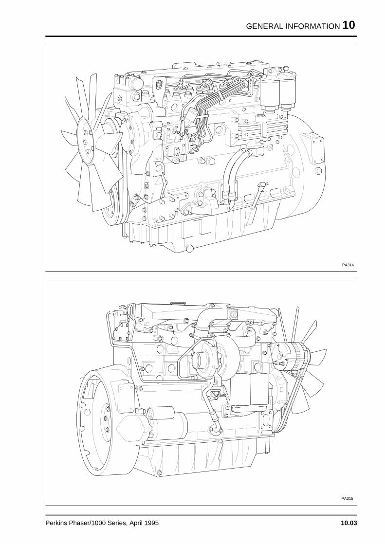
GENERAL INFORMATION 10
PA314
PA315
Perkins Phaser/1000 Series, April 1995 10.03
10 GENERAL INFORMATION
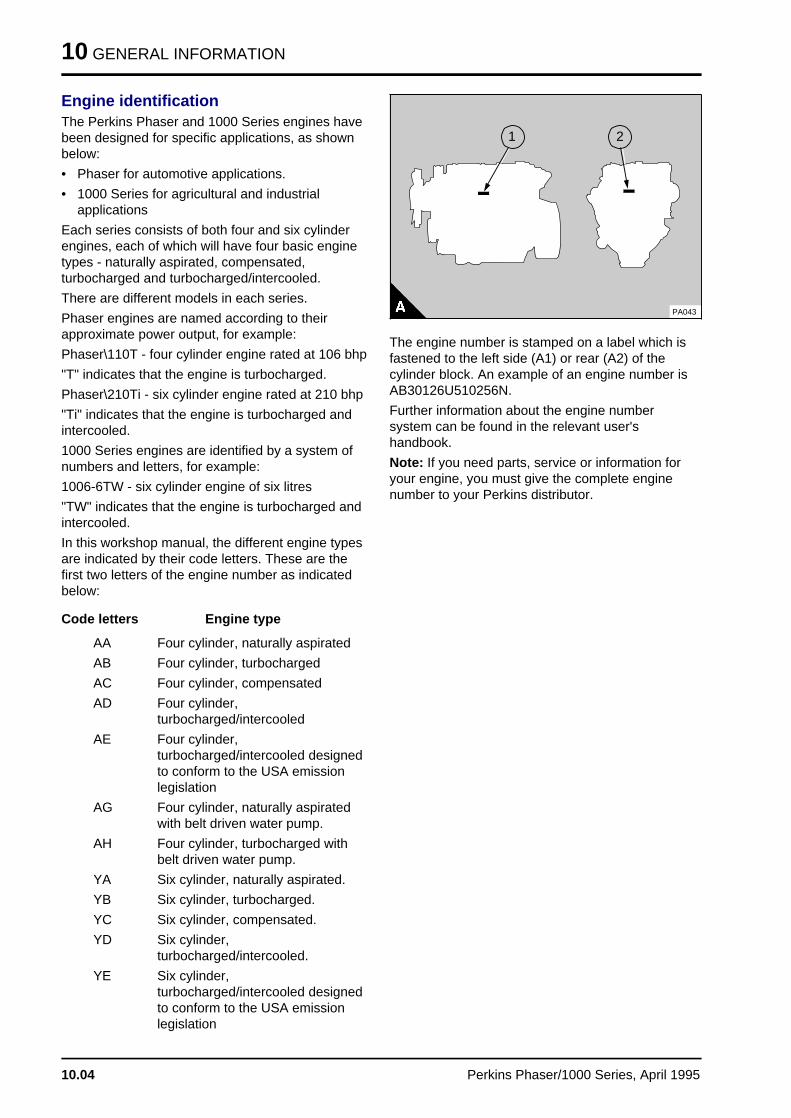
Engine identificationThe Perkins Phaser and 1000 Series engines havebeen designed for specific applications, as shownbelow:
• Phaser for automotive applications.
• 1000 Series for agricultural and industrialapplications
Each series consists of both four and six cylinderengines, each of which will have four basic enginetypes - naturally aspirated, compensated,turbocharged and turbocharged/intercooled.
There are different models in each series.
Phaser engines are named according to theirapproximate power output, for example:
Phaser\110T - four cylinder engine rated at 106 bhp
"T" indicates that the engine is turbocharged.
Phaser\210Ti - six cylinder engine rated at 210 bhp
"Ti" indicates that the engine is turbocharged andintercooled.
1000 Series engines are identified by a system ofnumbers and letters, for example:
1006-6TW - six cylinder engine of six litres
"TW" indicates that the engine is turbocharged andintercooled.
In this workshop manual, the different engine typesare indicated by their code letters. These are thefirst two letters of the engine number as indicatedbelow:
Code letters Engine type
AA Four cylinder, naturally aspirated
AB Four cylinder, turbocharged
AC Four cylinder, compensated
AD Four cylinder,turbocharged/intercooled
AE Four cylinder,turbocharged/intercooled designedto conform to the USA emissionlegislation
AG Four cylinder, naturally aspiratedwith belt driven water pump.
AH Four cylinder, turbocharged withbelt driven water pump.
YA Six cylinder, naturally aspirated.
YB Six cylinder, turbocharged.
YC Six cylinder, compensated.
YD Six cylinder,turbocharged/intercooled.
YE Six cylinder,turbocharged/intercooled designedto conform to the USA emissionlegislation
a a a
a a a
a a a
a a a
a a a
a a a
1
a a a
a a a
a a a
a a a
2
PA043
The engine number is stamped on a label which isfastened to the left side (A1) or rear (A2) of thecylinder block. An example of an engine number isAB30126U510256N.
Further information about the engine numbersystem can be found in the relevant user'shandbook.
Note: If you need parts, service or information foryour engine, you must give the complete enginenumber to your Perkins distributor.
10.04 Perkins Phaser/1000 Series, April 1995
GENERAL INFORMATION 10
General safety precautionsThese safety precautions are important. Youmust refer also to the local regulations in thecountry of use. Some items only refer to specificapplications.
• Only use these engines in the type of applicationfor which they have been designed.
• Do not change the specification of the engine.
• Do not smoke when you put fuel in the tank.
• Clean away fuel which has been spilt. Materialwhich has been contaminated by fuel must bemoved to a safe place.
• Do not put fuel in the tank while the engine runs(unless it is absolutely necessary).
• Do not clean, add lubricating oil, or adjust theengine while it runs (unless you have had thecorrect training; even then extreme care must beused to prevent injury).
• Do not make adjustments that you do notunderstand.
• Ensure that the engine does not run in a locationwhere it can cause a concentration of toxicemissions.
• Other persons must be kept at a safe distancewhile the engine or auxiliary equipment is inoperation.
• Do not permit loose clothing or long hair nearmoving parts.
• Keep away from moving parts during engineoperation. Warning! Some moving parts cannotbe seen clearly while the engine runs.
• Do not operate the engine if a safety guard hasbeen removed.
• Do not remove the filler cap of the coolingsystem while the engine is hot and while thecoolant is under pressure, because dangeroushot coolant can be discharged.
• Do not use salt water or any other coolant whichcan cause corrosion in the closed circuit of thecooling system.
• Do not allow sparks or fire near the batteries(especially when the batteries are on charge)because the gases from the electrolyte are highlyflammable. The battery fluid is dangerous to theskin and especially to the eyes.
• Disconnect the battery terminals before a repairis made to the electrical system.
• Only one person must control the engine.
• Ensure that the engine is operated only from thecontrol panel or from the operators position.
• If your skin comes into contact with high-pressure fuel, obtain medical assistanceimmediately.
• Diesel fuel and lubricating oil (especially usedlubricating oil) can damage the skin of certainpersons. Protect your hands with gloves or aspecial solution to protect the skin.
• Do not wear clothing which is contaminated bylubricating oil. Do not put material which iscontaminated with oil into the pockets of clothing.
• Discard used lubricating oil in a safe place toprevent contamination.
• Ensure that the control lever of the transmissiondrive is in the "out-of-drive" position before theengine is started.
• Use extreme care if emergency repairs must bemade in adverse conditions.
• The combustible material of some componentsof the engine (for example certain seals) canbecome extremely dangerous if it is burned.Never allow this burnt material to come intocontact with the skin or with the eyes.
• Read and use the instructions relevant to liftequipment which are given on page 10.06.
• Always use a safety cage to protect the operatorwhen a component is to be pressure tested in acontainer of water. Fit safety wires to secure theplugs which seal the hose connections of acomponent which is to be pressure tested.
• Do not allow compressed air to contact yourskin. If compressed air enters your skin, obtainmedical help immediately.
• Turbochargers operate at high speed and at hightemperatures. Keep fingers, tools and debrisaway from the inlet and outlet ports of theturbocharger and prevent contact with hotsurfaces.
• Fit only genuine Perkins parts.
Perkins Phaser/1000 Series, April 1995 10.05
10 GENERAL INFORMATION
Safety
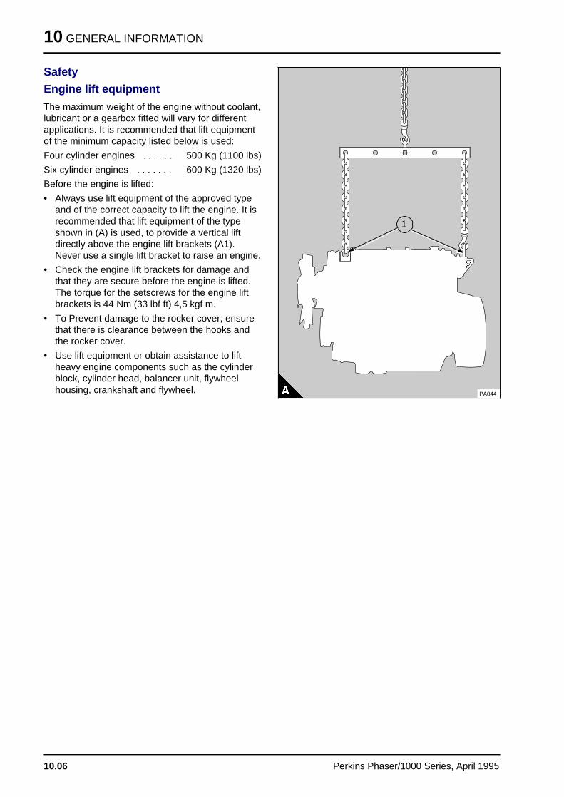
Engine lift equipment
The maximum weight of the engine without coolant,lubricant or a gearbox fitted will vary for differentapplications. It is recommended that lift equipmentof the minimum capacity listed below is used:
Four cylinder engines . . . . . . 500 Kg (1100 lbs)
Six cylinder engines . . . . . . . 600 Kg (1320 lbs)
Before the engine is lifted:
• Always use lift equipment of the approved typeand of the correct capacity to lift the engine. It isrecommended that lift equipment of the typeshown in (A) is used, to provide a vertical liftdirectly above the engine lift brackets (A1).Never use a single lift bracket to raise an engine.
• Check the engine lift brackets for damage andthat they are secure before the engine is lifted.The torque for the setscrews for the engine liftbrackets is 44 Nm (33 lbf ft) 4,5 kgf m.
• To Prevent damage to the rocker cover, ensurethat there is clearance between the hooks andthe rocker cover.
• Use lift equipment or obtain assistance to liftheavy engine components such as the cylinderblock, cylinder head, balancer unit, flywheelhousing, crankshaft and flywheel. PA044
a aa aa aa a
1
a a a
a a a
a a a
a a a
10.06 Perkins Phaser/1000 Series, April 1995
GENERAL INFORMATION 10
Safety
Asbestos joints
Some joints and gaskets contain compressedasbestos fibres in a rubber compound or in a metalouter cover. The "white" asbestos (Chrysotile)which is used is a safer type of asbestos and therisk of damage to health is extremely small.
• The risk of asbestos from joints occurs at theiredges or if a joint is damaged when a componentis removed or if a joint is removed by abrasives.
• To ensure that the risk is kept to a minimum, theprecautions given below must be applied whenan engine which has asbestos joints isdismantled or assembled.
• Work in an area with good ventilation.
• Do not smoke.
• Use a hand scraper to remove the joints - do notuse a rotary wire brush.
• Ensure that the joint to be removed is wet withoil or water to contain loose particles.
• Spray all asbestos debris with water and put it ina closed container which can be sealed for safedisposal.
PG008
Perkins Phaser/1000 Series, April 1995 10.07
10 GENERAL INFORMATION
Safety
Viton seals
Some seals used in engines and in componentsfitted to engines are made of Viton.
Viton is used by many manufacturers and is a safematerial under normal conditions of operation.
If Viton is burned, a product of this burnt material isan acid which is extremely dangerous. Never allowthis burnt material to come into contact with theskin or with the eyes.
If it is necessary to come into contact withcomponents which have been burnt, ensure thatthe precautions which follow are used:
• Ensure that the components have cooled.
• Use Neoprene gloves and discard the glovessafely after use.
• Wash the area with calcium hydroxide solutionand then with clean water.
• Disposal of components and gloves which arecontaminated must be in accordance with localregulations.
If there is contamination of the skin or eyes, washthe affected area with a continuous supply of cleanwater or with calcium hydroxide solution for 15-60minutes. Obtain immediate medical attention.
10.08 Perkins Phaser/1000 Series, April 1995
GENERAL INFORMATION 10
POWERPART consumable productsPerkins have made available the productsrecommended below in order to assist in thecorrect operation, service and maintenance of yourengine and your machine. The instructions for theuse of each product are given on the outside ofeach container. These products are available fromyour Perkins distributor.
POWERPART Antifreeze
Protects the cooling system against frost andcorrosion. Part number 1 litre 21825166 or 5 litres21825167, see the User's Handbook.
POWERPART Easy Flush
Cleans the cooling system. Part number 2182501
POWERPART Jointing compound
Universal jointing compound which seals joints.Currently Hylomar. Part number 1861155 or1861117.
POWERPART Silicone rubber sealant
Silicone rubber sealant which prevents leakagethrough gaps. Currently Hylosil. Part number1861108.
POWERPART Lay-Up 1
A diesel fuel additive for protection againstcorrosion. Part number 1772204, see the User'sHandbook.
POWERPART Lay-Up 2
Protects the inside of the engine and of otherclosed systems. Part number 1762811, see theUser's Handbook.
POWERPART Lay-Up 3
Protects outside metal parts. Part number 1734115,see the User's Handbook.
POWERPART Chisel
Allows easy removal of old gaskets and joints.Currently Loctite Chisel. Part number 21825163.
POWERPART Repel
Dries damp equipment and gives protection againstcorrosion. Passes through dirt and corrosion tolubricate and to assist removal of components.Currently Loctite Repel. Part number 21825164.
POWERPART Threadlock
To retain small fasteners where easy removal isnecessary. Currently Loctite 222e. Part number21820222.
POWERPART Nutlock
To retain and seal threaded fasteners and cupplugs where easy removal is necessary. Currently Loctite 242e. Part number 21820242
POWERPART Studlock
To permanently retain large fasteners and studs.Currently Loctite 270. Part number 21820270.
POWERPART Liquid gasket
To seal flat faces of components where no joint isused. Especially suitable for aluminiumcomponents. Currently Loctite 518. Part number21820518
POWERPART Threadlock (hydraulic/pneumatic)
To retain and seal pipe connections with finethreads. Especially suitable for hydraulic andpneumatic systems. Currently Loctite 542. Partnumber 2180542
POWERPART Threadlock (pipe)
To retain and seal pipe connections with coarsethreads. Pressure systems can be usedimmediately. Currently Loctite 575. Part number21820575.
POWERPART Retainer (oil tolerant)
To retain components which have a transition fit.Currently Loctite 603. Part number 21820603.
POWERPART Retainer (high strength)
To retain components which have an interferencefit. Currently Loctite 638. Part number 21820638.
Perkins Phaser/1000 Series, April 1995 10.09
Specification s 11
Basic engine data . . . . . . . . . . . . . . . . . . . . . . . . . . . . . . . . . . . . . . . 11A
Recommended torque tensions . . . . . . . . . . . . . . . . . . . . . . . . . . . . . 11B
Perkins Phaser/1000 Series, April 1995 11.01
Basic engine dat a 11A
Basic engine data . . . . . . . . . . . . . . . . . . . . . . . . . . . . . . . . . . . . . . . . . . . 11A.02
Perkins Phaser/1000 Series, April 1995 11A.01
11A BASIC ENGINE DATA
Basic engine data
Number of cylinders:
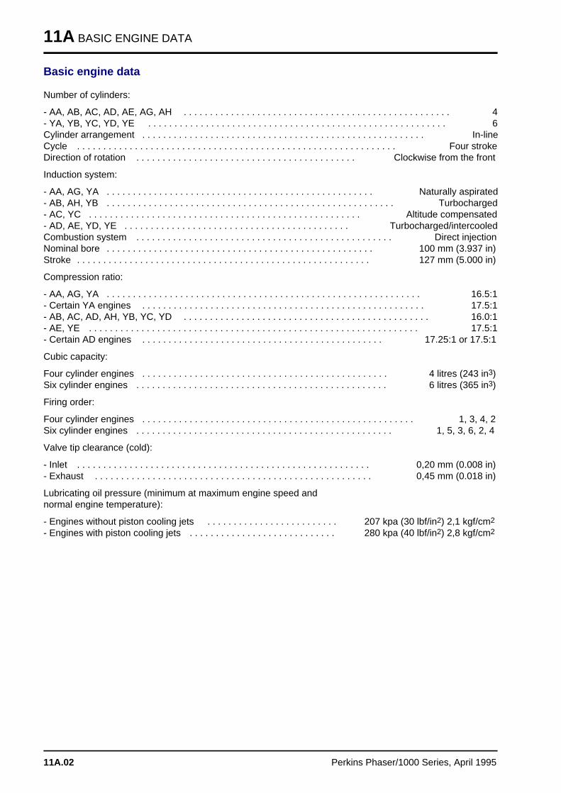
- AA, AB, AC, AD, AE, AG, AH . . . . . . . . . . . . . . . . . . . . . . . . . . . . . . . . . . . . . . . . . . . . . . . . . . . 4- YA, YB, YC, YD, YE . . . . . . . . . . . . . . . . . . . . . . . . . . . . . . . . . . . . . . . . . . . . . . . . . . . . . . . . . 6Cylinder arrangement . . . . . . . . . . . . . . . . . . . . . . . . . . . . . . . . . . . . . . . . . . . . . . . . . . . . . . In-lineCycle . . . . . . . . . . . . . . . . . . . . . . . . . . . . . . . . . . . . . . . . . . . . . . . . . . . . . . . . . . . . . Four strokeDirection of rotation . . . . . . . . . . . . . . . . . . . . . . . . . . . . . . . . . . . . . . . . . . Clockwise from the front
Induction system:
- AA, AG, YA . . . . . . . . . . . . . . . . . . . . . . . . . . . . . . . . . . . . . . . . . . . . . . . . . . . Naturally aspirated- AB, AH, YB . . . . . . . . . . . . . . . . . . . . . . . . . . . . . . . . . . . . . . . . . . . . . . . . . . . . . . . Turbocharged- AC, YC . . . . . . . . . . . . . . . . . . . . . . . . . . . . . . . . . . . . . . . . . . . . . . . . . . . . Altitude compensated- AD, AE, YD, YE . . . . . . . . . . . . . . . . . . . . . . . . . . . . . . . . . . . . . . . . . . . Turbocharged/intercooledCombustion system . . . . . . . . . . . . . . . . . . . . . . . . . . . . . . . . . . . . . . . . . . . . . . . . . Direct injectionNominal bore . . . . . . . . . . . . . . . . . . . . . . . . . . . . . . . . . . . . . . . . . . . . . . . . . . . 100 mm (3.937 in)Stroke . . . . . . . . . . . . . . . . . . . . . . . . . . . . . . . . . . . . . . . . . . . . . . . . . . . . . . . . 127 mm (5.000 in)
Compression ratio:
- AA, AG, YA . . . . . . . . . . . . . . . . . . . . . . . . . . . . . . . . . . . . . . . . . . . . . . . . . . . . . . . . . . . . 16.5:1- Certain YA engines . . . . . . . . . . . . . . . . . . . . . . . . . . . . . . . . . . . . . . . . . . . . . . . . . . . . . . 17.5:1- AB, AC, AD, AH, YB, YC, YD . . . . . . . . . . . . . . . . . . . . . . . . . . . . . . . . . . . . . . . . . . . . . . . 16.0:1- AE, YE . . . . . . . . . . . . . . . . . . . . . . . . . . . . . . . . . . . . . . . . . . . . . . . . . . . . . . . . . . . . . . . 17.5:1- Certain AD engines . . . . . . . . . . . . . . . . . . . . . . . . . . . . . . . . . . . . . . . . . . . . . . 17.25:1 or 17.5:1
Cubic capacity:
Four cylinder engines . . . . . . . . . . . . . . . . . . . . . . . . . . . . . . . . . . . . . . . . . . . . . . . 4 litres (243 in3)Six cylinder engines . . . . . . . . . . . . . . . . . . . . . . . . . . . . . . . . . . . . . . . . . . . . . . . . 6 litres (365 in3)
Firing order:
Four cylinder engines . . . . . . . . . . . . . . . . . . . . . . . . . . . . . . . . . . . . . . . . . . . . . . . . . . . . 1, 3, 4, 2Six cylinder engines . . . . . . . . . . . . . . . . . . . . . . . . . . . . . . . . . . . . . . . . . . . . . . . . . 1, 5, 3, 6, 2, 4
Valve tip clearance (cold):
- Inlet . . . . . . . . . . . . . . . . . . . . . . . . . . . . . . . . . . . . . . . . . . . . . . . . . . . . . . . . 0,20 mm (0.008 in)- Exhaust . . . . . . . . . . . . . . . . . . . . . . . . . . . . . . . . . . . . . . . . . . . . . . . . . . . . . 0,45 mm (0.018 in)
Lubricating oil pressure (minimum at maximum engine speed and normal engine temperature):
- Engines without piston cooling jets . . . . . . . . . . . . . . . . . . . . . . . . . 207 kpa (30 lbf/in2) 2,1 kgf/cm2
- Engines with piston cooling jets . . . . . . . . . . . . . . . . . . . . . . . . . . . . 280 kpa (40 lbf/in2) 2,8 kgf/cm2
11A.02 Perkins Phaser/1000 Series, April 1995
Recommended torque tension s 11B
Cylinder head assembly . . . . . . . . . . . . . . . . . . . . . . . . . . . . . . . . . . . . . . 11B.02Pistons and connecting rod assemblies . . . . . . . . . . . . . . . . . . . . . . . . . . . 11B.02Crankshaft assembly . . . . . . . . . . . . . . . . . . . . . . . . . . . . . . . . . . . . . . . . . 11B.02Timing case and drive assembly . . . . . . . . . . . . . . . . . . . . . . . . . . . . . . . . 11B.03Cylinder block . . . . . . . . . . . . . . . . . . . . . . . . . . . . . . . . . . . . . . . . . . . . . . 11B.03Aspiration system . . . . . . . . . . . . . . . . . . . . . . . . . . . . . . . . . . . . . . . . . . . 11B.03Fuel system . . . . . . . . . . . . . . . . . . . . . . . . . . . . . . . . . . . . . . . . . . . . . . . 11B.03Lubrication system . . . . . . . . . . . . . . . . . . . . . . . . . . . . . . . . . . . . . . . . . . 11B.04Cooling system . . . . . . . . . . . . . . . . . . . . . . . . . . . . . . . . . . . . . . . . . . . . . 11B.04Flywheel and housing . . . . . . . . . . . . . . . . . . . . . . . . . . . . . . . . . . . . . . . . 11B.04Electrical equipment . . . . . . . . . . . . . . . . . . . . . . . . . . . . . . . . . . . . . . . . . 11B.04Auxiliary equipment . . . . . . . . . . . . . . . . . . . . . . . . . . . . . . . . . . . . . . . . . . 11B.05
Perkins Phaser/1000 Series, April 1995 11B.01
11B RECOMMENDED TORQUE TENSIONS
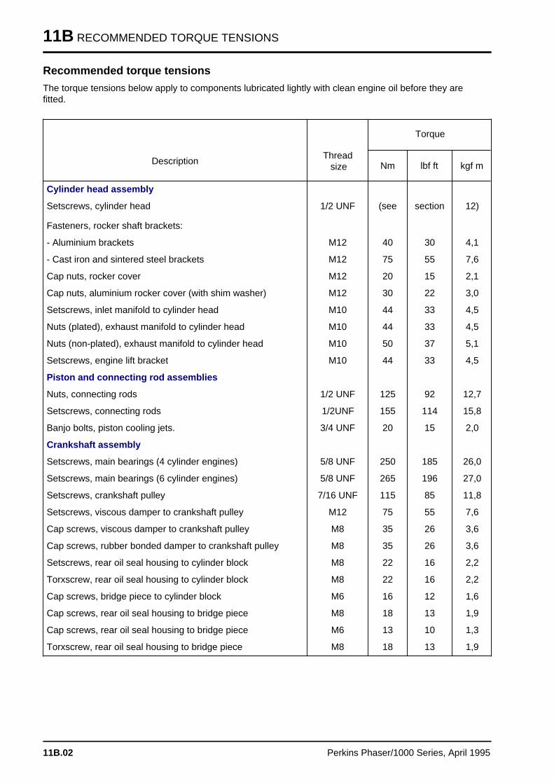
Recommended torque tensions
The torque tensions below apply to components lubricated lightly with clean engine oil before they arefitted.
DescriptionThread size
Torque
Nm lbf ft kgf m
Cylinder head assembly
Setscrews, cylinder head 1/2 UNF (see section 12)
Fasteners, rocker shaft brackets:
- Aluminium brackets M12 40 30 4,1
- Cast iron and sintered steel brackets M12 75 55 7,6
Cap nuts, rocker cover M12 20 15 2,1
Cap nuts, aluminium rocker cover (with shim washer) M12 30 22 3,0
Setscrews, inlet manifold to cylinder head M10 44 33 4,5
Nuts (plated), exhaust manifold to cylinder head M10 44 33 4,5
Nuts (non-plated), exhaust manifold to cylinder head M10 50 37 5,1
Setscrews, engine lift bracket M10 44 33 4,5
Piston and connecting rod assemblies
Nuts, connecting rods 1/2 UNF 125 92 12,7
Setscrews, connecting rods 1/2UNF 155 114 15,8
Banjo bolts, piston cooling jets. 3/4 UNF 20 15 2,0
Crankshaft assembly
Setscrews, main bearings (4 cylinder engines) 5/8 UNF 250 185 26,0
Setscrews, main bearings (6 cylinder engines) 5/8 UNF 265 196 27,0
Setscrews, crankshaft pulley 7/16 UNF 115 85 11,8
Setscrews, viscous damper to crankshaft pulley M12 75 55 7,6
Cap screws, viscous damper to crankshaft pulley M8 35 26 3,6
Cap screws, rubber bonded damper to crankshaft pulley M8 35 26 3,6
Setscrews, rear oil seal housing to cylinder block M8 22 16 2,2
Torxscrew, rear oil seal housing to cylinder block M8 22 16 2,2
Cap screws, bridge piece to cylinder block M6 16 12 1,6
Cap screws, rear oil seal housing to bridge piece M8 18 13 1,9
Cap screws, rear oil seal housing to bridge piece M6 13 10 1,3
Torxscrew, rear oil seal housing to bridge piece M8 18 13 1,9
11B.02 Perkins Phaser/1000 Series, April 1995
RECOMMENDED TORQUE TENSIONS 11B
DescriptionThread size
Torque
Nm lbf ft kgf m
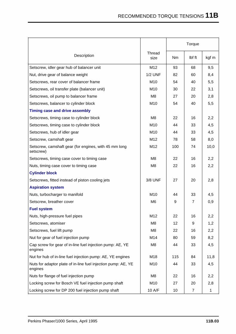
Setscrew, idler gear hub of balancer unit M12 93 68 9,5
Nut, drive gear of balance weight 1/2 UNF 82 60 8,4
Setscrews, rear cover of balancer frame M10 54 40 5,5
Setscrews, oil transfer plate (balancer unit) M10 30 22 3,1
Setscrews, oil pump to balancer frame M8 27 20 2,8
Setscrews, balancer to cylinder block M10 54 40 5,5
Timing case and drive assembly
Setscrews, timing case to cylinder block M8 22 16 2,2
Setscrews, timing case to cylinder block M10 44 33 4,5
Setscrews, hub of idler gear M10 44 33 4,5
Setscrew, camshaft gear M12 78 58 8,0
Setscrew, camshaft gear (for engines, with 45 mm longsetscrew)
M12 100 74 10,0
Setscrews, timing case cover to timing case M8 22 16 2,2
Nuts, timing case cover to timing case M8 22 16 2,2
Cylinder block
Setscrews, fitted instead of piston cooling jets 3/8 UNF 27 20 2,8
Aspiration system
Nuts, turbocharger to manifold M10 44 33 4,5
Setscrew, breather cover M6 9 7 0,9
Fuel system
Nuts, high-pressure fuel pipes M12 22 16 2,2
Setscrews, atomiser M8 12 9 1,2
Setscrews, fuel lift pump M8 22 16 2,2
Nut for gear of fuel injection pump M14 80 59 8,2
Cap screw for gear of in-line fuel injection pump: AE, YEengines
M8 44 33 4,5
Nut for hub of in-line fuel injection pump: AE, YE engines M18 115 84 11,8
Nuts for adaptor plate of in-line fuel injection pump: AE, YEengines
M10 44 33 4,5
Nuts for flange of fuel injection pump M8 22 16 2,2
Locking screw for Bosch VE fuel injection pump shaft M10 27 20 2,8
Locking screw for DP 200 fuel injection pump shaft 10 A/F 10 7 1
Perkins Phaser/1000 Series, April 1995 11B.03
11B RECOMMENDED TORQUE TENSIONS
DescriptionThread size
Torque
Nm lbf ft kgf m
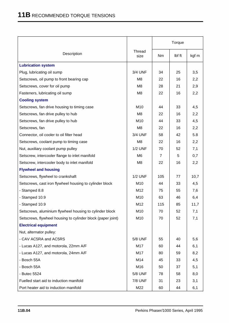
Lubrication system
Plug, lubricating oil sump 3/4 UNF 34 25 3,5
Setscrews, oil pump to front bearing cap M8 22 16 2,2
Setscrews, cover for oil pump M8 28 21 2,9
Fasteners, lubricating oil sump M8 22 16 2,2
Cooling system
Setscrews, fan drive housing to timing case M10 44 33 4,5
Setscrews, fan drive pulley to hub M8 22 16 2,2
Setscrews, fan drive pulley to hub M10 44 33 4,5
Setscrews, fan M8 22 16 2,2
Connector, oil cooler to oil filter head 3/4 UNF 58 42 5.8
Setscrews, coolant pump to timing case M8 22 16 2,2
Nut, auxiliary coolant pump pulley 1/2 UNF 70 52 7,1
Setscrew, intercooler flange to inlet manifold M6 7 5 0,7
Setscrew, intercooler body to inlet manifold M8 22 16 2,2
Flywheel and housing
Setscrews, flywheel to crankshaft 1/2 UNF 105 77 10,7
Setscrews, cast iron flywheel housing to cylinder block M10 44 33 4,5
- Stamped 8.8 M12 75 55 7,6
- Stamped 10.9 M10 63 46 6,4
- Stamped 10.9 M12 115 85 11,7
Setscrews, aluminium flywheel housing to cylinder block M10 70 52 7,1
Setscrews, flywheel housing to cylinder block (paper joint) M10 70 52 7,1
Electrical equipment
Nut, alternator pulley:
- CAV AC5RA and AC5RS 5/8 UNF 55 40 5,6
- Lucas A127, and motorola, 22mm A/F M17 60 44 6,1
- Lucas A127, and motorola, 24mm A/F M17 80 59 8,2
- Bosch 55A M14 45 33 4,5
- Bosch 55A M16 50 37 5,1
- Butec 5524 5/8 UNF 78 58 8,0
Fuelled start aid to induction manifold 7/8 UNF 31 23 3,1
Port heater aid to induction manifold M22 60 44 6,1
11B.04 Perkins Phaser/1000 Series, April 1995
RECOMMENDED TORQUE TENSIONS 11B
DescriptionThread size
Torque
Nm lbf ft kgf m
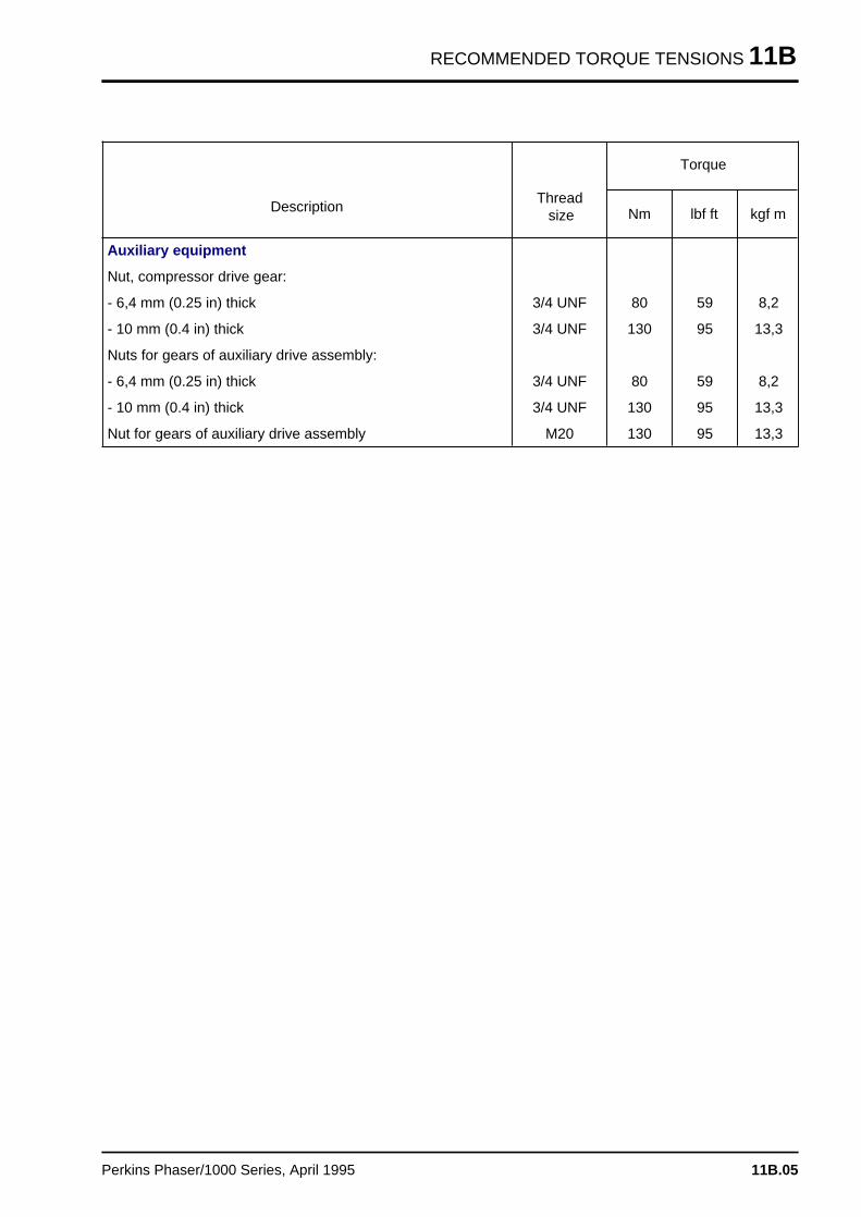
Auxiliary equipment
Nut, compressor drive gear:
- 6,4 mm (0.25 in) thick 3/4 UNF 80 59 8,2
- 10 mm (0.4 in) thick 3/4 UNF 130 95 13,3
Nuts for gears of auxiliary drive assembly:
- 6,4 mm (0.25 in) thick 3/4 UNF 80 59 8,2
- 10 mm (0.4 in) thick 3/4 UNF 130 95 13,3
Nut for gears of auxiliary drive assembly M20 130 95 13,3
Perkins Phaser/1000 Series, April 1995 11B.05
CYLINDER HEAD ASSEMBLY 12
Cylinder head assembl y 12
General descriptio n . . . . . . . . . . . . . . . . . . . . . . . . . . . . . . . . . . . . . . . . . 12A.02
Rocker cover
12A-01 To remove and to fit . . . . . . . . . . . . . . . . . . . . . . . . . . . . . . . . . 12A.03
Rocker assembly
12A-02 To remove and to fit . . . . . . . . . . . . . . . . . . . . . . . . . . . . . . . . . 12A.0512A-03 To dismantle and to assemble . . . . . . . . . . . . . . . . . . . . . . . . . . 12A.0612A-04 To inspect and to correct . . . . . . . . . . . . . . . . . . . . . . . . . . . . . 12A.06
Valve tip clearances
12A-05 To check and to adjust . . . . . . . . . . . . . . . . . . . . . . . . . . . . . . . 12A.07
Valve springs
12A-06 To change the valve springs (with cylinder head fitted) . . . . . . . . 12A.09
Cylinder head assembly
12A-07 To remove and to fit . . . . . . . . . . . . . . . . . . . . . . . . . . . . . . . . . 12A.11
Valves and valve springs
12A-08 To remove and to fit . . . . . . . . . . . . . . . . . . . . . . . . . . . . . . . . . 12A.1612A-09 To inspect and to correct . . . . . . . . . . . . . . . . . . . . . . . . . . . . . 12A.17
Valve guides
12A-10 To inspect . . . . . . . . . . . . . . . . . . . . . . . . . . . . . . . . . . . . . . . . 12A.1812A-11 To remove and to fit . . . . . . . . . . . . . . . . . . . . . . . . . . . . . . . . . 12A.19
Cylinder head
12A-12 To inspect and to correct . . . . . . . . . . . . . . . . . . . . . . . . . . . . . 12A.2012A-13 To correct a valve seat with a valve seat cutter . . . . . . . . . . . . . 12A.2112A-14 To fit valve seat inserts . . . . . . . . . . . . . . . . . . . . . . . . . . . . . . . 12A.22
Data and dimension s . . . . . . . . . . . . . . . . . . . . . . . . . . . . . . . . . . . . . . . 12A.23
Perkins Phaser/1000 Series, April 1995 12A.01
12 CYLINDER HEAD ASSEMBLY
General description
In a diesel engine there is little carbon deposit andfor this reason the number of hours run is noindication of when to overhaul a cylinder headassembly. The factors which indicate when anoverhaul is necessary are how easily the enginestarts and its general performance.
The cylinder head assembly has two valves fittedfor each cylinder, each fitted with double or singlevalve springs, according to the engine application.The double springs have damper coils which arefitted towards the top face of the cylinder head.
In most engines the face angle of the valves is 45°,but some engines have inlet valves with a faceangle of 30°. The angle of the valve seats in thecylinder head are either 46° or 31°.
The valves move in phosphated guides which canbe renewed. The exhaust valve guide has acounterbore at the bottom and is a little longer thanthe inlet valve guide.
Both valve stems are fitted with oil seals which fitover the top of the valve guides.
Turbocharged engines and some naturally aspiratedengines have valve seat inserts fitted in the cylinderhead for both inlet and exhaust valves. Engineswhich do not have valve seat inserts fitted asstandard, in production, can have them fitted inservice.
12A.02 Perkins Phaser/1000 Series, April 1995
CYLINDER HEAD ASSEMBLY 12
Rocker cover
To remove and to fit 12A-01
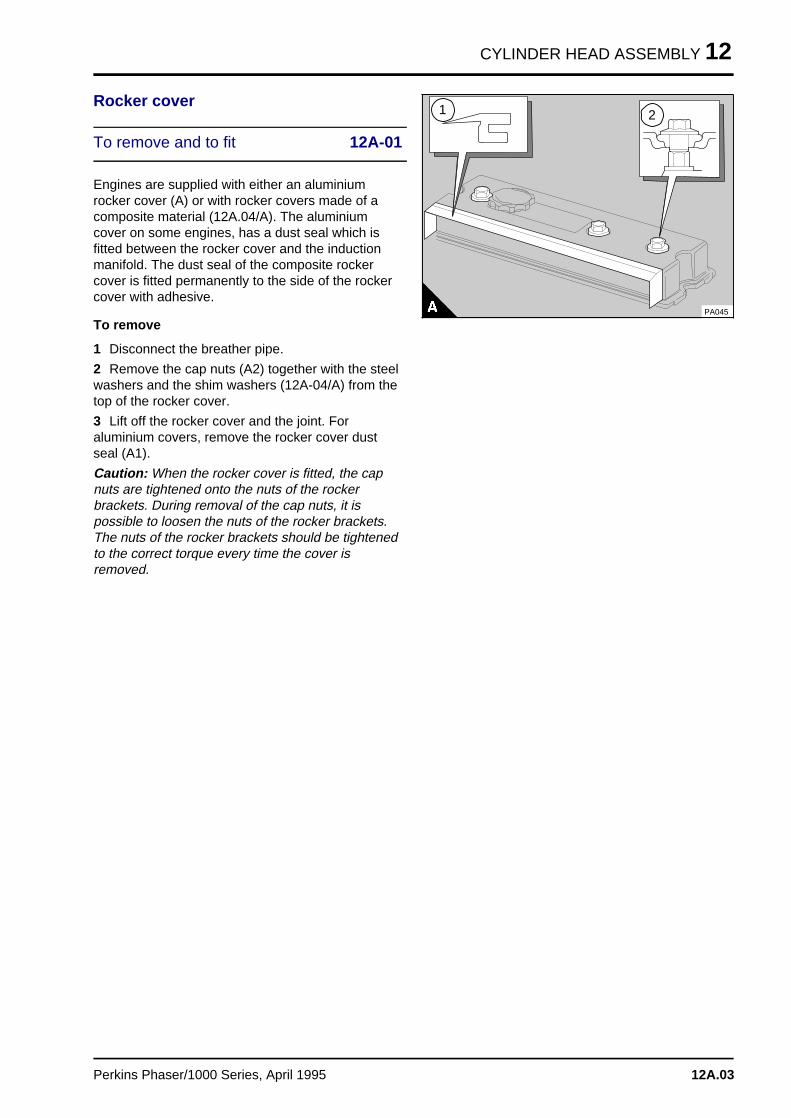
Engines are supplied with either an aluminiumrocker cover (A) or with rocker covers made of acomposite material (12A.04/A). The aluminiumcover on some engines, has a dust seal which isfitted between the rocker cover and the inductionmanifold. The dust seal of the composite rockercover is fitted permanently to the side of the rockercover with adhesive.
To remove
1 Disconnect the breather pipe.
2 Remove the cap nuts (A2) together with the steelwashers and the shim washers (12A-04/A) from thetop of the rocker cover.
3 Lift off the rocker cover and the joint. Foraluminium covers, remove the rocker cover dustseal (A1).
Caution: When the rocker cover is fitted, the capnuts are tightened onto the nuts of the rockerbrackets. During removal of the cap nuts, it ispossible to loosen the nuts of the rocker brackets.The nuts of the rocker brackets should be tightenedto the correct torque every time the cover isremoved.
a a a
a a a
a a a
a a a
1 a a a
a a a
a a a
a a a
2
PA045
Perkins Phaser/1000 Series, April 1995 12A.03
12 CYLINDER HEAD ASSEMBLY
To fit
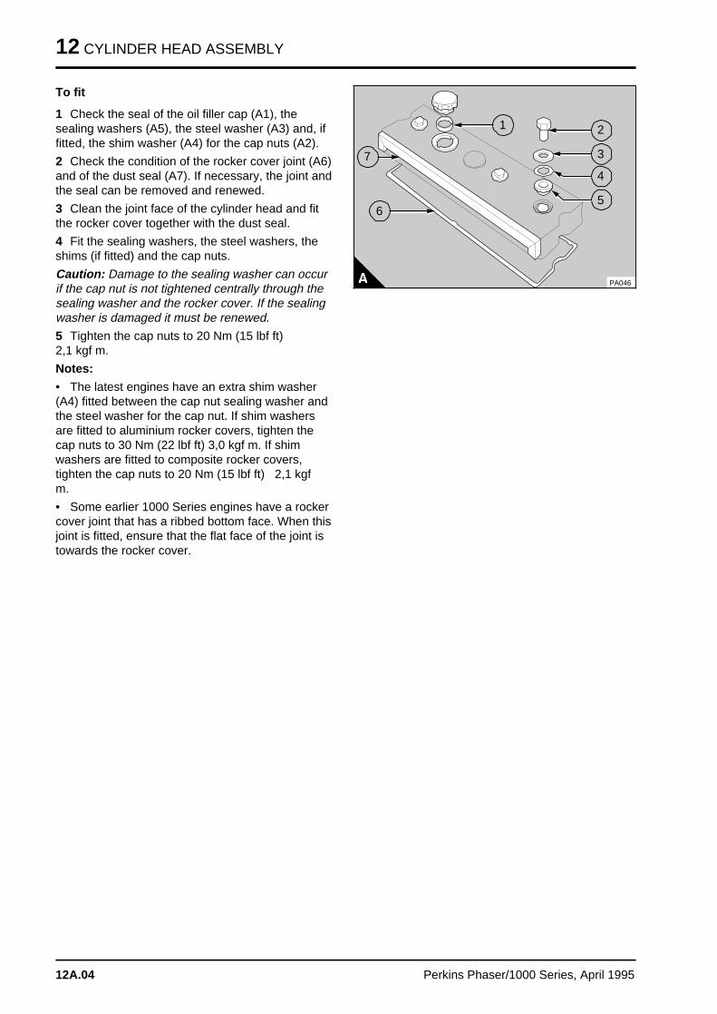
1 Check the seal of the oil filler cap (A1), thesealing washers (A5), the steel washer (A3) and, iffitted, the shim washer (A4) for the cap nuts (A2).
2 Check the condition of the rocker cover joint (A6)and of the dust seal (A7). If necessary, the joint andthe seal can be removed and renewed.
3 Clean the joint face of the cylinder head and fitthe rocker cover together with the dust seal.
4 Fit the sealing washers, the steel washers, theshims (if fitted) and the cap nuts.
Caution: Damage to the sealing washer can occurif the cap nut is not tightened centrally through thesealing washer and the rocker cover. If the sealingwasher is damaged it must be renewed.
5 Tighten the cap nuts to 20 Nm (15 lbf ft) 2,1 kgf m.
Notes:
• The latest engines have an extra shim washer(A4) fitted between the cap nut sealing washer andthe steel washer for the cap nut. If shim washersare fitted to aluminium rocker covers, tighten thecap nuts to 30 Nm (22 lbf ft) 3,0 kgf m. If shimwashers are fitted to composite rocker covers,tighten the cap nuts to 20 Nm (15 lbf ft) 2,1 kgfm.
• Some earlier 1000 Series engines have a rockercover joint that has a ribbed bottom face. When thisjoint is fitted, ensure that the flat face of the joint istowards the rocker cover.
PA046
a a a
a a a
a a a
a a a
a a a
1 a aa aa aa aa a
2
a aa aa aa a
3
a aa aa aa aa a
4
a aa aa aa a
5a aa aa aa a
6
a a a
a a a
a a a
a a a
7
12A.04 Perkins Phaser/1000 Series, April 1995
CYLINDER HEAD ASSEMBLY 12
Rocker assembly
To remove and to fit 12A-02
To remove
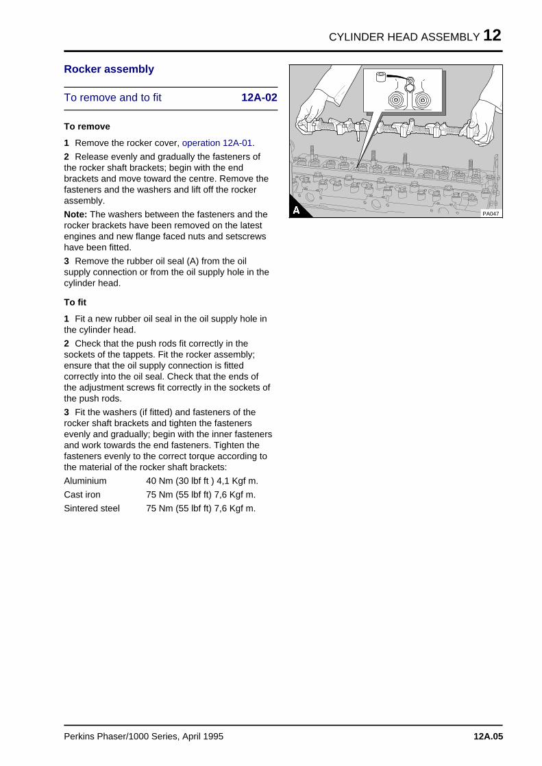
1 Remove the rocker cover, operation 12A-01.
2 Release evenly and gradually the fasteners ofthe rocker shaft brackets; begin with the endbrackets and move toward the centre. Remove thefasteners and the washers and lift off the rockerassembly.
Note: The washers between the fasteners and therocker brackets have been removed on the latestengines and new flange faced nuts and setscrewshave been fitted.
3 Remove the rubber oil seal (A) from the oilsupply connection or from the oil supply hole in thecylinder head.
To fit
1 Fit a new rubber oil seal in the oil supply hole inthe cylinder head.
2 Check that the push rods fit correctly in thesockets of the tappets. Fit the rocker assembly;ensure that the oil supply connection is fittedcorrectly into the oil seal. Check that the ends ofthe adjustment screws fit correctly in the sockets ofthe push rods.
3 Fit the washers (if fitted) and fasteners of therocker shaft brackets and tighten the fastenersevenly and gradually; begin with the inner fastenersand work towards the end fasteners. Tighten thefasteners evenly to the correct torque according tothe material of the rocker shaft brackets:
Aluminium 40 Nm (30 lbf ft ) 4,1 Kgf m.
Cast iron 75 Nm (55 lbf ft) 7,6 Kgf m.
Sintered steel 75 Nm (55 lbf ft) 7,6 Kgf m.
PA047
Perkins Phaser/1000 Series, April 1995 12A.05
12 CYLINDER HEAD ASSEMBLY
Rocker assembly
To dismantle and to assemble 12A-03
To dismantle
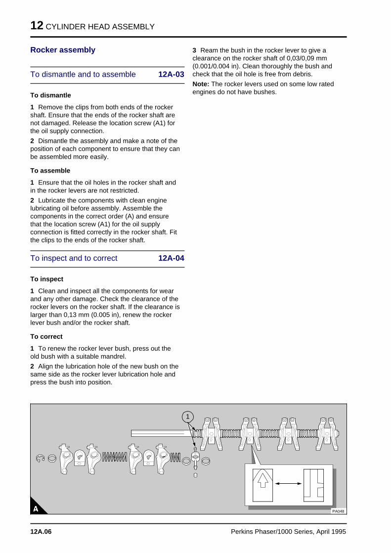
1 Remove the clips from both ends of the rockershaft. Ensure that the ends of the rocker shaft arenot damaged. Release the location screw (A1) forthe oil supply connection.
2 Dismantle the assembly and make a note of theposition of each component to ensure that they canbe assembled more easily.
To assemble
1 Ensure that the oil holes in the rocker shaft andin the rocker levers are not restricted.
2 Lubricate the components with clean enginelubricating oil before assembly. Assemble thecomponents in the correct order (A) and ensurethat the location screw (A1) for the oil supplyconnection is fitted correctly in the rocker shaft. Fitthe clips to the ends of the rocker shaft.
To inspect and to correct 12A-04
To inspect
1 Clean and inspect all the components for wearand any other damage. Check the clearance of therocker levers on the rocker shaft. If the clearance islarger than 0,13 mm (0.005 in), renew the rockerlever bush and/or the rocker shaft.
To correct
1 To renew the rocker lever bush, press out theold bush with a suitable mandrel.
2 Align the lubrication hole of the new bush on thesame side as the rocker lever lubrication hole andpress the bush into position.
3 Ream the bush in the rocker lever to give aclearance on the rocker shaft of 0,03/0,09 mm(0.001/0.004 in). Clean thoroughly the bush andcheck that the oil hole is free from debris.
Note: The rocker levers used on some low ratedengines do not have bushes.
a a a
a a a
a a a
a a a
a a a
1
PA048
12A.06 Perkins Phaser/1000 Series, April 1995
CYLINDER HEAD ASSEMBLY 12
Valve tip clearances
To check and to adjust 12A-05
Notes:
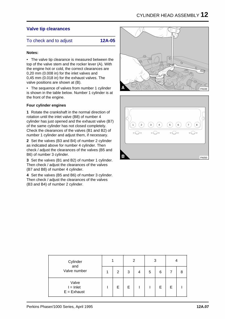
• The valve tip clearance is measured between thetop of the valve stem and the rocker lever (A). Withthe engine hot or cold, the correct clearances are0,20 mm (0.008 in) for the inlet valves and 0,45 mm (0.018 in) for the exhaust valves. Thevalve positions are shown at (B).
• The sequence of valves from number 1 cylinderis shown in the table below. Number 1 cylinder is atthe front of the engine.
Four cylinder engines
1 Rotate the crankshaft in the normal direction ofrotation until the inlet valve (B8) of number 4cylinder has just opened and the exhaust valve (B7)of the same cylinder has not closed completely.Check the clearances of the valves (B1 and B2) ofnumber 1 cylinder and adjust them, if necessary.
2 Set the valves (B3 and B4) of number 2 cylinderas indicated above for number 4 cylinder. Thencheck / adjust the clearances of the valves (B5 andB6) of number 3 cylinder.
3 Set the valves (B1 and B2) of number 1 cylinder.Then check / adjust the clearances of the valves(B7 and B8) of number 4 cylinder.
4 Set the valves (B5 and B6) of number 3 cylinder.Then check / adjust the clearances of the valves(B3 and B4) of number 2 cylinder.
PA049
1 2 3 4 5 6 7 8
PA050
Cylinderand
Valve number
1
1 2
2
3 4
3
5 6
4
7 8
ValveI = Inlet
E = ExhaustI E E I I E E I
Perkins Phaser/1000 Series, April 1995 12A.07
12 CYLINDER HEAD ASSEMBLY
Six cylinder engines
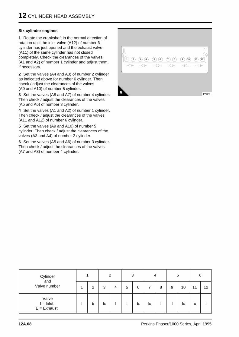
1 Rotate the crankshaft in the normal direction ofrotation until the inlet valve (A12) of number 6cylinder has just opened and the exhaust valve(A11) of the same cylinder has not closedcompletely. Check the clearances of the valves (A1 and A2) of number 1 cylinder and adjust them,if necessary.
2 Set the valves (A4 and A3) of number 2 cylinderas indicated above for number 6 cylinder. Thencheck / adjust the clearances of the valves (A9 and A10) of number 5 cylinder.
3 Set the valves (A8 and A7) of number 4 cylinder.Then check / adjust the clearances of the valves(A5 and A6) of number 3 cylinder.
4 Set the valves (A1 and A2) of number 1 cylinder.Then check / adjust the clearances of the valves(A11 and A12) of number 6 cylinder.
5 Set the valves (A9 and A10) of number 5cylinder. Then check / adjust the clearances of thevalves (A3 and A4) of number 2 cylinder.
6 Set the valves (A5 and A6) of number 3 cylinder.Then check / adjust the clearances of the valves(A7 and A8) of number 4 cylinder.
a aa a1 a aa a4a aa a2 a aa a3 a aa a5 a aa a6 a aa a7 a aa a8 a aa a9 a a a
a a a10 a a a
a a a12a a a
a a a11
PA028
Cylinderand
Valve number
1
1 2
2
3 4
3
5 6
4
7 8
5
9 10
6
11 12
ValveI = Inlet
E = ExhaustI E E I I E E I I E E I
12A.08 Perkins Phaser/1000 Series, April 1995
CYLINDER HEAD ASSEMBLY 12
Valve springs
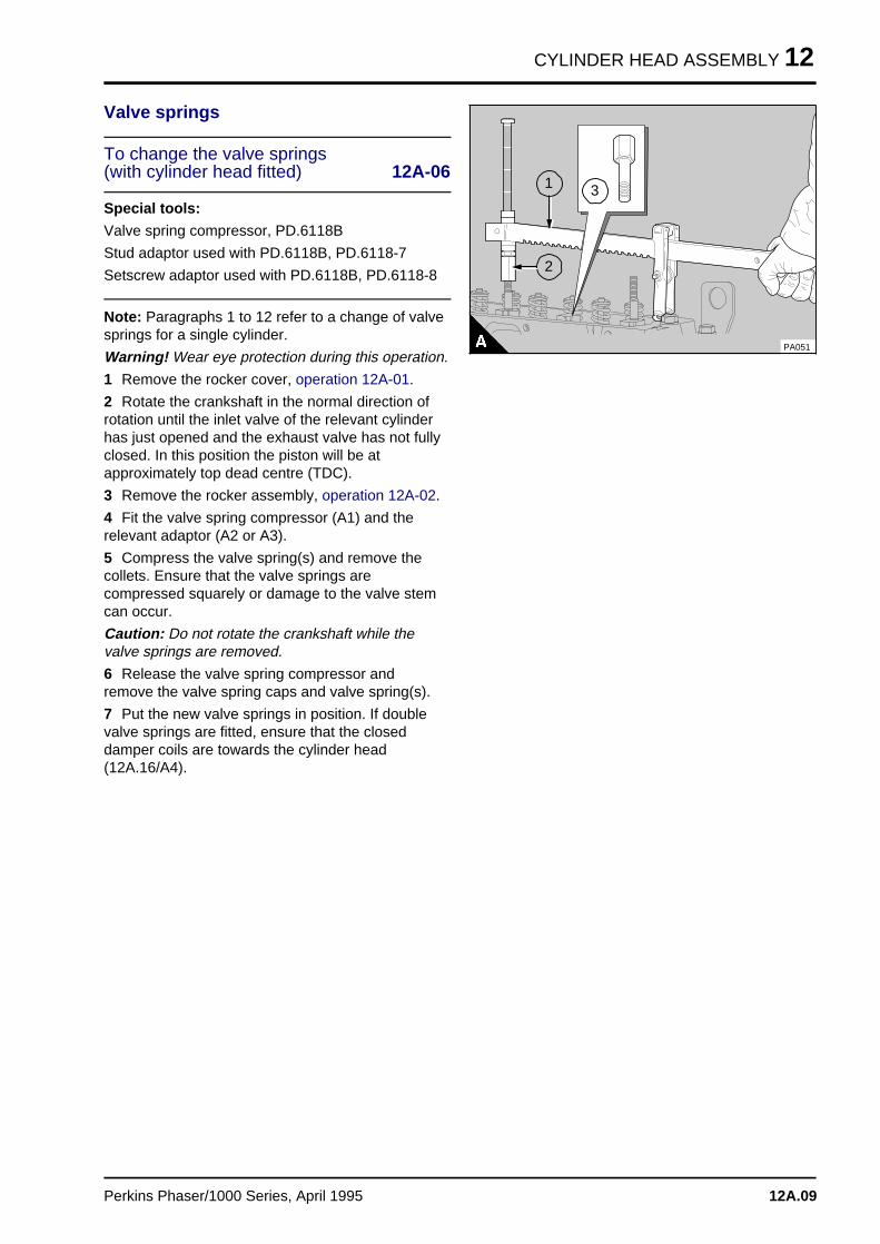
To change the valve springs(with cylinder head fitted) 12A-06
Special tools:
Valve spring compressor, PD.6118B
Stud adaptor used with PD.6118B, PD.6118-7
Setscrew adaptor used with PD.6118B, PD.6118-8
Note: Paragraphs 1 to 12 refer to a change of valvesprings for a single cylinder.
Warning! Wear eye protection during this operation.
1 Remove the rocker cover, operation 12A-01.
2 Rotate the crankshaft in the normal direction ofrotation until the inlet valve of the relevant cylinderhas just opened and the exhaust valve has not fullyclosed. In this position the piston will be atapproximately top dead centre (TDC).
3 Remove the rocker assembly, operation 12A-02.
4 Fit the valve spring compressor (A1) and therelevant adaptor (A2 or A3).
5 Compress the valve spring(s) and remove thecollets. Ensure that the valve springs arecompressed squarely or damage to the valve stemcan occur.
Caution: Do not rotate the crankshaft while thevalve springs are removed.
6 Release the valve spring compressor andremove the valve spring caps and valve spring(s).
7 Put the new valve springs in position. If doublevalve springs are fitted, ensure that the closeddamper coils are towards the cylinder head(12A.16/A4).
a a a
a a a
a a a
a a a
1
a a a
a a a
a a a
a a a
2
a a a
a a a
a a a
a a a
3
PA051
Perkins Phaser/1000 Series, April 1995 12A.09
12 CYLINDER HEAD ASSEMBLY
8 Fit the valve spring caps.
Caution: Ensure that the valve springs arecompressed squarely or damage can occur to thevalve stem.
9 Fit the valve spring compressor, compress thevalve springs and fit the collets. Remove the valvespring compressor.
10 Fit the rocker assembly, operation 12A-02.
11 Check the valve tip clearances, operation 12A-05.
12 Fit the rocker cover, operation 12A-01.
Note: If other or all of the valve springs are to bechanged, they can be changed two cylinders at atime. The sets of cylinders are:
For 4 cylinder engines: 1 and 4, 2 and 3
For 6 cylinder engines: 1 and 6, 2 and 5, 3 and 4
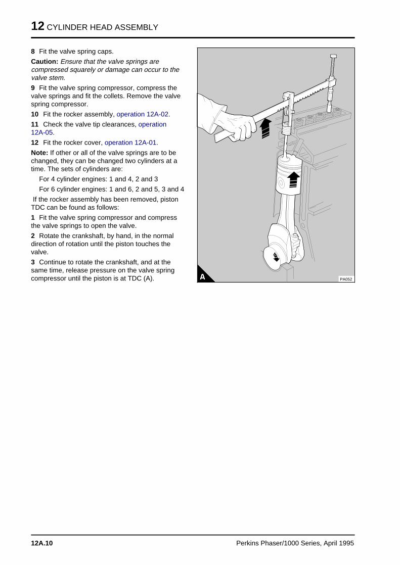
If the rocker assembly has been removed, pistonTDC can be found as follows:
1 Fit the valve spring compressor and compressthe valve springs to open the valve.
2 Rotate the crankshaft, by hand, in the normaldirection of rotation until the piston touches thevalve.
3 Continue to rotate the crankshaft, and at thesame time, release pressure on the valve springcompressor until the piston is at TDC (A). PA052
12A.10 Perkins Phaser/1000 Series, April 1995
CYLINDER HEAD ASSEMBLY 12
Cylinder head assembly
To remove and to fit 12A-07
To remove
1 Drain the cooling system.
2 Disconnect the battery terminals.
3 Remove the air filter/cleaner hose at theinduction manifold.
4 For engines fitted with turbochargers: Removethe air filter/cleaner hose at the compressor inlet ofthe turbocharger.
5 Remove the pipe which is fitted between thefuelled starting aid in the induction manifold and thefuel filter. Disconnect the electrical connection.
6 For engines fitted with a boost control device:Remove the boost control pipe which is fittedbetween the induction manifold and the top of thefuel injection pump.
7 Remove the induction manifold.
8 For engines fitted with turbochargers: Disconnectall connections to the turbocharger and remove theturbocharger, operation 18A-01.
9 Remove the exhaust manifold.
10 Remove the low-pressure fuel pipes which arefitted between the fuel injection pump and the fuelfilter.
Note: Where a Bosch fuel injection pump is fitted,keep the fuel outlet banjo bolt with the fuel injectionpump.
Remove the fuel pipe fitted between the fuel liftpump and the fuel filter. Remove the fuel filterbracket together with the fuel filter.
11 Remove the high-pressure fuel pipes.
Caution: Where access to the fuel injection pumpoutlet unions is possible, ensure that a separatespanner is used to prevent movement of the fuelinjection pump outlets when the connections of thehigh-pressure pipes are released. Fit suitablecovers to all open connections on the fuel injectionpump.
12 Remove the atomiser leak-off pipe.
13 Remove the atomisers, operation 20A-02. Fitsuitable covers to the nozzles and the openconnections.
14 If a compressor is fitted: Remove the coolantpipe which is fitted between the cylinder head andthe compressor. Then remove the coolant pipewhich is fitted between the by-pass connection andthe compressor.
15 Release the clip of the coolant by-pass hose atthe cylinder head. Release the setscrews and
remove the coolant by-pass connection and thehose.
16 Disconnect the coolant temperature senderunit.
17 For turbocharged and some naturally aspiratedfour cylinder engines: Remove the oil cooler,operation 21A-07A.
18 Remove the rocker cover, operation 12A-01.
19 Remove the rocker assembly, operation 12A-02.
20 Remove the push rods.
Perkins Phaser/1000 Series, April 1995 12A.11
12 CYLINDER HEAD ASSEMBLY
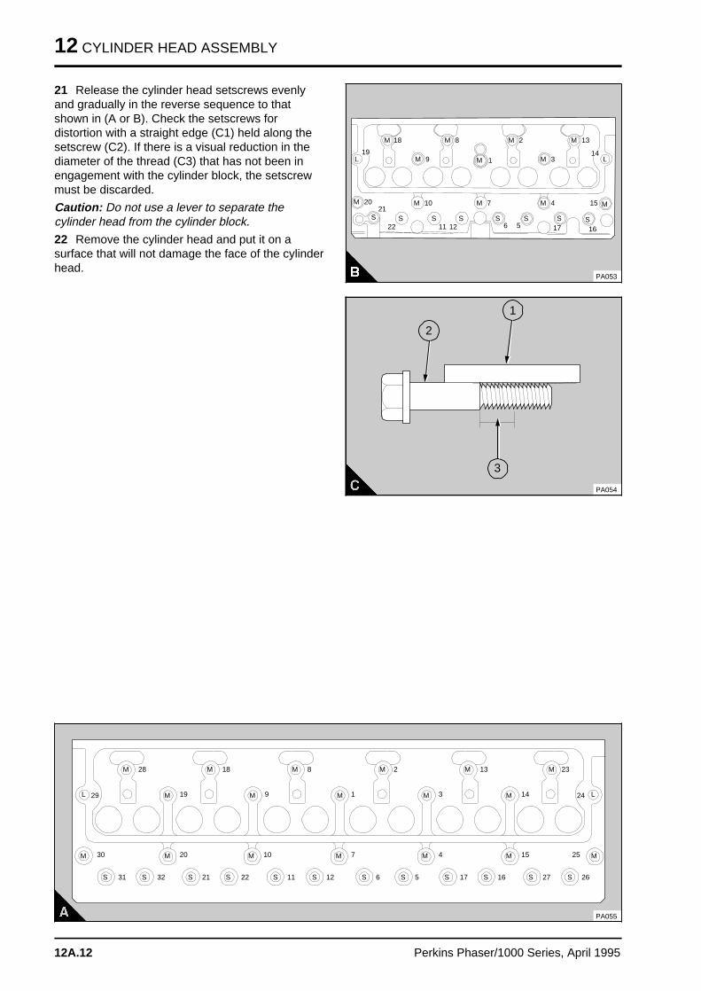
21 Release the cylinder head setscrews evenlyand gradually in the reverse sequence to thatshown in (A or B). Check the setscrews fordistortion with a straight edge (C1) held along thesetscrew (C2). If there is a visual reduction in thediameter of the thread (C3) that has not been inengagement with the cylinder block, the setscrewmust be discarded.
Caution: Do not use a lever to separate thecylinder head from the cylinder block.
22 Remove the cylinder head and put it on asurface that will not damage the face of the cylinderhead.
a aa aa a
L
a aa aa a
S
a aa aa a
S
a aa aa a
S
a aa aa a
S
a aa aa a
S
a a a
a a a
a a a
S
a aa aa a
S a aa aS
a aa aM a aa aa a
M a aa aa a
M a aa aa a
M a a a
a a a
a a a
M
a aa aa a
M
19
a a a a
a a a a
a a a a
18
a aa aa a
8
a aa a
1
a aa aa a
2
a aa aa a
3
a a a
a a a
a a a
13
a a a
a a a20 a a a
a a a
a a a
21
a a a
a a a
a a a
22
a a a
a a a
a a a
10
a a a a
a a a a
a a a a
11
a a a
a a a
a a a
12
a aa aa a
7
a aa aa a
6 a aa aa a
5
a aa aa a
4 a a a
a a a
a a a
15
a a a
a a a16a a a
a a a
17
14
PA053
a a a
a a a
a a a
M
a a a
a a a
a a a
M
a aa aa a
M
a aa aa a
M
a aa aa a
M
a aa aa a
La aa a
M
a aa aa a
9
a aa aa aa a
2
a a a
a a a
a a a
a a a
1
a aa aa aa a
3
PA054
a a a
a a a
a a a
M
a a a
a a a
a a a
S a aa aa a
S a aa aa a
S a a a
a a a
a a a
S a aa aa a
S a a a
a a a
a a a
S a a a
a a a
a a a
S a aa aa a
S a aa aa a
S a a a
a a a
a a a
S a a a
a a a
a a a
S a aa aa a
S
a aa aa a
M
a a a
a a a
a a a
M
a aa aa a
M
a aa aa a
M
a a a
a a a
a a a
M
a a a
a a a
a a a
M
a aa aa a
M
a aa aM
a a a
a a a
a a a
M
a aa aM
M
a a a
a a aM
a a a
a a a
a a a
M
a a a
a a aM
a a a
a a a
a a a
M
a a a
a a aM
a aa aa a
M
a aa a
L a aa a
L
PA055
a a a
a a a
a a a
30
a a a
a a a
a a a
31 a a a
a a a
a a a
32
a a a
a a a
a a a
20
a a a
a a a
a a a
21 a a a
a a a
a a a
22 a a a
a a a
a a a
11 a a a
a a a
a a a
12 a aa aa a
6 a aa aa a
5 a a a
a a a
a a a
17 a a a a
a a a a
a a a a
16 a a a
a a a
a a a
27 a a a
a a a
a a a
26
a a a
a a a
a a a
10 a aa aa a
7 a aa aa a
4 a a a
a a a
a a a
15 a a a
a a a
a a a
25
a a a
a a a
a a a
18
a aa aa a
8
a a a
a a a
a a a
2
a a a
a a a
a a a
13
a a a
a a a
a a a
23
a a a
a a a
a a a
28
a a a
a a a
19 a aa a
9 a aa a
1 a aa a
3 a a a
a a a
14a a a
a a a29 a a a
a a a24
12A.12 Perkins Phaser/1000 Series, April 1995
CYLINDER HEAD ASSEMBLY 12
To fit
Special tools:
Angle gauge, to tighten cylinder head setscrews,MS.1531
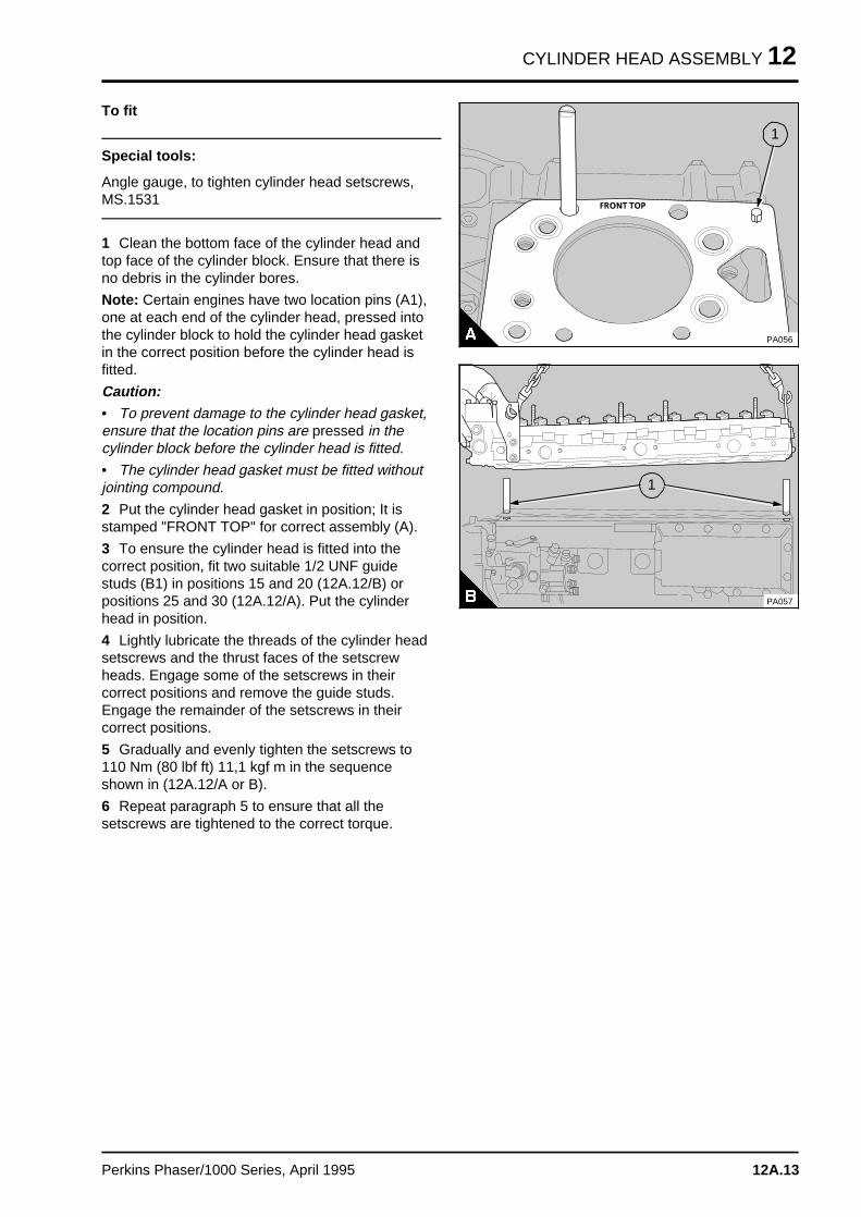
1 Clean the bottom face of the cylinder head andtop face of the cylinder block. Ensure that there isno debris in the cylinder bores.
Note: Certain engines have two location pins (A1),one at each end of the cylinder head, pressed intothe cylinder block to hold the cylinder head gasketin the correct position before the cylinder head isfitted.
Caution:• To prevent damage to the cylinder head gasket,ensure that the location pins are pressed in thecylinder block before the cylinder head is fitted.
• The cylinder head gasket must be fitted withoutjointing compound.
2 Put the cylinder head gasket in position; It isstamped "FRONT TOP" for correct assembly (A).
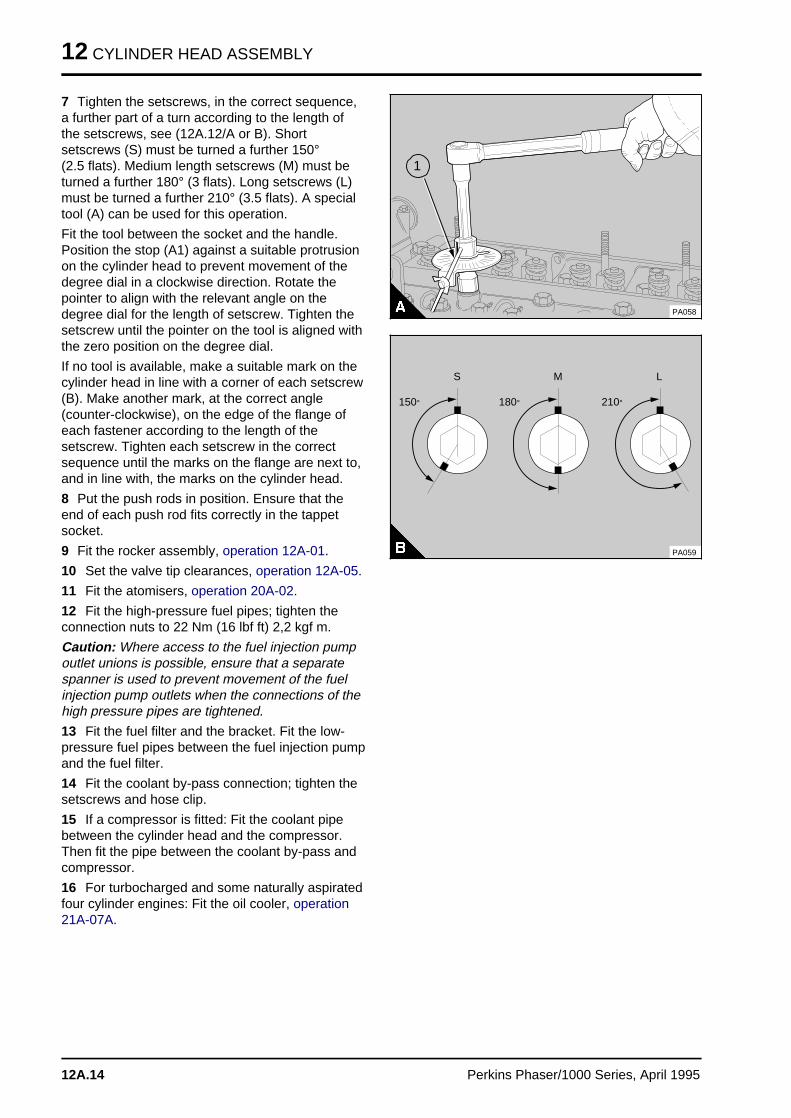
3 To ensure the cylinder head is fitted into thecorrect position, fit two suitable 1/2 UNF guidestuds (B1) in positions 15 and 20 (12A.12/B) orpositions 25 and 30 (12A.12/A). Put the cylinderhead in position.
4 Lightly lubricate the threads of the cylinder headsetscrews and the thrust faces of the setscrewheads. Engage some of the setscrews in theircorrect positions and remove the guide studs.Engage the remainder of the setscrews in theircorrect positions.
5 Gradually and evenly tighten the setscrews to110 Nm (80 lbf ft) 11,1 kgf m in the sequenceshown in (12A.12/A or B).
6 Repeat paragraph 5 to ensure that all thesetscrews are tightened to the correct torque.
a a a a a a a a a a
a a a a a a a a a a
a a a a a a a a a a
a a a a a a a a a a
FRONT TOP
a a a
a a a
a a a
a a a
1
PA056
PA057
a a a
a a a
a a a
a a a
1
Perkins Phaser/1000 Series, April 1995 12A.13
12 CYLINDER HEAD ASSEMBLY
7 Tighten the setscrews, in the correct sequence,a further part of a turn according to the length ofthe setscrews, see (12A.12/A or B). Shortsetscrews (S) must be turned a further 150° (2.5 flats). Medium length setscrews (M) must beturned a further 180° (3 flats). Long setscrews (L)must be turned a further 210° (3.5 flats). A specialtool (A) can be used for this operation.
Fit the tool between the socket and the handle.Position the stop (A1) against a suitable protrusionon the cylinder head to prevent movement of thedegree dial in a clockwise direction. Rotate thepointer to align with the relevant angle on thedegree dial for the length of setscrew. Tighten thesetscrew until the pointer on the tool is aligned withthe zero position on the degree dial.
If no tool is available, make a suitable mark on thecylinder head in line with a corner of each setscrew(B). Make another mark, at the correct angle(counter-clockwise), on the edge of the flange ofeach fastener according to the length of thesetscrew. Tighten each setscrew in the correctsequence until the marks on the flange are next to,and in line with, the marks on the cylinder head.
8 Put the push rods in position. Ensure that theend of each push rod fits correctly in the tappetsocket.
9 Fit the rocker assembly, operation 12A-01.
10 Set the valve tip clearances, operation 12A-05.
11 Fit the atomisers, operation 20A-02.
12 Fit the high-pressure fuel pipes; tighten theconnection nuts to 22 Nm (16 lbf ft) 2,2 kgf m.
Caution: Where access to the fuel injection pumpoutlet unions is possible, ensure that a separatespanner is used to prevent movement of the fuelinjection pump outlets when the connections of thehigh pressure pipes are tightened.
13 Fit the fuel filter and the bracket. Fit the low-pressure fuel pipes between the fuel injection pumpand the fuel filter.
14 Fit the coolant by-pass connection; tighten thesetscrews and hose clip.
15 If a compressor is fitted: Fit the coolant pipebetween the cylinder head and the compressor.Then fit the pipe between the coolant by-pass andcompressor.
16 For turbocharged and some naturally aspiratedfour cylinder engines: Fit the oil cooler, operation21A-07A.
PA058
a a a
a a a
a a a
a a a
1
a a a a a
a a a a a
a a a a a
150°
a a a
a a a
a a a
S
a a a a a a
a a a a a a
a a a a a a
180°
a a a
a a a
a a a
M
a a a a a a
a a a a a a
a a a a a a
210°
a aa aa a
L
PA059
12A.14 Perkins Phaser/1000 Series, April 1995
CYLINDER HEAD ASSEMBLY 12
17 Fit the exhaust manifold. The manifold joints arefitted without jointing compound.
18 For engines fitted with turbochargers: Fit theturbocharger, operation 18A-01.
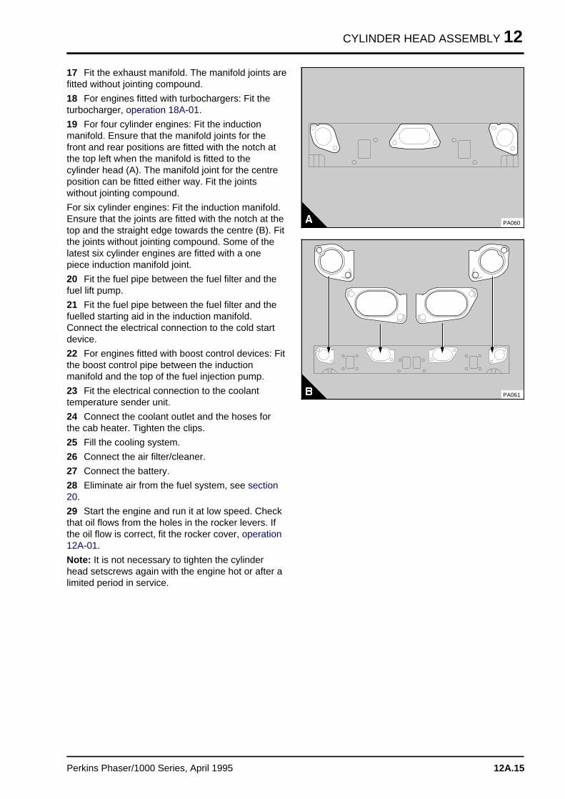
19 For four cylinder engines: Fit the inductionmanifold. Ensure that the manifold joints for thefront and rear positions are fitted with the notch atthe top left when the manifold is fitted to thecylinder head (A). The manifold joint for the centreposition can be fitted either way. Fit the jointswithout jointing compound.
For six cylinder engines: Fit the induction manifold.Ensure that the joints are fitted with the notch at thetop and the straight edge towards the centre (B). Fitthe joints without jointing compound. Some of thelatest six cylinder engines are fitted with a onepiece induction manifold joint.
20 Fit the fuel pipe between the fuel filter and thefuel lift pump.
21 Fit the fuel pipe between the fuel filter and thefuelled starting aid in the induction manifold.Connect the electrical connection to the cold startdevice.
22 For engines fitted with boost control devices: Fitthe boost control pipe between the inductionmanifold and the top of the fuel injection pump.
23 Fit the electrical connection to the coolanttemperature sender unit.
24 Connect the coolant outlet and the hoses forthe cab heater. Tighten the clips.
25 Fill the cooling system.
26 Connect the air filter/cleaner.
27 Connect the battery.
28 Eliminate air from the fuel system, see section20.
29 Start the engine and run it at low speed. Checkthat oil flows from the holes in the rocker levers. Ifthe oil flow is correct, fit the rocker cover, operation12A-01.
Note: It is not necessary to tighten the cylinderhead setscrews again with the engine hot or after alimited period in service.
PA060
PA061
Perkins Phaser/1000 Series, April 1995 12A.15
12 CYLINDER HEAD ASSEMBLY
Valves and valve springs
To remove and to fit 12A-08
Special tools:
Valve spring compressor, PD.6118B
Stud adaptor, PD.6118-7
Setscrew adaptor, PD.6118-8
To remove
1 Remove the cylinder head, operation 12A-07.
2 Clean the bottom face of the cylinder head andcheck the depth of the heads of the valves belowthe face of the cylinder head, see operation 12A-09.
3 Make a suitable mark on the heads of the valvesto ensure that the valves can be fitted in theiroriginal positions, if they are to be used again.
Warning! Wear eye protection during this operation.
Caution: Ensure that the valve springs arecompressed squarely or the valve stem can bedamaged.
4 Use the valve spring compressor and therelevant adaptor to compress the valve spring(s)and remove the collets.
5 Release the valve spring compressor andremove the valve spring cap, valve spring(s), valvestem seal and the valve seat washer.
6 Repeat items 4 and 5 for the other valves.
To fit
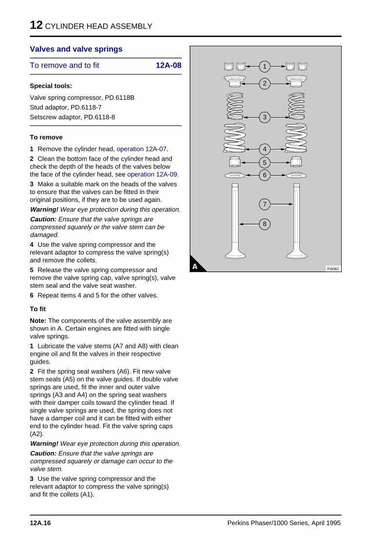
Note: The components of the valve assembly areshown in A. Certain engines are fitted with singlevalve springs.
1 Lubricate the valve stems (A7 and A8) with cleanengine oil and fit the valves in their respectiveguides.
2 Fit the spring seat washers (A6). Fit new valvestem seals (A5) on the valve guides. If double valvesprings are used, fit the inner and outer valvesprings (A3 and A4) on the spring seat washerswith their damper coils toward the cylinder head. Ifsingle valve springs are used, the spring does nothave a damper coil and it can be fitted with eitherend to the cylinder head. Fit the valve spring caps(A2).
Warning! Wear eye protection during this operation.
Caution: Ensure that the valve springs arecompressed squarely or damage can occur to thevalve stem.
3 Use the valve spring compressor and therelevant adaptor to compress the valve spring(s)and fit the collets (A1).
a a a
a a a
a a a
a a a
1
a a a
a a a
a a a
a a a
2
a a a
a a a
a a a
a a a
a a a
4
a a a
a a a
a a a
a a a
3
a a a
a a a
a a a
a a a
5
a a a
a a a
a a a
a a a
6
a a a
a a a
a a a
a a a
7
a a a
a a a
a a a
a a a
8
PA062
12A.16 Perkins Phaser/1000 Series, April 1995
CYLINDER HEAD ASSEMBLY 12
To inspect and to correct 12A-09
Special tool:
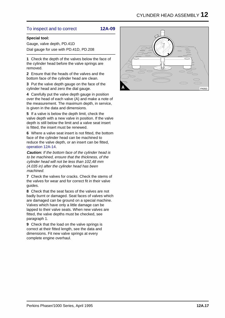
Gauge, valve depth, PD.41D
Dial gauge for use with PD.41D, PD.208
1 Check the depth of the valves below the face ofthe cylinder head before the valve springs areremoved.
2 Ensure that the heads of the valves and thebottom face of the cylinder head are clean.
3 Put the valve depth gauge on the face of thecylinder head and zero the dial gauge.
4 Carefully put the valve depth gauge in positionover the head of each valve (A) and make a note ofthe measurement. The maximum depth, in service,is given in the data and dimensions.
5 If a valve is below the depth limit, check thevalve depth with a new valve in position. If the valvedepth is still below the limit and a valve seat insertis fitted, the insert must be renewed.
6 Where a valve seat insert is not fitted, the bottomface of the cylinder head can be machined toreduce the valve depth, or an insert can be fitted,operation 12A-14.
Caution: If the bottom face of the cylinder head isto be machined, ensure that the thickness, of thecylinder head will not be less than 102,48 mm(4.035 in) after the cylinder head has beenmachined.
7 Check the valves for cracks. Check the stems ofthe valves for wear and for correct fit in their valveguides.
8 Check that the seat faces of the valves are notbadly burnt or damaged. Seat faces of valves whichare damaged can be ground on a special machine.Valves which have only a little damage can belapped to their valve seats. When new valves arefitted, the valve depths must be checked, seeparagraph 1.
9 Check that the load on the valve springs iscorrect at their fitted length, see the data anddimensions. Fit new valve springs at everycomplete engine overhaul.
a a
a aa a
a aa aa a
PA063
Perkins Phaser/1000 Series, April 1995 12A.17
12 CYLINDER HEAD ASSEMBLY
Valve guides
To inspect 12A-10
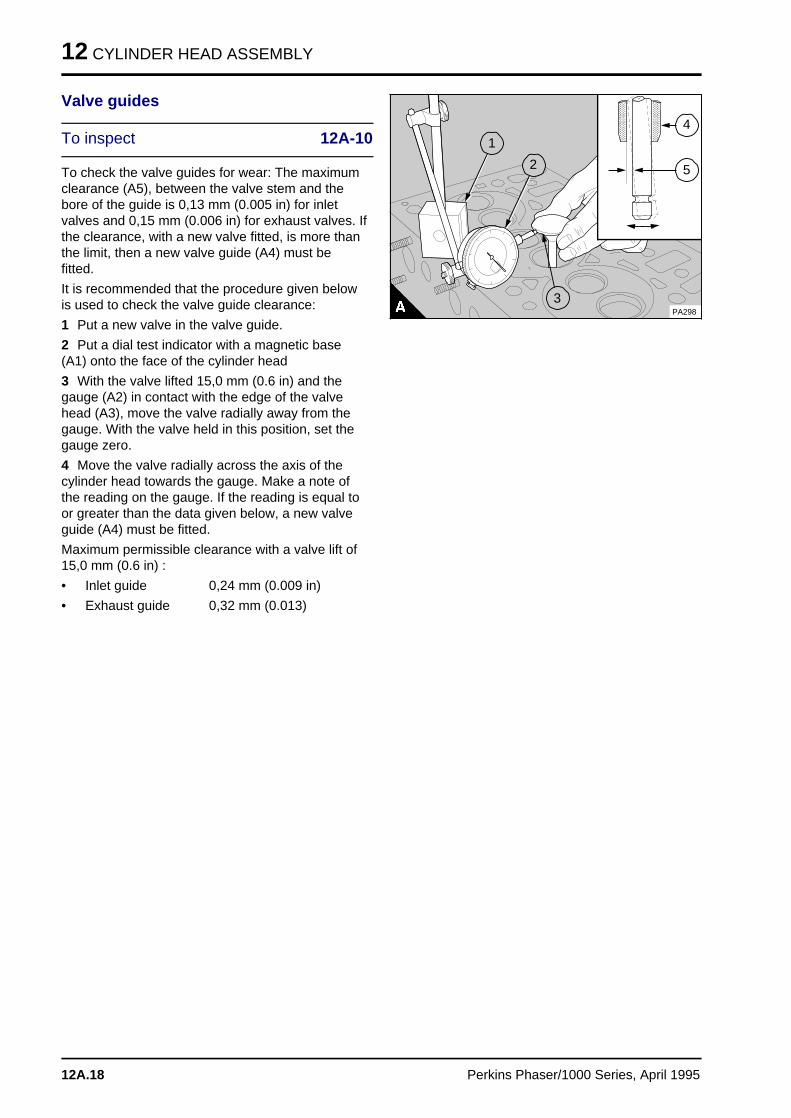
To check the valve guides for wear: The maximumclearance (A5), between the valve stem and thebore of the guide is 0,13 mm (0.005 in) for inletvalves and 0,15 mm (0.006 in) for exhaust valves. Ifthe clearance, with a new valve fitted, is more thanthe limit, then a new valve guide (A4) must befitted.
It is recommended that the procedure given belowis used to check the valve guide clearance:
1 Put a new valve in the valve guide.
2 Put a dial test indicator with a magnetic base(A1) onto the face of the cylinder head
3 With the valve lifted 15,0 mm (0.6 in) and thegauge (A2) in contact with the edge of the valvehead (A3), move the valve radially away from thegauge. With the valve held in this position, set thegauge zero.
4 Move the valve radially across the axis of thecylinder head towards the gauge. Make a note ofthe reading on the gauge. If the reading is equal toor greater than the data given below, a new valveguide (A4) must be fitted.
Maximum permissible clearance with a valve lift of15,0 mm (0.6 in) :
• Inlet guide 0,24 mm (0.009 in)
• Exhaust guide 0,32 mm (0.013)
a a a
a a a
a a a
a a a
5
a a a
a a a
a a a
a a a
4
a a a
a a a
a a a
a a a
a a a
1
a a a
a a a
a a a
a a a
2
PA298
a aa aa aa a
3
12A.18 Perkins Phaser/1000 Series, April 1995
CYLINDER HEAD ASSEMBLY 12
To remove and to fit 12A-11
Special tools:
Remover/replacer for valve guides (main tool),PD.1D
Adaptor used with PD.1D, PD.1D-1A
Adaptor used with PD.1D and PD.1D-1A, PD.1C-6
To remove
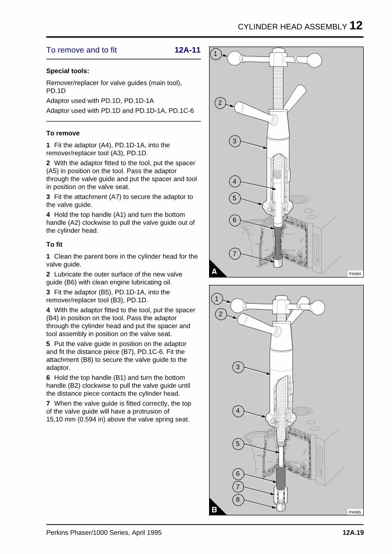
1 Fit the adaptor (A4), PD.1D-1A, into theremover/replacer tool (A3), PD.1D.
2 With the adaptor fitted to the tool, put the spacer(A5) in position on the tool. Pass the adaptorthrough the valve guide and put the spacer and toolin position on the valve seat.
3 Fit the attachment (A7) to secure the adaptor tothe valve guide.
4 Hold the top handle (A1) and turn the bottomhandle (A2) clockwise to pull the valve guide out ofthe cylinder head.
To fit
1 Clean the parent bore in the cylinder head for thevalve guide.
2 Lubricate the outer surface of the new valveguide (B6) with clean engine lubricating oil.
3 Fit the adaptor (B5), PD.1D-1A, into theremover/replacer tool (B3), PD.1D.
4 With the adaptor fitted to the tool, put the spacer(B4) in position on the tool. Pass the adaptorthrough the cylinder head and put the spacer andtool assembly in position on the valve seat.
5 Put the valve guide in position on the adaptorand fit the distance piece (B7), PD.1C-6. Fit theattachment (B8) to secure the valve guide to theadaptor.
6 Hold the top handle (B1) and turn the bottomhandle (B2) clockwise to pull the valve guide untilthe distance piece contacts the cylinder head.
7 When the valve guide is fitted correctly, the topof the valve guide will have a protrusion of 15,10 mm (0.594 in) above the valve spring seat.
a a a
a a a
a a a
a a a
3
a a a
a a a
a a a
a a a
4
a a a
a a a
a a a
a a a
5
a a a
a a a
a a a
a a a
7
a a a
a a a
a a a
a a a
a a a
6
PA064
a aa aa aa a
1
a aa aa aa a
2
PA065
a aa aa aa aa a
3
a aa aa aa a
4
a aa aa aa a
5
a aa aa aa a
6
a aa aa aa a
7
a aa aa aa a
8
a a a
a a a
a a a
a a a
2
a a a
a a a
a a a
a a a
1
Perkins Phaser/1000 Series, April 1995 12A.19
12 CYLINDER HEAD ASSEMBLY
Cylinder head
To inspect and to correct 12A-12
1 Remove the cylinder head assembly, operation12A-07.
2 Remove the thermostat housing.
3 Inspect the cylinder head for signs of gas orcoolant leakage.
4 Remove the valve springs and the valves,operation 12A-08.
5 Clean the face of the cylinder head and thepassages for coolant and for lubricating oil. Thewater jacket can be cleaned with a special solventwhich must be used in accordance with themanufacturer's instructions.
6 Test the cylinder head for leaks at the pressuregiven in the data and dimensions.
7 When the cylinder head is thoroughly clean,check it for cracks. Inspect carefully the areasaround the valve seats and around the holes for theatomiser nozzles.
8 The bottom face of the cylinder head can bemachined if: there is distortion, see paragraph 9;there are deep scratches; or, for engines withoutvalve seat inserts, the valve depths are below theservice limit.
9 Use a straight edge and feeler gauges to checkthe cylinder head for distortion across and along itsbottom face, see the data and dimensions. If thedistortion is more than the limit given in the dataand dimensions, the bottom face can be machined.
Caution: Remove only the minimum material andensure that the thickness of the cylinder head willnot be less than 102,48 mm (4.035 in) after thecylinder head has been machined.
Notes:
• On AE and YE engines the protrusion of theatomiser nozzle below the bottom face of thecylinder head must not be more than 4,82 mm(0.190 in).
• The nozzle protrusion must be measured withthe nozzle seat washer fitted.
Caution: After the cylinder head has beenmachined the valve seats must be corrected to givethe correct valve head depth.Work to the minimumlimit to allow for later wear.
10 Check the valve seats for wear and for damage.
11 Before any work is done on the valve seats,new valve guides must be fitted, operation 12A-11.
12 Where there is little damage, the valve andvalve seat can be lapped. When the valve seats arelapped keep the seat as narrow as possible andensure that all the compound used to lap the valveand the seat is removed.
13 More badly damaged valve seats can becorrected by use of the cutter tool, operation 12A-13, or new inserts can be fitted, operation12A-14.
12A.20 Perkins Phaser/1000 Series, April 1995
CYLINDER HEAD ASSEMBLY 12
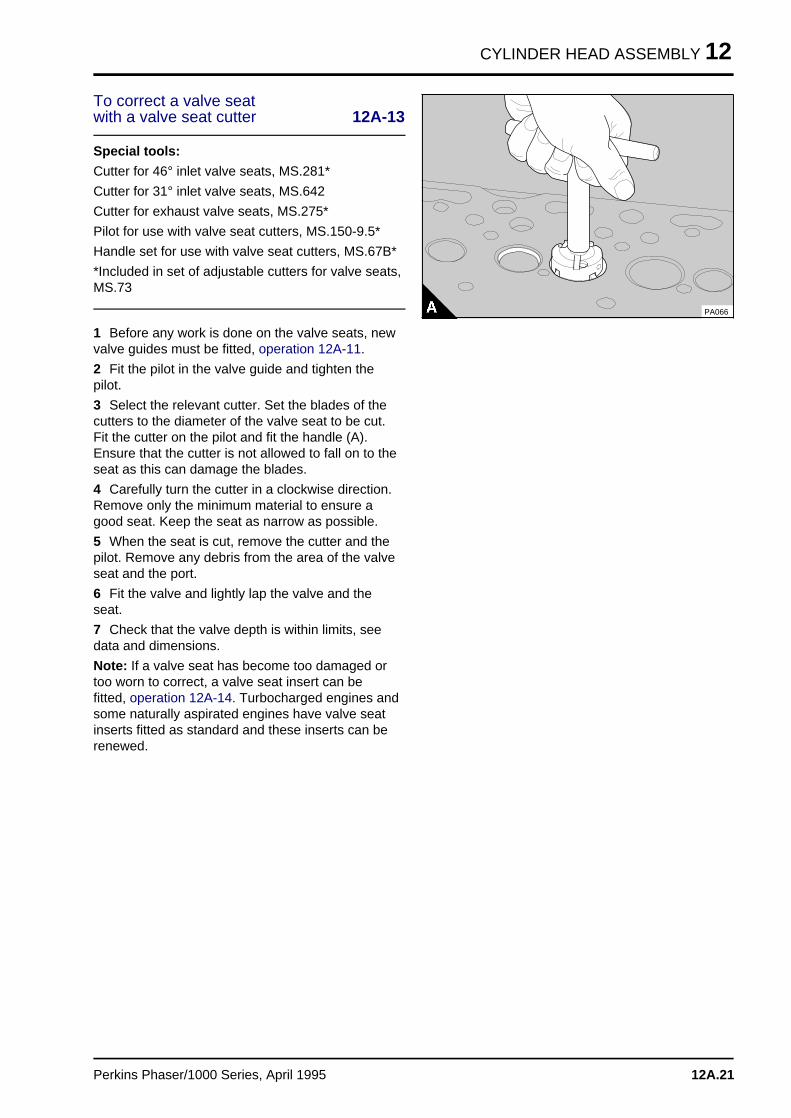
To correct a valve seatwith a valve seat cutter 12A-13
Special tools:
Cutter for 46° inlet valve seats, MS.281*
Cutter for 31° inlet valve seats, MS.642
Cutter for exhaust valve seats, MS.275*
Pilot for use with valve seat cutters, MS.150-9.5*
Handle set for use with valve seat cutters, MS.67B*
*Included in set of adjustable cutters for valve seats,MS.73
1 Before any work is done on the valve seats, newvalve guides must be fitted, operation 12A-11.
2 Fit the pilot in the valve guide and tighten thepilot.
3 Select the relevant cutter. Set the blades of thecutters to the diameter of the valve seat to be cut.Fit the cutter on the pilot and fit the handle (A).Ensure that the cutter is not allowed to fall on to theseat as this can damage the blades.
4 Carefully turn the cutter in a clockwise direction.Remove only the minimum material to ensure agood seat. Keep the seat as narrow as possible.
5 When the seat is cut, remove the cutter and thepilot. Remove any debris from the area of the valveseat and the port.
6 Fit the valve and lightly lap the valve and theseat.
7 Check that the valve depth is within limits, seedata and dimensions.
Note: If a valve seat has become too damaged ortoo worn to correct, a valve seat insert can befitted, operation 12A-14. Turbocharged engines andsome naturally aspirated engines have valve seatinserts fitted as standard and these inserts can berenewed.
PA066
Perkins Phaser/1000 Series, April 1995 12A.21
12 CYLINDER HEAD ASSEMBLY
To fit valve seat inserts 12A-14
1 Remove the valve guide and clean the bore intowhich the guide is to be fitted.
2 Fit new valve guides, operation 12A-11.
3 With the bore of the new valve guide used as apilot, machine the recess in the cylinder head to thedimensions shown in data and dimensions at theend of this section, or machine out the old insert.Remove all debris and clean the insert recess.
4 If the bottom face of the cylinder head has beenmachined, the insert will have to be surface groundon the back face to ensure that there is noprotrusion of the insert above the bottom face ofthe cylinder head. After the back of the insert hasbeen ground, ensure that the outer edge of theback face has a 0,9/1,3 mm (0.035/0.051 in)chamfer at 30° to the vertical.
5 With the bore of the valve guide used as a pilot,and with the rear face of the insert towards thecylinder head, press in the insert with the valve seatinsert tool, see data and dimensions. Do not use ahammer on the insert and do not use lubrication.Use a hydraulic press or a hand press in onecontinuous movement. Ensure that the bottom ofthe insert is in contact with the bottom of therecess.
6 Cut the valve seat at an included angle of 88°for 46° valve seats or 118° for 31° valve seats,operation 12A-13, and lap the valve on to the valveseat. Ensure that the depth of the valve head belowthe face of the cylinder head is within theproduction limits, see data and dimensions. Workas near as possible to the minimum figure to allowfor future wear on the valve seat.
12A.22 Perkins Phaser/1000 Series, April 1995
CYLINDER HEAD ASSEMBLY 12
Data and dimensions
Note: This information is given as a guide for personnel engaged on engine overhauls. The dimensionswhich are shown are those which are mainly used in the factory. The information applies to all engines,unless an engine type code is shown.
Cylinder head
Angle of valve seat:
- Exhaust . . . . . . . . . . . . . . . . . . . . . . . . . . . . . . . . . . . . . . . . . . . . . . . . . . 46° (88° included angle)
- Inlet . . . . . . . . . . . . . . . . . . . . . . . . . . . . . . 46° (88° included angle) or 31° (118° included angle)
Diameter of parent bore for valve guide . . . . . . . . . . . . . . . . . . . . 15,87/15,89 mm (0.6247/0.6257 in)
Leak test pressure . . . . . . . . . . . . . . . . . . . . . . . . . . . . . . . . . . . . . 200 kPa (29 lbf/in2) 2,04 kgf/cm2
Head thickness . . . . . . . . . . . . . . . . . . . . . . . . . . . . . . . . . . . . . 102,79/103,59 mm (4.047/4.078 in)
Minimum permissible thickness after head face has been machined . . . . . . . . . . 102,48 mm (4.035 in)
- AE, YE engines . . . . . . . . . . . . . . . . . . . . . . . . . . . . . . . . . . . . . . . . . . . . . . See operation 12A-12
Inlet valves
Diameter of valve stem . . . . . . . . . . . . . . . . . . . . . . . . . . . . . . . . . . 9,46/9,49 mm (0.3725/0.3735 in)
Clearance in valve guide . . . . . . . . . . . . . . . . . . . . . . . . . . . . . . . . . 0,02/0,10 mm (0.0008/0.0039 in)
Maximum clearance in valve guide . . . . . . . . . . . . . . . . . . . . . . . . . . . . . . . . . . . . 0,13 mm (0.005 in)
Diameter of valve head . . . . . . . . . . . . . . . . . . . . . . . . . . . . . . . . . . 44,86/45,11 mm (1.766/1.776 in)
Angle of valve face . . . . . . . . . . . . . . . . . . . . . . . . . . . . . . . . . . . . . . . . . . . . . . . . . . . . . 45° or 30°
Full length . . . . . . . . . . . . . . . . . . . . . . . . . . . . . . . . . . . . . . . . . 122,66/123,07 mm (4.829/4.845 in)
Seal arrangement . . . . . . . . . . . . . . . . . . . . . . . . . . . . . . . . . . . . . . Rubber seal fitted to valve guide
Depth of valve head below the face of cylinder head AA, AB, AC, AD(1), AG, AH, YA(2), YB, YC:
Note: The inlet valve depth for certain engine types fitted with valve seat inserts can vary. The completeengine number must be given to the distributor when parts are needed.
- Production limits . . . . . . . . . . . . . . . . . . . . . . . . . . . . . . . . . . . . . . . 1,27/1,60 mm (0.050/0.063 in)
- Service limit . . . . . . . . . . . . . . . . . . . . . . . . . . . . . . . . . . . . . . . . . . . . . . . . . . 1,85 mm (0.073 in)
(1) AD vehicle applications fitted with an intercooler . . . . . . . . . . . . . . 1,37/1,68 mm (0.054/0.066 in)
(2) YA engines fitted with original valve seat inserts . . . . . . . . . . . . . . . 1,37/1,68 mm (0.054/0.066 in)
Depth of valve head below the face of cylinder head YD(1):
- Production limits . . . . . . . . . . . . . . . . . . . . . . . . . . . . . . . . . . . . . . . 1,37/1,68 mm (0.054/0.066 in)
(1) Engine build list YD 80571 . . . . . . . . . . . . . . . . . . . . . . . . . . . . . . 1,27/1,60 mm (0.050/0.063 in)
- AE, YE engines:
- Production limits . . . . . . . . . . . . . . . . . . . . . . . . . . . . . . . . . . . . . . . 1,37/1,62 mm (0.054/0.064 in)
- Production limits (for 30° valves) . . . . . . . . . . . . . . . . . . . . . . . . . . . . 1,27/1,76 mm (0.050/0.069 in)
- Service limit (for 30° valves) . . . . . . . . . . . . . . . . . . . . . . . . . . . . . . . . . . . . . . . 2,01 mm (0.079 in)
Perkins Phaser/1000 Series, April 1995 12A.23
12 CYLINDER HEAD ASSEMBLY
Exhaust valves
Diameter of valve stem . . . . . . . . . . . . . . . . . . . . . . . . . . . . . . . . . . . . 9,43/9,46 mm (0.371/0.372 in)
Clearance in valve guide . . . . . . . . . . . . . . . . . . . . . . . . . . . . . . . . . . 0,05/0,13 mm (0.002/0.005 in)
Maximum clearance in valve guide . . . . . . . . . . . . . . . . . . . . . . . . . . . . . . . . . . . 0,15 mm (0.006 in)
Diameter of valve head . . . . . . . . . . . . . . . . . . . . . . . . . . . . . . . . . . 37,26/37,52 mm (1.467/1.477 in)
Angle of valve face . . . . . . . . . . . . . . . . . . . . . . . . . . . . . . . . . . . . . . . . . . . . . . . . . . . . . . . . . 45°
Full length . . . . . . . . . . . . . . . . . . . . . . . . . . . . . . . . . . . . . . . . . 123,07/123,57 mm (4.845/4.865 in)
Seal arrangement . . . . . . . . . . . . . . . . . . . . . . . . . . . . . . . . . . . . . Rubber seal fitted to valve guide
Depth of valve head below face of cylinder head AA, AB, AC, AD(1), AG, AH, YA(2), YB, YC:
Note: The exhaust valve depth for certain engine types fitted with valve seat inserts can vary. Thecomplete engine number must be given to the distributor when parts are needed.
- Production limits . . . . . . . . . . . . . . . . . . . . . . . . . . . . . . . . . . . . . . . 1,28/1,60 mm (0.050/0.063 in)
- Service limit . . . . . . . . . . . . . . . . . . . . . . . . . . . . . . . . . . . . . . . . . . . . . . . . . . 1,85 mm (0.073 in)
(1) AD vehicle applications fitted with an intercooler . . . . . . . . . . . . . . . 1,47/1,79 mm (0.058/0.070 in)
(2) YA engines fitted with original valve seat inserts . . . . . . . . . . . . . . . 1,47/1,79 mm (0.058/0.070 in)
Depth of valve head below face of cylinder head AE, YD(1), YE:
- Production limits . . . . . . . . . . . . . . . . . . . . . . . . . . . . . . . . . . . . . . . 1,47/1,79 mm (0.058/0.070 in)
(1) Engine build list YD 80571 . . . . . . . . . . . . . . . . . . . . . . . . . . . . . . 1,28/1,60 mm (0.050/0.063 in)
12A.24 Perkins Phaser/1000 Series, April 1995
CYLINDER HEAD ASSEMBLY 12
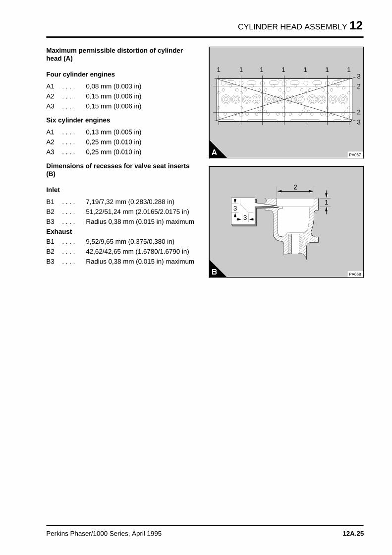
Maximum permissible distortion of cylinderhead (A)
Four cylinder engines
A1 . . . . 0,08 mm (0.003 in)
A2 . . . . 0,15 mm (0.006 in)
A3 . . . . 0,15 mm (0.006 in)
Six cylinder engines
A1 . . . . 0,13 mm (0.005 in)
A2 . . . . 0,25 mm (0.010 in)
A3 . . . . 0,25 mm (0.010 in)
Dimensions of recesses for valve seat inserts(B)
Inlet
B1 . . . . 7,19/7,32 mm (0.283/0.288 in)
B2 . . . . 51,22/51,24 mm (2.0165/2.0175 in)
B3 . . . . Radius 0,38 mm (0.015 in) maximum
Exhaust
B1 . . . . 9,52/9,65 mm (0.375/0.380 in)
B2 . . . . 42,62/42,65 mm (1.6780/1.6790 in)
B3 . . . . Radius 0,38 mm (0.015 in) maximum
a aa aa aa a
3
a a a
a a a
a a a
a a a
1
a a a
a a a
a a a
a a a
1
a a a
a a a
a a a
a a a
1
a aa aa aa a
1
a a a
a a a
a a a
a a a
1
a a a
a a a
a a a
a a a
1
a aa aa aa a
1
a aa aa aa a
3
a aa aa aa a
2
a aa aa aa a
2
PA067
PA068
a a a
a a a
a a a
a a a
2
a aa aa aa a
1
33
Perkins Phaser/1000 Series, April 1995 12A.25
12 CYLINDER HEAD ASSEMBLY
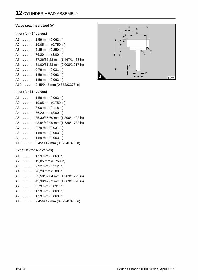
Valve seat insert tool (A)
Inlet (for 45° valves)
A1 . . . . . 1,59 mm (0.063 in)
A2 . . . . . 19,05 mm (0.750 in)
A3 . . . . . 6,35 mm (0.250 in)
A4 . . . . . 76,20 mm (3.00 in)
A5 . . . . . 37,26/37,28 mm (1.467/1.468 in)
A6 . . . . . 51,00/51,23 mm (2.008/2.017 in)
A7 . . . . . 0,79 mm (0.031 in)
A8 . . . . . 1,59 mm (0.063 in)
A9 . . . . . 1,59 mm (0.063 in)
A10 . . . . 9,45/9,47 mm (0.372/0.373 in)
Inlet (for 31° valves)
A1 . . . . . 1,59 mm (0.063 in)
A2 . . . . . 19,05 mm (0.750 in)
A3 . . . . . 3,00 mm (0.118 in)
A4 . . . . . 76,20 mm (3.00 in)
A5 . . . . . 35,30/35,60 mm (1.390/1.402 in)
A6 . . . . . 43,94/43,99 mm (1.730/1.732 in)
A7 . . . . . 0,79 mm (0.031 in)
A8 . . . . . 1,59 mm (0.063 in)
A9 . . . . . 1,59 mm (0.063 in)
A10 . . . . 9,45/9,47 mm (0.372/0.373 in)
Exhaust (for 45° valves)
A1 . . . . . 1,59 mm (0.063 in)
A2 . . . . . 19,05 mm (0.750 in)
A3 . . . . . 7,92 mm (0.312 in)
A4 . . . . . 76,20 mm (3.00 in)
A5 . . . . . 32,58/32,84 mm (1.283/1.293 in)
A6 . . . . . 42,39/42,62 mm (1,669/1.678 in)
A7 . . . . . 0,79 mm (0.031 in)
A8 . . . . . 1,59 mm (0.063 in)
A9 . . . . . 1,59 mm (0.063 in)
A10 . . . . 9,45/9,47 mm (0.372/0.373 in)
a aa aa a
1
a a a
a a a
a a a
1
a aa aa a
6
a aa aa a
5
a aa aa a
2
a a a
a a a
a a a
3a a a
a a a
a a a
4
a aa aa a
9
a aa aa a
9
a a a
a a a
a a a
10
a a a
a a a
a a a
8
a aa aa a
7
PA069
12A.26 Perkins Phaser/1000 Series, April 1995
CYLINDER HEAD ASSEMBLY 12
Valve guides
Inside diameter . . . . . . . . . . . . . . . . . . . . . . . . . . . . . . . . . . . . . . . 9,51/9,56 mm (0.3744/0.3764 in)
Outside diameter . . . . . . . . . . . . . . . . . . . . . . . . . . . . . . . . . . . . 15,90/15,91 mm (0.6260/0.6265 in)
Interference fit of valve guide in cylinder head . . . . . . . . . . . . . . . . . . 0,03/0,07 mm (0.0012/0.0027 in)
Full length:
- Inlet . . . . . . . . . . . . . . . . . . . . . . . . . . . . . . . . . . . . . . . . . . . . . . . . . . . . . . 57,94 mm (2.281 in)
- Exhaust . . . . . . . . . . . . . . . . . . . . . . . . . . . . . . . . . . . . . . . . . . . . . . . . . . . . 61,10 mm (2.406 in)
Protrusion from bottom of recess for valve spring . . . . . . . . . . . . . . . . . . . . . . . . 15,10 mm (0.594 in)
Double valve springs - outer
Fitted length . . . . . . . . . . . . . . . . . . . . . . . . . . . . . . . . . . . . . . . . . . . . . . . . . . . . . 35,8 mm (1.41 in)
Load at fitted length . . . . . . . . . . . . . . . . . . . . . . . . . . . . . . . . . . 176/195 N (39.5/43.7 lbf) 18/20 kgf
Number of active coils . . . . . . . . . . . . . . . . . . . . . . . . . . . . . . . . . . . . . . . . . . . . . . . . . . . . . . . 3.6
Number of damper coils . . . . . . . . . . . . . . . . . . . . . . . . . . . . . . . . . . . . . . . . . . . . . . . . . . . . . . . . 1
Direction of coils . . . . . . . . . . . . . . . . . . . . . . . . . . . . . . . . . Left hand - damper coil to cylinder head
Double valve springs - inner
Fitted length . . . . . . . . . . . . . . . . . . . . . . . . . . . . . . . . . . . . . . . . . . . . . . . . . . . . . 34,0 mm (1.34 in)
Load at fitted length . . . . . . . . . . . . . . . . . . . . . . . . . . . . . . . . . . . . . . . 89/104 N (20/23 lbf) 9/11 kgf
Number of active coils . . . . . . . . . . . . . . . . . . . . . . . . . . . . . . . . . . . . . . . . . . . . . . . . . . . . . . . 4.9
Number of damper coils . . . . . . . . . . . . . . . . . . . . . . . . . . . . . . . . . . . . . . . . . . . . . . . . . . . . . . . . 1
Direction of coils . . . . . . . . . . . . . . . . . . . . . . . . . . . . . . . . Right hand - damper coil to cylinder head
Single valve springs
Fitted length . . . . . . . . . . . . . . . . . . . . . . . . . . . . . . . . . . . . . . . . . . . . . . . . . . . . . 40,0 mm (1.57 in)
Load at fitted length . . . . . . . . . . . . . . . . . . . . . . . . . . . . . . . . 312/344 N (70.1/77.3 lbf) 31,8/35,1 kgf
Number of active coils . . . . . . . . . . . . . . . . . . . . . . . . . . . . . . . . . . . . . . . . . . . . . . . . . . . . . . . 4.5
Number of damper coils . . . . . . . . . . . . . . . . . . . . . . . . . . . . . . . . . . . . . . . . . . . . . . . . . . . . . . . . 0
Direction of coils . . . . . . . . . . . . . . . . . . . . . . . . . . . . . . . . . . . . . . . . . . . . . . . . . . . . . . . Left hand
Perkins Phaser/1000 Series, April 1995 12A.27
12 CYLINDER HEAD ASSEMBLY
Tappets
Diameter of tappet stem . . . . . . . . . . . . . . . . . . . . . . . . . . . . . . . 18,99/19,01 mm (0.7475/0.7485 in)
Diameter of tappet bore in cylinder block . . . . . . . . . . . . . . . . . . . 19,05/19,08 mm (0.7500/0.7512 in)
Clearance of tappet in cylinder block . . . . . . . . . . . . . . . . . . . . . . . . . 0,04/0,09 mm (0.0015/0.0037 in
Rocker shaft
Outside diameter . . . . . . . . . . . . . . . . . . . . . . . . . . . . . . . . . . . . 19,01/19,04 mm (0.7485/0.7495 in)
Rocker levers and bushes
Diameter of parent bore for bush . . . . . . . . . . . . . . . . . . . . . . . . . 22,23/22,26 mm (0.8750/0.8762 in)
Outside diameter of bush . . . . . . . . . . . . . . . . . . . . . . . . . . . . . . 22,28/22,31 mm (0.8770/0.8785 in)
Interference fit of bush in rocker lever . . . . . . . . . . . . . . . . . . . . . 0,020/0,089 mm (0.0008/0.0035 in)
Internal diameter of fitted bush when reamed . . . . . . . . . . . . . . . . 19,06/19,10 mm (0.7505/0.7520 in)
Clearance between rocker lever bush and rocker shaft . . . . . . . . . . . . 0,03/0,09 mm (0.001/0.0035 in)
Maximum permissible clearance between
rocker lever bush and rocker shaft . . . . . . . . . . . . . . . . . . . . . . . . . . . . . . . . . . . 0,13 mm (0.005 in)
12A.28 Perkins Phaser/1000 Series, April 1995
PISTON AND CONNECTING ROD ASSEMBLIES 13
Piston and connecting rod assemblie s 13
General descriptio n . . . . . . . . . . . . . . . . . . . . . . . . . . . . . . . . . . . . . . . . . 13A.02
Big end bearing
13A-01 To remove and to fit . . . . . . . . . . . . . . . . . . . . . . . . . . . . . . . . 13A.0313A-02 To inspect . . . . . . . . . . . . . . . . . . . . . . . . . . . . . . . . . . . . . . . . 13A.04
Piston and connecting rod assembly
13A-03 To remove and to fit . . . . . . . . . . . . . . . . . . . . . . . . . . . . . . . . . 13A.0513A-03A To check the piston height above the cylinder block . . . . . . . . . . 13A.0813A-03B To check the height grade of a Fastram piston . . . . . . . . . . . . . . 13A.09
Piston rings
13A-04 To remove and to fit . . . . . . . . . . . . . . . . . . . . . . . . . . . . . . . . . 13A.10
Piston and connecting rod assembly
13A-05 To dismantle and to assemble . . . . . . . . . . . . . . . . . . . . . . . . . . 13A.11
Piston and piston rings
13A-06 To inspect . . . . . . . . . . . . . . . . . . . . . . . . . . . . . . . . . . . . . . . . 13A.12
Connecting rod
13A-07 To inspect . . . . . . . . . . . . . . . . . . . . . . . . . . . . . . . . . . . . . . . . 13A.13
Small end bush
13A-08 To remove and to fit . . . . . . . . . . . . . . . . . . . . . . . . . . . . . . . . . 13A.13
Piston cooling jets
13A-09 To remove and to fit . . . . . . . . . . . . . . . . . . . . . . . . . . . . . . . . . 13A.1413A-10 To check the jet alignment . . . . . . . . . . . . . . . . . . . . . . . . . . . . 13A.14
Data and dimension s . . . . . . . . . . . . . . . . . . . . . . . . . . . . . . . . . . . . . . . 13A.15
Perkins Phaser/1000 Series, April 1995 13A.01
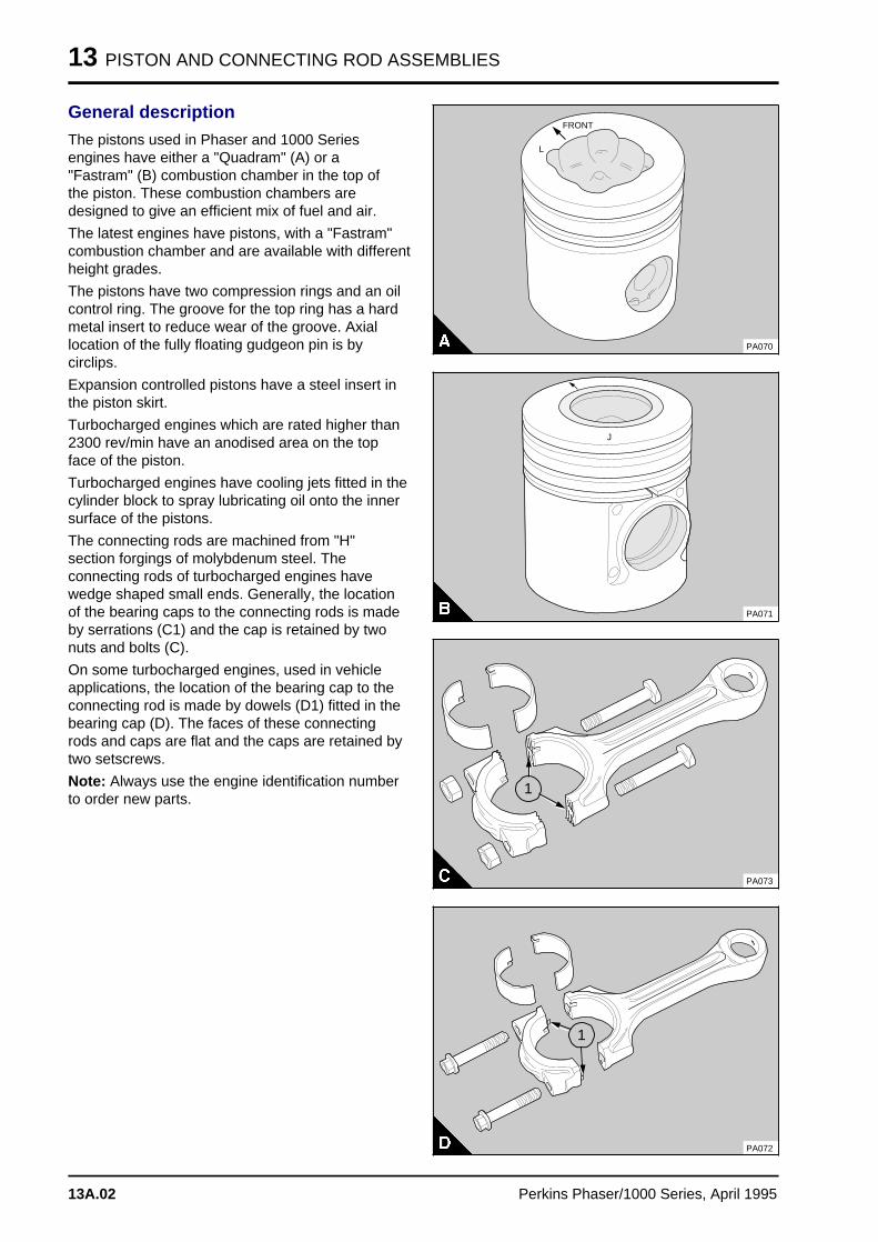
13 PISTON AND CONNECTING ROD ASSEMBLIES
General description
The pistons used in Phaser and 1000 Seriesengines have either a "Quadram" (A) or a"Fastram" (B) combustion chamber in the top ofthe piston. These combustion chambers aredesigned to give an efficient mix of fuel and air.
The latest engines have pistons, with a "Fastram"combustion chamber and are available with differentheight grades.
The pistons have two compression rings and an oilcontrol ring. The groove for the top ring has a hardmetal insert to reduce wear of the groove. Axiallocation of the fully floating gudgeon pin is bycirclips.
Expansion controlled pistons have a steel insert inthe piston skirt.
Turbocharged engines which are rated higher than2300 rev/min have an anodised area on the topface of the piston.
Turbocharged engines have cooling jets fitted in thecylinder block to spray lubricating oil onto the innersurface of the pistons.
The connecting rods are machined from "H"section forgings of molybdenum steel. Theconnecting rods of turbocharged engines havewedge shaped small ends. Generally, the locationof the bearing caps to the connecting rods is madeby serrations (C1) and the cap is retained by twonuts and bolts (C).
On some turbocharged engines, used in vehicleapplications, the location of the bearing cap to theconnecting rod is made by dowels (D1) fitted in thebearing cap (D). The faces of these connectingrods and caps are flat and the caps are retained bytwo setscrews.
Note: Always use the engine identification numberto order new parts.
a a a a a a a
a a a a a a a
a a a a a a a
FRONT
a aa aa a
L
PA070
a aa aa a
J
PA071
PA073
a a a
a a a
a a a
a a a
a a a
1
a a a
a a a
a a a
a a a
1
PA072
13A.02 Perkins Phaser/1000 Series, April 1995
PISTON AND CONNECTING ROD ASSEMBLIES 13
Big end bearing
To remove and to fit 13A-01
To remove
1 Drain the engine lubricating oil.
2 Remove the lubricating oil sump, operation 19A-03.
3 Remove the lubricating oil strainer and suctionpipe, operation 19A-04 or remove the balancer unit,operation 14A-10.
4 Rotate the crankshaft until the relevantconnecting rod is at its lowest position.
5 Release the nuts and remove the bearing cap.Remove the bolts from the connecting rod. If thebearing cap is retained by setscrews, the locationof the bearing cap will be by two dowels. Toremove these bearing caps, release the setscrewsby approximately four rotates. Lightly hit the headsof the setscrews with a soft face hammer toseparate the connecting rod from the bearing cap.Remove the setscrews and the bearing cap.
6 Remove the lower half of the shell bearing fromthe cap, but keep it with its relevant cap.
7 Carefully push the connecting rod up the cylinderbore just enough to allow access to the upper halfof the shell bearing. Remove the bearing from theconnecting rod. Keep the bearings from theconnecting rod and cap together.
Caution: Do not allow the connecting rod to hit thepiston cooling jet, if fitted.
Perkins Phaser/1000 Series, April 1995 13A.03
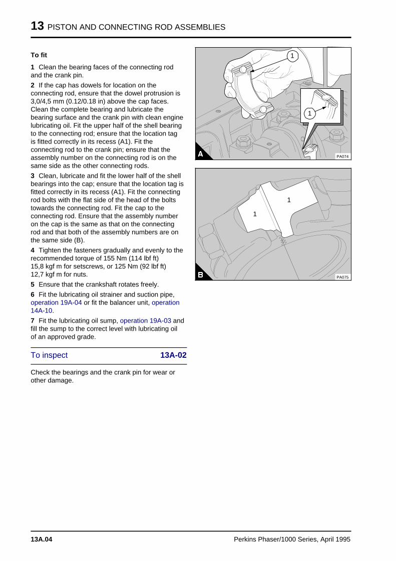
13 PISTON AND CONNECTING ROD ASSEMBLIES
To fit
1 Clean the bearing faces of the connecting rodand the crank pin.
2 If the cap has dowels for location on theconnecting rod, ensure that the dowel protrusion is3,0/4,5 mm (0.12/0.18 in) above the cap faces.Clean the complete bearing and lubricate thebearing surface and the crank pin with clean enginelubricating oil. Fit the upper half of the shell bearingto the connecting rod; ensure that the location tagis fitted correctly in its recess (A1). Fit theconnecting rod to the crank pin; ensure that theassembly number on the connecting rod is on thesame side as the other connecting rods.
3 Clean, lubricate and fit the lower half of the shellbearings into the cap; ensure that the location tag isfitted correctly in its recess (A1). Fit the connectingrod bolts with the flat side of the head of the boltstowards the connecting rod. Fit the cap to theconnecting rod. Ensure that the assembly numberon the cap is the same as that on the connectingrod and that both of the assembly numbers are onthe same side (B).
4 Tighten the fasteners gradually and evenly to therecommended torque of 155 Nm (114 lbf ft) 15,8 kgf m for setscrews, or 125 Nm (92 lbf ft)12,7 kgf m for nuts.
5 Ensure that the crankshaft rotates freely.
6 Fit the lubricating oil strainer and suction pipe,operation 19A-04 or fit the balancer unit, operation14A-10.
7 Fit the lubricating oil sump, operation 19A-03 andfill the sump to the correct level with lubricating oilof an approved grade.
To inspect 13A-02
Check the bearings and the crank pin for wear orother damage.
a a a
a a a
a a a
a a a
1
a aa aa aa a
1
PA074
PA075
a aa aa aa aa a
1
a a a
a a a
a a a
a a a
1
13A.04 Perkins Phaser/1000 Series, April 1995
PISTON AND CONNECTING ROD ASSEMBLIES 13
Piston and connecting rod
To remove and to fit 13A-03
To remove
1 Drain the lubricating oil and the cooling system.
2 Remove the cylinder head assembly, operation12A-07.
3 Remove all carbon from the top of the bores ofthe cylinder liners.
4 Remove the lubricating oil sump, operation 19A-03.
5 Remove the lubricating oil strainer and suctionpipe, operation 19A-04, or remove the balancerunit, operation 14A-10.
6 Remove the big end caps and the big endbearings from the connecting rods, operation 13A-01.
Caution: Do not allow the connecting rods to hitthe piston cooling jets, if fitted. If a cooling jet is hit,check its alignment, operation 13A-10, and renewit, if necessary.
7 Turn the connecting rods 90° to prevent contactwith the piston cooling jets. Push the pistons andthe connecting rods out through the top of thecylinder liners. Keep the bearings and capstogether to ensure that they can be fitted in theiroriginal positions.
8 Inspect the crank pins for damage.
Perkins Phaser/1000 Series, April 1995 13A.05
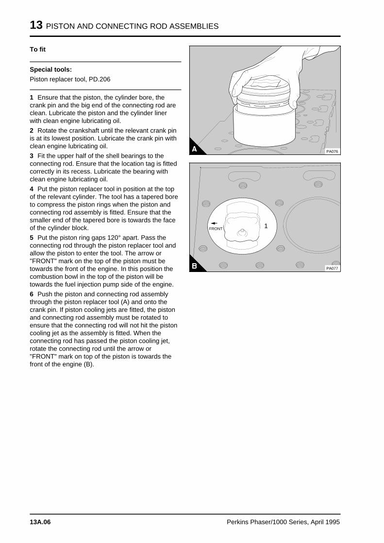
13 PISTON AND CONNECTING ROD ASSEMBLIES
To fit
Special tools:
Piston replacer tool, PD.206
1 Ensure that the piston, the cylinder bore, thecrank pin and the big end of the connecting rod areclean. Lubricate the piston and the cylinder linerwith clean engine lubricating oil.
2 Rotate the crankshaft until the relevant crank pinis at its lowest position. Lubricate the crank pin withclean engine lubricating oil.
3 Fit the upper half of the shell bearings to theconnecting rod. Ensure that the location tag is fittedcorrectly in its recess. Lubricate the bearing withclean engine lubricating oil.
4 Put the piston replacer tool in position at the topof the relevant cylinder. The tool has a tapered boreto compress the piston rings when the piston andconnecting rod assembly is fitted. Ensure that thesmaller end of the tapered bore is towards the faceof the cylinder block.
5 Put the piston ring gaps 120° apart. Pass theconnecting rod through the piston replacer tool andallow the piston to enter the tool. The arrow or"FRONT" mark on the top of the piston must betowards the front of the engine. In this position thecombustion bowl in the top of the piston will betowards the fuel injection pump side of the engine.
6 Push the piston and connecting rod assemblythrough the piston replacer tool (A) and onto thecrank pin. If piston cooling jets are fitted, the pistonand connecting rod assembly must be rotated toensure that the connecting rod will not hit the pistoncooling jet as the assembly is fitted. When theconnecting rod has passed the piston cooling jet,rotate the connecting rod until the arrow or"FRONT" mark on top of the piston is towards thefront of the engine (B).
PA076
1a a a a a a a
a a a a a a a
a a a a a a a
a a a a a a a
a a a a a a a
FRONT
PA077
13A.06 Perkins Phaser/1000 Series, April 1995
PISTON AND CONNECTING ROD ASSEMBLIES 13
7 Clean the connecting rod cap and the lower halfof the shell bearings. Fit the bearing to the cap;ensure that the location tag is fitted correctly in itsrecess. Lubricate the bearing with clean enginelubricating oil. Fit the cap and ensure that theassembly number is the same as that on theconnecting rod and that the numbers are on thesame side. Fit the fasteners; ensure that the flatside of the head of the bolts is towards theconnecting rod. When the fasteners are nuts, newnuts must be fitted. Tighten the fasteners graduallyand evenly to the recommended torque of 155 Nm(114 lbf ft) 15,8 kgf m for setscrews, or 125 Nm (92 lbf ft) 12,7 kgf m for nuts.
8 Check that the crankshaft will rotate freely.
9 Check the piston height above the top face ofthe cylinder block, operation 13A-05.
10 Fit the lubricating oil strainer and suction pipe,operation 19A-04 or fit the balancer unit, operation14A-10.
11 Fit the lubricating oil sump, operation 19A-03.
12 Fit the cylinder head assembly, operation 12A-07.
13 Fill the sump to the correct level with lubricatingoil of an approved grade.
14 Fill the cooling system.
Perkins Phaser/1000 Series, April 1995 13A.07
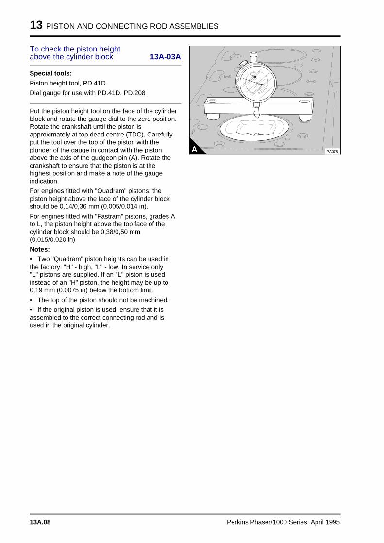
13 PISTON AND CONNECTING ROD ASSEMBLIES
To check the piston heightabove the cylinder block 13A-03A
Special tools:
Piston height tool, PD.41D
Dial gauge for use with PD.41D, PD.208
Put the piston height tool on the face of the cylinderblock and rotate the gauge dial to the zero position.Rotate the crankshaft until the piston isapproximately at top dead centre (TDC). Carefullyput the tool over the top of the piston with theplunger of the gauge in contact with the pistonabove the axis of the gudgeon pin (A). Rotate thecrankshaft to ensure that the piston is at thehighest position and make a note of the gaugeindication.
For engines fitted with "Quadram" pistons, thepiston height above the face of the cylinder blockshould be 0,14/0,36 mm (0.005/0.014 in).
For engines fitted with "Fastram" pistons, grades Ato L, the piston height above the top face of thecylinder block should be 0,38/0,50 mm(0.015/0.020 in)
Notes:
• Two "Quadram" piston heights can be used inthe factory: "H" - high, "L" - low. In service only"L" pistons are supplied. If an "L" piston is usedinstead of an "H" piston, the height may be up to0,19 mm (0.0075 in) below the bottom limit.
• The top of the piston should not be machined.
• If the original piston is used, ensure that it isassembled to the correct connecting rod and isused in the original cylinder.
PA078
13A.08 Perkins Phaser/1000 Series, April 1995
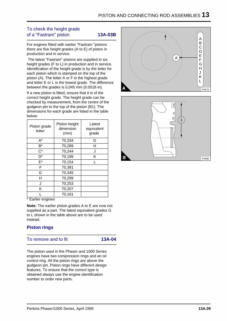
PISTON AND CONNECTING ROD ASSEMBLIES 13
To check the height gradeof a "Fastram" piston 13A-03B
For engines fitted with earlier "Fastram "pistonsthere are five height grades (A to E) of piston inproduction and in service.
The latest "Fastram" pistons are supplied in sixheight grades (F to L) in production and in service.Identification of the height grade is by the letter foreach piston which is stamped on the top of thepiston (A). The letter A or F is the highest gradeand letter E or L is the lowest grade. The differencebetween the grades is 0,045 mm (0.0018 in).
If a new piston is fitted, ensure that it is of thecorrect height grade. The height grade can bechecked by measurement, from the centre of thegudgeon pin to the top of the piston (B1). Thedimensions for each grade are listed in the tablebelow:
* Earlier engines
Piston gradeletter
Piston heightdimension
(mm)
Latestequivalent
grade
A* 70,334 GB* 70,289 HC* 70,244 JD* 70,199 KE* 70,154 LF 70,391G 70,345H 70,299J 70,253K 70,207L 70,161
Note: The earlier piston grades A to E are now notsupplied as a part. The latest equivalent grades Gto L shown in the table above are to be usedinstead.
Piston rings
To remove and to fit 13A-04
The piston used in the Phaser and 1000 Seriesengines have two compression rings and an oilcontrol ring. All the piston rings are above thegudgeon pin. Piston rings have different designfeatures. To ensure that the correct type isobtained always use the engine identificationnumber to order new parts.
a a a
a a a
a a a
a a a
A
a a a
a a a
a a a
a a a
a a a
a a a
a a a
a a a
a a a
a a a
a a a
a a a
a a a
a a a
a a a
a a a
a a a
a a a
a a a
a a a
a a a
a a a
a a a
a a a
a a a
a a a
a a a
a a a
a a a
a a a
a a a
a a a
a a a
ABCDEFGHJKL
PA079
PA080
a aa aa aa a
1
Perkins Phaser/1000 Series, April 1995 13A.09
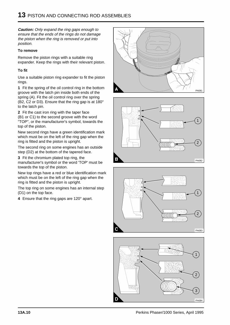
13 PISTON AND CONNECTING ROD ASSEMBLIES
Caution: Only expand the ring gaps enough toensure that the ends of the rings do not damagethe piston when the ring is removed or put intoposition.
To remove
Remove the piston rings with a suitable ringexpander. Keep the rings with their relevant piston.
To fit
Use a suitable piston ring expander to fit the pistonrings.
1 Fit the spring of the oil control ring in the bottomgroove with the latch pin inside both ends of thespring (A). Fit the oil control ring over the spring(B2, C2 or D3). Ensure that the ring gap is at 180°to the latch pin.
2 Fit the cast iron ring with the taper face (B1 or C1) to the second groove with the word"TOP", or the manufacturer's symbol, towards thetop of the piston.
New second rings have a green identification markwhich must be on the left of the ring gap when thering is fitted and the piston is upright.
The second ring on some engines has an outsidestep (D2) at the bottom of the tapered face.
3 Fit the chromium plated top ring, themanufacturer's symbol or the word 'TOP' must betowards the top of the piston.
New top rings have a red or blue identification markwhich must be on the left of the ring gap when thering is fitted and the piston is upright.
The top ring on some engines has an internal step(D1) on the top face.
4 Ensure that the ring gaps are 120° apart.
PA081
a a a
a a a
a a a
a a a
1
a a a
a a a
a a a
a a a
2
PA082
a a a
a a a
a a a
a a a
1a a a
a a a
a a a
a a a
a a a
2
PA083
a aa aa aa a
1
a aa aa aa a
2
a aa aa aa a
3
PA084
13A.10 Perkins Phaser/1000 Series, April 1995
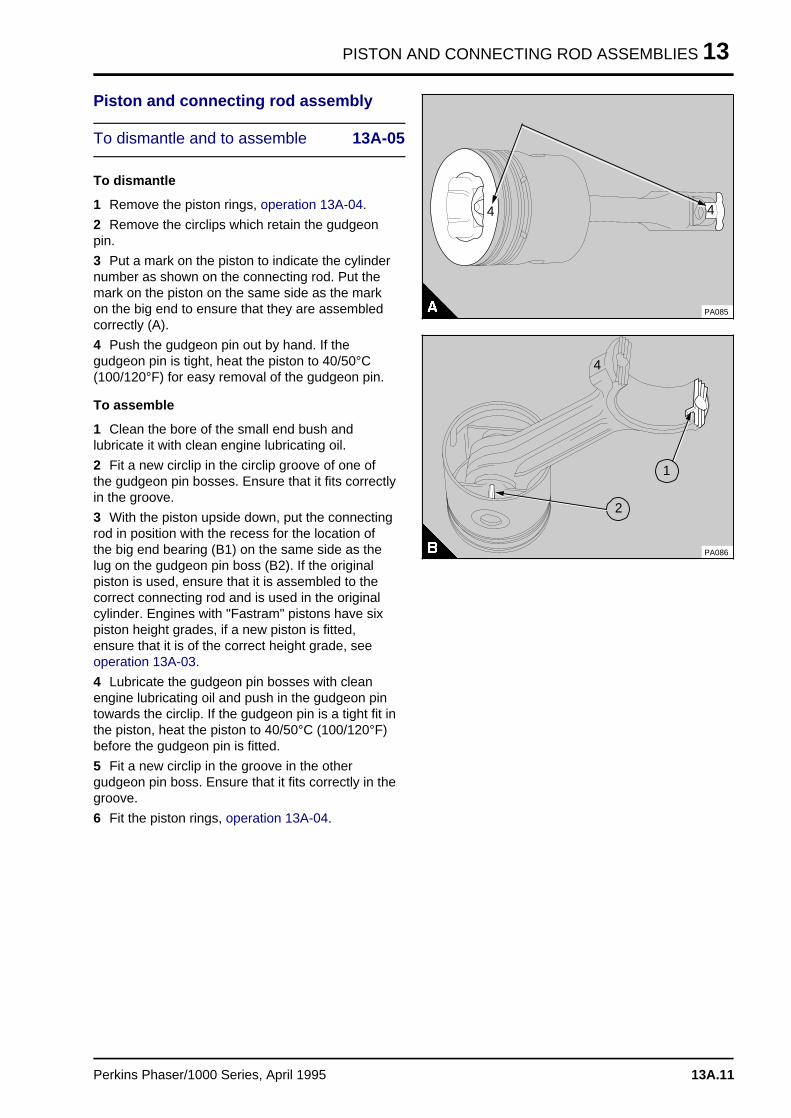
PISTON AND CONNECTING ROD ASSEMBLIES 13
Piston and connecting rod assembly
To dismantle and to assemble 13A-05
To dismantle
1 Remove the piston rings, operation 13A-04.
2 Remove the circlips which retain the gudgeonpin.
3 Put a mark on the piston to indicate the cylindernumber as shown on the connecting rod. Put themark on the piston on the same side as the markon the big end to ensure that they are assembledcorrectly (A).
4 Push the gudgeon pin out by hand. If thegudgeon pin is tight, heat the piston to 40/50°C(100/120°F) for easy removal of the gudgeon pin.
To assemble
1 Clean the bore of the small end bush andlubricate it with clean engine lubricating oil.
2 Fit a new circlip in the circlip groove of one ofthe gudgeon pin bosses. Ensure that it fits correctlyin the groove.
3 With the piston upside down, put the connectingrod in position with the recess for the location ofthe big end bearing (B1) on the same side as thelug on the gudgeon pin boss (B2). If the originalpiston is used, ensure that it is assembled to thecorrect connecting rod and is used in the originalcylinder. Engines with "Fastram" pistons have sixpiston height grades, if a new piston is fitted,ensure that it is of the correct height grade, seeoperation 13A-03.
4 Lubricate the gudgeon pin bosses with cleanengine lubricating oil and push in the gudgeon pintowards the circlip. If the gudgeon pin is a tight fit inthe piston, heat the piston to 40/50°C (100/120°F)before the gudgeon pin is fitted.
5 Fit a new circlip in the groove in the othergudgeon pin boss. Ensure that it fits correctly in thegroove.
6 Fit the piston rings, operation 13A-04.
a a a
a a a
a a a
a a a
4a aa aa aa a
4
PA085
a a a
a a a
a a a
a a a
1
a aa aa aa a
2
PA086
a aa aa aa a
4
Perkins Phaser/1000 Series, April 1995 13A.11
13 PISTON AND CONNECTING ROD ASSEMBLIES
Piston and piston rings
To inspect 13A-06
1 Check the piston for wear and other damage.
2 Check that the piston rings are free to move intheir grooves and that the the rings are not broken.
3 Remove the piston rings, operation 13A-04, andclean the piston ring grooves and the piston rings.
4 Fit new piston rings in the grooves and check forwear of the grooves with feeler gauges (A).Compare the piston ring clearance in the groove tothat given for new components in the data anddimensions and renew the piston, if necessary.
Note: Some pistons have a tapered top groove andthe piston ring is wedge shaped (13A.10 C/D);when this occurs the top piston ring clearancecannot be checked by this method.
5 Clean all carbon from the top of the cylinderliners. Fit the piston rings in the top part of thecylinder liner and measure the ring gap with feelergauges (B). The coil spring must be fitted to the oilcontrol ring when the gap of this piston ring ismeasured. The piston ring gaps for newcomponents are given in the data and dimensions.
PA087
PA088
13A.12 Perkins Phaser/1000 Series, April 1995
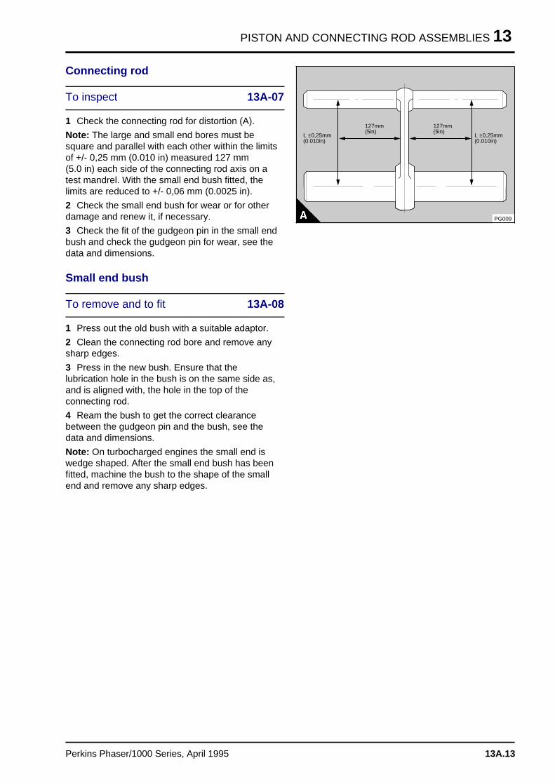
PISTON AND CONNECTING ROD ASSEMBLIES 13
Connecting rod
To inspect 13A-07
1 Check the connecting rod for distortion (A).
Note: The large and small end bores must besquare and parallel with each other within the limitsof +/- 0,25 mm (0.010 in) measured 127 mm (5.0 in) each side of the connecting rod axis on atest mandrel. With the small end bush fitted, thelimits are reduced to +/- 0,06 mm (0.0025 in).
2 Check the small end bush for wear or for otherdamage and renew it, if necessary.
3 Check the fit of the gudgeon pin in the small endbush and check the gudgeon pin for wear, see thedata and dimensions.
Small end bush
To remove and to fit 13A-08
1 Press out the old bush with a suitable adaptor.
2 Clean the connecting rod bore and remove anysharp edges.
3 Press in the new bush. Ensure that thelubrication hole in the bush is on the same side as,and is aligned with, the hole in the top of theconnecting rod.
4 Ream the bush to get the correct clearancebetween the gudgeon pin and the bush, see thedata and dimensions.
Note: On turbocharged engines the small end iswedge shaped. After the small end bush has beenfitted, machine the bush to the shape of the smallend and remove any sharp edges.
a a a a a a a a a a
a a a a a a a a a a
a a a a a a a a a a
a a a a a a a a a a
L ±0,25mm(0.010in)
a a a a a a a
a a a a a a a
a a a a a a a
a a a a a a a
a a a a a a a
127mm(5in)
a a a a a a a
a a a a a a a
a a a a a a a
a a a a a a a
a a a a a a a
127mm(5in) a a a a a a a a a a
a a a a a a a a a a
a a a a a a a a a a
a a a a a a a a a a
L ±0,25mm(0.010in)
PG009
Perkins Phaser/1000 Series, April 1995 13A.13
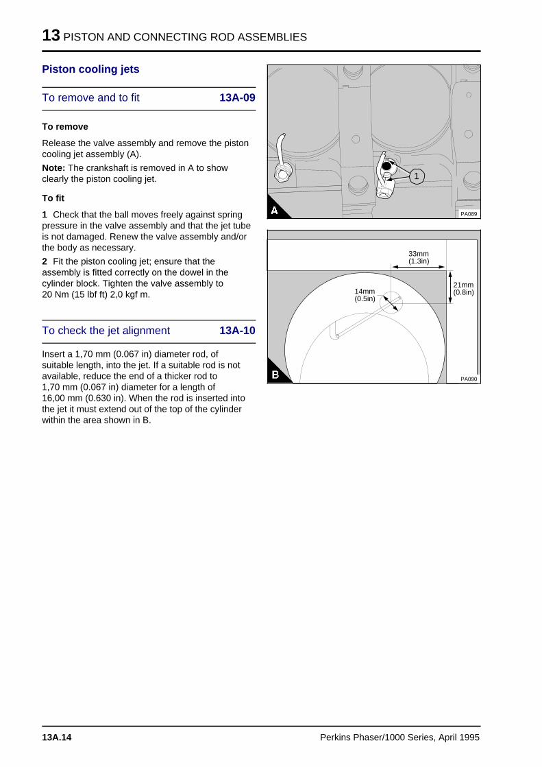
13 PISTON AND CONNECTING ROD ASSEMBLIES
Piston cooling jets
To remove and to fit 13A-09
To remove
Release the valve assembly and remove the pistoncooling jet assembly (A).
Note: The crankshaft is removed in A to showclearly the piston cooling jet.
To fit
1 Check that the ball moves freely against springpressure in the valve assembly and that the jet tubeis not damaged. Renew the valve assembly and/orthe body as necessary.
2 Fit the piston cooling jet; ensure that theassembly is fitted correctly on the dowel in thecylinder block. Tighten the valve assembly to 20 Nm (15 lbf ft) 2,0 kgf m.
To check the jet alignment 13A-10
Insert a 1,70 mm (0.067 in) diameter rod, ofsuitable length, into the jet. If a suitable rod is notavailable, reduce the end of a thicker rod to 1,70 mm (0.067 in) diameter for a length of 16,00 mm (0.630 in). When the rod is inserted intothe jet it must extend out of the top of the cylinderwithin the area shown in B.
a aa aa aa a
1
PA089
a a a a a a a
a a a a a a a
a a a a a a a
a a a a a a a
a a a a a a a
14mm(0.5in)
a a a a a a a
a a a a a a a
a a a a a a a
a a a a a a a
a a a a a a a
33mm(1.3in)
a a a a a a a
a a a a a a a
a a a a a a a
a a a a a a a
a a a a a a a
a a a a a a a
21mm(0.8in)
PA090
13A.14 Perkins Phaser/1000 Series, April 1995
PISTON AND CONNECTING ROD ASSEMBLIES 13
Data and dimensions
Note: This information is given as a guide for personnel engaged on engine overhauls. The dimensionswhich are shown are those which are mainly used in the factory. The information applies to all engines,unless an engine type code is shown.
Pistons - Naturally aspirated engines:
Type . . . . . . . . . . . . . . . . . . . . . . . . . . . . . . . . . . . . . . . . . . "Quadram" combustion bowl, controlled
expansion, inserted top ring groove
Diameter of bore for gudgeon pin . . . . . . . . . . . . . . . . . . . . . . 34,928/34,934 mm (1.3751/1.3754 in)
Height of piston above top face of cylinder block . . . . . . . . . . . . . . . . . . 0,14/0,36 mm (0.005/0.014 in)
Width of groove for top ring . . . . . . . . . . . . . . . . . . . . . . . . . . . . . . . . . 2,57/2,59 mm (0.101/0.102 in)
Width of groove for second ring . . . . . . . . . . . . . . . . . . . . . . . . . . . . . . 2,55/2,57 mm (0.100/0.101 in)
Width of groove for third ring . . . . . . . . . . . . . . . . . . . . . . . . . . . . . . 4,03/4,06 mm (0.1587/0.1598 in)
Pistons - Turbocharged engines:
Type . . . . . . . . . . . . . . . . . . . . . . . . . . . . . . . . . . "Quadram" combustion bowl, controlled expansion,
inserted top ring groove, reduced diameter top land
Diameter of bore for gudgeon pin . . . . . . . . . . . . . . . . . . . . . . . 38,103/38,109 mm (1.500/1.5004 in)
Height of piston above top face of cylinder block . . . . . . . . . . . . . . . . . . 0,14/0,36 mm (0.005/0.014 in)
Width of groove for top ring . . . . . . . . . . . . . . . . . . . . . . . . . . . . . . . . . . . . . . . . . . . . . . . . Tapered
Width of groove for second ring . . . . . . . . . . . . . . . . . . . . . . . . . . . . 2,56/2,58 mm (0.1008/0.1016 in)
Width of groove for third ring . . . . . . . . . . . . . . . . . . . . . . . . . . . . . . 4,04/4,06 mm (0.1591/0.1598 in)
Pistons - Turbocharged AE, YE, AD* engines:
Type . . . . . . . . . . . . . . . . . . . . . . . . . . . . . . . . . . "Fastram" combustion bowl, controlled expansion,
inserted top ring groove, high top ring groove
Diameter of bore for gudgeon pin . . . . . . . . . . . . . . . . . . . . . 39,7003/39,7009 mm (1.5355/1.5358 in)
Difference between height grades . . . . . . . . . . . . . . . . . . . . . . . . . . . . . . . . . . 0,046 mm (0.0018 in)
Height of piston above top face of cylinder block . . . . . . . . . . . . . . . . . 0,38/0,50 mm (0.015/0.020 in)
Width of groove for top ring . . . . . . . . . . . . . . . . . . . . . . . . . . . . . . . . . . . . . . . . . . . . . . . . Tapered
Width of groove for second ring . . . . . . . . . . . . . . . . . . . . . . . . . . . . 2,56/2,58 mm (0.1008/0.1016 in)
Width of groove for third ring . . . . . . . . . . . . . . . . . . . . . . . . . . . . . . 4,04/4,06 mm (0.1591/0.1598 in)
Piston cooling jets - Turbocharged engines:
Valve open pressure . . . . . . . . . . . . . . . . . . . . . . . . . . . . . 178/250 kPa (26/36 lbf/in2) 1,8/2,6 kgf/cm2
* 110 Ti and 135 Ti AD lists are fitted with pistons which are designed for use in emission controlled areas.Some of these pistons are non-expansion controlled.
Perkins Phaser/1000 Series, April 1995 13A.15
13 PISTON AND CONNECTING ROD ASSEMBLIES
Piston rings - Naturally aspirated engines:
Top compression ring . . . . . . . . . . . . . . . . . . . . . . . . . . . . . . . . Barrel face, molybdenum insert, with
a chamfer at the top of the inner face
Second compression ring . . . . . . . . . . . . . . . . . . . . . . . . . . . . . . . . . . . . . . . . . Taper face, cast iron
Oil scraper ring . . . . . . . . . . . . . . . . . . . . . . . . . . . . . . . . . . . . . Coil spring loaded, chromium faced
Width of top ring . . . . . . . . . . . . . . . . . . . . . . . . . . . . . . . . . . . . . . . . 2,48/2,49 mm (0.097/0.098 in)
Width of second ring . . . . . . . . . . . . . . . . . . . . . . . . . . . . . . . . . . . . . 2,48/2,49 mm (0.097/0.098 in)
Width of third ring . . . . . . . . . . . . . . . . . . . . . . . . . . . . . . . . . . . . . 3,98/3,99 mm (0.1566/0.1571 in)
Clearance of top ring in groove . . . . . . . . . . . . . . . . . . . . . . . . . . . . . . 0,08/0,11 mm (0.003/0.004 in)
Clearance of second ring in groove . . . . . . . . . . . . . . . . . . . . . . . . . . . 0,06/0,09 mm (0.002/0.003 in)
Clearance of third ring in groove . . . . . . . . . . . . . . . . . . . . . . . . . . . . . 0,04/0,08 mm (0.002/0.003 in)
Gap of top ring . . . . . . . . . . . . . . . . . . . . . . . . . . . . . . . . . . . . . . . . . 0,40/0,85 mm (0.016/0.033 in)
Gap of second ring . . . . . . . . . . . . . . . . . . . . . . . . . . . . . . . . . . . . . . 0,30/0,76 mm (0.012/0.030 in)
Gap of third ring . . . . . . . . . . . . . . . . . . . . . . . . . . . . . . . . . . . . . . . . 0,38/0,84 mm (0.015/0.033 in)
Piston rings - Turbocharged engines:
Top compression ring . . . . . . . . . . . . . . . . . . . . . . . . . . . . . . . Barrel face, molybdenum insert, wedge
Second compression ring . . . . . . . . . . . . . . . . . . . . . . . . . . . . . . . . . . . . . . . . . Taper face, cast iron
Oil scraper ring . . . . . . . . . . . . . . . . . . . . . . . . . . . . . . . . . . . . . . Coil spring loaded, chromium face
Width of top ring . . . . . . . . . . . . . . . . . . . . . . . . . . . . . . . . . . . . . . . . . . . . . . . . . . . . . . . . . Wedge
Width of second ring . . . . . . . . . . . . . . . . . . . . . . . . . . . . . . . . . . . . . 2,48/2,49 mm (0.097/0.098 in)
Width of third ring . . . . . . . . . . . . . . . . . . . . . . . . . . . . . . . . . . . . . . . 3,98/3,99 mm (0.156/0.157 in)
Clearance of top ring in groove . . . . . . . . . . . . . . . . . . . . . . . . . . . . . . . . . . . . . . . . . . . . . . . Wedge
Clearance of second ring in groove . . . . . . . . . . . . . . . . . . . . . . . . . . . 0,07/0,11 mm (0.003/0.004 in)
Clearance of third ring in groove . . . . . . . . . . . . . . . . . . . . . . . . . . . . . 0,05/0,08 mm (0.002/0.003 in)
Gap of top ring . . . . . . . . . . . . . . . . . . . . . . . . . . . . . . . . . . . . . . . . . 0,35/0,80 mm (0.014/0.031 in)
Gap of top ring with internal step . . . . . . . . . . . . . . . . . . . . . . . . . . . . . 0,35/0,70 mm (0.014/0.028 in)
Gap of second ring . . . . . . . . . . . . . . . . . . . . . . . . . . . . . . . . . . . . . . 0,30/0,76 mm (0.012/0.030 in)
For second rings with outside step . . . . . . . . . . . . . . . . . . . . . . . . . . . 0,40/0,85 mm (0.016/0.033 in)
Gap of third ring . . . . . . . . . . . . . . . . . . . . . . . . . . . . . . . . . . . . . . . . 0,38/0,84 mm (0.015/0.033 in)
13A.16 Perkins Phaser/1000 Series, April 1995
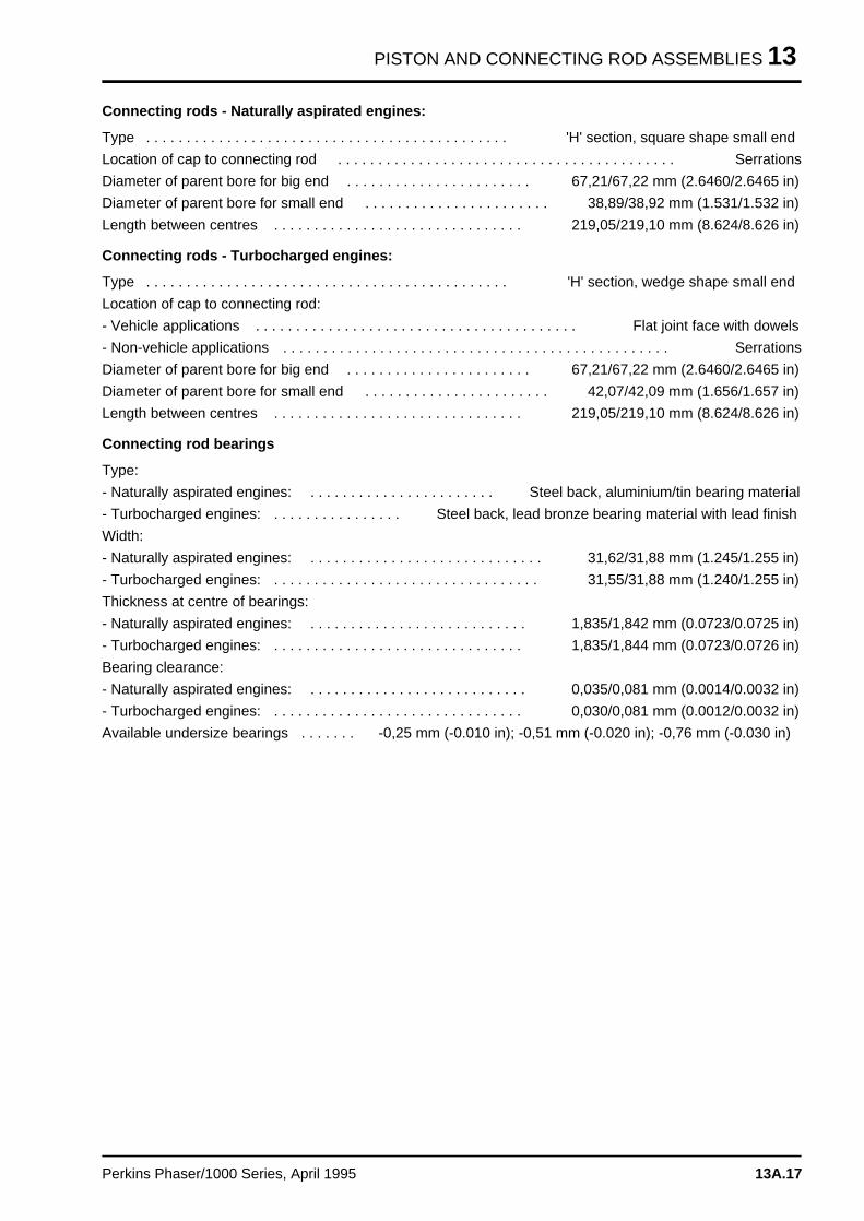
PISTON AND CONNECTING ROD ASSEMBLIES 13
Connecting rods - Naturally aspirated engines:
Type . . . . . . . . . . . . . . . . . . . . . . . . . . . . . . . . . . . . . . . . . . . . . 'H' section, square shape small end
Location of cap to connecting rod . . . . . . . . . . . . . . . . . . . . . . . . . . . . . . . . . . . . . . . . . . Serrations
Diameter of parent bore for big end . . . . . . . . . . . . . . . . . . . . . . . 67,21/67,22 mm (2.6460/2.6465 in)
Diameter of parent bore for small end . . . . . . . . . . . . . . . . . . . . . . . 38,89/38,92 mm (1.531/1.532 in)
Length between centres . . . . . . . . . . . . . . . . . . . . . . . . . . . . . . . 219,05/219,10 mm (8.624/8.626 in)
Connecting rods - Turbocharged engines:
Type . . . . . . . . . . . . . . . . . . . . . . . . . . . . . . . . . . . . . . . . . . . . . 'H' section, wedge shape small end
Location of cap to connecting rod:
- Vehicle applications . . . . . . . . . . . . . . . . . . . . . . . . . . . . . . . . . . . . . . . . Flat joint face with dowels
- Non-vehicle applications . . . . . . . . . . . . . . . . . . . . . . . . . . . . . . . . . . . . . . . . . . . . . . . . Serrations
Diameter of parent bore for big end . . . . . . . . . . . . . . . . . . . . . . . 67,21/67,22 mm (2.6460/2.6465 in)
Diameter of parent bore for small end . . . . . . . . . . . . . . . . . . . . . . . 42,07/42,09 mm (1.656/1.657 in)
Length between centres . . . . . . . . . . . . . . . . . . . . . . . . . . . . . . . 219,05/219,10 mm (8.624/8.626 in)
Connecting rod bearings
Type:
- Naturally aspirated engines: . . . . . . . . . . . . . . . . . . . . . . . Steel back, aluminium/tin bearing material
- Turbocharged engines: . . . . . . . . . . . . . . . . Steel back, lead bronze bearing material with lead finish
Width:
- Naturally aspirated engines: . . . . . . . . . . . . . . . . . . . . . . . . . . . . . 31,62/31,88 mm (1.245/1.255 in)
- Turbocharged engines: . . . . . . . . . . . . . . . . . . . . . . . . . . . . . . . . . 31,55/31,88 mm (1.240/1.255 in)
Thickness at centre of bearings:
- Naturally aspirated engines: . . . . . . . . . . . . . . . . . . . . . . . . . . . 1,835/1,842 mm (0.0723/0.0725 in)
- Turbocharged engines: . . . . . . . . . . . . . . . . . . . . . . . . . . . . . . . 1,835/1,844 mm (0.0723/0.0726 in)
Bearing clearance:
- Naturally aspirated engines: . . . . . . . . . . . . . . . . . . . . . . . . . . . 0,035/0,081 mm (0.0014/0.0032 in)
- Turbocharged engines: . . . . . . . . . . . . . . . . . . . . . . . . . . . . . . . 0,030/0,081 mm (0.0012/0.0032 in)
Available undersize bearings . . . . . . . -0,25 mm (-0.010 in); -0,51 mm (-0.020 in); -0,76 mm (-0.030 in)
Perkins Phaser/1000 Series, April 1995 13A.17
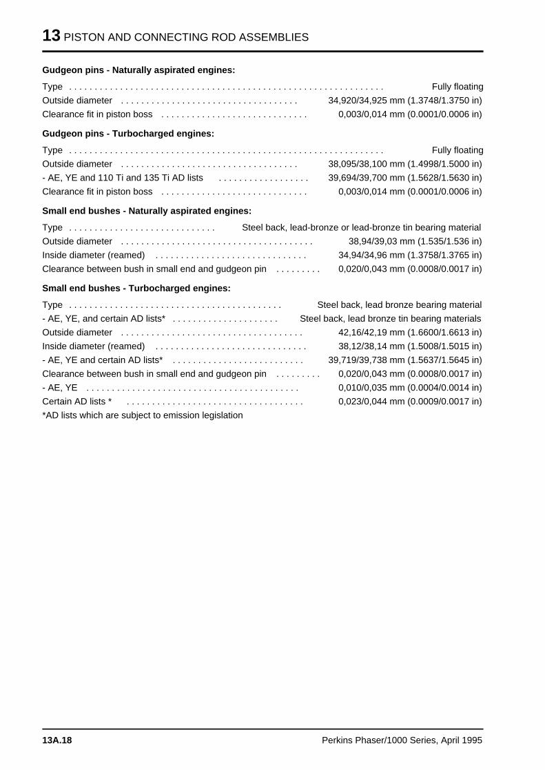
13 PISTON AND CONNECTING ROD ASSEMBLIES
Gudgeon pins - Naturally aspirated engines:
Type . . . . . . . . . . . . . . . . . . . . . . . . . . . . . . . . . . . . . . . . . . . . . . . . . . . . . . . . . . . . . . Fully floating
Outside diameter . . . . . . . . . . . . . . . . . . . . . . . . . . . . . . . . . . . 34,920/34,925 mm (1.3748/1.3750 in)
Clearance fit in piston boss . . . . . . . . . . . . . . . . . . . . . . . . . . . . . 0,003/0,014 mm (0.0001/0.0006 in)
Gudgeon pins - Turbocharged engines:
Type . . . . . . . . . . . . . . . . . . . . . . . . . . . . . . . . . . . . . . . . . . . . . . . . . . . . . . . . . . . . . . Fully floating
Outside diameter . . . . . . . . . . . . . . . . . . . . . . . . . . . . . . . . . . . 38,095/38,100 mm (1.4998/1.5000 in)
- AE, YE and 110 Ti and 135 Ti AD lists . . . . . . . . . . . . . . . . . . 39,694/39,700 mm (1.5628/1.5630 in)
Clearance fit in piston boss . . . . . . . . . . . . . . . . . . . . . . . . . . . . . 0,003/0,014 mm (0.0001/0.0006 in)
Small end bushes - Naturally aspirated engines:
Type . . . . . . . . . . . . . . . . . . . . . . . . . . . . . Steel back, lead-bronze or lead-bronze tin bearing material
Outside diameter . . . . . . . . . . . . . . . . . . . . . . . . . . . . . . . . . . . . . . 38,94/39,03 mm (1.535/1.536 in)
Inside diameter (reamed) . . . . . . . . . . . . . . . . . . . . . . . . . . . . . . 34,94/34,96 mm (1.3758/1.3765 in)
Clearance between bush in small end and gudgeon pin . . . . . . . . . 0,020/0,043 mm (0.0008/0.0017 in)
Small end bushes - Turbocharged engines:
Type . . . . . . . . . . . . . . . . . . . . . . . . . . . . . . . . . . . . . . . . . . Steel back, lead bronze bearing material
- AE, YE, and certain AD lists* . . . . . . . . . . . . . . . . . . . . . Steel back, lead bronze tin bearing materials
Outside diameter . . . . . . . . . . . . . . . . . . . . . . . . . . . . . . . . . . . . 42,16/42,19 mm (1.6600/1.6613 in)
Inside diameter (reamed) . . . . . . . . . . . . . . . . . . . . . . . . . . . . . . 38,12/38,14 mm (1.5008/1.5015 in)
- AE, YE and certain AD lists* . . . . . . . . . . . . . . . . . . . . . . . . . . 39,719/39,738 mm (1.5637/1.5645 in)
Clearance between bush in small end and gudgeon pin . . . . . . . . . 0,020/0,043 mm (0.0008/0.0017 in)
- AE, YE . . . . . . . . . . . . . . . . . . . . . . . . . . . . . . . . . . . . . . . . . . 0,010/0,035 mm (0.0004/0.0014 in)
Certain AD lists * . . . . . . . . . . . . . . . . . . . . . . . . . . . . . . . . . . . 0,023/0,044 mm (0.0009/0.0017 in)
*AD lists which are subject to emission legislation
13A.18 Perkins Phaser/1000 Series, April 1995
CRANKSHAFT ASSEMBLY 14
Crankshaft assembl y 14
General descriptio n . . . . . . . . . . . . . . . . . . . . . . . . . . . . . . . . . . . . . . . . . 14A.03
Crankshaft pulley
14A-01A To remove and to fit - four cylinder engine types . . . . . . . . . . . . 14A.04
Crankshaft pulley and damper
14A-01B To remove and to fit - six cylinder engine types . . . . . . . . . . . . . 14A.0514A-01C To inspect . . . . . . . . . . . . . . . . . . . . . . . . . . . . . . . . . . . . . . . . 14A.07
Rear oil seal assembly
14A-02A To remove and to fit - engines which have the standard seal . . . 14A.0814A-02B To remove and to fit - engines which have a flywheel housing
that is oil filled . . . . . . . . . . . . . . . . . . . . . . . . . . . . . . . . . . . . . 14A.0914A-03A To renew the rear oil seal - engines which have the standard seal 14A.1114A-03B To renew the rear oil seals - engines which have a flywheel housing
that is oil filled . . . . . . . . . . . . . . . . . . . . . . . . . . . . . . . . . . . . . 14A.12
Thrust washers
14A-04 To check crankshaft end-float . . . . . . . . . . . . . . . . . . . . . . . . . . 14A.1414A-05 To remove and to fit . . . . . . . . . . . . . . . . . . . . . . . . . . . . . . . . . 14A.15
Main bearings
14A-06 To remove and to fit (with the crankshaft in position) . . . . . . . . . 14A.1614A-07 To inspect . . . . . . . . . . . . . . . . . . . . . . . . . . . . . . . . . . . . . . . . 14A.17
Crankshaft
14A-08 To remove and to fit . . . . . . . . . . . . . . . . . . . . . . . . . . . . . . . . . 14A.1814A-09 To inspect . . . . . . . . . . . . . . . . . . . . . . . . . . . . . . . . . . . . . . . . 14A.21
Continued
Perkins Phaser/1000 Series, April 1995 14A.01
14 CRANKSHAFT ASSEMBLY
Balancer unit
14A-10 To remove and to fit . . . . . . . . . . . . . . . . . . . . . . . . . . . . . . . . . 14A.2214A-11 To dismantle and to assemble . . . . . . . . . . . . . . . . . . . . . . . . . . 14A.2314A-12 To inspect . . . . . . . . . . . . . . . . . . . . . . . . . . . . . . . . . . . . . . . . . 14A.2814A-13 To remove and to fit the needle roller bearings for the drive shaft 14A.2914A-14 To remove and to fit the bushes for the balance weights . . . . . . . 14A.30
Data and dimension s . . . . . . . . . . . . . . . . . . . . . . . . . . . . . . . . . . . . . . . . 14A.31
14A.02 Perkins Phaser/1000 Series, April 1995
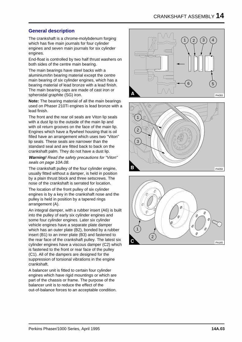
CRANKSHAFT ASSEMBLY 14
General description
The crankshaft is a chrome-molybdenum forgingwhich has five main journals for four cylinderengines and seven main journals for six cylinderengines.
End-float is controlled by two half thrust washers onboth sides of the centre main bearing.
The main bearings have steel backs with aaluminium/tin bearing material except the centremain bearing of six cylinder engines, which has abearing material of lead bronze with a lead finish.The main bearing caps are made of cast iron orspheroidal graphite (SG) iron.
Note: The bearing material of all the main bearingsused on Phaser 210Ti engines is lead bronze with alead finish.
The front and the rear oil seals are Viton lip sealswith a dust lip to the outside of the main lip andwith oil return grooves on the face of the main lip.Engines which have a flywheel housing that is oilfilled have an arrangement which uses two "Viton"lip seals. These seals are narrower than thestandard seal and are fitted back to back on thecrankshaft palm. They do not have a dust lip.
Warning! Read the safety precautions for "Viton"seals on page 10A.08.
The crankshaft pulley of the four cylinder engine,usually fitted without a damper, is held in positionby a plain thrust block and three setscrews. Thenose of the crankshaft is serrated for location.
The location of the front pulley of six cylinderengines is by a key in the crankshaft nose and thepulley is held in position by a tapered ringsarrangement (A).
An integral damper, with a rubber insert (A6) is builtinto the pulley of early six cylinder engines andsome four cylinder engines. Later six cylindervehicle engines have a separate plate damperwhich has an outer plate (B2), bonded by a rubberinsert (B1) to an inner plate (B3) and fastened tothe rear face of the crankshaft pulley. The latest sixcylinder engines have a viscous damper (C2) whichis fastened to the front or rear face of the pulley(C1). All of the dampers are designed for thesuppression of torsional vibrations in the enginecrankshaft.
A balancer unit is fitted to certain four cylinderengines which have rigid mountings or which arepart of the chassis or frame. The purpose of thebalancer unit is to reduce the effect of the out-of-balance forces to an acceptable condition.
a a a
a a a
a a a
a a a
4
a a a
a a a
a a a
a a a
3
a aa aa aa aa a
2
a a a
a a a
a a a
a a a
1
a a a
a a a
a a a
a a a
5
a a a
a a a
a a a
a a a
6
PA093
a a a
a a a
a a a
a a a
1
a a a
a a a
a a a
a a a
2
a a a
a a a
a a a
a a a
3
PA094
PA165
a aa aa aa a
1
a a a
a a a
a a a
a a a
2
Perkins Phaser/1000 Series, April 1995 14A.03
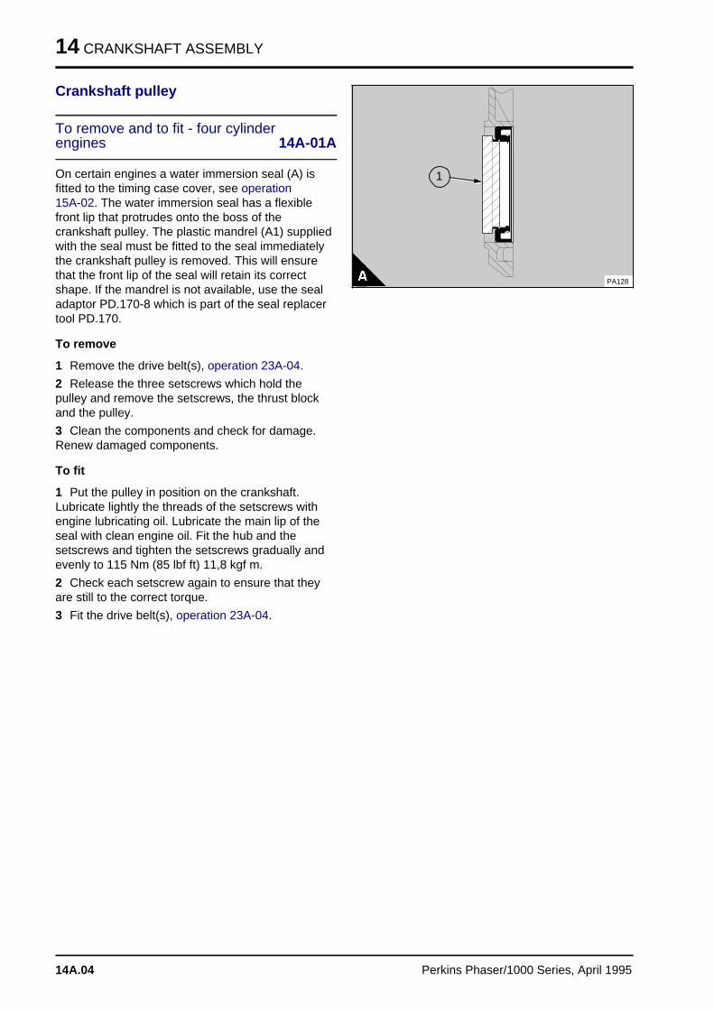
14 CRANKSHAFT ASSEMBLY
Crankshaft pulley
To remove and to fit - four cylinderengines 14A-01A
On certain engines a water immersion seal (A) isfitted to the timing case cover, see operation 15A-02. The water immersion seal has a flexiblefront lip that protrudes onto the boss of thecrankshaft pulley. The plastic mandrel (A1) suppliedwith the seal must be fitted to the seal immediatelythe crankshaft pulley is removed. This will ensurethat the front lip of the seal will retain its correctshape. If the mandrel is not available, use the sealadaptor PD.170-8 which is part of the seal replacertool PD.170.
To remove
1 Remove the drive belt(s), operation 23A-04.
2 Release the three setscrews which hold thepulley and remove the setscrews, the thrust blockand the pulley.
3 Clean the components and check for damage.Renew damaged components.
To fit
1 Put the pulley in position on the crankshaft.Lubricate lightly the threads of the setscrews withengine lubricating oil. Lubricate the main lip of theseal with clean engine oil. Fit the hub and thesetscrews and tighten the setscrews gradually andevenly to 115 Nm (85 lbf ft) 11,8 kgf m.
2 Check each setscrew again to ensure that theyare still to the correct torque.
3 Fit the drive belt(s), operation 23A-04.
a a a a a a
a a a a a a
a a a a a a
a a a a a a
a a a a a a
a a a a a a
a a a a a a
a a a a a a
a a a a a a
a a a a a a
a a a a a a
a a a a a a
a a a a a a
a a a a a a
a a a a a a
a a a a a a
a a a a a a
a a a a a a
a a a a a a
a a a a a a
a a a a a a
a a a a a a
a a a a a a
a a a a a a
a a a a a a
a a a a a a
a a a a a a
a a a
a a a
a a a
a a a
1
PA128
14A.04 Perkins Phaser/1000 Series, April 1995
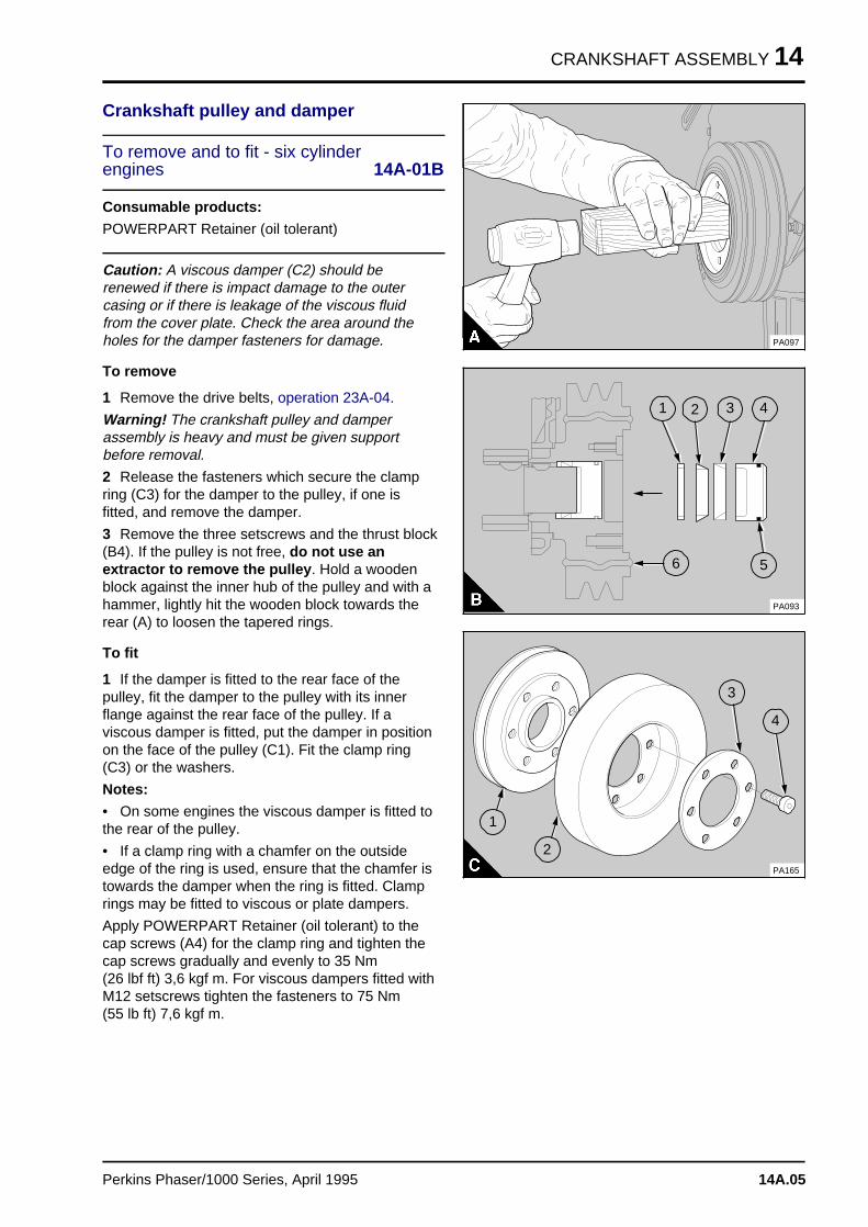
CRANKSHAFT ASSEMBLY 14
Crankshaft pulley and damper
To remove and to fit - six cylinder engines 14A-01B
Consumable products:
POWERPART Retainer (oil tolerant)
Caution: A viscous damper (C2) should berenewed if there is impact damage to the outercasing or if there is leakage of the viscous fluidfrom the cover plate. Check the area around theholes for the damper fasteners for damage.
To remove
1 Remove the drive belts, operation 23A-04.
Warning! The crankshaft pulley and damperassembly is heavy and must be given supportbefore removal.
2 Release the fasteners which secure the clampring (C3) for the damper to the pulley, if one isfitted, and remove the damper.
3 Remove the three setscrews and the thrust block(B4). If the pulley is not free, do not use anextractor to remove the pulley . Hold a woodenblock against the inner hub of the pulley and with ahammer, lightly hit the wooden block towards therear (A) to loosen the tapered rings.
To fit
1 If the damper is fitted to the rear face of thepulley, fit the damper to the pulley with its innerflange against the rear face of the pulley. If aviscous damper is fitted, put the damper in positionon the face of the pulley (C1). Fit the clamp ring(C3) or the washers.
Notes:
• On some engines the viscous damper is fitted tothe rear of the pulley.
• If a clamp ring with a chamfer on the outsideedge of the ring is used, ensure that the chamfer istowards the damper when the ring is fitted. Clamprings may be fitted to viscous or plate dampers.
Apply POWERPART Retainer (oil tolerant) to thecap screws (A4) for the clamp ring and tighten thecap screws gradually and evenly to 35 Nm (26 lbf ft) 3,6 kgf m. For viscous dampers fitted withM12 setscrews tighten the fasteners to 75 Nm (55 lb ft) 7,6 kgf m.
PA097
a a a
a a a
a a a
a a a
4
a a a
a a a
a a a
a a a
3a aa aa aa a
2
a a a
a a a
a a a
a a a
1
a a a
a a a
a a a
a a a
5
a a a
a a a
a a a
a a a
6
PA093
a a a
a a a
a a a
a a a
3
a a a
a a a
a a a
a a a
4
PA165
a aa aa aa a
1
a a a
a a a
a a a
a a a
2
Perkins Phaser/1000 Series, April 1995 14A.05
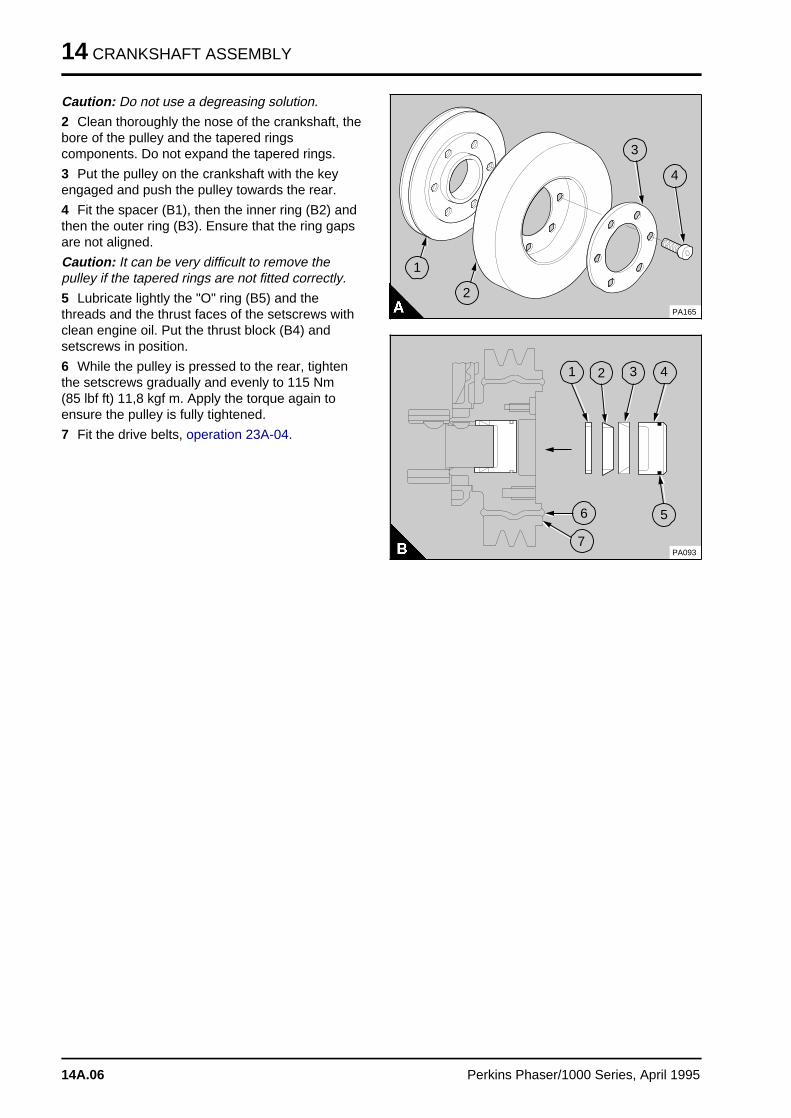
14 CRANKSHAFT ASSEMBLY
Caution: Do not use a degreasing solution.
2 Clean thoroughly the nose of the crankshaft, thebore of the pulley and the tapered ringscomponents. Do not expand the tapered rings.
3 Put the pulley on the crankshaft with the keyengaged and push the pulley towards the rear.
4 Fit the spacer (B1), then the inner ring (B2) andthen the outer ring (B3). Ensure that the ring gapsare not aligned.
Caution: It can be very difficult to remove thepulley if the tapered rings are not fitted correctly.
5 Lubricate lightly the "O" ring (B5) and thethreads and the thrust faces of the setscrews withclean engine oil. Put the thrust block (B4) andsetscrews in position.
6 While the pulley is pressed to the rear, tightenthe setscrews gradually and evenly to 115 Nm (85 lbf ft) 11,8 kgf m. Apply the torque again toensure the pulley is fully tightened.
7 Fit the drive belts, operation 23A-04.
a a a
a a a
a a a
a a a
3
a aa aa aa a
4
PA165
a a a
a a a
a a a
a a a
1
a a a
a a a
a a a
a a a
2
a aa aa aa a
4
a aa aa aa a
3a a a
a a a
a a a
a a a
2
a aa aa aa a
1
a aa aa aa a
5
a a a
a a a
a a a
a a a
6
PA093
a aa aa aa aa a
7
14A.06 Perkins Phaser/1000 Series, April 1995
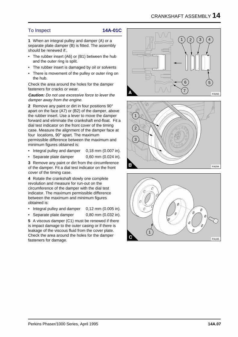
CRANKSHAFT ASSEMBLY 14
To Inspect 14A-01C
1 When an integral pulley and damper (A) or aseparate plate damper (B) is fitted. The assemblyshould be renewed if:,
• The rubber insert (A6) or (B1) between the huband the outer ring is split.
• The rubber insert is damaged by oil or solvents
• There is movement of the pulley or outer ring onthe hub.
Check the area around the holes for the damperfasteners for cracks or wear.
Caution: Do not use excessive force to lever thedamper away from the engine.
2 Remove any paint or dirt in four positions 90°apart on the face (A7) or (B2) of the damper, abovethe rubber insert. Use a lever to move the damperforward and eliminate the crankshaft end-float. Fit adial test indicator on the front cover of the timingcase. Measure the alignment of the damper face atfour locations, 90° apart. The maximumpermissible difference between the maximum andminimum figures obtained is:
• Integral pulley and damper 0,18 mm (0.007 in).
• Separate plate damper 0,60 mm (0.024 in).
3 Remove any paint or dirt from the circumferenceof the damper. Fit a dial test indicator on the frontcover of the timing case.
4 Rotate the crankshaft slowly one completerevolution and measure for run-out on thecircumference of the damper with the dial testindicator. The maximum permissible differencebetween the maximum and minimum figuresobtained is:
• Integral pulley and damper 0,12 mm (0.005 in).
• Separate plate damper 0,80 mm (0.032 in).
5 A viscous damper (C1) must be renewed if thereis impact damage to the outer casing or if there isleakage of the viscous fluid from the cover plate.Check the area around the holes for the damperfasteners for damage.
a a a
a a a
a a a
a a a
4
a a a
a a a
a a a
a a a
3
a aa aa aa aa a
2
a a a
a a a
a a a
a a a
1
a a a
a a a
a a a
a a a
5
a a a
a a a
a a a
a a a
6
PA093
a aa aa aa aa a
7
a a a
a a a
a a a
a a a
1
a a a
a a a
a a a
a a a
2
a a a
a a a
a a a
a a a
3
PA094
PA165
a a a
a a a
a a a
a a a
1
Perkins Phaser/1000 Series, April 1995 14A.07
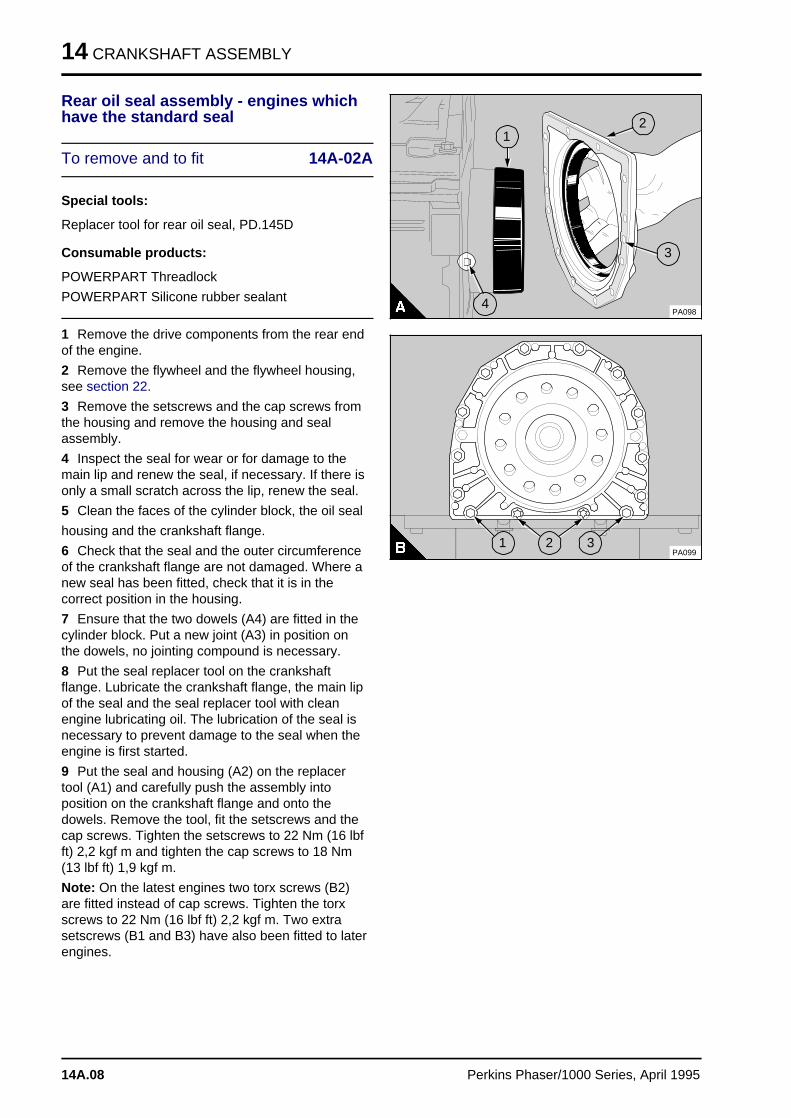
14 CRANKSHAFT ASSEMBLY
Rear oil seal assembly - engines whichhave the standard seal
To remove and to fit 14A-02A
Special tools:
Replacer tool for rear oil seal, PD.145D
Consumable products:
POWERPART Threadlock
POWERPART Silicone rubber sealant
1 Remove the drive components from the rear endof the engine.
2 Remove the flywheel and the flywheel housing,see section 22.
3 Remove the setscrews and the cap screws fromthe housing and remove the housing and sealassembly.
4 Inspect the seal for wear or for damage to themain lip and renew the seal, if necessary. If there isonly a small scratch across the lip, renew the seal.
5 Clean the faces of the cylinder block, the oil seal
housing and the crankshaft flange.
6 Check that the seal and the outer circumferenceof the crankshaft flange are not damaged. Where anew seal has been fitted, check that it is in thecorrect position in the housing.
7 Ensure that the two dowels (A4) are fitted in thecylinder block. Put a new joint (A3) in position onthe dowels, no jointing compound is necessary.
8 Put the seal replacer tool on the crankshaftflange. Lubricate the crankshaft flange, the main lipof the seal and the seal replacer tool with cleanengine lubricating oil. The lubrication of the seal isnecessary to prevent damage to the seal when theengine is first started.
9 Put the seal and housing (A2) on the replacertool (A1) and carefully push the assembly intoposition on the crankshaft flange and onto thedowels. Remove the tool, fit the setscrews and thecap screws. Tighten the setscrews to 22 Nm (16 lbfft) 2,2 kgf m and tighten the cap screws to 18 Nm(13 lbf ft) 1,9 kgf m.
Note: On the latest engines two torx screws (B2)are fitted instead of cap screws. Tighten the torxscrews to 22 Nm (16 lbf ft) 2,2 kgf m. Two extrasetscrews (B1 and B3) have also been fitted to laterengines.
a a a a a a a a a
a a a a a a a a a
a a a a a a a a a
a a a a a a a a a
a a a a a a a a a
a a a a a a a a a
a a a a a a a a a
a a a a a a a a a
a a a a a a a a a
a a a a a a a a a
a a a a a a a a a
a a a a a a a a a
a a a a a a a a a
a a a a a a a a a
a a a a a a a a a
a a a a a a a a a
a a a a a a a a a
a a a a a a a a a
a a a a a a a a a
a a a a a a a a a
a a a a a a a a a
a a a a a a a a a
a a a a a a a a a
a a a a a a a a a
a a a a a a a a a
a aa aa aa a
4
a a a
a a a
a a a
a a a
1
a aa aa aa a
3
PA098
a aa aa aa a
2
PA099a a a
a a a
a a a
a a a
2
a a a
a a a
a a a
a a a
3
a a a
a a a
a a a
a a a
1
14A.08 Perkins Phaser/1000 Series, April 1995
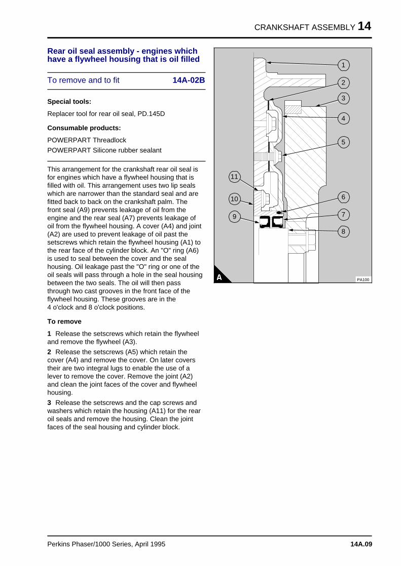
CRANKSHAFT ASSEMBLY 14
Rear oil seal assembly - engines whichhave a flywheel housing that is oil filled
To remove and to fit 14A-02B
Special tools:
Replacer tool for rear oil seal, PD.145D
Consumable products:
POWERPART Threadlock
POWERPART Silicone rubber sealant
This arrangement for the crankshaft rear oil seal isfor engines which have a flywheel housing that isfilled with oil. This arrangement uses two lip sealswhich are narrower than the standard seal and arefitted back to back on the crankshaft palm. Thefront seal (A9) prevents leakage of oil from theengine and the rear seal (A7) prevents leakage ofoil from the flywheel housing. A cover (A4) and joint(A2) are used to prevent leakage of oil past thesetscrews which retain the flywheel housing (A1) tothe rear face of the cylinder block. An "O" ring (A6)is used to seal between the cover and the sealhousing. Oil leakage past the "O" ring or one of theoil seals will pass through a hole in the seal housingbetween the two seals. The oil will then passthrough two cast grooves in the front face of theflywheel housing. These grooves are in the 4 o'clock and 8 o'clock positions.
To remove
1 Release the setscrews which retain the flywheeland remove the flywheel (A3).
2 Release the setscrews (A5) which retain thecover (A4) and remove the cover. On later coverstheir are two integral lugs to enable the use of alever to remove the cover. Remove the joint (A2)and clean the joint faces of the cover and flywheelhousing.
3 Release the setscrews and the cap screws andwashers which retain the housing (A11) for the rearoil seals and remove the housing. Clean the jointfaces of the seal housing and cylinder block.
a a a
a a a
a a a
a a a
1
a a a
a a a
a a a
a a a
a a a
2
a a a
a a a
a a a
a a a
a a a
3
a a a
a a a
a a a
a a a
4
a a a
a a a
a a a
a a a
a a a
5
a a a
a a a
a a a
a a a
6
a a a
a a a
a a a
a a a
a a a
7
a a a
a a a
a a a
a a a
8a a a
a a a
a a a
a a a
9
a a a a
a a a a
a a a a
a a a a
a a a a
10
a a a a
a a a a
a a a a
a a a a
11
PA100
Perkins Phaser/1000 Series, April 1995 14A.09
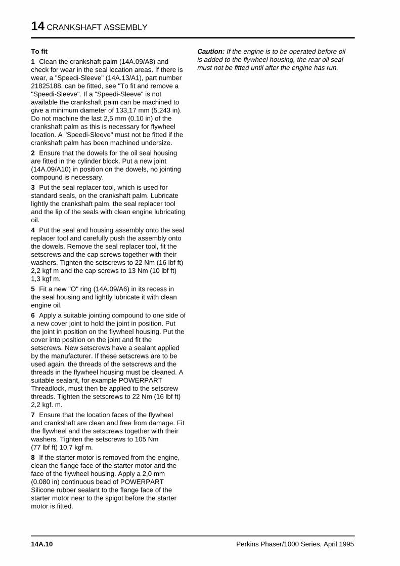
14 CRANKSHAFT ASSEMBLY
To fit
1 Clean the crankshaft palm (14A.09/A8) andcheck for wear in the seal location areas. If there iswear, a "Speedi-Sleeve" (14A.13/A1), part number21825188, can be fitted, see "To fit and remove a"Speedi-Sleeve". If a "Speedi-Sleeve" is notavailable the crankshaft palm can be machined togive a minimum diameter of 133,17 mm (5.243 in).Do not machine the last 2,5 mm (0.10 in) of thecrankshaft palm as this is necessary for flywheellocation. A "Speedi-Sleeve" must not be fitted if thecrankshaft palm has been machined undersize.
2 Ensure that the dowels for the oil seal housingare fitted in the cylinder block. Put a new joint(14A.09/A10) in position on the dowels, no jointingcompound is necessary.
3 Put the seal replacer tool, which is used forstandard seals, on the crankshaft palm. Lubricatelightly the crankshaft palm, the seal replacer tooland the lip of the seals with clean engine lubricatingoil.
4 Put the seal and housing assembly onto the sealreplacer tool and carefully push the assembly ontothe dowels. Remove the seal replacer tool, fit thesetscrews and the cap screws together with theirwashers. Tighten the setscrews to 22 Nm (16 lbf ft)2,2 kgf m and the cap screws to 13 Nm (10 lbf ft)1,3 kgf m.
5 Fit a new "O" ring (14A.09/A6) in its recess inthe seal housing and lightly lubricate it with cleanengine oil.
6 Apply a suitable jointing compound to one side ofa new cover joint to hold the joint in position. Putthe joint in position on the flywheel housing. Put thecover into position on the joint and fit thesetscrews. New setscrews have a sealant appliedby the manufacturer. If these setscrews are to beused again, the threads of the setscrews and thethreads in the flywheel housing must be cleaned. Asuitable sealant, for example POWERPARTThreadlock, must then be applied to the setscrewthreads. Tighten the setscrews to 22 Nm (16 lbf ft)2,2 kgf. m.
7 Ensure that the location faces of the flywheeland crankshaft are clean and free from damage. Fitthe flywheel and the setscrews together with theirwashers. Tighten the setscrews to 105 Nm (77 lbf ft) 10,7 kgf m.
8 If the starter motor is removed from the engine,clean the flange face of the starter motor and theface of the flywheel housing. Apply a 2,0 mm(0.080 in) continuous bead of POWERPARTSilicone rubber sealant to the flange face of thestarter motor near to the spigot before the startermotor is fitted.
Caution: If the engine is to be operated before oilis added to the flywheel housing, the rear oil sealmust not be fitted until after the engine has run.
14A.10 Perkins Phaser/1000 Series, April 1995
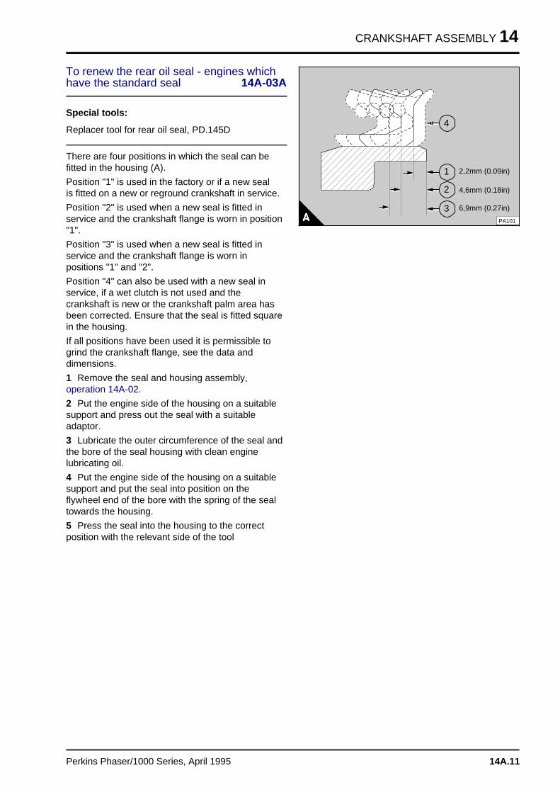
CRANKSHAFT ASSEMBLY 14
To renew the rear oil seal - engines whichhave the standard seal 14A-03A
Special tools:
Replacer tool for rear oil seal, PD.145D
There are four positions in which the seal can befitted in the housing (A).
Position "1" is used in the factory or if a new sealis fitted on a new or reground crankshaft in service.
Position "2" is used when a new seal is fitted inservice and the crankshaft flange is worn in position"1".
Position "3" is used when a new seal is fitted inservice and the crankshaft flange is worn inpositions "1" and "2".
Position "4" can also be used with a new seal inservice, if a wet clutch is not used and thecrankshaft is new or the crankshaft palm area hasbeen corrected. Ensure that the seal is fitted squarein the housing.
If all positions have been used it is permissible togrind the crankshaft flange, see the data anddimensions.
1 Remove the seal and housing assembly,operation 14A-02.
2 Put the engine side of the housing on a suitablesupport and press out the seal with a suitableadaptor.
3 Lubricate the outer circumference of the seal andthe bore of the seal housing with clean enginelubricating oil.
4 Put the engine side of the housing on a suitablesupport and put the seal into position on theflywheel end of the bore with the spring of the sealtowards the housing.
5 Press the seal into the housing to the correctposition with the relevant side of the tool
a a a
a a a
a a a
a a a
4
a a a
a a a
a a a
a a a
1
a a a
a a a
a a a
a a a
2
a a a
a a a
a a a
a a a
3PA101
a a a a a a a a a a a a a a a a
a a a a a a a a a a a a a a a a
a a a a a a a a a a a a a a a a
2,2mm (0.09in)
a a a a a a a a a a a a a a a a
a a a a a a a a a a a a a a a a
a a a a a a a a a a a a a a a a
a a a a a a a a a a a a a a a a
4,6mm (0.18in)
a a a a a a a a a a a a a a a a
a a a a a a a a a a a a a a a a
a a a a a a a a a a a a a a a a
a a a a a a a a a a a a a a a a
6,9mm (0.27in)
Perkins Phaser/1000 Series, April 1995 14A.11
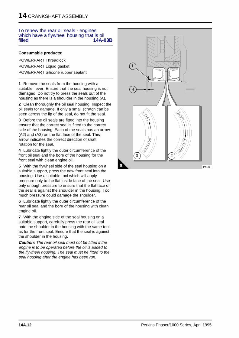
14 CRANKSHAFT ASSEMBLY
To renew the rear oil seals - engineswhich have a flywheel housing that is oilfilled 14A-03B
Consumable products:
POWERPART Threadlock
POWERPART Liquid gasket
POWERPART Silicone rubber sealant
1 Remove the seals from the housing with asuitable lever. Ensure that the seal housing is notdamaged. Do not try to press the seals out of thehousing as there is a shoulder in the housing (A).
2 Clean thoroughly the oil seal housing. Inspect theoil seals for damage. If only a small scratch can beseen across the lip of the seal, do not fit the seal.
3 Before the oil seals are fitted into the housingensure that the correct seal is fitted to the correctside of the housing. Each of the seals has an arrow(A2) and (A3) on the flat face of the seal. Thisarrow indicates the correct direction of shaftrotation for the seal.
4 Lubricate lightly the outer circumference of thefront oil seal and the bore of the housing for thefront seal with clean engine oil.
5 With the flywheel side of the seal housing on asuitable support, press the new front seal into thehousing. Use a suitable tool which will applypressure only to the flat inside face of the seal. Useonly enough pressure to ensure that the flat face ofthe seal is against the shoulder in the housing. Toomuch pressure could damage the shoulder.
6 Lubricate lightly the outer circumference of therear oil seal and the bore of the housing with cleanengine oil.
7 With the engine side of the seal housing on asuitable support, carefully press the rear oil sealonto the shoulder in the housing with the same toolas for the front seal. Ensure that the seal is againstthe shoulder in the housing.
Caution: The rear oil seal must not be fitted if theengine is to be operated before the oil is added tothe flywheel housing. The seal must be fitted to theseal housing after the engine has been run.
a aa aa aa a
4
a aa aa aa a
1
PA102a a a
a a a
a a a
a a a
2
a aa aa aa a
3
14A.12 Perkins Phaser/1000 Series, April 1995
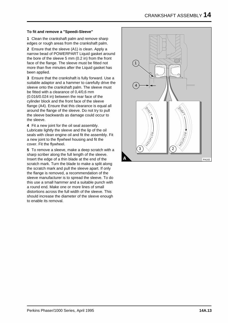
CRANKSHAFT ASSEMBLY 14
To fit and remove a "Speedi-Sleeve"
1 Clean the crankshaft palm and remove sharpedges or rough areas from the crankshaft palm.
2 Ensure that the sleeve (A1) is clean. Apply anarrow bead of POWERPART Liquid gasket aroundthe bore of the sleeve 5 mm (0.2 in) from the frontface of the flange. The sleeve must be fitted notmore than five minutes after the Liquid gasket hasbeen applied.
3 Ensure that the crankshaft is fully forward. Use asuitable adaptor and a hammer to carefully drive thesleeve onto the crankshaft palm. The sleeve mustbe fitted with a clearance of 0,4/0,6 mm(0.016/0.024 in) between the rear face of thecylinder block and the front face of the sleeveflange (A4). Ensure that this clearance is equal allaround the flange of the sleeve. Do not try to pullthe sleeve backwards as damage could occur tothe sleeve.
4 Fit a new joint for the oil seal assembly.Lubricate lightly the sleeve and the lip of the oilseals with clean engine oil and fit the assembly. Fita new joint to the flywheel housing and fit thecover. Fit the flywheel.
5 To remove a sleeve, make a deep scratch with asharp scriber along the full length of the sleeve.Insert the edge of a thin blade at the end of thescratch mark. Turn the blade to make a split alongthe scratch mark and pull the sleeve apart. If onlythe flange is removed, a recommendation of thesleeve manufacturer is to spread the sleeve. To dothis use a small hammer and a suitable punch witha round end. Make one or more lines of smalldistortions across the full width of the sleeve. Thisshould increase the diameter of the sleeve enoughto enable its removal.
a a a
a a a
a a a
a a a
4
a aa aa aa a
1
PA102
a a a
a a a
a a a
a a a
2
a aa aa aa a
3
Perkins Phaser/1000 Series, April 1995 14A.13
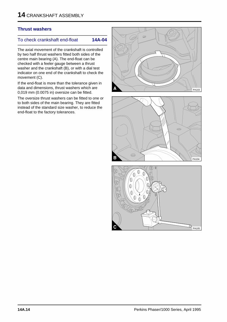
14 CRANKSHAFT ASSEMBLY
Thrust washers
To check crankshaft end-float 14A-04
The axial movement of the crankshaft is controlledby two half thrust washers fitted both sides of thecentre main bearing (A). The end-float can bechecked with a feeler gauge between a thrustwasher and the crankshaft (B), or with a dial testindicator on one end of the crankshaft to check themovement (C).
If the end-float is more than the tolerance given indata and dimensions, thrust washers which are0,019 mm (0.0075 in) oversize can be fitted.
The oversize thrust washers can be fitted to one orto both sides of the main bearing. They are fittedinstead of the standard size washer, to reduce theend-float to the factory tolerances.
PA103
PA104
PA105
14A.14 Perkins Phaser/1000 Series, April 1995
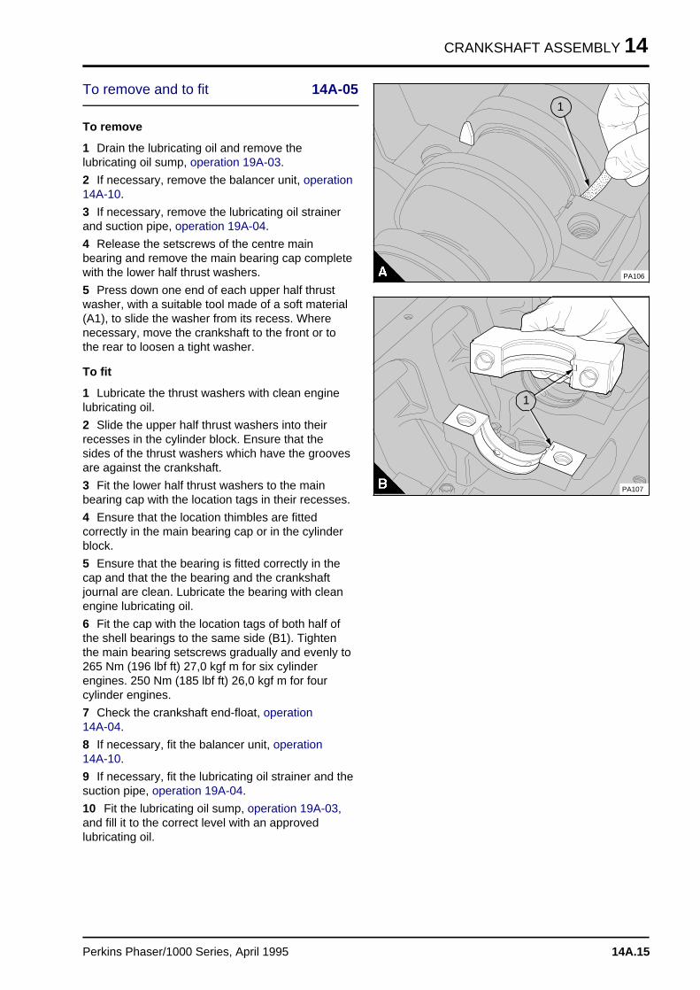
CRANKSHAFT ASSEMBLY 14
To remove and to fit 14A-05
To remove
1 Drain the lubricating oil and remove thelubricating oil sump, operation 19A-03.
2 If necessary, remove the balancer unit, operation14A-10.
3 If necessary, remove the lubricating oil strainerand suction pipe, operation 19A-04.
4 Release the setscrews of the centre mainbearing and remove the main bearing cap completewith the lower half thrust washers.
5 Press down one end of each upper half thrustwasher, with a suitable tool made of a soft material(A1), to slide the washer from its recess. Wherenecessary, move the crankshaft to the front or tothe rear to loosen a tight washer.
To fit
1 Lubricate the thrust washers with clean enginelubricating oil.
2 Slide the upper half thrust washers into theirrecesses in the cylinder block. Ensure that thesides of the thrust washers which have the groovesare against the crankshaft.
3 Fit the lower half thrust washers to the mainbearing cap with the location tags in their recesses.
4 Ensure that the location thimbles are fittedcorrectly in the main bearing cap or in the cylinderblock.
5 Ensure that the bearing is fitted correctly in thecap and that the the bearing and the crankshaftjournal are clean. Lubricate the bearing with cleanengine lubricating oil.
6 Fit the cap with the location tags of both half ofthe shell bearings to the same side (B1). Tightenthe main bearing setscrews gradually and evenly to265 Nm (196 lbf ft) 27,0 kgf m for six cylinderengines. 250 Nm (185 lbf ft) 26,0 kgf m for fourcylinder engines.
7 Check the crankshaft end-float, operation 14A-04.
8 If necessary, fit the balancer unit, operation 14A-10.
9 If necessary, fit the lubricating oil strainer and thesuction pipe, operation 19A-04.
10 Fit the lubricating oil sump, operation 19A-03,and fill it to the correct level with an approvedlubricating oil.
a aa aa aa a
1
PA106
a a a
a a a
a a a
a a a
1
PA107
Perkins Phaser/1000 Series, April 1995 14A.15
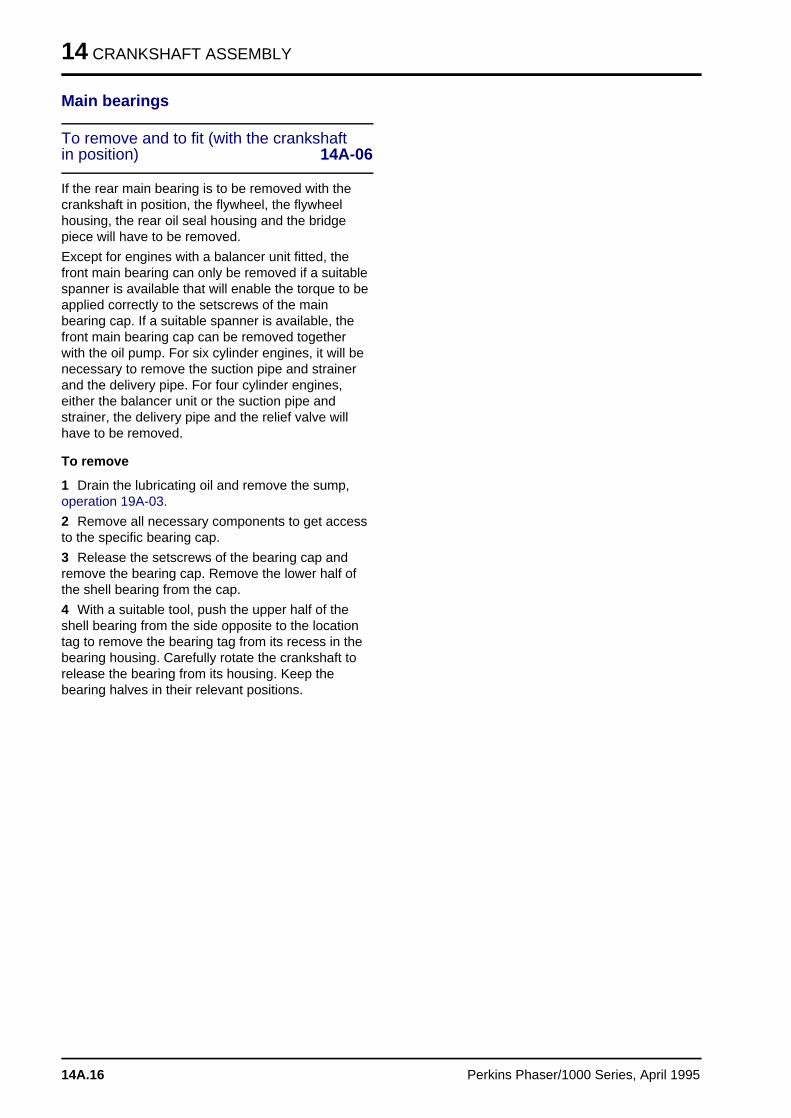
14 CRANKSHAFT ASSEMBLY
Main bearings
To remove and to fit (with the crankshaftin position) 14A-06
If the rear main bearing is to be removed with thecrankshaft in position, the flywheel, the flywheelhousing, the rear oil seal housing and the bridgepiece will have to be removed.
Except for engines with a balancer unit fitted, thefront main bearing can only be removed if a suitablespanner is available that will enable the torque to beapplied correctly to the setscrews of the mainbearing cap. If a suitable spanner is available, thefront main bearing cap can be removed togetherwith the oil pump. For six cylinder engines, it will benecessary to remove the suction pipe and strainerand the delivery pipe. For four cylinder engines,either the balancer unit or the suction pipe andstrainer, the delivery pipe and the relief valve willhave to be removed.
To remove
1 Drain the lubricating oil and remove the sump,operation 19A-03.
2 Remove all necessary components to get accessto the specific bearing cap.
3 Release the setscrews of the bearing cap andremove the bearing cap. Remove the lower half ofthe shell bearing from the cap.
4 With a suitable tool, push the upper half of theshell bearing from the side opposite to the locationtag to remove the bearing tag from its recess in thebearing housing. Carefully rotate the crankshaft torelease the bearing from its housing. Keep thebearing halves in their relevant positions.
14A.16 Perkins Phaser/1000 Series, April 1995
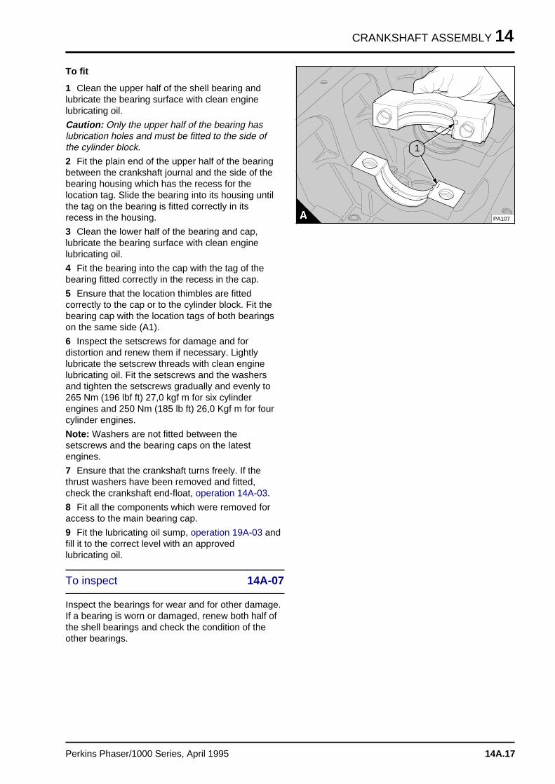
CRANKSHAFT ASSEMBLY 14
To fit
1 Clean the upper half of the shell bearing andlubricate the bearing surface with clean enginelubricating oil.
Caution: Only the upper half of the bearing haslubrication holes and must be fitted to the side ofthe cylinder block.
2 Fit the plain end of the upper half of the bearingbetween the crankshaft journal and the side of thebearing housing which has the recess for thelocation tag. Slide the bearing into its housing untilthe tag on the bearing is fitted correctly in itsrecess in the housing.
3 Clean the lower half of the bearing and cap,lubricate the bearing surface with clean enginelubricating oil.
4 Fit the bearing into the cap with the tag of thebearing fitted correctly in the recess in the cap.
5 Ensure that the location thimbles are fittedcorrectly to the cap or to the cylinder block. Fit thebearing cap with the location tags of both bearingson the same side (A1).
6 Inspect the setscrews for damage and fordistortion and renew them if necessary. Lightlylubricate the setscrew threads with clean enginelubricating oil. Fit the setscrews and the washersand tighten the setscrews gradually and evenly to265 Nm (196 lbf ft) 27,0 kgf m for six cylinderengines and 250 Nm (185 lb ft) 26,0 Kgf m for fourcylinder engines.
Note: Washers are not fitted between thesetscrews and the bearing caps on the latestengines.
7 Ensure that the crankshaft turns freely. If thethrust washers have been removed and fitted,check the crankshaft end-float, operation 14A-03.
8 Fit all the components which were removed foraccess to the main bearing cap.
9 Fit the lubricating oil sump, operation 19A-03 andfill it to the correct level with an approvedlubricating oil.
To inspect 14A-07
Inspect the bearings for wear and for other damage.If a bearing is worn or damaged, renew both half ofthe shell bearings and check the condition of theother bearings.
a a a
a a a
a a a
a a a
1
PA107
Perkins Phaser/1000 Series, April 1995 14A.17
14 CRANKSHAFT ASSEMBLY
Crankshaft
To remove and to fit 14A-08
Consumable products:
POWERPART Silicone rubber sealant
POWERPART liquid gasket
Warning! Use lift equipment or obtain assistance tolift heavy engine components such as the balancerunit, flywheel housing, crankshaft and flywheel.
To remove
1 Before the engine is removed from the vehicle orfrom the machine, drain the lubricating oil and thecoolant.
2 Remove the lubricating oil sump, operation 19A-03.
3 Remove the fan, the drive belts, the fan drivepulley and housing and the coolant pump, seesection 21.
4 Remove the crankshaft pulley, operation 14A-01A or 14A.01B.
5 Remove the alternator and its mounting bracket,see section 23.
6 Remove the compressor and its drive assemblyor remove the exhauster, see section 24.
7 Remove the timing case cover, operation 15A-01.
8 Remove the fuel injection pump, see section 20.
9 Remove the timing gears and the timing case,see section 15.
10 Remove the flywheel and the flywheel housing,see section 22.
11 Remove the rear oil seal housing, operation14A-02A or 14A.02B.
12 If a balancer unit is fitted, remove it, operation14A-10. If a balancer unit is not fitted, remove thelubricating oil suction pipe and strainer, thelubricating oil pump, the delivery pipe and the reliefvalve (four cylinder engines) and the lubricating oilcrossover pipe, if fitted, see section 19.
13 Remove the bridge piece and the rubber seals.Later engines may not have rubber seals fitted.
14 Remove the caps of the connecting rods. Keepthe bearings and caps together. Remove the boltsof the connecting rods and carefully push thepistons into their bores.
14A.18 Perkins Phaser/1000 Series, April 1995
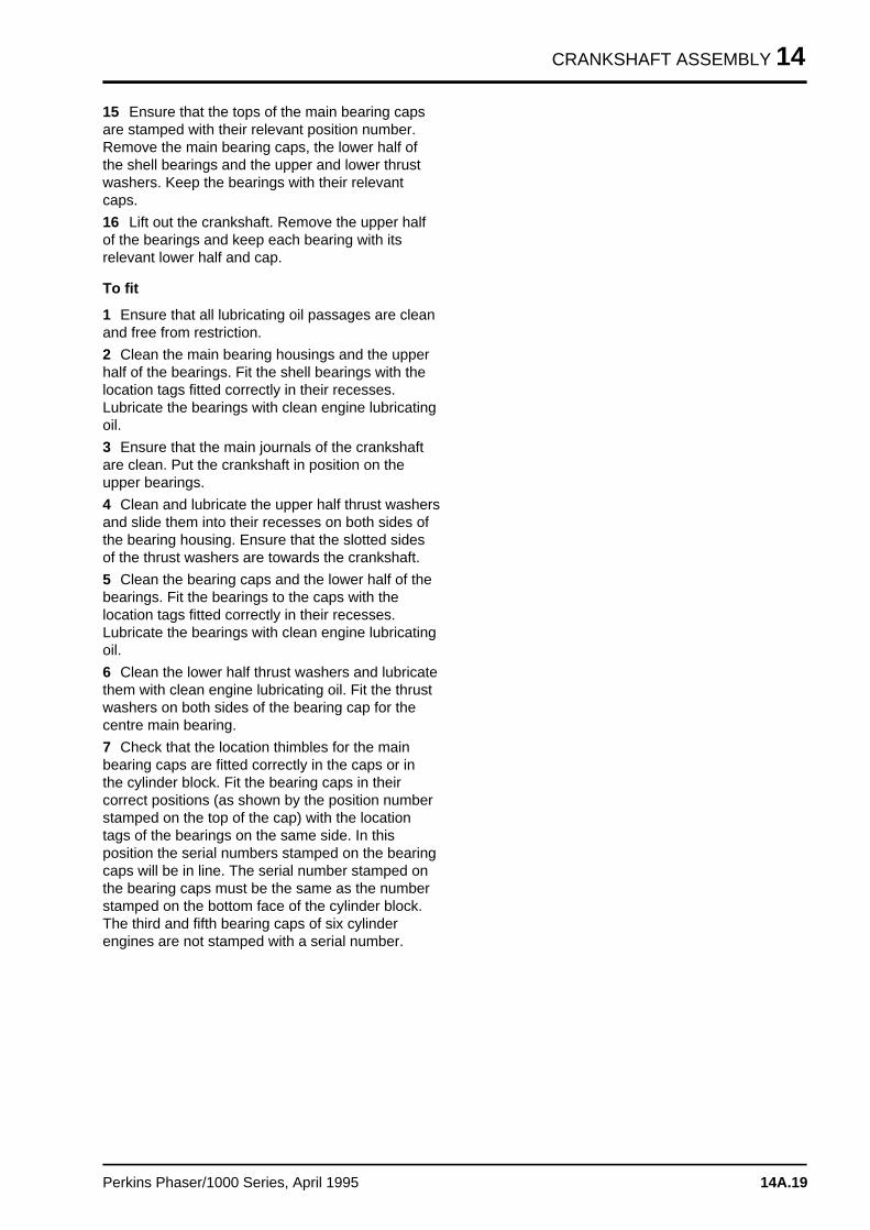
CRANKSHAFT ASSEMBLY 14
15 Ensure that the tops of the main bearing capsare stamped with their relevant position number.Remove the main bearing caps, the lower half ofthe shell bearings and the upper and lower thrustwashers. Keep the bearings with their relevantcaps.
16 Lift out the crankshaft. Remove the upper halfof the bearings and keep each bearing with itsrelevant lower half and cap.
To fit
1 Ensure that all lubricating oil passages are cleanand free from restriction.
2 Clean the main bearing housings and the upperhalf of the bearings. Fit the shell bearings with thelocation tags fitted correctly in their recesses.Lubricate the bearings with clean engine lubricatingoil.
3 Ensure that the main journals of the crankshaftare clean. Put the crankshaft in position on theupper bearings.
4 Clean and lubricate the upper half thrust washersand slide them into their recesses on both sides ofthe bearing housing. Ensure that the slotted sidesof the thrust washers are towards the crankshaft.
5 Clean the bearing caps and the lower half of thebearings. Fit the bearings to the caps with thelocation tags fitted correctly in their recesses.Lubricate the bearings with clean engine lubricatingoil.
6 Clean the lower half thrust washers and lubricatethem with clean engine lubricating oil. Fit the thrustwashers on both sides of the bearing cap for thecentre main bearing.
7 Check that the location thimbles for the mainbearing caps are fitted correctly in the caps or inthe cylinder block. Fit the bearing caps in theircorrect positions (as shown by the position numberstamped on the top of the cap) with the locationtags of the bearings on the same side. In thisposition the serial numbers stamped on the bearingcaps will be in line. The serial number stamped onthe bearing caps must be the same as the numberstamped on the bottom face of the cylinder block.The third and fifth bearing caps of six cylinderengines are not stamped with a serial number.
Perkins Phaser/1000 Series, April 1995 14A.19
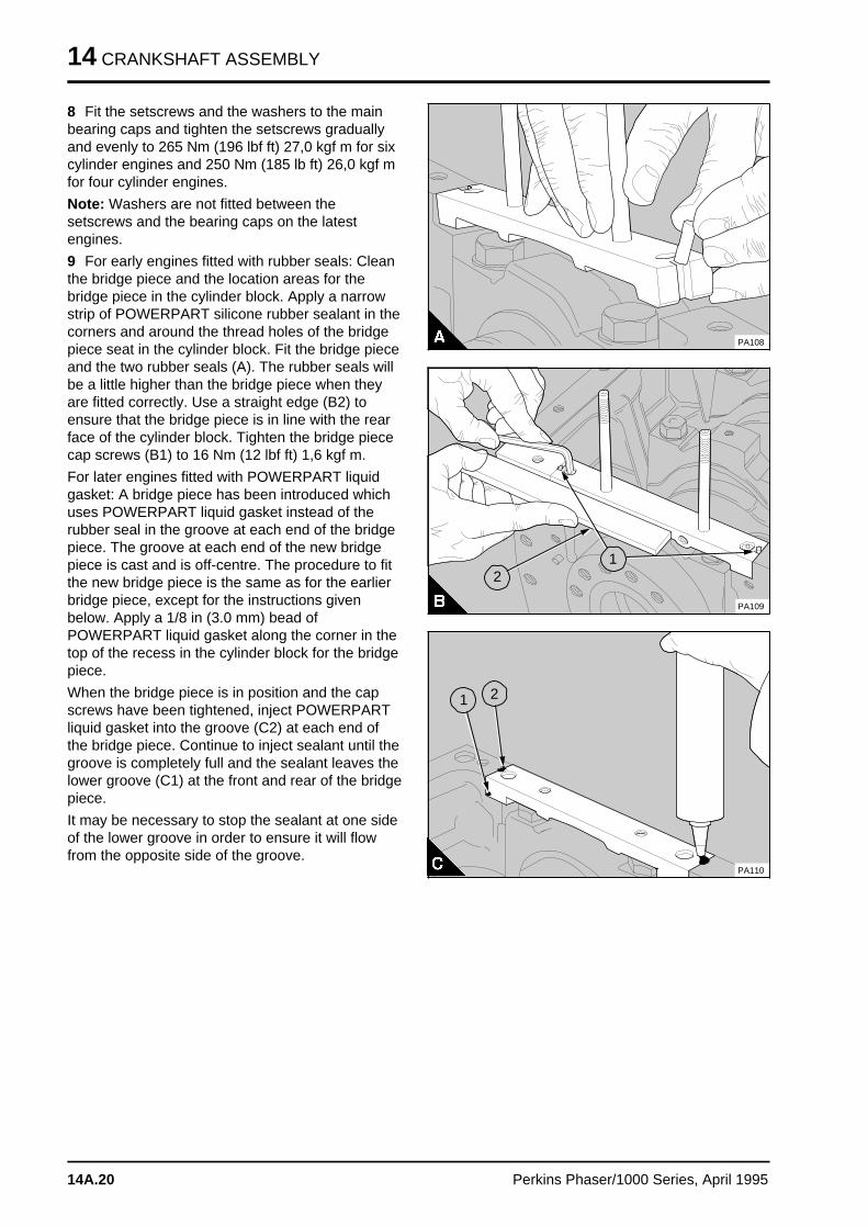
14 CRANKSHAFT ASSEMBLY
8 Fit the setscrews and the washers to the mainbearing caps and tighten the setscrews graduallyand evenly to 265 Nm (196 lbf ft) 27,0 kgf m for sixcylinder engines and 250 Nm (185 lb ft) 26,0 kgf mfor four cylinder engines.
Note: Washers are not fitted between thesetscrews and the bearing caps on the latestengines.
9 For early engines fitted with rubber seals: Cleanthe bridge piece and the location areas for thebridge piece in the cylinder block. Apply a narrowstrip of POWERPART silicone rubber sealant in thecorners and around the thread holes of the bridgepiece seat in the cylinder block. Fit the bridge pieceand the two rubber seals (A). The rubber seals willbe a little higher than the bridge piece when theyare fitted correctly. Use a straight edge (B2) toensure that the bridge piece is in line with the rearface of the cylinder block. Tighten the bridge piececap screws (B1) to 16 Nm (12 lbf ft) 1,6 kgf m.
For later engines fitted with POWERPART liquidgasket: A bridge piece has been introduced whichuses POWERPART liquid gasket instead of therubber seal in the groove at each end of the bridgepiece. The groove at each end of the new bridgepiece is cast and is off-centre. The procedure to fitthe new bridge piece is the same as for the earlierbridge piece, except for the instructions givenbelow. Apply a 1/8 in (3.0 mm) bead ofPOWERPART liquid gasket along the corner in thetop of the recess in the cylinder block for the bridgepiece.
When the bridge piece is in position and the capscrews have been tightened, inject POWERPARTliquid gasket into the groove (C2) at each end ofthe bridge piece. Continue to inject sealant until thegroove is completely full and the sealant leaves thelower groove (C1) at the front and rear of the bridgepiece.
It may be necessary to stop the sealant at one sideof the lower groove in order to ensure it will flowfrom the opposite side of the groove.
PA108
PA109
a aa aa aa aa a
2
a a a
a a a
a a a
a a a
1
a a a
a a a
a aa aa aa a
1
a a a
a a a
a a a
a a a
2
a aa a
PA110
14A.20 Perkins Phaser/1000 Series, April 1995
CRANKSHAFT ASSEMBLY 14
Caution: When the sump joint is removed, damagecan occur to the seal in the grooves of the bridgepiece. If the seal is damaged, apply enough sealantto completely fill the grooves.
Note: Most of the latest engines have setscrews inplace of studs to fasten the sump to the bridgepiece. The threads of the setscrews have a sealantapplied by the manufacturer. When the setscrewsare to be used again, ensure that the threads of thesetscrews and of the bridge piece are clean and asealant is applied to the threads of the setscrews.These instructions also apply to studs.
10 Fit the connecting rod caps, operation 13A-01.Rotate the crankshaft two turns to ensure freemovement.
11 If necessary, fit the balancer unit, operation 14A-10. If a balancer unit is not used, fit thelubricating oil pump, the lubricating oil suction pipeand strainer, the delivery pipe and the relief valve(four cylinder engines) and if necessary, thelubricating oil crossover pipe, see section 19.
12 Fit the rear oil seal housing, operation 14A-02Aor 14A-02B.
13 Fit the flywheel housing and the flywheel, seesection 22.
14 Fit the timing case and the timing gears, seesection 15.
15 Fit the fuel injection pump, see section 20.
16 Fit the timing case cover, operation 15A-01.
17 Fit the compressor and its drive assembly or fitthe exhauster, see section 24.
18 Fit the alternator and its mounting bracket, seesection 23.
19 Fit the crankshaft pulley, operation 14A-01A or14A-01B.
20 Fit the coolant pump, the fan drive pulley andhousing, the drive belts and the fan , see section21.
21 Fit the lubricating oil sump, operation 19A-03.
22 After the engine has been installed, fill thelubricating oil sump to the correct level with anapproved oil. Fill the cooling system.
To inspect 14A-09
Check the crankshaft for wear and other damage.The maximum permissible wear and ovality on thecrankshaft journals and crank pins is 0,04 mm(0.0016 in).
The main journals and the crank pins of standardsize crank shafts can be machined to 0,25mm(0.010 in), 0,50mm (0.020 in) or 0,75 mm (0.030 in)undersize on diameter, see the data anddimensions. Special undersize bearings areavailable.
If the seal has been used in all of the servicepositions, the crankshaft palm can be machined toremove the wear marks. Further information can befound in the data and dimensions.
Perkins Phaser/1000 Series, April 1995 14A.21
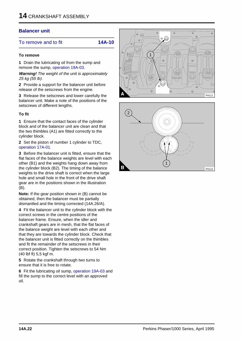
14 CRANKSHAFT ASSEMBLY
Balancer unit
To remove and to fit 14A-10
To remove
1 Drain the lubricating oil from the sump andremove the sump, operation 19A-03.
Warning! The weight of the unit is approximately25 kg (55 lb).
2 Provide a support for the balancer unit beforerelease of the setscrews from the engine.
3 Release the setscrews and lower carefully thebalancer unit. Make a note of the positions of thesetscrews of different lengths.
To fit
1 Ensure that the contact faces of the cylinderblock and of the balancer unit are clean and thatthe two thimbles (A1) are fitted correctly to thecylinder block.
2 Set the piston of number 1 cylinder to TDC,operation 17A-01.
3 Before the balancer unit is fitted, ensure that theflat faces of the balance weights are level with eachother (B1) and the weights hang down away fromthe cylinder block (B2). The timing of the balanceweights to the drive shaft is correct when the largehole and small hole in the front of the drive shaftgear are in the positions shown in the illustration(B).
Note: If the gear position shown in (B) cannot beobtained, then the balancer must be partiallydismantled and the timing corrected (14A.26/A).
4 Fit the balancer unit to the cylinder block with thecorrect screws in the centre positions of thebalancer frame. Ensure, when the idler andcrankshaft gears are in mesh, that the flat faces ofthe balance weight are level with each other andthat they are towards the cylinder block. Check thatthe balancer unit is fitted correctly on the thimblesand fit the remainder of the setscrews in theircorrect position. Tighten the setscrews to 54 Nm(40 lbf ft) 5,5 kgf m.
5 Rotate the crankshaft through two turns toensure that it is free to rotate.
6 Fit the lubricating oil sump, operation 19A-03 andfill the sump to the correct level with an approvedoil.
a a a
a a a
a a a
a a a
1
PA111
a a a
a a a
a a a
a a a
1
a a a
a a a
a a a
a a a
2
PA112
14A.22 Perkins Phaser/1000 Series, April 1995
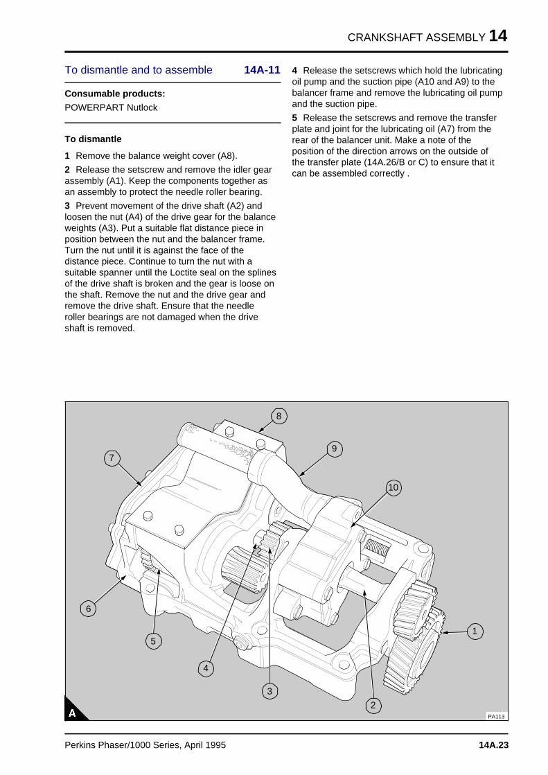
CRANKSHAFT ASSEMBLY 14
To dismantle and to assemble 14A-11
Consumable products:
POWERPART Nutlock
To dismantle
1 Remove the balance weight cover (A8).
2 Release the setscrew and remove the idler gearassembly (A1). Keep the components together asan assembly to protect the needle roller bearing.
3 Prevent movement of the drive shaft (A2) andloosen the nut (A4) of the drive gear for the balanceweights (A3). Put a suitable flat distance piece inposition between the nut and the balancer frame.Turn the nut until it is against the face of thedistance piece. Continue to turn the nut with asuitable spanner until the Loctite seal on the splinesof the drive shaft is broken and the gear is loose onthe shaft. Remove the nut and the drive gear andremove the drive shaft. Ensure that the needleroller bearings are not damaged when the driveshaft is removed.
4 Release the setscrews which hold the lubricatingoil pump and the suction pipe (A10 and A9) to thebalancer frame and remove the lubricating oil pumpand the suction pipe.
5 Release the setscrews and remove the transferplate and joint for the lubricating oil (A7) from therear of the balancer unit. Make a note of theposition of the direction arrows on the outside ofthe transfer plate (14A.26/B or C) to ensure that itcan be assembled correctly .
a a a
a a a
a a a
a a a
2
a a a
a a a
a a a
a a a
3
a a a
a a a
a a a
a a a
5
a aa aa aa aa a
6
a a a
a a a
a a a
a a a
7
a aa aa aa a
8
a a a
a a a
a a a
a a a
9
a a a a
a a a a
a a a a
a a a a
10
a a a
a a a
a a a
a a a
1
a a a
a a a
a a a
a a a
4
PA113
Perkins Phaser/1000 Series, April 1995 14A.23
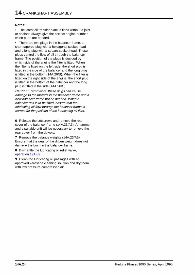
14 CRANKSHAFT ASSEMBLY
Notes:
• The latest oil transfer plate is fitted without a jointor sealant; always give the correct engine numberwhen parts are needed.
• There are two plugs in the balancer frame, ashort tapered plug with a hexagonal socket headand a long plug with a square socket head. Theseplugs control the flow of oil through the balancerframe. The position of the plugs is decided bywhich side of the engine the filter is fitted. Whenthe filter is fitted on the left side, the short plug isfitted in the side of the balancer and the long plugis fitted in the bottom (14A.26/B). When the filter isfitted on the right side of the engine, the short plugis fitted in the bottom of the balancer and the longplug is fitted in the side (14A.26/C).
Caution: Removal of these plugs can causedamage to the threads in the balancer frame and anew balancer frame will be needed. When abalancer unit is to be fitted, ensure that thelubricating oil flow through the balancer frame iscorrect for the position of the lubricating oil filter.
6 Release the setscrews and remove the rearcover of the balancer frame (14A.23/A6). A hammerand a suitable drift will be necessary to remove therear cover from the dowels.
7 Remove the balance weights (14A.23/A5).Ensure that the gear of the driven weight does notdamage the bush in the balancer frame.
8 Dismantle the lubricating oil relief valve,operation 19A-09.
9 Clean the lubricating oil passages with anapproved kerosene cleaning solution and dry themwith low pressure compressed air.
14A.24 Perkins Phaser/1000 Series, April 1995
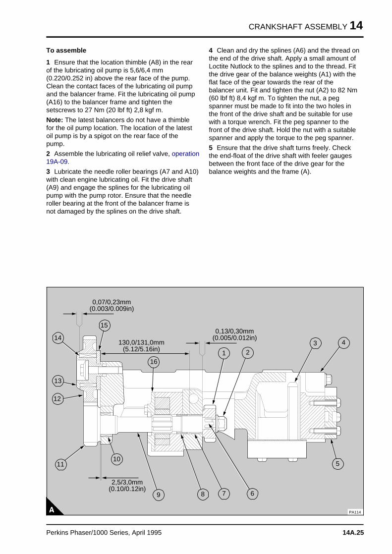
CRANKSHAFT ASSEMBLY 14
To assemble
1 Ensure that the location thimble (A8) in the rearof the lubricating oil pump is 5,6/6,4 mm(0.220/0.252 in) above the rear face of the pump.Clean the contact faces of the lubricating oil pumpand the balancer frame. Fit the lubricating oil pump(A16) to the balancer frame and tighten thesetscrews to 27 Nm (20 lbf ft) 2,8 kgf m.
Note: The latest balancers do not have a thimblefor the oil pump location. The location of the latestoil pump is by a spigot on the rear face of thepump.
2 Assemble the lubricating oil relief valve, operation19A-09.
3 Lubricate the needle roller bearings (A7 and A10)with clean engine lubricating oil. Fit the drive shaft(A9) and engage the splines for the lubricating oilpump with the pump rotor. Ensure that the needleroller bearing at the front of the balancer frame isnot damaged by the splines on the drive shaft.
4 Clean and dry the splines (A6) and the thread onthe end of the drive shaft. Apply a small amount ofLoctite Nutlock to the splines and to the thread. Fitthe drive gear of the balance weights (A1) with theflat face of the gear towards the rear of thebalancer unit. Fit and tighten the nut (A2) to 82 Nm(60 lbf ft) 8,4 kgf m. To tighten the nut, a pegspanner must be made to fit into the two holes inthe front of the drive shaft and be suitable for usewith a torque wrench. Fit the peg spanner to thefront of the drive shaft. Hold the nut with a suitablespanner and apply the torque to the peg spanner.
5 Ensure that the drive shaft turns freely. Checkthe end-float of the drive shaft with feeler gaugesbetween the front face of the drive gear for thebalance weights and the frame (A).
a a a
a a a
a a a
a a a
1
a a a a
a a a a
a a a a
a a a a
10
a aa aa aa a
2
a a a
a a a
a a a
a a a
3a aa aa aa a
4a a a
a a a
a a a
a a a
5
a a a
a a a
a a a
a a a
a a a
6
a a a
a a a
a a a
a a a
a a a
7a aa aa aa a
8
a a a
a a a
a a a
a a a
9
a a a a
a a a a
a a a a
a a a a
11
a a a a
a a a a
a a a a
a a a a
12
a a a a
a a a a
a a a a
a a a a
13
a a a a
a a a a
a a a a
a a a a
14
a a a a
a a a a
a a a a
a a a a
15
a a a a
a a a a
a a a a
a a a a
a a a a
16
a a a a a a a a a a a a a a a a a a a
a a a a a a a a a a a a a a a a a a a
a a a a a a a a a a a a a a a a a a a
a a a a a a a a a a a a a a a a a a a
a a a a a a a a a a a a a a a a a a a
a a a a a a a a a a a a a a a a a a a
0,07/0,23mm(0.003/0.009in)
a a a a a a a a a a a a a a a a a a a a
a a a a a a a a a a a a a a a a a a a a
a a a a a a a a a a a a a a a a a a a a
a a a a a a a a a a a a a a a a a a a a
a a a a a a a a a a a a a a a a a a a a
a a a a a a a a a a a a a a a a a a a a
130,0/131,0mm(5.12/5.16in)
a a a a a a a a a a a a a a a a a a a
a a a a a a a a a a a a a a a a a a a
a a a a a a a a a a a a a a a a a a a
a a a a a a a a a a a a a a a a a a a
a a a a a a a a a a a a a a a a a a a
a a a a a a a a a a a a a a a a a a a
0,13/0,30mm(0.005/0.012in)
a a a a a a a a a a a a a a a a
a a a a a a a a a a a a a a a a
a a a a a a a a a a a a a a a a
a a a a a a a a a a a a a a a a
a a a a a a a a a a a a a a a a
a a a a a a a a a a a a a a a a
a a a a a a a a a a a a a a a a
2,5/3,0mm(0.10/0.12in)
PA114
Perkins Phaser/1000 Series, April 1995 14A.25
14 CRANKSHAFT ASSEMBLY
6 Put the balancer frame upside down on thebench (A1). Turn the gear of the drive shaft (A3)until the larger of the two outer holes (A2) - in thefront face of the drive gear - is in the positionshown in (A). Ensure that the drive shaft will notmove from this position. Lubricate the bushes in therear of the balancer frame with clean enginelubricating oil and fit the balance weights in theposition shown in figure A. Ensure that the flats onthe balance weights are level with each other (A4).With the balance weights in the correct position,check that the drive shaft is still in the correctposition.
7 Fit the two dowels to the rear face of thebalancer frame. Lubricate the bushes in the rearcover of the balance frame with clean enginelubricating oil. Put the rear cover (14A.24/A4) inposition with the rear spigots of the balance weightsin the bushes of the cover. Hit lightly the rear coverwith a soft face hammer to fit the cover onto thedowels. Fit the cover setscrews and tighten them to54 Nm (40 lbf ft) 5,5 kgf m. Check the end-float ofthe balance weights with feeler gauges between therear face of the balance weights and the front faceof the rear cover (14A.30/B). The correct end-floatis given in the data and dimensions. Check thebacklash between the drive gear of the balanceweights and the driven gear on the balance weight.The correct backlash is given in the data anddimensions.
8 Fit the oil transfer plate and the joint, if fitted, tothe rear of the rear cover and tighten the setscrewsto 30 Nm (22 lbf ft) 3,1 kgf m. Ensure that the plateis fitted correctly for the oil filter position. Thedirection arrow (B or C) indicates the direction oflubricating oil flow for left side (B) and right side (C)oil filter positions. The symbols and arrows (B or C)indicate the position of the plugs in the balancerframe and the shape of their socket heads. Ensurethat the plug on the bottom face of the frame is justbelow the face. If a new frame and plugs are used,ensure that the plugs are fitted correctly for the oilfilter position and the symbols on the oil transferplate.
a aa aa aa a
3
a aa aa aa a
1
a a a
a a a
a a a
a a a
4
a aa aa aa a
2
PA115
PA116
PA117
14A.26 Perkins Phaser/1000 Series, April 1995
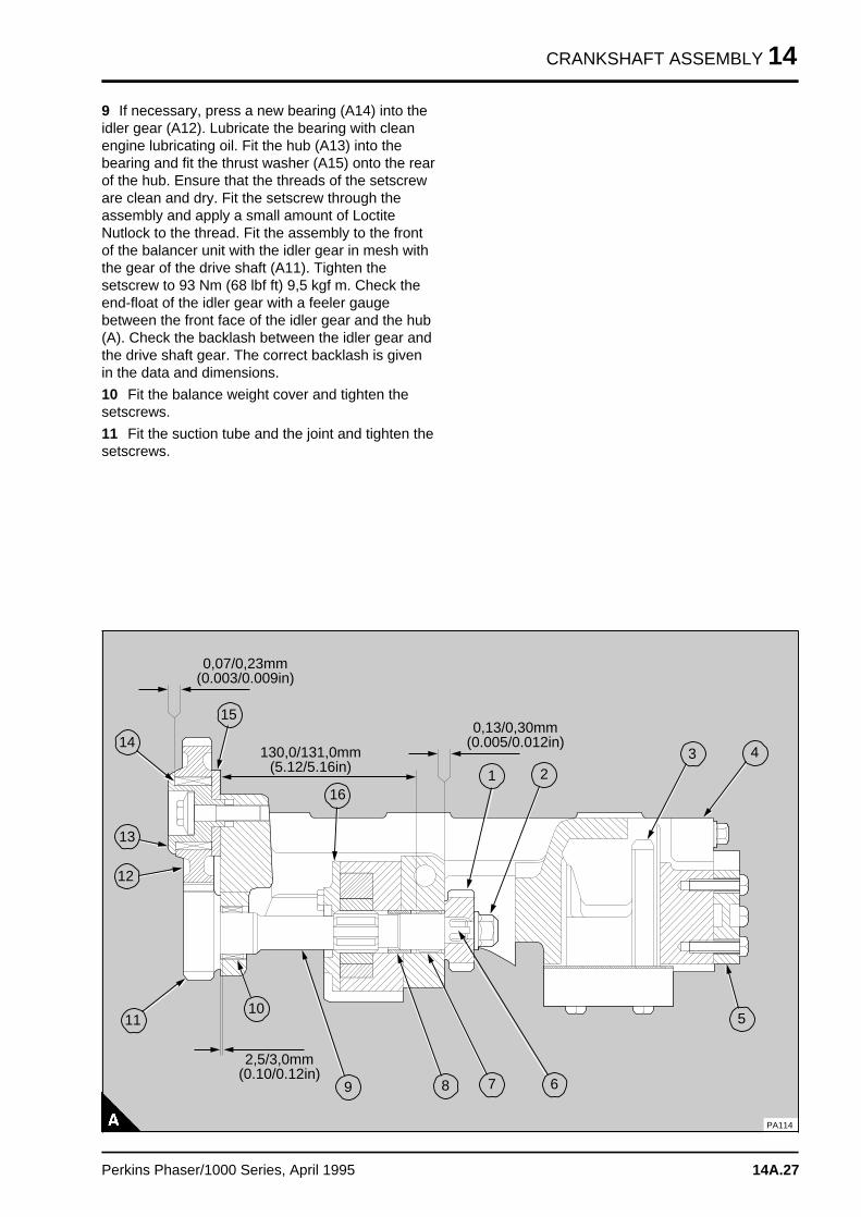
CRANKSHAFT ASSEMBLY 14
9 If necessary, press a new bearing (A14) into theidler gear (A12). Lubricate the bearing with cleanengine lubricating oil. Fit the hub (A13) into thebearing and fit the thrust washer (A15) onto the rearof the hub. Ensure that the threads of the setscreware clean and dry. Fit the setscrew through theassembly and apply a small amount of LoctiteNutlock to the thread. Fit the assembly to the frontof the balancer unit with the idler gear in mesh withthe gear of the drive shaft (A11). Tighten thesetscrew to 93 Nm (68 lbf ft) 9,5 kgf m. Check theend-float of the idler gear with a feeler gaugebetween the front face of the idler gear and the hub(A). Check the backlash between the idler gear andthe drive shaft gear. The correct backlash is givenin the data and dimensions.
10 Fit the balance weight cover and tighten thesetscrews.
11 Fit the suction tube and the joint and tighten thesetscrews.
a a a
a a a
a a a
a a a
1
a a a a
a a a a
a a a a
a a a a
10
a aa aa aa a
2
a a a
a a a
a a a
a a a
3a aa aa aa a
4a a a
a a a
a a a
a a a
5
a a a
a a a
a a a
a a a
a a a
6
a a a
a a a
a a a
a a a
a a a
7a aa aa aa a
8
a a a
a a a
a a a
a a a
9
a a a a
a a a a
a a a a
a a a a
11
a a a a
a a a a
a a a a
a a a a
12
a a a a
a a a a
a a a a
a a a a
13
a a a a
a a a a
a a a a
a a a a
14
a a a a
a a a a
a a a a
a a a a
15
a a a a
a a a a
a a a a
a a a a
a a a a
16
a a a a a a a a a a a a a a a a a a a
a a a a a a a a a a a a a a a a a a a
a a a a a a a a a a a a a a a a a a a
a a a a a a a a a a a a a a a a a a a
a a a a a a a a a a a a a a a a a a a
a a a a a a a a a a a a a a a a a a a
0,07/0,23mm(0.003/0.009in)
a a a a a a a a a a a a a a a a a a a a
a a a a a a a a a a a a a a a a a a a a
a a a a a a a a a a a a a a a a a a a a
a a a a a a a a a a a a a a a a a a a a
a a a a a a a a a a a a a a a a a a a a
a a a a a a a a a a a a a a a a a a a a
130,0/131,0mm(5.12/5.16in)
a a a a a a a a a a a a a a a a a a a
a a a a a a a a a a a a a a a a a a a
a a a a a a a a a a a a a a a a a a a
a a a a a a a a a a a a a a a a a a a
a a a a a a a a a a a a a a a a a a a
a a a a a a a a a a a a a a a a a a a
0,13/0,30mm(0.005/0.012in)
a a a a a a a a a a a a a a a a
a a a a a a a a a a a a a a a a
a a a a a a a a a a a a a a a a
a a a a a a a a a a a a a a a a
a a a a a a a a a a a a a a a a
a a a a a a a a a a a a a a a a
a a a a a a a a a a a a a a a a
2,5/3,0mm(0.10/0.12in)
PA114
Perkins Phaser/1000 Series, April 1995 14A.27
14 CRANKSHAFT ASSEMBLY
To inspect 14A-12
1 Clean all the components before inspection.
2 Check the gear teeth and the splines of the driveshaft for wear or other damage. Renew the driveshaft if necessary.
3 Check the idler gear, needle roller bearing, huband thrust washer for wear or other damage.Renew the components if necessary.
4 Check the drive gear for the balance weights forwear or other damage. Renew the gear ifnecessary.
5 Check the balance weights for wear or otherdamage. If either balance weight is worn ordamaged, both balance weights must be renewed.
6 Check the needle roller bearings for the driveshaft for wear or other damage. Renew thebearings, operation 14A-13, if necessary.
7 Check the bushes for the balance weights forwear or other damage. Renew the bushes,operation 14A-14, if necessary.
8 To inspect the lubricating oil pump, see operation19A-07.
14A.28 Perkins Phaser/1000 Series, April 1995
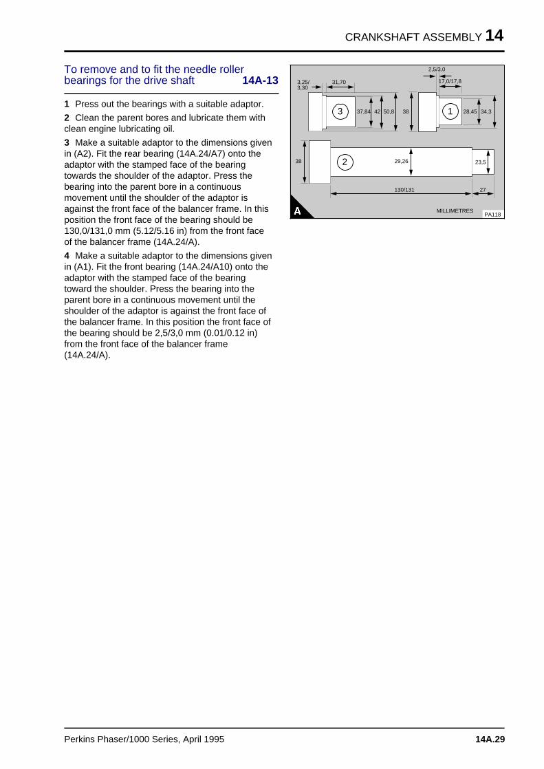
CRANKSHAFT ASSEMBLY 14
To remove and to fit the needle rollerbearings for the drive shaft 14A-13
1 Press out the bearings with a suitable adaptor.
2 Clean the parent bores and lubricate them withclean engine lubricating oil.
3 Make a suitable adaptor to the dimensions givenin (A2). Fit the rear bearing (14A.24/A7) onto theadaptor with the stamped face of the bearingtowards the shoulder of the adaptor. Press thebearing into the parent bore in a continuousmovement until the shoulder of the adaptor isagainst the front face of the balancer frame. In thisposition the front face of the bearing should be130,0/131,0 mm (5.12/5.16 in) from the front faceof the balancer frame (14A.24/A).
4 Make a suitable adaptor to the dimensions givenin (A1). Fit the front bearing (14A.24/A10) onto theadaptor with the stamped face of the bearingtoward the shoulder. Press the bearing into theparent bore in a continuous movement until theshoulder of the adaptor is against the front face ofthe balancer frame. In this position the front face ofthe bearing should be 2,5/3,0 mm (0.01/0.12 in)from the front face of the balancer frame(14A.24/A).
a a a a a
a a a a a
a a a a a
a a a a a
3,25/3,30
a a a a a a
a a a a a a
31,70
a a a a a a
a a a a a a
a a a a a a
37,84 a a a
a a a
a a a
42 a a a a
a a a a
a a a a
50,8 a a a a a a
a a a a a a
a a a a a a
28,45 a a a a a
a a a a a
a a a a a
34,3
a a a a a a a a
a a a a a a a a
a a a a a a a a
17,0/17,8
a a a a a a a
a a a a a a a2,5/3,0
a a a a
a a a a
a a a a
23,5
a a a
a a a
a a a
27
a a a a a
a a a a a
a a a a a
29,26
a a a a a a a
a a a a a a a
a a a a a a a
130/131
a a a
a a a
a a a
38
PA118
a a a a a a a a a a a a
a a a a a a a a a a a a
a a a a a a a a a a a a
MILLIMETRES
a a a
a a a
a a a
a a a
1
a aa aa aa a
3
a a a
a a a
a a a
a a a
2
a a a
a a a
a a a
38
Perkins Phaser/1000 Series, April 1995 14A.29
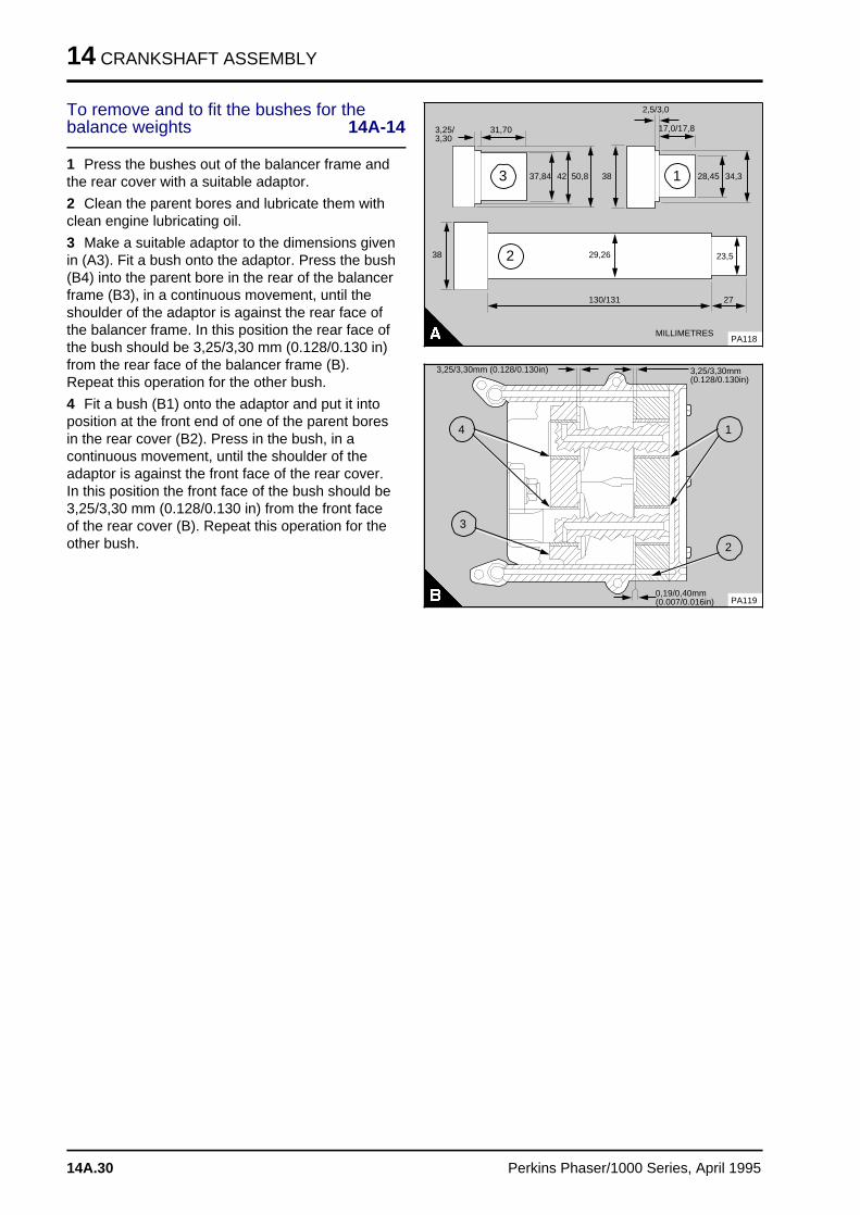
14 CRANKSHAFT ASSEMBLY
To remove and to fit the bushes for thebalance weights 14A-14
1 Press the bushes out of the balancer frame andthe rear cover with a suitable adaptor.
2 Clean the parent bores and lubricate them withclean engine lubricating oil.
3 Make a suitable adaptor to the dimensions givenin (A3). Fit a bush onto the adaptor. Press the bush(B4) into the parent bore in the rear of the balancerframe (B3), in a continuous movement, until theshoulder of the adaptor is against the rear face ofthe balancer frame. In this position the rear face ofthe bush should be 3,25/3,30 mm (0.128/0.130 in)from the rear face of the balancer frame (B).Repeat this operation for the other bush.
4 Fit a bush (B1) onto the adaptor and put it intoposition at the front end of one of the parent boresin the rear cover (B2). Press in the bush, in acontinuous movement, until the shoulder of theadaptor is against the front face of the rear cover.In this position the front face of the bush should be3,25/3,30 mm (0.128/0.130 in) from the front faceof the rear cover (B). Repeat this operation for theother bush.
a a a a a
a a a a a
a a a a a
a a a a a
3,25/3,30
a a a a a
a a a a a
31,70
a a a a a
a a a a a
a a a a a
37,84 a a a
a a a
a a a
42 a a a a a
a a a a a
a a a a a
50,8 a a a a a a
a a a a a a
a a a a a a
28,45 a a a a a
a a a a a
a a a a a
34,3
a a a a a a a a
a a a a a a a a
a a a a a a a a
17,0/17,8
a a a a a a
a a a a a a2,5/3,0
a a a a
a a a a
a a a a
23,5
a a a
a a a
a a a
27
a a a a a
a a a a a
a a a a a
29,26
a a a a a a a
a a a a a a a
a a a a a a a
130/131
a a a
a a a
a a a
38
PA118
a a a a a a a a a a a a
a a a a a a a a a a a a
a a a a a a a a a a a a
MILLIMETRES
a aa aa aa a
1
a a a
a a a
a a a
a a a
3
a aa aa aa a
2
a a a
a a a
a a a
38
a aa aa aa a
1
a a a
a a a
a a a
a a a
3
a aa aa aa a
4
PA119
a a a a a a a a a a a a
a a a a a a a a a a a a
a a a a a a a a a a a a
a a a a a a a a a a a a
0,19/0,40mm(0.007/0.016in)
a a a a a a a a a a a a
a a a a a a a a a a a a
a a a a a a a a a a a a
a a a a a a a a a a a a
3,25/3,30mm(0.128/0.130in)
a a a a a a a a a a a a a a a a a a a a a a a
a a a a a a a a a a a a a a a a a a a a a a a3,25/3,30mm (0.128/0.130in)
a aa aa aa a
2
14A.30 Perkins Phaser/1000 Series, April 1995
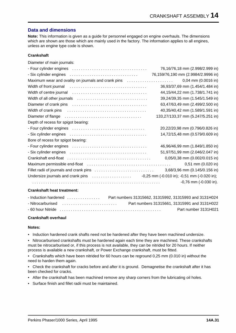
CRANKSHAFT ASSEMBLY 14
Data and dimensionsNote: This information is given as a guide for personnel engaged on engine overhauls. The dimensionswhich are shown are those which are mainly used in the factory. The information applies to all engines,unless an engine type code is shown.
Crankshaft
Diameter of main journals:
- Four cylinder engines . . . . . . . . . . . . . . . . . . . . . . . . . . . . . . . . . . 76,16/76,18 mm (2.998/2.999 in)
- Six cylinder engines . . . . . . . . . . . . . . . . . . . . . . . . . . . . . . . 76,159/76,190 mm (2.9984/2.9996 in)
Maximum wear and ovality on journals and crank pins . . . . . . . . . . . . . . . . . . . . . 0,04 mm (0.0016 in)
Width of front journal . . . . . . . . . . . . . . . . . . . . . . . . . . . . . . . . . . . 36,93/37,69 mm (1.454/1.484 in)
Width of centre journal . . . . . . . . . . . . . . . . . . . . . . . . . . . . . . . . . . 44,15/44,22 mm (1.738/1.741 in)
Width of all other journals . . . . . . . . . . . . . . . . . . . . . . . . . . . . . . . . 39,24/39,35 mm (1.545/1.549 in)
Diameter of crank pins . . . . . . . . . . . . . . . . . . . . . . . . . . . . . . . . . . 63,47/63,49 mm (2.499/2.500 in)
Width of crank pins . . . . . . . . . . . . . . . . . . . . . . . . . . . . . . . . . . . . 40,35/40,42 mm (1.589/1.591 in)
Diameter of flange . . . . . . . . . . . . . . . . . . . . . . . . . . . . . . . . . . . 133,27/133,37 mm (5.247/5.251 in)
Depth of recess for spigot bearing:
- Four cylinder engines . . . . . . . . . . . . . . . . . . . . . . . . . . . . . . . . . 20,22/20,98 mm (0.796/0.826 in)
- Six cylinder engines . . . . . . . . . . . . . . . . . . . . . . . . . . . . . . . . . . . 14,72/15,48 mm (0.579/0.609 in)
Bore of recess for spigot bearing:
- Four cylinder engines . . . . . . . . . . . . . . . . . . . . . . . . . . . . . . . . . . 46,96/46,99 mm (1.849/1.850 in)
- Six cylinder engines . . . . . . . . . . . . . . . . . . . . . . . . . . . . . . . . . . . 51,97/51,99 mm (2.046/2.047 in)
Crankshaft end-float . . . . . . . . . . . . . . . . . . . . . . . . . . . . . . . . . . . . . . 0,05/0,38 mm (0.002/0.015 in)
Maximum permissible end-float . . . . . . . . . . . . . . . . . . . . . . . . . . . . . . . . . . . . . . 0,51 mm (0.020 in)
Fillet radii of journals and crank pins . . . . . . . . . . . . . . . . . . . . . . . . . . . 3,68/3,96 mm (0.145/0.156 in)
Undersize journals and crank pins . . . . . . . . . . . . . . . . . . -0,25 mm (-0.010 in); -0,51 mm (-0.020 in);
. . . . . . . . . . . . . . . . . . . . . . . . . . . . . . . . . . . . . . . . . . . . . . . . . . . . . . . . . . -0,76 mm (-0.030 in).
Crankshaft heat treatment:
- Induction hardened . . . . . . . . . . . . . . . Part numbers 31315662, 31315992, 31315993 and 3131H024
- Nitrocarburised . . . . . . . . . . . . . . . . . . . . . . . . . Part numbers 31315661, 31315991 and 3131H022
- 60 hour Nitride . . . . . . . . . . . . . . . . . . . . . . . . . . . . . . . . . . . . . . . . . . . . . . Part number 3131H021
Crankshaft overhaul
Notes:
• Induction hardened crank shafts need not be hardened after they have been machined undersize.
• Nitrocarburised crankshafts must be hardened again each time they are machined. These crankshaftsmust be nitrocarburised or, if this process is not available, they can be nitrided for 20 hours. If neitherprocess is available a new crankshaft, or Power Exchange crankshaft, must be fitted.
• Crankshafts which have been nitrided for 60 hours can be reground 0,25 mm (0.010 in) without theneed to harden them again.
• Check the crankshaft for cracks before and after it is ground. Demagnetise the crankshaft after it hasbeen checked for cracks.
• After the crankshaft has been machined remove any sharp corners from the lubricating oil holes.
• Surface finish and fillet radii must be maintained.
Perkins Phaser/1000 Series, April 1995 14A.31
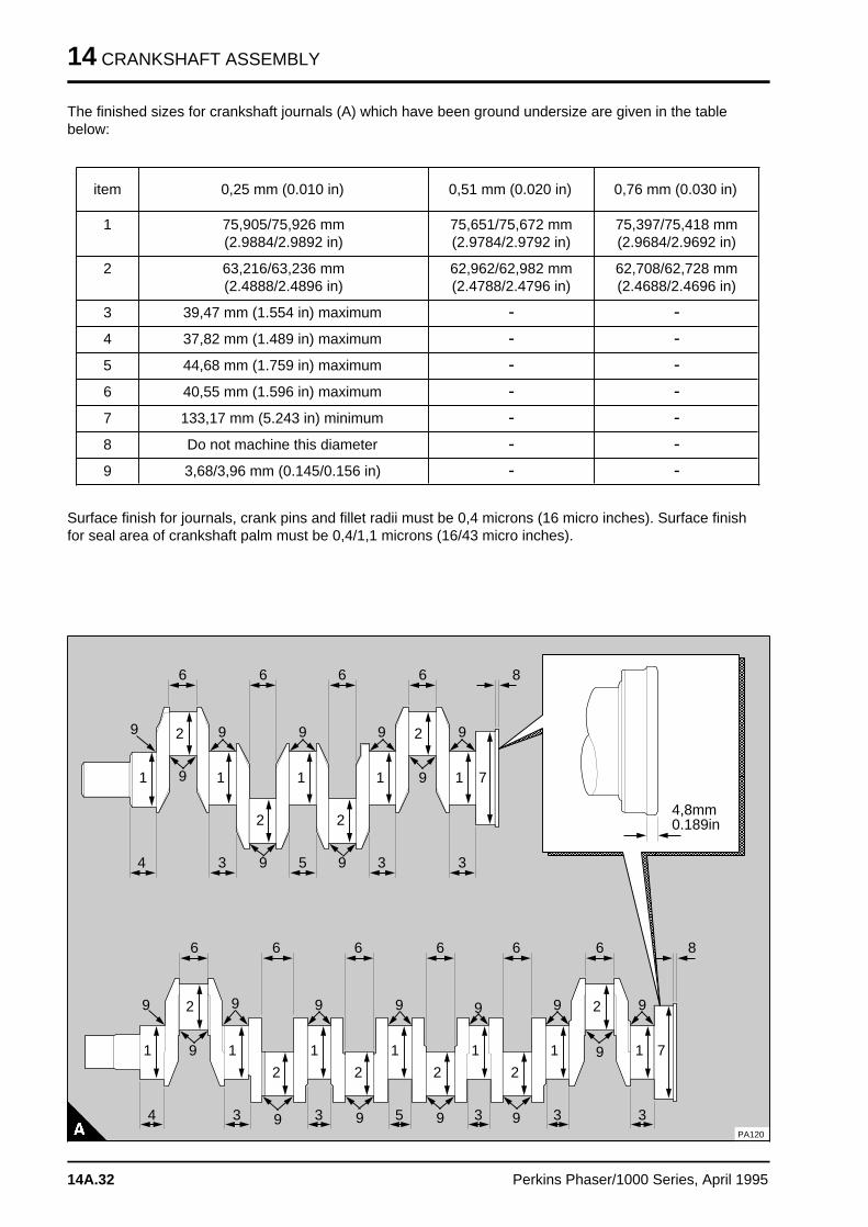
14 CRANKSHAFT ASSEMBLY
The finished sizes for crankshaft journals (A) which have been ground undersize are given in the tablebelow:
item 0,25 mm (0.010 in) 0,51 mm (0.020 in) 0,76 mm (0.030 in)
1 75,905/75,926 mm(2.9884/2.9892 in)
75,651/75,672 mm(2.9784/2.9792 in)
75,397/75,418 mm(2.9684/2.9692 in)
2 63,216/63,236 mm(2.4888/2.4896 in)
62,962/62,982 mm(2.4788/2.4796 in)
62,708/62,728 mm(2.4688/2.4696 in)
3 39,47 mm (1.554 in) maximum > >
4 37,82 mm (1.489 in) maximum > >
5 44,68 mm (1.759 in) maximum > >
6 40,55 mm (1.596 in) maximum > >
7 133,17 mm (5.243 in) minimum > >
8 Do not machine this diameter > >
9 3,68/3,96 mm (0.145/0.156 in) > >
Surface finish for journals, crank pins and fillet radii must be 0,4 microns (16 micro inches). Surface finishfor seal area of crankshaft palm must be 0,4/1,1 microns (16/43 micro inches).
a a a a a a a a a a a a a a a a a a a a a a a a a a a a a a a a a a a a a a a a a a a a a
a a a a a a a a a a a a a a a a a a a a a a a a a a a a a a a a a a a a a a a a a a a a a
a a a a a a a a a a a a a a a a a a a a a a a a a a a a a a a a a a a a a a a a a a a a a
a a a a a a a a a a a a a a a a a a a a a a a a a a a a a a a a a a a a a a a a a a a a a
a a a a a a a a a a a a a a a a a a a a a a a a a a a a a a a a a a a a a a a a a a a a a
a a a a a a a a a a a a a a a a a a a a a a a a a a a a a a a a a a a a a a a a a a a a a
a a a a a a a a a a a a a a a a a a a a a a a a a a a a a a a a a a a a a a a a a a a a a
a a a a a a a a a a a a a a a a a a a a a a a a a a a a a a a a a a a a a a a a a a a a a
a a a a a a a a a a a a a a a a a a a a a a a a a a a a a a a a a a a a a a a a a a a a a
a a a a a a a a a a a a a a a a a a a a a a a a a a a a a a a a a a a a a a a a a a a a a
a a a a a a a a a a a a a a a a a a a a a a a a a a a a a a a a a a a a a a a a a a a a a
a a a a a a a a a a a a a a a a a a a a a a a a a a a a a a a a a a a a a a a a a a a a a
a a a a a a a a a a a a a a a a a a a a a a a a a a a a a a a a a a a a a a a a a a a a a
a a a a a a a a a a a a a a a a a a a a a a a a a a a a a a a a a a a a a a a a a a a a a
a a a a a a a a a a a a a a a a a a a a a a a a a a a a a a a a a a a a a a a a a a a a a
a a a a a a a a a a a a a a a a a a a a a a a a a a a a a a a a a a a a a a a a a a a a a
a a a a a a a a a a a a a a a a a a a a a a a a a a a a a a a a a a a a a a a a a a a a a
a a a a a a a a a a a a a a a a a a a a a a a a a a a a a a a a a a a a a a a a a a a a a
a a a a a a a a a a a a a a a a a a a a a a a a a a a a a a a a a a a a a a a a a a a a a
a a a a a a a a a a a a a a a a a a a a a a a a a a a a a a a a a a a a a a a a a a a a a
a a a a a a a a a a a a a a a a a a a a a a a a a a a a a a a a a a a a a a a a a a a a a
a a a a a a a a a a a a a a a a a a a a a a a a a a a a a a a a a a a a a a a a a a a a a
a a a a a a a a a a a a a a a a a a a a a a a a a a a a a a a a a a a a a a a a a a a a a
a a a a a a a a a a a a a a a a a a a a a a a a a a a a a a a a a a a a a a a a a a a a a
a a a a a a a a a a a a a a a a a a a a a a a a a a a a a a a a a a a a a a a a a a a a a
a a a a a a a a a a a a a a a a a a a a a a a a a a a a a a a a a a a a a a a a a a a a a
a a a a a a a a a a a a a a a a a a a a a a a a a a a a a a a a a a a a a a a a a a a a a
a a a a a a a a a a a a a a a a a a a a a a a a a a a a a a a a a a a a a a a a a a a a a
a a a a a a a a a a a a a a a a a a a a a a a a a a a a a a a a a a a a a a a a a a a a a
a a a a a a a a a a a a a a a a a a a a a a a a a a a a a a a a a a a a a a a a a a a a a
a a a a a a a a a a a a a a a a a a a a a a a a a a a a a a a a a a a a a a a a a a a a a
a a a a a a a a a a a a a a a a a a a a a a a a a a a a a a a a a a a a a a a a a a a a a
a a a a a a a a a a a a a a a a a a a a a a a a a a a a a a a a a a a a a a a a a a a a a
a a a a a a a a a a a a a a a a a a a a a a a a a a a a a a a a a a a a a a a a a a a a a
a a a a a a a a a a a a a a a a a a a a a a a a a a a a a a a a a a a a a a a a a a a a a
a a a a a a a a a a a a a a a a a a a a a a a a a a a a a a a a a a a a a a a a a a a a a
a a a a a a a a a a a a a a a a a a a a a a a a a a a a a a a a a a a a a a a a a a a a a
a a a a a a a a a a a a a a a a a a a a a a a a a a a a a a a a a a a a a a a a a a a a a
a a a a a a a a a a a a a a a a a a a a a a a a a a a a a a a a a a a a a a a a a a a a a
a a a a a a a a a a a a a a a a a a a a a a a a a a a a a a a a a a a a a a a a a a a a a
a a a a a a a a a a a a a a a a a a a a a a a a a a a a a a a a a a a a a a a a a a a a a
a a a a a a a a a a a a a a a a a a a a a a a a a a a a a a a a a a a a a a a a a a a a a
a a a a a a a a a a a a a a a a a a a a a a a a a a a a a a a a a a a a a a a a a a a a a
a a a a a a a a a a a a a a a a a a a a a a a a a a a a a a a a a a a a a a a a a a a a a
a a a a a a a a a a a a a a a a a a a a a a a a a a a a a a a a a a a a a a a a a a a a a
a a a a a a a a a a a a a a a a a a a a a a a a a a a a a a a a a a a a a a a a a a a a a
a a a a a a a a a a a a a a a a a a a a a a a a a a a a a a a a a a a a a a a a a a a a a
a a a a a a a a a a a a a a a a a a a a a a a a a a a a a a a a a a a a a a a a a a a a a
a a a a a a a a a a a a a a a a a a a a a a a a a a a a a a a a a a a a a a a a a a a a a
a a a a a a a a a a a a a a a a a a a a a a a a a a a a a a a a a a a a a a a a a a a a a
a a a a a a a a a a a a a a a a a a a a a a a a a a a a a a a a a a a a a a a a a a a a a
a a a a a a a a a a a a a a a a a a a a a a a a a a a a a a a a a a a a a a a a a a a a a
a a a a a a a a a a a a a a a a a a a a a a a a a a a a a a a a a a a a a a a a a a a a a
a a a a a a a a a a a a a a a a a a a a a a a a a a a a a a a a a a a a a a a a a a a a a
a a a a a a a a a a a a a a a a a a a a a a a a a a a a a a a a a a a a a a a a a a a a a
a a a a a a a a a a a a a a a a a a a a a a a a a a a a a a a a a a a a a a a a a a a a a
a a a a a a a a a a a a a a a a a a a a a a a a a a a a a a a a a a a a a a a a a a a a a
a a a a a a a a a a a a a a a a a a a a a a a a a a a a a a a a a a a a a a a a a a a a a
a a a a a a a a a a a a a a a a a a a a a a a a a a a a a a a a a a a a a a a a a a a a a
a a a a a a a a a a a a a a a a a a a a a a a a a a a a a a a a a a a a a a a a a a a a a
a a a a a a a a a a a a a a a a a a a a a a a a a a a a a a a a a a a a a a a a a a a a a
a a a a a a a a a a a a a a a a a a a a a a a a a a a a a a a a a a a a a a a a a a a a a
a a a a a a a a a a a a a a a a a a a a a a a a a a a a a a a a a a a a a a a a a a a a a
a a a
a a a
a a a
a a a
a a a
4
a a a
a a a
a a a
a a a
a a a
3
a aa aa aa aa a
5
a aa aa aa aa a
3
a a a
a a a
a a a
a a a
9
a aa aa aa a
7
a aa aa aa a
1
a a a
a a a
a a a
a a a
9
a a a
a a a
a a a
a a a
a a a
2
a aa aa aa a
9
a aa aa aa a
1
a aa aa aa a
2
a aa aa aa aa a
9
a aa aa aa a
1
a aa aa aa a
9
a a a
a a a
a a a
a a a
2
a aa aa aa aa a
9
a a a
a a a
a a a
a a a
1
a a a
a a a
a a a
a a a
9
a a a
a a a
a a a
a a a
9
a aa aa aa aa a
2
a aa aa aa a
9
a a a
a a a
a a a
a a a
1
a a a
a a a
a a a
a a a
6
a aa aa aa a
6
a aa aa aa a
6
a a a
a a a
a a a
a a a
6
a aa aa aa a
8
a a a
a a a
a a a
a a a
a a a
3
a aa aa aa aa a
4
a a a
a a a
a a a
a a a
a a a
3
a aa aa aa aa a
3
a a a
a a a
a a a
a a a
a a a
5
a a a
a a a
a a a
a a a
a a a
3
a a a
a a a
a a a
a a a
a a a
3
a a a
a a a
a a a
a a a
a a a
3
a aa aa aa a
9
a aa aa aa a
9
a a a
a a a
a a a
a a a
9
a a a
a a a
a a a
a a a
9
a a a
a a a
a a a
a a a
9
a a a
a a a
a a a
a a a
9
a a a
a a a
a a a
a a a
1
a a a
a a a
a a a
a a a
1
a aa aa aa a
1
a a a
a a a
a a a
a a a
1
a aa aa aa a
1
a aa aa aa a
1
a aa aa aa a
1
a aa aa aa a
9
a aa aa aa a
2
a a a
a a a
a a a
a a a
2
a aa aa aa a
2
a aa aa aa a
2
a aa aa aa a
2
a a a
a a a
a a a
a a a
2
a a a
a a a
a a a
a a a
9
a a a
a a a
a a a
a a a
9
a a a
a a a
a a a
a a a
9
a a a
a a a
a a a
a a a
9
a aa aa aa a
9
a aa aa aa a
9
a a a
a a a
a a a
a a a
6 a a a
a a a
a a a
a a a
6 a aa aa aa a
6 a a a
a a a
a a a
a a a
6 a aa aa aa a
6 a aa aa aa a
6 a a a
a a a
a a a
a a a
8
a aa aa aa a
7
a a a a a a a a a a
a a a a a a a a a a
a a a a a a a a a a
a a a a a a a a a a
a a a a a a a a a a
a a a a a a a a a a
4,8mm0.189in
PA120
14A.32 Perkins Phaser/1000 Series, April 1995
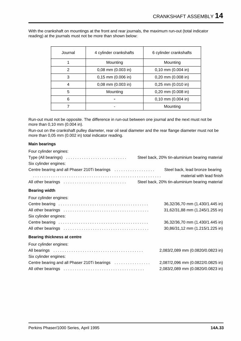
CRANKSHAFT ASSEMBLY 14
With the crankshaft on mountings at the front and rear journals, the maximum run-out (total indicatorreading) at the journals must not be more than shown below:
Journal 4 cylinder crankshafts 6 cylinder crankshafts
1 Mounting Mounting
2 0,08 mm (0.003 in) 0,10 mm (0.004 in)
3 0,15 mm (0.006 in) 0,20 mm (0.008 in)
4 0,08 mm (0.003 in) 0,25 mm (0.010 in)
5 Mounting 0,20 mm (0.008 in)
6 > 0,10 mm (0.004 in)
7 - Mounting
Run-out must not be opposite. The difference in run-out between one journal and the next must not bemore than 0,10 mm (0.004 in).
Run-out on the crankshaft pulley diameter, rear oil seal diameter and the rear flange diameter must not bemore than 0,05 mm (0.002 in) total indicator reading.
Main bearings
Four cylinder engines:
Type (All bearings) . . . . . . . . . . . . . . . . . . . . . . . . . . . Steel back, 20% tin-aluminium bearing material
Six cylinder engines:
Centre bearing and all Phaser 210Ti bearings . . . . . . . . . . . . . . . . . . Steel back, lead bronze bearing
. . . . . . . . . . . . . . . . . . . . . . . . . . . . . . . . . . . . . . . . . . . . . . . . . . . . . . . . . material with lead finish
All other bearings . . . . . . . . . . . . . . . . . . . . . . . . . . . . Steel back, 20% tin-aluminium bearing material
Bearing width
Four cylinder engines:
Centre bearing . . . . . . . . . . . . . . . . . . . . . . . . . . . . . . . . . . . . . . . . 36,32/36,70 mm (1.430/1.445 in)
All other bearings . . . . . . . . . . . . . . . . . . . . . . . . . . . . . . . . . . . . . . 31,62/31,88 mm (1.245/1.255 in)
Six cylinder engines:
Centre bearing . . . . . . . . . . . . . . . . . . . . . . . . . . . . . . . . . . . . . . . . 36,32/36,70 mm (1.430/1.445 in)
All other bearings . . . . . . . . . . . . . . . . . . . . . . . . . . . . . . . . . . . . . . 30,86/31,12 mm (1.215/1.225 in)
Bearing thickness at centre
Four cylinder engines:
All bearings . . . . . . . . . . . . . . . . . . . . . . . . . . . . . . . . . . . . . . . . 2,083/2,089 mm (0.0820/0.0823 in)
Six cylinder engines:
Centre bearing and all Phaser 210Ti bearings . . . . . . . . . . . . . . . . 2,087/2,096 mm (0.0822/0.0825 in)
All other bearings . . . . . . . . . . . . . . . . . . . . . . . . . . . . . . . . . . . . 2,083/2,089 mm (0.0820/0.0823 in)
Perkins Phaser/1000 Series, April 1995 14A.33
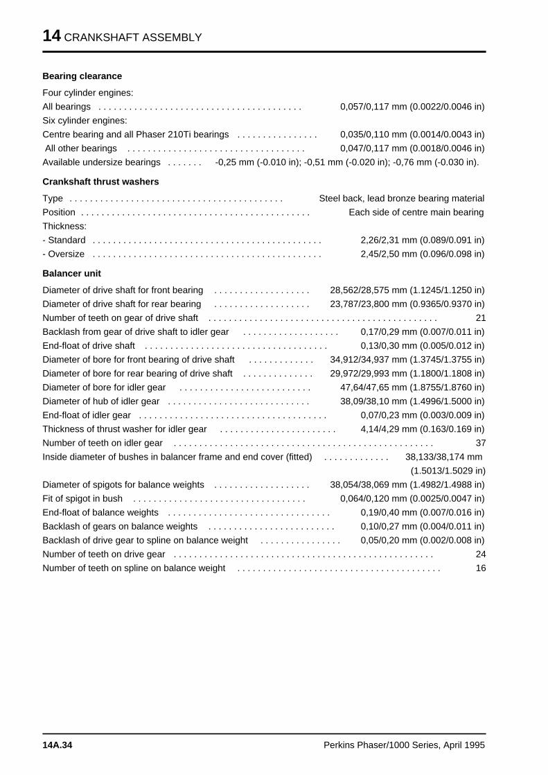
14 CRANKSHAFT ASSEMBLY
Bearing clearance
Four cylinder engines:
All bearings . . . . . . . . . . . . . . . . . . . . . . . . . . . . . . . . . . . . . . . . 0,057/0,117 mm (0.0022/0.0046 in)
Six cylinder engines:
Centre bearing and all Phaser 210Ti bearings . . . . . . . . . . . . . . . . 0,035/0,110 mm (0.0014/0.0043 in)
All other bearings . . . . . . . . . . . . . . . . . . . . . . . . . . . . . . . . . . . 0,047/0,117 mm (0.0018/0.0046 in)
Available undersize bearings . . . . . . . -0,25 mm (-0.010 in); -0,51 mm (-0.020 in); -0,76 mm (-0.030 in).
Crankshaft thrust washers
Type . . . . . . . . . . . . . . . . . . . . . . . . . . . . . . . . . . . . . . . . . . Steel back, lead bronze bearing material
Position . . . . . . . . . . . . . . . . . . . . . . . . . . . . . . . . . . . . . . . . . . . . . Each side of centre main bearing
Thickness:
- Standard . . . . . . . . . . . . . . . . . . . . . . . . . . . . . . . . . . . . . . . . . . . . . 2,26/2,31 mm (0.089/0.091 in)
- Oversize . . . . . . . . . . . . . . . . . . . . . . . . . . . . . . . . . . . . . . . . . . . . . 2,45/2,50 mm (0.096/0.098 in)
Balancer unit
Diameter of drive shaft for front bearing . . . . . . . . . . . . . . . . . . . 28,562/28,575 mm (1.1245/1.1250 in)
Diameter of drive shaft for rear bearing . . . . . . . . . . . . . . . . . . . 23,787/23,800 mm (0.9365/0.9370 in)
Number of teeth on gear of drive shaft . . . . . . . . . . . . . . . . . . . . . . . . . . . . . . . . . . . . . . . . . . . . . 21
Backlash from gear of drive shaft to idler gear . . . . . . . . . . . . . . . . . . . 0,17/0,29 mm (0.007/0.011 in)
End-float of drive shaft . . . . . . . . . . . . . . . . . . . . . . . . . . . . . . . . . . . . 0,13/0,30 mm (0.005/0.012 in)
Diameter of bore for front bearing of drive shaft . . . . . . . . . . . . . 34,912/34,937 mm (1.3745/1.3755 in)
Diameter of bore for rear bearing of drive shaft . . . . . . . . . . . . . . 29,972/29,993 mm (1.1800/1.1808 in)
Diameter of bore for idler gear . . . . . . . . . . . . . . . . . . . . . . . . . . 47,64/47,65 mm (1.8755/1.8760 in)
Diameter of hub of idler gear . . . . . . . . . . . . . . . . . . . . . . . . . . . . 38,09/38,10 mm (1.4996/1.5000 in)
End-float of idler gear . . . . . . . . . . . . . . . . . . . . . . . . . . . . . . . . . . . . . 0,07/0,23 mm (0.003/0.009 in)
Thickness of thrust washer for idler gear . . . . . . . . . . . . . . . . . . . . . . . 4,14/4,29 mm (0.163/0.169 in)
Number of teeth on idler gear . . . . . . . . . . . . . . . . . . . . . . . . . . . . . . . . . . . . . . . . . . . . . . . . . . . 37
Inside diameter of bushes in balancer frame and end cover (fitted) . . . . . . . . . . . . . 38,133/38,174 mm
(1.5013/1.5029 in)
Diameter of spigots for balance weights . . . . . . . . . . . . . . . . . . . 38,054/38,069 mm (1.4982/1.4988 in)
Fit of spigot in bush . . . . . . . . . . . . . . . . . . . . . . . . . . . . . . . . . . 0,064/0,120 mm (0.0025/0.0047 in)
End-float of balance weights . . . . . . . . . . . . . . . . . . . . . . . . . . . . . . . . 0,19/0,40 mm (0.007/0.016 in)
Backlash of gears on balance weights . . . . . . . . . . . . . . . . . . . . . . . . . 0,10/0,27 mm (0.004/0.011 in)
Backlash of drive gear to spline on balance weight . . . . . . . . . . . . . . . . 0,05/0,20 mm (0.002/0.008 in)
Number of teeth on drive gear . . . . . . . . . . . . . . . . . . . . . . . . . . . . . . . . . . . . . . . . . . . . . . . . . . . 24
Number of teeth on spline on balance weight . . . . . . . . . . . . . . . . . . . . . . . . . . . . . . . . . . . . . . . . 16
14A.34 Perkins Phaser/1000 Series, April 1995
TIMING CASE AND DRIVE ASSEMBLY 15
Timing case and drive assembl y 15
General descriptio n . . . . . . . . . . . . . . . . . . . . . . . . . . . . . . . . . . . . . . . . . 15A.02
Timing case cover
15A-01 To remove and to fit . . . . . . . . . . . . . . . . . . . . . . . . . . . . . . . . . 15A.03
Front oil seal
15A-02 To remove and to fit . . . . . . . . . . . . . . . . . . . . . . . . . . . . . . . . . 15A.04
Idler gear and hub
15A-03A To remove and to fit . . . . . . . . . . . . . . . . . . . . . . . . . . . . . . . . . 15A.06
Compressor idler gear (Bendix)
15A-03B To remove and to fit . . . . . . . . . . . . . . . . . . . . . . . . . . . . . . . . . 15A.09
Fuel pump gear
15A-04 To remove and to fit . . . . . . . . . . . . . . . . . . . . . . . . . . . . . . . . . 15A.11
Camshaft gear
15A-05 To remove and to fit . . . . . . . . . . . . . . . . . . . . . . . . . . . . . . . . . 15A.13
Crankshaft gear
15A-06 To remove and to fit . . . . . . . . . . . . . . . . . . . . . . . . . . . . . . . . . 15A.15
Timing case
15A-07 To remove and to fit . . . . . . . . . . . . . . . . . . . . . . . . . . . . . . . . . 15A.16
Camshaft and tappets
15A-08 To remove and to fit . . . . . . . . . . . . . . . . . . . . . . . . . . . . . . . . . 15A.19
Data and dimension s . . . . . . . . . . . . . . . . . . . . . . . . . . . . . . . . . . . . . . . 15A.21
Perkins Phaser/1000 Series, April 1995 15A.01
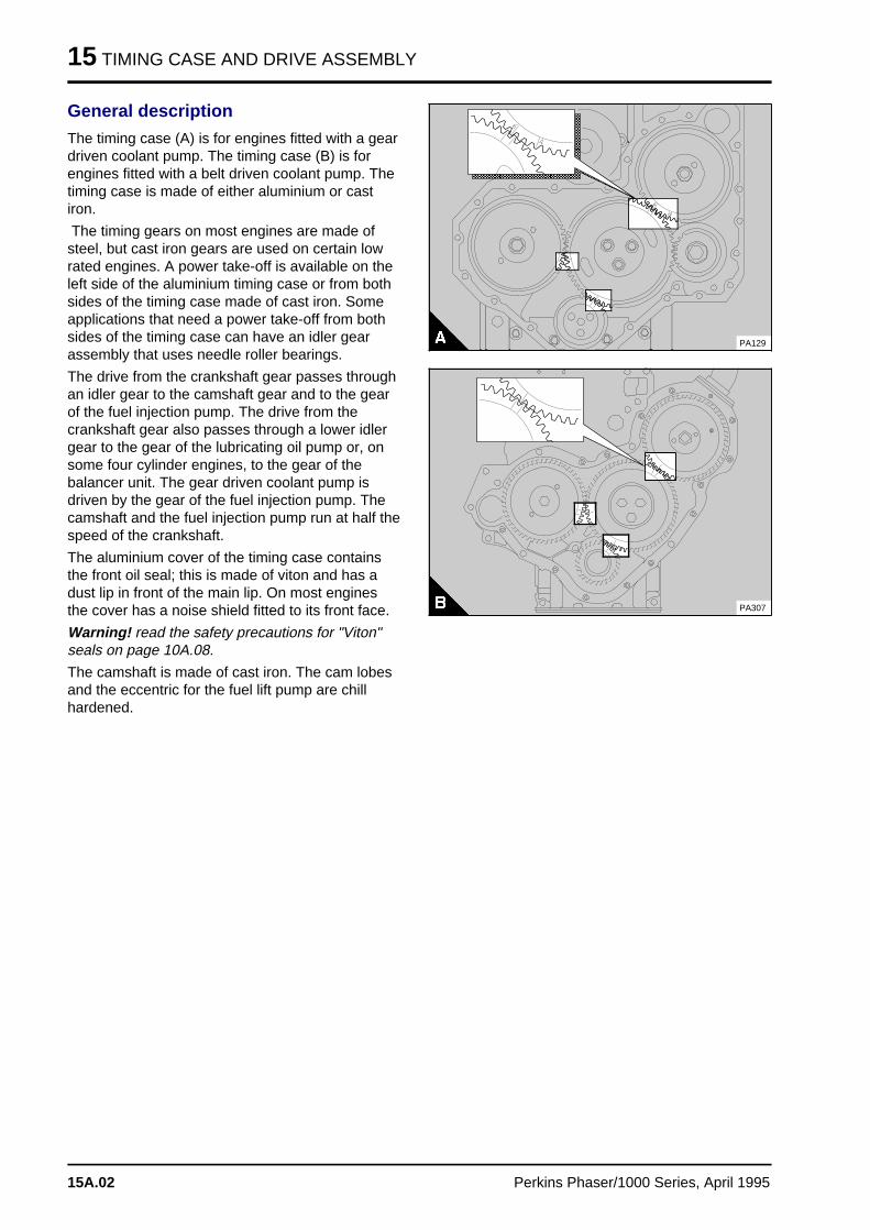
15 TIMING CASE AND DRIVE ASSEMBLY
General description
The timing case (A) is for engines fitted with a geardriven coolant pump. The timing case (B) is forengines fitted with a belt driven coolant pump. Thetiming case is made of either aluminium or castiron.
The timing gears on most engines are made ofsteel, but cast iron gears are used on certain lowrated engines. A power take-off is available on theleft side of the aluminium timing case or from bothsides of the timing case made of cast iron. Someapplications that need a power take-off from bothsides of the timing case can have an idler gearassembly that uses needle roller bearings.
The drive from the crankshaft gear passes throughan idler gear to the camshaft gear and to the gearof the fuel injection pump. The drive from thecrankshaft gear also passes through a lower idlergear to the gear of the lubricating oil pump or, onsome four cylinder engines, to the gear of thebalancer unit. The gear driven coolant pump isdriven by the gear of the fuel injection pump. Thecamshaft and the fuel injection pump run at half thespeed of the crankshaft.
The aluminium cover of the timing case containsthe front oil seal; this is made of viton and has adust lip in front of the main lip. On most enginesthe cover has a noise shield fitted to its front face.
Warning! read the safety precautions for "Viton"seals on page 10A.08.
The camshaft is made of cast iron. The cam lobesand the eccentric for the fuel lift pump are chillhardened.
a a a a a a a a a a a a a a a a a a a a a a a a a a a a a a
a a a a a a a a a a a a a a a a a a a a a a a a a a a a a a
a a a a a a a a a a a a a a a a a a a a a a a a a a a a a a
a a a a a a a a a a a a a a a a a a a a a a a a a a a a a a
a a a a a a a a a a a a a a a a a a a a a a a a a a a a a a
a a a a a a a a a a a a a a a a a a a a a a a a a a a a a a
a a a a a a a a a a a a a a a a a a a a a a a a a a a a a a
a a a a a a a a a a a a a a a a a a a a a a a a a a a a a a
a a a a a a a a a a a a a a a a a a a a a a a a a a a a a a
a a a a a a a a a a a a a a a a a a a a a a a a a a a a a a
a a a a a a a a a a a a a a a a a a a a a a a a a a a a a a
a a a a a a a a a a a a a a a a a a a a a a a a a a a a a a
a a a a a a a a a a a a a a a a a a a a a a a a a a a a a a
a a a a a a a a a a a a a a a a a a a a a a a a a a a a a a
a a a a a a a a a a a a a a a a a a a a a a a a a a a a a a
a a a a a a a a a a a a a a a a a a a a a a a a a a a a a a
PA129
PA307
15A.02 Perkins Phaser/1000 Series, April 1995
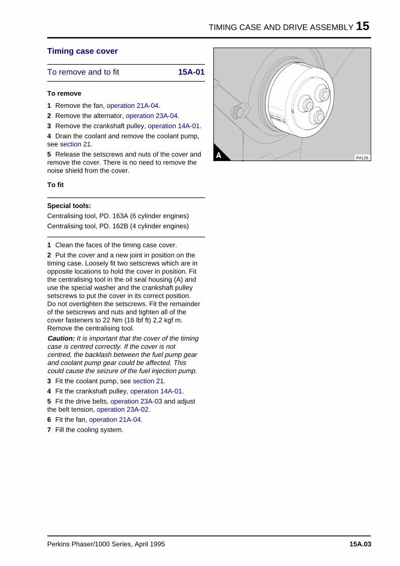
TIMING CASE AND DRIVE ASSEMBLY 15
Timing case cover
To remove and to fit 15A-01
To remove
1 Remove the fan, operation 21A-04.
2 Remove the alternator, operation 23A-04.
3 Remove the crankshaft pulley, operation 14A-01.
4 Drain the coolant and remove the coolant pump,see section 21.
5 Release the setscrews and nuts of the cover andremove the cover. There is no need to remove thenoise shield from the cover.
To fit
Special tools:
Centralising tool, PD. 163A (6 cylinder engines)
Centralising tool, PD. 162B (4 cylinder engines)
1 Clean the faces of the timing case cover.
2 Put the cover and a new joint in position on thetiming case. Loosely fit two setscrews which are inopposite locations to hold the cover in position. Fitthe centralising tool in the oil seal housing (A) anduse the special washer and the crankshaft pulleysetscrews to put the cover in its correct position.Do not overtighten the setscrews. Fit the remainderof the setscrews and nuts and tighten all of thecover fasteners to 22 Nm (16 lbf ft) 2,2 kgf m.Remove the centralising tool.
Caution: It is important that the cover of the timingcase is centred correctly. If the cover is notcentred, the backlash between the fuel pump gearand coolant pump gear could be affected. Thiscould cause the seizure of the fuel injection pump.
3 Fit the coolant pump, see section 21.
4 Fit the crankshaft pulley, operation 14A-01.
5 Fit the drive belts, operation 23A-03 and adjustthe belt tension, operation 23A-02.
6 Fit the fan, operation 21A-04.
7 Fill the cooling system.
PA126
Perkins Phaser/1000 Series, April 1995 15A.03
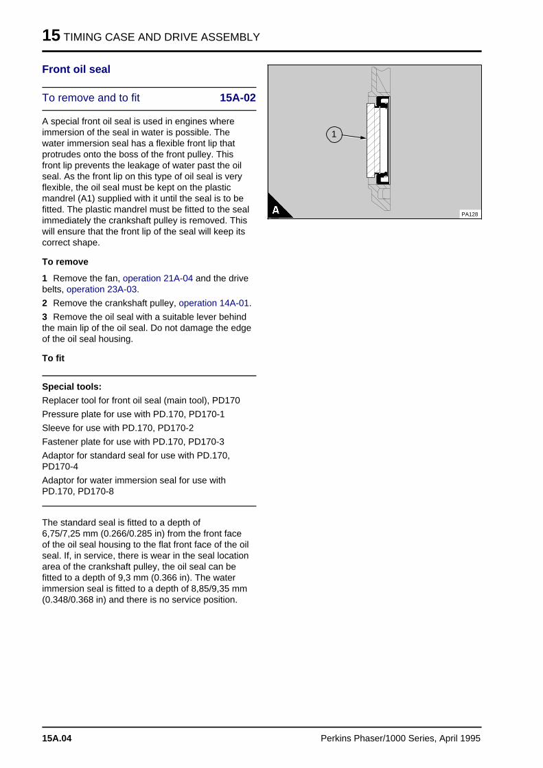
15 TIMING CASE AND DRIVE ASSEMBLY
Front oil seal
To remove and to fit 15A-02
A special front oil seal is used in engines whereimmersion of the seal in water is possible. Thewater immersion seal has a flexible front lip thatprotrudes onto the boss of the front pulley. Thisfront lip prevents the leakage of water past the oilseal. As the front lip on this type of oil seal is veryflexible, the oil seal must be kept on the plasticmandrel (A1) supplied with it until the seal is to befitted. The plastic mandrel must be fitted to the sealimmediately the crankshaft pulley is removed. Thiswill ensure that the front lip of the seal will keep itscorrect shape.
To remove
1 Remove the fan, operation 21A-04 and the drivebelts, operation 23A-03.
2 Remove the crankshaft pulley, operation 14A-01.
3 Remove the oil seal with a suitable lever behindthe main lip of the oil seal. Do not damage the edgeof the oil seal housing.
To fit
Special tools:
Replacer tool for front oil seal (main tool), PD170
Pressure plate for use with PD.170, PD170-1
Sleeve for use with PD.170, PD170-2
Fastener plate for use with PD.170, PD170-3
Adaptor for standard seal for use with PD.170,PD170-4
Adaptor for water immersion seal for use withPD.170, PD170-8
The standard seal is fitted to a depth of 6,75/7,25 mm (0.266/0.285 in) from the front faceof the oil seal housing to the flat front face of the oilseal. If, in service, there is wear in the seal locationarea of the crankshaft pulley, the oil seal can befitted to a depth of 9,3 mm (0.366 in). The waterimmersion seal is fitted to a depth of 8,85/9,35 mm(0.348/0.368 in) and there is no service position.
a a a a a a
a a a a a a
a a a a a a
a a a a a a
a a a a a a
a a a a a a
a a a a a a
a a a a a a
a a a a a a
a a a a a a
a a a a a a
a a a a a a
a a a a a a
a a a a a a
a a a a a a
a a a a a a
a a a a a a
a a a a a a
a a a a a a
a a a a a a
a a a a a a
a a a a a a
a a a a a a
a a a a a a
a a a a a a
a a a a a a
a a a a a a
a a a
a a a
a a a
a a a
1
PA128
15A.04 Perkins Phaser/1000 Series, April 1995
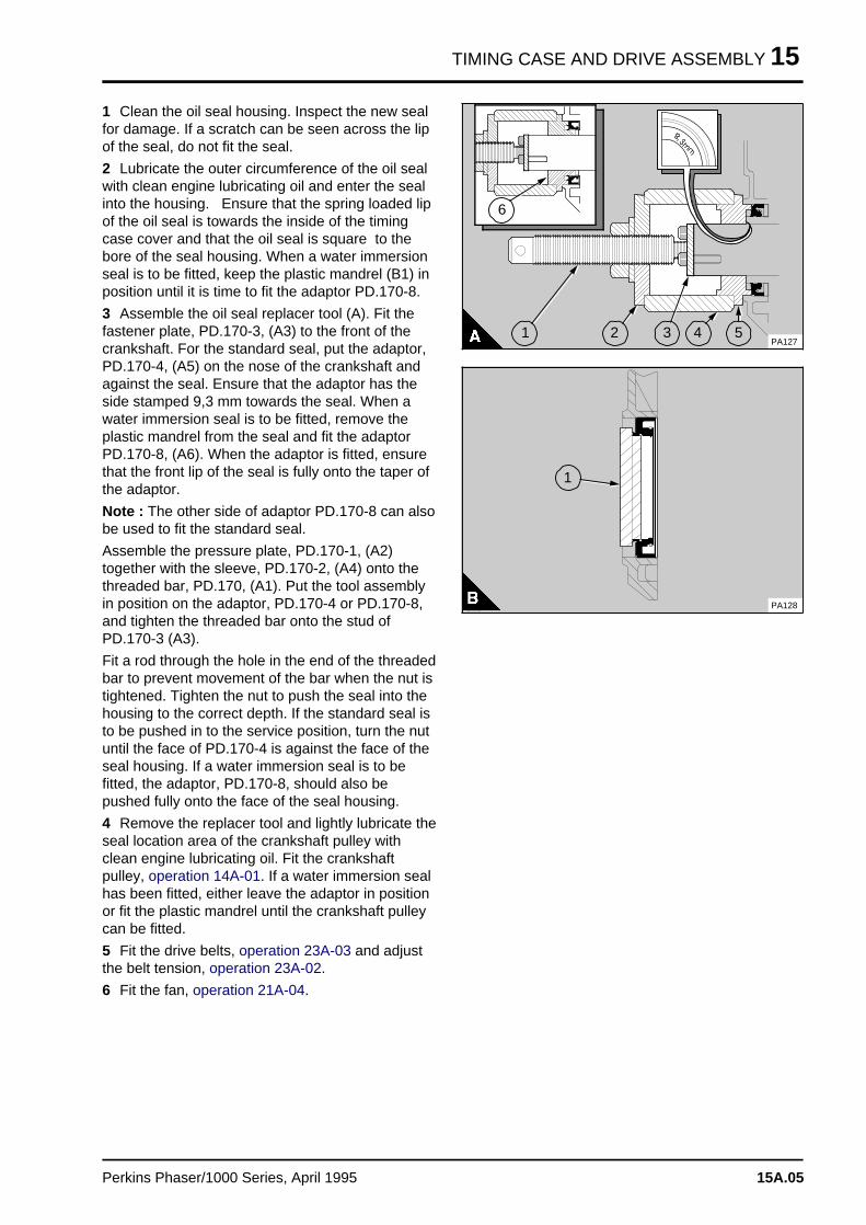
TIMING CASE AND DRIVE ASSEMBLY 15
1 Clean the oil seal housing. Inspect the new sealfor damage. If a scratch can be seen across the lipof the seal, do not fit the seal.
2 Lubricate the outer circumference of the oil sealwith clean engine lubricating oil and enter the sealinto the housing. Ensure that the spring loaded lipof the oil seal is towards the inside of the timingcase cover and that the oil seal is square to thebore of the seal housing. When a water immersionseal is to be fitted, keep the plastic mandrel (B1) inposition until it is time to fit the adaptor PD.170-8.
3 Assemble the oil seal replacer tool (A). Fit thefastener plate, PD.170-3, (A3) to the front of thecrankshaft. For the standard seal, put the adaptor,PD.170-4, (A5) on the nose of the crankshaft andagainst the seal. Ensure that the adaptor has theside stamped 9,3 mm towards the seal. When awater immersion seal is to be fitted, remove theplastic mandrel from the seal and fit the adaptorPD.170-8, (A6). When the adaptor is fitted, ensurethat the front lip of the seal is fully onto the taper ofthe adaptor.
Note : The other side of adaptor PD.170-8 can alsobe used to fit the standard seal.
Assemble the pressure plate, PD.170-1, (A2)together with the sleeve, PD.170-2, (A4) onto thethreaded bar, PD.170, (A1). Put the tool assemblyin position on the adaptor, PD.170-4 or PD.170-8,and tighten the threaded bar onto the stud ofPD.170-3 (A3).
Fit a rod through the hole in the end of the threadedbar to prevent movement of the bar when the nut istightened. Tighten the nut to push the seal into thehousing to the correct depth. If the standard seal isto be pushed in to the service position, turn the nutuntil the face of PD.170-4 is against the face of theseal housing. If a water immersion seal is to befitted, the adaptor, PD.170-8, should also bepushed fully onto the face of the seal housing.
4 Remove the replacer tool and lightly lubricate theseal location area of the crankshaft pulley withclean engine lubricating oil. Fit the crankshaftpulley, operation 14A-01. If a water immersion sealhas been fitted, either leave the adaptor in positionor fit the plastic mandrel until the crankshaft pulleycan be fitted.
5 Fit the drive belts, operation 23A-03 and adjustthe belt tension, operation 23A-02.
6 Fit the fan, operation 21A-04.
a a a
a a a
a a a
a aa aa aa a
5
a aa aa aa a
4
a a a
a a a
a a a
a a a
3
a aa aa aa a
2
a aa aa aa a
1
a aa aa aa a
6
PA127
a a a
a a a
a a a
a a a
a a a a a
a a a a a
a a a a a
a a a a a
a a a a a
a a a a a
a a a a a
a a a a a
a a a a a
a a a a a
a a a a a
a a a a a
a a a a a
a a a a a
a a a a a
a a a a a
a a a a a
a a a a a
a a a a a
a a a a a
a a a a a
a a a a a
a a a a a
a a a a a
a a a a a
a a a a a
a a a
a a a
a a a
a a a
1
PA128
Perkins Phaser/1000 Series, April 1995 15A.05
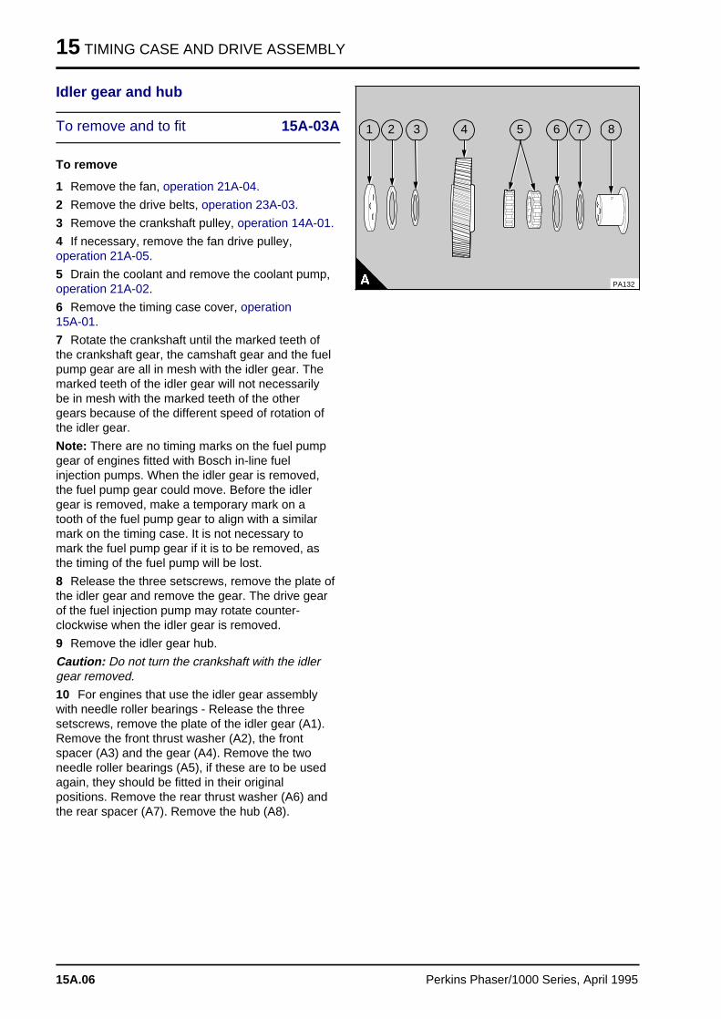
15 TIMING CASE AND DRIVE ASSEMBLY
Idler gear and hub
To remove and to fit 15A-03A
To remove
1 Remove the fan, operation 21A-04.
2 Remove the drive belts, operation 23A-03.
3 Remove the crankshaft pulley, operation 14A-01.
4 If necessary, remove the fan drive pulley,operation 21A-05.
5 Drain the coolant and remove the coolant pump,operation 21A-02.
6 Remove the timing case cover, operation 15A-01.
7 Rotate the crankshaft until the marked teeth ofthe crankshaft gear, the camshaft gear and the fuelpump gear are all in mesh with the idler gear. Themarked teeth of the idler gear will not necessarilybe in mesh with the marked teeth of the othergears because of the different speed of rotation ofthe idler gear.
Note: There are no timing marks on the fuel pumpgear of engines fitted with Bosch in-line fuelinjection pumps. When the idler gear is removed,the fuel pump gear could move. Before the idlergear is removed, make a temporary mark on atooth of the fuel pump gear to align with a similarmark on the timing case. It is not necessary tomark the fuel pump gear if it is to be removed, asthe timing of the fuel pump will be lost.
8 Release the three setscrews, remove the plate ofthe idler gear and remove the gear. The drive gearof the fuel injection pump may rotate counter-clockwise when the idler gear is removed.
9 Remove the idler gear hub.
Caution: Do not turn the crankshaft with the idlergear removed.
10 For engines that use the idler gear assemblywith needle roller bearings - Release the threesetscrews, remove the plate of the idler gear (A1).Remove the front thrust washer (A2), the frontspacer (A3) and the gear (A4). Remove the twoneedle roller bearings (A5), if these are to be usedagain, they should be fitted in their originalpositions. Remove the rear thrust washer (A6) andthe rear spacer (A7). Remove the hub (A8).
a a a
a a a
a a a
a a a
7
a a a
a a a
a a a
a a a
6
a a a
a a a
a a a
a a a
5
a a a
a a a
a a a
a a a
8
a a a
a a a
a a a
a a a
4
a a a
a a a
a a a
a a a
3
a aa aa aa a
2
a a a
a a a
a a a
a a a
1
PA132
15A.06 Perkins Phaser/1000 Series, April 1995
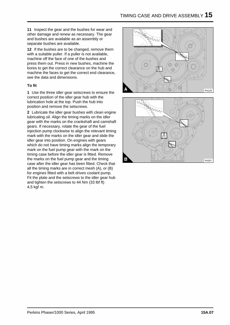
TIMING CASE AND DRIVE ASSEMBLY 15
11 Inspect the gear and the bushes for wear andother damage and renew as necessary. The gearand bushes are available as an assembly orseparate bushes are available.
12 If the bushes are to be changed, remove themwith a suitable puller. If a puller is not available,machine off the face of one of the bushes andpress them out. Press in new bushes, machine thebores to get the correct clearance on the hub andmachine the faces to get the correct end clearance,see the data and dimensions.
To fit
1 Use the three idler gear setscrews to ensure thecorrect position of the idler gear hub with thelubrication hole at the top. Push the hub intoposition and remove the setscrews.
2 Lubricate the idler gear bushes with clean enginelubricating oil. Align the timing marks on the idlergear with the marks on the crankshaft and camshaftgears. If necessary, rotate the gear of the fuelinjection pump clockwise to align the relevant timingmark with the marks on the idler gear and slide theidler gear into position. On engines with gearswhich do not have timing marks align the temporarymark on the fuel pump gear with the mark on thetiming case before the idler gear is fitted. Removethe marks on the fuel pump gear and the timingcase after the idler gear has been fitted. Check thatall the timing marks are in correct mesh (A), or (B)for engines fitted with a belt driven coolant pump.Fit the plate and the setscrews to the idler gear huband tighten the setscrews to 44 Nm (33 lbf ft) 4,5 kgf m.
a a a a a a a a a a a a a a a a a a a a a a a a a a a a a a
a a a a a a a a a a a a a a a a a a a a a a a a a a a a a a
a a a a a a a a a a a a a a a a a a a a a a a a a a a a a a
a a a a a a a a a a a a a a a a a a a a a a a a a a a a a a
a a a a a a a a a a a a a a a a a a a a a a a a a a a a a a
a a a a a a a a a a a a a a a a a a a a a a a a a a a a a a
a a a a a a a a a a a a a a a a a a a a a a a a a a a a a a
a a a a a a a a a a a a a a a a a a a a a a a a a a a a a a
a a a a a a a a a a a a a a a a a a a a a a a a a a a a a a
a a a a a a a a a a a a a a a a a a a a a a a a a a a a a a
a a a a a a a a a a a a a a a a a a a a a a a a a a a a a a
a a a a a a a a a a a a a a a a a a a a a a a a a a a a a a
a a a a a a a a a a a a a a a a a a a a a a a a a a a a a a
a a a a a a a a a a a a a a a a a a a a a a a a a a a a a a
a a a a a a a a a a a a a a a a a a a a a a a a a a a a a a
a a a a a a a a a a a a a a a a a a a a a a a a a a a a a a
PA129
PA307
Perkins Phaser/1000 Series, April 1995 15A.07
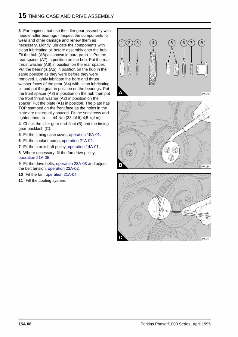
15 TIMING CASE AND DRIVE ASSEMBLY
3 For engines that use the idler gear assembly withneedle roller bearings - Inspect the components forwear and other damage and renew them asnecessary. Lightly lubricate the components withclean lubricating oil before assembly onto the hub.Fit the hub (A8) as shown in paragraph 1. Put therear spacer (A7) in position on the hub. Put the rearthrust washer (A6) in position on the rear spacer.Put the bearings (A5) in position on the hub in thesame position as they were before they wereremoved. Lightly lubricate the bore and thrustwasher faces of the gear (A4) with clean lubricatingoil and put the gear in position on the bearings. Putthe front spacer (A3) in position on the hub then putthe front thrust washer (A2) in position on thespacer. Put the plate (A1) in position. The plate hasTOP stamped on the front face as the holes in theplate are not equally spaced. Fit the setscrews andtighten them to 44 Nm (33 lbf ft) 4,5 kgf m).
4 Check the idler gear end-float (B) and the timinggear backlash (C).
5 Fit the timing case cover, operation 15A-01.
6 Fit the coolant pump, operation 21A-02.
7 Fit the crankshaft pulley, operation 14A-01.
8 Where necessary, fit the fan drive pulley,operation 21A-05.
9 Fit the drive belts, operation 23A-03 and adjustthe belt tension, operation 23A-02.
10 Fit the fan, operation 21A-04.
11 Fill the cooling system.
a a a
a a a
a a a
a a a
7
a a a
a a a
a a a
a a a
6
a a a
a a a
a a a
a a a
5
a a a
a a a
a a a
a a a
8
a a a
a a a
a a a
a a a
4
a a a
a a a
a a a
a a a
3
a aa aa aa a
2
a a a
a a a
a a a
a a a
1
PA132
PA130
PA131
15A.08 Perkins Phaser/1000 Series, April 1995
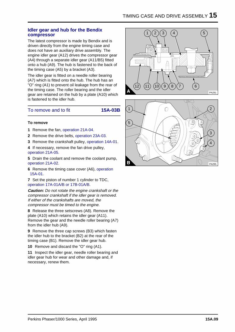
TIMING CASE AND DRIVE ASSEMBLY 15
Idler gear and hub for the BendixcompressorThe latest compressor is made by Bendix and isdriven directly from the engine timing case anddoes not have an auxiliary drive assembly. Theengine idler gear (A12) drives the compressor gear(A4) through a separate idler gear (A11/B5) fittedonto a hub (A9). The hub is fastened to the back ofthe timing case (A5) by a bracket (A3).
The idler gear is fitted on a needle roller bearing(A7) which is fitted onto the hub. The hub has an"O" ring (A1) to prevent oil leakage from the rear ofthe timing case. The roller bearing and the idlergear are retained on the hub by a plate (A10) whichis fastened to the idler hub.
To remove and to fit 15A-03B
To remove
1 Remove the fan, operation 21A-04.
2 Remove the drive belts, operation 23A-03.
3 Remove the crankshaft pulley, operation 14A-01.
4 If necessary, remove the fan drive pulley,operation 21A-05.
5 Drain the coolant and remove the coolant pump,operation 21A-02.
6 Remove the timing case cover (A6), operation 15A-01.
7 Set the piston of number 1 cylinder to TDC,operation 17A-01A/B or 17B-01A/B.
Caution: Do not rotate the engine crankshaft or thecompressor crankshaft if the idler gear is removed.If either of the crankshafts are moved, thecompressor must be timed to the engine.
8 Release the three setscrews (A8). Remove theplate (A10) which retains the idler gear (A11).Remove the gear and the needle roller bearing (A7)from the idler hub (A9).
9 Remove the three cap screws (B3) which fastenthe idler hub to the bracket (B2) at the rear of thetiming case (B1). Remove the idler gear hub.
10 Remove and discard the "O" ring (A1).
11 Inspect the idler gear, needle roller bearing andidler gear hub for wear and other damage and, ifnecessary, renew them.
a a a
a a a
a a a
a a a
5
a a a a
a a a a
a a a a
a a a a
11
a a a a a
a a a a a
a a a a a
a a a a a
10
a a a
a a a
a a a
a a a
8
a a a
a a a
a a a
a a a
9
a a a
a a a
a a a
a a a
7
a aa aa aa a
6
a a a a
a a a a
a a a a
a a a a
12
a a a
a a a
a a a
a a a
4
a a a
a a a
a a a
a a a
3
a a a
a a a
a a a
a a a
2
a aa aa aa a
1
PA291
PA295
a aa aa aa a
1
a aa aa aa aa a
5
a aa aa aa a
2
a aa aa aa a
3
a aa aa aa a
4
Perkins Phaser/1000 Series, April 1995 15A.09
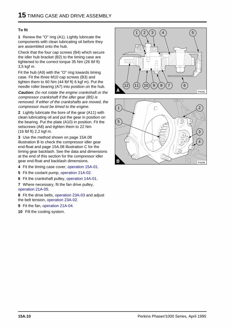
15 TIMING CASE AND DRIVE ASSEMBLY
To fit
1 Renew the "O" ring (A1). Lightly lubricate thecomponents with clean lubricating oil before theyare assembled onto the hub.
Check that the four cap screws (B4) which securethe idler hub bracket (B2) to the timing case aretightened to the correct torque 35 Nm (26 lbf ft) 3,5 kgf m.
Fit the hub (A9) with the "O" ring towards timingcase. Fit the three M10 cap screws (B3) andtighten them to 60 Nm (44 lbf ft) 6 kgf m). Put theneedle roller bearing (A7) into position on the hub.
Caution: Do not rotate the engine crankshaft or thecompressor crankshaft if the idler gear (B5) isremoved. If either of the crankshafts are moved, thecompressor must be timed to the engine.
2 Lightly lubricate the bore of the gear (A11) withclean lubricating oil and put the gear in position onthe bearing. Put the plate (A10) in position. Fit thesetscrews (A8) and tighten them to 22 Nm (16 lbf ft) 2,2 kgf m.
3 Use the method shown on page 15A.08illustration B to check the compressor idler gearend-float and page 15A.08 illustration C for thetiming gear backlash. See the data and dimensionsat the end of this section for the compressor idlergear end-float and backlash dimensions.
4 Fit the timing case cover, operation 15A-01.
5 Fit the coolant pump, operation 21A-02.
6 Fit the crankshaft pulley, operation 14A-01.
7 Where necessary, fit the fan drive pulley,operation 21A-05.
8 Fit the drive belts, operation 23A-03 and adjustthe belt tension, operation 23A-02.
9 Fit the fan, operation 21A-04.
10 Fill the cooling system.
a a a
a a a
a a a
a a a
5
a a a a
a a a a
a a a a
a a a a
11
a a a a
a a a a
a a a a
a a a a
10
a a a
a a a
a a a
a a a
8
a a a
a a a
a a a
a a a
9
a a a
a a a
a a a
a a a
7
a a a
a a a
a a a
a a a
6
a a a a
a a a a
a a a a
a a a a
12
a a a
a a a
a a a
a a a
4
a a a
a a a
a a a
a a a
3
a aa aa aa a
2
a aa aa aa a
1
PA291
PA295
a aa aa aa a
1
a aa aa aa aa a
5
a a a
a a a
a a a
a a a
2
a a a
a a a
a a a
a a a
3
a a a
a a a
a a a
a a a
4
15A.10 Perkins Phaser/1000 Series, April 1995
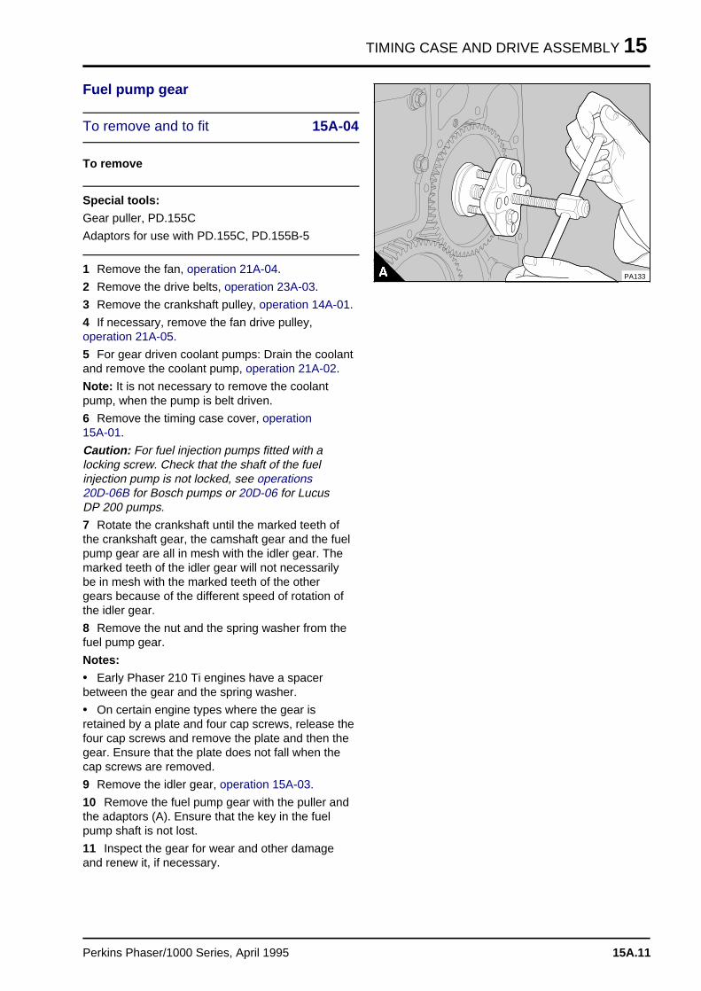
TIMING CASE AND DRIVE ASSEMBLY 15
Fuel pump gear
To remove and to fit 15A-04
To remove
Special tools:
Gear puller, PD.155C
Adaptors for use with PD.155C, PD.155B-5
1 Remove the fan, operation 21A-04.
2 Remove the drive belts, operation 23A-03.
3 Remove the crankshaft pulley, operation 14A-01.
4 If necessary, remove the fan drive pulley,operation 21A-05.
5 For gear driven coolant pumps: Drain the coolantand remove the coolant pump, operation 21A-02.
Note: It is not necessary to remove the coolantpump, when the pump is belt driven.
6 Remove the timing case cover, operation 15A-01.
Caution: For fuel injection pumps fitted with alocking screw. Check that the shaft of the fuelinjection pump is not locked, see operations 20D-06B for Bosch pumps or 20D-06 for Lucus DP 200 pumps.
7 Rotate the crankshaft until the marked teeth ofthe crankshaft gear, the camshaft gear and the fuelpump gear are all in mesh with the idler gear. Themarked teeth of the idler gear will not necessarilybe in mesh with the marked teeth of the othergears because of the different speed of rotation ofthe idler gear.
8 Remove the nut and the spring washer from thefuel pump gear.
Notes:
• Early Phaser 210 Ti engines have a spacerbetween the gear and the spring washer.
• On certain engine types where the gear isretained by a plate and four cap screws, release thefour cap screws and remove the plate and then thegear. Ensure that the plate does not fall when thecap screws are removed.
9 Remove the idler gear, operation 15A-03.
10 Remove the fuel pump gear with the puller andthe adaptors (A). Ensure that the key in the fuelpump shaft is not lost.
11 Inspect the gear for wear and other damageand renew it, if necessary.
PA133
Perkins Phaser/1000 Series, April 1995 15A.11
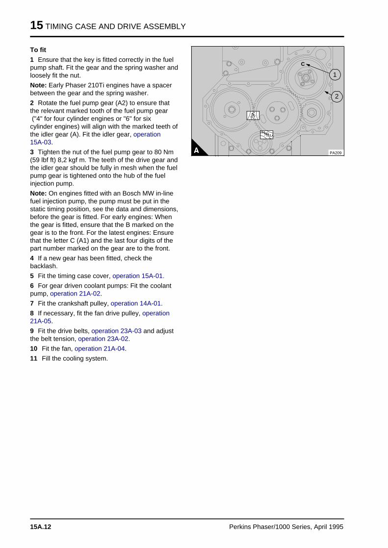
15 TIMING CASE AND DRIVE ASSEMBLY
To fit
1 Ensure that the key is fitted correctly in the fuel pump shaft. Fit the gear and the spring washer andloosely fit the nut.
Note: Early Phaser 210Ti engines have a spacerbetween the gear and the spring washer.
2 Rotate the fuel pump gear (A2) to ensure thatthe relevant marked tooth of the fuel pump gear ("4" for four cylinder engines or "6" for sixcylinder engines) will align with the marked teeth ofthe idler gear (A). Fit the idler gear, operation 15A-03.
3 Tighten the nut of the fuel pump gear to 80 Nm(59 lbf ft) 8,2 kgf m. The teeth of the drive gear andthe idler gear should be fully in mesh when the fuelpump gear is tightened onto the hub of the fuelinjection pump.
Note: On engines fitted with an Bosch MW in-linefuel injection pump, the pump must be put in thestatic timing position, see the data and dimensions,before the gear is fitted. For early engines: Whenthe gear is fitted, ensure that the B marked on thegear is to the front. For the latest engines: Ensurethat the letter C (A1) and the last four digits of thepart number marked on the gear are to the front.
4 If a new gear has been fitted, check thebacklash.
5 Fit the timing case cover, operation 15A-01.
6 For gear driven coolant pumps: Fit the coolantpump, operation 21A-02.
7 Fit the crankshaft pulley, operation 14A-01.
8 If necessary, fit the fan drive pulley, operation21A-05.
9 Fit the drive belts, operation 23A-03 and adjustthe belt tension, operation 23A-02.
10 Fit the fan, operation 21A-04.
11 Fill the cooling system.
PA209
a a a
a a a
a a a
a a a
2
a a a
a a a
a a a
a a a
1
a aa aa aa a
C
15A.12 Perkins Phaser/1000 Series, April 1995
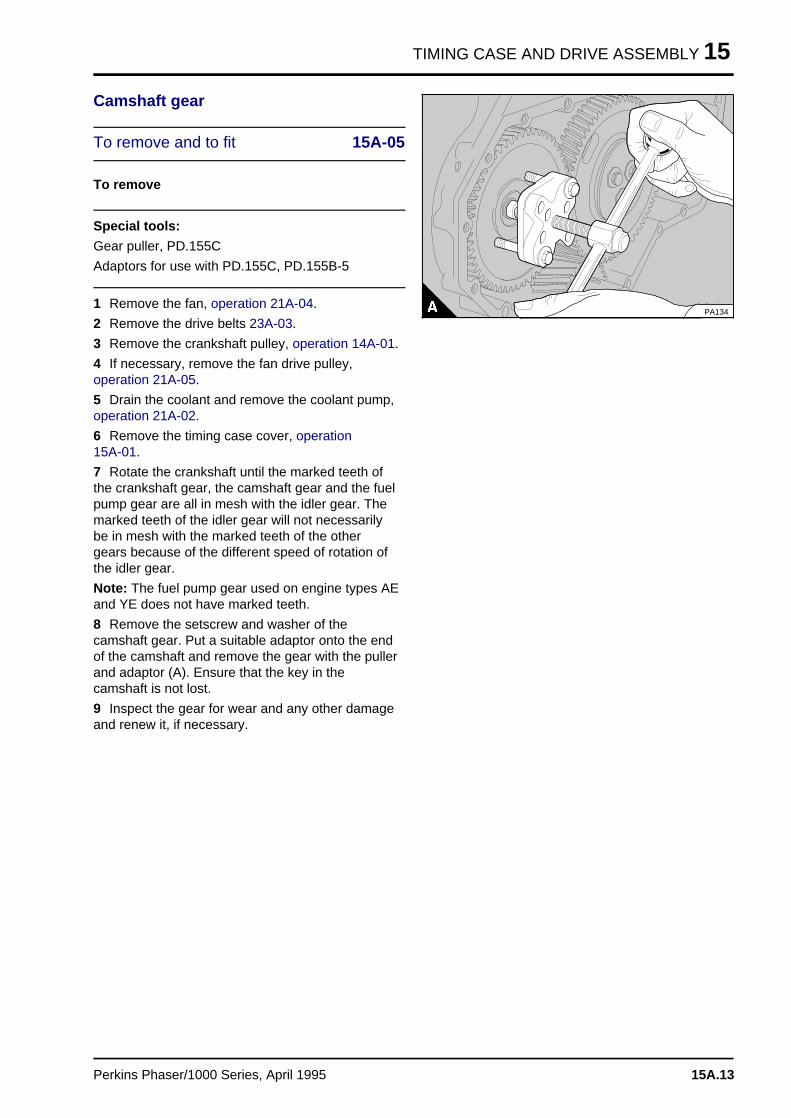
TIMING CASE AND DRIVE ASSEMBLY 15
Camshaft gear
To remove and to fit 15A-05
To remove
Special tools:
Gear puller, PD.155C
Adaptors for use with PD.155C, PD.155B-5
1 Remove the fan, operation 21A-04.
2 Remove the drive belts 23A-03.
3 Remove the crankshaft pulley, operation 14A-01.
4 If necessary, remove the fan drive pulley,operation 21A-05.
5 Drain the coolant and remove the coolant pump,operation 21A-02.
6 Remove the timing case cover, operation 15A-01.
7 Rotate the crankshaft until the marked teeth ofthe crankshaft gear, the camshaft gear and the fuelpump gear are all in mesh with the idler gear. Themarked teeth of the idler gear will not necessarilybe in mesh with the marked teeth of the othergears because of the different speed of rotation ofthe idler gear.
Note: The fuel pump gear used on engine types AEand YE does not have marked teeth.
8 Remove the setscrew and washer of thecamshaft gear. Put a suitable adaptor onto the endof the camshaft and remove the gear with the pullerand adaptor (A). Ensure that the key in thecamshaft is not lost.
9 Inspect the gear for wear and any other damageand renew it, if necessary.
PA134
Perkins Phaser/1000 Series, April 1995 15A.13
15 TIMING CASE AND DRIVE ASSEMBLY
To fit
1 Ensure that the key in the camshaft is fittedcorrectly.
2 Remove the idler gear, operation 15A-03.
3 Fit the camshaft gear to the camshaft with themarked teeth towards the front and the keywaycorrectly aligned with the key. If necessary, lightlyhit the gear with a soft face hammer to engage thekey into the keyway.
4 Fit the idler gear with the marked teeth in correctmesh, operation 15A-03. If the camshaft has to beturned and a valve hits a piston, disengage therocker assembly.
5 Fit the washer and the setscrew for the camshaftgear and tighten the setscrew to press thecamshaft gear into position. Tighten the setscrew to78 Nm (58 lbf ft) 8,0 kgf m. If a new camshaft gearhas been fitted, check the backlash.
6 Fit the timing case cover, operation 15A-01.
7 Fit the coolant pump, operation 21A-02.
8 Fit the crankshaft pulley, operation 14A-01.
9 If necessary, fit the fan drive pulley, operation21A-05.
10 Fit the drive belts, operation 23A-03 and adjustthe belt tension, operation 23A-02.
11 Fit the fan, operation 21A-04.
12 Fill the cooling system.
15A.14 Perkins Phaser/1000 Series, April 1995
TIMING CASE AND DRIVE ASSEMBLY 15
Crankshaft gear
To remove and to fit 15A-06
To remove
1 Remove the fan, operation 21A-04.
2 Remove the drive belts, operation 23A-03.
3 Remove the crankshaft pulley, operation 14A-01.
4 If necessary, remove the fan drive pulley,operation 21A-05.
5 Drain the coolant and remove the coolant pump,operation 21A-02.
6 Remove the timing case cover, operation 15A-01.
7 Rotate the crankshaft until the marked teeth ofthe crankshaft gear, the camshaft gear and the fuelpump gear are all in mesh with the idler gear. Themarked teeth of the idler gear will not necessarilybe in mesh with the marked teeth of the othergears because of the different speed of rotation ofthe idler gear.
Note: The fuel pump gear used on engine types AEand YE does not have marked teeth.
8 Remove the idler gear, operation 15A-03.
9 The crankshaft gear is a transition fit on thecrankshaft. It may slide off easily or, if it is a tightfit and the gear is to be renewed, it may benecessary to remove the crankshaft, operation 14A-08, to remove the gear safely.
To fit
1 The gear can fit easily, or it may be necessary toheat the gear before it will fit onto the crankshaft. Ifthe gear is to be heated, heat it in an oven to notmore than 180°C (226°F). If an oven is notavailable, heat it in coolant which is at its boilingpoint. Do not use a flame as this can cause localdamage. Fit the gear with the timing marks to thefront.
2 Fit the idler gear, operation 15A-03 and ensurethat all the timing marks are correctly aligned.
3 Fit the timing case cover, operation 15A-01.
4 Fit the coolant pump, operation 21A-02.
5 Fit the crankshaft pulley, operation 14A-01.
6 If necessary, fit the fan drive pulley, operation21A-05.
7 Fit the drive belts, operation 23A-03 and adjustthe belt tension, operation 23A-02.
8 Fit the fan, operation 21A-04.
9 Fill the cooling system.
Perkins Phaser/1000 Series, April 1995 15A.15
15 TIMING CASE AND DRIVE ASSEMBLY
Timing case
To remove and to fit 15A-07
Consumable products:
POWERPART Jointing compound
POWERPART Nutlock
To remove
1 Remove the fan, operation 21A-04.
2 Remove the drive belts, operation 23A-03.
3 Remove the crankshaft pulley, operation 14A-01.
4 If necessary, remove the fan drive assembly,operation 21A-05.
5 Drain the coolant and remove the coolant pump,operation 21A-02.
6 Remove the alternator together with its mountingbracket and front support plate.
7 Remove the compressor and drive assembly,operation 24A-01, if fitted.
8 Remove the timing case cover, operation 15A-01.
9 Rotate the crankshaft until the marked teeth ofthe crankshaft gear, the camshaft gear and the fuelpump gear are all in mesh with the idler gear. Themarked teeth of the idler gear will not necessarilybe in mesh with the marked teeth of the othergears because of the different speed of rotation ofthe idler gear.
Note: The fuel pump gear used on engine types AEand YE does not have marked teeth.
10 Remove the fuel injection pump, see section20.
11 Remove the idler gear, operation 15A-03 andthe camshaft gear, operation 15A-05.
12 Remove the setscrews which hold the timingcase to the cylinder block and the setscrews whichhold the sump to the bottom of the timing case.
13 Remove the timing case and the joint, do notallow the idler gear hub to fall. Ensure that thecamshaft thrust washer is not lost.
15A.16 Perkins Phaser/1000 Series, April 1995
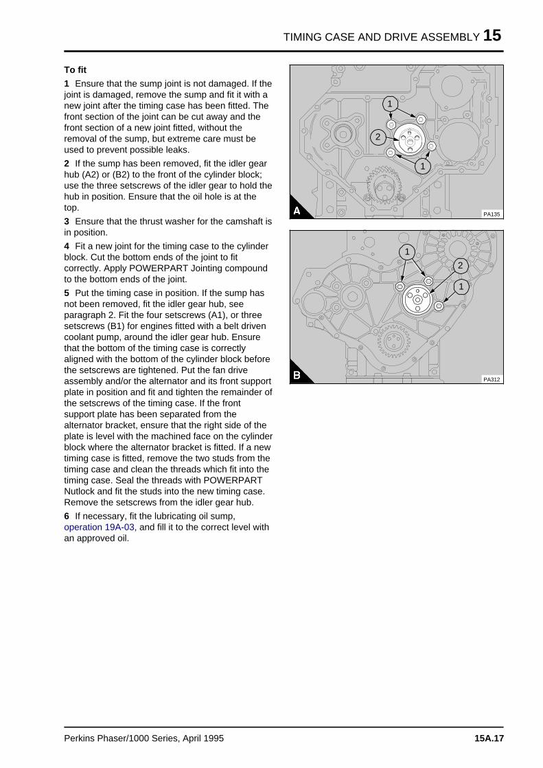
TIMING CASE AND DRIVE ASSEMBLY 15
To fit
1 Ensure that the sump joint is not damaged. If thejoint is damaged, remove the sump and fit it with anew joint after the timing case has been fitted. Thefront section of the joint can be cut away and thefront section of a new joint fitted, without theremoval of the sump, but extreme care must beused to prevent possible leaks.
2 If the sump has been removed, fit the idler gearhub (A2) or (B2) to the front of the cylinder block;use the three setscrews of the idler gear to hold thehub in position. Ensure that the oil hole is at thetop.
3 Ensure that the thrust washer for the camshaft isin position.
4 Fit a new joint for the timing case to the cylinderblock. Cut the bottom ends of the joint to fitcorrectly. Apply POWERPART Jointing compoundto the bottom ends of the joint.
5 Put the timing case in position. If the sump hasnot been removed, fit the idler gear hub, seeparagraph 2. Fit the four setscrews (A1), or threesetscrews (B1) for engines fitted with a belt drivencoolant pump, around the idler gear hub. Ensurethat the bottom of the timing case is correctlyaligned with the bottom of the cylinder block beforethe setscrews are tightened. Put the fan driveassembly and/or the alternator and its front supportplate in position and fit and tighten the remainder ofthe setscrews of the timing case. If the frontsupport plate has been separated from thealternator bracket, ensure that the right side of theplate is level with the machined face on the cylinderblock where the alternator bracket is fitted. If a newtiming case is fitted, remove the two studs from thetiming case and clean the threads which fit into thetiming case. Seal the threads with POWERPARTNutlock and fit the studs into the new timing case.Remove the setscrews from the idler gear hub.
6 If necessary, fit the lubricating oil sump,operation 19A-03, and fill it to the correct level withan approved oil.
a a a
a a a
a a a
a a a
1
a aa aa aa aa a
2
a a a
a a a
a a a
a a a
1
PA135
PA312
a a a
a a a
a a a
a a a
1
a a a
a a a
a a a
a a a
2
a a a
a a a
a a a
a a a
1
Perkins Phaser/1000 Series, April 1995 15A.17
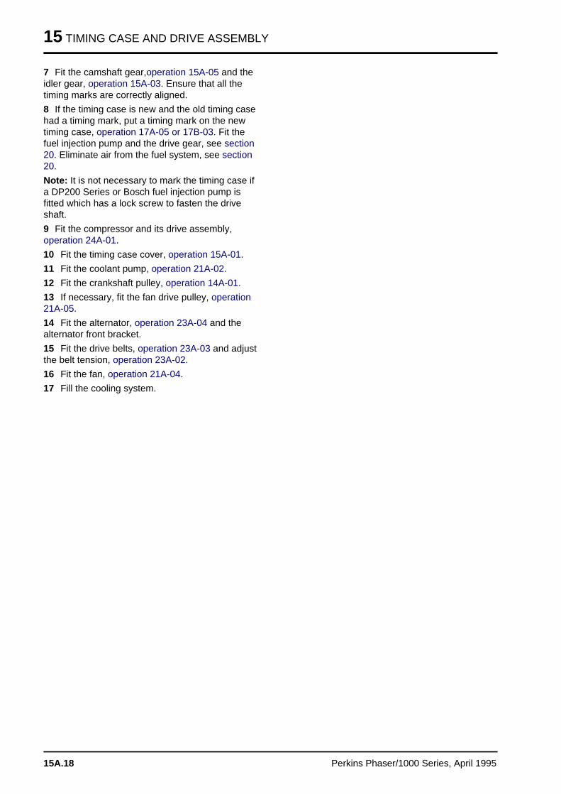
15 TIMING CASE AND DRIVE ASSEMBLY
7 Fit the camshaft gear,operation 15A-05 and theidler gear, operation 15A-03. Ensure that all thetiming marks are correctly aligned.
8 If the timing case is new and the old timing casehad a timing mark, put a timing mark on the newtiming case, operation 17A-05 or 17B-03. Fit thefuel injection pump and the drive gear, see section20. Eliminate air from the fuel system, see section20.
Note: It is not necessary to mark the timing case ifa DP200 Series or Bosch fuel injection pump isfitted which has a lock screw to fasten the driveshaft.
9 Fit the compressor and its drive assembly,operation 24A-01.
10 Fit the timing case cover, operation 15A-01.
11 Fit the coolant pump, operation 21A-02.
12 Fit the crankshaft pulley, operation 14A-01.
13 If necessary, fit the fan drive pulley, operation21A-05.
14 Fit the alternator, operation 23A-04 and thealternator front bracket.
15 Fit the drive belts, operation 23A-03 and adjustthe belt tension, operation 23A-02.
16 Fit the fan, operation 21A-04.
17 Fill the cooling system.
15A.18 Perkins Phaser/1000 Series, April 1995
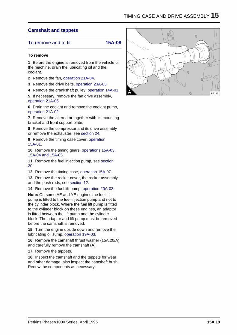
TIMING CASE AND DRIVE ASSEMBLY 15
Camshaft and tappets
To remove and to fit 15A-08
To remove
1 Before the engine is removed from the vehicle orthe machine, drain the lubricating oil and thecoolant.
2 Remove the fan, operation 21A-04.
3 Remove the drive belts, operation 23A-03.
4 Remove the crankshaft pulley, operation 14A-01.
5 If necessary, remove the fan drive assembly,operation 21A-05.
6 Drain the coolant and remove the coolant pump,operation 21A-02.
7 Remove the alternator together with its mountingbracket and front support plate.
8 Remove the compressor and its drive assemblyor remove the exhauster, see section 24.
9 Remove the timing case cover, operation 15A-01.
10 Remove the timing gears, operations 15A-03,15A-04 and 15A-05.
11 Remove the fuel injection pump, see section20.
12 Remove the timing case, operation 15A-07.
13 Remove the rocker cover, the rocker assemblyand the push rods, see section 12.
14 Remove the fuel lift pump, operation 20A-03.
Note: On some AE and YE engines the fuel liftpump is fitted to the fuel injection pump and not tothe cylinder block. Where the fuel lift pump is fittedto the cylinder block on these engines, an adaptoris fitted between the lift pump and the cylinderblock. The adaptor and lift pump must be removedbefore the camshaft is removed.
15 Turn the engine upside down and remove thelubricating oil sump, operation 19A-03.
16 Remove the camshaft thrust washer (15A.20/A)and carefully remove the camshaft (A).
17 Remove the tappets.
18 Inspect the camshaft and the tappets for wearand other damage, also inspect the camshaft bush.Renew the components as necessary.
PA136
Perkins Phaser/1000 Series, April 1995 15A.19
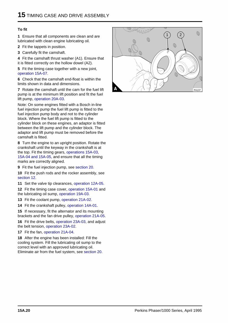
15 TIMING CASE AND DRIVE ASSEMBLY
To fit
1 Ensure that all components are clean and arelubricated with clean engine lubricating oil.
2 Fit the tappets in position.
3 Carefully fit the camshaft.
4 Fit the camshaft thrust washer (A1). Ensure thatit is fitted correctly on the hollow dowel (A2).
5 Fit the timing case together with a new joint,operation 15A-07.
6 Check that the camshaft end-float is within thelimits shown in data and dimensions.
7 Rotate the camshaft until the cam for the fuel liftpump is at the minimum lift position and fit the fuellift pump, operation 20A-03.
Note: On some engines fitted with a Bosch in-linefuel injection pump the fuel lift pump is fitted to thefuel injection pump body and not to the cylinderblock. Where the fuel lift pump is fitted to thecylinder block on these engines, an adaptor is fittedbetween the lift pump and the cylinder block. Theadaptor and lift pump must be removed before thecamshaft is fitted.
8 Turn the engine to an upright position. Rotate thecrankshaft until the keyway in the crankshaft is atthe top. Fit the timing gears, operations 15A-03,15A-04 and 15A-05, and ensure that all the timingmarks are correctly aligned.
9 Fit the fuel injection pump, see section 20.
10 Fit the push rods and the rocker assembly, seesection 12.
11 Set the valve tip clearances, operation 12A-05.
12 Fit the timing case cover, operation 15A-01 andthe lubricating oil sump, operation 19A-03.
13 Fit the coolant pump, operation 21A-02.
14 Fit the crankshaft pulley, operation 14A-01.
15 If necessary, fit the alternator and its mountingbrackets and the fan drive pulley, operation 21A-05.
16 Fit the drive belts, operation 23A-03, and adjustthe belt tension, operation 23A-02.
17 Fit the fan, operation 21A-04.
18 After the engine has been installed: Fill thecooling system. Fill the lubricating oil sump to thecorrect level with an approved lubricating oil.Eliminate air from the fuel system, see section 20.
a a a
a a a
a a a
a a a
2
a a a
a a a
a a a
a a a
1
PA137
15A.20 Perkins Phaser/1000 Series, April 1995
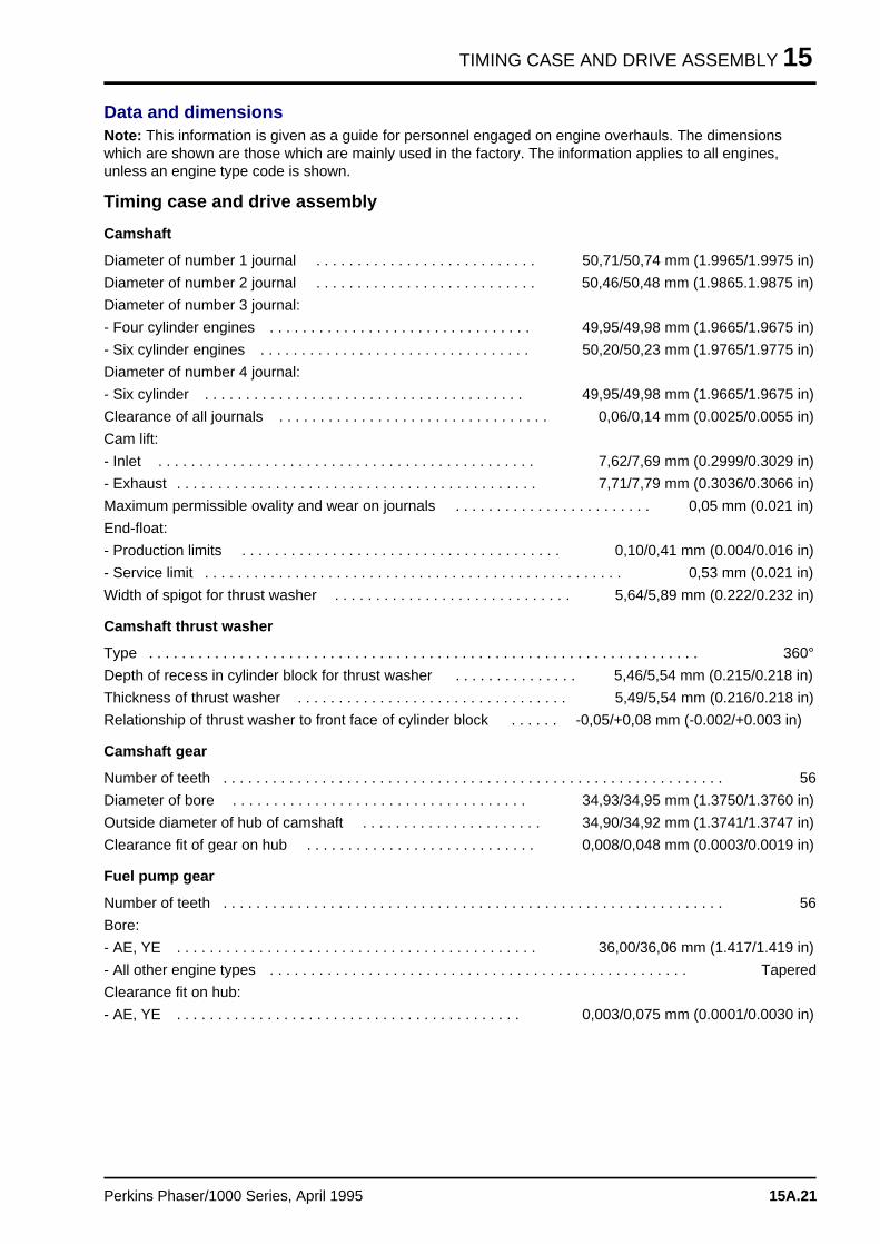
TIMING CASE AND DRIVE ASSEMBLY 15
Data and dimensionsNote: This information is given as a guide for personnel engaged on engine overhauls. The dimensionswhich are shown are those which are mainly used in the factory. The information applies to all engines,unless an engine type code is shown.
Timing case and drive assembly
Camshaft
Diameter of number 1 journal . . . . . . . . . . . . . . . . . . . . . . . . . . . 50,71/50,74 mm (1.9965/1.9975 in)
Diameter of number 2 journal . . . . . . . . . . . . . . . . . . . . . . . . . . . 50,46/50,48 mm (1.9865.1.9875 in)
Diameter of number 3 journal:
- Four cylinder engines . . . . . . . . . . . . . . . . . . . . . . . . . . . . . . . . 49,95/49,98 mm (1.9665/1.9675 in)
- Six cylinder engines . . . . . . . . . . . . . . . . . . . . . . . . . . . . . . . . . 50,20/50,23 mm (1.9765/1.9775 in)
Diameter of number 4 journal:
- Six cylinder . . . . . . . . . . . . . . . . . . . . . . . . . . . . . . . . . . . . . . . 49,95/49,98 mm (1.9665/1.9675 in)
Clearance of all journals . . . . . . . . . . . . . . . . . . . . . . . . . . . . . . . . . 0,06/0,14 mm (0.0025/0.0055 in)
Cam lift:
- Inlet . . . . . . . . . . . . . . . . . . . . . . . . . . . . . . . . . . . . . . . . . . . . . . 7,62/7,69 mm (0.2999/0.3029 in)
- Exhaust . . . . . . . . . . . . . . . . . . . . . . . . . . . . . . . . . . . . . . . . . . . . 7,71/7,79 mm (0.3036/0.3066 in)
Maximum permissible ovality and wear on journals . . . . . . . . . . . . . . . . . . . . . . . . 0,05 mm (0.021 in)
End-float:
- Production limits . . . . . . . . . . . . . . . . . . . . . . . . . . . . . . . . . . . . . . . 0,10/0,41 mm (0.004/0.016 in)
- Service limit . . . . . . . . . . . . . . . . . . . . . . . . . . . . . . . . . . . . . . . . . . . . . . . . . . . 0,53 mm (0.021 in)
Width of spigot for thrust washer . . . . . . . . . . . . . . . . . . . . . . . . . . . . . 5,64/5,89 mm (0.222/0.232 in)
Camshaft thrust washer
Type . . . . . . . . . . . . . . . . . . . . . . . . . . . . . . . . . . . . . . . . . . . . . . . . . . . . . . . . . . . . . . . . . . . 360°
Depth of recess in cylinder block for thrust washer . . . . . . . . . . . . . . . 5,46/5,54 mm (0.215/0.218 in)
Thickness of thrust washer . . . . . . . . . . . . . . . . . . . . . . . . . . . . . . . . . 5,49/5,54 mm (0.216/0.218 in)
Relationship of thrust washer to front face of cylinder block . . . . . . -0,05/+0,08 mm (-0.002/+0.003 in)
Camshaft gear
Number of teeth . . . . . . . . . . . . . . . . . . . . . . . . . . . . . . . . . . . . . . . . . . . . . . . . . . . . . . . . . . . . . 56
Diameter of bore . . . . . . . . . . . . . . . . . . . . . . . . . . . . . . . . . . . . 34,93/34,95 mm (1.3750/1.3760 in)
Outside diameter of hub of camshaft . . . . . . . . . . . . . . . . . . . . . . 34,90/34,92 mm (1.3741/1.3747 in)
Clearance fit of gear on hub . . . . . . . . . . . . . . . . . . . . . . . . . . . . 0,008/0,048 mm (0.0003/0.0019 in)
Fuel pump gear
Number of teeth . . . . . . . . . . . . . . . . . . . . . . . . . . . . . . . . . . . . . . . . . . . . . . . . . . . . . . . . . . . . . 56
Bore:
- AE, YE . . . . . . . . . . . . . . . . . . . . . . . . . . . . . . . . . . . . . . . . . . . . 36,00/36,06 mm (1.417/1.419 in)
- All other engine types . . . . . . . . . . . . . . . . . . . . . . . . . . . . . . . . . . . . . . . . . . . . . . . . . . . Tapered
Clearance fit on hub:
- AE, YE . . . . . . . . . . . . . . . . . . . . . . . . . . . . . . . . . . . . . . . . . . 0,003/0,075 mm (0.0001/0.0030 in)
Perkins Phaser/1000 Series, April 1995 15A.21
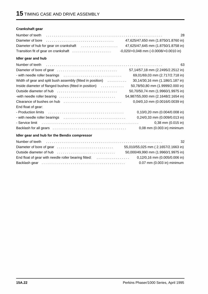
15 TIMING CASE AND DRIVE ASSEMBLY
Crankshaft gear
Number of teeth . . . . . . . . . . . . . . . . . . . . . . . . . . . . . . . . . . . . . . . . . . . . . . . . . . . . . . . . . . . . 28
Diameter of bore . . . . . . . . . . . . . . . . . . . . . . . . . . . . . . . . . . . 47,625/47,650 mm (1.8750/1.8760 in)
Diameter of hub for gear on crankshaft . . . . . . . . . . . . . . . . . . . 47,625/47,645 mm (1.8750/1.8758 in)
Transition fit of gear on crankshaft . . . . . . . . . . . . . . . . . . . . -0,020/+0,048 mm (-0.0008/+0.0010 in)
Idler gear and hub
Number of teeth . . . . . . . . . . . . . . . . . . . . . . . . . . . . . . . . . . . . . . . . . . . . . . . . . . . . . . . . . . . . 63
Diameter of bore of gear . . . . . . . . . . . . . . . . . . . . . . . . . . . . . . . 57,14/57,18 mm (2.2495/2.2512 in)
- with needle roller bearings . . . . . . . . . . . . . . . . . . . . . . . . . . . . . . 69,01/69,03 mm (2.717/2.718 in)
Width of gear and split bush assembly (fitted in position) . . . . . . . . . . 30,14/30,16 mm (1.186/1.187 in)
Inside diameter of flanged bushes (fitted in position) . . . . . . . . . . . . 50,78/50,80 mm (1.9999/2.000 in)
Outside diameter of hub . . . . . . . . . . . . . . . . . . . . . . . . . . . . . . . 50,70/50,74 mm (1.9960/1.9975 in)
-with needle roller bearing . . . . . . . . . . . . . . . . . . . . . . . . . . . . . 54,987/55,000 mm (2.1648/2.1654 in)
Clearance of bushes on hub . . . . . . . . . . . . . . . . . . . . . . . . . . . . . . 0,04/0,10 mm (0.0016/0.0039 in)
End float of gear:
- Production limits . . . . . . . . . . . . . . . . . . . . . . . . . . . . . . . . . . . . . . . 0,10/0,20 mm (0.004/0.008 in)
- with needle roller bearings . . . . . . . . . . . . . . . . . . . . . . . . . . . . . . . . 0,24/0,33 mm (0.009/0.013 in)
- Service limit . . . . . . . . . . . . . . . . . . . . . . . . . . . . . . . . . . . . . . . . . . . . . . . . . . 0,38 mm (0.015 in)
Backlash for all gears . . . . . . . . . . . . . . . . . . . . . . . . . . . . . . . . . . . . . . 0,08 mm (0.003 in) minimum
Idler gear and hub for the Bendix compressor
Number of teeth . . . . . . . . . . . . . . . . . . . . . . . . . . . . . . . . . . . . . . . . . . . . . . . . . . . . . . . . . . . . 32
Diameter of bore of gear . . . . . . . . . . . . . . . . . . . . . . . . . . . . . 55,010/55,025 mm ( 2.1657/2.1663 in)
Outside diameter of hub . . . . . . . . . . . . . . . . . . . . . . . . . . . . . . 50,000/49,990 mm (1.9960/1.9975 in)
End float of gear with needle roller bearing fitted: . . . . . . . . . . . . . . . . . 0,12/0,16 mm (0.005/0.006 in)
Backlash gear . . . . . . . . . . . . . . . . . . . . . . . . . . . . . . . . . . . . . . . . . . . 0.07 mm (0.003 in) minimum
15A.22 Perkins Phaser/1000 Series, April 1995
CYLINDER BLOCK ASSEMBLY 16
Cylinder block assembl y 16
General descriptio n . . . . . . . . . . . . . . . . . . . . . . . . . . . . . . . . . . . . . . . . . 16A.02
Cylinder block
16A-01 To dismantle and to assemble . . . . . . . . . . . . . . . . . . . . . . . . . . 16A.0316A-02 To inspect . . . . . . . . . . . . . . . . . . . . . . . . . . . . . . . . . . . . . . . . 16A.05
Cylinder liner
16A-03 To inspect . . . . . . . . . . . . . . . . . . . . . . . . . . . . . . . . . . . . . . . . 16A.0616A-04 To remove glaze from the bore . . . . . . . . . . . . . . . . . . . . . . . . . 16A.0716A-05 To remove and to fit . . . . . . . . . . . . . . . . . . . . . . . . . . . . . . . . . 16A.08
Data and dimension s . . . . . . . . . . . . . . . . . . . . . . . . . . . . . . . . . . . . . . . 16A.13
Perkins Phaser/1000 Series, April 1995 16A.01
16 CYLINDER BLOCK ASSEMBLY
General description
The cylinder block is made of cast iron andprovides a full length support for the dry linerswhich are also made of cast iron. Production linersare a press fit in the block and service liners are atransition fit. Both types of liners are honed withsilicon carbide tools to a controlled finish to ensurelong life and low oil consumption. The cylinderliners fitted to some engines have a flame ringabove the flange. A bush is fitted in the cylinderblock for the front camshaft journal and the othercamshaft journals run directly in the block.
16A.02 Perkins Phaser/1000 Series, April 1995
CYLINDER BLOCK ASSEMBLY 16
Cylinder block
To dismantle and to assemble 16A-01
Consumable products:
POWERPART Nutlock
To dismantle
1 Drain the cooling system and the lubricating oil.
2 Remove the engine from the vehicle or machine.
3 Remove the alternator drive belts and thealternator and its mounting brackets, see section23.
4 Remove the fan, the fan drive and the waterpump, see section 21.
5 Remove the compressor or the exhauster, wherefitted, see section 24.
6 Remove the fuel filter, the atomisers and the fuelinjection pump, see section 20.
7 Remove the lubricating oil cooler, where fitted,operation 21A-07.
8 Remove the lubricating oil filter assembly and thelubricating oil sump, see section 19.
9 If necessary, remove the turbocharger, operation18A-01.
10 Remove the fuel lift pump, operation 20A-03 or20B-03.
11 Remove the starter motor, operation 23B-01.
12 Remove the cylinder head assembly, operation12A-07.
13 Remove the timing case and the timing gears,see section 15. Remove the lubricating oil pumpand the pressure relief valve, see section 19, orremove the balancer unit, operation 14A-10.
15 Remove the piston and connecting rodassemblies, operation 13A-04.
16 Remove the camshaft and the tappets,operation 15A-08.
17 Remove the flywheel and the flywheel housing,see section 22.
18 Remove the rear oil seal assembly and thecrankshaft, see section 14.
19 Remove the piston cooling jets, operation 13A-09, or remove the setscrews and spacers ifjets are not fitted.
20 Inspect the cylinder block, operation 16A-02
Perkins Phaser/1000 Series, April 1995 16A.03
16 CYLINDER BLOCK ASSEMBLY
To assemble
1 Clean thoroughly the new cylinder block. Ensurethat all the oil passages are clean and free fromdebris.
2 Remove the threaded plugs from the old cylinderblock and clean the threads. Seal the threads withPOWERPART Nutlock, or a similar sealant, and fitthe threaded plugs into the new cylinder block.
3 Fit the piston cooling jets, or the spacers andsetscrews where jets are not fitted, operation 13A-09.
4 Fit the crankshaft and the rear oil seal assembly,see section 14.
5 Fit the piston and connecting rod assembly,operation 13A-03.
6 Fit the flywheel housing and the flywheel, seesection 22.
7 Fit the tappets and the camshaft, operation 15A-08.
8 Fit the lubricating oil pump and the pressurerelief valve, see section 19, or fit the balancer unit,operation 14A-10.
9 Fit the timing case and the timing gears, seesection 15.
10 Fit the cylinder head assembly, operation 12A-07.
11 Fit the starter motor, operation 23B-01.
12 Fit the fuel lift pump, operation 20A-03 or 20B-03.
13 If necessary, fit the turbocharger, operation18A-01.
14 Fit the lubricating oil filter assembly and thelubricating oil sump, see section 19.
15 If necessary, fit the lubricating oil cooler,operation 21A-07.
16 Fit the fuel filter, the atomisers and the fuel
injection pump, see section 20.
17 If necessary, fit the compressor or theexhauster, see section 24.
18 Fit the fan, the fan drive and the water pump,see section 21.
19 Fit the alternator and its mounting brackets andthe alternator drive belts, see section 23.
20 Install the engine into the vehicle or machine.
21 Fill the cooling system.
22 Fill the lubricating oil sump to the correct levelwith an approved lubricating oil.
23 Eliminate air from the fuel system, see section20.
16A.04 Perkins Phaser/1000 Series, April 1995
CYLINDER BLOCK ASSEMBLY 16
To inspect 16A-02
1 Clean the passages for the coolant and for theoil.
2 Check the cylinder block for cracks and for otherdamage.
3 The top face of the cylinder block must not bemachined as this will affect the liner flange depthand the piston height above the top face of thecylinder block.
4 Check the camshaft bush for wear. If the bush isto be renewed, use a suitable adaptor to press itout of the bore. Ensure that the lubricating oil holein the new bush will be towards the front of theengine, when fitted. Press in the bush with the oilhole on the same side and aligned with the oil holein the block until the front end of the bush isaligned with the face of the recess.
Perkins Phaser/1000 Series, April 1995 16A.05
16 CYLINDER BLOCK ASSEMBLY
Cylinder liner
To inspect 16A-03
To ensure the best performance during the life ofthe engine it is important that worn or damagedcylinder liners are renewed. If a change of linerbecomes necessary in service, a service liner isavailable.
The condition of a cylinder liner is decided by:
• The amount and location of any polished areas.
• Wear.
• Damage to the liner wall.
Notes: It will not be necessary to renew the linersIf:
• The honed finish can still be clearly seen.
• The engine performance and oil consumption isacceptable.
To check the condition of a cylinder liner
1 Inspect the liner surface for cracks and deepscratches.
2 Check the liner wall for areas where the honedfinish has been polished away. Check especially thearea around the top of the liner bore just below thecarbon ring. In this area, thrust from the top pistonring is at its maximum.
Cautions:
• Damaged or worn liners must be discarded.
• New piston rings must be fitted when thecylinder liner is renewed.
• An engine can have high oil consumption withvery little wear of the liner bores, if the surfaces ofthe liners are glazed.
16A.06 Perkins Phaser/1000 Series, April 1995
CYLINDER BLOCK ASSEMBLY 16
To remove glaze from the bore 16A-04
A tool, known as a "Flex-Hone", is available tocorrect the liner surface. This tool can be used withan electric hand drill at low speed. The pistons andconnecting rods must be removed and the pistoncooling jets, where fitted, must also be removed.Use covers to protect all engine components fromthe debris which is caused during the process.
Details and supply of the "Flex-hone" are availablefrom:
Nicro (Leamington) Ltd.
Unit One
South Woodchester Trading Estate
Stroud
Gloucestershire GL5 5NR
Caution: Do not use a "Flex-hone" on the cylinderliners of engine types AE and YE.
1 Grade 80SC Flex-Hone is to be used. A 4 inchor 4 1/8 inch size Flex-Hone can be used accordingto how badly the bore is glazed.
2 New Flex-Hones must be operated in an old linerbefore use on an engine to remove all loosematerial and sharp edges.
3 Lubricate lightly the liner and the Flex-Hone withclean engine lubricating oil.
4 Put the tool in position on top of the liner, but donot press the tool into the liner until the tool isoperated.
5 Operate the tool and move it up and down theliner bore once a second for 30-50 seconds.Remove the tool while it rotates.
6 Clean thoroughly the liner bore to remove all dirtfrom the operation, use a hard brush and kerosene.
7 Dry the liners and remove carefully all the coversused to protect the components. Clean thoroughlyall the engine components which have beenaffected by debris.
8 Fit the piston cooling jets or the plugs. Ensurethat new piston rings are fitted when the engine isassembled in accordance with the relevant sectionsof this workshop manual.
Caution: After a glazed bore has been corrected,these recommendations are advised for the first240 km (150 miles) or 5 hours of operation:
• Do not operate the engine at full load.
• Do not operate the engine at high speed.
• Do not allow the engine to run at low idlespeed for extended periods.
Perkins Phaser/1000 Series, April 1995 16A.07
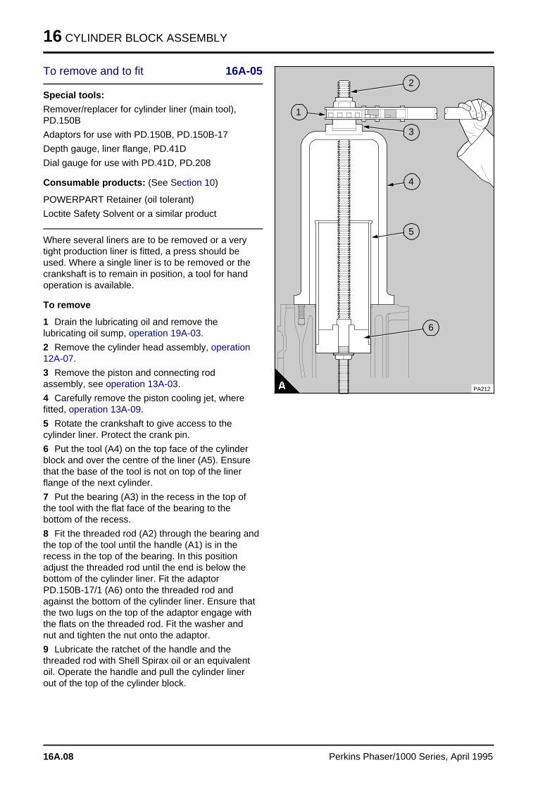
16 CYLINDER BLOCK ASSEMBLY
To remove and to fit 16A-05
Special tools:
Remover/replacer for cylinder liner (main tool),PD.150B
Adaptors for use with PD.150B, PD.150B-17
Depth gauge, liner flange, PD.41D
Dial gauge for use with PD.41D, PD.208
Consumable products: (See Section 10)
POWERPART Retainer (oil tolerant)
Loctite Safety Solvent or a similar product
Where several liners are to be removed or a verytight production liner is fitted, a press should beused. Where a single liner is to be removed or thecrankshaft is to remain in position, a tool for handoperation is available.
To remove
1 Drain the lubricating oil and remove thelubricating oil sump, operation 19A-03.
2 Remove the cylinder head assembly, operation12A-07.
3 Remove the piston and connecting rodassembly, see operation 13A-03.
4 Carefully remove the piston cooling jet, wherefitted, operation 13A-09.
5 Rotate the crankshaft to give access to thecylinder liner. Protect the crank pin.
6 Put the tool (A4) on the top face of the cylinderblock and over the centre of the liner (A5). Ensurethat the base of the tool is not on top of the linerflange of the next cylinder.
7 Put the bearing (A3) in the recess in the top ofthe tool with the flat face of the bearing to thebottom of the recess.
8 Fit the threaded rod (A2) through the bearing andthe top of the tool until the handle (A1) is in therecess in the top of the bearing. In this positionadjust the threaded rod until the end is below thebottom of the cylinder liner. Fit the adaptorPD.150B-17/1 (A6) onto the threaded rod andagainst the bottom of the cylinder liner. Ensure thatthe two lugs on the top of the adaptor engage withthe flats on the threaded rod. Fit the washer andnut and tighten the nut onto the adaptor.
9 Lubricate the ratchet of the handle and thethreaded rod with Shell Spirax oil or an equivalentoil. Operate the handle and pull the cylinder linerout of the top of the cylinder block.
a a a
a a a
a a a
a a a
2
a aa aa aa a
1
a a a
a a a
a a a
a a a
3
a a a
a a a
a a a
a a a
4
a a a
a a a
a a a
a a a
5
a aa aa aa a
6
PA212
16A.08 Perkins Phaser/1000 Series, April 1995
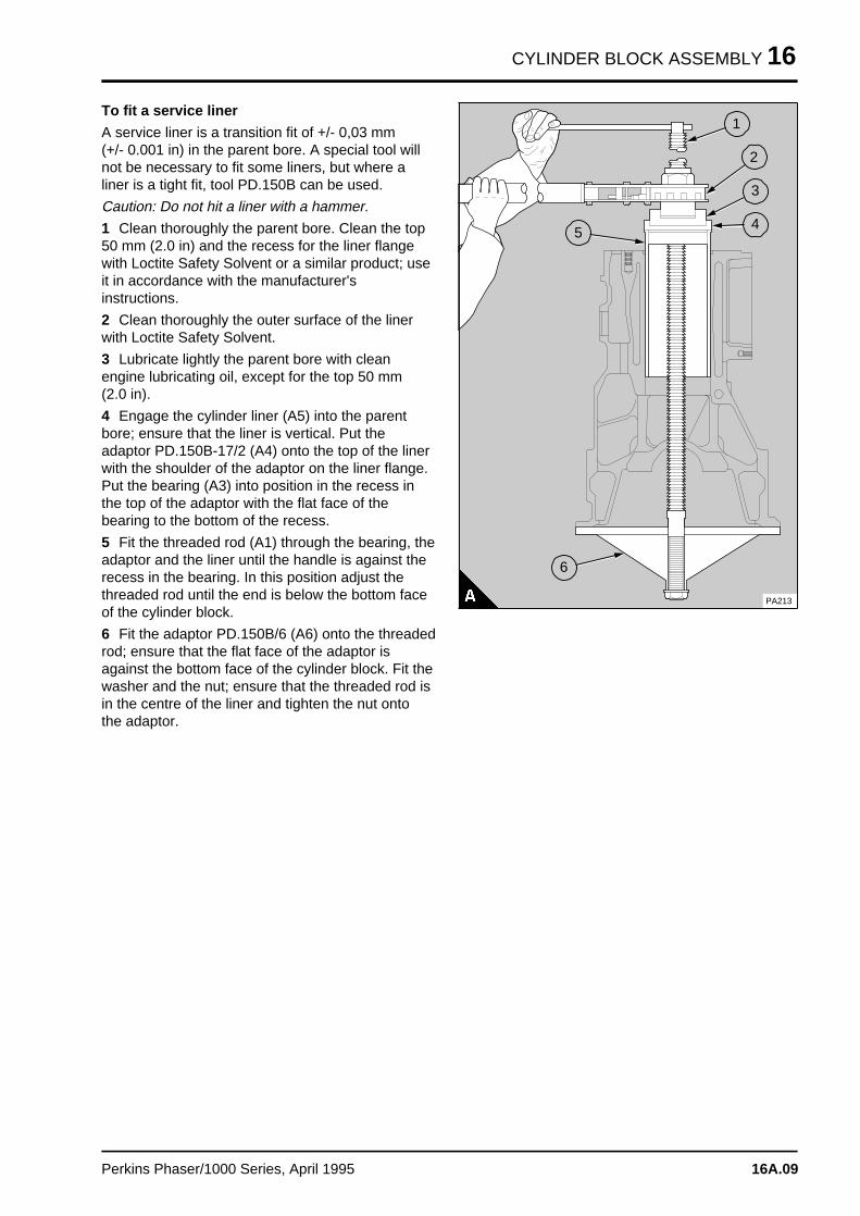
CYLINDER BLOCK ASSEMBLY 16
To fit a service liner A service liner is a transition fit of +/- 0,03 mm(+/- 0.001 in) in the parent bore. A special tool willnot be necessary to fit some liners, but where aliner is a tight fit, tool PD.150B can be used.
Caution: Do not hit a liner with a hammer.
1 Clean thoroughly the parent bore. Clean the top50 mm (2.0 in) and the recess for the liner flangewith Loctite Safety Solvent or a similar product; useit in accordance with the manufacturer'sinstructions.
2 Clean thoroughly the outer surface of the linerwith Loctite Safety Solvent.
3 Lubricate lightly the parent bore with cleanengine lubricating oil, except for the top 50 mm(2.0 in).
4 Engage the cylinder liner (A5) into the parentbore; ensure that the liner is vertical. Put theadaptor PD.150B-17/2 (A4) onto the top of the linerwith the shoulder of the adaptor on the liner flange.Put the bearing (A3) into position in the recess inthe top of the adaptor with the flat face of thebearing to the bottom of the recess.
5 Fit the threaded rod (A1) through the bearing, theadaptor and the liner until the handle is against therecess in the bearing. In this position adjust thethreaded rod until the end is below the bottom faceof the cylinder block.
6 Fit the adaptor PD.150B/6 (A6) onto the threadedrod; ensure that the flat face of the adaptor isagainst the bottom face of the cylinder block. Fit thewasher and the nut; ensure that the threaded rod isin the centre of the liner and tighten the nut ontothe adaptor.
a a a
a a a
a a a
a a a
1
a aa aa aa a
2
a aa aa aa a
3
a aa aa aa a
4a a a
a a a
a a a
a a a
a a a
5
a a a
a a a
a a a
a a a6
PA213
Perkins Phaser/1000 Series, April 1995 16A.09
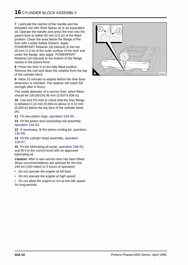
16 CYLINDER BLOCK ASSEMBLY
7 Lubricate the ratchet of the handle and thethreaded rod with Shell Spirax oil or an equivalentoil. Operate the handle and press the liner into theparent bore to within 50 mm (2.0 in) of the fittedposition. Clean the area below the flange of theliner with Loctite Safety Solvent. ApplyPOWERPART Retainer (oil tolerant) to the top 25 mm (1.0 in) of the outer surface of the liner andunder the flange; also apply POWERPARTRetainer (oil tolerant) to the bottom of the flangerecess in the parent bore.
8 Press the liner in to the fully fitted position.Remove the tool and clean the retainer from the topof the cylinder block.
9 Allow 15 minutes to elapse before the liner boredimension is checked. The retainer will reach fullstrength after 6 hours.
The inside diameter of a service liner, when fitted,should be 100,00/100,06 mm (3.937/3.939 in)
10 Use tool PD.41D to check that the liner flangeis between 0,10 mm (0.004 in) above to 0,10 mm(0.004 in) below the top face of the cylinder block(A).
11 Fit new piston rings, operation 13A-04.
12 Fit the piston and connecting rod assembly,operation 13A-03.
13 If necessary, fit the piston cooling jet, operation13A-09.
14 Fit the cylinder head assembly, operation 12A-07.
15 Fit the lubricating oil sump, operation 19A-03,and fill it to the correct level with an approvedlubricating oil.
Caution: After a new service liner has been fitted,these recommendations are advised for the first240 km (150 miles) or 5 hours of operation:
• Do not operate the engine at full load.
• Do not operate the engine at high speed.
• Do not allow the engine to run at low idle speedfor long periods.
a a a
a a a
a a a
a a a
a a a
2
a a a
a a a
a a a
a a a
1
PA214
16A.10 Perkins Phaser/1000 Series, April 1995
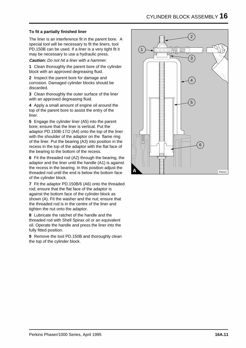
CYLINDER BLOCK ASSEMBLY 16
To fit a partially finished liner
The liner is an interference fit in the parent bore. Aspecial tool will be necessary to fit the liners, toolPD.150B can be used. If a liner is a very tight fit itmay be necessary to use a hydraulic press.
Caution: Do not hit a liner with a hammer.
1 Clean thoroughly the parent bore of the cylinderblock with an approved degreasing fluid.
2 Inspect the parent bore for damage andcorrosion. Damaged cylinder blocks should bediscarded.
3 Clean thoroughly the outer surface of the linerwith an approved degreasing fluid.
4 Apply a small amount of engine oil around thetop of the parent bore to assist the entry of theliner.
5 Engage the cylinder liner (A5) into the parentbore; ensure that the liner is vertical. Put theadaptor PD.150B-17/2 (A4) onto the top of the linerwith the shoulder of the adaptor on the flame ringof the liner. Put the bearing (A3) into position in therecess in the top of the adaptor with the flat face ofthe bearing to the bottom of the recess.
6 Fit the threaded rod (A2) through the bearing, theadaptor and the liner until the handle (A1) is againstthe recess in the bearing. In this position adjust thethreaded rod until the end is below the bottom faceof the cylinder block.
7 Fit the adaptor PD.150B/6 (A6) onto the threadedrod; ensure that the flat face of the adaptor isagainst the bottom face of the cylinder block asshown (A). Fit the washer and the nut; ensure thatthe threaded rod is in the centre of the liner andtighten the nut onto the adaptor.
8 Lubricate the ratchet of the handle and thethreaded rod with Shell Spirax oil or an equivalentoil. Operate the handle and press the liner into thefully fitted position.
9 Remove the tool PD.150B and thoroughly cleanthe top of the cylinder block.
a a a
a a a
a a a
a a a
2
a a a
a a a
a a a
a a a
1
a a a
a a a
a a a
a a a
3
a a a
a a a
a a a
a a a
4
a a a
a a a
a a a
a a a
5
a aa aa aa a
6
PA212
Perkins Phaser/1000 Series, April 1995 16A.11
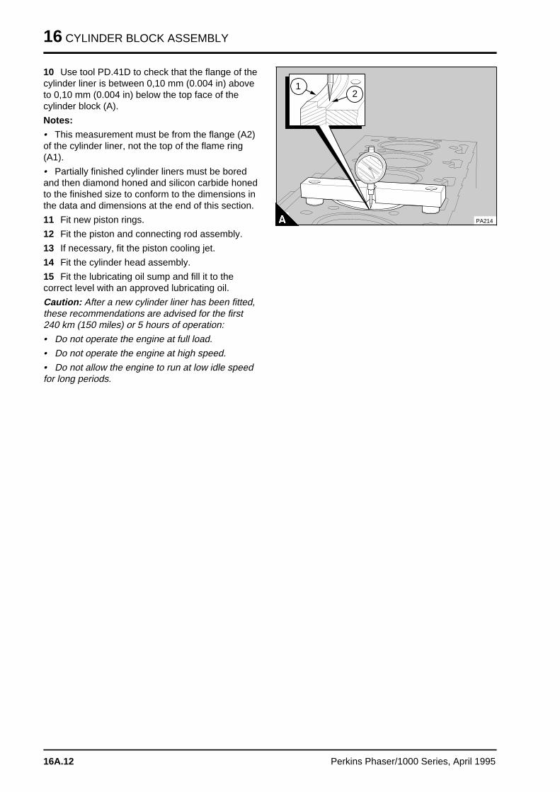
16 CYLINDER BLOCK ASSEMBLY
10 Use tool PD.41D to check that the flange of thecylinder liner is between 0,10 mm (0.004 in) aboveto 0,10 mm (0.004 in) below the top face of thecylinder block (A).
Notes:
• This measurement must be from the flange (A2)of the cylinder liner, not the top of the flame ring(A1).
• Partially finished cylinder liners must be boredand then diamond honed and silicon carbide honedto the finished size to conform to the dimensions inthe data and dimensions at the end of this section.
11 Fit new piston rings.
12 Fit the piston and connecting rod assembly.
13 If necessary, fit the piston cooling jet.
14 Fit the cylinder head assembly.
15 Fit the lubricating oil sump and fill it to thecorrect level with an approved lubricating oil.
Caution: After a new cylinder liner has been fitted,these recommendations are advised for the first240 km (150 miles) or 5 hours of operation:
• Do not operate the engine at full load.
• Do not operate the engine at high speed.
• Do not allow the engine to run at low idle speedfor long periods.
a a a
a a a
a a a
a a a
a a a
2
a a a
a a a
a a a
a a a
1
PA214
16A.12 Perkins Phaser/1000 Series, April 1995
CYLINDER BLOCK ASSEMBLY 16
Data and dimensionsNote: This information is given as a guide for personnel engaged on engine overhauls. The dimensionswhich are shown are those which are mainly used in the factory. The information applies to all engines,unless an engine type code is shown.
Cylinder block assembly
Cylinder block
Height between top and bottom faces . . . . . . . . . . . . . . . . . . . 441,12/441,33 mm (17.367/17.375 in)
Diameter of parent bore for cylinder liner . . . . . . . . . . . . . . . . . . . 104,20/104,23 mm (4.103/4.104 in)
Depth of recess for flange of cylinder liner . . . . . . . . . . . . . . . . . . . . . . 3,81/3,91 mm (0.150/0.154 in)
Diameter of recess for flange of cylinder liner . . . . . . . . . . . . . . . . 107,82/107,95 mm (4.245/4.250 in)
Diameter of parent bore for main bearing . . . . . . . . . . . . . . . . . 80,416/80,442 mm (3.1660/3.1670 in)
Camshaft bore diameter:
- Four cylinder engines:
Number 1 (for bush) . . . . . . . . . . . . . . . . . . . . . . . . . . . . . . . . . . . . 55,56/55,59 mm (2.188/2.189 in)
Number 2 . . . . . . . . . . . . . . . . . . . . . . . . . . . . . . . . . . . . . . . . . . . 50,55/50,60 mm (1.990/1.992 in)
Number 3 . . . . . . . . . . . . . . . . . . . . . . . . . . . . . . . . . . . . . . . . . . . 50,04/50,09 mm (1.970/1.972 in)
- Six cylinder engines:
Number 1 (for bush) . . . . . . . . . . . . . . . . . . . . . . . . . . . . . . . . . . . . 55,56/55,59 mm (2.188/2.189 in)
Number 2 . . . . . . . . . . . . . . . . . . . . . . . . . . . . . . . . . . . . . . . . . . . 50,55/50,60 mm (1.990/1.992 in)
Number 3 . . . . . . . . . . . . . . . . . . . . . . . . . . . . . . . . . . . . . . . . . . . 50,29/50,34 mm (1.980.1.982 in)
Number 4 . . . . . . . . . . . . . . . . . . . . . . . . . . . . . . . . . . . . . . . . . . . 50,04/50,09 mm (1.970/1.972 in)
Bore of bush for number 1 camshaft journal . . . . . . . . . . . . . . . . . . . 50,79/50,85 mm (2.000/2.002 in)
Cylinder liners
Type:
- Production . . . . . . . . . . . . . . . . . . . . . . . . . . . . . . . . . . . . . . . . . . . . . Dry, interference fit, flanged
- Service . . . . . . . . . . . . . . . . . . . . . . . . . . . . . . . . . . . . . . . . . . . . . . . . . Dry, transition fit, flanged
- Service . . . . . . . . . . . . . . . . . . . . . . . . . . . . . . . . . . . . . . Dry, transition fit, flanged, with flame ring
partially finished liner . . . . . . . . . . . . . . . . . . . . . . . . . . . Dry, interference fit, flanged, with flame ring
- AE, YE, 110Ti and 135Ti AD lists:
- Production . . . . . . . . . . . . . . . . . . . . . . . . . . . . . . . . . . Dry, interference fit, flanged, with flame ring
Outside diameter of production liner . . . . . . . . . . . . . . . . . . . . . . . 104,25/104,28 mm (4.105/4.106 in)
Interference fit of production liner . . . . . . . . . . . . . . . . . . . . . . . . . . . . . 0,03/0,08 mm (0.001/0.003 in)
Inside diameter of production liner . . . . . . . . . . . . . . . . . . . . . . . . 100,00/100,03 mm (3.937/3.938 in)
Transition fit of service liner . . . . . . . . . . . . . . . . . . . . . . . . . . . . . . . . . . +/- 0,03 mm (+/- 0.001 in)
Inside diameter of service liner (fitted) . . . . . . . . . . . . . . . . . . . 100,04/100,063 mm (3.9385/3.9395 in)
Inside diameter of service liner with a flame ring (fitted) . . . . . . . . 100,00/100,063 mm (3.937/3.939 in)
Maximum permissible wear of liner bore . . . . . . . . . . . . . . . . . . . . . . . . . . . . . . . . 0,25 mm (0.010 in)
Thickness of flange . . . . . . . . . . . . . . . . . . . . . . . . . . . . . . . . . . . . . . 3,81/3,86 mm (0.150/0.152 in)
Relative position of top of liner flange to top face of cylinder block . . . . . . . 0,10 mm (0.004 in) above
0,10 mm (0.004 in) below
Perkins Phaser/1000 Series, April 1995 16A.13
16 CYLINDER BLOCK ASSEMBLY
Partially finished liner
Inside diameter of partially finished liner . . . . . . . . . . . . . . . . . . . 99,162/99,415 mm (3.9040/3.9139 in)
Interference fit of partially finished liner in parent bore . . . . . . . . . . . . 0,025/0,076 mm (0.003/0.001 in)
Hone angle (cross hatch) . . . . . . . . . . . . . . . . . . . . . . . . . . . . . . . . . . . . . . . . . . . . . . . . . . 30°/35°
Final finish grade, silicon carbide (Plateau hone) . . . . . . . . . . . . . . . . . . . . . . . . 0,65/1,3 micrometers
Inside diameter of finished liner . . . . . . . . . . . . . . . . . . . . . . . . . . 100,00/100,03 mm (3.937/3.938 in)
16A.14 Perkins Phaser/1000 Series, April 1995
Engine timin g 17
Bosch EPVE fuel injection pumps . . . . . . . . . . . . . . . . . . . . . . . . . . . 17A
Bosch MW in-line fuel injection pump . . . . . . . . . . . . . . . . . . . . . . . . 17B
Lucas DPA and DPS fuel injection pumps . . . . . . . . . . . . . . . . . . . . 17C
Lucas DP200 Series fuel injection pump . . . . . . . . . . . . . . . . . . . . . 17D
Stanadyne fuel injection pump . . . . . . . . . . . . . . . . . . . . . . . . . . . . . 17E
Perkins Phaser/1000 Series, April 1995 17.01
Engines fitted with Bosch EPVEfuel injection pump s 17A
General description. . . . . . . . . . . . . . . . . . . . . . . . . . . . . . . . . . . . . . . . . . . . . . 17A.02
Engine timing
17A-01A To set number 1 piston to TDC on the compression stroke . . . . . 17A.0317A-01B An other method to set number 1 piston to TDC on
the compression stroke . . . . . . . . . . . . . . . . . . . . . . . . . . . . . . . 17A.0417A-02 To check the valve timing . . . . . . . . . . . . . . . . . . . . . . . . . . . . . 17A.0417A-03 To check the timing of the fuel injection pump . . . . . . . . . . . . . . 17A.0517A-04 To check the timing mark of the fuel injection pump . . . . . . . . . . 17A.0717A-05 To check the engine timing mark . . . . . . . . . . . . . . . . . . . . . . . . 17A.08
Data and dimension s . . . . . . . . . . . . . . . . . . . . . . . . . . . . . . . . . . . . . . . 17A.09
Perkins Phaser/1000 Series, April 1995 17A.01
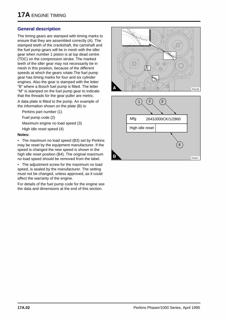
17A ENGINE TIMING
General description
The timing gears are stamped with timing marks toensure that they are assembled correctly (A). Thestamped teeth of the crankshaft, the camshaft andthe fuel pump gears will be in mesh with the idlergear when number 1 piston is at top dead centre(TDC) on the compression stroke. The markedteeth of the idler gear may not necessarily be inmesh in this position, because of the differentspeeds at which the gears rotate.The fuel pumpgear has timing marks for four and six cylinderengines. Also the gear is stamped with the letter"B" where a Bosch fuel pump is fitted. The letter"M" is stamped on the fuel pump gear to indicatethat the threads for the gear puller are metric.
A data plate is fitted to the pump. An example ofthe information shown on the plate (B) is:
Perkins part number (1)
Fuel pump code (2)
Maximum engine no load speed (3)
High idle reset speed (4)
Notes:
• The maximum no load speed (B3) set by Perkinsmay be reset by the equipment manufacturer. If thespeed is changed the new speed is shown in thehigh idle reset position (B4). The original maximumno load speed should be removed from the label.
• The adjustment screw for the maximum no loadspeed, is sealed by the manufacturer. The settingmust not be changed, unless approved, as it couldaffect the warranty of the engine.
For details of the fuel pump code for the engine seethe data and dimensions at the end of this section.
a a a a a a a a a a a a a a a a a a a a a a a a a a a a a a
a a a a a a a a a a a a a a a a a a a a a a a a a a a a a a
a a a a a a a a a a a a a a a a a a a a a a a a a a a a a a
a a a a a a a a a a a a a a a a a a a a a a a a a a a a a a
a a a a a a a a a a a a a a a a a a a a a a a a a a a a a a
a a a a a a a a a a a a a a a a a a a a a a a a a a a a a a
a a a a a a a a a a a a a a a a a a a a a a a a a a a a a a
a a a a a a a a a a a a a a a a a a a a a a a a a a a a a a
a a a a a a a a a a a a a a a a a a a a a a a a a a a a a a
a a a a a a a a a a a a a a a a a a a a a a a a a a a a a a
a a a a a a a a a a a a a a a a a a a a a a a a a a a a a a
a a a a a a a a a a a a a a a a a a a a a a a a a a a a a a
a a a a a a a a a a a a a a a a a a a a a a a a a a a a a a
a a a a a a a a a a a a a a a a a a a a a a a a a a a a a a
a a a a a a a a a a a a a a a a a a a a a a a a a a a a a a
a a a a a a a a a a a a a a a a a a a a a a a a a a a a a a
PA129
a a a
a a a
a a a
a a a
3
a a a
a a a
a a a
a a a
1
High idle reset
PA317
a a a
a a a
a a a
a a a
2
a aa aa aa aa a
4
2643J000CK/1/2860 Mfg
17A.02 Perkins Phaser/1000 Series, April 1995
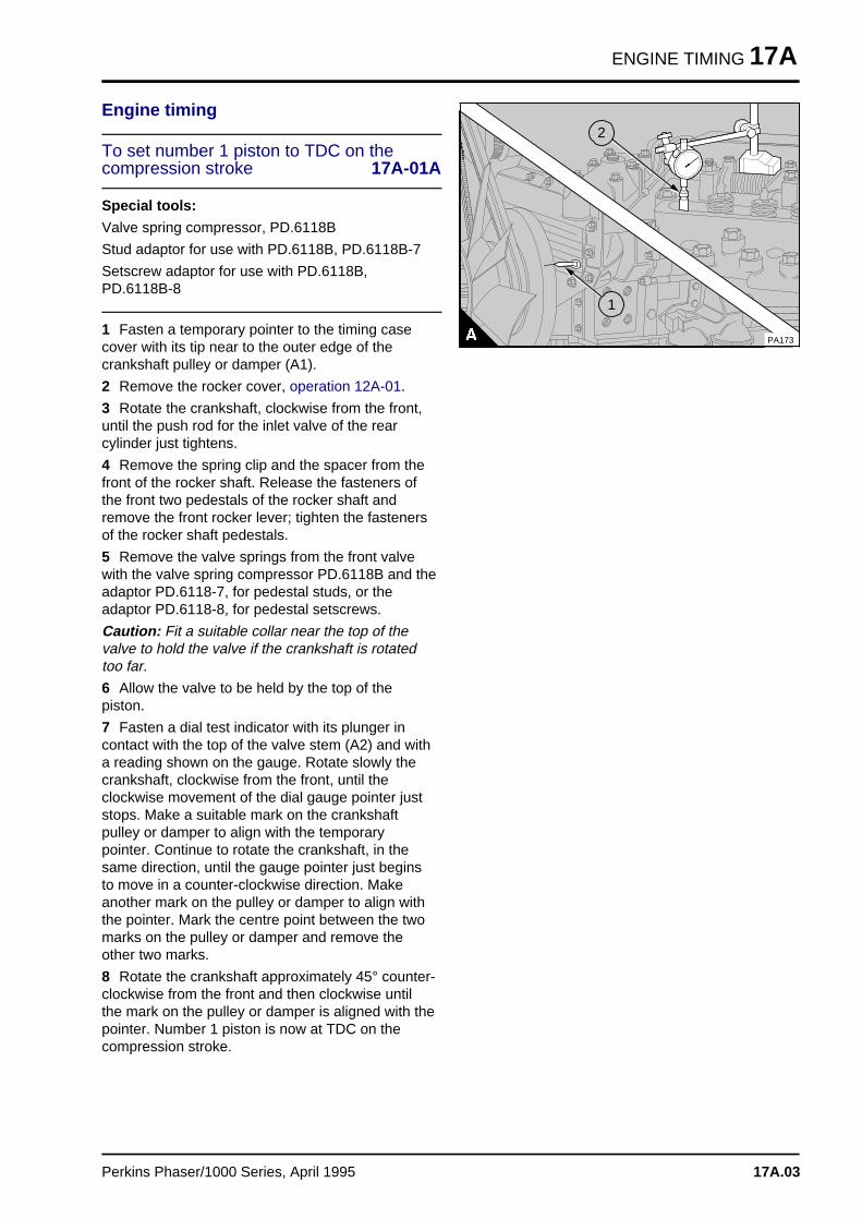
ENGINE TIMING 17A
Engine timing
To set number 1 piston to TDC on thecompression stroke 17A-01A
Special tools:
Valve spring compressor, PD.6118B
Stud adaptor for use with PD.6118B, PD.6118B-7
Setscrew adaptor for use with PD.6118B,PD.6118B-8
1 Fasten a temporary pointer to the timing casecover with its tip near to the outer edge of thecrankshaft pulley or damper (A1).
2 Remove the rocker cover, operation 12A-01.
3 Rotate the crankshaft, clockwise from the front,until the push rod for the inlet valve of the rearcylinder just tightens.
4 Remove the spring clip and the spacer from thefront of the rocker shaft. Release the fasteners ofthe front two pedestals of the rocker shaft andremove the front rocker lever; tighten the fastenersof the rocker shaft pedestals.
5 Remove the valve springs from the front valvewith the valve spring compressor PD.6118B and theadaptor PD.6118-7, for pedestal studs, or theadaptor PD.6118-8, for pedestal setscrews.
Caution: Fit a suitable collar near the top of thevalve to hold the valve if the crankshaft is rotatedtoo far.
6 Allow the valve to be held by the top of thepiston.
7 Fasten a dial test indicator with its plunger incontact with the top of the valve stem (A2) and witha reading shown on the gauge. Rotate slowly thecrankshaft, clockwise from the front, until theclockwise movement of the dial gauge pointer juststops. Make a suitable mark on the crankshaftpulley or damper to align with the temporarypointer. Continue to rotate the crankshaft, in thesame direction, until the gauge pointer just beginsto move in a counter-clockwise direction. Makeanother mark on the pulley or damper to align withthe pointer. Mark the centre point between the twomarks on the pulley or damper and remove theother two marks.
8 Rotate the crankshaft approximately 45° counter-clockwise from the front and then clockwise untilthe mark on the pulley or damper is aligned with thepointer. Number 1 piston is now at TDC on thecompression stroke.
a aa aa aa a
2
a aa aa aa a
1
PA173
Perkins Phaser/1000 Series, April 1995 17A.03
17A ENGINE TIMING
An other method to set number 1 pistonto TDC on the compression stroke 17A-01B
1 Fasten a temporary pointer to the timing casecover (or other suitable position) with its tip near tothe outer edge of the crankshaft damper or pulley.
2 Loosen the setscrews that retain the atomisers.
3 Remove the rocker cover.
4 Rotate the crankshaft clockwise, from the front,until the push rod for the inlet valve of the rearcylinder just tightens.
5 Rotate the crankshaft a further 1/8 of a turnclockwise. Insert a suitable lever between therocker lever and the valve spring cap of number 1inlet valve. Open the inlet valve and put a spacerapproximately 5,0 mm (0.2 in) thick between thevalve tip and the rocker lever.
6 Slowly rotate the crankshaft counter-clockwiseuntil the piston makes contact with the open valve.Make a temporary mark on the damper or pulley toalign accurately with the tip of the pointer.
7 Rotate the crankshaft clockwise one or twodegrees and remove the spacer between the valveand the rocker lever. Rotate the crankshaft 1/4 of aturn counter-clockwise. Put the spacer between thevalve tip and the rocker lever.
8 Slowly rotate the crankshaft clockwise until thepiston makes contact with the open valve. Makeanother temporary mark on the damper or pulley toalign accurately with the tip of the pointer.
9 Make a temporary mark at the centre pointbetween the two marks on the damper or pulleyand remove the other two marks. Rotate thecrankshaft counter-clockwise 1/8 of a rotate andremove the spacer between the valve and therocker lever. Slowly rotate the crankshaft clockwiseuntil the mark on the damper or pulley alignsaccurately with the tip of the pointer. Number 1piston is now at TDC on the compression stroke.
To check the valve timing 17A-02
1 Set the piston of number 1 cylinder to TDC onthe compression stroke, operation 17A-01A.
2 Remove the dial test indicator from number 1inlet valve and fit the valve springs and the rockerlever. Ensure that the fasteners for the rocker shaftpedestals are to the correct torque.
3 Rotate the crankshaft, clockwise from the front,until the inlet valve of the rear cylinder is fully open.
4 Set the valve tip clearance of number 1 cylinderinlet valve to 1,5 mm (0.059 in).
5 Rotate the crankshaft, clockwise from the front,until the push rod of number 1 cylinder inlet valvejust tightens. In this position, check if the mark onthe crankshaft pulley or damper is within +/- 2 1/2°of the temporary pointer. Use the formula below tofind the measurement which is equal to 2 1/2° onthe pulley or damper.
C x P 360
C = circumference of pulley or damper
P = 2.5 degrees
6 If the timing is more than 2 1/2° out of position,the timing gears are probablely not in correct mesh.
Note: One tooth on the camshaft gear is equivalentto 23 mm (0.9 in) at the circumference of a pulleyof 203 mm (8 in) diameter. If a large damper isfitted, one tooth on the camshaft gear is equivalentto 35 mm (1.4 in) at the circumference of a damperof 310 mm (12.2 in) diameter, or 37 mm (1.5 in) atthe circumference of a damper of 327 mm (12.8 in)diameter.
7 Rotate the crankshaft, clockwise from the front,until the inlet valve of the rear cylinder is fully open.Set the valve tip clearance of the inlet valve ofnumber 1 cylinder to 0,20 mm (0.008 in).
8 Fit the rocker cover, operation 12A-01.
9 Remove the temporary pointer from the timingcase and the timing mark from the pulley ordamper.
17A.04 Perkins Phaser/1000 Series, April 1995
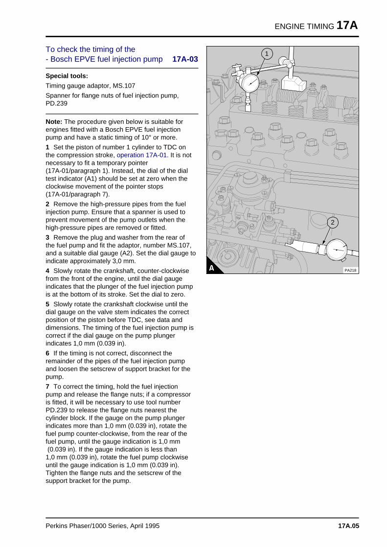
ENGINE TIMING 17A
To check the timing of the - Bosch EPVE fuel injection pump 17A-03
Special tools:
Timing gauge adaptor, MS.107
Spanner for flange nuts of fuel injection pump,PD.239
Note: The procedure given below is suitable forengines fitted with a Bosch EPVE fuel injectionpump and have a static timing of 10° or more.
1 Set the piston of number 1 cylinder to TDC onthe compression stroke, operation 17A-01. It is notnecessary to fit a temporary pointer (17A-01/paragraph 1). Instead, the dial of the dialtest indicator (A1) should be set at zero when theclockwise movement of the pointer stops (17A-01/paragraph 7).
2 Remove the high-pressure pipes from the fuelinjection pump. Ensure that a spanner is used toprevent movement of the pump outlets when thehigh-pressure pipes are removed or fitted.
3 Remove the plug and washer from the rear ofthe fuel pump and fit the adaptor, number MS.107,and a suitable dial gauge (A2). Set the dial gauge toindicate approximately 3,0 mm.
4 Slowly rotate the crankshaft, counter-clockwisefrom the front of the engine, until the dial gaugeindicates that the plunger of the fuel injection pumpis at the bottom of its stroke. Set the dial to zero.
5 Slowly rotate the crankshaft clockwise until thedial gauge on the valve stem indicates the correctposition of the piston before TDC, see data anddimensions. The timing of the fuel injection pump iscorrect if the dial gauge on the pump plungerindicates 1,0 mm (0.039 in).
6 If the timing is not correct, disconnect theremainder of the pipes of the fuel injection pumpand loosen the setscrew of support bracket for thepump.
7 To correct the timing, hold the fuel injectionpump and release the flange nuts; if a compressoris fitted, it will be necessary to use tool numberPD.239 to release the flange nuts nearest thecylinder block. If the gauge on the pump plungerindicates more than 1,0 mm (0.039 in), rotate thefuel pump counter-clockwise, from the rear of thefuel pump, until the gauge indication is 1,0 mm (0.039 in). If the gauge indication is less than 1,0 mm (0.039 in), rotate the fuel pump clockwiseuntil the gauge indication is 1,0 mm (0.039 in).Tighten the flange nuts and the setscrew of thesupport bracket for the pump.
a aa aa aa a
1
a a a
a a a
a a a
a a a
a a a
2
PA218
Perkins Phaser/1000 Series, April 1995 17A.05
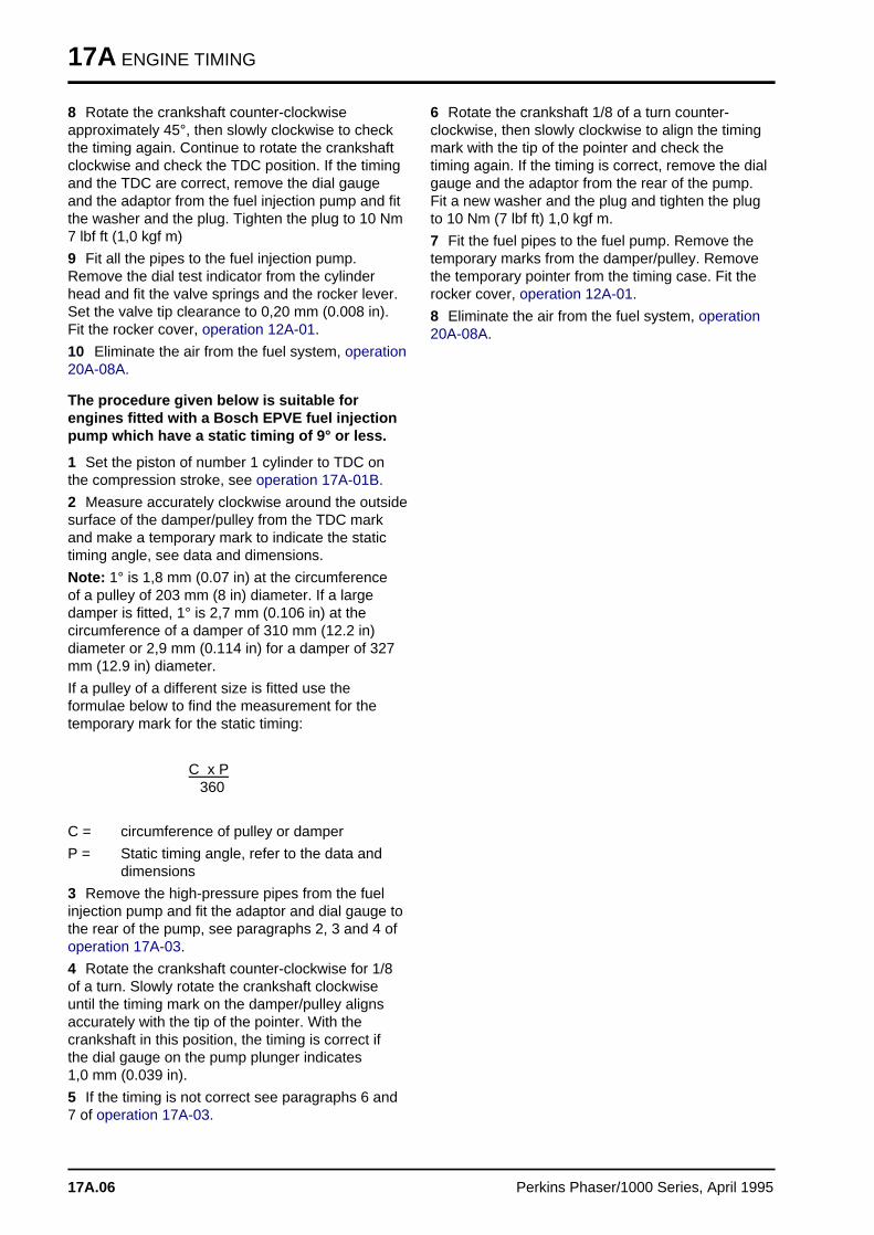
17A ENGINE TIMING
8 Rotate the crankshaft counter-clockwiseapproximately 45°, then slowly clockwise to checkthe timing again. Continue to rotate the crankshaftclockwise and check the TDC position. If the timingand the TDC are correct, remove the dial gaugeand the adaptor from the fuel injection pump and fitthe washer and the plug. Tighten the plug to 10 Nm7 lbf ft (1,0 kgf m)
9 Fit all the pipes to the fuel injection pump.Remove the dial test indicator from the cylinderhead and fit the valve springs and the rocker lever.Set the valve tip clearance to 0,20 mm (0.008 in).Fit the rocker cover, operation 12A-01.
10 Eliminate the air from the fuel system, operation20A-08A.
The procedure given below is suitable forengines fitted with a Bosch EPVE fuel injectionpump which have a static timing of 9° or less.
1 Set the piston of number 1 cylinder to TDC onthe compression stroke, see operation 17A-01B.
2 Measure accurately clockwise around the outsidesurface of the damper/pulley from the TDC markand make a temporary mark to indicate the statictiming angle, see data and dimensions.
Note: 1° is 1,8 mm (0.07 in) at the circumferenceof a pulley of 203 mm (8 in) diameter. If a largedamper is fitted, 1° is 2,7 mm (0.106 in) at thecircumference of a damper of 310 mm (12.2 in)diameter or 2,9 mm (0.114 in) for a damper of 327mm (12.9 in) diameter.
If a pulley of a different size is fitted use theformulae below to find the measurement for thetemporary mark for the static timing:
C x P 360
C = circumference of pulley or damper
P = Static timing angle, refer to the data anddimensions
3 Remove the high-pressure pipes from the fuelinjection pump and fit the adaptor and dial gauge tothe rear of the pump, see paragraphs 2, 3 and 4 ofoperation 17A-03.
4 Rotate the crankshaft counter-clockwise for 1/8of a turn. Slowly rotate the crankshaft clockwiseuntil the timing mark on the damper/pulley alignsaccurately with the tip of the pointer. With thecrankshaft in this position, the timing is correct ifthe dial gauge on the pump plunger indicates 1,0 mm (0.039 in).
5 If the timing is not correct see paragraphs 6 and7 of operation 17A-03.
6 Rotate the crankshaft 1/8 of a turn counter-clockwise, then slowly clockwise to align the timingmark with the tip of the pointer and check thetiming again. If the timing is correct, remove the dialgauge and the adaptor from the rear of the pump.Fit a new washer and the plug and tighten the plugto 10 Nm (7 lbf ft) 1,0 kgf m.
7 Fit the fuel pipes to the fuel pump. Remove thetemporary marks from the damper/pulley. Removethe temporary pointer from the timing case. Fit therocker cover, operation 12A-01.
8 Eliminate the air from the fuel system, operation20A-08A.
17A.06 Perkins Phaser/1000 Series, April 1995
ENGINE TIMING 17A
To check the timing mark of the fuelinjection pump 17A-04
Special tools:
Pump timing gauge, MS.107
Universal timing gauge, MS.67B
Gear adaptor for use with MS.67B, PD.67-3
Note: Only early Bosch EPVE pumps have a markon the flange. The mark was removed when thelocking screw was introduced.
1 Remove the fuel injection pump, operation 20A-06A.
2 Fit the adaptor PD.67-3 to the drive shaft of thefuel pump (A) and fasten it with the nut of the fuelpump gear.
3 Release the screw (B3), set the timing tool to thecorrect angle, see data and dimensions, and tightenthe screw.
4 Fit the timing tool to the splined adaptor on thefuel pump drive. Release the screw (B1), slide thepointer (B2) forward until it is over the centre of thefuel pump flange and tighten the screw. Rotate thetiming tool and the pump shaft to align the masterspline with the number 1 outlet of the pump (outlet "C").
5 Remove the plug and the washer from the centreof the rear of the fuel pump and fit the adaptorMS.107. Fit a dial gauge to the adaptor and set thegauge to indicate approximately 2,0 mm (0.080 in).
6 With the fuel injection pump held securely, rotatethe tool and the drive shaft counter-clockwise, fromthe drive end, and set the dial gauge to zero whenthe pump plunger is at its lowest position. Keep thefuel pump secure and rotate the drive shaftclockwise until the gauge indicates 1,0 mm (0.039 in) plunger lift. At this position the slot in thepointer of the timing tool must align with the markon the flange of the fuel pump.
8 If the mark is not correct, remove the timing tooland eliminate the mark on the flange. Fit the timingtool and repeat the above operation to obtain 1,0 mm (0.039 in) plunger lift. With the fuel injectionpump and timing tool held securely in the correctposition, make a new mark on the flange of the fuelpump, within the slot of the pointer. Release thetiming tool and repeat the operation to check thatthe new mark is correct.
9 Remove the timing tool, splined adaptor and theadaptor and dial gauge. Fit the washer and plug tothe rear of the fuel pump.
10 Fit the fuel injection pump, operation 20A-06A.
11 Eliminate air from the fuel system, operation20A-08A.
PA215
a aa aa aa a
1
a aa aa aa a
3
a aa aa aa a
2
PA216
Perkins Phaser/1000 Series, April 1995 17A.07
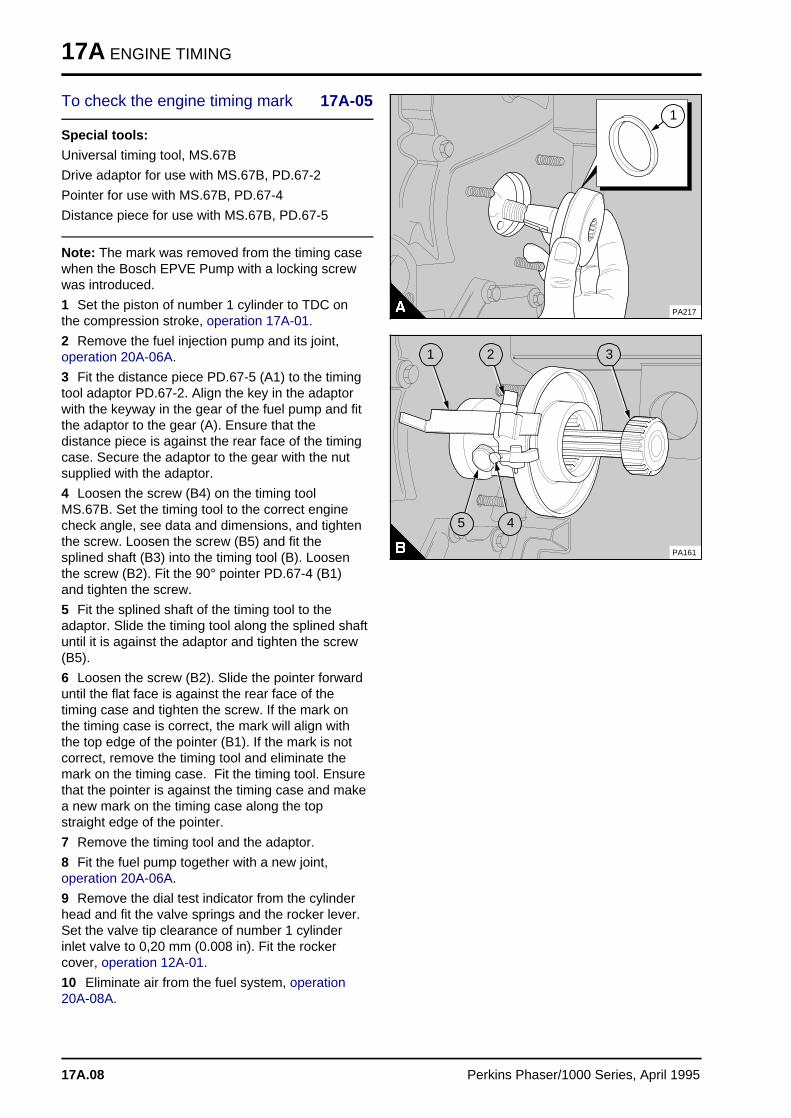
17A ENGINE TIMING
To check the engine timing mark 17A-05
Special tools:
Universal timing tool, MS.67B
Drive adaptor for use with MS.67B, PD.67-2
Pointer for use with MS.67B, PD.67-4
Distance piece for use with MS.67B, PD.67-5
Note: The mark was removed from the timing casewhen the Bosch EPVE Pump with a locking screwwas introduced.
1 Set the piston of number 1 cylinder to TDC onthe compression stroke, operation 17A-01.
2 Remove the fuel injection pump and its joint,operation 20A-06A.
3 Fit the distance piece PD.67-5 (A1) to the timingtool adaptor PD.67-2. Align the key in the adaptorwith the keyway in the gear of the fuel pump and fitthe adaptor to the gear (A). Ensure that thedistance piece is against the rear face of the timingcase. Secure the adaptor to the gear with the nutsupplied with the adaptor.
4 Loosen the screw (B4) on the timing toolMS.67B. Set the timing tool to the correct enginecheck angle, see data and dimensions, and tightenthe screw. Loosen the screw (B5) and fit thesplined shaft (B3) into the timing tool (B). Loosenthe screw (B2). Fit the 90° pointer PD.67-4 (B1)and tighten the screw.
5 Fit the splined shaft of the timing tool to theadaptor. Slide the timing tool along the splined shaftuntil it is against the adaptor and tighten the screw(B5).
6 Loosen the screw (B2). Slide the pointer forwarduntil the flat face is against the rear face of thetiming case and tighten the screw. If the mark onthe timing case is correct, the mark will align withthe top edge of the pointer (B1). If the mark is notcorrect, remove the timing tool and eliminate themark on the timing case. Fit the timing tool. Ensurethat the pointer is against the timing case and makea new mark on the timing case along the topstraight edge of the pointer.
7 Remove the timing tool and the adaptor.
8 Fit the fuel pump together with a new joint,operation 20A-06A.
9 Remove the dial test indicator from the cylinderhead and fit the valve springs and the rocker lever.Set the valve tip clearance of number 1 cylinderinlet valve to 0,20 mm (0.008 in). Fit the rockercover, operation 12A-01.
10 Eliminate air from the fuel system, operation20A-08A.
PA217
a aa aa aa a
1
a a a
a a a
a a a
a a a
5a aa aa aa a
4
a a a
a a a
a a a
a a a
1
a aa aa aa a
2
a a a
a a a
a a a
a a a
3
PA161
17A.08 Perkins Phaser/1000 Series, April 1995
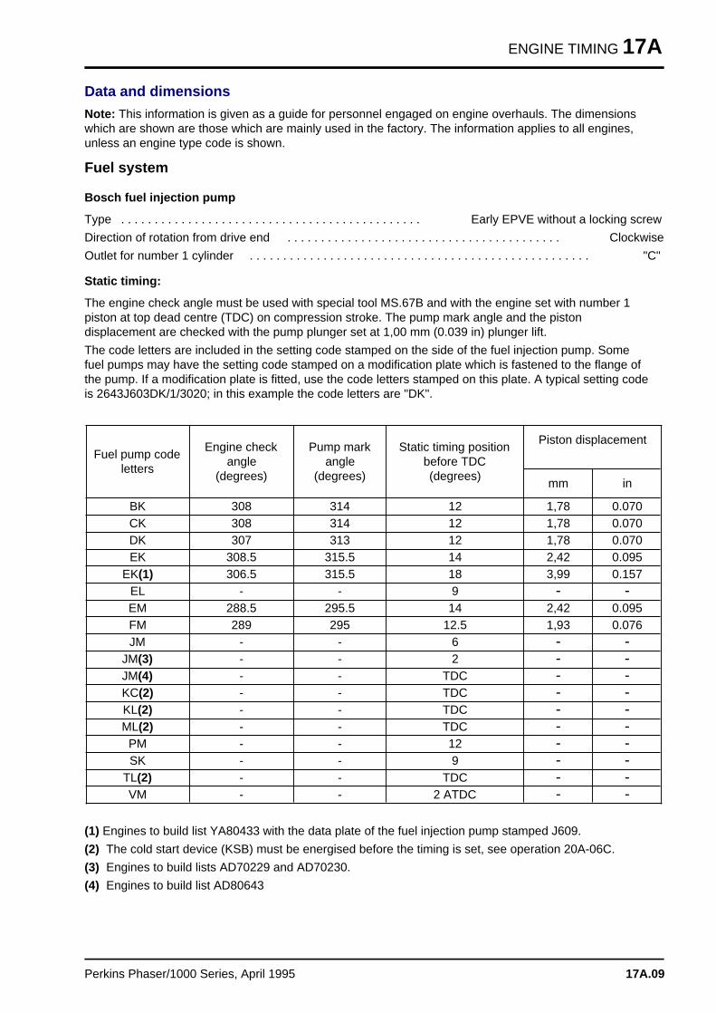
ENGINE TIMING 17A
Data and dimensions
Note: This information is given as a guide for personnel engaged on engine overhauls. The dimensionswhich are shown are those which are mainly used in the factory. The information applies to all engines,unless an engine type code is shown.
Fuel system
Bosch fuel injection pump
Type . . . . . . . . . . . . . . . . . . . . . . . . . . . . . . . . . . . . . . . . . . . . . Early EPVE without a locking screw
Direction of rotation from drive end . . . . . . . . . . . . . . . . . . . . . . . . . . . . . . . . . . . . . . . . . Clockwise
Outlet for number 1 cylinder . . . . . . . . . . . . . . . . . . . . . . . . . . . . . . . . . . . . . . . . . . . . . . . . . . . "C"
Static timing:
The engine check angle must be used with special tool MS.67B and with the engine set with number 1piston at top dead centre (TDC) on compression stroke. The pump mark angle and the pistondisplacement are checked with the pump plunger set at 1,00 mm (0.039 in) plunger lift.
The code letters are included in the setting code stamped on the side of the fuel injection pump. Somefuel pumps may have the setting code stamped on a modification plate which is fastened to the flange ofthe pump. If a modification plate is fitted, use the code letters stamped on this plate. A typical setting codeis 2643J603DK/1/3020; in this example the code letters are "DK".
Fuel pump codeletters
Engine checkangle
(degrees)
Pump markangle
(degrees)
Static timing positionbefore TDC(degrees)
Piston displacement
mm in
BK 308 314 12 1,78 0.070CK 308 314 12 1,78 0.070DK 307 313 12 1,78 0.070EK 308.5 315.5 14 2,42 0.095
EK(1) 306.5 315.5 18 3,99 0.157EL - - 9 > >EM 288.5 295.5 14 2,42 0.095FM 289 295 12.5 1,93 0.076JM - - 6 > >
JM(3) - - 2 > >JM(4) - - TDC > >KC(2) - - TDC > >KL(2) - - TDC > >ML(2) - - TDC > >
PM - - 12 > >SK - - 9 > >
TL(2) - - TDC > >VM - - 2 ATDC > >
(1) Engines to build list YA80433 with the data plate of the fuel injection pump stamped J609.
(2) The cold start device (KSB) must be energised before the timing is set, see operation 20A-06C.
(3) Engines to build lists AD70229 and AD70230.
(4) Engines to build list AD80643
Perkins Phaser/1000 Series, April 1995 17A.09
Engines fitted with Bosch MW in-line fuel injection pump s 17BGeneral description. . . . . . . . . . . . . . . . . . . . . . . . . . . . . . . . . . . . . . . . . . . . . . . 17B.02
Engine timing
17B-01 To set number 1 piston to TDC on the compression stroke refer to 17A.0417B-02 To check the valve timing . . . . . . . . . . . . . . . . . . . . . . . . refer to 17A.0417B-03 To check the timing of the fuel injection pump . . . . . . . . . . . . . . 17B.03
Data and dimension s . . . . . . . . . . . . . . . . . . . . . . . . . . . . . . . . . . . . . . . 17B.05
Perkins Phaser/1000 Series, April 1995 17B.01

17B ENGINE TIMING
General description
The timing gears are stamped with timing marks toensure that they are assembled correctly (A). Thestamped teeth of the crankshaft and camshaftgears will be in mesh with the idler gear whennumber 1 piston is at top dead centre (TDC) on thecompression stroke. The marked teeth of the idlergear may not necessarily be in mesh, in thisposition, because of the different speeds at whichthe gears rotate.
There are no timing marks on the fuel pump gear ofengine types AE and YE. The gear, which isfastened to a hub on the drive shaft of the fuelinjection pump, has slots to allow adjustment to thetiming.A data plate is fitted to the pump. An example ofthe information shown on the plate (B) is:
Perkins part number (1)
Fuel pump code (2)
Maximum engine no load speed (3)
High idle reset speed (4)
Notes:
• The maximum no load speed (B3) set by Perkinsmay be reset by the equipment manufacturer. If thespeed is changed the new speed is shown in thehigh idle reset position (B4). The original maximumno load speed should be remove from the label.
• The adjustment screw for the maximum no loadspeed, is sealed by the manufacturer. The settingmust not be changed, unless approved, as it couldaffect the warranty of the engine.
For details of the fuel pump code for the engine seethe data and dimensions at the end of this section.
PA209
a a a
a a a
a a a
a a a
3
a a a
a a a
a a a
a a a
1
High idle reset
PA317
a a a
a a a
a a a
a a a
2
a aa aa aa aa a
4
2643J000WM/1/2860 Mfg
17B.02 Perkins Phaser/1000 Series, April 1995
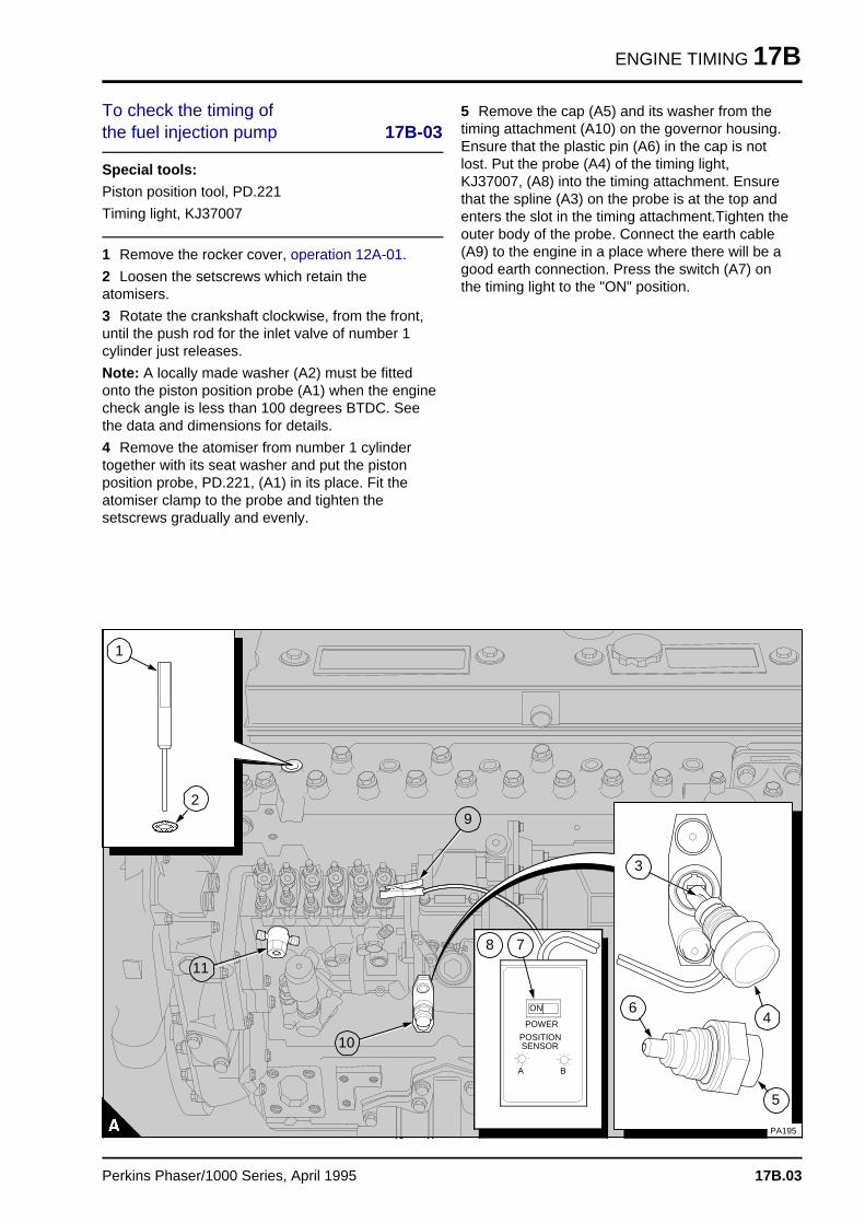
ENGINE TIMING 17B
To check the timing of the fuel injection pump 17B-03
Special tools:
Piston position tool, PD.221
Timing light, KJ37007
1 Remove the rocker cover, operation 12A-01.
2 Loosen the setscrews which retain theatomisers.
3 Rotate the crankshaft clockwise, from the front,until the push rod for the inlet valve of number 1cylinder just releases.
Note: A locally made washer (A2) must be fittedonto the piston position probe (A1) when the enginecheck angle is less than 100 degrees BTDC. Seethe data and dimensions for details.
4 Remove the atomiser from number 1 cylindertogether with its seat washer and put the pistonposition probe, PD.221, (A1) in its place. Fit theatomiser clamp to the probe and tighten thesetscrews gradually and evenly.
5 Remove the cap (A5) and its washer from thetiming attachment (A10) on the governor housing.Ensure that the plastic pin (A6) in the cap is notlost. Put the probe (A4) of the timing light,KJ37007, (A8) into the timing attachment. Ensurethat the spline (A3) on the probe is at the top andenters the slot in the timing attachment.Tighten theouter body of the probe. Connect the earth cable(A9) to the engine in a place where there will be agood earth connection. Press the switch (A7) onthe timing light to the "ON" position.
a a a a a a a a a a a a a a a a a a a a a a a a
a a a a a a a a a a a a a a a a a a a a a a a a
a a a a a a a a a a a a a a a a a a a a a a a a
a a a a a a a a a a a a a a a a a a a a a a a a
a a a a a a a a a a a a a a a a a a a a a a a a
a a a a a a a a a a a a a a a a a a a a a a a a
a a a a a a a a a a a a a a a a a a a a a a a a
a a a a a a a a a a a a a a a a a a a a a a a a
a a a a a a a a a a a a a a a a a a a a a a a a
a a a a a a a a a a a a a a a a a a a a a a a a
a a a a a a a a a a a a a a a a a a a a a a a a
a a a a a a a a a a a a a a a a a a a a a a a a
a a a a a a a a a a a a a a a a a a a a a a a a
a a a a a a a a a a a a a a a a a a a a a a a a
a a a a a a a a a a a a a a a a a a a a a a a a
a a a a a a a a a a a a a a a a a a a a a a a a
a a a a a a a a a a a a a a a a a a a a a a a a
a a a a a a a a a a a a a a a a a a a a a a a a
a a a a a a a a a a a a a a a a a a a a a a a a
a a a a a a a a a a a a a a a a a a a a a a a a
a a a a a a a a a a a a a a a a a a a a a a a a
a a a a a a a a a a a a a a a a a a a a a a a a
a a a a a a a a a a a a a a a a a a a a a a a a
a a a a a a a a a a a a a a a a a a a a a a a a
a a a a a a a a a a a a a a a a a a a a a a a a
a a a a a a a a a a a a a a a a a a a a a a a a
a a a a a a a a a a a a a a a a a a a a a a a a
a a a a a a a a a a a a a a a a a a a a a a a a
a a a a a a a a a a a a a a a a a a a a a a a a
a a a a a a a a a a a a a a a a a a a a a a a a
a a a a a a a a a a a a a a a a a a a a a a a a
a a a a a a a a a a a a a a a a a a a a a a a a
a a a a a a a a a a a a a a a a a a a a a a a a
a a a a a a a a a a a a a a a a a a a a a a a a
a a a a a a a a a a a a a a a a a a a a a a a a
a a a a a a a a a a a a a a a a a a a a a a a a
a a a a a a a a a a a a a a a a a a a a a a a a
a a a a
a a a a
ON
a a a a a a a
a a a a a a a
a a a a a a a
POWER
a a a
a a aA a aa aB
a a a a a a a a a
a a a a a a a a a
a a a a a a a a a
a a a a a a a a a
POSITIONSENSOR
a a a a a a a a a a a a a a a a a a a a a a a a a a a a a a a a a
a a a a a a a a a a a a a a a a a a a a a a a a a a a a a a a a a
a a a a a a a a a a a a a a a a a a a a a a a a a a a a a a a a a
a a a a a a a a a a a a a a a a a a a a a a a a a a a a a a a a a
a a a a a a a a a a a a a a a a a a a a a a a a a a a a a a a a a
a a a a a a a a a a a a a a a a a a a a a a a a a a a a a a a a a
a a a a a a a a a a a a a a a a a a a a a a a a a a a a a a a a a
a a a a a a a a a a a a a a a a a a a a a a a a a a a a a a a a a
a a a a a a a a a a a a a a a a a a a a a a a a a a a a a a a a a
a a a a a a a a a a a a a a a a a a a a a a a a a a a a a a a a a
a a a a a a a a a a a a a a a a a a a a a a a a a a a a a a a a a
a a a a a a a a a a a a a a a a a a a a a a a a a a a a a a a a a
a a a a a a a a a a a a a a a a a a a a a a a a a a a a a a a a a
a a a a a a a a a a a a a a a a a a a a a a a a a a a a a a a a a
a a a a a a a a a a a a a a a a a a a a a a a a a a a a a a a a a
a a a a a a a a a a a a a a a a a a a a a a a a a a a a a a a a a
a a a a a a a a a a a a a a a a a a a a a a a a a a a a a a a a a
a a a a a a a a a a a a a a a a a a a a a a a a a a a a a a a a a
a a a a a a a a a a a a a a a a a a a a a a a a a a a a a a a a a
a a a a a a a a a a a a a a a a a a a a a a a a a a a a a a a a a
a a a a a a a a a a a a a a a a a a a a a a a a a a a a a a a a a
a a a a a a a a a a a a a a a a a a a a a a a a a a a a a a a a a
a a a a a a a a a a a a a a a a a a a a a a a a a a a a a a a a a
a a a a a a a a a a a a a a a a a a a a a a a a a a a a a a a a a
a a a a a a a a a a a a a a a a a a a a a a a a a a a a a a a a a
a a a a a a a a a a a a a a a a a a a a a a a a a a a a a a a a a
a a a a a a a a a a a a a a a a a a a a a a a a a a a a a a a a a
a a a a a a a a a a a a a a a a a a a a a a a a a a a a a a a a a
a a a a a a a a a a a a a a a a a a a a a a a a a a a a a a a a a
a a a a a a a a a a a a a a a a a a a a a a a a a a a a a a a a a
a a a a a a a a a a a a a a a a a a a a a a a a a a a a a a a a a
a a a a a a a a a a a a a a a a a a a a a a a a a a a a a a a a a
a a a a a a a a a a a a a a a a a a a a a a a a a a a a a a a a a
a a a a a a a a a a a a a a a a a a a a a a a a a a a a a a a a a
a a a a a a a a a a a a a a a a a a a a a a a a a a a a a a a a a
a a a a a a a a a a a a a a a a a a a a a a a a a a a a a a a a a
a a a a a a a a a a a a a a a a a a a a a a a a a a a a a a a a a
a a a a a a a a a a a a a a a a a a a a a a a a a a a a a a a a a
a a a a a a a a a a a a a a a a a a a a a a a a a a a a a a a a a
a a a a a a a a a a a a a a a a a a a a a a a a a a a a a a a a a
a a a a a a a a a a a a a a a a a a a a a a a a a a a a a a a a a
a a a a a a a a a a a a a a a a a a a a a a a a a a a a a a a a a
a a a a a a a a a a a a a a a a a a a a a a a a a a a a a a a a a
a a a a a a a a a a a a a a a a a a a a a a a a a a a a a a a a a
a a a a a a a a a a a a a a a a a a a a a a a a a a a a a a a a a
a a a a a a a a a a a a a a a a a a a a a a a a a a a a a a a a a
a a a a a a a a a a a a a a a a a a a a a a a a a a a a a a a a a
a a a a a a a a a a a a a a a a a a a a a a a a a a a a a a a a a
a a a a a a a a a a a a a a a a a a a a a a a a a a a a a a a a a
a a a a a a a a a a a a a a a a a a a a a a a a a a a a a a a a a
a a a a a a a a a a a a a a a a a a a a a a a a a a a a a a a a a
a a a a a a a a a a a a a a a a a a a a a a a a a a a a a a a a a
a a a a a a a a a a a a a a a a a a a a a a a a a a a a a a a a a
a a a a a a a a a a a a a a a a a a a a a a a a a a a a a a a a a
a a a a a a a a a a a a a a a a a a a a a a a a a a a a a a a a a
a a a a a a a a a a a a a a a a a a a a a a a a a a a a a a a a a
a a a a a a a a a a a a a a a a a a a a a a a a a a a a a a a a a
a a a a a a a a a a a a a a a a a a a a a a a a a a a a a a a a a
a a a a a a a a a a a a a a a a a a a a a a a a a a a a a a a a a
a a a a a a a a a a a a a a a a a a a a a a a a a a a a a a a a a
a a a
a a a
a a a
a a a
1a a a
a a a
a a a
a a a
a a a
3
a a a
a a a
a a a
a a a
4
a aa aa aa a
5
a a a
a a a
a a a
a a a
6
a a a
a a a
a a a
a a a
8 a a a
a a a
a a a
a a a
7
a a a a
a a a a
a a a a
a a a a
10
a aa aa aa a
9
PA195
a a a a
a a a a
a a a a
a a a a
11
a a a a a
a a a a a
a a a a a
a aa aa aa a
2
Perkins Phaser/1000 Series, April 1995 17B.03
17B ENGINE TIMING
Caution: Ensure that the piston comes lightly intocontact with the piston position probe, or both thepiston and the probe could be damaged.
6 Very carefully rotate the crankshaft clockwiseuntil the piston just comes into contact with thepiston position probe.
7 The timing is correct when the two lamps on thetiming light are illuminated.
If both of the lamps are not illuminated, release thesetscrews and remove the gear cover from thetiming case cover. Loosen the cap screws whichretain the fuel pump gear. Adjust the position of thefuel injection pump hub until both lamps areilluminated. Tighten the cap screws to 35 Nm (26 lbf ft) 3,6 kgf m.
8 To check the timing is correct: Rotate thecrankshaft counter-clockwise, from the front of theengine to move the piston away from the probe andrepeat paragraphs six and seven above.
9 Press the switch on the timing light to the "OFF"position. Disconnect the earth cable from theengine. Release the outer body of the probe andremove the probe from the timing attachment andremove the timing light.
10 Check that the brass end of the plastic pin canbe seen in the cap for the timing attachment. Fit thecap together with a new washer.
Caution: If the plastic pin is not put into the capcorrectly, damage could occur to the fuel injectionpump.
11 Release the setscrews and remove the pistonposition probe from number 1 cylinder. Fit theatomiser together with a new seat washer. Tightenthe setscrews for all of the atomisers gradually andevenly to 12 Nm (9 lbf ft) 1,2 kgf m.
12 Fit the gear cover together with a new joint tothe timing case cover. Clean the threads of thesetscrews for the gear cover and apply a sealant tothe threads. Fit the setscrews and tighten them.
13 Fit the rocker cover, operation 12A-01.
17B.04 Perkins Phaser/1000 Series, April 1995
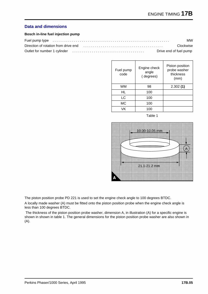
ENGINE TIMING 17B
Data and dimensions
Bosch in-line fuel injection pump
Fuel pump type . . . . . . . . . . . . . . . . . . . . . . . . . . . . . . . . . . . . . . . . . . . . . . . . . . . . . . . . . . . . MW
Direction of rotation from drive end . . . . . . . . . . . . . . . . . . . . . . . . . . . . . . . . . . . . . . . . . Clockwise
Outlet for number 1 cylinder . . . . . . . . . . . . . . . . . . . . . . . . . . . . . . . . . . . . . Drive end of fuel pump
Table 1
Fuel pumpcode
Engine checkangle
( degrees)
Piston positionprobe washer
thickness(mm)
WM 98 2.302 (1)
HL 100
LC 100
MC 100
VK 100a a a a a a a a a a a a a a a a a a a a a a a a a a a a a a a a a a a a a a a a a a a a a a a a a a a a a a a a a a a a a
a a a a a a a a a a a a a a a a a a a a a a a a a a a a a a a a a a a a a a a a a a a a a a a a a a a a a a a a a a a a a
a a a a a a a a a a a a a a a a a a a a a a a a a a a a a a a a a a a a a a a a a a a a a a a a a a a a a a a a a a a a a
a a a a a a a a a a a a a a a a a a a a a a a a a a a a a a a a a a a a a a a a a a a a a a a a a a a a a a a a a a a a a
a a a a a a a a a a a a a a a a a a a a a a a a a a a a a a a a a a a a a a a a a a a a a a a a a a a a a a a a a a a a a
a a a a a a a a a a a a a a a a a a a a a a a a a a a a a a a a a a a a a a a a a a a a a a a a a a a a a a a a a a a a a
a a a a a a a a a a a a a a a a a a a a a a a a a a a a a a a a a a a a a a a a a a a a a a a a a a a a a a a a a a a a a
a a a a a a a a a a a a a a a a a a a a a a a a a a a a a a a a a a a a a a a a a a a a a a a a a a a a a a a a a a a a a
a a a a a a a a a a a a a a a a a a a a a a a a a a a a a a a a a a a a a a a a a a a a a a a a a a a a a a a a a a a a a
a a a a a a a a a a a a a a a a a a a a a a a a a a a a a a a a a a a a a a a a a a a a a a a a a a a a a a a a a a a a a
a a a a a a a a a a a a a a a a a a a a a a a a a a a a a a a a a a a a a a a a a a a a a a a a a a a a a a a a a a a a a
a a a a a a a a a a a a a a a a a a a a a a a a a a a a a a a a a a a a a a a a a a a a a a a a a a a a a a a a a a a a a
a a a a a a a a a a a a a a a a a a a a a a a a a a a a a a a a a a a a a a a a a a a a a a a a a a a a a a a a a a a a a
a a a a a a a a a a a a a a a a a a a a a a a a a a a a a a a a a a a a a a a a a a a a a a a a a a a a a a a a a a a a a
a a a a a a a a a a a a a a a a a a a a a a a a a a a a a a a a a a a a a a a a a a a a a a a a a a a a a a a a a a a a a
a a a a a a a a a a a a a a a a a a a a a a a a a a a a a a a a a a a a a a a a a a a a a a a a a a a a a a a a a a a a a
a a a a a a a a a a a a a a a a a a a a a a a a a a a a a a a a a a a a a a a a a a a a a a a a a a a a a a a a a a a a a
a a a a a a a a a a a a a a a a a a a a a a a a a a a a a a a a a a a a a a a a a a a a a a a a a a a a a a a a a a a a a
a a a a a a a a a a a a a a a a a a a a a a a a a a a a a a a a a a a a a a a a a a a a a a a a a a a a a a a a a a a a a
a a a a a a a a a a a a a a a a a a a a a a a a a a a a a a a a a a a a a a a a a a a a a a a a a a a a a a a a a a a a a
a a a a a a a a a a a a a a a a a a a a a a a a a a a a a a a a a a a a a a a a a a a a a a a a a a a a a a a a a a a a a
a a a a a a a a a a a a a a a a a a a a a a a a a a a a a a a a a a a a a a a a a a a a a a a a a a a a a a a a a a a a a
a a a a a a a a a a a a a a a a a a a a a a a a a a a a a a a a a a a a a a a a a a a a a a a a a a a a a a a a a a a a a
a a a a a a a a a a a a a a a a a a a a a a a a a a a a a a a a a a a a a a a a a a a a a a a a a a a a a a a a a a a a a
a a a a a a a a a a a a a a a a a a a a a a a a a a a a a a a a a a a a a a a a a a a a a a a a a a a a a a a a a a a a a
a a a a a a a a a a a a a a a a a a a a a a a a a a a a a a a a a a a a a a a a a a a a a a a a a a a a a a a a a a a a a
a a a a a a a a a a a a a a a a a a a a a a a a a a a a a a a a a a a a a a a a a a a a a a a a a a a a a a a a a a a a a
a a a a a a a a a a a a a a a a a a a a a a a a a a a a a a a a a a a a a a a a a a a a a a a a a a a a a a a a a a a a a
a a a a a a a a a a a a a a a a a a a a a a a a a a a a a a a a a a a a a a a a a a a a a a a a a a a a a a a a a a a a a
a a a a a a a a a a a a a a a a a a a a a a a a a a a a a a a a a a a a a a a a a a a a a a a a a a a a a a a a a a a a a
a a a a a a a a a a a a a a a a a a a a a a a a a a a a a a a a a a a a a a a a a a a a a a a a a a a a a a a a a a a a a
a a a a a a a a a a a a a a a a a a a a a a a a a a a a a a a a a a a a a a a a a a a a a a a a a a a a a a a a a a a a a
a a a a a a a a a a a a a a a a a a a a a a a a a a a a a a a a a a a a a a a a a a a a a a a a a a a a a a a a a a a a a
a a a a a a a a a a a a a a a a a a a a a a a a a a a a a a a a a a a a a a a a a a a a a a a a a a a a a a a a a a a a a
a a a a a a a a a a a a a a a a a a a a a a a a a a a a a a a a a a a a a a a a a a a a a a a a a a a a a a a a a a a a a
a a a a a a a a a a a a a a a a a a a a a a a a a a a a a a a a a a a a a a a a a a a a a a a a a a a a a a a a a a a a a
a a a a a a a a a a a a a a a a a a a a a a a a a a a a a a a a a a a a a a a a a a a a a a a a a a a a a a a a a a a a a
a a a a a a a a a a a a a a a a a a a a a a a a a a a a a a a a a a a a a a a a a a a a a a a a a a a a a a a a a a a a a
a a a a a a a a a a a a a a a a a a a a a a a a a a a a a a a a a a a a a a a a a a a a a a a a a a a a a a a a a a a a a
a a a a a a a a a a a a a a a a a a a a a a a a a a a a a a a a a a a a a a a a a a a a a a a a a a a a a a a a a a a a a
a a a a a a a a a a a a a a a a a a a a a a a a a a a a a a a a a a a a a a a a a a a a a a a a a a a a a a a a a a a a a
a a a a a a a a a a a a a a a a a a a a a a a a a a a a a a a a a a a a a a a a a a a a a a a a a a a a a a a a a a a a a
a a a a a a a a a a a a a a a a a a a a a a a a a a a a a a a a a a a a a a a a a a a a a a a a a a a a a a a a a a a a a
a a a a a a a a a a a a a a a a a a a a a a a a a a a a a a a a a a a a a a a a a a a a a a a a a a a a a a a a a a a a a
a a a a a a a a a a a a a a a a a a a a a a a a a a a a a a a a a a a a a a a a a a a a a a a a a a a a a a a a a a a a a
a a a
a a a
a a a
a a a
A
a a a a a a a a a a a a a a a a a a
a a a a a a a a a a a a a a a a a a
a a a a a a a a a a a a a a a a a a
a a a a a a a a a a a a a a a a a a
21.1-21.2 mm
a a a a a a a a a a a a a a a a a a a a a
a a a a a a a a a a a a a a a a a a a a a
a a a a a a a a a a a a a a a a a a a a a
a a a a a a a a a a a a a a a a a a a a a
10.00-10.05 mm
The piston position probe PD 221 is used to set the engine check angle to 100 degrees BTDC.
A locally made washer (A) must be fitted onto the piston position probe when the engine check angle isless than 100 degrees BTDC.
The thickness of the piston position probe washer, dimension A, in illustration (A) for a specific engine isshown in shown in table 1. The general dimensions for the piston position probe washer are also shown in(A).
Perkins Phaser/1000 Series, April 1995 17B.05
Engines fitted with Lucas DPA and DPSfuel injection pump s 17C
General description. . . . . . . . . . . . . . . . . . . . . . . . . . . . . . . . . . . . . . . . . . . . . . 17C.02
Engine timing
17C-01A To set number 1 piston to TDC on the compression stroke refer to 17A.0317C-01B Another method to set number 1 piston to TDC on
the compression stroke . . . . . . . . . . . . . . . . . . . . . . . . . . refer to 17A.0417C-02 To check the valve timing . . . . . . . . . . . . . . . . . . . . . . . . refer to 17A.0417C-03 To check the timing of the fuel injection pump . . . . . . . . . . . . . . 17C.0317C-04 To check the timing mark of the fuel injection pump . . . . . . . . . . 17C.0417C-05 To check the engine timing mark . . . . . . . . . . . . . . . . . . . . . . . . 17C.05
Data and dimension s . . . . . . . . . . . . . . . . . . . . . . . . . . . . . . . . . . . . . . . 17C.06
Perkins Phaser/1000 Series, April 1995 17C.01
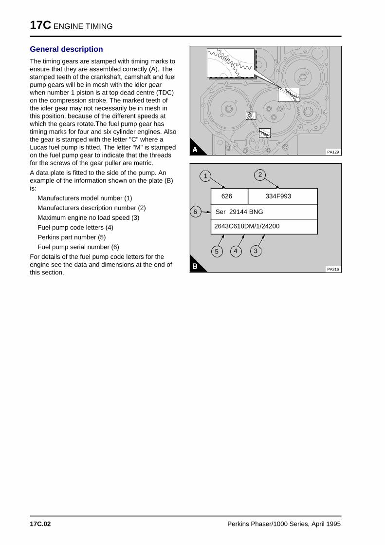
17C ENGINE TIMING
General description
The timing gears are stamped with timing marks toensure that they are assembled correctly (A). Thestamped teeth of the crankshaft, camshaft and fuelpump gears will be in mesh with the idler gearwhen number 1 piston is at top dead centre (TDC)on the compression stroke. The marked teeth ofthe idler gear may not necessarily be in mesh inthis position, because of the different speeds atwhich the gears rotate.The fuel pump gear hastiming marks for four and six cylinder engines. Alsothe gear is stamped with the letter "C" where aLucas fuel pump is fitted. The letter "M" is stampedon the fuel pump gear to indicate that the threadsfor the screws of the gear puller are metric.
A data plate is fitted to the side of the pump. Anexample of the information shown on the plate (B)is:
Manufacturers model number (1)
Manufacturers description number (2)
Maximum engine no load speed (3)
Fuel pump code letters (4)
Perkins part number (5)
Fuel pump serial number (6)
For details of the fuel pump code letters for theengine see the data and dimensions at the end ofthis section.
a a a a a a a a a a a a a a a a a a a a a a a a a a a a a a
a a a a a a a a a a a a a a a a a a a a a a a a a a a a a a
a a a a a a a a a a a a a a a a a a a a a a a a a a a a a a
a a a a a a a a a a a a a a a a a a a a a a a a a a a a a a
a a a a a a a a a a a a a a a a a a a a a a a a a a a a a a
a a a a a a a a a a a a a a a a a a a a a a a a a a a a a a
a a a a a a a a a a a a a a a a a a a a a a a a a a a a a a
a a a a a a a a a a a a a a a a a a a a a a a a a a a a a a
a a a a a a a a a a a a a a a a a a a a a a a a a a a a a a
a a a a a a a a a a a a a a a a a a a a a a a a a a a a a a
a a a a a a a a a a a a a a a a a a a a a a a a a a a a a a
a a a a a a a a a a a a a a a a a a a a a a a a a a a a a a
a a a a a a a a a a a a a a a a a a a a a a a a a a a a a a
a a a a a a a a a a a a a a a a a a a a a a a a a a a a a a
a a a a a a a a a a a a a a a a a a a a a a a a a a a a a a
a a a a a a a a a a a a a a a a a a a a a a a a a a a a a a
PA129
334F993 626
PA316
a a a
a a a
a a a
a a a
2
a a a a a a a a a a a a a a a a a a a a a a
a a a a a a a a a a a a a a a a a a a a a a
a a a a a a a a a a a a a a a a a a a a a a
a a a a a a a a a a a a a a a a a a a a a a
Ser 29144 BNG a a a a a a a a a a a a a a a a a a a a a a a a a a a
a a a a a a a a a a a a a a a a a a a a a a a a a a a
a a a a a a a a a a a a a a a a a a a a a a a a a a a
a a a a a a a a a a a a a a a a a a a a a a a a a a a
2643C618DM/1/24200
a aa aa aa a
1
a a a
a a a
a a a
a a a
6
a aa aa aa a
3
a aa aa aa a
4a a a
a a a
a a a
a a a
5
17C.02 Perkins Phaser/1000 Series, April 1995
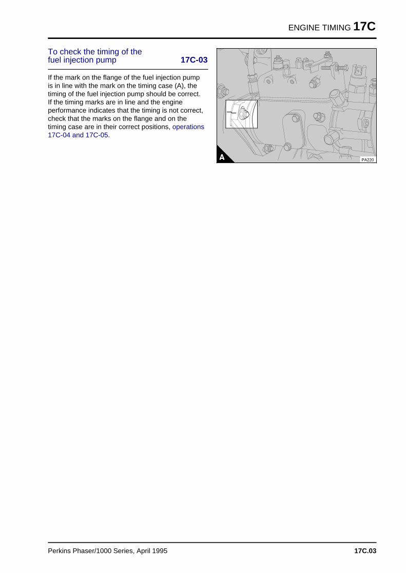
ENGINE TIMING 17C
To check the timing of the fuel injection pump 17C-03
If the mark on the flange of the fuel injection pumpis in line with the mark on the timing case (A), thetiming of the fuel injection pump should be correct.If the timing marks are in line and the engineperformance indicates that the timing is not correct,check that the marks on the flange and on thetiming case are in their correct positions, operations17C-04 and 17C-05.
PA220
Perkins Phaser/1000 Series, April 1995 17C.03
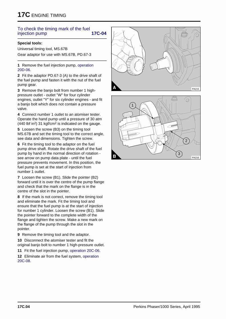
17C ENGINE TIMING
To check the timing mark of the fuelinjection pump 17C-04
Special tools:
Universal timing tool, MS.67B
Gear adaptor for use with MS.67B, PD.67-3
1 Remove the fuel injection pump, operation 20D-06.
2 Fit the adaptor PD.67-3 (A) to the drive shaft ofthe fuel pump and fasten it with the nut of the fuelpump gear.
3 Remove the banjo bolt from number 1 high-pressure outlet - outlet "W" for four cylinderengines, outlet "Y" for six cylinder engines - and fita banjo bolt which does not contain a pressurevalve.
4 Connect number 1 outlet to an atomiser tester.Operate the hand pump until a pressure of 30 atm(440 lbf in2) 31 kgf/cm2 is indicated on the gauge.
5 Loosen the screw (B3) on the timing toolMS.67B and set the timing tool to the correct angle,see data and dimensions. Tighten the screw.
6 Fit the timing tool to the adaptor on the fuelpump drive shaft. Rotate the drive shaft of the fuelpump by hand in the normal direction of rotation -see arrow on pump data plate - until the fuelpressure prevents movement. In this position, thefuel pump is set at the start of injection fromnumber 1 outlet.
7 Loosen the screw (B1). Slide the pointer (B2)forward until it is over the centre of the pump flangeand check that the mark on the flange is in thecentre of the slot in the pointer.
8 If the mark is not correct, remove the timing tooland eliminate the mark. Fit the timing tool andensure that the fuel pump is at the start of injectionfor number 1 cylinder. Loosen the screw (B1). Slidethe pointer forward to the complete width of theflange and tighten the screw. Make a new mark onthe flange of the pump through the slot in thepointer.
9 Remove the timing tool and the adaptor.
10 Disconnect the atomiser tester and fit theoriginal banjo bolt to number 1 high-pressure outlet.
11 Fit the fuel injection pump, operation 20C-06.
12 Eliminate air from the fuel system, operation 20C-08.
PA215
a aa aa aa a
1
a a a
a a a
a a a
a a a
3
a a a
a a a
a a a
a a a
2
PA216
17C.04 Perkins Phaser/1000 Series, April 1995
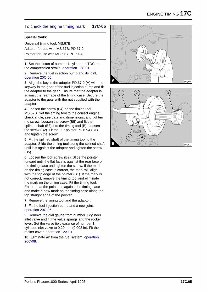
ENGINE TIMING 17C
To check the engine timing mark 17C-05
Special tools:
Universal timing tool, MS.67B
Adaptor for use with MS.67B, PD.67-2
Pointer for use with MS.67B, PD.67-4
1 Set the piston of number 1 cylinder to TDC onthe compression stroke, operation 17C-01.
2 Remove the fuel injection pump and its joint,operation 20C-06.
3 Align the key in the adaptor PD.67-2 (A) with thekeyway in the gear of the fuel injection pump and fitthe adaptor to the gear. Ensure that the adaptor isagainst the rear face of the timing case. Secure theadaptor to the gear with the nut supplied with theadaptor.
4 Loosen the screw (B4) on the timing toolMS.67B. Set the timing tool to the correct enginecheck angle, see data and dimensions, and tightenthe screw. Loosen the screw (B5) and fit thesplined shaft (B3) into the timing tool (B). Loosenthe screw (B2). Fit the 90° pointer PD.67-4 (B1)and tighten the screw.
5 Fit the splined shaft of the timing tool to theadaptor. Slide the timing tool along the splined shaftuntil it is against the adaptor and tighten the screw(B5).
6 Loosen the lock screw (B2). Slide the pointerforward until the flat face is against the rear face ofthe timing case and tighten the screw. If the markon the timing case is correct, the mark will alignwith the top edge of the pointer (B1). If the mark isnot correct, remove the timing tool and eliminatethe mark on the timing case. Fit the timing tool.Ensure that the pointer is against the timing caseand make a new mark on the timing case along thetop straight edge of the pointer.
7 Remove the timing tool and the adaptor.
8 Fit the fuel injection pump and a new joint,operation 20C-06.
9 Remove the dial gauge from number 1 cylinderinlet valve and fit the valve springs and the rockerlever. Set the valve tip clearance of number 1cylinder inlet valve to 0,20 mm (0.008 in). Fit therocker cover, operation 12A-01.
10 Eliminate air from the fuel system, operation20C-08.
PA160
a a a
a a a
a a a
a a a
5a a a
a a a
a a a
a a a
4
a a a
a a a
a a a
a a a
1
a a a
a a a
a a a
a a a
2
a a a
a a a
a a a
a a a
3
PA161
Perkins Phaser/1000 Series, April 1995 17C.05
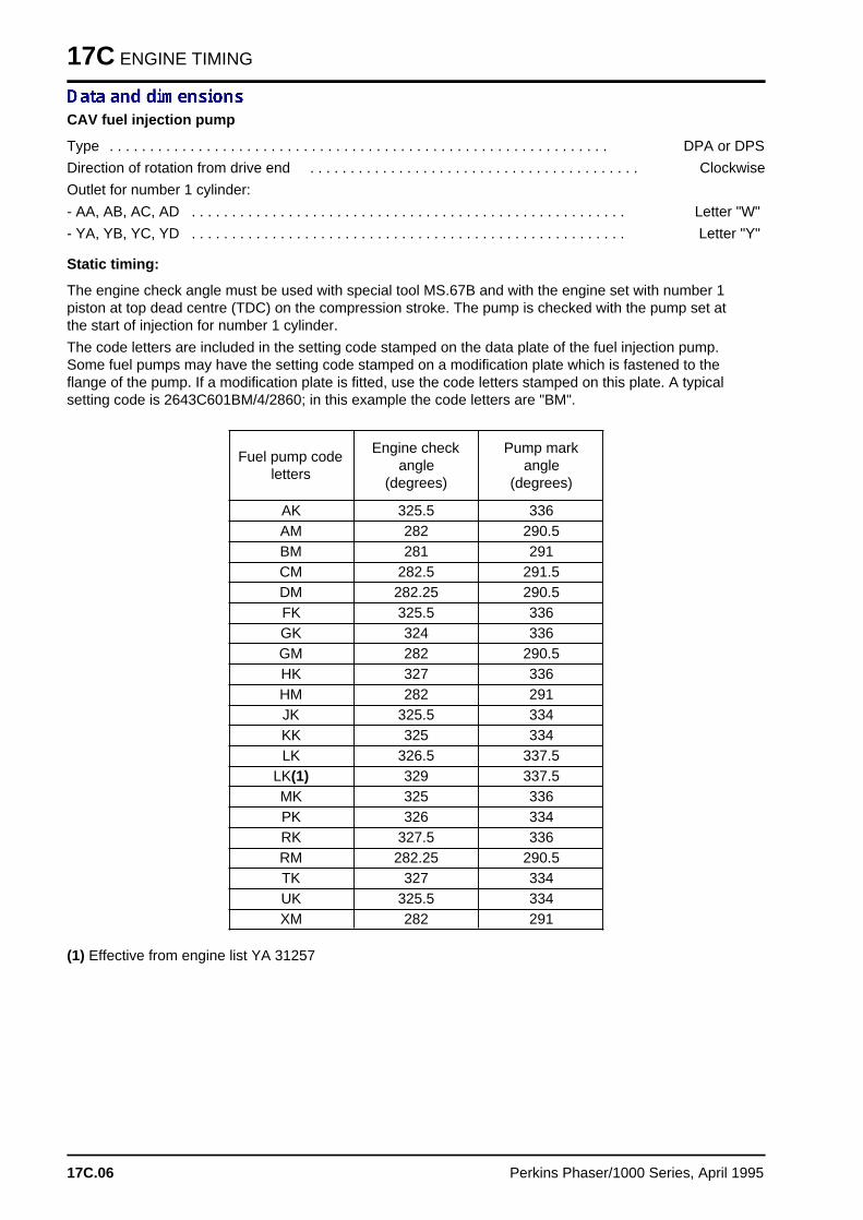
17C ENGINE TIMING
CAV fuel injection pump
Type . . . . . . . . . . . . . . . . . . . . . . . . . . . . . . . . . . . . . . . . . . . . . . . . . . . . . . . . . . . . . . DPA or DPS
Direction of rotation from drive end . . . . . . . . . . . . . . . . . . . . . . . . . . . . . . . . . . . . . . . . . Clockwise
Outlet for number 1 cylinder:
- AA, AB, AC, AD . . . . . . . . . . . . . . . . . . . . . . . . . . . . . . . . . . . . . . . . . . . . . . . . . . . . . . Letter "W"
- YA, YB, YC, YD . . . . . . . . . . . . . . . . . . . . . . . . . . . . . . . . . . . . . . . . . . . . . . . . . . . . . . Letter "Y"
Static timing:
The engine check angle must be used with special tool MS.67B and with the engine set with number 1piston at top dead centre (TDC) on the compression stroke. The pump is checked with the pump set atthe start of injection for number 1 cylinder.
The code letters are included in the setting code stamped on the data plate of the fuel injection pump.Some fuel pumps may have the setting code stamped on a modification plate which is fastened to theflange of the pump. If a modification plate is fitted, use the code letters stamped on this plate. A typicalsetting code is 2643C601BM/4/2860; in this example the code letters are "BM".
Fuel pump codeletters
Engine checkangle
(degrees)
Pump markangle
(degrees)
AK 325.5 336AM 282 290.5BM 281 291CM 282.5 291.5DM 282.25 290.5FK 325.5 336GK 324 336GM 282 290.5HK 327 336HM 282 291JK 325.5 334KK 325 334LK 326.5 337.5
LK(1) 329 337.5MK 325 336PK 326 334RK 327.5 336RM 282.25 290.5TK 327 334UK 325.5 334XM 282 291
(1) Effective from engine list YA 31257
17C.06 Perkins Phaser/1000 Series, April 1995
Engines fitted with a Lucas DP200 Seriesfuel injection pum p 17D
General descriptio n . . . . . . . . . . . . . . . . . . . . . . . . . . . . . . . . . . . . . . . . . 17D.02
Engine timing
17D-02 To check valve timing . . . . . . . . . . . . . . . . . . . . . . . . . . . refer to 17A.0417D-03 To check the timing of the fuel injection pump . . . . . . . . . . . . . . 17D.03
Perkins Phaser/1000 Series, April 1995 17D.01
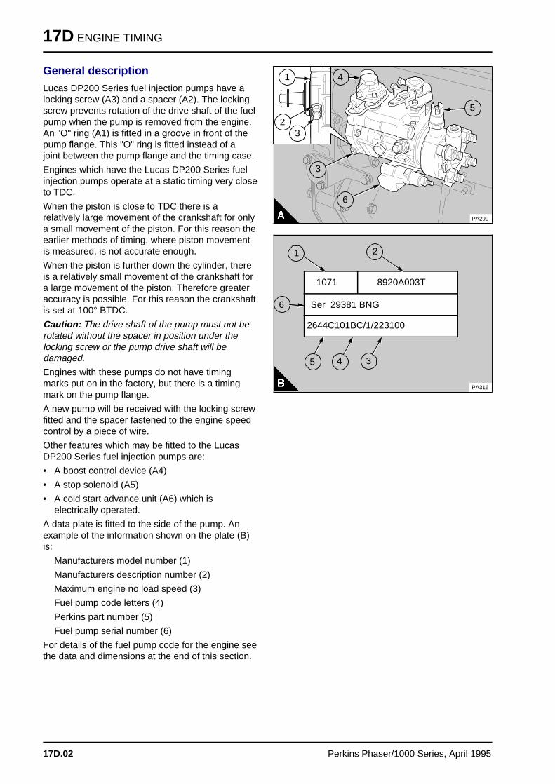
17D ENGINE TIMING
General description
Lucas DP200 Series fuel injection pumps have alocking screw (A3) and a spacer (A2). The lockingscrew prevents rotation of the drive shaft of the fuelpump when the pump is removed from the engine.An "O" ring (A1) is fitted in a groove in front of thepump flange. This "O" ring is fitted instead of ajoint between the pump flange and the timing case.
Engines which have the Lucas DP200 Series fuelinjection pumps operate at a static timing very closeto TDC.
When the piston is close to TDC there is arelatively large movement of the crankshaft for onlya small movement of the piston. For this reason theearlier methods of timing, where piston movementis measured, is not accurate enough.
When the piston is further down the cylinder, thereis a relatively small movement of the crankshaft fora large movement of the piston. Therefore greateraccuracy is possible. For this reason the crankshaftis set at 100° BTDC.
Caution: The drive shaft of the pump must not berotated without the spacer in position under thelocking screw or the pump drive shaft will bedamaged.
Engines with these pumps do not have timingmarks put on in the factory, but there is a timingmark on the pump flange.
A new pump will be received with the locking screwfitted and the spacer fastened to the engine speedcontrol by a piece of wire.
Other features which may be fitted to the LucasDP200 Series fuel injection pumps are:
• A boost control device (A4)
• A stop solenoid (A5)
• A cold start advance unit (A6) which iselectrically operated.
A data plate is fitted to the side of the pump. Anexample of the information shown on the plate (B)is:
Manufacturers model number (1)
Manufacturers description number (2)
Maximum engine no load speed (3)
Fuel pump code letters (4)
Perkins part number (5)
Fuel pump serial number (6)
For details of the fuel pump code for the engine seethe data and dimensions at the end of this section.
aaaaaaaaaa
a aa aa aa a
3
a aa aa aa a
2
a aa aa aa a
1
a aa aa aa a
4
PA299
a a a
a a a
a a a
a a a
6
a aa aa aa a
3
a aa aa aa a
5
8920A003T 1071
PA316
a a a
a a a
a a a
a a a
2
a a a a a a a a a a a a a a a a a a a a a a
a a a a a a a a a a a a a a a a a a a a a a
a a a a a a a a a a a a a a a a a a a a a a
a a a a a a a a a a a a a a a a a a a a a a
Ser 29381 BNG a a a a a a a a a a a a a a a a a a a a a a a a a a a a
a a a a a a a a a a a a a a a a a a a a a a a a a a a a
a a a a a a a a a a a a a a a a a a a a a a a a a a a a
a a a a a a a a a a a a a a a a a a a a a a a a a a a a
2644C101BC/1/223100
a aa aa aa a
1
a a a
a a a
a a a
a a a
6
a aa aa aa a
3
a aa aa aa a
4a a a
a a a
a a a
a a a
5
17D.02 Perkins Phaser/1000 Series, April 1995
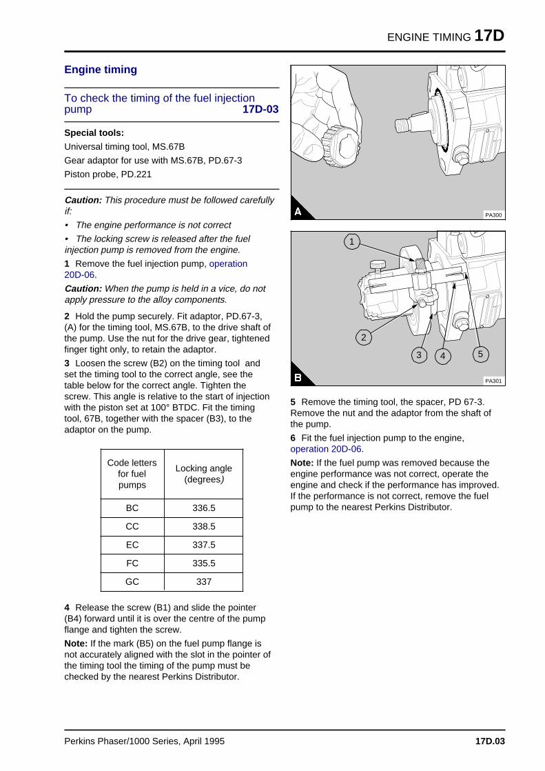
ENGINE TIMING 17D
Engine timing
To check the timing of the fuel injectionpump 17D-03
Special tools:
Universal timing tool, MS.67B
Gear adaptor for use with MS.67B, PD.67-3
Piston probe, PD.221
Caution: This procedure must be followed carefullyif:
• The engine performance is not correct
• The locking screw is released after the fuelinjection pump is removed from the engine.
1 Remove the fuel injection pump, operation 20D-06.
Caution: When the pump is held in a vice, do notapply pressure to the alloy components.
2 Hold the pump securely. Fit adaptor, PD.67-3,(A) for the timing tool, MS.67B, to the drive shaft ofthe pump. Use the nut for the drive gear, tightenedfinger tight only, to retain the adaptor.
3 Loosen the screw (B2) on the timing tool andset the timing tool to the correct angle, see thetable below for the correct angle. Tighten thescrew. This angle is relative to the start of injectionwith the piston set at 100° BTDC. Fit the timingtool, 67B, together with the spacer (B3), to theadaptor on the pump.
Code lettersfor fuelpumps
Locking angle(degrees)
BC 336.5
CC 338.5
EC 337.5
FC 335.5
GC 337
4 Release the screw (B1) and slide the pointer(B4) forward until it is over the centre of the pumpflange and tighten the screw.
Note: If the mark (B5) on the fuel pump flange isnot accurately aligned with the slot in the pointer ofthe timing tool the timing of the pump must bechecked by the nearest Perkins Distributor.
a a a a a
a a a a a
a a a a a
a a a a a
a a a a a
a a a a a
a a a a a
a a a a a
a a a a a
a a a a a
a a a a a
a a a a a
a a a a a
a a a a a
a a a a a
a a a a a
a a a a a
a a a a a
a a a a a
PA300
a aa aa aa a
4
a aa aa aa a
3a a a
a a a
a a a
a a a
2a aa aa aa a
1
a a a
a a a
a a a
a a a
5
PA301
5 Remove the timing tool, the spacer, PD 67-3.Remove the nut and the adaptor from the shaft ofthe pump.
6 Fit the fuel injection pump to the engine,operation 20D-06.
Note: If the fuel pump was removed because theengine performance was not correct, operate theengine and check if the performance has improved.If the performance is not correct, remove the fuelpump to the nearest Perkins Distributor.
Perkins Phaser/1000 Series, April 1995 17D.03
Engines fitted with Stanadyne fuel injection pump s 17E
General descriptio n . . . . . . . . . . . . . . . . . . . . . . . . . . . . . . . . . . . . . . . . . 17E.02
Engine timing
17E-01 To set number 1 piston to TDC on the compression stroke refer to 17A.0317E-02 To check the valve timing . . . . . . . . . . . . . . . . . . . . . . . . refer to 17A.0417E-03 To check the timing of the fuel injection pump . . . . . . . . . . . . . . 17E.0317E-04 To check the timing mark of the fuel injection pump . . . . . . . . . . 17E.0417E-05 To check the engine timing mark . . . . . . . . . . . . . . . . . . . . . . . . 17E.05
Data and dimension s . . . . . . . . . . . . . . . . . . . . . . . . . . . . . . . . . . . . . . . 17E.06
Perkins Phaser/1000 Series, April 1995 17E.01
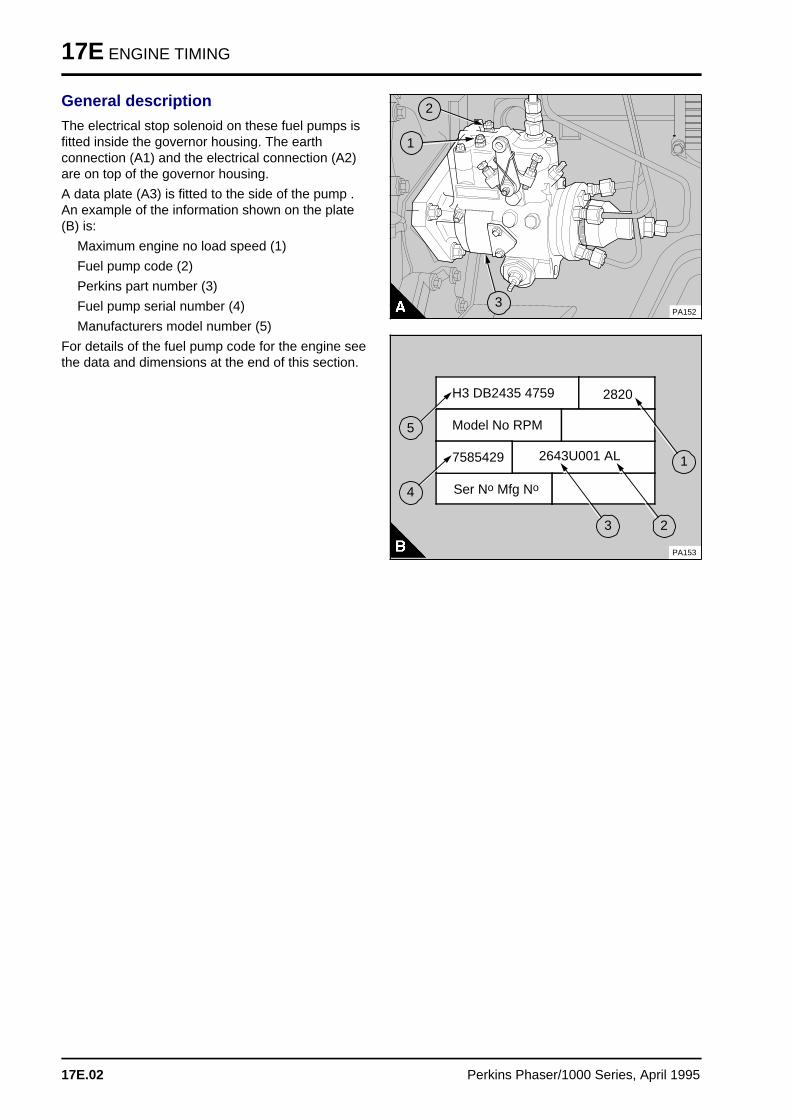
17E ENGINE TIMING
General description
The electrical stop solenoid on these fuel pumps isfitted inside the governor housing. The earthconnection (A1) and the electrical connection (A2)are on top of the governor housing.
A data plate (A3) is fitted to the side of the pump .An example of the information shown on the plate(B) is:
Maximum engine no load speed (1)
Fuel pump code (2)
Perkins part number (3)
Fuel pump serial number (4)
Manufacturers model number (5)
For details of the fuel pump code for the engine seethe data and dimensions at the end of this section.
a aa aa aa a
2
a a a
a a a
a a a
a a a
a a a
1
a a a
a a a
a a a
a a a
3PA152
H3 DB2435 4759 2820
Model No RPM
Ser No Mfg No
2643U001 AL7585429
PA153
a a a
a a a
a a a
a a a
5
a a a
a a a
a a a
a a a
4
a aa aa aa aa a
2
a aa aa aa aa a
3
a aa aa aa a
1
17E.02 Perkins Phaser/1000 Series, April 1995
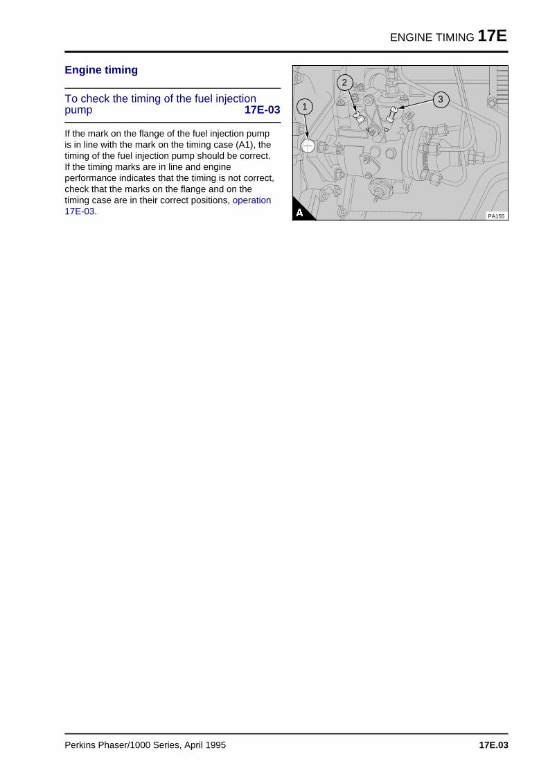
ENGINE TIMING 17E
Engine timing
To check the timing of the fuel injectionpump 17E-03
If the mark on the flange of the fuel injection pumpis in line with the mark on the timing case (A1), thetiming of the fuel injection pump should be correct.If the timing marks are in line and engineperformance indicates that the timing is not correct,check that the marks on the flange and on thetiming case are in their correct positions, operation17E-03.
a a a
a a a
a a a
a a a
a a a
3
a a a
a a a
a a a
a a a
2
PA155
a aa aa aa a
1
Perkins Phaser/1000 Series, April 1995 17E.03
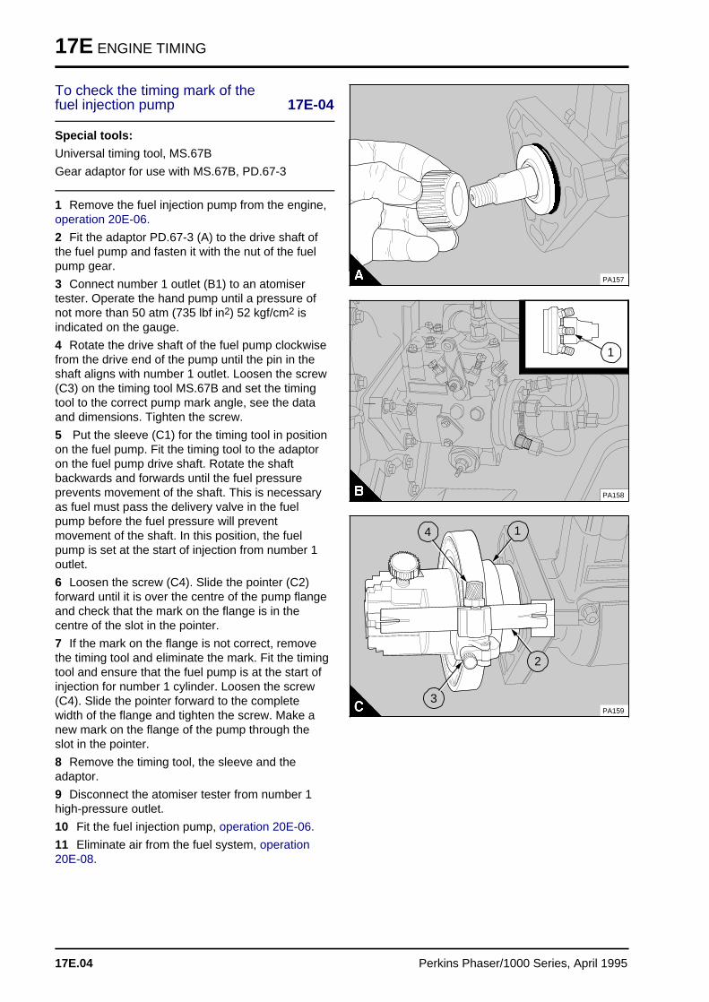
17E ENGINE TIMING
To check the timing mark of the fuel injection pump 17E-04
Special tools:
Universal timing tool, MS.67B
Gear adaptor for use with MS.67B, PD.67-3
1 Remove the fuel injection pump from the engine,operation 20E-06.
2 Fit the adaptor PD.67-3 (A) to the drive shaft ofthe fuel pump and fasten it with the nut of the fuelpump gear.
3 Connect number 1 outlet (B1) to an atomisertester. Operate the hand pump until a pressure ofnot more than 50 atm (735 lbf in2) 52 kgf/cm2 isindicated on the gauge.
4 Rotate the drive shaft of the fuel pump clockwisefrom the drive end of the pump until the pin in theshaft aligns with number 1 outlet. Loosen the screw(C3) on the timing tool MS.67B and set the timingtool to the correct pump mark angle, see the dataand dimensions. Tighten the screw.
5 Put the sleeve (C1) for the timing tool in positionon the fuel pump. Fit the timing tool to the adaptoron the fuel pump drive shaft. Rotate the shaftbackwards and forwards until the fuel pressureprevents movement of the shaft. This is necessaryas fuel must pass the delivery valve in the fuelpump before the fuel pressure will preventmovement of the shaft. In this position, the fuelpump is set at the start of injection from number 1outlet.
6 Loosen the screw (C4). Slide the pointer (C2)forward until it is over the centre of the pump flangeand check that the mark on the flange is in thecentre of the slot in the pointer.
7 If the mark on the flange is not correct, removethe timing tool and eliminate the mark. Fit the timingtool and ensure that the fuel pump is at the start ofinjection for number 1 cylinder. Loosen the screw(C4). Slide the pointer forward to the completewidth of the flange and tighten the screw. Make anew mark on the flange of the pump through theslot in the pointer.
8 Remove the timing tool, the sleeve and theadaptor.
9 Disconnect the atomiser tester from number 1high-pressure outlet.
10 Fit the fuel injection pump, operation 20E-06.
11 Eliminate air from the fuel system, operation20E-08.
a a a a a a a
a a a a a a a
a a a a a a a
a a a a a a a
a a a a a a a
a a a a a a a
a a a a a a a
a a a a a a a
a a a a a a a
a a a a a a a
a a a a a a a
a a a a a a a
a a a a a a a
a a a a a a a
a a a a a a a
a a a a a a a
a a a a a a a
PA157
PA158
a a a
a a a
a a a
a a a
a a a
1
PA159
a a a
a a a
a a a
a a a
4
a aa aa aa a
3
a a a
a a a
a a a
a a a
2
a aa aa aa aa a
1
17E.04 Perkins Phaser/1000 Series, April 1995
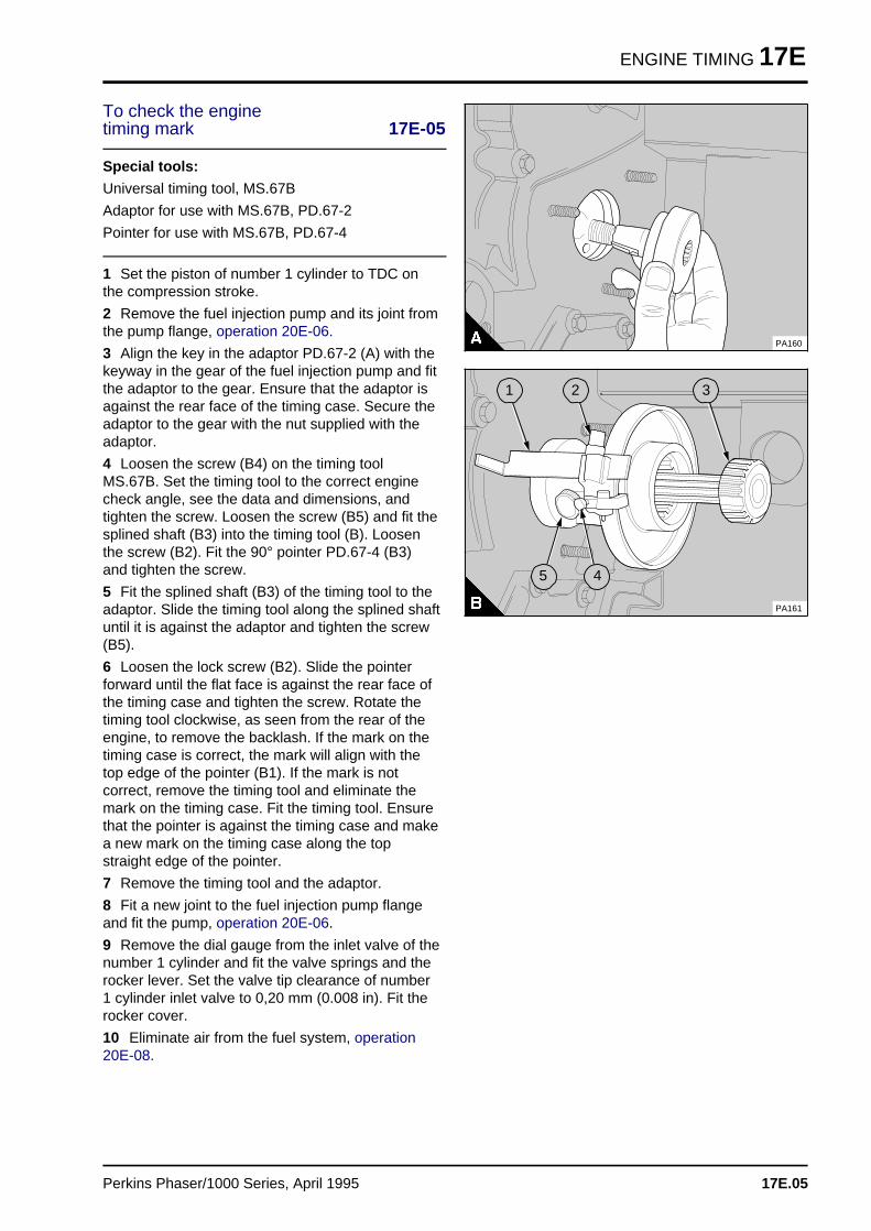
ENGINE TIMING 17E
To check the engine timing mark 17E-05
Special tools:
Universal timing tool, MS.67B
Adaptor for use with MS.67B, PD.67-2
Pointer for use with MS.67B, PD.67-4
1 Set the piston of number 1 cylinder to TDC onthe compression stroke.
2 Remove the fuel injection pump and its joint fromthe pump flange, operation 20E-06.
3 Align the key in the adaptor PD.67-2 (A) with thekeyway in the gear of the fuel injection pump and fitthe adaptor to the gear. Ensure that the adaptor isagainst the rear face of the timing case. Secure theadaptor to the gear with the nut supplied with theadaptor.
4 Loosen the screw (B4) on the timing toolMS.67B. Set the timing tool to the correct enginecheck angle, see the data and dimensions, andtighten the screw. Loosen the screw (B5) and fit thesplined shaft (B3) into the timing tool (B). Loosenthe screw (B2). Fit the 90° pointer PD.67-4 (B3)and tighten the screw.
5 Fit the splined shaft (B3) of the timing tool to theadaptor. Slide the timing tool along the splined shaftuntil it is against the adaptor and tighten the screw(B5).
6 Loosen the lock screw (B2). Slide the pointerforward until the flat face is against the rear face ofthe timing case and tighten the screw. Rotate thetiming tool clockwise, as seen from the rear of theengine, to remove the backlash. If the mark on thetiming case is correct, the mark will align with thetop edge of the pointer (B1). If the mark is notcorrect, remove the timing tool and eliminate themark on the timing case. Fit the timing tool. Ensurethat the pointer is against the timing case and makea new mark on the timing case along the topstraight edge of the pointer.
7 Remove the timing tool and the adaptor.
8 Fit a new joint to the fuel injection pump flangeand fit the pump, operation 20E-06.
9 Remove the dial gauge from the inlet valve of thenumber 1 cylinder and fit the valve springs and therocker lever. Set the valve tip clearance of number1 cylinder inlet valve to 0,20 mm (0.008 in). Fit therocker cover.
10 Eliminate air from the fuel system, operation20E-08.
PA160
a a a
a a a
a a a
a a a
5a a a
a a a
a a a
a a a
4
a a a
a a a
a a a
a a a
1
a a a
a a a
a a a
a a a
2
a a a
a a a
a a a
a a a
3
PA161
Perkins Phaser/1000 Series, April 1995 17E.05
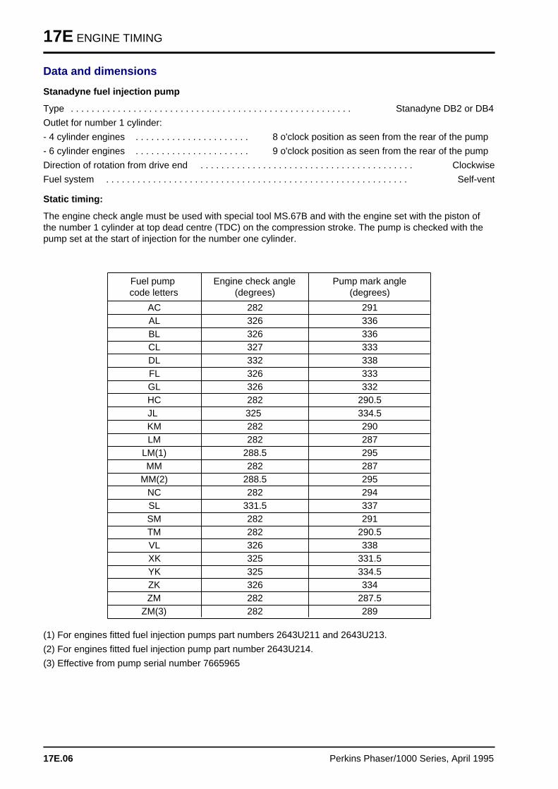
17E ENGINE TIMING
Data and dimensions
Stanadyne fuel injection pump
Type . . . . . . . . . . . . . . . . . . . . . . . . . . . . . . . . . . . . . . . . . . . . . . . . . . . . . . Stanadyne DB2 or DB4
Outlet for number 1 cylinder:
- 4 cylinder engines . . . . . . . . . . . . . . . . . . . . . . 8 o'clock position as seen from the rear of the pump
- 6 cylinder engines . . . . . . . . . . . . . . . . . . . . . . 9 o'clock position as seen from the rear of the pump
Direction of rotation from drive end . . . . . . . . . . . . . . . . . . . . . . . . . . . . . . . . . . . . . . . . . Clockwise
Fuel system . . . . . . . . . . . . . . . . . . . . . . . . . . . . . . . . . . . . . . . . . . . . . . . . . . . . . . . . . . Self-vent
Static timing:
The engine check angle must be used with special tool MS.67B and with the engine set with the piston ofthe number 1 cylinder at top dead centre (TDC) on the compression stroke. The pump is checked with thepump set at the start of injection for the number one cylinder.
Fuel pump code letters
Engine check angle(degrees)
Pump mark angle(degrees)
AC 282 291AL 326 336BL 326 336CL 327 333DL 332 338FL 326 333GL 326 332HC 282 290.5JL 325 334.5KM 282 290LM 282 287
LM(1) 288.5 295MM 282 287
MM(2) 288.5 295NC 282 294SL 331.5 337SM 282 291TM 282 290.5VL 326 338XK 325 331.5YK 325 334.5ZK 326 334ZM 282 287.5
ZM(3) 282 289
(1) For engines fitted fuel injection pumps part numbers 2643U211 and 2643U213.
(2) For engines fitted fuel injection pump part number 2643U214.
(3) Effective from pump serial number 7665965
17E.06 Perkins Phaser/1000 Series, April 1995
ASPIRATION SYSTEM 18
Aspiration syste m 18
General descriptio n . . . . . . . . . . . . . . . . . . . . . . . . . . . . . . . . . . . . . . . . . 18A.02
Turbocharger
18A-01 To remove and to fit . . . . . . . . . . . . . . . . . . . . . . . . . . . . . . . . . 18A.0318A-02 To clean the impeller and the compressor casing . . . . . . . . . . . . 18A.0618A-03 To remove and to fit the actuator assembly of the waste-gate unit 18A.0718A-04 To check and to adjust the operation of the waste-gate . . . . . . . 18A.08
Turbocharger fault s . . . . . . . . . . . . . . . . . . . . . . . . . . . . . . . . . . . . . . . . . 18A.10
Engine breather systems
18A-05 Open engine breather . . . . . . . . . . . . . . . . . . . . . . . . . . . . . . . . 18A.1218A-06 Closed engine breather . . . . . . . . . . . . . . . . . . . . . . . . . . . . . . . 18A.13
Data and dimension s . . . . . . . . . . . . . . . . . . . . . . . . . . . . . . . . . . . . . . . 18A.14
Perkins Phaser/1000 Series, April 1995 18A.01
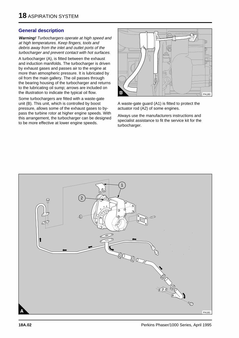
18 ASPIRATION SYSTEM
General description
Warning! Turbochargers operate at high speed andat high temperatures. Keep fingers, tools anddebris away from the inlet and outlet ports of theturbocharger and prevent contact with hot surfaces.
A turbocharger (A), is fitted between the exhaustand induction manifolds. The turbocharger is drivenby exhaust gases and passes air to the engine atmore than atmospheric pressure. It is lubricated byoil from the main gallery. The oil passes throughthe bearing housing of the turbocharger and returnsto the lubricating oil sump; arrows are included onthe illustration to indicate the typical oil flow.
Some turbochargers are fitted with a waste-gateunit (B). This unit, which is controlled by boostpressure, allows some of the exhaust gases to by-pass the turbine rotor at higher engine speeds. Withthis arrangement, the turbocharger can be designedto be more effective at lower engine speeds.
PA180
A waste-gate guard (A1) is fitted to protect theactuator rod (A2) of some engines.
Always use the manufacturers instructions andspecialist assistance to fit the service kit for theturbocharger.
PA181
a aa aa aa a
2
a aa aa aa aa a
1
18A.02 Perkins Phaser/1000 Series, April 1995
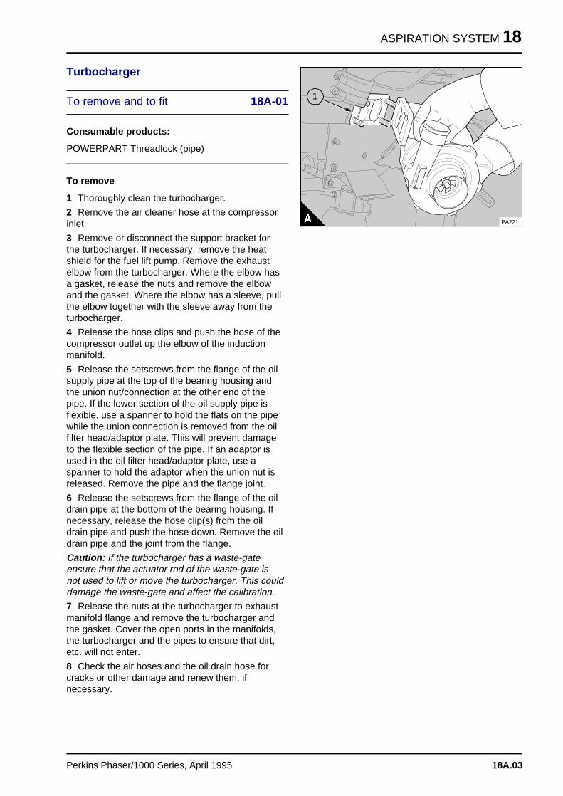
ASPIRATION SYSTEM 18
Turbocharger
To remove and to fit 18A-01
Consumable products:
POWERPART Threadlock (pipe)
To remove
1 Thoroughly clean the turbocharger.
2 Remove the air cleaner hose at the compressorinlet.
3 Remove or disconnect the support bracket forthe turbocharger. If necessary, remove the heatshield for the fuel lift pump. Remove the exhaustelbow from the turbocharger. Where the elbow hasa gasket, release the nuts and remove the elbowand the gasket. Where the elbow has a sleeve, pullthe elbow together with the sleeve away from theturbocharger.
4 Release the hose clips and push the hose of thecompressor outlet up the elbow of the inductionmanifold.
5 Release the setscrews from the flange of the oilsupply pipe at the top of the bearing housing andthe union nut/connection at the other end of thepipe. If the lower section of the oil supply pipe isflexible, use a spanner to hold the flats on the pipewhile the union connection is removed from the oilfilter head/adaptor plate. This will prevent damageto the flexible section of the pipe. If an adaptor isused in the oil filter head/adaptor plate, use aspanner to hold the adaptor when the union nut isreleased. Remove the pipe and the flange joint.
6 Release the setscrews from the flange of the oildrain pipe at the bottom of the bearing housing. Ifnecessary, release the hose clip(s) from the oildrain pipe and push the hose down. Remove the oildrain pipe and the joint from the flange.
Caution: If the turbocharger has a waste-gateensure that the actuator rod of the waste-gate isnot used to lift or move the turbocharger. This coulddamage the waste-gate and affect the calibration.
7 Release the nuts at the turbocharger to exhaustmanifold flange and remove the turbocharger andthe gasket. Cover the open ports in the manifolds,the turbocharger and the pipes to ensure that dirt,etc. will not enter.
8 Check the air hoses and the oil drain hose forcracks or other damage and renew them, ifnecessary.
PA221
a a a
a a a
a a a
a a a
1
Perkins Phaser/1000 Series, April 1995 18A.03
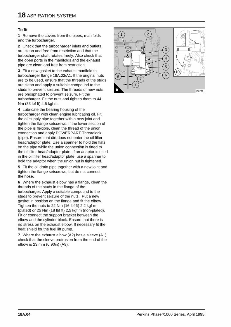
18 ASPIRATION SYSTEM
To fit
1 Remove the covers from the pipes, manifoldsand the turbocharger.
2 Check that the turbocharger inlets and outletsare clean and free from restriction and that theturbocharger shaft rotates freely. Also check thatthe open ports in the manifolds and the exhaustpipe are clean and free from restriction.
3 Fit a new gasket to the exhaust manifold toturbocharger flange 18A.03/A1. If the original nutsare to be used, ensure that the threads of the studsare clean and apply a suitable compound to thestuds to prevent seizure. The threads of new nutsare phosphated to prevent seizure. Fit theturbocharger. Fit the nuts and tighten them to 44Nm (33 lbf ft) 4,5 kgf m.
4 Lubricate the bearing housing of theturbocharger with clean engine lubricating oil. Fitthe oil supply pipe together with a new joint andtighten the flange setscrews. If the lower section ofthe pipe is flexible, clean the thread of the unionconnection and apply POWERPART Threadlock(pipe). Ensure that dirt does not enter the oil filterhead/adaptor plate. Use a spanner to hold the flatson the pipe while the union connection is fitted tothe oil filter head/adaptor plate. If an adaptor is usedin the oil filter head/adaptor plate, use a spanner tohold the adaptor when the union nut is tightened.
5 Fit the oil drain pipe together with a new joint andtighten the flange setscrews, but do not connectthe hose.
6 Where the exhaust elbow has a flange, clean thethreads of the studs in the flange of theturbocharger. Apply a suitable compound to thestuds to prevent seizure of the nuts. Put a newgasket in position on the flange and fit the elbow.Tighten the nuts to 22 Nm (16 lbf ft) 2,2 kgf m(plated) or 25 Nm (18 lbf ft) 2,5 kgf m (non-plated).Fit or connect the support bracket between theelbow and the cylinder block. Ensure that there isno stress on the exhaust elbow. If necessary fit theheat shield for the fuel lift pump.
7 Where the exhaust elbow (A2) has a sleeve (A1),check that the sleeve protrusion from the end of theelbow is 23 mm (0.90in) (A9).
a aa aa aa a
9
a a a
a a a
a a a
a a a
5
a a a
a a a
a a a
a a a
6
a a a a
a a a a
a a a a
a a a a
10
a a a
a a a
a a a
a a a
1
a a a
a a a
a a a
a a a
2
a a a
a a a
a a a
a a a
a a a
4
a aa aa aa a
8
a a a
a a a
a a a
a a a
a a a
7
a a a
a a a
a a a
a a a
3
PA222
18A.04 Perkins Phaser/1000 Series, April 1995
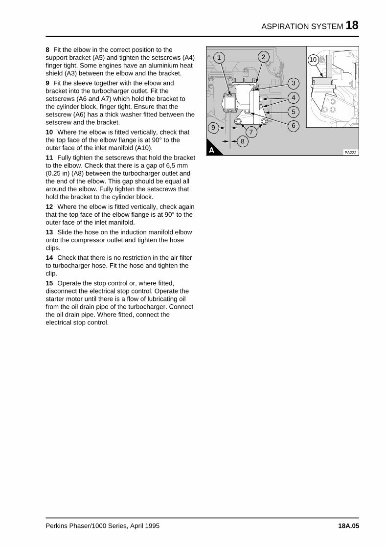
ASPIRATION SYSTEM 18
8 Fit the elbow in the correct position to thesupport bracket (A5) and tighten the setscrews (A4)finger tight. Some engines have an aluminium heatshield (A3) between the elbow and the bracket.
9 Fit the sleeve together with the elbow andbracket into the turbocharger outlet. Fit thesetscrews (A6 and A7) which hold the bracket tothe cylinder block, finger tight. Ensure that thesetscrew (A6) has a thick washer fitted between thesetscrew and the bracket.
10 Where the elbow is fitted vertically, check thatthe top face of the elbow flange is at 90° to theouter face of the inlet manifold (A10).
11 Fully tighten the setscrews that hold the bracketto the elbow. Check that there is a gap of 6,5 mm(0.25 in) (A8) between the turbocharger outlet andthe end of the elbow. This gap should be equal allaround the elbow. Fully tighten the setscrews thathold the bracket to the cylinder block.
12 Where the elbow is fitted vertically, check againthat the top face of the elbow flange is at 90° to theouter face of the inlet manifold.
13 Slide the hose on the induction manifold elbowonto the compressor outlet and tighten the hoseclips.
14 Check that there is no restriction in the air filterto turbocharger hose. Fit the hose and tighten theclip.
15 Operate the stop control or, where fitted,disconnect the electrical stop control. Operate thestarter motor until there is a flow of lubricating oilfrom the oil drain pipe of the turbocharger. Connectthe oil drain pipe. Where fitted, connect theelectrical stop control.
a a a
a a a
a a a
a a a
9
a a a
a a a
a a a
a a a
5
a a a
a a a
a a a
a a a
6
a a a a
a a a a
a a a a
a a a a
10
a a a
a a a
a a a
a a a
1
a a a
a a a
a a a
a a a
2
a a a
a a a
a a a
a a a
a a a
4
a aa aa aa a
8
a a a
a a a
a a a
a a a
a a a
7
a a a
a a a
a a a
a a a
3
PA222
Perkins Phaser/1000 Series, April 1995 18A.05
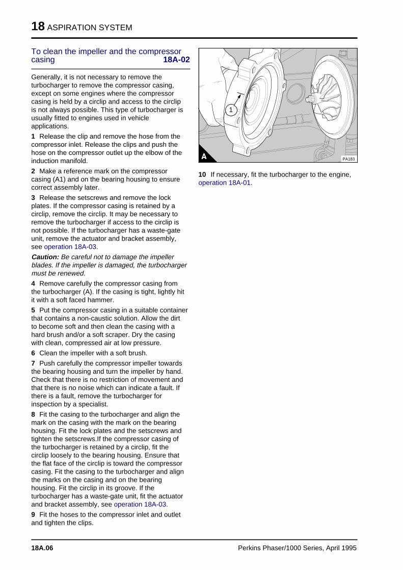
18 ASPIRATION SYSTEM
To clean the impeller and the compressorcasing 18A-02
Generally, it is not necessary to remove theturbocharger to remove the compressor casing,except on some engines where the compressorcasing is held by a circlip and access to the circlipis not always possible. This type of turbocharger isusually fitted to engines used in vehicleapplications.
1 Release the clip and remove the hose from thecompressor inlet. Release the clips and push thehose on the compressor outlet up the elbow of theinduction manifold.
2 Make a reference mark on the compressorcasing (A1) and on the bearing housing to ensurecorrect assembly later.
3 Release the setscrews and remove the lockplates. If the compressor casing is retained by acirclip, remove the circlip. It may be necessary toremove the turbocharger if access to the circlip isnot possible. If the turbocharger has a waste-gateunit, remove the actuator and bracket assembly,see operation 18A-03.
Caution: Be careful not to damage the impellerblades. If the impeller is damaged, the turbochargermust be renewed.
4 Remove carefully the compressor casing fromthe turbocharger (A). If the casing is tight, lightly hitit with a soft faced hammer.
5 Put the compressor casing in a suitable containerthat contains a non-caustic solution. Allow the dirtto become soft and then clean the casing with ahard brush and/or a soft scraper. Dry the casingwith clean, compressed air at low pressure.
6 Clean the impeller with a soft brush.
7 Push carefully the compressor impeller towardsthe bearing housing and turn the impeller by hand.Check that there is no restriction of movement andthat there is no noise which can indicate a fault. Ifthere is a fault, remove the turbocharger forinspection by a specialist.
8 Fit the casing to the turbocharger and align themark on the casing with the mark on the bearinghousing. Fit the lock plates and the setscrews andtighten the setscrews.If the compressor casing ofthe turbocharger is retained by a circlip, fit thecirclip loosely to the bearing housing. Ensure thatthe flat face of the circlip is toward the compressorcasing. Fit the casing to the turbocharger and alignthe marks on the casing and on the bearinghousing. Fit the circlip in its groove. If theturbocharger has a waste-gate unit, fit the actuatorand bracket assembly, see operation 18A-03.
9 Fit the hoses to the compressor inlet and outletand tighten the clips.
a aa aa aa a
1
PA183
10 If necessary, fit the turbocharger to the engine,operation 18A-01.
18A.06 Perkins Phaser/1000 Series, April 1995
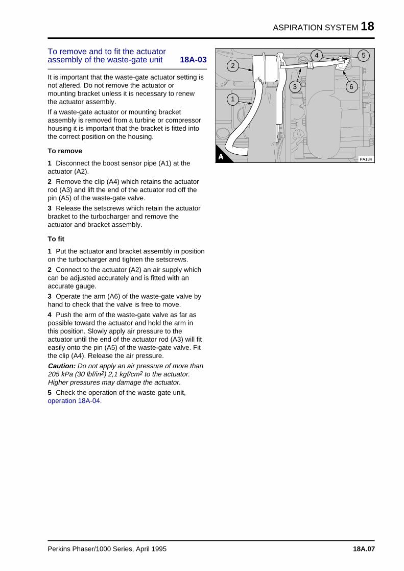
ASPIRATION SYSTEM 18
To remove and to fit the actuatorassembly of the waste-gate unit 18A-03
It is important that the waste-gate actuator setting isnot altered. Do not remove the actuator ormounting bracket unless it is necessary to renewthe actuator assembly.
If a waste-gate actuator or mounting bracketassembly is removed from a turbine or compressorhousing it is important that the bracket is fitted intothe correct position on the housing.
To remove
1 Disconnect the boost sensor pipe (A1) at theactuator (A2).
2 Remove the clip (A4) which retains the actuatorrod (A3) and lift the end of the actuator rod off thepin (A5) of the waste-gate valve.
3 Release the setscrews which retain the actuatorbracket to the turbocharger and remove theactuator and bracket assembly.
To fit
1 Put the actuator and bracket assembly in positionon the turbocharger and tighten the setscrews.
2 Connect to the actuator (A2) an air supply whichcan be adjusted accurately and is fitted with anaccurate gauge.
3 Operate the arm (A6) of the waste-gate valve byhand to check that the valve is free to move.
4 Push the arm of the waste-gate valve as far aspossible toward the actuator and hold the arm inthis position. Slowly apply air pressure to theactuator until the end of the actuator rod (A3) will fiteasily onto the pin (A5) of the waste-gate valve. Fitthe clip (A4). Release the air pressure.
Caution: Do not apply an air pressure of more than205 kPa (30 lbf/in2) 2,1 kgf/cm2 to the actuator.Higher pressures may damage the actuator.
5 Check the operation of the waste-gate unit,operation 18A-04.
PA184
a a a
a a a
a a a
a a a
4
a a a
a a a
a a a
a a a
5
a a a
a a a
a a a
a a a
2
a a a
a a a
a a a
a a a
a a a
1
a a a
a a a
a a a
a a a
6
a aa aa aa a
3
Perkins Phaser/1000 Series, April 1995 18A.07
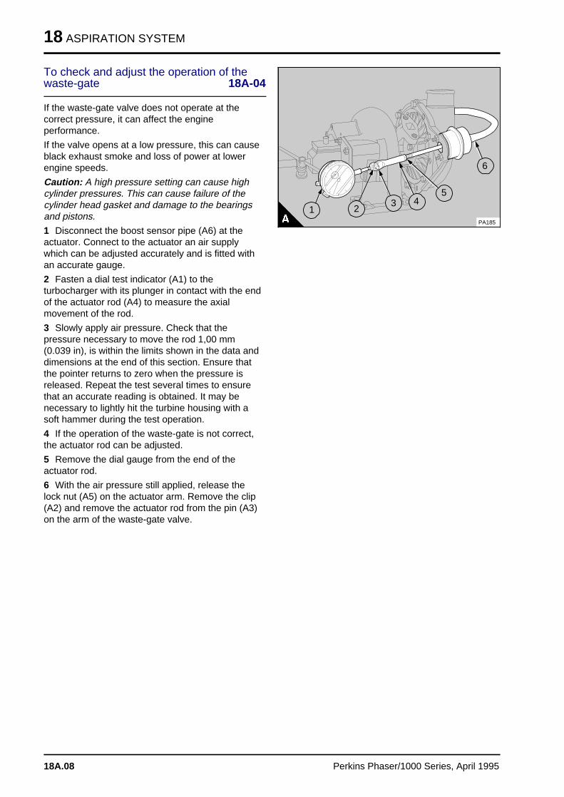
18 ASPIRATION SYSTEM
To check and adjust the operation of thewaste-gate 18A-04
If the waste-gate valve does not operate at thecorrect pressure, it can affect the engineperformance.
If the valve opens at a low pressure, this can causeblack exhaust smoke and loss of power at lowerengine speeds.
Caution: A high pressure setting can cause highcylinder pressures. This can cause failure of thecylinder head gasket and damage to the bearingsand pistons.
1 Disconnect the boost sensor pipe (A6) at theactuator. Connect to the actuator an air supplywhich can be adjusted accurately and is fitted withan accurate gauge.
2 Fasten a dial test indicator (A1) to theturbocharger with its plunger in contact with the endof the actuator rod (A4) to measure the axialmovement of the rod.
3 Slowly apply air pressure. Check that thepressure necessary to move the rod 1,00 mm(0.039 in), is within the limits shown in the data anddimensions at the end of this section. Ensure thatthe pointer returns to zero when the pressure isreleased. Repeat the test several times to ensurethat an accurate reading is obtained. It may benecessary to lightly hit the turbine housing with asoft hammer during the test operation.
4 If the operation of the waste-gate is not correct,the actuator rod can be adjusted.
5 Remove the dial gauge from the end of theactuator rod.
6 With the air pressure still applied, release thelock nut (A5) on the actuator arm. Remove the clip(A2) and remove the actuator rod from the pin (A3)on the arm of the waste-gate valve.
a a a
a a a
a a a
a a a
1
a aa aa aa aa a
5
a a a
a a a
a a a
a a a
6
PA185
a aa aa aa a
2
a aa aa aa a
3
a a a
a a a
a a a
a a a
4
18A.08 Perkins Phaser/1000 Series, April 1995
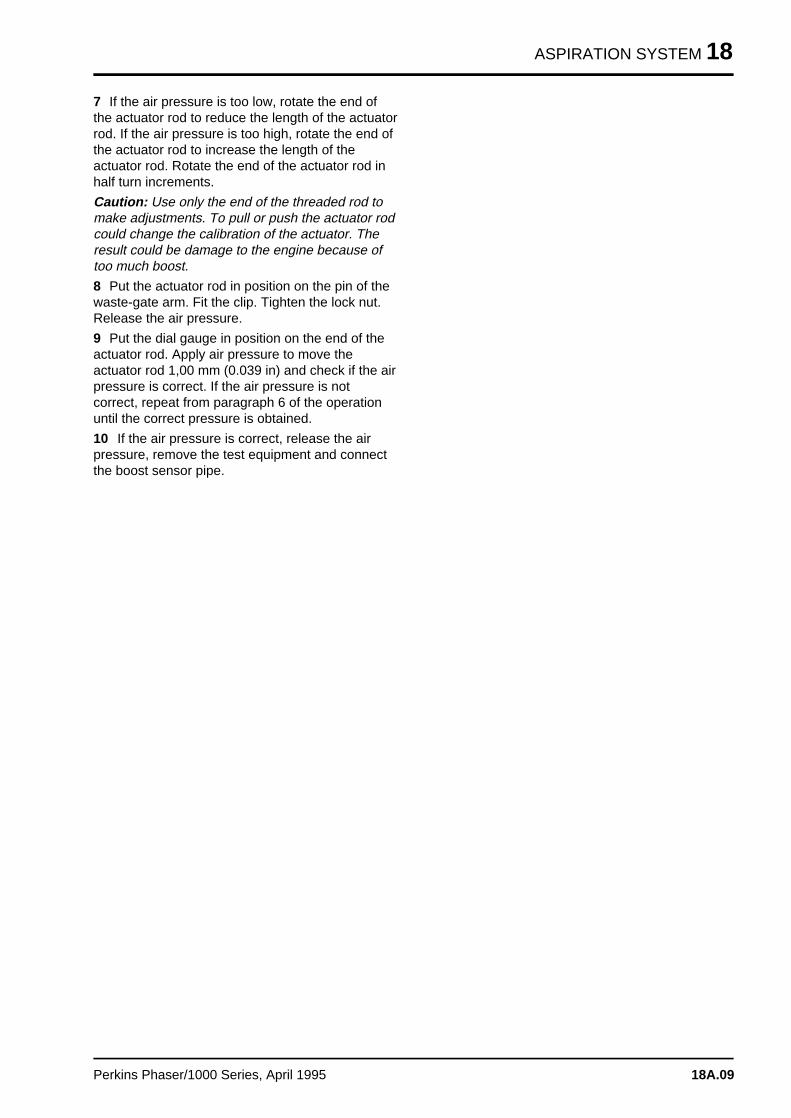
ASPIRATION SYSTEM 18
7 If the air pressure is too low, rotate the end ofthe actuator rod to reduce the length of the actuatorrod. If the air pressure is too high, rotate the end ofthe actuator rod to increase the length of theactuator rod. Rotate the end of the actuator rod inhalf turn increments.
Caution: Use only the end of the threaded rod tomake adjustments. To pull or push the actuator rodcould change the calibration of the actuator. Theresult could be damage to the engine because oftoo much boost.
8 Put the actuator rod in position on the pin of thewaste-gate arm. Fit the clip. Tighten the lock nut.Release the air pressure.
9 Put the dial gauge in position on the end of theactuator rod. Apply air pressure to move theactuator rod 1,00 mm (0.039 in) and check if the airpressure is correct. If the air pressure is notcorrect, repeat from paragraph 6 of the operationuntil the correct pressure is obtained.
10 If the air pressure is correct, release the airpressure, remove the test equipment and connectthe boost sensor pipe.
Perkins Phaser/1000 Series, April 1995 18A.09
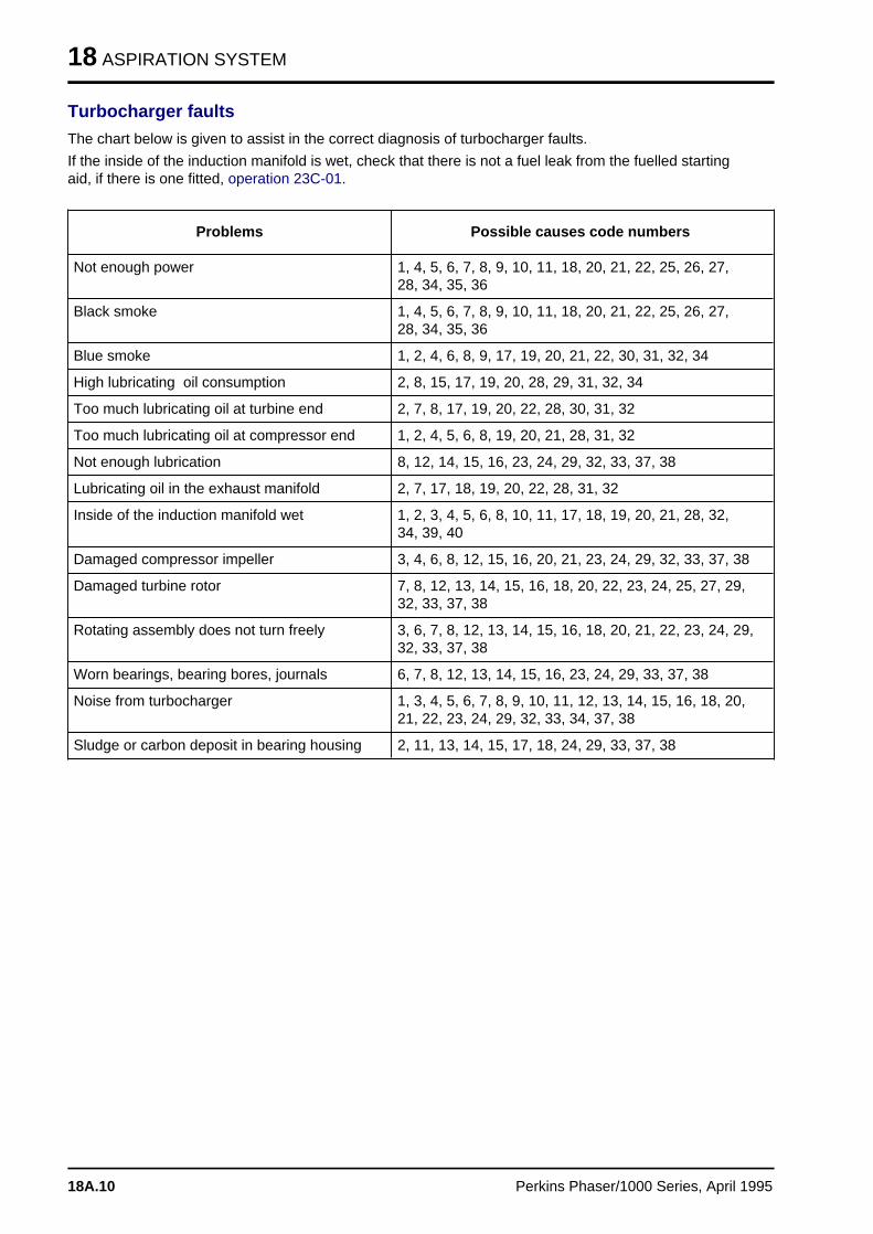
18 ASPIRATION SYSTEM
Turbocharger faults
The chart below is given to assist in the correct diagnosis of turbocharger faults.
If the inside of the induction manifold is wet, check that there is not a fuel leak from the fuelled startingaid, if there is one fitted, operation 23C-01.
Problems Possible causes code numbers
Not enough power 1, 4, 5, 6, 7, 8, 9, 10, 11, 18, 20, 21, 22, 25, 26, 27,28, 34, 35, 36
Black smoke 1, 4, 5, 6, 7, 8, 9, 10, 11, 18, 20, 21, 22, 25, 26, 27,28, 34, 35, 36
Blue smoke 1, 2, 4, 6, 8, 9, 17, 19, 20, 21, 22, 30, 31, 32, 34
High lubricating oil consumption 2, 8, 15, 17, 19, 20, 28, 29, 31, 32, 34
Too much lubricating oil at turbine end 2, 7, 8, 17, 19, 20, 22, 28, 30, 31, 32
Too much lubricating oil at compressor end 1, 2, 4, 5, 6, 8, 19, 20, 21, 28, 31, 32
Not enough lubrication 8, 12, 14, 15, 16, 23, 24, 29, 32, 33, 37, 38
Lubricating oil in the exhaust manifold 2, 7, 17, 18, 19, 20, 22, 28, 31, 32
Inside of the induction manifold wet 1, 2, 3, 4, 5, 6, 8, 10, 11, 17, 18, 19, 20, 21, 28, 32,34, 39, 40
Damaged compressor impeller 3, 4, 6, 8, 12, 15, 16, 20, 21, 23, 24, 29, 32, 33, 37, 38
Damaged turbine rotor 7, 8, 12, 13, 14, 15, 16, 18, 20, 22, 23, 24, 25, 27, 29,32, 33, 37, 38
Rotating assembly does not turn freely 3, 6, 7, 8, 12, 13, 14, 15, 16, 18, 20, 21, 22, 23, 24, 29,32, 33, 37, 38
Worn bearings, bearing bores, journals 6, 7, 8, 12, 13, 14, 15, 16, 23, 24, 29, 33, 37, 38
Noise from turbocharger 1, 3, 4, 5, 6, 7, 8, 9, 10, 11, 12, 13, 14, 15, 16, 18, 20,21, 22, 23, 24, 29, 32, 33, 34, 37, 38
Sludge or carbon deposit in bearing housing 2, 11, 13, 14, 15, 17, 18, 24, 29, 33, 37, 38
18A.10 Perkins Phaser/1000 Series, April 1995
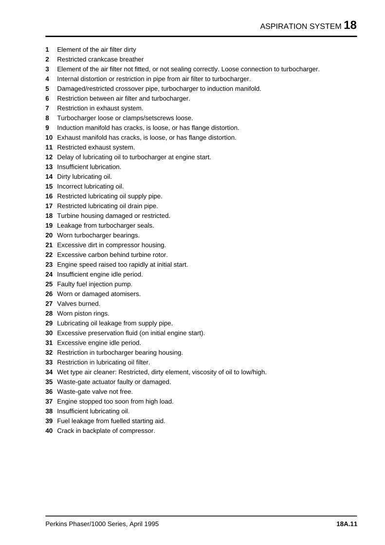
ASPIRATION SYSTEM 18
1 Element of the air filter dirty
2 Restricted crankcase breather
3 Element of the air filter not fitted, or not sealing correctly. Loose connection to turbocharger.
4 Internal distortion or restriction in pipe from air filter to turbocharger.
5 Damaged/restricted crossover pipe, turbocharger to induction manifold.
6 Restriction between air filter and turbocharger.
7 Restriction in exhaust system.
8 Turbocharger loose or clamps/setscrews loose.
9 Induction manifold has cracks, is loose, or has flange distortion.
10 Exhaust manifold has cracks, is loose, or has flange distortion.
11 Restricted exhaust system.
12 Delay of lubricating oil to turbocharger at engine start.
13 Insufficient lubrication.
14 Dirty lubricating oil.
15 Incorrect lubricating oil.
16 Restricted lubricating oil supply pipe.
17 Restricted lubricating oil drain pipe.
18 Turbine housing damaged or restricted.
19 Leakage from turbocharger seals.
20 Worn turbocharger bearings.
21 Excessive dirt in compressor housing.
22 Excessive carbon behind turbine rotor.
23 Engine speed raised too rapidly at initial start.
24 Insufficient engine idle period.
25 Faulty fuel injection pump.
26 Worn or damaged atomisers.
27 Valves burned.
28 Worn piston rings.
29 Lubricating oil leakage from supply pipe.
30 Excessive preservation fluid (on initial engine start).
31 Excessive engine idle period.
32 Restriction in turbocharger bearing housing.
33 Restriction in lubricating oil filter.
34 Wet type air cleaner: Restricted, dirty element, viscosity of oil to low/high.
35 Waste-gate actuator faulty or damaged.
36 Waste-gate valve not free.
37 Engine stopped too soon from high load.
38 Insufficient lubricating oil.
39 Fuel leakage from fuelled starting aid.
40 Crack in backplate of compressor.
Perkins Phaser/1000 Series, April 1995 18A.11
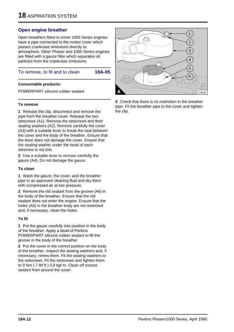
18 ASPIRATION SYSTEM
Open engine breather
Open breathers fitted to some 1000 Series engineshave a pipe connected to the rocker cover whichpasses crankcase emissions directly toatmosphere. Other Phaser and 1000 Series enginesare fitted with a gauze filter which separates oilparticles from the crankcase emissions.
To remove, to fit and to clean 18A-05
Consumable products:
POWERPART silicone rubber sealant
To remove
1 Release the clip, disconnect and remove thepipe from the breather cover. Release the twosetscrews (A1). Remove the setscrews and theirsealing washers (A2). Remove carefully the cover(A3) with a suitable lever to break the seal betweenthe cover and the body of the breather. Ensure thatthe lever does not damage the cover. Ensure thatthe sealing washer under the head of eachsetscrew is not lost.
2 Use a suitable lever to remove carefully thegauze (A4). Do not damage the gauze.
To clean
1 Wash the gauze, the cover, and the breatherpipe in an approved cleaning fluid and dry themwith compressed air at low pressure.
2 Remove the old sealant from the groove (A6) inthe body of the breather. Ensure that the oldsealant does not enter the engine. Ensure that theholes (A5) in the breather body are not restrictedand, if necessary, clean the holes.
To fit
1 Put the gauze carefully into position in the bodyof the breather. Apply a bead of PerkinsPOWERPART silicone rubber sealant to fill thegroove in the body of the breather.
2 Put the cover in the correct position on the bodyof the breather. Inspect the sealing washers and, ifnecessary, renew them. Fit the sealing washers tothe setscrews. Fit the setscrews and tighten themto 9 Nm ( 7 lbf ft ) 0,9 kgf m. Clean off excesssealant from around the cover.
a a a a a a a a a a a a a a a a
a a a a a a a a a a a a a a a a
a a a a a a a a a a a a a a a a
a a a a a a a a a a a a a a a a
a a a a a a a a a a a a a a a a
a a a a a a a a a a a a a a a a
a a a a a a a a a a a a a a a a
a a a a a a a a a a a a a a a a
a a a a a a a a a a a a a a a a
a a a a a a a a a a a a a a a a
a a a a a a a a a a a a a a a a
a a a a a a a a a a a a a a a a
a a a a a a a a a a a a a a a a
a a a a a a a a a a a a a a a a
a a a
a a a
a a a
a a a
1
a a a
a a a
a a a
a a a
2
a a a
a a a
a a a
a a a
3
a a a
a a a
a a a
a a a
4
a a a
a a a
a a a
a a a
a a a
5
a a a
a a a
a a a
a a a
6
PA035
3 Check that there is no restriction in the breatherpipe. Fit the breather pipe to the cover and tightenthe clip.
18A.12 Perkins Phaser/1000 Series, April 1995
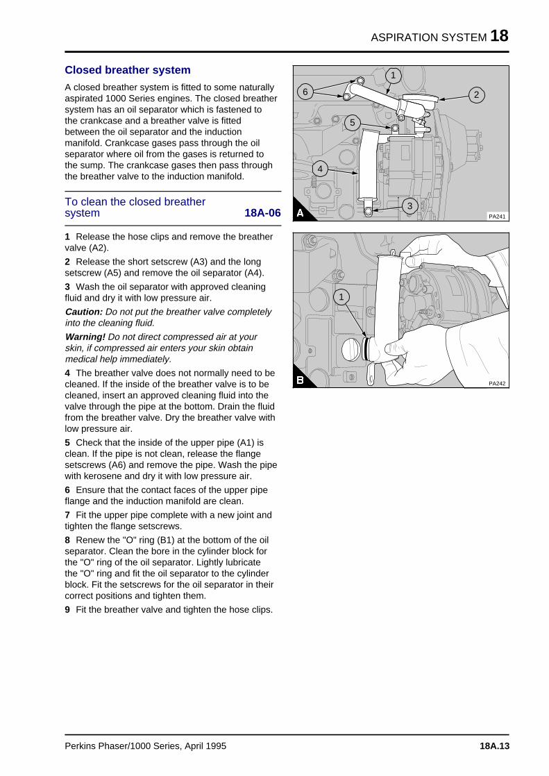
ASPIRATION SYSTEM 18
Closed breather system
A closed breather system is fitted to some naturallyaspirated 1000 Series engines. The closed breathersystem has an oil separator which is fastened tothe crankcase and a breather valve is fittedbetween the oil separator and the inductionmanifold. Crankcase gases pass through the oilseparator where oil from the gases is returned tothe sump. The crankcase gases then pass throughthe breather valve to the induction manifold.
To clean the closed breathersystem 18A-06
1 Release the hose clips and remove the breathervalve (A2).
2 Release the short setscrew (A3) and the longsetscrew (A5) and remove the oil separator (A4).
3 Wash the oil separator with approved cleaningfluid and dry it with low pressure air.
Caution: Do not put the breather valve completelyinto the cleaning fluid.
Warning! Do not direct compressed air at yourskin, if compressed air enters your skin obtainmedical help immediately.
4 The breather valve does not normally need to becleaned. If the inside of the breather valve is to becleaned, insert an approved cleaning fluid into thevalve through the pipe at the bottom. Drain the fluidfrom the breather valve. Dry the breather valve withlow pressure air.
5 Check that the inside of the upper pipe (A1) isclean. If the pipe is not clean, release the flangesetscrews (A6) and remove the pipe. Wash the pipewith kerosene and dry it with low pressure air.
6 Ensure that the contact faces of the upper pipeflange and the induction manifold are clean.
7 Fit the upper pipe complete with a new joint andtighten the flange setscrews.
8 Renew the "O" ring (B1) at the bottom of the oilseparator. Clean the bore in the cylinder block forthe "O" ring of the oil separator. Lightly lubricatethe "O" ring and fit the oil separator to the cylinderblock. Fit the setscrews for the oil separator in theircorrect positions and tighten them.
9 Fit the breather valve and tighten the hose clips.
a aa aa aa a
1
a a a
a a a
a a a
a a a
2
a a a
a a a
a a a
a a a
3
a a a
a a a
a a a
a a a
4
a a a
a a a
a a a
a a a
5
a aa aa aa aa a
6
PA241
PA242
a a a
a a a
a a a
a a a
1
Perkins Phaser/1000 Series, April 1995 18A.13
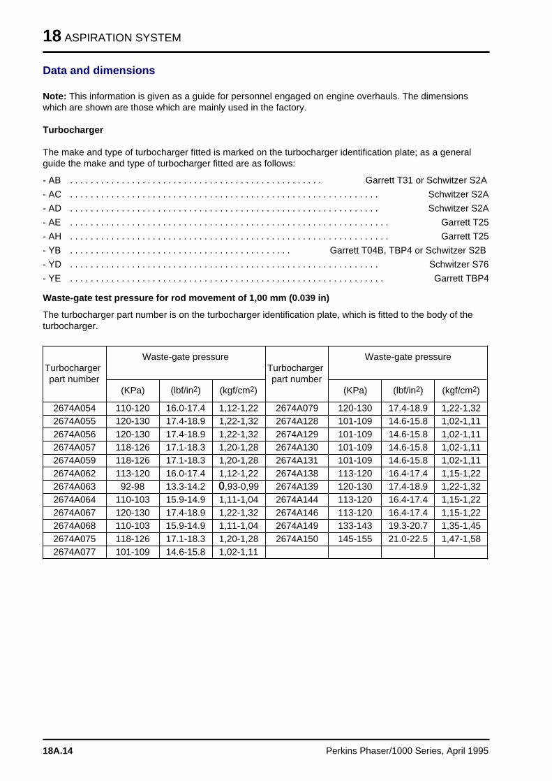
18 ASPIRATION SYSTEM
Data and dimensions
Note: This information is given as a guide for personnel engaged on engine overhauls. The dimensionswhich are shown are those which are mainly used in the factory.
Turbocharger
The make and type of turbocharger fitted is marked on the turbocharger identification plate; as a generalguide the make and type of turbocharger fitted are as follows:
- AB . . . . . . . . . . . . . . . . . . . . . . . . . . . . . . . . . . . . . . . . . . . . . . . . . Garrett T31 or Schwitzer S2A
- AC . . . . . . . . . . . . . . . . . . . . . . . . . . . . . . . . . . . . . . . . . . . . . . . . . . . . . . . . . . . . Schwitzer S2A
- AD . . . . . . . . . . . . . . . . . . . . . . . . . . . . . . . . . . . . . . . . . . . . . . . . . . . . . . . . . . . . Schwitzer S2A
- AE . . . . . . . . . . . . . . . . . . . . . . . . . . . . . . . . . . . . . . . . . . . . . . . . . . . . . . . . . . . . . . Garrett T25
- AH . . . . . . . . . . . . . . . . . . . . . . . . . . . . . . . . . . . . . . . . . . . . . . . . . . . . . . . . . . . . . . Garrett T25
- YB . . . . . . . . . . . . . . . . . . . . . . . . . . . . . . . . . . . . . . . . . . . Garrett T04B, TBP4 or Schwitzer S2B
- YD . . . . . . . . . . . . . . . . . . . . . . . . . . . . . . . . . . . . . . . . . . . . . . . . . . . . . . . . . . . . Schwitzer S76
- YE . . . . . . . . . . . . . . . . . . . . . . . . . . . . . . . . . . . . . . . . . . . . . . . . . . . . . . . . . . . . . Garrett TBP4
Waste-gate test pressure for rod movement of 1,00 mm (0.039 in)
The turbocharger part number is on the turbocharger identification plate, which is fitted to the body of theturbocharger.
Turbocharger part number
Waste-gate pressure
(KPa) (lbf/in2) (kgf/cm2)
Turbocharger part number
Waste-gate pressure
(KPa) (lbf/in2) (kgf/cm2)
2674A054 110-120 16.0-17.4 1,12-1,22 2674A079 120-130 17.4-18.9 1,22-1,322674A055 120-130 17.4-18.9 1,22-1,32 2674A128 101-109 14.6-15.8 1,02-1,112674A056 120-130 17.4-18.9 1,22-1,32 2674A129 101-109 14.6-15.8 1,02-1,112674A057 118-126 17.1-18.3 1,20-1,28 2674A130 101-109 14.6-15.8 1,02-1,112674A059 118-126 17.1-18.3 1,20-1,28 2674A131 101-109 14.6-15.8 1,02-1,112674A062 113-120 16.0-17.4 1,12-1,22 2674A138 113-120 16.4-17.4 1,15-1,222674A063 92-98 13.3-14.2 0,93-0,99 2674A139 120-130 17.4-18.9 1,22-1,322674A064 110-103 15.9-14.9 1,11-1,04 2674A144 113-120 16.4-17.4 1,15-1,222674A067 120-130 17.4-18.9 1,22-1,32 2674A146 113-120 16.4-17.4 1,15-1,222674A068 110-103 15.9-14.9 1,11-1,04 2674A149 133-143 19.3-20.7 1,35-1,452674A075 118-126 17.1-18.3 1,20-1,28 2674A150 145-155 21.0-22.5 1,47-1,582674A077 101-109 14.6-15.8 1,02-1,11
18A.14 Perkins Phaser/1000 Series, April 1995
LUBRICATION SYSTEM 19
Lubrication syste m 19
General descriptio n . . . . . . . . . . . . . . . . . . . . . . . . . . . . . . . . . . . . . . . . . 19A.02
Filter canister
19A-01 To renew . . . . . . . . . . . . . . . . . . . . . . . . . . . . . . . . . . . . . . . . . 19A.06
Filter head
19A-02 To remove and to fit . . . . . . . . . . . . . . . . . . . . . . . . . . . . . . . . . 19A.07
Sump
19A-03 To remove and to fit . . . . . . . . . . . . . . . . . . . . . . . . . . . . . . . . . 19A.10
Oil strainer and suction pipe
19A-04 To remove and to fit . . . . . . . . . . . . . . . . . . . . . . . . . . . . . . . . . 19A.1019A-05 To inspect and to correct . . . . . . . . . . . . . . . . . . . . . . . . . . . . . 19A.11
Lubricating oil pump
19A-06 To remove and to fit . . . . . . . . . . . . . . . . . . . . . . . . . . . . . . . . . 19A.1219A-07 To inspect . . . . . . . . . . . . . . . . . . . . . . . . . . . . . . . . . . . . . . . . 19A.18
Relief valve
19A-08 To remove and to fit . . . . . . . . . . . . . . . . . . . . . . . . . . . . . . . . . 19A.1919A-09 To dismantle and to assemble . . . . . . . . . . . . . . . . . . . . . . . . . . 19A.2019A-10 To inspect . . . . . . . . . . . . . . . . . . . . . . . . . . . . . . . . . . . . . . . . 19A.20
Flexible oil pipes
19A-11 To remove, to fit and to inspect . . . . . . . . . . . . . . . . . . . . . . . . 19A.08
Data and dimension s . . . . . . . . . . . . . . . . . . . . . . . . . . . . . . . . . . . . . . . 19A.21
Perkins Phaser/1000 Series, April 1995 19A.01
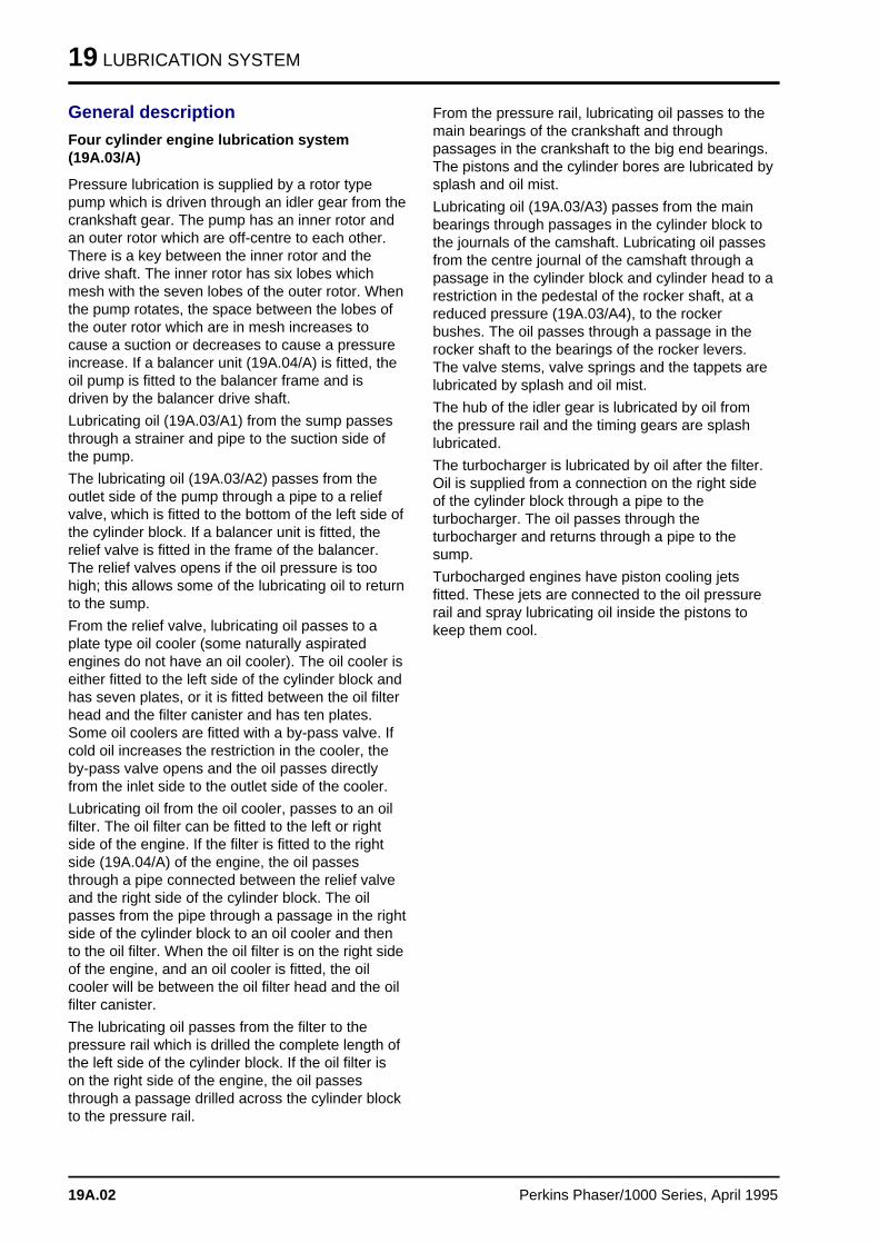
19 LUBRICATION SYSTEM
General description
Four cylinder engine lubrication system (19A.03/A)
Pressure lubrication is supplied by a rotor typepump which is driven through an idler gear from thecrankshaft gear. The pump has an inner rotor andan outer rotor which are off-centre to each other.There is a key between the inner rotor and thedrive shaft. The inner rotor has six lobes whichmesh with the seven lobes of the outer rotor. Whenthe pump rotates, the space between the lobes ofthe outer rotor which are in mesh increases tocause a suction or decreases to cause a pressureincrease. If a balancer unit (19A.04/A) is fitted, theoil pump is fitted to the balancer frame and isdriven by the balancer drive shaft.
Lubricating oil (19A.03/A1) from the sump passesthrough a strainer and pipe to the suction side ofthe pump.
The lubricating oil (19A.03/A2) passes from theoutlet side of the pump through a pipe to a reliefvalve, which is fitted to the bottom of the left side ofthe cylinder block. If a balancer unit is fitted, therelief valve is fitted in the frame of the balancer.The relief valves opens if the oil pressure is toohigh; this allows some of the lubricating oil to returnto the sump.
From the relief valve, lubricating oil passes to aplate type oil cooler (some naturally aspiratedengines do not have an oil cooler). The oil cooler iseither fitted to the left side of the cylinder block andhas seven plates, or it is fitted between the oil filterhead and the filter canister and has ten plates.Some oil coolers are fitted with a by-pass valve. Ifcold oil increases the restriction in the cooler, theby-pass valve opens and the oil passes directlyfrom the inlet side to the outlet side of the cooler.
Lubricating oil from the oil cooler, passes to an oilfilter. The oil filter can be fitted to the left or rightside of the engine. If the filter is fitted to the rightside (19A.04/A) of the engine, the oil passesthrough a pipe connected between the relief valveand the right side of the cylinder block. The oilpasses from the pipe through a passage in the rightside of the cylinder block to an oil cooler and thento the oil filter. When the oil filter is on the right sideof the engine, and an oil cooler is fitted, the oilcooler will be between the oil filter head and the oilfilter canister.
The lubricating oil passes from the filter to thepressure rail which is drilled the complete length ofthe left side of the cylinder block. If the oil filter ison the right side of the engine, the oil passesthrough a passage drilled across the cylinder blockto the pressure rail.
From the pressure rail, lubricating oil passes to themain bearings of the crankshaft and throughpassages in the crankshaft to the big end bearings.The pistons and the cylinder bores are lubricated bysplash and oil mist.
Lubricating oil (19A.03/A3) passes from the mainbearings through passages in the cylinder block tothe journals of the camshaft. Lubricating oil passesfrom the centre journal of the camshaft through apassage in the cylinder block and cylinder head to arestriction in the pedestal of the rocker shaft, at areduced pressure (19A.03/A4), to the rockerbushes. The oil passes through a passage in therocker shaft to the bearings of the rocker levers.The valve stems, valve springs and the tappets arelubricated by splash and oil mist.
The hub of the idler gear is lubricated by oil fromthe pressure rail and the timing gears are splashlubricated.
The turbocharger is lubricated by oil after the filter.Oil is supplied from a connection on the right sideof the cylinder block through a pipe to theturbocharger. The oil passes through theturbocharger and returns through a pipe to thesump.
Turbocharged engines have piston cooling jetsfitted. These jets are connected to the oil pressurerail and spray lubricating oil inside the pistons tokeep them cool.
19A.02 Perkins Phaser/1000 Series, April 1995
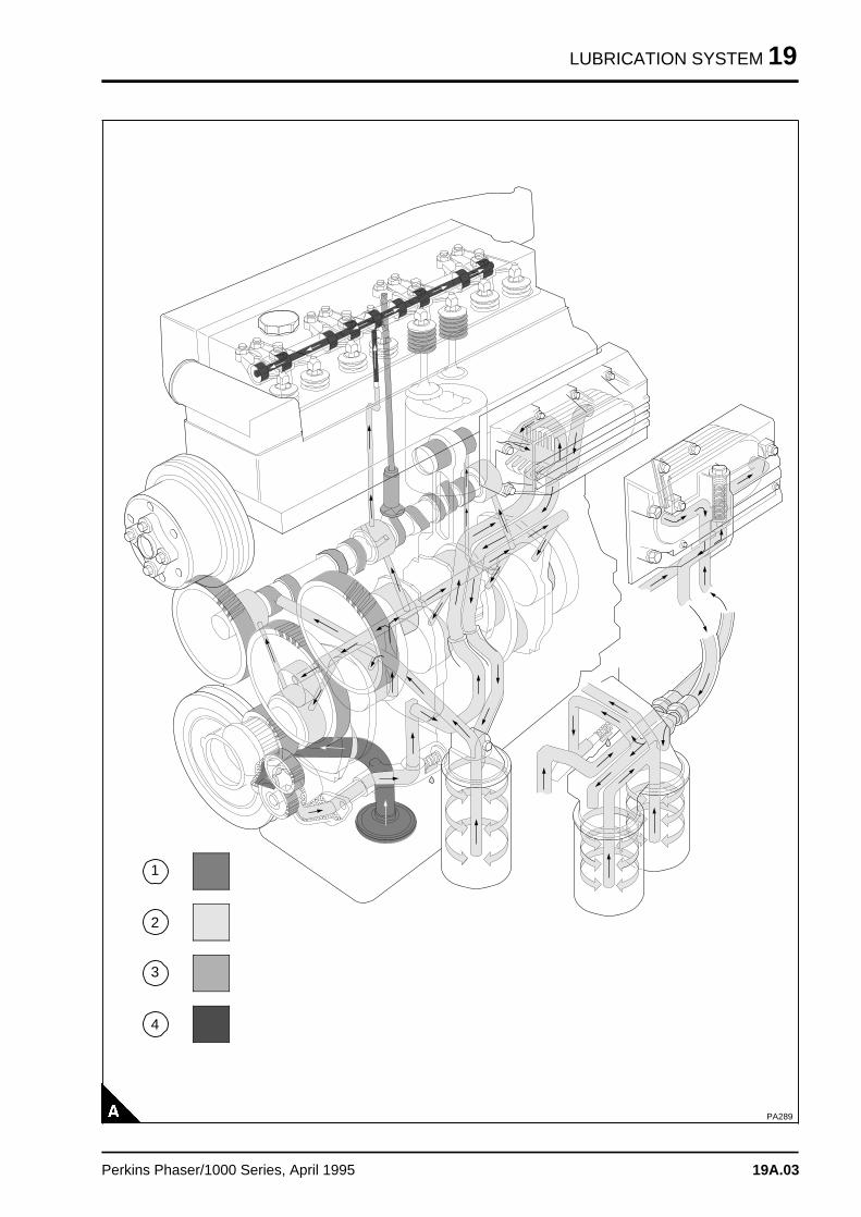
LUBRICATION SYSTEM 19
PA289
a aa aa aa a
1
a aa aa aa aa a
2
a aa aa aa a
3
a aa aa aa a
4
Perkins Phaser/1000 Series, April 1995 19A.03
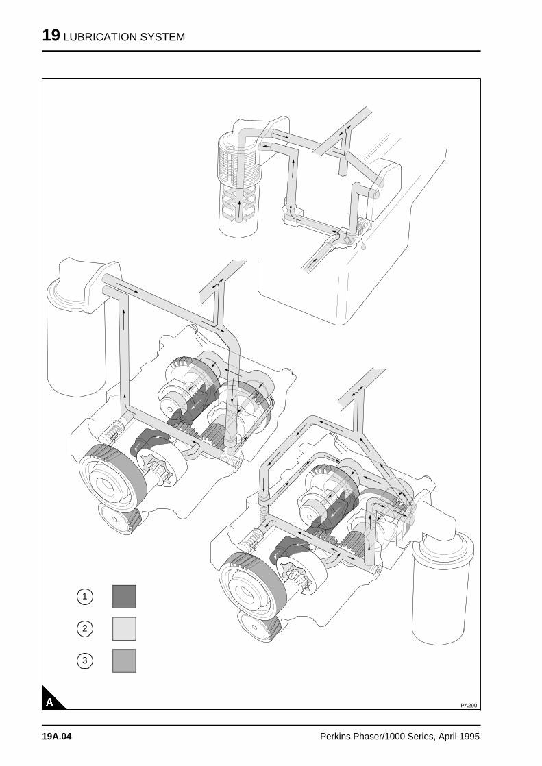
19 LUBRICATION SYSTEM
PA290
a a a
a a a
a a a
a a a
1
a a a
a a a
a a a
a a a
2
a a a
a a a
a a a
a a a
3
19A.04 Perkins Phaser/1000 Series, April 1995
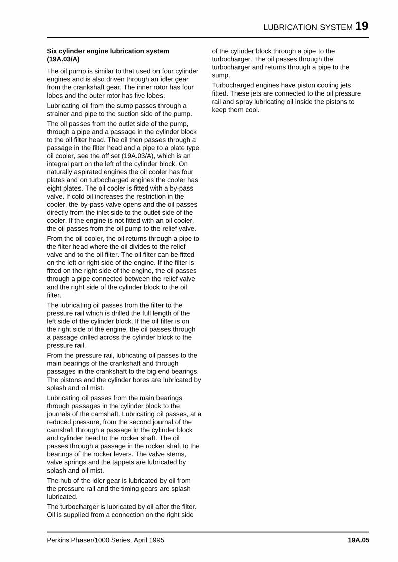
LUBRICATION SYSTEM 19
Six cylinder engine lubrication system (19A.03/A)
The oil pump is similar to that used on four cylinderengines and is also driven through an idler gearfrom the crankshaft gear. The inner rotor has fourlobes and the outer rotor has five lobes.
Lubricating oil from the sump passes through astrainer and pipe to the suction side of the pump.
The oil passes from the outlet side of the pump,through a pipe and a passage in the cylinder blockto the oil filter head. The oil then passes through apassage in the filter head and a pipe to a plate typeoil cooler, see the off set (19A.03/A), which is anintegral part on the left of the cylinder block. Onnaturally aspirated engines the oil cooler has fourplates and on turbocharged engines the cooler haseight plates. The oil cooler is fitted with a by-passvalve. If cold oil increases the restriction in thecooler, the by-pass valve opens and the oil passesdirectly from the inlet side to the outlet side of thecooler. If the engine is not fitted with an oil cooler,the oil passes from the oil pump to the relief valve.
From the oil cooler, the oil returns through a pipe tothe filter head where the oil divides to the reliefvalve and to the oil filter. The oil filter can be fittedon the left or right side of the engine. If the filter isfitted on the right side of the engine, the oil passesthrough a pipe connected between the relief valveand the right side of the cylinder block to the oilfilter.
The lubricating oil passes from the filter to thepressure rail which is drilled the full length of theleft side of the cylinder block. If the oil filter is onthe right side of the engine, the oil passes througha passage drilled across the cylinder block to thepressure rail.
From the pressure rail, lubricating oil passes to themain bearings of the crankshaft and throughpassages in the crankshaft to the big end bearings.The pistons and the cylinder bores are lubricated bysplash and oil mist.
Lubricating oil passes from the main bearingsthrough passages in the cylinder block to thejournals of the camshaft. Lubricating oil passes, at areduced pressure, from the second journal of thecamshaft through a passage in the cylinder blockand cylinder head to the rocker shaft. The oilpasses through a passage in the rocker shaft to thebearings of the rocker levers. The valve stems,valve springs and the tappets are lubricated bysplash and oil mist.
The hub of the idler gear is lubricated by oil fromthe pressure rail and the timing gears are splashlubricated.
The turbocharger is lubricated by oil after the filter.Oil is supplied from a connection on the right side
of the cylinder block through a pipe to theturbocharger. The oil passes through theturbocharger and returns through a pipe to thesump.
Turbocharged engines have piston cooling jetsfitted. These jets are connected to the oil pressurerail and spray lubricating oil inside the pistons tokeep them cool.
Perkins Phaser/1000 Series, April 1995 19A.05
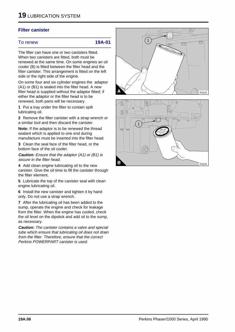
19 LUBRICATION SYSTEM
Filter canister
To renew 19A-01
The filter can have one or two canisters fitted.When two canisters are fitted, both must berenewed at the same time. On some engines an oilcooler (B) is fitted between the filter head and thefilter canister. This arrangement is fitted on the leftside or the right side of the engine.
On some four and six cylinder engines the adaptor(A1) or (B1) is sealed into the filter head. A newfilter head is supplied without the adaptor fitted; ifeither the adaptor or the filter head is to berenewed, both parts will be necessary.
1 Put a tray under the filter to contain spiltlubricating oil.
2 Remove the filter canister with a strap wrench ora similar tool and then discard the canister.
Note: If the adaptor is to be renewed the threadsealant which is applied to one end duringmanufacture must be inserted into the filter head.
3 Clean the seal face of the filter head, or thebottom face of the oil cooler.
Caution: Ensure that the adaptor (A1) or (B1) issecure in the filter head.
4 Add clean engine lubricating oil to the newcanister. Give the oil time to fill the canister throughthe filter element.
5 Lubricate the top of the canister seal with cleanengine lubricating oil.
6 Install the new canister and tighten it by handonly. Do not use a strap wrench.
7 After the lubricating oil has been added to thesump, operate the engine and check for leakagefrom the filter. When the engine has cooled, checkthe oil level on the dipstick and add oil to the sump,as necessary.
Caution: The canister contains a valve and specialtube which ensure that lubricating oil does not drainfrom the filter. Therefore, ensure that the correctPerkins POWERPART canister is used.
a a a a a a a a a a a a a a a a a
a a a a a a a a a a a a a a a a a
a a a a a a a a a a a a a a a a a
a a a a a a a a a a a a a a a a a
a a a a a a a a a a a a a a a a a
a a a a a a a a a a a a a a a a a
a a a a a a a a a a a a a a a a a
a a a
a a a
a a a
a a a
1
PA223
PA224
a a a
a a a
a a a
a a a
1
19A.06 Perkins Phaser/1000 Series, April 1995
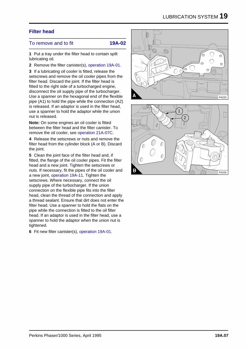
LUBRICATION SYSTEM 19
Filter head
To remove and to fit 19A-02
1 Put a tray under the filter head to contain spiltlubricating oil.
2 Remove the filter canister(s), operation 19A-01.
3 If a lubricating oil cooler is fitted, release thesetscrews and remove the oil cooler pipes from thefilter head. Discard the joint. If the filter head isfitted to the right side of a turbocharged engine,disconnect the oil supply pipe of the turbocharger.Use a spanner on the hexagonal end of the flexiblepipe (A1) to hold the pipe while the connection (A2)is released. If an adaptor is used in the filter head,use a spanner to hold the adaptor while the unionnut is released.
Note: On some engines an oil cooler is fittedbetween the filter head and the filter canister. Toremove the oil cooler, see operation 21A-07C.
4 Release the setscrews or nuts and remove thefilter head from the cylinder block (A or B). Discardthe joint.
5 Clean the joint face of the filter head and, iffitted, the flange of the oil cooler pipes. Fit the filterhead and a new joint. Tighten the setscrews ornuts. If necessary, fit the pipes of the oil cooler anda new joint, operation 19A-11. Tighten thesetscrews. Where necessary, connect the oilsupply pipe of the turbocharger. If the unionconnection on the flexible pipe fits into the filterhead, clean the thread of the connection and applya thread sealant. Ensure that dirt does not enter thefilter head. Use a spanner to hold the flats on thepipe while the connection is fitted to the oil filterhead. If an adaptor is used in the filter head, use aspanner to hold the adaptor when the union nut istightened.
6 Fit new filter canister(s), operation 19A-01.
PA225
PA226
a a a
a a a
a a a
a a a
2
a aa aa aa a
1
Perkins Phaser/1000 Series, April 1995 19A.07
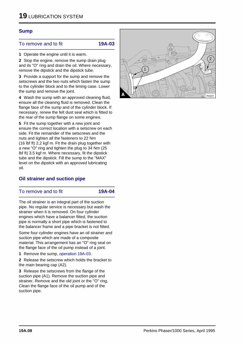
19 LUBRICATION SYSTEM
Sump
To remove and to fit 19A-03
1 Operate the engine until it is warm.
2 Stop the engine, remove the sump drain plugand its "O" ring and drain the oil. Where necessary,remove the dipstick and the dipstick tube.
3 Provide a support for the sump and remove thesetscrews and the two nuts which fasten the sumpto the cylinder block and to the timing case. Lowerthe sump and remove the joint.
4 Wash the sump with an approved cleaning fluid,ensure all the cleaning fluid is removed. Clean theflange face of the sump and of the cylinder block. Ifnecessary, renew the felt dust seal which is fitted tothe rear of the sump flange on some engines.
5 Fit the sump together with a new joint andensure the correct location with a setscrew on eachside. Fit the remainder of the setscrews and thenuts and tighten all the fasteners to 22 Nm (16 lbf ft) 2,2 kgf m. Fit the drain plug together witha new "O" ring and tighten the plug to 34 Nm (25lbf ft) 3,5 kgf m. Where necessary, fit the dipsticktube and the dipstick. Fill the sump to the "MAX"level on the dipstick with an approved lubricatingoil.
Oil strainer and suction pipe
To remove and to fit 19A-04
The oil strainer is an integral part of the suctionpipe. No regular service is necessary but wash thestrainer when it is removed. On four cylinderengines which have a balancer fitted, the suctionpipe is normally a short pipe which is fastened tothe balancer frame and a pipe bracket is not fitted.
Some four cylinder engines have an oil strainer andsuction pipe which are made of a compositematerial. This arrangement has an "O" ring seal onthe flange face of the oil pump instead of a joint.
1 Remove the sump, operation 19A-03.
2 Release the setscrew which holds the bracket tothe main bearing cap (A2).
3 Release the setscrews from the flange of thesuction pipe (A1). Remove the suction pipe andstrainer. Remove and the old joint or the "O" ring.Clean the flange face of the oil pump and of thesuction pipe.
PA227
a a a
a a a
a a a
a a a
a a a
1
a a a
a a a
a a a
a a a
2
19A.08 Perkins Phaser/1000 Series, April 1995
LUBRICATION SYSTEM 19
4 Loosely assemble the bracket of the suction pipeto the correct main bearing cap. Fit the suction pipeto the oil pump together with a new joint or an "O"ring. Tighten the setscrews. Tighten the setscrew ofthe suction pipe bracket. If the clamp type bracket,used on some four cylinder engines, has beenremoved, ensure that the clamp, the bracket andthe pipe are correctly aligned before the setscrewsare tightened. Ensure that there is no stress on thesuction pipe.
5 Fit the sump, operation 19A-03, and fill it with anapproved oil to the "MAX" level on the dipstick.
To inspect and to correct 19A-05
1 Wash the assembly in an approved cleaning fluidand dry it thoroughly.
2 Check the pipe, the strainer and the weldedjoints for cracks and other damage. Check that themounting bracket is secure.
3 If the damaged component cannot be weldedcorrectly, renew the assembly.
4 Composite material parts must be renewed ifthey have cracks or damage.
Perkins Phaser/1000 Series, April 1995 19A.09
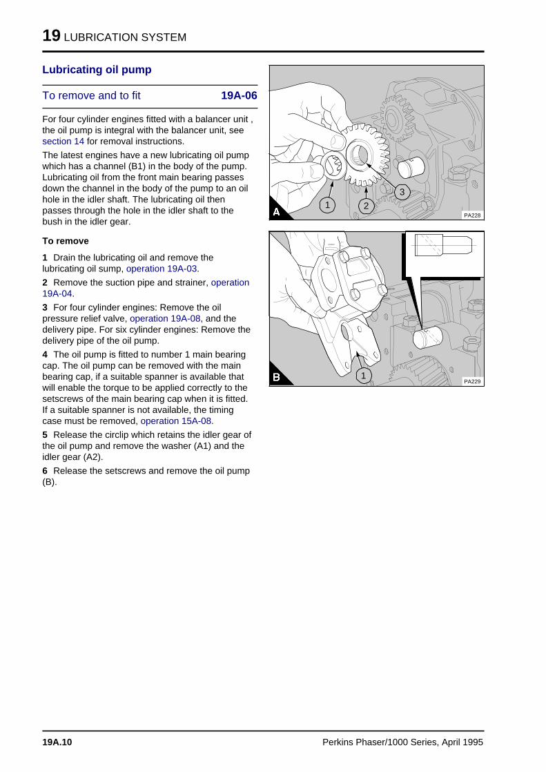
19 LUBRICATION SYSTEM
Lubricating oil pump
To remove and to fit 19A-06
For four cylinder engines fitted with a balancer unit ,the oil pump is integral with the balancer unit, seesection 14 for removal instructions.
The latest engines have a new lubricating oil pumpwhich has a channel (B1) in the body of the pump.Lubricating oil from the front main bearing passesdown the channel in the body of the pump to an oilhole in the idler shaft. The lubricating oil thenpasses through the hole in the idler shaft to thebush in the idler gear.
To remove
1 Drain the lubricating oil and remove thelubricating oil sump, operation 19A-03.
2 Remove the suction pipe and strainer, operation19A-04.
3 For four cylinder engines: Remove the oilpressure relief valve, operation 19A-08, and thedelivery pipe. For six cylinder engines: Remove thedelivery pipe of the oil pump.
4 The oil pump is fitted to number 1 main bearingcap. The oil pump can be removed with the mainbearing cap, if a suitable spanner is available thatwill enable the torque to be applied correctly to thesetscrews of the main bearing cap when it is fitted.If a suitable spanner is not available, the timingcase must be removed, operation 15A-08.
5 Release the circlip which retains the idler gear ofthe oil pump and remove the washer (A1) and theidler gear (A2).
6 Release the setscrews and remove the oil pump(B).
PA228
a aa aa aa a
3
a aa aa aa a
2
a aa aa aa a
1
PA229
a aa aa aa a
1
19A.10 Perkins Phaser/1000 Series, April 1995
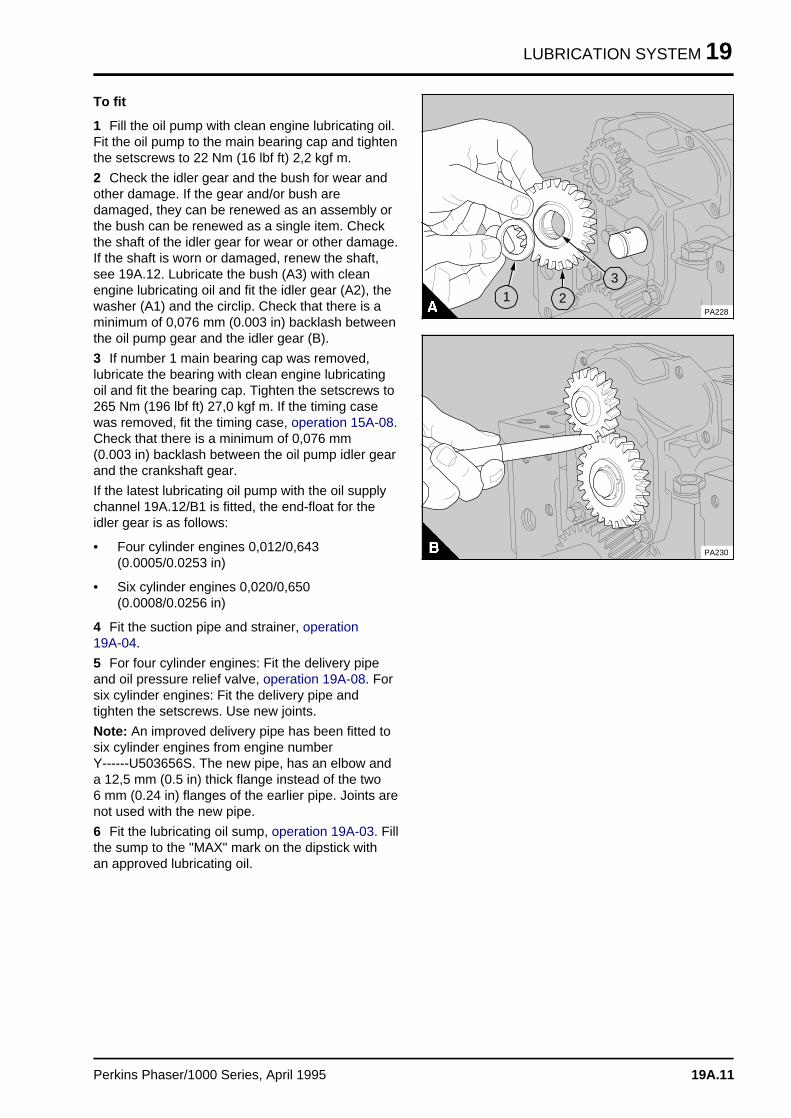
LUBRICATION SYSTEM 19
To fit
1 Fill the oil pump with clean engine lubricating oil.Fit the oil pump to the main bearing cap and tightenthe setscrews to 22 Nm (16 lbf ft) 2,2 kgf m.
2 Check the idler gear and the bush for wear andother damage. If the gear and/or bush aredamaged, they can be renewed as an assembly orthe bush can be renewed as a single item. Checkthe shaft of the idler gear for wear or other damage.If the shaft is worn or damaged, renew the shaft,see 19A.12. Lubricate the bush (A3) with cleanengine lubricating oil and fit the idler gear (A2), thewasher (A1) and the circlip. Check that there is aminimum of 0,076 mm (0.003 in) backlash betweenthe oil pump gear and the idler gear (B).
3 If number 1 main bearing cap was removed,lubricate the bearing with clean engine lubricatingoil and fit the bearing cap. Tighten the setscrews to265 Nm (196 lbf ft) 27,0 kgf m. If the timing casewas removed, fit the timing case, operation 15A-08.Check that there is a minimum of 0,076 mm (0.003 in) backlash between the oil pump idler gearand the crankshaft gear.
If the latest lubricating oil pump with the oil supplychannel 19A.12/B1 is fitted, the end-float for theidler gear is as follows:
• Four cylinder engines 0,012/0,643(0.0005/0.0253 in)
• Six cylinder engines 0,020/0,650(0.0008/0.0256 in)
4 Fit the suction pipe and strainer, operation 19A-04.
5 For four cylinder engines: Fit the delivery pipeand oil pressure relief valve, operation 19A-08. Forsix cylinder engines: Fit the delivery pipe andtighten the setscrews. Use new joints.
Note: An improved delivery pipe has been fitted tosix cylinder engines from engine number Y------U503656S. The new pipe, has an elbow anda 12,5 mm (0.5 in) thick flange instead of the two 6 mm (0.24 in) flanges of the earlier pipe. Joints arenot used with the new pipe.
6 Fit the lubricating oil sump, operation 19A-03. Fillthe sump to the "MAX" mark on the dipstick withan approved lubricating oil.
PA228
a a a
a a a
a a a
a a a
3
a a a
a a a
a a a
a a a
2
a a a
a a a
a a a
a a a
1
PA230
Perkins Phaser/1000 Series, April 1995 19A.11
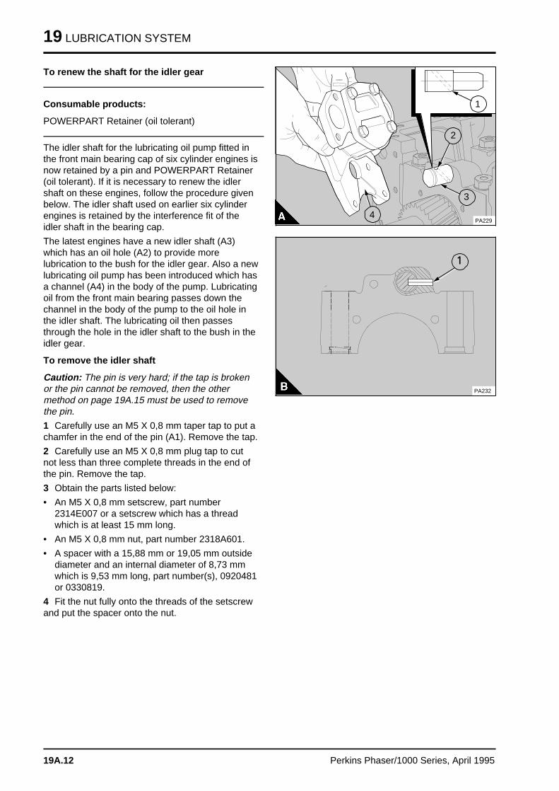
19 LUBRICATION SYSTEM
To renew the shaft for the idler gear
Consumable products:
POWERPART Retainer (oil tolerant)
The idler shaft for the lubricating oil pump fitted inthe front main bearing cap of six cylinder engines isnow retained by a pin and POWERPART Retainer(oil tolerant). If it is necessary to renew the idlershaft on these engines, follow the procedure givenbelow. The idler shaft used on earlier six cylinderengines is retained by the interference fit of theidler shaft in the bearing cap.
The latest engines have a new idler shaft (A3)which has an oil hole (A2) to provide morelubrication to the bush for the idler gear. Also a newlubricating oil pump has been introduced which hasa channel (A4) in the body of the pump. Lubricatingoil from the front main bearing passes down thechannel in the body of the pump to the oil hole inthe idler shaft. The lubricating oil then passesthrough the hole in the idler shaft to the bush in theidler gear.
To remove the idler shaft
Caution: The pin is very hard; if the tap is brokenor the pin cannot be removed, then the othermethod on page 19A.15 must be used to removethe pin.
1 Carefully use an M5 X 0,8 mm taper tap to put achamfer in the end of the pin (A1). Remove the tap.
2 Carefully use an M5 X 0,8 mm plug tap to cutnot less than three complete threads in the end ofthe pin. Remove the tap.
3 Obtain the parts listed below:
• An M5 X 0,8 mm setscrew, part number2314E007 or a setscrew which has a threadwhich is at least 15 mm long.
• An M5 X 0,8 mm nut, part number 2318A601.
• A spacer with a 15,88 mm or 19,05 mm outsidediameter and an internal diameter of 8,73 mmwhich is 9,53 mm long, part number(s), 0920481or 0330819.
4 Fit the nut fully onto the threads of the setscrewand put the spacer onto the nut.
a a a
a a a
a a a
a a a
1
a a a
a a a
a a a
a a a
3
a a a
a a a
a a a
a a a
2
PA229
a aa aa aa a
4
a a a
a a a
a a a
a a a
1
PA232
19A.12 Perkins Phaser/1000 Series, April 1995
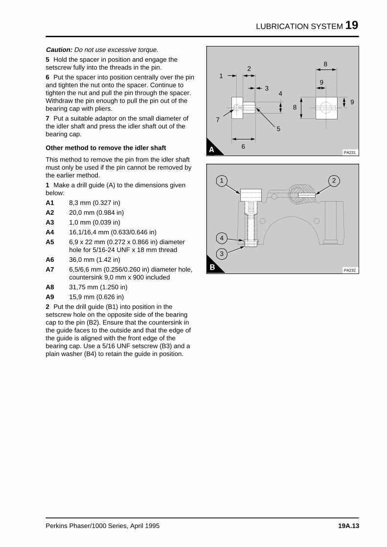
LUBRICATION SYSTEM 19
Caution: Do not use excessive torque.
5 Hold the spacer in position and engage thesetscrew fully into the threads in the pin.
6 Put the spacer into position centrally over the pinand tighten the nut onto the spacer. Continue totighten the nut and pull the pin through the spacer.Withdraw the pin enough to pull the pin out of thebearing cap with pliers.
7 Put a suitable adaptor on the small diameter ofthe idler shaft and press the idler shaft out of thebearing cap.
Other method to remove the idler shaft
This method to remove the pin from the idler shaftmust only be used if the pin cannot be removed bythe earlier method.
1 Make a drill guide (A) to the dimensions givenbelow:
A1 8,3 mm (0.327 in)
A2 20,0 mm (0.984 in)
A3 1,0 mm (0.039 in)
A4 16,1/16,4 mm (0.633/0.646 in)
A5 6,9 x 22 mm (0.272 x 0.866 in) diameterhole for 5/16-24 UNF x 18 mm thread
A6 36,0 mm (1.42 in)
A7 6,5/6,6 mm (0.256/0.260 in) diameter hole,countersink 9,0 mm x 900 included
A8 31,75 mm (1.250 in)
A9 15,9 mm (0.626 in)
2 Put the drill guide (B1) into position in thesetscrew hole on the opposite side of the bearingcap to the pin (B2). Ensure that the countersink inthe guide faces to the outside and that the edge ofthe guide is aligned with the front edge of thebearing cap. Use a 5/16 UNF setscrew (B3) and aplain washer (B4) to retain the guide in position.
a aa aa aa a
3 a a a
a a a
a a a
a a a
4
a a a
a a a
a a a
a a a
5
a aa aa aa aa a
8
a a a
a a a
a a a
a a a
6
a a a
a a a
a a a
a a a
a a a
7
a a a
a a a
a a a
a a a
2
a a a
a a a
a a a
a a a
1
a a a
a a a
a a a
a a a
8
a aa aa aa a
9
a a a
a a a
a a a
a a a
a a a
9
PA231
a aa aa aa a
1
a a a
a a a
a a a
a a a
2
a aa aa aa a
3
a aa aa aa a
4
PA232
Perkins Phaser/1000 Series, April 1995 19A.13
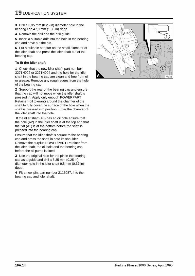
19 LUBRICATION SYSTEM
3 Drill a 6,35 mm (0.25 in) diameter hole in thebearing cap 47,0 mm (1.85 in) deep.
4 Remove the drill and the drill guide.
5 Insert a suitable drift into the hole in the bearingcap and drive out the pin.
6 Put a suitable adaptor on the small diameter ofthe idler shaft and press the idler shaft out of thebearing cap.
To fit the idler shaft
1 Check that the new idler shaft, part number3271H002 or 3271H004 and the hole for the idlershaft in the bearing cap are clean and free from oilor grease. Remove any rough edges from the holeof the bearing cap.
2 Support the rear of the bearing cap and ensurethat the cap will not move when the idler shaft ispressed in. Apply only enough POWERPARTRetainer (oil tolerant) around the chamfer of theshaft to fully cover the surface of the hole when theshaft is pressed into position. Enter the chamfer ofthe idler shaft into the hole.
If the idler shaft (A3) has an oil hole ensure thatthe hole (A2) in the idler shaft is at the top and thatthe flat (A1) is at the bottom before the shaft ispressed into the bearing cap.
Ensure that the idler shaft is square to the bearingcap and press the shaft in onto its shoulder.Remove the surplus POWERPART Retainer fromthe idler shaft, the oil hole and the bearing capbefore the oil pump is fitted.
3 Use the original hole for the pin in the bearingcap as a guide and drill a 6,35 mm (0.25 in)diameter hole in the idler shaft 9,5 mm (0.37 in)deep.
4 Fit a new pin, part number 2116087, into thebearing cap and idler shaft.
a a a
a a a
a a a
a a a
1
a a a
a a a
a a a
a a a
3
a a a
a a a
a a a
a a a
2
PA229
19A.14 Perkins Phaser/1000 Series, April 1995
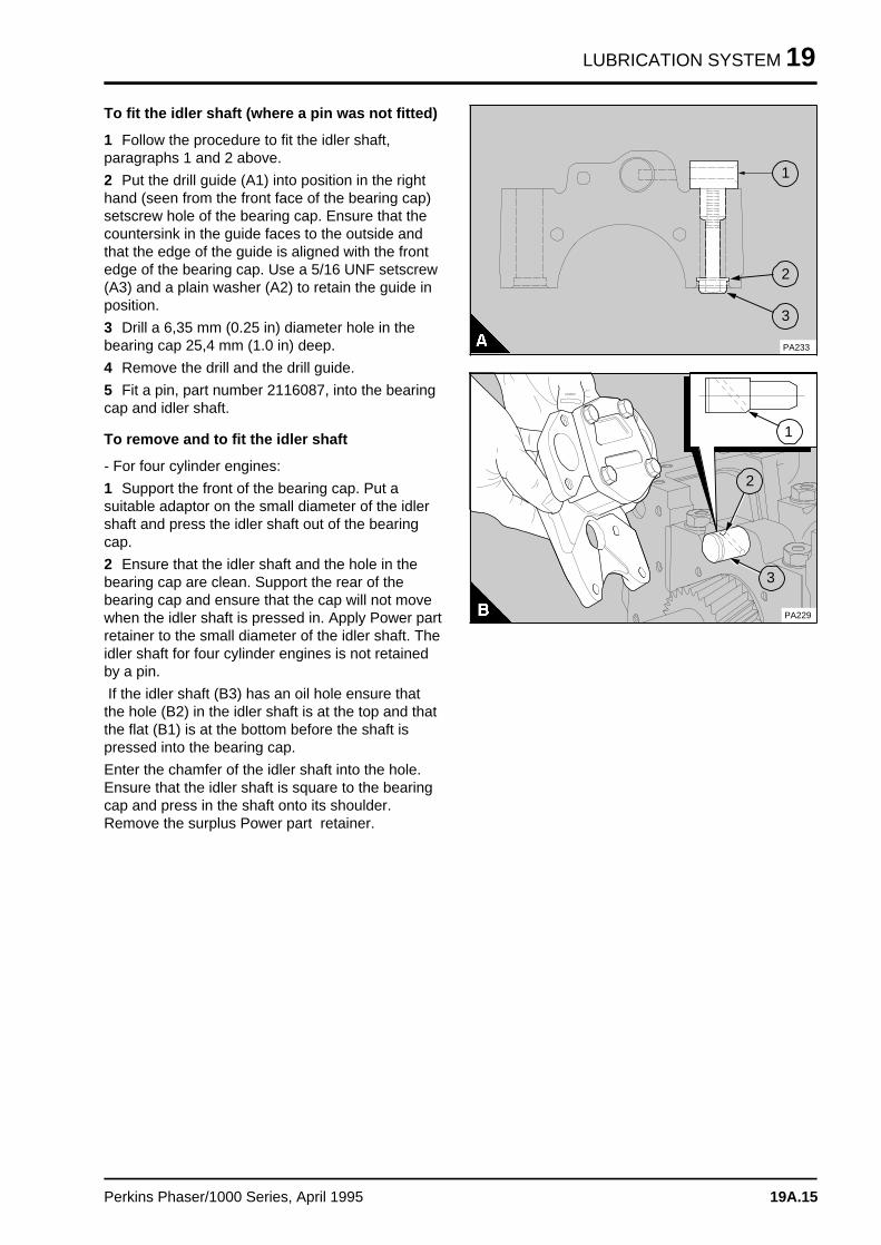
LUBRICATION SYSTEM 19
To fit the idler shaft (where a pin was not fitted)
1 Follow the procedure to fit the idler shaft,paragraphs 1 and 2 above.
2 Put the drill guide (A1) into position in the righthand (seen from the front face of the bearing cap)setscrew hole of the bearing cap. Ensure that thecountersink in the guide faces to the outside andthat the edge of the guide is aligned with the frontedge of the bearing cap. Use a 5/16 UNF setscrew(A3) and a plain washer (A2) to retain the guide inposition.
3 Drill a 6,35 mm (0.25 in) diameter hole in thebearing cap 25,4 mm (1.0 in) deep.
4 Remove the drill and the drill guide.
5 Fit a pin, part number 2116087, into the bearingcap and idler shaft.
To remove and to fit the idler shaft
- For four cylinder engines:
1 Support the front of the bearing cap. Put asuitable adaptor on the small diameter of the idlershaft and press the idler shaft out of the bearingcap.
2 Ensure that the idler shaft and the hole in thebearing cap are clean. Support the rear of thebearing cap and ensure that the cap will not movewhen the idler shaft is pressed in. Apply Power partretainer to the small diameter of the idler shaft. Theidler shaft for four cylinder engines is not retainedby a pin.
If the idler shaft (B3) has an oil hole ensure thatthe hole (B2) in the idler shaft is at the top and thatthe flat (B1) is at the bottom before the shaft ispressed into the bearing cap.
Enter the chamfer of the idler shaft into the hole.Ensure that the idler shaft is square to the bearingcap and press in the shaft onto its shoulder.Remove the surplus Power part retainer.
a aa aa aa a
1
a aa aa aa a
2
a aa aa aa a
3
PA233
a a a
a a a
a a a
a a a
a a a
1
a a a
a a a
a a a
a a a
3
a aa aa aa a
2
PA229
Perkins Phaser/1000 Series, April 1995 19A.15
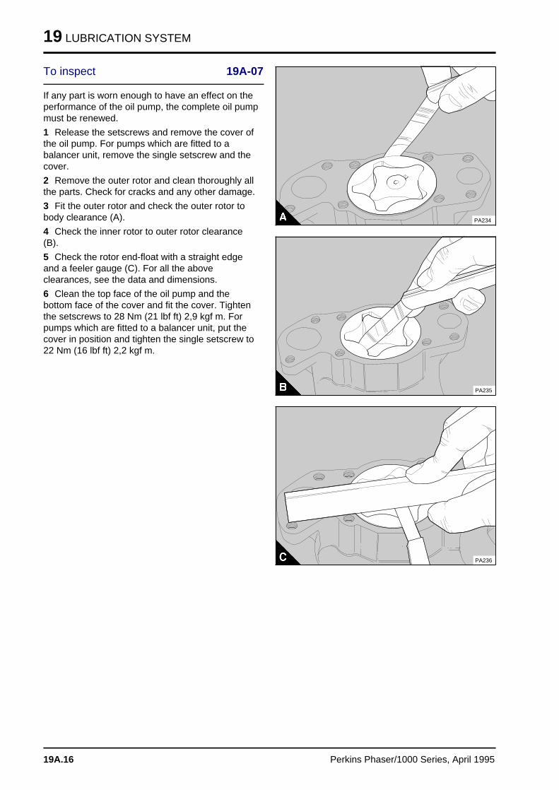
19 LUBRICATION SYSTEM
To inspect 19A-07
If any part is worn enough to have an effect on theperformance of the oil pump, the complete oil pumpmust be renewed.
1 Release the setscrews and remove the cover ofthe oil pump. For pumps which are fitted to abalancer unit, remove the single setscrew and thecover.
2 Remove the outer rotor and clean thoroughly allthe parts. Check for cracks and any other damage.
3 Fit the outer rotor and check the outer rotor tobody clearance (A).
4 Check the inner rotor to outer rotor clearance(B).
5 Check the rotor end-float with a straight edgeand a feeler gauge (C). For all the aboveclearances, see the data and dimensions.
6 Clean the top face of the oil pump and thebottom face of the cover and fit the cover. Tightenthe setscrews to 28 Nm (21 lbf ft) 2,9 kgf m. Forpumps which are fitted to a balancer unit, put thecover in position and tighten the single setscrew to22 Nm (16 lbf ft) 2,2 kgf m.
PA234
PA235
PA236
19A.16 Perkins Phaser/1000 Series, April 1995
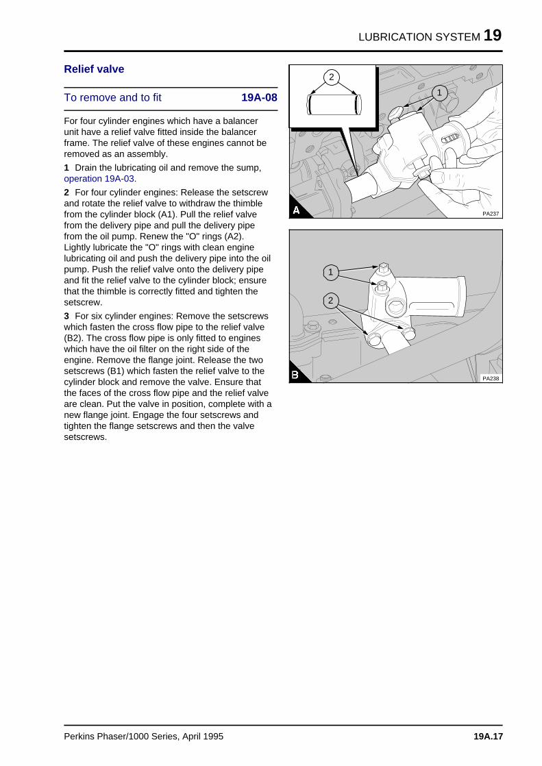
LUBRICATION SYSTEM 19
Relief valve
To remove and to fit 19A-08
For four cylinder engines which have a balancerunit have a relief valve fitted inside the balancerframe. The relief valve of these engines cannot beremoved as an assembly.
1 Drain the lubricating oil and remove the sump,operation 19A-03.
2 For four cylinder engines: Release the setscrewand rotate the relief valve to withdraw the thimblefrom the cylinder block (A1). Pull the relief valvefrom the delivery pipe and pull the delivery pipefrom the oil pump. Renew the "O" rings (A2).Lightly lubricate the "O" rings with clean enginelubricating oil and push the delivery pipe into the oilpump. Push the relief valve onto the delivery pipeand fit the relief valve to the cylinder block; ensurethat the thimble is correctly fitted and tighten thesetscrew.
3 For six cylinder engines: Remove the setscrewswhich fasten the cross flow pipe to the relief valve(B2). The cross flow pipe is only fitted to engineswhich have the oil filter on the right side of theengine. Remove the flange joint. Release the twosetscrews (B1) which fasten the relief valve to thecylinder block and remove the valve. Ensure thatthe faces of the cross flow pipe and the relief valveare clean. Put the valve in position, complete with anew flange joint. Engage the four setscrews andtighten the flange setscrews and then the valvesetscrews.
a aa aa aa aa a
2
a a a
a a a
a a a
a a a
1
PA237
aaaaaaa
a aa aa aa aa aa aa a
a a a
a a a
a a a
a a a
2
PA238
a a a
a a a
a a a
a a a
1
Perkins Phaser/1000 Series, April 1995 19A.17
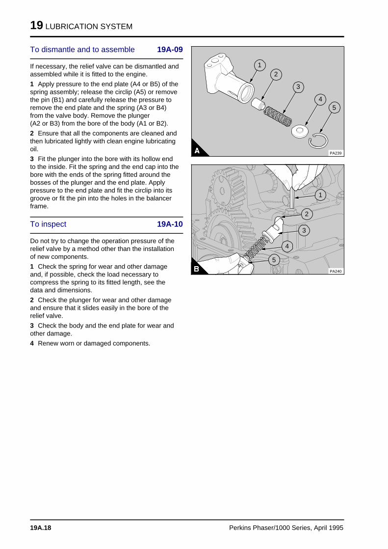
19 LUBRICATION SYSTEM
To dismantle and to assemble 19A-09
If necessary, the relief valve can be dismantled andassembled while it is fitted to the engine.
1 Apply pressure to the end plate (A4 or B5) of thespring assembly; release the circlip (A5) or removethe pin (B1) and carefully release the pressure toremove the end plate and the spring (A3 or B4)from the valve body. Remove the plunger (A2 or B3) from the bore of the body (A1 or B2).
2 Ensure that all the components are cleaned andthen lubricated lightly with clean engine lubricatingoil.
3 Fit the plunger into the bore with its hollow endto the inside. Fit the spring and the end cap into thebore with the ends of the spring fitted around thebosses of the plunger and the end plate. Applypressure to the end plate and fit the circlip into itsgroove or fit the pin into the holes in the balancerframe.
To inspect 19A-10
Do not try to change the operation pressure of therelief valve by a method other than the installationof new components.
1 Check the spring for wear and other damageand, if possible, check the load necessary tocompress the spring to its fitted length, see thedata and dimensions.
2 Check the plunger for wear and other damageand ensure that it slides easily in the bore of therelief valve.
3 Check the body and the end plate for wear andother damage.
4 Renew worn or damaged components.
a a a
a a a
a a a
a a a
a a a
1
a a a
a a a
a a a
a a a
2
a aa aa aa a
3
a aa aa aa a
4
a a a
a a a
a a a
a a a
a a a
5
PA239
a aa aa aa a
1
a a a
a a a
a a a
a a a
2
a a a
a a a
a a a
a a a
a a a
3
a a a
a a a
a a a
a a a
4
a a a
a a a
a a a
a a a
5
PA240
19A.18 Perkins Phaser/1000 Series, April 1995
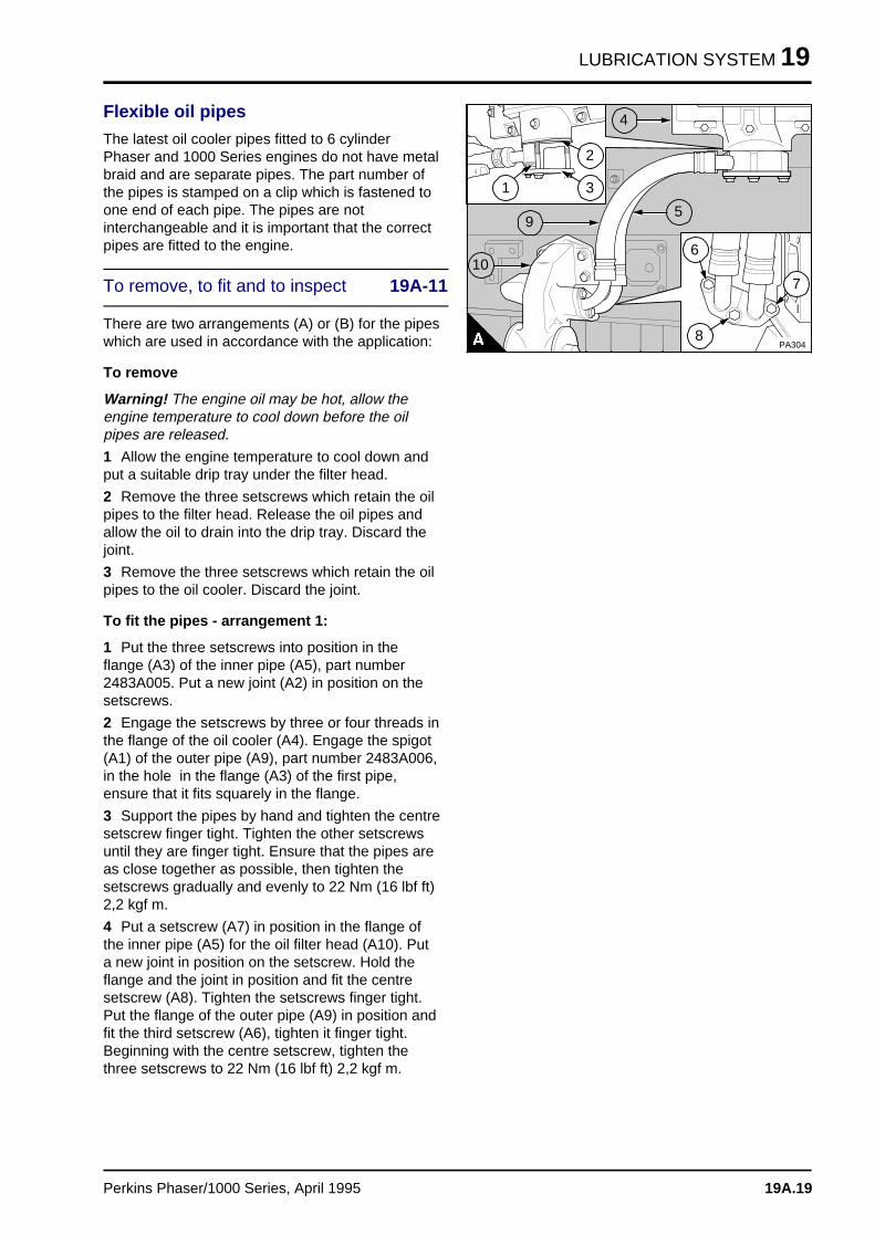
LUBRICATION SYSTEM 19
Flexible oil pipes
The latest oil cooler pipes fitted to 6 cylinderPhaser and 1000 Series engines do not have metalbraid and are separate pipes. The part number ofthe pipes is stamped on a clip which is fastened toone end of each pipe. The pipes are notinterchangeable and it is important that the correctpipes are fitted to the engine.
To remove, to fit and to inspect 19A-11
There are two arrangements (A) or (B) for the pipeswhich are used in accordance with the application:
To remove
Warning! The engine oil may be hot, allow theengine temperature to cool down before the oilpipes are released.
1 Allow the engine temperature to cool down andput a suitable drip tray under the filter head.
2 Remove the three setscrews which retain the oilpipes to the filter head. Release the oil pipes andallow the oil to drain into the drip tray. Discard thejoint.
3 Remove the three setscrews which retain the oilpipes to the oil cooler. Discard the joint.
To fit the pipes - arrangement 1:
1 Put the three setscrews into position in theflange (A3) of the inner pipe (A5), part number2483A005. Put a new joint (A2) in position on thesetscrews.
2 Engage the setscrews by three or four threads inthe flange of the oil cooler (A4). Engage the spigot(A1) of the outer pipe (A9), part number 2483A006,in the hole in the flange (A3) of the first pipe,ensure that it fits squarely in the flange.
3 Support the pipes by hand and tighten the centresetscrew finger tight. Tighten the other setscrewsuntil they are finger tight. Ensure that the pipes areas close together as possible, then tighten thesetscrews gradually and evenly to 22 Nm (16 lbf ft)2,2 kgf m.
4 Put a setscrew (A7) in position in the flange ofthe inner pipe (A5) for the oil filter head (A10). Puta new joint in position on the setscrew. Hold theflange and the joint in position and fit the centresetscrew (A8). Tighten the setscrews finger tight.Put the flange of the outer pipe (A9) in position andfit the third setscrew (A6), tighten it finger tight.Beginning with the centre setscrew, tighten thethree setscrews to 22 Nm (16 lbf ft) 2,2 kgf m.
PA304
a a a
a a a
a a a
a a a
1
a a a
a a a
a a a
a a a
3
a a a
a a a
a a a
a a a
2
a aa aa aa a
5
a aa aa aa a
6
a aa aa aa a
8
a a a
a a a
a a a
a a a
4
a a a
a a a
a a a
a a a
9
a a a a
a a a a
a a a a
a a a a
10
a aa aa aa a
7
Perkins Phaser/1000 Series, April 1995 19A.19
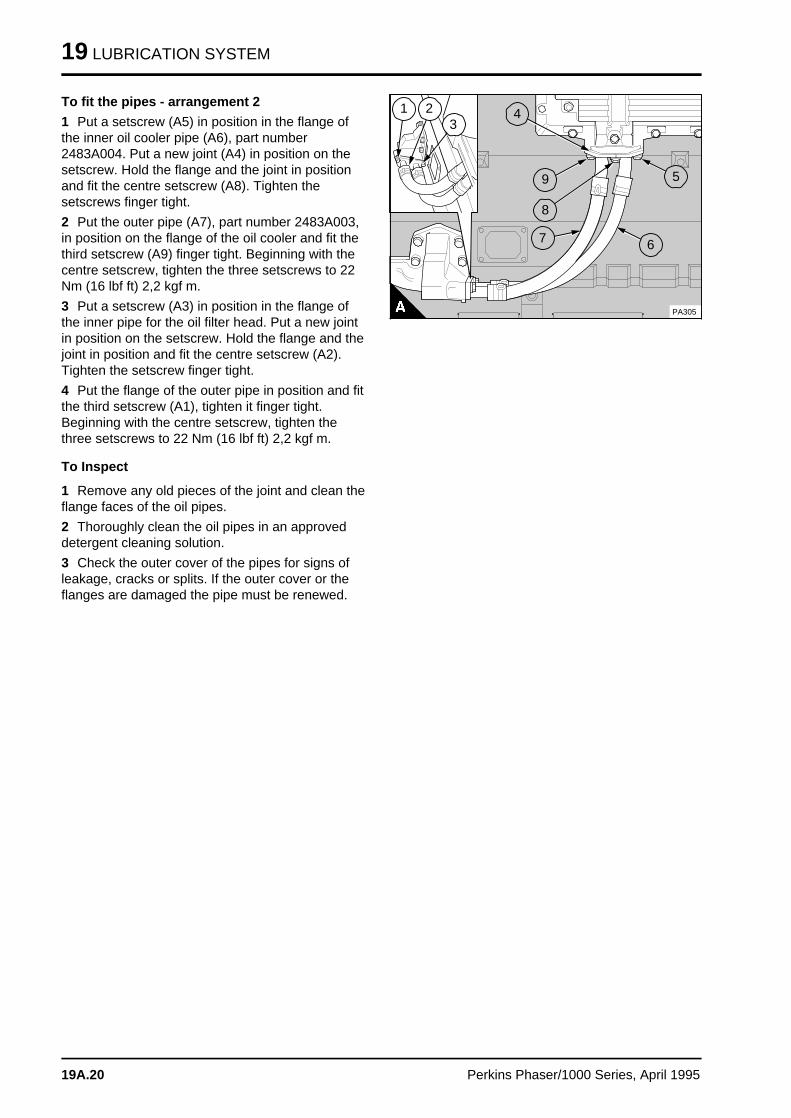
19 LUBRICATION SYSTEM
To fit the pipes - arrangement 2
1 Put a setscrew (A5) in position in the flange ofthe inner oil cooler pipe (A6), part number2483A004. Put a new joint (A4) in position on thesetscrew. Hold the flange and the joint in positionand fit the centre setscrew (A8). Tighten thesetscrews finger tight.
2 Put the outer pipe (A7), part number 2483A003,in position on the flange of the oil cooler and fit thethird setscrew (A9) finger tight. Beginning with thecentre setscrew, tighten the three setscrews to 22Nm (16 lbf ft) 2,2 kgf m.
3 Put a setscrew (A3) in position in the flange ofthe inner pipe for the oil filter head. Put a new jointin position on the setscrew. Hold the flange and thejoint in position and fit the centre setscrew (A2).Tighten the setscrew finger tight.
4 Put the flange of the outer pipe in position and fitthe third setscrew (A1), tighten it finger tight.Beginning with the centre setscrew, tighten thethree setscrews to 22 Nm (16 lbf ft) 2,2 kgf m.
To Inspect
1 Remove any old pieces of the joint and clean theflange faces of the oil pipes.
2 Thoroughly clean the oil pipes in an approveddetergent cleaning solution.
3 Check the outer cover of the pipes for signs ofleakage, cracks or splits. If the outer cover or theflanges are damaged the pipe must be renewed.
PA305
a aa aa aa a
1
a aa aa aa a
2
a aa aa aa a
3
a a a
a a a
a a a
a a a
4
a a a
a a a
a a a
a a a
5
a a a
a a a
a a a
a a a
a a a
6
a aa aa aa a
9
a aa aa aa a
8
a a a
a a a
a a a
a a a
7
19A.20 Perkins Phaser/1000 Series, April 1995
LUBRICATION SYSTEM 19
Data and dimensionsNote: This information is given as a guide for personnel engaged on engine overhauls. The dimensionswhich are shown are those which are mainly used in the factory. The information applies to all engines,unless an engine type code is shown.
Lubrication system
Lubricating oil pump - four cylinder engines
Type . . . . . . . . . . . . . . . . . . . . . . . . . . . . . . . . . . . . . . . . . . . . . . . . . . Differential rotor, gear driven
Number of lobes . . . . . . . . . . . . . . . . . . . . . . . . . . . . . . . . . . . . . . . . . . . Inner rotor 6, outer rotor 7
Clearance of outer rotor to body:
- Without balancer unit . . . . . . . . . . . . . . . . . . . . . . . . . . . . . . . . . . . . 0,15/0,34 mm (0.006/0.013 in)
- With balancer unit . . . . . . . . . . . . . . . . . . . . . . . . . . . . . . . . . . . . . . 0,31/0,45 mm (0.012/0.017 in)
Clearance of inner rotor to outer rotor . . . . . . . . . . . . . . . . . . . . . . . 0,04/0,13 mm (0.0015/0.0050 in)
End-float of rotor assembly . . . . . . . . . . . . . . . . . . . . . . . . . . . . . . . . . 0,03/0,10 mm (0.001/0.004 in)
Lubricating oil pump - six cylinder engines
Type . . . . . . . . . . . . . . . . . . . . . . . . . . . . . . . . . . . . . . . . . . . . . . . . . . Differential rotor, gear driven
Number of lobes:
- Inner rotor . . . . . . . . . . . . . . . . . . . . . . . . . . . . . . . . . . . . . . . . . . . . . . . . . . . . . . . . . . . . . . . . . 4
- Outer rotor . . . . . . . . . . . . . . . . . . . . . . . . . . . . . . . . . . . . . . . . . . . . . . . . . . . . . . . . . . . . . . . . 5
Clearance of outer rotor to body . . . . . . . . . . . . . . . . . . . . . . . . . . . . . 0,15/0,34 mm (0.006/0.013 in)
Clearance of inner rotor to outer rotor . . . . . . . . . . . . . . . . . . . . . . . 0,04/0,13 mm (0.0015/0.0050 in)
End clearance YA, YC:
- Inner rotor . . . . . . . . . . . . . . . . . . . . . . . . . . . . . . . . . . . . . . . . . . . . 0,05/0,12 mm (0.002/0.005 in)
- Outer rotor . . . . . . . . . . . . . . . . . . . . . . . . . . . . . . . . . . . . . . . . . 0,04/0,11 mm (0.0015/0.0044 in)
End clearance (six cylinder turbocharged engines)
- Inner rotor . . . . . . . . . . . . . . . . . . . . . . . . . . . . . . . . . . . . . . . . 0,043/0,118 mm (0.0017/0.0046 in)
- Outer rotor . . . . . . . . . . . . . . . . . . . . . . . . . . . . . . . . . . . . . . . 0,031/0,106 mm (0.0012/0.0042 in)
Idler gear for lubricating oil pump
End float . . . . . . . . . . . . . . . . . . . . . . . . . . . . . . . . . . . . . . . . . . . . . 0,03/0,33 mm (0.001/0.0013 in)
Inside diameter of bush (fitted) . . . . . . . . . . . . . . . . . . . . . . . . . . . . 22,23/22,26 mm (0.875/0.866 in)
Outside diameter of idler shaft . . . . . . . . . . . . . . . . . . . . . . . . . . . . . 22,19/22,21 mm (0.873/0.874 in)
Clearance of bush of idler gear on shaft . . . . . . . . . . . . . . . . . . . . 0,020/0,066 mm (0.0008/0.0026 in)
Oil pressure relief valve (standard)
Diameter of bore for plunger . . . . . . . . . . . . . . . . . . . . . . . . . . . . . . 18,24/18,27 mm (0.718/0.719 in)
Outside diameter of plunger . . . . . . . . . . . . . . . . . . . . . . . . . . . . . . 18,16/18,18 mm (0.715/0.716 in)
Clearance of plunger in bore . . . . . . . . . . . . . . . . . . . . . . . . . . . . . . . . 0,06/0,11 mm (0.002/0.004 in)
Length of spring (fitted):
- Four cylinder engines . . . . . . . . . . . . . . . . . . . . . . . . . . . . . . . . . . . . . . . . . . . . . 59,8 mm (2.4 in)
- Six cylinder engines . . . . . . . . . . . . . . . . . . . . . . . . . . . . . . . . . . . . . . . . . . . . . . 55,6 mm (2.2 in)
Load on spring (fitted):
- Four cylinder engines . . . . . . . . . . . . . . . . . . . . . . . . . . . . . . . . 15,9/23,1 N (3.6/5.2 lbf) 1,6/2,4 kgf
- Six cylinder engines . . . . . . . . . . . . . . . . . . . . . . . . . . . . . . . . . 12,9/18,6 N (2.9/4.2 lbf) 1,3/1,9 kgf
Perkins Phaser/1000 Series, April 1995 19A.21
19 LUBRICATION SYSTEM
Pressure to open valve (Four cylinder engines):
- Without piston cooling jets . . . . . . . . . . . . . . . . . . . . . . . 340/395 kPa (49/57 lbf/in2) 3,4/4,0 kgf/cm2
- With piston cooling jets . . . . . . . . . . . . . . . . . . . . . . . . . 415/470 kPa (60/68 lbf/in2) 4,2/4,8 kgf/cm2
- Six cylinder engines . . . . . . . . . . . . . . . . . . . . . . . . . . . . 345/414 kPa (50/60 lbf/in2) 3,5/4,2 kgf/cm2
Oil pressure relief valve (with balancer)
Diameter of bore for plunger . . . . . . . . . . . . . . . . . . . . . . . . . . . . . . 16,00/16,03 mm (0.630/0.631 in)
Outside diameter of plunger . . . . . . . . . . . . . . . . . . . . . . . . . . . . . . 15,95/15,98 mm (0.628/0.629 in)
Clearance of plunger in bore . . . . . . . . . . . . . . . . . . . . . . . . . . . . . . . 0,02/0,08 mm (0.0008/0.003 in)
Length of spring (fitted) . . . . . . . . . . . . . . . . . . . . . . . . . . . . . . . . . . . . . . . . . . . . . 42,7 mm (1.7 in)
Load on spring (fitted):
- Engines without piston cooling jets . . . . . . . . . . . . . . . . . . . . . . . . . 24/30 N (5.4/6.7 lbf) 2,4/3,1 kgf
- Engines with piston cooling jets . . . . . . . . . . . . . . . . . . . . . . . . . . . . 34/38 N (7.6/8.5 lbf) 3,5/3,9 kgf
Pressure to open valve:
- Engines without piston cooling jets . . . . . . . . . . . . . . . . . . . . . . . . . 414 kPa (60 lbf/in2) 4,2 kgf/cm2
- Engines with piston cooling jets . . . . . . . . . . . . . . . . . . . . . . . . . . . . 523 kPa (76 lbf/in2) 5,3 kgf/cm2
Oil filter
Type . . . . . . . . . . . . . . . . . . . . . . . . . . . . . . . . . . . . . . . . . . . . . . . Full flow, screw-on type canister
Pressure to open by-pass valve in filter . . . . . . . . . . . . . . . . . . 55/83 kPa (8/12 lbf/in2) 0,6/0,8 kgf/cm2
Pressure to open by-pass valve in oil cooler . . . . . . . . . . . . . . . . . . . . 172 kPa (25 lbf/in2) 1,8 kgf/cm2
19A.22 Perkins Phaser/1000 Series, April 1995
Fuel syste m 20
Bosch EPVE fuel injection pumps . . . . . . . . . . . . . . . . . . . . . . . . . . . 20A
Bosch MW in-line fuel injection pump . . . . . . . . . . . . . . . . . . . . . . . . 20B
Lucas DPA and DPS fuel injection pumps . . . . . . . . . . . . . . . . . . . . 20C
Lucas DP200 Series fuel injection pump . . . . . . . . . . . . . . . . . . . . . 20D
Stanadyne fuel injection pump . . . . . . . . . . . . . . . . . . . . . . . . . . . . . 20E
Perkins Phaser/1000 Series, April 1995 20.01
Engines fitted with Bosch EPVE fuel injection pump s 20A
General descriptio n . . . . . . . . . . . . . . . . . . . . . . . . . . . . . . . . . . . . . . . . . 20A.02
Fuel filter element
20A-01 To renew . . . . . . . . . . . . . . . . . . . . . . . . . . . . . . . . . . . . . . . . . 20A.04
Atomisers
Atomiser fault . . . . . . . . . . . . . . . . . . . . . . . . . . . . . . . . . . . . . . 20A.0720A-02 To remove and to fit . . . . . . . . . . . . . . . . . . . . . . . . . . . . . . . . . 20A.07
Fuel lift pump
20A-03 To remove and to fit . . . . . . . . . . . . . . . . . . . . . . . . . . . . . . . . . 20A.0820A-04 To dismantle and to assemble . . . . . . . . . . . . . . . . . . . . . . . . . . 20A.0820A-05 To test . . . . . . . . . . . . . . . . . . . . . . . . . . . . . . . . . . . . . . . . . . . 20A.10
Fuel injection pump
20A-06A To remove and to fit . . . . . . . . . . . . . . . . . . . . . . . . . . . . . . . . . 20A.1120A-06B To remove and to fit - pumps fitted with a locking screw . . . . . . . 20A.1320A-06C To set the injection advance device (KSB) . . . . . . . . . . . . . . . . . 20A.1820A-07 To adjust . . . . . . . . . . . . . . . . . . . . . . . . . . . . . . . . . . . . . . . . . 20A.1820A-08 To eliminate air from the fuel system . . . . . . . . . . . . . . . . . . . . . 20A.20
Data and dimension s . . . . . . . . . . . . . . . . . . . . . . . . . . . . . . . . . . . . . . . 20A.22
Perkins Phaser/1000 Series, April 1995 20A.01
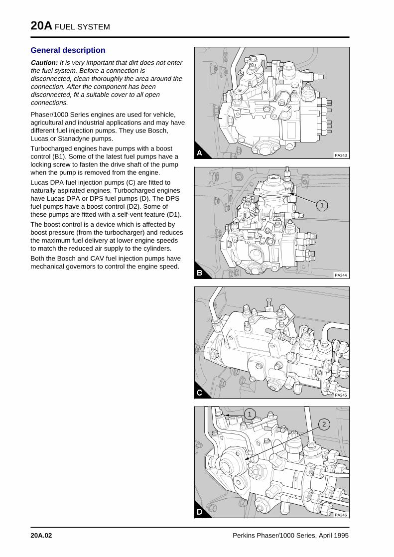
20A FUEL SYSTEM
General description
Caution: It is very important that dirt does not enterthe fuel system. Before a connection isdisconnected, clean thoroughly the area around theconnection. After the component has beendisconnected, fit a suitable cover to all openconnections.
Phaser/1000 Series engines are used for vehicle,agricultural and industrial applications and may havedifferent fuel injection pumps. They use Bosch,Lucas or Stanadyne pumps.
Turbocharged engines have pumps with a boostcontrol (B1). Some of the latest fuel pumps have alocking screw to fasten the drive shaft of the pumpwhen the pump is removed from the engine.
Lucas DPA fuel injection pumps (C) are fitted tonaturally aspirated engines. Turbocharged engineshave Lucas DPA or DPS fuel pumps (D). The DPSfuel pumps have a boost control (D2). Some ofthese pumps are fitted with a self-vent feature (D1).
The boost control is a device which is affected byboost pressure (from the turbocharger) and reducesthe maximum fuel delivery at lower engine speedsto match the reduced air supply to the cylinders.
Both the Bosch and CAV fuel injection pumps havemechanical governors to control the engine speed.
PA243
a a a
a a a
a a a
a a a
1
PA244
PA245
a a a
a a a
a a a
a a a
2
PA246
a a a
a a a
a a a
a a a
1
20A.02 Perkins Phaser/1000 Series, April 1995
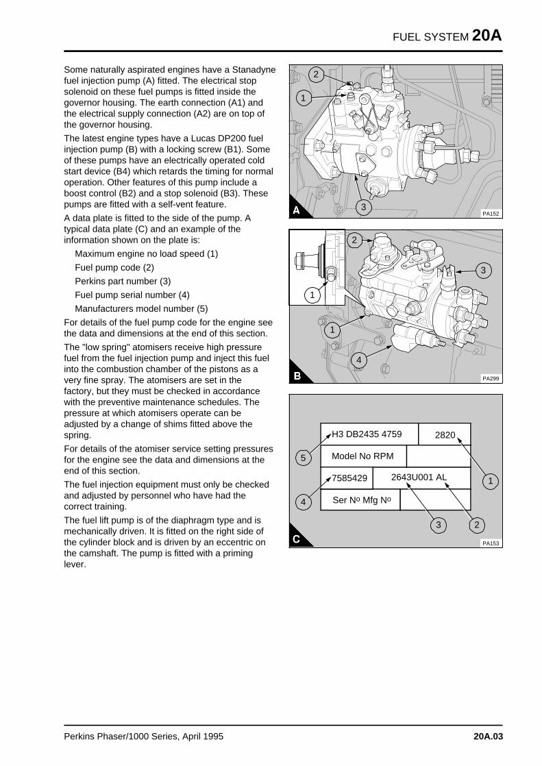
FUEL SYSTEM 20A
Some naturally aspirated engines have a Stanadynefuel injection pump (A) fitted. The electrical stopsolenoid on these fuel pumps is fitted inside thegovernor housing. The earth connection (A1) andthe electrical supply connection (A2) are on top ofthe governor housing.
The latest engine types have a Lucas DP200 fuelinjection pump (B) with a locking screw (B1). Someof these pumps have an electrically operated coldstart device (B4) which retards the timing for normaloperation. Other features of this pump include aboost control (B2) and a stop solenoid (B3). Thesepumps are fitted with a self-vent feature.
A data plate is fitted to the side of the pump. Atypical data plate (C) and an example of theinformation shown on the plate is:
Maximum engine no load speed (1)
Fuel pump code (2)
Perkins part number (3)
Fuel pump serial number (4)
Manufacturers model number (5)
For details of the fuel pump code for the engine seethe data and dimensions at the end of this section.
The "low spring" atomisers receive high pressurefuel from the fuel injection pump and inject this fuelinto the combustion chamber of the pistons as avery fine spray. The atomisers are set in thefactory, but they must be checked in accordancewith the preventive maintenance schedules. Thepressure at which atomisers operate can beadjusted by a change of shims fitted above thespring.
For details of the atomiser service setting pressuresfor the engine see the data and dimensions at theend of this section.
The fuel injection equipment must only be checkedand adjusted by personnel who have had thecorrect training.
The fuel lift pump is of the diaphragm type and ismechanically driven. It is fitted on the right side ofthe cylinder block and is driven by an eccentric onthe camshaft. The pump is fitted with a priminglever.
a a a
a a a
a a a
a a a
2
a a a
a a a
a a a
a a a
a a a
1
a aa aa aa a
3PA152
aaaaaaaaaa
a a a
a a a
a a a
a a a
1
a a a
a a a
a a a
a a a
2
PA299
a a a
a a a
a a a
a a a
a a a4
a aa aa aa a
1
a aa aa aa a
3
H3 DB2435 4759 2820
Model No RPM
Ser No Mfg No
2643U001 AL7585429
PA153
a a a
a a a
a a a
a a a
a a a
5
a a a
a a a
a a a
a a a
4
a a a
a a a
a a a
a a a
a a a
2
a a a
a a a
a a a
a a a
a a a
3
a a a
a a a
a a a
a a a
1
Perkins Phaser/1000 Series, April 1995 20A.03
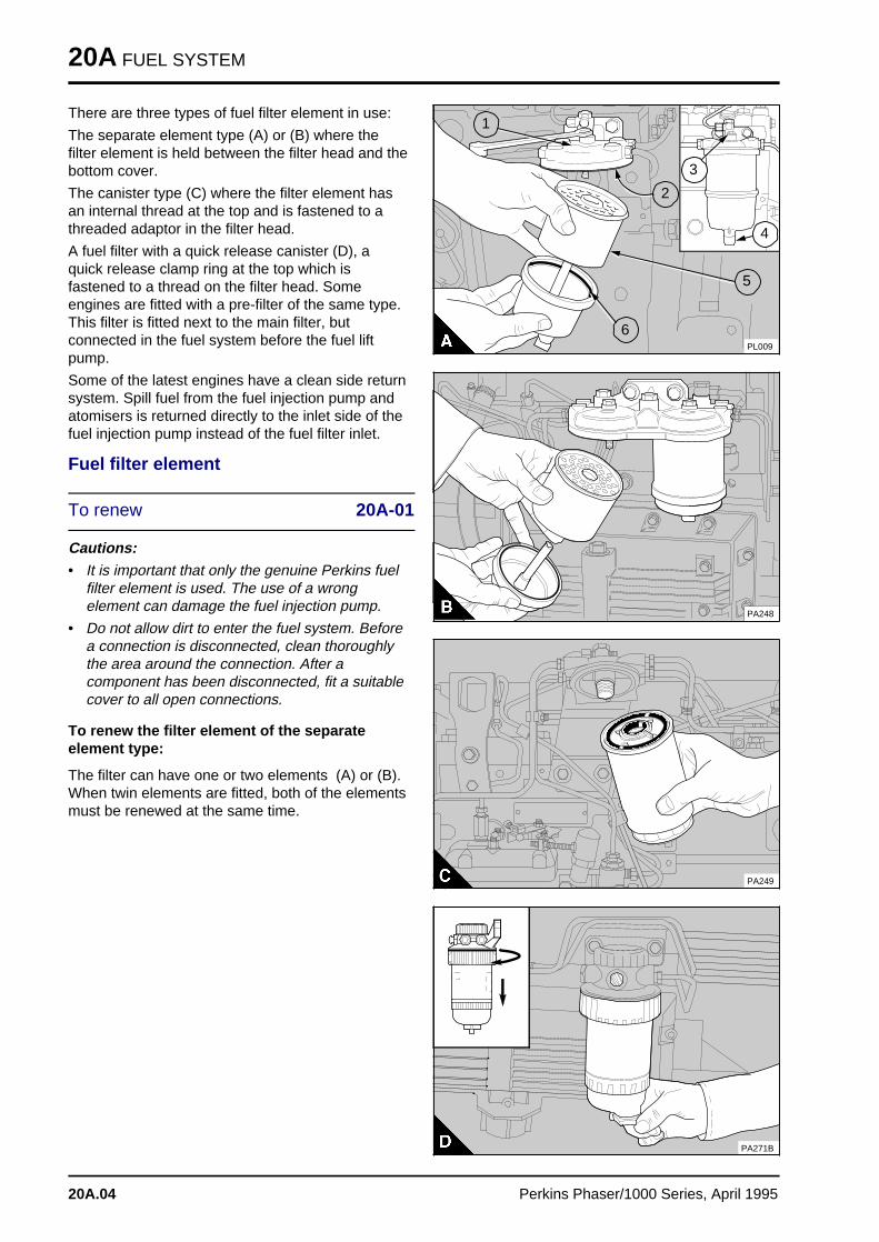
20A FUEL SYSTEM
There are three types of fuel filter element in use:
The separate element type (A) or (B) where thefilter element is held between the filter head and thebottom cover.
The canister type (C) where the filter element hasan internal thread at the top and is fastened to athreaded adaptor in the filter head.
A fuel filter with a quick release canister (D), aquick release clamp ring at the top which isfastened to a thread on the filter head. Someengines are fitted with a pre-filter of the same type.This filter is fitted next to the main filter, butconnected in the fuel system before the fuel liftpump.
Some of the latest engines have a clean side returnsystem. Spill fuel from the fuel injection pump andatomisers is returned directly to the inlet side of thefuel injection pump instead of the fuel filter inlet.
Fuel filter element
To renew 20A-01
Cautions:
• It is important that only the genuine Perkins fuelfilter element is used. The use of a wrongelement can damage the fuel injection pump.
• Do not allow dirt to enter the fuel system. Beforea connection is disconnected, clean thoroughlythe area around the connection. After acomponent has been disconnected, fit a suitablecover to all open connections.
To renew the filter element of the separateelement type:
The filter can have one or two elements (A) or (B).When twin elements are fitted, both of the elementsmust be renewed at the same time.
PL009
a a a
a a a
a a a
a a a
5
a a a
a a a
a a a
a a a
6
a a a
a a a
a a a
a a a
1
a a a
a a a
a a a
a a a
2
a a a
a a a
a a a
a a a
4
a a a
a a a
a a a
a a a
3
aaaa
PA248a a a a a a a a a a a a
a a a a a a a a a a a a
a a a a a a a a a a a a
a a a a a a a a a a a a
a a a a a a a a a a a a
a a a a a a a a a a a a
a a a a a a a a a a a a
a a a a a a
a a a a a a
a a a a a a
PA249
a a a a a a a a a a
a a a a a a a a a a
PA271B
20A.04 Perkins Phaser/1000 Series, April 1995
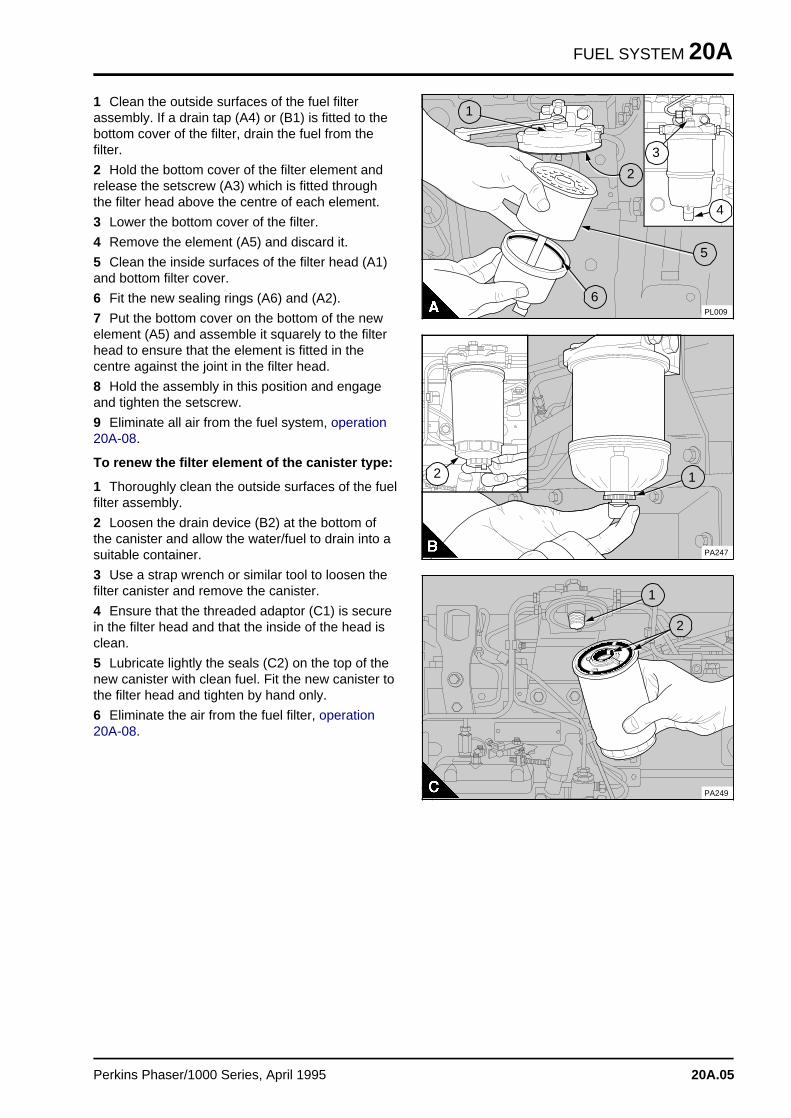
FUEL SYSTEM 20A
1 Clean the outside surfaces of the fuel filterassembly. If a drain tap (A4) or (B1) is fitted to thebottom cover of the filter, drain the fuel from thefilter.
2 Hold the bottom cover of the filter element andrelease the setscrew (A3) which is fitted throughthe filter head above the centre of each element.
3 Lower the bottom cover of the filter.
4 Remove the element (A5) and discard it.
5 Clean the inside surfaces of the filter head (A1)and bottom filter cover.
6 Fit the new sealing rings (A6) and (A2).
7 Put the bottom cover on the bottom of the newelement (A5) and assemble it squarely to the filterhead to ensure that the element is fitted in thecentre against the joint in the filter head.
8 Hold the assembly in this position and engageand tighten the setscrew.
9 Eliminate all air from the fuel system, operation20A-08.
To renew the filter element of the canister type:
1 Thoroughly clean the outside surfaces of the fuelfilter assembly.
2 Loosen the drain device (B2) at the bottom ofthe canister and allow the water/fuel to drain into asuitable container.
3 Use a strap wrench or similar tool to loosen thefilter canister and remove the canister.
4 Ensure that the threaded adaptor (C1) is securein the filter head and that the inside of the head isclean.
5 Lubricate lightly the seals (C2) on the top of thenew canister with clean fuel. Fit the new canister tothe filter head and tighten by hand only.
6 Eliminate the air from the fuel filter, operation20A-08.
PL009
a aa aa aa a
5
a a a
a a a
a a a
a a a
6
a aa aa aa a
1
a a a
a a a
a a a
a a a
2
a aa aa aa a
4
a a a
a a a
a a a
a a a
3
a aa aa aa a
a a a
a a a
a a a
a a a
2 a a a
a a a
a a a
a a a
1
PA247
a a a a a a a a a a a a
a a a a a a a a a a a a
a a a a a a a a a a a a
a a a a a a a a a a a a
a a a a a a a a a a a a
a a a a a a a a a a a a
a a a a a a a a a a a a
a a a a a
a a a a a
a a a a a
a a a
a a a
a a a
a a a
1
a a a
a a a
a a a
a a a
2
PA249
Perkins Phaser/1000 Series, April 1995 20A.05
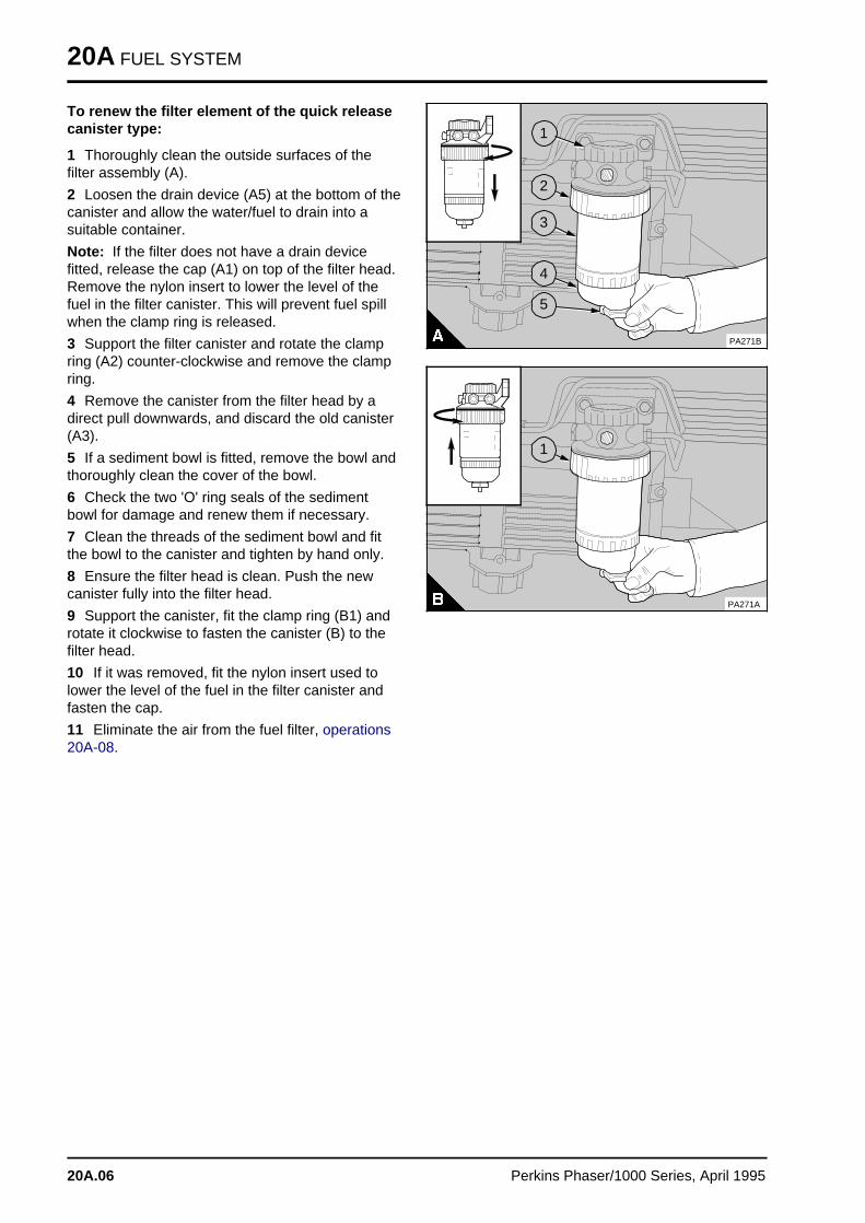
20A FUEL SYSTEM
To renew the filter element of the quick releasecanister type:
1 Thoroughly clean the outside surfaces of thefilter assembly (A).
2 Loosen the drain device (A5) at the bottom of thecanister and allow the water/fuel to drain into asuitable container.
Note: If the filter does not have a drain devicefitted, release the cap (A1) on top of the filter head.Remove the nylon insert to lower the level of thefuel in the filter canister. This will prevent fuel spillwhen the clamp ring is released.
3 Support the filter canister and rotate the clampring (A2) counter-clockwise and remove the clampring.
4 Remove the canister from the filter head by adirect pull downwards, and discard the old canister(A3).
5 If a sediment bowl is fitted, remove the bowl andthoroughly clean the cover of the bowl.
6 Check the two 'O' ring seals of the sedimentbowl for damage and renew them if necessary.
7 Clean the threads of the sediment bowl and fitthe bowl to the canister and tighten by hand only.
8 Ensure the filter head is clean. Push the newcanister fully into the filter head.
9 Support the canister, fit the clamp ring (B1) androtate it clockwise to fasten the canister (B) to thefilter head.
10 If it was removed, fit the nylon insert used tolower the level of the fuel in the filter canister andfasten the cap.
11 Eliminate the air from the fuel filter, operations20A-08.
a a a a a a a a a a
a a a
a a a
a a a
a a a
1
a a a
a a a
a a a
a a a
2
a a a
a a a
a a a
a a a
3
a a a
a a a
a a a
a a a
a a a
4
a a a
a a a
a a a
a a a
5
PA271B
a a a a a a a a a a
a a a
a a a
a a a
a a a
1
PA271A
20A.06 Perkins Phaser/1000 Series, April 1995
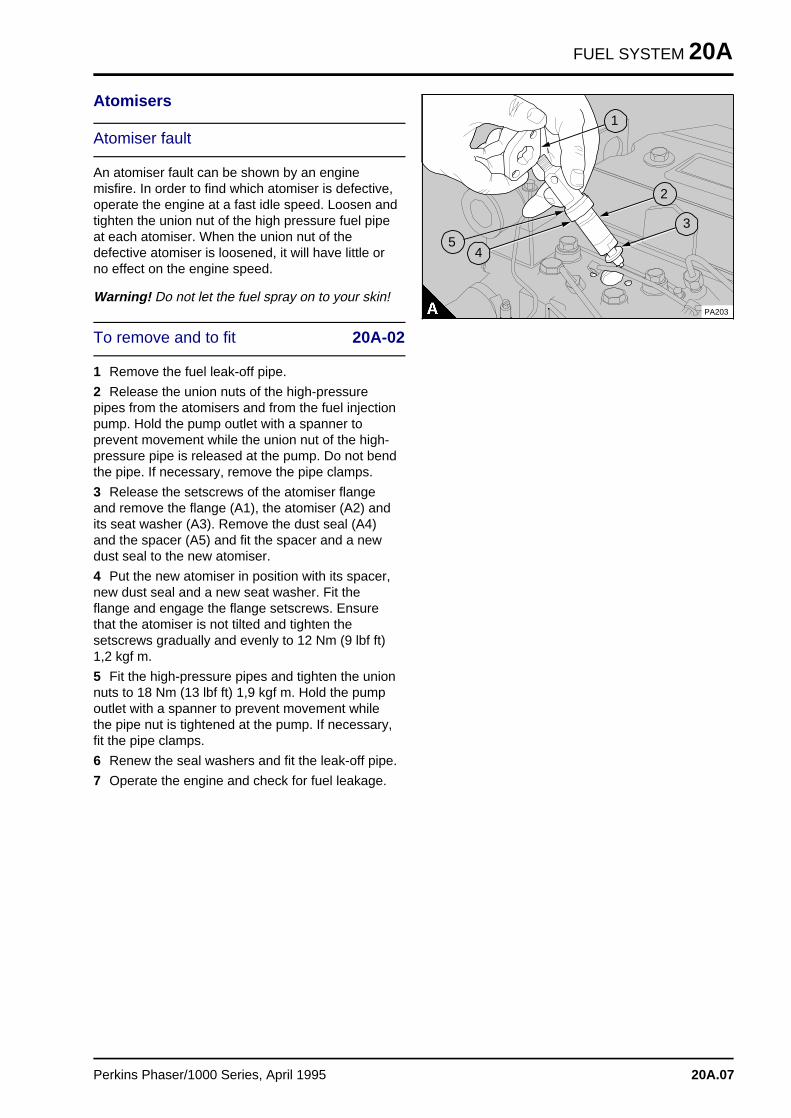
FUEL SYSTEM 20A
Atomisers
Atomiser fault
An atomiser fault can be shown by an enginemisfire. In order to find which atomiser is defective,operate the engine at a fast idle speed. Loosen andtighten the union nut of the high pressure fuel pipeat each atomiser. When the union nut of thedefective atomiser is loosened, it will have little orno effect on the engine speed.
Warning! Do not let the fuel spray on to your skin!
To remove and to fit 20A-02
1 Remove the fuel leak-off pipe.
2 Release the union nuts of the high-pressurepipes from the atomisers and from the fuel injectionpump. Hold the pump outlet with a spanner toprevent movement while the union nut of the high-pressure pipe is released at the pump. Do not bendthe pipe. If necessary, remove the pipe clamps.
3 Release the setscrews of the atomiser flangeand remove the flange (A1), the atomiser (A2) andits seat washer (A3). Remove the dust seal (A4)and the spacer (A5) and fit the spacer and a newdust seal to the new atomiser.
4 Put the new atomiser in position with its spacer,new dust seal and a new seat washer. Fit theflange and engage the flange setscrews. Ensurethat the atomiser is not tilted and tighten thesetscrews gradually and evenly to 12 Nm (9 lbf ft)1,2 kgf m.
5 Fit the high-pressure pipes and tighten the unionnuts to 18 Nm (13 lbf ft) 1,9 kgf m. Hold the pumpoutlet with a spanner to prevent movement whilethe pipe nut is tightened at the pump. If necessary,fit the pipe clamps.
6 Renew the seal washers and fit the leak-off pipe.
7 Operate the engine and check for fuel leakage.
a a a
a a a
a a a
a a a
5 a a a
a a a
a a a
a a a
4
a a a
a a a
a a a
a a a
3
a aa aa aa aa a
2
a a a
a a a
a a a
a a a
1
PA203
Perkins Phaser/1000 Series, April 1995 20A.07
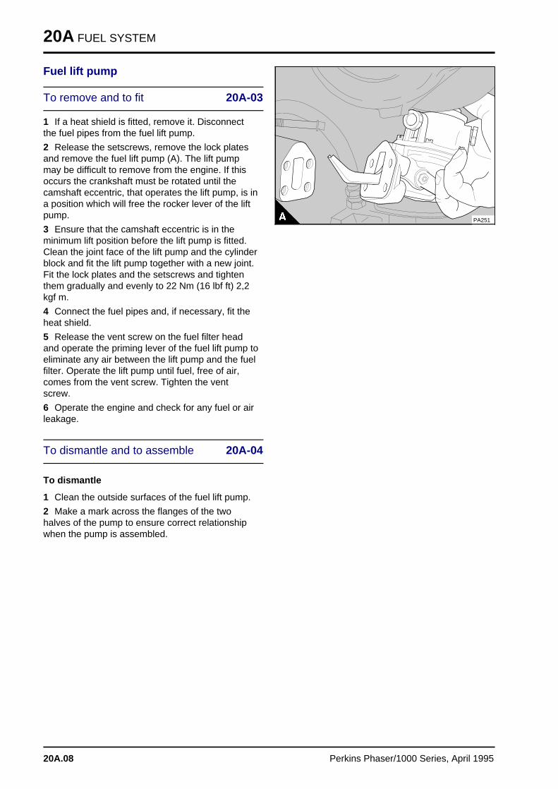
20A FUEL SYSTEM
Fuel lift pump
To remove and to fit 20A-03
1 If a heat shield is fitted, remove it. Disconnectthe fuel pipes from the fuel lift pump.
2 Release the setscrews, remove the lock platesand remove the fuel lift pump (A). The lift pumpmay be difficult to remove from the engine. If thisoccurs the crankshaft must be rotated until thecamshaft eccentric, that operates the lift pump, is ina position which will free the rocker lever of the liftpump.
3 Ensure that the camshaft eccentric is in theminimum lift position before the lift pump is fitted.Clean the joint face of the lift pump and the cylinderblock and fit the lift pump together with a new joint.Fit the lock plates and the setscrews and tightenthem gradually and evenly to 22 Nm (16 lbf ft) 2,2kgf m.
4 Connect the fuel pipes and, if necessary, fit theheat shield.
5 Release the vent screw on the fuel filter headand operate the priming lever of the fuel lift pump toeliminate any air between the lift pump and the fuelfilter. Operate the lift pump until fuel, free of air,comes from the vent screw. Tighten the ventscrew.
6 Operate the engine and check for any fuel or airleakage.
To dismantle and to assemble 20A-04
To dismantle
1 Clean the outside surfaces of the fuel lift pump.
2 Make a mark across the flanges of the twohalves of the pump to ensure correct relationshipwhen the pump is assembled.
PA251
20A.08 Perkins Phaser/1000 Series, April 1995
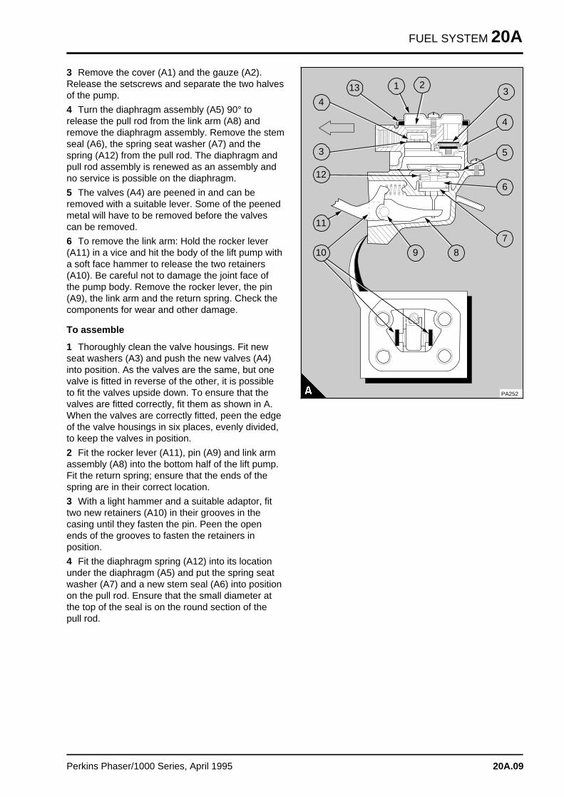
FUEL SYSTEM 20A
3 Remove the cover (A1) and the gauze (A2).Release the setscrews and separate the two halvesof the pump.
4 Turn the diaphragm assembly (A5) 90° torelease the pull rod from the link arm (A8) andremove the diaphragm assembly. Remove the stemseal (A6), the spring seat washer (A7) and thespring (A12) from the pull rod. The diaphragm andpull rod assembly is renewed as an assembly andno service is possible on the diaphragm.
5 The valves (A4) are peened in and can beremoved with a suitable lever. Some of the peenedmetal will have to be removed before the valvescan be removed.
6 To remove the link arm: Hold the rocker lever(A11) in a vice and hit the body of the lift pump witha soft face hammer to release the two retainers(A10). Be careful not to damage the joint face ofthe pump body. Remove the rocker lever, the pin(A9), the link arm and the return spring. Check thecomponents for wear and other damage.
To assemble
1 Thoroughly clean the valve housings. Fit newseat washers (A3) and push the new valves (A4)into position. As the valves are the same, but onevalve is fitted in reverse of the other, it is possibleto fit the valves upside down. To ensure that thevalves are fitted correctly, fit them as shown in A.When the valves are correctly fitted, peen the edgeof the valve housings in six places, evenly divided,to keep the valves in position.
2 Fit the rocker lever (A11), pin (A9) and link armassembly (A8) into the bottom half of the lift pump.Fit the return spring; ensure that the ends of thespring are in their correct location.
3 With a light hammer and a suitable adaptor, fittwo new retainers (A10) in their grooves in thecasing until they fasten the pin. Peen the openends of the grooves to fasten the retainers inposition.
4 Fit the diaphragm spring (A12) into its locationunder the diaphragm (A5) and put the spring seatwasher (A7) and a new stem seal (A6) into positionon the pull rod. Ensure that the small diameter atthe top of the seal is on the round section of thepull rod.
PA252a aa aa aa a
1
a aa aa aa a
2 a aa aa aa a
3
a a a
a a a
a a a
a a a
4
a a a
a a a
a a a
a a a
a a a
5
a a a
a a a
a a a
a a a
6
a a a
a a a
a a a
a a a
7
a a a
a a a
a a a
a a a
8
a aa aa aa a
9
a a a a
a a a a
a a a a
a a a a
10
a a a a
a a a a
a a a a
a a a a
11
a a a a
a a a a
a a a a
a a a a
a a a a
12
a a a
a a a
a a a
a a a
3
a a a
a a a
a a a
a a a
a a a
4
a a a a a
a a a a a
a a a a a
a a a a a
13
Perkins Phaser/1000 Series, April 1995 20A.09
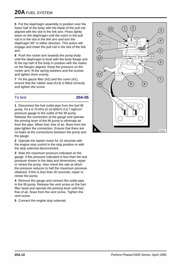
20A FUEL SYSTEM
5 Put the diaphragm assembly in position over thelower half of the body with the blade of the pull rodaligned with the slot in the link arm. Press lightlydown on the diaphragm until the notch in the pullrod is in the slot in the link arm and turn thediaphragm 90° in either direction. This action willengage and retain the pull rod in the slot of the linkarm.
6 Push the rocker arm towards the pump bodyuntil the diaphragm is level with the body flange andfit the top half of the body in position with the markson the flanges aligned. Keep the pressure on therocker arm; fit the spring washers and the screwsand tighten them evenly.
7 Fit the gauze filter (A2) and the cover (A1),ensure that the rubber seal (A13) is fitted correctlyand tighten the screw.
To test 20A-05
1 Disconnect the fuel outlet pipe from the fuel liftpump. Fit a 0-70 kPa (0-10 lbf/in2) 0-0,7 kgf/cm2
pressure gauge to the outlet of the lift pump.Release the connection at the gauge and operatethe priming lever of the lift pump to eliminate airfrom the pipe. When fuel, free of air, flows from thepipe tighten the connection. Ensure that there areno leaks at the connections between the pump andthe gauge.
2 Operate the starter motor for 10 seconds withthe engine stop control in the stop position or withthe stop solenoid disconnected.
3 Note the maximum pressure indicated on thegauge. If the pressure indicated is less than the testpressure shown in the data and dimensions, repairor renew the pump. Also check the rate at whichthe pressure reduces to half the maximum pressureobtained. If this is less than 30 seconds, repair orrenew the pump.
4 Remove the gauge and connect the outlet pipeto the lift pump. Release the vent screw on the fuelfilter head and operate the priming lever until fuel,free of air, flows from the vent screw. Tighten thevent screw.
5 Connect the engine stop solenoid.
PA252
a a a
a a a
a a a
a a a
1
a a a
a a a
a a a
a a a
2 a a a
a a a
a a a
a a a
3
a a a
a a a
a a a
a a a
4
a a a
a a a
a a a
a a a
a a a
5
a a a
a a a
a a a
a a a
6
a a a
a a a
a a a
a a a
7
a aa aa aa a
8
a aa aa aa a
9
a a a a
a a a a
a a a a
a a a a
10
a a a a
a a a a
a a a a
a a a a
11
a a a a
a a a a
a a a a
a a a a
a a a a
12
a aa aa aa a
3
a aa aa aa aa a
4
a a a a
a a a a
a a a a
a a a a
13
20A.10 Perkins Phaser/1000 Series, April 1995
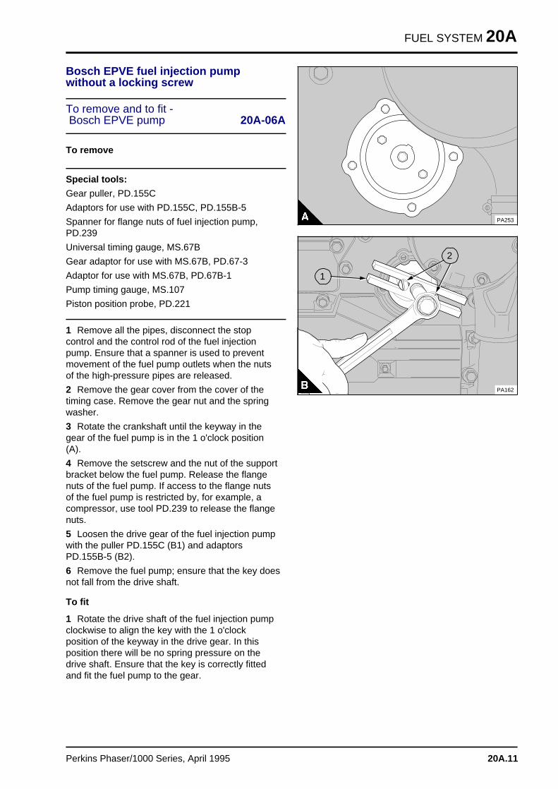
FUEL SYSTEM 20A
Bosch EPVE fuel injection pumpwithout a locking screw
To remove and to fit - Bosch EPVE pump 20A-06A
To remove
Special tools:
Gear puller, PD.155C
Adaptors for use with PD.155C, PD.155B-5
Spanner for flange nuts of fuel injection pump,PD.239
Universal timing gauge, MS.67B
Gear adaptor for use with MS.67B, PD.67-3
Adaptor for use with MS.67B, PD.67B-1
Pump timing gauge, MS.107
Piston position probe, PD.221
1 Remove all the pipes, disconnect the stopcontrol and the control rod of the fuel injectionpump. Ensure that a spanner is used to preventmovement of the fuel pump outlets when the nutsof the high-pressure pipes are released.
2 Remove the gear cover from the cover of thetiming case. Remove the gear nut and the springwasher.
3 Rotate the crankshaft until the keyway in thegear of the fuel pump is in the 1 o'clock position(A).
4 Remove the setscrew and the nut of the supportbracket below the fuel pump. Release the flangenuts of the fuel pump. If access to the flange nutsof the fuel pump is restricted by, for example, acompressor, use tool PD.239 to release the flangenuts.
5 Loosen the drive gear of the fuel injection pumpwith the puller PD.155C (B1) and adaptorsPD.155B-5 (B2).
6 Remove the fuel pump; ensure that the key doesnot fall from the drive shaft.
To fit
1 Rotate the drive shaft of the fuel injection pumpclockwise to align the key with the 1 o'clockposition of the keyway in the drive gear. In thisposition there will be no spring pressure on thedrive shaft. Ensure that the key is correctly fittedand fit the fuel pump to the gear.
PA253
a a a
a a a
a a a
a a a
1
a aa aa aa aa a
2
PA162
Perkins Phaser/1000 Series, April 1995 20A.11
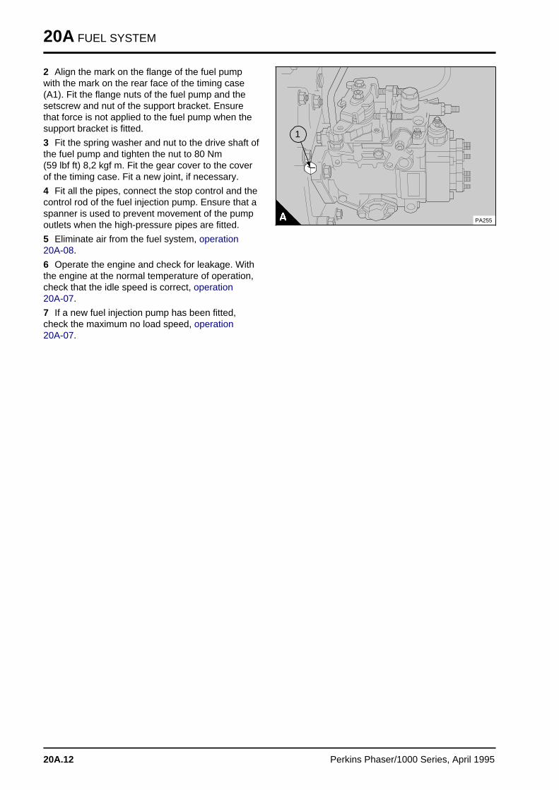
20A FUEL SYSTEM
2 Align the mark on the flange of the fuel pumpwith the mark on the rear face of the timing case(A1). Fit the flange nuts of the fuel pump and thesetscrew and nut of the support bracket. Ensurethat force is not applied to the fuel pump when thesupport bracket is fitted.
3 Fit the spring washer and nut to the drive shaft ofthe fuel pump and tighten the nut to 80 Nm (59 lbf ft) 8,2 kgf m. Fit the gear cover to the coverof the timing case. Fit a new joint, if necessary.
4 Fit all the pipes, connect the stop control and thecontrol rod of the fuel injection pump. Ensure that aspanner is used to prevent movement of the pumpoutlets when the high-pressure pipes are fitted.
5 Eliminate air from the fuel system, operation 20A-08.
6 Operate the engine and check for leakage. Withthe engine at the normal temperature of operation,check that the idle speed is correct, operation 20A-07.
7 If a new fuel injection pump has been fitted,check the maximum no load speed, operation 20A-07.
PA255
a a a
a a a
a a a
a a a
1
20A.12 Perkins Phaser/1000 Series, April 1995
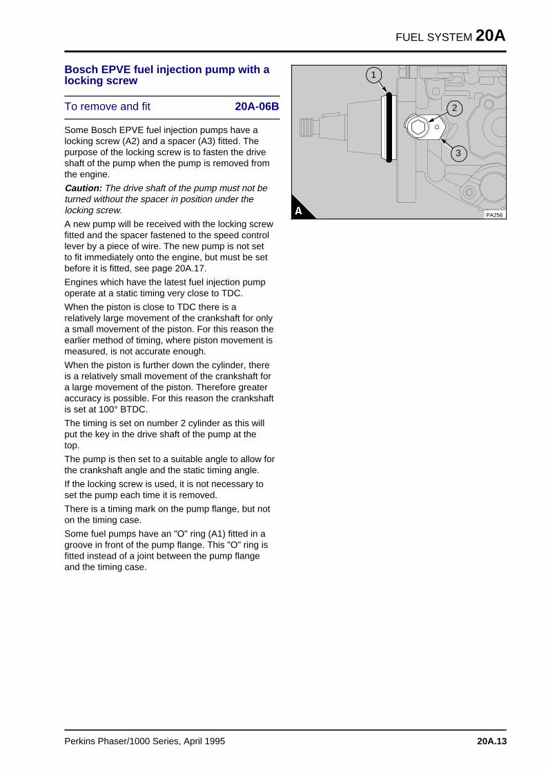
FUEL SYSTEM 20A
Bosch EPVE fuel injection pump with alocking screw
To remove and fit 20A-06B
Some Bosch EPVE fuel injection pumps have alocking screw (A2) and a spacer (A3) fitted. Thepurpose of the locking screw is to fasten the driveshaft of the pump when the pump is removed fromthe engine.
Caution: The drive shaft of the pump must not beturned without the spacer in position under thelocking screw.
A new pump will be received with the locking screwfitted and the spacer fastened to the speed controllever by a piece of wire. The new pump is not setto fit immediately onto the engine, but must be setbefore it is fitted, see page 20A.17.
Engines which have the latest fuel injection pumpoperate at a static timing very close to TDC.
When the piston is close to TDC there is arelatively large movement of the crankshaft for onlya small movement of the piston. For this reason theearlier method of timing, where piston movement ismeasured, is not accurate enough.
When the piston is further down the cylinder, thereis a relatively small movement of the crankshaft fora large movement of the piston. Therefore greateraccuracy is possible. For this reason the crankshaftis set at 100° BTDC.
The timing is set on number 2 cylinder as this willput the key in the drive shaft of the pump at thetop.
The pump is then set to a suitable angle to allow forthe crankshaft angle and the static timing angle.
If the locking screw is used, it is not necessary toset the pump each time it is removed.
There is a timing mark on the pump flange, but noton the timing case.
Some fuel pumps have an "O" ring (A1) fitted in agroove in front of the pump flange. This "O" ring isfitted instead of a joint between the pump flangeand the timing case.
a a a
a a a
a a a
a a a
a a a
a a a
a a a
a a a
a a a
a a a
a a a
a a a
a a a
a a a
a a a
a a a
a a a
a a a
a a a
a a a
a a a
a aa aa aa a
1
a aa aa aa a
2
a aa aa aa a
3
PA256
Perkins Phaser/1000 Series, April 1995 20A.13
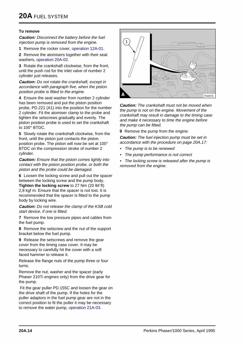
20A FUEL SYSTEM
To remove
Caution: Disconnect the battery before the fuelinjection pump is removed from the engine.
1 Remove the rocker cover, operation 12A-01.
2 Remove the atomisers together with their seatwashers, operation 20A-02.
3 Rotate the crankshaft clockwise, from the front,until the push rod for the inlet valve of number 2cylinder just releases.
Caution: Do not rotate the crankshaft, except inaccordance with paragraph five, when the pistonposition probe is fitted to the engine.
4 Ensure the seat washer from number 2 cylinderhas been removed and put the piston positionprobe, PD.221 (A1) into the position for the number2 cylinder. Fit the atomiser clamp to the probe andtighten the setscrews gradually and evenly. Thepiston position probe is used to set the crankshaftto 100° BTDC.
5 Slowly rotate the crankshaft clockwise, from thefront, until the piston just contacts the pistonposition probe. The piston will now be set at 100°BTDC on the compression stroke of number 2cylinder.
Caution: Ensure that the piston comes lightly intocontact with the piston position probe, or both thepiston and the probe could be damaged.
6 Loosen the locking screw and pull out the spacerbetween the locking screw and the pump body.Tighten the locking screw to 27 Nm (20 lbf ft) 2,8 kgf m. Ensure that the spacer is not lost. It isrecommended that the spacer is fitted to the pumpbody by locking wire.
Caution: Do not release the clamp of the KSB coldstart device, if one is fitted.
7 Remove the low pressure pipes and cables fromthe fuel pump.
8 Remove the setscrew and the nut of the supportbracket below the fuel pump.
9 Release the setscrews and remove the gearcover from the timing case cover. It may benecessary to carefully hit the cover with a softfaced hammer to release it.
Release the flange nuts of the pump three or fourturns.
Remove the nut, washer and the spacer (earlyPhaser 210Ti engines only) from the drive gear forthe pump.
Fit the gear puller PD.155C and loosen the gear onthe drive shaft of the pump. If the holes for thepuller adaptors in the fuel pump gear are not in thecorrect position to fit the puller it may be necessaryto remove the water pump, operation 21A-03.
PA257A
a a a
a a a
a a a
a a a
1
Caution: The crankshaft must not be moved whenthe pump is not on the engine. Movement of thecrankshaft may result in damage to the timing caseand make it necessary to time the engine beforethe pump can be fitted.
9 Remove the pump from the engine.
Caution: The fuel injection pump must be set inaccordance with the procedure on page 20A.17:
• The pump is to be renewed
• The pump performance is not correct
• The locking screw is released after the pump isremoved from the engine.
20A.14 Perkins Phaser/1000 Series, April 1995

FUEL SYSTEM 20A
To fit
Cautions:• Do not rotate the crankshaft when the pistonposition probe is fitted to the engine.
• Ensure that the spacer, fitted to early 210Tiengines, is in position or the nut will not tighten thegear correctly.
1 Fit a new joint or the "O" ring (A1) and put thepump into position on the timing case. Ensure thatthe key is engaged correctly in the keyway of thedrive gear.
2 Fit the spacer (early Phaser 210Ti engines only),spring washer and the nut to retain the drive gear.Tighten the nut to approximately 15 Nm (11 lbf ft)1,5 kgf m.
3 Hold the top of the pump toward the engine toremove the backlash and fit the nuts to the pumpflange. Tighten them to 22 Nm (16 lbf ft) 2,2 kgf m.
4 Fit the fastener for the pump bracket, ensure thatthere is no tension on the pump and tighten thefastener.
5 Release the locking screw (2) and fit thespacer (3) , tighten the locking screw to 12 Nm (9 lbf ft) 1,2 kgf m.
6 Remove the piston position probe from theengine and fit the atomiser together with a new seatwasher. Fit the remainder of the atomisers. Tightenthe setscrews for all of the atomisers.
7 Fully tighten the nut for the drive gear to 80 Nm(59 lbf ft) 8,2 kgf m. Fit the gear cover.
8 Fit the pipes and cables to the pump.
9 Eliminate air from the fuel system, operation 20A-08.
10 Fit the rocker cover, operation 12A-01.
11 Operate the engine and check for leakage. Withthe engine at the normal temperature of operation,check that the idle speed and the maximum no loadspeed is correct, operation 20A-07.
a a a
a a a
a a a
a a a
a a a
a a a
a a a
a a a
a a a
a a a
a a a
a a a
a a a
a a a
a a a
a a a
a a a
a a a
a a a
a a a
a a a
a aa aa aa a
1
a aa aa aa a
2
a aa aa aa a
3
PA256
Perkins Phaser/1000 Series, April 1995 20A.15
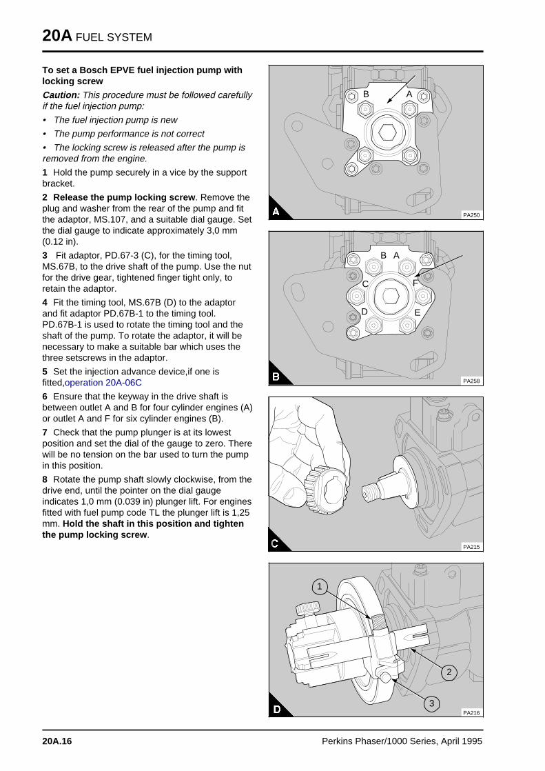
20A FUEL SYSTEM
To set a Bosch EPVE fuel injection pump withlocking screw
Caution: This procedure must be followed carefullyif the fuel injection pump:
• The fuel injection pump is new
• The pump performance is not correct
• The locking screw is released after the pump isremoved from the engine.
1 Hold the pump securely in a vice by the supportbracket.
2 Release the pump locking screw . Remove theplug and washer from the rear of the pump and fitthe adaptor, MS.107, and a suitable dial gauge. Setthe dial gauge to indicate approximately 3,0 mm(0.12 in).
3 Fit adaptor, PD.67-3 (C), for the timing tool,MS.67B, to the drive shaft of the pump. Use the nutfor the drive gear, tightened finger tight only, toretain the adaptor.
4 Fit the timing tool, MS.67B (D) to the adaptorand fit adaptor PD.67B-1 to the timing tool.PD.67B-1 is used to rotate the timing tool and theshaft of the pump. To rotate the adaptor, it will benecessary to make a suitable bar which uses thethree setscrews in the adaptor.
5 Set the injection advance device,if one isfitted,operation 20A-06C
6 Ensure that the keyway in the drive shaft isbetween outlet A and B for four cylinder engines (A)or outlet A and F for six cylinder engines (B).
7 Check that the pump plunger is at its lowestposition and set the dial of the gauge to zero. Therewill be no tension on the bar used to turn the pumpin this position.
8 Rotate the pump shaft slowly clockwise, from thedrive end, until the pointer on the dial gaugeindicates 1,0 mm (0.039 in) plunger lift. For enginesfitted with fuel pump code TL the plunger lift is 1,25mm. Hold the shaft in this position and tightenthe pump locking screw .
a a a
a a a
a a a
a a a
A
a a a
a a a
a a a
a a a
B
PA250
PA258
AB
a a a a
a a a a
a a a a
a a a a
C
a a a
a a a
a a a
a a a
D E
a aa aa aa a
F
PA215
a aa aa aa a
1
a a a
a a a
a a a
a a a
3
a a a
a a a
a a a
a a a
2
PA216
20A.16 Perkins Phaser/1000 Series, April 1995
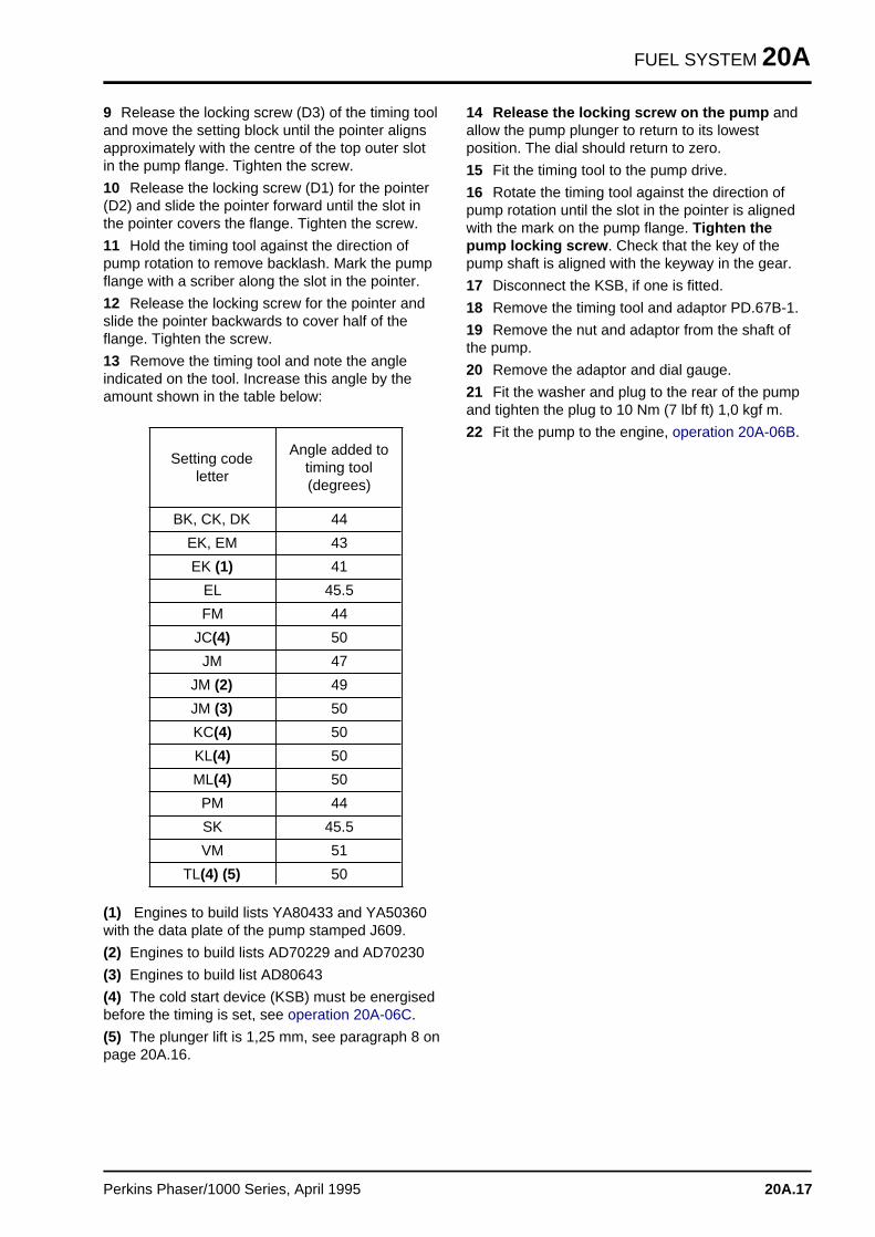
FUEL SYSTEM 20A
9 Release the locking screw (D3) of the timing tooland move the setting block until the pointer alignsapproximately with the centre of the top outer slotin the pump flange. Tighten the screw.
10 Release the locking screw (D1) for the pointer(D2) and slide the pointer forward until the slot inthe pointer covers the flange. Tighten the screw.
11 Hold the timing tool against the direction ofpump rotation to remove backlash. Mark the pumpflange with a scriber along the slot in the pointer.
12 Release the locking screw for the pointer andslide the pointer backwards to cover half of theflange. Tighten the screw.
13 Remove the timing tool and note the angleindicated on the tool. Increase this angle by theamount shown in the table below:
Setting codeletter
Angle added totiming tool(degrees)
BK, CK, DK 44
EK, EM 43
EK (1) 41
EL 45.5
FM 44
JC(4) 50
JM 47
JM (2) 49
JM (3) 50
KC(4) 50
KL(4) 50
ML(4) 50
PM 44
SK 45.5
VM 51
TL(4) (5) 50
(1) Engines to build lists YA80433 and YA50360with the data plate of the pump stamped J609.
(2) Engines to build lists AD70229 and AD70230
(3) Engines to build list AD80643
(4) The cold start device (KSB) must be energisedbefore the timing is set, see operation 20A-06C.
(5) The plunger lift is 1,25 mm, see paragraph 8 onpage 20A.16.
14 Release the locking screw on the pump andallow the pump plunger to return to its lowestposition. The dial should return to zero.
15 Fit the timing tool to the pump drive.
16 Rotate the timing tool against the direction ofpump rotation until the slot in the pointer is alignedwith the mark on the pump flange. Tighten thepump locking screw . Check that the key of thepump shaft is aligned with the keyway in the gear.
17 Disconnect the KSB, if one is fitted.
18 Remove the timing tool and adaptor PD.67B-1.
19 Remove the nut and adaptor from the shaft ofthe pump.
20 Remove the adaptor and dial gauge.
21 Fit the washer and plug to the rear of the pumpand tighten the plug to 10 Nm (7 lbf ft) 1,0 kgf m.
22 Fit the pump to the engine, operation 20A-06B.
Perkins Phaser/1000 Series, April 1995 20A.17
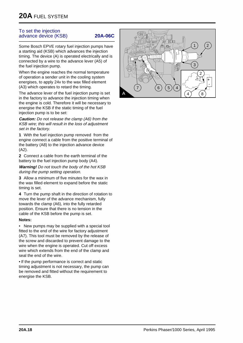
20A FUEL SYSTEM
To set the injection advance device (KSB) 20A-06C
Some Bosch EPVE rotary fuel injection pumps havea starting aid (KSB) which advances the injectiontiming. The device (A) is operated electrically and isconnected by a wire to the advance lever (A5) ofthe fuel injection pump.
When the engine reaches the normal temperatureof operation a sender unit in the cooling systemenergises, to apply 24v to the wax filled element(A3) which operates to retard the timing.
The advance lever of the fuel injection pump is setin the factory to advance the injection timing whenthe engine is cold. Therefore it will be necessary toenergise the KSB if the static timing of the fuelinjection pump is to be set:
Caution: Do not release the clamp (A6) from theKSB wire; this will result in the loss of adjustmentset in the factory.
1 With the fuel injection pump removed from theengine connect a cable from the positive terminal ofthe battery (A8) to the injection advance device(A2).
2 Connect a cable from the earth terminal of thebattery to the fuel injection pump body (A4).
Warning! Do not touch the body of the hot KSBduring the pump setting operation.
3 Allow a minimum of five minutes for the wax inthe wax filled element to expand before the statictiming is set.
4 Turn the pump shaft in the direction of rotation tomove the lever of the advance mechanism, fullytowards the clamp (A6), into the fully retardedposition. Ensure that there is no tension in thecable of the KSB before the pump is set.
Notes:
• New pumps may be supplied with a special toolfitted to the end of the wire for factory adjustment(A7). This tool must be removed by the release ofthe screw and discarded to prevent damage to thewire when the engine is operated. Cut off excesswire which extends from the end of the clamp andseal the end of the wire.
• If the pump performance is correct and statictiming adjustment is not necessary, the pump canbe removed and fitted without the requirement toenergise the KSB.
a a a
a a aa a a
a a a
a a a
a a a
a a a
7
a aa aa aa aa a
6
a a a
a a a
a a a
a a a
a a a
5
a aa aa aa a
1 a a a
a a a
a a a
a a a
2
a aa aa aa a
3
a aa aa aa aa a
4
a aa aa aa aa a
8
a aa aa aa a
2
a aa aa aa aa a
4
a a a
a a a
a a a
a a a
+
a a a
a a a
a a a
a a a
-
20A.18 Perkins Phaser/1000 Series, April 1995
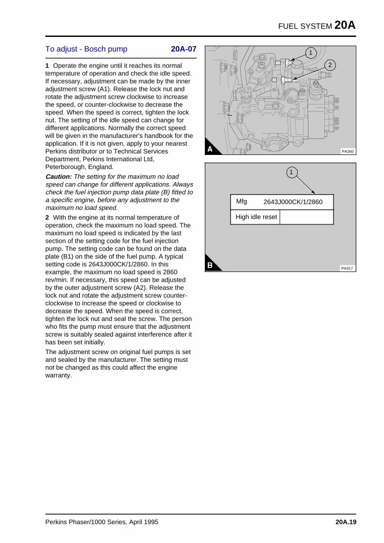
FUEL SYSTEM 20A
To adjust - Bosch pump 20A-07
1 Operate the engine until it reaches its normaltemperature of operation and check the idle speed.If necessary, adjustment can be made by the inneradjustment screw (A1). Release the lock nut androtate the adjustment screw clockwise to increasethe speed, or counter-clockwise to decrease thespeed. When the speed is correct, tighten the locknut. The setting of the idle speed can change fordifferent applications. Normally the correct speedwill be given in the manufacturer's handbook for theapplication. If it is not given, apply to your nearestPerkins distributor or to Technical ServicesDepartment, Perkins International Ltd,Peterborough, England.
Caution: The setting for the maximum no loadspeed can change for different applications. Alwayscheck the fuel injection pump data plate (B) fitted toa specific engine, before any adjustment to themaximum no load speed.
2 With the engine at its normal temperature ofoperation, check the maximum no load speed. Themaximum no load speed is indicated by the lastsection of the setting code for the fuel injectionpump. The setting code can be found on the dataplate (B1) on the side of the fuel pump. A typicalsetting code is 2643J000CK/1/2860. In thisexample, the maximum no load speed is 2860rev/min. If necessary, this speed can be adjustedby the outer adjustment screw (A2). Release thelock nut and rotate the adjustment screw counter-clockwise to increase the speed or clockwise todecrease the speed. When the speed is correct,tighten the lock nut and seal the screw. The personwho fits the pump must ensure that the adjustmentscrew is suitably sealed against interference after ithas been set initially.
The adjustment screw on original fuel pumps is setand sealed by the manufacturer. The setting mustnot be changed as this could affect the enginewarranty.
a a a
a a a
a a a
a a a
1
a a a
a a a
a a a
a a a
2
PA260
a a a
a a a
a a a
a a a
1
High idle reset
PA317
2643J000CK/1/2860 Mfg
Perkins Phaser/1000 Series, April 1995 20A.19
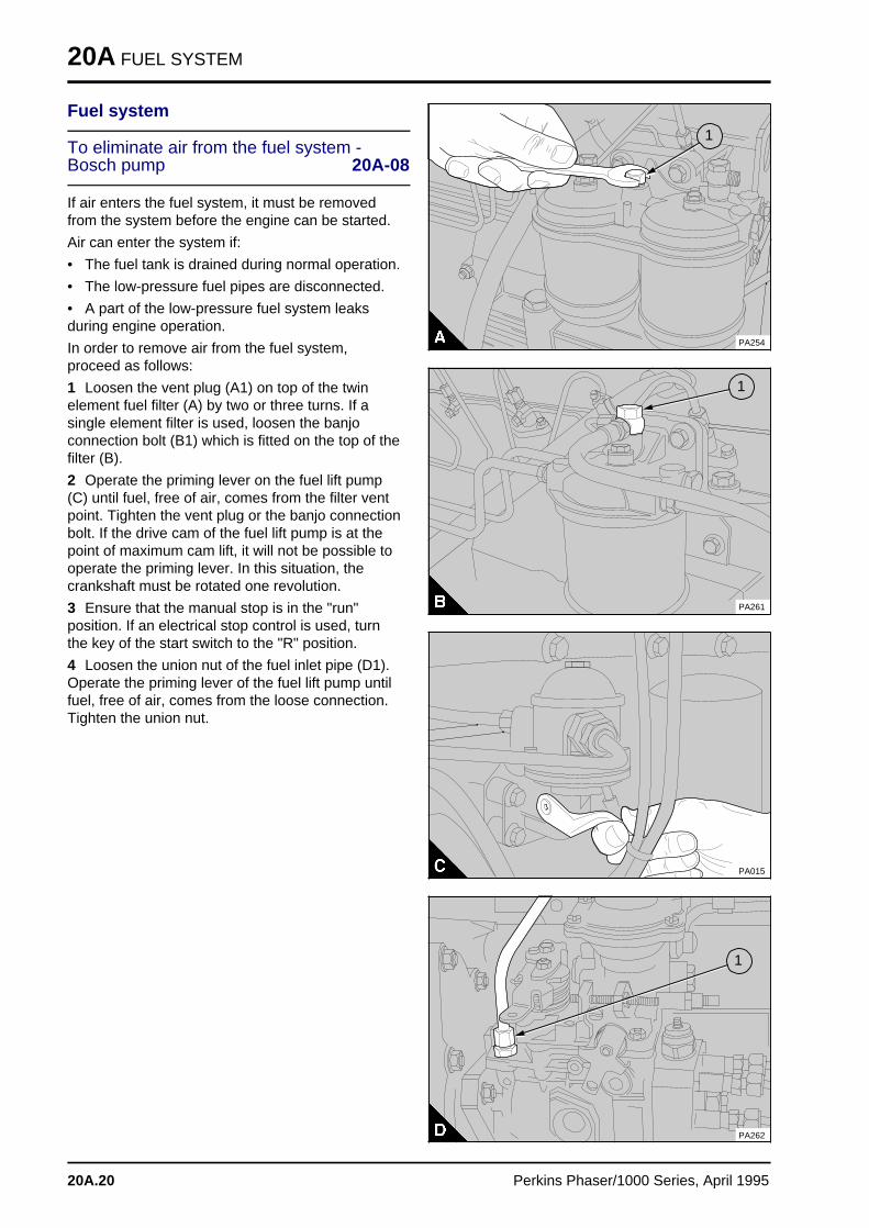
20A FUEL SYSTEM
Fuel system
To eliminate air from the fuel system -Bosch pump 20A-08
If air enters the fuel system, it must be removedfrom the system before the engine can be started.
Air can enter the system if:
• The fuel tank is drained during normal operation.
• The low-pressure fuel pipes are disconnected.
• A part of the low-pressure fuel system leaksduring engine operation.
In order to remove air from the fuel system,proceed as follows:
1 Loosen the vent plug (A1) on top of the twinelement fuel filter (A) by two or three turns. If asingle element filter is used, loosen the banjoconnection bolt (B1) which is fitted on the top of thefilter (B).
2 Operate the priming lever on the fuel lift pump(C) until fuel, free of air, comes from the filter ventpoint. Tighten the vent plug or the banjo connectionbolt. If the drive cam of the fuel lift pump is at thepoint of maximum cam lift, it will not be possible tooperate the priming lever. In this situation, thecrankshaft must be rotated one revolution.
3 Ensure that the manual stop is in the "run"position. If an electrical stop control is used, turnthe key of the start switch to the "R" position.
4 Loosen the union nut of the fuel inlet pipe (D1).Operate the priming lever of the fuel lift pump untilfuel, free of air, comes from the loose connection.Tighten the union nut.
a a a
a a a
a a a
a a a
1
PA254
a aa aa aa a
1
PA261
PA015
a a a
a a a
a a a
a a a
1
PA262
20A.20 Perkins Phaser/1000 Series, April 1995
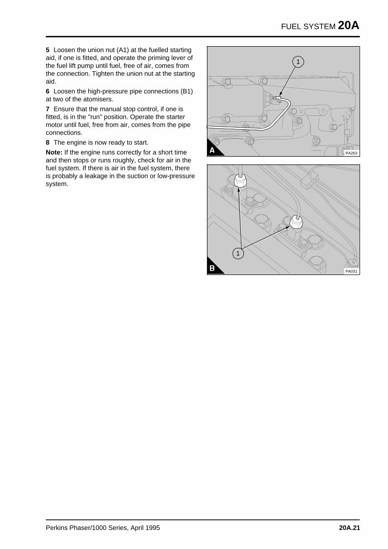
FUEL SYSTEM 20A
5 Loosen the union nut (A1) at the fuelled startingaid, if one is fitted, and operate the priming lever ofthe fuel lift pump until fuel, free of air, comes fromthe connection. Tighten the union nut at the startingaid.
6 Loosen the high-pressure pipe connections (B1)at two of the atomisers.
7 Ensure that the manual stop control, if one isfitted, is in the "run" position. Operate the startermotor until fuel, free from air, comes from the pipeconnections.
8 The engine is now ready to start.
Note: If the engine runs correctly for a short timeand then stops or runs roughly, check for air in thefuel system. If there is air in the fuel system, thereis probably a leakage in the suction or low-pressuresystem.
a aa aa aa a
1
PA263
PA031
a aa aa aa a
1
Perkins Phaser/1000 Series, April 1995 20A.21
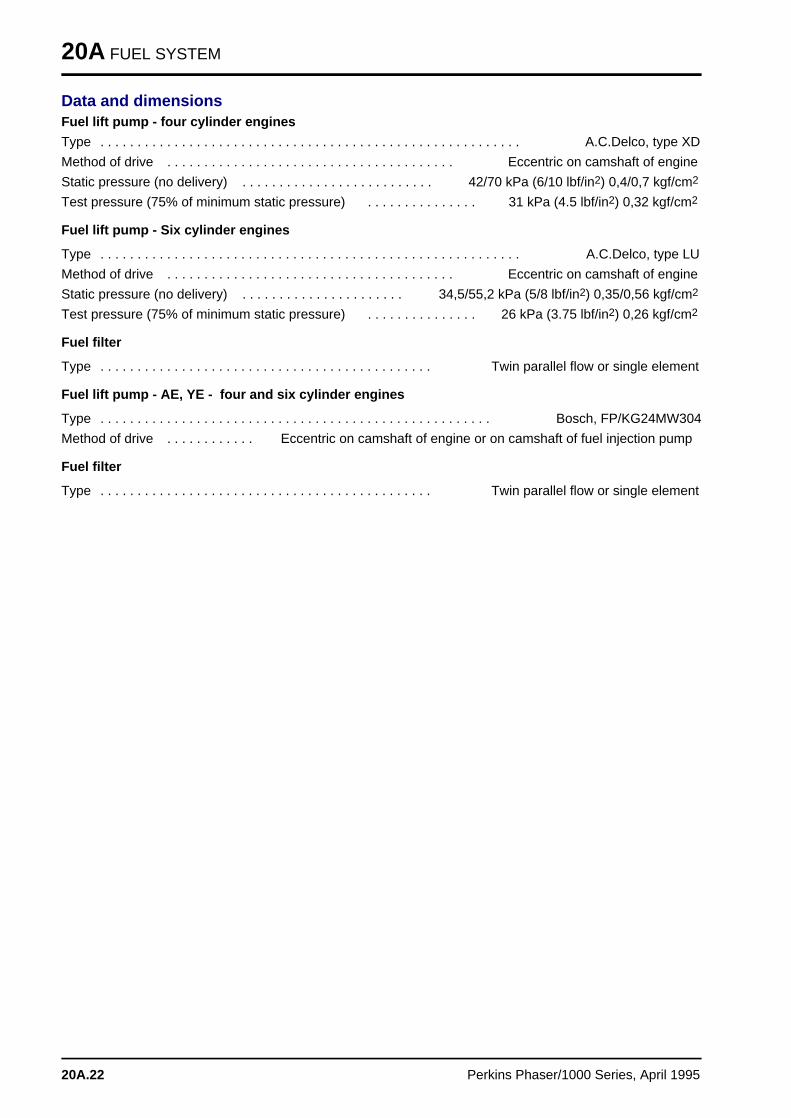
20A FUEL SYSTEM
Data and dimensionsFuel lift pump - four cylinder engines
Type . . . . . . . . . . . . . . . . . . . . . . . . . . . . . . . . . . . . . . . . . . . . . . . . . . . . . . . . . A.C.Delco, type XD
Method of drive . . . . . . . . . . . . . . . . . . . . . . . . . . . . . . . . . . . . . . . Eccentric on camshaft of engine
Static pressure (no delivery) . . . . . . . . . . . . . . . . . . . . . . . . . . 42/70 kPa (6/10 lbf/in2) 0,4/0,7 kgf/cm2
Test pressure (75% of minimum static pressure) . . . . . . . . . . . . . . . 31 kPa (4.5 lbf/in2) 0,32 kgf/cm2
Fuel lift pump - Six cylinder engines
Type . . . . . . . . . . . . . . . . . . . . . . . . . . . . . . . . . . . . . . . . . . . . . . . . . . . . . . . . . A.C.Delco, type LU
Method of drive . . . . . . . . . . . . . . . . . . . . . . . . . . . . . . . . . . . . . . . Eccentric on camshaft of engine
Static pressure (no delivery) . . . . . . . . . . . . . . . . . . . . . . 34,5/55,2 kPa (5/8 lbf/in2) 0,35/0,56 kgf/cm2
Test pressure (75% of minimum static pressure) . . . . . . . . . . . . . . . 26 kPa (3.75 lbf/in2) 0,26 kgf/cm2
Fuel filter
Type . . . . . . . . . . . . . . . . . . . . . . . . . . . . . . . . . . . . . . . . . . . . . Twin parallel flow or single element
Fuel lift pump - AE, YE - four and six cylinder engines
Type . . . . . . . . . . . . . . . . . . . . . . . . . . . . . . . . . . . . . . . . . . . . . . . . . . . . . Bosch, FP/KG24MW304
Method of drive . . . . . . . . . . . . Eccentric on camshaft of engine or on camshaft of fuel injection pump
Fuel filter
Type . . . . . . . . . . . . . . . . . . . . . . . . . . . . . . . . . . . . . . . . . . . . . Twin parallel flow or single element
20A.22 Perkins Phaser/1000 Series, April 1995
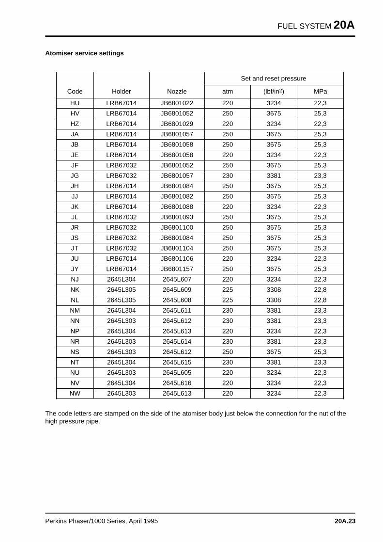
FUEL SYSTEM 20A
Atomiser service settings
Code Holder Nozzle
Set and reset pressure
atm (lbf/in2) MPa
HU LRB67014 JB6801022 220 3234 22,3
HV LRB67014 JB6801052 250 3675 25,3
HZ LRB67014 JB6801029 220 3234 22,3
JA LRB67014 JB6801057 250 3675 25,3
JB LRB67014 JB6801058 250 3675 25,3
JE LRB67014 JB6801058 220 3234 22,3
JF LRB67032 JB6801052 250 3675 25,3
JG LRB67032 JB6801057 230 3381 23,3
JH LRB67014 JB6801084 250 3675 25,3
JJ LRB67014 JB6801082 250 3675 25,3
JK LRB67014 JB6801088 220 3234 22,3
JL LRB67032 JB6801093 250 3675 25,3
JR LRB67032 JB6801100 250 3675 25,3
JS LRB67032 JB6801084 250 3675 25,3
JT LRB67032 JB6801104 250 3675 25,3
JU LRB67014 JB6801106 220 3234 22,3
JY LRB67014 JB6801157 250 3675 25,3
NJ 2645L304 2645L607 220 3234 22,3
NK 2645L305 2645L609 225 3308 22,8
NL 2645L305 2645L608 225 3308 22,8
NM 2645L304 2645L611 230 3381 23,3
NN 2645L303 2645L612 230 3381 23,3
NP 2645L304 2645L613 220 3234 22,3
NR 2645L303 2645L614 230 3381 23,3
NS 2645L303 2645L612 250 3675 25,3
NT 2645L304 2645L615 230 3381 23,3
NU 2645L303 2645L605 220 3234 22,3
NV 2645L304 2645L616 220 3234 22,3
NW 2645L303 2645L613 220 3234 22,3
The code letters are stamped on the side of the atomiser body just below the connection for the nut of thehigh pressure pipe.
Perkins Phaser/1000 Series, April 1995 20A.23
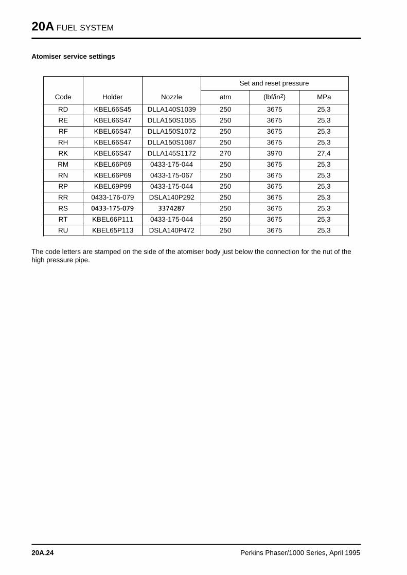
20A FUEL SYSTEM
Atomiser service settings
Code Holder Nozzle
Set and reset pressure
atm (lbf/in2) MPa
RD KBEL66S45 DLLA140S1039 250 3675 25,3
RE KBEL66S47 DLLA150S1055 250 3675 25,3
RF KBEL66S47 DLLA150S1072 250 3675 25,3
RH KBEL66S47 DLLA150S1087 250 3675 25,3
RK KBEL66S47 DLLA145S1172 270 3970 27,4
RM KBEL66P69 0433-175-044 250 3675 25,3
RN KBEL66P69 0433-175-067 250 3675 25,3
RP KBEL69P99 0433-175-044 250 3675 25,3
RR 0433-176-079 DSLA140P292 250 3675 25,3
RS 0433>175>079 3374287 250 3675 25,3
RT KBEL66P111 0433-175-044 250 3675 25,3
RU KBEL65P113 DSLA140P472 250 3675 25,3
The code letters are stamped on the side of the atomiser body just below the connection for the nut of thehigh pressure pipe.
20A.24 Perkins Phaser/1000 Series, April 1995
Engines fitted with an in-line fuel injection pum p 20B
General descriptio n . . . . . . . . . . . . . . . . . . . . . . . . . . . . . . . . . . . . . . . . . 20B.02
Fuel filter canister
20B-01 To renew . . . . . . . . . . . . . . . . . . . . . . . . . . . . . . . . . . . . . . . . . 20B.03
Atomisers
Atomiser fault . . . . . . . . . . . . . . . . . . . . . . . . . . . . . . . . . refer to 20A.0720B-02 To remove and to fit . . . . . . . . . . . . . . . . . . . . . . . . . . . . refer to 20A.07
Fuel lift pump
20B-03 To remove and to fit . . . . . . . . . . . . . . . . . . . . . . . . . . . . . . . . . 20B.0420B-04 To dismantle and to assemble . . . . . . . . . . . . . . . . . . . . . . . . . . 20B.05
Fuel injection pump
20B-05 To remove and to fit . . . . . . . . . . . . . . . . . . . . . . . . . . . . . . . . . 20B.0620B-06 To adjust . . . . . . . . . . . . . . . . . . . . . . . . . . . . . . . . . . . . . . . . . 20B.1220B-07 To remove and to fit the adaptor plate for the fuel injection pump 20B.13
Fuel system
20B-08 To eliminate air from the fuel system . . . . . . . . . . . . . . . . . . . . . 20B.14
Data and dimension s . . . . . . . . . . . . . . . . . . . . . . . . . . . . . . . . . . . . . . . 20B.15
Perkins Phaser/1000 Series, April 1995 20B.01
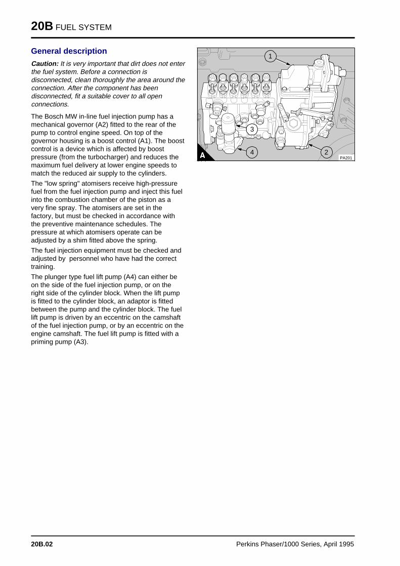
20B FUEL SYSTEM
General description
Caution: It is very important that dirt does not enterthe fuel system. Before a connection isdisconnected, clean thoroughly the area around theconnection. After the component has beendisconnected, fit a suitable cover to all openconnections.
The Bosch MW in-line fuel injection pump has amechanical governor (A2) fitted to the rear of thepump to control engine speed. On top of thegovernor housing is a boost control (A1). The boostcontrol is a device which is affected by boostpressure (from the turbocharger) and reduces themaximum fuel delivery at lower engine speeds tomatch the reduced air supply to the cylinders.
The "low spring" atomisers receive high-pressurefuel from the fuel injection pump and inject this fuelinto the combustion chamber of the piston as avery fine spray. The atomisers are set in thefactory, but must be checked in accordance withthe preventive maintenance schedules. Thepressure at which atomisers operate can beadjusted by a shim fitted above the spring.
The fuel injection equipment must be checked andadjusted by personnel who have had the correcttraining.
The plunger type fuel lift pump (A4) can either beon the side of the fuel injection pump, or on theright side of the cylinder block. When the lift pumpis fitted to the cylinder block, an adaptor is fittedbetween the pump and the cylinder block. The fuellift pump is driven by an eccentric on the camshaftof the fuel injection pump, or by an eccentric on theengine camshaft. The fuel lift pump is fitted with apriming pump (A3).
a a a
a a a
a a a
a a a
a a a
2
a a a
a a a
a a a
a a a
a a a
4
a a a
a a a
a a a
a a a
1
a a a
a a a
a a a
a a a
a a a
3
PA201
20B.02 Perkins Phaser/1000 Series, April 1995
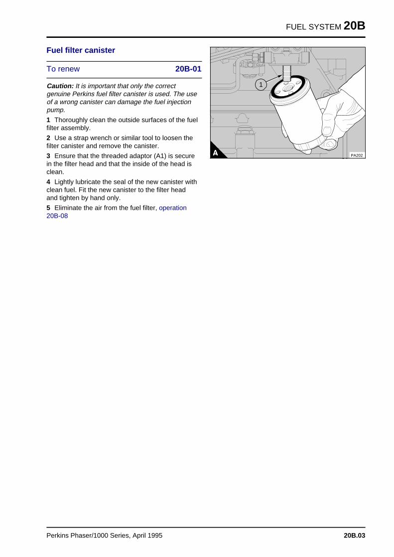
FUEL SYSTEM 20B
Fuel filter canister
To renew 20B-01
Caution: It is important that only the correctgenuine Perkins fuel filter canister is used. The useof a wrong canister can damage the fuel injectionpump.
1 Thoroughly clean the outside surfaces of the fuelfilter assembly.
2 Use a strap wrench or similar tool to loosen thefilter canister and remove the canister.
3 Ensure that the threaded adaptor (A1) is securein the filter head and that the inside of the head isclean.
4 Lightly lubricate the seal of the new canister withclean fuel. Fit the new canister to the filter headand tighten by hand only.
5 Eliminate the air from the fuel filter, operation20B-08
a a a
a a a
a a a
a a a
1
PA202
Perkins Phaser/1000 Series, April 1995 20B.03
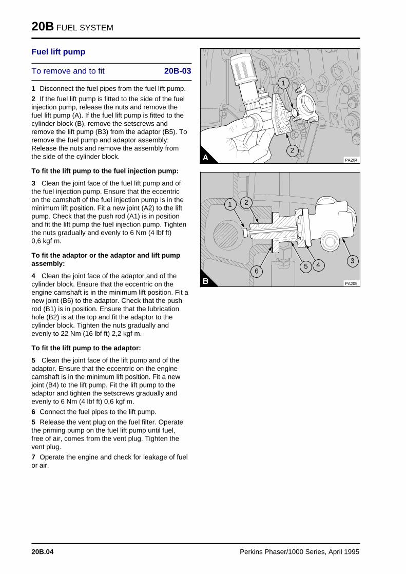
20B FUEL SYSTEM
Fuel lift pump
To remove and to fit 20B-03
1 Disconnect the fuel pipes from the fuel lift pump.
2 If the fuel lift pump is fitted to the side of the fuelinjection pump, release the nuts and remove thefuel lift pump (A). If the fuel lift pump is fitted to thecylinder block (B), remove the setscrews andremove the lift pump (B3) from the adaptor (B5). Toremove the fuel pump and adaptor assembly:Release the nuts and remove the assembly fromthe side of the cylinder block.
To fit the lift pump to the fuel injection pump:
3 Clean the joint face of the fuel lift pump and ofthe fuel injection pump. Ensure that the eccentricon the camshaft of the fuel injection pump is in theminimum lift position. Fit a new joint (A2) to the liftpump. Check that the push rod (A1) is in positionand fit the lift pump the fuel injection pump. Tightenthe nuts gradually and evenly to 6 Nm (4 lbf ft) 0,6 kgf m.
To fit the adaptor or the adaptor and lift pumpassembly:
4 Clean the joint face of the adaptor and of thecylinder block. Ensure that the eccentric on theengine camshaft is in the minimum lift position. Fit anew joint (B6) to the adaptor. Check that the pushrod (B1) is in position. Ensure that the lubricationhole (B2) is at the top and fit the adaptor to thecylinder block. Tighten the nuts gradually andevenly to 22 Nm (16 lbf ft) 2,2 kgf m.
To fit the lift pump to the adaptor:
5 Clean the joint face of the lift pump and of theadaptor. Ensure that the eccentric on the enginecamshaft is in the minimum lift position. Fit a newjoint (B4) to the lift pump. Fit the lift pump to theadaptor and tighten the setscrews gradually andevenly to 6 Nm (4 lbf ft) 0,6 kgf m.
6 Connect the fuel pipes to the lift pump.
5 Release the vent plug on the fuel filter. Operatethe priming pump on the fuel lift pump until fuel,free of air, comes from the vent plug. Tighten thevent plug.
7 Operate the engine and check for leakage of fuelor air.
a aa aa aa a
1
a a a
a a a
a a a
a a a
2PA204
a a a
a a a
a a a
a a a
a a a
1
a aa aa aa a
2
a a a
a a a
a a a
a a a
5
a a a
a a a
a a a
a a a
4
a a a
a a a
a a a
a a a
3a aa aa aa a
6
PA205
20B.04 Perkins Phaser/1000 Series, April 1995
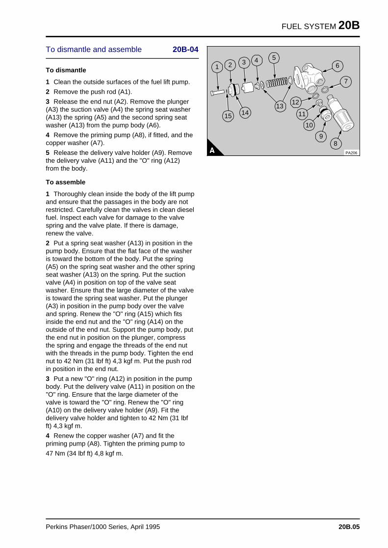
FUEL SYSTEM 20B
To dismantle and assemble 20B-04
To dismantle
1 Clean the outside surfaces of the fuel lift pump.
2 Remove the push rod (A1).
3 Release the end nut (A2). Remove the plunger(A3) the suction valve (A4) the spring seat washer(A13) the spring (A5) and the second spring seatwasher (A13) from the pump body (A6).
4 Remove the priming pump (A8), if fitted, and thecopper washer (A7).
5 Release the delivery valve holder (A9). Removethe delivery valve (A11) and the "O" ring (A12)from the body.
To assemble
1 Thoroughly clean inside the body of the lift pumpand ensure that the passages in the body are notrestricted. Carefully clean the valves in clean dieselfuel. Inspect each valve for damage to the valvespring and the valve plate. If there is damage,renew the valve.
2 Put a spring seat washer (A13) in position in thepump body. Ensure that the flat face of the washeris toward the bottom of the body. Put the spring(A5) on the spring seat washer and the other springseat washer (A13) on the spring. Put the suctionvalve (A4) in position on top of the valve seatwasher. Ensure that the large diameter of the valveis toward the spring seat washer. Put the plunger(A3) in position in the pump body over the valveand spring. Renew the "O" ring (A15) which fitsinside the end nut and the "O" ring (A14) on theoutside of the end nut. Support the pump body, putthe end nut in position on the plunger, compressthe spring and engage the threads of the end nutwith the threads in the pump body. Tighten the endnut to 42 Nm (31 lbf ft) 4,3 kgf m. Put the push rodin position in the end nut.
3 Put a new "O" ring (A12) in position in the pumpbody. Put the delivery valve (A11) in position on the"O" ring. Ensure that the large diameter of thevalve is toward the "O" ring. Renew the "O" ring(A10) on the delivery valve holder (A9). Fit thedelivery valve holder and tighten to 42 Nm (31 lbfft) 4,3 kgf m.
4 Renew the copper washer (A7) and fit thepriming pump (A8). Tighten the priming pump to
47 Nm (34 lbf ft) 4,8 kgf m.
a a a a
a a a a
a a a a
a a a a
a a a
a a a
a a a
a a a
a a a
a a a
a a a
a a a
a a a
1
a aa aa aa aa a
2
a a a
a a a
a a a
a a a
a a a
3
a a a
a a a
a a a
a a a
4
a a a
a a a
a a a
a a a
5
a a a
a a a
a a a
a a a
6
a aa aa aa a
7
a a a a
a a a a
a a a a
a a a a
15
a a a a
a a a a
a a a a
a a a a
a a a a
14
a a a a
a a a a
a a a a
a a a a
13
a a a a
a a a a
a a a a
a a a a
12
a a a a
a a a a
a a a a
a a a a
11
a a a a a
a a a a a
a a a a a
a a a a a
a a a a a
10
a a a
a a a
a a a
a a a
9
a aa aa aa a
8PA206
Perkins Phaser/1000 Series, April 1995 20B.05
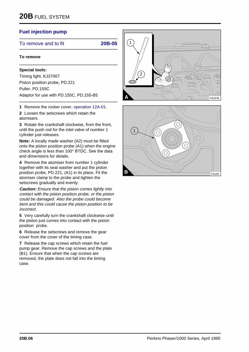
20B FUEL SYSTEM
Fuel injection pump
To remove and to fit 20B-05
To remove
Special tools:
Timing light, KJ37007
Piston position probe, PD.221
Puller, PD.155C
Adaptor for use with PD.155C, PD.155-B5
1 Remove the rocker cover, operation 12A-01.
2 Loosen the setscrews which retain theatomisers.
3 Rotate the crankshaft clockwise, from the front,until the push rod for the inlet valve of number 1cylinder just releases.
Note: A locally made washer (A2) must be fittedonto the piston position probe (A1) when the enginecheck angle is less than 100° BTDC. See the dataand dimensions for details.
4 Remove the atomiser from number 1 cylindertogether with its seat washer and put the pistonposition probe, PD.221, (A1) in its place. Fit theatomiser clamp to the probe and tighten thesetscrews gradually and evenly.
Caution: Ensure that the piston comes lightly intocontact with the piston position probe, or the pistoncould be damaged. Also the probe could becomebent and this could cause the piston position to beincorrect.
5 Very carefully turn the crankshaft clockwise untilthe piston just comes into contact with the pistonposition probe.
6 Release the setscrews and remove the gearcover from the cover of the timing case.
7 Release the cap screws which retain the fuelpump gear. Remove the cap screws and the plate(B1). Ensure that when the cap screws areremoved, the plate does not fall into the timingcase.
PA257B
a a a
a a a
a a a
a a a
1
a a a a a
a a a a a
a a a a a
a a a
a a a
a a a
a a a
2
a a a
a a a
a a a
a a a
1
PA199
20B.06 Perkins Phaser/1000 Series, April 1995
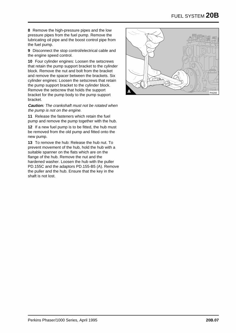
FUEL SYSTEM 20B
8 Remove the high-pressure pipes and the lowpressure pipes from the fuel pump. Remove thelubricating oil pipe and the boost control pipe fromthe fuel pump.
9 Disconnect the stop control/electrical cable andthe engine speed control.
10 Four cylinder engines: Loosen the setscrewsthat retain the pump support bracket to the cylinderblock. Remove the nut and bolt from the bracketand remove the spacer between the brackets. Sixcylinder engines: Loosen the setscrews that retainthe pump support bracket to the cylinder block.Remove the setscrew that holds the supportbracket for the pump body to the pump supportbracket.
Caution: The crankshaft must not be rotated whenthe pump is not on the engine.
11 Release the fasteners which retain the fuelpump and remove the pump together with the hub.
12 If a new fuel pump is to be fitted, the hub mustbe removed from the old pump and fitted onto thenew pump.
13 To remove the hub: Release the hub nut. Toprevent movement of the hub, hold the hub with asuitable spanner on the flats which are on theflange of the hub. Remove the nut and thehardened washer. Loosen the hub with the pullerPD.155C and the adaptors PD.155-B5 (A). Removethe puller and the hub. Ensure that the key in theshaft is not lost.
PA200
Perkins Phaser/1000 Series, April 1995 20B.07
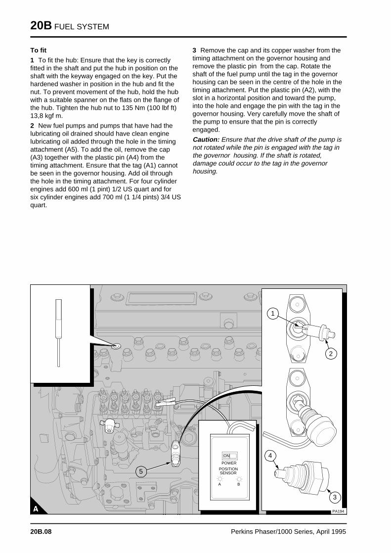
20B FUEL SYSTEM
To fit
1 To fit the hub: Ensure that the key is correctlyfitted in the shaft and put the hub in position on theshaft with the keyway engaged on the key. Put thehardened washer in position in the hub and fit thenut. To prevent movement of the hub, hold the hubwith a suitable spanner on the flats on the flange ofthe hub. Tighten the hub nut to 135 Nm (100 lbf ft)13,8 kgf m.
2 New fuel pumps and pumps that have had thelubricating oil drained should have clean enginelubricating oil added through the hole in the timingattachment (A5). To add the oil, remove the cap(A3) together with the plastic pin (A4) from thetiming attachment. Ensure that the tag (A1) cannotbe seen in the governor housing. Add oil throughthe hole in the timing attachment. For four cylinderengines add 600 ml (1 pint) 1/2 US quart and forsix cylinder engines add 700 ml (1 1/4 pints) 3/4 USquart.
3 Remove the cap and its copper washer from thetiming attachment on the governor housing andremove the plastic pin from the cap. Rotate theshaft of the fuel pump until the tag in the governorhousing can be seen in the centre of the hole in thetiming attachment. Put the plastic pin (A2), with theslot in a horizontal position and toward the pump,into the hole and engage the pin with the tag in thegovernor housing. Very carefully move the shaft ofthe pump to ensure that the pin is correctlyengaged.
Caution: Ensure that the drive shaft of the pump isnot rotated while the pin is engaged with the tag inthe governor housing. If the shaft is rotated,damage could occur to the tag in the governorhousing.
a a a a a a a a a a a a a a a a a a a a a a a a
a a a a a a a a a a a a a a a a a a a a a a a a
a a a a a a a a a a a a a a a a a a a a a a a a
a a a a a a a a a a a a a a a a a a a a a a a a
a a a a a a a a a a a a a a a a a a a a a a a a
a a a a a a a a a a a a a a a a a a a a a a a a
a a a a a a a a a a a a a a a a a a a a a a a a
a a a a a a a a a a a a a a a a a a a a a a a a
a a a a a a a a a a a a a a a a a a a a a a a a
a a a a a a a a a a a a a a a a a a a a a a a a
a a a a a a a a a a a a a a a a a a a a a a a a
a a a a a a a a a a a a a a a a a a a a a a a a
a a a a a a a a a a a a a a a a a a a a a a a a
a a a a a a a a a a a a a a a a a a a a a a a a
a a a a a a a a a a a a a a a a a a a a a a a a
a a a a a a a a a a a a a a a a a a a a a a a a
a a a a a a a a a a a a a a a a a a a a a a a a
a a a a a a a a a a a a a a a a a a a a a a a a
a a a a a a a a a a a a a a a a a a a a a a a a
a a a a a a a a a a a a a a a a a a a a a a a a
a a a a a a a a a a a a a a a a a a a a a a a a
a a a a a a a a a a a a a a a a a a a a a a a a
a a a a a a a a a a a a a a a a a a a a a a a a
a a a a a a a a a a a a a a a a a a a a a a a a
a a a a a a a a a a a a a a a a a a a a a a a a
a a a a a a a a a a a a a a a a a a a a a a a a
a a a a a a a a a a a a a a a a a a a a a a a a
a a a a a a a a a a a a a a a a a a a a a a a a
a a a a a a a a a a a a a a a a a a a a a a a a
a a a a a a a a a a a a a a a a a a a a a a a a
a a a a a a a a a a a a a a a a a a a a a a a a
a a a a a a a a a a a a a a a a a a a a a a a a
a a a a a a a a a a a a a a a a a a a a a a a a
a a a a a a a a a a a a a a a a a a a a a a a a
a a a a a a a a a a a a a a a a a a a a a a a a
a a a a a a a a a a a a a a a a a a a a a a a a
a a a a a a a a a a a a a a a a a a a a a a a a
a a a a
a a a a
ON
a a a a a a a a
a a a a a a a a
a a a a a a a a
POWER
a aa aA a aa aB
a a a a a a a a a
a a a a a a a a a
a a a a a a a a a
a a a a a a a a a
POSITIONSENSOR
a a a a a a a a a a a a a a a a a a a a a a a a a a a a a a a a a
a a a a a a a a a a a a a a a a a a a a a a a a a a a a a a a a a
a a a a a a a a a a a a a a a a a a a a a a a a a a a a a a a a a
a a a a a a a a a a a a a a a a a a a a a a a a a a a a a a a a a
a a a a a a a a a a a a a a a a a a a a a a a a a a a a a a a a a
a a a a a a a a a a a a a a a a a a a a a a a a a a a a a a a a a
a a a a a a a a a a a a a a a a a a a a a a a a a a a a a a a a a
a a a a a a a a a a a a a a a a a a a a a a a a a a a a a a a a a
a a a a a a a a a a a a a a a a a a a a a a a a a a a a a a a a a
a a a a a a a a a a a a a a a a a a a a a a a a a a a a a a a a a
a a a a a a a a a a a a a a a a a a a a a a a a a a a a a a a a a
a a a a a a a a a a a a a a a a a a a a a a a a a a a a a a a a a
a a a a a a a a a a a a a a a a a a a a a a a a a a a a a a a a a
a a a a a a a a a a a a a a a a a a a a a a a a a a a a a a a a a
a a a a a a a a a a a a a a a a a a a a a a a a a a a a a a a a a
a a a a a a a a a a a a a a a a a a a a a a a a a a a a a a a a a
a a a a a a a a a a a a a a a a a a a a a a a a a a a a a a a a a
a a a a a a a a a a a a a a a a a a a a a a a a a a a a a a a a a
a a a a a a a a a a a a a a a a a a a a a a a a a a a a a a a a a
a a a a a a a a a a a a a a a a a a a a a a a a a a a a a a a a a
a a a a a a a a a a a a a a a a a a a a a a a a a a a a a a a a a
a a a a a a a a a a a a a a a a a a a a a a a a a a a a a a a a a
a a a a a a a a a a a a a a a a a a a a a a a a a a a a a a a a a
a a a a a a a a a a a a a a a a a a a a a a a a a a a a a a a a a
a a a a a a a a a a a a a a a a a a a a a a a a a a a a a a a a a
a a a a a a a a a a a a a a a a a a a a a a a a a a a a a a a a a
a a a a a a a a a a a a a a a a a a a a a a a a a a a a a a a a a
a a a a a a a a a a a a a a a a a a a a a a a a a a a a a a a a a
a a a a a a a a a a a a a a a a a a a a a a a a a a a a a a a a a
a a a a a a a a a a a a a a a a a a a a a a a a a a a a a a a a a
a a a a a a a a a a a a a a a a a a a a a a a a a a a a a a a a a
a a a a a a a a a a a a a a a a a a a a a a a a a a a a a a a a a
a a a a a a a a a a a a a a a a a a a a a a a a a a a a a a a a a
a a a a a a a a a a a a a a a a a a a a a a a a a a a a a a a a a
a a a a a a a a a a a a a a a a a a a a a a a a a a a a a a a a a
a a a a a a a a a a a a a a a a a a a a a a a a a a a a a a a a a
a a a a a a a a a a a a a a a a a a a a a a a a a a a a a a a a a
a a a a a a a a a a a a a a a a a a a a a a a a a a a a a a a a a
a a a a a a a a a a a a a a a a a a a a a a a a a a a a a a a a a
a a a a a a a a a a a a a a a a a a a a a a a a a a a a a a a a a
a a a a a a a a a a a a a a a a a a a a a a a a a a a a a a a a a
a a a a a a a a a a a a a a a a a a a a a a a a a a a a a a a a a
a a a a a a a a a a a a a a a a a a a a a a a a a a a a a a a a a
a a a a a a a a a a a a a a a a a a a a a a a a a a a a a a a a a
a a a a a a a a a a a a a a a a a a a a a a a a a a a a a a a a a
a a a a a a a a a a a a a a a a a a a a a a a a a a a a a a a a a
a a a a a a a a a a a a a a a a a a a a a a a a a a a a a a a a a
a a a a a a a a a a a a a a a a a a a a a a a a a a a a a a a a a
a a a a a a a a a a a a a a a a a a a a a a a a a a a a a a a a a
a a a a a a a a a a a a a a a a a a a a a a a a a a a a a a a a a
a a a a a a a a a a a a a a a a a a a a a a a a a a a a a a a a a
a a a a a a a a a a a a a a a a a a a a a a a a a a a a a a a a a
a a a a a a a a a a a a a a a a a a a a a a a a a a a a a a a a a
a a a a a a a a a a a a a a a a a a a a a a a a a a a a a a a a a
a a a a a a a a a a a a a a a a a a a a a a a a a a a a a a a a a
a a a a a a a a a a a a a a a a a a a a a a a a a a a a a a a a a
a a a a a a a a a a a a a a a a a a a a a a a a a a a a a a a a a
a a a a a a a a a a a a a a a a a a a a a a a a a a a a a a a a a
a a a a a a a a a a a a a a a a a a a a a a a a a a a a a a a a a
a a a a a a a a a a a a a a a a a a a a a a a a a a a a a a a a a
a aa aa aa a
5
a a a
a a a
a a a
a a a
3
a aa aa aa a
4
a aa aa aa a
2
a aa aa aa a
1
PA194
20B.08 Perkins Phaser/1000 Series, April 1995
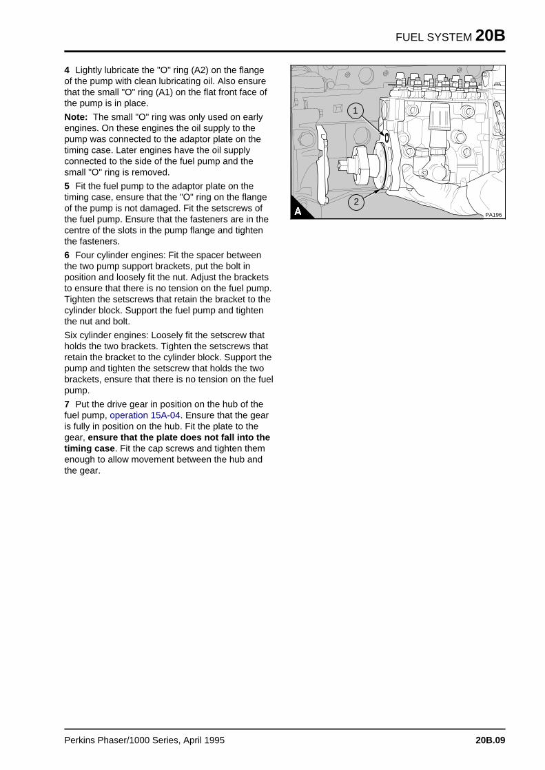
FUEL SYSTEM 20B
4 Lightly lubricate the "O" ring (A2) on the flangeof the pump with clean lubricating oil. Also ensurethat the small "O" ring (A1) on the flat front face ofthe pump is in place.
Note: The small "O" ring was only used on earlyengines. On these engines the oil supply to thepump was connected to the adaptor plate on thetiming case. Later engines have the oil supplyconnected to the side of the fuel pump and thesmall "O" ring is removed.
5 Fit the fuel pump to the adaptor plate on thetiming case, ensure that the "O" ring on the flangeof the pump is not damaged. Fit the setscrews ofthe fuel pump. Ensure that the fasteners are in thecentre of the slots in the pump flange and tightenthe fasteners.
6 Four cylinder engines: Fit the spacer betweenthe two pump support brackets, put the bolt inposition and loosely fit the nut. Adjust the bracketsto ensure that there is no tension on the fuel pump.Tighten the setscrews that retain the bracket to thecylinder block. Support the fuel pump and tightenthe nut and bolt.
Six cylinder engines: Loosely fit the setscrew thatholds the two brackets. Tighten the setscrews thatretain the bracket to the cylinder block. Support thepump and tighten the setscrew that holds the twobrackets, ensure that there is no tension on the fuelpump.
7 Put the drive gear in position on the hub of thefuel pump, operation 15A-04. Ensure that the gearis fully in position on the hub. Fit the plate to thegear, ensure that the plate does not fall into thetiming case . Fit the cap screws and tighten themenough to allow movement between the hub andthe gear.
PA196
a aa aa aa a
1
a a a
a a a
a a a
a a a
2
Perkins Phaser/1000 Series, April 1995 20B.09
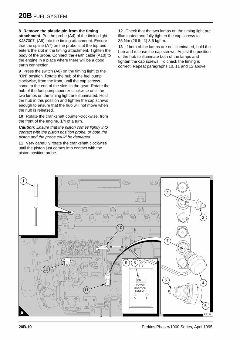
20B FUEL SYSTEM
8 Remove the plastic pin from the timingattachment . Put the probe (A4) of the timing light,KJ37007, (A9) into the timing attachment. Ensurethat the spline (A7) on the probe is at the top andenters the slot in the timing attachment. Tighten thebody of the probe. Connect the earth cable (A10) tothe engine in a place where there will be a goodearth connection.
9 Press the switch (A8) on the timing light to the"ON" position. Rotate the hub of the fuel pumpclockwise, from the front, until the cap screwscome to the end of the slots in the gear. Rotate thehub of the fuel pump counter-clockwise until thetwo lamps on the timing light are illuminated. Holdthe hub in this position and tighten the cap screwsenough to ensure that the hub will not move whenthe hub is released.
10 Rotate the crankshaft counter-clockwise, fromthe front of the engine, 1/4 of a turn.
Caution: Ensure that the piston comes lightly intocontact with the piston position probe, or both thepiston and the probe could be damaged.
11 Very carefully rotate the crankshaft clockwiseuntil the piston just comes into contact with thepiston position probe.
12 Check that the two lamps on the timing light areilluminated and fully tighten the cap screws to 35 Nm (26 lbf ft) 3,6 kgf m.
13 If both of the lamps are not illuminated, hold thehub and release the cap screws. Adjust the positionof the hub to illuminate both of the lamps andtighten the cap screws. To check the timing iscorrect: Repeat paragraphs 10, 11 and 12 above.
a a a a a a a a a a a a a a a a a a a a a a a a
a a a a a a a a a a a a a a a a a a a a a a a a
a a a a a a a a a a a a a a a a a a a a a a a a
a a a a a a a a a a a a a a a a a a a a a a a a
a a a a a a a a a a a a a a a a a a a a a a a a
a a a a a a a a a a a a a a a a a a a a a a a a
a a a a a a a a a a a a a a a a a a a a a a a a
a a a a a a a a a a a a a a a a a a a a a a a a
a a a a a a a a a a a a a a a a a a a a a a a a
a a a a a a a a a a a a a a a a a a a a a a a a
a a a a a a a a a a a a a a a a a a a a a a a a
a a a a a a a a a a a a a a a a a a a a a a a a
a a a a a a a a a a a a a a a a a a a a a a a a
a a a a a a a a a a a a a a a a a a a a a a a a
a a a a a a a a a a a a a a a a a a a a a a a a
a a a a a a a a a a a a a a a a a a a a a a a a
a a a a a a a a a a a a a a a a a a a a a a a a
a a a a a a a a a a a a a a a a a a a a a a a a
a a a a a a a a a a a a a a a a a a a a a a a a
a a a a a a a a a a a a a a a a a a a a a a a a
a a a a a a a a a a a a a a a a a a a a a a a a
a a a a a a a a a a a a a a a a a a a a a a a a
a a a a a a a a a a a a a a a a a a a a a a a a
a a a a a a a a a a a a a a a a a a a a a a a a
a a a a a a a a a a a a a a a a a a a a a a a a
a a a a a a a a a a a a a a a a a a a a a a a a
a a a a a a a a a a a a a a a a a a a a a a a a
a a a a a a a a a a a a a a a a a a a a a a a a
a a a a a a a a a a a a a a a a a a a a a a a a
a a a a a a a a a a a a a a a a a a a a a a a a
a a a a a a a a a a a a a a a a a a a a a a a a
a a a a a a a a a a a a a a a a a a a a a a a a
a a a a a a a a a a a a a a a a a a a a a a a a
a a a a a a a a a a a a a a a a a a a a a a a a
a a a a a a a a a a a a a a a a a a a a a a a a
a a a a a a a a a a a a a a a a a a a a a a a a
a a a a a a a a a a a a a a a a a a a a a a a a
a a a a
a a a a
ON
a a a a a a a a
a a a a a a a a
a a a a a a a a
POWER
a aa aA a aa aB
a a a a a a a a a
a a a a a a a a a
a a a a a a a a a
a a a a a a a a a
POSITIONSENSOR
a a a a a a a a a a a a a a a a a a a a a a a a a a a a a a a a a
a a a a a a a a a a a a a a a a a a a a a a a a a a a a a a a a a
a a a a a a a a a a a a a a a a a a a a a a a a a a a a a a a a a
a a a a a a a a a a a a a a a a a a a a a a a a a a a a a a a a a
a a a a a a a a a a a a a a a a a a a a a a a a a a a a a a a a a
a a a a a a a a a a a a a a a a a a a a a a a a a a a a a a a a a
a a a a a a a a a a a a a a a a a a a a a a a a a a a a a a a a a
a a a a a a a a a a a a a a a a a a a a a a a a a a a a a a a a a
a a a a a a a a a a a a a a a a a a a a a a a a a a a a a a a a a
a a a a a a a a a a a a a a a a a a a a a a a a a a a a a a a a a
a a a a a a a a a a a a a a a a a a a a a a a a a a a a a a a a a
a a a a a a a a a a a a a a a a a a a a a a a a a a a a a a a a a
a a a a a a a a a a a a a a a a a a a a a a a a a a a a a a a a a
a a a a a a a a a a a a a a a a a a a a a a a a a a a a a a a a a
a a a a a a a a a a a a a a a a a a a a a a a a a a a a a a a a a
a a a a a a a a a a a a a a a a a a a a a a a a a a a a a a a a a
a a a a a a a a a a a a a a a a a a a a a a a a a a a a a a a a a
a a a a a a a a a a a a a a a a a a a a a a a a a a a a a a a a a
a a a a a a a a a a a a a a a a a a a a a a a a a a a a a a a a a
a a a a a a a a a a a a a a a a a a a a a a a a a a a a a a a a a
a a a a a a a a a a a a a a a a a a a a a a a a a a a a a a a a a
a a a a a a a a a a a a a a a a a a a a a a a a a a a a a a a a a
a a a a a a a a a a a a a a a a a a a a a a a a a a a a a a a a a
a a a a a a a a a a a a a a a a a a a a a a a a a a a a a a a a a
a a a a a a a a a a a a a a a a a a a a a a a a a a a a a a a a a
a a a a a a a a a a a a a a a a a a a a a a a a a a a a a a a a a
a a a a a a a a a a a a a a a a a a a a a a a a a a a a a a a a a
a a a a a a a a a a a a a a a a a a a a a a a a a a a a a a a a a
a a a a a a a a a a a a a a a a a a a a a a a a a a a a a a a a a
a a a a a a a a a a a a a a a a a a a a a a a a a a a a a a a a a
a a a a a a a a a a a a a a a a a a a a a a a a a a a a a a a a a
a a a a a a a a a a a a a a a a a a a a a a a a a a a a a a a a a
a a a a a a a a a a a a a a a a a a a a a a a a a a a a a a a a a
a a a a a a a a a a a a a a a a a a a a a a a a a a a a a a a a a
a a a a a a a a a a a a a a a a a a a a a a a a a a a a a a a a a
a a a a a a a a a a a a a a a a a a a a a a a a a a a a a a a a a
a a a a a a a a a a a a a a a a a a a a a a a a a a a a a a a a a
a a a a a a a a a a a a a a a a a a a a a a a a a a a a a a a a a
a a a a a a a a a a a a a a a a a a a a a a a a a a a a a a a a a
a a a a a a a a a a a a a a a a a a a a a a a a a a a a a a a a a
a a a a a a a a a a a a a a a a a a a a a a a a a a a a a a a a a
a a a a a a a a a a a a a a a a a a a a a a a a a a a a a a a a a
a a a a a a a a a a a a a a a a a a a a a a a a a a a a a a a a a
a a a a a a a a a a a a a a a a a a a a a a a a a a a a a a a a a
a a a a a a a a a a a a a a a a a a a a a a a a a a a a a a a a a
a a a a a a a a a a a a a a a a a a a a a a a a a a a a a a a a a
a a a a a a a a a a a a a a a a a a a a a a a a a a a a a a a a a
a a a a a a a a a a a a a a a a a a a a a a a a a a a a a a a a a
a a a a a a a a a a a a a a a a a a a a a a a a a a a a a a a a a
a a a a a a a a a a a a a a a a a a a a a a a a a a a a a a a a a
a a a a a a a a a a a a a a a a a a a a a a a a a a a a a a a a a
a a a a a a a a a a a a a a a a a a a a a a a a a a a a a a a a a
a a a a a a a a a a a a a a a a a a a a a a a a a a a a a a a a a
a a a a a a a a a a a a a a a a a a a a a a a a a a a a a a a a a
a a a a a a a a a a a a a a a a a a a a a a a a a a a a a a a a a
a a a a a a a a a a a a a a a a a a a a a a a a a a a a a a a a a
a a a a a a a a a a a a a a a a a a a a a a a a a a a a a a a a a
a a a a a a a a a a a a a a a a a a a a a a a a a a a a a a a a a
a a a a a a a a a a a a a a a a a a a a a a a a a a a a a a a a a
a a a a a a a a a a a a a a a a a a a a a a a a a a a a a a a a a
a aa aa aa a
1
a a a
a a a
a a a
a a a
9 a aa aa aa a
8
a a a a
a a a a
a a a a
a a a a
11
a a a a a
a a a a a
a a a a a
a a a a a
10
a aa aa aa aa a
7
a aa aa aa a
4
a a a
a a a
a a a
a a a
5
a aa aa aa a
6
a aa aa aa a
3
a aa aa aa a
2
PA194
a a a a
a a a a
a a a a
a a a a
12
20B.10 Perkins Phaser/1000 Series, April 1995
FUEL SYSTEM 20B
14 Fit the gear cover together with a new joint tothe cover of the timing case. Clean the threads ofthe setscrews for the gear cover and apply asealant to the threads. Tighten the setscrews to 9 Nm (6.5 lbf ft) 0,9 kgf m.
15 Press the switch on the timing light to the"OFF" position. Disconnect the earth lead, removethe probe of the timing light from the timingattachment and remove the timing light.
16 Put the plastic pin into the cap 20B.11/A5 forthe timing attachment. Ensure that when the pin isin the cap, the brass end of the pin 20B.11/A6 canbe seen. Put the cap and its copper washer inposition on the timing attachment and tighten thecap.
Caution: If the plastic pin is not put into the capcorrectly, damage could occur to the fuel injectionpump.
17 Release the setscrews and remove the pistonposition probe from number 1 cylinder and thespecial washer, if one is fitted. Fit the atomisertogether with a new seat washer. Tighten thesetscrews of all the atomisers gradually and evenlyto 12 Nm (9 lbf ft) 1,2 kgf m.
18 Fit the high-pressure pipes. The relevantcylinder outlets of the pump are in the sequence1,2,3,4 or 1,2,3,4,5,6 with the number 1 cylinderoutlet at the drive end of the pump. Fit the low-pressure pipes. Ensure that the banjo connectionbolt (20B.11/A12) with the spring loaded valve isfitted to the low-pressure connection at the driveend of the fuel pump. This banjo connection bolt isusually identified by a ball bearing in the head.Connect the lubricating oil pipe to the fuel pump.Connect the stop control/electrical cable and theengine speed control.
19 Fit the rocker cover, operation 12A-01.
20 Eliminate the air from the fuel system, operation20B-08.
21 Operate the engine and check for leakage. Withthe engine at the normal temperature of operation,check that the idle speed is correct, operation 20B-06.
22 If a new fuel injection pump has been fitted,check the maximum no-load speed, operation 20B-06.
Perkins Phaser/1000 Series, April 1995 20B.11
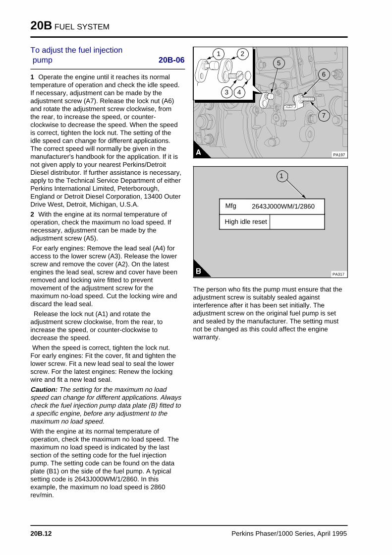
20B FUEL SYSTEM
To adjust the fuel injection pump 20B-06
1 Operate the engine until it reaches its normaltemperature of operation and check the idle speed.If necessary, adjustment can be made by theadjustment screw (A7). Release the lock nut (A6)and rotate the adjustment screw clockwise, fromthe rear, to increase the speed, or counter-clockwise to decrease the speed. When the speedis correct, tighten the lock nut. The setting of theidle speed can change for different applications.The correct speed will normally be given in themanufacturer's handbook for the application. If it isnot given apply to your nearest Perkins/DetroitDiesel distributor. If further assistance is necessary,apply to the Technical Service Department of eitherPerkins International Limited, Peterborough,England or Detroit Diesel Corporation, 13400 OuterDrive West, Detroit, Michigan, U.S.A.
2 With the engine at its normal temperature ofoperation, check the maximum no load speed. Ifnecessary, adjustment can be made by theadjustment screw (A5).
For early engines: Remove the lead seal (A4) foraccess to the lower screw (A3). Release the lowerscrew and remove the cover (A2). On the latestengines the lead seal, screw and cover have beenremoved and locking wire fitted to preventmovement of the adjustment screw for themaximum no-load speed. Cut the locking wire anddiscard the lead seal.
Release the lock nut (A1) and rotate theadjustment screw clockwise, from the rear, toincrease the speed, or counter-clockwise todecrease the speed.
When the speed is correct, tighten the lock nut.For early engines: Fit the cover, fit and tighten thelower screw. Fit a new lead seal to seal the lowerscrew. For the latest engines: Renew the lockingwire and fit a new lead seal.
Caution: The setting for the maximum no loadspeed can change for different applications. Alwayscheck the fuel injection pump data plate (B) fitted toa specific engine, before any adjustment to themaximum no load speed.
With the engine at its normal temperature ofoperation, check the maximum no load speed. Themaximum no load speed is indicated by the lastsection of the setting code for the fuel injectionpump. The setting code can be found on the dataplate (B1) on the side of the fuel pump. A typicalsetting code is 2643J000WM/1/2860. In thisexample, the maximum no load speed is 2860rev/min.
a aa aa aa a
2
a a a
a a a
a a a
a a a
4
a a a
a a a
a a a
a a a
1
a a a
a a a
a a a
a a a
3
a a a
a a a
a a a
a a a
a a a
5
a aa aa aa a
6
a aa aa aa a
7
PA197
a a a
a a a
a a a
a a a
1
High idle reset
PA317
2643J000WM/1/2860 Mfg
The person who fits the pump must ensure that theadjustment screw is suitably sealed againstinterference after it has been set initially. Theadjustment screw on the original fuel pump is setand sealed by the manufacturer. The setting mustnot be changed as this could affect the enginewarranty.
20B.12 Perkins Phaser/1000 Series, April 1995
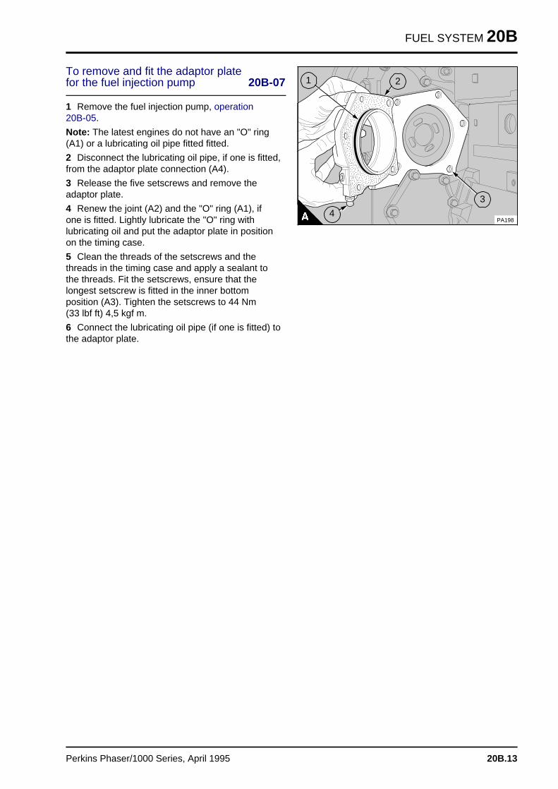
FUEL SYSTEM 20B
To remove and fit the adaptor plate for the fuel injection pump 20B-07
1 Remove the fuel injection pump, operation 20B-05.
Note: The latest engines do not have an "O" ring(A1) or a lubricating oil pipe fitted fitted.
2 Disconnect the lubricating oil pipe, if one is fitted,from the adaptor plate connection (A4).
3 Release the five setscrews and remove theadaptor plate.
4 Renew the joint (A2) and the "O" ring (A1), ifone is fitted. Lightly lubricate the "O" ring withlubricating oil and put the adaptor plate in positionon the timing case.
5 Clean the threads of the setscrews and thethreads in the timing case and apply a sealant tothe threads. Fit the setscrews, ensure that thelongest setscrew is fitted in the inner bottomposition (A3). Tighten the setscrews to 44 Nm (33 lbf ft) 4,5 kgf m.
6 Connect the lubricating oil pipe (if one is fitted) tothe adaptor plate.
PA198
a a a
a a a
a a a
a a a
1
a a a
a a a
a a a
a a a
2
a aa aa aa a
3
a aa aa aa a
4
Perkins Phaser/1000 Series, April 1995 20B.13
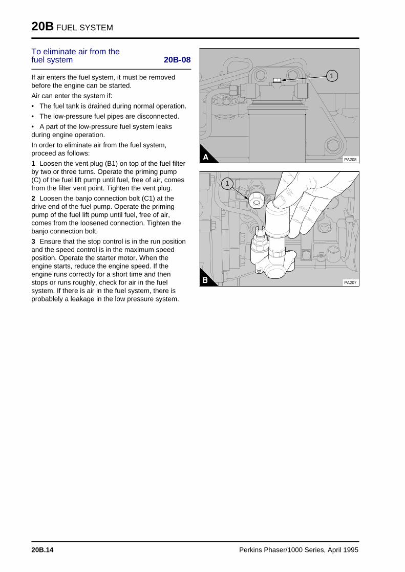
20B FUEL SYSTEM
To eliminate air from the fuel system 20B-08
If air enters the fuel system, it must be removedbefore the engine can be started.
Air can enter the system if:
• The fuel tank is drained during normal operation.
• The low-pressure fuel pipes are disconnected.
• A part of the low-pressure fuel system leaksduring engine operation.
In order to eliminate air from the fuel system,proceed as follows:
1 Loosen the vent plug (B1) on top of the fuel filterby two or three turns. Operate the priming pump(C) of the fuel lift pump until fuel, free of air, comesfrom the filter vent point. Tighten the vent plug.
2 Loosen the banjo connection bolt (C1) at thedrive end of the fuel pump. Operate the primingpump of the fuel lift pump until fuel, free of air,comes from the loosened connection. Tighten thebanjo connection bolt.
3 Ensure that the stop control is in the run positionand the speed control is in the maximum speedposition. Operate the starter motor. When theengine starts, reduce the engine speed. If theengine runs correctly for a short time and thenstops or runs roughly, check for air in the fuelsystem. If there is air in the fuel system, there isprobablely a leakage in the low pressure system.
a aa aa aa a
1
PA208
a aa aa aa a
1
PA207
20B.14 Perkins Phaser/1000 Series, April 1995
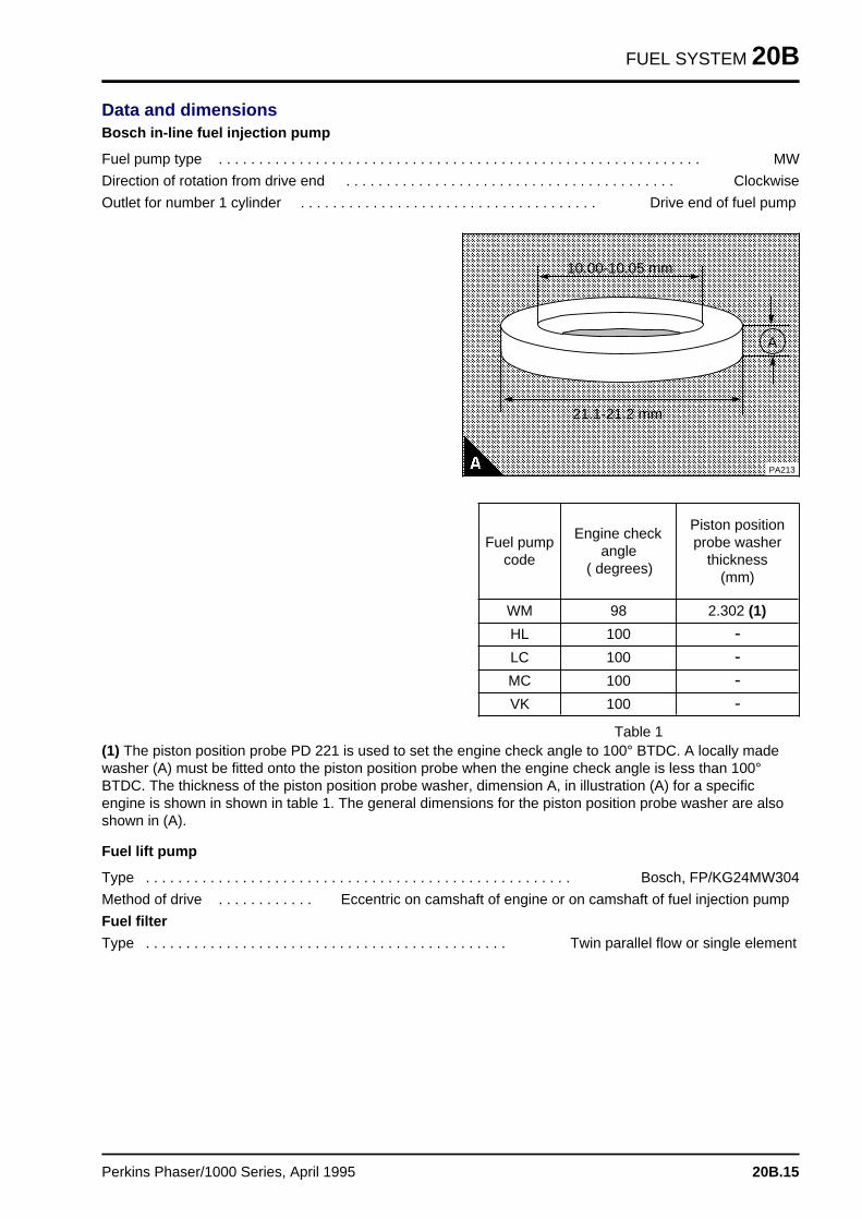
FUEL SYSTEM 20B
Data and dimensionsBosch in-line fuel injection pump
Fuel pump type . . . . . . . . . . . . . . . . . . . . . . . . . . . . . . . . . . . . . . . . . . . . . . . . . . . . . . . . . . . . MW
Direction of rotation from drive end . . . . . . . . . . . . . . . . . . . . . . . . . . . . . . . . . . . . . . . . . Clockwise
Outlet for number 1 cylinder . . . . . . . . . . . . . . . . . . . . . . . . . . . . . . . . . . . . . Drive end of fuel pump
a a a a a a a a a a a a a a a a a a a a a a a a a a a a a a a a a a a a a a a a a a a a a a a a a a a a a a a a a a a a a
a a a a a a a a a a a a a a a a a a a a a a a a a a a a a a a a a a a a a a a a a a a a a a a a a a a a a a a a a a a a a
a a a a a a a a a a a a a a a a a a a a a a a a a a a a a a a a a a a a a a a a a a a a a a a a a a a a a a a a a a a a a
a a a a a a a a a a a a a a a a a a a a a a a a a a a a a a a a a a a a a a a a a a a a a a a a a a a a a a a a a a a a a
a a a a a a a a a a a a a a a a a a a a a a a a a a a a a a a a a a a a a a a a a a a a a a a a a a a a a a a a a a a a a
a a a a a a a a a a a a a a a a a a a a a a a a a a a a a a a a a a a a a a a a a a a a a a a a a a a a a a a a a a a a a
a a a a a a a a a a a a a a a a a a a a a a a a a a a a a a a a a a a a a a a a a a a a a a a a a a a a a a a a a a a a a
a a a a a a a a a a a a a a a a a a a a a a a a a a a a a a a a a a a a a a a a a a a a a a a a a a a a a a a a a a a a a
a a a a a a a a a a a a a a a a a a a a a a a a a a a a a a a a a a a a a a a a a a a a a a a a a a a a a a a a a a a a a
a a a a a a a a a a a a a a a a a a a a a a a a a a a a a a a a a a a a a a a a a a a a a a a a a a a a a a a a a a a a a
a a a a a a a a a a a a a a a a a a a a a a a a a a a a a a a a a a a a a a a a a a a a a a a a a a a a a a a a a a a a a
a a a a a a a a a a a a a a a a a a a a a a a a a a a a a a a a a a a a a a a a a a a a a a a a a a a a a a a a a a a a a
a a a a a a a a a a a a a a a a a a a a a a a a a a a a a a a a a a a a a a a a a a a a a a a a a a a a a a a a a a a a a
a a a a a a a a a a a a a a a a a a a a a a a a a a a a a a a a a a a a a a a a a a a a a a a a a a a a a a a a a a a a a
a a a a a a a a a a a a a a a a a a a a a a a a a a a a a a a a a a a a a a a a a a a a a a a a a a a a a a a a a a a a a
a a a a a a a a a a a a a a a a a a a a a a a a a a a a a a a a a a a a a a a a a a a a a a a a a a a a a a a a a a a a a
a a a a a a a a a a a a a a a a a a a a a a a a a a a a a a a a a a a a a a a a a a a a a a a a a a a a a a a a a a a a a
a a a a a a a a a a a a a a a a a a a a a a a a a a a a a a a a a a a a a a a a a a a a a a a a a a a a a a a a a a a a a
a a a a a a a a a a a a a a a a a a a a a a a a a a a a a a a a a a a a a a a a a a a a a a a a a a a a a a a a a a a a a
a a a a a a a a a a a a a a a a a a a a a a a a a a a a a a a a a a a a a a a a a a a a a a a a a a a a a a a a a a a a a
a a a a a a a a a a a a a a a a a a a a a a a a a a a a a a a a a a a a a a a a a a a a a a a a a a a a a a a a a a a a a
a a a a a a a a a a a a a a a a a a a a a a a a a a a a a a a a a a a a a a a a a a a a a a a a a a a a a a a a a a a a a
a a a a a a a a a a a a a a a a a a a a a a a a a a a a a a a a a a a a a a a a a a a a a a a a a a a a a a a a a a a a a
a a a a a a a a a a a a a a a a a a a a a a a a a a a a a a a a a a a a a a a a a a a a a a a a a a a a a a a a a a a a a
a a a a a a a a a a a a a a a a a a a a a a a a a a a a a a a a a a a a a a a a a a a a a a a a a a a a a a a a a a a a a
a a a a a a a a a a a a a a a a a a a a a a a a a a a a a a a a a a a a a a a a a a a a a a a a a a a a a a a a a a a a a
a a a a a a a a a a a a a a a a a a a a a a a a a a a a a a a a a a a a a a a a a a a a a a a a a a a a a a a a a a a a a
a a a a a a a a a a a a a a a a a a a a a a a a a a a a a a a a a a a a a a a a a a a a a a a a a a a a a a a a a a a a a
a a a a a a a a a a a a a a a a a a a a a a a a a a a a a a a a a a a a a a a a a a a a a a a a a a a a a a a a a a a a a
a a a a a a a a a a a a a a a a a a a a a a a a a a a a a a a a a a a a a a a a a a a a a a a a a a a a a a a a a a a a a
a a a a a a a a a a a a a a a a a a a a a a a a a a a a a a a a a a a a a a a a a a a a a a a a a a a a a a a a a a a a a
a a a a a a a a a a a a a a a a a a a a a a a a a a a a a a a a a a a a a a a a a a a a a a a a a a a a a a a a a a a a a
a a a a a a a a a a a a a a a a a a a a a a a a a a a a a a a a a a a a a a a a a a a a a a a a a a a a a a a a a a a a a
a a a a a a a a a a a a a a a a a a a a a a a a a a a a a a a a a a a a a a a a a a a a a a a a a a a a a a a a a a a a a
a a a a a a a a a a a a a a a a a a a a a a a a a a a a a a a a a a a a a a a a a a a a a a a a a a a a a a a a a a a a a
a a a a a a a a a a a a a a a a a a a a a a a a a a a a a a a a a a a a a a a a a a a a a a a a a a a a a a a a a a a a a
a a a a a a a a a a a a a a a a a a a a a a a a a a a a a a a a a a a a a a a a a a a a a a a a a a a a a a a a a a a a a
a a a a a a a a a a a a a a a a a a a a a a a a a a a a a a a a a a a a a a a a a a a a a a a a a a a a a a a a a a a a a
a a a a a a a a a a a a a a a a a a a a a a a a a a a a a a a a a a a a a a a a a a a a a a a a a a a a a a a a a a a a a
a a a a a a a a a a a a a a a a a a a a a a a a a a a a a a a a a a a a a a a a a a a a a a a a a a a a a a a a a a a a a
a a a a a a a a a a a a a a a a a a a a a a a a a a a a a a a a a a a a a a a a a a a a a a a a a a a a a a a a a a a a a
a a a a a a a a a a a a a a a a a a a a a a a a a a a a a a a a a a a a a a a a a a a a a a a a a a a a a a a a a a a a a
a a a a a a a a a a a a a a a a a a a a a a a a a a a a a a a a a a a a a a a a a a a a a a a a a a a a a a a a a a a a a
a a a a a a a a a a a a a a a a a a a a a a a a a a a a a a a a a a a a a a a a a a a a a a a a a a a a a a a a a a a a a
a a a
a a a
a a a
a a a
A
a a a a a a a a a a a a a a a a a a
a a a a a a a a a a a a a a a a a a
a a a a a a a a a a a a a a a a a a
a a a a a a a a a a a a a a a a a a
21.1-21.2 mm
a a a a a a a a a a a a a a a a a a a a a
a a a a a a a a a a a a a a a a a a a a a
a a a a a a a a a a a a a a a a a a a a a
a a a a a a a a a a a a a a a a a a a a a
10.00-10.05 mm
PA213
Table 1
Fuel pumpcode
Engine checkangle
( degrees)
Piston positionprobe washer
thickness(mm)
WM 98 2.302 (1)
HL 100 >
LC 100 >
MC 100 >
VK 100 >
(1) The piston position probe PD 221 is used to set the engine check angle to 100° BTDC. A locally madewasher (A) must be fitted onto the piston position probe when the engine check angle is less than 100°BTDC. The thickness of the piston position probe washer, dimension A, in illustration (A) for a specificengine is shown in shown in table 1. The general dimensions for the piston position probe washer are alsoshown in (A).
Fuel lift pump
Type . . . . . . . . . . . . . . . . . . . . . . . . . . . . . . . . . . . . . . . . . . . . . . . . . . . . . Bosch, FP/KG24MW304
Method of drive . . . . . . . . . . . . Eccentric on camshaft of engine or on camshaft of fuel injection pump
Fuel filter
Type . . . . . . . . . . . . . . . . . . . . . . . . . . . . . . . . . . . . . . . . . . . . . Twin parallel flow or single element
Perkins Phaser/1000 Series, April 1995 20B.15
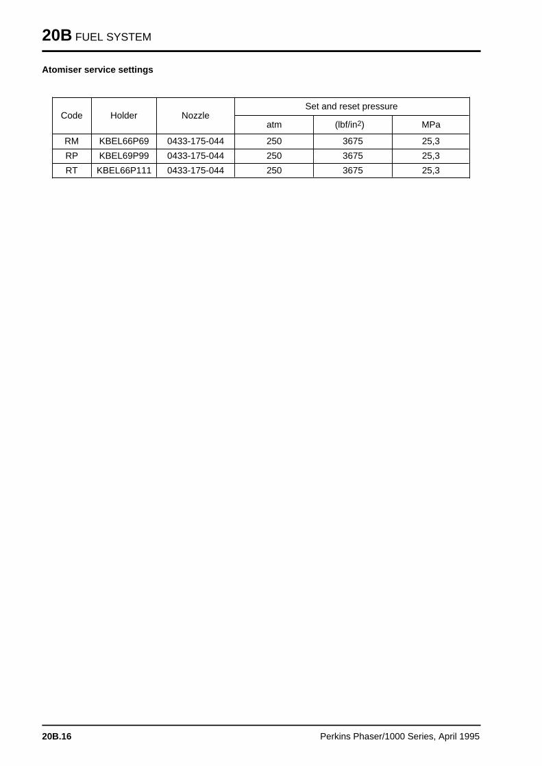
20B FUEL SYSTEM
Atomiser service settings
Code Holder NozzleSet and reset pressure
atm (lbf/in2) MPa
RM KBEL66P69 0433-175-044 250 3675 25,3
RP KBEL69P99 0433-175-044 250 3675 25,3
RT KBEL66P111 0433-175-044 250 3675 25,3
20B.16 Perkins Phaser/1000 Series, April 1995

Engines fitted with Lucas DPA and DPS fuel injection pump s 20C
General descriptio n . . . . . . . . . . . . . . . . . . . . . . . . . . . . . . . . . . . . refer to 20A.02
Fuel filter element
20C-01 To renew . . . . . . . . . . . . . . . . . . . . . . . . . . . . . . . . . . . . refer to 20A.04
Atomisers
Atomiser fault . . . . . . . . . . . . . . . . . . . . . . . . . . . . . . . . . refer to 20A.0720C-02 To remove and to fit . . . . . . . . . . . . . . . . . . . . . . . . . . . . refer to 20A.07
Fuel lift pump
20C-03 To remove and to fit . . . . . . . . . . . . . . . . . . . . . . . . . . . . refer to 20A.0820C-04 To dismantle and to assemble . . . . . . . . . . . . . . . . . . . . . refer to 20A.0820C-05 To test . . . . . . . . . . . . . . . . . . . . . . . . . . . . . . . . . . . . . . refer to 20A.10
Fuel injection pump
20C-06 To remove and to fit . . . . . . . . . . . . . . . . . . . . . . . . . . . . . . . . . 20C.0220C-07 To adjust . . . . . . . . . . . . . . . . . . . . . . . . . . . . . . . . . . . . . . . . . 20C.0420C-08 To eliminate air from the fuel system . . . . . . . . . . . . . . . . . . . . . 20C.05
Data and dimension s . . . . . . . . . . . . . . . . . . . . . . . . . . . . . . . . . . refer to 20A.22
Perkins Phaser/1000 Series, April 1995 20C.01
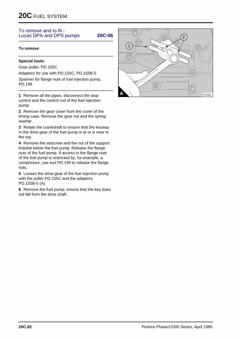
20C FUEL SYSTEM
To remove and to fit - Lucas DPA and DPS pumps 20C-06
To remove
Special tools:
Gear puller, PD.155C
Adaptors for use with PD.155C, PD.155B-5
Spanner for flange nuts of fuel injection pump,PD.199
1 Remove all the pipes, disconnect the stopcontrol and the control rod of the fuel injectionpump.
2 Remove the gear cover from the cover of thetiming case. Remove the gear nut and the springwasher.
3 Rotate the crankshaft to ensure that the keywayin the drive gear of the fuel pump is at or is near tothe top.
4 Remove the setscrew and the nut of the supportbracket below the fuel pump. Release the flangenuts of the fuel pump. If access to the flange nutsof the fuel pump is restricted by, for example, acompressor, use tool PD.199 to release the flangenuts.
5 Loosen the drive gear of the fuel injection pumpwith the puller PD.155C and the adaptorsPD.155B-5 (A).
6 Remove the fuel pump; ensure that the key doesnot fall from the drive shaft.
a a a
a a a
a a a
a a a
1
a a a
a a a
a a a
a a a
2
PA162
20C.02 Perkins Phaser/1000 Series, April 1995
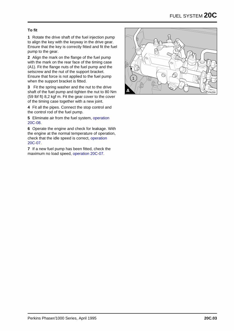
FUEL SYSTEM 20C
To fit
1 Rotate the drive shaft of the fuel injection pumpto align the key with the keyway in the drive gear.Ensure that the key is correctly fitted and fit the fuelpump to the gear.
2 Align the mark on the flange of the fuel pumpwith the mark on the rear face of the timing case(A1). Fit the flange nuts of the fuel pump and thesetscrew and the nut of the support bracket.Ensure that force is not applied to the fuel pumpwhen the support bracket is fitted.
3 Fit the spring washer and the nut to the driveshaft of the fuel pump and tighten the nut to 80 Nm(59 lbf ft) 8,2 kgf m. Fit the gear cover to the coverof the timing case together with a new joint.
4 Fit all the pipes. Connect the stop control andthe control rod of the fuel pump.
5 Eliminate air from the fuel system, operation20C-08.
6 Operate the engine and check for leakage. Withthe engine at the normal temperature of operation,check that the idle speed is correct, operation 20C-07.
7 If a new fuel pump has been fitted, check themaximum no load speed, operation 20C-07.
PA259
a a a
a a a
a a a
a a a
1
Perkins Phaser/1000 Series, April 1995 20C.03
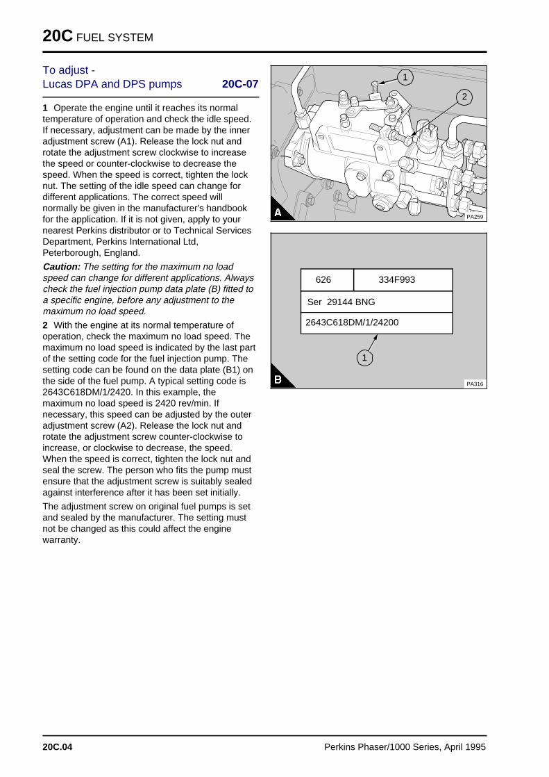
20C FUEL SYSTEM
To adjust - Lucas DPA and DPS pumps 20C-07
1 Operate the engine until it reaches its normaltemperature of operation and check the idle speed.If necessary, adjustment can be made by the inneradjustment screw (A1). Release the lock nut androtate the adjustment screw clockwise to increasethe speed or counter-clockwise to decrease thespeed. When the speed is correct, tighten the locknut. The setting of the idle speed can change fordifferent applications. The correct speed willnormally be given in the manufacturer's handbookfor the application. If it is not given, apply to yournearest Perkins distributor or to Technical ServicesDepartment, Perkins International Ltd,Peterborough, England.
Caution: The setting for the maximum no loadspeed can change for different applications. Alwayscheck the fuel injection pump data plate (B) fitted toa specific engine, before any adjustment to themaximum no load speed.
2 With the engine at its normal temperature ofoperation, check the maximum no load speed. Themaximum no load speed is indicated by the last partof the setting code for the fuel injection pump. Thesetting code can be found on the data plate (B1) onthe side of the fuel pump. A typical setting code is2643C618DM/1/2420. In this example, themaximum no load speed is 2420 rev/min. Ifnecessary, this speed can be adjusted by the outeradjustment screw (A2). Release the lock nut androtate the adjustment screw counter-clockwise toincrease, or clockwise to decrease, the speed.When the speed is correct, tighten the lock nut andseal the screw. The person who fits the pump mustensure that the adjustment screw is suitably sealedagainst interference after it has been set initially.
The adjustment screw on original fuel pumps is setand sealed by the manufacturer. The setting mustnot be changed as this could affect the enginewarranty.
PA259
a aa aa aa a
2
a a a
a a a
a a a
a a a
1
334F993 626
PA316
a a a a a a a a a a a a a a a a a a a a a a
a a a a a a a a a a a a a a a a a a a a a a
a a a a a a a a a a a a a a a a a a a a a a
a a a a a a a a a a a a a a a a a a a a a a
Ser 29144 BNG a a a a a a a a a a a a a a a a a a a a a a a a a a a
a a a a a a a a a a a a a a a a a a a a a a a a a a a
a a a a a a a a a a a a a a a a a a a a a a a a a a a
a a a a a a a a a a a a a a a a a a a a a a a a a a a
2643C618DM/1/24200
a aa aa aa a
1
20C.04 Perkins Phaser/1000 Series, April 1995
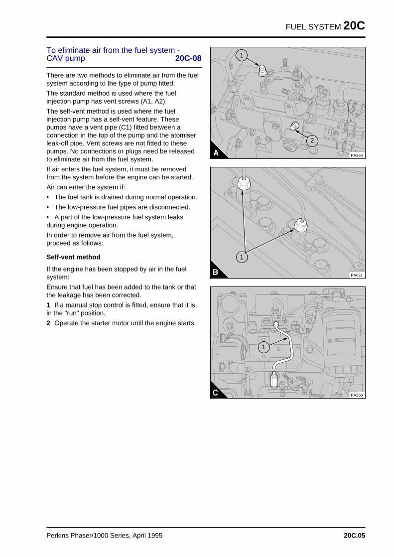
FUEL SYSTEM 20C
To eliminate air from the fuel system -CAV pump 20C-08
There are two methods to eliminate air from the fuelsystem according to the type of pump fitted:
The standard method is used where the fuelinjection pump has vent screws (A1, A2).
The self-vent method is used where the fuelinjection pump has a self-vent feature. Thesepumps have a vent pipe (C1) fitted between aconnection in the top of the pump and the atomiserleak-off pipe. Vent screws are not fitted to thesepumps. No connections or plugs need be releasedto eliminate air from the fuel system.
If air enters the fuel system, it must be removedfrom the system before the engine can be started.
Air can enter the system if:
• The fuel tank is drained during normal operation.
• The low-pressure fuel pipes are disconnected.
• A part of the low-pressure fuel system leaksduring engine operation.
In order to remove air from the fuel system,proceed as follows:
Self-vent method
If the engine has been stopped by air in the fuelsystem:
Ensure that fuel has been added to the tank or thatthe leakage has been corrected.
1 If a manual stop control is fitted, ensure that it isin the "run" position.
2 Operate the starter motor until the engine starts.
PA264
a aa aa aa a
1
a a a
a a a
a a a
a a a
2
PA031
a aa aa aa a
1
PA266
a a a
a a a
a a a
a a a
1
Perkins Phaser/1000 Series, April 1995 20C.05
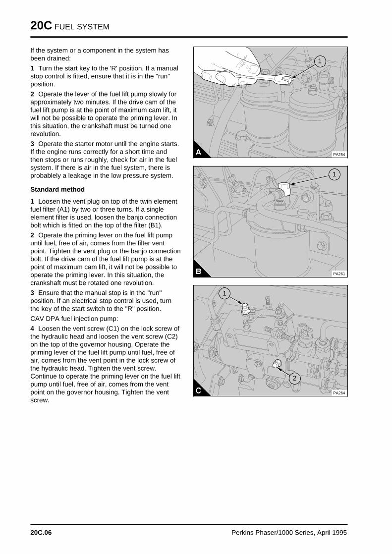
20C FUEL SYSTEM
If the system or a component in the system hasbeen drained:
1 Turn the start key to the 'R' position. If a manualstop control is fitted, ensure that it is in the "run"position.
2 Operate the lever of the fuel lift pump slowly forapproximately two minutes. If the drive cam of thefuel lift pump is at the point of maximum cam lift, itwill not be possible to operate the priming lever. Inthis situation, the crankshaft must be turned onerevolution.
3 Operate the starter motor until the engine starts.If the engine runs correctly for a short time andthen stops or runs roughly, check for air in the fuelsystem. If there is air in the fuel system, there isprobablely a leakage in the low pressure system.
Standard method
1 Loosen the vent plug on top of the twin elementfuel filter (A1) by two or three turns. If a singleelement filter is used, loosen the banjo connectionbolt which is fitted on the top of the filter (B1).
2 Operate the priming lever on the fuel lift pumpuntil fuel, free of air, comes from the filter ventpoint. Tighten the vent plug or the banjo connectionbolt. If the drive cam of the fuel lift pump is at thepoint of maximum cam lift, it will not be possible tooperate the priming lever. In this situation, thecrankshaft must be rotated one revolution.
3 Ensure that the manual stop is in the "run"position. If an electrical stop control is used, turnthe key of the start switch to the "R" position.
CAV DPA fuel injection pump:
4 Loosen the vent screw (C1) on the lock screw ofthe hydraulic head and loosen the vent screw (C2)on the top of the governor housing. Operate thepriming lever of the fuel lift pump until fuel, free ofair, comes from the vent point in the lock screw ofthe hydraulic head. Tighten the vent screw.Continue to operate the priming lever on the fuel liftpump until fuel, free of air, comes from the ventpoint on the governor housing. Tighten the ventscrew.
a a a
a a a
a a a
a a a
1
PA254
a aa aa aa a
1
PA261
PA264
a aa aa aa aa a
1a a a
a a a
a a a
a a a
2
20C.06 Perkins Phaser/1000 Series, April 1995
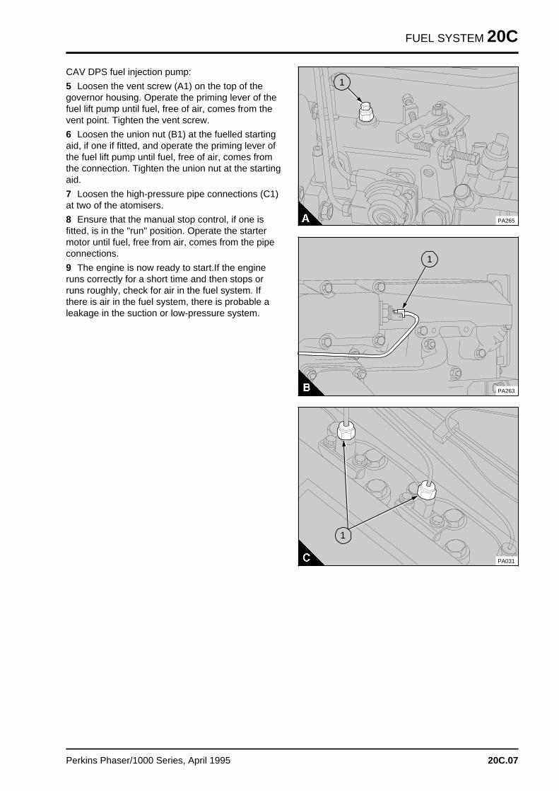
FUEL SYSTEM 20C
CAV DPS fuel injection pump:
5 Loosen the vent screw (A1) on the top of thegovernor housing. Operate the priming lever of thefuel lift pump until fuel, free of air, comes from thevent point. Tighten the vent screw.
6 Loosen the union nut (B1) at the fuelled startingaid, if one if fitted, and operate the priming lever ofthe fuel lift pump until fuel, free of air, comes fromthe connection. Tighten the union nut at the startingaid.
7 Loosen the high-pressure pipe connections (C1)at two of the atomisers.
8 Ensure that the manual stop control, if one isfitted, is in the "run" position. Operate the startermotor until fuel, free from air, comes from the pipeconnections.
9 The engine is now ready to start.If the engineruns correctly for a short time and then stops orruns roughly, check for air in the fuel system. Ifthere is air in the fuel system, there is probable aleakage in the suction or low-pressure system.
PA265
a aa aa aa a
1
a aa aa aa a
1
PA263
PA031
a aa aa aa a
1
Perkins Phaser/1000 Series, April 1995 20C.07
Engines fitted with Lucas DP200 Series fuel injection pump s 20D
General descriptio n . . . . . . . . . . . . . . . . . . . . . . . . . . . . . . . . . . . . refer to 20A.02
Fuel filter element
20D-01 To renew . . . . . . . . . . . . . . . . . . . . . . . . . . . . . . . . . . . . refer to 20A.04
Atomisers
Atomiser fault . . . . . . . . . . . . . . . . . . . . . . . . . . . . . . . . . refer to 20A.0720D-02 To remove and to fit . . . . . . . . . . . . . . . . . . . . . . . . . . . . refer to 20A.07
Fuel lift pump
20D-03 To remove and to fit . . . . . . . . . . . . . . . . . . . . . . . . . . . . refer to 20A.0820D-04 To dismantle and to assemble . . . . . . . . . . . . . . . . . . . . . refer to 20A.0820D-05 To test . . . . . . . . . . . . . . . . . . . . . . . . . . . . . . . . . . . . . . refer to 20A.10
Fuel injection pump
20D-06 To remove and to fit . . . . . . . . . . . . . . . . . . . . . . . . . . . . . . . . . 20D.0220D-07 To adjust . . . . . . . . . . . . . . . . . . . . . . . . . . . . . . . . . . . . . . . . . 20D.0420D-08 To eliminate air from the fuel system . . . . . . . . . . . . . . . . . . . . . 20D.05
Data and dimension s . . . . . . . . . . . . . . . . . . . . . . . . . . . . . . . . . . refer to 20A.22
Perkins Phaser/1000 Series, April 1995 20D.01
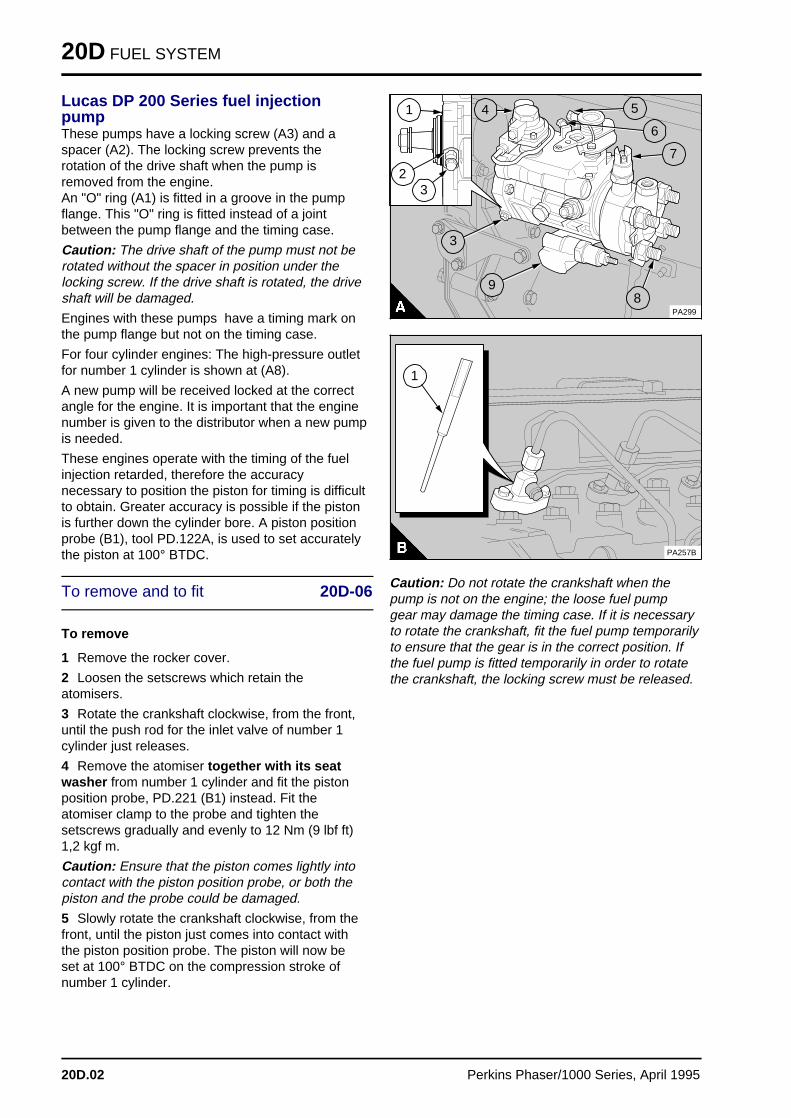
20D FUEL SYSTEM
Lucas DP 200 Series fuel injectionpumpThese pumps have a locking screw (A3) and aspacer (A2). The locking screw prevents therotation of the drive shaft when the pump isremoved from the engine.An "O" ring (A1) is fitted in a groove in the pumpflange. This "O" ring is fitted instead of a jointbetween the pump flange and the timing case.
Caution: The drive shaft of the pump must not berotated without the spacer in position under thelocking screw. If the drive shaft is rotated, the driveshaft will be damaged.
Engines with these pumps have a timing mark onthe pump flange but not on the timing case.
For four cylinder engines: The high-pressure outletfor number 1 cylinder is shown at (A8).
A new pump will be received locked at the correctangle for the engine. It is important that the enginenumber is given to the distributor when a new pumpis needed.
These engines operate with the timing of the fuelinjection retarded, therefore the accuracynecessary to position the piston for timing is difficultto obtain. Greater accuracy is possible if the pistonis further down the cylinder bore. A piston positionprobe (B1), tool PD.122A, is used to set accuratelythe piston at 100° BTDC.
To remove and to fit 20D-06
To remove
1 Remove the rocker cover.
2 Loosen the setscrews which retain theatomisers.
3 Rotate the crankshaft clockwise, from the front,until the push rod for the inlet valve of number 1cylinder just releases.
4 Remove the atomiser together with its seatwasher from number 1 cylinder and fit the pistonposition probe, PD.221 (B1) instead. Fit theatomiser clamp to the probe and tighten thesetscrews gradually and evenly to 12 Nm (9 lbf ft)1,2 kgf m.
Caution: Ensure that the piston comes lightly intocontact with the piston position probe, or both thepiston and the probe could be damaged.
5 Slowly rotate the crankshaft clockwise, from thefront, until the piston just comes into contact withthe piston position probe. The piston will now beset at 100° BTDC on the compression stroke ofnumber 1 cylinder.
aaaaaaaaaa
a aa aa aa a
3
a aa aa aa a
2
a aa aa aa a
1
a aa aa aa a
4
a a a
a a a
a a a
a a a
5
PA299
a aa aa aa a
8
a a a
a a a
a a a
a a a
9
a aa aa aa a
3
a aa aa aa a
7
a a a
a a a
a a a
a a a
6
PA257B
a a a
a a a
a a a
a a a
1
Caution: Do not rotate the crankshaft when thepump is not on the engine; the loose fuel pumpgear may damage the timing case. If it is necessaryto rotate the crankshaft, fit the fuel pump temporarilyto ensure that the gear is in the correct position. Ifthe fuel pump is fitted temporarily in order to rotatethe crankshaft, the locking screw must be released.
20D.02 Perkins Phaser/1000 Series, April 1995
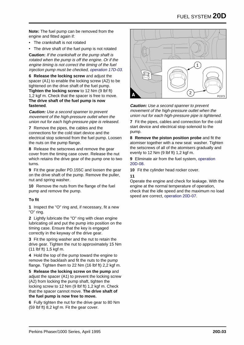
FUEL SYSTEM 20D
Note: The fuel pump can be removed from theengine and fitted again if:
• The crankshaft is not rotated
• The drive shaft of the fuel pump is not rotated
Caution: If the crankshaft or the pump shaft isrotated when the pump is off the engine. Or if theengine timing is not correct the timing of the fuelinjection pump must be checked, operation 17D-03.
6 Release the locking screw and adjust thespacer (A1) to enable the locking screw (A2) to betightened on the drive shaft of the fuel pump.Tighten the locking screw to 12 Nm (9 lbf ft) 1,2 kgf m. Check that the spacer is free to move.The drive shaft of the fuel pump is nowfastened .
Caution: Use a second spanner to preventmovement of the high-pressure outlet when theunion nut for each high-pressure pipe is released.
7 Remove the pipes, the cables and theconnections for the cold start device and theelectrical stop solenoid from the fuel pump. Loosenthe nuts on the pump flange.
8 Release the setscrews and remove the gearcover from the timing case cover. Release the nutwhich retains the drive gear of the pump one to twoturns.
9 Fit the gear puller PD.155C and loosen the gearon the drive shaft of the pump. Remove the puller,nut and spring washer.
10 Remove the nuts from the flange of the fuelpump and remove the pump.
To fit
1 Inspect the "O" ring and, if necessary, fit a new"O" ring.
2 Lightly lubricate the "O" ring with clean enginelubricating oil and put the pump into position on thetiming case. Ensure that the key is engagedcorrectly in the keyway of the drive gear.
3 Fit the spring washer and the nut to retain thedrive gear. Tighten the nut to approximately 15 Nm(11 lbf ft) 1,5 kgf m.
4 Hold the top of the pump toward the engine toremove the backlash and fit the nuts to the pumpflange. Tighten them to 22 Nm (16 lbf ft) 2,2 kgf m.
5 Release the locking screw on the pump andadjust the spacer (A1) to prevent the locking screw(A2) from locking the pump shaft, tighten thelocking screw to 12 Nm (9 lbf ft) 1,2 kgf m. Checkthat the spacer cannot move. The drive shaft ofthe fuel pump is now free to move.
6 Fully tighten the nut for the drive gear to 80 Nm(59 lbf ft) 8,2 kgf m. Fit the gear cover.
a aa aa aa aa a
2
a a a
a a a
a a a
a a a
1
PC073
Caution: Use a second spanner to preventmovement of the high-pressure outlet when theunion nut for each high-pressure pipe is tightened.
7 Fit the pipes, cables and connection for the coldstart device and electrical stop solenoid to thepump.
8 Remove the piston position probe and fit theatomiser together with a new seat washer. Tightenthe setscrews of all of the atomisers gradually andevenly to 12 Nm (9 lbf ft) 1,2 kgf m.
9 Eliminate air from the fuel system, operation20D-08.
10 Fit the cylinder head rocker cover.
11Operate the engine and check for leakage. With theengine at the normal temperature of operation,check that the idle speed and the maximum no loadspeed are correct, operation 20D-07.
Perkins Phaser/1000 Series, April 1995 20D.03
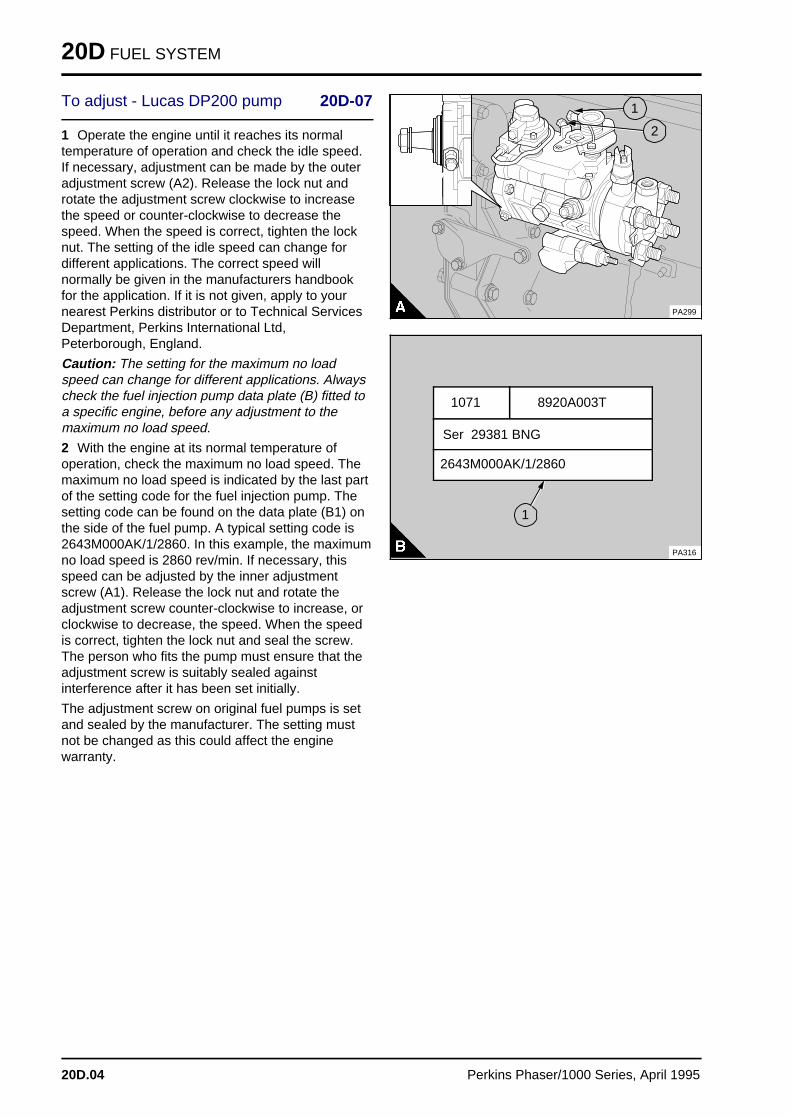
20D FUEL SYSTEM
To adjust - Lucas DP200 pump 20D-07
1 Operate the engine until it reaches its normaltemperature of operation and check the idle speed.If necessary, adjustment can be made by the outeradjustment screw (A2). Release the lock nut androtate the adjustment screw clockwise to increasethe speed or counter-clockwise to decrease thespeed. When the speed is correct, tighten the locknut. The setting of the idle speed can change fordifferent applications. The correct speed willnormally be given in the manufacturers handbookfor the application. If it is not given, apply to yournearest Perkins distributor or to Technical ServicesDepartment, Perkins International Ltd,Peterborough, England.
Caution: The setting for the maximum no loadspeed can change for different applications. Alwayscheck the fuel injection pump data plate (B) fitted toa specific engine, before any adjustment to themaximum no load speed.
2 With the engine at its normal temperature ofoperation, check the maximum no load speed. Themaximum no load speed is indicated by the last partof the setting code for the fuel injection pump. Thesetting code can be found on the data plate (B1) onthe side of the fuel pump. A typical setting code is2643M000AK/1/2860. In this example, the maximumno load speed is 2860 rev/min. If necessary, thisspeed can be adjusted by the inner adjustmentscrew (A1). Release the lock nut and rotate theadjustment screw counter-clockwise to increase, orclockwise to decrease, the speed. When the speedis correct, tighten the lock nut and seal the screw.The person who fits the pump must ensure that theadjustment screw is suitably sealed againstinterference after it has been set initially.
The adjustment screw on original fuel pumps is setand sealed by the manufacturer. The setting mustnot be changed as this could affect the enginewarranty.
aaaaaaaaaa
a a a
a a a
a a a
a a a
1
PA299
a a a
a a a
a a a
a a a
2
8920A003T 1071
PA316
a a a a a a a a a a a a a a a a a a a a a a
a a a a a a a a a a a a a a a a a a a a a a
a a a a a a a a a a a a a a a a a a a a a a
a a a a a a a a a a a a a a a a a a a a a a
Ser 29381 BNG a a a a a a a a a a a a a a a a a a a a a a a a a a a
a a a a a a a a a a a a a a a a a a a a a a a a a a a
a a a a a a a a a a a a a a a a a a a a a a a a a a a
a a a a a a a a a a a a a a a a a a a a a a a a a a a
2643M000AK/1/2860
a aa aa aa a
1
20D.04 Perkins Phaser/1000 Series, April 1995
FUEL SYSTEM 20D
To eliminate air from the fuel systemLucas DP200 pump 20D-08
Air will usually be removed from the fuel pumpautomatically. If the fuel system is empty or if thecanister of the fuel filter has been renewed, it willbe necessary to eliminate air from the fuel system.
1 Release the vent plug on the fuel filter head (A).
2 Operate the priming lever of the fuel lift pump (B)until fuel, free of air, comes from the vent plug.Tighten the vent plug. If the drive cam of the fuellift pump is at the point of maximum lift, it will notbe possible to operate the priming lever. In thissituation, the crankshaft must be rotated onerevolution.
3 Loosen the union nut (C1) at the fuelled startingaid, if one if fitted, and operate the priming lever ofthe fuel lift pump until fuel, free of air, comes fromthe connection. Tighten the union nut at the startingaid.
4 Loosen the high-pressure connections at two ofthe atomisers (D1).
5 Ensure that the manual stop control, if one isfitted, is in the "run" position. Operate the startermotor until fuel, free of air, comes from the pipeconnections. Tighten the connections to 22 Nm(16 lbf ft) 2,3 kgf m.
6 The engine is now ready to start.
a a a
a a a
a a a
a a a
1
PA254
PA015
a aa aa aa a
1
PA263
PA031
a aa aa aa a
1
Perkins Phaser/1000 Series, April 1995 20D.05
Engines fitted with Stanadyne fuel injection pump s 20E
General descriptio n . . . . . . . . . . . . . . . . . . . . . . . . . . . . . . . . . . . . refer to 20A.02
Fuel filter element
20E-01 To renew . . . . . . . . . . . . . . . . . . . . . . . . . . . . . . . . . . . . refer to 20A.04
Atomisers
Atomiser fault . . . . . . . . . . . . . . . . . . . . . . . . . . . . . . . . . refer to 20A.0720E-02 To remove and to fit . . . . . . . . . . . . . . . . . . . . . . . . . . . . refer to 20A.07
Fuel lift pump
20E-03 To remove and to fit . . . . . . . . . . . . . . . . . . . . . . . . . . . . refer to 20A.0820E-04 To dismantle and to assemble . . . . . . . . . . . . . . . . . . . . . refer to 20A.0820E-05 To test . . . . . . . . . . . . . . . . . . . . . . . . . . . . . . . . . . . . . . refer to 20A.10
Fuel injection pump
20E-06 To remove and to fit . . . . . . . . . . . . . . . . . . . . . . . . . . . . . . . . . 20E.0220E-07 To adjust . . . . . . . . . . . . . . . . . . . . . . . . . . . . . . . . . . . . . . . . . 20E.0420E-08 To eliminate air from the fuel system . . . . . . . . . . . . . . . . . . . . . 20E.05
Data and dimension s . . . . . . . . . . . . . . . . . . . . . . . . . . . . . . . . . . refer to 20A.22
Perkins Phaser/1000 Series, April 1995 20E.01
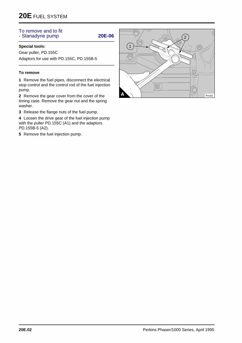
20E FUEL SYSTEM
To remove and to fit- Stanadyne pump 20E-06
Special tools:
Gear puller, PD.155C
Adaptors for use with PD.155C, PD.155B-5
To remove
1 Remove the fuel pipes, disconnect the electricalstop control and the control rod of the fuel injectionpump.
2 Remove the gear cover from the cover of thetiming case. Remove the gear nut and the springwasher.
3 Release the flange nuts of the fuel pump.
4 Loosen the drive gear of the fuel injection pumpwith the puller PD.155C (A1) and the adaptorsPD.155B-5 (A2).
5 Remove the fuel injection pump.a a a
a a a
a a a
a a a
1
a a a
a a a
a a a
a a a
2
PA162
20E.02 Perkins Phaser/1000 Series, April 1995
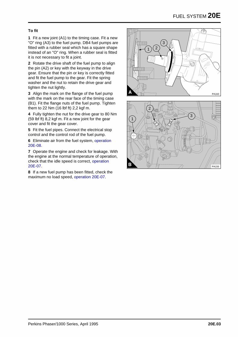
FUEL SYSTEM 20E
To fit
1 Fit a new joint (A1) to the timing case. Fit a new"O" ring (A3) to the fuel pump. DB4 fuel pumps arefitted with a rubber seal which has a square shapeinstead of an "O" ring. When a rubber seal is fittedit is not necessary to fit a joint.
2 Rotate the drive shaft of the fuel pump to alignthe pin (A2) or key with the keyway in the drivegear. Ensure that the pin or key is correctly fittedand fit the fuel pump to the gear. Fit the springwasher and the nut to retain the drive gear andtighten the nut lightly.
3 Align the mark on the flange of the fuel pumpwith the mark on the rear face of the timing case(B1). Fit the flange nuts of the fuel pump. Tightenthem to 22 Nm (16 lbf ft) 2,2 kgf m.
4 Fully tighten the nut for the drive gear to 80 Nm(59 lbf ft) 8,2 kgf m. Fit a new joint for the gearcover and fit the gear cover.
5 Fit the fuel pipes. Connect the electrical stopcontrol and the control rod of the fuel pump.
6 Eliminate air from the fuel system, operation20E-08.
7 Operate the engine and check for leakage. Withthe engine at the normal temperature of operation,check that the idle speed is correct, operation 20E-07.
8 If a new fuel pump has been fitted, check themaximum no load speed, operation 20E-07.
a a a
a a a
a a a
a a a
a a a
1
a aa aa aa a
2
a a a
a a a
a a a
a a a
3
PA163
a a a
a a a
a a a
a a a
3
a a a
a a a
a a a
a a a
2
PA155
a aa aa aa a
1
Perkins Phaser/1000 Series, April 1995 20E.03
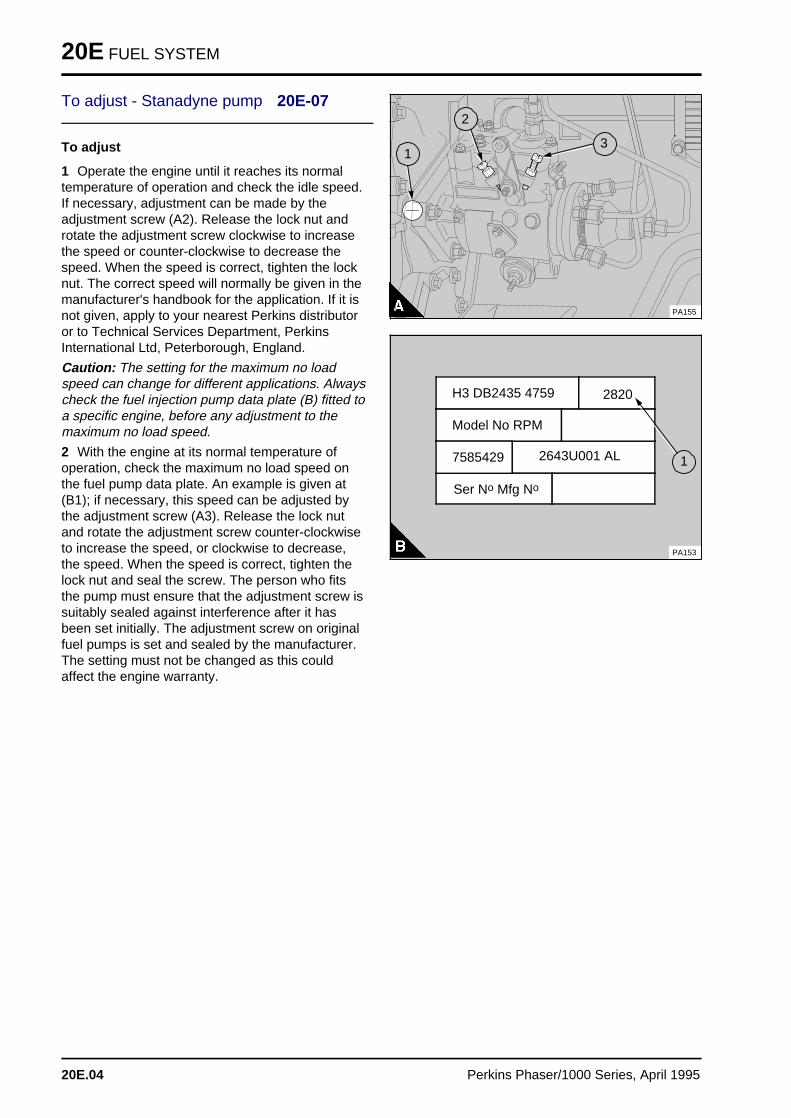
20E FUEL SYSTEM
To adjust - Stanadyne pump 20E-07
To adjust
1 Operate the engine until it reaches its normaltemperature of operation and check the idle speed.If necessary, adjustment can be made by theadjustment screw (A2). Release the lock nut androtate the adjustment screw clockwise to increasethe speed or counter-clockwise to decrease thespeed. When the speed is correct, tighten the locknut. The correct speed will normally be given in themanufacturer's handbook for the application. If it isnot given, apply to your nearest Perkins distributoror to Technical Services Department, PerkinsInternational Ltd, Peterborough, England.
Caution: The setting for the maximum no loadspeed can change for different applications. Alwayscheck the fuel injection pump data plate (B) fitted toa specific engine, before any adjustment to themaximum no load speed.
2 With the engine at its normal temperature ofoperation, check the maximum no load speed onthe fuel pump data plate. An example is given at(B1); if necessary, this speed can be adjusted bythe adjustment screw (A3). Release the lock nutand rotate the adjustment screw counter-clockwiseto increase the speed, or clockwise to decrease,the speed. When the speed is correct, tighten thelock nut and seal the screw. The person who fitsthe pump must ensure that the adjustment screw issuitably sealed against interference after it hasbeen set initially. The adjustment screw on originalfuel pumps is set and sealed by the manufacturer.The setting must not be changed as this couldaffect the engine warranty.
a a a
a a a
a a a
a a a
a a a
3
a aa aa aa a
2
PA155
a aa aa aa a
1
H3 DB2435 4759 2820
Model No RPM
Ser No Mfg No
2643U001 AL7585429
PA153
a aa aa aa a
1
20E.04 Perkins Phaser/1000 Series, April 1995
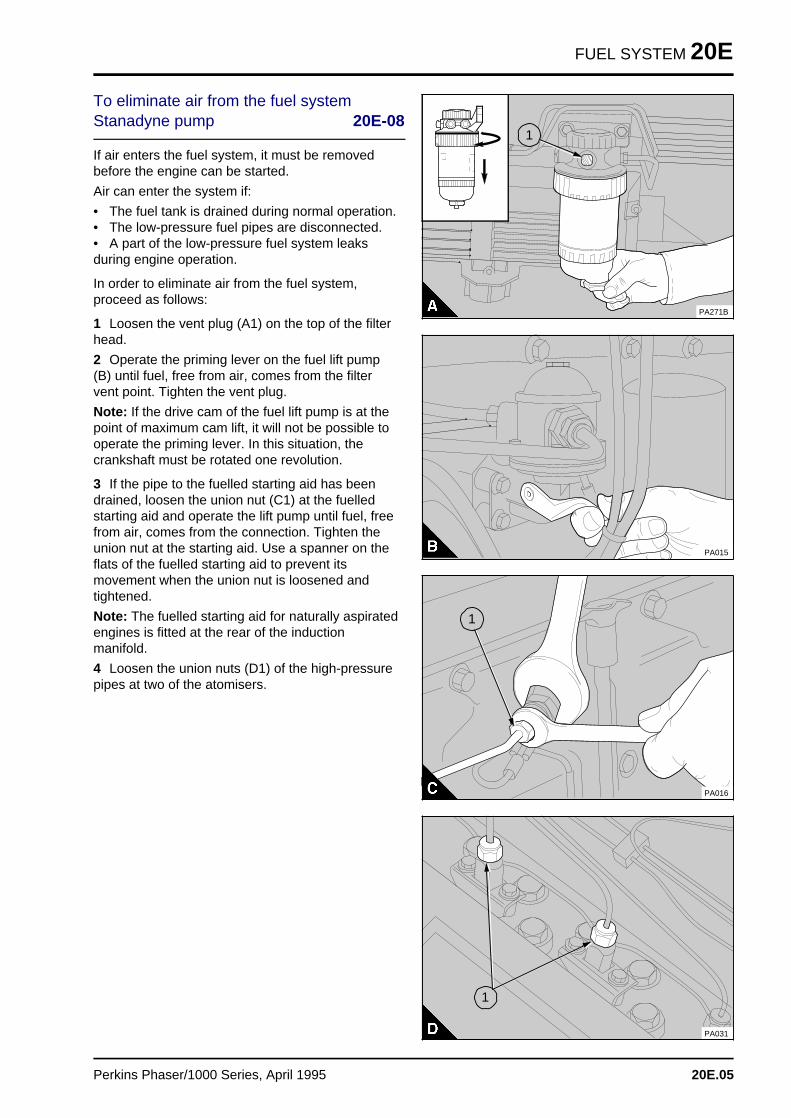
FUEL SYSTEM 20E
To eliminate air from the fuel systemStanadyne pump 20E-08
If air enters the fuel system, it must be removedbefore the engine can be started.
Air can enter the system if:
• The fuel tank is drained during normal operation.• The low-pressure fuel pipes are disconnected.• A part of the low-pressure fuel system leaksduring engine operation.
In order to eliminate air from the fuel system,proceed as follows:
1 Loosen the vent plug (A1) on the top of the filterhead.
2 Operate the priming lever on the fuel lift pump(B) until fuel, free from air, comes from the filtervent point. Tighten the vent plug.
Note: If the drive cam of the fuel lift pump is at thepoint of maximum cam lift, it will not be possible tooperate the priming lever. In this situation, thecrankshaft must be rotated one revolution.
3 If the pipe to the fuelled starting aid has beendrained, loosen the union nut (C1) at the fuelledstarting aid and operate the lift pump until fuel, freefrom air, comes from the connection. Tighten theunion nut at the starting aid. Use a spanner on theflats of the fuelled starting aid to prevent itsmovement when the union nut is loosened andtightened.
Note: The fuelled starting aid for naturally aspiratedengines is fitted at the rear of the inductionmanifold.
4 Loosen the union nuts (D1) of the high-pressurepipes at two of the atomisers.
a a a a a a a a a
a a a
a a a
a a a
a a a
1
PA271B
PA015
a a a
a a a
a a a
a a a
1
PA016
PA031
a aa aa aa a
1
Perkins Phaser/1000 Series, April 1995 20E.05
20E FUEL SYSTEM
5 Put the electrical system switch to the "ON"position. Operate the starter motor until fuel, freefrom air, comes from the pipe connections. Tightenthe high-pressure pipe connections to 22 Nm (16 lbf ft) 2,2 kgf m. Return the switch to the "OFF"position.
6 The engine is now ready to start.
If the engine runs correctly for a short time andthen stops or runs roughly, check for air in the fuelsystem. If there is air in the fuel system, there isprobablely a leakage in the low pressure system.
20E.06 Perkins Phaser/1000 Series, April 1995
COOLING SYSTEM 21
Cooling system 21
General descriptio n . . . . . . . . . . . . . . . . . . . . . . . . . . . . . . . . . . . . . . . . . 21A.03
Thermostats
21A-01 To remove, to fit and to test . . . . . . . . . . . . . . . . . . . . . . . . . . . 21A.04
Coolant pump
21A-02A To remove and to fit - gear driven . . . . . . . . . . . . . . . . . . . . . . . 21A.0521A-02B To remove and to fit - belt driven . . . . . . . . . . . . . . . . . . . . . . . . 21A.0621A-02C To remove and to fit - auxiliary pump . . . . . . . . . . . . . . . . . . . . . 21A.0821A-03A To dismantle and to assemble - gear driven . . . . . . . . . . . . . . . 21A.0921A-03B To dismantle and to assemble - belt driven . . . . . . . . . . . . . . . . 21A.1421A-03C To dismantle and to assemble - auxiliary pump . . . . . . . . . . . . . 21A.17
Fan
21A-04 To remove and to fit . . . . . . . . . . . . . . . . . . . . . . . . . . . . . . . . . 21A.20
Fan drive
21A-05 To remove and to fit . . . . . . . . . . . . . . . . . . . . . . . . . . . . . . . . . 21A.2021A-06 removed
Lubricating oil cooler
21A-07A To remove and to fit - four cylinder turbocharged engines . . . . . . 21A.2121A-07B To remove and to fit - six cylinder turbocharged engines . . . . . . 21A.2221A-07C To remove and to fit - canister type . . . . . . . . . . . . . . . . . . . . . . 21A.2321A-08A To dismantle and to assemble - four cylinder turbocharged engines 21A.2421A-08B To dismantle and to assemble - six cylinder turbocharged engines 21A.25
Continued
Perkins Phaser/1000 Series, April 1995 21A.01
21 COOLING SYSTEM
Cooler by-pass valve
21A-09 To remove and to fit . . . . . . . . . . . . . . . . . . . . . . . . . . . . . . . . . 21A.25
Intercooler
21A-10 To remove and to fit . . . . . . . . . . . . . . . . . . . . . . . . . . . . . . . . . 21A.2621A-11 To clean and to inspect . . . . . . . . . . . . . . . . . . . . . . . . . . . . . . . 21A.28
Data and dimension s . . . . . . . . . . . . . . . . . . . . . . . . . . . . . . . . . . . . . . . . 21A.29
21A.02 Perkins Phaser/1000 Series, April 1995
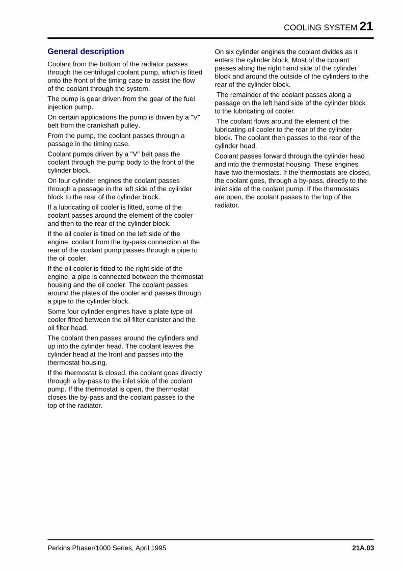
COOLING SYSTEM 21
General description
Coolant from the bottom of the radiator passesthrough the centrifugal coolant pump, which is fittedonto the front of the timing case to assist the flowof the coolant through the system.
The pump is gear driven from the gear of the fuelinjection pump.
On certain applications the pump is driven by a "V"belt from the crankshaft pulley.
From the pump, the coolant passes through apassage in the timing case.
Coolant pumps driven by a "V" belt pass thecoolant through the pump body to the front of thecylinder block.
On four cylinder engines the coolant passesthrough a passage in the left side of the cylinderblock to the rear of the cylinder block.
If a lubricating oil cooler is fitted, some of thecoolant passes around the element of the coolerand then to the rear of the cylinder block.
If the oil cooler is fitted on the left side of theengine, coolant from the by-pass connection at therear of the coolant pump passes through a pipe tothe oil cooler.
If the oil cooler is fitted to the right side of theengine, a pipe is connected between the thermostathousing and the oil cooler. The coolant passesaround the plates of the cooler and passes througha pipe to the cylinder block.
Some four cylinder engines have a plate type oilcooler fitted between the oil filter canister and theoil filter head.
The coolant then passes around the cylinders andup into the cylinder head. The coolant leaves thecylinder head at the front and passes into thethermostat housing.
If the thermostat is closed, the coolant goes directlythrough a by-pass to the inlet side of the coolantpump. If the thermostat is open, the thermostatcloses the by-pass and the coolant passes to thetop of the radiator.
On six cylinder engines the coolant divides as itenters the cylinder block. Most of the coolantpasses along the right hand side of the cylinderblock and around the outside of the cylinders to therear of the cylinder block.
The remainder of the coolant passes along apassage on the left hand side of the cylinder blockto the lubricating oil cooler.
The coolant flows around the element of thelubricating oil cooler to the rear of the cylinderblock. The coolant then passes to the rear of thecylinder head.
Coolant passes forward through the cylinder headand into the thermostat housing. These engineshave two thermostats. If the thermostats are closed,the coolant goes, through a by-pass, directly to theinlet side of the coolant pump. If the thermostatsare open, the coolant passes to the top of theradiator.
Perkins Phaser/1000 Series, April 1995 21A.03
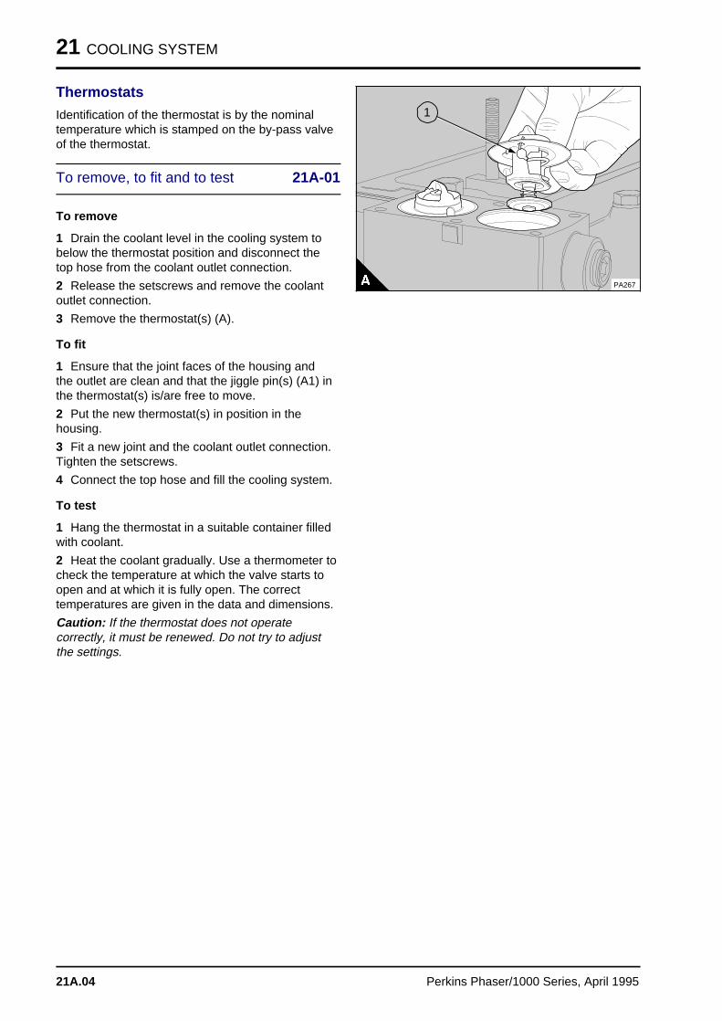
21 COOLING SYSTEM
Thermostats
Identification of the thermostat is by the nominaltemperature which is stamped on the by-pass valveof the thermostat.
To remove, to fit and to test 21A-01
To remove
1 Drain the coolant level in the cooling system tobelow the thermostat position and disconnect thetop hose from the coolant outlet connection.
2 Release the setscrews and remove the coolantoutlet connection.
3 Remove the thermostat(s) (A).
To fit
1 Ensure that the joint faces of the housing andthe outlet are clean and that the jiggle pin(s) (A1) inthe thermostat(s) is/are free to move.
2 Put the new thermostat(s) in position in thehousing.
3 Fit a new joint and the coolant outlet connection.Tighten the setscrews.
4 Connect the top hose and fill the cooling system.
To test
1 Hang the thermostat in a suitable container filledwith coolant.
2 Heat the coolant gradually. Use a thermometer tocheck the temperature at which the valve starts toopen and at which it is fully open. The correcttemperatures are given in the data and dimensions.
Caution: If the thermostat does not operatecorrectly, it must be renewed. Do not try to adjustthe settings.
PA267
a a a
a a a
a a a
a a a
1
21A.04 Perkins Phaser/1000 Series, April 1995
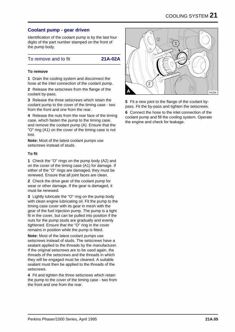
COOLING SYSTEM 21
Coolant pump - gear driven
Identification of the coolant pump is by the last fourdigits of the part number stamped on the front ofthe pump body.
To remove and to fit 21A-02A
To remove
1 Drain the cooling system and disconnect thehose at the inlet connection of the coolant pump.
2 Release the setscrews from the flange of thecoolant by-pass.
3 Release the three setscrews which retain thecoolant pump to the cover of the timing case - twofrom the front and one from the rear.
4 Release the nuts from the rear face of the timingcase, which fasten the pump to the timing case,and remove the coolant pump (A). Ensure that the"O" ring (A1) on the cover of the timing case is notlost.
Note: Most of the latest coolant pumps usesetscrews instead of studs.
To fit
1 Check the "O" rings on the pump body (A2) andon the cover of the timing case (A1) for damage. Ifeither of the "O" rings are damaged, they must berenewed. Ensure that all joint faces are clean.
2 Check the drive gear of the coolant pump forwear or other damage. If the gear is damaged, itmust be renewed.
3 Lightly lubricate the "O" ring on the pump bodywith clean engine lubricating oil. Fit the pump to thetiming case cover with its gear in mesh with thegear of the fuel injection pump. The pump is a tightfit in the cover, but can be pulled into position if thenuts for the pump studs are gradually and evenlytightened. Ensure that the "O" ring in the coverremains in position while the pump is fitted.
Note: Most of the latest coolant pumps usesetscrews instead of studs. The setscrews have asealant applied to the threads by the manufacturer.If the original setscrews are to be used again, thethreads of the setscrews and the threads in whichthey will be engaged must be cleaned. A suitablesealant must then be applied to the threads of thesetscrews.
4 Fit and tighten the three setscrews which retainthe pump to the cover of the timing case - two fromthe front and one from the rear.
a a a a a a a a
a a a a a a a a
a a a a a a a a
a a a a a a a a
a a a a a a a a
a a a a a a a a
a a a a a a a a
a a a a a a a a
a a a a a a a a
a a a a a a a a
PA268
a aa aa aa a
1
a a a
a a a
a a a
a a a
2
5 Fit a new joint to the flange of the coolant by-pass. Fit the by-pass and tighten the setscrews.
6 Connect the hose to the inlet connection of thecoolant pump and fill the cooling system. Operatethe engine and check for leakage.
Perkins Phaser/1000 Series, April 1995 21A.05
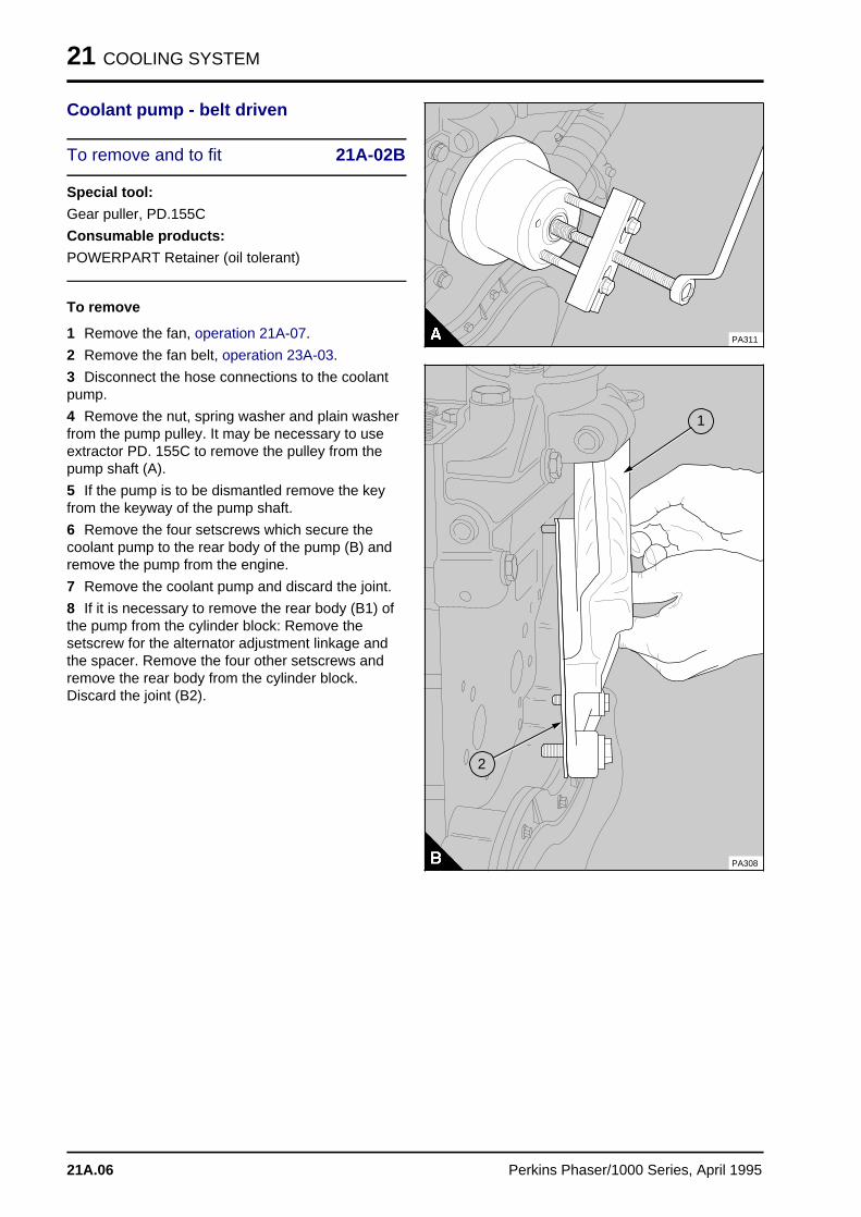
21 COOLING SYSTEM
Coolant pump - belt driven
To remove and to fit 21A-02B
Special tool:
Gear puller, PD.155C
Consumable products:
POWERPART Retainer (oil tolerant)
To remove
1 Remove the fan, operation 21A-07.
2 Remove the fan belt, operation 23A-03.
3 Disconnect the hose connections to the coolantpump.
4 Remove the nut, spring washer and plain washerfrom the pump pulley. It may be necessary to useextractor PD. 155C to remove the pulley from thepump shaft (A).
5 If the pump is to be dismantled remove the keyfrom the keyway of the pump shaft.
6 Remove the four setscrews which secure thecoolant pump to the rear body of the pump (B) andremove the pump from the engine.
7 Remove the coolant pump and discard the joint.
8 If it is necessary to remove the rear body (B1) ofthe pump from the cylinder block: Remove thesetscrew for the alternator adjustment linkage andthe spacer. Remove the four other setscrews andremove the rear body from the cylinder block.Discard the joint (B2).
PA311
PA308
a aa aa aa a
1
a a a
a a a
a a a
a a a
2
21A.06 Perkins Phaser/1000 Series, April 1995
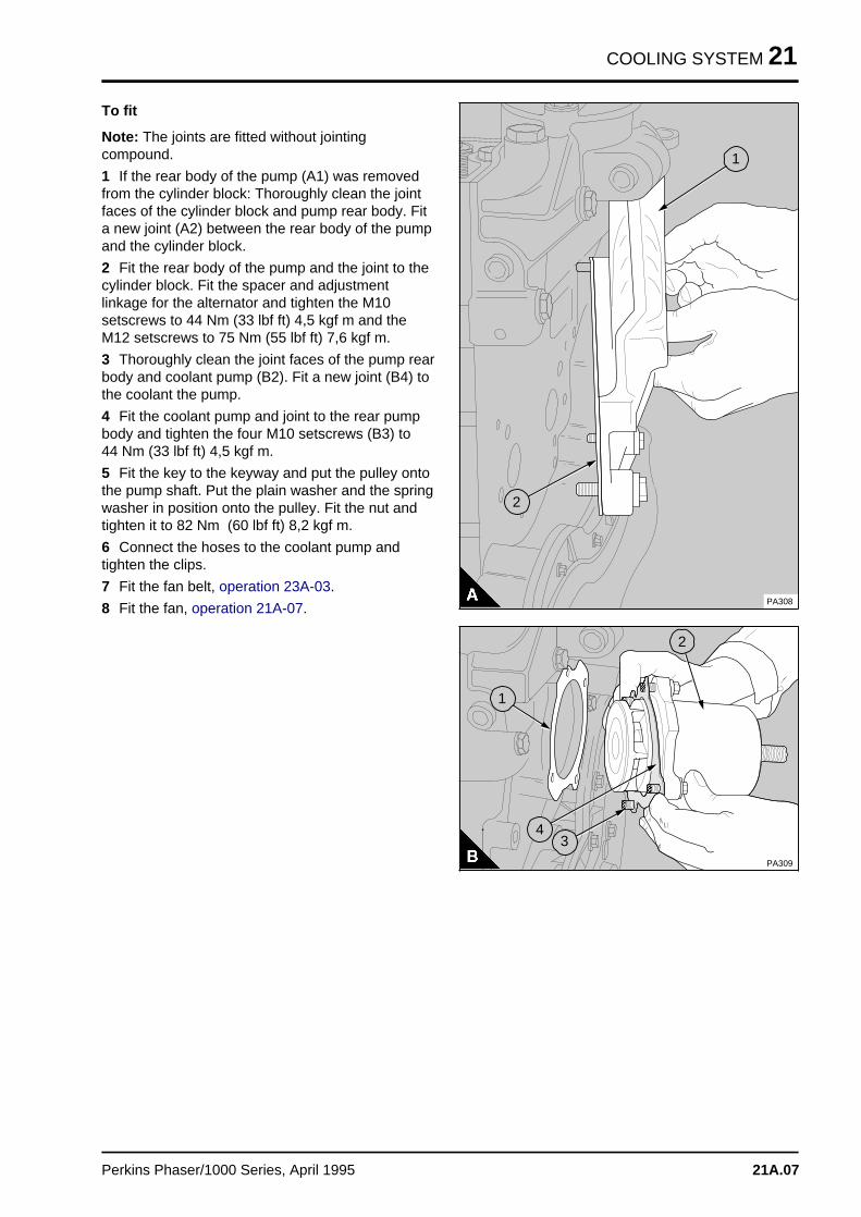
COOLING SYSTEM 21
To fit
Note: The joints are fitted without jointingcompound.
1 If the rear body of the pump (A1) was removedfrom the cylinder block: Thoroughly clean the jointfaces of the cylinder block and pump rear body. Fita new joint (A2) between the rear body of the pumpand the cylinder block.
2 Fit the rear body of the pump and the joint to thecylinder block. Fit the spacer and adjustmentlinkage for the alternator and tighten the M10setscrews to 44 Nm (33 lbf ft) 4,5 kgf m and theM12 setscrews to 75 Nm (55 lbf ft) 7,6 kgf m.
3 Thoroughly clean the joint faces of the pump rearbody and coolant pump (B2). Fit a new joint (B4) tothe coolant the pump.
4 Fit the coolant pump and joint to the rear pumpbody and tighten the four M10 setscrews (B3) to 44 Nm (33 lbf ft) 4,5 kgf m.
5 Fit the key to the keyway and put the pulley ontothe pump shaft. Put the plain washer and the springwasher in position onto the pulley. Fit the nut andtighten it to 82 Nm (60 lbf ft) 8,2 kgf m.
6 Connect the hoses to the coolant pump andtighten the clips.
7 Fit the fan belt, operation 23A-03.
8 Fit the fan, operation 21A-07. PA308
a a a
a a a
a a a
a a a
1
a aa aa aa a
2
a aa a
a aa a
a aa aa a
a aa aa a
PA309
a a a
a a a
a a a
a a a
3
a aa aa aa a
4
a a a
a a a
a a a
a a a
1
a a a
a a a
a a a
a a a
2
Perkins Phaser/1000 Series, April 1995 21A.07
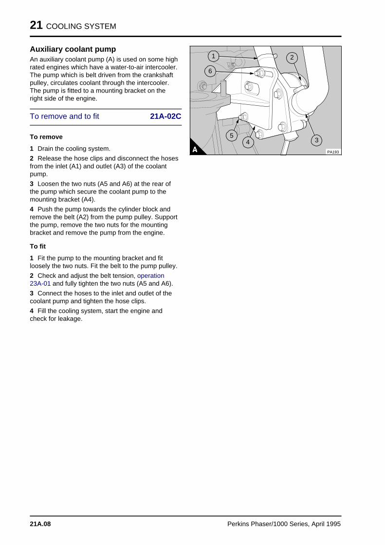
21 COOLING SYSTEM
Auxiliary coolant pumpAn auxiliary coolant pump (A) is used on some highrated engines which have a water-to-air intercooler.The pump which is belt driven from the crankshaftpulley, circulates coolant through the intercooler.The pump is fitted to a mounting bracket on theright side of the engine.
To remove and to fit 21A-02C
To remove
1 Drain the cooling system.
2 Release the hose clips and disconnect the hosesfrom the inlet (A1) and outlet (A3) of the coolantpump.
3 Loosen the two nuts (A5 and A6) at the rear ofthe pump which secure the coolant pump to themounting bracket (A4).
4 Push the pump towards the cylinder block andremove the belt (A2) from the pump pulley. Supportthe pump, remove the two nuts for the mountingbracket and remove the pump from the engine.
To fit
1 Fit the pump to the mounting bracket and fitloosely the two nuts. Fit the belt to the pump pulley.
2 Check and adjust the belt tension, operation23A-01 and fully tighten the two nuts (A5 and A6).
3 Connect the hoses to the inlet and outlet of thecoolant pump and tighten the hose clips.
4 Fill the cooling system, start the engine andcheck for leakage.
a a a
a a a
a a a
a a a
5
a a a
a a a
a a a
a a a
4
a a a
a a a
a a a
a a a
3
a a a
a a a
a a a
a a a
2
a a a
a a a
a a a
a a a
6
a aa aa aa a
1
PA193
21A.08 Perkins Phaser/1000 Series, April 1995
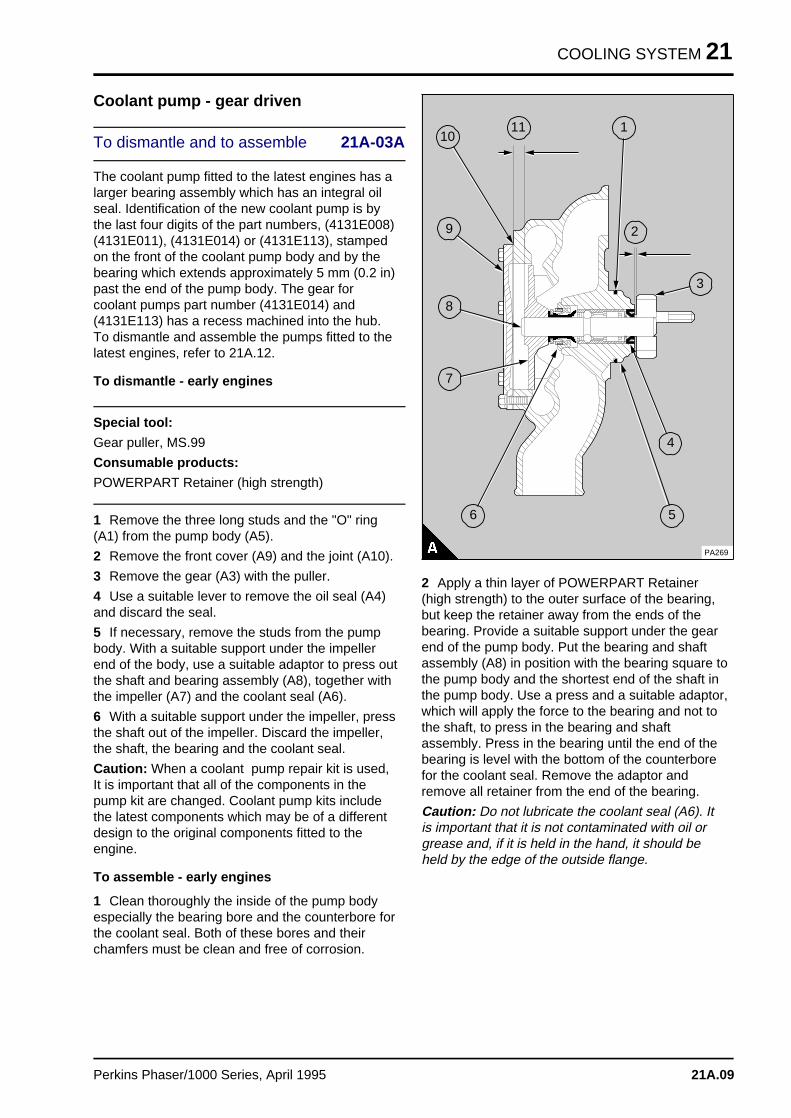
COOLING SYSTEM 21
Coolant pump - gear driven
To dismantle and to assemble 21A-03A
The coolant pump fitted to the latest engines has alarger bearing assembly which has an integral oilseal. Identification of the new coolant pump is bythe last four digits of the part numbers, (4131E008)(4131E011), (4131E014) or (4131E113), stampedon the front of the coolant pump body and by thebearing which extends approximately 5 mm (0.2 in)past the end of the pump body. The gear forcoolant pumps part number (4131E014) and(4131E113) has a recess machined into the hub.To dismantle and assemble the pumps fitted to thelatest engines, refer to 21A.12.
To dismantle - early engines
Special tool:
Gear puller, MS.99
Consumable products:
POWERPART Retainer (high strength)
1 Remove the three long studs and the "O" ring(A1) from the pump body (A5).
2 Remove the front cover (A9) and the joint (A10).
3 Remove the gear (A3) with the puller.
4 Use a suitable lever to remove the oil seal (A4)and discard the seal.
5 If necessary, remove the studs from the pumpbody. With a suitable support under the impellerend of the body, use a suitable adaptor to press outthe shaft and bearing assembly (A8), together withthe impeller (A7) and the coolant seal (A6).
6 With a suitable support under the impeller, pressthe shaft out of the impeller. Discard the impeller,the shaft, the bearing and the coolant seal.
Caution: When a coolant pump repair kit is used,It is important that all of the components in thepump kit are changed. Coolant pump kits includethe latest components which may be of a differentdesign to the original components fitted to theengine.
To assemble - early engines
1 Clean thoroughly the inside of the pump bodyespecially the bearing bore and the counterbore forthe coolant seal. Both of these bores and theirchamfers must be clean and free of corrosion.
a a a a a a
a a a a a a
aa
a a a a a a
a a a a a a
aa
a a a a
a a a a
a a a a
a a a a
a a a a
11
a a a
a a a
a a a
a a a
a a a
1
a aa aa aa a
3
a a a
a a a
a a a
a a a
4
a a a
a a a
a a a
a a a
6
a aa aa aa a
7
a aa aa aa aa a
8
a aa aa aa a
9
a a a a
a a a a
a a a a
a a a a
10
a a a
a a a
a a a
a a a
5
a a a
a a a
a a a
a a a
2
PA269
2 Apply a thin layer of POWERPART Retainer(high strength) to the outer surface of the bearing,but keep the retainer away from the ends of thebearing. Provide a suitable support under the gearend of the pump body. Put the bearing and shaftassembly (A8) in position with the bearing square tothe pump body and the shortest end of the shaft inthe pump body. Use a press and a suitable adaptor,which will apply the force to the bearing and not tothe shaft, to press in the bearing and shaftassembly. Press in the bearing until the end of thebearing is level with the bottom of the counterborefor the coolant seal. Remove the adaptor andremove all retainer from the end of the bearing.
Caution: Do not lubricate the coolant seal (A6). Itis important that it is not contaminated with oil orgrease and, if it is held in the hand, it should beheld by the edge of the outside flange.
Perkins Phaser/1000 Series, April 1995 21A.09
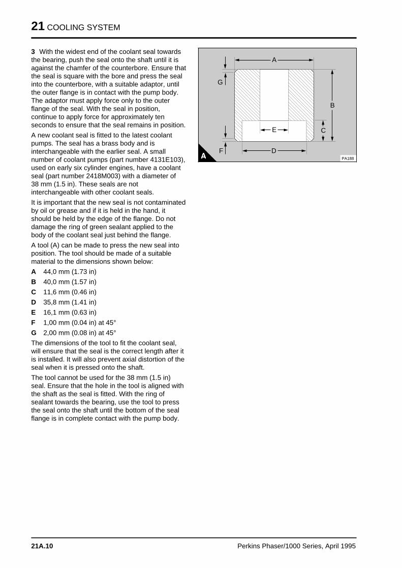
21 COOLING SYSTEM
3 With the widest end of the coolant seal towardsthe bearing, push the seal onto the shaft until it isagainst the chamfer of the counterbore. Ensure thatthe seal is square with the bore and press the sealinto the counterbore, with a suitable adaptor, untilthe outer flange is in contact with the pump body.The adaptor must apply force only to the outerflange of the seal. With the seal in position,continue to apply force for approximately tenseconds to ensure that the seal remains in position.
A new coolant seal is fitted to the latest coolantpumps. The seal has a brass body and isinterchangeable with the earlier seal. A smallnumber of coolant pumps (part number 4131E103),used on early six cylinder engines, have a coolantseal (part number 2418M003) with a diameter of38 mm (1.5 in). These seals are notinterchangeable with other coolant seals.
It is important that the new seal is not contaminatedby oil or grease and if it is held in the hand, itshould be held by the edge of the flange. Do notdamage the ring of green sealant applied to thebody of the coolant seal just behind the flange.
A tool (A) can be made to press the new seal intoposition. The tool should be made of a suitablematerial to the dimensions shown below:
A 44,0 mm (1.73 in)
B 40,0 mm (1.57 in)
C 11,6 mm (0.46 in)
D 35,8 mm (1.41 in)
E 16,1 mm (0.63 in)
F 1,00 mm (0.04 in) at 45°
G 2,00 mm (0.08 in) at 45°
The dimensions of the tool to fit the coolant seal,will ensure that the seal is the correct length after itis installed. It will also prevent axial distortion of theseal when it is pressed onto the shaft.
The tool cannot be used for the 38 mm (1.5 in)seal. Ensure that the hole in the tool is aligned withthe shaft as the seal is fitted. With the ring ofsealant towards the bearing, use the tool to pressthe seal onto the shaft until the bottom of the sealflange is in complete contact with the pump body.
a a a
a a a
a a a
D
a a a
a a a
a a a
A
a a a
a a a
a a a
a a a
B
a a a
a a a
a a a
a a a
C
a aa aa a
F
a a a
a a a
a a a
a a a
G
a a a
a a a
a a a
E
PA188
21A.10 Perkins Phaser/1000 Series, April 1995
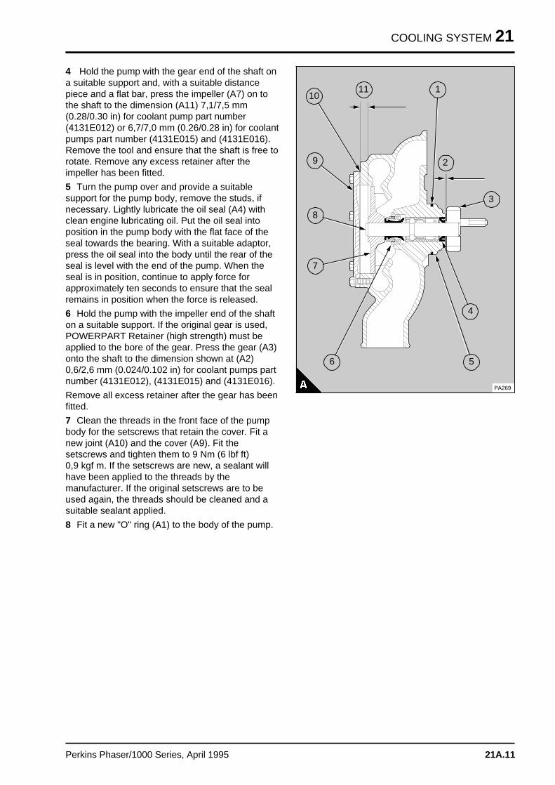
COOLING SYSTEM 21
4 Hold the pump with the gear end of the shaft ona suitable support and, with a suitable distancepiece and a flat bar, press the impeller (A7) on tothe shaft to the dimension (A11) 7,1/7,5 mm(0.28/0.30 in) for coolant pump part number(4131E012) or 6,7/7,0 mm (0.26/0.28 in) for coolantpumps part number (4131E015) and (4131E016).Remove the tool and ensure that the shaft is free torotate. Remove any excess retainer after theimpeller has been fitted.
5 Turn the pump over and provide a suitablesupport for the pump body, remove the studs, ifnecessary. Lightly lubricate the oil seal (A4) withclean engine lubricating oil. Put the oil seal intoposition in the pump body with the flat face of theseal towards the bearing. With a suitable adaptor,press the oil seal into the body until the rear of theseal is level with the end of the pump. When theseal is in position, continue to apply force forapproximately ten seconds to ensure that the sealremains in position when the force is released.
6 Hold the pump with the impeller end of the shafton a suitable support. If the original gear is used,POWERPART Retainer (high strength) must beapplied to the bore of the gear. Press the gear (A3)onto the shaft to the dimension shown at (A2)0,6/2,6 mm (0.024/0.102 in) for coolant pumps partnumber (4131E012), (4131E015) and (4131E016).
Remove all excess retainer after the gear has beenfitted.
7 Clean the threads in the front face of the pumpbody for the setscrews that retain the cover. Fit anew joint (A10) and the cover (A9). Fit thesetscrews and tighten them to 9 Nm (6 lbf ft) 0,9 kgf m. If the setscrews are new, a sealant willhave been applied to the threads by themanufacturer. If the original setscrews are to beused again, the threads should be cleaned and asuitable sealant applied.
8 Fit a new "O" ring (A1) to the body of the pump.
a a a a a a
a a a a a a
aa
a a a a a a
a a a a a a
aa
a a a a
a a a a
a a a a
a a a a
a a a a
11
a a a
a a a
a a a
a a a
a a a
1
a aa aa aa a
3
a a a
a a a
a a a
a a a
4
a a a
a a a
a a a
a a a
6
a aa aa aa a
7
a aa aa aa aa a
8
a aa aa aa a
9
a a a a
a a a a
a a a a
a a a a
10
a a a
a a a
a a a
a a a
5
a a a
a a a
a a a
a a a
2
PA269
Perkins Phaser/1000 Series, April 1995 21A.11
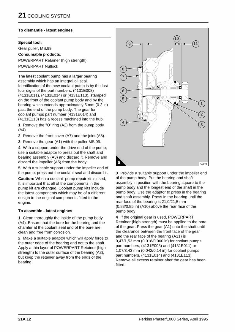
21 COOLING SYSTEM
To dismantle - latest engines
Special tool:
Gear puller, MS.99
Consumable products:
POWERPART Retainer (high strength)
POWERPART Nutlock
The latest coolant pump has a larger bearingassembly which has an integral oil seal.Identification of the new coolant pump is by the lastfour digits of the part numbers, (4131E008)(4131E011), (4131E014) or (4131E113), stampedon the front of the coolant pump body and by thebearing which extends approximately 5 mm (0.2 in)past the end of the pump body. The gear forcoolant pumps part number (4131E014) and(4131E113) has a recess machined into the hub.
1 Remove the "O" ring (A2) from the pump body(A4).
2 Remove the front cover (A7) and the joint (A8).
3 Remove the gear (A1) with the puller MS.99.
4 With a support under the drive end of the pump,use a suitable adaptor to press out the shaft andbearing assembly (A3) and discard it. Remove anddiscard the impeller (A5) from the body.
5 With a suitable support under the impeller end ofthe pump, press out the coolant seal and discard it.
Caution: When a coolant pump repair kit is used,It is important that all of the components in thepump kit are changed. Coolant pump kits includethe latest components which may be of a differentdesign to the original components fitted to theengine.
To assemble - latest engines
1 Clean thoroughly the inside of the pump body(A4). Ensure that the bore for the bearing and thechamfer at the coolant seal end of the bore areclean and free from corrosion.
2 Make a suitable adaptor which will apply force tothe outer edge of the bearing and not to the shaft.Apply a thin layer of POWERPART Retainer (highstrength) to the outer surface of the bearing (A3),but keep the retainer away from the ends of thebearing.
a a a
a a a
a aaa
a a a
a a a
a a a
a a aa
a a a a
a a a a
a a a a
a a a a
11
a aa aa aa a
1
a aa aa aa a
2
a aa aa aa a
3a a a
a a a
a a a
a a a
4a a a
a a a
a a a
a a a
5
a a a
a a a
a a a
a a a
a a a
6
a a a
a a a
a a a
a a a
7
a a a
a a a
a a a
a a a
8
a a a
a a a
a a a
a a a
9
a a a a a
a a a a a
a a a a a
a a a a a
10
PA270
3 Provide a suitable support under the impeller endof the pump body. Put the bearing and shaftassembly in position with the bearing square to thepump body and the longest end of the shaft in thepump body. Use the adaptor to press in the bearingand shaft assembly. Press in the bearing until therear face of the bearing is 21,0/21,5 mm (0.83/0.85 in) (A10) above the rear face of thepump body
4 If the original gear is used, POWERPARTRetainer (high strength) must be applied to the boreof the gear. Press the gear (A1) onto the shaft untilthe clearance between the front face of the gearand the rear face of the bearing (A11) is 0,47/1,53 mm (0.018/0.060 in) for coolant pumpspart numbers, (4131E008) and (4131E011) or1,07/3,43 mm (0.042/0.14 in) for coolant pumpspart numbers, (4131E014) and (4131E113).Remove all excess retainer after the gear has beenfitted.
21A.12 Perkins Phaser/1000 Series, April 1995
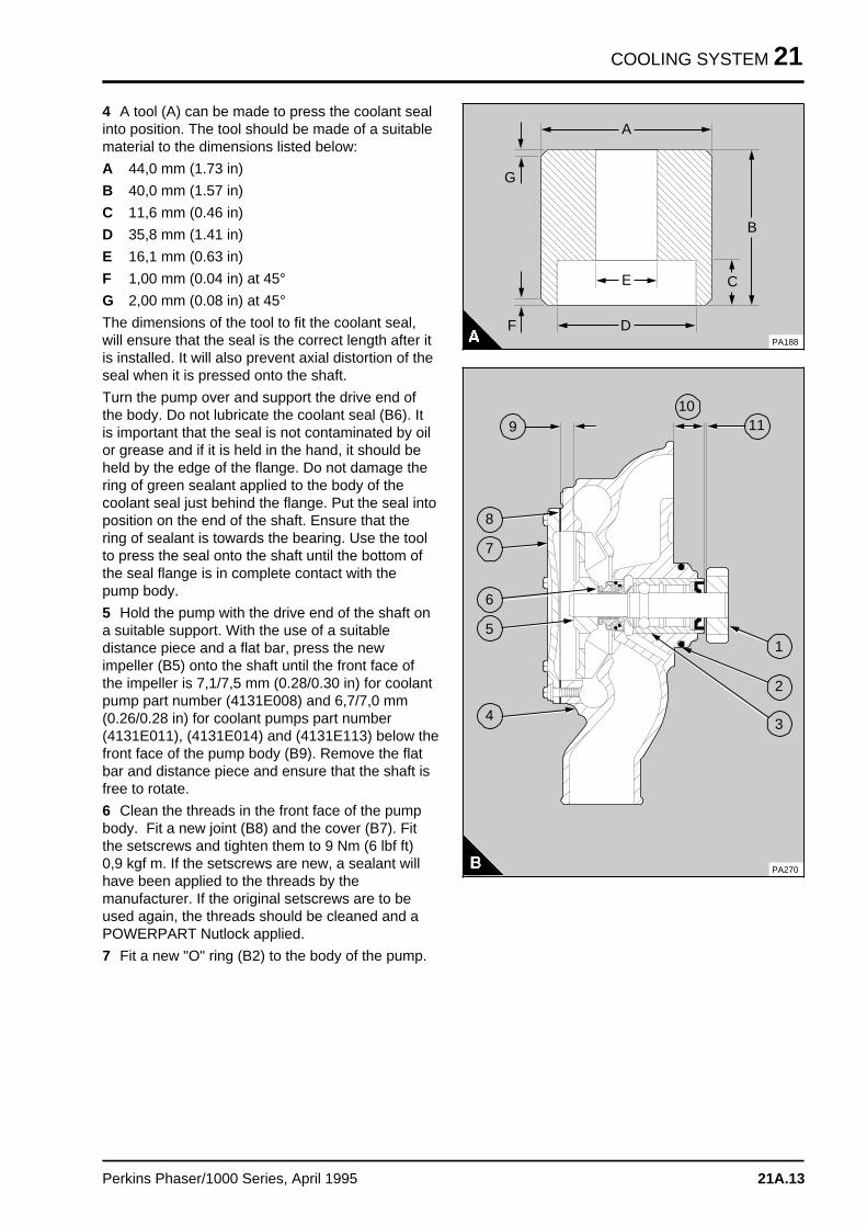
COOLING SYSTEM 21
4 A tool (A) can be made to press the coolant sealinto position. The tool should be made of a suitablematerial to the dimensions listed below:
A 44,0 mm (1.73 in)
B 40,0 mm (1.57 in)
C 11,6 mm (0.46 in)
D 35,8 mm (1.41 in)
E 16,1 mm (0.63 in)
F 1,00 mm (0.04 in) at 45°
G 2,00 mm (0.08 in) at 45°
The dimensions of the tool to fit the coolant seal,will ensure that the seal is the correct length after itis installed. It will also prevent axial distortion of theseal when it is pressed onto the shaft.
Turn the pump over and support the drive end ofthe body. Do not lubricate the coolant seal (B6). Itis important that the seal is not contaminated by oilor grease and if it is held in the hand, it should beheld by the edge of the flange. Do not damage thering of green sealant applied to the body of thecoolant seal just behind the flange. Put the seal intoposition on the end of the shaft. Ensure that thering of sealant is towards the bearing. Use the toolto press the seal onto the shaft until the bottom ofthe seal flange is in complete contact with thepump body.
5 Hold the pump with the drive end of the shaft ona suitable support. With the use of a suitabledistance piece and a flat bar, press the newimpeller (B5) onto the shaft until the front face ofthe impeller is 7,1/7,5 mm (0.28/0.30 in) for coolantpump part number (4131E008) and 6,7/7,0 mm(0.26/0.28 in) for coolant pumps part number(4131E011), (4131E014) and (4131E113) below thefront face of the pump body (B9). Remove the flatbar and distance piece and ensure that the shaft isfree to rotate.
6 Clean the threads in the front face of the pumpbody. Fit a new joint (B8) and the cover (B7). Fitthe setscrews and tighten them to 9 Nm (6 lbf ft)0,9 kgf m. If the setscrews are new, a sealant willhave been applied to the threads by themanufacturer. If the original setscrews are to beused again, the threads should be cleaned and aPOWERPART Nutlock applied.
7 Fit a new "O" ring (B2) to the body of the pump.
a a a
a a a
a a a
D
a a a
a a a
a a a
A
a a a
a a a
a a a
a a a
B
a a a
a a a
a a a
a a a
C
a a a
a a a
a a a
F
a a a
a a a
a a a
a a a
G
a a a
a a a
a a a
E
PA188
a aa aa a
a aaa
a aa a
a aaa
a a a a
a a a a
a a a a
a a a a
a a a a
11
a a a
a a a
a a a
a a a
1
a a a
a a a
a a a
a a a
2
a a a
a a a
a a a
a a a
3
a a a
a a a
a a a
a a a
4
a a a
a a a
a a a
a a a
5
a a a
a a a
a a a
a a a
6
a a a
a a a
a a a
a a a
a a a
7
a a a
a a a
a a a
a a a
8a a a
a a a
a a a
a a a
9
a a a a
a a a a
a a a a
a a a a
10
PA270
Perkins Phaser/1000 Series, April 1995 21A.13
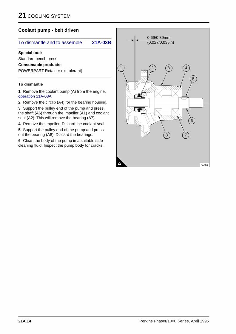
21 COOLING SYSTEM
Coolant pump - belt driven
To dismantle and to assemble 21A-03B
Special tool:
Standard bench press
Consumable products:
POWERPART Retainer (oil tolerant)
To dismantle
1 Remove the coolant pump (A) from the engine,operation 21A-03A.
2 Remove the circlip (A4) for the bearing housing.
3 Support the pulley end of the pump and pressthe shaft (A6) through the impeller (A1) and coolantseal (A2). This will remove the bearing (A7).
4 Remove the impeller. Discard the coolant seal.
5 Support the pulley end of the pump and pressout the bearing (A8). Discard the bearings.
6 Clean the body of the pump in a suitable safecleaning fluid. Inspect the pump body for cracks.
a a a a a a a a a a a a a a a a a a a
a a a a a a a a a a a a a a a a a a a
a a a a a a a a a a a a a a a a a a a
a a a a a a a a a a a a a a a a a a a
a a a a a a a a a a a a a a a a a a a
a a a a a a a a a a a a a a a a a a a
a a a a a a a a a a a a a a a a a a a
0,69/0,89mm(0.027/0.035in)
a a a
a a a
a a a
a a a
8
a aa aa aa a
7
a aa aa aa a
6
a aa aa aa a
5
a a a
a a a
a a a
a a a
1
a aa aa aa a
2
a a a
a a a
a a a
a a a
3
a a a
a a a
a a a
a a a
4
PA306
21A.14 Perkins Phaser/1000 Series, April 1995
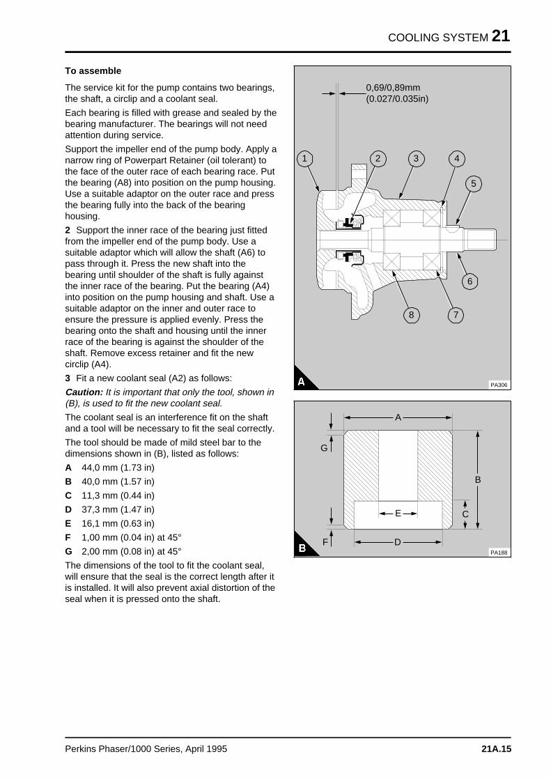
COOLING SYSTEM 21
To assemble
The service kit for the pump contains two bearings,the shaft, a circlip and a coolant seal.
Each bearing is filled with grease and sealed by thebearing manufacturer. The bearings will not needattention during service.
Support the impeller end of the pump body. Apply anarrow ring of Powerpart Retainer (oil tolerant) tothe face of the outer race of each bearing race. Putthe bearing (A8) into position on the pump housing.Use a suitable adaptor on the outer race and pressthe bearing fully into the back of the bearinghousing.
2 Support the inner race of the bearing just fittedfrom the impeller end of the pump body. Use asuitable adaptor which will allow the shaft (A6) topass through it. Press the new shaft into thebearing until shoulder of the shaft is fully againstthe inner race of the bearing. Put the bearing (A4)into position on the pump housing and shaft. Use asuitable adaptor on the inner and outer race toensure the pressure is applied evenly. Press thebearing onto the shaft and housing until the innerrace of the bearing is against the shoulder of theshaft. Remove excess retainer and fit the newcirclip (A4).
3 Fit a new coolant seal (A2) as follows:
Caution: It is important that only the tool, shown in(B), is used to fit the new coolant seal.
The coolant seal is an interference fit on the shaftand a tool will be necessary to fit the seal correctly.
The tool should be made of mild steel bar to thedimensions shown in (B), listed as follows:
A 44,0 mm (1.73 in)
B 40,0 mm (1.57 in)
C 11,3 mm (0.44 in)
D 37,3 mm (1.47 in)
E 16,1 mm (0.63 in)
F 1,00 mm (0.04 in) at 45°
G 2,00 mm (0.08 in) at 45°
The dimensions of the tool to fit the coolant seal,will ensure that the seal is the correct length after itis installed. It will also prevent axial distortion of theseal when it is pressed onto the shaft.
a a a a a a a a a a a a a a a a a a a
a a a a a a a a a a a a a a a a a a a
a a a a a a a a a a a a a a a a a a a
a a a a a a a a a a a a a a a a a a a
a a a a a a a a a a a a a a a a a a a
a a a a a a a a a a a a a a a a a a a
a a a a a a a a a a a a a a a a a a a
0,69/0,89mm(0.027/0.035in)
a a a
a a a
a a a
a a a
8
a a a
a a a
a a a
a a a
7
a aa aa aa a
6
a a a
a a a
a a a
a a a
5
a a a
a a a
a a a
a a a
1
a a a
a a a
a a a
a a a
2
a aa aa aa a
3
a a a
a a a
a a a
a a a
4
PA306a a a
a a a
a a a
a a a
D
a a a
a a a
a a a
a a a
A
a a a
a a a
a a aB
a a a
a a a
a a a
a a a
C
a a a
a a a
a a a
a a a
F
a a a
a a a
a a a
G
a a a
a a a
a a a
a a a
E
PA188
Perkins Phaser/1000 Series, April 1995 21A.15
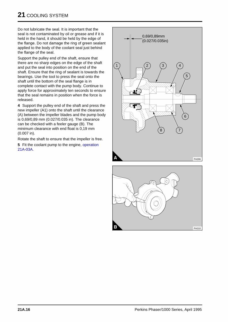
21 COOLING SYSTEM
Do not lubricate the seal. It is important that theseal is not contaminated by oil or grease and if it isheld in the hand, it should be held by the edge ofthe flange. Do not damage the ring of green sealantapplied to the body of the coolant seal just behindthe flange of the seal.
Support the pulley end of the shaft, ensure thatthere are no sharp edges on the edge of the shaftand put the seal into position on the end of theshaft. Ensure that the ring of sealant is towards thebearings. Use the tool to press the seal onto theshaft until the bottom of the seal flange is incomplete contact with the pump body. Continue toapply force for approximately ten seconds to ensurethat the seal remains in position when the force isreleased.
4 Support the pulley end of the shaft and press thenew impeller (A1) onto the shaft until the clearance(A) between the impeller blades and the pump bodyis 0,69/0,89 mm (0.027/0.035 in). The clearancecan be checked with a feeler gauge (B). Theminimum clearance with end float is 0,19 mm(0.007 in).
Rotate the shaft to ensure that the impeller is free.
5 Fit the coolant pump to the engine, operation21A-03A.
a a a a a a a a a a a a a a a a a a a
a a a a a a a a a a a a a a a a a a a
a a a a a a a a a a a a a a a a a a a
a a a a a a a a a a a a a a a a a a a
a a a a a a a a a a a a a a a a a a a
a a a a a a a a a a a a a a a a a a a
a a a a a a a a a a a a a a a a a a a
0,69/0,89mm(0.027/0.035in)
a a a
a a a
a a a
a a a
8
a aa aa aa a
7
a aa aa aa a
6
a aa aa aa a
5
a a a
a a a
a a a
a a a
1
a aa aa aa a
2
a a a
a a a
a a a
a a a
3
a a a
a a a
a a a
a a a
4
PA306
PA310
21A.16 Perkins Phaser/1000 Series, April 1995
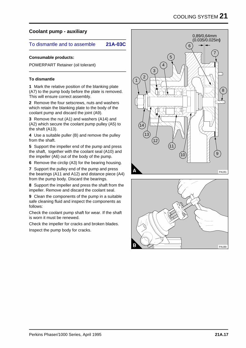
COOLING SYSTEM 21
Coolant pump - auxiliary
To dismantle and to assemble 21A-03C
Consumable products:
POWERPART Retainer (oil tolerant)
To dismantle
1 Mark the relative position of the blanking plate(A7) to the pump body before the plate is removed.This will ensure correct assembly.
2 Remove the four setscrews, nuts and washerswhich retain the blanking plate to the body of thecoolant pump and discard the joint (A9).
3 Remove the nut (A1) and washers (A14) and(A2) which secure the coolant pump pulley (A5) tothe shaft (A13).
4 Use a suitable puller (B) and remove the pulleyfrom the shaft.
5 Support the impeller end of the pump and pressthe shaft, together with the coolant seal (A10) andthe impeller (A6) out of the body of the pump.
6 Remove the circlip (A3) for the bearing housing.
7 Support the pulley end of the pump and pressthe bearings (A11 and A12) and distance piece (A4)from the pump body. Discard the bearings.
8 Support the impeller and press the shaft from theimpeller. Remove and discard the coolant seal.
9 Clean the components of the pump in a suitablesafe cleaning fluid and inspect the components asfollows:
Check the coolant pump shaft for wear. If the shaftis worn it must be renewed.
Check the impeller for cracks and broken blades.
Inspect the pump body for cracks.
a aa aa aa a
1
a aa aa aa a
2
a aa aa aa a
3
a aa aa aa a
4
a a a
a a a
a a a
a a a
a a a
5
a a a
a a a
a a a
a a a
6
a a a
a a a
a a a
a a a
7
a aa aa aa a
9
a a a a
a a a a
a a a a
a a a a
14
a a a a a
a a a a a
a a a a a
a a a a a
13
a a a a
a a a a
a a a a
a a a a
12
a a a a
a a a a
a a a a
a a a a
a a a a
11
a a a a
a a a a
a a a a
a a a a
10
a a a
a a a
a a a
a a a
8
a a a a a a a a a a a a a a a a a a
a a a a a a a a a a a a a a a a a a
a a a a a a a a a a a a a a a a a a
a a a a a a a a a a a a a a a a a a
a a a a a a a a a a a a a a a a a a
a a a a a a a a a a a a a a a a a a
a a a a a a a a a a a a a a a a a a
0,89/0,64mm(0.035/0.025in)
PA191
PA190
Perkins Phaser/1000 Series, April 1995 21A.17
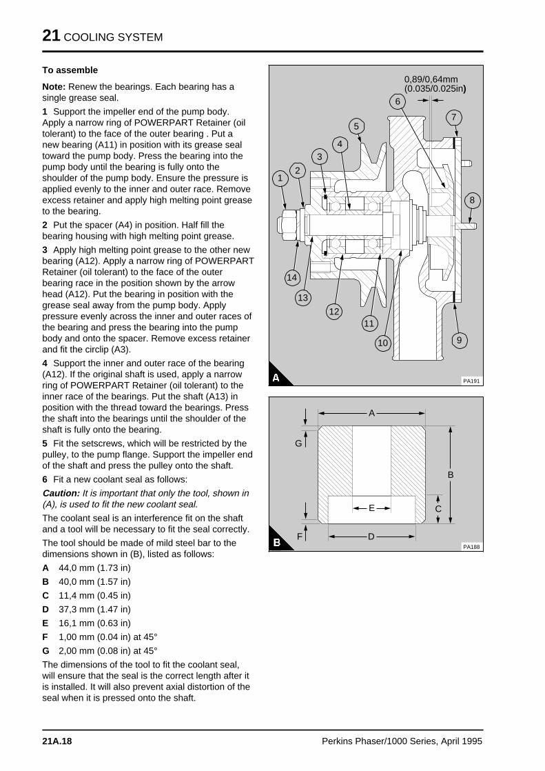
21 COOLING SYSTEM
To assemble
Note: Renew the bearings. Each bearing has asingle grease seal.
1 Support the impeller end of the pump body.Apply a narrow ring of POWERPART Retainer (oiltolerant) to the face of the outer bearing . Put anew bearing (A11) in position with its grease sealtoward the pump body. Press the bearing into thepump body until the bearing is fully onto theshoulder of the pump body. Ensure the pressure isapplied evenly to the inner and outer race. Removeexcess retainer and apply high melting point greaseto the bearing.
2 Put the spacer (A4) in position. Half fill thebearing housing with high melting point grease.
3 Apply high melting point grease to the other newbearing (A12). Apply a narrow ring of POWERPARTRetainer (oil tolerant) to the face of the outerbearing race in the position shown by the arrowhead (A12). Put the bearing in position with thegrease seal away from the pump body. Applypressure evenly across the inner and outer races ofthe bearing and press the bearing into the pumpbody and onto the spacer. Remove excess retainerand fit the circlip (A3).
4 Support the inner and outer race of the bearing(A12). If the original shaft is used, apply a narrowring of POWERPART Retainer (oil tolerant) to theinner race of the bearings. Put the shaft (A13) inposition with the thread toward the bearings. Pressthe shaft into the bearings until the shoulder of theshaft is fully onto the bearing.
5 Fit the setscrews, which will be restricted by thepulley, to the pump flange. Support the impeller endof the shaft and press the pulley onto the shaft.
6 Fit a new coolant seal as follows:
Caution: It is important that only the tool, shown in(A), is used to fit the new coolant seal.
The coolant seal is an interference fit on the shaftand a tool will be necessary to fit the seal correctly.
The tool should be made of mild steel bar to thedimensions shown in (B), listed as follows:
A 44,0 mm (1.73 in)
B 40,0 mm (1.57 in)
C 11,4 mm (0.45 in)
D 37,3 mm (1.47 in)
E 16,1 mm (0.63 in)
F 1,00 mm (0.04 in) at 45°
G 2,00 mm (0.08 in) at 45°
The dimensions of the tool to fit the coolant seal,will ensure that the seal is the correct length after itis installed. It will also prevent axial distortion of theseal when it is pressed onto the shaft.
a a a
a a a
a a a
a a a
1
a a a
a a a
a a a
a a a
2
a aa aa aa a
3
a a a
a a a
a a a
a a a
4
a a a
a a a
a a a
a a a
a a a
5
a aa aa aa a
6
a aa aa aa a
7
a a a
a a a
a a a
a a a
9
a a a a
a a a a
a a a a
a a a a
14
a a a a
a a a a
a a a a
a a a a
13
a a a a
a a a a
a a a a
a a a a
12
a a a a
a a a a
a a a a
a a a a
a a a a
11
a a a a
a a a a
a a a a
a a a a
10
a a a
a a a
a a a
a a a
8
a a a a a a a a a a a a a a a a a a a
a a a a a a a a a a a a a a a a a a a
a a a a a a a a a a a a a a a a a a a
a a a a a a a a a a a a a a a a a a a
a a a a a a a a a a a a a a a a a a a
a a a a a a a a a a a a a a a a a a a
a a a a a a a a a a a a a a a a a a a
0,89/0,64mm(0.035/0.025in)
PA191
a a a
a a a
a a a
a a a
D
a a a
a a a
a a a
a a a
A
a a a
a a a
a a a
B
a a a
a a a
a a a
a a a
C
a aa aa aa a
F
a a a
a a a
a a a
G
a a a
a a a
a a a
a a a
E
PA188
21A.18 Perkins Phaser/1000 Series, April 1995
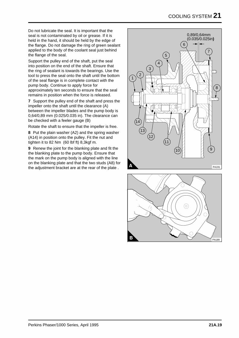
COOLING SYSTEM 21
Do not lubricate the seal. It is important that theseal is not contaminated by oil or grease. If it isheld in the hand, it should be held by the edge ofthe flange. Do not damage the ring of green sealantapplied to the body of the coolant seal just behindthe flange of the seal.
Support the pulley end of the shaft, put the sealinto position on the end of the shaft. Ensure thatthe ring of sealant is towards the bearings. Use thetool to press the seal onto the shaft until the bottomof the seal flange is in complete contact with thepump body. Continue to apply force forapproximately ten seconds to ensure that the sealremains in position when the force is released.
7 Support the pulley end of the shaft and press theimpeller onto the shaft until the clearance (A)between the impeller blades and the pump body is0,64/0,89 mm (0.025/0.035 in). The clearance canbe checked with a feeler gauge (B)
Rotate the shaft to ensure that the impeller is free.
8 Put the plain washer (A2) and the spring washer(A14) in position onto the pulley. Fit the nut andtighten it to 82 Nm (60 lbf ft) 8,3kgf m.
9 Renew the joint for the blanking plate and fit thethe blanking plate to the pump body. Ensure thatthe mark on the pump body is aligned with the lineon the blanking plate and that the two studs (A8) forthe adjustment bracket are at the rear of the plate .
a aa aa aa a
1
a aa aa aa a
2
a aa aa aa a
3
a aa aa aa a
4
a a a
a a a
a a a
a a a
a a a
5
a a a
a a a
a a a
a a a
6
a a a
a a a
a a a
a a a
7
a aa aa aa a
9
a a a a
a a a a
a a a a
a a a a
14
a a a a a
a a a a a
a a a a a
a a a a a
13
a a a a
a a a a
a a a a
a a a a
12
a a a a
a a a a
a a a a
a a a a
a a a a
11
a a a a
a a a a
a a a a
a a a a
10
a a a
a a a
a a a
a a a
8
a a a a a a a a a a a a a a a a a a
a a a a a a a a a a a a a a a a a a
a a a a a a a a a a a a a a a a a a
a a a a a a a a a a a a a a a a a a
a a a a a a a a a a a a a a a a a a
a a a a a a a a a a a a a a a a a a
a a a a a a a a a a a a a a a a a a
0,89/0,64mm(0.035/0.025in)
PA191
PA189
Perkins Phaser/1000 Series, April 1995 21A.19
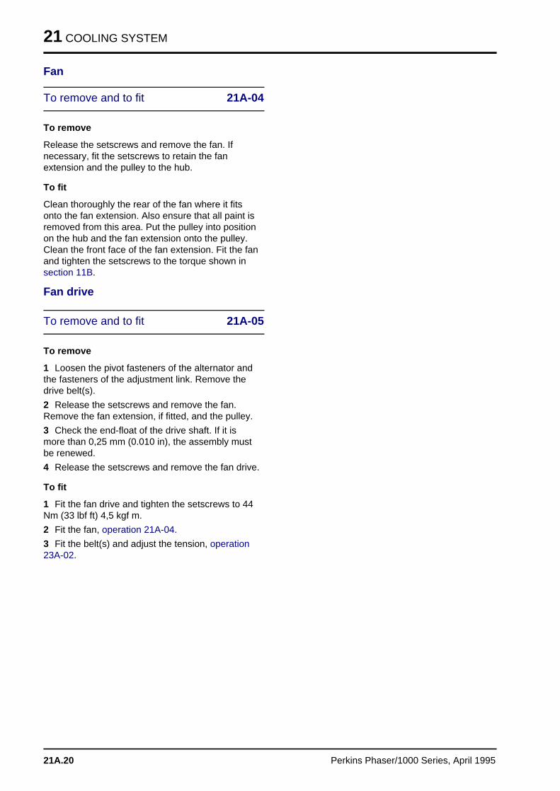
21 COOLING SYSTEM
Fan
To remove and to fit 21A-04
To remove
Release the setscrews and remove the fan. Ifnecessary, fit the setscrews to retain the fanextension and the pulley to the hub.
To fit
Clean thoroughly the rear of the fan where it fitsonto the fan extension. Also ensure that all paint isremoved from this area. Put the pulley into positionon the hub and the fan extension onto the pulley.Clean the front face of the fan extension. Fit the fanand tighten the setscrews to the torque shown insection 11B.
Fan drive
To remove and to fit 21A-05
To remove
1 Loosen the pivot fasteners of the alternator andthe fasteners of the adjustment link. Remove thedrive belt(s).
2 Release the setscrews and remove the fan.Remove the fan extension, if fitted, and the pulley.
3 Check the end-float of the drive shaft. If it ismore than 0,25 mm (0.010 in), the assembly mustbe renewed.
4 Release the setscrews and remove the fan drive.
To fit
1 Fit the fan drive and tighten the setscrews to 44Nm (33 lbf ft) 4,5 kgf m.
2 Fit the fan, operation 21A-04.
3 Fit the belt(s) and adjust the tension, operation23A-02.
21A.20 Perkins Phaser/1000 Series, April 1995
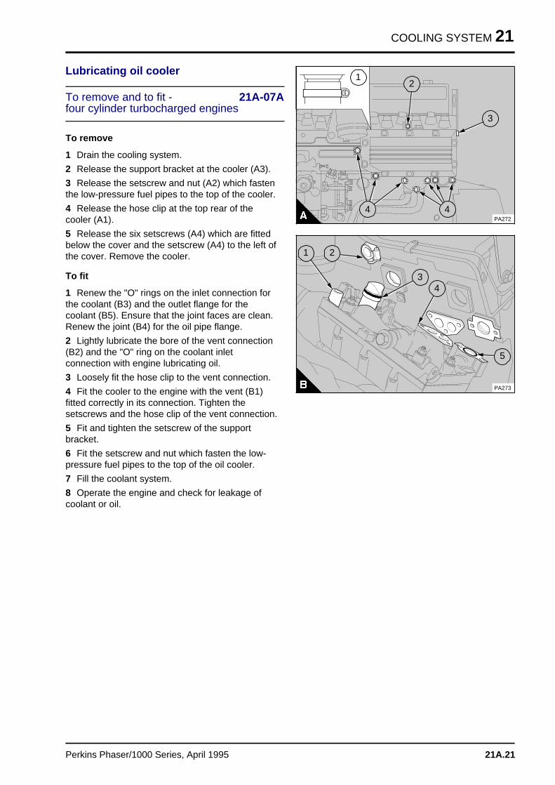
COOLING SYSTEM 21
Lubricating oil cooler
To remove and to fit - 21A-07Afour cylinder turbocharged engines
To remove
1 Drain the cooling system.
2 Release the support bracket at the cooler (A3).
3 Release the setscrew and nut (A2) which fastenthe low-pressure fuel pipes to the top of the cooler.
4 Release the hose clip at the top rear of thecooler (A1).
5 Release the six setscrews (A4) which are fittedbelow the cover and the setscrew (A4) to the left ofthe cover. Remove the cooler.
To fit
1 Renew the "O" rings on the inlet connection forthe coolant (B3) and the outlet flange for thecoolant (B5). Ensure that the joint faces are clean.Renew the joint (B4) for the oil pipe flange.
2 Lightly lubricate the bore of the vent connection(B2) and the "O" ring on the coolant inletconnection with engine lubricating oil.
3 Loosely fit the hose clip to the vent connection.
4 Fit the cooler to the engine with the vent (B1)fitted correctly in its connection. Tighten thesetscrews and the hose clip of the vent connection.
5 Fit and tighten the setscrew of the supportbracket.
6 Fit the setscrew and nut which fasten the low-pressure fuel pipes to the top of the oil cooler.
7 Fill the coolant system.
8 Operate the engine and check for leakage ofcoolant or oil.
a aa aa aa a
1 a aa aa aa a
2
a aa aa aa aa a
3
a aa aa aa a
4
a a a
a a a
a a a
a a a
4PA272
a a a a a a
a a a a a a
a a a a a a
a a a a a a
a a a
a a a
a a a
a a a
1
a a a
a a a
a a a
a a a
5
a aa aa aa a
4
a a a
a a a
a a a
a a a
3
a a a
a a a
a a a
a a a
2
PA273
Perkins Phaser/1000 Series, April 1995 21A.21
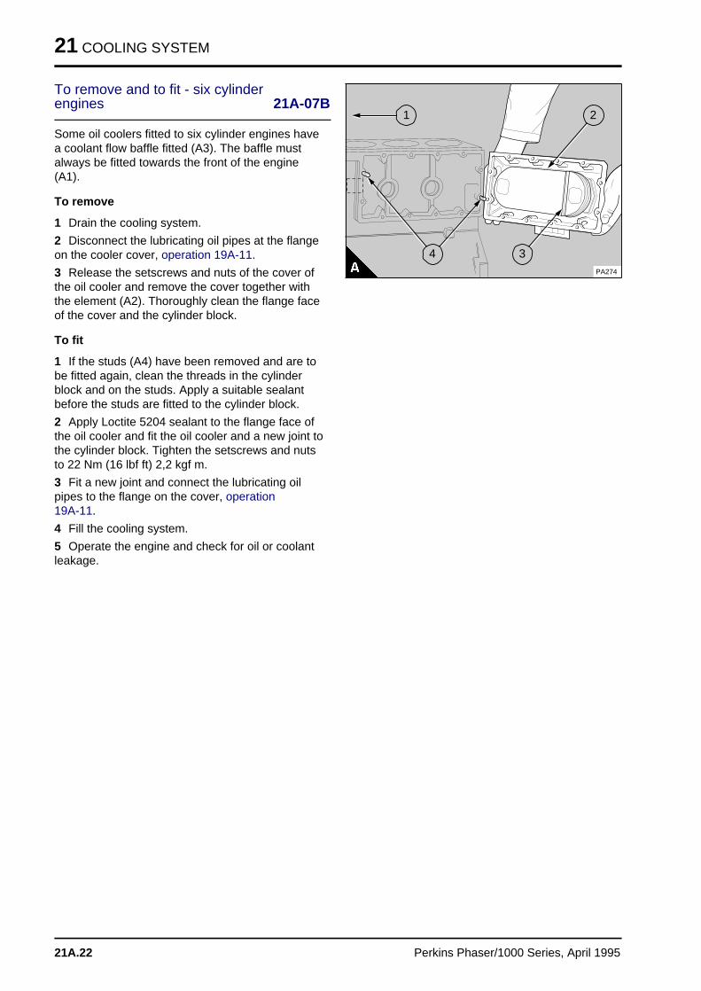
21 COOLING SYSTEM
To remove and to fit - six cylinderengines 21A-07B
Some oil coolers fitted to six cylinder engines havea coolant flow baffle fitted (A3). The baffle mustalways be fitted towards the front of the engine(A1).
To remove
1 Drain the cooling system.
2 Disconnect the lubricating oil pipes at the flangeon the cooler cover, operation 19A-11.
3 Release the setscrews and nuts of the cover ofthe oil cooler and remove the cover together withthe element (A2). Thoroughly clean the flange faceof the cover and the cylinder block.
To fit
1 If the studs (A4) have been removed and are tobe fitted again, clean the threads in the cylinderblock and on the studs. Apply a suitable sealantbefore the studs are fitted to the cylinder block.
2 Apply Loctite 5204 sealant to the flange face ofthe oil cooler and fit the oil cooler and a new joint tothe cylinder block. Tighten the setscrews and nutsto 22 Nm (16 lbf ft) 2,2 kgf m.
3 Fit a new joint and connect the lubricating oilpipes to the flange on the cover, operation 19A-11.
4 Fill the cooling system.
5 Operate the engine and check for oil or coolantleakage.
a aa aa aa a
1
a aa aa aa a
2
a a a
a a a
a a a
a a a
a a a
3
a a a
a a a
a a a
a a a
a a a
4PA274
21A.22 Perkins Phaser/1000 Series, April 1995
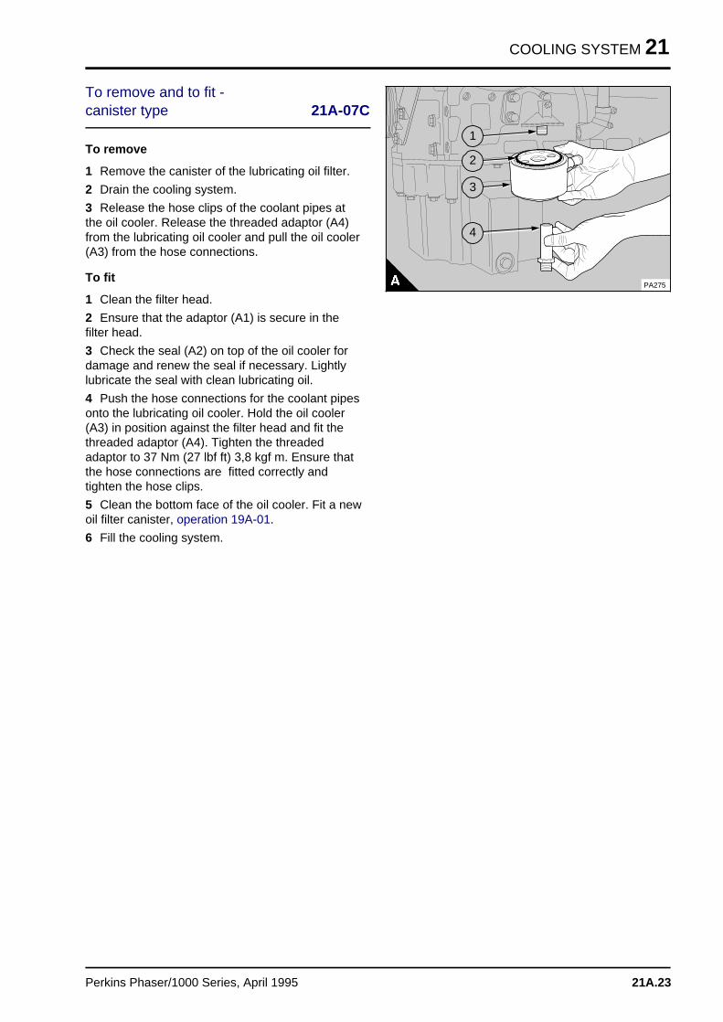
COOLING SYSTEM 21
To remove and to fit - canister type 21A-07C
To remove
1 Remove the canister of the lubricating oil filter.
2 Drain the cooling system.
3 Release the hose clips of the coolant pipes atthe oil cooler. Release the threaded adaptor (A4)from the lubricating oil cooler and pull the oil cooler(A3) from the hose connections.
To fit
1 Clean the filter head.
2 Ensure that the adaptor (A1) is secure in thefilter head.
3 Check the seal (A2) on top of the oil cooler fordamage and renew the seal if necessary. Lightlylubricate the seal with clean lubricating oil.
4 Push the hose connections for the coolant pipesonto the lubricating oil cooler. Hold the oil cooler(A3) in position against the filter head and fit thethreaded adaptor (A4). Tighten the threadedadaptor to 37 Nm (27 lbf ft) 3,8 kgf m. Ensure thatthe hose connections are fitted correctly andtighten the hose clips.
5 Clean the bottom face of the oil cooler. Fit a newoil filter canister, operation 19A-01.
6 Fill the cooling system.
a a a a a a a a a a a
a a a a a a a a a a a
a a a a a a a a a a a
a a a a a a a a a a a
a a a a a a a a a a a
a a a
a a a
a a a
a a a
4
a a a
a a a
a a a
a a a
3
a a a
a a a
a a a
a a a
2
a a a
a a a
a a a
a a a
1
PA275
Perkins Phaser/1000 Series, April 1995 21A.23
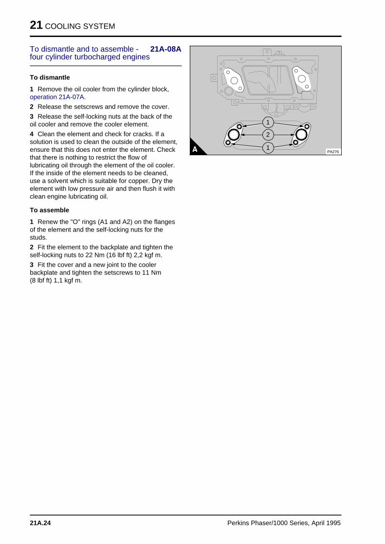
21 COOLING SYSTEM
To dismantle and to assemble - 21A-08Afour cylinder turbocharged engines
To dismantle
1 Remove the oil cooler from the cylinder block,operation 21A-07A.
2 Release the setscrews and remove the cover.
3 Release the self-locking nuts at the back of theoil cooler and remove the cooler element.
4 Clean the element and check for cracks. If asolution is used to clean the outside of the element,ensure that this does not enter the element. Checkthat there is nothing to restrict the flow oflubricating oil through the element of the oil cooler.If the inside of the element needs to be cleaned,use a solvent which is suitable for copper. Dry theelement with low pressure air and then flush it withclean engine lubricating oil.
To assemble
1 Renew the "O" rings (A1 and A2) on the flangesof the element and the self-locking nuts for thestuds.
2 Fit the element to the backplate and tighten theself-locking nuts to 22 Nm (16 lbf ft) 2,2 kgf m.
3 Fit the cover and a new joint to the coolerbackplate and tighten the setscrews to 11 Nm (8 lbf ft) 1,1 kgf m.
a a a
a a a
a a a
a a a
a a a
a a aa a a a a a
a a a a a a
a a a a a a
a a a a a a
a a a a a a
a a a a a a
a a a
a a a
a a a
a a a
a a a
a a aa a a a a a
a a a a a a
a a a a a a
a a a a a a
a a a a a a
a a a a a a
PA276
a aa aa aa a
1
a aa aa aa a
2
a aa aa aa a
1
21A.24 Perkins Phaser/1000 Series, April 1995
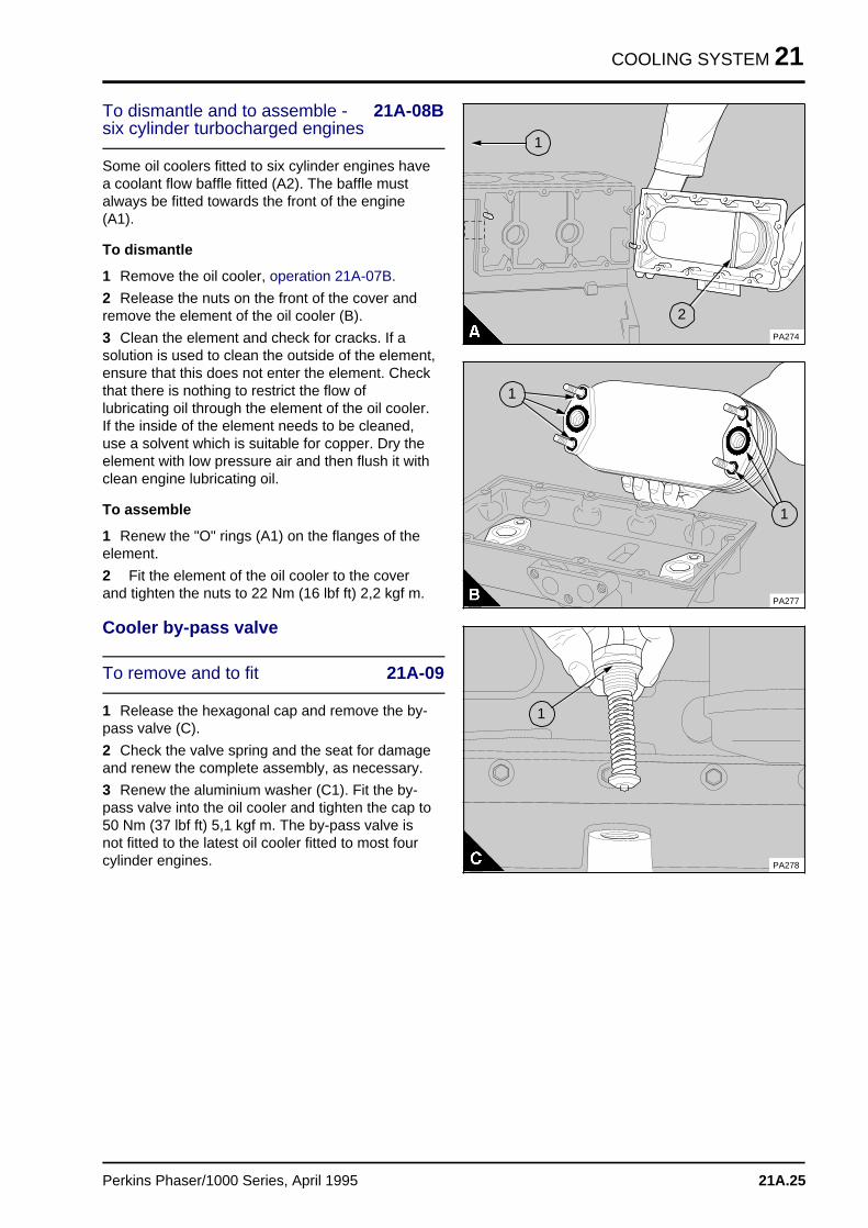
COOLING SYSTEM 21
To dismantle and to assemble - 21A-08Bsix cylinder turbocharged engines
Some oil coolers fitted to six cylinder engines havea coolant flow baffle fitted (A2). The baffle mustalways be fitted towards the front of the engine(A1).
To dismantle
1 Remove the oil cooler, operation 21A-07B.
2 Release the nuts on the front of the cover andremove the element of the oil cooler (B).
3 Clean the element and check for cracks. If asolution is used to clean the outside of the element,ensure that this does not enter the element. Checkthat there is nothing to restrict the flow oflubricating oil through the element of the oil cooler.If the inside of the element needs to be cleaned,use a solvent which is suitable for copper. Dry theelement with low pressure air and then flush it withclean engine lubricating oil.
To assemble
1 Renew the "O" rings (A1) on the flanges of theelement.
2 Fit the element of the oil cooler to the coverand tighten the nuts to 22 Nm (16 lbf ft) 2,2 kgf m.
Cooler by-pass valve
To remove and to fit 21A-09
1 Release the hexagonal cap and remove the by-pass valve (C).
2 Check the valve spring and the seat for damageand renew the complete assembly, as necessary.
3 Renew the aluminium washer (C1). Fit the by-pass valve into the oil cooler and tighten the cap to50 Nm (37 lbf ft) 5,1 kgf m. The by-pass valve isnot fitted to the latest oil cooler fitted to most fourcylinder engines.
a aa aa aa a
1
a a a
a a a
a a a
a a a
a a a
2PA274
a a a a a a
a a a a a a
a a a a a a
a a a a a a
a a a a a a
a a a a a a
a a a a a
a a a a a
a a a a a
a a a a a
a a a a a
a a a a a
a aa aa aa a
1a a a
a a a
a a a
a a a
1
PA277
a aa aa aa a
a a a
a a a
a a a
a a a
1
PA278
Perkins Phaser/1000 Series, April 1995 21A.25
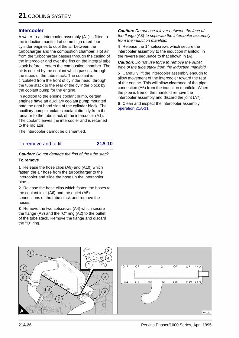
21 COOLING SYSTEM
IntercoolerA water-to-air intercooler assembly (A1) is fitted tothe induction manifold of some high rated fourcylinder engines to cool the air between theturbocharger and the combustion chamber. Hot airfrom the turbocharger passes through the casing ofthe intercooler and over the fins on the integral tubestack before it enters the combustion chamber. Theair is cooled by the coolant which passes throughthe tubes of the tube stack. The coolant iscirculated from the front of cylinder head, throughthe tube stack to the rear of the cylinder block bythe coolant pump for the engine.
In addition to the engine coolant pump, certainengines have an auxiliary coolant pump mountedonto the right hand side of the cylinder block. Theauxiliary pump circulates coolant directly from theradiator to the tube stack of the intercooler (A1).The coolant leaves the intercooler and is returnedto the radiator.
The intercooler cannot be dismantled.
To remove and to fit 21A-10
Caution: Do not damage the fins of the tube stack.
To remove
1 Release the hose clips (A9) and (A10) whichfasten the air hose from the turbocharger to theintercooler and slide the hose up the intercoolerpipe.
2 Release the hose clips which fasten the hoses tothe coolant inlet (A6) and the outlet (A5)connections of the tube stack and remove thehoses.
3 Remove the two setscrews (A4) which securethe flange (A3) and the "O" ring (A2) to the outletof the tube stack. Remove the flange and discardthe "O" ring.
Caution: Do not use a lever between the face ofthe flange (A8) to separate the intercooler assemblyfrom the induction manifold.
4 Release the 14 setscrews which secure theintercooler assembly to the induction manifold, inthe reverse sequence to that shown in (A).
Caution: Do not use force to remove the outletpipe of the tube stack from the induction manifold.
5 Carefully lift the intercooler assembly enough toallow movement of the intercooler toward the rearof the engine. This will allow clearance of the pipeconnection (A6) from the induction manifold. Whenthe pipe is free of the manifold remove theintercooler assembly and discard the joint (A7).
6 Clean and inspect the intercooler assembly,operation 21A-11
a aa aa aa a
1
a a a
a a a
a a a
a a a
3
a a a
a a a
a a a
a a a
4
a a a
a a a
a a a
a a a
2
a aa aa aa a
5
a aa aa aa a
6
a aa aa aa a
7
a a a
a a a
a a a
a a a
8
a aa aa aa a
9
a a a a
a a a a
a a a a
a a a a
10
a a a
a a a12 a aa a4 a aa a1 a aa a5 a aa a9 a a a
a a a13
a a a
a a a11 a aa a7 a aa a3 a aa a2 a aa a6 a a a
a a a10 a a a
a a a14
a aa a8
PA192
21A.26 Perkins Phaser/1000 Series, April 1995
COOLING SYSTEM 21
To fit
1 Renew the joint (21A.26/A7) between the flangeface of the intercooler and the induction manifold.The joint is fitted dry.
Caution: Do not use force to fit the outlet pipe ofthe tube stack into the induction manifold.
2 Carefully lift the intercooler into the inductionmanifold. Do not damage the inlet pipe of the tubestack which must be put into position carefully toallow entry into the manifold.
3 Fit the 14 setscrews which secure the intercoolerassembly to the induction manifold and apply atorque tension of 22 Nm (16 lb ft) 2,2 kgf m to thefasteners in the sequence shown in (A).
4 Fit a new "O" ring (A2) into the flange. Fit theflange (A3) with the two setscrews (A4) onto theoutlet pipe (A6) of the tube stack. Tighten theflange to the manifold and apply a torque tension of7 Nm (5 lbf ft ) 0,7 kgf m.
5 Fit the inlet and the outlet hoses for the tubestack and fasten the hose clips.
6 Fit the air hose from the turbocharger to theintercooler assembly and tighten the hose clips (A9)and (A10).
7 Operate the engine and check for coolant and airleaks.
Perkins Phaser/1000 Series, April 1995 21A.27
21 COOLING SYSTEM
To clean and to inspect 21A-11
To clean
Caution: Do not clean the tube stack in a causticcleaning solution.
1 Thoroughly clean the intercooler body its flangeand the flange of the induction manifold with anapproved detergent solution.
Warning! Do not allow compressed air to contactyour skin, if compressed air enters your skin obtainmedical help immediately.
2 Soak the fins of the tube stack in an approveddetergent degreasing fluid. Allow the excess fluid todrain off and dry the fins with low pressurecompressed air.
3 Flush the tube stack with clean coolant throughthe outlet connection, in the opposite direction offlow.
To inspect
1 Inspect the casing of the intercooler for cracks ordistortion, especially the flange faces which mustbe flat to prevent leakage of air.
2 Inspect the tube stack for signs of coolantleakage. Also inspect the tube stack for damage tothe fins, the hose connections, and for cracks. Ifthe tube stack is damaged or restricted it must berenewed.
21A.28 Perkins Phaser/1000 Series, April 1995
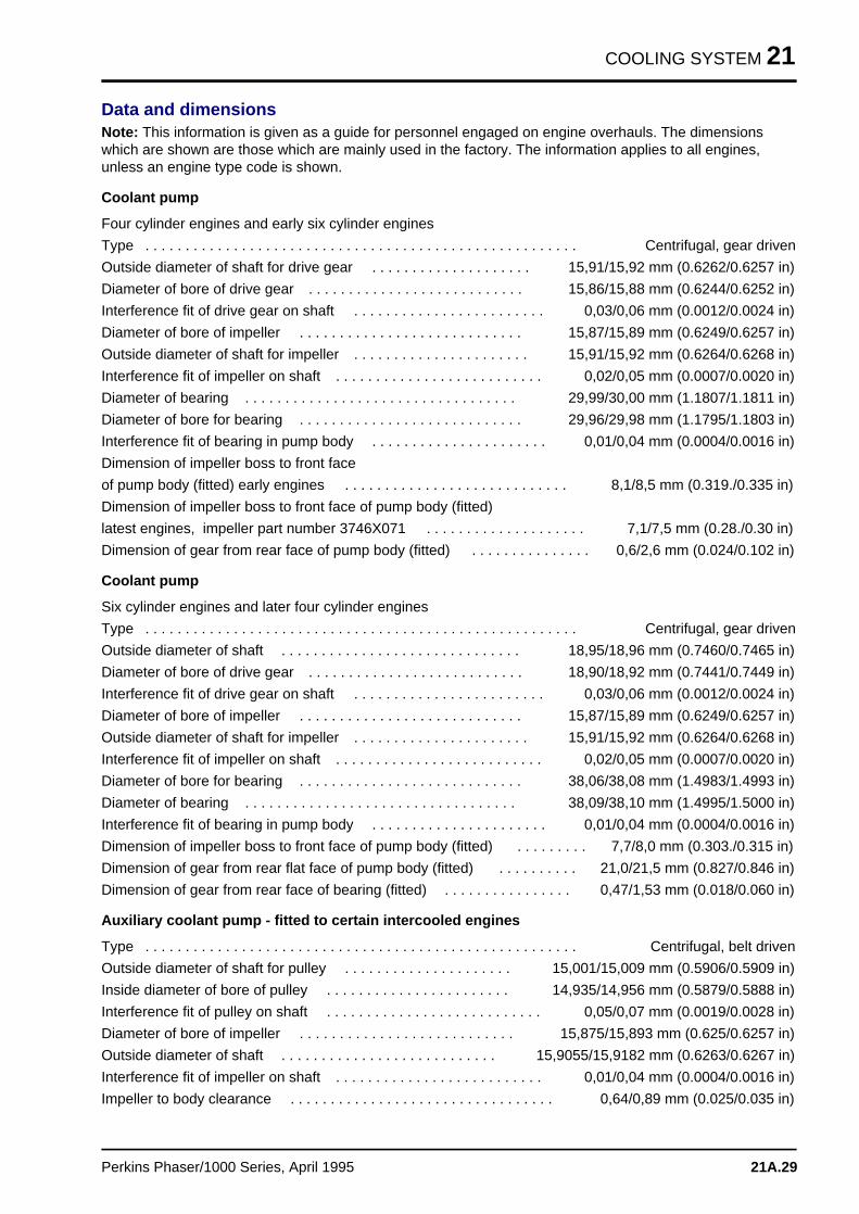
COOLING SYSTEM 21
Data and dimensionsNote: This information is given as a guide for personnel engaged on engine overhauls. The dimensionswhich are shown are those which are mainly used in the factory. The information applies to all engines,unless an engine type code is shown.
Coolant pump
Four cylinder engines and early six cylinder engines
Type . . . . . . . . . . . . . . . . . . . . . . . . . . . . . . . . . . . . . . . . . . . . . . . . . . . . . . Centrifugal, gear driven
Outside diameter of shaft for drive gear . . . . . . . . . . . . . . . . . . . . 15,91/15,92 mm (0.6262/0.6257 in)
Diameter of bore of drive gear . . . . . . . . . . . . . . . . . . . . . . . . . . . 15,86/15,88 mm (0.6244/0.6252 in)
Interference fit of drive gear on shaft . . . . . . . . . . . . . . . . . . . . . . . . 0,03/0,06 mm (0.0012/0.0024 in)
Diameter of bore of impeller . . . . . . . . . . . . . . . . . . . . . . . . . . . . 15,87/15,89 mm (0.6249/0.6257 in)
Outside diameter of shaft for impeller . . . . . . . . . . . . . . . . . . . . . . 15,91/15,92 mm (0.6264/0.6268 in)
Interference fit of impeller on shaft . . . . . . . . . . . . . . . . . . . . . . . . . . 0,02/0,05 mm (0.0007/0.0020 in)
Diameter of bearing . . . . . . . . . . . . . . . . . . . . . . . . . . . . . . . . . . 29,99/30,00 mm (1.1807/1.1811 in)
Diameter of bore for bearing . . . . . . . . . . . . . . . . . . . . . . . . . . . . 29,96/29,98 mm (1.1795/1.1803 in)
Interference fit of bearing in pump body . . . . . . . . . . . . . . . . . . . . . . 0,01/0,04 mm (0.0004/0.0016 in)
Dimension of impeller boss to front face
of pump body (fitted) early engines . . . . . . . . . . . . . . . . . . . . . . . . . . . . 8,1/8,5 mm (0.319./0.335 in)
Dimension of impeller boss to front face of pump body (fitted)
latest engines, impeller part number 3746X071 . . . . . . . . . . . . . . . . . . . . 7,1/7,5 mm (0.28./0.30 in)
Dimension of gear from rear face of pump body (fitted) . . . . . . . . . . . . . . . 0,6/2,6 mm (0.024/0.102 in)
Coolant pump
Six cylinder engines and later four cylinder engines
Type . . . . . . . . . . . . . . . . . . . . . . . . . . . . . . . . . . . . . . . . . . . . . . . . . . . . . . Centrifugal, gear driven
Outside diameter of shaft . . . . . . . . . . . . . . . . . . . . . . . . . . . . . . 18,95/18,96 mm (0.7460/0.7465 in)
Diameter of bore of drive gear . . . . . . . . . . . . . . . . . . . . . . . . . . . 18,90/18,92 mm (0.7441/0.7449 in)
Interference fit of drive gear on shaft . . . . . . . . . . . . . . . . . . . . . . . . 0,03/0,06 mm (0.0012/0.0024 in)
Diameter of bore of impeller . . . . . . . . . . . . . . . . . . . . . . . . . . . . 15,87/15,89 mm (0.6249/0.6257 in)
Outside diameter of shaft for impeller . . . . . . . . . . . . . . . . . . . . . . 15,91/15,92 mm (0.6264/0.6268 in)
Interference fit of impeller on shaft . . . . . . . . . . . . . . . . . . . . . . . . . . 0,02/0,05 mm (0.0007/0.0020 in)
Diameter of bore for bearing . . . . . . . . . . . . . . . . . . . . . . . . . . . . 38,06/38,08 mm (1.4983/1.4993 in)
Diameter of bearing . . . . . . . . . . . . . . . . . . . . . . . . . . . . . . . . . . 38,09/38,10 mm (1.4995/1.5000 in)
Interference fit of bearing in pump body . . . . . . . . . . . . . . . . . . . . . . 0,01/0,04 mm (0.0004/0.0016 in)
Dimension of impeller boss to front face of pump body (fitted) . . . . . . . . . 7,7/8,0 mm (0.303./0.315 in)
Dimension of gear from rear flat face of pump body (fitted) . . . . . . . . . . 21,0/21,5 mm (0.827/0.846 in)
Dimension of gear from rear face of bearing (fitted) . . . . . . . . . . . . . . . . 0,47/1,53 mm (0.018/0.060 in)
Auxiliary coolant pump - fitted to certain intercooled engines
Type . . . . . . . . . . . . . . . . . . . . . . . . . . . . . . . . . . . . . . . . . . . . . . . . . . . . . . Centrifugal, belt driven
Outside diameter of shaft for pulley . . . . . . . . . . . . . . . . . . . . . 15,001/15,009 mm (0.5906/0.5909 in)
Inside diameter of bore of pulley . . . . . . . . . . . . . . . . . . . . . . . 14,935/14,956 mm (0.5879/0.5888 in)
Interference fit of pulley on shaft . . . . . . . . . . . . . . . . . . . . . . . . . . . 0,05/0,07 mm (0.0019/0.0028 in)
Diameter of bore of impeller . . . . . . . . . . . . . . . . . . . . . . . . . . . 15,875/15,893 mm (0.625/0.6257 in)
Outside diameter of shaft . . . . . . . . . . . . . . . . . . . . . . . . . . . 15,9055/15,9182 mm (0.6263/0.6267 in)
Interference fit of impeller on shaft . . . . . . . . . . . . . . . . . . . . . . . . . . 0,01/0,04 mm (0.0004/0.0016 in)
Impeller to body clearance . . . . . . . . . . . . . . . . . . . . . . . . . . . . . . . . . 0,64/0,89 mm (0.025/0.035 in)
Perkins Phaser/1000 Series, April 1995 21A.29
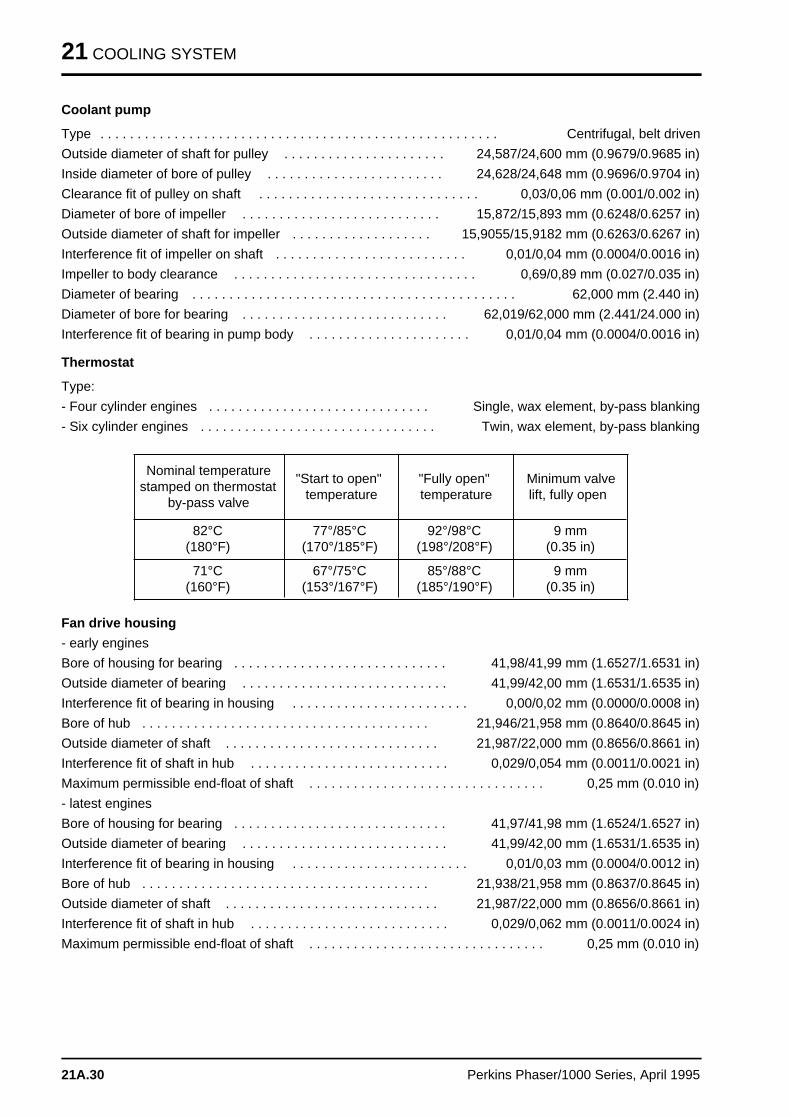
21 COOLING SYSTEM
Coolant pump
Type . . . . . . . . . . . . . . . . . . . . . . . . . . . . . . . . . . . . . . . . . . . . . . . . . . . . . . Centrifugal, belt driven
Outside diameter of shaft for pulley . . . . . . . . . . . . . . . . . . . . . . 24,587/24,600 mm (0.9679/0.9685 in)
Inside diameter of bore of pulley . . . . . . . . . . . . . . . . . . . . . . . . 24,628/24,648 mm (0.9696/0.9704 in)
Clearance fit of pulley on shaft . . . . . . . . . . . . . . . . . . . . . . . . . . . . . . 0,03/0,06 mm (0.001/0.002 in)
Diameter of bore of impeller . . . . . . . . . . . . . . . . . . . . . . . . . . . 15,872/15,893 mm (0.6248/0.6257 in)
Outside diameter of shaft for impeller . . . . . . . . . . . . . . . . . . . 15,9055/15,9182 mm (0.6263/0.6267 in)
Interference fit of impeller on shaft . . . . . . . . . . . . . . . . . . . . . . . . . . 0,01/0,04 mm (0.0004/0.0016 in)
Impeller to body clearance . . . . . . . . . . . . . . . . . . . . . . . . . . . . . . . . . 0,69/0,89 mm (0.027/0.035 in)
Diameter of bearing . . . . . . . . . . . . . . . . . . . . . . . . . . . . . . . . . . . . . . . . . . . . 62,000 mm (2.440 in)
Diameter of bore for bearing . . . . . . . . . . . . . . . . . . . . . . . . . . . . 62,019/62,000 mm (2.441/24.000 in)
Interference fit of bearing in pump body . . . . . . . . . . . . . . . . . . . . . . 0,01/0,04 mm (0.0004/0.0016 in)
Thermostat
Type:
- Four cylinder engines . . . . . . . . . . . . . . . . . . . . . . . . . . . . . . Single, wax element, by-pass blanking
- Six cylinder engines . . . . . . . . . . . . . . . . . . . . . . . . . . . . . . . . Twin, wax element, by-pass blanking
Nominal temperaturestamped on thermostat
by-pass valve
"Start to open"temperature
"Fully open"temperature
Minimum valvelift, fully open
82°C(180°F)
77°/85°C(170°/185°F)
92°/98°C(198°/208°F)
9 mm(0.35 in)
71°C(160°F)
67°/75°C(153°/167°F)
85°/88°C(185°/190°F)
9 mm(0.35 in)
Fan drive housing
- early engines
Bore of housing for bearing . . . . . . . . . . . . . . . . . . . . . . . . . . . . . 41,98/41,99 mm (1.6527/1.6531 in)
Outside diameter of bearing . . . . . . . . . . . . . . . . . . . . . . . . . . . . 41,99/42,00 mm (1.6531/1.6535 in)
Interference fit of bearing in housing . . . . . . . . . . . . . . . . . . . . . . . . 0,00/0,02 mm (0.0000/0.0008 in)
Bore of hub . . . . . . . . . . . . . . . . . . . . . . . . . . . . . . . . . . . . . . . 21,946/21,958 mm (0.8640/0.8645 in)
Outside diameter of shaft . . . . . . . . . . . . . . . . . . . . . . . . . . . . . 21,987/22,000 mm (0.8656/0.8661 in)
Interference fit of shaft in hub . . . . . . . . . . . . . . . . . . . . . . . . . . . 0,029/0,054 mm (0.0011/0.0021 in)
Maximum permissible end-float of shaft . . . . . . . . . . . . . . . . . . . . . . . . . . . . . . . . 0,25 mm (0.010 in)
- latest engines
Bore of housing for bearing . . . . . . . . . . . . . . . . . . . . . . . . . . . . . 41,97/41,98 mm (1.6524/1.6527 in)
Outside diameter of bearing . . . . . . . . . . . . . . . . . . . . . . . . . . . . 41,99/42,00 mm (1.6531/1.6535 in)
Interference fit of bearing in housing . . . . . . . . . . . . . . . . . . . . . . . . 0,01/0,03 mm (0.0004/0.0012 in)
Bore of hub . . . . . . . . . . . . . . . . . . . . . . . . . . . . . . . . . . . . . . . 21,938/21,958 mm (0.8637/0.8645 in)
Outside diameter of shaft . . . . . . . . . . . . . . . . . . . . . . . . . . . . . 21,987/22,000 mm (0.8656/0.8661 in)
Interference fit of shaft in hub . . . . . . . . . . . . . . . . . . . . . . . . . . . 0,029/0,062 mm (0.0011/0.0024 in)
Maximum permissible end-float of shaft . . . . . . . . . . . . . . . . . . . . . . . . . . . . . . . . 0,25 mm (0.010 in)
21A.30 Perkins Phaser/1000 Series, April 1995
FLYWHEEL AND FLYWHEEL HOUSING 22
Flywheel and flywheel housin g 22
General descriptio n . . . . . . . . . . . . . . . . . . . . . . . . . . . . . . . . . . . . . . . . . 22A.02
Flywheel
22A-01 To remove and to fit . . . . . . . . . . . . . . . . . . . . . . . . . . . . . . . . . 22A.03
Ring gear
22A-02 To remove and to fit . . . . . . . . . . . . . . . . . . . . . . . . . . . . . . . . . 22A.03
Flywheel housing
22A-03 To remove and to fit . . . . . . . . . . . . . . . . . . . . . . . . . . . . . . . . . 22A.04
Data and dimension s . . . . . . . . . . . . . . . . . . . . . . . . . . . . . . . . . . . . . . . 22A.05
Perkins Phaser/1000 Series, April 1995 22A.01
22 FLYWHEEL AND FLYWHEEL HOUSING
General description
The steel flywheel is fitted with a hardened starterring. Generally the starter rings have 126 teeth, butcertain starter rings have 132 teeth.
The flywheel housing is normally made of cast iron,but certain flywheel housings are made ofaluminium alloy.
22A.02 Perkins Phaser/1000 Series, April1995
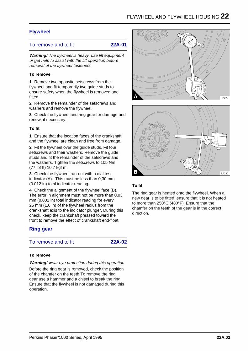
FLYWHEEL AND FLYWHEEL HOUSING 22
Flywheel
To remove and to fit 22A-01
Warning! The flywheel is heavy, use lift equipmentor get help to assist with the lift operation beforeremoval of the flywheel fasteners.
To remove
1 Remove two opposite setscrews from theflywheel and fit temporarily two guide studs toensure safety when the flywheel is removed andfitted.
2 Remove the remainder of the setscrews andwashers and remove the flywheel.
3 Check the flywheel and ring gear for damage andrenew, if necessary.
To fit
1 Ensure that the location faces of the crankshaftand the flywheel are clean and free from damage.
2 Fit the flywheel over the guide studs. Fit foursetscrews and their washers. Remove the guidestuds and fit the remainder of the setscrews andthe washers. Tighten the setscrews to 105 Nm (77 lbf ft) 10,7 kgf m.
3 Check the flywheel run-out with a dial testindicator (A). This must be less than 0,30 mm(0.012 in) total indicator reading.
4 Check the alignment of the flywheel face (B).The error in alignment must not be more than 0,03mm (0.001 in) total indicator reading for every 25 mm (1.0 in) of the flywheel radius from thecrankshaft axis to the indicator plunger. During thischeck, keep the crankshaft pressed toward thefront to remove the effect of crankshaft end-float.
Ring gear
To remove and to fit 22A-02
To remove
Warning! wear eye protection during this operation.
Before the ring gear is removed, check the positionof the chamfer on the teeth.To remove the ringgear use a hammer and a chisel to break the ring.Ensure that the flywheel is not damaged during thisoperation.
a a a a a
a a a a a
a a a a a
a a a a a
a a a a a
PA279
PA280
To fit
The ring gear is heated onto the flywheel. When anew gear is to be fitted, ensure that it is not heatedto more than 250°C (480°F). Ensure that thechamfer on the teeth of the gear is in the correctdirection.
Perkins Phaser/1000 Series, April 1995 22A.03
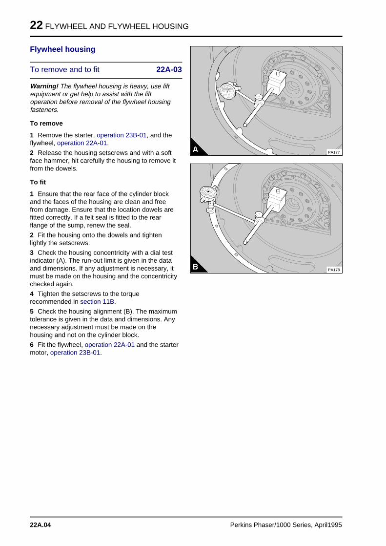
22 FLYWHEEL AND FLYWHEEL HOUSING
Flywheel housing
To remove and to fit 22A-03
Warning! The flywheel housing is heavy, use liftequipment or get help to assist with the liftoperation before removal of the flywheel housingfasteners.
To remove
1 Remove the starter, operation 23B-01, and theflywheel, operation 22A-01.
2 Release the housing setscrews and with a softface hammer, hit carefully the housing to remove itfrom the dowels.
To fit
1 Ensure that the rear face of the cylinder blockand the faces of the housing are clean and freefrom damage. Ensure that the location dowels arefitted correctly. If a felt seal is fitted to the rearflange of the sump, renew the seal.
2 Fit the housing onto the dowels and tightenlightly the setscrews.
3 Check the housing concentricity with a dial testindicator (A). The run-out limit is given in the dataand dimensions. If any adjustment is necessary, itmust be made on the housing and the concentricitychecked again.
4 Tighten the setscrews to the torquerecommended in section 11B.
5 Check the housing alignment (B). The maximumtolerance is given in the data and dimensions. Anynecessary adjustment must be made on thehousing and not on the cylinder block.
6 Fit the flywheel, operation 22A-01 and the startermotor, operation 23B-01.
PA177
a
PA178
22A.04 Perkins Phaser/1000 Series, April1995
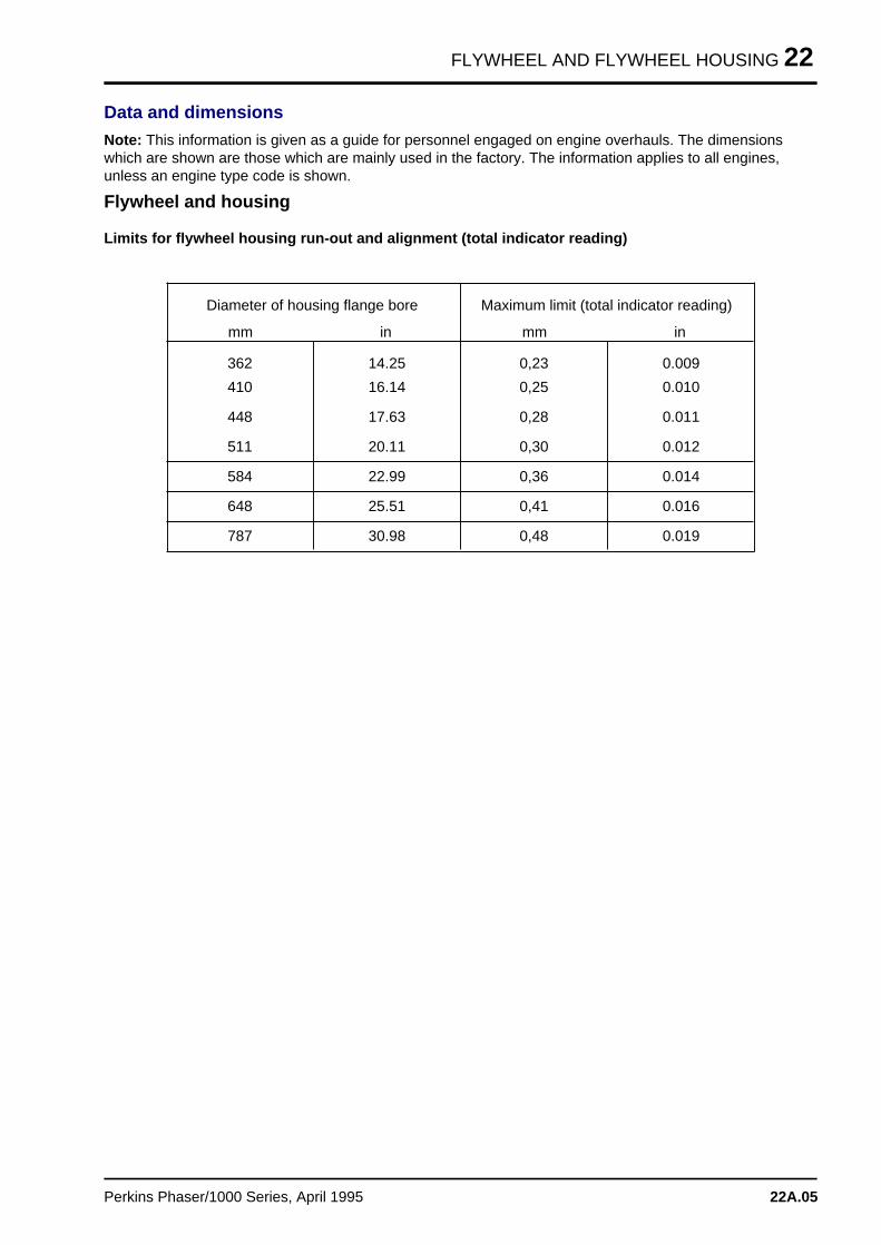
FLYWHEEL AND FLYWHEEL HOUSING 22
Data and dimensions
Note: This information is given as a guide for personnel engaged on engine overhauls. The dimensionswhich are shown are those which are mainly used in the factory. The information applies to all engines,unless an engine type code is shown.
Flywheel and housing
Limits for flywheel housing run-out and alignment (total indicator reading)
Diameter of housing flange bore
mm in
362 14.25
Maximum limit (total indicator reading)
mm in
0,23 0.009
410 16.14 0,25 0.010
448 17.63 0,28 0.011
511 20.11 0,30 0.012
584 22.99 0,36 0.014
648 25.51 0,41 0.016
787 30.98 0,48 0.019
Perkins Phaser/1000 Series, April 1995 22A.05
Electrical equipmen t 23
Alternators . . . . . . . . . . . . . . . . . . . . . . . . . . . . . . . . . . . . . . . . . . . . 23A
Starter motors . . . . . . . . . . . . . . . . . . . . . . . . . . . . . . . . . . . . . . . . . . 23B
Starting aid . . . . . . . . . . . . . . . . . . . . . . . . . . . . . . . . . . . . . . . . . . . 23C
Perkins Phaser/1000 Series, April 1995 23.01
ELECTRICAL EQUIPMENT 23A
Alternator s 23A
General descriptio n . . . . . . . . . . . . . . . . . . . . . . . . . . . . . . . . . . . . . . . . . 23A.02
Precaution s . . . . . . . . . . . . . . . . . . . . . . . . . . . . . . . . . . . . . . . . . . . . . . . 23A.02
Drive belts
23A-01 To check . . . . . . . . . . . . . . . . . . . . . . . . . . . . . . . . . . . . . . . . . 23A.0323A-02 To adjust tension . . . . . . . . . . . . . . . . . . . . . . . . . . . . . . . . . . . 23A.0323A-03 To remove and to fit . . . . . . . . . . . . . . . . . . . . . . . . . . . . . . . . . 23A.03
Alternator
23A-04 To remove and to fit . . . . . . . . . . . . . . . . . . . . . . . . . . . . . . . . . 23A.04To maintain . . . . . . . . . . . . . . . . . . . . . . . . . . . . . . . . . . . . . . . 23A.04
Fault diagnosi s . . . . . . . . . . . . . . . . . . . . . . . . . . . . . . . . . . . . . . . . . . . . 23A.05
Data and dimension s . . . . . . . . . . . . . . . . . . . . . . . . . . . . . . . . . . . . . . . 23A.07
Perkins Phaser/1000 Series, April 1995 23A.01
23A ELECTRICAL EQUIPMENT
General description
The alternator is driven from the crankshaft pulleyby single or double belt(s).
The CAV AC5RA or AC5RS and the Lucas A127alternators have solid state regulators fitted at therear. The regulator of the Lucas A127 alternatorincludes the brush box as a part of the unit. Theregulators of both alternators are sealed and repairis not possible.
Precautions
To prevent damage to the diodes and to theresistors, the precautions given below must befollowed:
• Do not disconnect the battery while the engine isin operation. This will cause a voltage surge in thealternator charge system which will immediatelycause damage to the diodes or to the transistors.
• Do not disconnect an electrical wire before theengine is stopped and all electrical switches are inthe "off" position.
• Do not cause a short circuit by the connection ofelectrical wires to the wrong terminals. The correctelectrical wire must be connected to the correctterminal. A short circuit or wrong connection whichgives reverse polarity will immediately causepermanent damage to the diodes and to thetransistors.
• Do not connect a battery into the system until ithas been checked for correct polarity and voltage.
• Do not check for current flow with a sparkcontact as damage can be caused to thetransistors.
23A.02 Perkins Phaser/1000 Series, April 1995
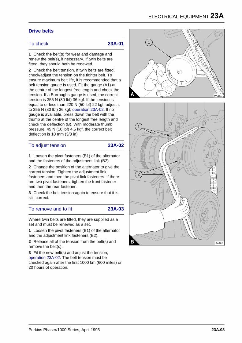
ELECTRICAL EQUIPMENT 23A
Drive belts
To check 23A-01
1 Check the belt(s) for wear and damage andrenew the belt(s), if necessary. If twin belts arefitted, they should both be renewed.
2 Check the belt tension. If twin belts are fitted,check/adjust the tension on the tighter belt. Toensure maximum belt life, it is recommended that abelt tension gauge is used. Fit the gauge (A1) atthe centre of the longest free length and check thetension. If a Burroughs gauge is used, the correcttension is 355 N (80 lbf) 36 kgf. If the tension isequal to or less than 220 N (50 lbf) 22 kgf, adjust itto 355 N (80 lbf) 36 kgf, operation 23A-02. If nogauge is available, press down the belt with thethumb at the centre of the longest free length andcheck the deflection (B). With moderate thumbpressure, 45 N (10 lbf) 4,5 kgf, the correct beltdeflection is 10 mm (3/8 in).
To adjust tension 23A-02
1 Loosen the pivot fasteners (B1) of the alternatorand the fasteners of the adjustment link (B2).
2 Change the position of the alternator to give thecorrect tension. Tighten the adjustment linkfasteners and then the pivot link fasteners. If thereare two pivot fasteners, tighten the front fastenerand then the rear fastener.
3 Check the belt tension again to ensure that it isstill correct.
To remove and to fit 23A-03
Where twin belts are fitted, they are supplied as aset and must be renewed as a set.
1 Loosen the pivot fasteners (B1) of the alternatorand the adjustment link fasteners (B2).
2 Release all of the tension from the belt(s) andremove the belt(s).
3 Fit the new belt(s) and adjust the tension,operation 23A-02. The belt tension must bechecked again after the first 1000 km (600 miles) or20 hours of operation.
a a a
a a a
a a a
a a a
a a a
1
PA281
a aa aa aa a
2
a aa aa aa aa a
1
PA282
Perkins Phaser/1000 Series, April 1995 23A.03
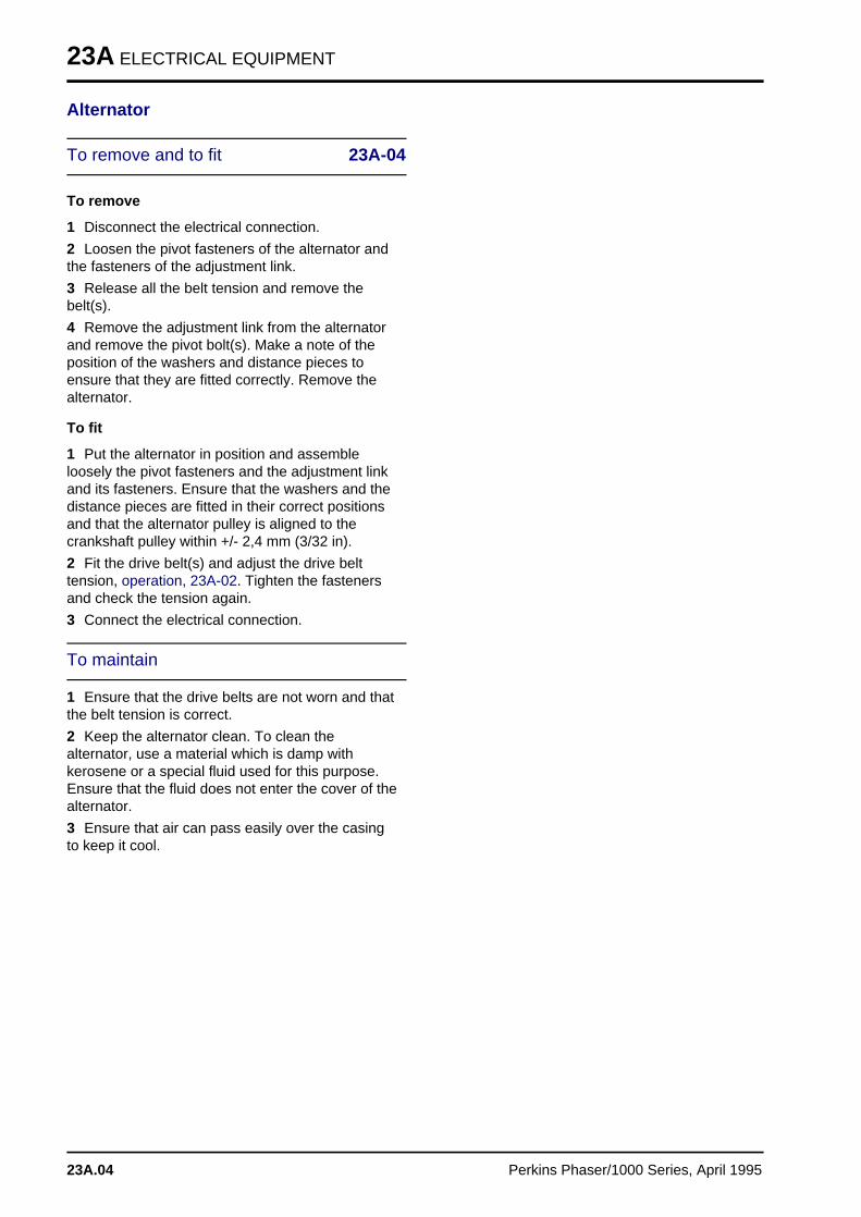
23A ELECTRICAL EQUIPMENT
Alternator
To remove and to fit 23A-04
To remove
1 Disconnect the electrical connection.
2 Loosen the pivot fasteners of the alternator andthe fasteners of the adjustment link.
3 Release all the belt tension and remove thebelt(s).
4 Remove the adjustment link from the alternatorand remove the pivot bolt(s). Make a note of theposition of the washers and distance pieces toensure that they are fitted correctly. Remove thealternator.
To fit
1 Put the alternator in position and assembleloosely the pivot fasteners and the adjustment linkand its fasteners. Ensure that the washers and thedistance pieces are fitted in their correct positionsand that the alternator pulley is aligned to thecrankshaft pulley within +/- 2,4 mm (3/32 in).
2 Fit the drive belt(s) and adjust the drive belttension, operation, 23A-02. Tighten the fastenersand check the tension again.
3 Connect the electrical connection.
To maintain
1 Ensure that the drive belts are not worn and thatthe belt tension is correct.
2 Keep the alternator clean. To clean thealternator, use a material which is damp withkerosene or a special fluid used for this purpose.Ensure that the fluid does not enter the cover of thealternator.
3 Ensure that air can pass easily over the casingto keep it cool.
23A.04 Perkins Phaser/1000 Series, April 1995
ELECTRICAL EQUIPMENT 23A
Fault diagnosis
The alternator is designed in such a way that a flowof current (indicated by no light at the warning lightor a reading shown on an ammeter) shows that thesystem is in correct operation. If the system is incorrect operation, no open circuit, voltage orcurrent output checks need to be done on theinstallation unless:
• The warning light does not show when thealternator is stationary and the switch is in the "on"position or it shows a light when the alternator is inoperation.
• No charge current is shown on the ammeter.
• The battery is discharged.
• The battery is hotter than normal which is anindication of loss of voltage control.
If one or more of the above symptoms occur, theprocedure indicated below should be applied.
1 Ensure that the battery is fully charged.
2 Connect a moving-coil voltmeter of good quality,with a range of 0-50 volts, across the positive andnegative terminals of the alternator. If an ammeteris not fitted in the electrical circuit, fit a moving-coilammeter of good quality, with a range of 0-100ampere, in the wire between the alternator and thepositive terminal of the battery.
3 Turn the warning light switch to the "on" position(main switch on instrument panel); the warning lightshould be illuminated.
4 Switch on a 10-15 ampere load, for example,lights, fans, etc.
5 Start the engine and operate it at a fast idlespeed; either the warning light should beextinguished or the ammeter indicates a smallchange in the current in relationship to the enginespeed.
6 Increase the engine speed for a moment to nearmaximum speed, when the charge current shouldbe approximately equal to the rating for thealternator, as shown in the data and dimensions.
7 Operate the alternator at approximately halfspeed (engine speed approximately 1500 rev/min)and remove the electrical load. The voltage shouldgo up to 14 volts for a 12 volt system or 28 voltsfor a 24 volt system and then remain constant. Atthe same time the current reading should show areduction.
Any change in the above data can indicate a faultand the procedure that follows should be usedbefore any components are disconnected. Thisprocedure is not suitable for A127 alternators and, ifa fault is found, the alternator should be removedfor test by a specialist.
The regulator is a sealed unit and a repair is notpossible. If there is a regulator fault, the regulatormust be renewed.
Perkins Phaser/1000 Series, April 1995 23A.05
23A ELECTRICAL EQUIPMENT
If the warning light is not illuminated when theswitch is in the "on" position:
Check the bulb.
If no fault:
Check all the connections at the regulator, at thealternator and at the battery.
If no fault:
Turn the switch to the "off" position. Disconnectthe wire from the "F" terminal on the alternator andconnect a wire between the "F" terminal and thenegative terminal on the alternator. Turn the switchto the "on" position.
If the warning light shows, the fault is in theregulator.
If the warning light does not show, the fault is in thealternator.
If the warning light continues to show and theammeter shows no output when the alternatoris in operation:
Check all the connections at the regulator,alternator and battery.
If no fault:
Turn the switch to the "off" position. Disconnectthe wire from the "F" terminal on the alternator andconnect a wire between the "F" terminal and thenegative terminal on the alternator. Turn the switchto the "on" position and operate the engine at fastidle.
If there is no output, there is a fault in thealternator.
If there is an output, there is a fault in the regulator.
If the warning light continues to show when thealternator is in operation and the ammetershows a reduced output with maximum outputonly at maximum engine speed or,if thewarning light does not show, but there is areduced output from the alternator withmaximum output only at maximum enginespeed:
There is a fault in the alternator.
If there is an intermittent light from the warninglight and the ammeter needle is not stationarywhen the battery is charged fully and no load isapplied:
Check for a higher than normal resistance in thenegative control wire of the regulator.
If the resistance is normal, there is a fault in theregulator.
If the battery charge is too high and the ammeterindicates high or maximum output at all times:
Check the positive control wire and its connectionat the regulator.
If the wire and its connection are correct, there is afault in the regulator.
23A.06 Perkins Phaser/1000 Series, April 1995
ELECTRICAL EQUIPMENT 23A
Data and dimensionsNote: This information is given as a guide for personnel engaged on engine overhauls. The dimensionswhich are shown are those which are mainly used in the factory. The information applies to all engines,unless an engine type code is shown.
Electrical equipment
The information which follows is general and can change with specific applications.
Alternators
Make and type . . . . . . . . . . . . . . . . . . . . . . . . . . . . . . Lucas, AC5RA, AC5RS, A127 and Butec 5524
Rating:
Lucas:
- AC5RA and AC5RS . . . . . . . . . . . . . . . . . . . . . . . . . . . . . . . . . . . . . . . . . . . . 12V/60A or 24V/40A
- A127 . . . . . . . . . . . . . . . . . . . . . . . . . . . . . . . . . . . . . . . . . . . . . . . . . . . . . . . 12V/55A or 12V/65A
Butec:
- 5524 . . . . . . . . . . . . . . . . . . . . . . . . . . . . . . . . . . . . . . . . . . . . . . . . . . . . . . . . . . . . . . . 24V/55A
Rotation . . . . . . . . . . . . . . . . . . . . . . . . . . . . . . . . . . . . . . . . . . . . . . . . . Clockwise from drive end
Perkins Phaser/1000 Series, April 1995 23A.07
ELECTRICAL EQUIPMENT 23B
Starter motor s 23B
General descriptio n . . . . . . . . . . . . . . . . . . . . . . . . . . . . . . . . . . . . . . . . . 23B.02
Starter motor
23B-01 To remove and to fit . . . . . . . . . . . . . . . . . . . . . . . . . . . . . . . . . 23B.0323B-02 To maintain the brush gear and the commutator . . . . . . . . . . . . . 23B.0323B-03 To test on the engine . . . . . . . . . . . . . . . . . . . . . . . . . . . . . . . . 23B.04
Data and dimension s . . . . . . . . . . . . . . . . . . . . . . . . . . . . . . . . . . . . . . . 23B.05
Perkins Phaser/1000 Series, April 1995 23B.01
23B ELECTRICAL EQUIPMENT
General description
The Lucas M127 starter motor is operated by asolenoid and has a five roller clutch. The solenoidengages the starter drive in two operations toensure that the motor gets its maximum torque onlywhen the starter motor is engaged fully with theflywheel. The clutch prevents rotation of thearmature at high speed if the starter is held in theengaged position.
The CAV CA45 or S115 starter motor has a smoothsurface with no protrusions. This is because thesolenoid and the main switch assemblies are insidethe drive end cover around (co-axially with) thearmature shaft. The main feature of the co-axialstarter is that only the pinion assembly movesaxially to engage the engine flywheel. There is noaxial movement of the whole armature as with theaxial type motor. To ensure smooth engagement ofthe pinion, full load is not applied until the pinion iscompletely engaged with the flywheel.
23B.02 Perkins Phaser/1000 Series, April1995
ELECTRICAL EQUIPMENT 23B
Starter motor
To remove and to fit 23B-01
Consumable products:
POWERPART Hylosil
To remove
If the engine has a flywheel housing which is oilfilled, drain the flywheel housing before the startermotor is removed.
1 Disconnect the battery.
2 Disconnect the starter motor cables.
3 Release the fasteners and remove the startermotor and, if necessary, the distance piece.
To fit
1 If necessary, put the distance piece in positionwith its location lip to the flywheel housing. Fit thestarter motor and tighten the fasteners.
2 Connect the starter motor cables. If the enginehas a flywheel housing which is oil filled, the startermotor must be sealed before it is fitted. Clean theflange face of the starter motor and the face of theflywheel housing. Apply a 2,0 mm (0.080 in)continuous bead of POWERPART Hylosil to theflange face of the starter motor near to the spigot.
3 Connect the battery.
To maintain the brush gear 23B-02and the commutator
CA45G or S115 starter motors
Inspect the brushes at intervals to ensure that theyare free in their guides and that the wireconnections are free to move. To check this, lift thespring from the brush and pull carefully on theflexible connections. If the brush does not movefreely, remove it from its holder and clean the sideswith a material which is damp with gasolene.
Ensure that the brushes are fitted in their originalpositions to keep the original wear seat. Thebrushes must have good seats which conform tothe shape of the commutator. If the brush seat isnot correct, put a piece of very fine carborundumpaper or similar material tight around thecommutator with the rough face to the outside. Withthe brush in position, turn the armature by hand, inthe normal direction of rotation, until the brush hasthe correct shape. If the brushes are worn and thesprings do not give enough pressure, they must
be renewed. Check the spring pressure with thehook of a spring balance under the spring lip. Thecorrect tension is 8,34/11,00 N (30/40 ozf)0,85/1,13 kgf.
The new brushes must be the exact same grade asthe original brushes. To ensure that correct brushesare fitted, use only parts from the approvedmanufacturer. To remove the brushes, remove thefour setscrews that hold the brushes, one for eachbrush. When the new brushes are assembled,connect carefully the field coil and connector wires,held by two of the setscrews. Before the brushesare inserted in their holders, it is advised that theholders are cleaned with compressed air or with amaterial which is damp with gasolene.
The commutator must be completely clean; dirt oroil must be removed by a piece of clean drymaterial (with no loose fibres) pressed against it,while the armature is turned by hand.If thecommutator is dirty and has a colour other than itsnatural colour, lift the brushes and put a strip of finecarborundum paper or similar material around thecommutator, with the rough surface to the inside.Turn the armature by hand until the surface hasreturned to its natural colour. Clean the commutatorwith a material which is damp with gasolene.
If a repair is necessary to the commutator or switchgear, etc. the starter must be removed for specialistrepair.
M127 Starter motor
Repair of this starter motor is more difficult. Ifnecessary, remove the starter motor for specialistrepair.
Perkins Phaser/1000 Series, April 1995 23B.03
23B ELECTRICAL EQUIPMENT
To test on the engine 23B-03
Ensure that the battery is fully charged.
Turn on the lights and operate the starter switch. Ifno lights are fitted to the machine, connect avoltmeter across the battery terminals and operatethe starter switch.
If the starter does not operate but the lights keeptheir power or there is no voltage drop across thebattery, check the switch and all the connectionsand wires. Slow action of the starter can be causedby faulty connections.
Failure to engage smoothly between the starter andthe flywheel can be caused, on some types ofstarter motor, by dirt on the helical grooves of thestarter motor drive, which can prevent free pinionmovement. Clean the shaft thoroughly withgasolene, or a fluid made especially for thepurpose, and apply a small quantity of Aero Shell6B or its equal.
23B.04 Perkins Phaser/1000 Series, April1995
ELECTRICAL EQUIPMENT 23B
Data and dimensionsNote: This information is given as a guide for personnel engaged on engine overhauls. The dimensionswhich are shown are those which are mainly used in the factory. The information applies to all engines,unless an engine type code is shown.
Electrical equipment
The information which follows is general and can change with specific applications.
Starter motors
Make and type . . . . . . . . . . . . . . . . . . . . . . . . . . . . . . . . . . . . CAV M45G, CAV S115 or Lucas M127
Voltage:
- M45G and S115 . . . . . . . . . . . . . . . . . . . . . . . . . . . . . . . . . . . . . . . . . . . . . . . . . . . . 12V or 24V
- M127 . . . . . . . . . . . . . . . . . . . . . . . . . . . . . . . . . . . . . . . . . . . . . . . . . . . . . . . . . . . . . . . . . . 12V
Number of teeth on pinion . . . . . . . . . . . . . . . . . . . . . . . . . . . . . . . . . . . . . . . . . . . . . . . . . . . . . . 10
Maximum starter cable resistance at 200C (680F):
- 12V . . . . . . . . . . . . . . . . . . . . . . . . . . . . . . . . . . . . . . . . . . . . . . . . . . . . . . . . . . . . 0.0017 ohms
- 24V . . . . . . . . . . . . . . . . . . . . . . . . . . . . . . . . . . . . . . . . . . . . . . . . . . . . . . . . . . . . 0.0034 ohms
Perkins Phaser/1000 Series, April 1995 23B.05
ELECTRICAL EQUIPMENT 23C
Starting ai d 23C
General descriptio n . . . . . . . . . . . . . . . . . . . . . . . . . . . . . . . . . . . . . . . . . 23C.02
Starting aid
23C-01A To remove and to fit a fuelled starting aid . . . . . . . . . . . . . . . . . 23C.02Twin fuelled starting aids . . . . . . . . . . . . . . . . . . . . . . . . . . . . . . 23C.03
23C-01B To remove and to fit a port heater . . . . . . . . . . . . . . . . . . . . . . . 23C.04
Data and dimension s . . . . . . . . . . . . . . . . . . . . . . . . . . . . . . . . . . . . . . . 23C.05
Perkins Phaser/1000 Series, April 1995 23C.01
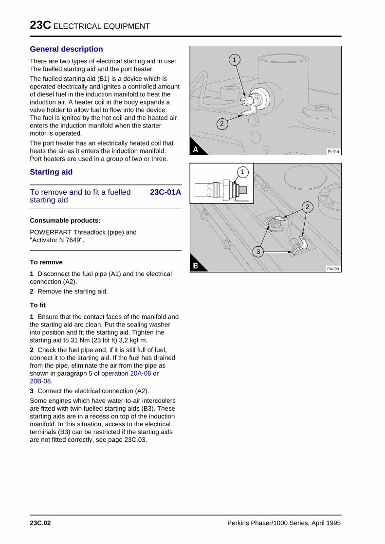
23C ELECTRICAL EQUIPMENT
General description
There are two types of electrical starting aid in use:The fuelled starting aid and the port heater.
The fuelled starting aid (B1) is a device which isoperated electrically and ignites a controlled amountof diesel fuel in the induction manifold to heat theinduction air. A heater coil in the body expands avalve holder to allow fuel to flow into the device.The fuel is ignited by the hot coil and the heated airenters the induction manifold when the startermotor is operated.
The port heater has an electrically heated coil thatheats the air as it enters the induction manifold.Port heaters are used in a group of two or three.
Starting aid
To remove and to fit a fuelled 23C-01Astarting aid
Consumable products:
POWERPART Threadlock (pipe) and "Activator N 7649".
To remove
1 Disconnect the fuel pipe (A1) and the electricalconnection (A2).
2 Remove the starting aid.
To fit
1 Ensure that the contact faces of the manifold andthe starting aid are clean. Put the sealing washerinto position and fit the starting aid. Tighten thestarting aid to 31 Nm (23 lbf ft) 3,2 kgf m.
2 Check the fuel pipe and, if it is still full of fuel,connect it to the starting aid. If the fuel has drainedfrom the pipe, eliminate the air from the pipe asshown in paragraph 5 of operation 20A-08 or 20B-08.
3 Connect the electrical connection (A2).
Some engines which have water-to-air intercoolersare fitted with twin fuelled starting aids (B3). Thesestarting aids are in a recess on top of the inductionmanifold. In this situation, access to the electricalterminals (B3) can be restricted if the starting aidsare not fitted correctly, see page 23C.03.
a a a
a a a
a a a
a a a
1
PL014
a a a
a a a
a a a
a a a
2
a a a
a a a
a a a
a a a
1
a aa aa aa a
2
a aa aa aa a
3
PA303
23C.02 Perkins Phaser/1000 Series, April 1995
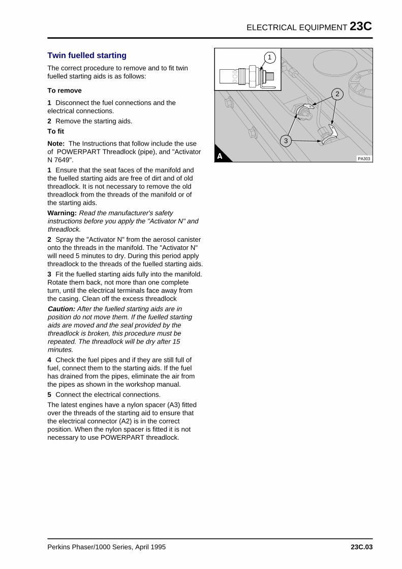
ELECTRICAL EQUIPMENT 23C
Twin fuelled starting
The correct procedure to remove and to fit twinfuelled starting aids is as follows:
To remove
1 Disconnect the fuel connections and theelectrical connections.
2 Remove the starting aids.
To fit
Note: The Instructions that follow include the useof POWERPART Threadlock (pipe), and "ActivatorN 7649".
1 Ensure that the seat faces of the manifold andthe fuelled starting aids are free of dirt and of oldthreadlock. It is not necessary to remove the oldthreadlock from the threads of the manifold or ofthe starting aids.
Warning: Read the manufacturer's safetyinstructions before you apply the "Activator N" andthreadlock.
2 Spray the "Activator N" from the aerosol canisteronto the threads in the manifold. The "Activator N"will need 5 minutes to dry. During this period applythreadlock to the threads of the fuelled starting aids.
3 Fit the fuelled starting aids fully into the manifold.Rotate them back, not more than one completeturn, until the electrical terminals face away fromthe casing. Clean off the excess threadlock
Caution: After the fuelled starting aids are inposition do not move them. If the fuelled startingaids are moved and the seal provided by thethreadlock is broken, this procedure must berepeated. The threadlock will be dry after 15minutes.
4 Check the fuel pipes and if they are still full offuel, connect them to the starting aids. If the fuelhas drained from the pipes, eliminate the air fromthe pipes as shown in the workshop manual.
5 Connect the electrical connections.
The latest engines have a nylon spacer (A3) fittedover the threads of the starting aid to ensure thatthe electrical connector (A2) is in the correctposition. When the nylon spacer is fitted it is notnecessary to use POWERPART threadlock.
a aa aa aa aa a
1
a aa aa aa a
2
a a a
a a a
a a a
a a a
3
PA303
Perkins Phaser/1000 Series, April 1995 23C.03
23C ELECTRICAL EQUIPMENT
How to check the fuelled starting aid
If the inside of the induction manifold is wet, checkthat there is not a fuel leak from the fuelled startingaid.
1 Disconnect the fuel pipe and the electricalconnection at the starting aid. Remove the startingaid from the manifold and fit a suitable plug in themanifold.
2 Connect the fuel pipe to the starting aid, butleave the connection loose. Do not fit the electricalconnection, but ensure that the connector has asuitable insulator fitted. Operate the priming lever ofthe fuel lift pump until fuel free of air comes fromthe connection. Tighten the connection.
3 Start the engine and operate it at low speed.Check that there is no fuel leakage from the valveof the starting aid.
4 If there is no leakage, remove the plug from theinduction manifold and fit the starting aid. Connectthe fuel pipe to the starting aid and remove the airfrom the pipe as shown above. Connect theelectrical connection.
If there is a leak from the valve of the starting aid,fit a new starting aid.
To remove and to fit 23C-01Ba port heater
1 Disconnect the electrical connection.
2 Remove the port heater from the inductionmanifold or from the elbow.
3 Fit the port heater and tighten it to 60 Nm (44 lbf ft) 6,1 kgf m.
4 Connect the electrical connection.
23C.04 Perkins Phaser/1000 Series, April 1995
ELECTRICAL EQUIPMENT 23C
Data and dimensionsNote: This information is given as a guide for personnel engaged on engine overhauls. The dimensionswhich are shown are those which are mainly used in the factory. The information applies to all engines,unless an engine type code is shown.
Electrical equipment
The information which follows is general and can change with specific applications.
Starting aid
Type . . . . . . . . . . . . . . . . . . . . . . . . . . . . . . . . . . . . . Electrically operated heater, with a fuel supply
Voltage . . . . . . . . . . . . . . . . . . . . . . . . . . . . . . . . . . . . . 12V (dropping resistor used on 24V system)
Flow rate of fuel through starting aid . . . . . . . . . . . . . . . . . . . . . . . . . . . . . . . . . . . . . 3,5/5,9 ml/min
Perkins Phaser/1000 Series, April 1995 23C.05
Auxiliary equipmen t 24
Compressors . . . . . . . . . . . . . . . . . . . . . . . . . . . . . . . . . . . . . . . . . . 24A
Power steering pump . . . . . . . . . . . . . . . . . . . . . . . . . . . . . . . . . . . . 24B
Exhauster . . . . . . . . . . . . . . . . . . . . . . . . . . . . . . . . . . . . . . . . . . . . 24C
Perkins Phaser/1000 Series, April 1995 24 .01
AUXILIARY EQUIPMENT 24A
Compressor s 24A
General descriptio n . . . . . . . . . . . . . . . . . . . . . . . . . . . . . . . . . . . . . . . . . 24A.02
Compressor Wabco 159 or 229 compressor
24A-01 To remove and to fit the compressor and drive housing . . . . . . . 24A.03
Compressor drive for the Wabco compressors
24A-02 To remove and to fit . . . . . . . . . . . . . . . . . . . . . . . . . . . . . . . . . 24A.0724A-03 To dismantle and to assemble . . . . . . . . . . . . . . . . . . . . . . . . . . 24A.07
Compressor Bendix 150 or 250 compressor
24A-04 To remove and to fit compressor . . . . . . . . . . . . . . . . . . . . . . . . 24A.11
Data and dimension s . . . . . . . . . . . . . . . . . . . . . . . . . . . . . . . . . . . . . . . 24A.14
Perkins Phaser/1000 Series, April 1995 24A.01
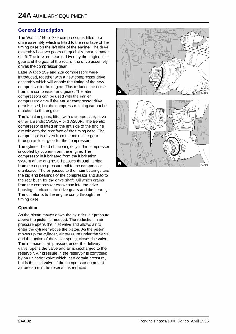
24A AUXILIARY EQUIPMENT
General description
The Wabco 159 or 229 compressor is fitted to adrive assembly which is fitted to the rear face of thetiming case on the left side of the engine. The driveassembly has two gears of equal size on a commonshaft. The forward gear is driven by the engine idlergear and the gear at the rear of the drive assemblydrives the compressor gear.
Later Wabco 159 and 229 compressors wereintroduced, together with a new compressor driveassembly which will enable the timing of the newcompressor to the engine. This reduced the noisefrom the compressor and gears. The latercompressors can be used with the earliercompressor drive if the earlier compressor drivegear is used, but the compressor timing cannot bematched to the engine.
The latest engines, fitted with a compressor, haveeither a Bendix 1W150R or 1W250R. The Bendixcompressor is fitted on the left side of the enginedirectly onto the rear face of the timing case. Thecompressor is driven from the main idler gearthrough an idler gear for the compressor.
The cylinder head of the single cylinder compressoris cooled by coolant from the engine. Thecompressor is lubricated from the lubricationsystem of the engine. Oil passes through a pipefrom the engine pressure rail to the compressorcrankcase. The oil passes to the main bearings andthe big end bearings of the compressor and also tothe rear bush for the drive shaft. Oil which drainsfrom the compressor crankcase into the drivehousing, lubricates the drive gears and the bearing.The oil returns to the engine sump through thetiming case.
Operation
As the piston moves down the cylinder, air pressureabove the piston is reduced. The reduction in airpressure opens the inlet valve and allows air toenter the cylinder above the piston. As the pistonmoves up the cylinder, air pressure under the valveand the action of the valve spring, closes the valve.The increase in air pressure under the deliveryvalve, opens the valve and air is discharged to thereservoir. Air pressure in the reservoir is controlledby an unloader valve which, at a certain pressure,holds the inlet valve of the compressor open untilair pressure in the reservoir is reduced.
a a a a a a a
a a a a a a a
a a a a a a a
a a a a a a a
a a a a a a a
a a a a a a a
a a a a a a a
a a a a a a a
a a a a a a a
a a a a a a a
a a a a a a a
a a a a a a a
a a a a a a a
a a a a a a a
a a a a a a a
PA283
PA069
24A.02 Perkins Phaser/1000 Series, April 1995
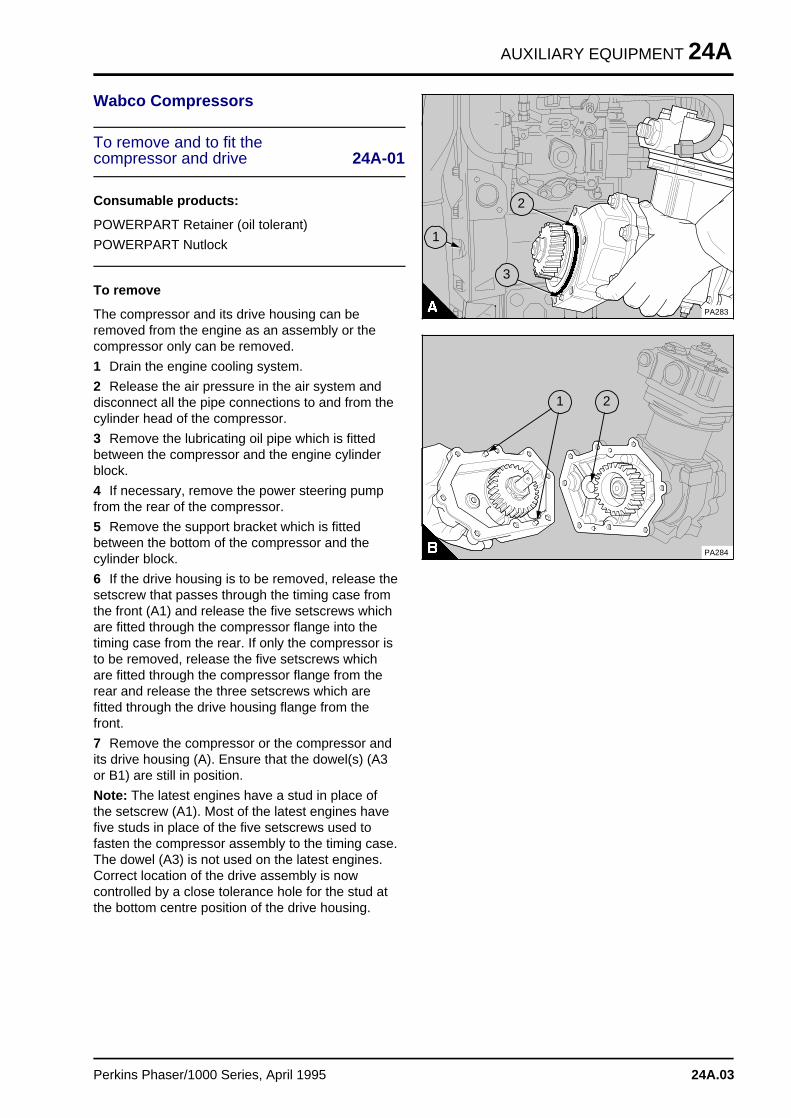
AUXILIARY EQUIPMENT 24A
Wabco Compressors
To remove and to fit the compressor and drive 24A-01
Consumable products:
POWERPART Retainer (oil tolerant)
POWERPART Nutlock
To remove
The compressor and its drive housing can beremoved from the engine as an assembly or thecompressor only can be removed.
1 Drain the engine cooling system.
2 Release the air pressure in the air system anddisconnect all the pipe connections to and from thecylinder head of the compressor.
3 Remove the lubricating oil pipe which is fittedbetween the compressor and the engine cylinderblock.
4 If necessary, remove the power steering pumpfrom the rear of the compressor.
5 Remove the support bracket which is fittedbetween the bottom of the compressor and thecylinder block.
6 If the drive housing is to be removed, release thesetscrew that passes through the timing case fromthe front (A1) and release the five setscrews whichare fitted through the compressor flange into thetiming case from the rear. If only the compressor isto be removed, release the five setscrews whichare fitted through the compressor flange from therear and release the three setscrews which arefitted through the drive housing flange from thefront.
7 Remove the compressor or the compressor andits drive housing (A). Ensure that the dowel(s) (A3or B1) are still in position.
Note: The latest engines have a stud in place ofthe setscrew (A1). Most of the latest engines havefive studs in place of the five setscrews used tofasten the compressor assembly to the timing case.The dowel (A3) is not used on the latest engines.Correct location of the drive assembly is nowcontrolled by a close tolerance hole for the stud atthe bottom centre position of the drive housing.
a a a a a a
a a a a a a
a a a a a a
a a a a a a
a a a a a a
a a a a a a
a a a a a a
a a a a a a
a a a a a a
a a a a a a
a a a a a a
a a a a a a
a a a a a a
a a a a a a
a a a a a a
PA283
a aa aa aa a
2
a a a
a a a
a a a
a a a
1
a a a
a a a
a a a
a a a
3
a a a
a a a
a a a
a a a
1
a aa aa aa a
2
PA284
Perkins Phaser/1000 Series, April 1995 24A.03
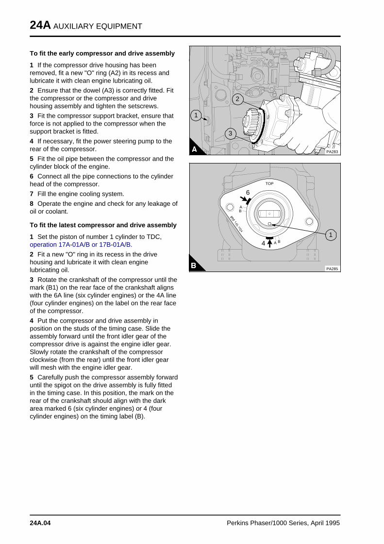
24A AUXILIARY EQUIPMENT
To fit the early compressor and drive assembly
1 If the compressor drive housing has beenremoved, fit a new "O" ring (A2) in its recess andlubricate it with clean engine lubricating oil.
2 Ensure that the dowel (A3) is correctly fitted. Fitthe compressor or the compressor and drivehousing assembly and tighten the setscrews.
3 Fit the compressor support bracket, ensure thatforce is not applied to the compressor when thesupport bracket is fitted.
4 If necessary, fit the power steering pump to therear of the compressor.
5 Fit the oil pipe between the compressor and thecylinder block of the engine.
6 Connect all the pipe connections to the cylinderhead of the compressor.
7 Fill the engine cooling system.
8 Operate the engine and check for any leakage ofoil or coolant.
To fit the latest compressor and drive assembly
1 Set the piston of number 1 cylinder to TDC,operation 17A-01A/B or 17B-01A/B.
2 Fit a new "O" ring in its recess in the drivehousing and lubricate it with clean enginelubricating oil.
3 Rotate the crankshaft of the compressor until themark (B1) on the rear face of the crankshaft alignswith the 6A line (six cylinder engines) or the 4A line(four cylinder engines) on the label on the rear faceof the compressor.
4 Put the compressor and drive assembly inposition on the studs of the timing case. Slide theassembly forward until the front idler gear of thecompressor drive is against the engine idler gear.Slowly rotate the crankshaft of the compressorclockwise (from the rear) until the front idler gearwill mesh with the engine idler gear.
5 Carefully push the compressor assembly forwarduntil the spigot on the drive assembly is fully fittedin the timing case. In this position, the mark on therear of the crankshaft should align with the darkarea marked 6 (six cylinder engines) or 4 (fourcylinder engines) on the timing label (B).
a a a a a a a
a a a a a a a
a a a a a a a
a a a a a a a
a a a a a a a
a a a a a a a
a a a a a a a
a a a a a a a
a a a a a a a
a a a a a a a
a a a a a a a
a a a a a a a
a a a a a a a
a a a a a a a
a a a a a a a
PA283
a aa aa aa a
2
a aa aa aa a
1
a aa aa aa a
3
a a a a
a a a a
a aa aa a
A
a aa aa a
B
a aa aA
a aa aa a
B
a a a a
a a a a
a a a a
TOP
a a a
a a a
a a a
a a a
a a a
4a aa aa aa a
6
a a a
a a a
a a a
a a a
1
PA285
24A.04 Perkins Phaser/1000 Series, April 1995
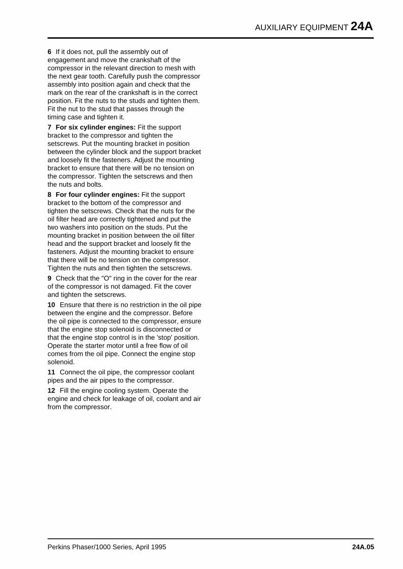
AUXILIARY EQUIPMENT 24A
6 If it does not, pull the assembly out ofengagement and move the crankshaft of thecompressor in the relevant direction to mesh withthe next gear tooth. Carefully push the compressorassembly into position again and check that themark on the rear of the crankshaft is in the correctposition. Fit the nuts to the studs and tighten them.Fit the nut to the stud that passes through thetiming case and tighten it.
7 For six cylinder engines: Fit the supportbracket to the compressor and tighten thesetscrews. Put the mounting bracket in positionbetween the cylinder block and the support bracketand loosely fit the fasteners. Adjust the mountingbracket to ensure that there will be no tension onthe compressor. Tighten the setscrews and thenthe nuts and bolts.
8 For four cylinder engines: Fit the supportbracket to the bottom of the compressor andtighten the setscrews. Check that the nuts for theoil filter head are correctly tightened and put thetwo washers into position on the studs. Put themounting bracket in position between the oil filterhead and the support bracket and loosely fit thefasteners. Adjust the mounting bracket to ensurethat there will be no tension on the compressor.Tighten the nuts and then tighten the setscrews.
9 Check that the "O" ring in the cover for the rearof the compressor is not damaged. Fit the coverand tighten the setscrews.
10 Ensure that there is no restriction in the oil pipebetween the engine and the compressor. Beforethe oil pipe is connected to the compressor, ensurethat the engine stop solenoid is disconnected orthat the engine stop control is in the 'stop' position.Operate the starter motor until a free flow of oilcomes from the oil pipe. Connect the engine stopsolenoid.
11 Connect the oil pipe, the compressor coolantpipes and the air pipes to the compressor.
12 Fill the engine cooling system. Operate theengine and check for leakage of oil, coolant and airfrom the compressor.
Perkins Phaser/1000 Series, April 1995 24A.05
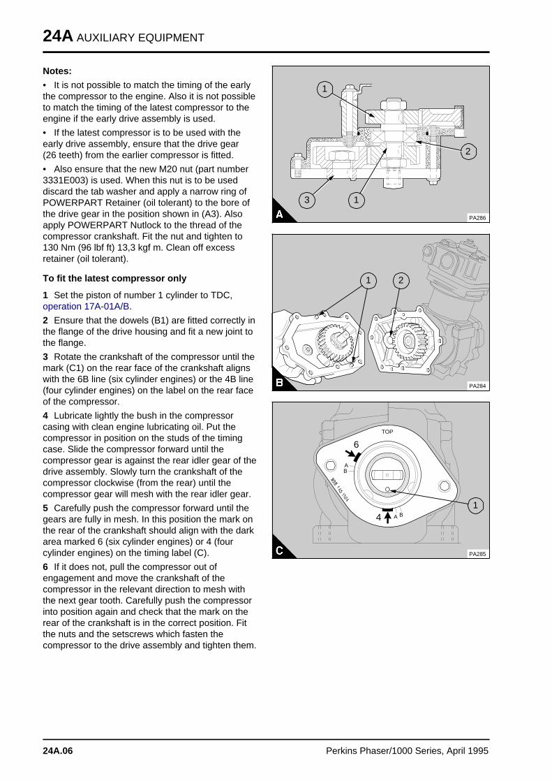
24A AUXILIARY EQUIPMENT
Notes:
• It is not possible to match the timing of the earlythe compressor to the engine. Also it is not possibleto match the timing of the latest compressor to theengine if the early drive assembly is used.
• If the latest compressor is to be used with theearly drive assembly, ensure that the drive gear(26 teeth) from the earlier compressor is fitted.
• Also ensure that the new M20 nut (part number3331E003) is used. When this nut is to be useddiscard the tab washer and apply a narrow ring ofPOWERPART Retainer (oil tolerant) to the bore ofthe drive gear in the position shown in (A3). Alsoapply POWERPART Nutlock to the thread of thecompressor crankshaft. Fit the nut and tighten to130 Nm (96 lbf ft) 13,3 kgf m. Clean off excessretainer (oil tolerant).
To fit the latest compressor only
1 Set the piston of number 1 cylinder to TDC,operation 17A-01A/B.
2 Ensure that the dowels (B1) are fitted correctly inthe flange of the drive housing and fit a new joint tothe flange.
3 Rotate the crankshaft of the compressor until themark (C1) on the rear face of the crankshaft alignswith the 6B line (six cylinder engines) or the 4B line(four cylinder engines) on the label on the rear faceof the compressor.
4 Lubricate lightly the bush in the compressorcasing with clean engine lubricating oil. Put thecompressor in position on the studs of the timingcase. Slide the compressor forward until thecompressor gear is against the rear idler gear of thedrive assembly. Slowly turn the crankshaft of thecompressor clockwise (from the rear) until thecompressor gear will mesh with the rear idler gear.
5 Carefully push the compressor forward until thegears are fully in mesh. In this position the mark onthe rear of the crankshaft should align with the darkarea marked 6 (six cylinder engines) or 4 (fourcylinder engines) on the timing label (C).
6 If it does not, pull the compressor out ofengagement and move the crankshaft of thecompressor in the relevant direction to mesh withthe next gear tooth. Carefully push the compressorinto position again and check that the mark on therear of the crankshaft is in the correct position. Fitthe nuts and the setscrews which fasten thecompressor to the drive assembly and tighten them.
a aa aa aa aa a
1
a a a
a a a
a a a
a a a
2
a aa aa aa aa a
3
a aa aa aa aa a
1
PA286
a a a
a a a
a a a
a a a
1
a a a
a a a
a a a
a a a
2
PA284a a a a
a a a a
a aa a
A
a aa aa a
B
a aa aa a
A
a aa aa a
B
a a a a
a a a a
a a a a
TOP
a a a
a a a
a a a
a a a
a a a
4
a aa aa aa a
6
a a a
a a a
a a a
a a a
1
PA285
24A.06 Perkins Phaser/1000 Series, April 1995
AUXILIARY EQUIPMENT 24A
Compressor drive for Wabcocompressors
To remove and to fit 24A-02
To remove
1 Remove the compressor and the drive housingassembly from the engine, operation 24A-01.
2 Release the setscrews and separate carefully thedrive housing from the compressor (A).
To fit
1 Check the drive gears, and the bearing for wearor for damage. Renew components if necessary.
2 Check the bush (A2), which is fitted in thecompressor casing, for wear. If necessary, renewthe bush. Ensure that the dowels (A1) are fittedcorrectly and that the joint faces are clean.
3 Lubricate lightly, with clean engine lubricating oil,the bush in the compressor casing. Put a new jointin position, fit the drive housing to the compressorand tighten the setscrews.
4 Fit the compressor and drive assembly to theengine, operation 24A-01.
To dismantle and to assemble 24A-03
Consumable products:
POWERPART retainer (oil tolerant)
POWERPART Nutlock
The gears, the drive shaft, the nuts of the driveshaft and the housing of the drive assembly havebeen changed.
The number of teeth on the gears have beenchanged to enable the compressor timing to bematched to the engine. The front idler gear has 26teeth, the rear idler gear has 39 teeth and thecompressor drive gear has 42 teeth. The drivehousing has been changed to increase theinterference between the housing and the bearing.The tab washers have been removed. The spacerbetween the rear idler gear and the bearing (onlyused in the drive assembly for the Wabco 159compressor) has also been removed. There is nowa boss on the rear idler gear instead of the spacer.The new and the old components are notinterchangeable.
The components of the new drive assembly willnow be the same when used with either the Wabco159 or 229 compressor.
a a a
a a a
a a a
a a a
1
a aa aa aa a
2
PA284
There have also been changes to the Wabco 159and 229 compressors. The thread on the front ofthe compressor crankshaft has been changed from3/4 UNF to M20 x 1,5 mm. A label which has timingmarks has been fastened with adhesive to the rearface of the compressor.
Perkins Phaser/1000 Series, April 1995 24A.07
24A AUXILIARY EQUIPMENT
To dismantle
1 Release the tab washer (A2) from the nut (A1)which is outside the housing (A8). Preventmovement of the shaft (A5) and remove the nut.Discard the tab washer. The latest drive assemblydoes not use tab washers.
2 With a suitable puller, remove the gear (A3).
3 Release the circlip (A4) which retains the bearing(A7).
4 Turn the housing upside down and release thetab washer (A12) from the nut (A13) inside thehousing. Prevent movement of the shaft andremove the nut. Discard the tab washer.
5 Provide a suitable support for the timing caseside of the housing. Protect the compressor end ofthe shaft and press the shaft and bearing assemblyout through the timing case side of the housing.
To remove the bearing and shaft assemblyfrom the latest drive housing:
Provide a suitable support for the timing case sideof the housing. Heat the housing to a temperatureof 130°/140°C (266°/284°F); ensure that thehousing is heated evenly. Protect the compressorend of the shaft and press the shaft and bearingassembly out through the timing case side of thehousing.
6 Remove the gear (A11) from the housing.
7 Remove the keys (A6) and the spacer (A10) -159 compressor only - from the shaft. A spacer isnot used in the latest drive assembly. With thecollar of the shaft towards the bottom, provide asuitable support for the inner ball guide of thebearing. Protect the end of the shaft and press theshaft out of the bearing.
To assemble
1 Clean the components and check them for wearor for damage, renew the components asnecessary.
2 Provide a suitable support for the inner ball guideof the bearing (A7). Put a suitable adaptor on to thecollar of the shaft (A5) and press the shaft into thebearing.
3 If necessary, remove the dowels (A9) from thecompressor flange of the housing (A8). Put thehousing with its compressor flange on a suitablesupport that will allow enough space below thehousing for the shaft protrusion.
PA287
a aa aa aa a
1
a a a
a a a
a a a
a a a
2
a aa aa aa a
3
a a a
a a a
a a a
a a a
4
a a a
a a a
a a a
a a a
a a a
6
a aa aa aa aa a
5
a aa aa aa a
7
a aa aa aa a
9
a a a
a a a
a a a
a a a
8
a a a a
a a a a
a a a a
a a a a
a a a a
10
a a a a
a a a a
a a a a
a a a a
a a a a
11
a a a a
a a a a
a a a a
a a a a
a a a a
12
a a a a
a a a a
a a a a
a a a a
13
24A.08 Perkins Phaser/1000 Series, April 1995
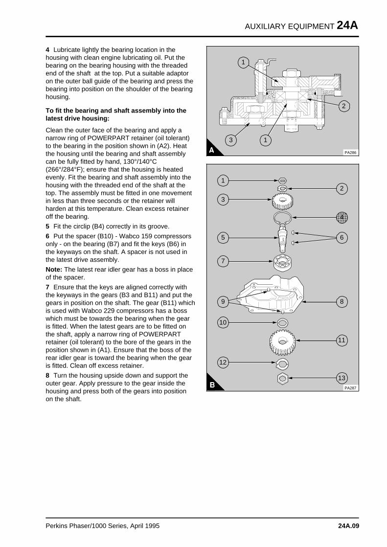
AUXILIARY EQUIPMENT 24A
4 Lubricate lightly the bearing location in thehousing with clean engine lubricating oil. Put thebearing on the bearing housing with the threadedend of the shaft at the top. Put a suitable adaptoron the outer ball guide of the bearing and press thebearing into position on the shoulder of the bearinghousing.
To fit the bearing and shaft assembly into thelatest drive housing:
Clean the outer face of the bearing and apply anarrow ring of POWERPART retainer (oil tolerant)to the bearing in the position shown in (A2). Heatthe housing until the bearing and shaft assemblycan be fully fitted by hand, 130°/140°C(266°/284°F); ensure that the housing is heatedevenly. Fit the bearing and shaft assembly into thehousing with the threaded end of the shaft at thetop. The assembly must be fitted in one movementin less than three seconds or the retainer willharden at this temperature. Clean excess retaineroff the bearing.
5 Fit the circlip (B4) correctly in its groove.
6 Put the spacer (B10) - Wabco 159 compressorsonly - on the bearing (B7) and fit the keys (B6) inthe keyways on the shaft. A spacer is not used inthe latest drive assembly.
Note: The latest rear idler gear has a boss in placeof the spacer.
7 Ensure that the keys are aligned correctly withthe keyways in the gears (B3 and B11) and put thegears in position on the shaft. The gear (B11) whichis used with Wabco 229 compressors has a bosswhich must be towards the bearing when the gearis fitted. When the latest gears are to be fitted onthe shaft, apply a narrow ring of POWERPARTretainer (oil tolerant) to the bore of the gears in theposition shown in (A1). Ensure that the boss of therear idler gear is toward the bearing when the gearis fitted. Clean off excess retainer.
8 Turn the housing upside down and support theouter gear. Apply pressure to the gear inside thehousing and press both of the gears into positionon the shaft.
a a a
a a a
a a a
a a a
a a a
1
a a a
a a a
a a a
a a a
2
a a a
a a a
a a a
a a a
a a a
3
a a a
a a a
a a a
a a a
a a a
1
PA286
PA287
a a a
a a a
a a a
a a a
1
a aa aa aa a
2
a a a
a a a
a a a
a a a
3
a a a a a a
a a a a a a
a a a a a a
a a a a a a
a a a a a a
a aa aa aa aa a
6
a a a
a a a
a a a
a a a
a a a
5
a a a
a a a
a a a
a a a
7
a a a
a a a
a a a
a a a
9
a aa aa aa a
8
a a a a
a a a a
a a a a
a a a a
10
a a a a
a a a a
a a a a
a a a a
11
a a a a
a a a a
a a a a
a a a a
a a a a
12
a a a a
a a a a
a a a a
a a a a
13
a aa aa aa aa a
4
Perkins Phaser/1000 Series, April 1995 24A.09
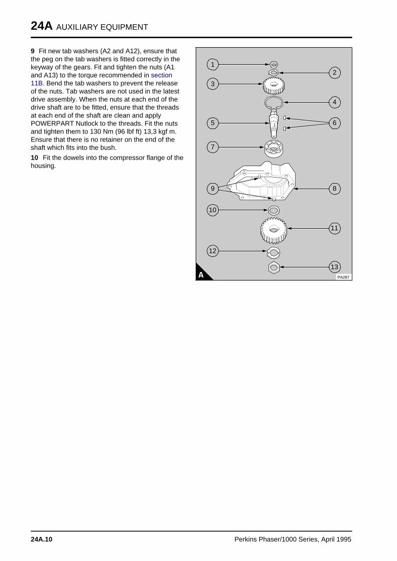
24A AUXILIARY EQUIPMENT
9 Fit new tab washers (A2 and A12), ensure thatthe peg on the tab washers is fitted correctly in thekeyway of the gears. Fit and tighten the nuts (A1and A13) to the torque recommended in section11B. Bend the tab washers to prevent the releaseof the nuts. Tab washers are not used in the latestdrive assembly. When the nuts at each end of thedrive shaft are to be fitted, ensure that the threadsat each end of the shaft are clean and applyPOWERPART Nutlock to the threads. Fit the nutsand tighten them to 130 Nm (96 lbf ft) 13,3 kgf m.Ensure that there is no retainer on the end of theshaft which fits into the bush.
10 Fit the dowels into the compressor flange of thehousing.
PA287
a aa aa aa a
1
a a a
a a a
a a a
a a a
2
a aa aa aa a
3
a a a
a a a
a a a
a a a
4
a a a
a a a
a a a
a a a
a a a
6
a aa aa aa aa a
5
a aa aa aa a
7
a aa aa aa a
9
a a a
a a a
a a a
a a a
8
a a a a
a a a a
a a a a
a a a a
a a a a
10
a a a a
a a a a
a a a a
a a a a
a a a a
11
a a a a
a a a a
a a a a
a a a a
a a a a
12
a a a a
a a a a
a a a a
a a a a
13
24A.10 Perkins Phaser/1000 Series, April 1995
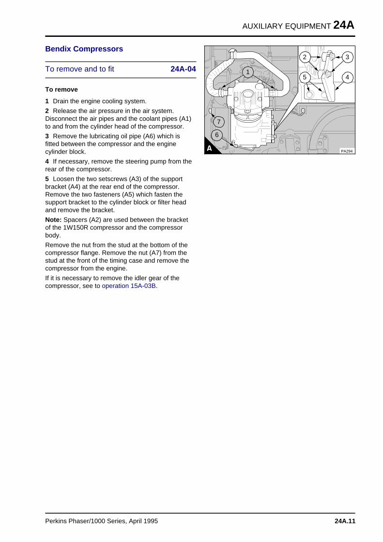
AUXILIARY EQUIPMENT 24A
Bendix Compressors
To remove and to fit 24A-04
To remove
1 Drain the engine cooling system.
2 Release the air pressure in the air system.Disconnect the air pipes and the coolant pipes (A1)to and from the cylinder head of the compressor.
3 Remove the lubricating oil pipe (A6) which isfitted between the compressor and the enginecylinder block.
4 If necessary, remove the steering pump from therear of the compressor.
5 Loosen the two setscrews (A3) of the supportbracket (A4) at the rear end of the compressor.Remove the two fasteners (A5) which fasten thesupport bracket to the cylinder block or filter headand remove the bracket.
Note: Spacers (A2) are used between the bracketof the 1W150R compressor and the compressorbody.
Remove the nut from the stud at the bottom of thecompressor flange. Remove the nut (A7) from thestud at the front of the timing case and remove thecompressor from the engine.
If it is necessary to remove the idler gear of thecompressor, see to operation 15A-03B.
a a a
a a a
a a a
a a a
2
a a a
a a a
a a a
a a a
5 a a a
a a a
a a a
a a a
4
a a a
a a a
a a a
a a a
3
a a a
a a a
a a a
a a a
7
a a a
a a a
a a a
a a a
1
PA294
a a a
a a a
a a a
a a a
6
Perkins Phaser/1000 Series, April 1995 24A.11
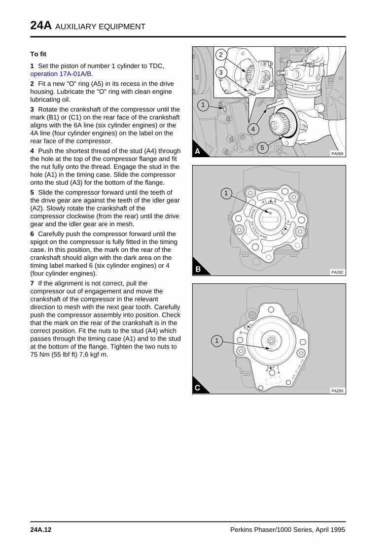
24A AUXILIARY EQUIPMENT
To fit
1 Set the piston of number 1 cylinder to TDC,operation 17A-01A/B.
2 Fit a new "O" ring (A5) in its recess in the drivehousing. Lubricate the "O" ring with clean enginelubricating oil.
3 Rotate the crankshaft of the compressor until themark (B1) or (C1) on the rear face of the crankshaftaligns with the 6A line (six cylinder engines) or the4A line (four cylinder engines) on the label on therear face of the compressor.
4 Push the shortest thread of the stud (A4) throughthe hole at the top of the compressor flange and fitthe nut fully onto the thread. Engage the stud in thehole (A1) in the timing case. Slide the compressoronto the stud (A3) for the bottom of the flange.
5 Slide the compressor forward until the teeth ofthe drive gear are against the teeth of the idler gear(A2). Slowly rotate the crankshaft of thecompressor clockwise (from the rear) until the drivegear and the idler gear are in mesh.
6 Carefully push the compressor forward until thespigot on the compressor is fully fitted in the timingcase. In this position, the mark on the rear of thecrankshaft should align with the dark area on thetiming label marked 6 (six cylinder engines) or 4(four cylinder engines).
7 If the alignment is not correct, pull thecompressor out of engagement and move thecrankshaft of the compressor in the relevantdirection to mesh with the next gear tooth. Carefullypush the compressor assembly into position. Checkthat the mark on the rear of the crankshaft is in thecorrect position. Fit the nuts to the stud (A4) whichpasses through the timing case (A1) and to the studat the bottom of the flange. Tighten the two nuts to75 Nm (55 lbf ft) 7,6 kgf m.
PA069
a a a
a a a
a a a
a a a
2
a a a
a a a
a a a
a a a
3
a a a
a a a
a a a
a a a
1
a a a
a a a
a a a
a a a
5
a a a
a a a
a a a
a a a
4
PA292
a aa aa aa a
1
a aa aa aa a
1
PA293
24A.12 Perkins Phaser/1000 Series, April 1995
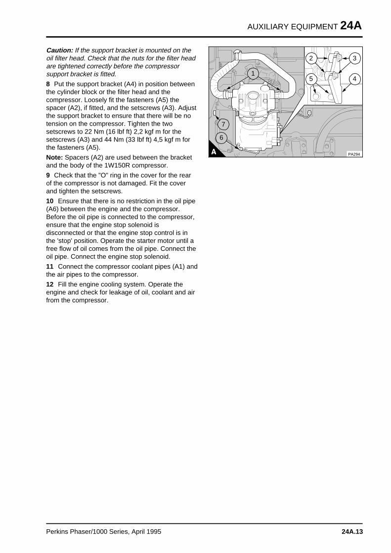
AUXILIARY EQUIPMENT 24A
Caution: If the support bracket is mounted on theoil filter head. Check that the nuts for the filter headare tightened correctly before the compressorsupport bracket is fitted.
8 Put the support bracket (A4) in position betweenthe cylinder block or the filter head and thecompressor. Loosely fit the fasteners (A5) thespacer (A2), if fitted, and the setscrews (A3). Adjustthe support bracket to ensure that there will be notension on the compressor. Tighten the twosetscrews to 22 Nm (16 lbf ft) 2,2 kgf m for thesetscrews (A3) and 44 Nm (33 lbf ft) 4,5 kgf m forthe fasteners (A5).
Note: Spacers (A2) are used between the bracketand the body of the 1W150R compressor.
9 Check that the "O" ring in the cover for the rearof the compressor is not damaged. Fit the coverand tighten the setscrews.
10 Ensure that there is no restriction in the oil pipe(A6) between the engine and the compressor.Before the oil pipe is connected to the compressor,ensure that the engine stop solenoid isdisconnected or that the engine stop control is inthe 'stop' position. Operate the starter motor until afree flow of oil comes from the oil pipe. Connect theoil pipe. Connect the engine stop solenoid.
11 Connect the compressor coolant pipes (A1) andthe air pipes to the compressor.
12 Fill the engine cooling system. Operate theengine and check for leakage of oil, coolant and airfrom the compressor.
a a a
a a a
a a a
a a a
2
a a a
a a a
a a a
a a a
5 a a a
a a a
a a a
a a a
4
a a a
a a a
a a a
a a a
3
a a a
a a a
a a a
a a a
7
a a a
a a a
a a a
a a a
1
PA294
a a a
a a a
a a a
a a a
6
Perkins Phaser/1000 Series, April 1995 24A.13
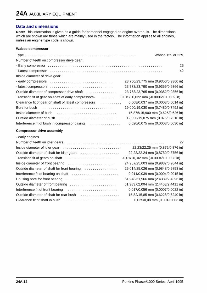
24A AUXILIARY EQUIPMENT
Data and dimensionsNote: This information is given as a guide for personnel engaged on engine overhauls. The dimensionswhich are shown are those which are mainly used in the factory. The information applies to all engines,unless an engine type code is shown.
Wabco compressor
Type . . . . . . . . . . . . . . . . . . . . . . . . . . . . . . . . . . . . . . . . . . . . . . . . . . . . . . . . . Wabco 159 or 229
Number of teeth on compressor drive gear:
- Early compressor . . . . . . . . . . . . . . . . . . . . . . . . . . . . . . . . . . . . . . . . . . . . . . . . . . . . . . . . . . . 26
- Latest compressor . . . . . . . . . . . . . . . . . . . . . . . . . . . . . . . . . . . . . . . . . . . . . . . . . . . . . . . . . . 42
Inside diameter of drive gear:
- early compressors . . . . . . . . . . . . . . . . . . . . . . . . . . . . . . . . . 23,750/23,775 mm (0.9350/0.9360 in)
- latest compressors . . . . . . . . . . . . . . . . . . . . . . . . . . . . . . . . . 23,773/23,790 mm (0.9359/0.9366 in)
Outside diameter of compressor drive shaft . . . . . . . . . . . . . . . . 23,753/23,765 mm (0.9352/0.9356 in)
Transition fit of gear on shaft of early compressors- . . . . . . . . 0,015/+0,022 mm (-0.0006/+0.0009 in)
Clearance fit of gear on shaft of latest compressors . . . . . . . . . . . 0,008/0,037 mm (0.0003/0.0014 in)
Bore for bush . . . . . . . . . . . . . . . . . . . . . . . . . . . . . . . . . . . . . 19,000/19,030 mm (0.7480/0.7492 in)
Inside diameter of bush . . . . . . . . . . . . . . . . . . . . . . . . . . . . . . . 15,875/15,900 mm (0.625/0.626 in)
Outside diameter of bush . . . . . . . . . . . . . . . . . . . . . . . . . . . . . . 19,050/19,075 mm (0.075/0.7510 in)
Interference fit of bush in compressor casing . . . . . . . . . . . . . . . . 0,020/0,075 mm (0.0008/0.0030 in)
Compressor drive assembly
- early engines
Number of teeth on idler gears . . . . . . . . . . . . . . . . . . . . . . . . . . . . . . . . . . . . . . . . . . . . . . . . . . 27
Inside diameter of idler gear . . . . . . . . . . . . . . . . . . . . . . . . . . . . . . 22,23/22,25 mm (0.875/0.876 in)
Outside diameter of shaft for idler gears . . . . . . . . . . . . . . . . . . . . 22,23/22,24 mm (0.8750/0.8756 in)
Transition fit of gears on shaft . . . . . . . . . . . . . . . . . . . . . . . . -0,01/+0,.02 mm (-0.0004/+0.0008 in)
Inside diameter of front bearing . . . . . . . . . . . . . . . . . . . . . . . . . 24,987/25,003 mm (0.9837/0.9844 in)
Outside diameter of shaft for front bearing . . . . . . . . . . . . . . . . . 25,014/25,026 mm (0.9848/0.9853 in)
Interference fit of bearing on shaft . . . . . . . . . . . . . . . . . . . . . . . . 0,011/0,039 mm (0.0004/0.0015 in)
Housing bore for front bearing . . . . . . . . . . . . . . . . . . . . . . . . . . 61,948/61,966 mm (2.4389/2.4396 in)
Outside diameter of front bearing . . . . . . . . . . . . . . . . . . . . . . . . 61,983.62,004 mm (2.4403/2.4411 in)
Interference fit of front bearing . . . . . . . . . . . . . . . . . . . . . . . . . . 0,017/0,056 mm (0.0007/0.0022 in)
Outside diameter of shaft for rear bush . . . . . . . . . . . . . . . . . . . . 15,82/15,85 mm (0.6228/0.6240 in)
Clearance fit of shaft in bush . . . . . . . . . . . . . . . . . . . . . . . . . . . . . . . 0,025/0,08 mm (0.001/0.003 in)
24A.14 Perkins Phaser/1000 Series, April 1995
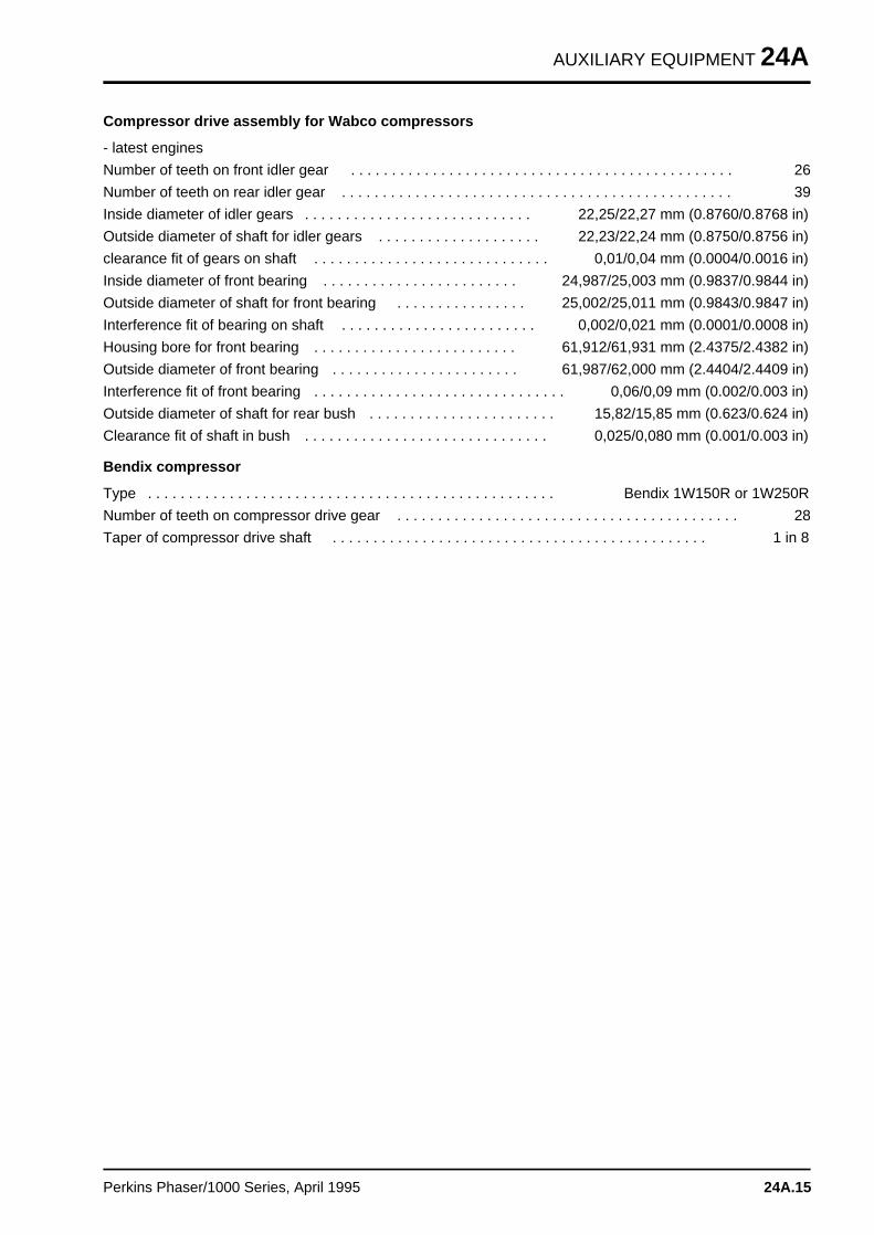
AUXILIARY EQUIPMENT 24A
Compressor drive assembly for Wabco compressors
- latest engines
Number of teeth on front idler gear . . . . . . . . . . . . . . . . . . . . . . . . . . . . . . . . . . . . . . . . . . . . . . . 26
Number of teeth on rear idler gear . . . . . . . . . . . . . . . . . . . . . . . . . . . . . . . . . . . . . . . . . . . . . . . . 39
Inside diameter of idler gears . . . . . . . . . . . . . . . . . . . . . . . . . . . . 22,25/22,27 mm (0.8760/0.8768 in)
Outside diameter of shaft for idler gears . . . . . . . . . . . . . . . . . . . . 22,23/22,24 mm (0.8750/0.8756 in)
clearance fit of gears on shaft . . . . . . . . . . . . . . . . . . . . . . . . . . . . . 0,01/0,04 mm (0.0004/0.0016 in)
Inside diameter of front bearing . . . . . . . . . . . . . . . . . . . . . . . . 24,987/25,003 mm (0.9837/0.9844 in)
Outside diameter of shaft for front bearing . . . . . . . . . . . . . . . . 25,002/25,011 mm (0.9843/0.9847 in)
Interference fit of bearing on shaft . . . . . . . . . . . . . . . . . . . . . . . . 0,002/0,021 mm (0.0001/0.0008 in)
Housing bore for front bearing . . . . . . . . . . . . . . . . . . . . . . . . . 61,912/61,931 mm (2.4375/2.4382 in)
Outside diameter of front bearing . . . . . . . . . . . . . . . . . . . . . . . 61,987/62,000 mm (2.4404/2.4409 in)
Interference fit of front bearing . . . . . . . . . . . . . . . . . . . . . . . . . . . . . . . 0,06/0,09 mm (0.002/0.003 in)
Outside diameter of shaft for rear bush . . . . . . . . . . . . . . . . . . . . . . . 15,82/15,85 mm (0.623/0.624 in)
Clearance fit of shaft in bush . . . . . . . . . . . . . . . . . . . . . . . . . . . . . . 0,025/0,080 mm (0.001/0.003 in)
Bendix compressor
Type . . . . . . . . . . . . . . . . . . . . . . . . . . . . . . . . . . . . . . . . . . . . . . . . . . Bendix 1W150R or 1W250R
Number of teeth on compressor drive gear . . . . . . . . . . . . . . . . . . . . . . . . . . . . . . . . . . . . . . . . . . 28
Taper of compressor drive shaft . . . . . . . . . . . . . . . . . . . . . . . . . . . . . . . . . . . . . . . . . . . . . . 1 in 8
Perkins Phaser/1000 Series, April 1995 24A.15
AUXILIARY EQUIPMENT 24B
Power steering pum p 24B
Power steering pump
24B-01 To remove and to fit . . . . . . . . . . . . . . . . . . . . . . . . . . . . . . . . . 24B.02
Adaptor for a hydraulic pump or a steering pump with a splined drive
24B-02 To remove and to fit . . . . . . . . . . . . . . . . . . . . . . . . . . . . . . . . . 24B.0324B-03 To dismantle and to assemble . . . . . . . . . . . . . . . . . . . . . . . . . . 24B.03
Perkins Phaser/1000 Series, April 1995 24B.01
24B AUXILIARY EQUIPMENT
Power steering pump
To remove and to fit 24B-01
To remove
1 Disconnect the pipe connections at the powersteering pump and fit covers to the open ends ofthe pipes.
2 Release the setscrews and remove the pump. Ifthe pump is fitted to the rear of the compressor,ensure that the drive coupling is not lost.
To fit
1 Renew the "O" ring and lubricate it with cleanengine lubricating oil.
2 Check the drive coupling or the gear for wear orfor damage. Renew it, if necessary.
3 If necessary, fit the drive coupling to the end ofthe compressor shaft and rotate the pump shaft toalign the drive with the coupling. Fit the pump to thecompressor and tighten the setscrews.
4 Remove the covers from the open ends of thepipes.and connect the connections.
24B.02 Perkins Phaser/1000 Series, April 1995
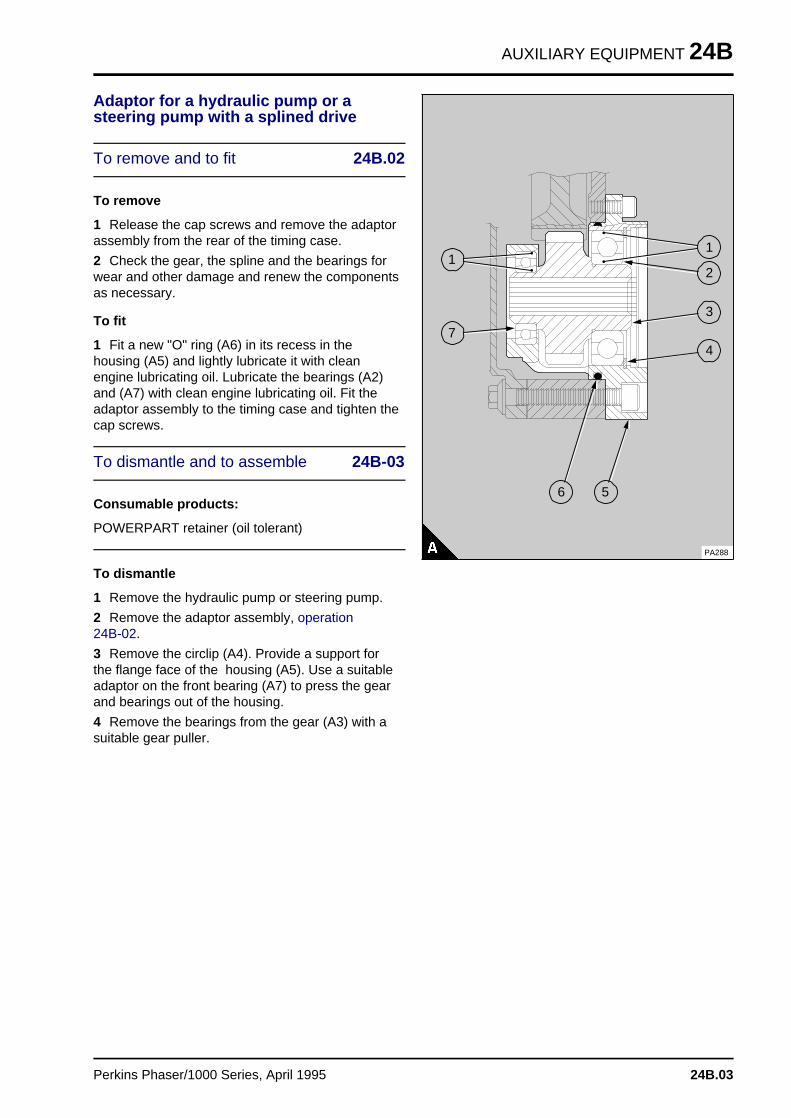
AUXILIARY EQUIPMENT 24B
Adaptor for a hydraulic pump or asteering pump with a splined drive
To remove and to fit 24B.02
To remove
1 Release the cap screws and remove the adaptorassembly from the rear of the timing case.
2 Check the gear, the spline and the bearings forwear and other damage and renew the componentsas necessary.
To fit
1 Fit a new "O" ring (A6) in its recess in thehousing (A5) and lightly lubricate it with cleanengine lubricating oil. Lubricate the bearings (A2)and (A7) with clean engine lubricating oil. Fit theadaptor assembly to the timing case and tighten thecap screws.
To dismantle and to assemble 24B-03
Consumable products:
POWERPART retainer (oil tolerant)
To dismantle
1 Remove the hydraulic pump or steering pump.
2 Remove the adaptor assembly, operation 24B-02.
3 Remove the circlip (A4). Provide a support forthe flange face of the housing (A5). Use a suitableadaptor on the front bearing (A7) to press the gearand bearings out of the housing.
4 Remove the bearings from the gear (A3) with asuitable gear puller.
a aa aa aa a
1
a aa aa aa a
2
a aa aa aa aa a
3
a aa aa aa a
4
a a a
a a a
a a a
a a a
1
a a a
a a a
a a a
a a a
7
a a a
a a a
a a a
a a a
5
a aa aa aa a
6
PA288
Perkins Phaser/1000 Series, April 1995 24B.03
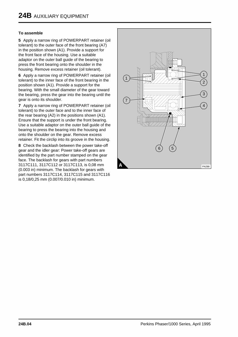
24B AUXILIARY EQUIPMENT
To assemble
5 Apply a narrow ring of POWERPART retainer (oiltolerant) to the outer face of the front bearing (A7)in the position shown (A1). Provide a support forthe front face of the housing. Use a suitableadaptor on the outer ball guide of the bearing topress the front bearing onto the shoulder in thehousing. Remove excess retainer (oil tolerant).
6 Apply a narrow ring of POWERPART retainer (oiltolerant) to the inner face of the front bearing in theposition shown (A1). Provide a support for thebearing. With the small diameter of the gear towardthe bearing, press the gear into the bearing until thegear is onto its shoulder.
7 Apply a narrow ring of POWERPART retainer (oiltolerant) to the outer face and to the inner face ofthe rear bearing (A2) in the positions shown (A1).Ensure that the support is under the front bearing.Use a suitable adaptor on the outer ball guide of thebearing to press the bearing into the housing andonto the shoulder on the gear. Remove excessretainer. Fit the circlip into its groove in the housing.
8 Check the backlash between the power take-offgear and the idler gear: Power take-off gears areidentified by the part number stamped on the gearface. The backlash for gears with part numbers3117C111, 3117C112 or 3117C113, is 0,08 mm(0.003 in) minimum. The backlash for gears withpart numbers 3117C114, 3117C115 and 3117C116is 0,18/0,25 mm (0.007/0.010 in) minimum.
a a a
a a a
a a a
a a a
1
a a a
a a a
a a a
a a a
2
a a a
a a a
a a a
a a a
a a a
3
a a a
a a a
a a a
a a a
4
a a a
a a a
a a a
a a a
1
a a a
a a a
a a a
a a a
7
a a a
a a a
a a a
a a a
5
a a a
a a a
a a a
a a a
6
PA288
24B.04 Perkins Phaser/1000 Series, April 1995
AUXILIARY EQUIPMENT 24C
Exhauste r 24C
Exhauster
24C-01 To remove and to fit . . . . . . . . . . . . . . . . . . . . . . . . . . . . . . . . . 24C.02
Perkins Phaser/1000 Series, April 1995 24C.01
24C AUXILIARY EQUIPMENT
Exhauster
To remove and to fit 24C-01
To remove
1 Disconnect the lubricating oil and vacuum pipesfrom the exhauster and fit covers to the open endsof the pipes.
2 Release the setscrews and remove theexhauster.
To fit
1 Ensure that the joint faces of the exhauster andthe timing case are clean and renew the joint. Fitthe exhauster to the timing case and tighten thesetscrews.
2 Remove the covers from the open ends of thepipes and connect the oil pipe and the vacuum pipeto the exhauster.
24C.02 Perkins Phaser/1000 Series, April 1995
LIST OF SPECIAL TOOLS 25
List of special tool s 25
List of special tools . . . . . . . . . . . . . . . . . . . . . . . . . . . . . . . . . . . . . . . . . . 25A.02
These tools are available through your local Perkins Distributor.
If you cannot obtain the correct tool locally contact:
The Perkins Service Department, Peterborough, PE1 5NA, England, UK.
Tel 01733 67474, Fax 01733 582240, Telex 32501 PERKEN G
Perkins Phaser/1000 Series, April 1995 25A.01
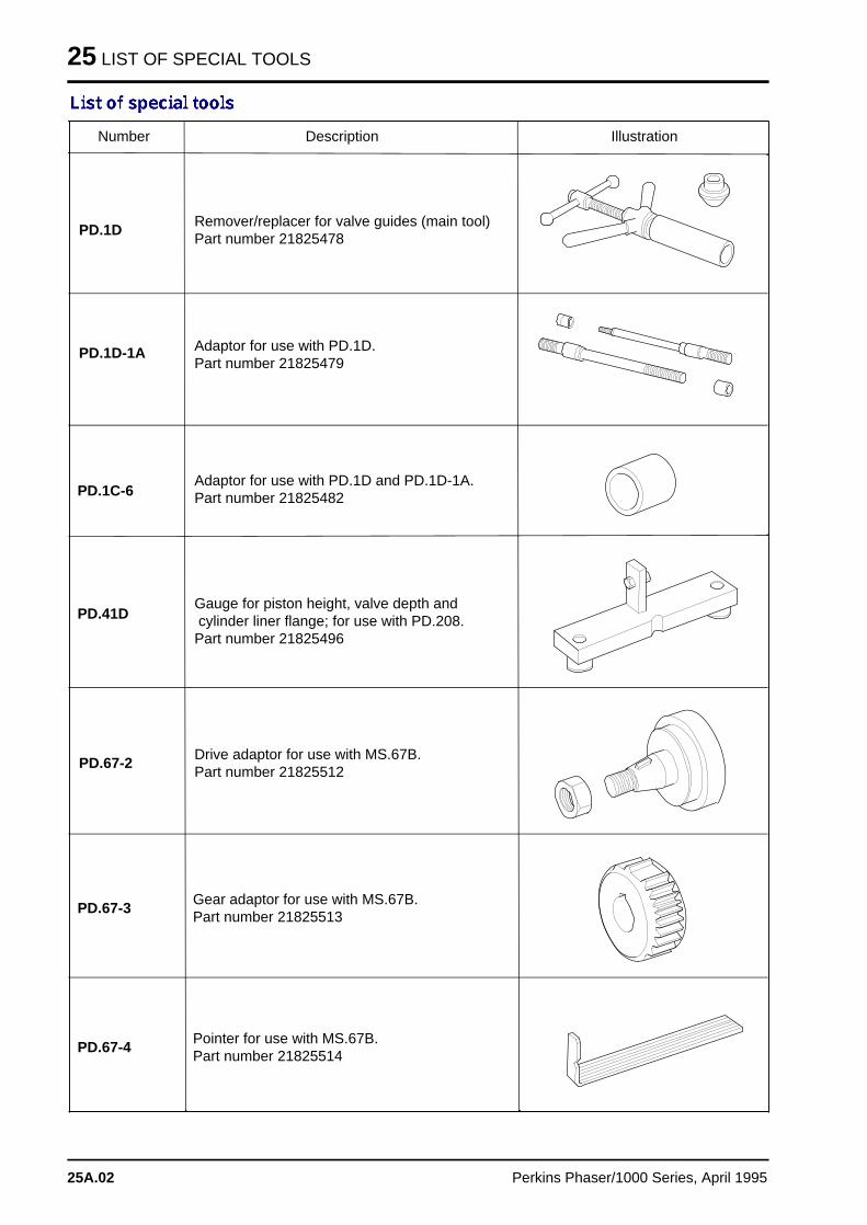
25 LIST OF SPECIAL TOOLS
Number Description Illustration
Remover/replacer for valve guides (main tool)Part number 21825478
PD.1D
PD.1D-1A
PD.41D
PD.67-2
PD.67-3
PD.67-4
PD.1C-6
Adaptor for use with PD.1D.Part number 21825479
Adaptor for use with PD.1D and PD.1D-1A.Part number 21825482
Gauge for piston height, valve depth and cylinder liner flange; for use with PD.208.Part number 21825496
Drive adaptor for use with MS.67B.Part number 21825512
Gear adaptor for use with MS.67B.Part number 21825513
Pointer for use with MS.67B.Part number 21825514
25A.02 Perkins Phaser/1000 Series, April 1995
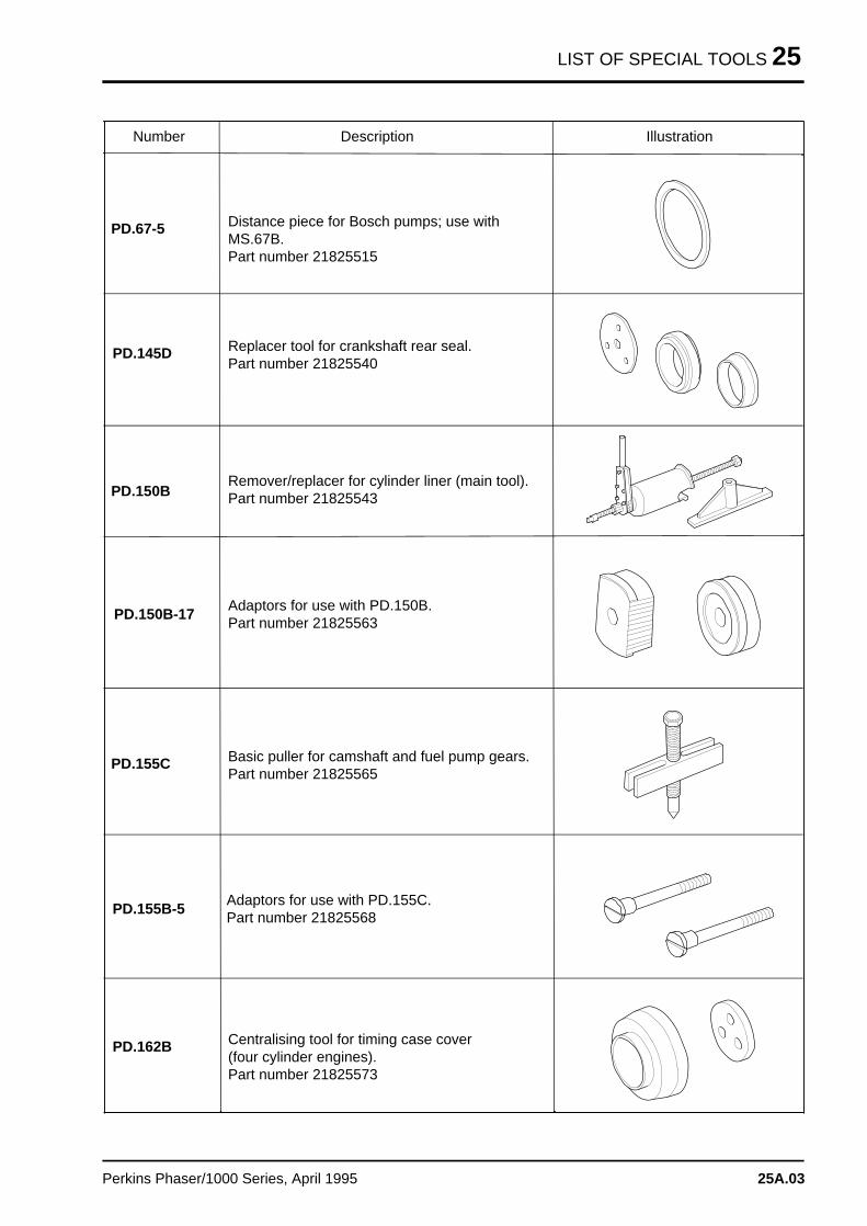
LIST OF SPECIAL TOOLS 25
Number Description Illustration
Distance piece for Bosch pumps; use withMS.67B.Part number 21825515
PD.67-5
PD.145D
PD.150B-17
PD.155C
PD.155B-5
PD.162B
PD.150B
Replacer tool for crankshaft rear seal.Part number 21825540
Remover/replacer for cylinder liner (main tool).Part number 21825543
Adaptors for use with PD.150B.Part number 21825563
Basic puller for camshaft and fuel pump gears.Part number 21825565
Adaptors for use with PD.155C.Part number 21825568
Centralising tool for timing case cover(four cylinder engines).Part number 21825573
Perkins Phaser/1000 Series, April 1995 25A.03
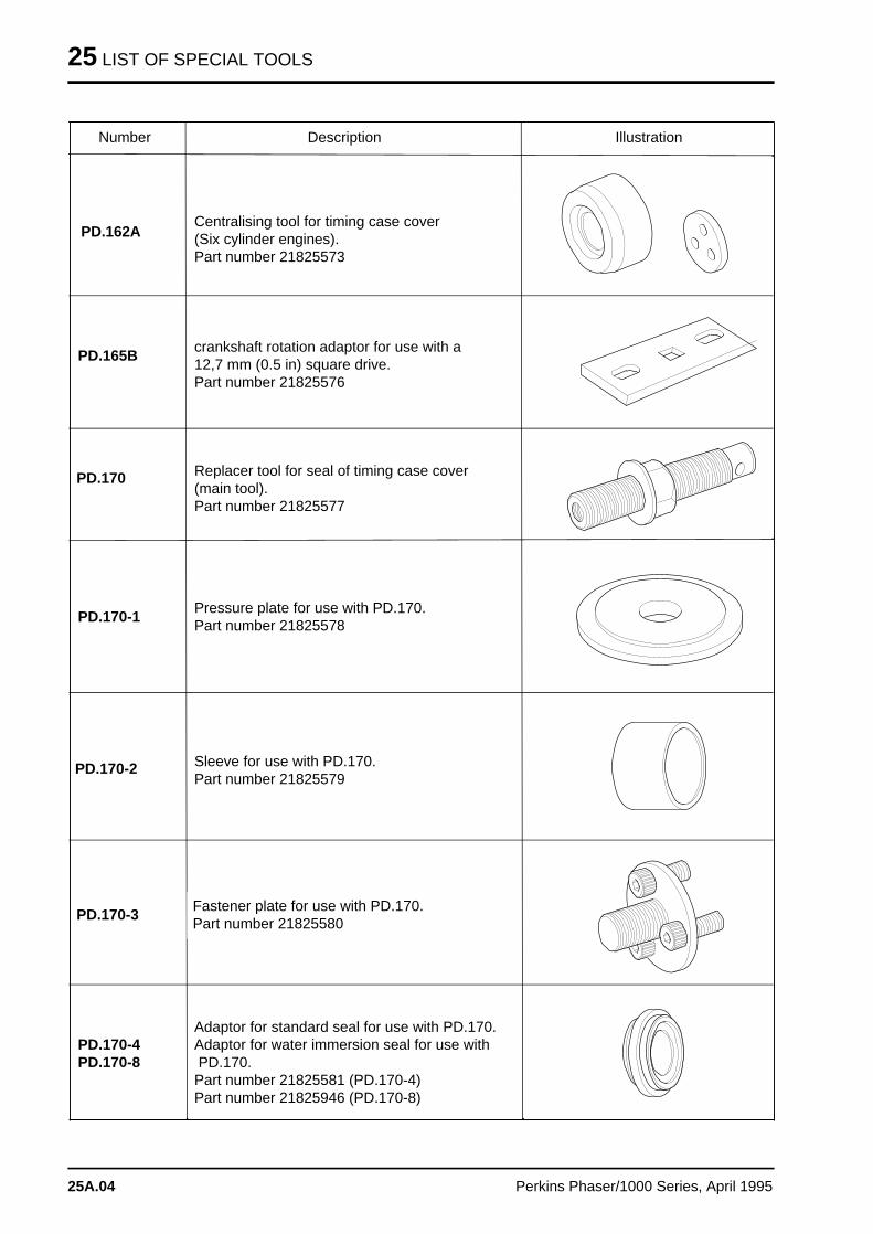
25 LIST OF SPECIAL TOOLS
Number Description Illustration
Centralising tool for timing case cover(Six cylinder engines).Part number 21825573
PD.162A
PD.165B
PD.170-1
PD.170-2
PD.170-3
PD.170-4PD.170-8
PD.170
crankshaft rotation adaptor for use with a12,7 mm (0.5 in) square drive.Part number 21825576
Replacer tool for seal of timing case cover(main tool).Part number 21825577
Pressure plate for use with PD.170.Part number 21825578
Sleeve for use with PD.170.Part number 21825579
Fastener plate for use with PD.170.Part number 21825580
Adaptor for standard seal for use with PD.170.Adaptor for water immersion seal for use with PD.170.Part number 21825581 (PD.170-4)Part number 21825946 (PD.170-8)
25A.04 Perkins Phaser/1000 Series, April 1995
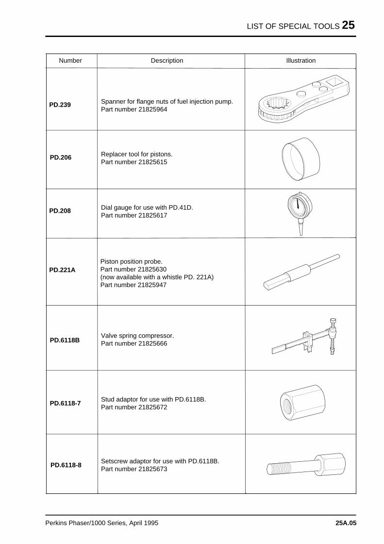
LIST OF SPECIAL TOOLS 25
Number Description Illustration
Spanner for flange nuts of fuel injection pump.Part number 21825964
PD.239
PD.206
PD.221A
PD.6118B
PD.6118-7
PD.6118-8
PD.208
Replacer tool for pistons.Part number 21825615
Dial gauge for use with PD.41D.Part number 21825617
Piston position probe.Part number 21825630(now available with a whistle PD. 221A)Part number 21825947
Valve spring compressor.Part number 21825666
Stud adaptor for use with PD.6118B.Part number 21825672
Setscrew adaptor for use with PD.6118B.Part number 21825673
Perkins Phaser/1000 Series, April 1995 25A.05
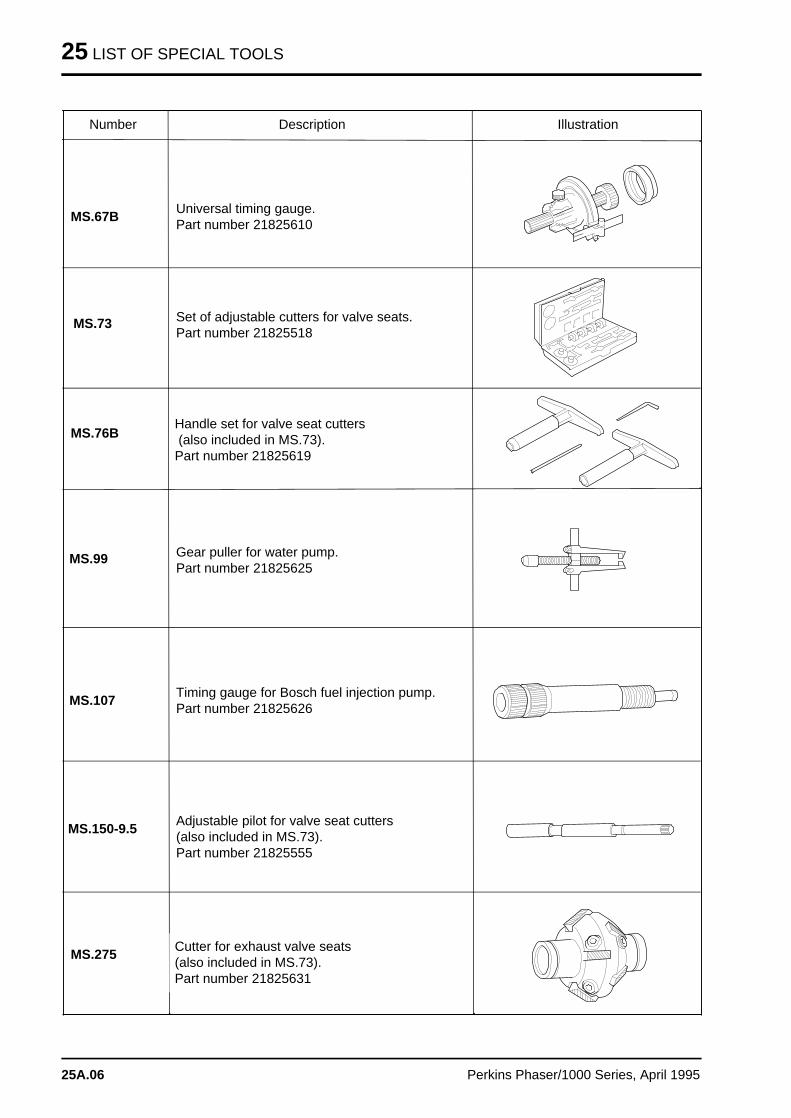
25 LIST OF SPECIAL TOOLS
Number Description Illustration
Universal timing gauge.Part number 21825610
MS.67B
MS.73
MS.99
MS.107
MS.150-9.5
MS.275
MS.76B
Set of adjustable cutters for valve seats.Part number 21825518
Handle set for valve seat cutters (also included in MS.73).Part number 21825619
Gear puller for water pump.Part number 21825625
Timing gauge for Bosch fuel injection pump.Part number 21825626
Adjustable pilot for valve seat cutters(also included in MS.73).Part number 21825555
Cutter for exhaust valve seats (also included in MS.73).Part number 21825631
25A.06 Perkins Phaser/1000 Series, April 1995
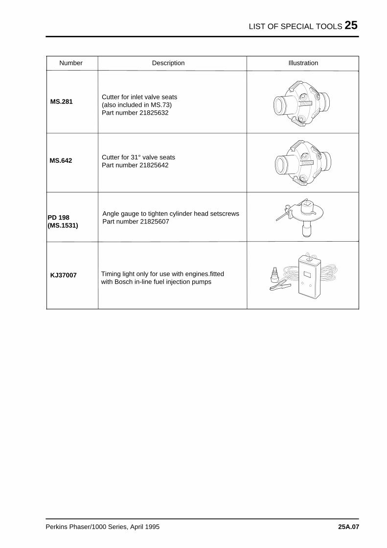
LIST OF SPECIAL TOOLS 25
Number Description Illustration
Cutter for inlet valve seats (also included in MS.73)Part number 21825632
MS.281
MS.642
KJ37007
PD 198(MS.1531)
Angle gauge to tighten cylinder head setscrewsPart number 21825607
Timing light only for use with engines.fittedwith Bosch in-line fuel injection pumps
Cutter for 31° valve seatsPart number 21825642
Perkins Phaser/1000 Series, April 1995 25A.07


