Embed Size (px)
Citation preview
PARKS CANADA KIOSKS PHASE 1
SPECIFICATIONS
Consultant Coles Associates Ltd. Charlottetown, PEI Project #171076 December 08, 2017

Coles Associates Ltd. Architects & Engineers
TABLE OF CONTENTS
Pages
Division 00 - PROCUREMENT AND CONTRACTING REQUIREMENTS
1Section 00 01 18 - Appendices
Division 01 - GENERAL REQUIREMENTS
3Section 01 10 10 - General Requirements
1Section 01 33 00 - Submittal Procedures
8Section 01 35 29 - Health and Safety Procedures
1Section 01 35 43 - Environmental Procedures
2Section 01 45 00 - Quality Control
1Section 01 50 00 - Temporary Facilities
2Section 01 51 00 - Temporary Utilities
1Section 01 52 00 - Construction Facilities
4Section 01 61 00 - Common Product Requirements
1Section 01 74 00 - Cleaning and Waste Management
2Section 01 74 19 - Construction Waste Management and Disposal
6Section 01 78 00 - Closeout Submittals
8Section 01 91 13 - General Commissioning Requirements
Division 03 - CONCRETE
3Section 03 10 00 - Concrete Forming and Accessories
3Section 03 20 00 - Concrete Reinforcing
5Section 03 30 00 - Cast-in-Place Concrete
Division 06 - WOOD, PLASTICS, AND COMPOSITES
Parks Canada Kiosks Phase 1 Section 00 01 10TABLE OF CONTENTS
December 08, 2017 Page 1

Coles Associates Ltd. Architects & Engineers
5Section 06 10 00 - Rough Carpentry
14Section 06 41 00 - Architectural Wood Casework
3Section 06 47 00 - Plastic Laminate Finishing
Division 07 - THERMAL AND MOISTURE PROTECTION
2Section 07 11 13 - Bituminous Dampproofing
2Section 07 21 13 - Board Insulation
4Section 07 21 16 - Blanket Insulation
2Section 07 26 00 - Vapour Retarders
3Section 07 31 29 - Wood Shingles and Shakes
3Section 07 46 23 - Wood Siding
4Section 07 61 00 - Sheet Metal Roofing
3Section 07 62 00 - Sheet Metal Flashing and Trim
8Section 07 92 00 - Joint Sealants
Division 08 - OPENINGS
8Section 08 11 13 - Hollow Metal Doors and Frames
6Section 08 41 13 - Aluminum-Framed Entrance and Storefronts
7Section 08 44 13 - Glazed Aluminum Curtain Walls
4Section 08 51 13 - Aluminum Windows
3Section 08 71 00 - Door Hardware
8Section 08 80 00 - Glazing
Division 09 - FINISHES
9Section 09 21 16 - Gypsum Board Assemblies
11Section 09 30 13 - Ceramic Tiling
Parks Canada Kiosks Phase 1 Section 00 01 10TABLE OF CONTENTS
December 08, 2017 Page 2

Coles Associates Ltd. Architects & Engineers
9Section 09 91 00 - Painting
Division 10 - SPECIALTIES
5Section 10 28 13 - Toilet Accessories
Division 12 - FURNISHINGS
8Section 12 24 13 - Roller Window Shades
Division 21 - FIRE SUPPRESSION
1Section 21 24 16 - Portable Fire Extinguishers
Division 22 - PLUMBING
3Section 22 05 00 - Common Work Results for Plumbing
7Section 22 11 18 - Domestic Water Piping Copper & PEX
2Section 22 13 17 - Drainage Waste and Vent Piping - Cast Iron and Copper
2Section 22 13 18 - Drainage Waste and Vent Piping - Plastic
2Section 22 30 05 - Domestic Water Heaters
6Section 22 42 01 - Plumbing Specialties and Accessories
3Section 22 42 03 - Washroom Fixtures
2Section 22 47 00 - Drinking Fountains and Water Coolers
Division 23 - HEATING VENTILATING AND AIR CONDITIONING
3Section 23 05 00 - Common Work Results for HVAC
4Section 23 05 01 - Installation of Pipework
3Section 23 05 13 - Common Motor Requirements for HVAC Equipment
3Section 23 05 21 - Thermometers and Pressure Gauges - Piping Systems
5Section 23 05 22 - Valves - Bronze
6Section 23 05 29 - Hangers and Supports for HVAC Piping and Equipment
Parks Canada Kiosks Phase 1 Section 00 01 10TABLE OF CONTENTS
December 08, 2017 Page 3

Coles Associates Ltd. Architects & Engineers
6Section 23 05 54 - Mechanical Identification
5Section 23 07 13 - Thermal Insulation for Ducting
7Section 23 20 21 - Thermal Insulation for Piping
5Section 23 31 13 - Metal Ducts - Low Pressure to 500 Pa
4Section 23 33 00 - Air Duct Accessories
3Section 23 33 46 - Flexible Ducts
3Section 23 34 24 - Domestic Fans
3Section 23 81 26 - Split Systems
Division 26 - ELECTRICAL
6Section 26 05 00 - Common Work Results - Electrical
2Section 26 05 20 - Wire and Box Connectors (0 - 1000V)
4Section 26 05 21 - Wires and Cables (0 - 1000V)
2Section 26 05 28 - Grounding - Secondary
1Section 26 05 29 - Hangers and Supports for Electrical Systems
1Section 26 05 31 - Junction and Pull Boxes
2Section 26 05 32 - Outlet Boxes, Conduit Boxes and Fittings
3Section 26 05 34 - Conduits, Conduit Fastenings and Conduit Fittings
2Section 26 05 43.01 - Installation of Cables in Trenches and in Ducts
2Section 26 09 23.04 - Lighting Control Devices - Motion Sensors
1Section 26 24 01 - Service Entrance
2Section 26 24 16.01 - Panelboards Breaker Type
3Section 26 27 26 - Wiring Devices
1Section 26 28 23 - Disconnect Switches - Non-Fused
2Section 26 50 00 - Lighting
Parks Canada Kiosks Phase 1 Section 00 01 10TABLE OF CONTENTS
December 08, 2017 Page 4

Coles Associates Ltd. Architects & Engineers
1Section 26 50 10 - Street Lighting
4Section 26 90 00 - Solar Energy Electrical Power Generation
Division 31 - EARTHWORK
1Section 31 05 13 - Soils for Earthwork
2Section 31 05 19 - Geotextiles
2Section 31 10 00 - Erosion Control
4Section 31 11 00 - Clearing and Grubbing
3Section 31 14 00 - Earth Stripping and Stockpiling
3Section 31 22 13 - Rough Grading
4Section 31 22 19 - Finish Grading
12Section 31 23 00 - Excavation and Fill
Division 32 - EXTERIOR IMPROVEMENTS
1Section 32 01 01 - Miscellaneous Site Items
2Section 32 01 02 - Sitework Demolition and Removal
2Section 32 12 18 - Asphalt Paving for Building Sites
5Section 32 16 00 - Curbs, Gutters, Sidewalks and Driveways
2Section 32 17 23 - Pavement Markings
1Section 32 39 00 - Manufactured Site Specialties
5Section 32 93 00 - Plants
Division 33 - UTILITIES
2Section 33 46 13 - Foundation Drainage
1Section 33 71 73.02 - Underground Electrical Service
Parks Canada Kiosks Phase 1 Section 00 01 10TABLE OF CONTENTS
December 08, 2017 Page 5

Coles Associates Ltd. Architects & Engineers
LIST OF DRAWINGS
A0 COVER PAGE
A1 PLANS AND ELEVATIONS
A2 BUILDING SECTIONS, WALL SECTIONS AND DETAILS
A3 WINDOW & DOOR SCHEDULES, ELEVATIONS AND MILLWORK
C1 CAWNPORE LANE KIOSK EXISTING SITE PLAN & NEW SITE PLAN
C2 NORTH RUSTICO KIOSK EXISTING SITE PLAN & NEW SITE PLAN
C3 DALVAY KIOSK EXISTING SITE PLAN & NEW SITE PLAN
C4 BAYSHORE KIOSK EXISTING SITE PLAN & NEW SITE PLAN
C5 SITE DETAILS
C6 CRASH PROTECTION & LANDSCAPING DETAILS
M1 MECHANICAL PLANS, DETAILS AND SCHEDULES
E1 CAWNPORE LANE KIOSK ELECTRICAL
E2 NORTH RUSTICO KIOSK ELECTRICAL
E3 DALVAY KIOSK ELECTRICAL
E4 BAYSHORE KIOSK ELECTRICAL
Parks Canada Kiosks Phase 1
December 08, 2017
Section 00 01 10 TABLE OF CONTENTS
Page 6


Coles Associates Ltd. Architects & Engineers
1 General
1.1 APPENDICES.1 Appendix A: Luminaire Schedule
END OF SECTION
Parks Canada Kiosks Phase 1 Section 00 01 18Appendices
December 08, 2017 Page 1

Coles Associates Ltd. Architects & Engineers
1 General
1.1 SCOPE OF WORK.1 The Contractor is to provide each item, and properly execute all work as specified
herein, indicated by drawings, addenda, or change orders issued with respect to this project.
.2 The Contractor shall coordinate, administer, and supervise all work, material acquisition and labour.
.3 The Contractor shall coordinate with Owner and facilitate installation of Owner provided equipment, including but not limited to:
.1 Antenna and cable, coordinate with Electrical drawings..4 In general the scope of work for each of the four (4) sites includes but is not limited to:
.1 Demolition of existing kiosk structure and foundations, steel guard rails and footings, concrete curb where noted and light standards. Coordinate site specific scopes with Civil drawings.
.2 Supply and installation of new slab-on-grade wood framed kiosk structure complete with cast in place foundation.
.3 Supply and installation of new doors, frames, hardware, glazing units, custom millwork, metal roof system, interior and exterior finishes, fixtures and accessories as specified on Drawings.
.4 Supply and installation of new asphalt base and seal complete with painted line markings to reflect new site design at Cawnpore Lane and Dalvay. Supply and installation of painted line markings at each of the North Rustico and Bayshore sites in accordance with the new site design.
.5 Supply and installation of new cast in place concrete pad(s) at kiosk entrance lanes, coordinate quantities with Civil drawings.
.6 Create one (1) staff parking space, unmarked, at each location, as indicated on the drawings where nonexistent. Import fill and/or gravel, as required, to establish required grade and dimensions.
.7 Supply and installation of three (3) new flashing amber lights.
.8 Supply and installation of four (4) new LED light standards.
.9 Supply and installation of new colored concrete median complete with cast in place curb at entrance/exit median.
.10 Supply and installation of new concrete crash protection barrier complete with shrubbery landscape finish.
.11 Supply and installation of three (3) new asphalt embedded traffic sensor loops wired to traffic counter inside new kiosk structure.
.12 Supply and installation of two (2) new entry gates complete with concrete filled steel bollard protection and push button control inside new kiosk structure.
.13 Supply and installation of new concrete entry ramp complete with landings at top and bottom of slope.
.14 Supply and installation of three (3) roof top mounted panel, photovoltaic system.
.15 Supply and installation of one (1) fully functional mini-split heat pump complete with required piping, equipment and accessories.
.16 Supply and installation of one (1) washroom lavatory, one (1) water closet, and one (1) bottle filling station and associated piping.
.17 Supply and installation of one (1) exhaust fan complete with integral backdraft damper.
.18 Supply and installation of one (1) domestic water heater complete with required piping, equipment, and accessories.
.19 Perform Mechanical work of plumbing, HVAC and controls systems for the new
Parks Canada Kiosks Phase 1 Section 01 10 10General Requirements
December 08, 2017 Page 1

Coles Associates Ltd. Architects & Engineers
kiosk building..20 Perform Electrical work of associated lighting, electrical wiring and distribution
and all electrical systems for the new kiosk building as indicated on the drawings.
1.2 EXECUTION.1 Execute work with least possible interference or disturbance to building operations,
public and normal use of premises, including roads.
1.3 DOCUMENTS.1 The Contract Documents are complementary and what is called for by anyone shall be
as binding as if called for by all..2 Descriptions of materials or work which have well known technical or trade meanings
shall be held to refer to such recognized standards..3 All specifications shall be interpreted in conformity with the agreement.
1.4 COMMUNICATION.1 All submissions and inquiries shall be directed to the Departmental Representative for
review..2 All direction will be transmitted to the Contractor by the Departmental Representative.
1.5 CODES AND REGULATIONS.1 Perform work in accordance with National Building Code of Canada (NBC) 2010 and any
other code of provincial or local application, provided that in any case of conflict or discrepancy the more stringent requirements shall apply.
.2 Meet or exceed requirements of contract documents and specified standards.
.3 References to standards, including manufacturer's direction for installation shall be the latest edition.
.4 All materials, components and equipment as well as construction methods shall comply with the latest edition of the National Building Code and all other applicable Provincial codes or regulations.
.5 The latest edition of the Canadian Electrical Code shall govern all electrical work, whether pre-wired an/or assembled remote from the site or not.
.6 All equipment supplied or installed shall be CSA approved for the intended use.
.7 The latest edition of the Canada Labour Code Part 2 and the PEI Occupational Health and Safety Act and Regulations shall govern safe construction practices.
.8 Provide a copy of all certificates of acceptance issued by Provincial or local authorities.
1.6 WORK SCHEDULE AND PROGRESS REPORTS.1 The Contractor will prepare and maintain a consolidated schedule in weekly increments
showing scheduled work versus actual work. The schedule shall indicate the contract commencement and completion date for the total project.
.2 Provide updated schedule information from time to time as the progress of the work or Departmental Representative may require.
1.7 CONTRACTOR'S USE OF SITE.1 Do not unreasonably encumber site with materials or equipment..2 Move stored products or equipment, which interfere with operations of Departmental
Representative or other Contractors..3 Obtain and pay for use of additional off site storage or work areas needed for operations..4 The work related to modifying the site roadways must be carried out so that one half of
the roadway is open to vehicle traffic at all times..5 Provide snow clearing to allow for access to site at all times.
Parks Canada Kiosks Phase 1 Section 01 10 10General Requirements
December 08, 2017 Page 2
Coles Associates Ltd. Architects & Engineers
1.8 PROJECT MEETINGS.1 Project meetings will be held as needed or as directed by the Departmental
Representative..2 Notify all parties concerned of such meetings. Anticipate weekly increments..3 The Contractor will record minutes of meetings and distribute to all parties within three
(3) days of meeting..4 Failure of the Contractor to accurately record minutes or distribute the minutes in a
timely manner may result in the Departmental Representative taking over the duties and invoicing the Contractor and deducting costs from the progress claims as compensation.
1.9 SITE INSPECTOR.1 No work is to be covered without having received approval from the Departmental
Representative. The Departmental Representative will have the authority to cause any part of the work to cease, should, in his or her opinion, there be cause to do so.
.2 This work shall be examined by the Departmental Representative and approval granted to resume when a satisfactory solution has been found out.
1.10 EXISTING SERVICES.1 Before commencing work, establish the location and extent of known service lines and
utilities and notify Departmental Representative of findings if in conflict with information or intent shown.
.2 Where unknown services are encountered, immediately advise Departmental Representative and confirm findings in writing.
.3 Contractor to be responsible for any damages caused by failure to locate, coordinate with, and preserve any and all existing underground services.
1.11 ACCESS AND SECURITY.1 Access and security on the entire job site will be the responsibility of the Contractor.
1.12 RELICS AND ANTIQUITIES.1 Relics and antiquities and items of historical or scientific interest such as cornerstones
and contents, commemorative plaques, inscribed tablets, and similar objects found during the work, shall remain property of the Owner. Protect such articles and request directives from Departmental Representative.
.2 Give immediate notice to Departmental Representative if evidence of archaeological finds are encountered during construction, and await Departmental Representative's written instructions before proceeding with work in this area.
END OF SECTION
Parks Canada Kiosks Phase 1 Section 01 10 10General Requirements
December 08, 2017 Page 3
Coles Associates Ltd. Architects & Engineers
1 General
1.1 ADMINISTRATIVE.1 Submit to Departmental Representative submittals listed for review. Submit 10 working
days after award of contract in orderly sequence to not cause delay in Work. Failure to submit in ample time is not considered sufficient reason for extension of Contract Time and no claim for extension by reason of such default will be allowed.
.2 Do not proceed with Work affected by submittal until review is complete.
.3 Present shop drawings, product data, samples and mock-ups in SI Metric units.
.4 Where items or information is not produced in SI Metric units converted values are acceptable.
.5 Review submittals prior to submission to Departmental Representative. This review represents that necessary requirements have been determined and verified, or will be, and that each submittal has been checked and co-ordinated with requirements of Work and Contract Documents. Submittals not stamped, signed, dated and identified as to specific project will be returned without being examined and considered rejected.
.6 Notify Departmental Representative, in writing at time of submission, identifying deviations from requirements of Contract Documents stating reasons for deviations.
.7 Verify field measurements and affected adjacent Work are co-ordinated.
.8 Contractor's responsibility for errors and omissions in submission is not relieved by Departmental Representative's review of submittals.
.9 Contractor's responsibility for deviations in submission from requirements of Contract Documents is not relieved by Departmental Representative review.
.10 Keep one reviewed copy of each submission on site.
1.2 General.1 At Commencement of Contract (and no later than 10 days after award) submit the
following:.1 Cost Breakdown.2 Permits as required.3 Construction schedule for Trade Package activity .4 Name of Project Superintendent.5 Corporate Safety Plan.6 Site specific safety plan.7 Shop drawing schedule
.2 During Construction submit the following:.1 Updated trade construction schedule.2 Shop drawings as required.3 Inspection and test reports.4 Request for Information
.3 Completion of Work submit the following:.1 Submission at completion of work as specified in Project Close Out,
Commissioning, and Operations and Maintenance Data Sections.
END OF SECTION
Parks Canada Kiosks Phase 1 Section 01 33 00Submittal Procedures
December 08, 2017 Page 1

Coles Associates Ltd. Architects & Engineers
1 General
1.1 RELATED SECTIONS.1 Section 01 33 00 - Submittal Procedures.
1.2 REFERENCES.1 Canada Labour Code, Part 2, Canada Occupational Safety and Health Regulations..2 Health Canada/Workplace Hazardous Materials Information System (WHMIS).
.1 Material Safety Data Sheets (MSDS)..3 Province of Prince Edward Island
.1 Occupational Health and Safety Act, R.S.P.E.I. 1988.
1.3 SUBMITTALS.1 Make submittals in accordance with Section 01 33 00 - Submittal Procedures..2 Submit site-specific Health and Safety Plan: Within 7 days after date of Notice to
Proceed and prior to commencement of Work. Health and Safety Plan must include:.1 Part 1: List of individual health risks and safety hazards identified by hazard
assessments. .2 Part 2: List specific measures to control or mitigate each hazard and risk
identified in part one of Plan. State engineering controls, personal protective equipment and safe work practices to be used for work having identified hazards(s) or risk(s).
.3 Part 3: Emergency and Communications Measures as follows:.1 Emergency Procedures: standard operating procedures, evacuation
measures and emergency response implemented on site during an accident or incident. State step by step procedures, applicable to each identified hazard.
.2 Emergency Communications: list names and telephone numbers of officials, to be contacted if incident, accident or emergency situation occurs, including:
.3 General Contractor and all Subcontractors.
.4 Provincial Departments and resources from local emergency organizations, based on type of hazard, incident or accident which might occur and as stipulated in applicable laws and regulations.
.3 Submit 2 copies of Contractor's authorized representative's work site health and safety inspection reports to Departmental Representative.
.4 Submit copies of incident and accident reports.
.5 Submit WHMIS MSDS - Material Safety Data Sheets in accordance with Section 02 61 00 - Hazardous Facility Remediation.
.6 Departmental Representative will review Contractor's site-specific Health and Safety Plan and provide comments to Contractor within 5 days after receipt of plan. Revise plan as appropriate and resubmit plan to Departmental Representative within 2 days after receipt of comments from Departmental Representative.
.7 Departmental Representative's review of Contractor's final Health and Safety plan should not be construed as approval and does not reduce the Contractor's overall responsibility for construction Health and Safety.
.8 On-site Contingency and Emergency Response Plan:address standard operating procedures to be implemented during emergency situations.
1.4 SITE CONTROL AND ACCESS.1 Control work site and entry points. Grant and allow entry to only workers and other
persons so authorized. Immediately stop non-authorized persons from circulating within
Parks Canada Kiosks Phase 1 Section 01 35 29Health and Safety Procedures
December 08, 2017 Page 1
Coles Associates Ltd. Architects & Engineers
construction areas and remove from site..2 Prior to gaining access to the site, all contractors, subcontractors and suppliers shall file
with the General Contractor their proof of Workers Compensation coverage, proof of required Insurance and proof of contract. Upon request, proof of these documents will be provided to the Owner and Departmental Representative.
.3 Delineate and isolate construction areas from other areas of site by use of appropriate means. Erect barricades, fences, hoarding and temporary lighting as required.
.4 Erect signage at entry points and at other strategic locations around site, clearly identifying construction area(s) as being "off limits" to non-authorized persons. Signage must be professionally made.
.5 Ensure persons granted access are fitted and wear appropriate personal protective equipment (PPE).
1.5 PROTECTION.1 Provide temporary facilities for protection and safe passage of building occupants, public
pedestrian and vehicular traffic around and adjacent to work site..2 Provide safety barricades, lights and signage on work site as required to provide a safe
working environment for workers.
1.6 PERMITS.1 Obtain permits, licenses and compliance certificates, at appropriate times and frequency
as stipulated by authorities having jurisdiction..2 Post all permits on site. Submit copies to Departmental Representative.
1.7 FILING OF NOTICE.1 File Notice of Project and other Notices with Provincial authorities prior to
commencement of Work.
1.8 SAFETY ASSESSMENT.1 Perform site specific safety hazard assessment related to project..2 Perform on-going hazard assessments during the progress of Work identifying new or
potential health risks and safety hazards not previously known. As a minimum hazard assessments shall be carried out when:
.1 New subtrade work, new subcontractor(s) or new workers arrive at the site to commence another portion of work.
.2 The scope of work has been changed by Change Order.
.3 Potential hazard or weakness in current health and safety practices are identified by Departmental Representative or by an authorized safety representative.
.3 Each hazard assessment to be made in writing. Keep copies of all assessments on site for duration of Work. Upon request, make available to Departmental Representative for inspection.
.4 Contractor to conduct a hazard assessment in conjunction with the Owner's maintenance staff as part of the planning process including isolating existing equipment where applicable and identification of hidden services where anchoring is required. Hazard Assessments to conform with requirements of Health and Safety Section 01 35 29.
1.9 MEETINGS.1 Prior to commencement of work hold Health and Safety meeting. Have Contractor's Site
Superintendent in attendance. .2 Provide site safety orientation session to all workers and other authorized persons prior
to granting them access to work site. Brief persons on site conditions and on the minimum site safety rules in force at site.
Parks Canada Kiosks Phase 1 Section 01 35 29Health and Safety Procedures
December 08, 2017 Page 2

Coles Associates Ltd. Architects & Engineers
.3 Conduct site specific occupational health and safety meetings during the entire work as follows:
.1 Formal meetings on a minimum monthly basis.
.2 Informal tool box meetings on a regular basis from a predetermined schedule..4 Keep workers informed of anticipated hazards, on safety practices and procedures to be
followed and of other pertinent safety information related to:.1 Progress of Work;.2 New sub-trades arriving on site and;.3 Changes in site and project conditions.
.5 Record and post minutes of meetings. Make copies available to Departmental Representative upon request.
1.10 COMPLIANCE REQUIREMENTS.1 Comply with Canada Labour Code, Canada Occupational Safety and Health
Regulations..2 Comply with Occupational Health and Safety Act, Occupational Health and Safety Act
Regulations, PEI..3 Provide Departmental Representative with Material Safety Data Sheets (MSDS)..4 Observe and enforce construction safety measures required by National Building code,
2015 Part 8, Provincial Government, Worker's Compensation Board and municipal statutes and authorities.
1.11 WHMIS.1 Comply with requirements of Workplace Hazardous Materials Information System
(WHMIS) regarding use, handling, storage, and disposal of hazardous materials; and regarding labeling and provision of material safety data sheets acceptable to Labour Canada and Health and Welfare Canada and Provincial Department of Labour.
.2 Submit WHMIS data sheets to Departmental Representative in accordance with Section 01 33 00 Submittal Procedures.
.3 Maintain WHMIS information station and ensure designated personnel are trained in its use.
.4 Submit copies of all Tool Box or Safety Meeting notes.
.5 Submit copies of all Worksite Safety Inspections.
1.12 UNFORSEEN HAZARDS.1 When unforeseen or peculiar safety-related factor, hazard, or condition occur during
performance of Work, follow procedures in place for Employee's Right to Refuse Work in accordance with Acts and Regulations of Province having jurisdiction and advise Departmental Representative verbally and in writing.
1.13 HEALTH AND SAFETY CO-ORDINATOR.1 Employ and assign to Work, competent and authorized representative as Health and
Safety Co-coordinator. Health and Safety Co-coordinator must:.1 Have working knowledge of occupational safety and health regulations..2 Be responsible for completing Contractor's Health and Safety Training Sessions
and ensuring that personnel not successfully completing required training are not permitted to enter site to perform Work.
.3 Be responsible for implementing, enforcing daily and monitoring site-specific Contractor's Health and Safety Plan.
1.14 CONSTRUCTION SAFETY MEASURES.1 Observe and enforce construction safety measures required by National Building Code,
2015 Part 8, Provincial Government, Worker's Compensation Board and municipal
Parks Canada Kiosks Phase 1 Section 01 35 29Health and Safety Procedures
December 08, 2017 Page 3
Coles Associates Ltd. Architects & Engineers
statutes and authorities..2 In event of conflict between any provisions of above authorities the most stringent
provision governs..3 PEI Occupational Health and Safety Act and regulations, guidelines and code practice,
stipulate standard equipment applicable to construction sites such as protective clothing, safety hats and boots, gloves, eye protection.
.4 Provide and maintain first aid equipment, supplied and medications appropriate to the work and its location in accordance with the First Aid Regulations. Obtain and implement recommendations from Occupational Health and Safety Division specific to the project work site.
.5 Identify and mark overhead hazards.
1.15 FIRE SAFETY REQUIREMENTS.1 Comply with requirements of latest standard for Building Construction Operations issued
by the Fire Commissioner of Canada and Fire Safety Regulations of Local Authority.
1.16 OVERLOADING.1 Ensure no part of work is subjected to a load that will endanger its safety or cause
permanent deformation.
1.17 WELDING AND CUTTING.1 Use noncombustible shields for electric and gas welding or cutting executed within two
(2) metes of combustible material or in occupied space..2 Place tanks supplying gases as close to work as possible. Fix in upright position, free
from exposure to sun or high temperatures..3 Locate fire extinguishing equipment near all welding and cutting operations.
1.18 TESTING AND MONITORING.1 Test and monitor for hazardous conditions, as required to demonstrate compliance with
provincial regulations..2 If multiple locations are being worked simultaneously, provide monitoring at all locations
where work is being carried out, including providing additional monitoring instruments.
1.19 RECORD KEEPING.1 ALL activities associated with Health and Safety shall be recorded daily in a bound
notebook. Include as a minimum; activity date, time, location of occurrence, mitigation action taken and results. Records shall be assessed by the Departmental Representative.
1.20 OPEN FLAMES, SPARKS, EXPLOSION PROTECTION.1 Keep open flames and sparks to minimum. When flame or sparks are required, follow
proper procedures to prevent fire or explosion.
1.21 FIRE SAFETY.1 The Sub-Contractors are to participate on the Fire Safety Committee under the Joint
Health and Safety Committee. The Fire Safety Committee under the direction of the Contractor is responsible for implementation and maintenance of the Construction Fire Safety Plan.
.2 Construction Fire Safety Plan:.1 The Construction Fire Safety Plan will include the following:
.1 Introduction of plan and purpose.
.2 Fire Safety Committee.
.3 Terms of reference.
Parks Canada Kiosks Phase 1 Section 01 35 29Health and Safety Procedures
December 08, 2017 Page 4

Coles Associates Ltd. Architects & Engineers
.2 Committee composition.
.3 Emergency Procedures.
.4 Fire protection equipment:
.5 .1Provisions for fire fighting.
.6 .2Portable extinguishers.
.7 Fire safety maintenance schedule:.1 General..2 Maintenance levels..3 Skill categories..4 Frequency..5 Checklists.
.8 Other information:.1 Instruction on use of fire extinguishers..2 Emergency Fire Drill procedures.
.3 Portable Fire Extinguishers:.1 During construction, Contractor is to provide and maintain on the site at all times,
ULC listed 25 lb ABC dry chemical type portable fire extinguishers..4 Blockage of Roadways:
.1 The Fire Department shall be advised of any work that would impede fire apparatus response. This includes violation of minimum overhead clearance, as prescribed by the Fire Department, erecting of barricades and the digging of trenches.
.5 Rubbish and Waste Materials:.1 Rubbish and waste materials are to be kept to a minimum..2 The burning of rubbish is prohibited..3 Removal:
.1 All rubbish shall be removed from the work site at the end of the workday or shift or as directed by Departmental Representative.
.4 Storage:.1 Extreme care is required where it is necessary to store oily waste in work
areas to ensure maximum possible cleanliness and safety..2 Greasy or oily rags or materials subject to spontaneous ignition shall be
deposited and kept in an approved receptacles..6 Flammable Liquids:
.1 The handling, storage and use of flammable liquids are to be governed by the current National Fire Code of Canada.
.2 Flammable liquids such as gasoline, kerosene and naphtha may be kept for ready use in quantities not exceeding 45 liters provided they are stored in approved safety cans bearing the Underwriter's Laboratory of Canada or Factory Mutual seal of approval. Storage of quantities of flammable liquids exceeding 45 liters for work purposes, requires the permission of the Fire Department.
.3 Transfer of flammable liquids having a flash point below 38ºC is prohibited within buildings.
.4 Transfer of flammable liquids shall not be carried out in the vicinity of open flames or any type of heat-producing devices.
.5 Flammable liquids having a flash point below 38ºC, such as naphtha or gasoline, shall not be used as solvents or cleaning agents.
.6 Flammable waste liquids, for disposal, shall be stored in approved containers located in a safe ventilated area. Quantities are to be kept to minimum and the Fire Department is to be notified when disposal is required.
.7 Fire Inspection:
Parks Canada Kiosks Phase 1 Section 01 35 29Health and Safety Procedures
December 08, 2017 Page 5
Coles Associates Ltd. Architects & Engineers
.1 The Fire Department shall be allowed unrestricted access to the work site.
.2 The Contractor shall cooperate with the Fire Department during routine inspections of the work site.
.3 The Contractor shall immediately remedy all unsafe fire situations observed by the Fire Department.
1.22 POSTING OF DOCUMENTS.1 Ensure applicable items, articles, notices and orders are posted in conspicuous location
on site in accordance with Acts and Regulations of Province having jurisdiction, and in consultation with Departmental Representative.
1.23 CORRECTION OF NON-COMPLIANCE.1 Immediately address health and safety non-compliance issues identified by authority
having jurisdiction or by Departmental Representative..2 Provide Departmental Representative with written report of action taken to correct non-
compliance of health and safety issues identified..3 Departmental Representative may stop Work if non-compliance of health and safety
regulations is not corrected.
1.24 BLASTING.1 Blasting or other use of explosives is not permitted.
1.25 POWDER ACTUATED DEVICES.1 Use powder actuated devices only after receipt of written permission from Departmental
Representative.
1.26 WORK STOPPAGE.1 Give precedence to safety and health of public and site personnel and protection of
environment over cost and schedule considerations for Work.
1.27 HANDLING AND TRANSPORTATION OF DANGEROUS GOODS.1 Observe and enforce all measures required by the regulatory agencies including but not
limited to Environment Canada, Prince Edward Island Department of Environment, and Transport Canada.
.2 Most current regulatory guidelines and Acts will apply to the work.
.3 In case of any conflict, the more stringent requirements will apply.
1.28 OPEN EXCAVATIONS.1 If open trenches are to be left at the end of a work day, protective fencing must be
placed around the entire perimeter to limit access by others. Fencing to be self-supporting, approved by the Department of Labour and the Construction Safety and Industrial Safety Regulations.
1.29 POTENTIAL HAZARDS.1 Hazards include, but are not limited to, electrocution and toxic, flammable and explosion
hazards associated with cleaning solvents..2 The Contractor shall become familiar with all potential hazards associated with the work,
and shall take necessary measures to avoid injury or damage of any kind.
1.30 HEALTH AND SAFETY PLAN .1 Prior to commencement of the work, submit to the Site Inspector a detailed Health and
Safety Plan for review. The Health and Safety Plan shall comply with the provisions of this section, and shall illustrate the Contractor's knowledge and understanding of health and safety aspects of the work, the Contractor's intention to maintain a high level of
Parks Canada Kiosks Phase 1 Section 01 35 29Health and Safety Procedures
December 08, 2017 Page 6
Coles Associates Ltd. Architects & Engineers
safety on-site, and shall include, but not be limited to:.1 Description of Work.2 Description of Site-specific hazards:
.1 Physical
.2 Chemical
.3 Environmental
.4 Electrical.3 Protective Equipment:
.1 Respiratory
.2 Contact
.3 Electrical personal protective equipment (PPE).4 Decontamination Procedures:
.1 Personal protective equipment (PPE)
.2 Equipment.5 Medical - Monitoring:
.1 Workers medical profile and suitability to work at the site..6 Emergency Procedures:
.1 Emergency Equipment
.2 Contingency Plans:.7 General Safety:
.1 Designation of site-safety officer
.2 Safety log
.3 Trenching, digging, excavations
.4 Storage of flammables
.5 Safety inspections.8 Site Training:
.1 Initial hazard
.2 Daily safety.2 All workers shall be trained and be familiar with the Health and Safety Plan and the use
of personal protective equipment.
1.31 SITE SAFETY OFFICER.1 Each Contractor shall appoint a responsible member of the work force as Site Safety
Officer (SSO). The selection of the SSO will be subject to the approval of the Departmental Representative, and changes shall be made as requested by the Departmental Representative. The SSO shall be responsible for ensuring that all provisions of the Health and Safety Plan and relevant legislation are implemented. The SSO shall ensure that all monitoring and testing, as specified and at the direction of the Departmental Representative, are conducted. The SSO shall maintain records of all readings that are taken by the Contractor report and any abnormal or dangerous situation to the Departmental Representative and the Municipality, after having implemented emergency measures, as required, work shall not continue or proceed until the situation has been rectified.
.2 The SSO shall be authorized to act on behalf of the Contractor on all matters related to Health and Safety.
1.32 PERSONAL PROTECTIVE EQUIPMENT.1 Use personal protection equipment as required by Occupational Health and Safety Act..2 Training of workers in the proper use, fitting, inspection and storage of personal
protective equipment shall be done prior to use of the equipment.
Parks Canada Kiosks Phase 1 Section 01 35 29Health and Safety Procedures
December 08, 2017 Page 7

Coles Associates Ltd. Architects & Engineers
1.33 WORK PRACTICES .1 Access to work areas shall be regulated and limited to authorized persons. A daily roster
shall be kept of persons entering such ares..2 Handling Contaminants and General Work Practices.
.1 Transportation and handling of contaminants to meet applicable local, provincial and federal regulations.
.2 Containers and systems shall be handled and opened with care.
.3 All wastes and residues containing contaminants shall be collected in appropriate containers.
.3 Confined or Enclosed Spaces.1 Entry into confined or enclosed spaces, where there is limited egress, shall be
controlled by a permit system. Permits shall be signed by an authorized representative of the employer and shall certify that appropriate measures have been taken to prevent adverse effects on the worker's health as a result of his or her entry into such space.
.2 Confined or enclosed spaces which have contained contaminants shall be thoroughly ventilated to assure an adequate supply of oxygen, tested for contaminants, and inspected for compliance with these requirements prior to each entry. Adequate ventilation shall be maintained while workers are in such spaces. Each individual entering such confined or enclosed space shall be furnished with appropriate personal protective equipment and clothing and be connected by a lifeline harness to standby worker stations outside of the space. The standby worker shall also be equipped for entry with approved personal protective equipment and clothing and have contact with a third person. The standby person shall maintain communication (visual, voice, signal line, telephone, radio, or other suitable means) with the employee inside the confined or enclosed space.
.3 Workers entering confined spaces and standby workers shall be trained at a recognized confined space training program.
1.34 SUSPENSION OF ACTIVITIES.1 Exposure to contaminants shall be controlled so that no worker is exposed to
contaminants at a concentration greater than the Time Weighted Average (TWA) concentration for the contaminant, for up to a 10 hour workday, 40 hour work week.
.2 The Contractor is to halt activities immediately during unsafe conditions. All costs relating to suspension of work for Contractor's failure to maintain Health and Safety procedures shall be borne by the Contractor.
END OF SECTION
Parks Canada Kiosks Phase 1 Section 01 35 29Health and Safety Procedures
December 08, 2017 Page 8
Coles Associates Ltd. Architects & Engineers
1 General
1.1 FIRES.1 Fires and burning of rubbish on site not permitted.
1.2 DISPOSAL OF WASTES.1 Do not bury rubbish and waste materials on site..2 Do not dispose of waste or volatile materials, such as mineral spirits, oil or paint thinner
into waterways, storm or sanitary sewers..3 Provide for removal and disposal of existing non-PCB dielectric transformer oil by an
approved disposal agency..1 Acceptable disposal agency or approved equal:
.1 Stark International, New Glasgow, Nova Scotia.
1.3 DRAINAGE.1 Provide temporary drainage and pumping as necessary to keep excavations and site
free from water..2 Do not pump water containing suspended materials into waterways, sewer or drainage
systems..3 Control disposal or runoff of water containing suspended materials or other harmful
substances in accordance with local authority and Owner requirements.
1.4 PLANT PROTECTION.1 Protect trees and plants on site and adjacent properties..2 Wrap in burlap, trees and shrubs adjacent to construction work, storage areas and
trucking lanes, and encase with protective wood framework from grade level to height of 2 m.
.3 Protect roots of designated trees to drip line during excavation and site grading to prevent disturbance or damage. Avoid unnecessary traffic, dumping and storage of materials over root zones.
.4 Restrict tree removal to areas indicated or designated by Departmental Representative.
1.5 WORK ADJACENT TO WATERWAYS.1 Do not operate construction equipment in waterways..2 Do not use waterway beds for borrow material..3 Do not dump excavated fill, waste material or debris in waterways..4 Design and construct temporary crossings to minimize erosion to waterways.
1.6 POLLUTION CONTROL.1 Maintain temporary erosion and pollution control features installed under this contract..2 Control emissions from equipment and plant to local authorities emission requirements..3 Cover or wet down dry materials and rubbish to prevent blowing dust and debris.
Provide dust control for temporary roads.
END OF SECTION
Parks Canada Kiosks Phase 1 Section 01 35 43Environmental Procedures
December 08, 2017 Page 1

Coles Associates Ltd. Architects & Engineers
1 General
1.1 INSPECTION.1 Allow Departmental Representative access to Work. If part of Work is in preparation at
locations other than Place of Work, allow access to such Work whenever it is in progress.
.2 Give timely notice requesting inspection if Work is designated for special tests, inspections or approvals by Departmental Representative instructions, or law of Place of Work.
.3 If Contractor covers or permits to be covered Work that has been designated for special tests, inspections or approvals before such is made, uncover such Work, have inspections or tests satisfactorily completed and make good such Work.
.4 Departmental Representative may order any part of Work to be examined if Work is suspected to be not in accordance with Contract Documents. If, upon examination such work is found not in accordance with Contract Documents, correct such Work and pay cost of examination and correction. If such Work is found in accordance with Contract Documents, Owner shall pay cost of examination and replacement.
1.2 INDEPENDENT INSPECTION AGENCIES.1 Independent Inspection/Testing Agencies are to be engaged by Contractor for purpose
of inspecting and/or testing portions of Work. Cost of such services will be borne by Contractor.
.2 Provide equipment required for executing inspection and testing by appointed agencies.
.3 Employment of Inspection/Testing Agencies does not relax responsibility to perform Work in accordance with Contract Documents.
.4 If defects are revealed during inspection and/or testing, appointed agency may request additional inspection and/or testing to ascertain full degree of defect. Correct defect and irregularities as advised by Departmental Representative at no cost to Owner. Pay costs for retesting and re inspection.
1.3 PROCEDURES.1 Notify appropriate agency and Departmental Representative in advance of requirement
for tests, in order that attendance arrangements can be made..2 Submit samples and/or materials required for testing, as specifically requested in
specifications. Submit with reasonable promptness and in an orderly sequence so as not to cause delay in Work.
.3 Provide labour and facilities to obtain and handle samples and materials on site. Provide sufficient space to store and cure test samples.
1.4 REJECTED WORK.1 Remove defective Work, whether result of poor workmanship, use of defective products
or damage and whether incorporated in Work or not, which has been rejected by Departmental Representative as failing to conform to Contract Documents. Replace or re-execute in accordance with Contract Documents.
.2 Make good other Contractor's work damaged by such removals or replacements promptly.
.3 If in opinion of Departmental Representative it is not expedient to correct defective Work or Work not performed in accordance with Contract Documents, Owner may deduct from Contract Price difference in value between Work performed and that called for by Contract Documents, amount of which shall be determined by Departmental Representative.
1.5 REPORTS
Parks Canada Kiosks Phase 1 Section 01 45 00Quality Control
December 08, 2017 Page 1
Coles Associates Ltd. Architects & Engineers
.1 Submit 3 copies of inspection and test reports to Departmental Representative.
.2 Provide copies to Subcontractor of work being inspected or tested.
1.6 TESTS AND MIX DESIGNS.1 Furnish test results and mix designs as may be requested..2 The cost of tests and mix designs beyond those called for in Contract Documents or
beyond those required by law of Place of Work shall be appraised by Departmental Representative and may be authorized as recoverable.
1.7 MILL TESTS.1 Submit mill test certificates as requested.
1.8 EQUIPMENT AND SYSTEMS.1 Submit adjustment and balancing reports for mechanical, electrical and building
equipment systems.
END OF SECTION
Parks Canada Kiosks Phase 1 Section 01 45 00Quality Control
December 08, 2017 Page 2
Coles Associates Ltd. Architects & Engineers
1 General
1.1 SITE ACCESS AND PARKING.1 The Departmental Representative will designate Contractor's access to project site as
well as parking facilities for equipment. .2 Parking facilities at site are limited but within reason may be used by Contractor. Make
arrangements elsewhere for Contractor's vehicles including those of subcontractors and workers, as necessary.
.3 The Contractor will maintain adjacent roads free from mud and debris tracked from construction site, on a daily basis, at no additional cost to Owner.
.4 The Contractor will provide snow removal within the site fence during period of work as required to maintain access to building, at no additional cost to the Owner.
.5 The Contractor will provide and maintain signs, barricades and other devices required to indicate construction activities or other temporary and unusual conditions resulting from project work, at no additional cost.
1.2 SITE SAFETY .1 Contractor to post notices for both construction zone and personal protective equipment
requirements.
1.3 MATERIAL STORAGE.1 Locate site storage trailers where directed by Departmental Representative. Place in
location of least interference with existing facility operations. .2 Material storage space on site is limited. Coordinate delivery to minimize storage period
on site before being needed for incorporation into work.
1.4 REMOVAL OF TEMPORARY FACILITIES.1 Remove temporary facilities from site when directed by Departmental Representative.
1.5 WASTE REMOVAL.1 The Contractor will provide bins as required. Contractor responsible for placement and
sorting of waste in the collection bins and removal of waste from site and in accordance with Final Modified Phase I Environmental Site Assessment and Hazardous Materials Survey for each individual location.
END OF SECTION
Parks Canada Kiosks Phase 1 Section 01 50 00Temporary Facilities
December 08, 2017 Page 1
Coles Associates Ltd. Architects & Engineers
1 General
1.1 INSTALLATION AND REMOVAL.1 Provide temporary utilities controls in order to execute work expeditiously..2 Remove from site all such work after use.
1.2 WATER SUPPLY.1 Water supply will be provided by the Owner for construction usage at no cost. Make
arrangements and pay costs for the use and transportation of such services to work area(s).
1.3 SANITARY FACILITIES.1 Sanitary facilities must be located within the limits of the temporary construction fence,
provided under the work of this Contract.
1.4 POWER.1 Power supply is available and will be provided for construction usage at no cost.
.1 Make arrangements for the use of such services through the Departmental Representative.
.2 Departmental Representative will designate and approve each location of existing power source to which connections can be made to obtain temporary power service.
.3 Connect to existing power supply in accordance with Canadian Electrical Code..2 Provide and pay all costs to supply and install temporary cabling, panel boards,
switching devices and other equipment as required to connect into power source, provide adequate ground fault protection and extend power supply from existing source to work areas. Perform work and make all connections in accordance with the Canadian Electrical Code, in compliance with the federal and provincial Occupational Health and Safety Regulations and to lockout requirements specified in Section 01 35 29 - Health, Safety and Emergency Response Procedures.
.3 Electrical power and lighting systems installed under this Contract can be used for construction requirements provided that guarantees are not affected thereby. Make good damage.
1.5 TEMPORARY HEATING AND VENTILATION.1 Provide temporary heating required during construction period, including attendance,
maintenance and fuel..2 Construction heaters used inside building must be vented to outside or be flameless
type. Solid fuel salamanders are not permitted..3 Provide temporary heat and ventilation in enclosed areas as required to:
.1 Facilitate progress of Work.
.2 Protect Work and products against dampness and cold.
.3 Prevent moisture condensation on surfaces.
.4 Provide ambient temperatures and humidity levels for storage, installation and curing of materials.
.5 Provide adequate ventilation to meet health regulations for safe working environment.
.4 Maintain temperatures of minimum 10 degrees C in areas where construction is in progress.
.5 Ventilating:.1 Prevent accumulations of dust, fumes, mists, vapours or gases in areas
occupied during construction.
Parks Canada Kiosks Phase 1 Section 01 51 00Temporary Utilities
December 08, 2017 Page 1

Coles Associates Ltd. Architects & Engineers
.2 Provide local exhaust ventilation to prevent harmful accumulation of hazardous substances into atmosphere of occupied areas.
.3 Dispose of exhaust materials in manner that will not result in harmful exposure to persons.
.4 Ventilate storage spaces containing hazardous or volatile materials.
.5 Ventilate temporary sanitary facilities.
.6 Continue operation of ventilation and exhaust system for time after cessation of work process to assure removal of harmful contaminants.
.6 Maintain strict supervision of operation of temporary heating and ventilating equipment to:
.1 Conform with applicable codes and standards.
.2 Enforce safe practices.
.3 Prevent abuse of services.
.4 Prevent damage to finishes.
.5 Vent direct-fired combustion units to outside..7 Be responsible for damage to Work due to failure in providing adequate heat and
protection during construction.
1.6 FIRE PROTECTION.1 Provide and maintain temporary fire protection equipment during performance of Work
required by insurance companies, authorities having jurisdiction, governing codes, regulations and bylaws.
END OF SECTION
Parks Canada Kiosks Phase 1 Section 01 51 00Temporary Utilities
December 08, 2017 Page 2

Coles Associates Ltd. Architects & Engineers
1 General
1.1 RELATED SECTIONS.1 Section 01 50 00 - Temporary Facilities
1.2 INSTALLATION AND REMOVAL.1 Provide construction facilities in order to execute work expeditiously..2 Remove from site all such work after use.
1.3 HOISTING.1 Provide, operate and maintain hoists and cranes required for moving of workers,
materials and equipment. Make financial arrangements with Subcontractors for use thereof.
.2 Hoists and cranes shall be operated by qualified operator.
1.4 SITE STORAGE/LOADING.1 Confine work and operations of employees by Contract Documents. Do not
unreasonably encumber premises with products..2 Do not load or permit to load any part of Work with a weight or force that will endanger
the Work.
1.5 SECURITY.1 Provide and pay for any responsible security personnel to guard site and contents of site
after working hours and during holidays, as directed by Departmental Representative.
1.6 EQUIPMENT, TOOL AND MATERIALS STORAGE.1 Provide and maintain, in a clean and orderly condition, lockable weatherproof sheds for
storage of tools, equipment and materials..2 Locate materials not required to be stored in weatherproof sheds on site in a manner to
cause least interference with work activities..3 Provide adequate weather tight, heat and ventilation appropriate for the use and storage
of equipment, tools and materials.
END OF SECTION
Parks Canada Kiosks Phase 1 Section 01 52 00Construction Facilities
December 08, 2017 Page 1

Coles Associates Ltd. Architects & Engineers
1 General
1.1 GENERAL.1 Use new material and equipment unless otherwise specified..2 Within 7 days of written request by Departmental Representative, submit following
information for materials and products proposed for supply:.1 Name and address of manufacturer..2 Trade name, model and catalog number..3 Performance, descriptive and test data..4 Manufacturer's installation or application instructions..5 Evidence of arrangements to procure.
.3 Use products of one manufacturer for equipment or material of same type or classification unless otherwise specified.
1.2 REFERENCE STANDARDS.1 Conform to reference standards, in whole or in part as specifically requested in
specifications..2 If there is question as to whether any product or system is in conformance with
applicable standards, Departmental Representative reserves right to have such products or systems tested to prove or disprove conformance.
.3 Conform to latest date of issue of referenced standards in effect on date of submission of Bids, except where specific date or issue is specifically noted.
1.3 CONFORMANCE.1 When material or equipment is specified by standard or performance specifications,
upon request of Departmental Representative, obtain from manufacturer an independent testing laboratory report, stating that material or equipment meets or exceeds specified requirements.
1.4 SUBSTITUTION OF MATERIAL.1 Proposals for substitution may be submitted only after award of Contract. Such requests
must include statements of respective costs of items originally specified and proposed substitutions.
.2 Proposals will be considered by Departmental Representative if:.1 Products selected by tenderer from those specified, are not available, or .2 Delivery date of products selected from those specified would unduly delay
completion of Contract..3 Alternative products to those specified, which are brought to attention of, and
considered by Departmental Representative as equivalent to those specified and will result in credit to Contract amount.
.4 Should proposed substitution be accepted either in part or in whole, assume full responsibility and costs when substitution affects other work on project. Pay for design or drawing changes required as a result of substitution.
.5 Amounts of all credits arising from approval of substitutions will be determined by Departmental Representative and Contract price will be reduced accordingly. No substitutions will be permitted without prior written approval of Departmental Representative.
1.5 QUALITY OF PRODUCTS.1 Products, materials, equipment and articles (referred to as products throughout
specifications) incorporated in Work shall be new, not damaged or defective, and of best quality (compatible with specifications) for purpose intended. If requested, furnish
Parks Canada Kiosks Phase 1 Section 01 61 00Common Product Requirements
December 08, 2017 Page 1
Coles Associates Ltd. Architects & Engineers
evidence as to type, source and quality of products provided..2 Defective products, whenever identified prior to completion of Work, will be rejected,
regardless of previous inspections. Inspection does not relieve responsibility, but is precaution against oversight or error. Remove and replace defective products at own expense and be responsible for delays and expenses caused by rejection.
.3 Should any dispute arise as to quality or fitness of products, decision rests strictly with Departmental Representative based upon requirements of Contract Documents.
.4 Unless otherwise indicated in specifications, maintain uniformity of manufacture for any particular or like item throughout building.
.5 Permanent labels, trademarks and nameplates on products are not acceptable in prominent locations, except where required for operating instructions, or when located in mechanical or electrical rooms.
1.6 QUALITY OF WORK.1 Ensure Quality of Work is of highest standard, executed by workers experienced and
skilled in respective duties for which they are employed. Immediately notify Departmental Representative if required Work is such as to make it impractical to produce required results.
.2 Do not employ anyone unskilled in their required duties. Departmental Representative reserves right to require dismissal from site, workers deemed incompetent or careless.
.3 Decisions as to standard of Quality of Work in cases of dispute rest solely with Departmental Representative, whose decision is final.
1.7 AVAILABILITY.1 Immediately upon signing Contract, review product delivery requirements and anticipate
foreseeable supply delays for any items. If delays in supply of products are foreseeable, notify Departmental Representative of such, in order that substitutions or other remedial action may be authorized in ample time to prevent delay in performance of Work.
.2 In event of failure to notify Departmental Representative at commencement of Work and should it subsequently appear that Work may be delayed for such reason, Departmental Representative reserves right to substitute more readily available products of similar character, at no increase in Contract Price or Contract Time.
1.8 TRANSPORTATION.1 Pay costs of transportation and handling of products required in performance of Work..2 Transportation cost of products supplied by Owner will be paid for by Owner. Contractor
to unload, handle and store such products.
1.9 STORAGE, HANDLING AND PROTECTION.1 Handle and store products in manner to prevent damage, adulteration, deterioration and
soiling and in accordance with manufacturer's instructions when applicable..2 Store packaged or bundled products in original and undamaged condition with
manufacturer's seal and labels intact. Do not remove from packaging or bundling until required in Work.
.3 Store products subject to damage from weather in weatherproof enclosures.
.4 Store cementitious products clear of earth or concrete floors, and away from walls.
.5 Keep sand, when used for grout or mortar materials, clean and dry. Store sand on wooden platforms and cover with waterproof tarpaulins during inclement weather.
.6 Store sheet materials and lumber on flat, solid supports and keep clear of ground. Slope to shed moisture.
.7 Store and mix paints in heated and ventilated room. Remove oily rags and other combustible debris from site daily. Take every precaution necessary to prevent spontaneous combustion.
Parks Canada Kiosks Phase 1 Section 01 61 00Common Product Requirements
December 08, 2017 Page 2
Coles Associates Ltd. Architects & Engineers
.8 Remove and replace damaged products at own expense and to satisfaction of Departmental Representative.
.9 Touch-up damaged factory finished surfaces to Departmental Representative's satisfaction. Use touch-up materials to match original. Do not paint over name plates.
1.10 MANUFACTURER'S INSTRUCTIONS.1 Unless otherwise indicated in specifications, install or erect products in accordance with
manufacturer's instructions. Do not rely on labels or enclosures provided with products. Obtain written instructions directly from manufacturers.
.2 Notify Departmental Representative in writing, of conflicts between specifications and manufacturer's instructions, so that Departmental Representative may establish course of action.
.3 Improper installation or erection of products, due to failure in complying with these requirements, authorizes Departmental Representative to require removal and re-installation at no increase in Contract Price or Contract Time.
1.11 CO-ORDINATION.1 Ensure cooperation of workers in laying out Work. Maintain efficient and continuous
supervision..2 Be responsible for coordination and placement of openings, sleeves and accessories.
1.12 FASTENINGS - GENERAL.1 Provide metal fastenings and accessories in same texture, color and finish as base
metal in which they occur..2 Prevent electrolytic action between dissimilar metals..3 Use non-corrosive fasteners, anchors and spacers for securing exterior work..4 Space anchors within limits of load bearing or shear capacity and ensure that they
provide positive permanent anchorage. Wood plugs not acceptable..5 Keep exposed fastenings to minimum, space evenly and lay out neatly..6 Fastenings which cause spalling or cracking are not acceptable..7 Obtain Departmental Representative's approval before using explosive actuated
fastening devices. If approval is obtained comply with CSA Z166-1975, and observe restrictions in Section 01 35 29 - Health, Safety and Emergency Response Procedures.
1.13 FASTENINGS - EQUIPMENT.1 Use fastenings of standard commercial sizes and patterns with material and finish
suitable for service..2 Use heavy hexagon heads, semi-finished unless otherwise specified. Use No. 304
stainless steel for exterior areas..3 Bolts may not project more than one diameter beyond nuts..4 Use plain type washers on equipment, sheet metal and soft gasket lock type washers
where vibrations occur and resilient washers with stainless steel.
1.14 LOCATION OF FIXTURES.1 Consider location of fixtures, outlets, and mechanical and electrical items indicated as
approximate..2 Inform Departmental Representative of conflicting installation. Install as directed.
1.15 CONCEALMENT.1 In finished areas, conceal pipes, ducts and wiring in floors, walls and ceilings, except
where indicated otherwise..2 Before installation, inform Departmental Representative if there is interference. Install as
directed by Departmental Representative.
Parks Canada Kiosks Phase 1 Section 01 61 00Common Product Requirements
December 08, 2017 Page 3

Coles Associates Ltd. Architects & Engineers
1.16 REMEDIAL WORK.1 Perform remedial work required to repair or replace parts or portions of Work identified
as defective or unacceptable. Coordinate adjacent affected Work as required..2 Perform remedial work by specialists familiar with materials affected. Perform in a
manner to neither damage nor put at risk any portion of Work.
1.17 CONSTRUCTION EQUIPMENT AND PLANT.1 On request, prove to the satisfaction of Departmental Representative that the
construction equipment and plant are adequate to manufacture, transport, place and finish work to quality and production rates specified. If inadequate, replace or provide additional equipment or plant as directed.
.2 Maintain construction equipment and plant in good operating order.
END OF SECTION
Parks Canada Kiosks Phase 1 Section 01 61 00Common Product Requirements
December 08, 2017 Page 4

Coles Associates Ltd. Architects & Engineers
1 General
1.1 RELATED SECTIONS.1 All sections
1.2 PROJECT CLEANLINESS.1 Maintain Work in tidy condition, free from accumulation of waste products and debris,
including that caused by Owner or other Contractors. Clean work site on a daily basis..2 Remove waste materials from site at regularly scheduled times or dispose of as directed
by Departmental Representative. .3 Clear snow and ice from access to construction, bank/pile snow in designated areas
only..4 Make arrangements with and obtain permits from authorities having jurisdiction for
disposal of waste and debris..5 Provide on-site containers for collection of waste materials and debris..6 Provide and use clearly marked separate bins. .7 Remove waste and debris from site and deposit in waste container at end of each
working day..8 Store volatile waste in covered metal containers, and remove from premises at end of
each day..9 Use only cleaning materials recommended by manufacturer of surface to be cleaned,
and as recommended by cleaning material manufacturer.
1.3 FINAL CLEANING.1 Prior to final review, remove surplus products, tools, construction machinery and
equipment..2 Remove waste products and debris..3 Broom clean and wash asphalt roadways; rake clean other surfaces of grounds..4 Remove snow and ice from access to construction.
END OF SECTION
Parks Canada Kiosks Phase 1 Section 01 74 00Cleaning and Waste Management
December 08, 2017 Page 1
Coles Associates Ltd. Architects & Engineers
1 General
1.1 RELATED SECTIONS.1 Section 01 33 00 - Submittal Procedures.
1.2 DEFINITIONS.1 Recyclable: Ability of product or material to be recovered at end of its life cycle and re-
manufactured into new product for reuse by others..2 Recycle: Process by which waste and recyclable materials are transformed or collected
for purpose of being transferred into new products..3 Recycling: Process of sorting, cleansing, treating and reconstituting solid waste and
other discarded materials for purpose of using in altered form. Recycling does not include burning, incinerating, or thermally destroying waste.
.4 Reuse: Repeated use of product in same form but not necessarily for same purpose. Reuse includes:
.1 Returning reusable items including pallets or unused products to vendors..5 Waste Reduction Work plan (WRW): Written report which addresses opportunities for
reduction, reuse, or recycling of materials.
1.3 DOCUMENTS.1 Maintain at job site, one copy of following documents:
.1 Waste Reduction Work plan.
1.4 SUBMITTALS.1 Submittals in accordance with Section 01 33 00 - Submittal Procedures..2 Prepare and submit following prior to project start-up:
.1 Submit 2 copies of completed Waste Reduction Work plan (WRW):
1.5 WASTE AUDIT (WA).1 Conduct WA prior to project start-up..2 Prepare WA: Schedule A..3 Record, on WA - Schedule A, extent to which materials or products used consist of
recycled or reused materials or products.
1.6 WASTE REDUCTION WORKPLAN (WRW).1 Prepare WRW prior to project start-up..2 WRW should include but not limited to:
.1 Material types, relative to Island Waste Management Protocols, including..1 Steel/Metals.2 Concrete.3 Topsoil.4 Subsoil.5 Mechanical/Electrical equipment.6 Wood.7 Destination of materials listed.8 Deconstruction/disassembly techniques and sequencing..9 Clear labeling of storage areas..10 Details on materials handling and removal procedures.
.3 Structure WRW to prioritize actions and follow 3R's hierarchy, with Reduction as first priority, followed by Reuse, then Recycle.
.4 Describe management of waste, during demolition and construction, including:
Parks Canada Kiosks Phase 1 Section 01 74 19Construction Waste Management and Disposal
December 08, 2017 Page 1
Coles Associates Ltd. Architects & Engineers
.1 Daily/Weekly cleaning protocol.
.2 Source separation of packaging materials/surplus materials.
.3 Trade participation in waste management.
.4 Waste containers, quantity and types (by content) on site..5 Identify opportunities for reduction, reuse, and recycling of materials. Based on
information acquired from WA..6 Post WRW or summary where trades and workers at site are able to review content..7 Set realistic goals for waste reduction.
1.7 DISPOSAL OF WASTES.1 Do not bury rubbish or waste materials..2 Do not dispose of waste into waterways, storm, or sanitary sewers.
1.8 USE OF SITE AND FACILITIES.1 Execute work with least possible interference or disturbance to normal use of premises..2 Maintain security measures.
1.9 SCHEDULING.1 Coordinate Work with other activities at site to ensure timely and orderly progress of
Work.
2 Products
2.1 NOT USED.1 Not Used.
3 Execution
3.1 APPLICATION.1 Do Work in compliance with WRW..2 Handle waste materials not reused, salvaged, or recycled in accordance with applicable
regulations and codes.
END OF SECTION
Parks Canada Kiosks Phase 1 Section 01 74 19Construction Waste Management and Disposal
December 08, 2017 Page 2
Coles Associates Ltd. Architects & Engineers
1 General
1.1 SECTION INCLUDES.1 Project Record Documents as follows:
.1 As-Built drawings;
.2 As-Built specifications;
.3 Reviewed shop drawings. .2 Operations and Maintenance data as follows:
.1 Operations and Maintenance Manual;
.2 Maintenance Materials;
.3 Spare Parts;
.4 Special Tools.
1.2 PROJECT RECORD DOCUMENTS.1 Departmental Representative will provide two white print sets of contract drawings and
two copies of Specifications Manual specifically for "as-built" purposes. .2 Maintain at site one set of the contract drawings and specifications to record actual as-
built site conditions. .3 Maintain up-to-date, real time as-built drawings and specifications in good condition and
make available for inspection by the Departmental Representative at any time during construction.
.4 As-Built Drawings: .1 Record changes in red ink on the prints. Mark only on one set of prints and at
completion of project and prior to interim inspection, neatly transfer notations to second set (also by use of red ink). Submit both sets to Departmental Representative. All drawings of both sets shall be stamped "As-Built Drawings" and be signed and dated by Contractor.
.2 Show all modifications, substitutions and deviations from what is shown on the contract drawings or in specifications.
.3 Record following information: .1 Location of internal utilities and appurtenances concealed in
construction, referenced to visible and accessible features of structure; .2 Field changes of dimension and detail; .3 Location of all capped or terminated services and utilities. .4 Chases for mechanical, electrical and other services; .5 Ceiling and floor elevations; .6 Reflected ceiling plan condition showing finished layout of all ceiling-
mounted services and devices; .7 Plumbing, heating, air conditioning and ventilation and electrical service
installation locations; all to be dimensioned and referenced to building columns or load bearing walls;
.8 All design elevations, sections, floor plans and details dimensioned and marked-up to consistently report finished installation conditions;
.9 Any details produced in the course of the contract by the Departmental Representative to supplement or to change existing design drawings must also be marked-up and dimensioned to reflect final as-built conditions and appended to the as-built drawing document;
.10 All change orders issued over the course of the contract must be documented on the finished as-built documents, accurately and consistently depicting the changed condition as it applies to all affected drawing details.
Parks Canada Kiosks Phase 1 Section 01 78 00Closeout Submittals
December 08, 2017 Page 1

Coles Associates Ltd. Architects & Engineers
.5 As-built Specifications: legibly mark in red each item to record actual construction, including:
.1 Manufacturer, trade name, and catalogue number of each product actually installed, particularly items substituted from that specified.
.2 Changes made by Addenda and Change Orders.
.3 Mark up both copies of specifications; stamp "as-built", sign and date similarly to drawings as per above clause.
.6 Maintain As-built documents current as the contract progresses. Departmental Representative will conduct reviews and inspections of the documents on a regular basis. Frequency of reviews will be subject to Departmental Representative's discretion.
1.3 REVIEWED SHOP DRAWINGS.1 Compile full set of shop drawings and product data reviewed on project and incorporate
into Operations and Maintenance Manual. Supply number of shop drawing sets equal to the required number of final Operations and Maintenance manuals.
.2 Submit shop drawing sets at same time and as part of the contents of the Operation and Maintenance manuals specified in this section.
1.4 OPERATIONS AND MAINTENANCE MANUALS.1 Definition: an organized compilation of operating and maintenance data including
detailed technical information, documents and records describing operation and maintenance of individual products or systems as specified in individual sections of the specifications.
.2 Manual Language: final manuals to be in English language.
.3 Number of copies required: .1 Submit 2 interim copies of the manual for review and inspection by Departmental
Representative. Make revisions and additions as directed and resubmit. .2 Upon review and acceptance by Departmental Representative, submit 3 final
copies. Initial copies are not to be considered as part of the final copies unless they have been fully revised and are identical to the final approved version.
.4 Submission Date: submit complete operation and maintenance manual to Departmental Representative 3 weeks prior to application for Interim Certificate of Completion of project.
.5 Binding: .1 Assemble, coordinate, bind and index required data into Operation and
Maintenance Manual. .2 Use vinyl, hard covered, 3 "D" ring binders, loose leaf, sized for 215 x 280 mm
paper, with spine pocket. .3 Where multiple binders are needed, correlate data into related consistent
groupings. .4 Identify contents of each binder on spine. .5 Organize and divide data into sections same as 16 division numerical order of
contract specifications and thereafter subdivided into various equipment or building systems.
.6 Material: separate each section by use of cardboard dividers and labels. Provide tabbed fly leaf for each separate product or system within each section and with typed description of product and major component parts of equipment.
.7 Type lists and notes. Do not hand write.
.8 Drawings, diagrams and manufacturers' literature must be legible. Provide with reinforced, punched binder tab. Bind in with text; fold larger drawings to size of text pages.
.6 Manual Contents:
Parks Canada Kiosks Phase 1 Section 01 78 00Closeout Submittals
December 08, 2017 Page 2

Coles Associates Ltd. Architects & Engineers
.1 Cover sheet containing: .1 Date submitted. .2 Project title, location and project number. .3 Names and addresses of Contractor, and all Sub-contractors.
.2 Table of Contents: provide full table of contents in each binder(s), clearly indicate which contents are in each binder.
.3 List of maintenance materials.
.4 List of spare parts.
.5 List of special tools.
.6 Original or certified copy of Warranties and Guarantees.
.7 Copies of approvals, and certificates issued by Inspection Authorities.
.8 Copies of reports and results from tests designated as Contractor's responsibilities.
.9 Product Information Data on all materials, equipment and systems as specified in individual sections of the specifications to include:
.1 List of equipment including manufacturer's name, supplier, local source of supplies and service depot(s). Provide full addresses and telephone numbers.
.2 Nameplate information including equipment number, make, size, capacity, model number and serial number.
.3 Parts list.
.4 Installation details.
.5 Operating instructions.
.6 Maintenance instructions for equipment.
.7 Maintenance instructions for finishes. .7 Shop drawings:
.1 Bind one complete set of reviewed shop drawings into each copy of operations and maintenance manual.
.2 Bind the shop drawings in a manner such that they correspond with the specification section they relate to.
.3 Where large quantity of data is supplied due to size of project, fold and bind professionally into separate correctly sized binder.
.8 Equipment and Systems Data: the following list indicates the type of data and extent of information required to be included for each item of equipment and for each system:
.1 Description of unit or system, and component parts. Give function, normal operation characteristics, and limiting conditions. Include performance curves, with engineering data and tests, and complete nomenclature and commercial number of replaceable parts.
.2 Panel board circuit directories: provide electrical service characteristics, controls, and communications.
.3 Include installed color coded wiring diagrams.
.4 Operating Procedures: include start-up, break-in, and routine normal operating instructions and sequences. Include regulation, control, stopping, shut-down, and emergency instructions. Include summer, winter, and any special operating instructions.
.5 Maintenance Requirements: include routine procedures and guide for trouble-shooting; disassembly, repair, and reassembly instructions; and alignment, adjusting, balancing, and checking instructions.
.6 Servicing and lubrication schedule, and list of lubricants required.
.7 Manufacturer's printed operation and maintenance instructions.
.8 Sequence of operation by controls manufacturer.
Parks Canada Kiosks Phase 1 Section 01 78 00Closeout Submittals
December 08, 2017 Page 3
Coles Associates Ltd. Architects & Engineers
.9 Provide original manufacturer's parts list, illustrations, assembly drawings, and diagrams required for maintenance.
.10 Provide installed control diagrams by controls manufacturer.
.11 Provide Contractor's coordination drawings, with installed color coded piping diagrams.
.12 Provide charts of valve tag numbers, with location and function of each valve, keyed to flow and control diagrams.
.13 Provide list of original manufacturer's spare parts, current prices, and recommended quantities to be maintained in storage.
.14 Include test and balancing reports.
.15 Additional requirements as specified in individual specification sections. .9 Materials and Finishes Maintenance Data:
.1 Building Products, Applied Materials, and Finishes: include product data, with catalogue number, size, composition, and color and texture designations.
.2 Instructions for cleaning agents and methods, precautions against detrimental agents and methods, and recommended schedule for cleaning and maintenance.
.3 Moisture-protection and Weather-exposed Products: include manufacturer's recommendations for cleaning agents and methods, precautions against detrimental agents and methods, and recommended schedule for cleaning and maintenance.
.4 Additional Requirements: as specified in individual specifications sections.
1.5 SPARE PARTS, TOOLS AND MAINTENANCE MATERIALS.1 Provide spare parts, special tools and extra materials for maintenance purposes in
quantities specified in individual specification sections. .2 Tag all items with associated function or equipment. .3 Provide items of same manufacture and quality as items in Work. .4 Deliver to site in well packaged condition. Store in location as directed by Departmental
Representative. .5 Clearly mark as to contents indicating:
.1 Part number.
.2 Identification of equipment or system for which parts are applicable.
.3 Installation instructions or intended use as applicable.
.4 Name, address and telephone number of nearest supplier. .6 Prepare and submit complete inventory list of items supplied. Include list within
Maintenance Manual.
1.6 SPECIAL TOOLS.1 Provide special tools, in quantities specified in individual specification section..2 Provide items with tags identifying their associated function and equipment..3 Deliver to site; place and store..4 Receive and catalog all items. Submit inventory listing to Departmental Representative.
Include approved listings in Maintenance Manual.
1.7 SUBMISSION.1 Prepare instructions and data using personnel experienced in maintenance and
operation of described products..2 Copy will be returned after final inspection, with Departmental Representative's
comments..3 Revise content of documents as required prior to final submittal..4 Two weeks prior to Substantial Performance of the Work, submit to the Departmental
Parks Canada Kiosks Phase 1 Section 01 78 00Closeout Submittals
December 08, 2017 Page 4
Coles Associates Ltd. Architects & Engineers
Representative, three final copies of operating and maintenance manuals in English..5 Ensure spare parts, maintenance materials and special tools provided are new,
undamaged or defective, and of same quality and manufacture as products provided in Work.
.6 If requested, furnish evidence as to type, source and quality of products provided.
.7 Defective products will be rejected, regardless of previous inspections. Replace products at own expense.
.8 Pay costs of transportation.
1.8 FORMAT.1 Organize data in the form of an instructional manual..2 Binders: vinyl, hard covered, 3 'D' ring, loose leaf 219 x 279 mm with spine and face
pockets..3 When multiple binders are used, correlate data into related consistent groupings. Identify
contents of each binder on spine..4 Cover: Identify each binder with type or printed title 'Project Record Documents'; list title
of project and identify subject matter of contents..5 Arrange content by systems, under Section numbers and sequence of Table of
Contents..6 Provide tabbed fly leaf for each separate product and system, with typed description of
product and major component parts of equipment..7 Text: Manufacturer's printed data, or typewritten data..8 Drawings: provide with reinforced punched binder tab. Bind in with text; fold larger
drawings to size of text pages.
1.9 CONTENTS - EACH VOLUME.1 Table of Contents: provide title of project;
.1 date of submission; names,
.2 addresses, and telephone numbers of Departmental Representative and Contractor with name of responsible parties;
.3 schedule of products and systems, indexed to content of volume..2 For each product or system:
.1 List names, addresses and telephone numbers of subcontractors and suppliers, including local source of supplies and replacement parts.
.3 Product Data: mark each sheet to clearly identify specific products and component parts, and data applicable to installation; delete inapplicable information.
.4 Drawings: supplement product data to illustrate relations of component parts of equipment and systems, to show control and flow diagrams.
.5 Typewritten Text: as required to supplement product data. Provide logical sequence of instructions for each procedure, incorporating manufacturer's instructions specified in Section 01 45 00 - Quality Control and Section 01 77 00 - Closeout Procedures.
.6 Training: Refer to Section 01 91 13 - General Commissioning Requirements.
1.10 RECORDING ACTUAL SITE CONDITIONS.1 Record information on 2 sets of blue line opaque drawings, and in copy of Project
Manual. .2 Provide felt tip marking pens, maintaining separate colors for each major system, for
recording information..3 Record information concurrently with construction progress. Do not conceal Work until
required information is recorded..4 Contract Drawings and shop drawings: legibly mark each item to record actual
construction, including:
Parks Canada Kiosks Phase 1 Section 01 78 00Closeout Submittals
December 08, 2017 Page 5
Coles Associates Ltd. Architects & Engineers
.1 Measured depths of elements of foundation in relation to finish first floor datum.
.2 Measured horizontal and vertical locations of underground utilities and appurtenances, referenced to permanent surface improvements.
.3 Measured locations of internal utilities and appurtenances, referenced to visible and accessible features of construction.
.4 Field changes of dimension and detail.
.5 Changes made by change orders.
.6 Details not on original Contract Drawings.
.7 References to related shop drawings and modifications..5 Specifications: legibly mark each item to record actual construction, including:
.1 Manufacturer, trade name, and catalog number of each product actually installed, particularly optional items and substitute items.
.2 Changes made by Addenda and change orders..6 Other Documents: maintain manufacturer's certifications, required by individual
specifications sections.
1.11 STORAGE, HANDLING AND PROTECTION.1 Store spare parts, maintenance materials, and special tools in manner to prevent
damage or deterioration..2 Store in original and undamaged condition with manufacturer's seal and labels intact..3 Store components subject to damage from weather in weatherproof enclosures..4 Store paints and freezable materials in a heated and ventilated room..5 Remove and replace damaged products at own expense and to satisfaction of
Departmental Representative.
1.12 WARRANTIES AND BONDS.1 Separate each warranty or bond with index tab sheets keyed to Table of Contents listing..2 List Subcontractor, supplier, and manufacturer, with name, address, and telephone
number of responsible principal..3 Obtain warranties and bonds, executed in duplicate by Subcontractors, suppliers, and
manufacturers where specifically requested by individual specification sections, within ten days after completion of the applicable item of work.
.4 Except for items put into use with Owner's permission, leave date of beginning of time of warranty until the Date of Substantial Performance is determined.
.5 Verify that documents are in proper form, contain full information, and are notarized.
.6 Co-execute submittals when required.
.7 Retain warranties and bonds until time specified for submittal.
END OF SECTION
Parks Canada Kiosks Phase 1 Section 01 78 00Closeout Submittals
December 08, 2017 Page 6
Coles Associates Ltd. Architects & Engineers
1 General
1.1 COMMISSIONING OBJECTIVE.1 Perform commissioning activities in order to achieve the following objectives:
.1 Collect data on equipment and systems supplied; and to document their installation;
.2 Conduct checks and tests on fully installed building component, equipment, systems and integrated systems to:
.1 Verify whether they operate in accordance with requirements of Contract Documents;
.2 Verify performance against design criteria and user requirements and measure peak capacities;
.3 Prepare a Building Management Manual (BMM) which contains operations and maintenance data, as-built record documents, commissioning reports, training data and other critical information for future use by Facility operational staff;
.4 Ensure transfer of knowledge on the operations, maintenance and management of the Facility to Owner and Operational personnel by means of appropriate training.
.2 Commissioning activities conducted by Owner and/or Departmental Representative does not replace checks, tests, adjustments, balancing and other performance verification responsibilities to be performed by Trade Contractor as part of the work and as specified in other sections of the Specifications.
1.2 DEFINITIONS.1 For the purpose of this contract, the following terms, used in this section, as they relate
directly or indirectly to the commissioning process, shall be deemed to have the meaning as defined hereafter.
.2 Commissioning Process: a planned program of tasks, activities and procedures carried out systematically during the Construction and Occupancy Stages in accordance with the commissioning objectives, specified in clause 1.2 above, to:
.1 Verify whether the fully installed equipment, systems and integrated systems operate in accordance with contract documents and design criteria and;
.2 Ensure that appropriate documentation is compiled to effectively train Operation and Maintenance staff and prepare a comprehensive Building Management Manual (BMM).
.3 Commission (ie: to commission a building component or system): tests and checks conducted on all systems and integrated systems of Facility; carried out only after they are fully installed, functional and Contractor's Performance Verification responsibilities have been completed and approved.
.1 Contractor provides assistance during this process by operating equipment and systems, by troubleshooting and making adjustments as may be required.
.2 Systems are run under their full operation and under various modes to determine if they function correctly, consistently, at peak efficiency and interactively with each other as intended in accordance with Contract Documents and design criteria.
.3 During these checks, adjustments may be made enhancing performance to meet environmental or user requirements.
.4 Contractor: means the Contractor, however it also refers to any personnel from Subcontractors, including the controls subcontractors, suppliers and manufacturer representatives with whom the Contractor contracts or obtains services for the performance of work and designated commissioning duties.
.5 Departmental Representative: persons from the civil, architectural, mechanical and
Parks Canada Kiosks Phase 1 Section 01 91 13General Commissioning Requirements
December 08, 2017 Page 1
Coles Associates Ltd. Architects & Engineers
electrical design disciplines of the Departmental Representative firm(s) engaged by Owner to prepare the final design and contract documents.
.6 Design Criteria: All those factors included in the design of a Facility prescribed by the tenant needs or as determined by Departmental Representative as necessary in order to meet all Facility functional and user operational requirements.
.7 Installation/Start-up Checks:(sometimes referred to as pre-functional checks). Checks and inspections to be performed by Contractor during the pre-start-up and start-up of a particular equipment or system component.
.1 Checklist sheets are produced which include the following data:.1 Product manufacturer's installation instructions and recommended
checks and;.2 Special procedures as specified in relevant sections of Specifications;.3 Other items considered good installation and engineering industry
practices deemed appropriate for proper and efficient operation..2 Standard Installation/Start-up Checklist sheets prepared by equipment
manufacturer are acceptable for use. Supplement with additional data representative of specific project conditions as deemed required by Departmental Representative.
.3 Use Checklist sheets for all equipment installation. Document in writing on checklist the various checks made, deficiencies noted and corrective action taken.
.4 Installing Sub-Contractor to sign Checklist sheets upon completion, certifying that stated checks and inspections have been performed.
.8 Performance Verification: (sometimes referred to Functional Testing) checks, running dynamic tests and adjustments carried out by Contractor on equipment and systems, upon their installation, to ensure they operate correctly, efficiently and function independently and interactively with other systems as intended in accordance with contract documents and manufacturer's recommendations.
.1 Performance Verification shall not be considered part of the commissioning process. It is however considered an essential and integral part of Contractor's responsibilities in the equipment installation process which must be stringently conducted, successfully completed and approved by Owner before a piece of equipment or system is considered fully installed and functional.
.2 Facility components and systems will not be commissioned until performance verification has been completed and approved.
.9 Product Information (PI Data): a compilation of data gathered on a particular piece of equipment, typically produced by manufacturer, which includes nameplate information, installation/startup instructions, parts list, operating instructions, maintenance guidelines and other pertinent technical data and recommended checks that is necessary to prepare for start-up and functional testing and used during operation and maintenance of such equipment. This documentation is included in the Building Management Manual (BMM) at completion of work.
1.3 CONTRACTOR'S COMMISSIONING RESPONSIBILITIES.1 General:
.1 Coordinate the participation of the various subcontractors, their specialists and manufacturer's representatives in providing the commissioning activities described below.
.2 Ensure that workers and manufacturer's personnel are knowledgeable and qualified to interpret system functions and intended design criteria.
.3 Develop a commissioning schedule.
.4 Notify Departmental Representative in writing when Facility is ready to be commissioned. Give 14 calendar day notice.
Parks Canada Kiosks Phase 1 Section 01 91 13General Commissioning Requirements
December 08, 2017 Page 2

Coles Associates Ltd. Architects & Engineers
.5 Commissioning of Facility and designated systems will only commence once that required documentation has been received and all installed equipment and systems have undergone successful performance verification.
.6 Be aware that inspection certificate will only be issued by Departmental Representative when:
.1 All commissioning documentation has been received, reviewed for suitability and approved by Departmental Representative;
.2 Designated facility components and systems have been commissioned and;
.3 Training has been completed. .7 Non-Conformance of Performance Verification Requirements:
.1 Should incorrectly installed or malfunctioning equipment, system components or associated controls be found while Facility is being commissioned, Contractor shall be required to re-verify 100% of all equipment and components within the non functional system, including other related system as deemed required by Departmental Representative, to correct deficiencies and ensure effective performance.
.2 Costs to correct work and any additional tests or inspections, as deemed required by Departmental Representative, to determine acceptability and proper performance of such items to be paid for by Contractor.
.2 Prior to Facility being Commissioned: .1 Submit commissioning documentation as specified in clause 1.8 for use during
commissioning. .2 Carryout pre-start-up and start-up of equipment. .3 Conduct performance verification on all installed equipment and systems.
Ensure they are fully functional. .4 Address deficiencies in Work identified during performance verification of
equipment and systems. Conduct additional performance verification checks and tests to ensure acceptability of Work.
.5 Arrange for special tools and devices, identified at commissioning meeting(s), as deemed required to assist with commissioning.
.6 Provide access ladders, two way radios and other equipment required by Team when facility will be commissioned.
.3 When Facility is being Commissioned: .1 Provide qualified tradespersons to be present at site to assist commissioning
activity..2 Assist in commissioning architectural and structural building component, and
mechanical, electrical and civil systems specified and as follows: .1 Operate designated building component, mechanical/electrical
equipment and system under all modes of operation and conduct checks and tests as directed by Departmental Representative.
.2 Check and verify that building component, equipment, systems and integrated systems, including their controls, are functioning and responding correctly and interactively with each other.
.3 Test systems independently and then in unison with other related systems.
.4 Conduct all Commissioning checks and tests in presence of and witnessed by Departmental Representative.
.3 Specific procedures used to commission Facility may be provided by Departmental Representative which includes:
.1 Sequential order of building component and system to be tested.
.2 Running systems under various anticipated modes and demands
Parks Canada Kiosks Phase 1 Section 01 91 13General Commissioning Requirements
December 08, 2017 Page 3
Coles Associates Ltd. Architects & Engineers
(example: high and low cooling or heating loads, duplicating outside temperature conditions, fire alarm and power failure conditions etc...).
.3 Running building controls through all sequences of operation to verify and confirm that equipment and systems are responding as designed and intended.
.4 Operating designated equipment at peak capacities, recording output data against design criteria.
.4 Run component or systems as long as necessary to effectively commission all items as deemed required by Departmental Representative.
.5 Monitor equipment and system responses.
.6 Record test results, measurements and other data.
.7 Assist in analyzing results. Identify system deficiencies and components not responding as intended.
.8 Correct deficiencies and system non-conformance issues. Adjust, calibrate or fine tune system components as required. Debug system software as may be required.
.9 Retest systems when directed to confirm compliance. .4 Upon completion of Facility Commissioning:
.1 Provide training to Maintenance & Operational personnel as specified in clause 1.7 below.
.2 Turn over any filled-in checks sheets or reports resulting from commissioning. .5 During Warranty period at Occupancy Stage:
.1 Fine tune components, systems and integrated systems and continue system debugging to optimize Facility performance.
.2 Rectify warranty issues.
.3 Submit written report to Departmental Representative..1 Indicate results noted and corrective action taken..2 Note improvements made to operating parameters and control settings..3 Recommend modifications deemed advisable to improve performance,
environmental conditions, energy consumptions and other issues. .4 Departmental Representative to be present during such work.
1.4 COMMISSIONING MEETINGS.1 Convene commissioning meetings following project meetings: as required through the
project to coordinate commissioning requirements..2 Purpose: to resolve issues, monitor progress, identify deficiencies, relating to
commissioning ..3 Continue commissioning meetings on regular basis until commissioning deliverables
have been addressed..4 At 60% construction completion stage. Contractor to call a separate commissioning
scope meeting to review progress including Departmental Representative, discuss schedule of equipment start-up activities and prepare for commissioning . Issues at meeting to include:
.1 Review duties and responsibilities of Contractor and subcontractors, addressing delays and potential problems.
.2 Determine the degree of involvement of trades and manufacturer's representatives in the commissioning process.
.5 Thereafter commissioning meetings to be held until project completion and as required during equipment start-up and functional testing period.
.6 Meeting will be chaired by Contractor, who will record and distribute minutes within 3 business days.
Parks Canada Kiosks Phase 1 Section 01 91 13General Commissioning Requirements
December 08, 2017 Page 4
Coles Associates Ltd. Architects & Engineers
.7 Ensure Subcontractors and relevant manufacturer representatives are present at subsequent commissioning meetings and as required.
1.5 COMMISSIONING SCHEDULE.1 Address commissioning activities within the construction work schedule. Clearly identify
allocated time period for commissioning and training activities. .2 Provide a commissioning schedule at the 60% construction stage in order that specific
issues and individual details of commissioning can be reviewed, discussed and dealt with from that period onward to project completion. Submit updates thereafter.
.3 Indicate allocated time period and anticipated dates for: .1 Submission of commissioning documentation, including O&M Manuals. .2 Equipment and system start-up and performance verification, making them ready
to be commissioned. .3 Allocated period to commission designated building components and systems. .4 Training period..5 Work during Warranty period.
.4 Submit schedule to Departmental Representative for review.
1.6 INSTRUCTORS.1 Contractor and certified factory-trained manufacturers' personnel to provide instruction
on the following:.1 Start-Up, operation, shut-down of equipment, components and systems..2 Control features, reasons for, results of, implications on associated systems of,
and adjustment of set points of control and safety devices..3 Instructions on servicing, maintenance and adjustment of systems, equipment
and components..2 Contractor and equipment manufacturer to provide instruction on:
.1 Start-up, operation, maintenance and shut-down of equipment they have certified installation, started up and carried out PV tests.
1.7 TRAINING OBJECTIVES.1 Training to be detailed and duration to ensure:
.1 Safe, reliable, cost-effective, energy-efficient operation of systems in normal and emergency modes under all conditions.
.2 Effective on-going inspection, measurements of system performance.
.3 Proper preventive maintenance, diagnosis and trouble-shooting.
.4 Ability to update documentation..2 Ability to operate equipment and systems under emergency conditions until appropriate
qualified assistance arrives.
1.8 TRAINING MATERIALS.1 Contractor to be responsible for content and quality..2 Training materials to include:
.1 "As-Built" Contract Documents.
.2 Operating Manual.
.3 Maintenance Manual.
.4 Management Manual.
.5 Testing, Adjusting and Balancing and Performance Verification Reports..3 Training materials to be in a format that permits future training procedures to same
degree of detail..4 Supplement training materials:
Parks Canada Kiosks Phase 1 Section 01 91 13General Commissioning Requirements
December 08, 2017 Page 5
Coles Associates Ltd. Architects & Engineers
.1 Transparencies for overhead projectors.
.2 Multimedia presentations.
.3 Manufacturer's training videos..5 Equipment models.
1.9 RESPONSIBILITIES.1 Be responsible for:
.1 Implementation of training activities,
.2 Coordination among instructors,
.3 Quality of training, training materials,.2 Departmental Representative will evaluate training and materials..3 Upon completion of training, provide written report, signed by Instructors, witnessed by
Departmental Representative..1 Report to include a list of all attendees.
1.10 TRAINING CONTENT.1 Training to include demonstrations by Instructors using the installed equipment and
systems..2 Content includes:
.1 Review of facility and occupancy profile.
.2 Functional requirements.
.3 System philosophy, limitations of systems and emergency procedures.
.4 Review of system layout, equipment, components and controls.
.5 Equipment and system start-up, operation, monitoring, servicing, maintenance and shut-down procedures.
.6 System operating sequences, including step-by-step directions for starting up, shut-down, operation of valves, dampers, switches, adjustment of control settings and emergency procedures.
.7 Maintenance and servicing.
.8 Trouble-shooting diagnosis.
.9 Inter-Action among systems during integrated operation.
.10 Review of O&M documentation..3 Provide specialized training as specified in relevant Technical Sections of the
construction specifications.
1.11 TRAINING.1 Commence process of familiarizing O&M personnel in the early stages of work on
purpose and operation of various equipment and systems. Continue process throughout the entire construction duration.
.1 Provide informal briefings during occasional site visits, at planned commissioning meetings and during the final commissioning site activities.
.2 Conduct formal demonstration and training sessions only after all identified systems have been commissioned and Departmental Representative has given approval to proceed with the training process.
.3 Provide training and demonstration on equipment, sub-systems, systems and integrated systems.
.4 Carryout training in accordance with requirements of Section 01 91 13 - General Commissioning Requirements.
.5 Submit written agenda of training session(s) 4 weeks before hand for review by Departmental Representative.
.6 Submit training manuals for review 2 weeks prior to actual training.
Parks Canada Kiosks Phase 1 Section 01 91 13General Commissioning Requirements
December 08, 2017 Page 6
Coles Associates Ltd. Architects & Engineers
.7 Ensure required tools and O&M Manuals are on site for training and system demonstration.
.8 As a minimum, the training sessions to cover the following information: .1 Introduction. .2 Description of the system with factory personnel being involved at appropriate
times. .3 Instructions on start-up procedures including seasonal procedures, system
check-lists and emergency procedures. .4 Operational procedures, including occupancy considerations, seasonal change-
over, manual and automatic operations and emergency modes. .5 Instruction on system shutdowns, including checklists. .6 Instructions on all aspects of system maintenance, including routine servicing,
lubrication, overhaul and factory servicing. .7 Information concerning the scope of warranties and their use. .8 A description of spare parts in stock and their service. .9 A description of normal tools required for servicing the systems/equipment.
.9 Submit typewritten record of training sessions given and list of attendees. Use forms of format approved by Departmental Representative.
1.12 DESCRIPTION.1 Demonstrate scheduled operation and maintenance of equipment and systems to
Owner's personnel two weeks prior to date of final inspection..2 Owner will provide list of personnel to receive instructions, and will co-ordinate their
attendance at agreed-upon times.
1.13 QUALITY CONTROL.1 When specified in individual Sections require manufacturer to provide authorized
representative to demonstrate operation of equipment and systems, instruct Owner's personnel, and provide written report that demonstration and instructions have been completed.
.2 Obtain signature from attendees and provide a copy in the Building Maintenance Manual.
1.14 SUBMITTALS.1 Submittals: in accordance with Section 01 33 00 - Submittal Procedures..2 Submit schedule of time and date for demonstration of each item of equipment and each
system two weeks prior to designated dates, for Departmental Representative's approval.
.3 Submit reports within one week after completion of demonstration, that demonstration and instructions have been satisfactorily completed.
.4 Record signatures of all attendees.
.5 Give time and date of each demonstration, with list of persons present.
1.15 CONDITIONS FOR DEMONSTRATIONS.1 Equipment has been inspected and put into operation in accordance with respective
applicable Sections..2 Testing, adjusting, and balancing has been performed and equipment and systems are
fully operational..3 Provide copies of completed operation and maintenance manuals for use in
demonstrations and instructions.
1.16 PREPARATIONS
Parks Canada Kiosks Phase 1 Section 01 91 13General Commissioning Requirements
December 08, 2017 Page 7
Coles Associates Ltd. Architects & Engineers
.1 Verify that conditions for demonstration and instructions comply with requirements.
.2 Verify that designated personnel are present.
1.17 DEMONSTRATION AND INSTRUCTIONS.1 Demonstrate start-up, operation, control, adjustment, trouble-shooting, sequencing,
winter/summer operating, servicing, and maintenance of each item of equipment at scheduled times, at the equipment location.
.2 Instruct personnel in phases of operation and maintenance using operation and maintenance manuals as basis of instruction.
.3 Review contents of manual in detail to explain aspects of operation and maintenance.
.4 Prepare and insert additional data in operations and maintenance manuals when need for additional data becomes apparent during instructions.
1.18 COMMISSIONING DOCUMENTATION.1 Submit the following documentation for use during commissioning and for incorporation
thereafter into a Building Management Manual (BMM)..2 Operations and Maintenance Manuals, Project Record Documents and other data as
specified in Section 01 78 00 - Closeout Submittals. Data to include: .1 Equipment Product Information (PI Data) complete with:
.1 Nameplate info,
.2 Installation instructions,
.3 Operating procedures and
.4 Maintenance guidelines.
.5 Reviewed shop drawings,
.6 As-built record drawings and Specifications. .2 Completed Installation/Start-up Checklist sheets used..3 Copy of any static and dynamic test and reports conducted. .4 Reports as specified in various trade sections.
.3 Documentation to include detailed information and number of copies as specified for maintenance manuals of Section 01 78 00 - Closeout Submittals.
END OF SECTION
Parks Canada Kiosks Phase 1 Section 01 91 13General Commissioning Requirements
December 08, 2017 Page 8

Coles Associates Ltd. Architects & Engineers
1 General
1.1 RELATED REQUIREMENTS.1 Section 03 20 00 - Concrete Reinforcing..2 Section 03 30 00 - Cast-in-Place Concrete..3 Section 07 92 00 - Joint Sealants.
1.2 REFERENCES.1 Canadian Standards Association (CSA)
.1 CAN/CSA-A23.1-09, Concrete Materials and Methods of Concrete Construction.
.2 CAN/CSA-O86-09, Engineering Design in Wood (Limit States Design).
.3 CSA O121-08, Douglas Fir Plywood.
.4 CSA O151-09, Canadian Softwood Plywood.
.5 CSA O153-M1980 (R2008), Poplar Plywood.
.6 CAN3-O188.0-M78, Standard Test Methods for Mat-Formed Wood Particleboards and Waferboard.
.7 CSA O437 Series-93 (R2006), Standards for OSB and Waferboard.
.8 CSA S269.1-1975 (R2003), Falsework for Construction Purposes.
.9 CAN/CSA-S269.3-M92 (R2008), Concrete Formwork..2 Council of Forest Industries of British Columbia (COFI)
.1 COFI Exterior Plywood for Concrete Formwork.
1.3 SHOP DRAWINGS.1 Submit shop drawings for formwork and falsework in accordance with Section 01 33 00 -
Submittal Procedures..2 Indicate method and schedule of construction, shoring, stripping and re-shoring
procedures, materials, arrangement of joints, special architectural exposed finishes, ties, liners, and locations of temporary embedded parts. Comply with CSA S269.1, for falsework drawings.
.3 Indicate sequence of erection and removal of formwork/falsework as directed by Departmental Representative.
.4 Each shop drawing submission shall bear stamp and signature of qualified professional engineer registered or licensed in the Province of Prince Edward Island, Canada.
1.4 QUALITY CONTROL.1 Pre-Pour Meeting
.1 Attend a quality control meeting including all relevant sub-trades to review the quality of the formwork, reinforcement installation, exposed concrete finishes, under floor services, pour sequence and related issues.
1.5 WASTE MANAGEMENT AND DISPOSAL.1 Collect and separate for disposal waste material generated by this Section. .2 Place in appropriate on-site bins in accordance with Waste Management Plan..3 A clean worksite is mandatory at all times. Failure to maintain the site in a clean, safe
condition shall result in the Owner initiating a clean-up and related costs being deducted from progress claims.
.4 Place materials defined as hazardous or toxic waste in designated containers.
.5 Ensure emptied containers are sealed and stored safely for disposal.
.6 Use sealers, form release and stripping agents that are non-toxic, biodegradable and have zero or low VOC's.
Parks Canada Kiosks Phase 1 Section 03 10 00Concrete Forming and Accessories
December 08, 2017 Page 1
Coles Associates Ltd. Architects & Engineers
2 Products
2.1 MATERIALS.1 Formwork materials:
.1 For concrete without special architectural features, use wood and wood product formwork materials to CSA-O121.
.2 For concrete with special architectural features, use formwork materials to CAN/CSA-A23.1.
.2 Form ties:.1 For concrete not designated 'Architectural', use removable or snap-off metal ties,
fixed or adjustable length, free of devices leaving holes larger than 25 mm dia. in concrete surface.
.2 For Architectural concrete, use snap ties complete with plastic cones and light grey concrete plugs.
.3 Form release agent: non-toxic,.
.4 Form release agent: chemically active release agents containing compounds that react with free lime present in concrete to provide water insoluble soaps, preventing concrete from sticking to forms.
.5 Falsework materials: to CSA-S269.1.
.6 Sealant: to Section 07 92 00 - Joint Sealing.
3 Execution
3.1 FABRICATION AND ERECTION.1 Verify lines, levels and centers before proceeding with formwork/falsework and ensure
dimensions agree with drawings..2 Obtain Departmental Representative's approval for framing openings not indicated on
drawings..3 Hand trim sides and bottoms of excavation and remove loose earth from earth forms
before placing concrete..4 Fabricate and erect falsework in accordance with CSA S269.1..5 Refer to architectural drawings for concrete members requiring architectural exposed
finishes..6 Do not place shores and mud sills on frozen ground..7 Fabricate and erect formwork in accordance with CAN/CSA-S269.3 to produce finished
concrete conforming to shape, dimensions, locations and levels indicated within tolerances required by CAN/CSA-A23.1.
.8 Align form joints and make watertight. Keep form joints to minimum.
.9 Locate horizontal form joints for exposed columns 2400 mm above finished floor elevation.
.10 Use 25 mm chamfer strips on external corners and/or 25 mm fillets at interior corners , joints, unless specified otherwise.
.11 Form chases, slots, openings, drips, recesses, expansion and control joints as indicated.
.12 Construct forms for architectural concrete, and place ties as indicated and/or as directed. Joint pattern not necessarily based on using standard size panels or maximum permissible spacing of ties.
.13 Build in anchors, sleeves, and other inserts required to accommodate Work specified in other sections. Assure that all anchors and inserts will not protrude beyond surfaces designated to receive applied finishes, including painting.
.14 Clean formwork in accordance with CAN/CSA-A23.1, before placing concrete.
Parks Canada Kiosks Phase 1 Section 03 10 00Concrete Forming and Accessories
December 08, 2017 Page 2

Coles Associates Ltd. Architects & Engineers
3.2 REMOVAL.1 Leave formwork in place for following minimum periods of time after placing concrete.
.1 72 hours for walls and sides of beams.
.2 72 hours for footings..2 Re-use formwork and falsework subject to requirements of CAN/CSA-A23.1.
END OF SECTION
Parks Canada Kiosks Phase 1 Section 03 10 00Concrete Forming and Accessories
December 08, 2017 Page 3

Coles Associates Ltd. Architects & Engineers
1 General
1.1 RELATED REQUIREMENTS.1 Section 03 10 00 - Concrete Forming and Accessories..2 Section 03 30 00 - Cast-in-Place Concrete..3 Section 32 16 00 - Curbs, Gutters, Sidewalks and Driveways.
1.2 REFERENCES.1 American Concrete Institute (ACI)
.1 ACI 315R-04, Manual of Engineering and Placing Drawings for Reinforced Concrete Structure.
.2 American National Standards Institute/American Concrete Institute (ANSI/ACI).1 ANSI/ACI 315-80, Details and Detailing of Concrete Reinforcement.
.3 American Society for Testing and Materials (ASTM).1 ASTM A 775/A 775M-076, Specification for Epoxy-Coated Reinforcing
Steel Bars..4 Canadian Standards Association (CSA)
.1 CAN/CSA-A23.1-09, Concrete Materials and Methods of Concrete Construction.
.2 CAN3-A23.3-04, Design of Concrete Structures for Buildings.
.3 CSA G30.3-M1983 (R1998), Cold Drawn Steel Wire for Concrete Reinforcement.
.4 CSA G30.5-M1983 (R1998), Welded Steel Wire Fabric for Concrete Reinforcement.
.5 CSA G30.14-M1983 (R1998), Deformed Steel Wire for Concrete Reinforcement.
.6 CSA G30.15-M1983 (R1998), Welded Deformed Steel Wire Fabric for Concrete Reinforcement.
.7 CAN/CSA-G30.18-09, Billet-Steel Bars for Concrete Reinforcement.
.8 CAN/CSA-G40.21-04 (2009), Structural Quality Steels.
.9 CAN/CSA-G164-M92 (R2003), Hot Dip Galvanizing of Irregularly Shaped Articles.
.10 CSA W186-M1990 (R2007), Welding of Reinforcing Bars in Reinforced Concrete Construction.
1.3 SOURCE QUALITY CONTROL.1 Upon request, provide Departmental Representative with certified copy of mill test report
of reinforcing steel, showing physical and chemical analysis, minimum 4 weeks prior to commencing reinforcing work.
.2 Upon request inform Departmental Representative of proposed source of material to be supplied.
1.4 SHOP DRAWINGS.1 Submit shop drawings including placing of reinforcement in accordance with Section 01
33 00 - Submittal Procedures..2 Indicate on shop drawings, bar bending details, lists, quantities of reinforcement, sizes,
spacings, locations of reinforcement and mechanical splices if approved by Departmental Representative, with identifying code marks to permit correct placement without reference to structural drawings. Indicate sizes, spacings and locations of chairs, spacers and hangers. Prepare reinforcement drawings in accordance with Reinforcing Steel Manual of Standard Practice - by Reinforcing Steel Institute of Canada, ANSI/ACI 315 and ACI 315R, Manual of Engineering and Placing Drawings for Reinforced
Parks Canada Kiosks Phase 1 Section 03 20 00Concrete Reinforcing
December 08, 2017 Page 1

Coles Associates Ltd. Architects & Engineers
Concrete Structure..3 Detail lap lengths and bar development lengths to CAN3-A23.3, unless otherwise
indicated. Provide type A tension lap splices where indicated..4 Each drawing submitted shall bear the signature and stamp of qualified professional
engineer registered to practice in Prince Edward Island.
1.5 WASTE MANAGEMENT AND DISPOSAL.1 Collect and separate for disposal waste material generated by this Section. .2 Place in appropriate on-site bins in accordance with Waste Management Plan..3 A clean worksite is mandatory at all times. Failure to maintain the site in a clean, safe
condition shall result in the Owner initiating a clean-up and related costs being deducted from progress claims.
2 Products
2.1 MATERIALS.1 Substitute different size bars only if permitted in writing by Departmental Representative..2 Reinforcing steel: billet steel, grade 400, deformed bars to CAN/CSA-G30.18, unless
indicated otherwise..3 Cold-drawn annealed steel wire ties: to CSA G30.3..4 Welded steel wire fabric: to CSA G30.5. Provide in flat sheets only.
.1 All 152 x 152 MW x 18.7 x 18.7.5 Chairs, bolsters, bar supports, spacers: to CAN/CSA-A23.1..6 Mechanical splices: subject to approval of Departmental Representative..7 Steel Fiber: DRAMIX 3D 55 / 60 to Manufacturers recommendations.
2.2 FABRICATION.1 Fabricate reinforcing steel in accordance with CAN/CSA-A23.1, ANSI/ACI 315, and
Reinforcing Steel Manual of Standard Practice by the Reinforcing Steel Institute of Canada. ACI 315R, Manual of Engineering and Placing Drawings for Reinforced Concrete Structures unless indicated otherwise.
.2 Obtain Departmental Representative's approval for locations of reinforcement splices other than those shown on placing drawings.
.3 Upon approval of Departmental Representative, weld reinforcement in accordance with CSA W186.
.4 Ship bundles of bar reinforcement, clearly identified in accordance with bar bending details and lists.
3 Execution
3.1 FIELD BENDING.1 Do not field bend or field weld reinforcement except where indicated or authorized by
Departmental Representative..2 When field bending is authorized, bend without heat, applying a slow and steady
pressure..3 Replace bars which develop cracks or splits.
3.2 PLACING REINFORCEMENT.1 Place reinforcing steel as indicated on reviewed placing drawings and in accordance
with CAN/CSA-A23.1..2 Use plain round bars as slip dowels in concrete. Paint portion of dowel intended to move
Parks Canada Kiosks Phase 1 Section 03 20 00Concrete Reinforcing
December 08, 2017 Page 2
Coles Associates Ltd. Architects & Engineers
within hardened concrete with one coat of asphalt paint. When paint is dry, apply a thick even film of mineral lubricating grease.
.3 Prior to placing concrete, obtain Departmental Representative's approval of reinforcing material and placement.
.4 Ensure cover to reinforcement is maintained during concrete pour.
.5 Protect epoxy coated portions of bars with covering during transportation and handling.
.6 Provide concrete half-bricks to support welded wire mesh in proper position in floor slabs during placing of concrete.
.7 Provide 20mm dowels into thickened concrete slabs at 1200mm on center or as noted on drawings for all masonry load bearing walls.
3.3 FIELD TOUCH-UP.1 Touch up damaged and cut ends of epoxy coated or galvanized reinforcing steel with
compatible finish to provide continuous coating.
END OF SECTION
Parks Canada Kiosks Phase 1 Section 03 20 00Concrete Reinforcing
December 08, 2017 Page 3
Coles Associates Ltd. Architects & Engineers
1 General
1.1 DESCRIPTION OF WORK.1 The work of this Section comprises the furnishings of all equipment, labor and materials
necessary for the provision of all concrete for the work of this project, which includes but is not necessarily limited to, the following:
.1 All concrete work required for the building which includes, but is NOT necessarily limited to:
.1 Foundation walls and footings.
.2 Entrance/exit slabs and sidewalks.
.3 Floor slabs on grade.
.4 All concrete work including both inside and outside of building, required for the work of Mechanical and Electrical Division. This work will be the financial responsibility of, and carried out by the General Contractor under the direction of the Mechanical and Electrical Division Subcontractors, respectively.
1.2 RELATED REQUIREMENTS.1 Section 03 10 00 - Concrete Forming and Accessories..2 Section 03 20 00 - Concrete Reinforcing..3 Section 31 23 00 - Excavation and Fill..4 Section 32 16 00 - Curbs, Gutters, Sidewalks and Driveways.
1.3 REFERENCES.1 American Society for Testing and Materials (ASTM)
.1 ASTM C109/C109M-08, Test Method for Compressive Strength of Hydraulic Cement Mortars (Using 2 in. or 50-mm Cube Specimens).
.2 ASTM C260-06, Specification for Air-Entraining Admixtures for Concrete.
.3 ASTM C309-07, Specification for Liquid Membrane-Forming Compounds for Curing Concrete.
.4 ASTM C494/C494M-10, Specification for Chemical Admixtures for Concrete.
.5 ASTM C827-01a (2005), Test Method for Change in Height at Early Ages of Cylindrical Specimens from Cementitious Mixtures.
.6 ASTM C939-02, Test Method for Flow of Grout for Preplaced-Aggregate Concrete.
.7 ASTM D1751-04(2008), Specification for Preformed Expansion Joint Fillers for Concrete Paving and Structural Construction (Non extruding and Resilient Bituminous Types).
.8 ASTM D1752-04a(2008), Specification for Preformed Sponge Rubber and Cork Expansion Joint Fillers for Concrete Paving and Structural Construction.
.2 Canadian General Standards Board (CGSB).1 CAN/CGSB-51.34-M86 AMEND., Vapor Barrier, Polyethylene Sheet for Use in
Building Construction..3 Canadian Standards Association (CSA)
.1 CAN/CSA-A3000-08, Cementious Materials Compendium.
.2 CAN/CSA-A23.1-09, Concrete Materials and Methods of Concrete Construction.
.3 CAN/CSA-A23.2-09, Methods of Test for Concrete.
1.4 CERTIFICATES.1 Submit certificates in accordance with Section 01 33 00 - Submittal Procedures..2 Provide certification that mix proportions selected will produce concrete of quality, yield
Parks Canada Kiosks Phase 1 Section 03 30 00Cast-in-Place Concrete
December 08, 2017 Page 1

Coles Associates Ltd. Architects & Engineers
and strength as specified in concrete mixes, and will comply with CAN/CSA-A23.1..3 Provide certification that plant, equipment, and materials to be used in concrete comply
with requirements of CAN/CSA-A23.1.
1.5 TESTING AND INSPECTION.1 Testing and inspection of concrete and concrete materials will be carried out by testing
laboratory engaged and paid by the Contractor in accordance with Section 01 29 83 -Payment Procedures: Testing Laboratory Services. Frequency of tests will be determined by the testing laboratory.
.2 Remove defective concrete and embedded debris and repair as directed by Departmental Representative.
1.6 QUALITY ASSURANCE.1 Quality Assurance: in accordance with Section 01 45 00 - Quality Control..2 Pre-Pour Meeting
.1 Convene a pre-pour meeting 2 weeks prior to beginning concrete works.
.2 Ensure concrete forming, finishing and concrete supplier personnel, attend.
.3 Verify project requirements.
.4 Review all aspects of the work including construction sequence, access to work by other Trade Contractors, Quality of falsework for trueness to dimensions, quality of finish expected at exposed concrete and all other aspects of the work.
.3 Submit to Departmental Representative, minimum 4 weeks prior to starting concrete work, valid and recognized certificate from plant delivering concrete.
.4 Minimum 4 weeks prior to starting concrete work, submit proposed quality control procedures for review by Departmental Representative on following items:
.1 Falsework erection.
.2 Hot weather concrete.
.3 Cold weather concrete.
.4 Curing.
.5 Finishes.
.6 Formwork removal.
.7 Joints.
1.7 ENVIRONMENTAL CONDITIONS.1 Provide all protection during concrete placing and curing in hot and in cold weather, and
to CAN/CSA-A23.1, Clause 21..2 Prior to placing, ensure that all needed material and equipment is on hand, and obtain
the Departmental Representative's approval for particular methods to be used.
1.8 WASTE MANAGEMENT AND DISPOSAL.1 Collect and separate for disposal waste material generated by this Section. .2 Place in appropriate on-site bins in accordance with Waste Management Plan..3 A clean worksite is mandatory at all times. Failure to maintain the site in a clean, safe
condition shall result in the Owner initiating a clean-up and related costs being deducted from progress claims.
.4 Use excess concrete for: additional paving, post footing anchorage, swale rip-rap reinforcing, mud slab, flowable fill, retaining wall footing ballast, storm structure covers, underground utility pipe kickers, storm pipe flared end section, toe wash protection, shoulder and toe outfall restraints for temporary erosion pipes.
.5 Use trigger operated spray nozzles for water hoses.
.6 Designate a cleaning area for tools to limit water use and runoff.
.7 Carefully coordinate the specified concrete work with weather conditions.
Parks Canada Kiosks Phase 1 Section 03 30 00Cast-in-Place Concrete
December 08, 2017 Page 2

Coles Associates Ltd. Architects & Engineers
.8 Ensure emptied containers are sealed and stored safely for disposal.
.9 Prevent plasticizers, water-reducing agents and air-entraining agents from entering drinking water supplies or streams. Using appropriate safety precautions, collect liquid or solidify liquid with an inert, noncombustible material and remove for disposal. Dispose of all waste in accordance with applicable local, provincial and national regulations.
.10 Choose least harmful, appropriate cleaning method which will perform adequately.
2 Products
2.1 MATERIALS.1 Portland cement: to CAN/CSA-A5..2 Blended hydraulic cement: to CSA A362-98..3 Supplementary cementing materials: to CAN/CSA-A23.5..4 Cementitious hydraulic slag: to CAN/CSA-A363..5 Water: to CAN/CSA-A23.1..6 Aggregates: to CAN/CSA-A23.1. Coarse aggregates to be normal density..7 Air entraining admixture: to CSA CAN3 - A 266.1.8 Chemical admixtures: to CSA CAN3 - A 266.2. Departmental Representative to approve
accelerating or set retarding admixtures during cold and hot weather placing..9 Curing compound: to CAN/CSA-A23.1 white and to ASTM C309, Type 1-chlorinated
rubber. Coordinate with finish floor materials for compatibility..10 Premoulded joint fillers:
.1 Bituminous impregnated fiber board: to ASTM D1751..11 Polyethylene film: 10 mil thickness to CAN/CGSB-51.34..12 Joint Sealer: chemical curing, multi-component, Class B, Type I for horizontal joints,
Type II for vertical joints to CAN/CGSB 19.24..13 Under slab Vapor Barrier: polyolefin-based resin chemical barrier to meet ASTM E-1745
Class A, B and C..1 Acceptable Material:
.1 Perminator, Sealtight distributed by W.R. Meadows.
2.2 MIXES.1 Proportion normal density concrete in accordance with CAN/CSA-A23.1, Alternative 1 to
give following properties:.1 Concrete foundation walls and footings, except where specified otherwise:
.1 Cement: use Type 10 Portland cement.
.2 Minimum compressive strength at 28 days: 25 MPa.
.3 Class of exposure: F-2.
.4 Nominal size of coarse aggregate: 20mm.
.5 Slump at point and time of discharge: 80mm +/- 20.
.6 Air content: 4 to 7%.2 Concrete floor slabs generally:
.1 Cement: use Type 10 Portland cement.
.2 Minimum compressive strength at 28 days: 25 MPa.
.3 Class of exposure: N.
.4 Nominal size of coarse aggregate: 20mm.
.5 Slump at point and time of discharge: 80mm +/- 20.3 Concrete exterior barriers - structurally reinforced:
.1 Cement: use Type 10 Portland cement.
.2 Minimum compressive strength at 28 days: 35 MPa.
Parks Canada Kiosks Phase 1 Section 03 30 00Cast-in-Place Concrete
December 08, 2017 Page 3
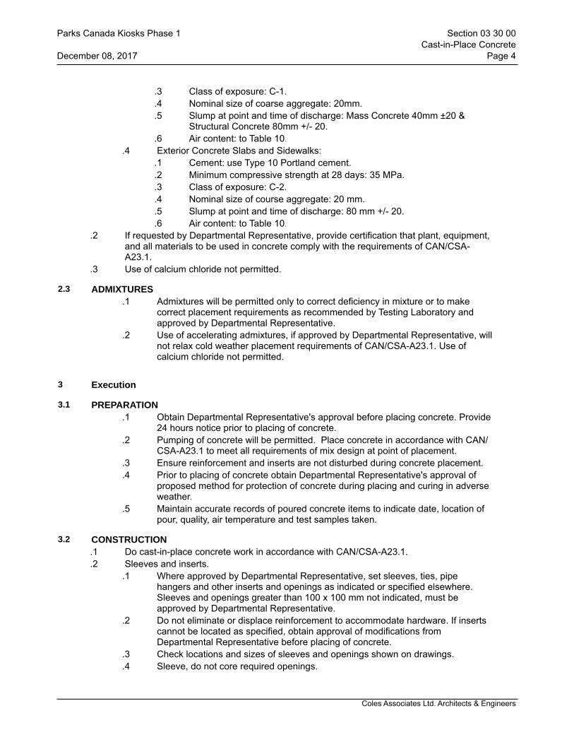
Coles Associates Ltd. Architects & Engineers
.3 Class of exposure: C-1.
.4 Nominal size of coarse aggregate: 20mm.
.5 Slump at point and time of discharge: Mass Concrete 40mm ±20 & Structural Concrete 80mm +/- 20.
.6 Air content: to Table 10..4 Exterior Concrete Slabs and Sidewalks:
.1 Cement: use Type 10 Portland cement.
.2 Minimum compressive strength at 28 days: 35 MPa.
.3 Class of exposure: C-2.
.4 Nominal size of course aggregate: 20 mm.
.5 Slump at point and time of discharge: 80 mm +/- 20.
.6 Air content: to Table 10..2 If requested by Departmental Representative, provide certification that plant, equipment,
and all materials to be used in concrete comply with the requirements of CAN/CSA-A23.1.
.3 Use of calcium chloride not permitted.
2.3 ADMIXTURES.1 Admixtures will be permitted only to correct deficiency in mixture or to make
correct placement requirements as recommended by Testing Laboratory and approved by Departmental Representative.
.2 Use of accelerating admixtures, if approved by Departmental Representative, will not relax cold weather placement requirements of CAN/CSA-A23.1. Use of calcium chloride not permitted.
3 Execution
3.1 PREPARATION.1 Obtain Departmental Representative's approval before placing concrete. Provide
24 hours notice prior to placing of concrete..2 Pumping of concrete will be permitted. Place concrete in accordance with CAN/
CSA-A23.1 to meet all requirements of mix design at point of placement..3 Ensure reinforcement and inserts are not disturbed during concrete placement..4 Prior to placing of concrete obtain Departmental Representative's approval of
proposed method for protection of concrete during placing and curing in adverse weather.
.5 Maintain accurate records of poured concrete items to indicate date, location of pour, quality, air temperature and test samples taken.
3.2 CONSTRUCTION.1 Do cast-in-place concrete work in accordance with CAN/CSA-A23.1..2 Sleeves and inserts.
.1 Where approved by Departmental Representative, set sleeves, ties, pipe hangers and other inserts and openings as indicated or specified elsewhere. Sleeves and openings greater than 100 x 100 mm not indicated, must be approved by Departmental Representative.
.2 Do not eliminate or displace reinforcement to accommodate hardware. If inserts cannot be located as specified, obtain approval of modifications from Departmental Representative before placing of concrete.
.3 Check locations and sizes of sleeves and openings shown on drawings.
.4 Sleeve, do not core required openings.
Parks Canada Kiosks Phase 1 Section 03 30 00Cast-in-Place Concrete
December 08, 2017 Page 4
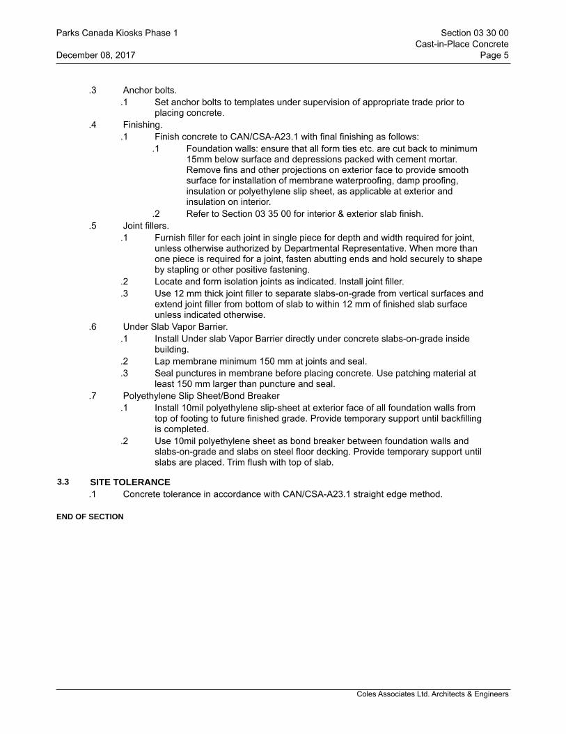
Coles Associates Ltd. Architects & Engineers
.3 Anchor bolts..1 Set anchor bolts to templates under supervision of appropriate trade prior to
placing concrete..4 Finishing.
.1 Finish concrete to CAN/CSA-A23.1 with final finishing as follows:.1 Foundation walls: ensure that all form ties etc. are cut back to minimum
15mm below surface and depressions packed with cement mortar. Remove fins and other projections on exterior face to provide smooth surface for installation of membrane waterproofing, damp proofing, insulation or polyethylene slip sheet, as applicable at exterior and insulation on interior.
.2 Refer to Section 03 35 00 for interior & exterior slab finish..5 Joint fillers.
.1 Furnish filler for each joint in single piece for depth and width required for joint, unless otherwise authorized by Departmental Representative. When more than one piece is required for a joint, fasten abutting ends and hold securely to shape by stapling or other positive fastening.
.2 Locate and form isolation joints as indicated. Install joint filler.
.3 Use 12 mm thick joint filler to separate slabs-on-grade from vertical surfaces and extend joint filler from bottom of slab to within 12 mm of finished slab surface unless indicated otherwise.
.6 Under Slab Vapor Barrier..1 Install Under slab Vapor Barrier directly under concrete slabs-on-grade inside
building..2 Lap membrane minimum 150 mm at joints and seal..3 Seal punctures in membrane before placing concrete. Use patching material at
least 150 mm larger than puncture and seal..7 Polyethylene Slip Sheet/Bond Breaker
.1 Install 10mil polyethylene slip-sheet at exterior face of all foundation walls from top of footing to future finished grade. Provide temporary support until backfilling is completed.
.2 Use 10mil polyethylene sheet as bond breaker between foundation walls and slabs-on-grade and slabs on steel floor decking. Provide temporary support until slabs are placed. Trim flush with top of slab.
3.3 SITE TOLERANCE.1 Concrete tolerance in accordance with CAN/CSA-A23.1 straight edge method.
END OF SECTION
Parks Canada Kiosks Phase 1 Section 03 30 00Cast-in-Place Concrete
December 08, 2017 Page 5
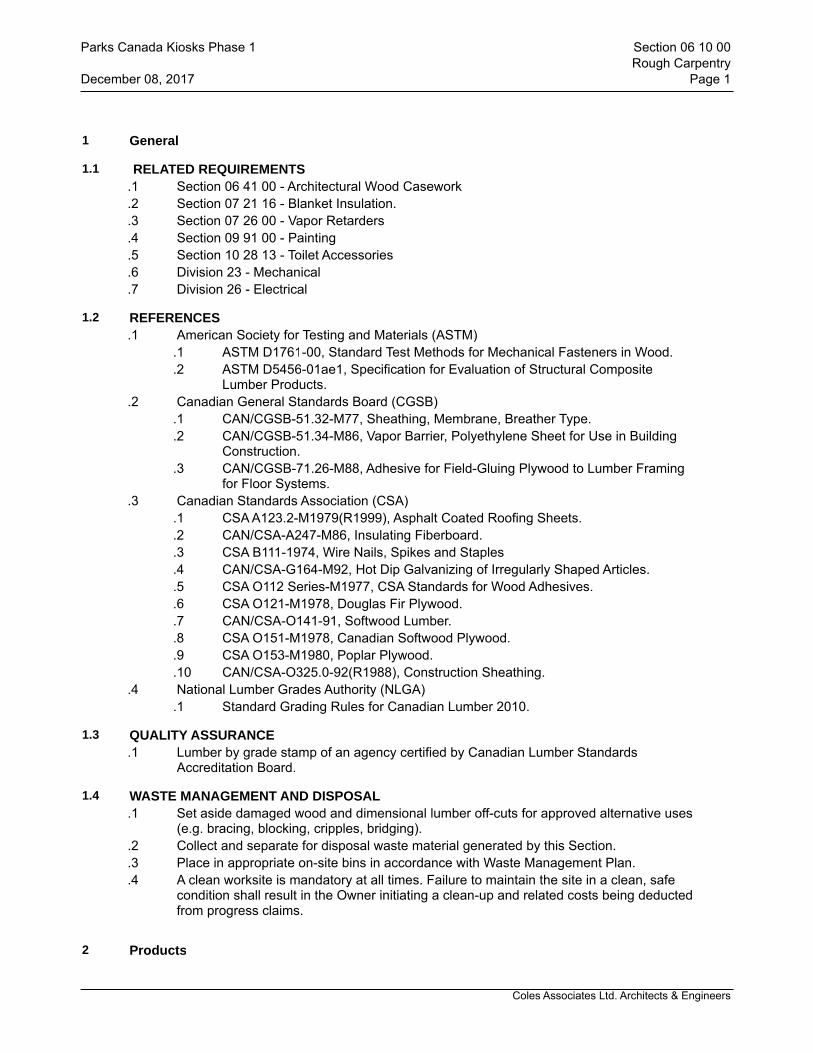
Coles Associates Ltd. Architects & Engineers
1 General
1.1 RELATED REQUIREMENTS.1 Section 06 41 00 - Architectural Wood Casework.2 Section 07 21 16 - Blanket Insulation..3 Section 07 26 00 - Vapor Retarders.4 Section 09 91 00 - Painting.5 Section 10 28 13 - Toilet Accessories.6 Division 23 - Mechanical.7 Division 26 - Electrical
1.2 REFERENCES.1 American Society for Testing and Materials (ASTM)
.1 ASTM D1761-00, Standard Test Methods for Mechanical Fasteners in Wood.
.2 ASTM D5456-01ae1, Specification for Evaluation of Structural Composite Lumber Products.
.2 Canadian General Standards Board (CGSB).1 CAN/CGSB-51.32-M77, Sheathing, Membrane, Breather Type..2 CAN/CGSB-51.34-M86, Vapor Barrier, Polyethylene Sheet for Use in Building
Construction..3 CAN/CGSB-71.26-M88, Adhesive for Field-Gluing Plywood to Lumber Framing
for Floor Systems..3 Canadian Standards Association (CSA)
.1 CSA A123.2-M1979(R1999), Asphalt Coated Roofing Sheets.
.2 CAN/CSA-A247-M86, Insulating Fiberboard.
.3 CSA B111-1974, Wire Nails, Spikes and Staples
.4 CAN/CSA-G164-M92, Hot Dip Galvanizing of Irregularly Shaped Articles.
.5 CSA O112 Series-M1977, CSA Standards for Wood Adhesives.
.6 CSA O121-M1978, Douglas Fir Plywood.
.7 CAN/CSA-O141-91, Softwood Lumber.
.8 CSA O151-M1978, Canadian Softwood Plywood.
.9 CSA O153-M1980, Poplar Plywood.
.10 CAN/CSA-O325.0-92(R1988), Construction Sheathing..4 National Lumber Grades Authority (NLGA)
.1 Standard Grading Rules for Canadian Lumber 2010.
1.3 QUALITY ASSURANCE.1 Lumber by grade stamp of an agency certified by Canadian Lumber Standards
Accreditation Board.
1.4 WASTE MANAGEMENT AND DISPOSAL.1 Set aside damaged wood and dimensional lumber off-cuts for approved alternative uses
(e.g. bracing, blocking, cripples, bridging)..2 Collect and separate for disposal waste material generated by this Section. .3 Place in appropriate on-site bins in accordance with Waste Management Plan..4 A clean worksite is mandatory at all times. Failure to maintain the site in a clean, safe
condition shall result in the Owner initiating a clean-up and related costs being deducted from progress claims.
2 Products
Parks Canada Kiosks Phase 1 Section 06 10 00Rough Carpentry
December 08, 2017 Page 1

Coles Associates Ltd. Architects & Engineers
2.1 FRAMING AND STRUCTURAL MATERIALS.1 Lumber:
.1 Unless specified otherwise, softwood, S4S, moisture content 19% (S-dry) or less in accordance with following standards:
.1 CAN/CSA-O141.
.2 NLGA Standard Grading Rules for Canadian Lumber..2 Glued end-jointed (finger-jointed) lumber are not acceptable.
.2 Structural Composite Lumber (SCL) in accordance with ASTM D5456.
.3 Framing and board lumber: in accordance with NBC.
.4 Furring, blocking, nailing strips, grounds, rough bucks, cants, curbs, fascia backing and sleepers:
.1 S4S is acceptable.
.2 Board sizes: "Standard" or better grade.
.3 Dimension sizes: "Standard" light framing or better grade.
.4 Post and timbers sizes: "Standard" or better grade.
2.2 PANEL MATERIALS.1 Plywood: to CAN/CSA-O325.0..2 Douglas fir plywood (DFP): to CSA O121, standard construction..3 Canadian softwood plywood (CSP): to CSA O151, standard construction..4 Poplar plywood (PP): to CSA O153, standard construction..5 Gypsum sheathing: to ASTM C36/C36M..6 Specifically:
.1 Roof sheathing: Douglas Fir Plywood (DFP) exterior sheathing grade, square edge, to thickness indicated, to CSA O121.
.2 Exterior wall sheathing: Douglas Fir Plywood (DFP) exterior sheathing grade, square edge, 12.7mm thickness, to CSA 0121.
.3 Plywood underlay: Douglas Fir plywood (DFP), to CSA O121 - M1978, GIS with solid wood boats, (PASTE TYPE FILLERS NOT ACCEPTABLE), 8mm thickness.
.4 Mechanical & Electrical equipment backboards: Douglas fir plywood (DFP), to CSA O121, G1S, square edge to thickness indicated.
2.3 ACCESSORIES.1 Roll roofing: to CSA A123.2, Type S..2 Air seal sill gasket: closed cell polyurethane or polyethylene..3 Sealants: Section 07 92 00 - Joint Sealants..4 General purpose adhesive: to CSA O112 Series..5 Nails, spikes and staples: to CSA B111.
.1 Use common spiral nails and spiral spikes except where indicated otherwise.
.2 Use hot galvanized finish steel for exterior work, including sheathing..6 Bolts: 12.5 mm diameter unless indicated otherwise, complete with nuts and washers..7 Proprietary fasteners: toggle bolts, expansion shields and lag bolts, screws and
inorganic fiber plugs, explosive actuated fastening devices, recommended for purpose by manufacturer.
.8 Nailing discs: flat caps, minimum 25 mm diameter, minimum 0.4 mm thick, sheet metal, fiber, formed to prevent dishing. Bell or cup shapes not acceptable.
.9 Roof sheathing H-Clips: formed "H" shape, thickness to suit panel material, extruded 6063-T6 aluminum alloy type approved by Departmental Representative.
.10 Use surface fastenings of following type except where specific type is indicated..1 To exterior face of concrete foundation wall with galvanized power driven
fasteners penetrating minimum 38mm into concrete.
Parks Canada Kiosks Phase 1 Section 06 10 00Rough Carpentry
December 08, 2017 Page 2
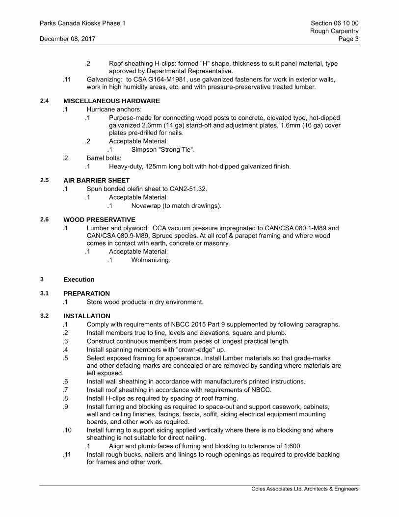
Coles Associates Ltd. Architects & Engineers
.2 Roof sheathing H-clips: formed "H" shape, thickness to suit panel material, type approved by Departmental Representative.
.11 Galvanizing: to CSA G164-M1981, use galvanized fasteners for work in exterior walls, work in high humidity areas, etc. and with pressure-preservative treated lumber.
2.4 MISCELLANEOUS HARDWARE.1 Hurricane anchors:
.1 Purpose-made for connecting wood posts to concrete, elevated type, hot-dipped galvanized 2.6mm (14 ga) stand-off and adjustment plates, 1.6mm (16 ga) cover plates pre-drilled for nails.
.2 Acceptable Material:.1 Simpson "Strong Tie".
.2 Barrel bolts: .1 Heavy-duty, 125mm long bolt with hot-dipped galvanized finish.
2.5 AIR BARRIER SHEET.1 Spun bonded olefin sheet to CAN2-51.32.
.1 Acceptable Material:.1 Novawrap (to match drawings).
2.6 WOOD PRESERVATIVE.1 Lumber and plywood: CCA vacuum pressure impregnated to CAN/CSA 080.1-M89 and
CAN/CSA 080.9-M89, Spruce species. At all roof & parapet framing and where wood comes in contact with earth, concrete or masonry.
.1 Acceptable Material:.1 Wolmanizing.
3 Execution
3.1 PREPARATION.1 Store wood products in dry environment.
3.2 INSTALLATION.1 Comply with requirements of NBCC 2015 Part 9 supplemented by following paragraphs..2 Install members true to line, levels and elevations, square and plumb..3 Construct continuous members from pieces of longest practical length..4 Install spanning members with "crown-edge" up..5 Select exposed framing for appearance. Install lumber materials so that grade-marks
and other defacing marks are concealed or are removed by sanding where materials are left exposed.
.6 Install wall sheathing in accordance with manufacturer's printed instructions.
.7 Install roof sheathing in accordance with requirements of NBCC.
.8 Install H-clips as required by spacing of roof framing.
.9 Install furring and blocking as required to space-out and support casework, cabinets, wall and ceiling finishes, facings, fascia, soffit, siding electrical equipment mounting boards, and other work as required.
.10 Install furring to support siding applied vertically where there is no blocking and where sheathing is not suitable for direct nailing.
.1 Align and plumb faces of furring and blocking to tolerance of 1:600..11 Install rough bucks, nailers and linings to rough openings as required to provide backing
for frames and other work.
Parks Canada Kiosks Phase 1 Section 06 10 00Rough Carpentry
December 08, 2017 Page 3

Coles Associates Ltd. Architects & Engineers
.12 Install wood cants, fascia backing, nailers, curbs and other wood supports as required and secure using galvanized fasteners.
.13 Use dust collectors and high quality respirator masks when cutting or sanding wood panels.
3.3 MISCELLANEOUS FURRING, BLOCKING AND STRAPPING.1 Install furring and blocking as required to space out and support casework, cabinets,
toilet and bath accessories, recessed panels and cabinets for work of Electrical and Mechanical Divisions, and other work as required, which includes, but is not limited to the following:
.1 At vanity tops and counter tops/worktops provide 38 x 140 wood blocking between steel studs at each metal bracket and at each end of vanity top and counter top/worktops.
.2 At all toilet and bath accessories provide wood blocking between steel studs, as required.
.3 Generally both vertical and horizontal blocking will be required to secure 100 mm deep accessories recessed in 100 mm thick walls.
.4 At cabinetwork provide 38 x 140 blocking between wood studs, as required to support cabinetwork.
.5 At mechanical and electrical panels and fire-extinguisher cabinets provide blocking between steel studs as required to support and secure cabinets.
.6 At all wall mounted doorstops.
.7 At ALL other wall-mounted items provide wood blocking between steel studs as required.
.2 Install furring to support any sheathing type material where there is no blocking and where sheathing is not suitable for direct nailing.
.3 Spacing of furring as required to provide adequate support for material.
.4 Install strapping as indicated or required to support panel material, except where metal strapping is specifically indicated.
.5 Align and plumb faces of furring and blocking to tolerance of 1:600.
3.4 NAILING STRIPS, FRAMING AND ROUGH BUCKS.1 Install rough bucks, nailers and linings to rough openings as required to provide backing
for window frames, door frames and other work..2 Install continuous pressure treated wood framing as indicated under all window stools..3 Install sloped sill framing and water stop as required by NBCC, latest edition..4 Countersink bolts where necessary to provide flush surface.
3.5 FASTENERS.1 Frame, anchor, fasten, tie and brace members to provide necessary strength and rigidity..2 Provide minimum three (3) 50 mm nails at each end to secure blocking between steel
studs..3 Countersink bolts where necessary to provide clearance for other work..4 Screws for fastening pressure treated lumber to be ceramic coated.
3.6 EQUIPMENT BACKBOARDS.1 Provide backboards for mounting equipment. Use 19mm thick DFP.G1S on 19 x 38mm
furring around perimeter and at maximum 300mm intermediate spacing..2 Supply and install these backboards where indicated or directed by Mechanical and
Electrical Division.
3.7 ERECTION
Parks Canada Kiosks Phase 1 Section 06 10 00Rough Carpentry
December 08, 2017 Page 4

Coles Associates Ltd. Architects & Engineers
.1 Frame, anchor, fasten, tie and brace members to provide necessary strength and rigidity.
.2 Countersink bolts where necessary to provide clearance for other work.
.3 Use nailing disks for soft sheathing as recommended by sheathing manufacturer.
END OF SECTION
Parks Canada Kiosks Phase 1 Section 06 10 00Rough Carpentry
December 08, 2017 Page 5

Coles Associates Ltd. Architects & Engineers
1 General
1.1 SUMMARY.1 Provide architectural woodwork including but not limited to following:
.1 Architectural cabinet casework.
.2 Architectural cabinet casework drawers, doors and shelves
.3 Countertops.
.4 Architectural cabinet casework hardware.
.5 Trim and moldings..2 Provide architectural woodwork at following locations and as shown on drawings:
.1 Room #100 - Workstation
.2 Room #101 - Bath
1.2 RELATED REQUIREMENTS.1 Section 06 47 00 - Plastic Laminate Finishing..2 Section 07 92 00 - Joint Sealants..3 Section 08 80 00 - Glazing..4 Section 09 91 00 - Painting..5 Section 22 42 01 - Plumbing Specialties and Accessories.6 Division 26 - Electrical: Outlets and Wiring
1.3 REFERENCES.1 American National Standards Institute (ANSI)
.1 ANSI/NEMA LD 3-2005, High-Pressure Decorative Laminates.
.2 ANSI/NEMA LD 3-2005, Thermofused Melamine B.
.3 ANSI/NEMA LD 3.1-2005, Application, Fabrication, and Installation of High-Pressure Decorative Laminates.
.4 ANSI/HPVA HP-1-2004, American National Standard for Hardwood and Decorative Plywood.
.2 American Society for Testing and Materials (ASTM).1 ASTM E1333-96, Test Method for Determining Formaldehyde Concentrations in
Air and Emissions Rates from Wood Products Using a Large Chamber..2 ASTM E84-08a, Test Method for Surface Burning Characteristics of Building
Materials..3 Architectural Woodwork Manufacturers Association of Canada (AWMAC)
.1 AWMAC Quality Standards for Architectural Woodwork 1994.
.2 Architectural Woodwork Standards (AWS) 2009 Edition..4 Canadian General Standards Board (CGSB)
.1 CAN/CGSB-11.3-M87, Hardboard..5 Canadian Standards Association (CSA)
.1 CAN/CSA-A247-M86(R1996), Insulating Fiberboard.
.2 CAN3-A172-M79, High Pressure Paper Base, Decorative Laminates.
.3 CSA B111-74(R1998), Wire Nails, Spikes and Staples.
.4 CAN/CSA-G164-M92(R1998), Hot Dip Galvanizing of Irregularly Shaped Articles.
.5 CSA O115-M82(R2001), Hardwood and Decorative Plywood.
.6 CSA O121-M78(R1998), Douglas Fir Plywood.
.7 CAN/CSA O141-91(R1999), Softwood Lumber.
.8 CSA O151-M78 (R1998), Canadian Softwood Plywood.
.9 CSA O153-M80 (R1998), Poplar Plywood.
Parks Canada Kiosks Phase 1 Section 06 41 00Architectural Wood Casework
December 08, 2017 Page 1
Coles Associates Ltd. Architects & Engineers
.10 CSA O112 Series-M77(R2001), CSA Standards for Wood Adhesives.
.11 CAN/ULC-S102-07, Standard Method of Test for Surface Burning..6 National Lumber Grades Authority (NLGA)
.1 Standard Grading Rules for Canadian Lumber 2000..7 NEMA, National Electrical Manufacturers Association..8 Canadian Electrical Code
1.4 SYSTEM DESCRIPTION.1 Design Requirements:
.1 Millwork casework (e.g. countertops, wall cabinets, cabinet drawers and similar items) shall be capable of supporting structural loads without deflection in accordance with Casework Integrity Tests in Appendix A of AWS.
.2 Design casework shelves for uniformly distributed loads as follow:.1 Other horizontal surfaces: 1.9 Kilopascals .2 Closet shelves: 1.197 Kilopascals.3 Bookshelves: 1.915 Kilopascals
.3 Without limitations, in particular ensure:.1 Millwork counter tops, are capable of supporting 907 kg.
.4 Minimum nominal thickness and material for cabinet components and shelf deflection, type of materials, thicknesses, span width and total load distribution shall be in accordance with Architectural Woodwork Standards.
1.5 SUBMITTALS.1 Make submittals in accordance with Section 01 33 00 - Submittal Procedures..2 Product Data:
.1 Submit manufacturer's literature, data sheets for each type of material provided under this Section for project.
.2 Data sheets shall provide all required information.
.3 Submit required copies of detailed instructions for maintaining, preserving and keeping materials in clean and safe conditions and give adequate warning of maintenance practices or materials detrimental to specified materials.
.4 Submit manufacturer's installation instructions..3 Material Safety Data Sheets:
.1 Submit MSDS for inclusion in Operation and Maintenance Manual..4 Shop Drawings:
.1 Clearly indicate material being supplied and show connections, attachments, reinforcing, anchorage and location of exposed fastenings in accordance with AWS Section 1.
1.6 QUALITY ASSURANCE.1 Provide Work of this Section in accordance with Architectural Woodwork Standards
(AWS), except as specified otherwise herein and by reference are hereby made a part of this Section.
.2 Any reference to grades and terminology in this Section shall be as defined in "AWS".
.3 Requirements of this Section govern and modify AWS.
.4 Regulatory Requirements:.1 Fire-Test-Response Characteristics:
.1 Where fire-retardant materials are indicated, provide materials with specified fire-test-response characteristics as determined by a testing and inspecting agency acceptable to authorities having jurisdiction.
.2 Identify materials with appropriate markings of applicable testing and
Parks Canada Kiosks Phase 1 Section 06 41 00Architectural Wood Casework
December 08, 2017 Page 2
Coles Associates Ltd. Architects & Engineers
inspecting agency on surfaces of materials that will be concealed from view after installation.
.2 No added urea-formaldehyde during manufacturing process..5 Pre-Installation Meetings:
.1 Prior to start of work, arrange for site meeting of all parties associated with work of this Section presided over by Contractor, including Departmental Representative, Subcontractor performing Work of trade involved, Testing Company's Representative and Contractor's Consultants of applicable discipline.
.2 Review Contract Documents for Work included under trade and determine complete understanding of requirements and responsibilities relative to Work included, storage and handling of materials, materials to be used, Installation of materials, sequence and quality control, project staffing, restrictions on areas of work and other matters affecting construction, to permit compliance with intent of this Section.
.6 Coordination with Mechanical, Electrical and Communication Services:.1 As a requirement of this Section, allow access to shop by associated trades for
purpose of performing pre-wiring and partial mounting of electrical and audio/visual equipment and concealed wiring to the required by the design.
.2 Exposed wiring is not acceptable.
1.7 FABRICATION.1 Fabricate finish carpentry to Quality Standards of the Architectural Woodwork
Manufacturers Association of Canada (AWMAC).
1.8 DELIVERY, STORAGE AND HANDLING.1 Do not deliver finished products during rainy or damp weather..2 Do not deliver Work of this Section until building and storage areas are sufficiently dry so
products will not be damaged by excessive changes in moisture content..3 Deliver, store and handle products of this Section in accordance with AWS Section 2..4 Do not deliver and install damaged products. Replace in accordance with requirements
of this Section..5 Cover finished plastic laminate surfaces and varnished surfaces with heavy kraft paper
and put in cartons for protection..6 Protect installed plastic laminate surfaces by acceptable means..7 Do not remove protective covers until immediately prior to final cleaning.
1.9 PROJECT CONDITIONS.1 Ensure project conditions conforms to requirements of AWS Section 2..2 Moisture contents of wood at time of installation shall be for interior locations at
established Optimum Moisture Content and Optimum Indoor Relative Humidity as outlined in AWS Section 2, Item 1.2.3.
1.10 WARRANTY.1 Warrant Work of this Section for period of 2 years against defects and/or deficiencies in
accordance with General Conditions of the Contract..2 Promptly correct any defects or deficiencies which become apparent within warranty
period, to satisfaction of Departmental Representative and at no expense to Owner..3 Defects include but are not limited to; delamination of plastic laminate, opening of
seams, warpage and extensive colour fading.
1.11 WASTE MANAGEMENT AND DISPOSAL.1 Collect and separate for disposal waste material generated by this Section. .2 Place in appropriate on-site bins in accordance with Waste Management Plan.
Parks Canada Kiosks Phase 1 Section 06 41 00Architectural Wood Casework
December 08, 2017 Page 3
Coles Associates Ltd. Architects & Engineers
.3 A clean worksite is mandatory at all times. Failure to maintain the site in a clean, safe condition shall result in the Owner initiating a clean-up and related costs being deducted from progress claims.
.4 Remove waste materials from site in accordance with Infection Control requirements.
.5 Set aside damaged wood for acceptable alternative uses (e.g. bracing, blocking, cripples, bridging, finger-joining, or ties).
2 Products
2.1 MATERIALS.1 Composite wood and agrifibre products, including core materials, to contain no added
urea-formaldehyde resins..2 Adhesives used to fabricate laminated assemblies containing these products to contain
no added urea-formaldehyde..3 Architectural Lumber:
.1 Conform to AWS Section 3.
.2 Clear, straight, kiln dried, Premium Grade Natural Birch for fitments and door jambs.
.3 Provide kiln dried lumber to 7% moisture content, free from blemishes that would be apparent after finish is applied.
.4 Softwood Lumber: .1 Conform to requirements AWS Section 3, Premium Grade Ontario White Pine,
Yellow Pine or other Pine species..2 S4S, moisture content 19% or less in accordance with following standards:
.1 CAN/CSA O141.
.2 NLGA Standard Grading Rules for Canadian Lumber.
.3 AWMAC custom grade, moisture content as specified..5 Hardwood Lumber:
.1 NHLA requirements, Hard Maple, FAS, of uniform grain and colour, Premium Grade.
.2 Moisture content 13% or less in accordance with following standards:.1 National Hardwood Lumber Association (NHLA)..2 AWMAC custom grade, moisture content as specified.
.6 Concealed framing: .1 Sound material of any species may be used for concealed members, free from
sap, shakes, knots, splits and other defects..2 Concealed wood shall also be of highest grade that satisfies fabrication, utility
and structural requirements..7 Exposed framing, solid members and trim:
.1 Hardwood lumber as specified herein or indicated on Drawings, or where not specified or indicated, of Maple , FAS grade, matched for compatibility of grain and colour for transparent finish.
.8 Panel Products:.1 Conform to AWMAC AWS Section, for Panel Products which includes types of
plywood, Particleboard Core Plywood, Veneer Core Plywood, Medium Density Fiberboard Core Plywood, Lumber Core Plywood and Combination Core Plywood.
.2 For plywood conform to AWS Section 4 paragraph 1.2.31..1 Douglas fir plywood (DFP): to CSA 0121, standard construction..2 Canadian softwood plywood (CSP): to CSA 0151, standard construction..3 Hardwood plywood: to CSA O115.
Parks Canada Kiosks Phase 1 Section 06 41 00Architectural Wood Casework
December 08, 2017 Page 4
Coles Associates Ltd. Architects & Engineers
.4 Poplar plywood (PP): to CSA 0153, standard construction.
.5 Birch plywood: to AWMAC Paint Grade, Natural, Select White, Select Red.
.3 Interior mat-formed wood particleboard: to CAN-0188.1.
.4 Hardboard: to CAN/CGSB-11.3.
.5 Medium density fiberboard (MDF): to ANSI A208.2, density 769kg/m³..9 Wood Cores:
.1 Medium Density Fibreboard Core (MDF).
.2 Medium density panels, meeting requirements of ANSI 208.2, balanced design, manufactured from 100% recycled materials, without the use of formaldehyde resins, meeting HUD 24 Standards for emissions, of minimum density of 770 kg/m3 and surface character to match sample in Departmental Representative's possession.
.3 Fire retardant product shall contain fire-retardant chemicals injected with raw materials during manufacturing and achieve a maximum Flame Spread rating of 25 with a maximum Smoke Developed of 200 when tested to ASTM E84.
.4 Do not use MDF panels in moist areas.
.5 Acceptable Material:.1 Flakeboard Company Limited; www.flakeboard.com.2 Uniboard Canada Inc.; www.uniboard.com;.3 Tafisa Canada and Company, Ltd.; www.tafisa.ca;
.10 Veneer Core (Plywood) post formed at Counter Tops with Sink and other Counter Tops:.1 Softwood Plywood: Douglas Fir, CSA O121-M, good two sides Standard Grade.
Poplar plywood conforming to CSA O153-M, Grades A and B..11 Thermofused Melamine Panels (semi-exposed locations only):
.1 Use melamine faced composition board, (MFCB) with high density particle board core to CSA 0188.0, faced both sides with melamine/polyester laminate of equal thickness and density, to overall thicknesses specified.
.2 Formaldehyde Emissions: shall conform to H.U.D. formaldehyde emission 24 CFR Part 3280.308 for particleboard, emission content of 0.14PPM or less, desicator value of mg/ml. Authorized label shall be affixed to each bundle or pallet load leaving plant. Melamine finish to be minimum 120 gram cover sheet, colour to be selected by Departmental Representative from FULL range.
.3 Uniform Thickness: to tolerance of +/- .006 inches.
.4 Product Specifications: shall exceed or meet ANSI A 2081-1979 Grade 1-M-3 and CAN3-0184. 1M Grade R.
.5 Screw Holding Capability: 300lbs/face, 225lbs/edge.
.6 Decor paper shall be thermofused to both faces to prevent warping.
.7 Melamine panels in finished (installed) condition shall show no exposed fasteners on exterior surfaces.
.8 Assemble melamine millwork using doweled/wafered-and-glued construction.
.9 Where indicated on Drawings construction system may also include assembly using hardware.
.10 Clean thermofused melamine surfaces with paint thinner or solvents for varnish or for contact glue.
.11 Do not use any abrasive substance that could damage surface of panels.
.12 Do not use acidic or alkaline products.
.13 Color and finish selected by Departmental Representative from manufacturer's full range.
.14 Acceptable Material:.1 Flakeboard Company Limited; www.flakeboard.com
Parks Canada Kiosks Phase 1 Section 06 41 00Architectural Wood Casework
December 08, 2017 Page 5
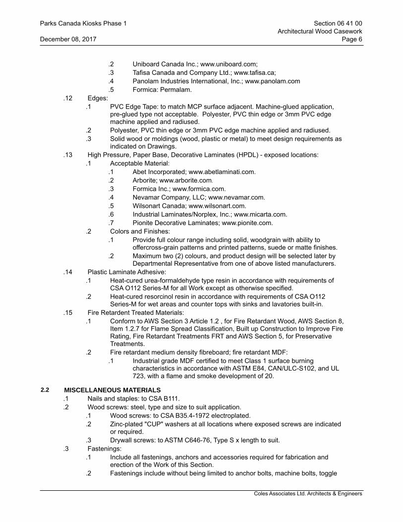
Coles Associates Ltd. Architects & Engineers
.2 Uniboard Canada Inc.; www.uniboard.com;
.3 Tafisa Canada and Company Ltd.; www.tafisa.ca;
.4 Panolam Industries International, Inc.; www.panolam.com
.5 Formica: Permalam..12 Edges:
.1 PVC Edge Tape: to match MCP surface adjacent. Machine-glued application, pre-glued type not acceptable. Polyester, PVC thin edge or 3mm PVC edge machine applied and radiused.
.2 Polyester, PVC thin edge or 3mm PVC edge machine applied and radiused.
.3 Solid wood or moldings (wood, plastic or metal) to meet design requirements as indicated on Drawings.
.13 High Pressure, Paper Base, Decorative Laminates (HPDL) - exposed locations:.1 Acceptable Material:
.1 Abet Incorporated; www.abetlaminati.com.
.2 Arborite; www.arborite.com.
.3 Formica Inc.; www.formica.com.
.4 Nevamar Company, LLC; www.nevamar.com.
.5 Wilsonart Canada; www.wilsonart.com.
.6 Industrial Laminates/Norplex, Inc.; www.micarta.com.
.7 Pionite Decorative Laminates; www.pionite.com..2 Colors and Finishes:
.1 Provide full colour range including solid, woodgrain with ability to offercross-grain patterns and printed patterns, suede or matte finishes.
.2 Maximum two (2) colours, and product design will be selected later by Departmental Representative from one of above listed manufacturers.
.14 Plastic Laminate Adhesive:.1 Heat-cured urea-formaldehyde type resin in accordance with requirements of
CSA O112 Series-M for all Work except as otherwise specified..2 Heat-cured resorcinol resin in accordance with requirements of CSA O112
Series-M for wet areas and counter tops with sinks and lavatories built-in..15 Fire Retardent Treated Materials:
.1 Conform to AWS Section 3 Article 1.2 , for Fire Retardant Wood, AWS Section 8, Item 1.2.7 for Flame Spread Classification, Built up Construction to Improve Fire Rating, Fire Retardant Treatments FRT and AWS Section 5, for Preservative Treatments.
.2 Fire retardant medium density fibreboard; fire retardant MDF:.1 Industrial grade MDF certified to meet Class 1 surface burning
characteristics in accordance with ASTM E84, CAN/ULC-S102, and UL 723, with a flame and smoke development of 20.
2.2 MISCELLANEOUS MATERIALS.1 Nails and staples: to CSA B111..2 Wood screws: steel, type and size to suit application.
.1 Wood screws: to CSA B35.4-1972 electroplated.
.2 Zinc-plated "CUP" washers at all locations where exposed screws are indicated or required.
.3 Drywall screws: to ASTM C646-76, Type S x length to suit..3 Fastenings:
.1 Include all fastenings, anchors and accessories required for fabrication and erection of the Work of this Section.
.2 Fastenings include without being limited to anchor bolts, machine bolts, toggle
Parks Canada Kiosks Phase 1 Section 06 41 00Architectural Wood Casework
December 08, 2017 Page 6
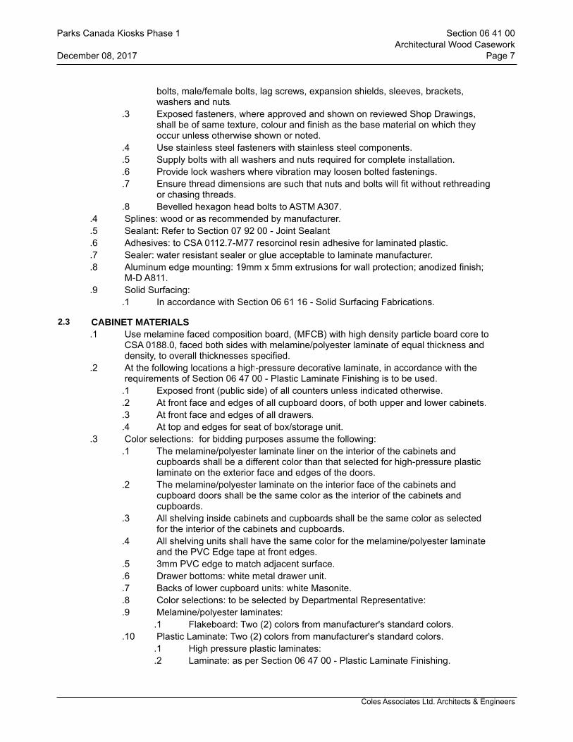
Coles Associates Ltd. Architects & Engineers
bolts, male/female bolts, lag screws, expansion shields, sleeves, brackets, washers and nuts.
.3 Exposed fasteners, where approved and shown on reviewed Shop Drawings, shall be of same texture, colour and finish as the base material on which they occur unless otherwise shown or noted.
.4 Use stainless steel fasteners with stainless steel components.
.5 Supply bolts with all washers and nuts required for complete installation.
.6 Provide lock washers where vibration may loosen bolted fastenings.
.7 Ensure thread dimensions are such that nuts and bolts will fit without rethreading or chasing threads.
.8 Bevelled hexagon head bolts to ASTM A307..4 Splines: wood or as recommended by manufacturer..5 Sealant: Refer to Section 07 92 00 - Joint Sealant.6 Adhesives: to CSA 0112.7-M77 resorcinol resin adhesive for laminated plastic..7 Sealer: water resistant sealer or glue acceptable to laminate manufacturer..8 Aluminum edge mounting: 19mm x 5mm extrusions for wall protection; anodized finish;
M-D A811..9 Solid Surfacing:
.1 In accordance with Section 06 61 16 - Solid Surfacing Fabrications.
2.3 CABINET MATERIALS.1 Use melamine faced composition board, (MFCB) with high density particle board core to
CSA 0188.0, faced both sides with melamine/polyester laminate of equal thickness and density, to overall thicknesses specified.
.2 At the following locations a high-pressure decorative laminate, in accordance with the requirements of Section 06 47 00 - Plastic Laminate Finishing is to be used.
.1 Exposed front (public side) of all counters unless indicated otherwise.
.2 At front face and edges of all cupboard doors, of both upper and lower cabinets.
.3 At front face and edges of all drawers.
.4 At top and edges for seat of box/storage unit..3 Color selections: for bidding purposes assume the following:
.1 The melamine/polyester laminate liner on the interior of the cabinets and cupboards shall be a different color than that selected for high-pressure plastic laminate on the exterior face and edges of the doors.
.2 The melamine/polyester laminate on the interior face of the cabinets and cupboard doors shall be the same color as the interior of the cabinets and cupboards.
.3 All shelving inside cabinets and cupboards shall be the same color as selected for the interior of the cabinets and cupboards.
.4 All shelving units shall have the same color for the melamine/polyester laminate and the PVC Edge tape at front edges.
.5 3mm PVC edge to match adjacent surface.
.6 Drawer bottoms: white metal drawer unit.
.7 Backs of lower cupboard units: white Masonite.
.8 Color selections: to be selected by Departmental Representative:
.9 Melamine/polyester laminates:.1 Flakeboard: Two (2) colors from manufacturer's standard colors.
.10 Plastic Laminate: Two (2) colors from manufacturer's standard colors..1 High pressure plastic laminates:.2 Laminate: as per Section 06 47 00 - Plastic Laminate Finishing.
Parks Canada Kiosks Phase 1 Section 06 41 00Architectural Wood Casework
December 08, 2017 Page 7

Coles Associates Ltd. Architects & Engineers
2.4 MANUFACTURED UNITS.1 Casework:
.1 Fabricate casework to AWMAC custom grade.
.2 Framing:.1 Melamine, thickness as required.
.3 Furring, blocking, nailing strips, grounds and rough bucks and sleepers:.1 Hardwood plywood, thickness as required.
.4 Case bodies (ends, divisions, gables and bottoms, including base, uppers and wall cabinets):
.1 Melamine, Grade R, 19mm thick.
.2 Edge banding: Heavy duty 3 mm PVC, color and finish to match top surface, strip same width as material.
.5 Backs: Composite Panel (melamine).1 Core: medium density M3 particleboard..2 Thickness 13 mm.
.6 Shelving (Melamine):.1 Melamine, Grade R, 19mm thick..2 Use recessed standards to support shelves..3 Edge Banding (all edges): Heavy duty 3 mm PVC, color and finish to
match top surface, same width as material. .2 Doors and Drawer Fronts:
.1 Fabricate doors to AWMAC custom grade, full overlays, supplemented as follows:
.1 Core: Particle board, grade R, 18 mm thick.
.2 Laminated Plastic: Standard grade, 1.15 mm thick.
.3 Edge banding (all edges): Heavy duty (3 mm) PVC, color and finish to match face surface, same width as door.
.3 Drawers: Fabricate drawers to AWMAC custom grade, supplemented as follows:.1 Sides and Backs:
.1 For drawers over 150 mm in height: Solid wood, Maple species, premium grade, 16 mm thick. Finish to requirements of Section 09 91 00 - Painting.
.2 For drawers up to 150 mm in height: sides to be metal integral side slide system - Metabox steel by Blum, Model 320M or 320H series as applicable. Back to be 16 mm M3 melamine.
.2 Bottoms: 16 mm M-3 Melamine..4 Laminated Plastic Counter Tops and Back Splashes:
.1 Counter tops and backsplash: one piece post formed, factory laminated, self-edged or post-formed as noted on drawings.
.1 Core: 19mm Douglas Fir plywood.
.2 Laminated plastic: Post forming Grade, 0.75 mm thick.
.3 Laminated Plastic: Standard grade, 1.15 mm thick.
.4 Laminated plastic (non-exposed surfaces): Liner sheet, 0.75 mm thick.
.5 Splash back side returns to be installed on site, based on field conditions.
2.5 CABINET HARDWARE.1 Recessed Shelf Pilasters, Standards and Clips:
.1 Acceptable Material:.1 KV255 pilaster and KV256 clip supports by Knape & Vogt Manufacturing
Parks Canada Kiosks Phase 1 Section 06 41 00Architectural Wood Casework
December 08, 2017 Page 8
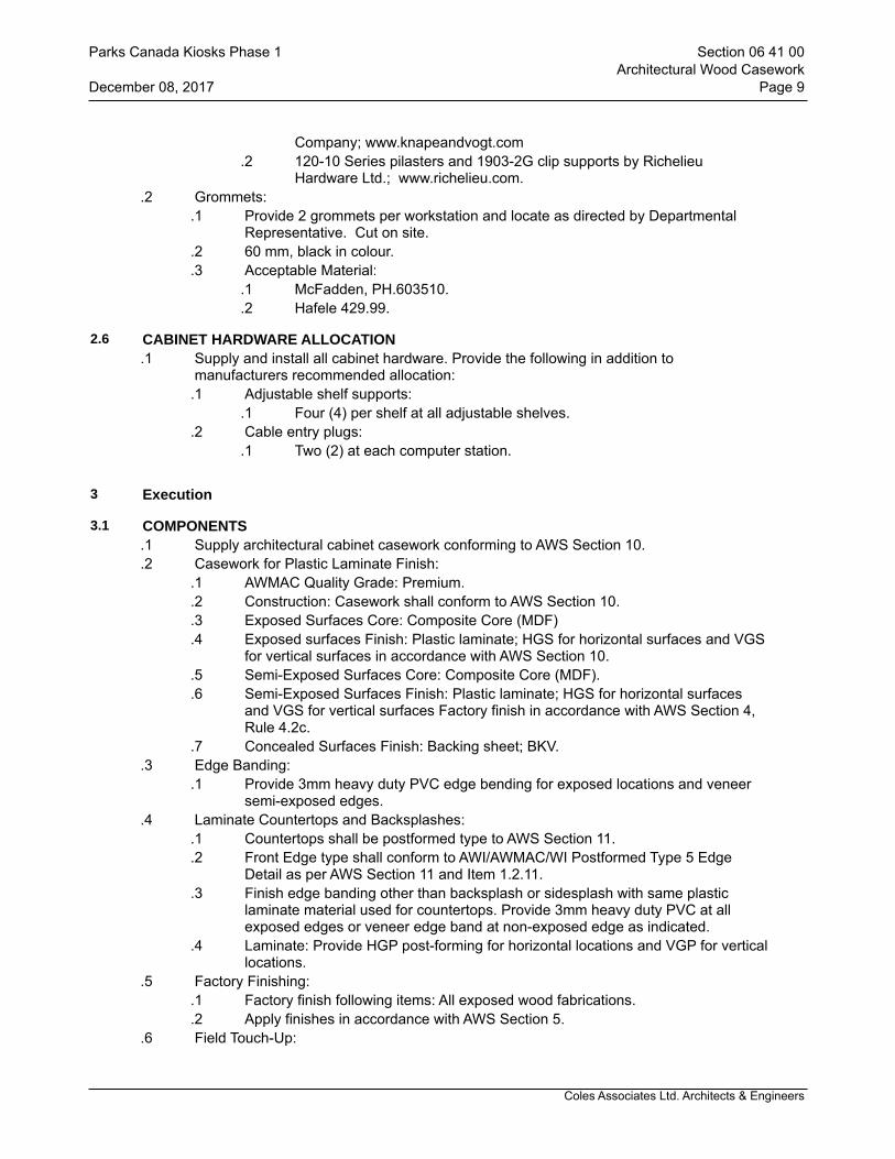
Coles Associates Ltd. Architects & Engineers
Company; www.knapeandvogt.com .2 120-10 Series pilasters and 1903-2G clip supports by Richelieu
Hardware Ltd.; www.richelieu.com..2 Grommets:
.1 Provide 2 grommets per workstation and locate as directed by Departmental Representative. Cut on site.
.2 60 mm, black in colour.
.3 Acceptable Material:.1 McFadden, PH.603510..2 Hafele 429.99.
2.6 CABINET HARDWARE ALLOCATION.1 Supply and install all cabinet hardware. Provide the following in addition to
manufacturers recommended allocation:.1 Adjustable shelf supports:
.1 Four (4) per shelf at all adjustable shelves..2 Cable entry plugs:
.1 Two (2) at each computer station.
3 Execution
3.1 COMPONENTS.1 Supply architectural cabinet casework conforming to AWS Section 10..2 Casework for Plastic Laminate Finish:
.1 AWMAC Quality Grade: Premium.
.2 Construction: Casework shall conform to AWS Section 10.
.3 Exposed Surfaces Core: Composite Core (MDF)
.4 Exposed surfaces Finish: Plastic laminate; HGS for horizontal surfaces and VGS for vertical surfaces in accordance with AWS Section 10.
.5 Semi-Exposed Surfaces Core: Composite Core (MDF).
.6 Semi-Exposed Surfaces Finish: Plastic laminate; HGS for horizontal surfaces and VGS for vertical surfaces Factory finish in accordance with AWS Section 4, Rule 4.2c.
.7 Concealed Surfaces Finish: Backing sheet; BKV..3 Edge Banding:
.1 Provide 3mm heavy duty PVC edge bending for exposed locations and veneer semi-exposed edges.
.4 Laminate Countertops and Backsplashes:.1 Countertops shall be postformed type to AWS Section 11..2 Front Edge type shall conform to AWI/AWMAC/WI Postformed Type 5 Edge
Detail as per AWS Section 11 and Item 1.2.11..3 Finish edge banding other than backsplash or sidesplash with same plastic
laminate material used for countertops. Provide 3mm heavy duty PVC at all exposed edges or veneer edge band at non-exposed edge as indicated.
.4 Laminate: Provide HGP post-forming for horizontal locations and VGP for vertical locations.
.5 Factory Finishing:.1 Factory finish following items: All exposed wood fabrications..2 Apply finishes in accordance with AWS Section 5.
.6 Field Touch-Up:
Parks Canada Kiosks Phase 1 Section 06 41 00Architectural Wood Casework
December 08, 2017 Page 9

Coles Associates Ltd. Architects & Engineers
.1 Field touch-up is responsibility of installing trade or architectural woodwork manufacturer providing it is responsible for factory finishing.
.2 Field touch-up includes filling and touch-up of exposed job-made nail and screw holes, refinishing of raw surface resulting from job fitting, repair of job-inflicted scratches and mars and final cleaning up of finished surfaces.
3.2 EXAMINATION.1 Ensure woodwork is back primed immediately after delivery to site. .2 Ensure cut ends are sealed.
3.3 PREPARATION.1 Wood Surface Preparation for Opaque Coating:
.1 Seal knots and sapwood in surfaces to receive paint with alcohol-based primer-sealer.
.2 Seal door edges.
.3 Sand smooth rough surfaces of woodwork to be finished using 150 grit paper followed by a second sanding using 220 grit paper.
.4 Sand in direction of grain.
.5 Clean surfaces free of dust before applying first coat using brush, compressed air or tack rags.
.6 Fill nail holes, splits and scratches with non-shrinking filler after first coat is dry.
.7 Remove salt deposits that may appear on wood surfaces treated with fire retarder.
.8 Prepare plywood surface by removing dirt and debris.
.9 Fill screw and nail holes or minor imperfections with recommended filler and sand properly to receive finish coating.
.10 Plywood requiring stained or painted finish shall be primed with top quality alkyd primer.
.11 Use only penetrating quality stain over plywood..2 Woodwork for Clear Finish or Stain:
.1 Sand smooth all woodwork to be finished using 150 grit paper followed by a second sanding using 220 grit paper and clean surfaces free of dust using brush, compressed air or tack rags before applying first coat.
.2 Abrade surfaces with stiff brush to remove loose fibers and splinters.
.3 Fill nail holes, splits and scratches with non-shrinking filler tinted to match local grain condition after first coat is dry.
.4 Sand lightly between coats with No. 220 sandpaper and remove dust.
.5 Remove salt deposits that may appear on wood surfaces treated with fire retarder.
.6 Ensure resilient flooring under millwork cabinets are provided prior to proceeding work of this Section unless indicated otherwise.
3.4 FABRICATION.1 Fabricate joints accurately fitted, coped where possible, and well glued up. .2 Fabricate joints mitred to perfect fit and alignments carefully matched..3 Fabricate finished woodwork in 1 piece where possible..4 Fabricate running members in the longest lengths obtainable..5 Fabricate to conceal fastenings..6 Provide plastic laminate Work in shop in accordance with ANSI/NEMA. LD3. .7 Provide backer sheets to panels and counters to ensure balance..8 Provide metal laminate Work in shop in accordance with ANSI/NEMA. LD3, Annex A.
Parks Canada Kiosks Phase 1 Section 06 41 00Architectural Wood Casework
December 08, 2017 Page 10

Coles Associates Ltd. Architects & Engineers
.9 Provide backer sheets to panels to ensure balance.
.10 Fabricate exposed gables to match the required exposed finishes.
.11 Exposed wood construction:.1 Fabricate joints carefully matched for grain and colour..2 Fabricate millwork with slow fed machines free from sticker and/or sander
markings, with sections and molding work cut accurately to profiles..3 Sandpaper woodwork, smooth removing burrs, feathers, sleeves, raised grain
and sharp arises and leave exposed surfaces perfectly clean and smooth ready for finishing.
.4 Provide edges noted to be solid, as minimum 6 mm thick wood to match exposed veneer to visible and semi-exposed edges, glued to core prior to application of face veneers.
.5 Provide plastic laminate or elastomeric edges to plastic laminate work visible or semi-visible edges.
.12 Countertops:.1 Fabricate and assemble countertops and splashbacks in shop to profiles and
lengths required..2 Fabricate cutouts for services penetrations as required..3 Verify governing dimensions before fabricating items which abut wall surfaces..4 Provide cutouts required and round internal corners, chamfer edges and seal
exposed core..5 Provide backer sheets on all counter construction..6 Provide veneer core plywood substrate to support counter spans in excess of
910mm..7 Provide sidesplashes at abutting ends of counters and at adjoining walls, unless
otherwise indicated..8 Provide a 6 mm drip groove approximately 13 mm in from the underside edge..9 Maximum free span 1200mm. Where free span exceeds 1200mm, provide HSS
supports as detailed..13 Melamine.
.1 Parallel clip and join face veneers by tapeless splicer and edge glue.
.2 Face veneers shall not contain open joints, face depression, glue stain, patches and repair any manufacturing irregularities or defects to meet quality requirements specified herein.
3.5 INSTALLATION.1 Do architectural woodwork to Quality Standards of the Architectural Woodwork
Manufacturers Association of Canada (AWMAC), except where specified otherwise..2 Install prefinished millwork at locations shown on drawings. Position accurately, level,
plumb straight and true..3 Complete fabrication at site to comply with requirements for fabrication specified herein
and to extent that it was not completed in shop..4 Shim as required with concealed shims..5 Fasten and anchor millwork securely. Provide heavy duty fixture attachments for wall
mounted cabinets..6 Install level and plumb (including tops) to a tolerance of 3 mm in 2400 mm..7 Secure with countersunk, concealed fasteners and blind nailing as required for complete
installation. Use fine finishing nails or finishing screws for exposed fastening, countersunk and filled flush with woodwork and matching final finish if transparent finish is indicated.
.8 Use draw bolts in countertop joints.
Parks Canada Kiosks Phase 1 Section 06 41 00Architectural Wood Casework
December 08, 2017 Page 11
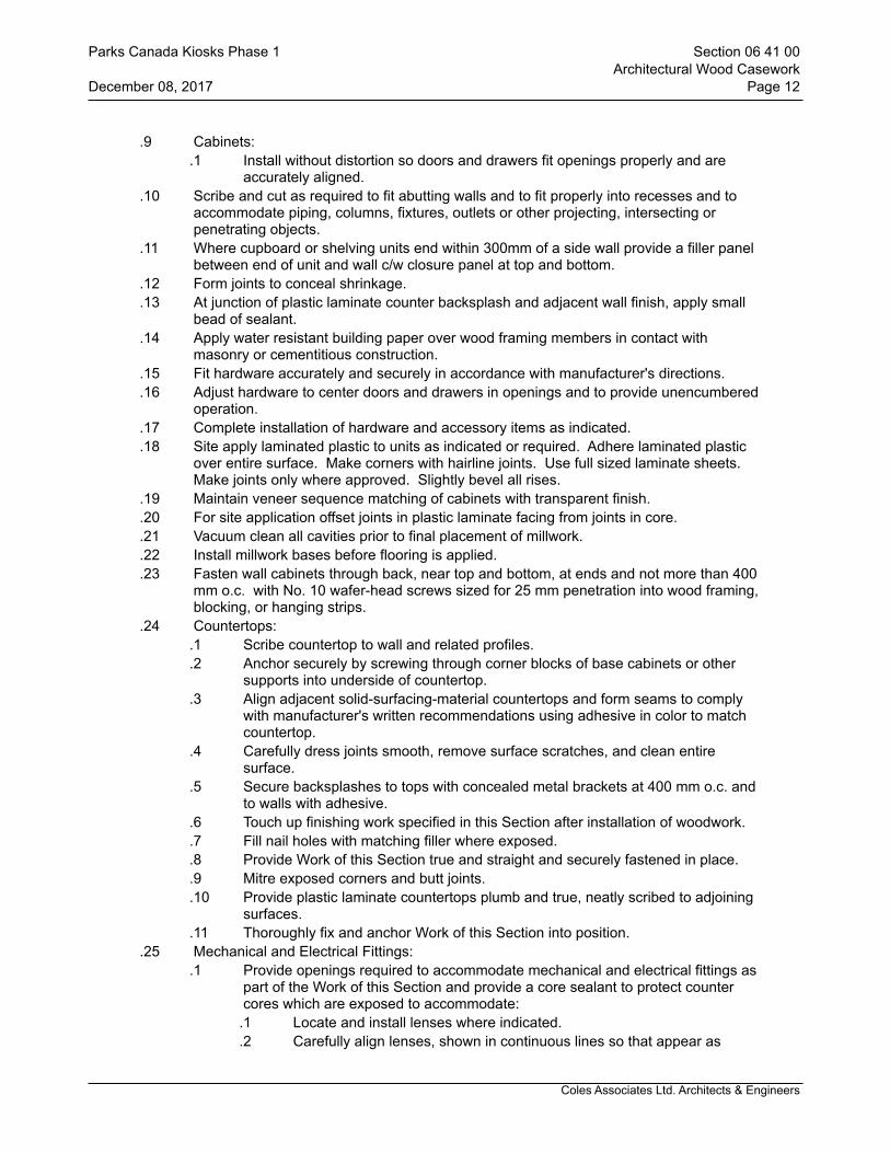
Coles Associates Ltd. Architects & Engineers
.9 Cabinets:.1 Install without distortion so doors and drawers fit openings properly and are
accurately aligned. .10 Scribe and cut as required to fit abutting walls and to fit properly into recesses and to
accommodate piping, columns, fixtures, outlets or other projecting, intersecting or penetrating objects.
.11 Where cupboard or shelving units end within 300mm of a side wall provide a filler panel between end of unit and wall c/w closure panel at top and bottom.
.12 Form joints to conceal shrinkage.
.13 At junction of plastic laminate counter backsplash and adjacent wall finish, apply small bead of sealant.
.14 Apply water resistant building paper over wood framing members in contact with masonry or cementitious construction.
.15 Fit hardware accurately and securely in accordance with manufacturer's directions.
.16 Adjust hardware to center doors and drawers in openings and to provide unencumbered operation.
.17 Complete installation of hardware and accessory items as indicated.
.18 Site apply laminated plastic to units as indicated or required. Adhere laminated plastic over entire surface. Make corners with hairline joints. Use full sized laminate sheets. Make joints only where approved. Slightly bevel all rises.
.19 Maintain veneer sequence matching of cabinets with transparent finish.
.20 For site application offset joints in plastic laminate facing from joints in core.
.21 Vacuum clean all cavities prior to final placement of millwork.
.22 Install millwork bases before flooring is applied.
.23 Fasten wall cabinets through back, near top and bottom, at ends and not more than 400 mm o.c. with No. 10 wafer-head screws sized for 25 mm penetration into wood framing, blocking, or hanging strips.
.24 Countertops:.1 Scribe countertop to wall and related profiles..2 Anchor securely by screwing through corner blocks of base cabinets or other
supports into underside of countertop. .3 Align adjacent solid-surfacing-material countertops and form seams to comply
with manufacturer's written recommendations using adhesive in color to match countertop.
.4 Carefully dress joints smooth, remove surface scratches, and clean entire surface.
.5 Secure backsplashes to tops with concealed metal brackets at 400 mm o.c. and to walls with adhesive.
.6 Touch up finishing work specified in this Section after installation of woodwork.
.7 Fill nail holes with matching filler where exposed.
.8 Provide Work of this Section true and straight and securely fastened in place.
.9 Mitre exposed corners and butt joints.
.10 Provide plastic laminate countertops plumb and true, neatly scribed to adjoining surfaces.
.11 Thoroughly fix and anchor Work of this Section into position..25 Mechanical and Electrical Fittings:
.1 Provide openings required to accommodate mechanical and electrical fittings as part of the Work of this Section and provide a core sealant to protect counter cores which are exposed to accommodate:
.1 Locate and install lenses where indicated.
.2 Carefully align lenses, shown in continuous lines so that appear as
Parks Canada Kiosks Phase 1 Section 06 41 00Architectural Wood Casework
December 08, 2017 Page 12
Coles Associates Ltd. Architects & Engineers
straight lines. .3 Mount lenses perfectly level or plumb. .4 Lenses shall fit tightly without showing space or light leak between frame
and lenses. .5 Remove improperly installed lenses and reinstall at no cost to Owner..6 Mechanical services and fittings..7 Washroom accessories..8 Mechanical and electrical fittings and services will be provided as part of
the Work of Sections 21, 22 23, 26, 27 and 28..26 Installation of Architectural Woodwork Hardware:
.1 Install architectural woodwork hardware in accordance with AWMAC AWS and manufacturer's requirements and templates.
.2 Adjust architectural woodwork hardware to provide smooth operation and ensure clearances are maintained.
.3 Repair damage to adjacent surfaces resulting from failure to conform with this requirement.
.4 Provide lubricants required and use in manner to ensure smooth function of hardware consistent with manufacturer's recommendations.
.5 Verify fastening components are tightened securely.
.6 Align screws, bolts and similar fastenings such that relationship of screw head indentations, similar surfaces and slots are perpendicular to matching vertical or horizontal position when on same surface.
.7 Do not burr or otherwise mar edges of surfaces of hardware components. .27 Do not burr or otherwise mar edges of surfaces of hardware components.
3.6 CONSTRUCTION.1 Fastening.
.1 Design and select fasteners to suit size and nature of components being joined. Use proprietary devices as recommended by manufacturer.
.2 Set finishing nails to receive filler. Where screws are used to secure members, countersink screw in round cleanly cut hole and plug with wood plug to match material being secured.
.3 Replace items of finish carpentry with damage to wood surfaces including hammer and other bruises.
.2 Standing and running trim..1 Butt and cope internal joints of baseboards to make snug, tight, joint. Cut right
angle joints of casing and base with mitered joints..2 Fit backs of baseboards and casing snugly to wall surfaces to eliminate cracks at
junction of base and casing with walls..3 Make joints in baseboard, where necessary using a 45 degrees scarf type joint..4 Install door and window trim in single lengths without splicing.
.3 Interior and exterior frames..1 Set frames with plumb sides and level heads and sills and secure.
.4 Shelving..1 Install shelving on ledgers or clips as indicated.
3.7 FABRICATION OF COUNTERTOPS, WORKTOPS AND VANITY TOPS.1 Fabricate counter tops/worktops/vanity tops continuous over multiple cabinetwork types,
in as long a length as practicable, using minimum 19mm thickness plywood, except where indicated otherwise.
.2 Provide backslash at vanity tops, and elsewhere where backslash is indicated, with
Parks Canada Kiosks Phase 1 Section 06 41 00Architectural Wood Casework
December 08, 2017 Page 13

Coles Associates Ltd. Architects & Engineers
return backslash along side wall(s) to front edge of counter..3 Cut holes for fittings, accessories and equipment..4 Use draw bolts and splines in counter top joints. Maximum spacing 450mm, keep back
75mm from edges..5 Leave ready for installation of plastic laminate by Section 06 47 00 - Plastic Laminate
Finishing..6 All PVC edge tape to be applied by hot glue with a purpose made machine.
3.8 INSTALLATION OF COUNTERTOPS/WORKTOPS AND VANITY TOPS.1 Install counter tops on cabinet bases. Fasten securely to cabinet. Ensure top is level,
with backslash tight against abutting walls..2 Install worktops and Vanity tops using metal support brackets. Anchor brackets securely
to wood blocking in steel stud walls using appropriate fasteners to ensure rigid installation and secure vanity top to brackets and to blocking at each end. Ensure top is level, with backslash tight against abutting walls.
.3 Leave ready for installation plastic laminate by Section 06 47 00 - Plastic Laminate Finishing and sealant between backslash and wall by Section 07 92 00 - Joint Sealants.
3.9 GROMMETED HOLES.1 Locate and drill grommeted holes after countertop equipment has been arranged and
located on site.
3.10 FINISHING.1 Prime unexposed surfaces including backs of fitments against walls and underside of
fitments..2 Before priming, treat knots and sap streaks, with a coat of shellac and then prime with a
wood primer..3 Shop finish natural finished wood surfaces.
3.11 ADJUSTING AND CLEANING.1 Repair damaged and defective woodwork, where possible, to eliminate functional and
visual defects; where not possible to repair, replace woodwork..2 Adjust joinery for uniform appearance..3 Clean, lubricate, and adjust hardware..4 Clean millwork and cabinet work inside cupboards and drawers and outside surfaces..5 Touch up shop-applied finishes to restore damaged or soiled areas.
3.12 PROTECTION.1 Protect millwork and cabinet work from damage until final inspection..2 Remove protection prior to Substantial Performance.
END OF SECTION
Parks Canada Kiosks Phase 1 Section 06 41 00Architectural Wood Casework
December 08, 2017 Page 14
Coles Associates Ltd. Architects & Engineers
1 General
1.1 WORK INCLUDED.1 Supply of plastic laminates for shop and site fabrication of casework, and as indicated
and detailed on the drawings.
1.2 RELATED REQUIREMENTS.1 Section 06 41 00 - Architectural Wood Casework..2 Section 07 92 00 - Joint Sealants.
1.3 REFERENCES.1 American National Standards Institute (ANSI)
.1 ANSI 208.1-99, Particleboard.
.2 ANSI A208.2-02, Medium Density Fiberboard (MDF) for Interior Applications..2 American Society for Testing and Materials International, (ASTM)
.1 ASTM D2832-92(R1999), Standard Guide for Determining Volatile and Nonvolatile Content of Paint and Related Coatings.
.2 ASTM D5116-97, Standard Guide For Small-Scale Environmental Chamber Determinations of Organic Emissions From Indoor Materials/Products.
.3 Canadian General Standards Board (CGSB).1 CAN/CGSB-71.20-M88, Adhesive, Contact, Brushable.
.4 Canadian Standards Association (CSA International).1 CSA O112-M1977(R2001, Standards for Wood Adhesives..2 CSA O112.5-1.1-Series-M-1977(R2001), Urea Resin Adhesives for Wood
(Room- and High-Temperature Curing)..3 CSA O112.7-1.1-Series M-1977(R2001), Resorcinol and Phenol-Resorcinol
Resin Adhesives for Wood (Room- and Intermediate-Temperature Curing)..4 CSA O121-M1978(R1998), Douglas Fir Plywood..5 CAN/CSA O141-91(R1999), Softwood Lumber..6 CSA O151-M1978(R1998), Canadian Softwood Plywood..7 CSA O153-M1980(R1998), Poplar Plywood.
.5 National Electrical Manufacturers Association (NEMA).1 NEMA LD3-2000, High Pressure Decorative Laminates.
1.4 SUBMITTALS.1 Product Data:
.1 Submit manufacturer's printed product literature, specifications and data sheet in accordance with Section 01 33 00 - Submittal Procedures.
.2 Submit two copies of WHMIS MSDS - Material Safety Data Sheets in accordance with Section 01 33 00 - Submittal Procedures. Indicate VOC's for adhesives, solvents and cleaners.
.2 Samples:.1 Submit samples in accordance with Section 01 33 00- Submittal Procedures..2 Submit full range of samples and textures from manufacturer's standard range.
.3 Closeout Submittals:.1 Provide maintenance data for laminate work for incorporation into manual
specified in Section 01 78 00 - Closeout Submittals.
1.5 QUALITY ASSURANCE.1 Pre-installation Meetings: Attend pre-installation meeting to verify project requirements,
manufacturer's installation instructions and manufacturer's warranty requirements.
Parks Canada Kiosks Phase 1 Section 06 47 00Plastic Laminate Finishing
December 08, 2017 Page 1

Coles Associates Ltd. Architects & Engineers
1.6 DELIVERY, STORAGE, AND HANDLING.1 Storage and Protection:
.1 Deliver, handle, store and protect materials of this section in accordance with Section 01 61 00 - Common Product Requirements.
.2 Maintain relative humidity between 25 and 60% at 22 degrees C during storage and installation. Maintain in storage environment for 72 hours prior to installation.
1.7 WASTE MANAGEMENT AND DISPOSAL.1 Collect and separate for disposal waste material generated by this Section. .2 Place in appropriate on-site bins in accordance with Waste Management Plan..3 A clean worksite is mandatory at all times. Failure to maintain the site in a clean, safe
condition shall result in the Owner initiating a clean-up and related costs being deducted from progress claims.
.4 Divert unused caulking, sealants, surface coatings and adhesive materials from landfill.
2 Products
2.1 MATERIALS.1 Laminated plastic facing sheet for flatwork: to NEMA LD3, Type 1b, 1.0mm thickness,
velor finish, unless noted otherwise..2 Color selections:
.1 Countertop: One (1) color, selected from Manufacturer's standard range.
.2 Laminated plastic at MFCB cabinetwork: .3 Acceptable Material:
.1 Formica
.2 Arborite
.3 Nevamar
.4 Wilsonart
.5 Pionite.4 Plywood core: to CSA O121 solid two sides, 19 mm thick..5 Particleboard core: to ANSI 208.1, sanded faces, of thickness indicated..6 Laminated plastic adhesive: urea resin adhesive to CSA O112.5.
.1 Test for acceptable VOC emissions in accordance with ASTM D2369 and ASTM D2832.
.7 Sealer: water resistant sealer or glue acceptable to laminate manufacturer..1 Test for acceptable VOC emissions in accordance with ASTM D2369 and ASTM
D2832..8 Draw bolts and splines: as recommended by fabricator.
3 Execution
3.1 FABRICATION.1 Comply with NEMA LD 3, Annex A..2 Obtain governing dimensions before fabricating items which are to accommodate or abut
appliances, equipment and other materials..3 Ensure adjacent parts of continuous laminate work match in color and pattern..4 Veneer laminated plastic to core material in accordance with adhesive manufacturer's
instructions. Ensure core and laminate profiles coincide to provide continuous support and bond over entire surface. Use continuous lengths up to 2400 mm. Keep joints 600 mm from sink cutouts.
Parks Canada Kiosks Phase 1 Section 06 47 00Plastic Laminate Finishing
December 08, 2017 Page 2
Coles Associates Ltd. Architects & Engineers
.5 Form shaped profiles and bends as indicated, using post forming grade laminate to laminate manufacturer's instructions.
.6 Use straight self-edging laminate strip for flatwork to cover exposed edge of core material. Chamfer exposed edges uniformly at approximately 20 degrees. Do not miter laminate edges.
.7 Apply laminate backing sheet to reverse side of core of plastic laminate work.
.8 Apply laminated plastic liner sheet to interior of cabinetry.
3.2 MANUFACTURER'S INSTRUCTIONS.1 Compliance: Comply with manufacturer's written data, including product technical
bulletins, product catalogue installation instructions, product carton installation instructions, and data sheets.
3.3 INSTALLATION.1 Install work plumb, true and square, neatly scribed to adjoining surfaces..2 Make allowances around perimeter where fixed objects pass through or project into
laminated plastic work to permit normal movement without restriction..3 Use draw bolts and splines in countertop joints. Maximum spacing 450 mm on center, 75
mm from edge. Make flush hairline joints..4 Provide cutouts for inserts, grilles, appliances, outlet boxes and other penetrations.
Round internal corners, chamfer edges and seal exposed core..5 At junction of laminated plastic counter back splash and adjacent wall finish, apply small
bead of sealant..6 Site apply laminated plastic to units as indicated. Adhere laminated plastic over entire
surface. Make corners with hairline joints. Use full sized laminate sheets. Make joints only where indicated. Slightly bevel arises.
.7 For site application, offset joints in plastic laminate facing from joints in core.
3.4 PROTECTION.1 Cover finished laminated plastic veneered surfaces with heavy kraft paper or put in
cartons during shipment. Protect installed laminated surfaces by approved means. Do not remove until immediately before final inspection.
3.5 CLEANING.1 Perform cleaning after installation to remove construction and accumulated
environmental dirt..2 Perform care and cleaning with NEMA LD 3, Annex B..3 Remove traces of primer, caulking, epoxy and filler materials; clean doors and frames.
END OF SECTION
Parks Canada Kiosks Phase 1 Section 06 47 00Plastic Laminate Finishing
December 08, 2017 Page 3
Coles Associates Ltd. Architects & Engineers
1 General
1.1 SECTION INCLUDES.1 Materials and installation for asphalt for use as dampproofing.
1.2 REFERENCES.1 Canadian General Standards Board (CGSB)
.1 CAN/CGSB-37.2-M88, Emulsified Asphalt, Mineral-Colloid Type, Unfilled, for Dampproofing and Waterproofing and for Roof Coatings.
.2 CAN/CGSB 37.3-M89, Application of Emulsified Asphalts for Dampproofing or Waterproofing.
.3 CAN/CGSB 37.5-M89, Cutback Asphalt Plastic Cement.
.4 CGSB 37-GP-6Ma-83, Asphalt, Cutback, Unfilled, for Dampproofing.
.5 CGSB 37-GP-9Ma-83, Primer, Asphalt, Unfilled, for Asphalt Roofing, Dampproofing and Waterproofing.
.6 CGSB 37-GP-11M-76(R1984), Application of Cutback Asphalt Plastic Cement.
.7 CGSB 37-GP-12Ma-84, Application of Unfilled Cutback Asphalt for Dampproofing.
.8 CGSB 37-GP-15M-76(R1984), Application of Asphalt Primer for Asphalt Roofing, Dampproofing and Waterproofing.
.9 CAN/CGSB 37.16-M89, Filled, Cutback, Asphalt for Dampproofing and Waterproofing.
.10 CAN/CGSB 37.28-M89, Reinforced Mineral Colloid Type, Emulsified Asphalt for Roof Coatings and for Waterproofing.
.11 CGSB 37-GP-36M-76, Application of Filled Cutback Asphalts for Dampproofing and Waterproofing.
.12 CGSB 37-GP-37M-77, Application of Hot Asphalt for Dampproofing or Waterproofing.
.2 Canadian Standards Association (CSA International).1 CSA A123.4-98, Bitumen for Use in Construction of Built-Up Roof Coverings and
Dampproofing and Waterproofing Systems..3 Health Canada
.1 Workplace Hazardous Materials Information System (WHMIS)
.2 Material Safety Data Sheets (MSDS).
1.3 DELIVERY, STORAGE AND HANDLING.1 Deliver, handle, store and protect materials in accordance with Section 01 61 00 -
Common Product Requirements..2 Store materials in accordance with manufacturer's written instructions.
1.4 SITE ENVIRONMENTAL REQUIREMENTS.1 Temperature, relative humidity, moisture content.
.1 Apply dampproofing materials only when surfaces and ambient temperatures are within manufacturers' prescribed limits.
.2 Do not proceed with Work when wind chill effect would tend to set bitumen before proper curing takes place.
.3 Maintain air temperature and substrate temperature at dampproofing installation area above 50 C for 24 hours before, during and 24 hours after installation.
.4 Do not apply dampproofing in wet weather..2 Safety: Comply with requirements of Workplace Hazardous Materials Information
System (WHMIS) regarding use, handling, storage, and disposal of asphalt, sealing
Parks Canada Kiosks Phase 1 Section 07 11 13Bituminous Dampproofing
December 08, 2017 Page 1
Coles Associates Ltd. Architects & Engineers
compounds and primers.
1.5 WASTE MANAGEMENT AND DISPOSAL.1 Collect and separate for disposal waste material generated by this Section. .2 Place in appropriate on-site bins in accordance with Waste Management Plan..3 A clean worksite is mandatory at all times. Failure to maintain the site in a clean, safe
condition shall result in the Owner initiating a clean-up and related costs being deducted from progress claims.
2 Products
2.1 MATERIALS.1 Asphalt:
.1 Package label or bill of lading for bulk hot liquid asphalt must indicate type, flash point, equiviscous temperature range and final blowing temperature.
.2 Acceptable Materials: asphalt, cut back, unfilled..2 Sealing compound: plastic cutback asphalt cement to CAN/CGSB-37.5..3 Asphalt primer: to CGSB 37-GP-9Ma.
.1 Acceptable Materials: plastic, cut back, asphalt, cement.
3 Execution
3.1 PREPARATION.1 Before applying dampproofing:
.1 Seal exterior joints between foundation walls and footings, joints between concrete floor slab and foundation and around penetrations through dampproofing with sealing compound.
.2 Ensure that all formwork ties have been properly removed and plugged by Section 03 30 00 - Cast-in-Place Concrete, and that all dirt and other deleterious material have been removed from existing walls.
.3 Apply primer to CGSB-37-GP-15M.
3.2 SCHEDULE.1 Apply 2 coats continuous, uniform coating to entire exterior faces of foundation walls
from 50 mm below finished grade level to and including tops of foundation wall footings..2 Apply continuous, uniform coating to exterior side of foundation walls..3 Apply one additional coat of dampproofing to vertical corners and construction joints for
a minimum width of 230 mm on each side, and all around and for 230 mm along pipes passing through walls.
END OF SECTION
Parks Canada Kiosks Phase 1 Section 07 11 13Bituminous Dampproofing
December 08, 2017 Page 2
Coles Associates Ltd. Architects & Engineers
1 General
1.1 RELATED REQUIREMENTS.1 Section 03 30 00 - Cast-in-Place Concrete..2 Section 06 10 00 - Rough Carpentry..3 Section 07 21 16 - Blanket Insulation..4 Section 07 26 00 - Vapor Retarders..5 Section 31 23 00 - Excavation and Fill.
1.2 REFERENCES.1 American Society for Testing and Materials International, (ASTM).
.1 ASTM E96-00e1, Test Methods for Water Vapor Transmission of Materials.
.2 ASTM C208-95(R2001), Specification for Cellulosic Fiber Insulating Board.
.3 ASTM C591-01, Specification for Unfaced Preformed Rigid Cellular Polyisocyanurate Thermal Insulation.
.4 ASTM C612-00a, Specification for Mineral Fiber Block and Board Thermal Insulation.
.5 ASTM C165 (2012), Standard Test Method for Measuring Compressive Properties of Thermal Insulations.
.6 ASTM C665 (2011), Standard Specification for Mineral-Fiber Blanket Thermal Insulation for Light Frame Construction and Manufactured Housing.
.7 ASTM C728-97e1, Specification for Perlite Thermal Insulation Board.
.8 ASTM C1126-00, Specification for Faced or Unfaced Rigid Cellular Phenolic Thermal Insulation.
.9 ASTM C1289-02, Specification for Faced Rigid Cellular Polyisocyanurate Thermal Insulation Board.
.10 ASTM C1338 (2008), Standard Test Method for Determining Fungi Resistance of Insulation Materials and Facings.
.2 Canadian General Standards Board (CGSB)..1 CGSB 71-GP-24M-77(R1983), Adhesive, Flexible, for Bonding Cellular
Polystyrene Insulation..3 Underwriters Laboratories of Canada (ULC).
.1 CAN/ULC-S102 (2010), Standard Method of Test for Surface Burning Characteristics of Building Materials and Assemblies.
.2 CAN/ULC-S604-91, Type A Chimneys.
.3 CAN/ULC-S701-01, Thermal Insulation, Polystyrene, Boards and Pipe Coverings.
.4 CAN/ULC-S702 (2012), Standard for Thermal Insulation Mineral Fibre for Buildings.
.5 CAN/ULC-S704-01, Thermal Insulation Polyurethane and Polyisocyanurate, Boards, Faced.
1.3 QUALITY ASSURANCE.1 Pre-Installation Meetings: attend pre-installation meeting to verify project requirements,
manufacturer's installation instructions and manufacturer's warranty requirements.
1.4 WASTE MANAGEMENT AND DISPOSAL.1 Collect and separate for disposal waste material generated by this Section. .2 Place in appropriate on-site bins in accordance with Waste Management Plan..3 A clean worksite is mandatory at all times. Failure to maintain the site in a clean, safe
condition shall result in the Owner initiating a clean-up and related costs being deducted
Parks Canada Kiosks Phase 1 Section 07 21 13Board Insulation
December 08, 2017 Page 1
Coles Associates Ltd. Architects & Engineers
from progress claims.
2 Products
2.1 FOUNDATION/FLOOR SLABS.1 Extruded polystyrene to CAN/ULC S701-97, Type IV, RS1 value of 0.87 (R-5)
per 25mm thickness, ship lapped, to thickness indicated..2 Acceptable Material:
.1 Celfort Celfortec-300
.2 Dow Styrofoam SM.
.3 Dow Styrofoam High Load 60.
3 Execution
3.1 EXAMINATION.1 Examine substrates and immediately inform Departmental Representative in writing of
defects..2 Prior to commencement of work ensure: substrates are firm, straight, smooth, dry, free of
snow, ice or frost, and clean of dust and debris.
3.2 MANUFACTURER'S INSTRUCTIONS.1 Comply with manufacturer's written data, including product technical bulletins, product
catalogue installation instructions, product carton installation instructions, and data sheets.
3.3 WORKMANSHIP.1 Install insulation after building substrate materials are dry..2 Install insulation to maintain continuity of thermal protection to building elements and
spaces..3 Cut and trim insulation neatly to fit spaces. Butt joints tightly, offset joints. Use only
insulation boards free from chipped or broken edges. Use largest possible dimensions to reduce number of joints.
.4 Do not enclose insulation until it has been inspected and approved by Departmental Representative.
3.4 CLEANING.1 Upon completion of installation, remove surplus materials, rubbish, tools and equipment
barriers.
END OF SECTION
Parks Canada Kiosks Phase 1 Section 07 21 13Board Insulation
December 08, 2017 Page 2

Coles Associates Ltd. Architects & Engineers
1 General
1.1 WORK INCLUDED.1 Provide and install all thermal and sound insulation and accessories on the interior of the
building between the steel studs and as indicated above ceiling necessary to complete all as shown on the drawings or specified.
1.2 RELATED REQUIREMENTS.1 Section 06 10 00 - Rough Carpentry..2 Section 07 21 13 - Board Insulation..3 Section 07 26 00 - Vapor Retarders.
1.3 REFERENCES.1 American Society for Testing and Materials International, (ASTM).
.1 ASTM C167, Standard Test Method for Thickness and Density of Blanket or Batt Thermal Insulations.
.2 ASTM C356, Standard Test Method for Linear Shrinkage of Performed High-Temperature Thermal Insulation Subjected to Soaking Heat.
.3 ASTM C423, Standard Test Method for Sound Absorption and Sound Absorption Coefficients by the Reverberation Room Method.
.4 ASTM C518, Standard Test Method for Steady-State Thermal Transmission Properties by Means of the Heat Flow Meter Apparatus.
.5 ASTM C553-02, Specification for Mineral Fiber Blanket Thermal Insulation for Commercial and Industrial Applications.
.6 ASTM C665-01e1, Specification for Mineral-Fiber Blanket Thermal Insulation for Light Frame Construction and Manufactured Housing.
.7 ASTM C1320-99, Standard Practice for Installation of Mineral Fiber Batt and Blanket Thermal Insulation for Light Frame Construction.
.8 ASTM E90, Standard Test Method for Laboratory Measurement of Airborne Sound Transmission Loss of Building Partitions and Elements.
.9 ASTM E413, Classification for Rating Sound Insulation.
.10 ASTM E1050, Standard Test Method for Impedance and Absorption of Acoustical Materials using a Tube, Two Microphones and a Digital Frequency Analysis System.
.2 Underwriters Laboratories of Canada (ULC)..1 CAN/ULC S102, Standard Method of Test for Surface Burning Characteristics of
Building Materials and Assemblies..2 CAN/ULC S114, Standard Method of Test for Determination of Non-
Combustibility in Building Materials..3 CAN/ULC S115, Standard Method of Test Firestop Systems. .4 CAN/ULC-S604-1991, Type A Chimneys..5 CAN/ULC-S702-1997, Standard for Thermal Insulation Mineral Fiber for
Buildings.
1.4 SUBMITTALS.1 Make submittals in accordance with Contract conditions and Section 01 33 00 -
Submittal Procedures..2 Product Data: Submit project data including manufacturer's literature for insulation
materials and accessories, indicating compliance with specified requirements and material characteristics.
.1 Submit list on insulation manufacturer's letterhead of materials and accessories to be incorporated into the Work.
Parks Canada Kiosks Phase 1 Section 07 21 16Blanket Insulation
December 08, 2017 Page 1
Coles Associates Ltd. Architects & Engineers
.2 MSDS report.
.3 Include product name.
.4 Include preparation instructions and recommendations, installation methods and storage and handing requirements.
.5 Include contact information for manufacturer and their representative for this project.
.3 Samples:.1 If requested, submit 140mm x 190mm minimum sample of insulation in thickness
used on project..4 Test Reports:
.1 Submit evaluation service reports or other independent testing agency reports, showing compliance with specified performance characteristics and physical properties.
.5 Field Reports:.1 Submit manufacturer's field reports within three (3) days of each manufacturer
representative's site visit and inspection.
1.5 CLOSEOUT SUBMITTALS.1 Operation and Maintenance Data: Supply maintenance data for insulation materials for
incorporation into manual specified in Section 01 78 00 - Closeout Submittals..2 Record Documentation: In accordance with Section 01 78 00 - Closeout Submittals.
.1 List materials used in insulation work.
.2 Warranty: Submit warranty documents specified.
1.6 DELIVERY, STORAGE AND HANDLING.1 Deliver and acceptance requirements:
.1 Deliver material in accordance with Section 01 61 00 - Common Product Requirements.
.2 Deliver materials and accessories in insulation manufacturer's original packaging with identification labels intact and in sizes to suit project.
.3 Ensure insulation materials are not exposed to moisture during delivery.
.4 Replace wet or damaged insulation materials..2 Storage and handling requirements: Store materials off ground in dry location and
protected from exposure to harmful weather conditions and at temperature conditions recommended by manufacturer.
.1 Store in original packaging until installed.
1.7 QUALITY ASSURANCE.1 Pre-installation Meetings: attend pre-installation meeting to verify project requirements,
manufacturer's installation instructions and manufacturer's warranty requirements.
1.8 WARRANTY.1 Manufacturer's warranty: Submit for Owner's acceptance, manufacturer's standard
warranty document executed by authorized company official. Manufacturer's warranty is in addition to and not intended to limit other rights the Owner may have under Contract conditions.
1.9 WASTE MANAGEMENT AND DISPOSAL.1 Collect and separate for disposal waste material generated by this Section. .2 Place in appropriate on-site bins in accordance with Waste Management Plan..3 A clean worksite is mandatory at all times. Failure to maintain the site in a clean, safe
condition shall result in the Owner initiating a clean-up and related costs being deducted
Parks Canada Kiosks Phase 1 Section 07 21 16Blanket Insulation
December 08, 2017 Page 2
Coles Associates Ltd. Architects & Engineers
from progress claims.
2 Products
2.1 INSULATION - THERMAL.1 Thermal batt insulation for exterior stud walls: To CAN/ULC S702, Type 1.
.1 Fire performance:.1 Non-combustibility: To CAN/ULC S114..2 Surface burning characteristics: To CAN/ULC S102.
.1 Flame spread: 0.
.2 Smoke developed: 0..3 Thermal resistance: to ASTM C518..4 Density: 32 kg/m³ to ASTM C167..5 Recycled content, 40% minimum.
.2 Acceptable Materials:.1 Fiberglass Pink - Owens Corning..2 Unfaced Fiber Glass Batts - Johns Manville..3 CertainTeed Insulation Canada, CertainTeed Fibre Glass Building Insulation;
www.certainteed.com/insulation..4 Knauf Insulation - Ecobatt Thermal / Acoustical Batt Insulation.
2.2 ACCESSORIES.1 Staples: 12.7mm minimum leg..2 Tape: as recommended by manufacturer. .3 Mechanical fasteners in accordance with insulation manufacturer's written
recommendations..4 Acoustical sealant in accordance with Section 07 92 19 - Acoustical Joint Sealants..5 Firestopping materials in accordance with Section 07 84 00 - Firestopping.
3 Execution
3.1 INSULATION INSTALLATION.1 Install insulation between studs to maintain continuity of acoustical protection to building
elements and spaces..2 Install insulation in areas as indicated. Friction-fit in position installed as recommended
by manufacturer..3 Fit insulation closely around electrical boxes, pipes, ducts, frames and other objects in or
passing through insulation..4 Do not compress insulation to fit into spaces..5 Keep insulation minimum 75mm from heat emitting devices such as recessed light
fixtures, and minimum 50mm from sidewalls of CAN/CGA-B149.1 and CAN/CGA-B149.2 Type B vents.
.6 Seal joints with acoustical joint sealant.
.7 Do not enclose insulation until it has been inspected and approved by Departmental Representative.
.8 Upon completion of installation, remove surplus materials, rubbish, tools and equipment barriers.
3.2 MANUFACTURER'S INSTRUCTIONS.1 Comply with manufacturer's written data, including product technical bulletins, product
catalogue installation instructions, product carton installation instructions, and data
Parks Canada Kiosks Phase 1 Section 07 21 16Blanket Insulation
December 08, 2017 Page 3

Coles Associates Ltd. Architects & Engineers
sheets.
END OF SECTION
Parks Canada Kiosks Phase 1 Section 07 21 16Blanket Insulation
December 08, 2017 Page 4
Coles Associates Ltd. Architects & Engineers
1 General
1.1 DESCRIPTION OF WORK.1 The work of this Section involves the provisions of a sheet vapour seals in the following
locations:.1 At entire warm side of exterior wall framing..2 Between window frames and framing for window openings..3 Between door frames and framing for door openings..4 Slip sheet at concrete foundation wall..5 Under slab vapor retarder by Section 06 10 00 - Rough Carpentry..6 All other locations where shown on drawings.
1.2 RELATED REQUIREMENTS.1 Section 06 10 00 - Rough Carpentry..2 Section 07 21 16 - Blanket Insulation..3 Section 07 92 00 - Joint Sealants.
1.3 REFERENCES.1 Canadian General Standards Board (CGSB)
.1 CAN/CGSB-51.34-M86, Vapor Barrier, Polyethylene Sheet, for Use in Building Construction.
1.4 PRODUCT DATA.1 Submit product data in accordance with Section 01 33 00 - Submittal Procedures..2 Submit product data sheets for sheet vapour retarders. Include:
.1 Product characteristics.
.2 Performance criteria.
.3 Limitations.
1.5 WASTE MANAGEMENT AND DISPOSAL.1 Collect and separate for disposal waste material generated by this Section. .2 Place in appropriate on-site bins in accordance with Waste Management Plan..3 A clean worksite is mandatory at all times. Failure to maintain the site in a clean, safe
condition shall result in the Owner initiating a clean-up and related costs being deducted from progress claims.
.4 Place materials defined as hazardous or toxic waste in designated containers.
.5 Use the least toxic sealants and adhesives necessary to comply with requirements of this section.
.6 Place used hazardous sealant tubes and adhesive containers in areas designated for hazardous materials.
2 Products
2.1 SHEET VAPOUR BARRIER.1 Polyethylene film: 10mil thick.
2.2 ACCESSORIES.1 Joint sealing tape: air resistant pressure sensitive adhesive tape, cloth fabric duct tape,
50 mm wide for lap joints and perimeter seals, 25 mm wide elsewhere..2 Sealant: EcoLogo certified, not to contain total of volatile organic compounds in excess
of 5 % by weight, asbestos-free sealant, compatible with vapour retarder materials,
Parks Canada Kiosks Phase 1 Section 07 26 00Vapour Retarders
December 08, 2017 Page 1
Coles Associates Ltd. Architects & Engineers
recommended by vapour retarder manufacturer and as specified in Section 07 92 00 -Joint Sealants.
.3 Staples: minimum 6 mm leg.
.4 Molded box vapour barrier: factory-molded polyethylene box for use with recessed electric switch and outlet device boxes.
3 Execution
3.1 INSTALLATION.1 Ensure services are installed and inspected prior to installation of retarder..2 Install sheet vapour retarder on warm side of exterior wall assemblies prior to installation
of gypsum board to form continuous retarder..3 Use sheets of largest practical size to minimize joints..4 Inspect for continuity. Repair punctures and tears with sealing tape before work is
concealed.
3.2 EXTERIOR SURFACE OPENINGS.1 Cut sheet vapour retarder to form openings and ensure material is lapped and sealed to
door and window frames.
3.3 PERIMETER SEALS.1 Seal perimeter of sheet vapour barrier as follows:
.1 Apply continuous bead of sealant to substrate at perimeter of sheets.
.2 Lap sheet over sealant and press into sealant bead.
.3 Install staples through lapped sheets at sealant bead into wood substrate.
.4 Ensure that no gaps exist in sealant bead. Smooth out folds and ripples occurring in sheet over sealant.
3.4 LAP JOINT SEALS.1 Seal lap joints of sheet vapour barrier as follows:
.1 Attach first sheet to substrate.
.2 Apply continuous bead of sealant over solid backing at joint.
.3 Lap adjoining sheet minimum 150 mm and press into sealant bead.
.4 Install staples through lapped sheets at sealant bead into wood substrate.
.5 Ensure that no gaps exist in sealant bead. Smooth out folds and ripples occurring in sheet over sealant.
3.5 ELECTRICAL BOXES.1 Seal electrical switch and outlet device boxes that penetrate vapour barrier as follows:
.1 Install molded box vapour barrier.
.2 Apply sealant to seal edges of flange to main vapour barrier and seal wiring penetrations through box cover.
END OF SECTION
Parks Canada Kiosks Phase 1 Section 07 26 00Vapour Retarders
December 08, 2017 Page 2
Coles Associates Ltd. Architects & Engineers
1 General
1.1 RELATED REQUIREMENTS.1 Section 07 62 00 - Sheet Metal Flashing and Trim.
1.2 REFERENCES.1 American Society for Testing and Materials International, (ASTM).
.1 ASTM D5116-97, Standard Guide For Small-Scale Environmental Chamber Determinations of Organic Emissions From Indoor Materials/Products.
.2 Canadian General Standards Board (CGSB)..1 CAN/CGSB-51.32-M77, Sheathing, Membrane, Breather Type..2 CAN/CGSB-51.34-M86(R1988), Vapor Barrier, Polyethylene Sheet for Use in
Building Construction..3 Canadian Standards Association (CSA International).
.1 CSA A123.3-98, Asphalt Saturated Organic Roofing Felt.
.2 CSA B111-1974(R2003), Wire Nails, Spikes and Staples.
.3 CSA 0118.1-97(R2002), Western Cedars Shakes and Shingles.
.4 CSA O118.2-M1981(R2002), Eastern White Cedar Shingles.
.5 CSA O118.3-93, Northern Pine Tapersawn Shakes..4 Cedar Shake and Shingle Bureau (CSSB).
.1 CSSB-97, Cedar Shake and Shingle Grading Rules.
.2 CSSB New Roof Construction Manual for Roof Application Details 2002.
.3 CSSB Exterior and Interior Wall Manual for Sidewall Application Details 2002.
1.3 DEFINITIONS.1 Shingle: tapered slice of wood sawn from block with taper in direction of grain or axial
direction..2 Shake: split shingle of 9.5 mm thickness with or without taper occurring in direction of
grain or axial direction.
1.4 SUBMITTALS.1 Product Data:
.1 Submit manufacturer's printed product literature, specifications and data sheet in accordance with Section 01 33 00 - Submittal Procedures.
.2 Shop Drawings:.1 Submit shop drawings in accordance with Section 01 33 00 - Submittal
Procedures..2 Indicate details of flashing installation.
.3 Samples:.1 Submit samples in accordance with Section 01 33 00 - Submittal Procedures..2 Submit duplicate full size shingles, of finish and profile specified.
.4 Manufacturer's Instructions:.1 Submit manufacturer's installation instructions.
1.5 QUALITY ASSURANCE.1 Certificates: product certificates signed by manufacturer certifying materials comply with
specified performance characteristics and criteria and physical requirements..2 Pre-Installation Meetings: conduct pre-installation meeting to verify project requirements,
manufacturer's installation instructions and manufacturer's warranty requirements.
1.6 QUALITY ASSURANCE MOCK-UP
Parks Canada Kiosks Phase 1 Section 07 31 29Wood Shingles and Shakes
December 08, 2017 Page 1

Coles Associates Ltd. Architects & Engineers
.1 Fabricate a mock-up that will demonstrate the various aspects of the air barrier / window connection / cladding installation and detailing.
.2 The installation is to reflect the intent to have a full tie in of the air barrier to the entire perimeter of all wall openings, including windows, doors and louvers, providing a tight air and water seal and the relationship of the cladding installation to the openings.
.3 The mock-up is to be reviewed by the Contractor, Membrane Installer, Window Installer, Owner and Departmental Representative prior to the Contractor moving forward with the installation of all other windows.
.4 Allow 24 hours to convene the review on site.
.5 Mock-up to be approved prior to fabrication of additional openings.
.6 Openings installed prior to review and approval will be removed at the Contractors expense and rebuilt.
.7 The approved mock-up may remain on site as part of the work and it will form the standard of acceptance for the remainder of the work.
1.7 DELIVERY, STORAGE AND HANDLING.1 Packing, Shipping, Handling and Unloading:
.1 Deliver, handle, store and protect materials in accordance with Section 01 61 00 - Common Product Requirements.
.2 Remove only in quantities required for same day use..2 Storage and Protection:
.1 Provide and maintain dry, off-ground weatherproof storage.
1.8 WASTE MANAGEMENT AND DISPOSAL.1 Collect and separate for disposal waste material generated by this Section. .2 Place in appropriate on-site bins in accordance with Waste Management Plan..3 A clean worksite is mandatory at all times. Failure to maintain the site in a clean, safe
condition shall result in the Owner initiating a clean-up and related costs being deducted from progress claims.
.4 Divert unused wood materials from landfill to recycling facility.
.5 Divert unused preservatives materials from landfill through disposal at special wastes depot.
2 Products
2.1 MATERIALS.1 Eastern White Cedar: 7- CSA 0118.2, 400mm length, random width, square pattern, A-
large rebutted joint..1 Acceptable Material:
.1 Maibel Inc. - Traditional Shingles, Bar Harbour Grade..1 Color: Maibec Natural..2 Touch-up Stain: Manufacturers recommendations for shingles
applications, color to match shingles. .2 Nails: to CSA 0118.1, Appendix E.
3 Execution
3.1 MANUFACTURER'S INSTRUCTIONS.1 Compliance: comply with manufacturer's written data, including product technical
bulletins, product catalogue installation instructions, product carton installation instructions, and data sheets.
Parks Canada Kiosks Phase 1 Section 07 31 29Wood Shingles and Shakes
December 08, 2017 Page 2

Coles Associates Ltd. Architects & Engineers
3.2 APPLICATION.1 Do wood shingle work in accordance with NBC, CAS and CCSB except where indicated
otherwise..2 Install shingles over dry substrate..3 Space shingles from 6 to 10 mm..4 Stagger joints minimum of 40 mm in succeeding courses. Ensure that in any 3 courses
no two joints are in alignment..5 Use two nails per shingle. Space nails 20 mm from edge and 40 mm above butt line of
following course..6 Drive nails flush but do not crush shingles.
3.3 WALL SIDING SHINGLES.1 Underlayment:
.1 Install over sheathing.
.2 Install horizontally and fasten to sheathing with nails. Lap edges 75 mm..2 Install shingles using single course method to ensure double thickness at any given
point. For double coursing set outer course 12 mm lower than under course. At external corners alternate overlap.
3.4 CLEANING.1 Upon completion of installation, remove surplus materials, rubbish, tools and equipment
barriers..2 Remove roofing nails that have fallen on ground using high powered, earth magnets or
other collection devices. Nail pickup to Departmental Representative's approval.
END OF SECTION
Parks Canada Kiosks Phase 1 Section 07 31 29Wood Shingles and Shakes
December 08, 2017 Page 3
Coles Associates Ltd. Architects & Engineers
1 General
1.1 RELATED REQUIREMENTS.1 Section 06 10 00 - Rough Carpentry..2 Section 07 62 00 - Sheet Metal Flashing and Trim..3 Section 07 92 00 - Joint Sealants..4 Section 09 91 00 - Painting.
1.2 REFERENCES.1 American Society for Testing and Materials International, (ASTM).
.1 ASTM D5116-97, Standard Guide For Small-Scale Environmental Chamber Determinations of Organic Emissions From Indoor Materials/Products.
.2 Canadian General Standards Board (CGSB)..1 CAN/CGSB-11.3-M87, Hardboard..2 CAN/CGSB-11.5-M87, Hardboard, Precoated, Factory Finished, for Exterior
Cladding..3 CAN/CGSB-11.6-M87, Installation of Exterior Hardboard Cladding..4 CAN/CGSB-51.32-M77, Sheathing, Membrane, Breather Type.
.3 Canadian Standards Association (CSA International)..1 CSA B111-1974(R2003), Wire Nails, Spikes and Staples.
.4 National Lumber Grades Authority (NLGA)..1 NLGA Standard Grading Rules for Canadian Lumber 2003.
1.3 SUBMITTALS.1 Make submittals in accordance with Section 01 33 00 - Submittal Procedures. .2 Product Data:
.1 Submit manufactures product data sheets..3 Samples:
.1 Submit duplicate 600mm long size and profile specified..4 Manufacturer's Instructions:
.1 Submit manufacturer's installation instructions.
1.4 QUALITY ASSURANCE.1 Pre-Installation Meetings: conduct pre-installation meeting to verify project requirements,
manufacturer's installation instructions and manufacturer's warranty requirements.
1.5 WASTE MANAGEMENT AND DISPOSAL.1 Collect and separate for disposal waste material generated by this Section. .2 Place in appropriate on-site bins in accordance with Waste Management Plan..3 A clean worksite is mandatory at all times. Failure to maintain the site in a clean, safe
condition shall result in the Owner initiating a clean-up and related costs being deducted from progress claims.
.4 Do not dispose of unused caulking materials into the sewer systems, into lakes, streams, onto ground or in locations where it will pose health or environmental hazard.
2 Products
2.1 MATERIALS.1 Siding:
.1 Profile: Brushed Modern - Horizontal, Regular, Texture Finish, as per drawings.
Parks Canada Kiosks Phase 1 Section 07 46 23Wood Siding
December 08, 2017 Page 1

Coles Associates Ltd. Architects & Engineers
.2 Stain: Factory stained.
.3 Color: Maibec, as per drawings.
.4 Color matched nails: Manufacturers recommendation for siding and molding application, color to match siding.
.5 Touch up stain: To match siding and molding color, sufficient to complete all necessary touch ups.
.6 Touch up Paint: Thermoplastic acrylic latex emulsion, same type and colour as siding, as recommended by manufacturer.
.7 Acceptable Material: .1 Maibec Inc. (Color 001 - Maibec Ultra White). .2 Capecod.
.2 Trim: Material and factory finish to match siding. Sizes as shown on drawings. .1 Acceptable Material:
.1 Maibec Inc.
.2 Capecod..3 Thermoplastic acrylic latex emulsion, factory coated under controlled environment
conditions by a modified vacuum coat method, one prime coat and one finish coat, applied to all board surfaces, minimum 0.15mm dry film thickness.
.4 Exterior Metal Corners:.1 Acceptable Material: Maibec Inc.
.5 Exterior wall sheathing paper: To CAN/CGSB-51.32 single ply, laminated, spun bonded olefin, type coated, impregnated, as indicated.
.6 Sealants: To manufacturers recommendation.
.7 Strapping: 31mm x 64mm pressure treated wood nailing strips at 400mm o/c vertically.
.8 Accessories:.1 Nails: Double hot dipped zinc coated galvanized to securely and rigidly retain the
work permanently in position, corrosion and rust resistant, per-finished baked on coating to match siding finish; manufactured by Maze Nails. Size: 64mm and 82m long as required to penetrate substrate minimum 32mm.
.2 Air Barrier: Spun bonded olefin sheeting, single ply laminated and coated. .1 Acceptable Material:
.1 Novawrap.
3 Execution
3.1 MANUFACTURER'S INSTRUCTIONS.1 Compliance: comply with manufacturer's written data, including product technical
bulletins, product catalogue installation instructions, product carton installation instructions, and data sheets.
3.2 PREPARATION.1 Verify that substrate surfaces wall openings are ready to receive work..2 Install metal flashings continuous at internal and external corners, siding bottom ledges,
sills, and over window and other openings. Lap ends and seal with sealant. Secure in position tight to wall sheathing.
.3 Install siding starter strips.
.4 Apply sealant around window, door, and other opening frames.
.5 Install siding and accessories to manufacturer's written instructions.
.6 Install siding for natural watershed.
.7 Seal end cuts and other pressure-treated wood exposed during installation with pressure-treatment sealer.
Parks Canada Kiosks Phase 1 Section 07 46 23Wood Siding
December 08, 2017 Page 2
Coles Associates Ltd. Architects & Engineers
.8 Install siding in straight aligned lengths, set level with plumb ends and corners.
.9 Cut butt joints at 45 degrees. Position cut ends over bearing surfaces. Sand cut ends smooth and site paint. Apply sealant to cut ends to minimize weather entry.
.10 Achieve siding joints no less than 800mm apart in adjoining boards and distribute evenly over wall surface.
.11 Miter external and internal corners. Install corner strips, closures, fascia boards, frieze boards, skirt boards, and trim.
.12 Fasten siding securely to wood battens; ensure minimum 32mm nail penetration into solid substrate.
.13 Face nail 25mm from bottom of siding board directly into solid substrate and studs wood strapping. Drive nail head just flush with siding surface; do not indent or penetrate painted coating.
3.3 CLEANING.1 Upon completion of installation, remove surplus materials, rubbish, tools and equipment
barriers.
END OF SECTION
Parks Canada Kiosks Phase 1 Section 07 46 23Wood Siding
December 08, 2017 Page 3

Coles Associates Ltd. Architects & Engineers
1 General
1.1 SUMMARY.1 Work Furnished and included: all labour and materials necessary to fabricate and install
the metal roof system in accordance with this performance specification including:.1 Underlayment..2 Roof panel..3 Accessories including associated flashings, closures and sealants.
1.2 RELATED REQUIREMENTS.1 Section 07 62 00 - Sheet Metal Flashing and Trim..2 Section 07 92 00 - Joint Sealants.
1.3 REFERENCES.1 Design of cladding system in according to the latest edition of:
.1 CSA-S136 for the design of Cold Formed Steel Structural Members.
.2 Canadian Sheet Steel Building Institute Standards 10M and 20M.
.3 National Building Code of Canada.
1.4 QUALITY ASSURANCE.1 Install two adjacent sheets c/w seaming for inspection by Departmental Representative..2 Mock-up will be used to judge workmanship..3 Locate where directed..4 Allow 24 hours for inspection of mock-up by Departmental Representative before
proceeding with work..5 When accepted, mock-up will demonstrate minimum standard of quality required for this
Work. Approved mock-up may remain as part of finished Work. .6 Manufacturer and/or approved applicator must have the single source facility to provide:
.1 Total design of the metal roofing system.
.2 Technical literature on tested metal roofing systems.
.3 Engineering facilities.
.4 Fabrication of metal roofing system and associated components.
.5 Technical representatives.
.6 Field installation by approved certified erectors.
.7 Fabrication/installation drawings must bear the stamp of a professional engineer registered in the Province of Prince Edward Island.
1.5 DESIGN REQUIREMENTS.1 Design roof system to resist:
.1 Snow loads and snow build-up and rain load, expected in this geographical region NBCC climatic data, 50 year probability.
.2 Wind loads, positive and negative, expected in this geographical region NBCC climatic data, 50 year probability.
.3 Dead load of roof system..2 Deflection of the roof system is not to exceed 1/240th of the span for the specified live
loading..3 Thermal movements: Allow for thermal movements from ambient and surface
temperature changes by preventing buckling, overstressing of components, failure of connections, and other detrimental effects. Base calculations on surface temperatures of materials due to solar heat gain and night time sky heat loss.
.1 Temperature change (range): 20 Deg C, ambient; 40 deg C, material surfaces.
Parks Canada Kiosks Phase 1 Section 07 61 00Sheet Metal Roofing
December 08, 2017 Page 1
Coles Associates Ltd. Architects & Engineers
1.6 SUBMITTALS.1 Make submittals in accordance with Section 01 33 00 - Submittal Procedures.2 Manufacturer's Instructions:
.1 Provide to indicate special handling criteria, installation sequence and cleaning procedures.
.3 Submit product data sheets for bitumen. Include:.1 Product characteristics..2 Performance criteria..3 Limitations.
.4 Shop drawings:.1 Submit six (6) copies of shop drawings for approval to the Departmental
Representative..2 No fabrication and or installation shall commence until all shop drawings have
been approved..3 Indicate arrangement of steel roof deck including thickness, type and welding
requirements..4 Indicate arrangement of prefinished roof sheet, including joints, ridges, valleys,
eaves, types and locations of supports, fasteners, flashing, gutters, miters, snow retention components and all metal components related to the roof installation. Include for underlayment as part of roof system.
.5 Each shop drawing shall be stamped by a professional engineer registered in the Province of Prince Edward Island.
.5 Samples:.1 Submit color samples for full range of manufacturer's standard colors..2 Submit samples of colored metal roof sheet for review by the Departmental
Representative, prior to fabrication..6 Maintenance Data:
.1 Provide maintenance data for cleaning and maintenance of panel finishes for incorporation into manual specified in Section 01 78 00 - Closeout Submittals.
1.7 PRODUCT DELIVERY, HANDLING & STORAGE.1 Store roofing products in accordance with manufacturer's recommendations..2 Protect prefinished steel during fabrication, transportation, site storage and erection, in
accordance with CSSBI Standards.
1.8 GUARANTEE.1 For work in this section, warranty by installer against defects or deficiencies in materials
or workmanship shall be for a period of one (1) year from date of Substantial Completion.
1.9 WARRANTY.1 Provide a manufacturer's written warranty: Furnish panel manufacturer's written
warranty covering failure of factory applied exterior finish within the warranty period. Warranty period for finish: 20 years after the date of Substantial Completion. The values below are based on normal environments and exclude any aggressive atmospheric conditions.
.1 Barrier Series (Polyvinyl Chloride - PVC) will not change color more than ten (10.0) Hunter Delta E units as determined by ASTM method D-2244-02 at any time for twenty (20) years from the date of installation (20.5 years from application).
1.10 WASTE MANAGEMENT AND DISPOSAL
Parks Canada Kiosks Phase 1 Section 07 61 00Sheet Metal Roofing
December 08, 2017 Page 2

Coles Associates Ltd. Architects & Engineers
.1 Collect and separate for disposal waste material generated by this Section.
.2 Place in appropriate on-site bins in accordance with Waste Management Plan.
.3 A clean worksite is mandatory at all times. Failure to maintain the site in a clean, safe condition shall result in the Owner initiating a clean-up and related costs being deducted from progress claims.
2 Products
2.1 ROOF SYSTEM COMPONENTS:.1 Roof System:
.1 Underlayment: .1 Membrane shall be Lastobond by Soprema..2 Ice and water shield by W.R. Grace.
.2 Clip System:.1 Thermally responsive clips to be fabricated from a minimum of 0.91mm
(.036") steel, with minimum Z275 galvanized coating designed to accommodate expansion and contraction of the roof sheet.
.2 Roof fasteners as recommended by manufacturer, to resist wind uplift and sliding snow forces.
.3 Prefinished Roof Sheet, exposed to exterior..1 Profile: Tradition 100-4, with I-style ribs at 400mm spacing..2 Panel: Z275 galvanized (zinc coated) sheet steel conforming to ASTM
A653M structural quality Grade 230 having a nominal core thickness 0.76mm (0.030").
.4 Snap Cap:.1 Provide 25mm high snap caps for full length of the roof panel and
retained by panel clips, fabricated from Z275 Galvanized (zinc coated) sheet steel conforming to ASTM A653M structural quality Grade 230 having a nominal core thickness 0.61mm (0.024"). Finish and color to match roof sheet.
.2 Acceptable Material: .1 Tradition 100-4 on Solid Substrate by VicWest. Refer to drawings for color
selections.
2.2 PANEL FINISHES:.1 Coating: Prepainted with WeatherX on interior face.
2.3 COLOUR.1 Barrier coating thickness shall be 6 mils on exterior exposed surface of the finished
profile and 4 mils on the reverse, selected from the manufacturer's standard color range.
2.4 ACCESSORIES.1 Flashing: In accordance with Section 07 62 00 - Sheet Metal Flashing and Trim.
Formed from same materials as the roof sheet. Custom fabricated to suit architectural detail, as required.
.2 Closures: Foam and metal closures to suit profiles selected, to manufacturer's recommendations.
.3 Sealants: In accordance with manufacturer's recommendation and Section 07 92 00 -Joint Sealants.
2.5 FABRICATION.1 Fabricate roof components to comply with dimensions, profiles, gauges and details as
Parks Canada Kiosks Phase 1 Section 07 61 00Sheet Metal Roofing
December 08, 2017 Page 3
Coles Associates Ltd. Architects & Engineers
shown on the shop drawings, including fascia and soffit panels and all companion flashing.
.2 Fabricate all components of the system in the factory, ready for field installation.
.3 Provide roof sheet and all accessories in longest practical length to minimize field lapping of joints.
3 Execution
3.1 EXAMINATION.1 Prior to proceeding with any metal roofing system installation, the completed installations
of preceding trades shall be inspected and any remedial work required shall be reported in writing to the Departmental Representative. The installation of the metal roofing system shall not begin until all remedial work has been completed and accepted by this trade.
3.2 INSTALLATION.1 Roof Materials:
.1 Underlayment: Install underlayment fully adhered to solid substrate according to manufacturer's recommendations. Ensure all joints are properly lapped and sealed. Tie in barriers on adjacent surfaces to ensure airtight construction. Provide a continuous seal around all openings in the insulated metal roof system.
.2 Clip: Attach Tradition clips using fasteners as recommended by the manufacturer, to suit the substrate.
.2 Roof Panel Installation:.1 Install exterior prefinished roof panels on panel support clips, using
manufacturer's proper construction procedure. Ensure metal roofing sheet side-lap is positively retained by clips, and proper sheet coverage is maintained.
.2 Install the snap-cap at all side laps as shown on the approved shop drawings. Mitre snap-cap as required to resist water entry.
.3 Where indicated on approved shop drawings, secure the end-lap of metal roofing sheets in accordance with the manufacturers specifications and detail to provide a weather-tight seal. Exposed fasteners to match color of the roof sheet.
.4 Provide notched and formed closures, sealed against weather penetration, at changes in pitch, and at ridges and eaves, where required.
.5 Install all companion flashing (gutters, ventilators) as shown on the shop drawings. Use concealed fasteners when possible. Exposed fasteners to match color of roof sheet.
3.3 CLEAN-UP.1 Clean exposed panel surfaces in accordance with manufacturer's instructions. .2 Repair and touch-up with color matching high grade enamel minor surface damage, only
where permitted by the Departmental Representative and only where appearance after touch-up is acceptable to Departmental Representative.
.3 Replace damaged panels and components that, in opinion of the Departmental Representative, cannot be satisfactorily repaired.
.4 Clean excessive foreign materials from the roof by dry wiping.
END OF SECTION
Parks Canada Kiosks Phase 1 Section 07 61 00Sheet Metal Roofing
December 08, 2017 Page 4
Coles Associates Ltd. Architects & Engineers
1 General
1.1 RELATED REQUIREMENTS.1 Section 07 61 00 - Sheet Metal Roofing
1.2 REFERENCES.1 The Aluminum Association Inc. (AA)
.1 Aluminum Sheet Metal Work in Building Construction-2000.
.2 AA DAF45-97, Designation System for Aluminum Finishes..2 American Society for Testing and Materials (ASTM International)
.1 ASTM A167-99, Specification for Stainless and Heat-Resisting Chromium-Nickel Steel Plate, Sheet, and Strip.
.2 ASTM A240/A240M-02, Standard Specification for Chromium and Chromium-Nickel Stainless Steel Plate, Sheet, and Strip for Pressure Vessels and for General Applications.
.3 ASTM A591/A591M-98, Standard Specification for Steel Sheet, Electrolytic Zinc-Coated, for Light Coating Mass Applications.
.4 ASTM A606-01, Standard Specification for Steel, Sheet and Strip, High-Strength, Low-Alloy, Hot-Rolled and Cold-Rolled, with Improved Atmospheric Corrosion Resistance.
.5 ASTM A653/A653M-01a, Standard Specification for Steel Sheet, Zinc-Coated (Galvanized) or Zinc-Iron Alloy-Coated (Galvannealed) by the Hot-Dip Process.
.6 ASTM A792/A792M-02, Standard Specification for Steel Sheet, 55% Aluminum-Zinc Alloy-Coated by the Hot-Dip Process.
.7 ASTM B32-00, Standard Specification for Solder Metal.
.8 ASTM B370-98, Standard Specification for Copper Sheet and Strip for Building Construction.
.9 ASTM D523-89(1999), Standard Test Method for Specular Gloss.
.10 ASTM D822-01, Standard Practice for Filtered Open-Flame Carbon-Arc Exposures of Paint and Related Coatings.
.3 Canadian Roofing Contractors Association (CRCA).1 Roofing Specifications Manual 1997.
.4 Canadian General Standards Board (CGSB).1 CAN/CGSB-37.5-M89, Cutback Asphalt Plastic Cement..2 CAN/CGSB-51.32-M77, Sheathing, Membrane, Breather Type..3 CAN/CGSB-93.1-M85, Sheet Aluminum Alloy, Prefinished, Residential.
.5 Canadian Standards Association (CSA International).1 CSA A123.3-98, Asphalt Saturated Organic Roofing Felt..2 CSA-A440-00/A440.1-00 - A440-00, Windows / Special Publication A440.1-00,
User Selection Guide to CSA Standard A440-00, Windows..3 CSA B111-1974(R1998), Wire Nails, Spikes and Staples.
1.3 WASTE MANAGEMENT AND DISPOSAL.1 Collect and separate for disposal waste material generated by this Section. .2 Place in appropriate on-site bins in accordance with Waste Management Plan..3 A clean worksite is mandatory at all times. Failure to maintain the site in a clean, safe
condition shall result in the Owner initiating a clean-up and related costs being deducted from progress claims.
2 Products
Parks Canada Kiosks Phase 1 Section 07 62 00Sheet Metal Flashing and Trim
December 08, 2017 Page 1

Coles Associates Ltd. Architects & Engineers
2.1 SHEET METAL MATERIALS.1 Prepainted Zinc coated steel sheet: 24 ga. thickness, commercial quality to ASTM A653/
A653M, with Z275 designation zinc coating.
2.2 PREFINISHED STEEL SHEET.1 Prefinished steel with factory applied polyvinylidene fluoride.
.1 Class F1S.
.2 One (1) color selected by Departmental Representative from manufacturer's standard range.
.3 Specular gloss: 30 units +/- in accordance with ASTM D523.
.4 Coating thickness: not less than 22 micrometers.
.5 Resistance to accelerated weathering for chalk rating of 8, color fade 5 units or less and erosion rate less than 20 % to ASTM D822 as follows:
.1 Outdoor exposure period 2500 hours.
.2 Humidity resistance exposure period 5000 hours.
2.3 ACCESSORIES.1 Isolation coating: alkali resistant bituminous paint..2 Plastic cement: to CAN/CGSB 37.5..3 Underlay for metal flashing: Membrane flashing by Section 07 52 00 - Modified Bitumen
Membrane Roofing..4 Sealants: to CAN/;CGSB 19.13, one component.
Acceptable Material:.1 Tremco A Spectrum 2".2 Pecora 895 NST.
.5 Cleats: of same material, and temper as sheet metal, minimum 50 mm wide. Thickness same as sheet metal being secured.
.6 Fasteners: of same material as sheet metal, to CSA B111, ring thread flat head roofing nails of length and thickness suitable for metal flashing application.
.7 Washers: of same material as sheet metal, 1 mm thick with rubber or neoprene packings.
.8 Prefabricated flashing at pipes penetrating roofs: purpose-made, neoprene or spun aluminum to CRCA Specification FL/532, minimum 300mm above top of roof membrane.
.9 Touch-up paint: as recommended by prefinished material manufacturer.
2.4 FABRICATION.1 Fabricate metal flashings and other sheet metal work in accordance with applicable
CRCA 'FL' series details..1 Brake form to profiles indicated and required to suit parapet configurations..2 Form pieces in 2400 mm maximum lengths. Make allowance for expansion at
joints..3 Hem exposed edges on underside 12 mm. Miter and seal corners with sealant..4 Form sections square, true and accurate to size, free from distortion and other
defects detrimental to appearance or performance..5 Apply isolation coating to metal surfaces to be embedded in concrete or mortar.
2.5 METAL FLASHINGS.1 Form flashings, copings and fascias to profiles indicated of 26 ga thick galvanized steel.
3 Execution
Parks Canada Kiosks Phase 1 Section 07 62 00Sheet Metal Flashing and Trim
December 08, 2017 Page 2

Coles Associates Ltd. Architects & Engineers
3.1 INSTALLATION.1 Install sheet metal work as detailed..2 Use concealed fastenings except where approved before installation..3 Provide underlay under sheet metal. Secure in place and lap joints 100 mm..4 Counter flash bituminous flashings at intersections of roof with vertical surfaces and
curbs. Flash joints using S-lock forming tight fit over hook strips, as detailed..5 Lock end joints and caulk with sealant..6 Install surface mounted reglets true and level, and caulk top of reglet with sealant..7 Insert metal flashing into reglets to form weather tight junction..8 Turn top edge of flashing into recessed reglet or mortar joint minimum of 25 mm. Lead
wedge flashing securely into joint..9 Caulk flashing at reglet with sealant..10 Install pans, where shown and around items projecting through roof membrane.
END OF SECTION
Parks Canada Kiosks Phase 1 Section 07 62 00Sheet Metal Flashing and Trim
December 08, 2017 Page 3
Coles Associates Ltd. Architects & Engineers
1 General
1.1 RELATED REQUIREMENTS.1 Section 03 30 00 - Cast-In-Place Concrete..2 Section 07 62 00 - Sheet Metal Flashing and Trim..3 Section 08 41 13 - Aluminium Framed Entrances and Storefronts.4 Section 08 80 00 - Glazing.
1.2 REFERENCES.1 American Society for Testing and Materials International, (ASTM)
.1 ASTM C 321 - Standard Test Method for Bond Strength of Chemical- Resistant Mortars.
.2 ASTM C 834 - Standard Specification for Latex Sealants.
.3 ASTM C 882 - Standard Test Method for Bond Strength of Epoxy-R Systems used with Concrete by Slant Shear.
.4 ASTM C 919 - Standard Specification for use of Sealants in Acoustical Applications.
.5 ASTM C 920 - Standard Specification for Elastomeric Joint Sealants.
.6 ASTM C 1330 - Standard Specification for Cylindrical Sealant Backing for use with Cold Liquid Applied Sealants.
.7 Sealants and associated materials must conform with the latest version of standards and specifications referenced.
.2 Transport Canada (TC).1 Transportation of Dangerous Goods Act (TDGA).
.3 Canadian General Standards Board (CGSB).1 CAN/CGSB-19.21, Sealing and Bedding Compound Acoustical.
.4 Department of Justice Canada (Jus).1 Canadian Environmental Protection Act, 1999 (CEPA).
.5 Health Canada/Workplace Hazardous Materials Information System (WHMIS).1 Material Safety Data Sheets (MSDS).
1.3 SUBMITTALS.1 Submit product data in accordance with Section 01 33 00 - Submittal Procedures.
.1 Caulking Compound.
.2 Primers.
.3 Sealing compound, each type, including compatibility when different sealants are in contact with each other.
.4 Installation instructions, surface preparation and product limitations..2 Manufacturer's Technical Data Guides and application procedures..3 Submit cured samples illustrating colors selected..4 Submit laboratory tests or data validating product compliance with performance criteria
specified. Include SWRI validation certificate where required. .5 Upon completion of the project the sealant applicator must submit copies of the
Manufacturer's Weatherseal and the Warranty Applicator's Workmanship Warranty..6 Before proceeding with work or ordering of material submit the following to the
Departmental Representative for review and acceptance:.1 Manufacturer's product data for sealants to be used..2 Manufacturer's recommended installation procedures.
.7 Material Safety Data Sheets: .1 Submit MSDS for inclusion in Operation and Maintenance Manual.
Parks Canada Kiosks Phase 1 Section 07 92 00Joint Sealants
December 08, 2017 Page 1
Coles Associates Ltd. Architects & Engineers
1.4 QUALITY ASSURANCE/MOCK-UP.1 Construct mock-up in accordance with Section 01 45 00 - Quality Control..2 Manufacturer Qualifications: Company regularly engaged in manufacturing and
marketing of products specified in this section. .3 Installer Qualifications: Qualified to perform work specified by reason of experience or
training provided by the product manufacturer. .4 Installer must submit a reference list including a minimum of three projects of similar size
and scope..5 Mock-ups: Include a minimum of 3m of sealant to show compatibility with substrate,
proper adhesion to substrate and chosen color. .1 Apply mock-up with specified joint filler types and with other components noted.
Installer must provide both primed and un-primed mock up to assess whether a primer is required for the project.
.2 Locate where directed by Departmental Representative.
.3 Mock-up may remain as part of the work if acceptable to Departmental Representative.
.4 Allow 24 hours for inspection of mock-up by Departmental Representative before proceeding with sealant work.
.5 When accepted, mock-up will demonstrate minimum standard of quality required for this Work.
.6 Adhesion pull tests: the number of adhesion pull tests is to be determined by the manufacturer's weatherseal warranty. Adhesion pull tests are to be conducted by or in the presence of the manufacturer's representative. The manufacturer is to supply the Departmental Representative / Owner with the results of the adhesion pull tests. The sealant installer is responsible for repairing areas where adhesion pull tests are conducted.
1.5 FIELD ADHESION / COHESION TESTS.1 Test Frequency:
.1 Perform a field test for each type of sealant and substrate combination, for all interior and exterior sealants associated with the building envelope.
.2 Perform three (3) additional tests for each failed test..2 Locate test joints as directed by Departmental Representative. Tests to be performed in
the presence of Departmental Representative and/or manufacturer's representative. .3 Notify Departmental Representative seven (7) days prior to dates tests are to be
performed. .4 Test joint sealants by hand-pull methods #1 and #2. Record results in Field Adhesion /
Cohesion Test Form..1 Test Method #1:
.1 Make a knife cut horizontally from one side of the joint to the other.
.2 Make two (2) vertical cuts (from the horizontal cut) approximately 75mm long on each side of the joint.
.3 Pry out flap created from cuts.
.4 Firmly grasp flap and slowing pull at 90 degrees from sealant plane.
.5 Pull flap until adhesive or cohesive failure occurs..1 Adhesive failure will be evidenced by the sealant pulling off clean
from the substrate..2 Cohesion failure will be evidenced by the sealant ripping or failing
within itself, leaving well-adhered sealant to the substrate, (cohesive failure is considered a positive result).
.2 Test Method #2:.1 Follow steps #1 to #4 (inclusive) of Test Method #1 above.
Parks Canada Kiosks Phase 1 Section 07 92 00Joint Sealants
December 08, 2017 Page 2

Coles Associates Ltd. Architects & Engineers
.2 Mark a benchmark on the sealant, 25mm from the plane of the installed sealant.
.3 Firmly grasp the flap and pull slowly, while holding a ruler parallel to the sealant flap. Note the position of the benchmark on the ruler.
.4 Refer to manufacturer's printed literature for each sealant tested for the required extension factor pass criteria; (i.e. if the 25mm benchmark on the sealant can be pulled to 100mm and held with no failure of sealant, 400% elongation is achieved).
.5 If no failure occurs prior to the manufacturer's stated extension factor, the test is successful. Extension factor should be three (3) times the movement capability of the sealant.
.5 Inspect joints for:.1 Complete fill..2 Absence of voids..3 Primer..4 Proper width / depth ratio..5 Backup material.
.6 Repair sealants pulled in test area by applying new sealants following same procedures used to original seal joints.
.7 Contactor shall repair test areas at no additional cost to the Owner.
1.6 DELIVERY, STORAGE, AND HANDLING.1 Deliver, handle, store and protect materials in accordance with Section 01 61 00 -
Common Product Requirements..2 Deliver products in original factory packaging bearing identification of product,
manufacturer, and batch number. Provide Material Safety Data Sheets (MSDS) for each product.
.3 Store products in location protected from freezing, damage, construction activity, precipitation and direct sunlight in strict accordance with manufacturer's recommendations.
.4 Condition products to approximately 16 to 21 degrees C, for use in accordance with manufacturer's recommendations.
.5 Handle all product with appropriate precautions and care as stated on Material Safety Data Sheet (MSDS).
1.7 PROJECT CONDITIONS.1 Do not use products under conditions of precipitation or freezing weather. Use
appropriate measures for protection and supplementary heating to ensure proper curing conditions in accordance with manufacturer's recommendations if application during inclement weather occurs.
.2 Ensure substrate is dry.
.3 Protect adjacent work from contamination due to mixing, handling and application.
.4 Joint-Width Conditions:.1 Do not proceed with installation of joint sealants where joint widths are less than
those allowed by joint sealant manufacturer for applications indicated..5 Joint-Substrate Conditions:
.1 Do not proceed with installation of joint sealants until contaminants capable of interfering with adhesion are removed from joint substrates.
1.8 ENVIRONMENTAL REQUIREMENTS.1 Comply with requirements of Workplace Hazardous Materials Information System
(WHMIS) regarding use, handling, storage, and disposal of hazardous materials; and
Parks Canada Kiosks Phase 1 Section 07 92 00Joint Sealants
December 08, 2017 Page 3

Coles Associates Ltd. Architects & Engineers
regarding labeling and provision of Material Safety Data Sheets (MSDS) acceptable to Labour Canada.
1.9 WARRANTY.1 Provide manufacturer's five (5) year standard material warranty..2 Include coverage for replacement of sealant materials which fail to achieve water tight
seal, exhibit loss of adhesion or cohesion, or do not cure..3 Warranty Exclusions: Failure resulting from concrete shrinkage, structural cracks or
defects, faulty construction, faulty design, faulty materials (other than sealant), misuse of structure, settlement or accident, fire or other casualty, or physical damage.
1.10 WASTE MANAGEMENT AND DISPOSAL.1 Collect and separate for disposal waste material generated by this Section. .2 Place in appropriate on-site bins in accordance with Waste Management Plan..3 A clean worksite is mandatory at all times. Failure to maintain the site in a clean, safe
condition shall result in the Owner initiating a clean-up and related costs being deducted from progress claims.
.4 Handle and dispose of hazardous materials in accordance with the CEPA, TDGA, Provincial and Municipal regulations.
2 Products
2.1 MANUFACTURERS.1 Acceptable material:
.1 BASF Building Systems.
.2 Pecora Corporation.
.3 Tremco Sealant and Waterproofing.
.4 Sika Canada Inc.
.5 Dow Corning..2 Provide all joint materials of the same type form a single manufacturer.
2.2 MATERIALS.1 Single Component, Non-Sag Polyurethane Sealant with plus or minus 25 percent
movement capability for vertical joints; ASTM C 920, Type S, Grade NS, Class 35, uses NT, M, A, O & I.
.1 Acceptable Materials:.1 MasterSeal NP1 by BASF Building Systems..2 Pecora DynaTrol 1-XL by Pecora Corporation..3 Sikaflex 1a by Sika Canada Inc.
.2 Single component texturized polyurethane sealant with plus or minus 25 percent joint movement capability for horizontal or vertical joints, ASTM C 920, Type S, Grade NS, Class 25, uses NT, M, A, O.
.1 Acceptable Materials:.1 MasterSeal TX1 by BASF Building Systems..2 Vulkem 116 by Tremco Sealant & Waterproofing.
.3 Single component low modulus high movement fast-curing silyl terminated polyether sealant with plus 100 and minus 50 percent joint movement capability; ASTM C 920, Type S, Grade NS, Class 50, uses NT, M, A, G, O; ASTM C 1382.
.1 Acceptable Materials:.1 MasterSeal NP 150 by BASF Building Systems.
.4 Multi-component field tintable low modulus high movement fast-curing sealant with plus
Parks Canada Kiosks Phase 1 Section 07 92 00Joint Sealants
December 08, 2017 Page 4

Coles Associates Ltd. Architects & Engineers
100 and minus 50 percent joint movement capability; ASTM C 920, Type M, Grade NS, Class 50.
.1 Acceptable Materials:.1 MasterSeal 150 Tint Base by BASF Building Systems..2 Pecora 890FTS by Pecora Corporation.
.5 Field tintable low modulus high movement fast-curing textured sealant with plus and minus 50 percent joint movement capability; ASTM C 920, Type M, Grade NS, Class 50.
.1 Acceptable Materials:.1 Pecora 890FTS-TXTR by Pecora Corporation.
.6 Multi-component, Polyurethane Sealant with plus or minus 50 percent joint movement capability; ASTM C 920, Type M, Grade NS, Class 25, uses NT, T, M, A, O, G and I; UL classified (fire resistance).
.1 Acceptable Materials:.1 DynaTrol ll by Pecora Corporation..2 MasterSeal NP2 by BASF Building Systems..3 Dymeric 240 by Tremco Sealant & Waterproofing..4 Sikaflex 2C NS by Sika Canada Inc.
.7 Single component self-leveling polyurethane sealant with plus or minus 25 percent movement capability for horizontal joints; ASTM C 920, Type S, Grade P, Class 25 uses T&M.
.1 Acceptable Materials:.1 Urexpan NR-201b by Pecora Corporation..2 MasterSeal SL1 by BASF Building Systems..3 Vulkem 45 by Tremco Sealant & Waterproofing..4 Sikaflex 1C SL by Sika Canada Inc.
.8 Multi-component, Self-Leveling Polyurethane Sealant with plus or minus 25 percent movement capability for horizontal joints, ASTM C 920, Type M, Grade P, Class 25 uses NT. T, A, I & M.
.1 Acceptable Materials:.1 Urexpan NR-200 by Pecora Corporation..2 MasterSeal SL2 by BASF Building Systems..3 Vulkem THC 900 by Tremco Sealant & Waterproofing..4 Sikaflex 2C SL by Sika Canada Inc.
.9 Single component neutral cure silicone sealant for non-structural glazing applications with plus / minus 50 percent joint movement capability; ASTM C 920, Type S, Grade NS, Class 50, Use NT, M, G and A.
.1 Acceptable Materials:.1 Pecora 864NST or 895NST by Pecora Corporation..2 Dow Corning 795 by Dow Corning..3 Spectrum 2 by Tremco Sealant & Waterproofing.
.10 Single component neutral cure silicone sealant for non-structural glazing applications with plus 100% minus 50% joint movement capability; ASTM C 920, Type S, Grade NS, Class 100/50, use T, NT, M, G, A and O. SWRI validated.
.1 Acceptable Materials:.1 Pecora 890NST by Pecora Corporation..2 Spectrum 1 by Tremco Sealant & Waterproofing. .3 Dow Corning 790 by Dow Corning.
.11 Single component mildew resistant silicone sealant plus/minus 25% movement capability; ASTM C 920, Type S, Grade NS, Class 25, Use NT, G and A.
.1 Acceptable Materials:
Parks Canada Kiosks Phase 1 Section 07 92 00Joint Sealants
December 08, 2017 Page 5
Coles Associates Ltd. Architects & Engineers
.1 Pecora 898 by Pecora Corporation.
.2 Tremsil 200 by Tremco Sealant & Waterproofing.
.3 Dow Corning 786..12 Single component silicone structural adhesive with plus/minus 50% joint movement
capability; ASTM C 920, Type S, Grade NS, Class 25, Use NT, G and A..1 Acceptable Materials:
.1 Dow Corning 995 by Dow Corning.
.2 Pecora 895NST by Pecora Corporation..13 Single component synthetic rubber sealant purpose made for use in acoustical
applications..1 Acceptable Materials:
.1 Tremoco Acoustical Sealant.
.2 Pecora BA-98..14 Single component pick resistant sealant with plus/minus 25 percent joint movement
capability; ASTM C 920, Type S, Grade NS, Class 25, uses NT, T, M, A, G and I..1 Acceptable Materials:
.1 Pecora 896HIS by Pecora Corporation.
.2 MasterSeal CR 195 by BASF Building Systems..15 Two-component self leveling, 100 percent solids Polyurea control joint filler.
.1 Shore A Hardness: 85 to 90.
.2 Tensile Strength: 1183 psi.
.3 Elongation: 240 percent.
.4 Acceptable Materials:.1 MasterSeal CR 100 by BASF Building Systems..2 Sika Loadflex Polyurea by Sika Canada Inc.
2.3 ACCESSORIES.1 Primer: Type recommended by the sealant manufacturer and compatible with joint
forming materials..2 Joint Cleaner: Non-corrosive and non-staining type recommended by sealant
manufacturer and compatible with joint forming materials..3 Soft Backer Rod: non-gassing, reticulated closed-cell polyethylene rod designed for use
with cold-applied joint sealants..1 Comply with ASTM C 1330..2 Size required for joint design.
.4 Closed-Cell Backer Rod: closed-cell polyethylene rod designed for use with cold-applied joint sealants for on-grade or below-grade applications.
.1 Comply with ASTM C 1330.
.2 Size required for joint design..5 Joint Filler: closed-cell polyethylene joint filler, designed for use in cold joints,
construction joints or isolation joints wider than 1/4 inch (6mm)..1 Size required for joint design.
.6 Bond Breaker: Pressure-sensitive tape recommended by sealant manufacturer to suit application.
2.4 COLOR.1 Sealant Colors: Selected by Departmental Representative.
.1 Manufacturer's standard color range.
.2 Custom color matching submittal of job site substrate samples.
Parks Canada Kiosks Phase 1 Section 07 92 00Joint Sealants
December 08, 2017 Page 6
Coles Associates Ltd. Architects & Engineers
3 Execution
3.1 PROTECTION.1 Protect installed Work of other trades from staining or contamination.
3.2 EXAMINATION.1 Inspect all areas involved in work to establish extent of work, access and need for
protection of surrounding construction..2 Conduct pre-application inspection of site verification with an authorized manufacturer's
representative..3 Occupied areas: where high VOC materials are utilized, investigate occupants to
determine the measures to be taken to accommodate them.
3.3 PREPARATION.1 Remove loose materials and foreign matter which could impair adhesion of the sealant..2 Clean joint and saw cuts by grinding, sandblasting or wire brushing to expose a sound
surface free of contamination and laitance..3 Ensure structurally sound surfaces are dry, clean, free of dirt, moisture, loose particles,
oil, grease, asphalt, tar, paint, wax, rust, waterproofing, curing and parting compounds, membrane materials and other foreign matter.
.4 Where the possibility of sealants staining adjacent areas or materials exist, mask joints prior to application.
.1 Do not remove masking tape before joints have been tooled and initial cure of joint filler has taken place.
.2 Work stained due to failure of proper masking precautions will not be accepted.
3.4 INSTALLATION:.1 Priming:
.1 Prime all surfaces to receive sealant with recommended primer unless the mockup proves otherwise.
.2 Back-Up Material:.1 Install appropriate size backer rod, larger than joint where necessary according
to manufacturer's recommendations..2 Install polyethylene joint filler in joints wider than 1/4 inch (6mm) to back-up
material per manufacturer's recommendations..3 Bond Breaker:
.1 Install bond-breaker strip in joint to be sealed on top of back-up material to prevent adhesion of sealant to back-up material; install per manufacturer's recommendations.
.4 Sealant:.1 Prepare sealants that require mixing; follow manufacturer's recommended
procedures, mixing thoroughly..2 Mix only as much material as can be applied within manufacturer's
recommended procedures, mixing thoroughly. .3 Apply materials in accordance with manufacturer's recommendations; take care
to produce beads of proper width and depth, tool as recommended by manufacturer and immediately remove surplus sealant.
.4 Apply materials only within manufacturer's specified application life period. Discard sealant after application life is expired or if prescribed application period has elapsed.
3.5 CLEANING
Parks Canada Kiosks Phase 1 Section 07 92 00Joint Sealants
December 08, 2017 Page 7
Coles Associates Ltd. Architects & Engineers
.1 Remove uncured sealant with Reducer 990, xylene, toluene or MEK. Remove cured sealant by razor, scraping or mechanically.
.2 Remove all debris related to application of sealants from job site in accordance with all applicable regulations for hazardous waste disposal.
3.6 APPLICATION.1 Sealant.
.1 Apply sealant in accordance with manufacturer's written instructions.
.2 Mask edges of joint where irregular surface or sensitive joint border exists to provide neat joint.
.3 Apply sealant in continuous beads.
.4 Apply sealant using gun with proper size nozzle.
.5 Use sufficient pressure to fill voids and joints solid.
.6 Form surface of sealant with full bead, smooth, free from ridges, wrinkles, sags, air pockets, embedded impurities.
.7 Tool exposed surfaces before skinning begins to give slightly concave shape.
.8 Remove excess compound promptly as work progresses and upon completion..2 Curing.
.1 Cure sealants in accordance with sealant manufacturer's instructions.
.2 Do not cover up sealants until proper curing has taken place..3 Cleanup.
.1 Clean adjacent surfaces immediately and leave Work neat and clean.
.2 Remove excess and droppings, using recommended cleaners as work progresses.
.3 Remove masking tape after initial set of sealant.
END OF SECTION
Parks Canada Kiosks Phase 1 Section 07 92 00Joint Sealants
December 08, 2017 Page 8
Coles Associates Ltd. Architects & Engineers
1 General
1.1 WORK INCLUDED.1 All hollow metal (HM) steel frames, and screens as per Door & Frame Schedule, and as
detailed on Drawings..2 Provide steel doors and frames including but not limited to following:
.1 Hollow metal doors, swing flush type.
.2 Hollow metal door frames.
1.2 RELATED REQUIREMENTS.1 Section 07 92 00 - Joint Sealants..2 Section 08 71 00 - Door Hardware. .3 Section 08 80 00 - Glazing..4 Section 09 91 00 - Painting.
1.3 REFERENCES.1 Canadian Standards Association (CSA).
.1 CSA A101-M1983, Thermal Insulation, Mineral Fibre, for Buildings.
.2 CSA W59-M1989, Welded Steel Construction (Metal Arc Welding).
.3 CSA-A440.S1, Canadian Supplement.
.4 AAMA/WDMA/CSA 101/I.S.2/A-440..2 Canadian General Standards Board (CGSB).
.1 CAN/CGSB-1.181-92, Ready-Mixed Organic Zinc-Rich Coating.
.2 CGSB 51-GP-21M-78, Thermal Insulation, Urethane and Isocyanurate, Unfaced.
.3 CGSB 41-GP-19M, Rigid Vinyl Extrusions for Windows and Doors.
.4 CAN/CGSB-82.5-M88, Insulated Steel Doors.
.5 CSA W59-03, Welded Steel Construction (Metal Arc Welding).
.6 CAN4-S104-M80, Standard Method for Fire Tests of Door Assemblies.
.7 CAN4-S105-M85, Standard Specification for Fire Door Frames Meeting the Performance Required by CAN4-S104.
.8 CAN4-S106-M80, Standard Method for Fire Test of Window and Glass Block Assemblies.
.9 CAN/ULC-S702-97, Standard for Mineral Fibre Thermal Insulation for Buildings..3 American Society for Testing and Materials (ASTM).
.1 ASTM A 525M-91b, General Requirements for Steel Sheet Zinc-Coated (Galvanized) by the Hot-Dip Process Metric.
.2 ASTM A 526M-90, Steel Sheet, Zinc-Coated (Galvanized) by the Hot-Dip Process, Commercial Quality.
.3 ASTM A 527M-90, Steel Sheet, Zinc-Coated (Galvanized) by the Hot-Dip Process, Lock-Forming Quality.
.4 ASTM A568M-07, Standard Specification for Steel, Sheet, Carbon, and High-Strength, Low-Alloy, Hot-Rolled and Cold-Rolled.
.5 ASTM A924M-07, Specification for General Requirements for Steel Sheet, Metallic- Coated by Hot-Dip Process.
.6 ASTM C578-07, Specification for Rigid, Cellular Polystyrene Thermal Insulation.
.7 ASTM C665-06, Specification for Mineral Fiber Insulation..4 ANSI:
.1 ANSI A115-05, Hardware Preparations for Steel Doors and Frames.
.2 ANSI A115-IG 94, Installation Guide for Doors and Hardware.
.3 ANSI A224.1-94, Test Procedure and Acceptance Criteria for Prime Painted
Parks Canada Kiosks Phase 1 Section 08 11 13Hollow Metal Doors and Frames
December 08, 2017 Page 1

Coles Associates Ltd. Architects & Engineers
Steel Surfaces for Steel Doors and Frames..4 ANSI A250.4-01, Test Procedure and Acceptance Criteria for Physical
Endurance for Steel Doors and Hardware Reinforcings.
1.4 DESIGN REQUIREMENTS.1 Design exterior frame assembly to accommodate expansion and contraction when
subjected to minimum and maximum surface temperature of -35°C to 35°C..2 Maximum deflection for exterior steel entrance screens under wind load of 1.2 kPa not to
exceed 1/175th of span..3 Product quality shall meet standards set by (CSDMA) Canadian Steel Door and Frame
Manufacturers Association.
1.5 SUBMITTALS.1 Submit shop drawings in accordance with Section 01 33 00 - Submittal Procedures..2 Product Data:
.1 Submit manufacturer's product specification, construction details, material, finish descriptions and dimensions of individual components.
.2 Submit manufacturer's literature, data sheets for each type of material provided under this Section for project.
.3 Data sheets shall provide all required information.
.4 Submit required copies of detailed instructions for inclusion in maintenance manual.
.5 Submit manufacturer's installation instructions..3 Material Safety Data Sheets:
.1 Submit MSDS for inclusion in Operation and Maintenance Manual. .4 Shop Drawings:
.1 Show each type of frame, door, core, metal thicknesses and finishes, openings (glazed and/or louvred), fire ratings, location of exposed fasteners, cutouts, hardware blanking, reinforcing, tapping and drilling arrangements.
.2 Show large scale frame sections and anchoring details.
.3 Submit door and frame schedule identifying each unit.
.4 Ensure each unit bears legible identifying mark corresponding to that listed in Door and Frame Schedule.
.5 Fabrication shall not proceed without receipt of reviewed submittal drawings and reviewed hardware schedule.
.5 Test Reports: .1 Submit following test reports:
.1 Steel door and frame assemblies supplied under this Section meet acceptance criteria of ANSI A224.1 and ANSI A250.4, Level "A".
.2 Insulated door cores supplied in exterior doors under this Section meet specified thermal resistance rating.
.3 Thermally broken frames meet or exceed CAN/CGSB-82.5-M.
.4 Acoustic door and frame assemblies provide the Sound Transmission Class (STC) and sound Transmission Loss (TL) values specified with the critical frequency range, as determined and scheduled by the Departmental Representative.
.5 Submit in addition to fire label, certificate to substantiate design and construction of firerated screen assemblies, if required by Departmental Representative or authorities having jurisdiction.
1.6 DELIVERY, STORAGE AND HANDLING.1 Be responsible for supply of products under this Section to site in timely manner, so as
Parks Canada Kiosks Phase 1 Section 08 11 13Hollow Metal Doors and Frames
December 08, 2017 Page 2
Coles Associates Ltd. Architects & Engineers
not to delay progress of other trades. .2 Protect doors and frames during shipping and storage. .3 Inspect all materials thoroughly upon receipt and report all discrepancies, deficiencies
and/or damages immediately in writing to the Supplier. Note all damage on carrier's Bill of Lading.
.4 Make good immediately any damage done. Clean scratches and touch up with rust-inhibitive primer. Replace damaged work which cannot be repaired, restored or cleaned.
.5 Store in a dry, secure location, on planks or dunnage. Doors and frame shall be stored in a vertical position, spaced with blocking. Materials shall be covered to protect them from damage but is such a manner as to permit air circulation. Site storage and protection of materials shall be in accordance with NAAMM-HMMA 840.
1.7 OPENING SIZES.1 Method of measuring sizes:
.1 Width - Width of openings shall be measured from inside to inside of frame jamb rabbets.
.2 Height - Heights of openings shall be measured from the level finished floor (exclusive of floor coverings to the head rabbet of the frame.
.3 Door sizes - Doors shall be sized so as to fit the above openings and allow 3 mm maximum clearance at jambs and head of frame. A clearance of 6 mm maximum shall be allowed between the bottom of the door and the finished floor (exclusive of floor coverings). These are considered to be nominal clearances, subject to ordinary commercial variations.
1.8 WARRANTY.1 Warrant work of this Section for period of 1 year against defects and/or deficiencies in
accordance with General Conditions of the Contract. Promptly correct any defects or deficiencies which become apparent within warranty period, to satisfaction of Departmental Representative and at no expense to Owner. Defects include but are not limited to; buckling, opening of seams, bond failure and extensive colour fading.
1.9 WASTE MANAGEMENT AND DISPOSAL.1 Collect and separate for disposal waste material generated by this Section. .2 Place in appropriate on-site bins in accordance with Waste Management Plan..3 A clean worksite is mandatory at all times. Failure to maintain the site in a clean, safe
condition shall result in the Owner initiating a clean-up and related costs being deducted from progress claims.
2 Products
2.1 ACCEPTABLE MATERIALS.1 Products of following manufacturers are acceptable subject to conformance to
requirements of Drawings, Schedules and Specifications: .1 Ambico Limited; www.ambico.com.2 Apex Machine Works Limited; www.apexmw.com.3 Daybar Industries Limited; www.daybar.com.4 Fleming Door Products Limited; www.flemingdoor.com
2.2 MATERIALS.1 Hot dipped galvanized steel sheet: to ASTM A 526M or ASTM A 527M coating
designation to ASTM A 525M, ZF75, minimum base steel thickness in accordance with CSDFMA Table 1 - Thickness for Component Parts.
Parks Canada Kiosks Phase 1 Section 08 11 13Hollow Metal Doors and Frames
December 08, 2017 Page 3
Coles Associates Ltd. Architects & Engineers
.2 Reinforcement channel: to CAN/CSA-G40.21, Type 44W, coating designation to ASTM A 525M, ZF75.
2.3 DOORS: CORE MATERIALS.1 Honeycomb construction:
.1 Structural small cell, 24.5 mm maximum kraft paper 'honeycomb', weight: 36.3 kg per ream minimum, density: 16.5 kg/m³ minimum sanded to required thickness.
2.4 DOORS: CONSTRUCTION.1 Form each face sheet for exterior doors from 18 ga sheet steel..2 Form each face sheet for interior doors from 18 ga sheet steel.
2.5 DOORS: FABRICATION GENERAL.1 Doors: swing type, flush, as indicated..2 Fabricate doors with longitudinal edges tack welded. Seams: grind welded joints to a flat
plane, fill with metallic paste filler and sand to a uniform smooth finish..3 Blank, reinforce, drill doors and tap for mortised, templated hardware and electronic
hardware..4 Reinforce doors where required, for surface mounted hardware. Provide flush vinyl top
caps to exterior doors. .5 Manufacturer's nameplates on doors are not permitted..6 Factory prepare holes 12.7 mm diameter and larger except mounting and through-bolt
holes, on site, at time of hardware installation..7 Provide factory-applied touch-up primer at areas where zinc coating has been removed
during fabrication.
2.6 PRIMERS.1 Touch-up prime CAN/CGSB-1.181.
2.7 ACCESSORIES.1 Door silencers: single stud rubber/neoprene type..2 Metallic paste filler: to manufacturer's standard..3 Sealant: Refer to Section 07 92 00 - Joint Sealants.
2.8 FRAMES: WELDED TYPE.1 Welding in accordance with CSA W59..2 Accurately mitre or mechanically joint frame product and securely weld on inside of
profile..3 Cope accurately and securely weld butt joints of mullions, transom bars, centre rails and
sills..4 Grind welded joints and corners to a flat plane, fill with metallic paste and sand to
uniform smooth finish..5 Securely attach floor anchors to inside of each jamb profile..6 Weld in 2 temporary jamb spreaders per frame to maintain proper alignment during
shipment..7 When required due to site access or due to shipping limitations, frame products for large
openings shall be fabricated in sections, with splice joints for field assembly by others..8 Securely attach lead to inside of frame profile from return to jamb soffit (inclusive) on
door side of frame only, where lead lined doors required.
2.9 FRAME ANCHORAGE.1 Frame Anchors:
Parks Canada Kiosks Phase 1 Section 08 11 13Hollow Metal Doors and Frames
December 08, 2017 Page 4

Coles Associates Ltd. Architects & Engineers
.1 Frame anchor shall be provided with anchorage appropriate wall and frame construction.
.2 Floor Anchors:.1 Where frame is installed prior to construction of adjacent wall, each jamb shall
be provided with 1.52 mm (16 ga) steel floor anchors..2 Each anchor shall be provided with 2 (two) holes for mounting to floor and shall
be securely welded to inside of jamb profile. .3 Wall Anchors:
.1 Each wall anchor shall be located immediately above or below each hinge reinforcement on hinge jamb and directly opposite on strike jamb.
.2 Provide 2 anchors for rebate opening heights up to and including 1500 mm and one (1) additional anchor for each additional 760 mm of height or fraction thereof, except as indicated below.
.3 For frames in previously placed concrete, masonry or structural steel provide anchors located not more than 150 mm from top and bottom of each jamb and intermediate anchors at 660 mm on center maximum.
.4 Frame installed in steel stud and drywall partitions shall be provided with 20 gauge steel snap-in or "Z" stud type anchors.
.5 Supply frame anchors to gypsum board installers with directions for installing steel door frames in solid gypsum board partitions.
.6 Anchor preparations and guides shall also be located immediately above or below the intermediate hinge reinforcing and directly opposite on the strike jamb.
.7 Each preparation shall be provided with 16 gauge anchor bolt guides.
.8 Formed adjusting brackets and fasteners shall be shipped loose.
.9 Channels shall be mechanically connected to mounting angles and adjusting brackets with supplied fasteners, on site, by Subcontractor responsible for installation.
.4 Fire Rated Door and Frame Assemblies:.1 Conform to CAN4-S104-M, CAN4-S105-M, NFPA 80 and NFPA 252.
2.10 HARDWARE PREPARATION.1 Doors and frames shall be prepared to receive hardware..2 Unless otherwise shown on the drawings, locate hardware in accordance with the
Recommended Locations For Architectural Hardware as published by the Door and Hardware Institute.
.3 Prepare doors and frames to receive electrified hardware.
.4 Frame preparation shall include the application of shallow back boxes suitable for EMT termination at all device locations.
.5 Back boxes shall be of sufficient size allowing for wiring, connectors, and the device to be properly installed in the mortise.
.6 Door preparation shall include the installation of conduit or suitable wire raceway within door assemblies during fabrication.
2.11 FABRICATION.1 Permit access by an approved inspection and testing company for purpose of inspecting
at random doors under fabrication..2 Welding: CSA W59-M..3 Grind exposed welds smooth and flush. Fill open joints, seams and depressions with
filler or by continuous brazing or welding. Grind smooth to true sharp arises and profiles and sand down to smooth, true, uniform finish.
.4 Hardware Requirements and Preparations:
Parks Canada Kiosks Phase 1 Section 08 11 13Hollow Metal Doors and Frames
December 08, 2017 Page 5
Coles Associates Ltd. Architects & Engineers
.1 Door and frame shall be blanked, reinforced, drilled and tapped at factory for fully templated hardware only in accordance with approved hardware schedule and templates provided by hardware Supplier.
.2 Check hardware list for requirements.
.3 Door and frame shall be blanked and reinforced only for mortised hardware that is not fully templated.
.4 Where surface mounted hardware, anchor hinges, thrust pivots, pivot reinforced hinges or non templated hardware apply, frame shall be reinforced only, with drilling and tapping done by others in field.
.5 Templated holes 12.7mm diameter and larger shall be factory prepared except mounting and through bolts holes which shall by Subcontractor responsible for installation on site, at time of application.
.6 Templated holes less than 12.7mm diameter shall be factory prepared only when required for function of device (for knobs, levers, cylinders, thumb or turn pieces) or when these holes over-lap function holes.
.7 Hinge reinforcing shall be 3.42 mm (10 ga) steel minimum, high frequency type be provided.
.8 Reinforcing for continuous hinges shall be 2.66 mm (12 ga) minimum.
.9 Cylindrical lock, ASA strike and flush bolt reinforcing shall be 2.66 mm (12 ga) steel minimum.
.10 Mortise lock and surface mounted hardware reinforcing shall be 1.52 mm (16 ga) steel minimum.
.11 Provide all hardware mortises on perimeter frame members shall be grouted.
.12 In masonry or concrete partitions with 0.76 mm (22 ga) steel grout guards. Where electrified hardware is specified on approved Hardware Schedule, steel door and frame shall have CSA approved system consisting of CSA approved conduit and junction boxes.
.13 Refer to Section 08 71 00 -Door Hardware for openings that require electrified hardware unless indicated otherwise.
.5 Frames - General:.1 Fabricate frames for doors, to profiles indicated..2 Reinforce frame as required for surface mounted hardware..3 Prepare each door opening for single stud door silencers: 3 for single door
openings placed opposite hinges: 2 for double door openings approximately 150 mm each side of centreline of head stop.
2.12 ACCEPTABLE MATERIALS - GROUT.1 Products of following manufacturers are acceptable subject to conformance to
requirements of Drawings, Schedules and Specifications:.1 ChemRex Inc.; www.chemrex.com.2 CPD Construction Products; www.cpd.ca.3 Euclid Admixture Canada Inc.; www.euclidchemical.com.4 Sika Canada Inc.; www.sikacanada.com.5 W.R. Meadows of Canada; www.wrmeadows.com
.2 Spot Grout: .1 Proportion when used at metal door frames; 1 part hardwall plaster to not more
than 2- 1/2 parts Perlite by weight, with enough water added for `hand pack' consistency.
.2 Acceptable Materials:.1 Gyproc 90 by Georgia-Pacific Canada, Inc..2 Durabond 90 by CGC Inc.
Parks Canada Kiosks Phase 1 Section 08 11 13Hollow Metal Doors and Frames
December 08, 2017 Page 6
Coles Associates Ltd. Architects & Engineers
.3 Continuous Grout: .1 Non-shrink, non-metallic, cementitious grout, containing no chlorides, conforming
to ASTM C1107 for Grade C type grouts..2 Acceptable Materials:
.1 "Sika Grout 212" by Sika Canada Inc.
.2 "CG-86 Construction Grout" by W.R. Meadows of Canada Ltd.
.3 "Set Grout" by ChemRex Inc.
3 Execution
3.1 INSTALLATION GENERAL.1 Install labeled steel fire rated doors and frames to NFPA 80 except where specified
otherwise..2 Install doors and frames to CSDMA Installation Guide.
3.2 FRAME INSTALLATION - GENERAL.1 Set frames plumb, square, level and at correct elevation..2 Secure anchorages and connections to adjacent construction..3 Brace frames rigidly in position while building-in. Install temporary horizontal wood
spreader at third points of door opening to maintain frame width..4 Provide vertical support at center of head for openings over 1200 mm wide..5 Provide vertical support at center of head for openings over 1200 mm wide..6 Remove temporary spreaders after frames are built-in..7 Caulk perimeter of frames between frame and adjacent material..8 Maintain continuity of vapor barrier and air barrier.
3.3 DOOR INSTALLATION - GENERAL.1 Install doors and hardware in accordance with hardware templates and manufacturer's
instructions and Section 08 71 00 - Door Hardware..2 Provide even margins between doors and jambs and doors and finished floor and
thresholds as follows..1 Hinge side: 1.0 mm..2 Latch side and head: 1.5 mm..3 Finished floor, top of carpet: 13 mm.
.3 Adjust operable parts for correct function.
.4 Install louvers.
3.4 HOLLOW METAL DOORS.1 Install hollow metal doors in accordance with manufacturer's instructions. .2 Install in accordance with following edge clearances unless otherwise indicated:
.1 Between doors and frames at head and jambs: 3 mm.
.2 At door bottom: 19 mm maximum to unfinished floor, 6 mm maximum to finished floor unless indicated to be undercut.
.3 Between meeting edges of pairs of doors: 3 mm.
3.5 HOLLOW METAL FRAMES.1 Install hollow metal frames in accordance with manufacturer's instructions..2 Set frames plumb, square, level and at correct elevation, maintaining uniform door width
and height..3 Secure anchorages and connections to adjacent construction..4 Brace frames rigidly in position while being built in.
Parks Canada Kiosks Phase 1 Section 08 11 13Hollow Metal Doors and Frames
December 08, 2017 Page 7
Coles Associates Ltd. Architects & Engineers
.5 Provide vertical supports and horizontal spreaders to prevent deflection and warping.
.6 Allow for deflection to prevent structural loads from being transmitted to frame.
.7 Provide batt insulation to completely fill pressed steel frames of exterior doors and adjacent cavities.
.8 Door Jamb Extensions:.1 Provide solid blocking and securement between all door frame extensions, metal
stud and door frames at a minimum four locations per door jamb.
3.6 FINISH REPAIRS.1 Touch up with primer finishes damaged during installation with zinc primer to CGSB 1-
GP-181..2 Fill exposed frame anchors and with metallic paste filler and sand to a uniform smooth
finish.
END OF SECTION
Parks Canada Kiosks Phase 1 Section 08 11 13Hollow Metal Doors and Frames
December 08, 2017 Page 8
Coles Associates Ltd. Architects & Engineers
1 General
1.1 WORK INCLUDED.1 Provide labour, materials and other services to complete the fabrication and installation
of the pre-finished aluminum doors, including all materials and components required for the operation of any doors included, in the manner, direction and performance shown on the architectural drawings and specified herein.
1.2 RELATED REQUIREMENTS.1 Section 06 10 00 - Rough Carpentry..2 Section 07 21 16 - Blanket Insulation..3 Section 07 92 00 - Joint Sealants..4 Section 08 71 00 Door Hardware..5 Section 08 80 00 - Glazing.
1.3 REFERENCES.1 Aluminum Association (AA).
.1 DAF 45-03, Designation System for Aluminum Finishes..2 American Architectural Manufacturers Association (AAMA).
.1 AAMA 609-93, Voluntary Guide Specification for Cleaning and Maintenance of Architectural Anodized Aluminum.
.3 American Society for Testing and Materials International, (ASTM)..1 ASTM E330 02, Standard Test Method for Structural Performance of Exterior
Windows, Doors, Skylights and Curtain Walls by Uniform Static Air Pressure Difference.
.4 Canadian General Standards Board (CGSB)..1 CGSB 1.40 97, Primer, Structural Steel, Oil Alkyd Type..2 CAN/CGSB 12.1 M90, Tempered or Laminated Safety Glass..3 CAN/CGSB 12.20 M89. Structural Design of Glass for Buildings.
.5 Canadian Standards Association (CSA International)..1 CAN/CSA G40.20/G40.21 98, General Requirements for Rolled or Welded
Structural Quality Steel/Structural Quality Steel..2 CAN/CSA G164 M92, Hot Dip Galvanizing of Irregularly Shaped Articles.
1.4 SYSTEM DESCRIPTION.1 Design Criteria.
.1 Design frames and doors in exterior walls to:.1 Expansion and contraction within service temperature range of - 35 to 35
degrees C..2 Limit deflection of mullions to maximum 1/175th of clear span when
tested to ASTM E330 under wind load of 1.2 kpa .3 Movement within system..4 Movement between system and perimeter framing components or
substrate..2 Size glass thickness and glass unit dimensions to limits in accordance with CAN/
CGSB-12.20..3 Tie in to exterior wall air barrier and vapor barrier to provide continuous air barrier and
vapour retarder through door system. Primarily in line with inside pane of glass and heel bead of glazing compound.
1.5 SUBMITTALS
Parks Canada Kiosks Phase 1 Section 08 41 13Aluminum-Framed Entrance and Storefronts
December 08, 2017 Page 1

Coles Associates Ltd. Architects & Engineers
.1 Make submittals in accordance with Section 01 33 00 - Submittal Procedures.
.2 Product Data:.1 Submit manufacturer's printed product literature, specifications and data sheets..2 Submit two copies of WHMIS MSDS Material Safety Data Sheets. Indicate
VOC's for caulking materials during application and curing..3 Manufacturer's Instructions:
.1 Submit manufacturer's installation instructions..4 Manufacturer's Field Reports:
.1 Submit two copies of manufacturers field reports..5 Shop Drawings:
.1 Indicate materials and profiles and provide full-size, scaled details of components for each type of door and frame. Indicate:
.1 Interior trim and exterior junctions with adjacent construction..1 Junctions between combination units..2 Elevations of units..3 Core thicknesses of components..4 Type and location of exposed finishes, method of anchorage,
number of anchors, supports, reinforcement, and accessories..5 Location of caulking..6 Each type of door system including location..7 Arrangement of hardware and required clearances..8 Submit catalogue details for each type of door and frame
illustrating profiles, dimensions and methods of assembly.
1.6 CLOSEOUT SUBMITTALS.1 Provide maintenance data for cleaning and maintenance of aluminum finishes for
incorporation into manual specified in Section 01 78 00 - Closeout Submittals .
1.7 QUALITY ASSURANCE.1 Test Reports: Submit certified test reports showing compliance with specified
performance characteristics and physical properties in accordance with Section 01 33 00 - Submittal Procedures
.2 Certificates: Submit product certificates signed by manufacturer certifying materials comply with specified performance characteristics and criteria and physical requirements in accordance with Section 01 33 00 - Submittal Procedures.
.3 Pre-installation Meetings: conduct pre-installation meeting to verify project requirements, manufacturer's installation instructions and manufacturer's warranty requirements.
1.8 QUALITY ASSURANCE MOCK-UP.1 The installation is to reflect the intent to have a full tie in of the air barrier to the entire
perimeter of all wall openings, including windows, doors and louvers, providing a tight air and water seal and the relationship of the cladding installation to the openings.
.2 Allow 48 hours to convene the review on site.
.3 Mock-up to be approved prior to fabrication of additional openings.
.4 Openings installed prior to review and approval will be removed at the Contractors expense and rebuilt.
.5 The approved mock-up may remain on site as part of the work and it will form the standard of acceptance for the remainder of the work.
1.9 DELIVERY, STORAGE, AND HANDLING.1 Storage and Protection:
.1 Apply temporary protective coating to finished surfaces. Do not use coatings that
Parks Canada Kiosks Phase 1 Section 08 41 13Aluminum-Framed Entrance and Storefronts
December 08, 2017 Page 2

Coles Associates Ltd. Architects & Engineers
will become hard to remove or leave residue..2 Leave protective covering in place until final cleaning of building.
1.10 WARRANTY.1 The work of this division shall be guaranteed against defects in materials and
workmanship for a period of 1 year following the date of substantial completion.
1.11 MAINTENANCE DATA.1 Provide Maintenance data for cleaning and maintenance of aluminum finishes for
incorporation into maintenance manual specified in Section 01 78 00 - Closeout Submittals.
1.12 PROTECTION.1 Apply temporary protective coating to finished surfaces. Remove coating after erection
and as indicated by Departmental Representative. Do not use coatings that will become hard to remove or leave residue.
1.13 WASTE MANAGEMENT AND DISPOSAL.1 Collect and separate for disposal waste material generated by this Section. .2 Place in appropriate on-site bins in accordance with Waste Management Plan..3 A clean worksite is mandatory at all times. Failure to maintain the site in a clean, safe
condition shall result in the Owner initiating a clean-up and related costs being deducted from progress claims.
2 Products
2.1 MATERIALS.1 Aluminum extrusions: Aluminum Association alloy AA6063 T6 anodizing quality..2 Sheet aluminum: Aluminum Association alloy AA5005 H34 anodizing quality..3 Steel reinforcement: to CAN/CSA G40.20/G40.21, grade 300 W..4 Fasteners: stainless steel..5 Weatherstrip:
.1 Thermoplastic elastomer weathering on a tubular shape with a semi-rigid polymeric backing.
.6 Door bumpers: black neoprene.
.7 Isolation coating: epoxy resin solution.
.8 Glass: tempered glass to CAN/CGSB 12.1, Type 2, Class B.
.9 Glazing materials: Refer to Section 08 80 00 - Glazing.
.10 Sealants: See Section 07 92 00 - Joint Sealants.
.11 Threshold: Extruded aluminum, one piece per door opening, with ribbed surface.
.12 Continuous Hinge.
.13 Sill Sweep Strips: EPDM blade gasket sweep strip in an aluminum extrusion applied to the interior exposed surface of the bottom rail with concealed fasteners.
2.2 ALUMINUM FINISHES.1 Finish exposed surfaces of aluminum components in accordance with Aluminum
Association Designation System for Aluminum Finishes..1 Provide clear anodic finish: designation AA-A41vClass 1 18um (.0007").
.2 Appearance and properties of anodized finishes designated by the Aluminum Association as Architectural Class 1.
2.3 ALUMINUM DOORS
Parks Canada Kiosks Phase 1 Section 08 41 13Aluminum-Framed Entrance and Storefronts
December 08, 2017 Page 3
Coles Associates Ltd. Architects & Engineers
.1 Construct doors of porthole extrusions with minimum wall thickness of 3 mm.
.2 Door stiles nominal 143 mm wide plus or minus 6 mm.
.3 Top rail nominal 178 mm wide plus or minus 6 mm.
.4 Bottom rail nominal 178 mm wide plus or minus 6 mm.
.5 Center rail nominal 178 mm wide plus or minus 6 mm.
.6 Reinforce mechanically joined corners of doors to produce sturdy door unit.
.7 Glazing stops: interlocking snap in type for dry glazing. Exterior stops: tamper proof type.
.8 Provide thermally broken doors for exterior.
.9 Hardware: By this Section
.10 Acceptable Material:.1 WINDSPEC HTP Narrow Stile Door.
2.4 ALUMINUM FRAMES.1 Construct thermally broken, insulated frames of aluminum extrusions with minimum wall
thickness of 4.8 mm..2 Frame members 50 x 114 mm nominal size, for flush glazing, seamless at corners..3 Acceptable Material:
.1 WINDSPEC 5500 HTP Series SS6
2.5 ALUMINUM WINDOW.1 Acceptable Material:
.1 WINDSPEC 720 Series, sealed unit slider.
2.6 STEEL FINISHES.1 Finish steel clips and reinforcing steel with zinc coating to CSA G164.
2.7 HARDWARE.1 Hinges:
.1 Full Length Hinges - Continuous extruded aluminum gear hinge finished to match door and applied to full height of door and frame without mortising.
.2 Acceptable Material:.1 Pemko HD, Continuous gear hinge.
.2 Push/Pulls:.1 Fabricated from "Bronze" 25.4mm Dia. offset pull handle or recessed pull
integrally secured..2 Acceptable Material:
.1 Kawneer Architect Class.
.2 Alumicor 1185, 25mm concealed mounting, pull handle..3 Closers:
.1 Fully hydraulic overhead concealed closer with back check and separate controls for latching and closing speed.
.2 ADA compliant.
.3 Painted to match aluminum door frames.
.4 Acceptable Material: .1 LCN 4040 complete with 18g drop plate..2 Norton 1601 BF.
.4 Door Actuator:.1 2 wall switches at each door identified..2 Acceptable Material:
.1 LCN 4622-CW 8310-856 with LCN wall switches.
.2 Besam Navigator with 75-02-102 push plate switches.
Parks Canada Kiosks Phase 1 Section 08 41 13Aluminum-Framed Entrance and Storefronts
December 08, 2017 Page 4
Coles Associates Ltd. Architects & Engineers
.3 Horton 4100 Series HCLE operator with C1260 - 4 push plate wall switches.
.4 Gyrotech GT-710 Automatic Operator.
.5 Stanley Magic Force Door Operator complete with wall switches as manufactured by Stanley Security Access Technologies.
.6 Sargent MD8600, complete with compatible series exterior lever trim and exterior cylinder.
.5 Emergency Stop:.1 Equip operators with back pressure sensing device which shall cause the door to
stop and permit manual operation should the door encounter an obstruction..6 Deadlock:
.1 5-ply laminated steel bolt with 34.9mm throw
.2 Acceptable Material: .1 Adams Rite MS-1850S deadlock..2 Cylinder and thumb turn: Adams Rite 4036 cylinder and 4066 thumb turn.
Supplied by Section 08 71 00 - Door Hardware..7 Thresholds:
.1 Extruded aluminum alloy 6063-T6, 19.1mm x 260mm finished to match door, serrated, full width of door opening barrier-free.
.2 Acceptable Materials:.1 2425 102mm thermally broken at exterior doors.
.8 Weatherstrip: .1 Weatherstrip W-14 1 x 72",2 x 84" BA KN.2 Threshold CT-10 72" AL KN.3 Door Sweep W-13S 36" BA KN.4 Meeting Stile Weatherstrip AP by height to suit (PE)
.9 Dome Door Stops:.1 Acceptable Material: Standard Metal Hardware, S102L. www.smhardware.com.
2.8 GLAZING.1 Refer to Section 08 80 00 - Glazing for exterior glazing requirements.
2.9 FABRICATION GENERAL.1 Doors and framing to be by same manufacturer..2 Fabricate doors and frames to profiles and maximum face sizes as shown.
Provide minimum 25 mm bite for insulating glazed units..3 Provide structural steel reinforcement as required for adequate strength,
stiffness and connections..4 Accurately fit intersecting members to flush hairline, weathertight joints and
mechanically interlock together. .5 Conceal fastenings..6 Accurately form cut-outs, recesses, mortising or milling required for finishing
hardware in accordance with templates supplied and adequately reinforce with aluminum or galvanized steel plates.
.7 Isolate aluminum from direct contact with dissimilar metals, concrete and masonry.
.8 Provide weatherstripping of a type which will permit replacement without special tools.
.9 Construct doors to sizes indicated on schedule, using porthole extrusions.
.10 Reinforce and plug weld corners using heavy extruded aluminum corner keys to ensure maximum strength at these critical stress points.
Parks Canada Kiosks Phase 1 Section 08 41 13Aluminum-Framed Entrance and Storefronts
December 08, 2017 Page 5
Coles Associates Ltd. Architects & Engineers
.11 Provide glazing stops of interlocking snap-in type for dry glazing.
2.10 HARDWARE SCHEDULE.1 Door # 100.1: Supply and install the following:
.1 1 set Hinges;
.2 1 set Push/Pulls;
.3 1 Closers;
.4 1 pair 2 Push Button Switches
.5 1 Deadlock;
.6 1 Thresholds;
.7 1 Dome Door Stop;
.8 1 set Weatherstrip;
3 Execution
3.1 MANUFACTURER'S INSTRUCTIONS.1 Compliance: comply with manufacturer's written data, including product technical
bulletins, product catalogue installation instructions, product carton installation instructions, and data sheets.
3.2 INSTALLATION.1 Set frames plumb, square, level at correct elevation in alignment with adjacent work..2 Anchor securely..3 Install doors and hardware in accordance with hardware templates and manufacturer's
instructions..4 Adjust operable parts for correct function..5 Make allowances for deflection of structure to ensure that structural loads are not
transmitted to frames.
3.3 GLAZING.1 Glaze aluminum doors and frames in accordance with Section 08 80 00 - Glazing.
3.4 CAULKING .1 Seal joints to provide weather tight seal at outside and air, vapour seal at inside..2 Apply sealant in accordance with Section 07 92 00 - Joint Sealants. Conceal sealant
within the aluminum work except where exposed use is permitted by Departmental Representative.
3.5 CLEANING.1 Perform cleaning of aluminum components in accordance with AAMA 609.1 - Voluntary
Guide Specification for Cleaning and Maintenance of Architectural Anodized Aluminum..2 Perform cleaning as soon as possible after installation to remove construction and
accumulated environmental dirt..3 Clean aluminum with damp rag and approved non-abrasive cleaner..4 Remove traces of primer, caulking, epoxy and filler materials; clean doors and frames..5 Clean glass and glazing materials with approved non-abrasive cleaner..6 Upon completion of installation, remove surplus materials, rubbish, tools and equipment
barriers.
END OF SECTION
Parks Canada Kiosks Phase 1 Section 08 41 13Aluminum-Framed Entrance and Storefronts
December 08, 2017 Page 6
Coles Associates Ltd. Architects & Engineers
1 General
1.1 SUMMARY OF WORK.1 This Section specifies thermally broken, stick-built, glazed aluminum curtain wall and
accessories.
1.2 RELATED REQUIREMENTS.1 Section 07 26 00 - Vapor Retarders..2 Section 07 27 00 - Air Barriers..3 Section 07 62 00 - Sheet Metal Flashing and Trim..4 Section 07 92 00 - Joint Sealants..5 Section 08 80 00 - Glazing
1.3 REFERENCE STANDARDS.1 Aluminum Association (AA).
.1 DAF 45-03, Designation System for Aluminum Finishes..2 American Architectural Manufacturers Association (AAMA).
.1 AAMA-501-05, Methods of Test for Exterior Walls.
.2 AAMA CW DG-1-96, Aluminum Curtain Wall Design Guide Manual.
.3 AAMA CW-11-85, Design Windloads for Buildings and Boundary Layer Wind.3 ASTM International (ASTM).
.1 ASTM A653 / A653M - [09a], Standard Specification for Steel Sheet, Zinc-Coated (Galvanized) or Zinc-Iron Alloy-Coated (Galvannealed) by the Hot-Dip Process.
.2 ASTM B209-[2010], Specification for Aluminum and Aluminum-Alloy Sheet and Plate.
.3 ASTM B221-[2013], Specification for Aluminum-Alloy Extruded Bars, Rods, Wire, Profiles, and Tubes.
.4 ASTM E283 [2012], Test Method for Determining the Rate of Air Leakage Through Exterior Windows, Curtain Walls, and Doors Under Specified Pressure Differences Across the Specimen.
.5 ASTM E331 [2009], Standard Test Method for Water Penetration of Exterior Windows, Skylights, Doors, and Curtain Walls, by Uniform Static Air Pressure Difference.
.6 ASTM E1105 - [2008], Standard Test Method for Field Determination of Water Penetration of Installed Exterior Windows, Skylights, Doors, and Curtain Walls, by Uniform or Cyclic Static Air Pressure Difference.
.7 ASTM D2240 - [2010], Standard Test Method for Rubber Property-Durometer Hardness.
.4 Canadian General Standards Board (CGSB)..1 CAN/CGSB-12.8-[97], Insulating Glass Units..2 CAN/CGSB-12.20-[M89], Structural Design of Glass for Buildings..3 CAN/CGSB-19.13-[M87], Sealing Compound, One-Component, Elastomeric,
Chemical Curing..5 Canadian Standards Association (CSA International).
.1 CAN/CSA-S157 [2005], Strength Design in Aluminum.
.2 CAN/CSA W59.2 [M1991(R2003)], Welded Aluminum Construction..6 Underwriter's Laboratories of Canada (ULC)
.1 CAN/ULC-S710.1 [2005], Standard for Thermal Insulation - Bead-Applied One Component Polyurethane Air Sealant Foam, Part 1: Materials Standard for Thermal Insulation - Bead - Applied One Component Polyurethane Air Sealant
Parks Canada Kiosks Phase 1 Section 08 44 13Glazed Aluminum Curtain Walls
December 08, 2017 Page 1
Coles Associates Ltd. Architects & Engineers
Foam, Part 1: Materials.
1.4 QUALITY CONTROL.1 Co-ordination: Co-ordinate work of this Section with work of other trades for proper time
and sequence to avoid construction delays..2 Pre-installation Meeting: Convene pre-installation meeting after Award of Contract and
one week prior to commencing work of this Section to verify project requirements, substrate conditions and coordination with other building sub-trades, and to review manufacturer's written installation instructions.
.1 Comply with Section 01 32 13 - Scheduling of Work and co-ordinate with other similar pre installation meetings.
.2 Notify attendees 2 weeks prior to meeting and ensure meeting attendees include as minimum:
.1 Owner;
.2 Departmental Representative;
.3 Glazing subcontractor;
.4 Manufacturer's Technical Representative..3 Ensure meeting agenda includes review of methods and procedures related to glazed
aluminum curtain wall installation including co-ordination with related work..4 Record meeting proceedings including corrective measures and other actions required
to ensure successful completion of work and distribute to each attendee within 1 week of meeting.
1.5 SUBMITTALS.1 Make submittals in accordance with Contract Conditions and Section 01 33 00 -
Submittal Procedures..2 Product Data: Submit product data including manufacturer's literature for glazed
aluminum curtain wall extruded members, panels, components and accessories, indicating compliance with specified requirements and material characteristics.
.1 Submit list on curtain wall manufacturer's letterhead of materials, components and accessories to be incorporated into Work.
.2 Include product names, types and series numbers.
.3 Include contact information for manufacturer and their representative for this Project.
.3 Shop Drawings: Submit drawings stamped and signed by Professional Engineer registered or licensed in the Province of Prince Edward Island, Canada. Include on shop drawings:
.1 Curtain wall panel and component dimensions, framed opening requirements and tolerances, adjacent construction, anchor details anticipated deflection under load, affected related Work, weep drainage network, expansion and contraction joint location and details, and field welding required. Manufacturer's nameplates not acceptable.
.4 Samples:.1 Submit duplicate 300 x 300 mm sample sections showing prefinished aluminum
surface, finish, colour and texture, and including section of infill panel..2 Submit duplicate 300 x 300 mm sample sections of insulating glass unit showing
glazing materials and edge and corner details..5 Test Reports:
.1 Submit test reports showing compliance with specified performance characteristics and physical properties including air infiltration, water infiltration and structural performance.
.6 Field Reports: Submit manufacturer's field reports within 3 days of manufacturer
Parks Canada Kiosks Phase 1 Section 08 44 13Glazed Aluminum Curtain Walls
December 08, 2017 Page 2
Coles Associates Ltd. Architects & Engineers
representatives site visit and inspection.
1.6 CLOSEOUT SUBMITTALS.1 Operation and Maintenance Data: Supply maintenance data for curtain wall for
incorporation into manual specified in Section 01 78 00 - Closeout Submittals..2 Record Documentation: In accordance with Section 01 78 00 - Closeout Submittals.
.1 List materials used in curtain wall work.
.2 Warranty: Submit warranty documents specified.
1.7 DELIVERY STORAGE AND HANDLING.1 Delivery and Acceptance Requirements:
.1 Deliver material in accordance with Section 01 61 00 - Common Product Requirements.
.2 Deliver glazed aluminum curtain wall materials and components in manufacturer's original packaging with identification labels intact and in sizes to suit project.
.2 Material Handling: To AAMA CW-10.
.3 Storage and Handling Requirements: Store materials off ground and protected from exposure to harmful weather conditions and at temperature conditions recommended by manufacturer.
.1 Material storage: To AAMA CW-10..4 Packaging Waste Management:
.1 Collect and separate for disposal waste in appropriate on-site containers for disposal in accordance with Contractor's Waste Management Plan.
1.8 WARRANTY.1 Project Warranty: Refer to Contract Conditions for project warranty provisions..2 Manufacturer's warranty: Submit, for Owner's acceptance, manufacturer's standard
warranty document executed by authorized company official. Manufacturer's warranty is in addition to and not intended to limit other rights Owner may have under Contract Conditions.
.3 Warranty period: 2 years commencing on Date of Substantial Performance of Work..1 Insulating glass units: 10 years, on Date of Substantial Performance of Work.
1.9 WASTE MANAGEMENT AND DISPOSAL.1 Collect and separate for disposal waste material generated by this Section. .2 Place in appropriate on-site bins in accordance with Waste Management Plan..3 A clean worksite is mandatory at all times. Failure to maintain the site in a clean, safe
condition shall result in the Owner initiating a clean-up and related costs being deducted from progress claims.
2 Products
2.1 MANUFACTURER.1 Specification is based on: WINDSPEC 550 HTP Series, SSG - by WINDSPEC Inc.,
1310 Creditstone Road, Concord, Ontario L4K 5T7. Website: www.windspec.com..2 Other equal manufacturers products are acceptable.
2.2 DESCRIPTION.1 Thermally broken, vertical stick-built glazed aluminum curtain wall system of tubular
aluminum sections with supplementary supported framing, shop fabricated, factory prefinished, vision glass; related flashings, anchorage and attachment devices.
Parks Canada Kiosks Phase 1 Section 08 44 13Glazed Aluminum Curtain Walls
December 08, 2017 Page 3
Coles Associates Ltd. Architects & Engineers
.2 Ensure assembled system design permits re-glazing of individual glass and infill panels from exterior without requiring removal of structural mullions.
2.3 DESIGN CRITERIA.1 Design curtain wall to AAMA CW-DG-1.
.1 Design glazed aluminum curtain wall following rainscreen principles.
.2 Ensure horizontal members are sealed to vertical members to form individual compartments in accordance with rainscreen principles.
.3 Ventilate and pressure equalize air space outside exterior surface of insulation to exterior.
.2 Design aluminum components to CAN/CSA S157.
.3 Design and size curtain wall components to withstand dead and live loads caused by pressure and suction of wind, acting normal to plane of wall using design pressure of 0.95 kPa to ASTM E330.
.1 Design curtain wall system for expansion and contraction caused by cycling temperature range of 95 degrees C over 12-hour period without causing detrimental effect to system components.
.2 Thermal expansion: Ensure curtain wall system can withstand temperature differential of 95 degrees C and is able to accommodate interior and exterior system expansion and contraction without damage to components or deterioration of seals.
.3 Design vertical expansion joints with baffled overlaps and compressed resilient air seal laid between mullion ends.
.4 Ensure system is designed to accommodate:.1 Movement within curtain wall assembly..2 Movement between system and perimeter framing components..3 Dynamic loading and release of loads..4 Deflection of structural support framing..5 Vision glass areas: Insulating Glass Unit as identified in Section 08 80 00
- Glazing, Par 2.3 and 2.4..5 Limit mullion deflection to flexure limit of glass maximum with full recovery of
glazing materials..6 Deadload prevention: Design curtain wall system with separate, integrated
support for insulating glass units..7 Sound attenuation through wall system (exterior to interior): STC 33..8 Glass dimensions: Size glass units to CAN/CGSB-12.20..9 Flatness criteria: 6 mm maximum in 6 m for each panel..10 Air infiltration: 0.3 L/s/m² maximum of wall area to ASTM E283 at differential
pressure across assembly of 300 Pa..11 Water infiltration: None to ASTM E331 at differential pressure across assembly
of 720 Pa..12 Maintain continuous air barrier and vapour retarder throughout building envelope
and curtain wall assembly..13 Ensure no vibration harmonics, wind whistles, noises caused by thermal
movement, thermal movement transmitted to other building elements, loosening, weakening, or fracturing of attachments or components of system occur.
.14 Reinforce curtain wall system to accommodate window washing guide rails where indicated.
2.4 MATERIALS.1 Curtain Wall System and Components:
.1 Extruded aluminum: To ASTM B221, 6063 alloy with T5 temper.
Parks Canada Kiosks Phase 1 Section 08 44 13Glazed Aluminum Curtain Walls
December 08, 2017 Page 4
Coles Associates Ltd. Architects & Engineers
.1 Finish coatings: To AA DAF 45 Architectural Class I 18 µm thick minimum.
.2 Sheet aluminum: To ASTM B209, utility grade for unexposed surfaces.
.3 Air barrier liner: Reinforce panels to maintain flat surface..1 Concealed locations: 0.952 mm steel sheet to CSA S136M with 458 g/m²
galvanized coating and corners sealed at concealed locations..2 Interior exposed locations: 1.588 mm (16 gauge) clear anodized
aluminum sheet..4 Fasteners, screws and bolts: Tamperproof, cadmium plated stainless steel 300
series to meet curtain wall requirements and as recommended by manufacturer..5 Anchors: Ensure anchors have three-way adjustment..6 Insulating glass units: In accordance with Section 08 80 00 - Glazing.
.2 Acceptable Material: WINDSPEC 5500 HTP, Series 556.
2.5 CURTAIN WALL SYSTEM FABRICATION.1 Do aluminum welding to CAN/CSA W59.2..2 Fabricate aluminum assemblies of extruded sections to sizes and profiles indicated.
.1 Ensure vertical and horizontal members are tubular extrusions designed for shear block corner construction.
.2 Mullion depth sizes as indicated.
.3 Cap depth sizes: 19 mm.
.4 Structural silicone joints where indicated.
.5 Ensure caps for mullion assemblies are constructed without gap..3 Construct units square, plumb and free from distortion, waves, twists, buckles or other
defects detrimental to performance or appearance..1 Ensure curtain wall is fabricated with separate, integrated support for insulating
glass unit. .2 Do glazing in accordance with Section 08 80 00 - Glazing..3 Site glazing is permitted.
.4 Fabricate curtain wall with minimum clearances and shim spacing around panel perimeter and ensure installation and dynamic movement of perimeter seal is enabled.
.5 Fabricate infill panels with metal covered edge seals around perimeter of panel assembly, enabling installation and minor movement of perimeter seal.
.1 Reinforce interior surface of exterior infill panel sheet from deflection caused by wind and suction loads.
.2 Place insulation within infill panel adhered to exterior face of interior panel sheet over entire area of sheet using impale fasteners with integral discs.
.6 Accurately fit and secure joints and corners..1 Ensure joints are flush, hairline, and weatherproof.
.7 Prepare curtain wall to receive anchor devices.
.8 Use only concealed fasteners.1 Ensure fasteners do not penetrate thermal break.
.9 Prepare components to receive doors and openings as indicated.
.10 Visible manufacturer's labels are not permitted.
2.6 ALUMINUM WINDOW.1 Acceptable Material:
.1 WINDSPEC 720 Series, sealed unit slider.
2.7 FINISHES.1 Exterior and interior aluminum finishes:
Parks Canada Kiosks Phase 1 Section 08 44 13Glazed Aluminum Curtain Walls
December 08, 2017 Page 5
Coles Associates Ltd. Architects & Engineers
.1 Provide clear anodic finish: designation AA-A41vClass 1 18um (.0007").
2.8 ACCESSORIES .1 Gasketing: To CCD-45 Silicone compatible rubber or extruded silicone gaskets..2 Setting Blocks: To ASTM D2240, EPDM 80 - 90 Shore A Durometer hardness..3 Spacers: To ASTM D2240, EPDM 50 - 60 Shore A Durometer hardness..4 Sealant: To CAN/CGSB-19.13, Class 40, one-component, cold-applied, non-sagging
silicone..1 Acceptable Material: Dow Corning 795.
.5 Sealant Bond Breaker: Open cell foam backer rod sized to suit project requirements.
.6 Flashings: 3 mm thick aluminum flashing and in accordance with Section 07 62 00 Sheet Metal Flashing and Trim.
.7 Liquid Foam Insulation: Single component, moisture cure, low expansion rate spray-in-place polyurethane liquid foam insulation to ULC-S710.1 and in accordance with manufacturer's written recommendations.
.8 Miscellaneous Components: Covers, copings, special flashings, filler pieces, termination pieces, cap closures, expansion joint covers, and metal bellows to match curtain wall system as indicated.
.9 Ensure components come from one manufacturer.
3 Execution
3.1 EXAMINATION.1 Verification of Conditions: Verify that conditions of substrate previously installed under
other Sections or Contracts are acceptable for curtain wall installation in accordance with manufacturer's written instructions.
.1 Visually inspect substrate in presence of Departmental Representative.
.2 Inform Departmental Representative of unacceptable conditions immediately upon discovery.
.3 Proceed with installation only after unacceptable conditions have been remedied and after receipt of written approval to proceed from Departmental Representative.
3.2 INSTALLATION.1 Install curtain wall in accordance with manufacturer's written instructions..2 Do aluminum welding to CAN/CSA W59.2..3 Attach curtain wall assemblies to structure plumb and level, free from warp, and allow for
sufficient adjustment to accommodate construction tolerances and other irregularities..1 Maintain dimensional tolerances and align with adjacent work..2 Use alignment attachments and shims to permanently fasten elements to
building structure..3 Clean welded surfaces and apply protective primer to field welds and adjacent
surfaces..4 Install thermal isolation where components penetrate or disrupt building insulation..5 Install sill flashings..6 Co-ordinate attachment and seal of perimeter air barrier in accordance with Section 07
27 00 - Air Barriers..7 Co-ordinate attachment and seal of perimeter vapour retarder in accordance with
Section 07 26 00 - Vapour Retarders..8 Install liquid foam insulation in shim spaces at perimeter of assembly to maintain
continuity of thermal barrier.
Parks Canada Kiosks Phase 1 Section 08 44 13Glazed Aluminum Curtain Walls
December 08, 2017 Page 6

Coles Associates Ltd. Architects & Engineers
.9 Install insulating glass units and infill panels in accordance with Section 08 80 00 Glazing and to manufacturer's written instructions.
.10 Install perimeter sealant to method required to achieve performance criteria, backing materials, and installation criteria in accordance with Section 07 92 00 - Joint Sealing.
3.3 FIELD QUALITY CONTROL.1 Field Inspection: Coordinate field inspection in accordance with Section 01 45 00
Quality Control..2 Site Installation Tolerances:
.1 Variation from plumb: 12 mm per 30 m maximum.
.2 Misalignment of two adjacent panels or members: 0.8 mm maximum.
.3 Sealant space between curtain wall and adjacent construction: 13 mm maximum.
3.4 CLEANING.1 Progress Cleaning: Perform cleanup as work progresses in accordance with Section 01
74 00 - Cleaning and Waste Management..1 Leave work area clean end of each day.
.2 Final leaning: Upon completion, remove surplus materials, rubbish, tools, and equipment in accordance with Section 01 74 00 - Cleaning and Waste Management.
3.5 PROTECTION.1 Protect installed products and components from damage during construction..2 Repair damage to adjacent materials caused by glazed aluminum curtain wall
installation.
END OF SECTION
Parks Canada Kiosks Phase 1 Section 08 44 13Glazed Aluminum Curtain Walls
December 08, 2017 Page 7
Coles Associates Ltd. Architects & Engineers
1 General
1.1 RELATED REQUIREMENTS.1 Section 07 26 00 - Vapor Retarders..2 Section 07 92 00 - Joint Sealants.
1.2 REFERENCES.1 Aluminum Association (AA), Designation System for Aluminum Finishes (2000).2 Canadian General Standards Board (CGSB)
.1 CAN/CGSB-79.1-M91, Insect Screens..3 Canadian Standards Association (CSA) International
.1 CSA-A440.S1, Canadian Supplement.
.2 AAMA/WDMA/CSA 101/I.S.2/A-440.
.3 CAN/CSA-G164-M92(R1998), Hot Dip Galvanizing of Irregularly Shaped Articles.
1.3 DESIGN CRITERIA.1 CAN3-A440-M90 - Windows.
.1 Wind load rating - C5.
.2 Air leakage - A3.
.3 Water leakage - B7
.4 Condensation resistance temperature index - I-67.
.5 Thermal transmittance - 2.1W/m²
.6 Resistance to Forced Entry - F1
.7 Insert Screens: S1
.8 Glazing: G1
1.4 SUBMITTALS.1 Make submittals in accordance with Section 01 33 00 - Submittal Procedures..2 Shop Drawings:
.1 Indicate materials and details in full size scale for head, jamb and sill, profiles of components, interior and exterior trim elevations of unit, anchorage details, location of isolation coating, description of related components and exposed finishes fasteners, and caulking.
.2 Each drawing submission shall bear the signature and stamp of a qualified professional engineer registered or licensed to practice in the province of Prince Edward Island.
.3 Maintenance Data:.1 Provide maintenance data for cleaning and maintenance of aluminum finishes
for incorporation into maintenance manual specified in Section 01 78 00 -Closeout Submittals.
.4 Closeout Submittals:.1 Provide operation and maintenance data for windows for incorporation into
manual specified in Section 01 78 00 - Closeout Submittals.
1.5 QUALITY ASSURANCE MOCK-UP.1 The installation is to reflect the intent to have a full tie in of the air barrier to the entire
perimeter of all wall openings, including windows, doors and louvers, providing a tight air and water seal and the relationship of the cladding installation to the openings.
.2 Allow 48 hours to convene the review on site.
.3 Mock-up to be approved prior to fabrication of additional openings.
Parks Canada Kiosks Phase 1 Section 08 51 13Aluminum Windows
December 08, 2017 Page 1
Coles Associates Ltd. Architects & Engineers
.4 Openings installed prior to review and approval will be removed at the Contractors expense and rebuilt.
.1 The approved mock-up may remain on site as part of the work and it will form the standard of acceptance for the remainder of the work.
1.6 PROTECTION.1 Apply temporary protective coating to finished surfaces. Remove coating after erection
and as indicated by Departmental Representative. Do not use coatings that will become hard to remove or leave residue.
1.7 WARRANTY.1 Contractor hereby warrants aluminum windows against leakage, defects and malfunction
under normal usage in accordance with GC12.3, but for 3 years.
1.8 WASTE MANAGEMENT AND DISPOSAL.1 Collect and separate for disposal waste material generated by this Section. .2 Place in appropriate on-site bins in accordance with Waste Management Plan..3 A clean worksite is mandatory at all times. Failure to maintain the site in a clean, safe
condition shall result in the Owner initiating a clean-up and related costs being deducted from progress claims.
2 Products
2.1 MATERIALS.1 Materials: to CSA-A440/A440.1 supplemented as follows:
.1 All windows by same manufacturer.
.2 Exposed nameplates not permitted.
.3 Aluminum Extrusions: Aluminum Association alloy AA6063-T5 or T6 anodizing quality.
.4 Sheet Aluminum: Aluminum Association alloy AA1100-H14 or AA5005 H32/H34 anodizing quality.
.5 Thermal Break: Extruded virgin polyvinylchloride.
.6 Fasteners: Non-magnetic, stain and corrosion resistant stainless steel to ASTM E-149.
.7 Glass and Glazing materials: In accordance with Section 08 80 00 - Glazing.
.8 Sealants: In accordance with Section 07 92 00 Joint Sealants.
.9 Weatherstripping: Extruded flexible EPDM to ASTM D2000.
.10 Aluminum Sill: Break form sill from 0.87 sheet, Color and finish to match windows.
.11 Batt Insulation: Fill voids.
.12 Insect screening fiberglas mesh: count 18 x 14.
2.2 WINDOWS.1 Windows: prefinished aluminum, thermally broken, fixed unit with overall depth of
127mm, locked-in screwless glass stop to accommodate 25 mm thickness sealed double glazing, shielded drainage and pressure equalizing vents.
.2 Color: clean anodized.
.3 Acceptable Material:.1 WINDSPEC, 720 Series - Seamless.
.4 Glass and glazing materials: in accordance with Section 08 80 00 - Glazing.
.5 Sealants: in accordance with Section 07 92 00 - Joint Sealants. Color selected by Departmental Representative.
Parks Canada Kiosks Phase 1 Section 08 51 13Aluminum Windows
December 08, 2017 Page 2
Coles Associates Ltd. Architects & Engineers
.6 Isolation coating: alkali resistant bituminous paint of epoxy solution.
2.3 ACCESSORIES.1 Exterior sills: Pre-fabricated extruded aluminum sill of type and size to suit configuration
shown and job conditions; minimum 3mm thick, complete with joint covers, jamb drip deflectors, chairs, anchors and anchoring devices as required for a complete installation.
2.4 FABRICATION.1 Fabricate in accordance with CSA-A440/A440.1 supplemented as follows:
.1 Fabricate units square and true with maximum tolerance of plus or minus 1.5 mm for units with a diagonal measurement of 1800 mm or less and plus or minus 3 mm for units with a diagonal measurement over 1800 mm.
.2 Face dimensions detailed are maximum permissible sizes.
.3 Brace frames to maintain squareness and rigidity during shipment and installation.
.4 Finish steel clips and reinforcement with shop coat primer to CAN/CGSB-1.40 g/m² zinc coating to CAN/CSA-G164.
2.5 ISOLATION COATING.1 Isolate aluminum from following components, by means of isolation coating: Dissimilar
metals except stainless steel, zinc, or white bronze of small area..1 Concrete, mortar and masonry..2 Wood.
2.6 AIR BARRIER AND VAPOR RETARDER.1 Equip window frames with site installed air barrier and vapor retarder material for sealing
to building air barrier and vapor retarder..2 Material identical to, or compatible with building air barrier and vapor retarder materials
to provide continuous, uninterrupted air tightness and vapor diffusion control throughout exterior envelope assembly.
.3 Material width adequate to provide required seal to building air barrier and vapor retarder but in no case shall be less than 400mm.
3 Execution
3.1 INSTALLATION.1 Install in accordance with CSA-A440/A440.1..2 Install metal sills with uniform wash to exterior, level in length, straight in alignment with
plumb upstands and faces. Use one piece mm lengths at each location..3 Cut sills to fit 50mm longer than window opening..4 Secure sills in place with anchoring devices located at ends joints of continuous sills and
evenly spaced 600 mm on center in between..5 Fasten expansion joint cover plates with self tapping stainless steel screws..6 Maintain 6 to 9 mm space between butt ends of continuous sills. For sills over 1200 mm
in length, maintain 3 to 6 mm space at each end..7 Set frames plumb, square, level at correct elevation in alignment with adjacent work..8 Anchor securely. Do not restrict thermal movement..9 Make allowances for deflection of structure to ensure that structural loads are not
transmitted to frames.
3.2 CAULKING.1 Seal joints between windows and window sills with sealant. Bed sill expansion joint
Parks Canada Kiosks Phase 1 Section 08 51 13Aluminum Windows
December 08, 2017 Page 3

Coles Associates Ltd. Architects & Engineers
cover plates and drip deflectors in bedding compound. Caulk between sill upstand and window-frame. Caulk butt joints in continuous sills.
.2 Apply sealant in accordance with Section 07 92 00 - Joint Sealants. Conceal sealant within window units except where exposed use is permitted by Departmental Representative.
END OF SECTION
Parks Canada Kiosks Phase 1 Section 08 51 13Aluminum Windows
December 08, 2017 Page 4

Coles Associates Ltd. Architects & Engineers
1 General
1.1 SUMMARY.1 Supply and deliver all finish hardware as specified in hardware sets for doors listed on
door schedule. Hardware shall include all fasteners and devices necessary for the proper installation of hardware.
1.2 RELATED REQUIREMENTS.1 Section 08 11 13 - Hollow Metal Doors and Frames.
1.3 REFERENCES.1 Canadian Steel Door and Frame Manufacturers' Association (CSDFMA).
.1 CSDFMA Canadian Metric Guide for Steel Doors and Frames (Modular Construction) prepared by Canadian Steel Door and Frames Manufacturer's Association.
.2 Canadian General Standards Board (CGSB)..1 CAN/CGSB 69.17 M86(R1993), Bored and reassembled Locks and Latches..2 CAN/CGSB 69.18 M90/ANSI/BHMA A156.1 1981, Butts and Hinges..3 CAN/CGSB 69.19 93/ANSI/BHMA A156.3 1984, Exit Devices..4 CAN/CGSB 69.20 M90/ANSI/BHMA A156.4 1986, Door Controls (Closers)..5 CAN/CGSB 69.21 M90/ANSI/BHMA A156.5 1984, Auxiliary Locks and
Associated Products..6 CAN/CGSB 69.22 M90/ANSI/BHMA A156.6 1986, Architectural Door Trim..7 CAN/CGSB 69.24 M90/ANSI/BHMA A156.8 1982, Door Controls Overhead
Holders..8 CAN/CGSB 69.29 93/ANSI/BHMA A156.13 1987, Mortise Locks and Latches..9 CAN/CGSB 69.31 M89/ANSI/BHMA A156.15 1981, Closer/Holder Release
Device..10 CAN/CGSB 69.32 M90/ANSI/BHMA A156.16 1981, Auxiliary Hardware..11 CAN/CGSB 69.34 93/ANSI/BHMA A156.18 1987, Materials and Finishes.
.3 All hardware shall comply with requirements of the National Building Code (2010).
1.4 SUBMITTALS.1 Product Data:
.1 Submit manufacturer's printed product literature, specifications and data sheet in accordance with Section 01 33 00 - Submittal Procedures.
.2 Hardware List:.1 Submit Finish Hardware Schedule electronically for approval..2 Schedule shall be written in accordance with DHI Sequence and Format for
vertical hardware schedule publication. .3 Schedule shall reference item and door number to hardware set specified..4 Door index to be included referencing the door number to scheduled item
number..5 Submit electronic copies of keying schedules for approval. .6 Schedule shall be written in accordance with DHI Handbook Keying Schedule
Systems and Nomenclature. Coordinate all keying in writing..3 Manufacturer's Instructions:
.1 Submit manufacturer's installation instructions.
.2 Provide template drawings as requested..4 Closeout Submittals
.1 Provide operation and maintenance data for door closers, lockets, door holders
Parks Canada Kiosks Phase 1 Section 08 71 00Door Hardware
December 08, 2017 Page 1

Coles Associates Ltd. Architects & Engineers
electrified hardware and fire exit hardware for incorporation into manual specified in Section 01 78 00 - Closeout Submittals.
1.5 QUALITY ASSURANCE.1 Hardware supplier must have supplied similar type projects and have adequate facilities
to service project.
1.6 DELIVERY, STORAGE, AND HANDLING.1 Trade Contractor to provide clean, dry locked room for storage of hardware on shelving..2 Each hardware item shall be delivered to site in manufacturers original packaging. Each
item shall be labeled with door and item number to correspond with hardware schedule..3 All hardware will be delivered to one receiving are on site.
1.7 WARRANTY.1 Furnish a one-year written warranty for all products with exceptions of door closers,
Mortise locksets and latchsets which shall be warranted for ten (10) years, and exit devices and trim, overhead holders and stops which shall be warranted for five (5) years.
1.8 WASTE DISPOSAL AND MANAGEMENT.1 Collect and separate for disposal waste material generated by this Section. .2 Place in appropriate on-site bins in accordance with Waste Management Plan..3 A clean worksite is mandatory at all times. Failure to maintain the site in a clean, safe
condition shall result in the Owner initiating a clean-up and related costs being deducted from progress claims.
2 Products
2.1 MANUFACTURERS.1 Acceptable Material: Specified in Hardware Sets.
.1 Hinges:.1 McKinney TA714/ TA314..2 Ives 3CB1
.2 Cylinder and thumb turn:.1 Adams Rite 4036 cylinder and 4066 thumb turn. Supplied by Section 08
71 00 - Door Hardware..3 Door Closers:
.1 Sargent 1430 / 31.
.2 Sargent 351 Series , arms as specified in hardware groups.
.3 LCN 1450 Series..4 Overhead Stops:
.1 Sargent 598 / 698 Series x 26D 630.
2.2 FINISH.1 Finish for this project in general shall be 626 (Satin Chrome). Exceptions are as noted in
hardware packages.
2.3 FASTENINGS.1 Use only fasteners provided by manufacturer. Failure to comply may void warranties and
applicable licensed labels..2 Supply screws, bolts, expansion shields and other fastening devices required for
satisfactory installation and operation of hardware..3 Exposed fastening devices to match finish of hardware.
Parks Canada Kiosks Phase 1 Section 08 71 00Door Hardware
December 08, 2017 Page 2

Coles Associates Ltd. Architects & Engineers
.4 Where pull is scheduled on one side of door and push plate on other side, supply fastening devices, and install so pull can be secured through door from reverse side. Install push plate to cover fasteners.
.5 Use fasteners compatible with material through which they pass.
3 Execution
3.1 MANUFACTURER'S INSTRUCTIONS.1 Compliance: comply with manufacturer's written data, including product technical
bulletins, product catalogue installation instructions, product carton installation instructions, and data sheets.
.2 Furnish metal door and frame manufacturers with complete instructions and templates for preparation of their work to receive hardware.
.3 Recommend mounting heights shall be in accordance with Canadian Metric Guide for Steel Doors and Frames (Modular Construction) prepared by Canadian Steel Door and Frame Manufacturer's Association.
.4 Furnish manufacturers' instructions for proper installation of each hardware component.
3.2 INSTALLATION.1 Install hardware to standard hardware location dimensions in accordance with Canadian
Metric Guide for Steel Doors and Frames (Modular Construction) prepared by Canadian Steel Door and Frame Manufacturers' Association.
.2 Where door stop contacts door pulls, mount stop to strike bottom of pull.
.3 Install key control cabinet.
.4 Use only manufacturer's supplied fasteners. Failure to comply may void manufacturer's warranties and applicable licensed labels. Use of "quick" type fasteners, unless specifically supplied by manufacturer, is unacceptable.
.5 Remove construction cores when directed by Departmental Representative; install permanent cores and check operation of locks.
3.3 ADJUSTING.1 Adjust door hardware, operators, closures and controls for optimum, smooth operating
condition, safety, weather tight closure and to provide tight fit at contact points with frames.
3.4 CLEANING.1 Perform cleaning after installation to remove construction and accumulated
environmental dirt..2 Clean hardware with damp rag and approved non-abrasive cleaner, and polish hardware
in accordance with manufacture's instructions..3 Remove protective material from hardware items where present.
3.5 PROTECTION.1 Provide proper protection of all hardware items until Owner accepts project as complete.
END OF SECTION
Parks Canada Kiosks Phase 1 Section 08 71 00Door Hardware
December 08, 2017 Page 3
Coles Associates Ltd. Architects & Engineers
1 General
1.1 DESCRIPTION OF WORK.1 The work of this Section comprises the provision of all equipment, labour and materials
necessary for the supply and installation of all interior and exterior glass and glazing.
1.2 RELATED REQUIREMENTS.1 Section 08 11 13 - Hollow Metal Doors and Frames.2 Section 08 41 13 - Aluminum-Framed Entrances and Storefronts.3 Section 08 44 13 - Glazed Aluminum Curtain Walls.4 Section 08 51 13 - Aluminum Windows.
1.3 REFERENCES.1 American National Standards Institute (ANSI).
.1 ANSI/ASTM E330-02, Test Method for Structural Performance of Exterior Windows, Doors, Skylights and Curtain Walls by Uniform Static Air Pressure Difference.
.2 American Society for Testing and Materials International, (ASTM)..1 ASTM C542-94(1999), Specification for Lock-Strip Gaskets..2 ASTM D1003-00, Test Method for Haze and Luminous Transmittance of Plastics..3 ASTM D2240-02b, Test Method for Rubber Property - Durometer Hardness..4 ASTM E84-01, Test Method for Surface Burning Characteristics of Building
Materials..5 ASTM F1233-98, Test Method for Security Glazing Materials and Systems..6 ASTM C509-06, Standard Specification for Elastomeric Cellular Preformed
Gasket and Sealing Material..7 ASTM C510-05a, Standard Test Method for Staining and Colour Change of
Single or Multicomponents Joint Sealants..8 ASTM C794-06, Standard Test Method for Adhesion in Peel of Elastomeric Joint
Sealants..9 ASTM C864-05, Standard Specification for Dense Elastomeric Compression
Seal Gaskets, Setting Blocks, and Spacers..10 ASTM C920-05, Standard Specification for Elastomeric Joint Sealants..11 ASTM C1036-06, Standard Specification for Flat Glass..12 ASTM C1048-04, Standard Specification for Heat-Treated Flat Glass - Kind HS,
Kind FT Coated and Uncoated Glass..13 ASTM C1115-06, Standard Specification for Dense Elastomeric Silicone Rubber
Gaskets and Accessories..14 ASTM C1349-04, Specification for Architectural Float Glass Clad Polycarbonate..15 ASTM C1376-03, Specification for Pyrolytic and Vacuum Deposition Coatings on
Glass..16 ASTM E1300-07e1, Practice of Determining Load Resistance of Glass in
Buildings..3 Canadian General Standards Board (CGSB).
.1 CAN/CGSB-12.1-M90, Tempered or Laminated Safety Glass.
.2 CAN/CGSB-12.2-M91, Flat, Clear Sheet Glass.
.3 CAN/CGSB-12.3-M91, Flat, Clear Float Glass.
.4 CAN/CGSB-12.4-M91, Heat Absorbing Glass.
.5 CAN/CGSB-12.8-97, Insulating Glass Units.
.6 CAN/CGSB-12.20-M89, Structural Design of Glass for Buildings.
Parks Canada Kiosks Phase 1 Section 08 80 00Glazing
December 08, 2017 Page 1

Coles Associates Ltd. Architects & Engineers
.7 CAN/CGSB-19.13-M87, Sealing Compound, One-Component, Elastomeric, Chemical Curing.
.8 CAN/CGSB-19.24-M90, Multicomponent, Chemical-Curing Sealing Compound.
.9 CAN4-S104-M80, Fire Test of Door Assemblies.
.10 CAN4-S106-M80, Fire Test of Windows and Glass Assembles..4 Canadian Standards Association (CSA International).
.1 CSA A440.4, Energy Performance Evaluation of Windows and Sliding Glass Doors.
.2 CSA Certification Program for Windows and Doors 2000..5 Flat Glass Manufacturers Association (FGMA).
.1 FGMA Glazing Manual - 1997..6 Laminators Safety Glass Association (LSGA).
.1 LSGA Laminated Glass Design Guide 2000..7 NFPA
.1 NFPA 80-99, Standard for Fire Doors and Fire Windows.
.2 ULC, Underwriters Laboratories of Canada Building Materials and Systems Directory, Fire Resistance Directory, Current Edition including Supplements to date.
1.4 SYSTEM DESCRIPTION.1 Design Requirements:
.1 Design glass and glazing to CAN/CGSB-12.20-M.
.2 Provide accessories, closures and trims required and necessary to complete work.
.2 Performance Requirements:.1 Ensure solvents and/or other volatile elements in glazing system do not affect
properties and performance of materials used for edge seal and sealant glass bond.
.2 Ensure materials used for edge seals are compatible with other materials they come in contact within glazing system. If required, perform compatibility tests to ASTM C510, ASTM C794 and ASTM C1087, or others as applicable.
.3 Use sealants and other materials in glazing system which are unaffected by long term UV light exposure.
1.5 SUBMITTALS.1 Submit Product Data, Samples, Manufacturer's printed product literature, specifications
and data sheet in accordance with Section 01 33 00 - Submittal Procedures..2 Product Data:
.1 Submit manufacturer's printed product literature, specifications and data sheets..3 Material Safety Data Sheets:
.1 Submit MSDS for inclusion in Operation and Maintenance Manual..4 Manufacturer's Instructions:
.1 Submit manufacturer's installation instructions..5 Closeout Submittals:
.1 Provide maintenance data including cleaning instructions for incorporation into manual specified in Section 01 78 00 - Closeout Submittals.
1.6 QUALITY ASSURANCE.1 Test Reports: provide certified test reports showing compliance with specified
performance characteristics and physical properties..2 Certificates: provide product certificates signed by manufacturer certifying materials
Parks Canada Kiosks Phase 1 Section 08 80 00Glazing
December 08, 2017 Page 2
Coles Associates Ltd. Architects & Engineers
comply with specified performance characteristics and criteria and physical requirements.
.3 Pre-installation Meetings: attend pre-installation meeting to verify project requirements, manufacturer's installation instructions and manufacturer's warranty requirements.
.4 Provide maintenance data including cleaning instructions for incorporation into manual specified in Section 01 78 00 - Closeout Submittals
.5 Perform work in accordance with FGMA Glazing Manual, IGMAC and Laminators Safety Glass Association - Standards Manual for glazing installation methods.
1.7 DELIVERY, STORAGE AND HANDLING.1 Deliver glass and associated materials to site in original crates and containers with
manufacturer's name and brand distinctly marked thereon and with glass labelled as to types. Do not remove labels on glass until after work is accepted by Departmental Representative.
.2 Store materials within the building, in a clean, dry location, acceptable or as designated by Departmental Representative. Fully protect materials from damage of any kind until ready for use.
1.8 PROJECT CONDITIONS.1 Environmental Requirements: No glazing done when temperature is less than 7 deg C or
sash or frames are wet, damp or frosted..2 Protect work of other trades from damage resulting from work of this Section. .3 Identify glazed openings immediately following glass installation. Use coloured tapes or
flags suspended near, but not in contact with glass. Attach to frames or surround with suitable non-staining strippable adhesives or tapes.
1.9 WARRANTY.1 Warrant factory sealed insulating units for period of 10 years against defects and/or
deficiencies in accordance with General Conditions of the Contract. .2 Warrant that factory sealed insulating units be free from material obstruction of vision as
result of dust or film formation on internal glass surfaces by any cause, under normal conditions anticipated under this Project, other extrinsic glass breakage, but including breakage due to thermal shock and temperature differential due to inherent glass or glazing fault.
1.10 WASTE MANAGEMENT AND DISPOSAL.1 Collect and separate for disposal waste material generated by this Section. .2 Place in appropriate on-site bins in accordance with Waste Management Plan..3 A clean worksite is mandatory at all times. Failure to maintain the site in a clean, safe
condition shall result in the Owner initiating a clean-up and related costs being deducted from progress claims.
2 Products
2.1 ACCEPTABLE MATERIALS.1 Products of following manufacturers are acceptable subject to conformance to
requirements of Drawings, Schedules and Specifications:.1 AGC Flat Glass North America, Ltd.; www.na.agc-flatglass.com..2 Ace Security Laminates; www.acesecuritylaminates.com..3 Barber Glass Industries; www.barberglass.com..4 GE Silicones; www.gesilicones.com..5 Guardian Industries Corp.; www.guardian.com.
Parks Canada Kiosks Phase 1 Section 08 80 00Glazing
December 08, 2017 Page 3
Coles Associates Ltd. Architects & Engineers
.6 PPG Canada Inc.; www.ppgglass.com.
.7 Pilkington Special Glass Limited; www.pilkington.com.
.8 Prelco Inc.; www.prelco.com.
.9 Schott North America Inc.; www.us.schott.com.
.10 Viracon Inc.; www.viracon.com.
.11 Tremco Canada; www.tremcosealants.com.
.12 Trulite Industries Limited; www.trulite.com.
2.2 MATERIALS: FLAT GLASS.1 Glass: Free from bubbles, waves, discolouration and other defects and of following types
for locations indicated on Drawings or noted on Door Schedule. Ensure glass bears manufacturer's label indicating quality. Leave labels in place until final cleaning.
.2 Single Glazed Glass Types:.1 Float Glass (CGL): Conforming to CAN/CGSB-12.3-M, clear transparent float
glass, minimum 6 mm..2 Tempered Glass (TGL):
.1 Minimum 6 mm.
.2 Conforming to ASTM C1048, CAN/CGSB-12.1-M, Type 2 tempered, Class B float glass, Category II.
.3 Perform heat strengthening using horizontal tong free method; surface compression not less than 7500 psi.
.3 Structural Glazing Sealant: .1 One component silicone base sealant, chemical curing conforming to CAN/
CGSB-19.13-M, Classification MCG-2-25-A-N and ASTM C1184 unless otherwise approved and/or directed.
.2 Suitable for metal, concrete and glass, non- sagging for vertical joints, capable to resist 25% movement with total loss of bond as specified in Standard, suitable for glazing, resists UV through glass, normal temperature, minimum application temperature 5 deg C.
.3 Sealant shall be UV resistant, ozone resistant, non-bleeding, non-staining and capable of supporting their own weight, structural glass units and all specified or referenced loads to meet design criteria and in conformance of OBC requirements.
.4 Cutting back or silicone based spandrel opacification at structural glazing shall not be permitted.
.5 Acceptable Material for shop glazing:.1 "Proglaze II Multi Component" by Tremco Canada;.2 "Ultraglaze 4400" (where recommended by manufacturer) by GE
Silicones;.3 "DC-983" by Dow Corning Canada.
.6 Acceptable Material for field glazing:.1 "Spectrum® 2 or Proglaze SG" by Tremco Canada;.2 "Ultraglaze 4400" or "Ultraglaze 4000" by GE Silicones;.3 "DC-795" by Dow Corning Canada.
.7 Sealant for Heel Bead Airseal at Windows: .1 Acceptable Material:
.1 One component, medium modulus silicone sealant.
.2 "SilGlaze II SCS2800" by GE Silicones.
.3 "Tremsil 600" by Tremco Canada..4 Glazing, Sealing Compounds and Accessories:
.1 Ensure glazing, sealing compounds and accessories are compatible with all
Parks Canada Kiosks Phase 1 Section 08 80 00Glazing
December 08, 2017 Page 4
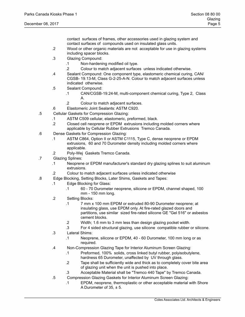
Coles Associates Ltd. Architects & Engineers
contact surfaces of frames, other accessories used in glazing system and contact surfaces of compounds used on insulated glass units.
.2 Wood or other organic materials are not acceptable for use in glazing systems including spacer blocks.
.3 Glazing Compound:.1 Non-hardening modified oil type..2 Colour to match adjacent surfaces unless indicated otherwise.
.4 Sealant Compound: One component type, elastomeric chemical curing, CAN/CGSB- 19.13-M, Class G-2-25-A-N. Colour to match adjacent surfaces unless indicated otherwise.
.5 Sealant Compound:.1 CAN/CGSB-19.24-M, multi-component chemical curing, Type 2, Class
A..2 Colour to match adjacent surfaces.
.6 Elastomeric Joint Sealants: ASTM C920..5 Cellular Gaskets for Compression Glazing:
.1 ASTM C509 cellular, elastomeric, preformed, black.
.2 Closed cell neoprene or EPDM extrusions including molded corners where applicable by Cellular Rubber Extrusions Tremco Canada.
.6 Dense Gaskets for Compression Glazing: .1 ASTM C864, Option II or ASTM C1115, Type C, dense neoprene or EPDM
extrusions, 60 and 70 Durometer density including molded corners where applicable.
.2 Poly-Wej Gaskets Tremco Canada..7 Glazing Splines:
.1 Neoprene or EPDM manufacturer's standard dry glazing splines to suit aluminum extrusions.
.2 Colour to match adjacent surfaces unless indicated otherwise.8 Edge Blocking, Setting Blocks, Later Shims, Gaskets and Tapes:
.1 Edge Blocking for Glass:.1 60 - 70 Durometer neoprene, silicone or EPDM, channel shaped, 100
mm - 150 mm long. .2 Setting Blocks:
.1 7 mm x 100 mm EPDM or extruded 80-90 Durometer neoprene; at insulating glass, use EPDM only. At fire-rated glazed doors and partitions, use similar sized fire-rated silicone GE "Gel 516" or asbestos cement blocks.
.2 Width; 1.6 mm to 3 mm less than design glazing pocket width.
.3 For 4 sided structural glazing, use silicone compatible rubber or silicone. .3 Lateral Shims:
.1 Neoprene, silicone or EPDM, 40 - 60 Durometer, 100 mm long or as required.
.4 Non-Compression Glazing Tape for Interior Aluminum Screen Glazing:.1 Preformed, 100% solids, cross linked butyl rubber, polyisobutylene,
hardness 65 Durometer, unaffected by UV through glass..2 Tape shall be sufficiently wide and thick as to completely cover bite area
of glazing unit when the unit is pushed into place..3 Acceptable Material shall be "Tremco 440 Tape" by Tremco Canada.
.5 Compression Glazing Gaskets for Interior Aluminum Screen Glazing:.1 EPDM, neoprene, thermoplastic or other acceptable material with Shore
A Durometer of 35, ± 5.
Parks Canada Kiosks Phase 1 Section 08 80 00Glazing
December 08, 2017 Page 5
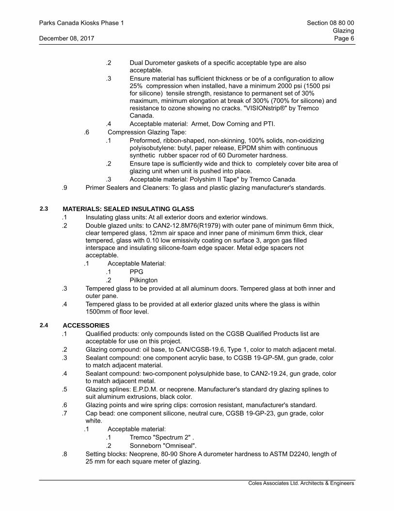
Coles Associates Ltd. Architects & Engineers
.2 Dual Durometer gaskets of a specific acceptable type are also acceptable.
.3 Ensure material has sufficient thickness or be of a configuration to allow 25% compression when installed, have a minimum 2000 psi (1500 psi for silicone) tensile strength, resistance to permanent set of 30% maximum, minimum elongation at break of 300% (700% for silicone) and resistance to ozone showing no cracks. "VISIONstrip®" by Tremco Canada.
.4 Acceptable material: Armet, Dow Corning and PTI. .6 Compression Glazing Tape:
.1 Preformed, ribbon-shaped, non-skinning, 100% solids, non-oxidizing polyisobutylene: butyl, paper release, EPDM shim with continuous synthetic rubber spacer rod of 60 Durometer hardness.
.2 Ensure tape is sufficiently wide and thick to completely cover bite area of glazing unit when unit is pushed into place.
.3 Acceptable material: Polyshim II Tape" by Tremco Canada..9 Primer Sealers and Cleaners: To glass and plastic glazing manufacturer's standards.
2.3 MATERIALS: SEALED INSULATING GLASS.1 Insulating glass units: At all exterior doors and exterior windows..2 Double glazed units: to CAN2-12.8M76(R1979) with outer pane of minimum 6mm thick,
clear tempered glass, 12mm air space and inner pane of minimum 6mm thick, clear tempered, glass with 0.10 low emissivity coating on surface 3, argon gas filled interspace and insulating silicone-foam edge spacer. Metal edge spacers not acceptable.
.1 Acceptable Material:.1 PPG.2 Pilkington
.3 Tempered glass to be provided at all aluminum doors. Tempered glass at both inner and outer pane.
.4 Tempered glass to be provided at all exterior glazed units where the glass is within 1500mm of floor level.
2.4 ACCESSORIES.1 Qualified products: only compounds listed on the CGSB Qualified Products list are
acceptable for use on this project..2 Glazing compound: oil base, to CAN/CGSB-19.6, Type 1, color to match adjacent metal..3 Sealant compound: one component acrylic base, to CGSB 19-GP-5M, gun grade, color
to match adjacent material. .4 Sealant compound: two-component polysulphide base, to CAN2-19.24, gun grade, color
to match adjacent metal..5 Glazing splines: E.P.D.M. or neoprene. Manufacturer's standard dry glazing splines to
suit aluminum extrusions, black color..6 Glazing points and wire spring clips: corrosion resistant, manufacturer's standard..7 Cap bead: one component silicone, neutral cure, CGSB 19-GP-23, gun grade, color
white..1 Acceptable material:
.1 Tremco "Spectrum 2" .
.2 Sonneborn "Omniseal"..8 Setting blocks: Neoprene, 80-90 Shore A durometer hardness to ASTM D2240, length of
25 mm for each square meter of glazing.
Parks Canada Kiosks Phase 1 Section 08 80 00Glazing
December 08, 2017 Page 6

Coles Associates Ltd. Architects & Engineers
.9 Spacer shims: Neoprene, 50-60 Shore A durometer hardness to ASTM D2240, 75 mm long x one half height of glazing stop x thickness to suit application. Self adhesive on one face.
.10 Glazing tape:.1 Preformed butyl compound with integral resilient tube spacing device, 10-15
Shore A durometer hardness to ASTM D2240; coiled on release paper; size as required; black/ bronze color.
.11 Glazing clips: manufacturer's standard type.
.12 Glazing points and wire spring clips: corrosion resistant, manufacturer's standard.
.13 Lock-strip gaskets: to ASTM C542.
.14 Cap bead: one component silicone, neutral cure, to CGSB 19-GP-23, gun grade, color white. Acceptable material:
.1 Trecmo "Spectrum 2"
.2 Sonneborn "Omniseal".15 Primer-sealers and cleaners: to glass manufacturer's standard.
3 Execution
3.1 MANUFACTURER'S INSTRUCTIONS.1 Compliance: Comply with manufacturer's written data, including product technical
bulletins, product catalogue installation instructions, product carton installation instructions, and data sheets.
3.2 FABRICATION.1 Label each light of glass and/or plastic glazing with registered name of Product and
weight and quality of glass and/or plastic glazing. .2 Check dimensions on job site before cutting materials. .3 Ensure minimum bite or lap of glass and/or plastic glazing on stops and rabbets as
recommended by glass and/or plastic glazing manufacturer..4 Provide "CLO Clearshield Coating" by CLO Glass Limited to all surfaces having been
etched.
3.3 EXAMINATION.1 Verify that openings for glazing are correctly sized and within tolerance..2 Verify that surfaces of glazing channels or recesses are clean, free of obstructions, and
ready to receive glazing.
3.4 PREPARATION .1 Thoroughly clean glass rebates and glass of dust, dirt, mortar and other foreign
materials prior to glazing. Remove oils and grease with non-staining solvents such as Xycol or Methyl Ethyl Ketone solutions.
3.5 WORKMANSHIP.1 Remove protective coatings and clean contact surfaces with solvent and wipe dry..2 Apply primer-sealer to contact surfaces..3 Place setting blocks as per manufacturer's instructions.4 Install glass, rest on setting blocks, ensure full contact and adhesion at perimeter..5 Install removable stops, without displacing tape or sealant..6 Provide edge clearance of 3 mm minimum..7 Insert spacer shims to center glass in space. Place shims at 600 mm oc and keep 6 mm
below sight line.
Parks Canada Kiosks Phase 1 Section 08 80 00Glazing
December 08, 2017 Page 7

Coles Associates Ltd. Architects & Engineers
.8 Apply cap bead of sealant at full perimeter of exterior, at all aluminum window glazing.
.9 Apply sealant to uniform and level line, flush with sight line and tooled or wiped with, solvent to smooth appearance.
.10 Do not cut or abrade tempered, heat treated, or coated glass.
3.6 ALUMINUM DOORS.1 All doors to be glazed with 25mm insulating units, in accordance with the requirements
of this Section, to door manufacturer's standard glazing installation practice unless noted otherwise on drawings.
3.7 ALUMINUM WINDOWS.1 All windows to be glazed with 25mm thickness insulating units in accordance with the
requirements in this Section, to window manufacturer's standard glazing installation practice.
.1 Provide cap bead of sealant at all four (4) sides, at exterior of each unit..2 Use tempered insulated glass doors for all exterior doors.
3.8 CLEANING.1 Perform cleaning after installation to remove construction and accumulated
environmental dirt..2 Remove traces of primer, caulking..3 Remove glazing materials from finish surfaces..4 Remove labels after work is complete..5 Clean glass using approved non-abrasive cleaner in accordance with manufacture's
instructions..6 Upon completion of installation, remove surplus materials, rubbish, tools and equipment
barriers.
3.9 PROTECTION OF FINISHED WORK.1 Provide and maintain necessary protection of completed work against damage. .2 Do not mark or attach anything directly to exposed glass and framing surfaces..3 If welding is to take place above or near completed glazing work, protect glass with
plywood or other suitable means to reduce likelihood of weld spatter damaging glass surfaces.
.4 Protect glass from other trades, workers, tools and other similar materials.
.5 Replace cracked, broken, or defective glass at no additional cost to the Owner and to Departmental Representative's satisfaction.
.6 Identification of Glazing: Mark glass lites with temporary, easily removable, large safety markings, immediately after glass installation. Maintain safety markings until final clean-up.
END OF SECTION
Parks Canada Kiosks Phase 1 Section 08 80 00Glazing
December 08, 2017 Page 8
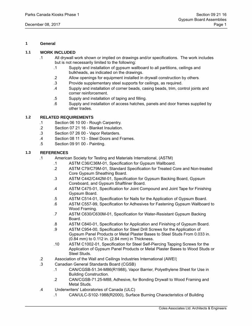
Coles Associates Ltd. Architects & Engineers
1 General
1.1 WORK INCLUDED.1 All drywall work shown or implied on drawings and/or specifications. The work includes
but is not necessarily limited to the following:.1 Supply and installation of gypsum wallboard to all partitions, ceilings and
bulkheads, as indicated on the drawings..2 Allow openings for equipment installed in drywall construction by others..3 Provide supplementary steel supports for ceilings, as required..4 Supply and installation of corner beads, casing beads, trim, control joints and
corner reinforcement..5 Supply and installation of taping and filling..6 Supply and installation of access hatches, panels and door frames supplied by
other trades.
1.2 RELATED REQUIREMENTS.1 Section 06 10 00 - Rough Carpentry..2 Section 07 21 16 - Blanket Insulation..3 Section 07 26 00 - Vapor Retarders..4 Section 08 11 13 - Steel Doors and Frames..5 Section 09 91 00 - Painting.
1.3 REFERENCES.1 American Society for Testing and Materials International, (ASTM)
.1 ASTM C36/C36M-01, Specification for Gypsum Wallboard.
.2 ASTM C79/C79M-01, Standard Specification for Treated Core and Non-treated Core Gypsum Sheathing Board.
.3 ASTM C442/C442M-01, Specification for Gypsum Backing Board, Gypsum Coreboard, and Gypsum Shaftliner Board.
.4 ASTM C475-01, Specification for Joint Compound and Joint Tape for Finishing Gypsum Board.
.5 ASTM C514-01, Specification for Nails for the Application of Gypsum Board.
.6 ASTM C557-99, Specification for Adhesives for Fastening Gypsum Wallboard to Wood Framing.
.7 ASTM C630/C630M-01, Specification for Water-Resistant Gypsum Backing Board.
.8 ASTM C840-01, Specification for Application and Finishing of Gypsum Board.
.9 ASTM C954-00, Specification for Steel Drill Screws for the Application of Gypsum Panel Products or Metal Plaster Bases to Steel Studs From 0.033 in. (0.84 mm) to 0.112 in. (2.84 mm) in Thickness.
.10 ASTM C1002-01, Specification for Steel Self-Piercing Tapping Screws for the Application of Gypsum Panel Products or Metal Plaster Bases to Wood Studs or Steel Studs.
.2 Association of the Wall and Ceilings Industries International (AWEI)
.3 Canadian General Standards Board (CGSB).1 CAN/CGSB-51.34-M86(R1988), Vapor Barrier, Polyethylene Sheet for Use in
Building Construction..2 CAN/CGSB-71.25-M88, Adhesive, for Bonding Drywall to Wood Framing and
Metal Studs..4 Underwriters' Laboratories of Canada (ULC)
.1 CAN/ULC-S102-1988(R2000), Surface Burning Characteristics of Building
Parks Canada Kiosks Phase 1 Section 09 21 16Gypsum Board Assemblies
December 08, 2017 Page 1
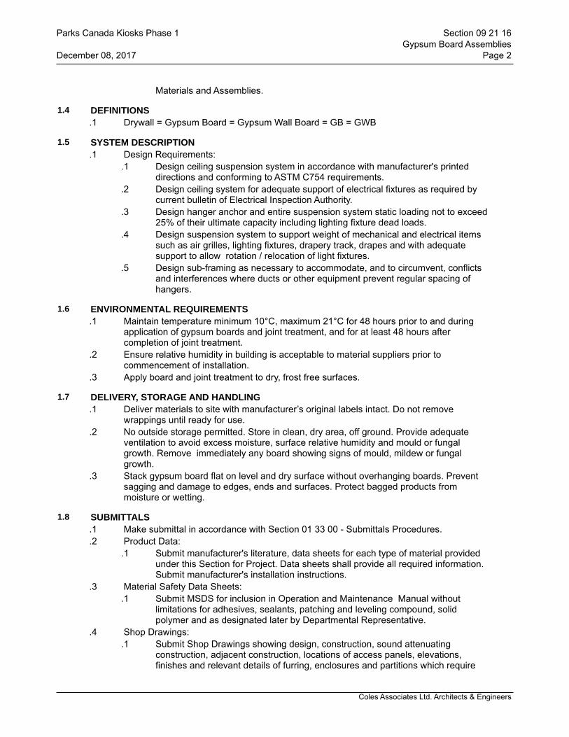
Coles Associates Ltd. Architects & Engineers
Materials and Assemblies.
1.4 DEFINITIONS.1 Drywall = Gypsum Board = Gypsum Wall Board = GB = GWB
1.5 SYSTEM DESCRIPTION.1 Design Requirements:
.1 Design ceiling suspension system in accordance with manufacturer's printed directions and conforming to ASTM C754 requirements.
.2 Design ceiling system for adequate support of electrical fixtures as required by current bulletin of Electrical Inspection Authority.
.3 Design hanger anchor and entire suspension system static loading not to exceed 25% of their ultimate capacity including lighting fixture dead loads.
.4 Design suspension system to support weight of mechanical and electrical items such as air grilles, lighting fixtures, drapery track, drapes and with adequate support to allow rotation / relocation of light fixtures.
.5 Design sub-framing as necessary to accommodate, and to circumvent, conflicts and interferences where ducts or other equipment prevent regular spacing of hangers.
1.6 ENVIRONMENTAL REQUIREMENTS.1 Maintain temperature minimum 10°C, maximum 21°C for 48 hours prior to and during
application of gypsum boards and joint treatment, and for at least 48 hours after completion of joint treatment.
.2 Ensure relative humidity in building is acceptable to material suppliers prior to commencement of installation.
.3 Apply board and joint treatment to dry, frost free surfaces.
1.7 DELIVERY, STORAGE AND HANDLING.1 Deliver materials to site with manufacturer’s original labels intact. Do not remove
wrappings until ready for use..2 No outside storage permitted. Store in clean, dry area, off ground. Provide adequate
ventilation to avoid excess moisture, surface relative humidity and mould or fungal growth. Remove immediately any board showing signs of mould, mildew or fungal growth.
.3 Stack gypsum board flat on level and dry surface without overhanging boards. Prevent sagging and damage to edges, ends and surfaces. Protect bagged products from moisture or wetting.
1.8 SUBMITTALS.1 Make submittal in accordance with Section 01 33 00 - Submittals Procedures..2 Product Data:
.1 Submit manufacturer's literature, data sheets for each type of material provided under this Section for Project. Data sheets shall provide all required information. Submit manufacturer's installation instructions.
.3 Material Safety Data Sheets: .1 Submit MSDS for inclusion in Operation and Maintenance Manual without
limitations for adhesives, sealants, patching and leveling compound, solid polymer and as designated later by Departmental Representative.
.4 Shop Drawings:.1 Submit Shop Drawings showing design, construction, sound attenuating
construction, adjacent construction, locations of access panels, elevations, finishes and relevant details of furring, enclosures and partitions which require
Parks Canada Kiosks Phase 1 Section 09 21 16Gypsum Board Assemblies
December 08, 2017 Page 2
Coles Associates Ltd. Architects & Engineers
fire rating..5 Certificates:
.1 Submit certification from structural engineer registered in Province of Prince Edward Island, who shall affix his/her seal and signature to certificate, stating that installed suspended ceiling system is capable of supporting its own weight and weight of lighting, grilles and other mechanical and electrical fixtures required by Mechanical and Electrical Divisions.
.2 Obtain approval of electrical utility authorities having jurisdiction for support of light fixtures, by ceiling grid and supports, to satisfy requirements of electrical inspection authority having jurisdiction. Adjust grid, fixing devices and support hangers as required to obtain approval.
.6 Quality Assurance:.1 Comply with ASTM C840 for application and finishing gypsum board and
manufacturer's written information..2 Comply with following guide recommendations unless specified otherwise:
.1 Applications Guide CGC folder SA-130;
.2 Moisture Resistant Assemblies CGC folder SA-934;
1.9 WASTE MANAGEMENT AND DISPOSAL.1 Collect and separate for disposal waste material generated by this Section. .2 Place in appropriate on-site bins in accordance with Waste Management Plan..3 A clean worksite is mandatory at all times. Failure to maintain the site in a clean, safe
condition shall result in the Owner initiating a clean-up and related costs being deducted from progress claims.
2 Products
2.1 MANUFACTURERS.1 Products of following manufacturers are acceptable subject to conformance to
requirements of Drawings, Schedules and Specifications:.1 Bailey Metal Products Ltd.; www.bmp-group.com..2 CertainTeed Gypsum Canada Inc.; www.certainteed.com.3 CGC Inc; www.cgcinc.com.4 Georgia-Pacific Canada, Inc.; www.gpgypsum.com.5 Acadia Drywall Supplies Ltd; www.acadiadrywall.com.".6 Gordon Incorporated.; www.gordongrid.com.7 Roll Formed Specialty; www.rollformed.com.8 Cabot Gypsum.
2.2 ACCEPTABLE MATERIALS.1 Standard Gypsum Board:
.1 To ASTM C 3696. 15.9 mm thick, 1219 mm wide x maximum practical length, Ends square cut, edges tapered.
.2 Acceptable Materials:.1 CGC Inc..2 CertainTeed Gypsum Canada..3 G-P Gypsum..4 Temple Island..5 Cabot Gypsum.
.2 Moisture Resistant Gypsum Board: .1 Use Type X where rating requires ASTM C 1658 regular, 15.9 mm thick, 1219
Parks Canada Kiosks Phase 1 Section 09 21 16Gypsum Board Assemblies
December 08, 2017 Page 3
Coles Associates Ltd. Architects & Engineers
mm wide x maximum practical length. Use in rooms containing washrooms..2 Acceptable Materials:
.1 Georgia Pacific DensArmor Plus.
.2 Georgia Pacific DenShield Tile Backer.
.3 CertainTeed Mold Resistant Board.
.4 GreenGlass Interior Gypsum Board by Temple-Inland.
.5 Fiberock Aqua Tough by CGC.
.6 Sheetrock Mold Tough, by CGC..3 Drywall Furring Channels:
.1 0.5 mm (25 gauge) core thickness galvanized steel channels for screw attachment of gypsum board.
.4 Nails: .1 To ASTM C 514.
.5 Steel drill screws: .1 To ASTM C 1002.
.6 Polyethylene: .1 To CAN/CGSB-51.34, 10 mil.
.7 Joint Compound: .1 Special setting type compound: chemically setting, sandable, to ASTM C475..2 Acceptable Material:
.1 Canadian Gypsum Company Sheetrock 90.
.2 CertainTeed ProRoc Moisture and Mould resistant 90 Setting Compound with M2Tech.
.3 Acadia Drywall Sandable 90..8 Taping compound:
.1 Pre-mixed, to ASTM C475.
.2 Acceptable Materials:.1 Canadian Gypsum Company All Purpose Ready-to-Use Joint
Compound..2 CertainTeed ProRoc Moisture and Mould resistant 90 Setting Compound
with M2Tech..3 Acadia Drywall Platinum Lite.
.9 Tape: .1 50mm wide x 0.25mm thick, perforated paper, with chamfered edges.
.10 Bonding Adhesive: .1 Type for purpose intended and as recommended and approved by manufacturer
(Lepage PL 200 or PL 400)..11 Metal Accessories:
.1 Corner Beads Minimum 0.40mm, Z180 zinc coated sheet steel to ASTM A525; beaded angle; flanges 32mm for 16mm board.
.2 Casing Beads: Minimum 0.40mm, Z180 zinc coated sheet steel to ASTM A525; "L" type; beaded angle or casing with one (1) side knurled for joint filling; suitable for 15.9mm wallboard, as specified.
.3 Casing Beads, corner beads, control joints and edge trim: to ASTMC 1047, Zinc metal, zinc-coated by hot-dip process zinc-coated by electrolytic process aluminum coated phosphatized, 0.5mm base thickness, perforated flanges, one piece length per location.
.4 Flexible Casing Beads:.1 0.531 mm (designation thichness 18mils/minimum base steel thickness
0.455 mm /25 ga) steel, wipe coated, angle shaped in size to fit over
Parks Canada Kiosks Phase 1 Section 09 21 16Gypsum Board Assemblies
December 08, 2017 Page 4

Coles Associates Ltd. Architects & Engineers
edge of gypsum board, to suit curved applications..5 Control joint strip: Roll formed from galvanized steel sheet, with a tape-protected
recess, 6mm wide x 41mm deep..12 Resilient Sponge Tape:
.1 Self-sticking adhesive on 1 side, closed cell neoprene sponge tape.
.2 Acceptable Materials:.1 Rubatex by Rubatex Corp..2 Perma-Stik 122X by Jacobs and Thompson Inc..3 Foamed vinyl Arnofoam by Arno Adhesive Tapes Incorporated..4 Greyflex Expanding Foam Sealant by Emseal Corporation.
.13 Water: .1 Fresh clean potable water, free from deleterious matter, acids or alkalies.
.14 Sealants: .1 In accordance with Section 07 92 00 - Joint Sealants
3 Execution
3.1 PARTITION TYPES.1 Refer to Drawings for partition types..2 Provide partitions complete to underside of structure, unless otherwise indicated on
Drawings.
3.2 EXAMINATION.1 Examine substrate for compliance with applicable requirements, installation tolerances
and other conditions affecting installation of fibre-reinforced gypsum board or sheathing. Do not proceed until unsatisfactory conditions have been corrected. Beginning of installation shall indicate acceptance of substrate conditions.
3.3 INSTALLATION.1 Give minimum 48 hours notice for Departmental Representative's inspection of internal
wall insulation, vapour barriers and services prior to concealing with gypsum board. .2 Carry out work using skilled tradesmen carefully supervised by competent foremen. .3 Take all measurements accurately..4 Comply with ASTM C754 and with ASTM C840 requirements that apply to framing
installation. Install framing, blocking and furring in accordance with ASTM C645, ASTM C1280.
.5 Maintain wallboard panels minimum 6 mm and maximum 13 mm above floor to prevent moisture transfer.
.6 Extend panels to underside of deck or structure and at fire rated and sound control partitions.
.7 Do taping and filling of concealed surfaces above ceiling line, except at fire rated and sound control partitions and walls.
.8 Erect plain wallboard vertically or horizontally, whichever results in fewer end joints.
.9 Keep end joints away from prominent locations and central portions of ceilings.
.10 Locate vertical joints at least 300 mm from jamb lines of openings.
.11 Space screws for regular wallboard at 300 mm oc along board edges and in board field on walls and ceilings; at fire-rated assemblies, reduce spacings to comply with labelling authorities assembly listings.
.12 For other specialty boards screw spacing shall be in accordance with manufacturer's recommendations.
.13 Drive screws with power screw-gun and set with countersunk heads slightly below
Parks Canada Kiosks Phase 1 Section 09 21 16Gypsum Board Assemblies
December 08, 2017 Page 5
Coles Associates Ltd. Architects & Engineers
surface of board. .14 Do not secure gypsum board by installing screws into aluminum or steel window and
door frames..15 Install resilient sponge tape where gypsum board ceilings abut heads of door frames and
where wallboard abuts heads or jambs of exterior door and window frames. Adhere tape to casing bead and compress during installation. Compressed thickness; 1.6 mm.
.16 At partitions, apply 1 continuous 6 mm bead of acoustical sealant to each side of partition where gypsum board meets dissimilar materials.
.17 Apply sealant beads at perimeter of all other services and like objects which penetrate wallboard in accordance with manufacturer's directions.
.18 Departmental Representative reserves right to relocate access panels up to 3600 mm from locations shown on Drawings due to site conditions, providing ample warning is given prior to installation.
.19 Install in accordance with manufacturer's instructions.
.20 Coordinate with other Sections for locations and sizes. Install in accordance with manufacturer's instructions.
.21 Gypsum Board Application:.1 Provide gypsum board in accordance with manufacturer's written installation
instructions and finish to requirements of ASTM C840. Ensure moisture resistant gypsum board is installed on any wall/partition containing a plumbing fixture (i.e. water closets, sinks, tubs, etc.).
.2 Provide metal trim casing bead at junctions with dissimilar materials.
.3 Provide reveals at junctions with dissimilar materials and where indicated.
.4 Apply joint compound and trowel smooth to provide continuous, smooth radius free from flat spots, facets and trowel marks.
.5 Allow gypsum boards to dry thoroughly before handling.
.6 Provide finished work plumb, level and true, free from perceptible waves or ridges and square with adjoining work.
.7 Cut and fit gypsum board to accommodate or fit around other parts of Work.
.8 Provide work of this Section accurately and neatly.
.9 Butt gypsum board sheets together in moderate contact.
.10 Do not force into place.
.11 Place tapered or wrapped edges next to 1 another.
.12 Provide gypsum board perpendicular to framing and in lengths that will span ceilings and walls without creating end (butt) joints.
.13 If butt joints do occur stagger and locate them as far from centre of walls and ceilings as possible.
.14 Accurately fit exposed butt joints together and make edges smooth.
.15 Support ends and edges on framing.
.16 Fasten gypsum board to metal furring and metal studs with screws. Space screws at 200 mm oc at board edges and 300 mm oc on board field. Ensure perimeter screws are not less than 9 mm nor more than 13 mm from edges and ends are opposite screws on adjacent boards.
.17 Gypsum Board - Single Layer:.1 Ceilings:
.1 Apply gypsum board to metal furring with screws. Erect board with long dimension parallel to supports. Locate end joints over supporting members.
.2 Space screws at 200 mm oc. .2 Partitions:
.1 Apply gypsum board to metal studs with screws. Erect board with
Parks Canada Kiosks Phase 1 Section 09 21 16Gypsum Board Assemblies
December 08, 2017 Page 6
Coles Associates Ltd. Architects & Engineers
long dimension parallel to supports. Locate end joints over supporting members. Locate vertical joints at least 300 mm from jamb lines of openings. Space screws at 200 mm oc at board edges and 300 mm oc on board field.
.3 Ceiling and Partition Fasteners:.1 Ensure perimeter screws are not less than 9 mm nor more than
13 mm from edges and ends are opposite screws on adjacent boards. Drive screws with power screw gun and set with countersunk head slightly below surface of board.
.4 Joints: Finish all joints unless specified otherwise..22 Interior Ceilings:
.1 Provide carrying channels maximum 1200 mm oc and within 150 mm of walls.
.2 Provide 25 mm clearance between runners and walls.
.3 Provide splicers behind joints. Level channels to a maximum tolerance of 3 mm over 3600 mm.
.4 Provide 25 mm clearance between furring ends and abutting walls.
.5 Provide additional cross-reinforcing at bulkheads and at other openings.
.6 Provide additional reinforcement for ceiling mounted miscellaneous accessories and signage.
.7 Provide ceiling gypsum board, smooth and level..23 Metal Trim and Accessories:
.1 Provide metal trim casing beads at reveals; at ceiling-wall intersections and partition perimeters; and at intersection of dissimilar constructions such as gypsum board to concrete.
.2 Provide metal trim casing beads where gypsum board abuts against a surface having no trim concealing junction.
.3 Provide ceiling fascia suspension trims at perimeter of "floating" suspended gypsum board ceilings as indicated on the Drawings.
.4 Provide a 13 mm separation gasket between metal trim casing beads and window frames or other cold surfaces or provide sponge tape between gypsum board partition or furring framing, where such framing abuts exterior door or window frame.
.5 Sponge tape between floor and gypsum board partition track.
.6 Tape shall be either full width or 1 strip 9 mm wide on each side of framing member.
.7 Provide casing bead and sponge tape where gypsum board abuts materials other than itself and acoustic tile ceilings including at exterior door and window frames, where juncture is not concealed with trim; or elsewhere where indicated on Drawings.
.8 Unless indicated otherwise, use tape 3 mm narrower than casing bead to provide recess at exposed side. Compress tape by 25%.
.9 Unless indicated otherwise, use tape 3 mm narrower than casing bead to provide recess at exposed side. Compress tape by 25%.
.10 Provide prefinished metal angle trim supports and Provide light pockets and eggcrate grilles and/or louvres in accordance with manufacturer's instructions.
.11 Install light pockets and eggcrate grilles and/or louvre units square, straight and in 1 piece where possible or with inconspicuous joints at long runs.
.24 Sealant:.1 Conform to ASTM C919 for use of sealants in sound attenuation partitions. .2 Apply acoustical sealant around partition cutouts including, but not limited to,
electrical outlets and boxes, plumbing and duct outlets, and other miscellaneous wall and floor penetrations or gaps.
Parks Canada Kiosks Phase 1 Section 09 21 16Gypsum Board Assemblies
December 08, 2017 Page 7
Coles Associates Ltd. Architects & Engineers
.3 Apply acoustical sealant to every air gap, such as gaps around perimeter of wall, between wall panels and around any penetrations made for plumbing or electrical wiring. Seal off any piping, electrical output boxes, and duct work with acoustical treatments. Treat junction boxes with acoustic putty, treat piping and duct work either with fiberglass duct liner or damping material or both.
.4 Treat frame with gasket material (weather-strip) and install security flap on bottom of door to seal it off.
.5 Apply minimum 13 mm diameter bead of acoustic sealant continuously around periphery of each face of partition to seal gypsum board/structure junction where partitions abut fixed building components in accordance with recommendations of "CGC Drywall/Steel Framed Systems, Folder SA923 09250".
.25 Joint Treatment - Gypsum Board:.1 Verify board is firm against framing members and screw heads are properly
depressed. .2 Mix joint compound or ready-to-use compounds according to manufacturer's
directions. Use pure, unadulterated, clean water for mixing. .3 Permit mixed material to stand 30 minutes before using. .4 Do not mix more material than can be used within 1 hour. .5 Do not use set or hardened compound. .6 Clean tools and equipment after mixing each batch..7 Tape and fill joints and corners in accordance with gypsum board manufacturer's
printed instructions. .8 Fill either manually, using hand tools of trade, or by a mechanical taping and
filling machine of proven efficiency. .9 Remove plastic tape from control joints after finishing with joint compound. .10 After final coats of filler have dried at least 24 hours, sand surface lightly with No.
00 sandpaper to leave it smooth, ready for decoration. .11 Provide finished work smooth, seamless, plumb and true, flush and with square
plumb neat corners..12 Levels of Finish: Provide following levels of finish in accordance with ASTM
C840:.1 Level 5: Use this level to provide a uniform surface and minimize
possibility of joint telegraphing and of fasteners showing through final decoration. Use this Level of finish when using gloss, semi-gloss or enamel paint finish or when working in a critical (severe) lighting areas including but not limited to walls and ceiling areas near windows, skylights, long hallways and atriums with large surface areas exposed to artificial and natural light. Refer to ASTM C840 for additional locations for Level 5 applications.
.2 Exposed Moisture Resistant Gypsum Board Joint Finish: All joints and interior angles shall have fiberglass tape embedded in setting 90 joint compound and 2 separate coats of joint compound applied over all flat joints and 1 separate coat of joint compound applied over interior angles. Cover fasteners heads and accessories with three (3) separate coats of joint compound. Ensure surface is smooth and free of tool marks and ridges.
3.4 CUTTING AND PATCHING.1 Cooperate and coordinate with other Sections to obtain satisfactory gypsum board finish
work. Do all cutting, patching and make good as required by installation of work of other Sections.
3.5 CLEANING
Parks Canada Kiosks Phase 1 Section 09 21 16Gypsum Board Assemblies
December 08, 2017 Page 8

Coles Associates Ltd. Architects & Engineers
.1 Clean off beads, casings, joint cement droppings and similar items and remove surplus materials and rubbish on completion and as directed.
END OF SECTION
Parks Canada Kiosks Phase 1 Section 09 21 16Gypsum Board Assemblies
December 08, 2017 Page 9
Coles Associates Ltd. Architects & Engineers
1 General
1.1 DESCRIPTION OF WORK.1 The work of this Section comprises the furnishings of all labour, equipment and materials
necessary for the supply and installation of the Ceramic Tile as indicated on the Drawings and Schedules, which includes but is NOT necessarily limited to:
.1 Floor Ceramic Tile.2 Work Included: Provide ceramic tile including but not limited to following:
.1 Grouting control joints in floor slab under tile.
.2 Waterproof membrane.
.3 Anti-fracture membrane.
.4 Leveling bed.
.5 Thin set mortar bed.
.6 Ceramic floor tile, base, trims and fittings.
.7 Installation systems, mortars and grouts.
.8 Sealing tile control joints and other accessories.
.9 Sealing penetrations through floor tile.
1.2 RELATED REQUIREMENTS.1 Section 03 30 00 - Cast-in-Place Concrete..2 Section 07 92 00 - Joint Sealants..3 Section 10 28 13 - Toilet Accessories.
1.3 REFERENCES.1 American National Standards Institute (ANSI)/Ceramic Tile Institute (CTI)
.1 ANSI A108.1-99, Specification for the Installation of Ceramic Tile (Includes ANSI A108.1A-C, 108.4-.13, A118.1-.10, ANSI A136.1).
.2 CTI A118.3-92, Specification for Chemical Resistant, Water Cleanable Tile Setting and Grouting Epoxy and Water Cleanable Tile Setting Epoxy Adhesive (included in ANSI A108.1).
.3 CTI A118.4-92, Specification for Latex Portland Cement Mortar (included in ANSI A108.1).
.4 CTI A118.5-92, Specification for Chemical Resistant Furan Resin Mortars and Grouts for Tile Installation (included in ANSI A108.1).
.5 CTI A118.6-92, Specification for Ceramic Tile Grouts (included in ANSI A108.1).
.6 ANSI A108.1-05, Installation of ceramic tile with Portland cement mortar.
.7 ANSI A108.4-99(R2005), Installation of ceramic tile with organic adhesives.
.8 ANSI A108.5, Installation of ceramic tile with dry-set Portland cement/latex Portland cement mortar.
.9 ANSI A108.6-99(R2005), Installation of ceramic tile with chemical resistant, water cleanable tile setting/grouting epoxy.
.10 ANSI A108.9-99(R2005), Installation of ceramic tile with modified epoxy emulsion mortar/ grout.
.11 ANSI A108.10-99(R2005), Installation of grout in tile work
.12 ANSI A108.11-99(R2005), Installation of cementitious backer unit.
.13 ANSI A108.12-99(R2005), Installation of ceramic tile with EGP (Exterior Glue Plywood) Latex Portland Cement Mortar.
.14 ANSI A108.13-05, Installation of load bearing, bonded, waterproofing membranes for thin set ceramic tile and dimension stone.
.15 ANSI A118.3-99(R2005), Specification for Chemical Resistant, Water Cleanable Tile Setting and Grouting Epoxy and Water Cleanable Tile Setting Epoxy
Parks Canada Kiosks Phase 1 Section 09 30 13Ceramic Tiling
December 08, 2017 Page 1

Coles Associates Ltd. Architects & Engineers
Adhesive..16 ANSI A118.4-99(R2005), Specification for Latex-Portland Cement Mortar..17 ANSI A118.5-99(R2005), Specification for Furan Mortars and Grout..18 ANSI A118.6-99(R2005), Specification for Ceramic Tile Grouts..19 ANSI A118.7-99(R2005), Polymer modified cement grouts for tile Installation..20 ANSI A108.9-99(R2005), Cementitious backer unit..21 ANSI A118.10-99(R2005), Specification for Load Bearing, Bonded Waterproof
Membrane for Thin-set Ceramic Tile and Dimension Stone Installation..22 ANSI A118.11-99(R2005), Standard for EGP (Exterior Glue Plywood) Latex
Portland Cement Mortar..23 ANSI A136.1-99(R2005), Specification for Organic Adhesives for the Installation
of Ceramic Tile..24 ANSI A137.1, Recommended Standard Specification for Ceramic Tile.
.2 American Society for Testing and Materials (ASTM International) International.1 ASTM C144-99, Specification for Aggregate for Masonry Mortar..2 ASTM C 207-91(1997), Specification for Hydrated Lime for Masonry Purposes..3 ASTM C979-99, Specification for Pigments for Integrally Colored Concrete..4 ASTM A185M-07, Specification for Steel Welded Wire Fabric, Plain, for Concrete
Reinforcement..5 ASTM C144-04, Specification for Aggregate for Masonry Mortar..6 ASTM C207-06, Specification for Hydrated Lime for Masonry Purposes..7 ASTM C373-88(06), Test Method for Water Absorption, Bulk Density, Apparent
Porosity, and Apparent Specific Gravity of Fired Whiteware Products..8 ASTM C503-08, Specification for Marble Dimension Stone (Exterior) .9 ASTM C627-93(99), Evaluating ceramic tile installation systems..10 ASTM C648-04, Specification for Standard Test Method for Breaking Strength of
Ceramic Tile..11 ASTM C650-04, Test Method for Resistance of Ceramic Tile to Chemical
Substances..12 ASTM C847-06, Specification for Metal Lath..13 ASTM C1027-99(04), Determining visible abrasion resistance of glazed ceramic
tile..14 ASTM C1028-07, Standard Test Method for Determining the Static Coefficient of
Friction of Ceramic Tile and Other Like Surfaces by the Horizontal Dynamometer Pull-Meter Method.
.3 Canadian General Standards Board (CGSB).1 CAN/CGSB-51.34-M86(R1988), Vapor Barrier, Polyethylene Sheet for Use in
Building Construction..2 CGSB 71-GP-22M-78, Adhesive, Organic, for Installation of Ceramic Wall Tile..3 CAN/CGSB-75.1-M88, Tile, Ceramic..4 CAN/CGSB-25.20-95, Surface Sealer for Floors..5 CGSB 71-GP-22M, Adhesive, Organic, for Installation of Ceramic Wall Tile..6 CGSB 71-GP-29M, Adhesive, Elastomeric, for Installation of Quarry Tiles..7 CGSB 71-GP-30M, Adhesive, Epoxy and Modified Mortar Systems for
Installation of Quarry Tiles..8 CAN/CGSB-51.34-M86, Vapour Barrier, Polyethylene Sheet for Use in Building
Construction. .9 CAN/CGSB-75.1-M88, Tile, Ceramic.
.4 Canadian Standards Association (CSA International).1 CAN/CSA-A3000-98, Cementitious Materials Compendium (Consists of A5-98,
Parks Canada Kiosks Phase 1 Section 09 30 13Ceramic Tiling
December 08, 2017 Page 2
Coles Associates Ltd. Architects & Engineers
A8-98, A23.5-98, A362-98, A363-98, A456.1-98, A456.2-98, A456.3-98)..2 CSA A123.3-98, Asphalt Saturated Organic Roofing Felt..3 CSA A3000-03, Cementitious Materials Compendium..4 CSA A123.3-05, Asphalt Saturated Organic Roofing Felt.5 CSA A23.1-04 / A23.2-04, Concrete Materials and Methods of Concrete
Construction..6 CSA G30.5-M - Welded Steel Wire Fabric for Concrete Reinforcement .7 ISO 13006 - Ceramic Tiles, Definitions, Classification, Characteristics and
Marking..8 ISO 10545 - Testing Procedures for Ceramic Tiles. .9 TTMAC - Terrazzo Tile & Marble Association of Canada - Specification Guide 09
30 00; Tile Installation Manual 2006 - 2007
1.4 SUBMITTALS.1 Make submittals in accordance with Section 01 33 00 - Submittal Procedures..2 Manufacturer's Instructions:
.1 Provide to indicate special handling criteria, installation sequence, cleaning procedures.
.3 Material Safety Data Sheets:.1 Submit MSDS for inclusion in Operation and Maintenance Manual.
.4 Shop Drawings:.1 In addition to minimum requirements indicate following:
.1 Details of construction.
.2 Joint layouts.
.3 Dimensions.
.4 Patterns and makings where applicable..5 Samples:
.1 Wall tile: submit duplicate sample of each color, texture, size, and pattern of tile.
.2 Trim shapes, bullnose cap and cove including bullnose cap and base pieces at internal and external corners of vertical surfaces, each type, color, and size.
.3 Submit individual sample panels of each colour of ceramic tile, set with adhesive, grouting and bonding method as specified, showing quality, colour and finish of material, grout and pattern of tiles. Each panel shall be minimum 600 mm x 600 mm.
.6 Maintenance Instructions:.1 Submit maintenance instructions in accordance with Section 01 78 00 - Closeout
Submittals. Provide Owner with required copies of TTMAC Maintenance Guide..2 Include specific warnings of any maintenance practice or materials which may
damage or disfigure tile work..3 Include cleaning methods, cleaning solutions recommended, stain removal
methods, polishes and waxes recommended.
1.5 QUALITY ASSURANCE.1 Qualifications:
.1 Provide test reports if requested to substantiate that Products supplied on this Project will be of consistent quality in appearance and physical properties.
.2 Perform tile work using skilled mechanics trained in work of this complexity. Install waterproofing system using an applicator approved by system manufacturer.
.3 Use proprietary Products in full compliance with manufacturer's recommendations. As far as possible obtain Product from single manufacturer
Parks Canada Kiosks Phase 1 Section 09 30 13Ceramic Tiling
December 08, 2017 Page 3
Coles Associates Ltd. Architects & Engineers
ensuring single source responsibility for consistent quality in appearance and physical properties, compatibility with adjacent components while maintaining quality. If requested, manufacturer of installation system shall provide laboratory confirmation to identify proper usage of specified materials. Have manufacturer's representative visit site at commencement of tile work to give proper direction and thereafter at regular interval to ensure proper workmanship.
1.6 DELIVERY, STORAGE AND HANDLING.1 Comply with material manufacturer’s ordering instructions and lead time requirements to
avoid delays. .2 Coordinate deliveries to comply with construction progress schedule and arrange for
above ground, under cover storage before materials are delivered to site..3 Store packaged materials in original containers with seals unbroken complete with labels
in accordance with manufacturer’s instructions. .1 Prevent damage to materials and Products during handling and storage..2 Keep delivered material dry and free from stains inside weatherproof structure or
otherwise protected from freezing and elements. .3 Store cementitious material off damp surfaces. .4 Protect organic and epoxy adhesives, additives, mortar mixes and grouts from
freezing, moisture and excessive heat during transportation and storage. Maintain temperatures in storage area between 15 deg C and 20 deg C.
1.7 EXTRA MATERIAL.1 Provide maintenance materials in accordance with Section 01 78 00 - Closeout
Submittals..2 Provide minimum 2% of each type and color of tile required for project for maintenance
use. .3 Deliver extra stock to Owner as soon as permanent, locking storage facilities are
available. Place extra stock in designated storage area where directed.
1.8 ENVIRONMENTAL REQUIREMENTS.1 Safety:
.1 Comply with requirements of Workplace Hazardous Materials Information System (WHMIS) regarding use, handling, storage, and disposal of materials.
.2 Ventilation:.1 Provided continuously during and after installation. Run system 24 hours per day
during installation; provide continuous ventilation for 7 days after completion of installation.
.3 Temperature:.1 Maintain air temperature and structural base temperature at ceramic tile
installation area above 12 °C for 48 h before, during, and 48 h after, installation..2 Do not install tiles at temperatures less than 12 °C or above 38 °C.
.4 Do not apply epoxy mortar and grouts at temperatures below 15 °C or above 25 °C.
1.9 WARRANTY.1 Warrant work of this Section for a period of 3 years against defects, excessive wear, and
loss of adhesion including replacement of defective tile work, materials, labour costs for demolition of defective work, accessories, and installation systems at Owner’s convenience.
.2 Defective work includes without limitation, tiles broken in normal use due to deficiencies in setting bed, loose tiles or grout and similar defects which can be attributed to poor performance of work or defective materials.
.3 Warrant waterproofing work of this Section against defects of workmanship and
Parks Canada Kiosks Phase 1 Section 09 30 13Ceramic Tiling
December 08, 2017 Page 4
Coles Associates Ltd. Architects & Engineers
materials, and against any actual leakage, for a period of 5 years. .4 Leakage due to structural failure of concrete shall be excepted. .5 Cracks arising from normal shrinkage and/or expansion of concrete shall not be
considered as structural failure..6 Hairline cracks which result from these causes shall be considered normal and warranty
shall not be voided as a result of these minor defects.
1.10 WASTE MANAGEMENT AND DISPOSAL.1 Collect and separate for disposal waste material generated by this Section. .2 Place in appropriate on-site bins in accordance with Waste Management Plan..3 A clean worksite is mandatory at all times. Failure to maintain the site in a clean, safe
condition shall result in the Owner initiating a clean-up and related costs being deducted from progress claims.
2 Products
2.1 CERAMIC TILE - GENERAL.1 Ceramic Tile:
.1 Conforming to ANSI A137.1, CAN/CGSB-75.1-M.
.2 Colour as selected by Departmental Representative from manufacturer's full ranges.
.3 Provide tile with minimum following characteristics:.1 Water Absorption: ASTM C373 -.2 Breaking Strength: ASTM C648 - > 250 lbs..3 Abrasion Resistance: ISO 10545-7 - Class Four Heavy Traffic..4 Scratch Hardness: MOH's - 7..5 Chemical Resistance: ASTM C650 - Resistant..6 Coefficient of Friction: ASTM C1028 - Wet: 0.60; Dry: 0.80..7 Ceramic Floor Tile: CAN/CGSB-75.1-M, Type 2, Class MR1, Mosaic
Unglazed, slip resistant..8 Ceramic Floor Tile: CAN/CGSB-75.1-M, Type 7, Class MR1, Glazed
Floor Tile, slip resistant.
2.2 CERAMIC FLOOR TILE.1 Type CT-1:
.1 Supply 300 mm x 600 mm size unglazed porcelain tiles..1 Acceptable Materials: Elegant Series.
.1 One (1) colour from manufacturer's complete colour as follows:.1 Field: Moonstone Series. Color: Brown.
2.3 GROUT.1 Epoxy Grout: Conforming to ANSI A118.3; Flextile Flex-Epoxy 100 - 100% Solids, two
component water based washable epoxy grout, consisting of two components; a hardening resin and premixed portion of epoxy resin, colour pigments, and graded aggregate.
.2 Color selected by Departmental Representative from Manufacturers standard range.
.3 Acceptable Material: .1 Epoxy Grout by Flextile Ltd..2 SPECTRALock Pro Gout by Laticrete International, Inc..3 Kerapoxy K400 by Mapei Inc.
.4 Grout Sealer: colorless, low viscosity, penetrating silicone sealer.
Parks Canada Kiosks Phase 1 Section 09 30 13Ceramic Tiling
December 08, 2017 Page 5

Coles Associates Ltd. Architects & Engineers
.1 Acceptable Material.1 Flextile 49 silicone sealer..2 Mapei "Ultracolor"
2.4 THIN-SET MORTARS AND ADHESIVE:.1 Mortar and Adhesive
.1 Polymer modified dryset mortar to ASTM C627-10.
.2 Mix to manufacturers requirements.
.3 Acceptable Material:.1 Flextile 52 "Versatile" Thinset Mortar..2 Mapei "Ultraflex II"..3 Flextile "Polymer Modified Wall Grout"..4 Mapei "Ultracolor".5 TEC Sturdi-flex.
.2 Pre-mixed - Leveling Bed, Scratch Coat and Underlayment:.1 Acceptable Material:
.1 Flextile # 53 Thin-Set Mortar and Flextile #44 Acrylic Latex Mortar Additive by Flextile Ltd.
.2 Latacrete 3701 Mortar Admixture with Laticrete 226 thick bed mortar mix by Laticrete International Inc.
.3 Planicrete 50 with Ketabond Mapei Inc.
.4 Mixed with water for underlayment mix at rates as recommended by manufacturer.
.5 Primer: Undiluted latex.
2.5 WATERPROOFING, CRACK SUPPRESSION AND ANTI-FRACTURE MEMBRANE SYSTEM.1 Extra heavy duty, cold applied, seamless, load bearing, non-toxic, non-flammable, non-
hazardous during storage, mixing, application and when cured, conforming to ANSI A118.10, for installation of ceramic tile and quarry tile for areas such as bathrooms, plazas, showers, kitchens, fountains, swimming pools and balconies.
.2 Reinforcing fabric shall be non-woven, rot-proof fabric specially for use with waterproofing membrane.
.3 All system materials shall be non-toxic, non-flammable and non- hazardous during storage, mixing, application and when cured.
.4 Waterproofing, crack suppression and anti fracture membrane shall meet following physical requirements:
.1 Water Permeability at 91.2 kPa (30 ft hydro/0.9 atoms): Nil.
.2 Elongation at break in accordance with ASTM D-751: 40%.
.3 Service Temperature: -28 deg C to +137 deg C.
.4 Tensile breaking strength: 20.4 Mpa.
.5 Thickness: 0.5 mm (20 mils).
.6 Bonding strength to concrete: 2.4 Mpa.
.7 Acceptable Material:.1 Flextile WP-980 Waterproof & Crack Isolation Membrane with
Reinforcing Fabric by Flextile Ltd. .2 Laticrete 9235 waterproof membrane system with Laticrete's fiberglass
cloth reinforcement..3 Mapelastic PRP 315 by Mapei Inc..4 Uncoupling membrane, Ditra by Schluter.
.5 Surface Preparation: .1 Self leveling and smoothing underlayment for rapid leveling of concrete, portland
Parks Canada Kiosks Phase 1 Section 09 30 13Ceramic Tiling
December 08, 2017 Page 6
Coles Associates Ltd. Architects & Engineers
cement mortar bed, plywood, terrazzo and existing ceramic tile floors..2 Acceptable Material:
.1 Flex-Flo up to 12 mm, by Flextile Ltd.
.2 Laticrete 86 up to 12 mm, by Laticrete International, Inc.
.3 Ultra lan/Ultra Plan MB up to 5 mm.
.4 Planicrete M20 up to 50 mm by Mapei Inc.
2.6 ACCESSORIES.1 Cleavage plane:
.1 Polyethylene film to CGSB 51-34 .
2.7 CLEANING COMPOUNDS.1 Specifically designed for cleaning masonry and concrete and which will not prevent bond
of subsequent tile setting materials including patching and leveling compounds and elastomeric waterproofing membrane and coat.
.2 Materials containing acid or caustic material are not acceptable.
3 Execution
3.1 EXAMINATION.1 Verify existing conditions and finishes are ready to receive specified tile work. .2 Ensure backings are structurally sound, level, and plumb within required tolerances. .3 Ensure concrete is cured, has no structural cracks, openings and projects not required
to meet design requirements..4 Concrete shall be cured for a minimum of 28 Days and shall have steel trowel finish if
installation to include load bearing waterproof membrane over concrete and thin set application; fine broom or wood float finish for thin set application; shall have screed finish for mortar bed applications.
.5 Notify Departmental Representative in writing of unacceptable substrate conditions.
.6 Beginning of installation implies acceptance of existing conditions.
.7 Ensure compatibility of adhesives, waterproofing, reinforcing and fillers with adjacent substrate and component coming in contact with these Products.
.8 Ensure waterproofing and adhesive manufacturers; examine substrate conditions, verify conditions are suitable for installation prior to commencement, and review application procedures. If requested submit written report.
3.2 PREPARATION.1 Clean substrate surfaces to receive ceramic tile. Surface shall be dimensionally stable,
cured free of contaminants such as oil, sealants, and curing compound..2 Mortar bed application substrate surface variation shall not exceed 6 mm in 3000 mm..3 Thin set application substrate surface variation shall not exceed 3 mm in 3000 mm..4 Apply latex cementitious leveling coat to correct substrate irregularity up to 8 mm
thickness. Above 8 mm correct irregularity by mortar bed method..5 Review setting out point with Departmental Representative for each location, verify
patterns and edge condition..6 Verify expansion joints have been installed properly..7 Verify service fittings, floor drains, rough-ins and similar requirements are completed and
are at proper levels to receive ceramic work.
3.3 MIXES - GENERAL.1 Mix mortars and grouts to comply with requirements of referenced Standards and
manufacturer's recommendations for accurate proportioning of materials, water or
Parks Canada Kiosks Phase 1 Section 09 30 13Ceramic Tiling
December 08, 2017 Page 7
Coles Associates Ltd. Architects & Engineers
additive content, mixing equipment and mixer speeds, mixing containers, mixing time, pot life and other procedures needed to produce mortars and grouts of uniform quality with optimum performance characteristics.
.2 Prepare and mix latex cement leveling bed/scratch coat mortar using recommended mixing proportions to achieve proper consistency in accordance with manufacturer's instructions.
.3 Prepare and mix dry-set cement mortar, latex cement mortar using recommended mixing proportions to obtain proper consistency in accordance with manufacturer's instructions and requirements of ANSI A108.5.
.4 Prepare and mix ceramic tile grout using recommended mixing proportions to obtain proper consistency in accordance with manufacturer's instructions and requirements of ANSI A108.10.
.5 Prepare and mix modified epoxy emulsion mortar using factory proportioned adhesive units to obtain proper consistency in accordance with manufacturer's instructions and requirements of ANSI A108.9.
.6 Prepare and mix chemical resistance, water cleanable, tile setting epoxy adhesive using factory proportioned adhesive units to obtain proper consistency in accordance with manufacturer's instructions and requirements of ANSI A108.6.
.7 Prepare and mix chemical resistance, water cleanable, grouting epoxy using factory proportioned epoxy grout units to obtain proper consistency in accordance with manufacturer's instructions and requirements of ANSI A108.6.
3.4 INSTALLATION.1 Provide tile in accordance with Terrazzo Tile & Marble Association of Canada -
Specification Guide 09 30 00; Tile Installation Manual 2006 - 2007 unless specified otherwise.
.2 Lay out tile so field or patterns are centered on wall and floor areas, or conform architectural details so no tile less than 1/2 size occurs.
.3 Provide uniform joint widths throughout.
.4 Prior to installation ensure back of each tile is free of contaminants.
.5 Distribute production run variations evenly, maintaining continuity of appearance.
.6 Arrange accessories in tile work so they are spaced evenly, centered with joints and set true with proper and adequate projection conforming to manufacturer's recommendations.
.7 Make sure tile has adequate solid backing.
.8 Ensure corner and edges are fully supported by bonding material. Avoid slippage.
.9 Tile installation shall have a minimum of 95% bond coverage by backbuttering or other approved technique.
.10 Fit tile units around corners, fitments, fixtures, drains and other built-in-objects to maintain uniform joint appearance.
.11 Cut, drill and set anchors, bolts for fastening fixtures and fittings in tile work.
.12 Make cut edges smooth, even and free from chipping. Do not split tile.
.13 Grout to match colour of tile unless indicated otherwise. Fill joints.
.14 Control Joints: Provide control joints in accordance with following layout guidelines and as indicated:
.1 Slabs-on-Grade:.1 Over saw cut control joints..2 Around columns..3 Over perimeter joints..4 Every 4500 mm to 6000 mm in a grid.
.2 Suspended Slabs:.1 Over beam locations.
Parks Canada Kiosks Phase 1 Section 09 30 13Ceramic Tiling
December 08, 2017 Page 8

Coles Associates Ltd. Architects & Engineers
.2 Around columns.
.3 Every 4500 mm to 6000 mm in a grid..15 Waterproof Membrane:
.1 Pre cut reinforcing fabric allowing 50 mm for overlap at ends and sides. Extend fabric 150 mm through door openings.
.2 Roll up fabric so that each piece can be placed when ready. Reinforce joints.
.3 Spread layer of waterproofing liquid at joints and cracks.
.4 Embed 150 mm wide strip of reinforcing fabric into liquid. Spread coat of liquid over fabric to seal it.
.5 At flash cove spread layer of waterproofing liquid in coves.
.6 Embed 150 mm wide strip of reinforcing fabric and allow 100 mm of fabric to be flashed up walls.
.7 Spread coat of liquid over fabric to seal it.
.8 Flash fabric and waterproofing liquid into any drain and around all projections.
.9 Use roller or brush to apply a liberal coat of waterproofing liquid to floor and/or wall slightly wider than reinforcing fabric width.
.10 Include joints and covers which have been previously reinforced. While surface is still wet, unroll pre cut piece of fabric into it.
.11 Embed fabric and smooth out any wrinkles.
.12 Ensure liquid shall bleed through fabric.
.13 Seal fabric.
.14 Immediately apply liberal coat of liquid to completely cover fabric. Lap fabric 50 mm at seams.
.15 Allow to dry until dry to touch.
.16 Apply final application of liquid to entire surface.
.17 If requested, flood test installation in designated locations after allowing membrane to cure fully for 7 Days at 21 deg C. Allow more cure time during cold weather.
.18 Flood test installation for 24 to 48 hours before setting of tile to ensure no water penetration.
.19 Repair and retest if required.
.20 Do not allow traffic on exposed waterproof membrane.
.21 Provide waterproof membrane to following decks, floors, walls, steps and ramps:.1 Swimming pools..2 Wading and whirl pools..3 Showers.
.16 Leveling Bed:.1 Provide minimum 1.6 mm leveling bed to surfaces to receive waterproof
membrane, in accordance with manufacturer's instructions. .2 Provide ramped leveling bed beneath finish flooring adjacent to ceramic tile, for
minimum 600 mm strip, to achieve flush finished surfaces at finished flooring transition.
.17 Ceramic Tile:.1 Provide setting bed in accordance with manufacturer's printed instructions and
as specified herein..2 Prepare gypsum board and cement board surfaces, by applying a scratch coat of
setting bed material..3 Provide setting compound in 1 layer with notched trowel to provide a continuous
3 mm to 6 mm bed, in accordance with tile manufacturer's written instructions..4 Place tiles to achieve uniform:
Parks Canada Kiosks Phase 1 Section 09 30 13Ceramic Tiling
December 08, 2017 Page 9
Coles Associates Ltd. Architects & Engineers
.1 Shading.
.2 Colouring.
.3 Jointing..5 Lay tiles in true lines, conforming to lines of building and arrange symmetrically
in accordance with Drawing layouts. .6 Review layout and slopes with Departmental Representative prior to setting of
tiles..7 When tiles are laid by thin-set method on exterior surfaces, in wet areas or laying
large size tiles, achieve minimum of 95% coverage. .8 Bonding shall be notched in horizontal straight lines. .9 Lay tile on freshly notched thin-set mortar, slide tile back and forth at 90 degree
to notches. .10 Ensure tiles are set while bond coat is wet and in tacky stage without skin. .11 Provide back buttering by applying thin troweled coat to back side of tile using
flat side of trowel immediately before laying to achieve minimum 95% adhesion for exterior work, or large tile area or wet areas.
.12 Lay ceramic tile with 1.6 mm joints, with joints running through in both directions.
.13 Lay out work to produce a symmetrical pattern with minimum amount of cutting. Cut tile at room perimeter shall be not less than 1/2 full size.
.14 Install divider strips and/or trims to suit design requirements at junction of flooring and dissimilar materials.
.15 Provide space or control or expansion joints in widths and depth as located and detailed on Drawings
.16 Existing joints in concrete sub floors shall be carried through to surface of tile work in accordance with details shown on Drawings.
.17 Install expansion joints where tile work abuts restraining surfaces such as perimeter walls, curbs, columns, wall corners and similar components, directly over joints in structural surfaces to details indicated.
.18 Provide uniform slopes to floor drains.
.19 Neatly and closely fit tiles around pipes, accessories and other items occurring in floor and walls.
.20 Provide necessary cutting without marring tile.
.21 Replace cracked, discoloured, chipped, and damaged tile.
.22 Align joints of floor, wall and base tiles..18 Grouting:
.1 Apply grout in accordance with manufacturer's printed instructions.
.2 Minimum of 2/3 of joint depth shall be kept open for grouting and grout shall penetrate joint to bond coat.
.3 When tiles have set, fill joints full with grout.
.4 Wipe clean surplus grout from face of tile, down to sharp edge of cushion edge of tile.
.5 After grout has attained slight initial set, completely clean-up and polish surfaces of tile.
3.5 CLEANING.1 Upon completion remove protective coverings and clean down finished work of this
Section leaving it in perfect condition, satisfactory to Departmental Representative. Correct defective pointing and other unsatisfactory conditions.
.2 Clean adjacent surfaces which have been soiled or otherwise marred, to completely remove evidence of material causing same.
3.6 PROTECTION
Parks Canada Kiosks Phase 1 Section 09 30 13Ceramic Tiling
December 08, 2017 Page 10

Coles Associates Ltd. Architects & Engineers
.1 Protect other parts of Work from spatters.
.2 Remove and replace with perfect materials, sections of work which have become stained, soiled, broken, chipped or otherwise damaged.
.3 Prohibit traffic during installation and for 96 hours after completion.
3.7 SEALER AND PROTECTIVE COATING.1 Apply in accordance with manufacturer's instructions.
3.8 JOINT PATTERN.1 Straight
END OF SECTION
Parks Canada Kiosks Phase 1 Section 09 30 13Ceramic Tiling
December 08, 2017 Page 11
Coles Associates Ltd. Architects & Engineers
1 General
1.1 SUMMARY.1 Work Included: Provide painting including but not limited to following:
.1 Interior:.1 Exposed building surfaces and as indicated on Room Finish Schedules..2 Pine wall, ceiling and door finishes..3 Metal doors including trim of lites in same doors..4 Exposed miscellaneous metal and steel items for the work of all trades,
including hangers, etc., for mechanical and electrical works..5 Cedar shingles..6 Mechanical and electrical backboards..7 Wood fitments unless plastic laminated as noted..8 Conduit, piping, ductwork, light panels, etc. exposed to view in areas
listed as painted on the Room Finish Schedule..9 Finish painting of prime painted diffusers, registers and grilles in exposed
locations..2 Work Excluded:
.1 Do not paint pre-finished metal siding, fascia and soffit, coping cap flashing and similar components. Refer to dedicated trade Sections for special finishes specified therein and their effects on your trade.
.2 Do not paint chrome, stainless steel, vinyl, plastic laminate and aluminum surfaces throughout unless specified otherwise.
.3 Do not paint equipment furnished completely prime and finish painted by manufacturer unless required to have field painting over factory finish to have one common corporate colour as identified in finish schedule.
1.2 RELATED REQUIREMENTS.1 Section 06 10 00 - Rough Carpentry..2 Section 06 41 00 - Architectural Wood Casework..3 Mechanical Sections..4 Electrical Sections.
1.3 REFERENCES.1 Department of Justice Canada (Jus)
.1 Canadian Environmental Protection Act (CEPA), 1999, c. 33
.2 Environmental Protection Agency (EPA).1 EPA Test Method for Measuring Total Volatile Organic Compound
Content of Consumer Products, Method 24 - 1995, (for Surface Coatings).
.3 Health Canada / Workplace Hazardous Materials Information System (WHMIS).1 Material Safety Data Sheets (MSDS).
.4 Master Painters Institute (MPI).1 MPI Architectural Painting Specifications Manual, 2004.
.5 National Fire Code of Canada - 1995
.6 Society for Protective Coatings (SSPC).1 SSPC Painting Manual, Volume Two, 8th Edition, Systems and
Specifications Manual.
1.4 DEFINITIONS.1 "Exposed” means visible in completed work. In case of closets, cabinets and drawers, it
Parks Canada Kiosks Phase 1 Section 09 91 00Painting
December 08, 2017 Page 1

Coles Associates Ltd. Architects & Engineers
includes their interiors. Exposed surfaces in underground parking areas are considered “Exterior” for purpose of this Contract.
.2 "Surface Preparation” means cleaning or treating of surface to be painted to ensure best possible bond between surface to and painting to be applied; remove surface contaminants that will affect performance of painting, without limitations such as oil, grease, salts, dust, dirt, rust, rust scale, ill scale, and old coatings where applicable; remove surface imperfections without limitations such as weld spatter, sharp edges, burrs, silvers, laminations, pits, porosities and crevices; prepare surfaces to provide anchor profile or surface profile which improve mechanical bonding of coating to prepared surface by increasing surface area.
1.5 QUALITY ASSURANCE.1 Journeymen: qualified journeymen who have "Tradesman Qualification Certificate of
Proficiency" engaged in painting work..2 Apprentices: working under direct supervision of qualified trades person in accordance
with trade regulations..3 Pre-Installation Meeting:
.1 Attend pre-installation meeting one week prior to beginning work of this Section..1 Verify project requirements..2 Review installation and substrate conditions..3 Coordination with other building subtrades..4 Review quality expectations.
.2 Standard of Acceptance:.1 Walls: No defects visible from a distance of 1000 mm at 900 to surface..2 Soffits: No defects visible from floor at 450 to surface when viewed using
final lighting source..3 Final coat to exhibit uniformity of color and uniformity of sheen across full
surface area.
1.6 HEALTH AND SAFETY.1 Occupational Health and Safety in accordance with Section 01 35 29 - Health, Safety,
and Emergency Response Procedures.
1.7 QUALITY CONTROL.1 Provide mock up in accordance with Section 01 45 00 - Quality Control..2 Prepare and paint one (1) designated wall of one (1) room to requirements specified
herein, with specified paint with selected colors, gloss/sheen, textures and workmanship to MPI Painting Specification Manual standards for review and approval.
.3 On completion have paint thickness tested for proper film thickness. Do not proceed with balance of project until test results are in compliance with MPI Painting Specification Manual standards.
.4 When approved, surface, area, room and/or items shall become acceptable standard of finish quality and workmanship for similar on site work.
1.8 SUBMITTALS.1 Submittals in accordance with Section 01 33 00 - Submittal Procedures..2 Product Data:
.1 Submit manufacturer's literature, data sheets for each type of material provided under this Section for Project. Data sheets shall provide all required information. Submit manufacturer's installation instructions.
.2 Material Safety Data Sheets: Submit MSDS for inclusion in Operation and Maintenance Manual without limitations for adhesives, sealants, patching and leveling compound, solid polymer and as designated later by Departmental
Parks Canada Kiosks Phase 1 Section 09 91 00Painting
December 08, 2017 Page 2
Coles Associates Ltd. Architects & Engineers
Representative..3 Samples:
.1 Submit full range color sample chips to indicate where color availability is restricted.
.2 Submit duplicate 200 mm sample panels of each paint with specified paint or coating in colors, gloss/sheen and textures required to MPI Painting Specification Manual standards.
.4 Manufacturer's Instructions:.1 Submit manufacturer's installation and instructions.
.5 Closeout Submittals: submit maintenance data for incorporation into manual specified in Section 01 78 00 - Closeout Submittals include following:
.1 Product name, type and use.
.2 Manufacturer's product number..1 Color numbers and associated locations.
1.9 DELIVERY, STORAGE AND HANDLING.1 Deliver, store and handle materials in accordance with Section 01 61 00 - Common
Product Requirements..2 Deliver and store materials in original containers, sealed, with labels intact..3 Labels shall clearly indicate:
.1 Manufacturer's name and address.
.2 Type of paint or coating.
.3 Compliance with applicable standard.
.4 Color number in accordance with established color schedule..4 Remove damaged, opened and rejected materials from site..5 Provide and maintain dry, temperature controlled, secure storage..6 Observe manufacturer's recommendations for storage and handling..7 Store materials and supplies away from heat generating devices..8 Store materials and equipment in a well ventilated area with temperature range 7°C to
25°C..9 Store temperature sensitive products above minimum temperature as recommended by
manufacturer..10 Keep areas used for storage, cleaning and preparation, clean and orderly to approval of
Departmental Representative. After completion of operations, return areas to clean condition to approval of Departmental Representative.
.11 Remove paint materials from storage only in quantities required for same day use.
.12 Comply with requirements of Workplace Hazardous Materials Information System (WHMIS) regarding use, handling storage, and disposal of hazardous materials.
1.10 SITE CONDITIONS.1 Environmental Requirements: Paint and finish in clean, dust-free, properly ventilated and
adequately lit areas (minimum 100 lx (9.3 ft candles). .2 Maintain minimum interior temperature of 18 deg C during application and drying of
paint and maintain until building occupancy occurs. .3 Do not undertake exterior painting if air and surface temperature are expected to fall
below 10 deg C before coating has dried. Avoid painting during winds, weather conditions which may affect paint application or following rain. Wait until frost, dew or condensation has evaporated. Avoid painting surfaces exposed directly to hot summer sun.
.4 Do not undertake interior painting on surfaces where condensation has or will form due to presence of high humidity and lack of proper ventilation.
Parks Canada Kiosks Phase 1 Section 09 91 00Painting
December 08, 2017 Page 3

Coles Associates Ltd. Architects & Engineers
.5 Ventilate enclosed spaces.
.6 Conduct moisture tests using a properly calibrated electronic Moisture Meter, except test concrete floors for moisture using a simple "cover patch test".
.7 Perform no painting work when maximum moisture content of substrate exceeds:.1 15% for wood.
.8 Surface and Environmental Conditions:.1 Apply paint finish only in areas where dust is no longer being generated by
related construction operations or when wind or ventilation conditions are such that airborne particles will not affect quality of finished surface.
.2 Apply paint only to adequately prepared surfaces and to surfaces within moisture limits noted herein.
.3 Apply paint only when previous coat of paint is dry or adequately cured.
.4 Apply paint finishes only when conditions forecast for entire period of application fall within manufacturer's recommendations.
.5 Do not apply paint when:.1 Temperature is expected to drop below 10°C before paint has thoroughly
cured..2 Substrate and ambient air temperatures are expected to fall outside MPI
or paint manufacturer's limits..3 Surface to be painted is wet, damp or frosted.
.6 Provide and maintain cover when paint must be applied in damp or cold weather.
.7 Heat substrates and surrounding air to comply with temperature and humidity conditions specified by manufacturer.
.8 Protect until paint is dry or until weather conditions are suitable.
.9 Schedule painting operations such that surfaces exposed to direct, intense sunlight are scheduled for completion during early morning.
1.11 EXTRA MATERIAL.1 Submit maintenance materials in accordance with Section 01 78 00 - Closeout
Submittals..2 Submit one - one liter can of each type and color of primer, identified color and paint type
in relation to established color schedule and finish system..3 Deliver and store where directed.
1.12 SCHEDULING OF THE WORK.1 Submit work schedule for various stages of painting to Departmental Representative for
approval. Submit schedule minimum of 48 hours in advance of proposed operations..2 Obtain written authorization from Departmental Representative for changes in work
schedule..3 Schedule painting operations to prevent disruption of occupants in and about the
building.
1.13 WARRANTY.1 Warrant work of this Section for period of 2 years against defects and/or deficiencies in
accordance with General Conditions of the Contract..2 Promptly correct any defects or deficiencies which become apparent within warranty
period, to satisfaction of Departmental Representative and at no expense to Owner..3 Defects include but are not limited to; material shrinkage, cracking, splitting and
defective workmanship including but are not limited to failure in bubbling, blistering and delamination.
1.14 WASTE MANAGEMENT AND DISPOSAL
Parks Canada Kiosks Phase 1 Section 09 91 00Painting
December 08, 2017 Page 4
Coles Associates Ltd. Architects & Engineers
.1 Collect and separate for disposal waste material generated by this Section.
.2 Place in appropriate on-site bins in accordance with Waste Management Plan.
.3 A clean worksite is mandatory at all times. Failure to maintain the site in a clean, safe condition shall result in the Owner initiating a clean-up and related costs being deducted from progress claims.
.4 Separate for reuse and place in designated containers steel waste in accordance with Waste Management Plan.
.5 Handle and dispose of hazardous materials in accordance with CEPA, regulations.
.6 Unused paint materials must be disposed of at official hazardous material collections site.
2 Products
2.1 MATERIALS.1 Provide paint materials for paint systems from single manufacturer..2 Conform to latest MPI requirements for painting work including preparation and priming..3 Materials (primers, paints, coatings, varnishes, stains, lacquers, fillers, thinners,
solvents, etc.) in accordance with MPI Architectural Painting Specification Manual "Approved Product" listing.
.4 Linseed oil, shellac, and turpentine: highest quality product from approved manufacturer listed in MPI Architectural Painting Specification Manual, compatible with other coating materials as required.
.5 Formulate and manufacture water-borne surface coatings with no aromatic solvents, formaldehyde, halogenated solvents, mercury, lead, cadmium, hexavalent chromium or their compounds.
.6 Water-borne surface coatings and recycled water-borne surface coatings must have a flash point of 61.00C or greater.
.7 Both water-borne surface coatings and recycled water-borne surface coatings must be made by a process that does not release:
.1 Matter in undiluted production plant effluent generating a 'Biochemical Oxygen Demand' (BOD) in excess of 15 mg/L to a natural watercourse or a sewage treatment facility lacking secondary treatment.
.2 Total Suspended Solids (TSS) in undiluted production plant effluent in excess of 15 mg/L to a natural watercourse or a sewage treatment facility lacking secondary treatment.
.8 Recycled water-borne surface coatings must contain 50 % post-consumer material by volume.
.9 Recycled water-borne surface coatings must not contain:.1 Lead in excess of 600.0 ppm weight/weight total solids..2 Mercury in excess of 50.0 ppm weight/weight total product..3 Cadmium in excess of 1.0 ppm weight/weight total product..4 Hexavelant chromium in excess of 3.0 ppm weight/weight total product..5 Organochlorines or polychlorinated biphenyls (PCBS) in excess of 1.0 ppm
weight/weight total product..10 The following must be performed on each batch of consolidated post-consumer material
before surface coating is reformulated and canned. These tests must be performed at a laboratory or facility which has been accredited by the Standards Council of Canada.
.1 Lead, cadmium and chromium are to be determined using ICP-AES (Inductively Coupled Plasma - Atomic Emission Spectroscopy) technique no. 6010 as defined in EPA SW-846.
.2 Mercury is to be determined by Cold Vapor Atomic Absorption Spectroscopy
Parks Canada Kiosks Phase 1 Section 09 91 00Painting
December 08, 2017 Page 5
Coles Associates Ltd. Architects & Engineers
using Technique no. 7471 as defined in EPA SW-846..11 Organochlorines and PCBs are to be determined by Gas Chromatography using
Technique No. 8081 as defined in EPA SW-846..12 Painting products: except where specifically specified otherwise all paint to be latex base
with the following manufacturer's product lines as Acceptable Material for use on this project.
.1 PPG - Pure Performance - 0 VOC.
.2 Benjamin Moore - Genex - 0 VOC.
.3 Glidden Lifemaster 2000 - 0 VOC..13 Primers
.1 Latex or alkyd as recommended by paint manufacturer except where specifically indicated otherwise.
2.2 COLORS.1 Departmental Representative will provide Color Schedule after Contract award..2 Color schedule will be based upon selection of three (3) base colors and one (1) accent
color. Allow for one (1) deep base color for base and accent colors..3 Selection of colors from manufacturers full range of colors..4 Second coat in three coat system to be tinted slightly lighter color than top coat to show
visible difference between coats.
2.3 MIXING AND TINTING.1 Perform color tinting operations prior to delivery of paint to site in strict accordance with
manufacturer's written instructions..2 Paste, powder or catalyzed paint mixes shall be mixed .3 Where thinner is used, addition shall not exceed paint manufacturer's recommendations.
Do not use kerosene or any such organic solvents to thin water-based paints..4 Thin paint for spraying according in strict accordance with paint manufacturer's
instructions. If directions are not on container, obtain instructions in writing from manufacturer and provide copy of instructions to Departmental Representative.
.5 Re-mix paint prior to and during application to ensure break-up of lumps, complete dispersion of settled pigment, and color and gloss uniformity.
2.4 GLOSS/SHEEN RATINGS.1 Paint gloss is defined as sheen rating of applied paint, in accordance with following
values:
Gloss @ 60 degrees Sheen @ 85 degrees
Gloss Level 1 Matte Finish (flat) Max. 5 Max. 10
Gloss Level 2 Velvet-Like Finish Max.10 10 to 35
Gloss Level 3 Eggshell Finish 10 to 25 10 to 35
Gloss Level 4 10 to 25 10 to 35 20 to 35 min. 35
Gloss Level 5 20 to 35 min. 35 35 to 70
Gloss Level 6 Traditional Gloss 70 to 85
Gloss Level 7 High Gloss Finish More than 85
.2 Gloss level ratings of painted surfaces as indicated.
2.5 INTERIOR PAINTING SYSTEMS.1 Galvanized metal: doors, frames, railings, misc. steel, pipes, overhead decking, and
ducts.
Parks Canada Kiosks Phase 1 Section 09 91 00Painting
December 08, 2017 Page 6
Coles Associates Ltd. Architects & Engineers
.1 INT 5.3A - Latex gloss level 5-semi-gloss finish..2 Plaster and gypsum board: gypsum wallboard, drywall, "sheet rock type material", and
textured finishes:.1 INT 9.2A - Latex gloss level 3-eggshell finish (over latex sealer).
2.6 EXTERIOR PAINTING SYSTEMS.1 Dimension Lumber:
.1 EXT 6.2C - Alkyd gloss level 5 finish..2 Dressed Lumber: doors, door and window frames, casings, battens, smooth fascias,etc.
.1 EXT 6.3B - Alkyd gloss level 5 finish do not use flat finish on doors..3 Wood Shingles and Shake Siding:
.1 EXT 6.6C - Solid color stain finish.
3 Execution
3.1 TOPCOAT AND INTERMEDIATE COAT THICKNESSES.1 Latex & Acrylics (Interior): 0.03 mm (1.2 mils) DFT/coat..2 Latex & Acrylics (Exterior): 0.038 mm (1.5 mils) DFT/coat..3 Urethanes (Interior and Exterior): 0.076 mm (3 mils) DFT/coat.
3.2 MANUFACTURER'S INSTRUCTIONS.1 Compliance: comply with manufacturer's written recommendations or specifications,
including product technical bulletins, handling, storage and installation instructions, and data sheet.
3.3 GENERAL.1 Perform preparation and operations for interior painting in accordance with MPI
Architectural Painting Specifications Manual..2 Apply paint materials in accordance with paint manufacturer's written application
instructions.
3.4 EXAMINATION.1 Investigate existing substrates for problems related to proper and complete preparation
of surfaces to be painted. Report to Departmental Representative damages, defects, unsatisfactory or unfavorable conditions before proceeding with work.
.2 Conduct moisture testing of surfaces to be painted using properly calibrated electronic moisture meter, except test concrete floors for moisture using simple "cover patch test". Do not proceed with work until conditions fall within acceptable range as recommended by manufacturer.
3.5 PREPARATION.1 Protection:
.1 Protect existing building surfaces and adjacent structures from paint spatters, markings and other damage by suitable non-staining covers or masking.
.2 Protect items that are permanently attached such as Fire Labels on doors and frames.
.3 Protect factory finished products and equipment..2 Surface Preparation:
.1 Remove electrical cover plates, light fixtures, surface hardware on doors, bath accessories and other surface mounted equipment, fittings and fastenings prior to undertaking painting operations. Identify and store items in secure location and re-installed after painting is completed.
Parks Canada Kiosks Phase 1 Section 09 91 00Painting
December 08, 2017 Page 7
Coles Associates Ltd. Architects & Engineers
.2 Move and cover furniture and portable equipment as necessary to carry out painting operations. Replace as painting operations progress.
.3 Place "WET PAINT" signs in occupied areas as painting operations progress. .3 Clean and prepare surfaces in accordance with MPI Architectural Painting Specification
Manual requirements. Refer to MPI Manual in regard to specific requirements and as follows:
.1 Remove dust, dirt, and other surface debris by vacuuming, wiping with dry, clean cloths or compressed air.
.4 Prevent contamination of cleaned surfaces by salts, acids, alkalies, other corrosive chemicals, grease, oil and solvents before prime coat is applied and between applications of remaining coats. Apply primer, paint, or pretreatment as soon as possible after cleaning and before deterioration occurs.
.5 Apply vinyl sealer to MPI #36 over knots, pitch, sap and resinous areas.
.6 Apply wood filler to nail holes and cracks.
.7 Tint filler to match stains for stained woodwork.
.8 Sand and dust between coats as required to provide adequate adhesion for next coat and to remove defects visible from a distance up to 1000 mm.
.9 Clean metal surfaces to be painted by removing rust, loose mill scale, welding slag, dirt, oil, grease and other foreign substances in accordance with MPI requirements.
3.6 APPLICATION.1 Method of application to be as approved by Departmental Representative. .2 Brush and Roller Application:
.1 Apply paint in uniform layer using brush and/or roller type suitable for application.
.2 Work paint into cracks, crevices and corners.
.3 Paint surfaces and corners not accessible to brush using spray, daubers and/or sheepskins.
.4 Brush and/or roll out runs and sags, and over-lap marks. Rolled surfaces free of roller tracking and heavy stipple.
.5 Remove runs, sags and brush marks from finished work and repaint..3 Spray application:
.1 Provide and maintain equipment that is suitable for intended purpose, capable of atomizing paint to be applied, and equipped with suitable pressure regulators and gauges.
.2 Keep paint ingredients properly mixed in containers during paint application either by continuous mechanical agitation or by intermittent agitation as frequently as necessary.
.3 Apply paint in uniform layer, with overlapping at edges of spray pattern. Back roll first coat application.
.4 Brush out immediately all runs and sags.
.5 Use brushes and rollers to work paint into cracks, crevices and places which are not adequately painted by spray.
.4 Use dipping, sheepskins or daubers only when no other method is practical in places of difficult access.
.5 Apply coats of paint continuous film of uniform thickness. Repaint thin spots or bare areas before next coat of paint is applied.
.6 Allow surfaces to dry and properly cure after cleaning and between subsequent coats for minimum time period as recommended by manufacturer.
.7 Sand and dust between coats to remove visible defects.
.8 Finish surfaces both above and below sight lines as specified for surrounding surfaces, including such surfaces as tops of interior cupboards and cabinets and projecting ledges.
Parks Canada Kiosks Phase 1 Section 09 91 00Painting
December 08, 2017 Page 8
Coles Associates Ltd. Architects & Engineers
.9 Finish inside of cupboards and cabinets as specified for outside surfaces.
.10 Finish closets and alcoves as specified for adjoining rooms.
.11 Finish top, bottom, edges and cutouts of doors after fitting as specified for door surfaces.
3.7 MECHANICAL/ELECTRICAL EQUIPMENT.1 Paint finished area exposed conduits, piping, hangers, ductwork and other mechanical
and electrical equipment with color and finish to match adjacent surfaces, except as indicated.
.2 Boiler room, mechanical and electrical rooms: paint exposed conduits, piping, hangers, ductwork and other mechanical and electrical equipment.
.3 Other unfinished areas: leave exposed conduits, piping, hangers, ductwork and other mechanical and electrical equipment in original finish and touch up scratches and marks.
.4 Touch up scratches and marks on factory painted finishes and equipment with paint as supplied by manufacturer of equipment.
.5 Do not paint over nameplates.
.6 Keep sprinkler heads free of paint.
.7 Paint inside of ductwork where visible behind grilles, registers and diffusers with primer and one coat of matte black paint.
.8 Paint fire protection piping red.
.9 Paint disconnect switches for fire alarm system and exit light systems in red enamel.
.10 Paint natural gas piping yellow.
.11 Paint both sides and edges of backboards for telephone and electrical equipment before installation. Leave equipment in original finish except for touch-up as required, and paint conduits, mounting accessories and other unfinished items.
.12 Do not paint interior transformers and substation equipment.
3.8 RESTORATION.1 Clean and re-install hardware items removed before undertaken painting operations..2 Remove protective coverings and warning signs as soon as practical after operations
cease..3 Remove paint splashings on exposed surfaces that were not painted. Remove smears
and spatter immediately as operations progress, using compatible solvent..4 Protect freshly completed surfaces from paint droppings and dust to approval of
Departmental Representative. Avoid scuffing newly applied paint..5 Restore areas used for storage, cleaning, mixing and handling of paint to clean condition
as approved by Departmental Representative.
END OF SECTION
Parks Canada Kiosks Phase 1 Section 09 91 00Painting
December 08, 2017 Page 9
Coles Associates Ltd. Architects & Engineers
1 General
1.1 SUMMARY.1 Provide washroom accessories including but not limited to following:
.1 Clothing Hook - CH
.2 Grab Bar - GB
.3 Paper Towel Dispenser - PTD
.4 Tilt Mirror - TMIR
1.2 RELATED REQUIREMENTS.1 Section 06 10 00 - Rough Carpentry.
1.3 REFERENCES.1 American Society for Testing and Materials (ASTM)
.1 ASTM A167-99, Specification for Stainless and Heat-Resisting Chromium-Nickel Steel Plate, Sheet, and Strip.
.2 ASTM B456-95, Specification for Electrodeposited Coatings of Copper Plus Nickel Plus Chromium and Nickel Plus Chromium.
.3 ASTM A653/A653M-99, Specification for Steel Sheet, Zinc-Coated (Galvanized) or Zinc-Iron Alloy-Coated (Galvannealed) by the Hot-Dip Process.
.4 ASTM A924/A924M-99, Specification for General Requirements for Steel Sheet, Metallic-Coated by the Hot-Dip Process.
.5 ASTM A666-03 - Specification for Annealed or Cold-Worked Austenitic Stainless Steel, Sheet, Strip, Plate, and Flat Bar.
.6 ASTM B456-03 - Specification for Electrodeposited Coatings of Copper Plus Nickel Plus Chromium and Nickel Plus Chromium
.2 Canadian General Standards Board (CGSB).1 CAN/CGSB-1.81-M90 - Air Drying and Baking Alkyd Primer for Vehicles and
Equipment. .2 CAN/CGSB-1.88-92 - Gloss Alkyd Enamel, Air Drying and Baking .3 CGSB 31-GP-107Ma - Non-inhibited Phosphoric Acid Base Metal Conditioner
and Rust Remover..4 CAN/CSA-G164-M92 (R2003) - Hot Dip Galvanizing of Irregularly Shaped
Articles..5 CSA W59-03 - Welded Steel Construction (Metal Arc Welding).6 CAN/CGSB-12.5-M86, Mirrors, Silvered.
.3 Canadian Standards Association (CSA).1 CSA Standards\CSA-B561-04, Barrier-Free Design.
1.4 SHOP DRAWINGS.1 Submit shop drawings in accordance with Section 01 33 00 - Submittal Procedures..2 Product Data:
.1 Submit manufacturer's literature, data sheets for each type of material provided under this Section.
.2 Data sheets shall provide all required information.
.3 Submit required copies of detailed instructions for maintaining, preserving and keeping materials in clean and safe conditions and give adequate warning of maintenance practices or materials detrimental to specified materials.
.4 Submit manufacturer's installation instructions..3 Material Safety Data Sheets:
.1 Submit MSDS for inclusion in Operation and Maintenance Manual.
Parks Canada Kiosks Phase 1 Section 10 28 13Toilet Accessories
December 08, 2017 Page 1
Coles Associates Ltd. Architects & Engineers
.4 Shop Drawings: .1 Shop drawings shall be in the form of catalogue cuts and fully illustrate specified
materials with description of components, surface finishes, hardware and securement devices.
.2 Submit a full schedule of accessories and identify Contractor Supplied / Contractor Installed and Owner Supplied / Contractor Installed accessories.
.5 Samples:.1 Submit complete samples of each accessory and modular unit to Departmental
Representative for review of construction quality, materials and finish prior to delivery of required quantities of items.
.2 Submit sample of each colour where applicable.
.3 No trademark and/or labels shall be accepted on exposed finishes..6 Maintenance Instructions:
.1 Submit an accessories schedule, keys and parts manual as part of project closeout documents.
.2 Submit 2 sets of following items of manufacturer's literature:.1 Technical Data Sheets of each item used for the project..2 Service and Parts Manuals.
.3 Name of local representative to be contacted in the event of need of field service of consultation.
.4 Indicate size and description of components, base material, surface finish inside and out, hardware and locks, attachment devices, description of rough-in-frame, building-in details of anchors for grab bars.
1.5 CLOSEOUT SUBMITTALS.1 Provide maintenance data for toilet and bath accessories for incorporation into manual
specified in Section 01 78 00 - Closeout Submittals..2 Provide special tools required for accessing, assembly/disassembly or removal for toilet
and bath accessories in accordance with requirements specified in Section 01 78 00 -Closeout Submittals.
.3 Deliver special tools to Owner.
1.6 EXTRA MATERIALS.1 Provide special tools required for accessing, assembly/disassembly or removal for toilet
and bath accessories in accordance with requirements specified in Section 01 78 00 -Closeout Submittals.
.2 Deliver special tools to Departmental Representative.
1.7 WARRANTY.1 Warrant work of this Section for period of 10 years against defects and/or deficiencies in
accordance with General Conditions of the Contract. .2 Promptly correct any defects or deficiencies which become apparent within warranty
period, to satisfaction of Departmental Representative and at no expense to Owner. .3 Defects include but are not limited to; deterioration of mirror's silvering.
1.8 WASTE MANAGEMENT AND DISPOSAL.1 Collect and separate for disposal waste material generated by this Section. .2 Place in appropriate on-site bins in accordance with Waste Management Plan..3 A clean worksite is mandatory at all times. Failure to maintain the site in a clean, safe
condition shall result in the Owner initiating a clean-up and related costs being deducted from progress claims.
Parks Canada Kiosks Phase 1 Section 10 28 13Toilet Accessories
December 08, 2017 Page 2
Coles Associates Ltd. Architects & Engineers
2 Products
2.1 MATERIALS.1 Sheet steel: commercial quality to ASTM A653/A653M with ZF001 designation zinc
coating..2 Stainless steel sheet metal type 302 or 304: to ASTM A167, with #4 finish. minimum
0.8mm thick except where noted otherwise..3 Stainless steel tubing type 304: commercial grade, seamless welded, 1.2 mm wall
thickness..4 Fasteners: concealed screws and bolts hot dip galvanized, exposed fasteners to match
face of unit. Expansion shields fiber, lead or rubber as recommended by accessory manufacturer for component and its intended use.
2.2 BLOCKING.1 Provide blocking for all accessories regardless of supply or installation responsibilities.
2.3 FINISHES.1 Chrome and nickel plating: to ASTM B456 79 satin polished finish..2 Baked enamel: condition metal by applying one coat of metal conditioner to CGSB 31
GP 107M, apply one coat Type 2 primer to CGSB 1 GP 81M and bake, apply two coats Type 2 enamel to CGSB 1 GP 88M and bake to hard, durable finish. Sand between final coats. Color selected from standard range by Departmental Representative.
.3 Manufacturer's or brand names on face of units not acceptable.
2.4 SCHEDULE OF ACCESSORIES.1 Supply and install each item in quantities shown on Accessories Schedule..2 Toilet Tissue Dispenser:
.1 Surface-mounted multi-roll toilet tissue dispenser shall be constructed of type 304 stainless steel with satin finish and all-welded construction.
.2 Front of toilet tissue dispenser shall be 22 gauge (0.8mm), drawn, one-piece, seamless construction; and shall be equipped with a tumbler lock.
.3 Unit shall dispense two 133mm diameter toilet tissue rolls.
.4 Roll held in reserve shall automatically drop into place after bottom roll is depleted.
.5 Dispensing mechanism shall be constructed of 16 gauge (1.6mm) plated steel with all-welded construction.
.6 Unit shall be equipped with theft-resistant, one-piece, molded polyethylene spindles with minimum 3mm wall thickness.
.7 Acceptable Material:.1 Bobrick B-2888
.3 Mirror:.1 Mirror shall be framed with one-piece, type 304, stainless steel 19mm x 19mm..2 Frame shall be roll-formed construction with continuous integral stiffener on all
sides..3 Frame shall have beveled design on front of angle to hold mirror tightly against
frame to prevent exposure to sharp edges..4 Corners shall be heliarc welded, ground, and polished smooth..5 Exposed surfaces shall have satin finish with vertical grain..6 Mirror shall be No. 1 quality, 6mm float/plate glass. All mirror edges shall be
protected with plastic filler strips..7 Mirror back shall be protected by full-size, shock-absorbing, water-resistant, non-
Parks Canada Kiosks Phase 1 Section 10 28 13Toilet Accessories
December 08, 2017 Page 3

Coles Associates Ltd. Architects & Engineers
abrasive 3mm thick polyethylene padding..8 Galvanized steel back shall have integral hanging brackets for mounting on
concealed one-piece rectangular wall hanger(s). .9 Galvanized steel back shall be fastened to frame with concealed screws to
permit glass replacement; attachment by rivets or tabs is not acceptable. Mirror shall be secured to hanger with concealed Phillips head locking setscrews in bottom of frame.
.10 Acceptable Material:.1 Bobrick B290
.4 Paper Towel Dispenser (PTD): .1 Recess mounted stainless steel construction with metal waste receptacle and C-
folded towel dispensing mechanism..2 Provide Type 304 (18-8) 1.519 mm (16 ga) stainless steel door complete with full
length heavy-duty stainless steel piano hinge. .3 Provide 2 pin type tumbler locks keyed alike:.4 Acceptable Material:
.1 Bobrick, Model No. B-36903.
.2 Bradley, Model No. 2297.
.3 ASI Watrous, Model No. W-64623..5 Soap Dispenser, Wall Mounted:
.1 Surface-mounted soap dispenser shall be constructed of type 304 stainless steel with satin finish.
.2 Corrosion-resistant valve shall dispense liquid and lotion soaps, and synthetic detergents.
.3 Valve shall be operable with one hand and require less than 2.2 kg of force to comply with ADA Accessibility Guidelines (ADAAG).
.4 Container shall be equipped with an unbreakable, clear acrylic refill-indicator window; a locked, hinged stainless steel lid for top filling; and shall have a capacity of 1.18 liters.
.5 Unit shall have concealed, vandal-resistant mounting.
.6 Acceptable Material:.1 Bobrick-2112
.6 Grab Bars:.1 Grab bar and concealed mounting plates shall be constructed of type 304
stainless steel satin finish with peened gripping surface..2 Grab bar shall have wall thickness of 18 gauge (1.2mm) and outside diameter of
32mm..3 Distance from inside of grab bar to finished wall shall be 38mm. Flanges shall be
3mm thick stainless steel plate, 79mm in diameter, and each shall have two screws holes.
.4 Flange covers shall be 22 gauge (0.8mm) and shall snap over mounting flanges to conceal mounting screws.
.5 Grab bar shall have 90º return to flange.
.6 Ends of grab bar shall pass through flanges and be heliarc welded to form one structural unit.
.7 600mm long at back of toilet, 600mm at side of toilet.
.8 Acceptable Material:.1 Bobrick B-5806.99 series
.7 Clothing Hook (CH):.1 Satin finished stainless steel, single hook type supplied with backplates and
screws.
Parks Canada Kiosks Phase 1 Section 10 28 13Toilet Accessories
December 08, 2017 Page 4
Coles Associates Ltd. Architects & Engineers
.2 Acceptable Material:.1 Bobrick, Model No. B-233..2 Bradley, Model No. 917..3 Frost, Model No.1138S..4 ASI Watrous, Model No. W-8425.
.8 Waste Receptacle: (1 per washroom).1 Owner Supplied / Owner Installed (OS/OI).
2.5 FABRICATION.1 Weld and grind joints of fabricated components flush and smooth. Use mechanical
fasteners only where approved..2 Wherever possible form exposed surfaces from one sheet of stock, free of joints..3 Brake form sheet metal work with 1.5 mm radius bends..4 Form surfaces flat without distortion. Maintain flat surfaces without scratches or dents..5 Back paint components where contact is made with building finishes to prevent
electrolysis..6 Hot dip galvanize concealed ferrous metal anchors and fastening devices to CSA G164..7 Shop assemble components and package complete with anchors and fittings..8 Deliver inserts and rough-in frames to job site at appropriate time for building-in. Provide
templates, details and instructions for building in anchors and inserts..9 Provide steel anchor plates and components for installation on studding and building
framing.
3 Execution
3.1 INSTALLATION.1 Install and secure accessories rigidly in place as follows:
.1 Stud walls: install wood blocking in stud space prior to plaster or drywall finish.
.2 Hollow masonry units or existing plaster/drywall: use toggle bolts drilled into cell/wall cavity.
.3 Solid masonry, marble, stone or concrete: use bolt with lead expansion sleeve set into drilled hole.
.2 Install grab bars on built-in anchors provided by bar manufacturer.
.3 Use tamper proof screws/bolts for fasteners.
.4 Fill contractor supplied units with necessary supplies shortly before final acceptance of building.
.5 Install Owner supplied washroom accessories.
.6 Install mirrors in accordance with Section 08 80 00 - Glazing.
END OF SECTION
Parks Canada Kiosks Phase 1 Section 10 28 13Toilet Accessories
December 08, 2017 Page 5
Coles Associates Ltd. Architects & Engineers
1 General
1.1 SUMMARY.1 Work of this Section consists of furnishing all labour, materials, equipment and services
necessary to complete the work indicated:.1 Interior, manually operated roll down blinds at all exterior windows.
.2 Roller blinds, sun control shade assembly.
1.2 RELATED SECTIONS.1 Section 06 10 00 - Rough Carpentry.2 Section 07 92 00 - Joint Sealants
1.3 REFERENCES.1 American Society for Testing Materials (ASTM)
.1 ASTM D 1784-99, Specifications for Rigid PVC Poly Vinyl Chloride Compounds (PVC) and Chlorinated Poly Vinyl Compounds (CPVC).
.2 ASTM G-22-80 Results for ATCC6538 and ATCC13388 indicating minimum 5mm "No Growth Contact Area"
.3 ASTM G-285 results for ATCC9642, ATCC9644, ATCC9348 and ATCC9645 indicating "No Growth".
.4 ASTM B209M-07, Specification for Aluminum and Aluminum-Alloy Sheet and Plate.
.5 ASTM B221M-07, Specification for Aluminum-Alloy Extruded Bars, Rods, Wire, Profiles, and Tubes.
.6 CAN/ULC-S109-03, Flame Tests of Flame Resistant Fabrics and Films.
.7 NFPA 701- 04, Standard Methods of Fire Tests for Flame Propagation of Textiles and Films.
1.4 PERFORMANCE REQUIREMENTS.1 Fire: Provide shade fabrics tested in accordance with NFPA 701-vertical burn test and
rate "pass"..2 Toxicity: Provide shade fabrics tested in accordance with University of Pittsburg Toxicity
Protocol including LC50 analysis and toxicity characteristics.
1.5 DESIGN REQUIREMENTS.1 Design roller shades to following requirements:
.1 Be designed in a manner that allows wear susceptible parts to be replaceable by either the user or the manufacturer.
.2 A guarantee of at least (5) five-years of available replacement parts following discontinue of the products manufacture.
.3 Be accompanied by instruction for replacing or repairing worn parts, including inventory numbers for parts and procedures for ordering replacement parts.
.4 Include stamps on all major plastic components indicating composition code to facilitate recycling efforts.
1.6 SUBMITTALS.1 Make submittals in accordance with Section 01 33 00 - Submittal Procedures..2 Product Data:
.1 Manufacturer's data sheets on each product specified, including:.1 Preparation instructions and recommendations..2 Installation and maintenance instructions..3 Styles, material descriptions, dimensions of individual components,
Parks Canada Kiosks Phase 1 Section 12 24 13Roller Window Shades
December 08, 2017 Page 1

Coles Associates Ltd. Architects & Engineers
profiles, features, finishes and operating instructions..4 Storage and handling requirements and recommendations..5 Mounting details and installation methods..6 Typical wiring diagrams including integration of motor controllers and
switching..3 Shop Drawings:
.1 Submit shop drawings which clearly indicate shade sizes, locations, operation, methods of attachment, and description of components, indicating for each component, size, shape, material, thickness, gauge, finish, methods of joining, joint locations, and methods of attachment and relationship with adjacent components and construction, fastening devices, anchorage components and adjacent materials.
.2 For all roller shades use same room designations as indicated on the Drawings, field verified window dimensions, quantities, type of shade, controls, fabric, and color, and include opening sizes and key to typical mounting details.
.4 Selection Samples: .1 For each finish product specified, two complete sets of shade cloth options and
aluminum finish color samples representing manufacturer's full range of available colors and patterns.
.5 Fabric Samples:.1 Submit 75mm x 125mm fabric samples of manufacturer's full range of colors and
fabrics..6 Test Data:
.1 Submit test data substantiating that proposed shade fabric meets all performance criteria specified herein.
.2 Submit independent test results showing properties and acceptable fire hazard classification of shade fabric.
.7 Manufacturers Literature:.1 Manufacturer's standard installation instructions..2 Submit maintenance instructions.
.8 Maintenance Data: .1 Methods for maintaining roller shades, precautions regarding cleaning materials
and methods, instructions for operating hardware and controls..9 Manufacturer's Certificates:
.1 Certify products meet or exceed specified requirements.
1.7 QUALITY ASSURANCE.1 Do not fabricate shades without obtaining field dimensions for each opening. Coordinate
construction of surrounding conditions to allow for timely field dimension verification..2 Screen fabric shall have a compliance to M1 and NFPA 701 flame retardant tests.
1.8 DELIVERY, STORAGE AND HANDLING.1 Do not deliver items to project until all concrete, masonry, plaster, painting and other wet
work has been completed and is dry..2 Deliver shades to project in labeled protective packaging. Uniquely labeled to identify
each shade for each opening. Schedule delivery to prevent delays to completion of work but to minimize on site storage time.
.3 Store materials in a dry secure place. Protect from weather, surface contaminants, corrosion, construction traffic and all other potential damage.
1.9 WARRANTY.1 Manual and Motorized Operating Components:
Parks Canada Kiosks Phase 1 Section 12 24 13Roller Window Shades
December 08, 2017 Page 2

Coles Associates Ltd. Architects & Engineers
.1 Provide Manufacturer's Warranty under provisions of Division 1 - General Requirements. Warranty period to be 5 years from Date of Substantial Completion and contain provisions that installation is to remain operational without fault for the warranty period and include all operating parts, including shade cloth, except for the bead chain which is not covered by the Warranty and is deemed to be a maintenance / service item.
.2 Installation:.1 Provide Contractor's warranty under provisions of Division 1 - General
Requirements that installation shall be free from defects for a period of not less than 1 year.
.3 Shadecloth:.1 Provide Warranty under provisions of Division 1 - General Requirements..2 Warranty shall be for a minimum period of 5 years from date of
Substantial Completion..3 Warranty shall contain provisions that the shadecloth will not deteriorate,
sag or warp and will not be unfit for the use intended for the warranty period.
.4 In the event of a warranted product failure, the Shade Contractor will, at no cost to Owner, facilitate acquisition and deliver of all necessary components to the Owner and will promptly correct any defects or deficiencies which become apparent within warranty period, to satisfaction of Departmental Representative and at no expense to Owner.
.5 Defects include but are not limited to deformation of members, mechanical failure, failure of system to operate as designed or faulty or poor quality of work.
1.10 WASTE MANAGEMENT AND DISPOSAL.1 Collect and separate for disposal waste material generated by this Section. .2 Place in appropriate on-site bins in accordance with Waste Management Plan..3 A clean worksite is mandatory at all times. Failure to maintain the site in a clean, safe
condition shall result in the Owner initiating a clean-up and related costs being deducted from progress claims.
.4 Remove waste materials from site in accordance with with Infection Control requirements.
2 Products
2.1 COMPONENTS - MANUAL OPERATION.1 Operation Type:
.1 Bead chain and clutch operated. vertical roll-up , fabric, opaque window shade system, complete with headbox, side and sill channels for total opacity.
.2 Operation:.1 Bead chain and clutch operating mechanism allowing shade to stop when chain
is released..2 Designed never to need adjustment or lubrication..3 Provide limit stops to prevent shade from being raised or lowered too far.
.3 Clutch Mechanism:.1 Fabricated from high carbon steel and molded fiberglass reinforced polyester.
.4 Bead Chain Loop:.1 Stainless steel bead chain hanging at side of window.
.5 Idler Assembly:.1 Provide roller idler assembly of molded nylon with adjustable length pin to
Parks Canada Kiosks Phase 1 Section 12 24 13Roller Window Shades
December 08, 2017 Page 3
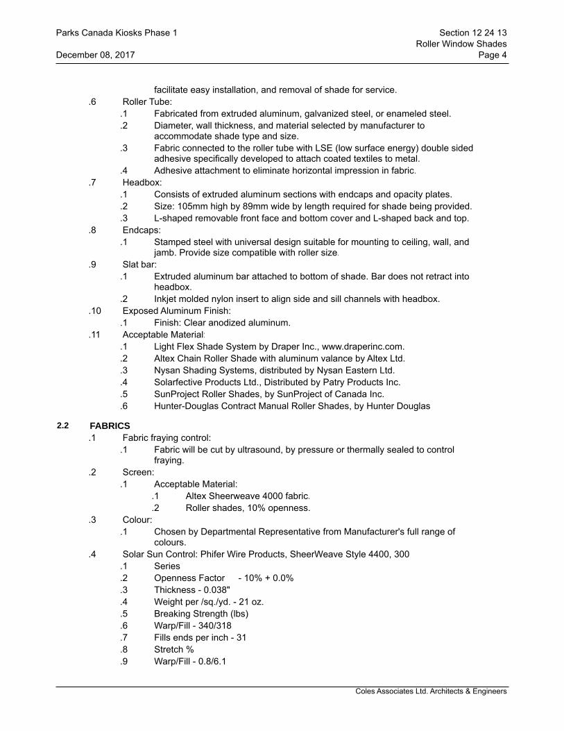
Coles Associates Ltd. Architects & Engineers
facilitate easy installation, and removal of shade for service..6 Roller Tube:
.1 Fabricated from extruded aluminum, galvanized steel, or enameled steel.
.2 Diameter, wall thickness, and material selected by manufacturer to accommodate shade type and size.
.3 Fabric connected to the roller tube with LSE (low surface energy) double sided adhesive specifically developed to attach coated textiles to metal.
.4 Adhesive attachment to eliminate horizontal impression in fabric..7 Headbox:
.1 Consists of extruded aluminum sections with endcaps and opacity plates.
.2 Size: 105mm high by 89mm wide by length required for shade being provided.
.3 L-shaped removable front face and bottom cover and L-shaped back and top..8 Endcaps:
.1 Stamped steel with universal design suitable for mounting to ceiling, wall, and jamb. Provide size compatible with roller size.
.9 Slat bar:.1 Extruded aluminum bar attached to bottom of shade. Bar does not retract into
headbox..2 Inkjet molded nylon insert to align side and sill channels with headbox.
.10 Exposed Aluminum Finish: .1 Finish: Clear anodized aluminum.
.11 Acceptable Material:.1 Light Flex Shade System by Draper Inc., www.draperinc.com..2 Altex Chain Roller Shade with aluminum valance by Altex Ltd..3 Nysan Shading Systems, distributed by Nysan Eastern Ltd..4 Solarfective Products Ltd., Distributed by Patry Products Inc..5 SunProject Roller Shades, by SunProject of Canada Inc..6 Hunter-Douglas Contract Manual Roller Shades, by Hunter Douglas
2.2 FABRICS.1 Fabric fraying control:
.1 Fabric will be cut by ultrasound, by pressure or thermally sealed to control fraying.
.2 Screen:.1 Acceptable Material:
.1 Altex Sheerweave 4000 fabric.
.2 Roller shades, 10% openness..3 Colour:
.1 Chosen by Departmental Representative from Manufacturer's full range of colours.
.4 Solar Sun Control: Phifer Wire Products, SheerWeave Style 4400, 300.1 Series.2 Openness Factor - 10% + 0.0%.3 Thickness - 0.038".4 Weight per /sq./yd. - 21 oz..5 Breaking Strength (lbs).6 Warp/Fill - 340/318.7 Fills ends per inch - 31.8 Stretch %.9 Warp/Fill - 0.8/6.1
Parks Canada Kiosks Phase 1 Section 12 24 13Roller Window Shades
December 08, 2017 Page 4
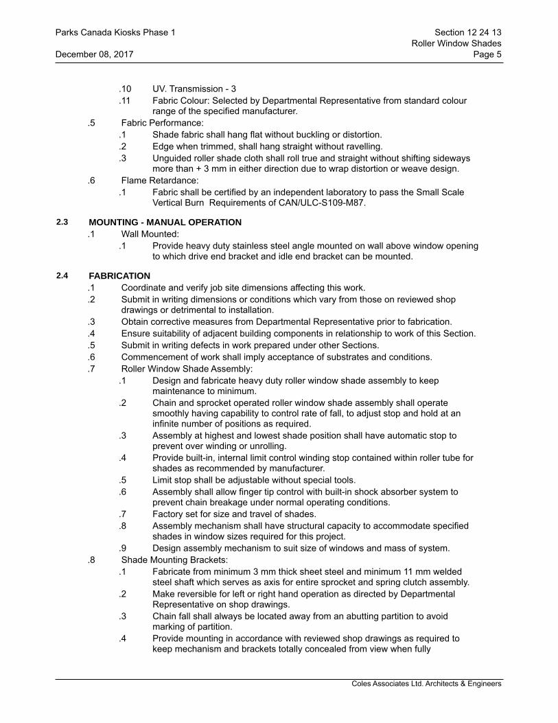
Coles Associates Ltd. Architects & Engineers
.10 UV. Transmission - 3
.11 Fabric Colour: Selected by Departmental Representative from standard colour range of the specified manufacturer.
.5 Fabric Performance:.1 Shade fabric shall hang flat without buckling or distortion..2 Edge when trimmed, shall hang straight without ravelling. .3 Unguided roller shade cloth shall roll true and straight without shifting sideways
more than + 3 mm in either direction due to wrap distortion or weave design..6 Flame Retardance:
.1 Fabric shall be certified by an independent laboratory to pass the Small Scale Vertical Burn Requirements of CAN/ULC-S109-M87.
2.3 MOUNTING - MANUAL OPERATION.1 Wall Mounted:
.1 Provide heavy duty stainless steel angle mounted on wall above window opening to which drive end bracket and idle end bracket can be mounted.
2.4 FABRICATION.1 Coordinate and verify job site dimensions affecting this work. .2 Submit in writing dimensions or conditions which vary from those on reviewed shop
drawings or detrimental to installation. .3 Obtain corrective measures from Departmental Representative prior to fabrication. .4 Ensure suitability of adjacent building components in relationship to work of this Section..5 Submit in writing defects in work prepared under other Sections. .6 Commencement of work shall imply acceptance of substrates and conditions..7 Roller Window Shade Assembly:
.1 Design and fabricate heavy duty roller window shade assembly to keep maintenance to minimum.
.2 Chain and sprocket operated roller window shade assembly shall operate smoothly having capability to control rate of fall, to adjust stop and hold at an infinite number of positions as required.
.3 Assembly at highest and lowest shade position shall have automatic stop to prevent over winding or unrolling.
.4 Provide built-in, internal limit control winding stop contained within roller tube for shades as recommended by manufacturer.
.5 Limit stop shall be adjustable without special tools.
.6 Assembly shall allow finger tip control with built-in shock absorber system to prevent chain breakage under normal operating conditions.
.7 Factory set for size and travel of shades.
.8 Assembly mechanism shall have structural capacity to accommodate specified shades in window sizes required for this project.
.9 Design assembly mechanism to suit size of windows and mass of system..8 Shade Mounting Brackets:
.1 Fabricate from minimum 3 mm thick sheet steel and minimum 11 mm welded steel shaft which serves as axis for entire sprocket and spring clutch assembly.
.2 Make reversible for left or right hand operation as directed by Departmental Representative on shop drawings.
.3 Chain fall shall always be located away from an abutting partition to avoid marking of partition.
.4 Provide mounting in accordance with reviewed shop drawings as required to keep mechanism and brackets totally concealed from view when fully
Parks Canada Kiosks Phase 1 Section 12 24 13Roller Window Shades
December 08, 2017 Page 5
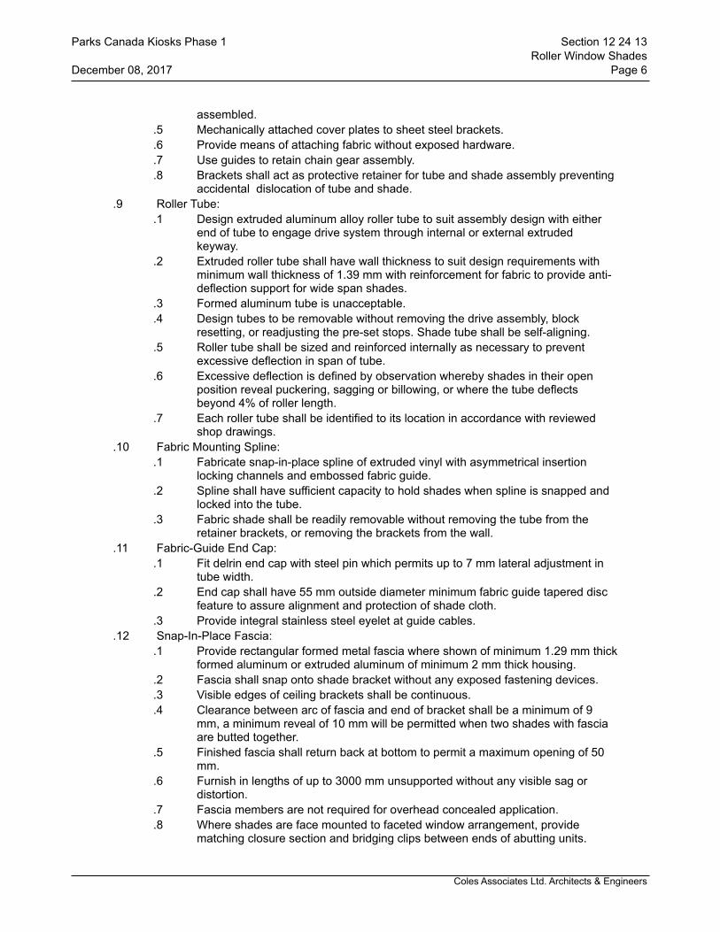
Coles Associates Ltd. Architects & Engineers
assembled. .5 Mechanically attached cover plates to sheet steel brackets..6 Provide means of attaching fabric without exposed hardware..7 Use guides to retain chain gear assembly. .8 Brackets shall act as protective retainer for tube and shade assembly preventing
accidental dislocation of tube and shade..9 Roller Tube:
.1 Design extruded aluminum alloy roller tube to suit assembly design with either end of tube to engage drive system through internal or external extruded keyway.
.2 Extruded roller tube shall have wall thickness to suit design requirements with minimum wall thickness of 1.39 mm with reinforcement for fabric to provide anti-deflection support for wide span shades.
.3 Formed aluminum tube is unacceptable.
.4 Design tubes to be removable without removing the drive assembly, block resetting, or readjusting the pre-set stops. Shade tube shall be self-aligning.
.5 Roller tube shall be sized and reinforced internally as necessary to prevent excessive deflection in span of tube.
.6 Excessive deflection is defined by observation whereby shades in their open position reveal puckering, sagging or billowing, or where the tube deflects beyond 4% of roller length.
.7 Each roller tube shall be identified to its location in accordance with reviewed shop drawings.
.10 Fabric Mounting Spline:.1 Fabricate snap-in-place spline of extruded vinyl with asymmetrical insertion
locking channels and embossed fabric guide. .2 Spline shall have sufficient capacity to hold shades when spline is snapped and
locked into the tube..3 Fabric shade shall be readily removable without removing the tube from the
retainer brackets, or removing the brackets from the wall..11 Fabric-Guide End Cap:
.1 Fit delrin end cap with steel pin which permits up to 7 mm lateral adjustment in tube width.
.2 End cap shall have 55 mm outside diameter minimum fabric guide tapered disc feature to assure alignment and protection of shade cloth.
.3 Provide integral stainless steel eyelet at guide cables..12 Snap-In-Place Fascia:
.1 Provide rectangular formed metal fascia where shown of minimum 1.29 mm thick formed aluminum or extruded aluminum of minimum 2 mm thick housing.
.2 Fascia shall snap onto shade bracket without any exposed fastening devices.
.3 Visible edges of ceiling brackets shall be continuous.
.4 Clearance between arc of fascia and end of bracket shall be a minimum of 9 mm, a minimum reveal of 10 mm will be permitted when two shades with fascia are butted together.
.5 Finished fascia shall return back at bottom to permit a maximum opening of 50 mm.
.6 Furnish in lengths of up to 3000 mm unsupported without any visible sag or distortion.
.7 Fascia members are not required for overhead concealed application.
.8 Where shades are face mounted to faceted window arrangement, provide matching closure section and bridging clips between ends of abutting units.
Parks Canada Kiosks Phase 1 Section 12 24 13Roller Window Shades
December 08, 2017 Page 6
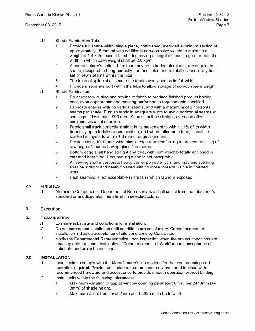
Coles Associates Ltd. Architects & Engineers
.13 Shade Fabric Hem Tube:.1 Provide full shade width, single piece, prefinished, extruded aluminum section of
approximately 15 mm od with additional non-corrosive weight to maintain a weight of 1.4 kg/m except for shades having a height dimension greater than the width, in which case weight shall be 2.0 kg/m.
.2 At manufacturer's option, hem tube may be extruded aluminum, rectangular in shape, designed to hang perfectly perpendicular, and to totally conceal any heat-set or sewn seams within the tube.
.3 The internal spline shall secure the fabric evenly across its full width.
.4 Provide a separate port within the tube to allow storage of non-corrosive weight..14 Shade Fabrication:
.1 Do necessary cutting and sewing of fabric to produce finished product having neat, even appearance and meeting performance requirements specified.
.2 Fabricate shades with no vertical seams, and with a maximum of 2 horizontal seams per shade. Furnish fabric in adequate width to avoid horizontal seams at spacings of less than 1900 mm. Seams shall be straight, even and offer minimum visual obstruction.
.3 Fabric shall track perfectly straight in its movement to within ±1% of its width from fully open to fully closed position, and when rolled onto tube, it shall be stacked in layers to within ± 3 mm of edge alignment.
.4 Provide clear, 10-12 mm wide plastic edge tape reinforcing to prevent ravelling of raw edge of shades having glass fibre cores.
.5 Bottom edge shall hang straight and true, with hem weights totally enclosed in extruded hem tube. Heat sealing alone is not acceptable.
.6 All sewing shall incorporate heavy denier polyester yarn and machine stitching shall be straight and neatly finished with no loose threads visible in finished work.
.7 Heat seaming is not acceptable in areas in which fabric is exposed.
2.5 FINISHES.1 Aluminum Components: Departmental Representative shall select from manufacturer's
standard or anodized aluminum finish in selected colors.
3 Execution
3.1 EXAMINATION.1 Examine substrate and conditions for installation..2 Do not commence installation until conditions are satisfactory. Commencement of
installation indicates acceptance of site conditions by Contractor..3 Notify the Departmental Representative upon inspection when the project conditions are
unacceptable for shade installation. "Commencement of Work" means acceptance of substrate and project conditions.
3.2 INSTALLATION.1 Install units to comply with the Manufacturer's instructions for the type mounting and
operation required. Provide units plumb, true, and securely anchored in place with recommended hardware and accessories to provide smooth operation without binding.
.2 Install units within the following tolerances:.1 Maximum variation of gap at window opening perimeter: 6mm, per 2440mm (+/-
3mm) of shade height. .2 Maximum offset from level: 1mm per 1520mm of shade width.
Parks Canada Kiosks Phase 1 Section 12 24 13Roller Window Shades
December 08, 2017 Page 7
Coles Associates Ltd. Architects & Engineers
3.3 ADJUSTING .1 Adjust drive / brake mechanism of units for smooth operation. Adjust shade and
shadecloth to hang flat without buckling or distortion. Replace any units or components which do not hang properly or operate smoothly.
3.4 CLEANING.1 Touch up damaged finishes and repair minor damage in order to eliminate evidence of
repair. Remove and replace work that cannot be satisfactorily repaired..2 Clean exposed surfaces, including metal and shadecloth, using non-abrasive materials
and methods recommended by the Shadecloth Manufacturer. Remove and replace work which cannot be satisfactorily cleaned.
3.5 TESTING.1 Test motorized window shades to verify that controls, limit switches and other operating
components are functional. Correct deficiencies..2 Test window shades to verify that operating mechanism, fabric retainer, and other
operating components are functional. Correct deficiencies..3 During daylight hours, lower shades and turn off interior lights. Verify that there are no
light leaks at perimeter or within shade assembly. Correct deficiencies.
3.6 DEMONSTRATION.1 Demonstrate operation of shades to Owner's designated representatives.
END OF SECTION
Parks Canada Kiosks Phase 1 Section 12 24 13Roller Window Shades
December 08, 2017 Page 8

Coles Associates Ltd. Architects & Engineers
1 General
1.1 REFERENCES.1 NFPA 10, Portable Fire Extinguishers - 1998 Edition..2 CAN-4-S508-M83, Rating and Fire Testing of Fire Extinguishers.
1.2 SHOP DRAWINGS.1 Submit shop drawings according to Section 01 33 00 - Submittal Procedures.
2 Products
2.1 EXTINGUISHER.1 FE-1:
10 lb. Type ABC dry chemical (ammonium phosphate powder) extinguisher with heavy duty mounting bracket.Acceptable material: Extinguisher
.1 Flag ABC -10G min. ULC rating 4-A, 60-B,C (Light & Ordinary hazard)
.2 Flag ABC -10H min. ULC rating 6-A, 80-B,C (Extra hazard).2 FE-2:
10 lb. Type ABC dry chemical (ammonium phosphate powder) extinguisher with semi recessed prime coated 16 ga. steel cabinet.Acceptable material: Extinguisher
.1 Flag ABC -10G min. ULC rating 4-A, 60-B,C (Light & ordinary hazard)
.2 Flag ABC -10H min. ULC rating 6-A, 80-B,C (Extra hazard).1 Acceptable material: Cabinet
.1 C.F.H. Industries Model CE-950-1
.2 Wilson Cousins Model 1E-10C
3 Execution
3.1 INSTALLATION.1 Install extinguishers securely mounted to walls in locations indicated on drawings..2 Fire extinguishers to be installed so that maximum travel distance does not exceed 22
m..3 Fire extinguishers to be installed 900mm above finished floor.
END OF SECTION
Parks Canada Kiosks Phase 1 Section 21 24 16Portable Fire Extinguishers
December 08, 2017 Page 1
Coles Associates Ltd. Architects & Engineers
1 General
1.1 RELATED SECTIONS.1 Section 21 05 01 - Common Work Results - Mechanical.
1.2 SUBMITTALS.1 Submittals: in accordance with Section 01 33 00 - Submittal Procedures..2 Shop drawings; submit drawings stamped and signed by a Contractor as reviewed..3 Shop drawings to show:
.1 Mounting arrangements.
.2 Operating and maintenance clearances..4 Shop drawings and product data accompanied by:
.1 Detailed drawings of bases, supports, and anchor bolts.
.2 Acoustical sound power data, where applicable.
.3 Points of operation on performance curves.
.4 Manufacturer to certify current model production.
.5 Certification of compliance to applicable codes..5 In addition to transmittal letter referred to in Section 01 33 00 - Submittal Procedures:
use MCAC "Shop Drawing Submittal Title Sheet". Identify section and paragraph number.
.6 Closeout Submittals:.1 Provide operation and maintenance data for incorporation into manual specified
in Section 01 78 00 - Closeout Submittals..2 Operation and maintenance manual approved by , and final copies deposited
with, Departmental Representative before final inspection..3 Operation data to include:
.1 Control schematics for systems including environmental controls.
.2 Description of systems and their controls.
.3 Description of operation of systems at various loads together with reset schedules and seasonal variances.
.4 Operation instruction for systems and component.
.5 Description of actions to be taken in event of equipment failure.
.6 Valves schedule and flow diagram.
.7 Colour coding chart..4 Maintenance data to include:
.1 Servicing, maintenance, operation and trouble-shooting instructions for each item of equipment.
.2 Data to include schedules of tasks, frequency, tools required and task time.
.5 Performance data to include:.1 Equipment manufacturer's performance datasheets with point of
operation as left after commissioning is complete..2 Equipment performance verification test results..3 Special performance data as specified..4 Testing, adjusting and balancing reports as specified in Section 23 05 93
- Testing, Adjusting and Balancing for HVAC..6 Approvals:
.1 Submit 2 copies of draft Operation and Maintenance Manual to Departmental Representative for approval 4 weeks prior to Substantial Completion. Submission of individual data will not be accepted unless
Parks Canada Kiosks Phase 1 Section 22 05 00Common Work Results for Plumbing
December 08, 2017 Page 1

Coles Associates Ltd. Architects & Engineers
directed by Departmental Representative..2 Make changes as required and re-submit as directed by Departmental
Representative..7 Additional data:
.1 becomes apparent during specified demonstrations and instructions..8 Site records:
.1 Departmental Representative will provide 1 set of reproducible mechanical drawings. Provide sets of white prints as required for each phase of work. Mark changes as work progresses and as changes occur. Include changes to existing mechanical systems, control systems and low voltage control wiring.
.2 Transfer information weekly to reproducibles, revising reproducibles to show work as actually installed.
.3 Use different colour water proof ink for each service.
.4 Make available for reference purposes and inspection..9 As-built drawings:
.1 Prior to start of Testing, Adjusting and Balancing for HVAC, finalize production of as-built drawings.
.2 Identify each drawing in lower right hand corner in letters at least 12 mm high as follows: "AS BUILT DRAWINGS: THIS DRAWING HAS BEEN REVISED TO SHOW MECHANICAL SYSTEMS AS INSTALLED" (Signature of Contractor) (Date).
.3 Submit to Departmental Representative for approval and make corrections as directed.
.4 Perform testing, adjusting and balancing for HVAC using as-built drawings.
.5 Submit completed reproducible as-built drawings with Operating and Maintenance Manuals.
.10 Submit copies of as-built drawings for inclusion in final TAB report.
1.3 QUALITY ASSURANCE.1 Quality Assurance: in accordance with Section 01 45 00 - Quality Control..2 Health and Safety Requirements: do construction occupational health and safety in
accordance with Section 01 35 29 - Health, Safety and Emergency Response Procedures.
1.4 MAINTENANCE.1 Furnish spare parts in accordance with Section 01 78 00 - Closeout Submittals as
follows:.1 One set of packing for each pump..2 One casing joint gasket for each size pump.
.2 Provide one set of special tools required to service equipment as recommended by manufacturers and in accordance with Section 01 78 00 - Closeout Submittals.
1.5 DELIVERY, STORAGE AND HANDLING.1 Waste Management and Disposal:
.1 Construction/Demolition Waste Management and Disposal: separate waste materials for reuse and recycling in accordance with Section 01 74 19 -Construction Waste Management Disposal.
2 Products
Parks Canada Kiosks Phase 1 Section 22 05 00Common Work Results for Plumbing
December 08, 2017 Page 2
Coles Associates Ltd. Architects & Engineers
2.1 MATERIALS.1 All materials used on this project shall be new and CSA approved unless noted
otherwise.
3 Execution
3.1 PAINTING, REPAIRS AND RESTORATION.1 Do painting in accordance with Section 09 91 00 - Painting..2 Prime and touch up marred finished paintwork to match original..3 Restore to new condition, finishes which have been damaged.
3.2 CLEANING.1 Clean interior and exterior of all systems including strainers. Vacuum interior of ductwork
and air handling units.
3.3 FIELD QUALITY CONTROL.1 Site Tests: conduct following tests in accordance with Section 01 45 00 - Quality Control
and submit report as described in PART 1 - SUBMITTALS..1 Perform tests as specified in other sections of this specification.
.2 Manufacturer's Field Services:.1 Obtain written report from manufacturer verifying compliance of Work, in
handling, installing, applying, protecting and cleaning of product and submit Manufacturer's Field Reports as described in PART 1 - SUBMITTALS.
.2 Provide manufacturer's field services consisting of product use recommendations and periodic site visits for inspection of product installation in accordance with manufacturer's instructions.
.3 Schedule site visits, to review Work, as directed in PART 1 - QUALITY ASSURANCE.
3.4 DEMONSTRATION.1 Departmental Representative will use equipment and systems for test purposes prior to
acceptance. Contractor to supply labour, material, and instruments required for testing..2 Supply tools, equipment and personnel to demonstrate and instruct operating and
maintenance personnel in operating, controlling, adjusting, trouble-shooting and servicing of all systems and equipment during regular work hours, prior to acceptance.
.3 Use operation and maintenance manual, as-built drawings, and audio visual aids as part of instruction materials.
.4 Instruction duration time requirements as specified in appropriate sections.
.5 Departmental Representative may record these demonstrations on video tape for future reference.
3.5 PROTECTION.1 Protect equipment and systems openings from dirt, dust, and other foreign materials with
materials appropriate to system
END OF SECTION
Parks Canada Kiosks Phase 1 Section 22 05 00Common Work Results for Plumbing
December 08, 2017 Page 3

Coles Associates Ltd. Architects & Engineers
1 General
1.1 SECTION INCLUDES.1 Materials and installation for copper domestic water service used in the following:
.1 Copper incoming domestic water service, up to NPS 2 1/2.
.2 Hard drawn copper domestic hot and cold water services inside building.
.3 Cross linked polyethylyne (PEX) tubing and fittings for a potable water distribution system.
1.2 RELATED SECTIONS.1 Section 23 05 01 - Installation of Pipework..2 Section 23 05 22 - Valves - Bronze..3 Section 23 20 21 - Thermal Insulation for Piping.
1.3 REFERENCES.1 American National Standards Institute (ANSI)/American Society of Mechanical
Engineers International (ASME)..1 ANSI/ASME B16.15, Cast Bronze Threaded Fittings, Classes 125 and 250..2 ANSI/ASME B16.18, Cast Copper Alloy Solder Joint Pressure Fittings..3 ANSI/ASME B16.22, Wrought Copper and Copper Alloy Solder Joint Pressure
Fittings..4 ANSI/ASME B16.24, Cast Copper Alloy Pipe Flanges and Flanged Fittings,
Class 150, 300, 400, 600, 900, 1500 and 2500..2 American Society for Testing and Materials International, (ASTM).
.1 ASTM A307, Standard Specification for Carbon Steel Bolts and Studs, 60,000 PSI Tensile Strength.
.2 ASTM A536 Standard Specification for Ductile Iron Castings.
.3 ASTM B88M, Standard Specification for Seamless Copper Water Tube (Metric).
.4 AST M - Standard Specification for cross linked Polyethylene (PEX) tubing.
.5 ASTM F877 Standard specification for cross-linked polyethylene (PEX) plastic hot and cold water distribution systems.
.6 ASTM F 1960 Standard Specification for cold expansion fittings with PEX reinforcing rings for use with cross-linked polyethylene (PEX) tubing.
.3 American Water Works Association (AWWA)..1 AWWA C111, Rubber-Gasket Joints for Ductile-Iron Pressure Pipe and Fittings..2 AWWA 6606 Grooved and Shouldered Joints.
.4 Canadian Standards Association (CSA International)..1 CSA B242, Groove and Shoulder Type Mechanical Pipe Couplings..2 CSA B137.5 Cross-linked polyethylene (PEX) tubing systems for pressure
applications..5 Department of Justice Canada (Jus).
.1 Canadian Environmental Protection Act, (CEPA)..6 Health Canada/Workplace Hazardous Materials Information System (WHMIS).
.1 Material Safety Data Sheets (MSDS)..7 Manufacturer's Standardization Society of the Valve and Fittings Industry (MSS).
.1 MSS-SP-67, Butterfly Valves.
.2 MSS-SP-70, Cast Iron Gate Valves, Flanged and Threaded Ends.
.3 MSS-SP-71, Cast Iron Swing Check Valves, Flanged and Threaded Ends.
.4 MSS-SP-80, Bronze Gate, Globe, Angle and Check Valves..8 National Research Council (NRC)/Institute for Research in Construction.
Parks Canada Kiosks Phase 1 Section 22 11 18Domestic Water Piping Copper & PEX
December 08, 2017 Page 1

Coles Associates Ltd. Architects & Engineers
.1 NRCC 38728, National Plumbing Code of Canada (NPC)..9 Transport Canada (TC).
.1 Transportation of Dangerous Goods Act, (TDGA)..10 American National Standards Institute/National Sanitation Foundation (ANSI/NSF).
.1 ANSI/NSF 61 Drinking Water System Components.
.2 ANSF/NSF14 Plastic Piping System Components and Related Materials.
1.4 SUBMITTALS.1 Submittals in accordance with Section 01 33 00 - Submittal Procedures..2 Submit product data for following: piping, fittings, valves and adhesives.
.1 Provide manufacturers printed product literature and data sheets including product characteristics, performance criteria, physical size, finish and pressure/temperature limitations.
.3 Submit WHMIS MSDS - Material Safety Data Sheets to Departmental Representative for each hazardous material prior to bringing hazardous materials to site.
.4 Provide maintenance data for incorporation into manual specified in Section 01 78 00 -Closeout Submittals.
.5 Grooved joint couplings and fittings to be indicated on product submittals and to be specifically identified with the applicable style or series designation.
.6 Cross linked polyethylene (PEX) tubing..1 Contractor to provide full layout drawings, details, riser diagrams, calculations
including fixture pressure, building pressure critical path, longest run pressure drop, pipe sizing, balancing valves pipe carrying capacity velocities and fixture units. Contractor must also provide installation diagrams, guidelines, hanger spacing, support details, support details thermal expansion contract on details, expansion joints and typical suite/unit details.
1.5 HEALTH AND SAFETY.1 Do construction occupational health and safety in accordance with Section 01 35 29 -
Health, Safety and Emergency Response Procedures.
1.6 WASTE MANAGEMENT AND DISPOSAL.1 Separate waste materials for reuse in accordance with Section 01 74 19 - Construction
Waste Management Disposal..2 Remove from site and dispose of packaging materials at appropriate recycling facilities..3 Separate for reuse and recycling and place in designated containers Steel waste in
accordance with Waste Management Plan..4 Place materials defined as hazardous or toxic in designated containers..5 Handle and dispose of hazardous materials in accordance with CEPA and local or
municipal regulations..6 Fold up metal banding, flatten and place in designated area for recycling.
1.7 QUALITY ASSURANCE.1 Cross Linked Polyethylene (PEX) tubing
.1 Qualifications:.1 Installer Qualifications: Installer shall be experience in performing work of
this section and has specialized in installation of work similar to that required for this project.
.2 Installer Qualifications: Installer shall be recognized by the tubing/fitting manufacturer as a "Trained Installer".
.3 Installation Qualifications: Installation must be by skilled tradesmen holding trade qualification license or apprentices under the supervision of
Parks Canada Kiosks Phase 1 Section 22 11 18Domestic Water Piping Copper & PEX
December 08, 2017 Page 2
Coles Associates Ltd. Architects & Engineers
a licensed tradesman..2 Regulatory Requirements: PEX tubing and components shall be installed in full
compliance with all Federal, Provincial and Municipal codes, standards and requirements.
.3 Pre-installation Meetings: Conduct pre-installation meeting to verify project requirements manufacturer's installation instructions and manufacturer's warranty requirements. Comply with Division 1 Project Management and Coordination (Project Meetings) Section.
.2 Press Joint Copper Systems..1 Installer shall be a qualified, licensed within the jurisdiction, and factory trained
with the installation of copper press joint systems. Certificate of factory training shall be submitted prior to starting work.
.2 Copper press fittings shall be installed using the proper tool, actuator, jaws and rings as instructed by the press fitting manufacturer.
.3 The installation of copper tubing for hot and cold water distribution systems shall conform to the requirements of the National Plumbing Code of Canada.
2 Products
2.1 PIPING.1 Domestic hot, cold and recirculation systems, within building.
.1 Above ground: .1 Copper tube, hard drawn, type L: to ASTM B88M..2 Cross-linked Polyethylene (PEX), non-air barrier type: to ASTM F 876
and ASTM F 877..2 Buried or embedded:
.1 Copper tube, soft annealed, type K: to ASTM B88M, in long lengths and with no buried joints.
.2 Cross-linked Polyethylene (PEX), non-air barrier type: to ASTM F 876 and ASTM F 877 with no buried joints.
.3 Pipe sleeve shall be provided where piping passes through concrete.
2.2 FITTINGS.1 Bronze pipe flanges and flanged fittings, Class 150: to ANSI/ASME B16.24..2 Cast bronze threaded fittings, Class 125: to ANSI/ASME B16.15..3 Cast copper, solder type: to ANSI/ASME B16.18..4 Wrought copper and copper alloy, solder type: to ANSI/ASME B16.22..5 NPS 2 and larger: roll grooved to CSA B242. Cast bronze to ANSI/ASME B16.18 or
wrought copper to ANSI/ASME B16.22..1 Fittings to be manufactured to copper tube dimensions, flaring of tube or fitting
ends to accommodate IPS sized couplings is not permitted..6 PEX fittings to ASTM F 877, ASTM F 1807 and/or ASTM F 1960, as appropriate..7 NPS 1 1/2 and under: Last copper, ANSI/ASMS B16.12 of wrought copper, ANSI/ASME
B16.22 with stainless steel internal components, EPDM seal and push to comment or press fit joints for hand drawn copper tube type L or type K rated for 1300 KPA at ASTM B88
.8 NPS 1½ and under: Cast copper, ANSI/ASME B16.18 or wrought copper, ANSI/ASME B16.22; with 301 stainless steel internal components. EPDM seal and push to connect or press fit joints, hand drawn copper tube type L or K rated for 1300 kPA at ASTM B88.
2.3 JOINTS.1 Rubber gaskets, latex free, 1.6 mm thick: to AWWA C111.
Parks Canada Kiosks Phase 1 Section 22 11 18Domestic Water Piping Copper & PEX
December 08, 2017 Page 3
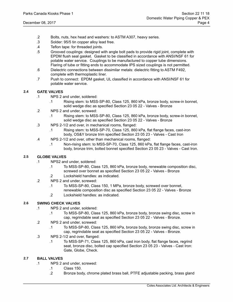
Coles Associates Ltd. Architects & Engineers
.2 Bolts, nuts, hex head and washers: to ASTM A307, heavy series.
.3 Solder: 95/5 tin copper alloy lead free.
.4 Teflon tape: for threaded joints.
.5 Grooved couplings: designed with angle bolt pads to provide rigid joint, complete with EPDM flush seal gasket. Gasket to be classified in accordance with ANSI/NSF 61 for potable water service. Couplings to be manufactured to copper tube dimensions. Flaring of tube or fitting ends to accommodate IPS sized couplings is not permitted.
.6 Dielectric connections between dissimilar metals: dielectric fitting to ASTM F492, complete with thermoplastic liner.
.7 Push to connect: EPDM gasket, UL classified in accordance with ANSI/NSF 61 for potable water service.
2.4 GATE VALVES.1 NPS 2 and under, soldered:
.1 Rising stem: to MSS-SP-80, Class 125, 860 kPa, bronze body, screw-in bonnet, solid wedge disc as specified Section 23 05 22 - Valves - Bronze
.2 NPS 2 and under, screwed:.1 Rising stem: to MSS-SP-80, Class 125, 860 kPa, bronze body, screw-in bonnet,
solid wedge disc as specified Section 23 05 22 - Valves - Bronze.3 NPS 2-1/2 and over, in mechanical rooms, flanged:
.1 Rising stem: to MSS-SP-70, Class 125, 860 kPa, flat flange faces, cast-iron body, OS&Y bronze trim specified Section 23 05 23 - Valves - Cast Iron
.4 NPS 2-1/2 and over, other than mechanical rooms, flanged:.1 Non-rising stem: to MSS-SP-70, Class 125, 860 kPa, flat flange faces, cast-iron
body, bronze trim, bolted bonnet specified Section 23 05 23 - Valves - Cast Iron.
2.5 GLOBE VALVES.1 NPS2 and under, soldered:
.1 To MSS-SP-80, Class 125, 860 kPa, bronze body, renewable composition disc, screwed over bonnet as specified Section 23 05 22 - Valves - Bronze
.2 Lockshield handles: as indicated..2 NPS 2 and under, screwed:
.1 To MSS-SP-80, Class 150, 1 MPa, bronze body, screwed over bonnet, renewable composition disc as specified Section 23 05 22 - Valves - Bronze
.2 Lockshield handles: as indicated.
2.6 SWING CHECK VALVES.1 NPS 2 and under, soldered:
.1 To MSS-SP-80, Class 125, 860 kPa, bronze body, bronze swing disc, screw in cap, regrindable seat as specified Section 23 05 22 - Valves - Bronze.
.2 NPS 2 and under, screwed:.1 To MSS-SP-80, Class 125, 860 kPa, bronze body, bronze swing disc, screw in
cap, regrindable seat as specified Section 23 05 22 - Valves - Bronze..3 NPS 2-1/2 and over, flanged:
.1 To MSS-SP-71, Class 125, 860 kPa, cast iron body, flat flange faces, regrind seat, bronze disc, bolted cap specified Section 23 05 23 - Valves - Cast Iron: Gate, Globe, Check.
2.7 BALL VALVES.1 NPS 2 and under, screwed:
.1 Class 150.
.2 Bronze body, chrome plated brass ball, PTFE adjustable packing, brass gland
Parks Canada Kiosks Phase 1 Section 22 11 18Domestic Water Piping Copper & PEX
December 08, 2017 Page 4
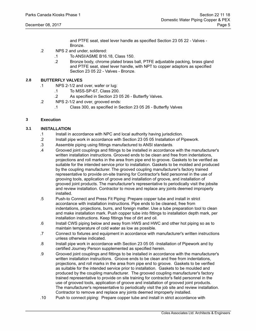
Coles Associates Ltd. Architects & Engineers
and PTFE seat, steel lever handle as specified Section 23 05 22 - Valves -Bronze.
.2 NPS 2 and under, soldered:.1 To ANSI/ASME B16.18, Class 150..2 Bronze body, chrome plated brass ball, PTFE adjustable packing, brass gland
and PTFE seat, steel lever handle, with NPT to copper adaptors as specified Section 23 05 22 - Valves - Bronze.
2.8 BUTTERFLY VALVES.1 NPS 2-1/2 and over, wafer or lug:
.1 To MSS-SP-67, Class 200.
.2 As specified in Section 23 05 26 - Butterfly Valves..2 NPS 2-1/2 and over, grooved ends:
.1 Class 300, as specified in Section 23 05 26 - Butterfly Valves
3 Execution
3.1 INSTALLATION.1 Install in accordance with NPC and local authority having jurisdiction..2 Install pipe work in accordance with Section 23 05 05 Installation of Pipework..3 Assemble piping using fittings manufactured to ANSI standards..4 Grooved joint couplings and fittings to be installed in accordance with the manufacturer's
written installation instructions. Grooved ends to be clean and free from indentations, projections and roll marks in the area from pipe end to groove. Gaskets to be verified as suitable for the intended service prior to installation. Gaskets to be molded and produced by the coupling manufacturer. The grooved coupling manufacturer's factory trained representative to provide on-site training for Contractor's field personnel in the use of grooving tools, application of groove and installation of groove, and installation of grooved joint products. The manufacturer's representative to periodically visit the jobsite and review installation. Contractor to move and replace any joints deemed improperly installed.
.5 Push-to Connect and Press Fit Piping: Prepare copper tube and install in strict accordance with installation instructions. Pipe ends to be cleaned, free from indentations, projections, burrs, and foreign matter. Use a tube preparation tool to clean and make installation mark. Push copper tube into fittings to installation depth mark, per installation instructions. Keep fittings free of dirt and oil.
.6 Install CWS piping below and away from HWS and HWC and other hot piping so as to maintain temperature of cold water as low as possible.
.7 Connect to fixtures and equipment in accordance with manufacturer's written instructions unless otherwise indicated.
.8 Install pipe work in accordance with Section 23 05 05 -Installation of Pipework and by certified Journey Person supplemented as specified herein.
.9 Grooved joint couplings and fittings to be installed in accordance with the manufacturer's written installation instructions. Groove ends to be clean and free from indentations, projections, and roll marks in the area from pipe end to groove. Gaskets to be verified as suitable for the intended service prior to installation. Gaskets to be moulded and produced by the coupling manufacturer. The grooved coupling manufacturer's factory trained representative to provide on site training for contractor's field personnel in the use of grooved tools, application of groove and installation of grooved joint products. The manufacturer's representative to periodically visit the job site and review installation. Contractor to remove and replace any joints deemed improperly installed.
.10 Push to connect piping: Prepare copper tube and install in strict accordance with
Parks Canada Kiosks Phase 1 Section 22 11 18Domestic Water Piping Copper & PEX
December 08, 2017 Page 5

Coles Associates Ltd. Architects & Engineers
installation instructions. Pipe ends to be cleaned, free from indentations, projections, burns, and foreign matter. Use tube preparation tool to clean and make installation mark. Push copper tube into fittings to installation depth mark, per installation instructions. Keep fittings free of dirt and oil.
.11 Buried Tubing:.1 Lay in well completed washed sand in accordance with AWWA Class B bedding..2 Bed tubing without crimping or constriction. Minimized us of fittings.
3.2 VALVES.1 Isolate equipment, fixtures and branches with butterfly or ball valves..2 Balance recirculation system using lockshield globe valves. Mark settings and record on
as-built drawings on completion.
3.3 PRESSURE TESTS.1 Conform to requirements of Section 21 05 01 - Common Work Results - Mechanical.2 Test pressure: greater of 1-½ times maximum system operating pressure or 860 kPa.
3.4 FLUSHING AND CLEANING.1 Flush entire system for 8 h. Ensure outlets flushed for 2 h. Let stand for 24 h, then draw
one sample off longest run. Submit to testing laboratory bacterialogical and chemical testing to verify that system is clean to provincial potable water guidelines. Let system flush for additional 2 h, then draw off another sample for testing.
3.5 PRE-START-UP INSPECTIONS.1 Systems to be complete, prior to flushing, testing and start-up..2 Verify that system can be completely drained..3 Ensure that pressure booster systems are operating properly..4 Ensure that air chambers, expansion compensators are installed properly.
3.6 DISINFECTION.1 Flush out, disinfect and rinse system to requirements of authority having jurisdiction and
approval of Departmental Representative..2 Upon completion, provide laboratory test reports on water quality for Departmental
Representative approval.
3.7 START-UP.1 Timing: Start up after:
.1 Pressure tests have been completed.
.2 Disinfection procedures have been completed.
.3 Water treatment systems operational..2 Provide continuous supervision during start-up..3 Start-up procedures:
.1 Establish circulation and ensure that air is eliminated.
.2 Check pressurization to ensure proper operation and to prevent water hammer, flashing and/or cavitation.
.3 Bring HWS storage tank up to design temperature slowly.
.4 Monitor piping HWS and HWC piping systems for freedom of movement, pipe expansion as designed.
.5 Check control, limit, safety devices for normal and safe operation..4 Rectify start-up deficiencies.
3.8 PERFORMANCE VERIFICATION
Parks Canada Kiosks Phase 1 Section 22 11 18Domestic Water Piping Copper & PEX
December 08, 2017 Page 6
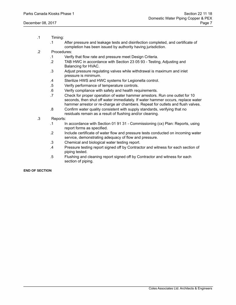
Coles Associates Ltd. Architects & Engineers
.1 Timing:.1 After pressure and leakage tests and disinfection completed, and certificate of
completion has been issued by authority having jurisdiction..2 Procedures:
.1 Verify that flow rate and pressure meet Design Criteria.
.2 TAB HWC in accordance with Section 23 05 93 - Testing, Adjusting and Balancing for HVAC.
.3 Adjust pressure regulating valves while withdrawal is maximum and inlet pressure is minimum.
.4 Sterilize HWS and HWC systems for Legionella control.
.5 Verify performance of temperature controls.
.6 Verify compliance with safety and health requirements.
.7 Check for proper operation of water hammer arrestors. Run one outlet for 10 seconds, then shut off water immediately. If water hammer occurs, replace water hammer arrestor or re-charge air chambers. Repeat for outlets and flush valves.
.8 Confirm water quality consistent with supply standards, verifying that no residuals remain as a result of flushing and/or cleaning.
.3 Reports:.1 In accordance with Section 01 91 31 - Commissioning (cx) Plan: Reports, using
report forms as specified..2 Include certificate of water flow and pressure tests conducted on incoming water
service, demonstrating adequacy of flow and pressure..3 Chemical and biological water testing report..4 Pressure testing report signed off by Contractor and witness for each section of
piping tested..5 Flushing and cleaning report signed off by Contractor and witness for each
section of piping.
END OF SECTION
Parks Canada Kiosks Phase 1 Section 22 11 18Domestic Water Piping Copper & PEX
December 08, 2017 Page 7
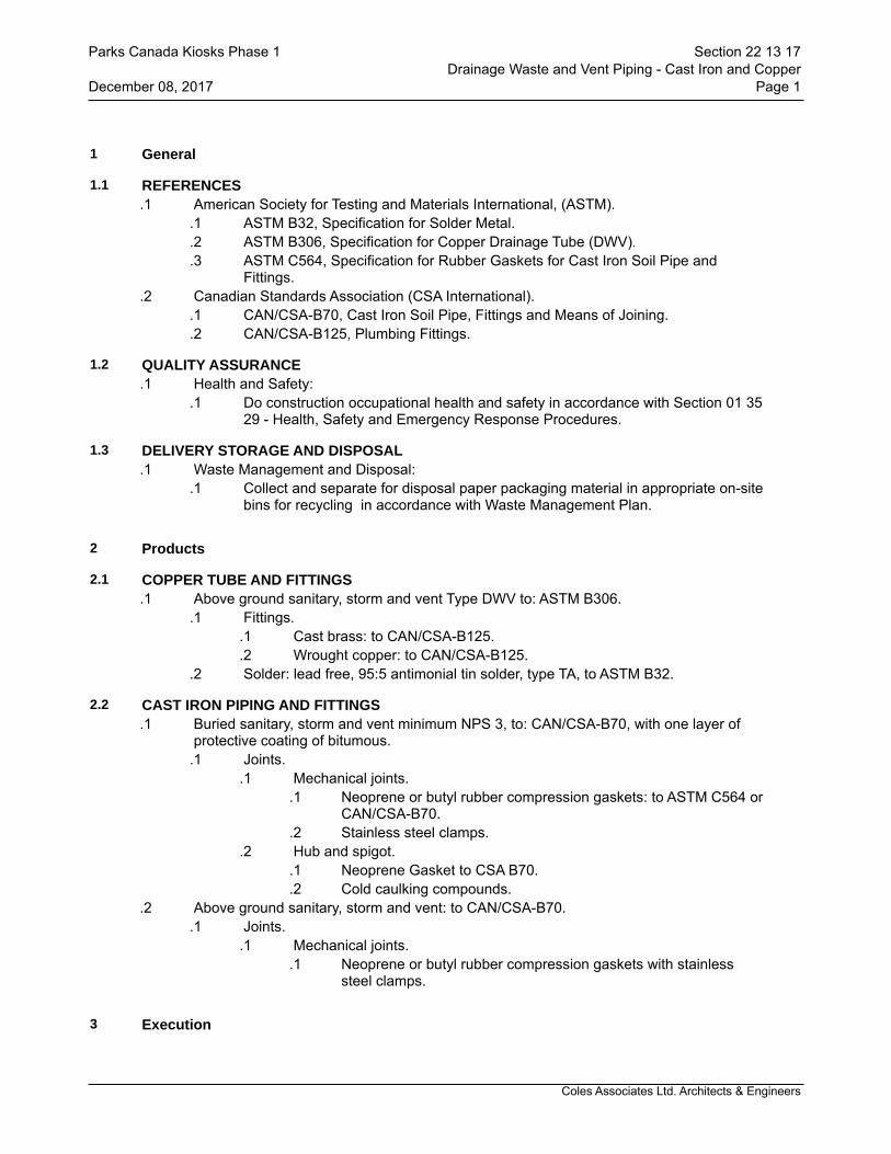
Coles Associates Ltd. Architects & Engineers
1 General
1.1 REFERENCES.1 American Society for Testing and Materials International, (ASTM).
.1 ASTM B32, Specification for Solder Metal.
.2 ASTM B306, Specification for Copper Drainage Tube (DWV).
.3 ASTM C564, Specification for Rubber Gaskets for Cast Iron Soil Pipe and Fittings.
.2 Canadian Standards Association (CSA International)..1 CAN/CSA-B70, Cast Iron Soil Pipe, Fittings and Means of Joining..2 CAN/CSA-B125, Plumbing Fittings.
1.2 QUALITY ASSURANCE.1 Health and Safety:
.1 Do construction occupational health and safety in accordance with Section 01 35 29 - Health, Safety and Emergency Response Procedures.
1.3 DELIVERY STORAGE AND DISPOSAL.1 Waste Management and Disposal:
.1 Collect and separate for disposal paper packaging material in appropriate on-site bins for recycling in accordance with Waste Management Plan.
2 Products
2.1 COPPER TUBE AND FITTINGS.1 Above ground sanitary, storm and vent Type DWV to: ASTM B306.
.1 Fittings..1 Cast brass: to CAN/CSA-B125..2 Wrought copper: to CAN/CSA-B125.
.2 Solder: lead free, 95:5 antimonial tin solder, type TA, to ASTM B32.
2.2 CAST IRON PIPING AND FITTINGS.1 Buried sanitary, storm and vent minimum NPS 3, to: CAN/CSA-B70, with one layer of
protective coating of bitumous..1 Joints.
.1 Mechanical joints..1 Neoprene or butyl rubber compression gaskets: to ASTM C564 or
CAN/CSA-B70..2 Stainless steel clamps.
.2 Hub and spigot..1 Neoprene Gasket to CSA B70..2 Cold caulking compounds.
.2 Above ground sanitary, storm and vent: to CAN/CSA-B70..1 Joints.
.1 Mechanical joints..1 Neoprene or butyl rubber compression gaskets with stainless
steel clamps.
3 Execution
Parks Canada Kiosks Phase 1 Section 22 13 17Drainage Waste and Vent Piping - Cast Iron and Copper
December 08, 2017 Page 1

Coles Associates Ltd. Architects & Engineers
3.1 INSTALLATION.1 In accordance with Section 23 05 01 - Installation of Pipework and by a Certified Journey
Person..2 Install in accordance with Canadian Plumbing Code and local authorities having
jurisdiction.
3.2 TESTING.1 Pressure test buried systems before backfilling..2 Hydraulically test to verify grades and freedom from obstructions.
3.3 PERFORMANCE VERIFICATION.1 Cleanouts:
.1 Ensure accessible and that access doors are correctly located.
.2 Open, cover with linseed oil and re-seal.
.3 Verify that cleanout rods can probe as far as the next cleanout, at least..2 Test to ensure traps are fully and permanently primed..3 Storm water drainage:
.1 Verify domes are secure.
.2 Ensure weirs are correctly sized and installed correctly.
.3 Verify provisions for movement of roof system..4 Ensure that fixtures are properly anchored, connected to system and effectively vented..5 Affix applicable label (storm, sanitary, vent, pump discharge etc.) c/w directional arrows
every floor or 4.5 m (whichever is less)..6 Provide copies of test reports for maintenance manuals.
END OF SECTION
Parks Canada Kiosks Phase 1 Section 22 13 17Drainage Waste and Vent Piping - Cast Iron and Copper
December 08, 2017 Page 2
Coles Associates Ltd. Architects & Engineers
1 General
1.1 RELATED SECTIONS.1 Section 23 05 01 - Installation of Pipework.
1.2 REFERENCES.1 American Society for Testing and Materials International, (ASTM).
.1 ASTM D2235, Specification for Solvent Cement for Acrylonitrille-Butadiene-Styrene (ABS) Plastic Pipe and Fittings.
.2 ASTM D2564, Specification for Solvent Cements for Poly(Vinyl-Chloride) (PVC) Plastic Piping Systems.
.2 Canadian Standards Association (CSA International)..1 CSA-Series B1800, Plastic Nonpressure Pipe Compendium..2 CSA-B181.2, PVC Drain, Waste and Vent Pipe and Pipe Fittings..3 CSA-B182.1, Plastic Drain and Sewer Pipe and Pipe Fittings.
.3 Underwriters Laboratory of Canada (ULC).1 CAN/ULC-S102.2 Method of Testing for Surface Burning Characteristics of
Flooring, Floor Coverings, and Miscellaneous Materials and Assemblies.
1.3 WASTE MANAGEMENT AND DISPOSAL.1 Collect and separate for disposal paper packaging material in appropriate on-site bins
for recycling in accordance with Waste Management Plan.
2 Products
2.1 PIPING AND FITTINGS.1 For buried DWV piping to:
.1 CSA-B181.1.
.2 CSA-B181.2.
.3 CSA-B182.1..2 For above ground DWV piping for combustible construction:
.1 CSA-B181.2..3 For above ground DWV piping for non-combustible construction:
.1 Flame spread rating less than 25 and smoke developed classification less than 50.
.2 CSA B181.2.
2.2 JOINTS.1 Solvent weld for PVC: to ASTM D2564..2 Solvent weld for ABS: to ASTM D2235.
3 Execution
3.1 INSTALLATION.1 Install in accordance with Canadian Plumbing Code and the local authority having
jurisdiction..2 In accordance with Section 23 05 05 - Installation of Pipework and certified Journey
Persons.
3.2 TESTING.1 Pressure test buried systems before backfilling in accordance with Canadian Plumbing
Parks Canada Kiosks Phase 1 Section 22 13 18Drainage Waste and Vent Piping - Plastic
December 08, 2017 Page 1

Coles Associates Ltd. Architects & Engineers
Code..2 Hydraulically test to verify grades and freedom from obstructions.
3.3 PERFORMANCE VERIFICATION.1 Cleanouts:
.1 Ensure accessible and that access doors are correctly located.
.2 Open, cover with linseed oil and re-seal.
.3 Verify cleanout rods can probe as far as the next cleanout, at least..2 Test to ensure traps are fully and permanently primed..3 Storm water drainage:
.1 Verify domes are secure.
.2 Ensure weirs are correctly sized and installed correctly.
.3 Verify provisions for movement of roof system..4 Ensure fixtures are properly anchored, connected to system and effectively vented..5 Affix applicable label (storm, sanitary, vent, pump discharge etc.) c/w directional arrows
every floor or 4.5 m (whichever is less)..6 Provide copies of test reports for maintenance manuals.
END OF SECTION
Parks Canada Kiosks Phase 1 Section 22 13 18Drainage Waste and Vent Piping - Plastic
December 08, 2017 Page 2

Coles Associates Ltd. Architects & Engineers
1 General
1.1 REFERENCES.1 Canadian Gas Association (CGA)
.1 ANSI Z21.10.1/CSA 4.1, Gas Water Heaters - Volume I, Storage Water Heaters With Input Ratings Below 75,000 Btu Per Hour.
.2 ANSI Z21.10.3/CSA 4.3, Gas Water Heaters - Volume III - Storage Water Heaters, with Input Ratings Above 75,000 Btu Per Hour.
.3 CSA-B149.1, Natural Gas and Propane Installation Code.
.4 CSA-B149.2, Propane Storage and Handling Code..2 Canadian Standards Association (CSA International)
.1 CSA B51, Boiler, Pressure Vessel, and Pressure Piping Code.
.2 CAN/CSA-B139, Installation Code for Oil Burning Equipment.
.3 CAN/CSA-B140.0, General Requirements for Oil Burning Equipment.
.4 CSA B140.12, Oil-Fired Service Water Heaters and Swimming Pool Heaters.
.5 CAN/CSA C22.2 No.110, Construction and Test of Electric Storage Tank Water Heaters.
.6 CAN/CSA-C191 Series, Performance of Electric Storage Tank Water Heaters for Household Service.
.7 CAN/CSA-C309, Performance Requirements for Glass-Lined Storage Tanks for Household Hot Water Service.
1.2 SHOP DRAWINGS.1 Submit shop drawings in accordance with Section 01 33 00 - Submittal Procedures..2 Indicate:
.1 Equipment, including connections, fittings, control assemblies and ancillaries, identifying factory and field assembled.
1.3 CLOSEOUT SUBMITTALS.1 Provide maintenance and engineering data for incorporation into manual specified in
Section 01 78 00 - Closeout Submittals .
1.4 WASTE MANAGEMENT AND DISPOSAL.1 Separate and recycle waste materials in accordance with Section 01 74 19 -
Construction Waste Management Disposal..2 Remove from site and dispose of packaging materials at appropriate recycling facilities..3 Collect and separate for disposal paper packaging material in appropriate on-site for
recycling in accordance with Waste Management Plan..4 Divert unused metal and wiring materials from landfill to metal recycling facility approved
by Departmental Representative.
2 Products
2.1 ELECTRIC.1 To CAN/CSA C22.2 No.110, CAN/CSA-C191 and CAN/CSA-C309 for glass-lined
storage tanks, with immersion type elements, kW rating as indicated, and surface mounted or immersion type adjustable thermostats.
.2 Tank: glass lined steel or stainless steel, 50 mm mineral wool or fibreglass insulation, enamelled steel jacket, 3 year warranty certificate. Capacity and size as indicated.
.3 Acceptable Material: Bradford-White, John Wood, A.O. Smith.
Parks Canada Kiosks Phase 1 Section 22 30 05Domestic Water Heaters
December 08, 2017 Page 1
Coles Associates Ltd. Architects & Engineers
2.2 TRIM AND INSTRUMENTATION.1 Drain valve: NPS 1 with hose end..2 Thermometer to Section 23 05 21 - Thermometers and Pressure Gauges..3 Pressure gauge to Section 23 05 21 - Thermometers and Pressure Gauges..4 ASME rated temperature and pressure relief valve sized for full capacity of heater,
having discharge terminating over floor drain and visible to operators..5 Supply anchor bolts and templates for installation by other Divisions..6 Magnesium anodes adequate for 20 years of operation and located for easy
replacement.
3 Execution
3.1 INSTALLATION.1 Install in accordance with manufacturer's recommendations and authority having
jurisdiction..2 Provide structural steel for horizontal mounted tanks..3 Provide insulation between tank and supports..4 Install oil burning domestic water heaters in accordance with CAN/CSA-B139..5 Install natural gas fired domestic water heaters in accordance with CSA-B149.1..6 Install propane gas fired domestic water heaters in accordance with CSA-B149.2.
END OF SECTION
Parks Canada Kiosks Phase 1 Section 22 30 05Domestic Water Heaters
December 08, 2017 Page 2
Coles Associates Ltd. Architects & Engineers
1 General
1.1 REFERENCES.1 American Society for Testing and Materials International (ASTM).
.1 ASTM A126, Specification for Gray Iron Castings for Valves, Flanges and Pipe Fittings.
.2 ASTM B62, Specification for Composition Bronze or Ounce Metal Castings..2 American Water Works Association (AWWA).
.1 AWWA C700, Cold Water Meters-Displacement Type, Bronze Main Case.
.2 AWWA C701, Cold Water Meters-Turbine Type for Customer Service.
.3 AWWA C702-1, Cold Water Meters-Compound Type..3 Canadian Standards Association (CSA International).
.1 CSA-B64 Series, Backflow Preventers and Vacuum Breakers.
.2 CSA-B79, Floor, Area and Shower Drains, and Cleanouts for Residential Construction.
.3 CSA-B356, Water Pressure Reducing Valves for Domestic Water Supply Systems.
.4 Health Canada/Workplace Hazardous Materials Information System (WHMIS)..1 Material Safety Data Sheets (MSDS).
.5 Plumbing and Drainage Institute (PDI)..1 PDI-G101, Testing and Rating Procedure for Grease Interceptors with Appendix
of Sizing and Installation Data..2 PDI-WH201, Water Hammer Arresters Standard.
1.2 SUBMITTALS.1 Submittals in accordance with Section 01 33 00 - Submittal Procedures..2 Product Data:
.1 Submit manufacturer's printed product literature, specifications and datasheet for fixtures and equipment.
.2 Indicate dimensions, construction details and materials for specified items.
.3 Submit WHMIS MSDS material safety data schools. Indicate VOC's for adhesive and solvents during application and curing.
.3 Instructions: submit manufacturer's installation instructions.
.4 Manufacturers' Field Reports: manufacturers' field reports specified.
.5 Closeout submittals: submit maintenance and engineering data for incorporation into manual specified in Section 01 78 00 - Closeout Submittals, include:
.1 Description of plumbing specialties and accessories, giving manufacturers name, type, model, year and capacity.
.2 Details of operation, servicing and maintenance.
.3 Recommended spare parts list.
1.3 QUALITY ASSURANCE.1 Health and Safety:
.1 Do construction occupational health and safety in accordance with Section 01 35 29 - Health and Safety Procedures.
1.4 WASTE MANAGEMENT AND DISPOSAL.1 Separate waste materials for reuse in accordance with Section 01 74 19 - Construction
Waste Management Disposal..2 Remove from site and dispose of packaging materials at appropriate recycling facilities..3 Collect and separate for disposal paper packaging material in appropriate on-site bins
Parks Canada Kiosks Phase 1 Section 22 42 01Plumbing Specialties and Accessories
December 08, 2017 Page 1
Coles Associates Ltd. Architects & Engineers
for recycling in accordance with Waste Management Plan..4 Divert unused metal materials from landfill to metal recycling facility as approved by
Departmental Representative..5 Fold up metal banding, flatten and place in designated area for recycling.
2 Products
2.1 FLOOR DRAINS.1 Floor Drains and Trench Drains: to CSA B79..2 Type 1: general duty; cast iron body round, adjustable head, 125 mm, sediment basket,
nickel bronze strainer, integral seepage pan and trap primer connection..1 Acceptable Material: Zurn ZN-415-B5-P, J.R. Smith, Mifab, Watts.
.3 Type 2: heavy duty; cast iron body, heavy duty non-tilting or hinged lacquered cast iron grate, integral seepage pan, trap primer connection, and clamping collar.
.1 Acceptable Material: Zurn ZN-536-P-Y, J.R. Smith, Mifab, Watts..4 Type 3: combination funnel floor drain; cast iron body with integral seepage pan, trap
primer connection and nickel-bronze adjustable head strainer with integral funnel..1 Acceptable Material: Zurn ZN-415-BF-P, J.R. Smith, Mifab, Watts.
2.2 CLEANOUTS.1 Cleanout Plugs: heavy cast iron male ferrule with brass screws and threaded brass or
bronze plug. Sealing-caulked lead seat or neoprene gasket..1 Acceptable Material: Zurn, Z1400, J.R. Smith, Mifab, Watts.
.2 Access Covers:.1 Wall Access: face or wall type, stainless steel square or round cover with flush
head securing screws, bevelled edge frame complete with anchoring lugs..1 Acceptable material: Zurn ZANB-1460, Mifab, Enpoco, J.R. Smith.
.2 Floor Access: cast iron body and frame with adjustable secured nickel bronze top and:
.1 Plugs: bolted bronze with neoprene gasket.
.2 Cover for Unfinished Concrete Floors: cast iron round, gasket, vandal-proof screws.
.1 Acceptable material: Zurn ZN-1400-VP, Mifab, Enpoco, J.R. Smith.
.3 Cover for Terrazzo Finish: polished nickel bronze with recessed cover for filling with terrazzo, vandal-proof locking screws.
.1 Acceptable material: Zurn ZN-1400-Z, Mifab, Enpoco, J.R. Smith..4 Cover for Tile and Linoleum Floors: polished nickel bronze with recessed
cover for linoleum or tile infill, complete with vandal-proof locking screws..1 Acceptable material: Zurn ZN-1400-X, Mifab, Enpoco, J.R. Smith.
.5 Cover for Carpeted Floors: polished nickel bronze with deep flange cover for carpet infill, complete with carpet retainer vandal-proof locking screws.
.3 Stack Cleanout:.1
2.3 NON-FREEZE WALL HYDRANTS.1 Recessed with integral hose connection vacuum breaker, NPS 3/4 hose outlet,
removable operating key, polished nickel bronze finish, non-freeze, encased, anti-siphon, automatic draining, wall clamp, ceramic disc cartridge. Lead free construction. Provide to suit wall thickness.
Parks Canada Kiosks Phase 1 Section 22 42 01Plumbing Specialties and Accessories
December 08, 2017 Page 2
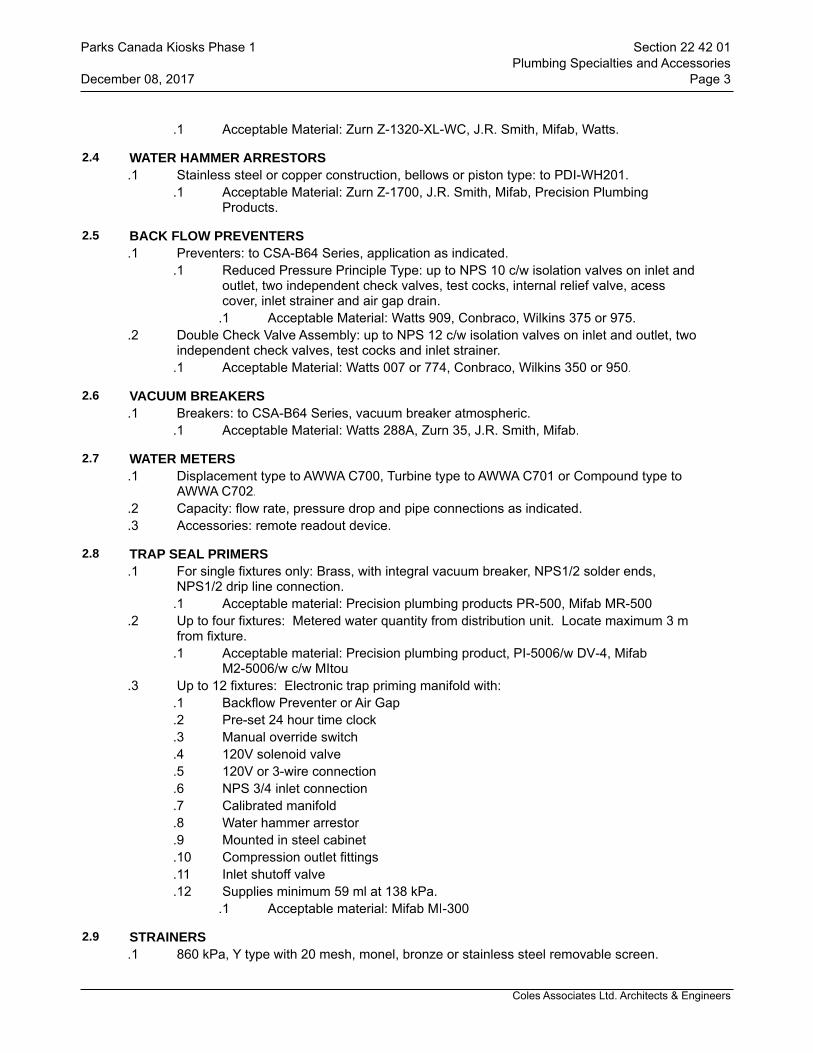
Coles Associates Ltd. Architects & Engineers
.1 Acceptable Material: Zurn Z-1320-XL-WC, J.R. Smith, Mifab, Watts.
2.4 WATER HAMMER ARRESTORS.1 Stainless steel or copper construction, bellows or piston type: to PDI-WH201.
.1 Acceptable Material: Zurn Z-1700, J.R. Smith, Mifab, Precision Plumbing Products.
2.5 BACK FLOW PREVENTERS.1 Preventers: to CSA-B64 Series, application as indicated.
.1 Reduced Pressure Principle Type: up to NPS 10 c/w isolation valves on inlet and outlet, two independent check valves, test cocks, internal relief valve, acess cover, inlet strainer and air gap drain.
.1 Acceptable Material: Watts 909, Conbraco, Wilkins 375 or 975..2 Double Check Valve Assembly: up to NPS 12 c/w isolation valves on inlet and outlet, two
independent check valves, test cocks and inlet strainer..1 Acceptable Material: Watts 007 or 774, Conbraco, Wilkins 350 or 950.
2.6 VACUUM BREAKERS.1 Breakers: to CSA-B64 Series, vacuum breaker atmospheric.
.1 Acceptable Material: Watts 288A, Zurn 35, J.R. Smith, Mifab.
2.7 WATER METERS.1 Displacement type to AWWA C700, Turbine type to AWWA C701 or Compound type to
AWWA C702..2 Capacity: flow rate, pressure drop and pipe connections as indicated..3 Accessories: remote readout device.
2.8 TRAP SEAL PRIMERS.1 For single fixtures only: Brass, with integral vacuum breaker, NPS1/2 solder ends,
NPS1/2 drip line connection..1 Acceptable material: Precision plumbing products PR-500, Mifab MR-500
.2 Up to four fixtures: Metered water quantity from distribution unit. Locate maximum 3 m from fixture.
.1 Acceptable material: Precision plumbing product, PI-5006/w DV-4, Mifab M2-5006/w c/w MItou
.3 Up to 12 fixtures: Electronic trap priming manifold with:.1 Backflow Preventer or Air Gap.2 Pre-set 24 hour time clock.3 Manual override switch.4 120V solenoid valve.5 120V or 3-wire connection.6 NPS 3/4 inlet connection.7 Calibrated manifold.8 Water hammer arrestor.9 Mounted in steel cabinet.10 Compression outlet fittings.11 Inlet shutoff valve.12 Supplies minimum 59 ml at 138 kPa.
.1 Acceptable material: Mifab MI-300
2.9 STRAINERS.1 860 kPa, Y type with 20 mesh, monel, bronze or stainless steel removable screen.
Parks Canada Kiosks Phase 1 Section 22 42 01Plumbing Specialties and Accessories
December 08, 2017 Page 3
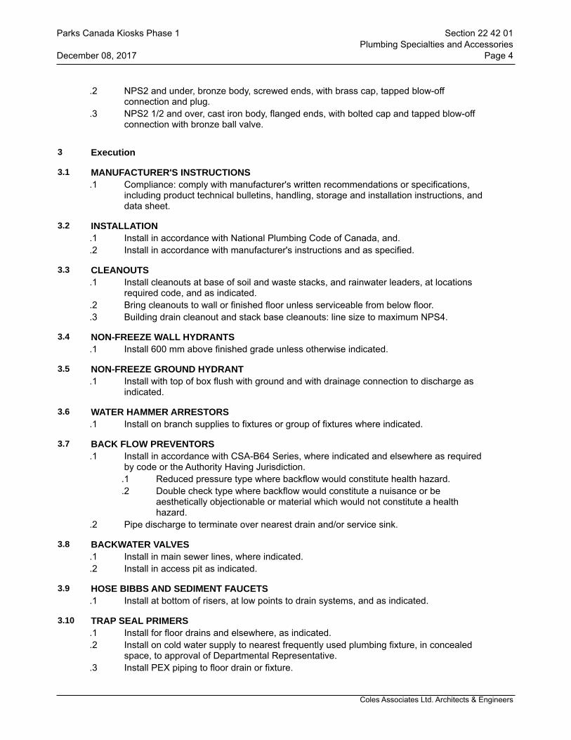
Coles Associates Ltd. Architects & Engineers
.2 NPS2 and under, bronze body, screwed ends, with brass cap, tapped blow-off connection and plug.
.3 NPS2 1/2 and over, cast iron body, flanged ends, with bolted cap and tapped blow-off connection with bronze ball valve.
3 Execution
3.1 MANUFACTURER'S INSTRUCTIONS.1 Compliance: comply with manufacturer's written recommendations or specifications,
including product technical bulletins, handling, storage and installation instructions, and data sheet.
3.2 INSTALLATION.1 Install in accordance with National Plumbing Code of Canada, and..2 Install in accordance with manufacturer's instructions and as specified.
3.3 CLEANOUTS.1 Install cleanouts at base of soil and waste stacks, and rainwater leaders, at locations
required code, and as indicated..2 Bring cleanouts to wall or finished floor unless serviceable from below floor..3 Building drain cleanout and stack base cleanouts: line size to maximum NPS4.
3.4 NON-FREEZE WALL HYDRANTS.1 Install 600 mm above finished grade unless otherwise indicated.
3.5 NON-FREEZE GROUND HYDRANT.1 Install with top of box flush with ground and with drainage connection to discharge as
indicated.
3.6 WATER HAMMER ARRESTORS.1 Install on branch supplies to fixtures or group of fixtures where indicated.
3.7 BACK FLOW PREVENTORS.1 Install in accordance with CSA-B64 Series, where indicated and elsewhere as required
by code or the Authority Having Jurisdiction..1 Reduced pressure type where backflow would constitute health hazard..2 Double check type where backflow would constitute a nuisance or be
aesthetically objectionable or material which would not constitute a health hazard.
.2 Pipe discharge to terminate over nearest drain and/or service sink.
3.8 BACKWATER VALVES.1 Install in main sewer lines, where indicated..2 Install in access pit as indicated.
3.9 HOSE BIBBS AND SEDIMENT FAUCETS.1 Install at bottom of risers, at low points to drain systems, and as indicated.
3.10 TRAP SEAL PRIMERS.1 Install for floor drains and elsewhere, as indicated..2 Install on cold water supply to nearest frequently used plumbing fixture, in concealed
space, to approval of Departmental Representative..3 Install PEX piping to floor drain or fixture.
Parks Canada Kiosks Phase 1 Section 22 42 01Plumbing Specialties and Accessories
December 08, 2017 Page 4

Coles Associates Ltd. Architects & Engineers
3.11 STRAINERS.1 Install with sufficient room to remove basket.
3.12 WATER METERS.1 Install water meter provided by local water authority..2 Install water meter as indicated.
3.13 START-UP.1 General:
.1 In accordance with Section 01 91 13 - General Commissioning Requirements: General Requirements, supplemented as specified herein.
.2 Timing: start-up only after:.1 Pressure tests have been completed..2 Disinfection procedures have been completed..3 Certificate of static completion has been issued..4 Water treatment systems operational.
.3 Provide continuous supervision during start-up.
3.14 TESTING AND ADJUSTING.1 General:
.1 In accordance with Section 01 91 13 - General Commissioning Requirements : General Requirements, supplemented as specified.
.2 Timing:.1 After start-up deficiencies rectified..2 After certificate of completion has been issued by authority having jurisdiction.
.3 Application tolerances:.1 Pressure at fixtures: +/- 70kPa..2 Flow rate at fixtures: +/- 20%.
.4 Adjustments:.1 Verify that flow rate and pressure meet design criteria..2 Make adjustments while flow rate or withdrawal is (1) maximum and (2) 25% of
maximum and while pressure is (1) maximum and (2) minimum..5 Floor drains:
.1 Verify operation of trap seal primer.
.2 Prime, using trap primer. Adjust flow rate to suit site conditions.
.3 Check operations of flushing features.
.4 Check security, accessibility, removeability of strainer.
.5 Clean out baskets..6 Vacuum breakers, backflow preventers, backwater valves:
.1 Test tightness, accessibility for O&M of cover and of valve.
.2 Simulate reverse flow and back-pressure conditions to test operation of vacuum breakers, backflow preventers.
.3 Verify visibility of discharge from open ports..7 Roof drains:
.1 Check location at low points in roof.
.2 Check security, removeability of dome.
.3 Adjust weirs to suit actual roof slopes, meet requirements of design.
.4 Clean out sumps.
.5 Verify provisions for movement of roof systems..8 Access doors:
Parks Canada Kiosks Phase 1 Section 22 42 01Plumbing Specialties and Accessories
December 08, 2017 Page 5
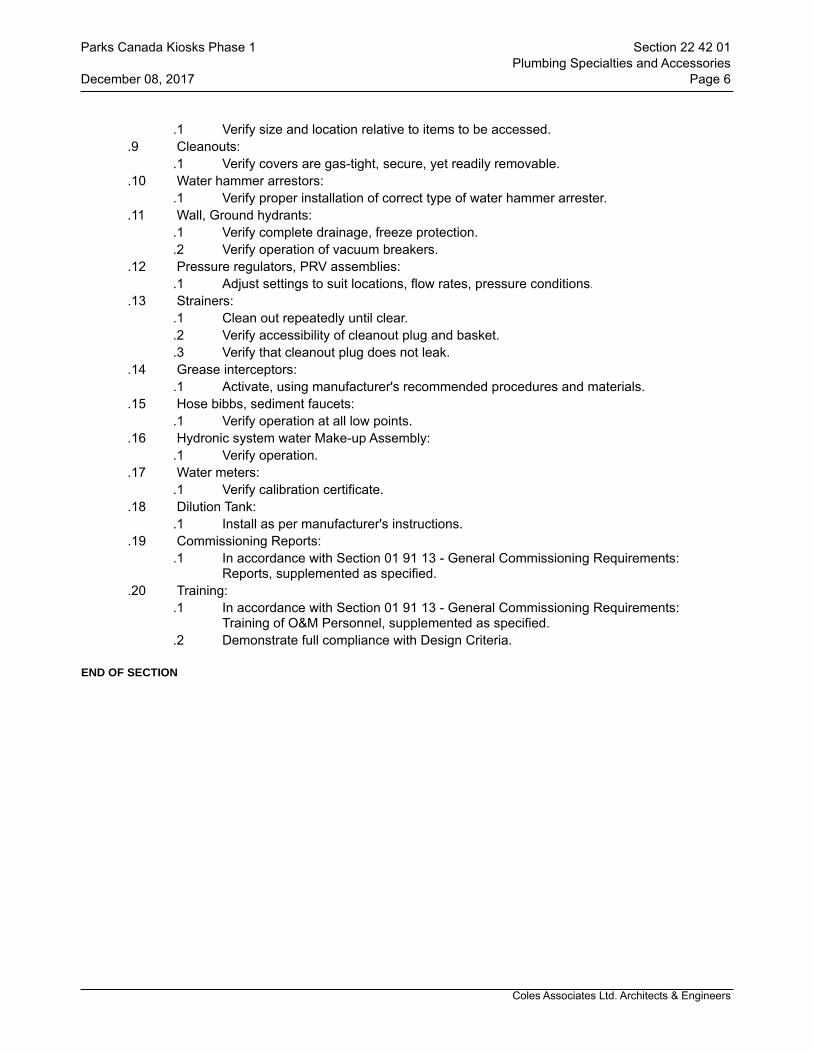
Coles Associates Ltd. Architects & Engineers
.1 Verify size and location relative to items to be accessed..9 Cleanouts:
.1 Verify covers are gas-tight, secure, yet readily removable..10 Water hammer arrestors:
.1 Verify proper installation of correct type of water hammer arrester..11 Wall, Ground hydrants:
.1 Verify complete drainage, freeze protection.
.2 Verify operation of vacuum breakers..12 Pressure regulators, PRV assemblies:
.1 Adjust settings to suit locations, flow rates, pressure conditions..13 Strainers:
.1 Clean out repeatedly until clear.
.2 Verify accessibility of cleanout plug and basket.
.3 Verify that cleanout plug does not leak..14 Grease interceptors:
.1 Activate, using manufacturer's recommended procedures and materials..15 Hose bibbs, sediment faucets:
.1 Verify operation at all low points..16 Hydronic system water Make-up Assembly:
.1 Verify operation..17 Water meters:
.1 Verify calibration certificate..18 Dilution Tank:
.1 Install as per manufacturer's instructions..19 Commissioning Reports:
.1 In accordance with Section 01 91 13 - General Commissioning Requirements: Reports, supplemented as specified.
.20 Training:.1 In accordance with Section 01 91 13 - General Commissioning Requirements:
Training of O&M Personnel, supplemented as specified..2 Demonstrate full compliance with Design Criteria.
END OF SECTION
Parks Canada Kiosks Phase 1 Section 22 42 01Plumbing Specialties and Accessories
December 08, 2017 Page 6
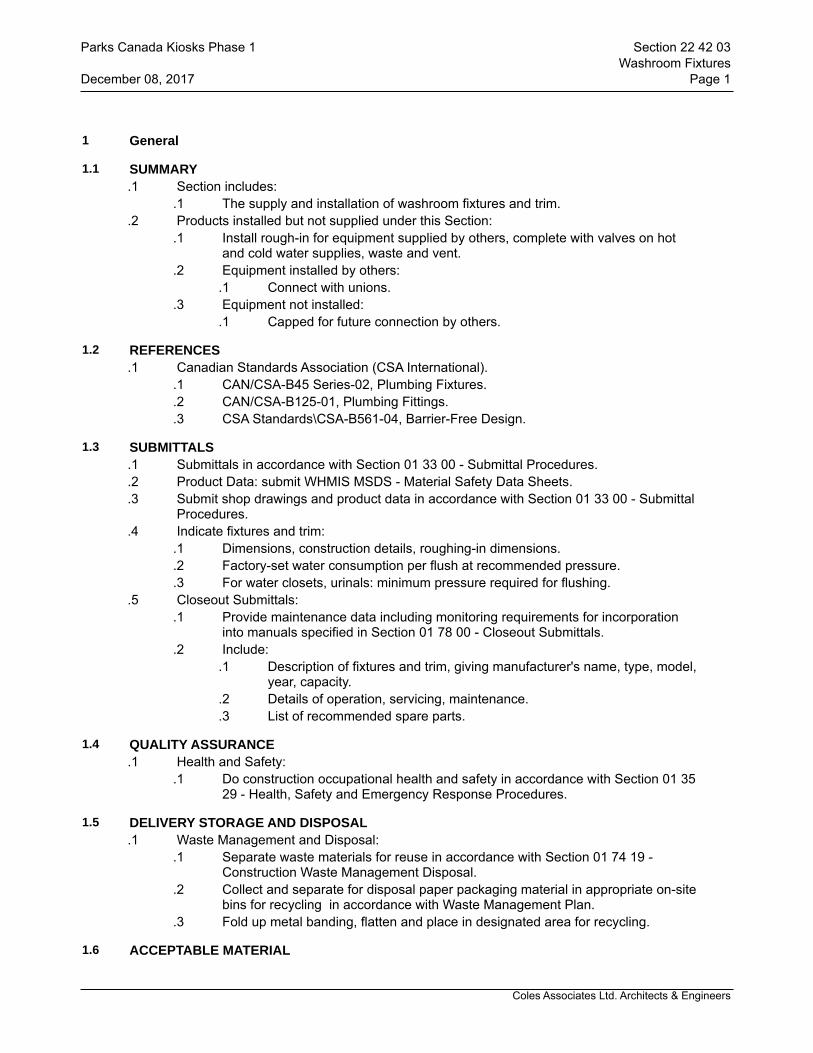
Coles Associates Ltd. Architects & Engineers
1 General
1.1 SUMMARY.1 Section includes:
.1 The supply and installation of washroom fixtures and trim..2 Products installed but not supplied under this Section:
.1 Install rough-in for equipment supplied by others, complete with valves on hot and cold water supplies, waste and vent.
.2 Equipment installed by others:.1 Connect with unions.
.3 Equipment not installed:.1 Capped for future connection by others.
1.2 REFERENCES.1 Canadian Standards Association (CSA International).
.1 CAN/CSA-B45 Series-02, Plumbing Fixtures.
.2 CAN/CSA-B125-01, Plumbing Fittings.
.3 CSA Standards\CSA-B561-04, Barrier-Free Design.
1.3 SUBMITTALS.1 Submittals in accordance with Section 01 33 00 - Submittal Procedures..2 Product Data: submit WHMIS MSDS - Material Safety Data Sheets..3 Submit shop drawings and product data in accordance with Section 01 33 00 - Submittal
Procedures..4 Indicate fixtures and trim:
.1 Dimensions, construction details, roughing-in dimensions.
.2 Factory-set water consumption per flush at recommended pressure.
.3 For water closets, urinals: minimum pressure required for flushing..5 Closeout Submittals:
.1 Provide maintenance data including monitoring requirements for incorporation into manuals specified in Section 01 78 00 - Closeout Submittals.
.2 Include:.1 Description of fixtures and trim, giving manufacturer's name, type, model,
year, capacity..2 Details of operation, servicing, maintenance..3 List of recommended spare parts.
1.4 QUALITY ASSURANCE.1 Health and Safety:
.1 Do construction occupational health and safety in accordance with Section 01 35 29 - Health, Safety and Emergency Response Procedures.
1.5 DELIVERY STORAGE AND DISPOSAL.1 Waste Management and Disposal:
.1 Separate waste materials for reuse in accordance with Section 01 74 19 -Construction Waste Management Disposal.
.2 Collect and separate for disposal paper packaging material in appropriate on-site bins for recycling in accordance with Waste Management Plan.
.3 Fold up metal banding, flatten and place in designated area for recycling.
1.6 ACCEPTABLE MATERIAL
Parks Canada Kiosks Phase 1 Section 22 42 03Washroom Fixtures
December 08, 2017 Page 1

Coles Associates Ltd. Architects & Engineers
.1 Fixtures: American Standard, AMI Novanni, Eljer, Toto, Kindred, Caroma, Kohler, Zurn.
.2 Trim: Delta, Chicago Faucets, Powers, Crane, Sloan, Zurn.
2 Products
2.1 MANUFACTURED UNITS.1 Fixtures: manufacture in accordance with CAN/CSA-B45 series..2 Trim, fittings: manufacture in accordance with CAN/CSA-B125..3 Exposed plumbing brass to be chrome plated..4 Number, locations: architectural drawings to govern..5 Fixtures in any one location to be product of one manufacturer and of same type..6 Trim in any one location to be product of one manufacturer and of same type..7 Water closets:
.1 WC : Floor-mounted, flush tank for handicapped..1 Top of seat to be between 400 mm and 460 mm from finished floor..2 Bowl: vitreous china, floor mounted, syphon jet, elongated rim, close-
coupled, bolt caps..3 Closet tank: vitreous china with tank liner, flapper type flush valve
assembly for ultra low flush cycle: factory set to 5.7 litres/flush..4 Acceptable material: American Standard Champion 4, Model 211AA 154.
.8 Water Closet Seats.1 Seat: white, elongated, open front, moulded solid plastic, less cover, stainless
steel check hinges, stainless steel insert post..2 Acceptable material: CENTOGO AM 500 ST5CC.
.9 Washroom Lavatories:.1 L-1 : Wall-hung, integral back:
.1 Vitreous china, with splash lip, soap depressions, supply openings on 200 mm centres, overflow. Size: 500 x 450mm.
.2 Acceptable material: American Standard Lucerne Model 0355.012..10 Washroom Lavatory Trim:
.1 Chrome plated brass, combination supply and waste fittings, mixing spout, washerless, aerator, metal indexed handles.
.1 Provide accessories to limit maximum flow rate to 8.35 l/minute at 413 kPa.
.2 Acceptable material: Delta 2IT132..11 Fixture piping:
.1 Hot and cold water supplies to fixtures:.1 Chrome plated flexible metal supply pipes with screw driver stop,
reducer, escutcheon..2 Waste:
.1 Brass P trap with clean out on fixtures not having integral trap.
.2 Chrome plated in exposed places.
.3 Escutcheon to properly cover all exposed pipe & fittings through the wall..12 Chair carriers:
.1 Factory manufactured floor-mounted carrier systems for wall-mounted fixtures.
.2 Acceptable material: J.R. Smith or Equal.
3 Execution
3.1 INSTALLATION
Parks Canada Kiosks Phase 1 Section 22 42 03Washroom Fixtures
December 08, 2017 Page 2
Coles Associates Ltd. Architects & Engineers
.1 Mounting heights:.1 Standard: to comply with manufacturer's recommendations unless otherwise
indicated or specified..2 Wall-hung fixtures: as indicated, measured from finished floor..3 For barrier-free washroom: to comply with most stringent of either NBCC or
CAN/CSA B651.
3.2 ADJUSTING.1 Conform to water conservation requirements specified this section..2 Adjustments:
.1 Adjust water flow rate to design flow rates.
.2 Adjust pressure to fixtures to ensure no splashing at maximum pressures.
.3 Adjust flush valves to suit actual site conditions.
.4 Adjust urinal flush timing mechanisms.
.5 Automatic flush valves for WC's and urinals: set controls to prevent unnecessary flush cycles during silent hours.
.3 Checks:.1 Water closets, urinals: flushing action..2 Aerators: operation, cleanliness..3 Vacuum breakers, backflow preventers: operation under all conditions.
.4 Thermostatic controls:.1 Verify temperature settings, operation of control, limit and safety controls.
END OF SECTION
Parks Canada Kiosks Phase 1 Section 22 42 03Washroom Fixtures
December 08, 2017 Page 3
Coles Associates Ltd. Architects & Engineers
1 General
1.1 SUMMARY.1 Section Includes:
.1 The supply and installation of drinking fountains and coolers..2 Products installed but not supplied under this Section:
.1 Install rough-in for equipment supplied by others, complete with valves on hot and cold water supplies, waste and vent.
.2 Equipment installed by others:.1 Connect with unions.
.3 Equipment not installed..1 Capped for future connection by others.
1.2 REFERENCES.1 Air-Conditioning and Refrigeration Institute (ARI).
.1 ARI 1010-02, Self-Contained, Mechanically Refrigerated Drinking-Water Coolers..2 Canadian Standards Association (CSA International).
.1 CAN/CSA-B45 Series, CSA Standards on Plumbing Fixtures.
.2 CAN/CSA-B125, Plumbing Fittings.
.3 CSA Standards\CSA-B561, Barrier-Free Design.
1.3 SUBMITTALS.1 Submittals in accordance with Section 01 33 00 - Submittal Procedures..2 Product Data: submit WHMIS MSDS - Material Safety Data Sheets..3 Submit shop drawings and product data in accordance with Section 01 33 00 - Submittal
Procedures..1 Indicate, for all fixtures:
.1 Dimensions, construction details, roughing-in dimensions..4 Closeout Submittals:
.1 Provide maintenance data including monitoring requirements for incorporation into manuals specified in Section 01 78 00 - Closeout Submittals.
.2 Include:.1 Description of fixtures and trim, giving manufacturer's name, type, model,
year, capacity..2 Details of operation, servicing, maintenance..3 List of recommended spare parts.
1.4 QUALITY ASSURANCE.1 Health and Safety:
.1 Do construction occupational health and safety in accordance with Section 01 35 29 - Health, Safety and Emergency Response Procedures.
1.5 DELIVERY STORAGE AND DISPOSAL.1 Waste Management and Disposal:
.1 Separate waste materials for reuse in accordance with Section 01 74 19 -Construction Waste Management Disposal.
.2 Collect and separate for disposal paper packaging material in appropriate on-site bins for recycling in accordance with Waste Management Plan.
.3 Fold up metal banding, flatten and place in designated area for recycling.
Parks Canada Kiosks Phase 1 Section 22 47 00Drinking Fountains and Water Coolers
December 08, 2017 Page 1
Coles Associates Ltd. Architects & Engineers
2 Products
2.1 MANUFACTURED UNITS.1 Fixtures: manufacture in accordance with CAN/CSA-B45 series..2 Trim, fittings: manufacture in accordance with CAN/CSA-B125..3 Exposed plumbing brass to be chrome plated..4 Number, locations: Architectural drawings to govern..5 Bottle Filling Station:
.1 Surface mounted bottle filling station.
.2 Mechancial activation and function, no electrical required, laminar flow provides minimal splash, fill rate of 1 gallon per minute.
.3 Meets ADA Guidelines.
.4 Lead free design meeting requirements of NSF/ANSO 61 and 372..6 Fixture piping:
.1 Cold water supplies to each fixture:.1 Shut-off valve in supply pipes to each fixture with reducers and
escutcheon..2 Waste:
.1 Brass P trap with cleanout on each fixture not having integral trap.
.2 Chrome plated in all exposed places..7 Chair carriers:
.1 Factory manufactured floor-mounted carrier systems for all wall-mounted fixtures.
3 Execution
3.1 INSTALLATION.1 Mounting heights:
.1 Standard: to comply with manufacturer's recommendations unless otherwise indicated or specified.
.2 Wall-hung fixtures: measured from finished floor.
.3 Physically handicapped: to comply with most stringent of either NBCC, CAN/CSA B651, or Provincial Building Code Accessibility Act or Regulations.
.2 Drinking fountains and water coolers :.1 In accordance with ARI 1010.
3.2 ADJUSTING.1 Conform to water conservation requirements specified this Section..2 Adjustments:
.1 Adjust water flow rate to design flow rates.
.2 Adjust water cooler, drinking fountain flow stream to ensure no spillage..3 Checks.
.1 Refrigerated water coolers: operation, temperature settings..4 Thermostatic controls.
.1 Verify temperature settings, operation of control, limit and safety controls.
END OF SECTION
Parks Canada Kiosks Phase 1 Section 22 47 00Drinking Fountains and Water Coolers
December 08, 2017 Page 2
Coles Associates Ltd. Architects & Engineers
1 General
1.1 SUBMITTALS.1 Submittals: in accordance with Section 01 33 00 - Submittal Procedures..2 Shop drawings; submit drawings stamped and signed for review by Departmental
Representative..3 Shop drawings to show:
.1 Mounting arrangements.
.2 Operating and maintenance clearances..4 Shop drawings and product data accompanied by:
.1 Detailed drawings of bases, supports, and anchor bolts.
.2 Acoustical sound power data, where applicable.
.3 Points of operation on performance curves.
.4 Manufacturer to certify current model production.
.5 Certification of compliance to applicable codes..5 In addition to transmittal letter referred to in Section 01 33 00 - Submittal Procedures:
use MCAC "Shop Drawing Submittal Title Sheet". Identify section and paragraph number.
.6 Closeout Submittals:.1 Provide operation and maintenance data for incorporation into manual specified
in Section 01 78 00 - Closeout Submittals..2 Operation and maintenance manual approved by, and final copies deposited
with, Departmental Representative before final inspection..3 Operation data to include:
.1 Control schematics for systems including environmental controls.
.2 Description of systems and their controls.
.3 Description of operation of systems at various loads together with reset schedules and seasonal variances.
.4 Operation instruction for systems and component.
.5 Description of actions to be taken in event of equipment failure.
.6 Valves schedule and flow diagram.
.7 Colour coding chart..4 Maintenance data to include:
.1 Servicing, maintenance, operation and trouble-shooting instructions for each item of equipment.
.2 Data to include schedules of tasks, frequency, tools required and task time.
.5 Performance data to include:.1 Equipment manufacturer's performance datasheets with point of
operation as left after commissioning is complete..2 Equipment performance verification test results..3 Special performance data as specified..4 Testing, adjusting and balancing reports as specified in Section 23 05 93
- Testing, Adjusting and Balancing for HVAC..6 Approvals:
.1 Submit 2 copies of draft Operation and Maintenance Manual to Departmental Representative for approval. Submission of individual data will not be accepted unless directed by Departmental Representative.
.2 Make changes as required and re-submit as directed by Departmental Representative.
Parks Canada Kiosks Phase 1 Section 23 05 00Common Work Results for HVAC
December 08, 2017 Page 1

Coles Associates Ltd. Architects & Engineers
.7 Additional data:.1 Prepare and insert into operation and maintenance manual additional
data when need for it becomes apparent during specified demonstrations and instructions.
.8 Site records:.1 Departmental Representative will provide 1 set of reproducible
mechanical drawings. Provide sets of white prints as required for each phase of work. Mark changes as work progresses and as changes occur. Include changes to existing mechanical systems, control systems and low voltage control wiring.
.2 Transfer information weekly to reproducibles, revising reproducibles to show work as actually installed.
.3 Use different colour waterproof ink for each service.
.4 Make available for reference purposes and inspection..9 As-built drawings:
.1 Prior to start of Testing, Adjusting and Balancing for HVAC, finalize production of as-built drawings.
.2 Identify each drawing in lower right hand corner in letters at least 12 mm high as follows: - "AS BUILT DRAWINGS: THIS DRAWING HAS BEEN REVISED TO SHOW MECHANICAL SYSTEMS AS INSTALLED" (Signature of Contractor) (Date).
.3 Submit to Departmental Representative for approval and make corrections as directed.
.4 Perform testing, adjusting and balancing for HVAC using as-built drawings.
.5 Submit completed reproducible as-built drawings with Operating and Maintenance Manuals.
.10 Submit copies of as-built drawings for inclusion in final TAB report.
1.2 QUALITY ASSURANCE.1 Quality Assurance: in accordance with Section 01 45 00 - Quality Control..2 Health and Safety Requirements: do construction occupational health and safety in
accordance with Section 01 35 29 - Health, Safety and Emergency Response Procedures.
1.3 MAINTENANCE.1 Furnish spare parts in accordance with Section 01 78 00 - Closeout Submittals as
follows:.1 One set of packing for each pump..2 One casing joint gasket for each size pump..3 One head gasket set for each heat exchanger..4 One glass for each gauge glass..5 One filter cartridge or set of filter media for each filter or filter bank in addition to
final operating set..2 Provide one set of special tools required to service equipment as recommended by
manufacturers and in accordance with Section 01 78 00 - Closeout Submittals..3 Furnish one commercial quality grease gun, grease and adapters to suit different types
of grease and grease fittings.
1.4 DELIVERY, STORAGE, AND HANDLING.1 Waste Management and Disposal:
.1 Construction/Demolition Waste Management and Disposal: separate waste
Parks Canada Kiosks Phase 1 Section 23 05 00Common Work Results for HVAC
December 08, 2017 Page 2
Coles Associates Ltd. Architects & Engineers
materials for reuse in accordance with Section 01 74 00 - Cleaning and Waste Management.
2 Products
2.1 MATERIALS.1 All materials used on this project shall be new and CSA approved unless noted
otherwise.
3 Execution
3.1 PAINTING REPAIRS AND RESTORATION.1 Do painting in accordance with Section 09 91 00 - Painting..2 Prime and touch up marred finished paintwork to match original..3 Restore to new condition, finishes which have been damaged.
3.2 CLEANING.1 Clean interior and exterior of all systems including strainers. Vacuum interior of ductwork
and air handling units. Protect open ends of ducts, diffusers, grilles and registers during construction to prevent ingress of dust and dirt into interior of ducts.
3.3 FIELD QUALITY CONTROL.1 Site Tests: conduct following tests in accordance with Section 01 45 00 - Quality Control
and submit report as described in PART 1 - SUBMITTALS..1 Submit tests as specified in other sections of this specification.
.2 Manufacturer's Field Services:.1 Obtain written report from manufacturer verifying compliance of Work, in
handling, installing, applying, protecting and cleaning of product and submit Manufacturer's Field Reports as described in PART 1 - SUBMITTALS.
.2 Provide manufacturer's field services consisting of product use recommendations and periodic site visits for inspection of product installation in accordance with manufacturer's instructions.
.3 Schedule site visits, to review Work, as directed in PART 1 - QUALITY ASSURANCE.
3.4 DEMONSTRATION.1 Departmental Representative will use equipment and systems for test purposes prior to
acceptance. Supply labour, material, and instruments required for testing..2 Supply tools, equipment and personnel to demonstrate and instruct operating and
maintenance personnel in operating, controlling, adjusting, trouble-shooting and servicing of all systems and equipment during regular work hours, prior to acceptance.
.3 Use operation and maintenance manual, as-built drawings, and audio visual aids as part of instruction materials.
.4 Instruction duration time requirements as specified in appropriate sections.
.5 Departmental Representative will record these demonstrations on video tape for future reference.
3.5 PROTECTION.1 Protect equipment and systems openings from dirt, dust, and other foreign materials with
materials appropriate to system.
END OF SECTION
Parks Canada Kiosks Phase 1 Section 23 05 00Common Work Results for HVAC
December 08, 2017 Page 3
Coles Associates Ltd. Architects & Engineers
1 General
1.1 REFERENCES.1 Canadian General Standards Board (CGSB)
.1 CAN/CGSB-1.181-99, Ready-Mixed Organic Zinc-Rich Coating.
1.2 WASTE MANAGEMENT AND DISPOSAL.1 Separate and recycle waste materials in accordance with Section 01 74 19 -
Construction Waste Management Disposal..2 Remove from site and dispose of packaging materials at appropriate recycling facilities..3 Collect and separate for disposal paper packaging material in appropriate on-site for
recycling in accordance with Waste Management Plan..4 Divert unused metal materials from landfill to metal recycling facility approved by
Departmental Representative.
2 Products
2.1 NOT USED.1 Not Used.
3 Execution
3.1 CONNECTIONS TO EQUIPMENT.1 In accordance with manufacturer's instructions unless otherwise indicated..2 Use valves and either unions or flanges for isolation and ease of maintenance and
assembly..1 Unions are not required in installations using grooved mechanical couplings (the
coupling shall serve as the union)..3 Use double swing joints when equipment mounted on vibration isolation and when piping
subject to movement..4 The flexible ground joint couplings may be used in lieu of a flexible connector at
equipment connections for vibration attenuation and stress relief, coupling shall be placed in close proximity to the source of vibration.
3.2 CLEARANCES.1 Provide clearance around systems, equipment and components for observation of
operation, inspection, servicing, maintenance and as recommended by manufacturer..2 Provide space for disassembly, removal of equipment and components as
recommended by manufacturer or as indicated (whichever is greater) without interrupting operation of other system, equipment, components.
3.3 DRAINS.1 Install piping with grade in direction of flow except as indicated..2 Install drain valve at low points in piping systems, at equipment and at section isolating
valves..3 Pipe each drain valve discharge separately to above floor drain. Discharge to be visible..4 Drain valves: NPS 3/4 gate or globe valves unless indicated otherwise, with hose end
male thread, cap and chain.
3.4 AIR VENTS.1 Install automatic air vents at high points in piping systems.
Parks Canada Kiosks Phase 1 Section 23 05 01Installation of Pipework
December 08, 2017 Page 1
Coles Associates Ltd. Architects & Engineers
.2 Install isolating valve at each automatic air valve.
.3 Install drain piping to approved location and terminate where discharge is visible.
3.5 DIELECTRIC COUPLINGS.1 General: Compatible with system, to suit pressure rating of system..2 Locations: Where dissimilar metals are joined..3 NPS 2 and under: isolating unions or bronze valves.
.1 Waterway fittings shall be complete with thermoplastic liner..4 Over NPS 2: Isolating flanges.
.1 Waterway fittings shall be complete with thermoplastic liner.
3.6 PIPEWORK INSTALLATION.1 Installed by certified journey person..2 Screwed fittings jointed with Teflon tape..3 Protect openings against entry of foreign material..4 Grooved joint couplings and fittings shall be installed in accordance with the
manufacturer's written installation instructions..1 Gaskets shall be verified as suitable for the intended service prior to installation.
Gaskets shall be molded and produced by the coupling manufacturer..2 The grooved coupling manufacturer's factory trained representative shall provide
on-site training for contractor's field personnel in the use of grooving tools, application of groove, and installation of grooved joint products. The manufacturer's representative shall periodically visit the jobsite and review installation. Contractor shall remove and replace any joints deemed improperly installed.
.5 Push-to-connect piping: Prepare copper tube and install in strict accordance with installation instructions. Pipe ends shall be cleaned, free from indentations, projections, burrs and foreign matter. Use a tube preparation tool as supplied by the manufacturer to clean and make installation mark. Push copper tube into fittings to installation depth mark, per installation instructions. Keep fittings free of dirt and oil.
.6 Saddle type branch fittings may be used on mains if branch line is no larger than half the size of main.
.1 Hole saw (or drill) and ream main to maintain full inside diameter of branch line prior to welding saddle.
.7 Install exposed piping, equipment, rectangular cleanouts and similar items parallel or perpendicular to building lines.
.8 Install concealed pipework to minimize furring space, maximize headroom, conserve space.
.9 Slope piping, except where indicated, in direction of flow for positive drainage and venting.
.10 Install, except where indicated, to permit separate thermal insulation of each pipe.
.11 Group piping wherever possible and as indicated.
.12 Ream pipes, remove scale and other foreign material before assembly.
.13 Use eccentric reducers at pipe size changes to ensure positive drainage and venting.
.14 Provide for thermal expansion as indicated.
.15 Valves:.1 Install in accessible locations..2 Remove interior parts before soldering..3 Install with stems above horizontal position unless otherwise indicated..4 Valves accessible for maintenance without removing adjacent piping..5 Install globe valves in bypass around control valves.
Parks Canada Kiosks Phase 1 Section 23 05 01Installation of Pipework
December 08, 2017 Page 2
Coles Associates Ltd. Architects & Engineers
.6 Use ball or butterfly valves at branch take-offs for isolating purposes except where otherwise specified.
.7 Install butterfly valves on chilled water and related condenser water systems only.
.8 Install butterfly valves between weld neck flanges to ensure full compression of liner.
.9 Install ball valves for glycol service.
.10 Use chain operators on valves NPS 2-1/2 and larger where installed more than 2400 mm above floor in Mechanical Rooms.
.16 Check Valves:.1 Install silent check valves on discharge of pumps and in vertical pipes with
downward flow and elsewhere as indicated..2 Install swing check valves in horizontal lines on discharge of pumps and
elsewhere as indicated.
3.7 SLEEVES.1 General: Install where pipes pass through masonry, concrete structures, fire rated
assemblies, and elsewhere as indicated..2 Material: Schedule 40 black steel pipe..3 Construction: Foundation walls and where sleeves extend above finished floors to have
annular fins continuously welded on at mid-point..4 Sizes: 6 mm minimum clearance between sleeve and uninsulated pipe or between
sleeve and insulation..5 Installation:
.1 Concrete, masonry walls, concrete floors on grade: Terminate flush with finished surface.
.2 Other floors: Terminate 25 mm above finished floor.
.3 Before installation, paint exposed exterior surfaces with heavy application of zinc-rich paint to CAN/CGSB-1.181.
.6 Sealing:.1 Foundation walls and below grade floors: Fire retardant, waterproof non-
hardening mastic..2 Elsewhere: Provide space for firestopping. Maintain fire rating integrity..3 Sleeves installed for future use: Fill with lime plaster or other easily removable
filler..4 Ensure no contact between copper pipe or tube and sleeve.
3.8 ESCUTCHEONS.1 Install on pipes passing through walls, partitions, floors, and ceilings in finished areas..2 Construction: One piece type with set screws. Chrome or nickel plated brass or type 302
stainless steel..3 Sizes: Outside diameter to cover opening or sleeve. Inside diameter to fit around pipe or
outside of insulation if so provided.
3.9 PREPARATION FOR FIRESTOPPING.1 Material and installation within annular space between pipes, ducts, insulation and
adjacent fire separation to Section 07 84 00 - Firestopping..2 Uninsulated unheated pipes not subject to movement: No special preparation..3 Uninsulated heated pipes subject to movement: Wrap with non-combustible smooth
material to permit pipe movement without damaging firestopping material or installation..4 Insulated pipes and ducts: Ensure integrity of insulation and vapour barriers.
Parks Canada Kiosks Phase 1 Section 23 05 01Installation of Pipework
December 08, 2017 Page 3
Coles Associates Ltd. Architects & Engineers
3.10 FLUSHING OUT OF PIPING SYSTEMS.1 In accordance with Section 23 08 02 - Cleaning and Start-up of Mechanical Piping
Systems..2 Before start-up, clean interior of piping systems in accordance with requirements of
Section 01 74 00 - Cleaning and Waste Management, supplemented as specified in relevant sections of Division 23.
.3 Preparatory to acceptance, clean and refurbish equipment and leave in operating condition, including replacement of filters in piping systems.
3.11 PRESSURE TESTING OF EQUIPMENT AND PIPEWORK.1 Advise Departmental Representative 48 hours minimum prior to performance of
pressure tests..2 Pipework: Test as specified in relevant sections of Division 23..3 Maintain specified test pressure without loss for 4 hours minimum unless specified for
longer period of time in relevant sections of Division 23..4 Prior to tests, isolate equipment and other parts which are not designed to withstand test
pressure or media..5 Conduct tests in presence of Departmental Representative. Work to be carried out in off
hours after 5 p.m., weekends or holidays..6 Pay costs for repairs or replacement, retesting, and making good. Departmental
Representative to determine whether repair or replacement is appropriate..7 Insulate or conceal work only after approval and certification of tests by Departmental
Representative.
3.12 EXISTING SYSTEMS.1 Connect into existing piping systems at times approved by Departmental
Representative. Work to be carried out in off hours after 5 p.m., weekends or holidays..2 Request written approval 10 days minimum, prior to commencement of work..3 Be responsible for damage to existing plant by this work..4 Ensure daily clean-up of existing areas.
END OF SECTION
Parks Canada Kiosks Phase 1 Section 23 05 01Installation of Pipework
December 08, 2017 Page 4
Coles Associates Ltd. Architects & Engineers
1 General
1.1 SUMMARY.1 Section Includes:
.1 Electrical motors, drives and guards for mechanical equipment and systems.
.2 Supplier and installer responsibility indicated in Motor, Control and Equipment Schedule on electrical drawings and related mechanical responsibility is indicated on Mechanical Equipment Schedule on mechanical drawings.
.3 Control wiring and conduit is specified in Division 26 except for conduit, wiring and connections below 50 V which are related to control systems specified in Division 22 and 23. Refer to Division 26 for quality of materials and workmanship.
1.2 REFERENCES.1 American Society of Heating, Refrigeration and Air-Conditioning Engineers (ASHRAE)
.1 ASHRAE 90.1, Energy Standard for Buildings Except Low-Rise Residential Buildings (IESNA cosponsored; ANSI approved; Continuous Maintenance Standard).
.2 Electrical Equipment Manufacturers' Association Council (EEMAC)
.3 Health Canada/Workplace Hazardous Materials Information System (WHMIS).1 Material Safety Data Sheets (MSDS).
1.3 SUBMITTALS.1 Submittals: in accordance with Section 01 33 00 - Submittal Procedures..2 Product Data:
.1 Submit manufacturer's printed product literature, specifications and datasheet in accordance with Section 01 33 00 - Submittal Procedures. Include product characteristics, performance criteria, and limitations.
.1 Submit two copies of Workplace Hazardous Materials Information System (WHMIS) Material Safety Data Sheets (MSDS) in accordance with Section 01 33 00 - Submittal Procedures.
.2 Shop Drawings: submit drawings stamped and signed by professional engineer registered or licensed in Province of work.
.3 Closeout Submittals.1 Provide maintenance data for motors, drives and guards for
incorporation into manual specified in Section 01 78 00 - Closeout Submittals.
1.4 QUALITY ASSURANCE.1 Regulatory Requirements: work to be performed in compliance with CEPA..2 Health and Safety Requirements: do construction occupational health and safety in
accordance with Section 01 35 29 - Health, Safety and Emergency Response Procedures.
1.5 DELIVERY, STORAGE, AND HANDLING.1 Packing, shipping, handling and unloading:
.1 Deliver, store and handle in accordance with Section 01 61 00 - Common Product Requirements.
.2 Deliver, store and handle materials in accordance with manufacturer's written instructions.
.2 Waste Management and Disposal:.1 Construction/Demolition Waste Management and Disposal: separate waste
Parks Canada Kiosks Phase 1 Section 23 05 13Common Motor Requirements for HVAC Equipment
December 08, 2017 Page 1
Coles Associates Ltd. Architects & Engineers
materials for reuse in accordance with Section 01 74 19 - Construction Waste Management Disposal.
2 Products
2.1 GENERAL.1 Motors: premium efficiency, in accordance with local utility company standards and to
ASHRAE 90.1.
2.2 MOTORS.1 Provide motors for mechanical equipment as specified..2 Motors under 560 W (3/4 HP): speed as indicated, continuous duty, built-in overload
protection, resilient mount, single phase, 120 V, unless otherwise specified or indicated..3 Motors 560 W (3/4 HP) and larger: EEMAC Class B, squirrel cage induction, speed as
indicated, continuous duty, drip proof, ball bearing, maximum temperature rise 40 degrees C, 3 phase, 208 V, unless otherwise specified or indicated.
2.3 TEMPORARY MOTORS.1 If delivery of specified motor will delay completion or commissioning work, install motor
approved by Departmental Representative for temporary use. Work will only be accepted when specified motor is installed.
2.4 BELT DRIVES.1 Fit reinforced belts in sheave matched to drive. Multiple belts to be matched sets..2 Use cast iron or steel sheaves secured to shafts with removable keys unless otherwise
indicated..3 For motors under 10 HP : standard adjustable pitch drive sheaves, having plus or minus
10% range. Use mid-position of range for specified r/min..4 For motors 10 HP and over: sheave with split tapered bushing and keyway having fixed
pitch unless specifically required for item concerned. Provide sheave of correct size to suit balancing.
.5 Correct size of sheave determined during commissioning.
.6 Minimum drive rating: 1.5 times nameplate rating on motor. Keep overhung loads within manufacturer's design requirements on prime mover shafts.
.7 Motor slide rail adjustment plates to allow for centre line adjustment.
.8 Supply one set of spare belts for each set installed in accordance with Section 01 78 00 - Closeout Submittals.
2.5 DRIVE GUARDS.1 Provide guards for unprotected drives..2 Guards for belt drives;
.1 Expanded metal screen welded to steel frame.
.2 Minimum 1.2 mm thick sheet metal tops and bottoms.
.3 38 mm dia holes on both shaft centres for insertion of tachometer.
.4 Removable for servicing..3 Provide means to permit lubrication and use of test instruments with guards in place..4 Install belt guards to allow movement of motors for adjusting belt tension.-.5 Guard for flexible coupling:
.1 "U" shaped, minimum 1.6 mm thick galvanized mild steel.
.2 Securely fasten in place.
.3 Removable for servicing..6 Unprotected fan inlets or outlets:
Parks Canada Kiosks Phase 1 Section 23 05 13Common Motor Requirements for HVAC Equipment
December 08, 2017 Page 2
Coles Associates Ltd. Architects & Engineers
.1 Wire or expanded metal screen, galvanized, 19 mm mesh.
.2 Net free area of guard: not less than 80% of fan openings.
.3 Securely fasten in place.
.4 Removable for servicing.
3 Execution
3.1 MANUFACTURER'S INSTRUCTIONS.1 Compliance: comply with manufacturer's written recommendations or specifications,
including product technical bulletins, handling, storage and installation instructions, and datasheet.
3.2 INSTALLATION.1 Fasten securely in place..2 Make removable for servicing, easily returned into, and positively in position.
3.3 FIELD QUALITY CONTROL.1 Site Tests: conduct following tests in accordance with Section 01 45 00 - Quality Control
and submit report as described in PART 1 - SUBMITTALS..1 As specified in other sections of this specification.
.2 Manufacturer's Field Services:.1 Obtain written report from manufacturer verifying compliance of Work, in
handling, installing, applying, protecting and cleaning of product and submit Manufacturer's Field Reports as described in PART 1 - SUBMITTALS.
.2 Provide manufacturer's field services consisting of product use recommendations and periodic site visits for inspection of product installation in accordance with manufacturer's instructions.
.3 Schedule site visits, to review Work, as directed in PART 1 - QUALITY ASSURANCE.
3.4 CLEANING.1 Proceed in accordance with Section 01 74 00 - Cleaning and Waste Management..2 Upon completion and verification of performance of installation, remove surplus
materials, excess materials, rubbish, tools and equipment.
END OF SECTION
Parks Canada Kiosks Phase 1 Section 23 05 13Common Motor Requirements for HVAC Equipment
December 08, 2017 Page 3

Coles Associates Ltd. Architects & Engineers
1 General
1.1 SECTION INCLUDES.1 Materials and installation for thermometers and pressure gauges in piping systems.
1.2 RELATED SECTIONS.1 Section 23 05 54 - Mechanical Identification.
1.3 REFERENCES.1 American Society of Mechanical Engineers (ASME).
.1 ASME B40.100, Pressure Gauges and Gauge Attachments.
.2 ASME B40.200, Thermometers, Direct Reading and Remote Reading..2 Canadian General Standards Board (CGSB).
.1 CAN/CGSB-14.4, Thermometers, Liquid-in-Glass, Self Indicating, Commercial/Industrial Type.
.2 CAN/CGSB-14.5, Thermometers, Bimetallic, Self-Indicating, Commercial/Industrial Type.
1.4 SUBMITTALS.1 Submittals in accordance with Section 01 33 00 - Submittal Procedures..2 Submit manufacturer's product data for following items:
.1 Thermometers.
.2 Pressure gauges.
.3 Stop cocks.
.4 Syphons.
.5 Wells..3 Product Data:
.1 Submit manufacturer's printed product literature, specifications and datasheet in accordance with Section 01 33 00 - Submittal Procedures. Include product characteristics, performance criteria, and limitations.
1.5 WASTE MANAGEMENT AND DISPOSAL.1 Separate waste materials for reuse and recycling in accordance with Section 01 74 19 -
Construction Waste Management Disposal..2 Collect, separate and place in designated containers for reuse and recycling, paper,
plastic, polystyrene, corrugated cardboard packaging, steel, metal, in accordance with Waste Management Plan.
.3 Fold up metal banding, flatten and place in designated area for recycling.
.4 Place materials defined as hazardous or toxic waste in designated containers.
.5 Ensure emptied containers are sealed, labelled and stored safely for disposal away from children.
2 Products
2.1 GENERAL.1 Design point to be at mid point of scale or range..2 Ranges: as indicated.
2.2 DIRECT READING THERMOMETERS.1 Industrial, variable angle type, liquid filled, accuracy +/- scale division 225 mm scale
length: to CAN/CGSB14.4 or ASME B 40, 200.
Parks Canada Kiosks Phase 1 Section 23 05 21Thermometers and Pressure Gauges - Piping Systems
December 08, 2017 Page 1

Coles Associates Ltd. Architects & Engineers
.1 Acceptable material: Trerice, Ashcroft, Wika, Winters, Marsh.
2.3 THERMOMETER WELLS.1 Copper pipe: copper or bronze..2 Steel pipe: brass.
2.4 REMOTE READING THERMOMETERS.1 100mm diameter liquid filled or vapor activated dial type: to CAN/CG SB - 14.4 or ASME
B40-200, accuracy within one scale division. Brass movement, stainless steel capillary, stainless steel spiral armour, stainless steel bulb, and polished brass or stainless steel case for wall mounting.
.1 Acceptable material: Trerice, Ashcroft, Wika, Winters, Marsh.
2.5 PRESSURE GAUGES.1 Dial type 112 mm, dial type: to ASME B40.100, Grade 2A, stainless steel or phosphor
bronze bourdon tube having 0.5% accuracy full scale, 1% accuracy for liquid filled..1 Acceptable material: Trerice, Ashcroft, Wika, Winters, Marsh.
.2 Provide bronze stop cock and :.1 Siphon for steam service..2 Snubber for pulsating operation..3 Diaphragm assembly for corrosive service..4 Gasketed pressure relief back with solid front..5 Oil filled for high vibration applications such as pumps..6 Bronze ball valve to Section 23 05 22 - Valves - Bronze.
3 Execution
3.1 GENERAL.1 Install so they can be easily read from floor or platform. If this cannot be accomplished,
install remote reading units..2 Install between equipment and first fitting or valve.
3.2 THERMOMETERS.1 Install in wells on piping arrange so that at least 25mm (1") of the stem of the
thermometer is immersed in flowing fluid. Provide heat conductive material inside well..2 Install on inlet and outlet of equipment:
.1 Heat exchangers.
.2 Heating and cooling coils.
.3 Boilers.
.4 Chillers.
.5 Cooling towers, closed circuit coolers and evaporative condensers
.6 DHW tanks..3 Install wells in other locations as indicated..4 Use extensions where thermometers are installed through insulation.
3.3 PRESSURE GAUGES.1 Install in following locations:
.1 Suction and discharge of pumps (liquid filled).
.2 Upstream and downstream of PRV's.
.3 Upstream and downstream of control valves.
.4 Inlet and outlet of coils.
Parks Canada Kiosks Phase 1 Section 23 05 21Thermometers and Pressure Gauges - Piping Systems
December 08, 2017 Page 2

Coles Associates Ltd. Architects & Engineers
.5 Inlet and outlet of heat exchanger.
.6 Outlet of boilers.
.7 In other locations as indicated..2 Install ball valves to Section 23 05 22 - Valves - Bronze..3 Use extensions where pressure gauges are installed through insulation.
3.4 NAMEPLATES.1 Install engraved lamicoid nameplates as specified in Section 23 05 54 - Mechanical
Identification, identifying medium.
END OF SECTION
Parks Canada Kiosks Phase 1 Section 23 05 21Thermometers and Pressure Gauges - Piping Systems
December 08, 2017 Page 3
Coles Associates Ltd. Architects & Engineers
1 General
1.1 SUMMARY.1 Section Includes:
.1 Bronze - valves.
1.2 RELATED SECTIONS.1 Section 23 05 01 - Installation of Pipework.
1.3 REFERENCES.1 American National Standards Institute (ANSI)/ American Society of Mechanical
Engineers (ASME)..1 ANSI/ASME B1.20.1 (R2001), Pipe Threads, General Purpose (Inch)..2 ANSI/ASME B16.18, Cast Copper Alloy Solder Joint Pressure Fittings..3 ANSI/ASME B16-22 Wrought Copper and Copper Alloy Soldier Joint Pressure
Fittings..2 American Society for Testing and Materials International, (ASTM).
.1 ASTM A276, Specification for Stainless Steel Bars and Shapes.
.2 ASTM A536, Specifications for Ductile Iron Castings.
.3 ASTM B62, Specification for Composition Bronze or Ounce Metal Castings.
.4 ASTM B16 Specifications for free cutting brass rod bar and shaps for use in screw machines.
.5 ASTM B283, Specification for Copper and Copper Alloy Die Forgings (Hot-Pressed).
.6 ASTM B505/B505M, Specification for Copper-Base Alloy Continuous Castings..3 Manufacturers Standardization Society of the Valve and Fittings Industry, Inc. (MSS).
.1 MSS-SP-25, Standard Marking System for Valves, Fittings, Flanges and Unions.
.2 MSS-SP-80, Bronze Gate Globe, Angle and Check Valves.
.3 MSS-SP-110, Ball Valves, Threaded, Socket-Welding, Solder Joint, Grooved and Flared Ends.
.4 Canadian Standards Association (CSA).1 CSA B242, Groove and Solder type mechanical pipe couplings.
1.4 SUBMITTALS.1 Submittals in accordance with Section 01 33 00 - Submittal Procedures..2 Product Data: submit WHMIS MSDS - Material Safety Data Sheets.
.1 Submit shop drawings and product data in accordance with Section 01 33 00 -Submittal Procedures.
.2 Submit data for valves specified in this section.
.3 Groove joint couplings and fittings to be indicated on product submittals and to be specifically identified with applicable style or series designation.
.3 Closeout Submittals:.1 Submit maintenance data for incorporation into manual specified in Section 01
78 00 - Closeout Submittals.
1.5 QUALITY ASSURANCE.1 Health and Safety:
.1 Do construction occupational health and safety in accordance with Section 01 35 29 - Health, Safety and Emergency Response Procedures.
1.6 DELIVERY STORAGE AND DISPOSAL
Parks Canada Kiosks Phase 1 Section 23 05 22Valves - Bronze
December 08, 2017 Page 1
Coles Associates Ltd. Architects & Engineers
.1 Waste Management and Disposal:.1 Separate and recycle waste materials in accordance with Section 01 74 19 -
Construction Waste Management Disposal..2 Collect and separate for disposal paper packaging material in appropriate on-site
bins for recycling in accordance with Waste Management Plan.
1.7 MAINTENANCE.1 Extra Materials:.2 Furnish following spare parts:
.1 Valve seats: one for every 10 valves each size, minimum 1.
.2 Discs: one for every 10 valves, each size. Minimum 1.
.3 Stem packing: one for every 10 valves, each size. Minimum 1.
.4 Valve handles: 2 of each size.
.5 Gaskets for flanges: one for every 10 flanged joints.
.6 Grooved Couplings: IPS and copper tube dimensions, one for every 10 (ten) ground joints.
2 Products
2.1 MATERIALS.1 Valves:
.1 Except for specialty valves, to be single manufacturer.
.2 All products to have CRN registration numbers..2 End Connections:
.1 Connection into adjacent piping/tubing:.1 Steel pipe systems: Screwed ends to ANSI/ASME B1.20.1..2 Copper tube systems:
.1 Solder ends to ANSI/ASME B16.18.
.2 Grooved ends to copper tube dimension and CSMB242
.3 Push-to-connect ends to ANSI/ASME B16.22 and manufacturers standards.
.3 Lockshield Keys:.1 Where lockshield valves are specified, provide 10 keys of each size: malleable
iron
2.2 CHECK VALVES.1 Requirements common to check valves, unless specified otherwise:
.1 Standard specification: MSS SP-80.
.2 Connections: screwed with hexagonal shoulders..1 Class 125, WP = 860 kPa (125 psi) 1.4 MPa (200psi) WOG.2 Class 150, WP = 1.03 MPa.3 200 6WP, WP = 1.4 MPa (200psi) Water.
.2 NPS 2 and under, non-rising stem, solid wedge disc, Class 125.1 Body: Y-pattern with integral seat at 45 degrees, screw-in cap with hex head..2 Disc and seat: renewable rotating disc, two-piece hinge disc construction; seat:
regrindable..3 NPS 2 and under, swing type, bronze disc:
.1 Body: Y-pattern with integral seat at 45 degrees, screw-in cap with hex head.
.2 Disc and seat: renewable rotating disc, two-piece hinge disc construction; seat: regrindable.
Parks Canada Kiosks Phase 1 Section 23 05 22Valves - Bronze
December 08, 2017 Page 2
Coles Associates Ltd. Architects & Engineers
.4 NPS 2 and under, swing type, composition disc, 200 CWP:.1 Body: Y-pattern with integral seat at 45 degrees, screw-in cap with hex head..2 Disc: renewable rotating disc of number 6 composition to suit service conditions,
bronze two-piece hinge disc construction..5 NPS 2 and under, horizontal lift type, composition disc, Class 150:
.1 Body: with integral seat, union bonnet ring with hex shoulders, cap.
.2 Disc: renewable PTFE for steam, #6 composition rotating disc for water, oil, or gas service in disc holder having guides top and bottom, of bronze to ASTM B62.
.6 NPS 2 and under, vertical lift type, bronze disc, Class 125:.1 Disc: rotating disc having guides top and bottom, disc guides, retaining rings.
.7 NPS 2 and under vertical on horizontal lift type 1380kPa CWP:.1 Disc type 301 stainless steel, center guided.
2.3 SILENT CHECK VALVES.1 NPS 2 and under:
.1 Body: cast high tensile bronze to ASTM B16 or ASTM B62 with integral seat.
.2 Pressure rating: Class 125, MPa Steam.
.3 Connections: screwed ends to ANSI B1.20.1 and with hex. shoulders.
.4 Disc and seat: renewable rotating disc.
.5 Stainless steel spring, heavy duty.
.6 Seat: regrindable.
2.4 BALL VALVES.1 NPS 2 and under:
.1 Body and cap: cast high tensile bronze to ASTM B62.
.2 Pressure rating: Class125, 860 kPa steam.
.3 Connections: Screwed ends to ANSI B1.20.1 and with hexagonal shoulders, push to connect press fit ends.
.4 Stem: tamperproof ball drive.
.5 Stem packing nut: external to body.
.6 Ball and seat: replaceable stainless steel solid ball of hand chrome plated brass solid ball and teflon seats.
.7 Stem seal: TFE EPDM, Nitrile, Flooroelustomer with external packing nut.
.8 Operator: removable lever handle.
.9 Cup and drain for service.
2.5 BUTTERFLY VALVES.1 NPS 2-1/2 through NPS 6.
.1 Body: cast bronze per CDA-836 (85-5-5-5).
.2 Pressure rating: 2065-kPa CWP.
.3 Connections: copper tube dimensioned grooved ends.
.4 Disc: ductile iron per ASTM A536 with elastomer coating.
.5 Stem: integrally cast with disc.
.6 Stem Nuts: nickel plated 416 stainless steel.
.7 Operator: gear operator, NPS and over.
2.6 GATE VALVES.1 Requirements common to all gate valves, unless specified otherwise:
.1 Standard specification: MSS SP-80.
.2 Bonnet: with hex, shoulders.
.3 Connections: with hex. shoulders.
Parks Canada Kiosks Phase 1 Section 23 05 22Valves - Bronze
December 08, 2017 Page 3
Coles Associates Ltd. Architects & Engineers
.4 Inspection and pressure testing: to MSS SP-80. Tests to be hydrostatic.
.5 Packing: high grade non-asbestos packing.
.6 Handwheel: non-ferrous.
.7 Handwheel Nut: bronze to ASTM B62.
.8 Class 125, WP = 860 kPa steam, 1.4 mPa WOG.
.9 Class 150 WP = 1.03 mPa steam, 2.07 mPa WOG..2 NPS 2 and under, non-rising stem, solid wedge disc, Class 125:
.1 Body: with long disc guides, screwed bonnet with stem retaining nut.
.2 Operator: Handwheel..3 NPS 2 and under, non-rising stem, solid wedge disc, Class 150:
.1 Body: with long disc guides, screwed bonnet with stem retaining nut.
.2 Operator: Handwheel..4 NPS 2 and under, rising stem, split wedge disc, Class 125:
.1 Body: with long disc guides, screwed bonnet.
.2 Disc: split wedge, bronze to ASTM B283, loosely secured to stem.
.3 Operator: Handwheel.5 NPS 2 and under, rising stem, solid wedge disc, Class 125:
.1 Body: with long disc guides, screwed bonnet.
.2 Operator: Handwheel..6 NPS 2 and under, rising stem, solid wedge disc, Class 150:
.1 Body: with long disc guides, screwed bonnet.
.2 Operator: Handwheel.
2.7 GLOBE VALVES.1 Requirements common to all globe valves, unless specified otherwise:
.1 Standard specification: MSS SP-80.
.2 Bonnet: union with hex. shoulders.
.3 Connections: screwed with hex. shoulders.
.4 Inspection and pressure testing: to MSS SP-80. Tests to be hydrostatic.
.5 Packing: non-asbestos.
.6 Handwheel: non-ferrous.
.7 Handwheel Nut: bronze to ASTM B62.
.8 Class 125, WP = 860 kPa steam, 1.4 MPa WOG.
.9 Class 150 WP = 1.03 mPa steam, 2.07 MPa WOG..2 NPS 2 and under, composition disc, Class 125:
.1 Body and bonnet: screwed bonnet.
.2 Disc and seat: renewable rotating PTFE disc regrindable bronze seat, loosely secured to bronze stem to ASTM B505.
.3 Operator: Handwheel..3 NPS 2 and under, composition disc, Class 150:
.1 Body and bonnet: union bonnet.
.2 Disc and seat: renewable rotating PTFE disc in easily removable disc holder, regrindable bronze seat, loosely secured to bronze stem to ASTM B505.
.3 Operator: Handwheel..4 NPS 2 and under, plug disc, Class 150, screwed ends:
.1 Body and bonnet.
.2 Disc and seat ring: tapered plug type with disc stem ring of stainless steel to ASTM A276, loosely secured of stem.
.3 Operator: Handwheel.
Parks Canada Kiosks Phase 1 Section 23 05 22Valves - Bronze
December 08, 2017 Page 4
Coles Associates Ltd. Architects & Engineers
.5 Angle valve, NPS 2 and under, composition disc, Class 150:.1 Body and bonnet: union bonnet..2 Disc and seat: renewable rotating PTFE disc in slip-on easily removable disc
holder having integral guides, regrindable bronze seat, loosely secured to stem. .3 Operator: Handwheel.
2.8 ACCEPTABLE MATERIAL.1 Jenkins, Crane, Watts, Newman Hattersley, Milwaukee, Conbraco, Kitz, Red White, M.A.
Stewart, Nibco, Victaulic, Boshart.
3 Execution
3.1 INSTALLATION.1 Install rising stem valves in upright position with stem above horizontal..2 Remove internal parts before soldering..3 Install valves with unions at each piece of equipment arranged to allow servicing,
maintenance, and equipment removal..1 Unions are not required in Installations using ground mechanical couplings. The
couplings shall serve as unions..4 Add joining tube, couplings and fittings with grooved joint valves shall be copper tube
dimensioned. Tlaring tube or fitting ends to accommodate IPS sized valves is not permitted.
3.2 COMMISSIONING.1 As part of commissioning activities, develop a schedule and valves and record there on
there as identifier, location, services, purchase order number and date, manufacturer, identification data specified above.
END OF SECTION
Parks Canada Kiosks Phase 1 Section 23 05 22Valves - Bronze
December 08, 2017 Page 5

Coles Associates Ltd. Architects & Engineers
1 General
1.1 SUMMARY.1 Section Includes:
.1 Concrete housekeeping pads, hangers and supports for mechanical piping, ducting and equipment.
1.2 RELATED SECTIONS.1 Section 03 30 00 - Cast in Place Concrete.
1.3 REFERENCES.1 American National Standards Institute/American Society of Mechanical Engineers
(ANSI/ASME).1 ANSI/ASME B31.1, Power Piping.
.2 American Society for Testing and Materials International (ASTM).1 ASTM A125, Specification for Steel Springs, Helical, Heat-Treated..2 ASTM A307, Specification for Carbon Steel Bolts and Studs, 60,000 PSI Tensile
Strength..3 ASTM A563, Specification for Carbon and Alloy Steel Nuts.
.3 Factory Mutual (FM)
.4 Health Canada/Workplace Hazardous Materials Information System (WHMIS).1 Material Safety Data Sheets (MSDS).
.5 Manufacturer's Standardization Society of the Valves and Fittings Industry (MSS).1 MSS SP58, Pipe Hangers and Supports - Materials, Design and Manufacture..2 ANSI/MSS SP69, Pipe Hangers and Supports - Selection and Application..3 MSS SP89, Pipe Hangers and Supports - Fabrication and Installation Practices.
.6 Underwriter's Laboratories of Canada (ULC)
1.4 SYSTEM DESCRIPTION.1 Design Requirements:
.1 Construct pipe hanger and support to manufacturer's recommendations utilizing manufacturer's regular production components, parts and assemblies.
.2 Base maximum load ratings on allowable stresses prescribed by ASME B31.1 or MSS SP58.
.3 Ensure that supports, guides, anchors do not transmit excessive quantities of heat to building structure.
.4 Design hangers and supports to support systems under conditions of operation, allow free expansion and contraction, prevent excessive stresses from being introduced into pipework or connected equipment.
.5 Provide for vertical adjustments after erection and during commissioning. Amount of adjustment in accordance with MSS SP58.
.2 Performance Requirements:.1 Design supports, platforms, cat walks, hangers, to withstand seismic events for
locations as per the national building code.
1.5 SUBMITTALS.1 Submittals: in accordance with Section 01 33 00 - Submittal Procedures..2 Shop drawings: submit drawings stamped and signed for approval by Departmental
Representative..3 Submit shop drawings and product data for following items:
.1 Bases, hangers and supports.
Parks Canada Kiosks Phase 1 Section 23 05 29Hangers and Supports for HVAC Piping and Equipment
December 08, 2017 Page 1
Coles Associates Ltd. Architects & Engineers
.2 Connections to equipment and structure.
.3 Structural assemblies.
.4 Quality Assurance Submittals: submit following in accordance with Section 01 33 00 - Submittal Procedures.
.1 Certification by manufacturer: submit certificates signed by manufacturer certifying that materials comply with specified performance characteristics and physical properties.
.2 Instructions: submit manufacturers installation instruction. .1 Departmental Representative will make available one (1) copy of
systems suppliers installation instructions..4 Closeout Submittals:
.1 Provide maintenance data for incorporation into manual specified in Section 01 78 00 - Closeout Submittals.
1.6 QUALITY ASSURANCE.1 Health and Safety:
.1 Do construction occupational health and safety in accordance with Section 01 35 29 - Health, Safety and Emergency Response Procedures.
2 Products
2.1 GENERAL.1 Fabricate hangers, supports and sway braces in accordance with ANSI B31.1 and MSS
SP58 and MSS SP59..2 Use components for intended design purpose only. Do not use for rigging or erection
purposes.
2.2 PIPE HANGERS.1 Finishes:
.1 Pipe hangers and supports: galvanized, painted with zinc-rich paint after manufacture.
.2 Use electro-plating galvanizing process or hot dipped galvanized process.
.3 Ensure steel hangers in contact with copper piping are copper plated or epoxy coated.
.2 Upper attachment structural: suspension from lower flange of I-Beam:.1 Cold piping NPS 2 maximum: malleable iron C-clamp with hardened steel cup
point setscrew, locknut and carbon steel retaining clip..1 Rod: 9 mm UL listed, 13 mm FM approved.
.2 Cold piping NPS 2 1/2 or greater, hot piping: malleable iron beam clamp, eye rod, jaws and extension with carbon steel retaining clip, tie rod, nuts and washers, UL listed FM approved where required to MSS-SP58 and MSS-SP69.
.3 Upper attachment structural: suspension from upper flange of I-Beam:.1 Cold piping NPS 2 maximum: ductile iron top-of-beam C-clamp with hardened
steel cup point setscrew, locknut and carbon steel retaining clip, UL listed. FM approved where required to MSS SP69.
.2 Cold piping NPS 2 1/2 or greater, hot piping: malleable iron top-of-beam jaw-clamp with hooked rod, spring washer, plain washer and nut UL listed, FM approved where required.
.4 Upper attachment to concrete:.1 Ceiling: carbon steel welded eye rod, clevis plate, clevis pin and cotters with
weldless forged steel eye nut. Ensure eye 6 mm minimum greater than rod diameter.
Parks Canada Kiosks Phase 1 Section 23 05 29Hangers and Supports for HVAC Piping and Equipment
December 08, 2017 Page 2
Coles Associates Ltd. Architects & Engineers
.2 Concrete inserts: wedge shaped body with knockout protector plate, UL listed to FM approved where required to MSS SP69.
.5 Shop and field-fabricated assemblies:.1 Trapeze hanger assemblies: MSS SP89..2 Steel brackets: MSS SP89..3 Sway braces for seismic restraint system: to MSS SP89.0
.6 Hanger rods: threaded rod material to MSS SP58:.1 Ensure that hanger rods are subject to tensile loading only..2 Provide linkages where lateral or axial movement of pipework is anticipated..3 Do not use 22 mm or 28 mm rod.
.7 Pipe attachments: material to MSS SP58:.1 Attachments for steel piping: carbon steel galvanized..2 Attachments for copper piping: copper plated black steel..3 Use insulation shields for hot pipework..4 Oversize pipe hangers and supports for insulated pipes.
.8 Adjustable clevis: material to MSS SP69 UL listed, (FM approved where required) clevis bolt with nipple spacer and vertical adjustment nuts above and below clevis.
.1 Ensure "U" has hole in bottom for riveting to insulation shields..9 Yoke style pipe roll: carbon steel yoke, rod and nuts with cast iron roll, to MSS SP69..10 U-bolts: carbon steel to MSS SP69 with 2 nuts at each end to ASTM A563.
.1 Finishes for steel pipework: galvanized.
.2 Finishes for copper, glass, brass or aluminum pipework: black with farmed portion plastic coated or epoxy coated.
.11 Pipe rollers: cast iron roll and roll stand with carbon steel rod to MSS SP69.
2.3 RISER CLAMPS.1 Steel or cast iron pipe: galvanized carbon steel to MSS SP58, type 42, UL listed, FM
approved where required..2 Copper pipe: carbon steel copper plated to MSS SP58, type 42..3 Bolts: to ASTM A307..4 Nuts: to ASTM A563.
2.4 INSULATION PROTECTION SHIELDS.1 Insulated cold piping:
.1 64 kg/m3 density insulation plus insulation protection shield to: MSS SP69, galvanized sheet carbon steel. Length designed for maximum 3 m span.
.2 Insulated hot piping:.1 Curved plate 300 mm long, with edges turned up, welded-in center plate for pipe
sizes NPS 12 and over, carbon steel to comply with MSS SP69.
2.5 CONSTANT SUPPORT SPRING HANGERS.1 Springs: alloy steel to ASTM A125, shot peened, magnetic particle inspected, with +/-5%
spring rate tolerance, tested for free height, spring rate, loaded height and provided with Certified Mill Test Report (CMTR).
.2 Load adjustability: 10% minimum adjustability each side of calibrated load. Adjustment without special tools. Adjustments not to affect travel capabilities.
.3 Provide upper and lower factory set travel stops.
.4 Provide load adjustment scale for field adjustments.
.5 Total travel to be actual travel + 20%. Difference between total travel and actual travel 25 mm minimum.
.6 Individually calibrated scales on each side of support calibrated prior to shipment,
Parks Canada Kiosks Phase 1 Section 23 05 29Hangers and Supports for HVAC Piping and Equipment
December 08, 2017 Page 3
Coles Associates Ltd. Architects & Engineers
complete with calibration record.
2.6 VARIABLE SUPPORT SPRING HANGERS.1 Vertical movement: 13 mm minimum, 50 mm maximum, use single spring pre-
compressed variable spring hangers..2 Vertical movement greater than 50 mm: use double spring pre-compressed variable
spring hanger with 2 springs in series in single casing..3 Variable spring hanger complete with factory calibrated travel stops. Provide certificate
of calibration for each hanger..4 Steel alloy springs: to ASTM A125, shot peened, magnetic particle inspected, with +/-5
% spring rate tolerance, tested for free height, spring rate, loaded height and provided with CMTR.
2.7 EQUIPMENT SUPPORTS.1 Fabricate equipment supports not provided by equipment manufacturer from structural
grade steel meeting requirements of Section 05 12 23 - Structural Steel for Buildings. Submit calculations with shop drawings.
2.8 EQUIPMENT ANCHOR BOLTS AND TEMPLATES.1 Provide templates to ensure accurate location of anchor bolts.
2.9 PLATFORMS AND CATWALKS.1 To Section 05 50 00 - Metal Fabrications.
2.10 HOUSE-KEEPING PADS.1 For base mounted equipment: Provide 100 mm high concrete housekeeping pads for
base-mounted equipment; size pads 50 mm larger than equipment; chamfer pad edges..2 Concrete: to Section 03 30 00 - Cast-in-place Concrete.
2.11 OTHER EQUIPMENT SUPPORTS.1 Fabricate equipment supports from structural grade steel meeting requirements of
Section 05 12 23 - Structural Steel for Buildings..2 Submit structural calculations with shop drawings.
3 Execution
3.1 MANUFACTURER'S INSTRUCTIONS.1 Compliance: comply with manufacturer's written recommendations or specifications,
including product technical bulletins, handling, storage and installation instructions, and datasheet.
3.2 INSTALLATION.1 Install in accordance with:
.1 manufacturer's instructions and recommendations..2 Vibration Control Devices:
.1 Install on piping systems at pumps, boilers, chillers, cooling towers, and as indicated.
.3 Clamps on riser piping:.1 Support independent of connected horizontal pipework using riser clamps and
riser clamp lugs welded to riser..2 Bolt-tightening torques to be to industry standards..3 Steel pipes: install below coupling or shear lugs welded to pipe..4 Cast iron pipes: install below joint.
Parks Canada Kiosks Phase 1 Section 23 05 29Hangers and Supports for HVAC Piping and Equipment
December 08, 2017 Page 4
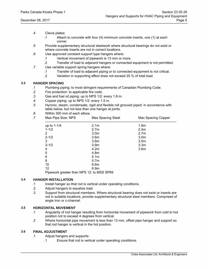
Coles Associates Ltd. Architects & Engineers
.4 Clevis plates:.1 Attach to concrete with four (4) minimum concrete inserts, one (1) at each
corner..5 Provide supplementary structural steelwork where structural bearings do not exist or
where concrete inserts are not in correct locations..6 Use approved constant support type hangers where:
.1 Vertical movement of pipework is 13 mm or more.
.2 Transfer of load to adjacent hangers or connected equipment is not permitted..7 Use variable support spring hangers where:
.1 Transfer of load to adjacent piping or to connected equipment is not critical.
.2 Variation in supporting effect does not exceed 25 % of total load.
3.3 HANGER SPACING.1 Plumbing piping: to most stringent requirements of Canadian Plumbing Code..2 Fire protection: to applicable fire code..3 Gas and fuel oil piping: up to NPS 1/2: every 1.8 m..4 Copper piping: up to NPS 1/2: every 1.5 m..5 Hyronic, steam, condensate, rigid and flexible roll grooved piped: in accordance with
table below, but not less than one hanger at joints..6 Within 300 mm of each elbow..7 Max Pipe Size: NPS Max Spacing Steel Max Spacing Copper
--------------------------------------------------------------------------------------------------------------------up to 1-1/4 2.1m 1.8m1-1/2 2.7m 2.4m2 3.0m 2.7m2-1/2 3.6m 3.0m3 3.6m 3.0m3-1/2 3.9m 3.3m4 4.2m 3.6m5 4.8m6 5.1m8 5.7m10 6.6m12 6.9mPipework greater than NPS 12: to MSS SP69
3.4 HANGER INSTALLATION.1 Install hanger so that rod is vertical under operating conditions..2 Adjust hangers to equalize load..3 Support from structural members. Where structural bearing does not exist or inserts are
not in suitable locations, provide supplementary structural steel members. Comprised of angle Iron or c-channel.
3.5 HORIZONTAL MOVEMENT.1 Angularity of rod hanger resulting from horizontal movement of pipework from cold to hot
position not to exceed 4 degrees from vertical..2 Where horizontal pipe movement is less than 13 mm, offset pipe hanger and support so
that rod hanger is vertical in the hot position.
3.6 FINAL ADJUSTMENT.1 Adjust hangers and supports:
.1 Ensure that rod is vertical under operating conditions.
Parks Canada Kiosks Phase 1 Section 23 05 29Hangers and Supports for HVAC Piping and Equipment
December 08, 2017 Page 5

Coles Associates Ltd. Architects & Engineers
.2 Equalize loads..2 Adjustable clevis:
.1 Tighten hanger load nut securely to ensure proper hanger performance.
.2 Tighten upper nut after adjustment..3 C-clamps:
.1 Follow manufacturer's recommended written instructions and torque values when tightening C-clamps to bottom flange of beam.
.4 Beam clamps:.1 Hammer jaw firmly against underside of beam.
END OF SECTION
Parks Canada Kiosks Phase 1 Section 23 05 29Hangers and Supports for HVAC Piping and Equipment
December 08, 2017 Page 6
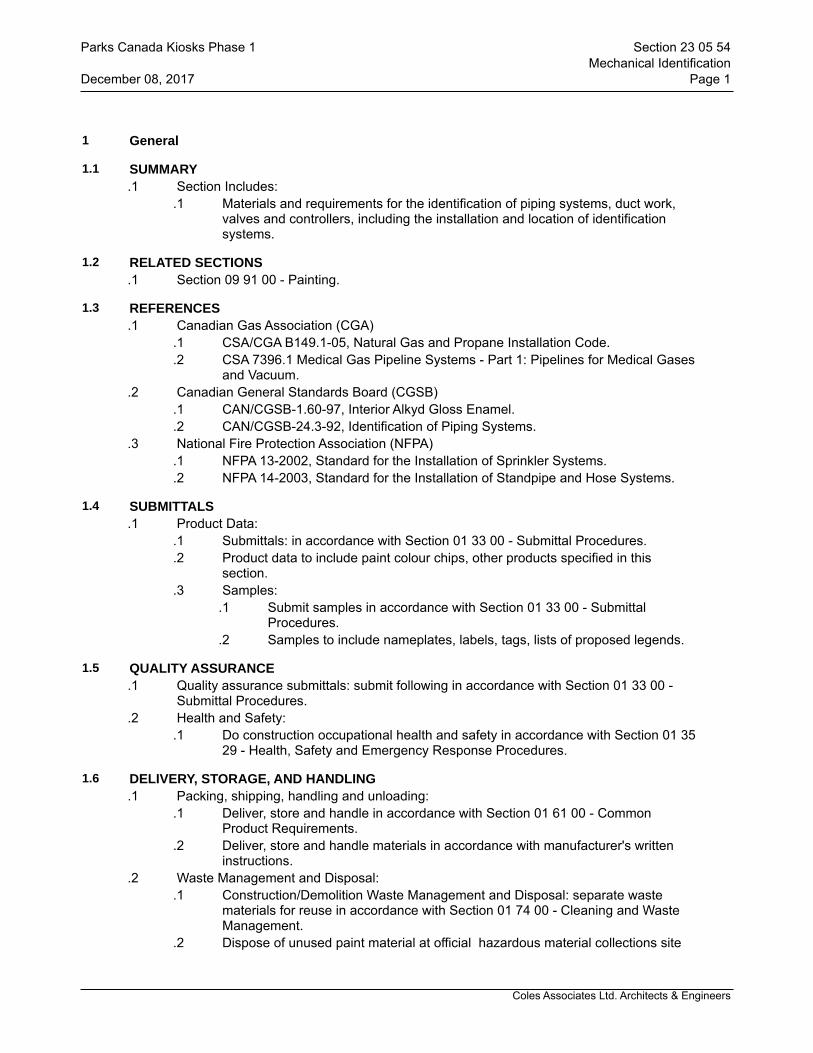
Coles Associates Ltd. Architects & Engineers
1 General
1.1 SUMMARY.1 Section Includes:
.1 Materials and requirements for the identification of piping systems, duct work, valves and controllers, including the installation and location of identification systems.
1.2 RELATED SECTIONS.1 Section 09 91 00 - Painting.
1.3 REFERENCES.1 Canadian Gas Association (CGA)
.1 CSA/CGA B149.1-05, Natural Gas and Propane Installation Code.
.2 CSA 7396.1 Medical Gas Pipeline Systems - Part 1: Pipelines for Medical Gases and Vacuum.
.2 Canadian General Standards Board (CGSB).1 CAN/CGSB-1.60-97, Interior Alkyd Gloss Enamel..2 CAN/CGSB-24.3-92, Identification of Piping Systems.
.3 National Fire Protection Association (NFPA).1 NFPA 13-2002, Standard for the Installation of Sprinkler Systems..2 NFPA 14-2003, Standard for the Installation of Standpipe and Hose Systems.
1.4 SUBMITTALS.1 Product Data:
.1 Submittals: in accordance with Section 01 33 00 - Submittal Procedures.
.2 Product data to include paint colour chips, other products specified in this section.
.3 Samples:.1 Submit samples in accordance with Section 01 33 00 - Submittal
Procedures..2 Samples to include nameplates, labels, tags, lists of proposed legends.
1.5 QUALITY ASSURANCE.1 Quality assurance submittals: submit following in accordance with Section 01 33 00 -
Submittal Procedures..2 Health and Safety:
.1 Do construction occupational health and safety in accordance with Section 01 35 29 - Health, Safety and Emergency Response Procedures.
1.6 DELIVERY, STORAGE, AND HANDLING.1 Packing, shipping, handling and unloading:
.1 Deliver, store and handle in accordance with Section 01 61 00 - Common Product Requirements.
.2 Deliver, store and handle materials in accordance with manufacturer's written instructions.
.2 Waste Management and Disposal:.1 Construction/Demolition Waste Management and Disposal: separate waste
materials for reuse in accordance with Section 01 74 00 - Cleaning and Waste Management.
.2 Dispose of unused paint material at official hazardous material collections site
Parks Canada Kiosks Phase 1 Section 23 05 54Mechanical Identification
December 08, 2017 Page 1
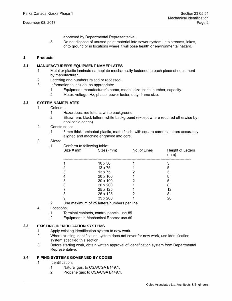
Coles Associates Ltd. Architects & Engineers
approved by Departmental Representative..3 Do not dispose of unused paint material into sewer system, into streams, lakes,
onto ground or in locations where it will pose health or environmental hazard.
2 Products
2.1 MANUFACTURER'S EQUIPMENT NAMEPLATES.1 Metal or plastic laminate nameplate mechanically fastened to each piece of equipment
by manufacturer..2 Lettering and numbers raised or recessed..3 Information to include, as appropriate:
.1 Equipment: manufacturer's name, model, size, serial number, capacity.
.2 Motor: voltage, Hz, phase, power factor, duty, frame size.
2.2 SYSTEM NAMEPLATES.1 Colours:
.1 Hazardous: red letters, white background.
.2 Elsewhere: black letters, white background (except where required otherwise by applicable codes).
.2 Construction:.1 3 mm thick laminated plastic, matte finish, with square corners, letters accurately
aligned and machine engraved into core..3 Sizes:
.1 Conform to following table:Size # mm Sizes (mm) No. of Lines Height of Letters
(mm)-----------------------------------------------------------------------------------------------------1 10 x 50 1 32 13 x 75 1 53 13 x 75 2 34 20 x 100 1 85 20 x 100 2 56 20 x 200 1 87 25 x 125 1 128 25 x 125 2 89 35 x 200 1 20
.2 Use maximum of 25 letters/numbers per line..4 Locations:
.1 Terminal cabinets, control panels: use #5.
.2 Equipment in Mechanical Rooms: use #9.
2.3 EXISTING IDENTIFICATION SYSTEMS.1 Apply existing identification system to new work..2 Where existing identification system does not cover for new work, use identification
system specified this section..3 Before starting work, obtain written approval of identification system from Departmental
Representative.
2.4 PIPING SYSTEMS GOVERNED BY CODES.1 Identification:
.1 Natural gas: to CSA/CGA B149.1.
.2 Propane gas: to CSA/CGA B149.1.
Parks Canada Kiosks Phase 1 Section 23 05 54Mechanical Identification
December 08, 2017 Page 2

Coles Associates Ltd. Architects & Engineers
.3 Sprinklers: to NFPA 13.
.4 Standpipe and hose systems: to NFPA 14.
.5 Medical Gas: to CAN/CSA Z 7396.1.
2.5 IDENTIFICATION OF PIPING SYSTEMS.1 Identify contents by background colour marking, pictogram (as necessary), legend;
direction of flow by arrows. To CAN/CGSB 24.3 except where specified otherwise..2 Pictograms:
.1 Where required: Workplace Hazardous Materials Information System (WHMIS) regulations.
.3 Legend:.1 Block capitals to sizes and colours listed in CAN/CGSB 24.3.
.4 Arrows showing direction of flow:.1 Outside diameter of pipe or insulation less than 75 mm: 100 mm long x 50 mm
high..2 Outside diameter of pipe or insulation 75 mm and greater: 150 mm long x 50 mm
high..3 Use double-headed arrows where flow is reversible.
.5 Extent of background colour marking:.1 To full circumference of pipe or insulation..2 Length to accommodate pictogram, full length of legend and arrows.
.6 Materials for background colour marking, legend, arrows:.1 Pipes and tubing 20 mm and smaller: waterproof and heat-resistant pressure
sensitive plastic marker tags..2 Other pipes: pressure sensitive plastic-coated cloth with protective overcoating,
waterproof contact adhesive undercoating, suitable for ambient of 100% RH and continuous operating temperature of 150 degrees C and intermittent temperature of 200 degrees C.
.7 Colours and Legends:.1 Where not listed, obtain direction from Departmental Representative..2 Colours for legends, arrows: to following table:
Background colour: Legend, arrows:Yellow BLACKGreen WHITERed WHITE
.3 Background colour marking and legends for piping systems:
Contents Background Legendcolour marking
----------------------------------------------------------------------------------------------------------Raw Water Green RAW WATERRiver water Green RIVER WATERSea water Green SEA WATERCity water Green CITY WATERTreated water Green TREATED WATERBrine Green BRINECondenser water supply Green COND. WTR. SUPPLYCondenser water return Green COND. WTR. RETURNChilled water supply Green CH. WTR. SUPPLYChilled water return Green CH. WTR. RETURNHot water heating supply Yellow HEATING SUPPLYHot water heating return Yellow HEATING RETURN
Parks Canada Kiosks Phase 1 Section 23 05 54Mechanical Identification
December 08, 2017 Page 3

Coles Associates Ltd. Architects & Engineers
High temp HW Htg supply Yellow HTHW HTG. SUPPLY++High temp HW Htg return Yellow HTHW HTG. RETURN++Make-up water Yellow MAKE-UP WTRBoiler feed water Yellow BLR. FEED WTRSteam ___kPa Yellow ___kPa STEAMSteam Cond. (gravity) Yellow ST.COND.RET (GRAVITY)Steam Cond. (pumped) Yellow ST.COND.RET (PUMPED)Safety valve vent Yellow STEAM VENTIntermittent blow-off Yellow INT. BLOW-OFFContinuous blow-off Yellow CONT. BLOW-OFFChilled drinking water Green CH. DRINK WTRDrinking water return Green CH. DRINK WTR. CIRCDomestic hot water supply Green DOM. HW SUPPLYDom. HWS recirculation Green DOM. HW CIRCDom. cold water supply Green DOM. CWSWaste water Green WASTE WATERContaminated lab waste Yellow CONT. LAB WASTEAcid waste Yellow ACID WASTE (add source)Storm water Green STORMSanitary Green SANPlumbing vent Green SAN. VENTRefrigeration suction Yellow REF. SUCTIONRefrigeration liquid Yellow REF. LIQUIDRefrigeration hot gas Yellow REF. HOT GASNo. ___ fuel oil suction Yellow #___ FUEL OILNo. ___ fuel oil return Yellow # ___ FUEL OILEngine exhaust Yellow ENGINE EXHAUSTLubricating oil Yellow LUB. OILHydraulic oil Yellow HYDRAULIC OILGasoline Yellow GASOLINENatural gas to CodesPropane to CodesGas regulator vents to CodesDistilled water Green DISTILL. WTRDemineralized water Green DEMIN. WATERChlorine Yellow CHLORINENitrogen Yellow NITROGENOxygen Yellow OXYGENCompressed air (700kPa) Green COMP. AIR ___ kPaCompressed air (>700kPa) Yellow COMP. AIR ___ kPaVacuum Green VACUUMFire protection water Red FIRE PROT. WTRSprinklers Red SPRINKLERSCarbon dioxide Red CO2Instrument air Green INSTRUMENT AIR**Add design temperature++Add design temperature and pressure
2.6 IDENTIFICATION DUCTWORK SYSTEMS.1 50 mm high stenciled letters and directional arrows 150 mm long x 50 mm high..2 Colours: back, or coordinated with base colour to ensure strong contrast..3 Identify Systems: eg Supply AHU-1, Exhaust EF-1
2.7 VALVES, CONTROLLERS.1 Brass tags with 12 mm stamped identification data filled with black paint.
Parks Canada Kiosks Phase 1 Section 23 05 54Mechanical Identification
December 08, 2017 Page 4

Coles Associates Ltd. Architects & Engineers
.2 Include flow diagrams for each system, of approved size, showing charts and schedules with identification of each tagged item, valve type, service, function, normal position, location of tagged item.
2.8 CONTROLS COMPONENTS IDENTIFICATION.1 Identify all systems, equipment, components, controls, sensors with system nameplates
specified in this section..2 Inscriptions to include function and (where appropriate) fail-safe position, component ID
name.
2.9 LANGUAGE.1 Identification in English..2 Use one nameplate and label for each language.
3 Execution
3.1 MANUFACTURER'S INSTRUCTIONS.1 Compliance: comply with manufacturer's written recommendations or specifications,
including product technical bulletins, handling, storage and installation instructions, and datasheet.
3.2 TIMING.1 Provide identification only after painting specified Section 09 91 23 - Interior Painting has
been completed.
3.3 INSTALLATION.1 Perform work in accordance with CAN/CGSB-24.3 except as specified otherwise..2 Provide ULC and CSA registration plates as required by respective agency.
3.4 NAMEPLATES.1 Locations:
.1 In conspicuous location to facilitate easy reading and identification from operating floor.
.2 Standoffs:.1 Provide for nameplates on hot and/or insulated surfaces.
.3 Protection:.1 Do not paint, insulate or cover in any way.
3.5 LOCATION OF IDENTIFICATION ON PIPING AND DUCTWORK SYSTEMS.1 On long straight runs in open areas in boiler rooms, equipment rooms, galleries, tunnels:
at not more than 17 m intervals and more frequently if required to ensure that at least one is visible from any one viewpoint in operating areas and walking aisles.
.2 Adjacent to each change in direction.
.3 At least once in each small room through which piping or ductwork passes.
.4 On both sides of visual obstruction or where run is difficult to follow.
.5 On both sides of separations such as walls, floors, partitions.
.6 Where system is installed in pipe chases, ceiling spaces, galleries, confined spaces, at entry and exit points, and at access openings.
.7 At beginning and end points of each run and at each piece of equipment in run.
.8 At point immediately upstream of major manually operated or automatically controlled valves, and dampers. Where this is not possible, place identification as close as possible, preferably on upstream side.
Parks Canada Kiosks Phase 1 Section 23 05 54Mechanical Identification
December 08, 2017 Page 5

Coles Associates Ltd. Architects & Engineers
.9 Identification easily and accurately readable from usual operating areas and from access points.
.1 Position of identification approximately at right angles to most convenient line of sight, considering operating positions, lighting conditions, risk of physical damage or injury and reduced visibility over time due to dust and dirt.
3.6 VALVES, CONTROLLERS.1 Valves and operating controllers, except at plumbing fixtures, radiation, or where in plain
sight of equipment they serve: Secure tags with non-ferrous chains or closed "S" hooks..2 Install one copy of flow diagrams, valve schedules mounted in frame behind non-glare
glass where directed by Departmental Representative. Provide one copy (reduced in size if required) in each operating and maintenance manual.
.3 Number valves in each system consecutively.
3.7 CLEANING.1 Proceed in accordance with Section 01 74 00 - Cleaning and Waste Management..2 Upon completion and verification of performance of installation, remove surplus
materials, excess materials, rubbish, tools and equipment.
END OF SECTION
Parks Canada Kiosks Phase 1 Section 23 05 54Mechanical Identification
December 08, 2017 Page 6

Coles Associates Ltd. Architects & Engineers
1 General
1.1 RELATED SECTIONS.1 Section 23 05 29 - Hangers and Supports for HVAC Piping and Equipment.
1.2 REFERENCES.1 American Society of Heating, Refrigeration and Air Conditioning Engineers (ASHRAE)
.1 ANSI/ASHRAE/IESNA 90.1-, SI; Energy Standard for Buildings Except Low-Rise Residential Buildings.
.2 American Society for Testing and Materials International, (ASTM).1 ASTM B209M-, Specification for Aluminum and Aluminum Alloy Sheet and Plate
(Metric)..2 ASTM C335-, Test Method for Steady State Heat Transfer Properties of
Horizontal Pipe Insulation..3 ASTM C411-, Test Method for Hot-Surface Performance of High-Temperature
Thermal Insulation..4 ASTM C449/C449M-, Standard Specification for Mineral Fiber-Hydraulic-Setting
Thermal Insulating and Finishing Cement..5 ASTM C547-, Specification for Mineral Fiber Pipe Insulation..6 ASTM C553-, Specification for Mineral Fiber Blanket Thermal Insulation for
Commercial and Industrial Applications..7 ASTM C612-, Specification for Mineral Fiber Block and Board Thermal
Insulation..8 ASTM C795-, Specification for Thermal Insulation for Use with Austenitic
Stainless Steel..9 ASTM C921-, Standard Specification for Thermal Insulation for Use in Contact
with Austenitic Stainless Steel..3 Canadian General Standards Board (CGSB)
.1 CGSB 51-GP-52Ma-, Vapour Barrier, Jacket and Facing Material for Pipe, Duct and Equipment Thermal Insulation.
.4 Thermal Insulation Association of Canada (TIAC): National Insulation Standards (R1999).
.5 Underwriters Laboratories of Canada (ULC).1 CAN/ULC-S102-, Surface Burning Characteristics of Building Materials and
Assemblies..2 CAN/ULC-S701-, Thermal Insulation Polyotrene, Boards and Pipe Covering.
1.3 DEFINITIONS.1 For purposes of this section:
.1 "CONCEALED" - means any work which is installed in suspended ceilings (accessible or non-accessible), attics and non-accessible chases and furred-in spaces.
.2 "EXPOSED" - means any work which is not concealed in walls, shafts, or above accessible or non-accessible ceilings. Work behind doors, in closets, in cupboards, or under counters is considered exposed.
.3 Insulation systems - insulation material, fasteners, jackets, and other accessories.
.2 TIAC Codes:.1 CRD: Commercial Round Ductwork,.2 CRF: Commercial Rectangular Finish,.3 CEF: Commercial Rigid Insulation External Application.
Parks Canada Kiosks Phase 1 Section 23 07 13Thermal Insulation for Ducting
December 08, 2017 Page 1

Coles Associates Ltd. Architects & Engineers
1.4 SHOP DRAWINGS.1 Submit shop drawings in accordance with Section 01 33 00 - Submittal Procedures..2 Submit for approval manufacturer's catalogue literature related to installation, fabrication
for duct jointing recommendations.
1.5 SAMPLES.1 Submit samples in accordance with Section 01 33 00 - Submittal Procedures..2 Submit for approval: complete assembly of each type of insulation system, insulation,
coating, and adhesive proposed. Mount sample on 12 mm plywood board. Affix typewritten label beneath sample indicating service.
1.6 MANUFACTURERS' INSTRUCTIONS.1 Submit manufacturer's installation instructions in accordance with Section 01 33 00 -
Submittal Procedures..2 Installation instructions to include procedures used, and installation standards achieved.
1.7 DELIVERY, STORAGE AND HANDLING.1 Deliver materials to site in original factory packaging, labelled with manufacturer's name,
address..2 Protect from weather and construction traffic..3 Protect against damage from any source..4 Store at temperatures and conditions recommended by manufacturer.
1.8 WASTE MANAGEMENT AND DISPOSAL.1 Separate and recycle waste materials in accordance with Section 01 74 19 -
Construction Waste Management Disposal..2 Remove from site and dispose of packaging materials at appropriate recycling facilities..3 Collect and separate for disposal paper packaging material in appropriate on-site for
recycling in accordance with Waste Management Plan..4 Divert unused metal materials from landfill to metal recycling facility approved by
Departmental Representative..5 Divert unused adhesive material from landfill to official hazardous material collections
site approved by Departmental Representative..6 Do not dispose of unused adhesive materials into sewer systems, into lakes, streams,
onto ground or in other locations where it will pose health or environmental hazard.
2 Products
2.1 FIRE AND SMOKE RATING.1 In accordance with CAN/ULC-S102:
.1 Maximum flame spread rating: 25.
.2 Maximum smoke developed rating: 50.
2.2 INSULATION.1 Mineral fibre: as specified includes glass fibre, rock wool, slag wool..2 Thermal conductivity ("k" factor) not to exceed specified values at 24°C mean
temperature when tested in accordance with ASTM C335..3 TIAC Code C-1: Rigid mineral fibre board to ASTM C612, with factory applied vapour
retarder jacket to CGSB 51-GP-52Ma (as scheduled in PART 3 of this Section)..4 TIAC Code C-2: Mineral fibre blanket to ASTM C553 faced with factory applied vapour
retarder jacket to CGSB 51-GP-52Ma (as scheduled in PART 3 of this section)..1 Mineral fibre: to ASTM C553.
Parks Canada Kiosks Phase 1 Section 23 07 13Thermal Insulation for Ducting
December 08, 2017 Page 2
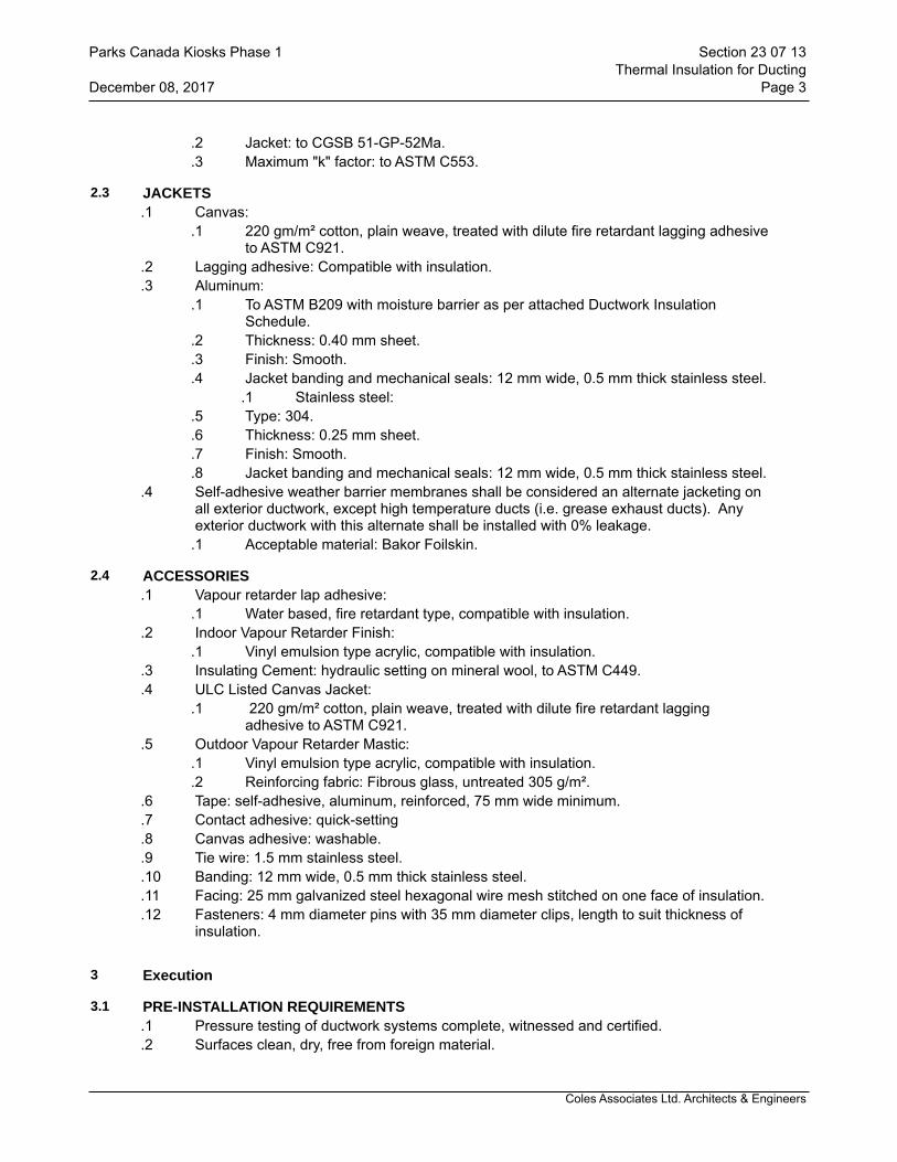
Coles Associates Ltd. Architects & Engineers
.2 Jacket: to CGSB 51-GP-52Ma.
.3 Maximum "k" factor: to ASTM C553.
2.3 JACKETS.1 Canvas:
.1 220 gm/m² cotton, plain weave, treated with dilute fire retardant lagging adhesive to ASTM C921.
.2 Lagging adhesive: Compatible with insulation.
.3 Aluminum:.1 To ASTM B209 with moisture barrier as per attached Ductwork Insulation
Schedule..2 Thickness: 0.40 mm sheet..3 Finish: Smooth..4 Jacket banding and mechanical seals: 12 mm wide, 0.5 mm thick stainless steel.
.1 Stainless steel:.5 Type: 304..6 Thickness: 0.25 mm sheet..7 Finish: Smooth..8 Jacket banding and mechanical seals: 12 mm wide, 0.5 mm thick stainless steel.
.4 Self-adhesive weather barrier membranes shall be considered an alternate jacketing on all exterior ductwork, except high temperature ducts (i.e. grease exhaust ducts). Any exterior ductwork with this alternate shall be installed with 0% leakage.
.1 Acceptable material: Bakor Foilskin.
2.4 ACCESSORIES.1 Vapour retarder lap adhesive:
.1 Water based, fire retardant type, compatible with insulation..2 Indoor Vapour Retarder Finish:
.1 Vinyl emulsion type acrylic, compatible with insulation..3 Insulating Cement: hydraulic setting on mineral wool, to ASTM C449..4 ULC Listed Canvas Jacket:
.1 220 gm/m² cotton, plain weave, treated with dilute fire retardant lagging adhesive to ASTM C921.
.5 Outdoor Vapour Retarder Mastic:.1 Vinyl emulsion type acrylic, compatible with insulation..2 Reinforcing fabric: Fibrous glass, untreated 305 g/m².
.6 Tape: self-adhesive, aluminum, reinforced, 75 mm wide minimum.
.7 Contact adhesive: quick-setting
.8 Canvas adhesive: washable.
.9 Tie wire: 1.5 mm stainless steel.
.10 Banding: 12 mm wide, 0.5 mm thick stainless steel.
.11 Facing: 25 mm galvanized steel hexagonal wire mesh stitched on one face of insulation.
.12 Fasteners: 4 mm diameter pins with 35 mm diameter clips, length to suit thickness of insulation.
3 Execution
3.1 PRE-INSTALLATION REQUIREMENTS.1 Pressure testing of ductwork systems complete, witnessed and certified..2 Surfaces clean, dry, free from foreign material.
Parks Canada Kiosks Phase 1 Section 23 07 13Thermal Insulation for Ducting
December 08, 2017 Page 3

Coles Associates Ltd. Architects & Engineers
3.2 INSTALLATION.1 Install in accordance with TIAC National Standards..2 Apply materials in accordance with manufacturers instructions and as indicated..3 Use two layers with staggered joints when required nominal thickness exceeds 75 mm..4 Maintain uninterrupted continuity and integrity of vapour retarder jacket and finishes.
.1 Hangers, supports to be outside vapour retarder jacket..5 Supports, Hangers in accordance with Section 23 05 29 - Hangers and Supports for
HVAC Piping and Equipment..1 Apply high compressive strength insulation where insulation may be compressed
by weight of ductwork..6 Fasteners: At 300 mm oc in horizontal and vertical directions, minimum two rows each
side.
3.3 DUCTWORK INSULATION SCHEDULE.1 Insulation types and thickness: Conform to following Table:
TIAC Vapour ThicknessCode Retarder (mm)
-------------------------------------------------------------------------------------------------------------Rectangular cold and dual C-1 yes 50temperature supply air ducts(exposed)
Round cold and dual temperature C-2 yes 50supply air ducts (concealed)
Rectangular warm air ducts C-1 no 25(exposed)
Round warm air ducts (exposed) C-1 no 25
Rectangular cold and dual C-2 yes 25temperature supply air ducts(concealed)
Round cold and dual temperature C-1 yes 50supply air ducts (exposed)
Rectangular warm air ducts C-2 no 25(concealed)
Round warm air ducts C-2 no 25(concealed)
Supply, return and exhaust ducts noneexposed in space being served
Outside air ducts to mixing C-1 yes 50plenum
Mixing Plenums C-1 yes 25
Parks Canada Kiosks Phase 1 Section 23 07 13Thermal Insulation for Ducting
December 08, 2017 Page 4
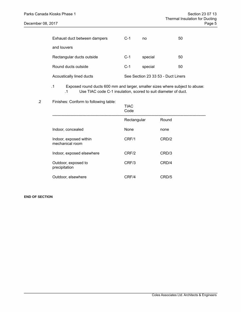
Coles Associates Ltd. Architects & Engineers
Exhaust duct between dampers C-1 no 50
and louvers
Rectangular ducts outside C-1 special 50
Round ducts outside C-1 special 50
Acoustically lined ducts See Section 23 33 53 - Duct Liners
.1 Exposed round ducts 600 mm and larger, smaller sizes where subject to abuse:.1 Use TIAC code C-1 insulation, scored to suit diameter of duct.
.2 Finishes: Conform to following table:TIACCode
---------------------------------------------------------------------------------------------------------------------Rectangular Round
Indoor, concealed None none
Indoor, exposed within CRF/1 CRD/2mechanical room
Indoor, exposed elsewhere CRF/2 CRD/3
Outdoor, exposed to CRF/3 CRD/4precipitation
Outdoor, elsewhere CRF/4 CRD/5
END OF SECTION
Parks Canada Kiosks Phase 1 Section 23 07 13Thermal Insulation for Ducting
December 08, 2017 Page 5

Coles Associates Ltd. Architects & Engineers
1 General
1.1 SUMMARY.1 Section Includes:
.1 Thermal insulation for piping and piping accessories in commercial type applications.
1.2 RELATED SECTIONS.1 Section 07 92 00 - Joint Seants..2 Section 23 05 54 - Mechanical Identification.
1.3 REFERENCES.1 American Society of Heating, Refrigeration and Air Conditioning Engineers (ASHRAE)
.1 ASHRAE Standard 90.1, Energy Standard for Buildings Except Low-Rise Residential Buildings.
.2 American Society for Testing and Materials International (ASTM).1 ASTM B209M, Standard Specification for Aluminum and Aluminum Alloy Sheet
and Plate Metric..2 ASTM C335, Standard Test Method for Steady State Heat Transfer Properties of
Horizontal Pipe Insulation..3 ASTM C411, Standard Test Method for Hot-Surface Performance of High-
Temperature Thermal Insulation..4 ASTM C449/C449M, Standard Specification for Mineral Fiber-Hydraulic-Setting
Thermal Insulating and Finishing Cement..5 ASTM C533, Calcium Silicate Block and Pipe Thermal Insulation..6 ASTM C547, Mineral Fiber Pipe Insulation..7 ASTM C795, Standard Specification for Thermal Insulation for Use in Contact
with Austenitic Stainless Steel..8 ASTM C921, Standard Practice for Determining the Properties of Jacketing
Materials for Thermal Insulation..9 ASTM D184, Standard Specification for Rigid Poly (Vinyl Chloride) (PUC)
Compounds and Cholorinated Poly (Vinyl Chloride) (CPVC) Compounds..3 Canadian General Standards Board (CGSB)
.1 CGSB 51-GP-52Ma, Vapour Barrier, Jacket and Facing Material for Pipe, Duct and Equipment Thermal Insulation.
.2 CAN/CGSB-51.53, Poly (Vinyl Chloride) Jacketting Sheet, for Insulated Pipes, Vessels and Round Ducts.
.4 Department of Justice Canada (Jus).1 Canadian Environmental Assessment Act (CEAA), c. 37..2 Canadian Environmental Protection Act (CEPA), c. 33..3 Transportation of Dangerous Goods Act (TDGA), c. 34.
.5 Health Canada/Workplace Hazardous Materials Information System (WHMIS).1 Material Safety Data Sheets (MSDS).
.6 Manufacturer's Trade Associations.1 Thermal Insulation Association of Canada (TIAC): National Insulation Standards.
.7 Underwriters' Laboratories of Canada (ULC).1 CAN/ULC-S102, Surface Burning Characteristics of Building Materials and
Assemblies..2 CAN/ULC-S701, Thermal Insulation, Polystyrene, Boards and Pipe Covering..3 CAN/ULC-S702, Thermal Insulation, Mineral Fibre, for Buildings.
Parks Canada Kiosks Phase 1 Section 23 20 21Thermal Insulation for Piping
December 08, 2017 Page 1
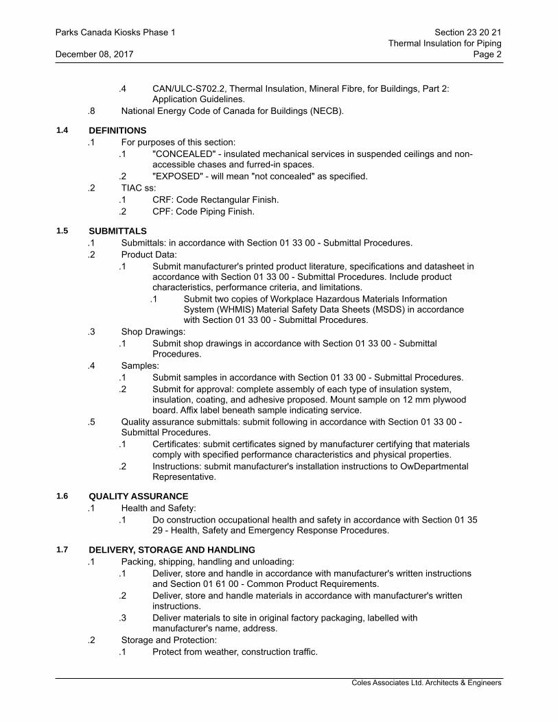
Coles Associates Ltd. Architects & Engineers
.4 CAN/ULC-S702.2, Thermal Insulation, Mineral Fibre, for Buildings, Part 2: Application Guidelines.
.8 National Energy Code of Canada for Buildings (NECB).
1.4 DEFINITIONS.1 For purposes of this section:
.1 "CONCEALED" - insulated mechanical services in suspended ceilings and non-accessible chases and furred-in spaces.
.2 "EXPOSED" - will mean "not concealed" as specified..2 TIAC ss:
.1 CRF: Code Rectangular Finish.
.2 CPF: Code Piping Finish.
1.5 SUBMITTALS.1 Submittals: in accordance with Section 01 33 00 - Submittal Procedures..2 Product Data:
.1 Submit manufacturer's printed product literature, specifications and datasheet in accordance with Section 01 33 00 - Submittal Procedures. Include product characteristics, performance criteria, and limitations.
.1 Submit two copies of Workplace Hazardous Materials Information System (WHMIS) Material Safety Data Sheets (MSDS) in accordance with Section 01 33 00 - Submittal Procedures.
.3 Shop Drawings:.1 Submit shop drawings in accordance with Section 01 33 00 - Submittal
Procedures..4 Samples:
.1 Submit samples in accordance with Section 01 33 00 - Submittal Procedures.
.2 Submit for approval: complete assembly of each type of insulation system, insulation, coating, and adhesive proposed. Mount sample on 12 mm plywood board. Affix label beneath sample indicating service.
.5 Quality assurance submittals: submit following in accordance with Section 01 33 00 -Submittal Procedures.
.1 Certificates: submit certificates signed by manufacturer certifying that materials comply with specified performance characteristics and physical properties.
.2 Instructions: submit manufacturer's installation instructions to OwDepartmental Representative.
1.6 QUALITY ASSURANCE.1 Health and Safety:
.1 Do construction occupational health and safety in accordance with Section 01 35 29 - Health, Safety and Emergency Response Procedures.
1.7 DELIVERY, STORAGE AND HANDLING.1 Packing, shipping, handling and unloading:
.1 Deliver, store and handle in accordance with manufacturer's written instructions and Section 01 61 00 - Common Product Requirements.
.2 Deliver, store and handle materials in accordance with manufacturer's written instructions.
.3 Deliver materials to site in original factory packaging, labelled with manufacturer's name, address.
.2 Storage and Protection:.1 Protect from weather, construction traffic.
Parks Canada Kiosks Phase 1 Section 23 20 21Thermal Insulation for Piping
December 08, 2017 Page 2
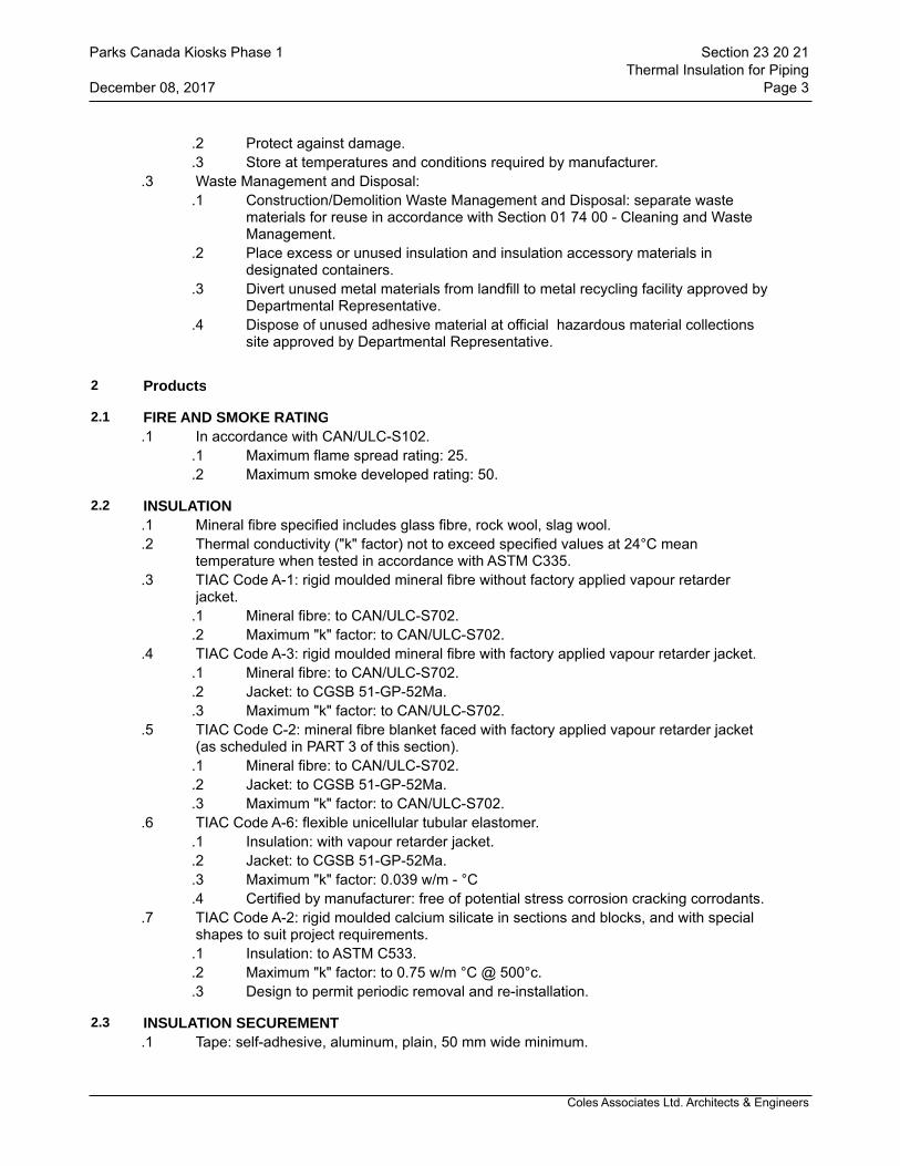
Coles Associates Ltd. Architects & Engineers
.2 Protect against damage.
.3 Store at temperatures and conditions required by manufacturer..3 Waste Management and Disposal:
.1 Construction/Demolition Waste Management and Disposal: separate waste materials for reuse in accordance with Section 01 74 00 - Cleaning and Waste Management.
.2 Place excess or unused insulation and insulation accessory materials in designated containers.
.3 Divert unused metal materials from landfill to metal recycling facility approved by Departmental Representative.
.4 Dispose of unused adhesive material at official hazardous material collections site approved by Departmental Representative.
2 Products
2.1 FIRE AND SMOKE RATING.1 In accordance with CAN/ULC-S102.
.1 Maximum flame spread rating: 25.
.2 Maximum smoke developed rating: 50.
2.2 INSULATION.1 Mineral fibre specified includes glass fibre, rock wool, slag wool..2 Thermal conductivity ("k" factor) not to exceed specified values at 24°C mean
temperature when tested in accordance with ASTM C335..3 TIAC Code A-1: rigid moulded mineral fibre without factory applied vapour retarder
jacket..1 Mineral fibre: to CAN/ULC-S702..2 Maximum "k" factor: to CAN/ULC-S702.
.4 TIAC Code A-3: rigid moulded mineral fibre with factory applied vapour retarder jacket..1 Mineral fibre: to CAN/ULC-S702..2 Jacket: to CGSB 51-GP-52Ma..3 Maximum "k" factor: to CAN/ULC-S702.
.5 TIAC Code C-2: mineral fibre blanket faced with factory applied vapour retarder jacket (as scheduled in PART 3 of this section).
.1 Mineral fibre: to CAN/ULC-S702.
.2 Jacket: to CGSB 51-GP-52Ma.
.3 Maximum "k" factor: to CAN/ULC-S702..6 TIAC Code A-6: flexible unicellular tubular elastomer.
.1 Insulation: with vapour retarder jacket.
.2 Jacket: to CGSB 51-GP-52Ma.
.3 Maximum "k" factor: 0.039 w/m - °C
.4 Certified by manufacturer: free of potential stress corrosion cracking corrodants..7 TIAC Code A-2: rigid moulded calcium silicate in sections and blocks, and with special
shapes to suit project requirements..1 Insulation: to ASTM C533..2 Maximum "k" factor: to 0.75 w/m °C @ 500°c..3 Design to permit periodic removal and re-installation.
2.3 INSULATION SECUREMENT.1 Tape: self-adhesive, aluminum, plain, 50 mm wide minimum.
Parks Canada Kiosks Phase 1 Section 23 20 21Thermal Insulation for Piping
December 08, 2017 Page 3

Coles Associates Ltd. Architects & Engineers
.2 Contact adhesive: quick setting.
.3 Canvas adhesive: washable.
.4 Tie wire: 1.5 mm diameter stainless steel.
.5 Bands: stainless steel, 19 mm wide, 0.5 mm thick.
2.4 CEMENT.1 Thermal insulating and finishing cement:
.1 Hydraulic setting or air drying on mineral wool, to ASTM C449/C449M.
2.5 VAPOUR RETARDER LAP ADHESIVE.1 Water based, fire retardant type, compatible with insulation.
2.6 INDOOR VAPOUR RETARDER FINISH.1 Vinyl emulsion type acrylic, compatible with insulation.
2.7 OUTDOOR VAPOUR RETARDER FINISH.1 Vinyl emulsion type acrylic, compatible with insulation..2 Reinforcing fabric: fibrous glass, untreated 305 g/m².
2.8 JACKETS.1 Polyvinyl Chloride (PVC):
.1 One-piece moulded type and sheet to CAN/CGSB-51.53 with pre-formed shapes as required.
.2 Colours: to match adjacent finish paint.
.3 Minimum service temperatures: -20°C.
.4 Maximum service temperature: 65°C.
.5 Moisture vapour transmission: 0.02 perm.
.6 Thickness: 0.55 mm.
.7 Fastenings:.1 Use solvent weld adhesive compatible with insulation to seal laps and
joints..2 Tacks..3 Pressure sensitive vinyl tape of matching colour.
.8 Special requirements:.1 Indoor: flame spread rating 25, smoke developed rating 50..2 Outdoor: UV rated material at least 0.5 mm thick.
.2 ABS Plastic:.1 One-piece moulded type and sheet with pre-formed shapes as required..2 Colours: to match adjacent finish paint..3 Minimum service temperatures: -40°C..4 Maximum service temperature: 82°C..5 Moisture vapour transmission: 0.012 perm..6 Thickness: 0.75 mm..7 Fastenings:
.1 Solvent weld adhesive compatible with insulation to seal laps and joints.
.2 Tacks.
.3 Pressure sensitive vinyl tape of matching colour..8 Locations:
.1 For outdoor use ONLY..3 Canvas:
.1 220 gm/m² cotton, plain weave, treated with dilute fire retardant lagging
Parks Canada Kiosks Phase 1 Section 23 20 21Thermal Insulation for Piping
December 08, 2017 Page 4
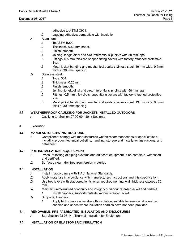
Coles Associates Ltd. Architects & Engineers
adhesive to ASTM C921..2 Lagging adhesive: compatible with insulation.
.4 Aluminum:.1 To ASTM B209..2 Thickness: 0.50 mm sheet..3 Finish: smooth..4 Joining: longitudinal and circumferential slip joints with 50 mm laps..5 Fittings: 0.5 mm thick die-shaped fitting covers with factory-attached protective
liner..6 Metal jacket banding and mechanical seals: stainless steel, 19 mm wide, 0.5mm
thick at 300 mm spacing..5 Stainless steel:
.1 Type: 304.
.2 Thickness: 0.25 mm.
.3 Finish: smooth.
.4 Joining: longitudinal and circumferential slip joints with 50 mm laps.
.5 Fittings: 0.5 mm thick die-shaped fitting covers with factory-attached protective liner.
.6 Metal jacket banding and mechanical seals: stainless steel, 19 mm wide, 0.5mm thick at 300 mm spacing.
2.9 WEATHERPROOF CAULKING FOR JACKETS INSTALLED OUTDOORS.1 Caulking to: Section 07 92 00 - Joint Sealants
3 Execution
3.1 MANUFACTURER'S INSTRUCTIONS.1 Compliance: comply with manufacturer's written recommendations or specifications,
including product technical bulletins, handling, storage and installation instructions, and datasheet.
3.2 PRE-INSTALLATION REQUIREMENT.1 Pressure testing of piping systems and adjacent equipment to be complete, witnessed
and certified..2 Surfaces clean, dry, free from foreign material.
3.3 INSTALLATION.1 Install in accordance with TIAC National Standards..2 Apply materials in accordance with manufacturers instructions and this specification..3 Use two layers with staggered joints when required nominal wall thickness exceeds 75
mm..4 Maintain uninterrupted continuity and integrity of vapour retarder jacket and finishes.
.1 Install hangers, supports outside vapour retarder jacket..5 Supports, Hangers:
.1 Apply high compressive strength insulation, suitable for service, at oversized saddles and shoes where insulation saddles have not been provided.
3.4 REMOVABLE, PRE-FABRICATED, INSULATION AND ENCLOSURES.1 See Section 23 07 14 - Thermal Insulation for Equipment.
3.5 INSTALLATION OF ELASTOMERIC INSULATION
Parks Canada Kiosks Phase 1 Section 23 20 21Thermal Insulation for Piping
December 08, 2017 Page 5
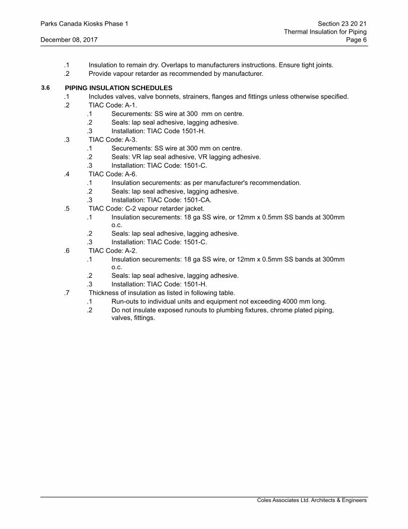
Coles Associates Ltd. Architects & Engineers
.1 Insulation to remain dry. Overlaps to manufacturers instructions. Ensure tight joints.
.2 Provide vapour retarder as recommended by manufacturer.
3.6 PIPING INSULATION SCHEDULES.1 Includes valves, valve bonnets, strainers, flanges and fittings unless otherwise specified..2 TIAC Code: A-1.
.1 Securements: SS wire at 300 mm on centre.
.2 Seals: lap seal adhesive, lagging adhesive.
.3 Installation: TIAC Code 1501-H..3 TIAC Code: A-3.
.1 Securements: SS wire at 300 mm on centre.
.2 Seals: VR lap seal adhesive, VR lagging adhesive.
.3 Installation: TIAC Code: 1501-C..4 TIAC Code: A-6.
.1 Insulation securements: as per manufacturer's recommendation.
.2 Seals: lap seal adhesive, lagging adhesive.
.3 Installation: TIAC Code: 1501-CA..5 TIAC Code: C-2 vapour retarder jacket.
.1 Insulation securements: 18 ga SS wire, or 12mm x 0.5mm SS bands at 300mm o.c.
.2 Seals: lap seal adhesive, lagging adhesive.
.3 Installation: TIAC Code: 1501-C..6 TIAC Code: A-2.
.1 Insulation securements: 18 ga SS wire, or 12mm x 0.5mm SS bands at 300mm o.c.
.2 Seals: lap seal adhesive, lagging adhesive.
.3 Installation: TIAC Code: 1501-H..7 Thickness of insulation as listed in following table.
.1 Run-outs to individual units and equipment not exceeding 4000 mm long.
.2 Do not insulate exposed runouts to plumbing fixtures, chrome plated piping, valves, fittings.
Parks Canada Kiosks Phase 1 Section 23 20 21Thermal Insulation for Piping
December 08, 2017 Page 6
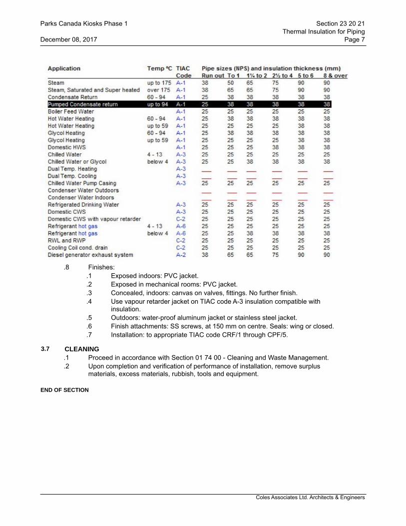
Coles Associates Ltd. Architects & Engineers
.8 Finishes:.1 Exposed indoors: PVC jacket..2 Exposed in mechanical rooms: PVC jacket..3 Concealed, indoors: canvas on valves, fittings. No further finish..4 Use vapour retarder jacket on TIAC code A-3 insulation compatible with
insulation..5 Outdoors: water-proof aluminum jacket or stainless steel jacket. .6 Finish attachments: SS screws, at 150 mm on centre. Seals: wing or closed..7 Installation: to appropriate TIAC code CRF/1 through CPF/5.
3.7 CLEANING.1 Proceed in accordance with Section 01 74 00 - Cleaning and Waste Management..2 Upon completion and verification of performance of installation, remove surplus
materials, excess materials, rubbish, tools and equipment.
END OF SECTION
Parks Canada Kiosks Phase 1 Section 23 20 21Thermal Insulation for Piping
December 08, 2017 Page 7
Coles Associates Ltd. Architects & Engineers
1 General
1.1 SUMMARY.1 Section Includes:
.1 Materials and installation of low-pressure metallic ductwork, joints and accessories.
1.2 RELATED SECTIONS.1 Section 23 05 29 - Hangers and Supports for HVAC Piping and Equipment.
1.3 REFERENCES.1 American Society of Heating, Refrigerating and Air-Conditioning Engineers, Inc.
(ASHRAE)..2 American Society for Testing and Materials International, (ASTM).
.1 ASTM A480/A480M, Standard Specification for General Requirements for Flat-Rolled Stainless and Heat-Resisting Steel Plate, Sheet and Strip.
.2 ASTM A635/A635M, Standard Specification for Steel, Sheet and Strip, Heavy-Thickness Coils, Carbon, Hot Rolled.
.3 ASTM A653/A653M, Standard Specification for Steel Sheet, Zinc Coated (Galvanized) or Zinc-Iron Alloy Coated (Galvannealed) by the Hot-Dip Process.
.3 Health Canada/Workplace Hazardous Materials Information System (WHMIS)..1 Material Safety Data Sheets (MSDS).
.4 National Fire Protection Association (NFPA)..1 NFPA 90A, Standard for the installation of Air-Conditioning and Ventilation
Systems..2 NFPA 90B, Standard for the Installation of Warm Air Heating and Air-
Conditioning Systems..3 NFPA 96, Standard for ventilation control and fire protection of commercial
cooling operations..5 Sheet Metal and Air Conditioning Contractors' National Association (SMACNA).
.1 SMACNA HVAC Duct Construction Standards - Metal and Flexible, 2nd Edition and Addendum No. 1.
.2 SMACNA HVAC Air Duct Leakage Test Manual, 1st Edition.
.3 IAQ Guideline for Occupied Buildings Under Construction, 1st Edition.
1.4 SUBMITTALS.1 Submit shop drawings and product data in accordance with Section 01 33 00 - Submittal
Procedures..2 Product Data: submit WHMIS MSDS - Material Safety Data Sheets for the following:
.1 Sealants.
.2 Tape.
.3 Proprietary Joints.
1.5 QUALITY ASSURANCE.1 Certification of Ratings:
.1 Catalogue or published ratings shall be those obtained from tests carried out by manufacturer or independent testing agency signifying adherence to codes and standards.
.2 Health and Safety:.1 Do construction occupational health and safety in accordance with Section 01 35
29 - Health, Safety and Emergency Response Procedures.
Parks Canada Kiosks Phase 1 Section 23 31 13Metal Ducts - Low Pressure to 500 Pa
December 08, 2017 Page 1
Coles Associates Ltd. Architects & Engineers
.3 Indoor Air Quality (IAQ) Management Plan..1 Develop and implement an Indoor Air Quality (IAQ) Management Plan for
construction and preoccupancy phases of building..2 During construction meet or exceed the requirements of SMACNA IAQ Guideline
for Occupied Buildings under Construction..4 Installers to be certified journey person level in sheet metal works.
1.6 DELIVERY, STORAGE AND HANDLING.1 Protect on site stored or installed absorptive material from moisture damage..2 Waste Management and Disposal:
.1 Separate waste materials for reuse in accordance with Section 01 74 00 -Cleaning and Waste Management.
.2 Remove from site and dispose of packaging materials at appropriate recycling facilities.
.3 Collect and separate for disposal paper packaging material in appropriate on-site bins for recycling in accordance with Waste Management Plan.
.4 Separate for reuse and place in designated containers Steel waste in accordance with Waste Management Plan.
.5 Place materials defined as hazardous or toxic in designated containers.
.6 Handle and dispose of hazardous materials in accordance with CEPA, regulations.
.7 Fold up metal banding, flatten and place in designated area for recycling.
2 Products
2.1 SEAL CLASSIFICATION.1 Classification as follows:
MAX Pressure Pa SMACNA Seal Class------------------------------------------------------------------------------------
1000 A750 B500 C250 C125 C
.2 Seal classification:.1 Class A: longitudinal seams, transverse joints, duct wall penetrations, and
connections made air tight with sealant and tape..2 Class B: Longitudinal seam transverse joints, and connections made air tight
with sealant, type or combination thereof. .3 Section 23 05 29 - Hangers and Supports for HVAC Piping and Equipment.
2.2 SEALANT.1 Sealant: oil resistant, polymer type flame resistant duct sealant. Temperature range of
minus 30 degrees C to plus 93 degrees C.
2.3 TAPE.1 Tape: polyvinyl treated, open weave fiberglass tape, 50 mm wide.
2.4 DUCT LEAKAGE.1 In accordance with SMACNA HVAC Air Duct Leakage Test Manual.
Parks Canada Kiosks Phase 1 Section 23 31 13Metal Ducts - Low Pressure to 500 Pa
December 08, 2017 Page 2
Coles Associates Ltd. Architects & Engineers
2.5 FITTINGS.1 Fabrication: to SMACNA..2 Radiused elbows.
.1 Rectangular: centreline radius: 1.5 times width of duct.
.2 Round: smooth radius or five piece. Centreline radius: 1.5 times diameter..3 Mitred elbows, rectangular:
.1 To 400 mm: with single thickness turning vanes.
.2 Over 400 mm: with double thickness turning vanes..4 Branches:
.1 Rectangular main and branch: with radius on branch 1.5 times width of duct or 45 degree entry on branch.
.2 Round main and branch: enter main duct at 45 degrees with conical connection.
.3 Provide volume control damper in branch duct near connection to main duct.
.4 Main duct branches: with splitter damper..5 Transitions:
.1 Diverging: 20 degrees maximum included angle.
.2 Converging: 30 degrees maximum included angle..6 Offsets:
.1 Full radiused elbows..7 Obstruction deflectors: maintain full cross-sectional area.
.1 Maximum included angles: as for transitions.
2.6 FIRE STOPPING.1 Retaining angles around duct, on both sides of fire separation in accordance with
Section 07 84 00 - Firestopping..2 Fire stopping material and installation must not distort duct.
2.7 GALVANIZED STEEL.1 Lock forming quality: to ASTM A653/A653M, Z90 zinc coating..2 Thickness, fabrication and reinforcement: to SMACNA..3 Joints: to SMACNA or proprietary manufactured duct joint. Proprietary manufactured
flanged duct joint to be considered to be a class A seal.
2.8 STAINLESS STEEL.1 To ASTM A480/A480M, Type 304. Except in swimming pools where material shall be
type 316..2 Finish: No 4. finish on exposed side of duct in finished areas. No. 3 finish or lower where
concealed..3 Thickness, fabrication and reinforcement: to SMACNA..4 Joints: to SMACNA and be continuous inert gas welded.
2.9 ALUMINUM.1 To SMACNA, Aluminum type: 3003-H-14..2 Thickness, fabrication and reinforcement: to SMACNA..3 Joints: to SMACNA and be continuous weld.
2.10 BLACK STEEL.1 To ASTM A635/A635M..2 Thickness: 1.2 mm..3 Fabrication: ducts and fittings or SMACNA..4 Reinforcement: to SMACNA.
Parks Canada Kiosks Phase 1 Section 23 31 13Metal Ducts - Low Pressure to 500 Pa
December 08, 2017 Page 3
Coles Associates Ltd. Architects & Engineers
.5 Joints: continuous weld.
2.11 KITCHEN EXHAUST SYSTEMS.1 Construct in accordance with NFPA 96..2 Material: Type 304 stainless steel where exposed, stainless steel where concealed or
black sheet where concealed..3 Thickness: to NFPA 96..4 Fabrication: joints, continuous inert gas welded for stainless steel, ARC welded for black
steel..5 Reinforcement: to SMACNA..6 Drainage: at low point..7 Grease filters: to Section 23 44 00 - HVAC Air Filtration.
2.12 HANGERS AND SUPPORTS.1 Hangers and Supports: in accordance with Section 23 05 29 - Hangers and Supports for
HVAC Piping and Equipment..1 Strap hangers: of same material as duct but next sheet metal thickness heavier
than duct..1 Maximum size duct supported by strap hanger: 500..2 Hanger configuration: to ASHRAE..3 Hangers: black steel angle with black steel rods to ASHRAE:
Duct Size(mm) Angle Size(mm) Rod Size(mm)--------------------------------------------------------------------------------up to 750 25 x 25 x 3 6751 to 1050 40 x 40 x 3 61051 to 1500 40 x 40 x 3 101501 to 2100 50 x 50 x 3 102101 to 2400 50 x 50 x 5 102410 and over 50 x 50 x 6 10
.4 Upper hanger attachments:.1 For concrete: manufactured concrete inserts..2 For steel joist: manufactured joist clamp..3 For steel beams: manufactured beam clamps..4 Acceptable material: Myatt, Grinnel, Hunt.
3 Execution
3.1 GENERAL.1 Do work in accordance with, NFPA 90A & 90B, ASHRAE and SMACNA..2 Do not break continuity of insulation vapour barrier with hangers or rods.
.1 Insulate strap hangers 100 mm beyond insulated duct..3 Support risers in accordance with SMACNA..4 Install breakaway joints in ductwork on sides of fire separation..5 Install proprietary manufactured flanged duct joints in accordance with manufacturer's
instructions..6 Manufacture duct in lengths and diameter to accommodate installation of acoustic duct
lining.
3.2 HANGERS.1 Strap hangers: install in accordance with SMACNA.
Parks Canada Kiosks Phase 1 Section 23 31 13Metal Ducts - Low Pressure to 500 Pa
December 08, 2017 Page 4
Coles Associates Ltd. Architects & Engineers
.2 Angle hangers: complete with locking nuts and washers.
.3 Hanger spacing: in accordance with SMACNA
Duct Size (mm) Spacing (mm)-----------------------------------------------------to 1500 30001501 and over 2500
3.3 WATERTIGHT DUCT.1 Provide watertight duct for:
.1 Dishwasher exhaust.
.2 Fresh air intake.
.3 Minimum 3000 mm from duct mounted humidifier in all directions.
.4 As indicated..2 Form bottom of horizontal duct without longitudinal seams.
.1 Solder joints of bottom and side sheets.
.2 Seal other joints with duct sealer..3 Slope horizontal branch ductwork down towards fume hoods served.
.1 Slope header ducts down toward risers..4 Fit base of riser with 150 mm deep drain sump and 32 mm drain connected, with deep
seal trap and valve and discharging to open funnel drain.
3.4 SEALING AND TAPING.1 Apply sealant to outside of joint to manufacturer's recommendations.
3.5 KITCHEN EXHAUST SYSTEMS.1 Install NFPA 96 and as indicated.
3.6 LEAKAGE TESTS AND COMMISSIONING.1 Refer to Section 23 05 94 - Pressure testing of ducted air systems..2 In accordance with SMACNA HVAC Duct Leakage Test Manual..3 Do leakage test in sections..4 Make trial leakage tests as instructed to demonstrate workmanship..5 Install no additional ductwork until trial test has been passed..6 Test section minimum of 30 m long with not less than three branch takeoffs and two 90
degree elbows..7 Complete test before insulation or concealment.
END OF SECTION
Parks Canada Kiosks Phase 1 Section 23 31 13Metal Ducts - Low Pressure to 500 Pa
December 08, 2017 Page 5
Coles Associates Ltd. Architects & Engineers
1 General
1.1 SUMMARY.1 Section Includes:
.1 Materials and installation for duct accessories including flexible connections, access doors, vanes and collars.
1.2 REFERENCES.1 Health Canada/Workplace Hazardous Materials Information System (WHMIS).
.1 Material Safety Data Sheets (MSDS)..2 Sheet Metal and Air Conditioning Contractors' National Association (SMACNA).
.1 SMACNA - HVAC Duct Construction Standards - Metal and Flexible, 95.
1.3 SUBMITTALS.1 Submittals in accordance with Section 01 33 00 - Submittal Procedures..2 Product Data:
.1 Submit manufacturer's printed product literature, specifications and data sheet. Indicate the following:
.1 Flexible connections.
.2 Duct access doors.
.3 Turning vanes.
.4 Instrument test ports..2 Submit WHMIS MSDS material safety data sheets. Indicate VOC's for adhesive
and solvents during application and curing..3 Test Reports: submit certified test reports from approved independent testing
laboratories indicating compliance with specifications for specified performance characteristics and physical properties.
.1 Certification of ratings: catalogue or published ratings to be those obtained from tests carried out by manufacturer or independent testing agency signifying adherence to codes and standards.
.4 Certificates: submit certificates signed by manufacturer certifying that materials comply with specified performance characteristics and physical properties.
.5 Instructions: submit manufacturer's installation instructions.
.6 Manufacturer's Field Reports: manufacturer's field reports specified.
.7 Closeout submittals: submit maintenance and engineering data for incorporation into manual specified in Section 01 78 00 - Closeout Submittals.
2 Products
2.1 GENERAL.1 Manufacture in accordance with SMACNA - HVAC Duct Construction Standards.
2.2 FLEXIBLE CONNECTIONS.1 Materials: Flame-retardant or noncombustible fabrics..2 Coatings and Adhesives: Comply with UL 181, Class 1..3 Metal-Edge Connectors: Factory fabricated with a fabric strip 3-1/2 inches (89 mm) wide
attached to 2 strips of 2-3/4 inch (70 mm) wide, 0.028 inch (0.7 mm) thick, galvanized sheet steel or 0.032 inch (0.8 mm) thick aluminum sheets. Provide metal compatible with connected ducts.
.4 Indoor System, Flexible Connector Fabric: Glass fabric double coated with neoprene..1 Minimum Weight: 26 oz / sq. yd. (880 g/sq. m).
Parks Canada Kiosks Phase 1 Section 23 33 00Air Duct Accessories
December 08, 2017 Page 1
Coles Associates Ltd. Architects & Engineers
.2 Tensile Strength: 480 lbf/inch (84 N/mm) in the wrap and 360 lbf/inch (63 N/mm) in the filling.
.3 Service Temperature: Minus 40 to plus 200 deg F (Minus 40 to plus 93 deg C)..5 Outdoor System, Flexible Connector Fabric: Glass fabric double coated with
weatherproof, synthetic rubber resistant to UV rays and ozone..1 Minimum Weight: 24 oz / sq. yd. (810 g/sq. m)..2 Minimum Tensile Strength: 500 lbf/inch (88 N/mm) in the wrap and 440 lbf/inch
(77 N/mm) in the filling..3 Service Temperature: Minus 50 to plus 250 deg F (Minus 45 to plus 121 deg C).
.6 High-Temperature System, Flexible Connectors: Glass fabric coated with silicone rubber. .1 Minimum Weight: 16 oz./sq. yd. (542 g/sq. m)..2 Tensile Strength: 285 lbf/inch (50 N/mm) in the warp and 185 lbf/inch (32 N/mm)
in the filling..3 Service Temperature: Minus 67 to plus 500 deg F (Minus 55 to plus 260 deg C).
.7 High-Corrosive-Environment System, Flexible Connectors: Glass fabric with chemical resistant coating.
.1 Minimum Weight: 14 oz / sq. yd. (474 g/sq. m).
.2 Tensile Strength: 450 lbf/inch (79 N/mm) in the warp and 340 lbf/inch (60 N/mm) in the filling.
.3 Service Temperature: Minus 67 to plus 500 deg F (Minus 55 to plus 260 deg C)..8 Thrust Limits: Combination coil spring and elastomeric insert with spring and insert in
compression, and with a load stop. Include rod and angle-iron brackets for attaching to fan discharge and duct.
.1 Frame: Steel, fabricated for connection to threaded rods and to allow for a maximum of 30 degrees of angular rod misalignment without binding or reducing isolation efficiency.
.2 Outdoor Spring Diameter: Not less than 80 percent of the compressed height of the spring at rated load.
.3 Minimum Additional Travel: 50 percent of the required deflection at rated load.
.4 Lateral Stiffness: More than 80 percent of rated vertical stiffness.
.5 Overload Capacity: Support 200 percent of rated load, fully compressed, without deformation or failure.
.6 Elastomeric Element: Molded, oil-resistant rubber or neoprene.
.7 Coil Spring: Factory set and field adjustable for a maximum of 1/4 inch (6 mm) movement at start and stop.
2.3 ACCESS DOORS IN DUCTS.1 Non-Insulated Ducts: sandwich construction of same material as duct, one sheet metal
thickness heavier, minimum 0.6 mm thick complete with sheet metal angle frame..2 Insulated Ducts: sandwich construction of same material as duct, one sheet metal
thickness heavier, minimum 0.6 mm thick complete with sheet metal angle frame and 25 mm thick rigid glass fibre insulation.
.3 Gaskets: neoprene.
.4 Hardware:.1 Hold open devices..2 300 x 300 glass viewing panels..3 Up to 300 x 300 mm: two sash locks complete with safety chain..4 301 to 450 mm: four sash locks complete with safety chain..5 451 to 1000 mm: piano hinge and minimum two sash locks..6 Doors over 1000 mm: piano hinge and two handles operable from both sides.
.1 Hold open devices.
Parks Canada Kiosks Phase 1 Section 23 33 00Air Duct Accessories
December 08, 2017 Page 2

Coles Associates Ltd. Architects & Engineers
.2 300 x 300 mm glass viewing panels.
2.4 GREASE DUCT ACCESS PANEL ASSEMBLIES.1 Labeled accordingly to UL 1978 by an (NRTL) Nationally Recognized Testing Laboratory..2 Panel and frame minimum thickness 0.0528 inch (1.3 mm) carbon steel. .3 Fasteners: Stainless steel panel fasteners shall not penetrate duct wall .4 Gasket: comply with NFPA 96; grease-tight, high temperature ceramic fiber rated for
minimum 2000 deg F (1093 deg C)..5 Minimum pressure rating: 10 inch wg (2500 pa) positive or negative.
2.5 TURNING VANES.1 Factory or shop fabricated single thickness, to recommendations of SMACNA and as
indicated.
2.6 INSTRUMENT TEST.1 1.6 mm thick steel zinc plated after manufacture..2 Cam lock handles with neoprene expansion plug and handle chain..3 28 mm minimum inside diameter. Length to suit insulation thickness..4 Neoprene mounting gasket.
2.7 SPIN-IN COLLARS.1 Conical galvanized sheet metal spin-in collars with lockable butterfly damper..2 Sheet metal thickness to co-responding round duct standards.
3 Execution
3.1 MANUFACTURER'S INSTRUCTIONS.1 Compliance: comply with manufacturer's written recommendations or specifications,
including product technical bulletins, handling, storage and installation instructions, and data sheet.
3.2 INSTALLATION.1 Flexible Connections:
.1 Install in following locations:.1 Inlets and outlets to supply air units and fans..2 Inlets and outlets of exhaust and return air fans..3 As indicated.
.2 Length of connection: 100 mm.
.3 Minimum distance between metal parts when system in operation: 75 mm.
.4 Install in accordance with recommendations of SMACNA.
.5 When fan is running:.1 Ducting on sides of flexible connection to be in alignment..2 Ensure slack material in flexible connection.
.2 Access Doors and Viewing Panels:.1 Size:
.1 600 x 600 mm for person size entry.
.2 450 x 450 mm for servicing entry.
.3 300 x 300 mm for viewing.
.4 As indicated..2 Locations:
.1 Fire and smoke dampers.
Parks Canada Kiosks Phase 1 Section 23 33 00Air Duct Accessories
December 08, 2017 Page 3

Coles Associates Ltd. Architects & Engineers
.2 Control dampers.
.3 Devices requiring maintenance.
.4 Required by code.
.5 Reheat coils.
.6 Elsewhere as indicated..3 Instrument Test Ports:
.1 General:.1 Install in accordance with recommendations of SMACNA and in
accordance with manufacturer's instructions..2 Locate to permit easy manipulation of instruments..3 Install insulation port extensions as required..4 Locations:
.1 For traverse readings:.1 Ducted inlets to roof and wall exhausters..2 Inlets and outlets of other fan systems..3 Main and sub-main ducts..4 And as indicated.
.2 For temperature readings:.1 At outside air intakes..2 In mixed air applications in locations as approved by
Departmental Representative..3 At inlet and outlet of coils..4 Downstream of junctions of two converging air streams of
different temperatures..5 And as indicated.
.4 Turning vanes:.1 Install in accordance with recommendations of SMACNA and as indicated.
3.3 CLEANING.1 Perform cleaning operations as specified in Section 01 74 00 - Cleaning and Waste
Management and in accordance with manufacturer's recommendations..2 Upon completion and verification of performance of installation, remove surplus
materials, excess materials, rubbish, tools and equipment.
END OF SECTION
Parks Canada Kiosks Phase 1 Section 23 33 00Air Duct Accessories
December 08, 2017 Page 4
Coles Associates Ltd. Architects & Engineers
1 General
1.1 REFERENCES.1 American Society of Heating, Refrigerating and Air-Conditioning Engineers, Inc.
(ASHRAE)..2 Department of Justice Canada (Jus).
.1 Canadian Environmental Protection Act (CEPA), 1999, c. 33.
.2 Transportation of Dangerous Goods Act, 1992 (TDGA), c. 34..3 Health Canada/Workplace Hazardous Materials Information System (WHMIS).
.1 Material Safety Data Sheets (MSDS)..4 National Fire Protection Association (NFPA).
.1 NFPA 90A, Standard for the Installation of Air-Conditioning and Ventilating Systems.
.2 NFPA 90B, Standard for Installation of Warm Air Heating and Air-Conditioning Systems.
.5 Sheet Metal and Air-Conditioning Contractors' National Association (SMACNA)..1 SMACNA HVAC Duct Construction Standards - Metal and Flexible, (Addendum
No.1, November 1997)..2 SMACNA IAQ Guideline for Occupied Buildings under Construction, 1st Edition.
.6 Underwriters' Laboratories Inc. (UL)..1 UL 181, Standard for Factory-Made Air Ducts and Air Connectors.
.7 Underwriters' Laboratories of Canada (ULC)..1 CAN/ULC-S110, Fire Tests for Air Ducts.
1.2 SUBMITTALS.1 Make submittals in accordance with Section 01 33 00 - Submittal Procedures..2 Product Data: submit WHMIS MSDS in accordance with Section 02 61 33 - Hazardous
Materials for the following:.1 Thermal properties..2 Friction loss..3 Acoustical loss..4 Leakage..5 Fire rating.
.3 Samples: submit samples with product data of different types of flexible duct being used in accordance with Section 01 33 00 - Submittal Procedures.
1.3 QUALITY ASSURANCE.1 Certification of Ratings:
.1 Catalogue or published ratings to be those obtained from tests carried out by manufacturer or independent testing agency signifying adherence to codes and standards.
.2 Health and Safety:.1 Do construction occupational health and safety in accordance with Section 01 35
29 - Health, Safety and Emergency Response Procedures.
1.4 DELIVERY, STORAGE AND HANDLING.1 Protect on site stored or installed absorptive material from moisture damage..2 Waste Management and Disposal:
.1 Separate waste materials for reuse in accordance with Section 01 74 00 -Cleaning and Waste Management.
.2 Remove from site and dispose of packaging materials at appropriate recycling
Parks Canada Kiosks Phase 1 Section 23 33 46Flexible Ducts
December 08, 2017 Page 1
Coles Associates Ltd. Architects & Engineers
facilities..3 Collect and separate for disposal paper packaging material in appropriate on-site
bins for recycling in accordance with Waste Management Plan..4 Place materials defined as hazardous or toxic in designated containers..5 Handle and dispose of hazardous materials in accordance with CEPA,
regulations..6 Ensure emptied containers are sealed and stored safely..7 Fold up metal banding, flatten and place in designated area for recycling.
1.5 INDOOR AIR QUALITY (IAQ) MANAGEMENT PLAN.1 During construction meet or exceed the requirements of SMACNA IAQ Guideline for
Occupied Buildings under Construction.
2 Products
2.1 GENERAL.1 Factory fabricated to CAN/ULC-S110..2 Pressure drop coefficients listed below are based on relative sheet metal duct pressure
drop coefficient of 1.00..3 Flame spread rating not to exceed 25. Smoke developed rating not to exceed 50.
2.2 METALLIC - UNINSULATED.1 Type 1: spiral wound flexible aluminum, as indicated..2 Performance:
.1 Factory tested to 2.5 kPa without leakage.
.2 Maximum relative pressure drop coefficient: 3.
2.3 METALLIC - INSULATED.1 Type 2: spiral wound flexible aluminum with factory applied, 37 mm thick flexible glass
fibre thermal insulation with vapour barrier and vinyl, reinforced mylar/neoprene laminate, or aluminum jacket, as indicated.
.2 Performance:.1 Factory tested to 2.5 kPa without leakage..2 Maximum relative pressure drop coefficient: 3..3 Thermal loss/gain: 1.3 W/m². degrees C mean.
2.4 NON-METALLIC - UNINSULATED.1 Type 3: non-collapsible, coated mineral base fabric or aluminum foil mylar type,
mechanically bonded to, and helically supported by, external steel wire, as indicated..2 Performance:
.1 Factory tested to 2.5 kPa without leakage.
.2 Maximum relative pressure drop coefficient: 3.
2.5 NON-METALLIC - INSULATED.1 Type 4: non-collapsible, coated mineral base fabric or aluminum foil/mylar type
mechanically bonded to, and helically supported by, external steel wire with factory applied, 37 mm thick flexible mineral fibre thermal insulation with vapour barrier and vinyl or reinforced mylar/neoprene laminate jacket, as indicated.
.2 Performance:.1 Factory tested to 2.5 kPa without leakage..2 Maximum relative pressure drop coefficient: 3..3 Thermal loss/gain: 1.3 W/m². degrees C mean.
Parks Canada Kiosks Phase 1 Section 23 33 46Flexible Ducts
December 08, 2017 Page 2
Coles Associates Ltd. Architects & Engineers
2.6 NON-METALLIC - ACOUSTIC INSULATED.1 Type 7: non-collapsible, coated mineral base perforated fabric type helically supported
by and mechanically bonded to steel wire with factory applied flexible mineral fibre acoustic insulation and encased in aluminum foil/mylar laminate vapour barrier, as indicated.
.2 Performance:.1 Factory tested to 2.5 kPa without leakage..2 Maximum relative pressure drop coefficient: 3..3 Acoustical performance: Minimum attenuation (dB/m) to following table:
FREQUENCY (Hz):Duct Diam. 125 250 500 1000 2000---------------------------------------------------------------------------------------------------100 0.6 3 12 27 0150 1.2 3 12 22 27200 2.0 5 12 19 20300 2.4 5 12 16 15
3 Execution
3.1 DUCT INSTALLATION.1 Install in accordance with: CAN/ULC-S110, NFPA 90A & 90B and SMACNA.
END OF SECTION
Parks Canada Kiosks Phase 1 Section 23 33 46Flexible Ducts
December 08, 2017 Page 3
Coles Associates Ltd. Architects & Engineers
1 General
1.1 RELATED SECTIONS.1 Section 23 05 13 - Common Motor Requirements for HVAC Equipment..2 Section 23 33 00 - Air Duct Accessories.
1.2 REFERENCES.1 Air Conditioning and Mechanical Contractors Association (AMCA)
.1 AMCA 201, Fans and Systems.
.2 AMCA 300, Reverberant Room Method for Sound Testing of Fans.
.3 AMCA 301, Methods for Calculating Fan Sound Ratings from Laboratory Test Data.
.4 AMCA 302, Application of Sone Ratings for Non-Ducted Air Moving Devices.
.5 AMCA 303, Application of Sound Power Level Ratings for Fans..2 American National Standards Institute (ANSI)/American Society of Mechanical
Engineers (ASME).1 ANSI/AMCA 210, Laboratory Methods of Testing Fans for Aerodynamic
Performance Rating..3 Health Canada/Workplace Hazardous Materials Information System (WHMIS)
1.3 SYSTEM DESCRIPTION.1 Performance Requirements:
.1 Catalogued or published ratings for manufactured items: obtained from tests carried out by manufacturer or those ordered by manufacturer from independent testing agency signifying adherence to codes and standards in force.
1.4 SUBMITTALS.1 Product Data:
.1 Submit manufacturer's printed product literature, specifications and datasheet in accordance with Section 01 33 00 - Submittal Procedures. Include product characteristics, performance criteria, and limitations.
.1 Submit two copies of Workplace Hazardous Materials Information System (WHMIS) Material Safety Data Sheets (MSDS) in accordance with Section 01 33 00 - Submittal Procedures.
.2 Shop Drawings:.1 Submit shop drawings in accordance with Section 01 33 00 - Submittal
Procedures..1 Submit shop drawings in accordance with Section 01 33 00 - Submittal
Procedures..3 Quality assurance submittals: submit following in accordance with Section 01 33 00 -
Submittal Procedures..1 Certificates: submit certificates signed by manufacturer certifying that materials
comply with specified performance characteristics and physical properties..2 Instructions: submit manufacturer's installation instructions.
.4 Closeout Submittals.1 Provide maintenance data for incorporation into manual specified in Section 01
78 00 - Closeout Submittals.
1.5 QUALITY ASSURANCE.1 Health and Safety Requirements: do construction occupational health and safety in
accordance with Section 01 35 29 - Health, Safety and Emergency Response Procedures.
Parks Canada Kiosks Phase 1 Section 23 34 24Domestic Fans
December 08, 2017 Page 1

Coles Associates Ltd. Architects & Engineers
1.6 MAINTENANCE.1 Extra Materials:
.1 Provide maintenance materials in accordance with Section 01 78 00 - Closeout Submittals.
.2 Furnish list of individual manufacturer's recommended spare parts for equipment, include:
.1 Bearings and seals.
.2 Addresses of suppliers.
.3 List of specialized tools necessary for adjusting, repairing or replacing.
1.7 DELIVERY, STORAGE, AND HANDLING.1 Packing, shipping, handling and unloading:
.1 Deliver, store and handle in accordance with Section 01 61 00 - Common Product Requirements.
.2 Deliver, store and handle materials in accordance with manufacturer's written instructions.
.2 Waste Management and Disposal:.1 Construction/Demolition Waste Management and Disposal: separate waste
materials for reuse in accordance with Section 01 74 00 - Cleaning and Waste Management.
2 Products
2.1 FANS - GENERAL.1 Standard of rating:
.1 AMCA 201 for fan application.
.2 AMCA 302 for application of sone loudness ratings for non-ducted air moving devices.
.3 AMCA 303 for application of sound power ratings for ducted air moving devices.
.4 Performance: to ANSI/AMCA 210..2 Sound level ratings to comply with AMCA 301, tested to AMCA 300 Unit to bear AMCA
certified sound rating seal, where possible..3 Maximum loudness: 5 sones, unless otherwise noted.
2.2 WALL AND CEILING DISCHARGE FANS.1 Centrifugal direct drive, with plug-in type electric motor suitable for ceiling installation,
zinc coated rectangular metal housing..2 Sizes and capacity: as indicated..3 Toggle switch operated (unless otherwise indicated) complete with integral electrical
outlet box with plug-in type receptacle..4 Top or side duct outlet with integral backdraft damper..5 Wall cap or roof jack complete with spring loaded backdraft damper with neoprene
gasket..6 White polymeric or silver anodized aluminum grille.
3 Execution
3.1 MANUFACTURER'S INSTRUCTIONS.1 Compliance: comply with manufacturer's written recommendations or specifications,
including product technical bulletins, handling, storage and installation instructions, and datasheet.
Parks Canada Kiosks Phase 1 Section 23 34 24Domestic Fans
December 08, 2017 Page 2
Coles Associates Ltd. Architects & Engineers
3.2 INSTALLATION.1 Install in accordance with manufacturer's recommendations.
3.3 ANCHOR BOLTS AND TEMPLATES.1 Supply for installation by other divisions.
3.4 CLEANING.1 Proceed in accordance with Section 01 74 00 - Cleaning and Waste Management..2 Upon completion and verification of performance of installation, remove surplus
materials, excess materials, rubbish, tools and equipment.
END OF SECTION
Parks Canada Kiosks Phase 1 Section 23 34 24Domestic Fans
December 08, 2017 Page 3
Coles Associates Ltd. Architects & Engineers
1 General
1.1 REFERENCES.1 American Society of Heating, Refrigeration and Air-Conditioning Engineers (ASHRAE):
.1 ASHRAE 52.1, Gravimetric and Dust Spot Procedures for Testing Air-Cleaning Devices used in General Ventilation for Removing Particulate Matter.
.2 Canadian General Standards Board (CGSB):.1 CAN/CGSB-115.10, Disposable Air Filters for Removal of Particulate Matter from
Ventilating Systems. .2 CAN/CGSB-115.15, High Efficiency, Rigid Type Air Filters for Removal of
Particulate Matter from Ventilating Systems..3 Canadian Standards Association (CSA International):
.1 CSA B52, Mechanical Refrigeration Code.
.2 CAN/CSA-C656, Performance Standard for Single Package Central Air-Conditioners and Heat Pumps.
.4 Environment Canada (EC) / Environmental Protection Services (EPS):.1 EPS 1/RA/2, Code of Practice for Elimination of Fluorocarbons Emissions from
Refrigeration and Air Conditioning Systems..2 Environment Canada, Ozone-Depleting Substances Alternatives and Suppliers
List.
1.2 SHOP DRAWINGS AND PRODUCT DATA.1 Submit shop drawings and product data in accordance with Section 01 33 00 - Submittal
Procedures..2 Indicate major components and accessories including sound power levels of units..3 Type of refrigerant used.
1.3 CLOSEOUT SUBMITTALS.1 Provide operation and maintenance data for incorporation into manual specified in
Section 01 78 00 - Closeout Submittals.
2 Products
2.1 GENERAL.1 Integrated package: to CAN/CSA-C656..2 System type:
.1 Cooling: direct expansion.
.2 Condensing: air cooled..3 Cooling capacity, see Equipment Schedule..4 Acceptable material: Carrier, York, McQuay, Engineered Air.
2.2 CABINET.1 Cabinets shall be of heavy gauge sheet metal, galvanized construction..2 Exposed surfacing shall be primed and painted followed by enamel finish coat..3 Cabinet shall be supported on formed galvanized or structural steel channel supports,
designed and welded for low deflection. .4 Access doors shall be waterproof, hinged with cam lock fasteners. .5 Integral lifting lugs shall be provided for hoisting.
2.3 COMPRESSORS.1 Fully hermetic scroll set on resilient neoprene mounts.
Parks Canada Kiosks Phase 1 Section 23 81 26Split Systems
December 08, 2017 Page 1
Coles Associates Ltd. Architects & Engineers
.2 Compressors are complete with crank case heaters, as a means of overload protection.
.3 An internal and external pressure limiting device to protect the compressor in the event of over pressure.
.4 Scroll compressor shall be equipped with a device to limit noise due to scroll reversal and resultant noise on compressor shutdown.
2.4 CONDENSER.1 Air cooled: free standing, welded steel unit construction, corrosion protected.
.1 Circuit to provide separate refrigerant circuit for each compressor / evaporator combination.
.2 Aluminium fins, mechanically bonded to copper tubes, tested to 3.1 MPa.
.3 Propeller type fan(s), direct drive.
.4 Electrical and control components housed in weather-tight access panels with electrical disconnect switch and control cable for control interconnection.
.5 Vibration isolation: providing at least 95% isolation efficiency.
2.5 CONTROLS.1 Controls shall include compressor and condenser fan motor contactors, control circuit
transformer, cooling relays, pump down relays, ambient compressor lockout, fuses, manual reset high pressure controls and automatic reset low pressure controls, head pressure actuated fan cycling controls for all multiple condenser fan units.
.2 Factory mounted and wired fused dual front panel mounted disconnect switch.
.3 Five minute anti short cycling timer on lead compressor and inter stage time delay relay(s) on subsequent stages.
.4 Low ambient controls down to 32 degrees F (0 degrees C) operation.
2.6 REFRIGERANT PIPING, VALVES, FITTING AND ACCESSORIES WITHIN UNIT.1 To CSA B52..2 Include for each refrigerant circuit:
.1 Thermal expansion valve, external equalizing type.
.2 Combination filter-dryer.
.3 Solenoid valves.
.4 Liquid sight glass with moisture indicator.
.5 Suction line insulation: flexible elastomeric unicellar to ASTM C547, 12mm minimum thickness.
.6 Liquid refrigerant receiver.
.7 Suction and liquid shut off valves.
.8 Internal factory mounted hot gas bypass valve.
2.7 ENVIRONMENTAL CONTROLS.1 Solid state electronic control system.
2.8 REFRIGERANT CHARGE.1 Charge refrigerant system at factory, seal and test..2 Holding charge of refrigerant applied at factory.
3 Execution
3.1 GENERAL.1 Install as indicated, to manufacturer's recommendations, and in accordance with EPS 1/
RA/2..2 Manufacturer to certify installation.
Parks Canada Kiosks Phase 1 Section 23 81 26Split Systems
December 08, 2017 Page 2

Coles Associates Ltd. Architects & Engineers
.3 Run drain line from cooling coils condensate drain pan to terminate over nearest floor drain.
3.2 EQUIPMENT PREPARATION.1 Provide services of manufacturer's field engineer to set and adjust equipment for
operation as specified.
END OF SECTION
Parks Canada Kiosks Phase 1 Section 23 81 26Split Systems
December 08, 2017 Page 3
Coles Associates Ltd. Architects & Engineers
1 General
1.1 REFERENCES.1 Canadian Standards Association (CSA)
.1 CSA C22.1-15, Canadian Electrical Code, Part 1, Safety Standard for Electrical Installations.
.2 CAN/CSA-22.3 No. 1, Overhead Systems.
.3 CAN3-C235-83(R2000), Preferred Voltage Levels for AC Systems, 0 to 50,000 V.
.4 CSA Z462-12, Workplace Electrical Safety..2 Institute of Electrical and Electronics Engineers (IEEE) / National Electrical Safety Code
Product Line (NESC)..1 IEEE SP1122-2000, The Authoritative Dictionary of IEEE Standard Terms, 7th
Edition.
1.2 DEFINITIONS.1 Electrical terms used in electrical specifications and on electrical drawings are those
defined by IEEE SP1122.
1.3 CARE, OPERATION AND START-UP.1 Instruct Departmental Representative and operating personnel in the operation, care and
maintenance of systems, system equipment and components.
1.4 DESIGN REQUIREMENTS.1 Operating voltages: to CAN3-C235-83(R2000). .2 Motors, electric heating, control and distribution devices and equipment to operate
satisfactorily at 60 Hz within normal operating limits established by above standard. Equipment to operate in extreme operating conditions established in above standard without damage to equipment.
1.5 SITE VISIT.1 Prior to tender submission visit the site and become familiar with the job and all
conditions which may affect the overall cost. Ignorance of existing conditions will not be considered as basis for extra claims. Refer to Division 01 - General Requirements for additional information.
1.6 SUBMITTALS.1 Submit shop drawings and product data in accordance with Division 01 - General
Requirements..1 Submit shop drawings for all electrical equipment unless otherwise indicated..2 Submit wiring diagrams and installation details of equipment indicating proposed
location, layout and arrangement, control panels, accessories, piping, ductwork, and other items that must be shown to ensure coordinated installation.
.3 Identify on wiring diagrams circuit terminals and indicate internal wiring for each item of equipment and interconnection between each item of equipment.
.4 Indicate on drawings clearances for operation, maintenance, and replacement of operating equipment devices.
.5 If changes are required, resubmit corrected shop drawings..2 Manufacturer's Field Reports: submit to Departmental Representative within 7 days of
review, verifying compliance of work and electrical system and instrumentation testing, as described in PART 3 - FIELD QUALITY CONTROL.
.3 Provide single line electrical diagrams in glazed frames or laminated sheets as follows:.1 Electrical distribution system: located beside distribution panel.
Parks Canada Kiosks Phase 1 Section 26 05 00Common Work Results - Electrical
December 08, 2017 Page 1

Coles Associates Ltd. Architects & Engineers
.4 Submit WHMIS MSDS information in accordance with Division 01 - General Requirements.
.5 Upon completion of work submit As-Built Drawings, Maintenance Manuals, and Submittals in accordance with Division 01 - General Requirements.
1.7 QUALITY ASSURANCE.1 Quality Assurance: in accordance with Division 01 - General Requirements..2 All electrical work is to be carried out by qualified, licensed electricians or apprentices for
the province of Prince Edward Island and the electrical contractor must have a valid contractor license issued by the province of Prince Edward Island.
.1 Permitted activities: determined based on training level attained and demonstration of ability to perform specific duties.
.3 The Departmental Representative reserves the right to approve the quality of material and workmanship, and to call for any tests which they deem necessary to establish the integrity of the installation during the progress of the work and a complete test of each system at the completion of the work. The cost of such tests are not to be considered as extras.
.4 Health and Safety: in accordance with Division 01 - General Requirements..1 Protect exposed live equipment during construction for personnel safety..2 Shield and mark all live parts “LIVE 120 VOLTS”, or with appropriate voltage in
English..5 Quality Control: in accordance with Division 01 - General Requirements.
.1 Provide CSA certified equipment and material. Where CSA certified equipment and material is not available, submit such equipment and material to the authority having jurisdiction for approval before delivery to site.
.2 Submit test results of installed electrical systems and instrumentation.
.3 Submit certificate of acceptance from authority having jurisdiction upon completion of work to Departmental Representative.
1.8 PERMITS, FEES AND INSPECTION.1 Submit to Electrical Inspection Division and Supply Authority necessary number of
drawings and specifications for examination and approval prior to commencement of work.
.2 Pay all associated fees.
.3 Notify Departmental Representative of changes required by Electrical Inspection Division prior to making changes.
.4 Submit Certificates of Acceptance from Electrical Inspection Division or authorities having jurisdiction on completion of work to Departmental Representative.
1.9 CO-ORDINATION.1 Co-ordinate all work with work of other divisions to avoid conflict and notify Departmental
Representative if any changes are required..2 Locate electrical systems, equipment, and materials to provide minimum interference
and maximum usable space..3 Contractor to locate all existing underground services before commencing work and
preserve underground services..4 Where interference occurs, the Departmental Representative must approve relocation of
equipment and materials regardless of installation order..5 Notwithstanding the review of shop drawings, the Electrical Contractor may be required
to relocate electrical equipment which interferes with the equipment of other trades, due to lack of co-ordination of the Electrical Contractor with other trades. The cost of this relocation will be the responsibility of the Electrical Contractor and the Departmental Representative will determine the extent of relocation required.
Parks Canada Kiosks Phase 1 Section 26 05 00Common Work Results - Electrical
December 08, 2017 Page 2

Coles Associates Ltd. Architects & Engineers
.6 Leave space clear, and install equipment to accommodate future materials and/or equipment as indicated or specified, or to accommodate equipment and/or materials supplied by other Contractors.
.7 Verify that the spaces in which the equipment is to be installed is sufficient and install all equipment to maintain head room and clearances, to conserve space, comply with codes, and to ensure adequate space for future servicing.
.8 The Drawings for the Electrical work are diagrammatic performance Drawings only and are intended to convey the scope of work and indicate the general arrangement, locations, and size of equipment fixtures and outlets. The Drawings do not show Architectural, Mechanical or Structural details.
.9 Do not scale or measure Drawings, but obtain information regarding accurate dimensions, from the dimensions shown on the Architectural Drawings or by site measurements. Follow the Electrical Drawings for laying out the work.
1.10 CUTTING AND PATCHING.1 Electrical Contractor to inform all other divisions in time, of required electrical openings
and/or penetrations. Where this requirement is not met, the cost of all cutting and associated work to provide openings and/or penetrations will be the responsibility of the Electrical Contractor. Obtain written approval of Structural Engineer before drilling through any beams or floors. Keep hole sizes to a minimum and be responsible to repair damage caused by lack of coordination.
1.11 DELIVERY, STORAGE AND HANDLING.1 Provide Departmental Representative with material delivery schedule within two weeks
after award of Contract..2 Arrange for delivery access and unloading and/or storage areas with General Contractor.
1.12 INSPECTION OF WORK.1 Periodic visits to the site during construction phase will take place to ascertain
reasonable conformity to plans and specifications. The Contractor will be responsible for the execution of their work in conformity with the construction documents, the Contract, and the requirements of the inspection authority.
2 Products
2.1 PRIOR APPROVAL OF PRODUCTS.1 The use of any product not listed by name in the specification must be approved by
Departmental Representative prior to tender submission..2 By using pre-approved product substitutions the Contractor accepts the responsibility
and associated costs for all required modifications to circuitry, devices and wiring. The Contractor is to submit shop drawings with deviation from the original design highlighted to the Departmental Representative for review and approval prior to rough-in.
2.2 MATERIALS AND EQUIPMENT.1 Provide materials and equipment in accordance with Division 01 - General
Requirements..2 Equipment and material to be CSA certified. Where there is no alternative to supplying
equipment which is not CSA certified, obtain special approval from Electrical Inspection Division prior to delivery and submit such approval as described in Part 1 - Submittals.
2.3 FINISHES.1 Shop finish metal enclosure surfaces by application of rust resistant primer inside and
outside, and at least two coats of finish enamel.
Parks Canada Kiosks Phase 1 Section 26 05 00Common Work Results - Electrical
December 08, 2017 Page 3

Coles Associates Ltd. Architects & Engineers
.1 Paint outdoor electrical equipment "equipment green" finish to EEMAC Y1-1.
.2 Paint indoor electrical equipment enclosures light grey to EEMAC 2Y-1.
2.4 WARNING SIGNS.1 As specified and to meet requirements of Electrical Inspection Department..2 Porcelain enamel or acrylic decal signs, minimum size 175 x 250 mm.
2.5 WIRING TERMINATIONS.1 Ensure lugs, terminals, screws used for termination of wiring are suitable for either
copper or aluminum conductors.
2.6 EQUIPMENT IDENTIFICATION.1 All junction and pull boxes are to be marked with an indelible ink marker to designate the
circuit number of enclosed wiring, the designated panel name and electrical characteristics. Where boxes are painted in exposed areas, information is to be written on inside of box cover.
.2 Identify electrical equipment with nameplates and labels as follows:.1 Nameplates: Lamicoid 3 mm thick plastic engraving sheet, black white face,
black white core, mechanically attached with self tapping screws..2 Sizes as follows:
NAMEPLATE SIZES:Size 1 10 x 50 mm 1 line 3 mm high lettersSize 2 12 x 70 mm 1 line 5 mm high lettersSize 3 12 x 70 mm 2 lines 3 mm high lettersSize 4 20 x 90 mm 1 line 8 mm high lettersSize 5 20 x 90 mm 2 lines 5 mm high lettersSize 6 25 x 100 mm 1 line 12 mm high lettersSize 7 25 x 100 mm 2 line 6 mm high letters
.3 Labels:.1 Embossed plastic labels with 6 mm high letters unless specified otherwise.
.4 Wording on nameplates and labels to be approved by Departmental Representative prior to manufacture.
.5 Allow for average of twenty-five (25) letters per nameplate and label.
.6 Identification to be English (and French where applicable).
.7 Nameplates for pull boxes and junction boxes to indicate system name and voltage characteristics.
.8 Nameplates for disconnects to indicate equipment being controlled, wire, voltage, phase, number of power source and branch circuit breaker number.
.9 Nameplates for pull boxes and panelboards to indicate system name, overcurrent protection device rating, voltage, phase, and number of wire, and power source.
.10 Lamicoid nameplate installed on panelboards shall indicate the following:.1 Designated name of equipment..2 Voltage, number of phases and wires..3 Designation of power source..4 The following is an example:
__________________________________________________________| || PANEL LT-24 120/208V - 3PH - 4W || || FED FROM DISTRIBUTION BOARD LD-T1 |
Parks Canada Kiosks Phase 1 Section 26 05 00Common Work Results - Electrical
December 08, 2017 Page 4

Coles Associates Ltd. Architects & Engineers
|_________________________________________________________|
.11 Lamicoid nameplates installed on disconnect switches, and large junction & pull boxes shall contain the following information:
.1 Designated name of equipment.
.2 Designated name of power source.
.3 Voltage, number of phases and wires.
.4 Branch circuit breaker number(s) where possible.
.5 The following is an example:__________________________________________________________| || FORESTAGE GRID CHAIN HOIST || || 208V-3PH, FED FROM LT-24-3, 5, 7 ||_________________________________________________________|
2.7 WIRING IDENTIFICATION.1 Identify wiring with indelible pre-printed self-adhesive vinyl tape, indicating panel and
circuit number. Wiring to be identified at both ends and at junction, pull boxes and splices.
.2 Maintain phase sequence and colour coding throughout.
.3 Colour code: to CSA C22.1-15, Canadian Electrical Code.
2.8 CONDUIT AND CABLE IDENTIFICATION.1 Colour code conduits, boxes and metallic sheathed cables..2 Code with plastic tape or paint at points where conduit or cable enters wall, ceiling, or
floor, and at 15 m intervals..1 Colours: 25 mm wide prime colour and 20 mm wide auxiliary colour.
SYSTEM PRIME COLOR AUXILIARY COLOR120/240V (normal) Yellow -------Photovoltaic Yellow Orange
3 Execution
3.1 NAMEPLATES AND LABELS.1 Ensure manufacturer's nameplates, CSA labels and identification nameplates are visible
and legible after equipment is installed.
3.2 LOCATION OF EQUIPMENT.1 Change location of equipment at no extra cost or credit, providing distance does not
exceed 3000 mm, and information is given before installation.
3.3 CONDUIT AND CABLE INSTALLATION.1 Install conduit and sleeves prior to pouring of concrete. Sleeves through concrete:
schedule 40 steel pipe, sized for free passage of conduit, and protruding 50 mm..2 Install cables, conduits and fittings to be embedded or plastered over, neatly and close
to building structure so furring can be kept to minimum..3 Prior to rough-in, coordinate locations of conduit runs with other trades.
3.4 MOUNTING HEIGHTS
Parks Canada Kiosks Phase 1 Section 26 05 00Common Work Results - Electrical
December 08, 2017 Page 5

Coles Associates Ltd. Architects & Engineers
.1 Mounting height of equipment is from finished floor to centreline of equipment unless indicated otherwise.
.2 If mounting height of equipment is not specified or indicated, verify with Departmental Representative before proceeding with installation.
.3 Install electrical equipment at the following heights:.1 Local switches: 1200 mm..2 Wall receptacles:
.1 General: 450 mm.
.2 Above top of counters or counter splash backs: 175 mm..3 Panelboards: 1600 mm or as required by Code..4 Luminaires: as indicated in the Luminaire Schedule.
3.5 FIELD QUALITY CONTROL.1 All electrical work to be carried out by qualified, licensed electricians or apprentices as
per the conditions of the Provincial Act respecting manpower vocational training and qualification. Employees registered in a provincial apprentices program will be permitted, under the direct supervision of a qualified licensed electrician.
.1 Permitted activities are to be determined based on the level of training attained and the demonstration of ability to perform specific duties.
.2 The work of this division to be carried out by a contractor who holds a valid Code 1 Electrical Contractor License as issued by the Province.
.3 Conduct and pay for following tests in accordance with Division 01 - General Requirements.
.1 Power generation and distribution system including phasing, voltage, grounding and load balancing.
.2 Circuits originating from branch distribution panels.
.3 Lighting and its control.
.4 Systems: photovoltaic..4 Provide instruments, meters, equipment and personnel required to conduct tests during
and conclusion of project.
3.6 CLEANING.1 Clean and touch up surfaces of shop-painted equipment scratched or marred during
shipment or installation, to match original paint..2 Clean and prime exposed non-galvanized hangers, racks and fastenings to prevent
rusting..3 Clean luminaire lenses, housings, louvers, etc. upon completion of construction.
END OF SECTION
Parks Canada Kiosks Phase 1 Section 26 05 00Common Work Results - Electrical
December 08, 2017 Page 6
Coles Associates Ltd. Architects & Engineers
1 General
1.1 REFERENCES.1 Canadian Standards Association (CSA)
.1 CAN/CSA-C22.2 No.18-98 (R2003), Outlet Boxes, Conduit Boxes, Fittings and Associated Hardware.
.2 CSA C22.2 No.65-93 (R2008), Wire Connectors..2 Electrical and Electronic Manufacturers' Association of Canada (EEMAC)
.1 EEMAC 1Y-2, Bushing Stud Connectors and Aluminum Adapters (1200 Ampere Maximum Rating).
2 Products
2.1 MATERIALS.1 Crimp style wire connectors, nylon insulated, with current carrying parts of copper alloy
for conductors #16 AWG and smaller..2 Fork tongue or ring style connectors, nylon insulated crimp style. Terminals for
connecting conductors #16 AWG and smaller to screw down terminals..3 Pressure type wire connectors to: CSA C22.2 No.65, with current carrying parts of
copper sized to fit copper conductors as required. Use twist-on connectors for #14 AWG to #8 AWG conductors.
.4 Fixture type twist-on splicing connectors to: CSA C22.2 No.65, with current carrying parts of copper sized to fit copper conductors #10 AWG or less.
.5 Compression type connectors for connecting #6 AWG conductors and larger, unless indicated otherwise.
.6 Bushing stud connectors: to EEMAC 1Y-2 to consist of:.1 Connector body and stud clamp for stranded round copper or aluminum
conductors. .2 Clamp for stranded round copper or aluminum conductors..3 Stud clamp bolts for copper or aluminum conductors..4 Bolts for copper bar. .5 Sized for conductors and bars as indicated.
.7 Clamps or connectors for armoured cable, aluminum sheathed cable, Teck cable as required to: CAN/CSA-C22.2 No.18.
3 Execution
3.1 INSTALLATION.1 Remove insulation carefully from ends of conductors and:
.1 Install mechanical pressure type connectors and tighten screws with appropriate compression tool recommended by manufacturer. Installation is to meet secureness tests in accordance with CSA C22.2 No.65.
.2 Install fixture type connectors and tighten. Replace insulating cap.
.3 Install bushing stud connectors in accordance with EEMAC 1Y-2.
.4 Where ACM conductors are used, apply zinc joint compound on aluminum conductors prior to installation of connectors or termination.
.5 Install crimp style connectors with snap-on nylon caps on splices and joints on branch circuits.
.2 All connections are to be made electrically and mechanically secure. Size and type of connector to be in accordance with manufacturers recommendations for each wire size
Parks Canada Kiosks Phase 1 Section 26 05 20Wire and Box Connectors (0 - 1000V)
December 08, 2017 Page 1

Coles Associates Ltd. Architects & Engineers
and combination of wires.
3.2 RESTRICTIONS.1 Circuit splices are NOT permitted in equipment enclosures or electrical panelboards.
END OF SECTION
Parks Canada Kiosks Phase 1 Section 26 05 20Wire and Box Connectors (0 - 1000V)
December 08, 2017 Page 2
Coles Associates Ltd. Architects & Engineers
1 General
1.1 RELATED SECTIONS.1 Section 26 05 00 - Common Work Results - Electrical..2 Section 26 05 20 - Wire and Box Connectors (0-1000V)..3 Section 26 05 29 - Hangers and Supports for Electrical Systems..4 Section 26 05 34 - Conduits, Conduit Fastenings and Conduit Fittings..5 Section 26 05 43.01 - Installation of Cables in Trenches and in Ducts..6 Section 26 24 01 - Service Entrance. .7 Section 26 50 00 - Lighting.
1.2 REFERENCES.1 Canadian Standards Association (CSA)
.1 CSA C22.2 No. 03-96, Test Methods for Electrical Wires and Cables.
.2 CAN/CSA C22.2 No. 131, Type TECK 90 Cable.
2 Products
2.1 BUILDING WIRES.1 Conductors: stranded for #8 AWG and larger, solid for #10 AWG and smaller..2 Minimum size to be #12 AWG for lighting and power, #14 AWG for controls, #16 AWG for
low voltage and lighting relay/controls..3 Conductors to be sized as indicated, with 600 V insulation of cross-linked thermosetting
polyethylene material rated RW90 XLPE and RWU90 XLPE as indicated. Provide RWU90 XLPE rated cable for underground wiring related to new service entrance feeders and site lighting circuits. RWU90 XLPE not required under interior floor slabs.
.4 Single conductor metal sheathed cables are not permitted.
.5 Conductor sizes on drawings are based on copper conductors.
.6 Aluminum Composite Material (ACM) conductors will be permitted as an acceptable alternative to copper conductors for service and panel feeders in excess of 60 A. ACM conductors are not to be terminated with copper bodied connectors, and all ACM conductor ends are to be treated with an oxide retardant coating prior to termination. The use of ACM conductors must be approved by the Departmental Representative prior to tender submission.
2.2 TECK CABLE.1 Cable: to CAN/CSA C22.2 No. 131..2 Conductors:
.1 Grounding conductor: copper.
.2 Circuit conductors: copper and ACM alloy, size as indicated..3 Insulation:
.1 Chemically cross-linked polyethylene (XLPE), rated RW90, 600 V..4 Inner jacket: polyvinyl chloride material..5 Armour: interlocking aluminum. .6 Overall covering: thermoplastic polyvinyl chloride material..7 Fastenings:
.1 One hole steel straps to secure surface cables 50 mm and smaller. Two hole steel straps for cables larger than 50 mm.
.2 Channel type supports for two or more cables at 1500 mm centers.
.3 Threaded rods: 6 mm dia. to support suspended channels.
Parks Canada Kiosks Phase 1 Section 26 05 21Wires and Cables (0 - 1000V)
December 08, 2017 Page 1

Coles Associates Ltd. Architects & Engineers
.8 Connectors:.1 Watertight spin-on style connectors or type approved for TECK cable.
.1 Acceptable material:.1 Thomas & Betts - Star Teck.
2.3 ARMOURED CABLES.1 Conductors: insulated, copper, size as indicated..2 Type: AC90..3 Armour: interlocking type fabricated from aluminum strip..4 Connectors: standard as required, complete with double split rings in accordance with
Section 26 05 20 - Wire and Box Connectors (0 - 1000 V).
2.4 CONTROL CABLES.1 Type LVT: 2 soft annealed copper conductors, sized as indicated, with thermoplastic
insulation, outer covering of thermoplastic jacket..2 Low energy 300 V control cable: stranded annealed copper conductors sized as
indicated, with PVC insulation type TW -40°C polyethylene insulation with shielding of tape coated with paramagnetic material wire braid over each conductor and overall covering of PVC jacket.
2.5 ACM CONDUCTORS.1 Annealed, compacted aluminum alloy conductor material (ACM), single or multi-
conductor, 600 V insulation..2 Type: AC90, ACWU90 and TECK90..3 Armour: interlocked aluminum strip..4 Conductivity: 61% IACS to that of copper..5 Outer jacket: ACWU90 PVC jacket, FT4 rated suitable for direct buried and Division 1
and Division 2 hazardous locations in accordance with CSA C22.1-15 Section 18.
3 Execution
3.1 WIRING METHODS.1 All work to be concealed in finished areas where possible, wire in painted conduit where
exposed in finished areas..2 Panelboard feeders: building wire in conduit..3 Branch circuit work:
.1 Concealed work in wall partitions: building wire in conduit or armoured cable.
.2 Horizontal work above accessible ceilings: building wire in conduit or armoured cable.
.3 Surface work in unfinished areas: building wire in conduit.
.4 Armoured cable may be used where permitted by the Canadian Electrical Code for drops to new equipment in existing gypsum board walls and ceilings.
.4 Drops to light fixtures to be building wire in flexible conduit or armoured cable, maximum length 1.5 m.
.5 Branch circuit wiring to be sized for a maximum voltage drop of 3%. .1 15A branch circuits to be wired with:
.1 #12 AWG up to 80'
.2 #10 AWG up to 125'
.3 #8 AWG up to 200'.2 20A branch circuits to be wired with:
.1 #12 AWG up to 60'
Parks Canada Kiosks Phase 1 Section 26 05 21Wires and Cables (0 - 1000V)
December 08, 2017 Page 2
Coles Associates Ltd. Architects & Engineers
.2 #10 AWG up to 95'
.3 #8 AWG up to 150'
3.2 GENERAL CABLE INSTALLATION.1 Install cable in trenches in accordance with Section 33 71 73.02 - Underground Electrical
Service..2 Support cables in accordance with Section 26 05 29 - Hangers and Supports for
Electrical Systems..3 Terminate cables in accordance with Section 26 05 20 - Wire and Box Connectors
(0-1000 V)..4 Cable Colour Coding: to Section 26 05 00 - Common Work Results - Electrical..5 Lace or clip groups of feeder cables at distribution centres, pull boxes, and termination
points..6 Wiring in walls: typically drop or loop vertically from above to better facilitate future
renovations. Generally wiring from below and horizontal wiring in walls to be avoided unless indicated.
.7 Provide numbered wire collars for control wiring. Numbers to correspond to control shop drawing legend. Obtain wiring diagram for control wiring.
3.3 INSTALLATION OF BUILDING WIRES.1 Install wiring as follows:
.1 In conduit systems in accordance with Section 26 05 34 - Conduits, Conduit Fastenings and Conduit Fittings.
.2 In trenches and underground ducts in accordance with Section 26 05 43.01 -Installation of Cables in Trenches and Ducts.
3.4 INSTALLATION OF TECK CABLE 0 - 1000 V.1 Install Teck cables where indicated.
.1 Group cables wherever possible on channels..2 Terminate cables in accordance with Section 26 05 20 - Wire and Box Connectors (0 -
1000 V).
3.5 INSTALLATION OF ARMOURED CABLES.1 Group cables wherever possible..2 Use permitted only for vertical power supply drops to lighting fixtures..3 Install anti-shorts as required..4 Terminate cables in accordance with Section 26 05 20 - Wire and Box Connectors (0 -
1000 V).
3.6 INSTALLATION OF CONTROL CABLES.1 Controls wiring for mechanical systems to be completed by the Controls Contractor. All
other controls wiring to be completed by the Electrical Contractor..2 Install control cables in conduit as indicated..3 Ground control cable shield..4 Terminate cables in accordance with Section 26 05 20 - Wire and Box Connectors (0 -
1000 V).
3.7 INSTALLATION OF ACM CONDUCTORS.1 Install ACM cables as per the latest edition of the Canadian Electrical Code and
manufacturers installation requirements..2 Do not terminate ACM conductors with a copper bodied connector..3 Apply oxide coating on base cables as per Canadian Electrical Code requirements.
Parks Canada Kiosks Phase 1 Section 26 05 21Wires and Cables (0 - 1000V)
December 08, 2017 Page 3

Coles Associates Ltd. Architects & Engineers
3.8 RESTRICTIONS.1 Splices in wire and cable #6 AWG and larger are not permitted..2 Flexible conduit or armoured cable drops to luminaires are to be installed from junction
box to luminaires, loops between luminaires is not permitted. .3 Wiring and cabling, both concealed and exposed, is to be installed parallel and/or
perpendicular to building lines in a clean, organized and professional fashion. Where possible, wiring and cabling is to follow a common pathway.
3.9 FIELD QUALITY CONTROL.1 Perform tests in accordance with Section 26 05 00 - Common Work Results - Electrical..2 Perform tests using method appropriate to site conditions and to approval of
Departmental Representative and local authority having jurisdiction over installation..3 Perform tests before energizing electrical system.
END OF SECTION
Parks Canada Kiosks Phase 1 Section 26 05 21Wires and Cables (0 - 1000V)
December 08, 2017 Page 4

Coles Associates Ltd. Architects & Engineers
1 General
1.1 RELATED SECTIONS.1 Section 26 05 00 – Common Work Results - Electrical.
2 Products
2.1 EQUIPMENT.1 Rod electrodes: copper clad steel 19 mm dia by 3 m long..2 Grounding conductors: bare stranded copper, soft annealed, size as indicated..3 Insulated grounding conductors: green, type RW90, copper, size as indicated. .4 Ground bus: copper, size as indicated, complete with insulated supports, fastenings,
connectors..5 Non-corroding accessories necessary for grounding system, type, size, material as
indicated, including but not necessarily limited to:.1 Grounding and bonding bushings..2 Protective type clamps..3 Bolted type conductor connectors, as required by local authority having
jurisdiction..4 Thermit welded type conductor connectors, as indicated..5 Bonding jumpers, straps..6 Pressure wire connectors.
3 Execution
3.1 INSTALLATION GENERAL.1 Install complete permanent, continuous grounding system including, electrodes,
conductors, connectors, and accessories. .2 Install connectors in accordance with manufacturer's instructions..3 Protect exposed grounding conductors from mechanical injury..4 Make buried connections, and connections to electrodes, using copper welding by
thermit process. .5 Use mechanical connectors for grounding connections to equipment provided with lugs..6 Soldered joints not permitted..7 Install a bonding wire in all conduits. Where EMT is used, run insulated copper ground
wire in conduit..8 Install internal bonding wire for flexible conduit, connected at both ends to grounding
bushing, solderless lug, clamp or cup washer and screw. .9 Install separate ground conductor to outdoor lighting standards..10 Make grounding connections in radial configuration only, with connections terminating at
single grounding point. Avoid loop connections..11 Bond single conductor, metallic armoured cables to cabinet at supply end and load end.
3.2 ELECTRODES.1 Install rod electrodes and make grounding connections..2 Bond separate, multiple electrodes together..3 Use #8 AWG copper conductors for connections to electrodes as required by Section 10
of the Canadian Electrical Code..4 Make special provision for installing electrodes that will give acceptable resistance to
ground value where rock or sand terrain prevails. Ground as indicated.
Parks Canada Kiosks Phase 1 Section 26 05 28Grounding - Secondary
December 08, 2017 Page 1
Coles Associates Ltd. Architects & Engineers
3.3 SYSTEM AND CIRCUIT GROUNDING.1 Install system and circuit grounding connections to neutral of primary 240 V system.
3.4 EQUIPMENT GROUNDING.1 Install grounding connections to typical equipment included in, but not necessarily limited
to following list. Service equipment, distribution panels, outdoor lighting and photovoltaic system.
3.5 FIELD QUALITY CONTROL.1 Perform tests in accordance with Section 26 05 00 – Common Work Results - Electrical..2 Perform ground continuity and resistance tests using method appropriate to site
conditions and to approval of Departmental Representative and local authority having jurisdiction over installation.
.3 Perform tests before energizing electrical system.
.4 Disconnect ground fault indicator during tests.
END OF SECTION
Parks Canada Kiosks Phase 1 Section 26 05 28Grounding - Secondary
December 08, 2017 Page 2

Coles Associates Ltd. Architects & Engineers
1 General
1.1 RELATED SECTIONS.1 Section 26 05 00 - Common Work Results - Electrical.
1.2 REFERENCES.1 Canadian Standards Association (CSA)
.1 CSA C22.2 No. 18.4-04 (R2009), Hardware for the support of Conduit, Tubing, and Cable (Bi-National Standard with UL 2239).
2 Products
2.1 SPECIFIC PURPOSE SUPPORTS.1 Specific purpose heat treated, spring steel fasteners to support boxes, conduit and cable
from main structure, channels, and metal studs.
3 Execution
3.1 INSTALLATION.1 Secure surface mounted equipment with bar type box hangers. Ensure that box hangers
are adequately supported to carry weight of equipment specified before installation..2 Support equipment, conduit or cables using clips, spring loaded bolts, cable clamps
designed as accessories to basic channel members..3 Fasten exposed conduit or cables to building construction or support system using
straps..1 One-hole steel straps to secure surface conduits and cables 50 mm and smaller..2 Two-hole steel straps for conduits and cables larger than 50 mm..3 Strap AC90 at box location and at every 900 mm.
.4 For surface mounting of two or more conduits use channels at 1.5 m on centre spacing.
.5 Provide metal brackets, frames, hangers, clamps and related types of support structures where indicated or as required to support conduit and cable runs.
.6 Ensure adequate support for raceways and cables dropped vertically to equipment where there is no wall support.
.7 Install fastenings and supports as required for each type of equipment cables and conduits, and in accordance with manufacturer's installation recommendations.
.8 Electrical boxes concealed in hollow gypsum board walls to be supported by specific purpose brackets or clips designed for stud wall construction.
3.2 RESTRICTIONS.1 Do not use wire lashing, wood blocking, nylon or plastic strap ('Ty-Wraps') to support or
secure raceways or cables..2 Do not use supports or equipment installed for other trades for conduit or cable support
except with permission of other trade and approval of Departmental Representative. .3 Do not install cable, raceway, or boxes directly to underside of roof deck, maintain a
minimum separation of 1.5" as required by Code.
END OF SECTION
Parks Canada Kiosks Phase 1 Section 26 05 29Hangers and Supports for Electrical Systems
December 08, 2017 Page 1
Coles Associates Ltd. Architects & Engineers
1 General
1.1 RELATED SECTIONS.1 Section 26 05 00 – Common Work Results – Electrical.
1.2 REFERENCES.1 Canadian Standards Association (CSA)
.1 CSA C22.1-15, Canadian Electrical Code, Part 1, 23rd Edition.
2 Products
2.1 JUNCTION AND PULL BOXES.1 Welded steel construction with screw-on flat covers for surface mounting..2 Covers with 25 mm minimum extension all around, for flush-mounted pull and junction
boxes..3 Covers with turned edges for surface-mounted pull and junction boxes.
2.2 EXTERIOR IN-GROUND PULL BOX.1 Pull boxes to be high density polyethylene enclosure with flange around base to prevent
frost heaving or tilting. .1 Acceptable Material:
.1 Pencell #PE-9Hd.
3 Execution
3.1 JUNCTION AND PULL BOXES INSTALLATION.1 Install pull boxes in inconspicuous, but accessible locations.
3.2 IDENTIFICATION.1 Provide equipment identification in accordance with Section 26 05 00 – Common Work
Results - Electrical..2 Install size 2 identification labels indicating system name voltage and phase or box
designation as indicated.
END OF SECTION
Parks Canada Kiosks Phase 1 Section 26 05 31Junction and Pull Boxes
December 08, 2017 Page 1

Coles Associates Ltd. Architects & Engineers
1 General
1.1 RELATED SECTIONS.1 Section 26 05 00..2 Section 26 05 29..3 Section 26 05 34 - Conduits, Conduit Fastenings and Conduit Fittings.
1.2 REFERENCES.1 Canadian Standards Association (CSA)
.1 CSA C22.2 No. 18-98 (R2003), Outlet Boxes, Conduit Boxes, and Fittings and Associated Hardware, a National Standard of Canada.
.2 CSA 22.1-15, Canadian Electrical Code, Part 1, 23rd Edition.
2 Products
2.1 OUTLET AND CONDUIT BOXES GENERAL.1 Size boxes in accordance with CSA C22.1-15. .2 102 mm square or larger outlet boxes as required..3 Gang boxes where wiring devices are grouped..4 Blank cover plates for boxes without wiring devices.
2.2 GALVANIZED STEEL OUTLET BOXES.1 Electro-galvanized steel single and multi gang flush device boxes for flush installation,
minimum size 76 x 50 x 38 mm or as indicated. 102 mm square outlet boxes when more than one conduit enters one side with extension and plaster rings as required.
.2 Electro-galvanized steel utility boxes for outlets connected to surface-mounted EMT conduit, minimum size 102 x 54 x 48 mm.
.1 Screw-on, turned edge covers for surface mounted boxes..3 102 mm square outlet boxes with extension and plaster rings for flush mounting devices
in finished plaster walls..4 102 mm square or octagonal outlet boxes for luminaires.
2.3 FITTINGS - GENERAL.1 Bushing and connectors with nylon insulated throats..2 Knock-out fillers to prevent entry of debris..3 Conduit outlet bodies for conduit up to 32 mm and pull boxes for larger conduits..4 Double locknuts and insulated bushings on sheet metal boxes..5 Double split rings for AC90 terminations.
3 Execution
3.1 INSTALLATION.1 Support boxes independently of connecting conduits..2 Fill boxes with paper, sponges or foam or similar approved material to prevent entry of
debris during construction. Remove upon completion of work..3 For flush installations mount outlets flush within finished walls using plaster rings to
permit wall finish to come within 6 mm of opening..4 Provide correct size of openings in boxes for conduit and armoured cable connections.
Reducing washers are not allowed..5 Vacuum clean interior of outlet boxes before installation of wiring devices.
Parks Canada Kiosks Phase 1 Section 26 05 32Outlet Boxes, Conduit Boxes and Fittings
December 08, 2017 Page 1

Coles Associates Ltd. Architects & Engineers
.6 Identify systems for outlet boxes in accordance with Section 26 05 00 - Common Work Results - Electrical.
.7 Outlet boxes and conduit boxes to be flush mounted in new construction.
.8 Install vapour barrier boxes around all galvanized steel device boxes recess mounted in exterior walls and structures.
END OF SECTION
Parks Canada Kiosks Phase 1 Section 26 05 32Outlet Boxes, Conduit Boxes and Fittings
December 08, 2017 Page 2

Coles Associates Ltd. Architects & Engineers
1 General
1.1 REFERENCES.1 Canadian Standards Association (CSA)
.1 CSA C22.2 No. 83-M1985 (R2003), Electrical Metallic Tubing.
.2 CSA C22.2 No. 211.2 (R2011), Rigid PVC (Unplasticized) Conduit.
.3 CSA C22.2 No. 227.3, Nonmetallic Mechanical Protection Tubing (NMPT), a National Standard of Canada.
.4 CSA C22.2 No. 18.3-12, Conduit, Tubing, and Cable Fittings (Tri-National Standard with ANCE NMX-J-017 & UL 514B).
.5 CSA 22.1-15, Canadian Electrical Code, Part 1, 23rd Edition.
1.2 SUBMITTALS.1 Provide shop drawings and product data in accordance with Division 01 - General
Requirements.
1.3 LOCATION OF CONDUITS.1 Drawings do not show all conduits. Those shown are in diagramatic form only.
2 Products
2.1 CONDUITS.1 Electrical metallic tubing (EMT): to CSA C22.2 No. 83, with steel set-screw couplings
and connectors..1 Exposed conduit in finished areas to be painted to match adjacent finished
surfaces where indicated. As an alternative to paint, conduit with a manufacturer applied color top coat may be used.
.1 Acceptable material:.1 Allied Tube and Conduit - True Color Conduit.
.2 Rigid pvc conduit: to CSA C22.2 No. 211.2.
2.2 CONDUIT FASTENINGS.1 One hole steel straps to secure surface conduits 50 mm and smaller. Two hole steel
straps for conduits larger than 50 mm..2 Beam clamps to secure conduits to exposed steel work..3 Channel type supports for two or more conduits spaced every 1.5 m on center..4 Threaded rods, 6 mm dia., to support suspended channels.
2.3 CONDUIT FITTINGS.1 Fittings: To CAN/CSA C22.2 No. 18.3, manufactured for use with conduit specified.
Coating: same as conduit..2 Factory "ells" where 90° bends are required for 25 mm and larger conduits, unless
indicated otherwise..3 Ensure conduit bends other than factory “ells” are made with an approved bender.
Making offsets and other bends by cutting and rejoining 90 degree bends is not permitted.
.4 Connectors and couplings for EMT. Steel set-screw type, size as required.
2.4 EXPANSION FITTINGS FOR RIGID CONDUIT.1 Weatherproof expansion fittings with internal bonding assembly suitable for 100 mm
linear expansion.
Parks Canada Kiosks Phase 1 Section 26 05 34Conduits, Conduit Fastenings and Conduit Fittings
December 08, 2017 Page 1

Coles Associates Ltd. Architects & Engineers
.2 Watertight expansion fittings with integral bonding jumper suitable for linear expansion and 19 mm deflection in all directions.
.3 Weatherproof expansion fittings for linear expansion at entry to panel.
2.5 FISH CORD.1 Polypropylene.
2.6 SEALANT.1 Low VOC mastic compound.
.1 Acceptable material:.1 DS-321..2 Flex Grip..3 Kingco 11-600.
3 Execution
3.1 MANUFACTURER'S INSTRUCTIONS.1 Compliance: comply with manufacturer's written recommendations or specifications,
including product technical bulletins, handling, storage and installation instructions, and datasheets.
3.2 INSTALLATION.1 Install all conduit, conduit fittings and accessories in accordance with the latest edition of
the Canadian Electrical Code in a manner that does not alter, change or violate any part of the installed system components or the certification of the components.
.2 Install conduits to conserve headroom in exposed locations and cause minimum interference in spaces through which they pass.
.3 Conceal conduits except on exposed ceilings.
.4 Use electrical metallic tubing (EMT) for interior wiring.
.5 Use rigid PVC conduit underground and buried in or under concrete slab on grade.
.6 Use AC-90 for vertical power supply drops to luminaires.
.7 Minimum conduit size for lighting and power circuits: 16 mm.
.8 Bend conduit cold. Replace conduit if kinked or flattened more than 1/10th of its original diameter.
.9 Mechanically bend steel conduit over 19 mm dia.
.10 Field threads on rigid conduit must be of sufficient length to draw conduits up tight.
.11 Install fish cord in empty conduits.
.12 Run 2 - 25 mm spare conduits up to ceiling space from each flush panel. Terminate these conduits in 152 x 152 x 102 mm junction boxes in ceiling space.
.13 Remove and replace blocked conduit sections. Do not use liquids to clean out conduits.
.14 Dry conduits out before installing wire.
3.3 SURFACE CONDUITS.1 Run parallel or perpendicular to building lines..2 Group conduits wherever possible on suspended channels..3 Do not pass conduits through structural members except as indicated.
3.4 CONCEALED CONDUITS.1 Run parallel or perpendicular to building lines.
3.5 CONDUITS IN CAST-IN-PLACE SLABS ON GRADE.1 Run conduits 25 mm and larger below slab and encased in 75 mm concrete envelope.
Parks Canada Kiosks Phase 1 Section 26 05 34Conduits, Conduit Fastenings and Conduit Fittings
December 08, 2017 Page 2

Coles Associates Ltd. Architects & Engineers
Provide 50 mm of sand over concrete envelope below floor slab.
3.6 CONDUITS UNDERGROUND.1 Slope conduits to provide drainage..2 Waterproof joints (PVC excepted) with heavy coat of bituminous paint.
3.7 CLEANING.1 On completion and verification of performance of installation, remove surplus materials,
excess materials rubbish, tools and equipment.
END OF SECTION
Parks Canada Kiosks Phase 1 Section 26 05 34Conduits, Conduit Fastenings and Conduit Fittings
December 08, 2017 Page 3
Coles Associates Ltd. Architects & Engineers
1 General
1.1 RELATED SECTIONS.1 Section 26 05 00 - Common Work Results - Electrical..2 Section 31 23 00 - Excavation and Fill.
1.2 REFERENCES.1 Canadian Standards Association, (CSA).2 Insulated Cable Engineers Association, Inc. (ICEA)
2 Products
2.1 MARKER TAPE.1 Metal detectable polyethylene marker tape: 75 mm wide for direct burial..2 Marker tape to be red in colour with the words "CAUTION ELECTRIC LINE
BURIED BELOW" in large black letters.
2.2 SEALANT.1 Low VOC mastic compound.
.1 Acceptable material:.1 DS-321..2 Flex Grip..3 Kingco 11-600.
3 Execution
3.1 CABLE INSTALLATION IN DUCTS.1 Install cables as indicated in ducts.
.1 Do not pull spliced cables inside ducts..2 Install multiple cables in duct simultaneously..3 Use CSA approved lubricants of type compatible with cable jacket to reduce pulling
tension..4 To facilitate matching of colour coded multiconductor control cables reel off in same
direction during installation..5 Before pulling cable into ducts and until cables are properly terminated, seal ends of
lead covered cables with wiping solder; seal ends of non-leaded cables with moisture seal tape.
.6 After installation of cables, seal duct ends with duct sealing compound.
3.2 MARKER TAPE.1 Install marker tape 300 mm below grade as indicated, continuous over full length of
cables and ducts.
3.3 FIELD QUALITY CONTROL.1 Perform tests in accordance with Section 26 05 00 - Common Work Results - Electrical. .2 Perform tests using qualified personnel. Provide necessary instruments and equipment..3 Check each feeder for continuity, short circuits and grounds. Ensure resistance to
ground of circuits is not less than 50 megohms..4 Pre-acceptance tests for incoming service feeders and wiring to distribution panels.
.1 After installing cable but before splicing and terminating, perform insulation resistance test with megger on each phase conductor.
Parks Canada Kiosks Phase 1 Section 26 05 43.01Installation of Cables in Trenches and in Ducts
December 08, 2017 Page 1

Coles Associates Ltd. Architects & Engineers
.2 Check insulation resistance after each splice and/or termination to ensure that cable system is ready for acceptance testing.
.5 Remove and replace entire length of cable if cable fails to meet any of test criteria.
END OF SECTION
Parks Canada Kiosks Phase 1 Section 26 05 43.01Installation of Cables in Trenches and in Ducts
December 08, 2017 Page 2
Coles Associates Ltd. Architects & Engineers
1 General
1.1 RELATED SECTIONS.1 Section 26 05 00 - Common Work Results - Electrical..2 Section 26 50 00 - Lighting.
1.2 SUBMITTALS.1 Submit shop drawings and product data in accordance with Division 01 - General
Requirements.
1.3 SYSTEM DESCRIPTION.1 Occupancy sensors to turn lighting on when entering a controlled area and off after the
area is vacated for 15 minutes..2 Occupancy related products are to be sourced from a single manufacturer.
2 Products
2.1 TECHNOLOGY.1 Passive infrared (PIR) sensing systems are passive and react only to energy sources.
They detect the difference between heat emitted by the human body and the background space.
2.2 PASSIVE INFRARED AUTOMATIC WALL SWITCH.1 Advanced PIR technology dual circuit wall switch to provide manual on / automatic off
control of lighting, and local exhaust fan..2 Programmable for either Manual-ON or Automatic-ON..3 Digital time delay of 15 seconds to 30 minutes..4 LED to indicate occupancy detection..5 Adjustable unit sensitivity..6 No minimum load requirement..7 Compatible with all load types..8 Five-year warranty..9 Load: up to 800 W @ 120 V..10 Minimum coverage: 180 deg. - 27 sq.m..11 Finish: White..12 Acceptable manufacturer or approved equal:
.1 Lutron #MS-OPS6DDV.
.2 Wattstopper #PW-200.
.3 Cooper Greengate.
3 Execution
3.1 INSTALLATION.1 Obtain complete installation instructions from manufacturer prior to rough-in..2 Review sensor locations on site prior to rough-in and install in location within room that
provides maximum sensor coverage but confines coverage to the room. Motion outside the room is not to activate lighting within the room.
.3 Locate occupancy sensors on vibration-free surfaces at least 1.8m away from air vents.
.4 Wire sensors into circuits as indicated to control luminaires in the indicated areas of coverage.
Parks Canada Kiosks Phase 1 Section 26 09 23.04Lighting Control Devices - Motion Sensors
December 08, 2017 Page 1
Coles Associates Ltd. Architects & Engineers
.5 Program sensors and timers with time delay off set to 15 minutes.
.6 Occupancy sensors are to be individually adjusted in accordance with the manufacturer's recommendations for the specific room in which they are installed, taking into account room shape, size and usage.
.7 Test for acceptable operation.
.8 Demonstrate operation to the satisfaction of the Consultant.
3.2 COMMISSIONING.1 The system must be completely commissioned prior to interim inspection to verify
optimum operation..2 Sensors must be added or relocated and patterns adjusted as required to eliminate
nuisance turning on/off of luminaires.
END OF SECTION
Parks Canada Kiosks Phase 1 Section 26 09 23.04Lighting Control Devices - Motion Sensors
December 08, 2017 Page 2
Coles Associates Ltd. Architects & Engineers
1 General
1.1 SECTION INCLUDES.1 Service equipment and installation.
1.2 RELATED WORK.1 Section 26 05 21 - Wires and Cables (0-1000V)..2 Section 26 05 28 - Grounding Secondary..3 Section 26 05 34 - Conduits, Conduit Fastenings and Conduit Fittings..4 Section 26 28 23 - Disconnect Switches - Fused and Non-Fused.
2 Products
2.1 EQUIPMENT.1 Meter Cabinet: to Utility requirements..2 Meter Socket: to Utility requirements.
3 Execution
3.1 INSTALLATION.1 Coordinate incoming service with Utility on site..2 Install service equipment..3 Connect to incoming service. Size and quantity of secondary voltage cables to be
supplied and installed by Division 26. Connection of secondary voltage cables to Utility transformer to be completed by Utility.
.4 Make grounding connections in accordance with Section 26 05 28 - Grounding -Secondary.
.5 Make provision for connection and installation of utility metering. Coordinate with utility on site.
END OF SECTION
Parks Canada Kiosks Phase 1 Section 26 24 01Service Entrance
December 08, 2017 Page 1

Coles Associates Ltd. Architects & Engineers
1 General
1.1 SECTION INCLUDES.1 Materials and installation for standard breaker type panelboards.
1.2 RELATED SECTIONS.1 Section 26 05 00 – Common Work Results - Electrical.
1.3 REFERENCES.1 Canadian Standards Association (CSA)
.1 CSA C22.2 No.29, Panelboards and enclosed Panelboards.
1.4 SUBMITTALS.1 Submit shop drawings and product data in accordance with Division 01 - General
Requirements..2 Drawings to include electrical detail of panel, branch breaker type, quantity, ampacity
and enclosure dimensions.
2 Products
2.1 PANELBOARDS.1 Panelboards: to CSA C22.2 No.29 and product of one manufacturer.
.1 Install circuit breakers in panelboards before shipment.
.2 In addition to CSA requirements manufacturer's nameplate must show fault current that panel including breakers has been built to withstand.
.2 250 V panelboard: bus and breakers rated for 10,000 A (symmetrical) minimum interrupting capacity.
.3 Sequence phase bussing with odd numbered breakers on left and even on right, with each breaker identified by permanent number identification as to circuit number and phase.
.4 Panelboards: mains, number of circuits, and number and size of branch circuit breakers as indicated.
.5 Tin plated aluminum bus with neutral of same ampere rating as mains. Panelboards are to be supplied fully bussed.
.6 Trim and door finish: baked grey enamel with concealed front bolts and hinges.
.7 Load centre c/w miniature circuit breakers will be acceptable.
2.2 BREAKERS.1 Breakers with thermal and magnetic tripping in panelboards except as indicated
otherwise. Minature circuit breakers will be acceptable. .2 Main breaker: service entrance rated, separately mounted on bottom of panel to suit
cable entry. When mounted vertically, down position should open breaker.
2.3 EQUIPMENT IDENTIFICATION.1 Provide equipment identification in accordance with Section 26 05 00 – Common Work
Results - Electrical. .2 Nameplate for each panelboard size 4 engraved as indicated. .3 Complete circuit directory with typewritten legend showing location and load of each
circuit.
2.4 MANUFACTURERS.1 Acceptable material:
Parks Canada Kiosks Phase 1 Section 26 24 16.01Panelboards Breaker Type
December 08, 2017 Page 1
Coles Associates Ltd. Architects & Engineers
.1 Schneider.
.2 Siemens.
.3 Cutler-Hammer.
3 Execution
3.1 INSTALLATION.1 Locate panelboard as indicated and mount securely, plumb, true and square, to
adjoining surfaces..2 Mount panelboards to height specified in Section 26 05 00 – Common Work Results -
Electrical or as indicated..3 Connect loads to circuits..4 Connect neutral conductors to common neutral bus with respective neutral identified.
END OF SECTION
Parks Canada Kiosks Phase 1 Section 26 24 16.01Panelboards Breaker Type
December 08, 2017 Page 2
Coles Associates Ltd. Architects & Engineers
1 General
1.1 RELATED SECTIONS.1 Section 26 05 00 – Common Work Results - Electrical.
1.2 REFERENCES.1 Canadian Standards Association (CSA)
.1 CSA-C22.2 No.42, General Use Receptacles, Attachment Plugs and Similar Devices.
.2 CSA-C22.2 No.42.1, Cover Plates for Flush-Mounted Wiring Devices (Bi-national standard, with UL 514D).
.3 CSA-C22.2 No.55, Special Use Switches.
.4 CSA-C22.2 No.111, General-Use Snap Switches (Bi-national standard, with UL 20, twelfth edition).
1.3 SUBMITTALS.1 Submit shop drawings and product data in accordance with Division 01 - General
Requirements.
2 Products
2.1 SWITCHES.1 15 A, 120 V, single pole switches as indicated to: CSA-C22.2 No.55 and CSA-C22.2
No.111..2 Manually-operated general purpose ac switches with following features:
.1 Terminal holes approved for # 10 AWG conductor.
.2 Silver alloy contacts.
.3 Urea or melamine moulding for parts subject to carbon tracking.
.4 Suitable for side wiring.
.5 White toggle.
.6 Specification grade..3 Toggle operated fully rated for LED drivers/lamps..4 Switches of one manufacturer throughout project..5 Acceptable material:
.1 Hubbel HBL 1201 W,
.2 Leviton 1201-2W,
.3 Or equal by Pass and Seymour.
2.2 RECEPTACLES.1 Duplex receptacles, CSA type as indicated, U ground, to: CSA-C22.2 No.42 with
following features:.1 White thermoplastic moulded housing..2 Suitable for # 10 AWG conductor for side wiring..3 Four side wiring screws..4 Triple wipe contacts and rivetted grounding contacts..5 Specification grade..6 Acceptable material:
.1 Decora Duplex, CSA 5-20R:.1 Cooper #6352W..2 Hubbell #DR20-WHI.
Parks Canada Kiosks Phase 1 Section 26 27 26Wiring Devices
December 08, 2017 Page 1
Coles Associates Ltd. Architects & Engineers
.3 Leviton #DR20-WH.
.4 Pass & Seymour #26352W..2 Duplex ground fault circuit interrupter (GFCI) receptacles to have the following features:
.1 White thermoplastic housing.
.2 Suitable for side wiring.
.3 0.025s trip-time and 10,000 A maximum interrupting capacity.
.4 Integral test button and indicator light.
.5 Acceptable material:.1 Decora Duplex CSA 5-15R:
.1 Cooper #VGF15-W.
.2 Hubbell #GF15WLA.
.3 Leviton #N7599-WH.
.4 Pass & Seymour #1595W..3 Receptacles of one manufacturer throughout project.
2.3 COVER PLATES.1 Cover plates for wiring devices to: CSA-C22.2 No.42.1..2 Cover plates from one manufacturer throughout project..3 Nylon white cover plates as indicated, thickness 2.5 mm for wiring devices mounted in
flush-mounted outlet box..4 Sheet metal cover plates with turned-in corners for wiring devices mounted in surface-
mounted FS or FD type conduit boxes..5 Weatherproof double lift spring-loaded non-metallic cover plates, complete with while-in-
use gaskets for GFCI duplex receptacles indicated as weatherproof..1 Acceptable manufacturer or approved equal.
.1 Hubbell Taymac MM Series..6 All wiring device cover plates to be labeled using clear, self adhesive vinyl strips with
black type lettering identifying panel and circuit number for each device.
3 Execution
3.1 INSTALLATION.1 Switches:
.1 Install single throw switches with handle in "UP" position when switch closed.
.2 Mount switches at height in accordance with Section 26 05 00 - Common Work Results - Electrical.
.2 Receptacles:.1 Install receptacles in gang type outlet box when more than one receptacle is
required in one location..2 Mount receptacles at height in accordance with Section 26 05 00 - Common
Work Results - Electrical..3 Do not use back entrances for connecting wiring devices to circuits. Wrap
conductors around screw terminals and tighten. Tighten all unused screw terminals.
.3 Cover plates:.1 Protect cover plate finish with paper or plastic film until painting and other work is
finished..2 Install suitable common cover plates where wiring devices are grouped..3 Do not use cover plates meant for flush outlet boxes on surface-mounted boxes..4 Do not install outlet boxes back-to-back in wall; allow 150 mm horizontal
Parks Canada Kiosks Phase 1 Section 26 27 26Wiring Devices
December 08, 2017 Page 2

Coles Associates Ltd. Architects & Engineers
clearance between boxes.
3.2 TESTING.1 All receptacles to be tested for voltage drop and results recorded where branch circuit
voltage drop exceeds 3%, the wire will have to be replaced to meet the 3% requirement.
END OF SECTION
Parks Canada Kiosks Phase 1 Section 26 27 26Wiring Devices
December 08, 2017 Page 3

Coles Associates Ltd. Architects & Engineers
1 General
1.1 RELATED SECTIONS.1 Section 26 05 00 – Common Work Results - Electrical.
1.2 REFERENCES.1 Canadian Standards Association (CSA)
.1 CAN/CSA C22.2 No. 4-89 (R2000), Enclosed Switches.
1.3 SUBMITTALS.1 Submit shop drawings and product data in accordance with Division 01 - General
Requirements.
2 Products
2.1 DISCONNECT SWITCHES.1 Non-fusible, horsepower rated disconnect switch in CSA Enclosure type 1, to CAN/CSA
C22.2 No. 4, size as indicated..2 Provision for padlocking in on-off switch position by three locks..3 Mechanically interlocked door to prevent opening when handle in ON position..4 Quick-make, quick-break action..5 ON-OFF switch position indication on switch enclosure cover..6 NEMA 4x rated disconnect switches where indicated.
2.2 MANUFACTURERS.1 Acceptable material:
.1 Cutler-Hammer.
.2 Siemens.
.3 Square D.
2.3 EQUIPMENT IDENTIFICATION.1 Provide equipment identification in accordance with Section 26 05 00 – Common Work
Results - Electrical..2 Indicate name of load controlled on size 4 nameplate.
3 Execution
3.1 INSTALLATION.1 Install disconnect switches as indicated..2 In finished areas mount disconnect switches on top of flush mounted junction box with
conduit nipple on its coverplate into the back of the switch.
END OF SECTION
Parks Canada Kiosks Phase 1 Section 26 28 23Disconnect Switches - Non-Fused
December 08, 2017 Page 1
Coles Associates Ltd. Architects & Engineers
1 General
1.1 REFERENCES.1 American National Standards Institute (ANSI)..2 American National Standards Institute/Institute of Electrical and Electronics Engineers
(ANSI/IEEE)..1 ANSI/IEEE C62.41, Surge Voltages in Low-Voltage AC Power Circuits.
.3 Illuminating Engineering Society of North America (IESNA)..1 LM-79, Photometric Measurements of Solid State Lighting Products..2 LM-80, Measuring Lumen Maintenance of LED Light Sources..3 TM-21, Projecting Long Term Lumen Maintenance of LED Light Sources.
.4 United States of America, Federal Communications Commission (FCC)..1 FCC (CFR47) EM and RF Interference Suppression.
1.2 RELATED SECTIONS.1 Section 26 05 00 - Common Work Results - Electrical.
1.3 SUBMITTALS.1 Provide manufacturer's printed product literature, specifications and datasheet and
include product characteristics, performance criteria, physical size, finish and limitations.
1.4 DELIVERY, STORAGE AND HANDLING.1 Deliver, store and handle materials in accordance with Division 01 - General
Requirements..2 Deliver materials to site in original factory packaging, labelled with manufacturer's name,
address..3 Divert unused metal materials from landfill to metal recycling facility.
1.5 ACCEPTABLE MATERIAL.1 Luminaires described in the Luminaire Schedule identify the minimum standard of quality
and performance criteria which is acceptable for product. Named fixtures are acceptable with modifications and accessories, as indicated.
.2 Fixtures from other manufacturers may be acceptable provided:.1 Appearance and lighting performance are similar..2 Quality is equal or better..3 Luminaire performance is equal or better..4 The fixture is provided with modifications and accessories to provide a complete
product in keeping with the intent of the project..5 Approval in writing is obtained from the Departmental Representative to the
supplier/manufacturer 5 days prior to tender closing date.
2 Products
2.1 LED DRIVERS.1 Power supply units including drivers:
.1 Minimum efficiency of 85%.
.2 Operate between -40°C and +50°C.
.3 120 V (±10%) input voltage; UL Class 1 or 2 output.
.4 Dimmable where indicated in Luminaire Schedule
.5 Power factor greater than or equal to 0.90; total harmonic distortion less than or equal to 20%.
Parks Canada Kiosks Phase 1 Section 26 50 00Lighting
December 08, 2017 Page 1
Coles Associates Ltd. Architects & Engineers
.6 Located with luminaire housing or remote as indicated.
.7 Minimum 5 year warranty.
2.2 LED LUMINAIRES.1 Proposed equal fixtures must meet or exceed the overall illuminance requirements of the
specific space without requiring changes to designed branch circuiting due to higher power consumption.
.2 Luminaire efficacy to be a minimum of 90 lumens/watt, unless noted otherwise in the Luminaire Schedule.
.3 Color rendering index to be a minimum of 70 for outdoor and 80 for indoor lighting, unless noted otherwise in the Luminaire Schedule.
.4 Color temperature as indicated in the Luminaire Schedule.
.5 Luminaire shall be tested using IESNA LM-79-08, in situ temperature measurement test (ISTMT) and IESNA LM-80-08 in an EPA recognized laboratory.
.6 A minimum of L70 = 50,000 hours or L90 = 36,000 hours as calculated using IESNA TM-21-11 standard.
.7 Luminaire distribution to be as indicated on the Luminaire Schedule.
.8 Minimum 5 year warranty on LED modules.
2.3 FINISHES.1 Light fixture finish as indicated in Luminaire Schedule. Finish to meet ULC listings and
CSA certifications related to intended installation.
2.4 LUMINAIRES.1 As indicated in Luminaire Schedule found in Appendix A.
3 Execution
3.1 INSTALLATION.1 Locate and install luminaires as indicated.
.1 Provide adequate support to suit ceiling system.
3.2 WIRING.1 Connect luminaires to lighting circuits.
.1 Install flexible conduit for vertical power supply drop to luminaires as indicated. Horizontal wiring using flexible conduit is not permitted.
3.3 LUMINAIRE ALIGNMENT.1 Align luminaires mounted individually parallel or perpendicular to building grid lines.
3.4 FIELD QUALITY CONTROL.1 Perform tests in accordance with Section 26 05 00 – Common Work Results - Electrical
and Section 01 91 13 – General Commissioning Requirements.
3.5 CLEANING.1 Luminaire lenses, housings, louvers, etc., are to be cleaned upon completion of
construction in accordance with Specification Section 01 74 00 - Cleaning and Waste Management.
END OF SECTION
Parks Canada Kiosks Phase 1 Section 26 50 00Lighting
December 08, 2017 Page 2
Coles Associates Ltd. Architects & Engineers
1 General
1.1 RELATED SECTIONS.1 Section 26 05 00 - Common Work Results – Electrical.
1.2 RELATED WORK.1 Concrete foundation: to Division 03 - Concrete .
1.3 SUBMITTALS.1 Submit shop drawings and product data in accordance with Division 01 - General
Requirements.
1.4 WASTE MANAGEMENT AND DISPOSAL.1 Separate and recycle waste materials in accordance with Division 01 - General
Requirements.
2 Products
2.1 ALUMINUM POLES.1 Aluminum poles: to NEMA SH5 designed for underground wiring and:.2 Mounting on concrete anchor base..3 Style: monotube, straight round aluminum, wall thickness 6 mm minimum, 100 mm wide
at base for incoming conduits, with internal vibration damper..4 Post top cap..5 Access handhole 500 mm above pole base for wiring connections, with welded-on
reinforcing frames bolted-on cover and grounding lug. .6 Size: 6096 mm high..7 Finish: to match luminaire..8 Anchor bolts, four galvanized steel sized as indicated with shims, nuts, washers and nut
covers.
2.2 LUMINAIRES.1 As indicated in Luminaire Schedule found in Appendix A.
2.3 FUSES.1 Type C fuse fitting and Type HRCII-C miniature fuse, rated 2A and mounted in handhole
of pole.
3 Execution
3.1 INSTALLATION.1 Install concrete foundation to standards set out in Division 3..2 Erect poles on foundation, true and plumb as indicated..3 Install luminaires on poles and connect to pole wiring..4 Install fuse fitting and fuse in pole handhole..5 Connect pole wiring to underground light circuit in handhole at pole base. .6 Perform tests in accordance with Section 26 05 00 – Common Work Results – Electrical.
END OF SECTION
Parks Canada Kiosks Phase 1 Section 26 50 10Street Lighting
December 08, 2017 Page 1

Coles Associates Ltd. Architects & Engineers
1 General
1.1 GENERAL.1 The supply, installation, and commissioning of the on-site solar photovoltaic (PV) system
will be the responsibility of the solar contractor under the direction of the General Contractor.
.2 This Performance Specifications delineates the minimum technical and installation specifications required by Parks Canada, for new Kiosks at Bayshore Road, Cawnpore Lane, Dalvay and North Rustico.
.3 The installation of the PV panels shall be roof mounted.
1.2 RELATED SECTIONS.1 Section 26 05 00 - Common Work Results - Electrical.2 Section 26 05 20 - Wire and Box Connectors (0-1000V).3 Section 26 05 21 - Wires and Cables (0-1000V).4 Section 26 05 28 - Grounding - Secondary.5 Section 26 05 29 - Hangers and Supports for Electrical Systems .6 Section 26 05 31 - Junction and Pull Boxes.7 Section 26 05 34 - Conduits, Conduit Fastenings and Conduit Fittings.8 Section 26 05 43.01 - Installation of Cables in Trenches and in Ducts.9 Section 26 28 23 - Disconnect Switches - Non-Fused
1.3 REFERENCES.1 The system must be compliant with applicable design guidelines, codes and standards
and shall adhere to any and all National Building Code of Canada, Canadian Electrical Code, other applicable codes and standards, applicable Utility regulations, and any and all CEC technical and installation specifications and guidelines.
.2 Canadian Standards Association (CSA). .1 CSA C22.1-15, Canadian Electrical Code, Part 1, Safety Standard for Electrical
Installations, especially Section 64 "Renewable Energy Systems" and Section 84 "Interconnection of Electric Power Production Sources".
.2 Institute of Electrical and Electronics Engineers (IEEE)..1 IEEE 929 - Recommended Practice for Utility Interface of Photovoltaic
Systems..2 IEEE 1547-2003 Interconnecting Distributed Resources with Electric
Power Systems..3 Underwriters Laboratories of Canada Inc. (ULC).
.1 ULC/ORD-C1703-01 Flat Plate Photovoltaic Modules and Panels.
.2 UL 1741 - Standard for Inverters, Convertors, Controllers and Interconnection System Equipment for use with Distributed Energy Sources.
.4 All applicable Provincial Building Codes and requirements.
1.4 SUBMITTALS.1 Include shop drawings and data for the proposed system in accordance with Division 01
- General Requirements. Drawings to include a schematic showing the layout and interconnections specific to this solar PV system. Documents shall include, but not be limited to:
.1 Site plan showing infrastructure layout and PV arrays location.
.2 Riser diagram showing connection to utility, conduits, power and communications wires, combiners, disconnects, inverters, meters, etc.
Parks Canada Kiosks Phase 1 Section 26 90 00Solar Energy Electrical Power Generation
December 08, 2017 Page 1
Coles Associates Ltd. Architects & Engineers
.3 PV System power production calculations and total system rating.
.4 PV system interconnection diagram showing AC and DC wiring, conduit fills, sizes, and types, wiring sizes and types, voltage rise, combiner box schedule (if applicable), and bill of materials.
.5 Assembly details including array attachment details, support spacing dimensions, module to module wiring diagrams, DC wire tray and combiner mounting details and grounding details.
.6 Details for all required warning signs.
.7 Product specifications and installation instructions..2 The solar contractor will be responsible for providing operation and maintenance
manuals for the solar PV system. .3 Essential spare parts: Supply sufficient spare parts for the first 5 years of operation.
Spare parts are to be provided in kit form for storage in appropriate quantities at the facility.
1.5 QUALITY ASSURANCE.1 All electrical work to be carried out by qualified, licenses electricians or apprentices
licensed by the Province of Prince Edward Island. The electrical contractor must have a valid contractor license issued by the Province of Prince Edward Island.
.2 Contractor shall have experience installing systems of similar size and complexity.
.3 Installer shall maintain a fully equipped service organization capable of furnishing repair service to the equipment.
.4 Installer shall submit certification from the equipment manufacturer indicating that installer is an authorized representative for the equipment manufacturer and is trained on the installations of the specified PV system products.
.5 Material and equipment shall be new and CSA certified.
.6 System components shall operate per industry standards.
1.6 WARRANTY.1 Solar contractor to provide a minimum warranty on the photovoltaic modules of 20 years
to 80% of the initial power rating. .2 System components (other than photovoltaic modules) shall be guaranteed against
defects in materials, fabrication and execution for a minimum of five years from date of system acceptance. Provide labor and materials to repair, reprogram, or replace components at no charge to the Owner during the warranty period. Corrective work or system modifications shall be updated on user documentation.
.1 Warranty shall include annual on-site inspection, including: system testing (operating current of each electrical system), system adjustments, cleaning and routine maintenance.
.2 Repair or replacement of defective parts.
.3 System performance monitoring and historical data access for customer. Data required includes: system energy and power production, ambient temperature, wind speed, and insolation.
.4 The maintenance agreement shall include a response time of 24 hours for major system failures (emergency service), and 48 hours for minor repairs (routine service).
1.7 TRAINING.1 Arrange, pay for, and schedule on-site lectures and demonstrations by manufacturer's
certified technician to train designated personnel in the use and maintenance of the solar photovoltaic system.
.2 Training shall cover instruction, theory, and expose the trainees to system's features, components, architecture, operations, programming, report generation, communications,
Parks Canada Kiosks Phase 1 Section 26 90 00Solar Energy Electrical Power Generation
December 08, 2017 Page 2

Coles Associates Ltd. Architects & Engineers
and any other pertinent information required for the operations and maintenance of the system.
2 Products
2.1 ELECTRIC POWER REQUIREMENTS.1 Power provided must be compatible with the onsite 120/240V, single phase distribution
system..2 Power capacity should be measured at the inverter AC output using the PVUSA Test
Conditions (PTC), i.e. 1,000 Watts/m² irradiance, 20 degree C ambient temperature and wind speed equivalent of 1 m/s.
.3 The System must include all the hardware needed for the photovoltaic system, including, but not limited to, disconnects, inverters, combiners, surge suppression, line filters, phase couplers, data loggers and all mounting hardware.
.4 The solar array is to be capable of sustaining the maximum load of 2 kW active power, with only 870W being installed initially.
.5 All systems must be installed in accordance with all applicable requirements of local electrical codes and the Canadian Electrical Code (CEC).
.6 Systems must be designed and installed using CSA or ULC listed components, including mounting systems.
.7 String inverters, multi-string inverters and micro inverters that comply with IEEE 929, UL1741, and are a certified product under CSA 22.2 107.1, will be acceptable.
.8 All system components including wiring, conduits, and connections must be suited for conditions for which they are to be installed.
.9 Interconnection must comply with Maritime Electric Company Limited (MECL) requirements.
.10 The solar contractor will assist the Owner in preparing and submitting appropriate interconnection agreements with MECL. This shall be done at no cost or liability to the Owner.
2.2 MODULES.1 Photovoltaic modules must be manufactured in Canada with a minimum of 16%
efficiency, minimum 290W capacity and demonstrated reliability..2 Photovoltaic modules must meet CSA22.2 61730-1-2 or ULC/ORD-C1703-01.3 System must comply with IEEE 1262 "Recommended Practice for Qualifications of
Photovoltaic Modules", CSA, CEC. .4 Design for temperature range from -40 to +40 degrees.
2.3 STRUCTURAL REQUIREMENTS.1 All structural components, including array structures and roof-mounted racking, shall be
designed in a manner commensurate with attaining a minimum 30 year design life. Particular attention shall be given to the prevention of corrosion at the connections between dissimilar metals, and proper sealing around the connections to the roof.
.2 Racking for the photovoltaic arrays shall be capable of manual adjustments to the angle.
3 Execution
3.1 INSTALLATION.1 Install photovoltaic system to manufacturer's recommendations, CSA, CEC and IEEE
standards..2 The system shall be grounded and bonded as per CEC sections 10, 64 and 84..3 Install components securely, properly aligned and in locations shown on reviewed shop
Parks Canada Kiosks Phase 1 Section 26 90 00Solar Energy Electrical Power Generation
December 08, 2017 Page 3
Coles Associates Ltd. Architects & Engineers
drawings..4 Provide and install warning labels as per CSA C22.1-15, 64-072, 64-074, 64-112,
64-200, 84-024-1(i), and 84-030.
3.2 TESTING.1 Provide tests in accordance with 26 05 00 - Common Work Results - Electrical. Tests
shall include:.1 System response, data logging, and performance..2 System features and components under normal operation..3 System shutdown from utility override switches..4 Before energizing the cables and wires, check for correct connections and test
for short circuits, ground faults, continuity, and insulation.
3.3 CLEANING.1 Remove dirt, debris or soiling from photovoltaic modules in accordance with Section 01
74 00 - Cleaning and Waste Management..2 Leave work area clean at the end of each day..3 On completion and verification of performance of installation, remove surplus materials,
rubbish, tools and equipment.
3.4 PROTECTION.1 Protect installed products and components from damage during construction..2 Repair damage to adjacent materials caused by photovoltaic systems installation.
END OF SECTION
Parks Canada Kiosks Phase 1 Section 26 90 00Solar Energy Electrical Power Generation
December 08, 2017 Page 4
Coles Associates Ltd. Architects & Engineers
1 General
1.1 RELATED SECTIONS.1 Section 31 23 00 - Excavation and Fill.
1.2 REFERENCES.1 American Society for Testing and Materials (ASTM)
.1 ASTM C127-88(2001), Standard Test Method for Specific Gravity and Absorption of Coarse Aggregate.
.2 ASTM D698-00a, Standard Test Methods for Laboratory Compaction Characteristics of Soil Using Standard Effort (12,400 ft-lbf/ft³ (600 kN-m/m³)).
.3 ASTM D 1557-00, Test Method for Laboratory Compaction Characteristics of Soil Using Modified Effort (56,000 ft-lbf/ft³ (2,700 kN-m/m³)).
.4 ASTM D4253-00, Standard Test Methods for Maximum Index Density and Unit Weight of Soils Using a Vibratory Table.
1.3 DEFINITIONS.1 Corrected maximum dry density is defined as:
.1 D =D1xD2/(F1 x D2) + (F2 x D1)
.2 D = (F1 x D1) + (0.9 x D2 x F2)
.3 Where: D = corrected maximum dry density kg/m³..1 F1 = fraction (decimal) of total field sample passing 19 mm sieve.2 F2 = fraction (decimal) of total field sample retained on 19 mm sieve
(equal to 1.00 - F1).3 D1 = maximum dry density, kg/m³ of material passing 19 mm sieve
determined in accordance with Method A of ASTM D698..4 D2 = bulk density, kg/m³, of material retained on 19 mm sieve, equal to
1000G where G is bulk specific gravity (dry basis) of material when tested to ASTM C127.
.4 For free draining aggregates, determine D1 (maximum dry density) to ASTM D4253 dry method when directed by Departmental Representative.
END OF SECTION
Parks Canada Kiosks Phase 1 Section 31 05 13Soils for Earthwork
December 08, 2017 Page 1
Coles Associates Ltd. Architects & Engineers
1 General
1.1 RELATED REQUIREMENTS.1 Section 31 23 00 - Excavation and Fill.
1.2 REFERENCES.1 CAN/CGSB-4.2, Textile Test Methods..2 CAN/CGSB-148.1, Methods of Testing Geotextiles and Geomembranes..3 ASTM D4595, Test Method for Tensile Properties of Geotextiles by the Wide Width Strip
Method..4 ASTM D4751, Test Method for Determining the Apparent Opening Size of a Geotextile..5 ASTM D4491, Test Methods for Water Permeability of Geotextiles by Permittivity..6 ASTM D4595, Test Method for Tensile Properties of Geotextiles by the Wide-Width Strip
Method..7 ASTM D4716, Test Method for Constant Head Hydraulic Transmissivity (In-Plane Flow)
of Geotextiles and Geotextiles Related Products..8 All noted Standards to be the latest revision.
1.3 DELIVERY AND STORAGE.1 During delivery and storage, protect geotextiles from direct sunlight, ultraviolet rays,
excessive heat, mud, dirt, dust, debris and rodents.
2 Products
2.1 MATERIALS.1 Geotextile: non-woven synthetic fibre fabric, supplied in rolls of minimum 3.5 meters
width and in one length. Standard of Acceptance:.1 Terrafix 600R..2 Synthetic Industries 1201.
.2 Synthetic fibre to be rot proof, unaffected by action of oil or salt water and not subject to attack of insects or rodents.
.3 Seams or joints to be constructed in accordance with manufacturer's recommendations.
.4 Thread for sewn seams: equal or better resistance to chemical and biological degratdation than geotextile.
.5 Physical properties:.1 Thickness: minimum 2.92 mm..2 Mass per unit area: minimum 380 g/m²..3 Tensile strength and elongation (in any principal direction):
.1 Tensile strength: minimum 1600 N, wet condition.
.2 Mullen burst strength: minimum 3.7 MPa.
.3 Apparent opening size (AOS): 75 to 150 micrometres.
.4 Elongation at break: 70-100%..6 Securing pins and washers: to CAN/CSA-G40.21, Grade 300W, hot-dipped galvanized
with minimum zinc coating of 600 g/m² to CSA G164.
3 Execution
3.1 INSTALLATION.1 Place geotextile material by unrolling onto graded surface and against walls in
orientation, manner and locations indicated and retain in position with weights.
Parks Canada Kiosks Phase 1 Section 31 05 19Geotextiles
December 08, 2017 Page 1
Coles Associates Ltd. Architects & Engineers
.2 Place geotextile material smooth and free of tension stress, folds, wrinkles and creases.
.3 Place geotextile material on sloping surfaces in one continuous length from toe of slope to upper extent of geotextile.
.4 Place geotextile material behind wall surfaces in one continuous length from bottom of excavation to upper extent of wall and extend horizontally top & bottom ends as indicated.
.5 Overlap each successive strip of geotextile 600 mm over previously laid strip.
.6 Protect installed geotextile material from displacement, damage or deterioration before, during and after placement of material layers.
.7 Replace damaged or deteriorated geotextile to approval of Departmental Representative.
3.2 PROTECTION.1 Do not permit passage of any vehicle directly on geotextile at any time.
END OF SECTION
Parks Canada Kiosks Phase 1 Section 31 05 19Geotextiles
December 08, 2017 Page 2
Coles Associates Ltd. Architects & Engineers
1 General
1.1 WORK INCLUDED.1 Planning and executing measures to prevent and control soil erosion..2 Furnishing, installing and maintaining erosion control materials.
1.2 REFERENCE STANDARDS.1 The requirements of the P.E.I. Department of Environment and as directed on site by
Departmental Representative.
1.3 PRODUCT CONDITIONS.1 Schedule temporary seeding, mulching and other erosion control measures to take place
as soon as possible, prior to beginning any work..2 When temporary seeding cannot be accomplished to have established or visible growth
by October 15, the disturbed areas shall be covered with 150 mm mulch for the winter.
2 Products
2.1 MATERIALS.1 Hay Bales: Securely tied baled at least 355 mm x 460 mm x 760 mm..2 Geotextile fabric, including means of anchoring..3 Mulch Material: Select mulch material for erosion control that will best meet the site
conditions from the following:.1 Hay or Stray- Shall be dry, free to mold and weed seeds..2 Wood chips - Shall be dry, free of soil and other foreign material.
.4 Mulch Anchoring: When mulch must be held in place, one of the following mulch anchoring materials shall be used:
.1 Mulch Netting (plastic, or plastic and wood fiber); North American Green, SC 150 or equal.
.5 Fertilizer: Complete fertilizer 10-20-20 (standard product).
.6 Lime: Ground limestone containing not less than 95% total carbonates (calcium or magnesium).
.7 Temporary Seed Mixture: as follows:- 30% Regent Kentucky Bluegrass- 30% Park Kentucky Bluegrass- 30% Creeping Red Fescue- 10% Fiesta 2 Perennial Ryegrass
3 Execution
3.1 EROSION AND SEDIMENT CONTROL.1 Provide sediment protection measures as indicated on design drawings and as specified
under this Section and in accordance with PEI Department of Transportation, Infrastructure & Energy, PEI Department of Environment.
.2 Install geotextile fabric over top of new and existing catch basins to eliminate sediment from entering into sanitary or storm sewer system. Maintain as required.
.3 Install sediment control berm, silt fences and silt screens where required to prevent siltation. Construct and install silt fences as indicated just up-slope of the area to be protected in order to prevent silt from being conveyed to an adjacent property or watercourse/wetland.
.4 Maintain erosion control structures to coordinate with the schedule and sequence of the
Parks Canada Kiosks Phase 1 Section 31 10 00Erosion Control
December 08, 2017 Page 1
Coles Associates Ltd. Architects & Engineers
site work. Adjust erosion control structures as required..5 Construct and maintain ditch dams properly designed to prevent migration of silt caused
by the construction activities..6 Maintain sediment control features throughout the construction period. Repair damage to
original condition..7 Remove accumulated sediment from behind berm and fences as necessary. Trapped
sediment shall be removed when it has accumulated to a level half the height of the fence/barrier and shall be disposed of at a location outside the buffer zone of a watercourse and such that it cannot enter a watercourse or other environmentally sensitive area.
.8 Do not remove any control features until authorized by Departmental Representative.
.9 Remove berm and fences when reinstatement has been well established and there will be no further erosion
3.2 GENERAL CONSTRUCTION SEQUENCE TO MINIMIZE EROSION.1 Erect hay bale dikes and/or silt fences as shown on Drawings and as may be required in
the field to protect property, waterways, grassed areas, roadways, parking lots, existing features and springs.
.2 Commence excavation. Stockpile soil so that erosion is minimized. Extra precautions shall be taken when soil is saturated.
.3 Backfill excavation to grade. Grade site so that soil erosion caused by runoff will be minimized.
.4 Seed and mulch exposed ground.
3.3 SEEDING AND MULCHING.1 All areas which will remain open shall be seeded and mulched within five (5) days of
being stripped or backfilled and graded.
3.4 HAY BALES.1 Embed hay bales into soil and anchor in place with stakes as shown on the drawings.
Butt hay bales together tightly..2 Hay bales shall be replaced when they become clogged with soil particles or as directed
by the Consultant.
3.5 DAMAGE AND REPAIR.1 Repair all damages caused by soil erosion or construction equipment at or before the
end of each working day.
END OF SECTION
Parks Canada Kiosks Phase 1 Section 31 10 00Erosion Control
December 08, 2017 Page 2
Coles Associates Ltd. Architects & Engineers
1 General
1.1 DESCRIPTION OF WORK.1 The work of this Section comprises the furnishing of all labor, materials, and equipment
necessary for the control of dust and other airborne pollutants or contaminants generated by the work of this project.
.2 It is the responsibility of the Contractor to perform the entire work of this project in a manner which will reduce airborne dust to an absolute minimum and prevent the blowing of dust beyond the limits of construction area. This will require the strict observance of all control measures specified in this Section and other restrictions as may be deemed necessary by the Contractor or Departmental Representative during the course of construction, including the requirement to cease operations.
1.2 RELATED SECTIONS.1 Section 31 14 00 - Earth Stripping and Stockpiling..2 Section 31 22 13 - Rough Grading..3 Section 31 23 00 - Excavation and Fill.
1.3 DEFINITIONS.1 Clearing consists of cutting off trees and brush vegetative growth to not more than
specified height above ground and disposing of felled trees, previously uprooted trees and stumps, and surface debris.
.2 Close-cut clearing consists of cutting off standing trees, brush, scrub, roots, stumps and embedded logs, removing at, or close to, existing grade and disposing of fallen timber and surface debris.
.3 Clearing isolated trees consists of cutting off to not more than specified height above ground of designated trees, and disposing of felled trees and debris.
.4 Underbrush clearing consists of removal from treed areas of undergrowth, deadwood, and trees smaller than 50 mm trunk diameter and disposing of fallen timber and surface debris.
.5 Grubbing consists of excavation and disposal of stumps and roots boulders and rock fragments of specified size to not less than specified depth below existing ground surface.
1.4 QUALITY ASSURANCE.1 Do construction in accordance with Section 01 35 29 - Health, Safety and Emergency
Response Procedures requirements..2 Safety Requirements: worker protection.
.1 Workers must wear personal protective equipment at all times.
1.5 STORAGE AND PROTECTION.1 Prevent damage to site features which are to remain..2 Repair damaged items to approval of Departmental Representative. Replace trees
designated to remain, if damaged, as directed by Departmental Representative.
1.6 WASTE MANAGEMENT AND DISPOSAL.1 Separate waste materials for reuse in accordance with Waste Management Plan..2 Consider felled timber from which saw logs, pulpwood, posts, poles, ties, or fuel wood
can be produced as saleable timber..1 Trim limbs and tops, and saw into saleable lengths of 2.4 m for saw logs, 2.4 m
for pulpwood, 2.8 m for poles, 1.2 m for ties, and 1.2 m for fuel wood..2 Stockpile adjacent to site.
Parks Canada Kiosks Phase 1 Section 31 11 00Clearing and Grubbing
December 08, 2017 Page 1
Coles Associates Ltd. Architects & Engineers
1.7 DEFINITION.1 Dust as defined in this Section is any airborne particulate that may result from the work
of this project, which includes, but is not limited to:.1 Soil particles..2 Fertilizer.3 Limestone..4 Soil additives..5 Sand.
1.8 VEHICLE REQUIREMENTS.1 All trucks bringing fill materials to site and removing surplus materials from site are to
have a heavy-duty tarpaulin covering the truck box, properly tied down, to prevent the spillage of materials or blowing of dust during transportation.
.2 Vehicles not equipped with a tarpaulin will not be allowed on site.
1.9 WORK RESTRICTIONS.1 Contractor will be required to stop work when wind speed, or unusually dry conditions
are such, that in the Contractor's or Departmental Representative's opinion, the control measures required under this Section are, or will be, unable to prevent the blowing of dust beyond the limits of the site.
1.10 AFTER WORKDAY REQUIREMENTS.1 During unusually dry conditions and when predicted wind speed is of a velocity, that in
the Contractor's or Departmental Representative's opinion will result in dust being blown beyond the limits of the site, the Contractor will continue the control measures specified in this Section throughout non-working hours, as required to prevent the blowing of dust.
2 Products
2.1 MATERIALS.1 Soil Material for Fill:
.1 Excavated soil material: free of debris, rock, roots, wood, scrap material, vegetable matter, refuse, soft unsound particles, deleterious, or objectionable materials.
.2 Remove and store soil material for reuse.
3 Execution
3.1 GENERAL.1 Carry out work to prevent blowing dust and debris during construction.
3.2 APPLICATION.1 Apply water over entire area of operation in sufficient quantities to prevent blowing of
dust, but not to create excess moisture that will prevent segregation of materials, or interfere with proper placement of materials. Application of water is required at all stages of work, which includes, but is not limited to, the following.
.1 Stripping of topsoil.
.2 Excavation Work.
.3 Grading operations.
.4 Placement of fill materials.
.5 Placement of topsoil.
.6 Removal of surplus materials.
Parks Canada Kiosks Phase 1 Section 31 11 00Clearing and Grubbing
December 08, 2017 Page 2
Coles Associates Ltd. Architects & Engineers
3.3 PROTECTION OF STOCKPILES.1 Apply water to materials during stockpiling operations and either cover stockpile at end
of day or continue with application of water both during workday and after hours in accordance with Par. 1.6 of this Section.
3.4 TRANSPORTATION OF MATERIALS.1 Leave tarpaulins in place during dumping of fill materials being brought to the site..2 Water materials being loaded onto trucks for removal from site and secure tarpaulins
before leaving loading area.
3.5 TEMPORARY EROSION AND SEDIMENTATION CONTROL.1 Provide temporary erosion and sedimentation control measures to prevent soil erosion
and discharge of soil-bearing water runoff or airborne dust to adjacent properties and waterways, according to requirements of authorities having jurisdiction.
.2 Inspect, repair, and maintain erosion and sedimentation control measures during construction until permanent vegetation has been established.
.3 Remove erosion and sedimentation controls and restore and stabilize areas disturbed during removal.
3.6 PREPARATION.1 Inspect site and verify with Departmental Representative, items designated to remain..2 Locate and protect utility lines: preserve in operating condition active utilities traversing
site..1 Notify Departmental Representative immediately of damage to or when unknown
existing utility lines are encountered..2 When utility lines which are to be removed are encountered within area of
operations, notify Departmental Representative a minimum of 48 hours prior to minimize interruption of service.
.3 Notify utility authorities before starting clearing.
.4 Keep roads and walks free of dirt and debris.
3.7 CLEARING.1 Clearing includes felling, satisfactory disposal of trees and other vegetation designated
for removal, including downed timber, occurring within cleared areas..2 Cut off branches overhanging area cleared as directed by Departmental Representative..3 Cut off unsound branches on trees designated to remain as directed by Departmental
Representative.
3.8 CLOSE CUT CLEARING.1 Close cut clearing to ground level..2 Perform close cut clearing by hand so that existing muskeg is not damaged..3 Cut off branches overhanging area cleared as directed by Departmental Representative..4 Cut off unsound branches on trees designated to remain as directed by Departmental
Representative.
3.9 UNDERBRUSH CLEARING.1 Clear underbrush from areas as indicated at ground level.
3.10 GRUBBING.1 Remove and dispose of roots larger than 75 mm in diameter, matted roots, and
designated stumps from indicated grubbing areas..2 Grub out stumps and roots to not less than 200 mm below ground surface..3 Grub out visible rock fragments and boulders, greater than 300 mm in greatest
Parks Canada Kiosks Phase 1 Section 31 11 00Clearing and Grubbing
December 08, 2017 Page 3
Coles Associates Ltd. Architects & Engineers
dimension, but less than 0.25 m³..4 Fill depressions made by grubbing with suitable material and to make new surface
conform with existing adjacent surface of ground.
3.11 REMOVAL AND DISPOSAL.1 Remove cleared materials off site..2 Dispose of cleared materials removal from site..3 Bury to approval of Departmental Representative by:
.1 Covering with minimum 500mm of mineral soil.
.2 Finishing surface..4 Stockpile cleared and grubbed vegetative material on site as directed by Departmental
Representative..5 Remove diseased trees identified by Departmental Representative and dispose of this
material to approval of Departmental Representative.
3.12 FINISHED SURFACE.1 Leave ground surface in condition suitable for immediate grading operations to approval
of Departmental Representative.
3.13 CLEANING.1 On completion and verification of performance of activity, remove surplus materials,
excess materials, rubbish, tools and equipment.
END OF SECTION
Parks Canada Kiosks Phase 1 Section 31 11 00Clearing and Grubbing
December 08, 2017 Page 4

Coles Associates Ltd. Architects & Engineers
1 General
1.1 DESCRIPTION OF WORK.1 The work of this Section comprises the furnishing of all labor, materials, and equipment
necessary for the stripping and stockpiling of topsoil and supplying or removing surplus topsoil.
.2 It is the responsibility of the Contractor to perform the entire work of this project in a manner which will reduce airborne dust to an absolute minimum and prevent the blowing of dust beyond the limits of construction area. This will require the strict observance of all control measures specified in this Section and other restrictions as may be deemed necessary by the Contractor or Departmental Representative's during the course of construction, including the requirement to cease operations.
1.2 DEFINITION.1 Dust as defined in this Section is any airborne particulate that may result from the work
of this project, which includes, but is not limited to:.1 Soil particles..2 Fertilizer.3 Limestone..4 Soil additives..5 Sand.
1.3 RELATED SECTIONS.1 Section 31 11 00 - Clearing and Grubbing..2 Section 31 22 13 - Rough Grading..3 Section 31 22 19 - Finish Grading..4 Section 31 23 00 - Excavation and Fill.
1.4 VEHICLE REQUIREMENTS.1 All trucks bringing fill materials to site and removing surplus materials from site are to
have a heavy-duty tarpaulin covering the truck box, properly tied down, to prevent the spillage of materials or blowing of dust during transportation.
.2 Vehicles not equipped with a tarpaulin will not be allowed on site.
1.5 WORK RESTRICTIONS.1 Contractor will be required to stop work when wind speed, or unusually dry conditions
are such, that in the Contractor's or Departmental Representative's opinion, the control measures required under this Section are, or will be, unable to prevent the blowing of dust beyond the limits of the site.
1.6 AFTER WORKDAY REQUIREMENTS.1 During unusually dry conditions and when predicted wind speed is of a velocity, that in
the Contractor's or Departmental Representative's opinion will result in dust being blown beyond the limits of the site, the Contractor will continue the control measures specified in this Section throughout non-working hours, as required to prevent the blowing of dust.
2 Products
2.1 NOT USED.1 Not Used.
3 Execution
Parks Canada Kiosks Phase 1 Section 31 14 00Earth Stripping and Stockpiling
December 08, 2017 Page 1
Coles Associates Ltd. Architects & Engineers
3.1 GENERAL.1 Carry out work to prevent blowing dust and debris during construction.
3.2 APPLICATION.1 Apply water over entire area of operation in sufficient quantities to prevent blowing of
dust, but not to create excess moisture that will prevent segregation of materials, or interfere with proper placement of materials. Application of water is required at all stages of work, which includes, but is not limited to, the following.
.1 Stripping of topsoil.
.2 Excavation Work.
.3 Grading operations.
.4 Placement of fill materials.
.5 Placement of topsoil.
.6 Removal of surplus materials.
3.3 PROTECTION OF STOCKPILES.1 Apply water to materials during stockpiling operations and either cover stockpile at end
of day or continue with application of water both during workday and after hours in accordance with Par. 1.6 of this Section.
3.4 TRANSPORTATION OF MATERIALS.1 Leave tarpaulins in place during dumping of fill materials being brought to the site..2 Water materials being loaded onto trucks for removal from site and secure tarpaulins
before leaving loading area.
3.5 TEMPORARY EROSION AND SEDIMENTATION CONTROL.1 Provide temporary erosion and sedimentation control measures to prevent soil erosion
and discharge of soil-bearing water runoff to adjacent properties and waterways, according to requirements of authorities having jurisdiction.
.2 Inspect, repair, and maintain erosion and sedimentation control measures during construction until permanent vegetation has been established.
.3 Remove erosion and sedimentation controls and restore and stabilize areas disturbed during removal.
3.6 PROTECTION.1 Prevent damage to trees, landscaping, natural features, bench marks, property pins,
surface or underground utility lines and appurtenances which are to remain. Make good any damage.
.2 Provide protection required to prevent disturbance of the legal survey markers which define the boundaries of the site. If legal survey markers must be moved for the normal execution of the work, arrange and pay for their replacement by a Land Surveyor licensed in the province of work.
3.7 STRIPPING OF TOPSOIL.1 Ensure that procedures are conducted in accordance with applicable Provincial
requirements..2 Handle topsoil only when it is dry and warm..3 Remove sodding, topsoil and rootmat as follows:
.1 To minimum 600mm depth. Remove in 2 layers. The first layer may be retained for use as topsoil for future use, if required.
.2 The balance to be removed to offsite. .4 Pile topsoil by mechanical equipment in berms in locations as directed by Departmental
Representativet.
Parks Canada Kiosks Phase 1 Section 31 14 00Earth Stripping and Stockpiling
December 08, 2017 Page 2

Coles Associates Ltd. Architects & Engineers
.1 Stockpile height not to exceed 2.5 - 3 m..5 Remove unused topsoil from site..6 Protect stockpiles from contamination and compaction..7 Cover topsoil that has been piled for long term storage, with trefoil or grass to maintain
agricultural potential of soil.
3.8 PREPARATION OF GRADE.1 Verify that grades are correct and notify Departmental Representative if discrepancies
occur.
3.9 CLEANING.1 On completion and verification of installation, remove surplus materials, excess
materials, rubbish, tools and equipment.
END OF SECTION
Parks Canada Kiosks Phase 1 Section 31 14 00Earth Stripping and Stockpiling
December 08, 2017 Page 3
Coles Associates Ltd. Architects & Engineers
1 General
1.1 DESCRIPTION OF WORK.1 The work of this Section comprises the furnishing of all labor, materials, and equipment
necessary for the rough grading of all disturbed areas..2 It is the responsibility of the Contractor to perform the entire work of this project in a
manner which will reduce airborne dust to an absolute minimum and prevent the blowing of dust beyond the limits of construction area. This will require the strict observance of all control measures specified in this Section and other restrictions as may be deemed necessary by the Contractor or Departmental Representative during the course of construction, including the requirement to cease operations.
1.2 DEFINITION.1 Dust as defined in this Section is any airborne particulate that may result from the work
of this project, which includes, but is not limited to:.1 Soil particles..2 Fertilizer.3 Limestone..4 Soil additives..5 Sand.
1.3 RELATED SECTIONS.1 Section 31 22 19 - Finish Grading..2 Section 31 23 00 - Excavation and Fill.
1.4 VEHICLE REQUIREMENTS.1 All trucks bringing fill materials to site and removing surplus materials from site are to
have a heavy-duty tarpaulin covering the truck box, properly tied down, to prevent the spillage of materials or blowing of dust during transportation.
.2 Vehicles not equipped with a tarpaulin will not be allowed on site.
1.5 WORK RESTRICTIONS.1 Contractor will be required to stop work when wind speed, or unusually dry conditions
are such, that in the Contractor's or Departmental Representative 's opinion, the control measures required under this Section are, or will be, unable to prevent the blowing of dust beyond the limits of the site.
1.6 AFTER WORKDAY REQUIREMENTS.1 During unusually dry conditions and when predicted wind speed is of a velocity, that in
the Contractor's or Departmental Representative 's opinion will result in dust being blown beyond the limits of the site, the Contractor will continue the control measures specified in this Section throughout non-working hours, as required to prevent the blowing of dust.
1.7 REFERENCES.1 American Society for Testing and Materials (ASTM)
.1 ASTM D698-91(1998), Test Method for Laboratory Compaction Characteristics of Soil Using Standard Effort (600 kN-m/m�).
1.8 EXISTING CONDITIONS.1 Known underground and surface utility lines and buried objects are as indicated on site
plan..2 Refer to dewatering in Section 31 23 00 - Excavation and Fill.
Parks Canada Kiosks Phase 1 Section 31 22 13Rough Grading
December 08, 2017 Page 1

Coles Associates Ltd. Architects & Engineers
1.9 PROTECTION.1 Protect existing fencing, landscaping, natural features, bench marks, buildings,
pavement, surface or underground utility lines which are to remain as directed by Departmental Representative. If damaged, restore to original or better condition unless directed otherwise.
.2 Maintain access roads and sidewalks to prevent accumulation of construction related debris on roads.
2 Products
2.1 MATERIALS.1 Fill material: In accordance with of Section 31 23 00 - Excavation and Fill..2 Excavated or graded material existing on site may be suitable to use as fill for grading
work if approved by Owner's Geotechnical Engineer.
2.2 EQUIPMENT.1 For application of water use pressurized distributor equipped with a spray system that
will ensure even distribution of controlled quantities of water with means of shut-off to avoid dumping of excess water.
.2 Following final grading and seeding use only a water distribution vehicle with tires of sufficient size that any impression left by the tires can, if necessary, be repaired by a light hand raking.
3 Execution
3.1 GENERAL.1 Carry out work to prevent blowing dust and debris during construction.
3.2 APPLICATION.1 Apply water over entire area of operation in sufficient quantities to prevent blowing of
dust, but not to create excess moisture that will prevent segregation of materials, or interfere with proper placement of materials. Application of water is required at all stages of work, which includes, but is not limited to, the following.
.1 Stripping of topsoil.
.2 Excavation Work.
.3 Grading operations.
.4 Placement of fill materials.
.5 Placement of topsoil.
.6 Removal of surplus materials.
3.3 PROTECTION OF STOCKPILES.1 Apply water to materials during stockpiling operations and either cover stockpile at end
of day or continue with application of water both during workday and after hours in accordance with Par. 1.6 of this Section.
3.4 TRANSPORTATION OF MATERIALS.1 Leave tarpaulins in place during dumping of fill materials being brought to the site..2 Water materials being loaded onto trucks for removal from site and secure tarpaulins
before leaving loading area..3 TEMPORAR� EROSION AND SEDIMENTATION CONTROL.4 Provide temporary erosion and sedimentation control measures to prevent soil erosion
and discharge of soil-bearing water runoff to adjacent properties and waterways,
Parks Canada Kiosks Phase 1 Section 31 22 13Rough Grading
December 08, 2017 Page 2

Coles Associates Ltd. Architects & Engineers
according to requirements of authorities having jurisdiction..5 Inspect, repair, and maintain erosion and sedimentation control measures during
construction until permanent vegetation has been established..6 Remove erosion and sedimentation controls and restore and stabilize areas disturbed
during removal.
3.5 GRADING.1 Rough grade to levels, profiles, and contours allowing for surface treatment as indicated..2 Rough grade to following depths below finish grades:
.1 150 mm for grassed areas.
.2 150mm for sod and topsoil total.
.3 100mm for Type 1 asphalt pavement, light duty.
.4 150mm for Type 2 asphalt pavement, medium duty.
.5 275mm for concrete sidewalk paving.
.6 200 mm for flowerbeds.
.7 200 mm for shrub beds..3 Slope rough grade away from building 1:50 minimum..4 Grade swales to depth required for maximum run-off..5 Prior to placing fill over existing ground, scarify surface to depth of 150 mm. Maintain fill
and existing surface at approximately same moisture content to facilitate bonding..6 Compact fill areas to corrected maximum dry density to ASTM D698, as follows:
.1 85% under landscaped areas.
.2 95 % under paved and walk areas..7 Do not disturb soil within branch spread of trees or shrubs to remain..8 Remove surplus material and material unsuitable for fill, grading or landscaping off site.
END OF SECTION
Parks Canada Kiosks Phase 1 Section 31 22 13Rough Grading
December 08, 2017 Page 3

Coles Associates Ltd. Architects & Engineers
1 General
1.1 DESCRIPTION OF WORK.1 The work of this Section comprises the furnishing of all labor, materials, and equipment
necessary for the finish grading of all disturbed areas. .2 It is the responsibility of the Contractor to perform the entire work of this project in a
manner which will reduce airborne dust to an absolute minimum and prevent the blowing of dust beyond the limits of construction area. This will require the strict observance of all control measures specified in this Section and other restrictions as may be deemed necessary by the Contractor or Departmental Representative during the course of construction, including the requirement to cease operations.
1.2 RELATED SECTIONS.1 Section 31 22 13 - Rough Grading..2 Section 32 92 23 - Sodding.3 Section 32 93 00 - Plants
1.3 DEFINITIONS.1 Compost:
.1 A mixture of soil and decomposing organic matter used as a fertilizer, mulch, or soil conditioner.
.2 Compost is processed organic matter containing 40% or more organic matter as determined by the Walkley-Black or LOI test. Product must be sufficiently decomposed (i.e. stable) so that any further decomposition does not adversely affect plant growth (C:N ratio below (25) (50)), and contain no toxic or growth inhibiting contaminates.
.3 Composed bio-solids must meet the requirements of the Guidelines for Compost Quality, Category (A) (B) produced by the Canadian Council of the Ministers of the Environment (CCME), January 1996.
.2 Dust as defined in this Section is any airborne particulate that may result from the work of this project, which includes, but is not limited to:
.1 Soil particles.
.2 Fertilizer
.3 Limestone.
.4 Soil additives.
.5 Sand.
1.4 VEHICLE REQUIREMENTS.1 All trucks bringing fill materials to site and removing surplus materials from site are to
have a heavy-duty tarpaulin covering the truck box, properly tied down, to prevent the spillage of materials or blowing of dust during transportation.
.2 Vehicles not equipped with a tarpaulin will not be allowed on site.
1.5 WORK RESTRICTIONS.1 Contractor will be required to stop work when wind speed, or unusually dry conditions
are such, that in the Contractor's or Departmental Representative's opinion, the control measures required under this Section are, or will be, unable to prevent the blowing of dust beyond the limits of the site.
1.6 AFTER WORKDAY REQUIREMENTS.1 During unusually dry conditions and when predicted wind speed is of a velocity, that in
the Contractor's or Departmental Representative's opinion will result in dust being blown
Parks Canada Kiosks Phase 1 Section 31 22 19Finish Grading
December 08, 2017 Page 1

Coles Associates Ltd. Architects & Engineers
beyond the limits of the site, the Contractor will continue the control measures specified in this Section throughout non-working hours, as required to prevent the blowing of dust.
1.7 SUBMITTALS.1 Submittals in accordance with Section 01 33 00 - Submittal Procedures.
.1 Submit MSDS sheets for all products
1.8 QUALITY ASSURANCE.1 Certificates: product certificates signed by manufacturer certifying materials comply with
specified performance characteristics and criteria and physical requirements..2 Pre-Installation Meetings: conduct pre-installation meeting to verify project requirements,
installation instructions and warranty requirements.
1.9 WASTE MANAGEMENT AND DISPOSAL.1 Remove unused soil amendments from site..2 Do not dispose of unused soil amendments into sewer systems, into lakes, streams,
onto ground or in locations where it will pose health or environmental hazard..3 Separate waste materials and place in on site containers in accordance with Waste
Management Plan.
2 Products
2.1 TOPSOIL.1 Topsoil for seeded areas : mixture of particulates, micro organisms and organic matter
which provides suitable medium for supporting intended plant growth..1 Soil texture based on The Canadian System of Soil Classification, to consist of
20 to 70 % sand, minimum 7 % clay, and contain 2 to 10 % organic matter by weight.
.2 Contain no toxic elements or growth inhibiting materials.
.3 Finished surface free from:.1 Debris and stones over 50 mm diameter..2 Course vegetative material, 10 mm diameter and 100 mm length,
occupying more than 2% of soil volume..4 Consistence: friable when moist..5 Existing topsoil is acceptable for reuse, subject to selection of material free from
deleterious material.
2.2 SOIL AMENDMENTS.1 Fertilizer:
.1 Fertility: major soil nutrients present in following amounts:
.2 Nitrogen (N): 20 to 40 micrograms of available N per gram of topsoil.
.3 Phosphorus (P): 40 to 50 micrograms of phosphate per gram of topsoil.
.4 Potassium (K): 75 to 110 micrograms of potassium per gram of topsoil.
.5 Calcium, magnesium, sulfur and micro-nutrients present in balanced ratios to support germination and/or establishment of intended vegetation.
.6 Ph value: 6.5 to 8.0..2 Peatmoss:
.1 Derived from partially decomposed species of Sphagnum Mosses.
.2 Elastic and homogeneous, brown in color.
.3 Free of wood and deleterious material which could prohibit growth.
.4 Shredded particle minimum size: 5 mm.
Parks Canada Kiosks Phase 1 Section 31 22 19Finish Grading
December 08, 2017 Page 2

Coles Associates Ltd. Architects & Engineers
.3 Sand: washed coarse silica sand, medium to course textured if supplement is required.
.4 Organic matter: compost Category A, B, unprocessed organic matter, such as rotted manure, hay, straw, bark residue or sawdust, meeting the organic matter, stability and contaminant requirements if supplement is required.
.5 Use composts meeting Category B requirements for land fill reclamation and large scale industrial applications.
.6 Limestone:.1 Ground agricultural limestone..2 Gradation requirements: percentage passing by weight, 90% passing 1.0 mm
sieve, 50% passing 0.125 mm sieve..7 Fertilizer: industry accepted standard medium containing nitrogen, phosphorous,
potassium and other micro-nutrients suitable to specific plant species or application or defined by soil test.
2.3 SOURCE QUALITY CONTROL.1 Contractor is responsible for amendments to supply topsoil as specified..2 Soil testing by recognized testing facility for PH, P and K, and organic matter..3 Testing of topsoil will be carried out by testing laboratory paid by Trade Contractor. Soil
sampling, testing and analysis to be in accordance with Provincial standards.
2.4 EQUIPMENT.1 For application of water use pressurized distributor equipped with a spray system that
will ensure even distribution of controlled quantities of water with means of shut-off to avoid dumping of excess water.
.2 Following final grading and seeding use only a water distribution vehicle with tires of sufficient size that any impression left by the tires can, if necessary, be repaired by a light hand raking.
3 Execution
3.1 GENERAL.1 Carry out work to prevent blowing dust and debris during construction.
3.2 APPLICATION.1 Apply water over entire area of operation in sufficient quantities to prevent blowing of
dust, but not to create excess moisture that will prevent segregation of materials, or interfere with proper placement of materials. Application of water is required at all stages of work, which includes, but is not limited to, the following.
.1 Stripping of topsoil.
.2 Excavation Work.
.3 Grading operations.
.4 Placement of fill materials.
.5 Placement of topsoil.
.6 Removal of surplus materials.
3.3 PROTECTION OF STOCKPILES.1 Apply water to materials during stockpiling operations and either cover stockpile at end
of day or continue with application of water both during workday and after hours in accordance with Par. 1.6 of this Section.
3.4 TRANSPORTATION OF MATERIALS.1 Leave tarpaulins in place during dumping of fill materials being brought to the site.
Parks Canada Kiosks Phase 1 Section 31 22 19Finish Grading
December 08, 2017 Page 3
Coles Associates Ltd. Architects & Engineers
.2 Water materials being loaded onto trucks for removal from site and secure tarpaulins before leaving loading area.
3.5 PREPARATION OF EXISTING GRADE.1 Verify that grades are correct. .2 Grade soil, eliminating uneven areas and low spots, ensuring positive drainage..3 Remove debris, roots, branches, stones in excess of 50 mm diameter and other
deleterious materials. .4 Remove soil contaminated with calcium chloride, toxic materials and petroleum
products. .5 Remove debris which protrudes more than 75mm above surface. .6 Dispose of removed material..7 Cultivate entire area which is to receive topsoil to minimum depth of 150 mm. .8 Cross cultivate those areas where equipment used for hauling and spreading has
compacted soil.
3.6 PLACING AND SPREADING OF TOPSOIL/PLANTING SOIL.1 Spread topsoil as indicated to following minimum depths after settlement.
.1 150 mm for seeded areas.
.2 115 mm for sodded areas.
.3 300 mm for flower beds.
.4 500 mm for shrub beds..2 Manually spread topsoil/planting soil around trees, shrubs and obstacles.
3.7 FINISH GRADING.1 Grade to eliminate rough spots and low areas and ensure positive drainage. Prepare
loose friable bed by means of cultivation and subsequent raking..2 Consolidate topsoil to required bulk density. Leave surfaces smooth, uniform and firm
against deep footprinting.
3.8 CLEANING.1 Upon completion of installation, remove surplus materials, rubbish, tools and equipment
barriers..2 Remove surplus topsoil & dust from adjacent hard surfaces.
END OF SECTION
Parks Canada Kiosks Phase 1 Section 31 22 19Finish Grading
December 08, 2017 Page 4
Coles Associates Ltd. Architects & Engineers
1 General
1.1 SCOPE OF WORK.1 The work of this Section comprises the furnishing of all equipment, labour and materials
necessary for the excavation, trenching and backfilling, as specified in this Section and indicated on the drawings, which includes, but is NOT necessarily limited to:
.1 Building:.1 All excavation, as required, through compacted structural fill and/or
undisturbed in-situ material for building foundations, including all related backfilling and compaction.
.2 Supply and installation of all structural fill, vapour barrier and granular base for concrete floor slab.
.3 Supply and installation of both vertical and/or horizontal perimeter insulation.
.4 All excavation, trenching, bedding, backfilling and compaction required for the work of Mechanical and Electrical Divisions inside the building.
.2 Outside of building:.1 All excavation, as required, through compacted structural fill and/or
undisturbed in-situ material for concrete aprons, including all related backfilling and compaction.
.2 Supply and installation of all structural fill, polyethylene vapour barrier and granular base for concrete aprons.
.3 All excavation, trenching, bedding, backfilling and compaction required for the work of Mechanical and Electrical Divisions outside the building.
.4 All areas under sidewalks, aprons, slabs and roadways.
.5 All excavation and backfill for miscellaneous items such as bollards..2 The work of this Section comprises the furnishing of all labor, materials, and equipment
necessary for the control of dust and other airborne pollutants or contaminants generated by the work of this project.
.3 It is the responsibility of the Contractor to perform the entire work of this project in a manner which will reduce airborne dust to an absolute minimum and prevent the blowing of dust beyond the limits of construction area. This will require the strict observance of all control measures specified in this Section and other restrictions as may be deemed necessary by the Contractor or Departmental Representative during the course of construction, including the requirement to cease operations.
.4 The requirements of the following Prince Edward Island, Department of Transportation, Infrastructure & Energy Specifications are to be followed for all work relating to the material specifications for fill materials and bedding sand within the foundation walls for the Building.
.1 401 - Aggregate
.2 402 - Bedding Sand
1.2 RELATED SECTIONS.1 Section 31 22 19 - Finish Grading.
1.3 REFERENCES.1 American Society for Testing and Materials International (ASTM)
.1 ASTM C117-03, Standard Test Method for Material Finer Than 0.075 mm (No.200) Sieve in Mineral Aggregates by Washing.
.2 ASTM C136-01, Standard Test Method for Sieve Analysis of Fine and Coarse Aggregates.
.3 ASTM D422-632002, Standard Test Method for Particle-Size Analysis of Soils.
Parks Canada Kiosks Phase 1 Section 31 23 00Excavation and Fill
December 08, 2017 Page 1
Coles Associates Ltd. Architects & Engineers
.4 ASTM D698-00ae1, Standard Test Methods for Laboratory Compaction Characteristics of Soil Using Standard Effort (12,400 ft-lbf/ft³) (600 kN-m/m³).
.5 ASTM D1557-02e1, Standard Test Methods for Laboratory Compaction Characteristics of Soil Using Modified Effort (56,000 ft-lbf/ft³) (2,700 kN-m/m³).
.6 ASTM D4318-00, Standard Test Methods for Liquid Limit, Plastic Limit, and Plasticity Index of Soils.
.2 Canadian General Standards Board (CGSB).1 CAN/CGSB-8.1-88, Sieves, Testing, Woven Wire, Inch Series..2 CAN/CGSB-8.2-M88, Sieves, Testing, Woven Wire, Metric.
.3 Canadian Standards Association (CSA International).1 CAN/CGSB-51.20-M87, Thermal Insulation, Polystyrene, Boards and Pipe
Covering..2 CAN/CGSB-51.34-M86, Vapor Barrier, Polyethylene Sheet for Use in Building
Construction.
1.4 DEFINITIONS.1 Dust as defined in this Section is any airborne particulate that may result from the work
of this project, which includes, but is not limited to:.1 Soil particles..2 Fertilizer..3 Limestone..4 Soil additives..5 Sand.
.2 Rock:.1 Any solid material in excess of 1.00 m 3 and which cannot be removed by
means of heavy duty mechanical excavating equipment with 0.95 to 1.15 m3 bucket. Frozen material not classified as rock.
.3 Common excavation:.1 Excavation of materials of whatever nature, which are not included under
definitions of rock excavation..4 Topsoil:
.1 Material capable of supporting good vegetative growth and suitable for use in top dressing, landscaping and seeding.
.2 Material reasonably free from subsoil, clay lumps, brush, objectionable weeds, and other litter, and free from cobbles, stumps, roots, and other objectionable material larger than 25 millimeters in any dimension.
.5 Waste material: excavated material unsuitable for use in Work or surplus to requirements.
.6 Borrow material: material obtained from locations outside area to be graded, and required for construction of fill areas or for other portions of Work.
.7 Cohesionless soil: For compaction purposes, cohesionless soil is:.1 Materials having less than 20% passing 75 micrometres sieve, regardless of
plasticity of fines..8 Cohesive soil: For compaction purposes, cohesive soil is soil not having properties to be
classified as cohesionless..9 Unsuitable materials:
.1 Weak, chemically unstable, and compressible materials.
.2 Frost susceptible materials:.1 Fine grained soils with plasticity index less than 10 when tested to ASTM
D4318, and gradation within limits specified when tested to ASTM D422..2 Sieve sizes to CAN/CGSB-8.1.
Parks Canada Kiosks Phase 1 Section 31 23 00Excavation and Fill
December 08, 2017 Page 2

Coles Associates Ltd. Architects & Engineers
.3 Table:
SIEVE DESIGNATION % PASSING2.00mm 1000.10mm 45-1000.02mm 10-800.005mm 0-45
1.5 VEHICLE REQUIREMENTS.1 All trucks bringing fill materials to site and removing surplus materials from site are to
have a heavy-duty tarpaulin covering the truck box, properly tied down, to prevent the spillage of materials or blowing of dust during transportation.
.2 Vehicles not equipped with a tarpaulin will not be allowed on site.
1.6 WORK RESTRICTIONS.1 Contractor will be required to stop work when wind speed, or unusually dry conditions
are such, that in the Contractor's or Departmental Representative's opinion, the control measures required under this Section are, or will be, unable to prevent the blowing of dust beyond the limits of the site.
1.7 AFTER WORKDAY REQUIREMENTS.1 During unusually dry conditions and when predicted wind speed is of a velocity, that in
the Contractor's or Departmental Representative's opinion will result in dust being blown beyond the limits of the site, the Contractor will continue the control measures specified in this Section throughout non-working hours, as required to prevent the blowing of dust.
1.8 PROTECTION OF EXISTING FEATURES.1 Existing buried utilities and structures:
.1 Size, depth and location of existing utilities and structures as indicated are for guidance only; completeness and accuracy are not guaranteed.
.2 Prior to commencing any excavation work, notify applicable Utility or authorities, establish location and state of use of buried utilities and structures. Clearly mark such locations to prevent disturbance during work.
.3 Confirm locations of buried utilities by careful test excavation.
.4 Maintain and protect from damage, water, sewer, gas, electric or other utilities encountered.
.5 Obtain direction of Departmental Representative before moving or otherwise disturbing utilities or structures.
.6 Where indicated, re-route existing lines in area of excavation.
.7 Pay costs for such work.
.8 Record in accordance with requirements of Section 01 78 00 - Closeout Submittals, locations of maintained, re-routed and abandoned underground services.
.9 Make good and pay for damage to any lines resulting from work..2 Existing surface features:
.1 Protect existing surface features, which may be affected by work from damage while work is in progress and repair damage resulting from work.
.2 Where excavation necessitates root or branch cutting do so only under direct control of Departmental Representative.
.3 Provide protection around bench markers, layout markers, survey markers, geodetic monuments and signage.
1.9 SHORING BRACING AND UNDERPINNING
Parks Canada Kiosks Phase 1 Section 31 23 00Excavation and Fill
December 08, 2017 Page 3

Coles Associates Ltd. Architects & Engineers
.1 Comply with Section 01 35 29 - Health, Safety, and Emergency Response Procedures and applicable local regulations and to protect existing features.
.2 Whenever shoring, sheeting, timbering and bracing of excavations or underpinning is required engage services of a Professional Engineer registered in Prince Edward Island, Canada, to design and assume responsibility for adequacy of shoring, bracing and underpinning.
.3 Design and supporting data submitted to bear the stamp and signature of qualified Professional Engineer registered in Canada.
1.10 COMPACTION DENSITIES.1 Compaction densities indicated are Standard Proctor Maximum Dry Densities.
1.11 GENERAL REQUIREMENTS.1 Following the removal of the 600 mm of topsoil and rootmat under the work of Section
31 14 00 -Earth Stripping and Stockpiling, the Owner's Geotechnical Engineer will visually inspect the exposed underlying material and issue instructions with respect to the extent of the excavation, backfilling and compaction work required within the foundation walls.
.2 Do not proceed with any excavation work until instructions with respect to the extent of the work have been received from the Departmental Representative. The cost of any geotechnical investigation work resultant from the Departmental Representative's visual inspection will be borne by the Owner.
.3 For bidding purposes include for the removal of all existing in-situ material within the limits of the foundation walls down to the bottom of the new footings.
.4 For bidding purposes include for the supply, installation and compaction of Type 5 fill from the bottom of the new footings, up to the underside of the granular base for the floor slab.
.5 If, resultant from the Departmental Representative's inspection, the underlying material is found to be acceptable, or acceptable in part, as a sub base for the structural fill and granular base for the floor slabs, the Contractor shall submit a credit quotation for the deletion or partial deletion of the excavation, backfilling and compaction work.
1.12 SUBMITTALS.1 Samples:
.1 Submit samples in accordance with Section 01 33 00 - Submittal Procedures.
.2 Inform Departmental Representative at least 2 weeks prior to beginning Work, of proposed source of fill materials and provide analysis if requested.
1.13 DELIVERY, STORAGE AND HANDLING.1 Storage and Protection:
.1 Protect existing features in accordance with Section 01 50 00 - Facilities and Controls and applicable local regulations.
1.14 WASTE MANAGEMENT AND DISPOSAL.1 Collect and separate for disposal waste material in appropriate on-site bins in
accordance with Waste Management Plan..2 Place materials defined as hazardous or toxic in designated containers..3 Ensure emptied containers are sealed and stored safely..4 Divert excess aggregate materials from landfill for reuse.
2 Products
2.1 MATERIALS
Parks Canada Kiosks Phase 1 Section 31 23 00Excavation and Fill
December 08, 2017 Page 4
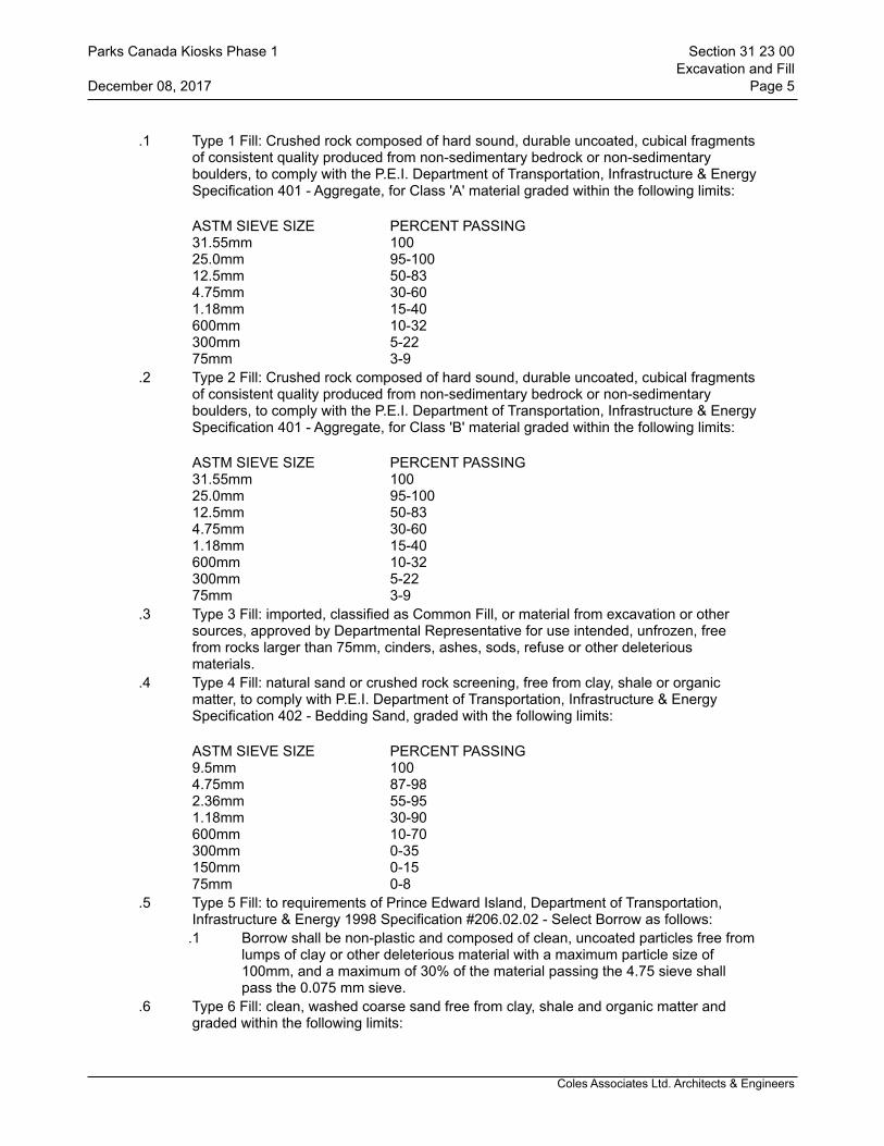
Coles Associates Ltd. Architects & Engineers
.1 Type 1 Fill: Crushed rock composed of hard sound, durable uncoated, cubical fragments of consistent quality produced from non-sedimentary bedrock or non-sedimentary boulders, to comply with the P.E.I. Department of Transportation, Infrastructure & Energy Specification 401 - Aggregate, for Class 'A' material graded within the following limits:
ASTM SIEVE SIZE PERCENT PASSING31.55mm 10025.0mm 95-10012.5mm 50-834.75mm 30-601.18mm 15-40600mm 10-32300mm 5-2275mm 3-9
.2 Type 2 Fill: Crushed rock composed of hard sound, durable uncoated, cubical fragments of consistent quality produced from non-sedimentary bedrock or non-sedimentary boulders, to comply with the P.E.I. Department of Transportation, Infrastructure & Energy Specification 401 - Aggregate, for Class 'B' material graded within the following limits:
ASTM SIEVE SIZE PERCENT PASSING31.55mm 10025.0mm 95-10012.5mm 50-834.75mm 30-601.18mm 15-40600mm 10-32300mm 5-2275mm 3-9
.3 Type 3 Fill: imported, classified as Common Fill, or material from excavation or other sources, approved by Departmental Representative for use intended, unfrozen, free from rocks larger than 75mm, cinders, ashes, sods, refuse or other deleterious materials.
.4 Type 4 Fill: natural sand or crushed rock screening, free from clay, shale or organic matter, to comply with P.E.I. Department of Transportation, Infrastructure & Energy Specification 402 - Bedding Sand, graded with the following limits:
ASTM SIEVE SIZE PERCENT PASSING9.5mm 1004.75mm 87-982.36mm 55-951.18mm 30-90600mm 10-70300mm 0-35150mm 0-1575mm 0-8
.5 Type 5 Fill: to requirements of Prince Edward Island, Department of Transportation, Infrastructure & Energy 1998 Specification #206.02.02 - Select Borrow as follows:
.1 Borrow shall be non-plastic and composed of clean, uncoated particles free from lumps of clay or other deleterious material with a maximum particle size of 100mm, and a maximum of 30% of the material passing the 4.75 sieve shall pass the 0.075 mm sieve.
.6 Type 6 Fill: clean, washed coarse sand free from clay, shale and organic matter and graded within the following limits:
Parks Canada Kiosks Phase 1 Section 31 23 00Excavation and Fill
December 08, 2017 Page 5
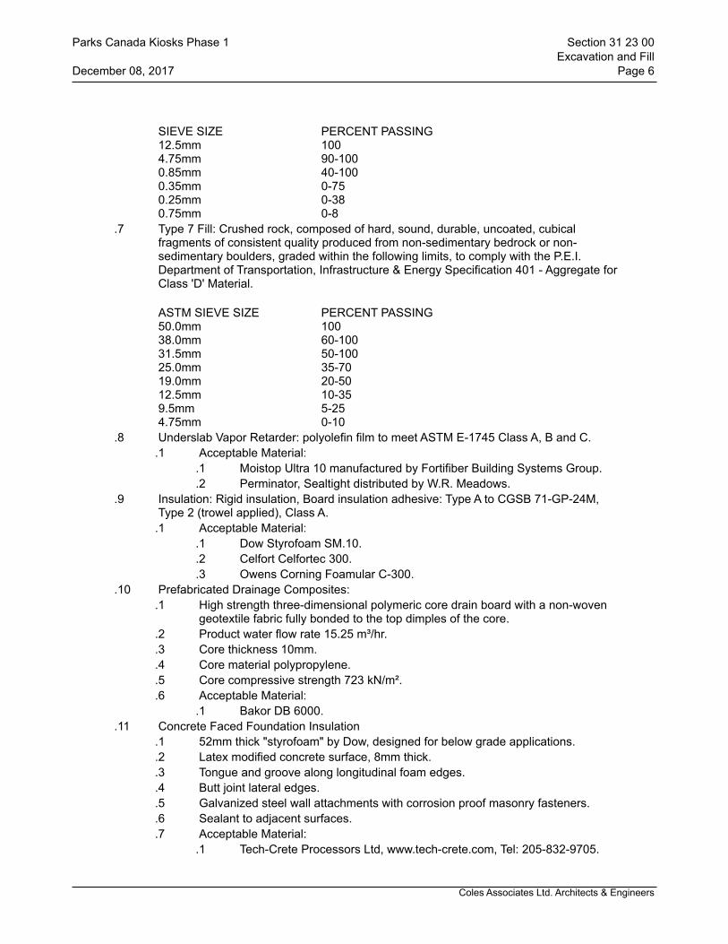
Coles Associates Ltd. Architects & Engineers
SIEVE SIZE PERCENT PASSING12.5mm 1004.75mm 90-1000.85mm 40-1000.35mm 0-750.25mm 0-380.75mm 0-8
.7 Type 7 Fill: Crushed rock, composed of hard, sound, durable, uncoated, cubical fragments of consistent quality produced from non-sedimentary bedrock or non-sedimentary boulders, graded within the following limits, to comply with the P.E.I. Department of Transportation, Infrastructure & Energy Specification 401 - Aggregate for Class 'D' Material.
ASTM SIEVE SIZE PERCENT PASSING50.0mm 10038.0mm 60-10031.5mm 50-10025.0mm 35-7019.0mm 20-5012.5mm 10-359.5mm 5-254.75mm 0-10
.8 Underslab Vapor Retarder: polyolefin film to meet ASTM E-1745 Class A, B and C..1 Acceptable Material:
.1 Moistop Ultra 10 manufactured by Fortifiber Building Systems Group.
.2 Perminator, Sealtight distributed by W.R. Meadows..9 Insulation: Rigid insulation, Board insulation adhesive: Type A to CGSB 71-GP-24M,
Type 2 (trowel applied), Class A..1 Acceptable Material:
.1 Dow Styrofoam SM.10.
.2 Celfort Celfortec 300.
.3 Owens Corning Foamular C-300..10 Prefabricated Drainage Composites:
.1 High strength three-dimensional polymeric core drain board with a non-woven geotextile fabric fully bonded to the top dimples of the core.
.2 Product water flow rate 15.25 m³/hr.
.3 Core thickness 10mm.
.4 Core material polypropylene.
.5 Core compressive strength 723 kN/m².
.6 Acceptable Material:.1 Bakor DB 6000.
.11 Concrete Faced Foundation Insulation.1 52mm thick "styrofoam" by Dow, designed for below grade applications..2 Latex modified concrete surface, 8mm thick..3 Tongue and groove along longitudinal foam edges. .4 Butt joint lateral edges..5 Galvanized steel wall attachments with corrosion proof masonry fasteners..6 Sealant to adjacent surfaces..7 Acceptable Material:
.1 Tech-Crete Processors Ltd, www.tech-crete.com, Tel: 205-832-9705.
Parks Canada Kiosks Phase 1 Section 31 23 00Excavation and Fill
December 08, 2017 Page 6

Coles Associates Ltd. Architects & Engineers
.12 Foundation drainage:.1 100mm diameter perforated PVC foundation drainage pipe with integral filter
fabric wrap..13 Filter Fabric:
.1 Filter light-weight, non-woven polypropylene fiber fabric, needle punched and heat set.
.14 Dampproofing:.1 Emulsified asphalt, mineral colloid type, unfilled: to CAN/CGSB-37.2, and to
Section 07 11 13 - Bituminous Dampproofing..15 Polyethylene film: 6 mil and 10 mil thickness..16 Foundation Waterproofing:
.1 SBS modified bitumen, self-adhering sheet membrane complete with a triple-ply woven complex.
.2 Thickness: 1.5 mm.
.3 Tensile Strength 11.3/15.4 KNm.
.4 Peel Strength SATM D903, 3000 N/m.
.5 Vapor permeance: 0.99 ng/Pa.m².s (0.0086 perms) to ASTM E96.
.6 Elongation: > 1000%.
.7 Acceptable Materials: .1 Soprema - Colphene 3000.
.8 Primer: Elastocol Stick as recommended by manufacturer.17 Corrugated Tree Protection
.1 Galvanized, corrugated, circular culvert sections, in the diameter and height indicated on drawings.
.18 Light Base.1 To match light standard for height..2 Acceptable Material:
.1 Ellamy 610R by Artforms International Inc.
2.2 EQUIPMENT.1 For application of water use pressurized distributor equipped with a spray system that
will ensure even distribution of controlled quantities of water with means of shut-off to avoid dumping of excess water.
.2 Following final grading and seeding use only a water distribution vehicle with tires of sufficient size that any impression left by the tires can, if necessary, be repaired by a light hand raking.
3 Execution
3.1 GENERAL.1 Carry out work to prevent blowing dust and debris during construction.
3.2 APPLICATION.1 Apply water over entire area of operation in sufficient quantities to prevent blowing of
dust, but not to create excess moisture that will prevent segregation of materials, or interfere with proper placement of materials. Application of water is required at all stages of work, which includes, but is not limited to, the following.
.1 Stripping of topsoil.
.2 Excavation Work.
.3 Grading operations.
.4 Placement of fill materials.
Parks Canada Kiosks Phase 1 Section 31 23 00Excavation and Fill
December 08, 2017 Page 7
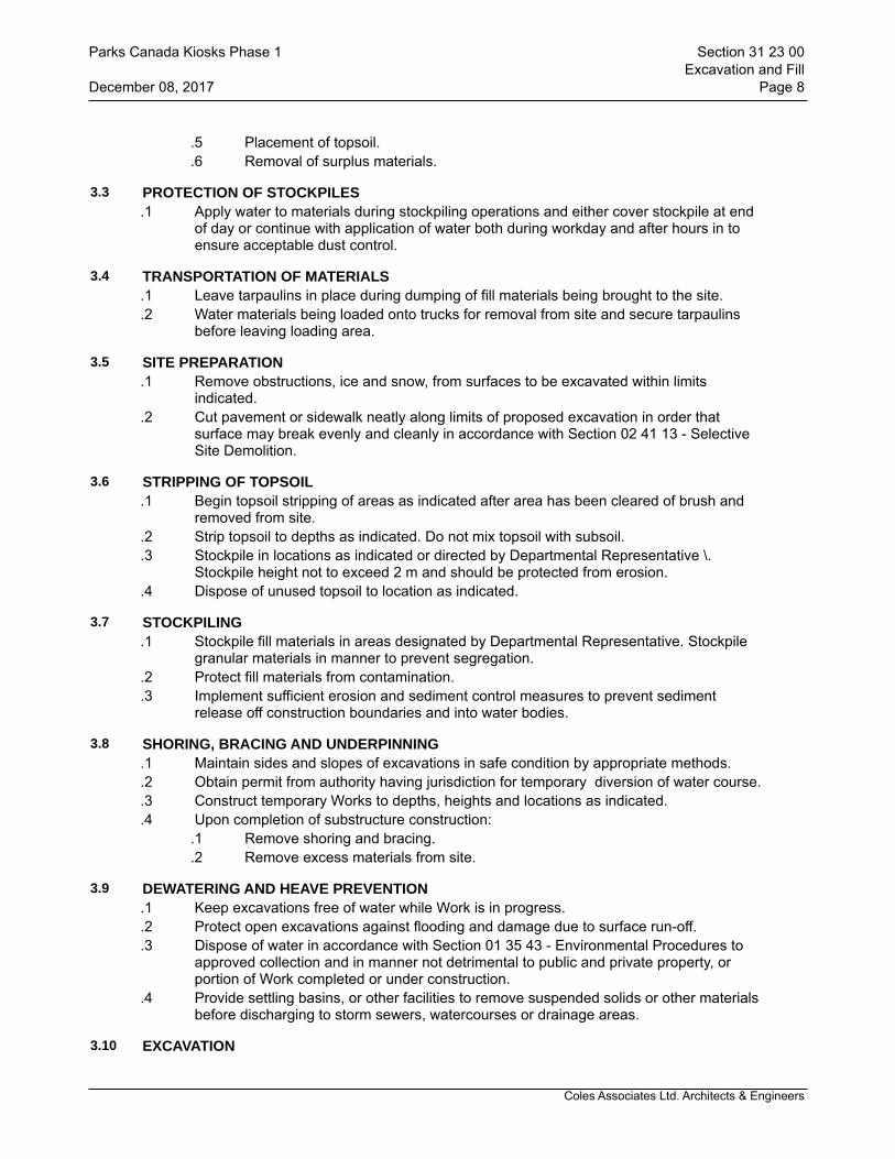
Coles Associates Ltd. Architects & Engineers
.5 Placement of topsoil.
.6 Removal of surplus materials.
3.3 PROTECTION OF STOCKPILES.1 Apply water to materials during stockpiling operations and either cover stockpile at end
of day or continue with application of water both during workday and after hours in to ensure acceptable dust control.
3.4 TRANSPORTATION OF MATERIALS.1 Leave tarpaulins in place during dumping of fill materials being brought to the site..2 Water materials being loaded onto trucks for removal from site and secure tarpaulins
before leaving loading area.
3.5 SITE PREPARATION.1 Remove obstructions, ice and snow, from surfaces to be excavated within limits
indicated..2 Cut pavement or sidewalk neatly along limits of proposed excavation in order that
surface may break evenly and cleanly in accordance with Section 02 41 13 - Selective Site Demolition.
3.6 STRIPPING OF TOPSOIL.1 Begin topsoil stripping of areas as indicated after area has been cleared of brush and
removed from site..2 Strip topsoil to depths as indicated. Do not mix topsoil with subsoil..3 Stockpile in locations as indicated or directed by Departmental Representative \.
Stockpile height not to exceed 2 m and should be protected from erosion..4 Dispose of unused topsoil to location as indicated.
3.7 STOCKPILING.1 Stockpile fill materials in areas designated by Departmental Representative. Stockpile
granular materials in manner to prevent segregation..2 Protect fill materials from contamination..3 Implement sufficient erosion and sediment control measures to prevent sediment
release off construction boundaries and into water bodies.
3.8 SHORING, BRACING AND UNDERPINNING.1 Maintain sides and slopes of excavations in safe condition by appropriate methods. .2 Obtain permit from authority having jurisdiction for temporary diversion of water course..3 Construct temporary Works to depths, heights and locations as indicated..4 Upon completion of substructure construction:
.1 Remove shoring and bracing.
.2 Remove excess materials from site.
3.9 DEWATERING AND HEAVE PREVENTION.1 Keep excavations free of water while Work is in progress..2 Protect open excavations against flooding and damage due to surface run-off..3 Dispose of water in accordance with Section 01 35 43 - Environmental Procedures to
approved collection and in manner not detrimental to public and private property, or portion of Work completed or under construction.
.4 Provide settling basins, or other facilities to remove suspended solids or other materials before discharging to storm sewers, watercourses or drainage areas.
3.10 EXCAVATION
Parks Canada Kiosks Phase 1 Section 31 23 00Excavation and Fill
December 08, 2017 Page 8
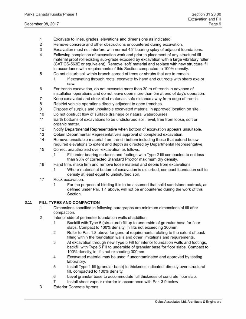
Coles Associates Ltd. Architects & Engineers
.1 Excavate to lines, grades, elevations and dimensions as indicated.
.2 Remove concrete and other obstructions encountered during excavation.
.3 Excavation must not interfere with normal 45° bearing splay of adjacent foundations.
.4 Following completion of excavation work and prior to placement of any structural fill material proof roll existing sub-grade exposed by excavation with a large vibratory roller (CAT CS-563E or equivalent). Remove 'soft' material and replace with new structural fill in accordance with requirements of this Section compacted to 100% density.
.5 Do not disturb soil within branch spread of trees or shrubs that are to remain..1 If excavating through roots, excavate by hand and cut roots with sharp axe or
saw..6 For trench excavation, do not excavate more than 30 m of trench in advance of
installation operations and do not leave open more than 5m at end of day's operation..7 Keep excavated and stockpiled materials safe distance away from edge of trench..8 Restrict vehicle operations directly adjacent to open trenches..9 Dispose of surplus and unsuitable excavated material in approved location on site..10 Do not obstruct flow of surface drainage or natural watercourses..11 Earth bottoms of excavations to be undisturbed soil, level, free from loose, soft or
organic matter..12 Notify Departmental Representative when bottom of excavation appears unsuitable..13 Obtain Departmental Representative's approval of completed excavation..14 Remove unsuitable material from trench bottom including those that extend below
required elevations to extent and depth as directed by Departmental Representative..15 Correct unauthorized over-excavation as follows:
.1 Fill under bearing surfaces and footings with Type 2 fill compacted to not less than 98% of corrected Standard Proctor maximum dry density.
.16 Hand trim, make firm and remove loose material and debris from excavations..1 Where material at bottom of excavation is disturbed, compact foundation soil to
density at least equal to undisturbed soil..17 Rock excavation:
.1 For the purpose of bidding it is to be assumed that solid sandstone bedrock, as defined under Par. 1.4 above, will not be encountered during the work of this Section.
3.11 FILL TYPES AND COMPACTION.1 Dimensions specified in following paragraphs are minimum dimensions of fill after
compaction..2 Interior side of perimeter foundation walls of addition:
.1 Backfill with Type 5 (structural) fill up to underside of granular base for floor slabs. Compact to 100% density, in lifts not exceeding 300mm.
.2 Refer to Par. 1.8 above for general requirements relating to the extent of back filling within the foundation walls and other limitations and requirements.
.3 At excavation through new Type 5 Fill for interior foundation walls and footings, backfill with Type 5 Fill to underside of granular base for floor slabs. Compact to 100% density, in lifts not exceeding 300mm.
.4 Excavated material may be used if uncontaminated and approved by testing laboratory.
.5 Install Type 1 fill (granular base) to thickness indicated, directly over structural fill, compacted to 100% density.
.6 Level granular base to accommodate full thickness of concrete floor slab.
.7 Install sheet vapour retarder in accordance with Par. 3.9 below..3 Exterior Concrete Aprons:
Parks Canada Kiosks Phase 1 Section 31 23 00Excavation and Fill
December 08, 2017 Page 9
Coles Associates Ltd. Architects & Engineers
.1 Backfill with Type 5 fill up to underside of granular base for concrete aprons at building exterior.
.2 Install Type 2 fill to thickness indicated, directly over structural fill, compacted to 100% density.
.3 Level granular base to accommodate full thickness of concrete aprons..4 Underground services:
.1 Use Type 4 Fill (bedding sand) to provide bedding and cover as indicated compacted full width of trench to minimum 95% density.
.2 Use excavated material to underside of granular base for floor slab at interior of addition, compacted to 100% density.
.3 Use Type 3 Fill to underside of topsoil at landscaped areas compacted to density at least equal to adjacent undisturbed soil or minimum 95%.
.5 Interior Concrete Slab on Grade:.1 Backfill with Type 5 Fill (select borrow) to a minimum thickness of 300 mm and to
suit grade. Compact to 100% SPDD..2 Install Type 1 Fill minimum 300 mm compact to 100% SPDD, Class "A".
3.12 BEDDING AND SURROUND OF UNDERGROUND SERVICES.1 Place and compact granular material for bedding and surround of underground services
as indicated..2 Place bedding and surround material in unfrozen condition.
3.13 PERIMETER INSULATION.1 Install horizontal and vertical perimeter board insulation to width and thickness indicated,
directly under floor slabs, adjacent to exterior perimeter walls, as indicated..2 Install boards on walls using a Type A adhesive to temporarily support boards tight
against face of wall until backfilling is complete..3 Install boards to tight fit against abutting boards.
3.14 PERIMETER FOUNDATION INSULATION (VERTICAL).1 Install polystyrene boards to depth and thickness indicated against inside face of exterior
perimeter foundation walls, as indicated..2 Install boards on walls using a Type A adhesive to temporarily support boards tight
against face of wall until backfilling is complete..3 Install boards to tight fit against abutting boards.
3.15 CONCRETE FACED INSULATED WALL PANEL.1 Install vertically in accordance with manufacturers instructions.
3.16 BACKFILLING.1 Do not proceed with backfilling operations until Departmental Representative has
inspected and approved installations..2 Areas to be backfilled to be free from debris, snow, ice, water and frozen ground..3 Do not use backfill material which is frozen or contains ice, snow or debris..4 Backfilling around perimeter foundation walls.
.1 Do NOT place fill material against perimeter foundation walls until:.1 Concrete has cured for a minimum of 14 days..2 Floor structures are permanently in place, unless approved by
Departmental Representative. Provide bracing as directed by Departmental Representative and leave in place until removal is approved by Departmental Representative.
.3 Exercise care not to damage insulation at interior face of foundation
Parks Canada Kiosks Phase 1 Section 31 23 00Excavation and Fill
December 08, 2017 Page 10
Coles Associates Ltd. Architects & Engineers
walls and polyethylene slip sheet at exterior face of the foundation walls..5 Backfilling around site installations.
.1 Place bedding and surround material as specified and indicated in applicable Section for service or utility to be installed.
.2 Do not backfill around or over cast-in-place concrete within 24 hours after placing.
.3 Place layers simultaneously on both sides of installed work to equalize loading.
.4 Where temporary unbalanced earth pressures are liable to develop on walls or other structures:
.1 Permit concrete to cure for minimum of 14 days or until it has sufficient strength to withstand earth and compaction pressure and approval has been obtained from Departmental Representative or:
.2 If approved by Departmental Representative erect bracing or shoring to counteract unbalance, and leave in place until removal is approved by Departmental Representative.
.5 Place material by hand under, around and over installations until 600mm of cover is provided, except where specifically permitted otherwise. Dumping material directly on installations will not be permitted.
.6 Place backfill material in uniform layers not exceeding 150mm up to grades indicated. Compact each layer before placing succeeding layer. Use methods to prevent damage to installations.
3.17 SLIP SHEET/BOND BREAKER.1 Polyethylene Slip Sheet/Bond Breaker
.1 Install 10mil polyethylene slip-sheet at exterior face of all foundation walls from top of footing to future finished grade. Provide temporary support until backfilling is completed.
.2 Use 10mil polyethylene sheet as bond breaker between foundation walls and slabs-on-grade and slabs on steel floor decking. Provide temporary support until slabs are placed. Trim flush with top of slab.
3.18 UNDERSLAB VAPOUR BARRIER.1 Install underslab vapor barrier over entire area of granular base. Lap all joints minimum
300 mm and seal with water impermeable adhesive tape..1 Turn vapour barrier, minimum 100mm, up face of existing foundation walls,
perimeter Insulation at exterior foundation walls and interior piers..2 Seal punctures in sheets before concrete is placed. Use patching material minimum 150
mm larger than puncture, and seal.
3.19 TESTING AND INSPECTION.1 Testing of materials and inspection and testing of placement and compaction will be
carried out by testing laboratory appointed and paid for by the Contractor, in accordance with Section 01 29 83 - Payment Procedures for Testing Laboratory Services. Frequency of tests will be determined by the testing laboratory.
3.20 RESTORATION.1 Upon completion of work, remove surplus materials and debris, trim slopes and correct
defects noted by Departmental Representative..2 Clean and reinstate areas affected by work to satisfaction of Departmental
Representative.
3.21 SURPLUS MATERIAL.1 Remove all surplus material from site, and pay all fees as may be charged at disposal
Parks Canada Kiosks Phase 1 Section 31 23 00Excavation and Fill
December 08, 2017 Page 11

Coles Associates Ltd. Architects & Engineers
site..2 Remove all soil contaminated with oil, gasoline, calcium chloride or other toxic or
dangerous materials resulting from the work of this contract and dispose of in manner to minimize danger at site and in a manner and to a location off site approved by Provincial Authority governing such disposal.
END OF SECTION
Parks Canada Kiosks Phase 1 Section 31 23 00Excavation and Fill
December 08, 2017 Page 12
Coles Associates Ltd. Architects & Engineers
1 General
1.1 RELATED WORK.1 Section 32 01 02 - Sitework Demolition and Removal.
1.2 DESCRIPTION OF WORK.1 The work of this Section compromises the furnishing of all labour, materials and
equipment necessary for the supply and installation of items of work specifically listed under Part 2 - PRODUCTS of this section as specified in this Section and shown on the Drawings.
.2 Contractor must inspect site, verify extent of landscaping items including but not limited to brick paved areas, concrete pads, benches, grassed areas, and other site features impacted by the work of this contract.
.3 Prevent damage to buildings, landscaping, curbs, sidewalks, trees, fences, roads, and adjacent property. Make good any damage.
.4 Undamaged existing site can be re-used and re-installed.
2 Products
2.1 CAST-IN-PLACE CONCRETE.1 Do concrete work in accordance with CAN/CSA A23.1 and A23.2..2 Minimum compressive strength at 28 days: 32 MPa..3 Class of Exposure: C1.4 Air content: 5.-8%.5 Reinforcing steel: grade 400, deformed bars to CSA G30.12.
3 Execution
3.1 CONCRETE.1 Provide an environmental protection during placement of concrete.
3.2 CONNECTION TO EXISTING WORK.1 Verify dimensions, alignment, elevations and condition of existing work before
commencing fabrication and report any discrepancies and potential problem areas to Departmental Representative and await instructions.
END OF SECTION
Parks Canada Kiosks Phase 1 Section 32 01 01Miscellaneous Site Items
December 08, 2017 Page 1
Coles Associates Ltd. Architects & Engineers
1 General
1.1 PROTECTION.1 Protect in accordance with Section 01 35 43 - Environmental Procedures..2 Protect existing items designated to remain. In event of damage, immediately replace
such items or make repairs to approval of Departmental Representative and at no additional cost to Owner.
.3 Prevent movement, settlement or damage of existing utilities, paving, and adjacent grades. Provide bracing, shoring and underpinning required. Make good damage and be liable for injury caused by demolition.
.4 If safety of structure being repaired or utilities appear to be endangered, cease operations and notify Departmental Representative. Take precautions to support structures. Do not resume operations until permission is granted by Departmental Representative.
1.2 DESCRIPTION OF WORK.1 Perform all demolition and removal as specified in this Section and indicated on the
Drawings, which includes but is NOT limited to the items referenced under PART 3 -EXECUTION.
2 Products
2.1 NOT APPLICABLE.1
3 Execution
3.1 PREPARATION.1 Inspect site and verify with Departmental Representative items designated for removal
and items to be salvaged and re-used..2 During demolition work provide protection to structure along adjacent properties..3 There are electrical wiring and water lines at the existing Kiosk. Locate and protect utility
lines and services. Preserve in operating condition active utilities traversing site. Contractor is financially responsible for replacing damaged utilites.
3.2 DEMOLITION AND REMOVAL.1 Remove items indicated for removal as indicated on drawings and as required to
complete the work. .2 Minimize dusting and keep dusty materials wetted.
3.3 PROTECTION.1 Take all necessary precautions and provide all bracing, shoring, and underpinning to
support structure, structures undergoing demolition, adjacent services, roads and walks, landscaping and grading.
.2 If during the demolition work a situation should develop or a condition be exposed which has the potential to endanger the safety of the workers, occupants or users of the structure in which demolition work is being carried out, or pedestrians and vehicles the Contractor will, cease operations, take whatever emergency action, in the Contractor's opinion, is required to ensure the immediate safety of the workers, users and notify the Departmental Representative before continuing with the work
.3 Prevent debris from blocking surface drainage, or from damaging or otherwise interfering with mechanical and electrical systems, which must remain active, and/or in place.
Parks Canada Kiosks Phase 1 Section 32 01 02Sitework Demolition and Removal
December 08, 2017 Page 1

Coles Associates Ltd. Architects & Engineers
3.4 DISPOSAL OF MATERIAL.1 Dispose of all removed materials off site..2 Except where indicated to be re-used all removed materials become the property of the
Contractor and are to be removed from the site and disposed of in a manner and in a location acceptable to Provincial Authority governing such disposal.
.3 Do not sell, burn or bury materials on site.
.4 Pay all fees that may be charged to dispose of materials at licensed disposal sites.
END OF SECTION
Parks Canada Kiosks Phase 1 Section 32 01 02Sitework Demolition and Removal
December 08, 2017 Page 2

Coles Associates Ltd. Architects & Engineers
1 General
1.1 RELATED SECTIONS.1 Section 32 17 23 - Pavement Markings.
1.2 DESCRIPTION OF WORK.1 This Section specifies the requirements for the materials, equipment and methods to be
followed for production, placement and compaction of hot mix, hot laid asphalt concrete for pavement construction for the parking areas, including access driveways.
.2 The following Prince Edward Island Department of Transportation, Infrastructure & Energy Specifications will be followed for all work related to Hot Mix Asphalt Concrete Paving.
.1 501 Asphalt Cement
.2 502 Asphalt Prime
.3 503 Asphalt Emulsions
.4 601 Tack Coat Application
.5 602 Prime Coat Application
.6 603 Hot Mix Asphaltic Concrete
.7 705 Cold Plane Construction Joint
.8 907 Vehicle Configurations and Restrictions
1.3 REFERENCES.1 American Society for Testing and Materials International, (ASTM)
.1 ASTM D995-95b(2002), Standard Specification for Mixing Plants for Hot-Mixed, Hot-Laid Bituminous Paving Mixtures.
.2 ASTM D1559-89, Test Method for Resistance to Plastic Flow of Bituminous Mixtures Using Marshall Apparatus, was withdrawn in 1998 with no replacement.
.2 Asphalt Institute (AI).1 AI MS-2-1993, Mix Design Methods for Asphalt Concrete and Other Hot-Mix
Types..3 Canadian General Standards Board (CGSB)
.1 CAN/CGSB-16.1-M89, Cutback Asphalts for Road Purposes.
.2 CAN/CGSB-16.3-M90, Asphalt Cements for Road Purposes.
1.4 WASTE MANAGEMENT AND DISPOSAL.1 Divert unused asphalt materials from landfill to local quarry as approved by
Departmental Representative..2 Divert unused aggregate materials from landfill to quarry for reuse..3 Unused protective coating material must be disposed of at an official hazardous material
collections site as approved by Departmental Representative..4 Asphalt Materials must not be disposed of into sewer system, into streams, lakes, onto
ground or in other location where it will pose health or environmental hazard.
2 Products
2.1 MATERIALS.1 Asphalt paving mixture: The current Prince Edward Island Department of Transportation,
Infrastructure & Energy Specifications 603 and 501 for hot-mixed, hot-laid asphalt concrete shall govern the materials and composition of the asphalt concrete pavements.
.1 Base: Mix designation 'A' - as per Specification 501
.2 Seal: Mix designation 'C' - as per Specification 501
Parks Canada Kiosks Phase 1 Section 32 12 18Asphalt Paving for Building Sites
December 08, 2017 Page 1
Coles Associates Ltd. Architects & Engineers
.2 Asphalt prime: In accordance with the PEI Department of Transportation, Infrastructure & Energy Specification 502.
.3 Asphalt emulsions: In accordance with the PEI Department of Transportation, Infrastructure & Energy Specification 503.
3 Execution
3.1 ASPHALT PRIME.1 Apply asphalt prime over imported granular base in accordance with the requirements of
PEI Department of Transportation, Infrastructure & Energy Specification 602, Paragraphs 602.01 to 602.04 inclusive.
3.2 ASPHALT CONCRETE PAVING.1 Place and compact asphalt concrete base and seal courses in accordance with the
requirements of PEI Department of Transportation, Infrastructure & Energy Specification 603 to thickness indicated on drawings.
3.3 ASPHALT TACK.1 Apply asphalt tack between base and seal courses and elsewhere as applicable in
accordance with the requirements of PEI Department of Transportation, Infrastructure & Energy Specification 601.
3.4 JOINTS.1 Provide cold plane joint at intersection with existing roads and elsewhere as required in
accordance with PEI Department of Transportation, Infrastructure & Energy Specification 705, Paragraphs 705.01 and 705.02.
3.5 VEHICLE REQUIREMENTS.1 In accordance with PEI Department of Transportation, Infrastructure & Energy,
Specification 907.
3.6 TESTING AND INSPECTION.1 Testing of asphalt materials and inspection and testing of placement and compaction to
be carried out by testing laboratory engaged and paid by the Contractor, in accordance with Section 01 29 83 - Payment Procedures for Testing Labratory Services. Frequency of tests to be determined by the testing laboratory.
3.7 SURPLUS MATERIALS.1 Remove all surplus materials from site..2 Dispose off site at a location approved by Provincial Authority governing such disposal
and pay all fees that may be charged to dispose of materials.
3.8 CLEANING.1 Thoroughly sweep surface of base course prior to apply asphalt tack.
3.9 PROTECTION.1 Keep vehicular traffic off newly paved areas until paving surface temperature has cooled
below 38 degrees C. Do not permit stationary loads on pavement until 24 hours after placement.
.2 Provide access to buildings as required. Arrange paving schedule so as not to interfere with normal use of premises.
END OF SECTION
Parks Canada Kiosks Phase 1 Section 32 12 18Asphalt Paving for Building Sites
December 08, 2017 Page 2

Coles Associates Ltd. Architects & Engineers
1 General
1.1 RELATED SECTIONS.1 Section 03 10 00 - Concrete Forming and Accessories..2 Section 03 20 00 - Concrete Reinforcing..3 Section 03 30 00 - Cast-in-Place Concrete..4 Section 32 12 18 - Asphalt Paving for Building Sites.
1.2 REFERENCES.1 American Society for Testing and Materials (ASTM)
.1 ASTM D698-91(1998), Test Method for Laboratory Compaction Characteristics of Soil Using Standard Effort (12,400ft-lbf/ft³) (600kN-m/m³).
.2 Canadian General Standards Board (CGSB).1 CAN/CGSB-1.2-98, Boiled Linseed Oil..2 CAN/CGSB-3.3-99, Kerosene.
.3 Canadian Standards Association (CSA).1 CAN/CSA-A23.1/A23.2-94, Concrete Materials and Methods of Concrete
Construction/Methods of Test for Concrete.
1.3 TESTING AND INSPECTION.1 Testing and inspection of concrete and concrete materials will be carried out by testing
laboratory engaged and paid by the Contractor in accordance with Section 01 29 83 -Payment Procedures for Testing Laboratory Services. Frequency of tests will be determined by the testing laboratory.
1.4 WASTE MANAGEMENT AND DISPOSAL.1 Separate and recycle waste materials and place in on-site bins in accordance with
Waste Management Plan..2 Place materials defined as hazardous or toxic waste in designated containers..3 Ensure emptied containers are sealed and stored safely.
2 Products
2.1 MATERIALS.1 Concrete mixes and materials: to Section 03 30 00 - Cast-in-Place Concrete..2 Reinforcing steel: to Section 03 20 00 - Concrete Reinforcing..3 Welded wire mesh: to CSA G30.5. Provide in flat sheets only.
.1 All 152 x 152 x 18.7 x 18.7.4 Joint filler: 20mm preformed, non-extruding, resilient, bituminous type..5 Granular base: to Section 31 23 00 - Excavation and Fill, type fill..6 Non-staining mineral type form release agent: chemically active release agents
containing compounds that react with free lime to provide water soluble soap..7 Fill material: to Section 31 23 00 - Excavation and Fill, type fill..8 Forms:
.1 Use minimum 38 mm thickness lumber x maximum practical length at sides of walks and curbs staked to ensure level, straight, undeviating edges over length of walk or
.2 Provide temporary 2 piece wood shut-offs to allow for continuity of welded wire fabric reinforcing.
Parks Canada Kiosks Phase 1 Section 32 16 00Curbs, Gutters, Sidewalks and Driveways
December 08, 2017 Page 1
Coles Associates Ltd. Architects & Engineers
3 Execution
3.1 CONSTRUCTION.1 Construction method:
.1 Curb and sidewalk shall be constructed on a prepared smooth sub-grade of uniform density. All large rocks, roots, sods, rubbish and soft or spongy material shall be removed from subgrade and the excavations filled with material conforming to that of the remainder of the sub-grade. The sub-grade shall then be brought to a smooth surface and thoroughly compacted by rolling or power tamping to finished grade.
.2 Excavation and filling:.1 Provide sand and preparation of sub-grade for curbs and sidewalks. Grade and
compact the sub-grade as specified above..3 Concrete material:
.1 Concrete supplied for the construction of curbs and sidewalks shall meet the following guidelines:
.1 The minimum allowable 28 day compressive strength shall be 35 MPa.
.2 The maximum size of course aggregate shall be 25mm minimal.
.3 The concrete shall have a minimum 25mm slump, with a maximum of a 75mm slump.
.4 Concrete shall have a total air content of 5-7%.
.5 Unless otherwise permitted by the Departmental Representative, only ready mix concrete is to be used for the curb and sidewalk construction. Hand mixing will not be permitted except with the approval of the Departmental Representative.
.4 Mixing and delivering of concrete:.1 Delivery and discharge of concrete by a truck mixer shall be completed within 1
1/2 hours of the introduction of cement and other materials. This period may be reduced by the Departmental Representative during hot weather or under conditions to rapid stiffening on the concrete. Mixing shall begin within thirty minutes of the introduction of cement to the aggregates. Addition of water after the initial introduction of the mixing water will not be permitted, if as a result, the specified 28 day strength will not be obtained.
.5 Forms:.1 Forms shall be of sturdy construction using dressed lumber. Sidewalk forms shall
be placed such as the surface of the walk will grade downwards toward the street at a slope of 1:50.
.2 Curb face forms shall be left in place until the concrete is hardened sufficiently so that they can be removed without damaging the curb. The exposed surfaces shall then be finished to give a granular or matted texture. The remaining forms shall not be removed for at least 24 hours after the concrete has been placed. The edges shall be rounded with an edging tool and no marks shall be left on exposed edges before final finishing.
.6 Construction details.1 All sidewalks construction shall be 1.5 meters wide except where local conditions
prohibit this width..2 All sidewalks bordering the street asphalt surface shall have an integral curb with
a finished face of approximately 150mm showing on the street side. The sidewalk portion of the construction shall be 125mm thick in these sections.
.3 Sidewalk crossing driveways and entrance ramps shall be 150mm thick rather than 125mm. 150 x 150mm steel mesh shall be placed in these sections.
.4 No sidewalk blocks shall have a dimension greater than 1500mm. Reinforced
Parks Canada Kiosks Phase 1 Section 32 16 00Curbs, Gutters, Sidewalks and Driveways
December 08, 2017 Page 2

Coles Associates Ltd. Architects & Engineers
steel dowels 12mm in diameter, 610mm long shall be encased in the concrete at 300mm intervals between adjacent blocks to prevent differential movement of the blocks.
.5 Saucer-type curbs shall be provided at crosswalks, driveways and other areas as directed by the Departmental Representative.
.7 Joints:.1 Expansion joints shall be provided every 7500mm of sidewalk, along the face of
abutting buildings or structures and between adjacent curb and sidewalk section. Expansion joint material shall be approved premolded bitumen filler 6mm in thickness.
.2 Control joints shall be provided every 1500mm of sidewalk.
.3 Curbs shall be provided with contraction joints of 6mm at intervals of 3000mm and at the beginning and end of every curve.
.8 Placing Concrete:.1 All concrete placing methods shall be subjected to the approval of the
Departmental Representative and placing shall not commence until a representative has inspected and approved of all preparations including forms, reinforcing and all spreading, compacting, finishing and curing equipment.
.2 The concrete shall be deposited on the sub-grade immediately after mixing and shall be screeded to a level surface within thirty minutes after discharge from the mixer.
.9 Sidewalk finishing:.1 Screeding shall be carried out immediately after consolidation of the concrete to
give the surface its approximate shape and grade. This shall be accomplished by moving a straight edge with a sawing motion along the top of the forms.
.2 After the screeding operation and the water sheen has disappeared from the surface of the concrete it shall be floated with a wooden float. The Contractor shall exercise care so as to not overwork the concrete, thus avoiding bring access water and fines to the surface.
.3 A pebble finish shall be applied when the concrete is sufficiently hard to retain marking. This finish shall be applied using a suitable metal roller. The edges of the exposed surfaces shall be rounded off with an edging tool and the top portion of joints adjacent to buildings shall be filled with bitumen compound to seal the filler.
.10 Protection and curing:.1 The Contractor shall have available at all time a supply of tarpaulins,
polyethylene of other suitable covering which may be placed over the fresh concrete to protect it from damage in event of rain.
.2 Should the surrounding air temperature fall below 3 degrees Celsius or if there is any likelihood of the temperature falling to this level within forty-eight hours of the placing of the concrete, the contractor shall protect the concrete from damage from frost by covering all exposed surfaces as soon as possible after finishing the tarpaulins or other suitable insulating material. This protection shall remain in place until such time as, in the opinion of the Departmental Representative, the concrete will not be damaged by frost. Well consolidated within the forms.
.3 An approved concrete curbing compound "Rite Cure" or equal shall be supplied to the concrete immediately following finishing. Rate of application shall be as recommended by the manufacturer.
.4 Approximately thirty days after the application of an approved curing compound, the Contractor shall apply an application of linseed oil and kerosene, the mixture shall consist of 50% linseed oil and 50% kerosene. One week after the first application the procedure shall be repeated using an identical mixture.
.11 Pedestrian protection:
Parks Canada Kiosks Phase 1 Section 32 16 00Curbs, Gutters, Sidewalks and Driveways
December 08, 2017 Page 3

Coles Associates Ltd. Architects & Engineers
.1 Place barricades to warn and keep motor vehicle traffic a safe distance from the working area. Also place barricades to warn pedestrian and other such traffic of the work area. If redirecting pedestrian traffic, make sure the alternate route is protected from any vehicle traffic. This may require a double row of barricades. Also make sure the alternate route is as mobility accessible as possible. Keep in mind wheelchairs and visually impaired person, temporary walking shall be Class A, minimum 50mm and shall be properly compacted by hand tamping floating, or vibrating.
3.2 GRADE PREPARATION.1 Do grade preparation work in accordance with Section 31 23 00 - Excavation and Fill..2 Construct embankments using excavated material free from organic matter or other
objectionable materials. Dispose of surplus and unsuitable excavated material in approved location on site.
.3 When constructing embankment provide for minimum 300mm shoulders, where applicable, outside of neat lines of concrete.
.4 Place fill in maximum 150 mm layers and compact to at least 95% of maximum density to ASTM D698.
3.3 GRANULAR BASE.1 Obtain Departmental Representative's approval of subgrade before placing granular
base..2 Place granular base material to lines, widths, and depths as indicated..3 Compact granular base to at least 95% of maximum density to ASTM D698.
3.4 CONCRETE.1 Obtain Departmental Representative's approval of granular base and reinforcing steel
prior to placing concrete..2 Do concrete work in accordance with Section 03 30 00 - Cast-in-Place Concrete..3 Immediately after floating, give sidewalk surface uniform broom finish to produce regular
corrugations not exceeding 2 mm deep, by drawing broom in direction normal to center line.
.4 Provide edging as indicated with 10 mm radius edging tool.
.5 Slip-form pavers equipped with string line system for line and grade control may be used if quality of work acceptable to Departmental Representative can be demonstrated. Hand finish surfaces when directed by Departmental Representative.
3.5 TOLERANCES.1 Finish surfaces to within 3 mm in 3 m as measured with 3 m straight edge placed on
surface.
3.6 EXPANSION AND CONTRACTION JOINTS.1 Install tooled transverse contraction joints after floating, when concrete is stiff, but still
plastic, at intervals of 1500mm..2 Install expansion joints as indicated at intervals of 7500mm max or as directed by
Departmental Representative..3 When sidewalk is adjacent to curb, make joints of curb, gutters and sidewalk coincide.
3.7 ISOLATION JOINTS.1 Install isolation joints around manholes and catch basins and along length adjacent to
concrete curbs, catch basins, buildings, or permanent structure..2 Install joint filler in isolation joints in accordance with Section 03 30 00 - Cast-in-Place
Concrete.
Parks Canada Kiosks Phase 1 Section 32 16 00Curbs, Gutters, Sidewalks and Driveways
December 08, 2017 Page 4

Coles Associates Ltd. Architects & Engineers
.3 Seal isolation joints with sealant approved by Departmental Representative.
3.8 CURING.1 Finish, cure concrete and protect concrete walks in strict accordance with the
requirements of Section 03 35 00 - Concrete Finishing and as noted in this Section.
3.9 BACKFILL.1 Allow concrete to cure for seven (7) days prior to backfilling.
END OF SECTION
Parks Canada Kiosks Phase 1 Section 32 16 00Curbs, Gutters, Sidewalks and Driveways
December 08, 2017 Page 5
Coles Associates Ltd. Architects & Engineers
1 General
1.1 RELATED WORK.1 Section 32 12 18 - Asphalt Paving for Building Sites.
1.2 DESCRIPTION OF WORK.1 The work of this Section comprises
.1 The furnishing of all material, labour and equipment for the provisions of all painted markings on all new asphalt paving inside the Limit of Contract, as specified in this Section and indicated on the drawings.
.2 Temporary markings at new entry road applied to base course, including center lines, stop bars and arrows.
.3 Removal of existing conflicting painted lines by painting over with black paint.
.4 STOP Bars as indicated within limit of contract
.5 Symbols as indicated within limit of contract.
1.3 REFERENCES.1 CAN/CGSB-1.5-M91, Low Flash Petroleum Spirits Thinner..2 CGSB1-GP-12c-68, Standard Paint Colors..3 CGSB1-GP-71-83, Method, of Testing Paints and Pigments..4 CGSB1-GP-74M-79, Paint, Traffic, Alkyd.
1.4 SAMPLES.1 If requested, submit samples in accordance with Section 01 33 00 - Submittal
Procedures..2 If requested, submit to Departmental Representative following material sample quantities
at least four (4) weeks prior to commencing work..1 Two 1L samples of each type of paint..2 One 1kg sample of glass beads..3 Sampling to CGSB1-GP-71.
.3 Mark samples with name of project and its location, paint manufacturer's name and address, name of paint, CGSB specification number and formulation number and batch number.
2 Products
2.1 MATERIALS.1 Paint:
.1 To CGSB1-GP-74M, alkyd traffic paint.
.2 Color: .1 Centerlines: to CGSB 1-GP-12C, yellow 505-308..2 Shoulder edge lines: to CGSB 1-GP-12C, white, 513-301..3 Directional arrows and stop lines: to CGSB 1-GP-12, white, 513-301..4 Painted medians: to CGSB 1-GP-12C, yellow 505-308..5 Barrier free symbols: Blue.6 Parking stalls: to CGSB 1-GP-12C, white, 513-301.
.3 Thinner: to CGSB 1-GP-5M
.4 Upon request, Departmental Representative will supply a qualified product list of paints applicable to work. Qualified paints may be used but Departmental Representative reserves right to perform further tests.
Parks Canada Kiosks Phase 1 Section 32 17 23Pavement Markings
December 08, 2017 Page 1

Coles Associates Ltd. Architects & Engineers
.2 Thinner: to CAN/CGSB-1.5.
.3 Glass beads:.1 Overlay type: to CGSB1-GP-74M.
3 Execution
3.1 EQUIPMENT REQUIREMENTS.1 Paint applicator to be an approved pressure type mobile distributor capable of applying
paint in single, double and dashed lines. Applicator to be capable of applying marking components uniformly, at rates specified, and to dimensions as indicated, and to have positive shut-off.
.2 Distributor to be capable of applying reflective glass beads as an overlay on freshly applied paint.
3.2 CONDITION OF SURFACES.1 Pavement surface to be dry, free from ponded water, frost, ice, dust, oil, grease and
other foreign materials.
3.3 TRAFFIC CONTROL.1 Control public traffic to avoid driving on painted markings while wet.
3.4 APPLICATION.1 Pavement markings to be laid out by Contractor as indicated on drawings and in
accordance with the Manual of Uniform Traffic Control Devices for Canada, latest edition.
.2 Unless otherwise approved by Departmental Representative, apply paint only when air temperature is above 10°C, wind speed is less than 60km/h and no rain is forecast within next 4h.
.3 Apply traffic paint evenly at rate of 3m²/L.
.4 Do not thin paint unless approved by Departmental Representative.
.5 Symbols and letters to conform to dimensions indicated.
.6 Paint lines to be of uniform color and density with sharp edges.
.7 Thoroughly clean distributor tank before refilling with paint of different color.
.8 Apply glass beads at rate of 200g/m² of painted area immediately after application of paint.
3.5 TOLERANCE.1 Paint markings to be within plus or minus 12 mm of dimensions indicated..2 Remove incorrect markings and apply correct markings.
3.6 PROTECTION OF COMPLETED WORK.1 Protect pavement markings until dry.
END OF SECTION
Parks Canada Kiosks Phase 1 Section 32 17 23Pavement Markings
December 08, 2017 Page 2
Coles Associates Ltd. Architects & Engineers
1 General
1.1 RELATED SECTIONS.1 Section 03 30 00 - Cast-in-Place Concrete.
1.2 DESCRIPTION OF WORK.1 The work of this Section comprises the furnishing of all labor, materials, and equipment
necessary for the supply and installation of the items of work specifically listed under Part 2 - PRODUCTS of this Section, as specified in this Section and shown on the Drawings.
2 Products
2.1 PIPE BOLLARDS.1 Fabricate from HSS Round, Grade 350 W to size indicated c/w anchor lugs..2 Prime paint ready for finish painting..3 Concrete to CSA A23.1 and CSA A 23.2. Min compressive strength = 25 MPa at 28 days
for installation in concrete bases.
3 Execution
3.1 INSTALLATION OF BOLLARDS.1 Install posts to details and as indicated and specified herein..2 Excavate post holes, compact bottom of hole to provide firm foundation. Set post plumb
and centered in concrete. Provide slip sheet around entire concrete base. Backfill with excavated material in 150 mm layers. Compact each layer before placing succeeding layer.
.3 Apply one cost steel primer CGSB 1-GP-40M and two coats exterior enamel CGSB 1-GP-59M (colour as approved by owner).
.4 Complete backfilling around posts to ground elevation when paint is dry.
END OF SECTION
Parks Canada Kiosks Phase 1 Section 32 39 00Manufactured Site Specialties
December 08, 2017 Page 1

Coles Associates Ltd. Architects & Engineers
1 General
1.1 RELATED SECTIONS.1 Section 31 22 13 - Rough Grading..2 Section 31 22 19 - Finish Grading.3 Section 31 23 00 - Excavation and Fill.
1.2 REFERENCES.1 Agriculture and Agri-Food Canada (AAFC).
.1 Plant Hardiness Zones in Canada-2000..2 Canadian Nursery Landscape Association (CNLA).
.1 Canadian Standards for Nursery Stock-2001..3 Health Canada/Workplace Hazardous Materials Information System (WHMIS).
.1 Material Safety Data Sheets (MSDS).
1.3 DEFINITIONS.1 Compost: A mixture of soil and decomposing organic matter used as a fertilizer, mulch,
or soil conditioner. Compost is processed organic matter containing 40% or more organic matter as determined by the Walkley-Black or LOI test. Product must be sufficiently decomposed (i.e. stable) so that any further decomposition does not adversely affect plant growth (C:N ratio below (25) (50)), and contain no toxic or growth inhibiting contaminates. Composed bio-solids must meet the requirements of the Guidelines for Compost Quality, Category (A) (B) produced by the Canadian Council of the Ministers of the Environment (CCME), January 1996.
.2 Mycorrhiza: association between fungus and roots of plants. This symbiosis, enhances plant establishment in newly landscaped and imported soils.
1.4 SUBMITTALS.1 Make submittals in accordance with Section 01 33 00 - Submittal Procedures..2 Submit product data and MSDS sheets for:
.1 Fertilizer.
.2 Mycorrhiza.
.3 Anti-desiccant.
.4 Guying assembly including clamps, collar, guying wire, anchors and wire tightener.
.5 Mulch..3 Submit WHMIS MSDS - in accordance with Section 01 33 00 - Submittal Procedures.
1.5 STORAGE AND PROTECTION.1 Protect plant material from frost, excessive heat, wind and sun during delivery..2 Immediately store and protect plant material which will not be installed within 1 hours
after arrival at site in storage location approved by Departmental Representative..3 Protect plant material from damage during transportation:
.1 When delivery distance is less than 30 km and vehicle travels at speeds under 80 km/h, tie tarpaulins around plants or over vehicle box.
.2 When delivery distance exceeds 30 km or vehicle travels at speeds over 80 km/h, use enclosed vehicle where practical.
.4 Protect stored plant material from frost, wind and sun and as follows:.1 For bare root plant material, preserve moisture around roots by heeling-in or
burying roots in sand or topsoil and watering to full depth of root zone..2 For pots and containers, maintain moisture level in containers. Heel-in fiber pots.
Parks Canada Kiosks Phase 1 Section 32 93 00Plants
December 08, 2017 Page 1

Coles Associates Ltd. Architects & Engineers
.3 For balled and burlapped and wire basket root balls, place to protect branches from damage. Maintain moisture level in root zones.
1.6 SCHEDULING.1 Obtain approval from Departmental Representative of schedule seven (7) days in
advance of shipment of plant material..2 Schedule to include:
.1 Quantity and type of plant material.
.2 Shipping dates.
.3 Arrival dates on site.
.4 Planting Dates.
1.7 WARRANTY.1 The Contractor hereby warrants that new plant material will remain free of defects for 2
full growing seasons..2 End-of-warranty inspection will be conducted by Departmental Representative..3 Departmental Representative reserves the right to extend Contractor's warranty
responsibilities for an additional one year if, at end of initial warranty period, leaf development and growth is not sufficient to ensure future survival.
1.8 WASTE MANAGEMENT AND DISPOSAL.1 Collect and separate waste material for disposal in appropriate on-site bins in
accordance with Waste Management Plan (WMP)..2 Handle and dispose of hazardous materials in accordance with CEPA..3 Dispose of unused fertilizer at official hazardous material collection site..4 Dispose of unused anti-desiccant at official hazardous material collections site.
2 Products
2.1 PLANT MATERIAL.1 Type of root preparation, sizing, grading and quality: comply to Canadian Standards for
Nursery Stock..1 In accordance with Plant Hardiness Zones in Canada..2 Plant material must be planted in zone indicated as appropriate for its species..3 Plant material in location appropriate for its species.
.2 Plant material: free of disease, insects, defects or injuries and structurally sound with strong fibrous root system.
.3 Bare root stock: nursery grown, in dormant stage, not balled and burlapped or container grown.
.4 Collected stock: maximum 40 mm in caliper, with well developed crowns and characteristically branched; no more than 40% of overall height may be free of branches.
.5 Types: as called for on Civil drawings.
2.2 WATER.1 Free of impurities that would inhibit plant growth.
2.3 STAKES.1 T-bar, steel, 40 x 40 x 5 x 2440 mm.
2.4 WIRE TIGHTENER.1 Turnbuckle, galvanized steel, 9.5 mm diameter with 270 mm open length.
Parks Canada Kiosks Phase 1 Section 32 93 00Plants
December 08, 2017 Page 2
Coles Associates Ltd. Architects & Engineers
2.5 GUYING WIRE.1 Type 1: steel, 3 mm wire..2 Type 2: 1.5 mm diameter multi-wire steel cable..3 Type 3: 3 mm diameter multi-wire steel cable.
2.6 CLAMPS.1 U-bolt: galvanized, 13 mm diameter, c/w curved retaining bar and hex nuts..2 Crimp type.
2.7 ANCHORS.1 Wood:
.1 Type 1: 38 x 38 x 460 mm.
.2 Type 2: 38 x 67 x 600 mm..2 Drive-in type.
.1 Type 1: 13 mm diameter x 75 mm long, aluminum.
.2 Type 2: 18 mm diameter x 120 mm long, aluminum.
.3 Screw-in type:.1 Type 1: 100 mm diameter steel disc.
2.8 GUYING COLLAR.1 Tube: plastic, 13 mm diameter, nylon reinforced.
2.9 SOIL AMENDMENTS.1 Peatmoss:
.1 Derived from partially decomposed species of Sphagnum Mosses.
.2 Elastic and homogeneous, brown in color.
.3 Free of wood and deleterious material which could prohibit growth.
.4 Shredded particle minimum size: 5 mm..2 Sand: washed coarse silica sand, medium to course textured if supplement is required..3 Organic matter: compost Category A, B, unprocessed organic matter, such as rotted
manure, hay, straw, bark residue or sawdust, meeting the organic matter, stability and contaminant requirements if supplement is required.
.4 Fertilizer: industry accepted standard medium containing nitrogen, phosphorous, potassium and other micro-nutrients suitable to specific plant species or application or defined by soil test.
2.10 MULCH.1 Bark chip: varying in size from 25 to 50 mm in diameter, from bark of coniferous trees..2 Wood chip: varying in size from 50 mm to 75 mm and 5 to 20 mm thick, free of bark,
small branches and leaves..3 Shredded wood: varying in size from 25 to 125 mm in length, from coniferous trees..4 1000 mm diameter around each tree.
2.11 FERTILIZER.1 Synthetic commercial type , ratio 5:3:2.
2.12 ANTI-DESICCANT.1 Wax-like emulsion.
2.13 FLAGGING TAPE.1 Fluorescent color, yellow, orange or blue.
Parks Canada Kiosks Phase 1 Section 32 93 00Plants
December 08, 2017 Page 3

Coles Associates Ltd. Architects & Engineers
2.14 SOURCE QUALITY CONTROL.1 Obtain approval from Departmental Representative of plant material prior to planting..2 Acceptance of source of plant material does not prevent rejection on site prior to or after
planting operations..3 Imported plant material must be accompanied with necessary permits and import
licenses. Conform to Federal, Provincial or Territorial regulations.
3 Execution
3.1 PRE-PLANTING PREPARATION.1 Ensure plant material acceptable to Departmental Representative..2 Remove damaged roots and branches from plant material.
3.2 EXCAVATION AND PREPARATION OF PLANTING BEDS.1 Stake out location and obtain approval from Departmental Representative prior to
excavating..2 Excavate to depth and width as indicated..3 Remove subsoil, rocks, roots, debris and toxic material from excavated material that will
be used as planting soil for individual shrubs. Dispose of excess material..4 Scarify sides of planting hole..5 Remove water which enters excavations prior to planting. Notify Departmental
Representative if water source is ground water.
3.3 REMOVAL OF EXISTING SHRUBS FOR TRANSPLANTING.1 Use tree-spade to shrubs from existing forestry plantation and move immediately to new
spaded holes..2 Excavate holes at transplanted shrub location, with tree spade and transport excavated
material to plantation to fill holes created by removal of shurubs..3 Take care to minimize damage to roots and branches of adjacent trees and shrubs.
3.4 PLANTING.1 For bare root stock, place 50 mm backfill soil in bottom of hole. Plant trees and shrubs
with roots placed straight out in hole..2 For jute burlapped root balls, cut away top one third of wrapping and wire basket without
damaging root ball. Do not pull burlap or rope from under root ball..3 For container stock or root balls in non-degradable wrapping, remove entire container or
wrapping without damaging root ball..4 Plant vertically in locations as indicated. Orient plant material to give best appearance in
relation to structure, roads and walks..5 For trees and shrubs:
.1 Backfill soil in 150 mm lifts. Tamp each lift to eliminate air pockets. When two thirds of depth of planting pit has been backfilled, fill remaining space with water. After water has penetrated into soil, backfill to finish grade.
.2 Form watering saucer as indicated..6 For ground covers, backfill soil evenly to finish grade and tamp to eliminate air pockets..7 Water plant material thoroughly..8 After soil settlement has occurred, fill with soil to finish grade..9 Dispose of burlap, wire and container material off site.
3.5 MULCHING.1 Ensure soil settlement has been corrected prior to mulching..2 Spread mulch as indicated.
Parks Canada Kiosks Phase 1 Section 32 93 00Plants
December 08, 2017 Page 4
Coles Associates Ltd. Architects & Engineers
3.6 MAINTENANCE DURING ESTABLISHMENT PERIOD.1 Perform the following maintenance operations from time of planting to acceptance by
Departmental Representative..1 Water to maintain soil moisture conditions for optimum establishment, growth
and health of plant material without causing erosion..1 For evergreen plant material, water thoroughly in late fall prior to freeze-
up to saturate soil around root system..2 Remove weeds monthly until end of Warranty Period..3 Replace or respread damaged, missing or disturbed mulch..4 For non-mulched areas, cultivate as required to keep top layer of soil
friable..5 If required to control insects, fungus and disease, use appropriate control
methods in accordance with Federal, Provincial and Municipal regulations. Obtain product approval from Departmental Representative prior to application.
.6 Remove dead or broken branches from plant material.
.7 Keep trunk protection and guy wires in proper repair and adjustment.
.8 Remove and replace dead plants and plants not in healthy growing condition. Make replacements in same manner as specified for original plantings.
3.7 MAINTENANCE DURING WARRANTY PERIOD.1 From time of acceptance by Departmental Representative to end of warranty period,
perform following maintenance operations..1 Water to maintain soil moisture conditions for optimum growth and health of plant
material without causing erosion..2 Reform damaged watering saucers..3 Remove weeds monthly..4 Replace or respread damaged, missing or disturbed mulch..5 For non-mulched areas, cultivate monthly to keep top layer of soil friable..6 If required to control insects, fungus and disease, use appropriate control
methods in accordance with Federal, Provincial and Municipal regulations. Obtain product approval from Departmental Representative prior to application.
.7 Apply fertilizer in early spring as indicated by soil test.
.8 Remove dead, broken or hazardous branches from plant material.
.9 Remove and replace dead plants and plants not in healthy growing condition. Make replacements in same manner as specified for original plantings.
3.8 ACCEPTANCE.1 Plant material will be accepted by Departmental Representative 90 days after planting
operation is completed provided that plant material exhibits healthy growing condition and is free from disease, insects and fungal organisms, determined by Departmental Representative to have been present before delivery to site.
.2 Plant material installed less than 90 days prior to frost will be accepted in following spring, 30 days after start of growing season provided that acceptance conditions are fulfilled.
3.9 SCHEDULE.1 As listed on Civil drawings.
END OF SECTION
Parks Canada Kiosks Phase 1 Section 32 93 00Plants
December 08, 2017 Page 5
Coles Associates Ltd. Architects & Engineers
1 General
1.1 RELATED SECTIONS.1 Section 31 23 00 - Excavation and Fill.
1.2 REFERENCES.1 Canadian Standards Association (CSA International)
.1 CSA-A23.1/A23.2-00(June 2001), Concrete Materials and Methods of Concrete Construction/Methods of Test for Concrete.
.2 CSA B1800-02, Plastic Non-pressure Pipe Compendium - B1800 Series (Consists of B181.1, B181.2, B181.3, B181.5, B182.1, B182.2, B182.4, B182.6, B182.7, B182.8 and B182.11).
1.3 WASTE MANAGEMENT AND DISPOSAL.1 Remove from site and dispose of packaging materials at appropriate recycling facilities..2 Collect and separate for disposal paper packaging material in appropriate on-site bins
for recycling in accordance with Waste Management Plan..3 Divert unused concrete and aggregate materials from landfill to local quarry.
2 Products
2.1 BEDDING AND SURROUND MATERIALS.1 Coarse filter aggregate: to CSA-A23.1/A23.2, Group 1 20-5 mm..2 Perforated drain pipe and fittings to be polyvinyl chloride complying with CAN/CSA-
B182.1 .3 Rigid plastic pipe and fittings: to CSA-B182.1, size NPS 2, complete with fittings..4 Non-perforated drain pipe and fitting to be polyvinylchloride complying with CAN/CSA
B182.1. .5 Geotextile filter: geotextile water permeable filter fabric with 40-70 sieve pore size.
2.2 BACKFILL MATERIAL.1 Type 2, in accordance with Section 31 23 00 - Excavation and Fill..2 Excavated or graded material existing on site may be suitable to use if approved by
Departmental Representative.
3 Execution
3.1 EXAMINATION.1 Ensure graded subgrade conforms with required drainage pattern before placing
bedding material..2 Ensure improper slopes, unstable areas, areas requiring additional compaction or other
unsatisfactory conditions are corrected to approval of Departmental Representative..3 Ensure foundation wall and dampproofing have been installed and approved by
Departmental Representative before placing bedding material.
3.2 BEDDING PREPARATION.1 Pipe bedding: place filter aggregate as required to ensure that perforated pipe is level
and at elevation shown on drawings to permit pipe sleeves passing through footings to be installed above footing reinforcing.
3.3 PIPE OR TUBING INSTALLATION
Parks Canada Kiosks Phase 1 Section 33 46 13Foundation Drainage
December 08, 2017 Page 1

Coles Associates Ltd. Architects & Engineers
.1 Ensure pipe interior and coupling surfaces are clean before laying.
.2 Lay perforated pipe minimum to slope of 1:100. For pipe face perforations and coupling slots downward.
.3 Lay non-perforated pipe from perforated pipe to disposal area. Make joints watertight.
.4 Grade bedding to establish pipe slope. Do not use concrete, masonry, stones, wood or any type of shim to establish pipe slope.
.5 Install end plugs at ends of collector drains to protect pipe ends from damage and ingress of foreign material.
.6 Connect non-perforated pipe to drain by appropriate adapters manufactured for this purpose.
.7 Provide cleanouts on non-perforated pipe at changes of pipe direction and in runs greater than 15 m.
.8 Provide flush cleanouts where directed by Departmental Representative.
.9 Connect drainage system to building storm sewers, as indicated.
3.4 PIPE OR TUBING SURROUND MATERIAL.1 Upon completion of pipe laying and after Departmental Representative has inspected
Work in place, surround and cover pipe as indicated..2 Hand place surround material in uniform layers not exceeding 150 mm compacted
thickness..3 Place layers uniformly and simultaneously on each side of pipe..4 Compact each layer from pipe invert to mid-height of pipe to at least 95% of corrected
maximum dry density..5 Compact each layer from mid-height of pipe to underside of backfill to at least 90% of
corrected maximum dry density.
3.5 BACKFILL MATERIAL.1 Place backfill material above pipe surround in uniform layers not exceeding 150 mm
compacted thickness up to grades as indicated..2 Under paving and walks, compact backfill to at least 95% corrected maximum dry
density. In other areas, compact to at least 90% corrected maximum dry density.
END OF SECTION
Parks Canada Kiosks Phase 1 Section 33 46 13Foundation Drainage
December 08, 2017 Page 2
Coles Associates Ltd. Architects & Engineers
1 General
1.1 RELATED SECTIONS.1 Section 26 05 00 - Common Work Results - Electrical..2 Section 26 05 28 - Grounding - Secondary..3 Section 26 05 34 - Conduits, Conduit Fastenings and Conduit Fittings..4 Section 26 05 43.01 - Installation of Cables in Trenches and in Ducts..5 Section 26 24 01 - Service Entrance.
2 Products
2.1 MATERIALS.1 Underground ducts: to Section 33 65 76 - Direct Buried Underground Cable Ducts, rigid
PVC type, size as indicated..2 Conductors: copper, type RWU-90, to Section 26 05 21 - Wires and Cables (0 -1000V),
size and number of conductors as indicated..3 Backfill: clean and free from debris.
3 Execution
3.1 MANUFACTURER'S INSTRUCTIONS.1 Compliance: comply with manufacturer's written recommendations or specifications
including product technical bulletins, handling, storage and installation instructions, and datasheets.
3.2 INSTALLATION.1 Coordinate incoming service with Utility on site..2 Install cables in ducts in accordance with Section 26 05 43.01 - Installation of Cables in
Ducts..3 Allow adequate conductor length for connection to service..4 Connect conductors to service equipment and arrange for energization with Utility.
Connection to Utility equipment to be completed by Utility..5 Allow adequate conductor length for connection to service equipment..6 Make grounding connections in accordance with Section 26 05 28 - Grounding -
Secondary..7 Seal ducts and conduits at building entrance location after installation of cables.
3.3 FIELD QUALITY CONTROL.1 Perform tests in accordance with Section 26 05 00 - Common Work Results - Electrical..2 Perform additional tests as required by authority having jurisdiction..3 Submit written test results for review and approval.
END OF SECTION
Parks Canada Kiosks Phase 1 Section 33 71 73.02Underground Electrical Service
December 08, 2017 Page 1


Parks Canada Kiosks Phase 1 December 08, 2017
Coles Associates Ltd. Architects & Engineers
APPENDIX A


TYPE
PROGRESS LIGHTING #P5036-09
LUMARK #XTOR2B-W-BK
PROGRESS LIGHTING #P2301-0930K9
GARDCO #P21-A1-1-2-55LA-NW-UNV-NP + SRAL4-20-AB-1DR-NA-BC
E
POLE MOUNTED LED ROADWAY LUMINAIRE C/W TYPE II DISTRIBUTION, NATURAL ALUMINUM FINISH, ON A 6.1M HIGH, STRAIGHT, ROUND, 100mm DIAMETER POLE TO MATCH EXISTING ROADWAY LIGHT STANDARDS.
LED SOURCE POLE MOUNTED
55W
MIN 120 LUMENS/WATT
6600 LUMEN
MIN. 70 CRI
4000K
D
LED SOURCE RECESS MOUNTED IN
SOFFIT15W
MIN 70 LUMENS/WATT
1000 LUMEN
MIN. 80 CRI
4000KJUNO #2LEDDRIVER G2 10LM 120 FRPC + 2LEDTRIM G2 ADJ 40K 80CRI FL BL
WALL WASH, ADJUSTABLE, WET LISTED, EXTERIOR LED POTLIGHT CAPABLE OF FITTING IN 250mm DEEP BY 200mm HIGH SOFFIT.
SPECTRUM LIGHTING #RAFO40C10L40KMDE1+RA4FOCSGSOX-WET LISTED
C
300mm DIAMETER, CEILING MOUNTED, LED LUMINAIRE C/W FROSTED GLASS, BRUSHED NICKEL FINISH, 120V.
LED SOURCE FLUSH CEILING MOUNTED
17W
MIN 70 LUMENS/WATT
1200 LUMEN
MIN. 80 CRI
3000K
B
LOW PROFILE LED WALLPACK C/W BLACK FINISH, 120V. MIN. 1400 LUMENS WALL MOUNTED AT 2100mm
FROM GRADE TO MIDDLE OF
LUMINAIRE
MIN. 70 CRI
MIN. 80 LUMENS/W
4000 K
A
CEILING STEM SUSPENDED TO
2500mm AFF
LUMINAIRE SCHEDULE
MOUNTINGLAMPDESCRIPTION
400mm DIAMETER, PENDANT MOUNTED LUMINAIRE C/W WHITE MYLAR SHADE SURROUNDING LINEN INTERIOR SHADE, BRUSHED NICKEL FINISH, 100W EQUIVALENT MEDIUM BASE LED LAMP, 120V.
MIN. 1600 LUMENS
MIN. 80 CRI
MAX 20W
3000 K
Section 26 50 00.1
Luminaire Schedule
Park Canada Kiosks Phase 1
December 8, 2017


