Embed Size (px)
Citation preview
MRPLClient :
MRPL BSVI PROJECT
MANGALORELocation
16/43Dept./Sect. :
Project :
PIPING MATERIAL
SPECIFICATION
Copyright EIL- All rights reserved
JOB SPECIFICATION No.
B038-6-44-0005 Rev. B
Package : IPMCS
Report No. : 50
Template No. 5-0000-0001-T2 Rev.
Page 70 of 208
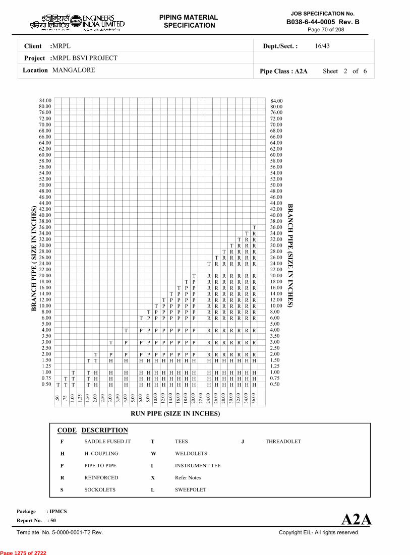
Sheet 2 ofPipe Class : A2A
T T T T H H H H H H H H H H H H H H H H H H0.50T T T H H H H H H H H H H H H H H H H H H0.75
T T H H H H H H H H H H H H H H H H H H1.001.25
T T H H H H H H H H H H H H H H H H H1.50T P P P P P P P P P P R R R R R R R2.00
2.50T P P P P P P P P P R R R R R R R3.00
3.50T P P P P P P P P R R R R R R R4.00
5.00T P P P P P P P R R R R R R R6.00
T P P P P P P R R R R R R R8.00T P P P P P R R R R R R R10.00
T P P P P R R R R R R R12.00T P P P R R R R R R R14.00
T P P R R R R R R R16.00T P R R R R R R R18.00
T R R R R R R R20.0022.00
T R R R R R R24.00T R R R R R26.00
T R R R R28.00T R R R30.00
T R R32.00T R34.00
T36.0038.0040.0042.0044.0046.0048.0050.0052.0054.0056.0058.0060.0062.0064.0066.0068.0070.0072.00
.
50
.
75
1
.00
1
.25
1
.50
2
.00
2
.50
3
.00
3
.50
4
.00
5
.00
6
.00
8
.00
10
.00
12
.00
14
.00
16
.00
18
.00
20
.00
22
.00
24
.00
26
.00
28
.00
30
.00
32
.00
34
.00
36
.00
BR
AN
CH
PIP
E (
SIZ
E I
N I
NC
HE
S)
0.500.751.001.251.502.002.503.003.504.005.006.008.0010.0012.0014.0016.0018.0020.0022.0024.0026.0028.0030.0032.0034.0036.0038.0040.0042.0044.0046.0048.0050.0052.0054.0056.0058.0060.0062.0064.0066.0068.0070.0072.00
BR
AN
CH
PIP
E (SIZ
E IN
INC
HE
S)
RUN PIPE (SIZE IN INCHES)
CODE DESCRIPTION
F
H
P
R
S
T
W
I
X
L
JSADDLE FUSED JT
H. COUPLING
PIPE TO PIPE
REINFORCED
SOCKOLETS
TEES
WELDOLETS
INSTRUMENT TEE
Refer Notes
SWEEPOLET
THREADOLET
A2A
76.0080.0084.00
76.0080.0084.00
6
Page 1275 of 2722
MRPLClient :
MRPL BSVI PROJECT
MANGALORELocation
16/43Dept./Sect. :
Project :
PIPING MATERIAL
SPECIFICATION
Copyright EIL- All rights reserved
JOB SPECIFICATION No.
B038-6-44-0005 Rev. B
Package : IPMCS
Report No. : 50
Template No. 5-0000-0001-T2 Rev.
Page 71 of 208
Sheet 3 ofPipe Class : A2A
InputId.
Item Type
LowerSize
Upper Size
Sch/Thk DescriptionMaterial
CommodityCode
NoteNo
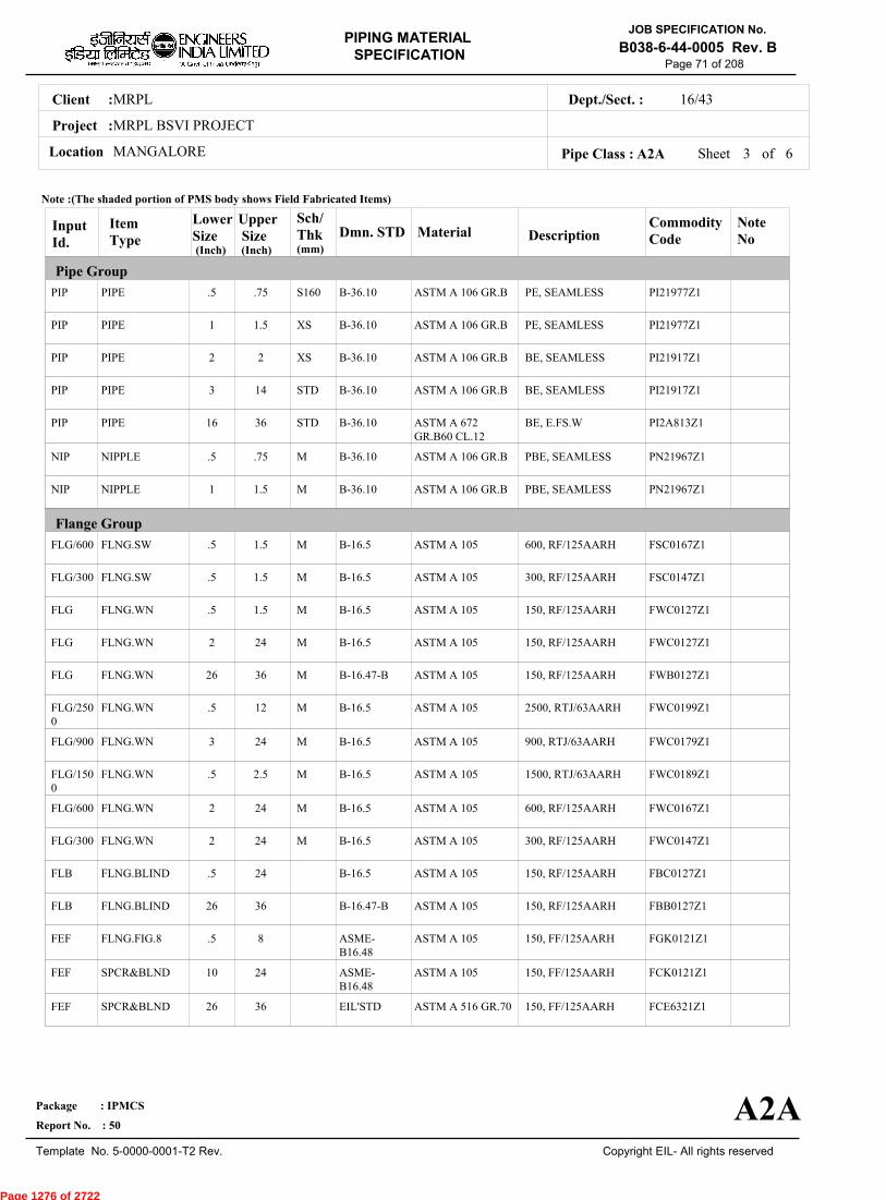
Pipe Group
Flange Group
Dmn. STD(Inch) (Inch)
PIP
PIP
PIP
PIP
PIP
NIP
NIP
FLG/600
FLG/300
FLG
FLG
FLG
FLG/2500
FLG/900
FLG/1500
FLG/600
FLG/300
FLB
FLB
FEF
FEF
FEF
PIPE
PIPE
PIPE
PIPE
PIPE
NIPPLE
NIPPLE
FLNG.SW
FLNG.SW
FLNG.WN
FLNG.WN
FLNG.WN
FLNG.WN
FLNG.WN
FLNG.WN
FLNG.WN
FLNG.WN
FLNG.BLIND
FLNG.BLIND
FLNG.FIG.8
SPCR&BLND
SPCR&BLND
.5
1
2
3
16
.5
1
.5
.5
.5
2
26
.5
3
.5
2
2
.5
26
.5
10
26
.75
1.5
2
14
36
.75
1.5
1.5
1.5
1.5
24
36
12
24
2.5
24
24
24
36
8
24
36
S160
XS
XS
STD
STD
M
M
M
M
M
M
M
M
M
M
M
M
PE, SEAMLESS
PE, SEAMLESS
BE, SEAMLESS
BE, SEAMLESS
BE, E.FS.W
PBE, SEAMLESS
PBE, SEAMLESS
600, RF/125AARH
300, RF/125AARH
150, RF/125AARH
150, RF/125AARH
150, RF/125AARH
2500, RTJ/63AARH
900, RTJ/63AARH
1500, RTJ/63AARH
600, RF/125AARH
300, RF/125AARH
150, RF/125AARH
150, RF/125AARH
150, FF/125AARH
150, FF/125AARH
150, FF/125AARH
ASTM A 106 GR.B
ASTM A 106 GR.B
ASTM A 106 GR.B
ASTM A 106 GR.B
ASTM A 672GR.B60 CL.12
ASTM A 106 GR.B
ASTM A 106 GR.B
ASTM A 105
ASTM A 105
ASTM A 105
ASTM A 105
ASTM A 105
ASTM A 105
ASTM A 105
ASTM A 105
ASTM A 105
ASTM A 105
ASTM A 105
ASTM A 105
ASTM A 105
ASTM A 105
ASTM A 516 GR.70
PI21977Z1
PI21977Z1
PI21917Z1
PI21917Z1
PI2A813Z1
PN21967Z1
PN21967Z1
FSC0167Z1
FSC0147Z1
FWC0127Z1
FWC0127Z1
FWB0127Z1
FWC0199Z1
FWC0179Z1
FWC0189Z1
FWC0167Z1
FWC0147Z1
FBC0127Z1
FBB0127Z1
FGK0121Z1
FCK0121Z1
FCE6321Z1
B-36.10
B-36.10
B-36.10
B-36.10
B-36.10
B-36.10
B-36.10
B-16.5
B-16.5
B-16.5
B-16.5
B-16.47-B
B-16.5
B-16.5
B-16.5
B-16.5
B-16.5
B-16.5
B-16.47-B
ASME-B16.48
ASME-B16.48
EIL'STD
Note :(The shaded portion of PMS body shows Field Fabricated Items)
A2A
(mm)
6
Page 1276 of 2722

MRPLClient :
MRPL BSVI PROJECT
MANGALORELocation
16/43Dept./Sect. :
Project :
PIPING MATERIAL
SPECIFICATION
Copyright EIL- All rights reserved
JOB SPECIFICATION No.
B038-6-44-0005 Rev. B
Package : IPMCS
Report No. : 50
Template No. 5-0000-0001-T2 Rev.
Page 72 of 208
Sheet 4 ofPipe Class : A2A
InputId.
Item Type
LowerSize
Upper Size
Sch/Thk DescriptionMaterial
CommodityCode
NoteNo
Fitting Group
Dmn. STD(Inch) (Inch)
ELB90
ELB90
ELB90
ELB90
ELB45
ELB45
ELB45
ELB45
TEQ
TEQ
TEQ
TEQ
TRED
TRED
TRED
TRED
REDC
REDC
REDE
REDE
SWGC
SWGE
CAP
ELBOW.90
ELBOW.90
ELBOW.90
ELBOW.90
ELBOW.45
ELBOW.45
ELBOW.45
ELBOW.45
T.EQUAL
T.EQUAL
T.EQUAL
T.EQUAL
T.RED
T.RED
T.RED
T.RED
REDUC.CONC
REDUC.CONC
REDUC.ECC
REDUC.ECC
SWAGE.CONC
SWAGE.ECC
CAP
.5
1
2
16
.5
1
2
16
.5
1
2
16
.5
1
2
16
2
16
2
16
.5
.5
.5
.75
1.5
14
36
.75
1.5
14
36
.75
1.5
14
36
.75
1.5
14
36
14
36
14
36
3
3
.75
M
M
M
M
M
M
M, M
M, M
M, M
M, M
M, M
M, M
M, M
M, M
SW, 6000
SW, 3000
BW, 1.5D
BW, 1.5D
SW, 6000
SW, 3000
BW, 1.5D
BW, 1.5D
SW, 6000
SW, 3000
BW
BW
SW, 6000
SW, 3000
BW
BW
BW
BW
BW
BW
PBE
PBE
SCRF, 6000
ASTM A 105
ASTM A 105
ASTM A 234GR.WPB
ASTM A 234GR.WPB-W
ASTM A 105
ASTM A 105
ASTM A 234GR.WPB
ASTM A 234GR.WPB-W
ASTM A 105
ASTM A 105
ASTM A 234GR.WPB
ASTM A 234GR.WPB-W
ASTM A 105
ASTM A 105
ASTM A 234GR.WPB
ASTM A 234GR.WPB-W
ASTM A 234GR.WPB
ASTM A 234GR.WPB-W
ASTM A 234GR.WPB
ASTM A 234GR.WPB-W
ASTM A 105
ASTM A 105
ASTM A 105
WA602D3Z1
WA602D2Z1
WAG684Z11
WAG754Z11
WB602D3Z1
WB602D2Z1
WBG684Z11
WBG754Z11
WE602D3Z1
WE602D2Z1
WEG684ZZ1
WEG754ZZ1
WR602D3Z1
WR602D2Z1
WRG684ZZ1
WRG754ZZ1
WUG684ZZ1
WUG754ZZ1
WVG684ZZ1
WVG754ZZ1
WNH026ZZ1
WPH026ZZ1
WF60283Z1 63
B-16.11
B-16.11
B-16.9
B-16.9
B-16.11
B-16.11
B-16.9
B-16.9
B-16.11
B-16.11
B-16.9
B-16.9
B-16.11
B-16.11
B-16.9
B-16.9
B-16.9
B-16.9
B-16.9
B-16.9
BS-3799
BS-3799
B-16.11
Note :(The shaded portion of PMS body shows Field Fabricated Items)
A2A
(mm)
6
Page 1277 of 2722
MRPLClient :
MRPL BSVI PROJECT
MANGALORELocation
16/43Dept./Sect. :
Project :
PIPING MATERIAL
SPECIFICATION
Copyright EIL- All rights reserved
JOB SPECIFICATION No.
B038-6-44-0005 Rev. B
Package : IPMCS
Report No. : 50
Template No. 5-0000-0001-T2 Rev.
Page 73 of 208
Sheet 5 ofPipe Class : A2A
InputId.
Item Type
LowerSize
Upper Size
Sch/Thk DescriptionMaterial
CommodityCode
NoteNo
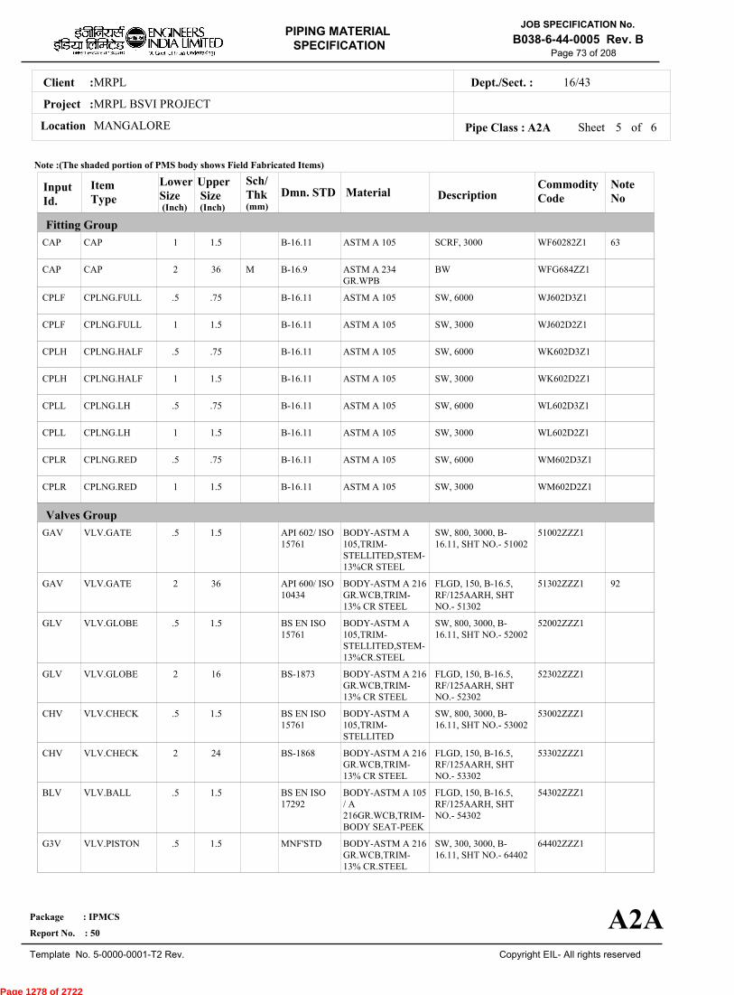
Fitting Group
Valves Group
Dmn. STD(Inch) (Inch)
CAP
CAP
CPLF
CPLF
CPLH
CPLH
CPLL
CPLL
CPLR
CPLR
GAV
GAV
GLV
GLV
CHV
CHV
BLV
G3V
CAP
CAP
CPLNG.FULL
CPLNG.FULL
CPLNG.HALF
CPLNG.HALF
CPLNG.LH
CPLNG.LH
CPLNG.RED
CPLNG.RED
VLV.GATE
VLV.GATE
VLV.GLOBE
VLV.GLOBE
VLV.CHECK
VLV.CHECK
VLV.BALL
VLV.PISTON
1
2
.5
1
.5
1
.5
1
.5
1
.5
2
.5
2
.5
2
.5
.5
1.5
36
.75
1.5
.75
1.5
.75
1.5
.75
1.5
1.5
36
1.5
16
1.5
24
1.5
1.5
M
SCRF, 3000
BW
SW, 6000
SW, 3000
SW, 6000
SW, 3000
SW, 6000
SW, 3000
SW, 6000
SW, 3000
SW, 800, 3000, B-16.11, SHT NO.- 51002
FLGD, 150, B-16.5,RF/125AARH, SHTNO.- 51302
SW, 800, 3000, B-16.11, SHT NO.- 52002
FLGD, 150, B-16.5,RF/125AARH, SHTNO.- 52302
SW, 800, 3000, B-16.11, SHT NO.- 53002
FLGD, 150, B-16.5,RF/125AARH, SHTNO.- 53302
FLGD, 150, B-16.5,RF/125AARH, SHTNO.- 54302
SW, 300, 3000, B-16.11, SHT NO.- 64402
ASTM A 105
ASTM A 234GR.WPB
ASTM A 105
ASTM A 105
ASTM A 105
ASTM A 105
ASTM A 105
ASTM A 105
ASTM A 105
ASTM A 105
BODY-ASTM A105,TRIM-STELLITED,STEM-13%CR STEEL
BODY-ASTM A 216GR.WCB,TRIM-13% CR STEEL
BODY-ASTM A105,TRIM-STELLITED,STEM-13%CR.STEEL
BODY-ASTM A 216GR.WCB,TRIM-13% CR STEEL
BODY-ASTM A105,TRIM-STELLITED
BODY-ASTM A 216GR.WCB,TRIM-13% CR STEEL
BODY-ASTM A 105/ A216GR.WCB,TRIM-BODY SEAT-PEEK
BODY-ASTM A 216GR.WCB,TRIM-13% CR.STEEL
WF60282Z1
WFG684ZZ1
WJ602D3Z1
WJ602D2Z1
WK602D3Z1
WK602D2Z1
WL602D3Z1
WL602D2Z1
WM602D3Z1
WM602D2Z1
51002ZZZ1
51302ZZZ1
52002ZZZ1
52302ZZZ1
53002ZZZ1
53302ZZZ1
54302ZZZ1
64402ZZZ1
63
92
B-16.11
B-16.9
B-16.11
B-16.11
B-16.11
B-16.11
B-16.11
B-16.11
B-16.11
B-16.11
API 602/ ISO15761
API 600/ ISO10434
BS EN ISO15761
BS-1873
BS EN ISO15761
BS-1868
BS EN ISO17292
MNF'STD
Note :(The shaded portion of PMS body shows Field Fabricated Items)
A2A
(mm)
6
Page 1278 of 2722
MRPLClient :
MRPL BSVI PROJECT
MANGALORELocation
16/43Dept./Sect. :
Project :
PIPING MATERIAL
SPECIFICATION
Copyright EIL- All rights reserved
JOB SPECIFICATION No.
B038-6-44-0005 Rev. B
Package : IPMCS
Report No. : 50
Template No. 5-0000-0001-T2 Rev.
Page 74 of 208
Sheet 6 of 6Pipe Class : A2A
InputId.
Item Type
LowerSize
Upper Size
Sch/Thk DescriptionMaterial
CommodityCode
NoteNo
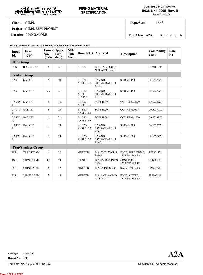
Bolt Group
Gasket Group
Trap/Strainer Group
Dmn. STD(Inch) (Inch)
BOS
GAS
GAS
GAS/2500
GAS/900
GAS/1500
GAS/600
GAS/300
TRP
TSR
PSR
PSR
BOLT.STUD
GASKET
GASKET
GASKET
GASKET
GASKET
GASKET
GASKET
TRAP.STEAM
STRNR.TEMP
STRNR.PERM
STRNR.PERM
.5
.5
26
5
3
.5
.5
.5
.5
1.5
.5
2
36
24
36
12
24
2.5
24
24
1.5
24
1.5
24
SPIRAL, 150
SPIRAL, 150
OCT-RING, 2500
OCT-RING, 900
OCT-RING, 1500
SPIRAL, 600
SPIRAL, 300
FLGD, THRMDNMC,150,RF/125AARH
CONETYPE,150,FF/125AARH
SW, Y-TYPE, 800
FLGD, Y-TYPE,150,RF/125AARH
BOLT:A193 GR.B7,NUT:A194 GR.2H
SP.WNDSS316+GRAFIL+ IRING
SP.WNDSS316+GRAFIL+ IRING
SOFT IRON
SOFT IRON
SOFT IRON
SP.WNDSS316+GRAFIL+ IRING
SP.WNDSS316+GRAFIL+ IRING
B:A105;T:13%CR;S:SS304
B:A516GR.70;INT:SS304
B:A105;INT:SS304
B:A216GR.WCB;INT:SS304
BS40404Z0
GK66272Z0
GK56272Z0
GK67239Z0
GK67237Z0
GK67238Z0
GK66276Z0
GK66274Z0
TR3065531
ST16831Z1
SP303D511
SP3805531
B-18.2
B-16.20-ANSI B16.5
B-16.20-ANSIB16.47B
B-16.20-ANSI B16.5
B-16.20-ANSI B16.5
B-16.20-ANSI B16.5
B-16.20-ANSI B16.5
B-16.20-ANSI B16.5
MNF'STD
EIL'STD
MNF'STD
MNF'STD
Note :(The shaded portion of PMS body shows Field Fabricated Items)
A2A
(mm)
Page 1279 of 2722

MRPLClient :
MRPL BSVI PROJECT
MANGALORELocation
16/43Dept./Sect. :
Project :
PIPING MATERIAL
SPECIFICATION
Copyright EIL- All rights reserved
JOB SPECIFICATION No.
B038-6-44-0005 Rev. B
Package : IPMCS
Report No. : 50
Template No. 5-0000-0001-T2 Rev.
Page 75 of 208
A32APIPE CLASS :150RATING :CARBON STEELBASE MATERIAL : 1.5CORROSION ALLOWANCE : SPECIAL REQUIREMENT :
MM
SERVICENONIBR STEAM TRACING (BEYOND STEAM SUPPLY MANIFOLD ISOLATION VALVES),NONIBR TRACER CONDENSATE
NOTES7
151
FOR RESTRICTION ON USE OF BALL,PLUG & BUTTERFLY VALVES,REFER GENERAL NOTES.
NDT REQUIREMENT SHALL BE AS PER JOB SPECIFICATION B038-6-44-0016.
SPECIAL NOTES
ITEM SIZE DESCRIPTION A.CODEMAINTAINENCEJOINTS
PIPE JOINTS
DRAINS
VENTS
TEMP.CONN.
PRESS.CONN.
ALL
1.5" & BELOW
2.0"
ON LINES <= 1.5"
ON LINES >=2.0"
ON LINES <= 1.5"
ON LINES >=2.0"
1.5"
0.75"
FLANGED, TO BE KEPT MINIMUM
SW COUPLING
BUTTWELDED
REFER EIL STD 7-44-0350, DF3
AS PER P&ID OR 0.75". REFER EIL STD 7-44-0351, D4
REFER EIL STD 7-44-0350, VF3
AS PER P&ID OR 0.75". REFER EIL STD 7-44-0351, V4
FLANGED. REFER EIL STD 7-44-0353
SW NIPPLE WITH VALVE TO SPEC AS PER EIL STD 7-44-0354
TEMP
PRESS 20.03 20.03 18.28 16.17 14.06 11.95 11.19
0 38 93 149 204 260 280
Sheet 1 of
TEMPERATURE (Deg. C) AND PRESSURE ( Kg/Sq. cm g ) RATINGS
Pipe Class : A32A
A32A
4
Page 1280 of 2722
MRPLClient :
MRPL BSVI PROJECT
MANGALORELocation
16/43Dept./Sect. :
Project :
PIPING MATERIAL
SPECIFICATION
Copyright EIL- All rights reserved
JOB SPECIFICATION No.
B038-6-44-0005 Rev. B
Package : IPMCS
Report No. : 50
Template No. 5-0000-0001-T2 Rev.
Page 76 of 208
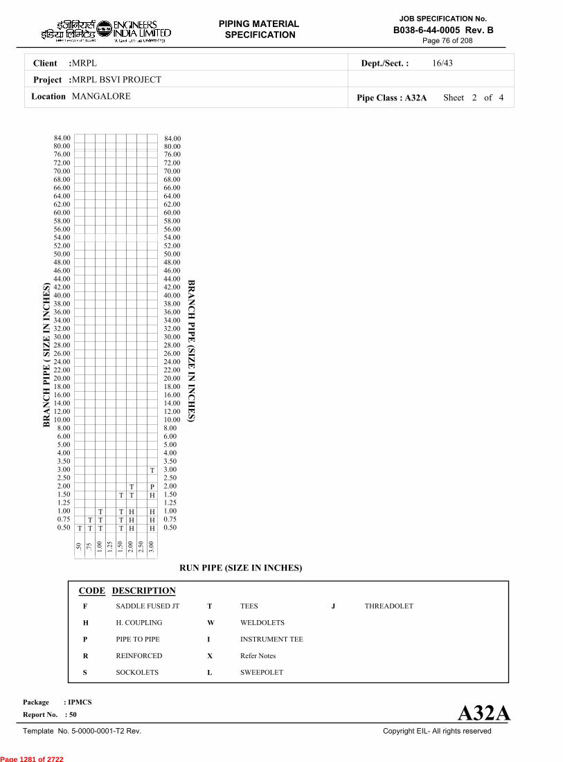
Sheet 2 ofPipe Class : A32A
T T T T H H0.50T T T H H0.75
T T H H1.001.25
T T H1.50T P2.00
2.50T3.00
3.504.005.006.008.00
10.0012.0014.0016.0018.0020.0022.0024.0026.0028.0030.0032.0034.0036.0038.0040.0042.0044.0046.0048.0050.0052.0054.0056.0058.0060.0062.0064.0066.0068.0070.0072.00
.
50
.
75
1
.00
1
.25
1
.50
2
.00
2
.50
3
.00
BR
AN
CH
PIP
E (
SIZ
E I
N I
NC
HE
S)
0.500.751.001.251.502.002.503.003.504.005.006.008.0010.0012.0014.0016.0018.0020.0022.0024.0026.0028.0030.0032.0034.0036.0038.0040.0042.0044.0046.0048.0050.0052.0054.0056.0058.0060.0062.0064.0066.0068.0070.0072.00
BR
AN
CH
PIP
E (SIZ
E IN
INC
HE
S)
RUN PIPE (SIZE IN INCHES)
CODE DESCRIPTION
F
H
P
R
S
T
W
I
X
L
JSADDLE FUSED JT
H. COUPLING
PIPE TO PIPE
REINFORCED
SOCKOLETS
TEES
WELDOLETS
INSTRUMENT TEE
Refer Notes
SWEEPOLET
THREADOLET
A32A
76.0080.0084.00
76.0080.0084.00
4
Page 1281 of 2722
MRPLClient :
MRPL BSVI PROJECT
MANGALORELocation
16/43Dept./Sect. :
Project :
PIPING MATERIAL
SPECIFICATION
Copyright EIL- All rights reserved
JOB SPECIFICATION No.
B038-6-44-0005 Rev. B
Package : IPMCS
Report No. : 50
Template No. 5-0000-0001-T2 Rev.
Page 77 of 208
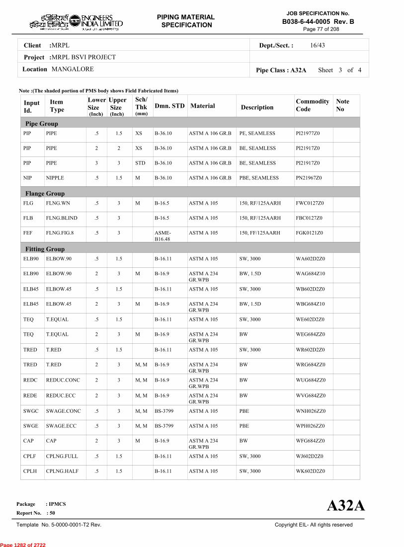
Sheet 3 ofPipe Class : A32A
InputId.
Item Type
LowerSize
Upper Size
Sch/Thk DescriptionMaterial
CommodityCode
NoteNo
Pipe Group
Flange Group
Fitting Group
Dmn. STD(Inch) (Inch)
PIP
PIP
PIP
NIP
FLG
FLB
FEF
ELB90
ELB90
ELB45
ELB45
TEQ
TEQ
TRED
TRED
REDC
REDE
SWGC
SWGE
CAP
CPLF
CPLH
PIPE
PIPE
PIPE
NIPPLE
FLNG.WN
FLNG.BLIND
FLNG.FIG.8
ELBOW.90
ELBOW.90
ELBOW.45
ELBOW.45
T.EQUAL
T.EQUAL
T.RED
T.RED
REDUC.CONC
REDUC.ECC
SWAGE.CONC
SWAGE.ECC
CAP
CPLNG.FULL
CPLNG.HALF
.5
2
3
.5
.5
.5
.5
.5
2
.5
2
.5
2
.5
2
2
2
.5
.5
2
.5
.5
1.5
2
3
1.5
3
3
3
1.5
3
1.5
3
1.5
3
1.5
3
3
3
3
3
3
1.5
1.5
XS
XS
STD
M
M
M
M
M
M, M
M, M
M, M
M, M
M, M
M
PE, SEAMLESS
BE, SEAMLESS
BE, SEAMLESS
PBE, SEAMLESS
150, RF/125AARH
150, RF/125AARH
150, FF/125AARH
SW, 3000
BW, 1.5D
SW, 3000
BW, 1.5D
SW, 3000
BW
SW, 3000
BW
BW
BW
PBE
PBE
BW
SW, 3000
SW, 3000
ASTM A 106 GR.B
ASTM A 106 GR.B
ASTM A 106 GR.B
ASTM A 106 GR.B
ASTM A 105
ASTM A 105
ASTM A 105
ASTM A 105
ASTM A 234GR.WPB
ASTM A 105
ASTM A 234GR.WPB
ASTM A 105
ASTM A 234GR.WPB
ASTM A 105
ASTM A 234GR.WPB
ASTM A 234GR.WPB
ASTM A 234GR.WPB
ASTM A 105
ASTM A 105
ASTM A 234GR.WPB
ASTM A 105
ASTM A 105
PI21977Z0
PI21917Z0
PI21917Z0
PN21967Z0
FWC0127Z0
FBC0127Z0
FGK0121Z0
WA602D2Z0
WAG684Z10
WB602D2Z0
WBG684Z10
WE602D2Z0
WEG684ZZ0
WR602D2Z0
WRG684ZZ0
WUG684ZZ0
WVG684ZZ0
WNH026ZZ0
WPH026ZZ0
WFG684ZZ0
WJ602D2Z0
WK602D2Z0
B-36.10
B-36.10
B-36.10
B-36.10
B-16.5
B-16.5
ASME-B16.48
B-16.11
B-16.9
B-16.11
B-16.9
B-16.11
B-16.9
B-16.11
B-16.9
B-16.9
B-16.9
BS-3799
BS-3799
B-16.9
B-16.11
B-16.11
Note :(The shaded portion of PMS body shows Field Fabricated Items)
A32A
(mm)
4
Page 1282 of 2722

MRPLClient :
MRPL BSVI PROJECT
MANGALORELocation
16/43Dept./Sect. :
Project :
PIPING MATERIAL
SPECIFICATION
Copyright EIL- All rights reserved
JOB SPECIFICATION No.
B038-6-44-0005 Rev. B
Package : IPMCS
Report No. : 50
Template No. 5-0000-0001-T2 Rev.
Page 78 of 208
Sheet 4 of 4Pipe Class : A32A
InputId.
Item Type
LowerSize
Upper Size
Sch/Thk DescriptionMaterial
CommodityCode
NoteNo
Fitting Group
Valves Group
Bolt Group
Gasket Group
Trap/Strainer Group
Dmn. STD(Inch) (Inch)
CPLL
CPLR
GAV
GAV
GLV
CHV
CHV
BLV
G3V
BOS
GAS
TRP
PSR
CPLNG.LH
CPLNG.RED
VLV.GATE
VLV.GATE
VLV.GLOBE
VLV.CHECK
VLV.CHECK
VLV.BALL
VLV.PISTON
BOLT.STUD
GASKET
TRAP.STEAM
STRNR.PERM
.5
.5
.25
2
.25
.25
2
.5
.5
.5
.5
.5
.5
1.5
1.5
1.5
42
1.5
1.5
24
3
1
3
3
1.5
1.5
SW, 3000
SW, 3000
SW, 800, 3000, B-16.11, SHT NO.- 51001
FLGD, 150, B-16.5,RF/125AARH, SHTNO.- 51301
SW, 800, 3000, B-16.11, SHT NO.- 52001
SW, 800, 3000, B-16.11, SHT NO.- 53001
FLGD, 150, B-16.5,RF/125AARH, SHTNO.- 53301
FLGD, 150, B-16.5,RF/125AARH, SHTNO.- 54322
SW, 300, 3000, B-16.11, SHT NO.- 64422
SPIRAL, 150
FLGD, BPTHRMST,150,RF/125AARH
SW, Y-TYPE, 800
ASTM A 105
ASTM A 105
BODY-ASTM A105,TRIM-STELLITED,STEM-13%CR.STEEL
BODY-ASTM A 216GR.WCB,TRIM-13% CR.STEEL
BODY-ASTM A105,TRIM-STELLITED,STEM-13%CR STEEL
BODY-ASTM A105,TRIM-STELLITED
BODY-ASTM A 216GR.WCB,TRIM-13% CR.STEEL
BODY-ASTM A 105/ A216GR.WCB,TRIM-BODY SEAT-PEEK
BODY-ASTM A 216GR.WCB,TRIM-13% CR.STEEL
BOLT:A193 GR.B7,NUT:A194 GR.2H
SP.WNDSS316+GRAFIL+ IRING
B:A105;T:13%CR;S:SS304
B:A105;INT:SS304
WL602D2Z0
WM602D2Z0
51001ZZZ0
51301ZZZ0
52001ZZZ0
53001ZZZ0
53301ZZZ0
54322ZZZ0
64422ZZZ0
BS40404Z0
GK66272Z0
TR3065730
SP303D510
B-16.11
B-16.11
API 602/ ISO15761
API 600/ ISO10434
BS EN ISO15761
BS EN ISO15761
BS-1868
BS EN ISO17292
MNF'STD
B-18.2
B-16.20-ANSI B16.5
MNF'STD
MNF'STD
Note :(The shaded portion of PMS body shows Field Fabricated Items)
A32A
(mm)
Page 1283 of 2722

MRPLClient :
MRPL BSVI PROJECT
MANGALORELocation
16/43Dept./Sect. :
Project :
PIPING MATERIAL
SPECIFICATION
Copyright EIL- All rights reserved
JOB SPECIFICATION No.
B038-6-44-0005 Rev. B
Package : IPMCS
Report No. : 50
Template No. 5-0000-0001-T2 Rev.
Page 79 of 208
A33APIPE CLASS :150RATING :CARBON STEELBASE MATERIAL : 1.5CORROSION ALLOWANCE : SPECIAL REQUIREMENT :
MM
SERVICEFIRE WATER (ABOVE GROUND)
NOTES1
5
32
65
88
NDT REQUIREMENTS AS PER EIL STANDARD 6-44-0016.
FOR PERMANENT 'T' TYPE BW STRAINERS,REFER EIL'STD 7-44-0303 & 7-44-0304; AND FOR TEMPORARYSTRAINERS,REFER EIL'STD 7-44-0300; FOR SPACER AND BLIND REFER EIL'STD 7-44-0162.CORROSION ALLOWANCE HAS BEEN ADJUSTED TO SELECT OPTIMUM SCH. REFER GENERAL NOTES TO PMS.
FORGINGS ARE ACCEPTABLE IN LIEU OF PLATE MATERIAL FOR BLIND FLANGES AND SPACER & BLINDS.
AS PER TAC REQUIREMENTS, 10% OF THE BUTT WELD JOINTS SHALL BE RADIOGRAPHED. HOWEVER, 50% OF THESEBUTT WELD JOINTS SHALL BE FIELD WELD JOINTS.
SPECIAL NOTES
ITEM SIZE DESCRIPTION A.CODEMAINTAINENCEJOINTS
PIPE JOINTS
DRAINS
VENTS
TEMP.CONN
PRESS.CONN
ALL
1.5" & BELOW
2.0" & ABOVE
ON LINES <= 1.5"
ON LINES >= 2.0"
ON LINES <= 1.5"
ON LINES >= 2.0"
1.5"
0.75"
FLANGED, TO BE KEPT MINIMUM
SW COUPLING
BUTTWELDED
REFER EILSTD 7-44-0350, DF3
AS PER P&ID OR 0.75". REFER EIL STD. 7-44-0351, D4
REFER EIL STD. 7-44-0350, VC1
AS PER P&ID OR 0.75". REFER EIL STD 7-44-0351, V1
FLANGED. REFER EIL STD 7-44-0353
SW NIPPLE WITH VALVE TO SPEC AS PER EIL STD 7-44-0354
TEMP
PRESS 18.9 18.9 18.9 18.9
0 38 50 65
Sheet 1 of
TEMPERATURE (Deg. C) AND PRESSURE ( Kg/Sq. cm g ) RATINGS
Pipe Class : A33A
A33A
5
Page 1284 of 2722
MRPLClient :
MRPL BSVI PROJECT
MANGALORELocation
16/43Dept./Sect. :
Project :
PIPING MATERIAL
SPECIFICATION
Copyright EIL- All rights reserved
JOB SPECIFICATION No.
B038-6-44-0005 Rev. B
Package : IPMCS
Report No. : 50
Template No. 5-0000-0001-T2 Rev.
Page 80 of 208
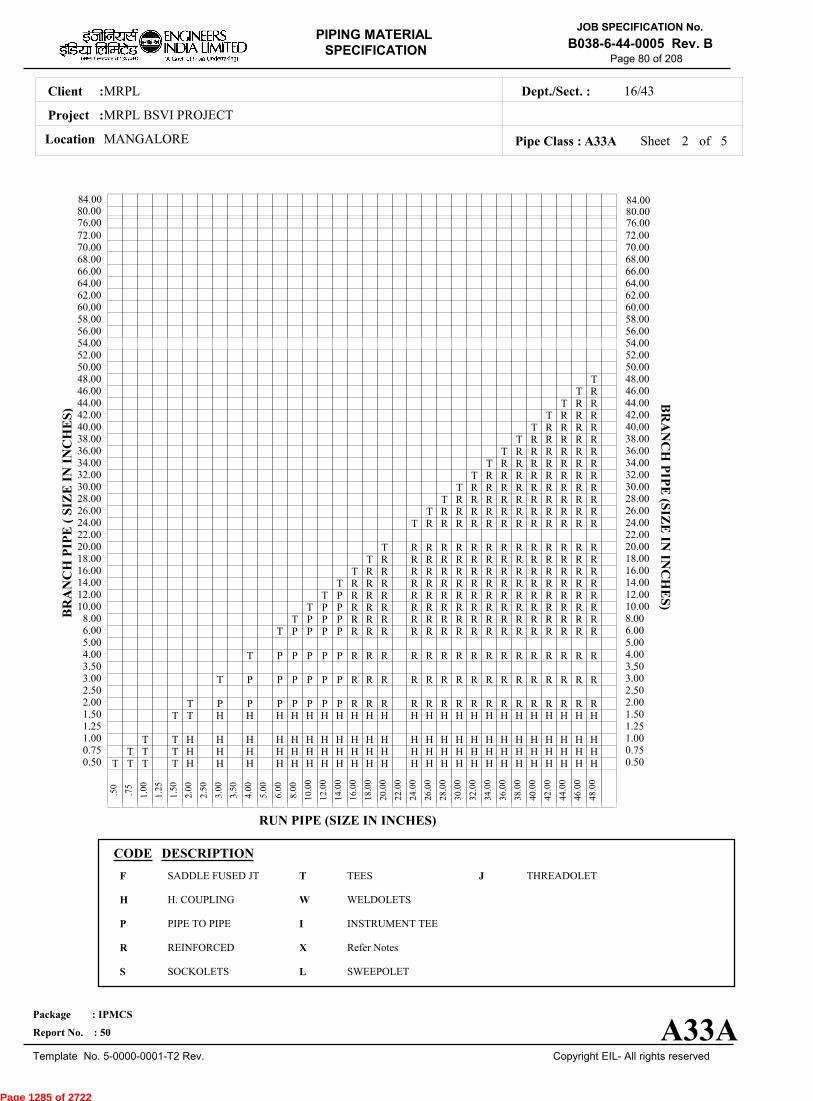
Sheet 2 ofPipe Class : A33A
T T T T H H H H H H H H H H H H H H H H H H H H H H H H0.50T T T H H H H H H H H H H H H H H H H H H H H H H H H0.75
T T H H H H H H H H H H H H H H H H H H H H H H H H1.001.25
T T H H H H H H H H H H H H H H H H H H H H H H H1.50T P P P P P P P R R R R R R R R R R R R R R R R2.00
2.50T P P P P P P R R R R R R R R R R R R R R R R3.00
3.50T P P P P P R R R R R R R R R R R R R R R R4.00
5.00T P P P P R R R R R R R R R R R R R R R R6.00
T P P P R R R R R R R R R R R R R R R R8.00T P P R R R R R R R R R R R R R R R R10.00
T P R R R R R R R R R R R R R R R R12.00T R R R R R R R R R R R R R R R R14.00
T R R R R R R R R R R R R R R R16.00T R R R R R R R R R R R R R R18.00
T R R R R R R R R R R R R R20.0022.00
T R R R R R R R R R R R R24.00T R R R R R R R R R R R26.00
T R R R R R R R R R R28.00T R R R R R R R R R30.00
T R R R R R R R R32.00T R R R R R R R34.00
T R R R R R R36.00T R R R R R38.00
T R R R R40.00T R R R42.00
T R R44.00T R46.00
T48.0050.0052.0054.0056.0058.0060.0062.0064.0066.0068.0070.0072.00
.
50
.
75
1
.00
1
.25
1
.50
2
.00
2
.50
3
.00
3
.50
4
.00
5
.00
6
.00
8
.00
10
.00
12
.00
14
.00
16
.00
18
.00
20
.00
22
.00
24
.00
26
.00
28
.00
30
.00
32
.00
34
.00
36
.00
38
.00
40
.00
42
.00
44
.00
46
.00
48
.00
BR
AN
CH
PIP
E (
SIZ
E I
N I
NC
HE
S)
0.500.751.001.251.502.002.503.003.504.005.006.008.0010.0012.0014.0016.0018.0020.0022.0024.0026.0028.0030.0032.0034.0036.0038.0040.0042.0044.0046.0048.0050.0052.0054.0056.0058.0060.0062.0064.0066.0068.0070.0072.00
BR
AN
CH
PIP
E (SIZ
E IN
INC
HE
S)
RUN PIPE (SIZE IN INCHES)
CODE DESCRIPTION
F
H
P
R
S
T
W
I
X
L
JSADDLE FUSED JT
H. COUPLING
PIPE TO PIPE
REINFORCED
SOCKOLETS
TEES
WELDOLETS
INSTRUMENT TEE
Refer Notes
SWEEPOLET
THREADOLET
A33A
76.0080.0084.00
76.0080.0084.00
5
Page 1285 of 2722
MRPLClient :
MRPL BSVI PROJECT
MANGALORELocation
16/43Dept./Sect. :
Project :
PIPING MATERIAL
SPECIFICATION
Copyright EIL- All rights reserved
JOB SPECIFICATION No.
B038-6-44-0005 Rev. B
Package : IPMCS
Report No. : 50
Template No. 5-0000-0001-T2 Rev.
Page 81 of 208
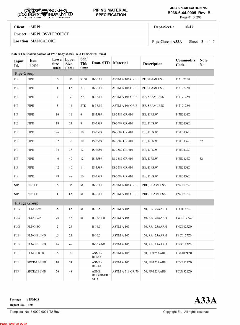
Sheet 3 ofPipe Class : A33A
InputId.
Item Type
LowerSize
Upper Size
Sch/Thk DescriptionMaterial
CommodityCode
NoteNo
Pipe Group
Flange Group
Dmn. STD(Inch) (Inch)
PIP
PIP
PIP
PIP
PIP
PIP
PIP
PIP
PIP
PIP
PIP
PIP
NIP
NIP
FLG
FLG
FLG
FLB
FLB
FEF
FEF
FEF
PIPE
PIPE
PIPE
PIPE
PIPE
PIPE
PIPE
PIPE
PIPE
PIPE
PIPE
PIPE
NIPPLE
NIPPLE
FLNG.SW
FLNG.WN
FLNG.SO
FLNG.BLIND
FLNG.BLIND
FLNG.FIG.8
SPCR&BLND
SPCR&BLND
.5
1
2
3
16
18
26
32
34
40
42
48
.5
1
.5
26
2
.5
26
.5
10
26
.75
1.5
2
14
16
24
30
32
38
40
46
48
.75
1.5
1.5
48
24
24
48
8
24
48
S160
XS
XS
STD
6
8
10
10
12
12
14
16
M
M
M
M
PE, SEAMLESS
PE, SEAMLESS
BE, SEAMLESS
BE, SEAMLESS
BE, E.FS.W
BE, E.FS.W
BE, E.FS.W
BE, E.FS.W
BE, E.FS.W
BE, E.FS.W
BE, E.FS.W
BE, E.FS.W
PBE, SEAMLESS
PBE, SEAMLESS
150, RF/125AARH
150, RF/125AARH
150, RF/125AARH
150, RF/125AARH
150, RF/125AARH
150, FF/125AARH
150, FF/125AARH
150, FF/125AARH
ASTM A 106 GR.B
ASTM A 106 GR.B
ASTM A 106 GR.B
ASTM A 106 GR.B
IS-3589 GR.410
IS-3589 GR.410
IS-3589 GR.410
IS-3589 GR.410
IS-3589 GR.410
IS-3589 GR.410
IS-3589 GR.410
IS-3589 GR.410
ASTM A 106 GR.B
ASTM A 106 GR.B
ASTM A 105
ASTM A 105
ASTM A 105
ASTM A 105
ASTM A 105
ASTM A 105
ASTM A 105
ASTM A 516 GR.70
PI21977Z0
PI21977Z0
PI21917Z0
PI21917Z0
PI7E313Z0
PI7E313Z0
PI7E313Z0
PI7E313Z0
PI7E313Z0
PI7E313Z0
PI7E313Z0
PI7E313Z0
PN21967Z0
PN21967Z0
FSC0127Z0
FWB0127Z0
FNC0127Z0
FBC0127Z0
FBB0127Z0
FGK0121Z0
FCK0121Z0
FCU6321Z0
32
32
B-36.10
B-36.10
B-36.10
B-36.10
IS-3589
IS-3589
IS-3589
IS-3589
IS-3589
IS-3589
IS-3589
IS-3589
B-36.10
B-36.10
B-16.5
B-16.47-B
B-16.5
B-16.5
B-16.47-B
ASME-B16.48
ASME-B16.48
ASMEB16.47B/EIL'STD
Note :(The shaded portion of PMS body shows Field Fabricated Items)
A33A
(mm)
5
Page 1286 of 2722

MRPLClient :
MRPL BSVI PROJECT
MANGALORELocation
16/43Dept./Sect. :
Project :
PIPING MATERIAL
SPECIFICATION
Copyright EIL- All rights reserved
JOB SPECIFICATION No.
B038-6-44-0005 Rev. B
Package : IPMCS
Report No. : 50
Template No. 5-0000-0001-T2 Rev.
Page 82 of 208
Sheet 4 ofPipe Class : A33A
InputId.
Item Type
LowerSize
Upper Size
Sch/Thk DescriptionMaterial
CommodityCode
NoteNo
Fitting Group
Dmn. STD(Inch) (Inch)
ELB90
ELB90
ELB90
ELB45
ELB45
ELB45
TEQ
TEQ
TEQ
TRED
TRED
TRED
REDC
REDC
REDE
REDE
SWGC
SWGE
CAP
CAP
CPLF
CPLH
CPLL
ELBOW.90
ELBOW.90
ELBOW.90
ELBOW.45
ELBOW.45
ELBOW.45
T.EQUAL
T.EQUAL
T.EQUAL
T.RED
T.RED
T.RED
REDUC.CONC
REDUC.CONC
REDUC.ECC
REDUC.ECC
SWAGE.CONC
SWAGE.ECC
CAP
CAP
CPLNG.FULL
CPLNG.HALF
CPLNG.LH
.5
2
8
.5
2
8
.5
2
8
.5
2
8
2
8
2
8
.5
.5
.5
2
.5
.5
.5
1.5
6
48
1.5
6
48
1.5
6
48
1.5
6
48
6
48
6
48
3
3
1.5
48
1.5
1.5
1.5
M
M
M
M
M
M
M, M
M, M
M, M
M, M
M, M
M, M
M, M
M, M
M
SW, 3000
BW, 1.5D
BW, 1.5D
SW, 3000
BW, 1.5D
BW, 1.5D
SW, 3000
BW
BW
SW, 3000
BW
BW
BW
BW
BW
BW
PBE
PBE
SCRF, 3000
BW
SW, 3000
SW, 3000
SW, 3000
ASTM A 105
ASTM A 234GR.WPB
ASTM A 234GR.WPB-W
ASTM A 105
ASTM A 234GR.WPB
ASTM A 234GR.WPB-W
ASTM A 105
ASTM A 234GR.WPB
ASTM A 234GR.WPB-W
ASTM A 105
ASTM A 234GR.WPB
ASTM A 234GR.WPB-W
ASTM A 234GR.WPB
ASTM A 234GR.WPB-W
ASTM A 234GR.WPB
ASTM A 234GR.WPB-W
ASTM A 105
ASTM A 105
ASTM A 105
ASTM A 234GR.WPB
ASTM A 105
ASTM A 105
ASTM A 105
WA602D2Z0
WAG684Z10
WAG754Z10
WB602D2Z0
WBG684Z10
WBG754Z10
WE602D2Z0
WEG684ZZ0
WEG754ZZ0
WR602D2Z0
WRG684ZZ0
WRG754ZZ0
WUG684ZZ0
WUG754ZZ0
WVG684ZZ0
WVG754ZZ0
WNH026ZZ0
WPH026ZZ0
WF60282Z0
WFG684ZZ0
WJ602D2Z0
WK602D2Z0
WL602D2Z0
B-16.11
B-16.9
B-16.9
B-16.11
B-16.9
B-16.9
B-16.11
B-16.9
B-16.9
B-16.11
B-16.9
B-16.9
B-16.9
B-16.9
B-16.9
B-16.9
BS-3799
BS-3799
B-16.11
B-16.9
B-16.11
B-16.11
B-16.11
Note :(The shaded portion of PMS body shows Field Fabricated Items)
A33A
(mm)
5
Page 1287 of 2722
MRPLClient :
MRPL BSVI PROJECT
MANGALORELocation
16/43Dept./Sect. :
Project :
PIPING MATERIAL
SPECIFICATION
Copyright EIL- All rights reserved
JOB SPECIFICATION No.
B038-6-44-0005 Rev. B
Package : IPMCS
Report No. : 50
Template No. 5-0000-0001-T2 Rev.
Page 83 of 208
Sheet 5 of 5Pipe Class : A33A
InputId.
Item Type
LowerSize
Upper Size
Sch/Thk DescriptionMaterial
CommodityCode
NoteNo
Fitting Group
Valves Group
Bolt Group
Gasket Group
Trap/Strainer Group
Dmn. STD(Inch) (Inch)
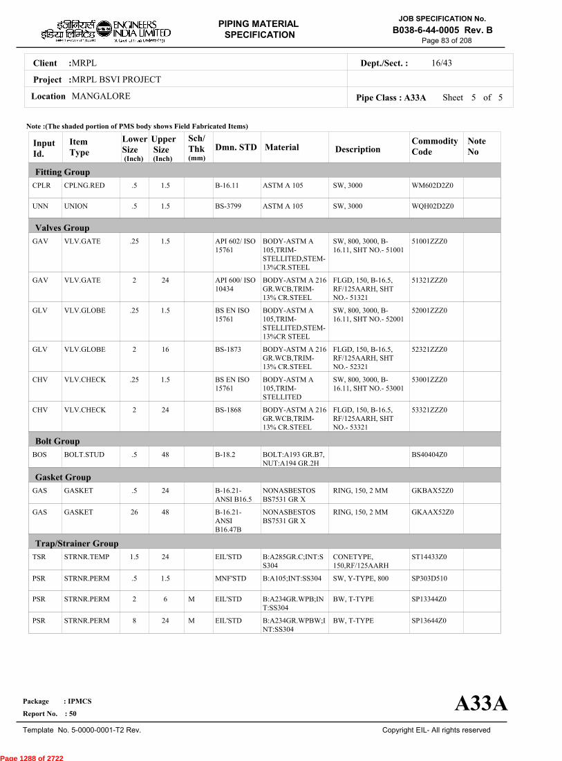
CPLR
UNN
GAV
GAV
GLV
GLV
CHV
CHV
BOS
GAS
GAS
TSR
PSR
PSR
PSR
CPLNG.RED
UNION
VLV.GATE
VLV.GATE
VLV.GLOBE
VLV.GLOBE
VLV.CHECK
VLV.CHECK
BOLT.STUD
GASKET
GASKET
STRNR.TEMP
STRNR.PERM
STRNR.PERM
STRNR.PERM
.5
.5
.25
2
.25
2
.25
2
.5
.5
26
1.5
.5
2
8
1.5
1.5
1.5
24
1.5
16
1.5
24
48
24
48
24
1.5
6
24
M
M
SW, 3000
SW, 3000
SW, 800, 3000, B-16.11, SHT NO.- 51001
FLGD, 150, B-16.5,RF/125AARH, SHTNO.- 51321
SW, 800, 3000, B-16.11, SHT NO.- 52001
FLGD, 150, B-16.5,RF/125AARH, SHTNO.- 52321
SW, 800, 3000, B-16.11, SHT NO.- 53001
FLGD, 150, B-16.5,RF/125AARH, SHTNO.- 53321
RING, 150, 2 MM
RING, 150, 2 MM
CONETYPE,150,RF/125AARH
SW, Y-TYPE, 800
BW, T-TYPE
BW, T-TYPE
ASTM A 105
ASTM A 105
BODY-ASTM A105,TRIM-STELLITED,STEM-13%CR.STEEL
BODY-ASTM A 216GR.WCB,TRIM-13% CR.STEEL
BODY-ASTM A105,TRIM-STELLITED,STEM-13%CR STEEL
BODY-ASTM A 216GR.WCB,TRIM-13% CR.STEEL
BODY-ASTM A105,TRIM-STELLITED
BODY-ASTM A 216GR.WCB,TRIM-13% CR.STEEL
BOLT:A193 GR.B7,NUT:A194 GR.2H
NONASBESTOSBS7531 GR X
NONASBESTOSBS7531 GR X
B:A285GR.C;INT:SS304
B:A105;INT:SS304
B:A234GR.WPB;INT:SS304
B:A234GR.WPBW;INT:SS304
WM602D2Z0
WQH02D2Z0
51001ZZZ0
51321ZZZ0
52001ZZZ0
52321ZZZ0
53001ZZZ0
53321ZZZ0
BS40404Z0
GKBAX52Z0
GKAAX52Z0
ST14433Z0
SP303D510
SP13344Z0
SP13644Z0
B-16.11
BS-3799
API 602/ ISO15761
API 600/ ISO10434
BS EN ISO15761
BS-1873
BS EN ISO15761
BS-1868
B-18.2
B-16.21-ANSI B16.5
B-16.21-ANSIB16.47B
EIL'STD
MNF'STD
EIL'STD
EIL'STD
Note :(The shaded portion of PMS body shows Field Fabricated Items)
A33A
(mm)
Page 1288 of 2722
MRPLClient :
MRPL BSVI PROJECT
MANGALORELocation
16/43Dept./Sect. :
Project :
PIPING MATERIAL
SPECIFICATION
Copyright EIL- All rights reserved
JOB SPECIFICATION No.
B038-6-44-0005 Rev. B
Package : IPMCS
Report No. : 50
Template No. 5-0000-0001-T2 Rev.
Page 84 of 208
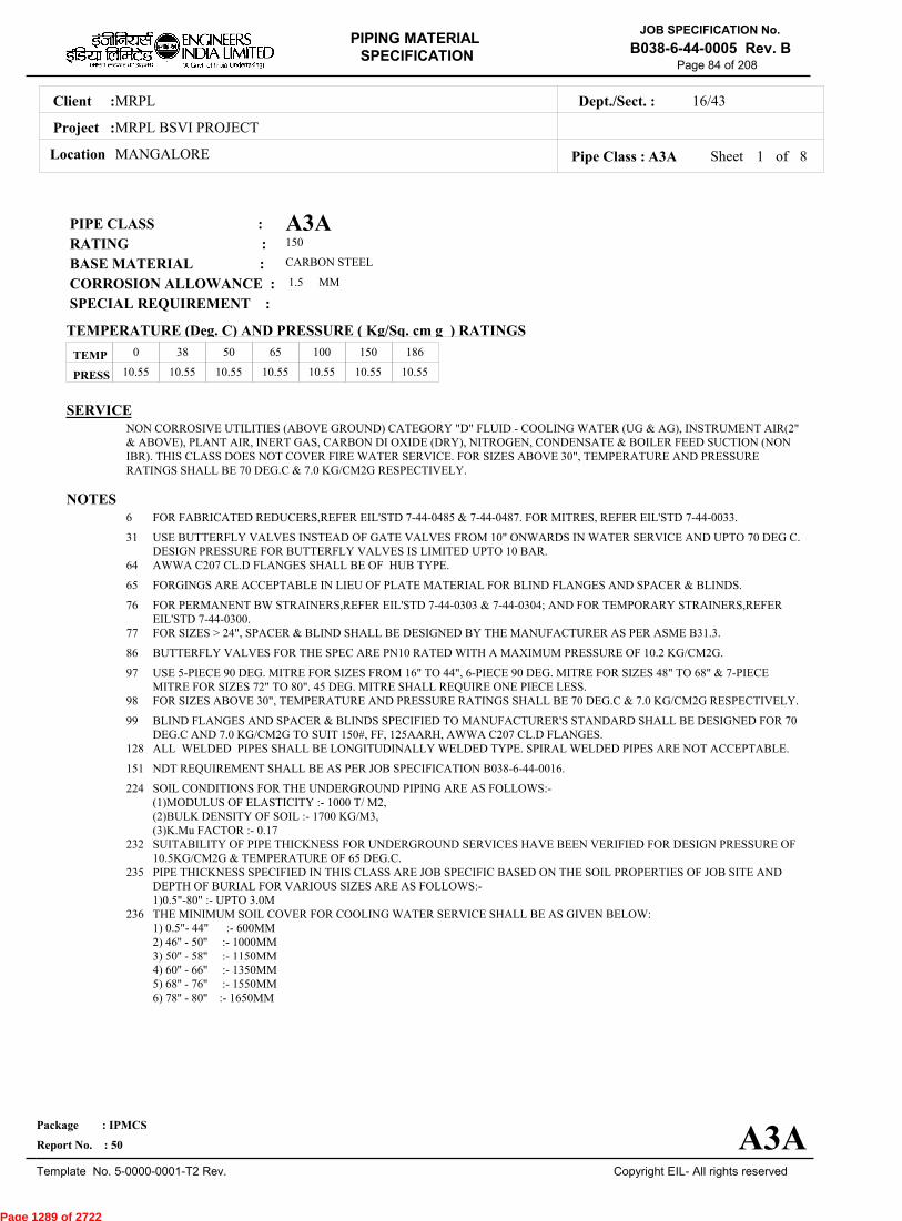
A3APIPE CLASS :150RATING :CARBON STEELBASE MATERIAL : 1.5CORROSION ALLOWANCE : SPECIAL REQUIREMENT :
MM
SERVICENON CORROSIVE UTILITIES (ABOVE GROUND) CATEGORY "D" FLUID - COOLING WATER (UG & AG), INSTRUMENT AIR(2"& ABOVE), PLANT AIR, INERT GAS, CARBON DI OXIDE (DRY), NITROGEN, CONDENSATE & BOILER FEED SUCTION (NONIBR). THIS CLASS DOES NOT COVER FIRE WATER SERVICE. FOR SIZES ABOVE 30", TEMPERATURE AND PRESSURERATINGS SHALL BE 70 DEG.C & 7.0 KG/CM2G RESPECTIVELY.
NOTES6
31
64
65
76
77
86
97
98
99
128
151
224
232
235
236
FOR FABRICATED REDUCERS,REFER EIL'STD 7-44-0485 & 7-44-0487. FOR MITRES, REFER EIL'STD 7-44-0033.
USE BUTTERFLY VALVES INSTEAD OF GATE VALVES FROM 10" ONWARDS IN WATER SERVICE AND UPTO 70 DEG C.DESIGN PRESSURE FOR BUTTERFLY VALVES IS LIMITED UPTO 10 BAR.AWWA C207 CL.D FLANGES SHALL BE OF HUB TYPE.
FORGINGS ARE ACCEPTABLE IN LIEU OF PLATE MATERIAL FOR BLIND FLANGES AND SPACER & BLINDS.
FOR PERMANENT BW STRAINERS,REFER EIL'STD 7-44-0303 & 7-44-0304; AND FOR TEMPORARY STRAINERS,REFEREIL'STD 7-44-0300.FOR SIZES > 24", SPACER & BLIND SHALL BE DESIGNED BY THE MANUFACTURER AS PER ASME B31.3.
BUTTERFLY VALVES FOR THE SPEC ARE PN10 RATED WITH A MAXIMUM PRESSURE OF 10.2 KG/CM2G.
USE 5-PIECE 90 DEG. MITRE FOR SIZES FROM 16" TO 44", 6-PIECE 90 DEG. MITRE FOR SIZES 48" TO 68" & 7-PIECEMITRE FOR SIZES 72" TO 80". 45 DEG. MITRE SHALL REQUIRE ONE PIECE LESS.FOR SIZES ABOVE 30", TEMPERATURE AND PRESSURE RATINGS SHALL BE 70 DEG.C & 7.0 KG/CM2G RESPECTIVELY.
BLIND FLANGES AND SPACER & BLINDS SPECIFIED TO MANUFACTURER'S STANDARD SHALL BE DESIGNED FOR 70DEG.C AND 7.0 KG/CM2G TO SUIT 150#, FF, 125AARH, AWWA C207 CL.D FLANGES.ALL WELDED PIPES SHALL BE LONGITUDINALLY WELDED TYPE. SPIRAL WELDED PIPES ARE NOT ACCEPTABLE.
NDT REQUIREMENT SHALL BE AS PER JOB SPECIFICATION B038-6-44-0016.
SOIL CONDITIONS FOR THE UNDERGROUND PIPING ARE AS FOLLOWS:-(1)MODULUS OF ELASTICITY :- 1000 T/ M2,(2)BULK DENSITY OF SOIL :- 1700 KG/M3,(3)K.Mu FACTOR :- 0.17SUITABILITY OF PIPE THICKNESS FOR UNDERGROUND SERVICES HAVE BEEN VERIFIED FOR DESIGN PRESSURE OF10.5KG/CM2G & TEMPERATURE OF 65 DEG.C.PIPE THICKNESS SPECIFIED IN THIS CLASS ARE JOB SPECIFIC BASED ON THE SOIL PROPERTIES OF JOB SITE ANDDEPTH OF BURIAL FOR VARIOUS SIZES ARE AS FOLLOWS:-1)0.5"-80" :- UPTO 3.0MTHE MINIMUM SOIL COVER FOR COOLING WATER SERVICE SHALL BE AS GIVEN BELOW:1) 0.5"- 44" :- 600MM2) 46'' - 50'' :- 1000MM3) 50'' - 58'' :- 1150MM4) 60'' - 66'' :- 1350MM5) 68'' - 76'' :- 1550MM6) 78'' - 80'' :- 1650MM
TEMP
PRESS 10.55 10.55 10.55 10.55 10.55 10.55 10.55
0 38 50 65 100 150 186
Sheet 1 of
TEMPERATURE (Deg. C) AND PRESSURE ( Kg/Sq. cm g ) RATINGS
Pipe Class : A3A
A3A
8
Page 1289 of 2722

MRPLClient :
MRPL BSVI PROJECT
MANGALORELocation
16/43Dept./Sect. :
Project :
PIPING MATERIAL
SPECIFICATION
Copyright EIL- All rights reserved
JOB SPECIFICATION No.
B038-6-44-0005 Rev. B
Package : IPMCS
Report No. : 50
Template No. 5-0000-0001-T2 Rev.
Page 85 of 208
SPECIAL NOTES
ITEM SIZE DESCRIPTION A.CODEMAINTAINENCEJOINTS
PIPE JOINTS
DRAINS
VENTS
TEMP.CONN
PRESS.CONN
ALL
1.5" & BELOW
2.0" & ABOVE
ON LINES <= 1.5"
ON LINES >= 2.0"
ON LINES <= 1.5"
ON LINES >= 2.0"
1.5"
0.75"
FLANGED, TO BE KEPT MINIMUM
SW COUPLING 3000 LBS.
BUTTWELDED
REFER EILSTD 7-44-350, DF3
0.75" OR AS PER P&ID. REFER EIL STD. 7-44-351, D4
REFER EIL STD. 7-44-350, VC1
0.75" OR AS PER P&ID. REFER EIL STD 7-44-351, V1
FLANGED. REFER EIL STD 7-44-353
SW, NIPPLE WITH GATE VALVE TO SPEC AS PER EIL STD 7-44-354
Sheet 2 ofPipe Class : A3A 8
Page 1290 of 2722
MRPLClient :
MRPL BSVI PROJECT
MANGALORELocation
16/43Dept./Sect. :
Project :
PIPING MATERIAL
SPECIFICATION
Copyright EIL- All rights reserved
JOB SPECIFICATION No.
B038-6-44-0005 Rev. B
Package : IPMCS
Report No. : 50
Template No. 5-0000-0001-T2 Rev.
Page 86 of 208
Sheet 3 ofPipe Class : A3A
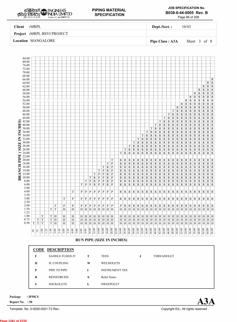
T T T T H H H H H H H H H H H H H H H H H H H H H H H H H H H H H H H H H0.50T T T H H H H H H H H H H H H H H H H H H H H H H H H H H H H H H H H H0.75
T T H H H H H H H H H H H H H H H H H H H H H H H H H H H H H H H H H1.001.25
T T H H H H H H H H H H H H H H H H H H H H H H H H H H H H H H H H1.50T P P P P P P P P P P P R R R R R R R R R R R R R R R R R R R R R2.00
2.50T P P P P P P P P P R R R R R R R R R R R R R R R R R R R R R R3.00
3.50T P P P P P P P P R R R R R R R R R R R R R R R R R R R R R R4.00
5.00T P P R P P R P R R R R R R R R R R R R R R R R R R R R R R6.00
T P R P P R P R R R R R R R R R R R R R R R R R R R R R R8.00T R P P R P R R R R R R R R R R R R R R R R R R R R R R10.00
T P P R P R R R R R R R R R R R R R R R R R R R R R R12.00T P R P R R R R R R R R R R R R R R R R R R R R R R14.00
T R P R R R R R R R R R R R R R R R R R R R R R R16.00T P R R R R R R R R R R R R R R R R R R R R R R18.00
T R R R R R R R R R R R R R R R R R R R R R R20.0022.00
T R R R R R R R R R R R R R R R R R R R R R24.00T R R R R R R R R R R R R R R R R R R R R26.00
T R R R R R R R R R R R R R R R R R R R28.00T R R R R R R R R R R R R R R R R R R30.00
T R R R R R R R R R R R R R R R R R32.00T R R R R R R R R R R R R R R R R34.00
T R R R R R R R R R R R R R R R36.00T R R R R R R R R R R R R R R38.00
T R R R R R R R R R R R R R40.00T R R R R R R R R R R R R42.00
T R R R R R R R R R R R44.00T R R R R R R R R R R46.00
T R R R R R R R R R48.00R R R R R R R R R50.00
R R R R R R R R52.00R R R R R R R54.00
R R R R R R56.00R R R R R58.00
R R R R60.00R R R62.00
R R64.00R66.00
68.0070.0072.00
.
50
.
75
1
.00
1
.25
1
.50
2
.00
2
.50
3
.00
3
.50
4
.00
5
.00
6
.00
8
.00
10
.00
12
.00
14
.00
16
.00
18
.00
20
.00
22
.00
24
.00
26
.00
28
.00
30
.00
32
.00
34
.00
36
.00
38
.00
40
.00
42
.00
44
.00
46
.00
48
.00
50
.00
52
.00
54
.00
56
.00
58
.00
60
.00
62
.00
64
.00
66
.00
BR
AN
CH
PIP
E (
SIZ
E I
N I
NC
HE
S)
RUN PIPE (SIZE IN INCHES)
CODE DESCRIPTION
F
H
P
R
S
T
W
I
X
L
JSADDLE FUSED JT
H. COUPLING
PIPE TO PIPE
REINFORCED
SOCKOLETS
TEES
WELDOLETS
INSTRUMENT TEE
Refer Notes
SWEEPOLET
THREADOLET
A3A
76.0080.0084.00
8
Page 1291 of 2722

MRPLClient :
MRPL BSVI PROJECT
MANGALORELocation
16/43Dept./Sect. :
Project :
PIPING MATERIAL
SPECIFICATION
Copyright EIL- All rights reserved
JOB SPECIFICATION No.
B038-6-44-0005 Rev. B
Package : IPMCS
Report No. : 50
Template No. 5-0000-0001-T2 Rev.
Page 87 of 208
Sheet 4 ofPipe Class : A3A
H H HH H HH H H
H H HR R R
R R R
R R R
R R RR R RR R RR R RR R RR R RR R RR R R
R R RR R RR R RR R RR R RR R RR R RR R RR R RR R RR R RR R RR R RR R RR R RR R RR R RR R RR R RR R RR R RR R RR R R
R RR
68
.00
70
.00
72
.00
0.500.751.001.251.502.002.503.003.504.005.006.008.0010.0012.0014.0016.0018.0020.0022.0024.0026.0028.0030.0032.0034.0036.0038.0040.0042.0044.0046.0048.0050.0052.0054.0056.0058.0060.0062.0064.0066.0068.0070.0072.00
BR
AN
CH
PIP
E (SIZ
E IN
INC
HE
S)
A3A
76.0080.0084.00
8
Page 1292 of 2722

MRPLClient :
MRPL BSVI PROJECT
MANGALORELocation
16/43Dept./Sect. :
Project :
PIPING MATERIAL
SPECIFICATION
Copyright EIL- All rights reserved
JOB SPECIFICATION No.
B038-6-44-0005 Rev. B
Package : IPMCS
Report No. : 50
Template No. 5-0000-0001-T2 Rev.
Page 88 of 208
Sheet 5 ofPipe Class : A3A
InputId.
Item Type
LowerSize
Upper Size
Sch/Thk DescriptionMaterial
CommodityCode
NoteNo
Pipe Group
Flange Group
Dmn. STD(Inch) (Inch)
PIP
PIP
PIP
PIP
PIP
PIP
PIP
PIP
PIP
PIP
NIP
FLG/300
FLG
FLG/900
FLG/1500
FLG/300
FLG
FLG
FLB
FLB
FEF
FEF
FEF
PIPE
PIPE
PIPE
PIPE
PIPE
PIPE
PIPE
PIPE
PIPE
PIPE
NIPPLE
FLNG.SW
FLNG.WN
FLNG.WN
FLNG.WN
FLNG.WN
FLNG.SO
FLNG.SO
FLNG.BLIND
FLNG.BLIND
FLNG.FIG.8
SPCR&BLND
SPCR&BLND
.5
1
2
3
16
20
26
50
64
76
.5
.5
.5
3
.5
2
16
26
.5
26
.5
10
26
.75
1.5
2
14
18
24
48
60
72
80
1.5
1.5
14
14
2.5
24
24
80
24
48
8
24
80
S160
XS
XS
STD
8.0
10.0
12.0
14.0
16.0
18.0
M
M
M
M
M
M
PE, SEAMLESS
PE, SEAMLESS
BE, SEAMLESS
BE, SEAMLESS
BE, WELDED
BE, WELDED
BE, WELDED
BE, WELDED
BE, WELDED
BE, WELDED
PBE, SEAMLESS
300, RF/125AARH
150, RF/125AARH
900, RTJ/63AARH
1500, RTJ/63AARH
300, RF/125AARH
150, RF/125AARH
150, FF/125AARH
150, RF/125AARH
150, FF/125AARH
150, FF/125AARH
150, FF/125AARH
150, FF/125AARH
ASTM A 106 GR.B
ASTM A 106 GR.B
ASTM A 106 GR.B
ASTM A 106 GR.B
IS-3589 GR.330
IS-3589 GR.330
IS-3589 GR.330
IS-3589 GR.330
IS-3589 GR.330
IS-3589 GR.330
ASTM A 106 GR.B
ASTM A 105
ASTM A 105
ASTM A 105
ASTM A 105
ASTM A 105
ASTM A 105
ASTM A 105
ASTM A 105
ASTM A 285 GR.C
ASTM A 105
ASTM A 105
ASTM A 285 GR.C
PI21977Z0
PI21977Z0
PI21917Z0
PI21917Z0
PI7D919Z0
PI7D919Z0
PI7D919Z0
PI7D919Z0
PI7D919Z0
PI7D919Z0
PN21967Z0
FSC0147Z0
FWC0127Z0
FWC0179Z0
FWC0189Z0
FWC0147Z0
FNC0127Z0
FN40121Z0
FBC0127Z0
FB45321Z0
FGK0121Z0
FCK0121Z0
FCG5321Z0
B-36.10
B-36.10
B-36.10
B-36.10
IS-3589
IS-3589
IS-3589
IS-3589
IS-3589
IS-3589
B-36.10
B-16.5
B-16.5
B-16.5
B-16.5
B-16.5
B-16.5
AWWA-C207CL.D
B-16.5
AWWA-C207CL.D
ASME-B16.48
ASME-B16.48
MNF'STD
Note :(The shaded portion of PMS body shows Field Fabricated Items)
A3A
(mm)
8
Page 1293 of 2722

MRPLClient :
MRPL BSVI PROJECT
MANGALORELocation
16/43Dept./Sect. :
Project :
PIPING MATERIAL
SPECIFICATION
Copyright EIL- All rights reserved
JOB SPECIFICATION No.
B038-6-44-0005 Rev. B
Package : IPMCS
Report No. : 50
Template No. 5-0000-0001-T2 Rev.
Page 89 of 208
Sheet 6 ofPipe Class : A3A
InputId.
Item Type
LowerSize
Upper Size
Sch/Thk DescriptionMaterial
CommodityCode
NoteNo
Fitting Group
Dmn. STD(Inch) (Inch)
ELB90
ELB90
ELB90
ELB45
ELB45
ELB45
MIT90
MIT45
TEQ
TEQ
TEQ
TEQ
TRED
TRED
TRED
TRED
REDC
REDC
REDE
REDE
SWGC
SWGE
CAP
CAP
ELBOW.90
ELBOW.90
ELBOW.90
ELBOW.45
ELBOW.45
ELBOW.45
MITRE.90
MITRE.45
T.EQUAL
T.EQUAL
T.EQUAL
T.EQUAL
T.RED
T.RED
T.RED
T.RED
REDUC.CONC
REDUC.CONC
REDUC.ECC
REDUC.ECC
SWAGE.CONC
SWAGE.ECC
CAP
CAP
.5
1
2
.5
1
2
16
16
.5
1
2
16
.5
1
2
16
2
16
2
16
.5
.5
.5
1
.75
1.5
14
.75
1.5
14
80
80
.75
1.5
14
48
.75
1.5
14
48
14
80
14
80
3
3
.75
1.5
M
M
M
M
M
M
M, M
M, M
M, M
M, M
M, M
M, M
M, M
M, M
SW, 6000
SW, 3000
BW, 1.5D
SW, 6000
SW, 3000
BW, 1.5D
BW, 1.5D
BW, 1.5D
SW, 6000
SW, 3000
BW
BW
SW, 6000
SW, 3000
BW
BW
BW
BW
BW
BW
PBE
PBE
SCRF, 6000
SCRF, 3000
ASTM A 105
ASTM A 105
ASTM A 234GR.WPB
ASTM A 105
ASTM A 105
ASTM A 234GR.WPB
IS-3589 GR.330
IS-3589 GR.330
ASTM A 105
ASTM A 105
ASTM A 234GR.WPB
ASTM A 234GR.WPB-W
ASTM A 105
ASTM A 105
ASTM A 234GR.WPB
ASTM A 234GR.WPB-W
ASTM A 234GR.WPB
IS-3589 GR.330
ASTM A 234GR.WPB
IS-3589 GR.330
ASTM A 105
ASTM A 105
ASTM A 105
ASTM A 105
WA602D3Z0
WA602D2Z0
WAG684Z10
WB602D3Z0
WB602D2Z0
WBG684Z10
WDKF141Z0
WGKF141Z0
WE602D3Z0
WE602D2Z0
WEG684ZZ0
WEG754ZZ0
WR602D3Z0
WR602D2Z0
WRG684ZZ0
WRG754ZZ0
WUG684ZZ0
WUKF14ZZ0
WVG684ZZ0
WVKF14ZZ0
WNH026ZZ0
WPH026ZZ0
WF60283Z0
WF60282Z0
B-16.11
B-16.11
B-16.9
B-16.11
B-16.11
B-16.9
EIL'STD
EIL'STD
B-16.11
B-16.11
B-16.9
B-16.9
B-16.11
B-16.11
B-16.9
B-16.9
B-16.9
EIL'STD
B-16.9
EIL'STD
BS-3799
BS-3799
B-16.11
B-16.11
Note :(The shaded portion of PMS body shows Field Fabricated Items)
A3A
(mm)
8
Page 1294 of 2722

MRPLClient :
MRPL BSVI PROJECT
MANGALORELocation
16/43Dept./Sect. :
Project :
PIPING MATERIAL
SPECIFICATION
Copyright EIL- All rights reserved
JOB SPECIFICATION No.
B038-6-44-0005 Rev. B
Package : IPMCS
Report No. : 50
Template No. 5-0000-0001-T2 Rev.
Page 90 of 208
Sheet 7 ofPipe Class : A3A
InputId.
Item Type
LowerSize
Upper Size
Sch/Thk DescriptionMaterial
CommodityCode
NoteNo
Fitting Group
Valves Group
Dmn. STD(Inch) (Inch)
CAP
CAP
CAP
CPLF
CPLH
CPLL
CPLR
UNN
GAV
GAV
GLV
GLV
CHV
CHV
CHV
BLV
BFV
CAP
CAP
CAP
CPLNG.FULL
CPLNG.HALF
CPLNG.LH
CPLNG.RED
UNION
VLV.GATE
VLV.GATE
VLV.GLOBE
VLV.GLOBE
VLV.CHECK
VLV.CHECK
VLV.CHECK
VLV.BALL
VLV.BTRFLY
2
16
50
.5
.5
.5
.5
.5
.25
2
.25
2
.25
2
26
.5
3
14
48
80
1.5
1.5
1.5
1.5
1.5
1.5
24
1.5
16
1.5
24
48
16
24
M
M
CALC
BW
BW
BW
SW, 3000
SW, 3000
SW, 3000
SW, 3000
SW, 3000
SW, 800, 3000, B-16.11, SHT NO.- 51001
FLGD, 150, B-16.5,RF/125AARH, SHTNO.- 51321
SW, 800, 3000, B-16.11, SHT NO.- 52001
FLGD, 150, B-16.5,RF/125AARH, SHTNO.- 52321
SW, 800, 3000, B-16.11, SHT NO.- 53001
FLGD, 150, B-16.5,RF/125AARH, SHTNO.- 53321
FLGD, 150,AWWAC207,FF/125AARH, SHTNO.- 53316
FLGD, 150, B-16.5,RF/125AARH, SHTNO.- 54321
WAFL, 150, B-16.5,WAF/125AARH, SHTNO.- 56321
ASTM A 234GR.WPB
ASTM A 234GR.WPB
ASTM A 285 GR.C
ASTM A 105
ASTM A 105
ASTM A 105
ASTM A 105
ASTM A 105
BODY-ASTM A105,TRIM-STELLITED,STEM-13%CR.STEEL
BODY-ASTM A 216GR.WCB,TRIM-13% CR.STEEL
BODY-ASTM A105,TRIM-STELLITED,STEM-13%CR STEEL
BODY-ASTM A 216GR.WCB,TRIM-13% CR.STEEL
BODY-ASTM A105,TRIM-STELLITED
BODY-ASTM A 216GR.WCB,TRIM-13% CR.STEEL
BODY-ASTM A 105/ A216GR.WCB,TRIM-13% CR.STEEL
BODY-ASTM A 105/ A216GR.WCB,TRIM-BODY SEAT-RPTFE
BODY-ASTM A 216GR.WCB,TRIM-13% CR.STEEL
WFG684ZZ0
WFG684ZZ0
WF3J54ZZ0
WJ602D2Z0
WK602D2Z0
WL602D2Z0
WM602D2Z0
WQH02D2Z0
51001ZZZ0
51321ZZZ0
52001ZZZ0
52321ZZZ0
53001ZZZ0
53321ZZZ0
53316ZZZ0
54321ZZZ0
56321ZZZ0
B-16.9
B-16.9
ASME-VIII
B-16.11
B-16.11
B-16.11
B-16.11
BS-3799
API 602/ ISO15761
API 600/ ISO10434
BS EN ISO15761
BS-1873
BS EN ISO15761
BS-1868
API-594
BS EN ISO17292
BS EN 593
Note :(The shaded portion of PMS body shows Field Fabricated Items)
A3A
(mm)
8
Page 1295 of 2722
MRPLClient :
MRPL BSVI PROJECT
MANGALORELocation
16/43Dept./Sect. :
Project :
PIPING MATERIAL
SPECIFICATION
Copyright EIL- All rights reserved
JOB SPECIFICATION No.
B038-6-44-0005 Rev. B
Package : IPMCS
Report No. : 50
Template No. 5-0000-0001-T2 Rev.
Page 91 of 208
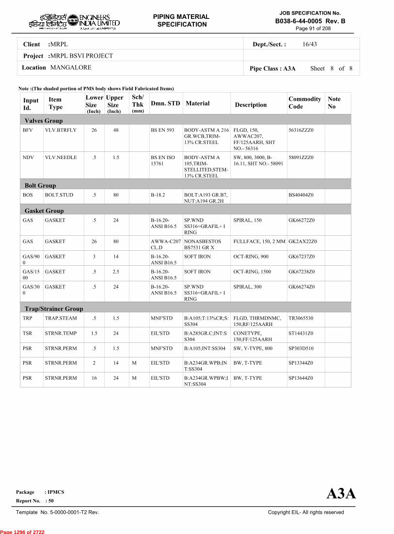
Sheet 8 of 8Pipe Class : A3A
InputId.
Item Type
LowerSize
Upper Size
Sch/Thk DescriptionMaterial
CommodityCode
NoteNo
Valves Group
Bolt Group
Gasket Group
Trap/Strainer Group
Dmn. STD(Inch) (Inch)
BFV
NDV
BOS
GAS
GAS
GAS/900
GAS/1500
GAS/300
TRP
TSR
PSR
PSR
PSR
VLV.BTRFLY
VLV.NEEDLE
BOLT.STUD
GASKET
GASKET
GASKET
GASKET
GASKET
TRAP.STEAM
STRNR.TEMP
STRNR.PERM
STRNR.PERM
STRNR.PERM
26
.5
.5
.5
26
3
.5
.5
.5
1.5
.5
2
16
48
1.5
80
24
80
14
2.5
24
1.5
24
1.5
14
24
M
M
FLGD, 150,AWWAC207,FF/125AARH, SHTNO.- 56316
SW, 800, 3000, B-16.11, SHT NO.- 58091
SPIRAL, 150
FULLFACE, 150, 2 MM
OCT-RING, 900
OCT-RING, 1500
SPIRAL, 300
FLGD, THRMDNMC,150,RF/125AARH
CONETYPE,150,FF/125AARH
SW, Y-TYPE, 800
BW, T-TYPE
BW, T-TYPE
BODY-ASTM A 216GR.WCB,TRIM-13% CR.STEEL
BODY-ASTM A105,TRIM-STELLITED,STEM-13% CR.STEEL
BOLT:A193 GR.B7,NUT:A194 GR.2H
SP.WNDSS316+GRAFIL+ IRING
NONASBESTOSBS7531 GR X
SOFT IRON
SOFT IRON
SP.WNDSS316+GRAFIL+ IRING
B:A105;T:13%CR;S:SS304
B:A285GR.C;INT:SS304
B:A105;INT:SS304
B:A234GR.WPB;INT:SS304
B:A234GR.WPBW;INT:SS304
56316ZZZ0
58091ZZZ0
BS40404Z0
GK66272Z0
GK2AX22Z0
GK67237Z0
GK67238Z0
GK66274Z0
TR3065530
ST14431Z0
SP303D510
SP13344Z0
SP13644Z0
BS EN 593
BS EN ISO15761
B-18.2
B-16.20-ANSI B16.5
AWWA-C207CL.D
B-16.20-ANSI B16.5
B-16.20-ANSI B16.5
B-16.20-ANSI B16.5
MNF'STD
EIL'STD
MNF'STD
EIL'STD
EIL'STD
Note :(The shaded portion of PMS body shows Field Fabricated Items)
A3A
(mm)
Page 1296 of 2722

MRPLClient :
MRPL BSVI PROJECT
MANGALORELocation
16/43Dept./Sect. :
Project :
PIPING MATERIAL
SPECIFICATION
Copyright EIL- All rights reserved
JOB SPECIFICATION No.
B038-6-44-0005 Rev. B
Package : IPMCS
Report No. : 50
Template No. 5-0000-0001-T2 Rev.
Page 92 of 208
A3KPIPE CLASS :150RATING :SS 304BASE MATERIAL : 0CORROSION ALLOWANCE : SPECIAL REQUIREMENT :
MM
SERVICEDEMINERALISED WATER (OUTSIDE DM PLANT BATTERY LIMITS), POLISHED WATER, POLISHED CONDENSTAE -CATEGORY 'D'
NOTES5
7
151
FOR PERMANENT 'T' TYPE BW STRAINERS,REFER EIL'STD 7-44-0303 & 7-44-0304; AND FOR TEMPORARYSTRAINERS,REFER EIL'STD 7-44-0300; FOR SPACER AND BLIND REFER EIL'STD 7-44-0162.FOR RESTRICTION ON USE OF BALL,PLUG & BUTTERFLY VALVES,REFER GENERAL NOTES.
NDT REQUIREMENT SHALL BE AS PER JOB SPECIFICATION B038-6-44-0016.
SPECIAL NOTES
ITEM SIZE DESCRIPTION A.CODEMAINTAINENCEJOINTS
PIPE JOINTS
DRAINS
VENTS
TEMP.CONN
PRESS.CONN
ALL
1.5" & BELOW
2.0" & ABOVE
ON LINES <= 1.5"
ON LINES >= 2.0"
ON LINES <= 1.5"
ON LINES >= 2.0"
1.5"
0.75"
FLANGED, TO BE KEPT MINIMUM
SW COUPLING
BUTTWELDED
REFER EILSTD 7-44-0350, DC3
AS PER P&ID. OR 0.75". REFER EIL STD. 7-44-0351, D3
REFER EIL STD. 7-44-0350, VC1
AS PER P&ID. OR 0.75". REFER EIL STD 7-44-0351, V1
FLANGED. REFER EIL STD 7-44-0353
SW NIPPLE WITH VALVE TO SPEC AS PER EIL STD 7-44-0354
TEMP
PRESS 10.55 10.55 10.55 10.55 10.55
0 38 93 149 186
Sheet 1 of
TEMPERATURE (Deg. C) AND PRESSURE ( Kg/Sq. cm g ) RATINGS
Pipe Class : A3K
A3K
5
Page 1297 of 2722

MRPLClient :
MRPL BSVI PROJECT
MANGALORELocation
16/43Dept./Sect. :
Project :
PIPING MATERIAL
SPECIFICATION
Copyright EIL- All rights reserved
JOB SPECIFICATION No.
B038-6-44-0005 Rev. B
Package : IPMCS
Report No. : 50
Template No. 5-0000-0001-T2 Rev.
Page 93 of 208
Sheet 2 ofPipe Class : A3K
T T T T H H H H H H H H0.50T T T H H H H H H H H0.75
T T H H H H H H H H1.001.25
T T H H H H H H H1.50T P P P P P P P2.00
2.50T P P P P P P3.00
3.50T P P P P P4.00
5.00T P P P P6.00
T P P P8.00T P P10.00
T P12.00T14.00
16.0018.0020.0022.0024.0026.0028.0030.0032.0034.0036.0038.0040.0042.0044.0046.0048.0050.0052.0054.0056.0058.0060.0062.0064.0066.0068.0070.0072.00
.
50
.
75
1
.00
1
.25
1
.50
2
.00
2
.50
3
.00
3
.50
4
.00
5
.00
6
.00
8
.00
10
.00
12
.00
14
.00
BR
AN
CH
PIP
E (
SIZ
E I
N I
NC
HE
S)
0.500.751.001.251.502.002.503.003.504.005.006.008.0010.0012.0014.0016.0018.0020.0022.0024.0026.0028.0030.0032.0034.0036.0038.0040.0042.0044.0046.0048.0050.0052.0054.0056.0058.0060.0062.0064.0066.0068.0070.0072.00
BR
AN
CH
PIP
E (SIZ
E IN
INC
HE
S)
RUN PIPE (SIZE IN INCHES)
CODE DESCRIPTION
F
H
P
R
S
T
W
I
X
L
JSADDLE FUSED JT
H. COUPLING
PIPE TO PIPE
REINFORCED
SOCKOLETS
TEES
WELDOLETS
INSTRUMENT TEE
Refer Notes
SWEEPOLET
THREADOLET
A3K
76.0080.0084.00
76.0080.0084.00
5
Page 1298 of 2722
MRPLClient :
MRPL BSVI PROJECT
MANGALORELocation
16/43Dept./Sect. :
Project :
PIPING MATERIAL
SPECIFICATION
Copyright EIL- All rights reserved
JOB SPECIFICATION No.
B038-6-44-0005 Rev. B
Package : IPMCS
Report No. : 50
Template No. 5-0000-0001-T2 Rev.
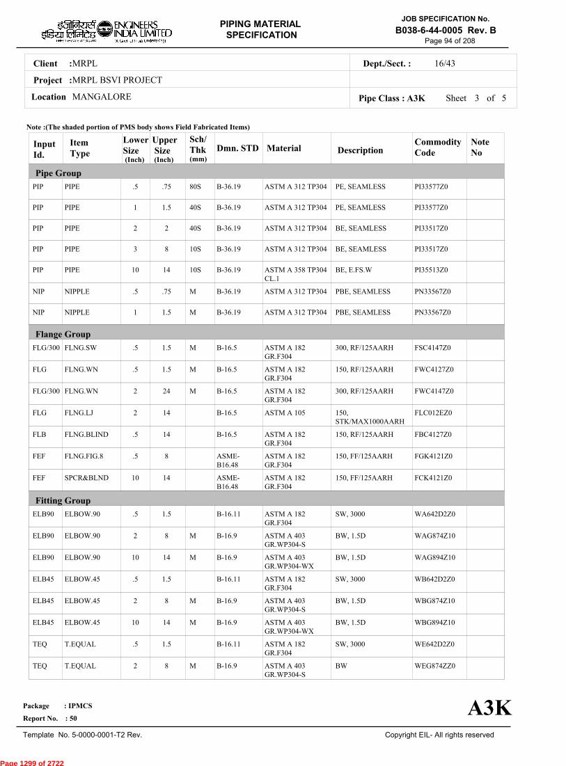
Page 94 of 208
Sheet 3 ofPipe Class : A3K
InputId.
Item Type
LowerSize
Upper Size
Sch/Thk DescriptionMaterial
CommodityCode
NoteNo
Pipe Group
Flange Group
Fitting Group
Dmn. STD(Inch) (Inch)
PIP
PIP
PIP
PIP
PIP
NIP
NIP
FLG/300
FLG
FLG/300
FLG
FLB
FEF
FEF
ELB90
ELB90
ELB90
ELB45
ELB45
ELB45
TEQ
TEQ
PIPE
PIPE
PIPE
PIPE
PIPE
NIPPLE
NIPPLE
FLNG.SW
FLNG.WN
FLNG.WN
FLNG.LJ
FLNG.BLIND
FLNG.FIG.8
SPCR&BLND
ELBOW.90
ELBOW.90
ELBOW.90
ELBOW.45
ELBOW.45
ELBOW.45
T.EQUAL
T.EQUAL
.5
1
2
3
10
.5
1
.5
.5
2
2
.5
.5
10
.5
2
10
.5
2
10
.5
2
.75
1.5
2
8
14
.75
1.5
1.5
1.5
24
14
14
8
14
1.5
8
14
1.5
8
14
1.5
8
80S
40S
40S
10S
10S
M
M
M
M
M
M
M
M
M
M
PE, SEAMLESS
PE, SEAMLESS
BE, SEAMLESS
BE, SEAMLESS
BE, E.FS.W
PBE, SEAMLESS
PBE, SEAMLESS
300, RF/125AARH
150, RF/125AARH
300, RF/125AARH
150,STK/MAX1000AARH
150, RF/125AARH
150, FF/125AARH
150, FF/125AARH
SW, 3000
BW, 1.5D
BW, 1.5D
SW, 3000
BW, 1.5D
BW, 1.5D
SW, 3000
BW
ASTM A 312 TP304
ASTM A 312 TP304
ASTM A 312 TP304
ASTM A 312 TP304
ASTM A 358 TP304CL.1
ASTM A 312 TP304
ASTM A 312 TP304
ASTM A 182GR.F304
ASTM A 182GR.F304
ASTM A 182GR.F304
ASTM A 105
ASTM A 182GR.F304
ASTM A 182GR.F304
ASTM A 182GR.F304
ASTM A 182GR.F304
ASTM A 403GR.WP304-S
ASTM A 403GR.WP304-WX
ASTM A 182GR.F304
ASTM A 403GR.WP304-S
ASTM A 403GR.WP304-WX
ASTM A 182GR.F304
ASTM A 403GR.WP304-S
PI33577Z0
PI33577Z0
PI33517Z0
PI33517Z0
PI35513Z0
PN33567Z0
PN33567Z0
FSC4147Z0
FWC4127Z0
FWC4147Z0
FLC012EZ0
FBC4127Z0
FGK4121Z0
FCK4121Z0
WA642D2Z0
WAG874Z10
WAG894Z10
WB642D2Z0
WBG874Z10
WBG894Z10
WE642D2Z0
WEG874ZZ0
B-36.19
B-36.19
B-36.19
B-36.19
B-36.19
B-36.19
B-36.19
B-16.5
B-16.5
B-16.5
B-16.5
B-16.5
ASME-B16.48
ASME-B16.48
B-16.11
B-16.9
B-16.9
B-16.11
B-16.9
B-16.9
B-16.11
B-16.9
Note :(The shaded portion of PMS body shows Field Fabricated Items)
A3K
(mm)
5
Page 1299 of 2722
MRPLClient :
MRPL BSVI PROJECT
MANGALORELocation
16/43Dept./Sect. :
Project :
PIPING MATERIAL
SPECIFICATION
Copyright EIL- All rights reserved
JOB SPECIFICATION No.
B038-6-44-0005 Rev. B
Package : IPMCS
Report No. : 50
Template No. 5-0000-0001-T2 Rev.
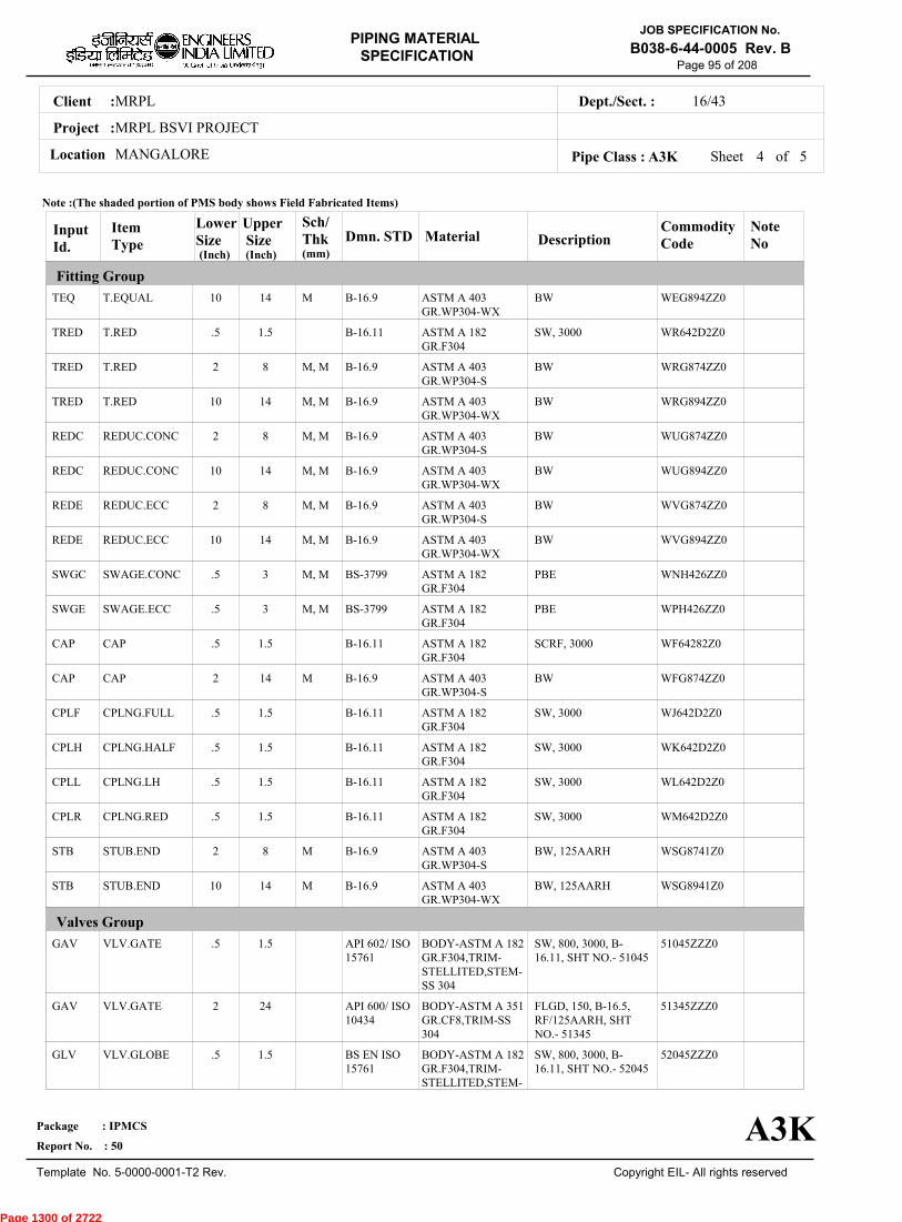
Page 95 of 208
Sheet 4 ofPipe Class : A3K
InputId.
Item Type
LowerSize
Upper Size
Sch/Thk DescriptionMaterial
CommodityCode
NoteNo
Fitting Group
Valves Group
Dmn. STD(Inch) (Inch)
TEQ
TRED
TRED
TRED
REDC
REDC
REDE
REDE
SWGC
SWGE
CAP
CAP
CPLF
CPLH
CPLL
CPLR
STB
STB
GAV
GAV
GLV
T.EQUAL
T.RED
T.RED
T.RED
REDUC.CONC
REDUC.CONC
REDUC.ECC
REDUC.ECC
SWAGE.CONC
SWAGE.ECC
CAP
CAP
CPLNG.FULL
CPLNG.HALF
CPLNG.LH
CPLNG.RED
STUB.END
STUB.END
VLV.GATE
VLV.GATE
VLV.GLOBE
10
.5
2
10
2
10
2
10
.5
.5
.5
2
.5
.5
.5
.5
2
10
.5
2
.5
14
1.5
8
14
8
14
8
14
3
3
1.5
14
1.5
1.5
1.5
1.5
8
14
1.5
24
1.5
M
M, M
M, M
M, M
M, M
M, M
M, M
M, M
M, M
M
M
M
BW
SW, 3000
BW
BW
BW
BW
BW
BW
PBE
PBE
SCRF, 3000
BW
SW, 3000
SW, 3000
SW, 3000
SW, 3000
BW, 125AARH
BW, 125AARH
SW, 800, 3000, B-16.11, SHT NO.- 51045
FLGD, 150, B-16.5,RF/125AARH, SHTNO.- 51345
SW, 800, 3000, B-16.11, SHT NO.- 52045
ASTM A 403GR.WP304-WX
ASTM A 182GR.F304
ASTM A 403GR.WP304-S
ASTM A 403GR.WP304-WX
ASTM A 403GR.WP304-S
ASTM A 403GR.WP304-WX
ASTM A 403GR.WP304-S
ASTM A 403GR.WP304-WX
ASTM A 182GR.F304
ASTM A 182GR.F304
ASTM A 182GR.F304
ASTM A 403GR.WP304-S
ASTM A 182GR.F304
ASTM A 182GR.F304
ASTM A 182GR.F304
ASTM A 182GR.F304
ASTM A 403GR.WP304-S
ASTM A 403GR.WP304-WX
BODY-ASTM A 182GR.F304,TRIM-STELLITED,STEM-SS 304
BODY-ASTM A 351GR.CF8,TRIM-SS304
BODY-ASTM A 182GR.F304,TRIM-STELLITED,STEM-
WEG894ZZ0
WR642D2Z0
WRG874ZZ0
WRG894ZZ0
WUG874ZZ0
WUG894ZZ0
WVG874ZZ0
WVG894ZZ0
WNH426ZZ0
WPH426ZZ0
WF64282Z0
WFG874ZZ0
WJ642D2Z0
WK642D2Z0
WL642D2Z0
WM642D2Z0
WSG8741Z0
WSG8941Z0
51045ZZZ0
51345ZZZ0
52045ZZZ0
B-16.9
B-16.11
B-16.9
B-16.9
B-16.9
B-16.9
B-16.9
B-16.9
BS-3799
BS-3799
B-16.11
B-16.9
B-16.11
B-16.11
B-16.11
B-16.11
B-16.9
B-16.9
API 602/ ISO15761
API 600/ ISO10434
BS EN ISO15761
Note :(The shaded portion of PMS body shows Field Fabricated Items)
A3K
(mm)
5
Page 1300 of 2722

MRPLClient :
MRPL BSVI PROJECT
MANGALORELocation
16/43Dept./Sect. :
Project :
PIPING MATERIAL
SPECIFICATION
Copyright EIL- All rights reserved
JOB SPECIFICATION No.
B038-6-44-0005 Rev. B
Package : IPMCS
Report No. : 50
Template No. 5-0000-0001-T2 Rev.
Page 96 of 208
Sheet 5 of 5Pipe Class : A3K
InputId.
Item Type
LowerSize
Upper Size
Sch/Thk DescriptionMaterial
CommodityCode
NoteNo
Valves Group
Bolt Group
Gasket Group
Trap/Strainer Group
Dmn. STD(Inch) (Inch)
GLV
CHV
CHV
BFV
BOM
GAS
GAS/300
TSR
PSR
PSR
PSR
VLV.GLOBE
VLV.CHECK
VLV.CHECK
VLV.BTRFLY
BOLT.M/C
GASKET
GASKET
STRNR.TEMP
STRNR.PERM
STRNR.PERM
STRNR.PERM
2
.5
2
3
.5
.5
.5
1.5
.5
2
10
16
1.5
24
14
14
14
24
14
1.5
8
14
M
M
FLGD, 150, B-16.5,RF/125AARH, SHTNO.- 52345
SW, 800, 3000, B-16.11, SHT NO.- 53045
FLGD, 150, B-16.5,RF/125AARH, SHTNO.- 53345
WAFL, 150, B-16.5,SHT NO.- 56351
SPIRAL, 150
SPIRAL, 300
CONETYPE,150,FF/125AARH
SW, Y-TYPE, 800
BW, T-TYPE
BW, T-TYPE
SS304
BODY-ASTM A 351GR.CF8,TRIM-SS304
BODY-ASTM A 182GR.F304,TRIM-STELLITED
BODY-ASTM A 351GR.CF8,TRIM-SS304
BODY-ASTM A 351GR CF8,TRIM-SS304
BOLT:A307 GR.B,NUT:A563 GR.B
SP.WNDSS316+GRAFIL+ IRING
SP.WNDSS316+GRAFIL+ IRING
B:A240TP304;INT:SS304
B:A182GR.F304;INT:SS304
B:A403GR.WP304-S;INT:SS304
B:A403GR.WP304-WX;INT:SS304
52345ZZZ0
53045ZZZ0
53345ZZZ0
56351ZZZ0
BM41418Z0
GK66272Z0
GK66274Z0
ST14131Z0
SP307D510
SP15344Z0
SP15444Z0
BS-1873
BS EN ISO15761
BS-1868
BS EN 593
B-18.2
B-16.20-ANSI B16.5
B-16.20-ANSI B16.5
EIL'STD
MNF'STD
EIL'STD
EIL'STD
Note :(The shaded portion of PMS body shows Field Fabricated Items)
A3K
(mm)
Page 1301 of 2722

MRPLClient :
MRPL BSVI PROJECT
MANGALORELocation
16/43Dept./Sect. :
Project :
PIPING MATERIAL
SPECIFICATION
Copyright EIL- All rights reserved
JOB SPECIFICATION No.
B038-6-44-0005 Rev. B
Package : IPMCS
Report No. : 50
Template No. 5-0000-0001-T2 Rev.
Page 97 of 208
A5APIPE CLASS :150RATING :CARBON STEELBASE MATERIAL : 1.5CORROSION ALLOWANCE :HYDROGEN SERVICESPECIAL REQUIREMENT :
MM
SERVICEHYDROGEN AND HYDROGEN BEARING HYDROCARBONS (NOTE 62)- FLAMMABLE, TOXIC/NON-TOXIC BUT NON-LETHAL.
NOTES5
7
17
62
63
151
FOR PERMANENT 'T' TYPE BW STRAINERS,REFER EIL'STD 7-44-0303 & 7-44-0304; AND FOR TEMPORARYSTRAINERS,REFER EIL'STD 7-44-0300; FOR SPACER AND BLIND REFER EIL'STD 7-44-0162.FOR RESTRICTION ON USE OF BALL,PLUG & BUTTERFLY VALVES,REFER GENERAL NOTES.
FOR HYDROGEN SERVICE, CARBON STEEL PIPING MATERIALS WITH WALL THICKNESS 3/8 INCH AND OVER SHALLBE NORMALISED.ANY MEDIUM CONTAINING HYDROGEN GAS WITH A PARTIAL PRESSURE OF 100 PSI & ABOVE SHALL BECONSIDERED AS HYDROGEN SERVICE.THIS ITEM IS INTENDED SOLELY FOR USE BY INSTRUMENTATION.
NDT REQUIREMENT SHALL BE AS PER JOB SPECIFICATION B038-6-44-0016.
SPECIAL NOTES
ITEM SIZE DESCRIPTION A.CODEMAINTAINENCEJOINTS
PIPE JOINTS
DRAINS
VENTS
TEMP.CONN
PRESS.CONN
ALL
1.5" & BELOW
2.0" & ABOVE
ON LINES <= 1.5"
ON LINES >= 2.0"
ON LINES <= 1.5"
ON LINES >= 2.0"
1.5"
0.75"
FLANGED, TO BE KEPT MINIMUM
SW COUPLING
BUTTWELDED
REFER EILSTD 7-44-0350, DF3
AS PER P&ID OR 0.75". REFER EIL STD. 7-44-0351, D4
REFER EIL STD. 7-44-0350, VF3
AS PER P&ID OR 0.75". REFER EIL STD 7-44-0351, V4
FLANGED. REFER EIL STD 7-44-0353
SW NIPPLE WITH VALVE TO SPEC AS PER EIL STD 7-44-0354
TEMP
PRESS 20.03 20.03 18.28 16.17 14.06 11.95
-29 38 93 149 204 260
Sheet 1 of
TEMPERATURE (Deg. C) AND PRESSURE ( Kg/Sq. cm g ) RATINGS
Pipe Class : A5A
A5A
6
Page 1302 of 2722

MRPLClient :
MRPL BSVI PROJECT
MANGALORELocation
16/43Dept./Sect. :
Project :
PIPING MATERIAL
SPECIFICATION
Copyright EIL- All rights reserved
JOB SPECIFICATION No.
B038-6-44-0005 Rev. B
Package : IPMCS
Report No. : 50
Template No. 5-0000-0001-T2 Rev.
Page 98 of 208
Sheet 2 ofPipe Class : A5A
T T T T H H H H H H H H H H H H0.50T T T H H H H H H H H H H H H0.75
T T H H H H H H H H H H H H1.001.25
T T H H H H H H H H H H H1.50T P P P P P P P P P P R2.00
2.50T P P P P P P P P P R3.00
3.50T P P P P P P P P R4.00
5.00T P P P P P P P R6.00
T P P P P P P R8.00T P P P P P R10.00
T P P P P R12.00T P P P R14.00
T P P R16.00T P R18.00
T R20.0022.00
T24.0026.0028.0030.0032.0034.0036.0038.0040.0042.0044.0046.0048.0050.0052.0054.0056.0058.0060.0062.0064.0066.0068.0070.0072.00
.
50
.
75
1
.00
1
.25
1
.50
2
.00
2
.50
3
.00
3
.50
4
.00
5
.00
6
.00
8
.00
10
.00
12
.00
14
.00
16
.00
18
.00
20
.00
22
.00
24
.00
BR
AN
CH
PIP
E (
SIZ
E I
N I
NC
HE
S)
0.500.751.001.251.502.002.503.003.504.005.006.008.0010.0012.0014.0016.0018.0020.0022.0024.0026.0028.0030.0032.0034.0036.0038.0040.0042.0044.0046.0048.0050.0052.0054.0056.0058.0060.0062.0064.0066.0068.0070.0072.00
BR
AN
CH
PIP
E (SIZ
E IN
INC
HE
S)
RUN PIPE (SIZE IN INCHES)
CODE DESCRIPTION
F
H
P
R
S
T
W
I
X
L
JSADDLE FUSED JT
H. COUPLING
PIPE TO PIPE
REINFORCED
SOCKOLETS
TEES
WELDOLETS
INSTRUMENT TEE
Refer Notes
SWEEPOLET
THREADOLET
A5A
76.0080.0084.00
76.0080.0084.00
6
Page 1303 of 2722

MRPLClient :
MRPL BSVI PROJECT
MANGALORELocation
16/43Dept./Sect. :
Project :
PIPING MATERIAL
SPECIFICATION
Copyright EIL- All rights reserved
JOB SPECIFICATION No.
B038-6-44-0005 Rev. B
Package : IPMCS
Report No. : 50
Template No. 5-0000-0001-T2 Rev.
Page 99 of 208
Sheet 3 ofPipe Class : A5A
InputId.
Item Type
LowerSize
Upper Size
Sch/Thk DescriptionMaterial
CommodityCode
NoteNo
Pipe Group
Flange Group
Fitting Group
Dmn. STD(Inch) (Inch)
PIP
PIP
PIP
PIP
PIP
NIP
NIP
FLG/300
FLG
FLG/300
FLB
FEF
FEF
ELB90
ELB90
ELB90
ELB90
ELB45
ELB45
ELB45
ELB45
TEQ
PIPE
PIPE
PIPE
PIPE
PIPE
NIPPLE
NIPPLE
FLNG.SW
FLNG.WN
FLNG.WN
FLNG.BLIND
FLNG.FIG.8
SPCR&BLND
ELBOW.90
ELBOW.90
ELBOW.90
ELBOW.90
ELBOW.45
ELBOW.45
ELBOW.45
ELBOW.45
T.EQUAL
.5
1
2
3
16
.5
1
.5
.5
2
.5
.5
10
.5
1
2
16
.5
1
2
16
.5
.75
1.5
2
14
24
.75
1.5
1.5
24
24
24
8
24
.75
1.5
14
24
.75
1.5
14
24
.75
S160
XS
XS
STD
STD
M
M
M
M
M
M
M
M
M
PE, SEAMLESS
PE, SEAMLESS
BE, SEAMLESS
BE, SEAMLESS
BE, E.FS.W
PBE, SEAMLESS
PBE, SEAMLESS
300, RF/125AARH
150, RF/125AARH
300, RF/125AARH
150, RF/125AARH
150, FF/125AARH
150, FF/125AARH
SW, 6000
SW, 3000
BW, 1.5D
BW, 1.5D
SW, 6000
SW, 3000
BW, 1.5D
BW, 1.5D
SW, 6000
ASTM A 106 GR.B
ASTM A 106 GR.B
ASTM A 106 GR.B
ASTM A 106 GR.B
ASTM A 672GR.B60 CL.32
ASTM A 106 GR.B
ASTM A 106 GR.B
ASTM A 105
ASTM A 105
ASTM A 105
ASTM A 105
ASTM A 105
ASTM A 105
ASTM A 105
ASTM A 105
ASTM A 234GR.WPB
ASTM A 234GR.WPB-W
ASTM A 105
ASTM A 105
ASTM A 234GR.WPB
ASTM A 234GR.WPB-W
ASTM A 105
PI21977Z7
PI21977Z7
PI21917Z7
PI21917Z7
PI2B113Z7
PN21967Z7
PN21967Z7
FSC0147Z7
FWC0127Z7
FWC0147Z7
FBC0127Z7
FGK0121Z7
FCK0121Z7
WA602D3Z7
WA602D2Z7
WAG684Z17
WAG754Z17
WB602D3Z7
WB602D2Z7
WBG684Z17
WBG754Z17
WE602D3Z7
B-36.10
B-36.10
B-36.10
B-36.10
B-36.10
B-36.10
B-36.10
B-16.5
B-16.5
B-16.5
B-16.5
ASME-B16.48
ASME-B16.48
B-16.11
B-16.11
B-16.9
B-16.9
B-16.11
B-16.11
B-16.9
B-16.9
B-16.11
Note :(The shaded portion of PMS body shows Field Fabricated Items)
A5A
(mm)
6
Page 1304 of 2722

MRPLClient :
MRPL BSVI PROJECT
MANGALORELocation
16/43Dept./Sect. :
Project :
PIPING MATERIAL
SPECIFICATION
Copyright EIL- All rights reserved
JOB SPECIFICATION No.
B038-6-44-0005 Rev. B
Package : IPMCS
Report No. : 50
Template No. 5-0000-0001-T2 Rev.
Page 100 of 208
Sheet 4 ofPipe Class : A5A
InputId.
Item Type
LowerSize
Upper Size
Sch/Thk DescriptionMaterial
CommodityCode
NoteNo
Fitting Group
Dmn. STD(Inch) (Inch)
TEQ
TEQ
TEQ
TRED
TRED
TRED
TRED
REDC
REDC
REDE
REDE
SWGC
SWGE
CAP
CAP
CAP
CPLF
CPLF
CPLH
CPLH
CPLL
CPLL
CPLR
T.EQUAL
T.EQUAL
T.EQUAL
T.RED
T.RED
T.RED
T.RED
REDUC.CONC
REDUC.CONC
REDUC.ECC
REDUC.ECC
SWAGE.CONC
SWAGE.ECC
CAP
CAP
CAP
CPLNG.FULL
CPLNG.FULL
CPLNG.HALF
CPLNG.HALF
CPLNG.LH
CPLNG.LH
CPLNG.RED
1
2
16
.5
1
2
16
2
16
2
16
.5
.5
.5
1
2
.5
1
.5
1
.5
1
.5
1.5
14
24
.75
1.5
14
24
14
24
14
24
3
3
.75
1.5
24
.75
1.5
.75
1.5
.75
1.5
.75
M
M
M, M
M, M
M, M
M, M
M, M
M, M
M, M
M, M
M
SW, 3000
BW
BW
SW, 6000
SW, 3000
BW
BW
BW
BW
BW
BW
PBE
PBE
SCRF, 6000
SCRF, 3000
BW
SW, 6000
SW, 3000
SW, 6000
SW, 3000
SW, 6000
SW, 3000
SW, 6000
ASTM A 105
ASTM A 234GR.WPB
ASTM A 234GR.WPB-W
ASTM A 105
ASTM A 105
ASTM A 234GR.WPB
ASTM A 234GR.WPB-W
ASTM A 234GR.WPB
ASTM A 234GR.WPB-W
ASTM A 234GR.WPB
ASTM A 234GR.WPB-W
ASTM A 105
ASTM A 105
ASTM A 105
ASTM A 105
ASTM A 234GR.WPB
ASTM A 105
ASTM A 105
ASTM A 105
ASTM A 105
ASTM A 105
ASTM A 105
ASTM A 105
WE602D2Z7
WEG684ZZ7
WEG754ZZ7
WR602D3Z7
WR602D2Z7
WRG684ZZ7
WRG754ZZ7
WUG684ZZ7
WUG754ZZ7
WVG684ZZ7
WVG754ZZ7
WNH026ZZ7
WPH026ZZ7
WF60283Z7
WF60282Z7
WFG684ZZ7
WJ602D3Z7
WJ602D2Z7
WK602D3Z7
WK602D2Z7
WL602D3Z7
WL602D2Z7
WM602D3Z7
63
63
B-16.11
B-16.9
B-16.9
B-16.11
B-16.11
B-16.9
B-16.9
B-16.9
B-16.9
B-16.9
B-16.9
BS-3799
BS-3799
B-16.11
B-16.11
B-16.9
B-16.11
B-16.11
B-16.11
B-16.11
B-16.11
B-16.11
B-16.11
Note :(The shaded portion of PMS body shows Field Fabricated Items)
A5A
(mm)
6
Page 1305 of 2722
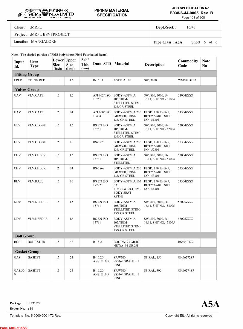
MRPLClient :
MRPL BSVI PROJECT
MANGALORELocation
16/43Dept./Sect. :
Project :
PIPING MATERIAL
SPECIFICATION
Copyright EIL- All rights reserved
JOB SPECIFICATION No.
B038-6-44-0005 Rev. B
Package : IPMCS
Report No. : 50
Template No. 5-0000-0001-T2 Rev.
Page 101 of 208
Sheet 5 ofPipe Class : A5A
InputId.
Item Type
LowerSize
Upper Size
Sch/Thk DescriptionMaterial
CommodityCode
NoteNo
Fitting Group
Valves Group
Bolt Group
Gasket Group
Dmn. STD(Inch) (Inch)
CPLR
GAV
GAV
GLV
GLV
CHV
CHV
BLV
NDV
NDV
BOS
GAS
GAS/300
CPLNG.RED
VLV.GATE
VLV.GATE
VLV.GLOBE
VLV.GLOBE
VLV.CHECK
VLV.CHECK
VLV.BALL
VLV.NEEDLE
VLV.NEEDLE
BOLT.STUD
GASKET
GASKET
1
.5
2
.5
2
.5
2
.5
.5
.5
.5
.5
.5
1.5
1.5
24
1.5
16
1.5
24
16
1.5
1.5
48
24
24
SW, 3000
SW, 800, 3000, B-16.11, SHT NO.- 51004
FLGD, 150, B-16.5,RF/125AARH, SHTNO.- 51304
SW, 800, 3000, B-16.11, SHT NO.- 52004
FLGD, 150, B-16.5,RF/125AARH, SHTNO.- 52304
SW, 800, 3000, B-16.11, SHT NO.- 53004
FLGD, 150, B-16.5,RF/125AARH, SHTNO.- 53304
FLGD, 150, B-16.5,RF/125AARH, SHTNO.- 54304
SW, 800, 3000, B-16.11, SHT NO.- 58095
SW, 800, 3000, B-16.11, SHT NO.- 58095
SPIRAL, 150
SPIRAL, 300
ASTM A 105
BODY-ASTM A105,TRIM-STELLITED,STEM-13%CR STEEL
BODY-ASTM A 216GR.WCB,TRIM-13% CR.STEEL
BODY-ASTM A105,TRIM-STELLITED,STEM-13%CR.STEEL
BODY-ASTM A 216GR.WCB,TRIM-13% CR.STEEL
BODY-ASTM A105,TRIM-STELLITED
BODY-ASTM A 216GR.WCB,TRIM-13% CR.STEEL
BODY-ASTM A 105/ A216GR.WCB,TRIM-BODY SEAT-RPTFE
BODY-ASTM A105,TRIM-STELLITED,STEM-13% CR.STEEL
BODY-ASTM A105,TRIM-STELLITED,STEM-13% CR.STEEL
BOLT:A193 GR.B7,NUT:A194 GR.2H
SP.WNDSS316+GRAFIL+ IRING
SP.WNDSS316+GRAFIL+ IRING
WM602D2Z7
51004ZZZ7
51304ZZZ7
52004ZZZ7
52304ZZZ7
53004ZZZ7
53304ZZZ7
54304ZZZ7
58095ZZZ7
58095ZZZ7
BS40404Z7
GK66272Z7
GK66274Z7
B-16.11
API 602/ ISO15761
API 600/ ISO10434
BS EN ISO15761
BS-1873
BS EN ISO15761
BS-1868
BS EN ISO17292
BS EN ISO15761
BS EN ISO15761
B-18.2
B-16.20-ANSI B16.5
B-16.20-ANSI B16.5
Note :(The shaded portion of PMS body shows Field Fabricated Items)
A5A
(mm)
6
Page 1306 of 2722
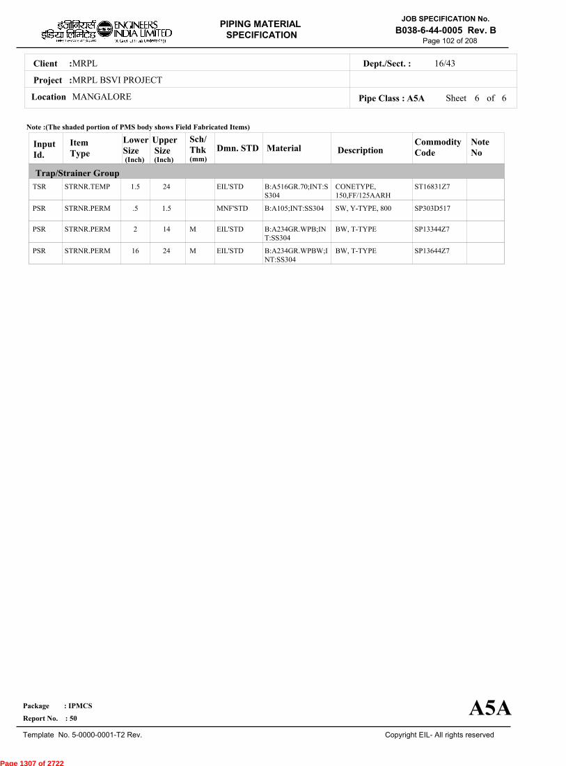
MRPLClient :
MRPL BSVI PROJECT
MANGALORELocation
16/43Dept./Sect. :
Project :
PIPING MATERIAL
SPECIFICATION
Copyright EIL- All rights reserved
JOB SPECIFICATION No.
B038-6-44-0005 Rev. B
Package : IPMCS
Report No. : 50
Template No. 5-0000-0001-T2 Rev.
Page 102 of 208
Sheet 6 of 6Pipe Class : A5A
InputId.
Item Type
LowerSize
Upper Size
Sch/Thk DescriptionMaterial
CommodityCode
NoteNo
Trap/Strainer Group
Dmn. STD(Inch) (Inch)
TSR
PSR
PSR
PSR
STRNR.TEMP
STRNR.PERM
STRNR.PERM
STRNR.PERM
1.5
.5
2
16
24
1.5
14
24
M
M
CONETYPE,150,FF/125AARH
SW, Y-TYPE, 800
BW, T-TYPE
BW, T-TYPE
B:A516GR.70;INT:SS304
B:A105;INT:SS304
B:A234GR.WPB;INT:SS304
B:A234GR.WPBW;INT:SS304
ST16831Z7
SP303D517
SP13344Z7
SP13644Z7
EIL'STD
MNF'STD
EIL'STD
EIL'STD
Note :(The shaded portion of PMS body shows Field Fabricated Items)
A5A
(mm)
Page 1307 of 2722

MRPLClient :
MRPL BSVI PROJECT
MANGALORELocation
16/43Dept./Sect. :
Project :
PIPING MATERIAL
SPECIFICATION
Copyright EIL- All rights reserved
JOB SPECIFICATION No.
B038-6-44-0005 Rev. B
Package : IPMCS
Report No. : 50
Template No. 5-0000-0001-T2 Rev.
Page 103 of 208
A93APIPE CLASS :150RATING :CARBON STEELBASE MATERIAL : 1.5CORROSION ALLOWANCE : SPECIAL REQUIREMENT :
MM
SERVICECATEGORY 'D' FLUID, CONTAMINATED RAIN WATER SEWER(CRWS) / STORM SEWER (UNDER GROUND).
NOTES6
7
31
65
76
97
128
151
224
234
237
FOR FABRICATED REDUCERS,REFER EIL'STD 7-44-0485 & 7-44-0487. FOR MITRES, REFER EIL'STD 7-44-0033.
FOR RESTRICTION ON USE OF BALL,PLUG & BUTTERFLY VALVES,REFER GENERAL NOTES.
USE BUTTERFLY VALVES INSTEAD OF GATE VALVES FROM 10" ONWARDS IN WATER SERVICE AND UPTO 70 DEG C.DESIGN PRESSURE FOR BUTTERFLY VALVES IS LIMITED UPTO 10 BAR.FORGINGS ARE ACCEPTABLE IN LIEU OF PLATE MATERIAL FOR BLIND FLANGES AND SPACER & BLINDS.
FOR PERMANENT BW STRAINERS,REFER EIL'STD 7-44-0303 & 7-44-0304; AND FOR TEMPORARY STRAINERS,REFEREIL'STD 7-44-0300.USE 5-PIECE 90 DEG. MITRE FOR SIZES FROM 16" TO 44", 6-PIECE 90 DEG. MITRE FOR SIZES 48" TO 68" & 7-PIECEMITRE FOR SIZES 72" TO 80". 45 DEG. MITRE SHALL REQUIRE ONE PIECE LESS.ALL WELDED PIPES SHALL BE LONGITUDINALLY WELDED TYPE. SPIRAL WELDED PIPES ARE NOT ACCEPTABLE.
NDT REQUIREMENT SHALL BE AS PER JOB SPECIFICATION B038-6-44-0016.
SOIL CONDITIONS FOR THE UNDERGROUND PIPING ARE AS FOLLOWS:-(1)MODULUS OF ELASTICITY :- 1000 T/ M2,(2)BULK DENSITY OF SOIL :- 1700 KG/M3,(3)K.Mu FACTOR :- 0.17PIPE THICKNESS SPECIFIED IN THIS CLASS ARE JOB SPECIFIC BASED ON THE SOIL PROPERTIES OF JOB SITE ANDDEPTH OF BURIAL FOR VARIOUS SIZES ARE AS FOLLOWS:-1)0.5"-32" :- UPTO 3.5MTHE MINIMUM SOIL COVER FOR U/G IS 600MM.
TEMP
PRESS 10.55 10.55 10.55 10.55 10.55 10.55 10.55
0 38 50 65 100 150 186
Sheet 1 of
TEMPERATURE (Deg. C) AND PRESSURE ( Kg/Sq. cm g ) RATINGS
Pipe Class : A93A
A93A
7
Page 1308 of 2722
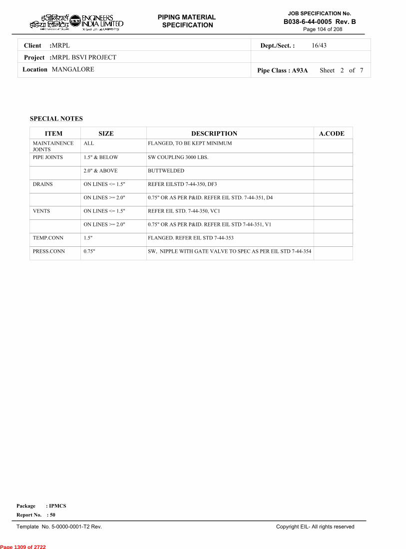
MRPLClient :
MRPL BSVI PROJECT
MANGALORELocation
16/43Dept./Sect. :
Project :
PIPING MATERIAL
SPECIFICATION
Copyright EIL- All rights reserved
JOB SPECIFICATION No.
B038-6-44-0005 Rev. B
Package : IPMCS
Report No. : 50
Template No. 5-0000-0001-T2 Rev.
Page 104 of 208
SPECIAL NOTES
ITEM SIZE DESCRIPTION A.CODEMAINTAINENCEJOINTS
PIPE JOINTS
DRAINS
VENTS
TEMP.CONN
PRESS.CONN
ALL
1.5" & BELOW
2.0" & ABOVE
ON LINES <= 1.5"
ON LINES >= 2.0"
ON LINES <= 1.5"
ON LINES >= 2.0"
1.5"
0.75"
FLANGED, TO BE KEPT MINIMUM
SW COUPLING 3000 LBS.
BUTTWELDED
REFER EILSTD 7-44-350, DF3
0.75" OR AS PER P&ID. REFER EIL STD. 7-44-351, D4
REFER EIL STD. 7-44-350, VC1
0.75" OR AS PER P&ID. REFER EIL STD 7-44-351, V1
FLANGED. REFER EIL STD 7-44-353
SW, NIPPLE WITH GATE VALVE TO SPEC AS PER EIL STD 7-44-354
Sheet 2 ofPipe Class : A93A 7
Page 1309 of 2722
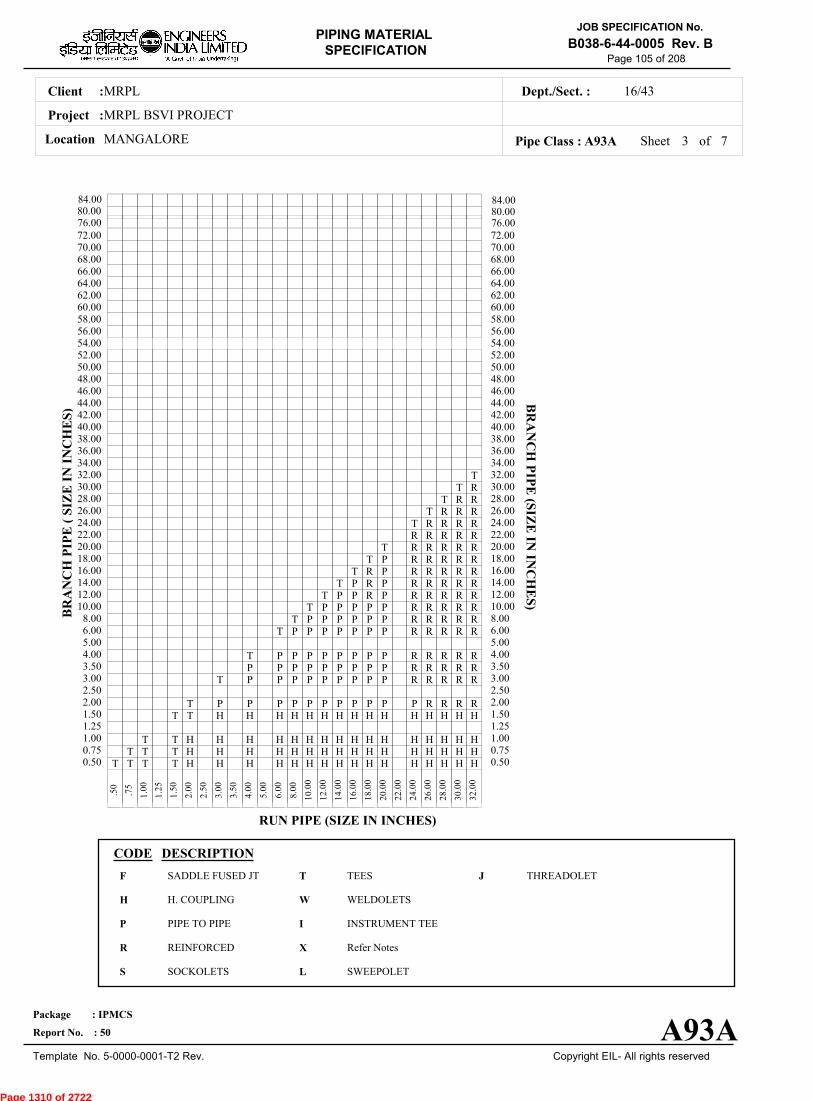
MRPLClient :
MRPL BSVI PROJECT
MANGALORELocation
16/43Dept./Sect. :
Project :
PIPING MATERIAL
SPECIFICATION
Copyright EIL- All rights reserved
JOB SPECIFICATION No.
B038-6-44-0005 Rev. B
Package : IPMCS
Report No. : 50
Template No. 5-0000-0001-T2 Rev.
Page 105 of 208
Sheet 3 ofPipe Class : A93A
T T T T H H H H H H H H H H H H H H H H0.50T T T H H H H H H H H H H H H H H H H0.75
T T H H H H H H H H H H H H H H H H1.001.25
T T H H H H H H H H H H H H H H H1.50T P P P P P P P P P P P R R R R2.00
2.50T P P P P P P P P P R R R R R3.00
P P P P P P P P P R R R R R3.50T P P P P P P P P R R R R R4.00
5.00T P P P P P P P R R R R R6.00
T P P P P P P R R R R R8.00T P P P P P R R R R R10.00
T P P R P R R R R R12.00T P R P R R R R R14.00
T R P R R R R R16.00T P R R R R R18.00
T R R R R R20.00R R R R R22.00T R R R R24.00
T R R R26.00T R R28.00
T R30.00T32.00
34.0036.0038.0040.0042.0044.0046.0048.0050.0052.0054.0056.0058.0060.0062.0064.0066.0068.0070.0072.00
.
50
.
75
1
.00
1
.25
1
.50
2
.00
2
.50
3
.00
3
.50
4
.00
5
.00
6
.00
8
.00
10
.00
12
.00
14
.00
16
.00
18
.00
20
.00
22
.00
24
.00
26
.00
28
.00
30
.00
32
.00
BR
AN
CH
PIP
E (
SIZ
E I
N I
NC
HE
S)
0.500.751.001.251.502.002.503.003.504.005.006.008.0010.0012.0014.0016.0018.0020.0022.0024.0026.0028.0030.0032.0034.0036.0038.0040.0042.0044.0046.0048.0050.0052.0054.0056.0058.0060.0062.0064.0066.0068.0070.0072.00
BR
AN
CH
PIP
E (SIZ
E IN
INC
HE
S)
RUN PIPE (SIZE IN INCHES)
CODE DESCRIPTION
F
H
P
R
S
T
W
I
X
L
JSADDLE FUSED JT
H. COUPLING
PIPE TO PIPE
REINFORCED
SOCKOLETS
TEES
WELDOLETS
INSTRUMENT TEE
Refer Notes
SWEEPOLET
THREADOLET
A93A
76.0080.0084.00
76.0080.0084.00
7
Page 1310 of 2722
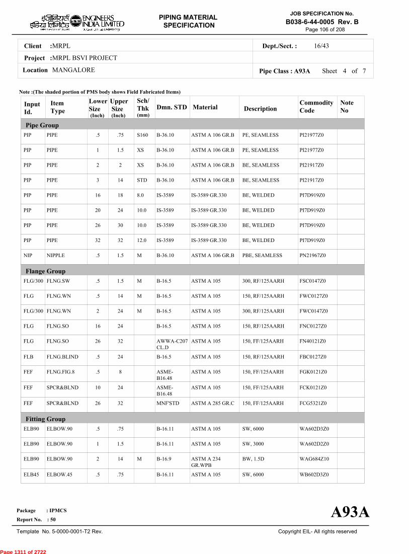
MRPLClient :
MRPL BSVI PROJECT
MANGALORELocation
16/43Dept./Sect. :
Project :
PIPING MATERIAL
SPECIFICATION
Copyright EIL- All rights reserved
JOB SPECIFICATION No.
B038-6-44-0005 Rev. B
Package : IPMCS
Report No. : 50
Template No. 5-0000-0001-T2 Rev.
Page 106 of 208
Sheet 4 ofPipe Class : A93A
InputId.
Item Type
LowerSize
Upper Size
Sch/Thk DescriptionMaterial
CommodityCode
NoteNo
Pipe Group
Flange Group
Fitting Group
Dmn. STD(Inch) (Inch)
PIP
PIP
PIP
PIP
PIP
PIP
PIP
PIP
NIP
FLG/300
FLG
FLG/300
FLG
FLG
FLB
FEF
FEF
FEF
ELB90
ELB90
ELB90
ELB45
PIPE
PIPE
PIPE
PIPE
PIPE
PIPE
PIPE
PIPE
NIPPLE
FLNG.SW
FLNG.WN
FLNG.WN
FLNG.SO
FLNG.SO
FLNG.BLIND
FLNG.FIG.8
SPCR&BLND
SPCR&BLND
ELBOW.90
ELBOW.90
ELBOW.90
ELBOW.45
.5
1
2
3
16
20
26
32
.5
.5
.5
2
16
26
.5
.5
10
26
.5
1
2
.5
.75
1.5
2
14
18
24
30
32
1.5
1.5
14
24
24
32
24
8
24
32
.75
1.5
14
.75
S160
XS
XS
STD
8.0
10.0
10.0
12.0
M
M
M
M
M
PE, SEAMLESS
PE, SEAMLESS
BE, SEAMLESS
BE, SEAMLESS
BE, WELDED
BE, WELDED
BE, WELDED
BE, WELDED
PBE, SEAMLESS
300, RF/125AARH
150, RF/125AARH
300, RF/125AARH
150, RF/125AARH
150, FF/125AARH
150, RF/125AARH
150, FF/125AARH
150, FF/125AARH
150, FF/125AARH
SW, 6000
SW, 3000
BW, 1.5D
SW, 6000
ASTM A 106 GR.B
ASTM A 106 GR.B
ASTM A 106 GR.B
ASTM A 106 GR.B
IS-3589 GR.330
IS-3589 GR.330
IS-3589 GR.330
IS-3589 GR.330
ASTM A 106 GR.B
ASTM A 105
ASTM A 105
ASTM A 105
ASTM A 105
ASTM A 105
ASTM A 105
ASTM A 105
ASTM A 105
ASTM A 285 GR.C
ASTM A 105
ASTM A 105
ASTM A 234GR.WPB
ASTM A 105
PI21977Z0
PI21977Z0
PI21917Z0
PI21917Z0
PI7D919Z0
PI7D919Z0
PI7D919Z0
PI7D919Z0
PN21967Z0
FSC0147Z0
FWC0127Z0
FWC0147Z0
FNC0127Z0
FN40121Z0
FBC0127Z0
FGK0121Z0
FCK0121Z0
FCG5321Z0
WA602D3Z0
WA602D2Z0
WAG684Z10
WB602D3Z0
B-36.10
B-36.10
B-36.10
B-36.10
IS-3589
IS-3589
IS-3589
IS-3589
B-36.10
B-16.5
B-16.5
B-16.5
B-16.5
AWWA-C207CL.D
B-16.5
ASME-B16.48
ASME-B16.48
MNF'STD
B-16.11
B-16.11
B-16.9
B-16.11
Note :(The shaded portion of PMS body shows Field Fabricated Items)
A93A
(mm)
7
Page 1311 of 2722
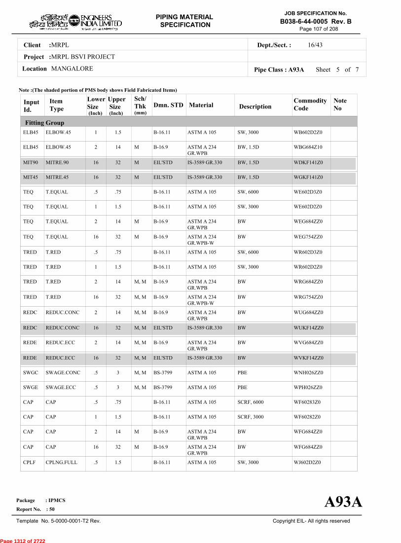
MRPLClient :
MRPL BSVI PROJECT
MANGALORELocation
16/43Dept./Sect. :
Project :
PIPING MATERIAL
SPECIFICATION
Copyright EIL- All rights reserved
JOB SPECIFICATION No.
B038-6-44-0005 Rev. B
Package : IPMCS
Report No. : 50
Template No. 5-0000-0001-T2 Rev.
Page 107 of 208
Sheet 5 ofPipe Class : A93A
InputId.
Item Type
LowerSize
Upper Size
Sch/Thk DescriptionMaterial
CommodityCode
NoteNo
Fitting Group
Dmn. STD(Inch) (Inch)
ELB45
ELB45
MIT90
MIT45
TEQ
TEQ
TEQ
TEQ
TRED
TRED
TRED
TRED
REDC
REDC
REDE
REDE
SWGC
SWGE
CAP
CAP
CAP
CAP
CPLF
ELBOW.45
ELBOW.45
MITRE.90
MITRE.45
T.EQUAL
T.EQUAL
T.EQUAL
T.EQUAL
T.RED
T.RED
T.RED
T.RED
REDUC.CONC
REDUC.CONC
REDUC.ECC
REDUC.ECC
SWAGE.CONC
SWAGE.ECC
CAP
CAP
CAP
CAP
CPLNG.FULL
1
2
16
16
.5
1
2
16
.5
1
2
16
2
16
2
16
.5
.5
.5
1
2
16
.5
1.5
14
32
32
.75
1.5
14
32
.75
1.5
14
32
14
32
14
32
3
3
.75
1.5
14
32
1.5
M
M
M
M
M
M, M
M, M
M, M
M, M
M, M
M, M
M, M
M, M
M
M
SW, 3000
BW, 1.5D
BW, 1.5D
BW, 1.5D
SW, 6000
SW, 3000
BW
BW
SW, 6000
SW, 3000
BW
BW
BW
BW
BW
BW
PBE
PBE
SCRF, 6000
SCRF, 3000
BW
BW
SW, 3000
ASTM A 105
ASTM A 234GR.WPB
IS-3589 GR.330
IS-3589 GR.330
ASTM A 105
ASTM A 105
ASTM A 234GR.WPB
ASTM A 234GR.WPB-W
ASTM A 105
ASTM A 105
ASTM A 234GR.WPB
ASTM A 234GR.WPB-W
ASTM A 234GR.WPB
IS-3589 GR.330
ASTM A 234GR.WPB
IS-3589 GR.330
ASTM A 105
ASTM A 105
ASTM A 105
ASTM A 105
ASTM A 234GR.WPB
ASTM A 234GR.WPB
ASTM A 105
WB602D2Z0
WBG684Z10
WDKF141Z0
WGKF141Z0
WE602D3Z0
WE602D2Z0
WEG684ZZ0
WEG754ZZ0
WR602D3Z0
WR602D2Z0
WRG684ZZ0
WRG754ZZ0
WUG684ZZ0
WUKF14ZZ0
WVG684ZZ0
WVKF14ZZ0
WNH026ZZ0
WPH026ZZ0
WF60283Z0
WF60282Z0
WFG684ZZ0
WFG684ZZ0
WJ602D2Z0
B-16.11
B-16.9
EIL'STD
EIL'STD
B-16.11
B-16.11
B-16.9
B-16.9
B-16.11
B-16.11
B-16.9
B-16.9
B-16.9
EIL'STD
B-16.9
EIL'STD
BS-3799
BS-3799
B-16.11
B-16.11
B-16.9
B-16.9
B-16.11
Note :(The shaded portion of PMS body shows Field Fabricated Items)
A93A
(mm)
7
Page 1312 of 2722
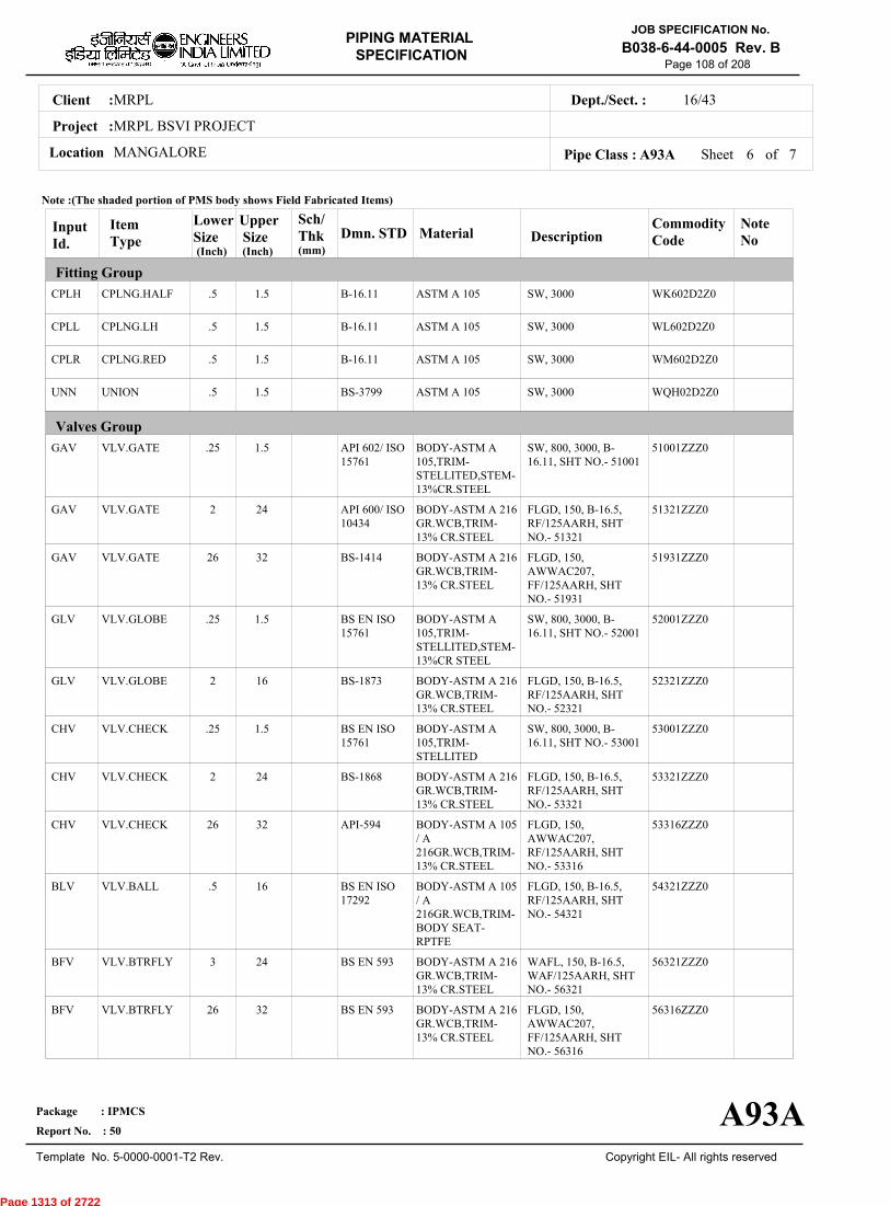
MRPLClient :
MRPL BSVI PROJECT
MANGALORELocation
16/43Dept./Sect. :
Project :
PIPING MATERIAL
SPECIFICATION
Copyright EIL- All rights reserved
JOB SPECIFICATION No.
B038-6-44-0005 Rev. B
Package : IPMCS
Report No. : 50
Template No. 5-0000-0001-T2 Rev.
Page 108 of 208
Sheet 6 ofPipe Class : A93A
InputId.
Item Type
LowerSize
Upper Size
Sch/Thk DescriptionMaterial
CommodityCode
NoteNo
Fitting Group
Valves Group
Dmn. STD(Inch) (Inch)
CPLH
CPLL
CPLR
UNN
GAV
GAV
GAV
GLV
GLV
CHV
CHV
CHV
BLV
BFV
BFV
CPLNG.HALF
CPLNG.LH
CPLNG.RED
UNION
VLV.GATE
VLV.GATE
VLV.GATE
VLV.GLOBE
VLV.GLOBE
VLV.CHECK
VLV.CHECK
VLV.CHECK
VLV.BALL
VLV.BTRFLY
VLV.BTRFLY
.5
.5
.5
.5
.25
2
26
.25
2
.25
2
26
.5
3
26
1.5
1.5
1.5
1.5
1.5
24
32
1.5
16
1.5
24
32
16
24
32
SW, 3000
SW, 3000
SW, 3000
SW, 3000
SW, 800, 3000, B-16.11, SHT NO.- 51001
FLGD, 150, B-16.5,RF/125AARH, SHTNO.- 51321
FLGD, 150,AWWAC207,FF/125AARH, SHTNO.- 51931
SW, 800, 3000, B-16.11, SHT NO.- 52001
FLGD, 150, B-16.5,RF/125AARH, SHTNO.- 52321
SW, 800, 3000, B-16.11, SHT NO.- 53001
FLGD, 150, B-16.5,RF/125AARH, SHTNO.- 53321
FLGD, 150,AWWAC207,RF/125AARH, SHTNO.- 53316
FLGD, 150, B-16.5,RF/125AARH, SHTNO.- 54321
WAFL, 150, B-16.5,WAF/125AARH, SHTNO.- 56321
FLGD, 150,AWWAC207,FF/125AARH, SHTNO.- 56316
ASTM A 105
ASTM A 105
ASTM A 105
ASTM A 105
BODY-ASTM A105,TRIM-STELLITED,STEM-13%CR.STEEL
BODY-ASTM A 216GR.WCB,TRIM-13% CR.STEEL
BODY-ASTM A 216GR.WCB,TRIM-13% CR.STEEL
BODY-ASTM A105,TRIM-STELLITED,STEM-13%CR STEEL
BODY-ASTM A 216GR.WCB,TRIM-13% CR.STEEL
BODY-ASTM A105,TRIM-STELLITED
BODY-ASTM A 216GR.WCB,TRIM-13% CR.STEEL
BODY-ASTM A 105/ A216GR.WCB,TRIM-13% CR.STEEL
BODY-ASTM A 105/ A216GR.WCB,TRIM-BODY SEAT-RPTFE
BODY-ASTM A 216GR.WCB,TRIM-13% CR.STEEL
BODY-ASTM A 216GR.WCB,TRIM-13% CR.STEEL
WK602D2Z0
WL602D2Z0
WM602D2Z0
WQH02D2Z0
51001ZZZ0
51321ZZZ0
51931ZZZ0
52001ZZZ0
52321ZZZ0
53001ZZZ0
53321ZZZ0
53316ZZZ0
54321ZZZ0
56321ZZZ0
56316ZZZ0
B-16.11
B-16.11
B-16.11
BS-3799
API 602/ ISO15761
API 600/ ISO10434
BS-1414
BS EN ISO15761
BS-1873
BS EN ISO15761
BS-1868
API-594
BS EN ISO17292
BS EN 593
BS EN 593
Note :(The shaded portion of PMS body shows Field Fabricated Items)
A93A
(mm)
7
Page 1313 of 2722
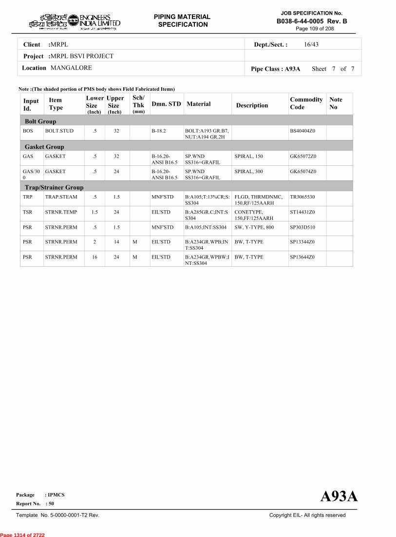
MRPLClient :
MRPL BSVI PROJECT
MANGALORELocation
16/43Dept./Sect. :
Project :
PIPING MATERIAL
SPECIFICATION
Copyright EIL- All rights reserved
JOB SPECIFICATION No.
B038-6-44-0005 Rev. B
Package : IPMCS
Report No. : 50
Template No. 5-0000-0001-T2 Rev.
Page 109 of 208
Sheet 7 of 7Pipe Class : A93A
InputId.
Item Type
LowerSize
Upper Size
Sch/Thk DescriptionMaterial
CommodityCode
NoteNo
Bolt Group
Gasket Group
Trap/Strainer Group
Dmn. STD(Inch) (Inch)
BOS
GAS
GAS/300
TRP
TSR
PSR
PSR
PSR
BOLT.STUD
GASKET
GASKET
TRAP.STEAM
STRNR.TEMP
STRNR.PERM
STRNR.PERM
STRNR.PERM
.5
.5
.5
.5
1.5
.5
2
16
32
32
24
1.5
24
1.5
14
24
M
M
SPIRAL, 150
SPIRAL, 300
FLGD, THRMDNMC,150,RF/125AARH
CONETYPE,150,FF/125AARH
SW, Y-TYPE, 800
BW, T-TYPE
BW, T-TYPE
BOLT:A193 GR.B7,NUT:A194 GR.2H
SP.WNDSS316+GRAFIL
SP.WNDSS316+GRAFIL
B:A105;T:13%CR;S:SS304
B:A285GR.C;INT:SS304
B:A105;INT:SS304
B:A234GR.WPB;INT:SS304
B:A234GR.WPBW;INT:SS304
BS40404Z0
GK65072Z0
GK65074Z0
TR3065530
ST14431Z0
SP303D510
SP13344Z0
SP13644Z0
B-18.2
B-16.20-ANSI B16.5
B-16.20-ANSI B16.5
MNF'STD
EIL'STD
MNF'STD
EIL'STD
EIL'STD
Note :(The shaded portion of PMS body shows Field Fabricated Items)
A93A
(mm)
Page 1314 of 2722
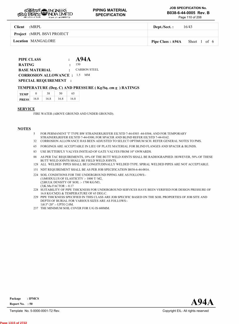
MRPLClient :
MRPL BSVI PROJECT
MANGALORELocation
16/43Dept./Sect. :
Project :
PIPING MATERIAL
SPECIFICATION
Copyright EIL- All rights reserved
JOB SPECIFICATION No.
B038-6-44-0005 Rev. B
Package : IPMCS
Report No. : 50
Template No. 5-0000-0001-T2 Rev.
Page 110 of 208
A94APIPE CLASS :150RATING :CARBON STEELBASE MATERIAL : 1.5CORROSION ALLOWANCE : SPECIAL REQUIREMENT :
MM
SERVICEFIRE WATER (ABOVE GROUND AND UNDER GROUND).
NOTES5
32
65
83
88
128
151
224
228
229
237
FOR PERMANENT 'T' TYPE BW STRAINERS,REFER EIL'STD 7-44-0303 -44-0304; AND FOR TEMPORARYSTRAINERS,REFER EIL'STD 7-44-0300; FOR SPACER AND BLIND REFER EIL'STD 7-44-0162.CORROSION ALLOWANCE HAS BEEN ADJUSTED TO SELECT OPTIMUM SCH. REFER GENERAL NOTES TO PMS.
FORGINGS ARE ACCEPTABLE IN LIEU OF PLATE MATERIAL FOR BLIND FLANGES AND SPACER & BLINDS.
USE BUTTERFLY VALVES INSTEAD OF GATE VALVES FROM 10" ONWARDS.
AS PER TAC REQUIREMENTS, 10% OF THE BUTT WELD JOINTS SHALL BE RADIOGRAPHED. HOWEVER, 50% OF THESEBUTT WELD JOINTS SHALL BE FIELD WELD JOINTS.ALL WELDED PIPES SHALL BE LONGITUDINALLY WELDED TYPE. SPIRAL WELDED PIPES ARE NOT ACCEPTABLE.
NDT REQUIREMENT SHALL BE AS PER JOB SPECIFICATION B038-6-44-0016.
SOIL CONDITIONS FOR THE UNDERGROUND PIPING ARE AS FOLLOWS:-(1)MODULUS OF ELASTICITY :- 1000 T/ M2,(2)BULK DENSITY OF SOIL :- 1700 KG/M3,(3)K.Mu FACTOR :- 0.17SUITABILITY OF PIPE THICKNESS FOR UNDERGROUND SERVICES HAVE BEEN VERIFIED FOR DESIGN PRESSURE OF16.8 KG/CM2G & TEMPERATURE OF 65 DEG.C.PIPE THICKNESS SPECIFIED IN THIS CLASS ARE JOB SPECIFIC BASED ON THE SOIL PROPERTIES OF JOB SITE ANDDEPTH OF BURIAL FOR VARIOUS SIZES ARE AS FOLLOWS:-1)0.5"-20" :- UPTO 2.0M.THE MINIMUM SOIL COVER FOR U/G IS 600MM.
TEMP
PRESS 16.8 16.8 16.8 16.8
0 38 50 65
Sheet 1 of
TEMPERATURE (Deg. C) AND PRESSURE ( Kg/Sq. cm g ) RATINGS
Pipe Class : A94A
A94A
6
Page 1315 of 2722
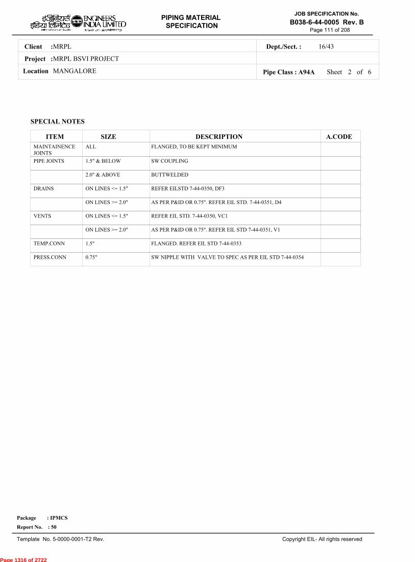
MRPLClient :
MRPL BSVI PROJECT
MANGALORELocation
16/43Dept./Sect. :
Project :
PIPING MATERIAL
SPECIFICATION
Copyright EIL- All rights reserved
JOB SPECIFICATION No.
B038-6-44-0005 Rev. B
Package : IPMCS
Report No. : 50
Template No. 5-0000-0001-T2 Rev.
Page 111 of 208
SPECIAL NOTES
ITEM SIZE DESCRIPTION A.CODEMAINTAINENCEJOINTS
PIPE JOINTS
DRAINS
VENTS
TEMP.CONN
PRESS.CONN
ALL
1.5" & BELOW
2.0" & ABOVE
ON LINES <= 1.5"
ON LINES >= 2.0"
ON LINES <= 1.5"
ON LINES >= 2.0"
1.5"
0.75"
FLANGED, TO BE KEPT MINIMUM
SW COUPLING
BUTTWELDED
REFER EILSTD 7-44-0350, DF3
AS PER P&ID OR 0.75". REFER EIL STD. 7-44-0351, D4
REFER EIL STD. 7-44-0350, VC1
AS PER P&ID OR 0.75". REFER EIL STD 7-44-0351, V1
FLANGED. REFER EIL STD 7-44-0353
SW NIPPLE WITH VALVE TO SPEC AS PER EIL STD 7-44-0354
Sheet 2 ofPipe Class : A94A 6
Page 1316 of 2722
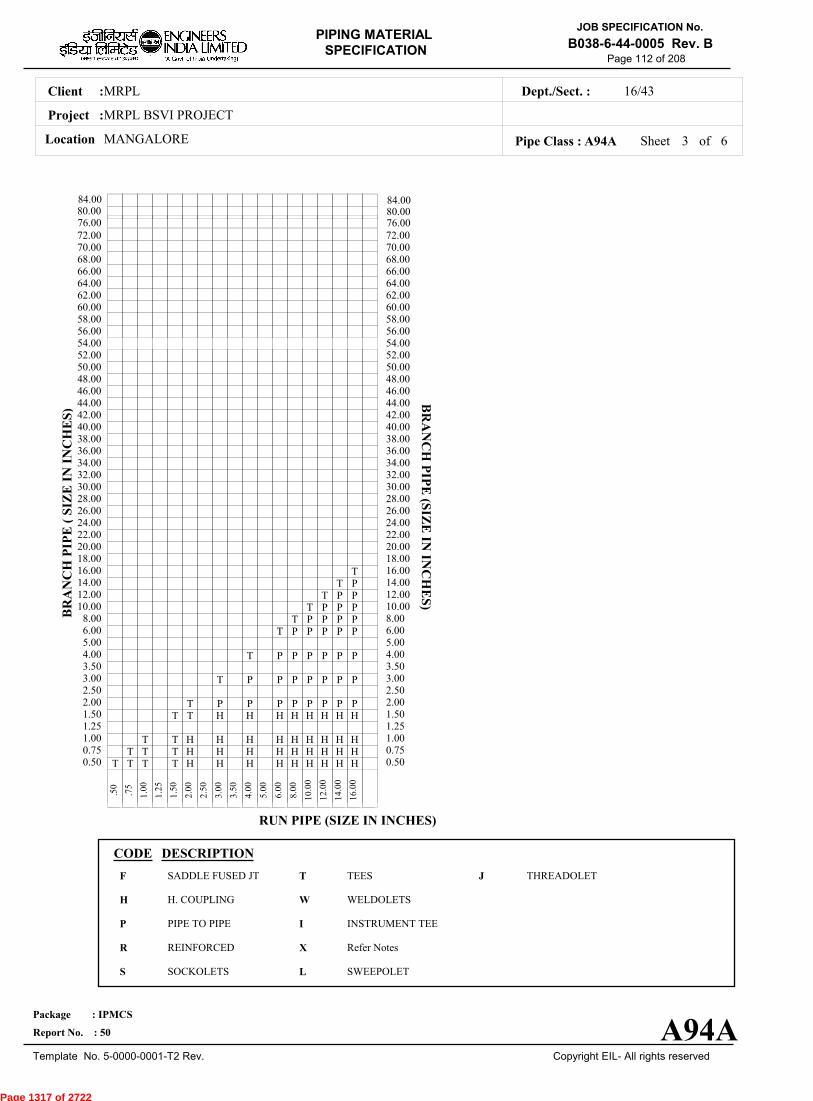
MRPLClient :
MRPL BSVI PROJECT
MANGALORELocation
16/43Dept./Sect. :
Project :
PIPING MATERIAL
SPECIFICATION
Copyright EIL- All rights reserved
JOB SPECIFICATION No.
B038-6-44-0005 Rev. B
Package : IPMCS
Report No. : 50
Template No. 5-0000-0001-T2 Rev.
Page 112 of 208
Sheet 3 ofPipe Class : A94A
T T T T H H H H H H H H H0.50T T T H H H H H H H H H0.75
T T H H H H H H H H H1.001.25
T T H H H H H H H H1.50T P P P P P P P P2.00
2.50T P P P P P P P3.00
3.50T P P P P P P4.00
5.00T P P P P P6.00
T P P P P8.00T P P P10.00
T P P12.00T P14.00
T16.0018.0020.0022.0024.0026.0028.0030.0032.0034.0036.0038.0040.0042.0044.0046.0048.0050.0052.0054.0056.0058.0060.0062.0064.0066.0068.0070.0072.00
.
50
.
75
1
.00
1
.25
1
.50
2
.00
2
.50
3
.00
3
.50
4
.00
5
.00
6
.00
8
.00
10
.00
12
.00
14
.00
16
.00
BR
AN
CH
PIP
E (
SIZ
E I
N I
NC
HE
S)
0.500.751.001.251.502.002.503.003.504.005.006.008.0010.0012.0014.0016.0018.0020.0022.0024.0026.0028.0030.0032.0034.0036.0038.0040.0042.0044.0046.0048.0050.0052.0054.0056.0058.0060.0062.0064.0066.0068.0070.0072.00
BR
AN
CH
PIP
E (SIZ
E IN
INC
HE
S)
RUN PIPE (SIZE IN INCHES)
CODE DESCRIPTION
F
H
P
R
S
T
W
I
X
L
JSADDLE FUSED JT
H. COUPLING
PIPE TO PIPE
REINFORCED
SOCKOLETS
TEES
WELDOLETS
INSTRUMENT TEE
Refer Notes
SWEEPOLET
THREADOLET
A94A
76.0080.0084.00
76.0080.0084.00
6
Page 1317 of 2722
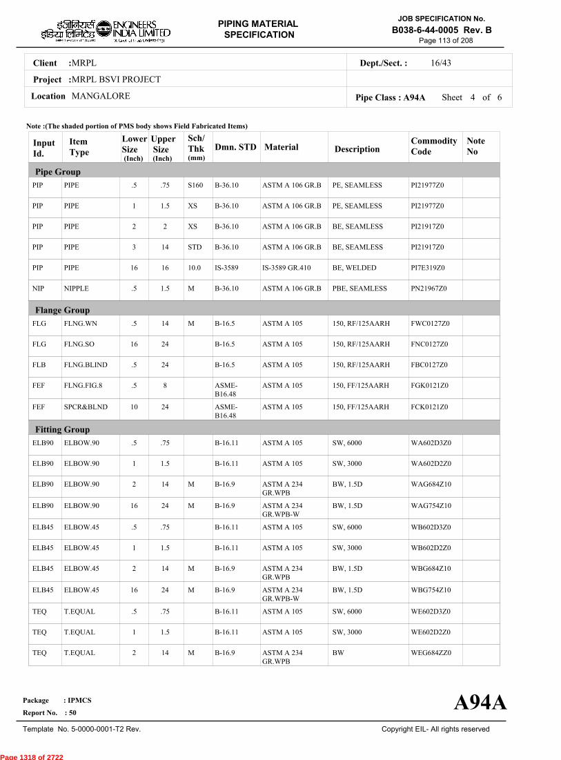
MRPLClient :
MRPL BSVI PROJECT
MANGALORELocation
16/43Dept./Sect. :
Project :
PIPING MATERIAL
SPECIFICATION
Copyright EIL- All rights reserved
JOB SPECIFICATION No.
B038-6-44-0005 Rev. B
Package : IPMCS
Report No. : 50
Template No. 5-0000-0001-T2 Rev.
Page 113 of 208
Sheet 4 ofPipe Class : A94A
InputId.
Item Type
LowerSize
Upper Size
Sch/Thk DescriptionMaterial
CommodityCode
NoteNo
Pipe Group
Flange Group
Fitting Group
Dmn. STD(Inch) (Inch)
PIP
PIP
PIP
PIP
PIP
NIP
FLG
FLG
FLB
FEF
FEF
ELB90
ELB90
ELB90
ELB90
ELB45
ELB45
ELB45
ELB45
TEQ
TEQ
TEQ
PIPE
PIPE
PIPE
PIPE
PIPE
NIPPLE
FLNG.WN
FLNG.SO
FLNG.BLIND
FLNG.FIG.8
SPCR&BLND
ELBOW.90
ELBOW.90
ELBOW.90
ELBOW.90
ELBOW.45
ELBOW.45
ELBOW.45
ELBOW.45
T.EQUAL
T.EQUAL
T.EQUAL
.5
1
2
3
16
.5
.5
16
.5
.5
10
.5
1
2
16
.5
1
2
16
.5
1
2
.75
1.5
2
14
16
1.5
14
24
24
8
24
.75
1.5
14
24
.75
1.5
14
24
.75
1.5
14
S160
XS
XS
STD
10.0
M
M
M
M
M
M
M
PE, SEAMLESS
PE, SEAMLESS
BE, SEAMLESS
BE, SEAMLESS
BE, WELDED
PBE, SEAMLESS
150, RF/125AARH
150, RF/125AARH
150, RF/125AARH
150, FF/125AARH
150, FF/125AARH
SW, 6000
SW, 3000
BW, 1.5D
BW, 1.5D
SW, 6000
SW, 3000
BW, 1.5D
BW, 1.5D
SW, 6000
SW, 3000
BW
ASTM A 106 GR.B
ASTM A 106 GR.B
ASTM A 106 GR.B
ASTM A 106 GR.B
IS-3589 GR.410
ASTM A 106 GR.B
ASTM A 105
ASTM A 105
ASTM A 105
ASTM A 105
ASTM A 105
ASTM A 105
ASTM A 105
ASTM A 234GR.WPB
ASTM A 234GR.WPB-W
ASTM A 105
ASTM A 105
ASTM A 234GR.WPB
ASTM A 234GR.WPB-W
ASTM A 105
ASTM A 105
ASTM A 234GR.WPB
PI21977Z0
PI21977Z0
PI21917Z0
PI21917Z0
PI7E319Z0
PN21967Z0
FWC0127Z0
FNC0127Z0
FBC0127Z0
FGK0121Z0
FCK0121Z0
WA602D3Z0
WA602D2Z0
WAG684Z10
WAG754Z10
WB602D3Z0
WB602D2Z0
WBG684Z10
WBG754Z10
WE602D3Z0
WE602D2Z0
WEG684ZZ0
B-36.10
B-36.10
B-36.10
B-36.10
IS-3589
B-36.10
B-16.5
B-16.5
B-16.5
ASME-B16.48
ASME-B16.48
B-16.11
B-16.11
B-16.9
B-16.9
B-16.11
B-16.11
B-16.9
B-16.9
B-16.11
B-16.11
B-16.9
Note :(The shaded portion of PMS body shows Field Fabricated Items)
A94A
(mm)
6
Page 1318 of 2722

MRPLClient :
MRPL BSVI PROJECT
MANGALORELocation
16/43Dept./Sect. :
Project :
PIPING MATERIAL
SPECIFICATION
Copyright EIL- All rights reserved
JOB SPECIFICATION No.
B038-6-44-0005 Rev. B
Package : IPMCS
Report No. : 50
Template No. 5-0000-0001-T2 Rev.
Page 114 of 208
Sheet 5 ofPipe Class : A94A
InputId.
Item Type
LowerSize
Upper Size
Sch/Thk DescriptionMaterial
CommodityCode
NoteNo
Fitting Group
Valves Group
Dmn. STD(Inch) (Inch)
TEQ
TRED
TRED
TRED
TRED
REDC
REDC
REDE
REDE
SWGC
SWGE
CAP
CAP
CAP
CAP
CPLF
CPLH
CPLL
CPLR
UNN
GAV
GAV
T.EQUAL
T.RED
T.RED
T.RED
T.RED
REDUC.CONC
REDUC.CONC
REDUC.ECC
REDUC.ECC
SWAGE.CONC
SWAGE.ECC
CAP
CAP
CAP
CAP
CPLNG.FULL
CPLNG.HALF
CPLNG.LH
CPLNG.RED
UNION
VLV.GATE
VLV.GATE
16
.5
1
2
16
2
16
2
16
.5
.5
.5
1
2
16
.5
.5
.5
.5
.5
.25
2
24
.75
1.5
14
24
14
24
14
24
3
3
.75
1.5
14
24
1.5
1.5
1.5
1.5
1.5
1.5
24
M
M, M
M, M
M, M
M, M
M, M
M, M
M, M
M, M
M
M
BW
SW, 6000
SW, 3000
BW
BW
BW
BW
BW
BW
PBE
PBE
SCRF, 6000
SCRF, 3000
BW
BW
SW, 3000
SW, 3000
SW, 3000
SW, 3000
SW, 3000
SW, 800, 3000, B-16.11, SHT NO.- 51001
FLGD, 150, B-16.5,RF/125AARH, SHT
ASTM A 234GR.WPB-W
ASTM A 105
ASTM A 105
ASTM A 234GR.WPB
ASTM A 234GR.WPB-W
ASTM A 234GR.WPB
ASTM A 234GR.WPB-W
ASTM A 234GR.WPB
ASTM A 234GR.WPB-W
ASTM A 105
ASTM A 105
ASTM A 105
ASTM A 105
ASTM A 234GR.WPB
ASTM A 234GR.WPB
ASTM A 105
ASTM A 105
ASTM A 105
ASTM A 105
ASTM A 105
BODY-ASTM A105,TRIM-STELLITED,STEM-13%CR.STEEL
BODY-ASTM A 216GR.WCB,TRIM-
WEG754ZZ0
WR602D3Z0
WR602D2Z0
WRG684ZZ0
WRG754ZZ0
WUG684ZZ0
WUG754ZZ0
WVG684ZZ0
WVG754ZZ0
WNH026ZZ0
WPH026ZZ0
WF60283Z0
WF60282Z0
WFG684ZZ0
WFG684ZZ0
WJ602D2Z0
WK602D2Z0
WL602D2Z0
WM602D2Z0
WQH02D2Z0
51001ZZZ0
51321ZZZ0
B-16.9
B-16.11
B-16.11
B-16.9
B-16.9
B-16.9
B-16.9
B-16.9
B-16.9
BS-3799
BS-3799
B-16.11
B-16.11
B-16.9
B-16.9
B-16.11
B-16.11
B-16.11
B-16.11
BS-3799
API 602/ ISO15761
API 600/ ISO10434
Note :(The shaded portion of PMS body shows Field Fabricated Items)
A94A
(mm)
6
Page 1319 of 2722
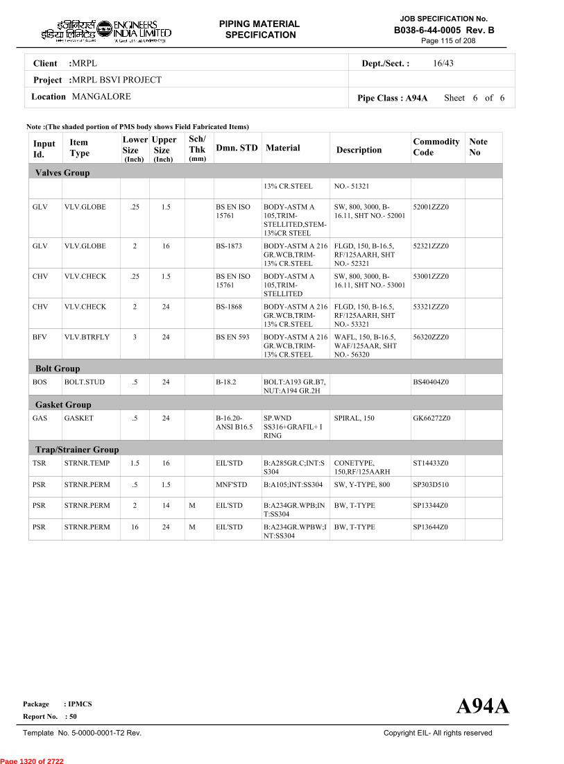
MRPLClient :
MRPL BSVI PROJECT
MANGALORELocation
16/43Dept./Sect. :
Project :
PIPING MATERIAL
SPECIFICATION
Copyright EIL- All rights reserved
JOB SPECIFICATION No.
B038-6-44-0005 Rev. B
Package : IPMCS
Report No. : 50
Template No. 5-0000-0001-T2 Rev.
Page 115 of 208
Sheet 6 of 6Pipe Class : A94A
InputId.
Item Type
LowerSize
Upper Size
Sch/Thk DescriptionMaterial
CommodityCode
NoteNo
Valves Group
Bolt Group
Gasket Group
Trap/Strainer Group
Dmn. STD(Inch) (Inch)
GLV
GLV
CHV
CHV
BFV
BOS
GAS
TSR
PSR
PSR
PSR
VLV.GLOBE
VLV.GLOBE
VLV.CHECK
VLV.CHECK
VLV.BTRFLY
BOLT.STUD
GASKET
STRNR.TEMP
STRNR.PERM
STRNR.PERM
STRNR.PERM
.25
2
.25
2
3
.5
.5
1.5
.5
2
16
1.5
16
1.5
24
24
24
24
16
1.5
14
24
M
M
NO.- 51321
SW, 800, 3000, B-16.11, SHT NO.- 52001
FLGD, 150, B-16.5,RF/125AARH, SHTNO.- 52321
SW, 800, 3000, B-16.11, SHT NO.- 53001
FLGD, 150, B-16.5,RF/125AARH, SHTNO.- 53321
WAFL, 150, B-16.5,WAF/125AAR, SHTNO.- 56320
SPIRAL, 150
CONETYPE,150,RF/125AARH
SW, Y-TYPE, 800
BW, T-TYPE
BW, T-TYPE
13% CR.STEEL
BODY-ASTM A105,TRIM-STELLITED,STEM-13%CR STEEL
BODY-ASTM A 216GR.WCB,TRIM-13% CR.STEEL
BODY-ASTM A105,TRIM-STELLITED
BODY-ASTM A 216GR.WCB,TRIM-13% CR.STEEL
BODY-ASTM A 216GR.WCB,TRIM-13% CR.STEEL
BOLT:A193 GR.B7,NUT:A194 GR.2H
SP.WNDSS316+GRAFIL+ IRING
B:A285GR.C;INT:SS304
B:A105;INT:SS304
B:A234GR.WPB;INT:SS304
B:A234GR.WPBW;INT:SS304
52001ZZZ0
52321ZZZ0
53001ZZZ0
53321ZZZ0
56320ZZZ0
BS40404Z0
GK66272Z0
ST14433Z0
SP303D510
SP13344Z0
SP13644Z0
BS EN ISO15761
BS-1873
BS EN ISO15761
BS-1868
BS EN 593
B-18.2
B-16.20-ANSI B16.5
EIL'STD
MNF'STD
EIL'STD
EIL'STD
Note :(The shaded portion of PMS body shows Field Fabricated Items)
A94A
(mm)
Page 1320 of 2722

MRPLClient :
MRPL BSVI PROJECT
MANGALORELocation
16/43Dept./Sect. :
Project :
PIPING MATERIAL
SPECIFICATION
Copyright EIL- All rights reserved
JOB SPECIFICATION No.
B038-6-44-0005 Rev. B
Package : IPMCS
Report No. : 50
Template No. 5-0000-0001-T2 Rev.
Page 116 of 208
A96APIPE CLASS :150RATING :CARBON STEELBASE MATERIAL : 1.5CORROSION ALLOWANCE : SPECIAL REQUIREMENT :
MM
SERVICEOWS(UG)
NOTES5
7
92
151
224
226
227
237
FOR PERMANENT 'T' TYPE BW STRAINERS,REFER EIL'STD 7-44-0303 & 7-44-0304; AND FOR TEMPORARYSTRAINERS,REFER EIL'STD 7-44-0300; FOR SPACER AND BLIND REFER EIL'STD 7-44-0162.FOR RESTRICTION ON USE OF BALL,PLUG & BUTTERFLY VALVES,REFER GENERAL NOTES.
GATE VALVES OF SIZE 26" AND ABOVE SHALL BE IN ACCORDANCE WITH B-16.34/ BS-1414 AND FLANGE ENDS SHALLBE IN ACCORDANCE WITH ASME B16.47 SERIES B.NDT REQUIREMENT SHALL BE AS PER JOB SPECIFICATION B038-6-44-0016.
SOIL CONDITIONS FOR THE UNDERGROUND PIPING ARE AS FOLLOWS:-(1)MODULUS OF ELASTICITY :- 1000 T/ M2,(2)BULK DENSITY OF SOIL :- 1700 KG/M3,(3)K.Mu FACTOR :- 0.17SUITABILITY OF PIPE THICKNESS FOR UNDERGROUND SERVICES HAVE BEEN VERIFIED FOR DESIGN PRESSURE OFATM & EMPERATURE OF 65 DEG.C.PIPE THICKNESS SPECIFIED IN THIS CLASS ARE JOB SPECIFIC BASED ON THE SOIL PROPERTIES OF JOB SITE ANDDEPTH OF BURIAL FOR VARIOUS SIZES ARE AS FOLLOWS:-1)0.5"-24" :- UPTO 3.5MTHE MINIMUM SOIL COVER FOR U/G IS 600MM.
SPECIAL NOTES
ITEM SIZE DESCRIPTION A.CODEMAINTAINENCEJOINTS
PIPE JOINTS
DRAINS
VENTS
TEMP.CONN
PRESS.CONN
ALL
1.5" & BELOW
2.0" & ABOVE
ON LINES <= 1.5"
ON LINES >= 2.0"
ON LINES <= 1.5"
ON LINES >= 2.0"
1.5"
0.75"
FLANGED, TO BE KEPT MINIMUM
SW COUPLING
BUTTWELDED
REFER EILSTD 7-44-0350, DF3
AS PER P&ID OR 0.75". REFER EIL STD. 7-44-0351, D4
REFER EIL STD. 7-44-0350, VF3
AS PER P&ID OR 0.75". REFER EIL STD 7-44-0351, V4
FLANGED. REFER EIL STD 7-44-0353
SW NIPPLE WITH VALVE TO SPEC AS PER EIL STD 7-44-0354
TEMP
PRESS 20.03 20.03 18.28 16.17 14.06 11.95 9.84 8.78 7.73
-29 38 93 149 204 260 316 343 371
Sheet 1 of
TEMPERATURE (Deg. C) AND PRESSURE ( Kg/Sq. cm g ) RATINGS
Pipe Class : A96A
A96A
5
Page 1321 of 2722

MRPLClient :
MRPL BSVI PROJECT
MANGALORELocation
16/43Dept./Sect. :
Project :
PIPING MATERIAL
SPECIFICATION
Copyright EIL- All rights reserved
JOB SPECIFICATION No.
B038-6-44-0005 Rev. B
Package : IPMCS
Report No. : 50
Template No. 5-0000-0001-T2 Rev.
Page 117 of 208
Sheet 2 ofPipe Class : A96A
T T T T H H H H H H H H H H H H0.50T T T H H H H H H H H H H H H0.75
T T H H H H H H H H H H H H1.001.25
T T H H H H H H H H H H H1.50T P P P P P P P P P P R2.00
2.50T P P P P P P P P P R3.00
3.50T P P P P P P P P R4.00
5.00T P P P P P P P R6.00
T P P P P P P R8.00T P P P P P R10.00
T P P P P R12.00T P P P R14.00
T P P R16.00T P R18.00
T R20.0022.00
T24.0026.0028.0030.0032.0034.0036.0038.0040.0042.0044.0046.0048.0050.0052.0054.0056.0058.0060.0062.0064.0066.0068.0070.0072.00
.
50
.
75
1
.00
1
.25
1
.50
2
.00
2
.50
3
.00
3
.50
4
.00
5
.00
6
.00
8
.00
10
.00
12
.00
14
.00
16
.00
18
.00
20
.00
22
.00
24
.00
BR
AN
CH
PIP
E (
SIZ
E I
N I
NC
HE
S)
0.500.751.001.251.502.002.503.003.504.005.006.008.0010.0012.0014.0016.0018.0020.0022.0024.0026.0028.0030.0032.0034.0036.0038.0040.0042.0044.0046.0048.0050.0052.0054.0056.0058.0060.0062.0064.0066.0068.0070.0072.00
BR
AN
CH
PIP
E (SIZ
E IN
INC
HE
S)
RUN PIPE (SIZE IN INCHES)
CODE DESCRIPTION
F
H
P
R
S
T
W
I
X
L
JSADDLE FUSED JT
H. COUPLING
PIPE TO PIPE
REINFORCED
SOCKOLETS
TEES
WELDOLETS
INSTRUMENT TEE
Refer Notes
SWEEPOLET
THREADOLET
A96A
76.0080.0084.00
76.0080.0084.00
5
Page 1322 of 2722
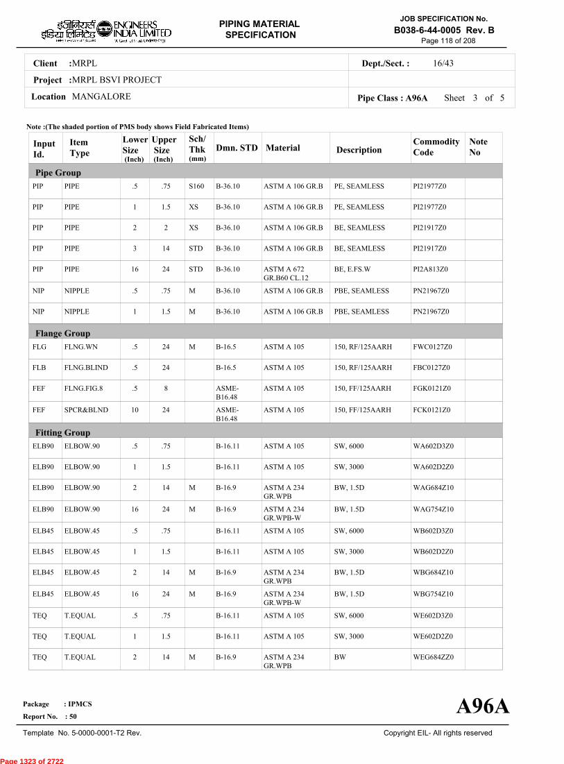
MRPLClient :
MRPL BSVI PROJECT
MANGALORELocation
16/43Dept./Sect. :
Project :
PIPING MATERIAL
SPECIFICATION
Copyright EIL- All rights reserved
JOB SPECIFICATION No.
B038-6-44-0005 Rev. B
Package : IPMCS
Report No. : 50
Template No. 5-0000-0001-T2 Rev.
Page 118 of 208
Sheet 3 ofPipe Class : A96A
InputId.
Item Type
LowerSize
Upper Size
Sch/Thk DescriptionMaterial
CommodityCode
NoteNo
Pipe Group
Flange Group
Fitting Group
Dmn. STD(Inch) (Inch)
PIP
PIP
PIP
PIP
PIP
NIP
NIP
FLG
FLB
FEF
FEF
ELB90
ELB90
ELB90
ELB90
ELB45
ELB45
ELB45
ELB45
TEQ
TEQ
TEQ
PIPE
PIPE
PIPE
PIPE
PIPE
NIPPLE
NIPPLE
FLNG.WN
FLNG.BLIND
FLNG.FIG.8
SPCR&BLND
ELBOW.90
ELBOW.90
ELBOW.90
ELBOW.90
ELBOW.45
ELBOW.45
ELBOW.45
ELBOW.45
T.EQUAL
T.EQUAL
T.EQUAL
.5
1
2
3
16
.5
1
.5
.5
.5
10
.5
1
2
16
.5
1
2
16
.5
1
2
.75
1.5
2
14
24
.75
1.5
24
24
8
24
.75
1.5
14
24
.75
1.5
14
24
.75
1.5
14
S160
XS
XS
STD
STD
M
M
M
M
M
M
M
M
PE, SEAMLESS
PE, SEAMLESS
BE, SEAMLESS
BE, SEAMLESS
BE, E.FS.W
PBE, SEAMLESS
PBE, SEAMLESS
150, RF/125AARH
150, RF/125AARH
150, FF/125AARH
150, FF/125AARH
SW, 6000
SW, 3000
BW, 1.5D
BW, 1.5D
SW, 6000
SW, 3000
BW, 1.5D
BW, 1.5D
SW, 6000
SW, 3000
BW
ASTM A 106 GR.B
ASTM A 106 GR.B
ASTM A 106 GR.B
ASTM A 106 GR.B
ASTM A 672GR.B60 CL.12
ASTM A 106 GR.B
ASTM A 106 GR.B
ASTM A 105
ASTM A 105
ASTM A 105
ASTM A 105
ASTM A 105
ASTM A 105
ASTM A 234GR.WPB
ASTM A 234GR.WPB-W
ASTM A 105
ASTM A 105
ASTM A 234GR.WPB
ASTM A 234GR.WPB-W
ASTM A 105
ASTM A 105
ASTM A 234GR.WPB
PI21977Z0
PI21977Z0
PI21917Z0
PI21917Z0
PI2A813Z0
PN21967Z0
PN21967Z0
FWC0127Z0
FBC0127Z0
FGK0121Z0
FCK0121Z0
WA602D3Z0
WA602D2Z0
WAG684Z10
WAG754Z10
WB602D3Z0
WB602D2Z0
WBG684Z10
WBG754Z10
WE602D3Z0
WE602D2Z0
WEG684ZZ0
B-36.10
B-36.10
B-36.10
B-36.10
B-36.10
B-36.10
B-36.10
B-16.5
B-16.5
ASME-B16.48
ASME-B16.48
B-16.11
B-16.11
B-16.9
B-16.9
B-16.11
B-16.11
B-16.9
B-16.9
B-16.11
B-16.11
B-16.9
Note :(The shaded portion of PMS body shows Field Fabricated Items)
A96A
(mm)
5
Page 1323 of 2722
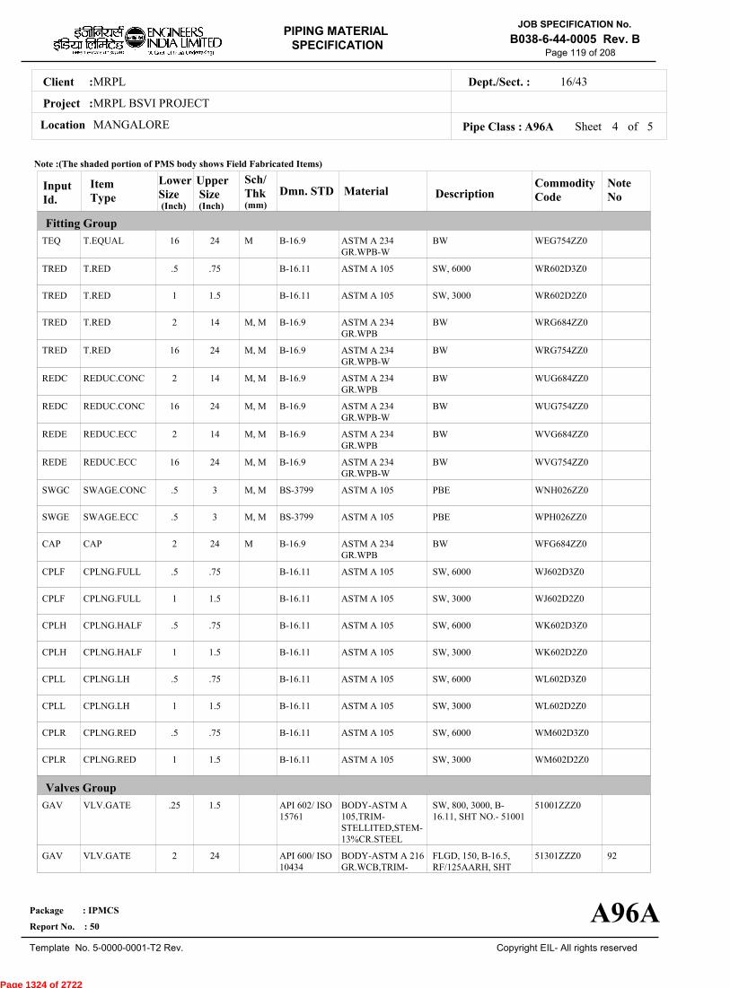
MRPLClient :
MRPL BSVI PROJECT
MANGALORELocation
16/43Dept./Sect. :
Project :
PIPING MATERIAL
SPECIFICATION
Copyright EIL- All rights reserved
JOB SPECIFICATION No.
B038-6-44-0005 Rev. B
Package : IPMCS
Report No. : 50
Template No. 5-0000-0001-T2 Rev.
Page 119 of 208
Sheet 4 ofPipe Class : A96A
InputId.
Item Type
LowerSize
Upper Size
Sch/Thk DescriptionMaterial
CommodityCode
NoteNo
Fitting Group
Valves Group
Dmn. STD(Inch) (Inch)
TEQ
TRED
TRED
TRED
TRED
REDC
REDC
REDE
REDE
SWGC
SWGE
CAP
CPLF
CPLF
CPLH
CPLH
CPLL
CPLL
CPLR
CPLR
GAV
GAV
T.EQUAL
T.RED
T.RED
T.RED
T.RED
REDUC.CONC
REDUC.CONC
REDUC.ECC
REDUC.ECC
SWAGE.CONC
SWAGE.ECC
CAP
CPLNG.FULL
CPLNG.FULL
CPLNG.HALF
CPLNG.HALF
CPLNG.LH
CPLNG.LH
CPLNG.RED
CPLNG.RED
VLV.GATE
VLV.GATE
16
.5
1
2
16
2
16
2
16
.5
.5
2
.5
1
.5
1
.5
1
.5
1
.25
2
24
.75
1.5
14
24
14
24
14
24
3
3
24
.75
1.5
.75
1.5
.75
1.5
.75
1.5
1.5
24
M
M, M
M, M
M, M
M, M
M, M
M, M
M, M
M, M
M
BW
SW, 6000
SW, 3000
BW
BW
BW
BW
BW
BW
PBE
PBE
BW
SW, 6000
SW, 3000
SW, 6000
SW, 3000
SW, 6000
SW, 3000
SW, 6000
SW, 3000
SW, 800, 3000, B-16.11, SHT NO.- 51001
FLGD, 150, B-16.5,RF/125AARH, SHT
ASTM A 234GR.WPB-W
ASTM A 105
ASTM A 105
ASTM A 234GR.WPB
ASTM A 234GR.WPB-W
ASTM A 234GR.WPB
ASTM A 234GR.WPB-W
ASTM A 234GR.WPB
ASTM A 234GR.WPB-W
ASTM A 105
ASTM A 105
ASTM A 234GR.WPB
ASTM A 105
ASTM A 105
ASTM A 105
ASTM A 105
ASTM A 105
ASTM A 105
ASTM A 105
ASTM A 105
BODY-ASTM A105,TRIM-STELLITED,STEM-13%CR.STEEL
BODY-ASTM A 216GR.WCB,TRIM-
WEG754ZZ0
WR602D3Z0
WR602D2Z0
WRG684ZZ0
WRG754ZZ0
WUG684ZZ0
WUG754ZZ0
WVG684ZZ0
WVG754ZZ0
WNH026ZZ0
WPH026ZZ0
WFG684ZZ0
WJ602D3Z0
WJ602D2Z0
WK602D3Z0
WK602D2Z0
WL602D3Z0
WL602D2Z0
WM602D3Z0
WM602D2Z0
51001ZZZ0
51301ZZZ0 92
B-16.9
B-16.11
B-16.11
B-16.9
B-16.9
B-16.9
B-16.9
B-16.9
B-16.9
BS-3799
BS-3799
B-16.9
B-16.11
B-16.11
B-16.11
B-16.11
B-16.11
B-16.11
B-16.11
B-16.11
API 602/ ISO15761
API 600/ ISO10434
Note :(The shaded portion of PMS body shows Field Fabricated Items)
A96A
(mm)
5
Page 1324 of 2722
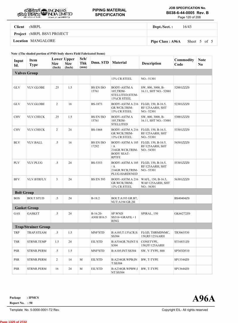
MRPLClient :
MRPL BSVI PROJECT
MANGALORELocation
16/43Dept./Sect. :
Project :
PIPING MATERIAL
SPECIFICATION
Copyright EIL- All rights reserved
JOB SPECIFICATION No.
B038-6-44-0005 Rev. B
Package : IPMCS
Report No. : 50
Template No. 5-0000-0001-T2 Rev.
Page 120 of 208
Sheet 5 of 5Pipe Class : A96A
InputId.
Item Type
LowerSize
Upper Size
Sch/Thk DescriptionMaterial
CommodityCode
NoteNo
Valves Group
Bolt Group
Gasket Group
Trap/Strainer Group
Dmn. STD(Inch) (Inch)
GLV
GLV
CHV
CHV
BLV
PLV
BFV
BOS
GAS
TRP
TSR
PSR
PSR
PSR
VLV.GLOBE
VLV.GLOBE
VLV.CHECK
VLV.CHECK
VLV.BALL
VLV.PLUG
VLV.BTRFLY
BOLT.STUD
GASKET
TRAP.STEAM
STRNR.TEMP
STRNR.PERM
STRNR.PERM
STRNR.PERM
.25
2
.25
2
.5
.5
3
.5
.5
.5
1.5
.5
2
16
1.5
16
1.5
24
16
24
24
24
24
1.5
24
1.5
14
24
M
M
NO.- 51301
SW, 800, 3000, B-16.11, SHT NO.- 52001
FLGD, 150, B-16.5,RF/125AARH, SHTNO.- 52301
SW, 800, 3000, B-16.11, SHT NO.- 53001
FLGD, 150, B-16.5,RF/125AARH, SHTNO.- 53301
FLGD, 150, B-16.5,RF/125AARH, SHTNO.- 54301
FLGD, 150, B-16.5,RF/125AARH, SHTNO.- 55301
WAFL, 150, B-16.5,WAF/125AARH, SHTNO.- 56301
SPIRAL, 150
FLGD, THRMDNMC,150,RF/125AARH
CONETYPE,150,FF/125AARH
SW, Y-TYPE, 800
BW, T-TYPE
BW, T-TYPE
13% CR.STEEL
BODY-ASTM A105,TRIM-STELLITED,STEM-13%CR STEEL
BODY-ASTM A 216GR.WCB,TRIM-13% CR.STEEL
BODY-ASTM A105,TRIM-STELLITED
BODY-ASTM A 216GR.WCB,TRIM-13% CR.STEEL
BODY-ASTM A 105/ A216GR.WCB,TRIM-BODY SEAT-RPTFE
BODY-ASTM A 105/ A216GR.WCB,TRIM-PLUG-HARDENED
BODY-ASTM A 216GR.WCB,TRIM-13% CR.STEEL
BOLT:A193 GR.B7,NUT:A194 GR.2H
SP.WNDSS316+GRAFIL+ IRING
B:A105;T:13%CR;S:SS304
B:A516GR.70;INT:SS304
B:A105;INT:SS304
B:A234GR.WPB;INT:SS304
B:A234GR.WPBW;INT:SS304
52001ZZZ0
52301ZZZ0
53001ZZZ0
53301ZZZ0
54301ZZZ0
55301ZZZ0
56301ZZZ0
BS40404Z0
GK66272Z0
TR3065530
ST16831Z0
SP303D510
SP13344Z0
SP13644Z0
BS EN ISO15761
BS-1873
BS EN ISO15761
BS-1868
BS EN ISO17292
BS-5353
BS EN 593
B-18.2
B-16.20-ANSI B16.5
MNF'STD
EIL'STD
MNF'STD
EIL'STD
EIL'STD
Note :(The shaded portion of PMS body shows Field Fabricated Items)
A96A
(mm)
Page 1325 of 2722

MRPLClient :
MRPL BSVI PROJECT
MANGALORELocation
16/43Dept./Sect. :
Project :
PIPING MATERIAL
SPECIFICATION
Copyright EIL- All rights reserved
JOB SPECIFICATION No.
B038-6-44-0005 Rev. B
Package : IPMCS
Report No. : 50
Template No. 5-0000-0001-T2 Rev.
Page 121 of 208
A9APIPE CLASS :150RATING :CARBON STEELBASE MATERIAL : 3CORROSION ALLOWANCE : SPECIAL REQUIREMENT :
MM
SERVICEMILD TO MODERATE CORROSIVE PROCESS SERVICES - FLAMMABLE / NON FLAMMABLE & NON LETHAL -HVGO,VGO,RCO,SLOP,VR,VGO,CAUSTIC (NO STRESS RELIEF ZONE)
NOTES3
5
7
32
92
151
USE PIPE OF CLASS 22 INSTEAD OF CLASS 12 IF PIPE THICKNESS EXCEEDS 20.00 MM.
FOR PERMANENT 'T' TYPE BW STRAINERS,REFER EIL'STD 7-44-0303 & 7-44-0304; AND FOR TEMPORARYSTRAINERS,REFER EIL'STD 7-44-0300; FOR SPACER AND BLIND REFER EIL'STD 7-44-0162.FOR RESTRICTION ON USE OF BALL,PLUG & BUTTERFLY VALVES,REFER GENERAL NOTES.
CORROSION ALLOWANCE HAS BEEN ADJUSTED TO SELECT OPTIMUM SCHEDULE. REFER GENERAL NOTES TO PMS.
GATE VALVES OF SIZE 26" AND ABOVE SHALL BE IN ACCORDANCE WITH B-16.34/ BS-1414 AND FLANGE ENDS SHALLBE IN ACCORDANCE WITH ASME B16.47 SERIES B.NDT REQUIREMENT SHALL BE AS PER JOB SPECIFICATION B038-6-44-0016.
SPECIAL NOTES
ITEM SIZE DESCRIPTION A.CODEMAINTAINENCEJOINTS
PIPE JOINTS
DRAINS
VENTS
TEMP.CONN
PRESS.CONN
ALL
1.5" & BELOW
2.0" & ABOVE
ON LINES <= 1.5"
ON LINES >= 2.0"
ON LINES <= 1.5"
ON LINES >= 2.0"
1.5"
0.75"
FLANGED, TO BE KEPT MINIMUM
SW COUPLING
BUTTWELDED
REFER EILSTD 7-44-0350, DF3
AS PER P&ID OR 0.75". REFER EIL STD. 7-44-0351, D4
REFER EIL STD. 7-44-0350, VF3
AS PER P&ID OR 0.75". REFER EIL STD 7-44-0351, V4
FLANGED. REFER EIL STD 7-44-0353
SW NIPPLE WITH VALVE TO SPEC AS PER EIL STD 7-44-0354
TEMP
PRESS 20.03 20.03 18.28 16.17 14.06 11.95 9.84 8.78 7.73
-29 38 93 149 204 260 316 343 371
Sheet 1 of
TEMPERATURE (Deg. C) AND PRESSURE ( Kg/Sq. cm g ) RATINGS
Pipe Class : A9A
A9A
6
Page 1326 of 2722

MRPLClient :
MRPL BSVI PROJECT
MANGALORELocation
16/43Dept./Sect. :
Project :
PIPING MATERIAL
SPECIFICATION
Copyright EIL- All rights reserved
JOB SPECIFICATION No.
B038-6-44-0005 Rev. B
Package : IPMCS
Report No. : 50
Template No. 5-0000-0001-T2 Rev.
Page 122 of 208
Sheet 2 ofPipe Class : A9A
T T T T H H H H H H H H H H H H H H H0.50T T T H H H H H H H H H H H H H H H0.75
T T H H H H H H H H H H H H H H H1.001.25
T T H H H H H H H H H H H H H H1.50T P P P P P P P P R R R R R R2.00
2.50T P P P P P P P R R R R R R3.00
3.50T P P P P P P R R R R R R4.00
5.00T P P P P P R R R R R R6.00
T P P P P R R R R R R8.00T P P P R R R R R R10.00
T P P R R R R R R12.00T P R R R R R R14.00
T R R R R R R16.00T R R R R R18.00
T R R R R20.0022.00
T R R R24.00T R R26.00
T R28.00T30.00
32.0034.0036.0038.0040.0042.0044.0046.0048.0050.0052.0054.0056.0058.0060.0062.0064.0066.0068.0070.0072.00
.
50
.
75
1
.00
1
.25
1
.50
2
.00
2
.50
3
.00
3
.50
4
.00
5
.00
6
.00
8
.00
10
.00
12
.00
14
.00
16
.00
18
.00
20
.00
22
.00
24
.00
26
.00
28
.00
30
.00
BR
AN
CH
PIP
E (
SIZ
E I
N I
NC
HE
S)
0.500.751.001.251.502.002.503.003.504.005.006.008.0010.0012.0014.0016.0018.0020.0022.0024.0026.0028.0030.0032.0034.0036.0038.0040.0042.0044.0046.0048.0050.0052.0054.0056.0058.0060.0062.0064.0066.0068.0070.0072.00
BR
AN
CH
PIP
E (SIZ
E IN
INC
HE
S)
RUN PIPE (SIZE IN INCHES)
CODE DESCRIPTION
F
H
P
R
S
T
W
I
X
L
JSADDLE FUSED JT
H. COUPLING
PIPE TO PIPE
REINFORCED
SOCKOLETS
TEES
WELDOLETS
INSTRUMENT TEE
Refer Notes
SWEEPOLET
THREADOLET
A9A
76.0080.0084.00
76.0080.0084.00
6
Page 1327 of 2722
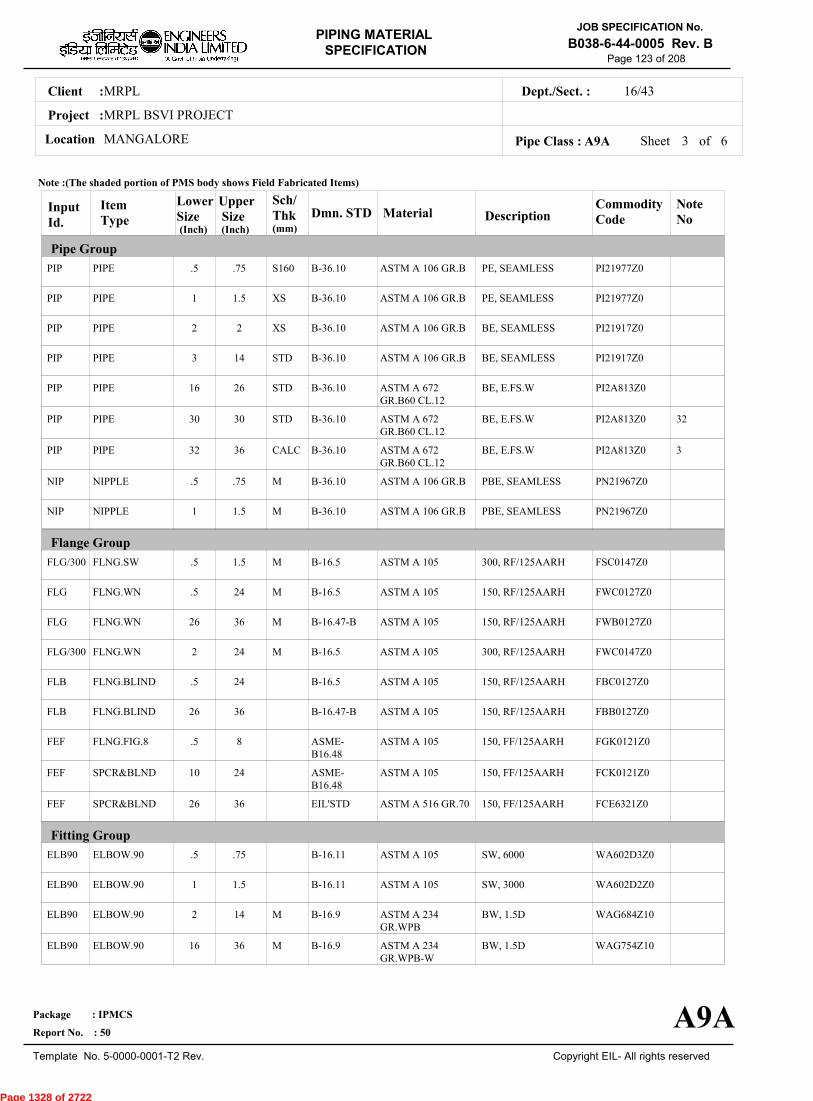
MRPLClient :
MRPL BSVI PROJECT
MANGALORELocation
16/43Dept./Sect. :
Project :
PIPING MATERIAL
SPECIFICATION
Copyright EIL- All rights reserved
JOB SPECIFICATION No.
B038-6-44-0005 Rev. B
Package : IPMCS
Report No. : 50
Template No. 5-0000-0001-T2 Rev.
Page 123 of 208
Sheet 3 ofPipe Class : A9A
InputId.
Item Type
LowerSize
Upper Size
Sch/Thk DescriptionMaterial
CommodityCode
NoteNo
Pipe Group
Flange Group
Fitting Group
Dmn. STD(Inch) (Inch)
PIP
PIP
PIP
PIP
PIP
PIP
PIP
NIP
NIP
FLG/300
FLG
FLG
FLG/300
FLB
FLB
FEF
FEF
FEF
ELB90
ELB90
ELB90
ELB90
PIPE
PIPE
PIPE
PIPE
PIPE
PIPE
PIPE
NIPPLE
NIPPLE
FLNG.SW
FLNG.WN
FLNG.WN
FLNG.WN
FLNG.BLIND
FLNG.BLIND
FLNG.FIG.8
SPCR&BLND
SPCR&BLND
ELBOW.90
ELBOW.90
ELBOW.90
ELBOW.90
.5
1
2
3
16
30
32
.5
1
.5
.5
26
2
.5
26
.5
10
26
.5
1
2
16
.75
1.5
2
14
26
30
36
.75
1.5
1.5
24
36
24
24
36
8
24
36
.75
1.5
14
36
S160
XS
XS
STD
STD
STD
CALC
M
M
M
M
M
M
M
M
PE, SEAMLESS
PE, SEAMLESS
BE, SEAMLESS
BE, SEAMLESS
BE, E.FS.W
BE, E.FS.W
BE, E.FS.W
PBE, SEAMLESS
PBE, SEAMLESS
300, RF/125AARH
150, RF/125AARH
150, RF/125AARH
300, RF/125AARH
150, RF/125AARH
150, RF/125AARH
150, FF/125AARH
150, FF/125AARH
150, FF/125AARH
SW, 6000
SW, 3000
BW, 1.5D
BW, 1.5D
ASTM A 106 GR.B
ASTM A 106 GR.B
ASTM A 106 GR.B
ASTM A 106 GR.B
ASTM A 672GR.B60 CL.12
ASTM A 672GR.B60 CL.12
ASTM A 672GR.B60 CL.12
ASTM A 106 GR.B
ASTM A 106 GR.B
ASTM A 105
ASTM A 105
ASTM A 105
ASTM A 105
ASTM A 105
ASTM A 105
ASTM A 105
ASTM A 105
ASTM A 516 GR.70
ASTM A 105
ASTM A 105
ASTM A 234GR.WPB
ASTM A 234GR.WPB-W
PI21977Z0
PI21977Z0
PI21917Z0
PI21917Z0
PI2A813Z0
PI2A813Z0
PI2A813Z0
PN21967Z0
PN21967Z0
FSC0147Z0
FWC0127Z0
FWB0127Z0
FWC0147Z0
FBC0127Z0
FBB0127Z0
FGK0121Z0
FCK0121Z0
FCE6321Z0
WA602D3Z0
WA602D2Z0
WAG684Z10
WAG754Z10
32
3
B-36.10
B-36.10
B-36.10
B-36.10
B-36.10
B-36.10
B-36.10
B-36.10
B-36.10
B-16.5
B-16.5
B-16.47-B
B-16.5
B-16.5
B-16.47-B
ASME-B16.48
ASME-B16.48
EIL'STD
B-16.11
B-16.11
B-16.9
B-16.9
Note :(The shaded portion of PMS body shows Field Fabricated Items)
A9A
(mm)
6
Page 1328 of 2722
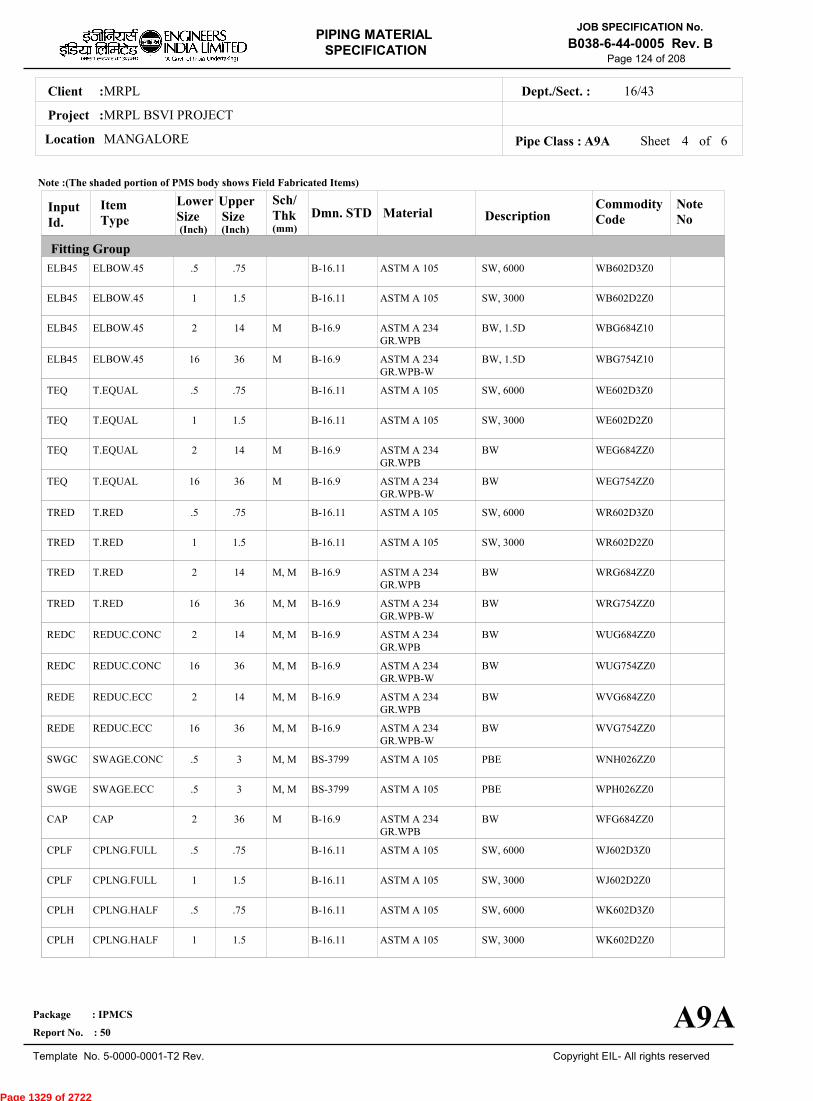
MRPLClient :
MRPL BSVI PROJECT
MANGALORELocation
16/43Dept./Sect. :
Project :
PIPING MATERIAL
SPECIFICATION
Copyright EIL- All rights reserved
JOB SPECIFICATION No.
B038-6-44-0005 Rev. B
Package : IPMCS
Report No. : 50
Template No. 5-0000-0001-T2 Rev.
Page 124 of 208
Sheet 4 ofPipe Class : A9A
InputId.
Item Type
LowerSize
Upper Size
Sch/Thk DescriptionMaterial
CommodityCode
NoteNo
Fitting Group
Dmn. STD(Inch) (Inch)
ELB45
ELB45
ELB45
ELB45
TEQ
TEQ
TEQ
TEQ
TRED
TRED
TRED
TRED
REDC
REDC
REDE
REDE
SWGC
SWGE
CAP
CPLF
CPLF
CPLH
CPLH
ELBOW.45
ELBOW.45
ELBOW.45
ELBOW.45
T.EQUAL
T.EQUAL
T.EQUAL
T.EQUAL
T.RED
T.RED
T.RED
T.RED
REDUC.CONC
REDUC.CONC
REDUC.ECC
REDUC.ECC
SWAGE.CONC
SWAGE.ECC
CAP
CPLNG.FULL
CPLNG.FULL
CPLNG.HALF
CPLNG.HALF
.5
1
2
16
.5
1
2
16
.5
1
2
16
2
16
2
16
.5
.5
2
.5
1
.5
1
.75
1.5
14
36
.75
1.5
14
36
.75
1.5
14
36
14
36
14
36
3
3
36
.75
1.5
.75
1.5
M
M
M
M
M, M
M, M
M, M
M, M
M, M
M, M
M, M
M, M
M
SW, 6000
SW, 3000
BW, 1.5D
BW, 1.5D
SW, 6000
SW, 3000
BW
BW
SW, 6000
SW, 3000
BW
BW
BW
BW
BW
BW
PBE
PBE
BW
SW, 6000
SW, 3000
SW, 6000
SW, 3000
ASTM A 105
ASTM A 105
ASTM A 234GR.WPB
ASTM A 234GR.WPB-W
ASTM A 105
ASTM A 105
ASTM A 234GR.WPB
ASTM A 234GR.WPB-W
ASTM A 105
ASTM A 105
ASTM A 234GR.WPB
ASTM A 234GR.WPB-W
ASTM A 234GR.WPB
ASTM A 234GR.WPB-W
ASTM A 234GR.WPB
ASTM A 234GR.WPB-W
ASTM A 105
ASTM A 105
ASTM A 234GR.WPB
ASTM A 105
ASTM A 105
ASTM A 105
ASTM A 105
WB602D3Z0
WB602D2Z0
WBG684Z10
WBG754Z10
WE602D3Z0
WE602D2Z0
WEG684ZZ0
WEG754ZZ0
WR602D3Z0
WR602D2Z0
WRG684ZZ0
WRG754ZZ0
WUG684ZZ0
WUG754ZZ0
WVG684ZZ0
WVG754ZZ0
WNH026ZZ0
WPH026ZZ0
WFG684ZZ0
WJ602D3Z0
WJ602D2Z0
WK602D3Z0
WK602D2Z0
B-16.11
B-16.11
B-16.9
B-16.9
B-16.11
B-16.11
B-16.9
B-16.9
B-16.11
B-16.11
B-16.9
B-16.9
B-16.9
B-16.9
B-16.9
B-16.9
BS-3799
BS-3799
B-16.9
B-16.11
B-16.11
B-16.11
B-16.11
Note :(The shaded portion of PMS body shows Field Fabricated Items)
A9A
(mm)
6
Page 1329 of 2722
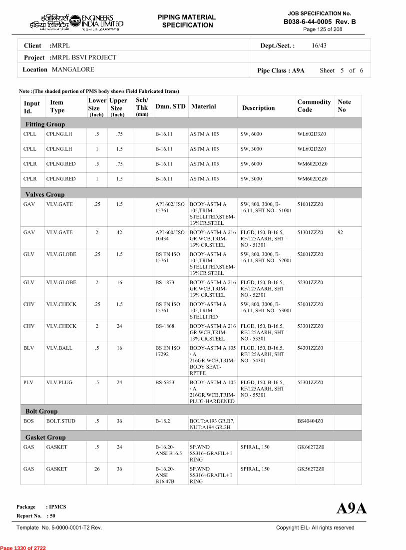
MRPLClient :
MRPL BSVI PROJECT
MANGALORELocation
16/43Dept./Sect. :
Project :
PIPING MATERIAL
SPECIFICATION
Copyright EIL- All rights reserved
JOB SPECIFICATION No.
B038-6-44-0005 Rev. B
Package : IPMCS
Report No. : 50
Template No. 5-0000-0001-T2 Rev.
Page 125 of 208
Sheet 5 ofPipe Class : A9A
InputId.
Item Type
LowerSize
Upper Size
Sch/Thk DescriptionMaterial
CommodityCode
NoteNo
Fitting Group
Valves Group
Bolt Group
Gasket Group
Dmn. STD(Inch) (Inch)
CPLL
CPLL
CPLR
CPLR
GAV
GAV
GLV
GLV
CHV
CHV
BLV
PLV
BOS
GAS
GAS
CPLNG.LH
CPLNG.LH
CPLNG.RED
CPLNG.RED
VLV.GATE
VLV.GATE
VLV.GLOBE
VLV.GLOBE
VLV.CHECK
VLV.CHECK
VLV.BALL
VLV.PLUG
BOLT.STUD
GASKET
GASKET
.5
1
.5
1
.25
2
.25
2
.25
2
.5
.5
.5
.5
26
.75
1.5
.75
1.5
1.5
42
1.5
16
1.5
24
16
24
36
24
36
SW, 6000
SW, 3000
SW, 6000
SW, 3000
SW, 800, 3000, B-16.11, SHT NO.- 51001
FLGD, 150, B-16.5,RF/125AARH, SHTNO.- 51301
SW, 800, 3000, B-16.11, SHT NO.- 52001
FLGD, 150, B-16.5,RF/125AARH, SHTNO.- 52301
SW, 800, 3000, B-16.11, SHT NO.- 53001
FLGD, 150, B-16.5,RF/125AARH, SHTNO.- 53301
FLGD, 150, B-16.5,RF/125AARH, SHTNO.- 54301
FLGD, 150, B-16.5,RF/125AARH, SHTNO.- 55301
SPIRAL, 150
SPIRAL, 150
ASTM A 105
ASTM A 105
ASTM A 105
ASTM A 105
BODY-ASTM A105,TRIM-STELLITED,STEM-13%CR.STEEL
BODY-ASTM A 216GR.WCB,TRIM-13% CR.STEEL
BODY-ASTM A105,TRIM-STELLITED,STEM-13%CR STEEL
BODY-ASTM A 216GR.WCB,TRIM-13% CR.STEEL
BODY-ASTM A105,TRIM-STELLITED
BODY-ASTM A 216GR.WCB,TRIM-13% CR.STEEL
BODY-ASTM A 105/ A216GR.WCB,TRIM-BODY SEAT-RPTFE
BODY-ASTM A 105/ A216GR.WCB,TRIM-PLUG-HARDENED
BOLT:A193 GR.B7,NUT:A194 GR.2H
SP.WNDSS316+GRAFIL+ IRING
SP.WNDSS316+GRAFIL+ IRING
WL602D3Z0
WL602D2Z0
WM602D3Z0
WM602D2Z0
51001ZZZ0
51301ZZZ0
52001ZZZ0
52301ZZZ0
53001ZZZ0
53301ZZZ0
54301ZZZ0
55301ZZZ0
BS40404Z0
GK66272Z0
GK56272Z0
92
B-16.11
B-16.11
B-16.11
B-16.11
API 602/ ISO15761
API 600/ ISO10434
BS EN ISO15761
BS-1873
BS EN ISO15761
BS-1868
BS EN ISO17292
BS-5353
B-18.2
B-16.20-ANSI B16.5
B-16.20-ANSIB16.47B
Note :(The shaded portion of PMS body shows Field Fabricated Items)
A9A
(mm)
6
Page 1330 of 2722
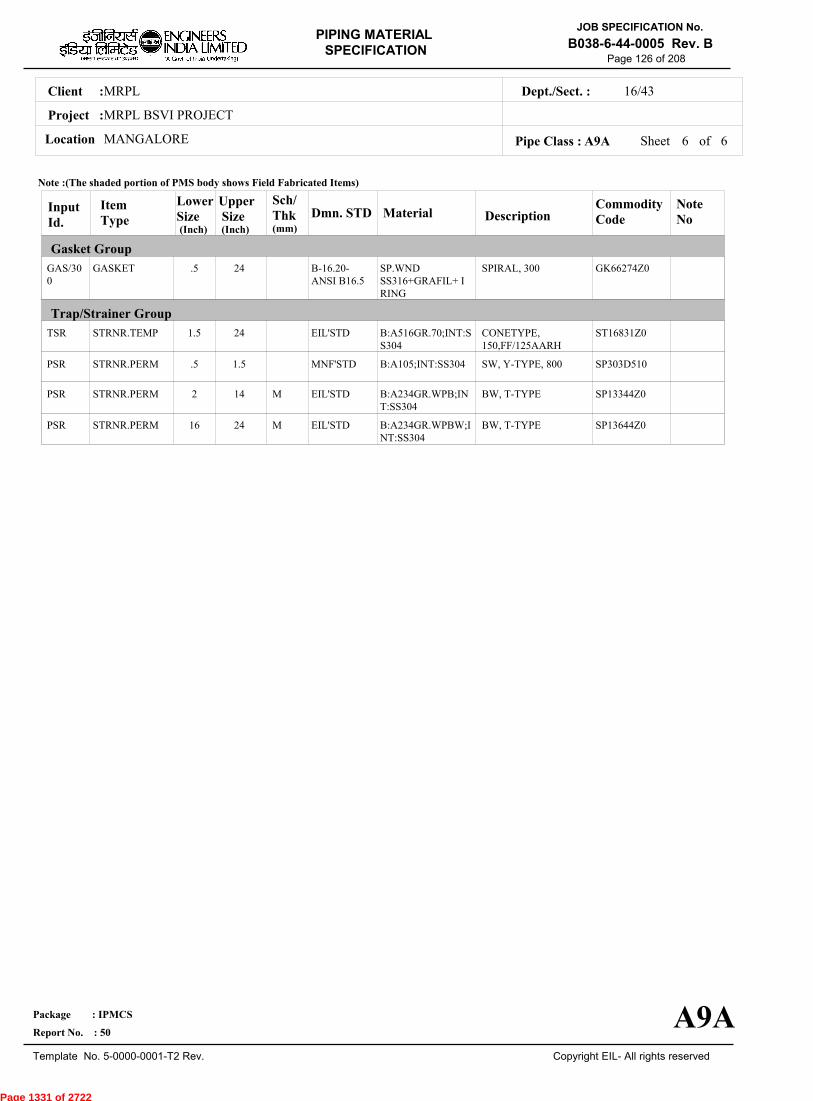
MRPLClient :
MRPL BSVI PROJECT
MANGALORELocation
16/43Dept./Sect. :
Project :
PIPING MATERIAL
SPECIFICATION
Copyright EIL- All rights reserved
JOB SPECIFICATION No.
B038-6-44-0005 Rev. B
Package : IPMCS
Report No. : 50
Template No. 5-0000-0001-T2 Rev.
Page 126 of 208
Sheet 6 of 6Pipe Class : A9A
InputId.
Item Type
LowerSize
Upper Size
Sch/Thk DescriptionMaterial
CommodityCode
NoteNo
Gasket Group
Trap/Strainer Group
Dmn. STD(Inch) (Inch)
GAS/300
TSR
PSR
PSR
PSR
GASKET
STRNR.TEMP
STRNR.PERM
STRNR.PERM
STRNR.PERM
.5
1.5
.5
2
16
24
24
1.5
14
24
M
M
SPIRAL, 300
CONETYPE,150,FF/125AARH
SW, Y-TYPE, 800
BW, T-TYPE
BW, T-TYPE
SP.WNDSS316+GRAFIL+ IRING
B:A516GR.70;INT:SS304
B:A105;INT:SS304
B:A234GR.WPB;INT:SS304
B:A234GR.WPBW;INT:SS304
GK66274Z0
ST16831Z0
SP303D510
SP13344Z0
SP13644Z0
B-16.20-ANSI B16.5
EIL'STD
MNF'STD
EIL'STD
EIL'STD
Note :(The shaded portion of PMS body shows Field Fabricated Items)
A9A
(mm)
Page 1331 of 2722

MRPLClient :
MRPL BSVI PROJECT
MANGALORELocation
16/43Dept./Sect. :
Project :
PIPING MATERIAL
SPECIFICATION
Copyright EIL- All rights reserved
JOB SPECIFICATION No.
B038-6-44-0005 Rev. B
Package : IPMCS
Report No. : 50
Template No. 5-0000-0001-T2 Rev.
Page 127 of 208
B16APIPE CLASS :300RATING :CARBON STEELBASE MATERIAL : 4.5CORROSION ALLOWANCE :NACE SERVICESPECIAL REQUIREMENT :
MM
SERVICENACE CORROSIVE, FLAMMABLE AND NONLETHAL SOUR SERVICES (STRESS RELIEVED)- SOUR WATER, SOUR GAS, ETC
NOTES5
7
32
34
35
63
93
107
151
FOR PERMANENT 'T' TYPE BW STRAINERS,REFER EIL'STD 7-44-0303 & 7-44-0304; AND FOR TEMPORARYSTRAINERS,REFER EIL'STD 7-44-0300; FOR SPACER AND BLIND REFER EIL'STD 7-44-0162.FOR RESTRICTION ON USE OF BALL,PLUG & BUTTERFLY VALVES,REFER GENERAL NOTES.
CORROSION ALLOWANCE HAS BEEN ADJUSTED TO SELECT OPTIMUM SCHEDULE. REFER GENERAL NOTES TO PMS.
MAXIMUM HARDNESS IN WELD JOINTS SHALL BE LIMITED TO 200 BHN.
ALL GIRTH WELD JOINTS SHALL BE 100% RADIOGRAPHED & ALL TYPES OF WELDS INCLUDING GIRTH WELDS SHALLBE WET FLOURESCENT MP TESTED.THIS ITEM IS INTENDED SOLELY FOR USE BY INSTRUMENTATION.
NACE REQUIREMENT OF MR0103 SHALL BE MET.
POST WELD HEAT TREATMENT IS REQUIRED FOR ALL WELD JOINTS IRRESPECTIVE OF THICKNESS.
NDT REQUIREMENT SHALL BE AS PER JOB SPECIFICATION B038-6-44-0016.
SPECIAL NOTES
ITEM SIZE DESCRIPTION A.CODEMAINTAINENCEJOINTS
PIPE JOINTS
DRAINS
VENTS
TEMP.CONN
PRESS.CONN
ALL
1.5" & BELOW
2.0" & ABOVE
ON LINES <= 1.5"
ON LINES >= 2.0"
ON LINES <= 1.5"
ON LINES >= 2.0"
1.5"
0.75"
FLANGED, TO BE KEPT MINIMUM
SW COUPLING
BUTTWELDED
REFER EILSTD 7-44-0350, DF3
AS PER P&ID OR 0.75". REFER EIL STD. 7-44-0351, D4
REFER EIL STD. 7-44-0350, VF3
AS PER P&ID OR 0.75". REFER EIL STD 7-440351, V4
FLANGED. REFER EIL STD 7-44-0353
SW NIPPLE WITH VALVE TO SPEC AS PER EIL STD 7-44-0354
TEMP
PRESS 52.02 52.02 47.8 46.05 44.64 42.53 40.07 38.66 37.26 35.5 28.82
-29 38 93 149 204 260 316 343 371 399 427
Sheet 1 of
TEMPERATURE (Deg. C) AND PRESSURE ( Kg/Sq. cm g ) RATINGS
Pipe Class : B16A
B16A
6
Page 1332 of 2722
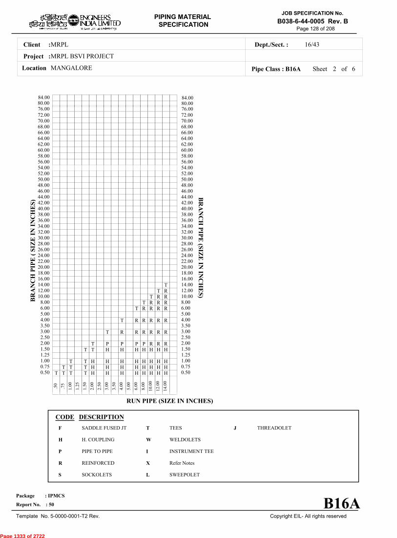
MRPLClient :
MRPL BSVI PROJECT
MANGALORELocation
16/43Dept./Sect. :
Project :
PIPING MATERIAL
SPECIFICATION
Copyright EIL- All rights reserved
JOB SPECIFICATION No.
B038-6-44-0005 Rev. B
Package : IPMCS
Report No. : 50
Template No. 5-0000-0001-T2 Rev.
Page 128 of 208
Sheet 2 ofPipe Class : B16A
T T T T H H H H H H H H0.50T T T H H H H H H H H0.75
T T H H H H H H H H1.001.25
T T H H H H H H H1.50T P P P P R R R2.00
2.50T R R R R R R3.00
3.50T R R R R R4.00
5.00T R R R R6.00
T R R R8.00T R R10.00
T R12.00T14.00
16.0018.0020.0022.0024.0026.0028.0030.0032.0034.0036.0038.0040.0042.0044.0046.0048.0050.0052.0054.0056.0058.0060.0062.0064.0066.0068.0070.0072.00
.
50
.
75
1
.00
1
.25
1
.50
2
.00
2
.50
3
.00
3
.50
4
.00
5
.00
6
.00
8
.00
10
.00
12
.00
14
.00
BR
AN
CH
PIP
E (
SIZ
E I
N I
NC
HE
S)
0.500.751.001.251.502.002.503.003.504.005.006.008.0010.0012.0014.0016.0018.0020.0022.0024.0026.0028.0030.0032.0034.0036.0038.0040.0042.0044.0046.0048.0050.0052.0054.0056.0058.0060.0062.0064.0066.0068.0070.0072.00
BR
AN
CH
PIP
E (SIZ
E IN
INC
HE
S)
RUN PIPE (SIZE IN INCHES)
CODE DESCRIPTION
F
H
P
R
S
T
W
I
X
L
JSADDLE FUSED JT
H. COUPLING
PIPE TO PIPE
REINFORCED
SOCKOLETS
TEES
WELDOLETS
INSTRUMENT TEE
Refer Notes
SWEEPOLET
THREADOLET
B16A
76.0080.0084.00
76.0080.0084.00
6
Page 1333 of 2722

MRPLClient :
MRPL BSVI PROJECT
MANGALORELocation
16/43Dept./Sect. :
Project :
PIPING MATERIAL
SPECIFICATION
Copyright EIL- All rights reserved
JOB SPECIFICATION No.
B038-6-44-0005 Rev. B
Package : IPMCS
Report No. : 50
Template No. 5-0000-0001-T2 Rev.
Page 129 of 208
Sheet 3 ofPipe Class : B16A
InputId.
Item Type
LowerSize
Upper Size
Sch/Thk DescriptionMaterial
CommodityCode
NoteNo
Pipe Group
Flange Group
Fitting Group
Dmn. STD(Inch) (Inch)
PIP
PIP
PIP
PIP
PIP
PIP
PIP
NIP
NIP
NIP
FLG
FLG
FLB
FEF
FEF
ELB90
ELB90
ELB90
ELB90
ELB45
ELB45
ELB45
PIPE
PIPE
PIPE
PIPE
PIPE
PIPE
PIPE
NIPPLE
NIPPLE
NIPPLE
FLNG.SW
FLNG.WN
FLNG.BLIND
FLNG.FIG.8
SPCR&BLND
ELBOW.90
ELBOW.90
ELBOW.90
ELBOW.90
ELBOW.45
ELBOW.45
ELBOW.45
.5
.75
1
2
3
14
16
.5
.75
1
.5
2
.5
.5
10
.5
.75
2
16
.5
.75
2
.5
.75
1.5
2
12
14
24
.5
.75
1.5
1.5
24
24
8
24
.5
1.5
14
24
.5
1.5
14
XXS
S160
S160
S160
XS
XS
CALC
M
M
M
M
M
M
M
M
PE, SEAMLESS
PE, SEAMLESS
PE, SEAMLESS
BE, SEAMLESS
BE, SEAMLESS
BE, SEAMLESS
BE, E.FS.W
PBE, SEAMLESS
PBE, SEAMLESS
PBE, SEAMLESS
300, RF/125AARH
300, RF/125AARH
300, RF/125AARH
300, FF/125AARH
300, FF/125AARH
SW, 9000
SW, 6000
BW, 1.5D
BW, 1.5D
SW, 9000
SW, 6000
BW, 1.5D
ASTM A 106 GR.B
ASTM A 106 GR.B
ASTM A 106 GR.B
ASTM A 106 GR.B
ASTM A 106 GR.B
ASTM A 106 GR.B
ASTM A 672GR.B60 CL.22
ASTM A 106 GR.B
ASTM A 106 GR.B
ASTM A 106 GR.B
ASTM A 105
ASTM A 105
ASTM A 105
ASTM A 105
ASTM A 105
ASTM A 105
ASTM A 105
ASTM A 234GR.WPB
ASTM A 234GR.WPB-W
ASTM A 105
ASTM A 105
ASTM A 234GR.WPB
PI21977Z2
PI21977Z2
PI21977Z2
PI21917Z2
PI21917Z2
PI21917Z2
PI2A913Z2
PN21967Z2
PN21967Z2
PN21967Z2
FSC0147Z2
FWC0147Z2
FBC0147Z2
FGK0141Z2
FCK0141Z2
WA602D4Z2
WA602D3Z2
WAG684Z12
WAG754Z12
WB602D4Z2
WB602D3Z2
WBG684Z12
32
32
32
B-36.10
B-36.10
B-36.10
B-36.10
B-36.10
B-36.10
B-36.10
B-36.10
B-36.10
B-36.10
B-16.5
B-16.5
B-16.5
ASME-B16.48
ASME-B16.48
B-16.11
B-16.11
B-16.9
B-16.9
B-16.11
B-16.11
B-16.9
Note :(The shaded portion of PMS body shows Field Fabricated Items)
B16A
(mm)
6
Page 1334 of 2722

MRPLClient :
MRPL BSVI PROJECT
MANGALORELocation
16/43Dept./Sect. :
Project :
PIPING MATERIAL
SPECIFICATION
Copyright EIL- All rights reserved
JOB SPECIFICATION No.
B038-6-44-0005 Rev. B
Package : IPMCS
Report No. : 50
Template No. 5-0000-0001-T2 Rev.
Page 130 of 208
Sheet 4 ofPipe Class : B16A
InputId.
Item Type
LowerSize
Upper Size
Sch/Thk DescriptionMaterial
CommodityCode
NoteNo
Fitting Group
Dmn. STD(Inch) (Inch)
ELB45
TEQ
TEQ
TEQ
TEQ
TRED
TRED
TRED
TRED
REDC
REDC
REDE
REDE
SWGC
SWGE
CAP
CAP
CAP
CPLF
CPLF
CPLH
CPLH
CPLL
ELBOW.45
T.EQUAL
T.EQUAL
T.EQUAL
T.EQUAL
T.RED
T.RED
T.RED
T.RED
REDUC.CONC
REDUC.CONC
REDUC.ECC
REDUC.ECC
SWAGE.CONC
SWAGE.ECC
CAP
CAP
CAP
CPLNG.FULL
CPLNG.FULL
CPLNG.HALF
CPLNG.HALF
CPLNG.LH
16
.5
.75
2
16
.5
.75
2
16
2
16
2
16
.5
.5
.5
.75
2
.5
.75
.5
.75
.5
24
.5
1.5
14
24
.5
1.5
14
24
14
24
14
24
3
3
.5
1.5
24
.5
1.5
.5
1.5
.5
M
M
M
M, M
M, M
M, M
M, M
M, M
M, M
M, M
M, M
M
BW, 1.5D
SW, 9000
SW, 6000
BW
BW
SW, 9000
SW, 6000
BW
BW
BW
BW
BW
BW
PBE
PBE
SCRF, 9000
SCRF, 6000
BW
SW, 9000
SW, 6000
SW, 9000
SW, 6000
SW, 9000
ASTM A 234GR.WPB-W
ASTM A 105
ASTM A 105
ASTM A 234GR.WPB
ASTM A 234GR.WPB-W
ASTM A 105
ASTM A 105
ASTM A 234GR.WPB
ASTM A 234GR.WPB-W
ASTM A 234GR.WPB
ASTM A 234GR.WPB-W
ASTM A 234GR.WPB
ASTM A 234GR.WPB-W
ASTM A 105
ASTM A 105
ASTM A 105
ASTM A 105
ASTM A 234GR.WPB
ASTM A 105
ASTM A 105
ASTM A 105
ASTM A 105
ASTM A 105
WBG754Z12
WE602D4Z2
WE602D3Z2
WEG684ZZ2
WEG754ZZ2
WR602D4Z2
WR602D3Z2
WRG684ZZ2
WRG754ZZ2
WUG684ZZ2
WUG754ZZ2
WVG684ZZ2
WVG754ZZ2
WNH026ZZ2
WPH026ZZ2
WF60284Z2
WF60283Z2
WFG684ZZ2
WJ602D4Z2
WJ602D3Z2
WK602D4Z2
WK602D3Z2
WL602D4Z2
63
63
B-16.9
B-16.11
B-16.11
B-16.9
B-16.9
B-16.11
B-16.11
B-16.9
B-16.9
B-16.9
B-16.9
B-16.9
B-16.9
BS-3799
BS-3799
B-16.11
B-16.11
B-16.9
B-16.11
B-16.11
B-16.11
B-16.11
B-16.11
Note :(The shaded portion of PMS body shows Field Fabricated Items)
B16A
(mm)
6
Page 1335 of 2722

MRPLClient :
MRPL BSVI PROJECT
MANGALORELocation
16/43Dept./Sect. :
Project :
PIPING MATERIAL
SPECIFICATION
Copyright EIL- All rights reserved
JOB SPECIFICATION No.
B038-6-44-0005 Rev. B
Package : IPMCS
Report No. : 50
Template No. 5-0000-0001-T2 Rev.
Page 131 of 208
Sheet 5 ofPipe Class : B16A
InputId.
Item Type
LowerSize
Upper Size
Sch/Thk DescriptionMaterial
CommodityCode
NoteNo
Fitting Group
Valves Group
Bolt Group
Gasket Group
Trap/Strainer Group
Dmn. STD(Inch) (Inch)
CPLL
CPLR
CPLR
GAV
GAV
GLV
GLV
CHV
CHV
PLV
BOS
GAS
TSR
PSR
PSR
PSR
CPLNG.LH
CPLNG.RED
CPLNG.RED
VLV.GATE
VLV.GATE
VLV.GLOBE
VLV.GLOBE
VLV.CHECK
VLV.CHECK
VLV.PLUG
BOLT.STUD
GASKET
STRNR.TEMP
STRNR.PERM
STRNR.PERM
STRNR.PERM
.75
.5
.75
.5
2
.5
2
.5
2
.5
.5
.5
1.5
.5
2
16
1.5
.5
1.5
1.5
24
1.5
12
1.5
24
24
24
24
24
1.5
14
24
M
M
SW, 6000
SW, 9000
SW, 6000
SW, 800, 3000, B-16.11, SHT NO.- 51011
FLGD, 300, B-16.5,RF/125AARH, SHTNO.- 51411
SW, 800, 3000, B-16.11, SHT NO.- 52011
FLGD, 300, B-16.5,RF/125AARH, SHTNO.- 52411
SW, 800, 3000, B-16.11, SHT NO.- 53011
FLGD, 300, B-16.5,RF/125AARH, SHTNO.- 53411
FLGD, 300, B-16.5,RF/125AARH, SHTNO.- 55411
SPIRAL, 300
CONETYPE,300,FF/125AARH
SW, Y-TYPE, 800
BW, T-TYPE
BW, T-TYPE
ASTM A 105
ASTM A 105
ASTM A 105
BODY-ASTM A105,TRIM-STELLITED,STEM-SS 316L
BODY-ASTM A 216GR.WCB,TRIM-SS316L
BODY-ASTM A105,TRIM-STELLITED,STEM-SS 316L
BODY-ASTM A 216GR.WCB,TRIM-SS316L
BODY-ASTM A105,TRIM-STELLITED
BODY-ASTM A 216GR.WCB,TRIM-SS316L
BODY-ASTM A 105/ A216GR.WCB,TRIM-PLUG-HARDENED
BOLT:A193GR.B7M,NUT:A194 GR.2HM
SP.WNDSS316L+GRAFIL+ IRING
B:A516GR.70;INT:SS316L
B:A105;INT:SS316L
B:A234GR.WPB;INT:SS316L
B:A234GR.WPBW;I
WL602D3Z2
WM602D4Z2
WM602D3Z2
51011ZZZ2
51411ZZZ2
52011ZZZ2
52411ZZZ2
53011ZZZ2
53411ZZZ2
55411ZZZ2
BS43405Z2
GK66374Z2
ST16939Z2
SP305D512
SP14044Z2
SP13844Z2
B-16.11
B-16.11
B-16.11
API 602/ ISO15761
API 600/ ISO10434
BS EN ISO15761
BS-1873
BS EN ISO15761
BS-1868
BS-5353
B-18.2
B-16.20-ANSI B16.5
EIL'STD
MNF'STD
EIL'STD
EIL'STD
Note :(The shaded portion of PMS body shows Field Fabricated Items)
B16A
(mm)
6
Page 1336 of 2722
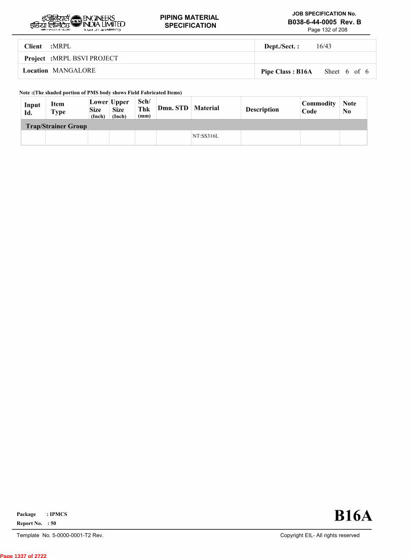
MRPLClient :
MRPL BSVI PROJECT
MANGALORELocation
16/43Dept./Sect. :
Project :
PIPING MATERIAL
SPECIFICATION
Copyright EIL- All rights reserved
JOB SPECIFICATION No.
B038-6-44-0005 Rev. B
Package : IPMCS
Report No. : 50
Template No. 5-0000-0001-T2 Rev.
Page 132 of 208
Sheet 6 of 6Pipe Class : B16A
InputId.
Item Type
LowerSize
Upper Size
Sch/Thk DescriptionMaterial
CommodityCode
NoteNo
Trap/Strainer Group
Dmn. STD(Inch) (Inch)
NT:SS316L
Note :(The shaded portion of PMS body shows Field Fabricated Items)
B16A
(mm)
Page 1337 of 2722
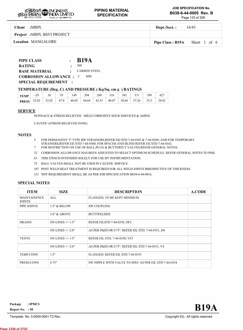
MRPLClient :
MRPL BSVI PROJECT
MANGALORELocation
16/43Dept./Sect. :
Project :
PIPING MATERIAL
SPECIFICATION
Copyright EIL- All rights reserved
JOB SPECIFICATION No.
B038-6-44-0005 Rev. B
Package : IPMCS
Report No. : 50
Template No. 5-0000-0001-T2 Rev.
Page 133 of 208
B19APIPE CLASS :300RATING :CARBON STEELBASE MATERIAL : 3CORROSION ALLOWANCE : SPECIAL REQUIREMENT :
MM
SERVICENONNACE & STRESS RELIEVED MILD CORROSIVE SOUR SERVICES & AMINE
CAUSTIC (STRESS RELIEVED ZONE)
NOTES5
7
32
63
75
107
151
FOR PERMANENT 'T' TYPE BW STRAINERS,REFER EIL'STD 7-44-0303 & 7-44-0304; AND FOR TEMPORARYSTRAINERS,REFER EIL'STD 7-44-0300; FOR SPACER AND BLIND REFER EIL'STD 7-44-0162.FOR RESTRICTION ON USE OF BALL,PLUG & BUTTERFLY VALVES,REFER GENERAL NOTES.
CORROSION ALLOWANCE HAS BEEN ADJUSTED TO SELECT OPTIMUM SCHEDULE. REFER GENERAL NOTES TO PMS.
THIS ITEM IS INTENDED SOLELY FOR USE BY INSTRUMENTATION.
BALL VALVES SHALL NOT BE USED IN CAUSTIC SERVICE.
POST WELD HEAT TREATMENT IS REQUIRED FOR ALL WELD JOINTS IRRESPECTIVE OF THICKNESS.
NDT REQUIREMENT SHALL BE AS PER JOB SPECIFICATION B038-6-44-0016.
SPECIAL NOTES
ITEM SIZE DESCRIPTION A.CODEMAINTAINENCEJOINTS
PIPE JOINTS
DRAINS
VENTS
TEMP.CONN
PRESS.CONN
ALL
1.5" & BELOW
2.0" & ABOVE
ON LINES <= 1.5"
ON LINES >= 2.0"
ON LINES <= 1.5"
ON LINES >= 2.0"
1.5"
0.75"
FLANGED, TO BE KEPT MINIMUM
SW COUPLING
BUTTWELDED
REFER EILSTD 7-44-0350, DF3
AS PER P&ID OR 0.75". REFER EIL STD. 7-44-0351, D4
REFER EIL STD. 7-44-0350, VF3
AS PER P&ID OR 0.75". REFER EIL STD 7-44-0351, V4
FLANGED. REFER EIL STD 7-44-0353
SW NIPPLE WITH VALVE TO SPEC AS PER EIL STD 7-44-0354
TEMP
PRESS 52.02 52.02 47.8 46.05 44.64 42.53 40.07 38.66 37.26 35.5 28.82
-29 38 93 149 204 260 316 343 371 399 427
Sheet 1 of
TEMPERATURE (Deg. C) AND PRESSURE ( Kg/Sq. cm g ) RATINGS
Pipe Class : B19A
B19A
6
Page 1338 of 2722

MRPLClient :
MRPL BSVI PROJECT
MANGALORELocation
16/43Dept./Sect. :
Project :
PIPING MATERIAL
SPECIFICATION
Copyright EIL- All rights reserved
JOB SPECIFICATION No.
B038-6-44-0005 Rev. B
Package : IPMCS
Report No. : 50
Template No. 5-0000-0001-T2 Rev.
Page 134 of 208
Sheet 2 ofPipe Class : B19A
T T T T H H H H H H H H H0.50T T T H H H H H H H H H0.75
T T H H H H H H H H H1.001.25
T T H H H H H H H H1.50T R R R R R R R R2.00
2.50T R R R R R R R3.00
3.50T R R R R R R4.00
5.00T R R R R R6.00
T R R R R8.00T R R R10.00
T R R12.00T R14.00
T16.0018.0020.0022.0024.0026.0028.0030.0032.0034.0036.0038.0040.0042.0044.0046.0048.0050.0052.0054.0056.0058.0060.0062.0064.0066.0068.0070.0072.00
.
50
.
75
1
.00
1
.25
1
.50
2
.00
2
.50
3
.00
3
.50
4
.00
5
.00
6
.00
8
.00
10
.00
12
.00
14
.00
16
.00
BR
AN
CH
PIP
E (
SIZ
E I
N I
NC
HE
S)
0.500.751.001.251.502.002.503.003.504.005.006.008.0010.0012.0014.0016.0018.0020.0022.0024.0026.0028.0030.0032.0034.0036.0038.0040.0042.0044.0046.0048.0050.0052.0054.0056.0058.0060.0062.0064.0066.0068.0070.0072.00
BR
AN
CH
PIP
E (SIZ
E IN
INC
HE
S)
RUN PIPE (SIZE IN INCHES)
CODE DESCRIPTION
F
H
P
R
S
T
W
I
X
L
JSADDLE FUSED JT
H. COUPLING
PIPE TO PIPE
REINFORCED
SOCKOLETS
TEES
WELDOLETS
INSTRUMENT TEE
Refer Notes
SWEEPOLET
THREADOLET
B19A
76.0080.0084.00
76.0080.0084.00
6
Page 1339 of 2722

MRPLClient :
MRPL BSVI PROJECT
MANGALORELocation
16/43Dept./Sect. :
Project :
PIPING MATERIAL
SPECIFICATION
Copyright EIL- All rights reserved
JOB SPECIFICATION No.
B038-6-44-0005 Rev. B
Package : IPMCS
Report No. : 50
Template No. 5-0000-0001-T2 Rev.
Page 135 of 208
Sheet 3 ofPipe Class : B19A
InputId.
Item Type
LowerSize
Upper Size
Sch/Thk DescriptionMaterial
CommodityCode
NoteNo
Pipe Group
Flange Group
Fitting Group
Dmn. STD(Inch) (Inch)
PIP
PIP
PIP
PIP
PIP
PIP
PIP
PIP
NIP
NIP
FLG
FLG
FLB
FEF
FEF
ELB90
ELB90
ELB90
ELB90
ELB45
ELB45
ELB45
PIPE
PIPE
PIPE
PIPE
PIPE
PIPE
PIPE
PIPE
NIPPLE
NIPPLE
FLNG.SW
FLNG.WN
FLNG.BLIND
FLNG.FIG.8
SPCR&BLND
ELBOW.90
ELBOW.90
ELBOW.90
ELBOW.90
ELBOW.45
ELBOW.45
ELBOW.45
.5
1
2
3
8
12
16
18
.5
1
.5
2
.5
.5
10
.5
1
2
16
.5
1
2
.75
1.5
2
6
10
14
16
24
.75
1.5
1.5
24
24
8
24
.75
1.5
14
24
.75
1.5
14
S160
XS
XS
STD
STD
XS
XS
CALC
M
M
M
M
M
M
M
PE, SEAMLESS
PE, SEAMLESS
BE, SEAMLESS
BE, SEAMLESS
BE, SEAMLESS
BE, SEAMLESS
BE, E.FS.W
BE, E.FS.W
PBE, SEAMLESS
PBE, SEAMLESS
300, RF/125AARH
300, RF/125AARH
300, RF/125AARH
300, FF/125AARH
300, FF/125AARH
SW, 6000
SW, 3000
BW, 1.5D
BW, 1.5D
SW, 6000
SW, 3000
BW, 1.5D
ASTM A 106 GR.B
ASTM A 106 GR.B
ASTM A 106 GR.B
ASTM A 106 GR.B
ASTM A 106 GR.B
ASTM A 106 GR.B
ASTM A 672GR.B60 CL.22
ASTM A 672GR.B60 CL.22
ASTM A 106 GR.B
ASTM A 106 GR.B
ASTM A 105
ASTM A 105
ASTM A 105
ASTM A 105
ASTM A 105
ASTM A 105
ASTM A 105
ASTM A 234GR.WPB
ASTM A 234GR.WPB-W
ASTM A 105
ASTM A 105
ASTM A 234GR.WPB
PI21977Z0
PI21977Z0
PI21917Z0
PI21917Z0
PI21917Z0
PI21917Z0
PI2A913Z0
PI2A913Z0
PN21967Z0
PN21967Z0
FSC0147Z0
FWC0147Z0
FBC0147Z0
FGK0141Z0
FCK0141Z0
WA602D3Z0
WA602D2Z0
WAG684Z10
WAG754Z10
WB602D3Z0
WB602D2Z0
WBG684Z10
32
B-36.10
B-36.10
B-36.10
B-36.10
B-36.10
B-36.10
B-36.10
B-36.10
B-36.10
B-36.10
B-16.5
B-16.5
B-16.5
ASME-B16.48
ASME-B16.48
B-16.11
B-16.11
B-16.9
B-16.9
B-16.11
B-16.11
B-16.9
Note :(The shaded portion of PMS body shows Field Fabricated Items)
B19A
(mm)
6
Page 1340 of 2722

MRPLClient :
MRPL BSVI PROJECT
MANGALORELocation
16/43Dept./Sect. :
Project :
PIPING MATERIAL
SPECIFICATION
Copyright EIL- All rights reserved
JOB SPECIFICATION No.
B038-6-44-0005 Rev. B
Package : IPMCS
Report No. : 50
Template No. 5-0000-0001-T2 Rev.
Page 136 of 208
Sheet 4 ofPipe Class : B19A
InputId.
Item Type
LowerSize
Upper Size
Sch/Thk DescriptionMaterial
CommodityCode
NoteNo
Fitting Group
Dmn. STD(Inch) (Inch)
ELB45
TEQ
TEQ
TEQ
TEQ
TRED
TRED
TRED
TRED
REDC
REDC
REDE
REDE
SWGC
SWGE
CAP
CAP
CAP
CPLF
CPLF
CPLH
CPLH
CPLL
ELBOW.45
T.EQUAL
T.EQUAL
T.EQUAL
T.EQUAL
T.RED
T.RED
T.RED
T.RED
REDUC.CONC
REDUC.CONC
REDUC.ECC
REDUC.ECC
SWAGE.CONC
SWAGE.ECC
CAP
CAP
CAP
CPLNG.FULL
CPLNG.FULL
CPLNG.HALF
CPLNG.HALF
CPLNG.LH
16
.5
1
2
16
.5
1
2
16
2
16
2
16
.5
.5
.5
1
2
.5
1
.5
1
.5
24
.75
1.5
14
24
.75
1.5
14
24
14
24
14
24
3
3
.75
1.5
24
.75
1.5
.75
1.5
.75
M
M
M
M, M
M, M
M, M
M, M
M, M
M, M
M, M
M, M
M
BW, 1.5D
SW, 6000
SW, 3000
BW
BW
SW, 6000
SW, 3000
BW
BW
BW
BW
BW
BW
PBE
PBE
SCRF, 6000
SCRF, 3000
BW
SW, 6000
SW, 3000
SW, 6000
SW, 3000
SW, 6000
ASTM A 234GR.WPB-W
ASTM A 105
ASTM A 105
ASTM A 234GR.WPB
ASTM A 234GR.WPB-W
ASTM A 105
ASTM A 105
ASTM A 234GR.WPB
ASTM A 234GR.WPB-W
ASTM A 234GR.WPB
ASTM A 234GR.WPB-W
ASTM A 234GR.WPB
ASTM A 234GR.WPB-W
ASTM A 105
ASTM A 105
ASTM A 105
ASTM A 105
ASTM A 234GR.WPB
ASTM A 105
ASTM A 105
ASTM A 105
ASTM A 105
ASTM A 105
WBG754Z10
WE602D3Z0
WE602D2Z0
WEG684ZZ0
WEG754ZZ0
WR602D3Z0
WR602D2Z0
WRG684ZZ0
WRG754ZZ0
WUG684ZZ0
WUG754ZZ0
WVG684ZZ0
WVG754ZZ0
WNH026ZZ0
WPH026ZZ0
WF60283Z0
WF60282Z0
WFG684ZZ0
WJ602D3Z0
WJ602D2Z0
WK602D3Z0
WK602D2Z0
WL602D3Z0
63
63
B-16.9
B-16.11
B-16.11
B-16.9
B-16.9
B-16.11
B-16.11
B-16.9
B-16.9
B-16.9
B-16.9
B-16.9
B-16.9
BS-3799
BS-3799
B-16.11
B-16.11
B-16.9
B-16.11
B-16.11
B-16.11
B-16.11
B-16.11
Note :(The shaded portion of PMS body shows Field Fabricated Items)
B19A
(mm)
6
Page 1341 of 2722

MRPLClient :
MRPL BSVI PROJECT
MANGALORELocation
16/43Dept./Sect. :
Project :
PIPING MATERIAL
SPECIFICATION
Copyright EIL- All rights reserved
JOB SPECIFICATION No.
B038-6-44-0005 Rev. B
Package : IPMCS
Report No. : 50
Template No. 5-0000-0001-T2 Rev.
Page 137 of 208
Sheet 5 ofPipe Class : B19A
InputId.
Item Type
LowerSize
Upper Size
Sch/Thk DescriptionMaterial
CommodityCode
NoteNo
Fitting Group
Valves Group
Bolt Group
Gasket Group
Trap/Strainer Group
Dmn. STD(Inch) (Inch)
CPLL
CPLR
CPLR
GAV
GAV
GLV
GLV
CHV
CHV
BLV
PLV
BOS
GAS
TSR
PSR
CPLNG.LH
CPLNG.RED
CPLNG.RED
VLV.GATE
VLV.GATE
VLV.GLOBE
VLV.GLOBE
VLV.CHECK
VLV.CHECK
VLV.BALL
VLV.PLUG
BOLT.STUD
GASKET
STRNR.TEMP
STRNR.PERM
1
.5
1
.5
2
.25
2
.5
2
.5
.5
.5
.5
1.5
.5
1.5
.75
1.5
1.5
24
1.5
12
1.5
24
16
24
24
24
24
1.5
SW, 3000
SW, 6000
SW, 3000
SW, 800, 3000, B-16.11, SHT NO.- 51013
FLGD, 300, B-16.5,RF/125AARH, SHTNO.- 51413
SW, 800, 3000, B-16.11, SHT NO.- 52013
FLGD, 300, B-16.5,RF/125AARH, SHTNO.- 52413
SW, 800, 3000, B-16.11, SHT NO.- 53013
FLGD, 300, B-16.5,RF/125AARH, SHTNO.- 53413
FLGD, 300, B-16.5,RF/125AARH, SHTNO.- 54413
FLGD, 300, B-16.5,RF/125AARH, SHTNO.- 55413
SPIRAL, 300
CONETYPE,300,FF/125AARH
SW, Y-TYPE, 800
ASTM A 105
ASTM A 105
ASTM A 105
BODY-ASTM A105,TRIM-STELLITED,STEM-SS 304
BODY-ASTM A 216GR.WCB,TRIM-SS304
BODY-ASTM A105,TRIM-STELLITED,STEM-SS304
BODY-ASTM A 216GR.WCB,TRIM-SS304
BODY-ASTM A105,TRIM-STELLITED
BODY-ASTM A 216GR.WCB,TRIM-SS304
BODY-ASTM A 105/ A216GR.WCB,TRIM-BODY SEAT-RPTFE
BODY-ASTM A105/ASTM A 216GR.WCB,TRIM-PLUG-HARDENED
BOLT:A193 GR.B7,NUT:A194 GR.2H
SP.WNDSS316+GRAFIL+ IRING
B:A516GR.70(NORM);INT:SS304
B:A105;INT:SS304
WL602D2Z0
WM602D3Z0
WM602D2Z0
51013ZZZ0
51413ZZZ0
52013ZZZ0
52413ZZZ0
53013ZZZ0
53413ZZZ0
54413ZZZ0
55413ZZZ0
BS40404Z0
GK66274Z0
ST17539Z0
SP303D510
75
B-16.11
B-16.11
B-16.11
API 602/ ISO15761
API 600/ ISO10434
BS EN ISO15761
BS-1873
BS EN ISO15761
BS-1868
BS EN ISO17292
BS-5353
B-18.2
B-16.20-ANSI B16.5
EIL'STD
MNF'STD
Note :(The shaded portion of PMS body shows Field Fabricated Items)
B19A
(mm)
6
Page 1342 of 2722

MRPLClient :
MRPL BSVI PROJECT
MANGALORELocation
16/43Dept./Sect. :
Project :
PIPING MATERIAL
SPECIFICATION
Copyright EIL- All rights reserved
JOB SPECIFICATION No.
B038-6-44-0005 Rev. B
Package : IPMCS
Report No. : 50
Template No. 5-0000-0001-T2 Rev.
Page 138 of 208
Sheet 6 of 6Pipe Class : B19A
InputId.
Item Type
LowerSize
Upper Size
Sch/Thk DescriptionMaterial
CommodityCode
NoteNo
Trap/Strainer Group
Dmn. STD(Inch) (Inch)
PSR
PSR
STRNR.PERM
STRNR.PERM
2
16
14
24
M
M
BW, T-TYPE
BW, T-TYPE
B:A234GR.WPB;INT:SS304
B:A234GR.WPBW;INT:SS304
SP13344Z0
SP13644Z0
EIL'STD
EIL'STD
Note :(The shaded portion of PMS body shows Field Fabricated Items)
B19A
(mm)
Page 1343 of 2722

MRPLClient :
MRPL BSVI PROJECT
MANGALORELocation
16/43Dept./Sect. :
Project :
PIPING MATERIAL
SPECIFICATION
Copyright EIL- All rights reserved
JOB SPECIFICATION No.
B038-6-44-0005 Rev. B
Package : IPMCS
Report No. : 50
Template No. 5-0000-0001-T2 Rev.
Page 139 of 208
B1APIPE CLASS :300RATING :CARBON STEELBASE MATERIAL : 1.5CORROSION ALLOWANCE : SPECIAL REQUIREMENT :
MM
SERVICENON CORROSIVE PROCESS - FLAMMABLE / NON FLAMMABLE, NON LETHAL - HYDROCARBONS, AROMATICS,AMMONIA, SWEET GAS, FLUSHING OIL AND OTHER UTILITIES -MP CONDENSATE, INSTRUMENT AIR, PLANT AIR,NITROGEN, AMMONIA GAS ETC. ABOVE CLASS 'A1A'.
NOTES3
5
7
32
63
151
282
303
USE PIPE OF CLASS 22 INSTEAD OF CLASS 12 IF PIPE THICKNESS EXCEEDS 20.00 MM.
FOR PERMANENT 'T' TYPE BW STRAINERS,REFER EIL'STD 7-44-0303 & 7-44-0304; AND FOR TEMPORARYSTRAINERS,REFER EIL'STD 7-44-0300; FOR SPACER AND BLIND REFER EIL'STD 7-44-0162.FOR RESTRICTION ON USE OF BALL,PLUG & BUTTERFLY VALVES,REFER GENERAL NOTES.
CORROSION ALLOWANCE HAS BEEN ADJUSTED TO SELECT OPTIMUM SCHEDULE. REFER GENERAL NOTES TO PMS.
THIS ITEM IS INTENDED SOLELY FOR USE BY INSTRUMENTATION.
NDT REQUIREMENT SHALL BE AS PER JOB SPECIFICATION B038-6-44-0016.
PIPE WALL THICKNESS IS CALCULATED BASED ON ACTUAL LINE DESIGN CONDITION [ 65 DEG. C & 49 KG/ CM2 G]
VALVE SHALL BE BELLOW SEAL TYPE
SPECIAL NOTES
ITEM SIZE DESCRIPTION A.CODEMAINTAINENCEJOINTS
PIPE JOINTS
DRAINS
VENTS
TEMP.CONN
PRESS.CONN
ALL
1.5" & BELOW
2.0" & ABOVE
ON LINES <= 1.5"
ON LINES >= 2.0"
ON LINES <= 1.5"
ON LINES >= 2.0"
1.5"
0.75"
FLANGED, TO BE KEPT MINIMUM
SW COUPLING
BUTTWELDED
REFER EILSTD 7-44-0350, DF3
AS PER P&ID OR 0.75". REFER EIL STD. 7-44-0351, D4
REFER EIL STD. 7-44-0350, VF3
AS PER P&ID OR 0.75". REFER EIL STD 7-44-0351, V4
FLANGED. REFER EIL STD 7-44-0353
SW NIPPLE WITH VALVE TO SPEC AS PER EIL STD 7-44-0354
TEMP
PRESS 52.02 52.02 47.8 46.05 44.64 42.53 40.07 38.66 37.26 35.5 28.82
-29 38 93 149 204 260 316 343 371 399 427
Sheet 1 of
TEMPERATURE (Deg. C) AND PRESSURE ( Kg/Sq. cm g ) RATINGS
Pipe Class : B1A
B1A
6
Page 1344 of 2722
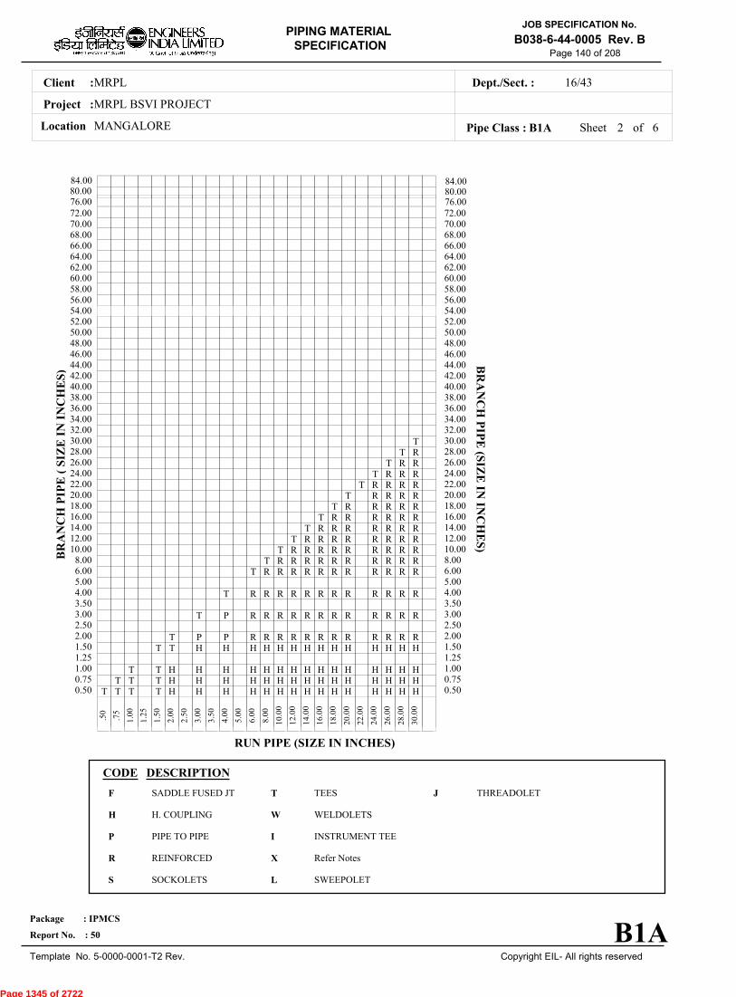
MRPLClient :
MRPL BSVI PROJECT
MANGALORELocation
16/43Dept./Sect. :
Project :
PIPING MATERIAL
SPECIFICATION
Copyright EIL- All rights reserved
JOB SPECIFICATION No.
B038-6-44-0005 Rev. B
Package : IPMCS
Report No. : 50
Template No. 5-0000-0001-T2 Rev.
Page 140 of 208
Sheet 2 ofPipe Class : B1A
T T T T H H H H H H H H H H H H H H H0.50T T T H H H H H H H H H H H H H H H0.75
T T H H H H H H H H H H H H H H H1.001.25
T T H H H H H H H H H H H H H H1.50T P P R R R R R R R R R R R R2.00
2.50T P R R R R R R R R R R R R3.00
3.50T R R R R R R R R R R R R4.00
5.00T R R R R R R R R R R R6.00
T R R R R R R R R R R8.00T R R R R R R R R R10.00
T R R R R R R R R12.00T R R R R R R R14.00
T R R R R R R16.00T R R R R R18.00
T R R R R20.00T R R R R22.00
T R R R24.00T R R26.00
T R28.00T30.00
32.0034.0036.0038.0040.0042.0044.0046.0048.0050.0052.0054.0056.0058.0060.0062.0064.0066.0068.0070.0072.00
.
50
.
75
1
.00
1
.25
1
.50
2
.00
2
.50
3
.00
3
.50
4
.00
5
.00
6
.00
8
.00
10
.00
12
.00
14
.00
16
.00
18
.00
20
.00
22
.00
24
.00
26
.00
28
.00
30
.00
BR
AN
CH
PIP
E (
SIZ
E I
N I
NC
HE
S)
0.500.751.001.251.502.002.503.003.504.005.006.008.0010.0012.0014.0016.0018.0020.0022.0024.0026.0028.0030.0032.0034.0036.0038.0040.0042.0044.0046.0048.0050.0052.0054.0056.0058.0060.0062.0064.0066.0068.0070.0072.00
BR
AN
CH
PIP
E (SIZ
E IN
INC
HE
S)
RUN PIPE (SIZE IN INCHES)
CODE DESCRIPTION
F
H
P
R
S
T
W
I
X
L
JSADDLE FUSED JT
H. COUPLING
PIPE TO PIPE
REINFORCED
SOCKOLETS
TEES
WELDOLETS
INSTRUMENT TEE
Refer Notes
SWEEPOLET
THREADOLET
B1A
76.0080.0084.00
76.0080.0084.00
6
Page 1345 of 2722
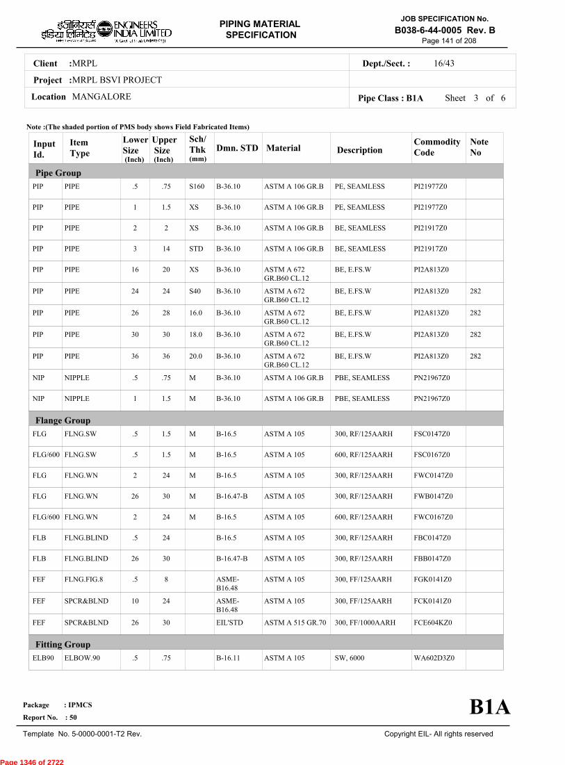
MRPLClient :
MRPL BSVI PROJECT
MANGALORELocation
16/43Dept./Sect. :
Project :
PIPING MATERIAL
SPECIFICATION
Copyright EIL- All rights reserved
JOB SPECIFICATION No.
B038-6-44-0005 Rev. B
Package : IPMCS
Report No. : 50
Template No. 5-0000-0001-T2 Rev.
Page 141 of 208
Sheet 3 ofPipe Class : B1A
InputId.
Item Type
LowerSize
Upper Size
Sch/Thk DescriptionMaterial
CommodityCode
NoteNo
Pipe Group
Flange Group
Fitting Group
Dmn. STD(Inch) (Inch)
PIP
PIP
PIP
PIP
PIP
PIP
PIP
PIP
PIP
NIP
NIP
FLG
FLG/600
FLG
FLG
FLG/600
FLB
FLB
FEF
FEF
FEF
ELB90
PIPE
PIPE
PIPE
PIPE
PIPE
PIPE
PIPE
PIPE
PIPE
NIPPLE
NIPPLE
FLNG.SW
FLNG.SW
FLNG.WN
FLNG.WN
FLNG.WN
FLNG.BLIND
FLNG.BLIND
FLNG.FIG.8
SPCR&BLND
SPCR&BLND
ELBOW.90
.5
1
2
3
16
24
26
30
36
.5
1
.5
.5
2
26
2
.5
26
.5
10
26
.5
.75
1.5
2
14
20
24
28
30
36
.75
1.5
1.5
1.5
24
30
24
24
30
8
24
30
.75
S160
XS
XS
STD
XS
S40
16.0
18.0
20.0
M
M
M
M
M
M
M
PE, SEAMLESS
PE, SEAMLESS
BE, SEAMLESS
BE, SEAMLESS
BE, E.FS.W
BE, E.FS.W
BE, E.FS.W
BE, E.FS.W
BE, E.FS.W
PBE, SEAMLESS
PBE, SEAMLESS
300, RF/125AARH
600, RF/125AARH
300, RF/125AARH
300, RF/125AARH
600, RF/125AARH
300, RF/125AARH
300, RF/125AARH
300, FF/125AARH
300, FF/125AARH
300, FF/1000AARH
SW, 6000
ASTM A 106 GR.B
ASTM A 106 GR.B
ASTM A 106 GR.B
ASTM A 106 GR.B
ASTM A 672GR.B60 CL.12
ASTM A 672GR.B60 CL.12
ASTM A 672GR.B60 CL.12
ASTM A 672GR.B60 CL.12
ASTM A 672GR.B60 CL.12
ASTM A 106 GR.B
ASTM A 106 GR.B
ASTM A 105
ASTM A 105
ASTM A 105
ASTM A 105
ASTM A 105
ASTM A 105
ASTM A 105
ASTM A 105
ASTM A 105
ASTM A 515 GR.70
ASTM A 105
PI21977Z0
PI21977Z0
PI21917Z0
PI21917Z0
PI2A813Z0
PI2A813Z0
PI2A813Z0
PI2A813Z0
PI2A813Z0
PN21967Z0
PN21967Z0
FSC0147Z0
FSC0167Z0
FWC0147Z0
FWB0147Z0
FWC0167Z0
FBC0147Z0
FBB0147Z0
FGK0141Z0
FCK0141Z0
FCE604KZ0
WA602D3Z0
282
282
282
282
B-36.10
B-36.10
B-36.10
B-36.10
B-36.10
B-36.10
B-36.10
B-36.10
B-36.10
B-36.10
B-36.10
B-16.5
B-16.5
B-16.5
B-16.47-B
B-16.5
B-16.5
B-16.47-B
ASME-B16.48
ASME-B16.48
EIL'STD
B-16.11
Note :(The shaded portion of PMS body shows Field Fabricated Items)
B1A
(mm)
6
Page 1346 of 2722

MRPLClient :
MRPL BSVI PROJECT
MANGALORELocation
16/43Dept./Sect. :
Project :
PIPING MATERIAL
SPECIFICATION
Copyright EIL- All rights reserved
JOB SPECIFICATION No.
B038-6-44-0005 Rev. B
Package : IPMCS
Report No. : 50
Template No. 5-0000-0001-T2 Rev.
Page 142 of 208
Sheet 4 ofPipe Class : B1A
InputId.
Item Type
LowerSize
Upper Size
Sch/Thk DescriptionMaterial
CommodityCode
NoteNo
Fitting Group
Dmn. STD(Inch) (Inch)
ELB90
ELB90
ELB90
ELB45
ELB45
ELB45
ELB45
TEQ
TEQ
TEQ
TEQ
TRED
TRED
TRED
TRED
REDC
REDC
REDE
REDE
SWGC
SWGE
CAP
CAP
ELBOW.90
ELBOW.90
ELBOW.90
ELBOW.45
ELBOW.45
ELBOW.45
ELBOW.45
T.EQUAL
T.EQUAL
T.EQUAL
T.EQUAL
T.RED
T.RED
T.RED
T.RED
REDUC.CONC
REDUC.CONC
REDUC.ECC
REDUC.ECC
SWAGE.CONC
SWAGE.ECC
CAP
CAP
1
2
16
.5
1
2
16
.5
1
2
16
.5
1
2
16
2
16
2
16
.5
.5
.5
1
1.5
14
30
.75
1.5
14
30
.75
1.5
14
30
.75
1.5
14
30
14
30
14
30
3
3
.75
1.5
M
M
M
M
M
M
M, M
M, M
M, M
M, M
M, M
M, M
M, M
M, M
SW, 3000
BW, 1.5D
BW, 1.5D
SW, 6000
SW, 3000
BW, 1.5D
BW, 1.5D
SW, 6000
SW, 3000
BW
BW
SW, 6000
SW, 3000
BW
BW
BW
BW
BW
BW
PBE
PBE
SCRF, 6000
SCRF, 3000
ASTM A 105
ASTM A 234GR.WPB
ASTM A 234GR.WPB-W
ASTM A 105
ASTM A 105
ASTM A 234GR.WPB
ASTM A 234GR.WPB-W
ASTM A 105
ASTM A 105
ASTM A 234GR.WPB
ASTM A 234GR.WPB-W
ASTM A 105
ASTM A 105
ASTM A 234GR.WPB
ASTM A 234GR.WPB-W
ASTM A 234GR.WPB
ASTM A 234GR.WPB-W
ASTM A 234GR.WPB
ASTM A 234GR.WPB-W
ASTM A 105
ASTM A 105
ASTM A 105
ASTM A 105
WA602D2Z0
WAG684Z10
WAG754Z10
WB602D3Z0
WB602D2Z0
WBG684Z10
WBG754Z10
WE602D3Z0
WE602D2Z0
WEG684ZZ0
WEG754ZZ0
WR602D3Z0
WR602D2Z0
WRG684ZZ0
WRG754ZZ0
WUG684ZZ0
WUG754ZZ0
WVG684ZZ0
WVG754ZZ0
WNH026ZZ0
WPH026ZZ0
WF60283Z0
WF60282Z0
63
63
B-16.11
B-16.9
B-16.9
B-16.11
B-16.11
B-16.9
B-16.9
B-16.11
B-16.11
B-16.9
B-16.9
B-16.11
B-16.11
B-16.9
B-16.9
B-16.9
B-16.9
B-16.9
B-16.9
BS-3799
BS-3799
B-16.11
B-16.11
Note :(The shaded portion of PMS body shows Field Fabricated Items)
B1A
(mm)
6
Page 1347 of 2722

MRPLClient :
MRPL BSVI PROJECT
MANGALORELocation
16/43Dept./Sect. :
Project :
PIPING MATERIAL
SPECIFICATION
Copyright EIL- All rights reserved
JOB SPECIFICATION No.
B038-6-44-0005 Rev. B
Package : IPMCS
Report No. : 50
Template No. 5-0000-0001-T2 Rev.
Page 143 of 208
Sheet 5 ofPipe Class : B1A
InputId.
Item Type
LowerSize
Upper Size
Sch/Thk DescriptionMaterial
CommodityCode
NoteNo
Fitting Group
Valves Group
Dmn. STD(Inch) (Inch)
CAP
CPLF
CPLF
CPLH
CPLH
CPLL
CPLL
CPLR
CPLR
GAV
GAV
GAV/2
GAV/1
GLV
GLV
GLV/2
GLV/1
CAP
CPLNG.FULL
CPLNG.FULL
CPLNG.HALF
CPLNG.HALF
CPLNG.LH
CPLNG.LH
CPLNG.RED
CPLNG.RED
VLV.GATE
VLV.GATE
VLV.GATE
VLV.GATE
VLV.GLOBE
VLV.GLOBE
VLV.GLOBE
VLV.GLOBE
2
.5
1
.5
1
.5
1
.5
1
.25
2
2
.5
.25
2
2
.5
30
.75
1.5
.75
1.5
.75
1.5
.75
1.5
1.5
24
12
1.5
1.5
12
8
1.5
M BW
SW, 6000
SW, 3000
SW, 6000
SW, 3000
SW, 6000
SW, 3000
SW, 6000
SW, 3000
SW, 800, 3000, B-16.11, SHT NO.- 51001
FLGD, 300, B-16.5,RF/125AARH, SHTNO.- 51401
BW, 300, B-16.25, SHTNO.- 51497
SW, 800, 3000, B-16.11, SHT NO.- 51907
SW, 800, 3000, B-16.11, SHT NO.- 52001
FLGD, 300, B-16.5,RF/125AARH, SHTNO.- 52401
BW, 300, B-16.25, SHTNO.- 52497
SW, 800, 3000, B-16.11, SHT NO.- 52907
ASTM A 234GR.WPB
ASTM A 105
ASTM A 105
ASTM A 105
ASTM A 105
ASTM A 105
ASTM A 105
ASTM A 105
ASTM A 105
BODY-ASTM A105,TRIM-STELLITED,STEM-13%CR.STEEL
BODY-ASTM A 216GR.WCB,TRIM-13% CR.STEEL
BODY-ASTM A 216GR.WCB,TRIM-STELLITED,STEM-13% CR.STEEL
BODY-ASTM A105,TRIM-STELLITED,STEM-13% CR.STEEL
BODY-ASTM A105,TRIM-STELLITED,STEM-13%CR STEEL
BODY-ASTM A 216GR.WCB,TRIM-13% CR.STEEL
BODY-ASTM A 216GR.WCB,TRIM-STELLITED,STEM-13% CR.STEEL
BODY-ASTM A105,TRIM-STELLITED,STEM-13% CR.STEEL
WFG684ZZ0
WJ602D3Z0
WJ602D2Z0
WK602D3Z0
WK602D2Z0
WL602D3Z0
WL602D2Z0
WM602D3Z0
WM602D2Z0
51001ZZZ0
51401ZZZ0
51497ZZZ0
51907ZZZ0
52001ZZZ0
52401ZZZ0
52497ZZZ0
52907ZZZ0
303
303
303
303
B-16.9
B-16.11
B-16.11
B-16.11
B-16.11
B-16.11
B-16.11
B-16.11
B-16.11
API 602/ ISO15761
API 600/ ISO10434
MSS-SP117
API-602
BS EN ISO15761
BS-1873
MSS-SP117
BS EN ISO15761
Note :(The shaded portion of PMS body shows Field Fabricated Items)
B1A
(mm)
6
Page 1348 of 2722
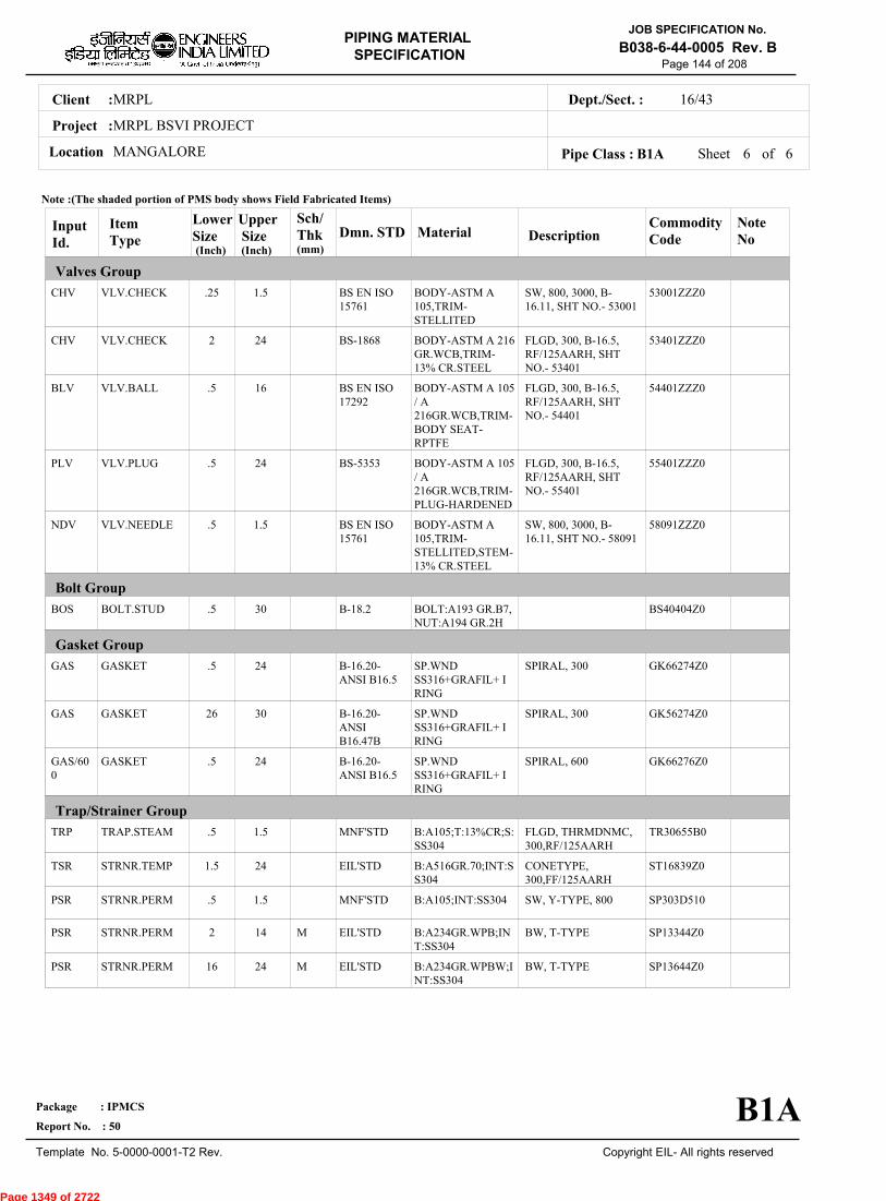
MRPLClient :
MRPL BSVI PROJECT
MANGALORELocation
16/43Dept./Sect. :
Project :
PIPING MATERIAL
SPECIFICATION
Copyright EIL- All rights reserved
JOB SPECIFICATION No.
B038-6-44-0005 Rev. B
Package : IPMCS
Report No. : 50
Template No. 5-0000-0001-T2 Rev.
Page 144 of 208
Sheet 6 of 6Pipe Class : B1A
InputId.
Item Type
LowerSize
Upper Size
Sch/Thk DescriptionMaterial
CommodityCode
NoteNo
Valves Group
Bolt Group
Gasket Group
Trap/Strainer Group
Dmn. STD(Inch) (Inch)
CHV
CHV
BLV
PLV
NDV
BOS
GAS
GAS
GAS/600
TRP
TSR
PSR
PSR
PSR
VLV.CHECK
VLV.CHECK
VLV.BALL
VLV.PLUG
VLV.NEEDLE
BOLT.STUD
GASKET
GASKET
GASKET
TRAP.STEAM
STRNR.TEMP
STRNR.PERM
STRNR.PERM
STRNR.PERM
.25
2
.5
.5
.5
.5
.5
26
.5
.5
1.5
.5
2
16
1.5
24
16
24
1.5
30
24
30
24
1.5
24
1.5
14
24
M
M
SW, 800, 3000, B-16.11, SHT NO.- 53001
FLGD, 300, B-16.5,RF/125AARH, SHTNO.- 53401
FLGD, 300, B-16.5,RF/125AARH, SHTNO.- 54401
FLGD, 300, B-16.5,RF/125AARH, SHTNO.- 55401
SW, 800, 3000, B-16.11, SHT NO.- 58091
SPIRAL, 300
SPIRAL, 300
SPIRAL, 600
FLGD, THRMDNMC,300,RF/125AARH
CONETYPE,300,FF/125AARH
SW, Y-TYPE, 800
BW, T-TYPE
BW, T-TYPE
BODY-ASTM A105,TRIM-STELLITED
BODY-ASTM A 216GR.WCB,TRIM-13% CR.STEEL
BODY-ASTM A 105/ A216GR.WCB,TRIM-BODY SEAT-RPTFE
BODY-ASTM A 105/ A216GR.WCB,TRIM-PLUG-HARDENED
BODY-ASTM A105,TRIM-STELLITED,STEM-13% CR.STEEL
BOLT:A193 GR.B7,NUT:A194 GR.2H
SP.WNDSS316+GRAFIL+ IRING
SP.WNDSS316+GRAFIL+ IRING
SP.WNDSS316+GRAFIL+ IRING
B:A105;T:13%CR;S:SS304
B:A516GR.70;INT:SS304
B:A105;INT:SS304
B:A234GR.WPB;INT:SS304
B:A234GR.WPBW;INT:SS304
53001ZZZ0
53401ZZZ0
54401ZZZ0
55401ZZZ0
58091ZZZ0
BS40404Z0
GK66274Z0
GK56274Z0
GK66276Z0
TR30655B0
ST16839Z0
SP303D510
SP13344Z0
SP13644Z0
BS EN ISO15761
BS-1868
BS EN ISO17292
BS-5353
BS EN ISO15761
B-18.2
B-16.20-ANSI B16.5
B-16.20-ANSIB16.47B
B-16.20-ANSI B16.5
MNF'STD
EIL'STD
MNF'STD
EIL'STD
EIL'STD
Note :(The shaded portion of PMS body shows Field Fabricated Items)
B1A
(mm)
Page 1349 of 2722

MRPLClient :
MRPL BSVI PROJECT
MANGALORELocation
16/43Dept./Sect. :
Project :
PIPING MATERIAL
SPECIFICATION
Copyright EIL- All rights reserved
JOB SPECIFICATION No.
B038-6-44-0005 Rev. B
Package : IPMCS
Report No. : 50
Template No. 5-0000-0001-T2 Rev.
Page 145 of 208
B1KPIPE CLASS :300RATING :SS 304BASE MATERIAL : 0CORROSION ALLOWANCE : SPECIAL REQUIREMENT :
MM
SERVICEPURE PROCESS LIQUID, VAPOUR AND GAS OR MILD CORROSIVE HYDROCARBON - FLAMMABLE/ NON FLAMMABLE &NON LETHAL HYDROCARBONS, CHEMICAL ETC.
NOTES5
7
48
51
63
74
151
FOR PERMANENT 'T' TYPE BW STRAINERS,REFER EIL'STD 7-44-0303 & 7-44-0304; AND FOR TEMPORARYSTRAINERS,REFER EIL'STD 7-44-0300; FOR SPACER AND BLIND REFER EIL'STD 7-44-0162.FOR RESTRICTION ON USE OF BALL,PLUG & BUTTERFLY VALVES,REFER GENERAL NOTES.
FOR INSULATED FLANGED JOINTS BEYOND 427 DEG.C. IN THIS CLASS, USE A453 GR.660 CL.A
DESIGN PRESSURE AT -29 DEG.C. AND 38 DEG.C. FOR THIS PRESSURE HAS BEEN REDUCED FROM 50.62 KG/CM2G TO50.50 KG/CM2G TO OPTIMISE THE THICKNESS FOR 6" SIZE.THIS ITEM IS INTENDED SOLELY FOR USE BY INSTRUMENTATION.
STRESS RUPTURE TEST AS DETAILED IN ASTM A453 SHALL BE CARRIED OUT FOR ALL ASTM A453 GR.660A BOLTINGMATERIALS.NDT REQUIREMENT SHALL BE AS PER JOB SPECIFICATION B038-6-44-0016.
SPECIAL NOTES
ITEM SIZE DESCRIPTION A.CODEMAINTAINENCEJOINTS
PIPE JOINTS
DRAINS
VENTS
TEMP.CONN
PRESS.CONN
ALL
1.5" & BELOW
2.0" & ABOVE
ON LINES <= 1.5"
ON LINES >= 2.0"
ON LINES <= 1.5"
ON LINES >= 2.0"
1.5"
0.75"
FLANGED, TO BE KEPT MINIMUM
SW COUPLING
BUTTWELDED
REFER EILSTD 7-44-0350, DF3
AS PER P&ID OR 0.75". REFER EIL STD. 7-44-0351, D4
REFER EIL STD. 7-44-350, VF3
AS PER P&ID OR 0.75". REFER EIL STD 7-44-0351, V4
FLANGED. REFER EIL STD 7-44-0353
SW NIPPLE WITH VALVE TO SPEC AS PER EIL STD 7-44-0354
TEMP
PRESS 50.5 50.5 42.18 37.96 34.8 32.69 30.93 30.23 29.52 29.17 28.47 27.77
-29 38 93 149 204 260 316 343 371 399 427 454
Sheet 1 of
TEMPERATURE (Deg. C) AND PRESSURE ( Kg/Sq. cm g ) RATINGS
Pipe Class : B1K
B1K
5
Page 1350 of 2722

MRPLClient :
MRPL BSVI PROJECT
MANGALORELocation
16/43Dept./Sect. :
Project :
PIPING MATERIAL
SPECIFICATION
Copyright EIL- All rights reserved
JOB SPECIFICATION No.
B038-6-44-0005 Rev. B
Package : IPMCS
Report No. : 50
Template No. 5-0000-0001-T2 Rev.
Page 146 of 208
Sheet 2 ofPipe Class : B1K
T T T T H H H H H H H H H H0.50T T T H H H H H H H H H H0.75
T T H H H H H H H H H H1.001.25
T T H H H H H H H H H1.50T P R R R R R R R R2.00
2.50T R R R R R R R R3.00
3.50T R R R R R R R4.00
5.00T R R R R R R6.00
T R R R R R8.00T R R R R10.00
T R R R12.00T R R14.00
T R16.00T18.00
20.0022.0024.0026.0028.0030.0032.0034.0036.0038.0040.0042.0044.0046.0048.0050.0052.0054.0056.0058.0060.0062.0064.0066.0068.0070.0072.00
.
50
.
75
1
.00
1
.25
1
.50
2
.00
2
.50
3
.00
3
.50
4
.00
5
.00
6
.00
8
.00
10
.00
12
.00
14
.00
16
.00
18
.00
BR
AN
CH
PIP
E (
SIZ
E I
N I
NC
HE
S)
0.500.751.001.251.502.002.503.003.504.005.006.008.0010.0012.0014.0016.0018.0020.0022.0024.0026.0028.0030.0032.0034.0036.0038.0040.0042.0044.0046.0048.0050.0052.0054.0056.0058.0060.0062.0064.0066.0068.0070.0072.00
BR
AN
CH
PIP
E (SIZ
E IN
INC
HE
S)
RUN PIPE (SIZE IN INCHES)
CODE DESCRIPTION
F
H
P
R
S
T
W
I
X
L
JSADDLE FUSED JT
H. COUPLING
PIPE TO PIPE
REINFORCED
SOCKOLETS
TEES
WELDOLETS
INSTRUMENT TEE
Refer Notes
SWEEPOLET
THREADOLET
B1K
76.0080.0084.00
76.0080.0084.00
5
Page 1351 of 2722
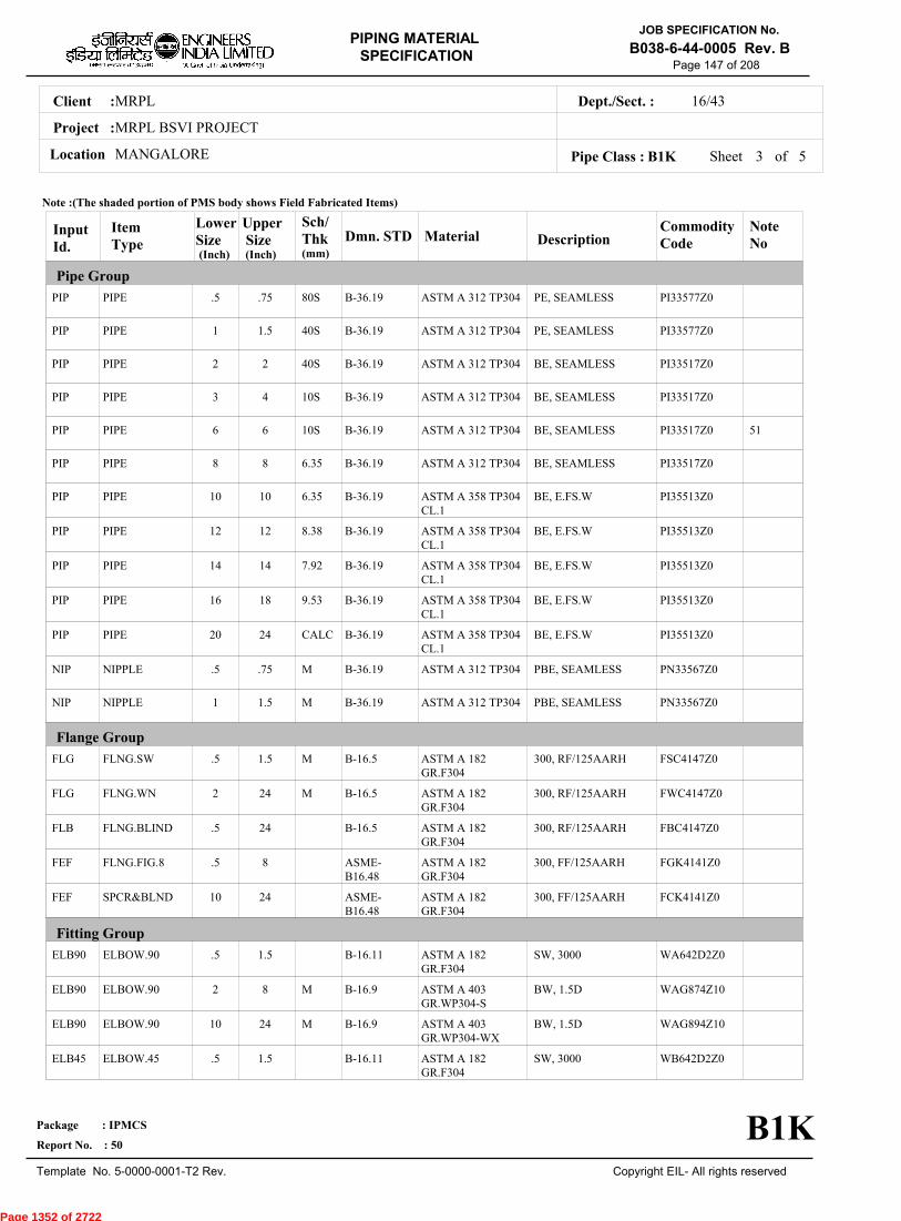
MRPLClient :
MRPL BSVI PROJECT
MANGALORELocation
16/43Dept./Sect. :
Project :
PIPING MATERIAL
SPECIFICATION
Copyright EIL- All rights reserved
JOB SPECIFICATION No.
B038-6-44-0005 Rev. B
Package : IPMCS
Report No. : 50
Template No. 5-0000-0001-T2 Rev.
Page 147 of 208
Sheet 3 ofPipe Class : B1K
InputId.
Item Type
LowerSize
Upper Size
Sch/Thk DescriptionMaterial
CommodityCode
NoteNo
Pipe Group
Flange Group
Fitting Group
Dmn. STD(Inch) (Inch)
PIP
PIP
PIP
PIP
PIP
PIP
PIP
PIP
PIP
PIP
PIP
NIP
NIP
FLG
FLG
FLB
FEF
FEF
ELB90
ELB90
ELB90
ELB45
PIPE
PIPE
PIPE
PIPE
PIPE
PIPE
PIPE
PIPE
PIPE
PIPE
PIPE
NIPPLE
NIPPLE
FLNG.SW
FLNG.WN
FLNG.BLIND
FLNG.FIG.8
SPCR&BLND
ELBOW.90
ELBOW.90
ELBOW.90
ELBOW.45
.5
1
2
3
6
8
10
12
14
16
20
.5
1
.5
2
.5
.5
10
.5
2
10
.5
.75
1.5
2
4
6
8
10
12
14
18
24
.75
1.5
1.5
24
24
8
24
1.5
8
24
1.5
80S
40S
40S
10S
10S
6.35
6.35
8.38
7.92
9.53
CALC
M
M
M
M
M
M
PE, SEAMLESS
PE, SEAMLESS
BE, SEAMLESS
BE, SEAMLESS
BE, SEAMLESS
BE, SEAMLESS
BE, E.FS.W
BE, E.FS.W
BE, E.FS.W
BE, E.FS.W
BE, E.FS.W
PBE, SEAMLESS
PBE, SEAMLESS
300, RF/125AARH
300, RF/125AARH
300, RF/125AARH
300, FF/125AARH
300, FF/125AARH
SW, 3000
BW, 1.5D
BW, 1.5D
SW, 3000
ASTM A 312 TP304
ASTM A 312 TP304
ASTM A 312 TP304
ASTM A 312 TP304
ASTM A 312 TP304
ASTM A 312 TP304
ASTM A 358 TP304CL.1
ASTM A 358 TP304CL.1
ASTM A 358 TP304CL.1
ASTM A 358 TP304CL.1
ASTM A 358 TP304CL.1
ASTM A 312 TP304
ASTM A 312 TP304
ASTM A 182GR.F304
ASTM A 182GR.F304
ASTM A 182GR.F304
ASTM A 182GR.F304
ASTM A 182GR.F304
ASTM A 182GR.F304
ASTM A 403GR.WP304-S
ASTM A 403GR.WP304-WX
ASTM A 182GR.F304
PI33577Z0
PI33577Z0
PI33517Z0
PI33517Z0
PI33517Z0
PI33517Z0
PI35513Z0
PI35513Z0
PI35513Z0
PI35513Z0
PI35513Z0
PN33567Z0
PN33567Z0
FSC4147Z0
FWC4147Z0
FBC4147Z0
FGK4141Z0
FCK4141Z0
WA642D2Z0
WAG874Z10
WAG894Z10
WB642D2Z0
51
B-36.19
B-36.19
B-36.19
B-36.19
B-36.19
B-36.19
B-36.19
B-36.19
B-36.19
B-36.19
B-36.19
B-36.19
B-36.19
B-16.5
B-16.5
B-16.5
ASME-B16.48
ASME-B16.48
B-16.11
B-16.9
B-16.9
B-16.11
Note :(The shaded portion of PMS body shows Field Fabricated Items)
B1K
(mm)
5
Page 1352 of 2722

MRPLClient :
MRPL BSVI PROJECT
MANGALORELocation
16/43Dept./Sect. :
Project :
PIPING MATERIAL
SPECIFICATION
Copyright EIL- All rights reserved
JOB SPECIFICATION No.
B038-6-44-0005 Rev. B
Package : IPMCS
Report No. : 50
Template No. 5-0000-0001-T2 Rev.
Page 148 of 208
Sheet 4 ofPipe Class : B1K
InputId.
Item Type
LowerSize
Upper Size
Sch/Thk DescriptionMaterial
CommodityCode
NoteNo
Fitting Group
Valves Group
Dmn. STD(Inch) (Inch)
ELB45
ELB45
TEQ
TEQ
TEQ
TRED
TRED
TRED
REDC
REDC
REDE
REDE
SWGC
SWGE
CAP
CAP
CPLF
CPLH
CPLL
CPLR
GAV
ELBOW.45
ELBOW.45
T.EQUAL
T.EQUAL
T.EQUAL
T.RED
T.RED
T.RED
REDUC.CONC
REDUC.CONC
REDUC.ECC
REDUC.ECC
SWAGE.CONC
SWAGE.ECC
CAP
CAP
CPLNG.FULL
CPLNG.HALF
CPLNG.LH
CPLNG.RED
VLV.GATE
2
10
.5
2
10
.5
2
10
2
10
2
10
.5
.5
.5
2
.5
.5
.5
.5
.5
8
24
1.5
8
24
1.5
8
24
8
24
8
24
3
3
1.5
24
1.5
1.5
1.5
1.5
1.5
M
M
M
M
M, M
M, M
M, M
M, M
M, M
M, M
M, M
M, M
M
BW, 1.5D
BW, 1.5D
SW, 3000
BW
BW
SW, 3000
BW
BW
BW
BW
BW
BW
PBE
PBE
SCRF, 3000
BW
SW, 3000
SW, 3000
SW, 3000
SW, 3000
SW, 800, 3000, B-16.11, SHT NO.- 51045
ASTM A 403GR.WP304-S
ASTM A 403GR.WP304-WX
ASTM A 182GR.F304
ASTM A 403GR.WP304-S
ASTM A 403GR.WP304-WX
ASTM A 182GR.F304
ASTM A 403GR.WP304-S
ASTM A 403GR.WP304-WX
ASTM A 403GR.WP304-S
ASTM A 403GR.WP304-WX
ASTM A 403GR.WP304-S
ASTM A 403GR.WP304-WX
ASTM A 182GR.F304
ASTM A 182GR.F304
ASTM A 182GR.F304
ASTM A 403GR.WP304-S
ASTM A 182GR.F304
ASTM A 182GR.F304
ASTM A 182GR.F304
ASTM A 182GR.F304
BODY-ASTM A 182GR.F304,TRIM-STELLITED,STEM-SS 304
WBG874Z10
WBG894Z10
WE642D2Z0
WEG874ZZ0
WEG894ZZ0
WR642D2Z0
WRG874ZZ0
WRG894ZZ0
WUG874ZZ0
WUG894ZZ0
WVG874ZZ0
WVG894ZZ0
WNH426ZZ0
WPH426ZZ0
WF64282Z0
WFG874ZZ0
WJ642D2Z0
WK642D2Z0
WL642D2Z0
WM642D2Z0
51045ZZZ0
63
B-16.9
B-16.9
B-16.11
B-16.9
B-16.9
B-16.11
B-16.9
B-16.9
B-16.9
B-16.9
B-16.9
B-16.9
BS-3799
BS-3799
B-16.11
B-16.9
B-16.11
B-16.11
B-16.11
B-16.11
API 602/ ISO15761
Note :(The shaded portion of PMS body shows Field Fabricated Items)
B1K
(mm)
5
Page 1353 of 2722
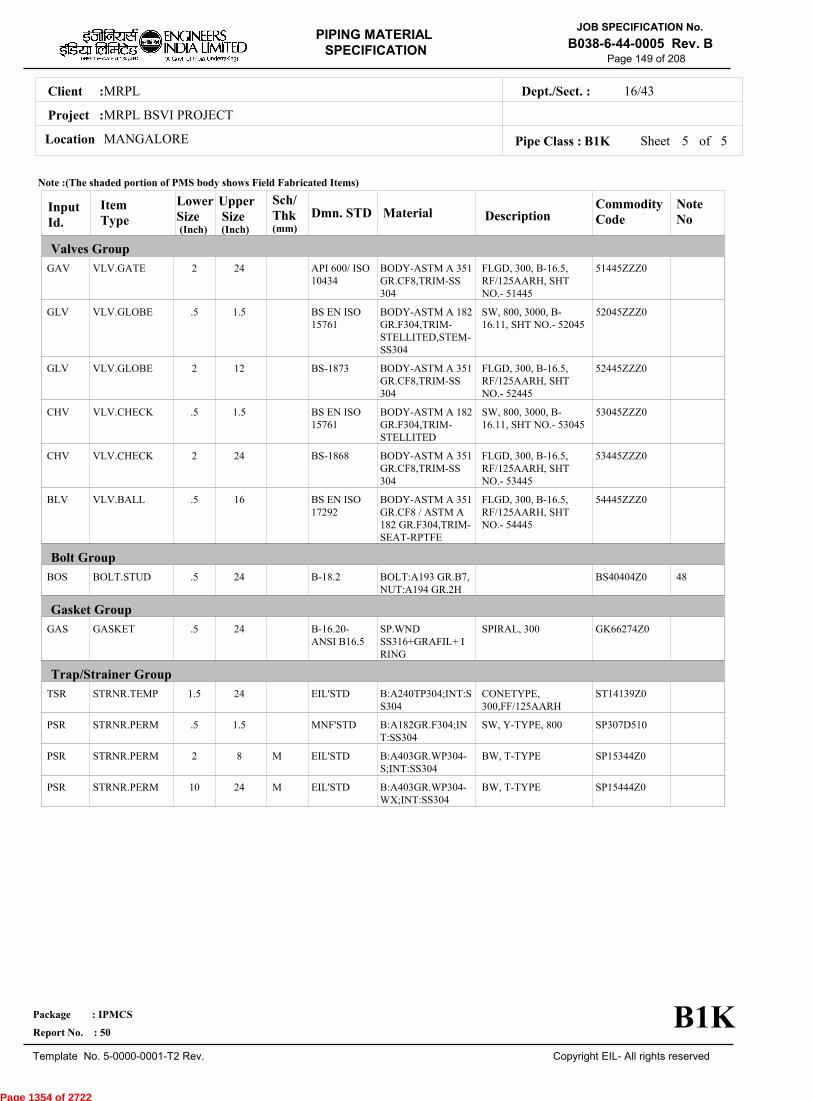
MRPLClient :
MRPL BSVI PROJECT
MANGALORELocation
16/43Dept./Sect. :
Project :
PIPING MATERIAL
SPECIFICATION
Copyright EIL- All rights reserved
JOB SPECIFICATION No.
B038-6-44-0005 Rev. B
Package : IPMCS
Report No. : 50
Template No. 5-0000-0001-T2 Rev.
Page 149 of 208
Sheet 5 of 5Pipe Class : B1K
InputId.
Item Type
LowerSize
Upper Size
Sch/Thk DescriptionMaterial
CommodityCode
NoteNo
Valves Group
Bolt Group
Gasket Group
Trap/Strainer Group
Dmn. STD(Inch) (Inch)
GAV
GLV
GLV
CHV
CHV
BLV
BOS
GAS
TSR
PSR
PSR
PSR
VLV.GATE
VLV.GLOBE
VLV.GLOBE
VLV.CHECK
VLV.CHECK
VLV.BALL
BOLT.STUD
GASKET
STRNR.TEMP
STRNR.PERM
STRNR.PERM
STRNR.PERM
2
.5
2
.5
2
.5
.5
.5
1.5
.5
2
10
24
1.5
12
1.5
24
16
24
24
24
1.5
8
24
M
M
FLGD, 300, B-16.5,RF/125AARH, SHTNO.- 51445
SW, 800, 3000, B-16.11, SHT NO.- 52045
FLGD, 300, B-16.5,RF/125AARH, SHTNO.- 52445
SW, 800, 3000, B-16.11, SHT NO.- 53045
FLGD, 300, B-16.5,RF/125AARH, SHTNO.- 53445
FLGD, 300, B-16.5,RF/125AARH, SHTNO.- 54445
SPIRAL, 300
CONETYPE,300,FF/125AARH
SW, Y-TYPE, 800
BW, T-TYPE
BW, T-TYPE
BODY-ASTM A 351GR.CF8,TRIM-SS304
BODY-ASTM A 182GR.F304,TRIM-STELLITED,STEM-SS304
BODY-ASTM A 351GR.CF8,TRIM-SS304
BODY-ASTM A 182GR.F304,TRIM-STELLITED
BODY-ASTM A 351GR.CF8,TRIM-SS304
BODY-ASTM A 351GR.CF8 / ASTM A182 GR.F304,TRIM-SEAT-RPTFE
BOLT:A193 GR.B7,NUT:A194 GR.2H
SP.WNDSS316+GRAFIL+ IRING
B:A240TP304;INT:SS304
B:A182GR.F304;INT:SS304
B:A403GR.WP304-S;INT:SS304
B:A403GR.WP304-WX;INT:SS304
51445ZZZ0
52045ZZZ0
52445ZZZ0
53045ZZZ0
53445ZZZ0
54445ZZZ0
BS40404Z0
GK66274Z0
ST14139Z0
SP307D510
SP15344Z0
SP15444Z0
48
API 600/ ISO10434
BS EN ISO15761
BS-1873
BS EN ISO15761
BS-1868
BS EN ISO17292
B-18.2
B-16.20-ANSI B16.5
EIL'STD
MNF'STD
EIL'STD
EIL'STD
Note :(The shaded portion of PMS body shows Field Fabricated Items)
B1K
(mm)
Page 1354 of 2722
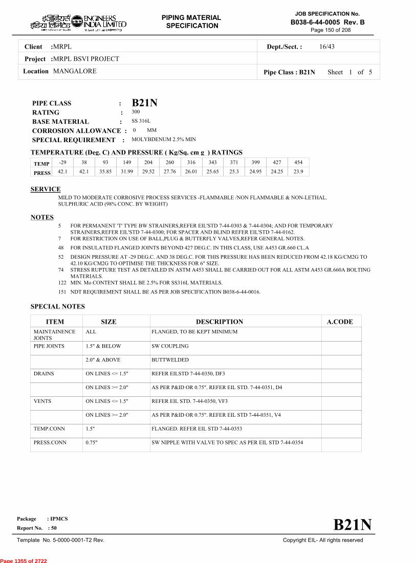
MRPLClient :
MRPL BSVI PROJECT
MANGALORELocation
16/43Dept./Sect. :
Project :
PIPING MATERIAL
SPECIFICATION
Copyright EIL- All rights reserved
JOB SPECIFICATION No.
B038-6-44-0005 Rev. B
Package : IPMCS
Report No. : 50
Template No. 5-0000-0001-T2 Rev.
Page 150 of 208
B21NPIPE CLASS :300RATING :SS 316LBASE MATERIAL : 0CORROSION ALLOWANCE :MOLYBDENUM 2.5% MINSPECIAL REQUIREMENT :
MM
SERVICEMILD TO MODERATE CORROSIVE PROCESS SERVICES -FLAMMABLE /NON FLAMMABLE & NON-LETHAL.SULPHURIC ACID (98% CONC. BY WEIGHT)
NOTES5
7
48
52
74
122
151
FOR PERMANENT 'T' TYPE BW STRAINERS,REFER EIL'STD 7-44-0303 & 7-44-0304; AND FOR TEMPORARYSTRAINERS,REFER EIL'STD 7-44-0300; FOR SPACER AND BLIND REFER EIL'STD 7-44-0162.FOR RESTRICTION ON USE OF BALL,PLUG & BUTTERFLY VALVES,REFER GENERAL NOTES.
FOR INSULATED FLANGED JOINTS BEYOND 427 DEG.C. IN THIS CLASS, USE A453 GR.660 CL.A
DESIGN PRESSURE AT -29 DEG.C. AND 38 DEG.C. FOR THIS PRESSURE HAS BEEN REDUCED FROM 42.18 KG/CM2G TO42.10 KG/CM2G TO OPTIMISE THE THICKNESS FOR 6" SIZE.STRESS RUPTURE TEST AS DETAILED IN ASTM A453 SHALL BE CARRIED OUT FOR ALL ASTM A453 GR.660A BOLTINGMATERIALS.MIN. Mo CONTENT SHALL BE 2.5% FOR SS316L MATERIALS.
NDT REQUIREMENT SHALL BE AS PER JOB SPECIFICATION B038-6-44-0016.
SPECIAL NOTES
ITEM SIZE DESCRIPTION A.CODEMAINTAINENCEJOINTS
PIPE JOINTS
DRAINS
VENTS
TEMP.CONN
PRESS.CONN
ALL
1.5" & BELOW
2.0" & ABOVE
ON LINES <= 1.5"
ON LINES >= 2.0"
ON LINES <= 1.5"
ON LINES >= 2.0"
1.5"
0.75"
FLANGED, TO BE KEPT MINIMUM
SW COUPLING
BUTTWELDED
REFER EILSTD 7-44-0350, DF3
AS PER P&ID OR 0.75". REFER EIL STD. 7-44-0351, D4
REFER EIL STD. 7-44-0350, VF3
AS PER P&ID OR 0.75". REFER EIL STD 7-44-0351, V4
FLANGED. REFER EIL STD 7-44-0353
SW NIPPLE WITH VALVE TO SPEC AS PER EIL STD 7-44-0354
TEMP
PRESS 42.1 42.1 35.85 31.99 29.52 27.76 26.01 25.65 25.3 24.95 24.25 23.9
-29 38 93 149 204 260 316 343 371 399 427 454
Sheet 1 of
TEMPERATURE (Deg. C) AND PRESSURE ( Kg/Sq. cm g ) RATINGS
Pipe Class : B21N
B21N
5
Page 1355 of 2722

MRPLClient :
MRPL BSVI PROJECT
MANGALORELocation
16/43Dept./Sect. :
Project :
PIPING MATERIAL
SPECIFICATION
Copyright EIL- All rights reserved
JOB SPECIFICATION No.
B038-6-44-0005 Rev. B
Package : IPMCS
Report No. : 50
Template No. 5-0000-0001-T2 Rev.
Page 151 of 208
Sheet 2 ofPipe Class : B21N
T T T T H H H H H H H H H H0.50T T T H H H H H H H H H H0.75
T T H H H H H H H H H H1.001.25
T T H H H H H H H H H1.50T P R R R R R R R R2.00
2.50T R R R R R R R R3.00
3.50T R R R R R R R4.00
5.00T R R R R R R6.00
T R R R R R8.00T R R R R10.00
T R R R12.00T R R14.00
T R16.00T18.00
20.0022.0024.0026.0028.0030.0032.0034.0036.0038.0040.0042.0044.0046.0048.0050.0052.0054.0056.0058.0060.0062.0064.0066.0068.0070.0072.00
.
50
.
75
1
.00
1
.25
1
.50
2
.00
2
.50
3
.00
3
.50
4
.00
5
.00
6
.00
8
.00
10
.00
12
.00
14
.00
16
.00
18
.00
BR
AN
CH
PIP
E (
SIZ
E I
N I
NC
HE
S)
0.500.751.001.251.502.002.503.003.504.005.006.008.0010.0012.0014.0016.0018.0020.0022.0024.0026.0028.0030.0032.0034.0036.0038.0040.0042.0044.0046.0048.0050.0052.0054.0056.0058.0060.0062.0064.0066.0068.0070.0072.00
BR
AN
CH
PIP
E (SIZ
E IN
INC
HE
S)
RUN PIPE (SIZE IN INCHES)
CODE DESCRIPTION
F
H
P
R
S
T
W
I
X
L
JSADDLE FUSED JT
H. COUPLING
PIPE TO PIPE
REINFORCED
SOCKOLETS
TEES
WELDOLETS
INSTRUMENT TEE
Refer Notes
SWEEPOLET
THREADOLET
B21N
76.0080.0084.00
76.0080.0084.00
5
Page 1356 of 2722

MRPLClient :
MRPL BSVI PROJECT
MANGALORELocation
16/43Dept./Sect. :
Project :
PIPING MATERIAL
SPECIFICATION
Copyright EIL- All rights reserved
JOB SPECIFICATION No.
B038-6-44-0005 Rev. B
Package : IPMCS
Report No. : 50
Template No. 5-0000-0001-T2 Rev.
Page 152 of 208
Sheet 3 ofPipe Class : B21N
InputId.
Item Type
LowerSize
Upper Size
Sch/Thk DescriptionMaterial
CommodityCode
NoteNo
Pipe Group
Flange Group
Fitting Group
Dmn. STD(Inch) (Inch)
PIP
PIP
PIP
PIP
PIP
PIP
PIP
PIP
PIP
PIP
PIP
NIP
NIP
FLG
FLG
FLB
FEF
FEF
ELB90
ELB90
ELB90
ELB45
PIPE
PIPE
PIPE
PIPE
PIPE
PIPE
PIPE
PIPE
PIPE
PIPE
PIPE
NIPPLE
NIPPLE
FLNG.SW
FLNG.WN
FLNG.BLIND
FLNG.FIG.8
SPCR&BLND
ELBOW.90
ELBOW.90
ELBOW.90
ELBOW.45
.5
1
2
3
6
8
10
12
14
16
20
.5
1
.5
2
.5
.5
10
.5
2
10
.5
.75
1.5
2
4
6
8
10
12
14
18
24
.75
1.5
1.5
24
24
8
24
1.5
8
24
1.5
80S
40S
40S
10S
10S
6.35
6.35
8.38
7.92
9.53
CALC
M
M
M
M
M
M
PE, SEAMLESS
PE, SEAMLESS
BE, SEAMLESS
BE, SEAMLESS
BE, SEAMLESS
BE, SEAMLESS
BE, E.FS.W
BE, E.FS.W
BE, E.FS.W
BE, E.FS.W
BE, E.FS.W
PBE, SEAMLESS
PBE, SEAMLESS
300, RF/125AARH
300, RF/125AARH
300, RF/125AARH
300, FF/125AARH
300, FF/125AARH
SW, 3000
BW, 1.5D
BW, 1.5D
SW, 3000
ASTM A 312TP316L
ASTM A 312TP316L
ASTM A 312TP316L
ASTM A 312TP316L
ASTM A 312TP316L
ASTM A 312TP316L
ASTM A 358TP316L CL.1
ASTM A 358TP316L CL.1
ASTM A 358TP316L CL.1
ASTM A 358TP316L CL.1
ASTM A 358TP316L CL.1
ASTM A 312TP316L
ASTM A 312TP316L
ASTM A 182GR.F316L
ASTM A 182GR.F316L
ASTM A 182GR.F316L
ASTM A 182GR.F316L
ASTM A 182GR.F316L
ASTM A 182GR.F316L
ASTM A 403GR.WP316L-S
ASTM A 403GR.WP316L-WX
ASTM A 182GR.F316L
PI34077ZO
PI34077ZO
PI34017ZO
PI34017ZO
PI34017ZO
PI34017ZO
PI36713ZO
PI36713ZO
PI36713ZO
PI36713ZO
PI36713ZO
PN34067ZO
PN34067ZO
FSC4647ZO
FWC4647ZO
FBC4647ZO
FGK4641ZO
FCK4641ZO
WA647D2ZO
WAGA34Z1O
WAG864Z1O
WB647D2ZO
52
B-36.19
B-36.19
B-36.19
B-36.19
B-36.19
B-36.19
B-36.19
B-36.19
B-36.19
B-36.19
B-36.19
B-36.19
B-36.19
B-16.5
B-16.5
B-16.5
ASME-B16.48
ASME-B16.48
B-16.11
B-16.9
B-16.9
B-16.11
Note :(The shaded portion of PMS body shows Field Fabricated Items)
B21N
(mm)
5
Page 1357 of 2722

MRPLClient :
MRPL BSVI PROJECT
MANGALORELocation
16/43Dept./Sect. :
Project :
PIPING MATERIAL
SPECIFICATION
Copyright EIL- All rights reserved
JOB SPECIFICATION No.
B038-6-44-0005 Rev. B
Package : IPMCS
Report No. : 50
Template No. 5-0000-0001-T2 Rev.
Page 153 of 208
Sheet 4 ofPipe Class : B21N
InputId.
Item Type
LowerSize
Upper Size
Sch/Thk DescriptionMaterial
CommodityCode
NoteNo
Fitting Group
Valves Group
Dmn. STD(Inch) (Inch)
ELB45
ELB45
TEQ
TEQ
TEQ
TRED
TRED
TRED
REDC
REDC
REDE
REDE
SWGC
SWGE
CAP
CPLF
CPLH
CPLL
CPLR
GAV
GAV
ELBOW.45
ELBOW.45
T.EQUAL
T.EQUAL
T.EQUAL
T.RED
T.RED
T.RED
REDUC.CONC
REDUC.CONC
REDUC.ECC
REDUC.ECC
SWAGE.CONC
SWAGE.ECC
CAP
CPLNG.FULL
CPLNG.HALF
CPLNG.LH
CPLNG.RED
VLV.GATE
VLV.GATE
2
10
.5
2
10
.5
2
10
2
10
2
10
.5
.5
2
.5
.5
.5
.5
.5
2
8
24
1.5
8
24
1.5
8
24
8
24
8
24
3
3
24
1.5
1.5
1.5
1.5
1.5
24
M
M
M
M
M, M
M, M
M, M
M, M
M, M
M, M
M, M
M, M
M
BW, 1.5D
BW, 1.5D
SW, 3000
BW
BW
SW, 3000
BW
BW
BW
BW
BW
BW
PBE
PBE
BW
SW, 3000
SW, 3000
SW, 3000
SW, 3000
SW, 800, 3000, B-16.11, SHT NO.- 51090
FLGD, 300, B-16.5,RF/125AARH, SHTNO.- 51490
ASTM A 403GR.WP316L-S
ASTM A 403GR.WP316L-WX
ASTM A 182GR.F316L
ASTM A 403GR.WP316L-S
ASTM A 403GR.WP316L-WX
ASTM A 182GR.F316L
ASTM A 403GR.WP316L-S
ASTM A 403GR.WP316L-WX
ASTM A 403GR.WP316L-S
ASTM A 403GR.WP316L-WX
ASTM A 403GR.WP316L-S
ASTM A 403GR.WP316L-WX
ASTM A 182GR.F316L
ASTM A 182GR.F316L
ASTM A 403GR.WP316L-S
ASTM A 182GR.F316L
ASTM A 182GR.F316L
ASTM A 182GR.F316L
ASTM A 182GR.F316L
BODY-ASTM A 182GR.F316L,TRIM-STELLITED,STEM-SS 316L
BODY-ASTM A 351GR CF3M,TRIM-SS316L
WBGA34Z1O
WBG864Z1O
WE647D2ZO
WEGA34ZZO
WEG864ZZO
WR647D2ZO
WRGA34ZZO
WRG864ZZO
WUGA34ZZO
WUG864ZZO
WVGA34ZZO
WVG864ZZO
WNH476ZZO
WPH476ZZO
WFGA34ZZO
WJ647D2ZO
WK647D2ZO
WL647D2ZO
WM647D2ZO
51090ZZZO
51490ZZZO
B-16.9
B-16.9
B-16.11
B-16.9
B-16.9
B-16.11
B-16.9
B-16.9
B-16.9
B-16.9
B-16.9
B-16.9
BS-3799
BS-3799
B-16.9
B-16.11
B-16.11
B-16.11
B-16.11
API 602/ ISO15761
API 600/ ISO10434
Note :(The shaded portion of PMS body shows Field Fabricated Items)
B21N
(mm)
5
Page 1358 of 2722

MRPLClient :
MRPL BSVI PROJECT
MANGALORELocation
16/43Dept./Sect. :
Project :
PIPING MATERIAL
SPECIFICATION
Copyright EIL- All rights reserved
JOB SPECIFICATION No.
B038-6-44-0005 Rev. B
Package : IPMCS
Report No. : 50
Template No. 5-0000-0001-T2 Rev.
Page 154 of 208
Sheet 5 of 5Pipe Class : B21N
InputId.
Item Type
LowerSize
Upper Size
Sch/Thk DescriptionMaterial
CommodityCode
NoteNo
Valves Group
Bolt Group
Gasket Group
Trap/Strainer Group
Dmn. STD(Inch) (Inch)
GLV
GLV
CHV
CHV
BOS
GAS
TSR
PSR
PSR
PSR
VLV.GLOBE
VLV.GLOBE
VLV.CHECK
VLV.CHECK
BOLT.STUD
GASKET
STRNR.TEMP
STRNR.PERM
STRNR.PERM
STRNR.PERM
.5
2
.5
2
.5
.5
1.5
.5
2
10
1.5
12
1.5
24
24
24
24
1.5
8
24
M
M
SW, 800, 3000, B-16.11, SHT NO.- 52090
FLGD, 300, B-16.5,RF/125AARH, SHTNO.- 52490
SW, 800, 3000, B-16.11, SHT NO.- 53090
FLGD, 300, B-16.5,RF/125AARH, SHTNO.- 53490
SPIRAL, 300
CONETYPE,300,FF/125AARH
SW, Y-TYPE, 800
BW, T-TYPE
BW, T-TYPE
BODY-ASTM A 182GR.F316L,TRIM-STELLITED,STEM-SS 316L
BODY-ASTM A 351GR CF3M,TRIM-SS316L
BODY-ASTM A 182GR.F316L,TRIM-STELLITED
BODY-ASTM A 351GR CF3M,TRIM-SS316L
BOLT:A193 GR.B7,NUT:A194 GR.2H
SP.WNDSS316L+GRAFIL+ IRING
B:A240TP316L;INT:SS316L
B:A182GR.F316L;INT:SS316L
B:A403WP316L-S;I:SS316L
B:A403WP316L-WX;I:SS316L
52090ZZZO
52490ZZZO
53090ZZZO
53490ZZZO
BS40404ZO
GK66374ZO
ST14339ZO
SP316D51O
SP15944ZO
SP16044ZO
48
BS EN ISO15761
BS-1873
BS EN ISO15761
BS-1868
B-18.2
B-16.20-ANSI B16.5
EIL'STD
MNF'STD
EIL'STD
EIL'STD
Note :(The shaded portion of PMS body shows Field Fabricated Items)
B21N
(mm)
Page 1359 of 2722
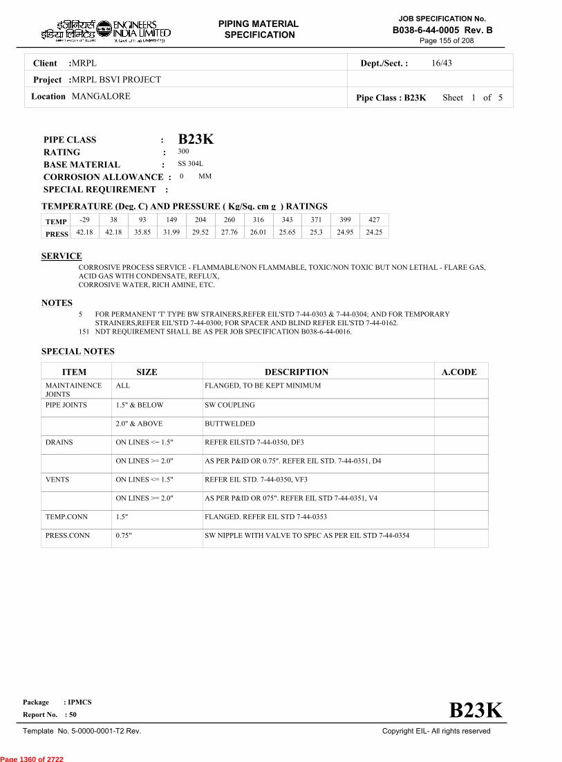
MRPLClient :
MRPL BSVI PROJECT
MANGALORELocation
16/43Dept./Sect. :
Project :
PIPING MATERIAL
SPECIFICATION
Copyright EIL- All rights reserved
JOB SPECIFICATION No.
B038-6-44-0005 Rev. B
Package : IPMCS
Report No. : 50
Template No. 5-0000-0001-T2 Rev.
Page 155 of 208
B23KPIPE CLASS :300RATING :SS 304LBASE MATERIAL : 0CORROSION ALLOWANCE : SPECIAL REQUIREMENT :
MM
SERVICECORROSIVE PROCESS SERVICE - FLAMMABLE/NON FLAMMABLE, TOXIC/NON TOXIC BUT NON LETHAL - FLARE GAS,ACID GAS WITH CONDENSATE, REFLUX,CORROSIVE WATER, RICH AMINE, ETC.
NOTES5
151
FOR PERMANENT 'T' TYPE BW STRAINERS,REFER EIL'STD 7-44-0303 & 7-44-0304; AND FOR TEMPORARYSTRAINERS,REFER EIL'STD 7-44-0300; FOR SPACER AND BLIND REFER EIL'STD 7-44-0162.NDT REQUIREMENT SHALL BE AS PER JOB SPECIFICATION B038-6-44-0016.
SPECIAL NOTES
ITEM SIZE DESCRIPTION A.CODEMAINTAINENCEJOINTS
PIPE JOINTS
DRAINS
VENTS
TEMP.CONN
PRESS.CONN
ALL
1.5" & BELOW
2.0" & ABOVE
ON LINES <= 1.5"
ON LINES >= 2.0"
ON LINES <= 1.5"
ON LINES >= 2.0"
1.5"
0.75"
FLANGED, TO BE KEPT MINIMUM
SW COUPLING
BUTTWELDED
REFER EILSTD 7-44-0350, DF3
AS PER P&ID OR 0.75". REFER EIL STD. 7-44-0351, D4
REFER EIL STD. 7-44-0350, VF3
AS PER P&ID OR 075". REFER EIL STD 7-44-0351, V4
FLANGED. REFER EIL STD 7-44-0353
SW NIPPLE WITH VALVE TO SPEC AS PER EIL STD 7-44-0354
TEMP
PRESS 42.18 42.18 35.85 31.99 29.52 27.76 26.01 25.65 25.3 24.95 24.25
-29 38 93 149 204 260 316 343 371 399 427
Sheet 1 of
TEMPERATURE (Deg. C) AND PRESSURE ( Kg/Sq. cm g ) RATINGS
Pipe Class : B23K
B23K
5
Page 1360 of 2722
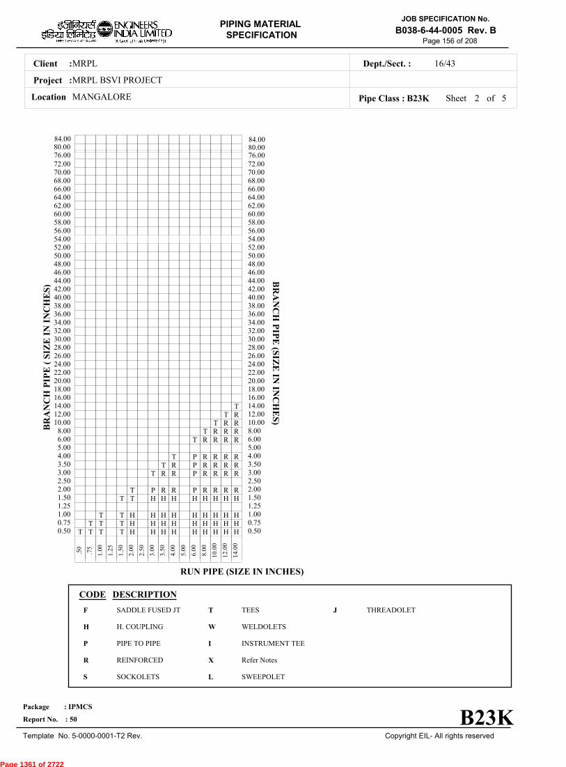
MRPLClient :
MRPL BSVI PROJECT
MANGALORELocation
16/43Dept./Sect. :
Project :
PIPING MATERIAL
SPECIFICATION
Copyright EIL- All rights reserved
JOB SPECIFICATION No.
B038-6-44-0005 Rev. B
Package : IPMCS
Report No. : 50
Template No. 5-0000-0001-T2 Rev.
Page 156 of 208
Sheet 2 ofPipe Class : B23K
T T T T H H H H H H H H H0.50T T T H H H H H H H H H0.75
T T H H H H H H H H H1.001.25
T T H H H H H H H H1.50T P R R P R R R R2.00
2.50T R R P R R R R3.00
T R P R R R R3.50T P R R R R4.00
5.00T R R R R6.00
T R R R8.00T R R10.00
T R12.00T14.00
16.0018.0020.0022.0024.0026.0028.0030.0032.0034.0036.0038.0040.0042.0044.0046.0048.0050.0052.0054.0056.0058.0060.0062.0064.0066.0068.0070.0072.00
.
50
.
75
1
.00
1
.25
1
.50
2
.00
2
.50
3
.00
3
.50
4
.00
5
.00
6
.00
8
.00
10
.00
12
.00
14
.00
BR
AN
CH
PIP
E (
SIZ
E I
N I
NC
HE
S)
0.500.751.001.251.502.002.503.003.504.005.006.008.0010.0012.0014.0016.0018.0020.0022.0024.0026.0028.0030.0032.0034.0036.0038.0040.0042.0044.0046.0048.0050.0052.0054.0056.0058.0060.0062.0064.0066.0068.0070.0072.00
BR
AN
CH
PIP
E (SIZ
E IN
INC
HE
S)
RUN PIPE (SIZE IN INCHES)
CODE DESCRIPTION
F
H
P
R
S
T
W
I
X
L
JSADDLE FUSED JT
H. COUPLING
PIPE TO PIPE
REINFORCED
SOCKOLETS
TEES
WELDOLETS
INSTRUMENT TEE
Refer Notes
SWEEPOLET
THREADOLET
B23K
76.0080.0084.00
76.0080.0084.00
5
Page 1361 of 2722
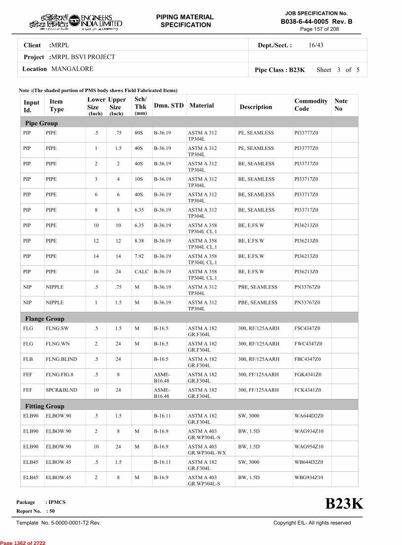
MRPLClient :
MRPL BSVI PROJECT
MANGALORELocation
16/43Dept./Sect. :
Project :
PIPING MATERIAL
SPECIFICATION
Copyright EIL- All rights reserved
JOB SPECIFICATION No.
B038-6-44-0005 Rev. B
Package : IPMCS
Report No. : 50
Template No. 5-0000-0001-T2 Rev.
Page 157 of 208
Sheet 3 ofPipe Class : B23K
InputId.
Item Type
LowerSize
Upper Size
Sch/Thk DescriptionMaterial
CommodityCode
NoteNo
Pipe Group
Flange Group
Fitting Group
Dmn. STD(Inch) (Inch)
PIP
PIP
PIP
PIP
PIP
PIP
PIP
PIP
PIP
PIP
NIP
NIP
FLG
FLG
FLB
FEF
FEF
ELB90
ELB90
ELB90
ELB45
ELB45
PIPE
PIPE
PIPE
PIPE
PIPE
PIPE
PIPE
PIPE
PIPE
PIPE
NIPPLE
NIPPLE
FLNG.SW
FLNG.WN
FLNG.BLIND
FLNG.FIG.8
SPCR&BLND
ELBOW.90
ELBOW.90
ELBOW.90
ELBOW.45
ELBOW.45
.5
1
2
3
6
8
10
12
14
16
.5
1
.5
2
.5
.5
10
.5
2
10
.5
2
.75
1.5
2
4
6
8
10
12
14
24
.75
1.5
1.5
24
24
8
24
1.5
8
24
1.5
8
80S
40S
40S
10S
40S
6.35
6.35
8.38
7.92
CALC
M
M
M
M
M
M
M
PE, SEAMLESS
PE, SEAMLESS
BE, SEAMLESS
BE, SEAMLESS
BE, SEAMLESS
BE, SEAMLESS
BE, E.FS.W
BE, E.FS.W
BE, E.FS.W
BE, E.FS.W
PBE, SEAMLESS
PBE, SEAMLESS
300, RF/125AARH
300, RF/125AARH
300, RF/125AARH
300, FF/125AARH
300, FF/125AARH
SW, 3000
BW, 1.5D
BW, 1.5D
SW, 3000
BW, 1.5D
ASTM A 312TP304L
ASTM A 312TP304L
ASTM A 312TP304L
ASTM A 312TP304L
ASTM A 312TP304L
ASTM A 312TP304L
ASTM A 358TP304L CL.1
ASTM A 358TP304L CL.1
ASTM A 358TP304L CL.1
ASTM A 358TP304L CL.1
ASTM A 312TP304L
ASTM A 312TP304L
ASTM A 182GR.F304L
ASTM A 182GR.F304L
ASTM A 182GR.F304L
ASTM A 182GR.F304L
ASTM A 182GR.F304L
ASTM A 182GR.F304L
ASTM A 403GR.WP304L-S
ASTM A 403GR.WP304L-WX
ASTM A 182GR.F304L
ASTM A 403GR.WP304L-S
PI33777Z0
PI33777Z0
PI33717Z0
PI33717Z0
PI33717Z0
PI33717Z0
PI36213Z0
PI36213Z0
PI36213Z0
PI36213Z0
PN33767Z0
PN33767Z0
FSC4347Z0
FWC4347Z0
FBC4347Z0
FGK4341Z0
FCK4341Z0
WA644D2Z0
WAG934Z10
WAG954Z10
WB644D2Z0
WBG934Z10
B-36.19
B-36.19
B-36.19
B-36.19
B-36.19
B-36.19
B-36.19
B-36.19
B-36.19
B-36.19
B-36.19
B-36.19
B-16.5
B-16.5
B-16.5
ASME-B16.48
ASME-B16.48
B-16.11
B-16.9
B-16.9
B-16.11
B-16.9
Note :(The shaded portion of PMS body shows Field Fabricated Items)
B23K
(mm)
5
Page 1362 of 2722
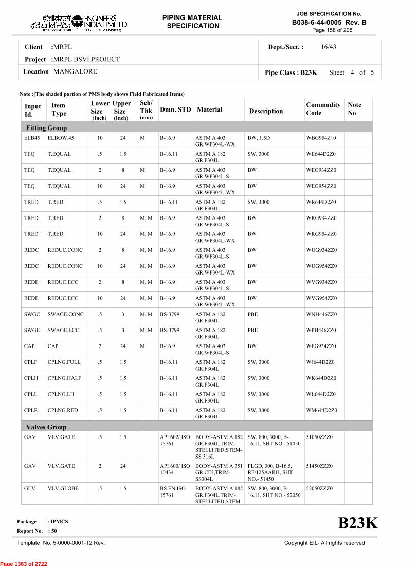
MRPLClient :
MRPL BSVI PROJECT
MANGALORELocation
16/43Dept./Sect. :
Project :
PIPING MATERIAL
SPECIFICATION
Copyright EIL- All rights reserved
JOB SPECIFICATION No.
B038-6-44-0005 Rev. B
Package : IPMCS
Report No. : 50
Template No. 5-0000-0001-T2 Rev.
Page 158 of 208
Sheet 4 ofPipe Class : B23K
InputId.
Item Type
LowerSize
Upper Size
Sch/Thk DescriptionMaterial
CommodityCode
NoteNo
Fitting Group
Valves Group
Dmn. STD(Inch) (Inch)
ELB45
TEQ
TEQ
TEQ
TRED
TRED
TRED
REDC
REDC
REDE
REDE
SWGC
SWGE
CAP
CPLF
CPLH
CPLL
CPLR
GAV
GAV
GLV
ELBOW.45
T.EQUAL
T.EQUAL
T.EQUAL
T.RED
T.RED
T.RED
REDUC.CONC
REDUC.CONC
REDUC.ECC
REDUC.ECC
SWAGE.CONC
SWAGE.ECC
CAP
CPLNG.FULL
CPLNG.HALF
CPLNG.LH
CPLNG.RED
VLV.GATE
VLV.GATE
VLV.GLOBE
10
.5
2
10
.5
2
10
2
10
2
10
.5
.5
2
.5
.5
.5
.5
.5
2
.5
24
1.5
8
24
1.5
8
24
8
24
8
24
3
3
24
1.5
1.5
1.5
1.5
1.5
24
1.5
M
M
M
M, M
M, M
M, M
M, M
M, M
M, M
M, M
M, M
M
BW, 1.5D
SW, 3000
BW
BW
SW, 3000
BW
BW
BW
BW
BW
BW
PBE
PBE
BW
SW, 3000
SW, 3000
SW, 3000
SW, 3000
SW, 800, 3000, B-16.11, SHT NO.- 51050
FLGD, 300, B-16.5,RF/125AARH, SHTNO.- 51450
SW, 800, 3000, B-16.11, SHT NO.- 52050
ASTM A 403GR.WP304L-WX
ASTM A 182GR.F304L
ASTM A 403GR.WP304L-S
ASTM A 403GR.WP304L-WX
ASTM A 182GR.F304L
ASTM A 403GR.WP304L-S
ASTM A 403GR.WP304L-WX
ASTM A 403GR.WP304L-S
ASTM A 403GR.WP304L-WX
ASTM A 403GR.WP304L-S
ASTM A 403GR.WP304L-WX
ASTM A 182GR.F304L
ASTM A 182GR.F304L
ASTM A 403GR.WP304L-S
ASTM A 182GR.F304L
ASTM A 182GR.F304L
ASTM A 182GR.F304L
ASTM A 182GR.F304L
BODY-ASTM A 182GR.F304L,TRIM-STELLITED,STEM-SS 316L
BODY-ASTM A 351GR.CF3,TRIM-SS304L
BODY-ASTM A 182GR.F304L,TRIM-STELLITED,STEM-
WBG954Z10
WE644D2Z0
WEG934ZZ0
WEG954ZZ0
WR644D2Z0
WRG934ZZ0
WRG954ZZ0
WUG934ZZ0
WUG954ZZ0
WVG934ZZ0
WVG954ZZ0
WNH446ZZ0
WPH446ZZ0
WFG934ZZ0
WJ644D2Z0
WK644D2Z0
WL644D2Z0
WM644D2Z0
51050ZZZ0
51450ZZZ0
52050ZZZ0
B-16.9
B-16.11
B-16.9
B-16.9
B-16.11
B-16.9
B-16.9
B-16.9
B-16.9
B-16.9
B-16.9
BS-3799
BS-3799
B-16.9
B-16.11
B-16.11
B-16.11
B-16.11
API 602/ ISO15761
API 600/ ISO10434
BS EN ISO15761
Note :(The shaded portion of PMS body shows Field Fabricated Items)
B23K
(mm)
5
Page 1363 of 2722

MRPLClient :
MRPL BSVI PROJECT
MANGALORELocation
16/43Dept./Sect. :
Project :
PIPING MATERIAL
SPECIFICATION
Copyright EIL- All rights reserved
JOB SPECIFICATION No.
B038-6-44-0005 Rev. B
Package : IPMCS
Report No. : 50
Template No. 5-0000-0001-T2 Rev.
Page 159 of 208
Sheet 5 of 5Pipe Class : B23K
InputId.
Item Type
LowerSize
Upper Size
Sch/Thk DescriptionMaterial
CommodityCode
NoteNo
Valves Group
Bolt Group
Gasket Group
Trap/Strainer Group
Dmn. STD(Inch) (Inch)
GLV
CHV
CHV
BOS
GAS
TSR
PSR
PSR
PSR
VLV.GLOBE
VLV.CHECK
VLV.CHECK
BOLT.STUD
GASKET
STRNR.TEMP
STRNR.PERM
STRNR.PERM
STRNR.PERM
2
.5
2
.5
.5
1.5
.5
2
10
12
1.5
24
24
24
24
1.5
8
24
M
M
FLGD, 300, B-16.5,RF/125AARH, SHTNO.- 52450
SW, 800, 3000, B-16.11, SHT NO.- 53050
FLGD, 300, B-16.5,RF/125AARH, SHTNO.- 53450
SPIRAL, 300
CONETYPE,300,FF/125AARH
SW, Y-TYPE, 800
BW, T-TYPE
BW, T-TYPE
SS 316L
BODY-ASTM A 351GR.CF3,TRIM-SS304L
BODY-ASTM A 182GR.F304L,TRIM-STELLITED
BODY-ASTM A 351GR.CF3,TRIM-SS304L
BOLT:A193 GR.B7,NUT:A194 GR.2H
SP.WNDSS316L+GRAFIL+ IRING
B:A240TP304L;INT:SS304L
B:A182GR.F304L;INT:SS304L
B:A403WP304L-S;INT:SS304L
B:A403WP304L-WX;INT:SS304L
52450ZZZ0
53050ZZZ0
53450ZZZ0
BS40404Z0
GK66374Z0
ST17139Z0
SP315D510
SP15544Z0
SP15644Z0
BS-1873
BS EN ISO15761
BS-1868
B-18.2
B-16.20-ANSI B16.5
EIL'STD
MNF'STD
EIL'STD
EIL'STD
Note :(The shaded portion of PMS body shows Field Fabricated Items)
B23K
(mm)
Page 1364 of 2722
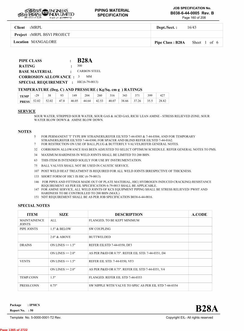
MRPLClient :
MRPL BSVI PROJECT
MANGALORELocation
16/43Dept./Sect. :
Project :
PIPING MATERIAL
SPECIFICATION
Copyright EIL- All rights reserved
JOB SPECIFICATION No.
B038-6-44-0005 Rev. B
Package : IPMCS
Report No. : 50
Template No. 5-0000-0001-T2 Rev.
Page 160 of 208
B28APIPE CLASS :300RATING :CARBON STEELBASE MATERIAL : 3CORROSION ALLOWANCE :HIC(6-79-0013)SPECIAL REQUIREMENT :
MM
SERVICESOUR WATER, STRIPPED SOUR WATER, SOUR GAS & ACID GAS, RICH/ LEAN AMINE - STRESS RELIEVED ZONE; SOURWATER BLOW DOWN & AMINE BLOW DOWN.
NOTES5
7
32
34
63
75
107
133
146
147
151
FOR PERMANENT 'T' TYPE BW STRAINERS,REFER EIL'STD 7-44-0303 & 7-44-0304; AND FOR TEMPORARYSTRAINERS,REFER EIL'STD 7-44-0300; FOR SPACER AND BLIND REFER EIL'STD 7-44-0162.FOR RESTRICTION ON USE OF BALL,PLUG & BUTTERFLY VALVES,REFER GENERAL NOTES.
CORROSION ALLOWANCE HAS BEEN ADJUSTED TO SELECT OPTIMUM SCHEDULE. REFER GENERAL NOTES TO PMS.
MAXIMUM HARDNESS IN WELD JOINTS SHALL BE LIMITED TO 200 BHN.
THIS ITEM IS INTENDED SOLELY FOR USE BY INSTRUMENTATION.
BALL VALVES SHALL NOT BE USED IN CAUSTIC SERVICE.
POST WELD HEAT TREATMENT IS REQUIRED FOR ALL WELD JOINTS IRRESPECTIVE OF THICKNESS.
SHORT FORM OF HIC1 IS HIC (6-79-0013)
FOR PIPES AND FITTINGS MADE OUT OF PLATE MATERIAL, HIC( HYDROGEN INDUCED CRACKING) RESISTANCEREQUIREMENT AS PER EIL SPECIFICATION 6-79-0013 SHALL BE APPLICABLE.FOR AMINE SERVICE, ALL WELD JOINTS OF KCS EQUIPMENT PIPING SHALL BE STRESS RELIEVED/ PWHT ANDHARDNESS TO BE CONTROLLED TO 200 BHN (MAX.)NDT REQUIREMENT SHALL BE AS PER JOB SPECIFICATION B038-6-44-0016.
SPECIAL NOTES
ITEM SIZE DESCRIPTION A.CODEMAINTAINENCEJOINTS
PIPE JOINTS
DRAINS
VENTS
TEMP.CONN
PRESS.CONN
ALL
1.5" & BELOW
2.0" & ABOVE
ON LINES <= 1.5"
ON LINES >= 2.0"
ON LINES <= 1.5"
ON LINES >= 2.0"
1.5"
0.75"
FLANGED, TO BE KEPT MINIMUM
SW COUPLING
BUTTWELDED
REFER EILSTD 7-44-0350, DF3
AS PER P&ID OR 0.75". REFER EIL STD. 7-44-0351, D4
REFER EIL STD. 7-44-0350, VF3
AS PER P&ID OR 0.75". REFER EIL STD 7-44-0351, V4
FLANGED. REFER EIL STD 7-44-0353
SW NIPPLE WITH VALVE TO SPEC AS PER EIL STD 7-44-0354
TEMP
PRESS 52.02 52.02 47.8 46.05 44.64 42.53 40.07 38.66 37.26 35.5 28.82
-29 38 93 149 204 260 316 343 371 399 427
Sheet 1 of
TEMPERATURE (Deg. C) AND PRESSURE ( Kg/Sq. cm g ) RATINGS
Pipe Class : B28A
B28A
6
Page 1365 of 2722

MRPLClient :
MRPL BSVI PROJECT
MANGALORELocation
16/43Dept./Sect. :
Project :
PIPING MATERIAL
SPECIFICATION
Copyright EIL- All rights reserved
JOB SPECIFICATION No.
B038-6-44-0005 Rev. B
Package : IPMCS
Report No. : 50
Template No. 5-0000-0001-T2 Rev.
Page 161 of 208
Sheet 2 ofPipe Class : B28A
T T T T H H H H H H H H H H H H0.50T T T H H H H H H H H H H H H0.75
T T H H H H H H H H H H H H1.001.25
T T H H H H H H H H H H H1.50T R R R R R R R R R R R2.00
2.50T R R R R R R R R R R3.00
3.50T R R R R R R R R R4.00
5.00T R R R R R R R R6.00
T R R R R R R R8.00T R R R R R R10.00
T R R R R R12.00T R R R R14.00
T R R R16.00T R R18.00
T R20.00R22.00T24.00
26.0028.0030.0032.0034.0036.0038.0040.0042.0044.0046.0048.0050.0052.0054.0056.0058.0060.0062.0064.0066.0068.0070.0072.00
.
50
.
75
1
.00
1
.25
1
.50
2
.00
2
.50
3
.00
3
.50
4
.00
5
.00
6
.00
8
.00
10
.00
12
.00
14
.00
16
.00
18
.00
20
.00
22
.00
24
.00
BR
AN
CH
PIP
E (
SIZ
E I
N I
NC
HE
S)
0.500.751.001.251.502.002.503.003.504.005.006.008.0010.0012.0014.0016.0018.0020.0022.0024.0026.0028.0030.0032.0034.0036.0038.0040.0042.0044.0046.0048.0050.0052.0054.0056.0058.0060.0062.0064.0066.0068.0070.0072.00
BR
AN
CH
PIP
E (SIZ
E IN
INC
HE
S)
RUN PIPE (SIZE IN INCHES)
CODE DESCRIPTION
F
H
P
R
S
T
W
I
X
L
JSADDLE FUSED JT
H. COUPLING
PIPE TO PIPE
REINFORCED
SOCKOLETS
TEES
WELDOLETS
INSTRUMENT TEE
Refer Notes
SWEEPOLET
THREADOLET
B28A
76.0080.0084.00
76.0080.0084.00
6
Page 1366 of 2722
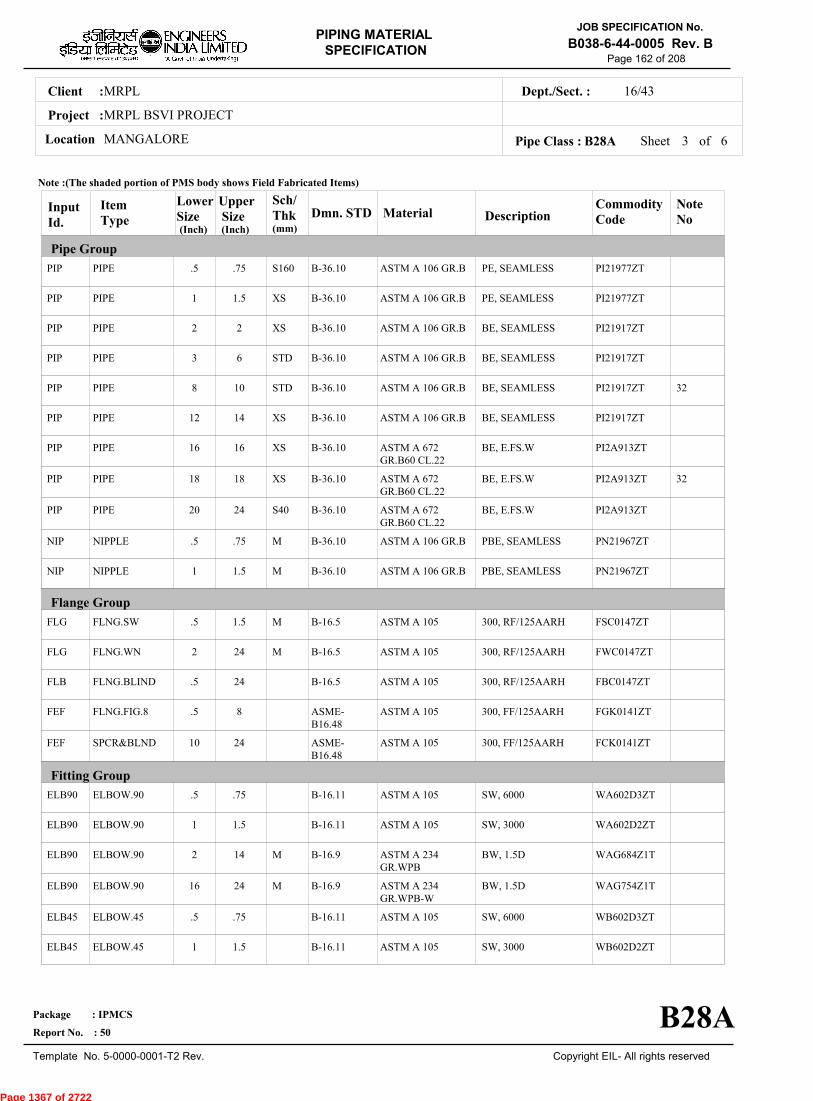
MRPLClient :
MRPL BSVI PROJECT
MANGALORELocation
16/43Dept./Sect. :
Project :
PIPING MATERIAL
SPECIFICATION
Copyright EIL- All rights reserved
JOB SPECIFICATION No.
B038-6-44-0005 Rev. B
Package : IPMCS
Report No. : 50
Template No. 5-0000-0001-T2 Rev.
Page 162 of 208
Sheet 3 ofPipe Class : B28A
InputId.
Item Type
LowerSize
Upper Size
Sch/Thk DescriptionMaterial
CommodityCode
NoteNo
Pipe Group
Flange Group
Fitting Group
Dmn. STD(Inch) (Inch)
PIP
PIP
PIP
PIP
PIP
PIP
PIP
PIP
PIP
NIP
NIP
FLG
FLG
FLB
FEF
FEF
ELB90
ELB90
ELB90
ELB90
ELB45
ELB45
PIPE
PIPE
PIPE
PIPE
PIPE
PIPE
PIPE
PIPE
PIPE
NIPPLE
NIPPLE
FLNG.SW
FLNG.WN
FLNG.BLIND
FLNG.FIG.8
SPCR&BLND
ELBOW.90
ELBOW.90
ELBOW.90
ELBOW.90
ELBOW.45
ELBOW.45
.5
1
2
3
8
12
16
18
20
.5
1
.5
2
.5
.5
10
.5
1
2
16
.5
1
.75
1.5
2
6
10
14
16
18
24
.75
1.5
1.5
24
24
8
24
.75
1.5
14
24
.75
1.5
S160
XS
XS
STD
STD
XS
XS
XS
S40
M
M
M
M
M
M
PE, SEAMLESS
PE, SEAMLESS
BE, SEAMLESS
BE, SEAMLESS
BE, SEAMLESS
BE, SEAMLESS
BE, E.FS.W
BE, E.FS.W
BE, E.FS.W
PBE, SEAMLESS
PBE, SEAMLESS
300, RF/125AARH
300, RF/125AARH
300, RF/125AARH
300, FF/125AARH
300, FF/125AARH
SW, 6000
SW, 3000
BW, 1.5D
BW, 1.5D
SW, 6000
SW, 3000
ASTM A 106 GR.B
ASTM A 106 GR.B
ASTM A 106 GR.B
ASTM A 106 GR.B
ASTM A 106 GR.B
ASTM A 106 GR.B
ASTM A 672GR.B60 CL.22
ASTM A 672GR.B60 CL.22
ASTM A 672GR.B60 CL.22
ASTM A 106 GR.B
ASTM A 106 GR.B
ASTM A 105
ASTM A 105
ASTM A 105
ASTM A 105
ASTM A 105
ASTM A 105
ASTM A 105
ASTM A 234GR.WPB
ASTM A 234GR.WPB-W
ASTM A 105
ASTM A 105
PI21977ZT
PI21977ZT
PI21917ZT
PI21917ZT
PI21917ZT
PI21917ZT
PI2A913ZT
PI2A913ZT
PI2A913ZT
PN21967ZT
PN21967ZT
FSC0147ZT
FWC0147ZT
FBC0147ZT
FGK0141ZT
FCK0141ZT
WA602D3ZT
WA602D2ZT
WAG684Z1T
WAG754Z1T
WB602D3ZT
WB602D2ZT
32
32
B-36.10
B-36.10
B-36.10
B-36.10
B-36.10
B-36.10
B-36.10
B-36.10
B-36.10
B-36.10
B-36.10
B-16.5
B-16.5
B-16.5
ASME-B16.48
ASME-B16.48
B-16.11
B-16.11
B-16.9
B-16.9
B-16.11
B-16.11
Note :(The shaded portion of PMS body shows Field Fabricated Items)
B28A
(mm)
6
Page 1367 of 2722
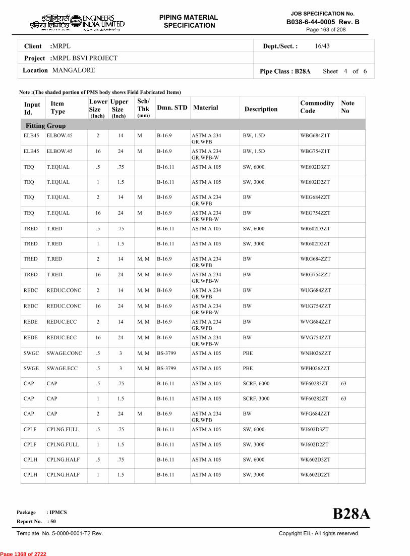
MRPLClient :
MRPL BSVI PROJECT
MANGALORELocation
16/43Dept./Sect. :
Project :
PIPING MATERIAL
SPECIFICATION
Copyright EIL- All rights reserved
JOB SPECIFICATION No.
B038-6-44-0005 Rev. B
Package : IPMCS
Report No. : 50
Template No. 5-0000-0001-T2 Rev.
Page 163 of 208
Sheet 4 ofPipe Class : B28A
InputId.
Item Type
LowerSize
Upper Size
Sch/Thk DescriptionMaterial
CommodityCode
NoteNo
Fitting Group
Dmn. STD(Inch) (Inch)
ELB45
ELB45
TEQ
TEQ
TEQ
TEQ
TRED
TRED
TRED
TRED
REDC
REDC
REDE
REDE
SWGC
SWGE
CAP
CAP
CAP
CPLF
CPLF
CPLH
CPLH
ELBOW.45
ELBOW.45
T.EQUAL
T.EQUAL
T.EQUAL
T.EQUAL
T.RED
T.RED
T.RED
T.RED
REDUC.CONC
REDUC.CONC
REDUC.ECC
REDUC.ECC
SWAGE.CONC
SWAGE.ECC
CAP
CAP
CAP
CPLNG.FULL
CPLNG.FULL
CPLNG.HALF
CPLNG.HALF
2
16
.5
1
2
16
.5
1
2
16
2
16
2
16
.5
.5
.5
1
2
.5
1
.5
1
14
24
.75
1.5
14
24
.75
1.5
14
24
14
24
14
24
3
3
.75
1.5
24
.75
1.5
.75
1.5
M
M
M
M
M, M
M, M
M, M
M, M
M, M
M, M
M, M
M, M
M
BW, 1.5D
BW, 1.5D
SW, 6000
SW, 3000
BW
BW
SW, 6000
SW, 3000
BW
BW
BW
BW
BW
BW
PBE
PBE
SCRF, 6000
SCRF, 3000
BW
SW, 6000
SW, 3000
SW, 6000
SW, 3000
ASTM A 234GR.WPB
ASTM A 234GR.WPB-W
ASTM A 105
ASTM A 105
ASTM A 234GR.WPB
ASTM A 234GR.WPB-W
ASTM A 105
ASTM A 105
ASTM A 234GR.WPB
ASTM A 234GR.WPB-W
ASTM A 234GR.WPB
ASTM A 234GR.WPB-W
ASTM A 234GR.WPB
ASTM A 234GR.WPB-W
ASTM A 105
ASTM A 105
ASTM A 105
ASTM A 105
ASTM A 234GR.WPB
ASTM A 105
ASTM A 105
ASTM A 105
ASTM A 105
WBG684Z1T
WBG754Z1T
WE602D3ZT
WE602D2ZT
WEG684ZZT
WEG754ZZT
WR602D3ZT
WR602D2ZT
WRG684ZZT
WRG754ZZT
WUG684ZZT
WUG754ZZT
WVG684ZZT
WVG754ZZT
WNH026ZZT
WPH026ZZT
WF60283ZT
WF60282ZT
WFG684ZZT
WJ602D3ZT
WJ602D2ZT
WK602D3ZT
WK602D2ZT
63
63
B-16.9
B-16.9
B-16.11
B-16.11
B-16.9
B-16.9
B-16.11
B-16.11
B-16.9
B-16.9
B-16.9
B-16.9
B-16.9
B-16.9
BS-3799
BS-3799
B-16.11
B-16.11
B-16.9
B-16.11
B-16.11
B-16.11
B-16.11
Note :(The shaded portion of PMS body shows Field Fabricated Items)
B28A
(mm)
6
Page 1368 of 2722

MRPLClient :
MRPL BSVI PROJECT
MANGALORELocation
16/43Dept./Sect. :
Project :
PIPING MATERIAL
SPECIFICATION
Copyright EIL- All rights reserved
JOB SPECIFICATION No.
B038-6-44-0005 Rev. B
Package : IPMCS
Report No. : 50
Template No. 5-0000-0001-T2 Rev.
Page 164 of 208
Sheet 5 ofPipe Class : B28A
InputId.
Item Type
LowerSize
Upper Size
Sch/Thk DescriptionMaterial
CommodityCode
NoteNo
Fitting Group
Valves Group
Bolt Group
Gasket Group
Trap/Strainer Group
Dmn. STD(Inch) (Inch)
CPLL
CPLL
CPLR
CPLR
GAV
GAV
GLV
GLV
CHV
CHV
PLV
BOS
GAS
TSR
PSR
PSR
CPLNG.LH
CPLNG.LH
CPLNG.RED
CPLNG.RED
VLV.GATE
VLV.GATE
VLV.GLOBE
VLV.GLOBE
VLV.CHECK
VLV.CHECK
VLV.PLUG
BOLT.STUD
GASKET
STRNR.TEMP
STRNR.PERM
STRNR.PERM
.5
1
.5
1
.5
2
.5
2
.5
2
.5
.5
.5
1.5
.5
2
.75
1.5
.75
1.5
1.5
24
1.5
12
1.5
24
24
24
24
24
1.5
14 M
SW, 6000
SW, 3000
SW, 6000
SW, 3000
SW, 800, 3000, B-16.11, SHT NO.- 51011
FLGD, 300, B-16.5,RF/125AARH, SHTNO.- 51411
SW, 800, 3000, B-16.11, SHT NO.- 52011
FLGD, 300, B-16.5,RF/125AARH, SHTNO.- 52411
SW, 800, 3000, B-16.11, SHT NO.- 53011
FLGD, 300, B-16.5,RF/125AARH, SHTNO.- 53411
FLGD, 300, B-16.5,RF/125AARH, SHTNO.- 55411
SPIRAL, 300
CONETYPE,300,FF/125AARH
SW, Y-TYPE, 800
BW, T-TYPE
ASTM A 105
ASTM A 105
ASTM A 105
ASTM A 105
BODY-ASTM A105,TRIM-STELLITED,STEM-SS 316L
BODY-ASTM A 216GR.WCB,TRIM-SS316L
BODY-ASTM A105,TRIM-STELLITED,STEM-SS 316L
BODY-ASTM A 216GR.WCB,TRIM-SS316L
BODY-ASTM A105,TRIM-STELLITED
BODY-ASTM A 216GR.WCB,TRIM-SS316L
BODY-ASTM A 105/ A216GR.WCB,TRIM-PLUG-HARDENED
BOLT:A193 GR.B7,NUT:A194 GR.2H
SP.WNDSS316+GRAFIL+ IRING
B:A516GR.70(NORM);INT:SS304
B:A105;INT:SS304
B:A234GR.WPB;INT:SS304
WL602D3ZT
WL602D2ZT
WM602D3ZT
WM602D2ZT
51011ZZZT
51411ZZZT
52011ZZZT
52411ZZZT
53011ZZZT
53411ZZZT
55411ZZZT
BS40404ZT
GK66274ZT
ST17539ZT
SP303D51T
SP13344ZT
B-16.11
B-16.11
B-16.11
B-16.11
API 602/ ISO15761
API 600/ ISO10434
BS EN ISO15761
BS-1873
BS EN ISO15761
BS-1868
BS-5353
B-18.2
B-16.20-ANSI B16.5
EIL'STD
MNF'STD
EIL'STD
Note :(The shaded portion of PMS body shows Field Fabricated Items)
B28A
(mm)
6
Page 1369 of 2722

MRPLClient :
MRPL BSVI PROJECT
MANGALORELocation
16/43Dept./Sect. :
Project :
PIPING MATERIAL
SPECIFICATION
Copyright EIL- All rights reserved
JOB SPECIFICATION No.
B038-6-44-0005 Rev. B
Package : IPMCS
Report No. : 50
Template No. 5-0000-0001-T2 Rev.
Page 165 of 208
Sheet 6 of 6Pipe Class : B28A
InputId.
Item Type
LowerSize
Upper Size
Sch/Thk DescriptionMaterial
CommodityCode
NoteNo
Trap/Strainer Group
Dmn. STD(Inch) (Inch)
PSR STRNR.PERM 16 24 M BW, T-TYPEB:A234GR.WPBW;INT:SS304
SP13644ZTEIL'STD
Note :(The shaded portion of PMS body shows Field Fabricated Items)
B28A
(mm)
Page 1370 of 2722

MRPLClient :
MRPL BSVI PROJECT
MANGALORELocation
16/43Dept./Sect. :
Project :
PIPING MATERIAL
SPECIFICATION
Copyright EIL- All rights reserved
JOB SPECIFICATION No.
B038-6-44-0005 Rev. B
Package : IPMCS
Report No. : 50
Template No. 5-0000-0001-T2 Rev.
Page 166 of 208
B2APIPE CLASS :300RATING :CARBON STEELBASE MATERIAL : 1.5CORROSION ALLOWANCE :IBR SERVICESPECIAL REQUIREMENT :
MM
SERVICESTEAM, BOILER FEED WATER & CONDENSATE - ALL IBR
NOTES3
5
8
9
32
63
151
USE PIPE OF CLASS 22 INSTEAD OF CLASS 12 IF PIPE THICKNESS EXCEEDS 20.00 MM.
FOR PERMANENT 'T' TYPE BW STRAINERS,REFER EIL'STD 7-44-0303 & 7-44-0304; AND FOR TEMPORARYSTRAINERS,REFER EIL'STD 7-44-0300; FOR SPACER AND BLIND REFER EIL'STD 7-44-0162.ALL PIPES,FITTINGS,VALVES,FLANGES,TRAPS AND STRAINERS SHALL BE TESTED AND TEST CERTIFICATE IN FORMIII A FOR PIPE AND FORM III C FOR OTHERS SHALL BE REQD. DULY COUNTERSIGNED BY IBR AUTHORITY OR ITSAPPROVED REPRESENTATIVE.CARBON CONTENT SHALL NOT EXCEED 0.25% FOR ALL PIPES,FITTINGS FLANGES ETC. THAT MAY REQUIREWELDING. MOREOVER,FOR FLANGES THE SULPHUR AND PHOSPHOROUS SHALL ALSO BE LIMITED TO 0.05% EACH.CORROSION ALLOWANCE HAS BEEN ADJUSTED TO SELECT OPTIMUM SCHEDULE. REFER GENERAL NOTES TO PMS.
THIS ITEM IS INTENDED SOLELY FOR USE BY INSTRUMENTATION.
NDT REQUIREMENT SHALL BE AS PER JOB SPECIFICATION B038-6-44-0016.
SPECIAL NOTES
ITEM SIZE DESCRIPTION A.CODEMAINTAINENCEJOINTS
PIPE JOINTS
DRAINS
VENTS
TEMP.CONN
PRESS.CONN
ALL
1.5" & BELOW
2.0" & ABOVE
ON LINES <= 1.5"
ON LINES >= 2.0"
ON LINES <= 1.5"
ON LINES >= 2.0"
1.5"
0.75"
FLANGED, TO BE KEPT MINIMUM
SW COUPLING
BUTTWELDED
REFER EILSTD 7-44-0350, DF3
AS PER P&ID OR 0.75". REFER EIL STD. 7-44-0351, D4
REFER EIL STD. 7-44-0350, VF3
AS PER P&ID OR 0.75". REFER EIL STD 7-44-0351, V4
FLANGED. REFER EIL STD 7-44-0353
SW NIPPLE WITH VALVE TO SPEC AS PER EIL STD 7-44-0354
TEMP
PRESS 52.02 52.02 47.8 46.05 44.64 42.53 40.07 38.66 37.26 35.5 28.82
0 38 93 149 204 260 316 343 371 399 427
Sheet 1 of
TEMPERATURE (Deg. C) AND PRESSURE ( Kg/Sq. cm g ) RATINGS
Pipe Class : B2A
B2A
6
Page 1371 of 2722
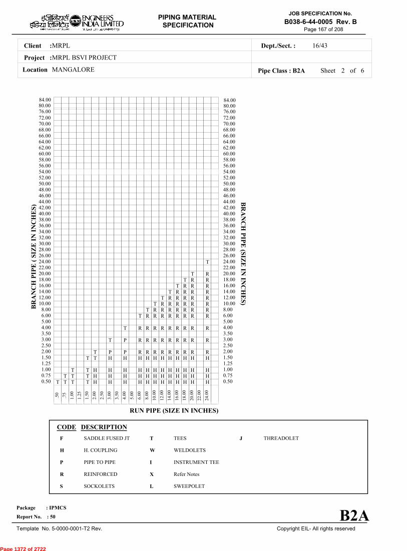
MRPLClient :
MRPL BSVI PROJECT
MANGALORELocation
16/43Dept./Sect. :
Project :
PIPING MATERIAL
SPECIFICATION
Copyright EIL- All rights reserved
JOB SPECIFICATION No.
B038-6-44-0005 Rev. B
Package : IPMCS
Report No. : 50
Template No. 5-0000-0001-T2 Rev.
Page 167 of 208
Sheet 2 ofPipe Class : B2A
T T T T H H H H H H H H H H H H0.50T T T H H H H H H H H H H H H0.75
T T H H H H H H H H H H H H1.001.25
T T H H H H H H H H H H H1.50T P P R R R R R R R R R2.00
2.50T P R R R R R R R R R3.00
3.50T R R R R R R R R R4.00
5.00T R R R R R R R R6.00
T R R R R R R R8.00T R R R R R R10.00
T R R R R R12.00T R R R R14.00
T R R R16.00T R R18.00
T R20.0022.00
T24.0026.0028.0030.0032.0034.0036.0038.0040.0042.0044.0046.0048.0050.0052.0054.0056.0058.0060.0062.0064.0066.0068.0070.0072.00
.
50
.
75
1
.00
1
.25
1
.50
2
.00
2
.50
3
.00
3
.50
4
.00
5
.00
6
.00
8
.00
10
.00
12
.00
14
.00
16
.00
18
.00
20
.00
22
.00
24
.00
BR
AN
CH
PIP
E (
SIZ
E I
N I
NC
HE
S)
0.500.751.001.251.502.002.503.003.504.005.006.008.0010.0012.0014.0016.0018.0020.0022.0024.0026.0028.0030.0032.0034.0036.0038.0040.0042.0044.0046.0048.0050.0052.0054.0056.0058.0060.0062.0064.0066.0068.0070.0072.00
BR
AN
CH
PIP
E (SIZ
E IN
INC
HE
S)
RUN PIPE (SIZE IN INCHES)
CODE DESCRIPTION
F
H
P
R
S
T
W
I
X
L
JSADDLE FUSED JT
H. COUPLING
PIPE TO PIPE
REINFORCED
SOCKOLETS
TEES
WELDOLETS
INSTRUMENT TEE
Refer Notes
SWEEPOLET
THREADOLET
B2A
76.0080.0084.00
76.0080.0084.00
6
Page 1372 of 2722
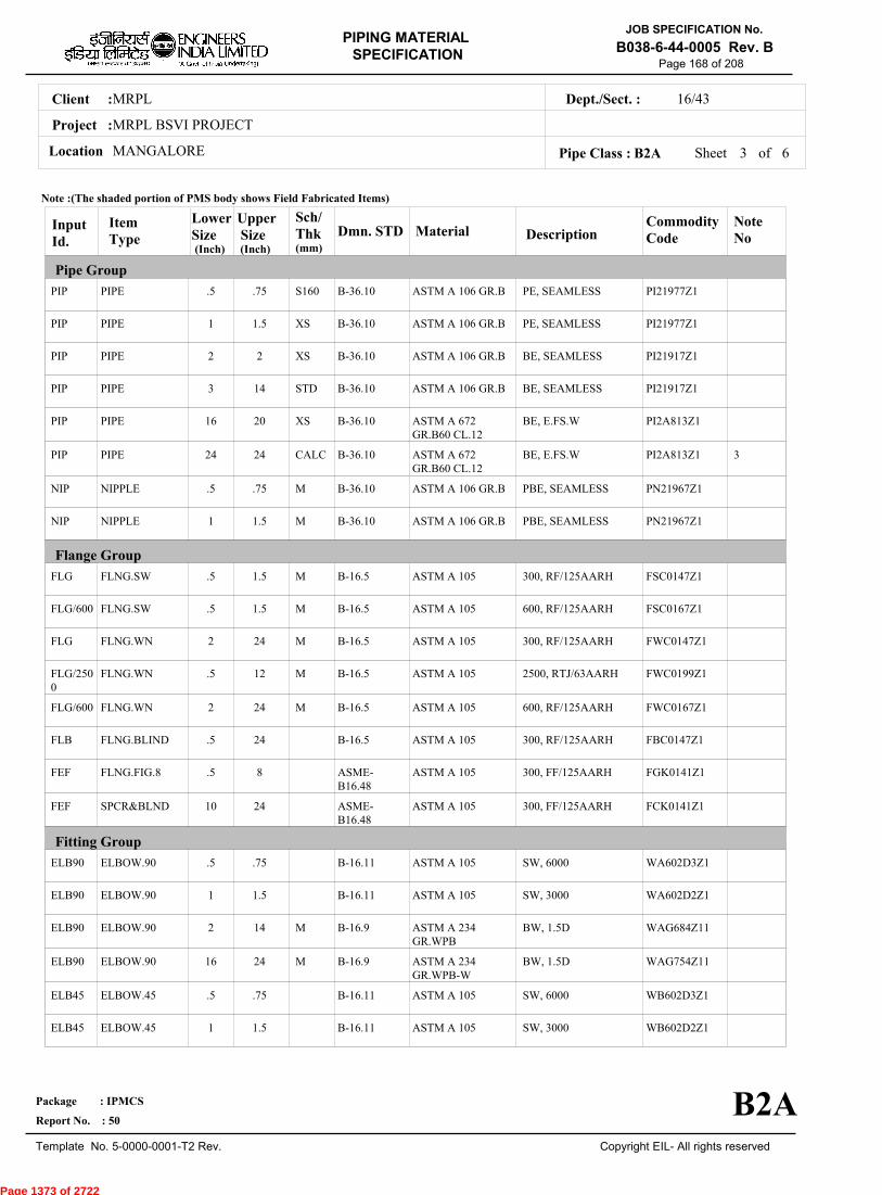
MRPLClient :
MRPL BSVI PROJECT
MANGALORELocation
16/43Dept./Sect. :
Project :
PIPING MATERIAL
SPECIFICATION
Copyright EIL- All rights reserved
JOB SPECIFICATION No.
B038-6-44-0005 Rev. B
Package : IPMCS
Report No. : 50
Template No. 5-0000-0001-T2 Rev.
Page 168 of 208
Sheet 3 ofPipe Class : B2A
InputId.
Item Type
LowerSize
Upper Size
Sch/Thk DescriptionMaterial
CommodityCode
NoteNo
Pipe Group
Flange Group
Fitting Group
Dmn. STD(Inch) (Inch)
PIP
PIP
PIP
PIP
PIP
PIP
NIP
NIP
FLG
FLG/600
FLG
FLG/2500
FLG/600
FLB
FEF
FEF
ELB90
ELB90
ELB90
ELB90
ELB45
ELB45
PIPE
PIPE
PIPE
PIPE
PIPE
PIPE
NIPPLE
NIPPLE
FLNG.SW
FLNG.SW
FLNG.WN
FLNG.WN
FLNG.WN
FLNG.BLIND
FLNG.FIG.8
SPCR&BLND
ELBOW.90
ELBOW.90
ELBOW.90
ELBOW.90
ELBOW.45
ELBOW.45
.5
1
2
3
16
24
.5
1
.5
.5
2
.5
2
.5
.5
10
.5
1
2
16
.5
1
.75
1.5
2
14
20
24
.75
1.5
1.5
1.5
24
12
24
24
8
24
.75
1.5
14
24
.75
1.5
S160
XS
XS
STD
XS
CALC
M
M
M
M
M
M
M
M
M
PE, SEAMLESS
PE, SEAMLESS
BE, SEAMLESS
BE, SEAMLESS
BE, E.FS.W
BE, E.FS.W
PBE, SEAMLESS
PBE, SEAMLESS
300, RF/125AARH
600, RF/125AARH
300, RF/125AARH
2500, RTJ/63AARH
600, RF/125AARH
300, RF/125AARH
300, FF/125AARH
300, FF/125AARH
SW, 6000
SW, 3000
BW, 1.5D
BW, 1.5D
SW, 6000
SW, 3000
ASTM A 106 GR.B
ASTM A 106 GR.B
ASTM A 106 GR.B
ASTM A 106 GR.B
ASTM A 672GR.B60 CL.12
ASTM A 672GR.B60 CL.12
ASTM A 106 GR.B
ASTM A 106 GR.B
ASTM A 105
ASTM A 105
ASTM A 105
ASTM A 105
ASTM A 105
ASTM A 105
ASTM A 105
ASTM A 105
ASTM A 105
ASTM A 105
ASTM A 234GR.WPB
ASTM A 234GR.WPB-W
ASTM A 105
ASTM A 105
PI21977Z1
PI21977Z1
PI21917Z1
PI21917Z1
PI2A813Z1
PI2A813Z1
PN21967Z1
PN21967Z1
FSC0147Z1
FSC0167Z1
FWC0147Z1
FWC0199Z1
FWC0167Z1
FBC0147Z1
FGK0141Z1
FCK0141Z1
WA602D3Z1
WA602D2Z1
WAG684Z11
WAG754Z11
WB602D3Z1
WB602D2Z1
3
B-36.10
B-36.10
B-36.10
B-36.10
B-36.10
B-36.10
B-36.10
B-36.10
B-16.5
B-16.5
B-16.5
B-16.5
B-16.5
B-16.5
ASME-B16.48
ASME-B16.48
B-16.11
B-16.11
B-16.9
B-16.9
B-16.11
B-16.11
Note :(The shaded portion of PMS body shows Field Fabricated Items)
B2A
(mm)
6
Page 1373 of 2722
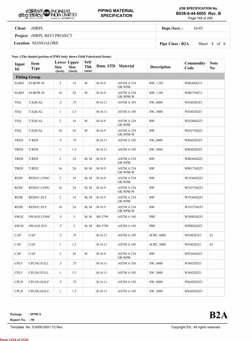
MRPLClient :
MRPL BSVI PROJECT
MANGALORELocation
16/43Dept./Sect. :
Project :
PIPING MATERIAL
SPECIFICATION
Copyright EIL- All rights reserved
JOB SPECIFICATION No.
B038-6-44-0005 Rev. B
Package : IPMCS
Report No. : 50
Template No. 5-0000-0001-T2 Rev.
Page 169 of 208
Sheet 4 ofPipe Class : B2A
InputId.
Item Type
LowerSize
Upper Size
Sch/Thk DescriptionMaterial
CommodityCode
NoteNo
Fitting Group
Dmn. STD(Inch) (Inch)
ELB45
ELB45
TEQ
TEQ
TEQ
TEQ
TRED
TRED
TRED
TRED
REDC
REDC
REDE
REDE
SWGC
SWGE
CAP
CAP
CAP
CPLF
CPLF
CPLH
CPLH
ELBOW.45
ELBOW.45
T.EQUAL
T.EQUAL
T.EQUAL
T.EQUAL
T.RED
T.RED
T.RED
T.RED
REDUC.CONC
REDUC.CONC
REDUC.ECC
REDUC.ECC
SWAGE.CONC
SWAGE.ECC
CAP
CAP
CAP
CPLNG.FULL
CPLNG.FULL
CPLNG.HALF
CPLNG.HALF
2
16
.5
1
2
16
.5
1
2
16
2
16
2
16
.5
.5
.5
1
2
.5
1
.5
1
14
24
.75
1.5
14
24
.75
1.5
14
24
14
24
14
24
3
3
.75
1.5
24
.75
1.5
.75
1.5
M
M
M
M
M, M
M, M
M, M
M, M
M, M
M, M
M, M
M, M
M
BW, 1.5D
BW, 1.5D
SW, 6000
SW, 3000
BW
BW
SW, 6000
SW, 3000
BW
BW
BW
BW
BW
BW
PBE
PBE
SCRF, 6000
SCRF, 3000
BW
SW, 6000
SW, 3000
SW, 6000
SW, 3000
ASTM A 234GR.WPB
ASTM A 234GR.WPB-W
ASTM A 105
ASTM A 105
ASTM A 234GR.WPB
ASTM A 234GR.WPB-W
ASTM A 105
ASTM A 105
ASTM A 234GR.WPB
ASTM A 234GR.WPB-W
ASTM A 234GR.WPB
ASTM A 234GR.WPB-W
ASTM A 234GR.WPB
ASTM A 234GR.WPB-W
ASTM A 105
ASTM A 105
ASTM A 105
ASTM A 105
ASTM A 234GR.WPB
ASTM A 105
ASTM A 105
ASTM A 105
ASTM A 105
WBG684Z11
WBG754Z11
WE602D3Z1
WE602D2Z1
WEG684ZZ1
WEG754ZZ1
WR602D3Z1
WR602D2Z1
WRG684ZZ1
WRG754ZZ1
WUG684ZZ1
WUG754ZZ1
WVG684ZZ1
WVG754ZZ1
WNH026ZZ1
WPH026ZZ1
WF60283Z1
WF60282Z1
WFG684ZZ1
WJ602D3Z1
WJ602D2Z1
WK602D3Z1
WK602D2Z1
63
63
B-16.9
B-16.9
B-16.11
B-16.11
B-16.9
B-16.9
B-16.11
B-16.11
B-16.9
B-16.9
B-16.9
B-16.9
B-16.9
B-16.9
BS-3799
BS-3799
B-16.11
B-16.11
B-16.9
B-16.11
B-16.11
B-16.11
B-16.11
Note :(The shaded portion of PMS body shows Field Fabricated Items)
B2A
(mm)
6
Page 1374 of 2722

MRPLClient :
MRPL BSVI PROJECT
MANGALORELocation
16/43Dept./Sect. :
Project :
PIPING MATERIAL
SPECIFICATION
Copyright EIL- All rights reserved
JOB SPECIFICATION No.
B038-6-44-0005 Rev. B
Package : IPMCS
Report No. : 50
Template No. 5-0000-0001-T2 Rev.
Page 170 of 208
Sheet 5 ofPipe Class : B2A
InputId.
Item Type
LowerSize
Upper Size
Sch/Thk DescriptionMaterial
CommodityCode
NoteNo
Fitting Group
Valves Group
Bolt Group
Gasket Group
Trap/Strainer Group
Dmn. STD(Inch) (Inch)
CPLL
CPLL
CPLR
CPLR
GAV
GAV
GLV
GLV
CHV
CHV
G3V
BOS
GAS
GAS/2500
GAS/600
TRP
CPLNG.LH
CPLNG.LH
CPLNG.RED
CPLNG.RED
VLV.GATE
VLV.GATE
VLV.GLOBE
VLV.GLOBE
VLV.CHECK
VLV.CHECK
VLV.PISTON
BOLT.STUD
GASKET
GASKET
GASKET
TRAP.STEAM
.5
1
.5
1
.5
2
.5
2
.5
2
.5
.5
.5
.5
.5
.5
.75
1.5
.75
1.5
1.5
24
1.5
12
1.5
24
1
24
24
12
24
1.5
SW, 6000
SW, 3000
SW, 6000
SW, 3000
SW, 800, 3000, B-16.11, SHT NO.- 51002
FLGD, 300, B-16.5,RF/125AARH, SHTNO.- 51402
SW, 800, 3000, B-16.11, SHT NO.- 52002
FLGD, 300, B-16.5,RF/125AARH, SHTNO.- 52402
SW, 800, 3000, B-16.11, SHT NO.- 53002
FLGD, 300, B-16.5,RF/125AARH, SHTNO.- 53402
SW, 300, 3000, B-16.11, SHT NO.- 64402
SPIRAL, 300
OCT-RING, 2500
SPIRAL, 600
FLGD, THRMDNMC,300,RF/125AARH
ASTM A 105
ASTM A 105
ASTM A 105
ASTM A 105
BODY-ASTM A105,TRIM-STELLITED,STEM-13%CR STEEL
BODY-ASTM A 216GR.WCB,TRIM-13% CR STEEL
BODY-ASTM A105,TRIM-STELLITED,STEM-13%CR.STEEL
BODY-ASTM A 216GR.WCB,TRIM-13% CR STEEL
BODY-ASTM A105,TRIM-STELLITED
BODY-ASTM A 216GR.WCB,TRIM-13% CR STEEL
BODY-ASTM A 216GR.WCB,TRIM-13% CR.STEEL
BOLT:A193 GR.B7,NUT:A194 GR.2H
SP.WNDSS316+GRAFIL+ IRING
SOFT IRON
SP.WNDSS316+GRAFIL+ IRING
B:A105;T:13%CR;S:SS304
WL602D3Z1
WL602D2Z1
WM602D3Z1
WM602D2Z1
51002ZZZ1
51402ZZZ1
52002ZZZ1
52402ZZZ1
53002ZZZ1
53402ZZZ1
64402ZZZ1
BS40404Z0
GK66274Z0
GK67239Z0
GK66276Z0
TR30655B1
B-16.11
B-16.11
B-16.11
B-16.11
API 602/ ISO15761
API 600/ ISO10434
BS EN ISO15761
BS-1873
BS EN ISO15761
BS-1868
MNF'STD
B-18.2
B-16.20-ANSI B16.5
B-16.20-ANSI B16.5
B-16.20-ANSI B16.5
MNF'STD
Note :(The shaded portion of PMS body shows Field Fabricated Items)
B2A
(mm)
6
Page 1375 of 2722

MRPLClient :
MRPL BSVI PROJECT
MANGALORELocation
16/43Dept./Sect. :
Project :
PIPING MATERIAL
SPECIFICATION
Copyright EIL- All rights reserved
JOB SPECIFICATION No.
B038-6-44-0005 Rev. B
Package : IPMCS
Report No. : 50
Template No. 5-0000-0001-T2 Rev.
Page 171 of 208
Sheet 6 of 6Pipe Class : B2A
InputId.
Item Type
LowerSize
Upper Size
Sch/Thk DescriptionMaterial
CommodityCode
NoteNo
Trap/Strainer Group
Dmn. STD(Inch) (Inch)
TSR
PSR
PSR
STRNR.TEMP
STRNR.PERM
STRNR.PERM
1.5
.5
2
24
1.5
24
CONETYPE,300,FF/125AARH
SW, Y-TYPE, 800
FLGD, Y-TYPE,300,RF/125AARH
B:A516GR.70;INT:SS304
B:A105;INT:SS304
B:A216GR.WCB;INT:SS304
ST16839Z1
SP303D511
SP38055B1
EIL'STD
MNF'STD
MNF'STD
Note :(The shaded portion of PMS body shows Field Fabricated Items)
B2A
(mm)
Page 1376 of 2722
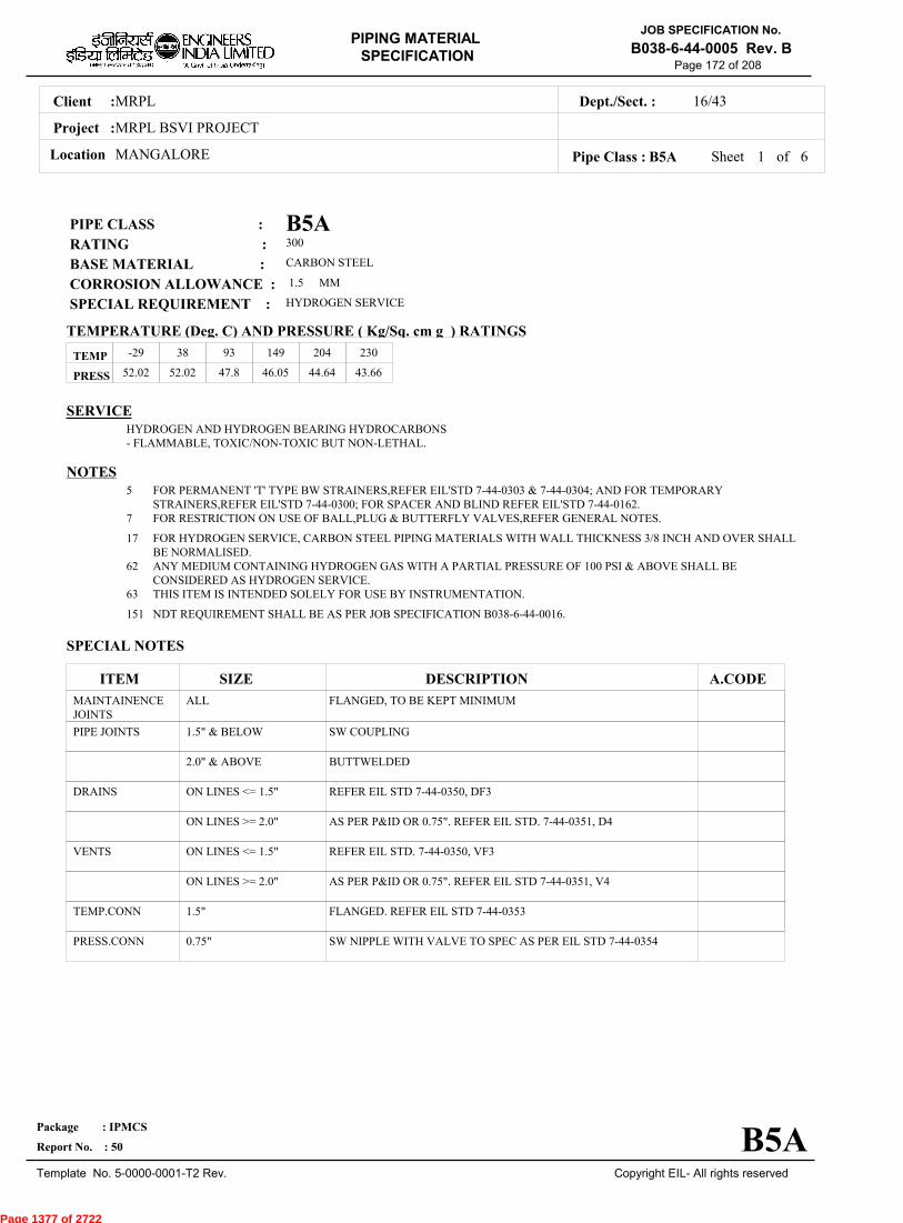
MRPLClient :
MRPL BSVI PROJECT
MANGALORELocation
16/43Dept./Sect. :
Project :
PIPING MATERIAL
SPECIFICATION
Copyright EIL- All rights reserved
JOB SPECIFICATION No.
B038-6-44-0005 Rev. B
Package : IPMCS
Report No. : 50
Template No. 5-0000-0001-T2 Rev.
Page 172 of 208
B5APIPE CLASS :300RATING :CARBON STEELBASE MATERIAL : 1.5CORROSION ALLOWANCE :HYDROGEN SERVICESPECIAL REQUIREMENT :
MM
SERVICEHYDROGEN AND HYDROGEN BEARING HYDROCARBONS- FLAMMABLE, TOXIC/NON-TOXIC BUT NON-LETHAL.
NOTES5
7
17
62
63
151
FOR PERMANENT 'T' TYPE BW STRAINERS,REFER EIL'STD 7-44-0303 & 7-44-0304; AND FOR TEMPORARYSTRAINERS,REFER EIL'STD 7-44-0300; FOR SPACER AND BLIND REFER EIL'STD 7-44-0162.FOR RESTRICTION ON USE OF BALL,PLUG & BUTTERFLY VALVES,REFER GENERAL NOTES.
FOR HYDROGEN SERVICE, CARBON STEEL PIPING MATERIALS WITH WALL THICKNESS 3/8 INCH AND OVER SHALLBE NORMALISED.ANY MEDIUM CONTAINING HYDROGEN GAS WITH A PARTIAL PRESSURE OF 100 PSI & ABOVE SHALL BECONSIDERED AS HYDROGEN SERVICE.THIS ITEM IS INTENDED SOLELY FOR USE BY INSTRUMENTATION.
NDT REQUIREMENT SHALL BE AS PER JOB SPECIFICATION B038-6-44-0016.
SPECIAL NOTES
ITEM SIZE DESCRIPTION A.CODEMAINTAINENCEJOINTS
PIPE JOINTS
DRAINS
VENTS
TEMP.CONN
PRESS.CONN
ALL
1.5" & BELOW
2.0" & ABOVE
ON LINES <= 1.5"
ON LINES >= 2.0"
ON LINES <= 1.5"
ON LINES >= 2.0"
1.5"
0.75"
FLANGED, TO BE KEPT MINIMUM
SW COUPLING
BUTTWELDED
REFER EIL STD 7-44-0350, DF3
AS PER P&ID OR 0.75". REFER EIL STD. 7-44-0351, D4
REFER EIL STD. 7-44-0350, VF3
AS PER P&ID OR 0.75". REFER EIL STD 7-44-0351, V4
FLANGED. REFER EIL STD 7-44-0353
SW NIPPLE WITH VALVE TO SPEC AS PER EIL STD 7-44-0354
TEMP
PRESS 52.02 52.02 47.8 46.05 44.64 43.66
-29 38 93 149 204 230
Sheet 1 of
TEMPERATURE (Deg. C) AND PRESSURE ( Kg/Sq. cm g ) RATINGS
Pipe Class : B5A
B5A
6
Page 1377 of 2722

MRPLClient :
MRPL BSVI PROJECT
MANGALORELocation
16/43Dept./Sect. :
Project :
PIPING MATERIAL
SPECIFICATION
Copyright EIL- All rights reserved
JOB SPECIFICATION No.
B038-6-44-0005 Rev. B
Package : IPMCS
Report No. : 50
Template No. 5-0000-0001-T2 Rev.
Page 173 of 208
Sheet 2 ofPipe Class : B5A
T T T T H H H H H H H H H H H0.50T T T H H H H H H H H H H H0.75
T T H H H H H H H H H H H1.001.25
T T H H H H H H H H H H1.50T P P R R R R R R R R2.00
2.50T P R R R R R R R R3.00
3.50T R R R R R R R R4.00
5.00T R R R R R R R6.00
T R R R R R R8.00T R R R R R10.00
T R R R R12.00T R R R14.00
T R R16.00T R18.00
T20.0022.0024.0026.0028.0030.0032.0034.0036.0038.0040.0042.0044.0046.0048.0050.0052.0054.0056.0058.0060.0062.0064.0066.0068.0070.0072.00
.
50
.
75
1
.00
1
.25
1
.50
2
.00
2
.50
3
.00
3
.50
4
.00
5
.00
6
.00
8
.00
10
.00
12
.00
14
.00
16
.00
18
.00
20
.00
BR
AN
CH
PIP
E (
SIZ
E I
N I
NC
HE
S)
0.500.751.001.251.502.002.503.003.504.005.006.008.0010.0012.0014.0016.0018.0020.0022.0024.0026.0028.0030.0032.0034.0036.0038.0040.0042.0044.0046.0048.0050.0052.0054.0056.0058.0060.0062.0064.0066.0068.0070.0072.00
BR
AN
CH
PIP
E (SIZ
E IN
INC
HE
S)
RUN PIPE (SIZE IN INCHES)
CODE DESCRIPTION
F
H
P
R
S
T
W
I
X
L
JSADDLE FUSED JT
H. COUPLING
PIPE TO PIPE
REINFORCED
SOCKOLETS
TEES
WELDOLETS
INSTRUMENT TEE
Refer Notes
SWEEPOLET
THREADOLET
B5A
76.0080.0084.00
76.0080.0084.00
6
Page 1378 of 2722
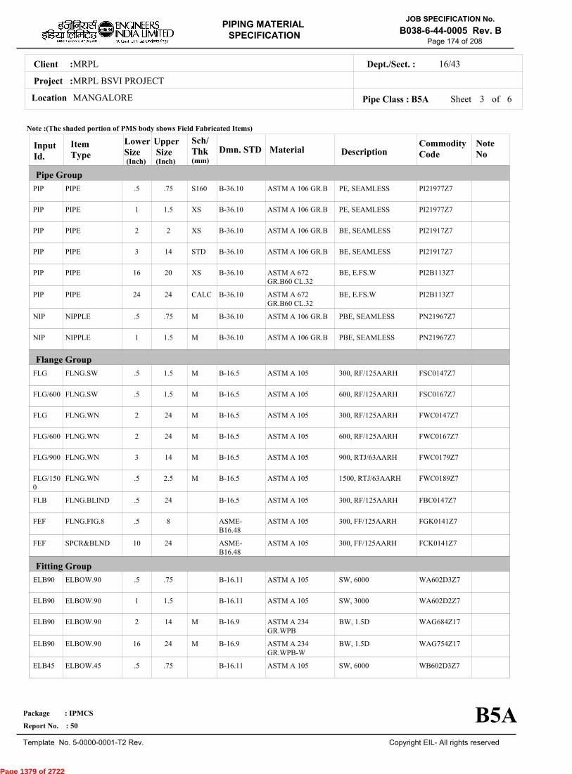
MRPLClient :
MRPL BSVI PROJECT
MANGALORELocation
16/43Dept./Sect. :
Project :
PIPING MATERIAL
SPECIFICATION
Copyright EIL- All rights reserved
JOB SPECIFICATION No.
B038-6-44-0005 Rev. B
Package : IPMCS
Report No. : 50
Template No. 5-0000-0001-T2 Rev.
Page 174 of 208
Sheet 3 ofPipe Class : B5A
InputId.
Item Type
LowerSize
Upper Size
Sch/Thk DescriptionMaterial
CommodityCode
NoteNo
Pipe Group
Flange Group
Fitting Group
Dmn. STD(Inch) (Inch)
PIP
PIP
PIP
PIP
PIP
PIP
NIP
NIP
FLG
FLG/600
FLG
FLG/600
FLG/900
FLG/1500
FLB
FEF
FEF
ELB90
ELB90
ELB90
ELB90
ELB45
PIPE
PIPE
PIPE
PIPE
PIPE
PIPE
NIPPLE
NIPPLE
FLNG.SW
FLNG.SW
FLNG.WN
FLNG.WN
FLNG.WN
FLNG.WN
FLNG.BLIND
FLNG.FIG.8
SPCR&BLND
ELBOW.90
ELBOW.90
ELBOW.90
ELBOW.90
ELBOW.45
.5
1
2
3
16
24
.5
1
.5
.5
2
2
3
.5
.5
.5
10
.5
1
2
16
.5
.75
1.5
2
14
20
24
.75
1.5
1.5
1.5
24
24
14
2.5
24
8
24
.75
1.5
14
24
.75
S160
XS
XS
STD
XS
CALC
M
M
M
M
M
M
M
M
M
M
PE, SEAMLESS
PE, SEAMLESS
BE, SEAMLESS
BE, SEAMLESS
BE, E.FS.W
BE, E.FS.W
PBE, SEAMLESS
PBE, SEAMLESS
300, RF/125AARH
600, RF/125AARH
300, RF/125AARH
600, RF/125AARH
900, RTJ/63AARH
1500, RTJ/63AARH
300, RF/125AARH
300, FF/125AARH
300, FF/125AARH
SW, 6000
SW, 3000
BW, 1.5D
BW, 1.5D
SW, 6000
ASTM A 106 GR.B
ASTM A 106 GR.B
ASTM A 106 GR.B
ASTM A 106 GR.B
ASTM A 672GR.B60 CL.32
ASTM A 672GR.B60 CL.32
ASTM A 106 GR.B
ASTM A 106 GR.B
ASTM A 105
ASTM A 105
ASTM A 105
ASTM A 105
ASTM A 105
ASTM A 105
ASTM A 105
ASTM A 105
ASTM A 105
ASTM A 105
ASTM A 105
ASTM A 234GR.WPB
ASTM A 234GR.WPB-W
ASTM A 105
PI21977Z7
PI21977Z7
PI21917Z7
PI21917Z7
PI2B113Z7
PI2B113Z7
PN21967Z7
PN21967Z7
FSC0147Z7
FSC0167Z7
FWC0147Z7
FWC0167Z7
FWC0179Z7
FWC0189Z7
FBC0147Z7
FGK0141Z7
FCK0141Z7
WA602D3Z7
WA602D2Z7
WAG684Z17
WAG754Z17
WB602D3Z7
B-36.10
B-36.10
B-36.10
B-36.10
B-36.10
B-36.10
B-36.10
B-36.10
B-16.5
B-16.5
B-16.5
B-16.5
B-16.5
B-16.5
B-16.5
ASME-B16.48
ASME-B16.48
B-16.11
B-16.11
B-16.9
B-16.9
B-16.11
Note :(The shaded portion of PMS body shows Field Fabricated Items)
B5A
(mm)
6
Page 1379 of 2722
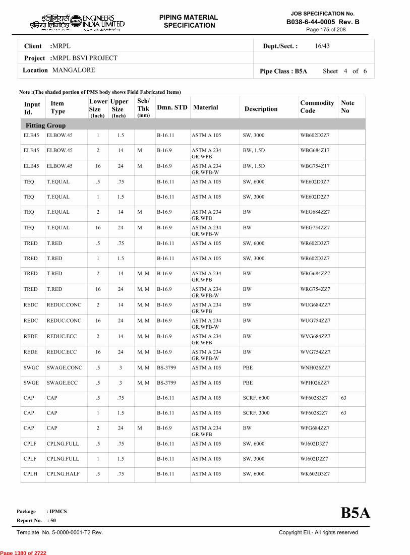
MRPLClient :
MRPL BSVI PROJECT
MANGALORELocation
16/43Dept./Sect. :
Project :
PIPING MATERIAL
SPECIFICATION
Copyright EIL- All rights reserved
JOB SPECIFICATION No.
B038-6-44-0005 Rev. B
Package : IPMCS
Report No. : 50
Template No. 5-0000-0001-T2 Rev.
Page 175 of 208
Sheet 4 ofPipe Class : B5A
InputId.
Item Type
LowerSize
Upper Size
Sch/Thk DescriptionMaterial
CommodityCode
NoteNo
Fitting Group
Dmn. STD(Inch) (Inch)
ELB45
ELB45
ELB45
TEQ
TEQ
TEQ
TEQ
TRED
TRED
TRED
TRED
REDC
REDC
REDE
REDE
SWGC
SWGE
CAP
CAP
CAP
CPLF
CPLF
CPLH
ELBOW.45
ELBOW.45
ELBOW.45
T.EQUAL
T.EQUAL
T.EQUAL
T.EQUAL
T.RED
T.RED
T.RED
T.RED
REDUC.CONC
REDUC.CONC
REDUC.ECC
REDUC.ECC
SWAGE.CONC
SWAGE.ECC
CAP
CAP
CAP
CPLNG.FULL
CPLNG.FULL
CPLNG.HALF
1
2
16
.5
1
2
16
.5
1
2
16
2
16
2
16
.5
.5
.5
1
2
.5
1
.5
1.5
14
24
.75
1.5
14
24
.75
1.5
14
24
14
24
14
24
3
3
.75
1.5
24
.75
1.5
.75
M
M
M
M
M, M
M, M
M, M
M, M
M, M
M, M
M, M
M, M
M
SW, 3000
BW, 1.5D
BW, 1.5D
SW, 6000
SW, 3000
BW
BW
SW, 6000
SW, 3000
BW
BW
BW
BW
BW
BW
PBE
PBE
SCRF, 6000
SCRF, 3000
BW
SW, 6000
SW, 3000
SW, 6000
ASTM A 105
ASTM A 234GR.WPB
ASTM A 234GR.WPB-W
ASTM A 105
ASTM A 105
ASTM A 234GR.WPB
ASTM A 234GR.WPB-W
ASTM A 105
ASTM A 105
ASTM A 234GR.WPB
ASTM A 234GR.WPB-W
ASTM A 234GR.WPB
ASTM A 234GR.WPB-W
ASTM A 234GR.WPB
ASTM A 234GR.WPB-W
ASTM A 105
ASTM A 105
ASTM A 105
ASTM A 105
ASTM A 234GR.WPB
ASTM A 105
ASTM A 105
ASTM A 105
WB602D2Z7
WBG684Z17
WBG754Z17
WE602D3Z7
WE602D2Z7
WEG684ZZ7
WEG754ZZ7
WR602D3Z7
WR602D2Z7
WRG684ZZ7
WRG754ZZ7
WUG684ZZ7
WUG754ZZ7
WVG684ZZ7
WVG754ZZ7
WNH026ZZ7
WPH026ZZ7
WF60283Z7
WF60282Z7
WFG684ZZ7
WJ602D3Z7
WJ602D2Z7
WK602D3Z7
63
63
B-16.11
B-16.9
B-16.9
B-16.11
B-16.11
B-16.9
B-16.9
B-16.11
B-16.11
B-16.9
B-16.9
B-16.9
B-16.9
B-16.9
B-16.9
BS-3799
BS-3799
B-16.11
B-16.11
B-16.9
B-16.11
B-16.11
B-16.11
Note :(The shaded portion of PMS body shows Field Fabricated Items)
B5A
(mm)
6
Page 1380 of 2722
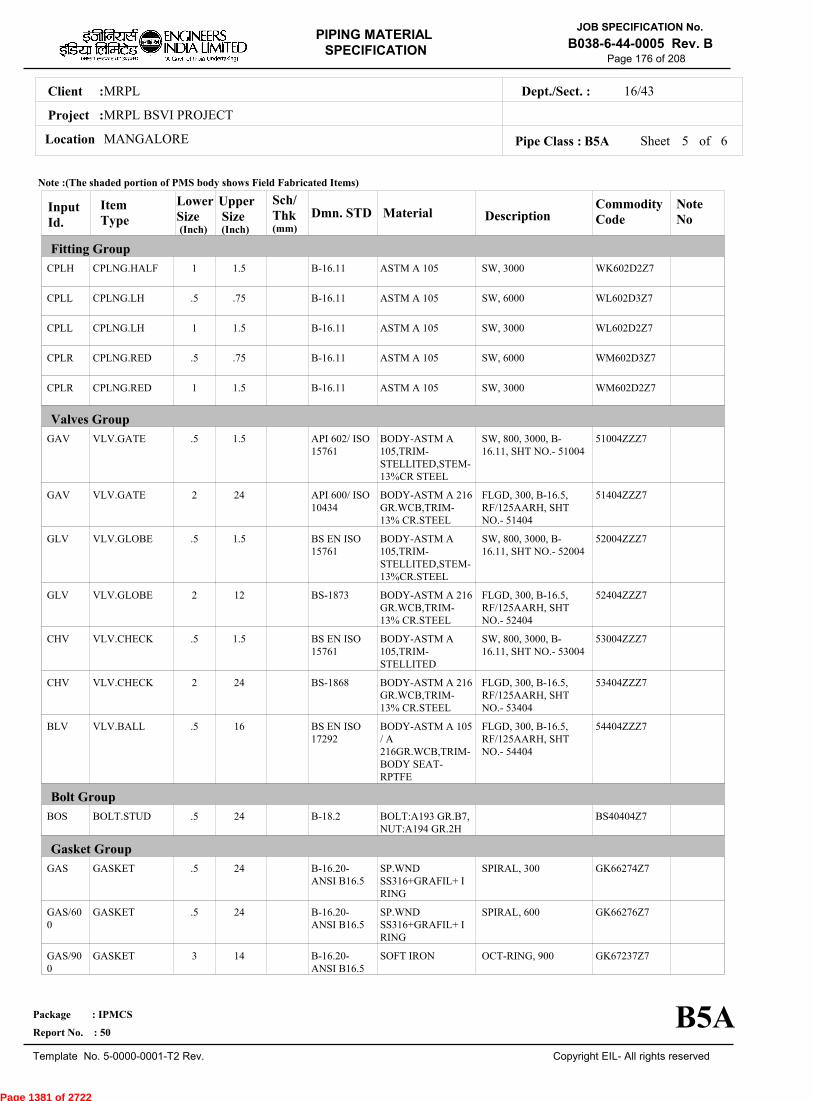
MRPLClient :
MRPL BSVI PROJECT
MANGALORELocation
16/43Dept./Sect. :
Project :
PIPING MATERIAL
SPECIFICATION
Copyright EIL- All rights reserved
JOB SPECIFICATION No.
B038-6-44-0005 Rev. B
Package : IPMCS
Report No. : 50
Template No. 5-0000-0001-T2 Rev.
Page 176 of 208
Sheet 5 ofPipe Class : B5A
InputId.
Item Type
LowerSize
Upper Size
Sch/Thk DescriptionMaterial
CommodityCode
NoteNo
Fitting Group
Valves Group
Bolt Group
Gasket Group
Dmn. STD(Inch) (Inch)
CPLH
CPLL
CPLL
CPLR
CPLR
GAV
GAV
GLV
GLV
CHV
CHV
BLV
BOS
GAS
GAS/600
GAS/900
CPLNG.HALF
CPLNG.LH
CPLNG.LH
CPLNG.RED
CPLNG.RED
VLV.GATE
VLV.GATE
VLV.GLOBE
VLV.GLOBE
VLV.CHECK
VLV.CHECK
VLV.BALL
BOLT.STUD
GASKET
GASKET
GASKET
1
.5
1
.5
1
.5
2
.5
2
.5
2
.5
.5
.5
.5
3
1.5
.75
1.5
.75
1.5
1.5
24
1.5
12
1.5
24
16
24
24
24
14
SW, 3000
SW, 6000
SW, 3000
SW, 6000
SW, 3000
SW, 800, 3000, B-16.11, SHT NO.- 51004
FLGD, 300, B-16.5,RF/125AARH, SHTNO.- 51404
SW, 800, 3000, B-16.11, SHT NO.- 52004
FLGD, 300, B-16.5,RF/125AARH, SHTNO.- 52404
SW, 800, 3000, B-16.11, SHT NO.- 53004
FLGD, 300, B-16.5,RF/125AARH, SHTNO.- 53404
FLGD, 300, B-16.5,RF/125AARH, SHTNO.- 54404
SPIRAL, 300
SPIRAL, 600
OCT-RING, 900
ASTM A 105
ASTM A 105
ASTM A 105
ASTM A 105
ASTM A 105
BODY-ASTM A105,TRIM-STELLITED,STEM-13%CR STEEL
BODY-ASTM A 216GR.WCB,TRIM-13% CR.STEEL
BODY-ASTM A105,TRIM-STELLITED,STEM-13%CR.STEEL
BODY-ASTM A 216GR.WCB,TRIM-13% CR.STEEL
BODY-ASTM A105,TRIM-STELLITED
BODY-ASTM A 216GR.WCB,TRIM-13% CR.STEEL
BODY-ASTM A 105/ A216GR.WCB,TRIM-BODY SEAT-RPTFE
BOLT:A193 GR.B7,NUT:A194 GR.2H
SP.WNDSS316+GRAFIL+ IRING
SP.WNDSS316+GRAFIL+ IRING
SOFT IRON
WK602D2Z7
WL602D3Z7
WL602D2Z7
WM602D3Z7
WM602D2Z7
51004ZZZ7
51404ZZZ7
52004ZZZ7
52404ZZZ7
53004ZZZ7
53404ZZZ7
54404ZZZ7
BS40404Z7
GK66274Z7
GK66276Z7
GK67237Z7
B-16.11
B-16.11
B-16.11
B-16.11
B-16.11
API 602/ ISO15761
API 600/ ISO10434
BS EN ISO15761
BS-1873
BS EN ISO15761
BS-1868
BS EN ISO17292
B-18.2
B-16.20-ANSI B16.5
B-16.20-ANSI B16.5
B-16.20-ANSI B16.5
Note :(The shaded portion of PMS body shows Field Fabricated Items)
B5A
(mm)
6
Page 1381 of 2722
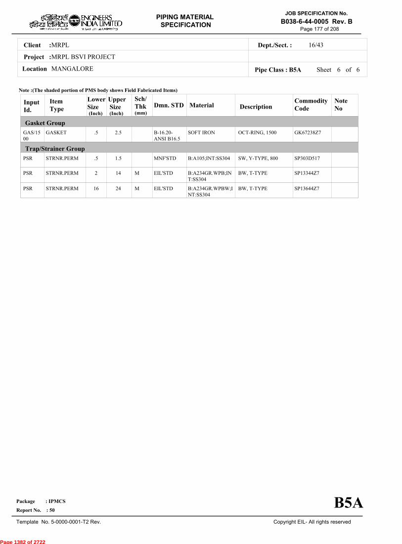
MRPLClient :
MRPL BSVI PROJECT
MANGALORELocation
16/43Dept./Sect. :
Project :
PIPING MATERIAL
SPECIFICATION
Copyright EIL- All rights reserved
JOB SPECIFICATION No.
B038-6-44-0005 Rev. B
Package : IPMCS
Report No. : 50
Template No. 5-0000-0001-T2 Rev.
Page 177 of 208
Sheet 6 of 6Pipe Class : B5A
InputId.
Item Type
LowerSize
Upper Size
Sch/Thk DescriptionMaterial
CommodityCode
NoteNo
Gasket Group
Trap/Strainer Group
Dmn. STD(Inch) (Inch)
GAS/1500
PSR
PSR
PSR
GASKET
STRNR.PERM
STRNR.PERM
STRNR.PERM
.5
.5
2
16
2.5
1.5
14
24
M
M
OCT-RING, 1500
SW, Y-TYPE, 800
BW, T-TYPE
BW, T-TYPE
SOFT IRON
B:A105;INT:SS304
B:A234GR.WPB;INT:SS304
B:A234GR.WPBW;INT:SS304
GK67238Z7
SP303D517
SP13344Z7
SP13644Z7
B-16.20-ANSI B16.5
MNF'STD
EIL'STD
EIL'STD
Note :(The shaded portion of PMS body shows Field Fabricated Items)
B5A
(mm)
Page 1382 of 2722
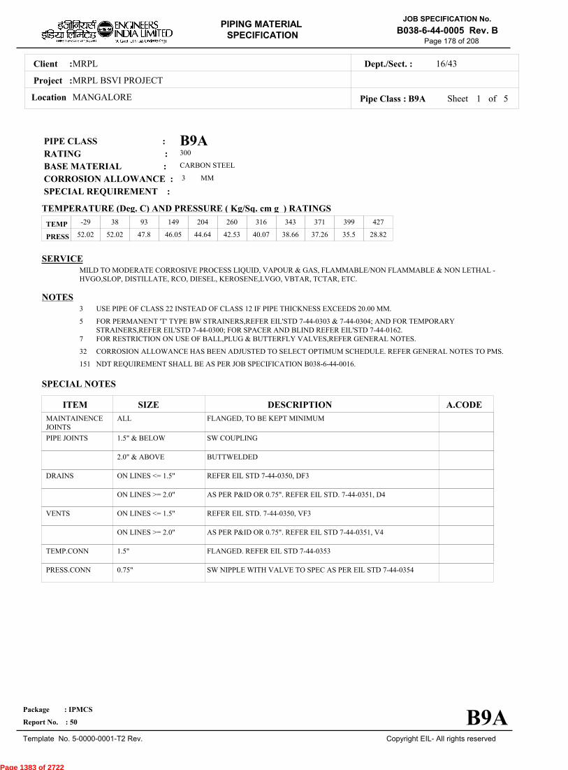
MRPLClient :
MRPL BSVI PROJECT
MANGALORELocation
16/43Dept./Sect. :
Project :
PIPING MATERIAL
SPECIFICATION
Copyright EIL- All rights reserved
JOB SPECIFICATION No.
B038-6-44-0005 Rev. B
Package : IPMCS
Report No. : 50
Template No. 5-0000-0001-T2 Rev.
Page 178 of 208
B9APIPE CLASS :300RATING :CARBON STEELBASE MATERIAL : 3CORROSION ALLOWANCE : SPECIAL REQUIREMENT :
MM
SERVICEMILD TO MODERATE CORROSIVE PROCESS LIQUID, VAPOUR & GAS, FLAMMABLE/NON FLAMMABLE & NON LETHAL -HVGO,SLOP, DISTILLATE, RCO, DIESEL, KEROSENE,LVGO, VBTAR, TCTAR, ETC.
NOTES3
5
7
32
151
USE PIPE OF CLASS 22 INSTEAD OF CLASS 12 IF PIPE THICKNESS EXCEEDS 20.00 MM.
FOR PERMANENT 'T' TYPE BW STRAINERS,REFER EIL'STD 7-44-0303 & 7-44-0304; AND FOR TEMPORARYSTRAINERS,REFER EIL'STD 7-44-0300; FOR SPACER AND BLIND REFER EIL'STD 7-44-0162.FOR RESTRICTION ON USE OF BALL,PLUG & BUTTERFLY VALVES,REFER GENERAL NOTES.
CORROSION ALLOWANCE HAS BEEN ADJUSTED TO SELECT OPTIMUM SCHEDULE. REFER GENERAL NOTES TO PMS.
NDT REQUIREMENT SHALL BE AS PER JOB SPECIFICATION B038-6-44-0016.
SPECIAL NOTES
ITEM SIZE DESCRIPTION A.CODEMAINTAINENCEJOINTS
PIPE JOINTS
DRAINS
VENTS
TEMP.CONN
PRESS.CONN
ALL
1.5" & BELOW
2.0" & ABOVE
ON LINES <= 1.5"
ON LINES >= 2.0"
ON LINES <= 1.5"
ON LINES >= 2.0"
1.5"
0.75"
FLANGED, TO BE KEPT MINIMUM
SW COUPLING
BUTTWELDED
REFER EIL STD 7-44-0350, DF3
AS PER P&ID OR 0.75". REFER EIL STD. 7-44-0351, D4
REFER EIL STD. 7-44-0350, VF3
AS PER P&ID OR 0.75". REFER EIL STD 7-44-0351, V4
FLANGED. REFER EIL STD 7-44-0353
SW NIPPLE WITH VALVE TO SPEC AS PER EIL STD 7-44-0354
TEMP
PRESS 52.02 52.02 47.8 46.05 44.64 42.53 40.07 38.66 37.26 35.5 28.82
-29 38 93 149 204 260 316 343 371 399 427
Sheet 1 of
TEMPERATURE (Deg. C) AND PRESSURE ( Kg/Sq. cm g ) RATINGS
Pipe Class : B9A
B9A
5
Page 1383 of 2722

MRPLClient :
MRPL BSVI PROJECT
MANGALORELocation
16/43Dept./Sect. :
Project :
PIPING MATERIAL
SPECIFICATION
Copyright EIL- All rights reserved
JOB SPECIFICATION No.
B038-6-44-0005 Rev. B
Package : IPMCS
Report No. : 50
Template No. 5-0000-0001-T2 Rev.
Page 179 of 208
Sheet 2 ofPipe Class : B9A
T T T T H H H H H H H H H0.50T T T H H H H H H H H H0.75
T T H H H H H H H H H1.001.25
T T H H H H H H H H1.50T R R R R R R R R2.00
2.50T R R R R R R R3.00
3.50T R R R R R R4.00
5.00T R R R R R6.00
T R R R R8.00T R R R10.00
T R R12.00T R14.00
T16.0018.0020.0022.0024.0026.0028.0030.0032.0034.0036.0038.0040.0042.0044.0046.0048.0050.0052.0054.0056.0058.0060.0062.0064.0066.0068.0070.0072.00
.
50
.
75
1
.00
1
.25
1
.50
2
.00
2
.50
3
.00
3
.50
4
.00
5
.00
6
.00
8
.00
10
.00
12
.00
14
.00
16
.00
BR
AN
CH
PIP
E (
SIZ
E I
N I
NC
HE
S)
0.500.751.001.251.502.002.503.003.504.005.006.008.0010.0012.0014.0016.0018.0020.0022.0024.0026.0028.0030.0032.0034.0036.0038.0040.0042.0044.0046.0048.0050.0052.0054.0056.0058.0060.0062.0064.0066.0068.0070.0072.00
BR
AN
CH
PIP
E (SIZ
E IN
INC
HE
S)
RUN PIPE (SIZE IN INCHES)
CODE DESCRIPTION
F
H
P
R
S
T
W
I
X
L
JSADDLE FUSED JT
H. COUPLING
PIPE TO PIPE
REINFORCED
SOCKOLETS
TEES
WELDOLETS
INSTRUMENT TEE
Refer Notes
SWEEPOLET
THREADOLET
B9A
76.0080.0084.00
76.0080.0084.00
5
Page 1384 of 2722
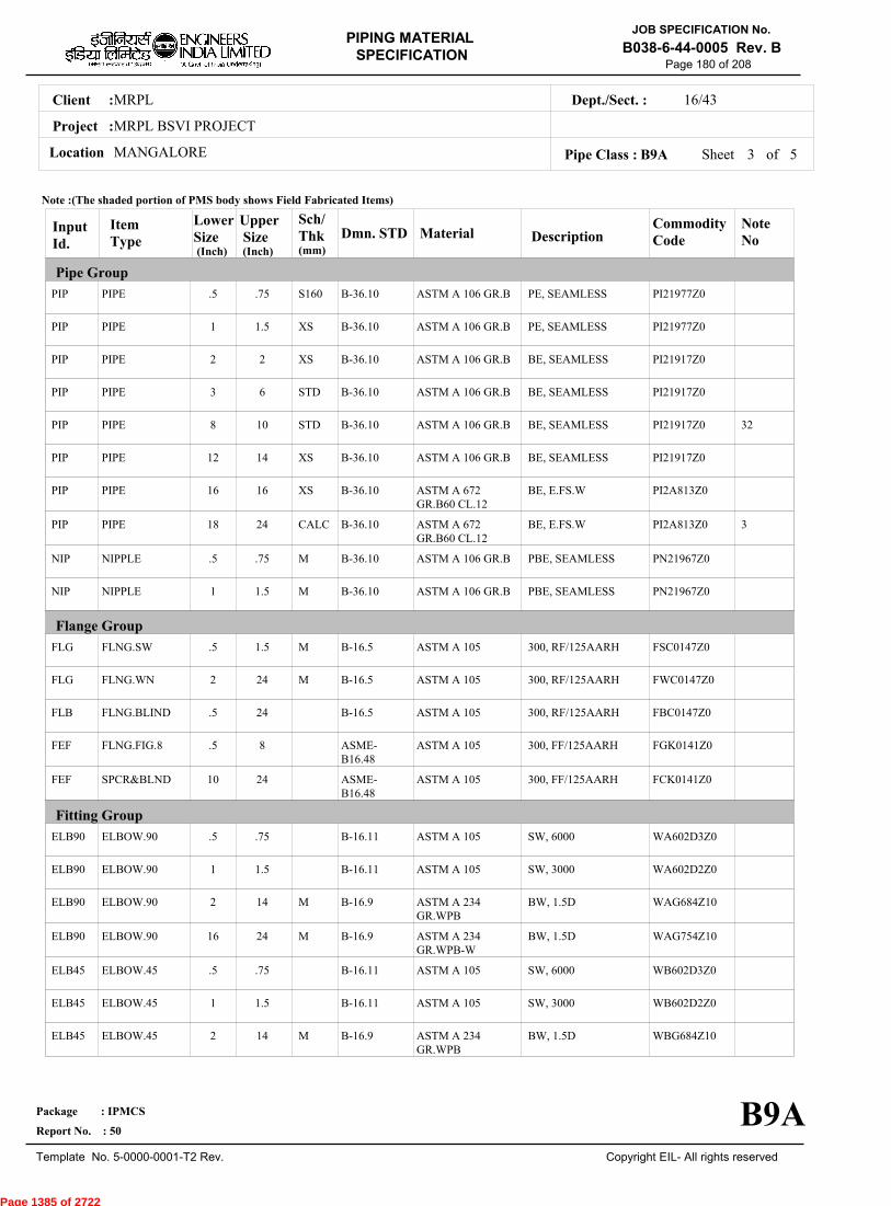
MRPLClient :
MRPL BSVI PROJECT
MANGALORELocation
16/43Dept./Sect. :
Project :
PIPING MATERIAL
SPECIFICATION
Copyright EIL- All rights reserved
JOB SPECIFICATION No.
B038-6-44-0005 Rev. B
Package : IPMCS
Report No. : 50
Template No. 5-0000-0001-T2 Rev.
Page 180 of 208
Sheet 3 ofPipe Class : B9A
InputId.
Item Type
LowerSize
Upper Size
Sch/Thk DescriptionMaterial
CommodityCode
NoteNo
Pipe Group
Flange Group
Fitting Group
Dmn. STD(Inch) (Inch)
PIP
PIP
PIP
PIP
PIP
PIP
PIP
PIP
NIP
NIP
FLG
FLG
FLB
FEF
FEF
ELB90
ELB90
ELB90
ELB90
ELB45
ELB45
ELB45
PIPE
PIPE
PIPE
PIPE
PIPE
PIPE
PIPE
PIPE
NIPPLE
NIPPLE
FLNG.SW
FLNG.WN
FLNG.BLIND
FLNG.FIG.8
SPCR&BLND
ELBOW.90
ELBOW.90
ELBOW.90
ELBOW.90
ELBOW.45
ELBOW.45
ELBOW.45
.5
1
2
3
8
12
16
18
.5
1
.5
2
.5
.5
10
.5
1
2
16
.5
1
2
.75
1.5
2
6
10
14
16
24
.75
1.5
1.5
24
24
8
24
.75
1.5
14
24
.75
1.5
14
S160
XS
XS
STD
STD
XS
XS
CALC
M
M
M
M
M
M
M
PE, SEAMLESS
PE, SEAMLESS
BE, SEAMLESS
BE, SEAMLESS
BE, SEAMLESS
BE, SEAMLESS
BE, E.FS.W
BE, E.FS.W
PBE, SEAMLESS
PBE, SEAMLESS
300, RF/125AARH
300, RF/125AARH
300, RF/125AARH
300, FF/125AARH
300, FF/125AARH
SW, 6000
SW, 3000
BW, 1.5D
BW, 1.5D
SW, 6000
SW, 3000
BW, 1.5D
ASTM A 106 GR.B
ASTM A 106 GR.B
ASTM A 106 GR.B
ASTM A 106 GR.B
ASTM A 106 GR.B
ASTM A 106 GR.B
ASTM A 672GR.B60 CL.12
ASTM A 672GR.B60 CL.12
ASTM A 106 GR.B
ASTM A 106 GR.B
ASTM A 105
ASTM A 105
ASTM A 105
ASTM A 105
ASTM A 105
ASTM A 105
ASTM A 105
ASTM A 234GR.WPB
ASTM A 234GR.WPB-W
ASTM A 105
ASTM A 105
ASTM A 234GR.WPB
PI21977Z0
PI21977Z0
PI21917Z0
PI21917Z0
PI21917Z0
PI21917Z0
PI2A813Z0
PI2A813Z0
PN21967Z0
PN21967Z0
FSC0147Z0
FWC0147Z0
FBC0147Z0
FGK0141Z0
FCK0141Z0
WA602D3Z0
WA602D2Z0
WAG684Z10
WAG754Z10
WB602D3Z0
WB602D2Z0
WBG684Z10
32
3
B-36.10
B-36.10
B-36.10
B-36.10
B-36.10
B-36.10
B-36.10
B-36.10
B-36.10
B-36.10
B-16.5
B-16.5
B-16.5
ASME-B16.48
ASME-B16.48
B-16.11
B-16.11
B-16.9
B-16.9
B-16.11
B-16.11
B-16.9
Note :(The shaded portion of PMS body shows Field Fabricated Items)
B9A
(mm)
5
Page 1385 of 2722

MRPLClient :
MRPL BSVI PROJECT
MANGALORELocation
16/43Dept./Sect. :
Project :
PIPING MATERIAL
SPECIFICATION
Copyright EIL- All rights reserved
JOB SPECIFICATION No.
B038-6-44-0005 Rev. B
Package : IPMCS
Report No. : 50
Template No. 5-0000-0001-T2 Rev.
Page 181 of 208
Sheet 4 ofPipe Class : B9A
InputId.
Item Type
LowerSize
Upper Size
Sch/Thk DescriptionMaterial
CommodityCode
NoteNo
Fitting Group
Dmn. STD(Inch) (Inch)
ELB45
TEQ
TEQ
TEQ
TEQ
TRED
TRED
TRED
TRED
REDC
REDC
REDE
REDE
SWGC
SWGE
CAP
CPLF
CPLF
CPLH
CPLH
CPLL
CPLL
CPLR
ELBOW.45
T.EQUAL
T.EQUAL
T.EQUAL
T.EQUAL
T.RED
T.RED
T.RED
T.RED
REDUC.CONC
REDUC.CONC
REDUC.ECC
REDUC.ECC
SWAGE.CONC
SWAGE.ECC
CAP
CPLNG.FULL
CPLNG.FULL
CPLNG.HALF
CPLNG.HALF
CPLNG.LH
CPLNG.LH
CPLNG.RED
16
.5
1
2
16
.5
1
2
16
2
16
2
16
.5
.5
2
.5
1
.5
1
.5
1
.5
24
.75
1.5
14
24
.75
1.5
14
24
14
24
14
24
3
3
24
.75
1.5
.75
1.5
.75
1.5
.75
M
M
M
M, M
M, M
M, M
M, M
M, M
M, M
M, M
M, M
M
BW, 1.5D
SW, 6000
SW, 3000
BW
BW
SW, 6000
SW, 3000
BW
BW
BW
BW
BW
BW
PBE
PBE
BW
SW, 6000
SW, 3000
SW, 6000
SW, 3000
SW, 6000
SW, 3000
SW, 6000
ASTM A 234GR.WPB-W
ASTM A 105
ASTM A 105
ASTM A 234GR.WPB
ASTM A 234GR.WPB-W
ASTM A 105
ASTM A 105
ASTM A 234GR.WPB
ASTM A 234GR.WPB-W
ASTM A 234GR.WPB
ASTM A 234GR.WPB-W
ASTM A 234GR.WPB
ASTM A 234GR.WPB-W
ASTM A 105
ASTM A 105
ASTM A 234GR.WPB
ASTM A 105
ASTM A 105
ASTM A 105
ASTM A 105
ASTM A 105
ASTM A 105
ASTM A 105
WBG754Z10
WE602D3Z0
WE602D2Z0
WEG684ZZ0
WEG754ZZ0
WR602D3Z0
WR602D2Z0
WRG684ZZ0
WRG754ZZ0
WUG684ZZ0
WUG754ZZ0
WVG684ZZ0
WVG754ZZ0
WNH026ZZ0
WPH026ZZ0
WFG684ZZ0
WJ602D3Z0
WJ602D2Z0
WK602D3Z0
WK602D2Z0
WL602D3Z0
WL602D2Z0
WM602D3Z0
B-16.9
B-16.11
B-16.11
B-16.9
B-16.9
B-16.11
B-16.11
B-16.9
B-16.9
B-16.9
B-16.9
B-16.9
B-16.9
BS-3799
BS-3799
B-16.9
B-16.11
B-16.11
B-16.11
B-16.11
B-16.11
B-16.11
B-16.11
Note :(The shaded portion of PMS body shows Field Fabricated Items)
B9A
(mm)
5
Page 1386 of 2722

MRPLClient :
MRPL BSVI PROJECT
MANGALORELocation
16/43Dept./Sect. :
Project :
PIPING MATERIAL
SPECIFICATION
Copyright EIL- All rights reserved
JOB SPECIFICATION No.
B038-6-44-0005 Rev. B
Package : IPMCS
Report No. : 50
Template No. 5-0000-0001-T2 Rev.
Page 182 of 208
Sheet 5 of 5Pipe Class : B9A
InputId.
Item Type
LowerSize
Upper Size
Sch/Thk DescriptionMaterial
CommodityCode
NoteNo
Fitting Group
Valves Group
Bolt Group
Gasket Group
Trap/Strainer Group
Dmn. STD(Inch) (Inch)
CPLR
GAV
GAV
GLV
GLV
CHV
CHV
BLV
PLV
BOS
GAS
TSR
PSR
PSR
PSR
CPLNG.RED
VLV.GATE
VLV.GATE
VLV.GLOBE
VLV.GLOBE
VLV.CHECK
VLV.CHECK
VLV.BALL
VLV.PLUG
BOLT.STUD
GASKET
STRNR.TEMP
STRNR.PERM
STRNR.PERM
STRNR.PERM
1
.25
2
.25
2
.25
2
.5
.5
.5
.5
1.5
.5
2
16
1.5
1.5
24
1.5
12
1.5
24
16
24
24
24
24
1.5
14
24
M
M
SW, 3000
SW, 800, 3000, B-16.11, SHT NO.- 51001
FLGD, 300, B-16.5,RF/125AARH, SHTNO.- 51401
SW, 800, 3000, B-16.11, SHT NO.- 52001
FLGD, 300, B-16.5,RF/125AARH, SHTNO.- 52401
SW, 800, 3000, B-16.11, SHT NO.- 53001
FLGD, 300, B-16.5,RF/125AARH, SHTNO.- 53401
FLGD, 300, B-16.5,RF/125AARH, SHTNO.- 54401
FLGD, 300, B-16.5,RF/125AARH, SHTNO.- 55401
SPIRAL, 300
CONETYPE,300,FF/125AARH
SW, Y-TYPE, 800
BW, T-TYPE
BW, T-TYPE
ASTM A 105
BODY-ASTM A105,TRIM-STELLITED,STEM-13%CR.STEEL
BODY-ASTM A 216GR.WCB,TRIM-13% CR.STEEL
BODY-ASTM A105,TRIM-STELLITED,STEM-13%CR STEEL
BODY-ASTM A 216GR.WCB,TRIM-13% CR.STEEL
BODY-ASTM A105,TRIM-STELLITED
BODY-ASTM A 216GR.WCB,TRIM-13% CR.STEEL
BODY-ASTM A 105/ A216GR.WCB,TRIM-BODY SEAT-RPTFE
BODY-ASTM A 105/ A216GR.WCB,TRIM-PLUG-HARDENED
BOLT:A193 GR.B7,NUT:A194 GR.2H
SP.WNDSS316+GRAFIL+ IRING
B:A516GR.70;INT:SS304
B:A105;INT:SS304
B:A234GR.WPB;INT:SS304
B:A234GR.WPBW;INT:SS304
WM602D2Z0
51001ZZZ0
51401ZZZ0
52001ZZZ0
52401ZZZ0
53001ZZZ0
53401ZZZ0
54401ZZZ0
55401ZZZ0
BS40404Z0
GK66274Z0
ST16839Z0
SP303D510
SP13344Z0
SP13644Z0
B-16.11
API 602/ ISO15761
API 600/ ISO10434
BS EN ISO15761
BS-1873
BS EN ISO15761
BS-1868
BS EN ISO17292
BS-5353
B-18.2
B-16.20-ANSI B16.5
EIL'STD
MNF'STD
EIL'STD
EIL'STD
Note :(The shaded portion of PMS body shows Field Fabricated Items)
B9A
(mm)
Page 1387 of 2722

MRPLClient :
MRPL BSVI PROJECT
MANGALORELocation
16/43Dept./Sect. :
Project :
PIPING MATERIAL
SPECIFICATION
Copyright EIL- All rights reserved
JOB SPECIFICATION No.
B038-6-44-0005 Rev. B
Package : IPMCS
Report No. : 50
Template No. 5-0000-0001-T2 Rev.
Page 183 of 208
D1APIPE CLASS :600RATING :CARBON STEELBASE MATERIAL : 1.5CORROSION ALLOWANCE : SPECIAL REQUIREMENT :
MM
SERVICENON CORROSIVE PROCESS - FLAMMABLE / NON FLAMMABL AND NON LETHAL - PETROLEUM PRODUCTS: FO. FG,SWEET GAS, INHIBITOR SOLUTION, NH3, BRINE (MINUS 10 DEG C), CO2, CAUSTIC SODA (20 Be MAX & TEMP 70 DEG CMAX), PARAXYLENE, BITUMEN.
NOTES3
5
7
32
63
151
239
USE PIPE OF CLASS 22 INSTEAD OF CLASS 12 IF PIPE THICKNESS EXCEEDS 20.00 MM.
FOR PERMANENT 'T' TYPE BW STRAINERS,REFER EIL'STD 7-44-0303 & 7-44-0304; AND FOR TEMPORARYSTRAINERS,REFER EIL'STD 7-44-0300; FOR SPACER AND BLIND REFER EIL'STD 7-44-0162.FOR RESTRICTION ON USE OF BALL,PLUG & BUTTERFLY VALVES,REFER GENERAL NOTES.
CORROSION ALLOWANCE HAS BEEN ADJUSTED TO SELECT OPTIMUM SCHEDULE. REFER GENERAL NOTES TO PMS.
THIS ITEM IS INTENDED SOLELY FOR USE BY INSTRUMENTATION.
NDT REQUIREMENT SHALL BE AS PER JOB SPECIFICATION B038-6-44-0016.
PIPE WALL THICKNESS IS CALCULATED ON THE BASIS OF 80% CLASS RATING CONDITION.
SPECIAL NOTES
ITEM SIZE DESCRIPTION A.CODEMAINTAINENCEJOINTS
PIPE JOINTS
DRAINS
VENTS
TEMP.CONN
PRESS.CONN
ALL
1.5" & BELOW
2.0" & ABOVE
ON LINES <= 1.5"
ON LINES >= 2.0"
ON LINES <= 1.5"
ON LINES >= 2.0"
1.5"
0.75"
FLANGED, TO BE KEPT MINIMUM
SW COUPLING
BUTTWELDED
REFER EILSTD 7-44-0350, DF3
AS PER P&ID OR 0.75". REFER EIL STD. 7-44-0351, D4
REFER EIL STD. 7-44-0350, VF3
AS PER P&ID OR 0.75". REFER EIL STD 7-44-0351, V4
FLANGED. REFER EIL STD 7-44-0353
SW NIPPLE WITH VALVE TO SPEC AS PER EIL STD 7-44-0354
TEMP
PRESS 104.05 104.05 95.6 92.09 88.92 84.71 79.79 77.33 74.52 71.35 58
-29 38 93 149 204 260 316 343 371 399 427
Sheet 1 of
TEMPERATURE (Deg. C) AND PRESSURE ( Kg/Sq. cm g ) RATINGS
Pipe Class : D1A
D1A
6
Page 1388 of 2722

MRPLClient :
MRPL BSVI PROJECT
MANGALORELocation
16/43Dept./Sect. :
Project :
PIPING MATERIAL
SPECIFICATION
Copyright EIL- All rights reserved
JOB SPECIFICATION No.
B038-6-44-0005 Rev. B
Package : IPMCS
Report No. : 50
Template No. 5-0000-0001-T2 Rev.
Page 184 of 208
Sheet 2 ofPipe Class : D1A
T T T T H H H H H H H H H H H H0.50T T T H H H H H H H H H H H H0.75
T T H H H H H H H H H H H H1.001.25
T T H H H H H H H H H H H1.50T R R R R R R R R R R R2.00
2.50T R R R R R R R R R R3.00
3.50T R R R R R R R R R4.00
5.00T R R R R R R R R6.00
T R R R R R R R8.00T R R R R R R10.00
T R R R R R12.00T R R R R14.00
T R R R16.00T R R18.00
T R20.0022.00
T24.0026.0028.0030.0032.0034.0036.0038.0040.0042.0044.0046.0048.0050.0052.0054.0056.0058.0060.0062.0064.0066.0068.0070.0072.00
.
50
.
75
1
.00
1
.25
1
.50
2
.00
2
.50
3
.00
3
.50
4
.00
5
.00
6
.00
8
.00
10
.00
12
.00
14
.00
16
.00
18
.00
20
.00
22
.00
24
.00
BR
AN
CH
PIP
E (
SIZ
E I
N I
NC
HE
S)
0.500.751.001.251.502.002.503.003.504.005.006.008.0010.0012.0014.0016.0018.0020.0022.0024.0026.0028.0030.0032.0034.0036.0038.0040.0042.0044.0046.0048.0050.0052.0054.0056.0058.0060.0062.0064.0066.0068.0070.0072.00
BR
AN
CH
PIP
E (SIZ
E IN
INC
HE
S)
RUN PIPE (SIZE IN INCHES)
CODE DESCRIPTION
F
H
P
R
S
T
W
I
X
L
JSADDLE FUSED JT
H. COUPLING
PIPE TO PIPE
REINFORCED
SOCKOLETS
TEES
WELDOLETS
INSTRUMENT TEE
Refer Notes
SWEEPOLET
THREADOLET
D1A
76.0080.0084.00
76.0080.0084.00
6
Page 1389 of 2722

MRPLClient :
MRPL BSVI PROJECT
MANGALORELocation
16/43Dept./Sect. :
Project :
PIPING MATERIAL
SPECIFICATION
Copyright EIL- All rights reserved
JOB SPECIFICATION No.
B038-6-44-0005 Rev. B
Package : IPMCS
Report No. : 50
Template No. 5-0000-0001-T2 Rev.
Page 185 of 208
Sheet 3 ofPipe Class : D1A
InputId.
Item Type
LowerSize
Upper Size
Sch/Thk DescriptionMaterial
CommodityCode
NoteNo
Pipe Group
Flange Group
Fitting Group
Dmn. STD(Inch) (Inch)
PIP
PIP
PIP
PIP
PIP
PIP
PIP
PIP
PIP
NIP
NIP
FLG
FLG
FLB
FEF
FEF
ELB90
ELB90
ELB90
ELB90
ELB45
ELB45
PIPE
PIPE
PIPE
PIPE
PIPE
PIPE
PIPE
PIPE
PIPE
NIPPLE
NIPPLE
FLNG.SW
FLNG.WN
FLNG.BLIND
FLNG.FIG.8
SPCR&BLND
ELBOW.90
ELBOW.90
ELBOW.90
ELBOW.90
ELBOW.45
ELBOW.45
.5
1
2
3
4
10
14
16
20
.5
1
.5
2
.5
.5
10
.5
1
2
16
.5
1
.75
1.5
2
3
8
12
14
18
24
.75
1.5
1.5
24
24
8
24
.75
1.5
14
24
.75
1.5
S160
XS
XS
STD
XS
XS
S60
S60
CALC
M
M
M
M
M
M
PE, SEAMLESS
PE, SEAMLESS
BE, SEAMLESS
BE, SEAMLESS
BE, SEAMLESS
BE, SEAMLESS
BE, SEAMLESS
BE, E.FS.W
BE, E.FS.W
PBE, SEAMLESS
PBE, SEAMLESS
600, RF/125AARH
600, RF/125AARH
600, RF/125AARH
600, FF/125AARH
600, FF/125AARH
SW, 6000
SW, 3000
BW, 1.5D
BW, 1.5D
SW, 6000
SW, 3000
ASTM A 106 GR.B
ASTM A 106 GR.B
ASTM A 106 GR.B
ASTM A 106 GR.B
ASTM A 106 GR.B
ASTM A 106 GR.B
ASTM A 106 GR.B
ASTM A 672GR.B60 CL.12
ASTM A 672GR.B60 CL.12
ASTM A 106 GR.B
ASTM A 106 GR.B
ASTM A 105
ASTM A 105
ASTM A 105
ASTM A 105
ASTM A 105
ASTM A 105
ASTM A 105
ASTM A 234GR.WPB
ASTM A 234GR.WPB-W
ASTM A 105
ASTM A 105
PI21977Z0
PI21977Z0
PI21917Z0
PI21917Z0
PI21917Z0
PI21917Z0
PI21917Z0
PI2A813Z0
PI2A813Z0
PN21967Z0
PN21967Z0
FSC0167Z0
FWC0167Z0
FBC0167Z0
FGK0161Z0
FCK0161Z0
WA602D3Z0
WA602D2Z0
WAG684Z10
WAG754Z10
WB602D3Z0
WB602D2Z0
32
239
239
239
B-36.10
B-36.10
B-36.10
B-36.10
B-36.10
B-36.10
B-36.10
B-36.10
B-36.10
B-36.10
B-36.10
B-16.5
B-16.5
B-16.5
ASME-B16.48
ASME-B16.48
B-16.11
B-16.11
B-16.9
B-16.9
B-16.11
B-16.11
Note :(The shaded portion of PMS body shows Field Fabricated Items)
D1A
(mm)
6
Page 1390 of 2722
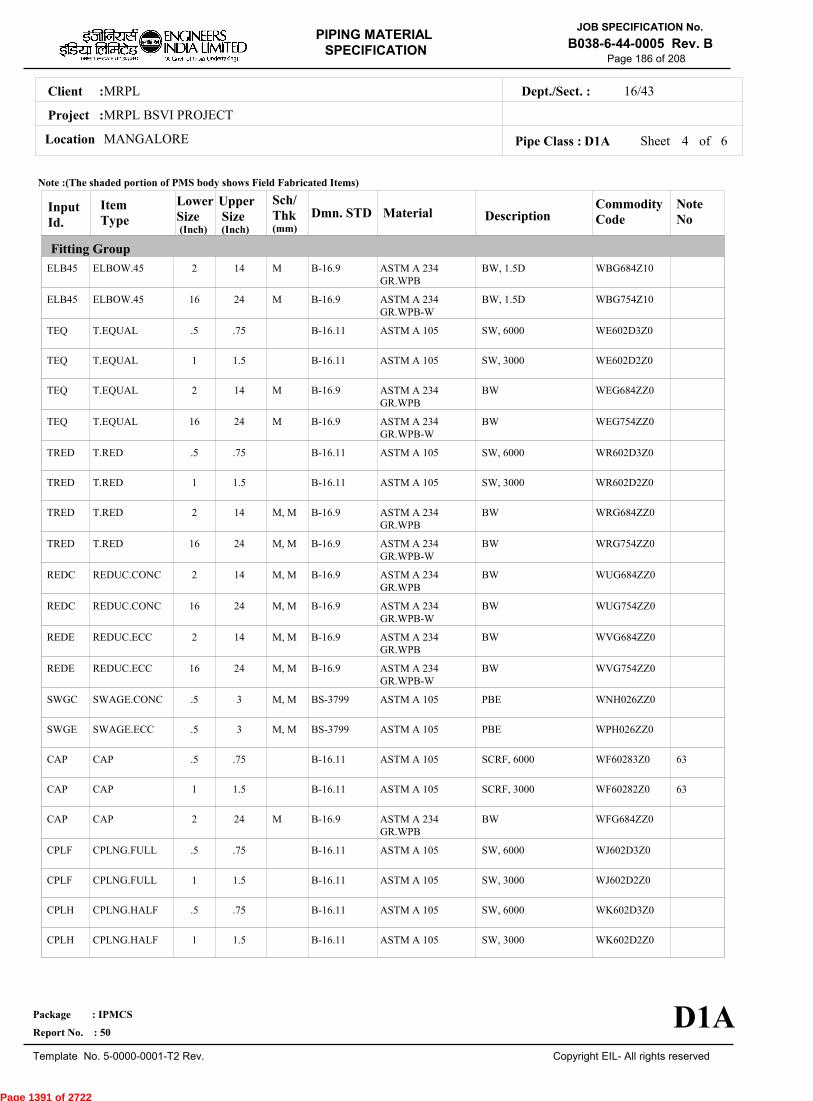
MRPLClient :
MRPL BSVI PROJECT
MANGALORELocation
16/43Dept./Sect. :
Project :
PIPING MATERIAL
SPECIFICATION
Copyright EIL- All rights reserved
JOB SPECIFICATION No.
B038-6-44-0005 Rev. B
Package : IPMCS
Report No. : 50
Template No. 5-0000-0001-T2 Rev.
Page 186 of 208
Sheet 4 ofPipe Class : D1A
InputId.
Item Type
LowerSize
Upper Size
Sch/Thk DescriptionMaterial
CommodityCode
NoteNo
Fitting Group
Dmn. STD(Inch) (Inch)
ELB45
ELB45
TEQ
TEQ
TEQ
TEQ
TRED
TRED
TRED
TRED
REDC
REDC
REDE
REDE
SWGC
SWGE
CAP
CAP
CAP
CPLF
CPLF
CPLH
CPLH
ELBOW.45
ELBOW.45
T.EQUAL
T.EQUAL
T.EQUAL
T.EQUAL
T.RED
T.RED
T.RED
T.RED
REDUC.CONC
REDUC.CONC
REDUC.ECC
REDUC.ECC
SWAGE.CONC
SWAGE.ECC
CAP
CAP
CAP
CPLNG.FULL
CPLNG.FULL
CPLNG.HALF
CPLNG.HALF
2
16
.5
1
2
16
.5
1
2
16
2
16
2
16
.5
.5
.5
1
2
.5
1
.5
1
14
24
.75
1.5
14
24
.75
1.5
14
24
14
24
14
24
3
3
.75
1.5
24
.75
1.5
.75
1.5
M
M
M
M
M, M
M, M
M, M
M, M
M, M
M, M
M, M
M, M
M
BW, 1.5D
BW, 1.5D
SW, 6000
SW, 3000
BW
BW
SW, 6000
SW, 3000
BW
BW
BW
BW
BW
BW
PBE
PBE
SCRF, 6000
SCRF, 3000
BW
SW, 6000
SW, 3000
SW, 6000
SW, 3000
ASTM A 234GR.WPB
ASTM A 234GR.WPB-W
ASTM A 105
ASTM A 105
ASTM A 234GR.WPB
ASTM A 234GR.WPB-W
ASTM A 105
ASTM A 105
ASTM A 234GR.WPB
ASTM A 234GR.WPB-W
ASTM A 234GR.WPB
ASTM A 234GR.WPB-W
ASTM A 234GR.WPB
ASTM A 234GR.WPB-W
ASTM A 105
ASTM A 105
ASTM A 105
ASTM A 105
ASTM A 234GR.WPB
ASTM A 105
ASTM A 105
ASTM A 105
ASTM A 105
WBG684Z10
WBG754Z10
WE602D3Z0
WE602D2Z0
WEG684ZZ0
WEG754ZZ0
WR602D3Z0
WR602D2Z0
WRG684ZZ0
WRG754ZZ0
WUG684ZZ0
WUG754ZZ0
WVG684ZZ0
WVG754ZZ0
WNH026ZZ0
WPH026ZZ0
WF60283Z0
WF60282Z0
WFG684ZZ0
WJ602D3Z0
WJ602D2Z0
WK602D3Z0
WK602D2Z0
63
63
B-16.9
B-16.9
B-16.11
B-16.11
B-16.9
B-16.9
B-16.11
B-16.11
B-16.9
B-16.9
B-16.9
B-16.9
B-16.9
B-16.9
BS-3799
BS-3799
B-16.11
B-16.11
B-16.9
B-16.11
B-16.11
B-16.11
B-16.11
Note :(The shaded portion of PMS body shows Field Fabricated Items)
D1A
(mm)
6
Page 1391 of 2722

MRPLClient :
MRPL BSVI PROJECT
MANGALORELocation
16/43Dept./Sect. :
Project :
PIPING MATERIAL
SPECIFICATION
Copyright EIL- All rights reserved
JOB SPECIFICATION No.
B038-6-44-0005 Rev. B
Package : IPMCS
Report No. : 50
Template No. 5-0000-0001-T2 Rev.
Page 187 of 208
Sheet 5 ofPipe Class : D1A
InputId.
Item Type
LowerSize
Upper Size
Sch/Thk DescriptionMaterial
CommodityCode
NoteNo
Fitting Group
Valves Group
Bolt Group
Gasket Group
Trap/Strainer Group
Dmn. STD(Inch) (Inch)
CPLL
CPLL
CPLR
CPLR
GAV
GAV
GLV
GLV
CHV
CHV
BLV
BOS
GAS
TSR
PSR
CPLNG.LH
CPLNG.LH
CPLNG.RED
CPLNG.RED
VLV.GATE
VLV.GATE
VLV.GLOBE
VLV.GLOBE
VLV.CHECK
VLV.CHECK
VLV.BALL
BOLT.STUD
GASKET
STRNR.TEMP
STRNR.PERM
.5
1
.5
1
.25
2
.25
2
.25
2
.5
.5
.5
1.5
.5
.75
1.5
.75
1.5
1.5
24
1.5
12
1.5
24
16
24
24
24
1.5
SW, 6000
SW, 3000
SW, 6000
SW, 3000
SW, 800, 3000, B-16.11, SHT NO.- 51001
FLGD, 600, B-16.5,RF/125AARH, SHTNO.- 51501
SW, 800, 3000, B-16.11, SHT NO.- 52001
FLGD, 600, B-16.5,RF/125AARH, SHTNO.- 52501
SW, 800, 3000, B-16.11, SHT NO.- 53001
FLGD, 600, B-16.5,RF/125AARH, SHTNO.- 53501
FLGD, 600, B-16.5,RF/125AARH, SHTNO.- 54501
SPIRAL, 600
CONETYPE,600,FF/125AARH
SW, Y-TYPE, 800
ASTM A 105
ASTM A 105
ASTM A 105
ASTM A 105
BODY-ASTM A105,TRIM-STELLITED,STEM-13%CR.STEEL
BODY-ASTM A 216GR.WCB,TRIM-STELLITED,STEM-13%CR STEEL
BODY-ASTM A105,TRIM-STELLITED,STEM-13%CR STEEL
BODY-ASTM A 216GR.WCB,TRIM-STELLITED,STEM-13%CR.STEEL
BODY-ASTM A105,TRIM-STELLITED
BODY-ASTM A 216GR.WCB,TRIM-STELLITED
BODY-ASTM A 105/ A216GR.WCB,TRIM-SEAT-RPTFE
BOLT:A193 GR.B7,NUT:A194 GR.2H
SP.WNDSS316+GRAFIL+ IRING
B:A516GR.70;INT:SS304
B:A105;INT:SS304
WL602D3Z0
WL602D2Z0
WM602D3Z0
WM602D2Z0
51001ZZZ0
51501ZZZ0
52001ZZZ0
52501ZZZ0
53001ZZZ0
53501ZZZ0
54501ZZZ0
BS40404Z0
GK66276Z0
ST1683IZ0
SP303D510
B-16.11
B-16.11
B-16.11
B-16.11
API 602/ ISO15761
API 600/ ISO10434
BS EN ISO15761
BS-1873
BS EN ISO15761
BS-1868
BS EN ISO17292
B-18.2
B-16.20-ANSI B16.5
EIL'STD
MNF'STD
Note :(The shaded portion of PMS body shows Field Fabricated Items)
D1A
(mm)
6
Page 1392 of 2722
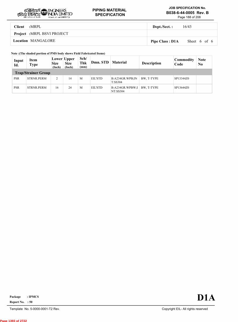
MRPLClient :
MRPL BSVI PROJECT
MANGALORELocation
16/43Dept./Sect. :
Project :
PIPING MATERIAL
SPECIFICATION
Copyright EIL- All rights reserved
JOB SPECIFICATION No.
B038-6-44-0005 Rev. B
Package : IPMCS
Report No. : 50
Template No. 5-0000-0001-T2 Rev.
Page 188 of 208
Sheet 6 of 6Pipe Class : D1A
InputId.
Item Type
LowerSize
Upper Size
Sch/Thk DescriptionMaterial
CommodityCode
NoteNo
Trap/Strainer Group
Dmn. STD(Inch) (Inch)
PSR
PSR
STRNR.PERM
STRNR.PERM
2
16
14
24
M
M
BW, T-TYPE
BW, T-TYPE
B:A234GR.WPB;INT:SS304
B:A234GR.WPBW;INT:SS304
SP13344Z0
SP13644Z0
EIL'STD
EIL'STD
Note :(The shaded portion of PMS body shows Field Fabricated Items)
D1A
(mm)
Page 1393 of 2722

MRPLClient :
MRPL BSVI PROJECT
MANGALORELocation
16/43Dept./Sect. :
Project :
PIPING MATERIAL
SPECIFICATION
Copyright EIL- All rights reserved
JOB SPECIFICATION No.
B038-6-44-0005 Rev. B
Package : IPMCS
Report No. : 50
Template No. 5-0000-0001-T2 Rev.
Page 189 of 208
D23KPIPE CLASS :600RATING :SS 304LBASE MATERIAL : 0CORROSION ALLOWANCE : SPECIAL REQUIREMENT :
MM
SERVICECORROSIVE PROCESS SERVICE - FLAMMABLE/NON FLAMMABLE, TOXIC/NON TOXIC BUT NON LETHAL - FLARE GAS,ACID GAS WITH CONDENSATE, REFLUX,CORROSIVE WATER, RICH AMINE, ETC.
NOTES5
7
151
FOR PERMANENT 'T' TYPE BW STRAINERS,REFER EIL'STD 7-44-0303 & 7-44-0304; AND FOR TEMPORARYSTRAINERS,REFER EIL'STD 7-44-0300; FOR SPACER AND BLIND REFER EIL'STD 7-44-0162.FOR RESTRICTION ON USE OF BALL,PLUG & BUTTERFLY VALVES,REFER GENERAL NOTES.
NDT REQUIREMENT SHALL BE AS PER JOB SPECIFICATION B038-6-44-0016.
SPECIAL NOTES
ITEM SIZE DESCRIPTION A.CODEMAINTAINENCEJOINTS
PIPE JOINTS
DRAINS
VENTS
TEMP.CONN
PRESS.CONN
ALL
1.5" & BELOW
2.0" & ABOVE
ON LINES <= 1.5"
ON LINES >= 2.0"
ON LINES <= 1.5"
ON LINES >= 2.0"
1.5"
0.75"
FLANGED, TO BE KEPT MINIMUM
SW COUPLING
BUTTWELDED
REFER EILSTD 7-44-0350, DF3
AS PER P&ID OR 0.75". REFER EIL STD. 7-44-0351, D4
REFER EIL STD. 7-44-0350, VF3
AS PER P&ID OR 0.75". REFER EIL STD 7-44-0351, V4
FLANGED. REFER EIL STD 7-44-0353
SW NIPPLE WITH VALVE TO SPEC AS PER EIL STD 7-44-0354
TEMP
PRESS 84.36 84.36 71.71 63.97 59.05 55.18 52.37 51.32 50.61 49.56 48.5
-29 38 93 149 204 260 316 343 371 399 427
Sheet 1 of
TEMPERATURE (Deg. C) AND PRESSURE ( Kg/Sq. cm g ) RATINGS
Pipe Class : D23K
D23K
5
Page 1394 of 2722
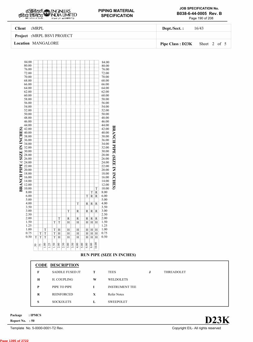
MRPLClient :
MRPL BSVI PROJECT
MANGALORELocation
16/43Dept./Sect. :
Project :
PIPING MATERIAL
SPECIFICATION
Copyright EIL- All rights reserved
JOB SPECIFICATION No.
B038-6-44-0005 Rev. B
Package : IPMCS
Report No. : 50
Template No. 5-0000-0001-T2 Rev.
Page 190 of 208
Sheet 2 ofPipe Class : D23K
T T T T H H H H H H0.50T T T H H H H H H0.75
T T H H H H H H1.001.25
T T H H H H H1.50T R R R R R2.00
2.50T R R R R3.00
3.50T R R R4.00
5.00T R R6.00
T R8.00T10.00
12.0014.0016.0018.0020.0022.0024.0026.0028.0030.0032.0034.0036.0038.0040.0042.0044.0046.0048.0050.0052.0054.0056.0058.0060.0062.0064.0066.0068.0070.0072.00
.
50
.
75
1
.00
1
.25
1
.50
2
.00
2
.50
3
.00
3
.50
4
.00
5
.00
6
.00
8
.00
10
.00
BR
AN
CH
PIP
E (
SIZ
E I
N I
NC
HE
S)
0.500.751.001.251.502.002.503.003.504.005.006.008.0010.0012.0014.0016.0018.0020.0022.0024.0026.0028.0030.0032.0034.0036.0038.0040.0042.0044.0046.0048.0050.0052.0054.0056.0058.0060.0062.0064.0066.0068.0070.0072.00
BR
AN
CH
PIP
E (SIZ
E IN
INC
HE
S)
RUN PIPE (SIZE IN INCHES)
CODE DESCRIPTION
F
H
P
R
S
T
W
I
X
L
JSADDLE FUSED JT
H. COUPLING
PIPE TO PIPE
REINFORCED
SOCKOLETS
TEES
WELDOLETS
INSTRUMENT TEE
Refer Notes
SWEEPOLET
THREADOLET
D23K
76.0080.0084.00
76.0080.0084.00
5
Page 1395 of 2722
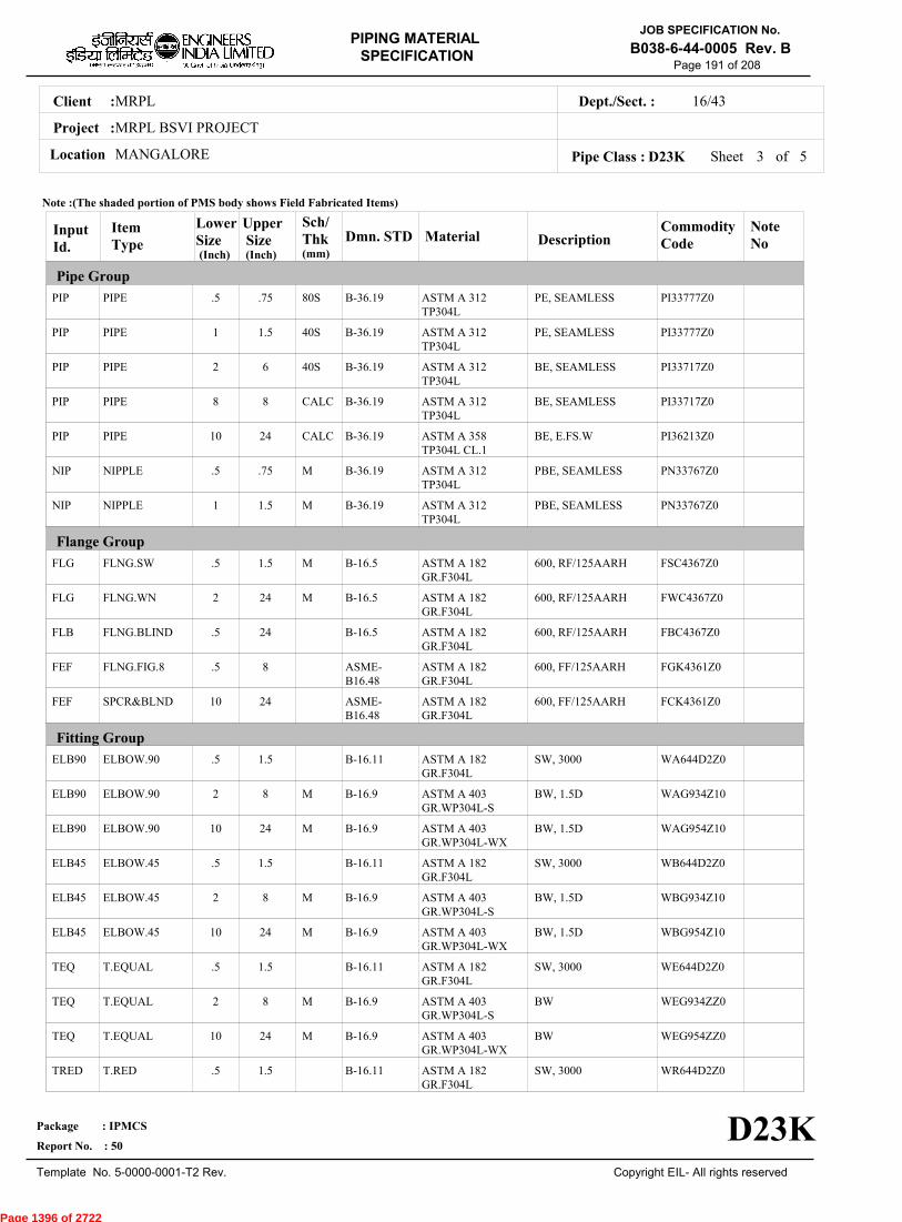
MRPLClient :
MRPL BSVI PROJECT
MANGALORELocation
16/43Dept./Sect. :
Project :
PIPING MATERIAL
SPECIFICATION
Copyright EIL- All rights reserved
JOB SPECIFICATION No.
B038-6-44-0005 Rev. B
Package : IPMCS
Report No. : 50
Template No. 5-0000-0001-T2 Rev.
Page 191 of 208
Sheet 3 ofPipe Class : D23K
InputId.
Item Type
LowerSize
Upper Size
Sch/Thk DescriptionMaterial
CommodityCode
NoteNo
Pipe Group
Flange Group
Fitting Group
Dmn. STD(Inch) (Inch)
PIP
PIP
PIP
PIP
PIP
NIP
NIP
FLG
FLG
FLB
FEF
FEF
ELB90
ELB90
ELB90
ELB45
ELB45
ELB45
TEQ
TEQ
TEQ
TRED
PIPE
PIPE
PIPE
PIPE
PIPE
NIPPLE
NIPPLE
FLNG.SW
FLNG.WN
FLNG.BLIND
FLNG.FIG.8
SPCR&BLND
ELBOW.90
ELBOW.90
ELBOW.90
ELBOW.45
ELBOW.45
ELBOW.45
T.EQUAL
T.EQUAL
T.EQUAL
T.RED
.5
1
2
8
10
.5
1
.5
2
.5
.5
10
.5
2
10
.5
2
10
.5
2
10
.5
.75
1.5
6
8
24
.75
1.5
1.5
24
24
8
24
1.5
8
24
1.5
8
24
1.5
8
24
1.5
80S
40S
40S
CALC
CALC
M
M
M
M
M
M
M
M
M
M
PE, SEAMLESS
PE, SEAMLESS
BE, SEAMLESS
BE, SEAMLESS
BE, E.FS.W
PBE, SEAMLESS
PBE, SEAMLESS
600, RF/125AARH
600, RF/125AARH
600, RF/125AARH
600, FF/125AARH
600, FF/125AARH
SW, 3000
BW, 1.5D
BW, 1.5D
SW, 3000
BW, 1.5D
BW, 1.5D
SW, 3000
BW
BW
SW, 3000
ASTM A 312TP304L
ASTM A 312TP304L
ASTM A 312TP304L
ASTM A 312TP304L
ASTM A 358TP304L CL.1
ASTM A 312TP304L
ASTM A 312TP304L
ASTM A 182GR.F304L
ASTM A 182GR.F304L
ASTM A 182GR.F304L
ASTM A 182GR.F304L
ASTM A 182GR.F304L
ASTM A 182GR.F304L
ASTM A 403GR.WP304L-S
ASTM A 403GR.WP304L-WX
ASTM A 182GR.F304L
ASTM A 403GR.WP304L-S
ASTM A 403GR.WP304L-WX
ASTM A 182GR.F304L
ASTM A 403GR.WP304L-S
ASTM A 403GR.WP304L-WX
ASTM A 182GR.F304L
PI33777Z0
PI33777Z0
PI33717Z0
PI33717Z0
PI36213Z0
PN33767Z0
PN33767Z0
FSC4367Z0
FWC4367Z0
FBC4367Z0
FGK4361Z0
FCK4361Z0
WA644D2Z0
WAG934Z10
WAG954Z10
WB644D2Z0
WBG934Z10
WBG954Z10
WE644D2Z0
WEG934ZZ0
WEG954ZZ0
WR644D2Z0
B-36.19
B-36.19
B-36.19
B-36.19
B-36.19
B-36.19
B-36.19
B-16.5
B-16.5
B-16.5
ASME-B16.48
ASME-B16.48
B-16.11
B-16.9
B-16.9
B-16.11
B-16.9
B-16.9
B-16.11
B-16.9
B-16.9
B-16.11
Note :(The shaded portion of PMS body shows Field Fabricated Items)
D23K
(mm)
5
Page 1396 of 2722
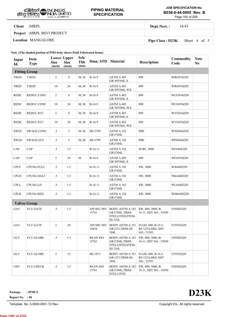
MRPLClient :
MRPL BSVI PROJECT
MANGALORELocation
16/43Dept./Sect. :
Project :
PIPING MATERIAL
SPECIFICATION
Copyright EIL- All rights reserved
JOB SPECIFICATION No.
B038-6-44-0005 Rev. B
Package : IPMCS
Report No. : 50
Template No. 5-0000-0001-T2 Rev.
Page 192 of 208
Sheet 4 ofPipe Class : D23K
InputId.
Item Type
LowerSize
Upper Size
Sch/Thk DescriptionMaterial
CommodityCode
NoteNo
Fitting Group
Valves Group
Dmn. STD(Inch) (Inch)
TRED
TRED
REDC
REDC
REDE
REDE
SWGC
SWGE
CAP
CAP
CPLF
CPLH
CPLL
CPLR
GAV
GAV
GLV
GLV
CHV
T.RED
T.RED
REDUC.CONC
REDUC.CONC
REDUC.ECC
REDUC.ECC
SWAGE.CONC
SWAGE.ECC
CAP
CAP
CPLNG.FULL
CPLNG.HALF
CPLNG.LH
CPLNG.RED
VLV.GATE
VLV.GATE
VLV.GLOBE
VLV.GLOBE
VLV.CHECK
2
10
2
10
2
10
.5
.5
.5
2
.5
.5
.5
.5
.5
2
.5
2
.5
8
24
8
24
8
24
3
3
1.5
24
1.5
1.5
1.5
1.5
1.5
24
1.5
12
1.5
M, M
M, M
M, M
M, M
M, M
M, M
M, M
M, M
M
BW
BW
BW
BW
BW
BW
PBE
PBE
SCRF, 3000
BW
SW, 3000
SW, 3000
SW, 3000
SW, 3000
SW, 800, 3000, B-16.11, SHT NO.- 51050
FLGD, 600, B-16.5,RF/125AARH, SHTNO.- 51593
SW, 800, 3000, B-16.11, SHT NO.- 52050
FLGD, 600, B-16.5,RF/125AARH, SHTNO.- 52593
SW, 800, 3000, B-16.11, SHT NO.- 53050
ASTM A 403GR.WP304L-S
ASTM A 403GR.WP304L-WX
ASTM A 403GR.WP304L-S
ASTM A 403GR.WP304L-WX
ASTM A 403GR.WP304L-S
ASTM A 403GR.WP304L-WX
ASTM A 182GR.F304L
ASTM A 182GR.F304L
ASTM A 182GR.F304L
ASTM A 403GR.WP304L-S
ASTM A 182GR.F304L
ASTM A 182GR.F304L
ASTM A 182GR.F304L
ASTM A 182GR.F304L
BODY-ASTM A 182GR.F304L,TRIM-STELLITED,STEM-SS 316L
BODY-ASTM A 351GR.CF3,TRIM-SS304L
BODY-ASTM A 182GR.F304L,TRIM-STELLITED,STEM-SS 316L
BODY-ASTM A 351GR CF3,TRIM-SS304L
BODY-ASTM A 182GR.F304L,TRIM-STELLITED
WRG934ZZ0
WRG954ZZ0
WUG934ZZ0
WUG954ZZ0
WVG934ZZ0
WVG954ZZ0
WNH446ZZ0
WPH446ZZ0
WF64482Z0
WFG934ZZ0
WJ644D2Z0
WK644D2Z0
WL644D2Z0
WM644D2Z0
51050ZZZ0
51593ZZZ0
52050ZZZ0
52593ZZZ0
53050ZZZ0
B-16.9
B-16.9
B-16.9
B-16.9
B-16.9
B-16.9
BS-3799
BS-3799
B-16.11
B-16.9
B-16.11
B-16.11
B-16.11
B-16.11
API 602/ ISO15761
API 600/ ISO10434
BS EN ISO15761
BS-1873
BS EN ISO15761
Note :(The shaded portion of PMS body shows Field Fabricated Items)
D23K
(mm)
5
Page 1397 of 2722
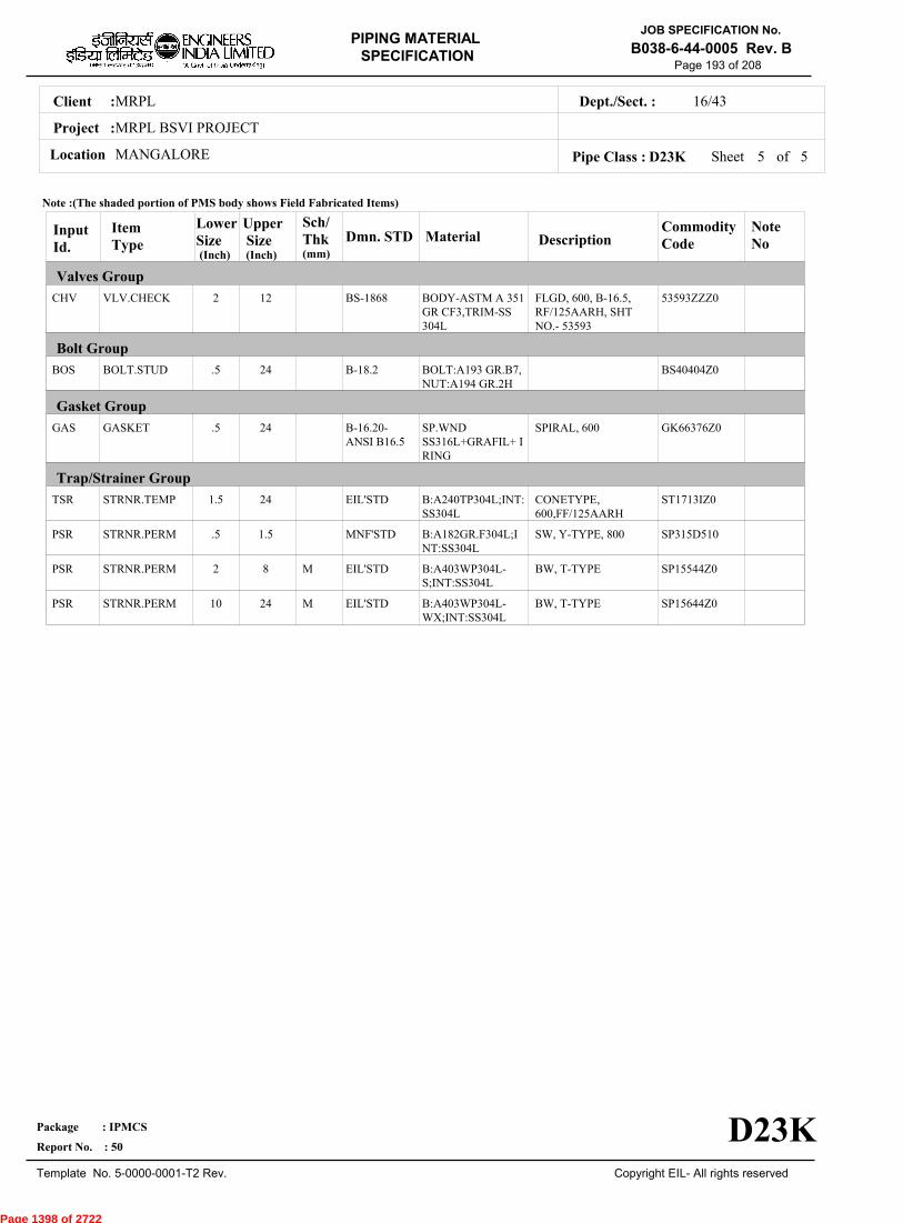
MRPLClient :
MRPL BSVI PROJECT
MANGALORELocation
16/43Dept./Sect. :
Project :
PIPING MATERIAL
SPECIFICATION
Copyright EIL- All rights reserved
JOB SPECIFICATION No.
B038-6-44-0005 Rev. B
Package : IPMCS
Report No. : 50
Template No. 5-0000-0001-T2 Rev.
Page 193 of 208
Sheet 5 of 5Pipe Class : D23K
InputId.
Item Type
LowerSize
Upper Size
Sch/Thk DescriptionMaterial
CommodityCode
NoteNo
Valves Group
Bolt Group
Gasket Group
Trap/Strainer Group
Dmn. STD(Inch) (Inch)
CHV
BOS
GAS
TSR
PSR
PSR
PSR
VLV.CHECK
BOLT.STUD
GASKET
STRNR.TEMP
STRNR.PERM
STRNR.PERM
STRNR.PERM
2
.5
.5
1.5
.5
2
10
12
24
24
24
1.5
8
24
M
M
FLGD, 600, B-16.5,RF/125AARH, SHTNO.- 53593
SPIRAL, 600
CONETYPE,600,FF/125AARH
SW, Y-TYPE, 800
BW, T-TYPE
BW, T-TYPE
BODY-ASTM A 351GR CF3,TRIM-SS304L
BOLT:A193 GR.B7,NUT:A194 GR.2H
SP.WNDSS316L+GRAFIL+ IRING
B:A240TP304L;INT:SS304L
B:A182GR.F304L;INT:SS304L
B:A403WP304L-S;INT:SS304L
B:A403WP304L-WX;INT:SS304L
53593ZZZ0
BS40404Z0
GK66376Z0
ST1713IZ0
SP315D510
SP15544Z0
SP15644Z0
BS-1868
B-18.2
B-16.20-ANSI B16.5
EIL'STD
MNF'STD
EIL'STD
EIL'STD
Note :(The shaded portion of PMS body shows Field Fabricated Items)
D23K
(mm)
Page 1398 of 2722

MRPLClient :
MRPL BSVI PROJECT
MANGALORELocation
16/43Dept./Sect. :
Project :
PIPING MATERIAL
SPECIFICATION
Copyright EIL- All rights reserved
JOB SPECIFICATION No.
B038-6-44-0005 Rev. B
Package : IPMCS
Report No. : 50
Template No. 5-0000-0001-T2 Rev.
Page 194 of 208
D2APIPE CLASS :600RATING :CARBON STEELBASE MATERIAL : 1.5CORROSION ALLOWANCE :IBR SERVICESPECIAL REQUIREMENT :
MM
SERVICESTEAM (IBR), BOILER FEED WATER (IBR)
NOTES3
5
8
9
32
63
151
241
USE PIPE OF CLASS 22 INSTEAD OF CLASS 12 IF PIPE THICKNESS EXCEEDS 20.00 MM.
FOR PERMANENT 'T' TYPE BW STRAINERS,REFER EIL'STD 7-44-0303 & 7-44-0304; AND FOR TEMPORARYSTRAINERS,REFER EIL'STD 7-44-0300; FOR SPACER AND BLIND REFER EIL'STD 7-44-0162.ALL PIPES,FITTINGS,VALVES,FLANGES,TRAPS AND STRAINERS SHALL BE TESTED AND TEST CERTIFICATE IN FORMIII A FOR PIPE AND FORM III C FOR OTHERS SHALL BE REQD. DULY COUNTERSIGNED BY IBR AUTHORITY OR ITSAPPROVED REPRESENTATIVE.CARBON CONTENT SHALL NOT EXCEED 0.25% FOR ALL PIPES,FITTINGS FLANGES ETC. THAT MAY REQUIREWELDING. MOREOVER,FOR FLANGES THE SULPHUR AND PHOSPHOROUS SHALL ALSO BE LIMITED TO 0.05% EACH.CORROSION ALLOWANCE HAS BEEN ADJUSTED TO SELECT OPTIMUM SCHEDULE. REFER GENERAL NOTES TO PMS.
THIS ITEM IS INTENDED SOLELY FOR USE BY INSTRUMENTATION.
NDT REQUIREMENT SHALL BE AS PER JOB SPECIFICATION B038-6-44-0016.
PIPE WALL THICKNESS IS CALCULATED BASED ON ACTUAL LINE DESIGN CONDITION [ 420 DEG. C & 50 KG/ CM2 G ].
SPECIAL NOTES
ITEM SIZE DESCRIPTION A.CODEMAINTAINENCEJOINTS
PIPE JOINTS
DRAINS
VENTS
TEMP.CONN
PRESS.CONN
ALL
1.5" & BELOW
2.0" & ABOVE
ON LINES <= 1.5"
ON LINES >= 2.0"
ON LINES <= 1.5"
ON LINES >= 2.0"
1.5"
0.75"
FLANGED, TO BE KEPT MINIMUM
SW COUPLING
BUTTWELDED
REFER EILSTD 7-44-0350, DF3
AS PER P&ID OR 0.75". REFER EIL STD. 7-44-0351, D4
REFER EIL STD. 7-44-0350, VF3
AS PER P&ID OR 0.75". REFER EIL STD 7-44-0351, V4
FLANGED. REFER EIL STD 7-44-0353
SW NIPPLE WITH VALVE TO SPEC AS PER EIL STD 7-44-0354
TEMP
PRESS 104.05 104.05 95.6 92.09 88.92 84.71 79.79 77.33 74.52 71.35 58
0 38 93 149 204 260 316 343 371 399 427
Sheet 1 of
TEMPERATURE (Deg. C) AND PRESSURE ( Kg/Sq. cm g ) RATINGS
Pipe Class : D2A
D2A
6
Page 1399 of 2722

MRPLClient :
MRPL BSVI PROJECT
MANGALORELocation
16/43Dept./Sect. :
Project :
PIPING MATERIAL
SPECIFICATION
Copyright EIL- All rights reserved
JOB SPECIFICATION No.
B038-6-44-0005 Rev. B
Package : IPMCS
Report No. : 50
Template No. 5-0000-0001-T2 Rev.
Page 195 of 208
Sheet 2 ofPipe Class : D2A
T T T T H H H H H H H H H H H H0.50T T T H H H H H H H H H H H H0.75
T T H H H H H H H H H H H H1.001.25
T T H H H H H H H H H H H1.50T R R R R R R R R R R R2.00
2.50T R R R R R R R R R R3.00
3.50T R R R R R R R R R4.00
5.00T R R R R R R R R6.00
T R R R R R R R8.00T R R R R R R10.00
T R R R R R12.00T R R R R14.00
T R R R16.00T R R18.00
T R20.00R22.00T24.00
26.0028.0030.0032.0034.0036.0038.0040.0042.0044.0046.0048.0050.0052.0054.0056.0058.0060.0062.0064.0066.0068.0070.0072.00
.
50
.
75
1
.00
1
.25
1
.50
2
.00
2
.50
3
.00
3
.50
4
.00
5
.00
6
.00
8
.00
10
.00
12
.00
14
.00
16
.00
18
.00
20
.00
22
.00
24
.00
BR
AN
CH
PIP
E (
SIZ
E I
N I
NC
HE
S)
0.500.751.001.251.502.002.503.003.504.005.006.008.0010.0012.0014.0016.0018.0020.0022.0024.0026.0028.0030.0032.0034.0036.0038.0040.0042.0044.0046.0048.0050.0052.0054.0056.0058.0060.0062.0064.0066.0068.0070.0072.00
BR
AN
CH
PIP
E (SIZ
E IN
INC
HE
S)
RUN PIPE (SIZE IN INCHES)
CODE DESCRIPTION
F
H
P
R
S
T
W
I
X
L
JSADDLE FUSED JT
H. COUPLING
PIPE TO PIPE
REINFORCED
SOCKOLETS
TEES
WELDOLETS
INSTRUMENT TEE
Refer Notes
SWEEPOLET
THREADOLET
D2A
76.0080.0084.00
76.0080.0084.00
6
Page 1400 of 2722
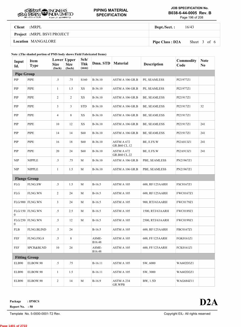
MRPLClient :
MRPL BSVI PROJECT
MANGALORELocation
16/43Dept./Sect. :
Project :
PIPING MATERIAL
SPECIFICATION
Copyright EIL- All rights reserved
JOB SPECIFICATION No.
B038-6-44-0005 Rev. B
Package : IPMCS
Report No. : 50
Template No. 5-0000-0001-T2 Rev.
Page 196 of 208
Sheet 3 ofPipe Class : D2A
InputId.
Item Type
LowerSize
Upper Size
Sch/Thk DescriptionMaterial
CommodityCode
NoteNo
Pipe Group
Flange Group
Fitting Group
Dmn. STD(Inch) (Inch)
PIP
PIP
PIP
PIP
PIP
PIP
PIP
PIP
PIP
NIP
NIP
FLG
FLG
FLG/900
FLG/1500
FLG/2500
FLB
FEF
FEF
ELB90
ELB90
ELB90
PIPE
PIPE
PIPE
PIPE
PIPE
PIPE
PIPE
PIPE
PIPE
NIPPLE
NIPPLE
FLNG.SW
FLNG.WN
FLNG.WN
FLNG.WN
FLNG.WN
FLNG.BLIND
FLNG.FIG.8
SPCR&BLND
ELBOW.90
ELBOW.90
ELBOW.90
.5
1
2
3
4
10
14
16
20
.5
1
.5
2
3
.5
.5
.5
.5
10
.5
1
2
.75
1.5
2
3
8
12
14
18
24
.75
1.5
1.5
24
24
2.5
12
24
8
24
.75
1.5
14
S160
XS
XS
STD
XS
XS
S60
S60
S60
M
M
M
M
M
M
M
M
PE, SEAMLESS
PE, SEAMLESS
BE, SEAMLESS
BE, SEAMLESS
BE, SEAMLESS
BE, SEAMLESS
BE, SEAMLESS
BE, E.FS.W
BE, E.FS.W
PBE, SEAMLESS
PBE, SEAMLESS
600, RF/125AARH
600, RF/125AARH
900, RTJ/63AARH
1500, RTJ/63AARH
2500, RTJ/63AARH
600, RF/125AARH
600, FF/125AARH
600, FF/125AARH
SW, 6000
SW, 3000
BW, 1.5D
ASTM A 106 GR.B
ASTM A 106 GR.B
ASTM A 106 GR.B
ASTM A 106 GR.B
ASTM A 106 GR.B
ASTM A 106 GR.B
ASTM A 106 GR.B
ASTM A 672GR.B60 CL.12
ASTM A 672GR.B60 CL.22
ASTM A 106 GR.B
ASTM A 106 GR.B
ASTM A 105
ASTM A 105
ASTM A 105
ASTM A 105
ASTM A 105
ASTM A 105
ASTM A 105
ASTM A 105
ASTM A 105
ASTM A 105
ASTM A 234GR.WPB
PI21977Z1
PI21977Z1
PI21917Z1
PI21917Z1
PI21917Z1
PI21917Z1
PI21917Z1
PI2A813Z1
PI2A913Z1
PN21967Z1
PN21967Z1
FSC0167Z1
FWC0167Z1
FWC0179Z1
FWC0189Z1
FWC0199Z1
FBC0167Z1
FGK0161Z1
FCK0161Z1
WA602D3Z1
WA602D2Z1
WAG684Z11
32
241
241
241
241
B-36.10
B-36.10
B-36.10
B-36.10
B-36.10
B-36.10
B-36.10
B-36.10
B-36.10
B-36.10
B-36.10
B-16.5
B-16.5
B-16.5
B-16.5
B-16.5
B-16.5
ASME-B16.48
ASME-B16.48
B-16.11
B-16.11
B-16.9
Note :(The shaded portion of PMS body shows Field Fabricated Items)
D2A
(mm)
6
Page 1401 of 2722
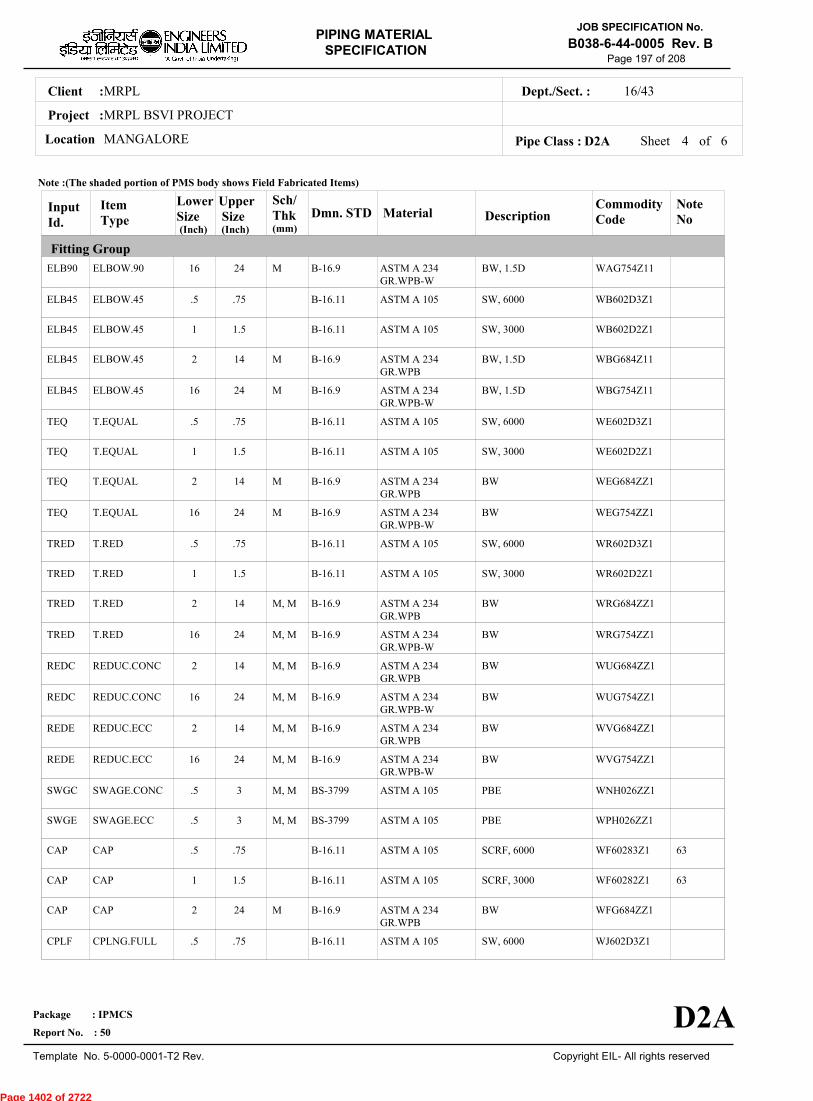
MRPLClient :
MRPL BSVI PROJECT
MANGALORELocation
16/43Dept./Sect. :
Project :
PIPING MATERIAL
SPECIFICATION
Copyright EIL- All rights reserved
JOB SPECIFICATION No.
B038-6-44-0005 Rev. B
Package : IPMCS
Report No. : 50
Template No. 5-0000-0001-T2 Rev.
Page 197 of 208
Sheet 4 ofPipe Class : D2A
InputId.
Item Type
LowerSize
Upper Size
Sch/Thk DescriptionMaterial
CommodityCode
NoteNo
Fitting Group
Dmn. STD(Inch) (Inch)
ELB90
ELB45
ELB45
ELB45
ELB45
TEQ
TEQ
TEQ
TEQ
TRED
TRED
TRED
TRED
REDC
REDC
REDE
REDE
SWGC
SWGE
CAP
CAP
CAP
CPLF
ELBOW.90
ELBOW.45
ELBOW.45
ELBOW.45
ELBOW.45
T.EQUAL
T.EQUAL
T.EQUAL
T.EQUAL
T.RED
T.RED
T.RED
T.RED
REDUC.CONC
REDUC.CONC
REDUC.ECC
REDUC.ECC
SWAGE.CONC
SWAGE.ECC
CAP
CAP
CAP
CPLNG.FULL
16
.5
1
2
16
.5
1
2
16
.5
1
2
16
2
16
2
16
.5
.5
.5
1
2
.5
24
.75
1.5
14
24
.75
1.5
14
24
.75
1.5
14
24
14
24
14
24
3
3
.75
1.5
24
.75
M
M
M
M
M
M, M
M, M
M, M
M, M
M, M
M, M
M, M
M, M
M
BW, 1.5D
SW, 6000
SW, 3000
BW, 1.5D
BW, 1.5D
SW, 6000
SW, 3000
BW
BW
SW, 6000
SW, 3000
BW
BW
BW
BW
BW
BW
PBE
PBE
SCRF, 6000
SCRF, 3000
BW
SW, 6000
ASTM A 234GR.WPB-W
ASTM A 105
ASTM A 105
ASTM A 234GR.WPB
ASTM A 234GR.WPB-W
ASTM A 105
ASTM A 105
ASTM A 234GR.WPB
ASTM A 234GR.WPB-W
ASTM A 105
ASTM A 105
ASTM A 234GR.WPB
ASTM A 234GR.WPB-W
ASTM A 234GR.WPB
ASTM A 234GR.WPB-W
ASTM A 234GR.WPB
ASTM A 234GR.WPB-W
ASTM A 105
ASTM A 105
ASTM A 105
ASTM A 105
ASTM A 234GR.WPB
ASTM A 105
WAG754Z11
WB602D3Z1
WB602D2Z1
WBG684Z11
WBG754Z11
WE602D3Z1
WE602D2Z1
WEG684ZZ1
WEG754ZZ1
WR602D3Z1
WR602D2Z1
WRG684ZZ1
WRG754ZZ1
WUG684ZZ1
WUG754ZZ1
WVG684ZZ1
WVG754ZZ1
WNH026ZZ1
WPH026ZZ1
WF60283Z1
WF60282Z1
WFG684ZZ1
WJ602D3Z1
63
63
B-16.9
B-16.11
B-16.11
B-16.9
B-16.9
B-16.11
B-16.11
B-16.9
B-16.9
B-16.11
B-16.11
B-16.9
B-16.9
B-16.9
B-16.9
B-16.9
B-16.9
BS-3799
BS-3799
B-16.11
B-16.11
B-16.9
B-16.11
Note :(The shaded portion of PMS body shows Field Fabricated Items)
D2A
(mm)
6
Page 1402 of 2722

MRPLClient :
MRPL BSVI PROJECT
MANGALORELocation
16/43Dept./Sect. :
Project :
PIPING MATERIAL
SPECIFICATION
Copyright EIL- All rights reserved
JOB SPECIFICATION No.
B038-6-44-0005 Rev. B
Package : IPMCS
Report No. : 50
Template No. 5-0000-0001-T2 Rev.
Page 198 of 208
Sheet 5 ofPipe Class : D2A
InputId.
Item Type
LowerSize
Upper Size
Sch/Thk DescriptionMaterial
CommodityCode
NoteNo
Fitting Group
Valves Group
Bolt Group
Gasket Group
Dmn. STD(Inch) (Inch)
CPLF
CPLH
CPLH
CPLL
CPLL
CPLR
CPLR
GAV
GAV
GLV
GLV
CHV
CHV
BOS
GAS
GAS/900
GAS/1500
CPLNG.FULL
CPLNG.HALF
CPLNG.HALF
CPLNG.LH
CPLNG.LH
CPLNG.RED
CPLNG.RED
VLV.GATE
VLV.GATE
VLV.GLOBE
VLV.GLOBE
VLV.CHECK
VLV.CHECK
BOLT.STUD
GASKET
GASKET
GASKET
1
.5
1
.5
1
.5
1
.5
2
.5
2
.5
2
.5
.5
3
.5
1.5
.75
1.5
.75
1.5
.75
1.5
1.5
24
1.5
12
1.5
24
24
24
24
2.5
SW, 3000
SW, 6000
SW, 3000
SW, 6000
SW, 3000
SW, 6000
SW, 3000
SW, 800, 3000, B-16.11, SHT NO.- 51002
FLGD, 600, B-16.5,RF/125AARH, SHTNO.- 51502
SW, 800, 3000, B-16.11, SHT NO.- 52002
FLGD, 600, B-16.5,RF/125AARH, SHTNO.- 52502
SW, 800, 3000, B-16.11, SHT NO.- 53002
FLGD, 600, B-16.5,RF/125AARH, SHTNO.- 53502
SPIRAL, 600
OCT-RING, 900
OCT-RING, 1500
ASTM A 105
ASTM A 105
ASTM A 105
ASTM A 105
ASTM A 105
ASTM A 105
ASTM A 105
BODY-ASTM A105,TRIM-STELLITED,STEM-13%CR STEEL
BODY-ASTM A 216GR.WCB,TRIM-STELLITED,STEM-13%CR STEEL
BODY-ASTM A105,TRIM-STELLITED,STEM-13%CR.STEEL
BODY-ASTM A 216GR.WCB,TRIM-STELLITED,STEM-13%CR.STEEL
BODY-ASTM A105,TRIM-STELLITED
BODY-ASTM A 216GR.WCB,TRIM-STELLITED
BOLT:A193 GR.B7,NUT:A194 GR.2H
SP.WNDSS316+GRAFIL+ IRING
SOFT IRON
SOFT IRON
WJ602D2Z1
WK602D3Z1
WK602D2Z1
WL602D3Z1
WL602D2Z1
WM602D3Z1
WM602D2Z1
51002ZZZ1
51502ZZZ1
52002ZZZ1
52502ZZZ1
53002ZZZ1
53502ZZZ1
BS40404Z0
GK66276Z0
GK67237Z0
GK67238Z0
B-16.11
B-16.11
B-16.11
B-16.11
B-16.11
B-16.11
B-16.11
API 602/ ISO15761
API 600/ ISO10434
BS EN ISO15761
BS-1873
BS EN ISO15761
BS-1868
B-18.2
B-16.20-ANSI B16.5
B-16.20-ANSI B16.5
B-16.20-ANSI B16.5
Note :(The shaded portion of PMS body shows Field Fabricated Items)
D2A
(mm)
6
Page 1403 of 2722

MRPLClient :
MRPL BSVI PROJECT
MANGALORELocation
16/43Dept./Sect. :
Project :
PIPING MATERIAL
SPECIFICATION
Copyright EIL- All rights reserved
JOB SPECIFICATION No.
B038-6-44-0005 Rev. B
Package : IPMCS
Report No. : 50
Template No. 5-0000-0001-T2 Rev.
Page 199 of 208
Sheet 6 of 6Pipe Class : D2A
InputId.
Item Type
LowerSize
Upper Size
Sch/Thk DescriptionMaterial
CommodityCode
NoteNo
Gasket Group
Trap/Strainer Group
Dmn. STD(Inch) (Inch)
GAS/2500
TRP
TSR
PSR
PSR
GASKET
TRAP.STEAM
STRNR.TEMP
STRNR.PERM
STRNR.PERM
.5
.5
1.5
.5
2
12
1.5
24
1.5
24
OCT-RING, 2500
FLGD, THRMDNMC,600,RF/125AARH
CONETYPE,600,FF/125AARH
SW, Y-TYPE, 800
FLGD, Y-TYPE,600,RF/125AARH
SOFT IRON
B:A105;T:13%CR;S:SS304
B:A516GR.70;INT:SS304
B:A105;INT:SS304
B:A216GR.WCB;INT:SS304
GK67239Z0
TR30655E1
ST1683IZ1
SP303D511
SP38055E1
B-16.20-ANSI B16.5
MNF'STD
EIL'STD
MNF'STD
MNF'STD
Note :(The shaded portion of PMS body shows Field Fabricated Items)
D2A
(mm)
Page 1404 of 2722
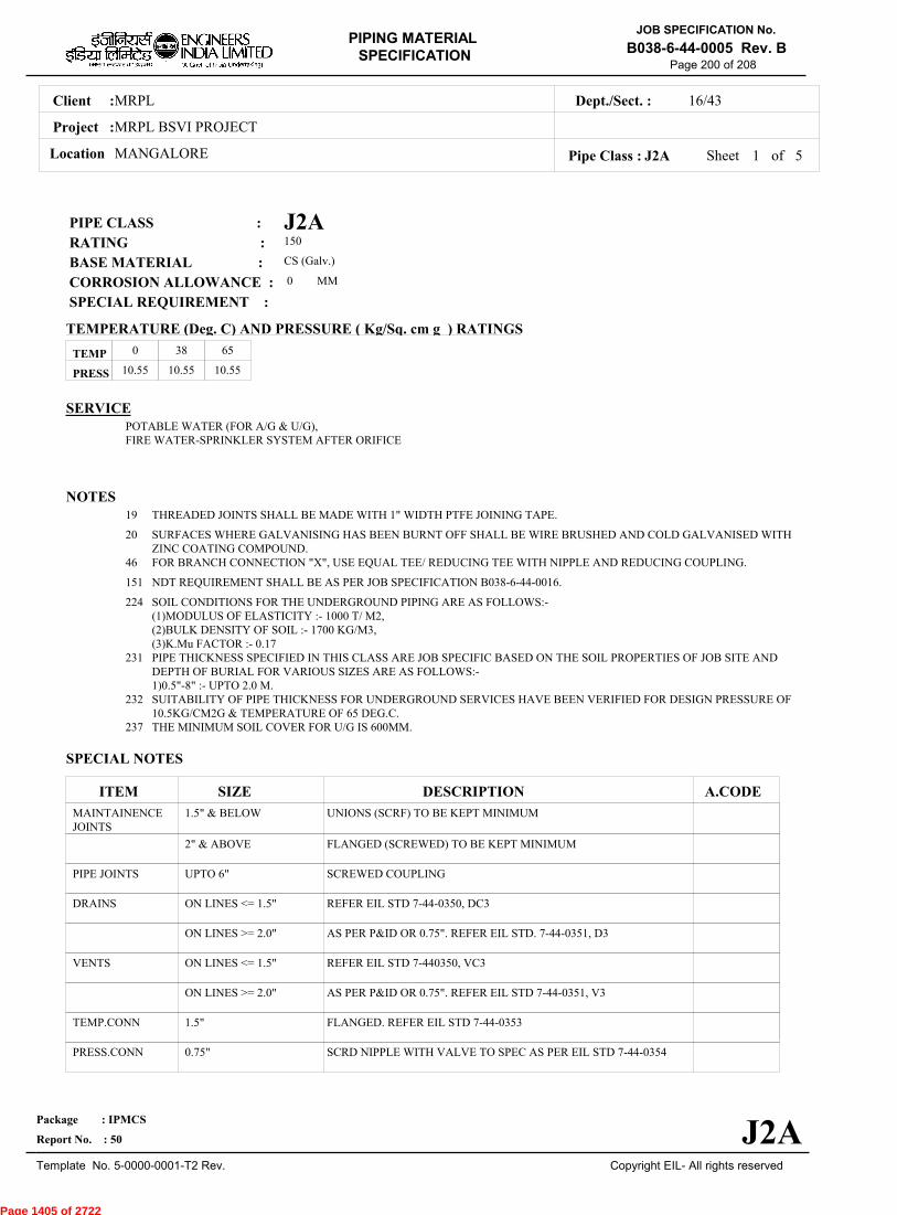
MRPLClient :
MRPL BSVI PROJECT
MANGALORELocation
16/43Dept./Sect. :
Project :
PIPING MATERIAL
SPECIFICATION
Copyright EIL- All rights reserved
JOB SPECIFICATION No.
B038-6-44-0005 Rev. B
Package : IPMCS
Report No. : 50
Template No. 5-0000-0001-T2 Rev.
Page 200 of 208
J2APIPE CLASS :150RATING :CS (Galv.)BASE MATERIAL : 0CORROSION ALLOWANCE : SPECIAL REQUIREMENT :
MM
SERVICEPOTABLE WATER (FOR A/G & U/G), FIRE WATER-SPRINKLER SYSTEM AFTER ORIFICE
NOTES19
20
46
151
224
231
232
237
THREADED JOINTS SHALL BE MADE WITH 1" WIDTH PTFE JOINING TAPE.
SURFACES WHERE GALVANISING HAS BEEN BURNT OFF SHALL BE WIRE BRUSHED AND COLD GALVANISED WITHZINC COATING COMPOUND.FOR BRANCH CONNECTION "X", USE EQUAL TEE/ REDUCING TEE WITH NIPPLE AND REDUCING COUPLING.
NDT REQUIREMENT SHALL BE AS PER JOB SPECIFICATION B038-6-44-0016.
SOIL CONDITIONS FOR THE UNDERGROUND PIPING ARE AS FOLLOWS:-(1)MODULUS OF ELASTICITY :- 1000 T/ M2,(2)BULK DENSITY OF SOIL :- 1700 KG/M3,(3)K.Mu FACTOR :- 0.17PIPE THICKNESS SPECIFIED IN THIS CLASS ARE JOB SPECIFIC BASED ON THE SOIL PROPERTIES OF JOB SITE ANDDEPTH OF BURIAL FOR VARIOUS SIZES ARE AS FOLLOWS:-1)0.5"-8" :- UPTO 2.0 M.SUITABILITY OF PIPE THICKNESS FOR UNDERGROUND SERVICES HAVE BEEN VERIFIED FOR DESIGN PRESSURE OF10.5KG/CM2G & TEMPERATURE OF 65 DEG.C.THE MINIMUM SOIL COVER FOR U/G IS 600MM.
SPECIAL NOTES
ITEM SIZE DESCRIPTION A.CODEMAINTAINENCEJOINTS
PIPE JOINTS
DRAINS
VENTS
TEMP.CONN
PRESS.CONN
1.5" & BELOW
2" & ABOVE
UPTO 6"
ON LINES <= 1.5"
ON LINES >= 2.0"
ON LINES <= 1.5"
ON LINES >= 2.0"
1.5"
0.75"
UNIONS (SCRF) TO BE KEPT MINIMUM
FLANGED (SCREWED) TO BE KEPT MINIMUM
SCREWED COUPLING
REFER EIL STD 7-44-0350, DC3
AS PER P&ID OR 0.75". REFER EIL STD. 7-44-0351, D3
REFER EIL STD 7-440350, VC3
AS PER P&ID OR 0.75". REFER EIL STD 7-44-0351, V3
FLANGED. REFER EIL STD 7-44-0353
SCRD NIPPLE WITH VALVE TO SPEC AS PER EIL STD 7-44-0354
TEMP
PRESS 10.55 10.55 10.55
0 38 65
Sheet 1 of
TEMPERATURE (Deg. C) AND PRESSURE ( Kg/Sq. cm g ) RATINGS
Pipe Class : J2A
J2A
5
Page 1405 of 2722

MRPLClient :
MRPL BSVI PROJECT
MANGALORELocation
16/43Dept./Sect. :
Project :
PIPING MATERIAL
SPECIFICATION
Copyright EIL- All rights reserved
JOB SPECIFICATION No.
B038-6-44-0005 Rev. B
Package : IPMCS
Report No. : 50
Template No. 5-0000-0001-T2 Rev.
Page 201 of 208
Sheet 2 ofPipe Class : J2A
T T T T T X X X X0.50T T T T T X X X0.75
T T T T T X X1.001.25
T T T T X X1.50T T T X X2.00
2.50T T X X3.00
3.50T T X4.00
5.00T T6.00
T8.0010.0012.0014.0016.0018.0020.0022.0024.0026.0028.0030.0032.0034.0036.0038.0040.0042.0044.0046.0048.0050.0052.0054.0056.0058.0060.0062.0064.0066.0068.0070.0072.00
.
50
.
75
1
.00
1
.25
1
.50
2
.00
2
.50
3
.00
3
.50
4
.00
5
.00
6
.00
8
.00
BR
AN
CH
PIP
E (
SIZ
E I
N I
NC
HE
S)
0.500.751.001.251.502.002.503.003.504.005.006.008.0010.0012.0014.0016.0018.0020.0022.0024.0026.0028.0030.0032.0034.0036.0038.0040.0042.0044.0046.0048.0050.0052.0054.0056.0058.0060.0062.0064.0066.0068.0070.0072.00
BR
AN
CH
PIP
E (SIZ
E IN
INC
HE
S)
RUN PIPE (SIZE IN INCHES)
CODE DESCRIPTION
F
H
P
R
S
T
W
I
X
L
JSADDLE FUSED JT
H. COUPLING
PIPE TO PIPE
REINFORCED
SOCKOLETS
TEES
WELDOLETS
INSTRUMENT TEE
Refer Notes
SWEEPOLET
THREADOLET
J2A
76.0080.0084.00
76.0080.0084.00
5
Page 1406 of 2722

MRPLClient :
MRPL BSVI PROJECT
MANGALORELocation
16/43Dept./Sect. :
Project :
PIPING MATERIAL
SPECIFICATION
Copyright EIL- All rights reserved
JOB SPECIFICATION No.
B038-6-44-0005 Rev. B
Package : IPMCS
Report No. : 50
Template No. 5-0000-0001-T2 Rev.
Page 202 of 208
Sheet 3 ofPipe Class : J2A
InputId.
Item Type
LowerSize
Upper Size
Sch/Thk DescriptionMaterial
CommodityCode
NoteNo
Pipe Group
Flange Group
Fitting Group
Dmn. STD(Inch) (Inch)
PIP
PIP
FLG
FLG
FLB
FEF
ELB90
ELB90
ELB90
ELB45
ELB45
ELB45
TEQ
TEQ
TEQ
TRED
TRED
TRED
SWGC
SWGE
CAP
CAP
PIPE
PIPE
FLNG.SCRD
FLNG.SO
FLNG.BLIND
FLNG.FIG.8
ELBOW.90
ELBOW.90
ELBOW.90
ELBOW.45
ELBOW.45
ELBOW.45
T.EQUAL
T.EQUAL
T.EQUAL
T.RED
T.RED
T.RED
SWAGE.CONC
SWAGE.ECC
CAP
CAP
.5
8
.5
8
.5
.5
.5
2
8
.5
2
8
.5
2
8
.5
2
8
.5
.5
.5
2
6
8
6
8
8
8
1.5
6
8
1.5
6
8
1.5
6
8
1.5
6
8
3
3
1.5
6
HVY
6.0
M
M
M
M, M
M, M
M, M
SCRM, WELDED
BE, WELDED
150, FF/125AARH
150, FF/125AARH
150, FF/125AARH
150, FF/125AARH
SCRF, 3000
SCRF, NA
BW, 1.5D
SCRF, 3000
SCRF, NA
BW, 1.5D
SCRF, 3000
SCRF, NA
BW
SCRF, 3000
SCRF, NA
BW
TBE
TBE
SCRF, 3000
SCRF, NA
IS-1239 (GALV)
IS-3589 GR.330(GALV)
ASTM A105(GALV.)
ASTM A105(GALV.)
ASTM A105(GALV.)
ASTM A105(GALV.)
ASTM A105(GALV)
IS-1239(PART-II)(GALV)
ASTM A 234GR.WPB-W(GALV)
ASTM A105(GALV)
IS-1239(PART-II)(GALV)
ASTM A 234GR.WPB-W(GALV)
ASTM A105(GALV)
IS-1239(PART-II)(GALV)
ASTM A 234GR.WPB-W(GALV)
ASTM A105(GALV)
IS-1239(PART-II)(GALV)
ASTM A 234GR.WPB-W(GALV)
ASTM A105(GALV)
ASTM A105(GALV)
ASTM A105(GALV)
IS-1239(PART-II)(GALV)
PI6D599Z0
PI7E219Z0
FTC0721Z0
FNC0721Z0
FBC0721Z0
FGK0721Z0
WA60882Z0
WALE98ZZ0
WAG764Z10
WB60882Z0
WBLE98ZZ0
WBG764Z10
WE60882Z0
WELE98ZZ0
WEG764ZZ0
WR60882Z0
WRLE98ZZ0
WRG764ZZ0
WNH08EZZ0
WPH08EZZ0
WF60882Z0
WFLE98ZZ0
IS-1239-I
IS-3589
B-16.5
B-16.5
B-16.5
ASME-B16.48
B-16.11
IS-1239-II
B-16.9
B-16.11
IS-1239-II
B-16.9
B-16.11
IS-1239-II
B-16.9
B-16.11
IS-1239-II
B-16.9
BS-3799
BS-3799
B-16.11
IS-1239-II
Note :(The shaded portion of PMS body shows Field Fabricated Items)
J2A
(mm)
5
Page 1407 of 2722

MRPLClient :
MRPL BSVI PROJECT
MANGALORELocation
16/43Dept./Sect. :
Project :
PIPING MATERIAL
SPECIFICATION
Copyright EIL- All rights reserved
JOB SPECIFICATION No.
B038-6-44-0005 Rev. B
Package : IPMCS
Report No. : 50
Template No. 5-0000-0001-T2 Rev.
Page 203 of 208
Sheet 4 ofPipe Class : J2A
InputId.
Item Type
LowerSize
Upper Size
Sch/Thk DescriptionMaterial
CommodityCode
NoteNo
Fitting Group
Valves Group
Bolt Group
Dmn. STD(Inch) (Inch)
CAP
CPLF
CPLF
CPLH
CPLH
CPLL
CPLL
CPLR
CPLR
UNN
GAV
GAV
GLV
CHV
CHV
BOM
CAP
CPLNG.FULL
CPLNG.FULL
CPLNG.HALF
CPLNG.HALF
CPLNG.LH
CPLNG.LH
CPLNG.RED
CPLNG.RED
UNION
VLV.GATE
VLV.GATE
VLV.GLOBE
VLV.CHECK
VLV.CHECK
BOLT.M/C
8
.5
2
.5
2
.5
2
.5
2
.5
.5
2
.5
.5
2
.5
8
1.5
6
1.5
6
1.5
6
1.5
6
6
1.5
6
1.5
1.5
6
8
M BW
SCRF, 3000
SCRF, NA
SCRF, 3000
SCRF, NA
SCRF, 3000
SCRF, NA
SCRF, 3000
SCRF, NA
SCRF, NA
SCRF, CL.2, 3000, B-1.20.1, SHT NO.- 51080
FLGD, PN1.6, B-16.1,FF/125AARH, SHTNO.- 51380
SCRF, CL.2, 3000, B-1.20.1, SHT NO.- 52080
SCRF, CL.2, 3000, B-1.20.1, SHT NO.- 53080
FLGD, PN1.6, B-16.1,FF/125AARH, SHTNO.- 53380
ASTM A 234GR.WPB-W(GALV)
ASTM A105(GALV)
IS-1239(PART-II)(GALV)
ASTM A105(GALV)
IS-1239(PART-II)(GALV)
ASTM A105(GALV)
IS-1239(PART-II)(GALV)
ASTM A105(GALV)
IS-1239(PART-II)(GALV)
IS-1239(PART-II)(GALV)
BODY-IS 318GR.LTB2 (LEADEDTINBRONZE),TRIM- IS320 ALLOY HT2
BODY-IS 210GR.FG 200,TRIM-IS 320 ALLOY HT2
BODY-IS 318GR.LTB2 (LEADEDTINBRONZE),TRIM- IS320 ALLOY HT2
BODY-IS 318GR.LTB2 (LEADEDTINBRONZE),TRIM- IS320 ALLOY HT2
BODY-IS 210GR.FG 200,TRIM-IS 320 ALLOY HT2
BOLT:A307GR.B(GALV),NUT:A563GR.B(GALV)
WFG764ZZ0
WJ60882Z0
WJLE98ZZ0
WK60882Z0
WKLE98ZZ0
WL60882Z0
WLLE98ZZ0
WM60882Z0
WMLE98ZZ0
WQLE98ZZ0
51080ZZZ0
51380ZZZ0
52080ZZZ0
53080ZZZ0
53380ZZZ0
BM41519Z0
B-16.9
B-16.11
IS-1239-II
B-16.11
IS-1239-II
B-16.11
IS-1239-II
B-16.11
IS-1239-II
IS-1239-II
IS:778 CL.2
IS:14846
IS:778 CL.2
IS:778 CL.2
IS:5312 (PT-1)
B-18.2
Note :(The shaded portion of PMS body shows Field Fabricated Items)
J2A
(mm)
5
Page 1408 of 2722
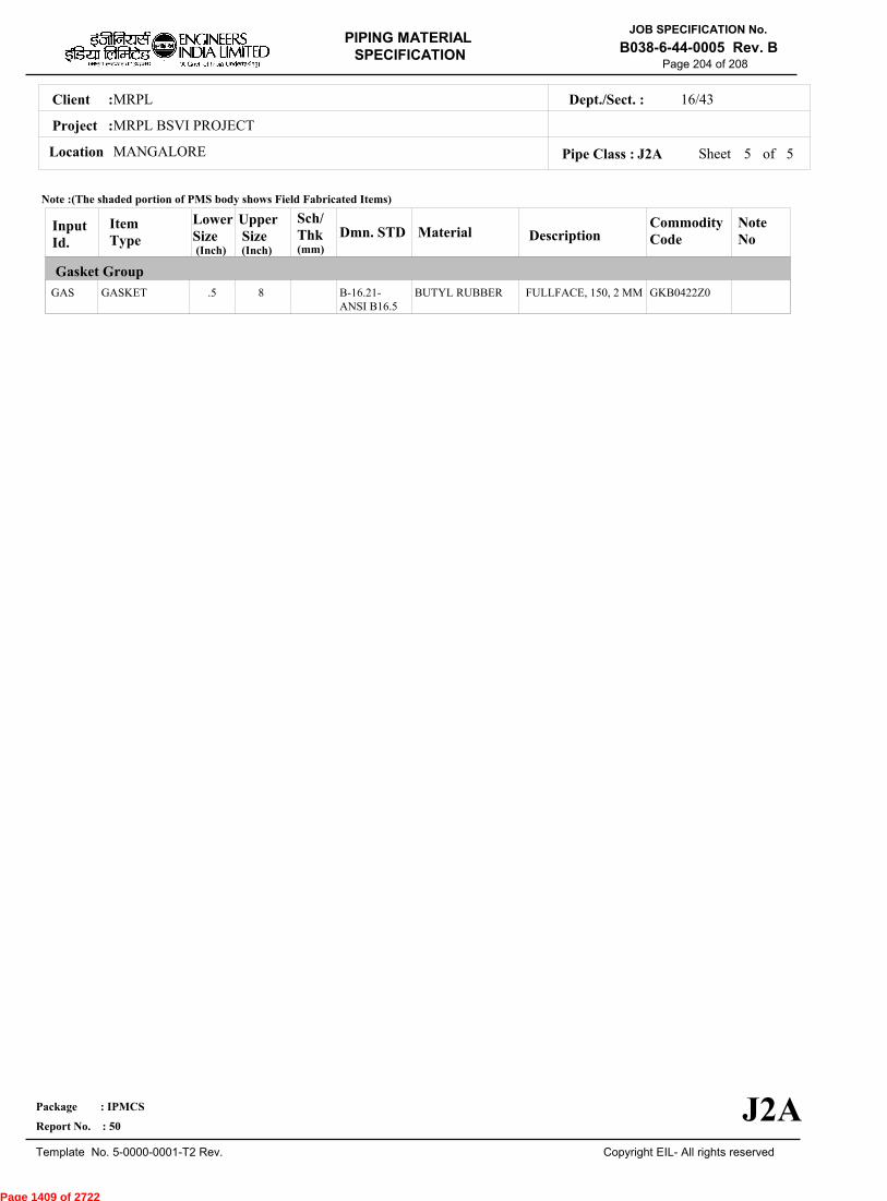
MRPLClient :
MRPL BSVI PROJECT
MANGALORELocation
16/43Dept./Sect. :
Project :
PIPING MATERIAL
SPECIFICATION
Copyright EIL- All rights reserved
JOB SPECIFICATION No.
B038-6-44-0005 Rev. B
Package : IPMCS
Report No. : 50
Template No. 5-0000-0001-T2 Rev.
Page 204 of 208
Sheet 5 of 5Pipe Class : J2A
InputId.
Item Type
LowerSize
Upper Size
Sch/Thk DescriptionMaterial
CommodityCode
NoteNo
Gasket Group
Dmn. STD(Inch) (Inch)
GAS GASKET .5 8 FULLFACE, 150, 2 MMBUTYL RUBBER GKB0422Z0B-16.21-ANSI B16.5
Note :(The shaded portion of PMS body shows Field Fabricated Items)
J2A
(mm)
Page 1409 of 2722

MRPLClient :
MRPL BSVI PROJECT
MANGALORELocation
16/43Dept./Sect. :
Project :
PIPING MATERIAL
SPECIFICATION
Copyright EIL- All rights reserved
JOB SPECIFICATION No.
B038-6-44-0005 Rev. B
Package : IPMCS
Report No. : 50
Template No. 5-0000-0001-T2 Rev.
Page 205 of 208
J3APIPE CLASS :150RATING :CS (Galv.)BASE MATERIAL : 0CORROSION ALLOWANCE : SPECIAL REQUIREMENT :
MM
SERVICEINSTRUMENT AIR
NOTES19
20
21
46
89
151
THREADED JOINTS SHALL BE MADE WITH 1" WIDTH PTFE JOINING TAPE.
SURFACES WHERE GALVANISING HAS BEEN BURNT OFF SHALL BE WIRE BRUSHED AND COLD GALVANISED WITHZINC COATING COMPOUND.NO FIELD HYDROSTATIC TESTING IS PERMITTED IN INSTRUMENT AIR SERVICE.
FOR BRANCH CONNECTION "X", USE EQUAL TEE / REDUCING TEE WITH NIPPLE AND REDUCING COUPLING.
FOR SIZES 2" & ABOVE, REFER A3A & A1A CLASSES CAN ALSO BE USED.
NDT REQUIREMENT SHALL BE AS PER JOB SPECIFICATION B038-6-44-0016.
SPECIAL NOTES
ITEM SIZE DESCRIPTION A.CODEMAINTAINENCEJOINTS
PIPE JOINTS
DRAINS
VENTS
TEMP.CONN
PRESS.CONN
ALL
ALL
ALL
ALL
1.5"
0.75"
UNIONS (SCRF)
SCREWED COUPLING
REFER EILSTD 7-44-0350, DC3
REFER EIL STD. 7-44-0350, VC3
FLANGED. REFER EIL STD 7-44-0353
SCRD NIPPLE WITH VALVE TO SPEC AS PER EIL STD 7-44-0354
TEMP
PRESS 10.55 10.55
0 65
Sheet 1 of
TEMPERATURE (Deg. C) AND PRESSURE ( Kg/Sq. cm g ) RATINGS
Pipe Class : J3A
J3A
4
Page 1410 of 2722
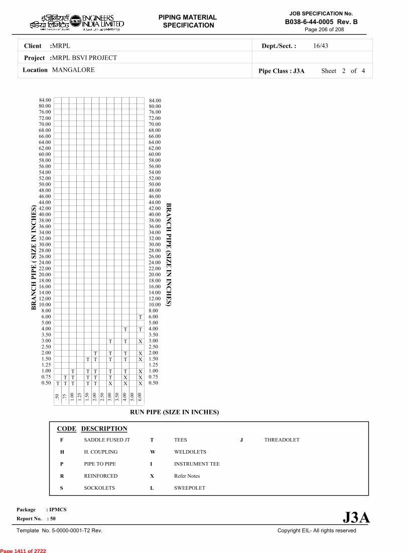
MRPLClient :
MRPL BSVI PROJECT
MANGALORELocation
16/43Dept./Sect. :
Project :
PIPING MATERIAL
SPECIFICATION
Copyright EIL- All rights reserved
JOB SPECIFICATION No.
B038-6-44-0005 Rev. B
Package : IPMCS
Report No. : 50
Template No. 5-0000-0001-T2 Rev.
Page 206 of 208
Sheet 2 ofPipe Class : J3A
T T T T T X X X0.50T T T T T X X0.75
T T T T T X1.001.25
T T T T X1.50T T T X2.00
2.50T T X3.00
3.50T T4.00
5.00T6.00
8.0010.0012.0014.0016.0018.0020.0022.0024.0026.0028.0030.0032.0034.0036.0038.0040.0042.0044.0046.0048.0050.0052.0054.0056.0058.0060.0062.0064.0066.0068.0070.0072.00
.
50
.
75
1
.00
1
.25
1
.50
2
.00
2
.50
3
.00
3
.50
4
.00
5
.00
6
.00
BR
AN
CH
PIP
E (
SIZ
E I
N I
NC
HE
S)
0.500.751.001.251.502.002.503.003.504.005.006.008.0010.0012.0014.0016.0018.0020.0022.0024.0026.0028.0030.0032.0034.0036.0038.0040.0042.0044.0046.0048.0050.0052.0054.0056.0058.0060.0062.0064.0066.0068.0070.0072.00
BR
AN
CH
PIP
E (SIZ
E IN
INC
HE
S)
RUN PIPE (SIZE IN INCHES)
CODE DESCRIPTION
F
H
P
R
S
T
W
I
X
L
JSADDLE FUSED JT
H. COUPLING
PIPE TO PIPE
REINFORCED
SOCKOLETS
TEES
WELDOLETS
INSTRUMENT TEE
Refer Notes
SWEEPOLET
THREADOLET
J3A
76.0080.0084.00
76.0080.0084.00
4
Page 1411 of 2722
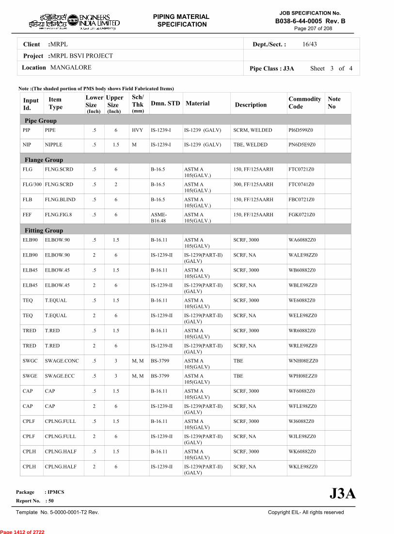
MRPLClient :
MRPL BSVI PROJECT
MANGALORELocation
16/43Dept./Sect. :
Project :
PIPING MATERIAL
SPECIFICATION
Copyright EIL- All rights reserved
JOB SPECIFICATION No.
B038-6-44-0005 Rev. B
Package : IPMCS
Report No. : 50
Template No. 5-0000-0001-T2 Rev.
Page 207 of 208
Sheet 3 ofPipe Class : J3A
InputId.
Item Type
LowerSize
Upper Size
Sch/Thk DescriptionMaterial
CommodityCode
NoteNo
Pipe Group
Flange Group
Fitting Group
Dmn. STD(Inch) (Inch)
PIP
NIP
FLG
FLG/300
FLB
FEF
ELB90
ELB90
ELB45
ELB45
TEQ
TEQ
TRED
TRED
SWGC
SWGE
CAP
CAP
CPLF
CPLF
CPLH
CPLH
PIPE
NIPPLE
FLNG.SCRD
FLNG.SCRD
FLNG.BLIND
FLNG.FIG.8
ELBOW.90
ELBOW.90
ELBOW.45
ELBOW.45
T.EQUAL
T.EQUAL
T.RED
T.RED
SWAGE.CONC
SWAGE.ECC
CAP
CAP
CPLNG.FULL
CPLNG.FULL
CPLNG.HALF
CPLNG.HALF
.5
.5
.5
.5
.5
.5
.5
2
.5
2
.5
2
.5
2
.5
.5
.5
2
.5
2
.5
2
6
1.5
6
2
6
6
1.5
6
1.5
6
1.5
6
1.5
6
3
3
1.5
6
1.5
6
1.5
6
HVY
M
M, M
M, M
SCRM, WELDED
TBE, WELDED
150, FF/125AARH
300, FF/125AARH
150, FF/125AARH
150, FF/125AARH
SCRF, 3000
SCRF, NA
SCRF, 3000
SCRF, NA
SCRF, 3000
SCRF, NA
SCRF, 3000
SCRF, NA
TBE
TBE
SCRF, 3000
SCRF, NA
SCRF, 3000
SCRF, NA
SCRF, 3000
SCRF, NA
IS-1239 (GALV)
IS-1239 (GALV)
ASTM A105(GALV.)
ASTM A105(GALV.)
ASTM A105(GALV.)
ASTM A105(GALV.)
ASTM A105(GALV)
IS-1239(PART-II)(GALV)
ASTM A105(GALV)
IS-1239(PART-II)(GALV)
ASTM A105(GALV)
IS-1239(PART-II)(GALV)
ASTM A105(GALV)
IS-1239(PART-II)(GALV)
ASTM A105(GALV)
ASTM A105(GALV)
ASTM A105(GALV)
IS-1239(PART-II)(GALV)
ASTM A105(GALV)
IS-1239(PART-II)(GALV)
ASTM A105(GALV)
IS-1239(PART-II)(GALV)
PI6D599Z0
PN6D5E9Z0
FTC0721Z0
FTC0741Z0
FBC0721Z0
FGK0721Z0
WA60882Z0
WALE98ZZ0
WB60882Z0
WBLE98ZZ0
WE60882Z0
WELE98ZZ0
WR60882Z0
WRLE98ZZ0
WNH08EZZ0
WPH08EZZ0
WF60882Z0
WFLE98ZZ0
WJ60882Z0
WJLE98ZZ0
WK60882Z0
WKLE98ZZ0
IS-1239-I
IS-1239-I
B-16.5
B-16.5
B-16.5
ASME-B16.48
B-16.11
IS-1239-II
B-16.11
IS-1239-II
B-16.11
IS-1239-II
B-16.11
IS-1239-II
BS-3799
BS-3799
B-16.11
IS-1239-II
B-16.11
IS-1239-II
B-16.11
IS-1239-II
Note :(The shaded portion of PMS body shows Field Fabricated Items)
J3A
(mm)
4
Page 1412 of 2722
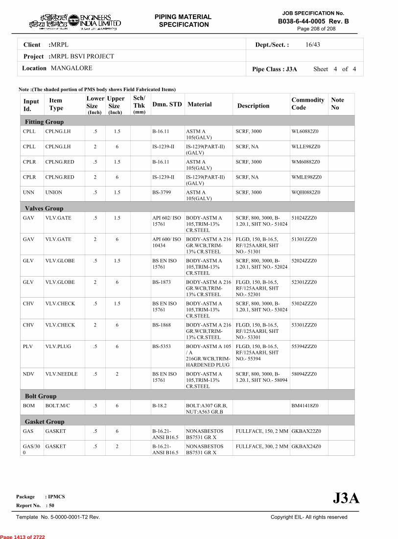
MRPLClient :
MRPL BSVI PROJECT
MANGALORELocation
16/43Dept./Sect. :
Project :
PIPING MATERIAL
SPECIFICATION
Copyright EIL- All rights reserved
JOB SPECIFICATION No.
B038-6-44-0005 Rev. B
Package : IPMCS
Report No. : 50
Template No. 5-0000-0001-T2 Rev.
Page 208 of 208
Sheet 4 of 4Pipe Class : J3A
InputId.
Item Type
LowerSize
Upper Size
Sch/Thk DescriptionMaterial
CommodityCode
NoteNo
Fitting Group
Valves Group
Bolt Group
Gasket Group
Dmn. STD(Inch) (Inch)
CPLL
CPLL
CPLR
CPLR
UNN
GAV
GAV
GLV
GLV
CHV
CHV
PLV
NDV
BOM
GAS
GAS/300
CPLNG.LH
CPLNG.LH
CPLNG.RED
CPLNG.RED
UNION
VLV.GATE
VLV.GATE
VLV.GLOBE
VLV.GLOBE
VLV.CHECK
VLV.CHECK
VLV.PLUG
VLV.NEEDLE
BOLT.M/C
GASKET
GASKET
.5
2
.5
2
.5
.5
2
.5
2
.5
2
.5
.5
.5
.5
.5
1.5
6
1.5
6
1.5
1.5
6
1.5
6
1.5
6
6
2
6
6
2
SCRF, 3000
SCRF, NA
SCRF, 3000
SCRF, NA
SCRF, 3000
SCRF, 800, 3000, B-1.20.1, SHT NO.- 51024
FLGD, 150, B-16.5,RF/125AARH, SHTNO.- 51301
SCRF, 800, 3000, B-1.20.1, SHT NO.- 52024
FLGD, 150, B-16.5,RF/125AARH, SHTNO.- 52301
SCRF, 800, 3000, B-1.20.1, SHT NO.- 53024
FLGD, 150, B-16.5,RF/125AARH, SHTNO.- 53301
FLGD, 150, B-16.5,RF/125AARH, SHTNO.- 55394
SCRF, 800, 3000, B-1.20.1, SHT NO.- 58094
FULLFACE, 150, 2 MM
FULLFACE, 300, 2 MM
ASTM A105(GALV)
IS-1239(PART-II)(GALV)
ASTM A105(GALV)
IS-1239(PART-II)(GALV)
ASTM A105(GALV)
BODY-ASTM A105,TRIM-13%CR.STEEL
BODY-ASTM A 216GR.WCB,TRIM-13% CR.STEEL
BODY-ASTM A105,TRIM-13%CR.STEEL
BODY-ASTM A 216GR.WCB,TRIM-13% CR.STEEL
BODY-ASTM A105,TRIM-13%CR.STEEL
BODY-ASTM A 216GR.WCB,TRIM-13% CR.STEEL
BODY-ASTM A 105/ A216GR.WCB,TRIM-HARDENED PLUG
BODY-ASTM A105,TRIM-13%CR.STEEL
BOLT:A307 GR.B,NUT:A563 GR.B
NONASBESTOSBS7531 GR X
NONASBESTOSBS7531 GR X
WL60882Z0
WLLE98ZZ0
WM60882Z0
WMLE98ZZ0
WQH0882Z0
51024ZZZ0
51301ZZZ0
52024ZZZ0
52301ZZZ0
53024ZZZ0
53301ZZZ0
55394ZZZ0
58094ZZZ0
BM41418Z0
GKBAX22Z0
GKBAX24Z0
B-16.11
IS-1239-II
B-16.11
IS-1239-II
BS-3799
API 602/ ISO15761
API 600/ ISO10434
BS EN ISO15761
BS-1873
BS EN ISO15761
BS-1868
BS-5353
BS EN ISO15761
B-18.2
B-16.21-ANSI B16.5
B-16.21-ANSI B16.5
Note :(The shaded portion of PMS body shows Field Fabricated Items)
J3A
(mm)
Page 1413 of 2722
JOB PIPING MATERIAL SPECIFICATION
GENERAL NOTES
JOB SPECIFICATION No.
B038-6-44-0005-A1 Rev.A
Page 1 of 13
A 29/05/2017 ISSUED FOR COMMENTS SG AAB MK
Rev. No
Date Purpose Prepared
by Checked
by Approved
by
Format No. EIL-1641-1924 Rev.1 Copyright EIL – All rights reserved
ANNEXURE – I (TO PMS)
JOB
PIPING MATERIAL SPECIFICATION
GENERAL NOTES
PROJECT : MRPL BS VI PROJECT
CLIENT : MRPL
LOCATION : MANGALORE.
JOB NO. : B038
Page 1414 of 2722

JOB PIPING MATERIAL SPECIFICATION
GENERAL NOTES
JOB SPECIFICATION No.
B038-6-44-0005-A1 Rev. A
Page 2 of 13
Format No. EIL-1641-1924 Rev.1 Copyright EIL – All rights reserved
Abbreviations:
PMS : Piping Material Specification
Page 1415 of 2722
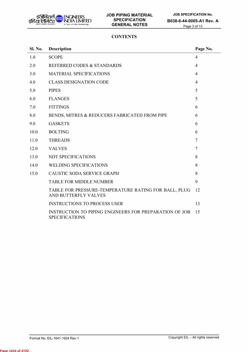
JOB PIPING MATERIAL SPECIFICATION
GENERAL NOTES
JOB SPECIFICATION No.
B038-6-44-0005-A1 Rev. A
Page 3 of 13
Format No. EIL-1641-1924 Rev.1 Copyright EIL – All rights reserved
CONTENTS
Sl. No. Description Page No.
1.0 SCOPE 4
2.0 REFERRED CODES & STANDARDS 4
3.0 MATERIAL SPECIFICATIONS 4
4.0 CLASS DESIGNATION CODE 4
5.0 PIPES 5
6.0 FLANGES 5
7.0 FITTINGS 6
8.0 BENDS, MITRES & REDUCERS FABRICATED FROM PIPE 6
9.0 GASKETS 6
10.0 BOLTING 6
11.0 THREADS 7
12.0 VALVES 7
13.0 NDT SPECIFICATIONS 8
14.0 WELDING SPECIFICATIONS 8
15.0 CAUSTIC SODA SERVICE GRAPH 8
TABLE FOR MIDDLE NUMBER 9
TABLE FOR PRESSURE-TEMPERATURE RATING FOR BALL, PLUG
AND BUTTERFLY VALVES
12
INSTRUCTIONS TO PROCESS USER 13
INSTRUCTION TO PIPING ENGINEERS FOR PREPARATION OF JOB
SPECIFICATIONS
15
Page 1416 of 2722
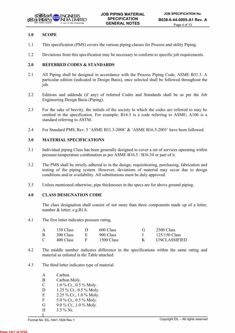
JOB PIPING MATERIAL SPECIFICATION
GENERAL NOTES
JOB SPECIFICATION No.
B038-6-44-0005-A1 Rev. A
Page 4 of 13
Format No. EIL-1641-1924 Rev.1 Copyright EIL – All rights reserved
1.0 SCOPE
1.1 This specification (PMS) covers the various piping classes for Process and utility Piping.
1.2 Deviations from this specification may be necessary to conform to specific job requirements.
2.0 REFERRED CODES & STANDARDS
2.1 All Piping shall be designed in accordance with the Process Piping Code, ASME B31.3. A
particular edition (indicated in Design Basis), once selected shall be followed throughout the
job.
2.2 Editions and addenda (if any) of referred Codes and Standards shall be as per the Job
Engineering Design Basis (Piping).
2.3 For the sake of brevity, the initials of the society to which the codes are referred to may be
omitted in the specification. For example; B16.5 is a code referring to ASME; A106 is a
standard referring to ASTM.
2.4 For Standard PMS, Rev. 5 ‘ASME B31.3-2008’ & ‘ASME B16.5-2003’ have been followed.
3.0 MATERIAL SPECIFICATIONS
3.1 Individual piping Class has been generally designed to cover a set of services operating within
pressure-temperature combination as per ASME B16.5 / B16.34 or part of it.
3.2 The PMS shall be strictly adhered to in the design, requisitioning, purchasing, fabrication and
testing of the piping system. However, deviations of material may occur due to design
conditions and/or availability. All substitutions must be duly approved.
3.3 Unless mentioned otherwise, pipe thicknesses in the specs are for above ground piping.
4.0 CLASS DESIGNATION CODE
The class designation shall consist of not more than three components made up of a letter,
number & letter; e.g.B1A.
4.1 The first letter indicates pressure rating.
A 150 Class D 600 Class G 2500 Class
B 300 Class E 900 Class J 125/150 Class
C 400 Class F 1500 Class K UNCLASSIFIED
4.2 The middle number indicates difference in the specifications within the same rating and
material as enlisted in the Table attached.
4.3 The third letter indicates type of material.
A Carbon
B Carbon Moly.
C 1.0 % Cr., 0.5 % Moly.
D 1.25 % Cr., 0.5 % Moly.
E 2.25 % Cr., 1.0 % Moly.
F 5.0 % Cr., 0.5 % Moly.
G 9.0 % Cr., 1.0 % Moly.
H 3.5 % Ni.
I
Page 1417 of 2722

JOB PIPING MATERIAL SPECIFICATION
GENERAL NOTES
JOB SPECIFICATION No.
B038-6-44-0005-A1 Rev. A
Page 5 of 13
Format No. EIL-1641-1924 Rev.1 Copyright EIL – All rights reserved
J Nickel / Titanum
K Stainless steel type 304, 304H, 304L.
L Aluminium
M Stabilised stainless steel type 316, 316H, 321, 347.
N 316L
P Monel / Alloy 20
Q Hastalloy / Inconel / Incoloy
R Lead
S PVC & FRP, PP / FRP, PVDF / FRP
T Cast Iron / Silicon Iron
U
V Duplex Stainless Steel
W Cupro-Nickel
Y Lined steel (Rubber Lined, Teflon Lined, Cement lined etc).
Z HDPE / PDVF / Teflon / PVC
5.0 PIPES
5.1 Pipe dimension shall be in accordance with ASME B36.10, IS:1239 & IS:3589 for wrought
steel and wrought iron pipe; to B36.10 / B36.19 for stainless steel pipe and respective ASTM
Standard for non-ferrous and non- metallic pipes.
5.2 Pipe made by acid-bessemer process shall not be acceptable, steel pipe shall be made by open
hearth, electric furnace or basic Oxygen process.
5.3 All pipe threads shall conform to ASME B1.20.1 except where otherwise noted.
5.4 Pipe thicknesses not covered in different classes of this specification shall be calculated to
meet specific job requirement based on actual max. design condition to economise on
thickness. However, in such cases the thickness shall be calculated at not less than 80% of
class rating unless defined otherwise in the Job Engineering Design Basis (Piping).
5.5 Maximum of 10% of Corrosion Allowance may be adjusted to optimize on pipe schedule.
However, if CA is suffixed by 'minimum', this downward adjustment shall not be used.
5.6 Non-standard pipe sizes 1¼", 2½", 3½", 5" and 22" shall not be treated as a part of this
specification unless these sizes are separately called out.
6.0 FLANGES
6.1 Flanges shall be in accordance with the following codes, except where otherwise noted:
Upto 24" (150# -1500#) ASME B16.5
Upto 12" , 2500# ASME B16.5
Above 24" ASME B16.47 SERIES 'B' / AWWA / EIL' STD.
Flanges to ASME B16.47 SERIES 'A' or any other standard (e.g. DIN, GOST, JIS etc.) may
be specified to mate with equipment or valve flanges with the corresponding bolting.
6.2 Finish of steel flange faces shall be as follows:
Stock Finish : 1000 µin AARH max.
Serrated Finish / 125 AARH / : Serrations with 125-250µin AARH
Smooth finish
63 AARH : 32 TO 63 µin AARH
Page 1418 of 2722
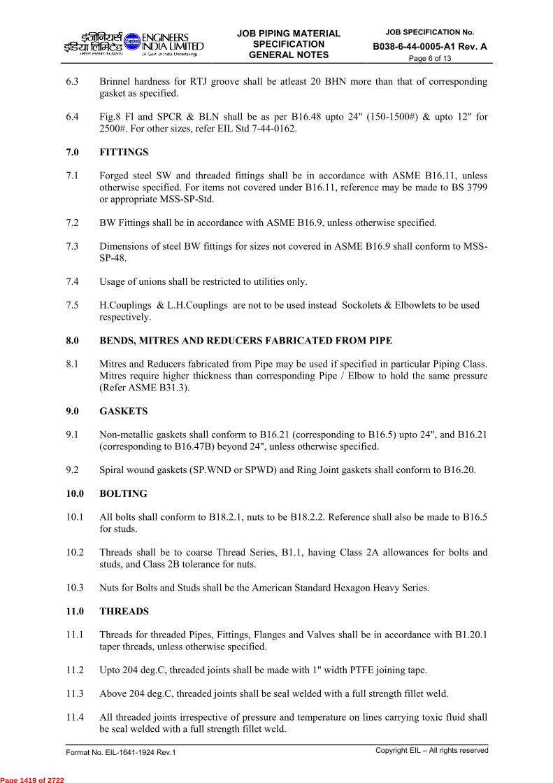
JOB PIPING MATERIAL SPECIFICATION
GENERAL NOTES
JOB SPECIFICATION No.
B038-6-44-0005-A1 Rev. A
Page 6 of 13
Format No. EIL-1641-1924 Rev.1 Copyright EIL – All rights reserved
6.3 Brinnel hardness for RTJ groove shall be atleast 20 BHN more than that of corresponding
gasket as specified.
6.4 Fig.8 Fl and SPCR & BLN shall be as per B16.48 upto 24" (150-1500#) & upto 12" for
2500#. For other sizes, refer EIL Std 7-44-0162.
7.0 FITTINGS
7.1 Forged steel SW and threaded fittings shall be in accordance with ASME B16.11, unless
otherwise specified. For items not covered under B16.11, reference may be made to BS 3799
or appropriate MSS-SP-Std.
7.2 BW Fittings shall be in accordance with ASME B16.9, unless otherwise specified.
7.3 Dimensions of steel BW fittings for sizes not covered in ASME B16.9 shall conform to MSS-
SP-48.
7.4 Usage of unions shall be restricted to utilities only.
7.5 H.Couplings & L.H.Couplings are not to be used instead Sockolets & Elbowlets to be used
respectively.
8.0 BENDS, MITRES AND REDUCERS FABRICATED FROM PIPE
8.1 Mitres and Reducers fabricated from Pipe may be used if specified in particular Piping Class.
Mitres require higher thickness than corresponding Pipe / Elbow to hold the same pressure
(Refer ASME B31.3).
9.0 GASKETS
9.1 Non-metallic gaskets shall conform to B16.21 (corresponding to B16.5) upto 24", and B16.21
(corresponding to B16.47B) beyond 24", unless otherwise specified.
9.2 Spiral wound gaskets (SP.WND or SPWD) and Ring Joint gaskets shall conform to B16.20.
10.0 BOLTING
10.1 All bolts shall conform to B18.2.1, nuts to be B18.2.2. Reference shall also be made to B16.5
for studs.
10.2 Threads shall be to coarse Thread Series, B1.1, having Class 2A allowances for bolts and
studs, and Class 2B tolerance for nuts.
10.3 Nuts for Bolts and Studs shall be the American Standard Hexagon Heavy Series.
11.0 THREADS
11.1 Threads for threaded Pipes, Fittings, Flanges and Valves shall be in accordance with B1.20.1
taper threads, unless otherwise specified.
11.2 Upto 204 deg.C, threaded joints shall be made with 1" width PTFE joining tape.
11.3 Above 204 deg.C, threaded joints shall be seal welded with a full strength fillet weld.
11.4 All threaded joints irrespective of pressure and temperature on lines carrying toxic fluid shall
be seal welded with a full strength fillet weld.
Page 1419 of 2722
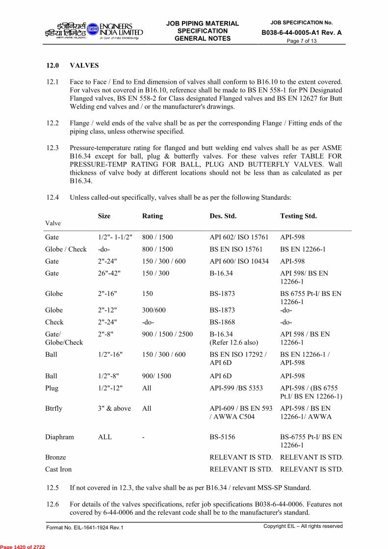
JOB PIPING MATERIAL SPECIFICATION
GENERAL NOTES
JOB SPECIFICATION No.
B038-6-44-0005-A1 Rev. A
Page 7 of 13
Format No. EIL-1641-1924 Rev.1 Copyright EIL – All rights reserved
12.0 VALVES
12.1 Face to Face / End to End dimension of valves shall conform to B16.10 to the extent covered.
For valves not covered in B16.10, reference shall be made to BS EN 558-1 for PN Designated
Flanged valves, BS EN 558-2 for Class designated Flanged valves and BS EN 12627 for Butt
Welding end valves and / or the manufacturer's drawings.
12.2 Flange / weld ends of the valve shall be as per the corresponding Flange / Fitting ends of the
piping class, unless otherwise specified.
12.3 Pressure-temperature rating for flanged and butt welding end valves shall be as per ASME
B16.34 except for ball, plug & butterfly valves. For these valves refer TABLE FOR
PRESSURE-TEMP RATING FOR BALL, PLUG AND BUTTERFLY VALVES. Wall
thickness of valve body at different locations should not be less than as calculated as per
B16.34.
12.4 Unless called-out specifically, valves shall be as per the following Standards:
Valve Size Rating Des. Std. Testing Std.
Gate 1/2"- 1-1/2" 800 / 1500 API 602/ ISO 15761 API-598
Globe / Check -do- 800 / 1500 BS EN ISO 15761 BS EN 12266-1
Gate 2"-24" 150 / 300 / 600 API 600/ ISO 10434 API-598
Gate 26"-42" 150 / 300 B-16.34 API 598/ BS EN
12266-1
Globe
Globe
2"-16"
2"-12"
150
300/600
BS-1873
BS-1873
BS 6755 Pt-I/ BS EN
12266-1
-do-
Check 2"-24" -do- BS-1868 -do-
Gate/
Globe/Check
2"-8" 900 / 1500 / 2500 B-16.34
(Refer 12.6 also)
API 598 / BS EN
12266-1
Ball 1/2"-16" 150 / 300 / 600
BS EN ISO 17292 /
API 6D
BS EN 12266-1 /
API-598
Ball 1/2"-8" 900/ 1500 API 6D API-598
Plug 1/2"-12" All API-599 /BS 5353 API-598 / (BS 6755
Pt.I/ BS EN 12266-1)
Btrfly 3" & above All API-609 / BS EN 593
/ AWWA C504
API-598 / BS EN
12266-1/ AWWA
Diaphram ALL - BS-5156 BS-6755 Pt-I/ BS EN
12266-1
Bronze RELEVANT IS STD. RELEVANT IS STD.
Cast Iron RELEVANT IS STD. RELEVANT IS STD.
12.5 If not covered in 12.3, the valve shall be as per B16.34 / relevant MSS-SP Standard.
12.6 For details of the valves specifications, refer job specifications B038-6-44-0006. Features not
covered by 6-44-0006 and the relevant code shall be to the manufacturer's standard.
Page 1420 of 2722

JOB PIPING MATERIAL SPECIFICATION
GENERAL NOTES
JOB SPECIFICATION No.
B038-6-44-0005-A1 Rev. A
Page 8 of 13
Format No. EIL-1641-1924 Rev.1 Copyright EIL – All rights reserved
12.7 Unless otherwise specifically called for, upto 600# rating, 2" and larger size steel Gate, Globe
& Check valves in Hydrocarbon and utility service shall have bolted bonnets. Pressure-seal
bonnets or covers shall be used for Classes 900# and above to minimize bonnet leakage.
However, valves with Pr-seal Bonnet shall have wall thickness & stem diameter as per API-
600, (if required). Welded bonnets or screwed & seal welded bonnets are acceptable for sizes
lower than 2" for Classes 900# & above.
13.0 For Non-Destructive Testing (NDT) specification, refer job std. B038-6-44-0016.
14.0 For Welding specifications, refer JOB specs.,Welding charts for piping classes
(B038-6-77-00005).
15.0 For ‘Caustic Soda service graph' refer sheet 13 of 13.
Page 1421 of 2722

JOB PIPING MATERIAL SPECIFICATION
GENERAL NOTES
JOB SPECIFICATION No.
B038-6-44-0005-A1 Rev. A
Page 9 of 13
Format No. EIL-1641-1924 Rev.1 Copyright EIL – All rights reserved
TABLE FOR MIDDLE NUMBER
Middle
Number
Carbon Steel
A
AlloySteel
B, C, D, E, F, G, H
SS304 / SS304H /
SS304L
K
SS 316 / 316H / 321 /
321H / 347
M
1 CA=1.5 CA=1.5 CA=NIL
(SS304)
CA=NIL
(SS316)
2 CA=1.5
(IBR)
CA=1.5 (IBR) CA=NIL
(SS304-CRYO)
CA=NIL
(SS321-CRYO)
3 CA=1.5
(CAT'D)
CA=6.0 CA=NIL
(CAT 'D' SS304)
CA=1.5
(SS321)
4 CA=1.5
(LTCS)
CA=3.0 CA=1.5
(SS304H)
CA=NIL
(SS321)
5 CA=1.5
(Hydrogen)
CA=1.5
(Hydrogen)>230OC
CA=3.0
(SS304H)
CA=NIL
(SS316H) – H2
6 CA=4.5 CA=4.5 CA=1.5
(SS304L)
CA=NIL
(SS316H)
7 CA=1.5
(Vacuum)
CA=NIL
(SS304L-Vacuum)
CA=NIL
(SS347)
8 CA=1.5
(Conc.Sulphuric
Acid)
CA=1.5
(SS304L-CRYO)
CA=1.5
(SS347)
9 CA=3.0 CA=1.5
(SS304)
CA=1.5
(SS316)
10 CA=1.5
(Offsites)
11 CA=3.0
(Hardness controlled)
CA=NIL
(SS304L)
12 CA=NIL
(SS304-IBR)
13 CA=6.0
14
15 CA=3.0
(Liquid Sulphur)
CA=1.5
(SS304 H2 & CO2)
CA=1.5
(SS321H - H2)
16 CA=4.5
(NACE)
CA=4.5 (NACE) CA=1.5
(SS304L - NACE)
CA=1.5
(SS321 - NACE)
17 CA=3.0
(dry Chlorine)
18 CA=1.5
(Oxygen)
CA=NIL
(SS304L-Oxygen)
19 CA=3.0
(Caustic / Amine,
Stress relieved)
20 CA=1.5
(Jacket for A15A)
21 CA=1.5
(Sea Water,CS)
32 CA=1.5
(Tracing)
CA=NIL
(Tracing)
33 CA=1.5
(Fire Water)
NOTE: USE MIDDLE NUMBERS 21 TO 30 & 91 TO 99 FOR PROJECT DEPENDENT CLASSES.
Page 1422 of 2722

JOB PIPING MATERIAL SPECIFICATION
GENERAL NOTES
JOB SPECIFICATION No.
B038-6-44-0005-A1 Rev. A
Page 10 of 13
Format No. EIL-1641-1924 Rev.1 Copyright EIL – All rights reserved
TABLE FOR MIDDLE NUMBER
Middle
Number
SS316L
N
NICKEL
/TITANUM
J
ALLUMINIUM
L
MONEL / ALLOY 20
P
1 CA=NIL CA=NIL (NICKEL)
CA=NIL (MONEL)
2 CA=1.5 (CRYO) CA=1.5 (NICKEL)
CA=1.5 (MONEL)
3 CA=NIL
(TITANUM)
CA=NIL(ALLOY 20)
4 CA=1.5
(TITANUM)
CA=1.5 (ALLOY 20)
5 CA=1.5 H2
6 CA=NIL (Vacuum)
7
8
9
10
11 CA=NIL
12
13
14
15
16 CA=1.5(NACE)
17
18 CA=NIL (MONEL)
OXYGEN
19
20
32
33
NOTE: USE MIDDLE NUMBERS 21 TO 30 & 91 TO 99 FOR PROJECT DEPENDENT CLASSES.
Page 1423 of 2722

JOB PIPING MATERIAL SPECIFICATION
GENERAL NOTES
JOB SPECIFICATION No.
B038-6-44-0005-A1 Rev. A
Page 11 of 13
Format No. EIL-1641-1924 Rev.1 Copyright EIL – All rights reserved
TABLE FOR MIDDLE NUMBER
Middle
Number
Hastelloy /
Inconel /
Incoloy
Q
PVC / FRP
S
LINED STEEL
Y
HDPE / PVDF /
TEFLON
Z
1 CA=NIL
(INCONEL
600)
CA=NIL
(PVC)
CA = NIL
(TEF LINED)
CA=NIL
(HDPE) H2SO4
2 CA=1.5
(PVC / FRP)
3 CA = NIL
(INCOLOY
800)
CA=NIL
(FRP)
CA = NIL
(RUBBER LINED -
SOFT)
4 CA = 1.5
(INCOLOY
800)
CA = NIL (RUBBER
LINED – SEMI HARD)
30% HCL
CA = NIL (HDPE) 30%
HCL
5 CA = 3.0 (<= 2”) & NIL
(>= 3”) (CEMENT
LINED) CAT ‘D’ SEA
WATER
CA = NIL (HDPE) 50%
HF
6 CA = 1.5
(INCOLOY
800H)
7
8
9
10
11
12
13
14
15
16
17
18
19
20
32
33 CA = 3.0 (<= 2”) & NIL
(>= 3”) (CEMENT
LINED) FIRE WATER
(SEA)
NOTE: USE MIDDLE NUMBERS 21 TO 30 & 91 TO 99 FOR PROJECT DEPENDENT CLASSES.
Page 1424 of 2722
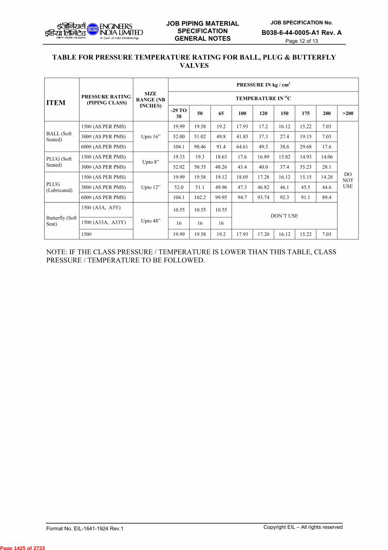
JOB PIPING MATERIAL SPECIFICATION
GENERAL NOTES
JOB SPECIFICATION No.
B038-6-44-0005-A1 Rev. A
Page 12 of 13
Format No. EIL-1641-1924 Rev.1 Copyright EIL – All rights reserved
TABLE FOR PRESSURE TEMPERATURE RATING FOR BALL, PLUG & BUTTERFLY
VALVES
ITEM PRESSURE RATING
(PIPING CLASS)
SIZE
RANGE (NB
INCHES)
PRESSURE IN kg / cm2
TEMPERATURE IN OC
-29 TO
38 50 65 100 120 150 175 200 >200
BALL (Soft Seated)
150# (AS PER PMS)
Upto 16”
19.99 19.58 19.2 17.93 17.2 16.12 15.22 7.03
DO
NOT USE
300# (AS PER PMS) 52.00 51.02 49.8 41.85 37.3 27.4 19.15 7.03
600# (AS PER PMS) 104.1 98.46 91.4 64.61 49.3 38.6 29.68 17.6
PLUG (Soft
Seated)
150# (AS PER PMS) Upto 8”
19.33 19.3 18.63 17.6 16.89 15.82 14.93 14.06
300# (AS PER PMS) 52.02 50.35 48.26 43.4 40.0 37.4 35.23 28.1
PLUG
(Lubricated)
150# (AS PER PMS)
Upto 12”
19.99 19.58 19.12 18.05 17.28 16.12 15.15 14.28
300# (AS PER PMS) 52.0 51.1 49.96 47.3 46.82 46.1 45.5 44.6
600# (AS PER PMS) 104.1 102.2 99.95 94.7 93.74 92.3 91.1 89.4
Butterfly (Soft
Seat)
150# (A3A, A5Y)
Upto 48”
10.55 10.55 10.55 DON’T USE
150# (A33A, A33Y) 16 16 16
150# 19.99 19.58 19.2 17.93 17.20 16.12 15.22 7.03
NOTE: IF THE CLASS PRESSURE / TEMPERATURE IS LOWER THAN THIS TABLE, CLASS
PRESSURE / TEMPERATURE TO BE FOLLOWED.
Page 1425 of 2722

JOB PIPING MATERIAL SPECIFICATION
GENERAL NOTES
JOB SPECIFICATION No.
B038-6-44-0005-A1 Rev. A
Page 13 of 13
Format No. EIL-1641-1924 Rev.1 Copyright EIL – All rights reserved
CAUSTIC SODA SERVICE GRAPH
DEGREE BAUME aBE
0
20
40
60
80
100
120
140
160
180
200
220
240
260
280
0 10 20 30 40 50
CONCENTRATED NaOH, % BY WEIGHT
TE
MP
ER
AT
UR
E O
F14.6 26.4 36 44 5
14.6 26.4 36 44 50.2
AREA – ‘C’
APPLICATION OF NICKEL ALLOYS TO BE CONSIDERED IN THIS AREA
NICKEL ALLOY TRIM FOR VALVES IN
AREAS ‘B’ AND ‘C’ AREA – ‘B’
CARBON STEEL
STESS RELIEVE WELDS & BENDS
AREA – ‘A’
CARBON STEEL
NO STESS RELIEF NECESSARY
Page 1426 of 2722

PIPING MATERIAL
SPECIFICATION EXTRACTS
JOB SPECIFICATION No.
B038-6-44-0005-A2 Rev. A
Template No. 5-0000-0001-T1 Rev.1 Copyright EIL - All rights reserved
Page 1 of 13
A 29/05/2017 ISSUED FOR COMMENTS (FOR SRU & SWS REVAMP)
Rev. No. Date Purpose Prepared by Checked by
PIPING MATERIAL SPECIFICATIONEXTRACTS
Approved by
ANNEXURE - II (TO PMS)
Client : MRPL
Project : MRPL BSVI PROJECT
Location : MANGALORE
Job No. : B038
SG AAB MK
Page 1427 of 2722

PIPING MATERIAL
SPECIFICATION EXTRACTS
JOB SPECIFICATION No.
B038-6-44-0005-A2 Rev. A
Copyright EIL - All rights reservedTemplate No. 5-0000-0001-T2 Rev.1
Page 2 of 13
Abbreviations:
PMS : Piping Material Specifications.
Page 1428 of 2722
PIPING MATERIAL
SPECIFICATION EXTRACTS
JOB SPECIFICATION No.
B038-6-44-0005-A2 Rev. A
Copyright EIL - All rights reservedTemplate No. 5-0000-0001-T2 Rev.1
Page 3 of 13
CONTENTS
Sl. No. Description Pages
1. Piping Material Specification Extracts, (B038-6-44-0005-A2) Rev.A Annexure - II 13
Page 1429 of 2722
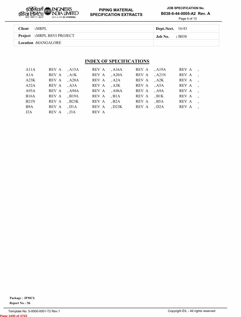
MRPLClient :
MRPL BSVI PROJECTProject :
MANGALORELocation :
16/43Dept./Sect.
PIPING MATERIAL
SPECIFICATION EXTRACTS
JOB SPECIFICATION No.
B038-6-44-0005-A2 Rev. A
Copyright EIL - All rights reserved
Package : IPMCS
Report No. : 56
Template No. 5-0000-0001-T2 Rev.1
Job No. : B038
Page 4 of 13
INDEX OF SPECIFICATIONS
A11A A15A A16A A19AA1A A1K A20A A21NA23K A28A A2A A2KA32A A3A A3K A5AA93A A94A A96A A9AB16A B19A B1A B1KB21N B23K B2A B5AB9A D1A D23K D2AJ2A J3A
REV REV REV REVREV REV REV REVREV REV REV REVREV REV REV REVREV REV REV REVREV REV REV REVREV REV REV REVREV REV REV REVREV REV
A A A AA A A AA A A AA A A AA A A AA A A AA A A AA A A AA A
, , , ,, , , ,, , , ,, , , ,, , , ,, , , ,, , , ,, , , ,,
Page 1430 of 2722
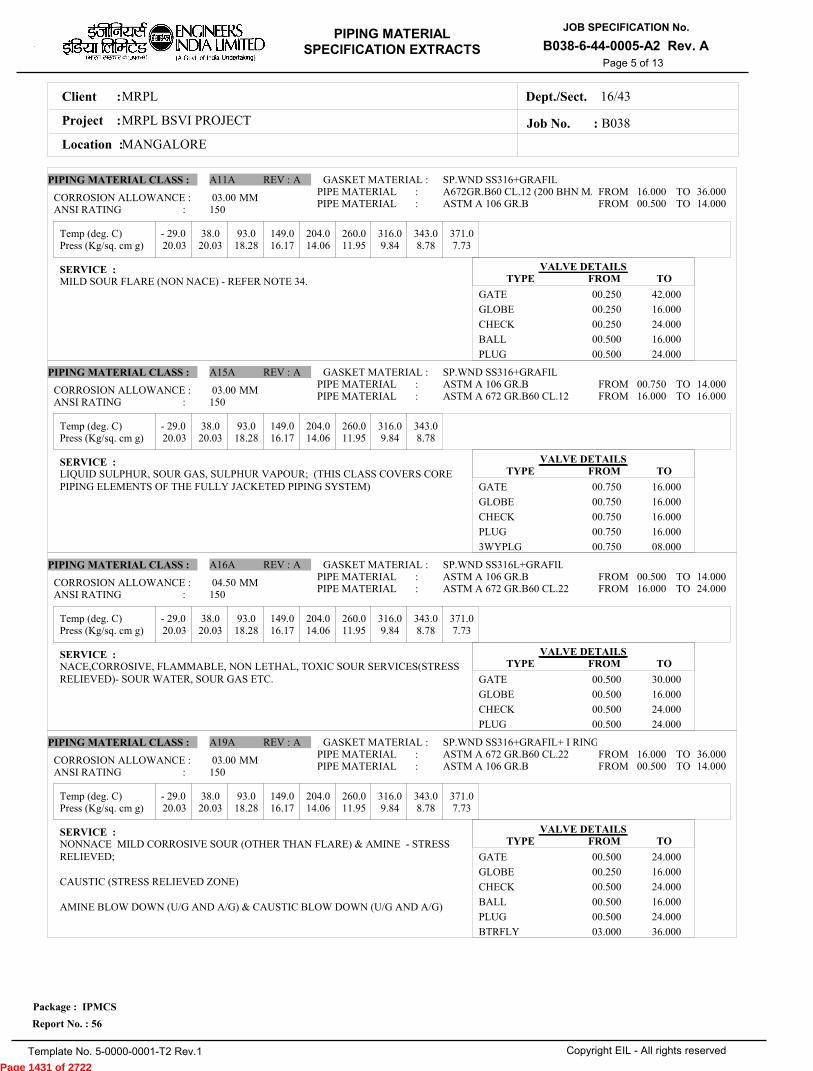
MRPLClient :
MRPL BSVI PROJECTProject :
MANGALORELocation :
16/43Dept./Sect.
PIPING MATERIAL
SPECIFICATION EXTRACTS
JOB SPECIFICATION No.
B038-6-44-0005-A2 Rev. A
Copyright EIL - All rights reserved
Package : IPMCS
Report No. : 56
Template No. 5-0000-0001-T2 Rev.1
Job No. : B038
Page 5 of 13
Temp (deg. C)
Temp (deg. C)
Temp (deg. C)
Temp (deg. C)
Press (Kg/sq. cm g)
Press (Kg/sq. cm g)
Press (Kg/sq. cm g)
Press (Kg/sq. cm g)
- 29.0 38.0 93.0 149.0 204.0 260.0 316.0 343.0 371.0
- 29.0 38.0 93.0 149.0 204.0 260.0 316.0 343.0
- 29.0 38.0 93.0 149.0 204.0 260.0 316.0 343.0 371.0
- 29.0 38.0 93.0 149.0 204.0 260.0 316.0 343.0 371.0
20.03 20.03 18.28 16.17 14.06 11.95 9.84 8.78 7.73
20.03 20.03 18.28 16.17 14.06 11.95 9.84 8.78
20.03 20.03 18.28 16.17 14.06 11.95 9.84 8.78 7.73
20.03 20.03 18.28 16.17 14.06 11.95 9.84 8.78 7.73
03.00
03.00
04.50
03.00
MM
MM
MM
MM
PIPING MATERIAL CLASS :
PIPING MATERIAL CLASS :
PIPING MATERIAL CLASS :
PIPING MATERIAL CLASS :
A11A
A15A
A16A
A19A
REV :
REV :
REV :
REV :
A
A
A
A
GASKET MATERIAL :
GASKET MATERIAL :
GASKET MATERIAL :
GASKET MATERIAL :
SP.WND SS316+GRAFIL
SP.WND SS316+GRAFIL
SP.WND SS316L+GRAFIL
SP.WND SS316+GRAFIL+ I RING
A672GR.B60 CL.12 (200 BHN MAASTM A 106 GR.B
ASTM A 106 GR.BASTM A 672 GR.B60 CL.12
ASTM A 106 GR.BASTM A 672 GR.B60 CL.22
ASTM A 672 GR.B60 CL.22ASTM A 106 GR.B
PIPE MATERIAL :PIPE MATERIAL :
PIPE MATERIAL :PIPE MATERIAL :
PIPE MATERIAL :PIPE MATERIAL :
PIPE MATERIAL :PIPE MATERIAL :
16.000 00.500
00.750 16.000
00.500 16.000
16.000 00.500
36.000 14.000
14.000 16.000
14.000 24.000
36.000 14.000
FROMFROM
FROMFROM
FROMFROM
FROMFROM
TOTO
TOTO
TOTO
TOTO
CORROSION ALLOWANCE :
CORROSION ALLOWANCE :
CORROSION ALLOWANCE :
CORROSION ALLOWANCE :
ANSI RATING :
ANSI RATING :
ANSI RATING :
ANSI RATING :
SERVICE :
SERVICE :
SERVICE :
SERVICE :
MILD SOUR FLARE (NON NACE) - REFER NOTE 34.
LIQUID SULPHUR, SOUR GAS, SULPHUR VAPOUR; (THIS CLASS COVERS COREPIPING ELEMENTS OF THE FULLY JACKETED PIPING SYSTEM)
NACE,CORROSIVE, FLAMMABLE, NON LETHAL, TOXIC SOUR SERVICES(STRESSRELIEVED)- SOUR WATER, SOUR GAS ETC.
NONNACE MILD CORROSIVE SOUR (OTHER THAN FLARE) & AMINE - STRESSRELIEVED;
CAUSTIC (STRESS RELIEVED ZONE)
AMINE BLOW DOWN (U/G AND A/G) & CAUSTIC BLOW DOWN (U/G AND A/G)
VALVE DETAILS
VALVE DETAILS
VALVE DETAILS
VALVE DETAILS
TYPE
TYPE
TYPE
TYPE
FROM
FROM
FROM
FROM
TO
TO
TO
TO
GATE
GLOBE
CHECK
BALL
PLUG
GATE
GLOBE
CHECK
PLUG
3WYPLG
GATE
GLOBE
CHECK
PLUG
GATE
GLOBE
CHECK
BALL
PLUG
BTRFLY
00.250
00.250
00.250
00.500
00.500
00.750
00.750
00.750
00.750
00.750
00.500
00.500
00.500
00.500
00.500
00.250
00.500
00.500
00.500
03.000
42.000
16.000
24.000
16.000
24.000
16.000
16.000
16.000
16.000
08.000
30.000
16.000
24.000
24.000
24.000
16.000
24.000
16.000
24.000
36.000
150
150
150
150
Page 1431 of 2722
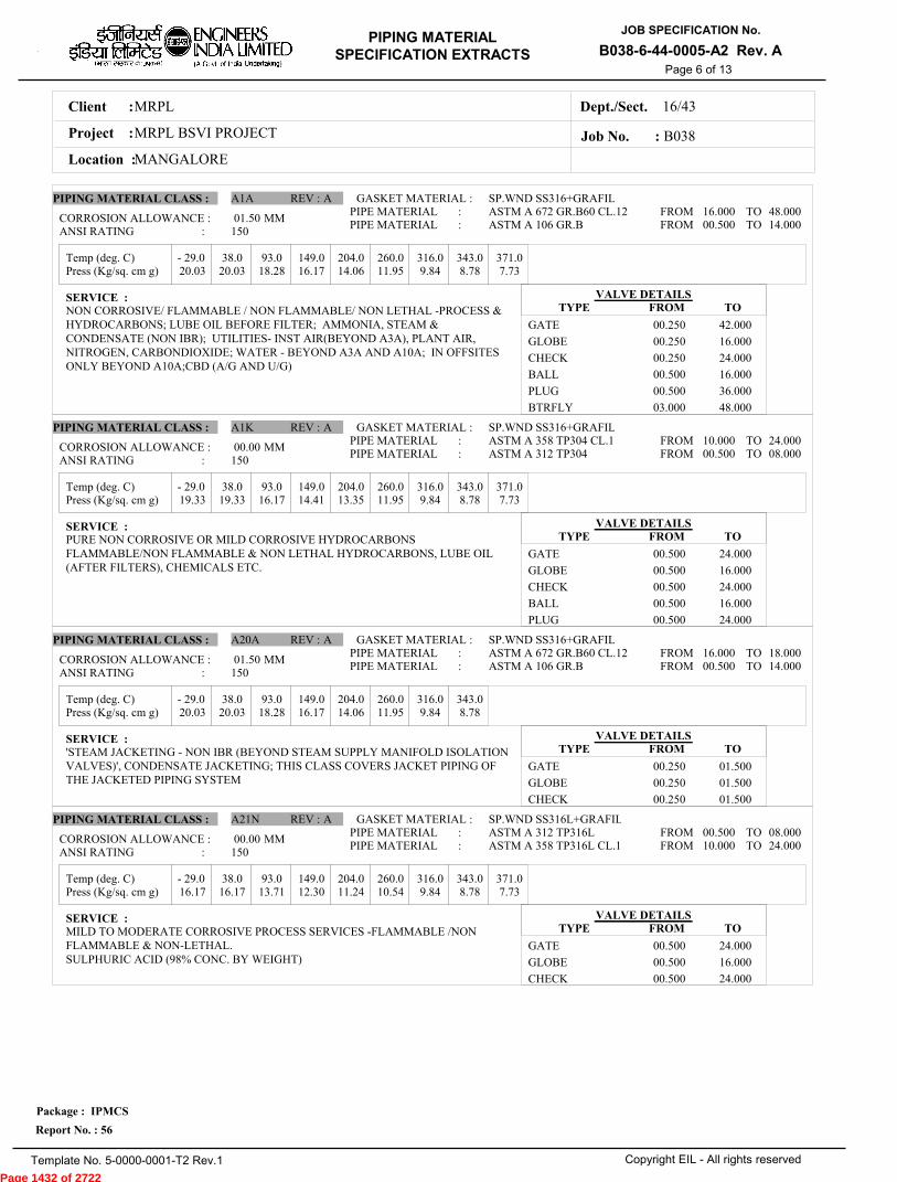
MRPLClient :
MRPL BSVI PROJECTProject :
MANGALORELocation :
16/43Dept./Sect.
PIPING MATERIAL
SPECIFICATION EXTRACTS
JOB SPECIFICATION No.
B038-6-44-0005-A2 Rev. A
Copyright EIL - All rights reserved
Package : IPMCS
Report No. : 56
Template No. 5-0000-0001-T2 Rev.1
Job No. : B038
Page 6 of 13
Temp (deg. C)
Temp (deg. C)
Temp (deg. C)
Temp (deg. C)
Press (Kg/sq. cm g)
Press (Kg/sq. cm g)
Press (Kg/sq. cm g)
Press (Kg/sq. cm g)
- 29.0 38.0 93.0 149.0 204.0 260.0 316.0 343.0 371.0
- 29.0 38.0 93.0 149.0 204.0 260.0 316.0 343.0 371.0
- 29.0 38.0 93.0 149.0 204.0 260.0 316.0 343.0
- 29.0 38.0 93.0 149.0 204.0 260.0 316.0 343.0 371.0
20.03 20.03 18.28 16.17 14.06 11.95 9.84 8.78 7.73
19.33 19.33 16.17 14.41 13.35 11.95 9.84 8.78 7.73
20.03 20.03 18.28 16.17 14.06 11.95 9.84 8.78
16.17 16.17 13.71 12.30 11.24 10.54 9.84 8.78 7.73
01.50
00.00
01.50
00.00
MM
MM
MM
MM
PIPING MATERIAL CLASS :
PIPING MATERIAL CLASS :
PIPING MATERIAL CLASS :
PIPING MATERIAL CLASS :
A1A
A1K
A20A
A21N
REV :
REV :
REV :
REV :
A
A
A
A
GASKET MATERIAL :
GASKET MATERIAL :
GASKET MATERIAL :
GASKET MATERIAL :
SP.WND SS316+GRAFIL
SP.WND SS316+GRAFIL
SP.WND SS316+GRAFIL
SP.WND SS316L+GRAFIL
ASTM A 672 GR.B60 CL.12ASTM A 106 GR.B
ASTM A 358 TP304 CL.1ASTM A 312 TP304
ASTM A 672 GR.B60 CL.12ASTM A 106 GR.B
ASTM A 312 TP316LASTM A 358 TP316L CL.1
PIPE MATERIAL :PIPE MATERIAL :
PIPE MATERIAL :PIPE MATERIAL :
PIPE MATERIAL :PIPE MATERIAL :
PIPE MATERIAL :PIPE MATERIAL :
16.000 00.500
10.000 00.500
16.000 00.500
00.500 10.000
48.000 14.000
24.000 08.000
18.000 14.000
08.000 24.000
FROMFROM
FROMFROM
FROMFROM
FROMFROM
TOTO
TOTO
TOTO
TOTO
CORROSION ALLOWANCE :
CORROSION ALLOWANCE :
CORROSION ALLOWANCE :
CORROSION ALLOWANCE :
ANSI RATING :
ANSI RATING :
ANSI RATING :
ANSI RATING :
SERVICE :
SERVICE :
SERVICE :
SERVICE :
NON CORROSIVE/ FLAMMABLE / NON FLAMMABLE/ NON LETHAL -PROCESS &HYDROCARBONS; LUBE OIL BEFORE FILTER; AMMONIA, STEAM &CONDENSATE (NON IBR); UTILITIES- INST AIR(BEYOND A3A), PLANT AIR,NITROGEN, CARBONDIOXIDE; WATER - BEYOND A3A AND A10A; IN OFFSITESONLY BEYOND A10A;CBD (A/G AND U/G)
PURE NON CORROSIVE OR MILD CORROSIVE HYDROCARBONSFLAMMABLE/NON FLAMMABLE & NON LETHAL HYDROCARBONS, LUBE OIL(AFTER FILTERS), CHEMICALS ETC.
'STEAM JACKETING - NON IBR (BEYOND STEAM SUPPLY MANIFOLD ISOLATIONVALVES)', CONDENSATE JACKETING; THIS CLASS COVERS JACKET PIPING OFTHE JACKETED PIPING SYSTEM
MILD TO MODERATE CORROSIVE PROCESS SERVICES -FLAMMABLE /NONFLAMMABLE & NON-LETHAL.SULPHURIC ACID (98% CONC. BY WEIGHT)
VALVE DETAILS
VALVE DETAILS
VALVE DETAILS
VALVE DETAILS
TYPE
TYPE
TYPE
TYPE
FROM
FROM
FROM
FROM
TO
TO
TO
TO
GATE
GLOBE
CHECK
BALL
PLUG
BTRFLY
GATE
GLOBE
CHECK
BALL
PLUG
GATE
GLOBE
CHECK
GATE
GLOBE
CHECK
00.250
00.250
00.250
00.500
00.500
03.000
00.500
00.500
00.500
00.500
00.500
00.250
00.250
00.250
00.500
00.500
00.500
42.000
16.000
24.000
16.000
36.000
48.000
24.000
16.000
24.000
16.000
24.000
01.500
01.500
01.500
24.000
16.000
24.000
150
150
150
150
Page 1432 of 2722
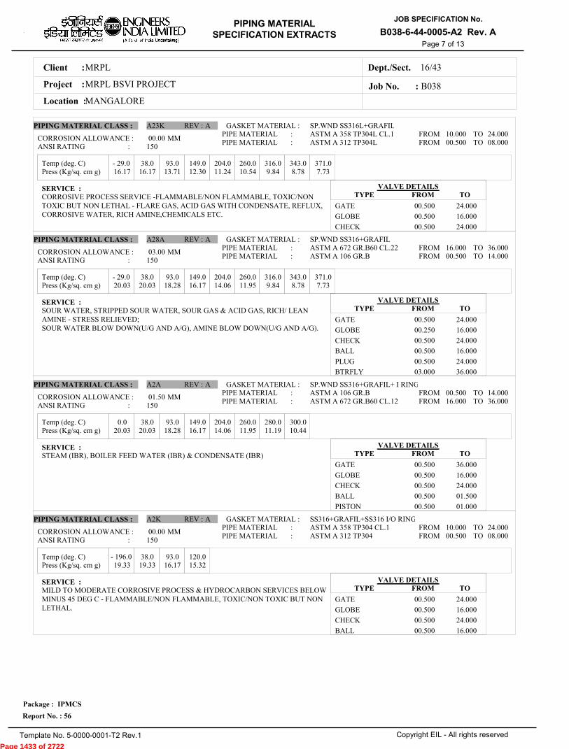
MRPLClient :
MRPL BSVI PROJECTProject :
MANGALORELocation :
16/43Dept./Sect.
PIPING MATERIAL
SPECIFICATION EXTRACTS
JOB SPECIFICATION No.
B038-6-44-0005-A2 Rev. A
Copyright EIL - All rights reserved
Package : IPMCS
Report No. : 56
Template No. 5-0000-0001-T2 Rev.1
Job No. : B038
Page 7 of 13
Temp (deg. C)
Temp (deg. C)
Temp (deg. C)
Temp (deg. C)
Press (Kg/sq. cm g)
Press (Kg/sq. cm g)
Press (Kg/sq. cm g)
Press (Kg/sq. cm g)
- 29.0 38.0 93.0 149.0 204.0 260.0 316.0 343.0 371.0
- 29.0 38.0 93.0 149.0 204.0 260.0 316.0 343.0 371.0
0.0 38.0 93.0 149.0 204.0 260.0 280.0 300.0
- 196.0 38.0 93.0 120.0
16.17 16.17 13.71 12.30 11.24 10.54 9.84 8.78 7.73
20.03 20.03 18.28 16.17 14.06 11.95 9.84 8.78 7.73
20.03 20.03 18.28 16.17 14.06 11.95 11.19 10.44
19.33 19.33 16.17 15.32
00.00
03.00
01.50
00.00
MM
MM
MM
MM
PIPING MATERIAL CLASS :
PIPING MATERIAL CLASS :
PIPING MATERIAL CLASS :
PIPING MATERIAL CLASS :
A23K
A28A
A2A
A2K
REV :
REV :
REV :
REV :
A
A
A
A
GASKET MATERIAL :
GASKET MATERIAL :
GASKET MATERIAL :
GASKET MATERIAL :
SP.WND SS316L+GRAFIL
SP.WND SS316+GRAFIL
SP.WND SS316+GRAFIL+ I RING
SS316+GRAFIL+SS316 I/O RING
ASTM A 358 TP304L CL.1ASTM A 312 TP304L
ASTM A 672 GR.B60 CL.22ASTM A 106 GR.B
ASTM A 106 GR.BASTM A 672 GR.B60 CL.12
ASTM A 358 TP304 CL.1ASTM A 312 TP304
PIPE MATERIAL :PIPE MATERIAL :
PIPE MATERIAL :PIPE MATERIAL :
PIPE MATERIAL :PIPE MATERIAL :
PIPE MATERIAL :PIPE MATERIAL :
10.000 00.500
16.000 00.500
00.500 16.000
10.000 00.500
24.000 08.000
36.000 14.000
14.000 36.000
24.000 08.000
FROMFROM
FROMFROM
FROMFROM
FROMFROM
TOTO
TOTO
TOTO
TOTO
CORROSION ALLOWANCE :
CORROSION ALLOWANCE :
CORROSION ALLOWANCE :
CORROSION ALLOWANCE :
ANSI RATING :
ANSI RATING :
ANSI RATING :
ANSI RATING :
SERVICE :
SERVICE :
SERVICE :
SERVICE :
CORROSIVE PROCESS SERVICE -FLAMMABLE/NON FLAMMABLE, TOXIC/NONTOXIC BUT NON LETHAL - FLARE GAS, ACID GAS WITH CONDENSATE, REFLUX,CORROSIVE WATER, RICH AMINE,CHEMICALS ETC.
SOUR WATER, STRIPPED SOUR WATER, SOUR GAS & ACID GAS, RICH/ LEANAMINE - STRESS RELIEVED;SOUR WATER BLOW DOWN(U/G AND A/G), AMINE BLOW DOWN(U/G AND A/G).
STEAM (IBR), BOILER FEED WATER (IBR) & CONDENSATE (IBR)
MILD TO MODERATE CORROSIVE PROCESS & HYDROCARBON SERVICES BELOWMINUS 45 DEG C - FLAMMABLE/NON FLAMMABLE, TOXIC/NON TOXIC BUT NONLETHAL.
VALVE DETAILS
VALVE DETAILS
VALVE DETAILS
VALVE DETAILS
TYPE
TYPE
TYPE
TYPE
FROM
FROM
FROM
FROM
TO
TO
TO
TO
GATE
GLOBE
CHECK
GATE
GLOBE
CHECK
BALL
PLUG
BTRFLY
GATE
GLOBE
CHECK
BALL
PISTON
GATE
GLOBE
CHECK
BALL
00.500
00.500
00.500
00.500
00.250
00.500
00.500
00.500
03.000
00.500
00.500
00.500
00.500
00.500
00.500
00.500
00.500
00.500
24.000
16.000
24.000
24.000
16.000
24.000
16.000
24.000
36.000
36.000
16.000
24.000
01.500
01.000
24.000
16.000
24.000
16.000
150
150
150
150
Page 1433 of 2722
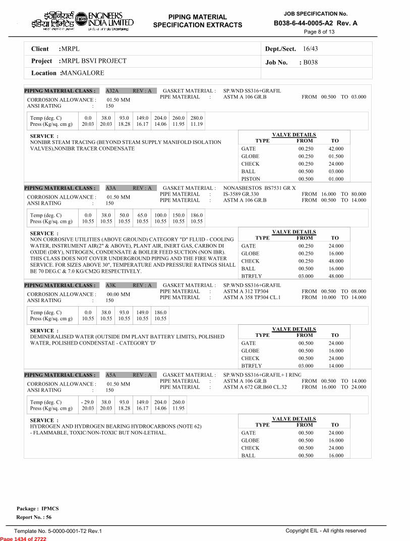
MRPLClient :
MRPL BSVI PROJECTProject :
MANGALORELocation :
16/43Dept./Sect.
PIPING MATERIAL
SPECIFICATION EXTRACTS
JOB SPECIFICATION No.
B038-6-44-0005-A2 Rev. A
Copyright EIL - All rights reserved
Package : IPMCS
Report No. : 56
Template No. 5-0000-0001-T2 Rev.1
Job No. : B038
Page 8 of 13
Temp (deg. C)
Temp (deg. C)
Temp (deg. C)
Temp (deg. C)
Press (Kg/sq. cm g)
Press (Kg/sq. cm g)
Press (Kg/sq. cm g)
Press (Kg/sq. cm g)
0.0 38.0 93.0 149.0 204.0 260.0 280.0
0.0 38.0 50.0 65.0 100.0 150.0 186.0
0.0 38.0 93.0 149.0 186.0
- 29.0 38.0 93.0 149.0 204.0 260.0
20.03 20.03 18.28 16.17 14.06 11.95 11.19
10.55 10.55 10.55 10.55 10.55 10.55 10.55
10.55 10.55 10.55 10.55 10.55
20.03 20.03 18.28 16.17 14.06 11.95
01.50
01.50
00.00
01.50
MM
MM
MM
MM
PIPING MATERIAL CLASS :
PIPING MATERIAL CLASS :
PIPING MATERIAL CLASS :
PIPING MATERIAL CLASS :
A32A
A3A
A3K
A5A
REV :
REV :
REV :
REV :
A
A
A
A
GASKET MATERIAL :
GASKET MATERIAL :
GASKET MATERIAL :
GASKET MATERIAL :
SP.WND SS316+GRAFIL
NONASBESTOS BS7531 GR X
SP.WND SS316+GRAFIL
SP.WND SS316+GRAFIL+ I RING
ASTM A 106 GR.B
IS-3589 GR.330ASTM A 106 GR.B
ASTM A 312 TP304ASTM A 358 TP304 CL.1
ASTM A 106 GR.BASTM A 672 GR.B60 CL.32
PIPE MATERIAL :
PIPE MATERIAL :PIPE MATERIAL :
PIPE MATERIAL :PIPE MATERIAL :
PIPE MATERIAL :PIPE MATERIAL :
00.500
16.000 00.500
00.500 10.000
00.500 16.000
03.000
80.000 14.000
08.000 14.000
14.000 24.000
FROM
FROMFROM
FROMFROM
FROMFROM
TO
TOTO
TOTO
TOTO
CORROSION ALLOWANCE :
CORROSION ALLOWANCE :
CORROSION ALLOWANCE :
CORROSION ALLOWANCE :
ANSI RATING :
ANSI RATING :
ANSI RATING :
ANSI RATING :
SERVICE :
SERVICE :
SERVICE :
SERVICE :
NONIBR STEAM TRACING (BEYOND STEAM SUPPLY MANIFOLD ISOLATIONVALVES),NONIBR TRACER CONDENSATE
NON CORROSIVE UTILITIES (ABOVE GROUND) CATEGORY "D" FLUID - COOLINGWATER, INSTRUMENT AIR(2" & ABOVE), PLANT AIR, INERT GAS, CARBON DIOXIDE (DRY), NITROGEN, CONDENSATE & BOILER FEED SUCTION (NON IBR).THIS CLASS DOES NOT COVER UNDERGROUND PIPING AND THE FIRE WATERSERVICE. FOR SIZES ABOVE 30", TEMPERATURE AND PRESSURE RATINGS SHALLBE 70 DEG.C & 7.0 KG/CM2G RESPECTIVELY.
DEMINERALISED WATER (OUTSIDE DM PLANT BATTERY LIMITS), POLISHEDWATER, POLISHED CONDENSTAE - CATEGORY 'D'
HYDROGEN AND HYDROGEN BEARING HYDROCARBONS (NOTE 62)- FLAMMABLE, TOXIC/NON-TOXIC BUT NON-LETHAL.
VALVE DETAILS
VALVE DETAILS
VALVE DETAILS
VALVE DETAILS
TYPE
TYPE
TYPE
TYPE
FROM
FROM
FROM
FROM
TO
TO
TO
TO
GATE
GLOBE
CHECK
BALL
PISTON
GATE
GLOBE
CHECK
BALL
BTRFLY
GATE
GLOBE
CHECK
BTRFLY
GATE
GLOBE
CHECK
BALL
00.250
00.250
00.250
00.500
00.500
00.250
00.250
00.250
00.500
03.000
00.500
00.500
00.500
03.000
00.500
00.500
00.500
00.500
42.000
01.500
24.000
03.000
01.000
24.000
16.000
48.000
16.000
48.000
24.000
16.000
24.000
14.000
24.000
16.000
24.000
16.000
150
150
150
150
Page 1434 of 2722
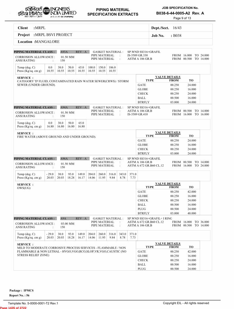
MRPLClient :
MRPL BSVI PROJECTProject :
MANGALORELocation :
16/43Dept./Sect.
PIPING MATERIAL
SPECIFICATION EXTRACTS
JOB SPECIFICATION No.
B038-6-44-0005-A2 Rev. A
Copyright EIL - All rights reserved
Package : IPMCS
Report No. : 56
Template No. 5-0000-0001-T2 Rev.1
Job No. : B038
Page 9 of 13
Temp (deg. C)
Temp (deg. C)
Temp (deg. C)
Temp (deg. C)
Press (Kg/sq. cm g)
Press (Kg/sq. cm g)
Press (Kg/sq. cm g)
Press (Kg/sq. cm g)
0.0 38.0 50.0 65.0 100.0 150.0 186.0
0.0 38.0 50.0 65.0
- 29.0 38.0 93.0 149.0 204.0 260.0 316.0 343.0 371.0
- 29.0 38.0 93.0 149.0 204.0 260.0 316.0 343.0 371.0
10.55 10.55 10.55 10.55 10.55 10.55 10.55
16.80 16.80 16.80 16.80
20.03 20.03 18.28 16.17 14.06 11.95 9.84 8.78 7.73
20.03 20.03 18.28 16.17 14.06 11.95 9.84 8.78 7.73
01.50
01.50
01.50
03.00
MM
MM
MM
MM
PIPING MATERIAL CLASS :
PIPING MATERIAL CLASS :
PIPING MATERIAL CLASS :
PIPING MATERIAL CLASS :
A93A
A94A
A96A
A9A
REV :
REV :
REV :
REV :
A
A
A
A
GASKET MATERIAL :
GASKET MATERIAL :
GASKET MATERIAL :
GASKET MATERIAL :
SP.WND SS316+GRAFIL
SP.WND SS316+GRAFIL
SP.WND SS316+GRAFIL
SP.WND SS316+GRAFIL+ I RING
IS-3589 GR.330ASTM A 106 GR.B
ASTM A 106 GR.BIS-3589 GR.410
ASTM A 106 GR.BASTM A 672 GR.B60 CL.12
ASTM A 672 GR.B60 CL.12ASTM A 106 GR.B
PIPE MATERIAL :PIPE MATERIAL :
PIPE MATERIAL :PIPE MATERIAL :
PIPE MATERIAL :PIPE MATERIAL :
PIPE MATERIAL :PIPE MATERIAL :
16.000 00.500
00.500 16.000
00.500 16.000
16.000 00.500
24.000 14.000
14.000 16.000
14.000 24.000
36.000 14.000
FROMFROM
FROMFROM
FROMFROM
FROMFROM
TOTO
TOTO
TOTO
TOTO
CORROSION ALLOWANCE :
CORROSION ALLOWANCE :
CORROSION ALLOWANCE :
CORROSION ALLOWANCE :
ANSI RATING :
ANSI RATING :
ANSI RATING :
ANSI RATING :
SERVICE :
SERVICE :
SERVICE :
SERVICE :
CATEGORY 'D' FLUID, CONTAMINATED RAIN WATER SEWER(CRWS) / STORMSEWER (UNDER GROUND).
FIRE WATER (ABOVE GROUND AND UNDER GROUND).
OWS(UG)
MILD TO MODERATE CORROSIVE PROCESS SERVICES - FLAMMABLE / NONFLAMMABLE & NON LETHAL - HVGO,VGO,RCO,SLOP,VR,VGO,CAUSTIC (NOSTRESS RELIEF ZONE)
VALVE DETAILS
VALVE DETAILS
VALVE DETAILS
VALVE DETAILS
TYPE
TYPE
TYPE
TYPE
FROM
FROM
FROM
FROM
TO
TO
TO
TO
GATE
GLOBE
CHECK
BALL
BTRFLY
GATE
GLOBE
CHECK
BTRFLY
GATE
GLOBE
CHECK
BALL
PLUG
BTRFLY
GATE
GLOBE
CHECK
BALL
PLUG
00.250
00.250
00.250
00.500
03.000
00.250
00.250
00.250
03.000
00.250
00.250
00.250
00.500
00.500
03.000
00.250
00.250
00.250
00.500
00.500
24.000
16.000
24.000
16.000
24.000
24.000
16.000
24.000
24.000
42.000
16.000
24.000
16.000
24.000
48.000
42.000
16.000
24.000
16.000
24.000
150
150
150
150
Page 1435 of 2722

MRPLClient :
MRPL BSVI PROJECTProject :
MANGALORELocation :
16/43Dept./Sect.
PIPING MATERIAL
SPECIFICATION EXTRACTS
JOB SPECIFICATION No.
B038-6-44-0005-A2 Rev. A
Copyright EIL - All rights reserved
Package : IPMCS
Report No. : 56
Template No. 5-0000-0001-T2 Rev.1
Job No. : B038
Page 10 of 13
Temp (deg. C)
Temp (deg. C)
Temp (deg. C)
Temp (deg. C)
Press (Kg/sq. cm g)
Press (Kg/sq. cm g)
Press (Kg/sq. cm g)
Press (Kg/sq. cm g)
- 29.0 38.0 93.0 149.0 204.0 260.0 316.0 343.0 371.0 399.0 427.0
- 29.0 38.0 93.0 149.0 204.0 260.0 316.0 343.0 371.0 399.0 427.0
- 29.0 38.0 93.0 149.0 204.0 260.0 316.0 343.0 371.0 399.0 427.0
- 29.0 38.0 93.0 149.0 204.0 260.0 316.0 343.0 371.0 399.0 427.0 454.0
52.02 52.02 47.80 46.05 44.64 42.53 40.07 38.66 37.26 35.50 28.82
52.02 52.02 47.80 46.05 44.64 42.53 40.07 38.66 37.26 35.50 28.82
52.02 52.02 47.80 46.05 44.64 42.53 40.07 38.66 37.26 35.50 28.82
50.50 50.50 42.18 37.96 34.80 32.69 30.93 30.23 29.52 29.17 28.47 27.77
04.50
03.00
01.50
00.00
MM
MM
MM
MM
PIPING MATERIAL CLASS :
PIPING MATERIAL CLASS :
PIPING MATERIAL CLASS :
PIPING MATERIAL CLASS :
B16A
B19A
B1A
B1K
REV :
REV :
REV :
REV :
A
A
A
A
GASKET MATERIAL :
GASKET MATERIAL :
GASKET MATERIAL :
GASKET MATERIAL :
SP.WND SS316L+GRAFIL
SP.WND SS316+GRAFIL
SP.WND SS316+GRAFIL
SP.WND SS316+GRAFIL+ I RING
ASTM A 672 GR.B60 CL.22ASTM A 106 GR.B
ASTM A 106 GR.BASTM A 672 GR.B60 CL.22
ASTM A 672 GR.B60 CL.12ASTM A 106 GR.B
ASTM A 358 TP304 CL.1ASTM A 312 TP304
PIPE MATERIAL :PIPE MATERIAL :
PIPE MATERIAL :PIPE MATERIAL :
PIPE MATERIAL :PIPE MATERIAL :
PIPE MATERIAL :PIPE MATERIAL :
16.000 00.500
00.500 16.000
16.000 00.500
10.000 00.500
24.000 14.000
14.000 24.000
24.000 14.000
24.000 08.000
FROMFROM
FROMFROM
FROMFROM
FROMFROM
TOTO
TOTO
TOTO
TOTO
CORROSION ALLOWANCE :
CORROSION ALLOWANCE :
CORROSION ALLOWANCE :
CORROSION ALLOWANCE :
ANSI RATING :
ANSI RATING :
ANSI RATING :
ANSI RATING :
SERVICE :
SERVICE :
SERVICE :
SERVICE :
NACE CORROSIVE, FLAMMABLE AND NONLETHAL SOUR SERVICES (STRESSRELIEVED)- SOUR WATER, SOUR GAS, ETC
NONNACE & STRESS RELIEVED MILD CORROSIVE SOUR SERVICES & AMINE
CAUSTIC (STRESS RELIEVED ZONE)
NON CORROSIVE PROCESS - FLAMMABLE / NON FLAMMABLE, NON LETHAL -HYDROCARBONS, AROMATICS, AMMONIA, SWEET GAS, FLUSHING OIL ANDOTHER UTILITIES -MP CONDENSATE, INSTRUMENT AIR, PLANT AIR, NITROGEN,AMMONIA GAS ETC. ABOVE CLASS 'A1A'.
PURE PROCESS LIQUID, VAPOUR AND GAS OR MILD CORROSIVEHYDROCARBON - FLAMMABLE/ NON FLAMMABLE & NON LETHALHYDROCARBONS, CHEMICAL ETC.
VALVE DETAILS
VALVE DETAILS
VALVE DETAILS
VALVE DETAILS
TYPE
TYPE
TYPE
TYPE
FROM
FROM
FROM
FROM
TO
TO
TO
TO
GATE
GLOBE
CHECK
PLUG
GATE
GLOBE
CHECK
BALL
PLUG
GATE
GLOBE
CHECK
BALL
PLUG
GATE
GLOBE
CHECK
BALL
00.500
00.500
00.500
00.500
00.500
00.250
00.500
00.500
00.500
00.250
00.250
00.250
00.500
00.500
00.500
00.500
00.500
00.500
24.000
12.000
24.000
24.000
24.000
12.000
24.000
16.000
24.000
24.000
12.000
24.000
16.000
24.000
24.000
12.000
24.000
16.000
300
300
300
300
Page 1436 of 2722
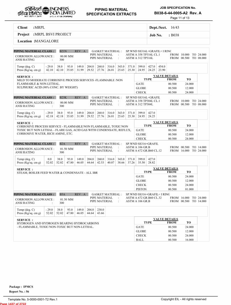
MRPLClient :
MRPL BSVI PROJECTProject :
MANGALORELocation :
16/43Dept./Sect.
PIPING MATERIAL
SPECIFICATION EXTRACTS
JOB SPECIFICATION No.
B038-6-44-0005-A2 Rev. A
Copyright EIL - All rights reserved
Package : IPMCS
Report No. : 56
Template No. 5-0000-0001-T2 Rev.1
Job No. : B038
Page 11 of 13
Temp (deg. C)
Temp (deg. C)
Temp (deg. C)
Temp (deg. C)
Press (Kg/sq. cm g)
Press (Kg/sq. cm g)
Press (Kg/sq. cm g)
Press (Kg/sq. cm g)
- 29.0 38.0 93.0 149.0 204.0 260.0 316.0 343.0 371.0 399.0 427.0 454.0
- 29.0 38.0 93.0 149.0 204.0 260.0 316.0 343.0 371.0 399.0 427.0
0.0 38.0 93.0 149.0 204.0 260.0 316.0 343.0 371.0 399.0 427.0
- 29.0 38.0 93.0 149.0 204.0 230.0
42.10 42.10 35.85 31.99 29.52 27.76 26.01 25.65 25.30 24.95 24.25 23.90
42.18 42.18 35.85 31.99 29.52 27.76 26.01 25.65 25.30 24.95 24.25
52.02 52.02 47.80 46.05 44.64 42.53 40.07 38.66 37.26 35.50 28.82
52.02 52.02 47.80 46.05 44.64 43.66
00.00
00.00
01.50
01.50
MM
MM
MM
MM
PIPING MATERIAL CLASS :
PIPING MATERIAL CLASS :
PIPING MATERIAL CLASS :
PIPING MATERIAL CLASS :
B21N
B23K
B2A
B5A
REV :
REV :
REV :
REV :
A
A
A
A
GASKET MATERIAL :
GASKET MATERIAL :
GASKET MATERIAL :
GASKET MATERIAL :
SP.WND SS316L+GRAFIL+ I RING
SP.WND SS316L+GRAFIL
SP.WND SS316+GRAFIL
SP.WND SS316+GRAFIL+ I RING
ASTM A 358 TP316L CL.1ASTM A 312 TP316L
ASTM A 358 TP304L CL.1ASTM A 312 TP304L
ASTM A 106 GR.BASTM A 672 GR.B60 CL.12
ASTM A 672 GR.B60 CL.32ASTM A 106 GR.B
PIPE MATERIAL :PIPE MATERIAL :
PIPE MATERIAL :PIPE MATERIAL :
PIPE MATERIAL :PIPE MATERIAL :
PIPE MATERIAL :PIPE MATERIAL :
10.000 00.500
10.000 00.500
00.500 16.000
16.000 00.500
24.000 08.000
24.000 08.000
14.000 24.000
24.000 14.000
FROMFROM
FROMFROM
FROMFROM
FROMFROM
TOTO
TOTO
TOTO
TOTO
CORROSION ALLOWANCE :
CORROSION ALLOWANCE :
CORROSION ALLOWANCE :
CORROSION ALLOWANCE :
ANSI RATING :
ANSI RATING :
ANSI RATING :
ANSI RATING :
SERVICE :
SERVICE :
SERVICE :
SERVICE :
MILD TO MODERATE CORROSIVE PROCESS SERVICES -FLAMMABLE /NONFLAMMABLE & NON-LETHAL.SULPHURIC ACID (98% CONC. BY WEIGHT)
CORROSIVE PROCESS SERVICE - FLAMMABLE/NON FLAMMABLE, TOXIC/NONTOXIC BUT NON LETHAL - FLARE GAS, ACID GAS WITH CONDENSATE, REFLUX,CORROSIVE WATER, RICH AMINE, ETC.
STEAM, BOILER FEED WATER & CONDENSATE - ALL IBR
HYDROGEN AND HYDROGEN BEARING HYDROCARBONS- FLAMMABLE, TOXIC/NON-TOXIC BUT NON-LETHAL.
VALVE DETAILS
VALVE DETAILS
VALVE DETAILS
VALVE DETAILS
TYPE
TYPE
TYPE
TYPE
FROM
FROM
FROM
FROM
TO
TO
TO
TO
GATE
GLOBE
CHECK
GATE
GLOBE
CHECK
GATE
GLOBE
CHECK
PISTON
GATE
GLOBE
CHECK
BALL
00.500
00.500
00.500
00.500
00.500
00.500
00.500
00.500
00.500
00.500
00.500
00.500
00.500
00.500
24.000
12.000
24.000
24.000
12.000
24.000
24.000
12.000
24.000
01.000
24.000
12.000
24.000
16.000
300
300
300
300
Page 1437 of 2722

MRPLClient :
MRPL BSVI PROJECTProject :
MANGALORELocation :
16/43Dept./Sect.
PIPING MATERIAL
SPECIFICATION EXTRACTS
JOB SPECIFICATION No.
B038-6-44-0005-A2 Rev. A
Copyright EIL - All rights reserved
Package : IPMCS
Report No. : 56
Template No. 5-0000-0001-T2 Rev.1
Job No. : B038
Page 12 of 13
Temp (deg. C)
Temp (deg. C)
Temp (deg. C)
Temp (deg. C)
Press (Kg/sq. cm g)
Press (Kg/sq. cm g)
Press (Kg/sq. cm g)
Press (Kg/sq. cm g)
- 29.0 38.0 93.0 149.0 204.0 260.0 316.0 343.0 371.0 399.0 427.0
- 29.0 38.0 93.0 149.0 204.0 260.0 316.0 343.0 371.0 399.0 427.0
- 29.0 38.0 93.0 149.0 204.0 260.0 316.0 343.0 371.0 399.0 427.0
0.0 38.0 93.0 149.0 204.0 260.0 316.0 343.0 371.0 399.0 427.0
52.02 52.02 47.80 46.05 44.64 42.53 40.07 38.66 37.26 35.50 28.82
104.05 104.05 95.60 92.09 88.92 84.71 79.79 77.33 74.52 71.35 58.00
84.36 84.36 71.71 63.97 59.05 55.18 52.37 51.32 50.61 49.56 48.50
104.05 104.05 95.60 92.09 88.92 84.71 79.79 77.33 74.52 71.35 58.00
03.00
01.50
00.00
01.50
MM
MM
MM
MM
PIPING MATERIAL CLASS :
PIPING MATERIAL CLASS :
PIPING MATERIAL CLASS :
PIPING MATERIAL CLASS :
B9A
D1A
D23K
D2A
REV :
REV :
REV :
REV :
A
A
A
A
GASKET MATERIAL :
GASKET MATERIAL :
GASKET MATERIAL :
GASKET MATERIAL :
SP.WND SS316+GRAFIL
SP.WND SS316+GRAFIL
SP.WND SS316L+GRAFIL
SP.WND SS316+GRAFIL
ASTM A 672 GR.B60 CL.12ASTM A 106 GR.B
ASTM A 106 GR.BASTM A 672 GR.B60 CL.12
ASTM A 312 TP304LASTM A 358 TP304L CL.1
ASTM A 672 GR.B60 CL.12ASTM A 106 GR.B
PIPE MATERIAL :PIPE MATERIAL :
PIPE MATERIAL :PIPE MATERIAL :
PIPE MATERIAL :PIPE MATERIAL :
PIPE MATERIAL :PIPE MATERIAL :
16.000 00.500
00.500 16.000
00.500 10.000
16.000 00.500
24.000 14.000
14.000 24.000
08.000 24.000
24.000 14.000
FROMFROM
FROMFROM
FROMFROM
FROMFROM
TOTO
TOTO
TOTO
TOTO
CORROSION ALLOWANCE :
CORROSION ALLOWANCE :
CORROSION ALLOWANCE :
CORROSION ALLOWANCE :
ANSI RATING :
ANSI RATING :
ANSI RATING :
ANSI RATING :
SERVICE :
SERVICE :
SERVICE :
SERVICE :
MILD TO MODERATE CORROSIVE PROCESS LIQUID, VAPOUR & GAS,FLAMMABLE/NON FLAMMABLE & NON LETHAL - HVGO,SLOP, DISTILLATE, RCO,DIESEL, KEROSENE,LVGO, VBTAR, TCTAR, ETC.
NON CORROSIVE PROCESS - FLAMMABLE / NON FLAMMABL AND NON LETHAL -PETROLEUM PRODUCTS: FO. FG, SWEET GAS, INHIBITOR SOLUTION, NH3, BRINE(MINUS 10 DEG C), CO2, CAUSTIC SODA (20 Be MAX & TEMP 70 DEG C MAX),PARAXYLENE, BITUMEN.
CORROSIVE PROCESS SERVICE - FLAMMABLE/NON FLAMMABLE, TOXIC/NONTOXIC BUT NON LETHAL - FLARE GAS, ACID GAS WITH CONDENSATE, REFLUX,CORROSIVE WATER, RICH AMINE, ETC.
STEAM (IBR), BOILER FEED WATER (IBR)
VALVE DETAILS
VALVE DETAILS
VALVE DETAILS
VALVE DETAILS
TYPE
TYPE
TYPE
TYPE
FROM
FROM
FROM
FROM
TO
TO
TO
TO
GATE
GLOBE
CHECK
BALL
PLUG
GATE
GLOBE
CHECK
BALL
GATE
GLOBE
CHECK
GATE
GLOBE
CHECK
00.250
00.250
00.250
00.500
00.500
00.250
00.250
00.250
00.500
00.500
00.500
00.500
00.500
00.500
00.500
24.000
12.000
24.000
16.000
24.000
24.000
12.000
24.000
16.000
24.000
12.000
12.000
24.000
12.000
24.000
300
600
600
600
Page 1438 of 2722
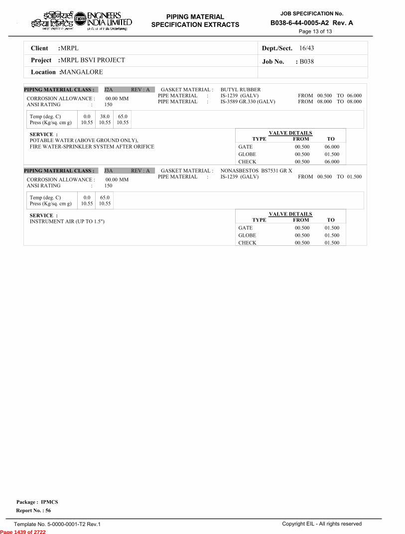
MRPLClient :
MRPL BSVI PROJECTProject :
MANGALORELocation :
16/43Dept./Sect.
PIPING MATERIAL
SPECIFICATION EXTRACTS
JOB SPECIFICATION No.
B038-6-44-0005-A2 Rev. A
Copyright EIL - All rights reserved
Package : IPMCS
Report No. : 56
Template No. 5-0000-0001-T2 Rev.1
Job No. : B038
Page 13 of 13
Temp (deg. C)
Temp (deg. C)
Press (Kg/sq. cm g)
Press (Kg/sq. cm g)
0.0 38.0 65.0
0.0 65.0
10.55 10.55 10.55
10.55 10.55
00.00
00.00
MM
MM
PIPING MATERIAL CLASS :
PIPING MATERIAL CLASS :
J2A
J3A
REV :
REV :
A
A
GASKET MATERIAL :
GASKET MATERIAL :
BUTYL RUBBER
NONASBESTOS BS7531 GR X
IS-1239 (GALV)IS-3589 GR.330 (GALV)
IS-1239 (GALV)
PIPE MATERIAL :PIPE MATERIAL :
PIPE MATERIAL :
00.500 08.000
00.500
06.000 08.000
01.500
FROMFROM
FROM
TOTO
TO
CORROSION ALLOWANCE :
CORROSION ALLOWANCE :
ANSI RATING :
ANSI RATING :
SERVICE :
SERVICE :
POTABLE WATER (ABOVE GROUND ONLY), FIRE WATER-SPRINKLER SYSTEM AFTER ORIFICE
INSTRUMENT AIR (UP TO 1.5")
VALVE DETAILS
VALVE DETAILS
TYPE
TYPE
FROM
FROM
TO
TO
GATE
GLOBE
CHECK
GATE
GLOBE
CHECK
00.500
00.500
00.500
00.500
00.500
00.500
06.000
01.500
06.000
01.500
01.500
01.500
150
150
Page 1439 of 2722
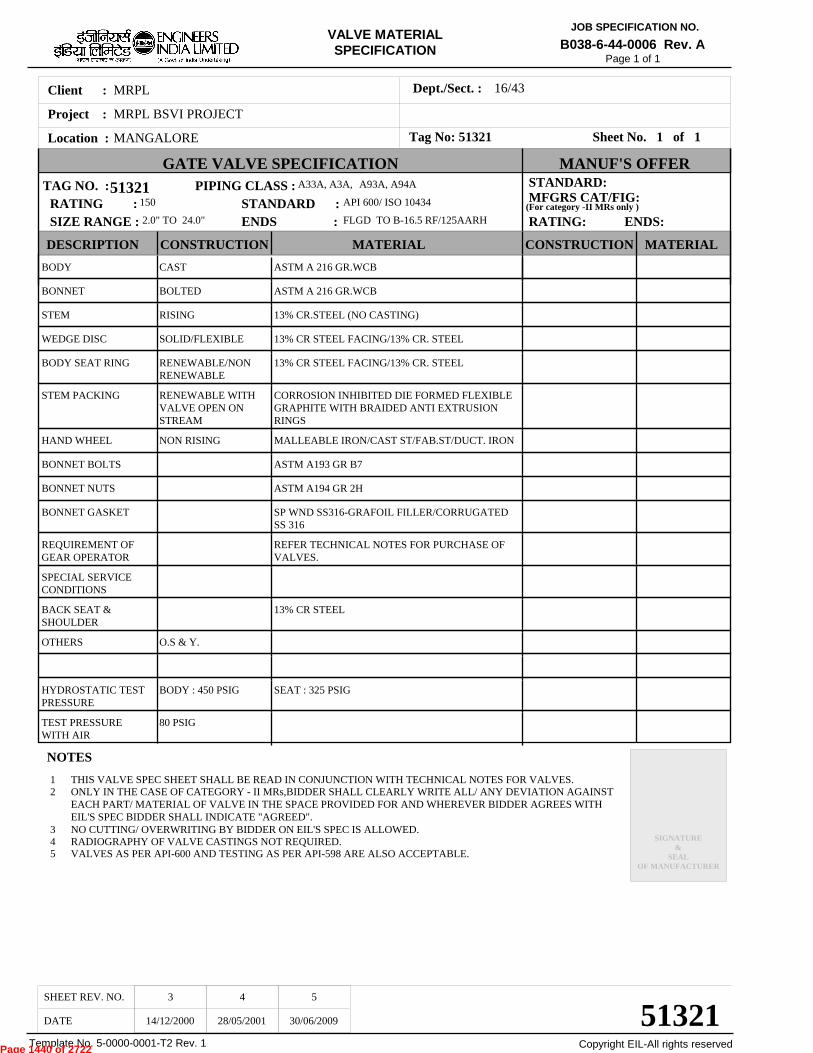
VALVE MATERIAL SPECIFICATION
MRPLClient :
MRPL BSVI PROJECTProject :
MANGALORELocation :
16/43Dept./Sect. :
JOB SPECIFICATION NO.
B038-6-44-0006 Rev. A
Copyright EIL-All rights reservedTemplate No. 5-0000-0001-T2 Rev. 1
Page 1 of 1
51321
51321
TAG NO. :
SHEET REV. NO.
DATE 14/12/2000 28/05/2001 30/06/2009
3 4 5
NOTES
45
RADIOGRAPHY OF VALVE CASTINGS NOT REQUIRED.VALVES AS PER API-600 AND TESTING AS PER API-598 ARE ALSO ACCEPTABLE.
BODY
BONNET
STEM
WEDGE DISC
BODY SEAT RING
STEM PACKING
HAND WHEEL
BONNET BOLTS
BONNET NUTS
BONNET GASKET
REQUIREMENT OFGEAR OPERATOR
SPECIAL SERVICECONDITIONS
BACK SEAT &SHOULDER
OTHERS
HYDROSTATIC TESTPRESSURE
TEST PRESSUREWITH AIR
CAST
BOLTED
RISING
SOLID/FLEXIBLE
RENEWABLE/NONRENEWABLE
RENEWABLE WITHVALVE OPEN ONSTREAM
NON RISING
O.S & Y.
BODY : 450 PSIG
80 PSIG
ASTM A 216 GR.WCB
ASTM A 216 GR.WCB
13% CR.STEEL (NO CASTING)
13% CR STEEL FACING/13% CR. STEEL
13% CR STEEL FACING/13% CR. STEEL
CORROSION INHIBITED DIE FORMED FLEXIBLEGRAPHITE WITH BRAIDED ANTI EXTRUSIONRINGS
MALLEABLE IRON/CAST ST/FAB.ST/DUCT. IRON
ASTM A193 GR B7
ASTM A194 GR 2H
SP WND SS316-GRAFOIL FILLER/CORRUGATEDSS 316
REFER TECHNICAL NOTES FOR PURCHASE OFVALVES.
13% CR STEEL
SEAT : 325 PSIG
Sheet No. 1 of 1
150 API 600/ ISO 10434RATING :SIZE RANGE : ENDS :
12
3
THIS VALVE SPEC SHEET SHALL BE READ IN CONJUNCTION WITH TECHNICAL NOTES FOR VALVES.ONLY IN THE CASE OF CATEGORY - II MRs,BIDDER SHALL CLEARLY WRITE ALL/ ANY DEVIATION AGAINSTEACH PART/ MATERIAL OF VALVE IN THE SPACE PROVIDED FOR AND WHEREVER BIDDER AGREES WITHEIL'S SPEC BIDDER SHALL INDICATE "AGREED".NO CUTTING/ OVERWRITING BY BIDDER ON EIL'S SPEC IS ALLOWED.
STANDARD:MFGRS CAT/FIG:
RATING: ENDS:
SIGNATURE&
SEALOF MANUFACTURER
GATE VALVE SPECIFICATION MANUF'S OFFER
DESCRIPTION CONSTRUCTION CONSTRUCTION MATERIALMATERIAL
STANDARD : 2.0" TO 24.0" FLGD TO B-16.5 RF/125AARH
PIPING CLASS : A33A, A3A, A93A, A94A
Tag No: 51321
(For category -II MRs only )
Page 1440 of 2722

Page 1441 of 2722
Page 1442 of 2722
Page 1443 of 2722
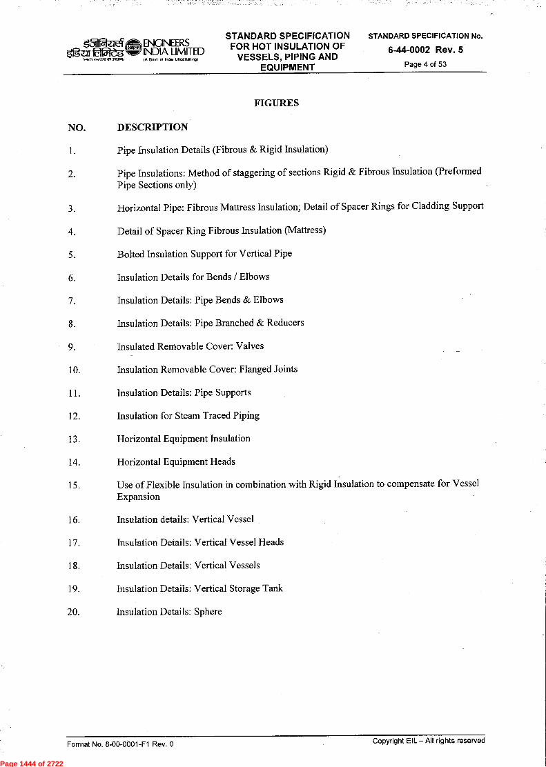
Page 1444 of 2722

Page 1445 of 2722
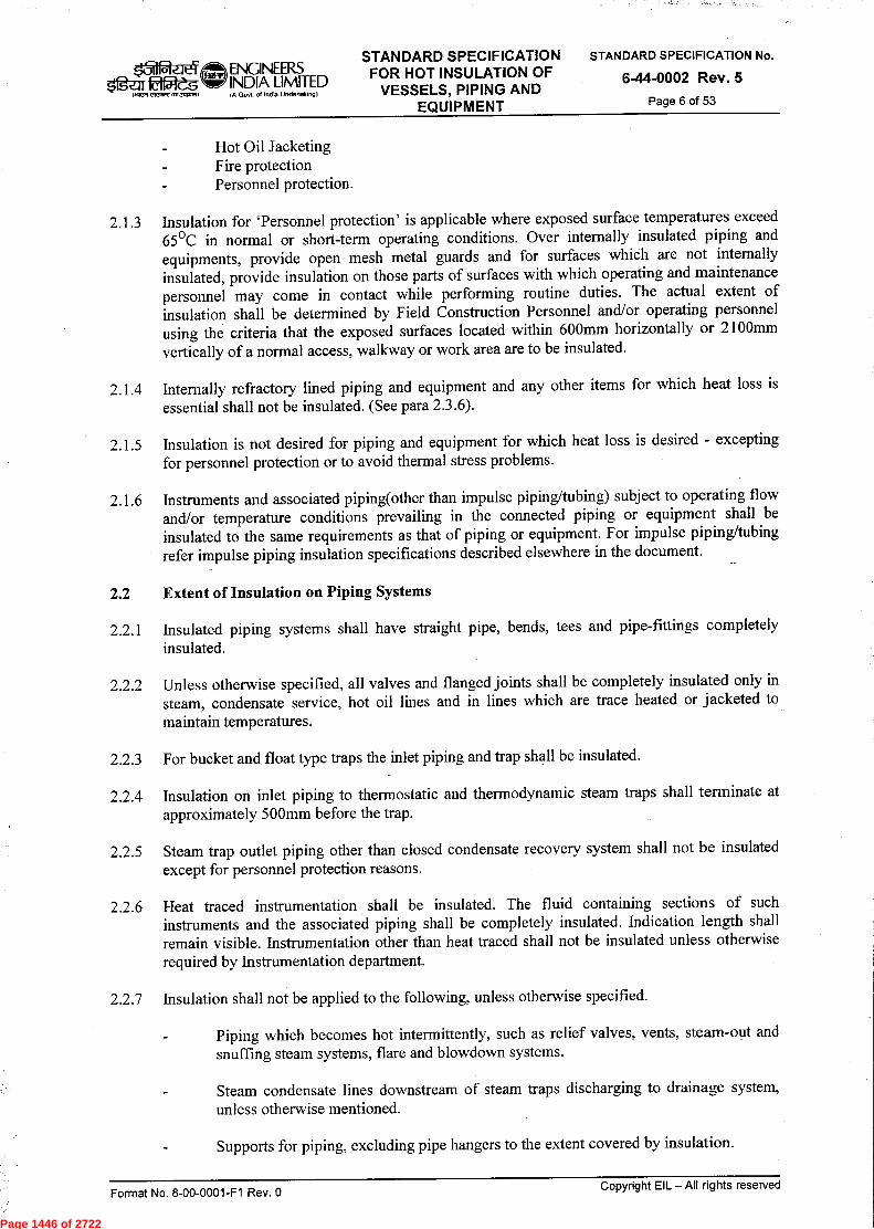
Page 1446 of 2722

Page 1447 of 2722
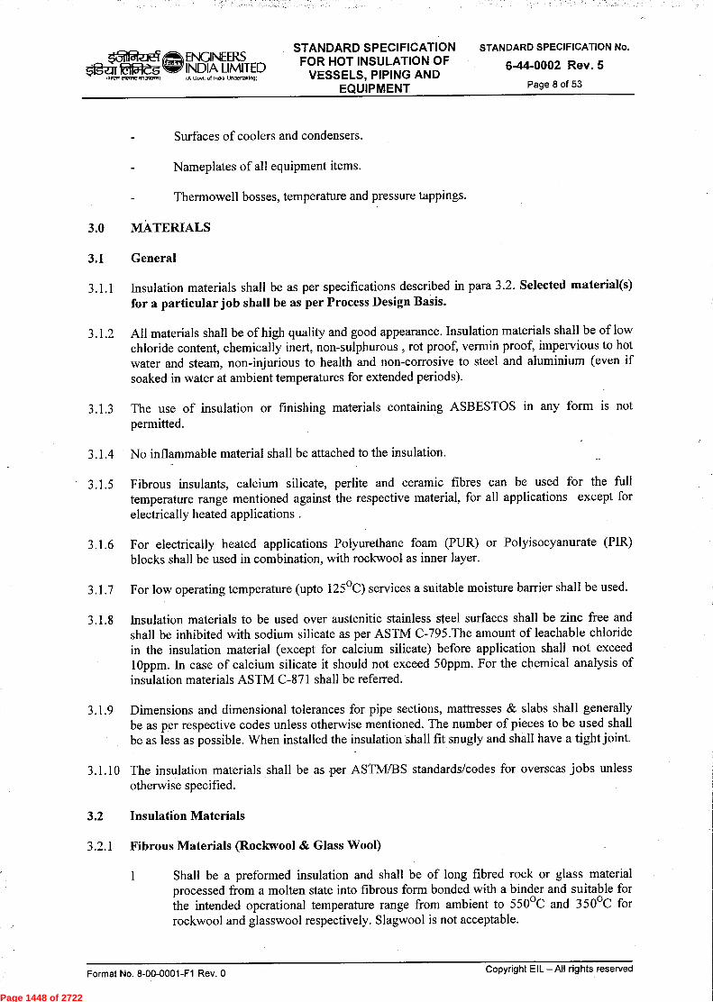
Page 1448 of 2722
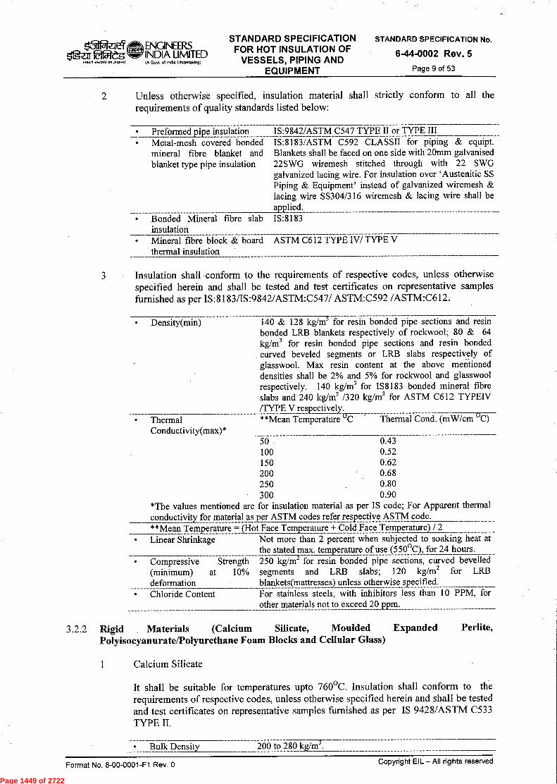
Page 1449 of 2722
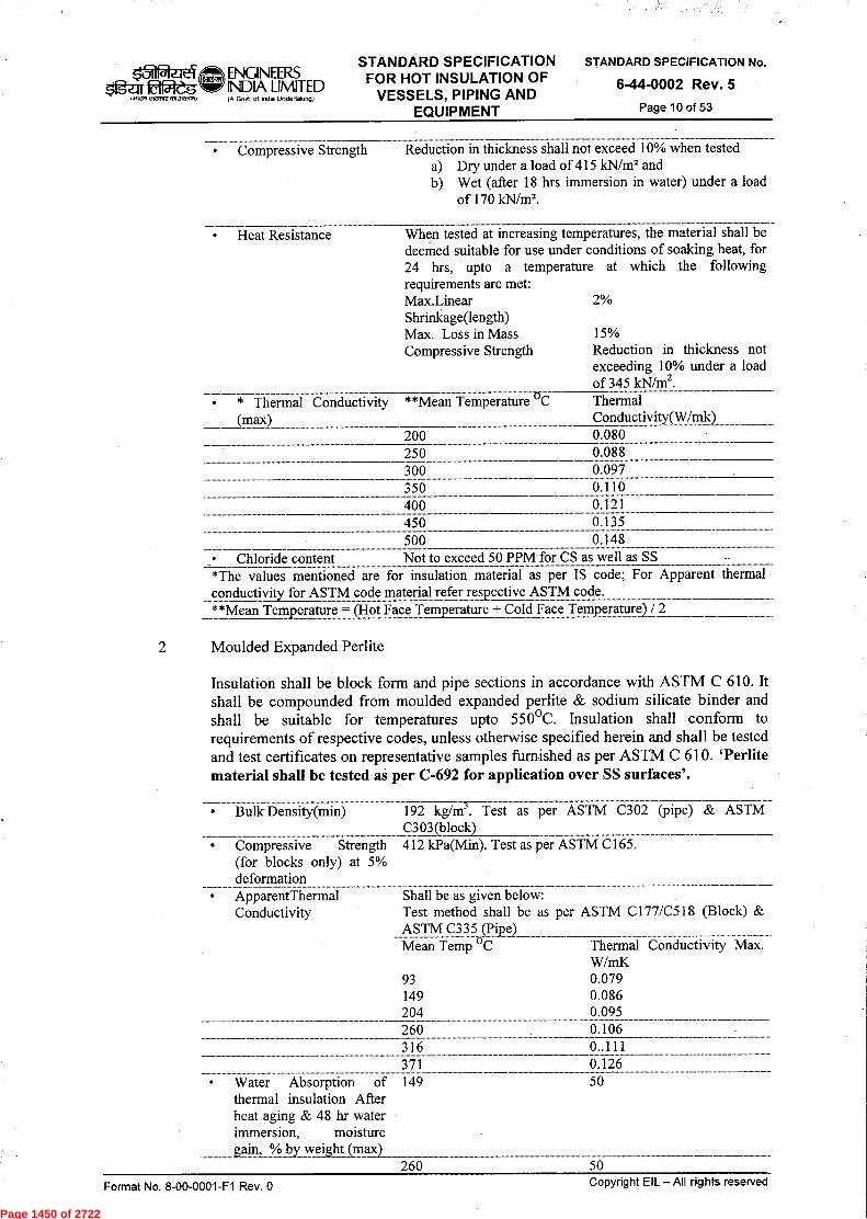
Page 1450 of 2722
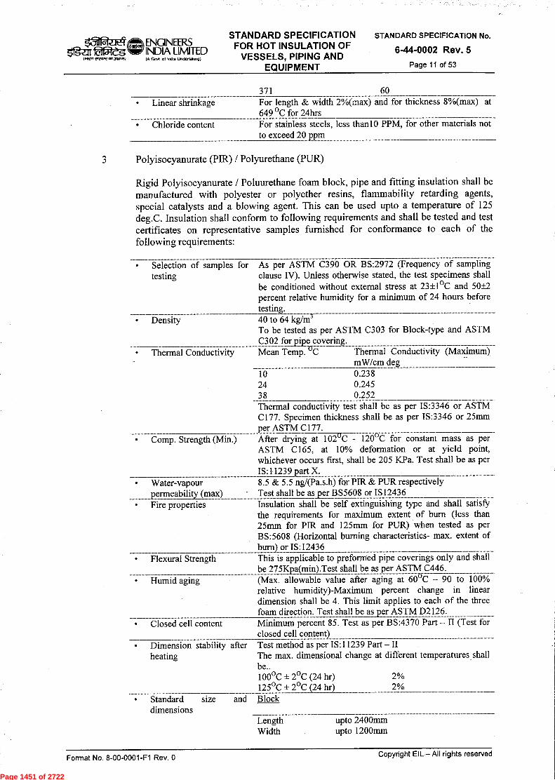
Page 1451 of 2722
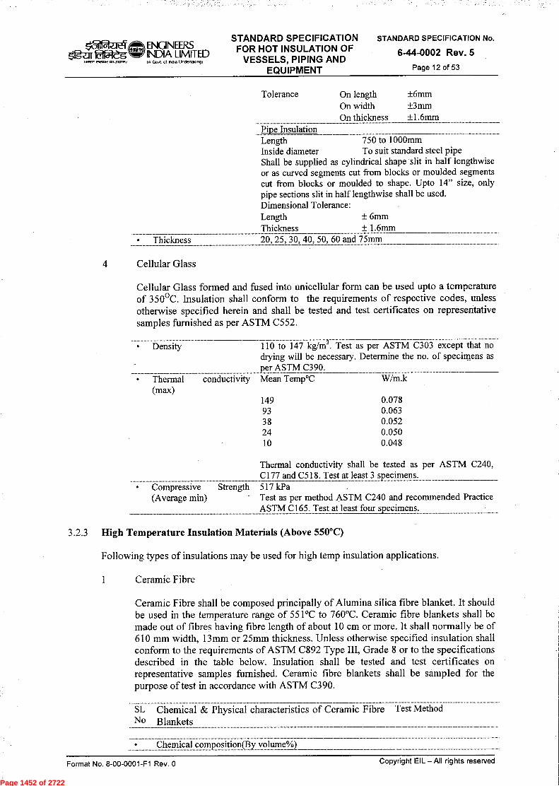
Page 1452 of 2722
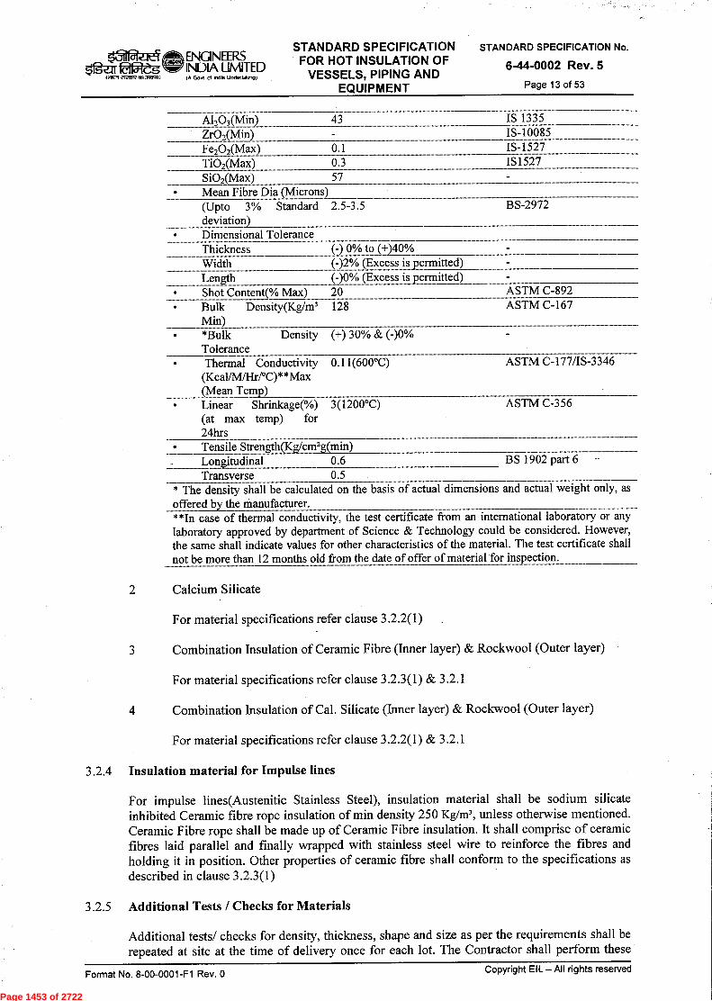
Page 1453 of 2722
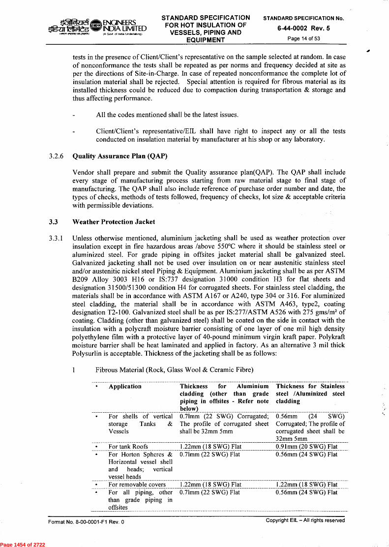
Page 1454 of 2722

Page 1455 of 2722

Page 1456 of 2722
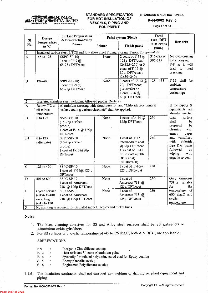
Page 1457 of 2722

Page 1458 of 2722
Page 1459 of 2722

Page 1460 of 2722

Page 1461 of 2722
Page 1462 of 2722

Page 1463 of 2722
Page 1464 of 2722

Page 1465 of 2722

Page 1466 of 2722
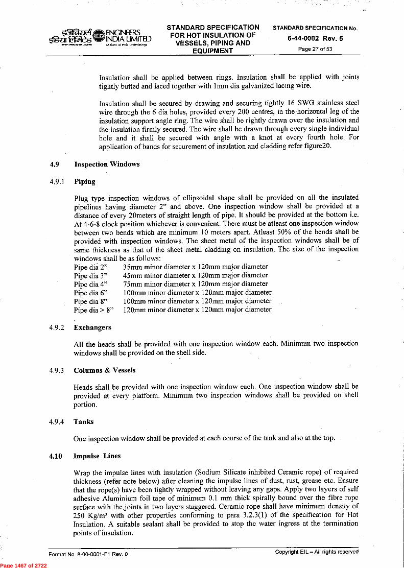
Page 1467 of 2722

Page 1468 of 2722

Page 1469 of 2722
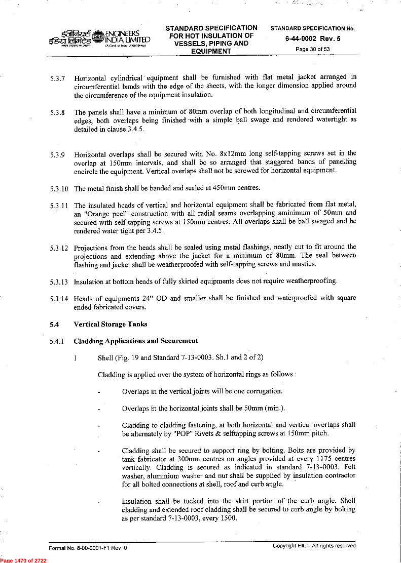
Page 1470 of 2722
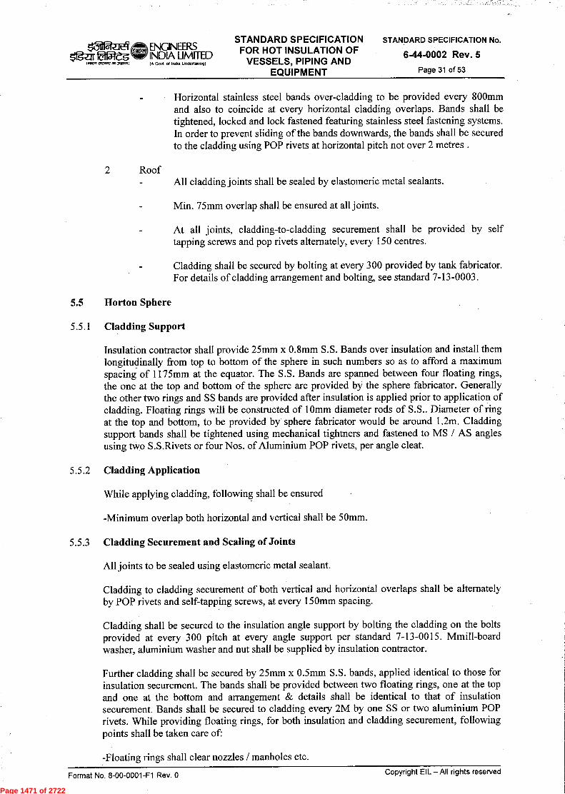
Page 1471 of 2722
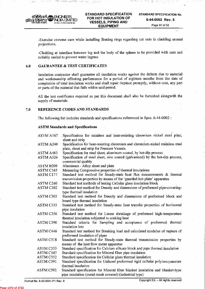
Page 1472 of 2722

Page 1473 of 2722
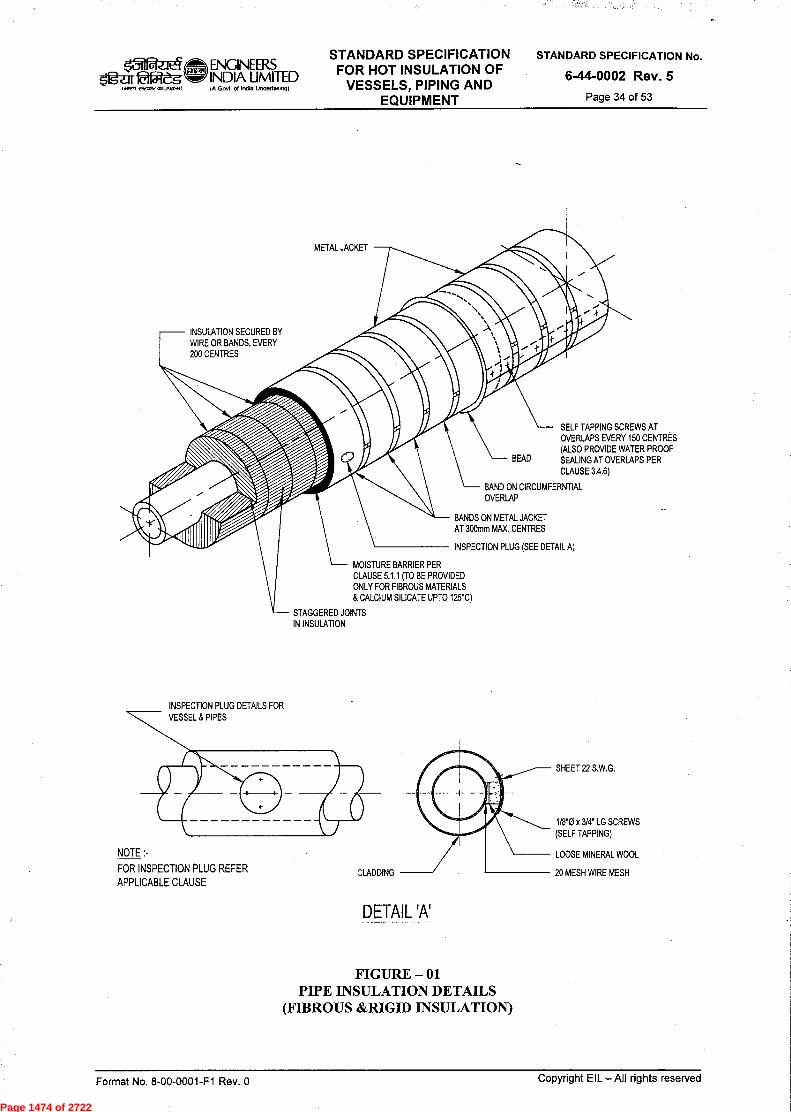
Page 1474 of 2722

Page 1475 of 2722
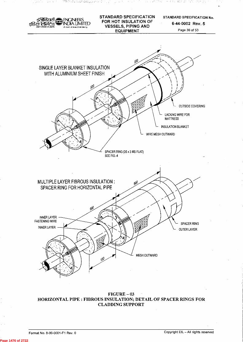
Page 1476 of 2722
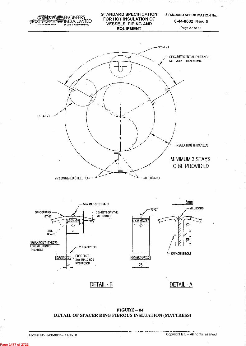
Page 1477 of 2722

Page 1478 of 2722

Page 1479 of 2722

Page 1480 of 2722
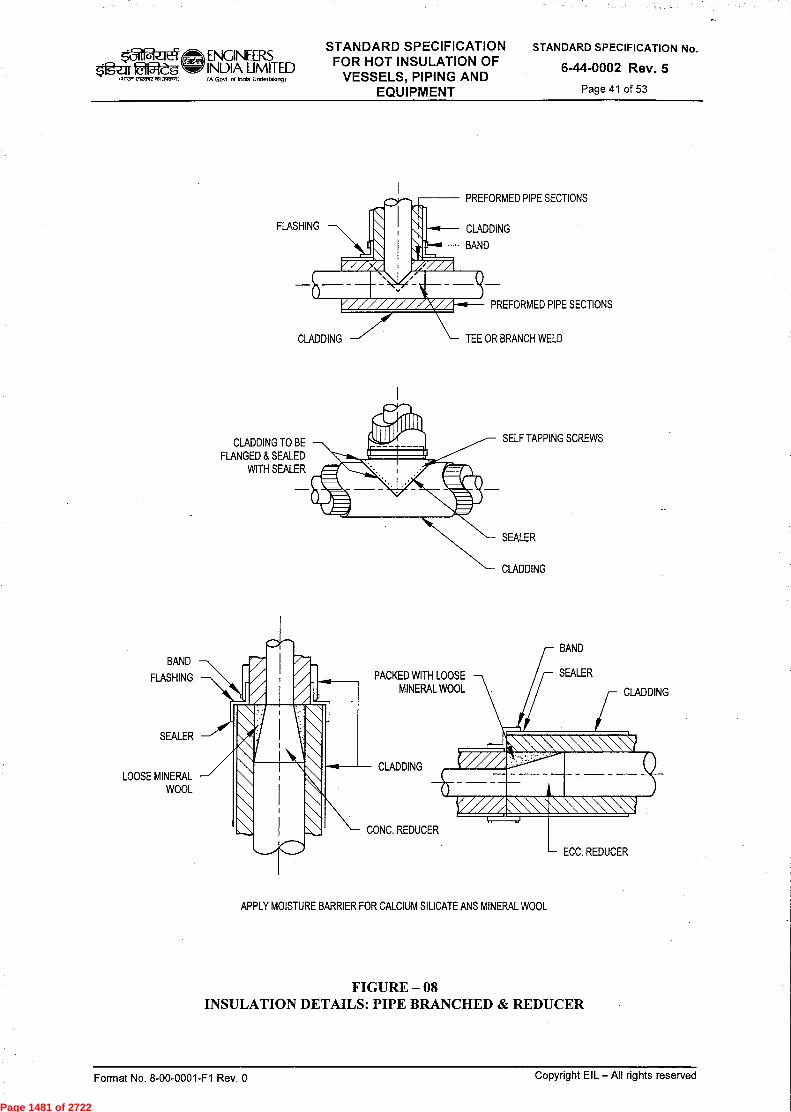
Page 1481 of 2722

Page 1482 of 2722
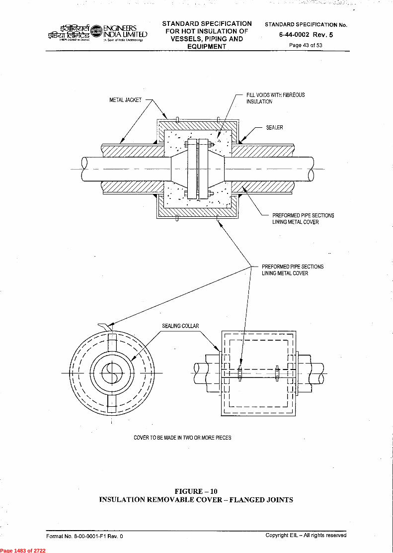
Page 1483 of 2722

Page 1484 of 2722

Page 1485 of 2722
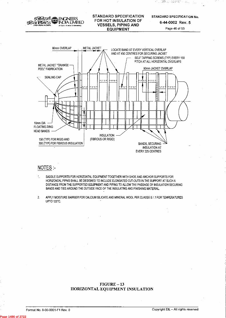
Page 1486 of 2722
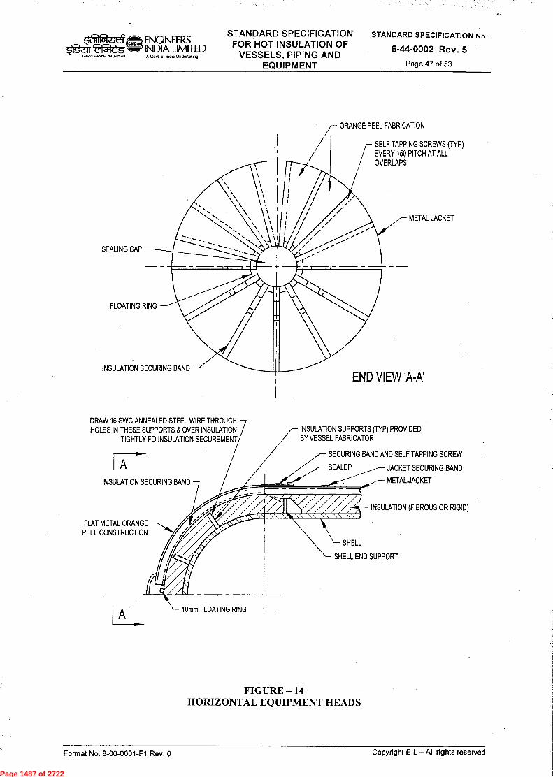
Page 1487 of 2722

Page 1488 of 2722
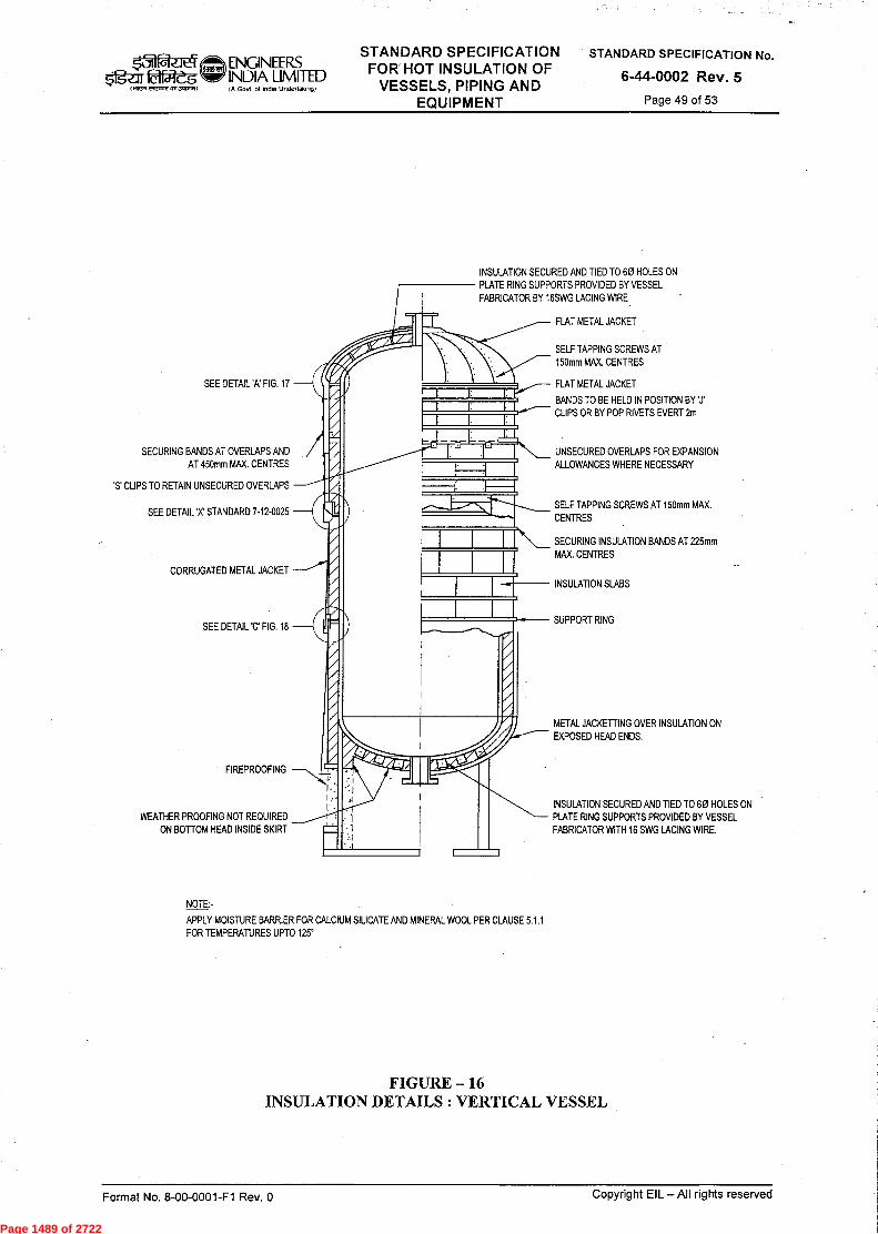
Page 1489 of 2722
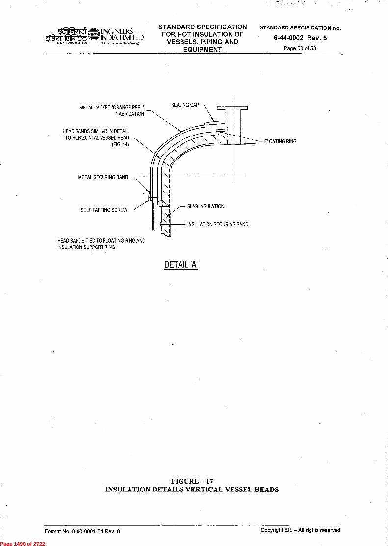
Page 1490 of 2722

Page 1491 of 2722

Page 1492 of 2722

Page 1493 of 2722
STANDARD SPECIFICATION ENGINEERS FOR COLD INSULATION OF ogur faf--Z5 INDIA LIMITED VESSELS, PIPING AND
Govt ol Inffia Underiffitingi
STANDARD SPECIFICATION No.
6-44-0003 Rev. 2
Page 1 of 32 EQUIPMENT
14T-4fST U$41. t-ffl .r4zià'gR "tq
STANDARD SPECIFICATION FOR COLD INSULATION OF VESSELS,
PIPING AND EQUIPMENT
\
41 41 '.411-‘.‘ 2 10.07.14 Reaffirmed & Issued as Standard Specification RN/PPL SC
1 09.07.08 Revised & Issued as Standard Specification RN PPL DM VC
0 15.01.82 Issued as Standard Specification NKM DB RSG
Standards Standards
Rev. No
Date Purpose Prepared
by Checked
by
Committee Convenor
Bureau
Chairman
Approved by
Format No. 8-00-0001-F1 Rev. 0 Copyright EIL — All rights reserved
Page 1494 of 2722

~_it4 5Ig-ar OWs
ENGINEERS INDIA LIMITED IA Govt of India Undertalong)
STANDARD SPECIFICATION FOR COLD INSULATION OF
VESSELS, PIPING AND EQUIPMENT
STANDARD SPECIFICATION No.
6-44-0003 Rev. 2
Page 2 of 32
Abbreviations:
ASTM : American Society for Testing and Materials
DFT : Dry Film Thickness
GI Galvanized Iron
IS Indian Standard
PIR : Rigid Poly Isocyanurate
PUF : Poly Urethane Foam
S.S. Stainless Steel
SWG : Standard Wire Gauge
Piping Standards Committee
Convenor : Mr. R. Nanda
Members : Mr. M. Ismaeel Mr. Amrendra Kumar Mr. G. Balaji Mr. K.J. Harinarayanan (HMTD) Mr. P P Lahiri / Mr. S. Ghoshal (SMMS) Mr. S. Mukherjee (Construction) Mr. K.V.K. Naidu (Projects)
Format No. 8-00-0001-F1 Rev. 0
Copyright EIL — All rights reserved
Page 1495 of 2722

ENGINEERS tffil-eg INDIA LIMITED
1.1r,
IA Govt ol Indu Undertatungt
STANDARD SPECIFICATION FOR COLD INSULATION OF
VESSELS, PIPING AND EQUIPMENT
STANDARD SPECIFICATION No.
6-44-0003 Rev. 2
Page 3 of 32
CONTENTS
NO. TITLE PAGE
1.0 SCOPE 4
2.0 GENERAL REQUIREMENTS 4
3.0 INSULATION MATERIALS 5
4.0 ANCILLIARY MATERIALS 6
5.0 APPLICATION 7
6.0 APPLICATION OF INSULATION ON PIPING, VESSELS & EQUIPMENTS IN DUAL TEMPERATURE SERVICE (HOT/COLD) 15
7.0 COLD INSULATION OF PIPING LOCATED AT OR BELOW GROUND LEVEL & WHERE THERE IS LIKELYHOOD OF FOOT TRAFFIC 15
8.0 SAFETY 15
9.0 GUARANTEE 15
10.0 ATTCHMENT DRAWINGS 16
Format No. 8-00-0001-F1 Rev. 0 Copyright EIL — All rights reserved
Page 1496 of 2722
ENQNEERS INDIA LIMITED IA Govt ot lnOia Undertaking)
STANDARD SPECIFICATION FOR COLD INSULATION OF
VESSELS, PIPING AND EQUIPMENT
STANDARD SPECIFICATION No.
6-44-0003 Rev. 2
Page 4 of 32
g-af 1~, vteavvon3tIooit
1.0 SCOPE
This specification covers technical requirements and procedure for the application of self extinguishing type insulation PUF/PIR and Mineral Wool to vessels, equipments, heat exchangers, pumps, piping and instruments, in temperature range of (+)120°C to (-)110°C.
2.0 GENERAL REQUIREMENTS
2.1 Insulation shall be provided on all vessels, equipments, heat exchangers, piping and instruments etc. containing fluids or vapour, for which it is necessary to :
a. Maintain low temperature for process control. b. Avoid surface condensation.
2.2 All applications of insulation shall be made in accordance with this specification. Contractor shall submit with his proposal, information on intended practices of insulation application, which are not covered in this specification, for approval of the Engineer-in-Charge. This information shall include all the details and sketches including those for the following :
a. Removable insulation housings; b. Flashing details; c. Additional Insulation supports; d. Vessel head insulation supports; e. Expansion joints; f. Vessel insulation details; g. Exchanger removable housings; h. Machinery removable housings etc.
2.3 Protection of Materials During Storage
Insulation materials must be protected against any damage, from delivery to finish cladding. Decking and covering with tarpaulins alone are not considered sufficient protection from weather for any length of time and shall not be permitted. Insulation material slabs and sections shall be stored on a flat surface in a horizontal position. Insulation material shall never be stacked directly on the ground. The contractor shall provide covered storage for insulation materials as directed by the Engineer-in-Charge.
2.4 Protection of Partially Completed Jobs
All precautions shall be taken to ensure that each day's work is vapour sealed and cladded during erection and before being left over-night to prevent seepage of water into the materials and getting trapped. The system shall be protected by tarpaulins, water shed and other protective means.
2.5 Hydrostatic Test
Insulation shall be applied on vessels, heat exchangers, piping and other equipment only after successful completion of hydrostatic test. In case insulation work starts before completion of hydrostatic test, all welded and mechanical joints shall be left exposed for testing and subsequently insulated after successful completion of the hydrostatic test.
2.6 Co-ordination with Other Agencies
Contractor shall work in close co-ordination with the erection Contractor. Wherever temporary supports are provided the Contractor shall remove there and provide the necessary
Format No. 8-00-0001-F1 Rev. 0
Copyright EIL — All rights reserved
Page 1497 of 2722

,31 Ogu22-eg
Istwt vivatot 4,1,3~1)
ENGINEERS INDIA LIMITED IA Govt ol Incha Undettakingt
STANDARD SPECIFICATION FOR COLD INSULATION OF
VESSELS, PIPING AND EQUIPMENT
STANDARD SPECIFICATION No.
6-44-0003 Rev. 2
Page 5 of 32
insulating blocks (wood/PUF etc.) as per support standard or as specified in the bid package/tender.
2.7 Extent of Insulation
2.7.1 Items requiring Insulation
a. Items requiring insulation are specified in the piping line schedule and equipment/vessel/heat exchanger data sheets.
b. All attachments and projections such as vessel supports, structural steel attached to vessels, piping hanger supports, instrument lead lines, branch lines like vents, drains and instrument connections connected directly to cold insulated piping, vessels and equipment shall be cold insulated upto a distance of 4 times the adjoining insulation thickness.
c. All flanged joints, manhole covers, etc. shall be cold insulated with removable box insulation. For insulation of manhole covers refer Drg. No. 09.
2.7.2 Items not requiring insulation
a. Bonnet of valves above the packing glands. b. Nameplates, stampings and code inspection plates on vessels & equipment
3.0 INSULATION MATERIALS
3.1 General
All materials used for insulation, fixing sealing and protection shall be new and shall conform to the details given below and in clause 4.0. All insulating materials whether dry or wet shall be non-corrosive to the surfaces insulated.
3.2 Insulation material for insulating piping, vessels and equipment in Cold and Dual temperature (Cold/Hot) service shall be as given below :
Operating temperature range Insulation material
-110°C to +120°C Polyurethane foam (PUF/PIR)
Note: Detailed Job Specification shall be prepared for materials other than PUF & for the temperature beyond the limits as specified in clause 1.1.
3.3 Form of insulation shall be as follows :
Pipes upto 400 NB Preformed pipe sections
Pipes upto 450 NB Preformed pipe sections/Radial lags
Vessel Shells Radial lags
Vessel heads Preformed sections or slabs contoured to the profile of vessel heads.
Equipments Radial lags or slabs as applicable to form, contour of the service to be insulated.
3.4 Dimensions of preformed sections for piping insulation shall be defined by the outside diameter and insulation thickness. Tolerances for preformed sections shall be as under:
Format No. 8-00-0001-F1 Rev. 0
Copyright EIL —All rights reserved
Page 1498 of 2722
.311 Og-ar 02-eg
1.4R, ,I,Dr2,151.3~)
ENGINEERS 1NDIA LIMITED IA Govt of InOia Undenalongt
STANDARD SPECIFICATION FOR COLD INSULATION OF
VESSELS, PIPING AND EQUIPMENT
STANDARD SPECIFICATION No.
6-44-0003 Rev. 2
Page 6 of 32
Outside diameter -0%, + 5% Concentricity + 3% O.D. Bore + 2mm, -0 mm Length, width and thickness of slabs + 2mm
3.5 The material used shall not disintegrate, settle, change its form or composition in a detrimental way at the service conditions.
3.6 The insulating material shall be chemically inert, moisture free, rot and vermin proof.
3.7 Preformed half sections and slabs shall be provided having their longitudinal and circumferential faces flat and smooth so as to mate with the mating sections of the whole face area. Ends of the preformed half sections shall be flat and perpendicular to the centre line.
3.8 Polyurethane Foam
3.8.1 The insulation material shall be rigid preformed cellular urethane foam of self extinguishing type in accordance with ASTM C 591, Type II, Grade 2. The foam shall be formulated in such a way that it shall be of a self extinguishing quality which under no circumstances shall cause fire to spread.
3.8.2 Composition
The insulation material shall be produced by reacting poly Isocyanates with polyhydroxy compounds and expanded with a blowing agent. The finished foam in the form of slabs or half sections shall be of uniform closed cell structures, free from unreacted materials, shrinkage and distortion.
3.8.3 Density
The density of finished foam shall be within 35.0 kg/m3 to 40 kg/m3 and shall be determined in accordance with ASTM C-302.
3.8.4 Thermal Conductivity
Thermal conductivity of the Polyurethane foam slabs and sections shall not exceed 0.019 K Cal/hr. m°c (0.16 BTU/ft2 hr°F/in) at 10°C mean temperature after ageing. The thermal conductivity shall be tested by the method prescribed in ASTM C335.
3.8.5 Closed Cell Content
The closed cell content shall be at least 95% by volume.
4.0 ANCILLIARY MATERIALS
4.1 Wire-netting, Lacing & Binding Wire
Wire netting shall be galvanized 24 SWG x 20mm to secure insulation blocks. Lacing and stitching wires shall be 20 and 22 SWG galvanized iron wire respectively.
4.2 Bands
Bands shall be of Aluminum, of dimensions 20mm width x 24 SWG, unless specified otherwise.
Format No. 8-00-0001-F1 Rev. 0
Copyright EIL — All rights reserved
Page 1499 of 2722
Ogz:Er ,ètRP, rtvow ottJotn•O
11 ENGINEERS INDIA LIMITED Ifit Govt ol India Undertaking)
STANDARD SPECIFICATION FOR COLD INSULATION OF
VESSELS, PIPING AND EQUIPMENT
STANDARD SPECIFICATION No.
6-44-0003 Rev. 2
Page 7 of 32
4.3 Adhesives
The adhesive to be used for bonding insulation sections shall be Foster Fire Resistive Adhesive 81-33.
4.4 Vapour Seal
The vapour seal shall be Foster Fire Retardant Mastic 60-30.
4.5 Filler Material
PUF/PIR or Mineral Wool mixed with specified adhesive shall be packed rightly so as to fill all irregular voids and at contraction joints.
4.6 Joint Sealer
The joint sealer to be used for sealing insulation joints and at flashing of insulation shall be Foster Foam Seal Sealer 30-45.
4.7 Glass Cloth
The glass cloth to be used for vapour barrier reinforcement, shall be open weave 10 mesh Glass Cloth having glass fibre thickness of 5 mils.
4.8 Aluminium sheets for cladding of Vapour barrier on the insulation shall be as follows:
Application Aluminium Sheet Gauge
a. Pipe Vessels and Equipment 26 SWG upto 500mm Nominal dia
b. Pipe Vessels and Equipment 24 SWG above 500mm Nominal dia
c. For Valves, flanges and 22 SWG other areas where mechanical damage is likely to occur
4.9 Anti-Corrosive Paint
One coat @ 65-75g DFT of primer, inorganic zinc silicate shall be applied on all carbon steel and alloy steel piping and equipment before application of cold insulation. Items made of stainless steel and other non-ferrous alloys shall not be painted but shall be wrapped with 0.1mm aluminium foil before application of cold insulation unless specified otherwise.
4.10 Bituminized Roofing Felt
Bituminized self finishing roofing felt shall conform to IS: 1322, type 3, grade 1.
5.0 APPLICATION
5.1 General
The following applies to all types of cold insulated equipment and piping:
Format No. 8-00-0001-F1 Rev. 0 Copyright EIL — All rights reserved
Page 1500 of 2722

ENGINEERS INDIA LIMITED IA Govt ol Indo Undertakngt
STANDARD SPECIFICATION FOR COLD INSULATION OF
VESSELS, PIPING AND EQUIPMENT
STANDARD SPECIFICATION No.
6-44-0003 Rev. 2
Page 8 of 32
02—eg laiRn vtvcortott,O1O■N)
5.1.1 Surface Preparation
The surfaces of tanks, vessels, piping and valves etc. on which cold insulation is to be applied shall be free of dust, loose paint or any other foreign matter. The surface irregularities shall be filled up with the approved filler. One coat of anticorrosive primer (as per clause 4.9) shall be applied over the carbon/Alloy Steel surfaces to be insulated and allowed to dry before application of insulation.
5.1.2 Insulation Thickness and Limit
Insulation thickness shall be in accordance with the equipment data sheets and piping line schedule. Insulation thickness on item covered in clause 2.7.1a & 2.7.1b shall be equivalent to that on adjoining piping and equipment.
5.1.3 Vapour Barrier for Polyurethane Insulation
A 3.0 mm (wet) thick coating of vapour seal mastic shall be applied to the surface of the insulation as soon as possible after erection, to reduce the time the insulation is exposed to the weather to a minimum. Whilst this coat is still wet, glass cloth shall be laid over the surface and embedded in the mastic. Care shall be taken to ensure that the glass cloth is laid smooth and free from wrinkles, and that no pockets of air are trapped beneath the surface. At junctions in the glass cloth, the overlap shall not be less than 75mm. A second 3mm thick coat of mastic shall be applied after approximately twelve hours. When dry this coating shall be a minimum of 1.50mm thick. Care must be taken, however to ensure that the individual coats are not greater than 3mm (especially in corners), otherwise some cracking of dried coat may result. The total dry film thickness of vapour seal shall not be less than 2.5mm with a tolerance of -0% to +50%. The mastic shall not be applied over wet insulation or until the adhesive is dry. During this drying time the insulation shall be protected from the weather by tarpaulin or similar materials approved by the Engineer-in-Charge.
Where joints have been left uninsulated, a complete vapour seal as specified above shall be applied to the exposed end of the insulation and flashed weather tight on to the metal.
5.1.4 Vapour barrier shall be protected by cladding with aluminium sheets. Joints in aluminium sheet shall be staggered and suitably sealed with an approved sealer. Aluminium cladding shall not be applied until the vapour barrier has completely dried and its solvents have dissipated. Self tapping screws shall not be used to secure aluminium cladding as they may puncture the vapour barrier.
5.1.5 Expansion / Contraction Joints
When specified on a pipe line or vessel drawing or where deemed necessary to allow movement and contraction of the pipe or vessel without producing random cracking of the insulation, contraction joints shall be provided in the insulation. At contraction joint location, provision shall be made in aluminium cladding to accommodate contraction of pipe or vessel.
The following steps shall be taken:
a. Both longitudinal and circumferential joints in insulation shall be staggered.
b. Contraction joints shall be provided at an interval depending on pipe or vessel material contraction/expansion co-efficient and temperature. Unless otherwise specified contraction joints shall be provided at an interval of 6.0m on straight run of pipes or vessels operating at temperatures (-)40°C & below.
Format No. 8-00-0001-F1 Rev. 0 Copyright EIL — All rights reserved
Page 1501 of 2722
STANDARD SPECIFICATION FOR COLD INSULATION OF
VESSELS, PIPING AND EQUIPMENT
STANDARD SPECIFICATION No.
6-44-0003 Rev. 2
Page 9 of 32
fs'zfl 02—eg v-k,or1Othfootat,
(1@, ENGINEERS INDIA LIMITED IA Govt of Indo UnOeflakovg)
c. Contraction joints in horizontal vessel insulation shall be close to support points while on vertical pipes & vessels, the same shall be provided at support ring location and at an interval of 4.0m straight run.
d. A contraction joint shall consist of 12mm gap in the Insulation, loosely packed with filler material, as applicable, described under clause 4.5 to a depth of 6mm less than the adjacent insulation thickness. 6mm gap thus left shall be filled up by approved non-setting compound (Foster Foam seal 30-45 sealer or equivalent) and finished smooth with the surface of insulation. Vapour barrier which shall cover the joint shall be applied only after the compound has dried. Expn/contraction joint details in insulation for `horizontal & vertical pipes' & for `expansion bellows' are given in Drg. Nos 10.1 to 10.4.
5.1.6 Stainless Steel Piping & Equipment
All pipes, vessels and equipment of stainless steel construction shall be wrapped with O.lmm thick aluminium foil with an overlap of 50mm having barium chromate sealer interposed in the joint prior to application of insulation. Foil shall be secured in position by aluminium bands, taking every precaution to avoid formation of pin holes or cracking in the aluminium foil. Cladding shall be done after the insulation and vapour barrier exactly the same way as for other pipes and equipment.
5.1.7 For all pipes, vessels, equipments etc. lying in a corrosive environment where Sulphur Dioxide or other corrosive media are likely to be present, stainless steel bands/clips shall be used to secure aluminium cladding in position.
5.1.8 Field Welding
Field welding of clips or other insulation supports on any vessel or piping, subjected to the pressure of operating fluid shall not be permitted. However, field welding on non pressure parts, to install insulation supports etc. can be permitted with prior approval of the Engineer-in-Charge, but extreme care shall be taken so that welding does not result in decrease of metal thickness or excessive burning of metal.
5.2 Application- Vessels & Equipment
5.2.1 General
Individual vessel and tank drawings indicate the location of insulation supports or anchorage, wherever required, to facilitate application of insulation and securing of insulation shall be provided by the contractor at his own cost. A11 surfaces shall be prepared as described in Clause 5.1.1 before application of insulation.
5.2.2 Single Layer Insulation
Insulation radial lags/preformed sections of handy sizes shall be installed on to the surfaces of vessels adhering to each other with applicable joint sealer and secured in position by G.1. wire netting and aluminium bands at an interval of 225mm. There shall be no through joints and the insulation shall not be bonded to the vessel.
5.2.3 Multilayer Insulation
The inner layer of insulation shall be bonded to the vessel with the applicable adhesive. Subsequent layers of insulation shall be bonded to the preceding layer, with the applicable adhesive. The joint sealer shall be applied to the ends and edges of all sections, including those in the inner most layer to seal all joints. Care shall be taken to ensure that the adhesive
Format No. 8-00-0001-F1 Rev. 0 Copyright EIL —All rights reserved
Page 1502 of 2722
_Jil ENGINEERS jr 02-eg INDIA LIMITED 1~1 twort,..Tros.) IH Govt of Ind. Undert.k.9)
STANDARD SPECIFICATION FOR COLD INSULATION OF
VESSELS, PIPING AND EQUIPMENT
STANDARD SPECIFICATION No.
6-44-0003 Rev. 2
Page 10 of 32
is evenly spread over the entire surface of the application and the insulation is closely butted to each other both longitudinally and circumferentially.
All the layers except the final shall be secured in position by metallic bands at an interval of 225 mm while the final layer shall be first secured with G.I. wire net and then with metallic bands at an interval of 225mm. Bands shall be staggered on successive layers. There shall be no through joints in the insulation.
5.2.4 Filling
All the cracks and voids in the main insulation shall be filled up with applicable filler material, as described under clause 4.5.
5.3 Vertical Vessels
5.3.1 Shell (Cylindrical)
Slabs in handy sizes as given below shall be applied resting onto the supports with joints tightly butted, staggered & adhering to each other with applicable adhesive and secured in position by circumferential metallic bands at a pitch of 225mm.
For vessels upto 2.5m O.D. - Radial lags of suitable width
For vessels over 2.5m O.D. - Radial lags. However the procedure given below can be used as an alternative.
Flat insulation slabs of width not more than 300mm shall be cut longitudinally to have notch (es) of suitable size spaced at suitable spacing, so as to form a radial segment suitable for the profile of the vessel shell. However extreme care shall be taken to ensure that no air pockets are formed in the finished insulation. All insulation joints shall be sealed with applicable joint sealer.
Where more than one layer is used, each layer shall be banded separately as given in Clause 5.2.3. Method of application shall be as given in Drg. No. 01. When mineral wool insulation is used, notches shall not be cut as the insulation itself is semi rigid and can be pressed to form contour of the shell.
5.3.2 Top Heads
Shaped insulation sections shall be installed on top head, banded and butted tightly to each other. Insulation shall be held in position by making use of galvanized iron floating ring (25mm x 0.6mm) placed over the insulation and positioned in the centre of the head so as not to touch the nozzle at the vortex. The insulation shall be held in position by use of radial metallic bands, one end of which shall be fastened to floating ring and the other end shall be anchored to the band(s) placed around the cylindrical section close to the head. Radial bands shall be spaced on 300mm centres measured around the circumference of the vessel.
The final layer of insulation shall be held in position also by metallic wire net laced at the nozzle location by 2-3 loops of 10 SWG galvanized wire and to the wire net over insulation on the shell at the cylindrical section close to the head.
When there is no nozzle at the top at the Vortex, the insulation shall be held in position by wire netting and metallic bands stretched over the head and anchored on the cylindrical section close to the head by circumferential metallic band(s) on the shell and near the head.
Format No. 8-00-0001-F1 Rev. 0 Copyright EIL — All rights reserved
Page 1503 of 2722

STANDARD SPECIFICATION FOR COLD INSULATION OF
VESSELS, PIPING AND EQUIPMENT
■31 ENGINEERS 5ga 22-dg INDIA LIMITED
Govi of Indie Undeltaking)
STANDARD SPECIFICATION No.
6-44-0003 Rev. 2
Page 11 of 32
5.3.3 Bottom Heads
In all the skirt supported vessels, insulation supports are provided inside the skirt as indicated in the equipment drawings, Drg No. 15.
Floating ring and wire loops around the nozzle and bands shall be used to support downward facing of insulation. Such a floating ring shall be positioned centrally around the nozzle but over the insulation by radial bands anchored to the lagging support angle ring fixed inside the skirt at a pitch of 300mm measured over the support angle ring.
If nozzle is not existing, metallic bands shall be stretched across the bottom head and anchored with lagging support angle ring inside the skirt. All the wire ends of wire netting shall be cut short and turned into the insulation.
5.4 Horizontal Vessels
The insulation radial lags of handy sizes shall be installed in close contact with the faces to be insulated and held in position by G.I. wire netting and metallic bands at a pitch of 225mm. Where more than one layer is required, each layer shall be banded separately. The bands for successive layers shall not coincide with each other, wire netting on the final layer shall be applied and ends shall be laced together by lacing wire before putting the metallic bands as per Clause 5.2.3.
Insulation sections on the vessel heads shall be secured in position by wire netting and metallic bands stretched across the heads and anchored to circumferential metallic band(s) on the shell near the heads. Anchoring of bands measured on the circumference of shell shall be of a pitch of 225mm max. Method of application of insulation shall be as given in Drg No. 02.
5.5 Tank Insulation
Material and method of application for tanks shall be the same as specified for vessels. Flat aluminium sheets for weather proofing shall be used exactly in the same manner as specified for other vessels.
5.6 Spherical Vessels
Insulation of spherical vessels shall be performed as shown in Drg No. 03. Before commencing the application of insulation, the contractor shall ensure that exterior surfaces have been prepared in accordance with clause 5.1.1. Shaped insulation to fit curvature of sphere shall be bonded to the vessel with applicable adhesive. A11 insulation joints shall be sealed with applicable joint sealer. The inner layer of insulation shall be held in position by 20mm x 20 SWG aluminium bands of 300mm max. centres of the equator. These bands are tied up with the rings provided as per EI1 std 7-13-0034. The bands being staggered on successive layers and the clips of the bands being recessed into the insulation. Over the outer layer galvanized wire netting shall be spread over and laced together.
5.7 Vapour Barrier
Vapour barrier shall be applied on all the vessels described above as per the procedure outlined in Clause 5.1.3.
Copyright EIL — All rights reserved Format No. 8-00-0001-F1 Rev. 0
Page 1504 of 2722
(31 ENGINEERS 22-eg INDIA LIMITED
Ift Govt ol India Undertak,ng)
STANDARD SPECIFICATION FOR COLD INSULATION OF
VESSELS, PIPING AND EQUIPMENT
STANDARD SPECIFICATION No.
6-44-0003 Rev. 2
Page 12 of 32
5.8 Metal Sheet Finishing
5.8.1 Horizontal Vessels
The insulation shall be covered with aluminium sheeting with all the longitudinal and circumferential joints having an overlap of minimum 50mm. All longitudinal and circumferential joints shall be sealed with suitable approved bituminized mastic sealer. Aluminium sheeting shall be secured in position by metallic bands on the shell at a max. pitch of 425mm. All the longitudinal joints with overlap of 50mm in the aluminium sheet shall be kept below the horizontal plane passing through the axis of the vessel to prevent water or other spillage from entering into the insulation.
Jacketing for dished heads shall be fabricated from radial segments with the radial overlap of minimum 50mm. The sheeting shall be secured in position by radial tensioned metallic bands stretched over the heads. One end of each band is anchored to the circumferential band(s) on the shell while the other is fastened (pop riveted) to 6mm dia. Floating rod ring which can be replaced by 6mm thick strip (G.I.) rolled in the form of a ring. Radial metallic bands, measured over the circumference of shell, shall be at a pitch of 300mm. All the sheet metal joints shall be properly sealed with approved sealing mastic.
5.8.2 Vertical Vessels
The aluminium sheeting shall be adequately rolled and installed over the insulation such that all the longitudinal joints are staggered. All the longitudinal and circumferential joints shall have an overlap of 50mm minimum and suitably sealed with approved mastic sealer. Aluminium sheeting shall be secured in position by tensioned metallic bands installed circumferentially at a max. pitch of 425mm.
a. Top Heads
Insulation shall be covered with flat aluminium jackjet fabricated in segmental form with lapped joints properly sealed with approved mastic sealer. Over-lapping of sheet metal joints shall not be less than 50mm. Aluminium jacket shall be secured in position by radial tensioned metallic bands anchored to the circumferential band(s) of vessel on one side and fastened to 6mm dia. floating rod ring, centralized at the vortex of head on the other side. 6mm thick metallic (G.I.) strip rolled into a ring can be a substitute for 6mm dia. Rod. Pitch of radial bands measured over the circumferential bands of shell shall be max. 300mm.
b. Bottom Heads
Aluminium sheeting shall be installed exactly in the same manner as indicated for top heads.
5.8.3 Spherical Vessels
Cladding of each hemisphere of spherical vessel shall be done with aluminium sheets placed horizontally and a thick circumferential tensioned band (6mm thick) shall be used at the equator to hold the radial metallic bands.
5.8.4 Others
Openings in metal jackets for nozzles, manways, brackets etc. shall be cut as close as possible for a snug fit.
Format No. 8-00-0001-F1 Rev. 0 Copyright EIL — All rights reserved
Page 1505 of 2722
1 Og-ar fffit'dg
ll lawR 2,,ATC ,151~1)
Cf.@ ENGINEERS INDIA LIMITED IA Govt ot Indla Undellakmg)
STANDARD SPECIFICATION FOR COLD INSULATION OF
VESSELS, PIPING AND EQUIPMENT
STANDARD SPECIFICATION No.
6-44-0003 Rev. 2
Page 13 of 32
5.9 Flashing
All openings through insulation finish shall be flashed weather tight particularly where connections are not insulated. Flashing shall be carried out as per details given in Drg Nos 14.1 & 14.2. Skirt supported vessels shall have the skirt insulated inside and outside for at least 600mm below the tangent line or such that temp. of adjacent non insulated surfaces of the skirt shall not be below dew point. Proper flashing and sealing shall be done on skirt where insulation and subsequent metal finish terminates as given in Drg No. 15.
5.10 Exchanger Insulation
Exchanger shells except for channels and channel covers shall be insulated and weather proofed as specified for vessels.
Exchanger channels and channel covers including flange bolting shall be insulated with removable aluminium covers lined with insulation slabs of required thickness.
5.11 Machinery
In general, removable aluminium boxes lined with slab insulation of required thickness shall be used for insulation of machinery after giving a coat of anticorrosive paint. The contractor shall submit details of individual pieces of equipment depending on the nature of items to be insulated to the Engineer-in Charge of site for approval.
5.12 Application — Piping
5.12.1 General
Insulation shall be applied on after ensuring that piping to be insulated is properly installed, supported and tested. Refer Drg No. 04 for application of insulation.
5.12.2 Horizontal Piping
a. Piping surface shall be cleaned of loose rust, mill scale, grease, dust or any other foreign contaminants. Surface preparation shall be done in accordance with clause 5.1.1.
b. The insulation shall be applied to pipes in half round sections in reasonably handy sizes.
Where insulation thickness required is greater than 50mm or that the metal temp. is below (-) 40°C, multilayer construction shall be followed with all the joints staggered in successive layers.
c. The inner layer of insulation shall be bonded to the piping with applicable adhesive. Subsequent layers of insulation shall be bonded to the preceding layers with the above adhesive. Joint sealer shall be applied to the ends and edges of all sections for sealing all longitudinal and circumferential joints. Adhesive shall be applied evenly and the half sections shall be closely butted to each other both longitudinally and circumferentially.
d. All the insulation layers except the final shall be secured in position by metallic bands at an interval of 225mm, while the final layer shall first be secured with G.I. wire netting and then with metallic bands at an interval of 225mm. Bands shall be staggered on successive layers.
e. Insulation of piping shall be stopped short of flanges to allow for withdrawal of bolts. For fittings, the insulation shall be completed by applying cut segments of the same insulation sections used for pipes.
Format No. 8-00-0001-F1 Rev. 0 Copyright EIL — All rights reserved
Page 1506 of 2722
ENGINEERS INDIA LIMITED IA Govt ol Incha Undertalungt
STANDARD SPECIFICATION FOR COLD INSULATION OF
VESSELS, PIPING AND EQUIPMENT
STANDARD SPECIFICATION No.
6-44-0003 Rev. 2
Page 14 of 32
f. Any cracks of irregularities in the external surface of insulation sections shall be filled up by applicable filler material, as described under clause 4.5.
g. For long run of pipes, the ends of insulation sections shall be sealed off at 12m intervals and vapour barrier carried down upto the metal surface.
h. Contraction joints shall be provided at an interval of 6.0m unless otherwise specified as per Clause 5.1.5.
5.12.3 Vapour Barrier
Vapour barrier shall be applied over the insulation as outlined in Clause 5.1.3.
5.12.4 Metal Sheet Finishing
Vapour barrier (after it has dried) shall be protected by cladding it with specified Aluminium sheeting. All joints between adjacent aluminium sheets shall be staggered and grooved with a minimum overlap of 25mm, and suitably sealed with approved sealer. The longitudinal joints shall have single grooves while the circumferential joints shall have two grooves. Aluminium or G.I. bands/clips at an interval of 425mm shall be used to secure the aluminium cladding in position. Self tapping screws shall not be used.
For pipes, vessels and equipments lying in a corrosive environment where Sulphur Dioxide is likely to be present, stainless steel bands/clips spaced at invervals of 425mm shall be used to secure the aluminium cladding in position.
5.12.5 Vertical Piping
Insulation, vapour barrier and metal sheet finishing shall be performed as specified for horizontal piping. Contraction joints shall be provided in accordance with clause 5.1.5.
Insulation support/spacer rings shall be provided at an interval of 4.0m (if other insulation supports are not already existing on the pipe) as shown in Drg No. 05.
5.12.6 Pipe Supports & Hangers
In all the supporting arrangements of both horizontal and vertical piping, dry hard wood pipe support bearing blocks coated with fire retardant paint/mastic or PUF, as applicable, shall be used. Metal cradles, metal pipe supports and hangers shall be attached to outside of the pipe support bearing blocks and not directly to bore pipe. Provision shall be made to prevent seepage of water into the insulation from pipe hangers.
5.12.7 Flanges & Valves
Removable covers shall be provided over all flanges and valves. Insulation shall be performed as per the details given in Drg 7 & 8. Loose fill mineral wool backed up by slab insulation of thickness equal to that an adjacent pipe shall be applied. Aluminium covers over the valves and flanges shall be fitted with quick release clips. This application shall be proposed for each case by the insulation contractor and approved by the Engineer-in-Charge.
5.12.8 Refrigerant Traced Lines
a. The lines to be refrigerant traced shall be given in the line schedule and also shall be given in layout drawings and isometrics.
Format No. 8-00-0001-F1 Rev. 0 Copyright EIL — All rights reserved
Page 1507 of 2722
ENGINEERS INDIA LIMITED IA Govl ol Incha Undertalfing)
STANDARD SPECIFICATION FOR COLD INSULATION OF
VESSELS, PIPING AND EQUIPMENT
STANDARD SPECIFICATION No.
6-44-0003 Rev. 2
Page 15 of 32
OgZiff faf<feg IMZI e1vcoo1,1~.11
b. When lines are traced with one or more tracers, insulation shall be of sufficient size to house the assembly without distortion or damage to the insulation.
c. The refrigerant traced assemblies shall be first wrapped with specified wire netting, thus ensuring tracer pipe wearing tightly against the line refrigerant — traced.
d. Application of insulation shall be exactly the same as for piping described earlier and as given in Drg. No. 13.
e. Application of vapour barrier and cladding with aluminium sheet shall also be same as for piping described earlier.
6.0 APPLICATION OF INSULATION ON PIPING, VESSELS & EQUIPMENT IN DUAL TEMPERATURE SERVICE (HOT/COLD)
PUF/PIR shall be insulation material for dual temperature service for the temperature range as specified in clause 3.2. Application of the same shall be in accordance with the procedure laid down in clause 5.0, for piping, vessels and equipment, as applicable. Other forms of insulation materials may be used if specified in the `JOB SPECIFICATIONS'.
7.0 COLD INSULATION OF PIPING LOCATED AT OR BELOW GROUND LEVEL AND WHERE THERE IS A LIKELYHOOD OF FOOT TRAFFIC
7.1 Material of insulation shall be preformed sections of Polyurethane, as indicated in clause 3.3.
7.2 For Polyurethane insulation material, application shall be carried out in accordance with the procedure specified in clause 5.0, for piping, vessels and equipment, as applicable, except that instead of providing aluminium cladding over the final layer of vapour barrier, the procedure laid down in clause 7.3 shall be adopted.
7.3 Bituminized self finishing roofing felt shall be wrapped over the final layer of vapour barrier after it has fully dried, with an overlap of minimum 50mm both on longitudinal and circumferential joints.
7.3.1 The roofing felt shall be secured with the specified galvanized iron wire netting, laced with 20 SWG galvanized iron wire.
7.3.2 3mm thick Bitumen Emulsion mastic shall be applied for water and weather proofing.
7.3.3 When bitumen emulsion has completely dried, the surfaces shall be painted with two coats of bitumen based aluminium paint.
8.0 SAFETY
The insulation contractor shall provide adequate protective appliances like hand gloves, masks, glasses etc. to the workmen carrying out the insulation work, to protect them from inhaling and touching insulation dust and fibres.
9.0 GUARANTEE
9.1 The insulation contractor shall submit along with the tender, authentic test certificates confirming that the insulation materials offered conform to the requirements of this specification and the Standards mentioned therein. Any deviations shall be clearly stated.
9.2 The insulation contractor shall guarantee the following :
Format No. 8-00-0001-F1 Rev. 0 Copyright EIL —All rights reserved
Page 1508 of 2722
k31 ENGINEERS fg-ar 22-g INDIA LIMITED
IA Govt of India Uode,1.■ong) wnri ertawm1J,,Rn-R)
STANDARD SPECIFICATION FOR COLD INSULATION OF
VESSELS, PIPING AND EQUIPMENT
STANDARD SPECIFICATION No.
6-44-0003 Rev. 2
Page 16 of 32
9.2.1 The insulation and ancillary materials are new and unused and conform to the Standards mentioned in the Specification.
9.2.2 The operating thermal conductivity shall be as specified.
9.2.3 The workmanship in execution of the insulation works shall be in accordance with sound engineering practice.
10.0 ATTACHMENT DRAWINGS
S.No. Description Drawing 1 Vertical Vessels- Cold insulation with Aluminium
cladding on shell, top and bottom heads DRAWING. No. 01
2 Horizontal Vessels- Cold insulation with Aluminium cladding
DRAWING. No. 02
3 Cold insulation for Spherical Vessels DRAWING. No. 03
4. Typical Cold insulation for Horizontal Pipes DRAWING. No. 04
5. Insulation Supports for Vertical Pipes DRAWING. No. 05 6. Method of Insulating feet of Vessels DRAWING. No. 06 7. Typical Cold Insulation for Flanged Joints DRAWING. No. 07 8. Typical Cold Insulation for Valves DRAWING. No. 08
9. Cold Insulation for Manholes DRAWING. No. 09
10. Multilayer Insulation Contraction Joint- Horizontal Vessels & Piping
DRAWING. No. 10.1
11. Single layer Insulation Contraction Joint- Horizontal Vessels & Piping
DRAWING. No. 10.2
12. Contraction Joint- Mechanical Expansion DRAWING. No. 10.3 13. Contraction Joint- Vertical Vessels & Piping DRAWING. No. 10.4 14. Supports for Block Insulation DRAWING. No. 11.1 15. Clips on Heads and Inside of Skirt for Block Insulation DRAWING. No. 11.2 16. Details of Spacer Ring DRAWING. No. 12 17. Refrigerant Tracing Insulation DRAWING. No. 13 18. Method of Lagging Flanged Joints of Vessels DRAWING. No. 14.1
& 14.2 19. Method of Insulating Vessel Skirt (Alternative for Half
or Full Insulation of Skirt) DRAWING. No. 15
Format No. 8-00-0001-F1 Rev. 0 Copyright EIL — All rights reserved
Page 1509 of 2722
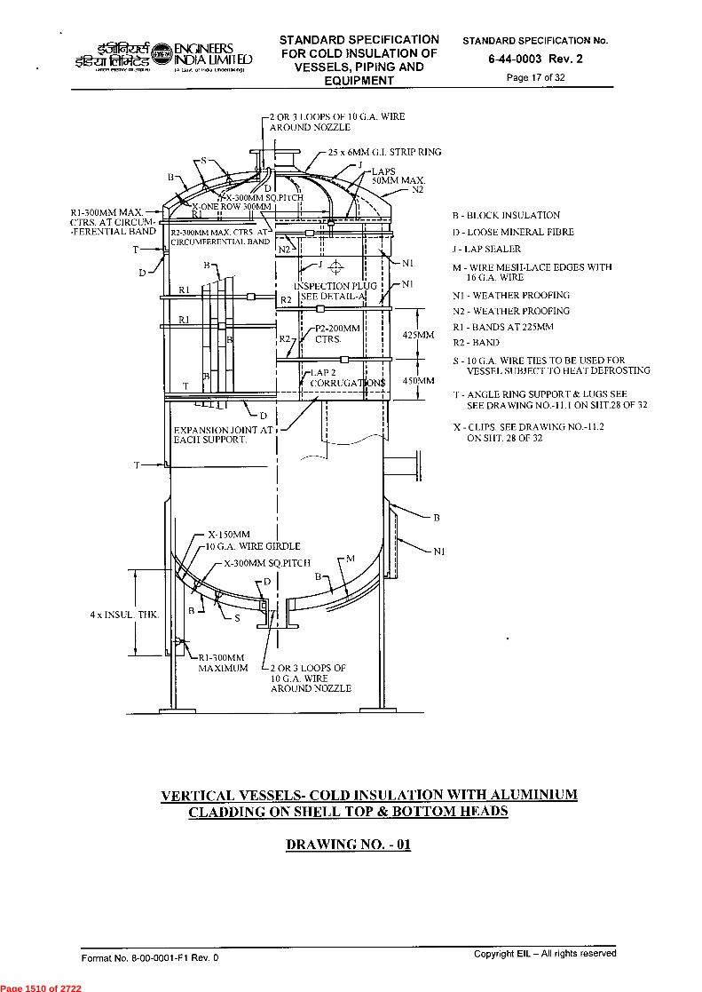
R1-300MM MAX. CTRS. AT CIRCUM--FERENTIAL BAND
X-300MM SQ.PITCH X-ONE ROW 300MM I I; R1 11 11 \, 1___11__
25 x 6MM G.I. STRIP RING
• 11,
`. l N .
LAPS 50MM MAX.
N2
R2-300MM MAX. CTRS. AT CIRCUMFERENTIAL BAND
N2 \ -r 1:
X-150MM 10 G.A. WIRE GIRDLE
X-300MM SQ.PITCH
DI
Og-2;rr~ INWR OfrtfOre 4113V0,)
ENGINEERS INDIA LIMITED IA GoN of Inclfa Ilndellakngf
STANDARD SPECIFICATION FOR COLD INSULATION OF
VESSELS, PIPING AND EQUIPMENT
STANDARD SPECIFICATION No.
6-44-0003 Rev. 2
Page 17 of 32
R1
R1
2 OR 3 LOOPS OF 10 G.A. WIRE AROUND NOZZLE
•- N1
INSPECTION PLUG /- N1 SEE DETAIL-A
P2-200MM CTRS. 425MM
v-LAP 2 l CORRUGATiON$
-4-
B - BLOCK INSULATION
D - LOOSE MINERAL FIBRE
J - LAP SEALER
M - WIRE MESH-LACE EDGES WITH 16 G.A. WIRE
N1 - WEATHER PROOFING
N2 - WEATHER PROOFING
R1 - BANDS AT 225MM
R2 - BAND
S - 10 G.A. WIRE TIES TO BE USED FOR VESSEL SUBJECT TO HEAT DEFROSTING
450MM
T - ANGLE RING SUPPORT & LUGS SEE SEE DRAWING NO.-11.1 ON SHT.28 OF 32
EXPANSION JOINT AT EACH SUPPORT.
X - CLIPS. SEE DRAWING NO.-11.2 ON SHT. 28 OF 32
B
N1
4 x INSUL. THK.
>r\-R1-300MM MAXIMUM 2 OR 3 LOOPS OF
10 G.A. WIRE AROUND NOZZLE
VERTICAL VESSELS- COLD INSULATION WITH ALUMINIUM CLADDING ON SHELL TOP & BOTTOM HEADS
DRAWING NO. - 01
n-
Copyright EIL —All rights reserved Format No. 8-00-0001-F1 Rev. 0
Page 1510 of 2722
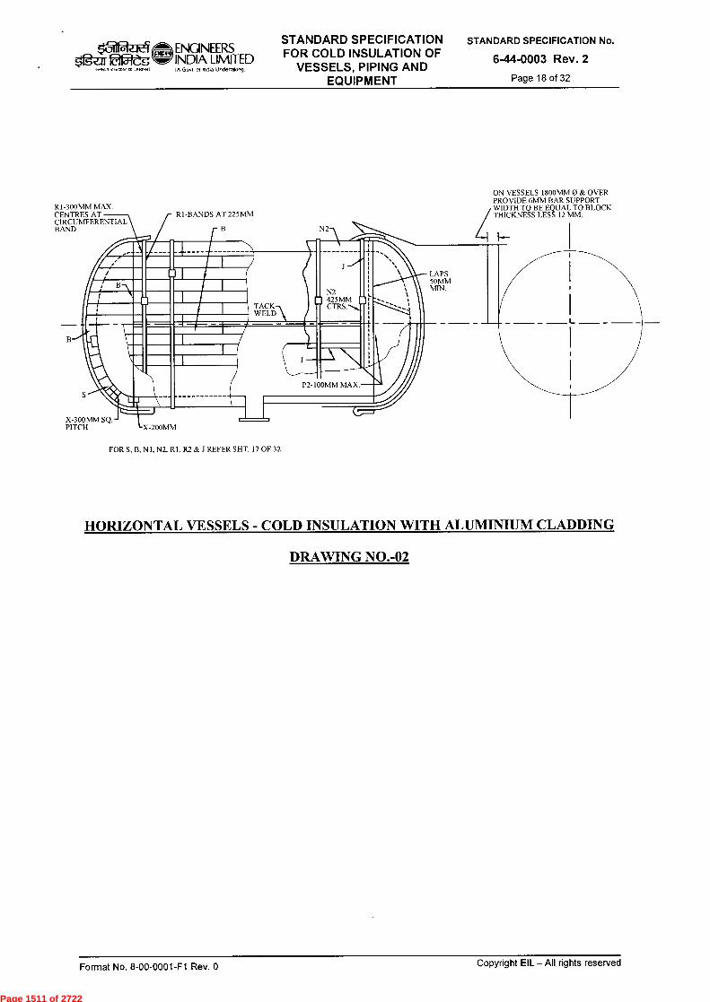
FOR S.13, N1, N2. R1. R2 & J REFER SHT. 17 OF 32
N2
J.
N2 D 425MM o TACK
WELD\
ON VESSELS 1800MM 0 & OVER PROVIDE 6MM BAR SUPPORT WIDTH TO BE EQUAL TO BLOCK THICKNESS LESS 12 MM.
LAPS 50MM MIN.
R1-300MM MAX. CENTRES AT CIRCUMEEREN1., BAND rB
X-300MM SQ. - PITCH
RI-BANDS AT 225MM
,312.1t4 fgLar0f51-2g
ENGINEERS INDIA LIMITED IA Govt of InOia Uncleflakoogi
STANDARD SPECIFICATION FOR COLD INSULATION OF
VESSELS, PIPING AND EQUIPMENT
STANDARD SPECIFICATION No.
6-44-0003 Rev. 2
Page 18 of 32
HORIZONTAL VESSELS - COLD INSULATION WITH ALUMINIUM CLADDING
DRAWING NO.-02
Format No. 8-00-0001-F1 Rev. 0 Copyright EIL — All rights reserved
Page 1511 of 2722

GLASS CLOTH MASTIC FIRST AS SPECIFIED
INSULATION SHAPED TO FIT CURVATURE OF SPHERE
300 MAX
BANDS
BANDS CRISS CROSSED 1.5 DIA M.S. ROD RING 180 DIA
SPHERE SURFACE PRIMED WITH SPECIFIED PRIMER
CLADDING
SHAPED INSULATION
VESSEL PRIMED WITH PRIMER AS SPECIFIED
GLASS CLOTH MASTIC FINISH
...„,;.„,
N.. .~.•■■ ___. ~~, a===• IM/ M• M~W /M M~• M •1=1ffia • MMEI~ MI M~M ffimma ~ffi IME ■:_■■ =11111M E111~11 11•11~1 IM• 111111~111•4, 111=111•••■ IENIIIMIEMB
IMINEMM• 11•I=1/
do, fflr
SUPPORT ANGLE (REFER 7-13-0034)
BANDS ON 300 MAX CENTRES AT EQUATOR BOTTOM HALF ONLY.
GREATER THAN 12 METRES DIA. w BOTTOM RING
BANDS ON 300 MAX CENTRES
AT EQUATOR
WIRE NETTING
6 DIA. STEEL BAR WELDED ON ANGLE
BAR SEAL
ANGLE BAND FASTENER
STANDARD SPECIFICATION FOR COLD INSULATION OF
VESSELS, PIPING AND EQUIPMENT
STANDARD SPECIFICATION No.
6-44-0003 Rev. 2
Page 19 of 32
ENGINEERS 5fgar fa2-dg INDIA LIMITED
vlvotrlOtIstattft
IA Govt of incha undenakng)
BOTTOM VIEW
TOP RING
LESS THAN 12 METRES DIA
ELEVATION VIEW
FIG.3-1 MULTI-LAYER APPLICATION
SPHERE INSULATION
FINISH AS SPECIFIED, GLASS CLOTH MASTIC
EXPANSION .1T
GLASS CLOTH MASTIC FINISH
AS SPECIFIED FOR SPHERE
1114
ADDITIONAL LAYER SPHERE SHELL
OF FINISH
LEG INSULATION ANGLE
OR PLATE SUPPORT
FLAT FINISH
TO SUPPORT
SPHERE SHELL
EQUATOR LINE
(REFER 7-13-0034)
SUPPORT ANGLE
ADDITIONAL LAYER OF FINISH 300 MIN. WIDTH FIG.3-3 INSULATION DETAIL
NEAR SUPPORT ANGLE FIG.3-2 LEG INSULATION DETAIL
NOTE: FOR DETAILS OF INSULATION SUPPORTS REFER STD. NO: 7-13-0034
COLD INSULATION FOR SPHERICAL VESSELS
DRAWING NO.-03 Copyright EIL —All rights reserved Format No. 8-00-0001-F1 Rev. 0
Page 1512 of 2722
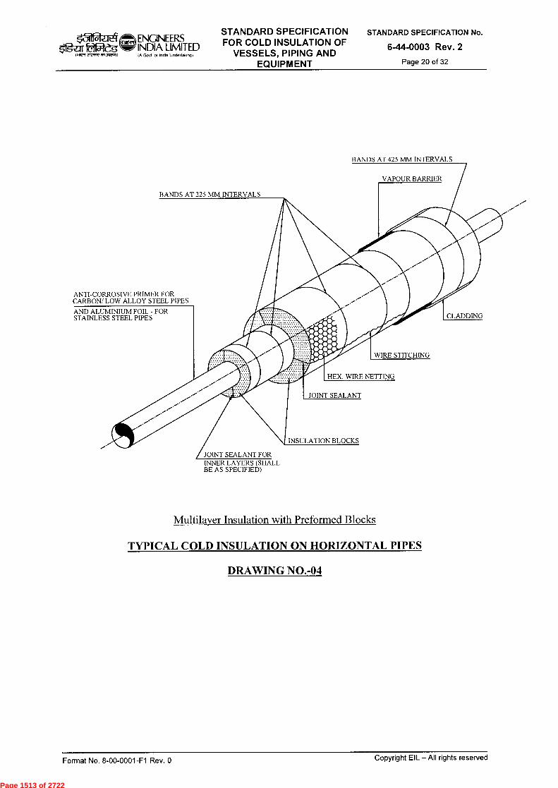
k31 ENGINEERS $gar 22-eg INDIA LIMITED
IA Govt of Inche Undertakng) .7,7 rrrmrr ,111,10.11
BANDS AT 425 MM INTERVALS
VAPOUR BARRIER
BANDS AT 225 MM INTERVALS
ANTI-CORROSIVE PRIMER FOR CARBON/ LOW ALLOY STEEL PIPES
AND ALUMINIUM FOIL - FOR STAINLESS STEEL PIPES CLADDING
WIRE STITCHING
HEX. WIRE NETTING
JOINT SEALANT
INSULATION BLOCKS
JOINT SEALANT FOR INNER LAYERS (SHALL BE AS SPECIFIED)
STANDARD SPECIFICATION FOR COLD INSULATION OF
VESSELS, PIPING AND EQUIPMENT
STANDARD SPECIFICATION No.
6-44-0003 Rev. 2
Page 20 of 32
Multilayer Insulation with Preformed Blocks
TYPICAL COLD INSULATION ON HORIZONTAL PIPES
DRAWING NO.-04
Format No. 8-00-0001-F1 Rev. 0 Copyright EIL —All rights reserved
Page 1513 of 2722

DETAIL - A
CLADDING
BAND
3 MILL BOARD
SUPPORT RING
(SPACING OF SUPPORT RINGS)
4.0 M RIVET
SPACER RING
(FOR DETAILS REFER DRG. NO-12)
DETAIL - A
INSULATION SUPPORT FOR
VERTICAL PIPING
I 0(TYP)
HOLE FOR 6 MM BOLT & NUT
6 MM
CLADDING
METALLIC BAND
ENGINEERS
dift INDIA LIMITED
er,Awan.3~0 IA Govt ot Indo Undertalfing)
STANDARD SPECIFICATION FOR COLD INSULATION OF
VESSELS, PIPING AND EQUIPMENT
STANDARD SPECIFICATION No.
6-44-0003 Rev. 2
Page 21 of 32
VIEW C-C
LEGEND:
A DIMENSIONS TO MATCH O.D. OF PIPE OR O.D. OF VESSEL
S INSULATION THICKNESS
SUPPORT RING FOR VERTICAL INSULATED PIPING DRAWING NO.-05
Format No. 8-00-0001-F1 Rev. 0 Copyright EIL - All rights reserved
Page 1514 of 2722
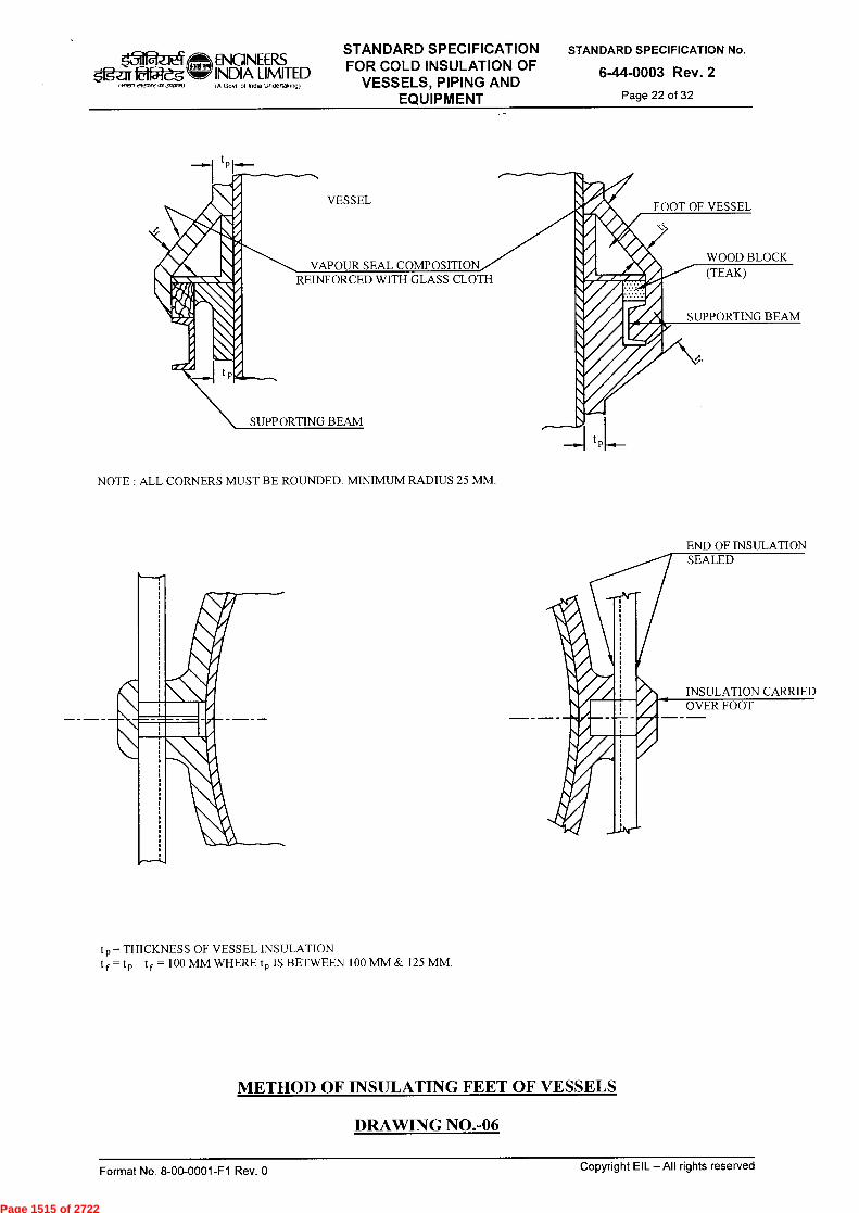
FOOT OF VESSEL
VAPOUR SEAL COMPOSITION REINFORCED WITH GLASS CLOTH
WOOD BLOCK (TEAK)
VESSEL
SUPPORTING BEAM
SUPPORTING BEAM
‘-31
oloo>t >
ENGINEERS INDIA LIMITED IA Govt o7 India Undedaong)
STANDARD SPECIFICATION FOR COLD INSULATION OF
VESSELS, PIPING AND EQUIPMENT
STANDARD SPECIFICATION No.
6-44-0003 Rev. 2
Page 22 of 32
NOTE : ALL CORNERS MUST BE ROUNDED. MINIMUM RADIUS 25 MM.
END OF INSULATION SEALED
INSULATION CARRIED OVER FOOT
t p = THICKNESS OF VESSEL INSULATION t f = t p tf = 100 MM WHERE t p IS BETWEEN 100 MM & 125 MM.
METHOD OF INSULATING FEET OF VESSELS
DRAWING NO.-06
Format No. 8-00-0001-F1 Rev. 0 Copyright EIL —All rights reserved
Page 1515 of 2722
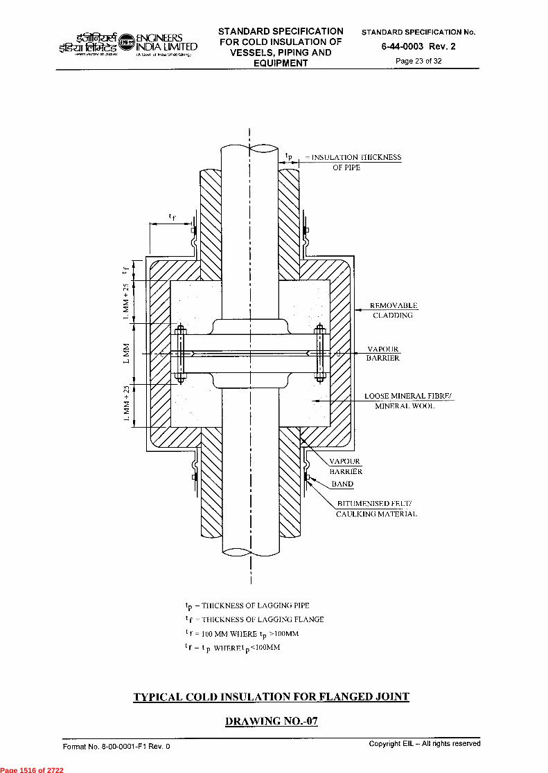
tp = INSULATION THICKNESS OF PIPE
II
REMOVABLE CLADDING
VAPOUR BARRIER
LOOSE MINERAL FIBRE/
MINERAL WOOL
\VAPOUR BARRIER
BAND
BITUMENISED FELT/
CAULKING MATERIAL
t = THICKNESS OF LAGGING PIPE
t f = THICKNESS OF LAGGING FLANGE
tf = 100 MM WHERE tp >100MM
tf = tp WHEREt p <100MM
tf
TYPICAL COLD INSULATION FOR FLANGED JOINT
DRAWING NO.-07
STANDARD SPECIFICATION FOR COLD INSULATION OF
VESSELS, PIPING AND EQUIPMENT
STANDARD SPECIFICATION No.
6-44-0003 Rev. 2
Page 23 of 32
t31 ENGINEERS 02-egd INDIA LIMITED
IA Govt of Indo Undertaking)
Copyright EIL —All rights reserved Format No. 8-00-0001-F1 Rev. 0
Page 1516 of 2722
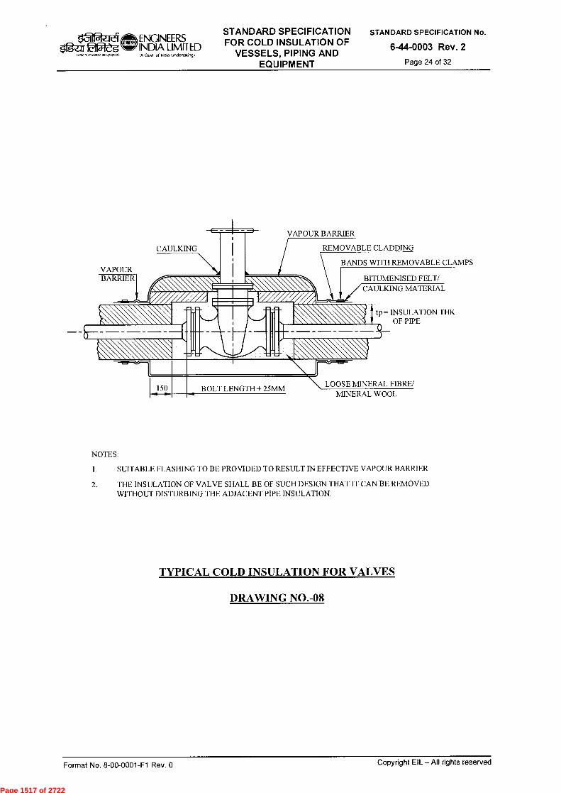
VAPOUR BARRIER
ENGINEERS INDIA LIMITED IA Govt of lnOa tindertakingt
STANDARD SPECIFICATION FOR COLD INSULATION OF
VESSELS, PIPING AND EQUIPMENT
STANDARD SPECIFICATION No.
6-44-0003 Rev. 2
Page 24 of 32 IN1,71,119,,,171.71~)
VAPOUR BARRIER
CAULKING REMOVABLE CLADDING
n\ C BITUMENISED FELT/
MATERIAL
BANDS WITH REMOVABLE CLAMPS
tp= INSULATION THK OF PIPE
1. 150 LOOSE MINERAL FIBRE/ MINERAL WOOL
BOLT LENGTH + 25MM
NOTES:
1. SUITABLE FLASHING TO BE PROVIDED TO RESULT IN EFFECTIVE VAPOUR BARRIER
2. THE INSULATION OF VALVE SHALL BE OF SUCH DESIGN THAT IT CAN BE REMOVED WITHOUT DISTURBING THE ADJACENT PIPE INSULATION.
TYPICAL COLD INSULATION FOR VALVES
DRAWING NO.-08
Copyright EIL — AII rights reserved Format No. 8-00-0001-F1 Rev. 0
Page 1517 of 2722

BITUMENISED FELT/ CAULKING MATERIAL
kil ...1 ENGINEERS INDIA LIMITED IA Govt of Indka Underfalonot
STANDARD SPECIFICATION FOR COLD INSULATION OF
VESSELS, PIPING AND EQUIPMENT
STANDARD SPECIFICATION No.
6-44-0003 Rev. 2
Page 25 of 32 '. INRT C1,4,,,1,1 1
SUITABLE FASHING TO BE PROVIDED
VAPOUR
BARRIER VAPOUR BARRIER
BOLT LENGTH + 25MM
LOOSE MINERAL FIBRE/ MINERAL WOOL
INTEGRAL MANHOLE COVER BUILT UP FROM SECTIONS
GLUED TOGETHER TO FACILITATE REMOVAL.THE COVER MUST NOT BE STUCK TO VESSEL INSUL.
REMOVABLE CLADDING
\ALL CORNERS ROUNDED
12MM 1 t f
t p = THICKNESS OF LAGGING IN VESSELS tf = tp + 25 MM WHERE tp >125 MM
tf = THICKNESS OF LAGGING IN FLANGES t f = 100 MM WHERE tp IS BETWEEN 100 MM & 125 MM
tf
= tp WHERE tp <100 MM
COLD INSULATION FOR MANHOLES
DRAWING NO.-09
BANDS TO MIN 25 MM RAD.
Copyright EIL — All rights reserved Format No. 8-00-0001-F1 Rev. 0
Page 1518 of 2722
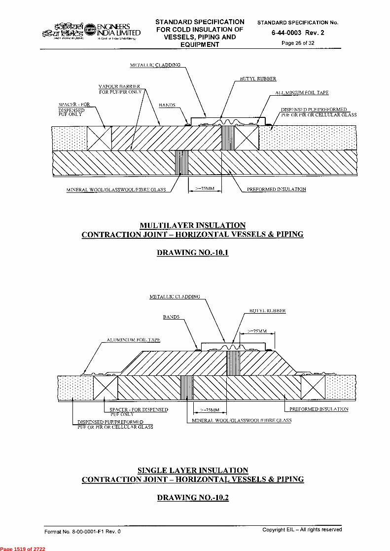
VAPOUR BARRIER FOR PUF/PIR ONLY ALUMINIUM FOIL TAPE
SPACER-FOR DISPENSED PUF ONLY
DISPENSED PUF/PREFORMED PUF OR PIR OR CELLULAR GLASS
BUTYL RUBBER
BANDS
MINERAL WOOL/GLASSWOOL/FIBRE GLASS >=75MM PREFORMED INSULATION
BUTYL RUBBER
/ >=75MM
ALUMINIUM FOIL TAPE
BANDS
PREFORMED INSULATION SPACER - FOR DISPENSED PUF ONLY
DISPENSED PUF/PREFORMED PUF OR PIR OR CELLULAR GLASS
MINERAL WOOL/GLASSWOOL/FIBRE GLASS
ENGINEERS STANDARD SPECIFICATION FOR COLD INSULATION OF
VESSELS, PIPING AND EQUIPMENT
STANDARD SPECIFICATION No.
6-44-0003 Rev. 2
Page 26 of 32
5gar 1.71771 rrmrcd51~ )
INDIA LIMITED IA Govt ol India Undenalong)
METALLIC CLADDING
MULTILAYER INSULATION CONTRACTION JOINT — HORIZONTAL VESSELS & PIPING
DRAWING NO.-10.1
METALLIC CLADDING
SINGLE LAYER INSULATION CONTRACTION JOINT — HORIZONTAL VESSELS & PIPING
DRAWING NO.-10.2
Format No. 8-00-0001-F1 Rev. 0 Copyright EIL —All rights reserved
Page 1519 of 2722
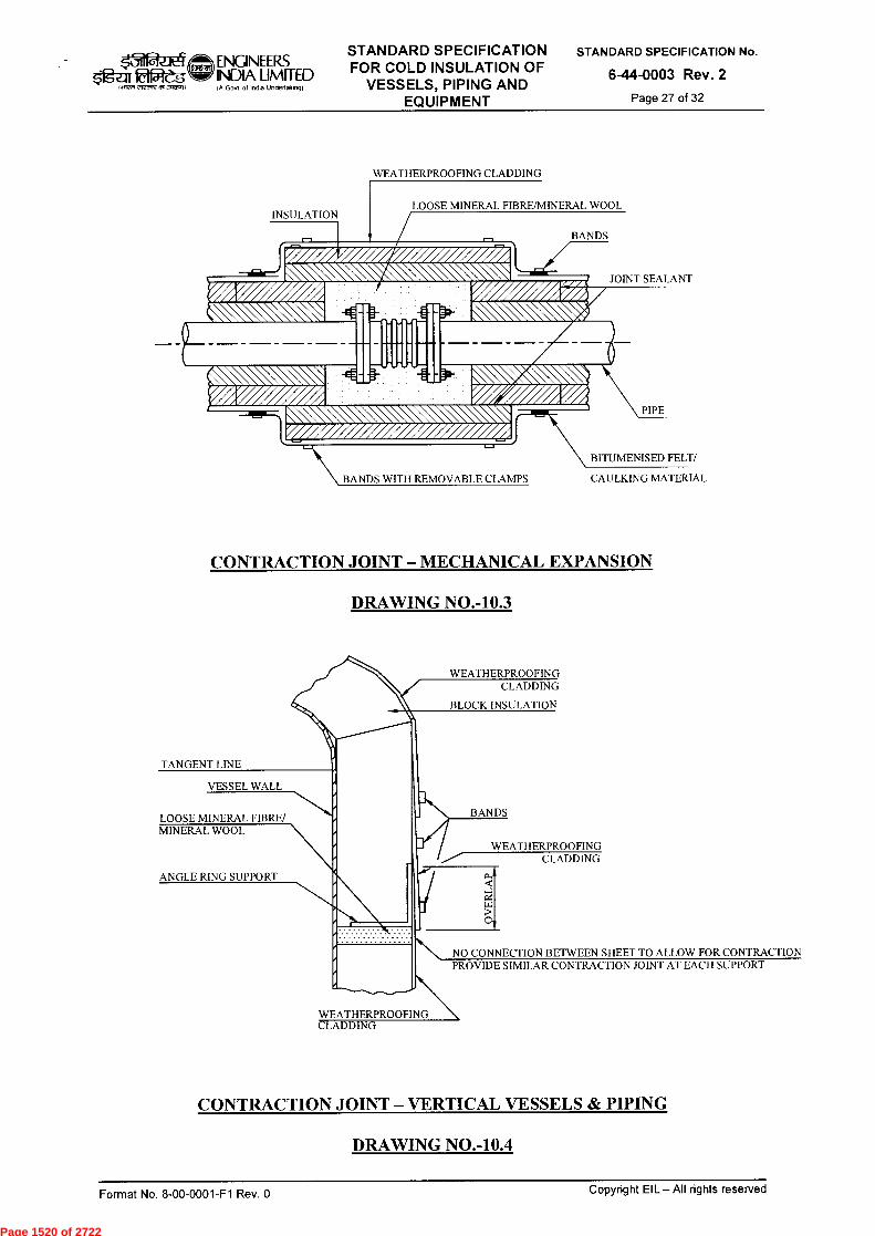
BITUMENISED FELT/
CAULKING MATERIAL BANDS WITH REMOVABLE CLAMPS
LOOSE MINERAL F BRE/MINERAL WOOL
BANDS
JOINT SEALANT
PIPE
INSULATION
arICIW5 1.7n ,i,cnrt a93~1)
ENGINEERS INDIA LIMITED IA Govt of Ind. Undertalong)
STANDARD SPECIFICATION FOR COLD INSULATION OF
VESSELS, PIPING AND EQUIPM ENT
STANDARD SPECIFICATION No.
6-44-0003 Rev. 2
Page 27 of 32
WEATHERPROOFING CLADDING
CONTRACTION JOINT — MECHANICAL EXPANSION
DRAWING NO.-10.3
TANGENT LINE
VESSEL WALL
LOOSE MINERAL FIBRE/ MINERAL WOOL
ANGLE RING SUPPORT
WEATHERPROOFING CLADDING
BLOCK INSULATION
BANDS
WEATHERPROOFING CLADDING
0
NO CONNECTION BETWEEN SHEET TO ALLOW FOR CONTRACTION PROVIDE SIMILAR CONTRACTION JOINT AT EACH SUPPORT
WEATHERPROOFING CLADDING
CONTRACTION JOINT — VERTICAL VESSELS & PIPING
DRAWING NO.-10.4
Copyright EIL — All rights reserved Format No. 8-00-0001-F1 Rev. 0
Page 1520 of 2722

TOP TANGENT LINE
z O
..71`1r&Ject ENGINEEFZS INDIA LIMITED
taffiztm 292zow3t~? IA Govt ot InOta Uneettakto9)
STANDARD SPECIFICATION FOR COLD INSULATION OF
VESSELS, PIPING AND EQUIPMENT
STANDARD SPECIFICATION No.
6-44-0003 Rev. 2
Page 28 of 32
OUTSIDE OF VESSEL
NOMINAL BLOCK INSULATION THICKNESS
BAND
6MM ANGLE RING (WELD ENDS) DO NOT WELD TO LUGS - T
10 MM PLATE LUGS 900 MM CENTRES (MINIMUM OF 3) - T
2725 MM SPACING (OR LESS)
12
SUPPORTS FOR BLOCK INSULATION DRAWING NO.-11.1
OUTSIDE OF HEAD OR INSIDE OF SKIRT
# 10 GA. WIRE 75 MM LONG OR 12 MM OR 6 MM SQ. BLANK NUT - S
CLIPS ON HEADS AND INSIDE SKIRT FOR BLOCK INSULATION DRAWING NO-11.2
12 6 MM
WELD BOTH SIDE
Copyright EIL All rights reserved Format No. 8-00-0001-F1 Rev. 0
Page 1521 of 2722
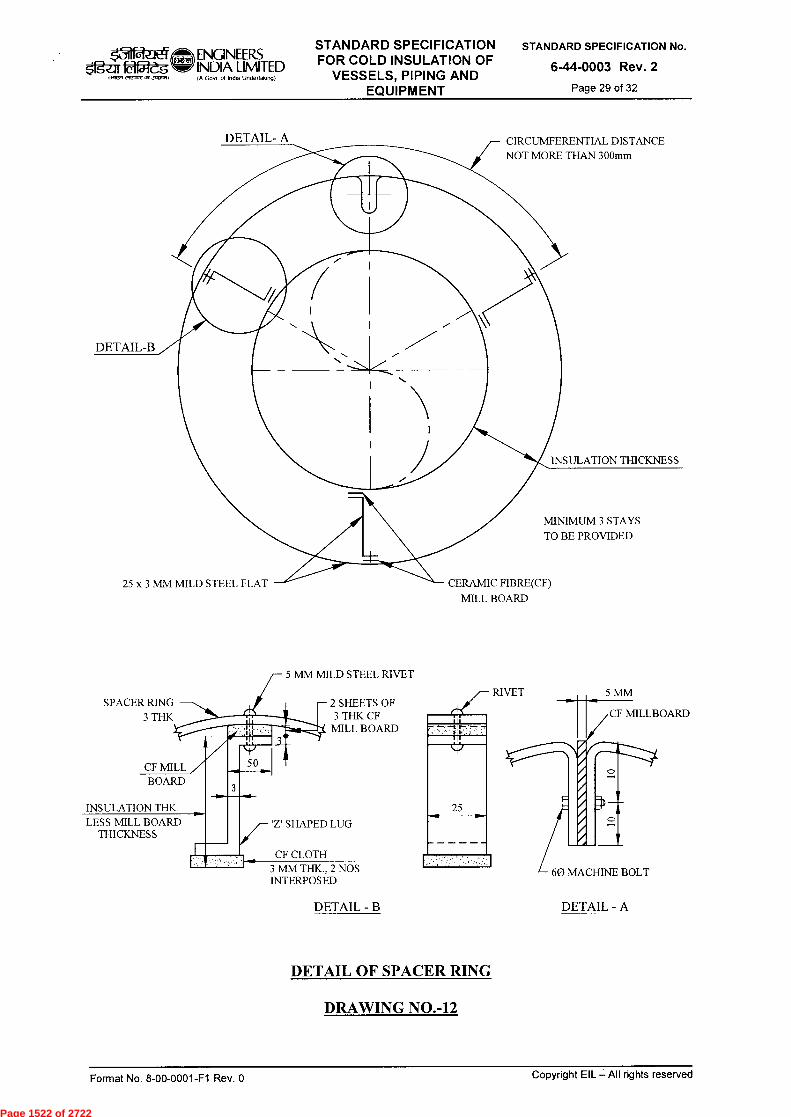
CIRCUMFERENTIAL DISTANCE NOT MORE THAN 300mm
DETAIL- A
25 x 3 MM MILD STEEL FLAT CERAMIC FIBRE(CF) MILL BOARD
INSULATION THICKNESS
MINIMUM 3 STAYS TO BE PROVIDED
DETAIL-B
SPACER RING 3 THK
BOARD
INSULATION THK LESS MILL BOARD
THICKNESS
— 2 SHEETS OF 3 THK CF MILL BOARD
RIVET 5 MM
CF MILLBOARD
60 MACHINE BOLT
01.111111.111111111111H'';'..».°11
CF MILL 50
'Z' SHAPED LUG
CF CLOTH 3 MM THK., 2 NOS INTERPOSED
k31 ENGINEERS 0151-eg• INDIA LIMITED
IA Gosi 01 Ind. Unde,tak.g)
STANDARD SPECIFICATION FOR COLD INSULATION OF
VESSELS, PIPING AND EQUIPMENT
STANDARD SPECIFICATION No.
6-44-0003 Rev. 2
Page 29 of 32
5 MM MILD STEEL RIVET
DETAIL - B
DETAIL - A
DETAIL OF SPACER RING
DRAWING NO.-12
Copyright EIL — All rights reserved Format No. 8-00-0001-F1 Rev. 0
Page 1522 of 2722
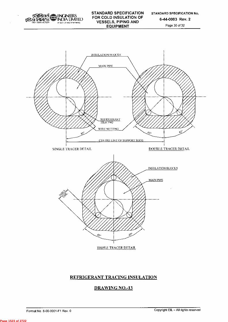
INSULATION BLOCKS
INSULATION BLOCKS
SINGLE TRACER DETAIL DOUBLE TRACER DETAIL
~, t7111
OXR, F2Otrzv91~tt
ENGINEERS INDIA LIMITED Ift Govt of InOia Undertakvogt
STANDARD SPECIFICATION FOR COLD INSULATION OF
VESSELS, PIPING AND EQUIPMENT
STANDARD SPECIFICATION No.
6-44-0003 Rev. 2
Page 30 of 32
CENTRE LINE OF SUPPORT SHOE
TRIPLE TRACER DETAIL
REFRIGERANT TRACING INSULATION
DRAWING NO.-13
Format No. 8-00-0001-F1 Rev. 0 Copyright EIL — All rights reserved
Page 1523 of 2722
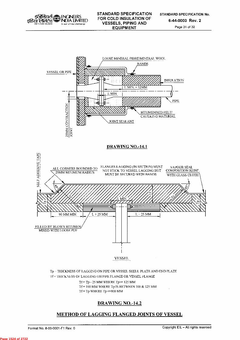
MIN
INSULATION
BANDS
L MIN. + 12MM
VESSEL OR PIPE
z ti 25
MM
CO
N
■
L + 25 MM L + 25 MM
PIPE
7-1111\ BITUMENISED FELT/ CAULKING MATERIAL
JOINT SEALANT
DRAWING NO.-14.1 [4]
H
ALL CORNERS ROUNDED TO FLANGES LAGGING (IN SECTION) MUST VAPOUR SEAL NOT STICK TO VESSEL LAGGING BUT COMPOSITION REINF.
MUST BE SECURED WITH BANDS WITH GLASS CLOTH
SE
LF
AD
HE
S
FILLED BY BLOWN BITUMEN MIXED WITH LOOSE PUF
VESSEL
25MM MINIMUM RADIUS
$*rga 92ès tffwv vrvottV Ot1,1025vit
ENGINEERS INDIA LIMITED IA Govt of Indta Unflettolong)
STANDARD SPECIFICATION FOR COLD INSULATION OF
VESSELS, PIPING AND EQUIPMENT
STANDARD SPECIFICATION No.
6-44-0003 Rev. 2
Page 31 of 32
LOOSE MINERAL FIBRE/MINERAL WOOL
Tp = THICKNESS OF LAGGING ON PIPE OR VESSEL SHELL PLATE AND END PLATE
Tf = THICKNESS OF LAGGING ON PIPE FLANGE OR VESSEL FLANGE
Tf = Tp - 25 MM WHERE Tp>= 125 MM
Tf = 100 MM WHERE Tp IS BETWEEN 100 & 125 MM
Tf = Tp WHERE Tp <=100 MM
DRAWING NO.-14.2
METHOD OF LAGGING FLANGED JOINTS OF VESSEL
Format No. 8-00-0001-F1 Rev. 0
Copyright EIL — All rights reserved
Page 1524 of 2722
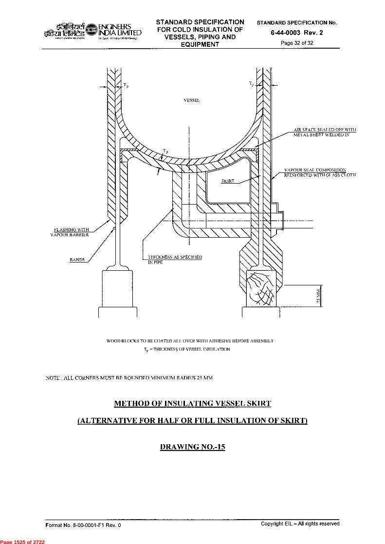
ENGINEERS g2-11215V-eg INDIA LIMITED
I A Govt of Intha Undertakingt ,rcnr, 95, JW".4)
THICKNESS AS SPECIFIED IN PIPE
VESSEL
AIR SPACE SEALED OFF WITH METAL SHEET WELDED IN
VAPOUR SEAL COMPOSITION REINFORCED WITH GLASS CLOTH
\ \ SKIRT
\
\ \
\ . \ \ \ \\
'1\\\\\
1
/FLASHING WITH
VAPOUR BARRIER
BANDS
STANDARD SPECIFICATION FOR COLD INSULATION OF
VESSELS, PIPING AND EQUIPMENT
STANDARD SPECIFICATION No.
6-44-0003 Rev. 2
Page 32 of 32
WOOD BLOCKS TO BE COATED ALL OVER WITH ADHESIVE BEFORE ASSEMBLY
T = THICKNESS OF VESSEL INSULATION
NOTE : ALL CORNERS MUST BE ROUNDED MINIMUM RADIUS 25 MM
METHOD OF INSULATING VESSEL SKIRT
(ALTERNATIVE FOR HALF OR FULL INSULATION OF SKIRT)
DRAWING NO.-15
Format No. 8-00-0001-F1 Rev. 0 Copyright EIL — All rights reserved
Page 1525 of 2722

Weg Ivoitot vvrcore 051,10S.
ENGINEERS INDIA LIMITED IA Govt ol India Undertalongt
SPECIFICATION FOR
MEDIUM VOLTAGE INDUCTION MOTORS
STANDARD SPECIFICATION No.
6-51-0032 Rev. 5
Page 1 of 15
f-~ SPECIFICATION
FOR MEDIUM VOLTAGE
INDUCTION MOTORS
5 02.05.14 REVISED AND ISSUED AS STANDARD SPECIFICATION
SA VKJ BRB SC
4 26.09.07 REVISED AND ISSUED AS STANDARD SPECIFICATION
SD BRB JMS VC
3 09.04.02 REVISED AND RE-ISSUED UG AAN VPS SKG
2 01.02.97 REVISED AND ISSUED AS STANDARD SPECIFICATION
AAN VPS SG AS
1 26.07.84 ISSUED AS STANDARD SPECIFICATION CSM VPS GNT
Rev. No Date Purpose Prepared
by Checked
by
Standards Committee Convenor
Standards Bureau
Chairman
Approved by
Format No. 8-00-0001-F1 Rev. 0 Copyright EIL — All rights reserved
Page 1526 of 2722

k31
c-tvotrt om.loo,)
ENGINEERS INDIA LIMITED IA Govt of India Unclettatongt
SPECIFICATION FOR
MEDIUM VOLTAGE INDUCTION MOTORS
STANDARD SPECIFICATION No.
6-51-0032 Rev. 5
Page 2 of 15
Abbreviations:
BASSEFA British Approvals Service for Electrical Equipment in Flammable Atmospheres
BIS Bureau of Indian Standards
BS British Standards
CIMFR Central Institute of Mines and Fuel Research
CT Current Transformer
EIL Engineers India Limited
FM Factory Mutual
FRP Fiberglass Reinforced Plastic
IEC International Electro-technical Commission
IEEE Institute of Electrical & Electronics Engineers
IS Indian Standard
JEC Japanese Electro-technical Committee
LCIE Laboratoire Central des Industries Electriques
LRWT Locked Rotor Withstand Time
NEMA National Electrical Manufacturers Association
PO Purchase Order
PVC Poly Vinyl Chloride
p.u. per unit
r.m.s Root Mean Square
RPM Revolutions per Minute
TETV Totally enclosed Tube Ventilated
UL Underwriter's Laboratories
VDE Verband Deutscher Elektrotechniker
CEA Central Electricity Authority
DOL Direct On line
VFD Variable Frequency Drive
OEM Original Equipment Manufacturers
TPIA Third party Inspection Agency
PESO Petroleum & Explosives Safety Organisation
Electrical Standards Committee
Convenor: Mr. BR Bhogal
Members: Ms. S. Anand Mr. Parag Gupta Mr. M.K. Sahu Mr. A.K. Chaudhary Ms. N.P. Guha
Format No. 8-00-0001-F1 Rev. 0
Copyright EIL —All rights reserved
Page 1527 of 2722
fafj1 -g NRR cv,nrc, 0,1 .~1)
ENGINEERS INDIA LIMITED (A Govt of indla Underta(ong(
SPECIFICATION FOR
MEDIUM VOLTAGE INDUCTION MOTORS
STANDARD SPECIFICATION No.
6-51-0032 Rev. 5
Page 3 of 15
CONTENTS
1.0 SCOPE 4
2.0 CODES AND STANDARDS 4
3.0 GENERAL REQUIREMENTS 5
4.0 OPERATING CONDITIONS 5
5.0 PERFORMANCE 6
6.0 CONSTRUCTION DETAILS 10
7.0 MISCELLANEOUS ACCESSORIES 14
8.0 CRITICAL SPEEDS 14
9.0 PAINTING 14
10.0 INSPECTION, TESTING AND ACCEPTANCE 14
11.0 CERTIFICATION 15
12.0 PACKING AND DESPATCH 15
Format No. 8-00-0001-F1 Rev. 0
Copyright EIL — All rights reserved
Page 1528 of 2722

Og-ar
>11277 J021,71,
ENGINEERS INDIA LIMITED IA Govt of lnela Undeflakingf
SPECIFICATION FOR
MEDIUM VOLTAGE INDUCTION MOTORS
STANDARD SPECIFICATION No.
6-51-0032 Rev. 5
Page 4 of 15
1.0 SCOPE
This specification covers the design, manufacture, testing, packing and supply of three phase medium voltage squirrel cage induction motors for line voltages upto 1000V AC.
2.0 CODES AND STANDARDS
2.1 The squirrel cage induction motors and their components shall comply with the latest editions of following standards issued by BIS.
IS - 5 : Colors for ready mixed paints and enamels. IS - 325 : Three phase induction motors. IS - 1076 : Preferred numbers. IS - 1231 : Dimensions of three phase foot mounted induction motors. IS - 1271 : Thermal evaluation and classification of electrical insulation. IS - 2223 : Dimensions of flange mounted AC Induction motors. IS - 2253 : Designation for type of construction and mounting arrangement of
rotating electrical machines. IS - 2254 : Dimensions of vertical shaft motors for pumps. IS - 2968 : Dimensions of slide rails for electric motors. IS - 4029 : Guide for testing three phase induction motors. IS - 4889 : Method of determination of efficiency of rotating electrical machines. IS - 6362 : Designation of methods of cooling of rotating electrical machines. IS - 7816 : Guide for testing insulation resistance of rotating machines. IS - 8223 : Dimensions and output series for rotating electrical machines. IS - 8789 : Values of performance characteristics for three phase induction
motors. IS - 9283 : Motors for submersible pump sets. IS - 12065 : Permissible limits of noise level for rotating electrical machines. IS - 12075 : Mechanical vibration of rotating Electrical Machines with shaft
heights 56 mm and higher - measurement, evaluation and limits of vibration severity.
IS - 13529 : Guide on effects of unbalanced voltages on the performance of three phase cage induction motors.
IS - 13555 : Guide for selection and application of three phase induction motors for different types of driven equipment.
IS - 14568 : Dimensions and output series for rotating electrical machines, frame numbers 355 to 1000 and flange numbers 1180 to 2360.
IS-15880 : Three phase cage induction motors when fed from IGBT Converters- Application guide
IS-15881 : Three phase cage induction motors specifically designed for IGBT converter supply
IS /IEC 60079-0 : Electrical apparatus for explosive gas atmospheres (General Requirements)
IS/IEC 60079-1 : Equipment protection by Flame proof enclosures "d'. IS/IEC 60079-7 : Explosive atmospheres-Equipment protection by increased safety —"e" IS/IEC 60079-15 : Electrical apparatus for explosive gas atmospheres Construction, test
& marking of type of protection "n" IS/IEC 60529 : Degree of protection provided by enclosures (IP Code)
IS/IEC 60034-5 : Degrees of protection provided by enclosure for rotating electrical machinery.
IS/IEC 60034-8 : Terminal marking and direction of rotation for rotating electrical machinery.
Format No. 8-00-0001-F1 Rev. 0
Copyright EIL — All rights reserved
Page 1529 of 2722
II $g2:1[ 02—eg
>IRPI 051,40,.1)
ENGINEERS INDIA LIMITED A Govt ol Indu UndeAaking)
SPECIFICATION FOR
MEDIUM VOLTAGE INDUCTION MOTORS
STANDARD SPECIFICATION No.
6-51-0032 Rev. 5
Page 5 of 15
2.2 In case of imported motors, standards of the country of origin shall be applicable if these standards are equivalent or stringent than the applicable Indian Standards.
2.3 The motors shall also conform to the provisions of CEA regulations and other statutory regulations currently in force in the country.
2.4 In case Indian Standards are not available, standards issued by IEC/ BS/ VDE/ IEEE/ JEC/NEMA or equivalent agency shall be applicable.
2.5 In case of any conflict between requirements specified in various applicable documents, the most stringent one shall prevail. However, owner's decision in this regard shall be final and binding.
3.0 GENERAL REQUIREMENTS
3.1 The offered equipment shall be brand new with state of the art technology and proven field track record. No prototype equipment shall be offered.
3.2 Vendor shall ensure availability of spare parts and maintenance support services for the offered equipment at least for 10 years from the date of supply.
3.3 Vendor shall give a notice of at least one year to the end user of equipment and EIL before phasing out the product/spares to ensure the end user for placement of order for spares and services.
4.0 OPERATING CONDITIONS
4.1 Ambient Conditions
Motors shall be suitable for operating satisfactorily in humid and corrosive atmosphere found in refineries, petrochemical, fertilizer and metallurgical plants. Service conditions shall be as specified in the motor data sheet. If not specifically mentioned therein, a design ambient temperature of 40°C and an altitude not exceeding 1000 meters above mean sea Level shall be taken into consideration.
4.2 Frequency and Voltage Variations
Unless otherwise agreed, motors shall be designed for continuous operation at rated output under the following conditions:
a) The terminal voltage differing from its rated value by not more than V 6 % or b) The frequency differing from its rated value by not more the V 3 % or c) Any combination of (a) and (b)
4.3 Starting
a) Motors shall be designed for direct-on-line starting or other method of starting as specified in datasheet.
b) Motors shall be designed for re-acceleration under full load after a momentary loss of voltage with the residual voltage being 100% and in phase opposition to the applied voltage.
c) Minimum locked rotor thermal withstand time at rated voltage shall be 10 seconds under cold conditions and 8 seconds under hot conditions. In addition, Locked Rotor withstand time under hot conditions at 75% & 100% voltages, shall be minimum 1.4 times the starting time at the corresponding voltage.
Format No. 8-00-0001-F1 Rev. 0
Copyright EIL — All rights reserved
Page 1530 of 2722

ENGINEER.S $1g-ar Odjeg INDIA LIMITED
IA GoN ol Ind. Undertakingi
SPECIFICATION FOR
MEDIUM VOLTAGE INDUCTION MOTORS
STANDARD SPECIFICATION No.
6-51-0032 Rev. 5
Page 6 of 15 I Nf"1,1 ,V1 .3~1
d) Al1 motors shall be suitable for starting under specified load conditions with 75 % of the rated voltage at the motor terminals.
e) Motors shall be designed to allow the minimum number of consecutive starts indicated in Table below:
Starts Min. no. of consecutive starts No. of consecutive start-ups with initial temp. of the motor at ambient level (cold)
3
No. of consecutive start-ups with initial temp. of the motor at full load operating level (hot).
2
4.4 Direction of Rotation
Motors shall be suitable for either direction of rotation. In case unidirectional fan is provided for motors, direction of rotation for which the motor is designed shall be permanently indicated by means of an arrow. When a motor is provided with bi-directional fan, a double-headed arrow should be provided.
Normally, clockwise rotation is desired as observed from the driving (coupling) end, when the terminals ABC are connected to a power supply giving a terminal phase sequence in the order ABC. Counter-clockwise rotation of the motor shall be obtained by connecting the power supply to terminals so that the phase sequence corresponds to the reversed alphabetical sequence of the terminal letters. Ample space shall be provided at the terminal box for interchanging any two external leads for obtaining the reverse phase sequence.
5.0 PERFORMANCE
5.1 Unless otherwise specified, Motors shall be rated for continuous duty (S1).
5.2 Unless otherwise specified, the starting current (as % rated current) shall not exceed 600% (subject to IS tolerance). However, motors upto 22KW motors having starting current upto 700% of rated current (subject to IS tolerance) shall also be acceptable.
5.3 In particular cases, when the starting current is to be limited, care shall be taken such that the design values of torque meets the load requirement while at the same time complying to clause 4.3 above of this specification.
5.4 In particular cases, when the starting with reduced voltage is specified, care shall be taken such that the design values of torque meets the load requirement while at the same time complying to clause 4.3 above of this specification.
5.5 Starting torque and minimum torque of the motor shall be compatible with the speed torque curve of the driven equipment under specified starting and operating conditions.
In case where characteristics of driven equipment are not available while selecting the motor, minimum starting torque shall be 110% of rated value for motors up to 75 kW and shall be 90% of rated value for motors above 75 kW.
5.6 The breakdown torque at the rated voltage shall not be less than 175 percent of the rated load torque with no negative tolerance. the breakdown torque shall not exceed 300 percent of the rated load torque. In case of motors driving equipment with pulsating loads (e.g. reciprocating compressors), the minimum value of breakdown torque at 75 percent of the rated voltage shall be more than the peak value of pulsating torque and the current pulsation shall be limited to 40%.
Format No. 8-00-0001-F1 Rev. 0 Copyright EIL — All rights reserved
Page 1531 of 2722

ENGINEERS INDIA LIMITED (A Govt ol indw Undertaking)
SPECIFICATION FOR
MEDIUM VOLTAGE INDUCTION MOTORS
STANDARD SPECIFICATION No.
6-51-0032 Rev. 5
Page 7 of 15
5.7 Motors fed by variable frequency drive shall additionally meet the following requirements:-
5.7.1 The motors shall be suitable for the current wave forms produced by the power supply including harmonics generated by the drive. The necessary coordination by motor manufacturers with drive manufacturers regarding harmonics generated by VFD shall be taken care and incorporated in motor design suitably.
5.7.2 The motors shall be designed to operate continuously at any speed over the range as per process requirement with minimum range as 10-100% of rated speed or as specified in data sheet. The characteristics shall be based on the application - in terms of constant torque / variable torque as per the driven equipment. Additional cooling fan shall be provided if required to limit the temperature rise to specified limits.
5.7.3 The motors shall withstand torque pulsation resulting from harmonics generated by the solid state power supply.
5.7.4 The motors required to be transferred to DOL bypass mode shall be rated for specified variations in line voltage and frequency.
5.8 The minimum values for performance characteristics of motors shall be as per Table 1-4 below TABLE 1
Values of Performance Characteristic of 2 Pole Induction Motors Rated output
kW
Frame Designation
Full Load speed
Min Rev/min
Full Load
Current
Max Amp
Breakaway Torque in
terms of Full load Torque
Min (Percent)
Breakaway Current in Terms of full Current, Equal or Below (Refer cl. 5.2)
(Percent)
Nominal Efficiency
(Percent)
(1) (2) (3) (4) (5) (6) (8) 0.37 71 2790 1.2 170.0 600 66.0 0.55 71 2760 1.6 170.0 600 70.0 0.75 80 2780 2.0 170.0 600 73.0 1.1 80 2790 2.8 170.0 600 76.2 1.5 90S 2800 3.7 170.0 600 78.5 2.2 90L 2810 5.0 170.0 600 81.0 3.7 100L 2820 8.0 160.0 600 84.0 5.5 132S 2830 11.0 160.0 600 85.7 7.5 132S 2840 15.0 160.0 600 87.0 9.3 160M 2840 18.5 160.0 600 87.7 11.0 160M 2860 21.5 160.0 600 88.4 15.0 160M 2870 29.0 160.0 600 89.4 18.5 160L 2880 35.0 160.0 600 90.0 22.0 180M 2890 41.5 160.0 600 90.5 30.0 200L 2900 54.0 160.0 600 91.4 37.0 200L 2900 67.0 160.0 600 92.0 45.0 225M 2955 80.0 160.0 600 92.5 55.0 250M 2960 95.0 160.0 600 93.0 75.0 280S 2970 130.0 160.0 600 93.6 90.0 280M 2970 150.0 160.0 600 93.9 110.0 315S 2980 185.0 160.0 600 94.0 125.0 315M 2980 209.0 160.0 600 94.5 132.011 315M 2980 220.0 160.0 600 94.5 160.011 315L 2980 265.0 160.0 600 94.8
NOTE: - Output to frame size relation is maintained in accordance with IS 1231 for all motors, except those marked as 11 , where in frame size indicated is `preferred frame size'.
Format No. 8-00-0001-F1 Rev. 0
Copyright EIL - All rights reserved
Page 1532 of 2722
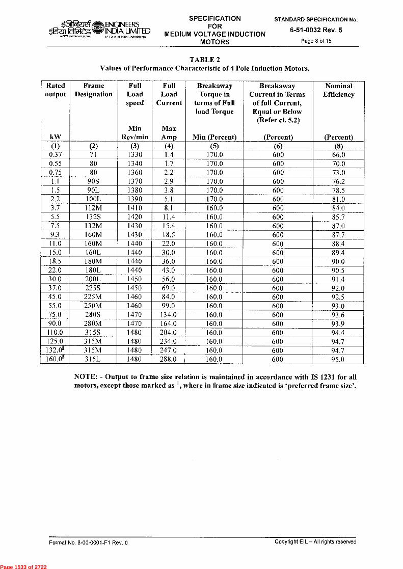
‘31 ENGINEERS INDIA LIMITED (A Govt of india Undertaking)
SPECIFICATION FOR
MEDIUM VOLTAGE INDUCTION MOTORS
STANDARD SPECIFICATION No.
6-51-0032 Rev. 5
Page 8 of 15
TABLE 2 Values of Performance Characteristic of 4 Pole Induction Motors.
Rated output
kW
Frame Designation
Full Load speed
Min Rev/min
Full Load
Current
Max Amp
Breakaway Torque in
terms of Full load Torque
Min (Percent)
Breakaway Current in Terms of full Current, Equal or Below
(Refer cl. 5.2)
(Percent)
Nominal Efficiency
(Percent) (1) (2) (3) (4) (5) (6) (8)
0.37 71 1330 1.4 170.0 600 66.0 0.55 80 1340 1.7 170.0 600 70.0 0.75 80 1360 2.2 170.0 600 73.0 1.1 90S 1370 2.9 170.0 600 76.2 1.5 90L 1380 3.8 170.0 600 78.5 2.2 100L 1390 5.1 170.0 600 81.0 3.7 112M 1410 8.1 160.0 600 84.0 5.5 132S 1420 11.4 160.0 600 85.7 7.5 132M 1430 15.4 160.0 600 87.0 9.3 160M 1430 18.5 160.0 600 87.7 11.0 160M 1440 22.0 160.0 600 88.4 15.0 160L 1440 30.0 160.0 600 89.4 18.5 180M 1440 36.0 160.0 600 90.0 22.0 180L 1440 43.0 160.0 600 90.5 30.0 200L 1450 56.0 160.0 600 91.4 37.0 225S 1450 69.0 160.0 600 92.0 45.0 225M 1460 84.0 160.0 600 92.5 55.0 250M 1460 99.0 160.0 600 93.0 75.0 280S 1470 134.0 160.0 600 93.6 90.0 280M 1470 164.0 160.0 600 93.9 110.0 315S 1480 204.0 160.0 600 94.4 125.0 315M 1480 234.0 160.0 600 94.7 132.011 315M 1480 247.0 160.0 600 94.7 160.011 315L 1480 288.0 160.0 600 95.0
NOTE: - Output to frame size relation is maintained in accordance with IS 1231 for all motors, except those marked as 11 , where in frame size indicated is `preferred frame size'.
Format No. 8-00-0001-F1 Rev. 0
Copyright EIL - All rights reserved
Page 1533 of 2722
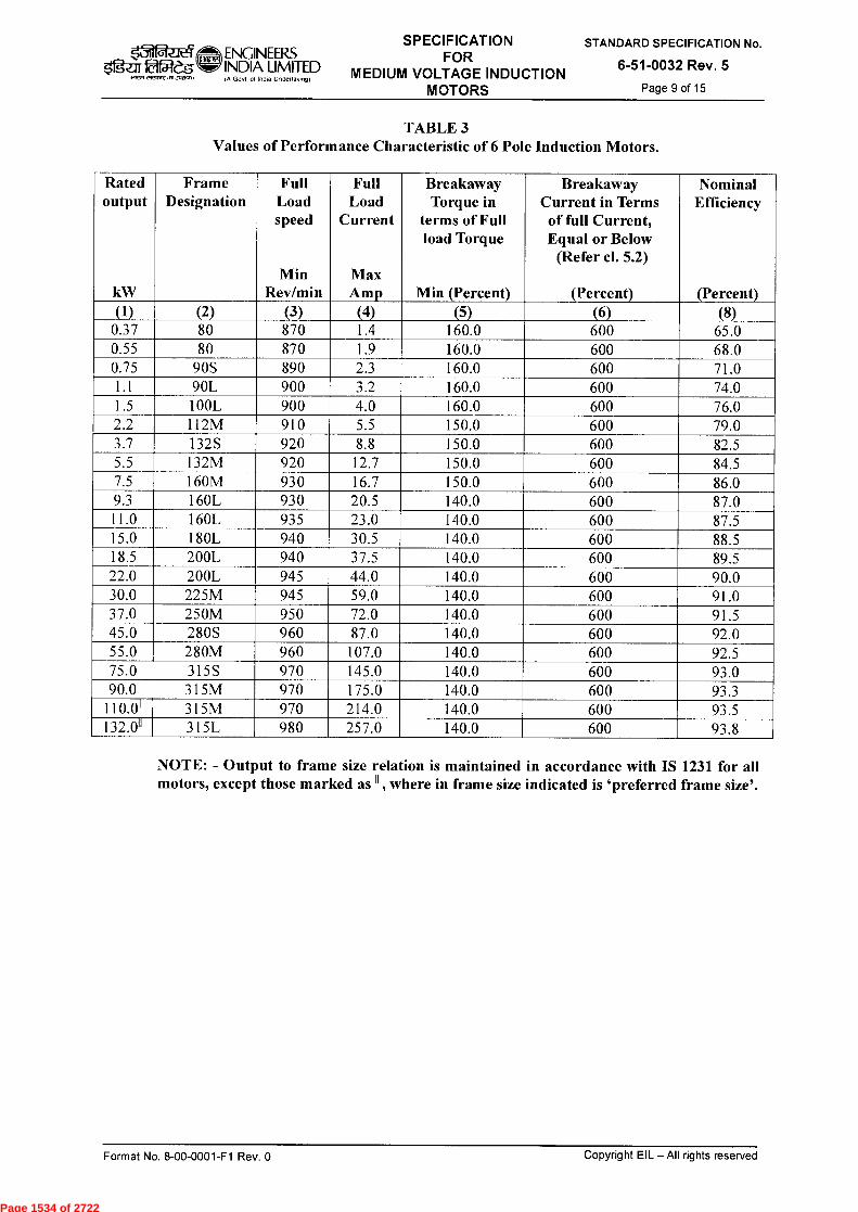
ENGINEERS Igaffa25 INDIA LIMITED
I NT,
SPECIFICATION FOR
MEDIUM VOLTAGE INDUCTION MOTORS
STANDARD SPECIFICATION No.
6-51-0032 Rev. 5
Page 9 of 15 IA Govt ot Incha Undettak,ngt
TABLE 3 Values of Performance Characteristic of 6 Pole Induction Motors.
Rated output
kW
Frame Designation
Full Load speed
Min Rev/min
Full Load
Current
Max Amp
Breakaway Torque in
terms of Full load Torque
Min (Percent)
Breakaway Current in Terms of full Current, Equal or Below
(Refer cl. 5.2)
(Percent)
Nominal Efficiency
(Percent) (1) (2) (3) (4) (5) (6) (8)
0.37 80 870 1.4 160.0 600 65.0 0.55 80 870 1.9 160.0 600 68.0 0.75 90S 890 2.3 160.0 600 71.0 1.1 90L 900 3.2 160.0 600 74.0 1.5 100L 900 4.0 160.0 600 76.0 2.2 112M 910 5.5 150.0 600 79.0 3.7 132S 920 8.8 150.0 600 82.5 5.5 132M 920 12.7 150.0 600 84.5 7.5 160M 930 16.7 150.0 600 86.0 9.3 160L 930 20.5 140.0 600 87.0 11.0 160L 935 23.0 140.0 600 87.5 15.0 180L 940 30.5 140.0 600 88.5 18.5 200L 940 37.5 140.0 600 89.5 22.0 200L 945 44.0 140.0 600 90.0 30.0 225M 945 59.0 140.0 600 91.0 37.0 250M 950 72.0 140.0 600 91.5 45.0 280S 960 87.0 140.0 600 92.0 55.0 280M 960 107.0 140.0 600 92.5 75.0 315S 970 145.0 140.0 600 93.0 90.0 315M 970 175.0 140.0 600 93.3
110.011 315M 970 214.0 140.0 600 93.5 132.011 315L 980 257.0 140.0 600 93.8
NOTE: - Output to frame size relation is maintained in accordance with IS 1231 for all motors, except those marked as 11 , where in frame size indicated is `preferred frame size'.
Format No. 8-00-0001-F1 Rev. 0
Copyright EIL - All rights reserved
Page 1534 of 2722

tll 5
Z:Er 02eg
ENGINEERS INDIA LIMITED IA Govt of ind,a Undettalongi
SPECIFICATION FOR
MEDIUM VOLTAGE INDUCTION MOTORS
STANDARD SPECIFICATION No.
6-51-0032 Rev. 5
Page 10 of 15
TABLE 4 Values of Performance Characteristic of 8 Pole Induction Motors.
Rated output
kW
Frame Designation
Full Load speed
Min Rev/min
Full Load
Current
Max Amp
Breakaway Torque in
terms of Full load Torque
Min (Percent)
Breakaway Current in Terms
of full Current, Equal or Below
(Refer cl. 5.2)
(Percent) (6)
Nominal Efficiency
(Percent) (8) (1) (2) (3) (4) (5)
0.37 90S 640 1.5 150.0 600 62.0
0.55 90L 640 2.1 150.0 600 67.0
0.75 100L 650 2.7 150.0 600 70.0
1.1 100L 660 3.5 150.0 600 72.0
1.5 112M 670 4.5 150.0 600 74.0
2.2 132S 680 6.1 140.0 600 77.0
3.7 160M 690 9.8 140.0 600 80.0
5.5 160M 690 14.2 140.0 600 82.5
7.5 160L 695 19.0 140.0 600 84.0
9.3 180L 700 23.0 140.0 600 85.0
11.0 180L 700 26.0 140.0 600 86.0
15.0 200L 705 35.0 130.0 600 87.0
18.5 225S 705 45.0 130.0 600 88.0
22.0 225M 710 52.0 130.0 600 88.5
30.0 250M 710 70.0 130.0 600 90.0
37.0 280S 710 86.0 130.0 600 90.5
45.0 280M 720 99.0 130.0 600 91.0
55.0 315S 720 118.0 130.0 600 91.5
75.0 315M 730 153.0 130.0 600 92.3
90.0 315L 730 182.0 130.0 600 92.8
110.011 315L 730 218.0 130.0 600 93.3
NOTE: - Output to frame size relation is maintained in accordance with IS 1231 for all motors, except those marked as 11 , where in frame size indicated is `preferred frame size'.
6.0 CONSTRUCTION DETAILS
6.1 Windings
6.1.1 Unless otherwise specified, Motors shall be provided with class 'B' insulation as a minimum. In case of motors with class 'F' insulation, the permissible temperature rise above the specified ambient temperature shall be limited to those specified in the applicable Indian standards for class 'B' insulation.
6.1.2 The winding shall be tropicalised. The windings shall preferably be vacuum impregnated. Alternately the windings shall be suitably varnished, baked and treated with epoxy gel for operating satisfactorily in humid and corrosive atmospheres.
6.1.3 Windings shall be adequately braced to prevent any relative movement during operation. In this respect, particular care shall be taken for the stator windings for direct-on-line starting squirrel cage motors. Insulation shall be provided between coils of different phases that lie together. Core laminations must be capable of withstanding burnout for rewind at 400EC without damage or loosening.
Format No. 8-00-0001-F1 Rev. 0 Copyright EIL - All rights reserved
Page 1535 of 2722
SPECIFICATION FOR
MEDIUM VOLTAGE INDUCTION MOTORS
k31 ENGINEERS $1g- xfa2e INDIA LIMITED
IA Go,t of Unde■ taMm)
STANDARD SPECIFICATION No.
6-51-0032 Rev. 5
Page 11 of 15
6.1.4 In case of motors driving equipment with pulsating loads, special care shall be taken for the joints of rotor bars and end rings to avoid premature failures due to induced fatigue stresses
6.1.5 The windings shall be connected in delta. However, for motors rated 2.2 kW and below, star connection may be accepted. In case of motors with star-delta starting, the motor windings shall be fully insulated for delta connection.
6.1.7 The ends of the windings shall be brought out into a terminal box. These shall be terminated by means of terminals mounted on an insulating base made of non-hygroscopic and non-flammable material.
6.1.6 All motors shall be with six terminals and suitable links to connect them in star or in delta except for motors rated up to and including 2.2 kW which may be accepted with three terminals.
6.2 Terminal Box and Cable Entries
6.2.1 The terminal box shall be located on the right hand side as viewed from the driving (coupling) end. The terminal box shall have side cable entry from non-driving end. However, as a special case, terminal box located on top may also be accepted, particularly for hazardous area motors, in case manufacturer has only TOP mounted terminal box design which is duly tested/certified by CIMFR and approved by PESO/CCOE for installation in hazardous area. The terminal box design shall allow rotation in steps of 90° to facilitate cable entry from any direction.
6.2.2 Terminal box cover shall be provided with handles to facilitate easy removal. However, for terminal box covers weighing less than 5 kg., terminal box covers without handles can be accepted.
6.2.3 The terminal box shall be provided with entries for suitable cable glands corresponding to the size of the specified cable. Crimp type tinned Cu lugs and nickel-plated brass (or aluminum if specifically required), double compression type cable glands shall be supplied along with the motors for the specified cable sizes for power and space heater cables.
6.2.4 For flameproof motors, terminal box can be provided in increased safety `Exe' execution.
Copyright EIL —All rights reserved Format No. 8-00-0001-F1 Rev. 0
Page 1536 of 2722

ENGINEERS fg -ar£;125 INDIA LIMITED
IA Govt ot India Unclettakotg)
SPECIFICATION FOR
MEDIUM VOLTAGE INDUCTION MOTORS
STANDARD SPECIFICATION No.
6-51-0032 Rev. 5
Page 12 of 15
6.2.5 The terminals, cable lugs, terminal box, cable entries and cable glands shall be suitable for the maximum cables sizes as specified below for 2 pole, 4 pole or 6 pole motors:
Motor rating up to and including Size of phase conductor (mm2) 2.2 kW and below 4 A1./ 2.5 cu
3.7 kW 10 Al./ 6 cu 5.5 kW 16 Al./ 10 cu 7.5 kW 25 A1./ 16 cu 9.3 kW 25 Al./ 16 cu 11.0 kW 25 Al./ 16 cu 15.0 kW 50 Al. 18.5 kW 70 Al 22.0 kW 70 AI 30.0 kW 95 Al 37.0 kW 120 Al 45.0 kW 150 Al 55.0 kW 185 Al 75.0 kW 2x95 Al 90.0 kW 2x120 Al 110.0 kW 2x185 Al
125.0 kW/132 kW 2x240 Al 150.0 kW 2x240 Al 160.0 kW 2x240 Al
6.2.6 Cable sizes for motors having synchronous speeds 750 RPM and below shall be as agreed between the purchaser and the manufacturer.
6.2.7 Cables used are of 650/1100 V grade aluminum conductor, PVC /XLPE insulated, PVC extruded inner sheath, armoured with overall PVC sheath. However for cables up to & including 16 mm2 cross-section, cables used may be with copper or aluminum conductor as indicated in the motor data sheet.
6.3 Motor Casing and Type of Enclosure
6.3.1 The minimum degree of motor enclosures including terminal boxes and bearing housing shall be IP-55 as per IS.
6.3.2 Motors for outdoor use shall be suitable for installation and satisfactory operation without any protective shelter or canopy. Motor casing shall be provided with a suitable drain for removal of condensed moisture except in case of flameproof motors (Type Ex d/Exde).
6.3.3 A11 internal and external metallic parts, which may come into contact with cooling air, shall be of corrosion resistant material or appropriately treated to resist the corrosive agents, which may be present in the atmosphere. Screws and bolts shall be of rust proof material or protected against corrosion.
6.3.4 Unless otherwise agreed, motors shall have standard frame sizes for various output ratings as stipulated in IS.
6.4 Bearing and Lubrication
6.4.1 Motors shall have grease lubricated ball or roller bearings. In all cases, the bearings shall be chosen to provide a minimum L-10 rating Life of 5 years, (40, 000 hours) at rated operating conditions.
Format No. 8-00-0001-F1 Rev. 0
Copyright EIL — All rights reserved
Page 1537 of 2722
ENGINEER.S INDIA LIMITED
i(WR c.-werAcV1 JA0.0 (A GoN of Ind. Undeflak,ngi
SPECIFICATION FOR
MEDIUM VOLTAGE INDUCTION MOTORS
STANDARD SPECIFICATION No.
6-51-0032 Rev. 5
Page 13 of 15
(The L-10 rating life is the number of hours at constant speed that 90% of a group of identical bearings will complete or exceed before the first evidence of failure).
6.4.2 The bearings shall be adequate to absorb axial thrust produced by the motor itself or due to shaft expansion. Motors designed to handle external thrust from the driven equipment shall be supplied with a thrust bearing at the non-driving end.
6.4.3 In cases such as pumps for hot liquids where the driven equipment operates at high temperatures, bearings shall be cooled by a shaft-mounted fan. This shall ensure efficient ventilation of the bearing and disperse the heat transmitted from the driven equipment by conduction or convection.
6.4.4 Bearings shall be capable of grease injection from outside without removal of covers with motors in the running conditions. The bearing boxes shall be provided with necessary features to prevent loss of grease or entry of dust / moisture e.g. labyrinth seal. Where grease nipples are provided, there shall be associated, where necessary, with appropriately located relief devices, which ensure passage of grease through the bearings.
6.4.5 Pre-lubricated sealed bearings may be considered provided a full guarantee is given for 4 to 5 years of trouble-free service without the necessity of re-lubrication.
6.5 Cooling System
A11 motors shall be self-ventilated, fan cooled. Fans shall be corrosion resistant or appropriately protected. They shall be suitable for motor rotation in either direction without affecting the performance of the motor. If this is not possible for large outputs, it shall be possible to reverse the fan without affecting the balancing of the motor. For motors operating in hazardous area, the fans shall be of an anti-static non-sparking material.
6.6 Rotor
The rotor shall be of squirrel cage type, dynamically balanced to provide a low vibration level and long service life for the bearings. Die cast aluminum rotors for motors in hazardous areas may be accepted provided the same are type tested and approved by competent authorities.
6.7 Shaft Extension
Motors shall be provided with a single shaft extension with key-way and full key. Motor shaft shall be sized to withstand 10 times the rated design torque.
6.8 Lifting Hooks A11 motors weighing more than 30 kg. shall be provided with lifting hooks of adequate capacity.
6.9 Earth Terminals
Two earth terminals located preferably on diametrically opposite sides shall be provided for each motor. Necessary nuts and spring washers shall be provided for earth connection.
Format No. 8-00-0001-F1 Rev. 0
Copyright EIL — All rights reserved
Page 1538 of 2722

$'1gLar fafes
ENGINEERS INDIA LIMITED (A Govl of India Undeffolong)
SPECIFICATION FOR
MEDIUM VOLTAGE INDUCTION MOTORS
STANDARD SPECIFICATION No.
6-51-0032 Rev. 5
Page 14 of 15
7.0 MISCELLANEOUS ACCESSORIES
7.1 Anti-Condensation Heaters
A11 motors rated 30 kW and above shall be provided with 240 V anti-condensation heaters, sized and located so as to prevent condensation of moisture during shutdown periods.
Motors with heaters installed in hazardous atmospheres (Zone-1 or Zone-2), shall conform to the provisions of applicable Indian standards and temperature classification specified in the motor data sheet
The heater leads shall be brought out, preferably, to a separate terminal box which shall be of the same specification and grade of protection as the main terminal box.
A warning label with indelible red inscription shall be provided on the motor to indicate that the heater supply shall be isolated before carrying out any work on the motor.
7.2 Name Plates
In addition to the motor rating plate, a separate number plate for motor tag number shall be fixed in a readily visible position. This tag number shall be as per the motor data sheets.
8.0 CRITICAL SPEEDS
The first actual critical speed of stiff rotors shall not be lower than 120 % of the synchronous speed. For flexible rotors this shall be between 60 % and 80 % of the synchronous speed; the second actual critical speed shall be above 120 % of the synchronous speed.
9.0 PAINTING
All metal surfaces shall undergo manufacturer's standard cleaning /painting cycle. After preparation of the under surface, the equipment shall be painted with two coats of epoxy based final paint. Color shade of final paint shall be 632 of IS: 5/ RAL-7035. All unpainted steel parts shall be suitably treated to prevent rust formation. If these parts are moving elements, then these shall be greased.
10.0 INSPECTION, TESTING AND ACCEPTANCE
10.1 A11 tests shall be carried out at manufacturer's shop under his care and expense.
10.2 The manufacturer shall submit all internal test records of the tests carried out by him on the bought-out items, motor sub-assembly and complete motor assembly.
10.3 The manufacturer shall carry out the following routine and acceptance tests as per applicable Standards/ITP on all the motors.
a) General visual checks, nameplate details b) Mounting, shaft centre height measurement c) Terminal box location, clearances, size, entries, space adequacy and cable gland sizes d) Terminals type of Exn, Exe, Exd motors e) Free rotation of shaft, shaft centre height, lubrication, fan mounting f) Direction of rotation
g) Coupling, bearing details h) Cable glands, cable lug size and no. of entries in terminal box i) Winding resistance
Format No. 8-00-0001-F1 Rev. 0
Copyright EIL — All rights reserved
Page 1539 of 2722

ENGINEERS INDIA LIMITED IA Govt of Indta Undertakingl
SPECIFICATION FOR
MEDIUM VOLTAGE INDUCTION MOTORS
STANDARD SPECIFICATION No.
6-51-0032 Rev. 5
Page 15 of 15
92e5 1~1 C41.TC JY13+.1)
j) No load test & measurement of voltage, speed, current, power input k) Locked rotor test at reduced voltage and measurement of voltage , current & wattage l) Reduced voltage starting & running m) Insulation resistance before and after high voltage test n) High voltage o) Vibration
10.4 The manufacturer shall submit the following type test certificates (one sample from each type/rating): a) Full load test & measurement of voltage, current, power slip, power factor, bearing,
noise b) Efficiency & pf at 100%, 75% and 50% load c) Temperature rise test d) Momentary overload test e) Vibration f) Noise Level
g) Over speed h) Measurement of starting torque, starting current, full load torque.
10.5 For VFD fed motors, all tests as specified in the VFD specification shall be followed in addition to the above.
11.0 CERTIFICATION
The motors and associated equipment shall have test certificates issued by recognised independent test house (CIMFR/ CPRI/ ERTL/ Baseefa/ LCIE/ UL/ FM or equivalent). A11 indigenous motors shall conform to Indian standards and shall be certified by recognised testing agencies. All motors (indigenous & imported) shall also have valid statutory approvals (e.g. PESO, DGMS etc). as applicable for the specified location. All indigenous flameproof motors shall have valid BIS license and marking as required by statutory authorities.
12.0 PACKING AND DESPATCH
A11 the equipment shall be divided into several sections for protection and ease of handling during transportation. The equipment shall be properly packed for selected mode of transportation i.e. ship/rail or trailer. The equipment shall be wrapped in polythene sheets before being placed in crates/cases to prevent damage to the finish. Crates/cases shall have skid bottom for handling. Special notations such as `Fragile', `This nide up', `Center of gravity', `Weight', `Owner's particulars', `PO Nos.' etc. shall be clearly marked on the package together with other details as per purchaser for scrutiny.
The equipment may be stored outdoors for long periods before installation. The packing shall be completely suitable for outdoor storage, in areas with heavy rains/ high ambient temperature.
Format No. 8-00-0001-F1 Rev. 0
Copyright EIL — All rights reserved
Page 1540 of 2722
gfga faWs lair,i237,15,2,131,05.)
ENGINEERS INDIA LIMITED IA Govt of Indla Undertalong)
SPECIFICATION FOR FIELD INSPECTION, TESTING AND
COMMISSIONING OF ELECTRICAL INSTALLATIONS
SPECIFICATION No.
6-51-0087 Rev. 3
Page 1 of 8
-ftw #f-~ PiRkurr, -crftwr
SPECIFICATION FOR
FIELD INSPECTION, TESTING AND
COMMISSIONING OF ELECTRICAL INSTALLATIONS
3 10.6.14 REAFFIRMED & ISSUED AS STANDARD SPECIFICATION AKG SA BRB *". SC
2 03.03.09 REVISED & ISSUED AS STANDARD SPECIFICATION RKS NS JMS ND
1 14.07.03 REVISED & ISSUED AS STANDARD SPECIFICATION
HKM RSG VPS SKG
0 02.08.01 ISSUED AS STANDARD SPECIFICATION UAP RR VPS MI
Rev. No Date Purpose
Prepared by
Checked by
Standards Committee Convenor
Standards Bureau
Chairman
Approved by
Copyright EIL — All rights reserved Format No. 8-00-0001-F1 Rev. 0
Page 1541 of 2722
k31 laW5
iairerf r-freA, asl,~7,)
ENGINEERS INDIA LIMITED A GoN of Indla Undeltaking)
SPECIFICATION FOR FIELD INSPECTION, TESTING AND
COMMISSIONING OF ELECTRICAL INSTALLATIONS
SPECIFICATION No.
6-51-0087 Rev. 3 Page 2 of 8
Abbreviations:
AC Alternating Current AFC Approved for Construction BIS Bureau of Indian Standards CCOE Chief Controller of Explosives CEA Central Electricity Authority DC Direct Current DCS Distributed Control System DGMS Director General for Mines and Safety ECS Electrical Control Station GI Galvanized Iron HV High Voltage IS Indian Standard MV Medium Voltage OISD Oil Industry Safety Directorate
Electrical Standards Committee
Convenor: Mr. BR Bhogal
Members: Ms. S. Anand Mr. Parag Gupta Mr. M.K. Sahu Mr. A.K. Chaudhary (Inspection) Ms. N.P. Guha (Projects)
Format No. 8-00-0001-F1 Rev. 0 Copyright EIL — All rights reserved
Page 1542 of 2722

ENG1NEERS INDIA LIMITED IA Govt ol Ind. Undertaiong)
SPECIFICATION FOR FIELD INSPECTION, TESTING AND
COMMISSIONING OF ELECTRICAL INSTALLATIONS
SPECIFICATION No.
6-51-0087 Rev. 3
Page 3 of 8
fawres,
CONTENTS
1.0 SCOPE 4
2.0 CODES AND STANDARDS 4
3.0 FIELD INSPECTION, TESTING AND COMMISSIONING 4
4.0 RECORDS 8
Copyright EIL — All rights reserved Format No. 8-00-0001-F1 Rev. 0
Page 1543 of 2722
k`5112..itq ENGINEERS SPECIFICATION FOR FIELD INSPECTION, TESTING AND
COMMISSIONING OF ELECTRICAL INSTALLATIONS
SPECIFICATION No.
6-51-0087 Rev. 3
Page 4 of 8
$'1gz:IT ft- s I.R77 c`F,1,4, CA3PC1171)
INDIA LIMITED IA Govt of India Undertalong)
1.0 SCOPE
This specification covers the requirements for the field inspection, testing and commissioning of Electrical Equipment and Installation, forming part of electrical power distribution and utilisation system.
2.0 CODES AND STANDARDS
2.1 The field inspection, testing and commissioning of electrical equipment shall be carried out in line with this specification and the latest edition of following Indian Standards and OISD standards.
SP-30(BIS) National Electrical Code. IS 1255 Code of practice for installation and maintenance of power cables up
to & including 33 kV rating. IS-7816 Guide for testing Insulation resistance of rotating machines. IS 10810(Part 43) Method of Test for cables; Part 43 Insulation resistance. IS 10810(Part 45) Method of Test for cables; Part 45 High voltage test. IS 12729 HV Switchgears OISD 137 Inspection of Electrical Equipment. OISD 147 Inspection and safe practice during electrical installation.
2.2 In addition to the above it shall be ensured that the installation conforms to the requirements of the following as applicable:
a. CEA Regulations
b. Regulations laid down by CEA / Electrical Inspectorate.
c. Regulations laid down by Tariff Advisory Committee/Loss prevention council. d. Regulations laid down by CCoE/DGMS (as applicable). e. The petroleum rules (Ministry of Industry, Government of India). f. Any other regulations laid down by central / state / local authorities / insurance
agencies
3.0 FIELD INSPECTION, TESTING AND COMMISSIONING
3.1 Contractor shall carry out complete field inspection, testing and commissioning of electrical equipment as per Inspection & Test plans.
3.2 Before the completed installation or an addition to the existing installation is put into service, inspection / pre-commissioning checks and tests shall be carried out by contractor. In the event of defects being found out, the same shall be rectified and the installation retested as applicable.
3.3 The pre-commissioning inspection among other requirements shall include visual inspection, checking the workmanship of the installation, the rating of equipment, safety clearances, sizes of cables installed, conformance to the AFC document, soundness of switchgear bus connections, wiring properly dressed and labeled, sealing of unused cable entries, checking of all safety interlocks, control/interface functions as per requirement etc.
3.4 Visual inspection for soundness of bus bar connections of busducts, terminal connections of equipment/motor shall be carried out. It shall be ensured that no foreign materials are present inside busduct and equipment terminal boxes. After the visual inspection, all the covers of terminal boxes, inspection chambers shall be refitted with gaskets, bolts & nuts as per equipment manufacturer's instructions.
Format No. 8-00-0001-F1 Rev. 0 Copyright EIL — All rights reserved
Page 1544 of 2722
k31 ENGINEERS Og-ar 2f5:1-g INDIA LIMITED
(A GoN cd InEia Und<rlAk(A9)
SPECIFICATION FOR FIELD INSPECTION, TESTING AND
COMMISSIONING OF ELECTRICAL INSTALLATIONS
SPECIFICATION No.
6-51-0087 Rev. 3
Page 5 of 8 (~1 ~srz as,:ror.)
3.5 Pre-commissioning tests shall include but not be limited to the following:
Continuity test for each winding and power and control circuits.
Insulation test for each winding and power and control circuit
High voltage test for cables
- Dielectric strength test on transformer oil.
- Checking the correctness of wiring schemes, control circuit interlocks for intended functioning.
- Verification of phase sequence.
Testing of all types of relays/releases for required operation.
- Testing of measuring instruments for proper functioning.
- Earth continuity test for all circuits.
Checking of safety features for correctness of operation, etc.
Checking of all wired interface contacts (analogue, digital input/output contacts) for DCS and ECS interface, at panel and equipment terminal chambers as applicable.
(Electrical contractor shall co-ordinate with other agencies involved for the above and provide support services for checking interfaces of electrical equipment and the intended functioning)
Earth resistance measurement for each earth electrode, and the earthing system as a whole.
Lighting installation shall be tested for correct illumination levels, with fittings installed. Fittings shall be operated only with specified type of a lamp or tube.
3.6 After the above tests and inspection are completed, control circuits shall be tested for correct operation under all operating combinations and proved correct before applying power to main circuit.
3.7 Plant Communication, Fire alarm detection and telephone system shall be checked for correct operation and intended function.
3.8 A close visual inspection of electrical equipment in hazardous areas shall be made to ensure that equipment is suitable for the classified zone and gas group and correctly installed, with all covers, bolts, nuts and hardwares intact and there is no physical damage mark seen on the enclo sure
3.9 Site Acceptance Test procedure for specific equipment shall be furnished by the respective equipment vendor. The contractor shall provide necessary assistance to the equipment vendor to perform Site acceptance testing to enable the equipment vendor to perform the same.
3.10 All pre-commissioning checks and tests shall be carried out as per the directions of Engineer- in-charge. In addition to the equipment manufacturer's instructions, pre-commissioning check requirements shall also be complied. All tests shall be carried out by contractor in the presence of EIL/Owner' s representatives
3.11 The contractor shall bring to site all required tools, tackles, and testing instruments for carrying out field testing. Contractor shall use only calibrated measuring and test instruments and shall maintain valid calibration records.
Format No. 8-00-0001-F1 Rev. 0
Copyright EIL — All rights reserved
Page 1545 of 2722
$tigzrr fa2es IN■fn
ENGINEERS INDIA LIMITED IF GoN of lndN Underfakrogf
SPECIFICATION FOR FIELD INSPECTION, TESTING AND
COMMISSIONING OF ELECTRICAL INSTALLATIONS
SPECIFICATION No.
6-51-0087 Rev. 3 Page 6 of 8
3.12 The Insulation Resistance test values for various electrical equipment shall be as below:
3.12.1 Cables
The insulation resistance test values for cables shall be as per following table:
Rated voltage of the Cable DC Test Voltage in Volts Minimum Insulation resistance in Mega ohms
Lighting and power circuit wiring
250 1
650/1100V grade cables 1,000 10
1,900/3,300V grade cables 1,000 200
3,800/6,600V grade cables 1,000 200
6,350/11,000V grade cables 5,000 200
8,700/15,000V grade cables 5,000 200
12,700/22,000V grade cables 5,000 200
19,000/33000V grade cables 5,000 200
3.12.2 IIV, MV and Miscellaneous Switchboards
The insulation resistance test values for the switchboards shall be as per following table:
Rated voltage of the Switchboard
DC Test Voltage in Volts Minimum Insulation resistance in Mega ohms
33,000V 5,000 200
11,000V 5,000 200
6,600V 1,000 200
3,300V 1,000 200
415V 1,000 100
240V 500 10
110V 500 10
3.12.3 Generators and Motors
3.12.4 The insulation resistance test values for the Generators and Motors shall be as per following table:
Rated voltage of the Generators and Motors
DC Test Voltage in Volts Minimum Insulation resistance in Mega ohms at 40 °C
11,000V 5,000 120
6,600V 1,000 80
3,300V 1,000 50
415V 1,000 15
240V 500 12
Format No. 8-00-0001-F1 Rev. 0 Copyright EIL — All rights reserved
Page 1546 of 2722

ENGINEERS SPECIFICATION FOR FIELD INSPECTION, TESTING AND
COMMISSIONING OF ELECTRICAL INSTALLATIONS
SPECIFICATION No.
6-51-0087 Rev. 3 Page 7 of 8
I f ~5 irr0n twor,on )
INDIA LIMITED in Govt ol IndU Undertalong)
3.12.5 Transformers
3.12.6 The insulation resistance test values for the Transformers shall be as per following table:
Rated voltage of the Transformers
DC Test Voltage in Volts Minimum Insulation resistance in Mega ohms at 40 °C
Up to 600V 1,000 100
601 to 5000V 2,500 1,000
5001 to 15,000V 5,000 5,000
15001 to 35,000V 5,000 10,000
3.12.7 It shall be ensured that during insulation tests, electronic devices and components that are liable to get damaged on applied test voltage shall be disconnected from circuit. The instructions of equipment/panel manufacturer shall be followed strictly in this regard.
3.13 High-voltage Testing
3.13.1 DC high voltage test shall be conducted as per following table on all HV feeder cables and also on 1100 V grade cables where straight through joints have been made.
Rated Voltage of Cable (kV)
TEST VOLTAGE (kV) BETWEEN Duration (Minutes)
U. / U* Any Conductor and Metallic Sheath/ Screen/Armour
Conductor to Conductor (For Unscreened Cables)
0.65/1.1 3 3 5
1.9/3.3 5 9 5
3.3/3.3 9 9 5
3.8/6.6 10.5 18 5
6.6/6.6 18 18 5
6.35/11 18 30 5
11/11 30 30 5
12.7/22 37.5 - 5
19/33 60 - 5
*U. : Phase Voltage
U : Line Voltage
The cable cores must be discharged on completion of DC high voltage test and cable shall be kept earthed until it is put into service.
DC test voltage for old cables shall be 1.5 times rated voltage or less depending on the age of cables, repair work or nature of jointing work carried out, etc. In any case, the test voltage shall not be less than the rated voltage.
Format No. 8-00-0001-F1 Rev. 0
Copyright EIL — All rights reserved
Page 1547 of 2722
ENGINEERS mar faZ5 INDIA LIMITED
IA Gosn of Intha Undertakog)
SPECIFICATION FOR FIELD INSPECTION, TESTING AND
COMMISSIONING OF ELECTRICAL INSTALLATIONS
SPECIFICATION No.
6-51-0087 Rev. 3
Page 8 of 8 l aiWn 23~ ag,o.)
3.13.2 AC high voltage test shall be conducted as per following table on all HV Switchboards.
Rated Voltage (rms Value in
kV)
Rated 1 Min. Power Frequency Withstand Voltage (rms Value in kV)
Duration in Minutes
U To Earth, Between Poles and Across Open
Switching Device
Across the Isolating Distance
3.6 10 12 1 7.2 20 23 1 12 28 32 1 24 50 60 1 36 70 80 1
72.5 140 160 1
The withstand voltage values across the isolating distances are valid only for switching devices, where the clearance between open contacts is designed to meet the safety requirements specified for disconnectors.
3.14 All protective relays including thermal overload relays shall be tested by secondary injection current. Primary injection tests shall be carried out for differential protection, restricted earth fault protection at full/reduced current to ensure correctness of complete wiring.
3.15 Before energizing any equipment, `COMMISSIONING CLEARANCE FORM' as per standard format shall be duly filled in by contractor and submitted to EIL/owner.
3.16 It shall be ensured that the electrical inspectorate approval is available before energizing the equipment
4.0 RECORDS
Contractor shall keep up-to-date records of all activities carried out and test results. Field inspection / test reports shall be submitted to EIL / Owner by the contractor in bound volumes (triplicate copies).
Format No. 8-00-0001-F1 Rev. 0
Copyright EIL — All rights reserved
Page 1548 of 2722
RG BRB
`40irSPECIFICATION FOR STANDARD SPECIFICATION NO.
Og-ar Ws INDIA LIMITED ENGINEERS ELECTRICAL MOTOR OPERATED 6-51-0091 Rev. 4 la IA GOA of India Undertaking) VALVE ACTUATORS Page 1 of 10
re1W1 1:frU "Clch arra
SPECIFICATION FOR
ELECTRICAL MOTOR OPERATED VALVE ACTUATORS
4 25-03-14 REVISED AND ISSUED AS STANDARD SPECIFICATION
3 27-08-07 REVISED AND ISSUED AS STANDARD SPECIFICATION
AM SKG JMS VC
2 16-09-02 REVISED AND ISSUED AS STANDARD SPECIFICATION
1 03-04-97 REVISED AND ISSUED AS STANDARD SPECIFICATION
VCB JMS VPS SKG
RKM VPS SG A.SONI
0 17-12-84 ISSUED AS STANDARD SPECIFICATION
ADS SG SGG
Rev. No Date Purpose
Standards Standards
Prepared Checked Committee Bureau by by Convenor Chairman
Approved by
Format No. 8-00-0001-F1 Rev. 0
Copyright EIL — All rights reserved
Page 1549 of 2722

ENGINEERS SPECIFICATION FOR
INDIA LIMITED ELECTRICAL MOTOR OPERATED IA Govt of InEia Undertaking) VALVE ACTUATORS
STANDARD SPECIFICATION NO.
6-51-0091 Rev. 4 Page 2 of 10
Abbreviations:
CEA CIMFR DGMS FM IEC LCIE MOV PESO PVC UL
Central Electricity Authority Central Institute of Mines & Fuel Research Director General of Mines & Safety Factory Mutual Research Corporation International Electrotechnical Commission Laboratoire Central des Industries Electriques Motor operated valve Petroleum and Explosives Safety Organisation Poly Vinyl Chloride Underwriters Laboratory
Electrical Standards Committee
Convener: Members:
Mr. B.R. Bhogal Ms. S. Anand Mr. Parag Gupta Mr. M. K. Sahu Mr. A.K. Choudhury (Inspection) Ms. N.P. Guha (Projects)
Format No. 8-00-0001-F1 Rev. 0 Copyright EIL — All rights reserved
Page 1550 of 2722
11 51g-ar 22e'g
INTRT
ENGINEERS SPECIFICATION FOR INDIA LIMITED ELECTRICAL MOTOR OPERATED IA Govt of Ind. undertak.g) VALVE ACTUATORS
STANDARD SPECIFICATION NO.
6-51-0091 Rev. 4 Page 3 of 10
CONTENTS
1.0 SCOPE 4
2.0 CODES AND STANDARDS 4
3.0 GENERAL REQUIREMENTS 4
4.0 SITE CONDITIONS 4
5.0 POWER SUPPLY 5
6.0 TECHNICAL SPECIFICATIONS 5
7.0 EQUIPMENT FOR CLASSIFIED HAZARDOUS AREAS 8
8.0 FIREPROOFING 9
9.0 INSPECTION, TESTING AND ACCEPTANCE 9
10.0 PACKING AND DESPATCH 10
Format No. 8-00-0001-F1 Rev. 0 Copyright EIL — All rights reserved
Page 1551 of 2722
ENGINEERS SPECIFICATION FOR
INDIA LIMITED ELECTRICAL MOTOR OPERATED Govt of India Undotto«..9) VALVE ACTUATORS
STANDARD SPECIFICATION NO.
6-51-0091 Rev. 4 Page 4 of 10
zlf Ofjig NRTII A771112. 7.1.3.70.1/
1.0 SCOPE
The scope of this specification covers design, manufacture, assembly, shop testing and supply of electrical motor operated valve actuators intended for fully/ partially opening and closing valve duty with inching facility.
2.0 CODES AND STANDARDS
2.1 The equipment shall comply with the requirements of latest revision of the following standards issued by BIS (Bureau of Indian Standards) unless specified otherwise:
IS 5 Colours for ready mixed paints and enamels
IS 325 Three-phase Induction Motors
IS 4691 Degrees of protection provided by enclosure for rotating electrical machinery
IS 4722 Rotating electrical machines- Specification
IS 5571 Guide for Selection of Electrical Equipment for Hazardous area
IS 9334 Electric Motor Operated Actuators
IS 13947 Low Voltage Switchgear and Controlgear (Parts-1, 3, 4 & 5)
2.2 In case of imported equipment, the standards of the country of origin shall be applicable if these standards are equivalent or more stringent than the applicable Indian standards.
2.3 The equipment shall also conform to the provisions of Central Electricity Authority Regulation - 2010 and other statutory regulations currently in force in the country.
2.4 In case Indian standards are not available for any equipment, standards issued by IEC/ BS/ VDE/ IEEE/ NEMA or equivalent agency shall be applicable.
2.5 In case of any contradiction between various referred standards/ specifications/ data sheets and statutory regulations, the most stringent requirement shall govern and decision of Owner in this regard shall be final and binding.
3.0 GENERAL REQUIREMENTS
3.1 The offered equipment shall be brand new with state of the art technology having a proven field track record. No prototype equipment shall be offered.
3.2 Vendor shall ensure availability of spare parts and maintenance support services for the offered equipment for at least 10 years from the date of supply.
3.3 Vendor shall give a notice of at least one year to the end user of equipment and EIL before phasing out the product/ spares to enable the end user to place order for spares and services.
3.4 The vendor shall be responsible for design, engineering and manufacturing of the complete actuator to fully meet the intent and requirements of this specification and attached data sheets.
4.0 SITE CONDITIONS
The electrical motor operated valve actuators shall be suitable for operating under site conditions as specified in the requisition and data sheet. If not specifically mentioned therein, a design ambient temperature of 40°C and an altitude not exceeding 1000m above mean sea level shall be considered.
Format No. 8-00-0001-F1 Rev. 0 Copyright EIL — All rights reserved
Page 1552 of 2722

IMI51-eg .T7PrFla,f7,01.3vo.a,
ENGINEERS SPECIFICATION FOR
INDIA LIMITED ELECTRICAL MOTOR OPERATED IA Govl of lncba Undertalong) VALVE ACTUATORS
STANDARD SPECIFICATION NO.
6-51-0091 Rev. 4 Page 5 of 10
5.0 POWER SUPPLY
The electrical motor operated valve actuators shall be suitable for power supply at 415V ± 10%, 50 Hz ± 3%, 3 phase, unless specified otherwise in the data sheet.
6.0 TECHNICAL SPECIFICATIONS
Each MOV actuator shall include the motor, actuator unit, gears, position indicators, limit switches, handwheel, electrical starter and controls, terminal box etc. as a self-contained unit. The actuator shall be sized to provide adequate torque and/ or thrust to ensure the complete intended travel of the valve under the worst operating and electrical power supply conditions.
6.1 Motor
6.1.1 The motor shall be 3-phase squirrel cage induction type unless specified otherwise in the data sheet. It shall have totally enclosed non-ventilated and surface cooled construction.
6.1.2 The motor shall be designed for valve actuator service with high starting torque and shall be suitable for Direct on line starting. It shall be rated for S2-15 minute duty and shall conform to IS 325 or equivalent international standards.
6.1.3 The actuator assembly shall be provided with Thermostat(s) embedded in it to achieve protection of motor against over-temperature.
6.1.4 The motor shall be suitable for starting under required torque with 75% of rated voltage at motor terminals.
6.1.5 The motor shall have class 'F' insulation with temperature rise limited to class `B' limits. Motor winding shall be treated to resist corrosive agents and moisture.
6.1.6 Motor rotor shall preferably be of die-cast aluminium and, if brazed, shall be free from phosphorous.
6.1.7 Motor installed in actuator shall be rated for minimum of 60 starts/stop per hour. This is minimum requirement of actuator envisaged for ON-OFF duty only.
6.1.8 In case of intrusive type actuator, anti-condensation heater shall be provided irrespective of IP- 65 enclosure. However, in case of non-intrusive type actuator, space heater is not required.
6.2 Integral Starter and Control Transformer
The reversing starter, control transformer and local controls shall be integral with the valve actuator, unless specified otherwise in the data sheet. Solid state control of valve actuator and electrically isolated interface for remote control requirement shall be provided, wherever these features exist in manufacturer's design.
The integral starter shall be supplied with the following devices:
a) Electrically and mechanically interlocked reversing contactors for opening and closing operations
b) Control transformer with necessary tapping and protected with suitable easily replaceable fuses
c) Terminal block for external cable connection fully prewired for internal devices of valve actuator.
d) MOV Actuators operating with AC power supply shall be provided with Instantaneous Phase reversal protection.
Format No. 8-00-0001-F1 Rev. 0 Copyright EIL — All rights reserved
Page 1553 of 2722
G1
f&A 02eg 1.27, t-ircnr, On alow3,7
ENQNEERS SPECIFICATION FOR
INDIA LIMITED ELECTRICAL MOTOR OPERATED IA Govt of india Undertalong) VALVE ACTUATORS
STANDARD SPECIFICATION NO.
6-51-0091 Rev. 4 Page 6 of 10
6.3 Integral Push Button, Selector switches, Indications and Control devices
The following local control devices shall be provided integral with the MOV actuator:
a) Push buttons for `Opening/ Closing/ Stop' or alternatively `Open/ Close' selector switch
b) `Local/ Off/ Remote' selector switch, pad-lockable in each position c) Local continuous position indication from `Valve fully open' to `Valve fully closed'
position, which may be of analogue or digital type using mechanical indication/ Indicating lamps/ LEDs.
6.4 Torque and Travel Limit Switches
Torque limit switches shall be provided to protect the motor from over-loading by cutting-off the power supply to motor during opening and closing operations. The limit switches shall be preset. However, it shall be possible to set the value of maximum torque during closing from 50% to 100% of rated torque of actuators. Travel limit switch shall be provided to cut-off the power supply to the motor at the end of preset limit of valve travel. The switches shall be provided with requisite number of potential-free contacts for valve actuator operation and for indication on remote panels as specified in data sheet. Instead of mechanical torque limit switches, magnetic pulse counter/encoders to measure and control the stroke of actuator may be provided, wherever this feature exists in manufacturer's design.
6.5 Control Facilities
The internal controls and monitoring circuits shall be incorporated within the integral starter along with transformer and control unit of valve actuator.
Remote control facility shall be provided as a standard feature. The remote control circuits shall be powered from internally derived control supply voltage. Common status contact indicating the availability of the MOV actuator for remote control shall be provided by monitoring the following:
Loss of one or more phases of power supply Loss of control circuit supply Selector switch in local mode Local stop push button set to `Off Motor thermostat tripped Any other local fault/ abnormal condition.
Where applicable, one number hand-held infrared/blue tooth remote programming device required for site commissioning and reconfiguring (without the need of removal of the MOV cover) shall be supplied for each group of 10 valve actuators (subject to minimum one infrared/ Bluetooth remote setting device, even if number of valve actuators are less than ten).
6.6 Interface with Owner's PLC/DCS / REMOTE PUSH BUTTON STATION
Potential free contacts for the following shall be provided in actuator assembly for hardwire interface with Owner's DCS/PLC and/or Remote Push Button station:-
a) Run indication b) Trip indication — 2 Nos. c) Open status — 2 Nos. d) Close status — 2 Nos. e) Ready to start indication f) Torque high indication
Format No. 8-00-0001-F1 Rev. 0 Copyright EIL — All rights reserved
Page 1554 of 2722

Ogzir l&f5Erdg mmar ,r2a5zt a57.~
ENQNEERS SPECIFICATION FOR INDIA LJMITED ELECTRICAL MOTOR OPERATED
Govt of Ind. Undettakng) VALVE ACTUATORS
STANDARD SPECIFICATION NO.
6-51-0091 Rev. 4 Page 7 of 10
g) Thermostat status h) Open command — 2 Nos. i) Close command — 2 Nos. j) Local/Remote
6.7 Hand Operation
A hand wheel with hand/ auto lockable lever shall be provided for emergency operation of the MOV. The energisation of the motor shall automatically re-engage power operation.
6.8 Two-Wire Control system
Where specified in the data sheet, the MOV actuators shall be suitable for 2-wire control system. These actuators shall have individual field units connectable to a master station through a single 2-core cable loop for control and monitoring of the MOVs. The vendor shall indicate the maximum number of field units that can be connected to a master station and the maximum distance from the field unit to the master station. The vendor shall also indicate maximum number of control inputs and control/ status outputs from each field unit that can be handled through the 2-wire control system.
Each field unit/ MOV actuator shall be addressable from the master station through a unique address code. A11 the field settable/ adjustable parameters of the MOV actuator shall be settable from the master station. Similarly all the indications available on the MOV actuator shall be available at the master station. Full diagnostic features for the MOV actuators shall be available from the master station as well.
Suitable redundancy feature shall be provided, such that in case of a single fault at any location in the cable, the field unit continues to communicate with the master station. The master station shall be suitable for hook-up with the plant DCS system.
6.9 Digital Control System
If specified in data sheet, electric actuator shall be provided with an integrally mounted device providing digital connectivity with Owner's PLC/DCS for actuator control, status indication & monitoring. In this case, master station is not required any more. The control device shall meet the appropriate recognized protocol or BUS standards. Selection of protocol shall be as per data sheet only. Typical protocol/buses include:-
- Modbus RTU - Profibus DP - Device Net
-
Foundation FieldBus
Terminal for hardwired communication shall also be provided in addition to digital communication facility.
6.10 Remote Position Indicator
If requirement of remote position indication is specified in the data sheet, a 4-20 mA remote position transmitter shall be provided in the valve actuator and a continuous position indicator for mounting in purchaser's remote panel shall be supplied as a loose item. The remote position indicator shall continuously indicate the position of travel of the valve.
Format No. 8-00-0001-F1 Rev. 0 Copyright EIL — All rights reserved
Page 1555 of 2722
SPECIFICATION FOR ELECTRICAL MOTOR OPERATED
VALVE ACTUATORS
STANDARD SPECIFICATION NO.
6-51-0091 Rev. 4 Page 8 of 10
ENQNEERS r 02-a'g INDIA LIMITED
NR71 F.1312 21513PLIM IA Govt ol India Unclettaiong)
6.11 Nameplate
Each motorized valve actuator shall be provided with a stainless steel nameplate furnishing the following details, attached firmly to it at a place convenient for reading:
a) Actuator tag number as per data sheet b) Motor kW rating, motor short time rating, motor supply voltage, nominal motor phase
current, auxiliary switch rating c) Maximum torque setting d) Actuator enclosure type, lubricant type e) Actuator type, wiring diagram number/ catalogue number, actuator serial number.
A separate nameplate shall be provided for hazardous area application.
6.12 The enclosure of complete MOV actuator including motor, integral starter, control transformer unit and all control devices shall have minimum IP-65 degree of protection which shall include the `0' ring for complete environmental protection.
6.13 Wiring and Terminals
A11 devices provided in the actuator shall be wired up to the terminal block. The contacts for remote operation and indication shall also be wired up to the terminal block. Minimum 10% spare terminals shall be provided for future interlocks. Internal wiring for power and control circuits shall be appropriately sized for MOV actuator rating. Each wire shall be identified at both ends using PVC ferrules. The terminal compartment shall be separated from the inner electrical components of the actuator by means of a watertight seal so that the actuator electrical components are protected from the ingress of moisture and foreign materials when the terminal cover is removed during installation and maintenance.
6.14 The actuator shall be provided with minimum five adequately sized cable entries viz., one for power cable and two for control cables. However, the actual number of control cable entries in actuators with 2-wire control system shall be provided based on job requirements as specified in data sheets/specification for control systems for MOVs. Suitable double compression cable glands shall be provided with each actuator for all cable entries and sealing plugs for all control cable entries. The cable glands and plugs shall be made of Nickel-plated brass. Plastic plugs shall not be acceptable.
7.0 EQUIPMENT FOR CLASSIFIED HAZARDOUS AREAS
7.1 Actuators meant for hazardous areas shall meet the requirements of IS 5571, IEC 60079 or equivalent international standards and shall be suitable for Gas groups and Temperature class as specified in the data sheet. Gas group IIB and Temperature class T3 (200°C) shall be considered if not indicated in data sheet. The manufacturer shall possess valid test certificates issued by a recognized independent test house (CIMFR/ Baseefa/ LCIE/ UL/ FM or equivalent) for the offered actuators. A11 indigenous equipment shall conform to Indian standards and shall have been tested and certified by Indian testing agencies. All equipment (indigenous and imported) shall also have valid statutory approvals as applicable for the specified hazardous locations from Petroleum and Explosives Safety Organisation (PESO / DGMS) or any other applicable statutory authority. All indigenous flameproof equipment shall have valid BIS license and corresponding marking as required by statutory authorities.
7.2 Apart from the nameplate indicating the tag no., a separate nameplate shall also be provided on each actuator to indicate the details of the testing agency (CIMFR or equivalent), test certificate number with date, statutory approval number with date, approval agency (PESO /
Format No. 8-00-0001-F1 Rev. 0 Copyright EIL — All rights reserved
Page 1556 of 2722

k5-11P_Jt.7 122es,
ENGINEERS SPECIFICATION FOR
INDIA LIMITED ELECTRICAL MOTOR OPERATED (A Govl of India UndertaInng) VALVE ACTUATORS
STANDARD SPECIFICATION NO. (r=,,) 6-51-0091 Rev. 4
Page 9 of 10
DGMS), BIS license number with date, applicable Gas group and Temperature class etc. The nameplates shall be riveted/ fixed with screws and not pasted. In case any of the standard details listed above are embossed on the enclosures, the same need not be repeated.
8.0 FIREPROOFING
8.1 Electric actuators shall be provided with fire proofing if specified in data sheet. The fire proofing shall be rated for 30 minutes. Arrangement can be made by Intumescent paint/fire resistant blankets/fire resistant boxes. Specific requirement of fire proofing arrangement shall be mentioned in data sheet. In general case, if only fire proofing is required, Intumescent paint (brand name: - K-Mass/ERS/Equivalent) shall be provided. The required certificates for the fireproof rating shall be furnished from an independent test laboratory.
8.2 MOV Actuators with fireproofing shall be suitable for termination of mica insulated fire survival type power and control cables.
9.0 INSPECTION, TESTING AND ACCEPTANCE
9.1 The equipment shall be subject to inspection by EIL/ Owner or by an agency authorized by the owner. Manufacturer shall furnish all necessary information concerning the supply to EIL/ Owner's inspector. During the course of manufacturing, the purchaser or his authorized representative shall be free to visit the works and assess the progress of work and the manufacturer shall render him all possible assistance to do so.
9.2 Following routine tests shall be carried out at the manufacturers' works under his supervision and at his own cost for all the actuators:-
9.2.1 Functional and calibration test for torque and limit switches
9.2.2 Response time test
9.2.3 Variation of supply voltage
9.2.4 Variation of frequency
9.2.5 Test on output shaft at 100% torque
9.2.6 Tests for motor(As per relevant IS/IEC)
9.3 Following type test certificates of offered model of actuator shall be submitted for review & approval:-
9.3.1 Life test
9.3.2 Test on motor terminal box
9.3.3 Damp heat recycling test
Two weeks' notice shall be given to Owner / EIL for witnessing the final testing of the complete assembly to ensure satisfactory operation of the MOV actuators. Type test certificates shall be furnished during detailed engineering. Final acceptance of MOVs at site shall be subject to successful testing of the MOV actuators with the valves.
9.4 Type test certificates, original drawings referred in certificates and statutory approval certificates and BIS license, where applicable, shall be shown to the inspection agency on demand. The certificates and BIS license must be valid at the time of dispatch.
Format No. 8-00-0001-F1 Rev. 0 Copyright EIL — All rights reserved
Page 1557 of 2722
ENGINEERS SPECIFICATION FOR
Og-ar ffit1.j-e'g INDIA LIMITED ELECTRICAL MOTOR OPERATED IA Govl of Ind. undenakng) VALVE ACTUATORS
STANDARD SPECIFICATION NO.
6-51-0091 Rev. 4 Page 10 of 10
F221512 217130,1571)
9.5 Test certificates of bought-out components shall be shown to the inspection agency on demand.
10.0 PACKING AND DESPATCH
A11 the equipment shall be divided into multiple sections for protection and ease of handling during transportation. The equipment shall be properly packed for the selected mode of transportation, i.e. by ship, rail or trailer. The equipment shall be wrapped in polythene sheets before being placed in crates/ cases to prevent damage to finish. The crates/ cases shall have skid bottoms for handling. Special notations such as `Fragile', `This side up', `Center of gravity', `Weighe, `Owner's particulars', `PO no.' etc. shall be clearly and indelibly marked on the packages together with other details as per purchase order.
The equipment may be stored outdoors for long periods before installation. The packing shall be completely suitable for outdoor storage in areas with heavy rains and high ambient temperature unless otherwise agreed. In order to prevent movement of equipment/ components within the crates, proper packing supports shall be provided. A set of instruction manuals for erection, testing and commissioning, a set of operation and maintenance manuals and a set of final drawings shall be enclosed in a waterproof cover along with the shipment
Format No. 8-00-0001-F1 Rev. 0 Copyright EIL — All rights reserved
Page 1558 of 2722
ei ENGINEERS Ogeir EVreg INDIA LIMITED
(A Govt of India Undenak.n9) RAM 217.17 MI JVMSI
STANDARD SPECIFICATION FOR
CHAIN PULLEY BLOCK
STANDARD SPECIFICATION No.
6-61-0015 Rev. 5 Page 1 of 6
. r.
■11•711011-q -q71§11' KIM IzR
1-111ch i ci
STANDARD SPECIFICATION FOR CHAIN PULLEY BLOCK
CliktiolA0- J Ml e-4. 1\frjr
5 14/12/16 REVISED AND REISSUED AK KC' PLC/ PB RN
4 01/08/12 REVISED AND REISSUED SPC PB AKN DM
3 01/06/10 REVISED AND REISSUED SPC PB MK/DM ND
2 31/07/06 REVISED AND REISSUED PPP AK SMA VJN
1 10/04/99 REVISED AND REISSUED YKS MST NN AS
0 22/06/90 ISSUED AS STANDARD SPECIFICATION
(RECOMPOSED IN AUGUST 1995) GVGC NN KNP RCPC
Rev. No
Date Purpose Prepared
by Checked
by
Standards Committee Convenor
Bureau
Standards
Chairman
Approved by
Format No. 8-00-0001-F1 Rev. 0 Copyright EIL - All rights reserved
Page 1559 of 2722
ENGINEERS INDIA LIMITED (A Goof of India Undertaking)
STANDARD SPECIFICATION FOR
CHAIN PULLEY BLOCK
STANDARD SPECIFICATION No.
6-61-0015 Rev. 5 Page 2 of 6
Abbreviations:
IS
: Indian Standard QA
: Quality Assurance
Machinery Equipment Standards Committee
Convenor : Mr. R.K. Trivedi
Members: Mr. P. Bhattacharjee Mr. Sanjay Mazumdar Mr. P.P. Pandey Mr. Nalin Kumar Mr. Tarun Kumar Mr. Anukul Mandal Mr. Shishupal Choudhary Mr. R. R. Shrivastava Mr. J.S. Duggal Mr. K.C. Paikar Mr. A. Natarajan Mr. K.V.K. Naidu (Projects)
Copyright EIL — All rights reserved Format No. 8-00-0001-F1 Rev. 0
Page 1560 of 2722

$50-zeMENGINEIRS g.artaiileg -wINDIA UNITED
1.41414 PRO4 ....10wiso IA Go. of InOn Undettaiung)
STANDARD SPECIFICATION FOR
CHAIN PULLEY BLOCK
STANDARD SPECIFICATION No.
6-61-0015 Rev. 5 Page 3 of 6
Contents
1.0 GENERAL 4
2.0 CODES AND STANDARDS 4
3.0 TECHNICAL REQUIREMENTS 4
4.0 INSPECTION AND TESTING 5
5.0 PROTECTION AND PAINTING 6
6.0 PACKAGING AND IDENTIFICATION 6
7.0 SPARE PARTS 6
Format No. 8-00-0001-F1 Rev. 0
Copyright EIL — All rights reserved
Page 1561 of 2722
STANDARD SPECIFICATION No.
6-61-0015 Rev. 5 Page 4 of 6
00z:1E4M, ENGINEERS ligar tagteg W. INDIA LIMITED
warn *wow,. „memo 0, Goo 01 ,o0o UNIerta.g)
STANDARD SPECIFICATION FOR
CHAIN PULLEY BLOCK
1.0 GENERAL
This specification outlines the minimum requirements under which the manufacturer shall design, manufacture, test and supply the Chain Pulley Block with or without trolley.
2.0 CODES AND STANDARDS
2.1 This standard is based on following Indian Standard, and the standards referred therein, which shall be deemed to be part of this standard.
IS - 3832
Hand operated Chain Pulley Blocks- Specification.
Latest revision of the above-mentioned standard as on the date of enquiry shall be applicable.
2.2 Other international standards may also be acceptable subject to their being equivalent or superior with prior approval of purchaser.
2.3 For provisions not covered by the above codes & standards, applicable engineering practices & norms shall govern.
3.0 TECHNICAL REQUIREMENTS
Technical requirements of Chain Pulley Block shall be as per Indian standards referred in clause 2.1 above, subject to the following additions, deletions and modifications:
3.1 Addition / Deletion / Modification to IS 3832: 2005 (Reaffirmed 2015)
i) Clause no. 4.2.1 (Modification): Mechanism class 2 shall be considered for design of chain pulley Block unless otherwise specified in the data sheet.
ii) Clause no. 5.0 (Addition): Chain Pulley Block shall be detachable type suitable for mounting on geared trolleys of the same ratings/capacities, unless otherwise specified in job specification/data sheet.
iii) Clause no. 5.1 (Addition): The frame shall be built from steel plates with bolted/welded construction.
iv) Clause no. 5.2 (Addition): All gears shall be machine cut.
v) Clause no. 5.5 (Modification): Only anti friction bearing shall be used. Bearing shall have L 10 life of minimum 25000 hrs. Bearings shall be of SKF/FAG/ NTN make only.
vi) Clause no. 5.6 (Modification): The block shall be provided with adequate facilities for lubrication and same shall be clearly indicated in the maintenance manual.
vii) Clause no. 5.7.1(Addition): Hook(s) (top -if applicable and bottom) shall be provided with safety latches to prevent accidental unhooking unless otherwise stated.
viii) Clause no. 5.7.1.2 (Modification): First line to be modified as "Bottom hook shall be provided with thrust bearing to enable it to rotate freely under load so as to prevent twisting of the load chain.
Copyright EIL — All rights reserved Format No. 8-00-0001-F1 Rev. 0
Page 1562 of 2722

051Weift. ENGINEERS 4fgeg WegViifII IA ED
MR, PRIEDers.,1121.,
IA Go. d loft Undertalung
STANDARD SPECIFICATION FOR
CHAIN PULLEY BLOCK
STANDARD SPECIFICATION No.
6-61-0015 Rev. 5 Page 5 of 6
ix) Clause no. 5.10.3 (Modification): The length of hand chain shall be such that the lowest point of the suspended loop shall be 400 mm (maximum) above operating level.
x) Clause no. 5.11 (Addition): The trolley for the chain pulley block shall be geared type, fabricated construction, 4 wheeled, driven by hand chain and shall have provision for mounting the chain pulley block. Trolley shall be designed to suit the suitable monorail beam size and the hoisting capacity.
xi) Clause no. 11.1 (Addition): Following shall also be marked on Chain Pulley block:
a) Tag number.
b) "Non Sparking Type" on chain pulley block suitable for hazardous area classification.
3.2 For offshore applications, load, hand and trolley chains shall be galvanized.
3.3 Special Requirements for Hazardous Area Chain Pulley Block
The materials for non-lubricated rubbing parts shall be of non-sparking type (non- ferrous). The suggested materials for such components are as follows:
Part/Component Material of Construction
A Lifting Mechanism
Ratchet wheel, chain guides Solid construction in Aluminium Bronze (IS - 305)/ High Tensile Brass (IS - 304)
Hand chain wheel Solid construction of Aluminium Bronze/ High Tensile Brass (IS- 304)/ Phosphor Bronze (IS-28)
Load chain wheel Solid construction in Aluminium Bronze (IS - 305)/ High Tensile Brass (IS - 304)
Hook (Top & bottom) Bronze coated Forged Steel / bronze coated Forged alloy Steel/Forged Stainless Steel.
B Trolley Mechanism
Hand chain wheel guides Solid construction in Aluminium Bronze (IS-305)/ High Tensile Brass (IS-304)/ Phosphor Bronze (IS-28)
Hand chain wheel Solid construction of Aluminium Bronze (IS-305)/ High Tensile Brass (IS-304)/ Phosphor Bronze (IS-28)
Ungeared and geared wheels Solid construction in Aluminium Bronze (IS - 305)/ High Tensile Brass (IS - 304) or tyre of Aluminium Bronze (IS-305)/ High Tensile Brass (IS-304) shrunk fitted on core wheel of C55Mn75.
4.0 INSPECTION AND TESTING
4.1 Equipment shall be subjected to stagewise expediting, inspection and testing at vendor's/subvendor's works by purchaser/its authorised inspection agency. Vendor shall
Format No. 8-00-0001-F1 Rev. 0
Copyright EIL — All rights reserved
Page 1563 of 2722

5ittaziel-IkENONEERS Og taiReg W INDIA LIMITED
A2W701AAP.)
STANDARD SPECIFICATION FOR
CHAIN PULLEY BLOCK
STANDARD SPECIFICATION No.
6-61-0015 Rev. 5 Page 6 of 6
(A Go. d MO. Undettaidow
submit Quality Assurance (QA) procedures before commencement of fabrication. Approved QA procedures shall form the basis for equipment inspection.
4.2 Testing at Works
4.2.1 Vendor shall perform operational Proof Test, as a minimum, necessary to ensure that the material and workmanship conform to the requirement of Clause 9.2 of IS- 3832.
4.2.2 The trolley (if applicable) shall be tested for smooth operation under loaded condition.
4.2.3 Certificate of test and examination shall be issued with all the chain pulley blocks as specified in clause 10.2 of IS — 3832.
4.2.4 Any or all the tests, at purchaser's option, shall be witnessed by purchaser/its authorized inspection agency. However, such inspection shall be regarded as check-up and in no way absolve the vendor of his responsibility.
5.0 PROTECTION AND PAINTING
5.1 Surface preparation and painting shall be done as per vendor's standard painting suitable for corrosive industrial environment, unless otherwise specified in the Job Specification.
5.2 Stainless steel surfaces, both inside and outside, shall be pickled and passivated.
5.3 Machined and bearing surfaces shall be protected with varnish or thick coat of grease.
6.0 PACKAGING AND IDENTIFICATION
6.1 All packaging shall be done in such a manner as to reduce the volume. The equipment shall be properly packed to provide adequate protection during shipment. All assemblies shall be properly match marked for site erection.
6.2 Attachments, spare parts of the equipment and small items shall be packed separately in wooden-cases. Each item shall be appropriately tagged with identification of main equipment, item denomination and reference number of the respective assembly drawing
6.3 Detailed packing list in water-proof envelope shall be inserted in the package together with equipment.
6.4 Each equipment shall have an identification plate giving salient equipment data, make, year of manufacture, equipment number, name of manufacturer etc.
7.0 SPARE PARTS
7.1 Vendor shall submit recommended list of spare parts with recommended quantities and itemised prices for first two years of operation of the equipment. Proper coding and referencing of spare parts shall be done so that later identification with appropriate equipment will be facilitated.
7.2 Recommended spares and their quantities shall take into account related factors of equipment reliability, effect of equipment downtime upon production or safety, cost of parts and availability of vendor's service facilities around the proposed location of equipment.
Format No. 8-00-0001-F1 Rev. 0
Copyright EIL — All rights reserved
Page 1564 of 2722

VJNNK VDS
A SONIPCS MMK
AKRPB RCPC
Checkedby
Standards GM Standards
Committee (Engg) BureauConvenor Chairman
3 23.05.11REVISED AND ISSUED AS STD.SPEC.
ALOK
2 16.02.06REVISED AND ISSUED AS STD.
SPECSKC
1 30.09.96REAFFIRMED & ISSUED AS STD.SPEC
SM
0 13.6.83 ISSUED AS STD. SPEC. UCJ
Rev.No
Date PurposePrepared
by
VK DMRK
Approved by
OOZE'? -ift" ENGINEERSSTANDARD SPECIFICATION FOR
ogeg fd51egW, INDIA LIMITED EARTHWORK FOR UNDERelvasetmagmo (A Govt d n Undertak.9) GROUND PIPING
STANDARD SPECIFICATIONNo.
6-65-0006 Rev. 3Page 1 of 7
Irma. trrectrr t wrziReR fgrffbi
STANDARD SPECIFICATIONFOR EARTHWORK
FOR UNDERGROUND PIPING
Format No. 8-00-0001-F1 Rev. 0 Copyright EIL — All rights reserved
Page 1565 of 2722

ENGINEERS STANDARD SPECIFICATION FORIfgar 056 INDIA LIMITED EARTHWORK FOR UNDER
GROUND PIPING
STANDARD SPECIFICATIONNo.
6-65-0006 Rev. 3Page 2 of 7
Often elenkenaanorkl/ IllGovt of India Undertaking)
Abbreviations:
IS India Standard
RCC : Reinforced Cement Concrete
U/G : Underground
General Civil Standards Committee
Convener: Mr. R. B. Bhutda
Members: Mr. Vipan GoelMr. D.C. BrahmaMr. R.K. SharmaMr. S. K. NaskarMr. Raju ChutaniMr. P.K. Mittal (Strl)Mr. A.T. Dharmik (Piping)Mr. U.A. Patro (Electrical)Mr. J. K. Joshi (Environment)Mr. S. Mukherjee (Construction)Mr. M.P. Jain (Projects)
Format No. 8-00-0001-F1 Rev. 0 Copyright EIL — All rights reserved
Page 1566 of 2722

ENGINEERS STANDARD SPECIFICATION FORINDIA LIMITED EARTHWORK FOR UNDERIA Govt or India Undertaking)
GROUND PIPING
STANDARD SPECIFICATIONNo.
6-65-0006 Rev. 3Page 3 of 7
Mf
CONTENTS
1.0 SCOPE 4
2.0 CODES & STANDARDS 4
3.0 MATERIAL 4
4.0 EARTHWORK IN EXCAVATION FOR TRENCHES / PITS FOR PIPELINES 4
5.0 BACKFILLING AND COMPACTION 6
6.0 TRANSPORTATION OF SURPLUS EARTH 7
7.0 PAYMENT 7
Format No. 8-00-0001-F1 Rev. 0 Copyright EIL — All rights reserved
Page 1567 of 2722

ENGINEERS STANDARD SPECIFICATION FOR STANDARD S
No
PECIFICATION
.
INDIA LIMITED EARTHWORK FOR UNDER 6-65-0006 Rev. 3IA Govt of India Undertaking) GROUND PIPING
Page 4 of 7
iaeag)+11e7. (9217R70173,10.1)
1.0 SCOPE
This specification deals with earthwork in trenches and pits (for valves, manholes, catch pitsetc.) for underground piping.
2.0 CODES & STANDARDS
IS: 783 Code of practice for laying of RCC pipes.
IS: 1200 (Part-I) Method of measurement of building and civil engineering works.
IS: 3764 Excavation work — code of safety.
NOTE:- Latest Edition of all Codes and Standards shall be followed.
3.0 MATERIAL
All workmanship and materials shall conform to the provisions of IS: 1200 (Part-1) and IS:3764.
4.0 EARTHWORK IN EXCAVATION FOR TRENCHES / PITS FOR PIPELINES
4.1 Excavation
Plant, machinery and equipments for excavation shall be selected and deployed to provideoptimum mechanisation in excavation of trenches and pits. The selection for excavation andearth movement machinery etc. shall take into account type of materials to be excavated,method of excavation, prevailing weather conditions and type of transport to be used.
The excavation of area of cut shall be so timed that the bottom level is not exposed to thedeteriorating influence of the weather for longer duration.
Excavation and earth moving equipment shall be deployed such that minimum damage iscaused to the natural sub-soil structure of exposed formations.
The monitoring of soil deformations, ground water levels during and possibly afterconstruction work shall be taken into consideration.
In the event, when excavation works are carried out in the vicinity of structures of anyimportance, the above monitoring shall be carried out within a distance, from the edge of theexcavation of 5 to 15 times the excavation depth, depending upon the subsoil conditions andthe stability of the neighboring structures.
4.2 Trenching work shall be carried out in all classes of soil including soft rock and excludinghard rock and shall be for all depths.
4.3 The trench shall be cut true to the line and level as per drawings.
4.4 If the trench is excavated below the required level than that indicated in the drawing, the extradepth shall be filled with concrete 1:5:10 or approved equivalent materials, as directed by theEngineer-in-Charge, at no extra cost to the owner.
4.5 In case of pressure piping, the trench shall be excavated generally as to provide a cover of1000 mm or dia of pipe whichever is more. In case of gravity sewers/ pipes, the trench shallbe excavated to conform to invert levels as per drawings. However in certain cases, the pipesmay run at shallower levels or at deeper levels depending upon drawing, site condition etc.
Format No. 8-00-0001-F1 Rev. 0
Copyright EIL — All rights reserved
Page 1568 of 2722

1611 faeleift- ENGINEERS STANDARD SPECIFICATION FOR5`gar &Wig W' INDIA LIMITED EARTHWORK FOR UNDER
RWOW O.M30.1) IA Govt of /We undertakm GROUND PIPING
STANDARD SPECIFICATION
No.
6-65-0006 Rev. 3Page 5 of 7
No rebate for lesser excavations, nor extra payment due to deeper excavations, shall beadmissible in those cases where pipeline laying rates are inclusive of earthwork items. Therates quoted shall be deemed to cover all works connected with trenching, whether trenchesare with single pipeline or have multiple pipelines in common trenches including road cuttingand making good the same.
4.6 The width of the trench shall be sufficient to give free working space of personnel,equipment, supports and ancillaries on each side of the pipe. The free working space shallconform to IS: 783. Generally it shall not be less than 150 mm on either side or 1/3 dia ofouter diameter of the pipe, whichever is greater.
4.7 When pipelines are running parallel, whether the trenching shall be individual or common,shall be decided by the Engineer-in-Charge and such decision shall be final and binding onthe contractor. No extra shall be payable for common excavations.
4.8 All earthwork involved in excavations of all types of manholes, catch pits, valve chambers,inspection chambers, chambers for instrumentation tapping etc., which are coming on thealignment of U/G piping or as defined by drawing as a part of U/G piping work, shall be paidextra under Earth work in excavation, back filling and removal of surplus earth etc. underrelevant clauses of the SOR.
4.9 Aspects such as variations in the soil conditions and the geological structure, depth ofexcavation, the existence of ground water and surface water, the type and extent ofexcavation, the topography of site, the proximity of items such as roads, buildings and buriedservices, construction traffic and activities near the excavation eg. stock piling shall be takeninto account when determining whether the sides of excavation should be free standing,sloping or temporary supported.
Suitable drainage and / or dewatering system like Well Point method / Bore well method etc.shall be provided to prevent or limit ingress of surface or sub surface water into excavation.
Serviceable materials intended for reuse should be used as soon as possible after excavationotherwise they should be stock piled at a location beyond 1.5m from the top edge of theexcavation or beyond a distance equal to the depth of the excavation whichever is higher at alocation approved by the Engineer-in-charge. If excavated serviceable material is not possibleto be stacked within the limits specified above, due to some constraint, it shall be stackedaway at a location approved by Engineer-in-Charge and paid separately under relevant item.
Areas used for temporary stockpiling of excavated material shall be kept clean and orderly,with excavated material kept by the side of road to avoid traffic movement. Excavated areasshall be restored to their original condition before completion of works.
All types of shoring and strutting, wherever necessary, shall be adopted to with hold the faceof earth or cutting in slope, as per site requirements and direction of Engineer-in-Charge.Supports shall be maintained such that the integrity of the sides of the excavation is notimpaired.
4.10 Any obstacle encountered during excavation shall be reported immediately to the Engineer-in-Charge and shall be dealt with as instructed.
4.11 The contractor shall maintain all excavated trenches and pits, in a dry and trim condition.
4.12 Necessary barricading and protection of slopes against slips due to traffic movement shall beprovided to the satisfaction of Engineer-in-Charge. Necessary warning flags and lights shallbe provided to caution traffic in the areas where trenches and/ or pits are provided.
Format No. 8-00-0001-F1 Rev. 0
Copyright EIL — All rights reserved
Page 1569 of 2722
1,5-ifaeley ,ftENGINEERs STANDARD SPECIFICATION FOROgar 51-e W INDIA LIMITED EARTHWORK FOR UNDER
(AAPA ?WW1' =JAW) (A Govt of India Underlakm) GROUND PIPING
STANDARD SPECIFICATIONNo.
6-65-0006 Rev. 3Page 6 of 7
4.13 In case of road cutting, all road material i.e. metal etc., shall be taken out carefully and keptseparately for reuse and road work shall be redone up to the original level, as it was prior tocutting the road, with the excavated road materials after laying and testing of the pipeline,within 10 days from the date of starting this work, at the cost of the contractor. The contractorshall provide suitable warning signs and barricades to prevent accidents.
Contractor shall also provide reasonable bye pass at his own cost when a road is cut for layingpipeline. Tankage dykes cut due to laying of the pipes, shall be redone conforming to theoriginal specifications, by the Contractor at his own cost. Secondary dykes, to take care ofany eventuality during construction, shall be provided by the Contractor at his own cost.
4.14 Dewatering shall be done in advance of the installation of the pipe to allow adequateinspection of padding of the bottom, if required. Dewatering shall be continued throughoutduring installation and backfilling.
The trench shall follow the gradient of pipeline as specified in the drawing. The contractorshall keep the trench in good condition, until the pipe is laid and tested. No extra claim shallbe entertained due to its caving or setting down, either before or after the pipe is laid.
In case, pipe is lowered in caved trench and backfilled before being inspected by theEngineer-in-Charge, the Contractor shall re-excavate the trench for inspection and backfill itat his own cost.
5.0 BACKFILLING AND COMPACTION
Backfilling
Trenches shall be back filled with suitable materials which should be compacted to the samedegree or better as the surrounding soils.
5.1 The soil used should be selected and approved by Engineer-in-Charge. Suitable material canbe extracted from available excavated material. The soil should be free from rubbish, grass,organic matter, stones, building waste and Black Cotton Soil etc. It should be free from clodsand hard lumps. In case good soil is not available from excavated material for back filling,trench shall be filled back with locally available coarse sand upto 30 cm. thick above the pipeand rest of trench shall be filled back with excavated soil upto required level.'
5.2 The filling should commence only after approval of Engineer-in-Charge is obtained and afterthe structures or pipes to be buried are tested and approved. Otherwise, if required, contractorshall uncover buried portion and refill at his own cost.
Temporary excavation supports should be removed as back filling and compaction proceeds,such that unacceptable movement of the supported ground does not occur.
Voids caused by extracted supports should be filled and compacted.
5.3 Filling should be done in layers. Each layer should be not more than 15 cm thick when looseand should be well rammed, with necessary watering, to obtain at least 90% of maximumlaboratory dry density.
Compaction trials should be carried out on each soil type to be placed in backfill, in order toconfirm the type of machine and number of passes required to obtain optimum compactionfor given soil moisture contents. These trials should also be used to determine the variabilityof the proposed fill material for different weather conditions.
Format No. 8-00-0001-F1 Rev. 0 Copyright EIL — All rights reserved
Page 1570 of 2722

Igar 251-egeiMIVOA3a0F,1)
ENGINEERS STANDARD SPECIFICATION FOR STANDARD S
No
PECIFICATION
.
INDIA LIMITED EARTHWORK FOR UNDER 6-65-0006 Rev. 3IA Govt of India undenakm) GROUND PIPING
Page 7 of 7
5.4 Care must be exercised to protect cables, pipes, joints, and other features from damage due tobackfilling and consolidation.
5.5 Filling should extend up to the level of original ground surface or as per drawing or asdirected by Engineer-in-Charge. The finished surface should be properly trimmed anddressed. The adjoining area should be cleaned and no heaps of surplus earth should be leftout.
6.0 TRANSPORTATION OF SURPLUS EARTH
Unserviceable materials and serviceable materials not intended for re-use shall be removedfrom the work site and disposed off at a location as approved by Engineer-in-charge.
The surplus earth is generated due to pipe laying, valve chambers, and manhole constructionetc. Surplus earth is also generated due to voids in the back filled volume of earth. Theremoval of surplus earth shall include excavation, loading, transportation, dumping, stackingor spreading, as per the directions of Engineer-in-charge.
7.0 PAYMENT
7.1 Unless specifically stated in the schedule of rates, no separate payment for earthwork inexcavation, backfilling, transportation, dewatering etc. shall be admissible and the paymentfor the same is deemed to have been included in the relevant items of the contract.
7.2 In case payment for earthwork is specified separately in the Schedule of Rates, the paymentshall be based on the actual quantity of excavation, backfilling and transportation done, takinginto consideration the slopes authorised by the Engineer-in-Charge for excavation, volume ofbackfilling calculated on the basis of excavation reduced by the volume of pipes.
7.3 In cases where hard rock excavation is involved, the matter shall be referred to Engineer-in-Charge, before proceeding with the work.
Format No. 8-00-0001-F1 Rev. 0
Copyright EIL — All rights reserved
Page 1571 of 2722
STANDARD SPECIFICATION FORlaitEJEth ENGINEERS UNDERGROUND AND ABOVE
g•tir tatatwer INDIA LIMITED GROUND G.1. PIPELINE SYSTEMlow/ marewarrn) IA GoA at inda undatakm
STANDARD SPECIFICATIONNo.
6-65-0027 Rev. 4Page 1 of 5(WATER SERVICES)
'VFW afIT IT 'TR *. aut. 111§14011
wind] Wff 1:ITETt * fR‘ TETTW
STANDARD SPECIFICATIONFOR
UNDERGROUND & ABOVE GROUNDGI. PIPELINE SYSTEM
(WATER SERVICES)
4 10.07.12 REVISED & ISSUED AS STD. SPEC. KUMAR VK DM
3 12.03.08 REAFFIRMED & ISSUED AS STD. SPEC. GAURAV RK NK VC
2 15.07.98 REVISED & ISSUED AS STD. SPEC RC PCS MMK — ASoni
1 08.02.91 UPDATED & ISSUED AS STD. SPEC PCS RB RPB — RNS
0 31.03.82 ISSUED AS STD. SPEC. HC RPB HVR — RCPC
Rev.No Date Purpose Prepared
byCheckedby
StandardsCornmitteeC
onvenorGM
(ENGG)
StandardsBureau
ChairmanApproved by
Copyright Ell_ — PJI rights reservedFormat No. 8-00-0001-F1 Rev. 0
Page 1572 of 2722
STANDARD SPECIFICATION FORUNDERGROUND AND ABOVE
GROUND G.I. PIPELINE SYSTEM(WATER SERVICES)
ale? atib ENGINEERSazir faffleuver INDIA LIMITED
eRaWan
STANDARD SPECIFICATION No.
6-65-0027 Rev. 4
Page 2 of 5
Abbreviations:
GI Galvanised Iron
IS Indian Standard
Kg/cm2 g Kilogram per Square Centimeter Guage
General Civil Standards Committee
Convener: Mr. R.B. Bhutda
Members: Mr. Vipan GoelMr. R.K. SharmaMr. S. K. NaskarMr. Vinod MahajanMr. Amitabh KishoreMr. P.K. Mittal (Structural)Mr. A.T. Dharmik (Piping)Mr. B. R. Bhogal (Electrical)Mr. Sushil Sadh (Environment)Mr. S. Mukherjee (Construction)Mr. M.P. Jain (Projects)
Copyright EIL — All rights reservedFormat No. 8-00-0001-F1 Rev. 0
Page 1573 of 2722
1512-aege ENGINEERSSTANDARD SPECIFICATION FOR
tlialeg'S INDIA LIMITED UNDERGROUND AND ABOVE
i.G&A oltndLiUndettaking) GROUND G.I. PIPELINE SYSTEM(WATER SERVICES)
STANDARD SPECIFICATION No.
6-65-0027 Rev. 4
Page 3 of 5
CONTENTS
1.0 SCOPE 4
2.0 CODES AND STANDARDS 4
3.0 MATERIALS 4
4.0 EARTHWORK IN EXCAVATION AND BACKFILLING ETC 4
5.0 JOINTING AND ERECTION OF GI PIPING SYSTEM 4
6.0 TESTING 5
7.0 PAYMENT 5
Format No. 8-00-0001-F1 Rev. 0 Copyright EIL — All rights reserved
Page 1574 of 2722
STANDARD SPECIFICATION FORUNDERGROUND AND ABOVE
GROUND G.I. PIPELINE SYSTEM(WATER SERVICES)
eia ea ENGINEERS$•igzir 004eglar INDIA UMITED
l'"^e".""W"l) A Gan of India Undeilaiiinfil
STANDARD SPECIFICATION No.
6-65-0027 Rev. 4Page 4 of 5
1.0 SCOPE
This specification covers the fabrication and erection of GI pipeline system, both undergroundand above ground, including excavation, backfilling for the pipeline and testing of completedsystem.
2.0 CODES AND STANDARDS
IS: 554
IS: 778IS: 1239 Part IIS: 1239 Part II
Dimensions for pipe threads where pressure tight joints are made onthreads.Copper alloy gate, globe and check valves for water works purposes.Mild steel Tubes, Tubular and other wrought steel fittings.Mild steel Tubes, Tubular and other Wrought Steel fittings. Mild steelSockets, Tubular and other Wrought steel pipe fittings.
NOTE: -Latest Edition of all Codes and Standards shall be followed.
3.0 MATERIALS
All G.I. piping shall conform to IS: 1239 part I.All gun metal valves shall conform to IS: 778 Class II.
c) All G.I. fittings shall conform to IS: 1239 Part II.
The schedule of pipes & fittings shall be as per schedule of items under respective works.
4.0 EARTHWORK IN EXCAVATION AND BACKFILLING ETC.
All earthwork for GI lines shall be governed by the provisions of EIL specification 6-65-0006,"Earthwork for underground piping", to the extent applicable. All earthwork inexcavation, backfilling and transportation are included in the quoted rates.
5.0 JOINTING AND ERECTION OF GI PIPING SYSTEM
5.1 Screw socket Joints.
The screwed end of all GI pipes shall be thoroughly cleaned and painted with a mixture ofRed and White Lead or Teflon before jointing. The joint shall be made by winding a fewthreads of hemp round the ends of tubes and then screwing them into sockets to the full depthof threads. Exposed threads shall be coated with approved anticorrosive paint. No pipe shallbe bent / offset to save fittings. The offset in GI pipes shall be made only after the permissionof the Engineer-in-Charge. If threaded end of pipe is damaged, the contractor shall cut the endwith hacksaw and shall prepare new threads conforming to IS: 554, to required length.
All fittings shall be malleable Galvanised Iron approved by the Engineer-in-charge. Fitting inGI line shall include all couplings, elbows, tees, bends, unions, nipples, reducers, flanges withnuts and rubber insertion and all other fittings to make a complete job.
5.2 Flanged Joints
Flanged joints shall be made by painting the faces of the flanges with red lead and bolting upevenly on all sides with compressed asbestos gasket as per piping material specification.
5.3 Valves
Flanged or screwed valves shall be installed in locations shown on the drawings as perspecification for screwed or flanged joints.
Copyright EIL—All rights reservedFormat No. 8-00-0001-F1 Rev. 0
Page 1575 of 2722

1611fflaTre?alla ENGINEERSSTANDARD SPECIFICATION FOR
Itgar El5Itglit INDIA LIMITED UNDERGROUND AND ABOVE
of India IMO edikng } GROUND G.I. PIPELINE SYSTEM(WATER SERVICES)
STANDARD SPECIFICATION No.
6-65-0027 Rev. 4
Page 5 of 5
6.0 TESTING
All completed GI piping shall be hydrostatically tested to a test pressure equal to one and ahalf times the working pressure, as per job requirement (Minimum test pressure shall be6Kg/Cm2 g) and the test pressure shall be maintained without loss for at least 30 minutes.Pipes or fittings which are found leaking shall be replaced and joints found leaking shall beredone, without extra payment.
7.0 PAYMENT
7.1 Payment shall be made on running meter basis of finished pipeline with fitting after testingetc. complete. No separate payment shall be made for earthwork in trenching and backfill,road cutting etc. Payment for valves and flanges etc. shall be made as per schedule of items onunit rate basis. The unions shall be provided at every 50 meter, unless otherwise stated inschedule of items / construction drawing. Rates shall include all incidental work such astransportation of all materials from Owners stores, custody, and fabrication and laying of GIpiping system.
7.2 The payment clause 7.1 is not applicable in case of LSTK Jobs
Copyright EIL — All rights reservedFormat No. 8-00-0001-F1 Rev. 0
Page 1576 of 2722

■31
,zri °Pr, ENGINEERS INDIA LIMITED IA Govt of India Undertaking)
STANDARD SPECIFICATION FOR
FABRICATION AND LAYING OF UNDERGROUND PIPING
STANDARD SPECIFICATION No.
6-65-0030 Rev. 4 Page 1 of 11
f\*
LIML14 1 on r,
Wa1141
1:TriW Fa Pi 4'k 11
STANDARD SPECIFICATION FOR
FABRICATION AND LAYING OF UNDERGROUND PIPING
4 20.05.13 RFAFFIRMED & ISSUED AS STD. SPEC RBT
3 29.04.08 REVISED & ISSUED AS STD. SPEC GAURAV RKS
2 25.06.99 REVISED & ISSUED AS STD. SPEC RC PCS
1 01.04.91 UPDATED & ISSUED AS STD. PCS PCS
Rev. No
Date Purpose Prepared
by Checked
by
c (
DM
NK VC
MMK A SONI
MMK RPB/RNS
Standards Standards Committee Bureau Convenor Chairman
Approved by
Format No 8-00-0001-F1 Rev. 0 Copyright EIL — All rights reserved
Page 1577 of 2722
5'gzir 2154- g etecrneak J•70%.
ENGINEERS STANDARD SPECIFICATION INDIA LIMITED FOR FABRICATION AND LAYING IA Govt of India Undertaking)
OF UNDERGROUND PIPING
STANDARD SPECIFICATION No.
6-65-0030 Rev. 4 Page 2 of 11
Abbreviations:
ANSI AMERICAN NATIONAL STANDARDS INSTITUTE
dia. DIAMETER
IS INDIAN STANDARD
Kg/cm2/minute KILOGRAME/SQUARE CENTIMETRE/MINUTE
m METRE
mm MILLIMETRE
CS CARBON STEEL
General Civil Standards Committee
Convener: Mr. R.B. Bhutda
Members: Mr. Vipan Goel Mr. R.K. Sharma Mr. S. K. Naskar Mr. Vinod Mahajan Mr. Amitabh Kishore Mr. Rajan ji Srivastava (Structural) Mr. Harish Chandra (Piping) Mr. B. R. Bhogal (Electrical) Mr. Praveen Goel (Environment) Mr. S. Mukherjee (Construction) Mr. V S Chhhaya (Projects)
Format No. 8-00-0001-F1 Rev. 0
Copyright EIL — All rights reserved
Page 1578 of 2722
Ifgar tlf5leg ,vit-tAt etrave m1 JPOni
ENGINEERS STANDARD SPECIFICATION INDIA LIMITED FOR FABRICATION AND LAYING (A Govt of Indla Undertaking, OF UNDERGROUND PIPING
STANDARD SPECIFICATION No.
6-65-0030 Rev. 4 Page 3 of 11
CONTENTS
1.0 SCOPE 4
2.0 CODES & STANDARDS 4
3.0 FABRICATION 4
4.0 LAYING OF UNDERGROUND PIPING 5
5.0 INSPECTION 8
6.0 TESTING 8
7.0 RECORDS 10
8.0 PAYMENT 10
Format No. 8-00-0001-F1 Rev. 0 Copyright EIL - All rights reserved
Page 1579 of 2722

f6t5teg (I,,oretn,oKrott
ENGINEERS STANDARD SPECIFICATION INDIA LIMITED FOR FABRICATION AND LAYING IA Govt 01 India undettalong) OF UNDERGROUND PIPING
STANDARD SPECIFICATION No.
6-65-0030 Rev. 4 Page 4 of 11
1.0 SCOPE
This specification covers the technical requirements for the execution of Piping Fabrication, Assembly and Laying of the underground pipe work defined here under, for water pipe lines.
i) Fabrication and erection of underground piping systems from piping materials supplied by Owner in accordance with this specification and applicable drawings and standards.
ii) Testing and flushing.
iii) Coating of under ground piping.
iv) Fabrication and erection of drain assemblies.
Underground piping systems shall be fabricated, installed, flushed, and tested in accordance with this specification and applicable codes, drawings and standards. Any deviation from the specification and drawings shall be permitted only after obtaining the written approval of the Engineer-in-Charge.
2.0 CODES & STANDARDS
ANSI B31.3 Chemical Plant and Petroleum Refinery Piping.
6-65-0006 Standard specification for earth work for U/G piping.
6-44-0012 Standard specification for fabrication and erection of piping.
6-77-0001 Welding specification for the fabrication of piping
6-77-0005 Welding specification charts for piping classes
6-79-0011 Standard specification for corrosion protection tape coating for underground steel piping
NOTE: - Latest Edition of all Codes and Standards shall be followed.
3.0 FABRICATION
3.1 The contractor shall fabricate all the pipe work in conformity with the Standard Specification for Erection of Piping, Specification no. 6-44-0012 and requirements of relevant general arrangement drawings. Where specific details of fabrication are not indicated on the drawings or not specified in the specification, fabrication and erection shall be done in accordance with ANSI B 31.3.
3.2 The contractor shall be responsible for working to the exact dimensions as shown on the drawings, irrespective of individual tolerances permissible. Where errors and / or omissions occur on the drawings, it shall be the contractor's responsibility to notify the Engineer-in-Charge, prior to fabrication or erection. Dimensional tolerance for fabrication shall be as per EIL standard.
Format No. 8-00-0001-F1 Rev. 0 Copyright EIL — All rights reserved
Page 1580 of 2722

t31 tifardg
ENGINEERS STANDARD SPECIFICATION INDIA LIMITED FOR FABRICATION AND LAYING
Govt ot India Undertaking) OF UNDERGROUND PIPING
STANDARD SPECIFICATION No.
6-65-0030 Rev. 4 Page 5 of 11
4.0 LAYING OF UNDERGROUND PIPING
4.1 Laying
4.1.1 The Contractor shall lay the underground piping in accordance with the following clauses and as per the piping arrangement drawings issued during the course of construction. Corrosion protection tape coating of the underground lines shall be in accordance with Standard Specification no. 6-79-0011.
4.1.2 The Contractor shall be responsible for correct layout and gradient of the line. Errors, if any, shall be rectified by the Contractor at his own cost.
4.2. Trenching
4.2.1 The trench shall be cut according to the drawing, true to the line, levelled with the help of sight rails provided at every 30 m, at change of direction / gradient and at any suitable distance, as directed by Engineer-in-Charge.
4.2.2 If the trench is excavated below the required level as indicated in the drawing, the extra depth shall be filled with concrete 1:5:10 or approved equivalent material, as directed by the Engineer-in-Charge, at no extra cost to owner.
4.2.3 The trench shall be excavated so as to provide an average cover of 1000 mm or equal to the diameter of the largest pipe to be laid in the trench, whichever is greater or as shown in drawings. The average cover will be reckoned from top of the pipe of the largest diameter to be laid in the trench, to the finished grade level. The width of the trench shall be sufficient to give free working space on each side of the pipe. The free working space shall conform to specifications. Generally it shall not be less than 150 mm on either side or 1/3 of dia of pipe, whichever is greater.
4.2.4 No excavated material shall be deposited within 1.5 meters from the excavated trench.
4.2.5 In case of road cutting, all materials i.e. metal, bricks etc., shall be taken out carefully and kept separately for reuse. Road work shall be redone up to the original level and profile with the excavated road materials, after laying and testing of the pipe line, within 10 days from the date of starting the work, at the cost of the contractor. The contractor shall provide suitable slings and barricades to prevent accidents. He shall also provide reasonable by-pass at his own cost when a road is cut for laying pipeline.
4.2.6 During excavation, if some obstacle is met with, the same shall be reported to the Engineer-in-Charge and dealt with as instructed by him.
4.2.7 The contractor shall do dewatering, shoring, strutting / timbering if required or do whatever might be required to excavate the trench, install the pipe in it and backfill the trench, in accordance with the specifications, at no extra cost to the Owner. Dewatering shall be done in advance of the laying of the pipe, to allow adequate inspection of padding of the bottom, if required. Dewatering shall be continued throughout during laying of the pipe and backfilling of the trench.
4.2.8 In muddy / slushy ground, the bed shall be provided with a layer of sand or lean concrete as directed by the Engineer-in-Charge.
4.2.9 The trench shall follow the gradient of pipeline as specified in the drawing. The contractor shall keep the trench in good condition, until the pipe is laid and tested. No extra claim shall be entertained due to its caving or settling down, either before or after the pipe is laid. All
Format No. 8-00-0001-F1 Rev. 0 Copyright EIL — All rights reserved
Page 1581 of 2722

ENGINEERS STANDARD SPECIFICATION FOR FABRICATION AND LAYING
OF UNDERGROUND PIPING
STANDARD SPECIFICATION No.
6-65-0030 Rev. 4 Page 6 of 11
0 'a 51g-ar tlf5teg c.1,Pre an 34;15,1) INDIA LIMITED
IA Govt of Indo UndefaNing)
materials to shore the trench, in order to prevent caving, shall be furnished and removed by the Contractor, at no extra cost to the Owner.
4.2.10 In case pipe is lowered in caved trench and back filled before being inspected by the Engineer-in-Charge, the Contractor shall re-excavate the trench for inspection and backfill it at his own cost.
4.3 Lowering & Laying
4.3.1 The pipe shall be lowered by mechanical method when the trench is ready and bottom of the trench is graded as per required pipe laying conditions and specifications.
4.3.2 By Machine
The shop coated pipe already transported to the pipe laying site in convenient length of pipe assembly, near the trench after hydrostatic testing, shall be placed on clean square cut skids suitably spaced, so as to keep the pipe away from touching the ground. The pipe may be lowered down in the trench by the launcher cranes with sufficient care, to protect the coating of the pipeline.
At tie in welds and other site fabrications, the contractor shall clean, prime, coat and wrap manually.
Also short sections of pipelines, which are impracticable to shop-treat, may be hand treated, but only after obtaining prior written approval of the Engineer-in-Charge.
4.3.3 By Hand
Only in unavoidable circumstances and after obtaining approval of Engineer-in-Charge, the pipe may be lowered with the help of tripods and chain pulley blocks into the trench. However, if in the opinion of the Engineer-in-Charge, the temperature condition does not allow direct lowering, then the pipes shall be set down on clean square cut skids. The skids shall be so spaced as to keep the pipe away from touching the ground.
4.4 Method & Time of Lowering Pipe
4.4.1 Under favorable temperature conditions and using methods, which will not damage the coating, the pipe may be lowered into the trench.
4.4.2 Pipes previously set on skids, because of unfavorable temperature conditions, shall be lowered into the trench normally in the cool of the morning and only when the temperature of the pipes is below the softening point of the coating materials.
4.4.3 All skid marks and other places of damage shall be thoroughly examined to ensure proper patching where necessary, before the pipe is finally lowered into the trench.
4.5 Handling Coated Pipe
4.5.1 Coated pipe shall not be placed in trench, until cave-in plugs, hard clods, stones, skids and welding rods etc. have been removed from there. Where the trench has a hard or jagged bottom, sufficient fine dirt or stand shall be placed therein, before the pipe is lowered.
4.5.2 Coated pipe shall not be handled or moved by means of cable or chains or by prying with skids or bars. It shall be tied and lowered by using belts of a standard width and design, for the size of pipe being handled.
Format No. 8-00-0001-F1 Rev. 0 Copyright EIL — All rights reserved
Page 1582 of 2722

STANDARD SPECIFICATION STANDARD SPECIFICATION No. II ENGINEERS
FOR FABRICATION AND LAYING 6-65-0030 Rev. 4 $fgar tif5reg INDIA LIMITED fafferf efrooreos,offnfif IA Govt of India Undertaking) OF UNDERGROUND PIPING Page 7 of 11
4.5.3 Coated pipe shall not be dragged along the ground or otherwise handled in a manner that will be detrimental to the coating.
4.5.4 Despite all precautions taken during handling of coated pipes, if the coating gets damaged, same shall be recoated by Contractor at site, at his own cost, as per directions of Engineer-in-Charge.
4.6 Lining up & Welding
4.6.1 The ends of the pipeline shall be kept securely closed, to prevent entry of any foreign material/ moisture, after lowering into the trench.
4.6.2 Before making joints the pipe shall be laid carefully, so as to be perfectly aligned, in both plan and profile and the end closures provided shall be removed.
4.6.3 Tie-in shall be made in the coolness of the morning or when the ambient temperature is not exceeding 29°C or softening temperature of the coating material, whichever is less. All bevelling, aligning and welding shall be in accordance with the welding specification given in the tender.
4.6.4 Free access shall be provided for the welding of the circumferential joints by increasing the width and depth of the trench at these points. There should be no obstruction to the welder from any side, so that good welded joint is obtained.
4.7 Testing & Coating
The completed system shall then be tested as per clause 6.0 and the field welded joints coated as per specification 6-79-0011.
4.8 Back Filling
4.8.1 After testing and inspection of the pipeline to the entire satisfaction of the Engineer-in-Charge, the trench shall be back filled with the excavated material. No trench shall be back filled without the approval of the Engineer-in-Charge.
4.8.2 Backfilling with the excavated material shall be done in layers of 200 mm, well watered and rammed to avoid any settling afterwards.
4.8.3 The Contractor shall place soil over the trench to such a height as well as in opinion of the Engineer-in-Charge, to provide adequately for future settlement of the trench backfill.
If due to exigencies of the work, some portion of the pipeline is backfilled without approval of the Engineer-in-Charge, the Engineer-in-Charge shall have the right to order uncovering of the pipe for examination and the cost of such uncovering shall be borne by the Contractor.
4.8.4 The backfill material shall be free from stone pieces.
4.8.5 When the trench has been dug through roads, all backfill shall be thoroughly compacted. In certain cases, special compaction methods may be required by the Engineer-in-Charge. This shall be done by the contractor at no extra cost to the Owner.
4.8.6 When the trench has been dug through unlined ditches, the backfill shall be thoroughly compacted in 150 mm layers for a distance of 1.5m beyond the outside banks of the ditch on either side. The banks of the ditch shall also be compacted in 150mm layers, at no extra cost to the Owner.
Format No. 8-00-0001-F1 Rev. 0 Copyright EIL — All rights reserved
Page 1583 of 2722
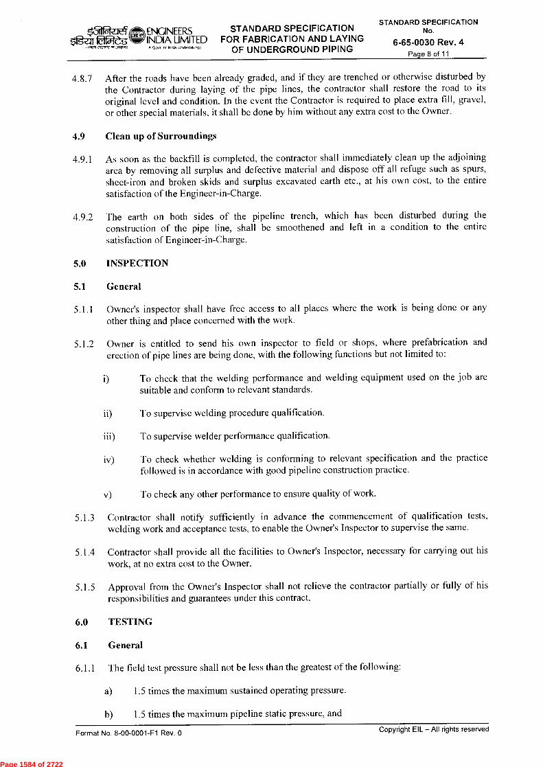
ENGINEERS STANDARD SPECIFICATION OgZIT laPreg w INDIA LIMITED FOR FABRICATION AND LAYING
111177 Re/RV 471,717u1,
IA Govt of India Undertaking)
OF UNDERGROUND PIPING
STANDARD SPECIFICATION No.
6-65-0030 Rev. 4 Page 8 of 11
4.8.7 After the roads have been already graded, and if they are trenched or otherwise disturbed by the Contractor during laying of the pipe lines, the contractor shall restore the road to its original level and condition. In the event the Contractor is required to place extra fill, gravel, or other special materials, it shall be done by him without any extra cost to the Owner.
4.9 Clean up of Surroundings
4.9.1 As soon as the backfill is completed, the contractor shall immediately clean up the adjoining area by removing all surplus and defective material and dispose off all refuge such as spurs, sheet-iron and broken skids and surplus excavated earth etc., at his own cost, to the entire satisfaction of the Engineer-in-Charge.
4.9.2 The earth on both sides of the pipeline trench, which has been disturbed during the construction of the pipe line, shall be smoothened and left in a condition to the entire satisfaction of Engineer-in-Charge.
5.0 INSPECTION
5.1 General
5.1.1 Owner's inspector shall have free access to all places where the work is being done or any other thing and place concerned with the work.
5.1.2 Owner is entitled to send his own inspector to field or shops, where prefabrication and erection of pipe lines are being done, with the following functions but not limited to:
i) To check that the welding performance and welding equipment used on the job are suitable and conform to relevant standards.
ii) To supervise welding procedure qualification.
iii) To supervise welder performance qualification.
iv) To check whether welding is conforming to relevant specification and the practice followed is in accordance with good pipeline construction practice.
v) To check any other performance to ensure quality of work.
5.1.3 Contractor shall notify sufficiently in advance the commencement of qualification tests, welding work and acceptance tests, to enable the Owner's Inspector to supervise the same.
5.1.4 Contractor shall provide all the facilities to Owner's Inspector, necessary for carrying out his work, at no extra cost to the Owner.
5.1.5 Approval from the Owner's Inspector shall not relieve the contractor partially or fully of his responsibilities and guarantees under this contract.
6.0 TESTING
6.1 General
6.1.1 The field test pressure shall not be less than the greatest of the following:
a) 1.5 times the maximum sustained operating pressure.
b) 1.5 times the maximum pipeline static pressure, and
Format No. 8-00-0001-F1 Rev. 0 Copyright EIL - All rights reserved
Page 1584 of 2722
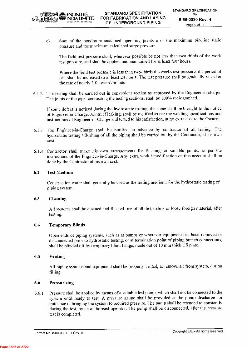
f=g-ar 051-es (HWI 2.1221,72 an ...1405gil
ENGINEERS STANDARD SPECIFICATION
INDIA LIMITED FOR FABRICATION AND LAYING (A Govt of India Undertaking)
OF UNDERGROUND PIPING
STANDARD SPECIFICATION No.
6-65-0030 Rev. 4 Page 9 of 11
c) Sum of the maximum sustained operating pressure or the maximum pipeline static pressure and the maximum calculated surge pressure.
The field test pressure shall, wherever possible be not less than two thirds of the work test pressure, and shall be applied and maintained for at least four hours.
Where the field test pressure is less than two-thirds the works test pressure, the period of test shall be increased to at least 24 hours. The test pressure shall be gradually raised at the rate of nearly 1.0 kg/cm2/minute.
6.1.2 The testing shall be carried out in convenient section as approved by the Engineer-in-charge. The joints of the pipe, connecting the testing sections, shall be 100% radiographed.
If some defect is noticed during the hydrostatic testing, the same shall be brought to the notice of Engineer-in-Charge. Joints, if leaking, shall be rectified as per the welding specifications and instructions of Engineer-in-Charge and tested to his satisfaction, at no extra cost to the Owner.
6.1.3 The Engineer-in-Charge shall be notified in advance by contractor of all testing. The hydrostatic testing / flushing of all the piping shall be carried out by the Contractor, at his own cost.
6.1.4 Contractor shall make his own arrangements for flushing, at suitable points, as per the instructions of the Engineer-in-Charge. Any extra work / modification on this account shall be done by the Contractor at his own cost.
6.2 Test Medium
Construction water shall generally be used as the testing medium, for the hydrostatic testing of piping system.
6.3 Cleaning
All systems shall be cleaned and flushed free of all dirt, debris or loose foreign material, after testing.
6.4 Temporary Blinds
Open ends of piping systems, such as at pumps or wherever equipment has been removed or disconnected prior to hydrostatic testing, or at termination point of piping branch connections, shall be blinded off by temporary blind flange, made out of 10 mm thick CS plate.
6.5 Venting
All piping systems and equipment shall be properly vented, to remove air from system, during filling.
6.6 Pressurizing
6.6.1 Pressure shall be applied by means of a suitable test pump, which shall not be connected to the system until ready to test. A pressure gauge shall be provided at the pump discharge for guidance in bringing the system to required pressure. The pump shall be attended to constantly during the test, by an authorised operator. The pump shall be disconnected, after the pressure test is completed.
Format No. 8-00-0001-F1 Rev. 0 Copyright EIL — All rights reserved
Page 1585 of 2722

$fgar far5reg 1>fre elecoreost,coo,
ENGINEERS STANDARD SPECIFICATION INDIA LIMITED FOR FABRICATION AND LAYING (A Govt of India Undertaking) OF UNDERGROUND PIPING
STANDARD SPECIFICATION No.
6-65-0030 Rev. 4 Page 10 of 11
6.6.2 The test pressure is to be maintained for sufficient time, to permit complete inspection of the system under test, but in no case shall the time be less than ten minutes. Test shall be considered complete only when approval is given by the Engineer-in-Charge.
6.7 Test Gauges
Contractor's own test gauge shall be installed as close as possible to the lowest point in the system being tested. Prior to installation, the test gauge shall be checked against a standard gauge or calibrated with the aid of a dead weight tester. Calibration of test gauges shall be the responsibility of the contractor.
6.8 Draining
6.8.1 All lines and equipments shall be completely drained after the hydrostatic test of the system has been completed. High point vents shall be open to prevent excessive vacuum and permit complete draining.
6.8.2 If it becomes necessary to leave a system filled with the testing medium for any abnormal length of time, suitable arrangement such as venting shall be made to provide for possible liquid expansion with change in ambient temperatures.
7.0 RECORDS
Records in triplicate shall be made for each piping system as follows:
7.1 In case of underground piping, layouts giving actual elevations of pipeline as laid.
7.2 Test certificates containing date of test, identification of the piping system, test fluid used, test pressure and approval of Owner's Inspector.
7.3 Certificates for flushing containing flushing medium used, identification of the piping system, date of flushing & approval by Owner's Inspector.
8.0 PAYMENT
8.1 Payment for piping shall be based on linear measurements, calculated on the basis of the execution drawings. The length shall be measured along the center lines of pipes, center lines of bends and elbows, tees, reducers and flanged joints. All types of valves shall be excluded from this measurement. Branch connections shall be measured from the outer surface of the header.
The payment shall be made on per metre basis of piping work laid, measured to the nearest centimeter. The unit rates for the underground piping shall be inclusive of earthwork in excavation, backfilling, compaction, disposal of surplus earth and coating and wrapping including supply of materials.
All piping attachments, such as couplings, nipples, thermowells etc., shall be installed by the Contractor as part of piping work and no separate payment shall be made for such work. However, extension on such attachments such as vents and drains will be measured and paid as applicable for the respective size and category of piping / valves.
Fabrication of mitre bends, concentric and eccentric reducers fabricated from pipes supplied by owner & fabrication of flanges from plates supplied by owner, will be paid at respective unit rates. However, erection of these items will be along with piping of the respective size and no separate payment will be made for erection.
The reducers will be measured and paid along with the piping of large diameter.
Format No. 8-00-0001-F1 Rev. 0 Copyright EIL — All rights reserved
Page 1586 of 2722

ENGINEERS STANDARD SPECIFICATION
f=g-ar Oa& INDIA LIMITED FOR FABRICATION AND LAYING OF UNDERGROUND PIPING
STANDARD SPECIFICATION No.
6-65-0030 Rev. 4 Page 11 of 11
17iRR 2172572151,31.1, IA Govt of Indo Unclefialong)
No separate payment will be made for making pipe to pipe branch connection and crosses, with or without reinforcing pads. The unit rates for piping are deemed to include all such work. Fabrication, installation and removal of temporary spool pieces etc. to aid contractor's work such as fabrication, erection, flushing and testing etc. will neither be measured nor paid separately. The same is deemed to be included in the unit rates for piping. Payment for carrying out radiographic examination shall be based on linear length of the welded joint radiographed. Repeat radiography / additional radiography required due to contractor's faults / poor performance of his welders and defective films etc., shall be done at contractor's own cost.
8.2 The payment clause(s) as described in the clause no. 8.1 shall not be referred / applicable for LSTK Jobs
Format No. 8-00-0001-F1 Rev. 0 Copyright EIL — All rights reserved
Page 1587 of 2722

STANDARD SPECIFICATION FOR MISCELLANEOUS CIVIL &
STRUCTURAL WORKS FOR U/G PIPING & OTHER CIVIL WORKS
ENGINEERS 1812--gw' INDIA LIMITED
IA Govt of India Undertalongt
STANDARD SPECIFICATION No.
6-65-0035 Rev. 3
Page 1 of 7
r* r 14-PETW , icsfR
fqr-4e6T fur wpf, fur chNT
f-4r-4-4rr
STANDARD SPECIFICATION FOR
MISC. CIVIL & STRUCTURAL WORKS FOR
U/G PIPING & OTHER CIVIL WORKS
3 25.06.14 REVISED & ISSUED AS STD. SPEC. '" 6s VM SC
2 16.04.09 REVISED & ISSUED AS STD. SPEC. GS RKS NK ND
1 30.10.97 REVISED & ISSUED AS STD. SPEC. SKC PCS MMK A SONI
0 31.3.82 ISSUED AS STD. SPEC. RB RSG
Standards Standards
Rev. No Date Purpose
Prepared by
Checked by
Comm ittee Convenor
Bureau Chairman
Approved by
Format No. 8-00-0001-F1 Rev. 0
Copyright EIL — All rights reserved
Page 1588 of 2722
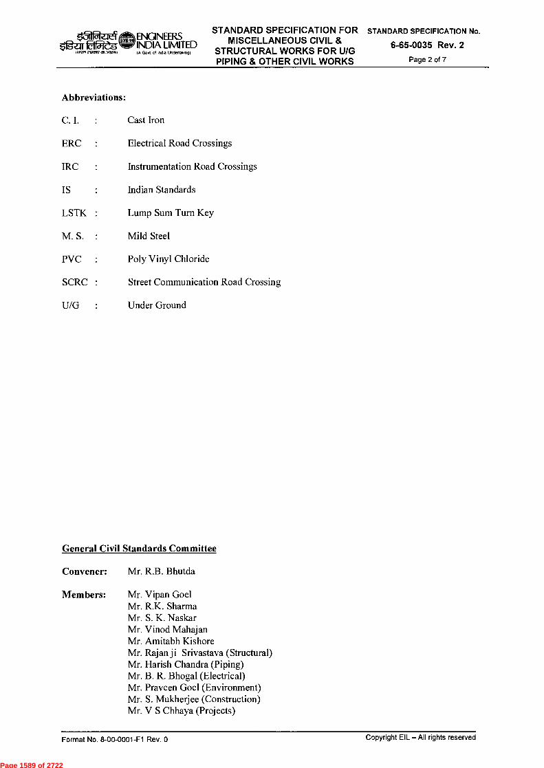
g1-11 22eg lv■Ien ~TsPOWI3OfOvI)
ENGINEERS INDIA LIMITED
GOvt of India Undellakino)
STANDARD SPECIFICATION FOR MISCELLANEOUS CIVIL &
STRUCTURAL WORKS FOR U/G PIPING & OTHER CIVIL WORKS
STANDARD SPECIFICATION No.
6-65-0035 Rev. 2
Page 2 of 7
Abbreviations:
C. I. Cast Iron
ERC :
Electrical Road Crossings
IRC :
Instrumentation Road Crossings
IS
Indian Standards
LSTK :
Lump Sum Turn Key
M. S. :
Mild Steel
PVC :
Poly Vinyl Chloride
SCRC :
Street Communication Road Crossing
U/G :
Under Ground
General Civil Standards Committee
Convener: Mr. R.B. Bhutda
Members: Mr. Vipan Goel Mr. R.K. Sharma Mr. S. K. Naskar Mr. Vinod Mahajan Mr. Amitabh Kishore Mr. Rajan ji Srivastava (Structural) Mr. Harish Chandra (Piping) Mr. B. R. Bhogal (Electrical) Mr. Praveen Goel (Environment) Mr. S. Mukherjee (Construction) Mr. V S Chhaya (Projects)
Format No. 8-00-0001-F1 Rev. 0
Copyright EIL — All rights reserved
Page 1589 of 2722

STANDARD SPECIFICATION FOR MISCELLANEOUS CIVIL &
STRUCTURAL WORKS FOR U/G PIPING & OTHER CIVIL WORKS
ENGINEERS 02-e-g INDIA LIMITED
(M177 292e1Ream.3~) IA Govt o1 India Undellaking)
STANDARD SPECIFICATION No.
6-65-0035 Rev. 2
Page 3 of 7
CONTENTS
1.0 SCOPE 4
2.0 CODES & STANDARDS 4
3.0 EARTHWORK & BACKFILLING 5
4.0 PLAIN AND REINFORCED CEMENT CONCRETE 5
5.0 BRICK WORK 5
6.0 CEMENT PLASTERING 5
7.0 RUNGS 5
8.0 CHEQUERED PLATES & STRUCTURAL STEEL WORKS 5
9.0 C.I. MANHOLE FRAME AND COVER 6
10.0 VENT PIPES FOR MANHOLES 6
11.0 FUNNELS, CLEAN OUTS, PLUGS 6
12.0 BRICK BAT FILL 6
13.0 PAYMENT 6
Copyright EIL — All rights reserved Format No. 8-00-0001-F1 Rev. 0
Page 1590 of 2722
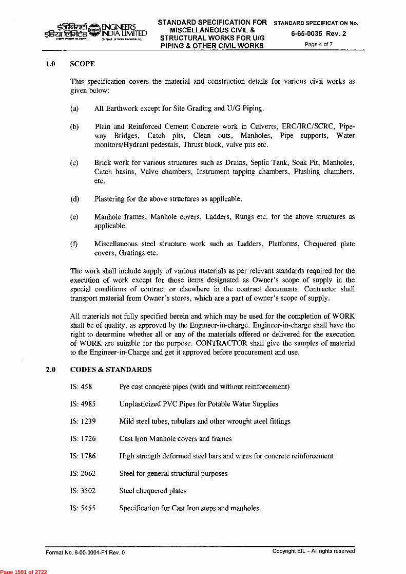
STANDARD SPECIFICATION FOR STANDARD SPECIFICATION No. x'_7-11 2-1t4 xj, ENGINEERS MISCELLANEOUS CIVIL & g_ji fffilegWINDIA LIMITED 6-65-0035 Rev. 2
1.11E,, 21~,m3aas.) IA Govt of India Undedak.g) STRUCTURAL WORKS FOR U/G PIPING & OTHER CIVIL WORKS Page 4 of 7
1.0 SCOPE
This specification covers the material and construction details for various civil works as given below:
(a) A11 Earthwork except for Site Grading and U/G Piping.
(b) Plain and Reinforced Cement Concrete work in Culverts, ERC/IRC/SCRC, Pipe-way Bridges, Catch pits, Clean outs, Manholes, Pipe supports, Water monitors/Hydrant pedestals, Thrust block, valve pits etc.
(c) Brick work for various structures such as Drains, Septic Tank, Soak Pit, Manholes, Catch basins, Valve chambers, Instrument tapping chambers, Flushing chambers, etc.
(d) Plastering for the above structures as applicable.
(e) Manhole frames, Manhole covers, Ladders, Rungs etc. for the above structures as applicable.
(t)
Miscellaneous steel structure work such as Ladders, Platforms, Chequered plate covers, Gratings etc.
The work shall include supply of various materials as per relevant standards required for the execution of work except for those items designated as Owner' s scope of supply in the special conditions of contract or elsewhere in the contract documents. Contractor shall transport material from Owner' s stores, which are a part of owner's scope of supply.
A11 materials not fully specified herein and which may be used for the completion of WORK shall be of quality, as approved by the Engineer-in-charge. Engineer-in-charge shall have the right to determine whether all or any of the materials offered or delivered for the execution of WORK are suitable for the purpose. CONTRACTOR shall give the samples of material to the Engineer-in-Charge and get it approved before procurement and use.
2.0 CODES & STANDARDS
IS: 458 Pre cast concrete pipes (with and without reinforcement)
IS: 4985 Unplasticized PVC Pipes for Potable Water Supplies
IS: 1239 Mild steel tubes, tubulars and other wrought steel fittings
IS: 1726 Cast Iron Manhole covers and frames
IS: 1786 High strength deformed steel bars and wires for concrete reinforcement
IS: 2062 Steel for general structural purposes
IS: 3502 Steel chequered plates
IS: 5455 Specification for Cast Iron steps and manholes.
Format No. 8-00-0001-F1 Rev. 0
Copyright EIL — All rights reserved
Page 1591 of 2722
STANDARD SPECIFICATION FOR MISCELLANEOUS CIVIL &
STRUCTURAL WORKS FOR U/G PIPING & OTHER CIVIL WORKS
gRzit4,, ENGINEERS 2."111=1P' INDIA LIMITED
~IRE' M"7.1) IA Govt of Inoie undertaking)
STANDARD SPECIFICATION No.
6-65-0035 Rev. 2
Page 5 of 7
3.0 EARTHWORK & BACKFILLING
Refer EIL Standard Specification No. 6-68-0003.
4.0 PLAIN AND REINFORCED CEMENT CONCRETE
Refer EIL Standard Specification No.6-68-0004.
5.0 BRICK WORK
Refer EIL Standard Specification No. 6-68-0009.
6.0 CEMENT PLASTERING
6.1 Materials
The specifications for cement, sand and water shall be as given in EIL Standard Specification No. 6-68-0002.
6.2 Cement mortar shall be of grade and thickness as specified in drawing or as directed by the Engineer-in-Charge, if not specified. The surface on which plastering is to be done shall be thoroughly cleaned from dust, dirt, oil, etc. It should be washed properly and watered for 4 hours before plastering. The joints of brickwork shall be raked out to a depth of at least 12mm when plastering has to be done. On cement concrete surface, the surface shall be scarified by lines with trowel when it is still green or hacked, if concrete is hard as directed by Engineer-in-Charge.
6.3 Plaster shall not in any case, be thinner than specified. It shall have uniform specified thickness. Any extra thickness of plaster done by contractor will not be paid for. When smooth finishing is required, the cement plaster shall be floated over with neat cement within 15 minutes of the application of the final coat.
During the process of plastering, all corners shall be rounded to a radius of 25mm unless otherwise specified.
6.4 The plaster shall be protected from Sun and rain by such means as per the approval of Engineer-in-Charge. The plaster shall be cured for 7 days.
6.5 Construction joint shall be kept in plastering work at places approved by Engineer-in-Charge.
7.0 RUNGS
7.1 Materials
The rungs for valve pits / manholes shall be of Tor Steel conforming to IS: 1786 and to the shape and size as shown in drawings. Rungs shall be coated with 2 coats of approved bituminous paint.
8.0 CHEQUERED PLATES & STRUCTURAL STEEL WORKS
8.1 Materials
8.1.1 Chequered plates shall be 6mm thick (7mm or more chequered plates shall conform to IS: 3502). Steel for chequered plate shall conform to IS: 2062 and shall be clearly rolled and free from harmful surface defects such as crack, surface flaws etc. The plate shall be cut to shape and fixed to the bearing members as shown in relevant drawings and as directed by Engineer-
Copyright EIL — All rights reserved Format No. 8-00-0001-F1 Rev. 0
Page 1592 of 2722

STANDARD SPECIFICATION FOR MISCELLANEOUS CIVIL &
STRUCTURAL WORKS FOR U/G PIPING & OTHER CIVIL WORKS
k3ir--!&.1t4 ENGINEERS W
$1g-ar 2154eg INDIA LIMITED
1.11VR 2~17013~) (A Govt of Indo Undertalmg)
STANDARD SPECIFICATION No.
6-65-0035 Rev. 2
Page 6 of 7
in-Charge. The edges shall be made smooth, no burrs or gagged ends shall be left. The plates may be spliced with prior consent of the Engineer-in-Charge. But in that case, care should be taken so that there is continuity in the pattern of the plates between the portions. Lifting arrangements shall be provided including lifting rods.
8.1.2 Grating shall be fabricated out of M.S flats, angles and rounds etc., as per drawings and as approved by Engineer-in-Charge. Steel for grating plates shall conform to IS: 2062 of general weldable quality and shall be clearly rolled and shall be free from harmful surface defects.
9.0 C.I. MANHOLE FRAME AND COVER
9.1 Materials
C I manhole frame and covers shall conform to IS: 1726 with size and grade as shown in drawings.
10.0 VENT PIPES FOR MANHOLES
10.1 Materials
These shall be black steel tube conforming to IS: 1239 medium grade or as specified in drawings/ Piping Material Specification. The pipe bends shall be embedded in 1:3:6 grade cement concrete or as shown in drawing.
10.2 A11 pipes shall be 25mm clear of wall or column with steel holder bat clamp, as per instructions of the Engineer-in-Charge. All holes in walls and column shall be made good by 1:2:4 grade cement concrete. All pipes and clamps shall be painted with two coats of paints of approved make.
11.0 FUNNELS, CLEAN OUTS, PLUGS
11.1 Materials
These shall be fabricated from M.S Plates, pipes, chequered plates, rounds, angles etc., to be supplied by the contractor and painted with 2 coats of anticorrosive paint of approved make. The fabrication shall be in accordance with the approved drawings.
12.0 BRICK BAT FILL
12.1 Materials
The brickbats used as filling in valve pits shall be from common burnt clay building bricks of size ranging from 27mm to 37mm. Sample of brickbats used shall be got approved from Engineer-in-charge.
12.2 The compaction of the layer of brickbat shall be proper so that brickbat are not disturbed and do not sink in the soil.
13.0 PAYMENT
13.1 Cement Plastering
13.1.1 Payment for plastering shall be made on basis of the area of surface plastered, measured before plastering. A11 measurements shall be separately made for each face of walls.
Copyright EIL — All rights reserved Format No. 8-00-0001-F1 Rev. 0
Page 1593 of 2722

STANDARD SPECIFICATION FOR MISCELLANEOUS CIVIL &
STRUCTURAL WORKS FOR U/G PIPING & OTHER CIVIL WORKS
ENGINEERS Ogzrr ffieg INDIA LIMITED
1.1T27I C,12,1W 01~1) IA Govt of India undertax.ng)
STANDARD SPECIFICATION No.
6-65-0035 Rev. 2
Page 7 of 7
13.1.2 The rate of plastering shall include cost of scaffolding, swings, cleaning the surface, raking out joints, hacking concrete surfaces, etc. needed for carrying the work and shall cover the extra labour for plastering the jambs, sills, and soffits or opening except for plastering bands, cornices and skirting upto 30 cm width.
13.2 Rungs
Payment for rungs shall be made per number and the rate shall include supply and fixing, finishing the wall etc. complete.
13.3 Chequered Plates & Structural Steel Works
Payment shall be made on the basis of weight of MS gratings / chequered plate and supporting frame including hold fast. The rate shall include supply of all necessary steel materials including cutting to size, fabricating, smoothening edge, if necessary, transporting and fixing at all positions and providing lifting arrangements. Full deductions shall be made for all openings above 30mm square and the rate shall include making of opening of all sizes and supplying and painting 2 coats of anticorrosive paint over a coat of red oxide zinc chromate primer. The exposed surface of grating and frame shall be painted with two thick coats of coal tar. The rate shall include providing and laying MS grating and frame, breaking and making good existing concrete/ brick masonry surface if necessary, finishing, painting etc. complete with all labour and materials. Payment shall be made on number basis.
13.4 CI Manhole Frame and Cover
Payment for Manhole Frame and cover shall be made per number and rate shall include supply and fixing etc. complete.
13.5 Vent Pipes for Manholes
Payment shall be made on running meter basis and the rate shall include supply of all materials, cutting, edge preparation, jointing by welding, fixing in concrete block, cutting of walls or concrete and making good the same, painting with 2 coats of anticorrosive paint of approved make, necessary scaffolding etc. complete.
The rate shall also include excavation and backfilling if any.
13.6 Funnels, Clean Outs, Plugs
Payment for these items shall be made on weight basis and rate shall include fabrication, erection, welding, jointing and painting etc. all complete.
13.7 Brick Bat Fill
The payment for brickbats fill shall be made on m2 basis, as shown in drawing and the rate shall include supply, laying, compacting etc. complete, with all materials & labour.
13.8 The payment clause(s) as described in the clause no. 13.1, 13.2, 13.3, 13.4, 13.5, 13.6 & 13.7 shall not be referred / applicable for LSTK Jobs.
Copyright EIL — All rights reserved Format No. 8-00-0001-F1 Rev. 0
Page 1594 of 2722
ENGINEESINDIA LIMITR ED
f5-.7r15101-zie0?eir kVieg
1.4■2n matte troNtrts0 IA Govt India Undertaking)
STANDARD SPECIFICATION FORSTAND POST TYPE FIRE HYDRANT
STANDARD SPECIFICATION No.
6-66-0012 Rev. 3Page 1 of 5
-ft-ETT mcbit -4- aim curii
9r—dV1 iiivich 1-4-54-r(-EFER TrrET aTem-r -ErgER *-)
STANDARD SPECIFICATION FORSTAND POST TYPE FIRE HYDRANT
(WITH OR WITHOUT PUMPERCONNECTION)
f>jko\c
: DM
3 23.05.11 REVISED AND ISSUED AS STD. SPEC. ALOK
2 22.12.05 REVISED & REISSUED AS STD. SPEC. SKC
NK VDS
VJN
1 15.02.98 REVISED & ISSUED AS STD. SPEC. VEDA SM MMK
ASONI
0 31.03.82 ISSUED AS STD. SPEC. RB
FIVR RCPC
Rev.No Date Purpose
Prepared Checkedby by
Standards GMCommittee (Engg)Convenor
StandardsBureau
Chairman
Approved by
Format No. 8-00-0001-F1 Rev. 0
Copyright EIL — All rights reserved
Page 1595 of 2722
1510zre*1 eg fai5reg
ragien ermine =3mm) IA Go.A. o India undertaking)
ENGINEERSINDIA LIMITED,7
SSTANDARD SPECIFICATION FOR
STANDARD SPECIFICATION No.
STAND POST TYPE FIRE HYDRANT 6-66-0012 Rev. 3Page 2 of 5
Abbreviations:
ANSI American National Standards Institute
FM Factory Mutual
IS Indian Standard
MS Mild Steel
UL Underwriters Laboratories
General Civil Standards Committee
Convener: Mr. R. B. Bhutda
Members: Mr. Vipan GoelMr. D.C. BrahmaMr. R.K. SharmaMr. S. K. NaskarMr. Raju ChutaniMr. P.K. Mittal (Strl)Mr. A.T. Dharmik (Piping)Mr. U.A. Patro(Electrical)Mr. J. K. Joshi (Environment)Mr. S. Mukherjee (Construction)Mr. M.P. Jain (Projects)
Format No. 6-66-0012-F1 Rev. 0
Copyright EIL — All rights reserved
Page 1596 of 2722

lalaelt4 (--aft ENGINEERS STANDARD SPECIFICATION FOR STANDARD SPECIFICATION No.
laf5tagW INDIA LIMITED STAND POST TYPE FIRE HYDRANT 6-66-0012 Rev. 3IAffi” Govt d India undertaking)
Page 3 of 5
CONTENTS
1.0 SCOPE 4
2.0 CODES AND STANDARDS 4
3.0 MATERIAL 4
4.0 DESCRIPTION 4
5.0 WORKMANSHIP AND FINISH 4
6.0 TESTING 4
7.0 PAINTING 4
8.0 MARKING 5
9.0 INSPECTION 5
10.0 DRAWINGS 5
11.0 VENDOR's DRAWING AND DATA REQUIREMENT 5
12.0 DATA SHEET REQUIREMENT 5
13.0 APPROVAL 5
Format No. 6-66-0012-F1 Rev. 0
Copyright EIL - All rights reserved
Page 1597 of 2722
ENGINEERS STANDARD SPECIFICATION FOR tatiegw/ INDIA LIMITED STAND POST TYPE FIRE HYDRANT
It/17/121atOMONJOIM'a) (A Govt o/ India Undertaking)
STANDARD SPECIFICATION No.
6-66-0012 Rev. 3Page 4 of 5
1.0 SCOPEThis standard lays down the requirements of codes and standards, type, shape, dimensions, materialand test for vertical stand post type fire hydrant (with or without pumper connection) to be installedon fire water main. The Hydrant shall normally be supplied without pumper connection unlessotherwise specifically mentioned in the Material Requisition.
2.0 CODES AND STANDARDS
IS: 902IS: 903IS: 5290ANSI B16.5
NOTE:-
3.0 MATERIAL
Suction hose couplings for fire fighting purposes.Fire hose delivery couplings, branch pipe.Specification for Landing Valves.Pipe Flanges And Flanged Fittings.
Latest Edition of all Codes and Standards shall be followed.
All material shall be as given in Job Specific Data Sheet provided along with this specification in theMaterial Requisition.
4.0 DESCRIPTION
4.1
The hydrant shall be stand post type. The vertical post shall be of 100 mm diameter with twohorizontal hydrant arms, each 80mm diameter, on which independent Landing valve shall be fixed.Landing valve shall comply to IS: 5290, Type A.
4.2 63mm coupling shall comply to IS: 903, and that the lug shall be twist release type.
4.3 For hydrant assembly with pumper connection, the vertical post shall have 100 mm outlet as pumperconnection and provided with a blind cap. The 100mm outlet shall have round male threads,conforming to IS: 902 and blind cap shall be provided with four fixing lugs and 500 mm long MSchain.
4.4 All flanges for Landing valve and base shall have all dimensions conforming to ANSI.B.16.5, 150 lbsrating, Flat Face, Slip On type.
4.5 Job specific requirements shall be as per Data Sheet enclosed in Bid / Requisition document.
5.0 WORKMANSHIP AND FINISH
All parts shall have good workmanship and finish. All warps and sharp edges shall be removed. Thewaterways shall have smooth finish.
6.0 TESTING
Hydrant assembly with Landing valves closed shall be satisfactorily tested and proved water tight,under a hydraulic pressure of 18.0 kg/cm 2. The pumper connection shall be kept closed during testingin case the same is provided on hydrant assembly.
7.0 PAINTING
The stand post and its arms shall be painted as specified in Job Specific Data Sheet attached with thisspecification.
Format No. 6-66-0012-F1 Rev. 0 Copyright EIL — All rights reserved
Page 1598 of 2722
ENGINEERSeir 05fez INDIA LIMITED
(A CA,AA India (A.leAAA(.2)
STANDARD SPECIFICATION FORSTAND POST TYPE FIRE HYDRANT
STANDARD SPECIFICATION No.
6-66-0012 Rev. 3Page 5 of 5
I ai/ERT 2:1MIE• 17115.105A )
8.0 MARKINGEach hydrant shall be clearly and permanently marked with the following:
Manufacturers name or trade mark.IS: 5290 on Landing Valve.Year of Manufacture.Purchaser name.
9.0 INSPECTION
Owner's / EIL's authorised representative shall have access at all reasonable times to vendor's workswhere Stand Post Hydrants and Landing Valves are being manufactured and/or tested. Vendor shallarrange for all tests and inspection facilities for checking material, design and construction, hydraulicperformance, workmanship, finish and hydrostatic testing. Any shortcoming pointed out shall berectified to the satisfaction of the inspectors. All consumables i.e. water etc. shall be arranged byvendor at his own cost.
10.0 DRAWINGS
Refer scope drawing enclosed in Bid / Requisition document.
11.0 VENDOR's DRAWING AND DATA REQUIREMENT
Vendor shall furnish drawings for review, prior to fabrication of Hydrant.
12.0 DATA SHEET REQUIREMENT
Vendor shall fill the relevant data in the Data Sheet provided along with this specification in theMaterial Requisition
13.0 APPROVAL
Vendor shall furnish valid BIS certificate approval letter, after award of Contract
Format No. 6-66-0012-F1 Rev. 0
Copyright EIL — All rights reserved
Page 1599 of 2722
151P-4eOga IM1Atg
1.11271zwase 141J.41.1)
ENGINEERSINDIA LIMITEDIA Govt of India Undertaking)
STANDARD SPECIFICATIONFOR FIRST AID HOSE REEL
STANDARD SPECIFICATIONNo.
6-66-0018 Rev. 3Page 1 of 4
-srrErrw *mial •71
"ftribi
STANDARD SPECIFICATIONFOR
FIRST AID HOSE REEL
3 23.05.11 REVISED & REISSUED AS STD. SPEC ALOK S VK DM
2 12.01.06 REVISED & REISSUED AS STD. SPEC SKC NK VDS VJN
1 21.11.96 REVISED & ISSUED AS STD. SPEC NK PCS MMK A SONI
0 31.03.82 ISSUED AS STD. SPEC. RB KP HVR RCPC
Standards GM Standards
Rev.No Date Purpose
Prepared by
Checke
d by
CommitteeConvenor
(Engg) BureauChairman
Approved by
Format No. 8-00-0001-F1 Rev. 0
Copyright EIL — All rights reserved
Page 1600 of 2722
STANDARD SPECIFICATIONNo.
6-66-0018 Rev. 3Page 2 of 4
151KRZOM- ENGINEERSa Etweg vio INDIA LIMITED1.101 (A Govt. Incha Undertaking)
STANDARD SPECIFICATIONFOR
FIRST AID HOSE REEL
ABBREVIATIONS:
IS Indian Standard
General Civil Standards Committee
Convener: Mr. R. B. Bhutda
Members: Mr. Vipan GoelMr. D.C. BrahmaMr. R.K. SharmaMr. S. K. NaskarMr. Raju ChutaniMr. P.K. Mittal (Strl)Mr. A.T. Dharmik (Piping)Mr. U.A. Patro (Electrical)Mr. J. K. Joshi (Environment)Mr. S. Mukherjee (Construction)Mr. M.P. Jain (Projects)
Copyright EIL — All rights reservedFormat No. 8-00-0001-F1 Rev. 0
Page 1601 of 2722
daraqA$1g7 felPrg)
ENGINEERSINDIA LIMITEDIA Gout d India Undertaking)
STANDARD SPECIFICATIONFOR
FIRST AID HOSE REEL
STANDARD SPECIFICATIONNo.
6-66-0018 Rev. 3Page 3 of 4
CONTENTS
1.0 SCOPE 4
2.0 CODES AND STANDARDS 4
3.0 MATERIAL, CONSTRUCTION AND TEST 4
4.0 SIZE 4
5.0 HYDRAULIC PERFORMANCE 4
6.0 MARKING 4
7.0 INSPECTION AND TESTING 4
8.0 VENDOR's DRAWING AND DATA REQUIREMENT 4
9.0 DATA SHEET REQUIREMENT 4
10.0 APPROVAL 4
Format No. 8-00-0001-F1 Rev. 0
Copyright EIL — All rights reserved
Page 1602 of 2722
ENGINEERS
Ogeir Nifieg INDIA LIMITED
ImWIml Milril) (A Gov/ 04 India Undertaking)
STANDARD SPECIFICATIONFOR
FIRST AID HOSE REEL
STANDARD SPECIFICATIONNo.
6-66-0018 Rev. 3Page 4 of 4
1.0 SCOPE
This specification covers the requirements regarding material, constructional details and test forFloor/Wall mounted First Aid Hose Reel, intended for installation within process units / buildings asemergency fire fighting equipment.
2.0 CODES AND STANDARDS
IS : 884 First-Aid hose reel for fire-fighting.NOTE: Latest Edition of all Codes and Standards shall be followed.
3.0 MATERIAL, CONSTRUCTION AND TEST
Material, Construction, tests and all other requirements shall conform to IS: 884, Type-A Hose Reel,except as mentioned in the Data Sheet of Hose Reel attached with Bids / Requestion.
4.0 SIZE
Length = 40 mInternal Bore = 20 mm
5.0 HYDRAULIC PERFORMANCE
5.1 First Aid hose reel shall be capable of discharging not less than 24 1pm at the reel inlet pressure of7 kg/cm2g.
5.2 The horizontal range of water jet shall not be less than 6.0 m at the reel inlet pressure of 7 kg/cm2g.
6.0 MARKING
Each hose reel shall be clearly and permanently marked with the following information along withPurchaser's name.
Manufacturer's name or Trade MarkYear of ManufactureThe letters IS: 884Length and size of tube carried on hose reel.
e) Type of Reel.
7.0 INSPECTION AND TESTING
Owner's / EIL's authorised representative shall have access at all reasonable times to vendor's workswhere Hose Reels are being manufactured and/or tested. Vendor shall arrange for all tests andinspection facilities for checking material, design and construction, hydraulic performance,workmanship, finish and hydrostatic testing. Any shortcoming pointed out shall be rectified to thesatisfaction of the inspectors. All consumables i.e. water etc. shall be arranged by vendor at his owncost.
8.0 VENDOR's DRAWING AND DATA REQUIREMENT
Vendor shall furnish drawings and data for review.
9.0 DATA SHEET REQUIREMENT
Vendor shall fill the relevant data in the Data Sheet provided along with this specification in MaterialRequisition.
10.0 APPROVAL
Vendor shall furnish valid BIS certificate letter after award of contract.
Format No. 8-00-0001-F1 Rev. 0
Copyright EIL — All rights reserved
Page 1603 of 2722
faa-& ENGINEERS lagrdg INDIA LIMITED riro, 3P{,i, (A Govt of India Undertaking)
STANDARD SPECIFICATION FOR STAND POST TYPE WATER MONITOR
STANDARD SPECIFICATION No.
6-66-0021 Rev. 3 Page 1 of 5
-chz mew 1111T-Ta
*MU
STANDARD SPECIFICATION FOR STAND POST
TYPE WATER MONITOR
N\4"; )))
3 24.09.13 REVISED & ISSUED AS STD. SPEC RBT RKS kg) DM
2 12.01.06 REVISED & ISSUED AS STD. SPEC SKC NK VDS VJN
1 15.07.98 REVISED & ISSUED AS STD. SPEC RC NK MMK A SONI
0 09.09.88 ISSUED AS STD. SPEC. NK PCS I-1VR RCPC
Rev. No Date Purpose
Prepared by
Checked by
Standards Committee Convenor
Standards Bureau
Chairman
Approved by
Format No. 8-00-0001-F1 Rev. 0 Copyright EIL — All rights reserved
Page 1604 of 2722
STANDARD SPECIFICATION No.
6-66-0021 Rev. 3 Page 2 of 5
lil 5fgar 051ft
(mrtn elecnream.ynn,)
ENGINEERS STANDARD SPECIFICATION FOR
INDIA LIMITED STAND POST TYPE IA Govt of Ind. Undertaking) WATER MONITOR
Abbreviations:
ANSI : American National Standards Institute
BIS : Bureau of Indian Standards
IS Indian Standard
NB Nominal Bore
General Civil Standards Committee
Convener: Mr. R.B. Bhutda
Members: Mr. Vipan Goel Mr. R.K. Sharma Mr. S. K. Naskar Mr. Vinod Mahajan Mr. Amitabh Kishore Mr. Rajan ji Srivastava (Structural) Mr. Harish Chandra (Piping) Mr. B. R. Bhogal (Electrical) Mr. Praveen Goel (Environment) Mr. S. Mukherjee (Construction) Mr. V S Chhhaya (Projects)
Copyright EIL — All rights reserved Format No. 8-00-0001-F1 Rev. 0
Page 1605 of 2722
lig-elt 00les IAAR-A
ENGINEERS STANDARD SPECIFICATION FOR
INDIA LIMITED STAND POST TYPE GovI of India Undenaking) WATER MONITOR
STANDARD SPECIFICATION No.
6-66-0021 Rev. 3 Page 3 of 5
CONTENTS
1.0 SCOPE 4
2.0 CODES AND STANDARDS 4
3.0 DESIGN AND CONSTRUCTION 4
4.0 MATERIAL 4
5.0 WORKMANSHIP AND FINISH 4
6.0 MARKING 4
7.0 INSPECTION 4
8.0 DRAWINGS 5
9.0 VENDOR's DRAWING AND DATA REQUIREMENT 5
10.0 APPROVAL 5
Format No. 8-00-0001-F1 Rev. 0 Copyright EIL — All rights reserved
Page 1606 of 2722

ENGINEERS STANDARD SPECIFICATION FOR
err faigieg INDIA LIMITED STAND POST TYPE tAr<nren,,AgrA/ IA Govt onnala Undertaking) WATER MONITOR
STANDARD SPECIFICATION No.
6-66-0021 Rev. 3 Page 4 of 5
1.0 SCOPE
This specification covers the general requirements regarding Material, Design and Construction, Workmanship and Finish, Anticorrosive Treatment, Performance requirements, Tests, Painting, Accessories, Marking and Inspection for Stand Post Type Water Monitor.
2.0 CODES AND STANDARDS
IS: 778
Copper alloy Gate, Globe and Check Valves for Water Works Purpose IS: 8442
Functional requirement For Stand Post Type Water Monitor for Fire Fighting.
NOTE: Latest Edition of all Codes and Standards shall be followed.
3.0 DESIGN AND CONSTRUCTION
3.1 Design and Construction of Water Monitor shall conform to IS: 8442, except as mentioned in data sheet for Stand Post Type Water Monitor enclosed with Bid / Requisition document.
3.2 The Monitor shall be Aqua Fog, self-locking type and operated by a single person.
3.3 The monitor shall be mounted on a 100 mm (4") N.B. Raised Face, Slip On type Flange with all dimensions conforming to ANSI B 16.5, 150 lbs rating,
3.4 Near the base flange a drain connection shall be provided with a 15 mm ('") NB drain valve at the end of pipe.
3.5 The threaded end of the water nozzle shall be hexagonal to facilitate screwing of the nozzle on the water barrel with nozzle spanner.
4.0 MATERIAL
All material for different parts of Water Monitor shall be as per IS: 8442 except as mentioned in data sheet for Stand Post Type Water Monitor enclosed with Bid/Requisition document.
5.0 WORKMANSHIP AND FINISH
Workmanship and finish, anticorrosive treatment, painting, Hydraulic performance, tests and accessories shall conform to IS: 8442, except as mentioned in data sheet for Stand Post Type Water Monitor enclosed with Bid/Requisition document.
6.0 MARKING
Each monitor shall be clearly and permanently marked with the following:
(a) Manufacturer's name or trademark (b) Year of manufacture (c) Purchaser's name. (d) Discharge Capacity in liters / minute. (e) BIS certification mark.
7.0 INSPECTION
Owner's / EIL's authorised representative shall have access at all reasonable times to vendor's works where Monitors are being manufactured and/or tested. Vendor shall arrange for all tests and inspection facilities for checking material, design and construction, hydraulic performance, workmanship, finish and hydrostatic testing as per IS: 8442. Any shortcoming pointed out shall be rectified to the satisfaction of the inspectors. All consumables i.e. water etc. shall be arranged by vendor at his own cost.
Format No. 8-00-0001-F1 Rev. 0
Copyright EIL — All rights reserved
Page 1607 of 2722

STANDARD SPECIFICATION No.
6-66-0021 Rev. 3 Page 5 of 5
01 el f=gzir OWeg
1.1,1 tveme 051,3PCM1 )
ENGINEERS STANDARD SPECIFICATION FOR
INDIA LIMITED STAND POST TYPE IA Govt of Inds Undenak.9) WATER MONITOR
8.0 DRAWINGS
Refer scope drawing enclosed in Bid / Requisition document.
9.0 VENDOR's DRAWING AND DATA REQUIREMENT
Vendor shall furnish drawings and data as per "Vendor's drawings and Data Requirements" for information and records.
10.0 APPROVAL
Vendor shall furnish BIS approval letter along with offer.
Copyright EIL — All rights reserved Format No. 8-00-0001-F1 Rev. 0
Page 1608 of 2722
ENGINEERS INDIA LIMITED In Goof Al Indio Undep !along)
STANDARD SPECIFICATION FOR
WATER CUM FOAM MONITOR SINGLE BARREL TYPE
STANDARD SPECIFICATION No.
6-66-0027 Rev. 4 Page 1 of 6
kicIH 114 1 7iTd- iff9r{
zrTEr 1-I I -1011 Ial1 kl
STANDARD SPECIFICATION FOR
WATER CUM FOAM MONITOR SINGLE BARREL TYPE
4 21.01.13
3 30.07.07
2 12.01.06
1 15.03.98
0 31.03.82
Rev. No Date
REVISED & ISSUED AS STD. SPEC
REVISED & ISSUED AS STD. SPEC
REVISED & ISSUED AS SM. SPEC
REVISED & ISSUED AS STD. SPEC
ISSUED AS STD. SPEC.
Purpose
SKC
NK
Prepared Checked by by
RKS NK VDS VC
VDS VJN
A SONI
RCPC
Standards Committee Convenor
GM (ERGO)
Standards Bureau
Chairman
RB PCS MMK
RB KP HVR
Approved by
Format No. 8-00-0001-F1 Rev. 0 Copyright EIL — All rights reserved
Page 1609 of 2722
°gala!' "rq ENGINEERS INDIA LIMITED IA Govt of India Underta&inpl
STANDARD SPECIFICATION FOR
WATER CUM FOAM MONITOR SINGLE BARREL TYPE
STANDARD SPECIFICATION No.
6-66-0027 Rev. 4 Page 2 of 6
Abbreviations:
ANSI American National Standards Institute
FM Factory Mutual
r0 Inch
IS Indian Standard
kg/cm2 Kilogram per Square Centimeter
lbs Pounds
m Meter
MS Mild Steel
mm Millimeter
m3 Cubic Meter
NB Nominal Bore
PVC Poly Vinyl Chloride
SS Stainless Steel
UL Underwriters Laboratory
VdS Verband Der Sachversicherer
General Civil Standards Committee
Convener: Mr. R.B. Bhutda
Members: Mr. Vipan Goel Mr. R.K. Sharma Mr. S. K. Naskar Mr. Vinod Mahajan Mr. Amitabh Kishore Mr. Rajan ji Srivastava (Structural) Mr. Harish Chandra (Piping) Mr. B. R. Bhogal (Electrical) Mr. Praveen Goel (Environment) Mr. S. Mukherjee (Construction) Mr. V S Chhaya (Projects)
Format No. 8-00-0001-F1 Rev. 0 Copyright EIL — All rights reserved
Page 1610 of 2722
514-,a.9,91-eg ENGINEERS INDIA LIMITED IP LInvI of 1.11a Uncienakag)
STANDARD SPECIFICATION FOR
WATER CUM FOAM MONITOR SINGLE BARREL TYPE
STANDARD SPECIFICATION No.
6-66-0027 Rev. 4 Page 3 of 6
CONTENTS
1.0 SCOPE 4
2.0 CODES AND STANDARDS 4
3.0 DESIGN AND CONSTRUCTION 4
4.0 MATERIAL 4
5.0 HYDRAULIC PERFORMANCE 5
6.0 WORKMANSHIP AND FINISH 5
7.0 ANTICORROSIVE TREATMENT AND PAINTING 5
8.0 TESTING 5
9.0 ACCESSORIES 6
10.0 MARKING 6
11.0 INSPECTION 6
12.0 APPROVAL 6
Format No. 8-00-0001-F1 Rev. 0
Copyright EIL — All rights reserved
Page 1611 of 2722
INDIA LIMITED Sal el ENGINEERS
SigT ei0f
STANDARD SPECIFICATION FOR
WATER CUM FOAM MONITOR SINGLE BARREL TYPE
STANDARD SPECIFICATION No.
6-66-0027 Rev. 4 Page 4 of 6
GnA of India underlakng)
1.0 SCOPE
This specification covers the general requirements regarding Material, Design and Construction, Workmanship and Finish, Anticorrosive Treatment, Performance requirements, Testing, Painting, Accessories, Marking and Inspection for Single Barrel, Stand Post Type Water cum Foam Monitor.
2.0 CODES AND STANDARDS
IS: 5
Colours for Ready Mix Paints and Enamels. IS: 291
Machining Purposes- Specification. IS: 1239-Part I MS Tubes, Tubulars and Other Wrought Steel Fittings - MS Tubes. IS: 1239-Part 2 MS Tubes, Tubulars and Other Wrought Steel Fittings - Tubulars and Other
Wrought Steel Fittings. IS: 2932
Enamel, Synthetic, Exterior: (a) Under Coating, (b) Finishing Specification.
IS: 3203
Methods of Testing Local Thickness of Electroplated Coatings.
ANSI 816.5
Pipe Flanges and Flanged Fittings.
NOTE:- Latest Edition of all Codes and Standards shall be followed.
3.0 DESIGN AND CONSTRUCTION
3.1 Design and Construction of Water cum Foam Monitor shall be single barrel type and shall be UL / FM / VdS approved and shall comply with Data Sheet of Water cum Foam Monitor attached with Bids / Requisition.
3.2 The Monitor shall be self-locking type and operated by a single person, with Non aspirating type self inducting Aqua Fog foam Nozzle.
3.3 A foam inductor shall be provided behind the air intake chamber of foam maker in Foam Monitor. A flexible pick up tube of 3 m. length, having strainer at the inlet, shall be provided. A foam concentrate ball valve shall induce 3% to 6% foam compound.
3.4 Near the base flange a drain connection shall be provided with a 15 mm (1/2") NB drain valve at the end of pipe. The drain pipe shall be long enough to drain water away from the base flange.
3.5 The threaded end of the nozzle shall be hexagonal to facilitate screwing of the nozzle on the water barrel with nozzle spanner.
4.0 MATERIAL
All material for different parts of Water cum Foam Monitor shall be as approved for UL / FM/ VdS certification and the Water cum Foam Monitor assembly shall be supplied as per data sheet enclosed with Bid / Requisition document. Any conflict between specifications and data sheet, Data Sheet shall govern.
4.1 Pick up tube shall be made from PVC hose reinforced with high tensile steel wire helix manufactured as per ASTM D1785 schedule 80. Pick up tube shall be 3m long with dip Pipe made of SS316. Foam concentrate ball valve shall be of SS316.
Pick up tube as per listing / approval from UL / FM / VdS shall be supplied along with additional loose supply of Pick up tube made from high tensile steel wire helix manufactured as per ASTM D1785 schedule 80.
Format No. 8-00-0001-F1 Rev. 0 Copyright EL—All rights reserved
Page 1612 of 2722

STANDARD SPECIFICATION No.
6-66-0027 Rev. 4 Page 5 of 6
_ aa.Je-1 \ ENGINEERS iniVeg INDIA LIMITED
eRn el,ffe IA Govt at inbia Underlakingi
STANDARD SPECIFICATION FOR
WATER CUM FOAM MONITOR SINGLE BARREL TYPE
4.2 Spring shall be of SS 316 or as per manufacturer standards.
5.0 HYDRAULIC PERFORMANCE
5.1 The Monitor shall be capable of discharging 750 US GPM (2839 1pm) of water at 7 kg/cm' pressure (at base flange of monitor).
5.2 The minimum horizontal ranges for Water and Foam jets shall be 52m and 50m respectively at 7 kg/cm" pressure, 2839 1pm and 30° nozzle angle from horizontal plane in still weather condition except if specifically specified in the data sheet attached with the bid document / purchase document. Monitor shall be tested for minimum two directions at 0 degrees and second reading at opposite direction i.e. 180 degrees apart as specified above and average reading shall be considered as horizontal throw of the monitor.
5.3 The minimum vertical water throw shall be 17m and foam throw 15m for the monitor and shall be conducted at 30° nozzle angle from horizontal plane at 7 kg/ cm" pressure and 2839 Ipm flow. The tests shall be witnessed and certified by any reputed Third party agency for the model to be supplied.
Vendor shall furnish the projectile curve for the monitor supplied showing horizontal and vertical throw for foam and water at angles 30, 45, 60, 75 degrees nozzle angle from horizontal plane for records.
5.5 Aqueous Film Fonning Foam (AFFF) shall be used for testing of foam monitor for horizontal and vertical throws as specified above.
6.0 WORKMANSHIP AND FINISH
6.1 All the parts shall have good workmanship and finish. All buns and sharp edges shall be removed. Particularly Water Way, Foam Way and Nozzle shall have smooth finish.
6.2 None of the joints shall be connected with permanent adhesive. No adhesive shall be used to arrest leaks or locking joint movement in threaded joints.
7.0 ANTICORROSIVE TREATMENT AND PAINTING
7.1 All metallic components (except stainless steel) subject to direct water or foam contact shall be hot dip galvanized, to a minimum thickness of 0.03 mm. The thickness of coating shall be measured as per IS: 3203. External surface and non-ferrous components shall be coated with Lead Tin Alloy by electrical deposition process.
7.2 Monitor's steel parts shall be painted with luminous fire red colour, conforming to IS: 5, shade no.536, over 2 coats of Red Oxide Zinc Chromate primer or single coat of Aluminium paint. Nozzle shall be Yellow Epoxy painted. The paint shall conform to IS: 2932. Copper Alloy parts shall be polished.
8.0 TESTING
8.1 Monitor shall be tested to fulfill hydraulic performance requirements as per clause 5.0 above and as per Data Sheet of Water cum Foam monitor attached with Bids / Requisition.
8.2 All the monitors shall be tested as follows: The entire assembly shall be subjected to hydraulic pressure of 23 kg/cm' and horizontal rotation shall be carried out 5 times and then vertical rotation up and down for 5 cycles. During the test there shall be no leakage observed in any of the swiveled joints.
Copyright EIL — All rights reserved Format No. 8-00-0001-F1 Rev. 0
Page 1613 of 2722
ENGINEERS sigiar ilafareg INDIA LIMITED
IA Gont o/ Inda Undenakingl
STANDARD SPECIFICATION FOR
WATER CUM FOAM MONITOR SINGLE BARREL TYPE
STANDARD SPECIFICATION No.
6-66-0027 Rev. 4 Page 6 of 6
9.0 ACCESSORIES
9.1 The accessories shall include nozzle spanner.
10.0 MARKING
10.1 Each Monitor shall be clearly and permanently marked with the following:
(a) Manufacturer's name or trademark (b) Year of manufacture (c) Purchaser's name. (d) Discharge Capacity in liters / minute. (e) FM/ULNdS listing marks.
11.0 INSPECTION
11.1 Owner's / EIL's authorized representative shall have access at all reasonable times to vendor's works where Monitors are being manufactured and/or tested. Vendor shall arrange for all tests and inspection facilities for checking material, design and construction, hydraulic performance, workmanship, finish and hydrostatic testing.
11.2 Verification of all the relevant document at shop before dispatch of the monitor.
11.3 Any shortcomings pointed out shall be rectified to the satisfaction of the inspectors. All consumables i.e. water and foam etc. shall be arranged by vendor at his own cost.
12.0 APPROVAL
12.1 Vendor shall provide certified approved drawings / documents authenticated by UL / FM / VdS as documentary evidence along with bids.
Format No. 8-00-0001-F1 Rev. 0 Copyright EIL — All rights reserved
Page 1614 of 2722

t3i ENGINEERS sigeg Rift INDIA LIMITED
IA Govt a Inda Undeltaiong)
STANDARD SPECIFICATION FOR LANDING VALVE
STANDARD SPECIFICATION No.
6-66-0035 Rev. 4 Page 1 of 4
(OW?! etramr051070571)
cilrq Trriw fe-ikr
STANDARD SPECIFICATION FOR
LANDING VALVE
4 21.09.16
3 23.05.11
2 12.01.06
1 15.03.98
0 31.03.82
Rev. No Date
REAFFIRMED AND ISSUED AS STD. SPEC. BP DCB RS R.NANDA
REVISED AND ISSUED AS STD. SPEC. ALOK RKS RBB DM
REVISED & ISSUED AS STD. SPEC SKC NK VDS VJN
REVISED & ISSUED AS STD. SPEC RB PCS MMK A SONI
ISSUED AS STD. SPEC. RB KP HVR RCPC
Standards Standards Committee Bureau Convenor Chairman
Approved by Purpose
Prepared Checked by by
Format No. 8-00-0001-F1 Rev. 0 Copyright EIL — All rights reserved
Page 1615 of 2722

it ENGINEERS Ogeir Rift INDIA LIMITED
(A Govt of India Undertaktng)
STANDARD SPECIFICATION No.
6-66-0035 Rev. 4 Page 2 of 4
STANDARD SPECIFICATION FOR LANDING VALVE 1711V77 elemle JR-4.1)
Abbreviations:
ANSI : American National Standards Institute
IS
Indian Standard
Structural Standards Committee
Convenor: Mr. Rajanji Srivastava
Members: Mr. JK Bhagchandani Mr. Anurag Sinha Mr. SK Naskar Mr. VK Panwar Mr. Charanjit Singh (Proj.) Mr. Ravindra Kumar (Const.)
Format No. 8-00-0001-F1 Rev. 0 Copyright EIL — All rights reserved
Page 1616 of 2722
Oelfaeiel ENGINEERS Ogeji faffleg W INDIA LIMITED
laiton clecnW os..flao.O (A Govt of India Underialoo9)
STANDARD SPECIFICATION FOR LANDING VALVE
STANDARD SPECIFICATION No.
6-66-0035 Rev. 4 Page 3 of 4
CONTENTS
1.0 SCOPE 4
2.0 CODES AND STANDARDS 4
3.0 MATERIAL AND FINISH 4
4.0 MARKING 4
5.0 INSPECTION 4
6.0 DRAWINGS 4
7.0 VENDOR DRAWING AND DATA REQUIREMENT 4
8.0 DATA SHEET REQUIREMENT 4
9.0 APPROVAL 4
Format No. 8-00-0001-F1 Rev. 0
Copyright EIL — All rights reserved
Page 1617 of 2722
k31 ENGINEERS INDIA LIMITED
(aire <wage Ana:N.) (A Govt 0( India Undettaking)
STANDARD SPECIFICATION FOR LANDING VALVE
STANDARD SPECIFICATION No.
6-66-0035 Rev. 4 Page 4 of 4
1.0 SCOPE
This specification describes the requirements and method of sampling and test for Landing Valve.
2.0 CODES AND STANDARDS
IS: 5290 Specification For Landing Valves. ANSI B16.5 Pipe Flanges And Flanged Fittings. NOTE:- Latest Edition of all Codes and Standards shall be followed.
3.0 MATERIAL AND FINISH
3.1 The landing valve shall be of either Type A (single outlet) or Type B (double head with double outlet) as per IS: 5290, as mentioned in the Data Sheet of Landing Valve attached with Bids / Requisition.
3.2 All material shall be as given in Job Specific Data Sheet provided along with this specification in the Material Requisition.
3.3 Finish, performance requirements and marking shall be as per IS: 5290.
4.0 MARKING
Each landing valve shall be clearly and permanently marked with the following:
a) Manufacturers name or trade mark. b) IS: 5290 on Landing Valve. c) Year of Manufacture. d) Purchaser name.
5.0 INSPECTION
Owner's / EIL's authorised representative shall have access at all reasonable times to vendor's works where Landing Valves are being manufactured and/or tested. Vendor shall arrange for all tests and inspection facilities for checking material, design and construction, hydraulic performance, workmanship, finish and hydrostatic testing as per IS: 5290. Any shortcoming pointed out shall be rectified to the satisfaction of the inspectors. All consumables i.e. water etc. shall be arranged by vendor at his own cost.
6.0 DRAWINGS
Refer scope drawing enclosed in Bid / Requisition document.
7.0 VENDOR DRAWING AND DATA REQUIREMENT
Vendor shall furnish drawings for review, prior to fabrication of Landing Valves.
8.0 DATA SHEET REQUIREMENT
Vendor shall fill the relevant data in the Data Sheet provided along with this specification in the Material requisition.
9.0 APPROVAL
Vendor shall furnish valid BIS certificate approval letter after award of Contract.
Format No. 8-00-0001-F1 Rev. 0
Copyright EIL — All rights reserved
Page 1618 of 2722
14Ct4Z (214-'1(
SC DM 3 21.01.2013 REAFFIRMED AND ISSUED AS STD. SPEC.
NK VC 2 26.12.07 REVISED AND REISSUED AS STD. SPEC. GAURAV PPC
Rev. No Date
GM (ENGG) Purpose
Standards Bureau
Chairman
Standards Committee Convenor
Prepared Checked by by
Copyright E IL - All rights reserved Format No. 8-00-0001-F1 Rev. 0
1 20.06.97 REVISED AND REISSUED AS STD. SPEC. NK PCS MMK
0 31.03.82 ISSUED AS SM. SPEC.
A.SONI
RECOMPOSED IN AUG. 95
Approved by
RB HVR
o an-e? ENGINEERS
/fg-al10,WE INDIA LIMITED Govl At moo undertarngiiA
STANDARD SPECIFICATION FOR
HOSE CABINET
STANDARD SPECIFICATION No.
6-66-0047 Rev. 3 Page 1 of 5
mi-41/2a rceR H Fa k ip
STANDARD SPECIFICATION FOR HOSE CABINET
Page 1619 of 2722

51ga iMeg ENGINEERS INDIA LIMITED IA Gnat of India Undenakingl
STANDARD SPECIFICATION FOR
HOSE CABINET
STANDARD SPECIFICATION No.
6-66-0047 Rev. 3 Page 2 of 5
Abbreviations:
BIS Bureau of Indian Standards
GI Galvanised Iron
IS Indian Standard
MS Mild Steel
mm Millimeter
General Civil Standards Committee
Convener: Mr. R.B. Bhutda
Members: Mr. Vipan Goel Mr. R.K. Sharma Mr. S. K. Naskar Mr. Vinod Mahajan Mr. Amitabh Kishore Mr. Rajan ji Srivastava (Structural) Mr. Harish Chandra (Piping) Mr. B. R. Bhogal (Electrical) Mr. Praveen Goel (Environment) Mr. S. Mukherjee (Construction) Mr. V S Chhaya (Projects)
Format No. 8-00-0001-F1 Rev. 0 Copyright EIL — All rights reserved
Page 1620 of 2722
d01 Stglir feRtg
ENGINEERS INDIA LIMITED IA Govl of India Undeptaltown
STANDARD SPECIFICATION FOR
HOSE CABINET
STANDARD SPECIFICATION No.
6-66-0047 Rev. 3 Page 3 of 5
CONTENTS
1.0 SCOPE 4
2.0 CODES AND STANDARDS 4
3.0 DESIGN REQUIREMENTS 4
4.0 MATERIAL 4
5.0 PAINTING 5
6.0 MARKING 5
7.0 TESTING 5
8.0 INSPECTION 5
9.0 VENDOR's DRAWING AND DATA REQUIREMENT 5
Format No. 8-00-0001-F1 Rev. 0 Copyright EIL — All rights reserved
Page 1621 of 2722

7 tll
ENGINEERS INDIA LIMITED IA Goy/ ol inc a LAleplaking)
STANDARD SPECIFICATION FOR
HOSE CABINET
STANDARD SPECIFICATION No. 6-66-0047 Rev. 3
Page 4 of 5
1.0 SCOPE
1.1 This specification covers the general requirements regarding the Design requirement, Material, Construction, Painting and Marking of Hose cabinet and fire fighting equipments contained in the cabinets.
1.2 The Hose cabinet shall be supplied along with all the fire fighting equipments contained in it.
2.0 CODES AND STANDARDS
IS: 5 Colors for Ready Mix Paints and Enamels
IS: 636 Non-Percolating flexible fire fighting delivery hose
IS: 903 Fire Hose Delivery Couplings, Branch Pipe, Nozzles and Nozzle Spanner
IS: 2871 Branch pipe, universal, for fire fighting purposes
IS: 2932 Enamel, Synthetic, Exterior: (a) Under Coating, (b) Finishing
IS: 4927 Unlined Flax Canvas Hose for Fire fighting
IS: 8423 Controlled percolating hose for fire fighting
NOTE: Latest Edition of all Codes and Standards shall be followed.
3.0 DESIGN REQUIREMENTS
3.1 Hose cabinet shall be of two types, Type-I and Type-11, to accommodate delivery hose and jet nozzle with branch pipe or universal branch pipe.
3.2 Type I Hose Cabinet
3.2.1 It shall be suitable to accommodate one delivery hose of size 63 mm, 15 meter long with ends couplings, one jet nozzle with branch pipe or one universal branch pipe.
3.2.2 It shall be capable of being mounted on wall. Necessary hangers and bracket for hose, nozzle and branch pipe or universal branch pipe shall be provided, with the cabinet.
3.2.3 It shall be provided with single panel glass door
3.3 Type II Hose Cabinet
3.3.1 It shall be suitable to accommodate two delivery hoses 63 mm, 15 meter long with end couplings, two jet nozzles with branch pipe or two universal branch pipes.
3.3.2 It shall be of self-supporting type, suitable for outside installation. Necessary hangers and brackets for hose, nozzle and branch pipe or universal branch pipe shall be provided within the cabinet.
3.3.3 It hall be provided with double panel glass door.
3.4 Both the types shall be provided with handle type lock, a small recess to keep cabinet key under glass cover, a small hammer secured to the cabinet with a chain to break key glass cover.
4.0 MATERIAL
4.1 Cabinet shall be made of 18 gauge MS sheet suitably welded with single/double MS door frame glass covered. Glass shall be securely fitted to the door frame in a standard manner.
Format No. 8-00-0001-F1 Rev. 0 Copyright EIL — All rights reserved
Page 1622 of 2722

gf T1,Meg■
ENGINEERS INDIA LIMITED IA roe of India Undenakingli
STANDARD SPECIFICATION FOR
HOSE CABINET
STANDARD SPECIFICATION No.
6-66-0047 Rev. 3 Page 5 of 5
4.2 Door shall be provided with standard handle Mortise type lock.
4.3 Hammer shall be of MS with GI chain.
4.4 Suitable size angle iron posts shall be provided to support type II cabinet.
4.5 Delivery hose shall be either of the following type
a) Unlined Flax canvas hose to IS 4927 or
b) Reinforced rubber lined hose to IS 636 or
c) Controlled percolating hose to IS 8423.
4.6 End couplings, jet nozzle and branch pipe shall conform to IS 903.
4.7 Universal branch pipe shall conform to IS 2871.
5.0 PAINTING
The hose cabinet shall be painted with 3 coats of anticorrosive fire red paint conforming to shade no. 536 of IS: 5 from outside and white paint from inside. The paint shall conform to IS: 2932.
6.0 MARKING
6.1 Each cabinet shall be clearly and permanently marked with following.
a) The words Hose Cabinet-Type I or II
b) Instructions for use.
6.2 Each equipment in the cabinet shall be marked with BIS certification mark and purchaser's name.
7.0 TESTING
All equipments being supplied with Hose Cabinet shall be tested as per relevant IS test requirements.
8.0 INSPECTION
Owner's / EIL's authorised representative shall have access at all reasonable times to vendor's works where Hose Cabinets and equipments being supplied with Hose Cabinet, are being manufactured and/or tested. Vendor shall arrange for all tests and inspection facilities for checking material, design and construction, hydraulic performance, workmanship, finish and hydrostatic testing. Any shortcoming pointed out shall be rectified to the satisfaction of the inspectors.
9.0 VENDOR's DRAWING AND DATA REQUIREMENT
Vendor shall furnish drawings and data as per "Vendor's drawings and Data Requirements" for information and records.
Format No. 8-00-0001-F1 Rev. 0 Copyright EIL — All rights reserved
Page 1623 of 2722
k5-11
$fgal idWg iir,73
STANDARD SPECIFICATION STANDARD SPECIFICATION No.
ENGINEERS CIVIL & STRUCTURAL WORKS — INDIA LIMITED 6-68-0001 Rev.4
Govt ol India Undenakinn) GENERAL SCOPE Page 1 of 4
41114) el I kiwi
Thr-4U 7-4 kitc111c-Ich chief
STANDARD SPECIFICATION CIVIL AND STRUCTURAL WORKS
'Eirft.T
GENERAL SCOPE
4 28.03.2013
3 26.02.2008
2 08.06.2001
1 02.03.1994
Rev. No
Date
REAFFIRMED AND REISSUED AS SPECIFICATION REAFFIRMED AND REISSUED AS SPECIFICATION REAFFIRMED AND REISSUED AS SPECIFICATION
ISSUED AS STD. SPECIFICATION
Purpose
Arro k AJS RS
PKB PKM
DPN RPM
HM
Prepared
Checked by
by
PKM SC
VK
SCJ
GPL
Standards Conimittee Convenor
Approved by
DM
VC
MI
AS
Standards Bureau
Chairman
Format No. 8-00-0001-F1 Rev. 0
Copyright EIL — All rights reserved
Page 1624 of 2722

ENGINEERS STANDARD SPECIFICATION STANDARD SPECIFICATION No.
INDIA LIMITED CIVIL & STRUCTURAL WORKS — 6-68-0001 Rev.4 ,3ilf-a_lt.-1.
fgar felf54-'dg Mi-e (A Govt of India undenakm GENERAL SCOPE Page 2 of 4
Abbreviations:
IS : Indian Standards
Structural Standards Committee
Convenor: Mr. P.K. Mittal
Members: Mr. S.Debnath Mr. P.J. Singh Mr. Rajanji Srivastava Mr. Samir Das Mr. V.S. Chhaya (Projects) Mr. Ravindra Kumar (Constn)
Format No. 8-00-0001-F1 Rev. 0 Copyright EIL — All rights reserved
Page 1625 of 2722
ENGINEERS STANDARD SPECIFICATION STANDARD SPECIFICATION No.
INDIA LIMITED CIVIL & STRUCTURAL WORKS — 6-68-0001 Rev.4 1 ar 16ifireg Hren ele,nre Jnurn) IA Govt of India Undertaking) GENERAL SCOPE Page 3 of 4
1 These specifications establish and define the material and constructional requirements for CIVIL and STRUCTURAL WORKS.
2. Methods of measurements are indicated in these specifications; where not so specified, latest revision of IS:1200 shall be applicable.
3. Providing and operating all necessary measuring and testing devices/ equipments including all materials and consumables are included in the scope of work. No separate measurement or payment for testing the quality of work and materials shall be made; rates quoted for various items shall be deemed to include the cost of such tests which are required to ensure achievement of specified quality.
4. All materials shall be of standard quality, manufactured by renowned concerns conforming to Indian Standards or equivalent, and shall have IS mark as far as possible unless otherwise approved by the Engineer-in-Charge. Vendor List attached in the Tender document shall be followed. The Contractor shall get all materials approved by the Engineer-in-Charge prior to procurement and use. The Contractor shall furnish manufacturer's certificates for the materials supplied by him when asked for. Further to that he shall get the materials tested from an approved test house if asked for by the Engineer-in- Charge. The cost for all the tests and test certificates for the material procured by the Contractor shall be borne by the Contractor. No separate payment shall be made for the testing. The Engineer-in-Charge shall have the right to determine whether all or any of the materials are suitable. Any materials procured or brought to site and not conforming to specifications and satisfaction of the Engineer-in-Charge shall be rejected and the Contractor shall have to remove the same immediately from site at his own expense and without any claim for compensation due to such rejection.
5. Wherever referred to in the tender document, only the latest revision of Specifications, Codes of Practice and other publications of Bureau of Indian Standards shall be applicable.
6. Wherever the Contractor executes civil and structural works involving buildings, equipment foundations, supporting structures, pipe racks, etc., the following works are deemed to have been included in the quoted rates for various works.
Marking of centre lines of foundations etc.
- Establishing layout and levels of foundations and superstructure etc., including establishment of reference lines, bench marks on various floors, platforms etc.
- General upkeep of the plant site.
- Preparation of Fabrication drawings and getting approval from Engineer-in-Charge after incorporating all the comments.
- Preparation of "As-Built" scheme of structural drawings indicating constructed details including levels, centre lines, layouts, member sizes etc. complete.
7.
The provisions of Schedule of Rates, specifications and drawings shall be read in conjunction with each other and in case of conflict amongst them, clarification shall be obtained from the Engineer-in-Charge whose decision shall be final and binding. However, the following procedure may generally be followed:
- Description of items in schedule of rates shall be followed when provisions therein are different from those in specifications.
Copyright EIL — All rights reserved Format No. 8-00-0001-F1 Rev. 0
Page 1626 of 2722
ei ENGINEERS STANDARD SPECIFICATION STANDARD SPECIFICATION No.
fg-ar taf51ft w INDIA LIMITED CIVIL & STRUCTURAL WORKS — 6-68-0001 Rev.4 IA Govt of India Undertaking, GENERAL SCOPE Page 4 of 4
iiarreA varotre inland.°
Where the description of item does not call for some specific requirement but the same is given in specifications, the specifications shall be followed in addition to the requirement given in description of item.
Where drawings call for requirements different from or additional to those given in item description and specifications, the decision of the Engineer-in-Charge shall be obtained as to what shall be followed.
Copyright EIL — All rights reserved Format No. 8-00-0001-F1 Rev. 0
Page 1627 of 2722

AS PKM S.CHANDA
SCH N. DUARI VINAY
KUMAR
5 16.05.16 UPDATED & REISSUED MK
4 21.08.14 UPDATED & REISSUED ASR
3 19.06.09 REAFFIRMED & REISSUED AS
2 18.02.00 UPDATED & REISSUED DPN
1 JUNE'94 ISSUED AS STANDARD SPECIFICATION
Rev. No Date Purpose
Prepared by
AJS RS R.NANDA
GPL A. SONI
Standards Standards Committee Bureau Convenor Chairman
Approved by
SKP SC JAIN A. SONI
SKP
Checked by
k3n-
Ifgar f6ifteu 411V,1 twaAV sPIJ.V.31
ENGINEERS STANDARD SPECIFICATION
INDIA LIMITED CIVIL & STRUCTURAL WORKS A Govt Inn o Urdettalung) MATERIALS
STANDARD SPECIFICATION No.
6-68-0002 Rev.5 Page 1 of 16
1-11vich q 11 kill
"tr-4-ff "R-4 4)14
STANDARD SPECIFICATION CIVIL & STRUCTURAL WORKS
MATERIALS
Format No. 8-00-0001-F1 Rev. 0
Copyright EIL — All rights reserved
Page 1628 of 2722

Ogar Elfa (WrI ereinV crIJW.1)
ENGINEERS INDIA LIMITED f n Govt of India Undeltakng)
STANDARD SPECIFICATION CIVIL & STRUCTURAL WORKS
MATERIALS
STANDARD SPECIFICATION No.
6-68-0002 Rev.5 Page 2 of 16
Abbreviations:
API American Petroleum Institute
ASTM American Society for Testing & Materials
BIS Bureau of Indian Standards
BS British Standard
C&D Waste Construction and Demolition Waste
DIN Deutsches Institut' filr Normung
IS Indian Standards
PCC Plain Cement Concrete
PVC Poly Vinyl Chloride
RA Recycled Aggregates
RCA Recycled Concrete Aggregates
RCC Reinforced Cement Concrete
Structural Standards Committee
Convenor: Mr. Rajanji Srivastava
Members : Mr. Anurag Sinha Mr. J K Bhagchandani Mr. S K Naskar Mr. V K Panwar Mr. Charanjit Singh (Projects) Mr. Ravindra Kumar (Construction)
Format No. 8-00-0001-F1 Rev. 0
Copyright EIL — All rights reserved
Page 1629 of 2722
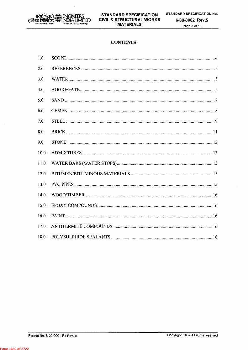
er-
ENGINEERS INDIA LIMITED IA GOY* Of InCIO UMIeltaking)
STANDARD SPECIFICATION CIVIL & STRUCTURAL WORKS
MATERIALS
STANDARD SPECIFICATION No.
6-68-0002 Rev.5 Page 3 of 16
ftr faffleg E4VVNE,1)1,A41.11
CONTENTS
1.0 SCOPE 4
2.0 REFERENCES 5
3.0 WATER 5
4.0 AGGREGATE 5
5.0 SAND 7
6.0 CEMENT 8
7.0 STEEL 9
8.0 BRICK 11
9.0 STONE 13
10.0 ADMIXTURES 13
11.0 WATER BARS (WATER STOPS) 15
12.0 BITUMEN/BITUMINOUS MATERIALS 15
13.0 PVC PIPES 15
14.0 WOOD/TIMBER 16
15.0 EPDXY COMPOUNDS 16
16.0 PAINT 16
17.0 ANTITERMITE COMPOUNDS 16
18.0 POLYSULPHIDE SEALANTS 16
Format No. 8-00-0001-F1 Rev. 0
Copyright EIL — All rights reserved
Page 1630 of 2722
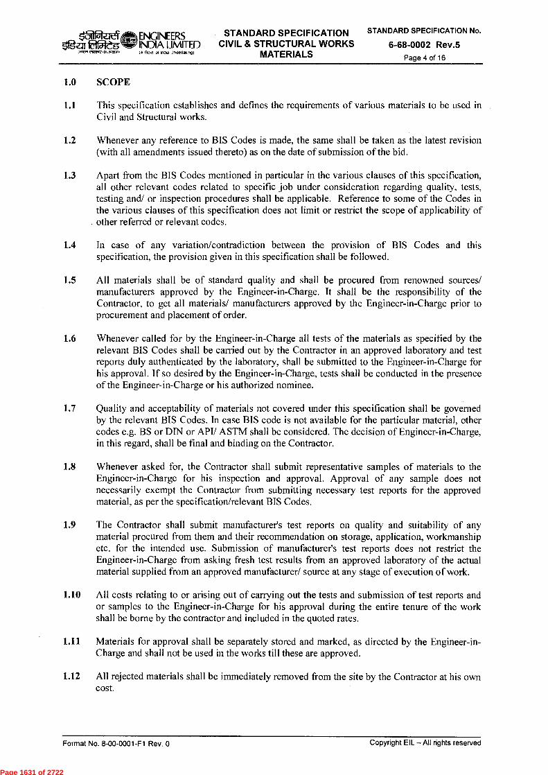
STANDARD SPECIFICATION No.
6-68-0002 Rev.5 Page 4 of 16
ENGINEERS STANDARD SPECIFICATION 51ga ..flaA
EifflegWr INDIA LIMITED CIVIL & STRUCTURAL WORKS A Govt of InOw urveitakngi MATERIALS
1.0 SCOPE
1.1 This specification establishes and defines the requirements of various materials to be used in Civil and Structural works.
1.2 Whenever any reference to BIS Codes is made, the same shall be taken as the latest revision (with all amendments issued thereto) as on the date of submission of the bid.
1.3 Apart from the BIS Codes mentioned in particular in the various clauses of this specification, all other relevant codes related to specific job under consideration regarding quality, tests, testing and/ or inspection procedures shall be applicable. Reference to some of the Codes in the various clauses of this specification does not limit or restrict the scope of applicability of
, other referred or relevant codes.
1.4 In case of any variation/contradiction between the provision of BIS Codes and this specification, the provision given in this specification shall be followed.
1.5 All materials shall be of standard quality and shall be procured from renowned sources/ manufacturers approved by the Engineer-in-Charge. It shall be the responsibility of the Contractor, to get all materials/ manufacturers approved by the Engineer-in-Charge prior to procurement and placement of order.
1.6 Whenever called for by the Engineer-in-Charge all tests of the materials as specified by the relevant BIS Codes shall be carried out by the Contractor in an approved laboratory and test reports duly authenticated by the laboratory, shall be submitted to the Engineer-in-Charge for his approval. If so desired by the Engineer-in-Charge, tests shall be conducted in the presence of the Engineer-in-Charge or his authorized nominee.
1.7 Quality and acceptability of materials not covered under this specification shall be governed by the relevant BIS Codes. In case BIS code is not available for the particular material, other codes e.g. BS or DIN or API/ ASTM shall be considered. The decision of Engineer-in-Charge, in this regard, shall be final and binding on the Contractor.
1.8 Whenever asked for, the Contractor shall submit representative samples of materials to the Engineer-in-Charge for his inspection and approval. Approval of any sample does not necessarily exempt the Contractor from submitting necessary test reports for the approved material, as per the specification/relevant BIS Codes.
1.9 The Contractor shall submit manufacturer's test reports on quality and suitability of any material procured from them and their recommendation on storage, application, workmanship etc. for the intended use. Submission of manufacturer's test reports does not restrict the Engineer-in-Charge from asking fresh test results from an approved laboratory of the actual material supplied from an approved manufacturer/ source at any stage of execution of work.
1.10 All costs relating to or arising out of carrying out the tests and submission of test reports and or samples to the Engineer-in-Charge for his approval during the entire tenure of the work shall be borne by the contractor and included in the quoted rates.
1.11 Materials for approval shall be separately stored and marked, as directed by the Engineer-in- Charge and shall not be used in the works till these are approved.
1.12 All rejected materials shall be immediately removed from the site by the Contractor at his own cost.
Copyright EIL — All rights reserved Format No. 8-00-0001-F1 Rev. 0
Page 1631 of 2722
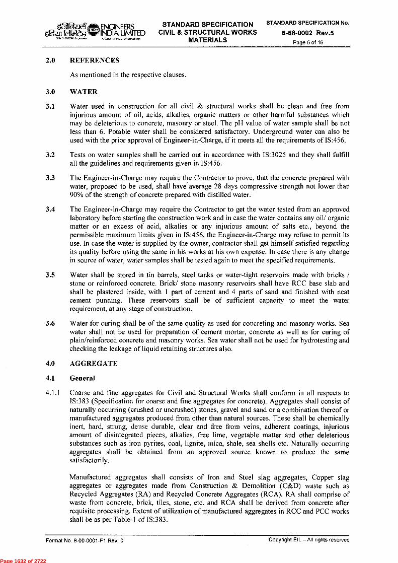
Zgar fal5leg eVIZTP MI,
ENGINEERS STANDARD SPECIFICATION INDIA LIMITED CIVIL & STRUCTURAL WORKS I Gout of Infla Undettaking) MATERIALS
STANDARD SPECIFICATION No.
6-68-0002 Rev.5 Page 5 of 16
2.0 REFERENCES
As mentioned in the respective clauses.
3.0 WATER
3.1 Water used in construction for all civil & structural works shall be clean and free from injurious amount of oil, acids, alkalies, organic matters or other harmful substances which may be deleterious to concrete, masonry or steel. The pH value of water sample shall be not less than 6. Potable water shall be considered satisfactory. Underground water can also be used with the prior approval of Engineer-in-Charge, if it meets all the requirements of IS:456.
3.2 Tests on water samples shall be carried out in accordance with IS:3025 and they shall fulfill all the guidelines and requirements given in IS:456.
3.3 The Engineer-in-Charge may require the Contractor to prove, that the concrete prepared with water, proposed to be used, shall have average 28 days compressive strength not lower than 90% of the strength of concrete prepared with distilled water.
3.4 The Engineer-in-Charge may require the Contractor to get the water tested from an approved laboratory before starting the construction work and in case the water contains any oil/ organic matter or an excess of acid, alkalies or any injurious amount of salts etc., beyond the permissible maximum limits given in IS:456, the Engineer-in-Charge may refuse to permit its use. In case the water is supplied by the owner, contractor shall get himself satisfied regarding its quality before using the same in his works at his own expense. In case there is any change in source of water, water samples shall be tested again to meet the specified requirements.
3.5 Water shall be stored in tin barrels, steel tanks or water-tight reservoirs made with bricks / stone or reinforced concrete. Brick/ stone masonry reservoirs shall have RCC base slab and shall be plastered inside, with 1 part of cement and 4 parts of sand and finished with neat cement punning. These reservoirs shall be of sufficient capacity to meet the water requirement, at any stage of construction.
3.6 Water for curing shall be of the same quality as used for concreting and masonry works. Sea water shall not be used for preparation of cement mortar, concrete as well as for curing of plain/reinforced concrete and masonry works. Sea water shall not be used for hydrotesting and checking the leakage of liquid retaining structures also.
4.0 AGGREGATE
4.1 General
4.1.1 Coarse and fine aggregates for Civil and Structural Works shall conform in all respects to IS:383 (Specification for coarse and fine aggregates for concrete). Aggregates shall consist of naturally occurring (crushed or uncrushed) stones, gravel and sand or a combination thereof or manufactured aggregates produced from other than natural sources. These shall be chemically inert, hard, strong, dense durable, clear and free from veins, adherent coatings, injurious amount of disintegrated pieces, alkalies, free lime, vegetable matter and other deleterious substances such as iron pyrites, coal, lignite, mica, shale, sea shells etc. Naturally occurring aggregates shall be obtained from an approved source known to produce the same satisfactorily.
Manufactured aggregates shall consists of Iron and Steel slag aggregates, Copper slag aggregates or aggregates made from Construction & Demolition (C&D) waste such as Recycled Aggregates (RA) and Recycled Concrete Aggregates (RCA). RA shall comprise of waste from concrete, brick, tiles, stone, etc. and RCA shall be derived from concrete after requisite processing. Extent of utilization of manufactured aggregates in RCC and PCC works shall be as per Table-1 of IS:383.
Format No. 8-00-0001-F1 Rev. 0
Copyright EIL — All rights reserved
Page 1632 of 2722

III EifAtg (awn emart12 %Durum)
ENGINEERS INDIA LIMITED (A Gov* of :nda Undertaking)
STANDARD SPECIFICATION CIVIL & STRUCTURAL WORKS
MATERIALS
STANDARD SPECIFICATION No.
6-68-0002 Rev.5 Page 6 of 16
4.1.2 Source and type of aggregates shall be got approved by the Engineer-in-Charge prior to procurement. Change in source and type of aggregates, at later stage, shall not be generally permitted; but under specific circumstances, Engineer-in-Charge can allow a change in source and type of aggregate. Contractor shall produce necessary test certificates from approved laboratories regarding the quality and suitability of the proposed aggregates and submit fresh mix design for approval of the Engineer-in-Charge. Any such change, if permitted by the Engineer-in-Charge, shall be without any time and cost implication to the owner.
4.1.3 Aggregates which may chemically react with alkalies of cement or might cause corrosion of the reinforcement, shall not be used. If so desired by the Engineer-in-Charge, the Contractor shall carry out alkali reactivity tests and submit the results to him for approval.
4.1.4 The maximum quantities of deleterious materials in the aggregates as determined in accordance with IS:2386 - Part II (Methods of Test for aggregates for concrete), shall not exceed the limits defined in IS: 383. No special test is required to prove the absence of such deleterious matters if the aggregates are from a known source with satisfactory prior data on the properties of concrete made with them. In case of newly developed quarry sites, the contractor shall submit necessary test results as per IS:383 and IS:2386 to the Engineer-in-Charge prior to his acceptance and approval. The method of Sampling shall be in accordance with the requirements given in IS:2430.
4.1.5 Coarse and fine aggregates shall be batched separately. All-in-aggregate shall be used only where specifically permitted by the Engineer-in-Charge.
Separate sieve analysis and grading curves shall be prepared by the Contractor for any/ all batches of coarse and fine aggregates, and submitted to the Engineer-in- Charge, whenever asked for, to ensure conformity with those submitted along with the mix design.
4.1.6 Whenever required by Engineer-in-Charge, the aggregates (coarse/ fine) shall be washed and/ or sieved by the contractor before use in the works to obtain clean and graded aggregate at no extra cost to the owner.
4.1.7 Aggregates not in conformity with the specifications shall be rejected and the Contractor shall immediately remove them from the site of work.
4.2 Coarse Aggregates
4.2.1 Coarse aggregates are the aggregates, which are retained on 4.75 mm BIS Sieve. It shall have a specific gravity not less than 2.6 (saturated surface dry basis).
4.2.2 These may be obtained from crushed or uncrushed gravel or stone or may be manufactured from other than natural sources like RCA or RA from C&D waste and may be supplied as single sized or graded. The grading of the aggregates shall be as per IS:383 or as required by the mix design, to obtain densest possible concrete. For this purpose, the contractor shall submit to the Engineer-in-Charge at least three sets of mix design and test results, each with different gradings of coarse aggregates, proposed to be used. The Engineer-in-Charge may allow "All-in-aggregates" to be used provided they satisfy the requirements of IS:383.
4.3 Fine Aggregates
4.3.1 Fine aggregates are the aggregates which pass through 4.75 mm BIS sieve but not more than ten percent (10%) pass through 150 micron BIS sieve. These shall comply with the requirements of grading zones I, II and III of IS:383. Fine aggregates conforming to grade zone IV shall not be used for reinforced concrete works.
Format No. 8-00-0001-F1 Rev. 0
Copyright EIL — All rights reserved
Page 1633 of 2722
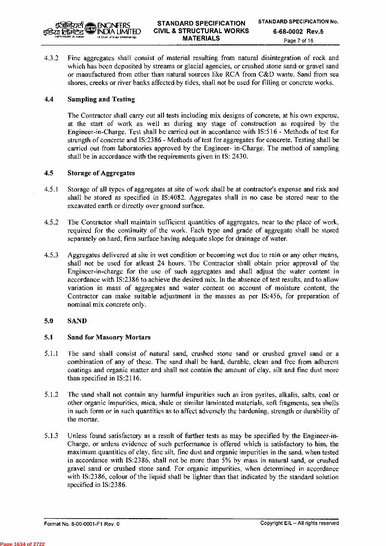
STANDARD SPECIFICATION No.
6-68-0002 Rev.5 Page 7 of 16
ENGINEERS tsar faffleg W INDIA LIMITED
MA., er-Zar7asisAromi, (A Gort of India Undertaking(
STANDARD SPECIFICATION CIVIL & STRUCTURAL WORKS
MATERIALS
4.3.2 Fine aggregates shall consist of material resulting from natural disintegration of rock and which has been deposited by streams or glacial agencies, or crushed stone sand or gravel sand or manufactured from other than natural sources like RCA from C&D waste. Sand from sea shores, creeks or river banks affected by tides, shall not be used for filling or concrete works.
4.4 Sampling and Testing
The Contractor shall carry out all tests including mix designs of concrete, at his own expense, at the start of work as well as during any stage of construction as required by the Engineer-in-Charge. Test shall be carried out in accordance with IS:516 - Methods of test for strength of concrete and IS:2386 - Methods of test for aggregates for concrete. Testing shall be carried out from laboratories approved by the Engineer- in-Charge. The method of sampling shall be in accordance with the requirements given in IS: 2430.
4.5 Storage of Aggregates
4.5.1 Storage of all types of aggregates at site of work shall be at contractor's expense and risk and shall be stored as specified in IS:4082. Aggregates shall in no case be stored near to the excavated earth or directly over ground surface.
4.5.2 The Contractor shall maintain sufficient quantities of aggregates, near to the place of work, required for the continuity of the work. Each type and grade of aggregate shall be stored separately on hard, firm surface having adequate slope for drainage of water.
4.5.3 Aggregates delivered at site in wet condition or becoming wet due to rain or any other means, shall not be used for atleast 24 hours. The Contractor shall obtain prior approval of the Engineer-in-charge for the use of such aggregates and shall adjust the water content in accordance with IS:2386 to achieve the desired mix. In the absence of test results, and to allow variation in mass of aggregates and water content on account of moisture content, the Contractor can make suitable adjustment in the masses as per IS:456, for preparation of nominal mix concrete only.
5.0 SAND
5.1 Sand for Masonry Mortars
5.1.1 The sand shall consist of natural sand, crushed stone sand or crushed gravel sand or a combination of any of these. The sand shall be hard, durable, clean and free from adherent coatings and organic matter and shall not contain the amount of clay, silt and fine dust more than specified in IS:2116.
5.1.2 The sand shall not contain any harmful impurities such as iron pyrites, alkalis, salts, coal or other organic impurities, mica, shale or similar laminated materials, soft fragments, sea shells in such form or in such quantities as to affect adversely the hardening, strength or durability of the mortar.
5.1.3 Unless found satisfactory as a result of further tests as may be specified by the Engineer-in-Charge, or unless evidence of such performance is offered which is satisfactory to him, the maximum quantities of clay, fine silt, fine dust and organic impurities in the sand, when tested in accordance with IS:2386, shall not be more than 5% by mass in natural sand, or crushed gravel sand or crushed stone sand. For organic impurities, when determined in accordance with IS:2386, colour of the liquid shall be lighter than that indicated by the standard solution specified in IS:2386.
Copyright EIL — All rights reserved Format No. 8-00-0001-F1 Rev. 0
Page 1634 of 2722
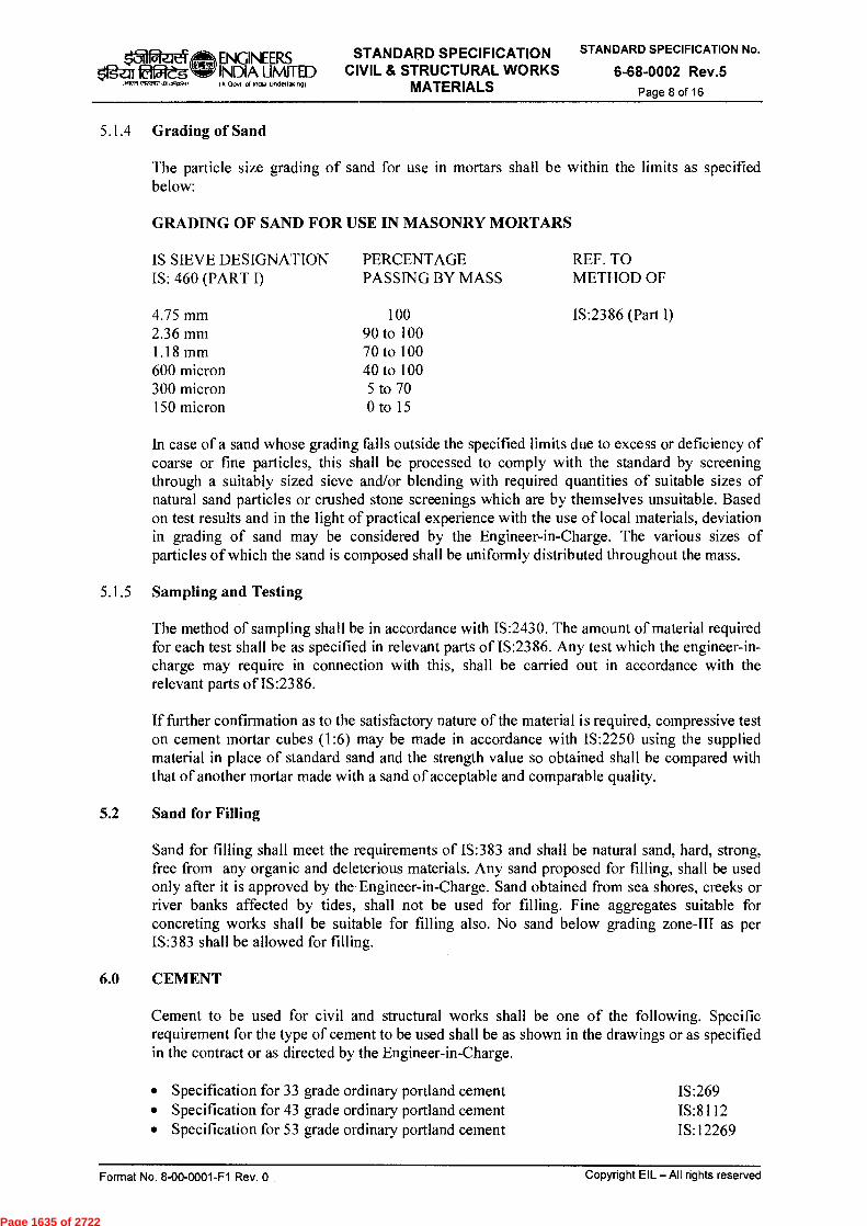
101 eJ 0g-en51e-g
eurark .voral
ENGINEERS INDIA LIMITED IA Govt of inota undettaking)
STANDARD SPECIFICATION CIVIL & STRUCTURAL WORKS
MATERIALS
STANDARD SPECIFICATION No.
6-68-0002 Rev.5 Page 8 of 16
5.1.4 Grading of Sand
The particle size grading of sand for use in mortars shall be within the limits as specified below:
GRADING OF SAND FOR USE IN MASONRY MORTARS
IS SIEVE DESIGNATION PERCENTAGE REF. TO IS: 460 (PART I)
PASSING BY MASS METHOD OF
4.75 mm 2.36 mm 1.18 mm 600 micron 300 micron 150 micron
100 90 to 100 70 to 100 40 to 100 5 to 70 0 to 15
IS:2386 (Part I)
In case of a sand whose grading falls outside the specified limits due to excess or deficiency of coarse or fine particles, this shall be processed to comply with the standard by screening through a suitably sized sieve and/or blending with required quantities of suitable sizes of natural sand particles or crushed stone screenings which are by themselves unsuitable. Based on test results and in the light of practical experience with the use of local materials, deviation in grading of sand may be considered by the Engineer-in-Charge. The various sizes of particles of which the sand is composed shall be uniformly distributed throughout the mass.
5.1.5 Sampling and Testing
The method of sampling shall be in accordance with IS:2430. The amount of material required for each test shall be as specified in relevant parts of IS:2386. Any test which the engineer-in-charge may require in connection with this, shall be carried out in accordance with the relevant parts of IS:2386.
If further confirmation as to the satisfactory nature of the material is required, compressive test on cement mortar cubes (1:6) may be made in accordance with IS:2250 using the supplied material in place of standard sand and the strength value so obtained shall be compared with that of another mortar made with a sand of acceptable and comparable quality.
5.2 Sand for Filling
Sand for filling shall meet the requirements of IS:383 and shall be natural sand, hard, strong, free from any organic and deleterious materials. Any sand proposed for filling, shall be used only after it is approved by the Engineer-in-Charge. Sand obtained from sea shores, creeks or river banks affected by tides, shall not be used for filling. Fine aggregates suitable for concreting works shall be suitable for filling also. No sand below grading zone-III as per IS:383 shall be allowed for filling.
6.0 CEMENT
Cement to be used for civil and structural works shall be one of the following. Specific requirement for the type of cement to be used shall be as shown in the drawings or as specified in the contract or as directed by the Engineer-in-Charge.
• Specification for 33 grade ordinary portland cement IS:269 • Specification for 43 grade ordinary portland cement IS:8112 • Specification for 53 grade ordinary portland cement IS:12269
Format No. 8-00-0001-F1 Rev. 0
Copyright EIL — All rights reserved
Page 1635 of 2722

STANDARD SPECIFICATION STANDARD SPECIFICATION No.
6-68-0002 Rev.5 Page 9 of 16
t5-1i IfgZITH5leg
mien eireZne
ENGINEERS INDIA LIMITED CIVIL & STRUCTURAL WORKS IA Govt of Mao undertaiongl MATERIALS
• Specification for portland slag cement IS :455 • Specification for Portland pozzolana cement (fly ash based) IS:1489 Pt.l • Specification for Portland pozzolana cement (calcined clay based) IS:1489 Pt.2 • Specification for Masonry Cement IS:3466 • Specification for high alumina cement for structural use IS:6452 • Specification for rapid hardening portland cement IS:8041 • Specification for 43 grade ordinary portland cement IS:8112 • Specification for 53 grade ordinary portland cement IS:12269 • Specification for Sulphate Resisting Portland cement IS:12330
6.1 Storage at Site
6.1.1 The storage of cement (lifted from the Owner's godown or procured by the Contractor himself) at the site of work shall be at contractor's expense and risk and shall meet the requirements of IS:4082. The cement shall be stored above ground in a suitable weather tight building or godown and in such a manner as to permit easy access for proper inspection and also to prevent deterioration due to moisture. In the event of any damage occurring to the quality of cement due to faulty storage or on account of negligence on the part of the contractor, such damages shall be borne by the contractor himself.
6.1.2 All approved cement shall be arranged in batches with type, brand and date of receipt flagged on them. A maximum of eight bags shall be stacked one over the other. Cement bags shall be used in the same order as received from the manufacturer/ owner. The contractor shall maintain a register, on day to day basis, giving the details of the receipt/ consumption, source of supply and type of cement etc. The register shall always be accessible to the Engineer-in-Charge for verification.
6.2 Tests after Delivery
Each consignment of cement supplied by Owner or contractor, shall, after delivery at site and at the discretion of the Engineer-in-Charge, be subjected to any or all of the tests and analyses, required by the relevant Indian Standard Codes. In case the cement is supplied by the owner, the contractor shall get himself satisfied regarding its quality before using the same in his works at his own expense. The contractor shall carry out and bear the cost of all tests and analyses required to ensure quality of cement before using in actual works, irrespective of the fact whether the cement is supplied by the Owner or procured by him.
6.3 Rejection
The Engineer-in-Charge may reject at his discretion any cement, notwithstanding the manufacturer's certificate or failing to meet the requirements of relevant BIS Codes for testing of cement. He may similarly reject any cement which has deteriorated owing to inadequate protection from moisture or due to intrusion of foreign matter or any other cause. Any cement which is considered defective, shall not be used and shall be promptly removed from the site by the contractor.
7.0 STEEL
7.1 General
All steel bars, sections, plates, and other miscellaneous steel materials, etc shall be free from loose mill scales, rust as well as oil, mud, paint or other coatings. The materials, construction specifications such as dimensions, shape, weight, tolerances, testing etc, for all materials covered under this section, shall conform to respective BIS Codes. Steel sections shall be conforming to IS:808 or IS:12778.
Format No. 8-00-0001-F1 Rev. 0
Copyright EIL — All rights reserved
Page 1636 of 2722
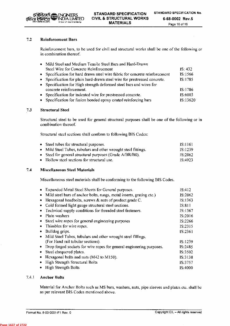
ENGINEERS STANDARD SPECIFICATION INDIA LIMITED CIVIL & STRUCTURAL WORKS (A G04 Of India Und.da.91 MATERIALS
STANDARD SPECIFICATION No.
6-68-0002 Rev.5 Page 10 of 16
Zig.Z11 056 Wel eIRIAV..porsil
7.2 Reinforcement Bars
Reinforcement bars, to be used for civil and structural works shall be one of the following or in combination thereof.
• Mild Steel and Medium Tensile Steel Bars and Hard-Drawn Steel Wire for Concrete Reinforcement IS: 432
• Specification for hard drawn steel wire fabric for concrete reinforcement IS:1566 • Specification for plain hard-drawn steel wire for prestressed concrete. IS:1785 • Specification for High strength deformed steel bars and wires for
concrete reinforcement. IS:1786 • Specification for indented wire for prestressed concrete. IS:6003 • Specification for fusion bonded epoxy coated reinforcing bars IS:13620
7.3 Structural Steel
Structural steel to be used for general structural purposes shall be one of the following or in combination thereof.
Structural steel sections shall conform to following BIS Codes:
• Steel tubes for structural purposes. IS:1161 • Mild Steel Tubes, tubulars and other wrought steel fittings. IS:1239 • Steel for general structural purposes (Grade A/BR/BO). IS:2062 • Hollow steel sections for structural use. IS:4923
7.4 Miscellaneous Steel Materials
Miscellaneous steel materials shall be conforming to the following BIS Codes.
• Expanded Metal Steel Sheets for General purposes. IS:412 • Mild steel bars of anchor bolts, rungs, metal inserts, grating etc.) IS:2062 • Hexagonal headbolts, screws & nuts of product grade C. IS:1363 • Cold formed light gauge structural steel sections. IS:811 • Technical supply conditions for threaded steel fasteners. IS:1367 • Plain washers IS:2016 • Steel wire ropes for general engineering purposes IS:2266 • Thimbles for wire ropes. IS:2315 • Bulldog grips. IS:2361 • Mild Steel Tubes, tubulars and other wrought steel fillings.
(For Hand rail tubular sections). IS:1239 • Drop forged sockets for wire ropes for general engineering purposes. IS:2485 • Steel chequered plates. IS:3502 • Hexagonal bolts and nuts (M42 to M150). IS:3138 • High Strength Structural Bolts IS:3757 • High Strength Bolts IS:4000
7.4.1 Anchor Bolts
Material for Anchor Bolts such as MS bars, washers, nuts, pipe sleeves and plates etc. shall be as per relevant BIS Codes mentioned above.
Format No. 8-00-0001-F1 Rev. 0
Copyright EIL — All rights reserved
Page 1637 of 2722

ENGINEERS STANDARD SPECIFICATION CIVIL & STRUCTURAL WORKS
MATERIALS
STANDARD SPECIFICATION No.
6-68-0002 Rev.5 Page 11 of 16
4t31 e1 fEt5teg
I W FreTrAP eTJ.1 VA, INDIA LIMITED (A Govt of I mho Unoertalomgi
7.5 Storage
The storage of all materials at site of work shall be at the contractor's expense and risk and shall be done as per the requirements given in IS:4082. The contractor shall maintain the proper records of receipt/consumption. The records shall always be accessible to the Engineer-in-Charge for verification.
The reinforcement bars, structural steel sections and other miscellaneous steel materials etc, shall be stored in such a way as to avoid and prevent deterioration, corrosion, bending, twisting and wrapping. In case of any damage occurring to the material on account of faulty storage or negligence by the contractor, same shall be borne by the contractor himself.
7.6 Tests after Delivery
Materials supplied by the Owner or Contractor, shall, after delivery at site and at the discretion of Engineer-in-Charge, be subjected to any or all of the tests, required by the relevant BIS Codes. The Contractor shall carry out and bear the cost of such tests irrespective of the fact whether the material is procured by the Owner or the contractor. In case steel is supplied by the Owner, the Contractor shall get himself satisfied regarding its quality before using the same in his works at his own expense.
7.7 Rejection
The Engineer-in-charge may reject at his discretion any material, not withstanding the manufacturer's certificate or failing to meet the requirements of relevant BIS Codes for testing of materials. He may similarly reject any material, which has deteriorated or corroded etc., due to improper storage, handling or transport. Defective materials shall not be used and removed from the site by the contractor at his own expense.
8.0 BRICK
8.1 General
All Bricks used for masonry works shall conform to the requirements of following BIS Codes:
• Common Burnt Clay Bricks- Specifications IS:1077 • Pulverized Fuel Lime Ash Bricks- Specifications IS:12894 • Burnt Clay Fly Ash Bricks- Specifications IS:13757
8.1.1 Common Burnt Clay Bricks
Bricks for masonry works shall conform to IS:1077 - Specification for common burnt clay building bricks and shall be of class 5.0 (with minimum compressive strength of 5.0 N/mm 2 ). Specific requirement for any other class of bricks shall be as shown in drawings or as described in the contract for a particular site or type of work. Physical requirements, quality, dimensions, tolerances etc. of common burnt clay building bricks shall conform to the requirements of IS:1077.
Bricks shall be hand - moulded or machine moulded and shall be made from suitable soils. The bricks shall have smooth rectangular faces with sharp corners and shall be well burnt, sound, hard, tough and uniform in colour. These shall be free from cracks, chips, flaws, stone or humps of any kind.
Format No. 8-00-0001-F1 Rev. 0
Copyright EIL — All rights reserved
Page 1638 of 2722
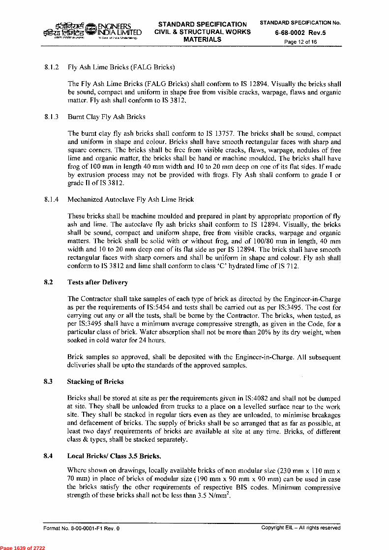
ziel. ENGINEERS STANDARD SPECIFICATION CIVIL & STRUCTURAL WORKS
MATERIALS
STANDARD SPECIFICATION No.
6-68-0002 Rev.5 Page 12 of 16
lisal iegleg I iiTeff efeaR2.477.-.1)
INDIA LIMITED CA Govt of Incla UndertakIng)
8.1.2 Fly Ash Lime Bricks (FALG Bricks)
The Fly Ash Lime Bricks (FALG Bricks) shall conform to IS 12894. Visually the bricks shall be sound, compact and uniform in shape free from visible cracks, warpage, flaws and organic matter. Fly ash shall conform to IS 3812.
8.1.3 Burnt Clay Fly Ash Bricks
The burnt clay fly ash bricks shall conform to IS 13757. The bricks shall be sound, compact and uniform in shape and colour. Bricks shall have smooth rectangular faces with sharp and square corners. The bricks shall be free from visible cracks, flaws, warpage, nodules of free lime and organic matter, the bricks shall be hand or machine moulded. The bricks shall have frog of 100 mm in length 40 mm width and 10 to 20 mm deep on one of its flat sides. If made by extrusion process may not be provided with frogs. Fly Ash shall conform to grade I or grade II of IS 3812.
8.1.4 Mechanized Autoclave Fly Ash Lime Brick
These bricks shall be machine moulded and prepared in plant by appropriate proportion of fly ash and lime. The autoclave fly ash bricks shall conform to IS 12894. Visually, the bricks shall be sound, compact and uniform shape, free from visible cracks, warpage and organic matters. The brick shall be solid with or without frog, and of 100/80 mm in length, 40 mm width and 10 to 20 mm deep one of its flat side as per IS 12894. The brick shall have smooth rectangular faces with sharp corners and shall be uniform in shape and colour. Fly ash shall conform to IS 3812 and lime shall conform to class 'C' hydrated lime of IS 712.
8.2 Tests after Delivery
The Contractor shall take samples of each type of brick as directed by the Engineer-in-Charge as per the requirements of IS:5454 and tests shall be carried out as per IS:3495. The cost for carrying out any or all the tests, shall be borne by the Contractor. The bricks, when tested, as per IS:3495 shall have a minimum average compressive strength, as given in the Code, for a particular class of brick. Water absorption shall not be more than 20% by its dry weight, when soaked in cold water for 24 hours.
Brick samples so approved, shall be deposited with the Engineer-in-Charge. All subsequent deliveries shall be upto the standards of the approved samples.
8.3 Stacking of Bricks
Bricks shall be stored at site as per the requirements given in IS:4082 and shall not be dumped at site. They shall be unloaded from trucks to a place on a levelled surface near to the work site. They shall be stacked in regular tiers even as they are unloaded, to minimise breakages and defacement of bricks. The supply of bricks shall be so arranged that as far as possible, at least two days' requirements of bricks are available at site at any time. Bricks, of different class & types, shall be stacked separately.
8.4 Local Bricks/ Class 3.5 Bricks.
Where shown on drawings, locally available bricks of non modular size (230 mm x 110 mm x 70 mm) in place of bricks of modular size (190 mm x 90 mm x 90 mm) can be used in case the bricks satisfy the other requirements of respective BIS codes. Minimum compressive strength of these bricks shall not be less than 3.5 N/mm 2 .
Format No. 8-00-0001-F1 Rev. 0
Copyright EIL — All rights reserved
Page 1639 of 2722
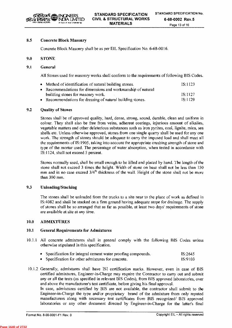
ENGINEERS Ogzil faajeg INDIA LIMITED
werr eiNfAVCRIJ4214i)
STANDARD SPECIFICATION CIVIL & STRUCTURAL WORKS
MATERIALS
STANDARD SPECIFICATION No.
6-68-0002 Rev.5 Page 13 of 16
(A Govt of 1ncla Undettakng)
8.5 Concrete Block Masonry
Concrete Block Masonry shall be as per EIL Specification No. 6-68-0016.
9.0 STONE
9.1 General
All Stones used for masonry works shall conform to the requirements of following BIS Codes.
• Method of identification of natural building stones. IS:1123 • Recommendations for dimensions and workmanship of natural
building stones for masonry work. IS:1127 • Recommendations for dressing of natural building stones. IS:1129
9.2 Quality of Stones
Stones shall be of approved quality, hard, dense, strong, sound, durable, clean and uniform in colour. They shall also be free from veins, adherent coatings, injurious amount of alkalies, vegetable matters and other deleterious substances such as iron pyrites, coal, lignite, mica, sea shells etc. Unless otherwise approved, stones from one single quarry shall be used for any one work. The strength of stones should be adequate to carry the imposed load and shall meet all the requirements of IS:1905, taking into account the appropriate crushing strength of stone and type of the mortar used. The percentage of water absorption, when tested in accordance with IS:1124, shall not exceed 5 percent.
Stones normally used, shall be small enough to be lifted and placed by hand. The length of the stone shall not exceed 3 times the height. Width of stone on base shall not be less than 150 mm and in no case exceed 3/4 th thickness of the wall. Height of the stone shall not be more than 300 mm.
9.3 Unloading/Stacking
The stones shall be unloaded from the trucks to a site near to the place of work as defined in IS:4082 and shall be stacked on a firm ground having adequate stope for drainage. The supply of stones shall be so arranged that as far as possible, at least two days' requirements of stone are available at site at any time.
10.0 ADMIXTURES
10.1 General Requirements for Admixtures
10.1.1 All concrete admixtures shall in general comply with the following BIS Codes unless otherwise stipulated in this specification.
• Specification for integral cement water proofing compounds. IS:2645 • Specification for other admixtures for concrete. IS:9103
10.1.2 Generally, admixtures shall have ISI certification marks. However, even in case of BIS certified admixtures, Engineer-in-Charge may require the Contractor to carry out and submit any or all the tests (as specified in relevant BIS Codes), from BIS approved laboratories, over and above the manufacturer's test certificate, before giving his final approval. In case, admixtures certified by BIS are not available, the contractor shall submit to the Engineer-in-Charge the type and/or proprietary brand of the admixture from only reputed manufacturers along with necessary test certificates from BIS recognized/ BIS approved laboratories or any other document directed by Engineer-in-Charge for the latter's final
Format No. 8-00-0001-F1 Rev. 0
Copyright EIL—All rights reserved
Page 1640 of 2722
ENGINEERS INDIA LIMITED
@s.,1 Ifgar Etatg (.01212Z731E'CD14.2re, IA Govt 01 .ncha Urulettaking)
STANDARD SPECIFICATION CIVIL & STRUCTURAL WORKS
MATERIALS
STANDARD SPECIFICATION No.
6-68-0002 Rev.5 Page 14 of 16
approval. In such cases, names of at least two manufacturers shall be submitted to the Engineer-in-Charge for his selection. In case, both the names are rejected, the contractor shall submit a fresh list of two manufacturers for approval by the Engineer-in-Charge.
The Engineer-in-Charge may direct the contractor to submit test results as required by IS:2645 or IS:9103 for any admixture proposed to be used in the concrete in any approved laboratory at his discretion at any stage of the work. The cost of any/all tests required to satisfy compliance with this specification shall be borne by the Contractor.
In case of non-availability of any BIS code for testing and acceptability criteria, relevant American, British or German Code shall be applicable.
10.1.3 Prior approval of the Engineer-in-Charge shall be obtained while using water reducing admixtures in the concrete (PCC/ RCC) or mortar. Other type of admixtures such as accelerating admixtures, retarding admixtures or air entraining admixtures, shall not be used unless specified on the design drawings or prior approval taken from the design approving authority. Once approved, utmost care shall be exercised at site by the Contractor to maintain the consistency in the quality of admixture and the concrete/ mortar so produced.
10.1.4 The suitability and effectiveness of any admixture shall be verified by trial with the designed concrete mixes using cement, aggregates together with any other materials to be actually used in the works as per the direction of Engineer-in-Charge. If two or more admixtures are to be used simultaneously in the same concrete mix, the Contractor must submit necessary test results from an approved laboratory to show their interaction and compatibility. Any/all tests specified in BIS Codes shall be carried out only with the type of material and mix design, to be actually used in the work site.
10.1.5 No admixture shall impair the durability of the concrete nor combine with the ingredients to form harmful compounds nor increase the risk of corrosion of reinforcement. Use of admixtures shall not reduce the dry density of concrete. Once the proportion of admixture has been established, strict check shall be maintained not to alter the proportions of ingredients and water-cement ratio of the Design Mix during execution.
10.1.6 The chloride contents in admixtures shall not exceed 2% by mass of the admixture or 0.03% by mass of the cement.
10.1.7 Admixtures which do not meet the requirements stipulated in this specification shall be rejected and shall not be used.
10.2 Water Proofing Compounds
10.2.1 Water proofing compounds shall be mixed with cement only.
10.2.2 The permeability of the specimen with the admixture shall be less than half of the permeability with similar specimen without the use of these compounds. These compounds shall be used in such proportion as recommended by manufacturer but in no case it shall exceed 3% by weight of cement.
10.2.3 The initial setting time of the cement with the use of these compounds shall not be less than 30 minutes and final setting time shall not be more than 10 hours. Test shall be carried out in accordance with IS:4031.
10.2.4 Compressive strength of specimen at 3 days shall not be less than 160 kg/sq.cm nor 80% of the 3 days compressive strength of mortar cubes prepared with same cement and sand only, whichever is higher. Similarly compressive strength at 7 days shall not be less than 220 kg/sq.cm nor less than 80% of the 7 days compressive strength prepared with the same cement
Format No. 8-00-0001-F1 Rev. 0
Copyright EIL — All rights reserved
Page 1641 of 2722
/a12-ZreT ENGINEERS STANDARD SPECIFICATION CIVIL & STRUCTURAL WORKS
MATERIALS
STANDARD SPECIFICATION No.
6-68-0002 Rev.5 Page 15 of 16
It sleg MX,/ F97,,IP M.1413.11
INDIA LIMITED IA Govl of Inoe Uridertaknq)
and sand only, whichever is higher. The test to determine the compressive strength shall conform to IS:4031.
10.3 Concrete Penetrating Corrosion Inhibiting Admixture shall be as per EIL Specification No. 6- 68-0017.
11.0 WATER BARS (WATER STOPS)
PVC water bars shall be used in reinforced concrete construction of liquid retaining structures or any other structure to safeguard them from hydrostatic pressure and water leakage and any relative movement between two parts of the structure due to thermal loading shrinkage or differential movement of foundations. Wherever desired or shown in the drawings, they shall be used at expansion/contraction/construction joints. These shall be pre-formed and shall provide a permanent water tight seal along the entire joint in the poured concrete structures. These shall also be flexible enough to withstand deflection/displacements at joints arising due to variation of temperatures or settlement of foundations. The minimum thickness of water bar shall be as shown on drawings or described in the schedule of rates and unless otherwise mentioned, these shall be able to withstand a water head of at least 12 meters.
11.2 Performance requirements of PVC water bars shall meet the requirements of IS:12200. These shall be of approved make and of ribbed/ serrated/ plane type with a bulb at the centre. The thickness and width of water bars shall be as per schedule of rates/ drawings but in no case the thickness shall be less than 5 mm and width less than 150 mm. The joining of the water bars shall be carried out by vulcanising strictly as per the manufacturer's specifications. Lapped joints shall not be allowed under any circumstances.
12.0 BITUMEN/BITUMINOUS MATERIALS
Bitumen to be used for various types of work shall meet all the requirements of relevant BIS Codes as given below:
• Specification of Paving Bitumen IS:73 • Specification for bitumen mastic for flooring IS:1195 • Specification for Bitumen felts for water proofing and damp proofing IS:1322 • Specification for Bituminous compounds for water proofing
and caulking purposes IS:1834 • Specification for preformed fillers for expansion joint in concrete
pavements and structures IS:1838 • Specification for bitumen mastic for use in water proofing of roofs IS:3037 • Specification for bitumen primer for use in water proofing & damp proofing IS:3384 • Specification for Bitumen Mastic for Tanking and Damp proofing IS:5871 • Specification for Glass fibre base coal tar pitch & bitumen felts IS:7193 • Code of practise for damp proofing using bitumen mastic IS:7198 • Specification for bitumen Mastic, Anti Static and electrically
conducting grade IS:8374
The type and grade shall be as shown on the drawings or as indicated in schedule of quantities or as directed by Engineer-in-Charge. Tests and acceptable criteria shall be as per relevant BIS Codes.
13.0 PVC PIPES
PVC Pipes shall conform to the requirements of IS:4985.
Format No. 8-00-0001-F1 Rev. 0
Copyright EIL — All rights reserved
Page 1642 of 2722

Igar laffleg (711Pef ■91.PRIRIP
ENGINEERS INDIA LIMITED :A Govt of mold Undettaltlom
STANDARD SPECIFICATION CIVIL & STRUCTURAL WORKS
• MATERIALS
STANDARD SPECIFICATION No.
6-68-0002 Rev.5 Page 16 of 16
14.0 WOOD/ TIMBER
14.1 Wood recommended for platforms of cold vessels or below cold vessels/ exchangers shall be hard and shall be of group A, grade I, and shall have safe permissible stress of 7 N/mm 2 in compression, perpendicular to grains on outside location as per IS:883. General characteristics like durability, treatability etc. shall conform to IS:883 and IS:3629.
14.2 Timber required to be used for formwork shall be fairly dry before use. It should maintain its shape during the use and even when it comes into contact with moisture from the concrete. Storage of Wood/Timber shall be as per the requirements of IS:4082.
For proper identification and selection of suitable timber for formwork, following codes shall be referred.
• Classification of commercial timbers and their zonal distribution IS:399 • Specification for ballies for general purposes IS:3337 • Specification for Ply wood for concrete shuttering work IS:4990
15.0 EPDXY COMPOUNDS
Refer EIL Specification No. 6-68-0056.
16.0 PAINT
16.1 Refer EIL Specification No. 6-79-0020 or the job specification whichever applicable.
17.0 ANTITERMITE COMPOUNDS
17.1 Chloropyrifos emulsifiable concentrates (1%) conforming to IS:8944 shall be used for treatment of soil for protection of buildings against attack by subterranean termites.
18.0 POLYSULPHLDE SEALANTS
Polysulphide Sealants shall conform to IS:12118 and be of approved make. Test conditions and requirements shall be as given in the above referred BIS code.
Format No. 8-00-0001-F1 Rev. 0
Copyright EIL — All rights reserved
Page 1643 of 2722
AJS PKM SC
Purpose Prepared Checked
by by
VINAY KUMAR
N. DUARI AS SCH REVISED & REISSUED
R SOOD R SOOD H MATHUR GRR UPDATED & REISSUED
5 21.08.14
4 19.06.09
3 22.01.02
2 AUG'94
Rev. No Date
REVISED & REISSUED
UPDATED & REISSUED H MATHUR GP LAHIRI A. SONI
Standards Standards Comm ittee Bureau Convenor Chairman
Approved by
el,crrt CrA ,rvosal
STANDARD SPECIFICATION
INDIA IJMITED ENGINEERS CIVIL & STRUCTURAL WORKS
Go„ of Inda UndenakIng) EARTHWORK
STANDARD SPECIFICATION No.
6-68-0003 Rev.5 Page 1 of 13
TIT-4W k 11 urfrftMa ki<1110-Ich Wr.4
STANDARD SPECIFICATION CIVIL & STRUCTURAL WORKS
r4-1) wrzi
EARTHWORK
Format No. 8-00-0001-F1 Rev. 0 Copyright EIL —All rights reserved
Page 1644 of 2722
ENQNEERS STANDARD SPECIFICATION
INDIA LIMITED CIVIL & STRUCTURAL WORKS A Govt ol Indla Undeltakog) EARTHWORK
STANDARD SPECIFICATION No.
6-68-0003 Rev.5 Page 2 of 13
tg-r:fr 412m,.-rroor,off1.3o-tro.o
Abbreviations:
CNS : Cohesive Non Swelling
Structural Standards Committee
Convenor : Mr. PK Mittal
Members : Mr. S Debnath (Geotech) Mr. Rajanji Stivastava Mr. PJ Singh Mr. Samir Das (Architecture) Mr. VS Chhaya (Projects) Mr. Ravindra Kumar (Construction)
Format No. 8-00-0001-F1 Rev. 0 Copyright EIL — All rights reserved
Page 1645 of 2722

ENGINEERS STANDARD SPECIFICATION INDIA LIMITED CIVIL & STRUCTURAL WORKS IA Govt ol Indo Undertakv,9) EARTHWORK
STANDARD SPECIFICATION No.
6-68-0003 Rev.5 Page 3 of 13
CONTENTS
1.0 SCOPE 4
2.0 CLASSIFICATION OF SOIL 4
3.0 BACKFILLING MATERIAL 5
4.0 SETTING OUT 6
5.0 EARTHWORK IN EXCAVATION 6
6.0 SHORING AND STRUTTING 12
7.0 BACK FILLING AROUND FOUNDATIONS AND IN PLINTH 12
8.0 TRANSPORTATION OF SURPLUS EARTH 13
9.0 PROTECTION OF PROPERTY AND PERSONNEL 13
10.0 CLEAN UP 13
Copyright EIL — All rights reserved Format No. 8-00-0001-F1 Rev. 0
Page 1646 of 2722

ry Og-alf612-'dg 1.I0R 2.10 ,12 ,151,30215,0
ENGINEERS STANDARD SPECIFICATION STANDARD SPECIFICATION No.
INDIA LIMITED CIVIL & STRUCTURAL WORKS 6-68-0003 Rev.5 lA GoN ol Indo Undertalong) EARTHWORK Page 4 of 13
1.0 SCOPE
This specification deals with earth work in excavation and filling.
2.0 CLASSIFICATION OF SOIL
2.1 Ordinary Soil
2.1.1 Soft Soil/ Loose Soil
Generally any soil which yields to the ordinary application of pick and shovel, or to phawra, rake or other ordinary digging implements such as:
a) Sand, gravel, loam, clay, mud, black cotton soil b) Vegetables or organic soil, turf, peats, soft shale or loose murrum c) Mud concrete below ground level d) Any mixture of soil mentioned above.
2.1.2 Hard/ Dense Soil
Generally any soil, which requires close application of picks or jumpers or scarifier and rippers to loosen the same, such as:
i) Stiff heavy clay, hard shale or compact murrum requiring grafting tool and/ or pick and shovel
ii) Shingle and river or nallah bed boulders iii) Soling of roads, paths etc. and hard core iv) Macadam surface of any description (water bound, grouted tarmac etc.) v) Lime concrete, stone masonry in lime or cement mortar below ground level vi) Soft conglomerate when the stone can be detached from the matrix with picks and
shovels
2.2 Soft Rock
This is fissured/ disintegrated rocky strata, boulders (volume more than 0.028 m3 and lens than 0.400 m3) and also which cannot be quarried/ excavated by using above manual tools but can be quarried/ excavated manually by using crow bars is classified as soft rock. Soft rock shall include all kinds of stiff and stratified rock, such as shales, thinly bedded philites, laterite hard conglomerate, lime stone, sand stone and unreinforced cement concrete below ground level. Soft rock may be quarried or split with crow bar or picks and can also be excavated by rippers, dozers and other mechanical equipment, but without the aid of blasting. If required and permitted, light blasting may be restored to, for loosening the materials, but this will not, in any way entitle the material to be classified as "Hard Rock".
2.3 Hard Rock
2.3.1 Hard Rock (Not Requiring Blasting)
This shall include all types of hard and compact rock, having closely spaced fissures or joints, on account of which blasting is not considered necessary and shall not be resorted unless permitted by the Engineer-in charge.
2.3.2 Hard Rock (Requiring General Blasting)
This shall include all types of hard and compact rock occurring in unfissured masses or similar foundations, boulders (volume more than 0.4 m3) for excavation in which blasting is
Fornnat No. 8-00-0001-F1 Rev. 0
Copyright EIL —All rights reserved
Page 1647 of 2722
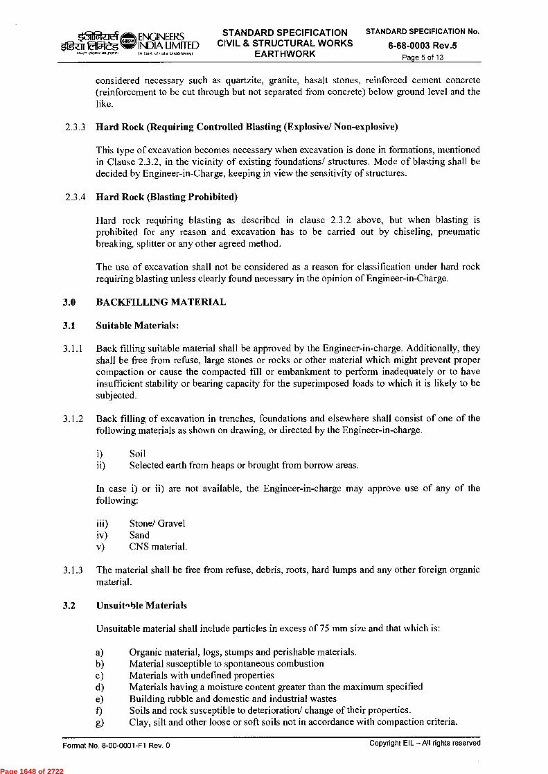
$11g-ar 22-dg 1..27122I2A2I2A~/
ENGINEERS STANDARD SPECIFICATION
INDIA LIMITED CIVIL & STRUCTURAL WORKS IA Govt n11nGa Undertaking) EARTHWORK
STANDARD SPECIFICATION No.
6-68-0003 Rev.5 Page 5 of 13
considered necessary such as quartzite, granite, basalt stones, reinforced cement concrete (reinforcement to be cut through but not separated from concrete) below ground level and the like.
2.3.3 Hard Rock (Requiring Controlled Blasting (Explosive/ Non-explosive)
This type of excavation becomes necessary when excavation is done in formations, mentioned in Clause 2.3.2, in the vicinity of existing foundations/ structures. Mode of blasting shall be decided by Engineer-in-Charge, keeping in view the sensitivity of structures.
2.3.4 Hard Rock (Blasting Prohibited)
Hard rock requiring blasting as described in clause 2.3.2 above, but when blasting is prohibited for any reason and excavation has to be carried out by chiseling, pneumatic breaking, splitter or any other agreed method.
The use of excavation shall not be considered as a reason for classification under hard rock requiring blasting unless clearly found necessary in the opinion of Engineer-in-Charge.
3.0 BACKFILLING MATERIAL
3.1 Suitable Materials:
3.1.1 Back filling suitable material shall be approved by the Engineer-in-charge. Additionally, they shall be free from refuse, large stones or rocks or other material which might prevent proper compaction or cause the compacted fill or embankment to perform inadequately or to have insufficient stability or bearing capacity for the superimposed loads to which it is likely to be subj ected.
3.1.2 Back filling of excavation in trenches, foundations and elsewhere shall consist of one of the following materials as shown on drawing, or directed by the Engineer-in-charge.
i) Soil ii) Selected earth from heaps or brought from borrow areas.
In case i) or ii) are not available, the Engineer-in-charge may approve use of any of the following:
iii) Stone/ Gravel iv) Sand v) CNS material.
3.1.3 The material shall be free from refuse, debris, roots, hard lumps and any other foreign organic material.
3.2 Unsuit.,ble Materials
Unsuitable material shall include particles in excess of 75 mm size and that which is:
a) Organic material, logs, stumps and perishable materials. b) Material susceptible to spontaneous combustion c) Materials with undefined properties d) Materials having a moisture content greater than the maximum specified e) Building rubble and domestic and industrial wastes f) Soils and rock susceptible to deterioration/ change of their properties.
g) Clay, silt and other loose or soft soils not in accordance with compaction criteria.
Format No. 8-00-0001-F1 Rev. 0 Copyright EIL —All rights reserved
Page 1648 of 2722
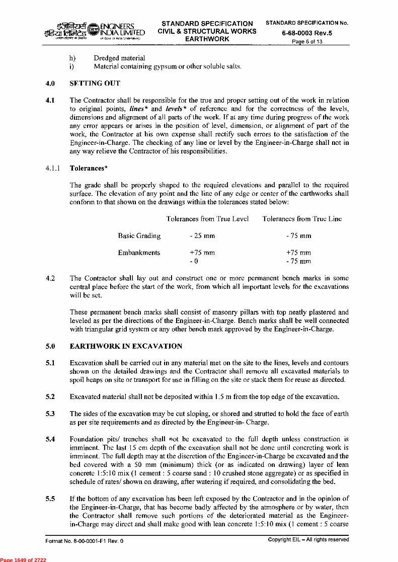
ENGINEERS STANDARD SPECIFICATION
gz.1122Cg IA Govt of InOla Undeflak.ngt EARTHWORK
STANDARD SPECIFICATION No.
6-68-0003 Rev.5 Page 6 of 13
INDIA LIMITED CIVIL & STRUCTURAL WORKS
h) Dredged material i) Material containing gypsum or other soluble salts.
4.0 SFTTING OUT
4.1 The Contractor shall be responsible for the true and proper setting out of the work in relation to original points, lines* and levels* of reference and for the correctness of the levels, dimensions and alignment of all parts of the work. If at any time during progress of the work any error appears or arises in the position of level, dimension, or alignment of part of the work, the Contractor at his own expense shall rectify such errors to the satisfaction of the Engineer-in-Charge. The checking of any line or level by the Engineer-in-Charge shall not in any way relieve the Contractor of his responsibilities.
4.1.1 Tolerances*
The grade shall be properly shaped to the required elevations and parallel to the required surface. The elevation of any point and the line of any edge or center of the earthworks shall conform to that shown on the drawings within the tolerances stated below:
Tolerances from True Level Tolerances from True Line
Basic Grading - 25 mm - 75 mm
Embankments
+75 mm +75 mm - 0 - 75 mm
4.2 The Contractor shall lay out and construct one or more permanent bench marks in some central place before the start of the work, from which all important levels for the excavations will be set.
These permanent bench marks shall consist of masonry pillars with top neatly plastered and leveled as per the directions of the Engineer-in-Charge. Bench marks shall be well connected with triangular grid system or any other bench mark approved by the Engineer-in-Charge.
5.0 EARTHWORK IN EXCAVATION
5.1 Excavation shall be carried out in any material met on the site to the lines, levels and contours shown on the detailed drawings and the Contractor shall remove all excavated materials to spoil heaps on site or transport for use in filling on the site or stack them for reuse as directed.
5.2 Excavated material shall not be deposited within 1.5 m from the top edge of the excavation.
5.3 The sides of the excavation may be cut sloping, or shored and strutted to hold the face of earth as per site requirements and as directed by the Engineer-in- Charge.
5.4 Foundation pits/ trenches shall not be excavated to the full depth unless construction is imminent. The last 15 cm depth of the excavation shall not be done until concreting work is imminent. The full depth may at the discretion of the Engineer-in-Charge be excavated and the bed covered with a 50 mm (minimum) thick (or as indicated on drawing) layer of lean concrete 1:5:10 mix (1 cement : 5 coarse sand : 10 crushed stone aggregate) or as specified in schedule of rates/ shown on drawing, after watering if required, and consolidating the bed.
5.5 If the bottom of any excavation has been left exposed by the Contractor and in the opinion of the Engineer-in-Charge, that has become badly affected by the atmosphere or by water, then the Contractor shall remove such portions of the deteriorated material as the Engineer-in-Charge may direct and shall make good with lean concrete 1:5:10 mix (1 cement : 5 coarse
Format No. 8-00-0001-F1 Rev. 0
Copyright EIL —All rights reserved
Page 1649 of 2722

,41 $'g-ars
tt~ elvav,am~o
ENGINEERS STANDARD SPECIFICATION
INDIA LIMITED CIVIL & STRUCTURAL WORKS lA Govt of Ince Undettalong) EARTHWORK
STANDARD SPECIFICATION No.
6-68-0003 Rev.5 Page 7 of 13
sand : 10 crushed stone aggregate). All expenses for such additional concrete and excavation shall be borne by the Contractor.
5.6 Where excavation is made in excess of the depth required, the Contractor shall, at his own expense, fill upto required level with lean concrete 1:5:10 mix (1 cement : 5 coarse Sand : 10 crushed stone aggregates ) or as decided by Engineer-in-Charge.
5.7 The Contractor shall provide suitable drainage arrangement to prevent surface water from any source entering the foundation pits at his own cost.
5.8 The Contractor shall make all arrangements for dewatering during excavation and subsequent works, the accumulated water from any source (including subsoil water) in the excavated pits/trenches and keeping the excavated pits/ trenches dry for subsequent works.
5.9 The Contractor shall make necessary arrangements for lighting, fencing and other suitable measures for protection against risk of accidents due to open excavation.
5.10 Where the excavation is to be carried out below the foundation level of an adjacent structure, the precaution to be taken such as under pinning, shoring and strutting etc. shall be determined by the Engineer- in-Charge. No excavation shall be done unless such precautionary measures are carried out as per directions of the Engineer-in-Charge. The payment for such precautionary measures shall, however, be made separately.
5.11 Loose or soft bed ground encountered in excavation at the required depth shall on the Engineers-in-Charge's instructions be excavated to a firm bed and difference made up to the required level with lean concrete 1:5:10 mix (1 cement : 5 coarse Sand : 10 crushed stone aggregates).
5.12 In those cases where during excavation, side slips occur for reasons not attributable to the Contractor (e.g. side slips which take place on their own but not due to surcharge of earth kept near the edge of excavation and cracking of excavation top strata due to clay drying out leading to collapse of excavation sides), the Engineer-in-Charge shall admit payment at his discretion.
5.13 Any obstacle encountered during excavation shall be reported immediately to the Engineer-in-Charge and shall be dealt with as instructed by him. Removal of buried pipes or cables shall not be done without prior permission of the Engineer-in-Charge and the Contractor shall provide all measures to protect the same. Cost of such protective measures are deemed to be included in the rates for various items of excavation.
5.14 The Contractor shall not undertake any concreting in foundation until the excavation pit/trench is approved by the Engineer-in-Charge.
5.15 The specification for earth work shall also apply to excavation in rock in general.
5.16 In case of hard rock requiring blasting, the prnvisions mentioned below shall be strictly followed.
5.16.1 General
Where hard rock is met with and blasting operations are considered necessary, the Contractor shall intimate about the same to the Engineer-in-Charge, and obtain his approval in writing for resorting to blasting operation.
The Contractor shall obtain license from the district authorities for undertaking blasting work as well as for obtaining and storing the explosive as per the Explosive Rules 2008, corrected
Format No 8-00-0001-F1 Rev. 0
Copyright EIL —All rights reserved
Page 1650 of 2722

ENGINEERS STANDARD SPECIFICATION
INDIA LIMITED CIVIL & STRUCTURAL WORKS IA Goot ol Indo Unce«ol;ng) EARTHWORK
STANDARD SPECIFICATION No.
6-68-0003 Rev.5 Page 8 of 13
upto date. He shall purchase the explosives, fuses, detonators etc. only from a licensed dealer. He shall be responsible for the safe custody and proper accounting of the explosive materials. The Engineer-in-Charge or his authorised representative shall have the access to check the Contractor's store of explosive and his accounts.
In case where explosives are required to be transported and stored at site, relevant clauses of the Explosive Rules, 2008 as amended subsequently, shall apply.
The Contractor shall be responsible for any accident to workmen, public or property, due to blasting operations.
5.16.2 Precautions
Blasting operations shall be carried out under the careful supervision of a responsible authorised and licensed blaster of the Contractor (referred subsequently as "blaster" only) during specified hours, as approved in writing by the Engineer-in-Charge. The blaster shall be fully conversant with the rules of blasting.
Proper precautions for safety of persons shall be taken. Red flags shall be prominently displayed around the area to be blasted and all the people on the work except those who actually light the fuses, shall withdraw to a safe distance of not less than 200 m from the blast. Precautions as per Explosive Rules 2008 with amendment shall be followed.
5.16.3 Fuses
All fuses shall be cut to the lengths required before being inserted into the holes. Joints in fuses shall be avoided. Where these are unavoidable, a semicircular niche shall be cut in one piece of fuse about 2 cm. deep from the end and the end of other piece inserted into this niche, and the two pieces then wrapped together with a string. All joints exposed to dampness shall be wrapped with rubber tape. Fuse and detonators shall be kept separated from the explosives.
5.16.4 Blasting with Gun Powder
Blasting shall normally be done with gun powder. Dynamite, gelatine or any other high explosive shall only be used in special cases with the written permission of the Engineer-in-Charge.
In case of blasting with gun powder, the position of all bore holes to be drilled shall be marked out in circles with white paint. The bore holes shall be jumped or drilled in the rock face. The depth of bore hole shall be about the same as that of the line of least resistance and its size shall be such that the cartridges can easily pass down to the bottom. The bore holes must be dried before being charged and these shall be inspected by the Contractor's agent.
Gun powder may be used in the form of pellet blasting cartridges or as powder or granules. Cartridges are provided with tapered central hole. One end of fuse is passed through the narrow end of the hole and a sufficient length of the fuse is doubled back that when the fuse is pulled, it is held tight in the tapered hole of the cartridge. Other cartridges are then inserted in the fuse to make up the required charge. The cartridge along with the fuse is lowered down in the bore hole, placed in position and gently filled and pressed home with dry hay or turf. The rest of the bore shall then be filled with dry clay, which shall be tamped with copper or brass rod until it becomes compact. Care shall be taken to avoid any possibility of an air space around the fuse. The safety fuses shall be taken to the required distance so as to allow the blasting to take place after the person lighting the fuse has withdrawn to a safe distance.
Where gun powder is used in the form of powder or granules it shall be introduced in the bore hole by means of funnel or copper tube. The bore holes shall be loaded with two thirds of the
Format No. 8-00-0001-F1 Rev. 0 Copyright EIL — All rights reserved
Page 1651 of 2722

ENGINEERS STANDARD SPECIFICATION STANDARD SPECIFICATION No.
INDIA LIMITED CIVIL & STRUCTURAL WORKS 6-68-0003 Rev.5 Page 9 of 13
1.112,1 eKent, ,1,13~1 Govt of InOia Undertak.ow EARTHWORK
quantity of charge required, and safety fuse then directly introduced over the charge. Remaining one third charge shall then be introduced, and gently filled and pressed home with dry hay or turf. The rest of the bore hole shall be filled with dry clay in the same way as for cartridges, and the safety fuse taken to the required distance.
The charges shall be fired by igniting the fuse. The number of charges to be fired and the actual number of shots heard, shall be compared, and the Contractor's blaster shall satisfy himself by examination that all the charges have exploded, before workmen are permitted to approach the site. The charge which has not exploded, shall not be permitted to be withdrawn. The tamping and charge shall be flooded with water and the holes marked with a red cross (X) over it. Another hole shall be jumped at a distance of about 45 cm from the old hole and fired in the usual way. This operation shall be continued, till the original and any subsequent unfired charges are exploded.
5.16.5 Blasting with Dynamite or any other High Explosive
In case of blasting with dynamite or any other high explosive the position of all bore holes to be drilled shall be marked out in circle with white paint. These shall be inspected by the Contractor's blaster. Bore holes shall be of a size that the cartridge can easily pass down. After the drilling operation, the blaster shall re-inspect the holes to see that the holes marked out by him have been drilled. The Blaster shall then prepare all charges necessary for the bore holes. The bore holes shall be thoroughly cleaned before a cartridge is inserted. Wooden tamping rods (not pointed but cylindrical throughout) shall be used, in charging holes. Metal rods shall never be used for tamping. One cartridge shall be first placed in the bore hole, gently pressed and not rammed down. Other cartridges shall then be added as may be required to make up the necessary charge for the bore hole. The top most cartridge shall be connected to the detonator which shall in turn be connected to the safety fuse of required length.
The maximum of eight (8) bore holes shall be loaded and fired on each occasion. The charges shall be fired successively and not simultaneously.
Immediately before firing a blast, due warning shall be given and the blaster shall see that all persons have retired to a place of safety. The safety fuses of the charged holes shall be ignited in the presence of the blaster, who shall see that all the fuses are properly ignited.
Careful count shall be kept by him and others of each blast as it explodes. After the blast the blaster shall inspect the work and ascertain that all the charged holes have been exploded. In case of misfired holes, the Blaster shall inspect the same after half an hour and mark red crosses (X) over the holes. During this interval of half an hour, no body shall approach the misfired holes. None of the drillers shall work near such holes, until one of the two following operations has been done by the blaster.
a) Either the Contractor's blaster shall very carefully (when the tamping is of damp clay) extract the tamping with a wooden scraper and withdraw the fuse, primer and detonator, after which a fresh detonator, primer and fuse shall be placed in the misfired holes and fired.
OR
b) The hole shall be cleaned for 30 cm of tamping and its direction ascertained by placing a stick in the hole. Another hole shall then be drilled 15 cm away and parallel to it. This hole shall be charged and fired. The misfired hole should also explode along with the new one.
Format No. 8-00-0001-F1 Rev. 0 Copyright EIL — All rights reserved
Page 1652 of 2722
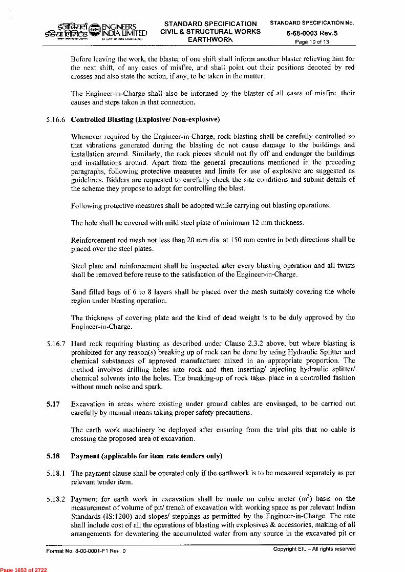
ENGINEEFZS STANDARD SPECIFICATION CIVIL & STRUCTURAL WORKS
EARTHWORK fA
Govf of hotha undenak,,,g)
STANDARD SPECIFICATION No.
6-68-0003 Rev.5 Page 10 of 13
ry ggar laffl-dg 1.12,■ eIrcm1,1,1,3~,
INDIA LIMITED
Before leaving the work, the blaster of one shift shall inform another blaster relieving him for the next shift, of any cases of misfire, and shall point out their positions denoted by red crosses and also state the action, if any, to be taken in the matter.
The Engineer-in-Charge shall also be informed by the blaster of all cases of misfire, their causes and steps taken in that connection.
5.16.6 Controlled Blasting (Explosive/ Non-explosive)
Whenever required by the Engineer-in-Charge, rock blasting shall be carefully controlled so that vibrations generated during the blasting do not cause damage to the buildings and installation around. Similarly, the rock pieces should not fly off and endanger the buildings and installations around. Apart from the general precautions mentioned in the preceding paragraphs, following protective measures and limits for use of explosive are suggested as guidelines. Bidders are requested to carefully check the site conditions and submit details of the scheme they propose to adopt for controlling the blast.
Following protective measures shall be adopted while carrying out blasting operations.
The hole shall be covered with mild steel plate of minimum 12 mm thickness.
Reinforcement rod mesh not less than 20 mm dia. at 150 mm centre in both directions shall be placed over the steel plates.
Steel plate and reinforcement shall be inspected after every blasting operation and all twists shall be removed before reuse to the satisfaction of the Engineer-in-Charge.
Sand filled bags of 6 to 8 layers shall be placed over the mesh suitably covering the whole region under blasting operation.
The thickness of covering plate and the kind of dead weight is to be duly approved by the Engineer-in-Charge.
5.16.7 Hard rock requiring blasting as described under Clause 2.3.2 above, but where blasting is prohibited for any reason(s) breaking up of rock can be done by using Hydraulic Splitter and chemical substances of approved manufacturer mixed in an appropriate proportion. The method involves drilling holes into rock and then inserting/ injecting hydraulic splitter/ chemical solvents into the holes. The breaking-up of rock takes place in a controlled fashion without much noise and spark.
5.17 Excavation in areas where existing under ground cables are envisaged, to be carried out carefully by manual means taking proper safety precautions.
The earth work machinery be deployed after ensuring from the trial pits that no cable is crossing the proposed area of excavation.
5.18 Payment (applicable for item rate tenders only)
5.18.1 The payment clause shall be operated only if the earthwork is to be measured separately as per relevant tender item.
5.18.2 Payment for earth work in excavation shall be made on cubic meter (m3) basis on the measurement of volume of pit/ trench of excavation with working space as per relevant Indian Standards (IS:1200) and slopes/ steppings as permitted by the Engineer-in-Charge. The rate shall include cost of all the operations of blasting with explosives & accessories, making of all arrangements for dewatering the accumulated water from any source in the excavated pit or
Format No. 8-00-0001-F1 Re■,*. 0 Copyright EIL — All rights reserved
Page 1653 of 2722

ENGINEERS STANDARD SPECIFICATION INDIA I IMITED CIVIL & STRUCTURAL WORKS A Govt olind."-Undertakng) EARTHWORK
STANDARD SPECIFICATION No.
6-68-0003 Rev.5 Page 11 of 13
$fg-2:11. 1.1V71 ttrarl +.1 SR1.1)
trench, removal and disposal of surplus excavated soil within a lead of 100 m from construction areas. The rate shall also include setting out and line out work required for the excavation.
5.18.3 The following works shall not be measured separately and allowance for the same shall be deemed to have been made in the description of main item:
a) Setting out works, profiles, etc.; b) Site clearance, such as cleaning grass and vegetation; c) Unauthorized battering or benching of excavation; d) Forming (or leaving 'dead men' or 'tell-tales' in borrow pits and their removal after
measurements; e) Forming (or leaving) steps in sides of deep excavation and their removal after
measurements;
0 Excavation for insertion of planking and strutting;
g) Unless otherwise specified, removing slips or falls in excavations; h) Bailing out or pumping of water in excavation from rains; i) Bailing out or pumping of water in excavation from sub-soil water, and
j) Slinging or supporting pipes, electric cables, etc, met during excavation.
5.18.4 Special pumping other than what is included in 5.18.3 (h and i) and well point dewatering where resorted to, shall each be measured separately, unless otherwise stated, in Kilo Watt Hour against separate specific provision(s) made for the purpose.
5.18.5 The Contractor shall intimate to the Engineer-in-Charge as soon as different classification of soils are met with. The measurements of various soil classifications then shall be worked out by either of the following alternatives in the order of their decreasing importance.
a) Joint levels shall be taken as to the levels of different soil classifications and volume worked out on the basis of levels only.
b) Where levels of different strata cannot be clearly marked and defined, the Contractor shall stack different soils of various classifications separately for measurement purpose and then dispose it off.
c) If the quantum of work involved in (b) above is extensively large & time consuming, then the total area may be divided into various zones and reasonably representative samples as in (b) above may be taken and quantities of soils of various classifications finalized for the entire zone based on the representative.
If soil of any classification other than that specified in the Schedule of Rates is met with during excavation, the decision of the Engineer-in-Charge as to the classification of soil, levels of the strata of different classifications and their location shall be binding.
In above case, the total quantity of excavation shall be computed from the measurement of the pit/ trench excavated. The hard rock and soft rock shall be measured separately from the relevant stacks and each shall be reduced by fifty percent for voids, and paid under the relevant items. The balance, that is the total quantity of excavation minus the reduced (for voids) quantity of excavation for rocks shall be paid as soft/ hard soil as per the direction of the Engineer-in-Charge (However, the maximum payment shall be limited to the volume of the excavated pit/ trench as approved by Engineer-in-Charge).
Format No. 8-00-0001-F1 Rev. 0
Copyright EIL — All rights reserved
Page 1654 of 2722
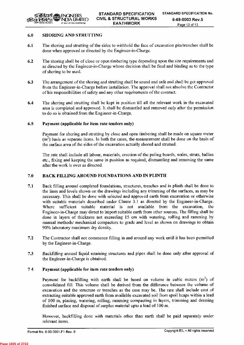
■31 51g-arfêt2es
IaRJf rirort."3.4)
ENGINEERS STANDARD SPECIFICATION INDIA LIMITED CIVIL & STRUCTURAL WORKS lA Govt ot Inda Unclertaking) EARTHWORK
STANDARD SPECIFICATION No.
6-68-0003 Rev.5 Page 12 of 13
6.0 SHORING AND STRUTTING
6.1 The shoring and strutting of the sides to withhold the face of excavation pits/trenches shall be done when approved or directed by the Engineer-in-Charge.
6.2 The shoring shall be of close or open timbering type depending upon the site requirements and as directed by the Engineer-in-Charge whose decision shall be final and binding as to the type of shoring to be used.
6.3 The arrangement of the shoring and strutting shall be sound and safe and shall be got approved from the Engineer-in-Charge before installation. The approval shall not absolve the Contractor of his responsibilities of safety and any other requirements of the contract.
6.4 The shoring and strutting shall be kept in position till all the relevant work in the excavated area is completed and approved. It shall be dismantled and removed only after the permission to do so is obtained from the Engineer-in-Charge.
6.5 Payment (applicable for item rate tenders only)
Payment for shoring and strutting by close and open timbering shall be made on square meter (m2) basis as separate items. In both the cases, the measurement shall be done on the basis of the surface area of the sides of the excavation actually shored and strutted.
The rate shall include all labour, materials, erection of the poling Boards, wales, struts, ballies etc., fixing and keeping the same in position as required, dismantling and removing the same after the work is over as directed.
7.0 BACK FILLING AROUND FOUNDATIONS AND IN PLINTH
7.1 Back filling around completed foundations, structures, trenches and in plinth shall be done to the lines and levels shown on the drawings including any trimming of the surfaces, as may be necessary. This shall be done with selected and approved earth from excavation or otherwise with suitable materials described under Clause 3.1 as directed by the Engineer-in-Charge. Where sufficient suitable material is not available from the excavation, the Engineer-in-Charge may direct to import suitable earth from other sources. The filling shall be done in layers of thickness not exceeding 15 cm with watering, rolling and ramming by manual methods/ mechanical compactors to grade and Level as shown on drawings to obtain 90% laboratory maximum dry density.
7.2 The Contractor shall not commence filling in and around any work until it has been permitted by the Engineer-in-Charge.
7.3 Backfilling around liquid retaining structures and pipes shall be done only after approval of the Engineer-in-Charge is obtained.
7 4 Payment (applicable for item rate tenders only)
Payment for backfilling with earth shall be based on volume in cubic meters (m3) of consolidated fill. This volume shall be derived from the difference between the volume of excavation and the structure or trenches as the case may be. The rate shall include cost of extracting suitable approved earth from available excavated soil from spoil heaps within a lead of 100 m, placing, watering, rolling, ramming compacting in layers, trimming and dressing finished surface and disposal of surplus material upto a lead of 100 m.
However, backfilling done with materials other than earth shall be paid separately under relevant items.
Format No. 8-00-0001-F1 Rev. 0
Copyright EIL —All rights reserved
Page 1655 of 2722

ENGINEERS STANDARD SPECIFICATION INDIA LIMITED CIVIL & STRUCTURAL WORKS
I A Govf of india Undertakingf EARTHWORK
STANDARD SPECIFICATION No.
6-68-0003 Rev.5 Page 13 of 13
1.41,71 ?:1EISr2 )
8.0 TRANSPORTATION OF SURPLUS EARTH
8.1 Surplus earth and soil from excavation shall be removed from construction area to the area demarcated by the Engineer-in-Charge.
8.2 Payment (applicable for item rate tenders only)
8.2.1 Payment shall be made only for the lead beyond initial 100 m from construction area. Rate shall include re-excavation, loading, transportation, dumping, stacking or spreading (as per directions of the Engineer-in-Charge) the surplus earth and the soil in the area demarcated by the Engineer-in-Charge. Payment shall be made on cubic metre (m3) basis on the difference of measurements of the volume of the excavated pits and the measurement of the back filling. Quantity generated due to voids in back filled volume of earth shall also be removed by the Contractor at no extra cost and this disposal of earth shall not be measured and paid under any item.
8.2.2 In exceptional circumstances the Engineer-in-Charge may direct the Contractor to remove surplus earth, concrete debris or any other waste material from site to the areas of disposal on the basis of truck measurement. In such cases volume of material shall be calculated on the basis of truck volume reduced by 30% for voids in case of soft/hard soils and 50% for soft/ hard rock. All other provisions of disposal such as spreading, levelling, grading shall apply in this case also.
9.0 PROTECTION OF PROPERTY AND PERSONNEL
9.1 The Contractor shall protect all active utility lines shown on the drawings or encountered during the excavation. If he damages those lines, the Contractor shall repair or replace them. If existing utilities interfere with his work, the Contractor shall inform to the Engineer-in-charge and secure written instructions for further action.
9.2 The Contractor shall barricade open holes and depressions which he creates or exposes as part of this, and he shall post warning signs and lights on property adjacent to or with public access. He shall operate warning lights during hours from dusk to dawn each day and as otherwise required for safety.
9.3 The Contractor shall protect structures, utilities, pavements, and other facilities from damage caused by settlement, lateral movement, washout, and other hazards created by his operations.
9.4 The Contractor shall plan and execute all aspects of the earthwork so that the safety of personnel, the work and adjacent property is guaranteed and such that a minimum of inconvenience is caused.
10.0 CLEAN UP
Upon completion nf work, the Contractor shall leave the project site clear nf debris and surplus materials off plant limits in a manner meeting all location authority requirements.
Format No. 8-00-0001-F1 Rev. 0
Copyright EIL —All rights reserved
Page 1656 of 2722
7 29h JAN 16 UPDATED & REISSUED
6 15th DEC 14 UPDATED & REISSUED
5 28th DEC 12 UPDATED & REISSUED
4 23 rd NOV 07 UPDATED & REISSUED
3 APR,01 UPDATED & REISSUED
y‘,Nr-,47
SC
SP AS PKM SC
CDS AJS PKM SC DM
YPC PKM VK VC
RPM7097 SCS SCJ1151 MI
feu & STRUCTURAL WORKS - PLAIN &
STANDARD SPECIFICATION No. ENGINEERS
STANDARD SPECIFICATION- CIVIL
INDIA LIMITED 6-68-0004 Rev.7 em t sue, (A Gov, of India Undellakog) Page 1 of 30 REINFORCED CEMENT CONCRETE
4-111011 a
-rzf
STANDARD SPECIFICATION CIVIL & STRUCTURAL WORKS
7:1114a t-4-a
PLAIN AND REINFORCED CEMENT CONCRETE
Rev. No
Date Purpose Prepared Checked
by by
Standards Standards Committee Bureau Convenor Chairman
Approved by
Format No. 8-00-0001-F1 Rev. 0 Copyright EIL — All rights reserved
Page 1657 of 2722

k31 ENGINEERS STANDARD SPECIFICATION- CIVIL STANDARD SPECIFICATION No.
51gar idf5ieg INDIA LIMITED & STRUCTURAL WORKS — PLAIN & 6-68-0004 Rev.7 (A Govt of Indla Undenaking) REINFORCED CEMENT CONCRETE Page 2 of 30
292,R12.1,1CD.1)
Abbreviations:
ACI : American Concrete Institute
ASTM : American Society for Testing and Materials
BS British Standards
GI Galvanized Iron
IS Indian Standard
ISO : International Organization for Standardization
PVC : PolyVinyl Chloride
RCC : Reinforced Cement Concrete
SCC : Self Compacting Concrete
SWG : Standard Wire Gauge
Structural Standards Committee
Convenor: Mr. Rajanji Srivastava
Members : Mr. Anurag Sinha Mr. J K Bhagchandani Mr. S K Naskar Mr. V K Panwar Mr. Charanjit Singh (Projects) Mr. Ravindra Kumar (Construction)
Format No. 8-00-0001-F1 Rev. 0 Copyright EIL — All rights reserved
Page 1658 of 2722

ENGINEERS STANDARD SPECIFICATION- CIVIL STANDARD SPECIFICATION No.
INDIA LIMITED & STRUCTURAL WORKS - PLAIN & 6-68-0004 Rev.7 IA Govt of India undertaking) REINFORCED CEMENT CONCRETE Page 3 of 30
• eteetta
CONTENTS
1.0 SCOPE 4
2.0 MATERIALS 4
3.0 GRADES OF CONCRETE 4
4.0 TYPE OF CONCRETE MIX 5
5.0 CONCRETE MIX PROPORTIONING 5
6.0 BATCHING 7
7.0 CONCRETE MIXING 7
8.0 TRANSPORTATION, PLACING AND COMPACTION 8
9.0 CONSTRUCTION JOINTS 11
10.0 SEPARATION JOINT 12
11.0 EXPANSION JOINTS/ISOLATION JOINT 12
12.0 WATER STOPS 12
13.0 PROTECTION OF FRESHLY LAID CONCRETE 12
14.0 CURING 13
15.0 FIELD TESTS 13
16.0 INSPECTION AND TESTING OF STRUCTURES 18
17.0 FINISHING OF CONCRETE 19
18.0 WATERPROOF CEMENT PAINT 20
19.0 FORM WORK 20
20.0 EXPOSED/ARCHITECTURAL CONCRETE WORK 25
21.0 REINFORCEMENT 25
22.0 PAYMENT 28
Format No. 8-00-0001-F1 Rev. 0 Copyright EIL — All rights reserved
Page 1659 of 2722
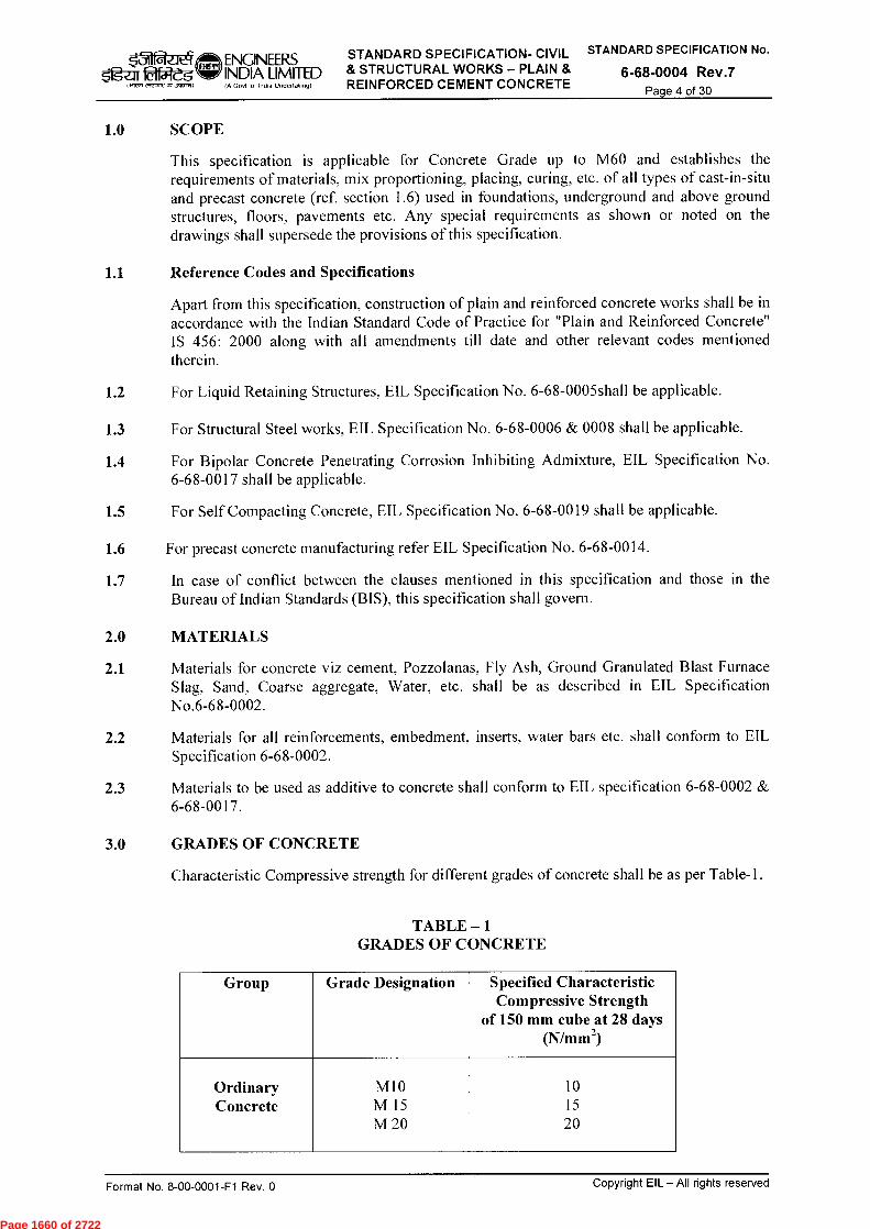
ENGINEERS STANDARD SPECIFICATION- CIVIL STANDARD SPECIFICATION No.
laiateg INDIA LIMITED & STRUCTURAL WORKS — PLAIN & 6-68-0004 Rev.7 IA Govt of India Undeflakm9) REINFORCED CEMENT CONCRETE Page 4 of 30
1.0 SCOPE
This specification is applicable for Concrete Grade up to M60 and establishes the requirements of materials, mix proportioning, placing, curing, etc. of all types of cast-in-situ and precast concrete (ref. section 1.6) used in foundations, underground and above ground structures, floors, pavements etc. Any special requirements as shown or noted on the drawings shall supersede the provisions of this specification.
1.1 Reference Codes and Specifications
Apart from this specification, construction of plain and reinforced concrete works shall be in accordance with the Indian Standard Code of Practice for "Plain and Reinforced Concrete" IS 456: 2000 along with all amendments till date and other relevant codes mentioned therein.
1.2 For Liquid Retaining Structures, EIL Specification No. 6-68-0005shall be applicable.
1.3 For Structural Steel works, EIL Specification No. 6-68-0006 & 0008 shall be applicable.
1.4 For Bipolar Concrete Penetrating Corrosion Inhibiting Admixture, EIL Specification No. 6-68-0017 shall be applicable.
1.5 For Self Compacting Concrete, EIL Specification No. 6-68-0019 shall be applicable.
1.6 For precast concrete manufacturing refer EIL Specification No. 6-68-0014.
1.7 In case of conflict between the clauses mentioned in this specification and those in the Bureau of Indian Standards (BIS), this specification shall govern.
2.0 MATERIALS
2.1 Materials for concrete viz cement, Pozzolanas, Fly Ash, Ground Granulated Blast Furnace Slag, Sand, Coarse aggregate, Water, etc. shall be as described in EIL Specification No.6-68-0002.
2.2 Materials for all reinforcements, embedment, inserts, water bars etc. shall conform to EIL Specification 6-68-0002.
2.3 Materials to be used as additive to concrete shall conform to EIL specification 6-68-0002 & 6-68-0017.
3.0 GRADES OF CONCRETE
Characteristic Compressive strength for different grades of concrete shall be as per Table-1.
TABLE —1 GRADES OF CONCRETE
Group Grade Designation Specified Characteristic Compressive Strength
of 150 mm cube at 28 days (N/mm 2)
Ordinary M10 10 Concrete M 15 15
M 20 20
1417R el,cr, JP415,11
Format No. 8-00-0001-F1 Rev. 0
Copyright EIL — All rights reserved
Page 1660 of 2722
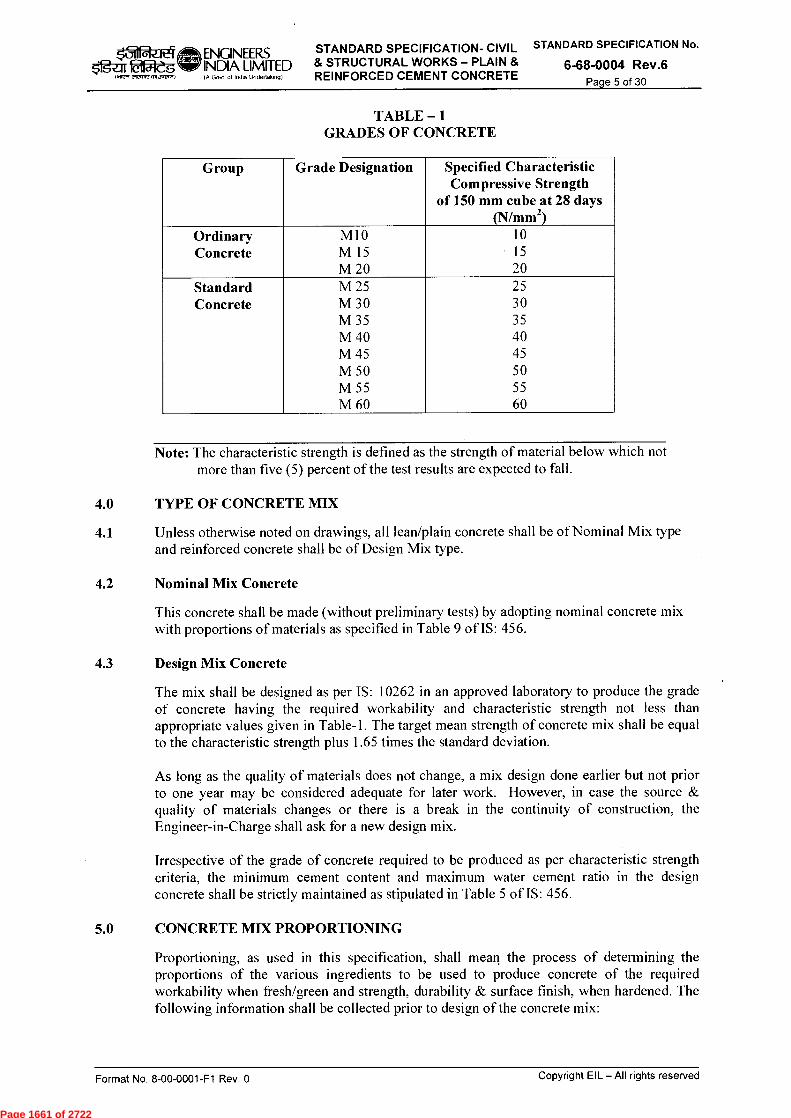
ENGINEERS INDIA LIMITED IA Govt 01 India Undertaking)
STANDARD SPECIFICATION- CIVIL & STRUCTURAL WORKS — PLAIN & REINFORCED CEMENT CONCRETE
STANDARD SPECIFICATION No.
6-68-0004 Rev.6 Page 5 of 30
eit4 51gar iMeg
IMF R elecnrc,1551,1741)
TABLE —1 GRADES OF CONCRETE
Group Grade Designation Specified Characteristic Compressive Strength
of 150 mm cube at 28 days (N/mm 2)
Ordinary M10 10 Concrete M 15 15
M 20 20 Standard M 25 25 Concrete M 30 30
M 35 35 M 40 40 M 45 45 M 50 50 M 55 55 M 60 60
Note: The characteristic strength is defined as the strength of material below which not more than five (5) percent of the test results are expected to fall.
4.0 TYPE OF CONCRETE MIX
4.1 Unless otherwise noted on drawings, all lean/plain concrete shall be of Nominal Mix type and reinforced concrete shall be of Design Mix type.
4.2 Nominal Mix Concrete
This concrete shall be made (without preliminary tests) by adopting nominal concrete mix with proportions of materials as specified in Table 9 of IS: 456.
4.3 Design Mix Concrete
The mix shall be designed as per IS: 10262 in an approved laboratory to produce the grade of concrete having the required workability and characteristic strength not less than appropriate values given in Table-1. The target mean strength of concrete mix shall be equal to the characteristic strength plus 1.65 times the standard deviation.
As long as the quality of materials does not change, a mix design done earlier but not prior to one year may be considered adequate for later work. However, in case the source & quality of materials changes or there is a break in the continuity of construction, the Engineer-in-Charge shall ask for a new design mix.
Irrespective of the grade of concrete required to be produced as per characteristic strength criteria, the minimum cement content and maximum water cement ratio in the design concrete shall be strictly maintained as stipulated in Table 5 of IS: 456.
5.0 CONCRETE MIX PROPORTIONING
Proportioning, as used in this specification, shall mean the process of determining the proportions of the various ingredients to be used to produce concrete of the required workability when fresh/green and strength, durability & surface finish, when hardened. The following information shall be collected prior to design of the concrete mix:
Format No. 8-00-0001-F1 Rev. 0
Copyright EIL — All rights reserved
Page 1661 of 2722
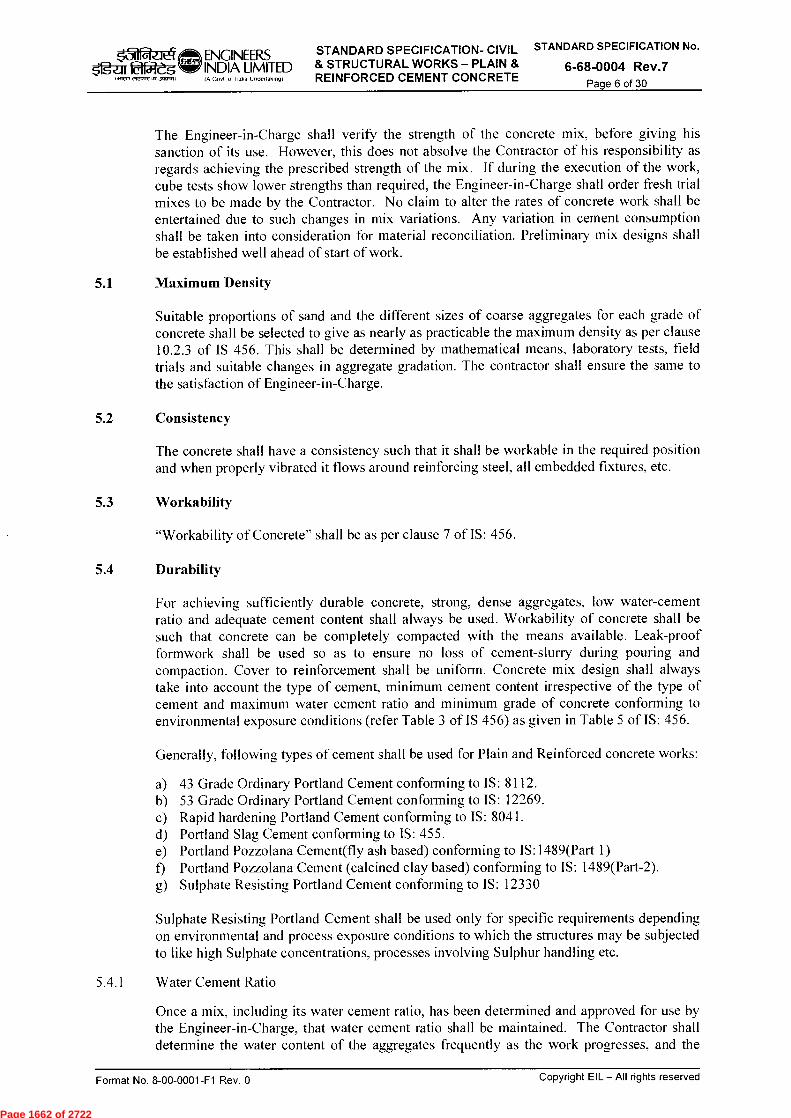
faele-iENGINEERS kitM-eg INDIA LIMITED etertnre raw.) IA Govt of India Undertaking)
STANDARD SPECIFICATION- CIVIL STANDARD SPECIFICATION No.
& STRUCTURAL WORKS - PLAIN & 6-68-0004 Rev.7 REINFORCED CEMENT CONCRETE Page 6 of 30
The Engineer-in-Charge shall verify the strength of the concrete mix, before giving his sanction of its use. However, this does not absolve the Contractor of his responsibility as regards achieving the prescribed strength of the mix. If during the execution of the work, cube tests show lower strengths than required, the Engineer-in-Charge shall order fresh trial mixes to be made by the Contractor. No claim to alter the rates of concrete work shall be entertained due to such changes in mix variations. Any variation in cement consumption shall be taken into consideration for material reconciliation. Preliminary mix designs shall be established well ahead of start of work.
5.1 Maximum Density
Suitable proportions of sand and the different sizes of coarse aggregates for each grade of concrete shall be selected to give as nearly as practicable the maximum density as per clause 10.2.3 of IS 456. This shall be determined by mathematical means, laboratory tests, field trials and suitable changes in aggregate gradation. The contractor shall ensure the same to the satisfaction of Engineer-in-Charge.
5.2 Consistency
The concrete shall have a consistency such that it shall be workable in the required position and when properly vibrated it flows around reinforcing steel, all embedded fixtures, etc.
5.3 Workability
"Workability of Concrete" shall be as per clause 7 of IS: 456.
5.4 Durability
For achieving sufficiently durable concrete, strong, dense aggregates, low water-cement ratio and adequate cement content shall always be used. Workability of concrete shall be such that concrete can be completely compacted with the means available. Leak-proof formwork shall be used so as to ensure no loss of cement-slurry during pouring and compaction. Cover to reinforcement shall be uniform. Concrete mix design shall always take into account the type of cement, minimum cement content irrespective of the type of cement and maximum water cement ratio and minimum grade of concrete conforming to environmental exposure conditions (refer Table 3 of IS 456) as given in Table 5 of IS: 456.
Generally, following types of cement shall be used for Plain and Reinforced concrete works:
a) 43 Grade Ordinary Portland Cement conforming to IS: 8112. b) 53 Grade Ordinary Portland Cement conforming to IS: 12269. c) Rapid hardening Portland Cement conforming to IS: 8041. d) Portland Slag Cement conforming to IS: 455. e) Portland Pozzolana Cement(fly ash based) conforming to IS:1489(Part 1) f) Portland Pozzolana Cement (calcined clay based) conforming to IS: 1489(Part-2). g) Sulphate Resisting Portland Cement conforming to IS: 12330
Sulphate Resisting Portland Cement shall be used only for specific requirements depending on environmental and process exposure conditions to which the structures may be subjected to like high Sulphate concentrations, processes involving Sulphur handling etc.
5.4.1 Water Cement Ratio
Once a mix, including its water cement ratio, has been determined and approved for use by the Engineer-in-Charge, that water cement ratio shall be maintained. The Contractor shall determine the water content of the aggregates frequently as the work progresses, and the
Format No. 8-00-0001-F1 Rev. 0
Copyright EIL — All rights reserved
Page 1662 of 2722
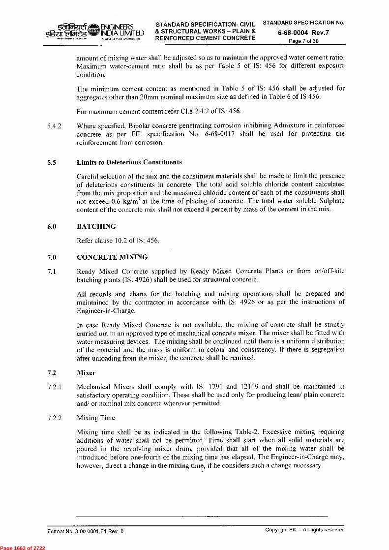
0 el ENGINEERS STANDARD SPECIFICATION- CIVIL STANDARD SPECIFICATION No.
51gzrr twi-eg INDIA LIMITED & STRUCTURAL WORKS — PLAIN & 6-68-0004 Rev.7 {AG. 0,...,9) REINFORCED CEMENT CONCRETE Page 7 of 30
1.17,, 212-.72,15I,NISA)
amount of mixing water shall be adjusted so as to maintain the approved water cement ratio. Maximum water-cement ratio shall be as per Table 5 of IS: 456 for different exposure condition.
The minimum cement content as mentioned in Table 5 of IS: 456 shall be adjusted for aggregates other than 20mm nominal maximum size as defined in Table 6 of IS 456.
For maximum cement content refer CI.8.2.4.2 of IS: 456.
5.4.2 Where specified, Bipolar concrete penetrating corrosion inhibiting Admixture in reinforced concrete as per EIL specification No. 6-68-0017 shall be used for protecting the reinforcement from corrosion.
5.5 Limits to Deleterious Constituents
Careful selection of the mix and the constituent materials shall be made to limit the presence of deleterious constituents in concrete. The total acid soluble chloride content calculated from the mix proportion and the measured chloride content of each of the constituents shall not exceed 0.6 kg/m 3 at the time of placing of concrete. The total water soluble Sulphate content of the concrete mix shall not exceed 4 percent by mass of the cement in the mix.
6.0 BATCHING
Refer clause 10.2 of IS: 456.
7.0 CONCRETE MIXING
7.1 Ready Mixed Concrete supplied by Ready Mixed Concrete Plants or from on/off-site batching plants (IS: 4926) shall be used for structural concrete.
All records and charts for the batching and mixing operations shall be prepared and maintained by the contractor in accordance with IS: 4926 or as per the instructions of Engineer-in-Charge.
In case Ready Mixed Concrete is not available, the mixing of concrete shall be strictly carried out in an approved type of mechanical concrete mixer. The mixer shall be fitted with water measuring devices. The mixing shall be continued until there is a uniform distribution of the material and the mass is uniform in colour and consistency. If there is segregation after unloading from the mixer, the concrete shall be remixed.
7.2 Mixer
7.2.1 Mechanical Mixers shall comply with IS: 1791 and 12119 and shall be maintained in satisfactory operating condition. These shall be used only for producing lean/ plain concrete and/ or nominal mix concrete wherever permitted.
7.2.2 Mixing Time
Mixing time shall be as indicated in the following Table-2. Excessive mixing requiring additions of water shall not be permitted. Time shall start when all solid materials are poured in the revolving mixer drum, provided that all of the mixing water shall be introduced before one-fourth of the mixing time has elapsed. The Engineer-in-Charge may, however, direct a change in the mixing time, if he considers such a change necessary.
Copyright EIL — All rights reserved Format No. 8-00-0001-F1 Rev. 0
Page 1663 of 2722
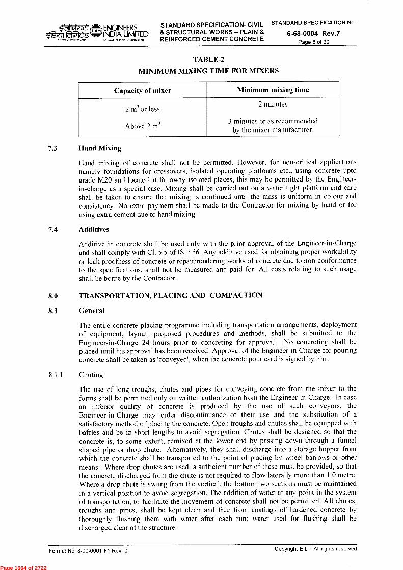
2-1 ENGINEERS STANDARD SPECIFICATION- CIVIL STANDARD SPECIFICATION No.
$fg-ar 2151eg INDIA LIMITED & STRUCTURAL WORKS — PLAIN & 6-68-0004 Rev.7 Govt of India undertaking) REINFORCED CEMENT CONCRETE Page 8 of 30
I >ir, ■ 151 Jrr
TABLE-2
MINIMUM MIXING TIME FOR MIXERS
Capacity of mixer Minimum mixing time
2 m3 or less
Above 2 m3
2 minutes
3 minutes or as recommended by the mixer manufacturer.
7.3 Hand Mixing
Hand mixing of concrete shall not be permitted. However, for non-critical applications namely foundations for crossovers, isolated operating platforms etc., using concrete upto grade M20 and located at far away isolated places, this may be permitted by the Engineer-in-charge as a special case. Mixing shall be carried out on a water tight platform and care shall be taken to ensure that mixing is continued until the mass is uniform in colour and consistency. No extra payment shall be made to the Contractor for mixing by hand or for using extra cement due to hand mixing.
7.4 Additives
Additive in concrete shall be used only with the prior approval of the Engineer-in-Charge and shall comply with Cl. 5.5 of IS: 456. Any additive used for obtaining proper workability or leak proofness of concrete or repair/rendering works of concrete due to non-conformance to the specifications, shall not be measured and paid for. All costs relating to such usage shall be borne by the Contractor.
8.0 TRANSPORTATION, PLACING AND COMPACTION
8.1 General
The entire concrete placing programme including transportation arrangements, deployment of equipment, layout, proposed procedures and methods, shall be submitted to the Engineer-in-Charge 24 hours prior to concreting for approval. No concreting shall be placed until his approval has been received. Approval of the Engineer-in-Charge for pouring concrete shall be taken as 'conveyed', when the concrete pour card is signed by him.
8.1.1 Chuting
The use of long troughs, chutes and pipes for conveying concrete from the mixer to the forms shall be permitted only on written authorization from the Engineer-in-Charge. In case an inferior quality of concrete is produced by the use of such conveyors, the Engineer-in-Charge may order discontinuance of their use and the substitution of a satisfactory method of placing the concrete. Open troughs and chutes shall be equipped with baffles and be in short lengths to avoid segregation. Chutes shall be designed so that the concrete is, to some extent, remixed at the lower end by passing down through a funnel shaped pipe or drop chute. Alternatively, they shall discharge into a storage hopper from which the concrete shall be transported to the point of placing by wheel barrows or other means. Where drop chutes are used, a sufficient number of these must be provided, so that the concrete discharged from the chute is not required to flow laterally more than 1.0 metre. Where a drop chute is swung from the vertical, the bottom two sections must be maintained in a vertical position to avoid segregation. The addition of water at any point in the system of transportation, to facilitate the movement of concrete shall not be permitted. All chutes, troughs and pipes, shall be kept clean and free from coatings of hardened concrete by thoroughly flushing them with water after each run; water used for flushing shall be discharged clear of the structure.
Copyright EIL — All rights reserved Format No. 8-00-0001-F1 Rev. 0
Page 1664 of 2722
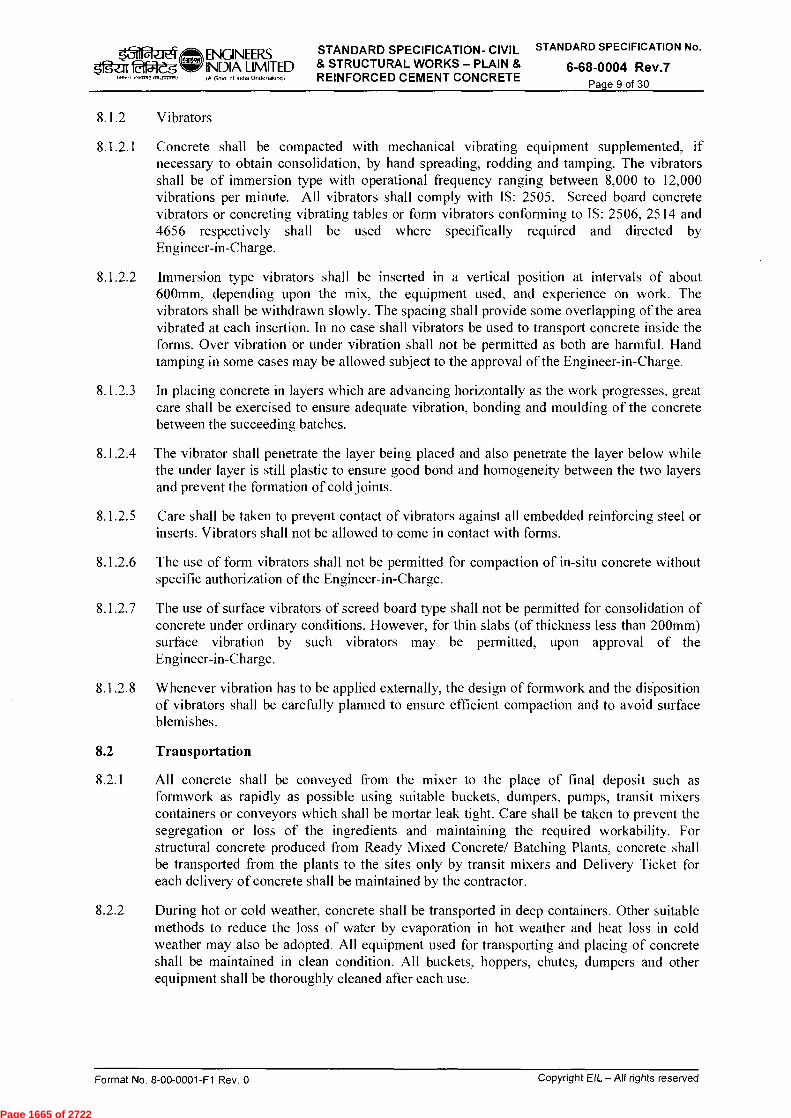
STANDARD SPECIFICATION- CIVIL STANDARD SPECIFICATION No.
& STRUCTURAL WORKS - PLAIN & 6-68-0004 Rev.7 REINFORCED CEMENT CONCRETE
Page 9 of 30 ittre7 etre", ■15134;1511,
ENGINEERS rf=g-zir iMfl-eg INDIA LIMITED
IA Govt of India Untleflaft , o9)
8.1.2 Vibrators
8.1.2.1 Concrete shall be compacted with mechanical vibrating equipment supplemented, if necessary to obtain consolidation, by hand spreading, rodding and tamping. The vibrators shall be of immersion type with operational frequency ranging between 8,000 to 12,000 vibrations per minute. All vibrators shall comply with IS: 2505. Screed board concrete vibrators or concreting vibrating tables or form vibrators conforming to IS: 2506, 2514 and 4656 respectively shall be used where specifically required and directed by Engineer-in-Charge.
8.1.2.2 Immersion type vibrators shall be inserted in a vertical position at intervals of about 600mm, depending upon the mix, the equipment used, and experience on work. The vibrators shall be withdrawn slowly. The spacing shall provide some overlapping of the area vibrated at each insertion. In no case shall vibrators be used to transport concrete inside the forms. Over vibration or under vibration shall not be permitted as both are harmful. Hand tamping in some cases may be allowed subject to the approval of the Engineer-in-Charge.
8.1.2.3 In placing concrete in layers which are advancing horizontally as the work progresses, great care shall be exercised to ensure adequate vibration, bonding and moulding of the concrete between the succeeding batches.
8.1.2.4 The vibrator shall penetrate the layer being placed and also penetrate the layer below while the under layer is still plastic to ensure good bond and homogeneity between the two layers and prevent the formation of cold joints.
8.1.2.5 Care shall be taken to prevent contact of vibrators against all embedded reinforcing steel or inserts. Vibrators shall not be allowed to come in contact with forms.
8.1.2.6 The use of form vibrators shall not be permitted for compaction of in-situ concrete without specific authorization of the Engineer-in-Charge.
8.1.2.7 The use of surface vibrators of screed board type shall not be permitted for consolidation of concrete under ordinary conditions. However, for thin slabs (of thickness less than 200mm) surface vibration by such vibrators may be permitted, upon approval of the Engineer-in-Charge.
8.1.2.8 Whenever vibration has to be applied externally, the design of formwork and the diiposition of vibrators shall be carefully planned to ensure efficient compaction and to avoid surface blemishes.
8.2 Transportation
8.2.1 All concrete shall be conveyed from the mixer to the place of final deposit such as formwork as rapidly as possible using suitable buckets, dumpers, pumps, transit mixers containers or conveyors which shall be mortar leak tight. Care shall be taken to prevent the segregation or loss of the ingredients and maintaining the required workability. For structural concrete produced from Ready Mixed Concrete/ Batching Plants, concrete shall be transported from the plants to the sites only by transit mixers and Delivery Ticket for each delivery of concrete shall be maintained by the contractor.
8.2.2 During hot or cold weather, concrete shall be transported in deep containers. Other suitable methods to reduce the loss of water by evaporation in hot weather and heat loss in cold weather may also be adopted. All equipment used for transporting and placing of concrete shall be maintained in clean condition. All buckets, hoppers, chutes, dumpers and other equipment shall be thoroughly cleaned after each use.
Copyright EIL — All rights reserved Format No. 8-00-0001-F1 Rev. 0
Page 1665 of 2722

STANDARD SPECIFICATION- CIVIL STANDARD SPECIFICATION No. & STRUCTURAL WORKS — PLAIN & 6-68-0004 Rev.7 REINFORCED CEMENT CONCRETE Page 10 of 30
1 ORM 2.22512. 451 J,11/5411
t71 LI a. ENGINEERS $Fgar faiieg INDIA LIMITED
(A Govt of India Undertaking)
8.3 Placing and Compaction
8.3.1 Before placing concrete, all soil surfaces upon which or against which concrete is to be placed shall be well compacted and free from standing water, mud or debris. Soft or yielding soil shall be removed and replaced, with lean concrete or with selected soils/sand and compacted to the density as directed by Engineer-in-Charge. The surface of absorptive soil (against which concrete is to be placed) shall be moistened thoroughly so that moisture is not drawn from the freshly placed concrete. Similarly, for concrete to be placed on formworks, all chippings, shavings and sawdust etc. shall be removed from the interior of the forms before the concrete is placed.
8.3.2 Concrete shall not be placed until the formwork, the placement of reinforcing steel, embedded parts; pockets etc. have been inspected and approved by the Engineer- in-Charge. Any accumulated water on the surface of the bedding layer shall be removed by suitable means before start of placement. No concrete shall be placed on a water covered surface.
8.3.3 Concrete shall be discharged by vertical drop only and the drop height shall not normally exceed 1.5 metre throughout all stages of delivery until the concrete comes to rest in forms. However, drop height can be relaxed by the Engineer-in-Charge as per the provisions given under Cl. 8.1.1. For continuous concreting operation windows of suitable size shall be kept in the formwork or chutes shall be used to avoid segregation of concrete.
8.3.4 Concrete shall be deposited as near as practicable in its final position to avoid rehandling. Concrete shall be placed in successive horizontal layers. The bucket loads, or other units of deposit, shall be placed progressively along the face of the layer with such over-lap as will facilitate spreading the layer of uniform depth and texture with a minimum of hand shoveling. Any tendency to segregation shall be corrected by shovelling coarse aggregates into mortar rather than mortar on the coarse aggregates. Such a tendency for segregation shall be corrected by redesign of mix, change in process or other means, as directed by the Engineer-in-Charge.
8.3.5 All struts, stays and braces (serving temporarily to hold the forms in correct shape and alignment pending the placing of concrete at their locations) shall be removed when the concrete placing has reached an elevation rendering their service unnecessary. These shall not be buried in the concrete. Concrete shall be thoroughly compacted with vibrators and fully worked around the reinforcement, embedded fixtures and into corners of formwork before setting commences and shall not be subsequently disturbed. Methods of placing shall be such as to preclude segregation and avoid displacement of reinforcement or formwork. The formation of stone-pockets or mortar bondage in corners and against face forms shall not be permitted. Should these occur, they shall be dug out, reformed and refilled to sufficient depth and shape for thorough bonding as directed by the Engineer-in-Charge. Care shall be taken to avoid displacement of reinforcement and embedded inserts or movement of formwork.
8.3.6 Unless otherwise approved, concrete shall be placed in single operation to the full thickness of foundation rafts, slabs, beams and similar members. Concrete shall be placed continuously until completion of the part of the work between approved construction joints or as directed by the Engineer-in-Charge.
8.3.7 The method of placing and compaction employed in any particular section of the work shall be to the entire satisfaction of the Engineer-in-Charge.
8.3.8 During hot weather (atmospheric temperature above 40 degree Celsius) or cold weather (atmospheric temperature below 5 degree Celsius, the concreting shall be done as per the procedure set out in IS: 7861).
8.3.9 Concrete that has set standing and becomes stiffened shall not be used in the work.
Copyright EIL - All rights reserved Format No. 8-00-0001-F1 Rev. 0
Page 1666 of 2722

ENGINEERS STANDARD SPECIFICATION- CIVIL STANDARD SPECIFICATION No.
fg-zrr iaaleg INDIA LIMITED & STRUCTURAL WORKS - PLAIN & 6-68-0004 Rev.7 IA Govt 01 India Undertaking) REINFORCED CEMENT CONCRETE Page 11 of 30
I HT7 eleq ,re m1 J.1317,11
8.3.10 Continuous Concreting
Where called out on the drawings, continuous concreting shall be done in a single operation as per the requirements of IS: 456 and IS: 2974. Sufficient "Windows" shall be left in the formwork for pouring & compaction of concrete and inspection. These windows shall be fixed tight once the level of concrete reaches their levels.
8.3.11 Concreting under special conditions
a) Work in extreme weather conditions during hot or cold weather, the concreting shall be done as per procedure set out in IS: 7861(Part 1) or IS: 7861 (Part2).
b) Under water concreting shall be as per clause 14.2 of IS: 456.
8.4 Items Embedded in Concrete
8.4.1 Concreting shall not be started unless the electrical conduits, pipes, fixtures etc., wherever required, are laid by the concerned agency. The Contractor shall afford all the facilities and maintain co-ordination of work with other agencies engaged in electrical and such other works as directed by the Engineer-in-Charge.
8.4.2 Before concreting, the Contractor shall provide, fabricate and lay in proper position all metal inserts, anchor bolts, pipes etc. (which are required to be embedded in concrete members) as per relevant drawings and directions of Engineer-In-Charge.
8.4.3 All embedment, inserts etc. shall be fully held and secured in their respective positions by the concerned agencies to the entire satisfaction of Engineer-in-Charge so as to avoid any dislocation or displacement during the concreting operations. The Contractor shall take all possible care during concreting to maintain these embedment/inserts in their exact locations.
9.0 CONSTRUCTION JOINTS
9.1 Construction joints shall be provided in position as shown or described on the drawings or as directed by the Engineer-in-Charge. Such joints shall be kept to the minimum. These shall be straight and at right angles to the direction of main reinforcement and shall be placed at accessible locations to permit cleaning out of laitance, cement slurry and unsound concrete.
9.2 In a column, the joint shall be formed about 100mm to 150mm below the lowest soffit of the beams framing into it. Concrete in a beam and slab shall be placed throughout without a joint but if the provision of a joint is unavoidable, the joint shall be vertical and located within 1/3 to 1/4 of the span, unless otherwise shown on the drawings.
9.3 When stopping the concrete on a vertical plane in slabs and beams, an approved stop board shall be placed with necessary slots for reinforcement bars. The construction joints shall be keyed by providing a triangular or trapezoidal fillet nailed on the stop board. Inclined joints shall not be permitted. Any concrete flowing through the joints of stop board shall be removed soon after the initial set. When concrete is stopped on a horizontal plane, the surface shall be roughened and cleaned after the initial set and a triangular or trapezoidal groove shall be provided for keying with the new concrete later.
9.4 When the work has to be resumed on a surface which has hardened, such surface shall be cleared of any foreign materials and roughened to expose the tips of the coarse aggregate. This may be done by manual chipping of concrete, with a high pressure water jet or by any other appropriate means as per Engineer-in-Charge's directions. It shall then be swept clean and thoroughly washed and wetted before any new concrete is poured. Any set mortar or concrete sticking to the exposed reinforcing rods in and around such joints shall be thoroughly removed. The reinforcements shall be wire brushed and washed just before
Copyright EIL — All rights reserved Format No. 8-00-0001-F1 Rev. 0
Page 1667 of 2722
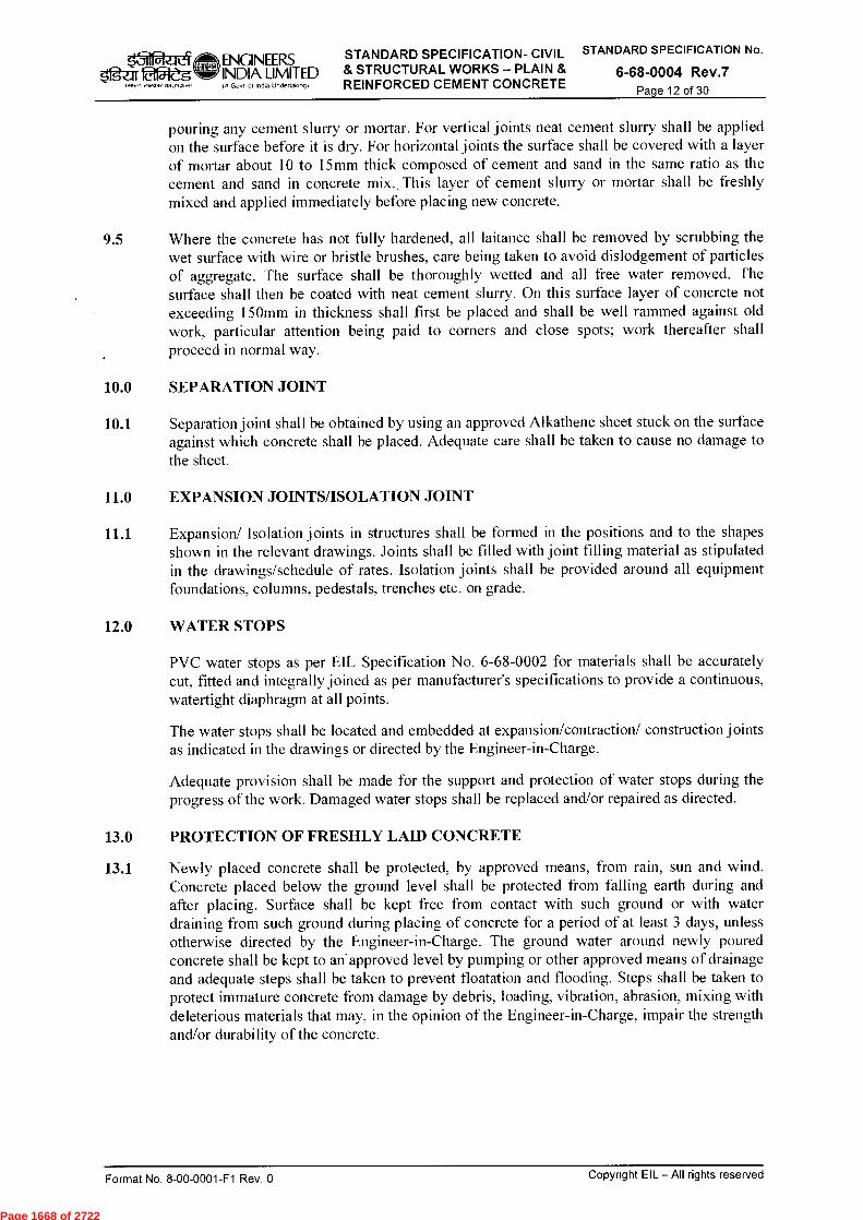
ENGINEERS STANDARD SPECIFICATION- CIVIL STANDARD SPECIFICATION No.
INDIA LIMITED & STRUCTURAL WORKS — PLAIN & 6-68-0004 Rev.7 (A Govt of India Undertaking) REINFORCED CEMENT CONCRETE
fg-ar 2154-eg .FR cYrtnt45l J7M,1)
Page 12 of 30
pouring any cement slurry or mortar. For vertical joints neat cement slurry shall be applied on the surface before it is dry. For horizontal joints the surface shall be covered with a layer of mortar about 10 to 15mm thick composed of cement and sand in the same ratio as the cement and sand in concrete mix., This layer of cement slurry or mortar shall be freshly mixed and applied immediately before placing new concrete.
9.5 Where the concrete has not fully hardened, all laitance shall be removed by scrubbing the wet surface with wire or bristle brushes, care being taken to avoid dislodgement of particles of aggregate. The surface shall be thoroughly wetted and all free water removed. The surface shall then be coated with neat cement slurry. On this surface layer of concrete not exceeding 150mm in thickness shall first be placed and shall be well rammed against old work, particular attention being paid to corners and close spots; work thereafter shall proceed in normal way.
10.0 SEPARATION JOINT
10.1 Separation joint shall be obtained by using an approved Alkathene sheet stuck on the surface against which concrete shall be placed. Adequate care shall be taken to cause no damage to the sheet.
11.0 EXPANSION JOINTS/ISOLATION JOINT
11.1 Expansion/ Isolation joints in structures shall be formed in the positions and to the shapes shown in the relevant drawings. Joints shall be filled with joint filling material as stipulated in the drawings/schedule of rates. Isolation joints shall be provided around all equipment foundations, columns, pedestals, trenches etc. on grade.
12.0 WATER STOPS
PVC water stops as per EIL Specification No. 6-68-0002 for materials shall be accurately cut, fitted and integrally joined as per manufacturer's specifications to provide a continuous, watertight diaphragm at all points.
The water stops shall be located and embedded at expansion/contraction/ construction joints as indicated in the drawings or directed by the Engineer-in-Charge.
Adequate provision shall be made for the support and protection of water stops during the progress of the work. Damaged water stops shall be replaced and/or repaired as directed.
13.0 PROTECTION OF FRESHLY LAID CONCRETE
13.1 Newly placed concrete shall be protected, by approved means, from rain, sun and wind. Concrete placed below the ground level shall be protected from falling earth during and after placing. Surface shall be kept free from contact with such ground or with water draining from such ground during placing of concrete for a period of at least 3 days, unless otherwise directed by the Engineer-in-Charge. The ground water around newly poured concrete shall be kept to an'approved level by pumping or other approved means of drainage and adequate steps shall be taken to prevent floatation and flooding. Steps shall be taken to protect immature concrete from damage by debris, loading, vibration, abrasion, mixing with deleterious materials that may, in the opinion of the Engineer-in-Charge, impair the strength and/or durability of the concrete.
Copyright EIL — All rights reserved Format No. 8-00-0001-F1 Rev. 0
Page 1668 of 2722
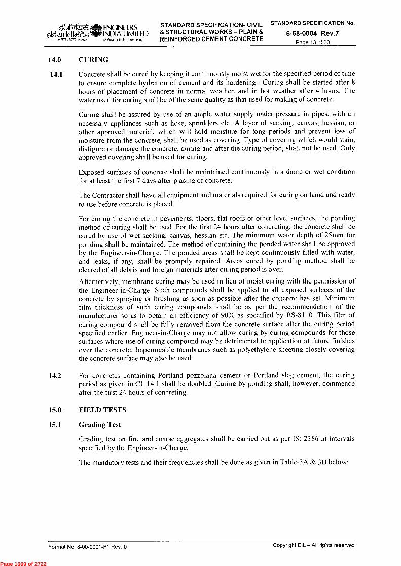
STANDARD SPECIFICATION- CIVIL STANDARD SPECIFICATION No.
& STRUCTURAL WORKS - PLAIN & 6-68-0004 Rev.7 REINFORCED CEMENT CONCRETE Page 13 of 30
ENGINEERS 1g-aria5ieg
INDIA LIMITED ierte eieMre
IA Govt of Incite Undertaking)
14.0 CURING
14.1 Concrete shall be cured by keeping it continuously moist wet for the specified period of time to ensure complete hydration of cement and its hardening. Curing shall be started after 8 hours of placement of concrete in normal weather, and in hot weather after 4 hours. The water used for curing shall be of the same quality as that used for making of concrete.
Curing shall be assured by use of an ample water supply under pressure in pipes, with all necessary appliances such as hose, sprinklers etc. A layer of sacking, canvas, hessian, or other approved material, which will hold moisture for long periods and prevent loss of moisture from the concrete, shall be used as covering. Type of covering which would stain, disfigure or damage the concrete, during and after the curing period, shall not be used. Only approved covering shall be used for curing.
Exposed surfaces of concrete shall be maintained continuously in a damp or wet condition for at least the first 7 days after placing of concrete.
The Contractor shall have all equipment and materials required for curing on hand and ready to use before concrete is placed.
For curing the concrete in pavements, floors, flat roofs or other level surfaces, the ponding method of curing shall be used. For the first 24 hours after concreting, the concrete shall be cured by use of wet sacking, canvas, hessian etc. The minimum water depth of 25mm for ponding shall be maintained. The method of containing the ponded water shall be approved by the Engineer-in-Charge. The ponded areas shall be kept continuously filled with water, and leaks, if any, shall be promptly repaired. Areas cured by ponding method shall be cleared of all debris and foreign materials after curing period is over.
Alternatively, membrane curing may be used in lieu of moist curing with the permission of the Engineer-in-Charge. Such compounds shall be applied to all exposed surfaces of the concrete by spraying or brushing as soon as possible after the concrete has set. Minimum film thickness of such curing compounds shall be as per the recommendation of the manufacturer so as to obtain an efficiency of 90% as specified by BS-8110. This film of curing compound shall be fully removed from the concrete surface after the curing period specified earlier. Engineer-in-Charge may not allow curing by curing compounds for those surfaces where use of curing compound may be detrimental to application of future finishes over the concrete. Impermeable membranes such as polyethylene sheeting closely covering the concrete surface may also be used.
14.2 For concretes containing Portland pozzolana cement or Portland slag cement, the curing period as given in Cl. 14.1 shall be doubled. Curing by ponding shall, however, commence after the first 24 hours of concreting.
15.0 FIELD TESTS
15.1 Grading Test
Grading test on fine and coarse aggregates shall be carried out as per IS: 2386 at intervals specified by the Engineer-in-Charge.
The mandatory tests and their frequencies shall be done as given in Table-3A & 3B below:
Format No. 8-00-0001-F1 Rev. 0
Copyright EIL — All rights reserved
Page 1669 of 2722
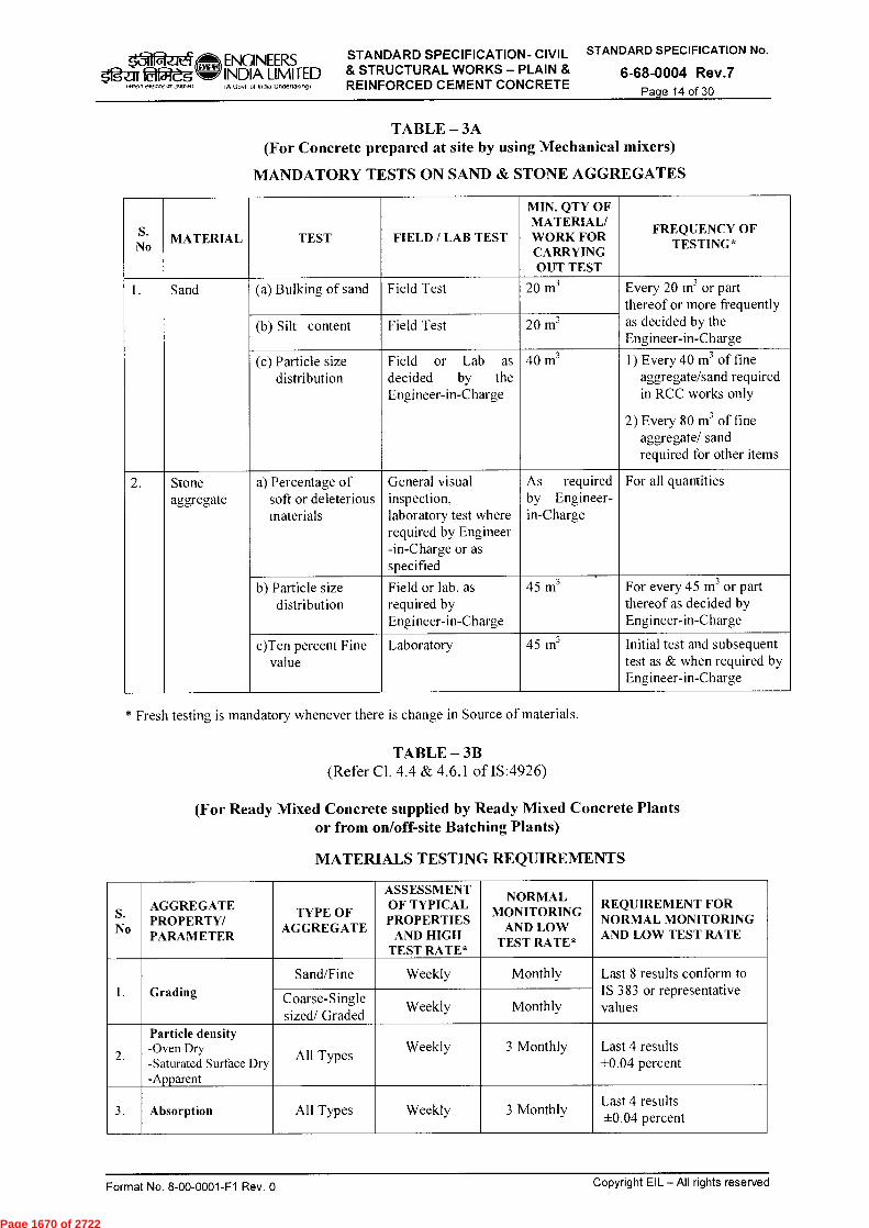
,31`11-aeleY 5'fgar ittgft
WWI 2i2.-re00,
ENGINEERS INDIA LIMITED
Govt of India lJndeflaIongf
STANDARD SPECIFICATION- CIVIL STANDARD SPECIFICATION No.
& STRUCTURAL WORKS — PLAIN & 6-68-0004 Rev.7 REINFORCED CEMENT CONCRETE Page 14 of 30
TABLE — 3A (For Concrete prepared at site by using Mechanical mixers)
MANDATORY TESTS ON SAND & STONE AGGREGATES
S. No
MATERIAL TEST FIELD / LAB TEST
MIN. QTY OF MATERIAL/ WORK FOR CARRYING OUT TEST
FREQUENCY OF TESTING*
1. Sand (a) Bulking of sand Field Test 20 m3 Every 20 m3 or part thereof or more frequently as decided by the Engineer-in-Charge
(b) Silt content Field Test 20 m3
(c) Particle size distribution
Field or Lab as decided by the Engineer-in-Charge
40 m3 1) Every 40 m3 of fine aggregate/sand required in RCC works only
2) Every 80 m3 of fine aggregate/ sand required for other items
2. Stone aggregate
a) Percentage of soft or deleterious materials
General visual inspection, laboratory test where required by Engineer -in-Charge or as specified
As required by Engineer- in-Charge
For all quantities
b) Particle size distribution
Field or lab. as required by Engineer-in-Charge
45 m3 For every 45 m 3 or part thereof as decided by Engineer-in-Charge
c)Ten percent Fine value
Laboratory 45 m3 Initial test and subsequent test as & when required by Engineer-in-Charge
* Fresh testing is mandatory whenever there is change in Source of materials.
TABLE — 3B (Refer Cl. 4.4 & 4.6.1 of IS:4926)
(For Ready Mixed Concrete supplied by Ready Mixed Concrete Plants or from on/off-site Batching Plants)
MATERIALS TESTING REQUIREMENTS
S. No
AGGREGATE PROPERTY/ PARAMETER
TYPE OF AGGREGATE
ASSESSMENT OF TYPICAL PROPERTIES
AND HIGH TEST RATE*
NORMAL MONITORING
AND LOW TEST RATE*
REQUIREMENT FOR NORMAL MONITORING AND LOW TEST RATE
1. Grading
Sand/Fine Weekly Monthly Last 8 results conform to IS 383 or representative values
Coarse-Single sized/ Graded
Weekly Monthly
2.
Particle density -Oven Dry -Saturated Surface Dry -Apparent
All Types Weekly 3 Monthly Last 4 results
+0.04 percent
3. Absorption All Types Weekly 3 Monthly Last 4 results +0.04 percent
Format No. 8-00-0001-F1 Rev. 0 Copyright EIL — All rights reserved
Page 1670 of 2722

STANDARD SPECIFICATION- CIVIL STANDARD SPECIFICATION No.
& STRUCTURAL WORKS — PLAIN & 6-68-0004 Rev.7 REINFORCED CEMENT CONCRETE Page 15 of 30
5,grai laa-L ENGINEERS INDIA LIMITED
I PO veeaverts),Ogrill
IA Govt of India Undertaking)
S. No
AGGREGATE PROPERTY/ PARAMETER
TYPE OF AGGREGATE
ASSESSMENT OF TYPICAL PROPERTIES
AND HIGH TEST RATE*
NORMAL MONITORING
AND LOW TEST RATE*
REQUIREMENT FOR NORMAL MONITORING AND LOW TEST RATE
4. Bulk Density - Loose - Compacted
All Types Monthly 6 Monthly Last 4 results ± 75kg/m3
5. Fines(Silt) Content
Sand Weekly Monthly Last 10 results <75 percent maximum allowed Coarse Monthly 3 Monthly
6. Aggregate Impact Value
Coarse As specified As specified -
7. 10 "A) Fines Coarse Yearly Yearly -
8. Flakiness Coarse 2 Weekly 6 Monthly Last 3 results conform to standard
9. Chloride Content All Types Weekly 6 Monthly Last 3 results < 0.01 percent
10. Aggregate Abrasion Value (Los Angeles Method)
Coarse - Source Change
Yearly/ -
11. Soundness Fine and Coarse
- Yearly/
Source Change -
12 .
Potential Alkali Aggregate Reactivity Including Petrography
Fine and Coarse
- 5 Yearly/
Source Change -
13. Petrographic Description (General)
All Types - 5 Yearly -
*Note : The high or low test rates apply in accordance with the following conditions:
a) High test rate i) To establish the typical characteristics of an aggregate, and
ii) When significant changes in properties occur outside the tolerances for low test rates given.
b) Low test rate i) When the typical characteristics of the aggregate have been established, and ii) When subsequent tests lie within the tolerances for low test rates given
15.2 Compaction Factor Test /Slump Test of Concrete
15.2.1 For structural quality concrete (excluding pavements, flooring etc.) at least one Slump Test shall be made for every compressive strength test carried out. More frequent tests shall be made if there is a distinct change in working conditions or if required by the Engineer-in-Charge.
In case of Ready Mixed Concrete, provisions of IS: 4926 shall be followed.
15.2.2 For structural quality concrete for pavements & floorings, measurement of workability shall be by determination of compacting factor. Value of compacting factor of 0.75 to 0.8 shall generally be acceptable.
15.3 Strength Test of Concrete
15.3.1 Samples from fresh concrete shall be taken as per IS: 1199 and cubes shall be made, cured and tested at 28 days in accordance with IS: 516.
Format No. 8-00-0001-F1 Rev. 0
Copyright EIL — All rights reserved
Page 1671 of 2722
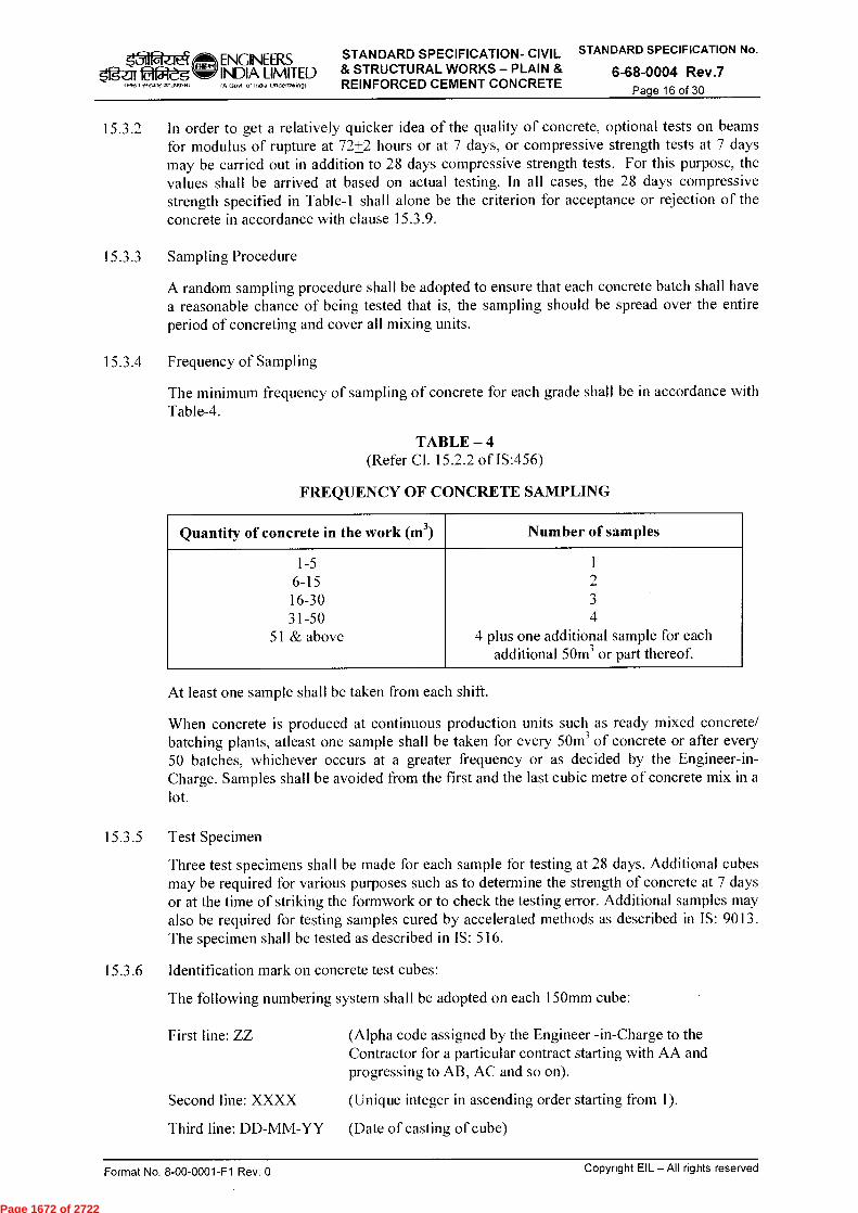
STANDARD SPECIFICATION- CIVIL STANDARD SPECIFICATION No.
& STRUCTURAL WORKS — PLAIN & 6-68-0004 Rev.7 REINFORCED CEMENT CONCRETE Page 16 of 30
1.112ar errcure an 0,2,0
k_71 ENGINEERS 52-ai 015leg INDIA LIMITED
IA Govt o1 India Undertaking)
15.3.2 In order to get a relatively quicker idea of the quality of concrete, optional tests on beams for modulus of rupture at 72+2 hours or at 7 days, or compressive strength tests at 7 days may be carried out in addition to 28 days compressive strength tests. For this purpose, the values shall be arrived at based on actual testing. In all cases, the 28 days compressive strength specified in Table-1 shall alone be the criterion for acceptance or rejection of the concrete in accordance with clause 15.3.9.
15.3.3 Sampling Procedure
A random sampling procedure shall be adopted to ensure that each concrete batch shall have a reasonable chance of being tested that is, the sampling should be spread over the entire period of concreting and cover all mixing units.
15.3.4 Frequency of Sampling
The minimum frequency of sampling of concrete for each grade shall be in accordance with Table-4.
TABLE — 4 (Refer Cl. 15.2.2 of IS:456)
FREQUENCY OF CONCRETE SAMPLING
Quantity of concrete in the work (m 3) Number of samples
1-5 1 6-15 2 16-30 3 31-50 4
51 & above 4 plus one additional sample for each additional 50m 3 or part thereof.
At least one sample shall be taken from each shift.
When concrete is produced at continuous production units such as ready mixed concrete/ batching plants, atleast one sample shall be taken for every 50m 3 of concrete or after every 50 batches, whichever occurs at a greater frequency or as decided by the Engineer-in-Charge. Samples shall be avoided from the first and the last cubic metre of concrete mix in a lot.
15.3.5 Test Specimen
Three test specimens shall be made for each sample for testing at 28 days. Additional cubes may be required for various purposes such as to determine the strength of concrete at 7 days or at the time of striking the formwork or to check the testing error. Additional samples may also be required for testing samples cured by accelerated methods as described in IS: 9013. The specimen shall be tested as described in IS: 516.
15.3.6 Identification mark on concrete test cubes:
The following numbering system shall be adopted on each 150mm cube:
First line: ZZ
Second line: XXXX
Third line: DD-MM-YY
(Alpha code assigned by the Engineer -in-Charge to the Contractor for a particular contract starting with AA and progressing to AB, AC and so on).
(Unique integer in ascending order starting from 1).
(Date of casting of cube)
Copyright EIL — All rights reserved Format No. 8-00-0001-F1 Rev. 0
Page 1672 of 2722

STANDARD SPECIFICATION- CIVIL STANDARD SPECIFICATION No.
& STRUCTURAL WORKS - PLAIN & 6-68-0004 Rev.7 REINFORCED CEMENT CONCRETE Page 17 of 30
ENGINEERS
1-ga tilgtft
INDIA LIMITED
1.117 2r2.517 3+13.71571,
IA God of India Undertaking)
15.3.7 Test Results of Sample
The test results of the sample shall be the average of the strength of three specimens. The individual variation should not be more than + 15 percent of the average. If more, the test results of the sample shall be considered invalid.
15.3.8 Standard Deviation Standard deviation for each grade of concrete shall be calculated separately.
Standard deviation based on test results of samples:
a) The total number of test samples required to constitute an acceptable record for calculation of standard deviation shall be not less than 30. Attempts shall be made to obtain the 30 samples, as early as possible, when a mix is used for the first time.
b) For design of mix in the first instance, the value of standard deviation given in Table 8 of IS: 456, Amendment No. 4 may be assumed.
c) As soon as sufficient results of samples are available, actual calculated standard deviation shall be used and the mix design shall be revised/ updated. However, when adequate past records for a similar grade exist and justify to the designer a value of standard deviation different from that shown in Table 8 of IS: 456, Amendment No. 4, it shall be permissible to use that value.
d) For additional requirement on standard deviation refer clause 9.2.4 of IS : 456.
15.3.9 Acceptance Criteria
15.3.9.1 Compressive Strength
The concrete shall be deemed to comply with the strength requirement when both the conditions as given in col. 2 & co1.3 of Table-5 for that particular grade of concrete are simultaneously met. For working out standard deviation compressive test result of date wise serially logged 30 sample test result shall be used.
15.3.9.2 Flexural Strength
The concrete shall be deemed to comply with flexural strength requirements when both the following conditions are simultaneously met:
a) The mean strength determined from any group of four non-overlapping consecutive test results exceeds the specified characteristic strength by at least 0.3 N/mm 2 .
(For non overlapping consecutive compressive test result any one alternate set of four samples shall be used for verification of compliance to clause no. 16.1.a of IS 456)
b) The strength determined from any test result is not less than the specified characteristic strength less 0.3 N/mm 2
Table-5 (Refer Cl. 16.1 & 16.3 of IS:456)
Characteristic Compressive Strength Compliance Requirement
Specified Grade
Mean of the Group of 4 Non-Overlapping Consecutive Test Results in N/mm 2
Individual Test Results in N/mm 2
M15 or above > fa< + 0.825 x established standard deviation (rounded off to nearest 0.5N/mm 2 ) or > fck + 3 N/mm2 , Whichever is greater
> fa — 3 N/mm 2
Format No. 8-00-0001-F1 Rev. 0
Copyright EIL — All rights reserved
Page 1673 of 2722

arIlt faiteg
galre,t ereenrens3gadi)
ENGINEERS INDIA LIMITED IA Govt of India Undertaking)
STANDARD SPECIFICATION- CIVIL STANDARD SPECIFICATION No. & STRUCTURAL WORKS — PLAIN & 6-68-0004 Rev.7 REINFORCED CEMENT CONCRETE Page 18 of 30
NOTE : 1) In the absence of established value of standard deviation, the values given in Table 8 of IS:456, Amendment No. 4, may be assumed, and attempt should be made to obtain results of 30 samples as early as possible to establish the value of standard deviation.
2) For concrete of quantity 30 m 3 (where the number of samples to be taken is less than four as per the frequency of sampling given in cl. 15.3.4, Table 4), the mean of test results of all such samples shall be fa( + 4 N/mm2, minimum and the requirement of individual test results shall be fck — 2 N/mm2, minimum. However, when the number of sample is only one as per Table 4, the requirement shall be fck + 4 N/mm 2 .
15.3.9.3 Quantity of Concrete Represented by Strength Test Results
The quantity of concrete represented by group of four consecutive test results shall include the batches from which first and last samples were taken together with all intervening batches. Acceptance of concrete shall be applicable for serially logged 30 samples. In case serially logged samples are less than 30 then standard deviation of adjoining previous sample sets will be used for establishing acceptance criteria as per clause 16.1.a of IS: 456.
For the individual test result requirements given in col. 3 of Table-5 or in item (b) of 15.3.9.2, only the particular batch from which the sample was taken shall be at risk.
Where the mean rate of sampling is not specified, the maximum quantity of concrete that four consecutive test results represent shall be limited to 60m 3 .
15.3.9.4 If the concrete is deemed not to comply pursuant to Cl. 15.3.9.1 or 15.3.9.2, the structural adequacy of the parts affected shall be investigated and any consequential action as needed shall be taken (Refer Cl. 16.0).
15.3.9.5 Concrete of each grade shall be assessed separately.
15.3.9.6 Concrete is liable to be rejected if it is porous or honey-combed, its placing has been interrupted without providing a proper construction joint, the reinforcement has been displaced beyond the tolerances specified, or construction tolerances have not been met. However, the hardened concrete may be accepted after carrying out suitable remedial measures and tests to the fullest satisfaction of the Engineer-in-Charge.
15.3.9.7 Tolerance in leveling of concrete surface at foundation/ pedestal top level where grouting is to be done:
Maximum Plan Dimension <2m >2m but <4m > 4m
Tolerance in leveling + 10mm + 10mm + 1 0mm
- 10mm - 20 mm - 25mm
15.3.9.8 Tolerance in dimensions of pocket:
20mm overall maximum tolerance on the size of pocket.
For pockets, chemically dissolvable moulds shall be preferred. Smooth removal of moulds without affecting the pocket size shall be ensured.
16.0 INSPECTION AND TESTING OF STRUCTURES
16.1 Inspection
To ensure that the construction complies with the design, an inspection procedure shall be set up by the contractor and duly approved by the Engineer-in Charge covering materials used, receipt of materials, their test results, records, workmanship and construction etc.
Contractor shall ensure that the surface which is to receive the grout is at proper level and so are the openings for pockets as per Cl. 15.3.9.7 & 15.3.9.8.
Format No. 8-00-0001-F1 Rev. 0
Copyright EIL — All rights reserved
Page 1674 of 2722
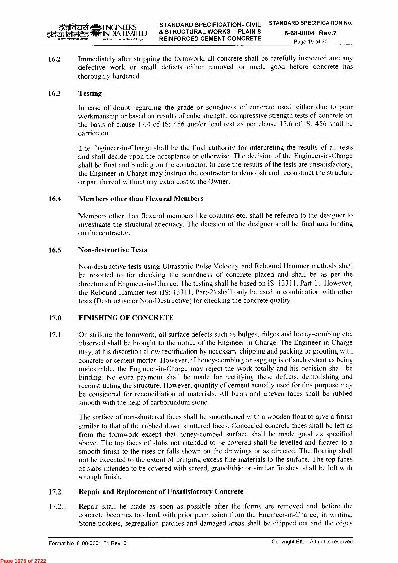
ENGINEERS STANDARD SPECIFICATION- CIVIL STANDARD SPECIFICATION No.
1=g-ar 211-e-G INDIA LIMITED & STRUCTURAL WORKS - PLAIN & 6-68-0004 Rev.7 A Govt of India Undertaking) REINFORCED CEMENT CONCRETE I air m veverve dean-dew
Page 19 of 30
16.2 Immediately after stripping the formwork, all concrete shall be carefully inspected and any defective work or small defects either removed or made good before concrete has thoroughly hardened.
16.3 Testing
In case of doubt regarding the grade or soundness of concrete used, either due to poor workmanship or based on results of cube strength, compressive strength tests of concrete on the basis of clause 17.4 of IS: 456 and/or load test as per clause 17.6 of IS: 456 shall be carried out.
The Engineer-in-Charge shall be the final authority for interpreting the results of all tests and shall decide upon the acceptance or otherwise. The decision of the Engineer-in-Charge shall be final and binding on the contractor. In case the results of the tests are unsatisfactory, the Engineer-in-Charge may instruct the contractor to demolish and reconstruct the structure or part thereof without any extra cost to the Owner.
16.4 Members other than Flexural Members
Members other than flexural members like columns etc. shall be referred to the designer to investigate the structural adequacy. The decision of the designer shall be final and binding on the contractor.
16.5 Non-destructive Tests
Non-destructive tests using Ultrasonic Pulse Velocity and Rebound Hammer methods shall be resorted to for checking the soundness of concrete placed and shall be as per the directions of Engineer-in-Charge. The testing shall be based on IS: 13311, Part-1. However, the Rebound Hammer test (IS: 13311, Part-2) shall only be used in combination with other tests (Destructive or Non-Destructive) for checking the concrete quality.
17.0 FINISHING OF CONCRETE
17.1 On striking the formwork, all surface defects such as bulges, ridges and honey-combing etc. observed shall be brought to the notice of the Engineer-in-Charge. The Engineer-in-Charge may, at his discretion allow rectification by necessary chipping and packing or grouting with concrete or cement mortar. However, if honey-combing or sagging is of such extent as being undesirable, the Engineer-in-Charge may reject the work totally and his decision shall be binding. No extra payment shall be made for rectifying these defects, demolishing and reconstructing the structure. However, quantity of cement actually used for this purpose may be considered for reconciliation of materials. All burrs and uneven faces shall be rubbed smooth with the help of carborundum stone.
The surface of non-shuttered faces shall be smoothened with a wooden float to give a finish similar to that of the rubbed down shuttered faces. Concealed concrete faces shall be left as from the formwork except that honey-combed surface shall be made good as specified above. The top faces of slabs not intended to be covered shall be levelled and floated to a smooth finish to the rises or falls shown on the drawings or as directed. The floating shall not be executed to the extent of bringing excess fine materials to the surface. The top faces of slabs intended to be covered with screed, granolithic or similar finishes, shall be left with a rough finish.
17.2 Repair and Replacement of Unsatisfactory Concrete
17.2.1 Repair shall be made as soon as possible after the forms are removed and before the concrete becomes too hard with prior permission from the Engineer-in-Charge, in writing. Stone pockets, segregation patches and damaged areas shall be chipped out and the edges
Copyright EIL — All rights reserved Format No. 8-00-0001-F1 Rev. 0
Page 1675 of 2722

ENGINEERS STANDARD SPECIFICATION- CIVIL STANDARD SPECIFICATION No. In
rfg-zir laajeg INDIA LIMITED & STRUCTURAL WORKS — PLAIN & 6-68-0004 Rev.7 (A Govt of India Undertaking) REINFORCED CEMENT CONCRETE
Page 20 of 30 2.12".72,751 JP15,1)
undercut slightly to form a key. All loose material shall be washed out before patching. No excess water shall be left in the cavity, but the concrete shall be damp. A good bond between the patch and parent concrete shall be obtained by sprinkling dry cement on the wet surface or by throwing mortar with force on to the wetted concrete, or by brush in a coat of thick cement grout of about 1:1 (1 cement:1 sand) just before applying the patching material. Before this has dried, the remainder of the patch shall be filled with mortar or concrete, depending on the extent of the repair.
17.2.2 Cement concrete/mortar used in repair of exposed surfaces shall be made with cement from the same source as that used in concrete and blended with sufficient amount of white Portland cement to produce the same colour as in the adjoining concrete. The proportions of ingredients shall be same as those used in parent concrete. The mortar shall be as dry as possible and well compacted into the cavity. All filling shall be tightly bonded to the concrete and shall be sound, free from shrinkage cracks after the filling has been cured and dried.
17.2.3 For larger repairs to hardened concrete, necessary formwork bearing tightly at the edges of the cavity shall be provided. Concrete shall be chipped out to a depth of at least 100mm and preferably 150mm. Mortar shall be scrubbed into all surfaces with a wire brush before placing the concrete. Damaged reinforcement shall be adequately spliced with new steel so as to maintain the original strength. Additional reinforcement, if required in the patch, shall be provided as per the instructions of Engineer-in-Charge.
17.2.4 In case, in the opinion of the Engineer-in-Charge, defects in the concrete is excessive or beyond repair, the contractor shall either redo the structure or take other remedial measures as instructed by the Engineer-in-Charge. The decision of the Engineer-in-Charge shall be final and binding to all in this respect.
17.2.5 Approved epoxy formulation for bonding fresh concrete used for repairs with already hardened concrete shall be used by the Contractor if asked by the Engineer-in-Charge. Epoxy shall be applied in strict accordance with EIL Specification 6-68-0056 and the instructions of the manufacturer.
17.2.6 All repair works due to non-conformance or non-adherence to specification, if allowed by the Engineer-in-Charge, shall be carried out free of cost to the owner.
17.3 Curing of Patched Work
Immediately after patching is completed, the patched area shall be covered with an approved non-staining water saturated material which shall be kept wet and protected against sun and wind for a period of 12 hours. Thereafter, the patched area shall be kept continuously wet by a fine spray or sprinkling for not less than 10 days.
18.0 WATERPROOF CEMENT PAINT
Wherever specified, concrete elements (whether cast-in-situ or precast) exposed to atmosphere shall be provided with three coats of cement based waterproof paint as per IS:5410 provided these surfaces shall not contain any protective coating. Prior to application of the paint, the surface shall be prepared to remove all foreign particles, loose materials, extra deposited concrete lumps, etc. using appropriate mechanical/ manual means.
19.0 FORM WORK
19.1 General
19.1.1 Forms for concrete shall be of plywood conforming to IS: 6461 (Part-5) or steel or as directed by the Engineer-in-Charge and shall give smooth and even surface after removal thereof.
Copyright EIL — All rights reserved Format No. 8-00-0001-F1 Rev. 0
Page 1676 of 2722
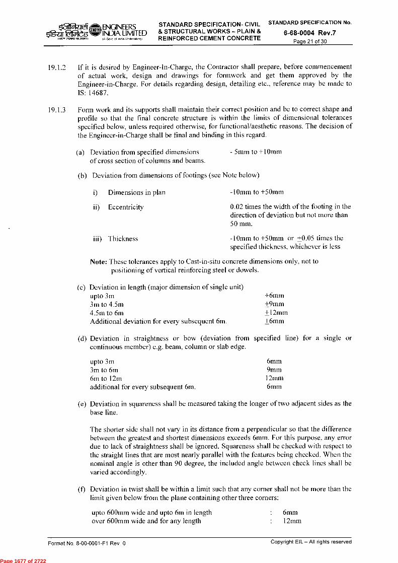
STANDARD SPECIFICATION- CIVIL STANDARD SPECIFICATION No.
& STRUCTURAL WORKS - PLAIN & 6-68-0004 Rev.7 REINFORCED CEMENT CONCRETE
Page 21 of 30 IM'-1 elecort Joo,A)
ENGINEERS ffg-ar is INDIA LIMITED
IA Govt Of India UooleflokINI
19.1.2 If it is desired by Engineer-In-Charge, the Contractor shall prepare, before commencement of actual work, design and drawings for formwork and get them approved by the Engineer-in-Charge. For details regarding design, detailing etc., reference may be made to IS: 14687.
19.1.3 Form work and its supports shall maintain their correct position and be to correct shape and profile so that the final concrete structure is within the limits of dimensional tolerances specified below, unless required otherwise, for functional/aesthetic reasons. The decision of the Engineer-in-Charge shall be final and binding in this regard.
(a) Deviation from specified dimensions - 5mm to +10mm of cross section of columns and beams.
(b) Deviation from dimensions of footings (see Note below)
i) Dimensions in plan
ii) Eccentricity
-10mm to +50mm
0.02 times the width of the footing in the direction of deviation but not more than 50 mm.
iii) Thickness
-10mm to +50mm or +0.05 times the specified thickness, whichever is less
Note: These tolerances apply to Cast-in-situ concrete dimensions only, not to positioning of vertical reinforcing steel or dowels.
(c) Deviation in length (major dimension of single unit) upto 3m ±6mm 3m to 4.5m +9mm 4.5m to 6m +12mm Additional deviation for every subsequent 6m. +6mm
(d) Deviation in straightness or bow (deviation from specified line) for a single or continuous member) e.g. beam, column or slab edge.
upto 3m 6mm 3m to 6m 9mm 6m to 12m 12mm additional for every subsequent 6m. 6mm
(e) Deviation in squareness shall be measured taking the longer of two adjacent sides as the base line.
The shorter side shall not vary in its distance from a perpendicular so that the difference between the greatest and shortest dimensions exceeds 6mm. For this purpose, any error due to lack of straightness shall be ignored. Squareness shall be checked with respect to the straight lines that are most nearly parallel with the features being checked. When the nominal angle is other than 90 degree, the included angle between check lines shall be varied accordingly.
(f) Deviation in twist shall be within a limit such that any corner shall not be more than the limit given below from the plane containing other three corners:
upto 600mm wide and upto 6m in length over 600mm wide and for any length
6mm
• 12mm
Copyright EIL — All rights reserved Format No. 8-00-0001-F1 Rev. 0
Page 1677 of 2722

STANDARD SPECIFICATION- CIVIL STANDARD SPECIFICATION No.
& STRUCTURAL WORKS - PLAIN & 6-68-0004 Rev.7 REINFORCED CEMENT CONCRETE Page 22 of 30
■_71 ENGINEERS fEitfReg INDIA LIMITED
rag, cleave velJnerki)
IA Govt of India Undertaking)
(g) Maximum deviation in flatness from a 1.5m straight edge placed in any position on a nominally plain surface shall not exceed 6mm.
(h) Tolerance in leveling of concrete surface at foundation/ :
As per Cl. 15.3.9.7 pedestal top level where grouting is to be done
19.2 Form Requirement
19.2.1 The formwork shall be true, rigid and adequately braced both horizontally as well as diagonally. The forms shall have smooth and even surface and be sufficiently strong to carry, without deformation, the dead weight of the green concrete, working load, wind load and also the side pressure exerted by the green concrete. As far as practical, clamps shall be used to hold the forms together. Where use of nails is unavoidable minimum number of nails shall be used. Projected part of nail shall not be bent or twisted for easy withdrawal.
19.2.2 Where through tie rods are required to be put to hold the formwork and maintain accurate dimension, they shall always be inserted through a precast concrete block (of same mix proportion as is to be used for concreting) with a through hole of bigger diameter. The Precast block shall tightly fit against in inner faces of formwork. The holes left after the withdrawal of tie rods shall be fully grouted with cement-sand mortar of same proportion as that used for concrete. However, use of such precast block shall in no case impair the desired appearance or durability of the structure. No such tie rods shall be used in any liquid retaining or basement structure.
19.2.3 Tie wires shall be permitted only upon approval of the Engineer-in-Charge and shall be cut off flush with the face of the concrete or counter sunk, filled and finished in the manner specified in clause 17.
19.2.4 Form joints shall not permit any leakage. The formwork shall be strong enough to withstand the effect of vibrations practically without any deflection, bulging, distortion or loosening of its components.
19.2.5 Forms for beams and slabs (span more than 6.0m) shall have camber of I in 500 so as to offset the deflection and assume correct shape and line after deposition of concrete. For cantilevers, the camber at free end shall be 1/100th of the projected length. Where architectural considerations and adjunctive work are critical, smaller form cambers shall be adopted as decided by the Engineer-in-Charge.
19.2.6 All vertical wall forms may be designed and constructed for the following minimum pressure. The pressures listed in Table-6 are intended as guide only and the Contractor shall ensure that the formwork is adequately strong and sturdy.
TABLE - 6 MINIMUM DESIGN PRESSURE FOR WALL FORMWORK
Rate of pour in meter/hour Pressure in KN/m2
at 10° (in Celsius) at 24° (in Celsius)
0.6 36.0 29.0 0.9 40.0 32.0 1.2 44.0 35.0 1.5 46.0 37.0
Format No. 8-00-0001-F1 Rev. 0
Copyright EIL — All rights reserved
Page 1678 of 2722

ENGINEERS STANDARD SPECIFICATION- CIVIL STANDARD SPECIFICATION No.
INDIA LIMITED & STRUCTURAL WORKS - PLAIN & 6-68-0004 Rev.7 IA Govt of India undeftaktng) REINFORCED CEMENT CONCRETE
01 5'fg-ar ia5ieg
it SIIZR Femm J, , +1)
Page 23 of 30
All horizontal forms shall be designed and constructed to withstand the dead load of the green concrete, reinforcement, equipment, material, embedment and a minimum live load of 2.0 kN/m2 .
19.3 Inspection of Forms
Temporary openings shall be provided at the base of column and wall forms and other places necessary to facilitate cleaning and inspection. Before concrete is placed, all forms shall be carefully inspected to ensure that they are properly placed, sufficiently rigid and tight, thoroughly cleaned, properly treated and free from foreign material. The complete form work shall be inspected and approved by the Engineer-in-Charge before the reinforcement bars are placed in position. When forms appear to be unsatisfactory in any way, either before or during the placing of concrete, the work shall be stopped until the defects have been rectified as per the instructions of the Engineer-in-Charge.
19.4 Cleaning and Treatment of Formwork
The surfaces of forms that would come in contact with concrete shall be well treated with approved non-staining form release agents such as soft soap, oil, emulsions etc. Release agents shall be applied so as to provide a thin uniform coating to the forms without coating the reinforcement.
19.5 Chamfers and Fillets
All corners and angles shall be formed with 45 degree mouldings to form chamfers or fillets on the finished concrete. The standard dimensions of chamfers and fillets, unless otherwise detailed or specified shall be 25x25mm. For heavier work chamfers or fillets shall be 50x5Omm. Care shall be exercised to ensure accurate mouldings. The diagonal face of the moulding shall be planed or surfaced to the same texture as the forms to which it is attached.
19.6 Reuse of forms
Before reuse, all forms shall be thoroughly scrapped, cleaned, examined and when necessary, repaired and retreated, before resetting. Formwork shall not be reused, if declared unfit or un-serviceable by the Engineer-in-Charge.
19.7 Removal of Forms/Stripping Time
In the determination of time for removal of forms, consideration shall be given to the location and character of the structures, the weather and other conditions including the setting and curing of the concrete and material used in the mix.
Forms and their supports shall not be removed without the approval of the Engineer-in-Charge. Forms shall not be released until the concrete has achieved a strength of at least twice the stress to which the concrete may be subjected at the time of removal. The formwork shall be removed without shock and methods of form removal likely to cause over stressing or damage to the concrete shall not be adopted. Supports shall be removed in such a manner as to permit the concrete to uniformly and gradually take the stresses due to its own weight.
In normal circumstances when average air temperature exceeds 15 degree Celsius during the period under consideration after pouring of concrete and where ordinary Portland cement is used, forms may generally be removed after expiry of following periods.
(a) Walls, columns and vertical faces of all structural members
(b) Slabs (props left under)
16 to 24 hours as may be decided by the Engineer-in-Charge.
3 days.
Copyright EIL — All rights reserved Format No. 8-00-0001-F1 Rev. 0
Page 1679 of 2722

STANDARD SPECIFICATION- CIVIL STANDARD SPECIFICATION No.
& STRUCTURAL WORKS - PLAIN & 6-68-0004 Rev.7 REINFORCED CEMENT CONCRETE
Page 24 of 30
ENGINEERS
f=g-Zir 215i-eg INDIA LIMITED
)Atteter etecoreQr Joson) IA Govt of India Undertaking)
(c) Beam Soffits (props left under)
(d) Removal of props under slabs:
Spanning upto 4.5m. Spanning over 4.5m.
7 days.
7 days. 14 days.
(e) Removal of props under beams and arches: Spanning upto 6m 14 days. Spanning over 6m 21 days
(f) Cantilever Construction Formwork shall remain till structures for counter acting or bearing down have been erected and have attained sufficient strength (minimum 14 days).
Notes:
i) For other cements, the stripping time recommended for ordinary Portland cement shall be suitably modified as per the instructions of the Engineer- in-Charge.
ii) The number of props left under, their sizes, supporting arrangement, and disposition shall be such as to be able to safely carry the full dead load of the slab, beam or arch as the case may be together with any live load likely to occur during curing or further construction.
iii) Where the shape of the element is such that the formwork has re-entrant angles, the form work shall be removed as soon as possible after the concrete has set, to avoid shrinkage cracking occurring due to the restraint imposed.
iv) For rapid hardening cement, 3/7 of the above mentioned periods shall be considered subject to a minimum of 16 hours.
v) For Portland pozzolana or low heat cement, 10/7 of the above mentioned periods shall be considered.
19.8 Staging/Scaffolding
19.8.1 Staging/Scaffolding shall be properly planned and designed by the Contractor. Use of only steel tubes is permitted for staging/scaffolding. The Contractor shall get it reviewed by Engineer-in-Charge before commencement of work. While designing and during erection of scaffolding/staging, the following measures shall be considered:
(a) Sufficient sills or underpinnings in addition to base plates shall be provided particularly where scaffolding is erected on soft grounds.
(b) Adjustable bases to compensate for uneven ground shall be used.
(c) Proper anchoring of the scaffolding/staging at reasonable intervals shall be provided in each direction with the main structure wherever available.
(d) Horizontal braces shall be provided to prevent the scaffolding/staging from rocking.
(e) Diagonal braces shall be provided continuously from bottom to top between two adjacent rows of uprights.
(f) The scaffolding/staging shall be checked at every stage for plumb line.
Copyright EIL — All rights reserved Format No. 8-00-0001-F1 Rev. 0
Page 1680 of 2722

STANDARD SPECIFICATION- CIVIL STANDARD SPECIFICATION No.
i:g-ZTr tif5iteg INDIA LIMITED & STRUCTURAL WORKS — PLAIN & 6-68-0004 Rev.7 REINFORCED CEMENT CONCRETE
Page 25 of 30
(g) Wherever the scaffolding/staging is found to be out of plumb line it shall be dismantled and re-erected afresh and effort shall not be made to bring it in line with a physical force.
(h) All nuts and bolts shall be properly tightened and care shall be taken that all clamps/couplings are firmly tightened to avoid slippage
(i) Erection work of a scaffolding/staging under no circumstances shall be left totally to semi-skilled or skilled workmen and shall be carried out under the supervision of a technically qualified civil engineer of the Contractor.
19.8.2 For smaller works or works in remote areas, wooden ballies may be permitted for scaffolding/staging by the Engineer-in-Charge at his sole discretion. The contractor must ensure the safety and suitability of such works as described under clause 19.8.1 above.
20.0 EXPOSED/ARCHITECTURAL CONCRETE WORK
20.1 Form Work
Other things remaining same as per clause 19.0, formwork shall be of high quality. Care shall be taken to arrange the forms so that the joints between forms correspond with the pattern indicated in the drawings. The forms shall be butting with each other in straight lines, the corners of the boards being truly at right angles. The joints between the forms shall cross in the two directions at right angles. The size of forms shall be so selected as to exactly match with the pattern of forms impression on the concrete face indicated in the drawings. Maximum care shall be taken to make the form work watertight. Burnt oil shall not be used for treatment of forms. The Contractor shall be permitted reuse of forms brought new on the work place only if forms are properly cared for, stored and treated after each use.
The Engineer-In-Charge may, at his absolute discretion, order removal of any forms considered unsuitable for use in the work.
20.2 Finishing
Repairing to exposed concrete work shall be avoided. Rendering and plastering shall not be done. Minor repairing, if unavoidable shall be done as specified in clause 17.0 with the written permission of the Engineer-in-Charge.
21.0 REINFORCEMENT
21.1 The Contractor shall develop the bar bending schedule for all RCC structures/ structural parts at no extra cost to the Owner and shall get it reviewed by the Engineer-in-charge. Reinforcement shall be cut and bent to shape as per dimensions shown in the bar bending schedule/ drawings.
If protective fusion bonded epoxy coating is required to be applied on reinforcement bars, the same shall be done as per IS: 13620. All repairs to applied protective coating required due to mishandling and/ or bending of reinforcement bars shall also be done as per relevant clauses of IS:13620.
21.2 Straightening, Cutting and Bending
Procedure for cutting and bending shall be as given in IS: 2502. Bars shall be bent in a slow and regular movement to avoid fractures by mechanical means only. In case bars are supplied in coils, they shall be smoothly straightened without any kinks.
ENGINEERS 441-2 etran,mt,tvoto IA Goof of India UntieOohing)
Format No. 8-00-0001-F1 Rev. 0
Copyright EIL — All rights reserved
Page 1681 of 2722

STANDARD SPECIFICATION- CIVIL STANDARD SPECIFICATION No.
& STRUCTURAL WORKS — PLAIN & 6-68-0004 Rev.7 REINFORCED CEMENT CONCRETE
Page 26 of 30
t_11 er ENGINEERS fetiteg INDIA LIMITED
tAtren r1on,re 1510,11.1)
IA Govt of India Undeltaking)
Cold twisted deformed bars shall be bent cold. Bars larger than 25mm in size (except cold twisted deformed bars) may be bent hot at cherry red heat to a temperature not exceeding 8500 Celsius as per the instructions of the Engineer-in-Charge. The bars shall be allowed to cool gradually without quenching.
Bars shall be cut & bend in a Bar Bending Machine. Bars which develops cracks or splits after bending shall be rejected. A second bending of reinforcement bars shall be avoided but when reinforcement bars are bent aside at construction joints and afterwards bent back into their original position, care should be taken to ensure that at no time is radius of the bend less than 6 times bar diameter for high strength deformed bars. Care shall also be taken when bending back the dowel bars to ensure that concrete around the bars is not damaged. All bars shall be properly tagged for easy identification.
21.3 Placing and Fixing
All reinforcement shall be cleaned to ensure freedom from loose mill scale, loose rust, oil, form releasing agents, grease or any other harmful material before placing them in position. Reinforcement shall not be surrounded by concrete unless it is free from all such materials. Rough handling and dropping of reinforcement from a height shall be avoided.
All reinforcement shall be fixed in the correct position and shall be properly supported to ensure that displacement will not occur when the concrete is placed and compacted. The uncoated reinforcement bars shall be tied at every intersection by two strands of 16 SWG black soft annealed binding wire. The Epoxy coated reinforcement bars shall be tied with 2 strands of PVC coated GI 18 SWG wire at every intersection. Crossing bars shall not be tack welded for assembly of reinforcement. The reinforcement bars shall be kept in position by using the following methods:
a) In case of beam and slab construction, precast cover blocks (having the same sand contents as the concrete which shall be placed) of size 40 x 40 mm and thickness equal to the specified covers shall be placed firmly in between the bars and forms so as to secure and maintain the specified covers over the reinforcement.
When reinforcement bars are placed in two or more layers in beams, the vertical distance between the horizontal bars shall be maintained by introducing spacer bars at 1 to 1.2m centre to centre.
b) In case of thick rafts & pile caps having two or multi layers of reinforcement, the vertical distance between the horizontal bars shall be maintained by introducing suitable chairs, spacers, etc.
c) In case of columns and walls, the vertical bars shall be kept in position by means of timber templates with slots accurately cut in them. The templates shall be removed after the concreting has been done below it.
d) Exposed portions of reinforcement bars shall not be subjected to impact or rough handling and workmen will not be permitted to climb on extending bars until the concrete has attained sufficient strength so that no movement of the bars in the concrete is possible.
21.4 Special requirements for Handling, Stacking, Placing of Epoxy coated Reinforcing bars.
Epoxy coated reinforcing bars shall be carefully handled and it shall be ensured that these do not rub on any hard surface or against another epoxy coated/uncoated reinforcing bar whether during conveying/transportation, stacking or placing.
Format No. 8-00-0001-F1 Rev. 0
Copyright EIL - All rights reserved
Page 1682 of 2722

:till $gal. tdfiteg
wr-rp, erreffe md,14n.)
ENGINEERS INDIA LIMITED la Govt of India Uncteltakortg)
STANDARD SPECIFICATION- CIVIL STANDARD SPECIFICATION No.
& STRUCTURAL WORKS — PLAIN & 6-68-0004 Rev.7 REINFORCED CEMENT CONCRETE Page 27 of 30
During transportation and while stacking the epoxy coated reinforcing bars shall be placed on wooden planks not spaced farther than 600mm. When placed in stacks the epoxy coated reinforcing bars shall be neatly tied in bundles using PVC binding material.
The cut ends of bars shall be touched up with special touch up material of specifications as provided by the coating agency. After cutting of the bar the application of touch up material shall be completed within four hours.
While bending the bars the pins of work bench(s) shall be provided with a PVC or plastic sleeve. Each bending operation on epoxy coated reinforcing bar shall be completed in time not less than 90 seconds.
Epoxy coated reinforcing steel bar shall not be directly exposed to sun rays or rain, and shall be protected with opaque polyethylene sheets or similar means as approved by the Engineer in Charge.
While doing concreting the workmen or machinery shall not rest or move on the epoxy coated reinforcing bars. Wooden planks shall suitably be placed to create proper gang-way.
21.5 Splicing/Overlapping
Only bars of full length shall be used as shown in the drawings. But where this cannot be done, overlapping of bars shall be done as directed by the Engineer-in-Charge. The overlapping bars shall be tied with two strands of 16 SWG black soft annealed binding wire. The overlaps shall be staggered for different bars and located at points along the span where neither shear nor bending moment is maximum.
21.6 Welded Joints
Welding of reinforcing bars shall not be permitted without the written permission of the Engineer-in- Charge. Where welding of reinforcing bars is permitted, it shall be in accordance with the recommendations of IS: 2751 and IS: 9417. Welded joints shall be located at suitable staggered positions. Tests shall be made as directed by the Engineer-in-Charge to prove that the joints are of the full strength of the bars. Maximum one welded joint shall be allowed per bar.
21.7 Mechanical Connections (upto Seismic Zone-III as per IS:1893 Part-I)
The mechanical splices in reinforcement by means of couplers, clamps etc. shall be used (as per manufacturer's specifications) with the written approval of the Engineer-in-Charge. Following tests, at the minimum, shall be conducted in advance to prove efficiency of the coupled joint before putting them in actual use:
Name of the Test Testing Requirement Code of conformance
Static Tension & Compression Test
Each connection shall develop atleast 125% of the specified yield strength of the reinforcing bar
ASTM A370/ ACI 318/ ISO 15835
Permanent Elongation (Slip)
Permanent elongation across the coupled joint shall be less than 0.1mm after loading at 60% of the yield strength of the reinforcing bar
BS 8110/ ISO 15835
Format No. 8-00-0001-F1 Rev. 0
Copyright EIL — All rights reserved
Page 1683 of 2722

STANDARD SPECIFICATION- CIVIL STANDARD SPECIFICATION No.
& STRUCTURAL WORKS - PLAIN & 6-68-0004 Rev.7 REINFORCED CEMENT CONCRETE
Page 28 of 30
■_71
ENGINEERS
5'igaf ta5leg
INDIA LIMITED
laireR eiee5re t 51,..)
(A Govt of India Undertaking)
Name of the Test Testing Requirement Code of conformance
Moderate Oligocyclic (Seismic) Test (Cyclic Tension & Compression Test)
Deformation across the coupled joint shall be less than 0.3mm after subjecting the joint to a series of 20 cycles with 90% tension as well as 50% compression of the yield strength of the reinforcing bar
ISO 15835
All operations relating to reinforcement coupling shall be done by using manufacturer's patented machine/ equipment in the presence of Engineer-in-Charge. Mechanical connections shall be placed away from points of high stress and shall be staggered.
21.8 Tolerances on Placing of Reinforcement
Unless otherwise directed by the Engineer-in-Charge, reinforcement shall be placed within the following tolerances:
a) For effective depth 200mm or less + 10mm
b) For effective depth more than 200mm + 15mm
21.9 Substitution
When indicated diameter of reinforcement bar is not available, the Contractor shall use other diameter of reinforcement bars on written approval of the Engineer-In-Charge.
21.10 Tolerance to Cover
The actual concrete cover shall not deviate from the required nominal cover by + 10mm measured over the steel reinforcement including links.
22.0 PAYMENT
22.1 Plain and Reinforced Concrete
22.1.1 Payment for plain and reinforced cement concrete (cast- in-situ) shall be made on cubic metre basis of the volume of the actual finished work done or as per approved construction drawings, whichever is less and shall be inclusive of providing pockets, openings, recesses of all sizes, chamfers, fillets, grooves, separation/ expansion/ isolation/ construction/ movement joints, curing by normal moist curing or using curing compound etc. as directed by Engineer-in-Charge etc. The rates shall be deemed to include complete cost of getting the respective mix designs approved, making and testing concrete cubes and carrying out other tests including tests of various ingredients, as per specifications and as directed by Engineer-in-Charge. Payment shall, however, be separately made for tests on concrete cubes done by accelerated methods of curing as defined in IS: 9013.
22.1.2 No separate payment shall be made for any additive/ admixture/ Plasticizer/ Fibres used by the contractor for accelerating or retarding the strength of concrete or for achieving specified workability. The rate quoted shall be deemed to be inclusive of all costs related to any such additive/admixture/ Plasticizer/ Fibres.
22.1.3 The rate shall however be exclusive of reinforcement, metal inserts, pipe sleeves, formwork, water stops and any filler material in expansion/isolation joints.
22.1.4 Where the strength of concrete mix as indicated by tests, lies in between the strengths of any two grades given in Table-1 and it is accepted by the Owner/Engineer-in-Charge, such
Format No. 8-00-0001-F1 Rev. 0
Copyright EIL — All rights reserved
Page 1684 of 2722
ENGINEERS f=g-zir ttaidg INDIA LIMITED
IA Govt of India Undertaking) 141TR c-wcnr,an Jvcr.)
STANDARD SPECIFICATION- CIVIL STANDARD SPECIFICATION No.
& STRUCTURAL WORKS - PLAIN & 6-68-0004 Rev.7 REINFORCED CEMENT CONCRETE
Page 29 of 30
concrete shall be classified as a grade belonging to the lower of the two grades between which it lies. In case the cube strength shows higher results than those specified for the particular grade of the concrete, it shall not be placed in the higher grade nor shall the Contractor be entitled for any extra payment on such account. The concrete giving lower strength than specified may be accepted at reduced rates after satisfying the safety of the structure by checking it with tests as specified or rejected entirely at the discretion of the Engineer-in- Charge. The rejected concrete shall be dismantled at no extra cost to the owner and no payment or extension of time shall be granted for the concrete so rejected and the formwork and reinforcement used for the same. Cost of any material supplied by the Owner free of cost shall be recovered from the Contractor at double the prevailing market rate. In case the concrete of lower strength can be improved by carrying out some strengthening measures entirely at the discretion of the Engineer-in-Charge, then the said measures including all related tests shall be carried out by Contractor at his own cost. If the Contractor is able to make up the strength to the required grade by such improvement measures to the entire satisfaction of Engineer-in-Charge, payment shall be made for the grade achieved. However, if the strength of concrete is not made up to the strength of required grade, payment shall be made only for the lower strength if such concrete is accepted by the Engineer-in-Charge.
22.1.5 Deductions for openings, pockets etc. shall be as specified in relevant parts of IS 1200.
22.1.6 Payment under continuous concreting item in the schedule of rates shall be made only where the total quantity of concrete between two consecutive construction joints specifically called-out on the drawings exceeds 250 cubic metres. For any foundation/structure involving concrete quantity upto 250 cubic metres between two consecutive construction joints shown on drawings, the concrete shall not be measured or paid for under this category (i.e. continuous concreting), even though the same is required to be constructed in single pour. The rate quoted against this item shall be inclusive of all extra cost related to labour, shuttering, staging and making all other arrangements for such continuous casting e.g. provisions for adequate movement and storage spaces, special gangways, scaffolding, additional construction equipments, adequate lighting and supervision while the work continues round the clock etc. The rate shall also be inclusive of all costs related to concreting in any thickness, shape and position and at any height or depth so as to avoid any cold joint between specified construction joints.
22.1.7 Form Work
Unless otherwise specified, payment for form work shall be on square metre basis of the actual area in contact with the concrete cast. The rates shall be inclusive of keeping the formwork for the full period as specified in the above clauses and removing the same after the period is over. No extra payment shall be made for providing scaffolding/ staging/ access/ stairways/ ladders etc.
The rates shall be inclusive of any provision to be made or kept in the formwork for providing dowels, inserts etc.
Superior quality formwork for exposed/architectural concrete work shall be measured and paid separately under the relevant item in the schedule of rates.
22.2 Reinforcement
22.2.1 Payment for plain round mild steel reinforcement bars, high strength deformed steel bars and epoxy coated reinforcing steel bar shall be on the basis of weight of bare steel irrespective of any coating applied in metric tons. The weight of the bar shall be derived from the sizes and corresponding nominal unit weight given in Table-1 of IS: 1786. In case actual unit weight of the bars is less than nominal unit weight, but within permissible tolerances, the weight of reinforcement shall be calculated on the basis of actual unit weight. In case actual unit weight of the bars is more than nominal unit weight, the payment shall be made on the basis
Format No. 8-00-0001-F1 Rev. 0
Copyright EIL — All rights reserved
Page 1685 of 2722

$1gar f61154eg I .117F1 ei-e215/E c751,Wil)
ENGINEERS INDIA LIMITED (A Goo of lode Um:fellalong)
STANDARD SPECIFICATION- CIVIL STANDARD SPECIFICATION No.
& STRUCTURAL WORKS - PLAIN & 6-68-0004 Rev.7 REINFORCED CEMENT CONCRETE Page 30 of 30
of nominal unit weight. Standard hook lengths, chairs, spacer bars and authorized laps only shall be included in the weight calculated. Binding wire shall not be weighed nor otherwise measured. Measurements for weight shall not include cutting allowance etc.
22.2.2 Rate quoted for reinforcement shall include cost of supplying, decoiling, straightening, cleaning, cutting, bending, placing, binding, welding (if required) and providing necessary cover blocks of concrete.
22.2.3 Payment for a mechanical threaded coupler/ clamp shall be made by measuring the Lap length of the respective rebar on which coupler/ clamp is used. The rate shall include supply of complete assembly, fixing, testing etc. all complete.
22.3 Water Stops/Water Bars & Expansion/Isolation Joints
22.3.1 Payment for PVC water bars shall be made on running metre (RM) basis of the water stops provided in position. Rate shall include supplying cutting, fixing, jointing by vulcanising or any other approved method, wastage, etc. complete.
22.3.2 Payment for filler materials in Expansion/Isolation joints shall be made on running metre basis of the joint provided. For boards provided at expansion/isolation joints, the measurement shall be made on square metre basis. Rate shall be inclusive of supply, cutting, fixing, jointing, wastage etc. complete.
22.4 Waterproof Cement Paint
22.4.1 Payment for waterproof cement paint as per Cl. 18.0 shall be made separately on Sqm basis.
Format No. 8-00-0001-F1 Rev. 0
Copyright EIL — All rights reserved
Page 1686 of 2722
ENGINEERS
la2e5 INDIA LIMITED
1.1,71 a"-KM,1,13,7;7.11
IA Govt ot lrtOo Undettatong)
STANDARD SPECIFICATION CIVIL & STRUCTURAL WORKS STRUCTURAL STEEL WORKS
STANDARD SPECIFICATION No.
6-68-0006 Rev.6
Page 1 of 24
Trr-iw faf-4-4-r wrzi
STANDARD SPECIFICATION CIVIL & STRUCTURAL WORKS
k«1110-1(4) 12-14
STRUCTURAL STEEL WORKS
Vi
6 26.08.14 UPDATED & REISSUED AS PKM S CHANDA
5 18.06.09 REAFFIRMED & REISSUED AS PKM VINAY
KUMAR N. DUARI
4 18.04.00 UPDATED & REISSUED DPN RS SCJ MI
3 MAY'94 UPDATED & REISSUED DPN RS GPL A. SONI
Rev. No
Date Purpose Prepared
by Checked
by
Standards Committee Convenor
Standards Bureau
Chairman
Approved by
Format No. 8-00-0001-F1 Rev. 0 Copyright EIL — All rights reserved
Page 1687 of 2722
fCMes ENGINEERS INDIA LIMITED IA Govl of Ind. Unclertaking)
STANDARD SPECIFICATION CIVIL & STRUCTURAL WORKS STRUCTURAL STEEL WORKS
STANDARD SPECIFICATION No.
6-68-0006 Rev.6
Page 2 of 24
Abbreviations:
BIS Bureau of Indian Standards
IS Indian Standards
Structural Standards Committee
Convenor : Mr P K MITTAL
Members : Mr S Debnath Mr. Rajanji Srivastava Mr. P J Singh Mr Samir Das Mr V S Chhaya (Proj.) Mr Ravindra Kumar (Const.)
Format No. 8-00-0001-F1 Rev. 0 Copyright EIL — All rights reserved
Page 1688 of 2722
ENGINEERS INDIA LIMITED ft> Govt of Incha Undertaking)
STANDARD SPECIFICATION CIVIL & STRUCTURAL WORKS STRUCTURAL STEEL WORKS
STANDARD SPECIFICATION No.
6-68-0006 Rev.6
Page 3 of 24
CONTENTS
1.0 SCOPE 4
2.0 REFERENCE 4
3.0 MATERIALS 4
4.0 FABRICATION DRAWINGS 5
5.0 FABRICATION 7
6.0 MARKING FOR IDENTIFICATION 15
7.0 SHOP ERECTION 15
8.0 INSPECTION & TESTING OF STRUCTURES 16
9.0 SHOP PAINTING 16
10.0 PACKING 17
11.0 TRANSPORTATION 17
12.0 SITE (FIELD) ERECTION 17
13.0 SAFETY & SECURITY DURING ERECTION 18
14.0 FIELD CONNECTIONS 18
15.0 GROUTING 18
16.0 SCHEME AND SEQUENCE OF ERECTION 19
17.0 PAYMENT 19
18.0 PAINTING AFTER ERECTION 20
ANNEXURE-'A' 22
ANNEXURE-'B' 24
Copyright EIL —All rights reserved Format No. 8-00-0001-F1 Rev. 0
Page 1689 of 2722
1-&it4 ENGINEEFZS
Ogula2es INDIA LIMITED I.ovvt
IA Govt ol Indu Undertalongt
STANDARD SPECIFICATION CIVIL & STRUCTURAL WORKS STRUCTURAL STEEL WORKS
STANDARD SPECIFICATION No.
6-68-0006 Rev.6
Page 4 of 24
1.0 SCOPE
This specification describes the information to be included in a Project Specification and also covers the requirements for material, storage, preparation of fabrication drawings, fabrication, assembly, tests/examinations, transportation, erection and painting of all types of bolted and/or welded structural steel works for general construction work. Fabrication of structures shall also include fabricating:
(a) Built up sections/plate girders made out of rolled section and/or plates.
(b) Compound sections made out of rolled sections.
2.0 REFERENCES
2.1 BIS Codes
IS: 800, 808, 816, 819, 822, 919, 1024, 1261, 1323, 1477, 1852, 2074, 7205, 7215, 7307, 7310, 7318,'9595, 12778 and other relevant BIS Codes.
SP: 6(1)
2.2 EIL Specifications
6-68-0002- Materials 6-79-0020 (or the relevant Job Specification) - Shop & Field Painting
2.3 In case of conflict between the clauses mentioned in this specification and those in the Indian Standards, this specification shall govern. Any special provision as shown or noted on the design drawings or any project specific specification specified elsewhere shall govern over the provisions of this specification.
3.0 MATERIALS
3.1 General
All materials shall conform to their respective specifications given in EIL Specification no. 6-68-0002. The use of equivalent or alternative materials shall be permitted only in very special cases and for all such cases prior written approval of the Engineer-in-Charge shall be obtained.
3.2 Receipt & Storing of Materials
3.2.1 Each section shall be marked for identification and each lot shall be accompanied by manufacturer's quality certificate, chemical analysis and mechanical characteristics.
3.2.2 All sections shall be checked, sorted out and arranged by grade and quality in the store. Any instruction given by the Engineer-in-Charge in this respect shall be strictly followed.
3.2.3 All material shall be free from surface defects such as pitting, cracks, laminations, twists etc. Defective material shall not be used and all such rejected material shall be immediately removed from the store/site. The decision of the Engineer-in- Charge in this regard shall be final and binding.
Format No. 8-00-0001-F1 Rev. 0 Copyright EIL — All rights reserved
Page 1690 of 2722

t31 ENGINEERS INDIA LIMITED
tate rt<coWott".) lA Govt ol lntlia Undertakng)
STANDARD SPECIFICATION CIVIL & STRUCTURAL WORKS STRUCTURAL STEEL WORKS
STANDARD SPECIFICATION No.
6-68-0006 Rev.6
Page 5 of 24
3.2.4 Welding wires and electrodes (packed in their original cartons) shall be stored separately by quality and lots inside a dry and enclosed room in compliance with IS:9595 and as per the instructions given by the Engineer-in-Charge. Electrodes shall be kept perfectly dry to ensure satisfactory operation and weld metal soundness.
3.2.5 Each lot of electrodes, bolts, nuts etc. shall be accompanied by manufacturer's quality/test certificates.
3.2.6 All bolts (including nuts & washers) shall be checked, sorted out and arranged diameter-wise by grade and quality in the store.
3.3 Material Tests
3.3.1 The Contractor shall submit manufacturers' quality certificates for all the materials supplied by him. In case, quality certificates are not available or are incomplete or when material quality differs from standard specifications, such materials shall not be used in the construction. However, the Contractor shall get all appropriate tests conducted in approved test houses for such materials as directed by the Engineer-in-Charge, at no extra cost, and submit the same to Engineer-in-Charge for his approval. The Engineer-in-Charge may approve the use of such materials entirely at his discretion.
3.3.2 The Contractor shall ensure that all materials brought to site are duly approved by the Engineer-in-Charge. Rejected materials shall not be used and shall be removed from site forthwith. Any material of doubtful quality for which specific tests are to be carried out as per the instruction of the Engineer-in-Charge shall be separately stacked and properly identified and shall not be used. These shall be removed from site forthwith.
4.0 FABRICATION DRAW1NGS
4.1 Fabrication and erection drawings shall be prepared by the Contractor on the basis of "Approved for Construction (AFC)" design drawings, EIL Standards issued to the Contractor. These drawings shall be prepared by the Contractor or by an agency appointed by the Contractor and approved by the Engineer-in-Charge.
4.2 Fabrication and erection drawings shall be thoroughly checked, stamped "Approved for Construction" and signed by the Contractor's own responsible Engineer irrespective of the fact that such drawings are prepared by the Contractor or his approved agency, to ensure accuracy and correctness of the drawings. Unchecked and unsigned drawings shall not be used for the purpose of proceeding with the work. The Contractor shall proceed with the fabrication and erection work only after thoroughly satisfying himself in this regard.
4.3 All fabrication and erection drawings shall be issued for construction by the Contractor directly to his work- site. Six copies of such drawings shall simultaneously be submitted to the Engineer-in-Charge who may check/ review some or all such drawings at his sole discretion and offer his comments for incorporation in these drawings by the Contractor.
However, the Contractor shall not proceed with the fabrication of such structures whose fabrication drawings are required to be reviewed before taking up the fabrication work as noted on "Approved for Construction (AFC)" design drawings issued to the Contractor or as conveyed by the Engineer-in-Charge. The fabrication of such structures shall be done only as per the reviewed fabrication drawings.
The review of such drawings by EIL shall be restricted to the checking of the following only:
Format No. 8-00-0001-F1 Rev. 0 Copyright EIL — All rights reserved
Page 1691 of 2722
ENGINEEFZS INDIA LIMITED
IA Govt of Incha Undertalong)
STANDARD SPECIFICATION CIVIL & STRUCTURAL WORKS STRUCTURAL STEEL WORKS
STANDARD SPECIFICATION No.
6-68-0006 Rev.6
Page 6 of 24
i) Structural layout, orientation and elevation of structures/members.
ii) Sizes of members.
iii) Critical joint details.
4.4 Fabrication drawings shall be drawn to scale and shall convey the information clearly and adequately. Following information shall be furnished on such drawings:
i) Reference to design drawing number (along with revision number) based on which fabrication drawing has been prepared.
ii) Structural layout, elevations & sections (with distinct erection marking of all members).
iii) Framing plans, member sizes, orientation and elevations.
iv) Layout and detailing of rain water pipes and gutters showing all necessary levels, connections and provisions wherever required.
v) Detailing of shop/field joints, connections, splices, for required strength and erection.
vi) Location, type, size and dimensions of welds and bolts.
vii) Shapes and sizes of edge preparation for welding.
viii) Details of shop and field joints/welds.
ix) Bill of materials/D.O.D. Lists.
x) Quality of structural steel, plates etc., welding electrodes, bolts, nuts and washers to be used.
xi) Erection assemblies identifying all transportable parts and sub-assemblies with special erection instructions, if required.
xii) Method of erection and special precautions to be taken during erection as required.
xiii) Details of holes and fittings in components necessary for safe lifting and erection purpose.
4.5 The Contractor shall additionally ensure accuracy of the following and shall be solely responsible for the same:
i) Provision for erection and erection clearances.
ii) Marking of members
iii) Cut length of members
iv) Matching of joints and holes.
v) Provision kept in the members for other interconnected members.
Format No. 8-00-0001-F1 Rev. 0 Copyright EIL — All rights reserved
Page 1692 of 2722

NGINEEM RS
tg E
-ar 0a-ègl INDIA LIITED IA Govt of InOia Unclettaking)
STANDARD SPECIFICATION CIVIL & STRUCTURAL WORKS STRUCTURAL STEEL WORKS
STANDARD SPECIFICATION No.
6-68-0006 Rev.6 Page 7 of 24
1.11WI 297.51Z (151 3PS15.1)
vi) Bill of materials/D.O.D. Lists.
4.6 Connections, splices and other details where not shown on the design drawings shall be suitably designed and shown on the fabrication drawings based on good engineering practice developing full member strength. Design calculations for such connections/splices shall be submitted to the Engineer-in-Charge alongwith the fabrication drawings.
4.7 Any substitution or change in section shall be allowed only when prior written approval of the Engineer-in-Charge has been obtained. Fabrication drawings shall be updated incorporating all such substitutions/changes by the Contractor at no extra cost to the Owner.
4.8 In case during execution of the work, the Engineer-in-Charge on review of drawings considers any modifications/substitutions necessary to meet the design parameters/good engineering practice, these shall be brought to the notice of the Contractor who shall incorporate the same in the drawings and works without any extra cost to the owner. The Contactor will be totally responsible for the correctness of the detailed fabrication drawings and execution of the work.
4.9 Contractor shall incorporate all the revisions made in the design drawings during the course of execution of work in his fabrication drawings, and resubmit the drawings at no extra cost to the Owner. All fabrication shall be carried out only as per the latest AFC design drawings and corresponding fabrication drawings.
4.10 The Contractor shall supply two prints each of the final/as built drawings alongwith their native soft file to Engineer-in-Charge for reference and record. The rates quoted shall include for the same.
5.0 FABRICATION
5.1 General
5.1.1 Fabrication of structures shall be done strictly as per "Approved for Construction" fabrication drawings (prepared by the Contractor based on the latest design drawings) and in accordance with IS:800, 9595 & other relevant BIS Codes and BIS Hand Book SP:6(1).
5.1.2 Prior to commencement of structural fabrication, undulations in the fabrication yard, if any, shall be removed and area levelled and paved by the Contractor.
5.1.3 Any defective material used in the work shall be replaced by the Contractor at his own expense. Necessary care and precautions shall be taken so as not to cause any damage to the structure during any such removal and replacement.
5.1.4 Any faulty fabrication pointed out at any stage of work by the Engineer-in- Charge, shall be made good or replaced by the Contractor at his own cost.
5.1.5 Tolerances for fabrication of steel structures shall be as per IS:7215.
5.2 Fabrication Procedure
5.2.1 Straightening & Bending
5.2.1.1 All materials shall be straight and, if necessary, before being worked shall be straightened and/or flattened (unless required to be of curvilinear form) and shall be free from twists.
Format No. 8-00-0001-F1 Rev. 0 Copyright EIL — All rights reserved
Page 1693 of 2722
faz.it4 ENGINEERS
fg`Q-ff fffiteg Ita NDIA LIMITED I A Govt of Intha undertaking)
STANDARD SPECIFICATION CIVIL & STRUCTURAL WORKS STRUCTURAL STEEL WORKS
STANDARD SPECIFICATION No.
6-68-0006 Rev.6
Page 8 of 24 NIETI cwar,r, 051.3~)
5.2.1.2 Bending of rolled sections and plates shall be done by cold process to shape/s as shown on drawings.
5.2.1.3 After completion of bending or straightening, welds within the area of bending or straightening shall be thoroughly visually inspected. Nondestructive tests required to be carried out for such locations shall be done only after straightening or bending activity.
5.2.2 Clearances
The erection clearance for cleated ends of members shall be not greater than 2mm at each end. The erection clearance at ends of beams without web cleats and end plates shall be not more than 3mm at each end but where for practical reasons, greater clearance is necessary, suitably designed seatings approved by the Engineer-in-Charge shall be provided.
5.2.3 Cutting
5.2.3.1 Prior to cutting, all members shall be properly marked showing the requisite cut length/width, connection provisions e.g. location and dimensions of holes, welds, cleats etc. Marking for cutting shall be done judiciously so as to avoid wastages or unnecessary joints as far as practicable. Marking shall be done by placing the members on horizontal supports/pads in order to ensure accuracy. Marking accuracy shall be limited to + lmm.
5.2.3.2 Cutting may be affected by shearing, cropping or sawing. Gas cutting by mechanically controlled torch shall be permitted for mild steel. Hand flame cutting may be permitted subject to the approval of the Engineer-in-Charge.
5.2.3.3 Except where the material is subsequently joined by welding, no loads shall be transmitted into metal through a gas cut surface.
5.2.3.4 Shearing, cropping and gas cutting shall be clean, square, free from any distortion & burrs, and should the Engineer-in-Charge find it necessary, the edges shall be ground afterwards, to make the same straight and uniform at no extra cost to the Owner.
5.2.4 Holing
5.2.4.1 Holes for bolts shall not be formed by gas cutting process.
5.2.4.2 Holes through more than one thickness of material of members such as compound stanchions and girder flanges shall, where possible, be drilled after the members are assembled and tightly clamped/bolted together. Punching may be permitted before assembly, provided the thickness of metal is less than 16mm and the holes are punched 3mm less in diameter than the required size and reamed, after assembly, to the full diameter. Punching shall not be adopted for dynamically loaded structures.
5.2.4.3 Holes may be drilled in one operation through two or more separable parts and burrs removed from each part after drilling.
5.2.4.4 Holes in connecting angles and plates, other than splices, also in roof members and light framing, may be punched full size through material not over 12mm thick, except where required for close tolerance bolts or barrel bolts.
5.2.4.5 All matching holes for black bolts shall register with each other so that a gauge of 2mm less in diameter than the diameter of hole shall pass freely through the assembled members in the direction at right angle to such members. Finished holes shall be not more than 2mm in
Format No. 8-00-0001-F1 Rev. 0 Copyright EIL —All rights reserved
Page 1694 of 2722

■31 ENGINEERS C5Eleg INDIA LIMITED
IA Govt ol inOta Undeltalongi
STANDARD SPECIFICATION CIVIL & STRUCTURAL WORKS STRUCTURAL STEEL WORKS
STANDARD SPECIFICATION No.
6-68-0006 Rev.6
Page 9 of 24
diameter larger than the diameter of the black bolt passing through them, unless otherwise specified by the Engineer- in-Charge.
5.2.4.6 Holes for turned and fitted bolts shall be drilled to a diameter equal to the nominal diameter of the shank or barrel subject to H8 tolerance specified in IS:919. Parts to be connected with close tolerance or barrel bolts shall be firmly held together by tacking bolts or clamps and the holes drilled through all the thicknesses in one operation and subsequently reamed to size. Holes not drilled through all the thicknesses in one operation shall be drilled to a smaller size and reamed out after assembly. Where this is not possible, the parts shall be drilled and reamed separately.
5.2.4.7 To facilitate grouting, holes shall be provided in column bases or seating plates exceeding 300mm in width for the escape of air.
5.2.4.8 To avoid accumulation of water in gussetted column bases of laced, battened or box type stanchions, suitable reverse U-type holes shall be provided at the junction of base plate and column section in the vertical gussets for draining out of any water.
5.2.4.9 Slotted holes shall be punched or formed by drilling two holes and completed by cutting.
5.2.5 Assembly
The component parts shall be assembled and aligned in such a manner that they are neither twisted nor otherwise damaged, and shall be so prepared that the required camber, if any, is provided. Proper clamps, clips, jigs and other fasteners (bolts and welds) shall be placed in a balanced pattern to avoid any distortion in the members and to ensure their correct positioning (i.e. angles, axes, nodes etc.). Any force fitting, pulling/stretching of members to join them shall be avoided. Proper care shall be taken for welding shrinkage & distortion so as to attain the finished dimensions of the structure shown on the drawings.
5.2.6 Welding
5.2.6.1 General
a) All joints shall be welded unless noted otherwise on the design drawings.
b) Welding shall be in accordance with IS:816, IS:819, IS:1024, IS:1261, IS:1323 and IS:9595 as appropriate.
c) The Contractor shall make necessary arrangement for providing sufficient number of welding sets of the required capacity, all consumables, cutting and grinding equipment with requisite accessories/ auxiliaries, equipment & materials required for carrying out various tests such as dye penetration, magnetic particle, ultrasonic etc.
d) Adequate protection against rain, dust, snow & strong winds shall be provided to the welding personnel and the structural members during welding operation. In the absence of such a protection no welding shall be carried out.
e) It shall be the responsibility of the Contractor to ensure that all welding is carried out in accordance with the terms of this specification and relevant BIS codes. The Contractor shall provide all the supervision to fulfil this requirement.
Format No. 8-00-0001-F1 Rev. 0 Copyright EIL — All rights reserved
Page 1695 of 2722
ENGINEERS 02eg INDIA LIMITED
e2asr2,151,110r74)
IA Govt of India Undertalomw
STANDARD SPECIFICATION CIVIL & STRUCTURAL WORKS STRUCTURAL STEEL WORKS
STANDARD SPECIFICATION No.
6-68-0006 Rev.6
Page 10 of 24
5.2.6.2 Preparation of Member for Welding
a) Edge Preparation Edge preparation/bevelling of fusion faces for welding shall be done strictly as per the dimensions shown in the drawings. In case, the same are not indicated, edges shall be prepared (depending on the type of weld indicated in the drawing) as per the details given in IS:9595. Bevelling of fusion faces shall be got checked and approved by the Engineer- in-Charge. The tolerances on limits of gap, root face & included angle shall be as stipulated in IS:9595.
b) Cleaning
Welding edges and the adjacent areas of the members (extending upto 20mm) shall be thoroughly cleaned of all oil, grease, scale and rust and made completely dry. Gaps between the members to be welded shall be kept free from all foreign matter.
c) Preheating
Preheating of members, shall be carried out as per IS:9595 when the base metal temperature is below the requisite temperature for the welding process being used. Preheating shall be done in such a manner that the parts, on which the weld metal is being deposited, are above the specified minimum temperature for a distance of not less than 75mm on each side of the weld line. The temperature shall be measured on the face opposite to that being heated. However, when there is access to only one face, the heat source shall be removed to allow for temperature equalization (1 minute for each 25mm of plate thickness) before measuring the temperature.
d) Grinding
i) Column splices & butt joints of struts and compression members (depending on contact for load transmission) shall be accurately ground and close-butted over the whole section with a tolerance not exceeding 0.2mm locally at any place. In column caps & bases, the ends of shafts together with the attached gussets, angles, channels etc., shall be accurately ground so that the parts connected butt over minimum 90% surface of contact. In case of connecting angles or channels, care shall be taken so that there are fixed with such accuracy that they are not reduced in thickness by grinding by more than 2mm.
ii) Ends of all bearing stiffeners shall be ground to fit tightly at both top and bottom. Similarly bottom of the knife edge supports along with the top surface of column brackets shall be accurately ground to provide effective bearing with a tolerance not exceeding 0.2mm locally at any place.
iii) Slab bases and caps shall be accurately ground over the bearing surfaces and shall have effective contact with the ends of stanchions. Bearing faces which are to be grouted direct to foundations need not be ground if such faces are true & parallel to the upper faces.
iv) Tack welding shall be thoroughly removed by grinding or gouging such that subsequent welding shall be done properly.
5.2.6.3 Welding Processes
Welding of various materials under this specification shall be carried out using one or more of the following processes.
Format No. 8-00-0001-F1 Rev. 0 Copyright EIL — All rights reserved
Page 1696 of 2722
~t4 ENGINEERS
$1g-ar 2ffl-eg INDIA LIMITED IA Govt ot India Unclerlaiongt
STANDARD SPECIFICATION CIVIL & STRUCTURAL WORKS STRUCTURAL STEEL WORKS
STANDARD SPECIFICATION No.
6-68-0006 Rev.6
Page 11 of 24
- Manual Metal Arc Welding Process (MMAW)
- Submerge Arc Welding Process (SAW)
- Gas Metal Arc Welding Process (GMAW)
- Flux Cored Arc Welding Process (FCAW)
The welding procedure adopted and consumables used shall be specifically approved by the Engineer-in-Charge. A combination of different welding processes or a combination of electrodes of different classes/makes may be employed for a particular joint only after qualifying the welding procedures to be adopted and obtaining the written approval of the Engineer-in-Charge.
5.2.6.4 Approval & Testing of Welders
The Contractor shall satisfy the Engineer-in-Charge that the welders are suitable for the work upon which they will be employed. For this purpose the welders shall have satisfied the relevant requirements of IS:7318. If the welders will be working to approved welding procedures, they shall have satisfied the relevant requirements of IS:7310.
Adequate means of identification shall be provided to enable each weld to be traced to the welder by whom it was made. The Contractor shall intimate the Engineer-in-Charge sufficiently in advance, the commencement of tests, to enable him to be present to witness the same.
5.2.6.5 Approval & Testing of Welding Procedures
The Contractor shall carry out procedure tests in accordance with IS:7307 to demonstrate by means of a specimen weld of adequate length on steel representative of that to be used, that he can make welds with the welding procedure to be used for the work to the complete satisfaction of the Engineer- in-Charge. The test weld shall include weld details from the actual construction and it shall be welded in a manner simulating the most unfavourable instances of fit-up, electrode condition etc., which are anticipated to occur on the particular fabrication. Where material analysis are available, the welding procedure shall be carried out on material with the highest carbon equivalent value.
After welding, but before the relevant tests given in IS:7307 are carried out, the test weld shall be held as long as possible at room temperature, but in any case not less than 72 hours, and shall then be examined for cracking. The examination procedure shall be sufficiently rigorous to be capable of revealing significant defects in both parent metal and weld metal.
After establishing the welding method, the Contractor shall finally submit to the Engineer-in-Charge for his approval the welding procedure specification in standard format given in IS:9595 before starting the fabrication.
5.2.6.6 Sequence of Welding
a) As far as practicable, all welds shall be made in a sequence that will balance the applied heat of welding while the welding progresses.
b) The direction of the general progression in welding on a member shall be from points where the parts are relatively fixed in position with respect to each other towards points where they have a greater relative freedom of movement.
Format No. 8-00-0001-F1 Rev. 0 Copyright EIL — All rights reserved
Page 1697 of 2722
STANDARD SPECIFICATION CIVIL & STRUCTURAL WORKS STRUCTURAL STEEL WORKS
k31 ENDIA
GINEERS Og-al IN LIMITED
vivcnrt attatram IP Govt ot Inelta Unctettakingt
STANDARD SPECIFICATION No.
6-68-0006 Rev.6
Page 12 of 24
c) All splices in each component part of a cover-plated beam or built up member shall be made before the component part is welded to other component parts of the member.
d) Joints expected to have significant shrinkage shall be welded before joints expected to have lesser shrinkage.
e) Welding shall be carried continuously to completion with correct number of runs.
f) The Contractor shall choose the welding sequence after carefully studying each case such as to minimize distortion and shrinkage & submit the same to the Engineer-in-Charge for comments and approval.
5.2.6.7 Welding Technique
a) After the fusion faces are carefully aligned and set with proper gaps, the root pass of butt joints shall be executed properly so as to achieve full penetration with complete fusion of the root edges.
b) On completion of each run, all slag and spatters shall be removed and the weld and the adjacent base metal shall be cleaned by wire brushing and light chipping. Visible defects such are cracks, cavities and other deposition faults, if any, shall be removed to sound metal before depositing subsequent run of weld.
c) All full penetration butt welds shall be completed by chipping/gouging to sound metal and then depositing a sealing run of weld metal on the back of the joints. Where butt welding is practicable from one side only, suitable backing steel strip shall be used and joint shall be arranged in such a way as to ensure that complete fusion of all the parts is readily obtained.
d) While welding is in progress care shall be taken to avoid any kind of movement of the components, shocks, vibrations to prevent occurrences of weld cracks.
e) Any deviation desired from the recommended welding technique and electrodes shall be adopted only after obtaining written approval of the Engineer-in-Charge.
5.2.6.8 Inspection & Testing of Welds
The method of inspection shall be according to IS:822 and extent of inspection and testing shall be in accordance with the relevant applicable standard or, in the absence of such a standard, as specified by the Engineer-in-Charge. Welds shall not be painted or otherwise obscured until they have been inspected, approved and accepted.
The Engineer-in-Charge or his representative shall have access to the Contractor's work at all reasonable times and the Contractor shall provide him with all facilities necessary for inspection during all stages of fabrication and erection with, but not limited to, the following obj ectives.
i) To check the conformity with the relevant standards and suitability of various welding equipments and their performance.
ii) To witness/approve the welding procedure qualification.
iii) To witness/approve the welders performance qualification.
Copyright EIL — All rights reserved Format No. 8-00-0001-F1 Rev. 0
Page 1698 of 2722
ENGINEERS Of5eg INDIA LIMITED
fA Govt of Irotha Undenalong)
STANDARD SPECIFICATION CIVIL & STRUCTURAL WORKS STRUCTURAL STEEL WORKS
STANDARD SPECIFICATION No.
6-68-0006 Rev.6 Page 13 of 24
iv) To check whether shop/field welding being executed is in conformity with the relevant specifications and codes of practice.
Inspection and testing of all fabricated structures shall be carried out by the Contractor by any, or, a combination of all the following methods as directed by the Engineer-in-Charge and no separate payment shall be made, unless otherwise mentioned, for inspection and testing of welds/fabricated structures:
A. Visual Inspection
A11 finished welds (i.e. 100 percent) shall be visually inspected for identification of the following types of weld defects & faults.
a) Weld defects occurring at the surface such as blow holes, exposed porosity, unfused welds etc.
b) Surface cracks in the weld metal or in the parent metal adjacent to it.
c) Damages to the parent metal such as undercuts, Burning, overheating etc.
d) Profile defects such as excessive convexity or concavity, overlapping, unequal leg lengths, excessive reinforcement, incompletely filled grooves, excessive penetration beads, root grooves etc.
e) Distortion due to welding i.e., local shrinkage, camber, bowing, twisting, rotation, wariness etc.
f) Linear eccentric, angular and rotational misalignment of parts.
g) Dimensional errors.
B. Mechanical Tests
The mechanical testing (such as tensile load tests, bend tests, impact tests etc.) shall be done in accordance with the relevant standards and as per the instructions of the Engineer-in-Charge.
C. Magnetic Particle/Dye Penetration/Ultrasonic Examination
The examination shall be done at random as directed by the Engineer-in-Charge. Whenever such tests are directed, the tests shall be carried out on joints chosen by him. The tests shall be carried out by employing approved testing procedure in accordance with IS:822.
D. Radiographic Examination
Radiographic examination shall be carried out only in special cases for random joints as directed by the Engineer-in-Charge. The Contractor shall be paid extra for such examination except for penalty radiographic tests for which the cost shall be borne by him. The Contractor shall make necessary arrangement at his own expense for providing the radiographic equipment, films and all other necessary materials required for carrying out the examination. The tests shall be carried in the presence of the Engineer-in-Charge by employing approved testing procedure in accordance with IS:822. The Contractor shall fulfill all the statutory safety requirements while handling X-ray and Gamma-ray equipment and provide the Engineer- in-Charge all the necessary facilities at site such as dark room, film viewer etc., to enable him to examine the radiographs.
Format No. 8-00-0001-F1 Rev. 0 Copyright EIL — All rights reserved
Page 1699 of 2722

,<S3 Og-ar fa2-g
(ffen rfecofto,~)
ENGINEERS INDIA UMITED IA Govt of India Undertakingf
STANDARD SPECIFICATION CIVIL & STRUCTURAL WORKS STRUCTURAL STEEL WORKS
STANDARD SPECIFICATION No.
6-68-0006 Rev.6
Page 14 of 24
5.2.6.9 Repair of Faulty Welds
No repair of defective welds shall be carried out without proper permission of the Engineer-in-Charge and his approval for the corrective procedure.
Welds not complying with the acceptance requirements (as specified by BIS Codes & the Engineer-in-Charge), as revealed during inspection & testing of welds or erection or in-situ condition, shall be corrected either by removing & replacing or as follows:
a) Excessive convexity - Reduced to size by removal of excess weld metal.
b) Shrinkage cracks, cracks in - Defective portions removed down to sound metal in parent plates and craters and re-welded.
c) Under cutting. - Additional weld metal deposited.
d) Improperly fitted/ - Welding cut & edges suitably prepared and parts. misaligned parts.
e) Members distorted - Member straightened by mechanical means or by the heat of welding careful application of limited amount of heat,
temperature of such area not to exceed 650 degree Centigrade (dull red heat).
In removing defective parts of a weld, gouging, chipping, oxygen cutting or grinding shall not extend into the parent metal to any substantial amount beyond the depth of weld penetration, unless cracks or other defects exist in the parent metal. The weld or parent metal shall not be undercut in chipping, grinding, gouging or oxygen cutting.
Any fabricated structure or its component which, in the opinion of Engineer- in-Charge, is defective and/or beyond any corrective action shall be removed forthwith from the site as instructed by the Engineer-in-Charge without any extra claim. The owner reserves the right to recover any compensation due to any loss arising out of such rejections.
5.2.7 Bolting
5.2.7.1 All bolts shall be provided such that no part of the threaded portion of the bolts is within the thickness of the parts bolted together. Washers of suitable thickness shall be used under the nuts to avoid any threaded portion of the bolt being within the thickness of parts bolted together.
5.2.7.2 The threaded portion of each bolt shall project through the nut at least one thread.
5.2.7.3 Flat washers shall be circular and of suitable thickness. However, where bolt heads/nuts bear upon the bevelled surfaces, they shall be provided with square tapered washers of suitable thickness to afford a seating square with the axis of the bolt.
5.2.7.4 Different bolt grades of the same diameter shall not be used in the same structure, except if agreed otherwise by the Engineer-in-Charge.
5.2.8 Splicing
5.2.8.1 Splicing of built up/compound/latticed sections shall be done in such a fashion that each component of the section is joined in a staggered manner.
Format No. 8-00-0001-F1 Rev. 0 Copyright EIL — All rights reserved
Page 1700 of 2722
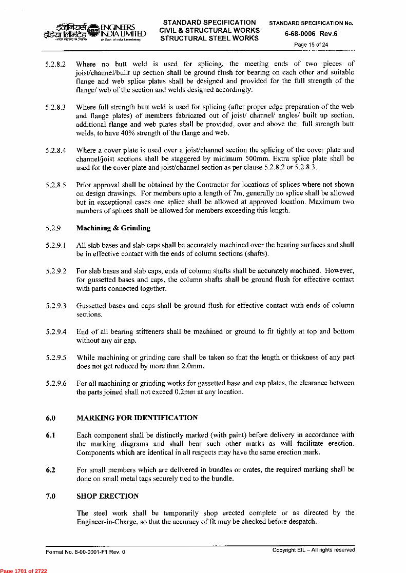
k31 fafg
1.1C71 e1e4 n5i..Nom)
ENGINEERS INDIA UMITED IA Govt ol India Undertalong)
STANDARD SPECIFICATION CIVIL & STRUCTURAL WORKS STRUCTURAL STEEL WORKS
STANDARD SPECIFICATION No.
6-68-0006 Rev.6
Page 15 of 24
5.2.8.2 Where no butt weld is used for splicing, the meeting ends of two pieces of joist/channel/built up section shall be ground flush for bearing on each other and suitable flange and web splice plates shall be designed and provided for the full strength of the flange/ web of the section and welds designed accordingly.
5.2.8.3 Where full strength butt weld is used for splicing (after proper edge preparation of the web and flange plates) of members fabricated out of joist/ channel/ angles/ built up section, additional flange and web plates shall be provided, over and above the full strength butt welds, to have 40% strength of the flange and web.
5.2.8.4 Where a cover plate is used over a joist/channel section the splicing of the cover plate and channel/joist sections shall be staggered by minimum 500mm. Extra splice plate shall be used for the cover plate and joist/channel section as per clause 5.2.8.2 or 5.2.8.3.
5.2.8.5 Prior approval shall be obtained by the Contractor for locations of splices where not shown on design drawings. For members upto a length of 7m, generally no splice shall be allowed but in exceptional cases one splice shall be allowed at approved location. Maximum two numbers of splices shall be allowed for members exceeding this length.
5.2.9 Machining & Grinding
5.2.9.1 All slab bases and slab caps shall be accurately machined over the bearing surfaces and shall be in effective contact with the ends of column sections (shafts).
5.2.9.2 For slab bases and slab caps, ends of column shafts shall be accurately machined. However, for gussetted bases and caps, the column shafts shall be ground flush for effective contact with parts connected together.
5.2.9.3 Gussetted bases and caps shall be ground flush for effective contact with ends of column sections.
5.2.9.4 End of all bearing stiffeners shall be machined or ground to fit tightly at top and bottom without any air gap.
5.2.9.5 While machining or grinding care shall be taken so that the length or thickness of any part does not get reduced by more than 2.0mm.
5.2.9.6 For all machining or grinding works for gassetted base and cap plates, the clearance between the parts joined shall not exceed 0.2mm at any location.
6.0 MARKING FOR IDENTIFICATION
6.1 Each component shall be distinctly marked (with paint) before delivery in accordance with the marking diagrams and shall bear such other marks as will facilitate erection. Components which are identical in all respects may have the same erection mark.
6.2 For small members which are delivered in bundles or crates, the required marking shall be done on small metal tags securely tied to the bundle.
7.0 SHOP ERECTION
The steel work shall be temporarily shop erected complete or as directed by the Engineer-in-Charge, so that the accuracy of fit may be checked before despatch.
Format No. 8-00-0001-F1 Rev. 0 Copyright EIL —All rights reserved
Page 1701 of 2722

nfcflc Og-zx 1.1$T CI,CIN1A71340,1
ENGINEERS INDIA LIMITED IA Govt of Incha Undedakng)
STANDARD SPECIFICATION CIVIL & STRUCTURAL WORKS STRUCTURAL STEEL WORKS
STANDARD SPECIFICATION No.
6-68-0006 Rev.6
Page 16 of 24
8.0 INSPECTION & TESTING OF STRUCTURES
8.1 The Engineer-in-Charge (or his authorised representative) shall have free access at all times to those parts of the Contractor's works which are concerned with the fabrication of the steel work and shall be provided with all reasonable facilities for satisfying himself that the fabrication is being undertaken in accordance with the provisions of these specifications & other relevant BIS Codes.
8.2 Should any structure or part of a structure be found not to comply with any of the provisions of this specification (or relevant BIS Codes as referred to), it shall be liable to rejection. No structure or part of the structure, once rejected shall be resubmitted for inspection, exception cases where the Engineer-in-Charge or his authorised representative considers the defect as rectifiable.
8.3 Defects which may appear during/after fabrication/ erection shall be made good only with the consent of the Engineer-in-Charge and procedure laid down by him.
8.4 A11 necessary gauges and templates shall be supplied free to the Engineer-in-Charge by the Contractor whenever asked for during inspection. The Engineer-in- Charge, may at his discretion, check the test results obtained at the Contractor's works by independent tests at a test house, and the cost of such tests shall be borne by the Contractor.
9.0 SHOP PAINTING
9.1 All components and members of steel work shall be given one shop coat of primer, as specified in the tender, immediately after the surfaces have been properly prepared (i.e. degreased, derusted, descaled & cleaned) in accordance with the job specification or 6-79-0020, as applicable.
The primer coat shall be applied over completely dry surfaces (using brushes of good quality) in a manner so as to ensure a continuous and uniform film without "holidaying". Special care shall be taken to cover all the crevices, corners, edges etc. However, in areas which are difficult to reach by brushing, daubers/mops shall be used by dipping the same in paint and then pulling/ pushing them through the narrow spaces. The primer coat shall be air dried and shall have the thickness as per EIL Specification no. 6-79-0020 or the relevant job specification.
9.2 Surfaces which are inaccessible after shop assembly, shall receive the full specified protective treatment before assembly (this shall not apply to the interior of sealed hollow sections).
9.3 Steel surfaces shall not be painted within a suitable distance of any edges to be welded if the paint specified would be harmful to welders or impair the quality of the welds.
9.4 Welds and adjacent parent metal shall not be painted prior to deslagging, inspection and approval by the Engineer-in-Charge.
9.5 Parts to be encased in concrete shall have only one coat of primer and shall not be painted after erection.
Format No. 8-00-0001-F1 Rev. 0 Copyright EIL —All rights reserved
Page 1702 of 2722
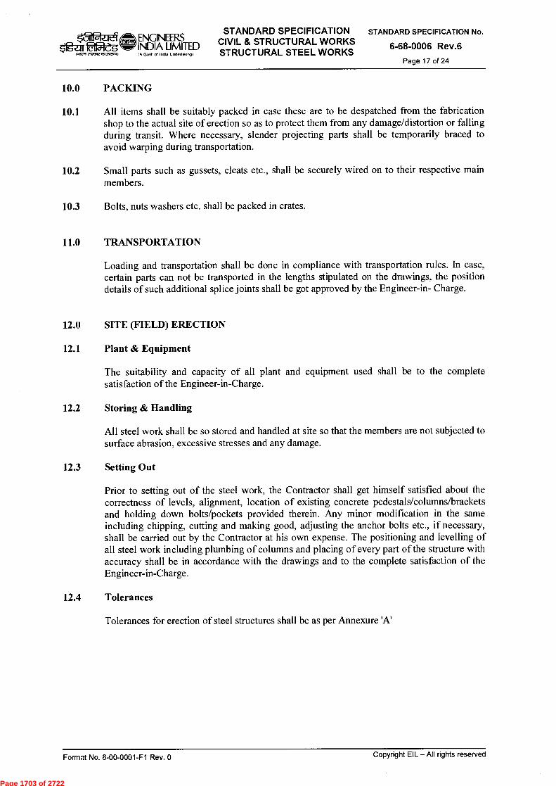
ENGINEERS $ifga~g INDIA LIMITED
1.1177f ,10,,,,A51,3~1)
IA Govt ol Indo Undertalong)
STANDARD SPECIFICATION CIVIL & STRUCTURAL WORKS STRUCTURAL STEEL WORKS
STANDARD SPECIFICATION No.
6-68-0006 Rev.6
Page 17 of 24
10.0 PACKING
10.1 All items shall be suitably packed in case these are to be despatched from the fabrication shop to the actual site of erection so as to protect them from any damage/distortion or falling during transit. Where necessary, slender projecting parts shall be temporarily braced to avoid warping during transportation.
10.2 Small parts such as gussets, cleats etc., shall be securely wired on to their respective main members.
10.3 Bolts, nuts washers etc. shall be packed in crates.
11.0 TRANSPORTATION
Loading and transportation shall be done in compliance with transportation rules. In case, certain parts can not be transported in the lengths stipulated on the drawings, the position details of such additional splice joints shall be got approved by the Engineer-in- Charge.
12.0 SITE (FIELD) ERECTION
12.1 Plant & Equipment
The suitability and capacity of all plant and equipment used shall be to the complete satisfaction of the Engineer-in-Charge.
12.2 Storing & Handling
All steel work shall be so stored and handled at site so that the members are not subjected to surface abrasion, excessive stresses and any damage.
12.3 Setting Out
Prior to setting out of the steel work, the Contractor shall get himself satisfied about the correctness of levels, alignment, location of existing concrete pedestals/columns/brackets and holding down bolts/pockets provided therein. Any minor modification in the same including chipping, cutting and making good, adjusting the anchor bolts etc., if necessary, shall be carried out by the Contractor at his own expense. The positioning and levelling of all steel work including plumbing of columns and placing of every part of the structure with accuracy shall be in accordance with the drawings and to the complete satisfaction of the Engineer-in-Charge.
12.4 Tolerances
Tolerances for erection of steel structures shall be as per Annexure 'A'
Format No. 8-00-0001-F1 Rev. 0 Copyright EIL — All rights reserved
Page 1703 of 2722
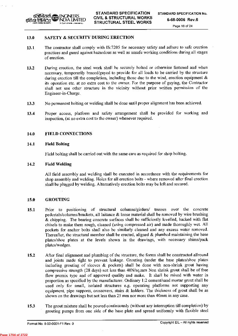
STANDARD SPECIFICATION ENGINEERS INDIA LIMITED CIVIL & STRUCTURAL WORKS IA Govt of Inda Undertaking) STRUCTURAL STEEL WORKS
‘311 fgar Êlfat'dg q51.3~)
STANDARD SPECIFICATION No.
6-68-0006 Rev.6
Page 18 of 24
13.0 SAFETY & SECURITY DURING ERECTION
13.1 The contractor shall comply with IS:7205 for necessary safety and adhere to safe erection practices and guard against hazardous as well as unsafe working conditions during all stages of erection.
13.2 During erection, the steel work shall be securely bolted or otherwise fastened and when necessary, temporarily braced/guyed to provide for all loads to be carried by the structure during erection till the completion, including those due to the wind, erection equipment & its operation etc. at no extra cost to the owner. For the purpose of guying, the Contractor shall not use other structure in the vicinity without prior written permission of the Engineer-in-Charge.
13.3 No permanent bolting or welding shall be done until proper alignment has been achieved.
13.4 Proper access, platform and safety arrangement shall be provided for working and inspection, (at no extra cost to the owner) whenever required.
14.0 FIELD CONNECTIONS
14.1 Field Bolting
Field bolting shall be carried out with the same care as required for shop bolting.
14.2 Field Welding
All field assembly and welding shall be executed in accordance with the requirements for shop assembly and welding. Holes for all erection bolts - where removed after final erection shall be plugged by welding. Alternatively erection bolts may be left and secured.
15.0 GROUTING
15.1 Prior to positioning of structural columns/girders/ trusses over the concrete pedestals/columns/brackets, all laitance & loose material shall be removed by wire brushing & chipping. The bearing concrete surfaces shall be sufficiently levelled, hacked with flat chisels to make them rough, cleaned (using compressed air) and made thoroughly wet. All pockets for anchor bolts shall also be similarly cleaned and any excess water removed. Thereafter, the structural member shall be erected, aligned & plumbed maintaining the base plates/shoe plates at the levels shown in the drawings, with necessary shims/pack plates/wedges.
15.2 After final alignment and plumbing of the structure, the forms shall be constructed allround and joints made tight to prevent leakage. Grouting (under the base plates/shoe plates including grouting of sleeves & pockets) shall be done with non-shrink grout having compressive strength (28 days) not less than 40N/sq mm Non shrink grout shall be of free flow premix type and of approved quality and make. It shall be mixed with water in proportion as specified by the manufacturer. Ordinary 1:2 cement/sand mortar grout shall be used only for small, isolated structures e.g. operating platforms not supporting any equipment, pipe supports, crossovers, stairs & ladders. The thickness of grout shall be as shown on the drawings but not less than 25 mm nor more than 40mm in any case.
15.3 The grout mixture shall be poured continuously (without any interruption till completion) by grouting pumps from one nide of the base plate and spread uniformly with flexible steel
Copyright EIL — All rights reserved Format No. 8-00-0001-F1 Rev. 0
Page 1704 of 2722
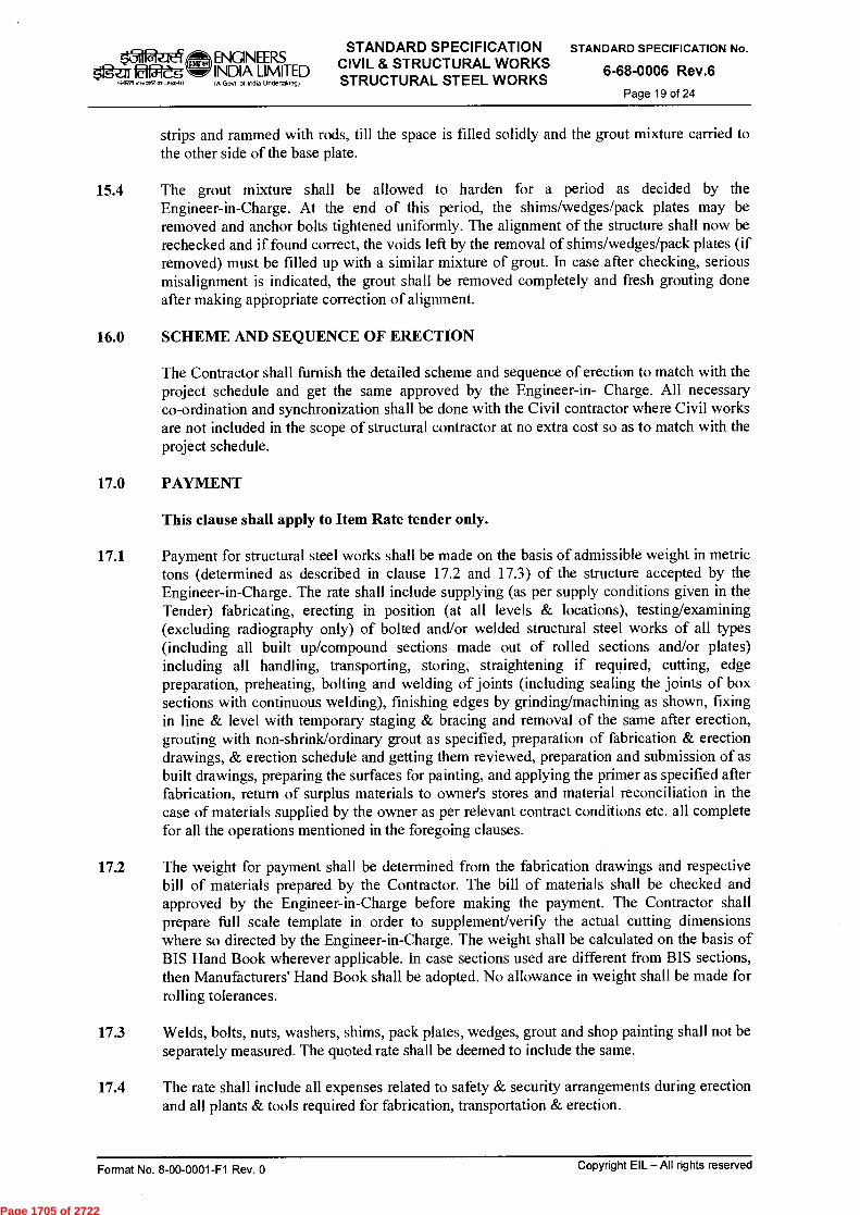
1.12T el,nrt )2,340.4)
ENGINEERS INDIA LIMITED IA Govt ol Indo Undertalong)
STANDARD SPECIFICATION CIVIL & STRUCTURAL WORKS STRUCTURAL STEEL WORKS
STANDARD SPECIFICATION No.
6-68-0006 Rev.6
Page 19 of 24
strips and rammed with rods, till the space is filled solidly and the grout mixture carried to the other side of the base plate.
15.4 The grout mixture shall be allowed to harden for a period as decided by the Engineer-in-Charge. At the end of this period, the shims/wedges/pack plates may be removed and anchor bolts tightened uniformly. The alignment of the structure shall now be rechecked and if found correct, the voids left by the removal of shims/wedges/pack plates (if removed) must be filled up with a similar mixture of grout. In case after checking, serious misalignment is indicated, the grout shall be removed completely and fresh grouting done after making appropriate correction of alignment.
16.0 SCHEME AND SEQUENCE OF ERECTION
The Contractor shall furnish the detailed scheme and sequence of erection to match with the project schedule and get the same approved by the Engineer-in- Charge. All necessary co-ordination and synchronization shall be done with the Civil contractor where Civil works are not included in the scope of structural contractor at no extra cost so as to match with the project schedule.
17.0 PAYMENT
This clause shall apply to Item Rate tender only.
17.1 Payment for structural steel works shall be made on the basis of admissible weight in metric tons (determined as described in clause 17.2 and 17.3) of the structure accepted by the Engineer-in-Charge. The rate shall include supplying (as per supply conditions given in the Tender) fabricating, erecting in position (at all levels & locations), testing/examining (excluding radiography only) of bolted and/or welded structural steel works of all types (including all built up/compound sections made out of rolled sections and/or plates) including all handling, transporting, storing, straightening if required, cutting, edge preparation, preheating, bolting and welding of joints (including sealing the joints of box sections with continuous welding), finishing edges by grinding/machining as shown, fixing in line & level with temporary staging & bracing and removal of the same after erection, grouting with non-shrink/ordinary grout as specified, preparation of fabrication & erection drawings, & erection schedule and getting them reviewed, preparation and submission of as built drawings, preparing the surfaces for painting, and applying the primer as specified after fabrication, return of surplus materials to owner's stores and material reconciliation in the case of materials supplied by the owner as per relevant contract conditions etc. all complete for all the operations mentioned in the foregoing clauses.
17.2 The weight for payment shall be determined from the fabrication drawings and respective bill of materials prepared by the Contractor. The bill of materials shall be checked and approved by the Engineer-in-Charge before making the payment. The Contractor shall prepare full scale template in order to supplement/verify the actual cutting dimensions where so directed by the Engineer-in-Charge. The weight shall be calculated on the basis of BIS Hand Book wherever applicable. In case sections used are different from BIS sections, then Manufacturers' Hand Book shall be adopted. No allowance in weight shall be made for rolling tolerances.
17.3 Welds, bolts, nuts, washers, shims, pack plates, wedges, grout and shop painting shall not be separately measured. The quoted rate shall be deemed to include the same.
17.4 The rate shall include all expenses related to safety & security arrangements during erection and all plants & tools required for fabrication, transportation & erection.
Format No. 8-00-0001-F1 Rev. 0 Copyright EIL — All rights reserved
Page 1705 of 2722
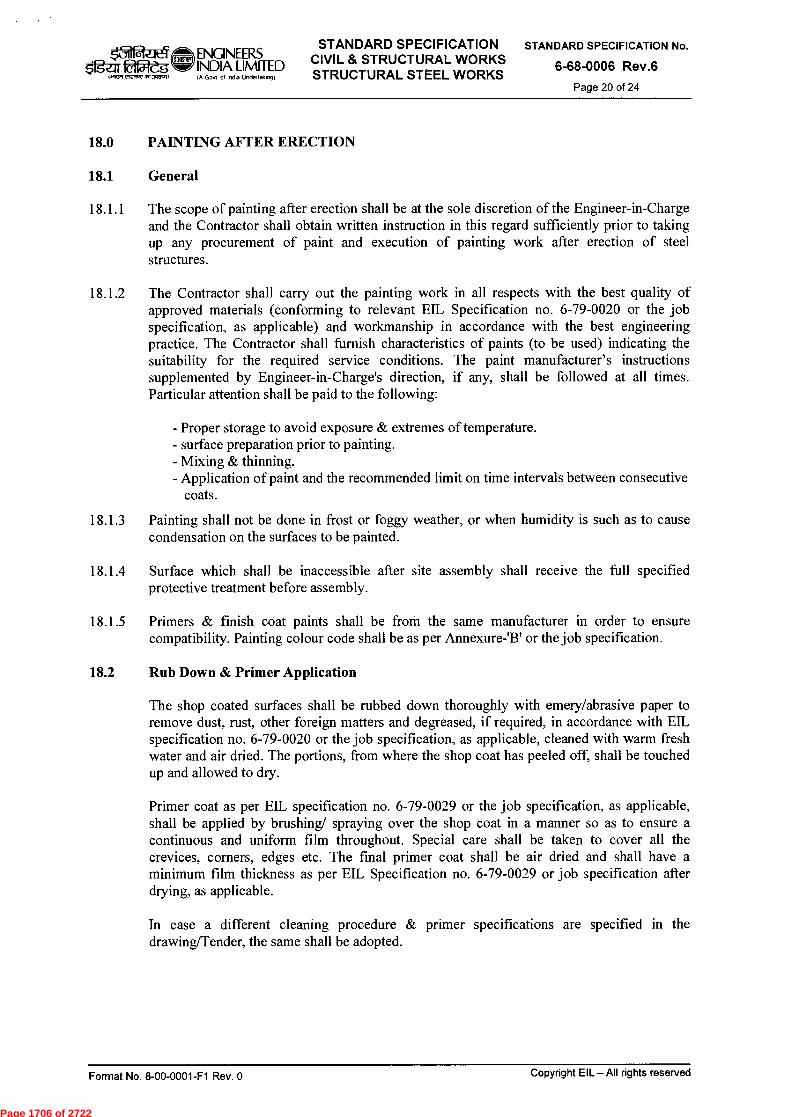
$&fg-ar fêt2e6 1~7S c'92,1,17 ,1513~11
ENGINEERS INDIA LIMITED IA Govt of in0ia Unclertalongt
STANDARD SPECIFICATION CIVIL STRUCTURAL WORKS STRUCTURAL STEEL WORKS
STANDARD SPECIFICATION No.
6-68-0006 Rev.6
Page 20 of 24
18.0 PAINTING AFTER ERECTION
18.1 General
18.1.1 The scope of painting after erection shall be at the sole discretion of the Engineer-in-Charge and the Contractor shall obtain written instruction in this regard sufficiently prior to taking up any procurement of paint and execution of painting work after erection of steel structures.
18.1.2 The Contractor shall carry out the painting work in all respects with the best quality of approved materials (conforming to relevant EIL Specification no. 6-79-0020 or the job specification, as applicable) and workmanship in accordance with the best engineering practice. The Contractor shall furnish characteristics of paints (to be used) indicating the suitability for the required service conditions. The paint manufacturer's instructions supplemented by Engineer-in-Charge's direction, if any, shall be followed at all times. Particular attention shall be paid to the following:
- Proper storage to avoid exposure & extremes of temperature. - surface preparation prior to painting. - Mixing & thinning. - Application of paint and the recommended limit on time intervals between consecutive
coats.
18.1.3 Painting shall not be done in frost or foggy weather, or when humidity is such as to cause condensation on the surfaces to be painted.
18.1.4 Surface which shall be inaccessible after site assembly shall receive the full specified protective treatment before assembly.
18.1.5 Primers & finish coat paints shall be from the same manufacturer in order to ensure compatibility. Painting colour code shall be as per Annexure-'B' or the job specification.
18.2 Rub Down & Primer Application
The shop coated surfaces shall be rubbed down thoroughly with emery/abrasive paper to remove dust, rust, other foreign matters and degreased, if required, in accordance with EIL specification no. 6-79-0020 or the job specification, as applicable, cleaned with warm fresh water and air dried. The portions, from where the shop coat has peeled off, shall be touched up and allowed to dry.
Primer coat as per EIL specification no. 6-79-0029 or the job specification, as applicable, shall be applied by brushing/ spraying over the shop coat in a manner so as to ensure a continuous and uniform film throughout. Special care shall be taken to cover all the crevices, corners, edges etc. The final primer coat shall be air dried and shall have a minimum film thickness as per EIL Specification no. 6-79-0029 or job specification after drying, as applicable.
In case a different cleaning procedure & primer specifications are specified in the drawing/Tender, the same shall be adopted.
Format No. 8-00-0001-F1 Rev. 0
Copyright EIL — All rights reserved
Page 1706 of 2722
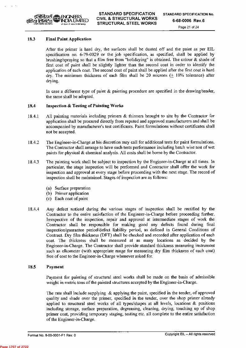
ENGINEERS eMe-gw INDIA LIMITED
talwr rivotf ■tot.3tratt,1)
I A Govt of Ind. Undertaking)
STANDARD SPECIFICATION CIVIL & STRUCTURAL WORKS STRUCTURAL STEEL WORKS
STANDARD SPECIFICATION No.
6-68-0006 Rev.6
Page 21 of 24
18.3 Final Paint Application
After the primer is hard dry, the surfaces shall be dusted off and the paint as per EIL specification no. 6-79-0029 or the job specification, as specified, shall be applied by brushing/spraying so that a film free from "holidaying" is obtained. The colour & shade of first coat of paint shall be slightly lighter than the second coat in order to identify the application of each coat. The second coat of paint shall be applied after the first coat is hard dry. The minimum thickness of each film shall be 20 microns (± 10% tolerance) after drying.
In case a different type of paint & painting procedure are specified in the drawing/tender, the same shall be adopted.
18.4 Inspection & Testing of Painting Works
18.4.1 All painting materials including primers & thinners brought to site by the Contractor for application shall be procured directly from reputed and approved manufacturers and shall be accompanied by manufacturer's test certificates. Paint formulations without certificates shall not be accepted.
18.4.2 The Engineer-in-Charge at his discretion may call for additional tests for paint formulations. The Contractor shall arrange to have such tests performance including batch wise test of wet paints for physical & chemical analysis. All costs shall be borne by the Contractor.
18.4.3 The painting work shall be subject to inspection by the Engineer-in-Charge at all times. In particular, the stage inspection will be performed and Contractor shall offer the work for inspection and approval at every stage before proceeding with the next stage. The record of inspection shall be maintained. Stages of inspection are as follows:
(a) Surface preparation (b) Primer application (c) Each coat of paint
18.4.4 Any defect noticed during the various stages of inspection shall be rectified by the Contractor to the entire satisfaction of the Engineer-in-Charge before proceeding further. Irrespective of the inspection, repair and approval at intermediate stages of work the Contractor shall be responsible for making good any defects found during final inspection/guarantee period/defect liability period, as defined in General Conditions of Contract. Dry film thickness (DFT) shall be checked and recorded after application of each coat. The thickness shall be measured at as many locations as decided by the Engineer-in-Charge. The Contractor shall provide standard thickness measuring instrument such as elkometer (with appropriate range for measuring dry film thickness of each coat) free of cost to the Engineer-in-Charge whenever asked for.
18.5 Payment
Payment for painting of structural steel works shall be made on the basis of admissible weight in metric tons of the painted structures accepted by the Engineer-in-Charge.
The rate shall include supplying & applying the paint, specified in the tender, of approved quality and shade over the primer, specified in the tender, over the shop primer already applied to structural steel works of all types/shapes at all levels, locations & positions including storage, surface preparation, degreasing, cleaning, drying, touching up of shop primer coat, providing temporary staging, testing etc. all complete to the entire satisfaction of the Engineer-in-Charge.
Format No. 8-00-0001-F1 Rev. 0 Copyright EIL — All rights reserved
Page 1707 of 2722

ENGINEERS ÊtPleg INDIA LIMITED
f A Govt of InOla Undeltakng)
STANDARD SPECIFICATION CIVIL & STRUCTURAL WORKS STRUCTURAL STEEL WORKS
STANDARD SPECIFICATION No.
6-68-0006 Rev.6
Page 22 of 24
ANNEXURE-'A' (Clause 12.4)
Maximum Permissible Erection Tolerances
A. Columns
1. Deviation of column axes at foundation top level with respect to true axes.
i) In longitudinal direction
ii) In lateral direction
2. Deviation in the level of bearing surface of columns at foundation top with respect to true level
3. Out of plumb (Verticality) of column axis from true vertical axis, as measured at top:
± 5 mm
± 5 mm
± 5 mm
i) Upto and including 30m height ± H/1000 or ± 25 mm whichever is less.
ii) Over 30m height ± H/1200 or ± 35 mm whichever is less.
4. Deviation in straightness in longitudinal & transverse planes of column at any point along the height. ± H/1000 or ± 10 mm
whichever is less. 5. Difference in the erected positions of adjacent pairs of columns
along length or across width of building prior to connecting trusses/beams with respect to true distance. ± 5 mm
6. Deviation in any bearing or seating level with respect to true ± 5 mm level.
7. Deviation in difference in bearing levels of a member on adjacent pair of columns both across & along the building. ± 5 mm
Note: 1. Tolerance specified under 3 should be read in conjunction with 4 & 5. Note: 2. 'H' is the column height in mm.
B. Trusses
1. Shift at the centre of span of top chord member with respect to the vertical plane passing through the centre of bottom chord.
2. Lateral shift of top chord of truss at the centre of span from the vertical plane passing through the centre of supports of the truss.
3. Lateral shift in location of truss from its true position.
± 1/250 of height of truss in mm at centre of span or ± 15mm whichever is less.
± 1/1500 of span of truss in mm or ± lOmm Whichever is less.
± lOmm
Format No. 8-00-0001-F1 Rev. 0
Copyright EIL — All rights reserved
Page 1708 of 2722

t31 ENGINEERS INDIA LIMITED
A Govt of Indo Undertaking)
STANDARD SPECIFICATION CIVIL & STRUCTURAL WORKS STRUCTURAL STEEL WORKS
STANDARD SPECIFICATION No.
6-68-0006 Rev.6
Page 23 of 24 NIR71 2.12E/A7 ■151.3.74.9)
4. Lateral shift in location of purlin from true position. ± 5mm
5. Deviation in difference of bearing levels of truss from ± 1/1200 of span of the true level. truss in mm or 20mm
whichever is less.
C. Gantry Girders & Rails
1. Shift in the centre line of crane rail with respect ± [{web thickness (mm)}+2 mm] to centre line of web of gantry girder. 2
2. Shift of alignment of crane rail (in plan) with respect to true axis of crane rail at any point. ± 5 mm
3. Deviation in crane track gauge with respect to true gauge.
i) For track gauge upto and including 15 m. ± 5 mm.
ii) For track gauge more than 15m. ± [ 5 + 0.25 (S-15)] Subject to maximum + l Omm, where S in metres is true gauge.
4. Deviation in the crane rail level at any point from true level. ± 10 mm.
5. Difference in level between crane track rails (across the bay) at
i) Supports of gantry girders 15 mm.
ii) Mid span of gantry girders 20 mm.
6. Relative shift of crane rail surfaces (at a joining) in plan and elevation. 2 mm.
Format No. 8-00-0001-F1 Rev. 0 Copyright EIL — All rights reserved
Page 1709 of 2722
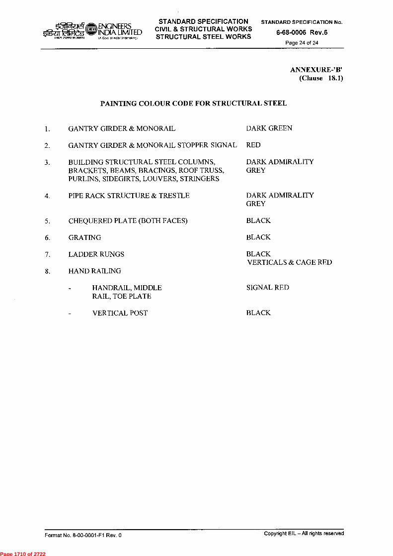
STANDARD SPECIFICATION CIVIL & STRUCTURAL WORKS STRUCTURAL STEEL WORKS
.5-111.1t4 ENGINEERS 2,..1^ INDIA LIMITED
IA Govt of indo Undertak,o9)
STANDARD SPECIFICATION No.
6-68-0006 Rev.6
Page 24 of 24
ANNEXURE-'B' (Clause 18.1)
PAINTING COLOUR CODE FOR STRUCTURAL STEEL
I. GANTRY GIRDER & MONORAIL DARK GREEN
2. GANTRY GIRDER & MONORAIL STOPPER SIGNAL RED
3. BUILDING STRUCTURAL STEEL COLUMNS, BRACKETS, BEAMS, BRACINGS, ROOF TRUSS, PURLINS, SIDEGIRTS, LOUVERS, STRINGERS
DARK ADMIRALITY GREY
4. PIPE RACK STRUCTURE & TRESTLE DARK ADMIRALITY GREY
5. CHEQUERED PLATE (BOTH FACES) BLACK
6. GRATING BLACK
7. LADDER RUNGS BLACK VERTICALS & CAGE RED
8. HAND RAILING
HANDRAIL, MIDDLE SIGNAL RED RAIL, TOE PLATE
.■ VERTICAL POST BLACK
Copyright EIL — All rights reserved Format No. 8-00-0001-F1 Rev. 0
Page 1710 of 2722

ENGINEEFZS $.'gzu f2W5 INDIA LIMITED
IA Govt ol Indo Unclertakeng)
STANDARD SPECIFICATION CIVIL & STRUCTURAL WORKS STRUCTURAL STEEL WORKS
(TUBULAR / HOLLOW SECTIONS)
STANDARD SPECIFICATION No.
6-68-0007 Rev.6 Page 1 of 16
ffrf
STANDARD SPECIFICATION CIVIL & STRUCTURAL WORKS
ki<=111clich Llicl WT4
( -u-dv<k§ftur-4 wre)
STRUCTURAL STEEL WORKS (TUBULAR/HOLLOW SECTIONS)
6 21.08.14 UPDATED & REISSUED S S.CHANDA
5 29.01.10 REAFFIRMED & ISSUED AS PKM SCH N. DUARI
4 18.04.00 UPDATED & REISSUED DPN RS SCJ MI
3 MAY'94 UPDATED & REISSUED DPN RS GPL A.SONI
Standards Standards Rev. Prepared Checked Committee Bureau No Date Purpose by by Convenor Chairman
Approved by
F•ormat No. 8-00-0001-F1 Rev. 0 Copyright EIL — All rights reserved
Page 1711 of 2722

ENQNEERS INDIA LIMITED
rrm a-Kcnr nI
IA Govt W lnda Undertalong)
STANDARD SPECIFICATION CIVIL & STRUCTURAL WORKS STRUCTURAL STEEL WORKS
(TUBULAR / HOLLOW SECTIONS)
STANDARD SPECIFICATION No.
6-68-0007 Rev.6 Page 2 of 16
Abbreviations:
BIS
Bureau of Indian Standards IS
Indian Standards
Structural Standards Committee
Convenor : Mr. P K Mittal
Members : Mr. S Debnath (Geotech) Mr. Rajan Srivastava Mr. P J Singh Mr. Samir Das (Architecture) Mr. V S Chhaya (Projects) Mr. Ravinder Kumar (Construction)
Copyright EIL —All rights reserved Format No. 8-00-0001-F1 Rev. 0
Page 1712 of 2722

ENGINEERS $'1 ).21122-eg INDIA LIMITED
IA Govt of Ind. Undonak,n9)
STANDARD SPECIFICATION CIVIL & STRUCTURAL WORKS STRUCTURAL STEEL Wr1RKS
(TUBULAR / HOLLOW SECTIONS)
STANDARD SPECIFICATION No.
6-68-0007 Rev.6 Page 3 of 16
CONTENTS
1.0 SCOPE 4
2.0 REFERENCES 4
3.0 MATERIAL 4
4.0 FABRICATION DRAWINGS 5
5.0 FABRICATION 7
6.0 MARKING FOR IDENTIFICATION 8
7.0 SHOP ERECTION 8
8.0 INSPECTION AND TESTING 8
9.0 SHOP PAINTING, PACKING AND TRANSPORTATION 9
10.0 SITE (FIELD) ERECTION 9
11.0 SAFETY AND SECURITY DURING ERECTION 9
12.0 FIELD CONNECTIONS 10
13.0 GROUTING 10
14.0 SCHEME AND SEQUENCE OF ERECTION 10
15.0 PAINTING AFTER ERECTION 11
16.0 PAYMENT EXCLUDING DESIGN AND DESIGN DRAWINGS 11
17.0 PAYMENT INCLUDING DESIGN AND DESIGN DRAWINGS 11
ANNEXURE-'A' 13
ANNEXURE-'B' 15
Format No. 8-00-0001-F1 Rev. Copyright EIL -All rights reserved
Page 1713 of 2722

laiRn 2171,415 01,
ENGINEERS INDIA LIMITED IA Govt of Ind. Undertaking)
STANDARD SPECIFICATION CIVIL & STRUCTURAL WORKS STRUCTURAL STEEL WORKS
(TUBULAR / HOLLOW SECTIONS)
STANDARD SPECIFICATION No.
6-68-0007 Rev.6 Page 4 of 16
1.0 SCOPE
This specification covers the requirements for design (Refer Annexure 'A'), material, fabrication, assembly, tests/ examinations, transportation, erection and painting preparation of fabrication drawings of bolted and/or welded structural steel works using tubular/ hollow sections for general construction work.
2.0 REFERENCES
2.1 BIS Codes
IS:800, IS:806, IS:816, Is:1161, IS:4923, IS:7205, IS:7215, IS:9595 & other relevant Codes.
2.2 EIL Specifications
6-68-0002 : Materials 6-68-0006 : Structural Steel Works 6-79-0020 : Standard specification for surface preparation and protective coating
2.3 In case of conflict between the clauses mentioned in this specification and those in the Indian Standards, this specification shall govern. Any special provision as shown or noted on the design drawings shall govern over the provisions of this specification.
3.0 MATERIAL
3.1 General
All materials shall conform to their respective specifications given in EIL Specification no. 6-68-0002. The use of equivalent or alternative materials shall be permitted only in very special cases and for all such cases prior written approval of the Engineer-in-Charge shall be obtained.
3.2 Receipt and Storing of Materials
3.2.1 Each section shall be marked for identification and each lot shall be accompanied by manufacturer's quality certificate, chemical analysis and mechanical characteristics.
3.2.2 All sections shall be checked, sorted out and arranged by grade and quality in the store. Any instruction given by the Engineer-in-Charge in this respect shall be strictly followed.
3 .2.3 All material shall be free from surface defects such as pitting, cracks, laminations, twists etc. Defective material shall not be used and all such rejected material shall be immediately removed from the store/site. The decision of Engineer-in-Charge in this regard shall be final and binding.
3.2.4- Welding wires and electrodes (packed in their original ::artons) shall be stored separately by quality and lots inside a dry and enclosed room in compliance with IS:9595 and as per instructions given by the Engineer-in-Charge. Electrodes shall be kept perfectly dry to ensure satisfactory operation and weld metal soundness.
3.2.5 Each lot of electrodes, bolts, nuts etc. shall be accompanied by manufacturer's quality test certificates.
3.2.6 All bolts (including nuts and washers) shall be checked, sorted out and arranged diameter- wise by grade and quality in the store.
Format No. 8-00-0061-F1 Rev. 0
Co Dyright EIL—All rights reserved
Page 1714 of 2722
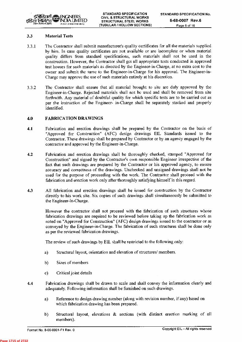
STANDARD SPECIFICATION CIVIL & STRUCTURAL WORKS STRUCTURAL STEEL WORKS
(TUBULAR / HOLLOW SECTIONS)
t31 41 ENGINEERS (00,9) $ifg-ar 0151-eg INDIA LIMITED IA Govt ol Indu Undertakio9)
STANDARD SPECIFICATION No.
6-68-0007 Rev.6 Page 5 of 16
3.3 Material Tests
3.3.1 The Contractor shall submit manufacturer's quality certificates for all the materials supplied by him. In case quality certificates are not available or are incomplete or when material quality differs from standard specifications, such materials shall not be used in the construction. However, the Contractor shall get all appropriate tests conducted in approved test houses for such materials as directed by the Engineer-in-Charge, at no extra cost to the owner and submit the same to the Engineer-in-Charge for his approval. The Engineer-in-Charge may approve the use of such materials entirely at his discretion.
3.3.2 The Contractor shall ensure that all material brought to site are duly approved by the Engineer-in-Charge. Rejected materials shall not be used and shall be removed from site forthwith. Any material of doubtful quality for which specific tests are to be carried out as per the instruction of the Engineer- in-Charge shall be separately stacked and properly identified.
4.0 FABRICATION DRAWINGS
4.1 Fabrication and erection drawings shall be prepared by the Contractor on the basis of "Approved for Construction" (AFC) design drawings EIL Standards issued to the Contractor. These drawings shall be prepared by Contractor or by an agency engaged by the contractor and approved by the Engineer-in-Charge.
4.2 Fabrication and erection drawings shall be thoroughly checked, stamped "Approved for Construction" and signed by the Contractor's own responsible Engineer irrespective of the fact that such drawings are prepared by the Contractor or his approved agency, to ensure accuracy and correctness of the drawings. Unchecked and unsigned drawings shall not be used for the purpose of proceeding with the work. The Contractor shall proceed with the fabrication and erection work only after thoroughly satisfying himself in this regard.
4.3 All fabrication and erection drawings shall be issued for construction by the Contractor directly to his work site. Six copies of such drawings shall simultaneously be submitted to the Engineer-in-Charge.
However the contractor shall not proceed with the fabrication of such structures whose fabrication drawings are required to be reviewed before taking up the fabrication work as noted on "Approved for Construction" (AFC) design drawings issued to the contractor or as conveyed by the Engineer-in-Charge. The fabrication of such structures shall be done only as per the reviewed fabrication drawings.
The review of such drawings by EIL shall be restricted to the following only:
a) Structural layout, orientation and elevation of structures/ members.
b) Sizes of members
c) Critical joint details
4.4 Fabrication drawings shall be drawn to scale and shall convey the information clearly and adequately. Following information shall be furnished on such drawings.
a) Reference to design drawing number (along with revision number, if any) based on which fabrication drawing has been prepared.
b) Structural layout, elevations & sections (with distinct erection marking of all members).
Copyright EIL — All rights reserved Format No. 8-00-0001-F1 Rev. 0
Page 1715 of 2722
∎ 711(~11C~ ENQNEERS INDIA LIMITED IA Govt of Ind. undertaiong)
STANDARD SPECIFICATION CIVIL & STRUCTURAL WORKS STRUCTURAL STEEL WORKS
(TUBULAR / HOLLOW SECTIONS)
STANDARD SPECIFICATION No.
6-68-0007 Rev.6 Page 6 of 16
c) Framing plans, member sizes, orientation and elevations.
d) Layout and detailing of rain water pipes and gutters showing all necessary levels, connections and provisions wherever required.
e) Detailing of shop/field joints/welds, connections, splices, for required strength and erection.
f) Location, type, size and dimensions of welds and bolts.
g) Shapes and sizes of edge preparation for welding.
h) Bill of materials.
i) Quality of structural steel tubes, hollow sections, plates etc., welding electrodes, bolts, nuts and washers to be used.
j) Erection assemblies identifying all transportable parts and sub-assemblies with special erection instructions, if required.
k) Method of erection and special precautions to be taken during erection as required.
4.5 The Contractor shall additionally ensure accuracy of the following and shall be solely responsible for the same:
a) Provision for erection and erection clearances.
b) Marking of members.
c) Cut length of members.
d) Matching of joints and holes.
e) Provision kept in the members for other interconnected members.
f) Bill of materials.
4.6 Connections, splices and other details where not shown on the design drawings shall be suitably designed and shown on the fabrication drawings based on good engineering practice developing full member strength. Design calculations for such connections/ splices shall be submitted to the Engineer-in-Charge along with the fabrication drawings.
4.7 Any substitution or change in section shall be allowed only when prior written approval of the Engineer-in-Charge has been obtained. Fabrication drawings shall be updated incorporating all such substitutions/changes 1--y the Contractor at no extra cost to the owner.
4.8 In case during execution of the work, the Engineer-in-Charge on review of drawings considers any modifications/substitutions necessary to meet the design parameters/ good engineering practice, there shall be brought to the notice of the Contractor who shall incorporate the same in the drawings without any extra cost to the owner. The Contractor will be totally responsible for the correctness of the detailed fabrication drawings and execution of the work.
4.9 Contractor shall incorporate all the revisions made in the design drawings during the course of execution of work in his fabrication drawings, and resubmit the drawings at no extra cost
Format No. 8-00-0001-F1 Rev. 0 Copyright EIL — All rights reserved
Page 1716 of 2722
ENGINEERS
$1g-af 12Wes INDIA LIMITED
,1,,X1enlJaar,1,
Govt Of Intha Undertalong)
STANDARD SPECIFICATION CIVIL & STRUCTURAL WORKS STRUCTURAL STEEL WORKS
(TUBULAR / HOLLOW SECTIONS)
STANDARD SPECIFICATION No.
6-68-0007 Rev.6 Page 7 of 16
to the owner. All fabrication shall be carried out only as per the latest AFC design drawings and corresponding fabrication drawings.
4.10 The Contractor shall supply two prints each of the final/as-built drawings along with their native soft files to Engineer-in-Charge for reference and record. The rates quoted shall include for the same.
5.0 FABRICATION
5.1 General
5.1.1 Fabrication of structures using tubular/hollow sections shall be done strictly as per "Approved For Construction" fabrication drawings (prepared by the Contractor based on the latest design drawings) and in accordance with IS:800, IS:806, IS:1161, IS:4923, IS:9595 and other relevant BIS Codes.
5.1.2 Prior to commencement of fabrication, undulations in the fabrication yard, if any, shall be removed and area levelled and paved by the Contractor.
5.1.3 Any defective material used in the work shall be replaced by the Contractor at his own expense. Necessary care and precautions shall be taken so as not to cause any damage to the structure during any such removal and replacement.
5.1.4 The components of the structure shall be assembled in such a manner that they are neither twisted nor otherwise damaged and be so prepared that the specified cambers, if any, are maintained.
5.1.5 Any faulty fabrication pointed out at any stage of work by the Engineer-in- Charge, shall be made good or replaced by the Contractor at his own cost.
5.1.6 Tolerances for fabrication of steel work shall conform to IS:7215.
5.2 Straightening & Bending
5.2.1 All materials before being assembled shall be straightened, if necessary (unless required to be of a curvilinear form) and shall be free from twist. Tubes shall not deviate from straightness by more than 1/600 of any length.
5.2.2 Bending of structural hollow or tubular sections shall be done by cold process to shapes as shown on drawings.
5.3 Cut Edges
Edges shall be dressed to a neat and workman like finish and be free from distortion.
5.4 Caps Bases for Columns
The ends of all tubes and hollow sections for columns (transmitting loads through the ends) shall be ground flush and made true square to the axis of the member and shall be provided with caps and base plates as shown on the drawings.
5.5 Sealing of Tubes and Hollow Sections
When the end of member is not automatically sealed by virtue of its connection by welding to another member, the end shall be properly and completely sealed against ingress of moisture. Before sealing, the inside of the tubes and hollow sections shall be made dry.
Format No. 8-00-0001-F1 Rev. 0 Copyright EIL —All rights reserved
Page 1717 of 2722

Ogz:11 lar51-g 1.417-n toro,,,On.~0
ENGINEERS INDIA LIMITED IA GoN of Indu Uncleetolong)
STANDARD SPECIFICATION CIVIL & STRUCTURAL WORKS STRUCTURAL STEEL WORKS
(TUBULAR / HOLLOW SECTIONS)
STANDARD SPECIFICATION No.
6-68-0007 Rev.6 Page 8 of 16
5.6 Flattened Ends
In tubular construction, joints may be formed by flattening or splitting or otherwise formed shapes for welded or bolted connections. The change in section shall be gradual to avoid concentration of stresses and all flattening shall be done by cold process only.
5.7 Welding
Welding shall be strictly in accordance with IS:9595 and carried out by experienced welders only. For welding (including testing & examining of welds) relevant clauses of EIL Specification no. 6-68-0006 for Structural Steel Works shall be referred to the extent applicable.
5.8 Bolting
5.8.1 Washers shall be specially shaped where necessary to give the nuts and the heads of bolts a full bearing.
5.8.2 In all cases where the full bearing area of the bolt is to be developed, the threaded portion of the bolt shall not be within the thickness of parts bolted together, and washer(s) of appropriate thickness shall be provided to allow the nut to be completely tightened.
6.0 MARKING FOR IDENTIFICATION
Each component shall be distinctly marked before delivery, in accordance with the marking diagram and shall bear such other marks as will facilitate erection.
7.0 SHOP ERECTION
The steel work shall be temporarily shop erected complete or as directed so that accuracy of fit may be checked before dispatch.
8.0 INSPECTION AND TESTING
8.1 The Engineer-in-Charge (or his authorised representative) shall have free access at all times to those parts of the Contractor's Works which are concerned with the storing and fabrication of the steel work and shall be provided with all reasonable facilities for satisfying himself that fabrication is being undertaken in accordance with the provisions of these specifications and other relevant BIS Codes.
8.2 Should any structure or part of a structure be found not to comply with any of the provisions of these specifications and other relevant BIS Codes, it shall be rejected. No structure or part of the structure, once rejected shall be resubmitted for inspection, except in cases where the Engineer-in-Charge or his authorised representative considers the defect as rectifiable.
8.3 Defects which may appear during fabrication/erection shall be made good only with the consent of the Engineer-in-Charge and procedure laid down by him.
8.4 All necessary gauges and templates shall be supplied free to the Engineer-in- Charge by the Contractor whenever asked for during inspection. The Engineer- in-Charge may, at his discretion, check the test results obtained at the Contractor's works by independent tests at a test house, the cost of such tests shall be borne by the Contractor.
Format No. 8-00-0001-F1 Rev. 0
Copyright EIL — All rights reserved
Page 1718 of 2722

ENGINEERS $figrr1M2-'dg INDIA LIMITED
Govt of India Unciertalongt
STANDARD SPECIFICATION CIVIL & STRUCTURAL WORKS STRUCTURAL STEE'. WORKS
(TUBULAR / HOLLOW SECTIONS)
STANDARD SPECIFICATION No.
6-68-0007 Rev.6 Page 9 of 16
9.0 SHOP PAINTING, PACKING AND TRANSPORTATION
9.1 All components and members of steel work shall be given one shop coat of primer as specified in the tender, immediately after the surface have been properly prepared (i.e. degreased, derusted, descaled and cleaned) in accordance with EIL Specification No. 6-79-0020 or the job specification, as applicable.
9.2 All items shall be suitably packed in case they are to be dispatched from the fabrication shop to the actual site of erection so as to protect them from any damage or distortion during transit.
10.0 SITE (FIELD) ERECTION
10.1 Plant and Equipment
The suitability and capacity of all plant and equipment used shall be to the complete satisfaction of the Engineer-in-Charge.
10.2 Storing and Handling
All steel work shall be so stored and handled at site so that the members are not subjected to excessive stresses and any damage.
10.3 Setting out
Prior to setting out of the steel work, the Contractor shall get himself satisfied about the correctness of levels, alignment, location of existing pedestals/ columns and holding down bolts/ pockets provided therein. Any minor modification in the same including chipping, cutting and making good, adjusting the anchor bolts etc. if necessary, shall be carried out by the Contractor at his own expense. The positioning and levelling of all steel work including plumbing of columns and placing of every part of the structure with accuracy shall be in accordance with the drawings and to the complete satisfaction of the Engineer-in-Charge.
10.4 Tolerances
Tolerances for erection of steel structures shall be as per Annexure - `13'.
11.0 SAFETY AND SECURITY DURING ERECTION
The Contractor shall comply with IS:7205 for necessary safety and adhere to safe erection practices and guard against hazardous and unsafe working conditions during all stages of erection.
11.2 During erection, the steel work shall be securely bolted or otherwise fastened, and when necessary, temporarily braced to provide for all loads to be carried by the structure during erection till the completion including those due to wir. -!, erection equipment and its operation etc. For the purpose of guying the Contractor shall not use other structures in the vicinity without prior written permission of the Engineer-in-Charge.
11.3 No permanent bolting or welding shall be done until proper alignment has been achieved.
11.4 Proper access, platform and safety arrangement shall be provided for working and inspection at no extra cost whenever required.
Format No. 8-00-0001-F1 Rev. 0 Copyright EIL — All rights reserved
Page 1719 of 2722

ENGINEERS ta51-eg INDIA LIMITED o10~OX,ylos".11 IA Govt ol rtd Unoonok,o9)
STANDARD SPECIFICATION CIVIL & STRUCTURAL WORKS STRUCTURAL STEEL WORKS
(TUBULAR / HOLLOW SECTIONS)
STANDARD SPECIFICATION No.
6-68-0007 Rev.6 Page 10 of 16
12.0 FIELD CONNECTIONS
12.1 Field Bolting
12.1.1 Field bolting shall be carried out with the same care as required for shop bolting.
12.2 Field Welding
12.2.1 All field assembly and welding shall be executed in accordance with the requirements for shop. Holes for all erection bolts where removed after final erection shall be plugged by welding. Alternatively erection bolts may be left and secured. Proper access, platform and safety arrangements shall be provided for inspection whenever required.
13.0 GROUTING
13.1 Prior to positioning of structural columns/ girders/ trusses over the concrete pedestals/ columns/ brackets, all laitance & loose material shall be removed by wire brushing & chipping. The bearing concrete surfaces shall be sufficiently leveled, hacked with flat chisels to make them rough, cleaned (using compressed air) and make thoroughly wet. All pockets for anchor bolts shall be thoroughly cleaned and excess water, if any, shall be removed. Thereafter, the structural members shall be erected, aligned & plumbed maintaining the base plates/ shoe plates at the levels shown in the drawings, with necessary shims/ pack plates/ wedges.
13.2 After final alignment and plumbing of the structure, the forms shall be constructed alround and joints made tight to prevent leakage. Grouting (under the base plates/ shoe plates including grouting of sleeves & pockets) shall be done with non-shrink grout having compressive strength (28 days) not less than 40 N/sq.mm. Non shrink grout shall be of free flow premix type of approved quality and make and mixed with water in proportion as specified by the manufacturer. Ordinary 1:2 cementl sand mortar grout shall be used only for small, isolated structures e.g. operating platforms not supporting any equipment, pipe supports, cross overs, stairs & ladders. The thickness of grout shall be as shown on the drawings but not less than 25mm nor more than 40mm in any case.
13.3 The grout mixture shall be poured continuously (without any interruption till completion) by grouting pumps from one side of the base plate and spread uniformly with flexible steel strips and rammed with rods, till the space is filled solidly and the grout mixture carried to the other side of the base plate.
13.4 The grout mixture shall be allowed to harden for a period as decided by the Engineer-in-Charge. At the end of this period, the shims/ wedges/ pack plates may be removed and anchor bolts tightened uniformly. The alignment of the structure shall now be rechecked and if found correct, the voids left by the removal of shims/ wedges/pack plates (if removed) must be filled up with a similar mixture of grout. In case after checking, serious misalignment is indicated, the grout shall be removed completely and fresh grouting done after making appropriate :orrection of alignment.
14.0 SCHEME AND SEQUENCE OF ERECTION
The Contractor shall furnish the detailed scheme and sequence of erection to match with the project schedule and get the same approved by the Engineer-in-Charge. All necessary co-ordination and synchronization shall be done with the civil contractor where civil works are not included in the scope of structural contractor at no extra cost so as to match with the project schedule.
Format No. 8-00-0001-F1 Rev. 0 Copyright EIL —All rights reserved
Page 1720 of 2722

■71 ENGINEERS $1g-LIT fafjrdg INDIA LIMITED
IA Go. of Inoia Undeflaking)
STANDARD SPECIFICATION CIVIL & STRUCTURAL WORKS STRUCTURAL STEEL WORKS
(TUBULAR / HOLLOW SECTIONS)
STANDARD SPECIFICATION No.
6-68-0007 Rev.6 Page 11 of 16
IffeR c-frow7aRalusal,
15.0 PAINTING AFTER ERECTION
Painting of Structural Steel Works using (tubular/ hollow sections) shall be done in accordance with relevant clauses of EIL Specification no. 6-68-0006.
16.0 PAYMENT EXCLUDING DESIGN AND DESIGN DRAWINGS
(Where design and design drawings are excluded from the scope of the Contractor)
16.1 Payment for structural steel works fabricated and made out of tubular/ hollow sections shall be made on the basis of admissible weight in metric tons (determined as described in clause 16.2 to 16.3) of the structure accepted by the Engineer-in-Charge.
The rate shall include supplying (as per supply conditions given in the tender), fabricating, erecting in position (at all levels and locations), transporting, storing, testing/examining of bolted and/or welded structural steel works using (tubular/hollow sections) of all types of trusses, girders, purlins, side rails, columns, runners, beams, ties, portals, framework, bracings, brackets, sag rods etc., including all handling, straightening/bending, if required, cutting, edge preparation, welding and/or bolting of joints, providing temporary bracing, providing and fixing end caps, fixing in line and level with necessary temporary staging, grouting with premix, free flow, non-shrink grout as shown on drawings including preparation of detailed fabrication drawings and getting them reviewed, preparing the exposed surface for painting, surface cleaning, wire brushing, removal of mill scale, rust, oil or grease and applying the primer as specified after fabrication, return the surplus materials to the owner's stores and material reconciliation in the case of materials supplied by Owner as per relevant contract conditions etc. all complete for all the operations mentioned in the foregoing clauses.
16.2 The weight for payment shall be determined from the fabrication drawings and respective bill of materials prepared by the Contractor. The bill of materials shall be checked and approved by the Engineer-in-Charge before making the payment. The weight shall be calculated on the basis of BIS Handbook wherever applicable. In case sections used are different from BIS sections, then Manufacturer's Handbook shall be adopted. No allowance in weight shall be made for rolling tolerances.
16.3 Welds, bolts, nuts, washers, shims, pack plates and grout shall not be measured. The quoted rate shall be deemed to include the same.
17.0 PAYMENT INCLUDING DESIGN AND DESIGN DRAWINGS
(Where design and design drawings are also included in the scope of the Contractor).
17.1 All design and design drawings shall be prepared strictly in accordance with DESIGN SPECIFICATIONS attached with this specification as Annexure - `A'.
17.2 Payment for structural steel works fabricated and made out of tubular/hollow sections be made on the basis of admissible weight in metric tons (determined as described in clause 17.3 to 17.4) of the structure accepted by the Engineer-in-Charge.
The rate shall include supplying, fabricating, erecting in position (at all levels and locations), transporting, storing, testing/examining of bolted and/or welded structural steel works using (tubular/hollow sections) of all types of trusses, girders, purlins, side rails, columns, runners, beams, ties, portals, framework, bracings, brackets, sag rods etc., including all handling straightening/bending if required, cutting, edge preparation, welding and/or bolting of joints, providing temporary bracing, providing and fixing end caps, fixing in line and level with necessary temporary staging, grouting with premix, free flow, non-shrink grout as shown on
Format No. 8-00-0001-F1 Rev. 0
Copyright EIL — All rights reserved
Page 1721 of 2722

Oriff la2es ENGINEERS INDIA LIMITED IA Govt of Indie lindertatungt
STANDARD SPECIFICATION CIVIL & STRUCTURAL WORKS STRUCTURAL STEEL WORKS
(TUBULAR / HOLLOW SECTIONS)
STANDARD SPECIFICATION No.
6-68-0007 Rev.6 Page 12 of 16
drawings including preparation of detailed fabrication drawings and getting them reviewed, preparing the exposed surface for painting, surface cleaning, wire brushing, removal of mill scale, rust, oil or grease and applying the primer as specified after fabrication, return the surplus materials to the owner's stores and material reconciliation in the case of materials supplied by Owner as per relevant contract conditions etc. all complete for all the operations mentioned in the foregoing clauses.
17.3 The weight for payment shall be determined from the fabrication drawings and respective bill of materials prepared by the Contractor. The bill of materials shall be checked and approved by the Engineer-in-Charge before making the payment. The weight shall be calculated on the basis of BIS Handbook wherever applicable. In case sections used are different from BIS sections, then Manufacturer's Handbook shall be adopted. No allowance in weight shall be made for rolling tolerances.
17.4 Welds, bolts, nuts, washers, shims, pack plates and grout shall not be measured. The quoted rate shall be deemed to include the same.
Format No. 8-00-0001-F1 Rev. 0 Copyright EIL—All rights reserved
Page 1722 of 2722

■31 S~SLnI ICIWes
ENGINEERS INDIA LIMITED IA Govt ol Indo Undertaiong)
STANDARD SPECIFICATION CIVIL & STRUCTURAL WORKS STRUCTURAL STEEL WORKS
(TUBULAR / HOLLOW SECTIONS)
STANDARD SPECIFICATION No.
6-68-0007 Rev.6 Page 13 of 16
ANNEXURE - 'A' (Clause no. 1.0 & 17.1)
DESIGN SPECIFICATIONS
1.0 DESIGN AND DESIGN DRAWINGS
1.1
The design and design drawings of the structure(s) shall be prepared by the Contractor on the basis of conceptual drawing(s) furnished to him. These (design and design drawings) shall be prepared in his own design office, or in case such facility is not available with the Contractor, by an approved and established agency. The names of agencies who may be considered for entrusting with this work shall be submitted along with the offer for approval of the Engineer-in-Charge. If none of the agencies so named is approved, the Contractor shall submit a fresh list for approval.
1.2 The design shall be done in accordance with IS:800, IS:801, IS:806, IS:1161 & IS:4923, and other relevant BIS Codes (latest revisions). The loads to be adopted in the design shall be in accordance with IS:875 & IS:1893 except otherwise specified. All design calculations and design drawings shall be prepared in metric units i.e. dimensions in millimetres and levels in metres.
1.3 The basic consideration for design of structural framework shall primarily be its stability, ease of fabrication and erection, overall economy satisfying the relevant BIS Codes of Practice and satisfactory performance. All structures shall be designed to withstand the worst combination of loading.
1.4 Structures, in general, shall be of welded construction. Roof trusses shall have a slope of 1:3 (1 vertical : 3 horizontal). Purlins shall be spaced in such a manner so as to achieve maximum economy in the use of roof sheets. Camber (span/500) shall be provided for trusses having span of 15 meters and above. The minimum thickness of gussets shall be 8mm.
1.5 All design calculations (supplemented with necessary explanatory sketches, computer outputs & explanatory notes) shall be done in a neat and systematic manner so as to facilitate review of the same. The design drawings shall include the following:
a) Structural layout, elevations, sections.
b) Sizes of members and tables showing forces in members under different loading conditions.
c) Proposed sizes of sheets and extent of sheeting (to be represented by chain dotted lines)
d) Blown up details of joints, connections, splices etc.
e) Size and type of welds/bolts
0 Quality of tubular/hollow sections and structural steel bolts etc.
g) Approximate quantity (Metric Tons)
h) Chart/table showing loading (under different conditions) and fixing details at base (required for the design of supporting structure/foundations which shall be in the Owner's scope of work)
Format No. 8-00-0001-F1 Rev. 0 Copyright EIL — All rights reserved
Page 1723 of 2722

ENQNEERS INDIA LIMITED I A Govt of India Underlaking)
STANDARD SPECIFICATION CIVIL & STRUCTURAL WORKS STRUCTURAL STEEL WORKS
(TUBULAR / HOLLOW SECTIONS)
STANDARD SPECIFICATION No.
6-68-0007 Rev.6 Page 14 of 16
gales na J.M.1
1.6 All design calculation sheets and design drawings shall be thoroughly checked, approved, stamped "Approved For Construction" and signed by a competent design engineer (engaged by the Contractor) prior to their submission to the Engineer-in-Charge for review. Unchecked and unsigned design calculations and design drawings shall not be accepted for review and shall be returned forthwith to the Contractor.
1.7 The Contractor shall submit the design calculations (3 sets) and design drawings (6 sets) for review to the Engineer-in-Charge. Any comments/ suggestions given by him shall be incorporated in the design/ design drawings (without any extra cost to the Owner) and resubmitted for review. However, it shall be clearly understood that review by the Engineer-in-Charge shall not relieve the Contractor of his responsibility for the correctness of design, drawings and execution of the works. Any defect observed either during construction/erection or till the defect liability period of works shall be rectified and removed by the Contractor without any cost implication.
1.8 The design calculations and design drawings for the building(s) shall be submitted by the Contractor in one lot so as to facilitate an overall systematic review by the Engineer-in-Charge.
1.9 The Contractor shall supply the all native soft files of all design calculations and design drawings at no extra cost to the Owner, for record.
1.10 Based on the final design drawings, the Contractor shall prepare necessary fabrication drawings in conformity with clause 4.0 of EIL Specification no. 6-68-0007.
Copyright EIL — All rights reserved Format No. 8-00-0001• F1 Rev. 0
Page 1724 of 2722

ENGINEERS INDIA LIMITED IA Govt of InOla Undeltakmg)
STANDARD SPECIFICATION CIVIL & STRUCTURAL WORKS STRUCTURAL STEEL WORKS
(TUBULAR / HOLLOW SECTIONS)
STANDARD SPECIFICATION No.
6.-68-0007 Rev.6 Page 15 of 16
jlnotel 2 .ir ICS'
1.1R,1 ~1512' 051,1057.
ANNEXURE - 'B' (Clause 10.4)
MAXIMUM PERMISSIBLE ERECTION TOLERANCES
A. COLUMNS
1. Deviation of column axes at foundation top level with respect to true axes.
+ 5 mm _ + 5 mm _
i) In longitudinal direction ii) In lateral direction
2. Deviation in the level of bearing surface of columns at foundation top with respect to true level. + 5 mm _
3. Out of plumbness (verticality) of column axis from true vertical axis, as measured at top:
i) Upto and including 30 m height
ii) Over 30 m height
4. Deviation in straightness in longitudinal and transverse planes of column at any point along the height.
5. Difference in the erected positions of adjacent pairs of columns along length or across width of building prior to connecting trusses/beams with respect to true distance
6. Deviation in any bearing or seating level with respect to true level
7. Deviation in difference in bearing levels of a member on adjacent pair of columns both across and along the building
+ H/1000 or + 25 mm (whichever is less)
+ H/1200 or + 35 mm _ _ (whichever is less)
+H/1000 or + 10 mm _ _ (whichever is less)
+ 5 mm _
+ 5 mm _
+ 5 mm ±
Notes: 1. Tolerance specified under 3 should be read in conjunction with 4 & 5. 2. 'H' is the column height in mm.
Format No. 8-00-0001-F1 Rev. 0 Copyright EIL — All rights reserved
Page 1725 of 2722
k31
e5 ENGINEERS
$fig-ar 22 s-kfax1aft,,ro,f41
STANDARD SPECIFICATION CIVIL & STRUCTURAL WORKS STR1 ICTURAL STEEL WORKS
(TUBULAR / HOLLOW SECTIONS) INDIA LIMITED IF Govt of Inda Undertaking)
STANDARD SPECIFICATION No.
6-68-0007 Rev.6 Page 16 of 16
B. TRUSSES:
1. Shift at the centre of span of top chord member with respect to the vertical plane passing through the centre of bottom chord.
2. Lateral shift of top chord of truss at the centre of span from vertical plane passing through the centre of supports of the truss.
3. Lateral shift in location of truss from its true vertical position
4. Lateral shift in location of purlin from true position
5. Deviation in difference of bearing levels of truss from the true level
+ 1/250 of Height of truss in mm at the centre of span or + 15 mm (whichever is less)
+ 1/1500 of span of truss in mm or + 10 mm (whichever is less)
+ 10 mm
± 5 mm
+ 1/1200 of span of truss in mm or + 20 mm (whichever is less)
Format No. 8-00-0001-F1 Rev. 0 Copyright EIL —All rights reserved
Page 1726 of 2722
laW5 14-WR
ENGINEERS INDIA LIMITED (P. Govl of Indo Undertaking)
STANDARD SPECIFICATION CIVIL AND STRUCTURAL WORKS MISCELLANEOUS STEEL WORKS
STANDARD SPECIFICATION No.
6-68-0008 Rev.6 Page 1 of 12
4-111ch cl k I wl
fur-4.ff ‹akti 1 I C-1-1ch
STANDARD SPECIFICATION CIVIL & STRUCTURAL WORKS
fq5-19 ch
MISCELLANEOUS STEEL WORKS
c 6 24 01.14 REVISED & REISSUED AJS RS PKM SC SC
5 10.06.08 REVISED & REISSUED PKB PKM VK VC
4 18.04.00 UPDATED & REISSUED DPN RS SCJ MI
3 MAY'94 UPDATED & REISSUED DPN RS GPL AS
Rev. No
Date Purpose Prepared
by Checked
by
Standards Committee Convenor
Standards Bureau
Chairman
Approved by
Format No. 8-00-0001-F1 Rev. 0
Copyright EIL — All rights reserved
Page 1727 of 2722

ENGINEERS
fgt-af £;45 INDIA LIMITED
2,952' Jr1-{1,
Govt ot Indta Unotertaking)
STANDARD SPECIFICATION CIVIL AND STRUCTURAL WORKS MISCELLANEOUS STEEL WORKS
STANDARD SPECIFICATION No.
6-68-0008 Rev.6 Page 2 of 12
Abbreviations:
BIS Bureau of Indian Standards
IS Indian Standard
M.S. Mild Steel
PCC Plain Cement Concrete
RCC Reinforced Cement Concrete
Structural Standards Committee
Convenor: Mr. P.K. Mittal
Members: Mr. S.Debnath Mr. P.J. Singh Mr. Rajanji Srivastava Mr. Samir Das Mr. V.S. Chhaya (Projects) Mr. Ravindra Kumar (Cor►stn)
Format No. 8-00-0001-F1 Rev. 0
Copyright EIL — All rights reserved
Page 1728 of 2722
ENGINEERS INDIA LIMITED (A Govt of Indta Undettalong)
STANDARD SPECIFICATION CIVIL AND STRUCTURAL WORKS MISCELLANEOUS STEEL WORKS
STANDARD SPECIFICATION No.
6-68-0008 Rev.6 Page 3 of 12
$1g-ar fêtW G 1~1 V1~,1)
CONTENTS
1.0 GENERAL 4
2.0 REFERENCES 4
3.0 MATERIAL 4
4.0 ANCHOR BOLTS 4
5.0 METAL INSERTS 5
6.0 CHEQUERED PLATES 5
7.0 GRATINGS 6
8.0 TUBULAR HAND RAILING 7
9.0 MILD STEEL RUNGS 8
10.0 LIGHT GAUGE STEEL STRUCTURAL SECTIONS 9
11.0 EXPANSION FASTENERS 10
12.0 CHEMICAL ANCHORS AND DOWELS 11
Format No. 8-00-0001-F1 Rev. 0
Copyright EIL — All rights reserved
Page 1729 of 2722
STANDARD SPECIFICATION STANDARD SPECIFICATION No.
CIVIL AND STRUCTURAL WORKS 6-68-0008 Rev.6 MISCELLANEOUS STEEL WORKS Page 4 of 12
ENGINEERS Og-ar~g INDIA LIMITED
e.(2(.1.a..3RffR1
(A Govt of India UndenakIng)
1.0 GENERAL
1.1 A11 materials supplied by the Contractor shall conform to specifications given in EIL Specification No.6-68-0002.
1.2 The Contractor shall furnish test certificates for all materials prior to their use in the works. Structural steel materials not supported by mill test certificates may be used after confirming their quality by carrying out appropriate tests in accordance with the method specified in IS:1608.
1.3 Other requirements not covered under this specification shall be in accordance with EIL Specification No.6-68-0006.
2.0 REFERENCES
As mentioned in the respective clauses.
3.0 MATERIAL
As mentioned in the respective clauses.
4.0 ANCHOR BOLTS
4.1 Material
Materials for anchor bolts, nuts, locknuts, washers, pipe sleeves and anchor plates shall conform to their respective clauses given in EIL Specification no.6-68-0002.
4.2 Fabrication
Fabrication of anchor bolts and their complete assemblies shall be strictly in compliance with the specifications and drawings/standards.
4.3 Placement
Anchor bolt assemblies shall be placed in position strictly as per drawings and securely field during pouring and vibrating of concrete with necessary templates and other dummy structures to prevent their dislocation.
4.4 Tolerances
Tolerances allowed for anchor bolts positioning shall be as below:
- For sleeved bolts, one tenth of the bolt nominal diameter.
- For bolts without sleeves, one twentieth of the bolt nominal diameter.
4.5 Protection
The exposed surfaces of bolts shall be properly covered (after greasing of bolts and packing of sleeves) with jute cloth so as to protect them from damage till final erection of structure/equipment is over.
4.6 Payment
4.6.1 Payment shall be made on the basis of actual weight in metric tons of the anchor bolt/anchor bolt assembly. The rate shall include supply (as per scope of supply conditions given in the
Format No. 8-00-0001-F1 Rev. 0 Copyright EIL — All rights reserved
Page 1730 of 2722
ENONEERS Ofzileg INDIA LIMITED
(A Govi ol Ind. Unclellaking(
STANDARD SPECIFICATION CIVIL AND STRUCTURAL WORKS MISCELLANEOUS STEEL WORKS
STANDARD SPECIFICATION No.
6-68-0008 Rev.6 Page 5 of 12
tender) of all materials, handling, transporting, fabrication, turning from available size to required diameter, threading, welding, fixing in position at all levels and locations, providing necessary templates, greasing, packing of sleeves, covering with jute cloth and other protective measures etc. all complete.
4.6.2 The rate shall cover bolt of any diameter and nomenclature.
4.6.3 Payment for fixing anchor bolt assembly (already fabricated and supplied by the Owner as free issue) in position shall be made on the basis of actual weight of anchor bolts/bolt assemblies in metric tons. The rate shall include handling, transporting, fixing in position at all levels and locations, welding if required, providing necessary templates, greasing, packing of sleeves, covering with jute cloth and other protective measures etc. all complete.
4.6.4 No separate payment shall be made for templates, dummy structures, supports etc. and the rate quoted shall be inclusive of all cost related to such provision required for correct and accurate installation of anchor bolts/anchor bolt assembly.
5.0 METAL INSERTS
5.1 Material
Materials required for fabricating metal inserts shall conform to their respective specification given in EIL Specification no. 6-68-0002.
5.2 Fabrication
Fabrication of inserts shall be done strictly as per drawings/standards and in compliance with the requirements given in EIL Specification no. 6-68-0006.
5.3 Placement
Metal inserts shall be correctly embedded (in plain concrete/reinforced concrete) as per their location shown on the drawings. Care shall be taken that these are securely held in position and do not get disturbed during concreting. Where necessary, these may be welded to the reinforcement bars. Suitable templates, spacers, dummy structures and temporary staging shall be provided. Necessary cutting in the formwork and adjustment of reinforcement bars shall be done for the placement of metal inserts where required.
5.4 Painting
The exposed surfaces of metal inserts shall be cleaned and given one coat of primer as per EIL Specification no. 6-79-0020 or job specification, as specified, after fabrication.
5.5 Payment
Payment shall be made on the basis of actual weight in metric tons of the metal inserts. The rate shall include supply (as per supply conditions given in the tender) of all materials, handling, transporting, fabrication, welding, fixing in position at all levels and locations, providing necessary templates, spacers, dummy structures, adjusting the formwork and reinforcement, staging, preparation of surface for painting, applying one coat of primer as per EIL Specification no. 6-79-0020 or job specification, as specified, etc. all complete.
6.0 CHEQUERED PLATES
6.1 Material
Material required for chequered plates shall conforni to the specifications given in EIL Specification No. 6-68-0002. Chequering shall be closed or open-ended or of any other pattern as shown on drawings.
Format No. 8-00-0001-F1 Rev. 0
Copyright EIL — All rights reserved
Page 1731 of 2722

STANDARD SPECIFICATION STANDARD SPECIFICATION No.
CIVIL AND STRUCTURAL WORKS 6-68-0008 Rev.6 MISCELLANEOUS STEEL WORKS
Page 6 of 12
22ig ENGINEERS Ogal 215ieg INDIA LIMITED
(A Govl of lrwla Undertaking)
6.2 Fabrication Drawings
As per the requirements given in EIL Specification No. 6-68-0006.
6.3 Fabrication
Chequered plates shall be fabricated as per the "Approved for Construction" fabrication drawings (prepared by the Contractor based on design drawings). These shall be perfectly flat and without any dents/deformations and shall be cut to the required size and shape. Holes/notches/openings of the required size, if any, shown on drawings shall be made. Nosing for staircase treads shall be made by cold bending of chequered plates. A11 edges shall be made smooth and even. A11 chequered plate units shall be given distinct erection marks in accordance with the marking drawings. Stiffeners of any description shall be welded with the chequered plates where shown on drawings.
6.4 Erection/Fixing
Chequered plates shall be fixed to the bearing members by welding/ bolting/ screwing as shown on drawings. All bolts/screws shall be of counter-sunk type so that the heads remain flush with the top of plate. Where welding is used for fixing, stitch welds of minimum 50mm length with a pitch of 150mm shall be used. Continuous sealing run of weld shall be provided along the junction of two consecutive chequered plates parallel to the span. For removeable flooring, details as shown on drawings shall be followed.
6.5 Painting
Chequered plates shall be cleaned (both the surfaces) and given one coat of primer/ galvanization as per EIL Specification No. 6-79-0020 or job specification, as specified, on both surfaces.
6.6 Payment
6.6.1 Payment shall be made on the basis of actual weight in metric tons of the chequered plate. If any stiffening sections are provided below the chequered plates for strengthening, the same shall be separately measured & paid under Structural Steel item (Refer EIL Specification No. 6-68-0006).
6.6.2 The rate shall include supplying (as per supply conditions given in the tender), fabricating, erecting M.S. chequered plates including transporting, handling, straightening if required, cutting to required size and shape, making holes/notches/opening of required size and nosing, smoothening the edges, fixing by welding/bolting/screwing, at all levels and locations, preparing detailed fabrication drawings, surface cleaning, removal of rust, scale, grease and applying one coat of primer/ galvanization as per EIL Specification No. 6-79- 0020 or job specification, as specified, etc. all complete.
6.6.3 Welds, bolts, nuts, screws, washers, clips shall not be measured. The quoted rate shall be deemed to include the same.
7.0 GRATINGS
7.1 Categories
The electroforged galvanized gratings shall be either Type-I or Type-Il as per EIL Standard No. 7-68-0697 and shall be procured from approved manufacturers as per Vendor List.
7.2 Material
Materials for fabrication and fixing of Gratings shall conform to specifications given in EIL Specification No. 6-68-0002.
Copyright EIL — All rights reserved Format No. 8-00-0001-F1 Rev. 0
Page 1732 of 2722
-61 ENGINEERS 1i la2e5 INDIA LIMITED
(A Govl uf Indu Undettaking)
STANDARD SPECIFICATION CIVIL AND STRUCTURAL WORKS MISCELLANEOUS STEEL WORKS
STANDARD SPECIFICATION No.
6-68-0008 Rev.6 Page 7 of 12
7.3 Fabrication Drawings
As per the requirements given in EIL Specification No. 6-68-0006.
7.4 Fabrication
The gratings shall be manufactured by electroforging process strictly as per the "Approved for Construction" fabrication drawings prepared by the Contractor based on EIL standard. All units shall be given distinct erection marks in accordance with the marking drawing. The Contractor shall submit sample gratings for inspection and approval by the Engineer-in-Charge whenever asked for.
7.5 Erection/Fixing
Gratings shall be fixed to the bearing members by welding/clamping and bolting as indicated in the Standard.
7.6 Galvanisation
Gratings and the fixing clamps, bolts, nuts shall be cleaned as per EIL Specification No 6- 79-0020 or job specification, as specified and galvanisation shall be done as specified in accordance with IS:2629 and tested as per IS:2633 & IS:6745.
7.7 Payment
7.7.1 Payment shall be made on the basis of actual weight in metric tons of the gratings manufactured in accordance with EIL Standard and accepted by the Engineer- in-Charge.
The weight for payment shall also include the weight of galvanization and welding.
7.7.2 The rate shall include supplying, fabricating, erecting electroforged galvanized gratings (of the specified category) including transporting, handling, cutting to required size and shape, making holes/notches/openings, smoothening the edges, fabricating clamps, fixing by welding/clamping/ bolting, at all levels and locations, preparing detailed fabrication drawings, surface cleaning, removal of rust, scale, grease and caiTying out galvanization, all complete.
7.7.3 Bolts, clamps, nuts and washers shall not be measured. The quoted rate shall be deemed to include the same.
8.0 TUBULAR HAND RAILING
8.1 Material
Materials for fabrication and fixing of Tubular Hand Railing shall confirm to specification given in EIL Specification no. 6-68-0002.
8.2 Fabrication Drawings
As per the requirements given in EIL Specification No. 6-68-0006.
8.3 Fabrication
8.3.1 Hand railing shall be fabricated strictly as per the "Approved for Construction" fabrication drawings prepared by the Contractor based on design drawings and standards. All tubes shall be straight and without any dents/deformations. Tubes shall be cut and ends shall be
Format No. 8-00-0001-F1 Rev. 0
Copyright EIL — All rights reserved
Page 1733 of 2722
,511 $'1g2-11 02-eg
ENGINEERS INDIA LIMITED
STANDARD SPECIFICATION CIVIL AND STRUCTURAL WORKS MISCELLANEOUS STEEL WORKS
STANDARD SPECIFICATION No.
6-68-0008 Rev.6 Page 8 of 12
2i24,72 el” SI-57/711 (A Govt ot India Undettaking)
prepared to a neat and workman-like finish. All elements shall be directly welded. All welded joints shall be cleaned and filed or ground smooth, if required, to have a smooth surface and aesthetically pleasant appearance. Splicing of top rail shall not be allowed. Tubes shall be cold bent to shape and curvature in case of discontinuous ends of handrails. Ripples, kinks and/or dents at bends shall not be accepted.
8.3.2 Lower ends of vertical posts shall be cut and splayed (for grouting in pockets in the concrete members). For removable type of hand railing, suitable base plates (with provision for bolting) shall be welded to the lower end of vertical posts. All units shall be given distinct erection marks in accordance with the marking drawing.
8.4 Erection/Fixing
Hand railing, shall be fixed to the bearing members by welding/ bolting/ grouting as indicated on the drawings. Local notching shall be made in the floor plate/ grating to accommodate vertical posts/their base plates which shall always be welded to the main supporting member. When the posts are to be fixed in concrete members, suitable pockets shall be made in concrete for grouting as shown on drawings/standards.
8.5 Painting
All hand railing components shall be cleaned and given one coat of primer/ galvanization as per EIL Specification No. 6-79-0020 or job specification, as specified, after fabrication.
8.6 Payment
8.6.1 Payment shall be made on the basis of measured length in meters (m) of top rail only (Horizontal and/or inclined lengths). The rate shall include preparation of fabrication drawings, supply of all materials, handling, transporting, straightening if required, cutting to required size, bending, welding, bolting, fixing in position at all levels and locations, grouting with 1:2 (cement: sand) mortar, surface cleaning, removal of rust, scale, grease and applying one coat of primer/ galvanization as per EIL Specification no. 6-79-0020 or job specification, as specified, after fabrication etc. all complete.
8.6.2 The rate shall include making suitable notches in floor plates/gratings and pockets in concrete structures for fixing the vertical posts.
9.0 MILD STEEL RUNGS
9.1 Material
All materials shall conform to specifications given in EIL Specification no. 6-68-0002.
9.2 Fabrication
Rungs shall be fabricated as per EIL standards/drawings. Mild steel bars shall be straightened if required, cut, bent to shape and given one coat of primer and two coat of finish paints per EIL Specification No. 6-79-0020 or job specification as specified, on exposed portions after fabrication.
9.3 Fixing
Rungs shall be fixed in position as per detailed drawing and firmly tied/welded with reinforcement to prevent their displacement during vibration of concrete.
9.4 Payment
Payment shall be made on the basis of actual weight in kilogram (Kg) of the M.S. rungs. The rate shall include supply of all materials, handling, transporting, straightening if required, cutting to required size, bending to shape, tying/welding with reinforcement bars,
Format No. 8-00-0001-F1 Rev. 0
Copyright EIL — All rights reserved
Page 1734 of 2722
ENGINEERS INDIA LIMITED la Govt of Incha Undeflaking)
STANDARD SPECIFICATION CIVIL AND STRUCTURAL WORKS MISCELLANEOUS STEEL WORKS
STANDARD SPECIFICATION No.
6-68-0008 Rev.6 Page 9 of 12
Ogar
£;IE12.l
5 (~,i,m,151.3~7
fixing at all levels and locations, adjustment of fonnwork, applying one coat of primer and two coats of finish paint as per EIL Specification no. 6-79-0020 or job specification, as specified, on the exposed portion of rungs etc. all complete.
10.0 LIGHT GAUGE STEEL STRUCTURAL SECTIONS
10.1 Material
All materials required for fabrication and fixing in position of Light Gauge Steel Structural Sections shall confonn to EIL Specification no. 6-68-0002.
10.2 Fabrication Drawings
As per the requirements given in EIL Specification No. 6-68-0006.
10.3 Fabrication
10.3.1 Fabrication of members shall be done strictly as per the "Approved for Construction" fabrication drawings prepared by the Contractor based on the latest design drawings and in accordance with IS:800, IS:801 and other relevant BIS Codes.
10.3.2 All members shall be straight and free from any dents/deformations/ twists. Members shall be cut to the required sizes and ends prepared to a neat and workman like finish. Holes (for sag rods and cleat bolts) of appropriate size shall be drilled and all members/ components shall be given distinct erection marks in accordance with the marking drawings. Holes shall not be fonned by gas cutting process.
10.4 Erection
Structural members shall be erected in proper sequence and aligned properly without causing any twist. Pennanent bolting/welding shall be done only after proper alignment has been achieved. Proper access, working platforms and safety arrangements shall be provided by the Contractor for working and inspection.
10.5 Painting
All structural components shall be cleaned and given one coat of primer as per EIL Specification No. 6-79-0020 or job specification, as specified, after fabrication.
10.6 Payment
10.6.1 Payment shall be made on the basis of admissible weight in metric tons of the structure accepted by the Engineer-in-Charge. The weight for payment shall include all structural members, cleats, splices, gussets and sag rods and shall be determined from the fabrication drawings along with respective bill of materials prepared by the Contractor. The bill of materials shall be checked and approved by the Engineer-in-Charge before making the payment. The weight shall be calculated as per IS:808/IS:1161. BIS Handbook/ Manufacturer's catalogues/ charts shall be adopted in case relevant weights of sections used are not covered in IS:808/IS:1161. No allowance in weight shall be made for rolling tolerances. In case of any doubt, actual weight of the section shall be measured at site.
The rate shall include supplying, fabricating, erecting, at all levels and locations, testing of bolted and/or welded Light Gauge structural steel works including cleats, crook bolts, splices/sleeves, all other fixtures and accessories, straightening if required, cutting, edge preparation, welding and bolting of joints, fixing in line and Level with temporary staging and removal of the same after final alignment, handling, transporting, storage, preparation of detailed fabrication drawings and getting them reviewed by the Engineer-in-Charge, surface
Format No. 8-00-0001-F1 Rev. 0
Copyright EIL — All rights reserved
Page 1735 of 2722

ENGINEERS Ogzir 02eg INDIA LIMITED
c-1~C IA Govt ol Incha Undeitaking)
STANDARD SPECIFICATION CIVIL AND STRUCTURAL WORKS MISCELLANEOUS STEEL WORKS
STANDARD SPECIFICATION No.
6-68-0008 Rev.6 Page 10 of 12
cleaning, removal of scale, rust, oil or grease and applying one coat of primer as per EIL Specification No. 6-79-0020 or job specification, etc., all complete.
10.6.2 All welds, bolts, nuts, washers, fixtures and accessories shall not be measured. The quoted rate shall be deemed to include the same.
11.0 EXPANSION FASTENERS
11.1 Material
Expansion fasteners (medium and heavy duty) shall be of mild steel/high tensile steel with rust proof coating.
11.2 Classification
The expansion fasteners shall be designated as medium and heavy duty depending on their usage. The broad classification is given below for general guidance.
11.2.1 Medium Duty (Mild steel/ High tensile steel)
- Ladders and stairs supports.
Cables and cable trays supports.
Electrical panels and fixtures.
Hangers for pipes and cable trays.
Pipe supports.
11.2.2 Heavy Duty (Mild steel/High tensile steel).
Platform supports (beam and columns)
Knee brackets for pipes/multi tiers cable trays/walkways etc.
Note:- Expansion fasteners shall not be used for
1. Members supporting equipment and pipes subjected to vibrations.
2. Cantilever connections designed to cater for effective cantilever spans greater than 1000mm and 1 000Kg of concentrated load at the free end.
11.3 Selection
The Contractor shall procure the expansion fasteners from the approved manufacturers as per Vendor List.
11.4 Testing
If so desired by the Engineer-in-Charge, the Contractor shall carry out all the requisite tests (pullout test, torque test etc.) of specimen expansion fasteners (representative of those to be used) from approved laboratory/ test house and submit the report to him for approval. The decision of the Engineer-in-Charge regarding the adequacy of strength and load carrying capacity of the expansion fastener shall be final and binding to all. The cost of all such tests shall be borne by the Contractor.
Format No. 8-00-0001-F1 Rev. 0
Copyright EIL — All rights reserved
Page 1736 of 2722

ENGINEERS $1gLar £12e5 w INDIA LIMITED
(A Govt rn Ind. Und,.(tak(n91
STANDARD SPECIFICATION CIVIL AND STRUCTURAL WORKS MISCELLANEOUS STEEL WORKS
STANDARD SPECIFICATION No.
6-68-0008 Rev.6 Page 11 of 12
cw.re 0,1,~1)
11.5 Installation
The Contractor shall install the expansion fasteners at their correct location (to suit the requirement of fixtures as shown in drawings) as per the procedure laid down by the manufacturer. Location of all holes shall be pre-marked on the concrete surfaces and then holes drilled carefully with an electric drill to the correct recommended size and depth. Holes shall be exactly round and true perpendicular to the concrete surface. Edge distance and pitch of fasteners shall be as recommended by the manufacturer. The contractor shall suitably Shift the hole with the approval of the Engineer-in-Charge in case any reinforcement bar is met with while drilling the hole in RCC structure. Necessary staging shall be provided for working and the Contractor shall take requisite safety precautions so as not to cause any damage to the existing structure/ equipment. Any damage done while executing the job shall be made good by the Contractor at his cost.
11.6 Protection
The exposed surfaces of expansion fasteners shall be properly greased & covered with jute cloth so as to protect them from damage.
11.7 Payment
Payment for installing rust proof expansion fasteners shall be made on number basis (each). The rate shall include supply of complete assembly, handling, transporting, providing necessary temporary staging, installing (as per manufacturer's specifications) in PCC/RCC structures, at all levels and locations, testing, drilling, cleaning, covering with jute cloth, relocating and re-drilling in case of any obstruction, making good any damage done to the structure, grouting the abandoned holes and any gap left between the contact surfaces of PCC/RCC and fixtures to be added, etc. all complete.
12.0 CHEMICAL ANCHORS AND DOWELS
12.1 Material
Chemical Anchors shall be of high tensile steel rods of minimum grade 5.8 galvanised to atleast 5 microns.
Grade of Rebars for chemical anchoring shall be as per the General Notes of the project.
12.2 Selection
The Contractor shall select the chemical anchors based on the parameters such as Loads and rebars for dowels as specified in the AFC drawings/ documents. The chemical anchors shall be procured from the approved manufacturers as per Vendor List.
12.3 Testing
The Contractor shall carry out, at the work place, the requisite tests like pull out test, shear test, etc. for chemical anchors and pull out test for dowels. The chemical anchors shall withstand the load specified in the drawing/ documents and the Dowels shall be tested for full tensile capacity of the rebars. The decision of the Engineer-in-Charge regarding the adequacy of strength and load carrying capacity of the anchors/ dowels shall be final and binding to all. The cost of all such tests shall be borne by the Contractor.
12.4 Installation
The Contractor shall install the chemical anchors/ dowels at their correct location (to suit the requirement of fixtures as shown in drawings) as per the procedure laid down by the manufacturer. Location of all holes shall be pre-marked on the concrete surfaces and then
Format No. 8-00-0001-F1 Rev. 0
Copyright EIL — All rights reserved
Page 1737 of 2722
■3112_JA. STANDARD SPECIFICATION CIVIL AND STRUCTURAL WORKS MISCELLANEOUS STEEL WORKS
STANDARD SPECIFICATION No.
6-68-0008 Rev.6 Page 12 of 12
ENGINEERS $1g-ar 02-eg
4,1,7,70.11 INDIA LIMITED IA Govt of Inda Undeltaking)
holes drilled carefully with an electric drill to the correct recommended size and depth. Holes shall be exactly round and true perpendicular to the concrete surface. Edge distance and pitch of fasteners shall be as recommended by the manufacturer. The contractor shall suitably shift the hole with the approval of the Engineer-in-Charge in case any reinforcement bar is met with while drilling the hole in RCC structure. Necessary staging shall be provided for working and the Contractor shall take requisite safety precautions so as not to cause any damage to the existing structure/ equipment. Any damage done while executing the job shall be made good by the Contractor at his cost.
12.5 Payment
Payment for installing chemical anchors shall be made on number basis (each). The rate shall include supply of complete assembly i.e. chemical anchors along with chemical foils as per manufacturer specifications.
Payment for installing chemical dowels shall be made on number basis (each). The rate shall include fixing of dowels by drilling/ cleaning hole and injecting odourless chemical as per manufacturer specifications. Rebars used as dowels shall be paid separately under relevant SOR item.
For chemical anchors/ dowels, the rate shall be inclusive of handling, transporting, providing necessary temporary staging, installing (as per manufacturer's specifications) in PCC/ RCC structures to a required depth with a specified hole diameter, at all levels and locations, testing, drilling holes, cleaning, covering with jute cloth, relocating and re-drilling in case of any obstruction, making good any damage done to the structure, grouting the abandoned holes and any gap left between the contact surfaces of PCC/ RCC and fixtures to be added, etc. all complete.
Format No. 8-00-0001-F1 Rev. 0
Copyright EIL — All rights reserved
Page 1738 of 2722

SC PKM
VK
Copyright EIL — All rights reserved Format No. 8-00-0001-F1 Rev. 0
4 18.11.13 REVISED & ISSUED AS STANDARD
SPECIFICATION AJS RS
3 10.06.08 REAFFIRMED & REISSUED PKB PKM
2 25.04.01 REVISED & ISSUED AS STANDARD
SPECIFICATION SKP RS
1 16.03.98 REVISED & ISSUED AS STANDARD
SPECIFICATION SARITA SKP
0 AUG'89 ISSUED AS STANDARD
SPECIFICATION AKV
Rev. No Date Purpose Prepared
by Checked
by
w SC
VC
MI
SCJ AS
SCJ
GPL RCPC
Standards Standards Comm ittee GM Bureau Convenor Chairman
Approved by
STANDARD SPECIFICATION 01 .41 ENGINEERS CIVIL & STRUCTURAL WORKS
f&IWg INDIA LIMITED IAGovfof Incha Undertakmg) DEMOLITION AND DISMANTLING
STANDARD SPECIFICATION No.
6-68-0012 Rev.4 Page 1 of 7
4-1114) cl
STANDARD SPECIFICATION CIVIL & STRUCTURAL WORKS
DEMOLITION AND DISMANTLING
Page 1739 of 2722

31 •-1 ENGINEERS STANDARD SPECIFICATION STANDARD SPECIFICATION No.
INDIA LIMITED CIVIL & STRUCTURAL WORKS 6-68-0012 Rev.4 DEMOLITION AND DISMANTLING Page 2 of 7
Abbreviations:
C&D : Construction & Demolition
GI Galvanized Iron
RA Recycled Aggregates
RCC : Reinforced Cement Concrete
. I r+rant .1,47D+1,
Structural Standards Committee
Convenor: Mr. P.K. Mittal
Members: Mr. S.Debnath Mr. P.J. Singh Mr. Rajanji Srivastava Mr. Samir Das Mr. V.S. Chhaya (Projects) Mr. Ravindra Kumar (Constn)
Format No. 8-00-0001-F1 Rev. 0 Copyright EIL — All rights reserved
Page 1740 of 2722
■31 ENGINEERS STANDARD SPECIFICATION STANDARD SPECIFICATION No.
INDIA LIMITED CIVIL & STRUCTURAL WORKS 6-68-0012 Rev.4 (A G" ''ind'Unde""9> DEMOLITION AND DISMANTLING Page 3 of 7
CONTENTS
1.0 SCOPE 4
2.0 GENERAL 4
3.0 SAFETY PRECAUTIONS 4
4.0 PROCEDURE 5
5.0 CLEANING & STACKING 5
6.0 DISPOSAL 5
7.0 C&D WASTE MANAGEMENT 6
8.0 PAYMENT 6
• I as,rwsn«,
Format No. 8-00-0001-F1 Rev. 0 Copyright EIL — All rights reserved
Page 1741 of 2722
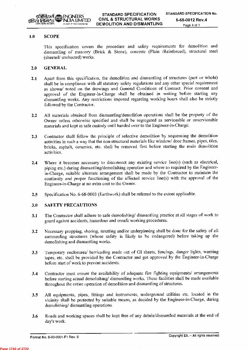
, ENGINEERS STANDARD SPECIFICATION STANDARD SPECIFICATION No.
$fgU 22-dg w INDIA LIMITED CIVIL & STRUCTURAL WORKS 6-68-0012 Rev.4 DEMOLITION AND DISMANTLING Page 4 of 7
1.0 SCOPE
This specification covers the procedure and safety requirements for demolition and dismantling of masonry (Brick & Stone), concrete (Plain /Reinforced), structural steel (sheeted/ unsheeted) works.
2.0 GENERAL
2.1 Apart from this specification, the demolition and dismantling of structures (part or whole) shall be in compliance with all statutory safety regulations and any other special requirement as shown/ noted on the drawings and General Conditions of Contract. Prior consent and approval of the Engineer-in-Charge shall be obtained in writing before starting any dismantling works. Any restrictions imposed regarding working hours shall also be strictly followed by the Contractor.
2.2 All materials obtained from dismantling/demolition operations shall be the property of the Owner unless otherwise specified and shall be segregated as serviceable or unserviceable materials and kept in safe custody until handed over to the Engineer-in-Charge.
2.3 Contractor shall follow the principle of selective demolition by sequencing the demolition activities in such a way that the non-structural materials like window/ door frames, pipes, tiles, bricks, asphalt, ceramics, etc. shall be removed first before starting the main demolition activities.
2.4 Where it becomes necessary to disconnect any existing service line(s) (such as electrical, piping etc.) during dismantling/demolishing operation and where so required by the Engineer-in-Charge, suitable alternate arrangement shall be made by the Contractor to maintain the continuity and proper functioning of the affected service line(s) with the approval of the Engineer-in-Charge at no extra cost to the Owner.
2.5 Specification No. 6-68-0003 (Earthwork) shall be referred to the extent applicable.
3.0 SAFETY PRECAUTIONS
3.1 The Contractor shall adhere to safe demolishing/ dismantling practice at all stages of work to guard against accidents, hazardous and unsafe working procedures.
3.2 Necessary propping, shoring, strutting and/or underpinning shall be done for the safety of all surrounding structures (whose safety is likely to be endangered) before taking up the demolishing and dismantling works.
3.3 Temporary enclosures/ barricading made out of GI sheets, fencings, danger lights, warning tapes, etc. shall be provided by the Contractor and got approved by the Engineer-in-Charge before start of work to prevent accidents.
3.4 Contractor must ensure the availability of adequate fire fighting equipments/ arrangements before starting actual demolishing/ dismantling works. These facilities shall be made available throughout the entire operation of demolition and dismantling of structures.
3.5 All equipments, pipes, fittings and instruments, underground utilities etc. located in the vicinity shall be protected by suitable means, as decided by the Engineer-in-Charge, during demolishing/ dismantling operations.
3.6 Roads and working spaces shall be kept free of any debris/dismantled materials at the end of day's work.
Format No. 8-00-0001-F1 Rev. 0 Copyright EIL — All rights reserved
Page 1742 of 2722
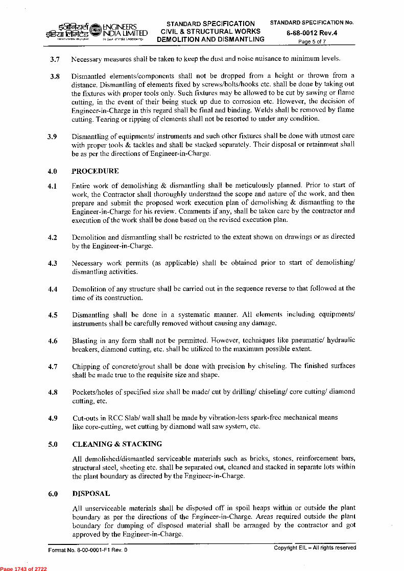
ENGINEERS STANDARD SPECIFICATION STANDARD SPECIFICATION No.
INDIA LIMITED CIVIL & STRUCTURAL WORKS 6-68-0012 Rev.4 DEMOLITION AND DISMANTLING Page 5 of 7
$tga 22-eg
3.7 Necessary measures shall be taken to keep the dust and noise nuisance to minimum levels.
3.8 Dismantled elements/components shall not be dropped from a height or thrown from a distance. Dismantling of elements fixed by screws/bolts/hooks etc. shall be done by taking out the fixtures with proper tools only. Such fixtures may be allowed to be cut by sawing or flame cutting, in the event of their being stuck up due to corrosion etc. However, the decision of Engineer-in-Charge in this regard shall be final and binding. Welds shall be removed by flame cutting. Tearing or ripping of elements shall not be resorted to under any condition.
3.9 Dismantling of equipments/ instruments and such other fixtures shall be done with utmost care with proper tools & tackles and shall be stacked separately. Their disposal or retainment shall be as per the directions of Engineer-in-Charge.
4.0 PROCEDURE
4.1 Entire work of demolishing & dismantling shall be meticulously planned. Prior to start of work, the Contractor shall thoroughly understand the scope and nature of the work, and then prepare and submit the proposed work execution plan of demolishing & dismantling to the Engineer-in-Charge for his review. Comments if any, shall be taken care by the contractor and execution of the work shall be done based on the revised execution plan.
4.2 Demolition and dismantling shall be restricted to the extent shown on drawings or as directed by the Engineer-in-Charge.
4.3 Necessary work permits (as applicable) shall be obtained prior to start of demolishing/ dismantling activities.
4.4 Demolition of any structure shall be carried out in the sequence reverse to that followed at the time of its construction.
4.5 Dismantling shall be done in a systematic manner. All elements including equipments/ instruments shall be carefully removed without causing any damage.
4.6 Blasting in any form shall not be permitted. However, techniques like pneumatic/ hydraulic breakers, diamond cutting, etc. shall be utilized to the maximum possible extent.
4.7 Chipping of concrete/grout shall be done with precision by chiseling. The finished surfaces shall be made true to the requisite size and shape.
4.8 Pockets/holes of specified size shall be made/ cut by drilling/ chiseling/ core cutting/ diamond cutting, etc.
4.9 Cut-outs in RCC Slab/ wall shall be made by vibration-less spark-free mechanical means like core-cutting, wet cutting by diamond wall saw system, etc.
5.0 CLEANING & STACKING
All demolished/dismantled serviceable materials such as bricks, stones, reinforcement bars, structural steel, sheeting etc. shall be separated out, cleaned and stacked in separate lots within the plant boundary as directed by the Engineer-in-Charge.
6.0 DISPOSAL
All unserviceable materials shall be disposed off in spoil heaps within or outside the plant boundary as per the directions of the Engineer-in-Charge. Areas required outside the plant boundary for dumping of disposed material shall be arranged by the contractor and got approved by the Engineer-in-Charge.
Copyright EIL — All rights reserved Format No. 8-00-0001-F1 Rev. 0
Page 1743 of 2722
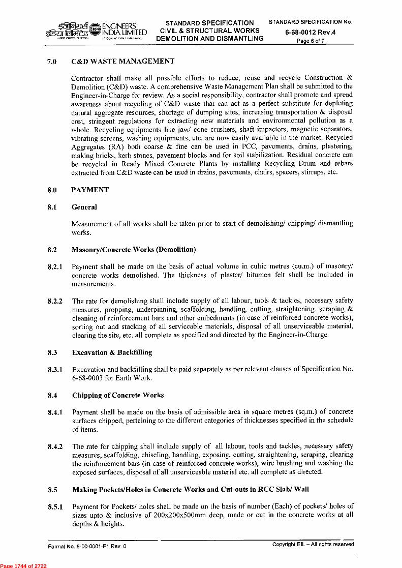
-1 ENGINEERS STANDARD SPECIFICATION STANDARD SPECIFICATION No.
fg-z:rr E;12es INDIA LIMITED CIVIL & STRUCTURAL WORKS 6-68-0012 Rev.4 DEMOLITION AND DISMANTLING Page 6 of 7
2:12,1,12,51,~1
7.0 C&D WASTE MANAGEMENT
Contractor shall make all possible efforts to reduce, reuse and recycle Construction & Demolition (C&D) waste. A comprehensive Waste Management Plan shall be submitted to the Engineer-in-Charge for review. As a social responsibility, contractor shall promote and spread awareness about recycling of C&D waste that can act as a perfect substitute for depleting natural aggregate resources, shortage of dumping sites, increasing transportation & disposal cost, stringent regulations for extracting new materials and environmental pollution as a whole. Recycling equipments like jaw/ cone crushers, shaft impactors, magnetic separators, vibrating screens, washing equipments, etc. are now easily available in the market. Recycled Aggregates (RA) both coarse & fine can be used in PCC, pavements, drains, plastering, making bricks, kerb stones, pavement blocks and for soil stabilization. Residual concrete can be recycled in Ready Mixed Concrete Plants by installing Recycling Drum and rebars extracted from C&D waste can be used in drains, pavements, chairs, spacers, stirrups, etc.
8.0 PAYMENT
8.1 General
Measurement of all works shall be taken prior to start of demolishing/ chipping/ dismantling works.
8.2 Masonry/Concrete Works (Demolition)
8.2.1 Payment shall be made on the basis of actual volume in cubic metres (cu.m.) of masonry/ concrete works demolished. The thickness of plaster/ bitumen felt shall be included in measurements.
8.2.2 The rate for demolishing shall include supply of all labour, tools & tackles, necessary safety measures, propping, underpinning, scaffolding, handling, cutting, straightening, scraping & cleaning of reinforcement bars and other embedments (in case of reinforced concrete works), sorting out and stacking of all serviceable materials, disposal of all unserviceable material, clearing the site, etc. all complete as specified and directed by the Engineer-in-Charge.
8.3 Excavation & Backfilling
8.3.1 Excavation and backfilling shall be paid separately as per relevant clauses of Specification No. 6-68-0003 for Earth Work.
8.4 Chipping of Concrete Works
8.4.1 Payment shall be made on the basis of admissible area in square metres (sq.m.) of concrete surfaces chipped, pertaining to the different categories of thicknesses specified in the schedule of items.
8.4.2 The rate for chipping shall include supply of all labour, tools and tackles, necessary safety measures, scaffolding, chiseling, handling, exposing, cutting, straightening, scraping, clearing the reinforcement bars (in case of reinforced concrete works), wire brushing and washing the exposed surfaces, disposal of all unserviceable material etc. all complete as directed.
8.5 Making Pockets/Holes in Concrete Works and Cut-outs in RCC Slab/ Wall
8.5.1 Payment for Pockets/ holes shall be made on the basis of number (Each) of pockets/ holes of sizes upto & inclusive of 200x200x500mm deep, made or cut in the concrete works at all depths & heights.
Copyright EIL — All rights reserved Format No. 8-00-0001-F1 Rev. 0
Page 1744 of 2722

k31 ENGINEERS STANDARD SPECIFICATION STANDARD SPECIFICATION No.
fga- INDIA LIMITED CIVIL & STRUCTURAL WORKS 6-68-0012 Rev.4 DEMOLITION AND DISMANTLING Page 7 of 7
elecnft
8.5.2 Payment for cut-outs in RCC slab/ wall shall be made in CuM on the basis of plan/ elevation area for a thickness upto & inclusive of 400mm at all depths & heights.
8.5.3 The rate for making pockets/holes and cut-outs shall include supply of all labour, tools & tackles, necessary safety measures, scaffolding, chiseling, drilling, core/ diamond cutting, diamond wall saw system, handling, cutting or relocating reinforcement bars, cleaning, disposal of all unserviceable material etc. all complete as directed.
8.6 Dismantling of Structural Steel Works
8.6.1 Payment shall be made on the basis of weight (MT) of the structure/components being dismantled. Assessment of weight shall be done as per the specifications or as per the direction of Engineer-in-Charge.
8.6.2 The rate for dismantling shall include supply of all labour, tools and tackles, equipment, consumables, necessary safety measures, scaffolding, propping, handling, unbolting, cutting (by sawing or flame cutting) of gussets/ plates/ bolts/ hooks/ welds, cleaning, sorting out and stacking of all serviceable materials, disposal of all unserviceable material, etc. all complete as specified and directed.
8.7 Dismantling of Roof & Wall Sheeting
8.7.1 Payment shall be made on the basis of dismantled sheeted area in square metres (sq.m.) of plan area in case of roof sheeting and area in elevation in case of side and louver sheeting.
8.7.2 The rate for dismantling shall include supply of all labour, tools and tackles, equipments, consumables, necessary safety measures, handling, scaffolding, unbolting, cutting (by saw or flame cutting) of hook bolts, removal of ridges, gutters, flashings, transporting, stacking of all serviceable materials, disposal of all unserviceable material, etc. all complete as directed.
Copyright EIL — AII rights reserved Format No. 8-00-0001-F1 Rev. 0
Page 1745 of 2722
ALPANA R.SRIVASTAVA 4 22.03.16 REVISED & REISSUED
MODITA
3 29.06.10 REISSUED AS PKM SCH
2 26.04.01 UPDATED & REISSUED SBJ R SOOD SC JAIN
1 AUG 94 UPDATED & REISSUED SBJ R SOOD GPL
0 AUG 89 ISSUED AS STANDARD SPECIFICATION AKV GPL2
Rev. No Date Purpose
Prepared by Checked by
Standards Committee Convenor
S.CHANDA
N DUARI
MI
A SONI
RCPC
Standards Bureau
Chairman
STANDARD SPECIFICATION a311 ENGINEERS CIVIL & STRUCTURAL WORKS 2e.litaf5i-eg INDIA LIMITED
IA Goat of Incite Undertaking) MISCELLANEOUS ITEMS 018 ewwaw M JPSA,1
STANDARD SPECIFICATION No.
6-68-0013 Rev.4 Page 1 of 9
Trriw fT
feqff R-4 tittiliciicri wig
1-444 -41-4
STANDARD SPECIFICATIONS CIVIL AND STRUCTURAL WORKS
MISCELLANEOUS ITEMS
Format No. 8-00-0001-F1 Rev. 0 Copyright EIL — All rights reserved
Page 1746 of 2722
■-11 ENGINEERS STANDARD SPECIFICATION
$fg-ar Ell5leg INDIA LIMITED CIVIL & STRUCTURAL WORKS IA Gout. of India Undertaking) MISCELLANEOUS ITEMS
STANDARD SPECIFICATION No.
6-68-0013 Rev.4 Page 2 of 9
rirmftAN,Kno)
Abbreviations:
BIS • . Bureau of Indian Standards
DPC • . Damp Proof Course
FGL • . Finished Ground Level
IS • . Indian Standard
RCC Reinforced Cement Concrete
Structural Standards Committee
Convenor : Mr. Rajanji Srivastava
Members : Mr. Anurag Sinha Mr. J K Bhagchandani Mr. S K Naskar Mr. V K Panwar Mr. Charanjit Singh (Projects) Mr. Ravindra Kumar (Construction)
Format No. 8-00-0001-F1 Rev. 0 Copyright EIL — All rights reserved
Page 1747 of 2722
ENGINEERS STANDARD SPECIFICATION STANDARD SPECIFICATION No.
INDIA LIMITED CIVIL & STRUCTURAL WORKS 6-68-0013 Rev.4 Ogzir 00leg 4ffiRA IA Gov't of lotto linfierlakIng) MISCELLANEOUS ITEMS Page 3 of 9
CONTENTS
1.0 SCOPE 4
2.0 REFERENCES 4
3.0 MATERIALS 4
4.0 GENERAL REQUIREMENTS 4
5.0 PRE-CONSTRUCTIONAL ANTI-TERMITE TREATMENT 4
6.0 ANTI-CORROSIVE LAYER 6
7.0 DRESSING & TRIMMING 6
8.0 BREAKING PILE HEADS 7
9.0 BUILDING-UP PILE HEADS 7
10.0 HARD CORE 8
11.0 SAND FILLING IN PLINTH/FOUNDATIONS 8
12.0 DAMP PROOF COURSE - (DPC) 9
Format No. 8-00-0001-F1 Rev. 0 Copyright Ell — All rights reserved
Page 1748 of 2722

31 ENGINEERS STANDARD SPECIFICATION STANDARD SPECIFICATION No.
idf5ift INDIA LIMITED CIVIL & STRUCTURAL WORKS 6-68-0013 Rev.4 Offirno-worrecoldoif.) IA Govt of India Undettalong) MISCELLANEOUS ITEMS Page 4 of 9
1.0 SCOPE
The scope shall be as specified separately for different items below.
2.0 REFERENCES
2.1 BIS Codes
S.No. IS No. Title 1. IS:73 Paving bitumen - specification
2. IS:383 Specification for coarse and fine aggregates from natural sources for Concrete
3. IS:6313 Code of practice for Anti-termite measures in buildings
2.2 EIL specifications
6-68-0002: Materials 6-68-0004: Plain and Reinforced Cement Concrete
3.0 MATERIALS
The materials shall be as specified separately for different items below.
4.0 GENERAL REQUIREMENTS
The Contractor shall test the materials, wherever applicable, in approved laboratory as required by the Engineer-in-Charge and furnish test certificates for materials and obtain the approval of the Engineer-in-Charge prior to the use of such materials in the works. All tests shall be in accordance with relevant Indian Standards.
5.0 PRE-CONSTRUCTIONAL ANTI-TERMITE TREATMENT
5.1 Scope
This specification establishes the materials and method of accomplishing pre-constructional anti-termite treatment of soil for protection of buildings against attack by subterranean termites with the usage of chemical emulsions in accordance with the procedure laid down.
5.2 Materials
Refer Ell, Specification No. 6-68-0002.
5.3 Procedure for Treatment
5.3.1 The treatment shall be carried out by an approved agency specialized in the field. Apart from this specification, the work shall be carried out in compliance with IS:6313. In case of any contradiction, this specification shall govern.
5.3.2 Site Preparation
Prior to start of Anti Termite treatment, area(s) shall be made free from logs, stumps, timber offcuts, leveling pegs, roots of plants/ trees etc. Soil treatment shall start when foundation trenches/ pits are ready to take concrete/ masonry in foundations and plinth area ready for laying the subgrade. Treatment shall not be carried out when it is raining or the subsoil
Copyright EIL — All rights reserved Format No. 8-00-0001-F1 Rev. 0
Page 1749 of 2722

ENGINEERS STANDARD SPECIFICATION INDIA LIMITED CIVIL & STRUCTURAL WORKS IA Govt of India Unclenak.g) MISCELLANEOUS ITEMS
STANDARD SPECIFICATION No.
6-68-0013 Rev.4 Page 5 of 9
Gcro)
water level is at the same or higher than the level of treatment. In the event of water-logging of foundations, the water shall be pumped out and the chemical emulsion applied when the soil is absorbent.
5.3.3 Treatment of the excavated pits/ trenches and backfill for Foundations
a) The bottom surface and the lower 300 mm side surfaces of the excavated pits/ trenches for foundations of masonry works and RCC plinth beams supporting such masonry works, shall be treated with specified chemical emulsion @ 5 litres/m 2 of the surface area. However, no such treatment shall be required in case of pits/ trenches made for RCC foundations supporting RCC walls and/ or columns.
b) On completion of construction of masonry foundations, the backfill in immediate contact with the substructure shall be treated in layers, of 300 mm, with emulsion @ 7.5 litres/m2 of the vertical surface of the substructure (i.e. 7.5 x 0.3 = 2.25 litres/meter of perimeter) for each side. The treatment shall be given after ramming of each layer of soil, by rodding the earth at 150 mm centres close to the wall surface and working the rod backward and forward (parallel to the wall surface) and then spraying the specified dosage of emulsion. The emulsion shall be directed towards the masonry surfaces so that the soil in contact with these surfaces is well treated with the chemical. After the treatment, the soil shall be tamped back into place. This shall be done for full depth of the fill.
c) For RCC walls and columns, the treatment as specified in (b) shall start from a depth 500 mm below the finished ground level, and shall be done upto the FGL.
5.3.4 Treatment of Plinth/ Basement and Apron
a) The top surface of the consolidated earth below the non-suspended floor slabs and the peripheral aprons of widths upto 750 mm, the bottom surface and side surfaces of the excavated pits for the basements shall be treated with chemical emulsion @ 5 litres/m 2
of the surface area. Holes 50 mm to 75 mm deep at 150 mm centre, both ways, shall be made on the surface with 12 mm diameter mild steel rod and then emulsion shall be sprayed uniformly over the area. At expansion joint locations, anti-termite treatment shall be supplemented by treating through the expansion joint @ 2.0 litres per linear metre of joint after the sub-grade has been laid.
b) Treatment of Junctions of plinth filling and wall/column faces shall be done after making a small channel 30 mm x 30 mm, by making rod holes 150 mm apart (upto the ground level) in the channel and then by moving the rod backward and forward to break up the earth. The chemical emulsion shall be poured along the channel @ 7.5 litres/m 2
of the vertical wall/column surface so as to soak the soil right to the bottom. The soil shall be tamped back into place after the treatment.
5.3.5 Treatment of Soil along External Perimeter of Building
After the building is complete, the earth along the external perimeter shall be rodded at intervals of 150 mm and to depth of 300 mm. The rod shall be moved backward and forward parallel to the wall to break up the earth and chemical emulsion poured along the wall @ 7.5 litres/m2 of vertical surface (i.e. 7.5 x 0.3 = 2.25 litres/metre of perimeter). After the treatment, the earth shall be tamped back into place.
5.4 Payment
This clause shall apply to Item Rate tender only.
Format No. 8-00-0001-F1 Rev. 0
Copyright EIL — All rights reserved
Page 1750 of 2722

ENGINEERS STANDARD SPECIFICATION STANDARD SPECIFICATION No.
elflaf=4ZEqr------) w INDIA LIMITED CIVIL & STRUCTURAL WORKS 6-68-0013 Rev.4
MISCELLANEOUS ITEMS 1.11¢t, 212.52 era 3qq.1) (A Govt of India Undertalong)
Page 6 of 9
Payment for pre-constructional anti-termite treatment shall be made on square metre (sq.m.) basis of plinth area of the building at ground floor only.
The rate shall include supplying all materials, spray pumps, tools, tackles & other accessories, labour, site preparation, rodding, tamping, mixing, spraying the specified chemical emulsion at prescribed dosage, storage facilities, handling, transporting etc. all complete as directed & specified.
6.0 ANTI-CORROSIVE LAYER
6.1 Scope
This specification covers the requirement of materials, method of preparation and procedure for laying an anticorrosive layer over top surface of tank foundations for protection of bottom plates of steel tanks against corrosion attack.
6.2 Materials
6.2.1 Sand shall be clean, dry, coarse, hard, angular, free from coatings of clay, dust and mix of vegetable and organic matter and shall conform to IS:383 - Grade III.
6.2.2 Bitumen shall be of grade VG10 conforming to IS:73.
63 Mixing and Laying
The bitumen shall be heated till it melts. 3% kerosene may be added if required. Sand shall be thoroughly mixed with bitumen (8% to 10% by volume) in a mixing drum to give a uniform mixture and shall be laid over clean and dry surface of tank foundation to line, grade and levels as shown on the drawings and directed by the Engineer-in-Charge. Bitumen shall not be heated beyond the specified temperature limits. The layer shall be tamped to form hard mass of specified compacted thickness.
6.4 Payment
This clause shall apply to Item Rate tender only.
The payment shall be made on square metre (sq.m.) basis of the area covered with the anticorrosive layer.
The rate shall include supplying all materials, tools, plants, labour, transportation, handling, heating, mixing, laying, tamping etc. all complete as specified.
7.0 DRESSING & TRIMMING
7.1 Scope
This specification covers the procedure for dressing, trimming and paving with earth the peripheral area around the completed building/ structure.
7.2 Procedure
The ground all around the completed building/structure for 3 metres width or as specified by the Engineer-in-Charge, shall be cleaned and dressed to suitable slope. Over the prepared ground a layer of approved earth shall be spread, watered and well consolidated so as to achieve an average thickness of 75 mm.
Copyright EIL - All rights reserved Format No. 8-00-0001-F1 Rev. 0
Page 1751 of 2722

ei Ogen fdigtag
WW1 2121A2 +7. 3021.1
ENGINEERS STANDARD SPECIFICATION INDIA LIMITED CIVIL & STRUCTURAL WORKS IA Goa. of India Underialoo9) MISCELLANEOUS ITEMS
STANDARD SPECIFICATION No.
6-68-0013 Rev.4 Page 7 of 9
7.3 Payment
This clause shall apply to Item Rate tender only.
Payment shall be made on square metre (sq.m.) basis of the actual area dressed and paved with earth.
The rate shall include supplying all materials, labour including cleaning, dressing the ground to required slope, spreading of earth, watering, ramming, consolidating etc. all complete as directed.
8.0 BREAKING PILE HEADS
8.1 Scope
This specification covers procedure for breaking pile heads of RCC piles.
8.2 Procedure
8.2.1 Head of already cast/ driven RCC piles shall be broken after 28 days of casting up to a length and elevation as shown on the drawing by chiseling or by approved mechanical means taking all necessary safety precautions. Care shall be taken that pile reinforcement is not cut or damaged during chiseling operation. All debris and loose or cracked concrete in the pile shall be removed and disposed off within the plant boundary as per the directions of the Engineer-in-Charge and site shall be left clean for casting of pile caps. The surface of reinforcement bars shall be cleaned, if required by wire brushing, so that no old concrete sticks to them.
8.3 Payment
This clause shall apply to Item Rate tender only.
Payment shall be made per pile basis for the actual number of pile heads broken.
The rate shall include supplying all tools and tackles, labour including disposal of debris, bending the pile reinforcements for proper anchorage within the pile cap etc. all complete as directed.
9.0 BUILDING-UP PILE HEADS
9.1 Scope
This specification covers requirements of materials and procedure for building-up of RCC Pile Heads.
9.2 Materials
9.2.1 Concrete shall be of the same grade & EIL specification shall be same as that for the pile.
9.2.2 Reinforcement shall be of the same grade as that for the pile.
9.2.3 Type of cement shall be same as that used for the pile.
Format No. 8-00-0001-F1 Rev. 0
Copyright EIL — All rights reserved
Page 1752 of 2722
ENGINEERS STANDARD SPECIFICATION STANDARD SPECIFICATION No.
INDIA LIMITED CIVIL & STRUCTURAL WORKS 6-68-0013 Rev.4 tige.litemeg IA Govt of India Undetaking) MISCELLANEOUS ITEMS Page 8 of 9
9.3 Procedure
Concrete in existing piles shall be chiseled off minimum upto the lap-length of the reinforcements in the pile. In cases where reinforcements are longer than the concreted piles, the top concrete of the existing piles shall be chiseled or by approved mechanical means upto a length of 800 mm.
Concrete surface and reinforcement of pile shall be cleaned of any dirt, grease, debris etc. and concrete surface shall be made rough by hacking. Reinforcement shall be lapped/ welded as per the direction of the Engineer-in-Charge. Neat cement slurry shall be applied on top surface of concrete and using approved formwork, concreting shall be done upto the level shown on the drawing and as directed by the Engineer-in-Charge.
9.4 Payment
This clause shall apply to Item Rate tender only.
Payment shall be made on cubic metre basis for the total quantity of concrete actually poured for achieving the level as shown on drawings.
The rate shall include supply of all materials (except reinforcement which shall be paid separately as per respective item) labour, cleaning, welding, shuttering, vibrating, finishing, curing etc. all complete. Cutting of pile heads and excavation including backfilling shall be paid separately as per respective item.
10.0 HARD CORE
10.1 Scope
This specification covers the requirements of materials and procedure for laying of hard core.
10.2 Materials
Hard core shall consist of broken/ crushed stones of 150 mm and down size. Stones shall be sound, angular, hard and free from flakes, dust and other impurities.
10.3 Procedure
Hard core shall be laid to the grade, level and thickness as shown on the drawing. Broken stones of required height shall be vertically placed and blinded with approved murrum/ sand and consolidated with roller including watering, dressing etc. However, areas inaccessible by roller may be compacted by hand rammer.
10.4 Payment
This clause shall apply to Item Rate tender only.
The hard core shall be measured on the basis of volume in cubic metres (cu.m.) of the compacted hard core laid. The rate shall include all labour, materials, consolidation by rammer/ roller, watering, dressing etc. all complete.
11.0 SAND FILLING IN PLINTH/FOUNDATIONS
11.1 For specification of sand to be used for filling, reference shall be made to EIL Specification No. 6-68-0002.
Copyright EIL—All rights reserved Format No. 8-00-0001-F1 Rev. 0
Page 1753 of 2722

STANDARD SPECIFICATION No.
6-68-0013 Rev.4 Page 9 of 9
OW71 eiVirr2 ,7513P415.1)
ENGINEERS STANDARD SPECIFICATION
tlfWe INDIA LIMITED CIVIL & STRUCTURAL WORKS (A Govt of India Undertaking) MISCELLANEOUS ITEMS
11.2 Filling shall be carried out in layers not exceeding 150 mm and shall be compacted mechanically or by saturation to specified grade and level and to obtain 90% laboratory maximum dry density or as specified in schedule of rates.
11.3 Compaction by flooding may be accepted at the discretion of the Engineer-in-Charge, provided the required compaction is achieved.
11.4 The Contractor shall not commence filling in and around any work until it has been permitted by the Engineer-in-Charge.
11.5 Payment
This clause shall apply to Item Rate tender only.
Payment shall be made on cubic metre (cu.m.) basis of the finished compact volume. The rate shall include cost of sand for any compacted thickness, wastage if any, all handling, transport for all leads, tamping, watering, flooding, dressing etc. Any brick work required for ponding shall be paid separately under relevant item.
12.0 DAMP PROOF COURSE - (DPC)
12.1 All materials used for Damp Proof Course shall comply with Ell, Specification No. 6-68- 0002.
12.2 The 40 mm thick Damp Proof Course shall consist of plain cement concrete of the same grade as used for RCC work.
12.3 The Damp Proof Course shall be laid at plinth level of masonry walls, flush with the floor surface and shall not be carried across doorways.
12.4 Before laying, the top surface of wall shall be thoroughly cleaned and watered. The DPC shall be laid in layers of 20 mm thickness retaining the edges by necessary formwork and shall be well tamped and troweled to smooth finish. The layer shall be cured by keeping the surface wet for 40 hours and after it has dried, two coats of hot bitumen of grade VG10 conforming to IS:73 shall be applied over it at the rate of 1.7 kg/m 2 . Over this, the second layer of 20 mm thick concrete shall be laid and cured as described in case of the first layer and two coats of hot bitumen at the rate of 1.7 kg/m 2 shall be applied again in a similar manner. Over this, dry sharp sand shall be sprinkled evenly before hardening of second coat of bitumen paint.
12.5 Payment
This clause shall apply to Item Rate tender only.
Payment shall be made on square metre (sq.m.) basis of the area laid. The rate shall be inclusive of formwork, curing, providing and laying bitumen, supplying and spreading sand over bitumen etc. complete.
Copyright EIL — All rights reserved Format No. 8-00-0001-F1 Rev. 0
Page 1754 of 2722
IStatzeie ENGINEERS10-ar Were INDIA LIMITED
INIMPIRPR =MOW IA Gent M MAO unartokno
STANDARD SPECIFICATIONCIVIL & STRUCTURAL WORKS
BIPOLAR CONCRETEPENETRATING CORROSION
INHIBITING ADMIXTURE
STANDARD SPECIFICATION No.
6-68-0017 Rev.0
Page 1 of 14
1:ITTW kill
furre ;r4 tioifficiich wrzi
wrickw (Able ataruffkutur atafrarar
STANDARD SPECIFICATIONCIVIL & STRUCTURAL WORKS
BIPOLAR CONCRETE PENETRATINGCORROSION INHIBITING ADMIXTURE
&AR— \ ( "1.1‘ CavvkSC VK DM0 26.04.2012 ISSUED AS STANDARD SPECIFICATION AJS PKM
Rev. DateNo Purpose Prepared Checkedby by
StandardsCommitteeConvenor
StandardsGM(E) Bureau
Chairman
Approved by
Format No. 8-00-0001-F1 Rev. 0 Copyright EIL — All rights reserved
Page 1755 of 2722
Offitaelda EnoNEERsogar Wagger INDIA LJMITEDWWI
STANDARD SPECIFICATIONCIVIL & STRUCTURAL WORKS
BIPOLAR CONCRETEPENETRATING CORROSION
INHIBITING ADMIXTURE
STANDARD SPECIFICATION No.6-68-0017 Rev.0
Page 2 of 14IA Gcnet al MY unertanto
ABBREVIATIONS:
AASHTO
ASTM
CPCIA
IS
JIS
OPC
PPC
PSC
SRC
American Association of State Highway and Transportation Officials
American Society for Testing & Materials
Concrete Penetrating Corrosion Inhibiting Admixture
Indian Standard
Japanese Industrial Standard
Ordinary Portland Cement
Portland Pozzolana Cement
Portland Slag Cement
Sulphate Resistant Cement
STRUCTURAL STANDARDS COMMITTEE
Convenor : Mr. S. Chaturvedi
Members : Mr. PK MittalMr. S. DebnathMr. Rajan SrivastavMr. PJ SinghMr. Samir DasMr. MP Jain (Projects)Mr. Ravindra Kumar (Construction)
Format No. 8-00-0001-F1 Rev. 0 Copyright EIL — All rights reserved
Page 1756 of 2722
PRZIBT AS- INGINEERSligataPitgW WA LIMITED
inmaxeivelJelmil IA Gat of So Limning)
STANDARD SPECIFICATIONCIVIL & STRUCTURAL WORKS
BIPOLAR CONCRETEPENETRATING CORROSION
INHIBITING ADMIXTURE
STANDARD SPECIFICATION No.648-0017 Rev.O
Page 3 of 14
CONTENTS
1.0 SCOPE 4
2.0 REFERENCES 4
3.0 SAMPLING 4
4.0 TESTING REQUIREMENTS 4
5.0 HEALTH, SAFETY & ENVIRONMENT CONSIDERATIONS 5
6.0 PACKAGING 5
ANNEXURE-A (SHORT TERM TESTS) 6
ANNEXURE-B (LONG TERM TESTS) 7
APPENDIX-I (MODIFIED ACCELERATED CORROSION TEST) 8
APPENDIX-II (IMMERSION TEST) 9
APPENDIX-III (TEST FOR EFFECT ON COMPRESSIVE STRENGTH WITH CCPIA)...10
APPENDIX-IV (ELECTROCHEMICAL POLARIZATION TEST) 11
APPENDIX-V (CORROSION TEST) 12
APPENDIX-VI (CHLORIDE ION PENETRATION TEST) 13
Format No. 8-00-0001-F1 Rev. 0 Copyright EIL — All rights reserved
Page 1757 of 2722
EiSil% 113\1149A LITSMITED1A Gal al India undertaking)
STANDARD SPECIFICATIONCIVIL & STRUCTURAL WORKS
BIPOLAR CONCRETEPENETRATING CORROSION
INHIBITING ADMIXTURE
STANDARD SPECIFICATION No.6-68-0017 Rev.0
Page 4 of 14
1.0 SCOPE
This specification prescribes the requirements and test methods including performance test forevaluating the efficiency of Bipolar Concrete Penetrating Corrosion Inhibiting Admixture(CPCIA) for protecting steel reinforcement embedded in concrete from corrosion. Non-concrete penetrating, Nitrite & Nitrate corrosion inhibitors are excluded from the scope.
2.0 REFERENCES
2.1 Codes
ASTM-G1, ASTM-G3, ASTM-G109, ASTM-C1202, JIS-Z-1535, AASHTO T259, IS:2,IS:101(Partl/Sec.5), IS:456, IS:1202, IS:1448, IS:1786, IS:9103, etc.
2.2 EIL Specifications
6-68-0001 : General Scope6-68-0002 : Materials
3.0 SAMPLING
3.1 The representative samples of the material shall be drawn as per the table given below:
No. of containers (Lot) No. of containers to be selected forsampling (N)
Up to 50 1
51-100 2
101-300 3
301-500 4
501& Above 5Plus 1 for every lot of 300 containers
4.0 TESTING REQUIREMENTS
4.1 The product shall comply with the requirements specified in Annexure-A (Short Term Tests)and Annexure-B (Long Term Tests). Both the tests shall be conducted in an approvedlaboratory.
4.2 Unless specified otherwise, all the tests under Indian tropical conditions shall be conducted atroom temperature 27 ± 2°C and relative humidity at 65 ± 5 % in a well ventilated chamberfree from dust.
4.3 The contractor shall submit the Manufacturer Test certificate to the Engineer-in-Charge.Approval for usage of product may be given after satisfactory Short Term test results as LongTerm test results would require a considerable time. However, the product shall also satisfythe requirements of Long Term Tests. Recommendations from reputed organizations about theproduct shall be an added advantage.
Format No. 8-00-0001-F1 Rev. 0 Copyright EIL —All rights reserved
Page 1758 of 2722
laiötzmiakENarNaRsIfgar ElPitg var WA UMETED
loan !MR elJn IA Govt S Wei Venting)
STANDARD SPECIFICATIONCIVIL & STRUCTURAL WORKS
BIPOLAR CONCRETEPENETRATING CORROSION
INHIBITING ADMIXTURE
STANDARD SPECIFICATION No.
6-68-0017 Rev.0
Page 5 of 14
5.0 HEALTH, SAFETY & ENVIRONMENT CONSIDERATIONS
5.1 The CPCIA shall not cause harm to applicators by mean of inhalation or skin contact. Allprecautionary measures shall be prescribed by the manufacturers along with instructions ofusage Application methodology shall be approved by the Engineer-in-Charge.
5.2 The waste shall be discharged in accordance with applicable Environmental laws of land.
5.3 CPCIA shall not degrade or damage the construction materials like concrete, aggregates, steelreinforcement, formwork/shuttering.
6.0 PACKAGING
The product shall be supplied in air tight containers and following information shall be labeledon each container:
Name of the materialName of the manufacturerVolume / weight of materialSpecification number
e) Batch No. or Lot No. in bar code or otherwise0 Month and year of manufacture
Ingredients & method of usageInstructions for safe usage
Format No. 8-00-0001-F1 Rev. 0 Copyright EIL — All rights reserved
Page 1759 of 2722
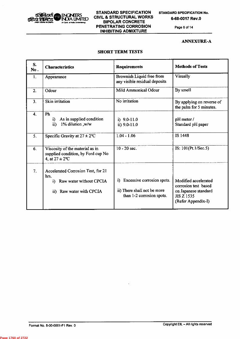
1511WIzeak_ ENGINEERSsigar egie INDIA UMITED
141R.1 emir is asam)
STANDARD SPECIFICATIONCIVIL & STRUCTURAL WORKS
BIPOLAR CONCRETEPENETRATING CORROSION
INHIBITING ADMIXTURE
STANDARD SPECIFICATION No.6-68-0017 Rev.)
Page 6 of 14
ANNEXURE-A
SHORT TERM TESTS
S.No. Characteristics Requirements Methods of Tests
Appearance Brownish Liquid free fromany visible residual deposits
Visually
Odour Mild Ammonical Odour By smell
Skin irritation No irritation By applying on reverse ofthe palm for 5 minutes.
PhAs in supplied condition1% dilution ,w/w
9.0-11.09.0-11.0
pH meter /Standard pH paper
Specific Gravity at 27 ± 2°C 1.04 - 1.06 IS 1448
Viscosity of the material as insupplied condition, by Ford cup No4, at 27 ± 2°C
10 - 20 sec. IS: 101(Pt.1/Sec.5)
7. Accelerated Corrosion Test, for 21hrs.
Raw water without CPCIA
Raw water with CPCIA
Excessive corrosion spots.
There shall not be morethan 1-2 corrosion spots.
Modified acceleratedcorrosion test basedon Japanese standardJIS Z 1535(Refer Appendix-I)
Format No. 8-00-0001-F1 Rev. 0 Copyright EIL — All rights reserved
Page 1760 of 2722

PR-atilt ENGINEERSsig-tar latiegilar INDIA UMITED
IA Gent a( Wd 1ftdeno.9)
STANDARD SPECIFICATIONCIVIL & STRUCTURAL WORKS
BIPOLAR CONCRETEPENETRATING CORROSION
INHIBITING ADMIXTURE
STANDARD SPECIFICATION No.
6-68-0017 Rev.0
Page 7 of 14
ANNEXURE-BLONG TERM TESTS
(Shall be performed in triplicate)
S.No . Characteristics
RequirementsMethods of Tests
Without CPCIA With 1% CPCIA
Immersion test for 720 hrs.(Rebar weight loss method )
40.00 mpy, max. 2.00 mpy, max. Immersion Test(Rebar weight loss test)as per ASTM GI(Refer Appendix-II)
Effect of Concrete admixture oncompressive strength
Concrete strength in sample withCPCIA* should be ?_concrete strength
in sample without CPCIA*
Test for effect oncompressive strengthby addition of CPCIAas per IS 9103(Refer Appendix-III)
Polarization test by Tafelpolarization with 3.5% SodiumChloride, for 20 days:
Rate of corrosion shall be
45 mpy, max. 9 mpy, max. Electrochemicalpolarization testconducted on steelrebars embedded inconcrete as perASTM-G 3 & IS 9103(Refer Appendix-IV)
Effect of CPCIA* on corrosion ofembedded steel rebars exposed tochloride environments after 09cycles (14 days wetting and 14days drying):
Rate of corrosion shall be25 Coulombs,max.
0.50 Coulombs,max.
Long term corrosiontest as per ASTM G109(Refer Appendix-V)
5. Chloride Migration profileproperties of concrete (for alltypes of cements viz. OPC, PPC,PSC, SRC)
Chloride % in concrete at30mm depth after 90 days.
Ability to resist chlorideion penetration
Concrete grade M-30,Water cement ratio: 0.45
Concrete grade M-40,Water cement ratio: 0.40
0.025%, max.
1650 Coulombs,max.
1550 Coulombs,max.
Nil
1000 Coulombs,max.
1000 Coulombs,max.
AASHTO T-259(Refer Appendix-VI)
Chloride ionpenetration(Salt ponding test)as per IS:456
Electrical indicationof concrete ability toresist Chloride IonPenetration (RapidChloride Permeabilitytest) as perASTM C1202
Notes:
CPCIA* : The CPCIA shall be used as 1% w/w of cement or as recommended by the manufacturerfor conducting the tests mentioned in Annexure-B except Immersion test for 720 hrs. mentioned atS.No.1 where it shall be used as 1% w/w of water or as recommended by the manufacturer.
Rebars conforming to IS: 1786 shall be used for testing purposes
Format No. 8-00-0001-F1 Rev. 0 Copyright EIL — All rights reserved
Page 1761 of 2722
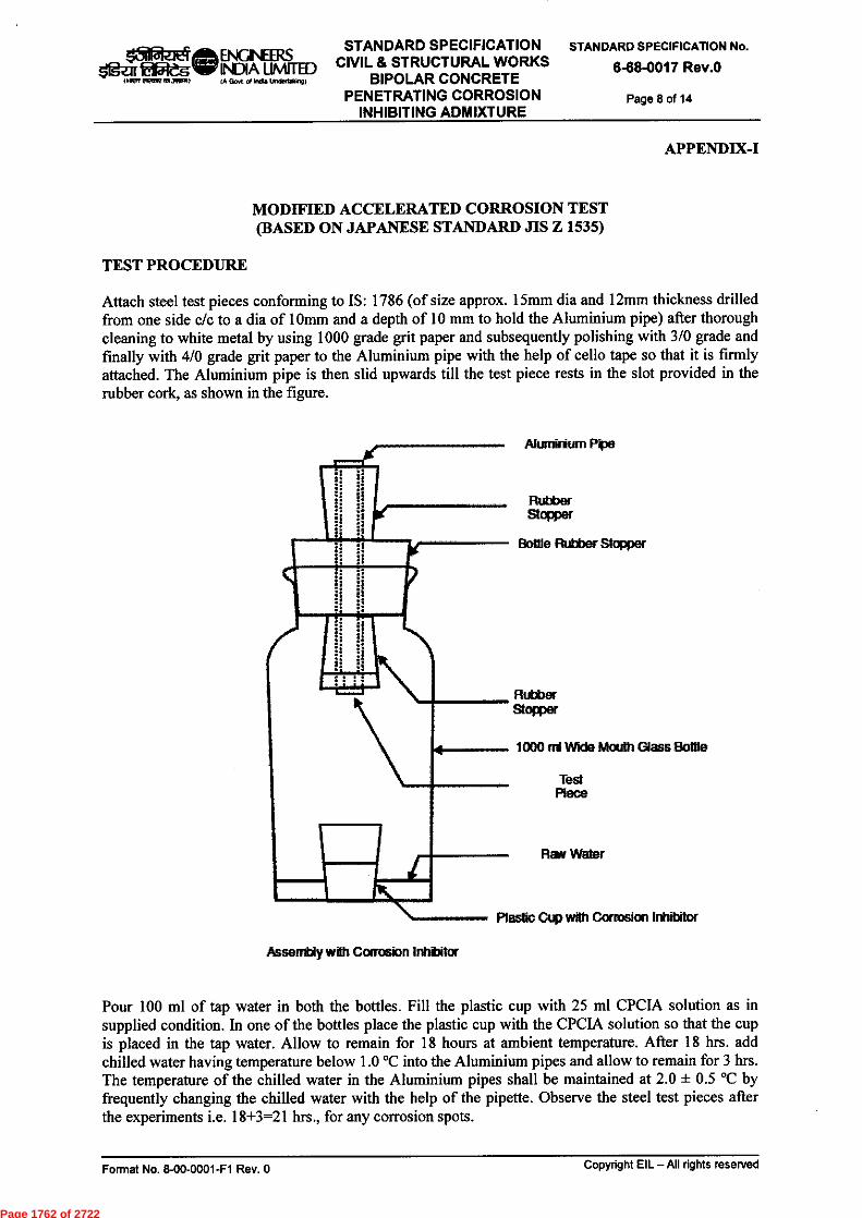
Alumirium Pita
RubberStopper
Bottle Rubber Stopper
RubberStopper
1000 rri 1We Mouth Glass Bottle
TestPiece
REIN Water
Plastic Ctip with Corrosion Inhibitor
ISIRIzet ENGINEER.Ssigzir €1151dgisr INDIA UMITEDOwen PIMP anaign) IA GON of India UnIonsking)
STANDARD SPECIFICATIONCIVIL & STRUCTURAL WORKS
BIPOLAR CONCRETEPENETRATING CORROSION
INHIBITING ADMIXTURE
STANDARD SPECIFICATION No.
6-68-0017 Rev.0
Page 8 of 14
APPENDIX-I
MODIFIED ACCELERATED CORROSION TEST(BASED ON JAPANESE STANDARD JIS Z 1535)
TEST PROCEDURE
Attach steel test pieces conforming to IS: 1786 (of size approx. 15mm dia and 12mm thickness drilledfrom one side c/c to a dia of lOmm and a depth of 10 mm to hold the Aluminium pipe) after thoroughcleaning to white metal by using 1000 grade grit paper and subsequently polishing with 3/0 grade andfinally with 4/0 grade grit paper to the Aluminium pipe with the help of cello tape so that it is firmlyattached. The Aluminium pipe is then slid upwards till the test piece rests in the slot provided in therubber cork, as shown in the figure.
Assent!). win Corrosion Inhbilor
Pour 100 ml of tap water in both the bottles. Fill the plastic cup with 25 ml CPCIA solution as insupplied condition. In one of the bottles place the plastic cup with the CPCIA solution so that the cupis placed in the tap water. Allow to remain for 18 hours at ambient temperature. After 18 hrs. addchilled water having temperature below 1.0 °C into the Aluminium pipes and allow to remain for 3 hrs.The temperature of the chilled water in the Aluminium pipes shall be maintained at 2.0 ± 0.5 °C byfrequently changing the chilled water with the help of the pipette. Observe the steel test pieces afterthe experiments i.e. 18+3=21 hrs., for any corrosion spots.
Format No. 8-00-0001-F1 Rev. 0 Copyright EIL —All rights reserved
Page 1762 of 2722
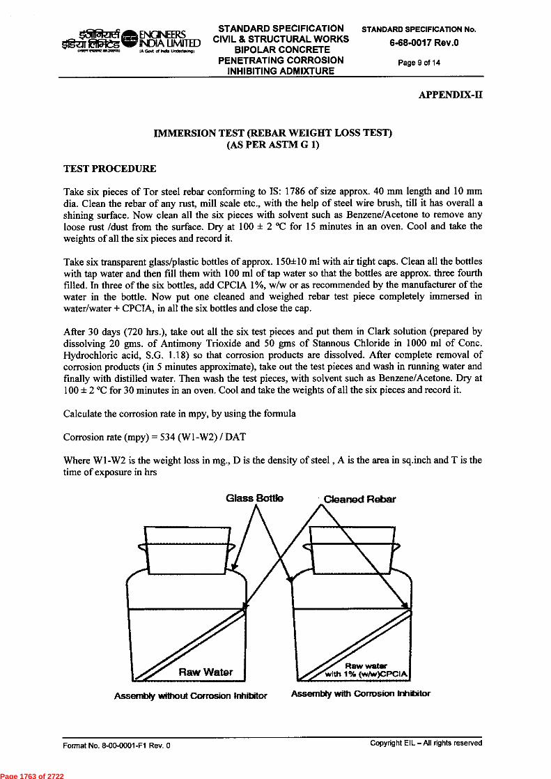
STANDARD SPECIFICATIONCIVIL & STRUCTURAL WORKS
BIPOLAR CONCRETEPENETRATING CORROSION
INHIBITING ADMIXTURE
STANDARD SPECIFICATION No.6-68-0017 Rev.0
Page 9 of 14IA Go (M MY mammon.,
APPENDIX-H
IMMERSION TEST (REBAR WEIGHT LOSS TEST)(AS PER ASTM G 1)
TEST PROCEDURE
Take six pieces of Tor steel rebar conforming to IS: 1786 of size approx. 40 mm length and 10 mmdia. Clean the rebar of any rust, mill scale etc., with the help of steel wire brush, till it has overall ashining surface. Now clean all the six pieces with solvent such as Benzene/Acetone to remove anyloose rust /dust from the surface. Dry at 100 ± 2 °C for 15 minutes in an oven. Cool and take theweights of all the six pieces and record it.
Take six transparent glass/plastic bottles of approx. 150+10 ml with air tight caps. Clean all the bottleswith tap water and then fill them with 100 ml of tap water so that the bottles are approx. three fourthfilled. In three of the six bottles, add CPCIA 1%, w/w or as recommended by the manufacturer of thewater in the bottle. Now put one cleaned and weighed rebar test piece completely immersed inwater/water + CPCIA, in all the six bottles and close the cap.
After 30 days (720 hrs.), take out all the six test pieces and put them in Clark solution (prepared bydissolving 20 gins of Antimony Trioxide and 50 gins of Stannous Chloride in 1000 ml of Conc.Hydrochloric acid, S.G. 1.18) so that corrosion products are dissolved. After complete removal ofcorrosion products (in 5 minutes approximate), take out the test pieces and wash in running water andfinally with distilled water. Then wash the test pieces, with solvent such as Benzene/Acetone. Dry at100 ± 2 °C for 30 minutes in an oven. Cool and take the weights of all the six pieces and record it.
Calculate the corrosion rate in mpy, by using the formula
Corrosion rate (mpy) = 534 (WI-W2) / DAT
Where WI -W2 is the weight loss in mg., D is the density of steel , A is the area in sq.inch and T is thetime of exposure in hrs
reark ela
Raw waterwith 1% (whie)CPCIA
Assembly without Corrosion Inhditor Assembly with Corrosion Inhibitor
Raw Water
Format No. 8-00-0001-F1 Rev. 0 Copyright EIL - All rights reserved
Page 1763 of 2722

1510zEta ENGINEERSSTANDARD SPECIFICATION STANDARD SPECIFICATION No.
sigar Wag's!, INDIA LIMITED CIVIL & STRUCTURAL WORKS 6-68-0017 Rev.OKAM eiteVallatAli IA GON ate. UMWMEMO) BIPOLAR CONCRETE
PENETRATING CORROSION Page 10 of 14INHIBITING ADMIXTURE
APPENDIX-HI
TEST FOR EFFECT ON COMPRESSIVE STRENGTH BY ADDITION OF CPCIA
TEST PROCEDURE
Cast three concrete blocks of size 100mm x 100mm x 100mm each without and with CPCIA 1%(w/w) of cement or as recommended by the manufacturer, by casting the concrete of M20 grade as perClause 6.2.3 of IS 9103.
The above casted blocks shall be demoulded after 24 hrs. These blocks shall be moist cured for 28days. After completion of the curing period, the blocks of each type shall be tested for compressivestrength in compression testing machine (Universal Tensile Machine) and data recorded.
Format No. 8-00-0001-F1 Rev. 0 Copyright EIL —All rights reserved
Page 1764 of 2722

STANDARD SPECIFICATIONCIVIL & STRUCTURAL WORKS
BIPOLAR CONCRETEPENETRATING CORROSION
INHIBITING ADMIXTURE
STANDARD SPECIFICATION No.
6-68-0017 Rev.0
Page 11 of 14
APPENDIX-IV
BRIEF OUTLINES OF ELECTROCHEMICAL POLARIZATION TEST CONDUCTED ONSTEEL REBARS EMBEDDED IN CONCRETE (AS PER ASTM G 3)
TEST PROCEDURE
Cast three concrete cylinders, of size 75mm dia and 150mm length each without and with CPCIA 1%(w/w) of cement or as recommended by the manufacturer, by casting the concrete of M 20 grade asper Clause 6.2.3 of IS 9103, and placement of one cleaned rebar conforming to IS:1786 of size 375mmlength and 12mm dia (preferably cleaned by pickling in Hydrochloric acid 20% (v/v) approximately,till surface shines and washed in running water) in each block .
The above casted blocks shall be demoulded after 24 hrs. These blocks shall be moist cured for 28days.
After completion of the curing period, the blocks shall be subjected for Polarization test for 20 days asper ASTM G-3 and observations recorded.
Copyright EIL — All rights reservedFormat No. 8-00-0001-F1 Rev. 0
Page 1765 of 2722

Sealed withepoxy
AnodeReba,
.3 In
0.75 In or 1
6 In
CathodeReber
4.5 In
05d ze ak ENGINEERSoig7 kilatalir INDIA LIMITEDmen ereetweg awem (A Goo of IWO UndeltelOM
STANDARD SPECIFICATIONCIVIL & STRUCTURAL WORKS
BIPOLAR CONCRETEPENETRATING CORROSION
INHIBITING ADMIXTURE
STANDARD SPECIFICATION No.
6-68-0017 Rev.0
Page 12 of 14
APPENDIX-V
BRIEF OUTLINES OF LONG TERM CORROSION TEST(AS PER ASTM G 109)
TEST PROCEDURE
Three specimens each of control concrete and that of CPCIA admixed concrete (1% w/w of cement oras recommended by the manufacturer) should be cast as per the size 280mmx150mmx115mm andwith placement of three cleaned reinforcement bars conforming to 1S:1786 (preferably cleaned bypicking in Hydrochloric acid 20% (v/v) approx, till surface shines and washed in running water) ofsize 12mm and length 375mm as per the details shown in the figure. Admixture shall be added as permanufacturers recommended dosage. All the casted concrete samples shall be moist cured for 28 days.
Ponding of samples with 3% NaCl solution as shown in the figure to be continued and measuring ofvoltage across 100 ohm resistor to be continued beginning of the second week of ponding. Calculatethe current IJ from the measured voltage and record. Also measure the corrosion potential of the barsagainst reference electrode. The experiment should be continued till the macrocell current reaches avalue of 10 IAA. After the experiment break the specimens and examine the rebars for extent ofcorrosion, measure the corroded area and record.
Note - All Maas urements in In. (25.4 mm = 1 In)
Format No. 8-00-0001-F1 Rev. 0 Copyright EIL — All rights reserved
Page 1766 of 2722

f ®ILI A ENGINEERS
UNITEDOWN eiVellerna0 IA GOA al Si tosnco
STANDARD SPECIFICATIONCIVIL & STRUCTURAL WORKS
BIPOLAR CONCRETEPENETRATING CORROSION
INHIBITING ADMIXTURE
STANDARD SPECIFICATION No.6-68-0017 Rev.0
Page 13 of 14
APPENDIX-VI(Sheet 1 of 2)
BRIEF OUTLINES OF RESISTANCE OF CONCRETE TO MIGRATION OFCHLORIDE ION TEST (AS PER AASHTO T259)
Part-A : Chloride Ion Penetration (Salt Ponding Test As per IS:456)
TEST PROCEDURE
Cast three concrete blocks of size 300mmx300mmx75mm each without and with CPCIA 1% (w/w) oras recommended by the manufacturer, by using the concrete mix as under:
S.No. Material M 30 (Kg) M 40 (Kg)53 Grade Cement 50 50Coarse Sand 104 87
Aggregate, passes through 20 mm and retained on 10 mesh 160 134
Water (subject to 55+5 slump) 24 20
v) CPCIA 0.5* 0.5** as recommended by the manufacturer with each type of cement viz. Ordinary Portland
Cement, Portland Pozzolana Cement, Portland Slag cement, Sulphate resisting Cement
AASHTO T259 test (commonly referred to as the salt ponding test) is a long-term test for measuringthe penetration of Chloride ions into concrete. Three slabs of 75 mm thick and having a surface area of300 mm square shall be casted. These slabs are moist cured for 14 days and then stored in drying roomat 50 percent relative humidity for 28 days. The sides of the slabs are sealed except for bottom and topface. After the conditioning period, a 3% NaCI solution is ponded on the top surface for 90 days, whilethe bottom face is left exposed to the drying environment (see figure below).
3% NaCI Solution
1 _I
t 13 mm
75 mm if
Sealed on _11,.Sides
Concrete Sample
50% r.h.atmosphere
At the end of this time (90 days) the slabs are removed from the drying environment and the Chlorideconcentration of 10 mm thick slices is then determined (AASHTO T259).Two or three slices are takenat progressive depth. The salt ponding test does provide a crude one-dimensional chloride ion ingressprofile. Test results should meet the requirements as stipulated in IS: 456.
Format No. 8-00-0001-F1 Rev. 0 Copyright EIL — All rights reserved
Page 1767 of 2722
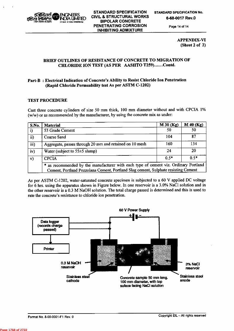
Concrete sample 50 nun long.100 mm diameter, with topsolace facing NCI solution
OM-addle ENGINEERSOgza W INDIA MOM
(A Gen ol Mm. undmA191
STANDARD SPECIFICATIONCIVIL & STRUCTURAL WORKS
BIPOLAR CONCRETEPENETRATING CORROSION
INHIBITING ADMIXTURE
STANDARD SPECIFICATION No.
6-68-0017 Rev.0Page 14 of 14
APPENDIX-VI(Sheet 2 of 2)
BRIEF OUTLINES OF RESISTANCE OF CONCRETE TO MIGRATION OFCHLORIDE ION TEST (AS PER AASHTO T259) Contd.
Part-B : Electrical Indication of Concrete's Ability to Resist Chloride Ion Penetration(Rapid Chloride Permeability test As per ASTM C-1202)
TEST PROCEDURE
Cast three concrete cylinders of size 50 mm thick, 100 mm diameter without and with CPCIA 1%(w/w) or as recommended by the manufacturer, by using the concrete mix as under:
S.No. Material M 30 (Kg) M 40 (Kg)53 Grade Cement 50 50
Coarse Sand 104 87
Aggregate, passes through 20 mm and retained on 10 mesh 160 134
Water (subject to 55±5 slump) 24 20
v) CPCIA 0.5* 0.5*
* as recommended by the manufacturer with each type of cement viz. Ordinary PortlandCement, Portland Pozzolana Cement, Portland Slag cement, Su phate resisting Cement
As per ASTM C-1202, water-saturated concrete specimen is subjected to a 60 V applied DC voltagefor 6 hrs. using the apparatus shown in Figure below. In one reservoir is a 3.0% NaC1 solution and inthe other reservoir is a 0.3 M NaOH solution. The total charge passed is determined and this is used torate the concrete's resistance to chloride ion penetration.
60 V Power Supply
Format No. 8-00-0001-F1 Rev. 0 Copyright EIL —All rights reserved
Page 1768 of 2722
Sitiazi ENGINEERS • 212Zfire ..3457,17
INDIA LIMITED A Govt of IntAa UntlettakIngt
OlY 3)41k AJS PKM SC DM
YPC PKM SC VK ND
RPM SKP SCJ MI
Prepared by
Checked by
Standards Committee Convenor
GM Standards
Bureau Chairman
Rev. No Date
Purpose
7 23.09.2013
6
5 02.05.2001
TITLE REVISED, UPDATED & REISSUED AS SPECIFICATION
UPDATED & REISSUED AS SPECIFICATION
23.06.2010 REVISED & REISSUED AS SPECIFICATION
STANDARD SPECIFICATION PASSIVE FIREPROOFING OF STEEL STRUCTURES
(HYDROCARBON POOL FIRE)
STANDARD SPECIFICATION No.
6-68-0033 Rev.7
Page 1 of 16
1-111ch q
"trITOn 7-4 Wrzi
STANDARD SPECIFICATION CIVIL & STRUCTURAL WORKS
-,111 firwr afT9.449.
(111c:r)1611-1 TOTruff aT179)
PASSIVE FIREPROOFING OF STEEL STRUCTURES
(HYDROCARBON POOL FIRE)
Approved by
Format No. 8-00-0001-F1 Rev. 0 Copyright EIL — All rights reserved
Page 1769 of 2722

Llei ENGINEERS
Igar tafgrdg INDIA LIMITED
,12,7,171,,F11
CA Govt of Indy UncleFtakogi
STANDARD SPECIFICATION PASSIVE FIREPROOFING OF STEEL STRUCTURES
(HYDROCARBON POOL FIRE)
STANDARD SPECIFICATION No.
6-68-0033 Rev.7
Page 2 of 16
Abbreviations:
AS : Australian Standard ASTM : American Society for Testing & Materials BS British Standard DFT Dry Film Thickness IS Indian Standards OISD : Oil Industry Safety Directorate UL Underwriters' Laboratory QAP Quality Assurance Plan
Structural Standards Committee
Convenor : Mr. P.K. Mittal
Members : Mr. S.Debnath (Geotech) Mr. P.J. Singh Mr. Rajanji Srivastava Mr. Samir Das (Architectural) Mr. V.S. Chhaya (Projects) Mr . Ravindra Kumar (Construction)
Special Invitees:
Mr. P.P. Lahiri (SMMS) Mr. Prasenjit Saha (SMMS)
Format No. 8-00-0001-F1 Rev. 0 Copyright EIL — All rights reserved
Page 1770 of 2722

ENGINEERS INDIA LIMITED (A Govt of India Undeftalong)
STANDARD SPECIFICATION PASSIVE FIREPROOFING OF STEEL STRUCTURES
(HYDROCARBON POOL FIRE)
STANDARD SPECIFICATION No.
6-68-0033 Rev.7
Page 3 of 16
CONTENTS
1.0 SCOPE .4
2.0 REFERENCES 4
3.0 DESIGN BASIS 4
4.0 FIREPROOFING SYSTEM AND MATERIALS 5
5.0 SURFACE PREPARATION 7
6.0 SPECIFIC REQUIREMENTS FOR FIRE PROOFING 8
7.0 APPLICATION METHOD 9
8.0 SCAFFOLDING & FORM WORK 10
9.0 FINISHING AND JOINT SEALING 10
10.0 TESTING REQUIREMENTS 10
11.0 PAYMENT 11
ANNEXURES 12-15
ATTACHMENT ..16
Copyright EIL — All rights reserved Format No. 8-00-0001-F1 Rev. 0
Page 1771 of 2722

k31 ENGINEERS fg-Tx id5teg INDIA LIMITED
14iRR
(A Go vi of India Undeitaking)
STANDARD SPECIFICATION PASSIVE FIREPROOFING OF STEEL STRUCTURES
(HYDROCARBON POOL FIRE)
STANDARD SPECIFICATION No.
6-68-0033 Rev.7
Page 4 of 16
1.0 SCOPE
This specification covers the general requirements of passive fire protection of external steel structures against hydrocarbon pool fire. Structural steel members shall be fire proofed for 2 hours such that the protected steel substrate temperature shall be restricted to 538°C, whereas in case of equipment skirts/ saddles/ supports the steel temperature shall be restricted to 427°C.
Following fireproofing materials and systems have been covered in this standard:
a) Type-I : In-situ cement concrete of minimum M30 Grade (for application up to 1.8m from grade level for steel structures)
b) Type-II: Spray applied vermiculite based lightweight cementitiuos concrete (for application above 1.8m of grade level for steel structures)
c) Type-Ill: Spray applied vermiculite based lightweight cementitiuos concrete (for application over equipment skirts/ saddles/ supports)
2.0 REFERENCES
• UL 1709: Rapid Rise Fire Tests of Protection of Structural Steel • OISD-STD-164 : Fireproofing of Steel Supporting Structures in Oil & Gas Industry • NORSOK Standard M-501 • Relevant ASTM Standards like ASTM C177, ASTM D790, ASTM D2240, ASTM E605,
ASTM E736, ASTM E760, ASTM E761, ASTM E84, ASTM E859, ASTM E937, ASTM G21, etc.
• Relevant BIS Standards like IS:383, IS:412, IS:455, 1S:456, IS:1367, IS:1489 (Part-I), IS:1566, IS:2062. 1S:2585, IS:8112, IS:9103, IS:12269, IS:12330, etc.
• Relevant British Standards like BS-8110, etc. • EIL Specification for Plain and Reinforced Cement Concrete No. : 6-68-0004 • EIL Specification for Self Compacting Concrete No. : 6-68-0019
3.0 DESIGN BASIS
Fire resistance of a material is defined by fire rating, evaluated through a fire test based on applied thickness and time taken to reach the defined critical steel temperature. Fire rating adopted in the present standard is based on UL-1709 rapid rise fire tests of protection materials for structural steel, conducted by Underwriters Laboratory, USA. In this test, fire resistance of a material is evaluated on a W10x49 steel column as per UL-1709 fire curve and fire rating is published in a UL design number under XR category for thickness and time. In addition to the fire rating, under this test, material for exterior use is also evaluated for accelerated ageing, high humidity, salt spray, wet-freeze-dry cycling, acid spray, solvent spray etc.
3.1 Fireproofing Thickness
Thickness of fireproof coating to be applied shall be based on the following:
a) Type-I : In-situ cement concrete for application up to 1.8m from grade level for steel structures shall be applied with minimum 65mm thickness.
b) Type-II : Structural steel members such as column, beam etc. which shall be protected for 2 hours from reaching critical temperature 538°C, shall be applied with vermiculite based lightweight cementitious fireproof of thickness corresponding to 2 hours fire rating as per respective UL design number under UL-1709 (XR category) subject to a minimum of 30mm.
Format No. 8-00-0001-F1 Rev. 0
Copyright EIL — All rights reserved
Page 1772 of 2722
eit4 ENGINEERS
051-eg INDIA LIMITED IA Gov( of India Undertaking
STANDARD SPECIFICATION PASSIVE FIREPROOFING OF STEEL STRUCTURES
(HYDROCARBON POOL FIRE)
STANDARD SPECIFICATION No.
6-68-0033 Rev.7
Page 5 of 16
c) Type-III : For equipment skirts/ saddles/ supports (which shall be protected for 2 hours from reaching critical temperature 427°C), 2 hours fire rating as per UL design is not adequate as the UL-1709 test is based on 538°C critical temperature. Therefore for the required fire protection from reaching 427°C, higher thickness shall be necessary. For this, fireproof thickness corresponding to 3 hours fire rating as per respective UL design number under UL-1709 (XR category) shall be adopted subject to a minimum of 30mm.
4.0 FIREPROOFING SYSTEM AND MATERIALS
All materials to be used shall conform to the requirements of UL-1709/ respective BIS codes/ respective acceptance criteria (as applicable). Materials shall meet the minimum acceptance criteria given under this section. Samples, test results and approval certificates for all materials shall be submitted and got approved from the Engineer-in-Charge before execution of work.
a) Vermiculite based lightweight cementitiuos fireproofing system shall have following compatible components:
• Primer • Reinforcing system • Fireproof coating as per UL-1709 • Curing • Water shed sealing at terminating edges/ metal joints • Weather barrier finish coat
b) In-situ cement concrete fireproofing system shall have following compatible components:
• Primer • Reinforcing system • Cement concrete • Curing • Water shed sealing at terminating edges/ metal joints • Weather barrier finish coat
4.1 Vermiculite Based Lightweight Cementitious Fireproofing Material
Vermiculite based lightweight cementitious fireproof material shall be UL certified for UL-1709 (Rapid rise fire test of protection materials for structural steels), UL classified under XR category and covered under UL follow up service (indicated by UL mark/ sticker on the packing). For list of UL certified materials. UL website (www.ul.com) shall be referred. The essential criteria for the material shall be:
a) Must be UL-1709 certified having UL design number under XR category b) Listed on UL website under specified category c) Bear UL-1709 mark/ sticker on packing bags/ container
The material shall be factory-blended, supplied in single component pre-mixed dry form, non-flaking and non-dusting suitable for spray-application, with added mold and fungi inhibitor. Material shall not contain asbestos & mineral wool and shall not contain more than 1% Sulphate (expressed in SO3). The material shall be free from toxicity release when subjected to heat.
In addition to the UL-1709 certificate, the contractor shall supply test certificate covering the information for the supplied batches of material as per Attachment-I.
Fire proofing materials shall be stored in well ventilated, dry place away from source of heat & direct sunlight. Special storage requirements such as temperature, humidity, stacking height, etc. as per manufacturer's specifications shall be ensured.
Format No. 8-00-0001-F1 Rev. 0
Copyright EIL — All rights reserved
Page 1773 of 2722
ENGINEERS
05f-e'-g INDIA LIMITED
17-11.eM cvemre as1J9gui, (A Govt of Indo Untletlaking)
STANDARD SPECIFICATION PASSIVE FIREPROOFING OF STEEL STRUCTURES
(HYDROCARBON POOL FIRE)
STANDARD SPECIFICATION No.
6-68-0033 Rev.7
Page 6 of 16
4.2 Reinforcement (for both Vermiculite based cementitious and In-situ concrete)
4.2.1 Expanded Metal Steel Sheet/ Lath
Expanded metal steel sheet shall conform to IS:412, galvanized (having minimum zinc coating of 250 g/m2) and shall weigh minimum 1.84 Kg/m2. Size of the mesh shall be 4.5x13.5mm.
4.2.2 Wire Fabric
Welded wire fabric to be used as reinforcement, shall conform to IS:1566 and shall be post weld hot dipped galvanized having minimum zinc coating of 250 g/in' of uncoated wire surface. Mesh size shall be 50mmx5Omm and thickness of wire shall be 2mm (Minimum).
4.2.3 Attachments
a) Mild Steel Tie Wire
MS Tie wires shall be minimum 16 SWG and galvanized (having minimum zinc coating of 100 g/m2).
b) Mild Steel Nuts
MS Nuts shall conform to IS:1367 and IS:2585.
c) Cover plates
Cover plates shall conform to IS:2062 Grade-A/ BR.
d) Cover blocks
Cover blocks shall be prepared in cement coarse sand mortar (1:3) with minimum 50mmx50mm size of thickness equal to half of the fireproofing thickness with MS Tie wire of sufficient length protruding from them for tying with the wire fabric.
4.3 Curing Compounds (for both Vermiculite based cementitious and In-situ concrete)
Membrane curing may be used in lieu of moist curing with the permission of the Engineer-in-Charge. Such compounds shall be compatible and applied to all exposed surfaces by spraying or brushing as soon as possible after the material has set. Minimum film thickness of such curing compounds shall be as per the recommendation of the manufacturer so as to obtain an efficiency of 90% as specified by BS-8110. This film of curing compound shall be fully removed from the surface after the specified curing period.
4.4 Water Shed Sealing at Terminating Edges/ Metal Joints (for both Vermiculite based cementitious and In-situ concrete)
All termination of the fireproofing and steel junctions shall be sealed by non-bituminous polysulfide or silicon rubber mastic sealant. The sealing compound shall be compatible and approved by fireproofing material supplier.
4.5 Weather Barrier Finish Coat (for both Vermiculite based cementitious and In-situ concrete)
a) Sealer Coat
A sealer coat of epoxy polyamide shall be applied over the fireproofing surface as a base for the finish coat. The sealing compound shall be compatible and approved by fireproofing material supplier.
Format No. 8-00-0001-F1 Rev. 0
Copyright EIL — All rights reserved
Page 1774 of 2722


