Embed Size (px)
Citation preview

Mot
herb
oard
P5B-Plus Series

ii
E3077
Second Edition V2 February 2007
Copyright © 2007 ASUSTeK COMPUTER INC. All Rights Reserved.No part of this manual, including the products and software described in it, may be reproduced, transmitted, transcribed, stored in a retrieval system, or translated into any language in any form or by any means, except documentation kept by the purchaser for backup purposes, without the express written permission of ASUSTeK COMPUTER INC. (“ASUS”).Product warranty or service will not be extended if: (1) the product is repaired, modified or altered, unless such repair, modification of alteration is authorized in writing by ASUS; or (2) the serial number of the product is defaced or missing.ASUS PROVIDES THIS MANUAL “AS IS” WITHOUT WARRANTY OF ANY KIND, EITHER EXPRESS OR IMPLIED, INCLUDING BUT NOT LIMITED TO THE IMPLIED WARRANTIES OR CONDITIONS OF MERCHANTABILITY OR FITNESS FOR A PARTICULAR PURPOSE. IN NO EVENT SHALL ASUS, ITS DIRECTORS, OFFICERS, EMPLOYEES OR AGENTS BE LIABLE FOR ANY INDIRECT, SPECIAL, INCIDENTAL, OR CONSEQUENTIAL DAMAGES (INCLUDING DAMAGES FOR LOSS OF PROFITS, LOSS OF BUSINESS, LOSS OF USE OR DATA, INTERRUPTION OF BUSINESS AND THE LIKE), EVEN IF ASUS HAS BEEN ADVISED OF THE POSSIBILITY OF SUCH DAMAGES ARISING FROM ANY DEFECT OR ERROR IN THIS MANUAL OR PRODUCT.SPECIFICATIONS AND INFORMATION CONTAINED IN THIS MANUAL ARE FURNISHED FOR INFORMATIONAL USE ONLY, AND ARE SUBJECT TO CHANGE AT ANY TIME WITHOUT NOTICE, AND SHOULD NOT BE CONSTRUED AS A COMMITMENT BY ASUS. ASUS ASSUMES NO RESPONSIBILITY OR LIABILITY FOR ANY ERRORS OR INACCURACIES THAT MAY APPEAR IN THIS MANUAL, INCLUDING THE PRODUCTS AND SOFTWARE DESCRIBED IN IT.Products and corporate names appearing in this manual may or may not be registered trademarks or copyrights of their respective companies, and are used only for identification or explanation and to the owners’ benefit, without intent to infringe.

iii
ContentsNotices ........................................................................................................ viiSafety information .................................................................................... viiiAbout this guide ......................................................................................... ixP5B-Plus Series specifications summary ................................................ xi
Chapter 1: Product introduction 1.1 Welcome! ...................................................................................... 1-11.2 Package contents ......................................................................... 1-11.3 Special features ............................................................................ 1-2
1.3.1 Product highlights ........................................................... 1-21.3.2 ASUS AI Lifestyle features ............................................. 1-41.3.3 ASUS Special features ................................................... 1-61.3.4 ASUS Intelligent Overclocking features .......................... 1-61.3.5 ASUS features and the supporting OS ........................... 1-7
Chapter 2: Hardware information2.1 Before you proceed ..................................................................... 2-12.2 Motherboard overview ................................................................. 2-2
2.2.1 Placement direction ........................................................ 2-22.2.2 Screw holes .................................................................... 2-22.2.3 Motherboard layout ......................................................... 2-32.2.4 Layout contents ............................................................... 2-4
2.3 Central Processing Unit (CPU) ................................................... 2-62.3.1 Installing the CPU ........................................................... 2-72.3.2 Installing the heatsink and fan ........................................ 2-92.3.3 Uninstalling the heatsink and fan ...................................2-11
2.4 System memory ......................................................................... 2-132.4.1 Overview ....................................................................... 2-132.4.2 Memory configurations .................................................. 2-132.4.3 Installing a DIMM .......................................................... 2-182.4.4 Removing a DIMM ........................................................ 2-18
2.5 Expansion slots .......................................................................... 2-192.5.1 Installing an expansion card ......................................... 2-192.5.2 Configuring an expansion card ..................................... 2-192.5.3 Interrupt assignments ................................................... 2-202.5.4 PCI slots ........................................................................ 2-212.5.5 PCI Express x1 slots ..................................................... 2-212.5.6 PCI Express x16 slot ..................................................... 2-21

iv
Contents2.6 Jumper ........................................................................................ 2-222.7 Connectors ................................................................................. 2-24
2.7.1 Rear panel connectors .................................................. 2-242.7.2 Internal connectors ....................................................... 2-27
Chapter 3: Powering up3.1 Starting up for the first time ........................................................ 3-13.2 Powering off the computer .......................................................... 3-2
3.2.1 Using the OS shut down function .................................... 3-23.2.2 Using the dual function power switch .............................. 3-2
Chapter 4: BIOS setup4.1 Managing and updating your BIOS ............................................ 4-1
4.1.1 ASUS Update utility ........................................................ 4-14.1.2 Creating a bootable floppy disk ....................................... 4-44.1.3 ASUS EZ Flash 2 utility ................................................... 4-54.1.4 AFUDOS utility ................................................................ 4-64.1.5 ASUS CrashFree BIOS 3 utility ...................................... 4-8
4.2 BIOS setup program .................................................................... 4-94.2.1 BIOS menu screen ........................................................ 4-104.2.2 Menu bar ....................................................................... 4-104.2.3 Navigation keys ............................................................. 4-104.2.4 Menu items ....................................................................4-114.2.5 Sub-menu items .............................................................4-114.2.6 Configuration fields ........................................................4-114.2.7 Pop-up window ..............................................................4-114.2.8 Scroll bar ........................................................................4-114.2.9 General help ..................................................................4-11
4.3 Main menu .................................................................................. 4-124.3.1 System Time ................................................................ 4-124.3.2 System Date ................................................................. 4-124.3.3 Legacy Diskette A ......................................................... 4-124.3.4 SATA 1-6 ..........................................................................................4-134.3.5 IDE Configuration .......................................................... 4-144.3.6 System Information ....................................................... 4-15

v
Contents4.4 Advanced menu ......................................................................... 4-16
4.4.1 JumperFree Configuration ............................................ 4-164.4.2 USB Configuration ........................................................ 4-194.4.3 TPM Configuration ........................................................ 4-204.4.4 CPU Configuration ........................................................ 4-214.4.5 Chipset .......................................................................... 4-234.4.6 Onboard Devices Configuration .................................... 4-244.4.7 PCIPnP ......................................................................... 4-26
4.5 Power menu ................................................................................ 4-274.5.1 Suspend Mode .............................................................. 4-274.5.2 Repost Video on S3 Resume ........................................ 4-274.5.3 ACPI 2.0 Support .......................................................... 4-274.5.4 ACPI APIC Support ....................................................... 4-274.5.5 APM Configuration ........................................................ 4-284.5.6 Hardware Monitor ......................................................... 4-29
4.6 Boot menu .................................................................................. 4-314.6.1 Boot Device Priority ...................................................... 4-314.6.2 Boot Settings Configuration .......................................... 4-324.6.3 Security ......................................................................... 4-34
4.7 Tools menu ................................................................................. 4-364.7.1 ASUS EZ Flash 2 .......................................................... 4-364.7.2 ASUS O.C. Profile ......................................................... 4-37
4.8 Exit menu .................................................................................... 4-38
Chapter 5: Software support5.1 Installing an operating system ................................................... 5-15.2 Support CD information .............................................................. 5-1
5.2.1 Running the support CD ................................................. 5-15.2.2 Drivers menu ................................................................... 5-25.2.3 Utilities menu .................................................................. 5-35.2.4 Make disk menu .............................................................. 5-55.2.5 Manual menu .................................................................. 5-65.2.6 ASUS contact information ............................................... 5-65.2.7 Other information ............................................................ 5-7

vi
Contents5.3 Software information ................................................................... 5-9
5.3.1 ASUS MyLogo2™ ........................................................... 5-95.3.2 PC Probe II ....................................................................5-115.3.3 ASUS AI Suite ............................................................... 5-175.3.4 ASUS AI Gear ............................................................... 5-195.3.5 ASUS AI Nap ................................................................ 5-205.3.6 ASUS AI N.O.S. ............................................................ 5-215.3.7 ASUS Q-Fan ................................................................. 5-225.3.8 ASUS AI Booster ........................................................... 5-235.3.9 AI Remote ..................................................................... 5-245.3.10 SoundMAX® High Definition Audio utility ....................... 5-32
5.4 Windows Vista feature ............................................................... 5-375.4.1 ASAP (ASUS Accelerated Propeller) ............................ 5-37
5.5 RAID configurations .................................................................. 5-385.5.1 RAID definitions ............................................................ 5-385.5.2 Installing Serial ATA hard disks ..................................... 5-395.5.3 Intel® RAID configurations ............................................. 5-395.5.4 JMicron® RAID Configuration ........................................ 5-47
5.6 Creating a RAID/SATA driver disk ............................................ 5-555.6.1 Creating a RAID/SATA driver disk without entering the OS ...................................................................................... 5-555.6.2 Creating a RAID/SATA driver disk in Windows® ............ 5-55
Appendix: CPU featuresA.1 Intel® EM64T ..................................................................................A-1A.2 Enhanced Intel SpeedStep® Technology (EIST) ........................A-1
A.2.1 System requirements ......................................................A-1A.2.2 Using the EIST ................................................................A-2
A.3 Intel® Hyper-Threading Technology ...........................................A-3

vii
Notices
Federal Communications Commission StatementThis device complies with Part 15 of the FCC Rules. Operation is subject to the following two conditions:• This device may not cause harmful interference, and• This device must accept any interference received including interference that
may cause undesired operation.
This equipment has been tested and found to comply with the limits for a Class B digital device, pursuant to Part 15 of the FCC Rules. These limits are designed to provide reasonable protection against harmful interference in a residential installation. This equipment generates, uses and can radiate radio frequency energy and, if not installed and used in accordance with manufacturer’s instructions, may cause harmful interference to radio communications. However, there is no guarantee that interference will not occur in a particular installation. If this equipment does cause harmful interference to radio or television reception, which can be determined by turning the equipment off and on, the user is encouraged to try to correct the interference by one or more of the following measures:• Reorient or relocate the receiving antenna.• Increase the separation between the equipment and receiver.• Connect the equipment to an outlet on a circuit different from that to which the
receiver is connected.• Consult the dealer or an experienced radio/TV technician for help.
Canadian Department of Communications StatementThis digital apparatus does not exceed the Class B limits for radio noise emissions from digital apparatus set out in the Radio Interference Regulations of the Canadian Department of Communications.
This class B digital apparatus complies with Canadian ICES-003.
The use of shielded cables for connection of the monitor to the graphics card is required to assure compliance with FCC regulations. Changes or modifications to this unit not expressly approved by the party responsible for compliance could void the user’s authority to operate this equipment.

viii
Safety information
Electrical safety• To prevent electrical shock hazard, disconnect the power cable from the
electrical outlet before relocating the system.• When adding or removing devices to or from the system, ensure that the
power cables for the devices are unplugged before the signal cables are connected. If possible, disconnect all power cables from the existing system before you add a device.
• Before connecting or removing signal cables from the motherboard, ensure that all power cables are unplugged.
• Seek professional assistance before using an adpater or extension cord. These devices could interrupt the grounding circuit.
• Make sure that your power supply is set to the correct voltage in your area. If you are not sure about the voltage of the electrical outlet you are using, contact your local power company.
• If the power supply is broken, do not try to fix it by yourself. Contact a qualified service technician or your retailer.
Operation safety• Before installing the motherboard and adding devices on it, carefully read all
the manuals that came with the package.• Before using the product, make sure all cables are correctly connected and the
power cables are not damaged. If you detect any damage, contact your dealer immediately.
• To avoid short circuits, keep paper clips, screws, and staples away from connectors, slots, sockets and circuitry.
• Avoid dust, humidity, and temperature extremes. Do not place the product in any area where it may become wet.
• Place the product on a stable surface.• If you encounter technical problems with the product, contact a qualified
service technician or your retailer.

ix
About this guideThis user guide contains the information you need when installing and configuring the motherboard.
How this guide is organizedThis guide contains the following parts:
• Chapter 1: Product introductionThis chapter describes the features of the motherboard and the new technology it supports.
• Chapter 2: Hardware informationThis chapter lists the hardware setup procedures that you have to perform when installing system components. It includes description of the switches, jumpers, and connectors on the motherboard.
• Chapter 3: Powering upThis chapter describes the power up sequence and ways of shutting down the system.
• Chapter 4: BIOS setupThis chapter tells how to change system settings through the BIOS Setup menus. Detailed descriptions of the BIOS parameters are also provided.
• Chapter 5: Software supportThis chapter describes the contents of the support CD that comes with the motherboard package.
• Appendix: CPU featuresThe Appendix describes the CPU features and technologies that the motherboard supports.
Where to find more informationRefer to the following sources for additional information and for product and software updates.
1. ASUS websitesThe ASUS website provides updated information on ASUS hardware and software products. Refer to the ASUS contact information.
2. Optional documentationYour product package may include optional documentation, such as warranty flyers, that may have been added by your dealer. These documents are not part of the standard package.

x
Conventions used in this guideTo make sure that you perform certain tasks properly, take note of the following symbols used throughout this manual.
TypographyBold text Indicates a menu or an item to select.
Italics Used to emphasize a word or a phrase.
<Key> Keys enclosed in the less-than and greater-than sign means that you must press the enclosed key. Example: <Enter> means that you must press the Enter or Return key.
<Key1+Key2+Key3> If you must press two or more keys simultaneously, the key names are linked with a plus sign (+). Example: <Ctrl+Alt+D>
Command Means that you must type the command exactly as shown, then supply the required item or value enclosed in brackets. Example: At the DOS prompt, type the command line:
afudos /i[filename]
afudos/iP5BP.ROM
DANGER/WARNING: Information to prevent injury to yourself when trying to complete a task.
CAUTION: Information to prevent damage to the components when trying to complete a task.
NOTE: Tips and additional information to help you complete a task.
IMPORTANT: Instructions that you MUST follow to complete a task.

xi
P5B-Plus Series specifications summary
(continued on the next page)
CPU LGA775 socket for Core™2 Quad / Core™2 Extreme / Core™2 Duo / Pentium® Extreme / Pentium® D / Pentium® 4 / Celeron® D processors Compatible with Intel® 05B/05A/06 processors Intel® Hyper-Threading Technology ready * Refer to www.asus.com for Intel CPU support list
Chipset Intel® P965 / ICH8R with Intel® Fast Memory Access Technology
System Bus 1066 / 800 / 533 MHzMemory 4 x DIMM, max. 8GB, DDR2 800 / 667 / 533 MHz, non-
ECC, un-buffered memory Dual channel memory architecture * Refer to www.asus.com or user manual for Memory QVL (Qualify Vendor List)
Expansion Slots 1 x PCI-E x16 3 x PCI-E x1 3 x PCI 2.2
Storage Southbridge - 6 x SATA 3.0 Gb/s ports - Intel Matrix Storage Technology supports RAID 0, 1, 5 and 10.
JMicron® JMB363 PATA and SATA controller - 1 x UltraDMA 133/100/66 for up to 2 PATA devices - 1 x Internal SATA 3.0 Gb/s port - 1 x External SATA 3.0 Gb/s port (SATA On-the-Go) - Support SATA RAID 0, 1 and JBOD (by 1 x External SATA and 1 x Internal SATA)
LAN PCI-E Gigabit LAN controllerAudio ADI® 1988 8-channel High Definition Audio CODEC
- Coaxial / Optical S/PDIF out ports at back I/OIEEE 1394 VIA® VT6307 1394a controller supports 2 x IEEE 1394a
ports (one at midboard; one at back panel)USB 10 x USB 2.0 ports (6 ports at mid-board, 4 ports at back
panel; 8 ports for Vista Edition)

xii
P5B-Plus Series specifications summary
ASUS AI Lifestyle Unique Features
ASUS AI Lifestyle Vista Edition Features: AI Remote ASAP (ASUS Accelerated Propeller) AP Trigger TPM Support (The TPM module is purchased separately) * AI Remote, AP Trigger and TPM can run both in Windows Vista and Windows XP. * AI Remote, ASAP and AP Trigger are for P5B-Plus Vista Edition only.
ASUS Quiet Thermal Solution: - ASUS AI Gear - ASUS AI Nap - ASUS Q-Fan 2
ASUS Crystal Sound: - ASUS Noise Filter
ASUS EZ DIY: - ASUS Q-Connector - ASUS O.C. Profile - ASUS CrashFree BIOS 3 - ASUS EZ Flash 2
ASUS Exclusive Overclocking Features
Intelligent overclocking tools: - AI NOS™ (Non-delay Overclocking System) - AI Overclocking (intelligent CPU frequency tuner) - ASUS AI Booster utility
Precision Tweaker: - vCore: Adjustable CPU voltage at 0.0125V increment - vDIMM: 14-step DRAM voltage control - VChipset: 4-step Chipset voltage control
SFS (Stepless Frequency Selection) - FSB tuning from 100MHz up to 650MHz at 1MHz increment - Memory tuning from 533MHz up to 1066MHz - PCI Express frequency turning from 90MHz up to 150MHz at 1MHz increment
Overclocking Protection: - ASUS C.P.R.(CPU Parameter Recall)
Back Panel I/O Ports 1 x PS/2 Keyboard 1 x PS/2 Mouse 1 x Parallel port 1 x S/PDIF Out (Coaxial + Optical) 1 x External SATA 1 x IEEE1394a 1 x RJ45 port 4 x USB 2.0/1.1 8-Channel Audio I/O
(continued on the next page)

xiii
P5B-Plus Series specifications summary
Other Features ASUS MyLogo2™
BIOS Features 8 Mb Flash ROM, AMI BIOS, PnP, DMI2.0, WfM2.0, SM BIOS 2.3, ACPI 2.0a, ASUS EZ Flash 2, ASUS CrashFree BIOS 3
Internal I/O Connectors 3 x USB connectors support additional 6 USB ports (4 ports for Vista Edition) 1 x Floppy disk drive connector 1 x IDE connector 1 x COM connector 1 x TPM connector 7 x SATA connectors 1 x CPU Fan connector 2 x Chassis Fan connector 1 x Power Fan connector 1 x IEEE1394a connector Front panel audio connector 1 x S/PDIF Out Header Chassis Intrusion connector CD audio in 24-pin ATX Power connector 1 x 4-pin ATX 12V Power connector System Panel
Manageability WfM 2.0, DMI 2.0, WOL by PME, WOR by PME, PXEAccessories AI Remote (Vista Edition for retail version only)
UltraDMA 133/100/66 cable FDD cable SATA cables SATA power cables I/O Shield User's manual USB2.0 port module 3 in 1 Q-connector (Retail version only)
Support CD Contents Drivers ASUS PC Probe II ASUS Update ASUS AI Suite Anti-virus software (OEM version)
Form Factor ATX Form Factor, 12”x 9” (30.5cm x 22.86cm)
*Specifications are subject to change without notice.

xiv

1Product introduction
This chapter describes the motherboard features and the new technologies it supports.

ASUS P5B-PLUS Series
Chapter summary 11.1 Welcome! ...................................................................................... 1-11.2 Package contents ......................................................................... 1-11.3 Special features ............................................................................ 1-2

ASUS P5B-Plus Series 1-1
1.1 Welcome!Thank you for buying an ASUS® P5B-Plus Series motherboard!
The motherboard delivers a host of new features and latest technologies, making it another standout in the long line of ASUS quality motherboards!
Before you start installing the motherboard, and hardware devices on it, check the items in your package with the list below.
If any of the above items is damaged or missing, contact your retailer.
1.2 Package contentsCheck your motherboard package for the following items.
Motherboard ASUS P5B-Plus SeriesI/O modules 1 x 2-port USB 2.0 moduleCables Serial ATA power and signal cables for 2 devices 1 x Ultra DMA 133/100/66 cable 1 x Floppy disk drive cableAccessories I/O shield 1 x ASUS Q-Connector Kit (USB, 1394, system panel; Retail version only) 1 x AI Remote kit (Vista Edition for retail version only)Application CD ASUS motherboard support CDDocumentation User guide

1-� Chapter 1: Product Introduction
1.3 Special features
1.3.1 Product highlights
Green ASUS This motherboard and its packaging comply with the European Union’s Restriction on the use of Hazardous Substances (RoHS). This is in line with the ASUS vision of creating environment-friendly and recyclable products/packaging to safeguard consumers’ health while minimizing the impact on the environment.
Intel® Core™ 2 Quad Processor Ready This motherboard supports the latest Intel® Core™ 2 Quad processors in the LGA775 package. It is excellent for multi-tasking, multi-media and enthusiastic gamers with 1066 / 800 MHz FSB. Intel® Quad-core processor is one of the most powerful CPU in the world.
Intel® Core™2 Duo/ Intel® Core™2 Extreme CPU support This motherboard supports the latest Intel® Core™2 processor in the LGA775 package. With the new Intel® Core™ microarchitecture technology and 1066 / 800 MHz FSB, the Intel® Core™2 is one of the most powerful and energy efficient CPUs in the world. This motherboard also supports the latest Intel® Quad-core processor, which is excellent for multi-tasking, multi-media and enthusiastic gamers with 1066 / 800 MHz FSB.
Intel P965 Chipset The Intel® P965 Express Chipset is the latest chipset designed to support 8GB of dual-channel DDR2 800/677/533 architecture, 1066/800 FSB (Front Side Bus), PCI Express x16 graphics and multi-core CPU. It especially includes Intel® Fast Memory Access technology that significantly optimizes the use of available memory bandwidth and reduces the latency of the memory accesses.
DDR2 memory support The motherboard supports DDR2 memory that features data transfer rates of 800/667/533 MHz to meet the higher bandwidth requirements of the latest 3D graphics, multimedia, and Internet applications. The dual-channel DDR2 architecture doubles the bandwidth of your system memory to boost system performance, eliminating bottlenecks with peak bandwidths of up to 12.8 GB/s. Furthermore, this motherboard does not restrict the memory size across two channels. Users may install different memory size DIMMs into the two channels and enjoy dual-channel and single-channel functions at the same time. This new feature optimizes the use of available memory size. See page 2-13 for details.

ASUS P5B-Plus Series 1-�
Serial ATA 3.0 Gb/s technology and SATA-On-The-Go This motherboard supports the next-generation hard drives based on the Serial ATA (SATA) 3Gb/s storage specification, delivering enhanced scalability and doubling the bus bandwidth for high-speed data retrieval and saves. The external SATA port located at the back I/O provides smart setup and hot-plug functions. Easily backup photos, videos and other entertainment contents to external devices. See pages 2-25, and 2-28 for details.
Dual RAID solution The Intel® ICH8R chipset incorporates six Serial ATA connectors with high performance RAID 0, 1, 5 and 10 functions. The JMicron controller provides another two Serial ATA connectors for RAID 0, 1, and JBOD functions. Making this motherboard an ideal solution to enhance hard disk performance and data back up protection without the cost of add-on cards. See pages 2-27 to 2-29 for details.
IEEE 1394a support The IEEE 1394a interface provides high speed digital interface for audio/video appliances such as digital television, digital video camcorders, storage peripherals & other PC portable devices. See pages 2-24 and 2-30 for details.
S/PDIF digital sound ready This motherboard provides convenient connectivity to external home theater audio systems via coaxial and optical S/PDIF-out (SONY-PHILIPS Digital Interface) jacks.It allows to transfer digital audio without converting to analog format and keeps the best signal quality. See pages 2-26 and 2-34 for details.
High Definition Audio Enjoy high-end sound quality on your PC! The onboard 8-channel HD audio (High Definition Audio, previously codenamed Azalia) CODEC enables high-quality 192KHz/24-bit audio output, jack-sensing feature, retasking functions and multi-streaming technology that simultaneously sends different audio streams to different destinations. You can now talk to your partners on the headphone while playing multi-channel network games. See pages 2-24 to 2-25 for details.

1-� Chapter 1: Product Introduction
1.3.2 ASUS AI Lifestyle unique features
AI Remote (Vista Edition only)The revolutionary AI Remote gives you unprecedented control from the comfort of your couch. With just the touch of a button, you can quickly do your usual computer activities such as turn ON/OFF your PC, launch your favorite applications by enabling AP Trigger function, or control AI Gear and AI Nap. The AI Remote also gives you the comfort of a traditional remote on media player. Have an AI Remote in your hand and do more with your PC from a distance! Refer to page 5-24 to 5-31 for more information.
ASAP (ASUS Accelerated Propeller) (Vista Edition only)ASAP gets you to your destination ASAP. ASAP supports the Windows Vista ReadyBoost™ technology which improves system performance under Windows Vista. Enjoy greater efficiency and get more productivity out of your system. Refer to page 5-37 for details.
AP Trigger (Vista Edition only)The AP Trigger allows you to quickly boot or resume directly into media or into your favorite applications. With just a touch of a button on the AI Remote controller, you can quickly turn on your PC and launch predefined applications simultaneously!
TPM Support This motherboard supports the Trusted Platform Module (TPM), which provides enhanced data protection via high-level encryption/decryption, and ensures platform integrity. The TPM meets the Windows Vista BitLocker™ Drive Encryption hardware requirement for a more secure working environment.
ASUS Quiet Thermal Solution ASUS Quiet Thermal solution makes system more stable and enhances the overclocking capability.
AI Gear
AI Gear provides four modes that adjust the CPU frequency and Vcore voltage minimizing system noise and power consumption. You can choose the mode that best suits your computing needs. See page 5-19 for details.
The TPM module is purchased separately. Use the ASUS TPM module ONLY!

ASUS P5B-Plus Series 1-�
AI Nap
With AI Nap, the system can continue running at minimum power and noise when you are temporarily away. To wake the system and return to the OS environment, simply click the mouse or press a key. See page 5-20 for details.
Q-Fan 2
ASUS Q-Fan2 technology intelligently adjusts both CPU fan and chassis fan speeds according to system loading to ensure quiet, cool and efficient operation. See page4-29 to 4-30 and 5-22 for details.
ASUS Crystal SoundThis feature can enhance speech-centric applications like Skype, online game, video conference and recording.
Noise Filter
This feature detects repetitive and stationary noises (non-voice signals) like computer fans, air conditioners, and other background noises then eliminates it in the incoming audio stream while recording. See page 5-36 for details.
ASUS EZ DIY
ASUS EZ DIY feature collection provides you easy ways to install computer components, update the BIOS or back up your favorite settings.
ASUS Q-Connector
ASUS Q-Connector allows you to easily connect or disconnect the chassis front panel cables to the motherboard. This unique module eliminates the trouble of connecting the system panel cables one at a time and avoiding wrong cable connections. See page 2-37 for details.
ASUS O.C. Profile
The motherboard features the ASUS O.C. Profile that allows users to conveniently store or load multiple BIOS settings. The BIOS settings can be stored in the CMOS or a separate file, giving users freedom to share and distribute their favorite settings. See page 4-37 for details.
ASUS CrashFree BIOS 3
The ASUS CrashFree BIOS 3 allows users to restore corrupted BIOS data from a USB flash disk containing the BIOS file. See page 4-8 for details.

1-� Chapter 1: Product Introduction
ASUS EZ Flash 2
EZ Flash 2 is a user-friendly BIOS update utility. Simply press the predefined hotkey to launch the utility and update the BIOS without entering the OS. Update your BIOS easily without preparing a bootable diskette or using an OS-based flash utility. See pages 4-5 and 4-36 for details.
1.3.3 ASUS Special features
ASUS MyLogo2™ This feature allows you to convert your favorite photo into a 256-color boot logo for a more colorful and vivid image on your screen. See pages 4-32 and 5-9 for details.
1.3.4 ASUS Intelligent Overclocking features
AI NOS™ (Non-Delay Overclocking System) The patented ASUS Non-delay Overclocking System™ (AI NOS™) technology auto-detects the CPU loading and dynamically overclocks the CPU speed when needed. Unlike other dynamic overclocking techniques, AI NOS™ reacts much faster to satisfy your need for speed. See pages 4-16 and 5-21 for details.
Precision Tweaker This feature allows you to fine tune the CPU/memory voltage and gradually increase the memory Front Side Bus (FSB) and PCI Express frequency at 1MHz increment to achieve maximum system performance. See pages 4-16 to 4-18 for details.
C.P.R. (CPU Parameter Recall) The C.P.R. feature of the motherboard BIOS allows automatic re-setting to the BIOS default settings in case the system hangs due to overclocking. When the system hangs due to overclocking, C.P.R. eliminates the need to open the system chassis and clear the RTC data. Simply shut down and reboot the system, and the BIOS automatically restores the CPU default setting for each parameter.
Due to the chipset behavior, AC power off is required before using C.P.R. function.
ASUS P5B-Plus Series 1-�
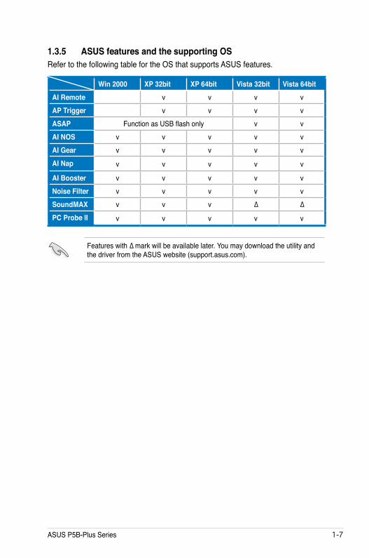
1.3.5 ASUS features and the supporting OS Refer to the following table for the OS that supports ASUS features.
Win 2000 XP 32bit XP 64bit Vista 32bit Vista 64bitAI Remote v v v vAP Trigger v v v vASAP Function as USB flash only v vAI NOS v v v v vAI Gear v v v v vAI Nap v v v v v
AI Booster v v v v vNoise Filter v v v v vSoundMAX v v v ∆ ∆PC Probe II v v v v v
Features with ∆ mark will be available later. You may download the utility and the driver from the ASUS website (support.asus.com).

1-� Chapter 1: Product Introduction

2Hardware information
This chapter lists the hardware setup procedures that you have to perform when installing system components. It includes description of the jumpers and connectors on the motherboard.

ASUS P5B-Plus Series
Chapter summary 22.1 Before you proceed ..................................................................... 2-12.2 Motherboard overview ................................................................. 2-22.3 Central Processing Unit (CPU) ................................................... 2-62.4 System memory ......................................................................... 2-132.5 Expansion slots .......................................................................... 2-192.6 Jumper ........................................................................................ 2-222.7 Connectors ................................................................................. 2-24

ASUS P5B-Plus Series 2-1
Onboard LEDThe motherboard comes with a standby power LED. The green LED lights up to indicate that the system is ON, in sleep mode, or in soft-off mode. This is a reminder that you should shut down the system and unplug the power cable before removing or plugging in any motherboard component. The illustration below shows the location of the onboard LED.
2.1 Before you proceedTake note of the following precautions before you install motherboard components or change any motherboard settings.
• Unplug the power cord from the wall socket before touching any component.
• Use a grounded wrist strap or touch a safely grounded object or a metal object, such as the power supply case, before handling components to avoid damaging them due to static electricity.
• Hold components by the edges to avoid touching the ICs on them.
• Whenever you uninstall any component, place it on a grounded antistatic pad or in the bag that came with the component.
• Before you install or remove any component, ensure that the ATX power supply is switched off or the power cord is detached from the power supply. Failure to do so may cause severe damage to the motherboard, peripherals, and/or components.
P5B
-PL
US
®
P5B-PLUS Onboard LED
SB_PWR
ONStandbyPower
OFFPowered
Off

2-2 Chapter 2: Hardware information
P5B
-PL
US
®
2.2 Motherboard overviewBefore you install the motherboard, study the configuration of your chassis to ensure that the motherboard fits into it.
Make sure to unplug the power cord before installing or removing the motherboard. Failure to do so can cause you physical injury and damage motherboard components.
DO NOT overtighten the screws! Doing so can damage the motherboard.
2.2.1 Placement directionWhen installing the motherboard, make sure that you place it into the chassis in the correct orientation. The edge with external ports goes to the rear part of the chassis as indicated in the image below.
2.2.2 Screw holesPlace six (6) screws into the holes indicated by circles to secure the motherboard to the chassis.
Place this side towards the rear of the chassis

ASUS P5B-Plus Series 2-3
2.2.3 Motherboard layout
PANEL
P5B
-PL
US
®
AAFP
CHASSIS
22.9cm (9in)
30.5
cm (1
2.0i
n)
CPU_FAN
DD
R2
DIM
M_B
1 (6
4 bi
t,240
-pin
mod
ule)
DD
R2
DIM
M_A
1 (6
4 bi
t,240
-pin
mod
ule)
DD
R2
DIM
M_A
2 (6
4 bi
t,240
-pin
mod
ule)
DD
R2
DIM
M_B
2 (6
4 bi
t,240
-pin
mod
ule)
SuperI/O
CD
PCIEX1_1
CLRTC
Intel®ICH8R
EATX
PWR
CR2032 3VLithium Cell
CMOS Power
Intel®P965
PCI1
USB56
PCIEX16_1
CHA_FAN1
JMicronJMB363
SPDIF_OUT
LGA775
USBPW5-8
IE1394_2
SATA1SATA6
TPM
SATA_RAID
AD1988A
88E8056
PWR_FAN
F_USB34
PS/2KBMST: MouseB: Keyboard
PAR
ALL
EL P
OR
T
SPDIF_O1
SPDIF_O2
LAN_USB12
IE13
94_1
AUDIO
PCI2
PCI3
PCIEX1_2
PCIEX1_3
CHA_FAN2
SATA2SATA5
SATA3SATA4
SB_PWR
FLO
PPY
PRI_IDE
COM1 USB78
VIAVT6307
USBPW1-4
KBPWR
EATX12V
Attansic
ASAP(Vista Edition only)
ASAP(Vista Edition only)
USB910(Standard Edtion only)
Refer to 2.7 Connectors for more information about rear panel connectors and internal connectors.

2-4 Chapter 2: Hardware information
2.2.4 Layout contents
Slots Page1. DDR2 DIMM slots 2-132. PCI slots 2-213. PCI Express x 1 slots 2-214. PCI Express x16 slot 2-21
Jumper Page1. Clear RTC RAM (3-pin CLRTC) 2-222. USB device wake-up (3-pin USBPW1-4, 3-pin USBPW5-8) 2-233. Keyboard power (3-pin KBPWR) 2-23
Rear panel connectors Page1. PS/2 mouse port (green) 2-242. Parallel port 2-243. IEEE 1394a port 2-244. LAN (RJ-45) port. 2-245. Rear Speaker Out port (black) 2-246. Center/Subwoofer port (orange) 2-247. Line In port (light blue) 2-248. Line Out port (lime) 2-249. Microphone port (pink) 2-2410. Side Speaker Out port (gray) 2-2411. USB 2.0 ports 1 and 2 2-2512. USB 2.0 ports 3 and 4 2-2513. External SATA port 2-2514. Optical S/PDIF Out port 2-2615. Coaxial S/PDIF Out port 2-2616. PS/2 keyboard port (purple) 2-26

ASUS P5B-Plus Series 2-5
Internal connectors Page1. Floppy disk drive connector (34-1 pin FLOPPY) 2-272. JMicron JMB363® Serial ATA RAID connector (7-pin SATA_RAID)
2-27
3. ICH8R Serial ATA connectors (7-pin SATA1 [red], SATA2 [red], SATA3 [black], SATA4 [black], SATA5 [red], SATA6 [red])
2-28
4. IDE connector (40-1 pin PRI_IDE)) 2-295. USB connectors Vista Edition: (10-1 pin USB56, USB 78) Standard Edition: (10-1 pin USB56, USB 78, USB910)
2-30
6. IEEE 1394a port connector (10-1 pin IE1394_2) 2-307. CPU, chassis, power fan connectors (4-pin CPU_FAN, 3-pin CHA_FAN1, 3-pin CHA_FAN2, 3-pin PWR_FAN)
2-31
8. Chassis intrusion connector (4-1 pin CHASSIS) 2-329. ATX power connectors (24-pin EATXPWR, 4-pin EATX12V) 2-3210. Front panel audio connector (10-1 pin AAFP) 2-3311. Optical drive audio connector (4-pin CD) 2-3412. Digital audio connector (4-1 pin SPDIF) 2-3413. Serial port connector (10-1 pin COM1) 2-3514. TPM connector (20-1 pin TPM) 2-3514. System panel connector (20-8 pin PANEL) 2-36

2-6 Chapter 2: Hardware information
2.3 Central Processing Unit (CPU)The motherboard comes with a surface mount LGA775 socket designed for the Intel® Core™2 Quad/Core™2/Pentium® D/Pentium® 4/Pentium® Extreme and Celeron® D processors.
• Upon purchase of the motherboard, make sure that the PnP cap is on the socket and the socket contacts are not bent. Contact your retailer immediately if the PnP cap is missing, or if you see any damage to the PnP cap/socket contacts/motherboard components. ASUS will shoulder the cost of repair only if the damage is shipment/transit-related.
• Keep the cap after installing the motherboard. ASUS will process Return Merchandise Authorization (RMA) requests only if the motherboard comes with the cap on the LGA775 socket.
• The product warranty does not cover damage to the socket contacts resulting from incorrect CPU installation/removal, or misplacement/loss/incorrect removal of the PnP cap.
• Make sure that all power cables are unplugged before installing the CPU.
• If installing a dual-core CPU, connect the chassis fan cable to the CHA_FAN1 connector to ensure system stability.

ASUS P5B-Plus Series 2-7
3. Lift the load lever in the direction of the arrow to a 135º angle.
2. Press the load lever with your thumb (A), then move it to the left (B) until it is released from the retention tab.
Retention tab
Load lever
This side of the socket box should face you.
PnP capA
B
To prevent damage to the socket pins, do not remove the PnP cap unless you are installing a CPU.
2.3.1 Installing the CPUTo install a CPU:
1. Locate the CPU socket on the motherboard.
Before installing the CPU, make sure that the cam box is facing towards you and the load lever is on your left.
P5
B-P
LU
S®
P5B-PLUS CPU Socket 775

2-8 Chapter 2: Hardware information
5. Position the CPU over the socket, making sure that the gold triangle is on the bottom-left corner of the socket then fit the socket alignment key into the CPU notch.
Alignment key
Gold triangle mark
6. Close the load plate (A), then push the load lever (B) until it snaps into the retention tab.
7. If installing a dual-core CPU, connect the chassis fan cable to the CHA_FAN1 connector to ensure system stability.
A
B
The CPU fits in only one correct orientation. DO NOT force the CPU into the socket to prevent bending the connectors on the socket and damaging the CPU!
The motherboard supports Intel® LGA775 processors with the Intel® Enhanced Memory 64 Technology (EM64T), Enhanced Intel SpeedStep® Technology (EIST), and Hyper-Threading Technology. Refer to the Appendix for more information on these CPU features.
4. Lift the load plate with your thumb and forefinger to a 100º angle (A), then push the PnP cap from the load plate window to remove (B).
Load plate
A
B
CPU notch

ASUS P5B-Plus Series 2-9
Fastener
Motherboard hole
2.3.2 Installing the CPU heatsink and fanThe Intel® LGA775 processor requires a specially designed heatsink and fan assembly to ensure optimum thermal condition and performance.
To install the CPU heatsink and fan:
1. Place the heatsink on top of the installed CPU, making sure that the four fasteners match the holes on the motherboard.
• When you buy a boxed Intel® processor, the package includes the CPU fan and heatsink assembly. If you buy a CPU separately, make sure that you use only Intel®-certified multi-directional heatsink and fan.
• Your Intel® LGA775 heatsink and fan assembly comes in a push-pin design and requires no tool to install.
• If you purchased a separate CPU heatsink and fan assembly, make sure that you have properly applied Thermal Interface Material to the CPU heatsink or CPU before you install the heatsink and fan assembly.
Make sure that you have installed the motherboard to the chassis before you install the CPU fan and heatsink assembly.
Make sure to orient each fastener with the narrow end of the groove pointing outward. (The photo shows the groove shaded for emphasis.)
Orient the heatsink and fan assembly such that the CPU fan cable is closest to the CPU fan connector.
Narrow end of the groove

2-10 Chapter 2: Hardware information
3. Connect the CPU fan cable to the connector on the motherboard labeled CPU_FAN.
2. Push down two fasteners at a time in a diagonal sequence to secure the heatsink and fan assembly in place.
B
A
A
A B
B
DO NOT forget to connect the CPU fan connector! Hardware monitoring errors can occur if you fail to plug this connector.
P5B
-PL
US
®
P5B-PLUS CPU fan connector
CPU_FAN
GN
DC
PU F
AN P
WR
CPU
FAN
INC
PU F
AN P
WM
A
B

ASUS P5B-Plus Series 2-11
2.3.3 Uninstalling the CPU heatsink and fan
3. Pull up two fasteners at a time in a diagonal sequence to disengage the heatsink and fan assembly from the motherboard.
B
B
AA
A
A B
B
4. Carefully remove the heatsink and fan assembly from the motherboard.
To uninstall the CPU heatsink and fan:
1. Disconnect the CPU fan cable from the connector on the motherboard.
2. Rotate each fastener counterclockwise.

2-12 Chapter 2: Hardware information
5. Rotate each fastener clockwise to ensure correct orientation when reinstalling.
Narrow end of the groove
Refer to the documentation in the boxed or stand-alone CPU fan package for detailed information on CPU fan installation.
The narrow end of the groove should point outward after resetting. (The photo shows the groove shaded for emphasis.)
ASUS P5B-Plus Series 2-13
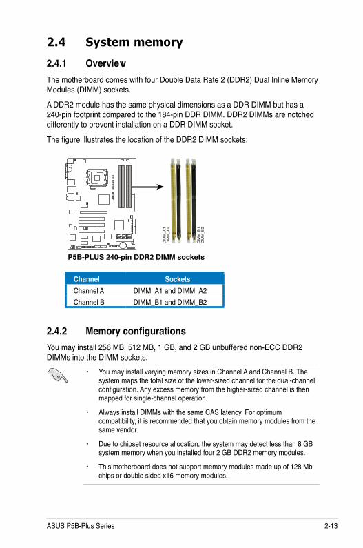
2.4 System memory
2.4.1 OverviewThe motherboard comes with four Double Data Rate 2 (DDR2) Dual Inline Memory Modules (DIMM) sockets.
A DDR2 module has the same physical dimensions as a DDR DIMM but has a 240-pin footprint compared to the 184-pin DDR DIMM. DDR2 DIMMs are notched differently to prevent installation on a DDR DIMM socket.
The figure illustrates the location of the DDR2 DIMM sockets:
2.4.2 Memory configurationsYou may install 256 MB, 512 MB, 1 GB, and 2 GB unbuffered non-ECC DDR2 DIMMs into the DIMM sockets.
• You may install varying memory sizes in Channel A and Channel B. The system maps the total size of the lower-sized channel for the dual-channel configuration. Any excess memory from the higher-sized channel is then mapped for single-channel operation.
• Always install DIMMs with the same CAS latency. For optimum compatibility, it is recommended that you obtain memory modules from the same vendor.
• Due to chipset resource allocation, the system may detect less than 8 GB system memory when you installed four 2 GB DDR2 memory modules.
• This motherboard does not support memory modules made up of 128 Mb chips or double sided x16 memory modules.
P5B
-PL
US
®
P5B-PLUS 240-pin DDR2 DIMM sockets
DIM
M_A
2D
IMM
_A1
DIM
M_B
2D
IMM
_B1
Channel SocketsChannel A DIMM_A1 and DIMM_A2Channel B DIMM_B1 and DIMM_B2

2-14 Chapter 2: Hardware information
• If you install four 1 GB memory modules, the system may detect less than 3 GB of total memory because of address space allocation for other critical functions. This limitation applies to Windows XP 32-bit version operating system since it does not support PAE (Physical Address Extention) mode.
• If you install Windows XP 32-bit version operating system, we recommend that you install less than 3GB of total memory.
Notes on memory limitations
• Due to chipset limitation, this motherboard can only support up to 8 GB on the operating systems listed below. You may install a maximum of 2 GB DIMMs on each slot, but only DDR2-533 and DDR2-667 2 GB density modules are available for this configuration.
• Some old-version DDR2-800/667 DIMMs may not match Intel®’s On-Die-Termination (ODT) requirement and will automatically downgrade to run at DDR2-533. If this happens, contact your memory vendor to check the ODT value.
• Due to chipset limitation, DDR2-800 with CL=4 will be downgraded to run at DDR2-667 by default setting. If you want to operate with lower latency, adjust the memory timing manually.
• Due to chipset limitation, DDR2-667 with CL=3 will be downgraded to run at DDR2-533 by default setting. If you want to operate with lower latency, adjust the memory timing manually.
32-bit 64-bitWindows 2000 Advanced Server Windows XP Professional x64 Edition
Windows Vista x64 Edition

ASUS P5B-Plus Series 2-15
P5B-Plus Series Motherboard Qualified Vendors Lists (QVL) DDR2-800MHz capability
Size Vendor Chip No. SS/DS Part No.
DIMM socket support (3Dmark)A* B* C*
512MB KINGSTON K4T51083QC SS KVR800D2N5/512 V V V1024MB KINGSTON Heat-Sink Package DS KHX6400D2LL/1G V V V1024MB KINGSTON Heat-Sink Package SS KHX6400D2LLK2/1GN V V V256MB Qimonda HYB18T512160BF-25F SS HYS64T32000HU-25F-B V V V512MB Qimonda HYB18T512800BF25F SS HYS64T64000HU-25F-B V V V1024MB Qimonda HYB18T512800BF25F DS HYS64T128020HU-25F-B V V V512MB SAMSUNG EDD339XX SS M378T6553CZ3-CE7 V V V256MB SAMSUNG K4T51163QC-ZCE7 SS M378T3354CZ3-CE7 V V V512MB SAMSUNG ZCE7K4T51083QC SS M378T6553CZ3-CE7 V V1024MB SAMSUNG ZCE7K4T51083QC DS M378T2953CZ3-CE7 V V 512MB Hynix HY5PS12821BFP-S5 SS HYMP564U64BP8-S5 V V V1024MB Hynix HY5PS12821BFP-S5 DS HYMP512U64BP8-S5 V V V512MB Hynix HY5PS12821CFP-S5 SS HYMP564U64CP8-S5 V V 1024MB Hynix HY5PS12821CFP-S5 DS HYMP512U64CP8-S5 V V V512MB MICRON 5JAIIZ9DQQ SS MT8HTF6464AY-80EA3 V V V1024MB MICRON 5JAIIZ9DQQ DS MT16HTF12864AY-80EA3 V V V512MB MICRON 5ZD22D9GKX SS MT8HTF6464AY-80ED4 V V V1024MB MICRON 5ZD22D9GKX DS MT16HTF12864AY-80ED4 V V V512MB MICRON 6CD22D9GKX SS MT8HTF6464AY-80ED4 V V V1024MB MICRON 6CD22D9GKX DS MT16HTF12864AY-80ED4 V V V512MB CORSAIR Heat-Sink Package SS CM2X512A-6400 V V 1024MB CORSAIR Heat-Sink Package DS CM2X1024-6400C4 V V V1024MB ELPIDA E1108AB-8E-E(ECC) SS EBE10EE8ABFA-8E-E V V V2048MB ELPIDA E1108AB-8E-E(ECC) DS EBE21EE8ABFA-8E-E V V512MB A-DATA N/A SS M2OAD6G3H3160J1E52 V V V512MB A-DATA AD29608A8A-25EG SS M20AD6G3H3160I1E5E V V 1024MB A-DATA K4T51083QC(ECC) DS M20AD6G3I4170G1E53 V V V512MB Crucial Heat-Sink Package SS BL6464AA804.8FD V V V512MB Crucial Heat-Sink Package SS BL6464AA804.8FD3 V V V1024MB Crucial Heat-Sink Package DS BL12864AA804.16FD V V1024MB Crucial Heat-Sink Package DS BL12864AL804.16FD3 V V V1024MB Crucial Heat-Sink Package DS BL12864AA804.16FD3 V V V512MB Apacer Heat-Sink Package DS AHU512E800C5K1C V V V1024MB Apacer Heat-Sink Package DS AHU01GE800C5K1C V V V512MB Transcend K4T51083QC SS TS64MLQ64V8J V V V1024MB Transcend K4T51083QC DS TS128MLQ64V8J V V V512MB KINGMAX KKEA88B4LZUG-25DF SS KLDC28F-A8KB5 V V V1024MB KINGMAX KKEA88B4LZUG-25DF DS KLDD48F-A8KB5 V V V

2-16 Chapter 2: Hardware information
DDR2-667MHz capability
Size Vendor Chip No. SS/DS Part No.
DIMM socket support (3Dmark)A* B* C*
256MB KINGSTON HYB18T256800AF3 SS KVR667D2N5/256 V V 512MB KINGSTON D6408TEBGGL3U SS KVR667D2N5/512 V V V1024MB KINGSTON D6408TEBGGL3U DS KVR667D2N5/1G V V V256MB Qimonda HYB18T512160AF-3S SS HYS64T32000HU-3S-A V V V512MB Qimonda HYB18T512800AF3S SS HYS64T64000HU-3S-A V V V1024MB Qimonda HYB18T512800AF3S DS HYS64T128020HU-3S-A V V 256MB Qimonda HYB18T256800AF3S(ECC) SS HYS72T32000HU-3S-A V V V512MB Qimonda HYB18T512800AF3S(ECC) SS HYS72T64000HU-3S-A V V V1024MB Qimonda HYB18T512800AF3S(ECC) DS HYS72T128020HU-3S-A V V V512MB Qimonda HYB18T512800BF3S(ECC) SS HYS72T64000HU-3S-B V V 1024MB Qimonda HYB18T512800BF3S(ECC) DS HYS72T128020HU-3S-B V V V256MB Qimonda HYB18T512160BF-3S SS HYS64T32000HU-3S-B V V V512MB Qimonda HYB18T512800BF3S SS HYS64T64000HU-3S-B V V V1024MB Qimonda HYB18T512800BF3S DS HYS64T128020HU-3S-B V V V256MB SAMSUNG K4T51163QC-ZCE6 SS M378T3354CZ0-CE6 V V 512MB SAMSUNG ZCE6K4T51083QC SS M378T6553CZ0-CE6 V V V256MB SAMSUNG K4T51163QC-ZCE6 SS M378T3354CZ3-CE6 V V V512MB SAMSUNG K4T51083QC SS M378T6553CZ3-CE6 V V V1024MB SAMSUNG ZCE6K4T51083QC DS M378T2953CZ3-CE6 V V V512MB Hynix HY5PS12821AFP-Y5 SS HYMP564U64AP8-Y5 V V V1024MB Hynix HY5PS12821AFP-Y5 DS HYMP512U64AP8-Y5 V V 1024MB Hynix HY5PS1G831FP-Y5(ECC) SS HYMP112U72P8-Y5 V V V512MB Hynix HY5PS12821AFP-Y5(ECC) SS HYMP564U72AP8-Y5 V V V1024MB Hynix HY5PS12821AFP-Y5(ECC) DS HYMP512U72AP8-Y5 V V V512MB Hynix HY5PS12821AFP-Y4 SS HYMP564U64AP8-Y4 V V V1024MB Hynix HY5PS12821AFP-Y4 DS HYMP512U64AP8-Y4 V V 512MB Hynix HY5PS12821AFP-Y4(ECC) SS HYMP564U72AP8-Y4 V V V1024MB Hynix HY5PS12821AFP-Y4(ECC) DS HYMP512U72AP8-Y4 V V 512MB CORSAIR 64M8CFEG SS VS512MB667D2 V V V1024MB CORSAIR 64M8CFEG DS VS1GB667D2 V V 256MB ELPIDA E2508AB-6E-E SS EBE25UC8ABFA-6E-E V V V512MB A-DATA AD29608A8B-3EG SS M20AD5Q3H3163J1C52 V V V512MB A-DATA AD29608A8A-3EG SS M2OAD5G3H3166I1C52 V V V1024MB A-DATA AD29608A8A-3EG DS M2OAD5G3I4176I1C52 V V V1024MB crucial Heat-Sink Package DS BL12864AL664.16FD V V V1024MB Apacer E5108AE-6E-E DS 78.01092.420 V V 1024MB Apacer AM4B5708GQJS7E DS AU01GE667C5KBGC V V V512MB Kingmax KKEA88B4LAUG-29DX SS KLCC28F-A8KB5 V V V1024MB Kingmax KKEA88B4LAUG-29DX DS KLCD48F-A8KB5 V V V512MB Transcend E5108AE-6E-E SS TS64MLQ64V6J V V V1024MB Transcend E5108AE-6E-E DS TS128MLQ64V6J V V V512MB Transcend J12Q3AB-6 SS JM367Q643A-6 V V 1024MB Transcend J12Q3AB-6 DS JM388Q643A-6 V V V512MB Super Talent Heat-Sink Package SS T6UA512C5 V V V1024MB Super Talent Heat-Sink Package DS T6UB1GC5 V V 512MB SMART G64M8XB3ITIX4TUE SS TB3D2667C58S V V V512MB SMART G64M8XB3ITIX4TUE DS TB4D2667C58D V V

ASUS P5B-Plus Series 2-17
DDR2-533MHz capability
SS - Single-sided DS - Double-sidedDIMM support:A - Supports one module inserted into either slot, in Single-channel memory configuration.B - Supports one pair of modules inserted into either Channel A or Channel B as one pair of Dual-
channel memory configuration.C - Supports four modules inserted into the yellow and black slots as two pairs of Dual-channel
memory configuration.
Visit the ASUS website for the latest DDR2-800/667/533 MHz QVL.
Size Vendor Chip No. SS/DS Part No.
DIMM socket support (3Dmark)A* B* C*
256MB KINGSTON E5116AF-5C-E SS KVR533D2N4/256 V V V512MB KINGSTON HYB18T512800AF37 SS KVR533D2N4/512 V V V1024MB KINGSTON 5YDIID9GCT DS KVR533D2N4/1G V V V512MB Qimonda HYB18T512800BF37 SS HYS64T64000HU-3.7-B V V V1024MB Qimonda HYB18T512800BF37 DS HYS64T128020HU-3.7-B V V V256MB SAMSUNG K4T51163QC-ZCD5 SS M378T3354CZ3-CD5 V V V512MB SAMSUNG ZCD5K4T51083QC SS M378T6553CZ3-CD5 V V V1024MB SAMSUNG ZCD5K4T51083QC DS M378T2953CZ3-CD5 V V V256MB CORSAIR 32M16CEDG SS VS256MB533D2 V V V512MB CORSAIR MI110052432M8CEC DS VS512MB533D2 V V 1024MB CORSAIR 64M8CEDG DS VS1GB533D2 V V V512MB ELPIDA E5108AB-5C-E SS EBE51UD8ABFA-5C V V 512MB ELPIDA E5108AB-5C-E SS EBE51UD8ABFA-5C-E V V V1024MB ELPIDA E5108AB-5C-E DS EBE11UD8ABFA-5C-E V V 512MB KINGMAX E5108AE-5C-E SS KLBC28F-A8EB4 V V V1024MB KINGMAX E5108AE-5C-E DS KLBD48F-A8EB4 V V V512MB KINGMAX KKEA88E4AAK-37 SS KLBC28F-A8KE4 V V V1024MB KINGMAX 5MB22D9DCN DS KLBD48F-A8ME4 V V V512MB Super Talent Heat-Sink Package SS T5UA512C4 V V V1024MB Super Talent Heat-Sink Package DS T5UB1GC4 V V V

2-18 Chapter 2: Hardware information
2.4.3 Installing a DIMMUnplug the power supply before adding or removing DIMMs or other system components. Failure to do so can cause severe damage to both the motherboard and the components.
To install a DIMM:
1. Unlock a DIMM socket by pressing the retaining clips outward.
2. Align a DIMM on the socket such that the notch on the DIMM matches the break on the socket.
3. Firmly insert the DIMM into the socket until the retaining clips snap back in place and the DIMM is properly seated.
2.4.4 Removing a DIMMTo remove a DIMM:
1. Simultaneously press the retaining clips outward to unlock the DIMM.
2. Remove the DIMM from the socket.
• A DDR2 DIMM is keyed with a notch so that it fits in only one direction. Do not force a DIMM into a socket to avoid damaging the DIMM.
• The DDR2 DIMM sockets do not support DDR DIMMs. Do not install DDR DIMMs to the DDR2 DIMM sockets.
Unlocked retaining clip
DDR2 DIMM notch
Support the DIMM lightly with your fingers when pressing the retaining clips. The DIMM might get damaged when it flips out with extra force.
DDR2 DIMM notch
1
2
3
1
2
1
1

ASUS P5B-Plus Series 2-19
2.5 Expansion slotsIn the future, you may need to install expansion cards. The following sub-sections describe the slots and the expansion cards that they support.
2.5.1 Installing an expansion cardTo install an expansion card:
1. Before installing the expansion card, read the documentation that came with it and make the necessary hardware settings for the card.
2. Remove the system unit cover (if your motherboard is already installed in a chassis).
3. Remove the bracket opposite the slot that you intend to use. Keep the screw for later use.
4. Align the card connector with the slot and press firmly until the card is completely seated on the slot.
5. Secure the card to the chassis with the screw you removed earlier.6. Replace the system cover.
2.5.2 Configuring an expansion cardAfter installing the expansion card, configure it by adjusting the software settings.
1. Turn on the system and change the necessary BIOS settings, if any. See Chapter 4 for information on BIOS setup.
2. Assign an IRQ to the card. Refer to the tables on the next page.3. Install the software drivers for the expansion card.
Make sure to unplug the power cord before adding or removing expansion cards. Failure to do so may cause you physical injury and damage motherboard components.
When using PCI cards on shared slots, ensure that the drivers support “Share IRQ” or that the cards do not need IRQ assignments. Otherwise, conflicts will arise between the two PCI groups, making the system unstable and the card inoperable. Refer to the table on the next page for details.

2-20 Chapter 2: Hardware information
2.5.3 Interrupt assignments
Standard interrupt assignmentsIRQ Priority StandardFunction0 1 System Timer1 2 Keyboard Controller2 — Re-direct to IRQ#93 12 IRQ holder for PCI steering* 4 13 Communications Port (COM1)* 5 14 IRQ holder for PCI steering*6 15 Floppy Disk Controller 7 16 Printer Port (LPT1)*8 3 System CMOS/Real Time Clock9 4 ACPI*10 5 SMBus Controller*11 6 IRQ holder for PCI steering*12 7 PS/2 Compatible Mouse Port*13 8 Numeric Data Processor14 9 IDEIRQ Compatible mode, Mapped as Primary Channel/Master-SATA1/Slave-SATA315 10 IDEIRQ Compatible mode, Mapped as Secondary Channel/Master-SATA2/Slave-SATA4
* These IRQs are usually available for PCI devices.IRQ assignments for this motherboard
A B C D E F G HPCI slot 1 — — — — used — — —PCI slot 2 — — — — — shared — —PCI slot 3 — — — — — — shared —PCIEX16_1 shared — — — — — — —PCIEX1_1 shared — — — — — — —PCIEX1_2 — shared — — — — — —PCIEX1_3 — — shared — — — — —GbEthernet — — — shared — — — —ESATA, SATA_RAID shared — — — — — — —PRI_IDE (JMicron363) shared — — — — — — —IEEE 1394a (VIA 6307) — — — — — shared — —HD Audio (ADI1988A) — — — — — — shared —USB 2.0 EHCI#1 — — — — — — — sharedUSB 2.0 EHCI#2 — — shared — — — — —USB12 OBCI#1 — — — — — — — sharedUSB34 OBCI#2 — — — — — — shared —USB56 OBCI#3 — — shared — — — — —USB78 OBCI#4 shared — — — — — —USB910 OBCI#5 — shared — — — — —SATA1,2, 3, 4, 5, 6 (ICH8) — — — shared — — — —

ASUS P5B-Plus Series 2-21
2.5.4 PCI slotsThe PCI slots support cards such as a LAN card, SCSI card, USB card, and other cards that comply with PCI specifications. The figure shows a LAN card installed on a PCI slot.
2.5.5 PCI Express x1 slotsThis motherboard supports PCI Express x1 network cards, SCSI cards and other cards that comply with the PCI Express specifications. The following figure shows a network card installed on the PCI Express x1 slot.
2.5.6 PCI Express x16 slotThis motherboard has one PCI Express x16 slots that support PCI Express x16 graphic cards complying with the PCI Express specifications.

2-22 Chapter 2: Hardware information
2.6 Jumper1. Clear RTC RAM (CLRTC)
This jumper allows you to clear the Real Time Clock (RTC) RAM in CMOS. You can clear the CMOS memory of date, time, and system setup parameters by erasing the CMOS RTC RAM data. The onboard button cell battery powers the RAM data in CMOS, which include system setup information such as system passwords.
To erase the RTC RAM:1. Turn OFF the computer and unplug the power cord.
2. Remove the onboard battery.
3. Move the jumper cap from pins 1-2 (default) to pins 2-3. Keep the cap on pins 2-3 for about 5~10 seconds, then move the cap back to pins 1-2.
4. Reinstall the battery.
5. Plug the power cord and turn ON the computer.
6. Hold down the <Del> key during the boot process and enter BIOS setup to re-enter data.
• You do not need to clear the RTC when the system hangs due to overclocking. For system failure due to overclocking, use the C.P.R. (CPU Parameter Recall) feature. Shut down and reboot the system so the BIOS can automatically reset parameter settings to default values.
• Due to the chipset behavior, AC power off is required to enable C.P.R. function. You must turn off and on the power supply or unplug and plug the power cord before reboot the system.
P5B
-PL
US
®
P5B-PLUS Clear RTC RAMNormal
(Default)Clear RTC
CLRTC
12
32
Except when clearing the RTC RAM, never remove the cap on CLRTC jumper default position. Removing the cap will cause system boot failure!

ASUS P5B-Plus Series 2-23
2. USB device wake-up (3-pin USBPW1-4, 3-pin USBPW5-8)Set these jumpers to +5V to wake up the computer from S1 sleep mode (CPU stopped, DRAM refreshed, system running in low power mode) using the connected USB devices. Set to +5VSB to wake up from S4 sleep mode (no power to CPU, DRAM in slow refresh, power supply in reduced power mode).
• The USB device wake-up feature requires a power supply that can provide 500mA on the +5VSB lead for each USB port; otherwise, the system will not power up.
• If you are using Windows® 2000, you need to install Service Pack 4 to wake up the system from S4 sleep mode.
• The total current consumed must NOT exceed the power supply capability (+5VSB) whether under normal condition or in sleep mode.
P5B
-PL
US
®
2 31 2
P5B-PLUS USB device wake-up
+5V(Default)
+5VSB
USBPW5-8
+5V(Default)+5VSB
USBPW1-4
12
32
3. Keyboard power (3-pin KBPWR)This jumper allows you to enable or disable the keyboard wake-up feature. Set this jumper to pins 2-3 (+5VSB) to wake up the computer when you press a key on the keyboard (the default is the Space Bar). This feature requires an ATX power supply that can supply at least 1A on the +5VSB lead, and a corresponding setting in the BIOS.
P5B
-PL
US
®
2 31 2
P5B-PLUS Keyboard power setting
+5V(Default)
+5VSB
KBPWR

2-24 Chapter 2: Hardware information
2.7 Connectors
2.7.1 Rear panel connectors
1. PS/2 mouse port (green). This port is for a PS/2 mouse.2. Parallel port. This 25-pin port connects a parallel printer, a scanner, or other
devices.3. IEEE 1394a port. This 6-pin IEEE 1394a port provides high-speed
connectivity for audio/video devices, storage peripherals, PCs, or portable devices.
4. LAN (RJ-45) port. Supported by Attansic® Gigabit LAN controller, this port allows Gigabit connection to a Local Area Network (LAN) through a network hub. Refer to the table below for the LAN port LED indications.
11
6
13
1
16
2
15 14
5 7 8
910
43
12
Activity/Link Speed LEDStatus Description Status DescriptionOFF No link OFF 10 Mbps connectionORANGE Linked ORANGE 100 Mbps connectionBLINKING Data activity GREEN 1 Gbps connection
LAN port LED indicationsSPEED
LEDACT/LINK
LED
LAN port5. Rear Speaker Out port (black). This port connects the rear speakers in a
4-channel, 6-channel, or 8-channel audio configuration.6. Center/Subwoofer port (orange). This port connects the center/subwoofer
speakers.7. Line In port (light blue). This port connects the tape, CD, DVD player, or
other audio sources.
8. Line Out port (lime). This port connects a headphone or a speaker. In 4-channel, 6-channel, and 8-channel configuration, the function of this port becomes Front Speaker Out.
9. Microphone port (pink). This port connects a microphone.10. Side Speaker Out port (gray). This port connects the side speakers in an
8-channel audio configuration.

ASUSP5B-Plus Series 2-25
The external SATA port supports external Serial ATA 3.0 Gb/s devices. Longer cables support higher power requirements to deliver signal up to two meters away, and enables improved hot-swap function.
Refer to the audio configuration table below for the function of the audio ports in 2, 4, 6, or 8-channel configuration.
Audio 2, 4, 6, or 8-channel configuration
Port Headset 2-channel
4-channel 6-channel 8-channel
Light Blue Line In Line In Line In Line InLime Line Out Front Speaker Out Front Speaker Out Front Speaker OutPink Mic In Mic In Mic In Mic InOrange – – Center/Subwoofer Center/SubwooferBlack – Rear Speaker Out Rear Speaker Out Rear Speaker OutGray – – – Side Speaker Out
11. USB 2.0 ports 1 and 2. These 4-pin Universal Serial Bus (USB) ports are available for connecting USB 2.0 devices.
13. External SATA port. This port connects to an external SATA box or a Serial ATA port multiplier. This port supports a Serial ATA hard disk drive that you can combine with an external Serial ATA 3.0 Gb/s device to configure a RAID 0, RAID 1, or JBOD set through the onboard JMicron SATA RAID controller.
Connect the IR receiver ONLY to USB port 1 and 2, which supports remote control function. Plugging any other USB devices to these two ports will turn on the computer.
12. USB 2.0 ports 3 and 4. These 4-pin Universal Serial Bus (USB) ports are available for connecting USB 2.0 devices.

2-26 Chapter 2: Hardware information
14. Optical S/PDIF Out port. This port connects an external audio output device via an optical S/PDIF cable.
15. Coaxial S/PDIF Out port. This port connects an external audio output device via a coaxial S/PDIF cable.
16. PS/2 keyboard port (purple). This port is for a PS/2 keyboard.
• DO NOT insert a different connector to this port.
• DO NOT unplug the external Serial ATA box when a RAID 0 or JBOD is configured.
• Before creating a RAID set using Serial ATA hard disks, make sure that you have connected the Serial ATA signal cable and installed Serial ATA hard disk drives; otherwise, you cannot enter the JMicron RAID utility and SATA BIOS setup during POST.
• If you intend to create a RAID configuration using this connector, set the JMicron Controller item in the BIOS to [RAID Mode]. See section 4.4.6 Onboard Device Configuration for details.

ASUSP5B-Plus Series 2-27
2.7.2 Internal connectors1. Floppy disk drive connector (34-1 pin FLOPPY)
This connector is for the provided floppy disk drive (FDD) signal cable. Insert one end of the cable to this connector, then connect the other end to the signal connector at the back of the floppy disk drive.
Pin 5 on the connector is removed to prevent incorrect cable connection when using a FDD cable with a covered Pin 5.
P5B
-PL
US
®
P5B-PLUS Floppy disk drive connector
NOTE: Orient the red markings onthe floppy ribbon cable to PIN 1.
FLOPPY
2. JMicron JMB363® Serial ATA RAID connector (7-pin SATA_RAID)
This connector is for a Serial ATA signal cable. This connector supports a Serial ATA hard disk drive, which you can combine with an external Serial ATA hard disk drive to configure for RAID via the onboard Serial ATA RAID controller.
The JMicron JMB363 controller item in the BIOS is set to [IDE] by default.
Before creating a RAID set using Serial ATA hard disks, make sure that you have connected the Serial ATA signal cables and installed Serial ATA hard disk drives; otherwise, you CANNOT enter the JMicron® JMB363 RAID utility and SATA BIOS setup during POST.
P5B
-PL
US
®
P5B-PLUS SATA_RAID connector
SATA_RAID
GND
RSAT
A_TX
P1RS
ATA_
TXN1
GNDRS
ATA_
RXP1
RSAT
A_RX
N1G
ND

2-28 Chapter 2: Hardware information
3. ICH8R Serial ATA connectors (7-pin SATA1 [red], SATA2 [red], SATA3 [black], SATA4 [black], SATA5 [red], SATA6 [red])These connectors are for the Serial ATA signal cables for Serial ATA hard disk drives.
If you installed Serial ATA hard disk drives, you can create a RAID 0, RAID 1, RAID 5, RAID 10 configuration with the Intel® Matrix Storage Technology through the onboard Intel® ICH8R RAID controller.
P5
B-P
LU
S®
P5B-PLUS SATA connectors
SATA1
GND
RSAT
A_TX
P3RS
ATA_
TXN3
GND
RSAT
A_RX
P3RS
ATA_
RXN3
GND
GND
RSAT
A_TX
P1RS
ATA_
TXN1
GNDRS
ATA_
RXP1
RSAT
A_RX
N1G
ND
SATA3
GND
RSAT
A_TX
P4RS
ATA_
TXN4
GND
RSAT
A_RX
P4RS
ATA_
RXN4
GND
SATA4
SATA2G
NDRS
ATA_
TXP2
RSAT
A_TX
N2G
NDRSAT
A_RX
P2RS
ATA_
RXN2
GND
SATA5
GND
RSAT
A_TX
P5RS
ATA_
TXN5
GNDRS
ATA_
RXP5
RSAT
A_RX
N5G
ND
GNDRS
ATA_
TXP6
RSAT
A_TX
N6G
NDRSAT
A_RX
P6RS
ATA_
RXN6
GND
SATA6
• These connectors are set to Standard IDE mode by default. In Standard IDE mode, you can connect Serial ATA boot/data hard disk drives to these connectors. If you intend to create a Serial ATA RAID set using these connectors, set the Configure SATA as item in the BIOS to [RAID]. See section 4.3.5 IDE Configuration for details.
• For RAID 5, use at least three hard disk drives. For RAID 10, use at least four hard disk drives. Use two to four Serial ATA hard disk drives for each RAID 0 or RAID 1 set.
• You must install Windows® 2000 Service Pack 4 or the Windows® XP Service Pack 1 before using Serial ATA hard disk drives. The Serial ATA RAID feature (RAID 0/RAID 1/RAID 5/RAID 10) is available only if you are using Windows® 2000/XP or later version.
• When using the connectors in Standard IDE mode, connect the primary (boot) hard disk drive to the SATA1/2/5/6 connector. Refer to the table below for the recommended SATA hard disk drive connections.
Serial ATA hard disk drive connectionConnector Color Setting Use
SATA1/2/5/6 Red Master Boot disk
SATA3/4 Black Slave Data Disk
P5
B-P
LU
S®
P5B-PLUS SATA connectors
SATA1
GND
RSAT
A_TX
P3RS
ATA_
TXN3
GND
RSAT
A_RX
P3RS
ATA_
RXN3
GND
GND
RSAT
A_TX
P1RS
ATA_
TXN1
GNDRS
ATA_
RXP1
RSAT
A_RX
N1G
ND
SATA3
GND
RSAT
A_TX
P4RS
ATA_
TXN4
GND
RSAT
A_RX
P4RS
ATA_
RXN4
GND
SATA4
SATA2G
NDRS
ATA_
TXP2
RSAT
A_TX
N2G
NDRSAT
A_RX
P2RS
ATA_
RXN2
GND
SATA5
GND
RSAT
A_TX
P5RS
ATA_
TXN5
GNDRS
ATA_
RXP5
RSAT
A_RX
N5G
ND
GNDRS
ATA_
TXP6
RSAT
A_TX
N6G
NDRSAT
A_RX
P6RS
ATA_
RXN6
GND
SATA6

ASUSP5B-Plus Series 2-29
Connect the right-angle side of SATA signal cable to SATA device. Or you may connect the right-angle side of SATA cable to the onboard SATA port to avoid mechanical conflict with huge graphics cards.
right angle side
P5B
-PL
US
®
P5B-PLUS IDE connectorNOTE: Orient the red markings(usually zigzag) on the IDEribbon cable to PIN 1.
PRI_IDE
4. IDE connector (40-1 pin PRI_IDE)The onboard IDE connector is for the Ultra DMA 133/100/66 signal cable. There are three connectors on each Ultra DMA 133/100/66 signal cable: blue, black, and gray. Connect the blue connector to the motherboard’s IDE connector, then select one of the following modes to configure your device.
• Pin 20 on the IDE connector is removed to match the covered hole on the Ultra DMA cable connector. This prevents incorrect insertion when you connect the IDE cable.
• Use the 80-conductor IDE cable for Ultra DMA 133/100/66 IDE devices.
If any device jumper is set as “Cable-Select,” make sure all other device jumpers have the same setting.
Drive jumper setting Mode of device(s)
Cable connector
Single device Cable-Select or Master - BlackTwo devices Cable-Select Master Black
Slave GrayMaster Master Black or graySlave Slave

2-30 Chapter 2: Hardware information
5. USB connectors Vista Edition: (10-1 pin USB56, USB 78) Standard Edition: (10-1 pin USB56, USB 78, USB910)These connectors are for USB 2.0 ports. Connect the USB module cable to any of these connectors, then install the module to a slot opening at the back of the system chassis. These USB connectors comply with USB 2.0 specification that supports up to 480 Mbps connection speed.
Never connect a 1394 cable to the USB connectors. Doing so will damage the motherboard!
6. IEEE 1394a port connector (10-1 pin IE1394_2)This connector is for a IEEE 1394a port. Connect the IEEE 1394a module cable to this connector, then install the module to a slot opening at the back of the system chassis.
P5
B-P
LU
S®
P5B-PLUS IEEE 1394a connector
IE1394_21
TPA2-G
ND
TPB2-+12VG
ND
TPA2+G
ND
TPB2++12V
P5B
-PL
US
®
P5B-PLUS USB 2.0 connectors
USB
+5V
USB
_P6-
USB
_P6+
GN
DN
C
USB
+5V
USB
_P5-
USB
_P5+
GN
DPIN1
NC
GN
DU
SB_P
10+
USB
_P10
-U
SB+5
V
GN
DU
SB_P
9+U
SB_P
9-U
SB+5
V
PIN1
USB
+5V
USB
_P8-
USB
_P8+
GN
DN
C
USB
+5V
USB
_P7-
USB
_P7+
GN
D
PIN1
Connect the USB cable to ASUS Q-Connector (USB, blue) first, and then install the Q-Connector (USB) to the USB56 connector onboard.
The IEEE1394a module is purchased separately.
ASUSP5B-Plus Series 2-31
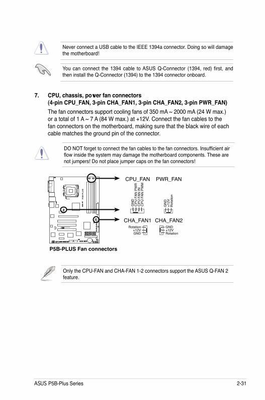
7. CPU, chassis, power fan connectors (4-pin CPU_FAN, 3-pin CHA_FAN1, 3-pin CHA_FAN2, 3-pin PWR_FAN)The fan connectors support cooling fans of 350 mA ~ 2000 mA (24 W max.) or a total of 1 A ~ 7 A (84 W max.) at +12V. Connect the fan cables to the fan connectors on the motherboard, making sure that the black wire of each cable matches the ground pin of the connector.
DO NOT forget to connect the fan cables to the fan connectors. Insufficient air flow inside the system may damage the motherboard components. These are not jumpers! Do not place jumper caps on the fan connectors!
P5B
-PL
US
®
P5B-PLUS Fan connectors
CPU_FAN
GN
DC
PU F
AN P
WR
CPU
FAN
INC
PU F
AN P
WM
CHA_FAN1
PWR_FAN
GN
D
Rot
atio
n+1
2V
GND
Rotation+12V
GND
Rotation+12V
CHA_FAN2
Only the CPU-FAN and CHA-FAN 1-2 connectors support the ASUS Q-FAN 2 feature.
Never connect a USB cable to the IEEE 1394a connector. Doing so will damage the motherboard!
You can connect the 1394 cable to ASUS Q-Connector (1394, red) first, and then install the Q-Connector (1394) to the 1394 connector onboard.

2-32 Chapter 2: Hardware information
9. ATX power connectors (24-pin EATXPWR, 4-pin EATX12V)These connectors are for ATX power supply plugs. The power supply plugs are designed to fit these connectors in only one orientation. Find the proper orientation and push down firmly until the connectors completely fit.
8. Chassis intrusion connector (4-1 pin CHASSIS)This connector is for a chassis-mounted intrusion detection sensor or switch. Connect one end of the chassis intrusion sensor or switch cable to this connector. The chassis intrusion sensor or switch sends a high-level signal to this connector when a chassis component is removed or replaced. The signal is then generated as a chassis intrusion event.
By default , the pin labeled “Chassis Signal” and “Ground” are shorted with a jumper cap. Remove the jumper caps only when you intend to use the chassis intrusion detection feature.
P5B
-PL
US
®
P5B-PLUS Chassis intrusion connector
CHASSIS
+5VS
B_M
B
Cha
ssis
Sig
nal
GN
D
(Default)
P5B
-PL
US
®
P5B-PLUS ATX power connectors
EATXPWREATX12V
+3 Volts+3 VoltsGround+5 Volts
+5 VoltsGround
GroundPower OK
+5V Standby+12 Volts
-5 Volts
+5 Volts
+3 Volts-12 VoltsGround
GroundGroundPSON#
Ground
+5 Volts
+12 Volts+3 Volts
+5 VoltsGround+12V DC
GND+12V DC
GND
• Make sure to remove the cap on the EATX12V connector before connecting an 4-pin EPS +12V power plug.
• Use only 4-pin ATX12V EPS +12V power plug for the EATX12V connector.

ASUS P5B-Plus Series 2-33
• For a fully configured system, we recommend that you use a power supply unit (PSU) that complies with ATX 12 V Specification 2.0 (or later version) and provides a minimum power of 400 W.
• Do not forget to connect the 4-pin EATX12V power plug; otherwise, the system will not boot.
• Use of a PSU with a higher power output is recommended when configuring a system with more power-consuming devices. The system may become unstable or may not boot up if the power is inadequate.
• The ATX 12 V Specification 2.0-compliant (400W) PSU has been tested to support the motherboard power requirements with the following configuration: CPU: Intel® Pentium® Extreme 3.73GHz Memory: 512 MB DDR2 (x4) Graphics card: ASUS EAX1900XT Parallel ATA device: IDE hard disk drive Serial ATA device: SATA hard disk drive (x2) Optical drive: DVD-RW
P5B
-PL
US
®
P5B-PLUS Analog front panel connector
AAFPLegacy AC 97 audiopin definitionSEN
SE2_RETU
R
PORT1 L
PORT2 R
PORT2 L
SENSE1_R
ETUR
SENSE_SEN
D
PORT1 R
PRESEN
CE#
GN
D
NC
MIC
2
Line out_R
Line out_L
NC
NCMIC
PWR
NC
AGN
D
HD Audio-compliantpin definition
10. Front panel audio connector (10-1 pin AAFP)This connector is for a chassis-mounted front panel audio I/O module that supports either HD Audio or legacy AC`97 audio standard. Connect one end of the front panel audio I/O module cable to this connector.
• We recommend that you connect a high-definition front panel audio module to this connector to avail of the motherboard’s high-definition audio capability.
• By default, this connector is set to [AC'97]. If you want to connect a High Definition front panel audio module to this connector, set the Front Panel Support Type item in the BIOS setup to [HD Audio]. See section 4.4.6 Onboard Device Configuration for details.

2-34 Chapter 2: Hardware information
P5B
-PL
US
®
P5B-PLUS Internal audio connector
CDRight Audio Channel
Left Audio ChannelGroundGround
11. Optical drive audio connector (4-pin CD)This connector allows you to receive stereo audio input from sound sources such as a CD-ROM, TV tuner, or MPEG card.
(black)
P5B
-PL
US
®
P5B-PLUS Digital audio connector
+5V
SPD
IFO
UT
GN
D
SPDIF_OUT
12. Digital audio connector (4-1 pin SPDIF)This connector is for an additional Sony/Philips Digital Interface (S/PDIF) port(s). Connect the S/PDIF Out module cable to this connector, then install the module to a slot opening at the back of the system chassis.
The S/PDIF module is purchased separately.

ASUS P5B-Plus Series 2-35
P5B
-PL
US
®
P5B-PLUS COM port connector
PIN 1
COM1
13. Serial port connector (10-1 pin COM1)This connector is for a serial (COM) port. Connect the serial port module cable to this connector, then install the module to a slot opening at the back of the system chassis.
The serial port module is purchased separately.
14. TPM connector (20-1 pin TPM)This connector supports a Trusted Platform Module (TPM) system, which can securely store keys, digital certificates, passwords, and data. A TPM system also helps enhance network security, protects digital identities, and ensures platform integrity.
P5B
-PL
US
®
P5B-PLUS TPM connectorTPM
The TPM module is purchased separately. Use the ASUS TPM module ONLY!

2-36 Chapter 2: Hardware information
• System power LED (2-pin PLED)This 2-pin connector is for the system power LED. Connect the chassis power LED cable to this connector. The system power LED lights up when you turn on the system power, and blinks when the system is in sleep mode.
• Hard disk drive activity LED (2-pin IDE_LED)This 2-pin connector is for the HDD Activity LED. Connect the HDD Activity LED cable to this connector. The IDE LED lights up or flashes when data is read from or written to the HDD.
• System warning speaker (4-pin SPEAKER)This 4-pin connector is for the chassis-mounted system warning speaker. The speaker allows you to hear system beeps and warnings.
• ATX power button/soft-off button (2-pin PWRSW)This connector is for the system power button. Pressing the power button turns the system on or puts the system in sleep or soft-off mode depending on the BIOS settings. Pressing the power switch for more than four seconds while the system is ON turns the system OFF.
• Reset button (2-pin RESET)This 2-pin connector is for the chassis-mounted reset button for system reboot without turning off the system power.
15. System panel connector (20-8 pin PANEL)
This connector supports several chassis-mounted functions.
P5B
-PL
US
®
P5B-PLUSSystem panel connector
* Requires an ATX power supply.
PANEL
PLED
-
PWR
+5V
Spea
ker
Gro
und
RESET
Gro
und
Res
etG
roun
dG
roun
d
PWRSW
PLED
+ID
E_LE
D-
IDE_
LED
+
IDE_LED
PLED SPEAKER

ASUS P5B-Plus Series 2-37
ASUS Q-Connector (system panel)You can use the ASUS Q-Connector to connect/disconnect chassis front panel cables in a few steps. Refer to the instructions below to install the ASUS Q-Connector.
1. Connect the front panel cables to the ASUS Q-Connector.
Refer to the labels on the Q-Connector to know the detailed pin definitions, then match them to the respective front panel cable labels.
2. Install the ASUS Q-Connector to the system panel connector, making sure the orientation matches the labels on the motherboard.
3. The front panel functions are now enabled. The figure shows the Q-Connector properly installed on the motherboard.

2-38 Chapter 2: Hardware information

3Powering up
This chapter describes the power up sequence, the vocal POST messages, and ways of shutting down the system.

ASUS P5B-Plus Series
Chapter summary 33.1 Starting up for the first time ........................................................ 3-13.2 Turning off the computer ............................................................. 3-2

ASUS P5B-Plus Series 3-1
3.1 Starting up for the first time
1. After making all the connections, replace the system case cover. 2. Be sure that all switches are off.3. Connect the power cord to the power connector at the back of the system
chassis.4. Connect the power cord to a power outlet that is equipped with a surge
protector.5. Turn on the devices in the following order: a. Monitor b. External SCSI devices (starting with the last device on the chain) c. System power6. After applying power, the system power LED on the system front panel case
lights up. For systems with ATX power supplies, the system LED lights up when you press the ATX power button. If your monitor complies with “green” standards or if it has a “power standby” feature, the monitor LED may light up or switch between orange and green after the system LED turns on.
The system then runs the power-on self tests or POST. While the tests are running, the BIOS beeps (see BIOS beep codes table below) or additional messages appear on the screen. If you do not see anything within 30 seconds from the time you turned on the power, the system may have failed a power-on test. Check the jumper settings and connections or call your retailer for assistance.
AMI BIOS beep codes
7. At power on, hold down the <Delete> key to enter the BIOS Setup. Follow the instructions in Chapter 4.
BIOS Beep DescriptionOne short beep VGA detected
Quick boot set to disabled No keyboard detected
One continuous beep followed by two short beeps then a pause (repeated)
No memory detected
One continuous beep followed by three short beeps
No VGA detected
One continuous beep followed by four short beeps
Hardware component failure

3-2 Chapter 3: Powering up
3.2 Turning off the computer
3.2.1 Using the OS shut down functionIf you are using Windows® 2000:
1. Click the Start button then click Shut Down.2. Make sure that the Shut Down option button is selected, then click the OK
button to shut down the computer. 3. The power supply should turn off after Windows® shuts down.
If you are using Windows® XP:
1. Click the Start button then select Turn Off Computer.2. Click the Turn Off button to shut down the computer. 3. The power supply should turn off after Windows® shuts down.
If you are using Windows® Vista:
1. Click the Start button then select ShutDown.2. The power supply should turn off after Windows® shuts down.
3.2.2 Using the dual function power switchWhile the system is ON, pressing the power switch for less than four seconds puts the system to sleep mode or to soft-off mode, depending on the BIOS setting. Pressing the power switch for more than four seconds lets the system enter the soft-off mode regardless of the BIOS setting. Refer to section 4.5 Power Menu in Chapter 4 for details.

4BIOS setup
This chapter tells how to change the system settings through the BIOS Setup menus. Detailed descriptions of the BIOS parameters are also provided.

Chapter summary 4
ASUS P5B-Plus Series
4.1 Managing and updating your BIOS ............................................ 4-14.2 BIOS setup program .................................................................... 4-94.3 Main menu .................................................................................. 4-124.4 Advanced menu ......................................................................... 4-164.5 Power menu ................................................................................ 4-274.6 Boot menu .................................................................................. 4-314.7 Tools menu ................................................................................. 4-364.8 Exit menu .................................................................................... 4-38

ASUS P5B-Plus Series 4-1
4.1 Managing and updating your BIOSThe following utilities allow you to manage and update the motherboard Basic Input/Output System (BIOS) setup.
1. ASUS Update (Updates the BIOS in Windows® environment.)2. ASUS EZ Flash 2 (Updates the BIOS using a floppy disk or USB flash disk.)3. ASUS AFUDOS (Updates the BIOS using a bootable floppy disk)4. ASUS CrashFree BIOS 3 (Recovers the BIOS using a bootable floppy disk,
USB flash disk or the motherboard support CD when the BIOS file fails or gets corrupted.)
Refer to the corresponding sections for details on these utilities.
Save a copy of the original motherboard BIOS file to a bootable floppy disk or USB flash disk in case you need to restore the BIOS in the future. Copy the original motherboard BIOS using the ASUS Update or AFUDOS utilities.
Installing ASUS UpdateTo install ASUS Update:
1. Place the support CD in the optical drive. The Drivers menu appears. 2. Click the Utilities tab, then click Install ASUS Update VX.XX.XX. 3. The ASUS Update utility is copied to your system.
4.1.1 ASUS Update utilityThe ASUS Update is a utility that allows you to manage, save, and update the motherboard BIOS in Windows® environment. The ASUS Update utility allows you to:
• Save the current BIOS file • Download the latest BIOS file from the Internet • Update the BIOS from an updated BIOS file • Update the BIOS directly from the Internet, and • View the BIOS version information.
This utility is available in the support CD that comes with the motherboard package.
ASUS Update requires an Internet connection either through a network or an Internet Service Provider (ISP).

4-2 Chapter 4: BIOS setup
Quit all Windows® applications before you update the BIOS using this utility.
3. Select the ASUS FTP site nearest you to avoid network traffic, or click Auto Select. Click Next.
Updating the BIOS through the InternetTo update the BIOS through the Internet:
1. Launch the ASUS Update utility from the Windows® desktop by clicking Start > Programs > ASUS > ASUSUpdate > ASUSUpdate. The ASUS Update main window appears.
2. Select Update BIOS from the Internet option from the drop-down menu, then click Next.

ASUS P5B-Plus Series 4-3
Updating the BIOS through a BIOS fileTo update the BIOS through a BIOS file:
1. Launch the ASUS Update utility from the Windows® desktop by clicking Start > Programs > ASUS > ASUSUpdate > ASUSUpdate. The ASUS Update main window appears.
2. Select Update BIOS from a file option from the drop-down menu, then click Next.
4. From the FTP site, select the BIOS version that you wish to download. Click Next.
5. Follow the screen instructions to complete the update process.
The ASUS Update utility is capable of updating itself through the Internet. Always update the utility to avail all its features.
3. Locate the BIOS file from the Open window, then click Open.
4. Follow the screen instructions to complete the update process.

4-4 Chapter 4: BIOS setup
4.1.2 Creating a bootable floppy disk1. Do either one of the following to create a bootable floppy disk.
DOS environmenta. Insert a 1.44MB floppy disk into the drive.b. At the DOS prompt, type format A:/S then press <Enter>.Windows® XP environmenta. Insert a 1.44 MB floppy disk to the floppy disk drive. b. Click Start from the Windows® desktop, then select My Computer.c. Select the 3 1/2 Floppy Drive icon.d. Click File from the menu, then select Format. A Format 3 1/2 Floppy
Disk window appears.e. Select Create an MS-DOS startup disk from the format options field,
then click Start.Windows® 2000 environment
To create a set of boot disks for Windows® 2000:a. Insert a formatted, high density 1.44 MB floppy disk into the drive.b. Insert the Windows® 2000 CD to the optical drive.c. Click Start, then select Run.d. From the Open field, type D:\bootdisk\makeboot a:
assuming that D: is your optical drive.e. Press <Enter>, then follow screen instructions to continue.
2. Copy the original or the latest motherboard BIOS file to the bootable floppy disk.

ASUS P5B-Plus Series 4-5
To update the BIOS using EZ Flash 2:
1. Visit the ASUS website (www.asus.com) to download the latest BIOS file for the motherboard.
2. Save the BIOS file to a floppy disk or a USB flash disk, then restart the system.
4.1.3 ASUS EZ Flash 2 utilityThe ASUS EZ Flash 2 feature allows you to update the BIOS without having to go through the long process of booting from a floppy disk and using a DOS-based utility. The EZ Flash 2 utility is built-in the BIOS chip so it is accessible by pressing <Alt> + <F2> during the Power-On Self Tests (POST).
(2) Enter BIOS setup program. Go to the Tools menu to select EZ Flash2 and press <Enter> to enable it.
You can switch between drives by pressing <Tab> before the correct file is found. Then press <Enter>.
3. You can launch the EZ Flash 2 by two methods.(1) Insert the floppy disk / USB flash disk that contains the BIOS file to the
floppy disk drive or the USB port.
Press <Alt> + <F2> during POST to display the following.
• This function can support devices such as USB flash disk, or floppy disk with FAT 32/16 format and single partition only.
• DO NOT shut down or reset the system while updating the BIOS to prevent system boot failure!
4. When the correct BIOS file is found, EZ Flash 2 performs the BIOS update process and automatically reboots the system when done.
ASUSTek EZ Flash 2 BIOS ROM Utility V3.00
Current ROM Update ROM
A:
Note [Enter] Select or Load [B] Backup [ESC] Exit
[Tab] Switch [Up/Down/Home/End] Move
FLASH TYPE: SST 25LF080
PATH: A:\
BOARD:P5B-PlusVER: 0106DATE: 12/14/06
BOARD:UnknownVER: UnknownDATE: Unknown

4-6 Chapter 4: BIOS setup
4.1.4 AFUDOS utilityThe AFUDOS utility allows you to update the BIOS file in DOS environment using a bootable floppy disk with the updated BIOS file. This utility also allows you to copy the current BIOS file that you can use as backup when the BIOS fails or gets corrupted during the updating process.
Copying the current BIOSTo copy the current BIOS file using the AFUDOS utility:
Main filename Extension name
1. Copy the AFUDOS utility (afudos.exe) from the motherboard support CD to the bootable floppy disk you created earlier.
2. Boot the system in DOS mode, then at the prompt type:afudos /o[filename]
where the [filename] is any user-assigned filename not more than eight alphanumeric characters for the main filename and three alphanumeric characters for the extension name.
A:\>afudos /oOLDBIOS1.rom
• Make sure that the floppy disk is not write-protected and has at least 1024KB free space to save the file.
• The succeeding BIOS screens are for reference only. The actual BIOS screen displays may not be same as shown.
The utility returns to the DOS prompt after copying the current BIOS file.
3. Press <Enter>. The utility copies the current BIOS file to the floppy disk.
A:\>afudos /oOLDBIOS1.romAMI Firmware Update Utility - Version 1.19(ASUS V2.07(03.11.24BB))Copyright (C) 2002 American Megatrends, Inc. All rights reserved. Reading flash ..... done Write to file...... okA:\>
Updating the BIOS fileTo update the BIOS file using the AFUDOS utility:
1. Visit the ASUS website (www.asus.com) and download the latest BIOS file for the motherboard. Save the BIOS file to a bootable floppy disk.

ASUS P5B-Plus Series 4-7
2. Copy the AFUDOS utility (afudos.exe) from the motherboard support CD to the bootable floppy disk you created earlier.
3. Boot the system in DOS mode, then at the prompt type: afudos /i[filename]
where [filename] is the latest or the original BIOS file on the bootable floppy disk.
A:\>afudos/iP5BP.ROM
Write the BIOS filename on a piece of paper. You need to type the exact BIOS filename at the DOS prompt.
5. The utility returns to the DOS prompt after the BIOS update process is completed. Reboot the system from the hard disk drive.
A:\>afudos/iP5BP.ROMAMI Firmware Update Utility - Version 1.19(ASUS V2.07(03.11.24BB))Copyright (C) 2002 American Megatrends, Inc. All rights reserved. WARNING!! Do not turn off power during flash BIOS Reading file ....... done Reading flash ...... done Advance Check ...... Erasing flash ...... done Writing flash ...... done Verifying flash .... done
Please restart your computer
A:\>
A:\>afudos/iP5BP.ROMAMI Firmware Update Utility - Version 1.19(ASUS V2.07(03.11.24BB))Copyright (C) 2002 American Megatrends, Inc. All rights reserved. WARNING!! Do not turn off power during flash BIOS Reading file ....... done Reading flash ...... done
Advance Check ...... Erasing flash ...... done Writing flash ...... 0x0008CC00 (9%)
4. The utility verifies the file and starts updating the BIOS.
DO NOT shut down or reset the system while updating the BIOS to prevent system boot failure!

4-8 Chapter 4: BIOS setup
4.1.5 ASUS CrashFree BIOS 3 utilityThe ASUS CrashFree BIOS 3 is an auto recovery tool that allows you to restore the BIOS file when it fails or gets corrupted during the updating process. You can update a corrupted BIOS file using the motherboard support CD, the floppy disk, or the USB flash disk that contains the updated BIOS file.
Prepare the motherboard support CD, the floppy disk or the USB flash disk containing the updated motherboard BIOS before using this utility.
Recovering the BIOS from the support CDTo recover the BIOS from the support CD:
1. Turn on the system.2. Insert the motherboard support CD to the optical drive.3. The utility displays the following message and automatically checks the CD
for the BIOS file.
4. Restart the system after the utility completes the updating process.
• Only the USB flash disk with FAT 32/16 format and single partition can support ASUS CrashFree BIOS 3. The device size should be smaller than 8GB.
• DO NOT shut down or reset the system while updating the BIOS! Doing so can cause system boot failure!
When found, the utility reads the BIOS file and starts flashing the corrupted BIOS file.
Recovering the BIOS from the USB flash diskTo recover the BIOS from the USB flash disk:
1. Insert the USB flash disk that contains BIOS file to the USB port.2. Turn on the system.3. The utility will automatically checks the devices for the BIOS file When found,
the utility reads the BIOS file and starts flashing the corrupted BIOS file.4. Restart the system after the utility completes the updating process.
Bad BIOS checksum. Starting BIOS recovery...Checking for floppy...
Bad BIOS checksum. Starting BIOS recovery...Checking for floppy...Floppy found!Reading file “P5BP.ROM”. Completed.Start flashing...

ASUS P5B-Plus Series 4-9
4.2 BIOS setup programThis motherboard supports a programmable Serial Peripheral Interface (SPI) chip that you can update using the provided utility described in section 4.1 Managing and updating your BIOS.
Use the BIOS Setup program when you are installing a motherboard, reconfiguring your system, or prompted to“Run Setup.” This section explains how to configure your system using this utility.
Even if you are not prompted to use the Setup program, you can change the configuration of your computer in the future. For example, you can enable the security password feature or change the power management settings. This requires you to reconfigure your system using the BIOS Setup program so that the computer can recognize these changes and record them in the CMOS RAM of the SPI chip.
The SPI chip on the motherboard stores the Setup utility. When you start up the computer, the system provides you with the opportunity to run this program. Press <Del> during the Power-On Self-Test (POST) to enter the Setup utility; otherwise, POST continues with its test routines.
If you wish to enter Setup after POST, restart the system by pressing <Ctrl+Alt+Delete>, or by pressing the reset button on the system chassis. You can also restart by turning the system off and then back on. Do this last option only if the first two failed.
The Setup program is designed to make it as easy to use as possible. Being a menu-driven program, it lets you scroll through the various sub-menus and make your selections from the available options using the navigation keys.
• The default BIOS settings for this motherboard apply for most conditions to ensure optimum performance. If the system becomes unstable after changing any BIOS settings, load the default settings to ensure system compatibility and stability. Select the Load Default Settings item under the Exit Menu. See section 4.8 Exit Menu.
• The BIOS setup screens shown in this section are for reference purposes only, and may not exactly match what you see on your screen.
• Visit the ASUS website (www.asus.com) to download the latest BIOS file for this motherboard.

4-10 Chapter 4: BIOS setup
Select Screen Select Item
+- Change FieldTab Select FieldF1 General HelpF10 Save and ExitESC Exit
v02.59 (C)Copyright 1985-2006, American Megatrends, Inc.
BIOS SETUP UTILITYMain Advanced Power Boot Tools Exit
System Time [10:55:25]System Date [Mon 07/24/2006] Legacy Diskette A [1.44M, 3.5 in]
SATA 1 [Not Detected] SATA 2 [Not Detected] SATA 3 [Not Detected] SATA 4 [Not Detected] SATA 5 [Not Detected] SATA 6 [Not Detected]
IDE Configuration
System Information
Use [ENTER], [TAB] or [SHIFT-TAB] to select a field.
Use [+] or [-] to configure the System Time.
4.2.2 Menu barThe menu bar on top of the screen has the following main items:
Main For changing the basic system configurationAdvanced For changing the advanced system settingsPower For changing the advanced power management (APM)
configurationBoot For changing the system boot configurationTools For configuring options for special functionsExit For selecting the exit options and loading default
settings
To select an item on the menu bar, press the right or left arrow key on the keyboard until the desired item is highlighted.
4.2.3 Navigation keysAt the bottom right corner of a menu screen are the navigation keys for that particular menu. Use the navigation keys to select items in the menu and change the settings.
4.2.1 BIOS menu screen
The navigation keys may differ from one screen to another.
Navigation keys
General helpMenu bar
Sub-menu items
Configuration fieldsMenu items

ASUS P5B-Plus Series 4-11
4.2.4 Menu itemsThe highlighted item on the menu bar displays the specific items for that menu. For example, selecting Main shows the Main menu items.
The other items (Advanced, Power, Boot, and Exit) on the menu bar have their respective menu items.
4.2.5 Sub-menu itemsA solid triangle before each item on any menu screen means that the iteam has a sub-menu. To display the sub-menu, select the item and press <Enter>.
4.2.6 Configuration fieldsThese fields show the values for the menu items. If an item is user- configurable, you can change the value of the field opposite the item. You cannot select an item that is not user-configurable.
A configurable field is enclosed in brackets, and is highlighted when selected. To change the value of a field, select it then press <Enter> to display a list of options. Refer to “4.2.7 Pop-up window.”
4.2.7 Pop-up windowSelect a menu item then press <Enter> to display a pop-up window with the configuration options for that item.
4.2.8 Scroll barA scroll bar appears on the right side of a menu screen when there are items that do not fit on the screen. Press the Up/Down arrow keys or <Page Up> /<Page Down> keys to display the other items on the screen.
4.2.9 General helpAt the top right corner of the menu screen is a brief description of the selected item.
Main menu items
Scroll bar
Pop-up window
System Time [06:22:54]System Date [Fri 5/04/2006]Legacy Diskette A [1.44M, 3.5 in]
SATA 1 [Not Detected]SATA 2 [Not Detected]SATA 3 [Not Detected]SATA 4 [Not Detected] SATA 5 [Not Detected] SATA 6 [Not Detected]
IDE Configuration
System Information
Use [ENTER], [TAB], or [SHIFT-TAB] to select a field.
Use [+] or [-] to configure system.

4-12 Chapter 4: BIOS setup
4.3 Main menuWhen you enter the BIOS Setup program, the Main menu screen appears, giving you an overview of the basic system information.
4.3.1 System Time [xx:xx:xx]Allows you to set the system time.
4.3.2 System Date [Day xx/xx/xxxx]Allows you to set the system date.
4.3.3 Legacy Diskette A [1.44M, 3.5 in.]
Sets the type of floppy drive installed. Configuration options: [Disabled] [360K, 5.25 in.] [1.2M , 5.25 in.] [720K , 3.5 in.] [1.44M, 3.5 in.] [2.88M, 3.5 in.]
Refer to section 4.2.1 BIOS menu screen for information on the menu screen items and how to navigate through them.
Select Screen Select Item
+- Change FieldTab Select FieldF1 General HelpF10 Save and ExitESC Exit
v02.59 (C)Copyright 1985-2006, American Megatrends, Inc.
BIOS SETUP UTILITYMain Advanced Power Boot Tools Exit
System Time [10:55:25]System Date [Mon 07/24/2006] Legacy Diskette A [1.44M, 3.5 in]
SATA 1 [Not Detected]SATA 2 [Not Detected]SATA 3 [Not Detected]SATA 4 [Not Detected] SATA 5 [Not Detected] SATA 6 [Not Detected] IDE Configuration System Information
Use [ENTER], [TAB] or [SHIFT-TAB] to select a field.
Use [+] or [-] to configure the System Time.

ASUS P5B-Plus Series 4-13
4.3.4 SATA 1-6While entering Setup, the BIOS automatically detects the presence of Serial ATA devices. There is a separate sub-menu for each SATA device. Select a device item then press <Enter> to display the SATA device information.
Select Screen Select Item
+- Change OptionF1 General HelpF10 Save and ExitESC Exit
v02.58 (C)Copyright 1985-2006, American Megatrends, Inc.
BIOS SETUP UTILITYMain
SATA 1Device : Hard DiskVendor : WDC WD800JD-00LSA0Size : 80.0GBLBA Mode : SupportedBlock Mode : 16 SectorsPIO Mode : 4Async DMA : MultiWord DMA-2Ultra DMA : Ultra DMA-5SMART Monitoring: Supported
Type [Auto]LBA/Large Mode [Auto]Block(Multi-sector Transfer)M [Auto]PIO Mode [Auto]DMA Mode [Auto]SMART Monitoring [Auto]32Bit Data Transfer [Enabled]
Select the type of device connected to the system.
The BIOS automatically detects the values opposite the dimmed items (Device, Vendor, Size, LBA Mode, Block Mode, PIO Mode, Async DMA, Ultra DMA, and SMART monitoring). These values are not user-configurable. These items show N/A if no IDE device is installed in the system.
Type [Auto]Selects the type of IDE drive. Setting to [Auto] allows automatic selection of the appropriate IDE device type. Select [CDROM] if you are specifically configuring a CD-ROM drive. Select [ARMD] (ATAPI Removable Media Device) if your device is either a ZIP, LS-120, or MO drive. Configuration options: [Not Installed] [Auto] [CDROM] [ARMD]
LBA/Large Mode [Auto]Enables or disables the LBA mode. Setting to [Auto] enables the LBA mode if the device supports this mode, and if the device was not previously formatted with LBA mode disabled. Configuration options: [Disabled] [Auto]
Block (Multi-Sector Transfer) M [Auto]Enables or disables data multi-sectors transfers. When set to [Auto], the data transfer from and to the device occurs multiple sectors at a time if the device supports multi-sector transfer feature. When set to [Disabled], the data transfer from and to the device occurs one sector at a time. Configuration options: [Disabled] [Auto]
PIO Mode [Auto]Selects the PIO mode. Configuration options: [Auto] [0] [1] [2] [3] [4]

4-14 Chapter 4: BIOS setup
DMA Mode [Auto]Selects the DMA mode. Configuration options: [Auto] [SWDMA0] [SWDMA1] [SWDMA2] [MWDMA0] [MWDMA1] [MWDMA2] [UDMA0] [UDMA1] [UDMA2] [UDMA3] [UDMA4] [UDMA5]
SMART Monitoring [Auto]Sets the Smart Monitoring, Analysis, and Reporting Technology. Configuration options: [Auto] [Disabled] [Enabled]
32Bit Data Transfer [Enabled]Enables or disables 32-bit data transfer. Configuration options: [Disabled] [Enabled]
SATA Configuration [Enhanced]Configuration options: [Disabled] [Compatible] [Enhanced]
Configure SATA As [IDE]Sets the configuration for the Serial ATA connectors supported by the Southbridge chip.
The AHCI allows the onboard storage driver to enable advanced Serial ATA features that increases storage performance on random workloads by allowing the drive to internally optimize the order of commands.
If you want to create a RAID 0, RAID 1, RAID 5, RAID 10, or the Intel® Matrix Storage Technology configuration from the Serial ATA hard disk drives, set this item to [RAID].
If you want to use the Serial ATA hard disk drives as Parallel ATA physical storage devices, keep the default setting [IDE].
IDE Configuration
SATA Configuraton [Enhanced] Configure SATA as [IDE]
Hard Disk Write Protect [Disabled]IDE Detect Time Out (Sec) [35]
4.3.5 IDE ConfigurationThe items in this menu allow you to set or change the configurations for the IDE devices installed in the system. Select an item then press <Enter> if you want to configure the item.
DisableCompatiable: for Win98 WinMeEnhanced

ASUS P5B-Plus Series 4-15
4.3.6 System Information
This menu gives you an overview of the general system specifications. The BIOS automatically detects the items in this menu.
AMI BIOSDisplays the auto-detected BIOS information.
ProcessorDisplays the auto-detected CPU specification.
System MemoryDisplays the auto-detected system memory.
Select Screen Select Item
F1 General HelpF10 Save and ExitESC Exit
v02.58 (C)Copyright 1985-2006, American Megatrends, Inc.
BIOS SETUP UTILITYMain
AMIBIOSVersion : 0106Build Date : 11/23/06
ProcessorType : Genuine Intel(R) CPU 3.20 GHzSpeed : 3200 MHzCount : 1
System MemoryAvailable : 512 MB
If you want the Serial ATA hard disk drives to use the Advanced Host Controller Interface (AHCI), set this item to [AHCI].
Hard Disk Write Protect [Disabled] Disables or enables device write protection. This will be effective only if the device is accessed through BIOS. Configuration option: [Disabled] [Enabled]
IDE Detect Time Out (Sec) [35]Selects the time out value for detecting ATA/ATAPI devices. Configuration options: [0] [5] [10] [15] [20] [25] [30] [35]

4-16 Chapter 4: BIOS setup
BIOS SETUP UTILITY Advanced
4.4 Advanced menu
The Advanced menu items allow you to change the settings for the CPU and other system devices.
4.4.1 JumperFree Configuration
Take caution when changing the settings of the Advanced menu items. Incorrect field values can cause the system to malfunction.
Configure System Frequency/Voltage
AI Tuning [Auto]DRAM Frequency [Auto]
Select the target CPUfrequency, and therelevant parameterswill be auto-adjusted.Frequencies higherthan CPU manufacturerrecommends are notguaranteed to be stable. If the systembecomes unstable,return to the default.
Select Screen Select Item
Enter Go to Sub ScreenF1 General HelpF10 Save and ExitESC Exit
v02.58 (C)Copyright 1985-2006, American Megatrends, Inc.
BIOS SETUP UTILITYMainAdvanced Power Boot Tools Exit
Jumperfree Configuration USB Configuration TPM Configuration
CPU Configuration Chipset Onboard Devices Configuration PCIPnP
Adjust system Frequency/Voltage,etc.
AI Tuning [Auto]Allows selection of CPU overclocking options to achieve desired CPU internal frequency. Selct either one of the preset overclocking configuration options:Manual Allows you to individually set overclocking parameters.
Auto Loads the optimal settings for the system.
Standard Loads the standard settings for the system.
AI N.O.S. The ASUS Non-delay Overclocking System feature intelligently determines the system load and automatically boosts the performance for the most demanding tasks.

ASUS P5B-Plus Series 4-17
FSB/CPU External Frequency Synchronization
CPU Frequency [XXX]Displays the frequency sent by the clock generator to the system bus and PCI bus. The value of this item is auto-detected by the BIOS. Use the <+> and <-> keys to adjust the CPU frequency. You can also type the desired CPU frequency using the numeric keypad. The values range from 100 to 650. Refer to the table below for the correct Front Side Bus and CPU External Frequency settings.
Selecting a very high DRAM frequency may cause the system to become unstable! If this happens, revert to the default setting.
The CPU Frequency item appears only when you set the AI Tuning item to [Manual].
N.O.S. Mode [Auto]Allows you to set the N.O.S. mode. Configuration options: [Auto] [Standard] [Sensitive] [Heavy Load]
The N.O.S. Mode item appears only when you set the AI Tuning item to [AI N.O.S.].
DRAM Frequency [Auto]Allows you to set the DDR operating frequency. Configuration options: [Auto] [DDR2 - 533MHz] [DDR2 - 667MHz] [DDR2 - 800MHz] [DDR2 - 889MHz] [DDR2 - 1067MHz]
FrontSideBus CPUExternalFrequency FSB10�� ���MHz FSB�00 �00MHz
PCI Express Frequency [Auto]Allows you to set the PCI Express frequency. This item is set to [Auto] by default. Configuration options: [Auto] [90] [91] ~ [149] [150]
PCI Clock Synchronization Mode [Auto]Allows you to synchronize the PCI frequency with the PCI Express or CPU frequency. Configuration options: [Auto] [33.33MHz]
Spread Spectrum [Auto]Allows you to enable or disable the clock generator spread spectrum. Configuration options: [Disabled] [Enabled] [Auto]
• The DRAM Frequency item always appears on the Advanced menu.
• The following items appear only when you set the AI Tuning item to [Manual]

4-18 Chapter 4: BIOS setup
The following items also appear when the AI Tuning item is set to [AI NOS].
Memory Voltage [Auto]Allows you to select the DDR2 reference voltage. Configuration options: [Auto] [1.80V] [1.85V] [1.90V]~[2.40V] [2.45V]
Refer to the DDR2 documentation before adjusting the memory voltage. Setting a very high memory voltage may damage the memory module(s)!
CPU VCore Voltage [Auto]Allows you to select the CPU VCore voltage. Configuration options: [Auto] [1.7000V] [1.6875V] [1.6750V] [1.6625V] [1.6500V] [1.6375V] [1.6250V] [1.6125V] [1.6000V] [1.5875V] [1.5750V] [1.5625V] [1.5500V] [1.5375V] [1.5250V] [1.5125V] [1.5000V] [1.4875V] [1.4750V] [1.4625V] [1.4500V] [1.4375V] [1.4250V] [1.4125V] [1.4000V] [1.3875V] [1.3750V] [1.3625V] [1.3500V] [1.3375V] [1.3250V] [1.3125V] [1.3000V] [1.2875V] [1.2750V]
Refer to the CPU documentation before setting the CPU Vcore voltage. Setting a high Vcore voltage may damage the CPU!
FSB Termination Voltage [Auto]Allows you to select the front side bus termination voltage. Configuration options: [Auto] [1.200V] [1.300V] [1.400V] [1.450V]
Setting a high FSB termination voltage may damage the chipset and CPU.
NB VCore [Auto]Configuration options: [Auto] [1.25V] [1.35V] [1.45V] [1.55V]
SB Vvore (SATA,PCIE) [Auto]Configuration options: [Auto] [1.50V] [1.60V] [1.70V] [1.80V]
ICH Chipset Voltage [Auto]Allows you to select the ICH Chipset Voltage. Configuration options: [Auto] [1.057V] [1.215V]

ASUS P5B-Plus Series 4-19
4.4.2 USB ConfigurationThe items in this menu allows you to change the USB-related features. Select an item then press <Enter> to display the configuration options.
The Module Version and USB Devices Enabled items show the auto-detected values. If no USB device is detected, the item shows None.
USB Functions [Enabled]Allows you to enable or disable the USB functions. Configuration options: [Disabled] [Enabled]
ASAP (ASUS Accelerated Propeller) will function only when the USB Functions item is set to [Enabled].
ASAP [Disabled]Allows you to enable or disable the ASAP function. Configuration options: [Disabled] [Enabled]
Legacy USB Support [Auto]Allows you to enable or disable support for legacy USB devices. Setting to [Auto] allows the system to detect the presence of USB devices at startup. If detected, the USB controller legacy mode is enabled. If no USB device is detected, the legacy USB support is disabled. Configuration options: [Disabled] [Enabled] [Auto]
Port 64/60 Emulation [Disabled]Allows you to enable or disable the I/O port 60h/64h emulation support. This item should be enabled for the complete USB keyboard legacy support for non-USB aware OSes. Configuration options: [Disabled] [Enabled]
USB 2.0 Controller Mode [HiSpeed]Allows you to set the USB 2.0 controller mode to HiSpeed (480 Mbps) or FullSpeed (12 Mbps). Configuration options: [FullSpeed ] [HiSpeed ]
Select Screen Select Item
+- Change OptionF1 General HelpF10 Save and ExitESC Exit
v02.58 (C)Copyright 1985-2006, American Megatrends, Inc.
BIOS SETUP UTILITY Advanced
USB ConfigurationModule Version - 2.24.0-11.4
USB Devices Enabled: None
USB Functions [Enabled]ASAP [Disabled]Legacy USB Support [Auto]Port 64/60 Emulation [Disabled]USB 2.0 Controller Mode [HiSpeed]BIOS EHCI Hand-off [Enabled]
Options
DisabledEnabled

4-20 Chapter 4: BIOS setup
4.4.3 TPM ConfigurationThe items in this menu allows you to configure the TPM functions. Select an item then press <Enter> to display the configuration options.
Select Screen Select Item
+- Change OptionF1 General HelpF10 Save and ExitESC Exit
v02.58 (C)Copyright 1985-2006, American Megatrends, Inc.
BIOS SETUP UTILITY Advanced
TPM ConfigurationTGC/TPM SUPPORT [Yes]
Execute TPM Command [Last setting] TPM Enable/Disable Status [Enabled]Clearing the TPM [Press Enter] TPM Owner Status [UnOwned]
Enable/Disable TPMTCG (TPM 1.1/1.2) suppin BIOS
TCG/TPM SUPPORT [Yes]Allows you to enable or disable the TCG/TPM support in BIOS. Configuration options: [Yes] [No]
Execute TPM Command [Last Setting]Allows you to activate and deactivate the TPM function. Once you activate or deactivate this function, it keeps the [Last Setting] as default value. Configuration options: [Last Setting] [Disabled] [Enabled]
TPM Enabled/Disabled Status [Enabled]This item shows the status of the TPM function. It switches status with the Execute TPM Command item. If you activate the TPM function, it shows [Enabled]. If not, it displays [Disabled]
Clearing the TPM [Press Enter]This item appears only when you activate the TPM function. Press <Enter> to clear the TPM setting.
TPM Owner Status [UnOwned]
The following items appear only when you set the TCG/TPM SUPPORT item to [Yes]
BIOS EHCI Hand-off [Enabled]Allows you to enable support for operating systems without an EHCI hand-off feature. Configuration options: [Disabled] [Enabled]

ASUS P5B-Plus Series 4-21
Select Screen Select Item
+- Change OptionF1 General HelpF10 Save and ExitESC Exit
v02.58 (C)Copyright 1985-2006, American Megatrends, Inc.
BIOS SETUP UTILITY Advanced
4.4.4 CPU ConfigurationThe items in this menu show the CPU-related information that the BIOS automatically detects.
The following BIOS screen items and configuration options differ with variant CPU models.
Configure advanced CPU settingsModule Version: 3C.0E
Manufacturer: IntelBrand String: Genuine Intel(R) CPU 3.20GHzFrequency : 3.20GHzFSB Speed : 533 MHzCache L1 : 16 KBCache L2 : 256 KBRatio Status: Unlocked (Max:24, Min:14)Ratio Actual Value : 24CPUID : F41Modify Ratio Support [Disabled]C1E CPUID Value Limit: [Disabled]Max CPUID Value Limit: [Disabled]Vanderpool Technology [Enabled]CPU TM function: [Enabled]Execute Disable Bit [Enabled]PECI [Disabled]Intel(R) SpeedStep(tm) Tech. [Disabled]
Modify Ratio Support [Disabled]Configuration options: [Disabled] [Enabled]
The following item appears when the item Modify Ratio Support is set to [Enabled].
Ratio CMOS Setting: [ 24]Allows you to set the ratio between the CPU Core Clock and the FSB Frequency. Use <+> and <-> to adjust the value. Configuration options: [14] [15]~[23] [24]
C1E Support [Enabled]Allows you to enable or disable C1E Support. Configuration options: [Disabled] [Enabled]
Options
DisabledEnabled

4-22 Chapter 4: BIOS setup
Max CPUID Value Limit [Disabled]Setting this item to [Enabled] allows legacy operating systems to boot even without support for CPUs with extended CPUID functions. Configuration options: [Disabled] [Enabled]
Vanderpool Technology [Enabled]Configuration options: [Enabled] [Disabled]
CPU TM function [Enabled]Configuration options: [Disabled] [Enabled]
Execute Disable Bit [Enabled]Allows you to enable or disable the No-Execution Page Protection Technology. Setting this item to [Disabled] forces the XD feature flag to always return to zero (0). Configuration options: [Disabled] [Enabled]
PECI [Disabled]Configuration options: [Disabled] [Enabled]
Intel(R) SpeedStep (tm) Tech. [Disabled]Configuration options: [Disabled] [Automatic]

ASUS P5B-Plus Series 4-23
BIOS SETUP UTILITY Advanced
4.4.5 ChipsetThe Chipset menu allows you to change the advanced chipset settings. Select an item then press <Enter> to display the sub-menu.
Advanced Chipset Settings WARMING: Setting wrong values in below sections may cause system to malfunction.
North Bridge Configuration
Select Screen Select Item
+- Change OptionF1 General HelpF10 Save and ExitESC Exit
v02.58 (C)Copyright 1985-2006, American Megatrends, Inc.
BIOS SETUP UTILITY Advanced
North Bridge Chipset Configuration Memory Remap Feature [Disabled]Configure DRAM Timing by SPD [Enabled]Static Read Control [Auto]Initiate Graphic Adapter [PEG/PCI]PEG Port ConfigurationPEG Force x1 [Disabled]
North Bridge Chipset Configuration
ENABLED: Allow remapping of overlapped PCI memory above the total physical memory.DISABLED: Do not allow remapping of memory
Configure Norrth Bridge features.
Memory Remap Feature [Disabled]Allows you to enable or disable the remapping of the overlapped PCI memory above the total physical memory. Enable this option only when you install 64-bit operating system. Configuration options: [Disabled] [Enabled]
Configure DRAM Timing by SPD [Enabled]Configuration options: [Enabled] [Disabled]
Static Read Control [Auto]Configuration options: [Disable] [Auto] [Fast] [Faster]
Initiate Graphic Adapter [PEG/PCI]Allows you to decide which graphics controller to use as the primary boot device. Configuration options: [PCI/PEG] [PEG/PCI]
PEG Force x1 [Disabled]Configuration options: [Enabled] [Disabled]

4-24 Chapter 4: BIOS setup
4.4.6 Onboard Devices Configuration
Select Screen Select Item
+- Change OptionF1 General HelpF10 Save and ExitESC Exit
v02.58 (C)Copyright 1985-2006, American Megatrends, Inc.
BIOS SETUP UTILITY Advanced
Configure Win627EHF Super IO Chipset HD Audio Controller [Enabled]Front Panel Support Type [AC97]Onboard 1394 Controller [Enabled]Onboard PCIE GbE LAN [Enabled] LAN Option ROM [Disabled]JMicron SATA/PATA Controller [Enabled] JMicron SATA Controller Mode [IDE]Serial Port1 Address [3F8/IRQ4]Parallel Port Address [378]Parallel Port Mode [ECP] ECP Mode DMA Channel [DMA3] Parallel Port IRQ [IRQ7]
Enable or Disable High Definition Audio Controller
HD Audio Controller [Enabled]Allows you to enable or disable the High Definition Audio Controller. Configuration options: [Enabled] [Disabled]
Front Panel Support Type [AC97]Allows you to set the front panel audio connector (AAFP) mode to legacy AC’97 or high-definition audio depending on the audio standard that the front panel audio module supports. Configuration options: [AC97] [HD Audio]
Onboard 1394 Controller [Enabled] Allows you to disable or enable the onboard 1394 device support. Configuration options: [Disabled] [Enabled]
Onboard PCIE GbE LAN [Enabled]Configuration options: [Enabled] [Disabled]
LAN Option ROM [Disabled]Configuration options: [Disabled] [Enabled]
JMicron SATA/PATA Controller [Enabled]Configuration options: [Enabled] [Disabled]
JMicron SATA Controller Mode [IDE]Configuration options: [RAID] [IDE] [AHCI]
Serial Port1 Address [3F8/IRQ4]Allows you to select the Serial Port1 base address. Configuration options: [Disabled] [3F8/IRQ4] [2F8/IRQ3] [3E8/IRQ4] [2E8/IRQ3]

ASUS P5B-Plus Series 4-25
Parallel Port Address [378]Allows you to select the Parallel Port base address. Configuration options: [Disabled] [378] [278] [3BC]
Parallel Port Mode [ECP]Allows you to select the Parallel Port mode. Configuration options: [Normal] [Bi-Directional] [EPP] [ECP]
ECP Mode DMA Channel [DMA3]Allows you to select the Parallel Port ECP DMA. Configuration options: [DMA0] [DMA1] [DMA3]
Parallel Port IRQ [IRQ7]Allows you to select the Parallel Port IRQ. Configuration options: [IRQ5] [IRQ7]

4-26 Chapter 4: BIOS setup
4.4.7 PCIPnP
The PCIPnP menu items allow you to change the advanced settings for PCI/PnP devices. The menu includes setting IRQ and DMA channel resources for either PCI/PnP or legacy ISA devices, and setting the memory size block for legacy ISA devices.
Take caution when changing the settings of the PCIPnP menu items. Incorrect field values can cause the system to malfunction.
Plug And Play O/S [No]When set to [No], BIOS configures all the devices in the system. When set to [Yes] and if you install a Plug and Play operating system, the operating system configures the Plug and Play devices not required for boot. Configuration options: [No] [Yes]
PCI Latency Timer [64]Allows you to select the value in units of PCI clocks for the PCI device latency timer register. Configuration options: [32] [64] [96] [128] [160] [192] [224] [248]
Allocate IRQ to PCI VGA [Yes]When set to [Yes], BIOS assigns an IRQ to PCI VGA card if the card requests for an IRQ. When set to [No], BIOS does not assign an IRQ to the PCI VGA card even if requested. Configuration options: [Yes] [No]
Palette Snooping [Disabled]When set to [Enabled], the palette snooping feature informs the PCI devices that an ISA graphics device is installed in the system so that the latter can function correctly. Configuration options: [Disabled] [Enabled]
IRQ-xx assigned to [PCI Device]When set to [PCI Device], the specific IRQ is free for use of PCI/PnP devices. When set to [Reserved], the IRQ is reserved for legacy ISA devices. Configuration options: [PCI Device] [Reserved]
Select Screen Select Item
+- Change OptionF1 General HelpF10 Save and ExitESC Exit
v02.58 (C)Copyright 1985-2006, American Megatrends, Inc.
BIOS SETUP UTILITY AdvancedAdvanced PCI/PnP Settings
WARNING: Setting wrong values in below sections may cause system to malfunction.Plug And Play O/S [No]PCI Latency Timer [64]Allocate IRQ to PCI VGA [Yes]Palette Snooping [Disabled]IRQ-3 assigned to [PCI Device]IRQ-4 assigned to [PCI Device]IRQ-5 assigned to [PCI Device]IRQ-7 assigned to [PCI Device]IRQ-9 assigned to [PCI Device]IRQ-10 assigned to [PCI Device]IRQ-11 assigned to [PCI Device]IRQ-14 assigned to [PCI Device]IRQ-15 assigned to [PCI Device]
NO: lets the BIOS configure all the devices in the system.YES: lets the operating system configure Plug and Play (PnP) devices not required for boot if your system has a Plug and Play operating system.

ASUS P5B-Plus Series 4-27
4.5 Power menu
The Power menu items allow you to change the settings for the Advanced Power Management (APM). Select an item then press <Enter> to display the configuration options.
4.5.1 Suspend Mode [Auto]Allows you to select the Advanced Configuration and Power Interface (ACPI) state to be used for system suspend. Configuration options: [S1 (POS) Only] [S3 Only] [Auto]
4.5.2 Repost Video on S3 Resume [Disabled]Determines whether to invoke VGA BIOS POST on S3/STR resume. Configuration options: [Disabled] [Enabled]
4.5.3 ACPI 2.0 Support [Disabled]Specifies the Advanced Configuration and Power Interface (ACPI) version supported. Configuration options: [Disabled] [Enabled]
4.5.4 ACPI APIC support [Enabled]Allows you to enable or disable the Advanced Configuration and Power Interface (ACPI) support in the Advanced Programmable Interrupt Controller (APIC). When set to [Enabled], the ACPI APIC table pointer is included in the RSDT pointer list. Configuration options: [Disabled] [Enabled]
Select Screen Select Item
+- Change OptionF1 General HelpF10 Save and ExitESC Exit
v02.58 (C)Copyright 1985-2006, American Megatrends, Inc.
BIOS SETUP UTILITYMain Advanced Power Boot Tools Exit
Suspend Mode [Auto]Repost Video on S3 Resume [Disabled]ACPI 2.0 Support [Disabled]ACPI APIC support [Enabled]
APM Configuration Hardware Monitor
Select the ACPI state used for System Suspend.

4-28 Chapter 4: BIOS setup
4.5.5 APM Configuration
Restore On AC Power Loss [Power Off]When set to [Power Off], the system goes into off state after an AC power loss. When set to [Power On], the system goes on after an AC power loss. When set to [Last State], the system goes into either off or on state, whatever the system state was before the AC power loss. Configuration options: [Power Off] [Power On] [Last State]
Power On By RTC Alarm [Disabled]Allows you to enable or disable RTC to generate a wake event. When this item is set to [Enabled], the items RTC Alarm Date/ RTC Alarm Hour/ RTC Alarm Minute/ RTC Alarm Second will become user-configurable with set values. Configuration options: [Disabled] [Enabled]
Power On By External Modems [Disabled]This allows either settings of [Enabled] or [Disabled] for powering up the computer when the external modem receives a call while the computer is in soft-off mode. Configuration options: [Disabled] [Enabled]
The computer cannot receive or transmit data until the computer and applications are fully running. Thus, connection cannot be made on the first try. Turning an external modem off and then back on while the computer is off causes an initialization string that turns the system power on.
Power On By PCI Devices [Disabled]Allows you to enable or disable the PME to wake up from S5 by PCI devices. Configuration options: [Disabled] [Enabled]
Power On By PCIE Devices [Disabled]Allows you to enable or disable the PCIE devices to generate a wake event. Configuration options: [Disabled] [Enabled]
Select Screen Select Item
+- Change OptionF1 General HelpF10 Save and ExitESC Exit
v02.58 (C)Copyright 1985-2006, American Megatrends, Inc.
BIOS SETUP UTILITY Power
APM Configuration
Restore on AC Power Loss [Power Off]Power On By RTC Alarm [Disabled]Power On By External Modems [Disabled]Power On By PCI Devices [Disabled]Power On By PCIE Devices [Disabled]Power On By PS/2 Keyboard [Disabled]Power On By PS/2 Mouse [Disabled]
<Enter> to select whether or not to restart the system after AC power loss.

ASUS P5B-Plus Series 4-29
Power On By PS/2 Keyboard [Disabled]Allows you to disable the Power On by PS/2 keyboard function or set specific keys on the PS/2 keyboard to turn on the system. This feature requires an ATX power supply that provides at least 1A on the +5VSB lead. Configuration options: [Disabled] [Space Bar] [Ctrl-Esc] [Power Key]
Power On By PS/2 Mouse [Disabled]When set to [Enabled], this parameter allows you to use the PS/2 mouse to turn on the system. This feature requires an ATX power supply that provides at least 1A on the +5VSB lead. Configuration options: [Disabled] [Enabled]
4.5.6 Hardware Monitor
Select Screen Select Item
+- Change FieldF1 General HelpF10 Save and ExitESC Exit
v02.58 (C)Copyright 1985-2006, American Megatrends, Inc.
BIOS SETUP UTILITY Power
Hardware Monitor
CPU Temperature [48.5ºC/118ºF]MB Temperature [37ºC/98.5ºF]
CPU Fan Speed (RPM) [4470 RPM]CPU Q-Fan Control [Disabled]Chassis Fan 1 Speed [N/A]Chassis Fan 2 Speed [N/A]Chassis Q-Fan Control [Disabled]Power Fan Speed (RPM) [N/A]
VCORE Voltage [ 1.296V]3.3V Voltage [ 3.264V]5V Voltage [ 5.120V]12V Voltage [12.302V]
CPU Temperature
CPU Temperature [xxxºC/xxxºF] MB Temperature [xxxºC/xxxºF] The onboard hardware monitor automatically detects and displays the motherboard and CPU temperatures. Select [Ignored] if you do not wish to display the detected temperatures.
CPU Fan Speed [xxxxRPM] or [Ignored] / [N/A]The onboard hardware monitor automatically detects and displays the CPU fan speed in rotations per minute (RPM). If the fan is not connected to the motherboard, the field shows [N/A].
CPU Q-Fan Control [Disabled]Allows you to enable or disable the CPU Q-Fan controller. Configuration options: [Disabled] [Enabled]

4-30 Chapter 4: BIOS setup
The CPU Q-Fan Profile item appears when you enable the CPU Q-Fan Control feature.
CPU Q-Fan Profile [Optimal]Allows you to set the appropriate performance level of the CPU Q-Fan. When set to [Optimal], the CPU fan automatically adjusts depending on the CPU temperature. Set this item to [Silent Mode] to minimize fan speed for quiet CPU fan operation, or [Performance Mode] to achieve maximum CPU fan speed. Configuration options: [Optimal] [Silent Mode] [Performance Mode]
Chassis Fan 1/2 Speed [xxxxRPM] or [Ignored] / [N/A]The onboard hardware monitor automatically detects and displays the chassis fan speed in rotations per minute (RPM). If the fan is not connected to the motherboard, the field shows [N/A].
Chassis Q-Fan Control [Disabled]Allows you to enable or disable the chassis Q-Fan controller. Configuration options: [Disabled] [Enabled]
The Chassis Q-Fan Profile item appears when you enable the Chassis Q-Fan Control feature.
Chassis Q-Fan Profile [Optimal]Allows you to set the appropriate performance level of the chassis Q-Fan. When set to [Optimal], the chassis fan automatically adjusts depending on the chassis temperature. Set this item to [Silent Mode] to minimize fan speed for quiet chassis fan operation, or [Performance Mode] to achieve maximum chassis fan speed. Configuration options: [Optimal] [Silent Mode] [Performance Mode]
Power Fan Speed (RPM) [xxxxRPM] or [Ignored] / [N/A]The onboard hardware monitor automatically detects and displays the power fan speed in rotations per minute (RPM). If the fan is not connected to the motherboard, the field shows [N/A].
Vcore Voltage, 3.3V Voltage, 5V Voltage, 12V Voltage The onboard hardware monitor automatically detects the voltage output through the onboard voltage regulators. Select [Ignored] if you do not want to detect these items.

ASUS P5B-Plus Series 4-31
4.6 Boot menu
The Boot menu items allow you to change the system boot options. Select an item then press <Enter> to display the sub-menu.
Select Screen Select Item
Enter Go to Sub ScreenF1 General HelpF10 Save and ExitESC Exit
v02.58 (C)Copyright 1985-2006, American Megatrends, Inc.
BIOS SETUP UTILITYMain Advanced Power BootTools Exit
Boot Settings
Boot Device Priority
Boot Settings Configuration Security
Specifies the BootDevice Boot Priority sequence.
A virtual floppy disk drive (Floppy Drive B:) may appear when you set the CD-ROM driveas the first bootdevice.
4.6.1 Boot Device Priority
1st ~ xxth Boot Device [xxx Drive]These items specify the boot device priority sequence from the available devices. The number of device items that appears on the screen depends on the number of devices installed in the system. Configuration options: [1st FLOPPY DRIVE] [Hard Drive] [ATAPI CD-ROM] [Disabled]
Select Screen Select Item
+- Change OptionF1 General HelpF10 Save and ExitESC Exit
v02.58 (C)Copyright 1985-2006, American Megatrends, Inc.
BIOS SETUP UTILITY Boot
Boot Device Priority
1st Boot Device [1st FLOPPY DRIVE]2nd Boot Device [Hard Drive]3rd Boot Device [ATAPI CD-ROM]
Specifies the bootsequence from theavailabe devices.
A device enclosed in parenthesis has beendisabled in thecorresponding typemenu.

4-32 Chapter 4: BIOS setup
4.6.2 Boot Settings Configuration
Quick Boot [Enabled]Enabling this item allows the BIOS to skip some power on self tests (POST) while booting to decrease the time needed to boot the system. When set to [Disabled], BIOS performs all the POST items. Configuration options: [Disabled] [Enabled]
Full Screen Logo [Enabled]This allows you to enable or disable the full screen logo display feature. Configuration options: [Disabled] [Enabled]
Set this item to [Enabled] to use the ASUS MyLogo2™ feature.
AddOn ROM Display Mode [Force BIOS]Sets the display mode for the option ROM. Configuration options: [Force BIOS] [Keep Current]
Bootup Num-Lock [On]Allows you to select the power-on state for the NumLock. Configuration options: [Off] [On]
PS/2 Mouse Support [Auto]Allows you to enable or disable support for PS/2 mouse. Configuration options: [Disabled] [Enabled] [Auto]
Wait for ‘F1’ If Error [Enabled]When set to [Enabled], the system waits for the <F1> key to be pressed when error occurs. Configuration options: [Disabled] [Enabled]
Select Screen Select Item
+- Change OptionF1 General HelpF10 Save and ExitESC Exit
v02.58 (C)Copyright 1985-2006, American Megatrends, Inc.
BIOS SETUP UTILITY Boot
Boot Settings Configuration
Quick Boot [Enabled]Full Screen Logo [Enabled]AddOn ROM Display Mode [Force BIOS]Bootup Num-Lock [On]PS/2 Mouse Support [Auto]Wait for ‘F1’ if Error [Enabled]Hit ‘DEL’ Message Display [Enabled]Interrupt 19 Capture [Disabled]
Allows BIOS to skip certain tests while booting. This will decrease the time needed to boot the system.

ASUS P5B-Plus Series 4-33
Hit ‘DEL’ Message Display [Enabled]When set to [Enabled], the system displays the message “Press DEL to run Setup” during POST. Configuration options: [Disabled] [Enabled]
Interrupt 19 Capture [Disabled]When set to [Enabled], this function allows the option ROMs to trap Interrupt 19. Configuration options: [Disabled] [Enabled]

4-34 Chapter 4: BIOS setup
4.6.3 Security
The Security menu items allow you to change the system security settings. Select an item then press <Enter> to display the configuration options.
Change Supervisor PasswordSelect this item to set or change the supervisor password. The Supervisor Password item on top of the screen shows the default Not Installed. After you set a password, this item shows Installed.
To set a Supervisor Password:
1. Select the Change Supervisor Password item and press <Enter>.2. From the password box, type a password composed of at least six letters
and/or numbers, then press <Enter>. 3. Confirm the password when prompted.
The message “Password Installed” appears after you successfully set your password.
To change the supervisor password, follow the same steps as in setting a user password.
To clear the supervisor password, select the Change Supervisor Password then press <Enter>. The message “Password Uninstalled” appears.
If you forget your BIOS password, you can clear it by erasing the CMOS Real Time Clock (RTC) RAM. See section 2.6 Jumper for information on how to erase the RTC RAM.
After you have set a supervisor password, the other items appear to allow you to change other security settings.
Select Screen Select Item
Enter ChangeF1 General HelpF10 Save and ExitESC Exit
v02.58 (C)Copyright 1985-2006, American Megatrends, Inc.
BIOS SETUP UTILITY Boot
Security Settings
Supervisor Password : Not InstalledUser Password : Not Installed
Change Supervisor PasswordChange User Password
<Enter> to changepassword.<Enter> again to disabled password.

ASUS P5B-Plus Series 4-35
User Access Level [Full Access]This item allows you to select the access restriction to the Setup items. Configuration options: [No Access] [View Only] [Limited] [Full Access]
[No Access] prevents user access to the Setup utility.
[View Only] allows access but does not allow change to any field.
[Limited] allows changes only to selected fields, such as Date and Time.
[Full Access] allows viewing and changing all the fields in the Setup utility.
Change User PasswordSelect this item to set or change the user password. The User Password item on top of the screen shows the default Not Installed. After you set a password, this item shows Installed.
To set a User Password:
1. Select the Change User Password item and press <Enter>.2. On the password box that appears, type a password composed of at least six
letters and/or numbers, then press <Enter>. 3. Confirm the password when prompted.
The message “Password Installed” appears after you set your password successfully.
To change the user password, follow the same steps as in setting a user password.
Clear User PasswordSelect this item to clear the user password.
Password Check [Setup]When set to [Setup], BIOS checks for user password when accessing the Setup utility. When set to [Always], BIOS checks for user password both when accessing Setup and booting the system. Configuration options: [Setup] [Always]
Select Screen Select Item
Enter ChangeF1 General HelpF10 Save and ExitESC Exit
v02.58 (C)Copyright 1985-2006, American Megatrends, Inc.
BIOS SETUP UTILITY Boot
Security Settings
Supervisor Password : InstalledUser Password : Installed
Change Supervisor PasswordUser Access Level [Full Access]Change User PasswordClear User PasswordPassword Check [Setup]
<Enter> to change password.<Enter> again to disabled password.

4-36 Chapter 4: BIOS setup
4.7 Tools menuThe Tools menu items allow you to configure options for special functions. Select an item then press <Enter> to display the sub-menu.
Select Screen Select Item
+- Change FieldEnter Go to Sub ScreenF1 General HelpF10 Save and ExitESC Exit
v02.58 (C)Copyright 1985-2006, American Megatrends, Inc.
BIOS SETUP UTILITYMain Advanced Power Boot Tools Exit
ASUS EZ Flash 2ASUS O.C. Profile
Press ENTER to run the utility to select and update BIOS. This utility doesn't support:1.NTFS format
4.7.1 ASUS EZ Flash 2Allows you to run ASUS EZ Flash 2. When you press <Enter>, a confirmation message appears. Use the left/right arrow key to select between [Yes] or [No], then press <Enter> to confirm your choice. Please see page 4-5, section 4.1.3 for details.
ASUSTek EZ Flash 2 BIOS ROM Utility V3.00
Current ROM Update ROM
A:
Note [Enter] Select or Load [B] Backup [ESC] Exit
[Tab] Switch [Up/Down/Home/End] Move
FLASH TYPE: SST 25LF080
PATH: A:\
BOARD:P5B-PlusVER: 0804DATE: 11/23/06
BOARD:UnknownVER: UnknownDATE: Unknown

ASUS P5B-Plus Series 4-37
Select Screen Select Item
Enter Go to Sub ScreenF1 General HelpF10 Save and ExitESC Exit
v02.58 (C)Copyright 1985-2006, American Megatrends, Inc.
BIOS SETUP UTILITY Tools
O.C. PROFILE Configuration
O.C. Profile 1 Status : Not InstalledO.C. Profile 2 Status : Not Installed
Save to Profile 1Load from Profile 1Save to Profile 2Load from Profile 2Start O.C. Profile
Save to Profile 1
4.7.2 ASUS O.C. ProfileThis item allows you to store or load multiple BIOS settings.
Save to Profle 1/2Allows you to save the current BIOS file to the BIOS Flash. Press <Enter> to save the file.
Load from Profile 1/2Allows you to load the previous BIOS settings saved in the BIOS Flash. Press <Enter> to load the file.
Start O.C. ProfileAllows you to run the utility to save and load CMOS. Press <Enter> to run the utility.
ASUSTek O.C. Profile Utility V1.00
Current CMOS Restore CMOS
A:
Note [Enter] Select or Load [B] Backup [ESC] Exit
[Tab] Switch [Up/Down/Home/End] Move
PATH: A:\
BOARD:P5B-PlusVER: 0106DATE: 11/23/06
BOARD:UnknownVER: UnknownDATE: Unknown
• This function can support devices such as USB flash disks or floppy disks with FAT 32/16 format and single partition only.
• DO NOT shut down or reset the system while updating the BIOS to prevent the system boot failure!

4-38 Chapter 4: BIOS setup
4.8 Exit menu
Pressing <Esc> does not immediately exit this menu. Select one of the options from this menu or <F10> from the legend bar to exit.
The Exit menu items allow you to load the optimal or failsafe default values for the BIOS items, and save or discard your changes to the BIOS items.
Select Screen Select Item
Enter Go to Sub ScreenTab Select FieldF1 General HelpF10 Save and ExitESC Exit
v02.58 (C)Copyright 1985-2006, American Megatrends, Inc.
BIOS SETUP UTILITYMain Advanced Power Boot Tools Exit
Exit Options
Exit & Save ChangesExit & Discard ChangesDiscard Changes
Load Setup Defaults
Exit system setup after saving the changes.
F10 key can be used for this operation.
Exit & Save ChangesOnce you finish making your selections, choose this option from the Exit menu to ensure the values you selected are saved to the CMOS RAM. An onboard backup battery sustains the CMOS RAM so it stays on even when the PC is turned off. When you select this option, a confirmation window appears. Select YES to save changes and exit.
If you attempt to exit the Setup program without saving your changes, the program prompts you with a message asking if you want to save your changes before exiting. Press <Enter> to save the changes while exiting.
Exit & Discard ChangesSelect this option only if you do not want to save the changes that you made to the Setup program. If you make changes to fields other than System Date, System Time, and Password, the BIOS asks for a confirmation before exiting.
Discard ChangesThis option allows you to discard the selections you made and restore the previously saved values. After selecting this option, a confirmation appears. Select YES to discard any changes and load the previously saved values.
Load Setup Defaults This option allows you to load the default values for each of the parameters on the Setup menus. When you select this option or if you press <F5>, a confirmation window appears. Select YES to load default values. Select Exit & Save Changes or make other changes before saving the values to the non-volatile RAM.

5Software support
This chapter describes the contents of the support CD that comes with the motherboard package.

ASUS P5B-Plus Series
Chapter summary 55.1 Installing an operating system ................................................... 5-15.2 Support CD information .............................................................. 5-15.3 Software information ................................................................... 5-95.4 Windows Vista feature ............................................................... 5-375.5 RAID configurations .................................................................. 5-385.6 Creating a RAID driver disk ....................................................... 5-55

ASUS P5B-Plus Series 5-1
If Autorun is NOT enabled in your computer, browse the contents of the support CD to locate the file ASSETUP.EXE from the BIN folder. Double-click the ASSETUP.EXE to run the CD.
Click an item to install
5.1 Installing an operating systemThis motherboard supports Windows® 2000/ XP/ 64-bit XP/ Vista™ operating systems (OS). Always install the latest OS version and corresponding updates to maximize the features of your hardware.
5.2 Support CD informationThe support CD that came with the motherboard package contains the drivers, software applications, and utilities that you can install to avail all motherboard features.
5.2.1 Running the support CDPlace the support CD to the optical drive. The CD automatically displays the Drivers menu if Autorun is enabled in your computer.
• Motherboard settings and hardware options vary. Use the setup procedures presented in this chapter for reference only. Refer to your OS documentation for detailed information.
• Make sure that you install Windows® 2000 Service Pack 4 or the Windows® XP Service Pack2 or later versions before installing the drivers for better compatibility and system stability.
The contents of the support CD are subject to change at any time without notice. Visit the ASUS website(www.asus.com) for updates.
Click an icon to display support CD/motherboard information

5-2 Chapter 5: Software support
5.2.2 Drivers menuThe Drivers menu shows the available device drivers if the system detects installed devices. Install the necessary drivers to activate the devices.
ASUS InstAll-Drivers Installation WizardInstalls all of the drivers through the Installation Wizard.
Intel Chipset Inf Update ProgramInstalls the Intel® chipset Inf update program.
ASUS AI RemoteInstalls ASUS AI Remote utility.
SoundMAX ADI1988 Audio DriverInstalls the SoundMAX® ADI1988 audio driver and application.
Attansic L1 Gigabit Ethernet DriverInstalls the Attansic L1 Gigabit Ethernet driver.
JMicron JMB36X RAID Controller DriverInstalls the JMicron® JMB36X Serial ATA RAID controller driver.
USB 2.0 DriverInstalls the USB 2.0 driver.

ASUS P5B-Plus Series 5-3
5.2.3 Utilities menuThe Utilities menu shows the applications and other software that the motherboard supports.
ASUS InstAll-Installation Wizard for UtilitiesInstall all of the utilities through the Installation Wizard.
ASUS AI SuiteInstall the ASUS AI Suite.
ASUS Update The ASUS Update utility allows you to update the motherboard BIOS in Windows® environment. This utility requires an Internet connection either through a network or an Internet Service Provider (ISP).
ASUS PC Probe IIThis smart utility monitors the fan speed, CPU temperature, and system voltages, and alerts you of any detected problems. This utility helps you keep your computer in healthy operating condition.
ASUS Accelerated PropellerInstalls ASUS Accelerated Propeller (ASAP) utility.

5-4 Chapter 5: Software support
ADOBE Acrobat Reader V7.0Installs the Adobe® Acrobat® Reader that allows you to open, view, and print documents in Portable Document Format (PDF).
Microsoft DirectX 9.0cInstalls the Microsoft® DirectX 9.0c driver. The Microsoft DirectX® 9.0c is a multimedia technology that enhances computer graphics and sound. DirectX® improves the multimedia features of you computer so you can enjoy watching TV and movies, capturing videos, or playing games in your computer. Visit the Microsoft® website (www.microsoft.com) for updates.
Symantec Norton Internet SecurityInstalls Symantec Norton Internet Security application.
WinDVD Copy5 TrialInstalls the WinDVD Copy5 trial version.
Corel Snapfire Plus SEInstalls Corel Snapfire Plus SE.
Install the following utilities from the ASUS Superb Software Library CD if needed..

ASUS P5B-Plus Series 5-5
5.2.4 Make disk menuThe Make disk menu contains items to create the Intel ICH8 or JMicron® JMB36X RAID/AHCI driver disk.
Make Intel ICH8 32/64bit RAID/AHCI Driver DiskAllows you to create an ICH8 32/64bit RAID/AHCI driver disk.
Make JMicron JMB36X 32/64bit RAID/AHCI Driver Allows you to create a JMicron® JMB36X 32/64bit RAID/AHCI driver.

5-6 Chapter 5: Software support
5.2.5 Manual menuThe Manual menu contains a list of supplementary user manuals. Click an item to open the folder of the user manual.
Most user manual files are in Portable Document Format (PDF). Install the Adobe® Acrobat® Reader from the Utilities menu before opening a user manual file.
5.2.6 ASUS Contact informationClick the Contact tab to display the ASUS contact information. You can also find this information on the inside front cover of this user guide.
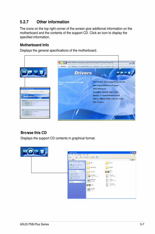
ASUS P5B-Plus Series 5-7
Browse this CDDisplays the support CD contents in graphical format.
5.2.7 Other informationThe icons on the top right corner of the screen give additional information on the motherboard and the contents of the support CD. Click an icon to display the specified information.
Motherboard InfoDisplays the general specifications of the motherboard.

5-8 Chapter 5: Software support
Technical support FormDisplays the ASUS Technical Support Request Form that you have to fill out when requesting technical support.
FilelistDisplays the contents of the support CD in text format.

ASUS P5B-Plus Series 5-9
5.3 Software informationMost of the applications in the support CD have wizards that will conveniently guide you through the installation. View the online help or readme file that came with the software application for more information.
5.3.1 ASUS MyLogo2™The ASUS MyLogo2™ utility lets you customize the boot logo. The boot logo is the image that appears on screen during the Power-On-Self-Tests (POST). The ASUS MyLogo2™ is automatically installed when you install the ASUS Update utility from the support CD. See section 5.2.3 Utilities menu for details.
To launch the ASUS MyLogo2™:
1. Launch the ASUS Update utility. Refer to section 4.1.1 ASUS Update utility for details.
2. Select Options from the drop down menu, then click Next.3. Check the option Launch MyLogo to replace system boot logo before flashing
BIOS, then click Next.4. Select Update BIOS from a file from the drop down menu, then click Next. 5. When prompted, locate the new BIOS file, then click Next. The ASUS
MyLogo2 window appears.6. From the left window pane, select the
folder that contains the image you intend to use as your boot logo.
• Before using the ASUS MyLogo2™, use the AFUDOS utility to make a copy of your original BIOS file, or obtain the latest BIOS version from the ASUS website. See section 4.1.4 AFUDOS utility.
• Make sure that the BIOS item Full Screen Logo is set to [Enabled] if you wish to use ASUS MyLogo2. See section 4.6.2 Boot Settings Configuration.
• You can create your own boot logo image in GIF, JPG, or BMP file formats.

5-10 Chapter 5: Software support
9. When the screen returns to the ASUS Update utility, flash the original BIOS to load the new boot logo.
10. After flashing the BIOS, restart the computer to display the new boot logo during POST.
8. Adjust the boot image to your desired size by selecting a value on the Ratio box.
7. When the logo images appear on the right window pane, select an image to enlarge by clicking on it.
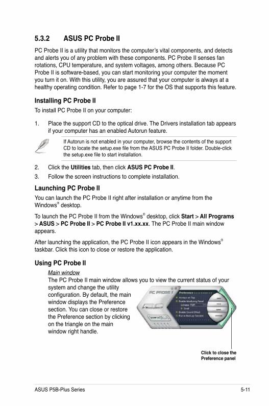
ASUS P5B-Plus Series 5-11
5.3.2 ASUS PC Probe IIPC Probe II is a utility that monitors the computer’s vital components, and detects and alerts you of any problem with these components. PC Probe II senses fan rotations, CPU temperature, and system voltages, among others. Because PC Probe II is software-based, you can start monitoring your computer the moment you turn it on. With this utility, you are assured that your computer is always at a healthy operating condition. Refer to page 1-7 for the OS that supports this feature.
Installing PC Probe IITo install PC Probe II on your computer:
1. Place the support CD to the optical drive. The Drivers installation tab appears if your computer has an enabled Autorun feature.
If Autorun is not enabled in your computer, browse the contents of the support CD to locate the setup.exe file from the ASUS PC Probe II folder. Double-click the setup.exe file to start installation.
2. Click the Utilities tab, then click ASUS PC Probe II.3. Follow the screen instructions to complete installation.
Launching PC Probe IIYou can launch the PC Probe II right after installation or anytime from the Windows® desktop.
To launch the PC Probe II from the Windows® desktop, click Start > All Programs > ASUS > PC Probe II > PC Probe II v1.xx.xx. The PC Probe II main window appears.
After launching the application, the PC Probe II icon appears in the Windows® taskbar. Click this icon to close or restore the application.
Using PC Probe IIMain windowThe PC Probe II main window allows you to view the current status of your system and change the utility configuration. By default, the main window displays the Preference section. You can close or restore the Preference section by clicking on the triangle on the main window right handle.
Click to close the Preference panel

5-12 Chapter 5: Software support
Button Function
Opens the Configuration window Opens the Report window Opens the Desktop Management Interface window Opens the Peripheral Component Interconnect window Opens the Windows Management Instrumentation window Opens the hard disk drive, memory, CPU usage window Shows/Hides the Preference section Minimizes the application Closes the application
Sensor alertWhen a system sensor detects a problem, the main window right handle turns red, as the illustrations below show.
When displayed, the monitor panel for that sensor also turns red. Refer to the Monitor panels section for details.
PreferencesYou can customize the application using the Preference section in the main window. Click the box before each preference to activate or deactivate.

ASUS P5B-Plus Series 5-13
Changing the monitor panels positionTo change the position of the monitor panels in the desktop, click the arrow down button of the Scheme options, then select another position from the list box. Click OK when finished.
Moving the monitor panelsAll monitor panels move together using a magnetic effect. If you want to detach a monitor panel from the group, click the horseshoe magnet icon. You can now move or reposition the panel independently.
Hardware monitor panelsThe hardware monitor panels display the current value of a system sensor such as fan rotation, CPU temperature, and voltages.
The hardware monitor panels come in two display modes: hexagonal (large) and rectangular (small). When you check the Enable Monitoring Panel option from the Preference section, the monitor panels appear on your computer’s desktop.
Large display
Small display
Click to increase value
Click to decrease
value
Adjusting the sensor threshold value You can adjust the sensor threshold value in the monitor panel by clicking the or buttons. You can also adjust the threshold values using the Config window.
You cannot adjust the sensor threshold values in a small monitoring panel.

5-14 Chapter 5: Software support
Monitoring sensor alertThe monitor panel turns red when a component value exceeds or is lower than the threshold value. Refer to the illustrations below.
Large display
Small display
WMI browserClick to display the WMI (Windows Management Instrumentation) browser. This browser displays various Windows® management information. Click an item from the left panel to display on the right panel. Click the plus sign (+) before WMI Information to display the available information.
You can enlarge or reduce the browser size by dragging the bottom right corner of the browser.
DMI browserClick to display the DMI (Desktop Management Interface) browser. This browser displays various desktop and system information. Click the plus sign (+) before DMI Information to display the available information.

ASUS P5B-Plus Series 5-15
PCI browserClick to display the PCI (Peripheral Component Interconnect) browser. This browser provides information on the PCI devices installed on your system. Click the plus sign (+) before the PCI Information item to display available information.
UsageThe Usage browser displays real-time information on the CPU, hard disk drive space, and memory usage. Click to display the Usage browser.
CPU usageThe CPU tab displays real-time CPU usage in line graph representation. If the CPU has an enabled Hyper-Threading, two separate line graphs display the operation of the two logical processors.
Hard disk drive space usageThe Hard Disk tab displays the used and available hard disk drive space. The left panel of the tab lists all logical drives. Click a hard disk drive to display the information on the right panel. The pie chart at the bottom of the window represents the used (blue) and the available HDD space.

5-16 Chapter 5: Software support
Memory usageThe Memory tab shows both used and available physical memory. The pie chart at the bottom of the window represents the used (blue) and the available physical memory.
Configuring PC Probe IIClick to view and adjust the sensor threshold values.
The Config window has two tabs: Sensor/Threshold and Preference. The Sensor/Threshold tab enables you to activate the sensors or to adjust the sensor threshold values. The Preference tab allows you to customize sensor alerts, or change the temperature scale.
Loads the default threshold values for
each sensorApplies your
changes
Cancels or ignores your changes
Loads your saved configuration
Saves your configuration

ASUS P5B-Plus Series 5-17
5.3.3 ASUS AI SuiteASUS AI Suite allows you to launch AI Gear, AI N.O.S., AI Booster, AI Nap, and Q-Fan utilities easily.
Installing AI SuiteTo install AI Suite on your computer:
1. Place the support CD to the optical drive. The Drivers installation tab appears if your computer has an enabled Autorun feature.
2. Click the Utilities tab, then click AI Suite.3. Follow the screen instructions to complete installation.Launching AI SuiteYou can launch the AI Suite right after installation or anytime from the Windows® desktop.
To launch the AI Suite from the Windows® desktop, click Start > All Programs > ASUS > AI Suite > AI Suite v1.xx.xx. The AI Suite main window appears.
After launching the application, the AI Suite icon appears in the Windows® taskbar. Click this icon to close or restore the application.
Using AI SuiteClick the AI N.O.S., AI Gear, AI Nap, AI Booster, or Q-Fan icon to launch the utility, or click the Normal icon to restore the system to normal state.
Press to launch AI Gear
Press to launch AI Nap
Press to launch AI N.O.S.
Press to launch Q-FanPress to launch AI Booster
Press to restore to normal

5-18 Chapter 5: Software support
Other feature buttons
Click on right corner of the main window to open the monitor window.
Click on right corner of the expanded window to switch the temperature from degrees Centigrade to degrees Fahrenheit.
Displays the CPU/system temperature, CPU/memory/PCIE voltage, and CPU/chassis fan speed
Displays the FSB/CPU frequency

ASUS P5B-Plus Series 5-19
5.3.4 ASUS AI GearASUS AI Gear provides four system performance options that allows you to select the best performance setting for your computing needs. This easy-to-use utility adjusts the processor frequency and vCore voltage to minimize system noise and power consumption.
After installing AI Suite from the bundled support CD, you can launch AI Gear by double-clicking the AI Suite icon on your Windows OS taskbar and then click the AI Gear button on the AI Suite main window.
Shift the gear to the performance setting that you like.
Maximum Performance
Medium Performance
High Performance
Maximum Power Saving
Refer to page 1-7 for the OS that supports this feature.

5-20 Chapter 5: Software support
5.3.5 ASUS AI NapThis feature allows you to minimize the power consumption of your computer whenever you are away. Enable this feature for minimum power consumption and a more quiet system operation.
After installing AI Suite from the bundled support CD, you can launch the utility by double-clicking the AI Suite icon on the Windows OS taskbar and click the AI Nap button on the AI Suite main window.
Click Yes on the confirmation screen.
To exit AI Nap mode, press the system power or mouse button then click Yes on the confirmation screen.
• Refer to page 1-7 for the OS that supports this feature.
• To switch the power button functions from AI Nap to shutting down, just right click the AI Suite icon on the OS taskbar, select AI Nap and click Use power button. Unclick the the item to switch the function back.

ASUS P5B-Plus Series 5-21
5.3.6 ASUS AI N.O.S.This ASUS Non-delay Overclocking System feature intelligently determines the system load and automatically boosts the performance for the most demanding tasks.
After installing AI Suite from the bundled support CD, you can launch the utility by double-clicking the AI Suite icon on the Windows OS taskbar and click the AI N.O.S. button on the AI Suite main window.
drop-down menu button
select an N.O.S. mode
Click the drop-down menu button and select Disable or Manual.
Click Apply at the bottom to save the configuration.
Refer to page 1-7 for the OS that supports this feature.

5-22 Chapter 5: Software support
5.3.7 ASUS Q-Fan
This ASUS Q-Fan Control feature allows you to set the appropriate performance level of the CPU Q-Fan or the Chassis Q-Fan for more efficient system operation. After enabling the Q-Fan function, the fans can be set to automatically adjust depending on the temperature, to decrease fan speed, or to achieve the maximum fan speed.
After installing AI Suite from the bundled support CD, you can launch the utility by double-clicking the AI Suite icon on the Windows® OS taskbar and click the Q-Fan button on the AI Suite main window.
Click the drop-down menu button and display the fan names. Select CPU Q-FAN or CHASSIS Q-FAN. Click the box of Enable Q-Fan to activate this function.
drop-down list buttonEnable Q-Fan box
Profile list appears after clicking the Enable Q-Fan box. Click the drop-down list button and select a profile. Optimal mode makes the fans adjust speed with the temperature; Silent mode minimizes fan speed for quiet fan operation; Performance mode boosts the fan to achieve maximal fan speed for the best cooling effect.
click to display the drop-down list and select a Q-Fan mode
Click Apply at the bottom to save the setup.
Refer to page 1-7 for the OS that supports this feature.

ASUS P5B-Plus Series 5-23
5.3.8 ASUS AI BoosterThe ASUS AI Booster application allows you to overclock the CPU speed in WIndows® environment without the hassle of booting the BIOS.
After installing AI Suite from the bundled support CD, you can launch the utility by double-clicking the AI Suite icon on the Windows® OS taskbar and click the AI Booster button on the AI Suite main window.
The options on the taskbar allow you to use the default settings, adjust CPU/Memory/PCI-E frequency manually, or create and apply your personal overclocking configurations.
Refer to page 1-7 for the OS that supports this feature.

5-24 Chapter 5: Software support
5.3.9 AI RemoteWith the ASUS AI Remote, you can play, pause, or adjust the volume on any songs desired without leaving your sofa. Have AI Remote in your hand and do more with your PC at a distance away.
Overview of the ASUS AI Remote
1. Power
5. AP-1/2 Trigger2. Full Screen
6. AP Menu
4. AI Nap3. AI Gear
7. Media Control Zone
1. Power: Turns the computer on/off.2. Full Screen: Puts the media application into full screen.3. AI Gear: Changes modes for optimizing performance and quietness.4. AI Nap: Snoozing system without terminating tasks into quietest state.5. AP-1/2 Trigger: Initiates the pre-defined applications.6. AP Menu: Displays the application menu.7. Media Control Zone: Controls the media application.
Volume Up
NextPreviousVolume Down
Play/Pause

ASUS P5B-Plus Series 5-25
ASUS >>USB receiver
USB receiver
USB IR ReceiverYour motherboard will come bundled with a IR Receiver, simply connect the USB end to your PC USB ports under the LAN2 port and place the IR receiver end at a suitable place without hindrance.
IR Receiver
Software InstallationBefore enjoying the convenience the ASUS AI Remote brings you, you need to install the software after the infrared receiver installation. Simply click and install the file ASUS AI Remote from Drivers menu of the Motherboard Support CD package for the first time, and it will launch automatically everytime you start up your PC.
• The valid IR function distance is 6m depending on the environment. Suggest you to aim at the IR receiver when using the ASUS AI Remote to ensure a smooth and successful operation.
• These two USB ports support USB wake-up capability. So when the computer is not turned on, removing USB devices such as the ASUS IR receiver from these two ports will start up the PC.
• Back I/O differs depending on the motherboards.• Refer to page 1-7 for the OS that supports this function.
USB PortsUSB end
Infrared end
ASUS AI Remote

5-26 Chapter 5: Software support
Activating HID-Compliant DevicesDue to the limitation of the operating system, if you remove the IR receiver from the previous port and have it reinstall into the other USB port, the IR receiver will not function. To activate the HID-compliant devices again, go to Device Manager/Power Manager and check the box of Allow this device to bring the computer out of standby.
1. Click Windows icon and choose Control Panel.
2. Double click System and Maintenance.
3. Click Device Manager. 4. Select HID-compliant device.
5. Check the box of Allow this device to wake the computer.

ASUS P5B-Plus Series 5-27
ASUS AI Remote SettingsAfter the installation of the ASUS AI Remote software, the utility screen will show up and allows you to configure the ASUS AI Remote settings. Set up the function keys following the instructions below.
1
1. Power On / Off KeyEnable power keyClick this box to enable this power button.
Enable power on after power lossClick this box to restart the system after the AC power loss. Whenever the power cord of your PC is removed from the outlet or there is a power failure, your PC will auto-boot and shut down around few seconds to enable the Power On function of AI Remote after the power supply is back.
Function switchYou can customize the Power key by switching the mode from Power off to Hibernate or Standby based on your preference. Setting this item to Hibernate allows you to lead your PC to the Windows S4 mode, which enables your PC to enter Hibernate faster and return to full power much more quickly.
2
3
• Power On/Off button does not support MS-DOS Mode.• You have to check the box of Enable Power Key before using the ASUS AI
Remote to turn on and off your PC or to have it hibernate or standby. Visit www.microsoft.com for details about Hibernate and Standby.

5-28 Chapter 5: Software support
3. Multimedia KeysProfileThere are nine default applications in the Profile drop-down menu and five sets of User Define.
Default applications are Media Player, iTunes, PowerDVD, WinDVD, QuickTime, Real Player, DivX Player, WinAmp and Power Point. (Default applications in the ASUS AI Remote software may change without notice.)
PathThe software will help locate the executable (.exe) file of the nine default applications. If the .exe file is not located, click Browse to direct the correct path. The .exe files of the User Define applications need to be located manually before you using the ASUS AI Remote.
• Save after the .exe file path is directed.• If the executable file is relocated or the application is re-installed, you have
to redirect the file path for a correct ASUS AI Remote operation.
2. AP-1/2You are allowed to configure two sets of applications for AP-1 Trigger and AP-2 Trigger buttons. After the setup, you can easily launch the pre-defined application by pressing the designated button.
(1) Click the box before Use Profile, and you are able to select a default application from the drop-down menu.
(2) To launch a non-default application, unclick the box before Use Profile.
(3) Click the Browse button and locate the executable (.exe) file of the application you want to launch by pressing the AP-1 button.
(4) Follow the same instructions to configure the AP-2 button.
(5) Click Save to save the configuration.

ASUS P5B-Plus Series 5-29
Select FileAfter selecting the correct path, you should select the correct executable file (.exe) of the application for launching the application.
If the executable file is located by the software successfully or you have already set up correctly in advance, this screen will show up directly when the application is chosen. After selecting a desired file, folder or CD-ROM, use / to choose Back/OK/Cancel and then press
to confirm.
AP Menu Button and Application menuNavigate with the media control zone.
Select Application PathIf the software fails to locate the executable file of the applicaton at the first-time use, the Select Application Path screen will appear.Specify the correct path on screen.
• For music listening, making playlists beforehand is suggested. • Press again to close the application and again to re-launch the profile
menu.
Select Application ProfileAfter you press (AP Menu) on the remote control, an application profile will be displayed on the screen. Use the remote control to navigate and initiate a desired application.
upward
leftward enter
rightward
downward

5-30 Chapter 5: Software support
Define Hotkeys for ApplicationIf you want to use the Media Control Zone to control non-default applications, such as ACDSee, you can select User Define from the drop-down menu and rename it by pressing Rename. The ASUS AI Remote software has correctly set up nine popular applications and defined the funtion buttons for your convenient operation.
User DefineAfter clicking the box before Use Hotkeys for Application, you are free to define the hotkeys of the User Define applications.
Select User Define 1~5 from the Profile drop-down menu for hotkeys definition. Press Save to save the new setup or press the Default button to clear ALL personalized setups and restore to the original definitions.
• The remote control buttons will function only when the definitions of the application hotkeys are correct.
• The hotkey definitions may vary with different software versions. Click the box of Redefine default hotkeys to give new correct definitions if needed. Press Save button to save the redefinitions or press Reset button to restore to the default hotkeys definition.
• After the initial setup, you will find an ASUS AI Remote icon on the Windows OS taskbar. Click the icon and select Settings to launch the utility screen.

ASUS P5B-Plus Series 5-31
Media Player iTunes PowerDVD WinDVD QuickTimeFull Screen v v v v v
v v v/x v v+ v v v v v- v v v v v
v v v v x v v v v x
*NOTE only play, no pause
Real Player DivX Player WinAmp Power Point User DefneFull Screen v v x v
v v v/x Full Screen+ v x v B- v x v ESC
v x v Page Down v x v Page Up
*NOTE only play, no pause
The Function Buttons and AP ProfileThe ASUS AI Remote software helps you set up the correspondence between the function buttons on the remote to the function hotkeys of nine popular applications in advance and leaves five sets for User Define.
If you find the 9 default applications insufficient and would like to add different applications, you are able to rename the 5 sets User Define and create your preferred applications and favorable setups.
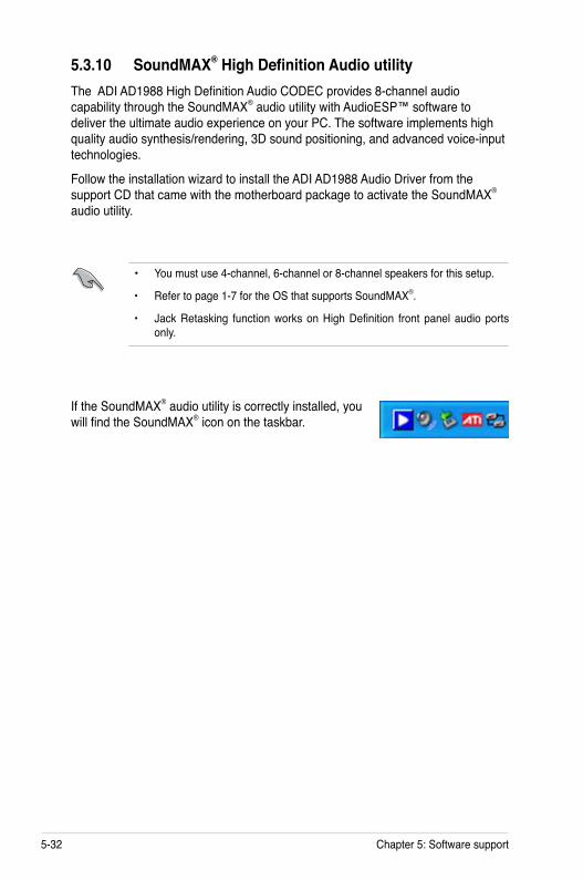
5-32 Chapter 5: Software support
5.3.10 SoundMAX® High Definition Audio utilityThe ADI AD1988 High Definition Audio CODEC provides 8-channel audio capability through the SoundMAX® audio utility with AudioESP™ software to deliver the ultimate audio experience on your PC. The software implements high quality audio synthesis/rendering, 3D sound positioning, and advanced voice-input technologies.
Follow the installation wizard to install the ADI AD1988 Audio Driver from the support CD that came with the motherboard package to activate the SoundMAX® audio utility.
If the SoundMAX® audio utility is correctly installed, you will find the SoundMAX® icon on the taskbar.
• You must use 4-channel, 6-channel or 8-channel speakers for this setup.
• Refer to page 1-7 for the OS that supports SoundMAX®.
• Jack Retasking function works on High Definition front panel audio ports only.

ASUS P5B-Plus Series 5-33
From the taskbar, double-click on the SoundMAX® icon to display the SoundMAX® Control Panel.
Audio Setup WizardBy clicking the icon from the SoundMAX® control panel, you can easily configure your audio settings. Simply follow succeeding screen instructions and begin enjoying High Definition Audio.

5-34 Chapter 5: Software support
Jack configurationThis screen helps you configure your computer’s audio ports, depending on the audio devices you have installed.
Adjust speaker volumeThis screen helps you adjust speaker volume. Click the Test button to hear the changes you have made.
Adjust microphone volumeThis screen helps you adjust microphone volume. You will be asked to read pre-written text to allow the AudioWizard to adjust the volume as you speak.

ASUS P5B-Plus Series 5-35
Audio preferences
Click the icon to go to the Preferences page. This page allows you to change various audio settings.
General optionsClick the General tab to choose your playback and recording devices, enable/disable the AudioESP™ feature, and enable/disable digital output.
Listening Environment optionsClick the Listening Environment tab to set up your speaker, acoustic environment, and enable/disable the Virtual Theater Surround function.

5-36 Chapter 5: Software support
Microphone optionsClick the Microphone tab allows you to optimize your microphone input settings.

ASUS P5B-Plus Series 5-37
5.4 Windows Vista feature
5.4.1 ASAP (ASUS Accelerated Propeller)This motherboard is equipped with the ASUS Accelerated Propeller (ASAP) feature. ASAP supports the Windows® Vista ReadyBoost™ function that improves system performance under Windows® Vista. Refer to page 1-7 for the OS that supports thiis feature.
Before activating ASAP, install the ASAP utility from the bundled support CD.
To activate ASAP:
1. From the Windows® Vista desktop, click Start > Computer.
2. Right-click on the USB Removable Storage device (ASAP), and select Properties.
3. Click the ReadyBoost tab. The following dialog box appears.
4. Check Use this device, and then move the slider to determine the amount of space researved for ReadyBoost™ cache.
5. Click OK to effect the settings.
• When you see the existing partition for ASAP, we advise you not to delete this partition that supports the ReadyBoost™ function. If you delete this partition by accident, you may recreate it by:
Clicking Start from the Windows® Vista desktop. Right-click on Computer and select Manage. Click Disk Management and right-click on the ASAP drive. Select Format > OK. OR
Going to Start > Control Panel > System and Maintenance > Administrative Tools > Computer Management > Disk Management. Right-click on the ASAP drive, and select Format > OK.
• If you accidentally remove the ASAP device from Windows® Vista, you may re-activate it by rebooting your computer.
• If you want to reinstall an operating system, uninstall the ASAP utility first.
• If you need to build RAID sets in your system, create RAID sets before installing the ASAP utility and activating ASAP function.

5-38 Chapter 5: Software support
5.5 RAID configurationsThe motherboard comes with the following RAID resolutions:
• Intel® ICH8R Southbridge RAID controller that allow you to configure IDE and Serial ATA hard disk drives as RAID sets. The motherboard supports the following RAID 0, 1, 5, 10.
• JMicron® RAID controller allows you to configure RAID 0, RAID 1 and JBOD sets on the external Serial ATA hard disk drives.
5.5.1 RAID definitionsRAID 0 (Data striping) optimizes two identical hard disk drives to read and write data in parallel, interleaved stacks. Two hard disks perform the same work as a single drive but at a sustained data transfer rate, double that of a single disk alone, thus improving data access and storage. Use of two new identical hard disk drives is required for this setup.
RAID 1 (Data mirroring) copies and maintains an identical image of data from one drive to a second drive. If one drive fails, the disk array management software directs all applications to the surviving drive as it contains a complete copy of the data in the other drive. This RAID configuration provides data protection and increases fault tolerance to the entire system. Use two new drives or use an existing drive and a new drive for this setup. The new drive must be of the same size or larger than the existing drive.
RAID 0+1 is data striping and data mirroring combined without parity (redundancy data) having to be calculated and written. With the RAID 0+1 configuration you get all the benefits of both RAID 0 and RAID 1 configurations. Use four new hard disk drives or use an existing drive and three new drives for this setup.
RAID 5 stripes both data and parity information across three or more hard disk drives. Among the advantages of RAID 5 configuration include better HDD performance, fault tolerance, and higher storage capacity. The RAID 5 configuration is best suited for transaction processing, relational database applications, enterprise resource planning, and other business systems. Use a minimum of three identical hard disk drives for this setup.
JBOD (Spanning) stands for Just a Bunch of Disks and refers to hard disk drives that are not yet configured as a RAID set. This configuration stores the same data redundantly on multiple disks that appear as a single disk on the operating system. Spanning does not deliver any advantage over using separate disks independently and does not provide fault tolerance or other RAID performance benefits.

ASUS P5B-Plus Series 5-39
5.5.3 Intel® RAID configurationsThis motherboard supports RAID 0, RAID 1, JBOD and Intel® Matrix Storage configurations for Serial ATA hard disks drives through the Intel® ICH8R Southbridge chip.
Setting the RAID item in BIOSYou must set the RAID item in the BIOS Setup before you can create a RAID set(s). To do this:
1. Enter the BIOS Setup during POST.2. Go to the Main Menu, select IDE Configuration, then press <Enter>.3. Select the item Configure SATA As, then press <Enter> to display the
configuration options.4. Select RAID from the Configure SATA As item options, then press <Enter>.5. Select the item Onboard Serial-ATA BOOTROM, press <Enter>, then select
Enabled from the options.6. Save your changes, then exit the BIOS Setup.
Refer to the system or the motherboard user guide for details on entering and navigating through the BIOS Setup.
5.5.2 Installing Serial ATA hard disksThe motherboard supports Serial ATA hard disk drives. For optimal performance, install identical drives of the same model and capacity when creating a disk array.
To install the SATA hard disks for a RAID configuration:
1. Install the SATA hard disks into the drive bays.2. Connect the SATA signal cables.3. Connect a SATA power cable to the power connector on each drive.
If you want to boot the system from a hard disk drive included in a created RAID set, copy first the RAID driver from the support CD to a floppy disk before you install an operating system to the selected hard disk drive. Refer to section 5.5 Creating a RAID driver disk for details.
Intel® Matrix Storage. The Intel® Matrix Storage technology supported by the ICH8R chip allows you to create a RAID 0, RAID 1, RAID 5, and RAID 10 function to improve both system performance and data safety. You can also combine two RAID sets to get higher performance, capacity, or fault tolerance provided by the difference RAID function. For example, RAID 0 and RAID 1 set can be created by using only two identical hard disk drives.

5-40 Chapter 5: Software support
Intel® Matrix Storage Manager Option ROM UtilityThe Intel® Matrix Storage Manager Option ROM utility allows you to create RAID 0, RAID 1, RAID 10 (RAID 0+1), and RAID 5 set(s) from Serial ATA hard disk drives that are connected to the Serial ATA connectors supported by the Southbridge.
Intel(R) Matrix Storage Manager Option ROM v5.0.0.1032 ICH8R wRAID5Copyright(C) 2003-05 Intel Corporation. All Rights Reserved.
[MAIN MENU ] 1. Create RAID Volume 2. Delete RAID Volume 3. Reset Disks to Non-RAID 4. Exit
[DISK/VOLUME INFORMATION ]RAID Volumes:None defined.
Physical Disks:Port Drive Model Serial # Size Type/Status(Vol ID)0 XXXXXXXXXXX XXXXXXXX XX.XXGB Non-RAID Disk1 XXXXXXXXXXX XXXXXXXX XX.XXGB Non-RAID Disk2 XXXXXXXXXXX XXXXXXXX XX.XXGB Non-RAID Disk3 XXXXXXXXXXX XXXXXXXX XX.XXGB Non-RAID Disk
[↑↓]-Select [ESC]-Exit [ENTER]-Select Menu
The navigation keys at the bottom of the screen allow you to move through the menus and select the menu options.
The RAID BIOS setup screens shown in this section are for reference only and may not exactly match the items on your screen.
To enter the Intel® Application Accelerator RAID Option ROM utility:
1. Install all the Serial ATA hard disk drives.2. Turn on the system.3. During POST, press <Ctrl+I> to display the utility main menu.
If you have activated ASAP, disable ASAP before you start to create RAID sets.

ASUS P5B-Plus Series 5-41
Creating a RAID 0 set (striped)To create a RAID 0 set:
1. From the utility main menu, select 1. Create RAID Volume, then press <Enter>. This screen appears.
2. Enter a name for the RAID 0 set, then press <Enter>.3. When the RAID Level item is highlighted, press the up/down arrow key to
select RAID 0(Stripe), then press <Enter>.4. When the Disks item is highlighted, press <Enter> to select the hard disk
drives to configure as RAID. This pop-up screen appears.
Intel(R) Matrix Storage Manager Option ROM v5.0.0.1032 ICH8R wRAID5Copyright(C) 2003-05 Intel Corporation. All Rights Reserved.
[CREATE ARRAY MENU]
[DISK/VOLUME INFORMATION ]
Enter a string between 1 and 16 characters in length that can be usedto uniquely identify the RAID volume. This name is case sensitive and
cannot contain special characters.
[↑↓]-Change [TAB]-Next [ESC]-Previous Menu [Enter]-Select
Name:RAID Level:
Disks:Strip Size:
Capacity:
Volume0RAID0(Stripe)Select Disks128KB0.0 GB
Create Volume
[SELECT DISKS ]
[↑↓]-Previous/Next [SPACE]-Selects [ENTER]-Selection Complete
Port Drive Model Serial # Size Status 0 XXXXXXXXXXXX XXXXXXXX XX.XGB Non-RAID Disk 1 XXXXXXXXXXXX XXXXXXXX XX.XGB Non-RAID Disk 2 XXXXXXXXXXXX XXXXXXXX XX.XGB Non-RAID Disk 3 XXXXXXXXXXXX XXXXXXXX XX.XGB Non-RAID Disk
Select 2 to 4 disks to use in creating the volume.
5. Use the up/down arrow key to highlight a drive, then press <Space> to select. A small triangle marks the selected drive. Press <Enter> after completing your selection.

5-42 Chapter 5: Software support
6. Use the up/down arrow key to select the stripe size for the RAID 0 array, then press <Enter>. The available stripe size values range from 4 KB to 128 KB. The default stripe size is 128 KB.
TIP: We recommend a lower stripe size for server systems, and a higher stripe size for multimedia computer systems used mainly for audio and video editing.
7. Key in the RAID volume capacity that you want, then press <Enter>. The default value indicates the maximum allowed capacity.
8. Press <Enter> when the Create Volume item is highlighted. This warning message appears.
WARNING: ALL DATA ON SELECTED DISKS WILL BE LOST.
Are you sure you want to create this volume? (Y/N):
9. Press <Y> to create the RAID volume and return to the main menu, or <N> to go back to the Create Volume menu.

ASUS P5B-Plus Series 5-43
Creating a RAID 1 set (mirrored)To create a RAID 1 set:
1. From the utility main menu, select 1. Create RAID Volume, then press <Enter>. This screen appears.
2. Enter a name for the RAID 1 set, then press <Enter>.3. When the RAID Level item is highlighted, press the up/down arrow key to
select RAID 1(Mirror), then press <Enter>.4. When the Capacity item is highlighted, key in the RAID volume capacity that
you want, then press <Enter>. The default value indicates the maximum allowed capacity.
5. Press <Enter> when the Create Volume item is highlighted. This warning message appears.
Intel(R) Matrix Storage Manager Option ROM v5.0.0.1032 ICH8R wRAID5Copyright(C) 2003-05 Intel Corporation. All Rights Reserved.
[CREATE ARRAY MENU ]
[DISK/VOLUME INFORMATION ]
Enter a string between 1 and 16 characters in length that can be usedto uniquely identify the RAID volume. This name is case sensitive and
cannot contain special characters.
[↑↓]-Change [TAB]-Next [ESC]-Previous Menu [Enter]-Select
Name:RAID Level:
Disks:Strip Size:
Capacity:
Volume1RAID1(Mirror)Select DisksN/AXX.X GB
Create Volume
WARNING: ALL DATA ON SELECTED DISKS WILL BE LOST.
Are you sure you want to create this volume? (Y/N):
6. Press <Y> to create the RAID volume and return to main menu or <N> to go back to Create Volume menu.

5-44 Chapter 5: Software support
Creating a RAID 10 set (RAID 0+1)To create a RAID 10 set:
1. From the utility main menu, select 1. Create RAID Volume, then press <Enter>. This screen appears.
Intel(R) Matrix Storage Manager Option ROM v5.0.0.1032 ICH8R wRAID5Copyright(C) 2003-05 Intel Corporation. All Rights Reserved.
[CREATE ARRAY MENU ]
[DISK/VOLUME INFORMATION ]
Enter a string between 1 and 16 characters in length that can be usedto uniquely identify the RAID volume. This name is case sensitive and
cannot contain special characters.
Name:RAID Level:
Disks:Strip Size:
Capacity:
Volume10RAID10(RAID0+1)Select Disks128KBXXX.X GB
Create Volume
2. Enter a name for the RAID 10 set, then press <Enter>.3. When the RAID Level item is highlighted, press the up/down arrow key to
select RAID 10(RAID0+1), then press <Enter>.4. When the Stripe Size item is highlighted, press the up/down arrow key to
select the stripe size for the RAID 10 array, then press <Enter>. The available stripe size values range from 4 KB to 128 KB. The default stripe size is 64 KB.
TIP: We recommend a lower stripe size for server systems, and a higher stripe size for multimedia computer systems used mainly for audio and video editing.
5. Key in the RAID volume capacity that you want then press <Enter> when the Capacity item is highlighted. The default value indicates the maximum allowed capacity.
[↑↓]-Change [TAB]-Next [ESC]-Previous Menu [Enter]-Select

ASUS P5B-Plus Series 5-45
Creating a RAID 5 set (parity)To create a RAID 5 set:
1. From the utility main menu, select 1. Create RAID Volume, then press <Enter>. This screen appears.
Intel(R) Matrix Storage Manager Option ROM v5.0.0.1032 ICH8R wRAID5Copyright(C) 2003-05 Intel Corporation. All Rights Reserved.
[CREATE ARRAY MENU ]
[DISK/VOLUME INFORMATION ]
Enter a string between 1 and 16 characters in length that can be usedto uniquely identify the RAID volume. This name is case sensitive and
cannot contain special characters.
Name:RAID Level:
Disks:Strip Size:
Capacity:
Volume5RAID5(Parity)Select Disks64KB0.0 GB
Create Volume
WARNING: ALL DATA ON SELECTED DISKS WILL BE LOST.
Are you sure you want to create this volume? (Y/N):
7. Press <Y> to create the RAID volume and return to the main menu or <N> to go back to the Create Volume menu.
[↑↓]-Change [TAB]-Next [ESC]-Previous Menu [Enter]-Select
6. Press <Enter> when the Create Volume item is highlighted. This warning message appears.
2. Enter a name for the RAID 5 set, then press <Enter>.3. When the RAID Level item is highlighted, press the up/down arrow key to
select RAID 5(Parity), then press <Enter>.

5-46 Chapter 5: Software support
4. The Disks item is highlighted, press <Enter> to select the hard disk drives to configure as RAID. The following pop-up screen appears.
[SELECT DISKS ]
[↑↓]-Previous/Next [SPACE]-Selects [ENTER]-Selection Complete
Port Drive Model Serial # Size Status 0 XXXXXXXXXXXX XXXXXXXX XX.XGB Non-RAID Disk 1 XXXXXXXXXXXX XXXXXXXX XX.XGB Non-RAID Disk 2 XXXXXXXXXXXX XXXXXXXX XX.XGB Non-RAID Disk 3 XXXXXXXXXXXX XXXXXXXX XX.XGB Non-RAID Disk
Select 2 to 4 disks to use in creating the volume.
5. Use the up/down arrow key to highlight the drive you want to set, then press <Space> to select. A small triangle marks the selected drive. Press <Enter> after completing your selection.
6. When the Stripe Size item is highlighted, press the up/down arrow key to select the stripe size for the RAID 5 array, then press <Enter>. The available stripe size values range from 4 KB to 128 KB. The default stripe size is 64 KB.
TIP: We recommend a lower stripe size for server systems, and a higher stripe size for multimedia computer systems used mainly for audio and video editing.
7. Key in the RAID volume capacity that you want, then press <Enter> when the Capacity item is highlighted. The default value indicates the maximum allowed capacity.
8. Press <Enter> when the Create Volume item is highlighted. This warning message appears.
WARNING: ALL DATA ON SELECTED DISKS WILL BE LOST.
Are you sure you want to create this volume? (Y/N):
9. Press <Y> to create the RAID volume and return to the main menu or <N> to go back to the Create Volume menu.

ASUS P5B-Plus Series 5-47
5.5.4 JMicron® RAID ConfigurationThe JMicron® Serial ATA controller allows you to configure RAID 0, RAID 1 and JBOD sets on the external Serial ATA hard disk drives.
Before creating a RAID setPrepare the following items:
1. Two SATA HDDs, preferably with the same model and capacity. 2. A write-enabled floppy disk3. Microsoft® Windows® OS installation disk (Windows 2000/XP)4. Motherboard support CD with JMB363 driver Complete the following steps before you create a RAID set:
1. Install an internal Serial ATA hard disk drive and an external Serial ATA hard disk drive on your system.
Install the internal Serial ATA hard disk drive to the SATA connector labeled SATA_RAID or SATA_RAID1.
2. Set the JMicron Controller Mode item in the BIOS to [RAID]. See section 4.4.6 Onboard Devices Configuration for details.
3. Enter the JMB363 RAID BIOS utility to set up your RAID configuration.4. Create a JMB363 RAID driver disk for Windows® OS installation. See section
5.6 Creating a RAID driver disk for details.5. Install the JMB363 driver after the Windows® OS had been installed.
Always install the JMB363 driver before creating RAID sets.
Select Screen Select Item
+- Change OptionF1 General HelpF10 Save and ExitESC Exit
v02.58 (C)Copyright 1985-2006, American Megatrends, Inc.
BIOS SETUP UTILITY Advanced
Configure Win627EHF Super IO Chipset HD Audio Controller [Enabled]Front Panel Support Type [AC97]Onboard 1394 Controller [Enabled]Onboard PCIE GbE LAN [Enabled] LAN Option ROM [Disabled]JMicron SATA/PATA Controller [Enabled] JMicron SATA Controller Mode [SATA]Serial Port1 Address [3F8/IRQ4]Parallel Port Address [378]Parallel Port Mode [ECP] ECP Mode DMA Channel [DMA3] Parallel Port IRQ [IRQ7]
Enable or Disable High Definition Audio Controller
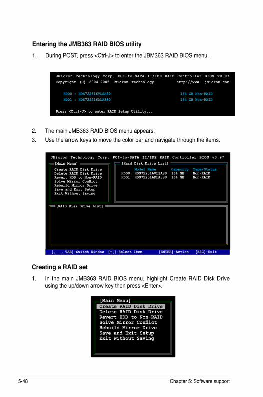
5-48 Chapter 5: Software support
Entering the JMB363 RAID BIOS utility1. During POST, press <Ctrl-J> to enter the JBM363 RAID BIOS menu.
JMicron Technology Corp. PCI-to-SATA II/IDE RAID Controller BIOS v0.97Copyright (C) 2004-2005 JMicron Technology http://www. jmicron.com
HDD0 : HDS722516VLSA80 164 GB Non-RAID HDD1 : HDS722516DLA380 164 GB Non-RAID
Press <Ctrl-J> to enter RAID Setup Utility...
2. The main JMB363 RAID BIOS menu appears. 3. Use the arrow keys to move the color bar and navigate through the items.
Creating a RAID set1. In the main JMB363 RAID BIOS menu, highlight Create RAID Disk Drive
using the up/down arrow key then press <Enter>.
[Main Menu]Create RAID Disk DriveDelete RAID Disk DriveRevert HDD to Non-RAIDSolve Mirror ConflictRebuild Mirror DriveSave and Exit SetupExit Without Saving
JMicron Technology Corp. PCI-to-SATA II/IDE RAID Controller BIOS v0.97
[ TAB]-Switch Window [↑↓]-Select Item [ENTER]-Action [ESC]-Exit
[Hard Disk Drive List] Model Name Capacity Type/Status HDD0: HDS722516VLSA80 164 GB Non-RAIDHDD1: HDS722516DLA380 164 GB Non-RAID
[RAID Disk Drive List]
[Main Menu]Create RAID Disk DriveDelete RAID Disk DriveRevert HDD to Non-RAIDSolve Mirror ConflictRebuild Mirror DriveSave and Exit SetupExit Without Saving

ASUS P5B-Plus Series 5-49
2. When the Level item is highlighted, use the up/down arrow key to select the RAID set that you want to create.
3. When the Disks item is highlighted, use the up/down arrow key to highlight an HDD that you want to belong to the RAID set, then press the space bar to confirm selection. Repeat the process until the HDDs are selected.
A selected HDD shows a sign before it.
4. Key in the RAID volume capacity. Use the up/down arrow to choose the block size. The default value indicates the maximum allowed capacity.
[Create New RAID]Name : JRAIDLevel: 0-StripeDisks: Select DiskBlock: 128 KBSize : 319 GB Confirm Creation
[Create New RAID]Name : JRAIDLevel: 1-MirrorDisks: Select DiskBlock: N/ASize : 159 GB Confirm Creation
[Hard Disk Drive List] Model Name Capacity Type/Status HDD0: HDS722516VLSA80 XXX GB Non-RAID HDD1: HDS722516DLA380 XXX GB Non-RAID
[Create New RAID]Name : JRAIDLevel: 0-StripeDisks: Select DiskBlock: 128 KBSize : 319 GB Confirm Creation

5-50 Chapter 5: Software support
5. When done, press <Enter> to confirm the creation of the RAID set. A dialogue box appears to confirm the action. Press <Y> to confirm; otherwise, press <N>.
6. The following screen appears, displaying the relevant information about the RAID set you created.
[RAID Disk Drive List] Model Name RAID Level Capacity Status Members(HDDx)RDD0: JRAID 0-Stripe XXX GB Normal 01
JMicron Technology Corp. PCI-to-SATA II/IDE RAID Controller BIOS v0.97
[Hard Disk Drive List] Model Name Available Type/Status HDD0: HDS722516VLSA80 164 GB Non-RAID HDD1: HDS722516DLA380 164 GB Non-RAID
[ TAB]-Switch Window [↑↓]-Select Item [ENTER]-Action [ESC]-Exit
Pressing <Y> deletes all the data in the HDDs.
[RAID Disk Drive List]
[Create New RAID]Name: JRAIDLevel: 0-StripeDisks: Select DiskBlock: 128 KBSize : 319 GBConfirm Creation
CONFIRM RAID CREATIONALL DATA ON THE SELECTED HARD DISKWILL BE LOST WHEN EXIT WITH SAVING
Create RAID on the selected HDD (Y/N)? Y

ASUS P5B-Plus Series 5-51
Deleting a RAID set1. In the main JMB363 RAID BIOS menu, highlight Delete RAID Disk Drive
using the up/down arrow key then press <Enter>.
2. Use the space bar to select the RAID set you want to delete. A selected set shows a sign before it. Press the <Del> key to delete the
set.3. A dialogue box appears to confirm the action. Press <Y> to confirm;
otherwise, press <N>.
Pressing <Y> deletes all the data in the HDDs.
[Main Menu]Create RAID Disk DriveDelete RAID Disk DriveRevert HDD to Non-RAIDSolve Mirror ConflictRebuild Mirror DriveSave and Exit SetupExit Without Saving
JMicron Technology Corp. PCI-to-SATA II/IDE RAID Controller BIOS v0.97
[Hard Disk Drive List] Model Name Capacity Type/Status HDD0: HDS722516VLSA80 164 GB RAID Inside HDD1: HDS722516DLA380 164 GB RAID Inside
[RAID Disk Drive List] Model Name RAID Level Capacity Status Members(HDDx) RDD0: JRAID 0-Stripe XXX GB Normal 01
[Main Menu]Create RAID Disk DriveDelete RAID Disk DriveRevert HDD to Non-RAIDSolve Mirror ConflictRebuild Mirror DriveSave and Exit SetupExit Without Saving
ALL DATA ON THE RAID WILL BE LOST!!ARE YOU SURE TO DELETE (Y/N)? Y
[ TAB]-Switch Window [↑↓]-Select Item [ENTER]-Action [ESC]-Exit
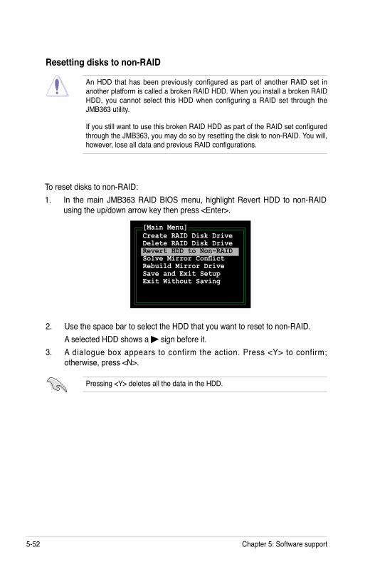
5-52 Chapter 5: Software support
Resetting disks to non-RAID
To reset disks to non-RAID:1. In the main JMB363 RAID BIOS menu, highlight Revert HDD to non-RAID
using the up/down arrow key then press <Enter>.
2. Use the space bar to select the HDD that you want to reset to non-RAID. A selected HDD shows a sign before it. 3. A dialogue box appears to confirm the action. Press <Y> to confirm;
otherwise, press <N>.
[Main Menu]Create RAID Disk DriveDelete RAID Disk DriveRevert HDD to Non-RAIDSolve Mirror ConflictRebuild Mirror DriveSave and Exit SetupExit Without Saving
Pressing <Y> deletes all the data in the HDD.
An HDD that has been previously configured as part of another RAID set in another platform is called a broken RAID HDD. When you install a broken RAID HDD, you cannot select this HDD when configuring a RAID set through the JMB363 utility.
If you still want to use this broken RAID HDD as part of the RAID set configured through the JMB363, you may do so by resetting the disk to non-RAID. You will, however, lose all data and previous RAID configurations.

ASUS P5B-Plus Series 5-53
To solve a Mirror conflict:1. In the main JMB363 RAID BIOS menu, highlight Solve Mirror Conflict using
the up/down arrow key then press <Enter>.
2. Use the space bar to select the HDD that you want to set as source drive. The selected HDD shows a sign before it. 3. Using the <TAB>, move to the RAID Disk Drive List menu and highlight the
RAID set that you want to rebuild. Press <Del> to begin rebuilding the Mirror configuration.
A status bar at the bottom of the screen shows the progress of the rebuilding.
[Main Menu]Create RAID Disk DriveDelete RAID Disk DriveRevert HDD to Non-RAIDSolve Mirror ConflictRebuild Mirror DriveSave and Exit SetupExit Without Saving
JMicron Technology Corp. PCI-to-SATA II/IDE RAID Controller BIOS v0.97
[Hard Disk Drive List] Model Name Capacity Type/Status HDD0: HDS722516VLSA80 164 GB RAID Inside HDD1: HDS722516DLA380 164 GB RAID Inside
[RAID Disk Drive List] Model Name RAID Level Capacity Status Members(HDDx) RDD0: JRAID 1-Mirror XXX GB Rebuild 01
[Main Menu]Create RAID Disk DriveDelete RAID Disk DriveRevert HDD to Non-RAIDSolve Mirror ConflictRebuild Mirror DriveSave and Exit SetupExit Without Saving
Rebuilding... 01%, please wait...
Solving a Mirror conflictA Mirror conflict occurs when both disks in a RAID 1 (Mirror) configuration are unplugged from the system in turn, then plugged in again. Since both disks contain exactly the same data, the system will be unable to determine which of the two is the source drive. This option allows you to set the source drive and rebuild the Mirror drive according to the contents of the source drive.

5-54 Chapter 5: Software support
Saving the settings and exiting setupWhen you have finished, highlight Save & Exit Setup using the up/down arrow key then press <Enter> to save the current RAID configuration and exit the JMB363 RAID BOS utility.
A dialogue box appears to confirm the action. Press <Y> to confirm; otherwise, press <N> to return to the JMB RAID BIOS menu.
To rebuild a Mirror drive:1. In the main JMB363 RAID BIOS menu, highlight Rebuild Mirror Drive using
the up/down arrow key then press <Enter>.[Main Menu]Create RAID Disk DriveDelete RAID Disk DriveRevert HDD to Non-RAIDSolve Mirror ConflictRebuild Mirror DriveSave and Exit SetupExit Without Saving
Rebuilding a Mirror DriveWhen one of the disks in a RAID 1 (Mirror) configuration is unplugged from the system, then plugged in again, a dialogue box appears to ask you to rebuild the Mirror drive. Press <Y> to confirm; otherwise, press <N>.
This option allows you to rebuild the Mirror drive later and synchronize the data between two hard disks.
2. Using the <TAB>, move to the RAID Disk Drive List menu and highlight the RAID set that you want to rebuild. Press <Del> to begin rebuilding the Mirror configuration.
A status bar at the bottom of the screen shows the progress of the rebuilding.
JMicron Technology Corp. PCI-to-SATA II/IDE RAID Controller BIOS v0.97
[Hard Disk Drive List] Model Name Capacity Type/Status HDD0: HDS722516VLSA80 164 GB RAID Inside HDD1: HDS722516DLA380 164 GB RAID Inside
[RAID Disk Drive List] Model Name RAID Level Capacity Status Members(HDDx) RDD0: JRAID 1-Mirror XXX GB Rebuild 01
[Main Menu]Create RAID Disk DriveDelete RAID Disk DriveRevert HDD to Non-RAIDSolve Mirror ConflictRebuild Mirror DriveSave and Exit SetupExit Without Saving
Rebuilding... 01%, please wait...

ASUS P5B-Plus Series 5-55
5.6.2 Creating a RAID driver disk in Windows®
To create a RAID driver disk in Windows®:1. Start Windows®.2. Place the motherboard support CD into the optical drive.3. Go to the Make Disk menu, then click Intel ICH8R 32/64 bit RAID Driver
Disk to create an Intel® ICH8R RAID driver disk or the Make JMicron JMB36X 32/64-bit RAID Driver to create a JMicron JMB363 RAID driver disk.
4. Insert a floppy disk into the floppy disk drive.5. Follow succeeding screen instructions to complete the process.
Write-protect the floppy disk to avoid computer virus infection.
5.6 Creating a RAID driver diskA floppy disk with the RAID driver is required when installing Windows® 2000/XP and later operating system on a hard disk drive that is included in a RAID set.
5.6.1 Creating a RAID driver disk without entering the OS
To create a RAID driver disk without entering the OS:1. Boot your computer.2. Press <Del> during POST to enter the BIOS setup utility. 3. Set the optical drive as the primary boot device.4. Insert the support CD into the optical drive.5. Save changes and exit BIOS.6. Press any key when the system prompts “Press any key to boot from the
optical drive.” 7. When the menu appears, press <1> to create a RAID driver disk.8. Insert a formatted floppy disk into the floppy drive then press <Enter>.9. Follow succeeding screen instructions to complete the process.

5-56 Chapter 5: Software support
To install the RAID driver:
1. During the OS installation, the system prompts you to press the F6 key to install third-party SCSI or RAID driver.
2. Press <F6> then insert the floppy disk with RAID driver into the floppy disk drive.
3. When prompted to select the SCSI adapter to install, make sure you select Intel(R) 82801GH/GM SATA RAID Controller (Desktop ICH8R) and JMicron JMB363.
4. Follow the succeeding screen instructions to complete the installation.

ACPU features
The Appendix describes the CPU features and technologies that the motherboard supports.

ASUS P5B-Plus Series
Chapter summary AA.1 Intel® EM64T ..................................................................................A-1A.2 Enhanced Intel SpeedStep® Technology (EIST) ........................A-1A.3 Intel® Hyper-Threading Technology ...........................................A-3

ASUS P5B-Plus Series A-1
A.1 Intel® EM64T
• The motherboard is fully compatible with Intel® LGA775 processors running on 32-bit operating systems.
• The motherboard comes with a BIOS file that supports EM64T. You can download the latest BIOS file from the ASUS website (www.asus.com/support/download/) if you need to update the BIOS file. See Chapter 4 for details.
• Visit www.intel.com for more information on the EM64T feature.
• Visit www.microsoft.com for more information on Windows® 64-bit OS.
Using the Intel® EM64T featureTo use the Intel® EM64T feature:
1. Install an Intel® CPU that supports the Intel® EM64T.2. Install a 64-bit operating system (Windows® Vista 64-bit Edition, Windows® XP
Professional x64 Edition or Windows® Server 2003 x64 Edition).3. Install the 64-bit drivers for the motherboard components and devices from
the support CD.4. Install the 64-bit drivers for expansion cards or add-on devices, if any.
Refer to the expansion card or add-on device(s) documentation, or visit the related website, to verify if the card/device supports a 64-bit system.
A.2 Enhanced Intel SpeedStep® Technology (EIST)
• The motherboard comes with a BIOS file that supports EIST. You can download the latest BIOS file from the ASUS website (www.asus.com/support/download/) if you need to update the BIOS. See Chapter 4 for details.
• Visit www.intel.com for more information on the EIST feature.
A.2.1 System requirementsBefore using EIST, check your system if it meets the following requirements:
• Intel® processor with EIST support• BIOS file with EIST support• Operating system with EIST support (Windows® Vista, Windows® XP SP2/
Windows® Server 2003 SP1/Linux 2.6 kernel or later versions)

A-2 Appendix: CPU features
A.2.2 Using the EISTTo use the EIST feature:
1. Turn on the computer, then enter the BIOS Setup.2. Go to the Advanced Menu, highlight CPU Configuration,
then press <Enter>.3. Set the Intel(R) SpeedStep Technology item to [Automatic],
then press <Enter>. See page 4-22 for details.4. Press <F10> to save your changes and exit the BIOS setup.5. After the computer restarts, right click on a blank space on the desktop, then
select Properties from the pop-up menu.6. When the Display Properties
window appears, click the Screen Saver tab.
7. Click the Power button on the Monitor power section to open the Power Options Properties window.
8. On the Power schemes section, click , then select any option except Home/Office Desktop or Always On.
9. Click Apply, then click OK.10. Close the Display Properties
window. After you adjust the power scheme,
the CPU internal frequency slightly decreases when the CPU loading is low.
The screen displays and procedures may vary depending on the operating system.

ASUS P5B-Plus Series A-3
A.3 Intel® Hyper-Threading Technology
• The motherboard supports Intel® Pentium® 4 LGA775 processors with Hyper-Threading Technology.
• Hyper-Threading Technology is supported under Windows® Vista/XP/2003 Server and Linux 2.4.x (kernel) and later versions only. Under Linux, use the Hyper-Threading compiler to compile the code. If you are using any other operating systems, disable the Hyper-Threading Technology item in the BIOS to ensure system stability and performance.
• Installing Windows® XP Service Pack 1 or later version is recommended.
• Make sure to enable the Hyper-Threading Technology item in BIOS before installing a supported operating system.
• For more information on Hyper-Threading Technology, visit www.intel.com/info/hyperthreading.
Using the Hyper-Threading Technology
To use the Hyper-Threading Technology:
1. Install an Intel® Pentium® 4 CPU that supports Hyper-Threading Technology.2. Power up the system and enter the BIOS Setup. Under the Advanced Menu,
make sure that the item Hyper-Threading Technology is set to [Enabled]. The BIOS item appears only if you installed a CPU that supports Hyper-
Threading Technology.3. Restart the computer.

A-4 Appendix: CPU features


