Embed Size (px)
Citation preview
EAN Plus Series
IP Box Camera
Userrsquos Manual
Lens not included
Copyright copy EverFocus Electronics Corp
Release Date October 2012
Copyright 2012 EverFocus Electronics Corp
All rights reserved No part of the contents of this manual may be reproduced or transmitted in any form or by
any means without written permission of the EverFocus Electronics Corporation
EverFocus
12F No79 Sec 1 Shin-Tai Wu Road
Hsi-Chih Taipei Taiwan
TEL +886 2 2698 2334
FAX +886 2 2698 2380
wwweverfocuscomtw
October 2012
Regulatory Notices
About this document
All the safety and operating instructions should be read and followed before the unit is operated This
manual should be retained for future reference The information in this manual was current when
published The manufacturer reserves the right to revise and improve its products All specifications are
therefore subject to change without notice
FCC Notice Declaration of Conformity Information
This equipment has been tested and found to comply with the limits for a Class
A digital device pursuant to part 15 of the FCC Rules These limits are designed to provide reasonable
protection against harmful interference in a residential installation This equipment generates uses and
can radiate radio frequency energy and if not installed and used in accordance with the instructions
may cause harmful interference to radio communications However there is no guarantee that
interference will not occur in a particular installation If this equipment does cause harmful interference
to radio or television reception which can be determined by turning the equipment off and on the user
is encouraged to try to correct the interference by one or more of the following measures
- Reorient or relocate the receiving antenna
- Increase the separation between the equipment and receiver
- Connect the equipment into an outlet on a circuit different from that to which the receiver is
connected
- Consult the dealer or an experienced radioTV technician for help
Warning Changes or modifications made to this equipment not expressly approved by EverFocus or
parties authorized by EverFocus could void the users authority to operate the equipment
This device complies with part 15 of the FCC Rules Operation is subject to the following two conditions
(1) This device may not cause harmful interference and
(2) This device must accept any interference received including interference that may cause undesired
operation
EverFocus Electronics Corp
12F No 79 Sec 1 Shin-Tai Wu Rd Hsi-Chi
Taipei Hsien Taiwan ROC
EAN Plus-series cameras comply with CE and FCC
ii
Safety Notice
These limits are designed to provide reasonable protection This equipment generates uses and can
radiated radio frequency energy and if not installed and used in accordance with the instructions may
cause harmful interference to radio communications However there is no guarantee that interference
will not occur in a particular installation If this equipment does cause harmful interference to radio or
television reception which can be determined by turning the equipment off and on the user is
encouraged to try to correct the interference by one or more of the following measures
- Reorient or relocate the receiving antenna
- Increase the distance between the equipment and the receiver
- Connect the equipment to an outlet on a circuit different from that to which the receiver is connected
- Consult the dealer or an experienced radioTV technician for help
Any changes or modifications not expressly approved by the party responsible for compliance could void
the users authority to operate the equipment
To reduce risk of fire or electric shock do not expose this appliance to rain or moisture
Do not attempt to disassemble the appliance To prevent electric shock do not remove screws or
covers There are no user-serviceable parts inside Contact qualified service personnel for maintenance
Handle the appliance with care Do not strike or shake as this may damage the appliance
Do not use strong or abrasive detergents when cleaning the appliance body Use a dry cloth to
clean the appliance when it is dirty When the dirt is hard to remove use a mild detergent and wipe
gently
Do not operate the appliance beyond its specified temperature humidity or power source ratings
Do not use the appliance in an extreme environment where high temperature or high humidity exists
Use the appliance at a temperature between 0degC and 50degC 32degF and 122degF and a humidity level
between 0 and 80 non-condensing The input power source for this appliance is 12VDC amp PoE
Use only the recommended power supplies Power supplies must comply with the requirement of
the latest version of IEC60950-1 Substitutions may damage the unit or cause a fire or shock hazard
Electrostatic-sensitive device Use proper CMOSMOSFET handing precautions to avoid
electrostatic discharge
Installation should be performed by qualified service personnel only in accordance with the
National Electrical Code or applicable local codes
iii
Terms and Trademark
Ethernet Internet Explorer Linux Microsoft Windows WWW are registered trademarks of the
respective holders Other product names appearing in this Users Guide may be trademarks or registered
trademarks of their respective holders Javatrade and all Java-related logos and trademarks are trademarks
or registered trademarks of Sun Microsystems Inc in the United States and other countries
Support
If the unit ever needs to be repaired or serviced the customer should contact the nearest EverFocus
Electronics Corp Service Center for return authorization and shipping instructions
iv
CONTENTS
1 Introduction 1
2 Overview 2
3 Features 3
4 Installation 4
41 Packing List 4
42 IO Terminal Block 5
43 Lens Installation and Adjustment 5
44 Top Bottom-Mount 6
45 Basic Connection 7
5 Accessing the User Interface 8
51 Assigning an IP Address 8
52 Settings for Microsoft Internet Explorer 10
53 Connecting the Camera to the Network 12
54 Live View Window 14
6 Playback 17
61 Remote Playback Using Playback Page 17
62 Setting up the Playback Function 19
621 Preparing the Micro SD Card 19
622 Testing the Playback Function 19
63 Playing Back Using ARV Viewer 21
7 Settings 22
71 System Info 22
711 Information 22
712 Log 23
72 User Config 24
721 Live View Config 24
722 Recording Snapshot 25
723 Language 26
73 Network 27
v
731 Network 27
732 DDNS 29
733 SMTP FTP 31
734 HTTPS 33
735 SNMP 36
736 Network Alarm 36
74 Video 37
741 Multi Streaming 37
742 Camera 39
743 Advanced 41
744 ROI (Region of Interest) 48
745 Privacy Mask 49
75 Audio 51
76 User 52
761 User Information 52
762 IP Address Filter 54
77 Event 55
771 Event Settings 55
772 Motion Detection 58
773 Tamper Detection 59
774 Alarm IO 59
775 Schedule 60
78 System 61
781 DateTime 61
782 Daylight Saving 62
783 SD Card 62
784 Maintenance 63
8 Upgrading Firmware Using IP Utility 65
9 Specifications 67
EAN Plus Series
1
1 Introduction
The EAN Plus series is a box-type IP camera delivering image quality of up to 3-megapixel The EAN Plus
series features the Wide Dynamic Range (WDR) function which can provide clear images even under
back light circumstances where intensity of illumination can vary excessively A built-in micro SD card slot
and Power over Ethernet (IEEE8023af) features are also provided You can power the camera over the
network or by connecting the camera to a 12V DC power supply The camera also features H264
MJPEG multi-stream output for simultaneous live monitoring and high-resolution recording Since the
EAN Plus series conforms to ONVIF PSIA for compatibility with other network video devices it
interoperates with a wide variety of hardware and software systems The EAN Plus series is designed for
simple installation and supports all types of indoor mounting applications
The EAN Plus Series Models
Model Name Megapixel WDR EAN3120 Plus 13 MP Yes EAN3220 Plus 2 MP Yes EAN3300 Plus 3 MP No
System Requirements
Before installing please check that your computer meets the following system requirements
Operating System Microsoft Windows XP Vista (32-bit) 7 (32-bit)
CPU Intel Core2 Duo 2 GHz or higher
RAM
1 GB or more
Additional HD space depends on required local storage of video files
100 Mbps network card
Screen Resolution 1024 x 768 pixels or higher 32-bit pixel color resolution
Software DirectX 90c
Microsoft Internet Explorer 7 or higher
Note For using the Internet Explorer some settings are required Please refer to 52 Settings for
Microsoft Internet Explorer
EAN Plus Series
2
2 Overview
2 3 4 6 7 8 9 105 111
No Item Name Descriptions 1 Memory Card Slot Insert a micro SD SDHC card to store recording data 2 Power LED Indicates the power is supplied 3 DC 12V Port Connects to power 4 Ethernet PoE Connects to a 10100 Ethernet or PoE 5 Reset Button Resets all configurations to factory default
6 IO Terminal Block Connects IO devices
7 Video Out Connects to a portable monitor for setting the focus and angle of
the camera during initial installation
8 Audio In Connects to a microphone for audio input Note that microphones
with external power supplies are required
9 Audio Out Connects to a speaker for audio output
10 Light Sensor Detects lights
11 Auto Iris Lens Connector Plug the Iris control cable to the connector
EAN Plus Series
3
3 Features
bull 13rdquo Panasonic CMOS sensor (for EAN3120 Plus 3220 Plus)
128rdquo Sony CMOS sensor (for EAN3300 Plus)
bull Triple streams (stream 1 2 3 from H264 or MJPEG)
bull Up to 30 fps at 1920 times 1080
Supports 15 fps at 2048 times 1536 (only for EAN3300 Plus)
bull Auto Iris control
bull Built-in micro SD SDHC card slot
bull Removable IR-cut filter for Day Night function
bull One alarm input and output
bull Two-way audio
bull TV-out
bull Wide Dynamic Range (for EAN3120 Plus 3220 Plus)
bull 2D 3D Dynamic Noise Reduction (DNR)
bull Motion detection
bull Privacy mask
bull DC 12V PoE
EAN Plus Series
4
4 Installation
41 Packing List
bull EAN Plus Series Camera (lens not included) x 1
bull Software CD x 1
bull Quick Installation Guide x 1
bull Tool Packet x 1 (contains the following items)
- C-mount lens adapter - frac14-20 UNC thread mounting bracket and 2 screws
- Hexagon wrench - Power pigtail cable
Note Contact the shipper if any items appear to have been damaged in the shipping process If any
items are missing notify your EverFocus Electronics Corp Sales Representative or Customer Service
Branch Please also keep the shipping carton for possible future use
EAN Plus Series
5
42 IO Terminal Block
The IO terminal block located on the rear panel of the camera can be used to develop application
for alarm input and output
1 2 3 4
Pin Assignment
No Function No Function
1 Alarm COM 3 Alarm Input
2 Alarm Output 4 Digital GND
43 Lens Installation and Adjustment
You can install either a CS-mount or a C-mount lens into the camera It is recommended to use a lens
with aperture ratio of F14 or smaller Please refer to the following reference steps
C-Mount Lens Adapter
DC Auto Iris Lens Connector
Focus Screw
Zoom Screw
CS-Mount Lens
1 Remove the cover cap from the camera body
2 Install the lens into the camera body
3 Adjust the lens using the Focus Zoom Screws
If you are using a DC Auto Iris lens
1 Remove the cover cap from the camera body
2 Install the lens into the camera body
3 Connect the DC cable to the DC Auto Iris Lens Connector
EAN Plus Series
6
4 When making final focus adjustment place the ND filter in front of the lens to force the lens iris
to open and then adjust the lens using the Focus Zoom Screws
Note To use the ND filter remove the protective sheets from both sides of an ND filter
5 Lock the Focus Screw and then remove the ND filter
C-Mount Lens
1 Remove the cover cap from the camera body
2 Install the lens into the camera body using the supplied C-mount lens adapter
3 Adjust the lens using the Focus Zoom Screws
Note Installing a C-mount lens without the C-mount lens adapter may damage the camera sensor
44 Top Bottom-Mount
You can use the supplied mounting bracket and screw it on the top of the camera body to suspend
the camera or on the bottom of the camera body to support the camera
Top Mount
Bottom Mount
EAN Plus Series
7
45 Basic Connection
Micro SD
Audio
In OutEthernet (PoE)
DC 12VPower
Reset
Video Out
COM
Out In
GN
D
Alarm
1
2
3
3
4
5
1 Use a standard network cable to connect the camera to the network
2 Connect the camera to power using one of the following methods
bull Plugging the supplied power pigtail cable to the DC 12V port
bull Using the PoE function and the power will be provided over the network cable
3 Optionally connect the camera to a speaker or microphone Note that microphones with
external power supplies are required
4 Optionally connect the camera to a monitor using a BNC cable
5 Optionally connect the camera to the input output devices
After powering the camera the power LED will be lit in red and you can access the live view and
adjust the image clarity
EAN Plus Series
8
5 Accessing the User Interface
This section explains how to access the Web interface of the camera for configuration
51 Assigning an IP Address
You have to assign an IP address for your camera to be accessible To assign an IP address to the
camera use the IP Utility (IPU) software included in the software CD Please connect the IP camera in
the same LAN of your computer
1 Install and then start the IPU program The following dialog box appears
2 Click Find Devices to search the cameras connected in the LAN The default network values of the
cameras will be displayed By default the network protocol of the camera is DHCP
3 To configure the network settings select a camera and then click LoginMulti Login to log in
EAN Plus Series
9
4 Type the user ID and password Click OK
Note
1 The default user ID is user1 and the default password is 11111111
2 If you select more than one camera that has the same user ID password you will be able
to log in several cameras at once
5 To change the IP address double-click the IP Address of the camera Type a new IP address and
then click Set IP Address to save the settings
You can also change the other settings by double-clicking the values After configuring the values
click Save Configuration
Note Most networks uses DHCP to assign IP address if you are unsure of your network
settings please consult your network administrators for configuration details
6 To access the camera highlight the camera and click Connect to Selected IP The Internet
Explorer window pops up
7 Type the user ID and password to log in The Live View window of the camera appears
Note You might be required to download ActiveX which is required to view the camera feed
If asked click Yes For more details on setting up the Microsoft Internet Explorer please refer
to 52 Settings for Microsoft Internet Explorer
EAN Plus Series
10
52 Settings for Microsoft Internet Explorer
To enable Remove Live View Firmware Upgrade and ActiveX Prompt on Internet Explorer some
settings have to be complete Please follow the steps below
1 On the computer click Start gt Control Panel gt System and Security gt Action Center (click Change
User Account Control Settings) the User Account Control Settings window appears Adjust the
slide bar to Never Notify and then click OK Restart your computer if requested
2 Open the Internet Explore click Tools gt Internet Options gt Security Tab gt Custom Level the
Security Settings windows appears
EAN Plus Series
11
3 In the Download unsigned ActiveX controls field select Prompt In the Include local directory
path when uploading files to a server field select Enable Click OK
4 In the Internet Options window click the Advanced tab and then disable Enable memory
protection to help mitigate online attacks Click OK
EAN Plus Series
12
53 Connecting the Camera to the Network
There are three methods to connect the IP camera to the network Router or LAN Connection Direct
High-Speed Connection and One-to-One Connection
Router or LAN connection
This is the most common connection in which the IP camera is connected to a router and allows
multiple users on and off site to see the IP camera on a LANWAN (Internet) The camera must be
assigned an IP address that is compatible with its LAN By setting up port forwarding on the router
you can remotely access the cameras from outside of the LAN via the Internet To remotely access the
Web interface of the IP camera please refer to 732 DDNS To set up port forwarding please consult
the manual of the router
Straight-through LAN patch cable
Right Pinout of a straight-through cable
EAN Plus Series
13
Direct High-Speed Connection
In a Direct High-Speed Connection the camera connects directly to a modem without the need for a
router You need to set the static or dynamic WAN IP address assigned by your ISP (Internet Service
Provider) in the camerarsquos configuration web pages To access the camera just type ldquohttpxxxrdquo
where xxx is the IP address given by your ISP If you have a dynamic IP address this connection may
require that you use DDNS for a reliable connection Please refer to 732 DDNS
One-to-One Connection (Directly from PC to IP Camera)
You can connect directly without using a switch router or modem However only the PC connected
to the camera will be able to view the IP camera You will also have to manually assign a compatible IP
address to both the computer and the IP camera Unless the PC has another network connection the
IP camera will be the only network device visible to the PC See the diagram below
Pinout of straight patch cable
Right Pinout of a crossed-over cable
EAN Plus Series
14
54 Live View Window
1 Press the button to display the Live View window Double-click on the
image to show a full-screen display double-click again or press ESC to return to the normal display
If you experience video feed lag time (if connected via Internet) you can reduce the resolution or
limit the number of streams See 741 Multi Streaming
2 Press the button to play the recorded data directly from the on-camera Micro
SD SDHC card (for this function to become active you have to insert a Micro SD SDHC card in the
Micro SD SDHC card slot on the rear panel of the camera See 783 SD Card
3 Press the button to enter the Settings page On the Settings page there are
8 submenu sections [System Info] [User Config] [Network] [Video] [Audio] [User] [Event] and
[System] Click on the section buttons to open their configuration fields See the Settings section
below for more information
EAN Plus Series
15
4 Press the button to exit the system and close this browser page
5 Video Stream
Select the Video Stream (Stream 1 Stream 2 or Stream 3) that will be displayed in the video box on
the right Stream 2 and Stream 3 are only selectable if you have enabled the stream The default
setting is Stream 1 only See 741 Multi Streaming
6 View Size
Use this to select the appropriate view size and shape of the video box on the right A smaller size
might increase transmission speed and video quality
7 Digital Zoom
Click the Zoom In Zoom Out buttons or roll the mouse wheel to zoom in out the camera live view
up to 10x Clicking on a magnified image will re-center the image around that point
8 Record
The Record button is used to record the current video stream Click the Record button to start
stop recording This icon is only for one-minute video recording To record long-period recordings
please set a recording schedule (See 775 Schedule) The location on your computer where the
image files will be saved to and file size can be specified in the submenu (see 72 User Config)
9 Snapshot
Click the Snapshot button to save a snapshot of the video image currently being displayed The
location on your computer where the snapshot data will be saved can be specified in ldquoSettings gt
User Config gt RecordingSnapshotrdquo (see 72 User Config)
10 Play Audio Transmit Audio
Click the ldquoPlay Audiordquo (speaker) and ldquoTransmit Audiordquo (microphone) buttons to switch the sound
onoff for the speaker and microphone respectively (if such external devices have been connected
to the camera directly or via the network)
EAN Plus Series
16
11 One Push
This function is only available for EAN3120 Plus 3220 Plus The One Push button can be displayed
on the live view window by enabling the Show One Push Buttons function on the User Config lt Live
View Config Setting page (see 721 Live View Config) To enable the button (turned from faded to
clear) on the Video lt Advanced Setting page select One Push from the White Balance Settings
Mode drop-down list and click the Apply button Once this is done pressing the One Push button
on the Live View Window will instruct the camera to adjust the white balance settings and these
settings will be active until the button is pushed again This is like a ldquosemi-automaticrdquo way to adjust
white balance to suit the user if the Auto or Manual mode does not give the result the user wants
12 Manual Control
ndash Trigger Event
Press the ldquoTrigger Eventrdquo button to trigger an event directly from the Live page If you have
configured an event (in the Event submenu) that will trigger a reaction (like a recording) when a
Manual Trigger event occurs clicking this button will trigger that reaction You can select what that
reaction will be You can for instance set the camera to record the audiovideo feed to the Micro
SD card on board the camera You can then click on the Playback button to open the Playback page
and search for and play all such recordings that had been stored on the card Such event actions
will be effective once they have been configured in the ldquoEventrdquo menu (see 77 Event)
ndash Reset Alarm
Press the ldquoReset Alarmrdquo button to reset the alarm output remotely
13 Status Display (info lines that can be placed above video box or at bottom of page)
This shows the name of the camera that is currently active or being configured current datetime
and current frame rate You can activate these info displays in the Settings gt User Config page (see
72 User Config)
14 Event Signal Icons (above video screen)
When an alarm or motion event is triggered a signal icon will appear at the top right of the Live
View window to alert the user
Alarm event icon When an alarm is triggered this icon appears
Motion detection icons The colors of these motion event icons correspond to the colors of the motion trigger areas you have configured in the Motion Detection submenu (see 772
Motion Detection)
Recording icon When the camera is recording to a PC-based folder this icon appears
EAN Plus Series
17
6 Playback
You can remotely play back the recordings stored in the on-camera micro SD card on the Web interface
or play back the recordings stored in the computer using the ARV Viewer included in the software CD
Playback is designed as a quick way to check recent recordings that were triggered by Events that were
configured to ldquoRecord to SD Cardrdquo in the Settings gt Event gt Event Settings page (see 771 Event
Settings)
Note Note that the Playback page is only accessible once the on-camera SD card is inserted and
active
61 Remote Playback Using Playback Page
On the Live View Window click the Playback button to open the Playback page
EAN Plus Series
18
Search by File Click the Search button to search for all recording files on the on-camera SD card
Search results will be displayed in the Filename area
Search by Time Click the calendar icon and select the date and time from which you want to search
until the present moment Click search to get your search results which will be displayed in the
Filename area
Search by event Click the type of Event recordings you want to search for (Alarm Motion Manual
Trigger) and then click the calendar icons to select the Start Time datetime and the End Time
datetime of your search Click Search to get your search results which will be displayed in the
Filename area
Multiple Files Check this box if you want the video player to play all the files in the selected folder
The files will be displayed in the Filename area
Loop Again Check this box if you want the video player to play the selected file over and over again
Play Once you have opened the filersquos folder and have clicked on the file to highlight it its details will
be displayed in the File Information area You can now click Play to play that specific file
Pause Click this button to pause the playback
Stop Click this button to stop the playback
【Recording List】
Filename This area will display a list of search results (recording files and folders) Folders (named
with the recorded date) will be displayed first Click on the folder and click on each subfolder until the
recording files (arv) in that folder is listed
File Information Click a file on the Filename list the selected file information will be listed
Copy Click this button to copy the selected file to the computer-based folder of your choice A
browsing box will open so that you can search for the folder of your choice You can use the ARV
Viewer to play back the recordings recorded in your computer For details on ARV Viewer see 63
Playing Back Using ARV Viewer
Lock Click this button to lock the selected file This will protect that file from being overwritten during
any overwrite procedure The file will thus be saved on the micro SD card indefinitely However the
file will still be deleted if the micro SD card is ever formatted
Remove Click this button to delete the selected file
EAN Plus Series
19
62 Setting up the Playback Function
Note that the Playback function will not be active until the user has inserted a micro SD card in the
camerarsquos micro SD card slot The card may also have to be formatted in the Settings submenu
Micro SD Card Slot
621 Preparing the Micro SD Card
Once you insert a functional micro SD card into the slot the Playback button on the Live page should
become active within seconds (see section 622 below ndash the grey letters should turn white) IF NOT
do the following
1 From the Live page click Settings gt System gt SD Card If no card has been inserted yet the
Remove button should be faded indicating that no card is being detected (If a card is
inserted and the Remove button is still faded pull the card out and re-insert it)
2 Slide the card into the slot until it clicks into position
3 The Remove button should become active within a few seconds indicating the card is active
4 If the Remove button stays faded click the Format button to format the card NOTE All data
on the disk will be deleted if the Format button is clicked
622 Testing the Playback Function
1 Once the SD card is detected by the system the button (inactive)
will turn to (active)
2 To test the Playback function (this is not required) set up a ldquoManual Triggerrdquo Recording
Event by clicking Settings gt Event gt Event Settings
3 Click the ldquoAddrdquo button on the middle right side of the page to open an ldquoAdd Eventrdquo box
4 Give the event a name like ldquoTest 1rdquo
EAN Plus Series
20
5 In the ldquoEvent Triggered byrdquo field click on Manual Trigger
6 Below this check ldquoEnable This Eventrdquo ldquoEnable Post-trigger Bufferrdquo and ldquoRecord to SD Cardrdquo
7 To save your settings click OK or close the box by clicking on the red x icon at top right of the
box (in which case you will be asked if you want to save the data to which you should reply OK)
The box will close and the new event will be listed in the list area of the Event Settings page
8 Look at the ldquoPost-trigger Bufferrdquo at the bottom to make sure the buffer time is set to 10 seconds
9 Click ldquoApplyrdquo to make sure all settings are saved
10 Click the Live button to go back to the Live page
11 Get ready to click the Trigger Event button at the bottom of the page Before you do see if you
can find something in the view screen that will give you a visual time marker For instance if you
can get your hand in front of the camerarsquos lens get ready to count down on your fingers
12 Click the Trigger Event button and slowly count down on your fingers in front of the lens (if you
are able to do so ndash if not try to find visual cues on the view screen that will help you to mark the
moment you pushed the trigger) The recording period will be as long as the buffer time you
selected ndash the default period is 10 seconds
13 Click the Playback button to open the Playback page
14 There are different ways to search for recording files on the camerarsquos Micro SD card (ie the
Playback memory) For a recent recording like your test event simply click the ldquoSearchrdquo button
under the ldquoSearch by Filerdquo header
15 If the SD card is active and formatted correctly the recording folderrsquos name (the recording dayrsquos
date) will appear in the Filename box at the bottom Click on this folder to open it If there are
sub-folders click on the bottom one (the most recent would be at the bottom) until you can click
on a file that cannot open to another sub-level and shows data in the File Information box to the
right This would be the file of the most recent recording event
16 To play this file click the Play button below the video box The test footage you have recorded
should start playing Play time should be 10 seconds if you left the Post-trigger Buffer as 10
seconds
EAN Plus Series
21
63 Playing Back Using ARV Viewer
You can play back the recordings stored in the computer using the ARV Viewer included in the
software CD To store the recordings in the computer please refer to Recording List gt Copy in 61
Remote Playback using Playback Page
4 5 6 7 8 9 10
321
No Item Name Descriptions
1 Snapshot Click to take and save a snapshot
2 Load File Click to load the recordings for playing back
3 Convert ARV to AVI Convert the recording from ARV format to AVI format
4 Playback Time Display the playback time
5 Total Time of Recording Display the total time of the recording
6 Stop Click to stop playing the recording
7 Step Reverse Click to display the previous frame
8 Play Click to play back the recording
9 Pause Click to pause the recording
10 Step Forward Click to display the next frame
EAN Plus Series
22
7 Settings
Click the Settings button on the Live View Window to enter the settings submenu There are nine buttons
on the left-side of the submenu Live System Info User Config Network Video Audio User Event and
System Click the Live button can go back to the Live View Window
71 System Info
The System Information and System Log can be checked on this page Click the top tab of the one you
want to see
711 Information
Click the Information tab the following dialog box appears These values cannot be changed on this
page and are for reference only
EAN Plus Series
23
712 Log
Click the Log tab the following dialog box appears The sequence number date time and event
messages of the log event will be displayed in the System Log field The log will display the last 256
log events Click the Export button to export the system log event list into a ldquotxtrdquo file and select the
location where the exported log file will be saved to
EAN Plus Series
24
72 User Config
Each user can set a different configuration for hisher Live page here These settings will be applied to
the logged-in userrsquos Live page every time heshe logs in
721 Live View Config
【VideoAudio Connection Protocol Setting】You can transmit the data stream from the IP cameras
using the RTSP (Real Time Streaming Protocol) on the network The RTSP is a protocol that allows
you to access video streams by using the compatible media players Click Apply to apply the
changes or Reset to reset without saving the changes RTP over UDP The RTSP protocol uses UDP for camera data stream transmission
RTP over TCP The RTSP protocol uses TCP for camera data stream transmission
RTP over HTTP The RTSP protocol uses HTTP for camera data stream transmission
Nevio CGI This is EverFocusrsquo protocol designed for EverFocusrsquo IP devices Select this
protocol for camera data stream transmission
【Text Settings】Check the box of each option (Machine name DateTime Frame Rate) to display
this info on the Live View Page
Foreground Color Slide the Red Green and Blue bars to create your preferred text color for the
info text line
Position Select the position where the text will be displayed Choose from Upper Left Lower
Right Lower Left
Click Apply to apply the changes or Reset to reset without saving the changes
EAN Plus Series
25
【DateTime Format Used in Text】Click the dropdown menu to select datetime format from the
listed options Click on the desired hour format Click Apply to apply the setting changes or Reset to
reset without saving the change
【Live View Layout Settings】 Check the ldquoShow One Push Buttonsrdquo boxes if you want to show these
buttons on the Live View Page Uncheck these boxes to hide these buttons This function is only
available for EAN3120 Plus 3220 Plus
722 Recording Snapshot
This configures where your Record Button and Snapshot Button ( ) files will be saved if
you click one of these buttons Selectable folders will be on the computer only not on the
on-camera SD card
【Recording Snapshot Export Settings】
Enable Event Recording to PC Checking this box will let the system save RecordSnapshot Button
recordings to the folder configured below on the userrsquos PC
Export Folder Select the Export folder for the action above by clicking on the browse (hellip) button
and then select the desired folder
File size The user can limit the size of each recorded file here (in minutes) When a single
recording file exceeds the time you set the system will create a new file to save that data to
Overwrite Select ldquoONrdquo for overwriting recordingsnapshot file when the disk storage capacity is
full The user can set the storage capacity limitation in the in-sentence field in the gray box below
the Overwrite setting ldquoIf the remaining hard disk capacity is less than ____ MB (50~2000) system
will stop recording or start overwriting ldquo
Click Apply to apply the setting changes or Reset to reset without saving the changes
EAN Plus Series
26
723 Language
Select the language to be displayed on the Web interface of the IP camera The default language is
English
To add a new language not listed in the current Language list click the Browse button to locate
the new language file (evb) on your computer and then click the Upload button Updated
language files might be available on the manufacturerrsquos website Contact your vendor if required
Click Apply to apply any changes or Reset to reset without saving the changes
Note Uploading a new language file will cause the system to reboot automatically Please create
a new network connection to the IP camera when the reboot is complete
EAN Plus Series
27
73 Network
This page covers network-related settings including Network DDNS SMTPFTP HTTPS SNMP and
Network Alarm
731 Network
The following information is required to configure the network settings Contact your network
administrator or your internet service provider to get the info
【IP Settings】
IP Type Refer to the network administrator for these settings of the server Default DHCP
DHCP This setting lets the system use an automatically assigned (dynamic) IP address This
address can change under certain circumstances For instance when the camerarsquos network
switchhub has to be rebooted Do not assign to the DHCP server the same IP addresses used
for the other network cameras and PCs with unique IP addresses
Static IP The user can manually set the Static IP address This type of address is stable and
cannot change but the user has to make sure there are no address conflicts with other
network-connected devices
PPPoE This is a DSL-connection application The ISP will ask the user to input a username and
password Contact your ISP for these details
EAN Plus Series
28
Note If PPPoE is selected as the IP type the supplied IP Utility program will not be able to
detect the device
IP address When DHCP is not used the user needs to manually enter the IP address of the
camera Do not enter an IP address that is already used for your computer or other network
cameras
Subnet Mask This field is used to set the netmask for your network so that the IP camera will be
recognized within the network Example 2552552550 When DHCP is selected the DHCP server
will assign this value automatically
Gateway This field is used to set the gateway for your network so that the IP camera will be
recognized within the network When DHCP is selected the DHCP server will assign this value
automatically
Primary DNS Enter the IP address of the DNS server if this is provided by an ISP
Secondary DNS If your ISP provided you with a secondary DNS address please enter it here
Username Enter the accountrsquos username (used only for PPPoE)
Password Used only for PPPoE
IPv6 Enter the IPv6 details in this area if this applies to your system
Click Apply to apply the setting changes or Reset to reset without saving the change
【Port Settings】Enter the HTTP HTTPS and RTSP port numbers and click Apply to save
【Multicast Settings】Enable if required fill in the setting options and click Apply to save
EAN Plus Series
29
732 DDNS
DDNS (Dynamic Domain Name System) is a service used to map a domain name to the dynamic IP
address of a network device You can set up the DDNS service for remote access to the IP camera
DDNS assigns a domain name (URL) to the IP camera so that the user does not need to go through
the trouble of checking if the IP address assigned by DHCP Server has changed Once the IP is
changed the IP camera will automatically update the information to the DDNS to ensure it is always
available for remote access
Before enabling the following DDNS function user should have applied for a host name from the
DDS service providerrsquos website We support these four DDNS server providers
wwweverfocusddnscom wwwsitelutionscom wwwdyndnscom and wwwno-ipcom
Note We highly recommend that you use xxxxeverfocusddnscom for the simplicity of setting up
your IP cameras
【DDNS Settings】
Enable Check this box to enable the DDNS function
Service ISP You can either apply for a host name from EverFocus or other DDNS server providers
If you choose the EverFocus DDNS server you can obtain a free host name from EverFocus by
following the steps below
bull From EverFocus To obtain a free host name from EverFocus type a desired host name in the
textbox click the Register Update button and then click the Apply button
bull From other DDNS server providers To obtain a domain name from one of the three DDNS
server providers you have to register your name with the provider first and then select the
provider and fill in the required information Please refer to the specific DDNS companyrsquos
website for further information
Record ID Type the record ID if provided by the DDNS server provider
EAN Plus Series
30
FQDN Type the fully qualified domain name applied from the DDNS server provider For
example xxxxdyndnscom
Username Password Type the login account of your DDNS server provider
Click Apply to apply the setting changes or Reset to reset without saving the changes
Note
1 In order to support the full functionality of the camera you must open the port numbers (80
554 443) on the router for remote access to the IP camera This function is available on most
routers in the market and is often known as ldquoPort Forwardingrdquo To set up Port Forwarding
please consult the manual of the router
2 In certain router models it is possible that you will not be able to access the camera using
DDNS while inside the routerrsquos network Please try using a PC located outside of your routerrsquos
network
Default Ports on All EverFocus IP Cameras
HTTP 80
RTSP 554
HTTPS 443
EAN Plus Series
31
733 SMTP FTP
【Set SMTP Server (email)】This area is for configuring the mail server that is used to send e-mail
notifications from the camera to predefined addresses via SMTP Note that to enable e-mail
notification function you have to check the Send Mail Notification item on the Event dialog box
(see 771 Event Settings)
SMTP Server Enter the IP address or the host name of the SMTP server used to send e-mails
SMTP Port Enter the port number for SMTP The default is 25
Authentication Check this box if the SMTP server requires authentication (userpassword)
User name Input the userrsquos login ID if the SMTP server requires authentication
Password Input the userrsquos login password if the SMTP server requires authentication
EAN Plus Series
32
Receiver Address Input the e-mail addresses for receiving an e-mail message when an EVENT is
enabled and triggered Please use ldquordquo to separate multiple addresses
Sender Address Input the senderrsquos e-mail address so that the receiver can recognize the sender
when an Event message is received
Attach Image Check this box if you want to attach an image when an alarm is triggered or an IP
camera detects events
Send Test Email Click the Test button to send a testing email to the assigned address
Click Apply to apply the setting changes or Reset to reset without saving the changes
【Set FTP Server】The settings relating to the FTP server used to transmit the alarm images can be
configured here Note that to enable uploading images to the FTP server function you have to
check the Upload to FTP item on the Event dialog box (see 771 Event Settings)
FTP Server Enter the IP address or the host name of the FTP server
FTP Port Enter the port number for the FTP server Default is 21
Recording Path Assign the recording path
User Name Set FTP Userrsquos name
Password Set FTP password
PASV mode Check to enable Passive mode Passive mode is normally enabled If a connection
cannot be established uncheck PASV Moderdquo
Test FTP Server Click the Test button to send a testing file to the assigned FTP server
Click Apply to apply the setting changes or Reset to reset without saving the changes
EAN Plus Series
33
734 HTTPS
Hypertext Transfer Protocol Secure (HTTPS) is a combination of the Hypertext Transfer Protocol
and the SSLTLS protocol and provides encrypted communication and secure identification of a
network web server
Before using the HTTPS function for communication with the IP camera a Certificate must be
created first There are two ways to create and install a certificate Create Self-Signed Certificate
and Create Certificate Request
Create Self-Signed Certificate
Please note that even though self-signed certificates are free and offer some protection true
security is only implemented after the installation of a signed certificate issued by a certificate
authority
1 Click the Create Self-Signed Certificate button the following dialog appears
EAN Plus Series
34
2 Type the required Certificate information and then click the Apply button The subject line will
be displayed in the Installed Certificate Information field
3 Click the Property button a pop-up window appears to display the details of the certificate
4 To optionally create and install other certificates remove the existing one by clicking the
Remove button to erase the certificate
5 On the Web page change the address from ldquohttprdquo to https in the address bar and press
Enter on the keyboard Some Security Alert dialogs will pop up Click OK or Yes to enable HTTPS
Create Certificate Request
You can apply for an official certificate from an issuing Certificate Authority
1 Click the Create Certificate Request button the following dialog appears
EAN Plus Series
35
2 Type the required Certificate information and then click the Apply button The subject line will
be displayed in the Created Request field
3 Click the Property button a pop-up window appears to display the details of the certificate
4 To optionally create and install other certificates or request remove the existing one by clicking
the Remove button to erase the certificate or request
5 Copy the contents of the Certificate request (in PEM format) and paste it to the certificate
request field on the Web page of the 3rd-party certification authority such as Symantec VeriSign
Wait for the certificate authority to issue an SSLTLS certificate and then download the issued
certificate on your computer
6 In the Install Signed Certificate field click the Browse button to search for the issued certificate
and then click the Upload button to import the certificate Once the certificate has been
uploaded this field will show the subject line of the certificate
EAN Plus Series
36
735 SNMP
The default values for SNMP v1v2v2c and SNMP v3 are already filled in Click either of the
Enable buttons to enable either of the two Make your changes as desired Click on the Trap
Address field to enter the digits if required
736 Network Alarm
This function works with EverFocusrsquos CMS software eg the PowerCon or the Power Video Plus For
the setting details please refer to the CMS network alarm protocol
EAN Plus Series
37
74 Video
The settings relating to video such as streaming camera OSD can be configured on this page The
Video page has five tabs Multi-streaming Camera Advanced ROI and Privacy Mask
741 Multi Streaming
【Stream Settings】 This IP camera can output three video streams simultaneously For each of these
streams the user can set the compression format resolution bit rate and frame rate individually
Stream 1 is always enabled for live view To enable Stream 2 andor Stream 3 check the ldquoEnablerdquo
box the header of each stream
Note If you connect to the camera via the Internet and experience a delay (lag time) in the video
feed try to reduce the number of streams and the quality and resolution of the streams ndash but
keep the frame rate at its maximum
EAN Plus Series
38
Format Select the encoding format ndash H264 or MJPEG
Resolution Select the most suitable resolution for your needs
Frame Rate Select from 1 to 30 fps
Bit Rate If required select whether you want the stream to stream a Constant Bit Rate or a
Variable Bit Rate and set the values of whichever option you choose
Click Apply to apply the setting changes or Reset to reset without saving the changes
【Video Recording Settings】Select the stream you want to configure and then select whether you
want the recording files of that stream to be saved in AVI or ARV format Click Apply to apply the
setting changes or Reset to reset without saving the changes
【Time Stamp Settings】 You can select the DateTime format position and add the setting to the
streaming
Click Apply to apply the changes or Reset to reset without saving the changes
EAN Plus Series
39
742 Camera
【Image Settings】Set the Brightness Saturation Contrast or Sharpness of the image Click Apply to
apply the changes or Reset to reset without saving the changes
【Camera Settings】
Mirror Switch Mirror ON to rotate the image horizontally around a vertical axis
Flip Switch Flip ON to rotate the image vertically around a horizontal axis
AE There are two options
ALC Selecting Automatic Light Control allows the camera circuitry to either take bright spots
more into consideration (peak) bringing out detail in bright areas or less into consideration
(average) bringing out detail in shadows
AES Selecting Auto Electronic Shutter disables the Shutter setting below this setting In this
mode the camera measures the light level and decides whether it needs more or less light and
then automatically adjusts the shutter speed accordingly
BLC Back Light Compensation (BLC) is used to make the subject appear clearer when it is set
against a bright background
OFF Select to switch Back Light Compensation functions off
(ON)BLC The BLC can increase the exposure of a dark area surrounded by a brighter area HLC
can decrease the exposure of bright areas surrounded by darker areas This enables the
camera to better display information that would otherwise have been ldquowhited outrdquo like a
license plate between two bright headlights on a dark road
(ON)HLC The Highlight-Suppression BLC is used to reduce the brightness of light sources in a
specific area It is activated only in a low illumination environment to minimize the effects of
glare from bright lights such as spotlights street lights or headlights in the field of view
EAN Plus Series
40
WDR The Wide Dynamic Range (WDR) function provides clearer images when both of the very
bright and dark areas simultaneously appear on the camera view There are four value options
OFF Low Middle and High Note that when WDR is ON some parts of the image may appear
solarized This is normal for WDR and is not a camera malfunction This function is only available
for EAN3120 Plus 3220 Plus
DN Mode
Auto Select to let the camera automatically switch to Night mode (black and white) when the
light levels fall to a specified level and back to Day mode (color) when the light levels rise to a
specified level
Day Select to keep the camera in Day mode (color) even in nighttime
Night Select to keep the camera in Night mode (black and white) even in daytime
EAN Plus Series
41
743 Advanced
EAN Plus Series
42
【Camera Settings】
Lens (IRIS Control) Select DC or Manual for IRIS control This function is only available for EAN3220
Plus
Exposure Settings (AE) This setting is used to adapt to the amount or type of light used by the
camera Note the settings vary among models
Mode This function is not available for EAN3220 Plus
Automatic Light Control (ALC) This option is only available for EAN3120 Plus 3300 Plus The
ALC allows the camera circuitry to either take bright spots more into consideration (peak)
bringing out detail in bright areas or less into consideration (average) bringing out detail in
shadows
Auto Electronic Shutter (AES) This option is only available for EAN3120 Plus 3300 Plus In
this mode the camera measures the light level and decides whether it needs more or less light
and then automatically adjusts the shutter speed accordingly
Manual This option is only available for EAN3300 Plus Select this option to manually set up
the Shutter (Manual) and AGC (Manual) values
Iris Specify the size of the Iris opening here
Shutter If enabled this setting lets you set the shutter speed yourself
Shutter Limit Use this setting to set the maximum shutter speed for the camera This function is
only available for EAN3120 Plus
AGC Set the Auto Gain Control limit here The lower the AGC level the lower the video signal and
the noise However the image will be darker under low-light condition with IR-off if you set up the
Iris to the maximum level
Slow Shutter This option can be switched on when AES Mode is selected in the Exposure Settings
(AE) field This function is only available for EAN3220 Plus 3300 Plus
Flickerless If the Mode field in the Exposure Settings (AE) area has been set to AES then this option
becomes available Choose between OFF 50HZ 60HZ 50HZ (High Luminance) or 60HZ (High
Luminance) This function is only available for EAN3300 Plus
EV Setting Set up the Exposure Value Note the brightness of the screen changes when you change
the EV value This function is only available for EAN3300 Plus
AE Response Set up Auto Exposure Response time This function is only available for EAN3300 Plus
AE Weighting Area Select an AE Weighting area Each setup AE Weighting Area is configured with
the appropriate brightness level on the center and the surrounding areas This function is only
available for EAN3300 Plus
Brightness Set the image brightness here
AE Reference Set the Auto Exposure value here This function is only available for EAN3120 Plus
EAN Plus Series
43
Black Level Set the Black level here This function is only available for EAN3300 Plus
WDR The Wide Dynamic Range (WDR) function provides clearer images when both of the very
bright and dark areas simultaneously appear on the camera view There are four value options OFF
Low Middle and High Note that when WDR is ON some parts of the image may appear solarized
This is normal for WDR and is not a camera malfunction This function is only available for EAN3120
Plus 3220 Plus
Visibility Enhancement (OFFLowMiddleHigh) Images in foggy or rain environments or in
environments with a very strong luminous intensity have a dynamic range that is significantly lower
than ordinary images The user can use this Visibility Enhancement setting to ldquoDEFOGrdquo the image if
such ldquoFOGGINGrdquo is an issue This function is only available for EAN3220 Plus
BLC Settings Back Light Compensation (BLC) is used to make the subject appear clearer when it is
set against a bright background
OFF Select to switch Back Light Compensation functions off
Back Light This option is only available for EAN3300 Plus The Back Light function is useful
when the background of the subject is very bright and the subject itself is dark Select Back
Light and adjust the slide bar to the left right for setting up the back light value The higher
the value the more the backlight compensation
Front Light This option is only available for EAN3300 Plus This function is useful when the
bright highlights such as flashlight or car headlights appear on the camera view Select Front
Light and adjust the slide bar to the left right for setting up the front light value The higher
the value the more the highlight compensation
ON (BLC) This option is only available when you select AES Mode in the Exposure Settings (AE)
field The option is only available for EAN3120 Plus 3220 Plus The BLC function is useful
when the background of the subject is very bright and the subject itself is dark Follow the
instructions below to configure the settings for each model
For EAN3120 Select ON (BLC) the button next to the Mode drop-down list will be
active (see image below) Click the button the green setup areas appear on the left
screen Click on the areas to enable disable the BLC function The selected areas (in green)
will be applied with the BLC function
EAN Plus Series
44
For EAN3220
You can configure one area to apply the BLC function Select ON (BLC) the setup buttons
appears (see image below) Select Low Middle High from the BLC Gain drop-down list To
set up a BLC area click the Edit Area button and then click on the blue color tab to turn your
mouse cursor into a blue pen Move the cursor to the position on the right screen where you
want the BLC rectangle to start and then click Move your cursor to the position (diagonally
opposing corner) where you want the BLC rectangle to end and then click The blue area will
be applied with the BLC function
ON (HLC) This option is only available when you select AES Mode in the Exposure Settings (AE)
field The option is only available for EAN3120 Plus 3220 Plus This function is useful when
the bright highlights such as flashlight or car headlights appear on the camera view Follow
the instructions below to configure the settings for each model
For EAN3120 Select ON (HLC) and then select a level from the drop-down list The higher the
level the more the highlight compensation
For EAN3220
HLC Level Select a level for the HLC setting The higher the level the more the highlight
compensation
HLC Mode Select All Day Night mode to apply the HLC function
HLC Black Mask Select On Off to apply the black mask on the selected areas The
over-exposure portions within the selected areas will be applied with the black mask
Color Tabs You can set up four HLC areas with different colors To set up a HLC area click the
Edit Area button and then click on the color tab to turn your mouse cursor into a pen of that
color Move the cursor to the position on the right screen where you want the HLC rectangle
to start and then click Move your cursor to the position (diagonally opposing corner) where
you want the HLC rectangle to end and then click Select ON from the color tab drop-down list
The rectangular area with the selected color will be applied with the HLC function
EAN Plus Series
45
Back Light This option is only available for EAN3300 Plus The Back Light function is useful
when the background of the subject is very bright and the subject itself is dark Select Back
Light and adjust the slide bar to the left right for setting up the back light value The higher
the value the more the backlight compensation
Front Light This option is only available for EAN3300 Plus This function is useful when the
bright highlights such as flashlight or car headlights appear on the camera view Select Front
Light and adjust the slide bar to the left right for setting up the front light value The higher
the value the more the highlight compensation
Noise Reduction Settings This limits the amount of digital ldquovideo noiserdquo that is usually found in any
video stream and helps to reduce file size The higher the level the more the reduction
For EAN3120 Plus 3300 Plus
Select ON OFF to enable disable the Noise Reduction function Or select Auto to let the camera
automatically enable disable the Noise Reduction function Slide the Level bar to set up the level
The higher the level the more the reduction
For EAN3220 Plus
2D DNR Select ON to enable the 2D DNR function
3D DNR Select ON to enable the 3D DNR function You can further set up the following settings
3D Start AGC Set up the AGC level to automatically start the 3D NR function
3D End AGC Set up the AGC level to automatically stop the 3D NR function
3D Level Set up the 3D DNR level
Smart NR Select ON to enable the Smart NR function The 3D NR function will be
automatically turned on when a motion event occurs
EAN Plus Series
46
White Balance Settings Select the mode that delivers the best quality image for the camerarsquos light
environment There are five options Auto Manual Indoor Outdoor One Push
Auto Select to let the camera automatically adjust the White Balance In the Auto mode the
camera computes the white balance value output using color information from the entire
screen It outputs the proper value using the color temperature radiating from a black subject
based on a range of value from 3000 to 7500K
Manual Select to adjust the Red and Blue values yourself in the fields below this field
Indoor Select to use the default settings for indoor environments In the Indoor mode the
camera uses 3200K as the base value
Outdoor Select to use the default settings for outdoor environment In the Outdoor mode it
uses 5800K as the base value
One Push Select to enable the Push button next to the Mode drop-down field This will allow you to force the camera to readjust the white balance every time you push the Push
button The lens will hold the same focal position until the next trigger command is received
This function helps to prevent incorrect focusing in dark environments This function is only
available for EAN3120 Plus 3220 Plus
Manual Temperature Select to use the optimized Red and Blue settings You can also
optionally adjust the Manual Level below this field for setting up the color temperature The
higher the value the more the color temperature This function is only available for EAN3300
Plus
DayNight Settings
Auto Select to let the camera automatically switch to Night mode (black and white) when the
light levels fall to a specified level and back to Day mode (color) when the light levels rise to a
specified level
Day Select to keep the camera in Day mode (color) even in nighttime
Night Select to keep the camera in Night mode (black and white) even in daytime
IR Smart Settings Select ON and set up the level to enhance the image quality when the images are
over exposure This function is useful when the camera is in the Night mode This function is only
available for EAN3220 Plus
Saturation Set the saturation value This function is not available for EAN3220 Plus
Monitor Type Select a gamma value from Set 1 Set 2 or Set 3 This function is only available for
EAN3120 Plus
Negative Switch this setting ON to view a color negative version of the video image This is useful
at night or when viewing temperature-sensitive images
EAN Plus Series
47
Sharpness Settings Select the sharpness level of the image A low sharpness level will deliver a
softer less detailed image A high level will deliver a sharp highly detailed image Switch Resolution
Enhancement ON to enable the resolution enhancement function
Contrast Select the contrast level of the image
Suppress Function This function is only available for EAN3300 Plus
Aperture Compensation Suppression (OFFLowMiddleHigh) This setting can be activated to
suppress luminance noise when the AGC level increases
Chroma Suppression (OFFLowMiddleHigh) This setting can be activated to suppress
chrominance noise when the AGC level increases
Ygamma (gamma 22standardcontrast enhancehigh light range mode LHigh light range mode
H) Select the Ygamma value for the video quality of the monitor This function is only available for
EAN3300 Plus
Monitor Settings The user can use this field to optimize video quality for his or her specific type of
monitor ndash LCD or CRT This function is only available for EAN3220 Plus
Color Space Standard The options are YUV601 for SD and YUV709 for HD These define the color
space standard required to convert an RGB picture to a YUV picture Generally YUV601 is used for
Standard Definition (720P) devices and the YUV709 is used for High Definition (1080P) devices
Click Apply to save all changes Click Reset to cancel all changes
EAN Plus Series
48
744 ROI (Region of Interest)
The Region of Interest (ROI) function allows users to set up multiple regions within an image with
better quality and less distortion than the rest of the image You can also use this function
together with the Digital Zoom function on the Live View Page to get a better image result Up to
eight ROIs can be configured in the ROI settings page
To set up an ROI region
1 Select an ROI number from the ROI No drop-down list
2 Click the Add button the mouse cursor will turn into a pen when you move it over the live
image on the left
3 Move the cursor to the position where you want the ROI rectangle to start and then click
Move the cursor to the position (diagonally opposing corner) where you want the ROI
rectangle to end and then click
4 Slide the Quality bar to set up the quality value
5 Click the Apply button to apply the settings or click the Reset button to reset without saving
the settings
EAN Plus Series
49
745 Privacy Mask
The Privacy Mask can block out sensitive areas from view covering the areas with colored or black
and white boxes in both live view and recorded clips This feature is useful when usersrsquo donrsquot want
the sensitive information visible Up to four Privacy Masks can be configured
【Privacy Mask Color Settings】The Modes vary among camera models
Mode Click Color to make the masks appear as colored rectangles on the screen Click BW to
make the masks appear as gray rectangles on the screen Click Mosaic to make the masks appear
as mosaic-effect rectangles on the screen
Level Select the color of the masks if you selected Color Mode Select the level of grayness of the
masks if you selected BW Mode Select the level of smallmiddlelarge if you selected Mosaic
Mode
Click Apply to apply the settings or click Reset to reset without saving the settings
Color Tabs Click on a color tab to turn your mouse cursor into a pen of that color
You can now create a block of that color on the video screen Move your cursor to the position
where you want your mask rectangle to start and then click Move your cursor to the position
(diagonally opposing corner) where you want your mask rectangle to end and then click The
rectangular area with the selected color will appear The live image will display the rectangular
area with the color you selected If you want to create another mask use one of the other three
colors Each color denotes a different mask area Only one block per color is allowed As the
number of colors suggests you can configure up to four blocks
EAN Plus Series
50
Select All Click to turn the whole screen into a mask area
Clear All Click to delete all configured mask blocks
Eraser Click to turn the mouse cursor into an eraser to delete any block you click on
Area Shows the color and number of the block
Enable Check this box to enable the related mask block
Click Apply to apply the settings or click Reset to reset without saving the settings
EAN Plus Series
51
75 Audio
The EAN Plus series IP camera can transmit audio to your computer if you have connected an external
microphone to its audio Input cable It can also receive audio input from you and transmit it via an
external speaker if you have connected such a speaker to its audio Output cable
Check the Enable Audio box to enable the camerarsquos audio function The camera will now act as a
digital bridge (via the IP network) between any connected audio input device and any connected
audio device
Adjust the Audio Input Volume if you have external audio input devices (microphones) connected to
the camera and if there are problems with the sound input being too low or high
Click Apply to save all settings or click Reset to cancel
EAN Plus Series
52
76 User
761 User Information
The system administrator can create up to ten user accounts on this page
To set up a user account
1 Highlight a user account and click the Modify button The following dialog box appears
2 Type the account name account description and password for the account Type the password
again in the Confirm field
3 Select an authority level for the user account from the Authority drop-down list
bull Supervisor Administrator The only difference between a supervisor and administrator is
that a supervisor can edit an administratorrsquos account and password but an administrator
cannot edit the supervisorrsquos account and password Multiple administrators can be
configured but there can be only one supervisor The supervisor and administrators all
have unrestricted access to the Settings submenus and can determine the registration of
all other users
EAN Plus Series
53
bull User A user can view the Live View page and view the system network video and audio
information A user can only adjust the User Config page settings The user does not have
access to the User Event and System pages
bull Guest The lowest level of access which only allows the user access to the Live View page
4 Select Active or Disable from the Status drop-down list to active or disable the user account
5 Click On in the SD Card Playback field to allow the user to access the SD card playback
function
6 Click OK
7 Click Apply to save all the settings
EAN Plus Series
54
762 IP Address Filter
Use this page to specify IP addresses that are not allowed to access this camera By default any IP
address can access the camera
Note The Allowed List addresses only become relevant when the Denied List contains a network
or range and the supervisor wants to allow one or more IP addresses within that excluded range
or network In such a scenario the user would enter the excluded range or network in the
Denied List and enter the exceptions in the Allowed List
To set up the IP Address Filter
1 Select Denied List Click the Add button the following dialog box appears
2 Select an IP type from the IP Type drop-down list
3 Select a network rule from the Rule drop-down list type the IP address and click OK
Single Type a single IP address in the IP Address field below
Network Type the IP address and subnet mask in the field below
Range Type a range for the IP addresses
4 If you have set up an IP range in Step 3 you can optionally set up the Allowed List to allow one
or more IP addresses within the setup IP range to access the IP camera
5 Click Apply
EAN Plus Series
55
77 Event
You can set up the Motion Detection event Tamper Detection event or the Alarm IO to automatically
notify the users when an event occurs or an alarm is triggered You can also set up a schedule to
automatically record the videos when an event occurs or an alarm is triggered
771 Event Settings
You can create a total of ten event or alarm settings page in the Event List
【Event List】
Click the Add button and the following Event Configuration Window appears
EAN Plus Series
56
Enter Event Name Type an event name
Event Triggered by Select an event or alarm type for the to-be-specified-below reactions
Alarm Input Select this if you want a reaction trigger coming from any external connected sensor
to activate a to-be-specified-below reactions via the camera system Make sure that a suitable
device is actually connected to the alarm input relay
Manual Trigger Select this option if you want to manually trigger the alarm by clicking the Trigger
Event button on the Live View Page
Motion Detection Select this option if you want motion in a specified part of the camerarsquos viewing
rectangle (the screen image) to trigger the to-be-specified-below reactions
Tampering Detection Select this option if you want the camerarsquos tampering detection sensor to
trigger the to-be-specified-below reactions
Schedule Recording Select this option if you want the Schedule Recording periods configured in
the recording schedule (the Settings gt Event gt Schedule page) to activate this event In this
scenario a preconfigured event reaction like a log entry will list the start and end times of each
period Actual recording will only be triggered if the event is preconfigured to do so
Enable This Event Select to activate the event
Enable Re-trigger Click to set a minimum time after the event is triggered before the event
can be triggered again
Enable Pre-trigger Buffer Click if you want the Event reaction (as selected in the ldquoNotification
Overrdquo field below) to be the activation of the video recording function and if you want the
recording to include the video feed from the time period (configurable on the previous ldquoEvent
Settingsrdquo page) just before the Event trigger occurred
Enable Post-trigger Buffer Click if you want the Event reaction (as selected in the Notification
Over field) to be the activation of the video recording function and if you want the recording
to include the video feed from a time period (configurable on the Event Settings page) just
after the Event trigger occurred
Motion Area Select a setup motion detection area from the drop down list Note this
function only becomes relevant after the Motion Detection areas have been set up (see 772
Motion Detection)
Notification Over Select the desired notification types form the following items
Log Click if you want the camera to list the eventrsquos details in its log if the event is triggered
Trigger Alarm Output Click if you want the camera to relay the event reaction to a device
attached to the alarm relay output wire and then set up the alarm output duration time
EAN Plus Series
57
Send Mail Notification Click if you want the camera to send an Event notification email to the
email address entered in the Set SMTP Server(email) field of the Network gt SMTPFTP page if
the Event occurs (see 733 SMTP FTP)
Upload to FTP Click if you want the camera to upload recorded footage to the FTP server
entered in the Set SMTP Server(email) field of the Network gt SMTPFTP page if the Event
occurs (see 733 SMTP FTP)
Record to SD Card Click if you want the camera to start recording its video feed (when the
event occurs) on an on-camera SD Card (if such a card has been inserted)
Note The recording will only be as long as the combined Pre- and Post-trigger Buffers so
make sure you enable at least one of these buffers especially the Post-trigger Buffer
Record to PC Check this box if you want the camera to start recording its video feed (when
the event occurs) on the same folder on the same PC as configured on the User Config gt
RecordingSnapshot page (if such a folder has been enabled and configured)
Note The recording will only be as long as the combined Pre- and Post-trigger Buffers (and
for as long as the event trigger is happening ndash eg a motion is detected) so make sure you
enable at least one of these buffers especially the Post-trigger Buffer
Network Alarm Check this box if you want the camera to send a network alarm signal (when
the event occurs) to the CMS servers configured on the Network gt Network Alarm page (see
736 Network Alarm)
Click OK to save all settings or click Cancel to cancel
【PrePost Trigger Settings】
Pre-trigger Buffer Select the duration for the buffer This will determine the amount of footage
(length of time) before the event trigger moment that will be included in an event-triggered video
recording if that buffer and video recording has been enabled in the Event Configuration Window
Post-trigger Buffer Select the duration for the buffer This will determine the amount of footage
(length of time) after the event trigger moment that will be included in an event-triggered video
recording if that buffer and video recording has been enabled in the Event Configuration Window
Click Apply to save all settings or click Reset to cancel
EAN Plus Series
58
772 Motion Detection
Use this page to configure up to four areas in which motion will be detected When a motion is
detected by the camera the motion detection icon will appear at the top right of the
Live page to alert the user This function can also be linked with correctly configured Events to
trigger Event reactions like the activation of video recording periods snapshots alarms etc
Color Tabs Click on a color tab to turn your mouse cursor into a pen of that color
You can now create a block of that color on the video screen Move your cursor to the position
where you want your detection rectangle to start and then click Move your cursor to the position
(diagonally opposing corner) where you want your detection rectangle to end and then click The
rectangular area with the selected color will appear This block will be an area inside which the
camera will detect motion If you want to create another detection area use one of the other three
palette colors Each color denotes a different detection area Only one block per color is allowed As
the number of colors suggests you can configure up to four blocks
Select All Click to turn the whole screen into a motion detection area
Clear All Click to delete all configured motion detection blocks
Eraser Click to turn your mouse cursor into an eraser to delete any block you click on
Area Shows the color and numberID of the block
Enable Check this box to enable the related motion detection block
Sensitivity Set the sensitivity of the motion detection sensor function
Click Apply to save all settings or click Reset to cancel
EAN Plus Series
59
773 Tamper Detection
Use this page to set the number of seconds that an alarm signal will be active if the device is
physically tampered (moved covered up or out of focus
774 Alarm IO
Use this page to set the type of trigger input and the type of output contact for the camerarsquos alarm
channel
EAN Plus Series
60
775 Schedule
Use this page to configure a schedule for periods during which the camera should deactivate all
user-activated Events (gray Deselect periods) or when the camera should deactivate all
user-activated Events except Schedule Recording (SR) events (blue Schedule Recording-only
periods) or when the camera should deactivate only SR events (red Event Recording-only periods)
or when it should enable all activated Events (yellow periods)
Event Recording Click this button to make every hour block you click on red A red block represents
an Event Recording-only block which represents an hour when the camera will deactivate all
preconfigured activated Schedule Recording events and keep all the other activated events active
Schedule Recording Click this button to make every hour block you click on blue A blue block
represents a Schedule Recording-only block which represents an hour when the camera will
deactivate all other preconfigured activated events and keep only the preconfigured activated
Schedule Recording events active
Event + Schedule Click this button to make every hour block you click on yellow A yellow block
represents an hour in which all activated events including Schedule Recording events will be
active
Deselect Click this button to make every hour block become grey A grey block represents an hour
in which all activated events including Schedule Recording events will be inactive
Click Apply to save all settings or click Reset to cancel
EAN Plus Series
61
78 System
You can set up the systemrsquos time and SD card settings and to do maintenance and reset actions like
reboots and upgrades
781 DateTime
【Machine Name Settings】If required enter a new name for the machine This name will be visible
in the Machine Name field of the IP Utility software which is included in the software CD
【Set Time Zone】Set the time zone of the camerarsquos location
【Set DateTime Manually】Set the datetime here if you wonrsquot be using an NTP server to update the
datetime (see below)
【Set DateTime Sync】Enter the Network Time Protocol server if applicable The camerarsquos time will
be automatically adjusted by synchronizing with the NTP server
Click Apply to save all settings or click Reset to cancel
EAN Plus Series
62
782 Daylight Saving
Click Enable Daylight Saving to enable this schedule and select the dates when the regionrsquos
daylight saving period begins and ends Click Apply to save all settings or click Reset to cancel
783 SD Card
Use this page to prepare the system for safely removing the SD Card from its slot
【Setup SD Card】
Notification Select the percentage of storage space that should be left on the card before the
camera notifies you of the impending storage shortage or overwrite
Event Recording Select if you want Event Recording only FTP Backup only or both
Overwrite Click ON if you want the card to start writing over recorded footage when its memory is
full Click OFF if you want the card to stop recording new footage when its memory is full
【SD Card Utility】
Capacity This shows you how much card memory has been used and how much memory capacity
remains on the card
Remove Click this button before removing the card from the system
Format Click this button to format the card All data saved on the SD card will be removed if the
card is formatted
EAN Plus Series
63
784 Maintenance
【Maintenance Server】
Reboot Click this button to reboot the unit without changing any of the settings Use this function if
the unit is not behaving as expected
Restore Click this button to restart and reset most of the current settings to their factory default
values The only settings that will not be changed to default are
bull IP settings
bull DDNS settings
Default The Default button should be used with caution Pressing this button will return all of the
cameras settings including the IP address to the factory default values The camera will then have
to be reconfigured
【SaveLoad Configuration Server】
Save To make a backup file of the machinersquos current configurations press Save to save all the
configurations to a config file This will enable the user to reload these configuration settings if the
settings are changed and there is unexpected behavior
Load To load a previously saved configuration press the Browse button to locate the saved config
file (see above) and then click the Load button The systemrsquos settings will be restored to the saved
configuration
EAN Plus Series
64
【SaveLoad Video Configuration Server】
Save To make a backup file of the machinersquos video configurations press Save to save the video
configurations to a config file This will enable the user to reload these configuration settings if the
settings are changed and there is unexpected behavior
Load To load a previously saved video configuration press the Browse button to locate the saved
config file (see above) and then click the Load button The systemrsquos settings will be restored to the
saved video configuration
【Upgrade Firmware】Click the Browse button to find a previously prepared firmware upgrade file
Click Upgrade to install the new firmware
Note
1 Do not disconnect power to the unit during the upgrade sequence The unit will reboot
automatically after the upgrade has completed (1-5 minutes)
2 During the upgrade process all event recording actions will be stopped Event recording
actions will resume after the camera is rebooted
3 If the ldquoFile Error Please re-loginrdquo warning message appears when upgrading the firmware
please try the following instructions
a Go to Internet Explorer gt Tools gt Internet Option gt Security gt Custom
b Find and enable the Include local directory path when uploading files to a server
EAN Plus Series
65
8 Upgrading Firmware Using IP Utility
You can upgrade the Firmware using the IP Utility software included in the software CD
1 Install and then start the IPU program The following dialog box appears
2 Click Find Devices to search the cameras connected in the LAN The default network values of the
cameras will be displayed By default the network protocol of the camera is DHCP
3 Select a camera and click LoginMulti Login to log in the camera
4 Type the user ID and password Click OK
Note
1 The default user ID is user1 and the default password is 11111111
2 If you select more than one camera that has the same user ID password you will be able
to log in several cameras at once
EAN Plus Series
66
5 Highlight the camera and then click Upgrade Firmware A browsing window appears
6 Select the firmware file (evb) and then click Open The IP Utility will automatically upgrade the
firmware
The camera will reboot once the update is complete Click Find Devices the new firmware version
should be displayed in the last part of the Machine Name
EAN Plus Series
67
9 Specifications
Model EAN3120 Plus EAN3220 Plus EAN3300 Plus
Camera
Image Sensor 13 Panasonic CMOS 128 Sony CMOS
Megapixel 13 MP 2 MP 3 MP
Picture Elements (H x V) 1280 x 1024 1944 x 1092 2048 x 1536
Min Illuminations 003 Lux at F14
Electronic Shutter (Sec) 85 ~ 160000 2 ~ 150000 1 ~ 110000
Scanning System NTSC PAL
WDR Yes Yes No
BLC Yes
Gain Control Yes
White Balance Yes
Lens
Mounting Type C CS
Day Night Yes (with removable auto IR-cut filter)
IRIS Control DC Electrical IRIS Lens IRIS
Video
Video Compression H264 MJPEG
Resolution
NTSC
2048 x 1536 1920 x 1200 (for EAN3300 Plus only)
1920 x 1080 (for EAN3300 Plus 3220 Plus only)
1280 x 1024 1280 x 720 1024 x 768 720 x 480 704 x 480 640 x 480
352 x 240 320 x 240 160 x 120
PAL
2048 x 1536 1920 x 1200 (for EAN3300 Plus only)
1920 x 1080 (for EAN3300 Plus 3220 Plus only)
1280 x 1024 1280 x 720 1024 x 768 720 x 576 704 x 576 640 x 480
352 x 288 320 x 240 160 x 120
Frame Rate 30 fps at 1280 x 1024 30 fps at 1920 x 1080 15 fps at 2048 x 1536
Audio
Audio Streaming Two-way audio
Audio Compression G711
EAN Plus Series
68
Network
Interface 10 100 Base-T Ethernet RJ-45 socket
Supported Protocols
TCPIP IPV6 UDP ICMP DHCP NTP DNS DDNS SMTP SNMP FTP
HTTP HTTPs PPPoE UPnP Bonjour RTP RTSP RTCP IGMP ARP ONVIF
PSIA
Connector
Power DC female port PoE
Ethernet RJ-45
Audio 1 In (phone jack for microphone)
1 Out (phone jack for Speaker)
Alarm IO Terminal IO wires
Local Storage Micro SD SDHC memory card slot
TV-Out BNC socket composite 1 V p-p 75 Ω
General
Power Source DC 12V PoE (IEEE8023af)
Power Consumption
(IR LEDs On)
5W (DC 12V)
621W (PoE)
5W (DC 12V)
522W (PoE)
5W (DC 12V)
536W (PoE)
Operating Temperature 0degC ~ +50degC 32degF ~ +122degF
Humidity 20 to 80 (no condensation)
Safety CE FCC
Dimensions (L x W x H) 117 x 56 x 68 mm 46 x 22 x 27 in
Weight 410 g 09 lb
EverFocus Electronics Corp EverFocus Taiwan 12F No79 Sec 1 Shin-Tai Wu Road Hsi-Chih Taipei Taiwan TEL +886 2 2698 2334 FAX +886 2 2698 2380 wwweverfocuscomtw marketingeverfocuscomtw
EverFocus Europe - Germany Albert-Einstein-Strasse 1 D-46446 Emmerich Germany TEL +49 2822 93940 FAX +49 2822 939495 wwweverfocusde infoeverfocusde
EverFocus China - Beijing Room 609 Technology Trade Building Shangdi Information Industry Base Haidian District Beijing 100085 China TEL +86 10 6297 3336~39 FAX +86 10 6297 1423 wwweverfocuscomcn marketingeverfocuscomcn
EverFocus China - Shenzhen 4F No 2 D4 Building Wan Yelong Industrial Park Tangtou Road Shiyan Baoan Shenzhen Guangdong 518101 China TEL +86 755 2765 1313 FAX +86 755 2765 0337 wwweverfocuscomcn marketingeverfocuscomcn
EverFocus USA - California 1801 Highland Avenue Unit A Duarte CA 91010 USA TEL +1 626 844 8888 FAX +1 626 844 8838 wwweverfocuscom saleseverfocuscom
EverFocus USA - New York 415 Oser Avenue Unit S Hauppauge NY 11788 USA TEL +1 631 436 5070 FAX +1 631 436 5027 wwweverfocuscom saleseverfocuscom
EverFocus Japan 5F Kinshicho City Building 2-13-4 Koto-BashiSumida-Ku Tokyo 130-0022 Japan TEL +81 3 5625 8188 FAX +81 3 5625 8189 wwweverfocuscojp infoeverfocuscojp
EverFocus Europe - UK Unit 12 Spitfire Business Park Hawker Road Croydon Surrey CR0 4WD UK TEL +44 20 8649 9757 +44 845 430 9999 FAX +44 20 8649 9907 wwweverfocusukcouk salesukeverfocuscom
EverFocus India Suite 803 Housefin Bhavan C-21 Bandra Kurla Complex Bandra (East) Mumbai 400051 India TEL +91 22 6128 8700 FAX +91 22 6128 8705 wwweverfocusin saleseverfocusin
PN 4605PQ3120B010A-VerC
Your EverFocus product is designed and manufactured with high quality materials and components which can be recycled and reused This symbol means that electrical and electronic equipment at their end-of-life should be disposed of separately from your household waste Please dispose of this equipment at your local community waste collectionrecycling centre In the European Union there are separate collection systems for used electrical and electronic product Please help us to conserve the environment we live in
Ihr EverFocus Produkt wurde entwickelt und hergestellt mit qualitativ hochwertigen Materialien und Komponenten die recycelt und wieder verwendet werden koumlnnen Dieses Symbol bedeutet dass elektrische und elektronische Geraumlte am Ende ihrer Nutzungsdauer vom Hausmuumlll getrennt entsorgt werden sollen Bitte entsorgen Sie dieses Geraumlt bei Ihrer oumlrtlichen kommunalen Sammelstelle oder im Recycling Centre Helfen Sie uns bitte die Umwelt zu erhalten in der wir leben
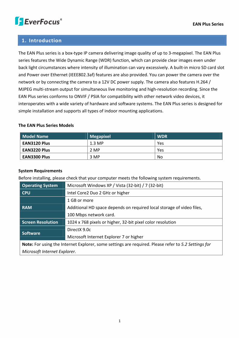
EAN Plus Series
1
1 Introduction
The EAN Plus series is a box-type IP camera delivering image quality of up to 3-megapixel The EAN Plus
series features the Wide Dynamic Range (WDR) function which can provide clear images even under
back light circumstances where intensity of illumination can vary excessively A built-in micro SD card slot
and Power over Ethernet (IEEE8023af) features are also provided You can power the camera over the
network or by connecting the camera to a 12V DC power supply The camera also features H264
MJPEG multi-stream output for simultaneous live monitoring and high-resolution recording Since the
EAN Plus series conforms to ONVIF PSIA for compatibility with other network video devices it
interoperates with a wide variety of hardware and software systems The EAN Plus series is designed for
simple installation and supports all types of indoor mounting applications
The EAN Plus Series Models
Model Name Megapixel WDR EAN3120 Plus 13 MP Yes EAN3220 Plus 2 MP Yes EAN3300 Plus 3 MP No
System Requirements
Before installing please check that your computer meets the following system requirements
Operating System Microsoft Windows XP Vista (32-bit) 7 (32-bit)
CPU Intel Core2 Duo 2 GHz or higher
RAM
1 GB or more
Additional HD space depends on required local storage of video files
100 Mbps network card
Screen Resolution 1024 x 768 pixels or higher 32-bit pixel color resolution
Software DirectX 90c
Microsoft Internet Explorer 7 or higher
Note For using the Internet Explorer some settings are required Please refer to 52 Settings for
Microsoft Internet Explorer
EAN Plus Series
2
2 Overview
2 3 4 6 7 8 9 105 111
No Item Name Descriptions 1 Memory Card Slot Insert a micro SD SDHC card to store recording data 2 Power LED Indicates the power is supplied 3 DC 12V Port Connects to power 4 Ethernet PoE Connects to a 10100 Ethernet or PoE 5 Reset Button Resets all configurations to factory default
6 IO Terminal Block Connects IO devices
7 Video Out Connects to a portable monitor for setting the focus and angle of
the camera during initial installation
8 Audio In Connects to a microphone for audio input Note that microphones
with external power supplies are required
9 Audio Out Connects to a speaker for audio output
10 Light Sensor Detects lights
11 Auto Iris Lens Connector Plug the Iris control cable to the connector
EAN Plus Series
3
3 Features
bull 13rdquo Panasonic CMOS sensor (for EAN3120 Plus 3220 Plus)
128rdquo Sony CMOS sensor (for EAN3300 Plus)
bull Triple streams (stream 1 2 3 from H264 or MJPEG)
bull Up to 30 fps at 1920 times 1080
Supports 15 fps at 2048 times 1536 (only for EAN3300 Plus)
bull Auto Iris control
bull Built-in micro SD SDHC card slot
bull Removable IR-cut filter for Day Night function
bull One alarm input and output
bull Two-way audio
bull TV-out
bull Wide Dynamic Range (for EAN3120 Plus 3220 Plus)
bull 2D 3D Dynamic Noise Reduction (DNR)
bull Motion detection
bull Privacy mask
bull DC 12V PoE
EAN Plus Series
4
4 Installation
41 Packing List
bull EAN Plus Series Camera (lens not included) x 1
bull Software CD x 1
bull Quick Installation Guide x 1
bull Tool Packet x 1 (contains the following items)
- C-mount lens adapter - frac14-20 UNC thread mounting bracket and 2 screws
- Hexagon wrench - Power pigtail cable
Note Contact the shipper if any items appear to have been damaged in the shipping process If any
items are missing notify your EverFocus Electronics Corp Sales Representative or Customer Service
Branch Please also keep the shipping carton for possible future use
EAN Plus Series
5
42 IO Terminal Block
The IO terminal block located on the rear panel of the camera can be used to develop application
for alarm input and output
1 2 3 4
Pin Assignment
No Function No Function
1 Alarm COM 3 Alarm Input
2 Alarm Output 4 Digital GND
43 Lens Installation and Adjustment
You can install either a CS-mount or a C-mount lens into the camera It is recommended to use a lens
with aperture ratio of F14 or smaller Please refer to the following reference steps
C-Mount Lens Adapter
DC Auto Iris Lens Connector
Focus Screw
Zoom Screw
CS-Mount Lens
1 Remove the cover cap from the camera body
2 Install the lens into the camera body
3 Adjust the lens using the Focus Zoom Screws
If you are using a DC Auto Iris lens
1 Remove the cover cap from the camera body
2 Install the lens into the camera body
3 Connect the DC cable to the DC Auto Iris Lens Connector
EAN Plus Series
6
4 When making final focus adjustment place the ND filter in front of the lens to force the lens iris
to open and then adjust the lens using the Focus Zoom Screws
Note To use the ND filter remove the protective sheets from both sides of an ND filter
5 Lock the Focus Screw and then remove the ND filter
C-Mount Lens
1 Remove the cover cap from the camera body
2 Install the lens into the camera body using the supplied C-mount lens adapter
3 Adjust the lens using the Focus Zoom Screws
Note Installing a C-mount lens without the C-mount lens adapter may damage the camera sensor
44 Top Bottom-Mount
You can use the supplied mounting bracket and screw it on the top of the camera body to suspend
the camera or on the bottom of the camera body to support the camera
Top Mount
Bottom Mount
EAN Plus Series
7
45 Basic Connection
Micro SD
Audio
In OutEthernet (PoE)
DC 12VPower
Reset
Video Out
COM
Out In
GN
D
Alarm
1
2
3
3
4
5
1 Use a standard network cable to connect the camera to the network
2 Connect the camera to power using one of the following methods
bull Plugging the supplied power pigtail cable to the DC 12V port
bull Using the PoE function and the power will be provided over the network cable
3 Optionally connect the camera to a speaker or microphone Note that microphones with
external power supplies are required
4 Optionally connect the camera to a monitor using a BNC cable
5 Optionally connect the camera to the input output devices
After powering the camera the power LED will be lit in red and you can access the live view and
adjust the image clarity
EAN Plus Series
8
5 Accessing the User Interface
This section explains how to access the Web interface of the camera for configuration
51 Assigning an IP Address
You have to assign an IP address for your camera to be accessible To assign an IP address to the
camera use the IP Utility (IPU) software included in the software CD Please connect the IP camera in
the same LAN of your computer
1 Install and then start the IPU program The following dialog box appears
2 Click Find Devices to search the cameras connected in the LAN The default network values of the
cameras will be displayed By default the network protocol of the camera is DHCP
3 To configure the network settings select a camera and then click LoginMulti Login to log in
EAN Plus Series
9
4 Type the user ID and password Click OK
Note
1 The default user ID is user1 and the default password is 11111111
2 If you select more than one camera that has the same user ID password you will be able
to log in several cameras at once
5 To change the IP address double-click the IP Address of the camera Type a new IP address and
then click Set IP Address to save the settings
You can also change the other settings by double-clicking the values After configuring the values
click Save Configuration
Note Most networks uses DHCP to assign IP address if you are unsure of your network
settings please consult your network administrators for configuration details
6 To access the camera highlight the camera and click Connect to Selected IP The Internet
Explorer window pops up
7 Type the user ID and password to log in The Live View window of the camera appears
Note You might be required to download ActiveX which is required to view the camera feed
If asked click Yes For more details on setting up the Microsoft Internet Explorer please refer
to 52 Settings for Microsoft Internet Explorer
EAN Plus Series
10
52 Settings for Microsoft Internet Explorer
To enable Remove Live View Firmware Upgrade and ActiveX Prompt on Internet Explorer some
settings have to be complete Please follow the steps below
1 On the computer click Start gt Control Panel gt System and Security gt Action Center (click Change
User Account Control Settings) the User Account Control Settings window appears Adjust the
slide bar to Never Notify and then click OK Restart your computer if requested
2 Open the Internet Explore click Tools gt Internet Options gt Security Tab gt Custom Level the
Security Settings windows appears
EAN Plus Series
11
3 In the Download unsigned ActiveX controls field select Prompt In the Include local directory
path when uploading files to a server field select Enable Click OK
4 In the Internet Options window click the Advanced tab and then disable Enable memory
protection to help mitigate online attacks Click OK
EAN Plus Series
12
53 Connecting the Camera to the Network
There are three methods to connect the IP camera to the network Router or LAN Connection Direct
High-Speed Connection and One-to-One Connection
Router or LAN connection
This is the most common connection in which the IP camera is connected to a router and allows
multiple users on and off site to see the IP camera on a LANWAN (Internet) The camera must be
assigned an IP address that is compatible with its LAN By setting up port forwarding on the router
you can remotely access the cameras from outside of the LAN via the Internet To remotely access the
Web interface of the IP camera please refer to 732 DDNS To set up port forwarding please consult
the manual of the router
Straight-through LAN patch cable
Right Pinout of a straight-through cable
EAN Plus Series
13
Direct High-Speed Connection
In a Direct High-Speed Connection the camera connects directly to a modem without the need for a
router You need to set the static or dynamic WAN IP address assigned by your ISP (Internet Service
Provider) in the camerarsquos configuration web pages To access the camera just type ldquohttpxxxrdquo
where xxx is the IP address given by your ISP If you have a dynamic IP address this connection may
require that you use DDNS for a reliable connection Please refer to 732 DDNS
One-to-One Connection (Directly from PC to IP Camera)
You can connect directly without using a switch router or modem However only the PC connected
to the camera will be able to view the IP camera You will also have to manually assign a compatible IP
address to both the computer and the IP camera Unless the PC has another network connection the
IP camera will be the only network device visible to the PC See the diagram below
Pinout of straight patch cable
Right Pinout of a crossed-over cable
EAN Plus Series
14
54 Live View Window
1 Press the button to display the Live View window Double-click on the
image to show a full-screen display double-click again or press ESC to return to the normal display
If you experience video feed lag time (if connected via Internet) you can reduce the resolution or
limit the number of streams See 741 Multi Streaming
2 Press the button to play the recorded data directly from the on-camera Micro
SD SDHC card (for this function to become active you have to insert a Micro SD SDHC card in the
Micro SD SDHC card slot on the rear panel of the camera See 783 SD Card
3 Press the button to enter the Settings page On the Settings page there are
8 submenu sections [System Info] [User Config] [Network] [Video] [Audio] [User] [Event] and
[System] Click on the section buttons to open their configuration fields See the Settings section
below for more information
EAN Plus Series
15
4 Press the button to exit the system and close this browser page
5 Video Stream
Select the Video Stream (Stream 1 Stream 2 or Stream 3) that will be displayed in the video box on
the right Stream 2 and Stream 3 are only selectable if you have enabled the stream The default
setting is Stream 1 only See 741 Multi Streaming
6 View Size
Use this to select the appropriate view size and shape of the video box on the right A smaller size
might increase transmission speed and video quality
7 Digital Zoom
Click the Zoom In Zoom Out buttons or roll the mouse wheel to zoom in out the camera live view
up to 10x Clicking on a magnified image will re-center the image around that point
8 Record
The Record button is used to record the current video stream Click the Record button to start
stop recording This icon is only for one-minute video recording To record long-period recordings
please set a recording schedule (See 775 Schedule) The location on your computer where the
image files will be saved to and file size can be specified in the submenu (see 72 User Config)
9 Snapshot
Click the Snapshot button to save a snapshot of the video image currently being displayed The
location on your computer where the snapshot data will be saved can be specified in ldquoSettings gt
User Config gt RecordingSnapshotrdquo (see 72 User Config)
10 Play Audio Transmit Audio
Click the ldquoPlay Audiordquo (speaker) and ldquoTransmit Audiordquo (microphone) buttons to switch the sound
onoff for the speaker and microphone respectively (if such external devices have been connected
to the camera directly or via the network)
EAN Plus Series
16
11 One Push
This function is only available for EAN3120 Plus 3220 Plus The One Push button can be displayed
on the live view window by enabling the Show One Push Buttons function on the User Config lt Live
View Config Setting page (see 721 Live View Config) To enable the button (turned from faded to
clear) on the Video lt Advanced Setting page select One Push from the White Balance Settings
Mode drop-down list and click the Apply button Once this is done pressing the One Push button
on the Live View Window will instruct the camera to adjust the white balance settings and these
settings will be active until the button is pushed again This is like a ldquosemi-automaticrdquo way to adjust
white balance to suit the user if the Auto or Manual mode does not give the result the user wants
12 Manual Control
ndash Trigger Event
Press the ldquoTrigger Eventrdquo button to trigger an event directly from the Live page If you have
configured an event (in the Event submenu) that will trigger a reaction (like a recording) when a
Manual Trigger event occurs clicking this button will trigger that reaction You can select what that
reaction will be You can for instance set the camera to record the audiovideo feed to the Micro
SD card on board the camera You can then click on the Playback button to open the Playback page
and search for and play all such recordings that had been stored on the card Such event actions
will be effective once they have been configured in the ldquoEventrdquo menu (see 77 Event)
ndash Reset Alarm
Press the ldquoReset Alarmrdquo button to reset the alarm output remotely
13 Status Display (info lines that can be placed above video box or at bottom of page)
This shows the name of the camera that is currently active or being configured current datetime
and current frame rate You can activate these info displays in the Settings gt User Config page (see
72 User Config)
14 Event Signal Icons (above video screen)
When an alarm or motion event is triggered a signal icon will appear at the top right of the Live
View window to alert the user
Alarm event icon When an alarm is triggered this icon appears
Motion detection icons The colors of these motion event icons correspond to the colors of the motion trigger areas you have configured in the Motion Detection submenu (see 772
Motion Detection)
Recording icon When the camera is recording to a PC-based folder this icon appears
EAN Plus Series
17
6 Playback
You can remotely play back the recordings stored in the on-camera micro SD card on the Web interface
or play back the recordings stored in the computer using the ARV Viewer included in the software CD
Playback is designed as a quick way to check recent recordings that were triggered by Events that were
configured to ldquoRecord to SD Cardrdquo in the Settings gt Event gt Event Settings page (see 771 Event
Settings)
Note Note that the Playback page is only accessible once the on-camera SD card is inserted and
active
61 Remote Playback Using Playback Page
On the Live View Window click the Playback button to open the Playback page
EAN Plus Series
18
Search by File Click the Search button to search for all recording files on the on-camera SD card
Search results will be displayed in the Filename area
Search by Time Click the calendar icon and select the date and time from which you want to search
until the present moment Click search to get your search results which will be displayed in the
Filename area
Search by event Click the type of Event recordings you want to search for (Alarm Motion Manual
Trigger) and then click the calendar icons to select the Start Time datetime and the End Time
datetime of your search Click Search to get your search results which will be displayed in the
Filename area
Multiple Files Check this box if you want the video player to play all the files in the selected folder
The files will be displayed in the Filename area
Loop Again Check this box if you want the video player to play the selected file over and over again
Play Once you have opened the filersquos folder and have clicked on the file to highlight it its details will
be displayed in the File Information area You can now click Play to play that specific file
Pause Click this button to pause the playback
Stop Click this button to stop the playback
【Recording List】
Filename This area will display a list of search results (recording files and folders) Folders (named
with the recorded date) will be displayed first Click on the folder and click on each subfolder until the
recording files (arv) in that folder is listed
File Information Click a file on the Filename list the selected file information will be listed
Copy Click this button to copy the selected file to the computer-based folder of your choice A
browsing box will open so that you can search for the folder of your choice You can use the ARV
Viewer to play back the recordings recorded in your computer For details on ARV Viewer see 63
Playing Back Using ARV Viewer
Lock Click this button to lock the selected file This will protect that file from being overwritten during
any overwrite procedure The file will thus be saved on the micro SD card indefinitely However the
file will still be deleted if the micro SD card is ever formatted
Remove Click this button to delete the selected file
EAN Plus Series
19
62 Setting up the Playback Function
Note that the Playback function will not be active until the user has inserted a micro SD card in the
camerarsquos micro SD card slot The card may also have to be formatted in the Settings submenu
Micro SD Card Slot
621 Preparing the Micro SD Card
Once you insert a functional micro SD card into the slot the Playback button on the Live page should
become active within seconds (see section 622 below ndash the grey letters should turn white) IF NOT
do the following
1 From the Live page click Settings gt System gt SD Card If no card has been inserted yet the
Remove button should be faded indicating that no card is being detected (If a card is
inserted and the Remove button is still faded pull the card out and re-insert it)
2 Slide the card into the slot until it clicks into position
3 The Remove button should become active within a few seconds indicating the card is active
4 If the Remove button stays faded click the Format button to format the card NOTE All data
on the disk will be deleted if the Format button is clicked
622 Testing the Playback Function
1 Once the SD card is detected by the system the button (inactive)
will turn to (active)
2 To test the Playback function (this is not required) set up a ldquoManual Triggerrdquo Recording
Event by clicking Settings gt Event gt Event Settings
3 Click the ldquoAddrdquo button on the middle right side of the page to open an ldquoAdd Eventrdquo box
4 Give the event a name like ldquoTest 1rdquo
EAN Plus Series
20
5 In the ldquoEvent Triggered byrdquo field click on Manual Trigger
6 Below this check ldquoEnable This Eventrdquo ldquoEnable Post-trigger Bufferrdquo and ldquoRecord to SD Cardrdquo
7 To save your settings click OK or close the box by clicking on the red x icon at top right of the
box (in which case you will be asked if you want to save the data to which you should reply OK)
The box will close and the new event will be listed in the list area of the Event Settings page
8 Look at the ldquoPost-trigger Bufferrdquo at the bottom to make sure the buffer time is set to 10 seconds
9 Click ldquoApplyrdquo to make sure all settings are saved
10 Click the Live button to go back to the Live page
11 Get ready to click the Trigger Event button at the bottom of the page Before you do see if you
can find something in the view screen that will give you a visual time marker For instance if you
can get your hand in front of the camerarsquos lens get ready to count down on your fingers
12 Click the Trigger Event button and slowly count down on your fingers in front of the lens (if you
are able to do so ndash if not try to find visual cues on the view screen that will help you to mark the
moment you pushed the trigger) The recording period will be as long as the buffer time you
selected ndash the default period is 10 seconds
13 Click the Playback button to open the Playback page
14 There are different ways to search for recording files on the camerarsquos Micro SD card (ie the
Playback memory) For a recent recording like your test event simply click the ldquoSearchrdquo button
under the ldquoSearch by Filerdquo header
15 If the SD card is active and formatted correctly the recording folderrsquos name (the recording dayrsquos
date) will appear in the Filename box at the bottom Click on this folder to open it If there are
sub-folders click on the bottom one (the most recent would be at the bottom) until you can click
on a file that cannot open to another sub-level and shows data in the File Information box to the
right This would be the file of the most recent recording event
16 To play this file click the Play button below the video box The test footage you have recorded
should start playing Play time should be 10 seconds if you left the Post-trigger Buffer as 10
seconds
EAN Plus Series
21
63 Playing Back Using ARV Viewer
You can play back the recordings stored in the computer using the ARV Viewer included in the
software CD To store the recordings in the computer please refer to Recording List gt Copy in 61
Remote Playback using Playback Page
4 5 6 7 8 9 10
321
No Item Name Descriptions
1 Snapshot Click to take and save a snapshot
2 Load File Click to load the recordings for playing back
3 Convert ARV to AVI Convert the recording from ARV format to AVI format
4 Playback Time Display the playback time
5 Total Time of Recording Display the total time of the recording
6 Stop Click to stop playing the recording
7 Step Reverse Click to display the previous frame
8 Play Click to play back the recording
9 Pause Click to pause the recording
10 Step Forward Click to display the next frame
EAN Plus Series
22
7 Settings
Click the Settings button on the Live View Window to enter the settings submenu There are nine buttons
on the left-side of the submenu Live System Info User Config Network Video Audio User Event and
System Click the Live button can go back to the Live View Window
71 System Info
The System Information and System Log can be checked on this page Click the top tab of the one you
want to see
711 Information
Click the Information tab the following dialog box appears These values cannot be changed on this
page and are for reference only
EAN Plus Series
23
712 Log
Click the Log tab the following dialog box appears The sequence number date time and event
messages of the log event will be displayed in the System Log field The log will display the last 256
log events Click the Export button to export the system log event list into a ldquotxtrdquo file and select the
location where the exported log file will be saved to
EAN Plus Series
24
72 User Config
Each user can set a different configuration for hisher Live page here These settings will be applied to
the logged-in userrsquos Live page every time heshe logs in
721 Live View Config
【VideoAudio Connection Protocol Setting】You can transmit the data stream from the IP cameras
using the RTSP (Real Time Streaming Protocol) on the network The RTSP is a protocol that allows
you to access video streams by using the compatible media players Click Apply to apply the
changes or Reset to reset without saving the changes RTP over UDP The RTSP protocol uses UDP for camera data stream transmission
RTP over TCP The RTSP protocol uses TCP for camera data stream transmission
RTP over HTTP The RTSP protocol uses HTTP for camera data stream transmission
Nevio CGI This is EverFocusrsquo protocol designed for EverFocusrsquo IP devices Select this
protocol for camera data stream transmission
【Text Settings】Check the box of each option (Machine name DateTime Frame Rate) to display
this info on the Live View Page
Foreground Color Slide the Red Green and Blue bars to create your preferred text color for the
info text line
Position Select the position where the text will be displayed Choose from Upper Left Lower
Right Lower Left
Click Apply to apply the changes or Reset to reset without saving the changes
EAN Plus Series
25
【DateTime Format Used in Text】Click the dropdown menu to select datetime format from the
listed options Click on the desired hour format Click Apply to apply the setting changes or Reset to
reset without saving the change
【Live View Layout Settings】 Check the ldquoShow One Push Buttonsrdquo boxes if you want to show these
buttons on the Live View Page Uncheck these boxes to hide these buttons This function is only
available for EAN3120 Plus 3220 Plus
722 Recording Snapshot
This configures where your Record Button and Snapshot Button ( ) files will be saved if
you click one of these buttons Selectable folders will be on the computer only not on the
on-camera SD card
【Recording Snapshot Export Settings】
Enable Event Recording to PC Checking this box will let the system save RecordSnapshot Button
recordings to the folder configured below on the userrsquos PC
Export Folder Select the Export folder for the action above by clicking on the browse (hellip) button
and then select the desired folder
File size The user can limit the size of each recorded file here (in minutes) When a single
recording file exceeds the time you set the system will create a new file to save that data to
Overwrite Select ldquoONrdquo for overwriting recordingsnapshot file when the disk storage capacity is
full The user can set the storage capacity limitation in the in-sentence field in the gray box below
the Overwrite setting ldquoIf the remaining hard disk capacity is less than ____ MB (50~2000) system
will stop recording or start overwriting ldquo
Click Apply to apply the setting changes or Reset to reset without saving the changes
EAN Plus Series
26
723 Language
Select the language to be displayed on the Web interface of the IP camera The default language is
English
To add a new language not listed in the current Language list click the Browse button to locate
the new language file (evb) on your computer and then click the Upload button Updated
language files might be available on the manufacturerrsquos website Contact your vendor if required
Click Apply to apply any changes or Reset to reset without saving the changes
Note Uploading a new language file will cause the system to reboot automatically Please create
a new network connection to the IP camera when the reboot is complete
EAN Plus Series
27
73 Network
This page covers network-related settings including Network DDNS SMTPFTP HTTPS SNMP and
Network Alarm
731 Network
The following information is required to configure the network settings Contact your network
administrator or your internet service provider to get the info
【IP Settings】
IP Type Refer to the network administrator for these settings of the server Default DHCP
DHCP This setting lets the system use an automatically assigned (dynamic) IP address This
address can change under certain circumstances For instance when the camerarsquos network
switchhub has to be rebooted Do not assign to the DHCP server the same IP addresses used
for the other network cameras and PCs with unique IP addresses
Static IP The user can manually set the Static IP address This type of address is stable and
cannot change but the user has to make sure there are no address conflicts with other
network-connected devices
PPPoE This is a DSL-connection application The ISP will ask the user to input a username and
password Contact your ISP for these details
EAN Plus Series
28
Note If PPPoE is selected as the IP type the supplied IP Utility program will not be able to
detect the device
IP address When DHCP is not used the user needs to manually enter the IP address of the
camera Do not enter an IP address that is already used for your computer or other network
cameras
Subnet Mask This field is used to set the netmask for your network so that the IP camera will be
recognized within the network Example 2552552550 When DHCP is selected the DHCP server
will assign this value automatically
Gateway This field is used to set the gateway for your network so that the IP camera will be
recognized within the network When DHCP is selected the DHCP server will assign this value
automatically
Primary DNS Enter the IP address of the DNS server if this is provided by an ISP
Secondary DNS If your ISP provided you with a secondary DNS address please enter it here
Username Enter the accountrsquos username (used only for PPPoE)
Password Used only for PPPoE
IPv6 Enter the IPv6 details in this area if this applies to your system
Click Apply to apply the setting changes or Reset to reset without saving the change
【Port Settings】Enter the HTTP HTTPS and RTSP port numbers and click Apply to save
【Multicast Settings】Enable if required fill in the setting options and click Apply to save
EAN Plus Series
29
732 DDNS
DDNS (Dynamic Domain Name System) is a service used to map a domain name to the dynamic IP
address of a network device You can set up the DDNS service for remote access to the IP camera
DDNS assigns a domain name (URL) to the IP camera so that the user does not need to go through
the trouble of checking if the IP address assigned by DHCP Server has changed Once the IP is
changed the IP camera will automatically update the information to the DDNS to ensure it is always
available for remote access
Before enabling the following DDNS function user should have applied for a host name from the
DDS service providerrsquos website We support these four DDNS server providers
wwweverfocusddnscom wwwsitelutionscom wwwdyndnscom and wwwno-ipcom
Note We highly recommend that you use xxxxeverfocusddnscom for the simplicity of setting up
your IP cameras
【DDNS Settings】
Enable Check this box to enable the DDNS function
Service ISP You can either apply for a host name from EverFocus or other DDNS server providers
If you choose the EverFocus DDNS server you can obtain a free host name from EverFocus by
following the steps below
bull From EverFocus To obtain a free host name from EverFocus type a desired host name in the
textbox click the Register Update button and then click the Apply button
bull From other DDNS server providers To obtain a domain name from one of the three DDNS
server providers you have to register your name with the provider first and then select the
provider and fill in the required information Please refer to the specific DDNS companyrsquos
website for further information
Record ID Type the record ID if provided by the DDNS server provider
EAN Plus Series
30
FQDN Type the fully qualified domain name applied from the DDNS server provider For
example xxxxdyndnscom
Username Password Type the login account of your DDNS server provider
Click Apply to apply the setting changes or Reset to reset without saving the changes
Note
1 In order to support the full functionality of the camera you must open the port numbers (80
554 443) on the router for remote access to the IP camera This function is available on most
routers in the market and is often known as ldquoPort Forwardingrdquo To set up Port Forwarding
please consult the manual of the router
2 In certain router models it is possible that you will not be able to access the camera using
DDNS while inside the routerrsquos network Please try using a PC located outside of your routerrsquos
network
Default Ports on All EverFocus IP Cameras
HTTP 80
RTSP 554
HTTPS 443
EAN Plus Series
31
733 SMTP FTP
【Set SMTP Server (email)】This area is for configuring the mail server that is used to send e-mail
notifications from the camera to predefined addresses via SMTP Note that to enable e-mail
notification function you have to check the Send Mail Notification item on the Event dialog box
(see 771 Event Settings)
SMTP Server Enter the IP address or the host name of the SMTP server used to send e-mails
SMTP Port Enter the port number for SMTP The default is 25
Authentication Check this box if the SMTP server requires authentication (userpassword)
User name Input the userrsquos login ID if the SMTP server requires authentication
Password Input the userrsquos login password if the SMTP server requires authentication
EAN Plus Series
32
Receiver Address Input the e-mail addresses for receiving an e-mail message when an EVENT is
enabled and triggered Please use ldquordquo to separate multiple addresses
Sender Address Input the senderrsquos e-mail address so that the receiver can recognize the sender
when an Event message is received
Attach Image Check this box if you want to attach an image when an alarm is triggered or an IP
camera detects events
Send Test Email Click the Test button to send a testing email to the assigned address
Click Apply to apply the setting changes or Reset to reset without saving the changes
【Set FTP Server】The settings relating to the FTP server used to transmit the alarm images can be
configured here Note that to enable uploading images to the FTP server function you have to
check the Upload to FTP item on the Event dialog box (see 771 Event Settings)
FTP Server Enter the IP address or the host name of the FTP server
FTP Port Enter the port number for the FTP server Default is 21
Recording Path Assign the recording path
User Name Set FTP Userrsquos name
Password Set FTP password
PASV mode Check to enable Passive mode Passive mode is normally enabled If a connection
cannot be established uncheck PASV Moderdquo
Test FTP Server Click the Test button to send a testing file to the assigned FTP server
Click Apply to apply the setting changes or Reset to reset without saving the changes
EAN Plus Series
33
734 HTTPS
Hypertext Transfer Protocol Secure (HTTPS) is a combination of the Hypertext Transfer Protocol
and the SSLTLS protocol and provides encrypted communication and secure identification of a
network web server
Before using the HTTPS function for communication with the IP camera a Certificate must be
created first There are two ways to create and install a certificate Create Self-Signed Certificate
and Create Certificate Request
Create Self-Signed Certificate
Please note that even though self-signed certificates are free and offer some protection true
security is only implemented after the installation of a signed certificate issued by a certificate
authority
1 Click the Create Self-Signed Certificate button the following dialog appears
EAN Plus Series
34
2 Type the required Certificate information and then click the Apply button The subject line will
be displayed in the Installed Certificate Information field
3 Click the Property button a pop-up window appears to display the details of the certificate
4 To optionally create and install other certificates remove the existing one by clicking the
Remove button to erase the certificate
5 On the Web page change the address from ldquohttprdquo to https in the address bar and press
Enter on the keyboard Some Security Alert dialogs will pop up Click OK or Yes to enable HTTPS
Create Certificate Request
You can apply for an official certificate from an issuing Certificate Authority
1 Click the Create Certificate Request button the following dialog appears
EAN Plus Series
35
2 Type the required Certificate information and then click the Apply button The subject line will
be displayed in the Created Request field
3 Click the Property button a pop-up window appears to display the details of the certificate
4 To optionally create and install other certificates or request remove the existing one by clicking
the Remove button to erase the certificate or request
5 Copy the contents of the Certificate request (in PEM format) and paste it to the certificate
request field on the Web page of the 3rd-party certification authority such as Symantec VeriSign
Wait for the certificate authority to issue an SSLTLS certificate and then download the issued
certificate on your computer
6 In the Install Signed Certificate field click the Browse button to search for the issued certificate
and then click the Upload button to import the certificate Once the certificate has been
uploaded this field will show the subject line of the certificate
EAN Plus Series
36
735 SNMP
The default values for SNMP v1v2v2c and SNMP v3 are already filled in Click either of the
Enable buttons to enable either of the two Make your changes as desired Click on the Trap
Address field to enter the digits if required
736 Network Alarm
This function works with EverFocusrsquos CMS software eg the PowerCon or the Power Video Plus For
the setting details please refer to the CMS network alarm protocol
EAN Plus Series
37
74 Video
The settings relating to video such as streaming camera OSD can be configured on this page The
Video page has five tabs Multi-streaming Camera Advanced ROI and Privacy Mask
741 Multi Streaming
【Stream Settings】 This IP camera can output three video streams simultaneously For each of these
streams the user can set the compression format resolution bit rate and frame rate individually
Stream 1 is always enabled for live view To enable Stream 2 andor Stream 3 check the ldquoEnablerdquo
box the header of each stream
Note If you connect to the camera via the Internet and experience a delay (lag time) in the video
feed try to reduce the number of streams and the quality and resolution of the streams ndash but
keep the frame rate at its maximum
EAN Plus Series
38
Format Select the encoding format ndash H264 or MJPEG
Resolution Select the most suitable resolution for your needs
Frame Rate Select from 1 to 30 fps
Bit Rate If required select whether you want the stream to stream a Constant Bit Rate or a
Variable Bit Rate and set the values of whichever option you choose
Click Apply to apply the setting changes or Reset to reset without saving the changes
【Video Recording Settings】Select the stream you want to configure and then select whether you
want the recording files of that stream to be saved in AVI or ARV format Click Apply to apply the
setting changes or Reset to reset without saving the changes
【Time Stamp Settings】 You can select the DateTime format position and add the setting to the
streaming
Click Apply to apply the changes or Reset to reset without saving the changes
EAN Plus Series
39
742 Camera
【Image Settings】Set the Brightness Saturation Contrast or Sharpness of the image Click Apply to
apply the changes or Reset to reset without saving the changes
【Camera Settings】
Mirror Switch Mirror ON to rotate the image horizontally around a vertical axis
Flip Switch Flip ON to rotate the image vertically around a horizontal axis
AE There are two options
ALC Selecting Automatic Light Control allows the camera circuitry to either take bright spots
more into consideration (peak) bringing out detail in bright areas or less into consideration
(average) bringing out detail in shadows
AES Selecting Auto Electronic Shutter disables the Shutter setting below this setting In this
mode the camera measures the light level and decides whether it needs more or less light and
then automatically adjusts the shutter speed accordingly
BLC Back Light Compensation (BLC) is used to make the subject appear clearer when it is set
against a bright background
OFF Select to switch Back Light Compensation functions off
(ON)BLC The BLC can increase the exposure of a dark area surrounded by a brighter area HLC
can decrease the exposure of bright areas surrounded by darker areas This enables the
camera to better display information that would otherwise have been ldquowhited outrdquo like a
license plate between two bright headlights on a dark road
(ON)HLC The Highlight-Suppression BLC is used to reduce the brightness of light sources in a
specific area It is activated only in a low illumination environment to minimize the effects of
glare from bright lights such as spotlights street lights or headlights in the field of view
EAN Plus Series
40
WDR The Wide Dynamic Range (WDR) function provides clearer images when both of the very
bright and dark areas simultaneously appear on the camera view There are four value options
OFF Low Middle and High Note that when WDR is ON some parts of the image may appear
solarized This is normal for WDR and is not a camera malfunction This function is only available
for EAN3120 Plus 3220 Plus
DN Mode
Auto Select to let the camera automatically switch to Night mode (black and white) when the
light levels fall to a specified level and back to Day mode (color) when the light levels rise to a
specified level
Day Select to keep the camera in Day mode (color) even in nighttime
Night Select to keep the camera in Night mode (black and white) even in daytime
EAN Plus Series
41
743 Advanced
EAN Plus Series
42
【Camera Settings】
Lens (IRIS Control) Select DC or Manual for IRIS control This function is only available for EAN3220
Plus
Exposure Settings (AE) This setting is used to adapt to the amount or type of light used by the
camera Note the settings vary among models
Mode This function is not available for EAN3220 Plus
Automatic Light Control (ALC) This option is only available for EAN3120 Plus 3300 Plus The
ALC allows the camera circuitry to either take bright spots more into consideration (peak)
bringing out detail in bright areas or less into consideration (average) bringing out detail in
shadows
Auto Electronic Shutter (AES) This option is only available for EAN3120 Plus 3300 Plus In
this mode the camera measures the light level and decides whether it needs more or less light
and then automatically adjusts the shutter speed accordingly
Manual This option is only available for EAN3300 Plus Select this option to manually set up
the Shutter (Manual) and AGC (Manual) values
Iris Specify the size of the Iris opening here
Shutter If enabled this setting lets you set the shutter speed yourself
Shutter Limit Use this setting to set the maximum shutter speed for the camera This function is
only available for EAN3120 Plus
AGC Set the Auto Gain Control limit here The lower the AGC level the lower the video signal and
the noise However the image will be darker under low-light condition with IR-off if you set up the
Iris to the maximum level
Slow Shutter This option can be switched on when AES Mode is selected in the Exposure Settings
(AE) field This function is only available for EAN3220 Plus 3300 Plus
Flickerless If the Mode field in the Exposure Settings (AE) area has been set to AES then this option
becomes available Choose between OFF 50HZ 60HZ 50HZ (High Luminance) or 60HZ (High
Luminance) This function is only available for EAN3300 Plus
EV Setting Set up the Exposure Value Note the brightness of the screen changes when you change
the EV value This function is only available for EAN3300 Plus
AE Response Set up Auto Exposure Response time This function is only available for EAN3300 Plus
AE Weighting Area Select an AE Weighting area Each setup AE Weighting Area is configured with
the appropriate brightness level on the center and the surrounding areas This function is only
available for EAN3300 Plus
Brightness Set the image brightness here
AE Reference Set the Auto Exposure value here This function is only available for EAN3120 Plus
EAN Plus Series
43
Black Level Set the Black level here This function is only available for EAN3300 Plus
WDR The Wide Dynamic Range (WDR) function provides clearer images when both of the very
bright and dark areas simultaneously appear on the camera view There are four value options OFF
Low Middle and High Note that when WDR is ON some parts of the image may appear solarized
This is normal for WDR and is not a camera malfunction This function is only available for EAN3120
Plus 3220 Plus
Visibility Enhancement (OFFLowMiddleHigh) Images in foggy or rain environments or in
environments with a very strong luminous intensity have a dynamic range that is significantly lower
than ordinary images The user can use this Visibility Enhancement setting to ldquoDEFOGrdquo the image if
such ldquoFOGGINGrdquo is an issue This function is only available for EAN3220 Plus
BLC Settings Back Light Compensation (BLC) is used to make the subject appear clearer when it is
set against a bright background
OFF Select to switch Back Light Compensation functions off
Back Light This option is only available for EAN3300 Plus The Back Light function is useful
when the background of the subject is very bright and the subject itself is dark Select Back
Light and adjust the slide bar to the left right for setting up the back light value The higher
the value the more the backlight compensation
Front Light This option is only available for EAN3300 Plus This function is useful when the
bright highlights such as flashlight or car headlights appear on the camera view Select Front
Light and adjust the slide bar to the left right for setting up the front light value The higher
the value the more the highlight compensation
ON (BLC) This option is only available when you select AES Mode in the Exposure Settings (AE)
field The option is only available for EAN3120 Plus 3220 Plus The BLC function is useful
when the background of the subject is very bright and the subject itself is dark Follow the
instructions below to configure the settings for each model
For EAN3120 Select ON (BLC) the button next to the Mode drop-down list will be
active (see image below) Click the button the green setup areas appear on the left
screen Click on the areas to enable disable the BLC function The selected areas (in green)
will be applied with the BLC function
EAN Plus Series
44
For EAN3220
You can configure one area to apply the BLC function Select ON (BLC) the setup buttons
appears (see image below) Select Low Middle High from the BLC Gain drop-down list To
set up a BLC area click the Edit Area button and then click on the blue color tab to turn your
mouse cursor into a blue pen Move the cursor to the position on the right screen where you
want the BLC rectangle to start and then click Move your cursor to the position (diagonally
opposing corner) where you want the BLC rectangle to end and then click The blue area will
be applied with the BLC function
ON (HLC) This option is only available when you select AES Mode in the Exposure Settings (AE)
field The option is only available for EAN3120 Plus 3220 Plus This function is useful when
the bright highlights such as flashlight or car headlights appear on the camera view Follow
the instructions below to configure the settings for each model
For EAN3120 Select ON (HLC) and then select a level from the drop-down list The higher the
level the more the highlight compensation
For EAN3220
HLC Level Select a level for the HLC setting The higher the level the more the highlight
compensation
HLC Mode Select All Day Night mode to apply the HLC function
HLC Black Mask Select On Off to apply the black mask on the selected areas The
over-exposure portions within the selected areas will be applied with the black mask
Color Tabs You can set up four HLC areas with different colors To set up a HLC area click the
Edit Area button and then click on the color tab to turn your mouse cursor into a pen of that
color Move the cursor to the position on the right screen where you want the HLC rectangle
to start and then click Move your cursor to the position (diagonally opposing corner) where
you want the HLC rectangle to end and then click Select ON from the color tab drop-down list
The rectangular area with the selected color will be applied with the HLC function
EAN Plus Series
45
Back Light This option is only available for EAN3300 Plus The Back Light function is useful
when the background of the subject is very bright and the subject itself is dark Select Back
Light and adjust the slide bar to the left right for setting up the back light value The higher
the value the more the backlight compensation
Front Light This option is only available for EAN3300 Plus This function is useful when the
bright highlights such as flashlight or car headlights appear on the camera view Select Front
Light and adjust the slide bar to the left right for setting up the front light value The higher
the value the more the highlight compensation
Noise Reduction Settings This limits the amount of digital ldquovideo noiserdquo that is usually found in any
video stream and helps to reduce file size The higher the level the more the reduction
For EAN3120 Plus 3300 Plus
Select ON OFF to enable disable the Noise Reduction function Or select Auto to let the camera
automatically enable disable the Noise Reduction function Slide the Level bar to set up the level
The higher the level the more the reduction
For EAN3220 Plus
2D DNR Select ON to enable the 2D DNR function
3D DNR Select ON to enable the 3D DNR function You can further set up the following settings
3D Start AGC Set up the AGC level to automatically start the 3D NR function
3D End AGC Set up the AGC level to automatically stop the 3D NR function
3D Level Set up the 3D DNR level
Smart NR Select ON to enable the Smart NR function The 3D NR function will be
automatically turned on when a motion event occurs
EAN Plus Series
46
White Balance Settings Select the mode that delivers the best quality image for the camerarsquos light
environment There are five options Auto Manual Indoor Outdoor One Push
Auto Select to let the camera automatically adjust the White Balance In the Auto mode the
camera computes the white balance value output using color information from the entire
screen It outputs the proper value using the color temperature radiating from a black subject
based on a range of value from 3000 to 7500K
Manual Select to adjust the Red and Blue values yourself in the fields below this field
Indoor Select to use the default settings for indoor environments In the Indoor mode the
camera uses 3200K as the base value
Outdoor Select to use the default settings for outdoor environment In the Outdoor mode it
uses 5800K as the base value
One Push Select to enable the Push button next to the Mode drop-down field This will allow you to force the camera to readjust the white balance every time you push the Push
button The lens will hold the same focal position until the next trigger command is received
This function helps to prevent incorrect focusing in dark environments This function is only
available for EAN3120 Plus 3220 Plus
Manual Temperature Select to use the optimized Red and Blue settings You can also
optionally adjust the Manual Level below this field for setting up the color temperature The
higher the value the more the color temperature This function is only available for EAN3300
Plus
DayNight Settings
Auto Select to let the camera automatically switch to Night mode (black and white) when the
light levels fall to a specified level and back to Day mode (color) when the light levels rise to a
specified level
Day Select to keep the camera in Day mode (color) even in nighttime
Night Select to keep the camera in Night mode (black and white) even in daytime
IR Smart Settings Select ON and set up the level to enhance the image quality when the images are
over exposure This function is useful when the camera is in the Night mode This function is only
available for EAN3220 Plus
Saturation Set the saturation value This function is not available for EAN3220 Plus
Monitor Type Select a gamma value from Set 1 Set 2 or Set 3 This function is only available for
EAN3120 Plus
Negative Switch this setting ON to view a color negative version of the video image This is useful
at night or when viewing temperature-sensitive images
EAN Plus Series
47
Sharpness Settings Select the sharpness level of the image A low sharpness level will deliver a
softer less detailed image A high level will deliver a sharp highly detailed image Switch Resolution
Enhancement ON to enable the resolution enhancement function
Contrast Select the contrast level of the image
Suppress Function This function is only available for EAN3300 Plus
Aperture Compensation Suppression (OFFLowMiddleHigh) This setting can be activated to
suppress luminance noise when the AGC level increases
Chroma Suppression (OFFLowMiddleHigh) This setting can be activated to suppress
chrominance noise when the AGC level increases
Ygamma (gamma 22standardcontrast enhancehigh light range mode LHigh light range mode
H) Select the Ygamma value for the video quality of the monitor This function is only available for
EAN3300 Plus
Monitor Settings The user can use this field to optimize video quality for his or her specific type of
monitor ndash LCD or CRT This function is only available for EAN3220 Plus
Color Space Standard The options are YUV601 for SD and YUV709 for HD These define the color
space standard required to convert an RGB picture to a YUV picture Generally YUV601 is used for
Standard Definition (720P) devices and the YUV709 is used for High Definition (1080P) devices
Click Apply to save all changes Click Reset to cancel all changes
EAN Plus Series
48
744 ROI (Region of Interest)
The Region of Interest (ROI) function allows users to set up multiple regions within an image with
better quality and less distortion than the rest of the image You can also use this function
together with the Digital Zoom function on the Live View Page to get a better image result Up to
eight ROIs can be configured in the ROI settings page
To set up an ROI region
1 Select an ROI number from the ROI No drop-down list
2 Click the Add button the mouse cursor will turn into a pen when you move it over the live
image on the left
3 Move the cursor to the position where you want the ROI rectangle to start and then click
Move the cursor to the position (diagonally opposing corner) where you want the ROI
rectangle to end and then click
4 Slide the Quality bar to set up the quality value
5 Click the Apply button to apply the settings or click the Reset button to reset without saving
the settings
EAN Plus Series
49
745 Privacy Mask
The Privacy Mask can block out sensitive areas from view covering the areas with colored or black
and white boxes in both live view and recorded clips This feature is useful when usersrsquo donrsquot want
the sensitive information visible Up to four Privacy Masks can be configured
【Privacy Mask Color Settings】The Modes vary among camera models
Mode Click Color to make the masks appear as colored rectangles on the screen Click BW to
make the masks appear as gray rectangles on the screen Click Mosaic to make the masks appear
as mosaic-effect rectangles on the screen
Level Select the color of the masks if you selected Color Mode Select the level of grayness of the
masks if you selected BW Mode Select the level of smallmiddlelarge if you selected Mosaic
Mode
Click Apply to apply the settings or click Reset to reset without saving the settings
Color Tabs Click on a color tab to turn your mouse cursor into a pen of that color
You can now create a block of that color on the video screen Move your cursor to the position
where you want your mask rectangle to start and then click Move your cursor to the position
(diagonally opposing corner) where you want your mask rectangle to end and then click The
rectangular area with the selected color will appear The live image will display the rectangular
area with the color you selected If you want to create another mask use one of the other three
colors Each color denotes a different mask area Only one block per color is allowed As the
number of colors suggests you can configure up to four blocks
EAN Plus Series
50
Select All Click to turn the whole screen into a mask area
Clear All Click to delete all configured mask blocks
Eraser Click to turn the mouse cursor into an eraser to delete any block you click on
Area Shows the color and number of the block
Enable Check this box to enable the related mask block
Click Apply to apply the settings or click Reset to reset without saving the settings
EAN Plus Series
51
75 Audio
The EAN Plus series IP camera can transmit audio to your computer if you have connected an external
microphone to its audio Input cable It can also receive audio input from you and transmit it via an
external speaker if you have connected such a speaker to its audio Output cable
Check the Enable Audio box to enable the camerarsquos audio function The camera will now act as a
digital bridge (via the IP network) between any connected audio input device and any connected
audio device
Adjust the Audio Input Volume if you have external audio input devices (microphones) connected to
the camera and if there are problems with the sound input being too low or high
Click Apply to save all settings or click Reset to cancel
EAN Plus Series
52
76 User
761 User Information
The system administrator can create up to ten user accounts on this page
To set up a user account
1 Highlight a user account and click the Modify button The following dialog box appears
2 Type the account name account description and password for the account Type the password
again in the Confirm field
3 Select an authority level for the user account from the Authority drop-down list
bull Supervisor Administrator The only difference between a supervisor and administrator is
that a supervisor can edit an administratorrsquos account and password but an administrator
cannot edit the supervisorrsquos account and password Multiple administrators can be
configured but there can be only one supervisor The supervisor and administrators all
have unrestricted access to the Settings submenus and can determine the registration of
all other users
EAN Plus Series
53
bull User A user can view the Live View page and view the system network video and audio
information A user can only adjust the User Config page settings The user does not have
access to the User Event and System pages
bull Guest The lowest level of access which only allows the user access to the Live View page
4 Select Active or Disable from the Status drop-down list to active or disable the user account
5 Click On in the SD Card Playback field to allow the user to access the SD card playback
function
6 Click OK
7 Click Apply to save all the settings
EAN Plus Series
54
762 IP Address Filter
Use this page to specify IP addresses that are not allowed to access this camera By default any IP
address can access the camera
Note The Allowed List addresses only become relevant when the Denied List contains a network
or range and the supervisor wants to allow one or more IP addresses within that excluded range
or network In such a scenario the user would enter the excluded range or network in the
Denied List and enter the exceptions in the Allowed List
To set up the IP Address Filter
1 Select Denied List Click the Add button the following dialog box appears
2 Select an IP type from the IP Type drop-down list
3 Select a network rule from the Rule drop-down list type the IP address and click OK
Single Type a single IP address in the IP Address field below
Network Type the IP address and subnet mask in the field below
Range Type a range for the IP addresses
4 If you have set up an IP range in Step 3 you can optionally set up the Allowed List to allow one
or more IP addresses within the setup IP range to access the IP camera
5 Click Apply
EAN Plus Series
55
77 Event
You can set up the Motion Detection event Tamper Detection event or the Alarm IO to automatically
notify the users when an event occurs or an alarm is triggered You can also set up a schedule to
automatically record the videos when an event occurs or an alarm is triggered
771 Event Settings
You can create a total of ten event or alarm settings page in the Event List
【Event List】
Click the Add button and the following Event Configuration Window appears
EAN Plus Series
56
Enter Event Name Type an event name
Event Triggered by Select an event or alarm type for the to-be-specified-below reactions
Alarm Input Select this if you want a reaction trigger coming from any external connected sensor
to activate a to-be-specified-below reactions via the camera system Make sure that a suitable
device is actually connected to the alarm input relay
Manual Trigger Select this option if you want to manually trigger the alarm by clicking the Trigger
Event button on the Live View Page
Motion Detection Select this option if you want motion in a specified part of the camerarsquos viewing
rectangle (the screen image) to trigger the to-be-specified-below reactions
Tampering Detection Select this option if you want the camerarsquos tampering detection sensor to
trigger the to-be-specified-below reactions
Schedule Recording Select this option if you want the Schedule Recording periods configured in
the recording schedule (the Settings gt Event gt Schedule page) to activate this event In this
scenario a preconfigured event reaction like a log entry will list the start and end times of each
period Actual recording will only be triggered if the event is preconfigured to do so
Enable This Event Select to activate the event
Enable Re-trigger Click to set a minimum time after the event is triggered before the event
can be triggered again
Enable Pre-trigger Buffer Click if you want the Event reaction (as selected in the ldquoNotification
Overrdquo field below) to be the activation of the video recording function and if you want the
recording to include the video feed from the time period (configurable on the previous ldquoEvent
Settingsrdquo page) just before the Event trigger occurred
Enable Post-trigger Buffer Click if you want the Event reaction (as selected in the Notification
Over field) to be the activation of the video recording function and if you want the recording
to include the video feed from a time period (configurable on the Event Settings page) just
after the Event trigger occurred
Motion Area Select a setup motion detection area from the drop down list Note this
function only becomes relevant after the Motion Detection areas have been set up (see 772
Motion Detection)
Notification Over Select the desired notification types form the following items
Log Click if you want the camera to list the eventrsquos details in its log if the event is triggered
Trigger Alarm Output Click if you want the camera to relay the event reaction to a device
attached to the alarm relay output wire and then set up the alarm output duration time
EAN Plus Series
57
Send Mail Notification Click if you want the camera to send an Event notification email to the
email address entered in the Set SMTP Server(email) field of the Network gt SMTPFTP page if
the Event occurs (see 733 SMTP FTP)
Upload to FTP Click if you want the camera to upload recorded footage to the FTP server
entered in the Set SMTP Server(email) field of the Network gt SMTPFTP page if the Event
occurs (see 733 SMTP FTP)
Record to SD Card Click if you want the camera to start recording its video feed (when the
event occurs) on an on-camera SD Card (if such a card has been inserted)
Note The recording will only be as long as the combined Pre- and Post-trigger Buffers so
make sure you enable at least one of these buffers especially the Post-trigger Buffer
Record to PC Check this box if you want the camera to start recording its video feed (when
the event occurs) on the same folder on the same PC as configured on the User Config gt
RecordingSnapshot page (if such a folder has been enabled and configured)
Note The recording will only be as long as the combined Pre- and Post-trigger Buffers (and
for as long as the event trigger is happening ndash eg a motion is detected) so make sure you
enable at least one of these buffers especially the Post-trigger Buffer
Network Alarm Check this box if you want the camera to send a network alarm signal (when
the event occurs) to the CMS servers configured on the Network gt Network Alarm page (see
736 Network Alarm)
Click OK to save all settings or click Cancel to cancel
【PrePost Trigger Settings】
Pre-trigger Buffer Select the duration for the buffer This will determine the amount of footage
(length of time) before the event trigger moment that will be included in an event-triggered video
recording if that buffer and video recording has been enabled in the Event Configuration Window
Post-trigger Buffer Select the duration for the buffer This will determine the amount of footage
(length of time) after the event trigger moment that will be included in an event-triggered video
recording if that buffer and video recording has been enabled in the Event Configuration Window
Click Apply to save all settings or click Reset to cancel
EAN Plus Series
58
772 Motion Detection
Use this page to configure up to four areas in which motion will be detected When a motion is
detected by the camera the motion detection icon will appear at the top right of the
Live page to alert the user This function can also be linked with correctly configured Events to
trigger Event reactions like the activation of video recording periods snapshots alarms etc
Color Tabs Click on a color tab to turn your mouse cursor into a pen of that color
You can now create a block of that color on the video screen Move your cursor to the position
where you want your detection rectangle to start and then click Move your cursor to the position
(diagonally opposing corner) where you want your detection rectangle to end and then click The
rectangular area with the selected color will appear This block will be an area inside which the
camera will detect motion If you want to create another detection area use one of the other three
palette colors Each color denotes a different detection area Only one block per color is allowed As
the number of colors suggests you can configure up to four blocks
Select All Click to turn the whole screen into a motion detection area
Clear All Click to delete all configured motion detection blocks
Eraser Click to turn your mouse cursor into an eraser to delete any block you click on
Area Shows the color and numberID of the block
Enable Check this box to enable the related motion detection block
Sensitivity Set the sensitivity of the motion detection sensor function
Click Apply to save all settings or click Reset to cancel
EAN Plus Series
59
773 Tamper Detection
Use this page to set the number of seconds that an alarm signal will be active if the device is
physically tampered (moved covered up or out of focus
774 Alarm IO
Use this page to set the type of trigger input and the type of output contact for the camerarsquos alarm
channel
EAN Plus Series
60
775 Schedule
Use this page to configure a schedule for periods during which the camera should deactivate all
user-activated Events (gray Deselect periods) or when the camera should deactivate all
user-activated Events except Schedule Recording (SR) events (blue Schedule Recording-only
periods) or when the camera should deactivate only SR events (red Event Recording-only periods)
or when it should enable all activated Events (yellow periods)
Event Recording Click this button to make every hour block you click on red A red block represents
an Event Recording-only block which represents an hour when the camera will deactivate all
preconfigured activated Schedule Recording events and keep all the other activated events active
Schedule Recording Click this button to make every hour block you click on blue A blue block
represents a Schedule Recording-only block which represents an hour when the camera will
deactivate all other preconfigured activated events and keep only the preconfigured activated
Schedule Recording events active
Event + Schedule Click this button to make every hour block you click on yellow A yellow block
represents an hour in which all activated events including Schedule Recording events will be
active
Deselect Click this button to make every hour block become grey A grey block represents an hour
in which all activated events including Schedule Recording events will be inactive
Click Apply to save all settings or click Reset to cancel
EAN Plus Series
61
78 System
You can set up the systemrsquos time and SD card settings and to do maintenance and reset actions like
reboots and upgrades
781 DateTime
【Machine Name Settings】If required enter a new name for the machine This name will be visible
in the Machine Name field of the IP Utility software which is included in the software CD
【Set Time Zone】Set the time zone of the camerarsquos location
【Set DateTime Manually】Set the datetime here if you wonrsquot be using an NTP server to update the
datetime (see below)
【Set DateTime Sync】Enter the Network Time Protocol server if applicable The camerarsquos time will
be automatically adjusted by synchronizing with the NTP server
Click Apply to save all settings or click Reset to cancel
EAN Plus Series
62
782 Daylight Saving
Click Enable Daylight Saving to enable this schedule and select the dates when the regionrsquos
daylight saving period begins and ends Click Apply to save all settings or click Reset to cancel
783 SD Card
Use this page to prepare the system for safely removing the SD Card from its slot
【Setup SD Card】
Notification Select the percentage of storage space that should be left on the card before the
camera notifies you of the impending storage shortage or overwrite
Event Recording Select if you want Event Recording only FTP Backup only or both
Overwrite Click ON if you want the card to start writing over recorded footage when its memory is
full Click OFF if you want the card to stop recording new footage when its memory is full
【SD Card Utility】
Capacity This shows you how much card memory has been used and how much memory capacity
remains on the card
Remove Click this button before removing the card from the system
Format Click this button to format the card All data saved on the SD card will be removed if the
card is formatted
EAN Plus Series
63
784 Maintenance
【Maintenance Server】
Reboot Click this button to reboot the unit without changing any of the settings Use this function if
the unit is not behaving as expected
Restore Click this button to restart and reset most of the current settings to their factory default
values The only settings that will not be changed to default are
bull IP settings
bull DDNS settings
Default The Default button should be used with caution Pressing this button will return all of the
cameras settings including the IP address to the factory default values The camera will then have
to be reconfigured
【SaveLoad Configuration Server】
Save To make a backup file of the machinersquos current configurations press Save to save all the
configurations to a config file This will enable the user to reload these configuration settings if the
settings are changed and there is unexpected behavior
Load To load a previously saved configuration press the Browse button to locate the saved config
file (see above) and then click the Load button The systemrsquos settings will be restored to the saved
configuration
EAN Plus Series
64
【SaveLoad Video Configuration Server】
Save To make a backup file of the machinersquos video configurations press Save to save the video
configurations to a config file This will enable the user to reload these configuration settings if the
settings are changed and there is unexpected behavior
Load To load a previously saved video configuration press the Browse button to locate the saved
config file (see above) and then click the Load button The systemrsquos settings will be restored to the
saved video configuration
【Upgrade Firmware】Click the Browse button to find a previously prepared firmware upgrade file
Click Upgrade to install the new firmware
Note
1 Do not disconnect power to the unit during the upgrade sequence The unit will reboot
automatically after the upgrade has completed (1-5 minutes)
2 During the upgrade process all event recording actions will be stopped Event recording
actions will resume after the camera is rebooted
3 If the ldquoFile Error Please re-loginrdquo warning message appears when upgrading the firmware
please try the following instructions
a Go to Internet Explorer gt Tools gt Internet Option gt Security gt Custom
b Find and enable the Include local directory path when uploading files to a server
EAN Plus Series
65
8 Upgrading Firmware Using IP Utility
You can upgrade the Firmware using the IP Utility software included in the software CD
1 Install and then start the IPU program The following dialog box appears
2 Click Find Devices to search the cameras connected in the LAN The default network values of the
cameras will be displayed By default the network protocol of the camera is DHCP
3 Select a camera and click LoginMulti Login to log in the camera
4 Type the user ID and password Click OK
Note
1 The default user ID is user1 and the default password is 11111111
2 If you select more than one camera that has the same user ID password you will be able
to log in several cameras at once
EAN Plus Series
66
5 Highlight the camera and then click Upgrade Firmware A browsing window appears
6 Select the firmware file (evb) and then click Open The IP Utility will automatically upgrade the
firmware
The camera will reboot once the update is complete Click Find Devices the new firmware version
should be displayed in the last part of the Machine Name
EAN Plus Series
67
9 Specifications
Model EAN3120 Plus EAN3220 Plus EAN3300 Plus
Camera
Image Sensor 13 Panasonic CMOS 128 Sony CMOS
Megapixel 13 MP 2 MP 3 MP
Picture Elements (H x V) 1280 x 1024 1944 x 1092 2048 x 1536
Min Illuminations 003 Lux at F14
Electronic Shutter (Sec) 85 ~ 160000 2 ~ 150000 1 ~ 110000
Scanning System NTSC PAL
WDR Yes Yes No
BLC Yes
Gain Control Yes
White Balance Yes
Lens
Mounting Type C CS
Day Night Yes (with removable auto IR-cut filter)
IRIS Control DC Electrical IRIS Lens IRIS
Video
Video Compression H264 MJPEG
Resolution
NTSC
2048 x 1536 1920 x 1200 (for EAN3300 Plus only)
1920 x 1080 (for EAN3300 Plus 3220 Plus only)
1280 x 1024 1280 x 720 1024 x 768 720 x 480 704 x 480 640 x 480
352 x 240 320 x 240 160 x 120
PAL
2048 x 1536 1920 x 1200 (for EAN3300 Plus only)
1920 x 1080 (for EAN3300 Plus 3220 Plus only)
1280 x 1024 1280 x 720 1024 x 768 720 x 576 704 x 576 640 x 480
352 x 288 320 x 240 160 x 120
Frame Rate 30 fps at 1280 x 1024 30 fps at 1920 x 1080 15 fps at 2048 x 1536
Audio
Audio Streaming Two-way audio
Audio Compression G711
EAN Plus Series
68
Network
Interface 10 100 Base-T Ethernet RJ-45 socket
Supported Protocols
TCPIP IPV6 UDP ICMP DHCP NTP DNS DDNS SMTP SNMP FTP
HTTP HTTPs PPPoE UPnP Bonjour RTP RTSP RTCP IGMP ARP ONVIF
PSIA
Connector
Power DC female port PoE
Ethernet RJ-45
Audio 1 In (phone jack for microphone)
1 Out (phone jack for Speaker)
Alarm IO Terminal IO wires
Local Storage Micro SD SDHC memory card slot
TV-Out BNC socket composite 1 V p-p 75 Ω
General
Power Source DC 12V PoE (IEEE8023af)
Power Consumption
(IR LEDs On)
5W (DC 12V)
621W (PoE)
5W (DC 12V)
522W (PoE)
5W (DC 12V)
536W (PoE)
Operating Temperature 0degC ~ +50degC 32degF ~ +122degF
Humidity 20 to 80 (no condensation)
Safety CE FCC
Dimensions (L x W x H) 117 x 56 x 68 mm 46 x 22 x 27 in
Weight 410 g 09 lb
EverFocus Electronics Corp EverFocus Taiwan 12F No79 Sec 1 Shin-Tai Wu Road Hsi-Chih Taipei Taiwan TEL +886 2 2698 2334 FAX +886 2 2698 2380 wwweverfocuscomtw marketingeverfocuscomtw
EverFocus Europe - Germany Albert-Einstein-Strasse 1 D-46446 Emmerich Germany TEL +49 2822 93940 FAX +49 2822 939495 wwweverfocusde infoeverfocusde
EverFocus China - Beijing Room 609 Technology Trade Building Shangdi Information Industry Base Haidian District Beijing 100085 China TEL +86 10 6297 3336~39 FAX +86 10 6297 1423 wwweverfocuscomcn marketingeverfocuscomcn
EverFocus China - Shenzhen 4F No 2 D4 Building Wan Yelong Industrial Park Tangtou Road Shiyan Baoan Shenzhen Guangdong 518101 China TEL +86 755 2765 1313 FAX +86 755 2765 0337 wwweverfocuscomcn marketingeverfocuscomcn
EverFocus USA - California 1801 Highland Avenue Unit A Duarte CA 91010 USA TEL +1 626 844 8888 FAX +1 626 844 8838 wwweverfocuscom saleseverfocuscom
EverFocus USA - New York 415 Oser Avenue Unit S Hauppauge NY 11788 USA TEL +1 631 436 5070 FAX +1 631 436 5027 wwweverfocuscom saleseverfocuscom
EverFocus Japan 5F Kinshicho City Building 2-13-4 Koto-BashiSumida-Ku Tokyo 130-0022 Japan TEL +81 3 5625 8188 FAX +81 3 5625 8189 wwweverfocuscojp infoeverfocuscojp
EverFocus Europe - UK Unit 12 Spitfire Business Park Hawker Road Croydon Surrey CR0 4WD UK TEL +44 20 8649 9757 +44 845 430 9999 FAX +44 20 8649 9907 wwweverfocusukcouk salesukeverfocuscom
EverFocus India Suite 803 Housefin Bhavan C-21 Bandra Kurla Complex Bandra (East) Mumbai 400051 India TEL +91 22 6128 8700 FAX +91 22 6128 8705 wwweverfocusin saleseverfocusin
PN 4605PQ3120B010A-VerC
Your EverFocus product is designed and manufactured with high quality materials and components which can be recycled and reused This symbol means that electrical and electronic equipment at their end-of-life should be disposed of separately from your household waste Please dispose of this equipment at your local community waste collectionrecycling centre In the European Union there are separate collection systems for used electrical and electronic product Please help us to conserve the environment we live in
Ihr EverFocus Produkt wurde entwickelt und hergestellt mit qualitativ hochwertigen Materialien und Komponenten die recycelt und wieder verwendet werden koumlnnen Dieses Symbol bedeutet dass elektrische und elektronische Geraumlte am Ende ihrer Nutzungsdauer vom Hausmuumlll getrennt entsorgt werden sollen Bitte entsorgen Sie dieses Geraumlt bei Ihrer oumlrtlichen kommunalen Sammelstelle oder im Recycling Centre Helfen Sie uns bitte die Umwelt zu erhalten in der wir leben
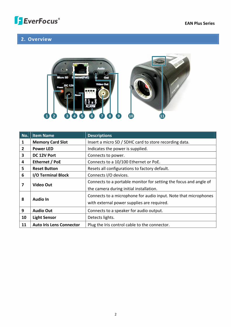
EAN Plus Series
2
2 Overview
2 3 4 6 7 8 9 105 111
No Item Name Descriptions 1 Memory Card Slot Insert a micro SD SDHC card to store recording data 2 Power LED Indicates the power is supplied 3 DC 12V Port Connects to power 4 Ethernet PoE Connects to a 10100 Ethernet or PoE 5 Reset Button Resets all configurations to factory default
6 IO Terminal Block Connects IO devices
7 Video Out Connects to a portable monitor for setting the focus and angle of
the camera during initial installation
8 Audio In Connects to a microphone for audio input Note that microphones
with external power supplies are required
9 Audio Out Connects to a speaker for audio output
10 Light Sensor Detects lights
11 Auto Iris Lens Connector Plug the Iris control cable to the connector
EAN Plus Series
3
3 Features
bull 13rdquo Panasonic CMOS sensor (for EAN3120 Plus 3220 Plus)
128rdquo Sony CMOS sensor (for EAN3300 Plus)
bull Triple streams (stream 1 2 3 from H264 or MJPEG)
bull Up to 30 fps at 1920 times 1080
Supports 15 fps at 2048 times 1536 (only for EAN3300 Plus)
bull Auto Iris control
bull Built-in micro SD SDHC card slot
bull Removable IR-cut filter for Day Night function
bull One alarm input and output
bull Two-way audio
bull TV-out
bull Wide Dynamic Range (for EAN3120 Plus 3220 Plus)
bull 2D 3D Dynamic Noise Reduction (DNR)
bull Motion detection
bull Privacy mask
bull DC 12V PoE
EAN Plus Series
4
4 Installation
41 Packing List
bull EAN Plus Series Camera (lens not included) x 1
bull Software CD x 1
bull Quick Installation Guide x 1
bull Tool Packet x 1 (contains the following items)
- C-mount lens adapter - frac14-20 UNC thread mounting bracket and 2 screws
- Hexagon wrench - Power pigtail cable
Note Contact the shipper if any items appear to have been damaged in the shipping process If any
items are missing notify your EverFocus Electronics Corp Sales Representative or Customer Service
Branch Please also keep the shipping carton for possible future use
EAN Plus Series
5
42 IO Terminal Block
The IO terminal block located on the rear panel of the camera can be used to develop application
for alarm input and output
1 2 3 4
Pin Assignment
No Function No Function
1 Alarm COM 3 Alarm Input
2 Alarm Output 4 Digital GND
43 Lens Installation and Adjustment
You can install either a CS-mount or a C-mount lens into the camera It is recommended to use a lens
with aperture ratio of F14 or smaller Please refer to the following reference steps
C-Mount Lens Adapter
DC Auto Iris Lens Connector
Focus Screw
Zoom Screw
CS-Mount Lens
1 Remove the cover cap from the camera body
2 Install the lens into the camera body
3 Adjust the lens using the Focus Zoom Screws
If you are using a DC Auto Iris lens
1 Remove the cover cap from the camera body
2 Install the lens into the camera body
3 Connect the DC cable to the DC Auto Iris Lens Connector
EAN Plus Series
6
4 When making final focus adjustment place the ND filter in front of the lens to force the lens iris
to open and then adjust the lens using the Focus Zoom Screws
Note To use the ND filter remove the protective sheets from both sides of an ND filter
5 Lock the Focus Screw and then remove the ND filter
C-Mount Lens
1 Remove the cover cap from the camera body
2 Install the lens into the camera body using the supplied C-mount lens adapter
3 Adjust the lens using the Focus Zoom Screws
Note Installing a C-mount lens without the C-mount lens adapter may damage the camera sensor
44 Top Bottom-Mount
You can use the supplied mounting bracket and screw it on the top of the camera body to suspend
the camera or on the bottom of the camera body to support the camera
Top Mount
Bottom Mount
EAN Plus Series
7
45 Basic Connection
Micro SD
Audio
In OutEthernet (PoE)
DC 12VPower
Reset
Video Out
COM
Out In
GN
D
Alarm
1
2
3
3
4
5
1 Use a standard network cable to connect the camera to the network
2 Connect the camera to power using one of the following methods
bull Plugging the supplied power pigtail cable to the DC 12V port
bull Using the PoE function and the power will be provided over the network cable
3 Optionally connect the camera to a speaker or microphone Note that microphones with
external power supplies are required
4 Optionally connect the camera to a monitor using a BNC cable
5 Optionally connect the camera to the input output devices
After powering the camera the power LED will be lit in red and you can access the live view and
adjust the image clarity
EAN Plus Series
8
5 Accessing the User Interface
This section explains how to access the Web interface of the camera for configuration
51 Assigning an IP Address
You have to assign an IP address for your camera to be accessible To assign an IP address to the
camera use the IP Utility (IPU) software included in the software CD Please connect the IP camera in
the same LAN of your computer
1 Install and then start the IPU program The following dialog box appears
2 Click Find Devices to search the cameras connected in the LAN The default network values of the
cameras will be displayed By default the network protocol of the camera is DHCP
3 To configure the network settings select a camera and then click LoginMulti Login to log in
EAN Plus Series
9
4 Type the user ID and password Click OK
Note
1 The default user ID is user1 and the default password is 11111111
2 If you select more than one camera that has the same user ID password you will be able
to log in several cameras at once
5 To change the IP address double-click the IP Address of the camera Type a new IP address and
then click Set IP Address to save the settings
You can also change the other settings by double-clicking the values After configuring the values
click Save Configuration
Note Most networks uses DHCP to assign IP address if you are unsure of your network
settings please consult your network administrators for configuration details
6 To access the camera highlight the camera and click Connect to Selected IP The Internet
Explorer window pops up
7 Type the user ID and password to log in The Live View window of the camera appears
Note You might be required to download ActiveX which is required to view the camera feed
If asked click Yes For more details on setting up the Microsoft Internet Explorer please refer
to 52 Settings for Microsoft Internet Explorer
EAN Plus Series
10
52 Settings for Microsoft Internet Explorer
To enable Remove Live View Firmware Upgrade and ActiveX Prompt on Internet Explorer some
settings have to be complete Please follow the steps below
1 On the computer click Start gt Control Panel gt System and Security gt Action Center (click Change
User Account Control Settings) the User Account Control Settings window appears Adjust the
slide bar to Never Notify and then click OK Restart your computer if requested
2 Open the Internet Explore click Tools gt Internet Options gt Security Tab gt Custom Level the
Security Settings windows appears
EAN Plus Series
11
3 In the Download unsigned ActiveX controls field select Prompt In the Include local directory
path when uploading files to a server field select Enable Click OK
4 In the Internet Options window click the Advanced tab and then disable Enable memory
protection to help mitigate online attacks Click OK
EAN Plus Series
12
53 Connecting the Camera to the Network
There are three methods to connect the IP camera to the network Router or LAN Connection Direct
High-Speed Connection and One-to-One Connection
Router or LAN connection
This is the most common connection in which the IP camera is connected to a router and allows
multiple users on and off site to see the IP camera on a LANWAN (Internet) The camera must be
assigned an IP address that is compatible with its LAN By setting up port forwarding on the router
you can remotely access the cameras from outside of the LAN via the Internet To remotely access the
Web interface of the IP camera please refer to 732 DDNS To set up port forwarding please consult
the manual of the router
Straight-through LAN patch cable
Right Pinout of a straight-through cable
EAN Plus Series
13
Direct High-Speed Connection
In a Direct High-Speed Connection the camera connects directly to a modem without the need for a
router You need to set the static or dynamic WAN IP address assigned by your ISP (Internet Service
Provider) in the camerarsquos configuration web pages To access the camera just type ldquohttpxxxrdquo
where xxx is the IP address given by your ISP If you have a dynamic IP address this connection may
require that you use DDNS for a reliable connection Please refer to 732 DDNS
One-to-One Connection (Directly from PC to IP Camera)
You can connect directly without using a switch router or modem However only the PC connected
to the camera will be able to view the IP camera You will also have to manually assign a compatible IP
address to both the computer and the IP camera Unless the PC has another network connection the
IP camera will be the only network device visible to the PC See the diagram below
Pinout of straight patch cable
Right Pinout of a crossed-over cable
EAN Plus Series
14
54 Live View Window
1 Press the button to display the Live View window Double-click on the
image to show a full-screen display double-click again or press ESC to return to the normal display
If you experience video feed lag time (if connected via Internet) you can reduce the resolution or
limit the number of streams See 741 Multi Streaming
2 Press the button to play the recorded data directly from the on-camera Micro
SD SDHC card (for this function to become active you have to insert a Micro SD SDHC card in the
Micro SD SDHC card slot on the rear panel of the camera See 783 SD Card
3 Press the button to enter the Settings page On the Settings page there are
8 submenu sections [System Info] [User Config] [Network] [Video] [Audio] [User] [Event] and
[System] Click on the section buttons to open their configuration fields See the Settings section
below for more information
EAN Plus Series
15
4 Press the button to exit the system and close this browser page
5 Video Stream
Select the Video Stream (Stream 1 Stream 2 or Stream 3) that will be displayed in the video box on
the right Stream 2 and Stream 3 are only selectable if you have enabled the stream The default
setting is Stream 1 only See 741 Multi Streaming
6 View Size
Use this to select the appropriate view size and shape of the video box on the right A smaller size
might increase transmission speed and video quality
7 Digital Zoom
Click the Zoom In Zoom Out buttons or roll the mouse wheel to zoom in out the camera live view
up to 10x Clicking on a magnified image will re-center the image around that point
8 Record
The Record button is used to record the current video stream Click the Record button to start
stop recording This icon is only for one-minute video recording To record long-period recordings
please set a recording schedule (See 775 Schedule) The location on your computer where the
image files will be saved to and file size can be specified in the submenu (see 72 User Config)
9 Snapshot
Click the Snapshot button to save a snapshot of the video image currently being displayed The
location on your computer where the snapshot data will be saved can be specified in ldquoSettings gt
User Config gt RecordingSnapshotrdquo (see 72 User Config)
10 Play Audio Transmit Audio
Click the ldquoPlay Audiordquo (speaker) and ldquoTransmit Audiordquo (microphone) buttons to switch the sound
onoff for the speaker and microphone respectively (if such external devices have been connected
to the camera directly or via the network)
EAN Plus Series
16
11 One Push
This function is only available for EAN3120 Plus 3220 Plus The One Push button can be displayed
on the live view window by enabling the Show One Push Buttons function on the User Config lt Live
View Config Setting page (see 721 Live View Config) To enable the button (turned from faded to
clear) on the Video lt Advanced Setting page select One Push from the White Balance Settings
Mode drop-down list and click the Apply button Once this is done pressing the One Push button
on the Live View Window will instruct the camera to adjust the white balance settings and these
settings will be active until the button is pushed again This is like a ldquosemi-automaticrdquo way to adjust
white balance to suit the user if the Auto or Manual mode does not give the result the user wants
12 Manual Control
ndash Trigger Event
Press the ldquoTrigger Eventrdquo button to trigger an event directly from the Live page If you have
configured an event (in the Event submenu) that will trigger a reaction (like a recording) when a
Manual Trigger event occurs clicking this button will trigger that reaction You can select what that
reaction will be You can for instance set the camera to record the audiovideo feed to the Micro
SD card on board the camera You can then click on the Playback button to open the Playback page
and search for and play all such recordings that had been stored on the card Such event actions
will be effective once they have been configured in the ldquoEventrdquo menu (see 77 Event)
ndash Reset Alarm
Press the ldquoReset Alarmrdquo button to reset the alarm output remotely
13 Status Display (info lines that can be placed above video box or at bottom of page)
This shows the name of the camera that is currently active or being configured current datetime
and current frame rate You can activate these info displays in the Settings gt User Config page (see
72 User Config)
14 Event Signal Icons (above video screen)
When an alarm or motion event is triggered a signal icon will appear at the top right of the Live
View window to alert the user
Alarm event icon When an alarm is triggered this icon appears
Motion detection icons The colors of these motion event icons correspond to the colors of the motion trigger areas you have configured in the Motion Detection submenu (see 772
Motion Detection)
Recording icon When the camera is recording to a PC-based folder this icon appears
EAN Plus Series
17
6 Playback
You can remotely play back the recordings stored in the on-camera micro SD card on the Web interface
or play back the recordings stored in the computer using the ARV Viewer included in the software CD
Playback is designed as a quick way to check recent recordings that were triggered by Events that were
configured to ldquoRecord to SD Cardrdquo in the Settings gt Event gt Event Settings page (see 771 Event
Settings)
Note Note that the Playback page is only accessible once the on-camera SD card is inserted and
active
61 Remote Playback Using Playback Page
On the Live View Window click the Playback button to open the Playback page
EAN Plus Series
18
Search by File Click the Search button to search for all recording files on the on-camera SD card
Search results will be displayed in the Filename area
Search by Time Click the calendar icon and select the date and time from which you want to search
until the present moment Click search to get your search results which will be displayed in the
Filename area
Search by event Click the type of Event recordings you want to search for (Alarm Motion Manual
Trigger) and then click the calendar icons to select the Start Time datetime and the End Time
datetime of your search Click Search to get your search results which will be displayed in the
Filename area
Multiple Files Check this box if you want the video player to play all the files in the selected folder
The files will be displayed in the Filename area
Loop Again Check this box if you want the video player to play the selected file over and over again
Play Once you have opened the filersquos folder and have clicked on the file to highlight it its details will
be displayed in the File Information area You can now click Play to play that specific file
Pause Click this button to pause the playback
Stop Click this button to stop the playback
【Recording List】
Filename This area will display a list of search results (recording files and folders) Folders (named
with the recorded date) will be displayed first Click on the folder and click on each subfolder until the
recording files (arv) in that folder is listed
File Information Click a file on the Filename list the selected file information will be listed
Copy Click this button to copy the selected file to the computer-based folder of your choice A
browsing box will open so that you can search for the folder of your choice You can use the ARV
Viewer to play back the recordings recorded in your computer For details on ARV Viewer see 63
Playing Back Using ARV Viewer
Lock Click this button to lock the selected file This will protect that file from being overwritten during
any overwrite procedure The file will thus be saved on the micro SD card indefinitely However the
file will still be deleted if the micro SD card is ever formatted
Remove Click this button to delete the selected file
EAN Plus Series
19
62 Setting up the Playback Function
Note that the Playback function will not be active until the user has inserted a micro SD card in the
camerarsquos micro SD card slot The card may also have to be formatted in the Settings submenu
Micro SD Card Slot
621 Preparing the Micro SD Card
Once you insert a functional micro SD card into the slot the Playback button on the Live page should
become active within seconds (see section 622 below ndash the grey letters should turn white) IF NOT
do the following
1 From the Live page click Settings gt System gt SD Card If no card has been inserted yet the
Remove button should be faded indicating that no card is being detected (If a card is
inserted and the Remove button is still faded pull the card out and re-insert it)
2 Slide the card into the slot until it clicks into position
3 The Remove button should become active within a few seconds indicating the card is active
4 If the Remove button stays faded click the Format button to format the card NOTE All data
on the disk will be deleted if the Format button is clicked
622 Testing the Playback Function
1 Once the SD card is detected by the system the button (inactive)
will turn to (active)
2 To test the Playback function (this is not required) set up a ldquoManual Triggerrdquo Recording
Event by clicking Settings gt Event gt Event Settings
3 Click the ldquoAddrdquo button on the middle right side of the page to open an ldquoAdd Eventrdquo box
4 Give the event a name like ldquoTest 1rdquo
EAN Plus Series
20
5 In the ldquoEvent Triggered byrdquo field click on Manual Trigger
6 Below this check ldquoEnable This Eventrdquo ldquoEnable Post-trigger Bufferrdquo and ldquoRecord to SD Cardrdquo
7 To save your settings click OK or close the box by clicking on the red x icon at top right of the
box (in which case you will be asked if you want to save the data to which you should reply OK)
The box will close and the new event will be listed in the list area of the Event Settings page
8 Look at the ldquoPost-trigger Bufferrdquo at the bottom to make sure the buffer time is set to 10 seconds
9 Click ldquoApplyrdquo to make sure all settings are saved
10 Click the Live button to go back to the Live page
11 Get ready to click the Trigger Event button at the bottom of the page Before you do see if you
can find something in the view screen that will give you a visual time marker For instance if you
can get your hand in front of the camerarsquos lens get ready to count down on your fingers
12 Click the Trigger Event button and slowly count down on your fingers in front of the lens (if you
are able to do so ndash if not try to find visual cues on the view screen that will help you to mark the
moment you pushed the trigger) The recording period will be as long as the buffer time you
selected ndash the default period is 10 seconds
13 Click the Playback button to open the Playback page
14 There are different ways to search for recording files on the camerarsquos Micro SD card (ie the
Playback memory) For a recent recording like your test event simply click the ldquoSearchrdquo button
under the ldquoSearch by Filerdquo header
15 If the SD card is active and formatted correctly the recording folderrsquos name (the recording dayrsquos
date) will appear in the Filename box at the bottom Click on this folder to open it If there are
sub-folders click on the bottom one (the most recent would be at the bottom) until you can click
on a file that cannot open to another sub-level and shows data in the File Information box to the
right This would be the file of the most recent recording event
16 To play this file click the Play button below the video box The test footage you have recorded
should start playing Play time should be 10 seconds if you left the Post-trigger Buffer as 10
seconds
EAN Plus Series
21
63 Playing Back Using ARV Viewer
You can play back the recordings stored in the computer using the ARV Viewer included in the
software CD To store the recordings in the computer please refer to Recording List gt Copy in 61
Remote Playback using Playback Page
4 5 6 7 8 9 10
321
No Item Name Descriptions
1 Snapshot Click to take and save a snapshot
2 Load File Click to load the recordings for playing back
3 Convert ARV to AVI Convert the recording from ARV format to AVI format
4 Playback Time Display the playback time
5 Total Time of Recording Display the total time of the recording
6 Stop Click to stop playing the recording
7 Step Reverse Click to display the previous frame
8 Play Click to play back the recording
9 Pause Click to pause the recording
10 Step Forward Click to display the next frame
EAN Plus Series
22
7 Settings
Click the Settings button on the Live View Window to enter the settings submenu There are nine buttons
on the left-side of the submenu Live System Info User Config Network Video Audio User Event and
System Click the Live button can go back to the Live View Window
71 System Info
The System Information and System Log can be checked on this page Click the top tab of the one you
want to see
711 Information
Click the Information tab the following dialog box appears These values cannot be changed on this
page and are for reference only
EAN Plus Series
23
712 Log
Click the Log tab the following dialog box appears The sequence number date time and event
messages of the log event will be displayed in the System Log field The log will display the last 256
log events Click the Export button to export the system log event list into a ldquotxtrdquo file and select the
location where the exported log file will be saved to
EAN Plus Series
24
72 User Config
Each user can set a different configuration for hisher Live page here These settings will be applied to
the logged-in userrsquos Live page every time heshe logs in
721 Live View Config
【VideoAudio Connection Protocol Setting】You can transmit the data stream from the IP cameras
using the RTSP (Real Time Streaming Protocol) on the network The RTSP is a protocol that allows
you to access video streams by using the compatible media players Click Apply to apply the
changes or Reset to reset without saving the changes RTP over UDP The RTSP protocol uses UDP for camera data stream transmission
RTP over TCP The RTSP protocol uses TCP for camera data stream transmission
RTP over HTTP The RTSP protocol uses HTTP for camera data stream transmission
Nevio CGI This is EverFocusrsquo protocol designed for EverFocusrsquo IP devices Select this
protocol for camera data stream transmission
【Text Settings】Check the box of each option (Machine name DateTime Frame Rate) to display
this info on the Live View Page
Foreground Color Slide the Red Green and Blue bars to create your preferred text color for the
info text line
Position Select the position where the text will be displayed Choose from Upper Left Lower
Right Lower Left
Click Apply to apply the changes or Reset to reset without saving the changes
EAN Plus Series
25
【DateTime Format Used in Text】Click the dropdown menu to select datetime format from the
listed options Click on the desired hour format Click Apply to apply the setting changes or Reset to
reset without saving the change
【Live View Layout Settings】 Check the ldquoShow One Push Buttonsrdquo boxes if you want to show these
buttons on the Live View Page Uncheck these boxes to hide these buttons This function is only
available for EAN3120 Plus 3220 Plus
722 Recording Snapshot
This configures where your Record Button and Snapshot Button ( ) files will be saved if
you click one of these buttons Selectable folders will be on the computer only not on the
on-camera SD card
【Recording Snapshot Export Settings】
Enable Event Recording to PC Checking this box will let the system save RecordSnapshot Button
recordings to the folder configured below on the userrsquos PC
Export Folder Select the Export folder for the action above by clicking on the browse (hellip) button
and then select the desired folder
File size The user can limit the size of each recorded file here (in minutes) When a single
recording file exceeds the time you set the system will create a new file to save that data to
Overwrite Select ldquoONrdquo for overwriting recordingsnapshot file when the disk storage capacity is
full The user can set the storage capacity limitation in the in-sentence field in the gray box below
the Overwrite setting ldquoIf the remaining hard disk capacity is less than ____ MB (50~2000) system
will stop recording or start overwriting ldquo
Click Apply to apply the setting changes or Reset to reset without saving the changes
EAN Plus Series
26
723 Language
Select the language to be displayed on the Web interface of the IP camera The default language is
English
To add a new language not listed in the current Language list click the Browse button to locate
the new language file (evb) on your computer and then click the Upload button Updated
language files might be available on the manufacturerrsquos website Contact your vendor if required
Click Apply to apply any changes or Reset to reset without saving the changes
Note Uploading a new language file will cause the system to reboot automatically Please create
a new network connection to the IP camera when the reboot is complete
EAN Plus Series
27
73 Network
This page covers network-related settings including Network DDNS SMTPFTP HTTPS SNMP and
Network Alarm
731 Network
The following information is required to configure the network settings Contact your network
administrator or your internet service provider to get the info
【IP Settings】
IP Type Refer to the network administrator for these settings of the server Default DHCP
DHCP This setting lets the system use an automatically assigned (dynamic) IP address This
address can change under certain circumstances For instance when the camerarsquos network
switchhub has to be rebooted Do not assign to the DHCP server the same IP addresses used
for the other network cameras and PCs with unique IP addresses
Static IP The user can manually set the Static IP address This type of address is stable and
cannot change but the user has to make sure there are no address conflicts with other
network-connected devices
PPPoE This is a DSL-connection application The ISP will ask the user to input a username and
password Contact your ISP for these details
EAN Plus Series
28
Note If PPPoE is selected as the IP type the supplied IP Utility program will not be able to
detect the device
IP address When DHCP is not used the user needs to manually enter the IP address of the
camera Do not enter an IP address that is already used for your computer or other network
cameras
Subnet Mask This field is used to set the netmask for your network so that the IP camera will be
recognized within the network Example 2552552550 When DHCP is selected the DHCP server
will assign this value automatically
Gateway This field is used to set the gateway for your network so that the IP camera will be
recognized within the network When DHCP is selected the DHCP server will assign this value
automatically
Primary DNS Enter the IP address of the DNS server if this is provided by an ISP
Secondary DNS If your ISP provided you with a secondary DNS address please enter it here
Username Enter the accountrsquos username (used only for PPPoE)
Password Used only for PPPoE
IPv6 Enter the IPv6 details in this area if this applies to your system
Click Apply to apply the setting changes or Reset to reset without saving the change
【Port Settings】Enter the HTTP HTTPS and RTSP port numbers and click Apply to save
【Multicast Settings】Enable if required fill in the setting options and click Apply to save
EAN Plus Series
29
732 DDNS
DDNS (Dynamic Domain Name System) is a service used to map a domain name to the dynamic IP
address of a network device You can set up the DDNS service for remote access to the IP camera
DDNS assigns a domain name (URL) to the IP camera so that the user does not need to go through
the trouble of checking if the IP address assigned by DHCP Server has changed Once the IP is
changed the IP camera will automatically update the information to the DDNS to ensure it is always
available for remote access
Before enabling the following DDNS function user should have applied for a host name from the
DDS service providerrsquos website We support these four DDNS server providers
wwweverfocusddnscom wwwsitelutionscom wwwdyndnscom and wwwno-ipcom
Note We highly recommend that you use xxxxeverfocusddnscom for the simplicity of setting up
your IP cameras
【DDNS Settings】
Enable Check this box to enable the DDNS function
Service ISP You can either apply for a host name from EverFocus or other DDNS server providers
If you choose the EverFocus DDNS server you can obtain a free host name from EverFocus by
following the steps below
bull From EverFocus To obtain a free host name from EverFocus type a desired host name in the
textbox click the Register Update button and then click the Apply button
bull From other DDNS server providers To obtain a domain name from one of the three DDNS
server providers you have to register your name with the provider first and then select the
provider and fill in the required information Please refer to the specific DDNS companyrsquos
website for further information
Record ID Type the record ID if provided by the DDNS server provider
EAN Plus Series
30
FQDN Type the fully qualified domain name applied from the DDNS server provider For
example xxxxdyndnscom
Username Password Type the login account of your DDNS server provider
Click Apply to apply the setting changes or Reset to reset without saving the changes
Note
1 In order to support the full functionality of the camera you must open the port numbers (80
554 443) on the router for remote access to the IP camera This function is available on most
routers in the market and is often known as ldquoPort Forwardingrdquo To set up Port Forwarding
please consult the manual of the router
2 In certain router models it is possible that you will not be able to access the camera using
DDNS while inside the routerrsquos network Please try using a PC located outside of your routerrsquos
network
Default Ports on All EverFocus IP Cameras
HTTP 80
RTSP 554
HTTPS 443
EAN Plus Series
31
733 SMTP FTP
【Set SMTP Server (email)】This area is for configuring the mail server that is used to send e-mail
notifications from the camera to predefined addresses via SMTP Note that to enable e-mail
notification function you have to check the Send Mail Notification item on the Event dialog box
(see 771 Event Settings)
SMTP Server Enter the IP address or the host name of the SMTP server used to send e-mails
SMTP Port Enter the port number for SMTP The default is 25
Authentication Check this box if the SMTP server requires authentication (userpassword)
User name Input the userrsquos login ID if the SMTP server requires authentication
Password Input the userrsquos login password if the SMTP server requires authentication
EAN Plus Series
32
Receiver Address Input the e-mail addresses for receiving an e-mail message when an EVENT is
enabled and triggered Please use ldquordquo to separate multiple addresses
Sender Address Input the senderrsquos e-mail address so that the receiver can recognize the sender
when an Event message is received
Attach Image Check this box if you want to attach an image when an alarm is triggered or an IP
camera detects events
Send Test Email Click the Test button to send a testing email to the assigned address
Click Apply to apply the setting changes or Reset to reset without saving the changes
【Set FTP Server】The settings relating to the FTP server used to transmit the alarm images can be
configured here Note that to enable uploading images to the FTP server function you have to
check the Upload to FTP item on the Event dialog box (see 771 Event Settings)
FTP Server Enter the IP address or the host name of the FTP server
FTP Port Enter the port number for the FTP server Default is 21
Recording Path Assign the recording path
User Name Set FTP Userrsquos name
Password Set FTP password
PASV mode Check to enable Passive mode Passive mode is normally enabled If a connection
cannot be established uncheck PASV Moderdquo
Test FTP Server Click the Test button to send a testing file to the assigned FTP server
Click Apply to apply the setting changes or Reset to reset without saving the changes
EAN Plus Series
33
734 HTTPS
Hypertext Transfer Protocol Secure (HTTPS) is a combination of the Hypertext Transfer Protocol
and the SSLTLS protocol and provides encrypted communication and secure identification of a
network web server
Before using the HTTPS function for communication with the IP camera a Certificate must be
created first There are two ways to create and install a certificate Create Self-Signed Certificate
and Create Certificate Request
Create Self-Signed Certificate
Please note that even though self-signed certificates are free and offer some protection true
security is only implemented after the installation of a signed certificate issued by a certificate
authority
1 Click the Create Self-Signed Certificate button the following dialog appears
EAN Plus Series
34
2 Type the required Certificate information and then click the Apply button The subject line will
be displayed in the Installed Certificate Information field
3 Click the Property button a pop-up window appears to display the details of the certificate
4 To optionally create and install other certificates remove the existing one by clicking the
Remove button to erase the certificate
5 On the Web page change the address from ldquohttprdquo to https in the address bar and press
Enter on the keyboard Some Security Alert dialogs will pop up Click OK or Yes to enable HTTPS
Create Certificate Request
You can apply for an official certificate from an issuing Certificate Authority
1 Click the Create Certificate Request button the following dialog appears
EAN Plus Series
35
2 Type the required Certificate information and then click the Apply button The subject line will
be displayed in the Created Request field
3 Click the Property button a pop-up window appears to display the details of the certificate
4 To optionally create and install other certificates or request remove the existing one by clicking
the Remove button to erase the certificate or request
5 Copy the contents of the Certificate request (in PEM format) and paste it to the certificate
request field on the Web page of the 3rd-party certification authority such as Symantec VeriSign
Wait for the certificate authority to issue an SSLTLS certificate and then download the issued
certificate on your computer
6 In the Install Signed Certificate field click the Browse button to search for the issued certificate
and then click the Upload button to import the certificate Once the certificate has been
uploaded this field will show the subject line of the certificate
EAN Plus Series
36
735 SNMP
The default values for SNMP v1v2v2c and SNMP v3 are already filled in Click either of the
Enable buttons to enable either of the two Make your changes as desired Click on the Trap
Address field to enter the digits if required
736 Network Alarm
This function works with EverFocusrsquos CMS software eg the PowerCon or the Power Video Plus For
the setting details please refer to the CMS network alarm protocol
EAN Plus Series
37
74 Video
The settings relating to video such as streaming camera OSD can be configured on this page The
Video page has five tabs Multi-streaming Camera Advanced ROI and Privacy Mask
741 Multi Streaming
【Stream Settings】 This IP camera can output three video streams simultaneously For each of these
streams the user can set the compression format resolution bit rate and frame rate individually
Stream 1 is always enabled for live view To enable Stream 2 andor Stream 3 check the ldquoEnablerdquo
box the header of each stream
Note If you connect to the camera via the Internet and experience a delay (lag time) in the video
feed try to reduce the number of streams and the quality and resolution of the streams ndash but
keep the frame rate at its maximum
EAN Plus Series
38
Format Select the encoding format ndash H264 or MJPEG
Resolution Select the most suitable resolution for your needs
Frame Rate Select from 1 to 30 fps
Bit Rate If required select whether you want the stream to stream a Constant Bit Rate or a
Variable Bit Rate and set the values of whichever option you choose
Click Apply to apply the setting changes or Reset to reset without saving the changes
【Video Recording Settings】Select the stream you want to configure and then select whether you
want the recording files of that stream to be saved in AVI or ARV format Click Apply to apply the
setting changes or Reset to reset without saving the changes
【Time Stamp Settings】 You can select the DateTime format position and add the setting to the
streaming
Click Apply to apply the changes or Reset to reset without saving the changes
EAN Plus Series
39
742 Camera
【Image Settings】Set the Brightness Saturation Contrast or Sharpness of the image Click Apply to
apply the changes or Reset to reset without saving the changes
【Camera Settings】
Mirror Switch Mirror ON to rotate the image horizontally around a vertical axis
Flip Switch Flip ON to rotate the image vertically around a horizontal axis
AE There are two options
ALC Selecting Automatic Light Control allows the camera circuitry to either take bright spots
more into consideration (peak) bringing out detail in bright areas or less into consideration
(average) bringing out detail in shadows
AES Selecting Auto Electronic Shutter disables the Shutter setting below this setting In this
mode the camera measures the light level and decides whether it needs more or less light and
then automatically adjusts the shutter speed accordingly
BLC Back Light Compensation (BLC) is used to make the subject appear clearer when it is set
against a bright background
OFF Select to switch Back Light Compensation functions off
(ON)BLC The BLC can increase the exposure of a dark area surrounded by a brighter area HLC
can decrease the exposure of bright areas surrounded by darker areas This enables the
camera to better display information that would otherwise have been ldquowhited outrdquo like a
license plate between two bright headlights on a dark road
(ON)HLC The Highlight-Suppression BLC is used to reduce the brightness of light sources in a
specific area It is activated only in a low illumination environment to minimize the effects of
glare from bright lights such as spotlights street lights or headlights in the field of view
EAN Plus Series
40
WDR The Wide Dynamic Range (WDR) function provides clearer images when both of the very
bright and dark areas simultaneously appear on the camera view There are four value options
OFF Low Middle and High Note that when WDR is ON some parts of the image may appear
solarized This is normal for WDR and is not a camera malfunction This function is only available
for EAN3120 Plus 3220 Plus
DN Mode
Auto Select to let the camera automatically switch to Night mode (black and white) when the
light levels fall to a specified level and back to Day mode (color) when the light levels rise to a
specified level
Day Select to keep the camera in Day mode (color) even in nighttime
Night Select to keep the camera in Night mode (black and white) even in daytime
EAN Plus Series
41
743 Advanced
EAN Plus Series
42
【Camera Settings】
Lens (IRIS Control) Select DC or Manual for IRIS control This function is only available for EAN3220
Plus
Exposure Settings (AE) This setting is used to adapt to the amount or type of light used by the
camera Note the settings vary among models
Mode This function is not available for EAN3220 Plus
Automatic Light Control (ALC) This option is only available for EAN3120 Plus 3300 Plus The
ALC allows the camera circuitry to either take bright spots more into consideration (peak)
bringing out detail in bright areas or less into consideration (average) bringing out detail in
shadows
Auto Electronic Shutter (AES) This option is only available for EAN3120 Plus 3300 Plus In
this mode the camera measures the light level and decides whether it needs more or less light
and then automatically adjusts the shutter speed accordingly
Manual This option is only available for EAN3300 Plus Select this option to manually set up
the Shutter (Manual) and AGC (Manual) values
Iris Specify the size of the Iris opening here
Shutter If enabled this setting lets you set the shutter speed yourself
Shutter Limit Use this setting to set the maximum shutter speed for the camera This function is
only available for EAN3120 Plus
AGC Set the Auto Gain Control limit here The lower the AGC level the lower the video signal and
the noise However the image will be darker under low-light condition with IR-off if you set up the
Iris to the maximum level
Slow Shutter This option can be switched on when AES Mode is selected in the Exposure Settings
(AE) field This function is only available for EAN3220 Plus 3300 Plus
Flickerless If the Mode field in the Exposure Settings (AE) area has been set to AES then this option
becomes available Choose between OFF 50HZ 60HZ 50HZ (High Luminance) or 60HZ (High
Luminance) This function is only available for EAN3300 Plus
EV Setting Set up the Exposure Value Note the brightness of the screen changes when you change
the EV value This function is only available for EAN3300 Plus
AE Response Set up Auto Exposure Response time This function is only available for EAN3300 Plus
AE Weighting Area Select an AE Weighting area Each setup AE Weighting Area is configured with
the appropriate brightness level on the center and the surrounding areas This function is only
available for EAN3300 Plus
Brightness Set the image brightness here
AE Reference Set the Auto Exposure value here This function is only available for EAN3120 Plus
EAN Plus Series
43
Black Level Set the Black level here This function is only available for EAN3300 Plus
WDR The Wide Dynamic Range (WDR) function provides clearer images when both of the very
bright and dark areas simultaneously appear on the camera view There are four value options OFF
Low Middle and High Note that when WDR is ON some parts of the image may appear solarized
This is normal for WDR and is not a camera malfunction This function is only available for EAN3120
Plus 3220 Plus
Visibility Enhancement (OFFLowMiddleHigh) Images in foggy or rain environments or in
environments with a very strong luminous intensity have a dynamic range that is significantly lower
than ordinary images The user can use this Visibility Enhancement setting to ldquoDEFOGrdquo the image if
such ldquoFOGGINGrdquo is an issue This function is only available for EAN3220 Plus
BLC Settings Back Light Compensation (BLC) is used to make the subject appear clearer when it is
set against a bright background
OFF Select to switch Back Light Compensation functions off
Back Light This option is only available for EAN3300 Plus The Back Light function is useful
when the background of the subject is very bright and the subject itself is dark Select Back
Light and adjust the slide bar to the left right for setting up the back light value The higher
the value the more the backlight compensation
Front Light This option is only available for EAN3300 Plus This function is useful when the
bright highlights such as flashlight or car headlights appear on the camera view Select Front
Light and adjust the slide bar to the left right for setting up the front light value The higher
the value the more the highlight compensation
ON (BLC) This option is only available when you select AES Mode in the Exposure Settings (AE)
field The option is only available for EAN3120 Plus 3220 Plus The BLC function is useful
when the background of the subject is very bright and the subject itself is dark Follow the
instructions below to configure the settings for each model
For EAN3120 Select ON (BLC) the button next to the Mode drop-down list will be
active (see image below) Click the button the green setup areas appear on the left
screen Click on the areas to enable disable the BLC function The selected areas (in green)
will be applied with the BLC function
EAN Plus Series
44
For EAN3220
You can configure one area to apply the BLC function Select ON (BLC) the setup buttons
appears (see image below) Select Low Middle High from the BLC Gain drop-down list To
set up a BLC area click the Edit Area button and then click on the blue color tab to turn your
mouse cursor into a blue pen Move the cursor to the position on the right screen where you
want the BLC rectangle to start and then click Move your cursor to the position (diagonally
opposing corner) where you want the BLC rectangle to end and then click The blue area will
be applied with the BLC function
ON (HLC) This option is only available when you select AES Mode in the Exposure Settings (AE)
field The option is only available for EAN3120 Plus 3220 Plus This function is useful when
the bright highlights such as flashlight or car headlights appear on the camera view Follow
the instructions below to configure the settings for each model
For EAN3120 Select ON (HLC) and then select a level from the drop-down list The higher the
level the more the highlight compensation
For EAN3220
HLC Level Select a level for the HLC setting The higher the level the more the highlight
compensation
HLC Mode Select All Day Night mode to apply the HLC function
HLC Black Mask Select On Off to apply the black mask on the selected areas The
over-exposure portions within the selected areas will be applied with the black mask
Color Tabs You can set up four HLC areas with different colors To set up a HLC area click the
Edit Area button and then click on the color tab to turn your mouse cursor into a pen of that
color Move the cursor to the position on the right screen where you want the HLC rectangle
to start and then click Move your cursor to the position (diagonally opposing corner) where
you want the HLC rectangle to end and then click Select ON from the color tab drop-down list
The rectangular area with the selected color will be applied with the HLC function
EAN Plus Series
45
Back Light This option is only available for EAN3300 Plus The Back Light function is useful
when the background of the subject is very bright and the subject itself is dark Select Back
Light and adjust the slide bar to the left right for setting up the back light value The higher
the value the more the backlight compensation
Front Light This option is only available for EAN3300 Plus This function is useful when the
bright highlights such as flashlight or car headlights appear on the camera view Select Front
Light and adjust the slide bar to the left right for setting up the front light value The higher
the value the more the highlight compensation
Noise Reduction Settings This limits the amount of digital ldquovideo noiserdquo that is usually found in any
video stream and helps to reduce file size The higher the level the more the reduction
For EAN3120 Plus 3300 Plus
Select ON OFF to enable disable the Noise Reduction function Or select Auto to let the camera
automatically enable disable the Noise Reduction function Slide the Level bar to set up the level
The higher the level the more the reduction
For EAN3220 Plus
2D DNR Select ON to enable the 2D DNR function
3D DNR Select ON to enable the 3D DNR function You can further set up the following settings
3D Start AGC Set up the AGC level to automatically start the 3D NR function
3D End AGC Set up the AGC level to automatically stop the 3D NR function
3D Level Set up the 3D DNR level
Smart NR Select ON to enable the Smart NR function The 3D NR function will be
automatically turned on when a motion event occurs
EAN Plus Series
46
White Balance Settings Select the mode that delivers the best quality image for the camerarsquos light
environment There are five options Auto Manual Indoor Outdoor One Push
Auto Select to let the camera automatically adjust the White Balance In the Auto mode the
camera computes the white balance value output using color information from the entire
screen It outputs the proper value using the color temperature radiating from a black subject
based on a range of value from 3000 to 7500K
Manual Select to adjust the Red and Blue values yourself in the fields below this field
Indoor Select to use the default settings for indoor environments In the Indoor mode the
camera uses 3200K as the base value
Outdoor Select to use the default settings for outdoor environment In the Outdoor mode it
uses 5800K as the base value
One Push Select to enable the Push button next to the Mode drop-down field This will allow you to force the camera to readjust the white balance every time you push the Push
button The lens will hold the same focal position until the next trigger command is received
This function helps to prevent incorrect focusing in dark environments This function is only
available for EAN3120 Plus 3220 Plus
Manual Temperature Select to use the optimized Red and Blue settings You can also
optionally adjust the Manual Level below this field for setting up the color temperature The
higher the value the more the color temperature This function is only available for EAN3300
Plus
DayNight Settings
Auto Select to let the camera automatically switch to Night mode (black and white) when the
light levels fall to a specified level and back to Day mode (color) when the light levels rise to a
specified level
Day Select to keep the camera in Day mode (color) even in nighttime
Night Select to keep the camera in Night mode (black and white) even in daytime
IR Smart Settings Select ON and set up the level to enhance the image quality when the images are
over exposure This function is useful when the camera is in the Night mode This function is only
available for EAN3220 Plus
Saturation Set the saturation value This function is not available for EAN3220 Plus
Monitor Type Select a gamma value from Set 1 Set 2 or Set 3 This function is only available for
EAN3120 Plus
Negative Switch this setting ON to view a color negative version of the video image This is useful
at night or when viewing temperature-sensitive images
EAN Plus Series
47
Sharpness Settings Select the sharpness level of the image A low sharpness level will deliver a
softer less detailed image A high level will deliver a sharp highly detailed image Switch Resolution
Enhancement ON to enable the resolution enhancement function
Contrast Select the contrast level of the image
Suppress Function This function is only available for EAN3300 Plus
Aperture Compensation Suppression (OFFLowMiddleHigh) This setting can be activated to
suppress luminance noise when the AGC level increases
Chroma Suppression (OFFLowMiddleHigh) This setting can be activated to suppress
chrominance noise when the AGC level increases
Ygamma (gamma 22standardcontrast enhancehigh light range mode LHigh light range mode
H) Select the Ygamma value for the video quality of the monitor This function is only available for
EAN3300 Plus
Monitor Settings The user can use this field to optimize video quality for his or her specific type of
monitor ndash LCD or CRT This function is only available for EAN3220 Plus
Color Space Standard The options are YUV601 for SD and YUV709 for HD These define the color
space standard required to convert an RGB picture to a YUV picture Generally YUV601 is used for
Standard Definition (720P) devices and the YUV709 is used for High Definition (1080P) devices
Click Apply to save all changes Click Reset to cancel all changes
EAN Plus Series
48
744 ROI (Region of Interest)
The Region of Interest (ROI) function allows users to set up multiple regions within an image with
better quality and less distortion than the rest of the image You can also use this function
together with the Digital Zoom function on the Live View Page to get a better image result Up to
eight ROIs can be configured in the ROI settings page
To set up an ROI region
1 Select an ROI number from the ROI No drop-down list
2 Click the Add button the mouse cursor will turn into a pen when you move it over the live
image on the left
3 Move the cursor to the position where you want the ROI rectangle to start and then click
Move the cursor to the position (diagonally opposing corner) where you want the ROI
rectangle to end and then click
4 Slide the Quality bar to set up the quality value
5 Click the Apply button to apply the settings or click the Reset button to reset without saving
the settings
EAN Plus Series
49
745 Privacy Mask
The Privacy Mask can block out sensitive areas from view covering the areas with colored or black
and white boxes in both live view and recorded clips This feature is useful when usersrsquo donrsquot want
the sensitive information visible Up to four Privacy Masks can be configured
【Privacy Mask Color Settings】The Modes vary among camera models
Mode Click Color to make the masks appear as colored rectangles on the screen Click BW to
make the masks appear as gray rectangles on the screen Click Mosaic to make the masks appear
as mosaic-effect rectangles on the screen
Level Select the color of the masks if you selected Color Mode Select the level of grayness of the
masks if you selected BW Mode Select the level of smallmiddlelarge if you selected Mosaic
Mode
Click Apply to apply the settings or click Reset to reset without saving the settings
Color Tabs Click on a color tab to turn your mouse cursor into a pen of that color
You can now create a block of that color on the video screen Move your cursor to the position
where you want your mask rectangle to start and then click Move your cursor to the position
(diagonally opposing corner) where you want your mask rectangle to end and then click The
rectangular area with the selected color will appear The live image will display the rectangular
area with the color you selected If you want to create another mask use one of the other three
colors Each color denotes a different mask area Only one block per color is allowed As the
number of colors suggests you can configure up to four blocks
EAN Plus Series
50
Select All Click to turn the whole screen into a mask area
Clear All Click to delete all configured mask blocks
Eraser Click to turn the mouse cursor into an eraser to delete any block you click on
Area Shows the color and number of the block
Enable Check this box to enable the related mask block
Click Apply to apply the settings or click Reset to reset without saving the settings
EAN Plus Series
51
75 Audio
The EAN Plus series IP camera can transmit audio to your computer if you have connected an external
microphone to its audio Input cable It can also receive audio input from you and transmit it via an
external speaker if you have connected such a speaker to its audio Output cable
Check the Enable Audio box to enable the camerarsquos audio function The camera will now act as a
digital bridge (via the IP network) between any connected audio input device and any connected
audio device
Adjust the Audio Input Volume if you have external audio input devices (microphones) connected to
the camera and if there are problems with the sound input being too low or high
Click Apply to save all settings or click Reset to cancel
EAN Plus Series
52
76 User
761 User Information
The system administrator can create up to ten user accounts on this page
To set up a user account
1 Highlight a user account and click the Modify button The following dialog box appears
2 Type the account name account description and password for the account Type the password
again in the Confirm field
3 Select an authority level for the user account from the Authority drop-down list
bull Supervisor Administrator The only difference between a supervisor and administrator is
that a supervisor can edit an administratorrsquos account and password but an administrator
cannot edit the supervisorrsquos account and password Multiple administrators can be
configured but there can be only one supervisor The supervisor and administrators all
have unrestricted access to the Settings submenus and can determine the registration of
all other users
EAN Plus Series
53
bull User A user can view the Live View page and view the system network video and audio
information A user can only adjust the User Config page settings The user does not have
access to the User Event and System pages
bull Guest The lowest level of access which only allows the user access to the Live View page
4 Select Active or Disable from the Status drop-down list to active or disable the user account
5 Click On in the SD Card Playback field to allow the user to access the SD card playback
function
6 Click OK
7 Click Apply to save all the settings
EAN Plus Series
54
762 IP Address Filter
Use this page to specify IP addresses that are not allowed to access this camera By default any IP
address can access the camera
Note The Allowed List addresses only become relevant when the Denied List contains a network
or range and the supervisor wants to allow one or more IP addresses within that excluded range
or network In such a scenario the user would enter the excluded range or network in the
Denied List and enter the exceptions in the Allowed List
To set up the IP Address Filter
1 Select Denied List Click the Add button the following dialog box appears
2 Select an IP type from the IP Type drop-down list
3 Select a network rule from the Rule drop-down list type the IP address and click OK
Single Type a single IP address in the IP Address field below
Network Type the IP address and subnet mask in the field below
Range Type a range for the IP addresses
4 If you have set up an IP range in Step 3 you can optionally set up the Allowed List to allow one
or more IP addresses within the setup IP range to access the IP camera
5 Click Apply
EAN Plus Series
55
77 Event
You can set up the Motion Detection event Tamper Detection event or the Alarm IO to automatically
notify the users when an event occurs or an alarm is triggered You can also set up a schedule to
automatically record the videos when an event occurs or an alarm is triggered
771 Event Settings
You can create a total of ten event or alarm settings page in the Event List
【Event List】
Click the Add button and the following Event Configuration Window appears
EAN Plus Series
56
Enter Event Name Type an event name
Event Triggered by Select an event or alarm type for the to-be-specified-below reactions
Alarm Input Select this if you want a reaction trigger coming from any external connected sensor
to activate a to-be-specified-below reactions via the camera system Make sure that a suitable
device is actually connected to the alarm input relay
Manual Trigger Select this option if you want to manually trigger the alarm by clicking the Trigger
Event button on the Live View Page
Motion Detection Select this option if you want motion in a specified part of the camerarsquos viewing
rectangle (the screen image) to trigger the to-be-specified-below reactions
Tampering Detection Select this option if you want the camerarsquos tampering detection sensor to
trigger the to-be-specified-below reactions
Schedule Recording Select this option if you want the Schedule Recording periods configured in
the recording schedule (the Settings gt Event gt Schedule page) to activate this event In this
scenario a preconfigured event reaction like a log entry will list the start and end times of each
period Actual recording will only be triggered if the event is preconfigured to do so
Enable This Event Select to activate the event
Enable Re-trigger Click to set a minimum time after the event is triggered before the event
can be triggered again
Enable Pre-trigger Buffer Click if you want the Event reaction (as selected in the ldquoNotification
Overrdquo field below) to be the activation of the video recording function and if you want the
recording to include the video feed from the time period (configurable on the previous ldquoEvent
Settingsrdquo page) just before the Event trigger occurred
Enable Post-trigger Buffer Click if you want the Event reaction (as selected in the Notification
Over field) to be the activation of the video recording function and if you want the recording
to include the video feed from a time period (configurable on the Event Settings page) just
after the Event trigger occurred
Motion Area Select a setup motion detection area from the drop down list Note this
function only becomes relevant after the Motion Detection areas have been set up (see 772
Motion Detection)
Notification Over Select the desired notification types form the following items
Log Click if you want the camera to list the eventrsquos details in its log if the event is triggered
Trigger Alarm Output Click if you want the camera to relay the event reaction to a device
attached to the alarm relay output wire and then set up the alarm output duration time
EAN Plus Series
57
Send Mail Notification Click if you want the camera to send an Event notification email to the
email address entered in the Set SMTP Server(email) field of the Network gt SMTPFTP page if
the Event occurs (see 733 SMTP FTP)
Upload to FTP Click if you want the camera to upload recorded footage to the FTP server
entered in the Set SMTP Server(email) field of the Network gt SMTPFTP page if the Event
occurs (see 733 SMTP FTP)
Record to SD Card Click if you want the camera to start recording its video feed (when the
event occurs) on an on-camera SD Card (if such a card has been inserted)
Note The recording will only be as long as the combined Pre- and Post-trigger Buffers so
make sure you enable at least one of these buffers especially the Post-trigger Buffer
Record to PC Check this box if you want the camera to start recording its video feed (when
the event occurs) on the same folder on the same PC as configured on the User Config gt
RecordingSnapshot page (if such a folder has been enabled and configured)
Note The recording will only be as long as the combined Pre- and Post-trigger Buffers (and
for as long as the event trigger is happening ndash eg a motion is detected) so make sure you
enable at least one of these buffers especially the Post-trigger Buffer
Network Alarm Check this box if you want the camera to send a network alarm signal (when
the event occurs) to the CMS servers configured on the Network gt Network Alarm page (see
736 Network Alarm)
Click OK to save all settings or click Cancel to cancel
【PrePost Trigger Settings】
Pre-trigger Buffer Select the duration for the buffer This will determine the amount of footage
(length of time) before the event trigger moment that will be included in an event-triggered video
recording if that buffer and video recording has been enabled in the Event Configuration Window
Post-trigger Buffer Select the duration for the buffer This will determine the amount of footage
(length of time) after the event trigger moment that will be included in an event-triggered video
recording if that buffer and video recording has been enabled in the Event Configuration Window
Click Apply to save all settings or click Reset to cancel
EAN Plus Series
58
772 Motion Detection
Use this page to configure up to four areas in which motion will be detected When a motion is
detected by the camera the motion detection icon will appear at the top right of the
Live page to alert the user This function can also be linked with correctly configured Events to
trigger Event reactions like the activation of video recording periods snapshots alarms etc
Color Tabs Click on a color tab to turn your mouse cursor into a pen of that color
You can now create a block of that color on the video screen Move your cursor to the position
where you want your detection rectangle to start and then click Move your cursor to the position
(diagonally opposing corner) where you want your detection rectangle to end and then click The
rectangular area with the selected color will appear This block will be an area inside which the
camera will detect motion If you want to create another detection area use one of the other three
palette colors Each color denotes a different detection area Only one block per color is allowed As
the number of colors suggests you can configure up to four blocks
Select All Click to turn the whole screen into a motion detection area
Clear All Click to delete all configured motion detection blocks
Eraser Click to turn your mouse cursor into an eraser to delete any block you click on
Area Shows the color and numberID of the block
Enable Check this box to enable the related motion detection block
Sensitivity Set the sensitivity of the motion detection sensor function
Click Apply to save all settings or click Reset to cancel
EAN Plus Series
59
773 Tamper Detection
Use this page to set the number of seconds that an alarm signal will be active if the device is
physically tampered (moved covered up or out of focus
774 Alarm IO
Use this page to set the type of trigger input and the type of output contact for the camerarsquos alarm
channel
EAN Plus Series
60
775 Schedule
Use this page to configure a schedule for periods during which the camera should deactivate all
user-activated Events (gray Deselect periods) or when the camera should deactivate all
user-activated Events except Schedule Recording (SR) events (blue Schedule Recording-only
periods) or when the camera should deactivate only SR events (red Event Recording-only periods)
or when it should enable all activated Events (yellow periods)
Event Recording Click this button to make every hour block you click on red A red block represents
an Event Recording-only block which represents an hour when the camera will deactivate all
preconfigured activated Schedule Recording events and keep all the other activated events active
Schedule Recording Click this button to make every hour block you click on blue A blue block
represents a Schedule Recording-only block which represents an hour when the camera will
deactivate all other preconfigured activated events and keep only the preconfigured activated
Schedule Recording events active
Event + Schedule Click this button to make every hour block you click on yellow A yellow block
represents an hour in which all activated events including Schedule Recording events will be
active
Deselect Click this button to make every hour block become grey A grey block represents an hour
in which all activated events including Schedule Recording events will be inactive
Click Apply to save all settings or click Reset to cancel
EAN Plus Series
61
78 System
You can set up the systemrsquos time and SD card settings and to do maintenance and reset actions like
reboots and upgrades
781 DateTime
【Machine Name Settings】If required enter a new name for the machine This name will be visible
in the Machine Name field of the IP Utility software which is included in the software CD
【Set Time Zone】Set the time zone of the camerarsquos location
【Set DateTime Manually】Set the datetime here if you wonrsquot be using an NTP server to update the
datetime (see below)
【Set DateTime Sync】Enter the Network Time Protocol server if applicable The camerarsquos time will
be automatically adjusted by synchronizing with the NTP server
Click Apply to save all settings or click Reset to cancel
EAN Plus Series
62
782 Daylight Saving
Click Enable Daylight Saving to enable this schedule and select the dates when the regionrsquos
daylight saving period begins and ends Click Apply to save all settings or click Reset to cancel
783 SD Card
Use this page to prepare the system for safely removing the SD Card from its slot
【Setup SD Card】
Notification Select the percentage of storage space that should be left on the card before the
camera notifies you of the impending storage shortage or overwrite
Event Recording Select if you want Event Recording only FTP Backup only or both
Overwrite Click ON if you want the card to start writing over recorded footage when its memory is
full Click OFF if you want the card to stop recording new footage when its memory is full
【SD Card Utility】
Capacity This shows you how much card memory has been used and how much memory capacity
remains on the card
Remove Click this button before removing the card from the system
Format Click this button to format the card All data saved on the SD card will be removed if the
card is formatted
EAN Plus Series
63
784 Maintenance
【Maintenance Server】
Reboot Click this button to reboot the unit without changing any of the settings Use this function if
the unit is not behaving as expected
Restore Click this button to restart and reset most of the current settings to their factory default
values The only settings that will not be changed to default are
bull IP settings
bull DDNS settings
Default The Default button should be used with caution Pressing this button will return all of the
cameras settings including the IP address to the factory default values The camera will then have
to be reconfigured
【SaveLoad Configuration Server】
Save To make a backup file of the machinersquos current configurations press Save to save all the
configurations to a config file This will enable the user to reload these configuration settings if the
settings are changed and there is unexpected behavior
Load To load a previously saved configuration press the Browse button to locate the saved config
file (see above) and then click the Load button The systemrsquos settings will be restored to the saved
configuration
EAN Plus Series
64
【SaveLoad Video Configuration Server】
Save To make a backup file of the machinersquos video configurations press Save to save the video
configurations to a config file This will enable the user to reload these configuration settings if the
settings are changed and there is unexpected behavior
Load To load a previously saved video configuration press the Browse button to locate the saved
config file (see above) and then click the Load button The systemrsquos settings will be restored to the
saved video configuration
【Upgrade Firmware】Click the Browse button to find a previously prepared firmware upgrade file
Click Upgrade to install the new firmware
Note
1 Do not disconnect power to the unit during the upgrade sequence The unit will reboot
automatically after the upgrade has completed (1-5 minutes)
2 During the upgrade process all event recording actions will be stopped Event recording
actions will resume after the camera is rebooted
3 If the ldquoFile Error Please re-loginrdquo warning message appears when upgrading the firmware
please try the following instructions
a Go to Internet Explorer gt Tools gt Internet Option gt Security gt Custom
b Find and enable the Include local directory path when uploading files to a server
EAN Plus Series
65
8 Upgrading Firmware Using IP Utility
You can upgrade the Firmware using the IP Utility software included in the software CD
1 Install and then start the IPU program The following dialog box appears
2 Click Find Devices to search the cameras connected in the LAN The default network values of the
cameras will be displayed By default the network protocol of the camera is DHCP
3 Select a camera and click LoginMulti Login to log in the camera
4 Type the user ID and password Click OK
Note
1 The default user ID is user1 and the default password is 11111111
2 If you select more than one camera that has the same user ID password you will be able
to log in several cameras at once
EAN Plus Series
66
5 Highlight the camera and then click Upgrade Firmware A browsing window appears
6 Select the firmware file (evb) and then click Open The IP Utility will automatically upgrade the
firmware
The camera will reboot once the update is complete Click Find Devices the new firmware version
should be displayed in the last part of the Machine Name
EAN Plus Series
67
9 Specifications
Model EAN3120 Plus EAN3220 Plus EAN3300 Plus
Camera
Image Sensor 13 Panasonic CMOS 128 Sony CMOS
Megapixel 13 MP 2 MP 3 MP
Picture Elements (H x V) 1280 x 1024 1944 x 1092 2048 x 1536
Min Illuminations 003 Lux at F14
Electronic Shutter (Sec) 85 ~ 160000 2 ~ 150000 1 ~ 110000
Scanning System NTSC PAL
WDR Yes Yes No
BLC Yes
Gain Control Yes
White Balance Yes
Lens
Mounting Type C CS
Day Night Yes (with removable auto IR-cut filter)
IRIS Control DC Electrical IRIS Lens IRIS
Video
Video Compression H264 MJPEG
Resolution
NTSC
2048 x 1536 1920 x 1200 (for EAN3300 Plus only)
1920 x 1080 (for EAN3300 Plus 3220 Plus only)
1280 x 1024 1280 x 720 1024 x 768 720 x 480 704 x 480 640 x 480
352 x 240 320 x 240 160 x 120
PAL
2048 x 1536 1920 x 1200 (for EAN3300 Plus only)
1920 x 1080 (for EAN3300 Plus 3220 Plus only)
1280 x 1024 1280 x 720 1024 x 768 720 x 576 704 x 576 640 x 480
352 x 288 320 x 240 160 x 120
Frame Rate 30 fps at 1280 x 1024 30 fps at 1920 x 1080 15 fps at 2048 x 1536
Audio
Audio Streaming Two-way audio
Audio Compression G711
EAN Plus Series
68
Network
Interface 10 100 Base-T Ethernet RJ-45 socket
Supported Protocols
TCPIP IPV6 UDP ICMP DHCP NTP DNS DDNS SMTP SNMP FTP
HTTP HTTPs PPPoE UPnP Bonjour RTP RTSP RTCP IGMP ARP ONVIF
PSIA
Connector
Power DC female port PoE
Ethernet RJ-45
Audio 1 In (phone jack for microphone)
1 Out (phone jack for Speaker)
Alarm IO Terminal IO wires
Local Storage Micro SD SDHC memory card slot
TV-Out BNC socket composite 1 V p-p 75 Ω
General
Power Source DC 12V PoE (IEEE8023af)
Power Consumption
(IR LEDs On)
5W (DC 12V)
621W (PoE)
5W (DC 12V)
522W (PoE)
5W (DC 12V)
536W (PoE)
Operating Temperature 0degC ~ +50degC 32degF ~ +122degF
Humidity 20 to 80 (no condensation)
Safety CE FCC
Dimensions (L x W x H) 117 x 56 x 68 mm 46 x 22 x 27 in
Weight 410 g 09 lb
EverFocus Electronics Corp EverFocus Taiwan 12F No79 Sec 1 Shin-Tai Wu Road Hsi-Chih Taipei Taiwan TEL +886 2 2698 2334 FAX +886 2 2698 2380 wwweverfocuscomtw marketingeverfocuscomtw
EverFocus Europe - Germany Albert-Einstein-Strasse 1 D-46446 Emmerich Germany TEL +49 2822 93940 FAX +49 2822 939495 wwweverfocusde infoeverfocusde
EverFocus China - Beijing Room 609 Technology Trade Building Shangdi Information Industry Base Haidian District Beijing 100085 China TEL +86 10 6297 3336~39 FAX +86 10 6297 1423 wwweverfocuscomcn marketingeverfocuscomcn
EverFocus China - Shenzhen 4F No 2 D4 Building Wan Yelong Industrial Park Tangtou Road Shiyan Baoan Shenzhen Guangdong 518101 China TEL +86 755 2765 1313 FAX +86 755 2765 0337 wwweverfocuscomcn marketingeverfocuscomcn
EverFocus USA - California 1801 Highland Avenue Unit A Duarte CA 91010 USA TEL +1 626 844 8888 FAX +1 626 844 8838 wwweverfocuscom saleseverfocuscom
EverFocus USA - New York 415 Oser Avenue Unit S Hauppauge NY 11788 USA TEL +1 631 436 5070 FAX +1 631 436 5027 wwweverfocuscom saleseverfocuscom
EverFocus Japan 5F Kinshicho City Building 2-13-4 Koto-BashiSumida-Ku Tokyo 130-0022 Japan TEL +81 3 5625 8188 FAX +81 3 5625 8189 wwweverfocuscojp infoeverfocuscojp
EverFocus Europe - UK Unit 12 Spitfire Business Park Hawker Road Croydon Surrey CR0 4WD UK TEL +44 20 8649 9757 +44 845 430 9999 FAX +44 20 8649 9907 wwweverfocusukcouk salesukeverfocuscom
EverFocus India Suite 803 Housefin Bhavan C-21 Bandra Kurla Complex Bandra (East) Mumbai 400051 India TEL +91 22 6128 8700 FAX +91 22 6128 8705 wwweverfocusin saleseverfocusin
PN 4605PQ3120B010A-VerC
Your EverFocus product is designed and manufactured with high quality materials and components which can be recycled and reused This symbol means that electrical and electronic equipment at their end-of-life should be disposed of separately from your household waste Please dispose of this equipment at your local community waste collectionrecycling centre In the European Union there are separate collection systems for used electrical and electronic product Please help us to conserve the environment we live in
Ihr EverFocus Produkt wurde entwickelt und hergestellt mit qualitativ hochwertigen Materialien und Komponenten die recycelt und wieder verwendet werden koumlnnen Dieses Symbol bedeutet dass elektrische und elektronische Geraumlte am Ende ihrer Nutzungsdauer vom Hausmuumlll getrennt entsorgt werden sollen Bitte entsorgen Sie dieses Geraumlt bei Ihrer oumlrtlichen kommunalen Sammelstelle oder im Recycling Centre Helfen Sie uns bitte die Umwelt zu erhalten in der wir leben
EAN Plus Series
3
3 Features
bull 13rdquo Panasonic CMOS sensor (for EAN3120 Plus 3220 Plus)
128rdquo Sony CMOS sensor (for EAN3300 Plus)
bull Triple streams (stream 1 2 3 from H264 or MJPEG)
bull Up to 30 fps at 1920 times 1080
Supports 15 fps at 2048 times 1536 (only for EAN3300 Plus)
bull Auto Iris control
bull Built-in micro SD SDHC card slot
bull Removable IR-cut filter for Day Night function
bull One alarm input and output
bull Two-way audio
bull TV-out
bull Wide Dynamic Range (for EAN3120 Plus 3220 Plus)
bull 2D 3D Dynamic Noise Reduction (DNR)
bull Motion detection
bull Privacy mask
bull DC 12V PoE
EAN Plus Series
4
4 Installation
41 Packing List
bull EAN Plus Series Camera (lens not included) x 1
bull Software CD x 1
bull Quick Installation Guide x 1
bull Tool Packet x 1 (contains the following items)
- C-mount lens adapter - frac14-20 UNC thread mounting bracket and 2 screws
- Hexagon wrench - Power pigtail cable
Note Contact the shipper if any items appear to have been damaged in the shipping process If any
items are missing notify your EverFocus Electronics Corp Sales Representative or Customer Service
Branch Please also keep the shipping carton for possible future use
EAN Plus Series
5
42 IO Terminal Block
The IO terminal block located on the rear panel of the camera can be used to develop application
for alarm input and output
1 2 3 4
Pin Assignment
No Function No Function
1 Alarm COM 3 Alarm Input
2 Alarm Output 4 Digital GND
43 Lens Installation and Adjustment
You can install either a CS-mount or a C-mount lens into the camera It is recommended to use a lens
with aperture ratio of F14 or smaller Please refer to the following reference steps
C-Mount Lens Adapter
DC Auto Iris Lens Connector
Focus Screw
Zoom Screw
CS-Mount Lens
1 Remove the cover cap from the camera body
2 Install the lens into the camera body
3 Adjust the lens using the Focus Zoom Screws
If you are using a DC Auto Iris lens
1 Remove the cover cap from the camera body
2 Install the lens into the camera body
3 Connect the DC cable to the DC Auto Iris Lens Connector
EAN Plus Series
6
4 When making final focus adjustment place the ND filter in front of the lens to force the lens iris
to open and then adjust the lens using the Focus Zoom Screws
Note To use the ND filter remove the protective sheets from both sides of an ND filter
5 Lock the Focus Screw and then remove the ND filter
C-Mount Lens
1 Remove the cover cap from the camera body
2 Install the lens into the camera body using the supplied C-mount lens adapter
3 Adjust the lens using the Focus Zoom Screws
Note Installing a C-mount lens without the C-mount lens adapter may damage the camera sensor
44 Top Bottom-Mount
You can use the supplied mounting bracket and screw it on the top of the camera body to suspend
the camera or on the bottom of the camera body to support the camera
Top Mount
Bottom Mount
EAN Plus Series
7
45 Basic Connection
Micro SD
Audio
In OutEthernet (PoE)
DC 12VPower
Reset
Video Out
COM
Out In
GN
D
Alarm
1
2
3
3
4
5
1 Use a standard network cable to connect the camera to the network
2 Connect the camera to power using one of the following methods
bull Plugging the supplied power pigtail cable to the DC 12V port
bull Using the PoE function and the power will be provided over the network cable
3 Optionally connect the camera to a speaker or microphone Note that microphones with
external power supplies are required
4 Optionally connect the camera to a monitor using a BNC cable
5 Optionally connect the camera to the input output devices
After powering the camera the power LED will be lit in red and you can access the live view and
adjust the image clarity
EAN Plus Series
8
5 Accessing the User Interface
This section explains how to access the Web interface of the camera for configuration
51 Assigning an IP Address
You have to assign an IP address for your camera to be accessible To assign an IP address to the
camera use the IP Utility (IPU) software included in the software CD Please connect the IP camera in
the same LAN of your computer
1 Install and then start the IPU program The following dialog box appears
2 Click Find Devices to search the cameras connected in the LAN The default network values of the
cameras will be displayed By default the network protocol of the camera is DHCP
3 To configure the network settings select a camera and then click LoginMulti Login to log in
EAN Plus Series
9
4 Type the user ID and password Click OK
Note
1 The default user ID is user1 and the default password is 11111111
2 If you select more than one camera that has the same user ID password you will be able
to log in several cameras at once
5 To change the IP address double-click the IP Address of the camera Type a new IP address and
then click Set IP Address to save the settings
You can also change the other settings by double-clicking the values After configuring the values
click Save Configuration
Note Most networks uses DHCP to assign IP address if you are unsure of your network
settings please consult your network administrators for configuration details
6 To access the camera highlight the camera and click Connect to Selected IP The Internet
Explorer window pops up
7 Type the user ID and password to log in The Live View window of the camera appears
Note You might be required to download ActiveX which is required to view the camera feed
If asked click Yes For more details on setting up the Microsoft Internet Explorer please refer
to 52 Settings for Microsoft Internet Explorer
EAN Plus Series
10
52 Settings for Microsoft Internet Explorer
To enable Remove Live View Firmware Upgrade and ActiveX Prompt on Internet Explorer some
settings have to be complete Please follow the steps below
1 On the computer click Start gt Control Panel gt System and Security gt Action Center (click Change
User Account Control Settings) the User Account Control Settings window appears Adjust the
slide bar to Never Notify and then click OK Restart your computer if requested
2 Open the Internet Explore click Tools gt Internet Options gt Security Tab gt Custom Level the
Security Settings windows appears
EAN Plus Series
11
3 In the Download unsigned ActiveX controls field select Prompt In the Include local directory
path when uploading files to a server field select Enable Click OK
4 In the Internet Options window click the Advanced tab and then disable Enable memory
protection to help mitigate online attacks Click OK
EAN Plus Series
12
53 Connecting the Camera to the Network
There are three methods to connect the IP camera to the network Router or LAN Connection Direct
High-Speed Connection and One-to-One Connection
Router or LAN connection
This is the most common connection in which the IP camera is connected to a router and allows
multiple users on and off site to see the IP camera on a LANWAN (Internet) The camera must be
assigned an IP address that is compatible with its LAN By setting up port forwarding on the router
you can remotely access the cameras from outside of the LAN via the Internet To remotely access the
Web interface of the IP camera please refer to 732 DDNS To set up port forwarding please consult
the manual of the router
Straight-through LAN patch cable
Right Pinout of a straight-through cable
EAN Plus Series
13
Direct High-Speed Connection
In a Direct High-Speed Connection the camera connects directly to a modem without the need for a
router You need to set the static or dynamic WAN IP address assigned by your ISP (Internet Service
Provider) in the camerarsquos configuration web pages To access the camera just type ldquohttpxxxrdquo
where xxx is the IP address given by your ISP If you have a dynamic IP address this connection may
require that you use DDNS for a reliable connection Please refer to 732 DDNS
One-to-One Connection (Directly from PC to IP Camera)
You can connect directly without using a switch router or modem However only the PC connected
to the camera will be able to view the IP camera You will also have to manually assign a compatible IP
address to both the computer and the IP camera Unless the PC has another network connection the
IP camera will be the only network device visible to the PC See the diagram below
Pinout of straight patch cable
Right Pinout of a crossed-over cable
EAN Plus Series
14
54 Live View Window
1 Press the button to display the Live View window Double-click on the
image to show a full-screen display double-click again or press ESC to return to the normal display
If you experience video feed lag time (if connected via Internet) you can reduce the resolution or
limit the number of streams See 741 Multi Streaming
2 Press the button to play the recorded data directly from the on-camera Micro
SD SDHC card (for this function to become active you have to insert a Micro SD SDHC card in the
Micro SD SDHC card slot on the rear panel of the camera See 783 SD Card
3 Press the button to enter the Settings page On the Settings page there are
8 submenu sections [System Info] [User Config] [Network] [Video] [Audio] [User] [Event] and
[System] Click on the section buttons to open their configuration fields See the Settings section
below for more information
EAN Plus Series
15
4 Press the button to exit the system and close this browser page
5 Video Stream
Select the Video Stream (Stream 1 Stream 2 or Stream 3) that will be displayed in the video box on
the right Stream 2 and Stream 3 are only selectable if you have enabled the stream The default
setting is Stream 1 only See 741 Multi Streaming
6 View Size
Use this to select the appropriate view size and shape of the video box on the right A smaller size
might increase transmission speed and video quality
7 Digital Zoom
Click the Zoom In Zoom Out buttons or roll the mouse wheel to zoom in out the camera live view
up to 10x Clicking on a magnified image will re-center the image around that point
8 Record
The Record button is used to record the current video stream Click the Record button to start
stop recording This icon is only for one-minute video recording To record long-period recordings
please set a recording schedule (See 775 Schedule) The location on your computer where the
image files will be saved to and file size can be specified in the submenu (see 72 User Config)
9 Snapshot
Click the Snapshot button to save a snapshot of the video image currently being displayed The
location on your computer where the snapshot data will be saved can be specified in ldquoSettings gt
User Config gt RecordingSnapshotrdquo (see 72 User Config)
10 Play Audio Transmit Audio
Click the ldquoPlay Audiordquo (speaker) and ldquoTransmit Audiordquo (microphone) buttons to switch the sound
onoff for the speaker and microphone respectively (if such external devices have been connected
to the camera directly or via the network)
EAN Plus Series
16
11 One Push
This function is only available for EAN3120 Plus 3220 Plus The One Push button can be displayed
on the live view window by enabling the Show One Push Buttons function on the User Config lt Live
View Config Setting page (see 721 Live View Config) To enable the button (turned from faded to
clear) on the Video lt Advanced Setting page select One Push from the White Balance Settings
Mode drop-down list and click the Apply button Once this is done pressing the One Push button
on the Live View Window will instruct the camera to adjust the white balance settings and these
settings will be active until the button is pushed again This is like a ldquosemi-automaticrdquo way to adjust
white balance to suit the user if the Auto or Manual mode does not give the result the user wants
12 Manual Control
ndash Trigger Event
Press the ldquoTrigger Eventrdquo button to trigger an event directly from the Live page If you have
configured an event (in the Event submenu) that will trigger a reaction (like a recording) when a
Manual Trigger event occurs clicking this button will trigger that reaction You can select what that
reaction will be You can for instance set the camera to record the audiovideo feed to the Micro
SD card on board the camera You can then click on the Playback button to open the Playback page
and search for and play all such recordings that had been stored on the card Such event actions
will be effective once they have been configured in the ldquoEventrdquo menu (see 77 Event)
ndash Reset Alarm
Press the ldquoReset Alarmrdquo button to reset the alarm output remotely
13 Status Display (info lines that can be placed above video box or at bottom of page)
This shows the name of the camera that is currently active or being configured current datetime
and current frame rate You can activate these info displays in the Settings gt User Config page (see
72 User Config)
14 Event Signal Icons (above video screen)
When an alarm or motion event is triggered a signal icon will appear at the top right of the Live
View window to alert the user
Alarm event icon When an alarm is triggered this icon appears
Motion detection icons The colors of these motion event icons correspond to the colors of the motion trigger areas you have configured in the Motion Detection submenu (see 772
Motion Detection)
Recording icon When the camera is recording to a PC-based folder this icon appears
EAN Plus Series
17
6 Playback
You can remotely play back the recordings stored in the on-camera micro SD card on the Web interface
or play back the recordings stored in the computer using the ARV Viewer included in the software CD
Playback is designed as a quick way to check recent recordings that were triggered by Events that were
configured to ldquoRecord to SD Cardrdquo in the Settings gt Event gt Event Settings page (see 771 Event
Settings)
Note Note that the Playback page is only accessible once the on-camera SD card is inserted and
active
61 Remote Playback Using Playback Page
On the Live View Window click the Playback button to open the Playback page
EAN Plus Series
18
Search by File Click the Search button to search for all recording files on the on-camera SD card
Search results will be displayed in the Filename area
Search by Time Click the calendar icon and select the date and time from which you want to search
until the present moment Click search to get your search results which will be displayed in the
Filename area
Search by event Click the type of Event recordings you want to search for (Alarm Motion Manual
Trigger) and then click the calendar icons to select the Start Time datetime and the End Time
datetime of your search Click Search to get your search results which will be displayed in the
Filename area
Multiple Files Check this box if you want the video player to play all the files in the selected folder
The files will be displayed in the Filename area
Loop Again Check this box if you want the video player to play the selected file over and over again
Play Once you have opened the filersquos folder and have clicked on the file to highlight it its details will
be displayed in the File Information area You can now click Play to play that specific file
Pause Click this button to pause the playback
Stop Click this button to stop the playback
【Recording List】
Filename This area will display a list of search results (recording files and folders) Folders (named
with the recorded date) will be displayed first Click on the folder and click on each subfolder until the
recording files (arv) in that folder is listed
File Information Click a file on the Filename list the selected file information will be listed
Copy Click this button to copy the selected file to the computer-based folder of your choice A
browsing box will open so that you can search for the folder of your choice You can use the ARV
Viewer to play back the recordings recorded in your computer For details on ARV Viewer see 63
Playing Back Using ARV Viewer
Lock Click this button to lock the selected file This will protect that file from being overwritten during
any overwrite procedure The file will thus be saved on the micro SD card indefinitely However the
file will still be deleted if the micro SD card is ever formatted
Remove Click this button to delete the selected file
EAN Plus Series
19
62 Setting up the Playback Function
Note that the Playback function will not be active until the user has inserted a micro SD card in the
camerarsquos micro SD card slot The card may also have to be formatted in the Settings submenu
Micro SD Card Slot
621 Preparing the Micro SD Card
Once you insert a functional micro SD card into the slot the Playback button on the Live page should
become active within seconds (see section 622 below ndash the grey letters should turn white) IF NOT
do the following
1 From the Live page click Settings gt System gt SD Card If no card has been inserted yet the
Remove button should be faded indicating that no card is being detected (If a card is
inserted and the Remove button is still faded pull the card out and re-insert it)
2 Slide the card into the slot until it clicks into position
3 The Remove button should become active within a few seconds indicating the card is active
4 If the Remove button stays faded click the Format button to format the card NOTE All data
on the disk will be deleted if the Format button is clicked
622 Testing the Playback Function
1 Once the SD card is detected by the system the button (inactive)
will turn to (active)
2 To test the Playback function (this is not required) set up a ldquoManual Triggerrdquo Recording
Event by clicking Settings gt Event gt Event Settings
3 Click the ldquoAddrdquo button on the middle right side of the page to open an ldquoAdd Eventrdquo box
4 Give the event a name like ldquoTest 1rdquo
EAN Plus Series
20
5 In the ldquoEvent Triggered byrdquo field click on Manual Trigger
6 Below this check ldquoEnable This Eventrdquo ldquoEnable Post-trigger Bufferrdquo and ldquoRecord to SD Cardrdquo
7 To save your settings click OK or close the box by clicking on the red x icon at top right of the
box (in which case you will be asked if you want to save the data to which you should reply OK)
The box will close and the new event will be listed in the list area of the Event Settings page
8 Look at the ldquoPost-trigger Bufferrdquo at the bottom to make sure the buffer time is set to 10 seconds
9 Click ldquoApplyrdquo to make sure all settings are saved
10 Click the Live button to go back to the Live page
11 Get ready to click the Trigger Event button at the bottom of the page Before you do see if you
can find something in the view screen that will give you a visual time marker For instance if you
can get your hand in front of the camerarsquos lens get ready to count down on your fingers
12 Click the Trigger Event button and slowly count down on your fingers in front of the lens (if you
are able to do so ndash if not try to find visual cues on the view screen that will help you to mark the
moment you pushed the trigger) The recording period will be as long as the buffer time you
selected ndash the default period is 10 seconds
13 Click the Playback button to open the Playback page
14 There are different ways to search for recording files on the camerarsquos Micro SD card (ie the
Playback memory) For a recent recording like your test event simply click the ldquoSearchrdquo button
under the ldquoSearch by Filerdquo header
15 If the SD card is active and formatted correctly the recording folderrsquos name (the recording dayrsquos
date) will appear in the Filename box at the bottom Click on this folder to open it If there are
sub-folders click on the bottom one (the most recent would be at the bottom) until you can click
on a file that cannot open to another sub-level and shows data in the File Information box to the
right This would be the file of the most recent recording event
16 To play this file click the Play button below the video box The test footage you have recorded
should start playing Play time should be 10 seconds if you left the Post-trigger Buffer as 10
seconds
EAN Plus Series
21
63 Playing Back Using ARV Viewer
You can play back the recordings stored in the computer using the ARV Viewer included in the
software CD To store the recordings in the computer please refer to Recording List gt Copy in 61
Remote Playback using Playback Page
4 5 6 7 8 9 10
321
No Item Name Descriptions
1 Snapshot Click to take and save a snapshot
2 Load File Click to load the recordings for playing back
3 Convert ARV to AVI Convert the recording from ARV format to AVI format
4 Playback Time Display the playback time
5 Total Time of Recording Display the total time of the recording
6 Stop Click to stop playing the recording
7 Step Reverse Click to display the previous frame
8 Play Click to play back the recording
9 Pause Click to pause the recording
10 Step Forward Click to display the next frame
EAN Plus Series
22
7 Settings
Click the Settings button on the Live View Window to enter the settings submenu There are nine buttons
on the left-side of the submenu Live System Info User Config Network Video Audio User Event and
System Click the Live button can go back to the Live View Window
71 System Info
The System Information and System Log can be checked on this page Click the top tab of the one you
want to see
711 Information
Click the Information tab the following dialog box appears These values cannot be changed on this
page and are for reference only
EAN Plus Series
23
712 Log
Click the Log tab the following dialog box appears The sequence number date time and event
messages of the log event will be displayed in the System Log field The log will display the last 256
log events Click the Export button to export the system log event list into a ldquotxtrdquo file and select the
location where the exported log file will be saved to
EAN Plus Series
24
72 User Config
Each user can set a different configuration for hisher Live page here These settings will be applied to
the logged-in userrsquos Live page every time heshe logs in
721 Live View Config
【VideoAudio Connection Protocol Setting】You can transmit the data stream from the IP cameras
using the RTSP (Real Time Streaming Protocol) on the network The RTSP is a protocol that allows
you to access video streams by using the compatible media players Click Apply to apply the
changes or Reset to reset without saving the changes RTP over UDP The RTSP protocol uses UDP for camera data stream transmission
RTP over TCP The RTSP protocol uses TCP for camera data stream transmission
RTP over HTTP The RTSP protocol uses HTTP for camera data stream transmission
Nevio CGI This is EverFocusrsquo protocol designed for EverFocusrsquo IP devices Select this
protocol for camera data stream transmission
【Text Settings】Check the box of each option (Machine name DateTime Frame Rate) to display
this info on the Live View Page
Foreground Color Slide the Red Green and Blue bars to create your preferred text color for the
info text line
Position Select the position where the text will be displayed Choose from Upper Left Lower
Right Lower Left
Click Apply to apply the changes or Reset to reset without saving the changes
EAN Plus Series
25
【DateTime Format Used in Text】Click the dropdown menu to select datetime format from the
listed options Click on the desired hour format Click Apply to apply the setting changes or Reset to
reset without saving the change
【Live View Layout Settings】 Check the ldquoShow One Push Buttonsrdquo boxes if you want to show these
buttons on the Live View Page Uncheck these boxes to hide these buttons This function is only
available for EAN3120 Plus 3220 Plus
722 Recording Snapshot
This configures where your Record Button and Snapshot Button ( ) files will be saved if
you click one of these buttons Selectable folders will be on the computer only not on the
on-camera SD card
【Recording Snapshot Export Settings】
Enable Event Recording to PC Checking this box will let the system save RecordSnapshot Button
recordings to the folder configured below on the userrsquos PC
Export Folder Select the Export folder for the action above by clicking on the browse (hellip) button
and then select the desired folder
File size The user can limit the size of each recorded file here (in minutes) When a single
recording file exceeds the time you set the system will create a new file to save that data to
Overwrite Select ldquoONrdquo for overwriting recordingsnapshot file when the disk storage capacity is
full The user can set the storage capacity limitation in the in-sentence field in the gray box below
the Overwrite setting ldquoIf the remaining hard disk capacity is less than ____ MB (50~2000) system
will stop recording or start overwriting ldquo
Click Apply to apply the setting changes or Reset to reset without saving the changes
EAN Plus Series
26
723 Language
Select the language to be displayed on the Web interface of the IP camera The default language is
English
To add a new language not listed in the current Language list click the Browse button to locate
the new language file (evb) on your computer and then click the Upload button Updated
language files might be available on the manufacturerrsquos website Contact your vendor if required
Click Apply to apply any changes or Reset to reset without saving the changes
Note Uploading a new language file will cause the system to reboot automatically Please create
a new network connection to the IP camera when the reboot is complete
EAN Plus Series
27
73 Network
This page covers network-related settings including Network DDNS SMTPFTP HTTPS SNMP and
Network Alarm
731 Network
The following information is required to configure the network settings Contact your network
administrator or your internet service provider to get the info
【IP Settings】
IP Type Refer to the network administrator for these settings of the server Default DHCP
DHCP This setting lets the system use an automatically assigned (dynamic) IP address This
address can change under certain circumstances For instance when the camerarsquos network
switchhub has to be rebooted Do not assign to the DHCP server the same IP addresses used
for the other network cameras and PCs with unique IP addresses
Static IP The user can manually set the Static IP address This type of address is stable and
cannot change but the user has to make sure there are no address conflicts with other
network-connected devices
PPPoE This is a DSL-connection application The ISP will ask the user to input a username and
password Contact your ISP for these details
EAN Plus Series
28
Note If PPPoE is selected as the IP type the supplied IP Utility program will not be able to
detect the device
IP address When DHCP is not used the user needs to manually enter the IP address of the
camera Do not enter an IP address that is already used for your computer or other network
cameras
Subnet Mask This field is used to set the netmask for your network so that the IP camera will be
recognized within the network Example 2552552550 When DHCP is selected the DHCP server
will assign this value automatically
Gateway This field is used to set the gateway for your network so that the IP camera will be
recognized within the network When DHCP is selected the DHCP server will assign this value
automatically
Primary DNS Enter the IP address of the DNS server if this is provided by an ISP
Secondary DNS If your ISP provided you with a secondary DNS address please enter it here
Username Enter the accountrsquos username (used only for PPPoE)
Password Used only for PPPoE
IPv6 Enter the IPv6 details in this area if this applies to your system
Click Apply to apply the setting changes or Reset to reset without saving the change
【Port Settings】Enter the HTTP HTTPS and RTSP port numbers and click Apply to save
【Multicast Settings】Enable if required fill in the setting options and click Apply to save
EAN Plus Series
29
732 DDNS
DDNS (Dynamic Domain Name System) is a service used to map a domain name to the dynamic IP
address of a network device You can set up the DDNS service for remote access to the IP camera
DDNS assigns a domain name (URL) to the IP camera so that the user does not need to go through
the trouble of checking if the IP address assigned by DHCP Server has changed Once the IP is
changed the IP camera will automatically update the information to the DDNS to ensure it is always
available for remote access
Before enabling the following DDNS function user should have applied for a host name from the
DDS service providerrsquos website We support these four DDNS server providers
wwweverfocusddnscom wwwsitelutionscom wwwdyndnscom and wwwno-ipcom
Note We highly recommend that you use xxxxeverfocusddnscom for the simplicity of setting up
your IP cameras
【DDNS Settings】
Enable Check this box to enable the DDNS function
Service ISP You can either apply for a host name from EverFocus or other DDNS server providers
If you choose the EverFocus DDNS server you can obtain a free host name from EverFocus by
following the steps below
bull From EverFocus To obtain a free host name from EverFocus type a desired host name in the
textbox click the Register Update button and then click the Apply button
bull From other DDNS server providers To obtain a domain name from one of the three DDNS
server providers you have to register your name with the provider first and then select the
provider and fill in the required information Please refer to the specific DDNS companyrsquos
website for further information
Record ID Type the record ID if provided by the DDNS server provider
EAN Plus Series
30
FQDN Type the fully qualified domain name applied from the DDNS server provider For
example xxxxdyndnscom
Username Password Type the login account of your DDNS server provider
Click Apply to apply the setting changes or Reset to reset without saving the changes
Note
1 In order to support the full functionality of the camera you must open the port numbers (80
554 443) on the router for remote access to the IP camera This function is available on most
routers in the market and is often known as ldquoPort Forwardingrdquo To set up Port Forwarding
please consult the manual of the router
2 In certain router models it is possible that you will not be able to access the camera using
DDNS while inside the routerrsquos network Please try using a PC located outside of your routerrsquos
network
Default Ports on All EverFocus IP Cameras
HTTP 80
RTSP 554
HTTPS 443
EAN Plus Series
31
733 SMTP FTP
【Set SMTP Server (email)】This area is for configuring the mail server that is used to send e-mail
notifications from the camera to predefined addresses via SMTP Note that to enable e-mail
notification function you have to check the Send Mail Notification item on the Event dialog box
(see 771 Event Settings)
SMTP Server Enter the IP address or the host name of the SMTP server used to send e-mails
SMTP Port Enter the port number for SMTP The default is 25
Authentication Check this box if the SMTP server requires authentication (userpassword)
User name Input the userrsquos login ID if the SMTP server requires authentication
Password Input the userrsquos login password if the SMTP server requires authentication
EAN Plus Series
32
Receiver Address Input the e-mail addresses for receiving an e-mail message when an EVENT is
enabled and triggered Please use ldquordquo to separate multiple addresses
Sender Address Input the senderrsquos e-mail address so that the receiver can recognize the sender
when an Event message is received
Attach Image Check this box if you want to attach an image when an alarm is triggered or an IP
camera detects events
Send Test Email Click the Test button to send a testing email to the assigned address
Click Apply to apply the setting changes or Reset to reset without saving the changes
【Set FTP Server】The settings relating to the FTP server used to transmit the alarm images can be
configured here Note that to enable uploading images to the FTP server function you have to
check the Upload to FTP item on the Event dialog box (see 771 Event Settings)
FTP Server Enter the IP address or the host name of the FTP server
FTP Port Enter the port number for the FTP server Default is 21
Recording Path Assign the recording path
User Name Set FTP Userrsquos name
Password Set FTP password
PASV mode Check to enable Passive mode Passive mode is normally enabled If a connection
cannot be established uncheck PASV Moderdquo
Test FTP Server Click the Test button to send a testing file to the assigned FTP server
Click Apply to apply the setting changes or Reset to reset without saving the changes
EAN Plus Series
33
734 HTTPS
Hypertext Transfer Protocol Secure (HTTPS) is a combination of the Hypertext Transfer Protocol
and the SSLTLS protocol and provides encrypted communication and secure identification of a
network web server
Before using the HTTPS function for communication with the IP camera a Certificate must be
created first There are two ways to create and install a certificate Create Self-Signed Certificate
and Create Certificate Request
Create Self-Signed Certificate
Please note that even though self-signed certificates are free and offer some protection true
security is only implemented after the installation of a signed certificate issued by a certificate
authority
1 Click the Create Self-Signed Certificate button the following dialog appears
EAN Plus Series
34
2 Type the required Certificate information and then click the Apply button The subject line will
be displayed in the Installed Certificate Information field
3 Click the Property button a pop-up window appears to display the details of the certificate
4 To optionally create and install other certificates remove the existing one by clicking the
Remove button to erase the certificate
5 On the Web page change the address from ldquohttprdquo to https in the address bar and press
Enter on the keyboard Some Security Alert dialogs will pop up Click OK or Yes to enable HTTPS
Create Certificate Request
You can apply for an official certificate from an issuing Certificate Authority
1 Click the Create Certificate Request button the following dialog appears
EAN Plus Series
35
2 Type the required Certificate information and then click the Apply button The subject line will
be displayed in the Created Request field
3 Click the Property button a pop-up window appears to display the details of the certificate
4 To optionally create and install other certificates or request remove the existing one by clicking
the Remove button to erase the certificate or request
5 Copy the contents of the Certificate request (in PEM format) and paste it to the certificate
request field on the Web page of the 3rd-party certification authority such as Symantec VeriSign
Wait for the certificate authority to issue an SSLTLS certificate and then download the issued
certificate on your computer
6 In the Install Signed Certificate field click the Browse button to search for the issued certificate
and then click the Upload button to import the certificate Once the certificate has been
uploaded this field will show the subject line of the certificate
EAN Plus Series
36
735 SNMP
The default values for SNMP v1v2v2c and SNMP v3 are already filled in Click either of the
Enable buttons to enable either of the two Make your changes as desired Click on the Trap
Address field to enter the digits if required
736 Network Alarm
This function works with EverFocusrsquos CMS software eg the PowerCon or the Power Video Plus For
the setting details please refer to the CMS network alarm protocol
EAN Plus Series
37
74 Video
The settings relating to video such as streaming camera OSD can be configured on this page The
Video page has five tabs Multi-streaming Camera Advanced ROI and Privacy Mask
741 Multi Streaming
【Stream Settings】 This IP camera can output three video streams simultaneously For each of these
streams the user can set the compression format resolution bit rate and frame rate individually
Stream 1 is always enabled for live view To enable Stream 2 andor Stream 3 check the ldquoEnablerdquo
box the header of each stream
Note If you connect to the camera via the Internet and experience a delay (lag time) in the video
feed try to reduce the number of streams and the quality and resolution of the streams ndash but
keep the frame rate at its maximum
EAN Plus Series
38
Format Select the encoding format ndash H264 or MJPEG
Resolution Select the most suitable resolution for your needs
Frame Rate Select from 1 to 30 fps
Bit Rate If required select whether you want the stream to stream a Constant Bit Rate or a
Variable Bit Rate and set the values of whichever option you choose
Click Apply to apply the setting changes or Reset to reset without saving the changes
【Video Recording Settings】Select the stream you want to configure and then select whether you
want the recording files of that stream to be saved in AVI or ARV format Click Apply to apply the
setting changes or Reset to reset without saving the changes
【Time Stamp Settings】 You can select the DateTime format position and add the setting to the
streaming
Click Apply to apply the changes or Reset to reset without saving the changes
EAN Plus Series
39
742 Camera
【Image Settings】Set the Brightness Saturation Contrast or Sharpness of the image Click Apply to
apply the changes or Reset to reset without saving the changes
【Camera Settings】
Mirror Switch Mirror ON to rotate the image horizontally around a vertical axis
Flip Switch Flip ON to rotate the image vertically around a horizontal axis
AE There are two options
ALC Selecting Automatic Light Control allows the camera circuitry to either take bright spots
more into consideration (peak) bringing out detail in bright areas or less into consideration
(average) bringing out detail in shadows
AES Selecting Auto Electronic Shutter disables the Shutter setting below this setting In this
mode the camera measures the light level and decides whether it needs more or less light and
then automatically adjusts the shutter speed accordingly
BLC Back Light Compensation (BLC) is used to make the subject appear clearer when it is set
against a bright background
OFF Select to switch Back Light Compensation functions off
(ON)BLC The BLC can increase the exposure of a dark area surrounded by a brighter area HLC
can decrease the exposure of bright areas surrounded by darker areas This enables the
camera to better display information that would otherwise have been ldquowhited outrdquo like a
license plate between two bright headlights on a dark road
(ON)HLC The Highlight-Suppression BLC is used to reduce the brightness of light sources in a
specific area It is activated only in a low illumination environment to minimize the effects of
glare from bright lights such as spotlights street lights or headlights in the field of view
EAN Plus Series
40
WDR The Wide Dynamic Range (WDR) function provides clearer images when both of the very
bright and dark areas simultaneously appear on the camera view There are four value options
OFF Low Middle and High Note that when WDR is ON some parts of the image may appear
solarized This is normal for WDR and is not a camera malfunction This function is only available
for EAN3120 Plus 3220 Plus
DN Mode
Auto Select to let the camera automatically switch to Night mode (black and white) when the
light levels fall to a specified level and back to Day mode (color) when the light levels rise to a
specified level
Day Select to keep the camera in Day mode (color) even in nighttime
Night Select to keep the camera in Night mode (black and white) even in daytime
EAN Plus Series
41
743 Advanced
EAN Plus Series
42
【Camera Settings】
Lens (IRIS Control) Select DC or Manual for IRIS control This function is only available for EAN3220
Plus
Exposure Settings (AE) This setting is used to adapt to the amount or type of light used by the
camera Note the settings vary among models
Mode This function is not available for EAN3220 Plus
Automatic Light Control (ALC) This option is only available for EAN3120 Plus 3300 Plus The
ALC allows the camera circuitry to either take bright spots more into consideration (peak)
bringing out detail in bright areas or less into consideration (average) bringing out detail in
shadows
Auto Electronic Shutter (AES) This option is only available for EAN3120 Plus 3300 Plus In
this mode the camera measures the light level and decides whether it needs more or less light
and then automatically adjusts the shutter speed accordingly
Manual This option is only available for EAN3300 Plus Select this option to manually set up
the Shutter (Manual) and AGC (Manual) values
Iris Specify the size of the Iris opening here
Shutter If enabled this setting lets you set the shutter speed yourself
Shutter Limit Use this setting to set the maximum shutter speed for the camera This function is
only available for EAN3120 Plus
AGC Set the Auto Gain Control limit here The lower the AGC level the lower the video signal and
the noise However the image will be darker under low-light condition with IR-off if you set up the
Iris to the maximum level
Slow Shutter This option can be switched on when AES Mode is selected in the Exposure Settings
(AE) field This function is only available for EAN3220 Plus 3300 Plus
Flickerless If the Mode field in the Exposure Settings (AE) area has been set to AES then this option
becomes available Choose between OFF 50HZ 60HZ 50HZ (High Luminance) or 60HZ (High
Luminance) This function is only available for EAN3300 Plus
EV Setting Set up the Exposure Value Note the brightness of the screen changes when you change
the EV value This function is only available for EAN3300 Plus
AE Response Set up Auto Exposure Response time This function is only available for EAN3300 Plus
AE Weighting Area Select an AE Weighting area Each setup AE Weighting Area is configured with
the appropriate brightness level on the center and the surrounding areas This function is only
available for EAN3300 Plus
Brightness Set the image brightness here
AE Reference Set the Auto Exposure value here This function is only available for EAN3120 Plus
EAN Plus Series
43
Black Level Set the Black level here This function is only available for EAN3300 Plus
WDR The Wide Dynamic Range (WDR) function provides clearer images when both of the very
bright and dark areas simultaneously appear on the camera view There are four value options OFF
Low Middle and High Note that when WDR is ON some parts of the image may appear solarized
This is normal for WDR and is not a camera malfunction This function is only available for EAN3120
Plus 3220 Plus
Visibility Enhancement (OFFLowMiddleHigh) Images in foggy or rain environments or in
environments with a very strong luminous intensity have a dynamic range that is significantly lower
than ordinary images The user can use this Visibility Enhancement setting to ldquoDEFOGrdquo the image if
such ldquoFOGGINGrdquo is an issue This function is only available for EAN3220 Plus
BLC Settings Back Light Compensation (BLC) is used to make the subject appear clearer when it is
set against a bright background
OFF Select to switch Back Light Compensation functions off
Back Light This option is only available for EAN3300 Plus The Back Light function is useful
when the background of the subject is very bright and the subject itself is dark Select Back
Light and adjust the slide bar to the left right for setting up the back light value The higher
the value the more the backlight compensation
Front Light This option is only available for EAN3300 Plus This function is useful when the
bright highlights such as flashlight or car headlights appear on the camera view Select Front
Light and adjust the slide bar to the left right for setting up the front light value The higher
the value the more the highlight compensation
ON (BLC) This option is only available when you select AES Mode in the Exposure Settings (AE)
field The option is only available for EAN3120 Plus 3220 Plus The BLC function is useful
when the background of the subject is very bright and the subject itself is dark Follow the
instructions below to configure the settings for each model
For EAN3120 Select ON (BLC) the button next to the Mode drop-down list will be
active (see image below) Click the button the green setup areas appear on the left
screen Click on the areas to enable disable the BLC function The selected areas (in green)
will be applied with the BLC function
EAN Plus Series
44
For EAN3220
You can configure one area to apply the BLC function Select ON (BLC) the setup buttons
appears (see image below) Select Low Middle High from the BLC Gain drop-down list To
set up a BLC area click the Edit Area button and then click on the blue color tab to turn your
mouse cursor into a blue pen Move the cursor to the position on the right screen where you
want the BLC rectangle to start and then click Move your cursor to the position (diagonally
opposing corner) where you want the BLC rectangle to end and then click The blue area will
be applied with the BLC function
ON (HLC) This option is only available when you select AES Mode in the Exposure Settings (AE)
field The option is only available for EAN3120 Plus 3220 Plus This function is useful when
the bright highlights such as flashlight or car headlights appear on the camera view Follow
the instructions below to configure the settings for each model
For EAN3120 Select ON (HLC) and then select a level from the drop-down list The higher the
level the more the highlight compensation
For EAN3220
HLC Level Select a level for the HLC setting The higher the level the more the highlight
compensation
HLC Mode Select All Day Night mode to apply the HLC function
HLC Black Mask Select On Off to apply the black mask on the selected areas The
over-exposure portions within the selected areas will be applied with the black mask
Color Tabs You can set up four HLC areas with different colors To set up a HLC area click the
Edit Area button and then click on the color tab to turn your mouse cursor into a pen of that
color Move the cursor to the position on the right screen where you want the HLC rectangle
to start and then click Move your cursor to the position (diagonally opposing corner) where
you want the HLC rectangle to end and then click Select ON from the color tab drop-down list
The rectangular area with the selected color will be applied with the HLC function
EAN Plus Series
45
Back Light This option is only available for EAN3300 Plus The Back Light function is useful
when the background of the subject is very bright and the subject itself is dark Select Back
Light and adjust the slide bar to the left right for setting up the back light value The higher
the value the more the backlight compensation
Front Light This option is only available for EAN3300 Plus This function is useful when the
bright highlights such as flashlight or car headlights appear on the camera view Select Front
Light and adjust the slide bar to the left right for setting up the front light value The higher
the value the more the highlight compensation
Noise Reduction Settings This limits the amount of digital ldquovideo noiserdquo that is usually found in any
video stream and helps to reduce file size The higher the level the more the reduction
For EAN3120 Plus 3300 Plus
Select ON OFF to enable disable the Noise Reduction function Or select Auto to let the camera
automatically enable disable the Noise Reduction function Slide the Level bar to set up the level
The higher the level the more the reduction
For EAN3220 Plus
2D DNR Select ON to enable the 2D DNR function
3D DNR Select ON to enable the 3D DNR function You can further set up the following settings
3D Start AGC Set up the AGC level to automatically start the 3D NR function
3D End AGC Set up the AGC level to automatically stop the 3D NR function
3D Level Set up the 3D DNR level
Smart NR Select ON to enable the Smart NR function The 3D NR function will be
automatically turned on when a motion event occurs
EAN Plus Series
46
White Balance Settings Select the mode that delivers the best quality image for the camerarsquos light
environment There are five options Auto Manual Indoor Outdoor One Push
Auto Select to let the camera automatically adjust the White Balance In the Auto mode the
camera computes the white balance value output using color information from the entire
screen It outputs the proper value using the color temperature radiating from a black subject
based on a range of value from 3000 to 7500K
Manual Select to adjust the Red and Blue values yourself in the fields below this field
Indoor Select to use the default settings for indoor environments In the Indoor mode the
camera uses 3200K as the base value
Outdoor Select to use the default settings for outdoor environment In the Outdoor mode it
uses 5800K as the base value
One Push Select to enable the Push button next to the Mode drop-down field This will allow you to force the camera to readjust the white balance every time you push the Push
button The lens will hold the same focal position until the next trigger command is received
This function helps to prevent incorrect focusing in dark environments This function is only
available for EAN3120 Plus 3220 Plus
Manual Temperature Select to use the optimized Red and Blue settings You can also
optionally adjust the Manual Level below this field for setting up the color temperature The
higher the value the more the color temperature This function is only available for EAN3300
Plus
DayNight Settings
Auto Select to let the camera automatically switch to Night mode (black and white) when the
light levels fall to a specified level and back to Day mode (color) when the light levels rise to a
specified level
Day Select to keep the camera in Day mode (color) even in nighttime
Night Select to keep the camera in Night mode (black and white) even in daytime
IR Smart Settings Select ON and set up the level to enhance the image quality when the images are
over exposure This function is useful when the camera is in the Night mode This function is only
available for EAN3220 Plus
Saturation Set the saturation value This function is not available for EAN3220 Plus
Monitor Type Select a gamma value from Set 1 Set 2 or Set 3 This function is only available for
EAN3120 Plus
Negative Switch this setting ON to view a color negative version of the video image This is useful
at night or when viewing temperature-sensitive images
EAN Plus Series
47
Sharpness Settings Select the sharpness level of the image A low sharpness level will deliver a
softer less detailed image A high level will deliver a sharp highly detailed image Switch Resolution
Enhancement ON to enable the resolution enhancement function
Contrast Select the contrast level of the image
Suppress Function This function is only available for EAN3300 Plus
Aperture Compensation Suppression (OFFLowMiddleHigh) This setting can be activated to
suppress luminance noise when the AGC level increases
Chroma Suppression (OFFLowMiddleHigh) This setting can be activated to suppress
chrominance noise when the AGC level increases
Ygamma (gamma 22standardcontrast enhancehigh light range mode LHigh light range mode
H) Select the Ygamma value for the video quality of the monitor This function is only available for
EAN3300 Plus
Monitor Settings The user can use this field to optimize video quality for his or her specific type of
monitor ndash LCD or CRT This function is only available for EAN3220 Plus
Color Space Standard The options are YUV601 for SD and YUV709 for HD These define the color
space standard required to convert an RGB picture to a YUV picture Generally YUV601 is used for
Standard Definition (720P) devices and the YUV709 is used for High Definition (1080P) devices
Click Apply to save all changes Click Reset to cancel all changes
EAN Plus Series
48
744 ROI (Region of Interest)
The Region of Interest (ROI) function allows users to set up multiple regions within an image with
better quality and less distortion than the rest of the image You can also use this function
together with the Digital Zoom function on the Live View Page to get a better image result Up to
eight ROIs can be configured in the ROI settings page
To set up an ROI region
1 Select an ROI number from the ROI No drop-down list
2 Click the Add button the mouse cursor will turn into a pen when you move it over the live
image on the left
3 Move the cursor to the position where you want the ROI rectangle to start and then click
Move the cursor to the position (diagonally opposing corner) where you want the ROI
rectangle to end and then click
4 Slide the Quality bar to set up the quality value
5 Click the Apply button to apply the settings or click the Reset button to reset without saving
the settings
EAN Plus Series
49
745 Privacy Mask
The Privacy Mask can block out sensitive areas from view covering the areas with colored or black
and white boxes in both live view and recorded clips This feature is useful when usersrsquo donrsquot want
the sensitive information visible Up to four Privacy Masks can be configured
【Privacy Mask Color Settings】The Modes vary among camera models
Mode Click Color to make the masks appear as colored rectangles on the screen Click BW to
make the masks appear as gray rectangles on the screen Click Mosaic to make the masks appear
as mosaic-effect rectangles on the screen
Level Select the color of the masks if you selected Color Mode Select the level of grayness of the
masks if you selected BW Mode Select the level of smallmiddlelarge if you selected Mosaic
Mode
Click Apply to apply the settings or click Reset to reset without saving the settings
Color Tabs Click on a color tab to turn your mouse cursor into a pen of that color
You can now create a block of that color on the video screen Move your cursor to the position
where you want your mask rectangle to start and then click Move your cursor to the position
(diagonally opposing corner) where you want your mask rectangle to end and then click The
rectangular area with the selected color will appear The live image will display the rectangular
area with the color you selected If you want to create another mask use one of the other three
colors Each color denotes a different mask area Only one block per color is allowed As the
number of colors suggests you can configure up to four blocks
EAN Plus Series
50
Select All Click to turn the whole screen into a mask area
Clear All Click to delete all configured mask blocks
Eraser Click to turn the mouse cursor into an eraser to delete any block you click on
Area Shows the color and number of the block
Enable Check this box to enable the related mask block
Click Apply to apply the settings or click Reset to reset without saving the settings
EAN Plus Series
51
75 Audio
The EAN Plus series IP camera can transmit audio to your computer if you have connected an external
microphone to its audio Input cable It can also receive audio input from you and transmit it via an
external speaker if you have connected such a speaker to its audio Output cable
Check the Enable Audio box to enable the camerarsquos audio function The camera will now act as a
digital bridge (via the IP network) between any connected audio input device and any connected
audio device
Adjust the Audio Input Volume if you have external audio input devices (microphones) connected to
the camera and if there are problems with the sound input being too low or high
Click Apply to save all settings or click Reset to cancel
EAN Plus Series
52
76 User
761 User Information
The system administrator can create up to ten user accounts on this page
To set up a user account
1 Highlight a user account and click the Modify button The following dialog box appears
2 Type the account name account description and password for the account Type the password
again in the Confirm field
3 Select an authority level for the user account from the Authority drop-down list
bull Supervisor Administrator The only difference between a supervisor and administrator is
that a supervisor can edit an administratorrsquos account and password but an administrator
cannot edit the supervisorrsquos account and password Multiple administrators can be
configured but there can be only one supervisor The supervisor and administrators all
have unrestricted access to the Settings submenus and can determine the registration of
all other users
EAN Plus Series
53
bull User A user can view the Live View page and view the system network video and audio
information A user can only adjust the User Config page settings The user does not have
access to the User Event and System pages
bull Guest The lowest level of access which only allows the user access to the Live View page
4 Select Active or Disable from the Status drop-down list to active or disable the user account
5 Click On in the SD Card Playback field to allow the user to access the SD card playback
function
6 Click OK
7 Click Apply to save all the settings
EAN Plus Series
54
762 IP Address Filter
Use this page to specify IP addresses that are not allowed to access this camera By default any IP
address can access the camera
Note The Allowed List addresses only become relevant when the Denied List contains a network
or range and the supervisor wants to allow one or more IP addresses within that excluded range
or network In such a scenario the user would enter the excluded range or network in the
Denied List and enter the exceptions in the Allowed List
To set up the IP Address Filter
1 Select Denied List Click the Add button the following dialog box appears
2 Select an IP type from the IP Type drop-down list
3 Select a network rule from the Rule drop-down list type the IP address and click OK
Single Type a single IP address in the IP Address field below
Network Type the IP address and subnet mask in the field below
Range Type a range for the IP addresses
4 If you have set up an IP range in Step 3 you can optionally set up the Allowed List to allow one
or more IP addresses within the setup IP range to access the IP camera
5 Click Apply
EAN Plus Series
55
77 Event
You can set up the Motion Detection event Tamper Detection event or the Alarm IO to automatically
notify the users when an event occurs or an alarm is triggered You can also set up a schedule to
automatically record the videos when an event occurs or an alarm is triggered
771 Event Settings
You can create a total of ten event or alarm settings page in the Event List
【Event List】
Click the Add button and the following Event Configuration Window appears
EAN Plus Series
56
Enter Event Name Type an event name
Event Triggered by Select an event or alarm type for the to-be-specified-below reactions
Alarm Input Select this if you want a reaction trigger coming from any external connected sensor
to activate a to-be-specified-below reactions via the camera system Make sure that a suitable
device is actually connected to the alarm input relay
Manual Trigger Select this option if you want to manually trigger the alarm by clicking the Trigger
Event button on the Live View Page
Motion Detection Select this option if you want motion in a specified part of the camerarsquos viewing
rectangle (the screen image) to trigger the to-be-specified-below reactions
Tampering Detection Select this option if you want the camerarsquos tampering detection sensor to
trigger the to-be-specified-below reactions
Schedule Recording Select this option if you want the Schedule Recording periods configured in
the recording schedule (the Settings gt Event gt Schedule page) to activate this event In this
scenario a preconfigured event reaction like a log entry will list the start and end times of each
period Actual recording will only be triggered if the event is preconfigured to do so
Enable This Event Select to activate the event
Enable Re-trigger Click to set a minimum time after the event is triggered before the event
can be triggered again
Enable Pre-trigger Buffer Click if you want the Event reaction (as selected in the ldquoNotification
Overrdquo field below) to be the activation of the video recording function and if you want the
recording to include the video feed from the time period (configurable on the previous ldquoEvent
Settingsrdquo page) just before the Event trigger occurred
Enable Post-trigger Buffer Click if you want the Event reaction (as selected in the Notification
Over field) to be the activation of the video recording function and if you want the recording
to include the video feed from a time period (configurable on the Event Settings page) just
after the Event trigger occurred
Motion Area Select a setup motion detection area from the drop down list Note this
function only becomes relevant after the Motion Detection areas have been set up (see 772
Motion Detection)
Notification Over Select the desired notification types form the following items
Log Click if you want the camera to list the eventrsquos details in its log if the event is triggered
Trigger Alarm Output Click if you want the camera to relay the event reaction to a device
attached to the alarm relay output wire and then set up the alarm output duration time
EAN Plus Series
57
Send Mail Notification Click if you want the camera to send an Event notification email to the
email address entered in the Set SMTP Server(email) field of the Network gt SMTPFTP page if
the Event occurs (see 733 SMTP FTP)
Upload to FTP Click if you want the camera to upload recorded footage to the FTP server
entered in the Set SMTP Server(email) field of the Network gt SMTPFTP page if the Event
occurs (see 733 SMTP FTP)
Record to SD Card Click if you want the camera to start recording its video feed (when the
event occurs) on an on-camera SD Card (if such a card has been inserted)
Note The recording will only be as long as the combined Pre- and Post-trigger Buffers so
make sure you enable at least one of these buffers especially the Post-trigger Buffer
Record to PC Check this box if you want the camera to start recording its video feed (when
the event occurs) on the same folder on the same PC as configured on the User Config gt
RecordingSnapshot page (if such a folder has been enabled and configured)
Note The recording will only be as long as the combined Pre- and Post-trigger Buffers (and
for as long as the event trigger is happening ndash eg a motion is detected) so make sure you
enable at least one of these buffers especially the Post-trigger Buffer
Network Alarm Check this box if you want the camera to send a network alarm signal (when
the event occurs) to the CMS servers configured on the Network gt Network Alarm page (see
736 Network Alarm)
Click OK to save all settings or click Cancel to cancel
【PrePost Trigger Settings】
Pre-trigger Buffer Select the duration for the buffer This will determine the amount of footage
(length of time) before the event trigger moment that will be included in an event-triggered video
recording if that buffer and video recording has been enabled in the Event Configuration Window
Post-trigger Buffer Select the duration for the buffer This will determine the amount of footage
(length of time) after the event trigger moment that will be included in an event-triggered video
recording if that buffer and video recording has been enabled in the Event Configuration Window
Click Apply to save all settings or click Reset to cancel
EAN Plus Series
58
772 Motion Detection
Use this page to configure up to four areas in which motion will be detected When a motion is
detected by the camera the motion detection icon will appear at the top right of the
Live page to alert the user This function can also be linked with correctly configured Events to
trigger Event reactions like the activation of video recording periods snapshots alarms etc
Color Tabs Click on a color tab to turn your mouse cursor into a pen of that color
You can now create a block of that color on the video screen Move your cursor to the position
where you want your detection rectangle to start and then click Move your cursor to the position
(diagonally opposing corner) where you want your detection rectangle to end and then click The
rectangular area with the selected color will appear This block will be an area inside which the
camera will detect motion If you want to create another detection area use one of the other three
palette colors Each color denotes a different detection area Only one block per color is allowed As
the number of colors suggests you can configure up to four blocks
Select All Click to turn the whole screen into a motion detection area
Clear All Click to delete all configured motion detection blocks
Eraser Click to turn your mouse cursor into an eraser to delete any block you click on
Area Shows the color and numberID of the block
Enable Check this box to enable the related motion detection block
Sensitivity Set the sensitivity of the motion detection sensor function
Click Apply to save all settings or click Reset to cancel
EAN Plus Series
59
773 Tamper Detection
Use this page to set the number of seconds that an alarm signal will be active if the device is
physically tampered (moved covered up or out of focus
774 Alarm IO
Use this page to set the type of trigger input and the type of output contact for the camerarsquos alarm
channel
EAN Plus Series
60
775 Schedule
Use this page to configure a schedule for periods during which the camera should deactivate all
user-activated Events (gray Deselect periods) or when the camera should deactivate all
user-activated Events except Schedule Recording (SR) events (blue Schedule Recording-only
periods) or when the camera should deactivate only SR events (red Event Recording-only periods)
or when it should enable all activated Events (yellow periods)
Event Recording Click this button to make every hour block you click on red A red block represents
an Event Recording-only block which represents an hour when the camera will deactivate all
preconfigured activated Schedule Recording events and keep all the other activated events active
Schedule Recording Click this button to make every hour block you click on blue A blue block
represents a Schedule Recording-only block which represents an hour when the camera will
deactivate all other preconfigured activated events and keep only the preconfigured activated
Schedule Recording events active
Event + Schedule Click this button to make every hour block you click on yellow A yellow block
represents an hour in which all activated events including Schedule Recording events will be
active
Deselect Click this button to make every hour block become grey A grey block represents an hour
in which all activated events including Schedule Recording events will be inactive
Click Apply to save all settings or click Reset to cancel
EAN Plus Series
61
78 System
You can set up the systemrsquos time and SD card settings and to do maintenance and reset actions like
reboots and upgrades
781 DateTime
【Machine Name Settings】If required enter a new name for the machine This name will be visible
in the Machine Name field of the IP Utility software which is included in the software CD
【Set Time Zone】Set the time zone of the camerarsquos location
【Set DateTime Manually】Set the datetime here if you wonrsquot be using an NTP server to update the
datetime (see below)
【Set DateTime Sync】Enter the Network Time Protocol server if applicable The camerarsquos time will
be automatically adjusted by synchronizing with the NTP server
Click Apply to save all settings or click Reset to cancel
EAN Plus Series
62
782 Daylight Saving
Click Enable Daylight Saving to enable this schedule and select the dates when the regionrsquos
daylight saving period begins and ends Click Apply to save all settings or click Reset to cancel
783 SD Card
Use this page to prepare the system for safely removing the SD Card from its slot
【Setup SD Card】
Notification Select the percentage of storage space that should be left on the card before the
camera notifies you of the impending storage shortage or overwrite
Event Recording Select if you want Event Recording only FTP Backup only or both
Overwrite Click ON if you want the card to start writing over recorded footage when its memory is
full Click OFF if you want the card to stop recording new footage when its memory is full
【SD Card Utility】
Capacity This shows you how much card memory has been used and how much memory capacity
remains on the card
Remove Click this button before removing the card from the system
Format Click this button to format the card All data saved on the SD card will be removed if the
card is formatted
EAN Plus Series
63
784 Maintenance
【Maintenance Server】
Reboot Click this button to reboot the unit without changing any of the settings Use this function if
the unit is not behaving as expected
Restore Click this button to restart and reset most of the current settings to their factory default
values The only settings that will not be changed to default are
bull IP settings
bull DDNS settings
Default The Default button should be used with caution Pressing this button will return all of the
cameras settings including the IP address to the factory default values The camera will then have
to be reconfigured
【SaveLoad Configuration Server】
Save To make a backup file of the machinersquos current configurations press Save to save all the
configurations to a config file This will enable the user to reload these configuration settings if the
settings are changed and there is unexpected behavior
Load To load a previously saved configuration press the Browse button to locate the saved config
file (see above) and then click the Load button The systemrsquos settings will be restored to the saved
configuration
EAN Plus Series
64
【SaveLoad Video Configuration Server】
Save To make a backup file of the machinersquos video configurations press Save to save the video
configurations to a config file This will enable the user to reload these configuration settings if the
settings are changed and there is unexpected behavior
Load To load a previously saved video configuration press the Browse button to locate the saved
config file (see above) and then click the Load button The systemrsquos settings will be restored to the
saved video configuration
【Upgrade Firmware】Click the Browse button to find a previously prepared firmware upgrade file
Click Upgrade to install the new firmware
Note
1 Do not disconnect power to the unit during the upgrade sequence The unit will reboot
automatically after the upgrade has completed (1-5 minutes)
2 During the upgrade process all event recording actions will be stopped Event recording
actions will resume after the camera is rebooted
3 If the ldquoFile Error Please re-loginrdquo warning message appears when upgrading the firmware
please try the following instructions
a Go to Internet Explorer gt Tools gt Internet Option gt Security gt Custom
b Find and enable the Include local directory path when uploading files to a server
EAN Plus Series
65
8 Upgrading Firmware Using IP Utility
You can upgrade the Firmware using the IP Utility software included in the software CD
1 Install and then start the IPU program The following dialog box appears
2 Click Find Devices to search the cameras connected in the LAN The default network values of the
cameras will be displayed By default the network protocol of the camera is DHCP
3 Select a camera and click LoginMulti Login to log in the camera
4 Type the user ID and password Click OK
Note
1 The default user ID is user1 and the default password is 11111111
2 If you select more than one camera that has the same user ID password you will be able
to log in several cameras at once
EAN Plus Series
66
5 Highlight the camera and then click Upgrade Firmware A browsing window appears
6 Select the firmware file (evb) and then click Open The IP Utility will automatically upgrade the
firmware
The camera will reboot once the update is complete Click Find Devices the new firmware version
should be displayed in the last part of the Machine Name
EAN Plus Series
67
9 Specifications
Model EAN3120 Plus EAN3220 Plus EAN3300 Plus
Camera
Image Sensor 13 Panasonic CMOS 128 Sony CMOS
Megapixel 13 MP 2 MP 3 MP
Picture Elements (H x V) 1280 x 1024 1944 x 1092 2048 x 1536
Min Illuminations 003 Lux at F14
Electronic Shutter (Sec) 85 ~ 160000 2 ~ 150000 1 ~ 110000
Scanning System NTSC PAL
WDR Yes Yes No
BLC Yes
Gain Control Yes
White Balance Yes
Lens
Mounting Type C CS
Day Night Yes (with removable auto IR-cut filter)
IRIS Control DC Electrical IRIS Lens IRIS
Video
Video Compression H264 MJPEG
Resolution
NTSC
2048 x 1536 1920 x 1200 (for EAN3300 Plus only)
1920 x 1080 (for EAN3300 Plus 3220 Plus only)
1280 x 1024 1280 x 720 1024 x 768 720 x 480 704 x 480 640 x 480
352 x 240 320 x 240 160 x 120
PAL
2048 x 1536 1920 x 1200 (for EAN3300 Plus only)
1920 x 1080 (for EAN3300 Plus 3220 Plus only)
1280 x 1024 1280 x 720 1024 x 768 720 x 576 704 x 576 640 x 480
352 x 288 320 x 240 160 x 120
Frame Rate 30 fps at 1280 x 1024 30 fps at 1920 x 1080 15 fps at 2048 x 1536
Audio
Audio Streaming Two-way audio
Audio Compression G711
EAN Plus Series
68
Network
Interface 10 100 Base-T Ethernet RJ-45 socket
Supported Protocols
TCPIP IPV6 UDP ICMP DHCP NTP DNS DDNS SMTP SNMP FTP
HTTP HTTPs PPPoE UPnP Bonjour RTP RTSP RTCP IGMP ARP ONVIF
PSIA
Connector
Power DC female port PoE
Ethernet RJ-45
Audio 1 In (phone jack for microphone)
1 Out (phone jack for Speaker)
Alarm IO Terminal IO wires
Local Storage Micro SD SDHC memory card slot
TV-Out BNC socket composite 1 V p-p 75 Ω
General
Power Source DC 12V PoE (IEEE8023af)
Power Consumption
(IR LEDs On)
5W (DC 12V)
621W (PoE)
5W (DC 12V)
522W (PoE)
5W (DC 12V)
536W (PoE)
Operating Temperature 0degC ~ +50degC 32degF ~ +122degF
Humidity 20 to 80 (no condensation)
Safety CE FCC
Dimensions (L x W x H) 117 x 56 x 68 mm 46 x 22 x 27 in
Weight 410 g 09 lb
EverFocus Electronics Corp EverFocus Taiwan 12F No79 Sec 1 Shin-Tai Wu Road Hsi-Chih Taipei Taiwan TEL +886 2 2698 2334 FAX +886 2 2698 2380 wwweverfocuscomtw marketingeverfocuscomtw
EverFocus Europe - Germany Albert-Einstein-Strasse 1 D-46446 Emmerich Germany TEL +49 2822 93940 FAX +49 2822 939495 wwweverfocusde infoeverfocusde
EverFocus China - Beijing Room 609 Technology Trade Building Shangdi Information Industry Base Haidian District Beijing 100085 China TEL +86 10 6297 3336~39 FAX +86 10 6297 1423 wwweverfocuscomcn marketingeverfocuscomcn
EverFocus China - Shenzhen 4F No 2 D4 Building Wan Yelong Industrial Park Tangtou Road Shiyan Baoan Shenzhen Guangdong 518101 China TEL +86 755 2765 1313 FAX +86 755 2765 0337 wwweverfocuscomcn marketingeverfocuscomcn
EverFocus USA - California 1801 Highland Avenue Unit A Duarte CA 91010 USA TEL +1 626 844 8888 FAX +1 626 844 8838 wwweverfocuscom saleseverfocuscom
EverFocus USA - New York 415 Oser Avenue Unit S Hauppauge NY 11788 USA TEL +1 631 436 5070 FAX +1 631 436 5027 wwweverfocuscom saleseverfocuscom
EverFocus Japan 5F Kinshicho City Building 2-13-4 Koto-BashiSumida-Ku Tokyo 130-0022 Japan TEL +81 3 5625 8188 FAX +81 3 5625 8189 wwweverfocuscojp infoeverfocuscojp
EverFocus Europe - UK Unit 12 Spitfire Business Park Hawker Road Croydon Surrey CR0 4WD UK TEL +44 20 8649 9757 +44 845 430 9999 FAX +44 20 8649 9907 wwweverfocusukcouk salesukeverfocuscom
EverFocus India Suite 803 Housefin Bhavan C-21 Bandra Kurla Complex Bandra (East) Mumbai 400051 India TEL +91 22 6128 8700 FAX +91 22 6128 8705 wwweverfocusin saleseverfocusin
PN 4605PQ3120B010A-VerC
Your EverFocus product is designed and manufactured with high quality materials and components which can be recycled and reused This symbol means that electrical and electronic equipment at their end-of-life should be disposed of separately from your household waste Please dispose of this equipment at your local community waste collectionrecycling centre In the European Union there are separate collection systems for used electrical and electronic product Please help us to conserve the environment we live in
Ihr EverFocus Produkt wurde entwickelt und hergestellt mit qualitativ hochwertigen Materialien und Komponenten die recycelt und wieder verwendet werden koumlnnen Dieses Symbol bedeutet dass elektrische und elektronische Geraumlte am Ende ihrer Nutzungsdauer vom Hausmuumlll getrennt entsorgt werden sollen Bitte entsorgen Sie dieses Geraumlt bei Ihrer oumlrtlichen kommunalen Sammelstelle oder im Recycling Centre Helfen Sie uns bitte die Umwelt zu erhalten in der wir leben
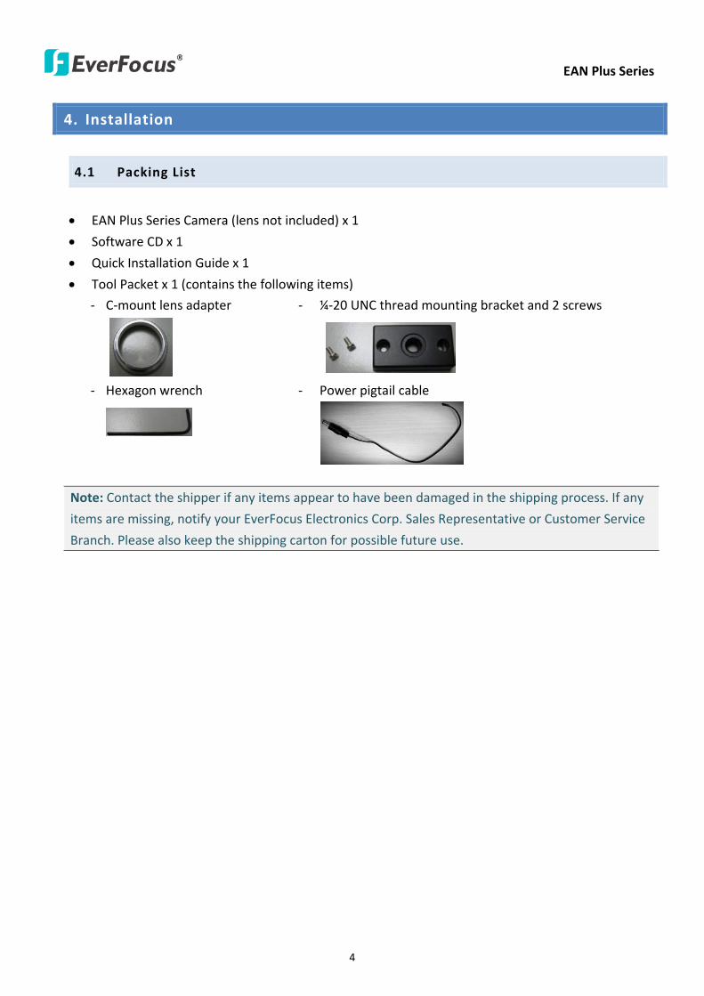
EAN Plus Series
4
4 Installation
41 Packing List
bull EAN Plus Series Camera (lens not included) x 1
bull Software CD x 1
bull Quick Installation Guide x 1
bull Tool Packet x 1 (contains the following items)
- C-mount lens adapter - frac14-20 UNC thread mounting bracket and 2 screws
- Hexagon wrench - Power pigtail cable
Note Contact the shipper if any items appear to have been damaged in the shipping process If any
items are missing notify your EverFocus Electronics Corp Sales Representative or Customer Service
Branch Please also keep the shipping carton for possible future use
EAN Plus Series
5
42 IO Terminal Block
The IO terminal block located on the rear panel of the camera can be used to develop application
for alarm input and output
1 2 3 4
Pin Assignment
No Function No Function
1 Alarm COM 3 Alarm Input
2 Alarm Output 4 Digital GND
43 Lens Installation and Adjustment
You can install either a CS-mount or a C-mount lens into the camera It is recommended to use a lens
with aperture ratio of F14 or smaller Please refer to the following reference steps
C-Mount Lens Adapter
DC Auto Iris Lens Connector
Focus Screw
Zoom Screw
CS-Mount Lens
1 Remove the cover cap from the camera body
2 Install the lens into the camera body
3 Adjust the lens using the Focus Zoom Screws
If you are using a DC Auto Iris lens
1 Remove the cover cap from the camera body
2 Install the lens into the camera body
3 Connect the DC cable to the DC Auto Iris Lens Connector
EAN Plus Series
6
4 When making final focus adjustment place the ND filter in front of the lens to force the lens iris
to open and then adjust the lens using the Focus Zoom Screws
Note To use the ND filter remove the protective sheets from both sides of an ND filter
5 Lock the Focus Screw and then remove the ND filter
C-Mount Lens
1 Remove the cover cap from the camera body
2 Install the lens into the camera body using the supplied C-mount lens adapter
3 Adjust the lens using the Focus Zoom Screws
Note Installing a C-mount lens without the C-mount lens adapter may damage the camera sensor
44 Top Bottom-Mount
You can use the supplied mounting bracket and screw it on the top of the camera body to suspend
the camera or on the bottom of the camera body to support the camera
Top Mount
Bottom Mount
EAN Plus Series
7
45 Basic Connection
Micro SD
Audio
In OutEthernet (PoE)
DC 12VPower
Reset
Video Out
COM
Out In
GN
D
Alarm
1
2
3
3
4
5
1 Use a standard network cable to connect the camera to the network
2 Connect the camera to power using one of the following methods
bull Plugging the supplied power pigtail cable to the DC 12V port
bull Using the PoE function and the power will be provided over the network cable
3 Optionally connect the camera to a speaker or microphone Note that microphones with
external power supplies are required
4 Optionally connect the camera to a monitor using a BNC cable
5 Optionally connect the camera to the input output devices
After powering the camera the power LED will be lit in red and you can access the live view and
adjust the image clarity
EAN Plus Series
8
5 Accessing the User Interface
This section explains how to access the Web interface of the camera for configuration
51 Assigning an IP Address
You have to assign an IP address for your camera to be accessible To assign an IP address to the
camera use the IP Utility (IPU) software included in the software CD Please connect the IP camera in
the same LAN of your computer
1 Install and then start the IPU program The following dialog box appears
2 Click Find Devices to search the cameras connected in the LAN The default network values of the
cameras will be displayed By default the network protocol of the camera is DHCP
3 To configure the network settings select a camera and then click LoginMulti Login to log in
EAN Plus Series
9
4 Type the user ID and password Click OK
Note
1 The default user ID is user1 and the default password is 11111111
2 If you select more than one camera that has the same user ID password you will be able
to log in several cameras at once
5 To change the IP address double-click the IP Address of the camera Type a new IP address and
then click Set IP Address to save the settings
You can also change the other settings by double-clicking the values After configuring the values
click Save Configuration
Note Most networks uses DHCP to assign IP address if you are unsure of your network
settings please consult your network administrators for configuration details
6 To access the camera highlight the camera and click Connect to Selected IP The Internet
Explorer window pops up
7 Type the user ID and password to log in The Live View window of the camera appears
Note You might be required to download ActiveX which is required to view the camera feed
If asked click Yes For more details on setting up the Microsoft Internet Explorer please refer
to 52 Settings for Microsoft Internet Explorer
EAN Plus Series
10
52 Settings for Microsoft Internet Explorer
To enable Remove Live View Firmware Upgrade and ActiveX Prompt on Internet Explorer some
settings have to be complete Please follow the steps below
1 On the computer click Start gt Control Panel gt System and Security gt Action Center (click Change
User Account Control Settings) the User Account Control Settings window appears Adjust the
slide bar to Never Notify and then click OK Restart your computer if requested
2 Open the Internet Explore click Tools gt Internet Options gt Security Tab gt Custom Level the
Security Settings windows appears
EAN Plus Series
11
3 In the Download unsigned ActiveX controls field select Prompt In the Include local directory
path when uploading files to a server field select Enable Click OK
4 In the Internet Options window click the Advanced tab and then disable Enable memory
protection to help mitigate online attacks Click OK
EAN Plus Series
12
53 Connecting the Camera to the Network
There are three methods to connect the IP camera to the network Router or LAN Connection Direct
High-Speed Connection and One-to-One Connection
Router or LAN connection
This is the most common connection in which the IP camera is connected to a router and allows
multiple users on and off site to see the IP camera on a LANWAN (Internet) The camera must be
assigned an IP address that is compatible with its LAN By setting up port forwarding on the router
you can remotely access the cameras from outside of the LAN via the Internet To remotely access the
Web interface of the IP camera please refer to 732 DDNS To set up port forwarding please consult
the manual of the router
Straight-through LAN patch cable
Right Pinout of a straight-through cable
EAN Plus Series
13
Direct High-Speed Connection
In a Direct High-Speed Connection the camera connects directly to a modem without the need for a
router You need to set the static or dynamic WAN IP address assigned by your ISP (Internet Service
Provider) in the camerarsquos configuration web pages To access the camera just type ldquohttpxxxrdquo
where xxx is the IP address given by your ISP If you have a dynamic IP address this connection may
require that you use DDNS for a reliable connection Please refer to 732 DDNS
One-to-One Connection (Directly from PC to IP Camera)
You can connect directly without using a switch router or modem However only the PC connected
to the camera will be able to view the IP camera You will also have to manually assign a compatible IP
address to both the computer and the IP camera Unless the PC has another network connection the
IP camera will be the only network device visible to the PC See the diagram below
Pinout of straight patch cable
Right Pinout of a crossed-over cable
EAN Plus Series
14
54 Live View Window
1 Press the button to display the Live View window Double-click on the
image to show a full-screen display double-click again or press ESC to return to the normal display
If you experience video feed lag time (if connected via Internet) you can reduce the resolution or
limit the number of streams See 741 Multi Streaming
2 Press the button to play the recorded data directly from the on-camera Micro
SD SDHC card (for this function to become active you have to insert a Micro SD SDHC card in the
Micro SD SDHC card slot on the rear panel of the camera See 783 SD Card
3 Press the button to enter the Settings page On the Settings page there are
8 submenu sections [System Info] [User Config] [Network] [Video] [Audio] [User] [Event] and
[System] Click on the section buttons to open their configuration fields See the Settings section
below for more information
EAN Plus Series
15
4 Press the button to exit the system and close this browser page
5 Video Stream
Select the Video Stream (Stream 1 Stream 2 or Stream 3) that will be displayed in the video box on
the right Stream 2 and Stream 3 are only selectable if you have enabled the stream The default
setting is Stream 1 only See 741 Multi Streaming
6 View Size
Use this to select the appropriate view size and shape of the video box on the right A smaller size
might increase transmission speed and video quality
7 Digital Zoom
Click the Zoom In Zoom Out buttons or roll the mouse wheel to zoom in out the camera live view
up to 10x Clicking on a magnified image will re-center the image around that point
8 Record
The Record button is used to record the current video stream Click the Record button to start
stop recording This icon is only for one-minute video recording To record long-period recordings
please set a recording schedule (See 775 Schedule) The location on your computer where the
image files will be saved to and file size can be specified in the submenu (see 72 User Config)
9 Snapshot
Click the Snapshot button to save a snapshot of the video image currently being displayed The
location on your computer where the snapshot data will be saved can be specified in ldquoSettings gt
User Config gt RecordingSnapshotrdquo (see 72 User Config)
10 Play Audio Transmit Audio
Click the ldquoPlay Audiordquo (speaker) and ldquoTransmit Audiordquo (microphone) buttons to switch the sound
onoff for the speaker and microphone respectively (if such external devices have been connected
to the camera directly or via the network)
EAN Plus Series
16
11 One Push
This function is only available for EAN3120 Plus 3220 Plus The One Push button can be displayed
on the live view window by enabling the Show One Push Buttons function on the User Config lt Live
View Config Setting page (see 721 Live View Config) To enable the button (turned from faded to
clear) on the Video lt Advanced Setting page select One Push from the White Balance Settings
Mode drop-down list and click the Apply button Once this is done pressing the One Push button
on the Live View Window will instruct the camera to adjust the white balance settings and these
settings will be active until the button is pushed again This is like a ldquosemi-automaticrdquo way to adjust
white balance to suit the user if the Auto or Manual mode does not give the result the user wants
12 Manual Control
ndash Trigger Event
Press the ldquoTrigger Eventrdquo button to trigger an event directly from the Live page If you have
configured an event (in the Event submenu) that will trigger a reaction (like a recording) when a
Manual Trigger event occurs clicking this button will trigger that reaction You can select what that
reaction will be You can for instance set the camera to record the audiovideo feed to the Micro
SD card on board the camera You can then click on the Playback button to open the Playback page
and search for and play all such recordings that had been stored on the card Such event actions
will be effective once they have been configured in the ldquoEventrdquo menu (see 77 Event)
ndash Reset Alarm
Press the ldquoReset Alarmrdquo button to reset the alarm output remotely
13 Status Display (info lines that can be placed above video box or at bottom of page)
This shows the name of the camera that is currently active or being configured current datetime
and current frame rate You can activate these info displays in the Settings gt User Config page (see
72 User Config)
14 Event Signal Icons (above video screen)
When an alarm or motion event is triggered a signal icon will appear at the top right of the Live
View window to alert the user
Alarm event icon When an alarm is triggered this icon appears
Motion detection icons The colors of these motion event icons correspond to the colors of the motion trigger areas you have configured in the Motion Detection submenu (see 772
Motion Detection)
Recording icon When the camera is recording to a PC-based folder this icon appears
EAN Plus Series
17
6 Playback
You can remotely play back the recordings stored in the on-camera micro SD card on the Web interface
or play back the recordings stored in the computer using the ARV Viewer included in the software CD
Playback is designed as a quick way to check recent recordings that were triggered by Events that were
configured to ldquoRecord to SD Cardrdquo in the Settings gt Event gt Event Settings page (see 771 Event
Settings)
Note Note that the Playback page is only accessible once the on-camera SD card is inserted and
active
61 Remote Playback Using Playback Page
On the Live View Window click the Playback button to open the Playback page
EAN Plus Series
18
Search by File Click the Search button to search for all recording files on the on-camera SD card
Search results will be displayed in the Filename area
Search by Time Click the calendar icon and select the date and time from which you want to search
until the present moment Click search to get your search results which will be displayed in the
Filename area
Search by event Click the type of Event recordings you want to search for (Alarm Motion Manual
Trigger) and then click the calendar icons to select the Start Time datetime and the End Time
datetime of your search Click Search to get your search results which will be displayed in the
Filename area
Multiple Files Check this box if you want the video player to play all the files in the selected folder
The files will be displayed in the Filename area
Loop Again Check this box if you want the video player to play the selected file over and over again
Play Once you have opened the filersquos folder and have clicked on the file to highlight it its details will
be displayed in the File Information area You can now click Play to play that specific file
Pause Click this button to pause the playback
Stop Click this button to stop the playback
【Recording List】
Filename This area will display a list of search results (recording files and folders) Folders (named
with the recorded date) will be displayed first Click on the folder and click on each subfolder until the
recording files (arv) in that folder is listed
File Information Click a file on the Filename list the selected file information will be listed
Copy Click this button to copy the selected file to the computer-based folder of your choice A
browsing box will open so that you can search for the folder of your choice You can use the ARV
Viewer to play back the recordings recorded in your computer For details on ARV Viewer see 63
Playing Back Using ARV Viewer
Lock Click this button to lock the selected file This will protect that file from being overwritten during
any overwrite procedure The file will thus be saved on the micro SD card indefinitely However the
file will still be deleted if the micro SD card is ever formatted
Remove Click this button to delete the selected file
EAN Plus Series
19
62 Setting up the Playback Function
Note that the Playback function will not be active until the user has inserted a micro SD card in the
camerarsquos micro SD card slot The card may also have to be formatted in the Settings submenu
Micro SD Card Slot
621 Preparing the Micro SD Card
Once you insert a functional micro SD card into the slot the Playback button on the Live page should
become active within seconds (see section 622 below ndash the grey letters should turn white) IF NOT
do the following
1 From the Live page click Settings gt System gt SD Card If no card has been inserted yet the
Remove button should be faded indicating that no card is being detected (If a card is
inserted and the Remove button is still faded pull the card out and re-insert it)
2 Slide the card into the slot until it clicks into position
3 The Remove button should become active within a few seconds indicating the card is active
4 If the Remove button stays faded click the Format button to format the card NOTE All data
on the disk will be deleted if the Format button is clicked
622 Testing the Playback Function
1 Once the SD card is detected by the system the button (inactive)
will turn to (active)
2 To test the Playback function (this is not required) set up a ldquoManual Triggerrdquo Recording
Event by clicking Settings gt Event gt Event Settings
3 Click the ldquoAddrdquo button on the middle right side of the page to open an ldquoAdd Eventrdquo box
4 Give the event a name like ldquoTest 1rdquo
EAN Plus Series
20
5 In the ldquoEvent Triggered byrdquo field click on Manual Trigger
6 Below this check ldquoEnable This Eventrdquo ldquoEnable Post-trigger Bufferrdquo and ldquoRecord to SD Cardrdquo
7 To save your settings click OK or close the box by clicking on the red x icon at top right of the
box (in which case you will be asked if you want to save the data to which you should reply OK)
The box will close and the new event will be listed in the list area of the Event Settings page
8 Look at the ldquoPost-trigger Bufferrdquo at the bottom to make sure the buffer time is set to 10 seconds
9 Click ldquoApplyrdquo to make sure all settings are saved
10 Click the Live button to go back to the Live page
11 Get ready to click the Trigger Event button at the bottom of the page Before you do see if you
can find something in the view screen that will give you a visual time marker For instance if you
can get your hand in front of the camerarsquos lens get ready to count down on your fingers
12 Click the Trigger Event button and slowly count down on your fingers in front of the lens (if you
are able to do so ndash if not try to find visual cues on the view screen that will help you to mark the
moment you pushed the trigger) The recording period will be as long as the buffer time you
selected ndash the default period is 10 seconds
13 Click the Playback button to open the Playback page
14 There are different ways to search for recording files on the camerarsquos Micro SD card (ie the
Playback memory) For a recent recording like your test event simply click the ldquoSearchrdquo button
under the ldquoSearch by Filerdquo header
15 If the SD card is active and formatted correctly the recording folderrsquos name (the recording dayrsquos
date) will appear in the Filename box at the bottom Click on this folder to open it If there are
sub-folders click on the bottom one (the most recent would be at the bottom) until you can click
on a file that cannot open to another sub-level and shows data in the File Information box to the
right This would be the file of the most recent recording event
16 To play this file click the Play button below the video box The test footage you have recorded
should start playing Play time should be 10 seconds if you left the Post-trigger Buffer as 10
seconds
EAN Plus Series
21
63 Playing Back Using ARV Viewer
You can play back the recordings stored in the computer using the ARV Viewer included in the
software CD To store the recordings in the computer please refer to Recording List gt Copy in 61
Remote Playback using Playback Page
4 5 6 7 8 9 10
321
No Item Name Descriptions
1 Snapshot Click to take and save a snapshot
2 Load File Click to load the recordings for playing back
3 Convert ARV to AVI Convert the recording from ARV format to AVI format
4 Playback Time Display the playback time
5 Total Time of Recording Display the total time of the recording
6 Stop Click to stop playing the recording
7 Step Reverse Click to display the previous frame
8 Play Click to play back the recording
9 Pause Click to pause the recording
10 Step Forward Click to display the next frame
EAN Plus Series
22
7 Settings
Click the Settings button on the Live View Window to enter the settings submenu There are nine buttons
on the left-side of the submenu Live System Info User Config Network Video Audio User Event and
System Click the Live button can go back to the Live View Window
71 System Info
The System Information and System Log can be checked on this page Click the top tab of the one you
want to see
711 Information
Click the Information tab the following dialog box appears These values cannot be changed on this
page and are for reference only
EAN Plus Series
23
712 Log
Click the Log tab the following dialog box appears The sequence number date time and event
messages of the log event will be displayed in the System Log field The log will display the last 256
log events Click the Export button to export the system log event list into a ldquotxtrdquo file and select the
location where the exported log file will be saved to
EAN Plus Series
24
72 User Config
Each user can set a different configuration for hisher Live page here These settings will be applied to
the logged-in userrsquos Live page every time heshe logs in
721 Live View Config
【VideoAudio Connection Protocol Setting】You can transmit the data stream from the IP cameras
using the RTSP (Real Time Streaming Protocol) on the network The RTSP is a protocol that allows
you to access video streams by using the compatible media players Click Apply to apply the
changes or Reset to reset without saving the changes RTP over UDP The RTSP protocol uses UDP for camera data stream transmission
RTP over TCP The RTSP protocol uses TCP for camera data stream transmission
RTP over HTTP The RTSP protocol uses HTTP for camera data stream transmission
Nevio CGI This is EverFocusrsquo protocol designed for EverFocusrsquo IP devices Select this
protocol for camera data stream transmission
【Text Settings】Check the box of each option (Machine name DateTime Frame Rate) to display
this info on the Live View Page
Foreground Color Slide the Red Green and Blue bars to create your preferred text color for the
info text line
Position Select the position where the text will be displayed Choose from Upper Left Lower
Right Lower Left
Click Apply to apply the changes or Reset to reset without saving the changes
EAN Plus Series
25
【DateTime Format Used in Text】Click the dropdown menu to select datetime format from the
listed options Click on the desired hour format Click Apply to apply the setting changes or Reset to
reset without saving the change
【Live View Layout Settings】 Check the ldquoShow One Push Buttonsrdquo boxes if you want to show these
buttons on the Live View Page Uncheck these boxes to hide these buttons This function is only
available for EAN3120 Plus 3220 Plus
722 Recording Snapshot
This configures where your Record Button and Snapshot Button ( ) files will be saved if
you click one of these buttons Selectable folders will be on the computer only not on the
on-camera SD card
【Recording Snapshot Export Settings】
Enable Event Recording to PC Checking this box will let the system save RecordSnapshot Button
recordings to the folder configured below on the userrsquos PC
Export Folder Select the Export folder for the action above by clicking on the browse (hellip) button
and then select the desired folder
File size The user can limit the size of each recorded file here (in minutes) When a single
recording file exceeds the time you set the system will create a new file to save that data to
Overwrite Select ldquoONrdquo for overwriting recordingsnapshot file when the disk storage capacity is
full The user can set the storage capacity limitation in the in-sentence field in the gray box below
the Overwrite setting ldquoIf the remaining hard disk capacity is less than ____ MB (50~2000) system
will stop recording or start overwriting ldquo
Click Apply to apply the setting changes or Reset to reset without saving the changes
EAN Plus Series
26
723 Language
Select the language to be displayed on the Web interface of the IP camera The default language is
English
To add a new language not listed in the current Language list click the Browse button to locate
the new language file (evb) on your computer and then click the Upload button Updated
language files might be available on the manufacturerrsquos website Contact your vendor if required
Click Apply to apply any changes or Reset to reset without saving the changes
Note Uploading a new language file will cause the system to reboot automatically Please create
a new network connection to the IP camera when the reboot is complete
EAN Plus Series
27
73 Network
This page covers network-related settings including Network DDNS SMTPFTP HTTPS SNMP and
Network Alarm
731 Network
The following information is required to configure the network settings Contact your network
administrator or your internet service provider to get the info
【IP Settings】
IP Type Refer to the network administrator for these settings of the server Default DHCP
DHCP This setting lets the system use an automatically assigned (dynamic) IP address This
address can change under certain circumstances For instance when the camerarsquos network
switchhub has to be rebooted Do not assign to the DHCP server the same IP addresses used
for the other network cameras and PCs with unique IP addresses
Static IP The user can manually set the Static IP address This type of address is stable and
cannot change but the user has to make sure there are no address conflicts with other
network-connected devices
PPPoE This is a DSL-connection application The ISP will ask the user to input a username and
password Contact your ISP for these details
EAN Plus Series
28
Note If PPPoE is selected as the IP type the supplied IP Utility program will not be able to
detect the device
IP address When DHCP is not used the user needs to manually enter the IP address of the
camera Do not enter an IP address that is already used for your computer or other network
cameras
Subnet Mask This field is used to set the netmask for your network so that the IP camera will be
recognized within the network Example 2552552550 When DHCP is selected the DHCP server
will assign this value automatically
Gateway This field is used to set the gateway for your network so that the IP camera will be
recognized within the network When DHCP is selected the DHCP server will assign this value
automatically
Primary DNS Enter the IP address of the DNS server if this is provided by an ISP
Secondary DNS If your ISP provided you with a secondary DNS address please enter it here
Username Enter the accountrsquos username (used only for PPPoE)
Password Used only for PPPoE
IPv6 Enter the IPv6 details in this area if this applies to your system
Click Apply to apply the setting changes or Reset to reset without saving the change
【Port Settings】Enter the HTTP HTTPS and RTSP port numbers and click Apply to save
【Multicast Settings】Enable if required fill in the setting options and click Apply to save
EAN Plus Series
29
732 DDNS
DDNS (Dynamic Domain Name System) is a service used to map a domain name to the dynamic IP
address of a network device You can set up the DDNS service for remote access to the IP camera
DDNS assigns a domain name (URL) to the IP camera so that the user does not need to go through
the trouble of checking if the IP address assigned by DHCP Server has changed Once the IP is
changed the IP camera will automatically update the information to the DDNS to ensure it is always
available for remote access
Before enabling the following DDNS function user should have applied for a host name from the
DDS service providerrsquos website We support these four DDNS server providers
wwweverfocusddnscom wwwsitelutionscom wwwdyndnscom and wwwno-ipcom
Note We highly recommend that you use xxxxeverfocusddnscom for the simplicity of setting up
your IP cameras
【DDNS Settings】
Enable Check this box to enable the DDNS function
Service ISP You can either apply for a host name from EverFocus or other DDNS server providers
If you choose the EverFocus DDNS server you can obtain a free host name from EverFocus by
following the steps below
bull From EverFocus To obtain a free host name from EverFocus type a desired host name in the
textbox click the Register Update button and then click the Apply button
bull From other DDNS server providers To obtain a domain name from one of the three DDNS
server providers you have to register your name with the provider first and then select the
provider and fill in the required information Please refer to the specific DDNS companyrsquos
website for further information
Record ID Type the record ID if provided by the DDNS server provider
EAN Plus Series
30
FQDN Type the fully qualified domain name applied from the DDNS server provider For
example xxxxdyndnscom
Username Password Type the login account of your DDNS server provider
Click Apply to apply the setting changes or Reset to reset without saving the changes
Note
1 In order to support the full functionality of the camera you must open the port numbers (80
554 443) on the router for remote access to the IP camera This function is available on most
routers in the market and is often known as ldquoPort Forwardingrdquo To set up Port Forwarding
please consult the manual of the router
2 In certain router models it is possible that you will not be able to access the camera using
DDNS while inside the routerrsquos network Please try using a PC located outside of your routerrsquos
network
Default Ports on All EverFocus IP Cameras
HTTP 80
RTSP 554
HTTPS 443
EAN Plus Series
31
733 SMTP FTP
【Set SMTP Server (email)】This area is for configuring the mail server that is used to send e-mail
notifications from the camera to predefined addresses via SMTP Note that to enable e-mail
notification function you have to check the Send Mail Notification item on the Event dialog box
(see 771 Event Settings)
SMTP Server Enter the IP address or the host name of the SMTP server used to send e-mails
SMTP Port Enter the port number for SMTP The default is 25
Authentication Check this box if the SMTP server requires authentication (userpassword)
User name Input the userrsquos login ID if the SMTP server requires authentication
Password Input the userrsquos login password if the SMTP server requires authentication
EAN Plus Series
32
Receiver Address Input the e-mail addresses for receiving an e-mail message when an EVENT is
enabled and triggered Please use ldquordquo to separate multiple addresses
Sender Address Input the senderrsquos e-mail address so that the receiver can recognize the sender
when an Event message is received
Attach Image Check this box if you want to attach an image when an alarm is triggered or an IP
camera detects events
Send Test Email Click the Test button to send a testing email to the assigned address
Click Apply to apply the setting changes or Reset to reset without saving the changes
【Set FTP Server】The settings relating to the FTP server used to transmit the alarm images can be
configured here Note that to enable uploading images to the FTP server function you have to
check the Upload to FTP item on the Event dialog box (see 771 Event Settings)
FTP Server Enter the IP address or the host name of the FTP server
FTP Port Enter the port number for the FTP server Default is 21
Recording Path Assign the recording path
User Name Set FTP Userrsquos name
Password Set FTP password
PASV mode Check to enable Passive mode Passive mode is normally enabled If a connection
cannot be established uncheck PASV Moderdquo
Test FTP Server Click the Test button to send a testing file to the assigned FTP server
Click Apply to apply the setting changes or Reset to reset without saving the changes
EAN Plus Series
33
734 HTTPS
Hypertext Transfer Protocol Secure (HTTPS) is a combination of the Hypertext Transfer Protocol
and the SSLTLS protocol and provides encrypted communication and secure identification of a
network web server
Before using the HTTPS function for communication with the IP camera a Certificate must be
created first There are two ways to create and install a certificate Create Self-Signed Certificate
and Create Certificate Request
Create Self-Signed Certificate
Please note that even though self-signed certificates are free and offer some protection true
security is only implemented after the installation of a signed certificate issued by a certificate
authority
1 Click the Create Self-Signed Certificate button the following dialog appears
EAN Plus Series
34
2 Type the required Certificate information and then click the Apply button The subject line will
be displayed in the Installed Certificate Information field
3 Click the Property button a pop-up window appears to display the details of the certificate
4 To optionally create and install other certificates remove the existing one by clicking the
Remove button to erase the certificate
5 On the Web page change the address from ldquohttprdquo to https in the address bar and press
Enter on the keyboard Some Security Alert dialogs will pop up Click OK or Yes to enable HTTPS
Create Certificate Request
You can apply for an official certificate from an issuing Certificate Authority
1 Click the Create Certificate Request button the following dialog appears
EAN Plus Series
35
2 Type the required Certificate information and then click the Apply button The subject line will
be displayed in the Created Request field
3 Click the Property button a pop-up window appears to display the details of the certificate
4 To optionally create and install other certificates or request remove the existing one by clicking
the Remove button to erase the certificate or request
5 Copy the contents of the Certificate request (in PEM format) and paste it to the certificate
request field on the Web page of the 3rd-party certification authority such as Symantec VeriSign
Wait for the certificate authority to issue an SSLTLS certificate and then download the issued
certificate on your computer
6 In the Install Signed Certificate field click the Browse button to search for the issued certificate
and then click the Upload button to import the certificate Once the certificate has been
uploaded this field will show the subject line of the certificate
EAN Plus Series
36
735 SNMP
The default values for SNMP v1v2v2c and SNMP v3 are already filled in Click either of the
Enable buttons to enable either of the two Make your changes as desired Click on the Trap
Address field to enter the digits if required
736 Network Alarm
This function works with EverFocusrsquos CMS software eg the PowerCon or the Power Video Plus For
the setting details please refer to the CMS network alarm protocol
EAN Plus Series
37
74 Video
The settings relating to video such as streaming camera OSD can be configured on this page The
Video page has five tabs Multi-streaming Camera Advanced ROI and Privacy Mask
741 Multi Streaming
【Stream Settings】 This IP camera can output three video streams simultaneously For each of these
streams the user can set the compression format resolution bit rate and frame rate individually
Stream 1 is always enabled for live view To enable Stream 2 andor Stream 3 check the ldquoEnablerdquo
box the header of each stream
Note If you connect to the camera via the Internet and experience a delay (lag time) in the video
feed try to reduce the number of streams and the quality and resolution of the streams ndash but
keep the frame rate at its maximum
EAN Plus Series
38
Format Select the encoding format ndash H264 or MJPEG
Resolution Select the most suitable resolution for your needs
Frame Rate Select from 1 to 30 fps
Bit Rate If required select whether you want the stream to stream a Constant Bit Rate or a
Variable Bit Rate and set the values of whichever option you choose
Click Apply to apply the setting changes or Reset to reset without saving the changes
【Video Recording Settings】Select the stream you want to configure and then select whether you
want the recording files of that stream to be saved in AVI or ARV format Click Apply to apply the
setting changes or Reset to reset without saving the changes
【Time Stamp Settings】 You can select the DateTime format position and add the setting to the
streaming
Click Apply to apply the changes or Reset to reset without saving the changes
EAN Plus Series
39
742 Camera
【Image Settings】Set the Brightness Saturation Contrast or Sharpness of the image Click Apply to
apply the changes or Reset to reset without saving the changes
【Camera Settings】
Mirror Switch Mirror ON to rotate the image horizontally around a vertical axis
Flip Switch Flip ON to rotate the image vertically around a horizontal axis
AE There are two options
ALC Selecting Automatic Light Control allows the camera circuitry to either take bright spots
more into consideration (peak) bringing out detail in bright areas or less into consideration
(average) bringing out detail in shadows
AES Selecting Auto Electronic Shutter disables the Shutter setting below this setting In this
mode the camera measures the light level and decides whether it needs more or less light and
then automatically adjusts the shutter speed accordingly
BLC Back Light Compensation (BLC) is used to make the subject appear clearer when it is set
against a bright background
OFF Select to switch Back Light Compensation functions off
(ON)BLC The BLC can increase the exposure of a dark area surrounded by a brighter area HLC
can decrease the exposure of bright areas surrounded by darker areas This enables the
camera to better display information that would otherwise have been ldquowhited outrdquo like a
license plate between two bright headlights on a dark road
(ON)HLC The Highlight-Suppression BLC is used to reduce the brightness of light sources in a
specific area It is activated only in a low illumination environment to minimize the effects of
glare from bright lights such as spotlights street lights or headlights in the field of view
EAN Plus Series
40
WDR The Wide Dynamic Range (WDR) function provides clearer images when both of the very
bright and dark areas simultaneously appear on the camera view There are four value options
OFF Low Middle and High Note that when WDR is ON some parts of the image may appear
solarized This is normal for WDR and is not a camera malfunction This function is only available
for EAN3120 Plus 3220 Plus
DN Mode
Auto Select to let the camera automatically switch to Night mode (black and white) when the
light levels fall to a specified level and back to Day mode (color) when the light levels rise to a
specified level
Day Select to keep the camera in Day mode (color) even in nighttime
Night Select to keep the camera in Night mode (black and white) even in daytime
EAN Plus Series
41
743 Advanced
EAN Plus Series
42
【Camera Settings】
Lens (IRIS Control) Select DC or Manual for IRIS control This function is only available for EAN3220
Plus
Exposure Settings (AE) This setting is used to adapt to the amount or type of light used by the
camera Note the settings vary among models
Mode This function is not available for EAN3220 Plus
Automatic Light Control (ALC) This option is only available for EAN3120 Plus 3300 Plus The
ALC allows the camera circuitry to either take bright spots more into consideration (peak)
bringing out detail in bright areas or less into consideration (average) bringing out detail in
shadows
Auto Electronic Shutter (AES) This option is only available for EAN3120 Plus 3300 Plus In
this mode the camera measures the light level and decides whether it needs more or less light
and then automatically adjusts the shutter speed accordingly
Manual This option is only available for EAN3300 Plus Select this option to manually set up
the Shutter (Manual) and AGC (Manual) values
Iris Specify the size of the Iris opening here
Shutter If enabled this setting lets you set the shutter speed yourself
Shutter Limit Use this setting to set the maximum shutter speed for the camera This function is
only available for EAN3120 Plus
AGC Set the Auto Gain Control limit here The lower the AGC level the lower the video signal and
the noise However the image will be darker under low-light condition with IR-off if you set up the
Iris to the maximum level
Slow Shutter This option can be switched on when AES Mode is selected in the Exposure Settings
(AE) field This function is only available for EAN3220 Plus 3300 Plus
Flickerless If the Mode field in the Exposure Settings (AE) area has been set to AES then this option
becomes available Choose between OFF 50HZ 60HZ 50HZ (High Luminance) or 60HZ (High
Luminance) This function is only available for EAN3300 Plus
EV Setting Set up the Exposure Value Note the brightness of the screen changes when you change
the EV value This function is only available for EAN3300 Plus
AE Response Set up Auto Exposure Response time This function is only available for EAN3300 Plus
AE Weighting Area Select an AE Weighting area Each setup AE Weighting Area is configured with
the appropriate brightness level on the center and the surrounding areas This function is only
available for EAN3300 Plus
Brightness Set the image brightness here
AE Reference Set the Auto Exposure value here This function is only available for EAN3120 Plus
EAN Plus Series
43
Black Level Set the Black level here This function is only available for EAN3300 Plus
WDR The Wide Dynamic Range (WDR) function provides clearer images when both of the very
bright and dark areas simultaneously appear on the camera view There are four value options OFF
Low Middle and High Note that when WDR is ON some parts of the image may appear solarized
This is normal for WDR and is not a camera malfunction This function is only available for EAN3120
Plus 3220 Plus
Visibility Enhancement (OFFLowMiddleHigh) Images in foggy or rain environments or in
environments with a very strong luminous intensity have a dynamic range that is significantly lower
than ordinary images The user can use this Visibility Enhancement setting to ldquoDEFOGrdquo the image if
such ldquoFOGGINGrdquo is an issue This function is only available for EAN3220 Plus
BLC Settings Back Light Compensation (BLC) is used to make the subject appear clearer when it is
set against a bright background
OFF Select to switch Back Light Compensation functions off
Back Light This option is only available for EAN3300 Plus The Back Light function is useful
when the background of the subject is very bright and the subject itself is dark Select Back
Light and adjust the slide bar to the left right for setting up the back light value The higher
the value the more the backlight compensation
Front Light This option is only available for EAN3300 Plus This function is useful when the
bright highlights such as flashlight or car headlights appear on the camera view Select Front
Light and adjust the slide bar to the left right for setting up the front light value The higher
the value the more the highlight compensation
ON (BLC) This option is only available when you select AES Mode in the Exposure Settings (AE)
field The option is only available for EAN3120 Plus 3220 Plus The BLC function is useful
when the background of the subject is very bright and the subject itself is dark Follow the
instructions below to configure the settings for each model
For EAN3120 Select ON (BLC) the button next to the Mode drop-down list will be
active (see image below) Click the button the green setup areas appear on the left
screen Click on the areas to enable disable the BLC function The selected areas (in green)
will be applied with the BLC function
EAN Plus Series
44
For EAN3220
You can configure one area to apply the BLC function Select ON (BLC) the setup buttons
appears (see image below) Select Low Middle High from the BLC Gain drop-down list To
set up a BLC area click the Edit Area button and then click on the blue color tab to turn your
mouse cursor into a blue pen Move the cursor to the position on the right screen where you
want the BLC rectangle to start and then click Move your cursor to the position (diagonally
opposing corner) where you want the BLC rectangle to end and then click The blue area will
be applied with the BLC function
ON (HLC) This option is only available when you select AES Mode in the Exposure Settings (AE)
field The option is only available for EAN3120 Plus 3220 Plus This function is useful when
the bright highlights such as flashlight or car headlights appear on the camera view Follow
the instructions below to configure the settings for each model
For EAN3120 Select ON (HLC) and then select a level from the drop-down list The higher the
level the more the highlight compensation
For EAN3220
HLC Level Select a level for the HLC setting The higher the level the more the highlight
compensation
HLC Mode Select All Day Night mode to apply the HLC function
HLC Black Mask Select On Off to apply the black mask on the selected areas The
over-exposure portions within the selected areas will be applied with the black mask
Color Tabs You can set up four HLC areas with different colors To set up a HLC area click the
Edit Area button and then click on the color tab to turn your mouse cursor into a pen of that
color Move the cursor to the position on the right screen where you want the HLC rectangle
to start and then click Move your cursor to the position (diagonally opposing corner) where
you want the HLC rectangle to end and then click Select ON from the color tab drop-down list
The rectangular area with the selected color will be applied with the HLC function
EAN Plus Series
45
Back Light This option is only available for EAN3300 Plus The Back Light function is useful
when the background of the subject is very bright and the subject itself is dark Select Back
Light and adjust the slide bar to the left right for setting up the back light value The higher
the value the more the backlight compensation
Front Light This option is only available for EAN3300 Plus This function is useful when the
bright highlights such as flashlight or car headlights appear on the camera view Select Front
Light and adjust the slide bar to the left right for setting up the front light value The higher
the value the more the highlight compensation
Noise Reduction Settings This limits the amount of digital ldquovideo noiserdquo that is usually found in any
video stream and helps to reduce file size The higher the level the more the reduction
For EAN3120 Plus 3300 Plus
Select ON OFF to enable disable the Noise Reduction function Or select Auto to let the camera
automatically enable disable the Noise Reduction function Slide the Level bar to set up the level
The higher the level the more the reduction
For EAN3220 Plus
2D DNR Select ON to enable the 2D DNR function
3D DNR Select ON to enable the 3D DNR function You can further set up the following settings
3D Start AGC Set up the AGC level to automatically start the 3D NR function
3D End AGC Set up the AGC level to automatically stop the 3D NR function
3D Level Set up the 3D DNR level
Smart NR Select ON to enable the Smart NR function The 3D NR function will be
automatically turned on when a motion event occurs
EAN Plus Series
46
White Balance Settings Select the mode that delivers the best quality image for the camerarsquos light
environment There are five options Auto Manual Indoor Outdoor One Push
Auto Select to let the camera automatically adjust the White Balance In the Auto mode the
camera computes the white balance value output using color information from the entire
screen It outputs the proper value using the color temperature radiating from a black subject
based on a range of value from 3000 to 7500K
Manual Select to adjust the Red and Blue values yourself in the fields below this field
Indoor Select to use the default settings for indoor environments In the Indoor mode the
camera uses 3200K as the base value
Outdoor Select to use the default settings for outdoor environment In the Outdoor mode it
uses 5800K as the base value
One Push Select to enable the Push button next to the Mode drop-down field This will allow you to force the camera to readjust the white balance every time you push the Push
button The lens will hold the same focal position until the next trigger command is received
This function helps to prevent incorrect focusing in dark environments This function is only
available for EAN3120 Plus 3220 Plus
Manual Temperature Select to use the optimized Red and Blue settings You can also
optionally adjust the Manual Level below this field for setting up the color temperature The
higher the value the more the color temperature This function is only available for EAN3300
Plus
DayNight Settings
Auto Select to let the camera automatically switch to Night mode (black and white) when the
light levels fall to a specified level and back to Day mode (color) when the light levels rise to a
specified level
Day Select to keep the camera in Day mode (color) even in nighttime
Night Select to keep the camera in Night mode (black and white) even in daytime
IR Smart Settings Select ON and set up the level to enhance the image quality when the images are
over exposure This function is useful when the camera is in the Night mode This function is only
available for EAN3220 Plus
Saturation Set the saturation value This function is not available for EAN3220 Plus
Monitor Type Select a gamma value from Set 1 Set 2 or Set 3 This function is only available for
EAN3120 Plus
Negative Switch this setting ON to view a color negative version of the video image This is useful
at night or when viewing temperature-sensitive images
EAN Plus Series
47
Sharpness Settings Select the sharpness level of the image A low sharpness level will deliver a
softer less detailed image A high level will deliver a sharp highly detailed image Switch Resolution
Enhancement ON to enable the resolution enhancement function
Contrast Select the contrast level of the image
Suppress Function This function is only available for EAN3300 Plus
Aperture Compensation Suppression (OFFLowMiddleHigh) This setting can be activated to
suppress luminance noise when the AGC level increases
Chroma Suppression (OFFLowMiddleHigh) This setting can be activated to suppress
chrominance noise when the AGC level increases
Ygamma (gamma 22standardcontrast enhancehigh light range mode LHigh light range mode
H) Select the Ygamma value for the video quality of the monitor This function is only available for
EAN3300 Plus
Monitor Settings The user can use this field to optimize video quality for his or her specific type of
monitor ndash LCD or CRT This function is only available for EAN3220 Plus
Color Space Standard The options are YUV601 for SD and YUV709 for HD These define the color
space standard required to convert an RGB picture to a YUV picture Generally YUV601 is used for
Standard Definition (720P) devices and the YUV709 is used for High Definition (1080P) devices
Click Apply to save all changes Click Reset to cancel all changes
EAN Plus Series
48
744 ROI (Region of Interest)
The Region of Interest (ROI) function allows users to set up multiple regions within an image with
better quality and less distortion than the rest of the image You can also use this function
together with the Digital Zoom function on the Live View Page to get a better image result Up to
eight ROIs can be configured in the ROI settings page
To set up an ROI region
1 Select an ROI number from the ROI No drop-down list
2 Click the Add button the mouse cursor will turn into a pen when you move it over the live
image on the left
3 Move the cursor to the position where you want the ROI rectangle to start and then click
Move the cursor to the position (diagonally opposing corner) where you want the ROI
rectangle to end and then click
4 Slide the Quality bar to set up the quality value
5 Click the Apply button to apply the settings or click the Reset button to reset without saving
the settings
EAN Plus Series
49
745 Privacy Mask
The Privacy Mask can block out sensitive areas from view covering the areas with colored or black
and white boxes in both live view and recorded clips This feature is useful when usersrsquo donrsquot want
the sensitive information visible Up to four Privacy Masks can be configured
【Privacy Mask Color Settings】The Modes vary among camera models
Mode Click Color to make the masks appear as colored rectangles on the screen Click BW to
make the masks appear as gray rectangles on the screen Click Mosaic to make the masks appear
as mosaic-effect rectangles on the screen
Level Select the color of the masks if you selected Color Mode Select the level of grayness of the
masks if you selected BW Mode Select the level of smallmiddlelarge if you selected Mosaic
Mode
Click Apply to apply the settings or click Reset to reset without saving the settings
Color Tabs Click on a color tab to turn your mouse cursor into a pen of that color
You can now create a block of that color on the video screen Move your cursor to the position
where you want your mask rectangle to start and then click Move your cursor to the position
(diagonally opposing corner) where you want your mask rectangle to end and then click The
rectangular area with the selected color will appear The live image will display the rectangular
area with the color you selected If you want to create another mask use one of the other three
colors Each color denotes a different mask area Only one block per color is allowed As the
number of colors suggests you can configure up to four blocks
EAN Plus Series
50
Select All Click to turn the whole screen into a mask area
Clear All Click to delete all configured mask blocks
Eraser Click to turn the mouse cursor into an eraser to delete any block you click on
Area Shows the color and number of the block
Enable Check this box to enable the related mask block
Click Apply to apply the settings or click Reset to reset without saving the settings
EAN Plus Series
51
75 Audio
The EAN Plus series IP camera can transmit audio to your computer if you have connected an external
microphone to its audio Input cable It can also receive audio input from you and transmit it via an
external speaker if you have connected such a speaker to its audio Output cable
Check the Enable Audio box to enable the camerarsquos audio function The camera will now act as a
digital bridge (via the IP network) between any connected audio input device and any connected
audio device
Adjust the Audio Input Volume if you have external audio input devices (microphones) connected to
the camera and if there are problems with the sound input being too low or high
Click Apply to save all settings or click Reset to cancel
EAN Plus Series
52
76 User
761 User Information
The system administrator can create up to ten user accounts on this page
To set up a user account
1 Highlight a user account and click the Modify button The following dialog box appears
2 Type the account name account description and password for the account Type the password
again in the Confirm field
3 Select an authority level for the user account from the Authority drop-down list
bull Supervisor Administrator The only difference between a supervisor and administrator is
that a supervisor can edit an administratorrsquos account and password but an administrator
cannot edit the supervisorrsquos account and password Multiple administrators can be
configured but there can be only one supervisor The supervisor and administrators all
have unrestricted access to the Settings submenus and can determine the registration of
all other users
EAN Plus Series
53
bull User A user can view the Live View page and view the system network video and audio
information A user can only adjust the User Config page settings The user does not have
access to the User Event and System pages
bull Guest The lowest level of access which only allows the user access to the Live View page
4 Select Active or Disable from the Status drop-down list to active or disable the user account
5 Click On in the SD Card Playback field to allow the user to access the SD card playback
function
6 Click OK
7 Click Apply to save all the settings
EAN Plus Series
54
762 IP Address Filter
Use this page to specify IP addresses that are not allowed to access this camera By default any IP
address can access the camera
Note The Allowed List addresses only become relevant when the Denied List contains a network
or range and the supervisor wants to allow one or more IP addresses within that excluded range
or network In such a scenario the user would enter the excluded range or network in the
Denied List and enter the exceptions in the Allowed List
To set up the IP Address Filter
1 Select Denied List Click the Add button the following dialog box appears
2 Select an IP type from the IP Type drop-down list
3 Select a network rule from the Rule drop-down list type the IP address and click OK
Single Type a single IP address in the IP Address field below
Network Type the IP address and subnet mask in the field below
Range Type a range for the IP addresses
4 If you have set up an IP range in Step 3 you can optionally set up the Allowed List to allow one
or more IP addresses within the setup IP range to access the IP camera
5 Click Apply
EAN Plus Series
55
77 Event
You can set up the Motion Detection event Tamper Detection event or the Alarm IO to automatically
notify the users when an event occurs or an alarm is triggered You can also set up a schedule to
automatically record the videos when an event occurs or an alarm is triggered
771 Event Settings
You can create a total of ten event or alarm settings page in the Event List
【Event List】
Click the Add button and the following Event Configuration Window appears
EAN Plus Series
56
Enter Event Name Type an event name
Event Triggered by Select an event or alarm type for the to-be-specified-below reactions
Alarm Input Select this if you want a reaction trigger coming from any external connected sensor
to activate a to-be-specified-below reactions via the camera system Make sure that a suitable
device is actually connected to the alarm input relay
Manual Trigger Select this option if you want to manually trigger the alarm by clicking the Trigger
Event button on the Live View Page
Motion Detection Select this option if you want motion in a specified part of the camerarsquos viewing
rectangle (the screen image) to trigger the to-be-specified-below reactions
Tampering Detection Select this option if you want the camerarsquos tampering detection sensor to
trigger the to-be-specified-below reactions
Schedule Recording Select this option if you want the Schedule Recording periods configured in
the recording schedule (the Settings gt Event gt Schedule page) to activate this event In this
scenario a preconfigured event reaction like a log entry will list the start and end times of each
period Actual recording will only be triggered if the event is preconfigured to do so
Enable This Event Select to activate the event
Enable Re-trigger Click to set a minimum time after the event is triggered before the event
can be triggered again
Enable Pre-trigger Buffer Click if you want the Event reaction (as selected in the ldquoNotification
Overrdquo field below) to be the activation of the video recording function and if you want the
recording to include the video feed from the time period (configurable on the previous ldquoEvent
Settingsrdquo page) just before the Event trigger occurred
Enable Post-trigger Buffer Click if you want the Event reaction (as selected in the Notification
Over field) to be the activation of the video recording function and if you want the recording
to include the video feed from a time period (configurable on the Event Settings page) just
after the Event trigger occurred
Motion Area Select a setup motion detection area from the drop down list Note this
function only becomes relevant after the Motion Detection areas have been set up (see 772
Motion Detection)
Notification Over Select the desired notification types form the following items
Log Click if you want the camera to list the eventrsquos details in its log if the event is triggered
Trigger Alarm Output Click if you want the camera to relay the event reaction to a device
attached to the alarm relay output wire and then set up the alarm output duration time
EAN Plus Series
57
Send Mail Notification Click if you want the camera to send an Event notification email to the
email address entered in the Set SMTP Server(email) field of the Network gt SMTPFTP page if
the Event occurs (see 733 SMTP FTP)
Upload to FTP Click if you want the camera to upload recorded footage to the FTP server
entered in the Set SMTP Server(email) field of the Network gt SMTPFTP page if the Event
occurs (see 733 SMTP FTP)
Record to SD Card Click if you want the camera to start recording its video feed (when the
event occurs) on an on-camera SD Card (if such a card has been inserted)
Note The recording will only be as long as the combined Pre- and Post-trigger Buffers so
make sure you enable at least one of these buffers especially the Post-trigger Buffer
Record to PC Check this box if you want the camera to start recording its video feed (when
the event occurs) on the same folder on the same PC as configured on the User Config gt
RecordingSnapshot page (if such a folder has been enabled and configured)
Note The recording will only be as long as the combined Pre- and Post-trigger Buffers (and
for as long as the event trigger is happening ndash eg a motion is detected) so make sure you
enable at least one of these buffers especially the Post-trigger Buffer
Network Alarm Check this box if you want the camera to send a network alarm signal (when
the event occurs) to the CMS servers configured on the Network gt Network Alarm page (see
736 Network Alarm)
Click OK to save all settings or click Cancel to cancel
【PrePost Trigger Settings】
Pre-trigger Buffer Select the duration for the buffer This will determine the amount of footage
(length of time) before the event trigger moment that will be included in an event-triggered video
recording if that buffer and video recording has been enabled in the Event Configuration Window
Post-trigger Buffer Select the duration for the buffer This will determine the amount of footage
(length of time) after the event trigger moment that will be included in an event-triggered video
recording if that buffer and video recording has been enabled in the Event Configuration Window
Click Apply to save all settings or click Reset to cancel
EAN Plus Series
58
772 Motion Detection
Use this page to configure up to four areas in which motion will be detected When a motion is
detected by the camera the motion detection icon will appear at the top right of the
Live page to alert the user This function can also be linked with correctly configured Events to
trigger Event reactions like the activation of video recording periods snapshots alarms etc
Color Tabs Click on a color tab to turn your mouse cursor into a pen of that color
You can now create a block of that color on the video screen Move your cursor to the position
where you want your detection rectangle to start and then click Move your cursor to the position
(diagonally opposing corner) where you want your detection rectangle to end and then click The
rectangular area with the selected color will appear This block will be an area inside which the
camera will detect motion If you want to create another detection area use one of the other three
palette colors Each color denotes a different detection area Only one block per color is allowed As
the number of colors suggests you can configure up to four blocks
Select All Click to turn the whole screen into a motion detection area
Clear All Click to delete all configured motion detection blocks
Eraser Click to turn your mouse cursor into an eraser to delete any block you click on
Area Shows the color and numberID of the block
Enable Check this box to enable the related motion detection block
Sensitivity Set the sensitivity of the motion detection sensor function
Click Apply to save all settings or click Reset to cancel
EAN Plus Series
59
773 Tamper Detection
Use this page to set the number of seconds that an alarm signal will be active if the device is
physically tampered (moved covered up or out of focus
774 Alarm IO
Use this page to set the type of trigger input and the type of output contact for the camerarsquos alarm
channel
EAN Plus Series
60
775 Schedule
Use this page to configure a schedule for periods during which the camera should deactivate all
user-activated Events (gray Deselect periods) or when the camera should deactivate all
user-activated Events except Schedule Recording (SR) events (blue Schedule Recording-only
periods) or when the camera should deactivate only SR events (red Event Recording-only periods)
or when it should enable all activated Events (yellow periods)
Event Recording Click this button to make every hour block you click on red A red block represents
an Event Recording-only block which represents an hour when the camera will deactivate all
preconfigured activated Schedule Recording events and keep all the other activated events active
Schedule Recording Click this button to make every hour block you click on blue A blue block
represents a Schedule Recording-only block which represents an hour when the camera will
deactivate all other preconfigured activated events and keep only the preconfigured activated
Schedule Recording events active
Event + Schedule Click this button to make every hour block you click on yellow A yellow block
represents an hour in which all activated events including Schedule Recording events will be
active
Deselect Click this button to make every hour block become grey A grey block represents an hour
in which all activated events including Schedule Recording events will be inactive
Click Apply to save all settings or click Reset to cancel
EAN Plus Series
61
78 System
You can set up the systemrsquos time and SD card settings and to do maintenance and reset actions like
reboots and upgrades
781 DateTime
【Machine Name Settings】If required enter a new name for the machine This name will be visible
in the Machine Name field of the IP Utility software which is included in the software CD
【Set Time Zone】Set the time zone of the camerarsquos location
【Set DateTime Manually】Set the datetime here if you wonrsquot be using an NTP server to update the
datetime (see below)
【Set DateTime Sync】Enter the Network Time Protocol server if applicable The camerarsquos time will
be automatically adjusted by synchronizing with the NTP server
Click Apply to save all settings or click Reset to cancel
EAN Plus Series
62
782 Daylight Saving
Click Enable Daylight Saving to enable this schedule and select the dates when the regionrsquos
daylight saving period begins and ends Click Apply to save all settings or click Reset to cancel
783 SD Card
Use this page to prepare the system for safely removing the SD Card from its slot
【Setup SD Card】
Notification Select the percentage of storage space that should be left on the card before the
camera notifies you of the impending storage shortage or overwrite
Event Recording Select if you want Event Recording only FTP Backup only or both
Overwrite Click ON if you want the card to start writing over recorded footage when its memory is
full Click OFF if you want the card to stop recording new footage when its memory is full
【SD Card Utility】
Capacity This shows you how much card memory has been used and how much memory capacity
remains on the card
Remove Click this button before removing the card from the system
Format Click this button to format the card All data saved on the SD card will be removed if the
card is formatted
EAN Plus Series
63
784 Maintenance
【Maintenance Server】
Reboot Click this button to reboot the unit without changing any of the settings Use this function if
the unit is not behaving as expected
Restore Click this button to restart and reset most of the current settings to their factory default
values The only settings that will not be changed to default are
bull IP settings
bull DDNS settings
Default The Default button should be used with caution Pressing this button will return all of the
cameras settings including the IP address to the factory default values The camera will then have
to be reconfigured
【SaveLoad Configuration Server】
Save To make a backup file of the machinersquos current configurations press Save to save all the
configurations to a config file This will enable the user to reload these configuration settings if the
settings are changed and there is unexpected behavior
Load To load a previously saved configuration press the Browse button to locate the saved config
file (see above) and then click the Load button The systemrsquos settings will be restored to the saved
configuration
EAN Plus Series
64
【SaveLoad Video Configuration Server】
Save To make a backup file of the machinersquos video configurations press Save to save the video
configurations to a config file This will enable the user to reload these configuration settings if the
settings are changed and there is unexpected behavior
Load To load a previously saved video configuration press the Browse button to locate the saved
config file (see above) and then click the Load button The systemrsquos settings will be restored to the
saved video configuration
【Upgrade Firmware】Click the Browse button to find a previously prepared firmware upgrade file
Click Upgrade to install the new firmware
Note
1 Do not disconnect power to the unit during the upgrade sequence The unit will reboot
automatically after the upgrade has completed (1-5 minutes)
2 During the upgrade process all event recording actions will be stopped Event recording
actions will resume after the camera is rebooted
3 If the ldquoFile Error Please re-loginrdquo warning message appears when upgrading the firmware
please try the following instructions
a Go to Internet Explorer gt Tools gt Internet Option gt Security gt Custom
b Find and enable the Include local directory path when uploading files to a server
EAN Plus Series
65
8 Upgrading Firmware Using IP Utility
You can upgrade the Firmware using the IP Utility software included in the software CD
1 Install and then start the IPU program The following dialog box appears
2 Click Find Devices to search the cameras connected in the LAN The default network values of the
cameras will be displayed By default the network protocol of the camera is DHCP
3 Select a camera and click LoginMulti Login to log in the camera
4 Type the user ID and password Click OK
Note
1 The default user ID is user1 and the default password is 11111111
2 If you select more than one camera that has the same user ID password you will be able
to log in several cameras at once
EAN Plus Series
66
5 Highlight the camera and then click Upgrade Firmware A browsing window appears
6 Select the firmware file (evb) and then click Open The IP Utility will automatically upgrade the
firmware
The camera will reboot once the update is complete Click Find Devices the new firmware version
should be displayed in the last part of the Machine Name
EAN Plus Series
67
9 Specifications
Model EAN3120 Plus EAN3220 Plus EAN3300 Plus
Camera
Image Sensor 13 Panasonic CMOS 128 Sony CMOS
Megapixel 13 MP 2 MP 3 MP
Picture Elements (H x V) 1280 x 1024 1944 x 1092 2048 x 1536
Min Illuminations 003 Lux at F14
Electronic Shutter (Sec) 85 ~ 160000 2 ~ 150000 1 ~ 110000
Scanning System NTSC PAL
WDR Yes Yes No
BLC Yes
Gain Control Yes
White Balance Yes
Lens
Mounting Type C CS
Day Night Yes (with removable auto IR-cut filter)
IRIS Control DC Electrical IRIS Lens IRIS
Video
Video Compression H264 MJPEG
Resolution
NTSC
2048 x 1536 1920 x 1200 (for EAN3300 Plus only)
1920 x 1080 (for EAN3300 Plus 3220 Plus only)
1280 x 1024 1280 x 720 1024 x 768 720 x 480 704 x 480 640 x 480
352 x 240 320 x 240 160 x 120
PAL
2048 x 1536 1920 x 1200 (for EAN3300 Plus only)
1920 x 1080 (for EAN3300 Plus 3220 Plus only)
1280 x 1024 1280 x 720 1024 x 768 720 x 576 704 x 576 640 x 480
352 x 288 320 x 240 160 x 120
Frame Rate 30 fps at 1280 x 1024 30 fps at 1920 x 1080 15 fps at 2048 x 1536
Audio
Audio Streaming Two-way audio
Audio Compression G711
EAN Plus Series
68
Network
Interface 10 100 Base-T Ethernet RJ-45 socket
Supported Protocols
TCPIP IPV6 UDP ICMP DHCP NTP DNS DDNS SMTP SNMP FTP
HTTP HTTPs PPPoE UPnP Bonjour RTP RTSP RTCP IGMP ARP ONVIF
PSIA
Connector
Power DC female port PoE
Ethernet RJ-45
Audio 1 In (phone jack for microphone)
1 Out (phone jack for Speaker)
Alarm IO Terminal IO wires
Local Storage Micro SD SDHC memory card slot
TV-Out BNC socket composite 1 V p-p 75 Ω
General
Power Source DC 12V PoE (IEEE8023af)
Power Consumption
(IR LEDs On)
5W (DC 12V)
621W (PoE)
5W (DC 12V)
522W (PoE)
5W (DC 12V)
536W (PoE)
Operating Temperature 0degC ~ +50degC 32degF ~ +122degF
Humidity 20 to 80 (no condensation)
Safety CE FCC
Dimensions (L x W x H) 117 x 56 x 68 mm 46 x 22 x 27 in
Weight 410 g 09 lb
EverFocus Electronics Corp EverFocus Taiwan 12F No79 Sec 1 Shin-Tai Wu Road Hsi-Chih Taipei Taiwan TEL +886 2 2698 2334 FAX +886 2 2698 2380 wwweverfocuscomtw marketingeverfocuscomtw
EverFocus Europe - Germany Albert-Einstein-Strasse 1 D-46446 Emmerich Germany TEL +49 2822 93940 FAX +49 2822 939495 wwweverfocusde infoeverfocusde
EverFocus China - Beijing Room 609 Technology Trade Building Shangdi Information Industry Base Haidian District Beijing 100085 China TEL +86 10 6297 3336~39 FAX +86 10 6297 1423 wwweverfocuscomcn marketingeverfocuscomcn
EverFocus China - Shenzhen 4F No 2 D4 Building Wan Yelong Industrial Park Tangtou Road Shiyan Baoan Shenzhen Guangdong 518101 China TEL +86 755 2765 1313 FAX +86 755 2765 0337 wwweverfocuscomcn marketingeverfocuscomcn
EverFocus USA - California 1801 Highland Avenue Unit A Duarte CA 91010 USA TEL +1 626 844 8888 FAX +1 626 844 8838 wwweverfocuscom saleseverfocuscom
EverFocus USA - New York 415 Oser Avenue Unit S Hauppauge NY 11788 USA TEL +1 631 436 5070 FAX +1 631 436 5027 wwweverfocuscom saleseverfocuscom
EverFocus Japan 5F Kinshicho City Building 2-13-4 Koto-BashiSumida-Ku Tokyo 130-0022 Japan TEL +81 3 5625 8188 FAX +81 3 5625 8189 wwweverfocuscojp infoeverfocuscojp
EverFocus Europe - UK Unit 12 Spitfire Business Park Hawker Road Croydon Surrey CR0 4WD UK TEL +44 20 8649 9757 +44 845 430 9999 FAX +44 20 8649 9907 wwweverfocusukcouk salesukeverfocuscom
EverFocus India Suite 803 Housefin Bhavan C-21 Bandra Kurla Complex Bandra (East) Mumbai 400051 India TEL +91 22 6128 8700 FAX +91 22 6128 8705 wwweverfocusin saleseverfocusin
PN 4605PQ3120B010A-VerC
Your EverFocus product is designed and manufactured with high quality materials and components which can be recycled and reused This symbol means that electrical and electronic equipment at their end-of-life should be disposed of separately from your household waste Please dispose of this equipment at your local community waste collectionrecycling centre In the European Union there are separate collection systems for used electrical and electronic product Please help us to conserve the environment we live in
Ihr EverFocus Produkt wurde entwickelt und hergestellt mit qualitativ hochwertigen Materialien und Komponenten die recycelt und wieder verwendet werden koumlnnen Dieses Symbol bedeutet dass elektrische und elektronische Geraumlte am Ende ihrer Nutzungsdauer vom Hausmuumlll getrennt entsorgt werden sollen Bitte entsorgen Sie dieses Geraumlt bei Ihrer oumlrtlichen kommunalen Sammelstelle oder im Recycling Centre Helfen Sie uns bitte die Umwelt zu erhalten in der wir leben
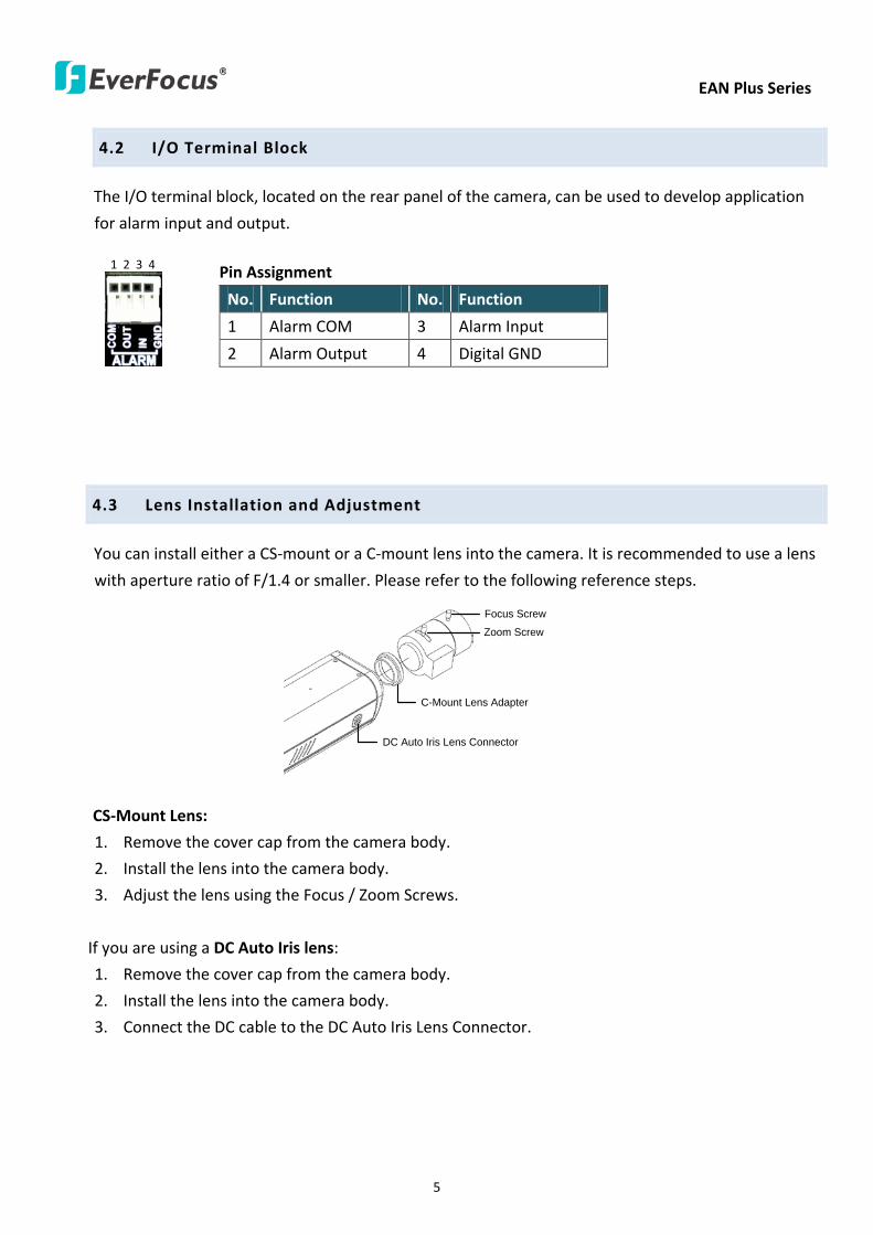
EAN Plus Series
5
42 IO Terminal Block
The IO terminal block located on the rear panel of the camera can be used to develop application
for alarm input and output
1 2 3 4
Pin Assignment
No Function No Function
1 Alarm COM 3 Alarm Input
2 Alarm Output 4 Digital GND
43 Lens Installation and Adjustment
You can install either a CS-mount or a C-mount lens into the camera It is recommended to use a lens
with aperture ratio of F14 or smaller Please refer to the following reference steps
C-Mount Lens Adapter
DC Auto Iris Lens Connector
Focus Screw
Zoom Screw
CS-Mount Lens
1 Remove the cover cap from the camera body
2 Install the lens into the camera body
3 Adjust the lens using the Focus Zoom Screws
If you are using a DC Auto Iris lens
1 Remove the cover cap from the camera body
2 Install the lens into the camera body
3 Connect the DC cable to the DC Auto Iris Lens Connector
EAN Plus Series
6
4 When making final focus adjustment place the ND filter in front of the lens to force the lens iris
to open and then adjust the lens using the Focus Zoom Screws
Note To use the ND filter remove the protective sheets from both sides of an ND filter
5 Lock the Focus Screw and then remove the ND filter
C-Mount Lens
1 Remove the cover cap from the camera body
2 Install the lens into the camera body using the supplied C-mount lens adapter
3 Adjust the lens using the Focus Zoom Screws
Note Installing a C-mount lens without the C-mount lens adapter may damage the camera sensor
44 Top Bottom-Mount
You can use the supplied mounting bracket and screw it on the top of the camera body to suspend
the camera or on the bottom of the camera body to support the camera
Top Mount
Bottom Mount
EAN Plus Series
7
45 Basic Connection
Micro SD
Audio
In OutEthernet (PoE)
DC 12VPower
Reset
Video Out
COM
Out In
GN
D
Alarm
1
2
3
3
4
5
1 Use a standard network cable to connect the camera to the network
2 Connect the camera to power using one of the following methods
bull Plugging the supplied power pigtail cable to the DC 12V port
bull Using the PoE function and the power will be provided over the network cable
3 Optionally connect the camera to a speaker or microphone Note that microphones with
external power supplies are required
4 Optionally connect the camera to a monitor using a BNC cable
5 Optionally connect the camera to the input output devices
After powering the camera the power LED will be lit in red and you can access the live view and
adjust the image clarity
EAN Plus Series
8
5 Accessing the User Interface
This section explains how to access the Web interface of the camera for configuration
51 Assigning an IP Address
You have to assign an IP address for your camera to be accessible To assign an IP address to the
camera use the IP Utility (IPU) software included in the software CD Please connect the IP camera in
the same LAN of your computer
1 Install and then start the IPU program The following dialog box appears
2 Click Find Devices to search the cameras connected in the LAN The default network values of the
cameras will be displayed By default the network protocol of the camera is DHCP
3 To configure the network settings select a camera and then click LoginMulti Login to log in
EAN Plus Series
9
4 Type the user ID and password Click OK
Note
1 The default user ID is user1 and the default password is 11111111
2 If you select more than one camera that has the same user ID password you will be able
to log in several cameras at once
5 To change the IP address double-click the IP Address of the camera Type a new IP address and
then click Set IP Address to save the settings
You can also change the other settings by double-clicking the values After configuring the values
click Save Configuration
Note Most networks uses DHCP to assign IP address if you are unsure of your network
settings please consult your network administrators for configuration details
6 To access the camera highlight the camera and click Connect to Selected IP The Internet
Explorer window pops up
7 Type the user ID and password to log in The Live View window of the camera appears
Note You might be required to download ActiveX which is required to view the camera feed
If asked click Yes For more details on setting up the Microsoft Internet Explorer please refer
to 52 Settings for Microsoft Internet Explorer
EAN Plus Series
10
52 Settings for Microsoft Internet Explorer
To enable Remove Live View Firmware Upgrade and ActiveX Prompt on Internet Explorer some
settings have to be complete Please follow the steps below
1 On the computer click Start gt Control Panel gt System and Security gt Action Center (click Change
User Account Control Settings) the User Account Control Settings window appears Adjust the
slide bar to Never Notify and then click OK Restart your computer if requested
2 Open the Internet Explore click Tools gt Internet Options gt Security Tab gt Custom Level the
Security Settings windows appears
EAN Plus Series
11
3 In the Download unsigned ActiveX controls field select Prompt In the Include local directory
path when uploading files to a server field select Enable Click OK
4 In the Internet Options window click the Advanced tab and then disable Enable memory
protection to help mitigate online attacks Click OK
EAN Plus Series
12
53 Connecting the Camera to the Network
There are three methods to connect the IP camera to the network Router or LAN Connection Direct
High-Speed Connection and One-to-One Connection
Router or LAN connection
This is the most common connection in which the IP camera is connected to a router and allows
multiple users on and off site to see the IP camera on a LANWAN (Internet) The camera must be
assigned an IP address that is compatible with its LAN By setting up port forwarding on the router
you can remotely access the cameras from outside of the LAN via the Internet To remotely access the
Web interface of the IP camera please refer to 732 DDNS To set up port forwarding please consult
the manual of the router
Straight-through LAN patch cable
Right Pinout of a straight-through cable
EAN Plus Series
13
Direct High-Speed Connection
In a Direct High-Speed Connection the camera connects directly to a modem without the need for a
router You need to set the static or dynamic WAN IP address assigned by your ISP (Internet Service
Provider) in the camerarsquos configuration web pages To access the camera just type ldquohttpxxxrdquo
where xxx is the IP address given by your ISP If you have a dynamic IP address this connection may
require that you use DDNS for a reliable connection Please refer to 732 DDNS
One-to-One Connection (Directly from PC to IP Camera)
You can connect directly without using a switch router or modem However only the PC connected
to the camera will be able to view the IP camera You will also have to manually assign a compatible IP
address to both the computer and the IP camera Unless the PC has another network connection the
IP camera will be the only network device visible to the PC See the diagram below
Pinout of straight patch cable
Right Pinout of a crossed-over cable
EAN Plus Series
14
54 Live View Window
1 Press the button to display the Live View window Double-click on the
image to show a full-screen display double-click again or press ESC to return to the normal display
If you experience video feed lag time (if connected via Internet) you can reduce the resolution or
limit the number of streams See 741 Multi Streaming
2 Press the button to play the recorded data directly from the on-camera Micro
SD SDHC card (for this function to become active you have to insert a Micro SD SDHC card in the
Micro SD SDHC card slot on the rear panel of the camera See 783 SD Card
3 Press the button to enter the Settings page On the Settings page there are
8 submenu sections [System Info] [User Config] [Network] [Video] [Audio] [User] [Event] and
[System] Click on the section buttons to open their configuration fields See the Settings section
below for more information
EAN Plus Series
15
4 Press the button to exit the system and close this browser page
5 Video Stream
Select the Video Stream (Stream 1 Stream 2 or Stream 3) that will be displayed in the video box on
the right Stream 2 and Stream 3 are only selectable if you have enabled the stream The default
setting is Stream 1 only See 741 Multi Streaming
6 View Size
Use this to select the appropriate view size and shape of the video box on the right A smaller size
might increase transmission speed and video quality
7 Digital Zoom
Click the Zoom In Zoom Out buttons or roll the mouse wheel to zoom in out the camera live view
up to 10x Clicking on a magnified image will re-center the image around that point
8 Record
The Record button is used to record the current video stream Click the Record button to start
stop recording This icon is only for one-minute video recording To record long-period recordings
please set a recording schedule (See 775 Schedule) The location on your computer where the
image files will be saved to and file size can be specified in the submenu (see 72 User Config)
9 Snapshot
Click the Snapshot button to save a snapshot of the video image currently being displayed The
location on your computer where the snapshot data will be saved can be specified in ldquoSettings gt
User Config gt RecordingSnapshotrdquo (see 72 User Config)
10 Play Audio Transmit Audio
Click the ldquoPlay Audiordquo (speaker) and ldquoTransmit Audiordquo (microphone) buttons to switch the sound
onoff for the speaker and microphone respectively (if such external devices have been connected
to the camera directly or via the network)
EAN Plus Series
16
11 One Push
This function is only available for EAN3120 Plus 3220 Plus The One Push button can be displayed
on the live view window by enabling the Show One Push Buttons function on the User Config lt Live
View Config Setting page (see 721 Live View Config) To enable the button (turned from faded to
clear) on the Video lt Advanced Setting page select One Push from the White Balance Settings
Mode drop-down list and click the Apply button Once this is done pressing the One Push button
on the Live View Window will instruct the camera to adjust the white balance settings and these
settings will be active until the button is pushed again This is like a ldquosemi-automaticrdquo way to adjust
white balance to suit the user if the Auto or Manual mode does not give the result the user wants
12 Manual Control
ndash Trigger Event
Press the ldquoTrigger Eventrdquo button to trigger an event directly from the Live page If you have
configured an event (in the Event submenu) that will trigger a reaction (like a recording) when a
Manual Trigger event occurs clicking this button will trigger that reaction You can select what that
reaction will be You can for instance set the camera to record the audiovideo feed to the Micro
SD card on board the camera You can then click on the Playback button to open the Playback page
and search for and play all such recordings that had been stored on the card Such event actions
will be effective once they have been configured in the ldquoEventrdquo menu (see 77 Event)
ndash Reset Alarm
Press the ldquoReset Alarmrdquo button to reset the alarm output remotely
13 Status Display (info lines that can be placed above video box or at bottom of page)
This shows the name of the camera that is currently active or being configured current datetime
and current frame rate You can activate these info displays in the Settings gt User Config page (see
72 User Config)
14 Event Signal Icons (above video screen)
When an alarm or motion event is triggered a signal icon will appear at the top right of the Live
View window to alert the user
Alarm event icon When an alarm is triggered this icon appears
Motion detection icons The colors of these motion event icons correspond to the colors of the motion trigger areas you have configured in the Motion Detection submenu (see 772
Motion Detection)
Recording icon When the camera is recording to a PC-based folder this icon appears
EAN Plus Series
17
6 Playback
You can remotely play back the recordings stored in the on-camera micro SD card on the Web interface
or play back the recordings stored in the computer using the ARV Viewer included in the software CD
Playback is designed as a quick way to check recent recordings that were triggered by Events that were
configured to ldquoRecord to SD Cardrdquo in the Settings gt Event gt Event Settings page (see 771 Event
Settings)
Note Note that the Playback page is only accessible once the on-camera SD card is inserted and
active
61 Remote Playback Using Playback Page
On the Live View Window click the Playback button to open the Playback page
EAN Plus Series
18
Search by File Click the Search button to search for all recording files on the on-camera SD card
Search results will be displayed in the Filename area
Search by Time Click the calendar icon and select the date and time from which you want to search
until the present moment Click search to get your search results which will be displayed in the
Filename area
Search by event Click the type of Event recordings you want to search for (Alarm Motion Manual
Trigger) and then click the calendar icons to select the Start Time datetime and the End Time
datetime of your search Click Search to get your search results which will be displayed in the
Filename area
Multiple Files Check this box if you want the video player to play all the files in the selected folder
The files will be displayed in the Filename area
Loop Again Check this box if you want the video player to play the selected file over and over again
Play Once you have opened the filersquos folder and have clicked on the file to highlight it its details will
be displayed in the File Information area You can now click Play to play that specific file
Pause Click this button to pause the playback
Stop Click this button to stop the playback
【Recording List】
Filename This area will display a list of search results (recording files and folders) Folders (named
with the recorded date) will be displayed first Click on the folder and click on each subfolder until the
recording files (arv) in that folder is listed
File Information Click a file on the Filename list the selected file information will be listed
Copy Click this button to copy the selected file to the computer-based folder of your choice A
browsing box will open so that you can search for the folder of your choice You can use the ARV
Viewer to play back the recordings recorded in your computer For details on ARV Viewer see 63
Playing Back Using ARV Viewer
Lock Click this button to lock the selected file This will protect that file from being overwritten during
any overwrite procedure The file will thus be saved on the micro SD card indefinitely However the
file will still be deleted if the micro SD card is ever formatted
Remove Click this button to delete the selected file
EAN Plus Series
19
62 Setting up the Playback Function
Note that the Playback function will not be active until the user has inserted a micro SD card in the
camerarsquos micro SD card slot The card may also have to be formatted in the Settings submenu
Micro SD Card Slot
621 Preparing the Micro SD Card
Once you insert a functional micro SD card into the slot the Playback button on the Live page should
become active within seconds (see section 622 below ndash the grey letters should turn white) IF NOT
do the following
1 From the Live page click Settings gt System gt SD Card If no card has been inserted yet the
Remove button should be faded indicating that no card is being detected (If a card is
inserted and the Remove button is still faded pull the card out and re-insert it)
2 Slide the card into the slot until it clicks into position
3 The Remove button should become active within a few seconds indicating the card is active
4 If the Remove button stays faded click the Format button to format the card NOTE All data
on the disk will be deleted if the Format button is clicked
622 Testing the Playback Function
1 Once the SD card is detected by the system the button (inactive)
will turn to (active)
2 To test the Playback function (this is not required) set up a ldquoManual Triggerrdquo Recording
Event by clicking Settings gt Event gt Event Settings
3 Click the ldquoAddrdquo button on the middle right side of the page to open an ldquoAdd Eventrdquo box
4 Give the event a name like ldquoTest 1rdquo
EAN Plus Series
20
5 In the ldquoEvent Triggered byrdquo field click on Manual Trigger
6 Below this check ldquoEnable This Eventrdquo ldquoEnable Post-trigger Bufferrdquo and ldquoRecord to SD Cardrdquo
7 To save your settings click OK or close the box by clicking on the red x icon at top right of the
box (in which case you will be asked if you want to save the data to which you should reply OK)
The box will close and the new event will be listed in the list area of the Event Settings page
8 Look at the ldquoPost-trigger Bufferrdquo at the bottom to make sure the buffer time is set to 10 seconds
9 Click ldquoApplyrdquo to make sure all settings are saved
10 Click the Live button to go back to the Live page
11 Get ready to click the Trigger Event button at the bottom of the page Before you do see if you
can find something in the view screen that will give you a visual time marker For instance if you
can get your hand in front of the camerarsquos lens get ready to count down on your fingers
12 Click the Trigger Event button and slowly count down on your fingers in front of the lens (if you
are able to do so ndash if not try to find visual cues on the view screen that will help you to mark the
moment you pushed the trigger) The recording period will be as long as the buffer time you
selected ndash the default period is 10 seconds
13 Click the Playback button to open the Playback page
14 There are different ways to search for recording files on the camerarsquos Micro SD card (ie the
Playback memory) For a recent recording like your test event simply click the ldquoSearchrdquo button
under the ldquoSearch by Filerdquo header
15 If the SD card is active and formatted correctly the recording folderrsquos name (the recording dayrsquos
date) will appear in the Filename box at the bottom Click on this folder to open it If there are
sub-folders click on the bottom one (the most recent would be at the bottom) until you can click
on a file that cannot open to another sub-level and shows data in the File Information box to the
right This would be the file of the most recent recording event
16 To play this file click the Play button below the video box The test footage you have recorded
should start playing Play time should be 10 seconds if you left the Post-trigger Buffer as 10
seconds
EAN Plus Series
21
63 Playing Back Using ARV Viewer
You can play back the recordings stored in the computer using the ARV Viewer included in the
software CD To store the recordings in the computer please refer to Recording List gt Copy in 61
Remote Playback using Playback Page
4 5 6 7 8 9 10
321
No Item Name Descriptions
1 Snapshot Click to take and save a snapshot
2 Load File Click to load the recordings for playing back
3 Convert ARV to AVI Convert the recording from ARV format to AVI format
4 Playback Time Display the playback time
5 Total Time of Recording Display the total time of the recording
6 Stop Click to stop playing the recording
7 Step Reverse Click to display the previous frame
8 Play Click to play back the recording
9 Pause Click to pause the recording
10 Step Forward Click to display the next frame
EAN Plus Series
22
7 Settings
Click the Settings button on the Live View Window to enter the settings submenu There are nine buttons
on the left-side of the submenu Live System Info User Config Network Video Audio User Event and
System Click the Live button can go back to the Live View Window
71 System Info
The System Information and System Log can be checked on this page Click the top tab of the one you
want to see
711 Information
Click the Information tab the following dialog box appears These values cannot be changed on this
page and are for reference only
EAN Plus Series
23
712 Log
Click the Log tab the following dialog box appears The sequence number date time and event
messages of the log event will be displayed in the System Log field The log will display the last 256
log events Click the Export button to export the system log event list into a ldquotxtrdquo file and select the
location where the exported log file will be saved to
EAN Plus Series
24
72 User Config
Each user can set a different configuration for hisher Live page here These settings will be applied to
the logged-in userrsquos Live page every time heshe logs in
721 Live View Config
【VideoAudio Connection Protocol Setting】You can transmit the data stream from the IP cameras
using the RTSP (Real Time Streaming Protocol) on the network The RTSP is a protocol that allows
you to access video streams by using the compatible media players Click Apply to apply the
changes or Reset to reset without saving the changes RTP over UDP The RTSP protocol uses UDP for camera data stream transmission
RTP over TCP The RTSP protocol uses TCP for camera data stream transmission
RTP over HTTP The RTSP protocol uses HTTP for camera data stream transmission
Nevio CGI This is EverFocusrsquo protocol designed for EverFocusrsquo IP devices Select this
protocol for camera data stream transmission
【Text Settings】Check the box of each option (Machine name DateTime Frame Rate) to display
this info on the Live View Page
Foreground Color Slide the Red Green and Blue bars to create your preferred text color for the
info text line
Position Select the position where the text will be displayed Choose from Upper Left Lower
Right Lower Left
Click Apply to apply the changes or Reset to reset without saving the changes
EAN Plus Series
25
【DateTime Format Used in Text】Click the dropdown menu to select datetime format from the
listed options Click on the desired hour format Click Apply to apply the setting changes or Reset to
reset without saving the change
【Live View Layout Settings】 Check the ldquoShow One Push Buttonsrdquo boxes if you want to show these
buttons on the Live View Page Uncheck these boxes to hide these buttons This function is only
available for EAN3120 Plus 3220 Plus
722 Recording Snapshot
This configures where your Record Button and Snapshot Button ( ) files will be saved if
you click one of these buttons Selectable folders will be on the computer only not on the
on-camera SD card
【Recording Snapshot Export Settings】
Enable Event Recording to PC Checking this box will let the system save RecordSnapshot Button
recordings to the folder configured below on the userrsquos PC
Export Folder Select the Export folder for the action above by clicking on the browse (hellip) button
and then select the desired folder
File size The user can limit the size of each recorded file here (in minutes) When a single
recording file exceeds the time you set the system will create a new file to save that data to
Overwrite Select ldquoONrdquo for overwriting recordingsnapshot file when the disk storage capacity is
full The user can set the storage capacity limitation in the in-sentence field in the gray box below
the Overwrite setting ldquoIf the remaining hard disk capacity is less than ____ MB (50~2000) system
will stop recording or start overwriting ldquo
Click Apply to apply the setting changes or Reset to reset without saving the changes
EAN Plus Series
26
723 Language
Select the language to be displayed on the Web interface of the IP camera The default language is
English
To add a new language not listed in the current Language list click the Browse button to locate
the new language file (evb) on your computer and then click the Upload button Updated
language files might be available on the manufacturerrsquos website Contact your vendor if required
Click Apply to apply any changes or Reset to reset without saving the changes
Note Uploading a new language file will cause the system to reboot automatically Please create
a new network connection to the IP camera when the reboot is complete
EAN Plus Series
27
73 Network
This page covers network-related settings including Network DDNS SMTPFTP HTTPS SNMP and
Network Alarm
731 Network
The following information is required to configure the network settings Contact your network
administrator or your internet service provider to get the info
【IP Settings】
IP Type Refer to the network administrator for these settings of the server Default DHCP
DHCP This setting lets the system use an automatically assigned (dynamic) IP address This
address can change under certain circumstances For instance when the camerarsquos network
switchhub has to be rebooted Do not assign to the DHCP server the same IP addresses used
for the other network cameras and PCs with unique IP addresses
Static IP The user can manually set the Static IP address This type of address is stable and
cannot change but the user has to make sure there are no address conflicts with other
network-connected devices
PPPoE This is a DSL-connection application The ISP will ask the user to input a username and
password Contact your ISP for these details
EAN Plus Series
28
Note If PPPoE is selected as the IP type the supplied IP Utility program will not be able to
detect the device
IP address When DHCP is not used the user needs to manually enter the IP address of the
camera Do not enter an IP address that is already used for your computer or other network
cameras
Subnet Mask This field is used to set the netmask for your network so that the IP camera will be
recognized within the network Example 2552552550 When DHCP is selected the DHCP server
will assign this value automatically
Gateway This field is used to set the gateway for your network so that the IP camera will be
recognized within the network When DHCP is selected the DHCP server will assign this value
automatically
Primary DNS Enter the IP address of the DNS server if this is provided by an ISP
Secondary DNS If your ISP provided you with a secondary DNS address please enter it here
Username Enter the accountrsquos username (used only for PPPoE)
Password Used only for PPPoE
IPv6 Enter the IPv6 details in this area if this applies to your system
Click Apply to apply the setting changes or Reset to reset without saving the change
【Port Settings】Enter the HTTP HTTPS and RTSP port numbers and click Apply to save
【Multicast Settings】Enable if required fill in the setting options and click Apply to save
EAN Plus Series
29
732 DDNS
DDNS (Dynamic Domain Name System) is a service used to map a domain name to the dynamic IP
address of a network device You can set up the DDNS service for remote access to the IP camera
DDNS assigns a domain name (URL) to the IP camera so that the user does not need to go through
the trouble of checking if the IP address assigned by DHCP Server has changed Once the IP is
changed the IP camera will automatically update the information to the DDNS to ensure it is always
available for remote access
Before enabling the following DDNS function user should have applied for a host name from the
DDS service providerrsquos website We support these four DDNS server providers
wwweverfocusddnscom wwwsitelutionscom wwwdyndnscom and wwwno-ipcom
Note We highly recommend that you use xxxxeverfocusddnscom for the simplicity of setting up
your IP cameras
【DDNS Settings】
Enable Check this box to enable the DDNS function
Service ISP You can either apply for a host name from EverFocus or other DDNS server providers
If you choose the EverFocus DDNS server you can obtain a free host name from EverFocus by
following the steps below
bull From EverFocus To obtain a free host name from EverFocus type a desired host name in the
textbox click the Register Update button and then click the Apply button
bull From other DDNS server providers To obtain a domain name from one of the three DDNS
server providers you have to register your name with the provider first and then select the
provider and fill in the required information Please refer to the specific DDNS companyrsquos
website for further information
Record ID Type the record ID if provided by the DDNS server provider
EAN Plus Series
30
FQDN Type the fully qualified domain name applied from the DDNS server provider For
example xxxxdyndnscom
Username Password Type the login account of your DDNS server provider
Click Apply to apply the setting changes or Reset to reset without saving the changes
Note
1 In order to support the full functionality of the camera you must open the port numbers (80
554 443) on the router for remote access to the IP camera This function is available on most
routers in the market and is often known as ldquoPort Forwardingrdquo To set up Port Forwarding
please consult the manual of the router
2 In certain router models it is possible that you will not be able to access the camera using
DDNS while inside the routerrsquos network Please try using a PC located outside of your routerrsquos
network
Default Ports on All EverFocus IP Cameras
HTTP 80
RTSP 554
HTTPS 443
EAN Plus Series
31
733 SMTP FTP
【Set SMTP Server (email)】This area is for configuring the mail server that is used to send e-mail
notifications from the camera to predefined addresses via SMTP Note that to enable e-mail
notification function you have to check the Send Mail Notification item on the Event dialog box
(see 771 Event Settings)
SMTP Server Enter the IP address or the host name of the SMTP server used to send e-mails
SMTP Port Enter the port number for SMTP The default is 25
Authentication Check this box if the SMTP server requires authentication (userpassword)
User name Input the userrsquos login ID if the SMTP server requires authentication
Password Input the userrsquos login password if the SMTP server requires authentication
EAN Plus Series
32
Receiver Address Input the e-mail addresses for receiving an e-mail message when an EVENT is
enabled and triggered Please use ldquordquo to separate multiple addresses
Sender Address Input the senderrsquos e-mail address so that the receiver can recognize the sender
when an Event message is received
Attach Image Check this box if you want to attach an image when an alarm is triggered or an IP
camera detects events
Send Test Email Click the Test button to send a testing email to the assigned address
Click Apply to apply the setting changes or Reset to reset without saving the changes
【Set FTP Server】The settings relating to the FTP server used to transmit the alarm images can be
configured here Note that to enable uploading images to the FTP server function you have to
check the Upload to FTP item on the Event dialog box (see 771 Event Settings)
FTP Server Enter the IP address or the host name of the FTP server
FTP Port Enter the port number for the FTP server Default is 21
Recording Path Assign the recording path
User Name Set FTP Userrsquos name
Password Set FTP password
PASV mode Check to enable Passive mode Passive mode is normally enabled If a connection
cannot be established uncheck PASV Moderdquo
Test FTP Server Click the Test button to send a testing file to the assigned FTP server
Click Apply to apply the setting changes or Reset to reset without saving the changes
EAN Plus Series
33
734 HTTPS
Hypertext Transfer Protocol Secure (HTTPS) is a combination of the Hypertext Transfer Protocol
and the SSLTLS protocol and provides encrypted communication and secure identification of a
network web server
Before using the HTTPS function for communication with the IP camera a Certificate must be
created first There are two ways to create and install a certificate Create Self-Signed Certificate
and Create Certificate Request
Create Self-Signed Certificate
Please note that even though self-signed certificates are free and offer some protection true
security is only implemented after the installation of a signed certificate issued by a certificate
authority
1 Click the Create Self-Signed Certificate button the following dialog appears
EAN Plus Series
34
2 Type the required Certificate information and then click the Apply button The subject line will
be displayed in the Installed Certificate Information field
3 Click the Property button a pop-up window appears to display the details of the certificate
4 To optionally create and install other certificates remove the existing one by clicking the
Remove button to erase the certificate
5 On the Web page change the address from ldquohttprdquo to https in the address bar and press
Enter on the keyboard Some Security Alert dialogs will pop up Click OK or Yes to enable HTTPS
Create Certificate Request
You can apply for an official certificate from an issuing Certificate Authority
1 Click the Create Certificate Request button the following dialog appears
EAN Plus Series
35
2 Type the required Certificate information and then click the Apply button The subject line will
be displayed in the Created Request field
3 Click the Property button a pop-up window appears to display the details of the certificate
4 To optionally create and install other certificates or request remove the existing one by clicking
the Remove button to erase the certificate or request
5 Copy the contents of the Certificate request (in PEM format) and paste it to the certificate
request field on the Web page of the 3rd-party certification authority such as Symantec VeriSign
Wait for the certificate authority to issue an SSLTLS certificate and then download the issued
certificate on your computer
6 In the Install Signed Certificate field click the Browse button to search for the issued certificate
and then click the Upload button to import the certificate Once the certificate has been
uploaded this field will show the subject line of the certificate
EAN Plus Series
36
735 SNMP
The default values for SNMP v1v2v2c and SNMP v3 are already filled in Click either of the
Enable buttons to enable either of the two Make your changes as desired Click on the Trap
Address field to enter the digits if required
736 Network Alarm
This function works with EverFocusrsquos CMS software eg the PowerCon or the Power Video Plus For
the setting details please refer to the CMS network alarm protocol
EAN Plus Series
37
74 Video
The settings relating to video such as streaming camera OSD can be configured on this page The
Video page has five tabs Multi-streaming Camera Advanced ROI and Privacy Mask
741 Multi Streaming
【Stream Settings】 This IP camera can output three video streams simultaneously For each of these
streams the user can set the compression format resolution bit rate and frame rate individually
Stream 1 is always enabled for live view To enable Stream 2 andor Stream 3 check the ldquoEnablerdquo
box the header of each stream
Note If you connect to the camera via the Internet and experience a delay (lag time) in the video
feed try to reduce the number of streams and the quality and resolution of the streams ndash but
keep the frame rate at its maximum
EAN Plus Series
38
Format Select the encoding format ndash H264 or MJPEG
Resolution Select the most suitable resolution for your needs
Frame Rate Select from 1 to 30 fps
Bit Rate If required select whether you want the stream to stream a Constant Bit Rate or a
Variable Bit Rate and set the values of whichever option you choose
Click Apply to apply the setting changes or Reset to reset without saving the changes
【Video Recording Settings】Select the stream you want to configure and then select whether you
want the recording files of that stream to be saved in AVI or ARV format Click Apply to apply the
setting changes or Reset to reset without saving the changes
【Time Stamp Settings】 You can select the DateTime format position and add the setting to the
streaming
Click Apply to apply the changes or Reset to reset without saving the changes
EAN Plus Series
39
742 Camera
【Image Settings】Set the Brightness Saturation Contrast or Sharpness of the image Click Apply to
apply the changes or Reset to reset without saving the changes
【Camera Settings】
Mirror Switch Mirror ON to rotate the image horizontally around a vertical axis
Flip Switch Flip ON to rotate the image vertically around a horizontal axis
AE There are two options
ALC Selecting Automatic Light Control allows the camera circuitry to either take bright spots
more into consideration (peak) bringing out detail in bright areas or less into consideration
(average) bringing out detail in shadows
AES Selecting Auto Electronic Shutter disables the Shutter setting below this setting In this
mode the camera measures the light level and decides whether it needs more or less light and
then automatically adjusts the shutter speed accordingly
BLC Back Light Compensation (BLC) is used to make the subject appear clearer when it is set
against a bright background
OFF Select to switch Back Light Compensation functions off
(ON)BLC The BLC can increase the exposure of a dark area surrounded by a brighter area HLC
can decrease the exposure of bright areas surrounded by darker areas This enables the
camera to better display information that would otherwise have been ldquowhited outrdquo like a
license plate between two bright headlights on a dark road
(ON)HLC The Highlight-Suppression BLC is used to reduce the brightness of light sources in a
specific area It is activated only in a low illumination environment to minimize the effects of
glare from bright lights such as spotlights street lights or headlights in the field of view
EAN Plus Series
40
WDR The Wide Dynamic Range (WDR) function provides clearer images when both of the very
bright and dark areas simultaneously appear on the camera view There are four value options
OFF Low Middle and High Note that when WDR is ON some parts of the image may appear
solarized This is normal for WDR and is not a camera malfunction This function is only available
for EAN3120 Plus 3220 Plus
DN Mode
Auto Select to let the camera automatically switch to Night mode (black and white) when the
light levels fall to a specified level and back to Day mode (color) when the light levels rise to a
specified level
Day Select to keep the camera in Day mode (color) even in nighttime
Night Select to keep the camera in Night mode (black and white) even in daytime
EAN Plus Series
41
743 Advanced
EAN Plus Series
42
【Camera Settings】
Lens (IRIS Control) Select DC or Manual for IRIS control This function is only available for EAN3220
Plus
Exposure Settings (AE) This setting is used to adapt to the amount or type of light used by the
camera Note the settings vary among models
Mode This function is not available for EAN3220 Plus
Automatic Light Control (ALC) This option is only available for EAN3120 Plus 3300 Plus The
ALC allows the camera circuitry to either take bright spots more into consideration (peak)
bringing out detail in bright areas or less into consideration (average) bringing out detail in
shadows
Auto Electronic Shutter (AES) This option is only available for EAN3120 Plus 3300 Plus In
this mode the camera measures the light level and decides whether it needs more or less light
and then automatically adjusts the shutter speed accordingly
Manual This option is only available for EAN3300 Plus Select this option to manually set up
the Shutter (Manual) and AGC (Manual) values
Iris Specify the size of the Iris opening here
Shutter If enabled this setting lets you set the shutter speed yourself
Shutter Limit Use this setting to set the maximum shutter speed for the camera This function is
only available for EAN3120 Plus
AGC Set the Auto Gain Control limit here The lower the AGC level the lower the video signal and
the noise However the image will be darker under low-light condition with IR-off if you set up the
Iris to the maximum level
Slow Shutter This option can be switched on when AES Mode is selected in the Exposure Settings
(AE) field This function is only available for EAN3220 Plus 3300 Plus
Flickerless If the Mode field in the Exposure Settings (AE) area has been set to AES then this option
becomes available Choose between OFF 50HZ 60HZ 50HZ (High Luminance) or 60HZ (High
Luminance) This function is only available for EAN3300 Plus
EV Setting Set up the Exposure Value Note the brightness of the screen changes when you change
the EV value This function is only available for EAN3300 Plus
AE Response Set up Auto Exposure Response time This function is only available for EAN3300 Plus
AE Weighting Area Select an AE Weighting area Each setup AE Weighting Area is configured with
the appropriate brightness level on the center and the surrounding areas This function is only
available for EAN3300 Plus
Brightness Set the image brightness here
AE Reference Set the Auto Exposure value here This function is only available for EAN3120 Plus
EAN Plus Series
43
Black Level Set the Black level here This function is only available for EAN3300 Plus
WDR The Wide Dynamic Range (WDR) function provides clearer images when both of the very
bright and dark areas simultaneously appear on the camera view There are four value options OFF
Low Middle and High Note that when WDR is ON some parts of the image may appear solarized
This is normal for WDR and is not a camera malfunction This function is only available for EAN3120
Plus 3220 Plus
Visibility Enhancement (OFFLowMiddleHigh) Images in foggy or rain environments or in
environments with a very strong luminous intensity have a dynamic range that is significantly lower
than ordinary images The user can use this Visibility Enhancement setting to ldquoDEFOGrdquo the image if
such ldquoFOGGINGrdquo is an issue This function is only available for EAN3220 Plus
BLC Settings Back Light Compensation (BLC) is used to make the subject appear clearer when it is
set against a bright background
OFF Select to switch Back Light Compensation functions off
Back Light This option is only available for EAN3300 Plus The Back Light function is useful
when the background of the subject is very bright and the subject itself is dark Select Back
Light and adjust the slide bar to the left right for setting up the back light value The higher
the value the more the backlight compensation
Front Light This option is only available for EAN3300 Plus This function is useful when the
bright highlights such as flashlight or car headlights appear on the camera view Select Front
Light and adjust the slide bar to the left right for setting up the front light value The higher
the value the more the highlight compensation
ON (BLC) This option is only available when you select AES Mode in the Exposure Settings (AE)
field The option is only available for EAN3120 Plus 3220 Plus The BLC function is useful
when the background of the subject is very bright and the subject itself is dark Follow the
instructions below to configure the settings for each model
For EAN3120 Select ON (BLC) the button next to the Mode drop-down list will be
active (see image below) Click the button the green setup areas appear on the left
screen Click on the areas to enable disable the BLC function The selected areas (in green)
will be applied with the BLC function
EAN Plus Series
44
For EAN3220
You can configure one area to apply the BLC function Select ON (BLC) the setup buttons
appears (see image below) Select Low Middle High from the BLC Gain drop-down list To
set up a BLC area click the Edit Area button and then click on the blue color tab to turn your
mouse cursor into a blue pen Move the cursor to the position on the right screen where you
want the BLC rectangle to start and then click Move your cursor to the position (diagonally
opposing corner) where you want the BLC rectangle to end and then click The blue area will
be applied with the BLC function
ON (HLC) This option is only available when you select AES Mode in the Exposure Settings (AE)
field The option is only available for EAN3120 Plus 3220 Plus This function is useful when
the bright highlights such as flashlight or car headlights appear on the camera view Follow
the instructions below to configure the settings for each model
For EAN3120 Select ON (HLC) and then select a level from the drop-down list The higher the
level the more the highlight compensation
For EAN3220
HLC Level Select a level for the HLC setting The higher the level the more the highlight
compensation
HLC Mode Select All Day Night mode to apply the HLC function
HLC Black Mask Select On Off to apply the black mask on the selected areas The
over-exposure portions within the selected areas will be applied with the black mask
Color Tabs You can set up four HLC areas with different colors To set up a HLC area click the
Edit Area button and then click on the color tab to turn your mouse cursor into a pen of that
color Move the cursor to the position on the right screen where you want the HLC rectangle
to start and then click Move your cursor to the position (diagonally opposing corner) where
you want the HLC rectangle to end and then click Select ON from the color tab drop-down list
The rectangular area with the selected color will be applied with the HLC function
EAN Plus Series
45
Back Light This option is only available for EAN3300 Plus The Back Light function is useful
when the background of the subject is very bright and the subject itself is dark Select Back
Light and adjust the slide bar to the left right for setting up the back light value The higher
the value the more the backlight compensation
Front Light This option is only available for EAN3300 Plus This function is useful when the
bright highlights such as flashlight or car headlights appear on the camera view Select Front
Light and adjust the slide bar to the left right for setting up the front light value The higher
the value the more the highlight compensation
Noise Reduction Settings This limits the amount of digital ldquovideo noiserdquo that is usually found in any
video stream and helps to reduce file size The higher the level the more the reduction
For EAN3120 Plus 3300 Plus
Select ON OFF to enable disable the Noise Reduction function Or select Auto to let the camera
automatically enable disable the Noise Reduction function Slide the Level bar to set up the level
The higher the level the more the reduction
For EAN3220 Plus
2D DNR Select ON to enable the 2D DNR function
3D DNR Select ON to enable the 3D DNR function You can further set up the following settings
3D Start AGC Set up the AGC level to automatically start the 3D NR function
3D End AGC Set up the AGC level to automatically stop the 3D NR function
3D Level Set up the 3D DNR level
Smart NR Select ON to enable the Smart NR function The 3D NR function will be
automatically turned on when a motion event occurs
EAN Plus Series
46
White Balance Settings Select the mode that delivers the best quality image for the camerarsquos light
environment There are five options Auto Manual Indoor Outdoor One Push
Auto Select to let the camera automatically adjust the White Balance In the Auto mode the
camera computes the white balance value output using color information from the entire
screen It outputs the proper value using the color temperature radiating from a black subject
based on a range of value from 3000 to 7500K
Manual Select to adjust the Red and Blue values yourself in the fields below this field
Indoor Select to use the default settings for indoor environments In the Indoor mode the
camera uses 3200K as the base value
Outdoor Select to use the default settings for outdoor environment In the Outdoor mode it
uses 5800K as the base value
One Push Select to enable the Push button next to the Mode drop-down field This will allow you to force the camera to readjust the white balance every time you push the Push
button The lens will hold the same focal position until the next trigger command is received
This function helps to prevent incorrect focusing in dark environments This function is only
available for EAN3120 Plus 3220 Plus
Manual Temperature Select to use the optimized Red and Blue settings You can also
optionally adjust the Manual Level below this field for setting up the color temperature The
higher the value the more the color temperature This function is only available for EAN3300
Plus
DayNight Settings
Auto Select to let the camera automatically switch to Night mode (black and white) when the
light levels fall to a specified level and back to Day mode (color) when the light levels rise to a
specified level
Day Select to keep the camera in Day mode (color) even in nighttime
Night Select to keep the camera in Night mode (black and white) even in daytime
IR Smart Settings Select ON and set up the level to enhance the image quality when the images are
over exposure This function is useful when the camera is in the Night mode This function is only
available for EAN3220 Plus
Saturation Set the saturation value This function is not available for EAN3220 Plus
Monitor Type Select a gamma value from Set 1 Set 2 or Set 3 This function is only available for
EAN3120 Plus
Negative Switch this setting ON to view a color negative version of the video image This is useful
at night or when viewing temperature-sensitive images
EAN Plus Series
47
Sharpness Settings Select the sharpness level of the image A low sharpness level will deliver a
softer less detailed image A high level will deliver a sharp highly detailed image Switch Resolution
Enhancement ON to enable the resolution enhancement function
Contrast Select the contrast level of the image
Suppress Function This function is only available for EAN3300 Plus
Aperture Compensation Suppression (OFFLowMiddleHigh) This setting can be activated to
suppress luminance noise when the AGC level increases
Chroma Suppression (OFFLowMiddleHigh) This setting can be activated to suppress
chrominance noise when the AGC level increases
Ygamma (gamma 22standardcontrast enhancehigh light range mode LHigh light range mode
H) Select the Ygamma value for the video quality of the monitor This function is only available for
EAN3300 Plus
Monitor Settings The user can use this field to optimize video quality for his or her specific type of
monitor ndash LCD or CRT This function is only available for EAN3220 Plus
Color Space Standard The options are YUV601 for SD and YUV709 for HD These define the color
space standard required to convert an RGB picture to a YUV picture Generally YUV601 is used for
Standard Definition (720P) devices and the YUV709 is used for High Definition (1080P) devices
Click Apply to save all changes Click Reset to cancel all changes
EAN Plus Series
48
744 ROI (Region of Interest)
The Region of Interest (ROI) function allows users to set up multiple regions within an image with
better quality and less distortion than the rest of the image You can also use this function
together with the Digital Zoom function on the Live View Page to get a better image result Up to
eight ROIs can be configured in the ROI settings page
To set up an ROI region
1 Select an ROI number from the ROI No drop-down list
2 Click the Add button the mouse cursor will turn into a pen when you move it over the live
image on the left
3 Move the cursor to the position where you want the ROI rectangle to start and then click
Move the cursor to the position (diagonally opposing corner) where you want the ROI
rectangle to end and then click
4 Slide the Quality bar to set up the quality value
5 Click the Apply button to apply the settings or click the Reset button to reset without saving
the settings
EAN Plus Series
49
745 Privacy Mask
The Privacy Mask can block out sensitive areas from view covering the areas with colored or black
and white boxes in both live view and recorded clips This feature is useful when usersrsquo donrsquot want
the sensitive information visible Up to four Privacy Masks can be configured
【Privacy Mask Color Settings】The Modes vary among camera models
Mode Click Color to make the masks appear as colored rectangles on the screen Click BW to
make the masks appear as gray rectangles on the screen Click Mosaic to make the masks appear
as mosaic-effect rectangles on the screen
Level Select the color of the masks if you selected Color Mode Select the level of grayness of the
masks if you selected BW Mode Select the level of smallmiddlelarge if you selected Mosaic
Mode
Click Apply to apply the settings or click Reset to reset without saving the settings
Color Tabs Click on a color tab to turn your mouse cursor into a pen of that color
You can now create a block of that color on the video screen Move your cursor to the position
where you want your mask rectangle to start and then click Move your cursor to the position
(diagonally opposing corner) where you want your mask rectangle to end and then click The
rectangular area with the selected color will appear The live image will display the rectangular
area with the color you selected If you want to create another mask use one of the other three
colors Each color denotes a different mask area Only one block per color is allowed As the
number of colors suggests you can configure up to four blocks
EAN Plus Series
50
Select All Click to turn the whole screen into a mask area
Clear All Click to delete all configured mask blocks
Eraser Click to turn the mouse cursor into an eraser to delete any block you click on
Area Shows the color and number of the block
Enable Check this box to enable the related mask block
Click Apply to apply the settings or click Reset to reset without saving the settings
EAN Plus Series
51
75 Audio
The EAN Plus series IP camera can transmit audio to your computer if you have connected an external
microphone to its audio Input cable It can also receive audio input from you and transmit it via an
external speaker if you have connected such a speaker to its audio Output cable
Check the Enable Audio box to enable the camerarsquos audio function The camera will now act as a
digital bridge (via the IP network) between any connected audio input device and any connected
audio device
Adjust the Audio Input Volume if you have external audio input devices (microphones) connected to
the camera and if there are problems with the sound input being too low or high
Click Apply to save all settings or click Reset to cancel
EAN Plus Series
52
76 User
761 User Information
The system administrator can create up to ten user accounts on this page
To set up a user account
1 Highlight a user account and click the Modify button The following dialog box appears
2 Type the account name account description and password for the account Type the password
again in the Confirm field
3 Select an authority level for the user account from the Authority drop-down list
bull Supervisor Administrator The only difference between a supervisor and administrator is
that a supervisor can edit an administratorrsquos account and password but an administrator
cannot edit the supervisorrsquos account and password Multiple administrators can be
configured but there can be only one supervisor The supervisor and administrators all
have unrestricted access to the Settings submenus and can determine the registration of
all other users
EAN Plus Series
53
bull User A user can view the Live View page and view the system network video and audio
information A user can only adjust the User Config page settings The user does not have
access to the User Event and System pages
bull Guest The lowest level of access which only allows the user access to the Live View page
4 Select Active or Disable from the Status drop-down list to active or disable the user account
5 Click On in the SD Card Playback field to allow the user to access the SD card playback
function
6 Click OK
7 Click Apply to save all the settings
EAN Plus Series
54
762 IP Address Filter
Use this page to specify IP addresses that are not allowed to access this camera By default any IP
address can access the camera
Note The Allowed List addresses only become relevant when the Denied List contains a network
or range and the supervisor wants to allow one or more IP addresses within that excluded range
or network In such a scenario the user would enter the excluded range or network in the
Denied List and enter the exceptions in the Allowed List
To set up the IP Address Filter
1 Select Denied List Click the Add button the following dialog box appears
2 Select an IP type from the IP Type drop-down list
3 Select a network rule from the Rule drop-down list type the IP address and click OK
Single Type a single IP address in the IP Address field below
Network Type the IP address and subnet mask in the field below
Range Type a range for the IP addresses
4 If you have set up an IP range in Step 3 you can optionally set up the Allowed List to allow one
or more IP addresses within the setup IP range to access the IP camera
5 Click Apply
EAN Plus Series
55
77 Event
You can set up the Motion Detection event Tamper Detection event or the Alarm IO to automatically
notify the users when an event occurs or an alarm is triggered You can also set up a schedule to
automatically record the videos when an event occurs or an alarm is triggered
771 Event Settings
You can create a total of ten event or alarm settings page in the Event List
【Event List】
Click the Add button and the following Event Configuration Window appears
EAN Plus Series
56
Enter Event Name Type an event name
Event Triggered by Select an event or alarm type for the to-be-specified-below reactions
Alarm Input Select this if you want a reaction trigger coming from any external connected sensor
to activate a to-be-specified-below reactions via the camera system Make sure that a suitable
device is actually connected to the alarm input relay
Manual Trigger Select this option if you want to manually trigger the alarm by clicking the Trigger
Event button on the Live View Page
Motion Detection Select this option if you want motion in a specified part of the camerarsquos viewing
rectangle (the screen image) to trigger the to-be-specified-below reactions
Tampering Detection Select this option if you want the camerarsquos tampering detection sensor to
trigger the to-be-specified-below reactions
Schedule Recording Select this option if you want the Schedule Recording periods configured in
the recording schedule (the Settings gt Event gt Schedule page) to activate this event In this
scenario a preconfigured event reaction like a log entry will list the start and end times of each
period Actual recording will only be triggered if the event is preconfigured to do so
Enable This Event Select to activate the event
Enable Re-trigger Click to set a minimum time after the event is triggered before the event
can be triggered again
Enable Pre-trigger Buffer Click if you want the Event reaction (as selected in the ldquoNotification
Overrdquo field below) to be the activation of the video recording function and if you want the
recording to include the video feed from the time period (configurable on the previous ldquoEvent
Settingsrdquo page) just before the Event trigger occurred
Enable Post-trigger Buffer Click if you want the Event reaction (as selected in the Notification
Over field) to be the activation of the video recording function and if you want the recording
to include the video feed from a time period (configurable on the Event Settings page) just
after the Event trigger occurred
Motion Area Select a setup motion detection area from the drop down list Note this
function only becomes relevant after the Motion Detection areas have been set up (see 772
Motion Detection)
Notification Over Select the desired notification types form the following items
Log Click if you want the camera to list the eventrsquos details in its log if the event is triggered
Trigger Alarm Output Click if you want the camera to relay the event reaction to a device
attached to the alarm relay output wire and then set up the alarm output duration time
EAN Plus Series
57
Send Mail Notification Click if you want the camera to send an Event notification email to the
email address entered in the Set SMTP Server(email) field of the Network gt SMTPFTP page if
the Event occurs (see 733 SMTP FTP)
Upload to FTP Click if you want the camera to upload recorded footage to the FTP server
entered in the Set SMTP Server(email) field of the Network gt SMTPFTP page if the Event
occurs (see 733 SMTP FTP)
Record to SD Card Click if you want the camera to start recording its video feed (when the
event occurs) on an on-camera SD Card (if such a card has been inserted)
Note The recording will only be as long as the combined Pre- and Post-trigger Buffers so
make sure you enable at least one of these buffers especially the Post-trigger Buffer
Record to PC Check this box if you want the camera to start recording its video feed (when
the event occurs) on the same folder on the same PC as configured on the User Config gt
RecordingSnapshot page (if such a folder has been enabled and configured)
Note The recording will only be as long as the combined Pre- and Post-trigger Buffers (and
for as long as the event trigger is happening ndash eg a motion is detected) so make sure you
enable at least one of these buffers especially the Post-trigger Buffer
Network Alarm Check this box if you want the camera to send a network alarm signal (when
the event occurs) to the CMS servers configured on the Network gt Network Alarm page (see
736 Network Alarm)
Click OK to save all settings or click Cancel to cancel
【PrePost Trigger Settings】
Pre-trigger Buffer Select the duration for the buffer This will determine the amount of footage
(length of time) before the event trigger moment that will be included in an event-triggered video
recording if that buffer and video recording has been enabled in the Event Configuration Window
Post-trigger Buffer Select the duration for the buffer This will determine the amount of footage
(length of time) after the event trigger moment that will be included in an event-triggered video
recording if that buffer and video recording has been enabled in the Event Configuration Window
Click Apply to save all settings or click Reset to cancel
EAN Plus Series
58
772 Motion Detection
Use this page to configure up to four areas in which motion will be detected When a motion is
detected by the camera the motion detection icon will appear at the top right of the
Live page to alert the user This function can also be linked with correctly configured Events to
trigger Event reactions like the activation of video recording periods snapshots alarms etc
Color Tabs Click on a color tab to turn your mouse cursor into a pen of that color
You can now create a block of that color on the video screen Move your cursor to the position
where you want your detection rectangle to start and then click Move your cursor to the position
(diagonally opposing corner) where you want your detection rectangle to end and then click The
rectangular area with the selected color will appear This block will be an area inside which the
camera will detect motion If you want to create another detection area use one of the other three
palette colors Each color denotes a different detection area Only one block per color is allowed As
the number of colors suggests you can configure up to four blocks
Select All Click to turn the whole screen into a motion detection area
Clear All Click to delete all configured motion detection blocks
Eraser Click to turn your mouse cursor into an eraser to delete any block you click on
Area Shows the color and numberID of the block
Enable Check this box to enable the related motion detection block
Sensitivity Set the sensitivity of the motion detection sensor function
Click Apply to save all settings or click Reset to cancel
EAN Plus Series
59
773 Tamper Detection
Use this page to set the number of seconds that an alarm signal will be active if the device is
physically tampered (moved covered up or out of focus
774 Alarm IO
Use this page to set the type of trigger input and the type of output contact for the camerarsquos alarm
channel
EAN Plus Series
60
775 Schedule
Use this page to configure a schedule for periods during which the camera should deactivate all
user-activated Events (gray Deselect periods) or when the camera should deactivate all
user-activated Events except Schedule Recording (SR) events (blue Schedule Recording-only
periods) or when the camera should deactivate only SR events (red Event Recording-only periods)
or when it should enable all activated Events (yellow periods)
Event Recording Click this button to make every hour block you click on red A red block represents
an Event Recording-only block which represents an hour when the camera will deactivate all
preconfigured activated Schedule Recording events and keep all the other activated events active
Schedule Recording Click this button to make every hour block you click on blue A blue block
represents a Schedule Recording-only block which represents an hour when the camera will
deactivate all other preconfigured activated events and keep only the preconfigured activated
Schedule Recording events active
Event + Schedule Click this button to make every hour block you click on yellow A yellow block
represents an hour in which all activated events including Schedule Recording events will be
active
Deselect Click this button to make every hour block become grey A grey block represents an hour
in which all activated events including Schedule Recording events will be inactive
Click Apply to save all settings or click Reset to cancel
EAN Plus Series
61
78 System
You can set up the systemrsquos time and SD card settings and to do maintenance and reset actions like
reboots and upgrades
781 DateTime
【Machine Name Settings】If required enter a new name for the machine This name will be visible
in the Machine Name field of the IP Utility software which is included in the software CD
【Set Time Zone】Set the time zone of the camerarsquos location
【Set DateTime Manually】Set the datetime here if you wonrsquot be using an NTP server to update the
datetime (see below)
【Set DateTime Sync】Enter the Network Time Protocol server if applicable The camerarsquos time will
be automatically adjusted by synchronizing with the NTP server
Click Apply to save all settings or click Reset to cancel
EAN Plus Series
62
782 Daylight Saving
Click Enable Daylight Saving to enable this schedule and select the dates when the regionrsquos
daylight saving period begins and ends Click Apply to save all settings or click Reset to cancel
783 SD Card
Use this page to prepare the system for safely removing the SD Card from its slot
【Setup SD Card】
Notification Select the percentage of storage space that should be left on the card before the
camera notifies you of the impending storage shortage or overwrite
Event Recording Select if you want Event Recording only FTP Backup only or both
Overwrite Click ON if you want the card to start writing over recorded footage when its memory is
full Click OFF if you want the card to stop recording new footage when its memory is full
【SD Card Utility】
Capacity This shows you how much card memory has been used and how much memory capacity
remains on the card
Remove Click this button before removing the card from the system
Format Click this button to format the card All data saved on the SD card will be removed if the
card is formatted
EAN Plus Series
63
784 Maintenance
【Maintenance Server】
Reboot Click this button to reboot the unit without changing any of the settings Use this function if
the unit is not behaving as expected
Restore Click this button to restart and reset most of the current settings to their factory default
values The only settings that will not be changed to default are
bull IP settings
bull DDNS settings
Default The Default button should be used with caution Pressing this button will return all of the
cameras settings including the IP address to the factory default values The camera will then have
to be reconfigured
【SaveLoad Configuration Server】
Save To make a backup file of the machinersquos current configurations press Save to save all the
configurations to a config file This will enable the user to reload these configuration settings if the
settings are changed and there is unexpected behavior
Load To load a previously saved configuration press the Browse button to locate the saved config
file (see above) and then click the Load button The systemrsquos settings will be restored to the saved
configuration
EAN Plus Series
64
【SaveLoad Video Configuration Server】
Save To make a backup file of the machinersquos video configurations press Save to save the video
configurations to a config file This will enable the user to reload these configuration settings if the
settings are changed and there is unexpected behavior
Load To load a previously saved video configuration press the Browse button to locate the saved
config file (see above) and then click the Load button The systemrsquos settings will be restored to the
saved video configuration
【Upgrade Firmware】Click the Browse button to find a previously prepared firmware upgrade file
Click Upgrade to install the new firmware
Note
1 Do not disconnect power to the unit during the upgrade sequence The unit will reboot
automatically after the upgrade has completed (1-5 minutes)
2 During the upgrade process all event recording actions will be stopped Event recording
actions will resume after the camera is rebooted
3 If the ldquoFile Error Please re-loginrdquo warning message appears when upgrading the firmware
please try the following instructions
a Go to Internet Explorer gt Tools gt Internet Option gt Security gt Custom
b Find and enable the Include local directory path when uploading files to a server
EAN Plus Series
65
8 Upgrading Firmware Using IP Utility
You can upgrade the Firmware using the IP Utility software included in the software CD
1 Install and then start the IPU program The following dialog box appears
2 Click Find Devices to search the cameras connected in the LAN The default network values of the
cameras will be displayed By default the network protocol of the camera is DHCP
3 Select a camera and click LoginMulti Login to log in the camera
4 Type the user ID and password Click OK
Note
1 The default user ID is user1 and the default password is 11111111
2 If you select more than one camera that has the same user ID password you will be able
to log in several cameras at once
EAN Plus Series
66
5 Highlight the camera and then click Upgrade Firmware A browsing window appears
6 Select the firmware file (evb) and then click Open The IP Utility will automatically upgrade the
firmware
The camera will reboot once the update is complete Click Find Devices the new firmware version
should be displayed in the last part of the Machine Name
EAN Plus Series
67
9 Specifications
Model EAN3120 Plus EAN3220 Plus EAN3300 Plus
Camera
Image Sensor 13 Panasonic CMOS 128 Sony CMOS
Megapixel 13 MP 2 MP 3 MP
Picture Elements (H x V) 1280 x 1024 1944 x 1092 2048 x 1536
Min Illuminations 003 Lux at F14
Electronic Shutter (Sec) 85 ~ 160000 2 ~ 150000 1 ~ 110000
Scanning System NTSC PAL
WDR Yes Yes No
BLC Yes
Gain Control Yes
White Balance Yes
Lens
Mounting Type C CS
Day Night Yes (with removable auto IR-cut filter)
IRIS Control DC Electrical IRIS Lens IRIS
Video
Video Compression H264 MJPEG
Resolution
NTSC
2048 x 1536 1920 x 1200 (for EAN3300 Plus only)
1920 x 1080 (for EAN3300 Plus 3220 Plus only)
1280 x 1024 1280 x 720 1024 x 768 720 x 480 704 x 480 640 x 480
352 x 240 320 x 240 160 x 120
PAL
2048 x 1536 1920 x 1200 (for EAN3300 Plus only)
1920 x 1080 (for EAN3300 Plus 3220 Plus only)
1280 x 1024 1280 x 720 1024 x 768 720 x 576 704 x 576 640 x 480
352 x 288 320 x 240 160 x 120
Frame Rate 30 fps at 1280 x 1024 30 fps at 1920 x 1080 15 fps at 2048 x 1536
Audio
Audio Streaming Two-way audio
Audio Compression G711
EAN Plus Series
68
Network
Interface 10 100 Base-T Ethernet RJ-45 socket
Supported Protocols
TCPIP IPV6 UDP ICMP DHCP NTP DNS DDNS SMTP SNMP FTP
HTTP HTTPs PPPoE UPnP Bonjour RTP RTSP RTCP IGMP ARP ONVIF
PSIA
Connector
Power DC female port PoE
Ethernet RJ-45
Audio 1 In (phone jack for microphone)
1 Out (phone jack for Speaker)
Alarm IO Terminal IO wires
Local Storage Micro SD SDHC memory card slot
TV-Out BNC socket composite 1 V p-p 75 Ω
General
Power Source DC 12V PoE (IEEE8023af)
Power Consumption
(IR LEDs On)
5W (DC 12V)
621W (PoE)
5W (DC 12V)
522W (PoE)
5W (DC 12V)
536W (PoE)
Operating Temperature 0degC ~ +50degC 32degF ~ +122degF
Humidity 20 to 80 (no condensation)
Safety CE FCC
Dimensions (L x W x H) 117 x 56 x 68 mm 46 x 22 x 27 in
Weight 410 g 09 lb
EverFocus Electronics Corp EverFocus Taiwan 12F No79 Sec 1 Shin-Tai Wu Road Hsi-Chih Taipei Taiwan TEL +886 2 2698 2334 FAX +886 2 2698 2380 wwweverfocuscomtw marketingeverfocuscomtw
EverFocus Europe - Germany Albert-Einstein-Strasse 1 D-46446 Emmerich Germany TEL +49 2822 93940 FAX +49 2822 939495 wwweverfocusde infoeverfocusde
EverFocus China - Beijing Room 609 Technology Trade Building Shangdi Information Industry Base Haidian District Beijing 100085 China TEL +86 10 6297 3336~39 FAX +86 10 6297 1423 wwweverfocuscomcn marketingeverfocuscomcn
EverFocus China - Shenzhen 4F No 2 D4 Building Wan Yelong Industrial Park Tangtou Road Shiyan Baoan Shenzhen Guangdong 518101 China TEL +86 755 2765 1313 FAX +86 755 2765 0337 wwweverfocuscomcn marketingeverfocuscomcn
EverFocus USA - California 1801 Highland Avenue Unit A Duarte CA 91010 USA TEL +1 626 844 8888 FAX +1 626 844 8838 wwweverfocuscom saleseverfocuscom
EverFocus USA - New York 415 Oser Avenue Unit S Hauppauge NY 11788 USA TEL +1 631 436 5070 FAX +1 631 436 5027 wwweverfocuscom saleseverfocuscom
EverFocus Japan 5F Kinshicho City Building 2-13-4 Koto-BashiSumida-Ku Tokyo 130-0022 Japan TEL +81 3 5625 8188 FAX +81 3 5625 8189 wwweverfocuscojp infoeverfocuscojp
EverFocus Europe - UK Unit 12 Spitfire Business Park Hawker Road Croydon Surrey CR0 4WD UK TEL +44 20 8649 9757 +44 845 430 9999 FAX +44 20 8649 9907 wwweverfocusukcouk salesukeverfocuscom
EverFocus India Suite 803 Housefin Bhavan C-21 Bandra Kurla Complex Bandra (East) Mumbai 400051 India TEL +91 22 6128 8700 FAX +91 22 6128 8705 wwweverfocusin saleseverfocusin
PN 4605PQ3120B010A-VerC
Your EverFocus product is designed and manufactured with high quality materials and components which can be recycled and reused This symbol means that electrical and electronic equipment at their end-of-life should be disposed of separately from your household waste Please dispose of this equipment at your local community waste collectionrecycling centre In the European Union there are separate collection systems for used electrical and electronic product Please help us to conserve the environment we live in
Ihr EverFocus Produkt wurde entwickelt und hergestellt mit qualitativ hochwertigen Materialien und Komponenten die recycelt und wieder verwendet werden koumlnnen Dieses Symbol bedeutet dass elektrische und elektronische Geraumlte am Ende ihrer Nutzungsdauer vom Hausmuumlll getrennt entsorgt werden sollen Bitte entsorgen Sie dieses Geraumlt bei Ihrer oumlrtlichen kommunalen Sammelstelle oder im Recycling Centre Helfen Sie uns bitte die Umwelt zu erhalten in der wir leben
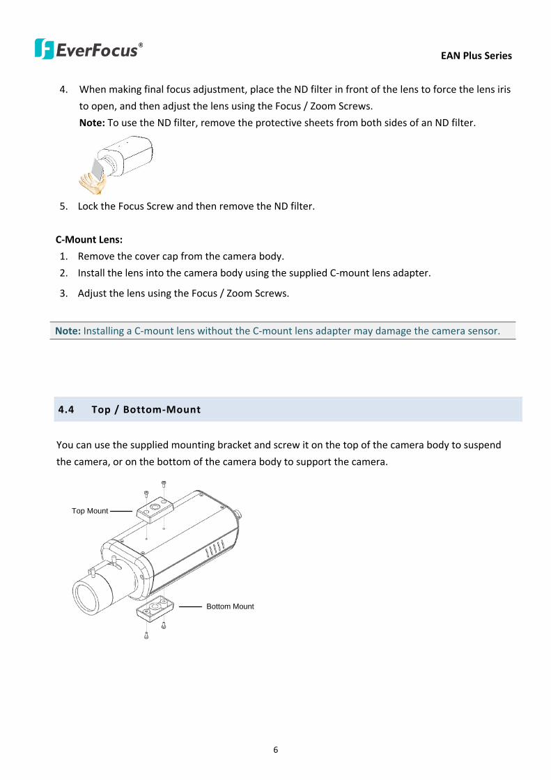
EAN Plus Series
7
45 Basic Connection
Micro SD
Audio
In OutEthernet (PoE)
DC 12VPower
Reset
Video Out
COM
Out In
GN
D
Alarm
1
2
3
3
4
5
1 Use a standard network cable to connect the camera to the network
2 Connect the camera to power using one of the following methods
bull Plugging the supplied power pigtail cable to the DC 12V port
bull Using the PoE function and the power will be provided over the network cable
3 Optionally connect the camera to a speaker or microphone Note that microphones with
external power supplies are required
4 Optionally connect the camera to a monitor using a BNC cable
5 Optionally connect the camera to the input output devices
After powering the camera the power LED will be lit in red and you can access the live view and
adjust the image clarity
EAN Plus Series
8
5 Accessing the User Interface
This section explains how to access the Web interface of the camera for configuration
51 Assigning an IP Address
You have to assign an IP address for your camera to be accessible To assign an IP address to the
camera use the IP Utility (IPU) software included in the software CD Please connect the IP camera in
the same LAN of your computer
1 Install and then start the IPU program The following dialog box appears
2 Click Find Devices to search the cameras connected in the LAN The default network values of the
cameras will be displayed By default the network protocol of the camera is DHCP
3 To configure the network settings select a camera and then click LoginMulti Login to log in
EAN Plus Series
9
4 Type the user ID and password Click OK
Note
1 The default user ID is user1 and the default password is 11111111
2 If you select more than one camera that has the same user ID password you will be able
to log in several cameras at once
5 To change the IP address double-click the IP Address of the camera Type a new IP address and
then click Set IP Address to save the settings
You can also change the other settings by double-clicking the values After configuring the values
click Save Configuration
Note Most networks uses DHCP to assign IP address if you are unsure of your network
settings please consult your network administrators for configuration details
6 To access the camera highlight the camera and click Connect to Selected IP The Internet
Explorer window pops up
7 Type the user ID and password to log in The Live View window of the camera appears
Note You might be required to download ActiveX which is required to view the camera feed
If asked click Yes For more details on setting up the Microsoft Internet Explorer please refer
to 52 Settings for Microsoft Internet Explorer
EAN Plus Series
10
52 Settings for Microsoft Internet Explorer
To enable Remove Live View Firmware Upgrade and ActiveX Prompt on Internet Explorer some
settings have to be complete Please follow the steps below
1 On the computer click Start gt Control Panel gt System and Security gt Action Center (click Change
User Account Control Settings) the User Account Control Settings window appears Adjust the
slide bar to Never Notify and then click OK Restart your computer if requested
2 Open the Internet Explore click Tools gt Internet Options gt Security Tab gt Custom Level the
Security Settings windows appears
EAN Plus Series
11
3 In the Download unsigned ActiveX controls field select Prompt In the Include local directory
path when uploading files to a server field select Enable Click OK
4 In the Internet Options window click the Advanced tab and then disable Enable memory
protection to help mitigate online attacks Click OK
EAN Plus Series
12
53 Connecting the Camera to the Network
There are three methods to connect the IP camera to the network Router or LAN Connection Direct
High-Speed Connection and One-to-One Connection
Router or LAN connection
This is the most common connection in which the IP camera is connected to a router and allows
multiple users on and off site to see the IP camera on a LANWAN (Internet) The camera must be
assigned an IP address that is compatible with its LAN By setting up port forwarding on the router
you can remotely access the cameras from outside of the LAN via the Internet To remotely access the
Web interface of the IP camera please refer to 732 DDNS To set up port forwarding please consult
the manual of the router
Straight-through LAN patch cable
Right Pinout of a straight-through cable
EAN Plus Series
13
Direct High-Speed Connection
In a Direct High-Speed Connection the camera connects directly to a modem without the need for a
router You need to set the static or dynamic WAN IP address assigned by your ISP (Internet Service
Provider) in the camerarsquos configuration web pages To access the camera just type ldquohttpxxxrdquo
where xxx is the IP address given by your ISP If you have a dynamic IP address this connection may
require that you use DDNS for a reliable connection Please refer to 732 DDNS
One-to-One Connection (Directly from PC to IP Camera)
You can connect directly without using a switch router or modem However only the PC connected
to the camera will be able to view the IP camera You will also have to manually assign a compatible IP
address to both the computer and the IP camera Unless the PC has another network connection the
IP camera will be the only network device visible to the PC See the diagram below
Pinout of straight patch cable
Right Pinout of a crossed-over cable
EAN Plus Series
14
54 Live View Window
1 Press the button to display the Live View window Double-click on the
image to show a full-screen display double-click again or press ESC to return to the normal display
If you experience video feed lag time (if connected via Internet) you can reduce the resolution or
limit the number of streams See 741 Multi Streaming
2 Press the button to play the recorded data directly from the on-camera Micro
SD SDHC card (for this function to become active you have to insert a Micro SD SDHC card in the
Micro SD SDHC card slot on the rear panel of the camera See 783 SD Card
3 Press the button to enter the Settings page On the Settings page there are
8 submenu sections [System Info] [User Config] [Network] [Video] [Audio] [User] [Event] and
[System] Click on the section buttons to open their configuration fields See the Settings section
below for more information
EAN Plus Series
15
4 Press the button to exit the system and close this browser page
5 Video Stream
Select the Video Stream (Stream 1 Stream 2 or Stream 3) that will be displayed in the video box on
the right Stream 2 and Stream 3 are only selectable if you have enabled the stream The default
setting is Stream 1 only See 741 Multi Streaming
6 View Size
Use this to select the appropriate view size and shape of the video box on the right A smaller size
might increase transmission speed and video quality
7 Digital Zoom
Click the Zoom In Zoom Out buttons or roll the mouse wheel to zoom in out the camera live view
up to 10x Clicking on a magnified image will re-center the image around that point
8 Record
The Record button is used to record the current video stream Click the Record button to start
stop recording This icon is only for one-minute video recording To record long-period recordings
please set a recording schedule (See 775 Schedule) The location on your computer where the
image files will be saved to and file size can be specified in the submenu (see 72 User Config)
9 Snapshot
Click the Snapshot button to save a snapshot of the video image currently being displayed The
location on your computer where the snapshot data will be saved can be specified in ldquoSettings gt
User Config gt RecordingSnapshotrdquo (see 72 User Config)
10 Play Audio Transmit Audio
Click the ldquoPlay Audiordquo (speaker) and ldquoTransmit Audiordquo (microphone) buttons to switch the sound
onoff for the speaker and microphone respectively (if such external devices have been connected
to the camera directly or via the network)
EAN Plus Series
16
11 One Push
This function is only available for EAN3120 Plus 3220 Plus The One Push button can be displayed
on the live view window by enabling the Show One Push Buttons function on the User Config lt Live
View Config Setting page (see 721 Live View Config) To enable the button (turned from faded to
clear) on the Video lt Advanced Setting page select One Push from the White Balance Settings
Mode drop-down list and click the Apply button Once this is done pressing the One Push button
on the Live View Window will instruct the camera to adjust the white balance settings and these
settings will be active until the button is pushed again This is like a ldquosemi-automaticrdquo way to adjust
white balance to suit the user if the Auto or Manual mode does not give the result the user wants
12 Manual Control
ndash Trigger Event
Press the ldquoTrigger Eventrdquo button to trigger an event directly from the Live page If you have
configured an event (in the Event submenu) that will trigger a reaction (like a recording) when a
Manual Trigger event occurs clicking this button will trigger that reaction You can select what that
reaction will be You can for instance set the camera to record the audiovideo feed to the Micro
SD card on board the camera You can then click on the Playback button to open the Playback page
and search for and play all such recordings that had been stored on the card Such event actions
will be effective once they have been configured in the ldquoEventrdquo menu (see 77 Event)
ndash Reset Alarm
Press the ldquoReset Alarmrdquo button to reset the alarm output remotely
13 Status Display (info lines that can be placed above video box or at bottom of page)
This shows the name of the camera that is currently active or being configured current datetime
and current frame rate You can activate these info displays in the Settings gt User Config page (see
72 User Config)
14 Event Signal Icons (above video screen)
When an alarm or motion event is triggered a signal icon will appear at the top right of the Live
View window to alert the user
Alarm event icon When an alarm is triggered this icon appears
Motion detection icons The colors of these motion event icons correspond to the colors of the motion trigger areas you have configured in the Motion Detection submenu (see 772
Motion Detection)
Recording icon When the camera is recording to a PC-based folder this icon appears
EAN Plus Series
17
6 Playback
You can remotely play back the recordings stored in the on-camera micro SD card on the Web interface
or play back the recordings stored in the computer using the ARV Viewer included in the software CD
Playback is designed as a quick way to check recent recordings that were triggered by Events that were
configured to ldquoRecord to SD Cardrdquo in the Settings gt Event gt Event Settings page (see 771 Event
Settings)
Note Note that the Playback page is only accessible once the on-camera SD card is inserted and
active
61 Remote Playback Using Playback Page
On the Live View Window click the Playback button to open the Playback page
EAN Plus Series
18
Search by File Click the Search button to search for all recording files on the on-camera SD card
Search results will be displayed in the Filename area
Search by Time Click the calendar icon and select the date and time from which you want to search
until the present moment Click search to get your search results which will be displayed in the
Filename area
Search by event Click the type of Event recordings you want to search for (Alarm Motion Manual
Trigger) and then click the calendar icons to select the Start Time datetime and the End Time
datetime of your search Click Search to get your search results which will be displayed in the
Filename area
Multiple Files Check this box if you want the video player to play all the files in the selected folder
The files will be displayed in the Filename area
Loop Again Check this box if you want the video player to play the selected file over and over again
Play Once you have opened the filersquos folder and have clicked on the file to highlight it its details will
be displayed in the File Information area You can now click Play to play that specific file
Pause Click this button to pause the playback
Stop Click this button to stop the playback
【Recording List】
Filename This area will display a list of search results (recording files and folders) Folders (named
with the recorded date) will be displayed first Click on the folder and click on each subfolder until the
recording files (arv) in that folder is listed
File Information Click a file on the Filename list the selected file information will be listed
Copy Click this button to copy the selected file to the computer-based folder of your choice A
browsing box will open so that you can search for the folder of your choice You can use the ARV
Viewer to play back the recordings recorded in your computer For details on ARV Viewer see 63
Playing Back Using ARV Viewer
Lock Click this button to lock the selected file This will protect that file from being overwritten during
any overwrite procedure The file will thus be saved on the micro SD card indefinitely However the
file will still be deleted if the micro SD card is ever formatted
Remove Click this button to delete the selected file
EAN Plus Series
19
62 Setting up the Playback Function
Note that the Playback function will not be active until the user has inserted a micro SD card in the
camerarsquos micro SD card slot The card may also have to be formatted in the Settings submenu
Micro SD Card Slot
621 Preparing the Micro SD Card
Once you insert a functional micro SD card into the slot the Playback button on the Live page should
become active within seconds (see section 622 below ndash the grey letters should turn white) IF NOT
do the following
1 From the Live page click Settings gt System gt SD Card If no card has been inserted yet the
Remove button should be faded indicating that no card is being detected (If a card is
inserted and the Remove button is still faded pull the card out and re-insert it)
2 Slide the card into the slot until it clicks into position
3 The Remove button should become active within a few seconds indicating the card is active
4 If the Remove button stays faded click the Format button to format the card NOTE All data
on the disk will be deleted if the Format button is clicked
622 Testing the Playback Function
1 Once the SD card is detected by the system the button (inactive)
will turn to (active)
2 To test the Playback function (this is not required) set up a ldquoManual Triggerrdquo Recording
Event by clicking Settings gt Event gt Event Settings
3 Click the ldquoAddrdquo button on the middle right side of the page to open an ldquoAdd Eventrdquo box
4 Give the event a name like ldquoTest 1rdquo
EAN Plus Series
20
5 In the ldquoEvent Triggered byrdquo field click on Manual Trigger
6 Below this check ldquoEnable This Eventrdquo ldquoEnable Post-trigger Bufferrdquo and ldquoRecord to SD Cardrdquo
7 To save your settings click OK or close the box by clicking on the red x icon at top right of the
box (in which case you will be asked if you want to save the data to which you should reply OK)
The box will close and the new event will be listed in the list area of the Event Settings page
8 Look at the ldquoPost-trigger Bufferrdquo at the bottom to make sure the buffer time is set to 10 seconds
9 Click ldquoApplyrdquo to make sure all settings are saved
10 Click the Live button to go back to the Live page
11 Get ready to click the Trigger Event button at the bottom of the page Before you do see if you
can find something in the view screen that will give you a visual time marker For instance if you
can get your hand in front of the camerarsquos lens get ready to count down on your fingers
12 Click the Trigger Event button and slowly count down on your fingers in front of the lens (if you
are able to do so ndash if not try to find visual cues on the view screen that will help you to mark the
moment you pushed the trigger) The recording period will be as long as the buffer time you
selected ndash the default period is 10 seconds
13 Click the Playback button to open the Playback page
14 There are different ways to search for recording files on the camerarsquos Micro SD card (ie the
Playback memory) For a recent recording like your test event simply click the ldquoSearchrdquo button
under the ldquoSearch by Filerdquo header
15 If the SD card is active and formatted correctly the recording folderrsquos name (the recording dayrsquos
date) will appear in the Filename box at the bottom Click on this folder to open it If there are
sub-folders click on the bottom one (the most recent would be at the bottom) until you can click
on a file that cannot open to another sub-level and shows data in the File Information box to the
right This would be the file of the most recent recording event
16 To play this file click the Play button below the video box The test footage you have recorded
should start playing Play time should be 10 seconds if you left the Post-trigger Buffer as 10
seconds
EAN Plus Series
21
63 Playing Back Using ARV Viewer
You can play back the recordings stored in the computer using the ARV Viewer included in the
software CD To store the recordings in the computer please refer to Recording List gt Copy in 61
Remote Playback using Playback Page
4 5 6 7 8 9 10
321
No Item Name Descriptions
1 Snapshot Click to take and save a snapshot
2 Load File Click to load the recordings for playing back
3 Convert ARV to AVI Convert the recording from ARV format to AVI format
4 Playback Time Display the playback time
5 Total Time of Recording Display the total time of the recording
6 Stop Click to stop playing the recording
7 Step Reverse Click to display the previous frame
8 Play Click to play back the recording
9 Pause Click to pause the recording
10 Step Forward Click to display the next frame
EAN Plus Series
22
7 Settings
Click the Settings button on the Live View Window to enter the settings submenu There are nine buttons
on the left-side of the submenu Live System Info User Config Network Video Audio User Event and
System Click the Live button can go back to the Live View Window
71 System Info
The System Information and System Log can be checked on this page Click the top tab of the one you
want to see
711 Information
Click the Information tab the following dialog box appears These values cannot be changed on this
page and are for reference only
EAN Plus Series
23
712 Log
Click the Log tab the following dialog box appears The sequence number date time and event
messages of the log event will be displayed in the System Log field The log will display the last 256
log events Click the Export button to export the system log event list into a ldquotxtrdquo file and select the
location where the exported log file will be saved to
EAN Plus Series
24
72 User Config
Each user can set a different configuration for hisher Live page here These settings will be applied to
the logged-in userrsquos Live page every time heshe logs in
721 Live View Config
【VideoAudio Connection Protocol Setting】You can transmit the data stream from the IP cameras
using the RTSP (Real Time Streaming Protocol) on the network The RTSP is a protocol that allows
you to access video streams by using the compatible media players Click Apply to apply the
changes or Reset to reset without saving the changes RTP over UDP The RTSP protocol uses UDP for camera data stream transmission
RTP over TCP The RTSP protocol uses TCP for camera data stream transmission
RTP over HTTP The RTSP protocol uses HTTP for camera data stream transmission
Nevio CGI This is EverFocusrsquo protocol designed for EverFocusrsquo IP devices Select this
protocol for camera data stream transmission
【Text Settings】Check the box of each option (Machine name DateTime Frame Rate) to display
this info on the Live View Page
Foreground Color Slide the Red Green and Blue bars to create your preferred text color for the
info text line
Position Select the position where the text will be displayed Choose from Upper Left Lower
Right Lower Left
Click Apply to apply the changes or Reset to reset without saving the changes
EAN Plus Series
25
【DateTime Format Used in Text】Click the dropdown menu to select datetime format from the
listed options Click on the desired hour format Click Apply to apply the setting changes or Reset to
reset without saving the change
【Live View Layout Settings】 Check the ldquoShow One Push Buttonsrdquo boxes if you want to show these
buttons on the Live View Page Uncheck these boxes to hide these buttons This function is only
available for EAN3120 Plus 3220 Plus
722 Recording Snapshot
This configures where your Record Button and Snapshot Button ( ) files will be saved if
you click one of these buttons Selectable folders will be on the computer only not on the
on-camera SD card
【Recording Snapshot Export Settings】
Enable Event Recording to PC Checking this box will let the system save RecordSnapshot Button
recordings to the folder configured below on the userrsquos PC
Export Folder Select the Export folder for the action above by clicking on the browse (hellip) button
and then select the desired folder
File size The user can limit the size of each recorded file here (in minutes) When a single
recording file exceeds the time you set the system will create a new file to save that data to
Overwrite Select ldquoONrdquo for overwriting recordingsnapshot file when the disk storage capacity is
full The user can set the storage capacity limitation in the in-sentence field in the gray box below
the Overwrite setting ldquoIf the remaining hard disk capacity is less than ____ MB (50~2000) system
will stop recording or start overwriting ldquo
Click Apply to apply the setting changes or Reset to reset without saving the changes
EAN Plus Series
26
723 Language
Select the language to be displayed on the Web interface of the IP camera The default language is
English
To add a new language not listed in the current Language list click the Browse button to locate
the new language file (evb) on your computer and then click the Upload button Updated
language files might be available on the manufacturerrsquos website Contact your vendor if required
Click Apply to apply any changes or Reset to reset without saving the changes
Note Uploading a new language file will cause the system to reboot automatically Please create
a new network connection to the IP camera when the reboot is complete
EAN Plus Series
27
73 Network
This page covers network-related settings including Network DDNS SMTPFTP HTTPS SNMP and
Network Alarm
731 Network
The following information is required to configure the network settings Contact your network
administrator or your internet service provider to get the info
【IP Settings】
IP Type Refer to the network administrator for these settings of the server Default DHCP
DHCP This setting lets the system use an automatically assigned (dynamic) IP address This
address can change under certain circumstances For instance when the camerarsquos network
switchhub has to be rebooted Do not assign to the DHCP server the same IP addresses used
for the other network cameras and PCs with unique IP addresses
Static IP The user can manually set the Static IP address This type of address is stable and
cannot change but the user has to make sure there are no address conflicts with other
network-connected devices
PPPoE This is a DSL-connection application The ISP will ask the user to input a username and
password Contact your ISP for these details
EAN Plus Series
28
Note If PPPoE is selected as the IP type the supplied IP Utility program will not be able to
detect the device
IP address When DHCP is not used the user needs to manually enter the IP address of the
camera Do not enter an IP address that is already used for your computer or other network
cameras
Subnet Mask This field is used to set the netmask for your network so that the IP camera will be
recognized within the network Example 2552552550 When DHCP is selected the DHCP server
will assign this value automatically
Gateway This field is used to set the gateway for your network so that the IP camera will be
recognized within the network When DHCP is selected the DHCP server will assign this value
automatically
Primary DNS Enter the IP address of the DNS server if this is provided by an ISP
Secondary DNS If your ISP provided you with a secondary DNS address please enter it here
Username Enter the accountrsquos username (used only for PPPoE)
Password Used only for PPPoE
IPv6 Enter the IPv6 details in this area if this applies to your system
Click Apply to apply the setting changes or Reset to reset without saving the change
【Port Settings】Enter the HTTP HTTPS and RTSP port numbers and click Apply to save
【Multicast Settings】Enable if required fill in the setting options and click Apply to save
EAN Plus Series
29
732 DDNS
DDNS (Dynamic Domain Name System) is a service used to map a domain name to the dynamic IP
address of a network device You can set up the DDNS service for remote access to the IP camera
DDNS assigns a domain name (URL) to the IP camera so that the user does not need to go through
the trouble of checking if the IP address assigned by DHCP Server has changed Once the IP is
changed the IP camera will automatically update the information to the DDNS to ensure it is always
available for remote access
Before enabling the following DDNS function user should have applied for a host name from the
DDS service providerrsquos website We support these four DDNS server providers
wwweverfocusddnscom wwwsitelutionscom wwwdyndnscom and wwwno-ipcom
Note We highly recommend that you use xxxxeverfocusddnscom for the simplicity of setting up
your IP cameras
【DDNS Settings】
Enable Check this box to enable the DDNS function
Service ISP You can either apply for a host name from EverFocus or other DDNS server providers
If you choose the EverFocus DDNS server you can obtain a free host name from EverFocus by
following the steps below
bull From EverFocus To obtain a free host name from EverFocus type a desired host name in the
textbox click the Register Update button and then click the Apply button
bull From other DDNS server providers To obtain a domain name from one of the three DDNS
server providers you have to register your name with the provider first and then select the
provider and fill in the required information Please refer to the specific DDNS companyrsquos
website for further information
Record ID Type the record ID if provided by the DDNS server provider
EAN Plus Series
30
FQDN Type the fully qualified domain name applied from the DDNS server provider For
example xxxxdyndnscom
Username Password Type the login account of your DDNS server provider
Click Apply to apply the setting changes or Reset to reset without saving the changes
Note
1 In order to support the full functionality of the camera you must open the port numbers (80
554 443) on the router for remote access to the IP camera This function is available on most
routers in the market and is often known as ldquoPort Forwardingrdquo To set up Port Forwarding
please consult the manual of the router
2 In certain router models it is possible that you will not be able to access the camera using
DDNS while inside the routerrsquos network Please try using a PC located outside of your routerrsquos
network
Default Ports on All EverFocus IP Cameras
HTTP 80
RTSP 554
HTTPS 443
EAN Plus Series
31
733 SMTP FTP
【Set SMTP Server (email)】This area is for configuring the mail server that is used to send e-mail
notifications from the camera to predefined addresses via SMTP Note that to enable e-mail
notification function you have to check the Send Mail Notification item on the Event dialog box
(see 771 Event Settings)
SMTP Server Enter the IP address or the host name of the SMTP server used to send e-mails
SMTP Port Enter the port number for SMTP The default is 25
Authentication Check this box if the SMTP server requires authentication (userpassword)
User name Input the userrsquos login ID if the SMTP server requires authentication
Password Input the userrsquos login password if the SMTP server requires authentication
EAN Plus Series
32
Receiver Address Input the e-mail addresses for receiving an e-mail message when an EVENT is
enabled and triggered Please use ldquordquo to separate multiple addresses
Sender Address Input the senderrsquos e-mail address so that the receiver can recognize the sender
when an Event message is received
Attach Image Check this box if you want to attach an image when an alarm is triggered or an IP
camera detects events
Send Test Email Click the Test button to send a testing email to the assigned address
Click Apply to apply the setting changes or Reset to reset without saving the changes
【Set FTP Server】The settings relating to the FTP server used to transmit the alarm images can be
configured here Note that to enable uploading images to the FTP server function you have to
check the Upload to FTP item on the Event dialog box (see 771 Event Settings)
FTP Server Enter the IP address or the host name of the FTP server
FTP Port Enter the port number for the FTP server Default is 21
Recording Path Assign the recording path
User Name Set FTP Userrsquos name
Password Set FTP password
PASV mode Check to enable Passive mode Passive mode is normally enabled If a connection
cannot be established uncheck PASV Moderdquo
Test FTP Server Click the Test button to send a testing file to the assigned FTP server
Click Apply to apply the setting changes or Reset to reset without saving the changes
EAN Plus Series
33
734 HTTPS
Hypertext Transfer Protocol Secure (HTTPS) is a combination of the Hypertext Transfer Protocol
and the SSLTLS protocol and provides encrypted communication and secure identification of a
network web server
Before using the HTTPS function for communication with the IP camera a Certificate must be
created first There are two ways to create and install a certificate Create Self-Signed Certificate
and Create Certificate Request
Create Self-Signed Certificate
Please note that even though self-signed certificates are free and offer some protection true
security is only implemented after the installation of a signed certificate issued by a certificate
authority
1 Click the Create Self-Signed Certificate button the following dialog appears
EAN Plus Series
34
2 Type the required Certificate information and then click the Apply button The subject line will
be displayed in the Installed Certificate Information field
3 Click the Property button a pop-up window appears to display the details of the certificate
4 To optionally create and install other certificates remove the existing one by clicking the
Remove button to erase the certificate
5 On the Web page change the address from ldquohttprdquo to https in the address bar and press
Enter on the keyboard Some Security Alert dialogs will pop up Click OK or Yes to enable HTTPS
Create Certificate Request
You can apply for an official certificate from an issuing Certificate Authority
1 Click the Create Certificate Request button the following dialog appears
EAN Plus Series
35
2 Type the required Certificate information and then click the Apply button The subject line will
be displayed in the Created Request field
3 Click the Property button a pop-up window appears to display the details of the certificate
4 To optionally create and install other certificates or request remove the existing one by clicking
the Remove button to erase the certificate or request
5 Copy the contents of the Certificate request (in PEM format) and paste it to the certificate
request field on the Web page of the 3rd-party certification authority such as Symantec VeriSign
Wait for the certificate authority to issue an SSLTLS certificate and then download the issued
certificate on your computer
6 In the Install Signed Certificate field click the Browse button to search for the issued certificate
and then click the Upload button to import the certificate Once the certificate has been
uploaded this field will show the subject line of the certificate
EAN Plus Series
36
735 SNMP
The default values for SNMP v1v2v2c and SNMP v3 are already filled in Click either of the
Enable buttons to enable either of the two Make your changes as desired Click on the Trap
Address field to enter the digits if required
736 Network Alarm
This function works with EverFocusrsquos CMS software eg the PowerCon or the Power Video Plus For
the setting details please refer to the CMS network alarm protocol
EAN Plus Series
37
74 Video
The settings relating to video such as streaming camera OSD can be configured on this page The
Video page has five tabs Multi-streaming Camera Advanced ROI and Privacy Mask
741 Multi Streaming
【Stream Settings】 This IP camera can output three video streams simultaneously For each of these
streams the user can set the compression format resolution bit rate and frame rate individually
Stream 1 is always enabled for live view To enable Stream 2 andor Stream 3 check the ldquoEnablerdquo
box the header of each stream
Note If you connect to the camera via the Internet and experience a delay (lag time) in the video
feed try to reduce the number of streams and the quality and resolution of the streams ndash but
keep the frame rate at its maximum
EAN Plus Series
38
Format Select the encoding format ndash H264 or MJPEG
Resolution Select the most suitable resolution for your needs
Frame Rate Select from 1 to 30 fps
Bit Rate If required select whether you want the stream to stream a Constant Bit Rate or a
Variable Bit Rate and set the values of whichever option you choose
Click Apply to apply the setting changes or Reset to reset without saving the changes
【Video Recording Settings】Select the stream you want to configure and then select whether you
want the recording files of that stream to be saved in AVI or ARV format Click Apply to apply the
setting changes or Reset to reset without saving the changes
【Time Stamp Settings】 You can select the DateTime format position and add the setting to the
streaming
Click Apply to apply the changes or Reset to reset without saving the changes
EAN Plus Series
39
742 Camera
【Image Settings】Set the Brightness Saturation Contrast or Sharpness of the image Click Apply to
apply the changes or Reset to reset without saving the changes
【Camera Settings】
Mirror Switch Mirror ON to rotate the image horizontally around a vertical axis
Flip Switch Flip ON to rotate the image vertically around a horizontal axis
AE There are two options
ALC Selecting Automatic Light Control allows the camera circuitry to either take bright spots
more into consideration (peak) bringing out detail in bright areas or less into consideration
(average) bringing out detail in shadows
AES Selecting Auto Electronic Shutter disables the Shutter setting below this setting In this
mode the camera measures the light level and decides whether it needs more or less light and
then automatically adjusts the shutter speed accordingly
BLC Back Light Compensation (BLC) is used to make the subject appear clearer when it is set
against a bright background
OFF Select to switch Back Light Compensation functions off
(ON)BLC The BLC can increase the exposure of a dark area surrounded by a brighter area HLC
can decrease the exposure of bright areas surrounded by darker areas This enables the
camera to better display information that would otherwise have been ldquowhited outrdquo like a
license plate between two bright headlights on a dark road
(ON)HLC The Highlight-Suppression BLC is used to reduce the brightness of light sources in a
specific area It is activated only in a low illumination environment to minimize the effects of
glare from bright lights such as spotlights street lights or headlights in the field of view
EAN Plus Series
40
WDR The Wide Dynamic Range (WDR) function provides clearer images when both of the very
bright and dark areas simultaneously appear on the camera view There are four value options
OFF Low Middle and High Note that when WDR is ON some parts of the image may appear
solarized This is normal for WDR and is not a camera malfunction This function is only available
for EAN3120 Plus 3220 Plus
DN Mode
Auto Select to let the camera automatically switch to Night mode (black and white) when the
light levels fall to a specified level and back to Day mode (color) when the light levels rise to a
specified level
Day Select to keep the camera in Day mode (color) even in nighttime
Night Select to keep the camera in Night mode (black and white) even in daytime
EAN Plus Series
41
743 Advanced
EAN Plus Series
42
【Camera Settings】
Lens (IRIS Control) Select DC or Manual for IRIS control This function is only available for EAN3220
Plus
Exposure Settings (AE) This setting is used to adapt to the amount or type of light used by the
camera Note the settings vary among models
Mode This function is not available for EAN3220 Plus
Automatic Light Control (ALC) This option is only available for EAN3120 Plus 3300 Plus The
ALC allows the camera circuitry to either take bright spots more into consideration (peak)
bringing out detail in bright areas or less into consideration (average) bringing out detail in
shadows
Auto Electronic Shutter (AES) This option is only available for EAN3120 Plus 3300 Plus In
this mode the camera measures the light level and decides whether it needs more or less light
and then automatically adjusts the shutter speed accordingly
Manual This option is only available for EAN3300 Plus Select this option to manually set up
the Shutter (Manual) and AGC (Manual) values
Iris Specify the size of the Iris opening here
Shutter If enabled this setting lets you set the shutter speed yourself
Shutter Limit Use this setting to set the maximum shutter speed for the camera This function is
only available for EAN3120 Plus
AGC Set the Auto Gain Control limit here The lower the AGC level the lower the video signal and
the noise However the image will be darker under low-light condition with IR-off if you set up the
Iris to the maximum level
Slow Shutter This option can be switched on when AES Mode is selected in the Exposure Settings
(AE) field This function is only available for EAN3220 Plus 3300 Plus
Flickerless If the Mode field in the Exposure Settings (AE) area has been set to AES then this option
becomes available Choose between OFF 50HZ 60HZ 50HZ (High Luminance) or 60HZ (High
Luminance) This function is only available for EAN3300 Plus
EV Setting Set up the Exposure Value Note the brightness of the screen changes when you change
the EV value This function is only available for EAN3300 Plus
AE Response Set up Auto Exposure Response time This function is only available for EAN3300 Plus
AE Weighting Area Select an AE Weighting area Each setup AE Weighting Area is configured with
the appropriate brightness level on the center and the surrounding areas This function is only
available for EAN3300 Plus
Brightness Set the image brightness here
AE Reference Set the Auto Exposure value here This function is only available for EAN3120 Plus
EAN Plus Series
43
Black Level Set the Black level here This function is only available for EAN3300 Plus
WDR The Wide Dynamic Range (WDR) function provides clearer images when both of the very
bright and dark areas simultaneously appear on the camera view There are four value options OFF
Low Middle and High Note that when WDR is ON some parts of the image may appear solarized
This is normal for WDR and is not a camera malfunction This function is only available for EAN3120
Plus 3220 Plus
Visibility Enhancement (OFFLowMiddleHigh) Images in foggy or rain environments or in
environments with a very strong luminous intensity have a dynamic range that is significantly lower
than ordinary images The user can use this Visibility Enhancement setting to ldquoDEFOGrdquo the image if
such ldquoFOGGINGrdquo is an issue This function is only available for EAN3220 Plus
BLC Settings Back Light Compensation (BLC) is used to make the subject appear clearer when it is
set against a bright background
OFF Select to switch Back Light Compensation functions off
Back Light This option is only available for EAN3300 Plus The Back Light function is useful
when the background of the subject is very bright and the subject itself is dark Select Back
Light and adjust the slide bar to the left right for setting up the back light value The higher
the value the more the backlight compensation
Front Light This option is only available for EAN3300 Plus This function is useful when the
bright highlights such as flashlight or car headlights appear on the camera view Select Front
Light and adjust the slide bar to the left right for setting up the front light value The higher
the value the more the highlight compensation
ON (BLC) This option is only available when you select AES Mode in the Exposure Settings (AE)
field The option is only available for EAN3120 Plus 3220 Plus The BLC function is useful
when the background of the subject is very bright and the subject itself is dark Follow the
instructions below to configure the settings for each model
For EAN3120 Select ON (BLC) the button next to the Mode drop-down list will be
active (see image below) Click the button the green setup areas appear on the left
screen Click on the areas to enable disable the BLC function The selected areas (in green)
will be applied with the BLC function
EAN Plus Series
44
For EAN3220
You can configure one area to apply the BLC function Select ON (BLC) the setup buttons
appears (see image below) Select Low Middle High from the BLC Gain drop-down list To
set up a BLC area click the Edit Area button and then click on the blue color tab to turn your
mouse cursor into a blue pen Move the cursor to the position on the right screen where you
want the BLC rectangle to start and then click Move your cursor to the position (diagonally
opposing corner) where you want the BLC rectangle to end and then click The blue area will
be applied with the BLC function
ON (HLC) This option is only available when you select AES Mode in the Exposure Settings (AE)
field The option is only available for EAN3120 Plus 3220 Plus This function is useful when
the bright highlights such as flashlight or car headlights appear on the camera view Follow
the instructions below to configure the settings for each model
For EAN3120 Select ON (HLC) and then select a level from the drop-down list The higher the
level the more the highlight compensation
For EAN3220
HLC Level Select a level for the HLC setting The higher the level the more the highlight
compensation
HLC Mode Select All Day Night mode to apply the HLC function
HLC Black Mask Select On Off to apply the black mask on the selected areas The
over-exposure portions within the selected areas will be applied with the black mask
Color Tabs You can set up four HLC areas with different colors To set up a HLC area click the
Edit Area button and then click on the color tab to turn your mouse cursor into a pen of that
color Move the cursor to the position on the right screen where you want the HLC rectangle
to start and then click Move your cursor to the position (diagonally opposing corner) where
you want the HLC rectangle to end and then click Select ON from the color tab drop-down list
The rectangular area with the selected color will be applied with the HLC function
EAN Plus Series
45
Back Light This option is only available for EAN3300 Plus The Back Light function is useful
when the background of the subject is very bright and the subject itself is dark Select Back
Light and adjust the slide bar to the left right for setting up the back light value The higher
the value the more the backlight compensation
Front Light This option is only available for EAN3300 Plus This function is useful when the
bright highlights such as flashlight or car headlights appear on the camera view Select Front
Light and adjust the slide bar to the left right for setting up the front light value The higher
the value the more the highlight compensation
Noise Reduction Settings This limits the amount of digital ldquovideo noiserdquo that is usually found in any
video stream and helps to reduce file size The higher the level the more the reduction
For EAN3120 Plus 3300 Plus
Select ON OFF to enable disable the Noise Reduction function Or select Auto to let the camera
automatically enable disable the Noise Reduction function Slide the Level bar to set up the level
The higher the level the more the reduction
For EAN3220 Plus
2D DNR Select ON to enable the 2D DNR function
3D DNR Select ON to enable the 3D DNR function You can further set up the following settings
3D Start AGC Set up the AGC level to automatically start the 3D NR function
3D End AGC Set up the AGC level to automatically stop the 3D NR function
3D Level Set up the 3D DNR level
Smart NR Select ON to enable the Smart NR function The 3D NR function will be
automatically turned on when a motion event occurs
EAN Plus Series
46
White Balance Settings Select the mode that delivers the best quality image for the camerarsquos light
environment There are five options Auto Manual Indoor Outdoor One Push
Auto Select to let the camera automatically adjust the White Balance In the Auto mode the
camera computes the white balance value output using color information from the entire
screen It outputs the proper value using the color temperature radiating from a black subject
based on a range of value from 3000 to 7500K
Manual Select to adjust the Red and Blue values yourself in the fields below this field
Indoor Select to use the default settings for indoor environments In the Indoor mode the
camera uses 3200K as the base value
Outdoor Select to use the default settings for outdoor environment In the Outdoor mode it
uses 5800K as the base value
One Push Select to enable the Push button next to the Mode drop-down field This will allow you to force the camera to readjust the white balance every time you push the Push
button The lens will hold the same focal position until the next trigger command is received
This function helps to prevent incorrect focusing in dark environments This function is only
available for EAN3120 Plus 3220 Plus
Manual Temperature Select to use the optimized Red and Blue settings You can also
optionally adjust the Manual Level below this field for setting up the color temperature The
higher the value the more the color temperature This function is only available for EAN3300
Plus
DayNight Settings
Auto Select to let the camera automatically switch to Night mode (black and white) when the
light levels fall to a specified level and back to Day mode (color) when the light levels rise to a
specified level
Day Select to keep the camera in Day mode (color) even in nighttime
Night Select to keep the camera in Night mode (black and white) even in daytime
IR Smart Settings Select ON and set up the level to enhance the image quality when the images are
over exposure This function is useful when the camera is in the Night mode This function is only
available for EAN3220 Plus
Saturation Set the saturation value This function is not available for EAN3220 Plus
Monitor Type Select a gamma value from Set 1 Set 2 or Set 3 This function is only available for
EAN3120 Plus
Negative Switch this setting ON to view a color negative version of the video image This is useful
at night or when viewing temperature-sensitive images
EAN Plus Series
47
Sharpness Settings Select the sharpness level of the image A low sharpness level will deliver a
softer less detailed image A high level will deliver a sharp highly detailed image Switch Resolution
Enhancement ON to enable the resolution enhancement function
Contrast Select the contrast level of the image
Suppress Function This function is only available for EAN3300 Plus
Aperture Compensation Suppression (OFFLowMiddleHigh) This setting can be activated to
suppress luminance noise when the AGC level increases
Chroma Suppression (OFFLowMiddleHigh) This setting can be activated to suppress
chrominance noise when the AGC level increases
Ygamma (gamma 22standardcontrast enhancehigh light range mode LHigh light range mode
H) Select the Ygamma value for the video quality of the monitor This function is only available for
EAN3300 Plus
Monitor Settings The user can use this field to optimize video quality for his or her specific type of
monitor ndash LCD or CRT This function is only available for EAN3220 Plus
Color Space Standard The options are YUV601 for SD and YUV709 for HD These define the color
space standard required to convert an RGB picture to a YUV picture Generally YUV601 is used for
Standard Definition (720P) devices and the YUV709 is used for High Definition (1080P) devices
Click Apply to save all changes Click Reset to cancel all changes
EAN Plus Series
48
744 ROI (Region of Interest)
The Region of Interest (ROI) function allows users to set up multiple regions within an image with
better quality and less distortion than the rest of the image You can also use this function
together with the Digital Zoom function on the Live View Page to get a better image result Up to
eight ROIs can be configured in the ROI settings page
To set up an ROI region
1 Select an ROI number from the ROI No drop-down list
2 Click the Add button the mouse cursor will turn into a pen when you move it over the live
image on the left
3 Move the cursor to the position where you want the ROI rectangle to start and then click
Move the cursor to the position (diagonally opposing corner) where you want the ROI
rectangle to end and then click
4 Slide the Quality bar to set up the quality value
5 Click the Apply button to apply the settings or click the Reset button to reset without saving
the settings
EAN Plus Series
49
745 Privacy Mask
The Privacy Mask can block out sensitive areas from view covering the areas with colored or black
and white boxes in both live view and recorded clips This feature is useful when usersrsquo donrsquot want
the sensitive information visible Up to four Privacy Masks can be configured
【Privacy Mask Color Settings】The Modes vary among camera models
Mode Click Color to make the masks appear as colored rectangles on the screen Click BW to
make the masks appear as gray rectangles on the screen Click Mosaic to make the masks appear
as mosaic-effect rectangles on the screen
Level Select the color of the masks if you selected Color Mode Select the level of grayness of the
masks if you selected BW Mode Select the level of smallmiddlelarge if you selected Mosaic
Mode
Click Apply to apply the settings or click Reset to reset without saving the settings
Color Tabs Click on a color tab to turn your mouse cursor into a pen of that color
You can now create a block of that color on the video screen Move your cursor to the position
where you want your mask rectangle to start and then click Move your cursor to the position
(diagonally opposing corner) where you want your mask rectangle to end and then click The
rectangular area with the selected color will appear The live image will display the rectangular
area with the color you selected If you want to create another mask use one of the other three
colors Each color denotes a different mask area Only one block per color is allowed As the
number of colors suggests you can configure up to four blocks
EAN Plus Series
50
Select All Click to turn the whole screen into a mask area
Clear All Click to delete all configured mask blocks
Eraser Click to turn the mouse cursor into an eraser to delete any block you click on
Area Shows the color and number of the block
Enable Check this box to enable the related mask block
Click Apply to apply the settings or click Reset to reset without saving the settings
EAN Plus Series
51
75 Audio
The EAN Plus series IP camera can transmit audio to your computer if you have connected an external
microphone to its audio Input cable It can also receive audio input from you and transmit it via an
external speaker if you have connected such a speaker to its audio Output cable
Check the Enable Audio box to enable the camerarsquos audio function The camera will now act as a
digital bridge (via the IP network) between any connected audio input device and any connected
audio device
Adjust the Audio Input Volume if you have external audio input devices (microphones) connected to
the camera and if there are problems with the sound input being too low or high
Click Apply to save all settings or click Reset to cancel
EAN Plus Series
52
76 User
761 User Information
The system administrator can create up to ten user accounts on this page
To set up a user account
1 Highlight a user account and click the Modify button The following dialog box appears
2 Type the account name account description and password for the account Type the password
again in the Confirm field
3 Select an authority level for the user account from the Authority drop-down list
bull Supervisor Administrator The only difference between a supervisor and administrator is
that a supervisor can edit an administratorrsquos account and password but an administrator
cannot edit the supervisorrsquos account and password Multiple administrators can be
configured but there can be only one supervisor The supervisor and administrators all
have unrestricted access to the Settings submenus and can determine the registration of
all other users
EAN Plus Series
53
bull User A user can view the Live View page and view the system network video and audio
information A user can only adjust the User Config page settings The user does not have
access to the User Event and System pages
bull Guest The lowest level of access which only allows the user access to the Live View page
4 Select Active or Disable from the Status drop-down list to active or disable the user account
5 Click On in the SD Card Playback field to allow the user to access the SD card playback
function
6 Click OK
7 Click Apply to save all the settings
EAN Plus Series
54
762 IP Address Filter
Use this page to specify IP addresses that are not allowed to access this camera By default any IP
address can access the camera
Note The Allowed List addresses only become relevant when the Denied List contains a network
or range and the supervisor wants to allow one or more IP addresses within that excluded range
or network In such a scenario the user would enter the excluded range or network in the
Denied List and enter the exceptions in the Allowed List
To set up the IP Address Filter
1 Select Denied List Click the Add button the following dialog box appears
2 Select an IP type from the IP Type drop-down list
3 Select a network rule from the Rule drop-down list type the IP address and click OK
Single Type a single IP address in the IP Address field below
Network Type the IP address and subnet mask in the field below
Range Type a range for the IP addresses
4 If you have set up an IP range in Step 3 you can optionally set up the Allowed List to allow one
or more IP addresses within the setup IP range to access the IP camera
5 Click Apply
EAN Plus Series
55
77 Event
You can set up the Motion Detection event Tamper Detection event or the Alarm IO to automatically
notify the users when an event occurs or an alarm is triggered You can also set up a schedule to
automatically record the videos when an event occurs or an alarm is triggered
771 Event Settings
You can create a total of ten event or alarm settings page in the Event List
【Event List】
Click the Add button and the following Event Configuration Window appears
EAN Plus Series
56
Enter Event Name Type an event name
Event Triggered by Select an event or alarm type for the to-be-specified-below reactions
Alarm Input Select this if you want a reaction trigger coming from any external connected sensor
to activate a to-be-specified-below reactions via the camera system Make sure that a suitable
device is actually connected to the alarm input relay
Manual Trigger Select this option if you want to manually trigger the alarm by clicking the Trigger
Event button on the Live View Page
Motion Detection Select this option if you want motion in a specified part of the camerarsquos viewing
rectangle (the screen image) to trigger the to-be-specified-below reactions
Tampering Detection Select this option if you want the camerarsquos tampering detection sensor to
trigger the to-be-specified-below reactions
Schedule Recording Select this option if you want the Schedule Recording periods configured in
the recording schedule (the Settings gt Event gt Schedule page) to activate this event In this
scenario a preconfigured event reaction like a log entry will list the start and end times of each
period Actual recording will only be triggered if the event is preconfigured to do so
Enable This Event Select to activate the event
Enable Re-trigger Click to set a minimum time after the event is triggered before the event
can be triggered again
Enable Pre-trigger Buffer Click if you want the Event reaction (as selected in the ldquoNotification
Overrdquo field below) to be the activation of the video recording function and if you want the
recording to include the video feed from the time period (configurable on the previous ldquoEvent
Settingsrdquo page) just before the Event trigger occurred
Enable Post-trigger Buffer Click if you want the Event reaction (as selected in the Notification
Over field) to be the activation of the video recording function and if you want the recording
to include the video feed from a time period (configurable on the Event Settings page) just
after the Event trigger occurred
Motion Area Select a setup motion detection area from the drop down list Note this
function only becomes relevant after the Motion Detection areas have been set up (see 772
Motion Detection)
Notification Over Select the desired notification types form the following items
Log Click if you want the camera to list the eventrsquos details in its log if the event is triggered
Trigger Alarm Output Click if you want the camera to relay the event reaction to a device
attached to the alarm relay output wire and then set up the alarm output duration time
EAN Plus Series
57
Send Mail Notification Click if you want the camera to send an Event notification email to the
email address entered in the Set SMTP Server(email) field of the Network gt SMTPFTP page if
the Event occurs (see 733 SMTP FTP)
Upload to FTP Click if you want the camera to upload recorded footage to the FTP server
entered in the Set SMTP Server(email) field of the Network gt SMTPFTP page if the Event
occurs (see 733 SMTP FTP)
Record to SD Card Click if you want the camera to start recording its video feed (when the
event occurs) on an on-camera SD Card (if such a card has been inserted)
Note The recording will only be as long as the combined Pre- and Post-trigger Buffers so
make sure you enable at least one of these buffers especially the Post-trigger Buffer
Record to PC Check this box if you want the camera to start recording its video feed (when
the event occurs) on the same folder on the same PC as configured on the User Config gt
RecordingSnapshot page (if such a folder has been enabled and configured)
Note The recording will only be as long as the combined Pre- and Post-trigger Buffers (and
for as long as the event trigger is happening ndash eg a motion is detected) so make sure you
enable at least one of these buffers especially the Post-trigger Buffer
Network Alarm Check this box if you want the camera to send a network alarm signal (when
the event occurs) to the CMS servers configured on the Network gt Network Alarm page (see
736 Network Alarm)
Click OK to save all settings or click Cancel to cancel
【PrePost Trigger Settings】
Pre-trigger Buffer Select the duration for the buffer This will determine the amount of footage
(length of time) before the event trigger moment that will be included in an event-triggered video
recording if that buffer and video recording has been enabled in the Event Configuration Window
Post-trigger Buffer Select the duration for the buffer This will determine the amount of footage
(length of time) after the event trigger moment that will be included in an event-triggered video
recording if that buffer and video recording has been enabled in the Event Configuration Window
Click Apply to save all settings or click Reset to cancel
EAN Plus Series
58
772 Motion Detection
Use this page to configure up to four areas in which motion will be detected When a motion is
detected by the camera the motion detection icon will appear at the top right of the
Live page to alert the user This function can also be linked with correctly configured Events to
trigger Event reactions like the activation of video recording periods snapshots alarms etc
Color Tabs Click on a color tab to turn your mouse cursor into a pen of that color
You can now create a block of that color on the video screen Move your cursor to the position
where you want your detection rectangle to start and then click Move your cursor to the position
(diagonally opposing corner) where you want your detection rectangle to end and then click The
rectangular area with the selected color will appear This block will be an area inside which the
camera will detect motion If you want to create another detection area use one of the other three
palette colors Each color denotes a different detection area Only one block per color is allowed As
the number of colors suggests you can configure up to four blocks
Select All Click to turn the whole screen into a motion detection area
Clear All Click to delete all configured motion detection blocks
Eraser Click to turn your mouse cursor into an eraser to delete any block you click on
Area Shows the color and numberID of the block
Enable Check this box to enable the related motion detection block
Sensitivity Set the sensitivity of the motion detection sensor function
Click Apply to save all settings or click Reset to cancel
EAN Plus Series
59
773 Tamper Detection
Use this page to set the number of seconds that an alarm signal will be active if the device is
physically tampered (moved covered up or out of focus
774 Alarm IO
Use this page to set the type of trigger input and the type of output contact for the camerarsquos alarm
channel
EAN Plus Series
60
775 Schedule
Use this page to configure a schedule for periods during which the camera should deactivate all
user-activated Events (gray Deselect periods) or when the camera should deactivate all
user-activated Events except Schedule Recording (SR) events (blue Schedule Recording-only
periods) or when the camera should deactivate only SR events (red Event Recording-only periods)
or when it should enable all activated Events (yellow periods)
Event Recording Click this button to make every hour block you click on red A red block represents
an Event Recording-only block which represents an hour when the camera will deactivate all
preconfigured activated Schedule Recording events and keep all the other activated events active
Schedule Recording Click this button to make every hour block you click on blue A blue block
represents a Schedule Recording-only block which represents an hour when the camera will
deactivate all other preconfigured activated events and keep only the preconfigured activated
Schedule Recording events active
Event + Schedule Click this button to make every hour block you click on yellow A yellow block
represents an hour in which all activated events including Schedule Recording events will be
active
Deselect Click this button to make every hour block become grey A grey block represents an hour
in which all activated events including Schedule Recording events will be inactive
Click Apply to save all settings or click Reset to cancel
EAN Plus Series
61
78 System
You can set up the systemrsquos time and SD card settings and to do maintenance and reset actions like
reboots and upgrades
781 DateTime
【Machine Name Settings】If required enter a new name for the machine This name will be visible
in the Machine Name field of the IP Utility software which is included in the software CD
【Set Time Zone】Set the time zone of the camerarsquos location
【Set DateTime Manually】Set the datetime here if you wonrsquot be using an NTP server to update the
datetime (see below)
【Set DateTime Sync】Enter the Network Time Protocol server if applicable The camerarsquos time will
be automatically adjusted by synchronizing with the NTP server
Click Apply to save all settings or click Reset to cancel
EAN Plus Series
62
782 Daylight Saving
Click Enable Daylight Saving to enable this schedule and select the dates when the regionrsquos
daylight saving period begins and ends Click Apply to save all settings or click Reset to cancel
783 SD Card
Use this page to prepare the system for safely removing the SD Card from its slot
【Setup SD Card】
Notification Select the percentage of storage space that should be left on the card before the
camera notifies you of the impending storage shortage or overwrite
Event Recording Select if you want Event Recording only FTP Backup only or both
Overwrite Click ON if you want the card to start writing over recorded footage when its memory is
full Click OFF if you want the card to stop recording new footage when its memory is full
【SD Card Utility】
Capacity This shows you how much card memory has been used and how much memory capacity
remains on the card
Remove Click this button before removing the card from the system
Format Click this button to format the card All data saved on the SD card will be removed if the
card is formatted
EAN Plus Series
63
784 Maintenance
【Maintenance Server】
Reboot Click this button to reboot the unit without changing any of the settings Use this function if
the unit is not behaving as expected
Restore Click this button to restart and reset most of the current settings to their factory default
values The only settings that will not be changed to default are
bull IP settings
bull DDNS settings
Default The Default button should be used with caution Pressing this button will return all of the
cameras settings including the IP address to the factory default values The camera will then have
to be reconfigured
【SaveLoad Configuration Server】
Save To make a backup file of the machinersquos current configurations press Save to save all the
configurations to a config file This will enable the user to reload these configuration settings if the
settings are changed and there is unexpected behavior
Load To load a previously saved configuration press the Browse button to locate the saved config
file (see above) and then click the Load button The systemrsquos settings will be restored to the saved
configuration
EAN Plus Series
64
【SaveLoad Video Configuration Server】
Save To make a backup file of the machinersquos video configurations press Save to save the video
configurations to a config file This will enable the user to reload these configuration settings if the
settings are changed and there is unexpected behavior
Load To load a previously saved video configuration press the Browse button to locate the saved
config file (see above) and then click the Load button The systemrsquos settings will be restored to the
saved video configuration
【Upgrade Firmware】Click the Browse button to find a previously prepared firmware upgrade file
Click Upgrade to install the new firmware
Note
1 Do not disconnect power to the unit during the upgrade sequence The unit will reboot
automatically after the upgrade has completed (1-5 minutes)
2 During the upgrade process all event recording actions will be stopped Event recording
actions will resume after the camera is rebooted
3 If the ldquoFile Error Please re-loginrdquo warning message appears when upgrading the firmware
please try the following instructions
a Go to Internet Explorer gt Tools gt Internet Option gt Security gt Custom
b Find and enable the Include local directory path when uploading files to a server
EAN Plus Series
65
8 Upgrading Firmware Using IP Utility
You can upgrade the Firmware using the IP Utility software included in the software CD
1 Install and then start the IPU program The following dialog box appears
2 Click Find Devices to search the cameras connected in the LAN The default network values of the
cameras will be displayed By default the network protocol of the camera is DHCP
3 Select a camera and click LoginMulti Login to log in the camera
4 Type the user ID and password Click OK
Note
1 The default user ID is user1 and the default password is 11111111
2 If you select more than one camera that has the same user ID password you will be able
to log in several cameras at once
EAN Plus Series
66
5 Highlight the camera and then click Upgrade Firmware A browsing window appears
6 Select the firmware file (evb) and then click Open The IP Utility will automatically upgrade the
firmware
The camera will reboot once the update is complete Click Find Devices the new firmware version
should be displayed in the last part of the Machine Name
EAN Plus Series
67
9 Specifications
Model EAN3120 Plus EAN3220 Plus EAN3300 Plus
Camera
Image Sensor 13 Panasonic CMOS 128 Sony CMOS
Megapixel 13 MP 2 MP 3 MP
Picture Elements (H x V) 1280 x 1024 1944 x 1092 2048 x 1536
Min Illuminations 003 Lux at F14
Electronic Shutter (Sec) 85 ~ 160000 2 ~ 150000 1 ~ 110000
Scanning System NTSC PAL
WDR Yes Yes No
BLC Yes
Gain Control Yes
White Balance Yes
Lens
Mounting Type C CS
Day Night Yes (with removable auto IR-cut filter)
IRIS Control DC Electrical IRIS Lens IRIS
Video
Video Compression H264 MJPEG
Resolution
NTSC
2048 x 1536 1920 x 1200 (for EAN3300 Plus only)
1920 x 1080 (for EAN3300 Plus 3220 Plus only)
1280 x 1024 1280 x 720 1024 x 768 720 x 480 704 x 480 640 x 480
352 x 240 320 x 240 160 x 120
PAL
2048 x 1536 1920 x 1200 (for EAN3300 Plus only)
1920 x 1080 (for EAN3300 Plus 3220 Plus only)
1280 x 1024 1280 x 720 1024 x 768 720 x 576 704 x 576 640 x 480
352 x 288 320 x 240 160 x 120
Frame Rate 30 fps at 1280 x 1024 30 fps at 1920 x 1080 15 fps at 2048 x 1536
Audio
Audio Streaming Two-way audio
Audio Compression G711
EAN Plus Series
68
Network
Interface 10 100 Base-T Ethernet RJ-45 socket
Supported Protocols
TCPIP IPV6 UDP ICMP DHCP NTP DNS DDNS SMTP SNMP FTP
HTTP HTTPs PPPoE UPnP Bonjour RTP RTSP RTCP IGMP ARP ONVIF
PSIA
Connector
Power DC female port PoE
Ethernet RJ-45
Audio 1 In (phone jack for microphone)
1 Out (phone jack for Speaker)
Alarm IO Terminal IO wires
Local Storage Micro SD SDHC memory card slot
TV-Out BNC socket composite 1 V p-p 75 Ω
General
Power Source DC 12V PoE (IEEE8023af)
Power Consumption
(IR LEDs On)
5W (DC 12V)
621W (PoE)
5W (DC 12V)
522W (PoE)
5W (DC 12V)
536W (PoE)
Operating Temperature 0degC ~ +50degC 32degF ~ +122degF
Humidity 20 to 80 (no condensation)
Safety CE FCC
Dimensions (L x W x H) 117 x 56 x 68 mm 46 x 22 x 27 in
Weight 410 g 09 lb
EverFocus Electronics Corp EverFocus Taiwan 12F No79 Sec 1 Shin-Tai Wu Road Hsi-Chih Taipei Taiwan TEL +886 2 2698 2334 FAX +886 2 2698 2380 wwweverfocuscomtw marketingeverfocuscomtw
EverFocus Europe - Germany Albert-Einstein-Strasse 1 D-46446 Emmerich Germany TEL +49 2822 93940 FAX +49 2822 939495 wwweverfocusde infoeverfocusde
EverFocus China - Beijing Room 609 Technology Trade Building Shangdi Information Industry Base Haidian District Beijing 100085 China TEL +86 10 6297 3336~39 FAX +86 10 6297 1423 wwweverfocuscomcn marketingeverfocuscomcn
EverFocus China - Shenzhen 4F No 2 D4 Building Wan Yelong Industrial Park Tangtou Road Shiyan Baoan Shenzhen Guangdong 518101 China TEL +86 755 2765 1313 FAX +86 755 2765 0337 wwweverfocuscomcn marketingeverfocuscomcn
EverFocus USA - California 1801 Highland Avenue Unit A Duarte CA 91010 USA TEL +1 626 844 8888 FAX +1 626 844 8838 wwweverfocuscom saleseverfocuscom
EverFocus USA - New York 415 Oser Avenue Unit S Hauppauge NY 11788 USA TEL +1 631 436 5070 FAX +1 631 436 5027 wwweverfocuscom saleseverfocuscom
EverFocus Japan 5F Kinshicho City Building 2-13-4 Koto-BashiSumida-Ku Tokyo 130-0022 Japan TEL +81 3 5625 8188 FAX +81 3 5625 8189 wwweverfocuscojp infoeverfocuscojp
EverFocus Europe - UK Unit 12 Spitfire Business Park Hawker Road Croydon Surrey CR0 4WD UK TEL +44 20 8649 9757 +44 845 430 9999 FAX +44 20 8649 9907 wwweverfocusukcouk salesukeverfocuscom
EverFocus India Suite 803 Housefin Bhavan C-21 Bandra Kurla Complex Bandra (East) Mumbai 400051 India TEL +91 22 6128 8700 FAX +91 22 6128 8705 wwweverfocusin saleseverfocusin
PN 4605PQ3120B010A-VerC
Your EverFocus product is designed and manufactured with high quality materials and components which can be recycled and reused This symbol means that electrical and electronic equipment at their end-of-life should be disposed of separately from your household waste Please dispose of this equipment at your local community waste collectionrecycling centre In the European Union there are separate collection systems for used electrical and electronic product Please help us to conserve the environment we live in
Ihr EverFocus Produkt wurde entwickelt und hergestellt mit qualitativ hochwertigen Materialien und Komponenten die recycelt und wieder verwendet werden koumlnnen Dieses Symbol bedeutet dass elektrische und elektronische Geraumlte am Ende ihrer Nutzungsdauer vom Hausmuumlll getrennt entsorgt werden sollen Bitte entsorgen Sie dieses Geraumlt bei Ihrer oumlrtlichen kommunalen Sammelstelle oder im Recycling Centre Helfen Sie uns bitte die Umwelt zu erhalten in der wir leben
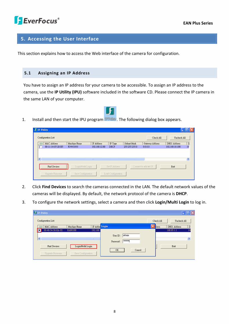
EAN Plus Series
8
5 Accessing the User Interface
This section explains how to access the Web interface of the camera for configuration
51 Assigning an IP Address
You have to assign an IP address for your camera to be accessible To assign an IP address to the
camera use the IP Utility (IPU) software included in the software CD Please connect the IP camera in
the same LAN of your computer
1 Install and then start the IPU program The following dialog box appears
2 Click Find Devices to search the cameras connected in the LAN The default network values of the
cameras will be displayed By default the network protocol of the camera is DHCP
3 To configure the network settings select a camera and then click LoginMulti Login to log in
EAN Plus Series
9
4 Type the user ID and password Click OK
Note
1 The default user ID is user1 and the default password is 11111111
2 If you select more than one camera that has the same user ID password you will be able
to log in several cameras at once
5 To change the IP address double-click the IP Address of the camera Type a new IP address and
then click Set IP Address to save the settings
You can also change the other settings by double-clicking the values After configuring the values
click Save Configuration
Note Most networks uses DHCP to assign IP address if you are unsure of your network
settings please consult your network administrators for configuration details
6 To access the camera highlight the camera and click Connect to Selected IP The Internet
Explorer window pops up
7 Type the user ID and password to log in The Live View window of the camera appears
Note You might be required to download ActiveX which is required to view the camera feed
If asked click Yes For more details on setting up the Microsoft Internet Explorer please refer
to 52 Settings for Microsoft Internet Explorer
EAN Plus Series
10
52 Settings for Microsoft Internet Explorer
To enable Remove Live View Firmware Upgrade and ActiveX Prompt on Internet Explorer some
settings have to be complete Please follow the steps below
1 On the computer click Start gt Control Panel gt System and Security gt Action Center (click Change
User Account Control Settings) the User Account Control Settings window appears Adjust the
slide bar to Never Notify and then click OK Restart your computer if requested
2 Open the Internet Explore click Tools gt Internet Options gt Security Tab gt Custom Level the
Security Settings windows appears
EAN Plus Series
11
3 In the Download unsigned ActiveX controls field select Prompt In the Include local directory
path when uploading files to a server field select Enable Click OK
4 In the Internet Options window click the Advanced tab and then disable Enable memory
protection to help mitigate online attacks Click OK
EAN Plus Series
12
53 Connecting the Camera to the Network
There are three methods to connect the IP camera to the network Router or LAN Connection Direct
High-Speed Connection and One-to-One Connection
Router or LAN connection
This is the most common connection in which the IP camera is connected to a router and allows
multiple users on and off site to see the IP camera on a LANWAN (Internet) The camera must be
assigned an IP address that is compatible with its LAN By setting up port forwarding on the router
you can remotely access the cameras from outside of the LAN via the Internet To remotely access the
Web interface of the IP camera please refer to 732 DDNS To set up port forwarding please consult
the manual of the router
Straight-through LAN patch cable
Right Pinout of a straight-through cable
EAN Plus Series
13
Direct High-Speed Connection
In a Direct High-Speed Connection the camera connects directly to a modem without the need for a
router You need to set the static or dynamic WAN IP address assigned by your ISP (Internet Service
Provider) in the camerarsquos configuration web pages To access the camera just type ldquohttpxxxrdquo
where xxx is the IP address given by your ISP If you have a dynamic IP address this connection may
require that you use DDNS for a reliable connection Please refer to 732 DDNS
One-to-One Connection (Directly from PC to IP Camera)
You can connect directly without using a switch router or modem However only the PC connected
to the camera will be able to view the IP camera You will also have to manually assign a compatible IP
address to both the computer and the IP camera Unless the PC has another network connection the
IP camera will be the only network device visible to the PC See the diagram below
Pinout of straight patch cable
Right Pinout of a crossed-over cable
EAN Plus Series
14
54 Live View Window
1 Press the button to display the Live View window Double-click on the
image to show a full-screen display double-click again or press ESC to return to the normal display
If you experience video feed lag time (if connected via Internet) you can reduce the resolution or
limit the number of streams See 741 Multi Streaming
2 Press the button to play the recorded data directly from the on-camera Micro
SD SDHC card (for this function to become active you have to insert a Micro SD SDHC card in the
Micro SD SDHC card slot on the rear panel of the camera See 783 SD Card
3 Press the button to enter the Settings page On the Settings page there are
8 submenu sections [System Info] [User Config] [Network] [Video] [Audio] [User] [Event] and
[System] Click on the section buttons to open their configuration fields See the Settings section
below for more information
EAN Plus Series
15
4 Press the button to exit the system and close this browser page
5 Video Stream
Select the Video Stream (Stream 1 Stream 2 or Stream 3) that will be displayed in the video box on
the right Stream 2 and Stream 3 are only selectable if you have enabled the stream The default
setting is Stream 1 only See 741 Multi Streaming
6 View Size
Use this to select the appropriate view size and shape of the video box on the right A smaller size
might increase transmission speed and video quality
7 Digital Zoom
Click the Zoom In Zoom Out buttons or roll the mouse wheel to zoom in out the camera live view
up to 10x Clicking on a magnified image will re-center the image around that point
8 Record
The Record button is used to record the current video stream Click the Record button to start
stop recording This icon is only for one-minute video recording To record long-period recordings
please set a recording schedule (See 775 Schedule) The location on your computer where the
image files will be saved to and file size can be specified in the submenu (see 72 User Config)
9 Snapshot
Click the Snapshot button to save a snapshot of the video image currently being displayed The
location on your computer where the snapshot data will be saved can be specified in ldquoSettings gt
User Config gt RecordingSnapshotrdquo (see 72 User Config)
10 Play Audio Transmit Audio
Click the ldquoPlay Audiordquo (speaker) and ldquoTransmit Audiordquo (microphone) buttons to switch the sound
onoff for the speaker and microphone respectively (if such external devices have been connected
to the camera directly or via the network)
EAN Plus Series
16
11 One Push
This function is only available for EAN3120 Plus 3220 Plus The One Push button can be displayed
on the live view window by enabling the Show One Push Buttons function on the User Config lt Live
View Config Setting page (see 721 Live View Config) To enable the button (turned from faded to
clear) on the Video lt Advanced Setting page select One Push from the White Balance Settings
Mode drop-down list and click the Apply button Once this is done pressing the One Push button
on the Live View Window will instruct the camera to adjust the white balance settings and these
settings will be active until the button is pushed again This is like a ldquosemi-automaticrdquo way to adjust
white balance to suit the user if the Auto or Manual mode does not give the result the user wants
12 Manual Control
ndash Trigger Event
Press the ldquoTrigger Eventrdquo button to trigger an event directly from the Live page If you have
configured an event (in the Event submenu) that will trigger a reaction (like a recording) when a
Manual Trigger event occurs clicking this button will trigger that reaction You can select what that
reaction will be You can for instance set the camera to record the audiovideo feed to the Micro
SD card on board the camera You can then click on the Playback button to open the Playback page
and search for and play all such recordings that had been stored on the card Such event actions
will be effective once they have been configured in the ldquoEventrdquo menu (see 77 Event)
ndash Reset Alarm
Press the ldquoReset Alarmrdquo button to reset the alarm output remotely
13 Status Display (info lines that can be placed above video box or at bottom of page)
This shows the name of the camera that is currently active or being configured current datetime
and current frame rate You can activate these info displays in the Settings gt User Config page (see
72 User Config)
14 Event Signal Icons (above video screen)
When an alarm or motion event is triggered a signal icon will appear at the top right of the Live
View window to alert the user
Alarm event icon When an alarm is triggered this icon appears
Motion detection icons The colors of these motion event icons correspond to the colors of the motion trigger areas you have configured in the Motion Detection submenu (see 772
Motion Detection)
Recording icon When the camera is recording to a PC-based folder this icon appears
EAN Plus Series
17
6 Playback
You can remotely play back the recordings stored in the on-camera micro SD card on the Web interface
or play back the recordings stored in the computer using the ARV Viewer included in the software CD
Playback is designed as a quick way to check recent recordings that were triggered by Events that were
configured to ldquoRecord to SD Cardrdquo in the Settings gt Event gt Event Settings page (see 771 Event
Settings)
Note Note that the Playback page is only accessible once the on-camera SD card is inserted and
active
61 Remote Playback Using Playback Page
On the Live View Window click the Playback button to open the Playback page
EAN Plus Series
18
Search by File Click the Search button to search for all recording files on the on-camera SD card
Search results will be displayed in the Filename area
Search by Time Click the calendar icon and select the date and time from which you want to search
until the present moment Click search to get your search results which will be displayed in the
Filename area
Search by event Click the type of Event recordings you want to search for (Alarm Motion Manual
Trigger) and then click the calendar icons to select the Start Time datetime and the End Time
datetime of your search Click Search to get your search results which will be displayed in the
Filename area
Multiple Files Check this box if you want the video player to play all the files in the selected folder
The files will be displayed in the Filename area
Loop Again Check this box if you want the video player to play the selected file over and over again
Play Once you have opened the filersquos folder and have clicked on the file to highlight it its details will
be displayed in the File Information area You can now click Play to play that specific file
Pause Click this button to pause the playback
Stop Click this button to stop the playback
【Recording List】
Filename This area will display a list of search results (recording files and folders) Folders (named
with the recorded date) will be displayed first Click on the folder and click on each subfolder until the
recording files (arv) in that folder is listed
File Information Click a file on the Filename list the selected file information will be listed
Copy Click this button to copy the selected file to the computer-based folder of your choice A
browsing box will open so that you can search for the folder of your choice You can use the ARV
Viewer to play back the recordings recorded in your computer For details on ARV Viewer see 63
Playing Back Using ARV Viewer
Lock Click this button to lock the selected file This will protect that file from being overwritten during
any overwrite procedure The file will thus be saved on the micro SD card indefinitely However the
file will still be deleted if the micro SD card is ever formatted
Remove Click this button to delete the selected file
EAN Plus Series
19
62 Setting up the Playback Function
Note that the Playback function will not be active until the user has inserted a micro SD card in the
camerarsquos micro SD card slot The card may also have to be formatted in the Settings submenu
Micro SD Card Slot
621 Preparing the Micro SD Card
Once you insert a functional micro SD card into the slot the Playback button on the Live page should
become active within seconds (see section 622 below ndash the grey letters should turn white) IF NOT
do the following
1 From the Live page click Settings gt System gt SD Card If no card has been inserted yet the
Remove button should be faded indicating that no card is being detected (If a card is
inserted and the Remove button is still faded pull the card out and re-insert it)
2 Slide the card into the slot until it clicks into position
3 The Remove button should become active within a few seconds indicating the card is active
4 If the Remove button stays faded click the Format button to format the card NOTE All data
on the disk will be deleted if the Format button is clicked
622 Testing the Playback Function
1 Once the SD card is detected by the system the button (inactive)
will turn to (active)
2 To test the Playback function (this is not required) set up a ldquoManual Triggerrdquo Recording
Event by clicking Settings gt Event gt Event Settings
3 Click the ldquoAddrdquo button on the middle right side of the page to open an ldquoAdd Eventrdquo box
4 Give the event a name like ldquoTest 1rdquo
EAN Plus Series
20
5 In the ldquoEvent Triggered byrdquo field click on Manual Trigger
6 Below this check ldquoEnable This Eventrdquo ldquoEnable Post-trigger Bufferrdquo and ldquoRecord to SD Cardrdquo
7 To save your settings click OK or close the box by clicking on the red x icon at top right of the
box (in which case you will be asked if you want to save the data to which you should reply OK)
The box will close and the new event will be listed in the list area of the Event Settings page
8 Look at the ldquoPost-trigger Bufferrdquo at the bottom to make sure the buffer time is set to 10 seconds
9 Click ldquoApplyrdquo to make sure all settings are saved
10 Click the Live button to go back to the Live page
11 Get ready to click the Trigger Event button at the bottom of the page Before you do see if you
can find something in the view screen that will give you a visual time marker For instance if you
can get your hand in front of the camerarsquos lens get ready to count down on your fingers
12 Click the Trigger Event button and slowly count down on your fingers in front of the lens (if you
are able to do so ndash if not try to find visual cues on the view screen that will help you to mark the
moment you pushed the trigger) The recording period will be as long as the buffer time you
selected ndash the default period is 10 seconds
13 Click the Playback button to open the Playback page
14 There are different ways to search for recording files on the camerarsquos Micro SD card (ie the
Playback memory) For a recent recording like your test event simply click the ldquoSearchrdquo button
under the ldquoSearch by Filerdquo header
15 If the SD card is active and formatted correctly the recording folderrsquos name (the recording dayrsquos
date) will appear in the Filename box at the bottom Click on this folder to open it If there are
sub-folders click on the bottom one (the most recent would be at the bottom) until you can click
on a file that cannot open to another sub-level and shows data in the File Information box to the
right This would be the file of the most recent recording event
16 To play this file click the Play button below the video box The test footage you have recorded
should start playing Play time should be 10 seconds if you left the Post-trigger Buffer as 10
seconds
EAN Plus Series
21
63 Playing Back Using ARV Viewer
You can play back the recordings stored in the computer using the ARV Viewer included in the
software CD To store the recordings in the computer please refer to Recording List gt Copy in 61
Remote Playback using Playback Page
4 5 6 7 8 9 10
321
No Item Name Descriptions
1 Snapshot Click to take and save a snapshot
2 Load File Click to load the recordings for playing back
3 Convert ARV to AVI Convert the recording from ARV format to AVI format
4 Playback Time Display the playback time
5 Total Time of Recording Display the total time of the recording
6 Stop Click to stop playing the recording
7 Step Reverse Click to display the previous frame
8 Play Click to play back the recording
9 Pause Click to pause the recording
10 Step Forward Click to display the next frame
EAN Plus Series
22
7 Settings
Click the Settings button on the Live View Window to enter the settings submenu There are nine buttons
on the left-side of the submenu Live System Info User Config Network Video Audio User Event and
System Click the Live button can go back to the Live View Window
71 System Info
The System Information and System Log can be checked on this page Click the top tab of the one you
want to see
711 Information
Click the Information tab the following dialog box appears These values cannot be changed on this
page and are for reference only
EAN Plus Series
23
712 Log
Click the Log tab the following dialog box appears The sequence number date time and event
messages of the log event will be displayed in the System Log field The log will display the last 256
log events Click the Export button to export the system log event list into a ldquotxtrdquo file and select the
location where the exported log file will be saved to
EAN Plus Series
24
72 User Config
Each user can set a different configuration for hisher Live page here These settings will be applied to
the logged-in userrsquos Live page every time heshe logs in
721 Live View Config
【VideoAudio Connection Protocol Setting】You can transmit the data stream from the IP cameras
using the RTSP (Real Time Streaming Protocol) on the network The RTSP is a protocol that allows
you to access video streams by using the compatible media players Click Apply to apply the
changes or Reset to reset without saving the changes RTP over UDP The RTSP protocol uses UDP for camera data stream transmission
RTP over TCP The RTSP protocol uses TCP for camera data stream transmission
RTP over HTTP The RTSP protocol uses HTTP for camera data stream transmission
Nevio CGI This is EverFocusrsquo protocol designed for EverFocusrsquo IP devices Select this
protocol for camera data stream transmission
【Text Settings】Check the box of each option (Machine name DateTime Frame Rate) to display
this info on the Live View Page
Foreground Color Slide the Red Green and Blue bars to create your preferred text color for the
info text line
Position Select the position where the text will be displayed Choose from Upper Left Lower
Right Lower Left
Click Apply to apply the changes or Reset to reset without saving the changes
EAN Plus Series
25
【DateTime Format Used in Text】Click the dropdown menu to select datetime format from the
listed options Click on the desired hour format Click Apply to apply the setting changes or Reset to
reset without saving the change
【Live View Layout Settings】 Check the ldquoShow One Push Buttonsrdquo boxes if you want to show these
buttons on the Live View Page Uncheck these boxes to hide these buttons This function is only
available for EAN3120 Plus 3220 Plus
722 Recording Snapshot
This configures where your Record Button and Snapshot Button ( ) files will be saved if
you click one of these buttons Selectable folders will be on the computer only not on the
on-camera SD card
【Recording Snapshot Export Settings】
Enable Event Recording to PC Checking this box will let the system save RecordSnapshot Button
recordings to the folder configured below on the userrsquos PC
Export Folder Select the Export folder for the action above by clicking on the browse (hellip) button
and then select the desired folder
File size The user can limit the size of each recorded file here (in minutes) When a single
recording file exceeds the time you set the system will create a new file to save that data to
Overwrite Select ldquoONrdquo for overwriting recordingsnapshot file when the disk storage capacity is
full The user can set the storage capacity limitation in the in-sentence field in the gray box below
the Overwrite setting ldquoIf the remaining hard disk capacity is less than ____ MB (50~2000) system
will stop recording or start overwriting ldquo
Click Apply to apply the setting changes or Reset to reset without saving the changes
EAN Plus Series
26
723 Language
Select the language to be displayed on the Web interface of the IP camera The default language is
English
To add a new language not listed in the current Language list click the Browse button to locate
the new language file (evb) on your computer and then click the Upload button Updated
language files might be available on the manufacturerrsquos website Contact your vendor if required
Click Apply to apply any changes or Reset to reset without saving the changes
Note Uploading a new language file will cause the system to reboot automatically Please create
a new network connection to the IP camera when the reboot is complete
EAN Plus Series
27
73 Network
This page covers network-related settings including Network DDNS SMTPFTP HTTPS SNMP and
Network Alarm
731 Network
The following information is required to configure the network settings Contact your network
administrator or your internet service provider to get the info
【IP Settings】
IP Type Refer to the network administrator for these settings of the server Default DHCP
DHCP This setting lets the system use an automatically assigned (dynamic) IP address This
address can change under certain circumstances For instance when the camerarsquos network
switchhub has to be rebooted Do not assign to the DHCP server the same IP addresses used
for the other network cameras and PCs with unique IP addresses
Static IP The user can manually set the Static IP address This type of address is stable and
cannot change but the user has to make sure there are no address conflicts with other
network-connected devices
PPPoE This is a DSL-connection application The ISP will ask the user to input a username and
password Contact your ISP for these details
EAN Plus Series
28
Note If PPPoE is selected as the IP type the supplied IP Utility program will not be able to
detect the device
IP address When DHCP is not used the user needs to manually enter the IP address of the
camera Do not enter an IP address that is already used for your computer or other network
cameras
Subnet Mask This field is used to set the netmask for your network so that the IP camera will be
recognized within the network Example 2552552550 When DHCP is selected the DHCP server
will assign this value automatically
Gateway This field is used to set the gateway for your network so that the IP camera will be
recognized within the network When DHCP is selected the DHCP server will assign this value
automatically
Primary DNS Enter the IP address of the DNS server if this is provided by an ISP
Secondary DNS If your ISP provided you with a secondary DNS address please enter it here
Username Enter the accountrsquos username (used only for PPPoE)
Password Used only for PPPoE
IPv6 Enter the IPv6 details in this area if this applies to your system
Click Apply to apply the setting changes or Reset to reset without saving the change
【Port Settings】Enter the HTTP HTTPS and RTSP port numbers and click Apply to save
【Multicast Settings】Enable if required fill in the setting options and click Apply to save
EAN Plus Series
29
732 DDNS
DDNS (Dynamic Domain Name System) is a service used to map a domain name to the dynamic IP
address of a network device You can set up the DDNS service for remote access to the IP camera
DDNS assigns a domain name (URL) to the IP camera so that the user does not need to go through
the trouble of checking if the IP address assigned by DHCP Server has changed Once the IP is
changed the IP camera will automatically update the information to the DDNS to ensure it is always
available for remote access
Before enabling the following DDNS function user should have applied for a host name from the
DDS service providerrsquos website We support these four DDNS server providers
wwweverfocusddnscom wwwsitelutionscom wwwdyndnscom and wwwno-ipcom
Note We highly recommend that you use xxxxeverfocusddnscom for the simplicity of setting up
your IP cameras
【DDNS Settings】
Enable Check this box to enable the DDNS function
Service ISP You can either apply for a host name from EverFocus or other DDNS server providers
If you choose the EverFocus DDNS server you can obtain a free host name from EverFocus by
following the steps below
bull From EverFocus To obtain a free host name from EverFocus type a desired host name in the
textbox click the Register Update button and then click the Apply button
bull From other DDNS server providers To obtain a domain name from one of the three DDNS
server providers you have to register your name with the provider first and then select the
provider and fill in the required information Please refer to the specific DDNS companyrsquos
website for further information
Record ID Type the record ID if provided by the DDNS server provider
EAN Plus Series
30
FQDN Type the fully qualified domain name applied from the DDNS server provider For
example xxxxdyndnscom
Username Password Type the login account of your DDNS server provider
Click Apply to apply the setting changes or Reset to reset without saving the changes
Note
1 In order to support the full functionality of the camera you must open the port numbers (80
554 443) on the router for remote access to the IP camera This function is available on most
routers in the market and is often known as ldquoPort Forwardingrdquo To set up Port Forwarding
please consult the manual of the router
2 In certain router models it is possible that you will not be able to access the camera using
DDNS while inside the routerrsquos network Please try using a PC located outside of your routerrsquos
network
Default Ports on All EverFocus IP Cameras
HTTP 80
RTSP 554
HTTPS 443
EAN Plus Series
31
733 SMTP FTP
【Set SMTP Server (email)】This area is for configuring the mail server that is used to send e-mail
notifications from the camera to predefined addresses via SMTP Note that to enable e-mail
notification function you have to check the Send Mail Notification item on the Event dialog box
(see 771 Event Settings)
SMTP Server Enter the IP address or the host name of the SMTP server used to send e-mails
SMTP Port Enter the port number for SMTP The default is 25
Authentication Check this box if the SMTP server requires authentication (userpassword)
User name Input the userrsquos login ID if the SMTP server requires authentication
Password Input the userrsquos login password if the SMTP server requires authentication
EAN Plus Series
32
Receiver Address Input the e-mail addresses for receiving an e-mail message when an EVENT is
enabled and triggered Please use ldquordquo to separate multiple addresses
Sender Address Input the senderrsquos e-mail address so that the receiver can recognize the sender
when an Event message is received
Attach Image Check this box if you want to attach an image when an alarm is triggered or an IP
camera detects events
Send Test Email Click the Test button to send a testing email to the assigned address
Click Apply to apply the setting changes or Reset to reset without saving the changes
【Set FTP Server】The settings relating to the FTP server used to transmit the alarm images can be
configured here Note that to enable uploading images to the FTP server function you have to
check the Upload to FTP item on the Event dialog box (see 771 Event Settings)
FTP Server Enter the IP address or the host name of the FTP server
FTP Port Enter the port number for the FTP server Default is 21
Recording Path Assign the recording path
User Name Set FTP Userrsquos name
Password Set FTP password
PASV mode Check to enable Passive mode Passive mode is normally enabled If a connection
cannot be established uncheck PASV Moderdquo
Test FTP Server Click the Test button to send a testing file to the assigned FTP server
Click Apply to apply the setting changes or Reset to reset without saving the changes
EAN Plus Series
33
734 HTTPS
Hypertext Transfer Protocol Secure (HTTPS) is a combination of the Hypertext Transfer Protocol
and the SSLTLS protocol and provides encrypted communication and secure identification of a
network web server
Before using the HTTPS function for communication with the IP camera a Certificate must be
created first There are two ways to create and install a certificate Create Self-Signed Certificate
and Create Certificate Request
Create Self-Signed Certificate
Please note that even though self-signed certificates are free and offer some protection true
security is only implemented after the installation of a signed certificate issued by a certificate
authority
1 Click the Create Self-Signed Certificate button the following dialog appears
EAN Plus Series
34
2 Type the required Certificate information and then click the Apply button The subject line will
be displayed in the Installed Certificate Information field
3 Click the Property button a pop-up window appears to display the details of the certificate
4 To optionally create and install other certificates remove the existing one by clicking the
Remove button to erase the certificate
5 On the Web page change the address from ldquohttprdquo to https in the address bar and press
Enter on the keyboard Some Security Alert dialogs will pop up Click OK or Yes to enable HTTPS
Create Certificate Request
You can apply for an official certificate from an issuing Certificate Authority
1 Click the Create Certificate Request button the following dialog appears
EAN Plus Series
35
2 Type the required Certificate information and then click the Apply button The subject line will
be displayed in the Created Request field
3 Click the Property button a pop-up window appears to display the details of the certificate
4 To optionally create and install other certificates or request remove the existing one by clicking
the Remove button to erase the certificate or request
5 Copy the contents of the Certificate request (in PEM format) and paste it to the certificate
request field on the Web page of the 3rd-party certification authority such as Symantec VeriSign
Wait for the certificate authority to issue an SSLTLS certificate and then download the issued
certificate on your computer
6 In the Install Signed Certificate field click the Browse button to search for the issued certificate
and then click the Upload button to import the certificate Once the certificate has been
uploaded this field will show the subject line of the certificate
EAN Plus Series
36
735 SNMP
The default values for SNMP v1v2v2c and SNMP v3 are already filled in Click either of the
Enable buttons to enable either of the two Make your changes as desired Click on the Trap
Address field to enter the digits if required
736 Network Alarm
This function works with EverFocusrsquos CMS software eg the PowerCon or the Power Video Plus For
the setting details please refer to the CMS network alarm protocol
EAN Plus Series
37
74 Video
The settings relating to video such as streaming camera OSD can be configured on this page The
Video page has five tabs Multi-streaming Camera Advanced ROI and Privacy Mask
741 Multi Streaming
【Stream Settings】 This IP camera can output three video streams simultaneously For each of these
streams the user can set the compression format resolution bit rate and frame rate individually
Stream 1 is always enabled for live view To enable Stream 2 andor Stream 3 check the ldquoEnablerdquo
box the header of each stream
Note If you connect to the camera via the Internet and experience a delay (lag time) in the video
feed try to reduce the number of streams and the quality and resolution of the streams ndash but
keep the frame rate at its maximum
EAN Plus Series
38
Format Select the encoding format ndash H264 or MJPEG
Resolution Select the most suitable resolution for your needs
Frame Rate Select from 1 to 30 fps
Bit Rate If required select whether you want the stream to stream a Constant Bit Rate or a
Variable Bit Rate and set the values of whichever option you choose
Click Apply to apply the setting changes or Reset to reset without saving the changes
【Video Recording Settings】Select the stream you want to configure and then select whether you
want the recording files of that stream to be saved in AVI or ARV format Click Apply to apply the
setting changes or Reset to reset without saving the changes
【Time Stamp Settings】 You can select the DateTime format position and add the setting to the
streaming
Click Apply to apply the changes or Reset to reset without saving the changes
EAN Plus Series
39
742 Camera
【Image Settings】Set the Brightness Saturation Contrast or Sharpness of the image Click Apply to
apply the changes or Reset to reset without saving the changes
【Camera Settings】
Mirror Switch Mirror ON to rotate the image horizontally around a vertical axis
Flip Switch Flip ON to rotate the image vertically around a horizontal axis
AE There are two options
ALC Selecting Automatic Light Control allows the camera circuitry to either take bright spots
more into consideration (peak) bringing out detail in bright areas or less into consideration
(average) bringing out detail in shadows
AES Selecting Auto Electronic Shutter disables the Shutter setting below this setting In this
mode the camera measures the light level and decides whether it needs more or less light and
then automatically adjusts the shutter speed accordingly
BLC Back Light Compensation (BLC) is used to make the subject appear clearer when it is set
against a bright background
OFF Select to switch Back Light Compensation functions off
(ON)BLC The BLC can increase the exposure of a dark area surrounded by a brighter area HLC
can decrease the exposure of bright areas surrounded by darker areas This enables the
camera to better display information that would otherwise have been ldquowhited outrdquo like a
license plate between two bright headlights on a dark road
(ON)HLC The Highlight-Suppression BLC is used to reduce the brightness of light sources in a
specific area It is activated only in a low illumination environment to minimize the effects of
glare from bright lights such as spotlights street lights or headlights in the field of view
EAN Plus Series
40
WDR The Wide Dynamic Range (WDR) function provides clearer images when both of the very
bright and dark areas simultaneously appear on the camera view There are four value options
OFF Low Middle and High Note that when WDR is ON some parts of the image may appear
solarized This is normal for WDR and is not a camera malfunction This function is only available
for EAN3120 Plus 3220 Plus
DN Mode
Auto Select to let the camera automatically switch to Night mode (black and white) when the
light levels fall to a specified level and back to Day mode (color) when the light levels rise to a
specified level
Day Select to keep the camera in Day mode (color) even in nighttime
Night Select to keep the camera in Night mode (black and white) even in daytime
EAN Plus Series
41
743 Advanced
EAN Plus Series
42
【Camera Settings】
Lens (IRIS Control) Select DC or Manual for IRIS control This function is only available for EAN3220
Plus
Exposure Settings (AE) This setting is used to adapt to the amount or type of light used by the
camera Note the settings vary among models
Mode This function is not available for EAN3220 Plus
Automatic Light Control (ALC) This option is only available for EAN3120 Plus 3300 Plus The
ALC allows the camera circuitry to either take bright spots more into consideration (peak)
bringing out detail in bright areas or less into consideration (average) bringing out detail in
shadows
Auto Electronic Shutter (AES) This option is only available for EAN3120 Plus 3300 Plus In
this mode the camera measures the light level and decides whether it needs more or less light
and then automatically adjusts the shutter speed accordingly
Manual This option is only available for EAN3300 Plus Select this option to manually set up
the Shutter (Manual) and AGC (Manual) values
Iris Specify the size of the Iris opening here
Shutter If enabled this setting lets you set the shutter speed yourself
Shutter Limit Use this setting to set the maximum shutter speed for the camera This function is
only available for EAN3120 Plus
AGC Set the Auto Gain Control limit here The lower the AGC level the lower the video signal and
the noise However the image will be darker under low-light condition with IR-off if you set up the
Iris to the maximum level
Slow Shutter This option can be switched on when AES Mode is selected in the Exposure Settings
(AE) field This function is only available for EAN3220 Plus 3300 Plus
Flickerless If the Mode field in the Exposure Settings (AE) area has been set to AES then this option
becomes available Choose between OFF 50HZ 60HZ 50HZ (High Luminance) or 60HZ (High
Luminance) This function is only available for EAN3300 Plus
EV Setting Set up the Exposure Value Note the brightness of the screen changes when you change
the EV value This function is only available for EAN3300 Plus
AE Response Set up Auto Exposure Response time This function is only available for EAN3300 Plus
AE Weighting Area Select an AE Weighting area Each setup AE Weighting Area is configured with
the appropriate brightness level on the center and the surrounding areas This function is only
available for EAN3300 Plus
Brightness Set the image brightness here
AE Reference Set the Auto Exposure value here This function is only available for EAN3120 Plus
EAN Plus Series
43
Black Level Set the Black level here This function is only available for EAN3300 Plus
WDR The Wide Dynamic Range (WDR) function provides clearer images when both of the very
bright and dark areas simultaneously appear on the camera view There are four value options OFF
Low Middle and High Note that when WDR is ON some parts of the image may appear solarized
This is normal for WDR and is not a camera malfunction This function is only available for EAN3120
Plus 3220 Plus
Visibility Enhancement (OFFLowMiddleHigh) Images in foggy or rain environments or in
environments with a very strong luminous intensity have a dynamic range that is significantly lower
than ordinary images The user can use this Visibility Enhancement setting to ldquoDEFOGrdquo the image if
such ldquoFOGGINGrdquo is an issue This function is only available for EAN3220 Plus
BLC Settings Back Light Compensation (BLC) is used to make the subject appear clearer when it is
set against a bright background
OFF Select to switch Back Light Compensation functions off
Back Light This option is only available for EAN3300 Plus The Back Light function is useful
when the background of the subject is very bright and the subject itself is dark Select Back
Light and adjust the slide bar to the left right for setting up the back light value The higher
the value the more the backlight compensation
Front Light This option is only available for EAN3300 Plus This function is useful when the
bright highlights such as flashlight or car headlights appear on the camera view Select Front
Light and adjust the slide bar to the left right for setting up the front light value The higher
the value the more the highlight compensation
ON (BLC) This option is only available when you select AES Mode in the Exposure Settings (AE)
field The option is only available for EAN3120 Plus 3220 Plus The BLC function is useful
when the background of the subject is very bright and the subject itself is dark Follow the
instructions below to configure the settings for each model
For EAN3120 Select ON (BLC) the button next to the Mode drop-down list will be
active (see image below) Click the button the green setup areas appear on the left
screen Click on the areas to enable disable the BLC function The selected areas (in green)
will be applied with the BLC function
EAN Plus Series
44
For EAN3220
You can configure one area to apply the BLC function Select ON (BLC) the setup buttons
appears (see image below) Select Low Middle High from the BLC Gain drop-down list To
set up a BLC area click the Edit Area button and then click on the blue color tab to turn your
mouse cursor into a blue pen Move the cursor to the position on the right screen where you
want the BLC rectangle to start and then click Move your cursor to the position (diagonally
opposing corner) where you want the BLC rectangle to end and then click The blue area will
be applied with the BLC function
ON (HLC) This option is only available when you select AES Mode in the Exposure Settings (AE)
field The option is only available for EAN3120 Plus 3220 Plus This function is useful when
the bright highlights such as flashlight or car headlights appear on the camera view Follow
the instructions below to configure the settings for each model
For EAN3120 Select ON (HLC) and then select a level from the drop-down list The higher the
level the more the highlight compensation
For EAN3220
HLC Level Select a level for the HLC setting The higher the level the more the highlight
compensation
HLC Mode Select All Day Night mode to apply the HLC function
HLC Black Mask Select On Off to apply the black mask on the selected areas The
over-exposure portions within the selected areas will be applied with the black mask
Color Tabs You can set up four HLC areas with different colors To set up a HLC area click the
Edit Area button and then click on the color tab to turn your mouse cursor into a pen of that
color Move the cursor to the position on the right screen where you want the HLC rectangle
to start and then click Move your cursor to the position (diagonally opposing corner) where
you want the HLC rectangle to end and then click Select ON from the color tab drop-down list
The rectangular area with the selected color will be applied with the HLC function
EAN Plus Series
45
Back Light This option is only available for EAN3300 Plus The Back Light function is useful
when the background of the subject is very bright and the subject itself is dark Select Back
Light and adjust the slide bar to the left right for setting up the back light value The higher
the value the more the backlight compensation
Front Light This option is only available for EAN3300 Plus This function is useful when the
bright highlights such as flashlight or car headlights appear on the camera view Select Front
Light and adjust the slide bar to the left right for setting up the front light value The higher
the value the more the highlight compensation
Noise Reduction Settings This limits the amount of digital ldquovideo noiserdquo that is usually found in any
video stream and helps to reduce file size The higher the level the more the reduction
For EAN3120 Plus 3300 Plus
Select ON OFF to enable disable the Noise Reduction function Or select Auto to let the camera
automatically enable disable the Noise Reduction function Slide the Level bar to set up the level
The higher the level the more the reduction
For EAN3220 Plus
2D DNR Select ON to enable the 2D DNR function
3D DNR Select ON to enable the 3D DNR function You can further set up the following settings
3D Start AGC Set up the AGC level to automatically start the 3D NR function
3D End AGC Set up the AGC level to automatically stop the 3D NR function
3D Level Set up the 3D DNR level
Smart NR Select ON to enable the Smart NR function The 3D NR function will be
automatically turned on when a motion event occurs
EAN Plus Series
46
White Balance Settings Select the mode that delivers the best quality image for the camerarsquos light
environment There are five options Auto Manual Indoor Outdoor One Push
Auto Select to let the camera automatically adjust the White Balance In the Auto mode the
camera computes the white balance value output using color information from the entire
screen It outputs the proper value using the color temperature radiating from a black subject
based on a range of value from 3000 to 7500K
Manual Select to adjust the Red and Blue values yourself in the fields below this field
Indoor Select to use the default settings for indoor environments In the Indoor mode the
camera uses 3200K as the base value
Outdoor Select to use the default settings for outdoor environment In the Outdoor mode it
uses 5800K as the base value
One Push Select to enable the Push button next to the Mode drop-down field This will allow you to force the camera to readjust the white balance every time you push the Push
button The lens will hold the same focal position until the next trigger command is received
This function helps to prevent incorrect focusing in dark environments This function is only
available for EAN3120 Plus 3220 Plus
Manual Temperature Select to use the optimized Red and Blue settings You can also
optionally adjust the Manual Level below this field for setting up the color temperature The
higher the value the more the color temperature This function is only available for EAN3300
Plus
DayNight Settings
Auto Select to let the camera automatically switch to Night mode (black and white) when the
light levels fall to a specified level and back to Day mode (color) when the light levels rise to a
specified level
Day Select to keep the camera in Day mode (color) even in nighttime
Night Select to keep the camera in Night mode (black and white) even in daytime
IR Smart Settings Select ON and set up the level to enhance the image quality when the images are
over exposure This function is useful when the camera is in the Night mode This function is only
available for EAN3220 Plus
Saturation Set the saturation value This function is not available for EAN3220 Plus
Monitor Type Select a gamma value from Set 1 Set 2 or Set 3 This function is only available for
EAN3120 Plus
Negative Switch this setting ON to view a color negative version of the video image This is useful
at night or when viewing temperature-sensitive images
EAN Plus Series
47
Sharpness Settings Select the sharpness level of the image A low sharpness level will deliver a
softer less detailed image A high level will deliver a sharp highly detailed image Switch Resolution
Enhancement ON to enable the resolution enhancement function
Contrast Select the contrast level of the image
Suppress Function This function is only available for EAN3300 Plus
Aperture Compensation Suppression (OFFLowMiddleHigh) This setting can be activated to
suppress luminance noise when the AGC level increases
Chroma Suppression (OFFLowMiddleHigh) This setting can be activated to suppress
chrominance noise when the AGC level increases
Ygamma (gamma 22standardcontrast enhancehigh light range mode LHigh light range mode
H) Select the Ygamma value for the video quality of the monitor This function is only available for
EAN3300 Plus
Monitor Settings The user can use this field to optimize video quality for his or her specific type of
monitor ndash LCD or CRT This function is only available for EAN3220 Plus
Color Space Standard The options are YUV601 for SD and YUV709 for HD These define the color
space standard required to convert an RGB picture to a YUV picture Generally YUV601 is used for
Standard Definition (720P) devices and the YUV709 is used for High Definition (1080P) devices
Click Apply to save all changes Click Reset to cancel all changes
EAN Plus Series
48
744 ROI (Region of Interest)
The Region of Interest (ROI) function allows users to set up multiple regions within an image with
better quality and less distortion than the rest of the image You can also use this function
together with the Digital Zoom function on the Live View Page to get a better image result Up to
eight ROIs can be configured in the ROI settings page
To set up an ROI region
1 Select an ROI number from the ROI No drop-down list
2 Click the Add button the mouse cursor will turn into a pen when you move it over the live
image on the left
3 Move the cursor to the position where you want the ROI rectangle to start and then click
Move the cursor to the position (diagonally opposing corner) where you want the ROI
rectangle to end and then click
4 Slide the Quality bar to set up the quality value
5 Click the Apply button to apply the settings or click the Reset button to reset without saving
the settings
EAN Plus Series
49
745 Privacy Mask
The Privacy Mask can block out sensitive areas from view covering the areas with colored or black
and white boxes in both live view and recorded clips This feature is useful when usersrsquo donrsquot want
the sensitive information visible Up to four Privacy Masks can be configured
【Privacy Mask Color Settings】The Modes vary among camera models
Mode Click Color to make the masks appear as colored rectangles on the screen Click BW to
make the masks appear as gray rectangles on the screen Click Mosaic to make the masks appear
as mosaic-effect rectangles on the screen
Level Select the color of the masks if you selected Color Mode Select the level of grayness of the
masks if you selected BW Mode Select the level of smallmiddlelarge if you selected Mosaic
Mode
Click Apply to apply the settings or click Reset to reset without saving the settings
Color Tabs Click on a color tab to turn your mouse cursor into a pen of that color
You can now create a block of that color on the video screen Move your cursor to the position
where you want your mask rectangle to start and then click Move your cursor to the position
(diagonally opposing corner) where you want your mask rectangle to end and then click The
rectangular area with the selected color will appear The live image will display the rectangular
area with the color you selected If you want to create another mask use one of the other three
colors Each color denotes a different mask area Only one block per color is allowed As the
number of colors suggests you can configure up to four blocks
EAN Plus Series
50
Select All Click to turn the whole screen into a mask area
Clear All Click to delete all configured mask blocks
Eraser Click to turn the mouse cursor into an eraser to delete any block you click on
Area Shows the color and number of the block
Enable Check this box to enable the related mask block
Click Apply to apply the settings or click Reset to reset without saving the settings
EAN Plus Series
51
75 Audio
The EAN Plus series IP camera can transmit audio to your computer if you have connected an external
microphone to its audio Input cable It can also receive audio input from you and transmit it via an
external speaker if you have connected such a speaker to its audio Output cable
Check the Enable Audio box to enable the camerarsquos audio function The camera will now act as a
digital bridge (via the IP network) between any connected audio input device and any connected
audio device
Adjust the Audio Input Volume if you have external audio input devices (microphones) connected to
the camera and if there are problems with the sound input being too low or high
Click Apply to save all settings or click Reset to cancel
EAN Plus Series
52
76 User
761 User Information
The system administrator can create up to ten user accounts on this page
To set up a user account
1 Highlight a user account and click the Modify button The following dialog box appears
2 Type the account name account description and password for the account Type the password
again in the Confirm field
3 Select an authority level for the user account from the Authority drop-down list
bull Supervisor Administrator The only difference between a supervisor and administrator is
that a supervisor can edit an administratorrsquos account and password but an administrator
cannot edit the supervisorrsquos account and password Multiple administrators can be
configured but there can be only one supervisor The supervisor and administrators all
have unrestricted access to the Settings submenus and can determine the registration of
all other users
EAN Plus Series
53
bull User A user can view the Live View page and view the system network video and audio
information A user can only adjust the User Config page settings The user does not have
access to the User Event and System pages
bull Guest The lowest level of access which only allows the user access to the Live View page
4 Select Active or Disable from the Status drop-down list to active or disable the user account
5 Click On in the SD Card Playback field to allow the user to access the SD card playback
function
6 Click OK
7 Click Apply to save all the settings
EAN Plus Series
54
762 IP Address Filter
Use this page to specify IP addresses that are not allowed to access this camera By default any IP
address can access the camera
Note The Allowed List addresses only become relevant when the Denied List contains a network
or range and the supervisor wants to allow one or more IP addresses within that excluded range
or network In such a scenario the user would enter the excluded range or network in the
Denied List and enter the exceptions in the Allowed List
To set up the IP Address Filter
1 Select Denied List Click the Add button the following dialog box appears
2 Select an IP type from the IP Type drop-down list
3 Select a network rule from the Rule drop-down list type the IP address and click OK
Single Type a single IP address in the IP Address field below
Network Type the IP address and subnet mask in the field below
Range Type a range for the IP addresses
4 If you have set up an IP range in Step 3 you can optionally set up the Allowed List to allow one
or more IP addresses within the setup IP range to access the IP camera
5 Click Apply
EAN Plus Series
55
77 Event
You can set up the Motion Detection event Tamper Detection event or the Alarm IO to automatically
notify the users when an event occurs or an alarm is triggered You can also set up a schedule to
automatically record the videos when an event occurs or an alarm is triggered
771 Event Settings
You can create a total of ten event or alarm settings page in the Event List
【Event List】
Click the Add button and the following Event Configuration Window appears
EAN Plus Series
56
Enter Event Name Type an event name
Event Triggered by Select an event or alarm type for the to-be-specified-below reactions
Alarm Input Select this if you want a reaction trigger coming from any external connected sensor
to activate a to-be-specified-below reactions via the camera system Make sure that a suitable
device is actually connected to the alarm input relay
Manual Trigger Select this option if you want to manually trigger the alarm by clicking the Trigger
Event button on the Live View Page
Motion Detection Select this option if you want motion in a specified part of the camerarsquos viewing
rectangle (the screen image) to trigger the to-be-specified-below reactions
Tampering Detection Select this option if you want the camerarsquos tampering detection sensor to
trigger the to-be-specified-below reactions
Schedule Recording Select this option if you want the Schedule Recording periods configured in
the recording schedule (the Settings gt Event gt Schedule page) to activate this event In this
scenario a preconfigured event reaction like a log entry will list the start and end times of each
period Actual recording will only be triggered if the event is preconfigured to do so
Enable This Event Select to activate the event
Enable Re-trigger Click to set a minimum time after the event is triggered before the event
can be triggered again
Enable Pre-trigger Buffer Click if you want the Event reaction (as selected in the ldquoNotification
Overrdquo field below) to be the activation of the video recording function and if you want the
recording to include the video feed from the time period (configurable on the previous ldquoEvent
Settingsrdquo page) just before the Event trigger occurred
Enable Post-trigger Buffer Click if you want the Event reaction (as selected in the Notification
Over field) to be the activation of the video recording function and if you want the recording
to include the video feed from a time period (configurable on the Event Settings page) just
after the Event trigger occurred
Motion Area Select a setup motion detection area from the drop down list Note this
function only becomes relevant after the Motion Detection areas have been set up (see 772
Motion Detection)
Notification Over Select the desired notification types form the following items
Log Click if you want the camera to list the eventrsquos details in its log if the event is triggered
Trigger Alarm Output Click if you want the camera to relay the event reaction to a device
attached to the alarm relay output wire and then set up the alarm output duration time
EAN Plus Series
57
Send Mail Notification Click if you want the camera to send an Event notification email to the
email address entered in the Set SMTP Server(email) field of the Network gt SMTPFTP page if
the Event occurs (see 733 SMTP FTP)
Upload to FTP Click if you want the camera to upload recorded footage to the FTP server
entered in the Set SMTP Server(email) field of the Network gt SMTPFTP page if the Event
occurs (see 733 SMTP FTP)
Record to SD Card Click if you want the camera to start recording its video feed (when the
event occurs) on an on-camera SD Card (if such a card has been inserted)
Note The recording will only be as long as the combined Pre- and Post-trigger Buffers so
make sure you enable at least one of these buffers especially the Post-trigger Buffer
Record to PC Check this box if you want the camera to start recording its video feed (when
the event occurs) on the same folder on the same PC as configured on the User Config gt
RecordingSnapshot page (if such a folder has been enabled and configured)
Note The recording will only be as long as the combined Pre- and Post-trigger Buffers (and
for as long as the event trigger is happening ndash eg a motion is detected) so make sure you
enable at least one of these buffers especially the Post-trigger Buffer
Network Alarm Check this box if you want the camera to send a network alarm signal (when
the event occurs) to the CMS servers configured on the Network gt Network Alarm page (see
736 Network Alarm)
Click OK to save all settings or click Cancel to cancel
【PrePost Trigger Settings】
Pre-trigger Buffer Select the duration for the buffer This will determine the amount of footage
(length of time) before the event trigger moment that will be included in an event-triggered video
recording if that buffer and video recording has been enabled in the Event Configuration Window
Post-trigger Buffer Select the duration for the buffer This will determine the amount of footage
(length of time) after the event trigger moment that will be included in an event-triggered video
recording if that buffer and video recording has been enabled in the Event Configuration Window
Click Apply to save all settings or click Reset to cancel
EAN Plus Series
58
772 Motion Detection
Use this page to configure up to four areas in which motion will be detected When a motion is
detected by the camera the motion detection icon will appear at the top right of the
Live page to alert the user This function can also be linked with correctly configured Events to
trigger Event reactions like the activation of video recording periods snapshots alarms etc
Color Tabs Click on a color tab to turn your mouse cursor into a pen of that color
You can now create a block of that color on the video screen Move your cursor to the position
where you want your detection rectangle to start and then click Move your cursor to the position
(diagonally opposing corner) where you want your detection rectangle to end and then click The
rectangular area with the selected color will appear This block will be an area inside which the
camera will detect motion If you want to create another detection area use one of the other three
palette colors Each color denotes a different detection area Only one block per color is allowed As
the number of colors suggests you can configure up to four blocks
Select All Click to turn the whole screen into a motion detection area
Clear All Click to delete all configured motion detection blocks
Eraser Click to turn your mouse cursor into an eraser to delete any block you click on
Area Shows the color and numberID of the block
Enable Check this box to enable the related motion detection block
Sensitivity Set the sensitivity of the motion detection sensor function
Click Apply to save all settings or click Reset to cancel
EAN Plus Series
59
773 Tamper Detection
Use this page to set the number of seconds that an alarm signal will be active if the device is
physically tampered (moved covered up or out of focus
774 Alarm IO
Use this page to set the type of trigger input and the type of output contact for the camerarsquos alarm
channel
EAN Plus Series
60
775 Schedule
Use this page to configure a schedule for periods during which the camera should deactivate all
user-activated Events (gray Deselect periods) or when the camera should deactivate all
user-activated Events except Schedule Recording (SR) events (blue Schedule Recording-only
periods) or when the camera should deactivate only SR events (red Event Recording-only periods)
or when it should enable all activated Events (yellow periods)
Event Recording Click this button to make every hour block you click on red A red block represents
an Event Recording-only block which represents an hour when the camera will deactivate all
preconfigured activated Schedule Recording events and keep all the other activated events active
Schedule Recording Click this button to make every hour block you click on blue A blue block
represents a Schedule Recording-only block which represents an hour when the camera will
deactivate all other preconfigured activated events and keep only the preconfigured activated
Schedule Recording events active
Event + Schedule Click this button to make every hour block you click on yellow A yellow block
represents an hour in which all activated events including Schedule Recording events will be
active
Deselect Click this button to make every hour block become grey A grey block represents an hour
in which all activated events including Schedule Recording events will be inactive
Click Apply to save all settings or click Reset to cancel
EAN Plus Series
61
78 System
You can set up the systemrsquos time and SD card settings and to do maintenance and reset actions like
reboots and upgrades
781 DateTime
【Machine Name Settings】If required enter a new name for the machine This name will be visible
in the Machine Name field of the IP Utility software which is included in the software CD
【Set Time Zone】Set the time zone of the camerarsquos location
【Set DateTime Manually】Set the datetime here if you wonrsquot be using an NTP server to update the
datetime (see below)
【Set DateTime Sync】Enter the Network Time Protocol server if applicable The camerarsquos time will
be automatically adjusted by synchronizing with the NTP server
Click Apply to save all settings or click Reset to cancel
EAN Plus Series
62
782 Daylight Saving
Click Enable Daylight Saving to enable this schedule and select the dates when the regionrsquos
daylight saving period begins and ends Click Apply to save all settings or click Reset to cancel
783 SD Card
Use this page to prepare the system for safely removing the SD Card from its slot
【Setup SD Card】
Notification Select the percentage of storage space that should be left on the card before the
camera notifies you of the impending storage shortage or overwrite
Event Recording Select if you want Event Recording only FTP Backup only or both
Overwrite Click ON if you want the card to start writing over recorded footage when its memory is
full Click OFF if you want the card to stop recording new footage when its memory is full
【SD Card Utility】
Capacity This shows you how much card memory has been used and how much memory capacity
remains on the card
Remove Click this button before removing the card from the system
Format Click this button to format the card All data saved on the SD card will be removed if the
card is formatted
EAN Plus Series
63
784 Maintenance
【Maintenance Server】
Reboot Click this button to reboot the unit without changing any of the settings Use this function if
the unit is not behaving as expected
Restore Click this button to restart and reset most of the current settings to their factory default
values The only settings that will not be changed to default are
bull IP settings
bull DDNS settings
Default The Default button should be used with caution Pressing this button will return all of the
cameras settings including the IP address to the factory default values The camera will then have
to be reconfigured
【SaveLoad Configuration Server】
Save To make a backup file of the machinersquos current configurations press Save to save all the
configurations to a config file This will enable the user to reload these configuration settings if the
settings are changed and there is unexpected behavior
Load To load a previously saved configuration press the Browse button to locate the saved config
file (see above) and then click the Load button The systemrsquos settings will be restored to the saved
configuration
EAN Plus Series
64
【SaveLoad Video Configuration Server】
Save To make a backup file of the machinersquos video configurations press Save to save the video
configurations to a config file This will enable the user to reload these configuration settings if the
settings are changed and there is unexpected behavior
Load To load a previously saved video configuration press the Browse button to locate the saved
config file (see above) and then click the Load button The systemrsquos settings will be restored to the
saved video configuration
【Upgrade Firmware】Click the Browse button to find a previously prepared firmware upgrade file
Click Upgrade to install the new firmware
Note
1 Do not disconnect power to the unit during the upgrade sequence The unit will reboot
automatically after the upgrade has completed (1-5 minutes)
2 During the upgrade process all event recording actions will be stopped Event recording
actions will resume after the camera is rebooted
3 If the ldquoFile Error Please re-loginrdquo warning message appears when upgrading the firmware
please try the following instructions
a Go to Internet Explorer gt Tools gt Internet Option gt Security gt Custom
b Find and enable the Include local directory path when uploading files to a server
EAN Plus Series
65
8 Upgrading Firmware Using IP Utility
You can upgrade the Firmware using the IP Utility software included in the software CD
1 Install and then start the IPU program The following dialog box appears
2 Click Find Devices to search the cameras connected in the LAN The default network values of the
cameras will be displayed By default the network protocol of the camera is DHCP
3 Select a camera and click LoginMulti Login to log in the camera
4 Type the user ID and password Click OK
Note
1 The default user ID is user1 and the default password is 11111111
2 If you select more than one camera that has the same user ID password you will be able
to log in several cameras at once
EAN Plus Series
66
5 Highlight the camera and then click Upgrade Firmware A browsing window appears
6 Select the firmware file (evb) and then click Open The IP Utility will automatically upgrade the
firmware
The camera will reboot once the update is complete Click Find Devices the new firmware version
should be displayed in the last part of the Machine Name
EAN Plus Series
67
9 Specifications
Model EAN3120 Plus EAN3220 Plus EAN3300 Plus
Camera
Image Sensor 13 Panasonic CMOS 128 Sony CMOS
Megapixel 13 MP 2 MP 3 MP
Picture Elements (H x V) 1280 x 1024 1944 x 1092 2048 x 1536
Min Illuminations 003 Lux at F14
Electronic Shutter (Sec) 85 ~ 160000 2 ~ 150000 1 ~ 110000
Scanning System NTSC PAL
WDR Yes Yes No
BLC Yes
Gain Control Yes
White Balance Yes
Lens
Mounting Type C CS
Day Night Yes (with removable auto IR-cut filter)
IRIS Control DC Electrical IRIS Lens IRIS
Video
Video Compression H264 MJPEG
Resolution
NTSC
2048 x 1536 1920 x 1200 (for EAN3300 Plus only)
1920 x 1080 (for EAN3300 Plus 3220 Plus only)
1280 x 1024 1280 x 720 1024 x 768 720 x 480 704 x 480 640 x 480
352 x 240 320 x 240 160 x 120
PAL
2048 x 1536 1920 x 1200 (for EAN3300 Plus only)
1920 x 1080 (for EAN3300 Plus 3220 Plus only)
1280 x 1024 1280 x 720 1024 x 768 720 x 576 704 x 576 640 x 480
352 x 288 320 x 240 160 x 120
Frame Rate 30 fps at 1280 x 1024 30 fps at 1920 x 1080 15 fps at 2048 x 1536
Audio
Audio Streaming Two-way audio
Audio Compression G711
EAN Plus Series
68
Network
Interface 10 100 Base-T Ethernet RJ-45 socket
Supported Protocols
TCPIP IPV6 UDP ICMP DHCP NTP DNS DDNS SMTP SNMP FTP
HTTP HTTPs PPPoE UPnP Bonjour RTP RTSP RTCP IGMP ARP ONVIF
PSIA
Connector
Power DC female port PoE
Ethernet RJ-45
Audio 1 In (phone jack for microphone)
1 Out (phone jack for Speaker)
Alarm IO Terminal IO wires
Local Storage Micro SD SDHC memory card slot
TV-Out BNC socket composite 1 V p-p 75 Ω
General
Power Source DC 12V PoE (IEEE8023af)
Power Consumption
(IR LEDs On)
5W (DC 12V)
621W (PoE)
5W (DC 12V)
522W (PoE)
5W (DC 12V)
536W (PoE)
Operating Temperature 0degC ~ +50degC 32degF ~ +122degF
Humidity 20 to 80 (no condensation)
Safety CE FCC
Dimensions (L x W x H) 117 x 56 x 68 mm 46 x 22 x 27 in
Weight 410 g 09 lb
EverFocus Electronics Corp EverFocus Taiwan 12F No79 Sec 1 Shin-Tai Wu Road Hsi-Chih Taipei Taiwan TEL +886 2 2698 2334 FAX +886 2 2698 2380 wwweverfocuscomtw marketingeverfocuscomtw
EverFocus Europe - Germany Albert-Einstein-Strasse 1 D-46446 Emmerich Germany TEL +49 2822 93940 FAX +49 2822 939495 wwweverfocusde infoeverfocusde
EverFocus China - Beijing Room 609 Technology Trade Building Shangdi Information Industry Base Haidian District Beijing 100085 China TEL +86 10 6297 3336~39 FAX +86 10 6297 1423 wwweverfocuscomcn marketingeverfocuscomcn
EverFocus China - Shenzhen 4F No 2 D4 Building Wan Yelong Industrial Park Tangtou Road Shiyan Baoan Shenzhen Guangdong 518101 China TEL +86 755 2765 1313 FAX +86 755 2765 0337 wwweverfocuscomcn marketingeverfocuscomcn
EverFocus USA - California 1801 Highland Avenue Unit A Duarte CA 91010 USA TEL +1 626 844 8888 FAX +1 626 844 8838 wwweverfocuscom saleseverfocuscom
EverFocus USA - New York 415 Oser Avenue Unit S Hauppauge NY 11788 USA TEL +1 631 436 5070 FAX +1 631 436 5027 wwweverfocuscom saleseverfocuscom
EverFocus Japan 5F Kinshicho City Building 2-13-4 Koto-BashiSumida-Ku Tokyo 130-0022 Japan TEL +81 3 5625 8188 FAX +81 3 5625 8189 wwweverfocuscojp infoeverfocuscojp
EverFocus Europe - UK Unit 12 Spitfire Business Park Hawker Road Croydon Surrey CR0 4WD UK TEL +44 20 8649 9757 +44 845 430 9999 FAX +44 20 8649 9907 wwweverfocusukcouk salesukeverfocuscom
EverFocus India Suite 803 Housefin Bhavan C-21 Bandra Kurla Complex Bandra (East) Mumbai 400051 India TEL +91 22 6128 8700 FAX +91 22 6128 8705 wwweverfocusin saleseverfocusin
PN 4605PQ3120B010A-VerC
Your EverFocus product is designed and manufactured with high quality materials and components which can be recycled and reused This symbol means that electrical and electronic equipment at their end-of-life should be disposed of separately from your household waste Please dispose of this equipment at your local community waste collectionrecycling centre In the European Union there are separate collection systems for used electrical and electronic product Please help us to conserve the environment we live in
Ihr EverFocus Produkt wurde entwickelt und hergestellt mit qualitativ hochwertigen Materialien und Komponenten die recycelt und wieder verwendet werden koumlnnen Dieses Symbol bedeutet dass elektrische und elektronische Geraumlte am Ende ihrer Nutzungsdauer vom Hausmuumlll getrennt entsorgt werden sollen Bitte entsorgen Sie dieses Geraumlt bei Ihrer oumlrtlichen kommunalen Sammelstelle oder im Recycling Centre Helfen Sie uns bitte die Umwelt zu erhalten in der wir leben
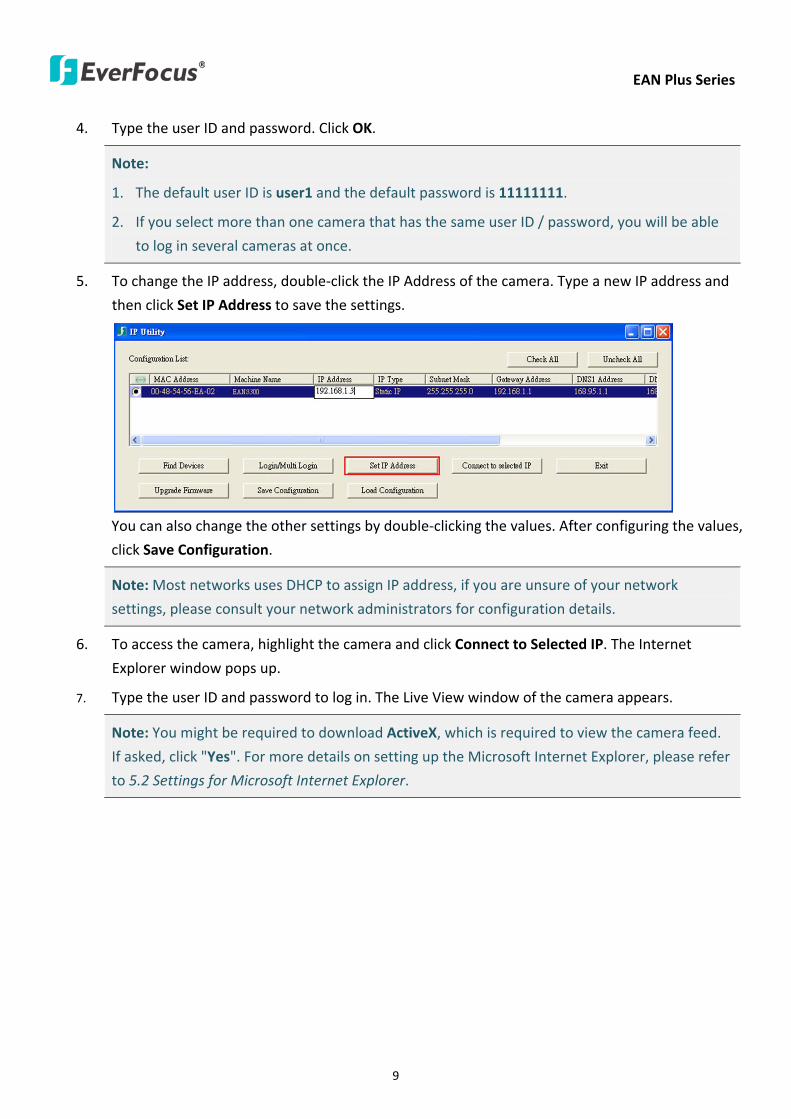
EAN Plus Series
9
4 Type the user ID and password Click OK
Note
1 The default user ID is user1 and the default password is 11111111
2 If you select more than one camera that has the same user ID password you will be able
to log in several cameras at once
5 To change the IP address double-click the IP Address of the camera Type a new IP address and
then click Set IP Address to save the settings
You can also change the other settings by double-clicking the values After configuring the values
click Save Configuration
Note Most networks uses DHCP to assign IP address if you are unsure of your network
settings please consult your network administrators for configuration details
6 To access the camera highlight the camera and click Connect to Selected IP The Internet
Explorer window pops up
7 Type the user ID and password to log in The Live View window of the camera appears
Note You might be required to download ActiveX which is required to view the camera feed
If asked click Yes For more details on setting up the Microsoft Internet Explorer please refer
to 52 Settings for Microsoft Internet Explorer
EAN Plus Series
10
52 Settings for Microsoft Internet Explorer
To enable Remove Live View Firmware Upgrade and ActiveX Prompt on Internet Explorer some
settings have to be complete Please follow the steps below
1 On the computer click Start gt Control Panel gt System and Security gt Action Center (click Change
User Account Control Settings) the User Account Control Settings window appears Adjust the
slide bar to Never Notify and then click OK Restart your computer if requested
2 Open the Internet Explore click Tools gt Internet Options gt Security Tab gt Custom Level the
Security Settings windows appears
EAN Plus Series
11
3 In the Download unsigned ActiveX controls field select Prompt In the Include local directory
path when uploading files to a server field select Enable Click OK
4 In the Internet Options window click the Advanced tab and then disable Enable memory
protection to help mitigate online attacks Click OK
EAN Plus Series
12
53 Connecting the Camera to the Network
There are three methods to connect the IP camera to the network Router or LAN Connection Direct
High-Speed Connection and One-to-One Connection
Router or LAN connection
This is the most common connection in which the IP camera is connected to a router and allows
multiple users on and off site to see the IP camera on a LANWAN (Internet) The camera must be
assigned an IP address that is compatible with its LAN By setting up port forwarding on the router
you can remotely access the cameras from outside of the LAN via the Internet To remotely access the
Web interface of the IP camera please refer to 732 DDNS To set up port forwarding please consult
the manual of the router
Straight-through LAN patch cable
Right Pinout of a straight-through cable
EAN Plus Series
13
Direct High-Speed Connection
In a Direct High-Speed Connection the camera connects directly to a modem without the need for a
router You need to set the static or dynamic WAN IP address assigned by your ISP (Internet Service
Provider) in the camerarsquos configuration web pages To access the camera just type ldquohttpxxxrdquo
where xxx is the IP address given by your ISP If you have a dynamic IP address this connection may
require that you use DDNS for a reliable connection Please refer to 732 DDNS
One-to-One Connection (Directly from PC to IP Camera)
You can connect directly without using a switch router or modem However only the PC connected
to the camera will be able to view the IP camera You will also have to manually assign a compatible IP
address to both the computer and the IP camera Unless the PC has another network connection the
IP camera will be the only network device visible to the PC See the diagram below
Pinout of straight patch cable
Right Pinout of a crossed-over cable
EAN Plus Series
14
54 Live View Window
1 Press the button to display the Live View window Double-click on the
image to show a full-screen display double-click again or press ESC to return to the normal display
If you experience video feed lag time (if connected via Internet) you can reduce the resolution or
limit the number of streams See 741 Multi Streaming
2 Press the button to play the recorded data directly from the on-camera Micro
SD SDHC card (for this function to become active you have to insert a Micro SD SDHC card in the
Micro SD SDHC card slot on the rear panel of the camera See 783 SD Card
3 Press the button to enter the Settings page On the Settings page there are
8 submenu sections [System Info] [User Config] [Network] [Video] [Audio] [User] [Event] and
[System] Click on the section buttons to open their configuration fields See the Settings section
below for more information
EAN Plus Series
15
4 Press the button to exit the system and close this browser page
5 Video Stream
Select the Video Stream (Stream 1 Stream 2 or Stream 3) that will be displayed in the video box on
the right Stream 2 and Stream 3 are only selectable if you have enabled the stream The default
setting is Stream 1 only See 741 Multi Streaming
6 View Size
Use this to select the appropriate view size and shape of the video box on the right A smaller size
might increase transmission speed and video quality
7 Digital Zoom
Click the Zoom In Zoom Out buttons or roll the mouse wheel to zoom in out the camera live view
up to 10x Clicking on a magnified image will re-center the image around that point
8 Record
The Record button is used to record the current video stream Click the Record button to start
stop recording This icon is only for one-minute video recording To record long-period recordings
please set a recording schedule (See 775 Schedule) The location on your computer where the
image files will be saved to and file size can be specified in the submenu (see 72 User Config)
9 Snapshot
Click the Snapshot button to save a snapshot of the video image currently being displayed The
location on your computer where the snapshot data will be saved can be specified in ldquoSettings gt
User Config gt RecordingSnapshotrdquo (see 72 User Config)
10 Play Audio Transmit Audio
Click the ldquoPlay Audiordquo (speaker) and ldquoTransmit Audiordquo (microphone) buttons to switch the sound
onoff for the speaker and microphone respectively (if such external devices have been connected
to the camera directly or via the network)
EAN Plus Series
16
11 One Push
This function is only available for EAN3120 Plus 3220 Plus The One Push button can be displayed
on the live view window by enabling the Show One Push Buttons function on the User Config lt Live
View Config Setting page (see 721 Live View Config) To enable the button (turned from faded to
clear) on the Video lt Advanced Setting page select One Push from the White Balance Settings
Mode drop-down list and click the Apply button Once this is done pressing the One Push button
on the Live View Window will instruct the camera to adjust the white balance settings and these
settings will be active until the button is pushed again This is like a ldquosemi-automaticrdquo way to adjust
white balance to suit the user if the Auto or Manual mode does not give the result the user wants
12 Manual Control
ndash Trigger Event
Press the ldquoTrigger Eventrdquo button to trigger an event directly from the Live page If you have
configured an event (in the Event submenu) that will trigger a reaction (like a recording) when a
Manual Trigger event occurs clicking this button will trigger that reaction You can select what that
reaction will be You can for instance set the camera to record the audiovideo feed to the Micro
SD card on board the camera You can then click on the Playback button to open the Playback page
and search for and play all such recordings that had been stored on the card Such event actions
will be effective once they have been configured in the ldquoEventrdquo menu (see 77 Event)
ndash Reset Alarm
Press the ldquoReset Alarmrdquo button to reset the alarm output remotely
13 Status Display (info lines that can be placed above video box or at bottom of page)
This shows the name of the camera that is currently active or being configured current datetime
and current frame rate You can activate these info displays in the Settings gt User Config page (see
72 User Config)
14 Event Signal Icons (above video screen)
When an alarm or motion event is triggered a signal icon will appear at the top right of the Live
View window to alert the user
Alarm event icon When an alarm is triggered this icon appears
Motion detection icons The colors of these motion event icons correspond to the colors of the motion trigger areas you have configured in the Motion Detection submenu (see 772
Motion Detection)
Recording icon When the camera is recording to a PC-based folder this icon appears
EAN Plus Series
17
6 Playback
You can remotely play back the recordings stored in the on-camera micro SD card on the Web interface
or play back the recordings stored in the computer using the ARV Viewer included in the software CD
Playback is designed as a quick way to check recent recordings that were triggered by Events that were
configured to ldquoRecord to SD Cardrdquo in the Settings gt Event gt Event Settings page (see 771 Event
Settings)
Note Note that the Playback page is only accessible once the on-camera SD card is inserted and
active
61 Remote Playback Using Playback Page
On the Live View Window click the Playback button to open the Playback page
EAN Plus Series
18
Search by File Click the Search button to search for all recording files on the on-camera SD card
Search results will be displayed in the Filename area
Search by Time Click the calendar icon and select the date and time from which you want to search
until the present moment Click search to get your search results which will be displayed in the
Filename area
Search by event Click the type of Event recordings you want to search for (Alarm Motion Manual
Trigger) and then click the calendar icons to select the Start Time datetime and the End Time
datetime of your search Click Search to get your search results which will be displayed in the
Filename area
Multiple Files Check this box if you want the video player to play all the files in the selected folder
The files will be displayed in the Filename area
Loop Again Check this box if you want the video player to play the selected file over and over again
Play Once you have opened the filersquos folder and have clicked on the file to highlight it its details will
be displayed in the File Information area You can now click Play to play that specific file
Pause Click this button to pause the playback
Stop Click this button to stop the playback
【Recording List】
Filename This area will display a list of search results (recording files and folders) Folders (named
with the recorded date) will be displayed first Click on the folder and click on each subfolder until the
recording files (arv) in that folder is listed
File Information Click a file on the Filename list the selected file information will be listed
Copy Click this button to copy the selected file to the computer-based folder of your choice A
browsing box will open so that you can search for the folder of your choice You can use the ARV
Viewer to play back the recordings recorded in your computer For details on ARV Viewer see 63
Playing Back Using ARV Viewer
Lock Click this button to lock the selected file This will protect that file from being overwritten during
any overwrite procedure The file will thus be saved on the micro SD card indefinitely However the
file will still be deleted if the micro SD card is ever formatted
Remove Click this button to delete the selected file
EAN Plus Series
19
62 Setting up the Playback Function
Note that the Playback function will not be active until the user has inserted a micro SD card in the
camerarsquos micro SD card slot The card may also have to be formatted in the Settings submenu
Micro SD Card Slot
621 Preparing the Micro SD Card
Once you insert a functional micro SD card into the slot the Playback button on the Live page should
become active within seconds (see section 622 below ndash the grey letters should turn white) IF NOT
do the following
1 From the Live page click Settings gt System gt SD Card If no card has been inserted yet the
Remove button should be faded indicating that no card is being detected (If a card is
inserted and the Remove button is still faded pull the card out and re-insert it)
2 Slide the card into the slot until it clicks into position
3 The Remove button should become active within a few seconds indicating the card is active
4 If the Remove button stays faded click the Format button to format the card NOTE All data
on the disk will be deleted if the Format button is clicked
622 Testing the Playback Function
1 Once the SD card is detected by the system the button (inactive)
will turn to (active)
2 To test the Playback function (this is not required) set up a ldquoManual Triggerrdquo Recording
Event by clicking Settings gt Event gt Event Settings
3 Click the ldquoAddrdquo button on the middle right side of the page to open an ldquoAdd Eventrdquo box
4 Give the event a name like ldquoTest 1rdquo
EAN Plus Series
20
5 In the ldquoEvent Triggered byrdquo field click on Manual Trigger
6 Below this check ldquoEnable This Eventrdquo ldquoEnable Post-trigger Bufferrdquo and ldquoRecord to SD Cardrdquo
7 To save your settings click OK or close the box by clicking on the red x icon at top right of the
box (in which case you will be asked if you want to save the data to which you should reply OK)
The box will close and the new event will be listed in the list area of the Event Settings page
8 Look at the ldquoPost-trigger Bufferrdquo at the bottom to make sure the buffer time is set to 10 seconds
9 Click ldquoApplyrdquo to make sure all settings are saved
10 Click the Live button to go back to the Live page
11 Get ready to click the Trigger Event button at the bottom of the page Before you do see if you
can find something in the view screen that will give you a visual time marker For instance if you
can get your hand in front of the camerarsquos lens get ready to count down on your fingers
12 Click the Trigger Event button and slowly count down on your fingers in front of the lens (if you
are able to do so ndash if not try to find visual cues on the view screen that will help you to mark the
moment you pushed the trigger) The recording period will be as long as the buffer time you
selected ndash the default period is 10 seconds
13 Click the Playback button to open the Playback page
14 There are different ways to search for recording files on the camerarsquos Micro SD card (ie the
Playback memory) For a recent recording like your test event simply click the ldquoSearchrdquo button
under the ldquoSearch by Filerdquo header
15 If the SD card is active and formatted correctly the recording folderrsquos name (the recording dayrsquos
date) will appear in the Filename box at the bottom Click on this folder to open it If there are
sub-folders click on the bottom one (the most recent would be at the bottom) until you can click
on a file that cannot open to another sub-level and shows data in the File Information box to the
right This would be the file of the most recent recording event
16 To play this file click the Play button below the video box The test footage you have recorded
should start playing Play time should be 10 seconds if you left the Post-trigger Buffer as 10
seconds
EAN Plus Series
21
63 Playing Back Using ARV Viewer
You can play back the recordings stored in the computer using the ARV Viewer included in the
software CD To store the recordings in the computer please refer to Recording List gt Copy in 61
Remote Playback using Playback Page
4 5 6 7 8 9 10
321
No Item Name Descriptions
1 Snapshot Click to take and save a snapshot
2 Load File Click to load the recordings for playing back
3 Convert ARV to AVI Convert the recording from ARV format to AVI format
4 Playback Time Display the playback time
5 Total Time of Recording Display the total time of the recording
6 Stop Click to stop playing the recording
7 Step Reverse Click to display the previous frame
8 Play Click to play back the recording
9 Pause Click to pause the recording
10 Step Forward Click to display the next frame
EAN Plus Series
22
7 Settings
Click the Settings button on the Live View Window to enter the settings submenu There are nine buttons
on the left-side of the submenu Live System Info User Config Network Video Audio User Event and
System Click the Live button can go back to the Live View Window
71 System Info
The System Information and System Log can be checked on this page Click the top tab of the one you
want to see
711 Information
Click the Information tab the following dialog box appears These values cannot be changed on this
page and are for reference only
EAN Plus Series
23
712 Log
Click the Log tab the following dialog box appears The sequence number date time and event
messages of the log event will be displayed in the System Log field The log will display the last 256
log events Click the Export button to export the system log event list into a ldquotxtrdquo file and select the
location where the exported log file will be saved to
EAN Plus Series
24
72 User Config
Each user can set a different configuration for hisher Live page here These settings will be applied to
the logged-in userrsquos Live page every time heshe logs in
721 Live View Config
【VideoAudio Connection Protocol Setting】You can transmit the data stream from the IP cameras
using the RTSP (Real Time Streaming Protocol) on the network The RTSP is a protocol that allows
you to access video streams by using the compatible media players Click Apply to apply the
changes or Reset to reset without saving the changes RTP over UDP The RTSP protocol uses UDP for camera data stream transmission
RTP over TCP The RTSP protocol uses TCP for camera data stream transmission
RTP over HTTP The RTSP protocol uses HTTP for camera data stream transmission
Nevio CGI This is EverFocusrsquo protocol designed for EverFocusrsquo IP devices Select this
protocol for camera data stream transmission
【Text Settings】Check the box of each option (Machine name DateTime Frame Rate) to display
this info on the Live View Page
Foreground Color Slide the Red Green and Blue bars to create your preferred text color for the
info text line
Position Select the position where the text will be displayed Choose from Upper Left Lower
Right Lower Left
Click Apply to apply the changes or Reset to reset without saving the changes
EAN Plus Series
25
【DateTime Format Used in Text】Click the dropdown menu to select datetime format from the
listed options Click on the desired hour format Click Apply to apply the setting changes or Reset to
reset without saving the change
【Live View Layout Settings】 Check the ldquoShow One Push Buttonsrdquo boxes if you want to show these
buttons on the Live View Page Uncheck these boxes to hide these buttons This function is only
available for EAN3120 Plus 3220 Plus
722 Recording Snapshot
This configures where your Record Button and Snapshot Button ( ) files will be saved if
you click one of these buttons Selectable folders will be on the computer only not on the
on-camera SD card
【Recording Snapshot Export Settings】
Enable Event Recording to PC Checking this box will let the system save RecordSnapshot Button
recordings to the folder configured below on the userrsquos PC
Export Folder Select the Export folder for the action above by clicking on the browse (hellip) button
and then select the desired folder
File size The user can limit the size of each recorded file here (in minutes) When a single
recording file exceeds the time you set the system will create a new file to save that data to
Overwrite Select ldquoONrdquo for overwriting recordingsnapshot file when the disk storage capacity is
full The user can set the storage capacity limitation in the in-sentence field in the gray box below
the Overwrite setting ldquoIf the remaining hard disk capacity is less than ____ MB (50~2000) system
will stop recording or start overwriting ldquo
Click Apply to apply the setting changes or Reset to reset without saving the changes
EAN Plus Series
26
723 Language
Select the language to be displayed on the Web interface of the IP camera The default language is
English
To add a new language not listed in the current Language list click the Browse button to locate
the new language file (evb) on your computer and then click the Upload button Updated
language files might be available on the manufacturerrsquos website Contact your vendor if required
Click Apply to apply any changes or Reset to reset without saving the changes
Note Uploading a new language file will cause the system to reboot automatically Please create
a new network connection to the IP camera when the reboot is complete
EAN Plus Series
27
73 Network
This page covers network-related settings including Network DDNS SMTPFTP HTTPS SNMP and
Network Alarm
731 Network
The following information is required to configure the network settings Contact your network
administrator or your internet service provider to get the info
【IP Settings】
IP Type Refer to the network administrator for these settings of the server Default DHCP
DHCP This setting lets the system use an automatically assigned (dynamic) IP address This
address can change under certain circumstances For instance when the camerarsquos network
switchhub has to be rebooted Do not assign to the DHCP server the same IP addresses used
for the other network cameras and PCs with unique IP addresses
Static IP The user can manually set the Static IP address This type of address is stable and
cannot change but the user has to make sure there are no address conflicts with other
network-connected devices
PPPoE This is a DSL-connection application The ISP will ask the user to input a username and
password Contact your ISP for these details
EAN Plus Series
28
Note If PPPoE is selected as the IP type the supplied IP Utility program will not be able to
detect the device
IP address When DHCP is not used the user needs to manually enter the IP address of the
camera Do not enter an IP address that is already used for your computer or other network
cameras
Subnet Mask This field is used to set the netmask for your network so that the IP camera will be
recognized within the network Example 2552552550 When DHCP is selected the DHCP server
will assign this value automatically
Gateway This field is used to set the gateway for your network so that the IP camera will be
recognized within the network When DHCP is selected the DHCP server will assign this value
automatically
Primary DNS Enter the IP address of the DNS server if this is provided by an ISP
Secondary DNS If your ISP provided you with a secondary DNS address please enter it here
Username Enter the accountrsquos username (used only for PPPoE)
Password Used only for PPPoE
IPv6 Enter the IPv6 details in this area if this applies to your system
Click Apply to apply the setting changes or Reset to reset without saving the change
【Port Settings】Enter the HTTP HTTPS and RTSP port numbers and click Apply to save
【Multicast Settings】Enable if required fill in the setting options and click Apply to save
EAN Plus Series
29
732 DDNS
DDNS (Dynamic Domain Name System) is a service used to map a domain name to the dynamic IP
address of a network device You can set up the DDNS service for remote access to the IP camera
DDNS assigns a domain name (URL) to the IP camera so that the user does not need to go through
the trouble of checking if the IP address assigned by DHCP Server has changed Once the IP is
changed the IP camera will automatically update the information to the DDNS to ensure it is always
available for remote access
Before enabling the following DDNS function user should have applied for a host name from the
DDS service providerrsquos website We support these four DDNS server providers
wwweverfocusddnscom wwwsitelutionscom wwwdyndnscom and wwwno-ipcom
Note We highly recommend that you use xxxxeverfocusddnscom for the simplicity of setting up
your IP cameras
【DDNS Settings】
Enable Check this box to enable the DDNS function
Service ISP You can either apply for a host name from EverFocus or other DDNS server providers
If you choose the EverFocus DDNS server you can obtain a free host name from EverFocus by
following the steps below
bull From EverFocus To obtain a free host name from EverFocus type a desired host name in the
textbox click the Register Update button and then click the Apply button
bull From other DDNS server providers To obtain a domain name from one of the three DDNS
server providers you have to register your name with the provider first and then select the
provider and fill in the required information Please refer to the specific DDNS companyrsquos
website for further information
Record ID Type the record ID if provided by the DDNS server provider
EAN Plus Series
30
FQDN Type the fully qualified domain name applied from the DDNS server provider For
example xxxxdyndnscom
Username Password Type the login account of your DDNS server provider
Click Apply to apply the setting changes or Reset to reset without saving the changes
Note
1 In order to support the full functionality of the camera you must open the port numbers (80
554 443) on the router for remote access to the IP camera This function is available on most
routers in the market and is often known as ldquoPort Forwardingrdquo To set up Port Forwarding
please consult the manual of the router
2 In certain router models it is possible that you will not be able to access the camera using
DDNS while inside the routerrsquos network Please try using a PC located outside of your routerrsquos
network
Default Ports on All EverFocus IP Cameras
HTTP 80
RTSP 554
HTTPS 443
EAN Plus Series
31
733 SMTP FTP
【Set SMTP Server (email)】This area is for configuring the mail server that is used to send e-mail
notifications from the camera to predefined addresses via SMTP Note that to enable e-mail
notification function you have to check the Send Mail Notification item on the Event dialog box
(see 771 Event Settings)
SMTP Server Enter the IP address or the host name of the SMTP server used to send e-mails
SMTP Port Enter the port number for SMTP The default is 25
Authentication Check this box if the SMTP server requires authentication (userpassword)
User name Input the userrsquos login ID if the SMTP server requires authentication
Password Input the userrsquos login password if the SMTP server requires authentication
EAN Plus Series
32
Receiver Address Input the e-mail addresses for receiving an e-mail message when an EVENT is
enabled and triggered Please use ldquordquo to separate multiple addresses
Sender Address Input the senderrsquos e-mail address so that the receiver can recognize the sender
when an Event message is received
Attach Image Check this box if you want to attach an image when an alarm is triggered or an IP
camera detects events
Send Test Email Click the Test button to send a testing email to the assigned address
Click Apply to apply the setting changes or Reset to reset without saving the changes
【Set FTP Server】The settings relating to the FTP server used to transmit the alarm images can be
configured here Note that to enable uploading images to the FTP server function you have to
check the Upload to FTP item on the Event dialog box (see 771 Event Settings)
FTP Server Enter the IP address or the host name of the FTP server
FTP Port Enter the port number for the FTP server Default is 21
Recording Path Assign the recording path
User Name Set FTP Userrsquos name
Password Set FTP password
PASV mode Check to enable Passive mode Passive mode is normally enabled If a connection
cannot be established uncheck PASV Moderdquo
Test FTP Server Click the Test button to send a testing file to the assigned FTP server
Click Apply to apply the setting changes or Reset to reset without saving the changes
EAN Plus Series
33
734 HTTPS
Hypertext Transfer Protocol Secure (HTTPS) is a combination of the Hypertext Transfer Protocol
and the SSLTLS protocol and provides encrypted communication and secure identification of a
network web server
Before using the HTTPS function for communication with the IP camera a Certificate must be
created first There are two ways to create and install a certificate Create Self-Signed Certificate
and Create Certificate Request
Create Self-Signed Certificate
Please note that even though self-signed certificates are free and offer some protection true
security is only implemented after the installation of a signed certificate issued by a certificate
authority
1 Click the Create Self-Signed Certificate button the following dialog appears
EAN Plus Series
34
2 Type the required Certificate information and then click the Apply button The subject line will
be displayed in the Installed Certificate Information field
3 Click the Property button a pop-up window appears to display the details of the certificate
4 To optionally create and install other certificates remove the existing one by clicking the
Remove button to erase the certificate
5 On the Web page change the address from ldquohttprdquo to https in the address bar and press
Enter on the keyboard Some Security Alert dialogs will pop up Click OK or Yes to enable HTTPS
Create Certificate Request
You can apply for an official certificate from an issuing Certificate Authority
1 Click the Create Certificate Request button the following dialog appears
EAN Plus Series
35
2 Type the required Certificate information and then click the Apply button The subject line will
be displayed in the Created Request field
3 Click the Property button a pop-up window appears to display the details of the certificate
4 To optionally create and install other certificates or request remove the existing one by clicking
the Remove button to erase the certificate or request
5 Copy the contents of the Certificate request (in PEM format) and paste it to the certificate
request field on the Web page of the 3rd-party certification authority such as Symantec VeriSign
Wait for the certificate authority to issue an SSLTLS certificate and then download the issued
certificate on your computer
6 In the Install Signed Certificate field click the Browse button to search for the issued certificate
and then click the Upload button to import the certificate Once the certificate has been
uploaded this field will show the subject line of the certificate
EAN Plus Series
36
735 SNMP
The default values for SNMP v1v2v2c and SNMP v3 are already filled in Click either of the
Enable buttons to enable either of the two Make your changes as desired Click on the Trap
Address field to enter the digits if required
736 Network Alarm
This function works with EverFocusrsquos CMS software eg the PowerCon or the Power Video Plus For
the setting details please refer to the CMS network alarm protocol
EAN Plus Series
37
74 Video
The settings relating to video such as streaming camera OSD can be configured on this page The
Video page has five tabs Multi-streaming Camera Advanced ROI and Privacy Mask
741 Multi Streaming
【Stream Settings】 This IP camera can output three video streams simultaneously For each of these
streams the user can set the compression format resolution bit rate and frame rate individually
Stream 1 is always enabled for live view To enable Stream 2 andor Stream 3 check the ldquoEnablerdquo
box the header of each stream
Note If you connect to the camera via the Internet and experience a delay (lag time) in the video
feed try to reduce the number of streams and the quality and resolution of the streams ndash but
keep the frame rate at its maximum
EAN Plus Series
38
Format Select the encoding format ndash H264 or MJPEG
Resolution Select the most suitable resolution for your needs
Frame Rate Select from 1 to 30 fps
Bit Rate If required select whether you want the stream to stream a Constant Bit Rate or a
Variable Bit Rate and set the values of whichever option you choose
Click Apply to apply the setting changes or Reset to reset without saving the changes
【Video Recording Settings】Select the stream you want to configure and then select whether you
want the recording files of that stream to be saved in AVI or ARV format Click Apply to apply the
setting changes or Reset to reset without saving the changes
【Time Stamp Settings】 You can select the DateTime format position and add the setting to the
streaming
Click Apply to apply the changes or Reset to reset without saving the changes
EAN Plus Series
39
742 Camera
【Image Settings】Set the Brightness Saturation Contrast or Sharpness of the image Click Apply to
apply the changes or Reset to reset without saving the changes
【Camera Settings】
Mirror Switch Mirror ON to rotate the image horizontally around a vertical axis
Flip Switch Flip ON to rotate the image vertically around a horizontal axis
AE There are two options
ALC Selecting Automatic Light Control allows the camera circuitry to either take bright spots
more into consideration (peak) bringing out detail in bright areas or less into consideration
(average) bringing out detail in shadows
AES Selecting Auto Electronic Shutter disables the Shutter setting below this setting In this
mode the camera measures the light level and decides whether it needs more or less light and
then automatically adjusts the shutter speed accordingly
BLC Back Light Compensation (BLC) is used to make the subject appear clearer when it is set
against a bright background
OFF Select to switch Back Light Compensation functions off
(ON)BLC The BLC can increase the exposure of a dark area surrounded by a brighter area HLC
can decrease the exposure of bright areas surrounded by darker areas This enables the
camera to better display information that would otherwise have been ldquowhited outrdquo like a
license plate between two bright headlights on a dark road
(ON)HLC The Highlight-Suppression BLC is used to reduce the brightness of light sources in a
specific area It is activated only in a low illumination environment to minimize the effects of
glare from bright lights such as spotlights street lights or headlights in the field of view
EAN Plus Series
40
WDR The Wide Dynamic Range (WDR) function provides clearer images when both of the very
bright and dark areas simultaneously appear on the camera view There are four value options
OFF Low Middle and High Note that when WDR is ON some parts of the image may appear
solarized This is normal for WDR and is not a camera malfunction This function is only available
for EAN3120 Plus 3220 Plus
DN Mode
Auto Select to let the camera automatically switch to Night mode (black and white) when the
light levels fall to a specified level and back to Day mode (color) when the light levels rise to a
specified level
Day Select to keep the camera in Day mode (color) even in nighttime
Night Select to keep the camera in Night mode (black and white) even in daytime
EAN Plus Series
41
743 Advanced
EAN Plus Series
42
【Camera Settings】
Lens (IRIS Control) Select DC or Manual for IRIS control This function is only available for EAN3220
Plus
Exposure Settings (AE) This setting is used to adapt to the amount or type of light used by the
camera Note the settings vary among models
Mode This function is not available for EAN3220 Plus
Automatic Light Control (ALC) This option is only available for EAN3120 Plus 3300 Plus The
ALC allows the camera circuitry to either take bright spots more into consideration (peak)
bringing out detail in bright areas or less into consideration (average) bringing out detail in
shadows
Auto Electronic Shutter (AES) This option is only available for EAN3120 Plus 3300 Plus In
this mode the camera measures the light level and decides whether it needs more or less light
and then automatically adjusts the shutter speed accordingly
Manual This option is only available for EAN3300 Plus Select this option to manually set up
the Shutter (Manual) and AGC (Manual) values
Iris Specify the size of the Iris opening here
Shutter If enabled this setting lets you set the shutter speed yourself
Shutter Limit Use this setting to set the maximum shutter speed for the camera This function is
only available for EAN3120 Plus
AGC Set the Auto Gain Control limit here The lower the AGC level the lower the video signal and
the noise However the image will be darker under low-light condition with IR-off if you set up the
Iris to the maximum level
Slow Shutter This option can be switched on when AES Mode is selected in the Exposure Settings
(AE) field This function is only available for EAN3220 Plus 3300 Plus
Flickerless If the Mode field in the Exposure Settings (AE) area has been set to AES then this option
becomes available Choose between OFF 50HZ 60HZ 50HZ (High Luminance) or 60HZ (High
Luminance) This function is only available for EAN3300 Plus
EV Setting Set up the Exposure Value Note the brightness of the screen changes when you change
the EV value This function is only available for EAN3300 Plus
AE Response Set up Auto Exposure Response time This function is only available for EAN3300 Plus
AE Weighting Area Select an AE Weighting area Each setup AE Weighting Area is configured with
the appropriate brightness level on the center and the surrounding areas This function is only
available for EAN3300 Plus
Brightness Set the image brightness here
AE Reference Set the Auto Exposure value here This function is only available for EAN3120 Plus
EAN Plus Series
43
Black Level Set the Black level here This function is only available for EAN3300 Plus
WDR The Wide Dynamic Range (WDR) function provides clearer images when both of the very
bright and dark areas simultaneously appear on the camera view There are four value options OFF
Low Middle and High Note that when WDR is ON some parts of the image may appear solarized
This is normal for WDR and is not a camera malfunction This function is only available for EAN3120
Plus 3220 Plus
Visibility Enhancement (OFFLowMiddleHigh) Images in foggy or rain environments or in
environments with a very strong luminous intensity have a dynamic range that is significantly lower
than ordinary images The user can use this Visibility Enhancement setting to ldquoDEFOGrdquo the image if
such ldquoFOGGINGrdquo is an issue This function is only available for EAN3220 Plus
BLC Settings Back Light Compensation (BLC) is used to make the subject appear clearer when it is
set against a bright background
OFF Select to switch Back Light Compensation functions off
Back Light This option is only available for EAN3300 Plus The Back Light function is useful
when the background of the subject is very bright and the subject itself is dark Select Back
Light and adjust the slide bar to the left right for setting up the back light value The higher
the value the more the backlight compensation
Front Light This option is only available for EAN3300 Plus This function is useful when the
bright highlights such as flashlight or car headlights appear on the camera view Select Front
Light and adjust the slide bar to the left right for setting up the front light value The higher
the value the more the highlight compensation
ON (BLC) This option is only available when you select AES Mode in the Exposure Settings (AE)
field The option is only available for EAN3120 Plus 3220 Plus The BLC function is useful
when the background of the subject is very bright and the subject itself is dark Follow the
instructions below to configure the settings for each model
For EAN3120 Select ON (BLC) the button next to the Mode drop-down list will be
active (see image below) Click the button the green setup areas appear on the left
screen Click on the areas to enable disable the BLC function The selected areas (in green)
will be applied with the BLC function
EAN Plus Series
44
For EAN3220
You can configure one area to apply the BLC function Select ON (BLC) the setup buttons
appears (see image below) Select Low Middle High from the BLC Gain drop-down list To
set up a BLC area click the Edit Area button and then click on the blue color tab to turn your
mouse cursor into a blue pen Move the cursor to the position on the right screen where you
want the BLC rectangle to start and then click Move your cursor to the position (diagonally
opposing corner) where you want the BLC rectangle to end and then click The blue area will
be applied with the BLC function
ON (HLC) This option is only available when you select AES Mode in the Exposure Settings (AE)
field The option is only available for EAN3120 Plus 3220 Plus This function is useful when
the bright highlights such as flashlight or car headlights appear on the camera view Follow
the instructions below to configure the settings for each model
For EAN3120 Select ON (HLC) and then select a level from the drop-down list The higher the
level the more the highlight compensation
For EAN3220
HLC Level Select a level for the HLC setting The higher the level the more the highlight
compensation
HLC Mode Select All Day Night mode to apply the HLC function
HLC Black Mask Select On Off to apply the black mask on the selected areas The
over-exposure portions within the selected areas will be applied with the black mask
Color Tabs You can set up four HLC areas with different colors To set up a HLC area click the
Edit Area button and then click on the color tab to turn your mouse cursor into a pen of that
color Move the cursor to the position on the right screen where you want the HLC rectangle
to start and then click Move your cursor to the position (diagonally opposing corner) where
you want the HLC rectangle to end and then click Select ON from the color tab drop-down list
The rectangular area with the selected color will be applied with the HLC function
EAN Plus Series
45
Back Light This option is only available for EAN3300 Plus The Back Light function is useful
when the background of the subject is very bright and the subject itself is dark Select Back
Light and adjust the slide bar to the left right for setting up the back light value The higher
the value the more the backlight compensation
Front Light This option is only available for EAN3300 Plus This function is useful when the
bright highlights such as flashlight or car headlights appear on the camera view Select Front
Light and adjust the slide bar to the left right for setting up the front light value The higher
the value the more the highlight compensation
Noise Reduction Settings This limits the amount of digital ldquovideo noiserdquo that is usually found in any
video stream and helps to reduce file size The higher the level the more the reduction
For EAN3120 Plus 3300 Plus
Select ON OFF to enable disable the Noise Reduction function Or select Auto to let the camera
automatically enable disable the Noise Reduction function Slide the Level bar to set up the level
The higher the level the more the reduction
For EAN3220 Plus
2D DNR Select ON to enable the 2D DNR function
3D DNR Select ON to enable the 3D DNR function You can further set up the following settings
3D Start AGC Set up the AGC level to automatically start the 3D NR function
3D End AGC Set up the AGC level to automatically stop the 3D NR function
3D Level Set up the 3D DNR level
Smart NR Select ON to enable the Smart NR function The 3D NR function will be
automatically turned on when a motion event occurs
EAN Plus Series
46
White Balance Settings Select the mode that delivers the best quality image for the camerarsquos light
environment There are five options Auto Manual Indoor Outdoor One Push
Auto Select to let the camera automatically adjust the White Balance In the Auto mode the
camera computes the white balance value output using color information from the entire
screen It outputs the proper value using the color temperature radiating from a black subject
based on a range of value from 3000 to 7500K
Manual Select to adjust the Red and Blue values yourself in the fields below this field
Indoor Select to use the default settings for indoor environments In the Indoor mode the
camera uses 3200K as the base value
Outdoor Select to use the default settings for outdoor environment In the Outdoor mode it
uses 5800K as the base value
One Push Select to enable the Push button next to the Mode drop-down field This will allow you to force the camera to readjust the white balance every time you push the Push
button The lens will hold the same focal position until the next trigger command is received
This function helps to prevent incorrect focusing in dark environments This function is only
available for EAN3120 Plus 3220 Plus
Manual Temperature Select to use the optimized Red and Blue settings You can also
optionally adjust the Manual Level below this field for setting up the color temperature The
higher the value the more the color temperature This function is only available for EAN3300
Plus
DayNight Settings
Auto Select to let the camera automatically switch to Night mode (black and white) when the
light levels fall to a specified level and back to Day mode (color) when the light levels rise to a
specified level
Day Select to keep the camera in Day mode (color) even in nighttime
Night Select to keep the camera in Night mode (black and white) even in daytime
IR Smart Settings Select ON and set up the level to enhance the image quality when the images are
over exposure This function is useful when the camera is in the Night mode This function is only
available for EAN3220 Plus
Saturation Set the saturation value This function is not available for EAN3220 Plus
Monitor Type Select a gamma value from Set 1 Set 2 or Set 3 This function is only available for
EAN3120 Plus
Negative Switch this setting ON to view a color negative version of the video image This is useful
at night or when viewing temperature-sensitive images
EAN Plus Series
47
Sharpness Settings Select the sharpness level of the image A low sharpness level will deliver a
softer less detailed image A high level will deliver a sharp highly detailed image Switch Resolution
Enhancement ON to enable the resolution enhancement function
Contrast Select the contrast level of the image
Suppress Function This function is only available for EAN3300 Plus
Aperture Compensation Suppression (OFFLowMiddleHigh) This setting can be activated to
suppress luminance noise when the AGC level increases
Chroma Suppression (OFFLowMiddleHigh) This setting can be activated to suppress
chrominance noise when the AGC level increases
Ygamma (gamma 22standardcontrast enhancehigh light range mode LHigh light range mode
H) Select the Ygamma value for the video quality of the monitor This function is only available for
EAN3300 Plus
Monitor Settings The user can use this field to optimize video quality for his or her specific type of
monitor ndash LCD or CRT This function is only available for EAN3220 Plus
Color Space Standard The options are YUV601 for SD and YUV709 for HD These define the color
space standard required to convert an RGB picture to a YUV picture Generally YUV601 is used for
Standard Definition (720P) devices and the YUV709 is used for High Definition (1080P) devices
Click Apply to save all changes Click Reset to cancel all changes
EAN Plus Series
48
744 ROI (Region of Interest)
The Region of Interest (ROI) function allows users to set up multiple regions within an image with
better quality and less distortion than the rest of the image You can also use this function
together with the Digital Zoom function on the Live View Page to get a better image result Up to
eight ROIs can be configured in the ROI settings page
To set up an ROI region
1 Select an ROI number from the ROI No drop-down list
2 Click the Add button the mouse cursor will turn into a pen when you move it over the live
image on the left
3 Move the cursor to the position where you want the ROI rectangle to start and then click
Move the cursor to the position (diagonally opposing corner) where you want the ROI
rectangle to end and then click
4 Slide the Quality bar to set up the quality value
5 Click the Apply button to apply the settings or click the Reset button to reset without saving
the settings
EAN Plus Series
49
745 Privacy Mask
The Privacy Mask can block out sensitive areas from view covering the areas with colored or black
and white boxes in both live view and recorded clips This feature is useful when usersrsquo donrsquot want
the sensitive information visible Up to four Privacy Masks can be configured
【Privacy Mask Color Settings】The Modes vary among camera models
Mode Click Color to make the masks appear as colored rectangles on the screen Click BW to
make the masks appear as gray rectangles on the screen Click Mosaic to make the masks appear
as mosaic-effect rectangles on the screen
Level Select the color of the masks if you selected Color Mode Select the level of grayness of the
masks if you selected BW Mode Select the level of smallmiddlelarge if you selected Mosaic
Mode
Click Apply to apply the settings or click Reset to reset without saving the settings
Color Tabs Click on a color tab to turn your mouse cursor into a pen of that color
You can now create a block of that color on the video screen Move your cursor to the position
where you want your mask rectangle to start and then click Move your cursor to the position
(diagonally opposing corner) where you want your mask rectangle to end and then click The
rectangular area with the selected color will appear The live image will display the rectangular
area with the color you selected If you want to create another mask use one of the other three
colors Each color denotes a different mask area Only one block per color is allowed As the
number of colors suggests you can configure up to four blocks
EAN Plus Series
50
Select All Click to turn the whole screen into a mask area
Clear All Click to delete all configured mask blocks
Eraser Click to turn the mouse cursor into an eraser to delete any block you click on
Area Shows the color and number of the block
Enable Check this box to enable the related mask block
Click Apply to apply the settings or click Reset to reset without saving the settings
EAN Plus Series
51
75 Audio
The EAN Plus series IP camera can transmit audio to your computer if you have connected an external
microphone to its audio Input cable It can also receive audio input from you and transmit it via an
external speaker if you have connected such a speaker to its audio Output cable
Check the Enable Audio box to enable the camerarsquos audio function The camera will now act as a
digital bridge (via the IP network) between any connected audio input device and any connected
audio device
Adjust the Audio Input Volume if you have external audio input devices (microphones) connected to
the camera and if there are problems with the sound input being too low or high
Click Apply to save all settings or click Reset to cancel
EAN Plus Series
52
76 User
761 User Information
The system administrator can create up to ten user accounts on this page
To set up a user account
1 Highlight a user account and click the Modify button The following dialog box appears
2 Type the account name account description and password for the account Type the password
again in the Confirm field
3 Select an authority level for the user account from the Authority drop-down list
bull Supervisor Administrator The only difference between a supervisor and administrator is
that a supervisor can edit an administratorrsquos account and password but an administrator
cannot edit the supervisorrsquos account and password Multiple administrators can be
configured but there can be only one supervisor The supervisor and administrators all
have unrestricted access to the Settings submenus and can determine the registration of
all other users
EAN Plus Series
53
bull User A user can view the Live View page and view the system network video and audio
information A user can only adjust the User Config page settings The user does not have
access to the User Event and System pages
bull Guest The lowest level of access which only allows the user access to the Live View page
4 Select Active or Disable from the Status drop-down list to active or disable the user account
5 Click On in the SD Card Playback field to allow the user to access the SD card playback
function
6 Click OK
7 Click Apply to save all the settings
EAN Plus Series
54
762 IP Address Filter
Use this page to specify IP addresses that are not allowed to access this camera By default any IP
address can access the camera
Note The Allowed List addresses only become relevant when the Denied List contains a network
or range and the supervisor wants to allow one or more IP addresses within that excluded range
or network In such a scenario the user would enter the excluded range or network in the
Denied List and enter the exceptions in the Allowed List
To set up the IP Address Filter
1 Select Denied List Click the Add button the following dialog box appears
2 Select an IP type from the IP Type drop-down list
3 Select a network rule from the Rule drop-down list type the IP address and click OK
Single Type a single IP address in the IP Address field below
Network Type the IP address and subnet mask in the field below
Range Type a range for the IP addresses
4 If you have set up an IP range in Step 3 you can optionally set up the Allowed List to allow one
or more IP addresses within the setup IP range to access the IP camera
5 Click Apply
EAN Plus Series
55
77 Event
You can set up the Motion Detection event Tamper Detection event or the Alarm IO to automatically
notify the users when an event occurs or an alarm is triggered You can also set up a schedule to
automatically record the videos when an event occurs or an alarm is triggered
771 Event Settings
You can create a total of ten event or alarm settings page in the Event List
【Event List】
Click the Add button and the following Event Configuration Window appears
EAN Plus Series
56
Enter Event Name Type an event name
Event Triggered by Select an event or alarm type for the to-be-specified-below reactions
Alarm Input Select this if you want a reaction trigger coming from any external connected sensor
to activate a to-be-specified-below reactions via the camera system Make sure that a suitable
device is actually connected to the alarm input relay
Manual Trigger Select this option if you want to manually trigger the alarm by clicking the Trigger
Event button on the Live View Page
Motion Detection Select this option if you want motion in a specified part of the camerarsquos viewing
rectangle (the screen image) to trigger the to-be-specified-below reactions
Tampering Detection Select this option if you want the camerarsquos tampering detection sensor to
trigger the to-be-specified-below reactions
Schedule Recording Select this option if you want the Schedule Recording periods configured in
the recording schedule (the Settings gt Event gt Schedule page) to activate this event In this
scenario a preconfigured event reaction like a log entry will list the start and end times of each
period Actual recording will only be triggered if the event is preconfigured to do so
Enable This Event Select to activate the event
Enable Re-trigger Click to set a minimum time after the event is triggered before the event
can be triggered again
Enable Pre-trigger Buffer Click if you want the Event reaction (as selected in the ldquoNotification
Overrdquo field below) to be the activation of the video recording function and if you want the
recording to include the video feed from the time period (configurable on the previous ldquoEvent
Settingsrdquo page) just before the Event trigger occurred
Enable Post-trigger Buffer Click if you want the Event reaction (as selected in the Notification
Over field) to be the activation of the video recording function and if you want the recording
to include the video feed from a time period (configurable on the Event Settings page) just
after the Event trigger occurred
Motion Area Select a setup motion detection area from the drop down list Note this
function only becomes relevant after the Motion Detection areas have been set up (see 772
Motion Detection)
Notification Over Select the desired notification types form the following items
Log Click if you want the camera to list the eventrsquos details in its log if the event is triggered
Trigger Alarm Output Click if you want the camera to relay the event reaction to a device
attached to the alarm relay output wire and then set up the alarm output duration time
EAN Plus Series
57
Send Mail Notification Click if you want the camera to send an Event notification email to the
email address entered in the Set SMTP Server(email) field of the Network gt SMTPFTP page if
the Event occurs (see 733 SMTP FTP)
Upload to FTP Click if you want the camera to upload recorded footage to the FTP server
entered in the Set SMTP Server(email) field of the Network gt SMTPFTP page if the Event
occurs (see 733 SMTP FTP)
Record to SD Card Click if you want the camera to start recording its video feed (when the
event occurs) on an on-camera SD Card (if such a card has been inserted)
Note The recording will only be as long as the combined Pre- and Post-trigger Buffers so
make sure you enable at least one of these buffers especially the Post-trigger Buffer
Record to PC Check this box if you want the camera to start recording its video feed (when
the event occurs) on the same folder on the same PC as configured on the User Config gt
RecordingSnapshot page (if such a folder has been enabled and configured)
Note The recording will only be as long as the combined Pre- and Post-trigger Buffers (and
for as long as the event trigger is happening ndash eg a motion is detected) so make sure you
enable at least one of these buffers especially the Post-trigger Buffer
Network Alarm Check this box if you want the camera to send a network alarm signal (when
the event occurs) to the CMS servers configured on the Network gt Network Alarm page (see
736 Network Alarm)
Click OK to save all settings or click Cancel to cancel
【PrePost Trigger Settings】
Pre-trigger Buffer Select the duration for the buffer This will determine the amount of footage
(length of time) before the event trigger moment that will be included in an event-triggered video
recording if that buffer and video recording has been enabled in the Event Configuration Window
Post-trigger Buffer Select the duration for the buffer This will determine the amount of footage
(length of time) after the event trigger moment that will be included in an event-triggered video
recording if that buffer and video recording has been enabled in the Event Configuration Window
Click Apply to save all settings or click Reset to cancel
EAN Plus Series
58
772 Motion Detection
Use this page to configure up to four areas in which motion will be detected When a motion is
detected by the camera the motion detection icon will appear at the top right of the
Live page to alert the user This function can also be linked with correctly configured Events to
trigger Event reactions like the activation of video recording periods snapshots alarms etc
Color Tabs Click on a color tab to turn your mouse cursor into a pen of that color
You can now create a block of that color on the video screen Move your cursor to the position
where you want your detection rectangle to start and then click Move your cursor to the position
(diagonally opposing corner) where you want your detection rectangle to end and then click The
rectangular area with the selected color will appear This block will be an area inside which the
camera will detect motion If you want to create another detection area use one of the other three
palette colors Each color denotes a different detection area Only one block per color is allowed As
the number of colors suggests you can configure up to four blocks
Select All Click to turn the whole screen into a motion detection area
Clear All Click to delete all configured motion detection blocks
Eraser Click to turn your mouse cursor into an eraser to delete any block you click on
Area Shows the color and numberID of the block
Enable Check this box to enable the related motion detection block
Sensitivity Set the sensitivity of the motion detection sensor function
Click Apply to save all settings or click Reset to cancel
EAN Plus Series
59
773 Tamper Detection
Use this page to set the number of seconds that an alarm signal will be active if the device is
physically tampered (moved covered up or out of focus
774 Alarm IO
Use this page to set the type of trigger input and the type of output contact for the camerarsquos alarm
channel
EAN Plus Series
60
775 Schedule
Use this page to configure a schedule for periods during which the camera should deactivate all
user-activated Events (gray Deselect periods) or when the camera should deactivate all
user-activated Events except Schedule Recording (SR) events (blue Schedule Recording-only
periods) or when the camera should deactivate only SR events (red Event Recording-only periods)
or when it should enable all activated Events (yellow periods)
Event Recording Click this button to make every hour block you click on red A red block represents
an Event Recording-only block which represents an hour when the camera will deactivate all
preconfigured activated Schedule Recording events and keep all the other activated events active
Schedule Recording Click this button to make every hour block you click on blue A blue block
represents a Schedule Recording-only block which represents an hour when the camera will
deactivate all other preconfigured activated events and keep only the preconfigured activated
Schedule Recording events active
Event + Schedule Click this button to make every hour block you click on yellow A yellow block
represents an hour in which all activated events including Schedule Recording events will be
active
Deselect Click this button to make every hour block become grey A grey block represents an hour
in which all activated events including Schedule Recording events will be inactive
Click Apply to save all settings or click Reset to cancel
EAN Plus Series
61
78 System
You can set up the systemrsquos time and SD card settings and to do maintenance and reset actions like
reboots and upgrades
781 DateTime
【Machine Name Settings】If required enter a new name for the machine This name will be visible
in the Machine Name field of the IP Utility software which is included in the software CD
【Set Time Zone】Set the time zone of the camerarsquos location
【Set DateTime Manually】Set the datetime here if you wonrsquot be using an NTP server to update the
datetime (see below)
【Set DateTime Sync】Enter the Network Time Protocol server if applicable The camerarsquos time will
be automatically adjusted by synchronizing with the NTP server
Click Apply to save all settings or click Reset to cancel
EAN Plus Series
62
782 Daylight Saving
Click Enable Daylight Saving to enable this schedule and select the dates when the regionrsquos
daylight saving period begins and ends Click Apply to save all settings or click Reset to cancel
783 SD Card
Use this page to prepare the system for safely removing the SD Card from its slot
【Setup SD Card】
Notification Select the percentage of storage space that should be left on the card before the
camera notifies you of the impending storage shortage or overwrite
Event Recording Select if you want Event Recording only FTP Backup only or both
Overwrite Click ON if you want the card to start writing over recorded footage when its memory is
full Click OFF if you want the card to stop recording new footage when its memory is full
【SD Card Utility】
Capacity This shows you how much card memory has been used and how much memory capacity
remains on the card
Remove Click this button before removing the card from the system
Format Click this button to format the card All data saved on the SD card will be removed if the
card is formatted
EAN Plus Series
63
784 Maintenance
【Maintenance Server】
Reboot Click this button to reboot the unit without changing any of the settings Use this function if
the unit is not behaving as expected
Restore Click this button to restart and reset most of the current settings to their factory default
values The only settings that will not be changed to default are
bull IP settings
bull DDNS settings
Default The Default button should be used with caution Pressing this button will return all of the
cameras settings including the IP address to the factory default values The camera will then have
to be reconfigured
【SaveLoad Configuration Server】
Save To make a backup file of the machinersquos current configurations press Save to save all the
configurations to a config file This will enable the user to reload these configuration settings if the
settings are changed and there is unexpected behavior
Load To load a previously saved configuration press the Browse button to locate the saved config
file (see above) and then click the Load button The systemrsquos settings will be restored to the saved
configuration
EAN Plus Series
64
【SaveLoad Video Configuration Server】
Save To make a backup file of the machinersquos video configurations press Save to save the video
configurations to a config file This will enable the user to reload these configuration settings if the
settings are changed and there is unexpected behavior
Load To load a previously saved video configuration press the Browse button to locate the saved
config file (see above) and then click the Load button The systemrsquos settings will be restored to the
saved video configuration
【Upgrade Firmware】Click the Browse button to find a previously prepared firmware upgrade file
Click Upgrade to install the new firmware
Note
1 Do not disconnect power to the unit during the upgrade sequence The unit will reboot
automatically after the upgrade has completed (1-5 minutes)
2 During the upgrade process all event recording actions will be stopped Event recording
actions will resume after the camera is rebooted
3 If the ldquoFile Error Please re-loginrdquo warning message appears when upgrading the firmware
please try the following instructions
a Go to Internet Explorer gt Tools gt Internet Option gt Security gt Custom
b Find and enable the Include local directory path when uploading files to a server
EAN Plus Series
65
8 Upgrading Firmware Using IP Utility
You can upgrade the Firmware using the IP Utility software included in the software CD
1 Install and then start the IPU program The following dialog box appears
2 Click Find Devices to search the cameras connected in the LAN The default network values of the
cameras will be displayed By default the network protocol of the camera is DHCP
3 Select a camera and click LoginMulti Login to log in the camera
4 Type the user ID and password Click OK
Note
1 The default user ID is user1 and the default password is 11111111
2 If you select more than one camera that has the same user ID password you will be able
to log in several cameras at once
EAN Plus Series
66
5 Highlight the camera and then click Upgrade Firmware A browsing window appears
6 Select the firmware file (evb) and then click Open The IP Utility will automatically upgrade the
firmware
The camera will reboot once the update is complete Click Find Devices the new firmware version
should be displayed in the last part of the Machine Name
EAN Plus Series
67
9 Specifications
Model EAN3120 Plus EAN3220 Plus EAN3300 Plus
Camera
Image Sensor 13 Panasonic CMOS 128 Sony CMOS
Megapixel 13 MP 2 MP 3 MP
Picture Elements (H x V) 1280 x 1024 1944 x 1092 2048 x 1536
Min Illuminations 003 Lux at F14
Electronic Shutter (Sec) 85 ~ 160000 2 ~ 150000 1 ~ 110000
Scanning System NTSC PAL
WDR Yes Yes No
BLC Yes
Gain Control Yes
White Balance Yes
Lens
Mounting Type C CS
Day Night Yes (with removable auto IR-cut filter)
IRIS Control DC Electrical IRIS Lens IRIS
Video
Video Compression H264 MJPEG
Resolution
NTSC
2048 x 1536 1920 x 1200 (for EAN3300 Plus only)
1920 x 1080 (for EAN3300 Plus 3220 Plus only)
1280 x 1024 1280 x 720 1024 x 768 720 x 480 704 x 480 640 x 480
352 x 240 320 x 240 160 x 120
PAL
2048 x 1536 1920 x 1200 (for EAN3300 Plus only)
1920 x 1080 (for EAN3300 Plus 3220 Plus only)
1280 x 1024 1280 x 720 1024 x 768 720 x 576 704 x 576 640 x 480
352 x 288 320 x 240 160 x 120
Frame Rate 30 fps at 1280 x 1024 30 fps at 1920 x 1080 15 fps at 2048 x 1536
Audio
Audio Streaming Two-way audio
Audio Compression G711
EAN Plus Series
68
Network
Interface 10 100 Base-T Ethernet RJ-45 socket
Supported Protocols
TCPIP IPV6 UDP ICMP DHCP NTP DNS DDNS SMTP SNMP FTP
HTTP HTTPs PPPoE UPnP Bonjour RTP RTSP RTCP IGMP ARP ONVIF
PSIA
Connector
Power DC female port PoE
Ethernet RJ-45
Audio 1 In (phone jack for microphone)
1 Out (phone jack for Speaker)
Alarm IO Terminal IO wires
Local Storage Micro SD SDHC memory card slot
TV-Out BNC socket composite 1 V p-p 75 Ω
General
Power Source DC 12V PoE (IEEE8023af)
Power Consumption
(IR LEDs On)
5W (DC 12V)
621W (PoE)
5W (DC 12V)
522W (PoE)
5W (DC 12V)
536W (PoE)
Operating Temperature 0degC ~ +50degC 32degF ~ +122degF
Humidity 20 to 80 (no condensation)
Safety CE FCC
Dimensions (L x W x H) 117 x 56 x 68 mm 46 x 22 x 27 in
Weight 410 g 09 lb
EverFocus Electronics Corp EverFocus Taiwan 12F No79 Sec 1 Shin-Tai Wu Road Hsi-Chih Taipei Taiwan TEL +886 2 2698 2334 FAX +886 2 2698 2380 wwweverfocuscomtw marketingeverfocuscomtw
EverFocus Europe - Germany Albert-Einstein-Strasse 1 D-46446 Emmerich Germany TEL +49 2822 93940 FAX +49 2822 939495 wwweverfocusde infoeverfocusde
EverFocus China - Beijing Room 609 Technology Trade Building Shangdi Information Industry Base Haidian District Beijing 100085 China TEL +86 10 6297 3336~39 FAX +86 10 6297 1423 wwweverfocuscomcn marketingeverfocuscomcn
EverFocus China - Shenzhen 4F No 2 D4 Building Wan Yelong Industrial Park Tangtou Road Shiyan Baoan Shenzhen Guangdong 518101 China TEL +86 755 2765 1313 FAX +86 755 2765 0337 wwweverfocuscomcn marketingeverfocuscomcn
EverFocus USA - California 1801 Highland Avenue Unit A Duarte CA 91010 USA TEL +1 626 844 8888 FAX +1 626 844 8838 wwweverfocuscom saleseverfocuscom
EverFocus USA - New York 415 Oser Avenue Unit S Hauppauge NY 11788 USA TEL +1 631 436 5070 FAX +1 631 436 5027 wwweverfocuscom saleseverfocuscom
EverFocus Japan 5F Kinshicho City Building 2-13-4 Koto-BashiSumida-Ku Tokyo 130-0022 Japan TEL +81 3 5625 8188 FAX +81 3 5625 8189 wwweverfocuscojp infoeverfocuscojp
EverFocus Europe - UK Unit 12 Spitfire Business Park Hawker Road Croydon Surrey CR0 4WD UK TEL +44 20 8649 9757 +44 845 430 9999 FAX +44 20 8649 9907 wwweverfocusukcouk salesukeverfocuscom
EverFocus India Suite 803 Housefin Bhavan C-21 Bandra Kurla Complex Bandra (East) Mumbai 400051 India TEL +91 22 6128 8700 FAX +91 22 6128 8705 wwweverfocusin saleseverfocusin
PN 4605PQ3120B010A-VerC
Your EverFocus product is designed and manufactured with high quality materials and components which can be recycled and reused This symbol means that electrical and electronic equipment at their end-of-life should be disposed of separately from your household waste Please dispose of this equipment at your local community waste collectionrecycling centre In the European Union there are separate collection systems for used electrical and electronic product Please help us to conserve the environment we live in
Ihr EverFocus Produkt wurde entwickelt und hergestellt mit qualitativ hochwertigen Materialien und Komponenten die recycelt und wieder verwendet werden koumlnnen Dieses Symbol bedeutet dass elektrische und elektronische Geraumlte am Ende ihrer Nutzungsdauer vom Hausmuumlll getrennt entsorgt werden sollen Bitte entsorgen Sie dieses Geraumlt bei Ihrer oumlrtlichen kommunalen Sammelstelle oder im Recycling Centre Helfen Sie uns bitte die Umwelt zu erhalten in der wir leben
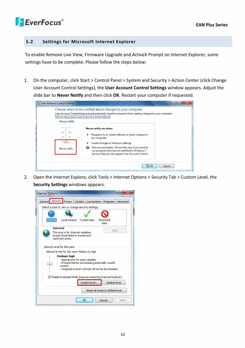
EAN Plus Series
10
52 Settings for Microsoft Internet Explorer
To enable Remove Live View Firmware Upgrade and ActiveX Prompt on Internet Explorer some
settings have to be complete Please follow the steps below
1 On the computer click Start gt Control Panel gt System and Security gt Action Center (click Change
User Account Control Settings) the User Account Control Settings window appears Adjust the
slide bar to Never Notify and then click OK Restart your computer if requested
2 Open the Internet Explore click Tools gt Internet Options gt Security Tab gt Custom Level the
Security Settings windows appears
EAN Plus Series
11
3 In the Download unsigned ActiveX controls field select Prompt In the Include local directory
path when uploading files to a server field select Enable Click OK
4 In the Internet Options window click the Advanced tab and then disable Enable memory
protection to help mitigate online attacks Click OK
EAN Plus Series
12
53 Connecting the Camera to the Network
There are three methods to connect the IP camera to the network Router or LAN Connection Direct
High-Speed Connection and One-to-One Connection
Router or LAN connection
This is the most common connection in which the IP camera is connected to a router and allows
multiple users on and off site to see the IP camera on a LANWAN (Internet) The camera must be
assigned an IP address that is compatible with its LAN By setting up port forwarding on the router
you can remotely access the cameras from outside of the LAN via the Internet To remotely access the
Web interface of the IP camera please refer to 732 DDNS To set up port forwarding please consult
the manual of the router
Straight-through LAN patch cable
Right Pinout of a straight-through cable
EAN Plus Series
13
Direct High-Speed Connection
In a Direct High-Speed Connection the camera connects directly to a modem without the need for a
router You need to set the static or dynamic WAN IP address assigned by your ISP (Internet Service
Provider) in the camerarsquos configuration web pages To access the camera just type ldquohttpxxxrdquo
where xxx is the IP address given by your ISP If you have a dynamic IP address this connection may
require that you use DDNS for a reliable connection Please refer to 732 DDNS
One-to-One Connection (Directly from PC to IP Camera)
You can connect directly without using a switch router or modem However only the PC connected
to the camera will be able to view the IP camera You will also have to manually assign a compatible IP
address to both the computer and the IP camera Unless the PC has another network connection the
IP camera will be the only network device visible to the PC See the diagram below
Pinout of straight patch cable
Right Pinout of a crossed-over cable
EAN Plus Series
14
54 Live View Window
1 Press the button to display the Live View window Double-click on the
image to show a full-screen display double-click again or press ESC to return to the normal display
If you experience video feed lag time (if connected via Internet) you can reduce the resolution or
limit the number of streams See 741 Multi Streaming
2 Press the button to play the recorded data directly from the on-camera Micro
SD SDHC card (for this function to become active you have to insert a Micro SD SDHC card in the
Micro SD SDHC card slot on the rear panel of the camera See 783 SD Card
3 Press the button to enter the Settings page On the Settings page there are
8 submenu sections [System Info] [User Config] [Network] [Video] [Audio] [User] [Event] and
[System] Click on the section buttons to open their configuration fields See the Settings section
below for more information
EAN Plus Series
15
4 Press the button to exit the system and close this browser page
5 Video Stream
Select the Video Stream (Stream 1 Stream 2 or Stream 3) that will be displayed in the video box on
the right Stream 2 and Stream 3 are only selectable if you have enabled the stream The default
setting is Stream 1 only See 741 Multi Streaming
6 View Size
Use this to select the appropriate view size and shape of the video box on the right A smaller size
might increase transmission speed and video quality
7 Digital Zoom
Click the Zoom In Zoom Out buttons or roll the mouse wheel to zoom in out the camera live view
up to 10x Clicking on a magnified image will re-center the image around that point
8 Record
The Record button is used to record the current video stream Click the Record button to start
stop recording This icon is only for one-minute video recording To record long-period recordings
please set a recording schedule (See 775 Schedule) The location on your computer where the
image files will be saved to and file size can be specified in the submenu (see 72 User Config)
9 Snapshot
Click the Snapshot button to save a snapshot of the video image currently being displayed The
location on your computer where the snapshot data will be saved can be specified in ldquoSettings gt
User Config gt RecordingSnapshotrdquo (see 72 User Config)
10 Play Audio Transmit Audio
Click the ldquoPlay Audiordquo (speaker) and ldquoTransmit Audiordquo (microphone) buttons to switch the sound
onoff for the speaker and microphone respectively (if such external devices have been connected
to the camera directly or via the network)
EAN Plus Series
16
11 One Push
This function is only available for EAN3120 Plus 3220 Plus The One Push button can be displayed
on the live view window by enabling the Show One Push Buttons function on the User Config lt Live
View Config Setting page (see 721 Live View Config) To enable the button (turned from faded to
clear) on the Video lt Advanced Setting page select One Push from the White Balance Settings
Mode drop-down list and click the Apply button Once this is done pressing the One Push button
on the Live View Window will instruct the camera to adjust the white balance settings and these
settings will be active until the button is pushed again This is like a ldquosemi-automaticrdquo way to adjust
white balance to suit the user if the Auto or Manual mode does not give the result the user wants
12 Manual Control
ndash Trigger Event
Press the ldquoTrigger Eventrdquo button to trigger an event directly from the Live page If you have
configured an event (in the Event submenu) that will trigger a reaction (like a recording) when a
Manual Trigger event occurs clicking this button will trigger that reaction You can select what that
reaction will be You can for instance set the camera to record the audiovideo feed to the Micro
SD card on board the camera You can then click on the Playback button to open the Playback page
and search for and play all such recordings that had been stored on the card Such event actions
will be effective once they have been configured in the ldquoEventrdquo menu (see 77 Event)
ndash Reset Alarm
Press the ldquoReset Alarmrdquo button to reset the alarm output remotely
13 Status Display (info lines that can be placed above video box or at bottom of page)
This shows the name of the camera that is currently active or being configured current datetime
and current frame rate You can activate these info displays in the Settings gt User Config page (see
72 User Config)
14 Event Signal Icons (above video screen)
When an alarm or motion event is triggered a signal icon will appear at the top right of the Live
View window to alert the user
Alarm event icon When an alarm is triggered this icon appears
Motion detection icons The colors of these motion event icons correspond to the colors of the motion trigger areas you have configured in the Motion Detection submenu (see 772
Motion Detection)
Recording icon When the camera is recording to a PC-based folder this icon appears
EAN Plus Series
17
6 Playback
You can remotely play back the recordings stored in the on-camera micro SD card on the Web interface
or play back the recordings stored in the computer using the ARV Viewer included in the software CD
Playback is designed as a quick way to check recent recordings that were triggered by Events that were
configured to ldquoRecord to SD Cardrdquo in the Settings gt Event gt Event Settings page (see 771 Event
Settings)
Note Note that the Playback page is only accessible once the on-camera SD card is inserted and
active
61 Remote Playback Using Playback Page
On the Live View Window click the Playback button to open the Playback page
EAN Plus Series
18
Search by File Click the Search button to search for all recording files on the on-camera SD card
Search results will be displayed in the Filename area
Search by Time Click the calendar icon and select the date and time from which you want to search
until the present moment Click search to get your search results which will be displayed in the
Filename area
Search by event Click the type of Event recordings you want to search for (Alarm Motion Manual
Trigger) and then click the calendar icons to select the Start Time datetime and the End Time
datetime of your search Click Search to get your search results which will be displayed in the
Filename area
Multiple Files Check this box if you want the video player to play all the files in the selected folder
The files will be displayed in the Filename area
Loop Again Check this box if you want the video player to play the selected file over and over again
Play Once you have opened the filersquos folder and have clicked on the file to highlight it its details will
be displayed in the File Information area You can now click Play to play that specific file
Pause Click this button to pause the playback
Stop Click this button to stop the playback
【Recording List】
Filename This area will display a list of search results (recording files and folders) Folders (named
with the recorded date) will be displayed first Click on the folder and click on each subfolder until the
recording files (arv) in that folder is listed
File Information Click a file on the Filename list the selected file information will be listed
Copy Click this button to copy the selected file to the computer-based folder of your choice A
browsing box will open so that you can search for the folder of your choice You can use the ARV
Viewer to play back the recordings recorded in your computer For details on ARV Viewer see 63
Playing Back Using ARV Viewer
Lock Click this button to lock the selected file This will protect that file from being overwritten during
any overwrite procedure The file will thus be saved on the micro SD card indefinitely However the
file will still be deleted if the micro SD card is ever formatted
Remove Click this button to delete the selected file
EAN Plus Series
19
62 Setting up the Playback Function
Note that the Playback function will not be active until the user has inserted a micro SD card in the
camerarsquos micro SD card slot The card may also have to be formatted in the Settings submenu
Micro SD Card Slot
621 Preparing the Micro SD Card
Once you insert a functional micro SD card into the slot the Playback button on the Live page should
become active within seconds (see section 622 below ndash the grey letters should turn white) IF NOT
do the following
1 From the Live page click Settings gt System gt SD Card If no card has been inserted yet the
Remove button should be faded indicating that no card is being detected (If a card is
inserted and the Remove button is still faded pull the card out and re-insert it)
2 Slide the card into the slot until it clicks into position
3 The Remove button should become active within a few seconds indicating the card is active
4 If the Remove button stays faded click the Format button to format the card NOTE All data
on the disk will be deleted if the Format button is clicked
622 Testing the Playback Function
1 Once the SD card is detected by the system the button (inactive)
will turn to (active)
2 To test the Playback function (this is not required) set up a ldquoManual Triggerrdquo Recording
Event by clicking Settings gt Event gt Event Settings
3 Click the ldquoAddrdquo button on the middle right side of the page to open an ldquoAdd Eventrdquo box
4 Give the event a name like ldquoTest 1rdquo
EAN Plus Series
20
5 In the ldquoEvent Triggered byrdquo field click on Manual Trigger
6 Below this check ldquoEnable This Eventrdquo ldquoEnable Post-trigger Bufferrdquo and ldquoRecord to SD Cardrdquo
7 To save your settings click OK or close the box by clicking on the red x icon at top right of the
box (in which case you will be asked if you want to save the data to which you should reply OK)
The box will close and the new event will be listed in the list area of the Event Settings page
8 Look at the ldquoPost-trigger Bufferrdquo at the bottom to make sure the buffer time is set to 10 seconds
9 Click ldquoApplyrdquo to make sure all settings are saved
10 Click the Live button to go back to the Live page
11 Get ready to click the Trigger Event button at the bottom of the page Before you do see if you
can find something in the view screen that will give you a visual time marker For instance if you
can get your hand in front of the camerarsquos lens get ready to count down on your fingers
12 Click the Trigger Event button and slowly count down on your fingers in front of the lens (if you
are able to do so ndash if not try to find visual cues on the view screen that will help you to mark the
moment you pushed the trigger) The recording period will be as long as the buffer time you
selected ndash the default period is 10 seconds
13 Click the Playback button to open the Playback page
14 There are different ways to search for recording files on the camerarsquos Micro SD card (ie the
Playback memory) For a recent recording like your test event simply click the ldquoSearchrdquo button
under the ldquoSearch by Filerdquo header
15 If the SD card is active and formatted correctly the recording folderrsquos name (the recording dayrsquos
date) will appear in the Filename box at the bottom Click on this folder to open it If there are
sub-folders click on the bottom one (the most recent would be at the bottom) until you can click
on a file that cannot open to another sub-level and shows data in the File Information box to the
right This would be the file of the most recent recording event
16 To play this file click the Play button below the video box The test footage you have recorded
should start playing Play time should be 10 seconds if you left the Post-trigger Buffer as 10
seconds
EAN Plus Series
21
63 Playing Back Using ARV Viewer
You can play back the recordings stored in the computer using the ARV Viewer included in the
software CD To store the recordings in the computer please refer to Recording List gt Copy in 61
Remote Playback using Playback Page
4 5 6 7 8 9 10
321
No Item Name Descriptions
1 Snapshot Click to take and save a snapshot
2 Load File Click to load the recordings for playing back
3 Convert ARV to AVI Convert the recording from ARV format to AVI format
4 Playback Time Display the playback time
5 Total Time of Recording Display the total time of the recording
6 Stop Click to stop playing the recording
7 Step Reverse Click to display the previous frame
8 Play Click to play back the recording
9 Pause Click to pause the recording
10 Step Forward Click to display the next frame
EAN Plus Series
22
7 Settings
Click the Settings button on the Live View Window to enter the settings submenu There are nine buttons
on the left-side of the submenu Live System Info User Config Network Video Audio User Event and
System Click the Live button can go back to the Live View Window
71 System Info
The System Information and System Log can be checked on this page Click the top tab of the one you
want to see
711 Information
Click the Information tab the following dialog box appears These values cannot be changed on this
page and are for reference only
EAN Plus Series
23
712 Log
Click the Log tab the following dialog box appears The sequence number date time and event
messages of the log event will be displayed in the System Log field The log will display the last 256
log events Click the Export button to export the system log event list into a ldquotxtrdquo file and select the
location where the exported log file will be saved to
EAN Plus Series
24
72 User Config
Each user can set a different configuration for hisher Live page here These settings will be applied to
the logged-in userrsquos Live page every time heshe logs in
721 Live View Config
【VideoAudio Connection Protocol Setting】You can transmit the data stream from the IP cameras
using the RTSP (Real Time Streaming Protocol) on the network The RTSP is a protocol that allows
you to access video streams by using the compatible media players Click Apply to apply the
changes or Reset to reset without saving the changes RTP over UDP The RTSP protocol uses UDP for camera data stream transmission
RTP over TCP The RTSP protocol uses TCP for camera data stream transmission
RTP over HTTP The RTSP protocol uses HTTP for camera data stream transmission
Nevio CGI This is EverFocusrsquo protocol designed for EverFocusrsquo IP devices Select this
protocol for camera data stream transmission
【Text Settings】Check the box of each option (Machine name DateTime Frame Rate) to display
this info on the Live View Page
Foreground Color Slide the Red Green and Blue bars to create your preferred text color for the
info text line
Position Select the position where the text will be displayed Choose from Upper Left Lower
Right Lower Left
Click Apply to apply the changes or Reset to reset without saving the changes
EAN Plus Series
25
【DateTime Format Used in Text】Click the dropdown menu to select datetime format from the
listed options Click on the desired hour format Click Apply to apply the setting changes or Reset to
reset without saving the change
【Live View Layout Settings】 Check the ldquoShow One Push Buttonsrdquo boxes if you want to show these
buttons on the Live View Page Uncheck these boxes to hide these buttons This function is only
available for EAN3120 Plus 3220 Plus
722 Recording Snapshot
This configures where your Record Button and Snapshot Button ( ) files will be saved if
you click one of these buttons Selectable folders will be on the computer only not on the
on-camera SD card
【Recording Snapshot Export Settings】
Enable Event Recording to PC Checking this box will let the system save RecordSnapshot Button
recordings to the folder configured below on the userrsquos PC
Export Folder Select the Export folder for the action above by clicking on the browse (hellip) button
and then select the desired folder
File size The user can limit the size of each recorded file here (in minutes) When a single
recording file exceeds the time you set the system will create a new file to save that data to
Overwrite Select ldquoONrdquo for overwriting recordingsnapshot file when the disk storage capacity is
full The user can set the storage capacity limitation in the in-sentence field in the gray box below
the Overwrite setting ldquoIf the remaining hard disk capacity is less than ____ MB (50~2000) system
will stop recording or start overwriting ldquo
Click Apply to apply the setting changes or Reset to reset without saving the changes
EAN Plus Series
26
723 Language
Select the language to be displayed on the Web interface of the IP camera The default language is
English
To add a new language not listed in the current Language list click the Browse button to locate
the new language file (evb) on your computer and then click the Upload button Updated
language files might be available on the manufacturerrsquos website Contact your vendor if required
Click Apply to apply any changes or Reset to reset without saving the changes
Note Uploading a new language file will cause the system to reboot automatically Please create
a new network connection to the IP camera when the reboot is complete
EAN Plus Series
27
73 Network
This page covers network-related settings including Network DDNS SMTPFTP HTTPS SNMP and
Network Alarm
731 Network
The following information is required to configure the network settings Contact your network
administrator or your internet service provider to get the info
【IP Settings】
IP Type Refer to the network administrator for these settings of the server Default DHCP
DHCP This setting lets the system use an automatically assigned (dynamic) IP address This
address can change under certain circumstances For instance when the camerarsquos network
switchhub has to be rebooted Do not assign to the DHCP server the same IP addresses used
for the other network cameras and PCs with unique IP addresses
Static IP The user can manually set the Static IP address This type of address is stable and
cannot change but the user has to make sure there are no address conflicts with other
network-connected devices
PPPoE This is a DSL-connection application The ISP will ask the user to input a username and
password Contact your ISP for these details
EAN Plus Series
28
Note If PPPoE is selected as the IP type the supplied IP Utility program will not be able to
detect the device
IP address When DHCP is not used the user needs to manually enter the IP address of the
camera Do not enter an IP address that is already used for your computer or other network
cameras
Subnet Mask This field is used to set the netmask for your network so that the IP camera will be
recognized within the network Example 2552552550 When DHCP is selected the DHCP server
will assign this value automatically
Gateway This field is used to set the gateway for your network so that the IP camera will be
recognized within the network When DHCP is selected the DHCP server will assign this value
automatically
Primary DNS Enter the IP address of the DNS server if this is provided by an ISP
Secondary DNS If your ISP provided you with a secondary DNS address please enter it here
Username Enter the accountrsquos username (used only for PPPoE)
Password Used only for PPPoE
IPv6 Enter the IPv6 details in this area if this applies to your system
Click Apply to apply the setting changes or Reset to reset without saving the change
【Port Settings】Enter the HTTP HTTPS and RTSP port numbers and click Apply to save
【Multicast Settings】Enable if required fill in the setting options and click Apply to save
EAN Plus Series
29
732 DDNS
DDNS (Dynamic Domain Name System) is a service used to map a domain name to the dynamic IP
address of a network device You can set up the DDNS service for remote access to the IP camera
DDNS assigns a domain name (URL) to the IP camera so that the user does not need to go through
the trouble of checking if the IP address assigned by DHCP Server has changed Once the IP is
changed the IP camera will automatically update the information to the DDNS to ensure it is always
available for remote access
Before enabling the following DDNS function user should have applied for a host name from the
DDS service providerrsquos website We support these four DDNS server providers
wwweverfocusddnscom wwwsitelutionscom wwwdyndnscom and wwwno-ipcom
Note We highly recommend that you use xxxxeverfocusddnscom for the simplicity of setting up
your IP cameras
【DDNS Settings】
Enable Check this box to enable the DDNS function
Service ISP You can either apply for a host name from EverFocus or other DDNS server providers
If you choose the EverFocus DDNS server you can obtain a free host name from EverFocus by
following the steps below
bull From EverFocus To obtain a free host name from EverFocus type a desired host name in the
textbox click the Register Update button and then click the Apply button
bull From other DDNS server providers To obtain a domain name from one of the three DDNS
server providers you have to register your name with the provider first and then select the
provider and fill in the required information Please refer to the specific DDNS companyrsquos
website for further information
Record ID Type the record ID if provided by the DDNS server provider
EAN Plus Series
30
FQDN Type the fully qualified domain name applied from the DDNS server provider For
example xxxxdyndnscom
Username Password Type the login account of your DDNS server provider
Click Apply to apply the setting changes or Reset to reset without saving the changes
Note
1 In order to support the full functionality of the camera you must open the port numbers (80
554 443) on the router for remote access to the IP camera This function is available on most
routers in the market and is often known as ldquoPort Forwardingrdquo To set up Port Forwarding
please consult the manual of the router
2 In certain router models it is possible that you will not be able to access the camera using
DDNS while inside the routerrsquos network Please try using a PC located outside of your routerrsquos
network
Default Ports on All EverFocus IP Cameras
HTTP 80
RTSP 554
HTTPS 443
EAN Plus Series
31
733 SMTP FTP
【Set SMTP Server (email)】This area is for configuring the mail server that is used to send e-mail
notifications from the camera to predefined addresses via SMTP Note that to enable e-mail
notification function you have to check the Send Mail Notification item on the Event dialog box
(see 771 Event Settings)
SMTP Server Enter the IP address or the host name of the SMTP server used to send e-mails
SMTP Port Enter the port number for SMTP The default is 25
Authentication Check this box if the SMTP server requires authentication (userpassword)
User name Input the userrsquos login ID if the SMTP server requires authentication
Password Input the userrsquos login password if the SMTP server requires authentication
EAN Plus Series
32
Receiver Address Input the e-mail addresses for receiving an e-mail message when an EVENT is
enabled and triggered Please use ldquordquo to separate multiple addresses
Sender Address Input the senderrsquos e-mail address so that the receiver can recognize the sender
when an Event message is received
Attach Image Check this box if you want to attach an image when an alarm is triggered or an IP
camera detects events
Send Test Email Click the Test button to send a testing email to the assigned address
Click Apply to apply the setting changes or Reset to reset without saving the changes
【Set FTP Server】The settings relating to the FTP server used to transmit the alarm images can be
configured here Note that to enable uploading images to the FTP server function you have to
check the Upload to FTP item on the Event dialog box (see 771 Event Settings)
FTP Server Enter the IP address or the host name of the FTP server
FTP Port Enter the port number for the FTP server Default is 21
Recording Path Assign the recording path
User Name Set FTP Userrsquos name
Password Set FTP password
PASV mode Check to enable Passive mode Passive mode is normally enabled If a connection
cannot be established uncheck PASV Moderdquo
Test FTP Server Click the Test button to send a testing file to the assigned FTP server
Click Apply to apply the setting changes or Reset to reset without saving the changes
EAN Plus Series
33
734 HTTPS
Hypertext Transfer Protocol Secure (HTTPS) is a combination of the Hypertext Transfer Protocol
and the SSLTLS protocol and provides encrypted communication and secure identification of a
network web server
Before using the HTTPS function for communication with the IP camera a Certificate must be
created first There are two ways to create and install a certificate Create Self-Signed Certificate
and Create Certificate Request
Create Self-Signed Certificate
Please note that even though self-signed certificates are free and offer some protection true
security is only implemented after the installation of a signed certificate issued by a certificate
authority
1 Click the Create Self-Signed Certificate button the following dialog appears
EAN Plus Series
34
2 Type the required Certificate information and then click the Apply button The subject line will
be displayed in the Installed Certificate Information field
3 Click the Property button a pop-up window appears to display the details of the certificate
4 To optionally create and install other certificates remove the existing one by clicking the
Remove button to erase the certificate
5 On the Web page change the address from ldquohttprdquo to https in the address bar and press
Enter on the keyboard Some Security Alert dialogs will pop up Click OK or Yes to enable HTTPS
Create Certificate Request
You can apply for an official certificate from an issuing Certificate Authority
1 Click the Create Certificate Request button the following dialog appears
EAN Plus Series
35
2 Type the required Certificate information and then click the Apply button The subject line will
be displayed in the Created Request field
3 Click the Property button a pop-up window appears to display the details of the certificate
4 To optionally create and install other certificates or request remove the existing one by clicking
the Remove button to erase the certificate or request
5 Copy the contents of the Certificate request (in PEM format) and paste it to the certificate
request field on the Web page of the 3rd-party certification authority such as Symantec VeriSign
Wait for the certificate authority to issue an SSLTLS certificate and then download the issued
certificate on your computer
6 In the Install Signed Certificate field click the Browse button to search for the issued certificate
and then click the Upload button to import the certificate Once the certificate has been
uploaded this field will show the subject line of the certificate
EAN Plus Series
36
735 SNMP
The default values for SNMP v1v2v2c and SNMP v3 are already filled in Click either of the
Enable buttons to enable either of the two Make your changes as desired Click on the Trap
Address field to enter the digits if required
736 Network Alarm
This function works with EverFocusrsquos CMS software eg the PowerCon or the Power Video Plus For
the setting details please refer to the CMS network alarm protocol
EAN Plus Series
37
74 Video
The settings relating to video such as streaming camera OSD can be configured on this page The
Video page has five tabs Multi-streaming Camera Advanced ROI and Privacy Mask
741 Multi Streaming
【Stream Settings】 This IP camera can output three video streams simultaneously For each of these
streams the user can set the compression format resolution bit rate and frame rate individually
Stream 1 is always enabled for live view To enable Stream 2 andor Stream 3 check the ldquoEnablerdquo
box the header of each stream
Note If you connect to the camera via the Internet and experience a delay (lag time) in the video
feed try to reduce the number of streams and the quality and resolution of the streams ndash but
keep the frame rate at its maximum
EAN Plus Series
38
Format Select the encoding format ndash H264 or MJPEG
Resolution Select the most suitable resolution for your needs
Frame Rate Select from 1 to 30 fps
Bit Rate If required select whether you want the stream to stream a Constant Bit Rate or a
Variable Bit Rate and set the values of whichever option you choose
Click Apply to apply the setting changes or Reset to reset without saving the changes
【Video Recording Settings】Select the stream you want to configure and then select whether you
want the recording files of that stream to be saved in AVI or ARV format Click Apply to apply the
setting changes or Reset to reset without saving the changes
【Time Stamp Settings】 You can select the DateTime format position and add the setting to the
streaming
Click Apply to apply the changes or Reset to reset without saving the changes
EAN Plus Series
39
742 Camera
【Image Settings】Set the Brightness Saturation Contrast or Sharpness of the image Click Apply to
apply the changes or Reset to reset without saving the changes
【Camera Settings】
Mirror Switch Mirror ON to rotate the image horizontally around a vertical axis
Flip Switch Flip ON to rotate the image vertically around a horizontal axis
AE There are two options
ALC Selecting Automatic Light Control allows the camera circuitry to either take bright spots
more into consideration (peak) bringing out detail in bright areas or less into consideration
(average) bringing out detail in shadows
AES Selecting Auto Electronic Shutter disables the Shutter setting below this setting In this
mode the camera measures the light level and decides whether it needs more or less light and
then automatically adjusts the shutter speed accordingly
BLC Back Light Compensation (BLC) is used to make the subject appear clearer when it is set
against a bright background
OFF Select to switch Back Light Compensation functions off
(ON)BLC The BLC can increase the exposure of a dark area surrounded by a brighter area HLC
can decrease the exposure of bright areas surrounded by darker areas This enables the
camera to better display information that would otherwise have been ldquowhited outrdquo like a
license plate between two bright headlights on a dark road
(ON)HLC The Highlight-Suppression BLC is used to reduce the brightness of light sources in a
specific area It is activated only in a low illumination environment to minimize the effects of
glare from bright lights such as spotlights street lights or headlights in the field of view
EAN Plus Series
40
WDR The Wide Dynamic Range (WDR) function provides clearer images when both of the very
bright and dark areas simultaneously appear on the camera view There are four value options
OFF Low Middle and High Note that when WDR is ON some parts of the image may appear
solarized This is normal for WDR and is not a camera malfunction This function is only available
for EAN3120 Plus 3220 Plus
DN Mode
Auto Select to let the camera automatically switch to Night mode (black and white) when the
light levels fall to a specified level and back to Day mode (color) when the light levels rise to a
specified level
Day Select to keep the camera in Day mode (color) even in nighttime
Night Select to keep the camera in Night mode (black and white) even in daytime
EAN Plus Series
41
743 Advanced
EAN Plus Series
42
【Camera Settings】
Lens (IRIS Control) Select DC or Manual for IRIS control This function is only available for EAN3220
Plus
Exposure Settings (AE) This setting is used to adapt to the amount or type of light used by the
camera Note the settings vary among models
Mode This function is not available for EAN3220 Plus
Automatic Light Control (ALC) This option is only available for EAN3120 Plus 3300 Plus The
ALC allows the camera circuitry to either take bright spots more into consideration (peak)
bringing out detail in bright areas or less into consideration (average) bringing out detail in
shadows
Auto Electronic Shutter (AES) This option is only available for EAN3120 Plus 3300 Plus In
this mode the camera measures the light level and decides whether it needs more or less light
and then automatically adjusts the shutter speed accordingly
Manual This option is only available for EAN3300 Plus Select this option to manually set up
the Shutter (Manual) and AGC (Manual) values
Iris Specify the size of the Iris opening here
Shutter If enabled this setting lets you set the shutter speed yourself
Shutter Limit Use this setting to set the maximum shutter speed for the camera This function is
only available for EAN3120 Plus
AGC Set the Auto Gain Control limit here The lower the AGC level the lower the video signal and
the noise However the image will be darker under low-light condition with IR-off if you set up the
Iris to the maximum level
Slow Shutter This option can be switched on when AES Mode is selected in the Exposure Settings
(AE) field This function is only available for EAN3220 Plus 3300 Plus
Flickerless If the Mode field in the Exposure Settings (AE) area has been set to AES then this option
becomes available Choose between OFF 50HZ 60HZ 50HZ (High Luminance) or 60HZ (High
Luminance) This function is only available for EAN3300 Plus
EV Setting Set up the Exposure Value Note the brightness of the screen changes when you change
the EV value This function is only available for EAN3300 Plus
AE Response Set up Auto Exposure Response time This function is only available for EAN3300 Plus
AE Weighting Area Select an AE Weighting area Each setup AE Weighting Area is configured with
the appropriate brightness level on the center and the surrounding areas This function is only
available for EAN3300 Plus
Brightness Set the image brightness here
AE Reference Set the Auto Exposure value here This function is only available for EAN3120 Plus
EAN Plus Series
43
Black Level Set the Black level here This function is only available for EAN3300 Plus
WDR The Wide Dynamic Range (WDR) function provides clearer images when both of the very
bright and dark areas simultaneously appear on the camera view There are four value options OFF
Low Middle and High Note that when WDR is ON some parts of the image may appear solarized
This is normal for WDR and is not a camera malfunction This function is only available for EAN3120
Plus 3220 Plus
Visibility Enhancement (OFFLowMiddleHigh) Images in foggy or rain environments or in
environments with a very strong luminous intensity have a dynamic range that is significantly lower
than ordinary images The user can use this Visibility Enhancement setting to ldquoDEFOGrdquo the image if
such ldquoFOGGINGrdquo is an issue This function is only available for EAN3220 Plus
BLC Settings Back Light Compensation (BLC) is used to make the subject appear clearer when it is
set against a bright background
OFF Select to switch Back Light Compensation functions off
Back Light This option is only available for EAN3300 Plus The Back Light function is useful
when the background of the subject is very bright and the subject itself is dark Select Back
Light and adjust the slide bar to the left right for setting up the back light value The higher
the value the more the backlight compensation
Front Light This option is only available for EAN3300 Plus This function is useful when the
bright highlights such as flashlight or car headlights appear on the camera view Select Front
Light and adjust the slide bar to the left right for setting up the front light value The higher
the value the more the highlight compensation
ON (BLC) This option is only available when you select AES Mode in the Exposure Settings (AE)
field The option is only available for EAN3120 Plus 3220 Plus The BLC function is useful
when the background of the subject is very bright and the subject itself is dark Follow the
instructions below to configure the settings for each model
For EAN3120 Select ON (BLC) the button next to the Mode drop-down list will be
active (see image below) Click the button the green setup areas appear on the left
screen Click on the areas to enable disable the BLC function The selected areas (in green)
will be applied with the BLC function
EAN Plus Series
44
For EAN3220
You can configure one area to apply the BLC function Select ON (BLC) the setup buttons
appears (see image below) Select Low Middle High from the BLC Gain drop-down list To
set up a BLC area click the Edit Area button and then click on the blue color tab to turn your
mouse cursor into a blue pen Move the cursor to the position on the right screen where you
want the BLC rectangle to start and then click Move your cursor to the position (diagonally
opposing corner) where you want the BLC rectangle to end and then click The blue area will
be applied with the BLC function
ON (HLC) This option is only available when you select AES Mode in the Exposure Settings (AE)
field The option is only available for EAN3120 Plus 3220 Plus This function is useful when
the bright highlights such as flashlight or car headlights appear on the camera view Follow
the instructions below to configure the settings for each model
For EAN3120 Select ON (HLC) and then select a level from the drop-down list The higher the
level the more the highlight compensation
For EAN3220
HLC Level Select a level for the HLC setting The higher the level the more the highlight
compensation
HLC Mode Select All Day Night mode to apply the HLC function
HLC Black Mask Select On Off to apply the black mask on the selected areas The
over-exposure portions within the selected areas will be applied with the black mask
Color Tabs You can set up four HLC areas with different colors To set up a HLC area click the
Edit Area button and then click on the color tab to turn your mouse cursor into a pen of that
color Move the cursor to the position on the right screen where you want the HLC rectangle
to start and then click Move your cursor to the position (diagonally opposing corner) where
you want the HLC rectangle to end and then click Select ON from the color tab drop-down list
The rectangular area with the selected color will be applied with the HLC function
EAN Plus Series
45
Back Light This option is only available for EAN3300 Plus The Back Light function is useful
when the background of the subject is very bright and the subject itself is dark Select Back
Light and adjust the slide bar to the left right for setting up the back light value The higher
the value the more the backlight compensation
Front Light This option is only available for EAN3300 Plus This function is useful when the
bright highlights such as flashlight or car headlights appear on the camera view Select Front
Light and adjust the slide bar to the left right for setting up the front light value The higher
the value the more the highlight compensation
Noise Reduction Settings This limits the amount of digital ldquovideo noiserdquo that is usually found in any
video stream and helps to reduce file size The higher the level the more the reduction
For EAN3120 Plus 3300 Plus
Select ON OFF to enable disable the Noise Reduction function Or select Auto to let the camera
automatically enable disable the Noise Reduction function Slide the Level bar to set up the level
The higher the level the more the reduction
For EAN3220 Plus
2D DNR Select ON to enable the 2D DNR function
3D DNR Select ON to enable the 3D DNR function You can further set up the following settings
3D Start AGC Set up the AGC level to automatically start the 3D NR function
3D End AGC Set up the AGC level to automatically stop the 3D NR function
3D Level Set up the 3D DNR level
Smart NR Select ON to enable the Smart NR function The 3D NR function will be
automatically turned on when a motion event occurs
EAN Plus Series
46
White Balance Settings Select the mode that delivers the best quality image for the camerarsquos light
environment There are five options Auto Manual Indoor Outdoor One Push
Auto Select to let the camera automatically adjust the White Balance In the Auto mode the
camera computes the white balance value output using color information from the entire
screen It outputs the proper value using the color temperature radiating from a black subject
based on a range of value from 3000 to 7500K
Manual Select to adjust the Red and Blue values yourself in the fields below this field
Indoor Select to use the default settings for indoor environments In the Indoor mode the
camera uses 3200K as the base value
Outdoor Select to use the default settings for outdoor environment In the Outdoor mode it
uses 5800K as the base value
One Push Select to enable the Push button next to the Mode drop-down field This will allow you to force the camera to readjust the white balance every time you push the Push
button The lens will hold the same focal position until the next trigger command is received
This function helps to prevent incorrect focusing in dark environments This function is only
available for EAN3120 Plus 3220 Plus
Manual Temperature Select to use the optimized Red and Blue settings You can also
optionally adjust the Manual Level below this field for setting up the color temperature The
higher the value the more the color temperature This function is only available for EAN3300
Plus
DayNight Settings
Auto Select to let the camera automatically switch to Night mode (black and white) when the
light levels fall to a specified level and back to Day mode (color) when the light levels rise to a
specified level
Day Select to keep the camera in Day mode (color) even in nighttime
Night Select to keep the camera in Night mode (black and white) even in daytime
IR Smart Settings Select ON and set up the level to enhance the image quality when the images are
over exposure This function is useful when the camera is in the Night mode This function is only
available for EAN3220 Plus
Saturation Set the saturation value This function is not available for EAN3220 Plus
Monitor Type Select a gamma value from Set 1 Set 2 or Set 3 This function is only available for
EAN3120 Plus
Negative Switch this setting ON to view a color negative version of the video image This is useful
at night or when viewing temperature-sensitive images
EAN Plus Series
47
Sharpness Settings Select the sharpness level of the image A low sharpness level will deliver a
softer less detailed image A high level will deliver a sharp highly detailed image Switch Resolution
Enhancement ON to enable the resolution enhancement function
Contrast Select the contrast level of the image
Suppress Function This function is only available for EAN3300 Plus
Aperture Compensation Suppression (OFFLowMiddleHigh) This setting can be activated to
suppress luminance noise when the AGC level increases
Chroma Suppression (OFFLowMiddleHigh) This setting can be activated to suppress
chrominance noise when the AGC level increases
Ygamma (gamma 22standardcontrast enhancehigh light range mode LHigh light range mode
H) Select the Ygamma value for the video quality of the monitor This function is only available for
EAN3300 Plus
Monitor Settings The user can use this field to optimize video quality for his or her specific type of
monitor ndash LCD or CRT This function is only available for EAN3220 Plus
Color Space Standard The options are YUV601 for SD and YUV709 for HD These define the color
space standard required to convert an RGB picture to a YUV picture Generally YUV601 is used for
Standard Definition (720P) devices and the YUV709 is used for High Definition (1080P) devices
Click Apply to save all changes Click Reset to cancel all changes
EAN Plus Series
48
744 ROI (Region of Interest)
The Region of Interest (ROI) function allows users to set up multiple regions within an image with
better quality and less distortion than the rest of the image You can also use this function
together with the Digital Zoom function on the Live View Page to get a better image result Up to
eight ROIs can be configured in the ROI settings page
To set up an ROI region
1 Select an ROI number from the ROI No drop-down list
2 Click the Add button the mouse cursor will turn into a pen when you move it over the live
image on the left
3 Move the cursor to the position where you want the ROI rectangle to start and then click
Move the cursor to the position (diagonally opposing corner) where you want the ROI
rectangle to end and then click
4 Slide the Quality bar to set up the quality value
5 Click the Apply button to apply the settings or click the Reset button to reset without saving
the settings
EAN Plus Series
49
745 Privacy Mask
The Privacy Mask can block out sensitive areas from view covering the areas with colored or black
and white boxes in both live view and recorded clips This feature is useful when usersrsquo donrsquot want
the sensitive information visible Up to four Privacy Masks can be configured
【Privacy Mask Color Settings】The Modes vary among camera models
Mode Click Color to make the masks appear as colored rectangles on the screen Click BW to
make the masks appear as gray rectangles on the screen Click Mosaic to make the masks appear
as mosaic-effect rectangles on the screen
Level Select the color of the masks if you selected Color Mode Select the level of grayness of the
masks if you selected BW Mode Select the level of smallmiddlelarge if you selected Mosaic
Mode
Click Apply to apply the settings or click Reset to reset without saving the settings
Color Tabs Click on a color tab to turn your mouse cursor into a pen of that color
You can now create a block of that color on the video screen Move your cursor to the position
where you want your mask rectangle to start and then click Move your cursor to the position
(diagonally opposing corner) where you want your mask rectangle to end and then click The
rectangular area with the selected color will appear The live image will display the rectangular
area with the color you selected If you want to create another mask use one of the other three
colors Each color denotes a different mask area Only one block per color is allowed As the
number of colors suggests you can configure up to four blocks
EAN Plus Series
50
Select All Click to turn the whole screen into a mask area
Clear All Click to delete all configured mask blocks
Eraser Click to turn the mouse cursor into an eraser to delete any block you click on
Area Shows the color and number of the block
Enable Check this box to enable the related mask block
Click Apply to apply the settings or click Reset to reset without saving the settings
EAN Plus Series
51
75 Audio
The EAN Plus series IP camera can transmit audio to your computer if you have connected an external
microphone to its audio Input cable It can also receive audio input from you and transmit it via an
external speaker if you have connected such a speaker to its audio Output cable
Check the Enable Audio box to enable the camerarsquos audio function The camera will now act as a
digital bridge (via the IP network) between any connected audio input device and any connected
audio device
Adjust the Audio Input Volume if you have external audio input devices (microphones) connected to
the camera and if there are problems with the sound input being too low or high
Click Apply to save all settings or click Reset to cancel
EAN Plus Series
52
76 User
761 User Information
The system administrator can create up to ten user accounts on this page
To set up a user account
1 Highlight a user account and click the Modify button The following dialog box appears
2 Type the account name account description and password for the account Type the password
again in the Confirm field
3 Select an authority level for the user account from the Authority drop-down list
bull Supervisor Administrator The only difference between a supervisor and administrator is
that a supervisor can edit an administratorrsquos account and password but an administrator
cannot edit the supervisorrsquos account and password Multiple administrators can be
configured but there can be only one supervisor The supervisor and administrators all
have unrestricted access to the Settings submenus and can determine the registration of
all other users
EAN Plus Series
53
bull User A user can view the Live View page and view the system network video and audio
information A user can only adjust the User Config page settings The user does not have
access to the User Event and System pages
bull Guest The lowest level of access which only allows the user access to the Live View page
4 Select Active or Disable from the Status drop-down list to active or disable the user account
5 Click On in the SD Card Playback field to allow the user to access the SD card playback
function
6 Click OK
7 Click Apply to save all the settings
EAN Plus Series
54
762 IP Address Filter
Use this page to specify IP addresses that are not allowed to access this camera By default any IP
address can access the camera
Note The Allowed List addresses only become relevant when the Denied List contains a network
or range and the supervisor wants to allow one or more IP addresses within that excluded range
or network In such a scenario the user would enter the excluded range or network in the
Denied List and enter the exceptions in the Allowed List
To set up the IP Address Filter
1 Select Denied List Click the Add button the following dialog box appears
2 Select an IP type from the IP Type drop-down list
3 Select a network rule from the Rule drop-down list type the IP address and click OK
Single Type a single IP address in the IP Address field below
Network Type the IP address and subnet mask in the field below
Range Type a range for the IP addresses
4 If you have set up an IP range in Step 3 you can optionally set up the Allowed List to allow one
or more IP addresses within the setup IP range to access the IP camera
5 Click Apply
EAN Plus Series
55
77 Event
You can set up the Motion Detection event Tamper Detection event or the Alarm IO to automatically
notify the users when an event occurs or an alarm is triggered You can also set up a schedule to
automatically record the videos when an event occurs or an alarm is triggered
771 Event Settings
You can create a total of ten event or alarm settings page in the Event List
【Event List】
Click the Add button and the following Event Configuration Window appears
EAN Plus Series
56
Enter Event Name Type an event name
Event Triggered by Select an event or alarm type for the to-be-specified-below reactions
Alarm Input Select this if you want a reaction trigger coming from any external connected sensor
to activate a to-be-specified-below reactions via the camera system Make sure that a suitable
device is actually connected to the alarm input relay
Manual Trigger Select this option if you want to manually trigger the alarm by clicking the Trigger
Event button on the Live View Page
Motion Detection Select this option if you want motion in a specified part of the camerarsquos viewing
rectangle (the screen image) to trigger the to-be-specified-below reactions
Tampering Detection Select this option if you want the camerarsquos tampering detection sensor to
trigger the to-be-specified-below reactions
Schedule Recording Select this option if you want the Schedule Recording periods configured in
the recording schedule (the Settings gt Event gt Schedule page) to activate this event In this
scenario a preconfigured event reaction like a log entry will list the start and end times of each
period Actual recording will only be triggered if the event is preconfigured to do so
Enable This Event Select to activate the event
Enable Re-trigger Click to set a minimum time after the event is triggered before the event
can be triggered again
Enable Pre-trigger Buffer Click if you want the Event reaction (as selected in the ldquoNotification
Overrdquo field below) to be the activation of the video recording function and if you want the
recording to include the video feed from the time period (configurable on the previous ldquoEvent
Settingsrdquo page) just before the Event trigger occurred
Enable Post-trigger Buffer Click if you want the Event reaction (as selected in the Notification
Over field) to be the activation of the video recording function and if you want the recording
to include the video feed from a time period (configurable on the Event Settings page) just
after the Event trigger occurred
Motion Area Select a setup motion detection area from the drop down list Note this
function only becomes relevant after the Motion Detection areas have been set up (see 772
Motion Detection)
Notification Over Select the desired notification types form the following items
Log Click if you want the camera to list the eventrsquos details in its log if the event is triggered
Trigger Alarm Output Click if you want the camera to relay the event reaction to a device
attached to the alarm relay output wire and then set up the alarm output duration time
EAN Plus Series
57
Send Mail Notification Click if you want the camera to send an Event notification email to the
email address entered in the Set SMTP Server(email) field of the Network gt SMTPFTP page if
the Event occurs (see 733 SMTP FTP)
Upload to FTP Click if you want the camera to upload recorded footage to the FTP server
entered in the Set SMTP Server(email) field of the Network gt SMTPFTP page if the Event
occurs (see 733 SMTP FTP)
Record to SD Card Click if you want the camera to start recording its video feed (when the
event occurs) on an on-camera SD Card (if such a card has been inserted)
Note The recording will only be as long as the combined Pre- and Post-trigger Buffers so
make sure you enable at least one of these buffers especially the Post-trigger Buffer
Record to PC Check this box if you want the camera to start recording its video feed (when
the event occurs) on the same folder on the same PC as configured on the User Config gt
RecordingSnapshot page (if such a folder has been enabled and configured)
Note The recording will only be as long as the combined Pre- and Post-trigger Buffers (and
for as long as the event trigger is happening ndash eg a motion is detected) so make sure you
enable at least one of these buffers especially the Post-trigger Buffer
Network Alarm Check this box if you want the camera to send a network alarm signal (when
the event occurs) to the CMS servers configured on the Network gt Network Alarm page (see
736 Network Alarm)
Click OK to save all settings or click Cancel to cancel
【PrePost Trigger Settings】
Pre-trigger Buffer Select the duration for the buffer This will determine the amount of footage
(length of time) before the event trigger moment that will be included in an event-triggered video
recording if that buffer and video recording has been enabled in the Event Configuration Window
Post-trigger Buffer Select the duration for the buffer This will determine the amount of footage
(length of time) after the event trigger moment that will be included in an event-triggered video
recording if that buffer and video recording has been enabled in the Event Configuration Window
Click Apply to save all settings or click Reset to cancel
EAN Plus Series
58
772 Motion Detection
Use this page to configure up to four areas in which motion will be detected When a motion is
detected by the camera the motion detection icon will appear at the top right of the
Live page to alert the user This function can also be linked with correctly configured Events to
trigger Event reactions like the activation of video recording periods snapshots alarms etc
Color Tabs Click on a color tab to turn your mouse cursor into a pen of that color
You can now create a block of that color on the video screen Move your cursor to the position
where you want your detection rectangle to start and then click Move your cursor to the position
(diagonally opposing corner) where you want your detection rectangle to end and then click The
rectangular area with the selected color will appear This block will be an area inside which the
camera will detect motion If you want to create another detection area use one of the other three
palette colors Each color denotes a different detection area Only one block per color is allowed As
the number of colors suggests you can configure up to four blocks
Select All Click to turn the whole screen into a motion detection area
Clear All Click to delete all configured motion detection blocks
Eraser Click to turn your mouse cursor into an eraser to delete any block you click on
Area Shows the color and numberID of the block
Enable Check this box to enable the related motion detection block
Sensitivity Set the sensitivity of the motion detection sensor function
Click Apply to save all settings or click Reset to cancel
EAN Plus Series
59
773 Tamper Detection
Use this page to set the number of seconds that an alarm signal will be active if the device is
physically tampered (moved covered up or out of focus
774 Alarm IO
Use this page to set the type of trigger input and the type of output contact for the camerarsquos alarm
channel
EAN Plus Series
60
775 Schedule
Use this page to configure a schedule for periods during which the camera should deactivate all
user-activated Events (gray Deselect periods) or when the camera should deactivate all
user-activated Events except Schedule Recording (SR) events (blue Schedule Recording-only
periods) or when the camera should deactivate only SR events (red Event Recording-only periods)
or when it should enable all activated Events (yellow periods)
Event Recording Click this button to make every hour block you click on red A red block represents
an Event Recording-only block which represents an hour when the camera will deactivate all
preconfigured activated Schedule Recording events and keep all the other activated events active
Schedule Recording Click this button to make every hour block you click on blue A blue block
represents a Schedule Recording-only block which represents an hour when the camera will
deactivate all other preconfigured activated events and keep only the preconfigured activated
Schedule Recording events active
Event + Schedule Click this button to make every hour block you click on yellow A yellow block
represents an hour in which all activated events including Schedule Recording events will be
active
Deselect Click this button to make every hour block become grey A grey block represents an hour
in which all activated events including Schedule Recording events will be inactive
Click Apply to save all settings or click Reset to cancel
EAN Plus Series
61
78 System
You can set up the systemrsquos time and SD card settings and to do maintenance and reset actions like
reboots and upgrades
781 DateTime
【Machine Name Settings】If required enter a new name for the machine This name will be visible
in the Machine Name field of the IP Utility software which is included in the software CD
【Set Time Zone】Set the time zone of the camerarsquos location
【Set DateTime Manually】Set the datetime here if you wonrsquot be using an NTP server to update the
datetime (see below)
【Set DateTime Sync】Enter the Network Time Protocol server if applicable The camerarsquos time will
be automatically adjusted by synchronizing with the NTP server
Click Apply to save all settings or click Reset to cancel
EAN Plus Series
62
782 Daylight Saving
Click Enable Daylight Saving to enable this schedule and select the dates when the regionrsquos
daylight saving period begins and ends Click Apply to save all settings or click Reset to cancel
783 SD Card
Use this page to prepare the system for safely removing the SD Card from its slot
【Setup SD Card】
Notification Select the percentage of storage space that should be left on the card before the
camera notifies you of the impending storage shortage or overwrite
Event Recording Select if you want Event Recording only FTP Backup only or both
Overwrite Click ON if you want the card to start writing over recorded footage when its memory is
full Click OFF if you want the card to stop recording new footage when its memory is full
【SD Card Utility】
Capacity This shows you how much card memory has been used and how much memory capacity
remains on the card
Remove Click this button before removing the card from the system
Format Click this button to format the card All data saved on the SD card will be removed if the
card is formatted
EAN Plus Series
63
784 Maintenance
【Maintenance Server】
Reboot Click this button to reboot the unit without changing any of the settings Use this function if
the unit is not behaving as expected
Restore Click this button to restart and reset most of the current settings to their factory default
values The only settings that will not be changed to default are
bull IP settings
bull DDNS settings
Default The Default button should be used with caution Pressing this button will return all of the
cameras settings including the IP address to the factory default values The camera will then have
to be reconfigured
【SaveLoad Configuration Server】
Save To make a backup file of the machinersquos current configurations press Save to save all the
configurations to a config file This will enable the user to reload these configuration settings if the
settings are changed and there is unexpected behavior
Load To load a previously saved configuration press the Browse button to locate the saved config
file (see above) and then click the Load button The systemrsquos settings will be restored to the saved
configuration
EAN Plus Series
64
【SaveLoad Video Configuration Server】
Save To make a backup file of the machinersquos video configurations press Save to save the video
configurations to a config file This will enable the user to reload these configuration settings if the
settings are changed and there is unexpected behavior
Load To load a previously saved video configuration press the Browse button to locate the saved
config file (see above) and then click the Load button The systemrsquos settings will be restored to the
saved video configuration
【Upgrade Firmware】Click the Browse button to find a previously prepared firmware upgrade file
Click Upgrade to install the new firmware
Note
1 Do not disconnect power to the unit during the upgrade sequence The unit will reboot
automatically after the upgrade has completed (1-5 minutes)
2 During the upgrade process all event recording actions will be stopped Event recording
actions will resume after the camera is rebooted
3 If the ldquoFile Error Please re-loginrdquo warning message appears when upgrading the firmware
please try the following instructions
a Go to Internet Explorer gt Tools gt Internet Option gt Security gt Custom
b Find and enable the Include local directory path when uploading files to a server
EAN Plus Series
65
8 Upgrading Firmware Using IP Utility
You can upgrade the Firmware using the IP Utility software included in the software CD
1 Install and then start the IPU program The following dialog box appears
2 Click Find Devices to search the cameras connected in the LAN The default network values of the
cameras will be displayed By default the network protocol of the camera is DHCP
3 Select a camera and click LoginMulti Login to log in the camera
4 Type the user ID and password Click OK
Note
1 The default user ID is user1 and the default password is 11111111
2 If you select more than one camera that has the same user ID password you will be able
to log in several cameras at once
EAN Plus Series
66
5 Highlight the camera and then click Upgrade Firmware A browsing window appears
6 Select the firmware file (evb) and then click Open The IP Utility will automatically upgrade the
firmware
The camera will reboot once the update is complete Click Find Devices the new firmware version
should be displayed in the last part of the Machine Name
EAN Plus Series
67
9 Specifications
Model EAN3120 Plus EAN3220 Plus EAN3300 Plus
Camera
Image Sensor 13 Panasonic CMOS 128 Sony CMOS
Megapixel 13 MP 2 MP 3 MP
Picture Elements (H x V) 1280 x 1024 1944 x 1092 2048 x 1536
Min Illuminations 003 Lux at F14
Electronic Shutter (Sec) 85 ~ 160000 2 ~ 150000 1 ~ 110000
Scanning System NTSC PAL
WDR Yes Yes No
BLC Yes
Gain Control Yes
White Balance Yes
Lens
Mounting Type C CS
Day Night Yes (with removable auto IR-cut filter)
IRIS Control DC Electrical IRIS Lens IRIS
Video
Video Compression H264 MJPEG
Resolution
NTSC
2048 x 1536 1920 x 1200 (for EAN3300 Plus only)
1920 x 1080 (for EAN3300 Plus 3220 Plus only)
1280 x 1024 1280 x 720 1024 x 768 720 x 480 704 x 480 640 x 480
352 x 240 320 x 240 160 x 120
PAL
2048 x 1536 1920 x 1200 (for EAN3300 Plus only)
1920 x 1080 (for EAN3300 Plus 3220 Plus only)
1280 x 1024 1280 x 720 1024 x 768 720 x 576 704 x 576 640 x 480
352 x 288 320 x 240 160 x 120
Frame Rate 30 fps at 1280 x 1024 30 fps at 1920 x 1080 15 fps at 2048 x 1536
Audio
Audio Streaming Two-way audio
Audio Compression G711
EAN Plus Series
68
Network
Interface 10 100 Base-T Ethernet RJ-45 socket
Supported Protocols
TCPIP IPV6 UDP ICMP DHCP NTP DNS DDNS SMTP SNMP FTP
HTTP HTTPs PPPoE UPnP Bonjour RTP RTSP RTCP IGMP ARP ONVIF
PSIA
Connector
Power DC female port PoE
Ethernet RJ-45
Audio 1 In (phone jack for microphone)
1 Out (phone jack for Speaker)
Alarm IO Terminal IO wires
Local Storage Micro SD SDHC memory card slot
TV-Out BNC socket composite 1 V p-p 75 Ω
General
Power Source DC 12V PoE (IEEE8023af)
Power Consumption
(IR LEDs On)
5W (DC 12V)
621W (PoE)
5W (DC 12V)
522W (PoE)
5W (DC 12V)
536W (PoE)
Operating Temperature 0degC ~ +50degC 32degF ~ +122degF
Humidity 20 to 80 (no condensation)
Safety CE FCC
Dimensions (L x W x H) 117 x 56 x 68 mm 46 x 22 x 27 in
Weight 410 g 09 lb
EverFocus Electronics Corp EverFocus Taiwan 12F No79 Sec 1 Shin-Tai Wu Road Hsi-Chih Taipei Taiwan TEL +886 2 2698 2334 FAX +886 2 2698 2380 wwweverfocuscomtw marketingeverfocuscomtw
EverFocus Europe - Germany Albert-Einstein-Strasse 1 D-46446 Emmerich Germany TEL +49 2822 93940 FAX +49 2822 939495 wwweverfocusde infoeverfocusde
EverFocus China - Beijing Room 609 Technology Trade Building Shangdi Information Industry Base Haidian District Beijing 100085 China TEL +86 10 6297 3336~39 FAX +86 10 6297 1423 wwweverfocuscomcn marketingeverfocuscomcn
EverFocus China - Shenzhen 4F No 2 D4 Building Wan Yelong Industrial Park Tangtou Road Shiyan Baoan Shenzhen Guangdong 518101 China TEL +86 755 2765 1313 FAX +86 755 2765 0337 wwweverfocuscomcn marketingeverfocuscomcn
EverFocus USA - California 1801 Highland Avenue Unit A Duarte CA 91010 USA TEL +1 626 844 8888 FAX +1 626 844 8838 wwweverfocuscom saleseverfocuscom
EverFocus USA - New York 415 Oser Avenue Unit S Hauppauge NY 11788 USA TEL +1 631 436 5070 FAX +1 631 436 5027 wwweverfocuscom saleseverfocuscom
EverFocus Japan 5F Kinshicho City Building 2-13-4 Koto-BashiSumida-Ku Tokyo 130-0022 Japan TEL +81 3 5625 8188 FAX +81 3 5625 8189 wwweverfocuscojp infoeverfocuscojp
EverFocus Europe - UK Unit 12 Spitfire Business Park Hawker Road Croydon Surrey CR0 4WD UK TEL +44 20 8649 9757 +44 845 430 9999 FAX +44 20 8649 9907 wwweverfocusukcouk salesukeverfocuscom
EverFocus India Suite 803 Housefin Bhavan C-21 Bandra Kurla Complex Bandra (East) Mumbai 400051 India TEL +91 22 6128 8700 FAX +91 22 6128 8705 wwweverfocusin saleseverfocusin
PN 4605PQ3120B010A-VerC
Your EverFocus product is designed and manufactured with high quality materials and components which can be recycled and reused This symbol means that electrical and electronic equipment at their end-of-life should be disposed of separately from your household waste Please dispose of this equipment at your local community waste collectionrecycling centre In the European Union there are separate collection systems for used electrical and electronic product Please help us to conserve the environment we live in
Ihr EverFocus Produkt wurde entwickelt und hergestellt mit qualitativ hochwertigen Materialien und Komponenten die recycelt und wieder verwendet werden koumlnnen Dieses Symbol bedeutet dass elektrische und elektronische Geraumlte am Ende ihrer Nutzungsdauer vom Hausmuumlll getrennt entsorgt werden sollen Bitte entsorgen Sie dieses Geraumlt bei Ihrer oumlrtlichen kommunalen Sammelstelle oder im Recycling Centre Helfen Sie uns bitte die Umwelt zu erhalten in der wir leben
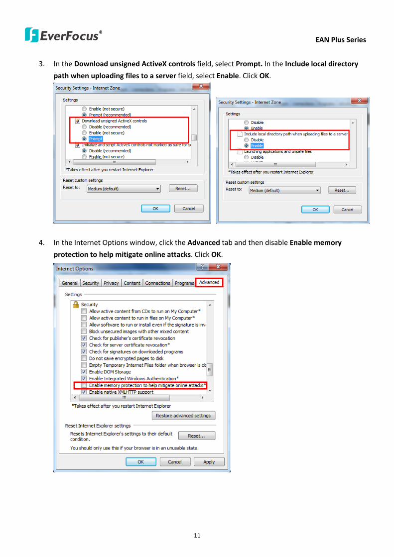
EAN Plus Series
11
3 In the Download unsigned ActiveX controls field select Prompt In the Include local directory
path when uploading files to a server field select Enable Click OK
4 In the Internet Options window click the Advanced tab and then disable Enable memory
protection to help mitigate online attacks Click OK
EAN Plus Series
12
53 Connecting the Camera to the Network
There are three methods to connect the IP camera to the network Router or LAN Connection Direct
High-Speed Connection and One-to-One Connection
Router or LAN connection
This is the most common connection in which the IP camera is connected to a router and allows
multiple users on and off site to see the IP camera on a LANWAN (Internet) The camera must be
assigned an IP address that is compatible with its LAN By setting up port forwarding on the router
you can remotely access the cameras from outside of the LAN via the Internet To remotely access the
Web interface of the IP camera please refer to 732 DDNS To set up port forwarding please consult
the manual of the router
Straight-through LAN patch cable
Right Pinout of a straight-through cable
EAN Plus Series
13
Direct High-Speed Connection
In a Direct High-Speed Connection the camera connects directly to a modem without the need for a
router You need to set the static or dynamic WAN IP address assigned by your ISP (Internet Service
Provider) in the camerarsquos configuration web pages To access the camera just type ldquohttpxxxrdquo
where xxx is the IP address given by your ISP If you have a dynamic IP address this connection may
require that you use DDNS for a reliable connection Please refer to 732 DDNS
One-to-One Connection (Directly from PC to IP Camera)
You can connect directly without using a switch router or modem However only the PC connected
to the camera will be able to view the IP camera You will also have to manually assign a compatible IP
address to both the computer and the IP camera Unless the PC has another network connection the
IP camera will be the only network device visible to the PC See the diagram below
Pinout of straight patch cable
Right Pinout of a crossed-over cable
EAN Plus Series
14
54 Live View Window
1 Press the button to display the Live View window Double-click on the
image to show a full-screen display double-click again or press ESC to return to the normal display
If you experience video feed lag time (if connected via Internet) you can reduce the resolution or
limit the number of streams See 741 Multi Streaming
2 Press the button to play the recorded data directly from the on-camera Micro
SD SDHC card (for this function to become active you have to insert a Micro SD SDHC card in the
Micro SD SDHC card slot on the rear panel of the camera See 783 SD Card
3 Press the button to enter the Settings page On the Settings page there are
8 submenu sections [System Info] [User Config] [Network] [Video] [Audio] [User] [Event] and
[System] Click on the section buttons to open their configuration fields See the Settings section
below for more information
EAN Plus Series
15
4 Press the button to exit the system and close this browser page
5 Video Stream
Select the Video Stream (Stream 1 Stream 2 or Stream 3) that will be displayed in the video box on
the right Stream 2 and Stream 3 are only selectable if you have enabled the stream The default
setting is Stream 1 only See 741 Multi Streaming
6 View Size
Use this to select the appropriate view size and shape of the video box on the right A smaller size
might increase transmission speed and video quality
7 Digital Zoom
Click the Zoom In Zoom Out buttons or roll the mouse wheel to zoom in out the camera live view
up to 10x Clicking on a magnified image will re-center the image around that point
8 Record
The Record button is used to record the current video stream Click the Record button to start
stop recording This icon is only for one-minute video recording To record long-period recordings
please set a recording schedule (See 775 Schedule) The location on your computer where the
image files will be saved to and file size can be specified in the submenu (see 72 User Config)
9 Snapshot
Click the Snapshot button to save a snapshot of the video image currently being displayed The
location on your computer where the snapshot data will be saved can be specified in ldquoSettings gt
User Config gt RecordingSnapshotrdquo (see 72 User Config)
10 Play Audio Transmit Audio
Click the ldquoPlay Audiordquo (speaker) and ldquoTransmit Audiordquo (microphone) buttons to switch the sound
onoff for the speaker and microphone respectively (if such external devices have been connected
to the camera directly or via the network)
EAN Plus Series
16
11 One Push
This function is only available for EAN3120 Plus 3220 Plus The One Push button can be displayed
on the live view window by enabling the Show One Push Buttons function on the User Config lt Live
View Config Setting page (see 721 Live View Config) To enable the button (turned from faded to
clear) on the Video lt Advanced Setting page select One Push from the White Balance Settings
Mode drop-down list and click the Apply button Once this is done pressing the One Push button
on the Live View Window will instruct the camera to adjust the white balance settings and these
settings will be active until the button is pushed again This is like a ldquosemi-automaticrdquo way to adjust
white balance to suit the user if the Auto or Manual mode does not give the result the user wants
12 Manual Control
ndash Trigger Event
Press the ldquoTrigger Eventrdquo button to trigger an event directly from the Live page If you have
configured an event (in the Event submenu) that will trigger a reaction (like a recording) when a
Manual Trigger event occurs clicking this button will trigger that reaction You can select what that
reaction will be You can for instance set the camera to record the audiovideo feed to the Micro
SD card on board the camera You can then click on the Playback button to open the Playback page
and search for and play all such recordings that had been stored on the card Such event actions
will be effective once they have been configured in the ldquoEventrdquo menu (see 77 Event)
ndash Reset Alarm
Press the ldquoReset Alarmrdquo button to reset the alarm output remotely
13 Status Display (info lines that can be placed above video box or at bottom of page)
This shows the name of the camera that is currently active or being configured current datetime
and current frame rate You can activate these info displays in the Settings gt User Config page (see
72 User Config)
14 Event Signal Icons (above video screen)
When an alarm or motion event is triggered a signal icon will appear at the top right of the Live
View window to alert the user
Alarm event icon When an alarm is triggered this icon appears
Motion detection icons The colors of these motion event icons correspond to the colors of the motion trigger areas you have configured in the Motion Detection submenu (see 772
Motion Detection)
Recording icon When the camera is recording to a PC-based folder this icon appears
EAN Plus Series
17
6 Playback
You can remotely play back the recordings stored in the on-camera micro SD card on the Web interface
or play back the recordings stored in the computer using the ARV Viewer included in the software CD
Playback is designed as a quick way to check recent recordings that were triggered by Events that were
configured to ldquoRecord to SD Cardrdquo in the Settings gt Event gt Event Settings page (see 771 Event
Settings)
Note Note that the Playback page is only accessible once the on-camera SD card is inserted and
active
61 Remote Playback Using Playback Page
On the Live View Window click the Playback button to open the Playback page
EAN Plus Series
18
Search by File Click the Search button to search for all recording files on the on-camera SD card
Search results will be displayed in the Filename area
Search by Time Click the calendar icon and select the date and time from which you want to search
until the present moment Click search to get your search results which will be displayed in the
Filename area
Search by event Click the type of Event recordings you want to search for (Alarm Motion Manual
Trigger) and then click the calendar icons to select the Start Time datetime and the End Time
datetime of your search Click Search to get your search results which will be displayed in the
Filename area
Multiple Files Check this box if you want the video player to play all the files in the selected folder
The files will be displayed in the Filename area
Loop Again Check this box if you want the video player to play the selected file over and over again
Play Once you have opened the filersquos folder and have clicked on the file to highlight it its details will
be displayed in the File Information area You can now click Play to play that specific file
Pause Click this button to pause the playback
Stop Click this button to stop the playback
【Recording List】
Filename This area will display a list of search results (recording files and folders) Folders (named
with the recorded date) will be displayed first Click on the folder and click on each subfolder until the
recording files (arv) in that folder is listed
File Information Click a file on the Filename list the selected file information will be listed
Copy Click this button to copy the selected file to the computer-based folder of your choice A
browsing box will open so that you can search for the folder of your choice You can use the ARV
Viewer to play back the recordings recorded in your computer For details on ARV Viewer see 63
Playing Back Using ARV Viewer
Lock Click this button to lock the selected file This will protect that file from being overwritten during
any overwrite procedure The file will thus be saved on the micro SD card indefinitely However the
file will still be deleted if the micro SD card is ever formatted
Remove Click this button to delete the selected file
EAN Plus Series
19
62 Setting up the Playback Function
Note that the Playback function will not be active until the user has inserted a micro SD card in the
camerarsquos micro SD card slot The card may also have to be formatted in the Settings submenu
Micro SD Card Slot
621 Preparing the Micro SD Card
Once you insert a functional micro SD card into the slot the Playback button on the Live page should
become active within seconds (see section 622 below ndash the grey letters should turn white) IF NOT
do the following
1 From the Live page click Settings gt System gt SD Card If no card has been inserted yet the
Remove button should be faded indicating that no card is being detected (If a card is
inserted and the Remove button is still faded pull the card out and re-insert it)
2 Slide the card into the slot until it clicks into position
3 The Remove button should become active within a few seconds indicating the card is active
4 If the Remove button stays faded click the Format button to format the card NOTE All data
on the disk will be deleted if the Format button is clicked
622 Testing the Playback Function
1 Once the SD card is detected by the system the button (inactive)
will turn to (active)
2 To test the Playback function (this is not required) set up a ldquoManual Triggerrdquo Recording
Event by clicking Settings gt Event gt Event Settings
3 Click the ldquoAddrdquo button on the middle right side of the page to open an ldquoAdd Eventrdquo box
4 Give the event a name like ldquoTest 1rdquo
EAN Plus Series
20
5 In the ldquoEvent Triggered byrdquo field click on Manual Trigger
6 Below this check ldquoEnable This Eventrdquo ldquoEnable Post-trigger Bufferrdquo and ldquoRecord to SD Cardrdquo
7 To save your settings click OK or close the box by clicking on the red x icon at top right of the
box (in which case you will be asked if you want to save the data to which you should reply OK)
The box will close and the new event will be listed in the list area of the Event Settings page
8 Look at the ldquoPost-trigger Bufferrdquo at the bottom to make sure the buffer time is set to 10 seconds
9 Click ldquoApplyrdquo to make sure all settings are saved
10 Click the Live button to go back to the Live page
11 Get ready to click the Trigger Event button at the bottom of the page Before you do see if you
can find something in the view screen that will give you a visual time marker For instance if you
can get your hand in front of the camerarsquos lens get ready to count down on your fingers
12 Click the Trigger Event button and slowly count down on your fingers in front of the lens (if you
are able to do so ndash if not try to find visual cues on the view screen that will help you to mark the
moment you pushed the trigger) The recording period will be as long as the buffer time you
selected ndash the default period is 10 seconds
13 Click the Playback button to open the Playback page
14 There are different ways to search for recording files on the camerarsquos Micro SD card (ie the
Playback memory) For a recent recording like your test event simply click the ldquoSearchrdquo button
under the ldquoSearch by Filerdquo header
15 If the SD card is active and formatted correctly the recording folderrsquos name (the recording dayrsquos
date) will appear in the Filename box at the bottom Click on this folder to open it If there are
sub-folders click on the bottom one (the most recent would be at the bottom) until you can click
on a file that cannot open to another sub-level and shows data in the File Information box to the
right This would be the file of the most recent recording event
16 To play this file click the Play button below the video box The test footage you have recorded
should start playing Play time should be 10 seconds if you left the Post-trigger Buffer as 10
seconds
EAN Plus Series
21
63 Playing Back Using ARV Viewer
You can play back the recordings stored in the computer using the ARV Viewer included in the
software CD To store the recordings in the computer please refer to Recording List gt Copy in 61
Remote Playback using Playback Page
4 5 6 7 8 9 10
321
No Item Name Descriptions
1 Snapshot Click to take and save a snapshot
2 Load File Click to load the recordings for playing back
3 Convert ARV to AVI Convert the recording from ARV format to AVI format
4 Playback Time Display the playback time
5 Total Time of Recording Display the total time of the recording
6 Stop Click to stop playing the recording
7 Step Reverse Click to display the previous frame
8 Play Click to play back the recording
9 Pause Click to pause the recording
10 Step Forward Click to display the next frame
EAN Plus Series
22
7 Settings
Click the Settings button on the Live View Window to enter the settings submenu There are nine buttons
on the left-side of the submenu Live System Info User Config Network Video Audio User Event and
System Click the Live button can go back to the Live View Window
71 System Info
The System Information and System Log can be checked on this page Click the top tab of the one you
want to see
711 Information
Click the Information tab the following dialog box appears These values cannot be changed on this
page and are for reference only
EAN Plus Series
23
712 Log
Click the Log tab the following dialog box appears The sequence number date time and event
messages of the log event will be displayed in the System Log field The log will display the last 256
log events Click the Export button to export the system log event list into a ldquotxtrdquo file and select the
location where the exported log file will be saved to
EAN Plus Series
24
72 User Config
Each user can set a different configuration for hisher Live page here These settings will be applied to
the logged-in userrsquos Live page every time heshe logs in
721 Live View Config
【VideoAudio Connection Protocol Setting】You can transmit the data stream from the IP cameras
using the RTSP (Real Time Streaming Protocol) on the network The RTSP is a protocol that allows
you to access video streams by using the compatible media players Click Apply to apply the
changes or Reset to reset without saving the changes RTP over UDP The RTSP protocol uses UDP for camera data stream transmission
RTP over TCP The RTSP protocol uses TCP for camera data stream transmission
RTP over HTTP The RTSP protocol uses HTTP for camera data stream transmission
Nevio CGI This is EverFocusrsquo protocol designed for EverFocusrsquo IP devices Select this
protocol for camera data stream transmission
【Text Settings】Check the box of each option (Machine name DateTime Frame Rate) to display
this info on the Live View Page
Foreground Color Slide the Red Green and Blue bars to create your preferred text color for the
info text line
Position Select the position where the text will be displayed Choose from Upper Left Lower
Right Lower Left
Click Apply to apply the changes or Reset to reset without saving the changes
EAN Plus Series
25
【DateTime Format Used in Text】Click the dropdown menu to select datetime format from the
listed options Click on the desired hour format Click Apply to apply the setting changes or Reset to
reset without saving the change
【Live View Layout Settings】 Check the ldquoShow One Push Buttonsrdquo boxes if you want to show these
buttons on the Live View Page Uncheck these boxes to hide these buttons This function is only
available for EAN3120 Plus 3220 Plus
722 Recording Snapshot
This configures where your Record Button and Snapshot Button ( ) files will be saved if
you click one of these buttons Selectable folders will be on the computer only not on the
on-camera SD card
【Recording Snapshot Export Settings】
Enable Event Recording to PC Checking this box will let the system save RecordSnapshot Button
recordings to the folder configured below on the userrsquos PC
Export Folder Select the Export folder for the action above by clicking on the browse (hellip) button
and then select the desired folder
File size The user can limit the size of each recorded file here (in minutes) When a single
recording file exceeds the time you set the system will create a new file to save that data to
Overwrite Select ldquoONrdquo for overwriting recordingsnapshot file when the disk storage capacity is
full The user can set the storage capacity limitation in the in-sentence field in the gray box below
the Overwrite setting ldquoIf the remaining hard disk capacity is less than ____ MB (50~2000) system
will stop recording or start overwriting ldquo
Click Apply to apply the setting changes or Reset to reset without saving the changes
EAN Plus Series
26
723 Language
Select the language to be displayed on the Web interface of the IP camera The default language is
English
To add a new language not listed in the current Language list click the Browse button to locate
the new language file (evb) on your computer and then click the Upload button Updated
language files might be available on the manufacturerrsquos website Contact your vendor if required
Click Apply to apply any changes or Reset to reset without saving the changes
Note Uploading a new language file will cause the system to reboot automatically Please create
a new network connection to the IP camera when the reboot is complete
EAN Plus Series
27
73 Network
This page covers network-related settings including Network DDNS SMTPFTP HTTPS SNMP and
Network Alarm
731 Network
The following information is required to configure the network settings Contact your network
administrator or your internet service provider to get the info
【IP Settings】
IP Type Refer to the network administrator for these settings of the server Default DHCP
DHCP This setting lets the system use an automatically assigned (dynamic) IP address This
address can change under certain circumstances For instance when the camerarsquos network
switchhub has to be rebooted Do not assign to the DHCP server the same IP addresses used
for the other network cameras and PCs with unique IP addresses
Static IP The user can manually set the Static IP address This type of address is stable and
cannot change but the user has to make sure there are no address conflicts with other
network-connected devices
PPPoE This is a DSL-connection application The ISP will ask the user to input a username and
password Contact your ISP for these details
EAN Plus Series
28
Note If PPPoE is selected as the IP type the supplied IP Utility program will not be able to
detect the device
IP address When DHCP is not used the user needs to manually enter the IP address of the
camera Do not enter an IP address that is already used for your computer or other network
cameras
Subnet Mask This field is used to set the netmask for your network so that the IP camera will be
recognized within the network Example 2552552550 When DHCP is selected the DHCP server
will assign this value automatically
Gateway This field is used to set the gateway for your network so that the IP camera will be
recognized within the network When DHCP is selected the DHCP server will assign this value
automatically
Primary DNS Enter the IP address of the DNS server if this is provided by an ISP
Secondary DNS If your ISP provided you with a secondary DNS address please enter it here
Username Enter the accountrsquos username (used only for PPPoE)
Password Used only for PPPoE
IPv6 Enter the IPv6 details in this area if this applies to your system
Click Apply to apply the setting changes or Reset to reset without saving the change
【Port Settings】Enter the HTTP HTTPS and RTSP port numbers and click Apply to save
【Multicast Settings】Enable if required fill in the setting options and click Apply to save
EAN Plus Series
29
732 DDNS
DDNS (Dynamic Domain Name System) is a service used to map a domain name to the dynamic IP
address of a network device You can set up the DDNS service for remote access to the IP camera
DDNS assigns a domain name (URL) to the IP camera so that the user does not need to go through
the trouble of checking if the IP address assigned by DHCP Server has changed Once the IP is
changed the IP camera will automatically update the information to the DDNS to ensure it is always
available for remote access
Before enabling the following DDNS function user should have applied for a host name from the
DDS service providerrsquos website We support these four DDNS server providers
wwweverfocusddnscom wwwsitelutionscom wwwdyndnscom and wwwno-ipcom
Note We highly recommend that you use xxxxeverfocusddnscom for the simplicity of setting up
your IP cameras
【DDNS Settings】
Enable Check this box to enable the DDNS function
Service ISP You can either apply for a host name from EverFocus or other DDNS server providers
If you choose the EverFocus DDNS server you can obtain a free host name from EverFocus by
following the steps below
bull From EverFocus To obtain a free host name from EverFocus type a desired host name in the
textbox click the Register Update button and then click the Apply button
bull From other DDNS server providers To obtain a domain name from one of the three DDNS
server providers you have to register your name with the provider first and then select the
provider and fill in the required information Please refer to the specific DDNS companyrsquos
website for further information
Record ID Type the record ID if provided by the DDNS server provider
EAN Plus Series
30
FQDN Type the fully qualified domain name applied from the DDNS server provider For
example xxxxdyndnscom
Username Password Type the login account of your DDNS server provider
Click Apply to apply the setting changes or Reset to reset without saving the changes
Note
1 In order to support the full functionality of the camera you must open the port numbers (80
554 443) on the router for remote access to the IP camera This function is available on most
routers in the market and is often known as ldquoPort Forwardingrdquo To set up Port Forwarding
please consult the manual of the router
2 In certain router models it is possible that you will not be able to access the camera using
DDNS while inside the routerrsquos network Please try using a PC located outside of your routerrsquos
network
Default Ports on All EverFocus IP Cameras
HTTP 80
RTSP 554
HTTPS 443
EAN Plus Series
31
733 SMTP FTP
【Set SMTP Server (email)】This area is for configuring the mail server that is used to send e-mail
notifications from the camera to predefined addresses via SMTP Note that to enable e-mail
notification function you have to check the Send Mail Notification item on the Event dialog box
(see 771 Event Settings)
SMTP Server Enter the IP address or the host name of the SMTP server used to send e-mails
SMTP Port Enter the port number for SMTP The default is 25
Authentication Check this box if the SMTP server requires authentication (userpassword)
User name Input the userrsquos login ID if the SMTP server requires authentication
Password Input the userrsquos login password if the SMTP server requires authentication
EAN Plus Series
32
Receiver Address Input the e-mail addresses for receiving an e-mail message when an EVENT is
enabled and triggered Please use ldquordquo to separate multiple addresses
Sender Address Input the senderrsquos e-mail address so that the receiver can recognize the sender
when an Event message is received
Attach Image Check this box if you want to attach an image when an alarm is triggered or an IP
camera detects events
Send Test Email Click the Test button to send a testing email to the assigned address
Click Apply to apply the setting changes or Reset to reset without saving the changes
【Set FTP Server】The settings relating to the FTP server used to transmit the alarm images can be
configured here Note that to enable uploading images to the FTP server function you have to
check the Upload to FTP item on the Event dialog box (see 771 Event Settings)
FTP Server Enter the IP address or the host name of the FTP server
FTP Port Enter the port number for the FTP server Default is 21
Recording Path Assign the recording path
User Name Set FTP Userrsquos name
Password Set FTP password
PASV mode Check to enable Passive mode Passive mode is normally enabled If a connection
cannot be established uncheck PASV Moderdquo
Test FTP Server Click the Test button to send a testing file to the assigned FTP server
Click Apply to apply the setting changes or Reset to reset without saving the changes
EAN Plus Series
33
734 HTTPS
Hypertext Transfer Protocol Secure (HTTPS) is a combination of the Hypertext Transfer Protocol
and the SSLTLS protocol and provides encrypted communication and secure identification of a
network web server
Before using the HTTPS function for communication with the IP camera a Certificate must be
created first There are two ways to create and install a certificate Create Self-Signed Certificate
and Create Certificate Request
Create Self-Signed Certificate
Please note that even though self-signed certificates are free and offer some protection true
security is only implemented after the installation of a signed certificate issued by a certificate
authority
1 Click the Create Self-Signed Certificate button the following dialog appears
EAN Plus Series
34
2 Type the required Certificate information and then click the Apply button The subject line will
be displayed in the Installed Certificate Information field
3 Click the Property button a pop-up window appears to display the details of the certificate
4 To optionally create and install other certificates remove the existing one by clicking the
Remove button to erase the certificate
5 On the Web page change the address from ldquohttprdquo to https in the address bar and press
Enter on the keyboard Some Security Alert dialogs will pop up Click OK or Yes to enable HTTPS
Create Certificate Request
You can apply for an official certificate from an issuing Certificate Authority
1 Click the Create Certificate Request button the following dialog appears
EAN Plus Series
35
2 Type the required Certificate information and then click the Apply button The subject line will
be displayed in the Created Request field
3 Click the Property button a pop-up window appears to display the details of the certificate
4 To optionally create and install other certificates or request remove the existing one by clicking
the Remove button to erase the certificate or request
5 Copy the contents of the Certificate request (in PEM format) and paste it to the certificate
request field on the Web page of the 3rd-party certification authority such as Symantec VeriSign
Wait for the certificate authority to issue an SSLTLS certificate and then download the issued
certificate on your computer
6 In the Install Signed Certificate field click the Browse button to search for the issued certificate
and then click the Upload button to import the certificate Once the certificate has been
uploaded this field will show the subject line of the certificate
EAN Plus Series
36
735 SNMP
The default values for SNMP v1v2v2c and SNMP v3 are already filled in Click either of the
Enable buttons to enable either of the two Make your changes as desired Click on the Trap
Address field to enter the digits if required
736 Network Alarm
This function works with EverFocusrsquos CMS software eg the PowerCon or the Power Video Plus For
the setting details please refer to the CMS network alarm protocol
EAN Plus Series
37
74 Video
The settings relating to video such as streaming camera OSD can be configured on this page The
Video page has five tabs Multi-streaming Camera Advanced ROI and Privacy Mask
741 Multi Streaming
【Stream Settings】 This IP camera can output three video streams simultaneously For each of these
streams the user can set the compression format resolution bit rate and frame rate individually
Stream 1 is always enabled for live view To enable Stream 2 andor Stream 3 check the ldquoEnablerdquo
box the header of each stream
Note If you connect to the camera via the Internet and experience a delay (lag time) in the video
feed try to reduce the number of streams and the quality and resolution of the streams ndash but
keep the frame rate at its maximum
EAN Plus Series
38
Format Select the encoding format ndash H264 or MJPEG
Resolution Select the most suitable resolution for your needs
Frame Rate Select from 1 to 30 fps
Bit Rate If required select whether you want the stream to stream a Constant Bit Rate or a
Variable Bit Rate and set the values of whichever option you choose
Click Apply to apply the setting changes or Reset to reset without saving the changes
【Video Recording Settings】Select the stream you want to configure and then select whether you
want the recording files of that stream to be saved in AVI or ARV format Click Apply to apply the
setting changes or Reset to reset without saving the changes
【Time Stamp Settings】 You can select the DateTime format position and add the setting to the
streaming
Click Apply to apply the changes or Reset to reset without saving the changes
EAN Plus Series
39
742 Camera
【Image Settings】Set the Brightness Saturation Contrast or Sharpness of the image Click Apply to
apply the changes or Reset to reset without saving the changes
【Camera Settings】
Mirror Switch Mirror ON to rotate the image horizontally around a vertical axis
Flip Switch Flip ON to rotate the image vertically around a horizontal axis
AE There are two options
ALC Selecting Automatic Light Control allows the camera circuitry to either take bright spots
more into consideration (peak) bringing out detail in bright areas or less into consideration
(average) bringing out detail in shadows
AES Selecting Auto Electronic Shutter disables the Shutter setting below this setting In this
mode the camera measures the light level and decides whether it needs more or less light and
then automatically adjusts the shutter speed accordingly
BLC Back Light Compensation (BLC) is used to make the subject appear clearer when it is set
against a bright background
OFF Select to switch Back Light Compensation functions off
(ON)BLC The BLC can increase the exposure of a dark area surrounded by a brighter area HLC
can decrease the exposure of bright areas surrounded by darker areas This enables the
camera to better display information that would otherwise have been ldquowhited outrdquo like a
license plate between two bright headlights on a dark road
(ON)HLC The Highlight-Suppression BLC is used to reduce the brightness of light sources in a
specific area It is activated only in a low illumination environment to minimize the effects of
glare from bright lights such as spotlights street lights or headlights in the field of view
EAN Plus Series
40
WDR The Wide Dynamic Range (WDR) function provides clearer images when both of the very
bright and dark areas simultaneously appear on the camera view There are four value options
OFF Low Middle and High Note that when WDR is ON some parts of the image may appear
solarized This is normal for WDR and is not a camera malfunction This function is only available
for EAN3120 Plus 3220 Plus
DN Mode
Auto Select to let the camera automatically switch to Night mode (black and white) when the
light levels fall to a specified level and back to Day mode (color) when the light levels rise to a
specified level
Day Select to keep the camera in Day mode (color) even in nighttime
Night Select to keep the camera in Night mode (black and white) even in daytime
EAN Plus Series
41
743 Advanced
EAN Plus Series
42
【Camera Settings】
Lens (IRIS Control) Select DC or Manual for IRIS control This function is only available for EAN3220
Plus
Exposure Settings (AE) This setting is used to adapt to the amount or type of light used by the
camera Note the settings vary among models
Mode This function is not available for EAN3220 Plus
Automatic Light Control (ALC) This option is only available for EAN3120 Plus 3300 Plus The
ALC allows the camera circuitry to either take bright spots more into consideration (peak)
bringing out detail in bright areas or less into consideration (average) bringing out detail in
shadows
Auto Electronic Shutter (AES) This option is only available for EAN3120 Plus 3300 Plus In
this mode the camera measures the light level and decides whether it needs more or less light
and then automatically adjusts the shutter speed accordingly
Manual This option is only available for EAN3300 Plus Select this option to manually set up
the Shutter (Manual) and AGC (Manual) values
Iris Specify the size of the Iris opening here
Shutter If enabled this setting lets you set the shutter speed yourself
Shutter Limit Use this setting to set the maximum shutter speed for the camera This function is
only available for EAN3120 Plus
AGC Set the Auto Gain Control limit here The lower the AGC level the lower the video signal and
the noise However the image will be darker under low-light condition with IR-off if you set up the
Iris to the maximum level
Slow Shutter This option can be switched on when AES Mode is selected in the Exposure Settings
(AE) field This function is only available for EAN3220 Plus 3300 Plus
Flickerless If the Mode field in the Exposure Settings (AE) area has been set to AES then this option
becomes available Choose between OFF 50HZ 60HZ 50HZ (High Luminance) or 60HZ (High
Luminance) This function is only available for EAN3300 Plus
EV Setting Set up the Exposure Value Note the brightness of the screen changes when you change
the EV value This function is only available for EAN3300 Plus
AE Response Set up Auto Exposure Response time This function is only available for EAN3300 Plus
AE Weighting Area Select an AE Weighting area Each setup AE Weighting Area is configured with
the appropriate brightness level on the center and the surrounding areas This function is only
available for EAN3300 Plus
Brightness Set the image brightness here
AE Reference Set the Auto Exposure value here This function is only available for EAN3120 Plus
EAN Plus Series
43
Black Level Set the Black level here This function is only available for EAN3300 Plus
WDR The Wide Dynamic Range (WDR) function provides clearer images when both of the very
bright and dark areas simultaneously appear on the camera view There are four value options OFF
Low Middle and High Note that when WDR is ON some parts of the image may appear solarized
This is normal for WDR and is not a camera malfunction This function is only available for EAN3120
Plus 3220 Plus
Visibility Enhancement (OFFLowMiddleHigh) Images in foggy or rain environments or in
environments with a very strong luminous intensity have a dynamic range that is significantly lower
than ordinary images The user can use this Visibility Enhancement setting to ldquoDEFOGrdquo the image if
such ldquoFOGGINGrdquo is an issue This function is only available for EAN3220 Plus
BLC Settings Back Light Compensation (BLC) is used to make the subject appear clearer when it is
set against a bright background
OFF Select to switch Back Light Compensation functions off
Back Light This option is only available for EAN3300 Plus The Back Light function is useful
when the background of the subject is very bright and the subject itself is dark Select Back
Light and adjust the slide bar to the left right for setting up the back light value The higher
the value the more the backlight compensation
Front Light This option is only available for EAN3300 Plus This function is useful when the
bright highlights such as flashlight or car headlights appear on the camera view Select Front
Light and adjust the slide bar to the left right for setting up the front light value The higher
the value the more the highlight compensation
ON (BLC) This option is only available when you select AES Mode in the Exposure Settings (AE)
field The option is only available for EAN3120 Plus 3220 Plus The BLC function is useful
when the background of the subject is very bright and the subject itself is dark Follow the
instructions below to configure the settings for each model
For EAN3120 Select ON (BLC) the button next to the Mode drop-down list will be
active (see image below) Click the button the green setup areas appear on the left
screen Click on the areas to enable disable the BLC function The selected areas (in green)
will be applied with the BLC function
EAN Plus Series
44
For EAN3220
You can configure one area to apply the BLC function Select ON (BLC) the setup buttons
appears (see image below) Select Low Middle High from the BLC Gain drop-down list To
set up a BLC area click the Edit Area button and then click on the blue color tab to turn your
mouse cursor into a blue pen Move the cursor to the position on the right screen where you
want the BLC rectangle to start and then click Move your cursor to the position (diagonally
opposing corner) where you want the BLC rectangle to end and then click The blue area will
be applied with the BLC function
ON (HLC) This option is only available when you select AES Mode in the Exposure Settings (AE)
field The option is only available for EAN3120 Plus 3220 Plus This function is useful when
the bright highlights such as flashlight or car headlights appear on the camera view Follow
the instructions below to configure the settings for each model
For EAN3120 Select ON (HLC) and then select a level from the drop-down list The higher the
level the more the highlight compensation
For EAN3220
HLC Level Select a level for the HLC setting The higher the level the more the highlight
compensation
HLC Mode Select All Day Night mode to apply the HLC function
HLC Black Mask Select On Off to apply the black mask on the selected areas The
over-exposure portions within the selected areas will be applied with the black mask
Color Tabs You can set up four HLC areas with different colors To set up a HLC area click the
Edit Area button and then click on the color tab to turn your mouse cursor into a pen of that
color Move the cursor to the position on the right screen where you want the HLC rectangle
to start and then click Move your cursor to the position (diagonally opposing corner) where
you want the HLC rectangle to end and then click Select ON from the color tab drop-down list
The rectangular area with the selected color will be applied with the HLC function
EAN Plus Series
45
Back Light This option is only available for EAN3300 Plus The Back Light function is useful
when the background of the subject is very bright and the subject itself is dark Select Back
Light and adjust the slide bar to the left right for setting up the back light value The higher
the value the more the backlight compensation
Front Light This option is only available for EAN3300 Plus This function is useful when the
bright highlights such as flashlight or car headlights appear on the camera view Select Front
Light and adjust the slide bar to the left right for setting up the front light value The higher
the value the more the highlight compensation
Noise Reduction Settings This limits the amount of digital ldquovideo noiserdquo that is usually found in any
video stream and helps to reduce file size The higher the level the more the reduction
For EAN3120 Plus 3300 Plus
Select ON OFF to enable disable the Noise Reduction function Or select Auto to let the camera
automatically enable disable the Noise Reduction function Slide the Level bar to set up the level
The higher the level the more the reduction
For EAN3220 Plus
2D DNR Select ON to enable the 2D DNR function
3D DNR Select ON to enable the 3D DNR function You can further set up the following settings
3D Start AGC Set up the AGC level to automatically start the 3D NR function
3D End AGC Set up the AGC level to automatically stop the 3D NR function
3D Level Set up the 3D DNR level
Smart NR Select ON to enable the Smart NR function The 3D NR function will be
automatically turned on when a motion event occurs
EAN Plus Series
46
White Balance Settings Select the mode that delivers the best quality image for the camerarsquos light
environment There are five options Auto Manual Indoor Outdoor One Push
Auto Select to let the camera automatically adjust the White Balance In the Auto mode the
camera computes the white balance value output using color information from the entire
screen It outputs the proper value using the color temperature radiating from a black subject
based on a range of value from 3000 to 7500K
Manual Select to adjust the Red and Blue values yourself in the fields below this field
Indoor Select to use the default settings for indoor environments In the Indoor mode the
camera uses 3200K as the base value
Outdoor Select to use the default settings for outdoor environment In the Outdoor mode it
uses 5800K as the base value
One Push Select to enable the Push button next to the Mode drop-down field This will allow you to force the camera to readjust the white balance every time you push the Push
button The lens will hold the same focal position until the next trigger command is received
This function helps to prevent incorrect focusing in dark environments This function is only
available for EAN3120 Plus 3220 Plus
Manual Temperature Select to use the optimized Red and Blue settings You can also
optionally adjust the Manual Level below this field for setting up the color temperature The
higher the value the more the color temperature This function is only available for EAN3300
Plus
DayNight Settings
Auto Select to let the camera automatically switch to Night mode (black and white) when the
light levels fall to a specified level and back to Day mode (color) when the light levels rise to a
specified level
Day Select to keep the camera in Day mode (color) even in nighttime
Night Select to keep the camera in Night mode (black and white) even in daytime
IR Smart Settings Select ON and set up the level to enhance the image quality when the images are
over exposure This function is useful when the camera is in the Night mode This function is only
available for EAN3220 Plus
Saturation Set the saturation value This function is not available for EAN3220 Plus
Monitor Type Select a gamma value from Set 1 Set 2 or Set 3 This function is only available for
EAN3120 Plus
Negative Switch this setting ON to view a color negative version of the video image This is useful
at night or when viewing temperature-sensitive images
EAN Plus Series
47
Sharpness Settings Select the sharpness level of the image A low sharpness level will deliver a
softer less detailed image A high level will deliver a sharp highly detailed image Switch Resolution
Enhancement ON to enable the resolution enhancement function
Contrast Select the contrast level of the image
Suppress Function This function is only available for EAN3300 Plus
Aperture Compensation Suppression (OFFLowMiddleHigh) This setting can be activated to
suppress luminance noise when the AGC level increases
Chroma Suppression (OFFLowMiddleHigh) This setting can be activated to suppress
chrominance noise when the AGC level increases
Ygamma (gamma 22standardcontrast enhancehigh light range mode LHigh light range mode
H) Select the Ygamma value for the video quality of the monitor This function is only available for
EAN3300 Plus
Monitor Settings The user can use this field to optimize video quality for his or her specific type of
monitor ndash LCD or CRT This function is only available for EAN3220 Plus
Color Space Standard The options are YUV601 for SD and YUV709 for HD These define the color
space standard required to convert an RGB picture to a YUV picture Generally YUV601 is used for
Standard Definition (720P) devices and the YUV709 is used for High Definition (1080P) devices
Click Apply to save all changes Click Reset to cancel all changes
EAN Plus Series
48
744 ROI (Region of Interest)
The Region of Interest (ROI) function allows users to set up multiple regions within an image with
better quality and less distortion than the rest of the image You can also use this function
together with the Digital Zoom function on the Live View Page to get a better image result Up to
eight ROIs can be configured in the ROI settings page
To set up an ROI region
1 Select an ROI number from the ROI No drop-down list
2 Click the Add button the mouse cursor will turn into a pen when you move it over the live
image on the left
3 Move the cursor to the position where you want the ROI rectangle to start and then click
Move the cursor to the position (diagonally opposing corner) where you want the ROI
rectangle to end and then click
4 Slide the Quality bar to set up the quality value
5 Click the Apply button to apply the settings or click the Reset button to reset without saving
the settings
EAN Plus Series
49
745 Privacy Mask
The Privacy Mask can block out sensitive areas from view covering the areas with colored or black
and white boxes in both live view and recorded clips This feature is useful when usersrsquo donrsquot want
the sensitive information visible Up to four Privacy Masks can be configured
【Privacy Mask Color Settings】The Modes vary among camera models
Mode Click Color to make the masks appear as colored rectangles on the screen Click BW to
make the masks appear as gray rectangles on the screen Click Mosaic to make the masks appear
as mosaic-effect rectangles on the screen
Level Select the color of the masks if you selected Color Mode Select the level of grayness of the
masks if you selected BW Mode Select the level of smallmiddlelarge if you selected Mosaic
Mode
Click Apply to apply the settings or click Reset to reset without saving the settings
Color Tabs Click on a color tab to turn your mouse cursor into a pen of that color
You can now create a block of that color on the video screen Move your cursor to the position
where you want your mask rectangle to start and then click Move your cursor to the position
(diagonally opposing corner) where you want your mask rectangle to end and then click The
rectangular area with the selected color will appear The live image will display the rectangular
area with the color you selected If you want to create another mask use one of the other three
colors Each color denotes a different mask area Only one block per color is allowed As the
number of colors suggests you can configure up to four blocks
EAN Plus Series
50
Select All Click to turn the whole screen into a mask area
Clear All Click to delete all configured mask blocks
Eraser Click to turn the mouse cursor into an eraser to delete any block you click on
Area Shows the color and number of the block
Enable Check this box to enable the related mask block
Click Apply to apply the settings or click Reset to reset without saving the settings
EAN Plus Series
51
75 Audio
The EAN Plus series IP camera can transmit audio to your computer if you have connected an external
microphone to its audio Input cable It can also receive audio input from you and transmit it via an
external speaker if you have connected such a speaker to its audio Output cable
Check the Enable Audio box to enable the camerarsquos audio function The camera will now act as a
digital bridge (via the IP network) between any connected audio input device and any connected
audio device
Adjust the Audio Input Volume if you have external audio input devices (microphones) connected to
the camera and if there are problems with the sound input being too low or high
Click Apply to save all settings or click Reset to cancel
EAN Plus Series
52
76 User
761 User Information
The system administrator can create up to ten user accounts on this page
To set up a user account
1 Highlight a user account and click the Modify button The following dialog box appears
2 Type the account name account description and password for the account Type the password
again in the Confirm field
3 Select an authority level for the user account from the Authority drop-down list
bull Supervisor Administrator The only difference between a supervisor and administrator is
that a supervisor can edit an administratorrsquos account and password but an administrator
cannot edit the supervisorrsquos account and password Multiple administrators can be
configured but there can be only one supervisor The supervisor and administrators all
have unrestricted access to the Settings submenus and can determine the registration of
all other users
EAN Plus Series
53
bull User A user can view the Live View page and view the system network video and audio
information A user can only adjust the User Config page settings The user does not have
access to the User Event and System pages
bull Guest The lowest level of access which only allows the user access to the Live View page
4 Select Active or Disable from the Status drop-down list to active or disable the user account
5 Click On in the SD Card Playback field to allow the user to access the SD card playback
function
6 Click OK
7 Click Apply to save all the settings
EAN Plus Series
54
762 IP Address Filter
Use this page to specify IP addresses that are not allowed to access this camera By default any IP
address can access the camera
Note The Allowed List addresses only become relevant when the Denied List contains a network
or range and the supervisor wants to allow one or more IP addresses within that excluded range
or network In such a scenario the user would enter the excluded range or network in the
Denied List and enter the exceptions in the Allowed List
To set up the IP Address Filter
1 Select Denied List Click the Add button the following dialog box appears
2 Select an IP type from the IP Type drop-down list
3 Select a network rule from the Rule drop-down list type the IP address and click OK
Single Type a single IP address in the IP Address field below
Network Type the IP address and subnet mask in the field below
Range Type a range for the IP addresses
4 If you have set up an IP range in Step 3 you can optionally set up the Allowed List to allow one
or more IP addresses within the setup IP range to access the IP camera
5 Click Apply
EAN Plus Series
55
77 Event
You can set up the Motion Detection event Tamper Detection event or the Alarm IO to automatically
notify the users when an event occurs or an alarm is triggered You can also set up a schedule to
automatically record the videos when an event occurs or an alarm is triggered
771 Event Settings
You can create a total of ten event or alarm settings page in the Event List
【Event List】
Click the Add button and the following Event Configuration Window appears
EAN Plus Series
56
Enter Event Name Type an event name
Event Triggered by Select an event or alarm type for the to-be-specified-below reactions
Alarm Input Select this if you want a reaction trigger coming from any external connected sensor
to activate a to-be-specified-below reactions via the camera system Make sure that a suitable
device is actually connected to the alarm input relay
Manual Trigger Select this option if you want to manually trigger the alarm by clicking the Trigger
Event button on the Live View Page
Motion Detection Select this option if you want motion in a specified part of the camerarsquos viewing
rectangle (the screen image) to trigger the to-be-specified-below reactions
Tampering Detection Select this option if you want the camerarsquos tampering detection sensor to
trigger the to-be-specified-below reactions
Schedule Recording Select this option if you want the Schedule Recording periods configured in
the recording schedule (the Settings gt Event gt Schedule page) to activate this event In this
scenario a preconfigured event reaction like a log entry will list the start and end times of each
period Actual recording will only be triggered if the event is preconfigured to do so
Enable This Event Select to activate the event
Enable Re-trigger Click to set a minimum time after the event is triggered before the event
can be triggered again
Enable Pre-trigger Buffer Click if you want the Event reaction (as selected in the ldquoNotification
Overrdquo field below) to be the activation of the video recording function and if you want the
recording to include the video feed from the time period (configurable on the previous ldquoEvent
Settingsrdquo page) just before the Event trigger occurred
Enable Post-trigger Buffer Click if you want the Event reaction (as selected in the Notification
Over field) to be the activation of the video recording function and if you want the recording
to include the video feed from a time period (configurable on the Event Settings page) just
after the Event trigger occurred
Motion Area Select a setup motion detection area from the drop down list Note this
function only becomes relevant after the Motion Detection areas have been set up (see 772
Motion Detection)
Notification Over Select the desired notification types form the following items
Log Click if you want the camera to list the eventrsquos details in its log if the event is triggered
Trigger Alarm Output Click if you want the camera to relay the event reaction to a device
attached to the alarm relay output wire and then set up the alarm output duration time
EAN Plus Series
57
Send Mail Notification Click if you want the camera to send an Event notification email to the
email address entered in the Set SMTP Server(email) field of the Network gt SMTPFTP page if
the Event occurs (see 733 SMTP FTP)
Upload to FTP Click if you want the camera to upload recorded footage to the FTP server
entered in the Set SMTP Server(email) field of the Network gt SMTPFTP page if the Event
occurs (see 733 SMTP FTP)
Record to SD Card Click if you want the camera to start recording its video feed (when the
event occurs) on an on-camera SD Card (if such a card has been inserted)
Note The recording will only be as long as the combined Pre- and Post-trigger Buffers so
make sure you enable at least one of these buffers especially the Post-trigger Buffer
Record to PC Check this box if you want the camera to start recording its video feed (when
the event occurs) on the same folder on the same PC as configured on the User Config gt
RecordingSnapshot page (if such a folder has been enabled and configured)
Note The recording will only be as long as the combined Pre- and Post-trigger Buffers (and
for as long as the event trigger is happening ndash eg a motion is detected) so make sure you
enable at least one of these buffers especially the Post-trigger Buffer
Network Alarm Check this box if you want the camera to send a network alarm signal (when
the event occurs) to the CMS servers configured on the Network gt Network Alarm page (see
736 Network Alarm)
Click OK to save all settings or click Cancel to cancel
【PrePost Trigger Settings】
Pre-trigger Buffer Select the duration for the buffer This will determine the amount of footage
(length of time) before the event trigger moment that will be included in an event-triggered video
recording if that buffer and video recording has been enabled in the Event Configuration Window
Post-trigger Buffer Select the duration for the buffer This will determine the amount of footage
(length of time) after the event trigger moment that will be included in an event-triggered video
recording if that buffer and video recording has been enabled in the Event Configuration Window
Click Apply to save all settings or click Reset to cancel
EAN Plus Series
58
772 Motion Detection
Use this page to configure up to four areas in which motion will be detected When a motion is
detected by the camera the motion detection icon will appear at the top right of the
Live page to alert the user This function can also be linked with correctly configured Events to
trigger Event reactions like the activation of video recording periods snapshots alarms etc
Color Tabs Click on a color tab to turn your mouse cursor into a pen of that color
You can now create a block of that color on the video screen Move your cursor to the position
where you want your detection rectangle to start and then click Move your cursor to the position
(diagonally opposing corner) where you want your detection rectangle to end and then click The
rectangular area with the selected color will appear This block will be an area inside which the
camera will detect motion If you want to create another detection area use one of the other three
palette colors Each color denotes a different detection area Only one block per color is allowed As
the number of colors suggests you can configure up to four blocks
Select All Click to turn the whole screen into a motion detection area
Clear All Click to delete all configured motion detection blocks
Eraser Click to turn your mouse cursor into an eraser to delete any block you click on
Area Shows the color and numberID of the block
Enable Check this box to enable the related motion detection block
Sensitivity Set the sensitivity of the motion detection sensor function
Click Apply to save all settings or click Reset to cancel
EAN Plus Series
59
773 Tamper Detection
Use this page to set the number of seconds that an alarm signal will be active if the device is
physically tampered (moved covered up or out of focus
774 Alarm IO
Use this page to set the type of trigger input and the type of output contact for the camerarsquos alarm
channel
EAN Plus Series
60
775 Schedule
Use this page to configure a schedule for periods during which the camera should deactivate all
user-activated Events (gray Deselect periods) or when the camera should deactivate all
user-activated Events except Schedule Recording (SR) events (blue Schedule Recording-only
periods) or when the camera should deactivate only SR events (red Event Recording-only periods)
or when it should enable all activated Events (yellow periods)
Event Recording Click this button to make every hour block you click on red A red block represents
an Event Recording-only block which represents an hour when the camera will deactivate all
preconfigured activated Schedule Recording events and keep all the other activated events active
Schedule Recording Click this button to make every hour block you click on blue A blue block
represents a Schedule Recording-only block which represents an hour when the camera will
deactivate all other preconfigured activated events and keep only the preconfigured activated
Schedule Recording events active
Event + Schedule Click this button to make every hour block you click on yellow A yellow block
represents an hour in which all activated events including Schedule Recording events will be
active
Deselect Click this button to make every hour block become grey A grey block represents an hour
in which all activated events including Schedule Recording events will be inactive
Click Apply to save all settings or click Reset to cancel
EAN Plus Series
61
78 System
You can set up the systemrsquos time and SD card settings and to do maintenance and reset actions like
reboots and upgrades
781 DateTime
【Machine Name Settings】If required enter a new name for the machine This name will be visible
in the Machine Name field of the IP Utility software which is included in the software CD
【Set Time Zone】Set the time zone of the camerarsquos location
【Set DateTime Manually】Set the datetime here if you wonrsquot be using an NTP server to update the
datetime (see below)
【Set DateTime Sync】Enter the Network Time Protocol server if applicable The camerarsquos time will
be automatically adjusted by synchronizing with the NTP server
Click Apply to save all settings or click Reset to cancel
EAN Plus Series
62
782 Daylight Saving
Click Enable Daylight Saving to enable this schedule and select the dates when the regionrsquos
daylight saving period begins and ends Click Apply to save all settings or click Reset to cancel
783 SD Card
Use this page to prepare the system for safely removing the SD Card from its slot
【Setup SD Card】
Notification Select the percentage of storage space that should be left on the card before the
camera notifies you of the impending storage shortage or overwrite
Event Recording Select if you want Event Recording only FTP Backup only or both
Overwrite Click ON if you want the card to start writing over recorded footage when its memory is
full Click OFF if you want the card to stop recording new footage when its memory is full
【SD Card Utility】
Capacity This shows you how much card memory has been used and how much memory capacity
remains on the card
Remove Click this button before removing the card from the system
Format Click this button to format the card All data saved on the SD card will be removed if the
card is formatted
EAN Plus Series
63
784 Maintenance
【Maintenance Server】
Reboot Click this button to reboot the unit without changing any of the settings Use this function if
the unit is not behaving as expected
Restore Click this button to restart and reset most of the current settings to their factory default
values The only settings that will not be changed to default are
bull IP settings
bull DDNS settings
Default The Default button should be used with caution Pressing this button will return all of the
cameras settings including the IP address to the factory default values The camera will then have
to be reconfigured
【SaveLoad Configuration Server】
Save To make a backup file of the machinersquos current configurations press Save to save all the
configurations to a config file This will enable the user to reload these configuration settings if the
settings are changed and there is unexpected behavior
Load To load a previously saved configuration press the Browse button to locate the saved config
file (see above) and then click the Load button The systemrsquos settings will be restored to the saved
configuration
EAN Plus Series
64
【SaveLoad Video Configuration Server】
Save To make a backup file of the machinersquos video configurations press Save to save the video
configurations to a config file This will enable the user to reload these configuration settings if the
settings are changed and there is unexpected behavior
Load To load a previously saved video configuration press the Browse button to locate the saved
config file (see above) and then click the Load button The systemrsquos settings will be restored to the
saved video configuration
【Upgrade Firmware】Click the Browse button to find a previously prepared firmware upgrade file
Click Upgrade to install the new firmware
Note
1 Do not disconnect power to the unit during the upgrade sequence The unit will reboot
automatically after the upgrade has completed (1-5 minutes)
2 During the upgrade process all event recording actions will be stopped Event recording
actions will resume after the camera is rebooted
3 If the ldquoFile Error Please re-loginrdquo warning message appears when upgrading the firmware
please try the following instructions
a Go to Internet Explorer gt Tools gt Internet Option gt Security gt Custom
b Find and enable the Include local directory path when uploading files to a server
EAN Plus Series
65
8 Upgrading Firmware Using IP Utility
You can upgrade the Firmware using the IP Utility software included in the software CD
1 Install and then start the IPU program The following dialog box appears
2 Click Find Devices to search the cameras connected in the LAN The default network values of the
cameras will be displayed By default the network protocol of the camera is DHCP
3 Select a camera and click LoginMulti Login to log in the camera
4 Type the user ID and password Click OK
Note
1 The default user ID is user1 and the default password is 11111111
2 If you select more than one camera that has the same user ID password you will be able
to log in several cameras at once
EAN Plus Series
66
5 Highlight the camera and then click Upgrade Firmware A browsing window appears
6 Select the firmware file (evb) and then click Open The IP Utility will automatically upgrade the
firmware
The camera will reboot once the update is complete Click Find Devices the new firmware version
should be displayed in the last part of the Machine Name
EAN Plus Series
67
9 Specifications
Model EAN3120 Plus EAN3220 Plus EAN3300 Plus
Camera
Image Sensor 13 Panasonic CMOS 128 Sony CMOS
Megapixel 13 MP 2 MP 3 MP
Picture Elements (H x V) 1280 x 1024 1944 x 1092 2048 x 1536
Min Illuminations 003 Lux at F14
Electronic Shutter (Sec) 85 ~ 160000 2 ~ 150000 1 ~ 110000
Scanning System NTSC PAL
WDR Yes Yes No
BLC Yes
Gain Control Yes
White Balance Yes
Lens
Mounting Type C CS
Day Night Yes (with removable auto IR-cut filter)
IRIS Control DC Electrical IRIS Lens IRIS
Video
Video Compression H264 MJPEG
Resolution
NTSC
2048 x 1536 1920 x 1200 (for EAN3300 Plus only)
1920 x 1080 (for EAN3300 Plus 3220 Plus only)
1280 x 1024 1280 x 720 1024 x 768 720 x 480 704 x 480 640 x 480
352 x 240 320 x 240 160 x 120
PAL
2048 x 1536 1920 x 1200 (for EAN3300 Plus only)
1920 x 1080 (for EAN3300 Plus 3220 Plus only)
1280 x 1024 1280 x 720 1024 x 768 720 x 576 704 x 576 640 x 480
352 x 288 320 x 240 160 x 120
Frame Rate 30 fps at 1280 x 1024 30 fps at 1920 x 1080 15 fps at 2048 x 1536
Audio
Audio Streaming Two-way audio
Audio Compression G711
EAN Plus Series
68
Network
Interface 10 100 Base-T Ethernet RJ-45 socket
Supported Protocols
TCPIP IPV6 UDP ICMP DHCP NTP DNS DDNS SMTP SNMP FTP
HTTP HTTPs PPPoE UPnP Bonjour RTP RTSP RTCP IGMP ARP ONVIF
PSIA
Connector
Power DC female port PoE
Ethernet RJ-45
Audio 1 In (phone jack for microphone)
1 Out (phone jack for Speaker)
Alarm IO Terminal IO wires
Local Storage Micro SD SDHC memory card slot
TV-Out BNC socket composite 1 V p-p 75 Ω
General
Power Source DC 12V PoE (IEEE8023af)
Power Consumption
(IR LEDs On)
5W (DC 12V)
621W (PoE)
5W (DC 12V)
522W (PoE)
5W (DC 12V)
536W (PoE)
Operating Temperature 0degC ~ +50degC 32degF ~ +122degF
Humidity 20 to 80 (no condensation)
Safety CE FCC
Dimensions (L x W x H) 117 x 56 x 68 mm 46 x 22 x 27 in
Weight 410 g 09 lb
EverFocus Electronics Corp EverFocus Taiwan 12F No79 Sec 1 Shin-Tai Wu Road Hsi-Chih Taipei Taiwan TEL +886 2 2698 2334 FAX +886 2 2698 2380 wwweverfocuscomtw marketingeverfocuscomtw
EverFocus Europe - Germany Albert-Einstein-Strasse 1 D-46446 Emmerich Germany TEL +49 2822 93940 FAX +49 2822 939495 wwweverfocusde infoeverfocusde
EverFocus China - Beijing Room 609 Technology Trade Building Shangdi Information Industry Base Haidian District Beijing 100085 China TEL +86 10 6297 3336~39 FAX +86 10 6297 1423 wwweverfocuscomcn marketingeverfocuscomcn
EverFocus China - Shenzhen 4F No 2 D4 Building Wan Yelong Industrial Park Tangtou Road Shiyan Baoan Shenzhen Guangdong 518101 China TEL +86 755 2765 1313 FAX +86 755 2765 0337 wwweverfocuscomcn marketingeverfocuscomcn
EverFocus USA - California 1801 Highland Avenue Unit A Duarte CA 91010 USA TEL +1 626 844 8888 FAX +1 626 844 8838 wwweverfocuscom saleseverfocuscom
EverFocus USA - New York 415 Oser Avenue Unit S Hauppauge NY 11788 USA TEL +1 631 436 5070 FAX +1 631 436 5027 wwweverfocuscom saleseverfocuscom
EverFocus Japan 5F Kinshicho City Building 2-13-4 Koto-BashiSumida-Ku Tokyo 130-0022 Japan TEL +81 3 5625 8188 FAX +81 3 5625 8189 wwweverfocuscojp infoeverfocuscojp
EverFocus Europe - UK Unit 12 Spitfire Business Park Hawker Road Croydon Surrey CR0 4WD UK TEL +44 20 8649 9757 +44 845 430 9999 FAX +44 20 8649 9907 wwweverfocusukcouk salesukeverfocuscom
EverFocus India Suite 803 Housefin Bhavan C-21 Bandra Kurla Complex Bandra (East) Mumbai 400051 India TEL +91 22 6128 8700 FAX +91 22 6128 8705 wwweverfocusin saleseverfocusin
PN 4605PQ3120B010A-VerC
Your EverFocus product is designed and manufactured with high quality materials and components which can be recycled and reused This symbol means that electrical and electronic equipment at their end-of-life should be disposed of separately from your household waste Please dispose of this equipment at your local community waste collectionrecycling centre In the European Union there are separate collection systems for used electrical and electronic product Please help us to conserve the environment we live in
Ihr EverFocus Produkt wurde entwickelt und hergestellt mit qualitativ hochwertigen Materialien und Komponenten die recycelt und wieder verwendet werden koumlnnen Dieses Symbol bedeutet dass elektrische und elektronische Geraumlte am Ende ihrer Nutzungsdauer vom Hausmuumlll getrennt entsorgt werden sollen Bitte entsorgen Sie dieses Geraumlt bei Ihrer oumlrtlichen kommunalen Sammelstelle oder im Recycling Centre Helfen Sie uns bitte die Umwelt zu erhalten in der wir leben
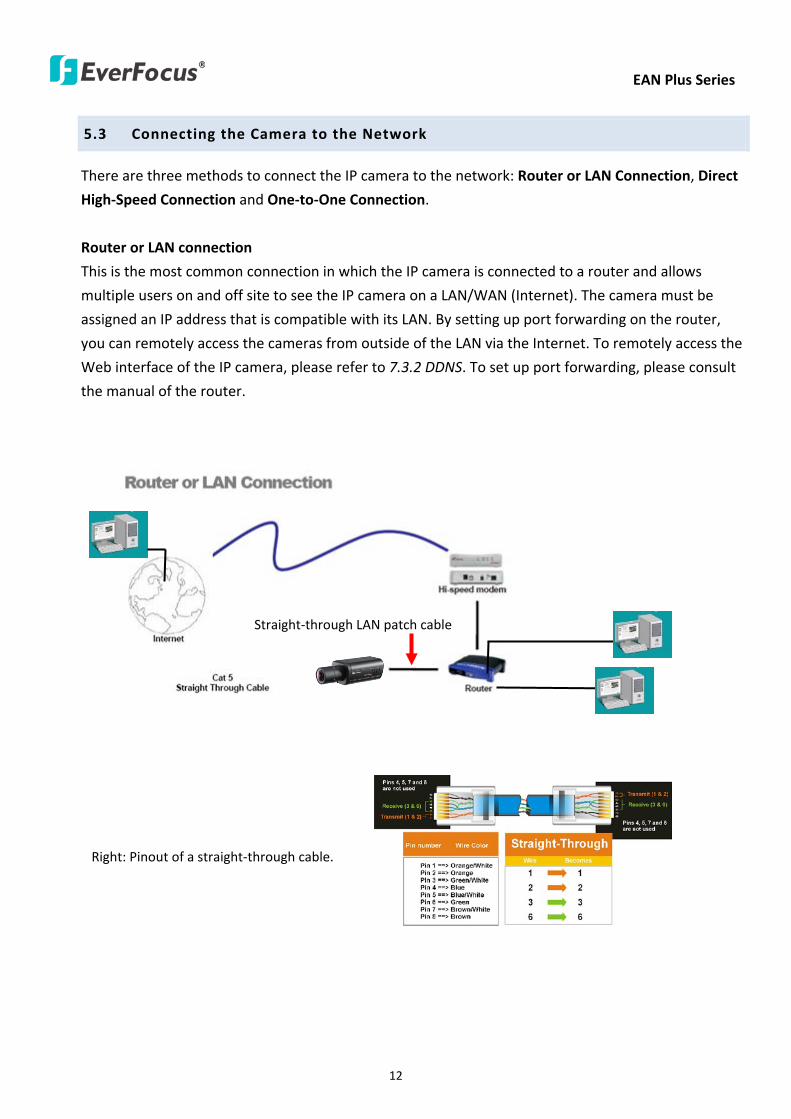
EAN Plus Series
12
53 Connecting the Camera to the Network
There are three methods to connect the IP camera to the network Router or LAN Connection Direct
High-Speed Connection and One-to-One Connection
Router or LAN connection
This is the most common connection in which the IP camera is connected to a router and allows
multiple users on and off site to see the IP camera on a LANWAN (Internet) The camera must be
assigned an IP address that is compatible with its LAN By setting up port forwarding on the router
you can remotely access the cameras from outside of the LAN via the Internet To remotely access the
Web interface of the IP camera please refer to 732 DDNS To set up port forwarding please consult
the manual of the router
Straight-through LAN patch cable
Right Pinout of a straight-through cable
EAN Plus Series
13
Direct High-Speed Connection
In a Direct High-Speed Connection the camera connects directly to a modem without the need for a
router You need to set the static or dynamic WAN IP address assigned by your ISP (Internet Service
Provider) in the camerarsquos configuration web pages To access the camera just type ldquohttpxxxrdquo
where xxx is the IP address given by your ISP If you have a dynamic IP address this connection may
require that you use DDNS for a reliable connection Please refer to 732 DDNS
One-to-One Connection (Directly from PC to IP Camera)
You can connect directly without using a switch router or modem However only the PC connected
to the camera will be able to view the IP camera You will also have to manually assign a compatible IP
address to both the computer and the IP camera Unless the PC has another network connection the
IP camera will be the only network device visible to the PC See the diagram below
Pinout of straight patch cable
Right Pinout of a crossed-over cable
EAN Plus Series
14
54 Live View Window
1 Press the button to display the Live View window Double-click on the
image to show a full-screen display double-click again or press ESC to return to the normal display
If you experience video feed lag time (if connected via Internet) you can reduce the resolution or
limit the number of streams See 741 Multi Streaming
2 Press the button to play the recorded data directly from the on-camera Micro
SD SDHC card (for this function to become active you have to insert a Micro SD SDHC card in the
Micro SD SDHC card slot on the rear panel of the camera See 783 SD Card
3 Press the button to enter the Settings page On the Settings page there are
8 submenu sections [System Info] [User Config] [Network] [Video] [Audio] [User] [Event] and
[System] Click on the section buttons to open their configuration fields See the Settings section
below for more information
EAN Plus Series
15
4 Press the button to exit the system and close this browser page
5 Video Stream
Select the Video Stream (Stream 1 Stream 2 or Stream 3) that will be displayed in the video box on
the right Stream 2 and Stream 3 are only selectable if you have enabled the stream The default
setting is Stream 1 only See 741 Multi Streaming
6 View Size
Use this to select the appropriate view size and shape of the video box on the right A smaller size
might increase transmission speed and video quality
7 Digital Zoom
Click the Zoom In Zoom Out buttons or roll the mouse wheel to zoom in out the camera live view
up to 10x Clicking on a magnified image will re-center the image around that point
8 Record
The Record button is used to record the current video stream Click the Record button to start
stop recording This icon is only for one-minute video recording To record long-period recordings
please set a recording schedule (See 775 Schedule) The location on your computer where the
image files will be saved to and file size can be specified in the submenu (see 72 User Config)
9 Snapshot
Click the Snapshot button to save a snapshot of the video image currently being displayed The
location on your computer where the snapshot data will be saved can be specified in ldquoSettings gt
User Config gt RecordingSnapshotrdquo (see 72 User Config)
10 Play Audio Transmit Audio
Click the ldquoPlay Audiordquo (speaker) and ldquoTransmit Audiordquo (microphone) buttons to switch the sound
onoff for the speaker and microphone respectively (if such external devices have been connected
to the camera directly or via the network)
EAN Plus Series
16
11 One Push
This function is only available for EAN3120 Plus 3220 Plus The One Push button can be displayed
on the live view window by enabling the Show One Push Buttons function on the User Config lt Live
View Config Setting page (see 721 Live View Config) To enable the button (turned from faded to
clear) on the Video lt Advanced Setting page select One Push from the White Balance Settings
Mode drop-down list and click the Apply button Once this is done pressing the One Push button
on the Live View Window will instruct the camera to adjust the white balance settings and these
settings will be active until the button is pushed again This is like a ldquosemi-automaticrdquo way to adjust
white balance to suit the user if the Auto or Manual mode does not give the result the user wants
12 Manual Control
ndash Trigger Event
Press the ldquoTrigger Eventrdquo button to trigger an event directly from the Live page If you have
configured an event (in the Event submenu) that will trigger a reaction (like a recording) when a
Manual Trigger event occurs clicking this button will trigger that reaction You can select what that
reaction will be You can for instance set the camera to record the audiovideo feed to the Micro
SD card on board the camera You can then click on the Playback button to open the Playback page
and search for and play all such recordings that had been stored on the card Such event actions
will be effective once they have been configured in the ldquoEventrdquo menu (see 77 Event)
ndash Reset Alarm
Press the ldquoReset Alarmrdquo button to reset the alarm output remotely
13 Status Display (info lines that can be placed above video box or at bottom of page)
This shows the name of the camera that is currently active or being configured current datetime
and current frame rate You can activate these info displays in the Settings gt User Config page (see
72 User Config)
14 Event Signal Icons (above video screen)
When an alarm or motion event is triggered a signal icon will appear at the top right of the Live
View window to alert the user
Alarm event icon When an alarm is triggered this icon appears
Motion detection icons The colors of these motion event icons correspond to the colors of the motion trigger areas you have configured in the Motion Detection submenu (see 772
Motion Detection)
Recording icon When the camera is recording to a PC-based folder this icon appears
EAN Plus Series
17
6 Playback
You can remotely play back the recordings stored in the on-camera micro SD card on the Web interface
or play back the recordings stored in the computer using the ARV Viewer included in the software CD
Playback is designed as a quick way to check recent recordings that were triggered by Events that were
configured to ldquoRecord to SD Cardrdquo in the Settings gt Event gt Event Settings page (see 771 Event
Settings)
Note Note that the Playback page is only accessible once the on-camera SD card is inserted and
active
61 Remote Playback Using Playback Page
On the Live View Window click the Playback button to open the Playback page
EAN Plus Series
18
Search by File Click the Search button to search for all recording files on the on-camera SD card
Search results will be displayed in the Filename area
Search by Time Click the calendar icon and select the date and time from which you want to search
until the present moment Click search to get your search results which will be displayed in the
Filename area
Search by event Click the type of Event recordings you want to search for (Alarm Motion Manual
Trigger) and then click the calendar icons to select the Start Time datetime and the End Time
datetime of your search Click Search to get your search results which will be displayed in the
Filename area
Multiple Files Check this box if you want the video player to play all the files in the selected folder
The files will be displayed in the Filename area
Loop Again Check this box if you want the video player to play the selected file over and over again
Play Once you have opened the filersquos folder and have clicked on the file to highlight it its details will
be displayed in the File Information area You can now click Play to play that specific file
Pause Click this button to pause the playback
Stop Click this button to stop the playback
【Recording List】
Filename This area will display a list of search results (recording files and folders) Folders (named
with the recorded date) will be displayed first Click on the folder and click on each subfolder until the
recording files (arv) in that folder is listed
File Information Click a file on the Filename list the selected file information will be listed
Copy Click this button to copy the selected file to the computer-based folder of your choice A
browsing box will open so that you can search for the folder of your choice You can use the ARV
Viewer to play back the recordings recorded in your computer For details on ARV Viewer see 63
Playing Back Using ARV Viewer
Lock Click this button to lock the selected file This will protect that file from being overwritten during
any overwrite procedure The file will thus be saved on the micro SD card indefinitely However the
file will still be deleted if the micro SD card is ever formatted
Remove Click this button to delete the selected file
EAN Plus Series
19
62 Setting up the Playback Function
Note that the Playback function will not be active until the user has inserted a micro SD card in the
camerarsquos micro SD card slot The card may also have to be formatted in the Settings submenu
Micro SD Card Slot
621 Preparing the Micro SD Card
Once you insert a functional micro SD card into the slot the Playback button on the Live page should
become active within seconds (see section 622 below ndash the grey letters should turn white) IF NOT
do the following
1 From the Live page click Settings gt System gt SD Card If no card has been inserted yet the
Remove button should be faded indicating that no card is being detected (If a card is
inserted and the Remove button is still faded pull the card out and re-insert it)
2 Slide the card into the slot until it clicks into position
3 The Remove button should become active within a few seconds indicating the card is active
4 If the Remove button stays faded click the Format button to format the card NOTE All data
on the disk will be deleted if the Format button is clicked
622 Testing the Playback Function
1 Once the SD card is detected by the system the button (inactive)
will turn to (active)
2 To test the Playback function (this is not required) set up a ldquoManual Triggerrdquo Recording
Event by clicking Settings gt Event gt Event Settings
3 Click the ldquoAddrdquo button on the middle right side of the page to open an ldquoAdd Eventrdquo box
4 Give the event a name like ldquoTest 1rdquo
EAN Plus Series
20
5 In the ldquoEvent Triggered byrdquo field click on Manual Trigger
6 Below this check ldquoEnable This Eventrdquo ldquoEnable Post-trigger Bufferrdquo and ldquoRecord to SD Cardrdquo
7 To save your settings click OK or close the box by clicking on the red x icon at top right of the
box (in which case you will be asked if you want to save the data to which you should reply OK)
The box will close and the new event will be listed in the list area of the Event Settings page
8 Look at the ldquoPost-trigger Bufferrdquo at the bottom to make sure the buffer time is set to 10 seconds
9 Click ldquoApplyrdquo to make sure all settings are saved
10 Click the Live button to go back to the Live page
11 Get ready to click the Trigger Event button at the bottom of the page Before you do see if you
can find something in the view screen that will give you a visual time marker For instance if you
can get your hand in front of the camerarsquos lens get ready to count down on your fingers
12 Click the Trigger Event button and slowly count down on your fingers in front of the lens (if you
are able to do so ndash if not try to find visual cues on the view screen that will help you to mark the
moment you pushed the trigger) The recording period will be as long as the buffer time you
selected ndash the default period is 10 seconds
13 Click the Playback button to open the Playback page
14 There are different ways to search for recording files on the camerarsquos Micro SD card (ie the
Playback memory) For a recent recording like your test event simply click the ldquoSearchrdquo button
under the ldquoSearch by Filerdquo header
15 If the SD card is active and formatted correctly the recording folderrsquos name (the recording dayrsquos
date) will appear in the Filename box at the bottom Click on this folder to open it If there are
sub-folders click on the bottom one (the most recent would be at the bottom) until you can click
on a file that cannot open to another sub-level and shows data in the File Information box to the
right This would be the file of the most recent recording event
16 To play this file click the Play button below the video box The test footage you have recorded
should start playing Play time should be 10 seconds if you left the Post-trigger Buffer as 10
seconds
EAN Plus Series
21
63 Playing Back Using ARV Viewer
You can play back the recordings stored in the computer using the ARV Viewer included in the
software CD To store the recordings in the computer please refer to Recording List gt Copy in 61
Remote Playback using Playback Page
4 5 6 7 8 9 10
321
No Item Name Descriptions
1 Snapshot Click to take and save a snapshot
2 Load File Click to load the recordings for playing back
3 Convert ARV to AVI Convert the recording from ARV format to AVI format
4 Playback Time Display the playback time
5 Total Time of Recording Display the total time of the recording
6 Stop Click to stop playing the recording
7 Step Reverse Click to display the previous frame
8 Play Click to play back the recording
9 Pause Click to pause the recording
10 Step Forward Click to display the next frame
EAN Plus Series
22
7 Settings
Click the Settings button on the Live View Window to enter the settings submenu There are nine buttons
on the left-side of the submenu Live System Info User Config Network Video Audio User Event and
System Click the Live button can go back to the Live View Window
71 System Info
The System Information and System Log can be checked on this page Click the top tab of the one you
want to see
711 Information
Click the Information tab the following dialog box appears These values cannot be changed on this
page and are for reference only
EAN Plus Series
23
712 Log
Click the Log tab the following dialog box appears The sequence number date time and event
messages of the log event will be displayed in the System Log field The log will display the last 256
log events Click the Export button to export the system log event list into a ldquotxtrdquo file and select the
location where the exported log file will be saved to
EAN Plus Series
24
72 User Config
Each user can set a different configuration for hisher Live page here These settings will be applied to
the logged-in userrsquos Live page every time heshe logs in
721 Live View Config
【VideoAudio Connection Protocol Setting】You can transmit the data stream from the IP cameras
using the RTSP (Real Time Streaming Protocol) on the network The RTSP is a protocol that allows
you to access video streams by using the compatible media players Click Apply to apply the
changes or Reset to reset without saving the changes RTP over UDP The RTSP protocol uses UDP for camera data stream transmission
RTP over TCP The RTSP protocol uses TCP for camera data stream transmission
RTP over HTTP The RTSP protocol uses HTTP for camera data stream transmission
Nevio CGI This is EverFocusrsquo protocol designed for EverFocusrsquo IP devices Select this
protocol for camera data stream transmission
【Text Settings】Check the box of each option (Machine name DateTime Frame Rate) to display
this info on the Live View Page
Foreground Color Slide the Red Green and Blue bars to create your preferred text color for the
info text line
Position Select the position where the text will be displayed Choose from Upper Left Lower
Right Lower Left
Click Apply to apply the changes or Reset to reset without saving the changes
EAN Plus Series
25
【DateTime Format Used in Text】Click the dropdown menu to select datetime format from the
listed options Click on the desired hour format Click Apply to apply the setting changes or Reset to
reset without saving the change
【Live View Layout Settings】 Check the ldquoShow One Push Buttonsrdquo boxes if you want to show these
buttons on the Live View Page Uncheck these boxes to hide these buttons This function is only
available for EAN3120 Plus 3220 Plus
722 Recording Snapshot
This configures where your Record Button and Snapshot Button ( ) files will be saved if
you click one of these buttons Selectable folders will be on the computer only not on the
on-camera SD card
【Recording Snapshot Export Settings】
Enable Event Recording to PC Checking this box will let the system save RecordSnapshot Button
recordings to the folder configured below on the userrsquos PC
Export Folder Select the Export folder for the action above by clicking on the browse (hellip) button
and then select the desired folder
File size The user can limit the size of each recorded file here (in minutes) When a single
recording file exceeds the time you set the system will create a new file to save that data to
Overwrite Select ldquoONrdquo for overwriting recordingsnapshot file when the disk storage capacity is
full The user can set the storage capacity limitation in the in-sentence field in the gray box below
the Overwrite setting ldquoIf the remaining hard disk capacity is less than ____ MB (50~2000) system
will stop recording or start overwriting ldquo
Click Apply to apply the setting changes or Reset to reset without saving the changes
EAN Plus Series
26
723 Language
Select the language to be displayed on the Web interface of the IP camera The default language is
English
To add a new language not listed in the current Language list click the Browse button to locate
the new language file (evb) on your computer and then click the Upload button Updated
language files might be available on the manufacturerrsquos website Contact your vendor if required
Click Apply to apply any changes or Reset to reset without saving the changes
Note Uploading a new language file will cause the system to reboot automatically Please create
a new network connection to the IP camera when the reboot is complete
EAN Plus Series
27
73 Network
This page covers network-related settings including Network DDNS SMTPFTP HTTPS SNMP and
Network Alarm
731 Network
The following information is required to configure the network settings Contact your network
administrator or your internet service provider to get the info
【IP Settings】
IP Type Refer to the network administrator for these settings of the server Default DHCP
DHCP This setting lets the system use an automatically assigned (dynamic) IP address This
address can change under certain circumstances For instance when the camerarsquos network
switchhub has to be rebooted Do not assign to the DHCP server the same IP addresses used
for the other network cameras and PCs with unique IP addresses
Static IP The user can manually set the Static IP address This type of address is stable and
cannot change but the user has to make sure there are no address conflicts with other
network-connected devices
PPPoE This is a DSL-connection application The ISP will ask the user to input a username and
password Contact your ISP for these details
EAN Plus Series
28
Note If PPPoE is selected as the IP type the supplied IP Utility program will not be able to
detect the device
IP address When DHCP is not used the user needs to manually enter the IP address of the
camera Do not enter an IP address that is already used for your computer or other network
cameras
Subnet Mask This field is used to set the netmask for your network so that the IP camera will be
recognized within the network Example 2552552550 When DHCP is selected the DHCP server
will assign this value automatically
Gateway This field is used to set the gateway for your network so that the IP camera will be
recognized within the network When DHCP is selected the DHCP server will assign this value
automatically
Primary DNS Enter the IP address of the DNS server if this is provided by an ISP
Secondary DNS If your ISP provided you with a secondary DNS address please enter it here
Username Enter the accountrsquos username (used only for PPPoE)
Password Used only for PPPoE
IPv6 Enter the IPv6 details in this area if this applies to your system
Click Apply to apply the setting changes or Reset to reset without saving the change
【Port Settings】Enter the HTTP HTTPS and RTSP port numbers and click Apply to save
【Multicast Settings】Enable if required fill in the setting options and click Apply to save
EAN Plus Series
29
732 DDNS
DDNS (Dynamic Domain Name System) is a service used to map a domain name to the dynamic IP
address of a network device You can set up the DDNS service for remote access to the IP camera
DDNS assigns a domain name (URL) to the IP camera so that the user does not need to go through
the trouble of checking if the IP address assigned by DHCP Server has changed Once the IP is
changed the IP camera will automatically update the information to the DDNS to ensure it is always
available for remote access
Before enabling the following DDNS function user should have applied for a host name from the
DDS service providerrsquos website We support these four DDNS server providers
wwweverfocusddnscom wwwsitelutionscom wwwdyndnscom and wwwno-ipcom
Note We highly recommend that you use xxxxeverfocusddnscom for the simplicity of setting up
your IP cameras
【DDNS Settings】
Enable Check this box to enable the DDNS function
Service ISP You can either apply for a host name from EverFocus or other DDNS server providers
If you choose the EverFocus DDNS server you can obtain a free host name from EverFocus by
following the steps below
bull From EverFocus To obtain a free host name from EverFocus type a desired host name in the
textbox click the Register Update button and then click the Apply button
bull From other DDNS server providers To obtain a domain name from one of the three DDNS
server providers you have to register your name with the provider first and then select the
provider and fill in the required information Please refer to the specific DDNS companyrsquos
website for further information
Record ID Type the record ID if provided by the DDNS server provider
EAN Plus Series
30
FQDN Type the fully qualified domain name applied from the DDNS server provider For
example xxxxdyndnscom
Username Password Type the login account of your DDNS server provider
Click Apply to apply the setting changes or Reset to reset without saving the changes
Note
1 In order to support the full functionality of the camera you must open the port numbers (80
554 443) on the router for remote access to the IP camera This function is available on most
routers in the market and is often known as ldquoPort Forwardingrdquo To set up Port Forwarding
please consult the manual of the router
2 In certain router models it is possible that you will not be able to access the camera using
DDNS while inside the routerrsquos network Please try using a PC located outside of your routerrsquos
network
Default Ports on All EverFocus IP Cameras
HTTP 80
RTSP 554
HTTPS 443
EAN Plus Series
31
733 SMTP FTP
【Set SMTP Server (email)】This area is for configuring the mail server that is used to send e-mail
notifications from the camera to predefined addresses via SMTP Note that to enable e-mail
notification function you have to check the Send Mail Notification item on the Event dialog box
(see 771 Event Settings)
SMTP Server Enter the IP address or the host name of the SMTP server used to send e-mails
SMTP Port Enter the port number for SMTP The default is 25
Authentication Check this box if the SMTP server requires authentication (userpassword)
User name Input the userrsquos login ID if the SMTP server requires authentication
Password Input the userrsquos login password if the SMTP server requires authentication
EAN Plus Series
32
Receiver Address Input the e-mail addresses for receiving an e-mail message when an EVENT is
enabled and triggered Please use ldquordquo to separate multiple addresses
Sender Address Input the senderrsquos e-mail address so that the receiver can recognize the sender
when an Event message is received
Attach Image Check this box if you want to attach an image when an alarm is triggered or an IP
camera detects events
Send Test Email Click the Test button to send a testing email to the assigned address
Click Apply to apply the setting changes or Reset to reset without saving the changes
【Set FTP Server】The settings relating to the FTP server used to transmit the alarm images can be
configured here Note that to enable uploading images to the FTP server function you have to
check the Upload to FTP item on the Event dialog box (see 771 Event Settings)
FTP Server Enter the IP address or the host name of the FTP server
FTP Port Enter the port number for the FTP server Default is 21
Recording Path Assign the recording path
User Name Set FTP Userrsquos name
Password Set FTP password
PASV mode Check to enable Passive mode Passive mode is normally enabled If a connection
cannot be established uncheck PASV Moderdquo
Test FTP Server Click the Test button to send a testing file to the assigned FTP server
Click Apply to apply the setting changes or Reset to reset without saving the changes
EAN Plus Series
33
734 HTTPS
Hypertext Transfer Protocol Secure (HTTPS) is a combination of the Hypertext Transfer Protocol
and the SSLTLS protocol and provides encrypted communication and secure identification of a
network web server
Before using the HTTPS function for communication with the IP camera a Certificate must be
created first There are two ways to create and install a certificate Create Self-Signed Certificate
and Create Certificate Request
Create Self-Signed Certificate
Please note that even though self-signed certificates are free and offer some protection true
security is only implemented after the installation of a signed certificate issued by a certificate
authority
1 Click the Create Self-Signed Certificate button the following dialog appears
EAN Plus Series
34
2 Type the required Certificate information and then click the Apply button The subject line will
be displayed in the Installed Certificate Information field
3 Click the Property button a pop-up window appears to display the details of the certificate
4 To optionally create and install other certificates remove the existing one by clicking the
Remove button to erase the certificate
5 On the Web page change the address from ldquohttprdquo to https in the address bar and press
Enter on the keyboard Some Security Alert dialogs will pop up Click OK or Yes to enable HTTPS
Create Certificate Request
You can apply for an official certificate from an issuing Certificate Authority
1 Click the Create Certificate Request button the following dialog appears
EAN Plus Series
35
2 Type the required Certificate information and then click the Apply button The subject line will
be displayed in the Created Request field
3 Click the Property button a pop-up window appears to display the details of the certificate
4 To optionally create and install other certificates or request remove the existing one by clicking
the Remove button to erase the certificate or request
5 Copy the contents of the Certificate request (in PEM format) and paste it to the certificate
request field on the Web page of the 3rd-party certification authority such as Symantec VeriSign
Wait for the certificate authority to issue an SSLTLS certificate and then download the issued
certificate on your computer
6 In the Install Signed Certificate field click the Browse button to search for the issued certificate
and then click the Upload button to import the certificate Once the certificate has been
uploaded this field will show the subject line of the certificate
EAN Plus Series
36
735 SNMP
The default values for SNMP v1v2v2c and SNMP v3 are already filled in Click either of the
Enable buttons to enable either of the two Make your changes as desired Click on the Trap
Address field to enter the digits if required
736 Network Alarm
This function works with EverFocusrsquos CMS software eg the PowerCon or the Power Video Plus For
the setting details please refer to the CMS network alarm protocol
EAN Plus Series
37
74 Video
The settings relating to video such as streaming camera OSD can be configured on this page The
Video page has five tabs Multi-streaming Camera Advanced ROI and Privacy Mask
741 Multi Streaming
【Stream Settings】 This IP camera can output three video streams simultaneously For each of these
streams the user can set the compression format resolution bit rate and frame rate individually
Stream 1 is always enabled for live view To enable Stream 2 andor Stream 3 check the ldquoEnablerdquo
box the header of each stream
Note If you connect to the camera via the Internet and experience a delay (lag time) in the video
feed try to reduce the number of streams and the quality and resolution of the streams ndash but
keep the frame rate at its maximum
EAN Plus Series
38
Format Select the encoding format ndash H264 or MJPEG
Resolution Select the most suitable resolution for your needs
Frame Rate Select from 1 to 30 fps
Bit Rate If required select whether you want the stream to stream a Constant Bit Rate or a
Variable Bit Rate and set the values of whichever option you choose
Click Apply to apply the setting changes or Reset to reset without saving the changes
【Video Recording Settings】Select the stream you want to configure and then select whether you
want the recording files of that stream to be saved in AVI or ARV format Click Apply to apply the
setting changes or Reset to reset without saving the changes
【Time Stamp Settings】 You can select the DateTime format position and add the setting to the
streaming
Click Apply to apply the changes or Reset to reset without saving the changes
EAN Plus Series
39
742 Camera
【Image Settings】Set the Brightness Saturation Contrast or Sharpness of the image Click Apply to
apply the changes or Reset to reset without saving the changes
【Camera Settings】
Mirror Switch Mirror ON to rotate the image horizontally around a vertical axis
Flip Switch Flip ON to rotate the image vertically around a horizontal axis
AE There are two options
ALC Selecting Automatic Light Control allows the camera circuitry to either take bright spots
more into consideration (peak) bringing out detail in bright areas or less into consideration
(average) bringing out detail in shadows
AES Selecting Auto Electronic Shutter disables the Shutter setting below this setting In this
mode the camera measures the light level and decides whether it needs more or less light and
then automatically adjusts the shutter speed accordingly
BLC Back Light Compensation (BLC) is used to make the subject appear clearer when it is set
against a bright background
OFF Select to switch Back Light Compensation functions off
(ON)BLC The BLC can increase the exposure of a dark area surrounded by a brighter area HLC
can decrease the exposure of bright areas surrounded by darker areas This enables the
camera to better display information that would otherwise have been ldquowhited outrdquo like a
license plate between two bright headlights on a dark road
(ON)HLC The Highlight-Suppression BLC is used to reduce the brightness of light sources in a
specific area It is activated only in a low illumination environment to minimize the effects of
glare from bright lights such as spotlights street lights or headlights in the field of view
EAN Plus Series
40
WDR The Wide Dynamic Range (WDR) function provides clearer images when both of the very
bright and dark areas simultaneously appear on the camera view There are four value options
OFF Low Middle and High Note that when WDR is ON some parts of the image may appear
solarized This is normal for WDR and is not a camera malfunction This function is only available
for EAN3120 Plus 3220 Plus
DN Mode
Auto Select to let the camera automatically switch to Night mode (black and white) when the
light levels fall to a specified level and back to Day mode (color) when the light levels rise to a
specified level
Day Select to keep the camera in Day mode (color) even in nighttime
Night Select to keep the camera in Night mode (black and white) even in daytime
EAN Plus Series
41
743 Advanced
EAN Plus Series
42
【Camera Settings】
Lens (IRIS Control) Select DC or Manual for IRIS control This function is only available for EAN3220
Plus
Exposure Settings (AE) This setting is used to adapt to the amount or type of light used by the
camera Note the settings vary among models
Mode This function is not available for EAN3220 Plus
Automatic Light Control (ALC) This option is only available for EAN3120 Plus 3300 Plus The
ALC allows the camera circuitry to either take bright spots more into consideration (peak)
bringing out detail in bright areas or less into consideration (average) bringing out detail in
shadows
Auto Electronic Shutter (AES) This option is only available for EAN3120 Plus 3300 Plus In
this mode the camera measures the light level and decides whether it needs more or less light
and then automatically adjusts the shutter speed accordingly
Manual This option is only available for EAN3300 Plus Select this option to manually set up
the Shutter (Manual) and AGC (Manual) values
Iris Specify the size of the Iris opening here
Shutter If enabled this setting lets you set the shutter speed yourself
Shutter Limit Use this setting to set the maximum shutter speed for the camera This function is
only available for EAN3120 Plus
AGC Set the Auto Gain Control limit here The lower the AGC level the lower the video signal and
the noise However the image will be darker under low-light condition with IR-off if you set up the
Iris to the maximum level
Slow Shutter This option can be switched on when AES Mode is selected in the Exposure Settings
(AE) field This function is only available for EAN3220 Plus 3300 Plus
Flickerless If the Mode field in the Exposure Settings (AE) area has been set to AES then this option
becomes available Choose between OFF 50HZ 60HZ 50HZ (High Luminance) or 60HZ (High
Luminance) This function is only available for EAN3300 Plus
EV Setting Set up the Exposure Value Note the brightness of the screen changes when you change
the EV value This function is only available for EAN3300 Plus
AE Response Set up Auto Exposure Response time This function is only available for EAN3300 Plus
AE Weighting Area Select an AE Weighting area Each setup AE Weighting Area is configured with
the appropriate brightness level on the center and the surrounding areas This function is only
available for EAN3300 Plus
Brightness Set the image brightness here
AE Reference Set the Auto Exposure value here This function is only available for EAN3120 Plus
EAN Plus Series
43
Black Level Set the Black level here This function is only available for EAN3300 Plus
WDR The Wide Dynamic Range (WDR) function provides clearer images when both of the very
bright and dark areas simultaneously appear on the camera view There are four value options OFF
Low Middle and High Note that when WDR is ON some parts of the image may appear solarized
This is normal for WDR and is not a camera malfunction This function is only available for EAN3120
Plus 3220 Plus
Visibility Enhancement (OFFLowMiddleHigh) Images in foggy or rain environments or in
environments with a very strong luminous intensity have a dynamic range that is significantly lower
than ordinary images The user can use this Visibility Enhancement setting to ldquoDEFOGrdquo the image if
such ldquoFOGGINGrdquo is an issue This function is only available for EAN3220 Plus
BLC Settings Back Light Compensation (BLC) is used to make the subject appear clearer when it is
set against a bright background
OFF Select to switch Back Light Compensation functions off
Back Light This option is only available for EAN3300 Plus The Back Light function is useful
when the background of the subject is very bright and the subject itself is dark Select Back
Light and adjust the slide bar to the left right for setting up the back light value The higher
the value the more the backlight compensation
Front Light This option is only available for EAN3300 Plus This function is useful when the
bright highlights such as flashlight or car headlights appear on the camera view Select Front
Light and adjust the slide bar to the left right for setting up the front light value The higher
the value the more the highlight compensation
ON (BLC) This option is only available when you select AES Mode in the Exposure Settings (AE)
field The option is only available for EAN3120 Plus 3220 Plus The BLC function is useful
when the background of the subject is very bright and the subject itself is dark Follow the
instructions below to configure the settings for each model
For EAN3120 Select ON (BLC) the button next to the Mode drop-down list will be
active (see image below) Click the button the green setup areas appear on the left
screen Click on the areas to enable disable the BLC function The selected areas (in green)
will be applied with the BLC function
EAN Plus Series
44
For EAN3220
You can configure one area to apply the BLC function Select ON (BLC) the setup buttons
appears (see image below) Select Low Middle High from the BLC Gain drop-down list To
set up a BLC area click the Edit Area button and then click on the blue color tab to turn your
mouse cursor into a blue pen Move the cursor to the position on the right screen where you
want the BLC rectangle to start and then click Move your cursor to the position (diagonally
opposing corner) where you want the BLC rectangle to end and then click The blue area will
be applied with the BLC function
ON (HLC) This option is only available when you select AES Mode in the Exposure Settings (AE)
field The option is only available for EAN3120 Plus 3220 Plus This function is useful when
the bright highlights such as flashlight or car headlights appear on the camera view Follow
the instructions below to configure the settings for each model
For EAN3120 Select ON (HLC) and then select a level from the drop-down list The higher the
level the more the highlight compensation
For EAN3220
HLC Level Select a level for the HLC setting The higher the level the more the highlight
compensation
HLC Mode Select All Day Night mode to apply the HLC function
HLC Black Mask Select On Off to apply the black mask on the selected areas The
over-exposure portions within the selected areas will be applied with the black mask
Color Tabs You can set up four HLC areas with different colors To set up a HLC area click the
Edit Area button and then click on the color tab to turn your mouse cursor into a pen of that
color Move the cursor to the position on the right screen where you want the HLC rectangle
to start and then click Move your cursor to the position (diagonally opposing corner) where
you want the HLC rectangle to end and then click Select ON from the color tab drop-down list
The rectangular area with the selected color will be applied with the HLC function
EAN Plus Series
45
Back Light This option is only available for EAN3300 Plus The Back Light function is useful
when the background of the subject is very bright and the subject itself is dark Select Back
Light and adjust the slide bar to the left right for setting up the back light value The higher
the value the more the backlight compensation
Front Light This option is only available for EAN3300 Plus This function is useful when the
bright highlights such as flashlight or car headlights appear on the camera view Select Front
Light and adjust the slide bar to the left right for setting up the front light value The higher
the value the more the highlight compensation
Noise Reduction Settings This limits the amount of digital ldquovideo noiserdquo that is usually found in any
video stream and helps to reduce file size The higher the level the more the reduction
For EAN3120 Plus 3300 Plus
Select ON OFF to enable disable the Noise Reduction function Or select Auto to let the camera
automatically enable disable the Noise Reduction function Slide the Level bar to set up the level
The higher the level the more the reduction
For EAN3220 Plus
2D DNR Select ON to enable the 2D DNR function
3D DNR Select ON to enable the 3D DNR function You can further set up the following settings
3D Start AGC Set up the AGC level to automatically start the 3D NR function
3D End AGC Set up the AGC level to automatically stop the 3D NR function
3D Level Set up the 3D DNR level
Smart NR Select ON to enable the Smart NR function The 3D NR function will be
automatically turned on when a motion event occurs
EAN Plus Series
46
White Balance Settings Select the mode that delivers the best quality image for the camerarsquos light
environment There are five options Auto Manual Indoor Outdoor One Push
Auto Select to let the camera automatically adjust the White Balance In the Auto mode the
camera computes the white balance value output using color information from the entire
screen It outputs the proper value using the color temperature radiating from a black subject
based on a range of value from 3000 to 7500K
Manual Select to adjust the Red and Blue values yourself in the fields below this field
Indoor Select to use the default settings for indoor environments In the Indoor mode the
camera uses 3200K as the base value
Outdoor Select to use the default settings for outdoor environment In the Outdoor mode it
uses 5800K as the base value
One Push Select to enable the Push button next to the Mode drop-down field This will allow you to force the camera to readjust the white balance every time you push the Push
button The lens will hold the same focal position until the next trigger command is received
This function helps to prevent incorrect focusing in dark environments This function is only
available for EAN3120 Plus 3220 Plus
Manual Temperature Select to use the optimized Red and Blue settings You can also
optionally adjust the Manual Level below this field for setting up the color temperature The
higher the value the more the color temperature This function is only available for EAN3300
Plus
DayNight Settings
Auto Select to let the camera automatically switch to Night mode (black and white) when the
light levels fall to a specified level and back to Day mode (color) when the light levels rise to a
specified level
Day Select to keep the camera in Day mode (color) even in nighttime
Night Select to keep the camera in Night mode (black and white) even in daytime
IR Smart Settings Select ON and set up the level to enhance the image quality when the images are
over exposure This function is useful when the camera is in the Night mode This function is only
available for EAN3220 Plus
Saturation Set the saturation value This function is not available for EAN3220 Plus
Monitor Type Select a gamma value from Set 1 Set 2 or Set 3 This function is only available for
EAN3120 Plus
Negative Switch this setting ON to view a color negative version of the video image This is useful
at night or when viewing temperature-sensitive images
EAN Plus Series
47
Sharpness Settings Select the sharpness level of the image A low sharpness level will deliver a
softer less detailed image A high level will deliver a sharp highly detailed image Switch Resolution
Enhancement ON to enable the resolution enhancement function
Contrast Select the contrast level of the image
Suppress Function This function is only available for EAN3300 Plus
Aperture Compensation Suppression (OFFLowMiddleHigh) This setting can be activated to
suppress luminance noise when the AGC level increases
Chroma Suppression (OFFLowMiddleHigh) This setting can be activated to suppress
chrominance noise when the AGC level increases
Ygamma (gamma 22standardcontrast enhancehigh light range mode LHigh light range mode
H) Select the Ygamma value for the video quality of the monitor This function is only available for
EAN3300 Plus
Monitor Settings The user can use this field to optimize video quality for his or her specific type of
monitor ndash LCD or CRT This function is only available for EAN3220 Plus
Color Space Standard The options are YUV601 for SD and YUV709 for HD These define the color
space standard required to convert an RGB picture to a YUV picture Generally YUV601 is used for
Standard Definition (720P) devices and the YUV709 is used for High Definition (1080P) devices
Click Apply to save all changes Click Reset to cancel all changes
EAN Plus Series
48
744 ROI (Region of Interest)
The Region of Interest (ROI) function allows users to set up multiple regions within an image with
better quality and less distortion than the rest of the image You can also use this function
together with the Digital Zoom function on the Live View Page to get a better image result Up to
eight ROIs can be configured in the ROI settings page
To set up an ROI region
1 Select an ROI number from the ROI No drop-down list
2 Click the Add button the mouse cursor will turn into a pen when you move it over the live
image on the left
3 Move the cursor to the position where you want the ROI rectangle to start and then click
Move the cursor to the position (diagonally opposing corner) where you want the ROI
rectangle to end and then click
4 Slide the Quality bar to set up the quality value
5 Click the Apply button to apply the settings or click the Reset button to reset without saving
the settings
EAN Plus Series
49
745 Privacy Mask
The Privacy Mask can block out sensitive areas from view covering the areas with colored or black
and white boxes in both live view and recorded clips This feature is useful when usersrsquo donrsquot want
the sensitive information visible Up to four Privacy Masks can be configured
【Privacy Mask Color Settings】The Modes vary among camera models
Mode Click Color to make the masks appear as colored rectangles on the screen Click BW to
make the masks appear as gray rectangles on the screen Click Mosaic to make the masks appear
as mosaic-effect rectangles on the screen
Level Select the color of the masks if you selected Color Mode Select the level of grayness of the
masks if you selected BW Mode Select the level of smallmiddlelarge if you selected Mosaic
Mode
Click Apply to apply the settings or click Reset to reset without saving the settings
Color Tabs Click on a color tab to turn your mouse cursor into a pen of that color
You can now create a block of that color on the video screen Move your cursor to the position
where you want your mask rectangle to start and then click Move your cursor to the position
(diagonally opposing corner) where you want your mask rectangle to end and then click The
rectangular area with the selected color will appear The live image will display the rectangular
area with the color you selected If you want to create another mask use one of the other three
colors Each color denotes a different mask area Only one block per color is allowed As the
number of colors suggests you can configure up to four blocks
EAN Plus Series
50
Select All Click to turn the whole screen into a mask area
Clear All Click to delete all configured mask blocks
Eraser Click to turn the mouse cursor into an eraser to delete any block you click on
Area Shows the color and number of the block
Enable Check this box to enable the related mask block
Click Apply to apply the settings or click Reset to reset without saving the settings
EAN Plus Series
51
75 Audio
The EAN Plus series IP camera can transmit audio to your computer if you have connected an external
microphone to its audio Input cable It can also receive audio input from you and transmit it via an
external speaker if you have connected such a speaker to its audio Output cable
Check the Enable Audio box to enable the camerarsquos audio function The camera will now act as a
digital bridge (via the IP network) between any connected audio input device and any connected
audio device
Adjust the Audio Input Volume if you have external audio input devices (microphones) connected to
the camera and if there are problems with the sound input being too low or high
Click Apply to save all settings or click Reset to cancel
EAN Plus Series
52
76 User
761 User Information
The system administrator can create up to ten user accounts on this page
To set up a user account
1 Highlight a user account and click the Modify button The following dialog box appears
2 Type the account name account description and password for the account Type the password
again in the Confirm field
3 Select an authority level for the user account from the Authority drop-down list
bull Supervisor Administrator The only difference between a supervisor and administrator is
that a supervisor can edit an administratorrsquos account and password but an administrator
cannot edit the supervisorrsquos account and password Multiple administrators can be
configured but there can be only one supervisor The supervisor and administrators all
have unrestricted access to the Settings submenus and can determine the registration of
all other users
EAN Plus Series
53
bull User A user can view the Live View page and view the system network video and audio
information A user can only adjust the User Config page settings The user does not have
access to the User Event and System pages
bull Guest The lowest level of access which only allows the user access to the Live View page
4 Select Active or Disable from the Status drop-down list to active or disable the user account
5 Click On in the SD Card Playback field to allow the user to access the SD card playback
function
6 Click OK
7 Click Apply to save all the settings
EAN Plus Series
54
762 IP Address Filter
Use this page to specify IP addresses that are not allowed to access this camera By default any IP
address can access the camera
Note The Allowed List addresses only become relevant when the Denied List contains a network
or range and the supervisor wants to allow one or more IP addresses within that excluded range
or network In such a scenario the user would enter the excluded range or network in the
Denied List and enter the exceptions in the Allowed List
To set up the IP Address Filter
1 Select Denied List Click the Add button the following dialog box appears
2 Select an IP type from the IP Type drop-down list
3 Select a network rule from the Rule drop-down list type the IP address and click OK
Single Type a single IP address in the IP Address field below
Network Type the IP address and subnet mask in the field below
Range Type a range for the IP addresses
4 If you have set up an IP range in Step 3 you can optionally set up the Allowed List to allow one
or more IP addresses within the setup IP range to access the IP camera
5 Click Apply
EAN Plus Series
55
77 Event
You can set up the Motion Detection event Tamper Detection event or the Alarm IO to automatically
notify the users when an event occurs or an alarm is triggered You can also set up a schedule to
automatically record the videos when an event occurs or an alarm is triggered
771 Event Settings
You can create a total of ten event or alarm settings page in the Event List
【Event List】
Click the Add button and the following Event Configuration Window appears
EAN Plus Series
56
Enter Event Name Type an event name
Event Triggered by Select an event or alarm type for the to-be-specified-below reactions
Alarm Input Select this if you want a reaction trigger coming from any external connected sensor
to activate a to-be-specified-below reactions via the camera system Make sure that a suitable
device is actually connected to the alarm input relay
Manual Trigger Select this option if you want to manually trigger the alarm by clicking the Trigger
Event button on the Live View Page
Motion Detection Select this option if you want motion in a specified part of the camerarsquos viewing
rectangle (the screen image) to trigger the to-be-specified-below reactions
Tampering Detection Select this option if you want the camerarsquos tampering detection sensor to
trigger the to-be-specified-below reactions
Schedule Recording Select this option if you want the Schedule Recording periods configured in
the recording schedule (the Settings gt Event gt Schedule page) to activate this event In this
scenario a preconfigured event reaction like a log entry will list the start and end times of each
period Actual recording will only be triggered if the event is preconfigured to do so
Enable This Event Select to activate the event
Enable Re-trigger Click to set a minimum time after the event is triggered before the event
can be triggered again
Enable Pre-trigger Buffer Click if you want the Event reaction (as selected in the ldquoNotification
Overrdquo field below) to be the activation of the video recording function and if you want the
recording to include the video feed from the time period (configurable on the previous ldquoEvent
Settingsrdquo page) just before the Event trigger occurred
Enable Post-trigger Buffer Click if you want the Event reaction (as selected in the Notification
Over field) to be the activation of the video recording function and if you want the recording
to include the video feed from a time period (configurable on the Event Settings page) just
after the Event trigger occurred
Motion Area Select a setup motion detection area from the drop down list Note this
function only becomes relevant after the Motion Detection areas have been set up (see 772
Motion Detection)
Notification Over Select the desired notification types form the following items
Log Click if you want the camera to list the eventrsquos details in its log if the event is triggered
Trigger Alarm Output Click if you want the camera to relay the event reaction to a device
attached to the alarm relay output wire and then set up the alarm output duration time
EAN Plus Series
57
Send Mail Notification Click if you want the camera to send an Event notification email to the
email address entered in the Set SMTP Server(email) field of the Network gt SMTPFTP page if
the Event occurs (see 733 SMTP FTP)
Upload to FTP Click if you want the camera to upload recorded footage to the FTP server
entered in the Set SMTP Server(email) field of the Network gt SMTPFTP page if the Event
occurs (see 733 SMTP FTP)
Record to SD Card Click if you want the camera to start recording its video feed (when the
event occurs) on an on-camera SD Card (if such a card has been inserted)
Note The recording will only be as long as the combined Pre- and Post-trigger Buffers so
make sure you enable at least one of these buffers especially the Post-trigger Buffer
Record to PC Check this box if you want the camera to start recording its video feed (when
the event occurs) on the same folder on the same PC as configured on the User Config gt
RecordingSnapshot page (if such a folder has been enabled and configured)
Note The recording will only be as long as the combined Pre- and Post-trigger Buffers (and
for as long as the event trigger is happening ndash eg a motion is detected) so make sure you
enable at least one of these buffers especially the Post-trigger Buffer
Network Alarm Check this box if you want the camera to send a network alarm signal (when
the event occurs) to the CMS servers configured on the Network gt Network Alarm page (see
736 Network Alarm)
Click OK to save all settings or click Cancel to cancel
【PrePost Trigger Settings】
Pre-trigger Buffer Select the duration for the buffer This will determine the amount of footage
(length of time) before the event trigger moment that will be included in an event-triggered video
recording if that buffer and video recording has been enabled in the Event Configuration Window
Post-trigger Buffer Select the duration for the buffer This will determine the amount of footage
(length of time) after the event trigger moment that will be included in an event-triggered video
recording if that buffer and video recording has been enabled in the Event Configuration Window
Click Apply to save all settings or click Reset to cancel
EAN Plus Series
58
772 Motion Detection
Use this page to configure up to four areas in which motion will be detected When a motion is
detected by the camera the motion detection icon will appear at the top right of the
Live page to alert the user This function can also be linked with correctly configured Events to
trigger Event reactions like the activation of video recording periods snapshots alarms etc
Color Tabs Click on a color tab to turn your mouse cursor into a pen of that color
You can now create a block of that color on the video screen Move your cursor to the position
where you want your detection rectangle to start and then click Move your cursor to the position
(diagonally opposing corner) where you want your detection rectangle to end and then click The
rectangular area with the selected color will appear This block will be an area inside which the
camera will detect motion If you want to create another detection area use one of the other three
palette colors Each color denotes a different detection area Only one block per color is allowed As
the number of colors suggests you can configure up to four blocks
Select All Click to turn the whole screen into a motion detection area
Clear All Click to delete all configured motion detection blocks
Eraser Click to turn your mouse cursor into an eraser to delete any block you click on
Area Shows the color and numberID of the block
Enable Check this box to enable the related motion detection block
Sensitivity Set the sensitivity of the motion detection sensor function
Click Apply to save all settings or click Reset to cancel
EAN Plus Series
59
773 Tamper Detection
Use this page to set the number of seconds that an alarm signal will be active if the device is
physically tampered (moved covered up or out of focus
774 Alarm IO
Use this page to set the type of trigger input and the type of output contact for the camerarsquos alarm
channel
EAN Plus Series
60
775 Schedule
Use this page to configure a schedule for periods during which the camera should deactivate all
user-activated Events (gray Deselect periods) or when the camera should deactivate all
user-activated Events except Schedule Recording (SR) events (blue Schedule Recording-only
periods) or when the camera should deactivate only SR events (red Event Recording-only periods)
or when it should enable all activated Events (yellow periods)
Event Recording Click this button to make every hour block you click on red A red block represents
an Event Recording-only block which represents an hour when the camera will deactivate all
preconfigured activated Schedule Recording events and keep all the other activated events active
Schedule Recording Click this button to make every hour block you click on blue A blue block
represents a Schedule Recording-only block which represents an hour when the camera will
deactivate all other preconfigured activated events and keep only the preconfigured activated
Schedule Recording events active
Event + Schedule Click this button to make every hour block you click on yellow A yellow block
represents an hour in which all activated events including Schedule Recording events will be
active
Deselect Click this button to make every hour block become grey A grey block represents an hour
in which all activated events including Schedule Recording events will be inactive
Click Apply to save all settings or click Reset to cancel
EAN Plus Series
61
78 System
You can set up the systemrsquos time and SD card settings and to do maintenance and reset actions like
reboots and upgrades
781 DateTime
【Machine Name Settings】If required enter a new name for the machine This name will be visible
in the Machine Name field of the IP Utility software which is included in the software CD
【Set Time Zone】Set the time zone of the camerarsquos location
【Set DateTime Manually】Set the datetime here if you wonrsquot be using an NTP server to update the
datetime (see below)
【Set DateTime Sync】Enter the Network Time Protocol server if applicable The camerarsquos time will
be automatically adjusted by synchronizing with the NTP server
Click Apply to save all settings or click Reset to cancel
EAN Plus Series
62
782 Daylight Saving
Click Enable Daylight Saving to enable this schedule and select the dates when the regionrsquos
daylight saving period begins and ends Click Apply to save all settings or click Reset to cancel
783 SD Card
Use this page to prepare the system for safely removing the SD Card from its slot
【Setup SD Card】
Notification Select the percentage of storage space that should be left on the card before the
camera notifies you of the impending storage shortage or overwrite
Event Recording Select if you want Event Recording only FTP Backup only or both
Overwrite Click ON if you want the card to start writing over recorded footage when its memory is
full Click OFF if you want the card to stop recording new footage when its memory is full
【SD Card Utility】
Capacity This shows you how much card memory has been used and how much memory capacity
remains on the card
Remove Click this button before removing the card from the system
Format Click this button to format the card All data saved on the SD card will be removed if the
card is formatted
EAN Plus Series
63
784 Maintenance
【Maintenance Server】
Reboot Click this button to reboot the unit without changing any of the settings Use this function if
the unit is not behaving as expected
Restore Click this button to restart and reset most of the current settings to their factory default
values The only settings that will not be changed to default are
bull IP settings
bull DDNS settings
Default The Default button should be used with caution Pressing this button will return all of the
cameras settings including the IP address to the factory default values The camera will then have
to be reconfigured
【SaveLoad Configuration Server】
Save To make a backup file of the machinersquos current configurations press Save to save all the
configurations to a config file This will enable the user to reload these configuration settings if the
settings are changed and there is unexpected behavior
Load To load a previously saved configuration press the Browse button to locate the saved config
file (see above) and then click the Load button The systemrsquos settings will be restored to the saved
configuration
EAN Plus Series
64
【SaveLoad Video Configuration Server】
Save To make a backup file of the machinersquos video configurations press Save to save the video
configurations to a config file This will enable the user to reload these configuration settings if the
settings are changed and there is unexpected behavior
Load To load a previously saved video configuration press the Browse button to locate the saved
config file (see above) and then click the Load button The systemrsquos settings will be restored to the
saved video configuration
【Upgrade Firmware】Click the Browse button to find a previously prepared firmware upgrade file
Click Upgrade to install the new firmware
Note
1 Do not disconnect power to the unit during the upgrade sequence The unit will reboot
automatically after the upgrade has completed (1-5 minutes)
2 During the upgrade process all event recording actions will be stopped Event recording
actions will resume after the camera is rebooted
3 If the ldquoFile Error Please re-loginrdquo warning message appears when upgrading the firmware
please try the following instructions
a Go to Internet Explorer gt Tools gt Internet Option gt Security gt Custom
b Find and enable the Include local directory path when uploading files to a server
EAN Plus Series
65
8 Upgrading Firmware Using IP Utility
You can upgrade the Firmware using the IP Utility software included in the software CD
1 Install and then start the IPU program The following dialog box appears
2 Click Find Devices to search the cameras connected in the LAN The default network values of the
cameras will be displayed By default the network protocol of the camera is DHCP
3 Select a camera and click LoginMulti Login to log in the camera
4 Type the user ID and password Click OK
Note
1 The default user ID is user1 and the default password is 11111111
2 If you select more than one camera that has the same user ID password you will be able
to log in several cameras at once
EAN Plus Series
66
5 Highlight the camera and then click Upgrade Firmware A browsing window appears
6 Select the firmware file (evb) and then click Open The IP Utility will automatically upgrade the
firmware
The camera will reboot once the update is complete Click Find Devices the new firmware version
should be displayed in the last part of the Machine Name
EAN Plus Series
67
9 Specifications
Model EAN3120 Plus EAN3220 Plus EAN3300 Plus
Camera
Image Sensor 13 Panasonic CMOS 128 Sony CMOS
Megapixel 13 MP 2 MP 3 MP
Picture Elements (H x V) 1280 x 1024 1944 x 1092 2048 x 1536
Min Illuminations 003 Lux at F14
Electronic Shutter (Sec) 85 ~ 160000 2 ~ 150000 1 ~ 110000
Scanning System NTSC PAL
WDR Yes Yes No
BLC Yes
Gain Control Yes
White Balance Yes
Lens
Mounting Type C CS
Day Night Yes (with removable auto IR-cut filter)
IRIS Control DC Electrical IRIS Lens IRIS
Video
Video Compression H264 MJPEG
Resolution
NTSC
2048 x 1536 1920 x 1200 (for EAN3300 Plus only)
1920 x 1080 (for EAN3300 Plus 3220 Plus only)
1280 x 1024 1280 x 720 1024 x 768 720 x 480 704 x 480 640 x 480
352 x 240 320 x 240 160 x 120
PAL
2048 x 1536 1920 x 1200 (for EAN3300 Plus only)
1920 x 1080 (for EAN3300 Plus 3220 Plus only)
1280 x 1024 1280 x 720 1024 x 768 720 x 576 704 x 576 640 x 480
352 x 288 320 x 240 160 x 120
Frame Rate 30 fps at 1280 x 1024 30 fps at 1920 x 1080 15 fps at 2048 x 1536
Audio
Audio Streaming Two-way audio
Audio Compression G711
EAN Plus Series
68
Network
Interface 10 100 Base-T Ethernet RJ-45 socket
Supported Protocols
TCPIP IPV6 UDP ICMP DHCP NTP DNS DDNS SMTP SNMP FTP
HTTP HTTPs PPPoE UPnP Bonjour RTP RTSP RTCP IGMP ARP ONVIF
PSIA
Connector
Power DC female port PoE
Ethernet RJ-45
Audio 1 In (phone jack for microphone)
1 Out (phone jack for Speaker)
Alarm IO Terminal IO wires
Local Storage Micro SD SDHC memory card slot
TV-Out BNC socket composite 1 V p-p 75 Ω
General
Power Source DC 12V PoE (IEEE8023af)
Power Consumption
(IR LEDs On)
5W (DC 12V)
621W (PoE)
5W (DC 12V)
522W (PoE)
5W (DC 12V)
536W (PoE)
Operating Temperature 0degC ~ +50degC 32degF ~ +122degF
Humidity 20 to 80 (no condensation)
Safety CE FCC
Dimensions (L x W x H) 117 x 56 x 68 mm 46 x 22 x 27 in
Weight 410 g 09 lb
EverFocus Electronics Corp EverFocus Taiwan 12F No79 Sec 1 Shin-Tai Wu Road Hsi-Chih Taipei Taiwan TEL +886 2 2698 2334 FAX +886 2 2698 2380 wwweverfocuscomtw marketingeverfocuscomtw
EverFocus Europe - Germany Albert-Einstein-Strasse 1 D-46446 Emmerich Germany TEL +49 2822 93940 FAX +49 2822 939495 wwweverfocusde infoeverfocusde
EverFocus China - Beijing Room 609 Technology Trade Building Shangdi Information Industry Base Haidian District Beijing 100085 China TEL +86 10 6297 3336~39 FAX +86 10 6297 1423 wwweverfocuscomcn marketingeverfocuscomcn
EverFocus China - Shenzhen 4F No 2 D4 Building Wan Yelong Industrial Park Tangtou Road Shiyan Baoan Shenzhen Guangdong 518101 China TEL +86 755 2765 1313 FAX +86 755 2765 0337 wwweverfocuscomcn marketingeverfocuscomcn
EverFocus USA - California 1801 Highland Avenue Unit A Duarte CA 91010 USA TEL +1 626 844 8888 FAX +1 626 844 8838 wwweverfocuscom saleseverfocuscom
EverFocus USA - New York 415 Oser Avenue Unit S Hauppauge NY 11788 USA TEL +1 631 436 5070 FAX +1 631 436 5027 wwweverfocuscom saleseverfocuscom
EverFocus Japan 5F Kinshicho City Building 2-13-4 Koto-BashiSumida-Ku Tokyo 130-0022 Japan TEL +81 3 5625 8188 FAX +81 3 5625 8189 wwweverfocuscojp infoeverfocuscojp
EverFocus Europe - UK Unit 12 Spitfire Business Park Hawker Road Croydon Surrey CR0 4WD UK TEL +44 20 8649 9757 +44 845 430 9999 FAX +44 20 8649 9907 wwweverfocusukcouk salesukeverfocuscom
EverFocus India Suite 803 Housefin Bhavan C-21 Bandra Kurla Complex Bandra (East) Mumbai 400051 India TEL +91 22 6128 8700 FAX +91 22 6128 8705 wwweverfocusin saleseverfocusin
PN 4605PQ3120B010A-VerC
Your EverFocus product is designed and manufactured with high quality materials and components which can be recycled and reused This symbol means that electrical and electronic equipment at their end-of-life should be disposed of separately from your household waste Please dispose of this equipment at your local community waste collectionrecycling centre In the European Union there are separate collection systems for used electrical and electronic product Please help us to conserve the environment we live in
Ihr EverFocus Produkt wurde entwickelt und hergestellt mit qualitativ hochwertigen Materialien und Komponenten die recycelt und wieder verwendet werden koumlnnen Dieses Symbol bedeutet dass elektrische und elektronische Geraumlte am Ende ihrer Nutzungsdauer vom Hausmuumlll getrennt entsorgt werden sollen Bitte entsorgen Sie dieses Geraumlt bei Ihrer oumlrtlichen kommunalen Sammelstelle oder im Recycling Centre Helfen Sie uns bitte die Umwelt zu erhalten in der wir leben
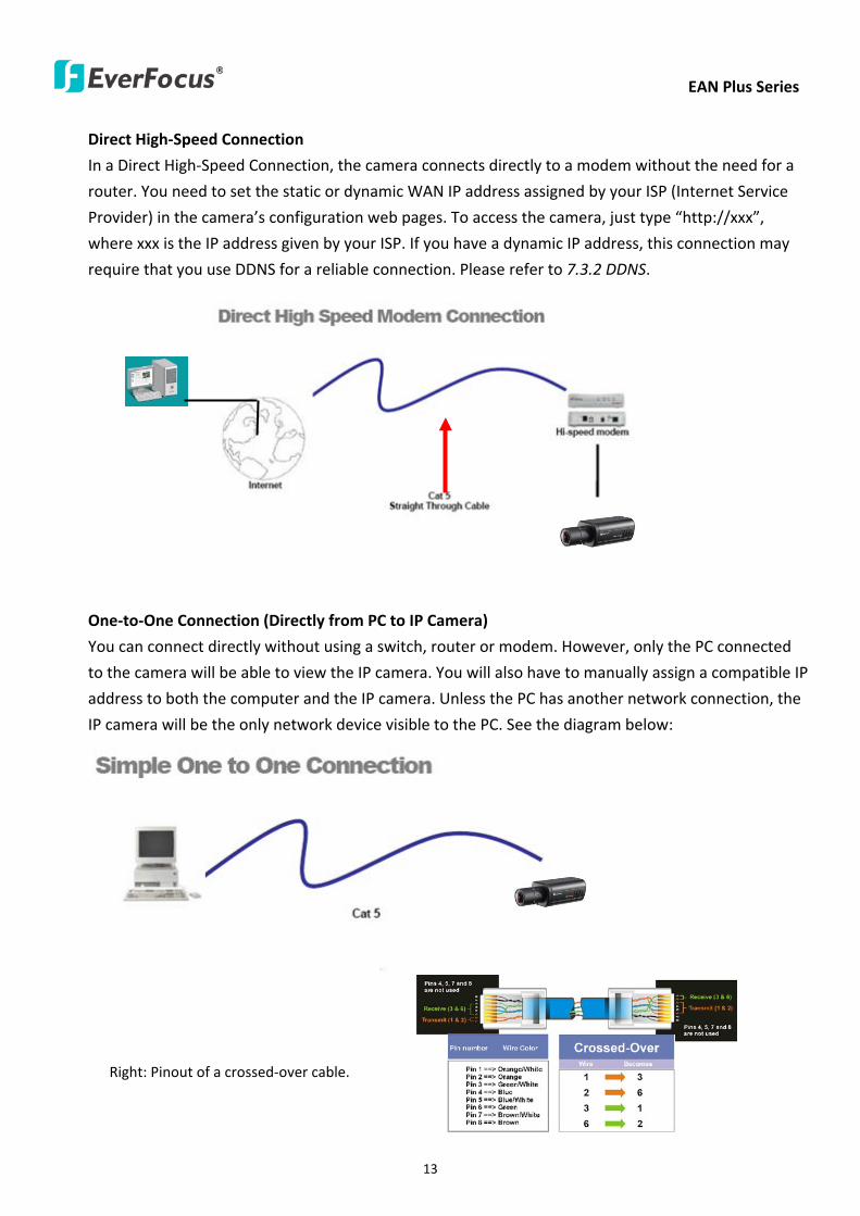
EAN Plus Series
13
Direct High-Speed Connection
In a Direct High-Speed Connection the camera connects directly to a modem without the need for a
router You need to set the static or dynamic WAN IP address assigned by your ISP (Internet Service
Provider) in the camerarsquos configuration web pages To access the camera just type ldquohttpxxxrdquo
where xxx is the IP address given by your ISP If you have a dynamic IP address this connection may
require that you use DDNS for a reliable connection Please refer to 732 DDNS
One-to-One Connection (Directly from PC to IP Camera)
You can connect directly without using a switch router or modem However only the PC connected
to the camera will be able to view the IP camera You will also have to manually assign a compatible IP
address to both the computer and the IP camera Unless the PC has another network connection the
IP camera will be the only network device visible to the PC See the diagram below
Pinout of straight patch cable
Right Pinout of a crossed-over cable
EAN Plus Series
14
54 Live View Window
1 Press the button to display the Live View window Double-click on the
image to show a full-screen display double-click again or press ESC to return to the normal display
If you experience video feed lag time (if connected via Internet) you can reduce the resolution or
limit the number of streams See 741 Multi Streaming
2 Press the button to play the recorded data directly from the on-camera Micro
SD SDHC card (for this function to become active you have to insert a Micro SD SDHC card in the
Micro SD SDHC card slot on the rear panel of the camera See 783 SD Card
3 Press the button to enter the Settings page On the Settings page there are
8 submenu sections [System Info] [User Config] [Network] [Video] [Audio] [User] [Event] and
[System] Click on the section buttons to open their configuration fields See the Settings section
below for more information
EAN Plus Series
15
4 Press the button to exit the system and close this browser page
5 Video Stream
Select the Video Stream (Stream 1 Stream 2 or Stream 3) that will be displayed in the video box on
the right Stream 2 and Stream 3 are only selectable if you have enabled the stream The default
setting is Stream 1 only See 741 Multi Streaming
6 View Size
Use this to select the appropriate view size and shape of the video box on the right A smaller size
might increase transmission speed and video quality
7 Digital Zoom
Click the Zoom In Zoom Out buttons or roll the mouse wheel to zoom in out the camera live view
up to 10x Clicking on a magnified image will re-center the image around that point
8 Record
The Record button is used to record the current video stream Click the Record button to start
stop recording This icon is only for one-minute video recording To record long-period recordings
please set a recording schedule (See 775 Schedule) The location on your computer where the
image files will be saved to and file size can be specified in the submenu (see 72 User Config)
9 Snapshot
Click the Snapshot button to save a snapshot of the video image currently being displayed The
location on your computer where the snapshot data will be saved can be specified in ldquoSettings gt
User Config gt RecordingSnapshotrdquo (see 72 User Config)
10 Play Audio Transmit Audio
Click the ldquoPlay Audiordquo (speaker) and ldquoTransmit Audiordquo (microphone) buttons to switch the sound
onoff for the speaker and microphone respectively (if such external devices have been connected
to the camera directly or via the network)
EAN Plus Series
16
11 One Push
This function is only available for EAN3120 Plus 3220 Plus The One Push button can be displayed
on the live view window by enabling the Show One Push Buttons function on the User Config lt Live
View Config Setting page (see 721 Live View Config) To enable the button (turned from faded to
clear) on the Video lt Advanced Setting page select One Push from the White Balance Settings
Mode drop-down list and click the Apply button Once this is done pressing the One Push button
on the Live View Window will instruct the camera to adjust the white balance settings and these
settings will be active until the button is pushed again This is like a ldquosemi-automaticrdquo way to adjust
white balance to suit the user if the Auto or Manual mode does not give the result the user wants
12 Manual Control
ndash Trigger Event
Press the ldquoTrigger Eventrdquo button to trigger an event directly from the Live page If you have
configured an event (in the Event submenu) that will trigger a reaction (like a recording) when a
Manual Trigger event occurs clicking this button will trigger that reaction You can select what that
reaction will be You can for instance set the camera to record the audiovideo feed to the Micro
SD card on board the camera You can then click on the Playback button to open the Playback page
and search for and play all such recordings that had been stored on the card Such event actions
will be effective once they have been configured in the ldquoEventrdquo menu (see 77 Event)
ndash Reset Alarm
Press the ldquoReset Alarmrdquo button to reset the alarm output remotely
13 Status Display (info lines that can be placed above video box or at bottom of page)
This shows the name of the camera that is currently active or being configured current datetime
and current frame rate You can activate these info displays in the Settings gt User Config page (see
72 User Config)
14 Event Signal Icons (above video screen)
When an alarm or motion event is triggered a signal icon will appear at the top right of the Live
View window to alert the user
Alarm event icon When an alarm is triggered this icon appears
Motion detection icons The colors of these motion event icons correspond to the colors of the motion trigger areas you have configured in the Motion Detection submenu (see 772
Motion Detection)
Recording icon When the camera is recording to a PC-based folder this icon appears
EAN Plus Series
17
6 Playback
You can remotely play back the recordings stored in the on-camera micro SD card on the Web interface
or play back the recordings stored in the computer using the ARV Viewer included in the software CD
Playback is designed as a quick way to check recent recordings that were triggered by Events that were
configured to ldquoRecord to SD Cardrdquo in the Settings gt Event gt Event Settings page (see 771 Event
Settings)
Note Note that the Playback page is only accessible once the on-camera SD card is inserted and
active
61 Remote Playback Using Playback Page
On the Live View Window click the Playback button to open the Playback page
EAN Plus Series
18
Search by File Click the Search button to search for all recording files on the on-camera SD card
Search results will be displayed in the Filename area
Search by Time Click the calendar icon and select the date and time from which you want to search
until the present moment Click search to get your search results which will be displayed in the
Filename area
Search by event Click the type of Event recordings you want to search for (Alarm Motion Manual
Trigger) and then click the calendar icons to select the Start Time datetime and the End Time
datetime of your search Click Search to get your search results which will be displayed in the
Filename area
Multiple Files Check this box if you want the video player to play all the files in the selected folder
The files will be displayed in the Filename area
Loop Again Check this box if you want the video player to play the selected file over and over again
Play Once you have opened the filersquos folder and have clicked on the file to highlight it its details will
be displayed in the File Information area You can now click Play to play that specific file
Pause Click this button to pause the playback
Stop Click this button to stop the playback
【Recording List】
Filename This area will display a list of search results (recording files and folders) Folders (named
with the recorded date) will be displayed first Click on the folder and click on each subfolder until the
recording files (arv) in that folder is listed
File Information Click a file on the Filename list the selected file information will be listed
Copy Click this button to copy the selected file to the computer-based folder of your choice A
browsing box will open so that you can search for the folder of your choice You can use the ARV
Viewer to play back the recordings recorded in your computer For details on ARV Viewer see 63
Playing Back Using ARV Viewer
Lock Click this button to lock the selected file This will protect that file from being overwritten during
any overwrite procedure The file will thus be saved on the micro SD card indefinitely However the
file will still be deleted if the micro SD card is ever formatted
Remove Click this button to delete the selected file
EAN Plus Series
19
62 Setting up the Playback Function
Note that the Playback function will not be active until the user has inserted a micro SD card in the
camerarsquos micro SD card slot The card may also have to be formatted in the Settings submenu
Micro SD Card Slot
621 Preparing the Micro SD Card
Once you insert a functional micro SD card into the slot the Playback button on the Live page should
become active within seconds (see section 622 below ndash the grey letters should turn white) IF NOT
do the following
1 From the Live page click Settings gt System gt SD Card If no card has been inserted yet the
Remove button should be faded indicating that no card is being detected (If a card is
inserted and the Remove button is still faded pull the card out and re-insert it)
2 Slide the card into the slot until it clicks into position
3 The Remove button should become active within a few seconds indicating the card is active
4 If the Remove button stays faded click the Format button to format the card NOTE All data
on the disk will be deleted if the Format button is clicked
622 Testing the Playback Function
1 Once the SD card is detected by the system the button (inactive)
will turn to (active)
2 To test the Playback function (this is not required) set up a ldquoManual Triggerrdquo Recording
Event by clicking Settings gt Event gt Event Settings
3 Click the ldquoAddrdquo button on the middle right side of the page to open an ldquoAdd Eventrdquo box
4 Give the event a name like ldquoTest 1rdquo
EAN Plus Series
20
5 In the ldquoEvent Triggered byrdquo field click on Manual Trigger
6 Below this check ldquoEnable This Eventrdquo ldquoEnable Post-trigger Bufferrdquo and ldquoRecord to SD Cardrdquo
7 To save your settings click OK or close the box by clicking on the red x icon at top right of the
box (in which case you will be asked if you want to save the data to which you should reply OK)
The box will close and the new event will be listed in the list area of the Event Settings page
8 Look at the ldquoPost-trigger Bufferrdquo at the bottom to make sure the buffer time is set to 10 seconds
9 Click ldquoApplyrdquo to make sure all settings are saved
10 Click the Live button to go back to the Live page
11 Get ready to click the Trigger Event button at the bottom of the page Before you do see if you
can find something in the view screen that will give you a visual time marker For instance if you
can get your hand in front of the camerarsquos lens get ready to count down on your fingers
12 Click the Trigger Event button and slowly count down on your fingers in front of the lens (if you
are able to do so ndash if not try to find visual cues on the view screen that will help you to mark the
moment you pushed the trigger) The recording period will be as long as the buffer time you
selected ndash the default period is 10 seconds
13 Click the Playback button to open the Playback page
14 There are different ways to search for recording files on the camerarsquos Micro SD card (ie the
Playback memory) For a recent recording like your test event simply click the ldquoSearchrdquo button
under the ldquoSearch by Filerdquo header
15 If the SD card is active and formatted correctly the recording folderrsquos name (the recording dayrsquos
date) will appear in the Filename box at the bottom Click on this folder to open it If there are
sub-folders click on the bottom one (the most recent would be at the bottom) until you can click
on a file that cannot open to another sub-level and shows data in the File Information box to the
right This would be the file of the most recent recording event
16 To play this file click the Play button below the video box The test footage you have recorded
should start playing Play time should be 10 seconds if you left the Post-trigger Buffer as 10
seconds
EAN Plus Series
21
63 Playing Back Using ARV Viewer
You can play back the recordings stored in the computer using the ARV Viewer included in the
software CD To store the recordings in the computer please refer to Recording List gt Copy in 61
Remote Playback using Playback Page
4 5 6 7 8 9 10
321
No Item Name Descriptions
1 Snapshot Click to take and save a snapshot
2 Load File Click to load the recordings for playing back
3 Convert ARV to AVI Convert the recording from ARV format to AVI format
4 Playback Time Display the playback time
5 Total Time of Recording Display the total time of the recording
6 Stop Click to stop playing the recording
7 Step Reverse Click to display the previous frame
8 Play Click to play back the recording
9 Pause Click to pause the recording
10 Step Forward Click to display the next frame
EAN Plus Series
22
7 Settings
Click the Settings button on the Live View Window to enter the settings submenu There are nine buttons
on the left-side of the submenu Live System Info User Config Network Video Audio User Event and
System Click the Live button can go back to the Live View Window
71 System Info
The System Information and System Log can be checked on this page Click the top tab of the one you
want to see
711 Information
Click the Information tab the following dialog box appears These values cannot be changed on this
page and are for reference only
EAN Plus Series
23
712 Log
Click the Log tab the following dialog box appears The sequence number date time and event
messages of the log event will be displayed in the System Log field The log will display the last 256
log events Click the Export button to export the system log event list into a ldquotxtrdquo file and select the
location where the exported log file will be saved to
EAN Plus Series
24
72 User Config
Each user can set a different configuration for hisher Live page here These settings will be applied to
the logged-in userrsquos Live page every time heshe logs in
721 Live View Config
【VideoAudio Connection Protocol Setting】You can transmit the data stream from the IP cameras
using the RTSP (Real Time Streaming Protocol) on the network The RTSP is a protocol that allows
you to access video streams by using the compatible media players Click Apply to apply the
changes or Reset to reset without saving the changes RTP over UDP The RTSP protocol uses UDP for camera data stream transmission
RTP over TCP The RTSP protocol uses TCP for camera data stream transmission
RTP over HTTP The RTSP protocol uses HTTP for camera data stream transmission
Nevio CGI This is EverFocusrsquo protocol designed for EverFocusrsquo IP devices Select this
protocol for camera data stream transmission
【Text Settings】Check the box of each option (Machine name DateTime Frame Rate) to display
this info on the Live View Page
Foreground Color Slide the Red Green and Blue bars to create your preferred text color for the
info text line
Position Select the position where the text will be displayed Choose from Upper Left Lower
Right Lower Left
Click Apply to apply the changes or Reset to reset without saving the changes
EAN Plus Series
25
【DateTime Format Used in Text】Click the dropdown menu to select datetime format from the
listed options Click on the desired hour format Click Apply to apply the setting changes or Reset to
reset without saving the change
【Live View Layout Settings】 Check the ldquoShow One Push Buttonsrdquo boxes if you want to show these
buttons on the Live View Page Uncheck these boxes to hide these buttons This function is only
available for EAN3120 Plus 3220 Plus
722 Recording Snapshot
This configures where your Record Button and Snapshot Button ( ) files will be saved if
you click one of these buttons Selectable folders will be on the computer only not on the
on-camera SD card
【Recording Snapshot Export Settings】
Enable Event Recording to PC Checking this box will let the system save RecordSnapshot Button
recordings to the folder configured below on the userrsquos PC
Export Folder Select the Export folder for the action above by clicking on the browse (hellip) button
and then select the desired folder
File size The user can limit the size of each recorded file here (in minutes) When a single
recording file exceeds the time you set the system will create a new file to save that data to
Overwrite Select ldquoONrdquo for overwriting recordingsnapshot file when the disk storage capacity is
full The user can set the storage capacity limitation in the in-sentence field in the gray box below
the Overwrite setting ldquoIf the remaining hard disk capacity is less than ____ MB (50~2000) system
will stop recording or start overwriting ldquo
Click Apply to apply the setting changes or Reset to reset without saving the changes
EAN Plus Series
26
723 Language
Select the language to be displayed on the Web interface of the IP camera The default language is
English
To add a new language not listed in the current Language list click the Browse button to locate
the new language file (evb) on your computer and then click the Upload button Updated
language files might be available on the manufacturerrsquos website Contact your vendor if required
Click Apply to apply any changes or Reset to reset without saving the changes
Note Uploading a new language file will cause the system to reboot automatically Please create
a new network connection to the IP camera when the reboot is complete
EAN Plus Series
27
73 Network
This page covers network-related settings including Network DDNS SMTPFTP HTTPS SNMP and
Network Alarm
731 Network
The following information is required to configure the network settings Contact your network
administrator or your internet service provider to get the info
【IP Settings】
IP Type Refer to the network administrator for these settings of the server Default DHCP
DHCP This setting lets the system use an automatically assigned (dynamic) IP address This
address can change under certain circumstances For instance when the camerarsquos network
switchhub has to be rebooted Do not assign to the DHCP server the same IP addresses used
for the other network cameras and PCs with unique IP addresses
Static IP The user can manually set the Static IP address This type of address is stable and
cannot change but the user has to make sure there are no address conflicts with other
network-connected devices
PPPoE This is a DSL-connection application The ISP will ask the user to input a username and
password Contact your ISP for these details
EAN Plus Series
28
Note If PPPoE is selected as the IP type the supplied IP Utility program will not be able to
detect the device
IP address When DHCP is not used the user needs to manually enter the IP address of the
camera Do not enter an IP address that is already used for your computer or other network
cameras
Subnet Mask This field is used to set the netmask for your network so that the IP camera will be
recognized within the network Example 2552552550 When DHCP is selected the DHCP server
will assign this value automatically
Gateway This field is used to set the gateway for your network so that the IP camera will be
recognized within the network When DHCP is selected the DHCP server will assign this value
automatically
Primary DNS Enter the IP address of the DNS server if this is provided by an ISP
Secondary DNS If your ISP provided you with a secondary DNS address please enter it here
Username Enter the accountrsquos username (used only for PPPoE)
Password Used only for PPPoE
IPv6 Enter the IPv6 details in this area if this applies to your system
Click Apply to apply the setting changes or Reset to reset without saving the change
【Port Settings】Enter the HTTP HTTPS and RTSP port numbers and click Apply to save
【Multicast Settings】Enable if required fill in the setting options and click Apply to save
EAN Plus Series
29
732 DDNS
DDNS (Dynamic Domain Name System) is a service used to map a domain name to the dynamic IP
address of a network device You can set up the DDNS service for remote access to the IP camera
DDNS assigns a domain name (URL) to the IP camera so that the user does not need to go through
the trouble of checking if the IP address assigned by DHCP Server has changed Once the IP is
changed the IP camera will automatically update the information to the DDNS to ensure it is always
available for remote access
Before enabling the following DDNS function user should have applied for a host name from the
DDS service providerrsquos website We support these four DDNS server providers
wwweverfocusddnscom wwwsitelutionscom wwwdyndnscom and wwwno-ipcom
Note We highly recommend that you use xxxxeverfocusddnscom for the simplicity of setting up
your IP cameras
【DDNS Settings】
Enable Check this box to enable the DDNS function
Service ISP You can either apply for a host name from EverFocus or other DDNS server providers
If you choose the EverFocus DDNS server you can obtain a free host name from EverFocus by
following the steps below
bull From EverFocus To obtain a free host name from EverFocus type a desired host name in the
textbox click the Register Update button and then click the Apply button
bull From other DDNS server providers To obtain a domain name from one of the three DDNS
server providers you have to register your name with the provider first and then select the
provider and fill in the required information Please refer to the specific DDNS companyrsquos
website for further information
Record ID Type the record ID if provided by the DDNS server provider
EAN Plus Series
30
FQDN Type the fully qualified domain name applied from the DDNS server provider For
example xxxxdyndnscom
Username Password Type the login account of your DDNS server provider
Click Apply to apply the setting changes or Reset to reset without saving the changes
Note
1 In order to support the full functionality of the camera you must open the port numbers (80
554 443) on the router for remote access to the IP camera This function is available on most
routers in the market and is often known as ldquoPort Forwardingrdquo To set up Port Forwarding
please consult the manual of the router
2 In certain router models it is possible that you will not be able to access the camera using
DDNS while inside the routerrsquos network Please try using a PC located outside of your routerrsquos
network
Default Ports on All EverFocus IP Cameras
HTTP 80
RTSP 554
HTTPS 443
EAN Plus Series
31
733 SMTP FTP
【Set SMTP Server (email)】This area is for configuring the mail server that is used to send e-mail
notifications from the camera to predefined addresses via SMTP Note that to enable e-mail
notification function you have to check the Send Mail Notification item on the Event dialog box
(see 771 Event Settings)
SMTP Server Enter the IP address or the host name of the SMTP server used to send e-mails
SMTP Port Enter the port number for SMTP The default is 25
Authentication Check this box if the SMTP server requires authentication (userpassword)
User name Input the userrsquos login ID if the SMTP server requires authentication
Password Input the userrsquos login password if the SMTP server requires authentication
EAN Plus Series
32
Receiver Address Input the e-mail addresses for receiving an e-mail message when an EVENT is
enabled and triggered Please use ldquordquo to separate multiple addresses
Sender Address Input the senderrsquos e-mail address so that the receiver can recognize the sender
when an Event message is received
Attach Image Check this box if you want to attach an image when an alarm is triggered or an IP
camera detects events
Send Test Email Click the Test button to send a testing email to the assigned address
Click Apply to apply the setting changes or Reset to reset without saving the changes
【Set FTP Server】The settings relating to the FTP server used to transmit the alarm images can be
configured here Note that to enable uploading images to the FTP server function you have to
check the Upload to FTP item on the Event dialog box (see 771 Event Settings)
FTP Server Enter the IP address or the host name of the FTP server
FTP Port Enter the port number for the FTP server Default is 21
Recording Path Assign the recording path
User Name Set FTP Userrsquos name
Password Set FTP password
PASV mode Check to enable Passive mode Passive mode is normally enabled If a connection
cannot be established uncheck PASV Moderdquo
Test FTP Server Click the Test button to send a testing file to the assigned FTP server
Click Apply to apply the setting changes or Reset to reset without saving the changes
EAN Plus Series
33
734 HTTPS
Hypertext Transfer Protocol Secure (HTTPS) is a combination of the Hypertext Transfer Protocol
and the SSLTLS protocol and provides encrypted communication and secure identification of a
network web server
Before using the HTTPS function for communication with the IP camera a Certificate must be
created first There are two ways to create and install a certificate Create Self-Signed Certificate
and Create Certificate Request
Create Self-Signed Certificate
Please note that even though self-signed certificates are free and offer some protection true
security is only implemented after the installation of a signed certificate issued by a certificate
authority
1 Click the Create Self-Signed Certificate button the following dialog appears
EAN Plus Series
34
2 Type the required Certificate information and then click the Apply button The subject line will
be displayed in the Installed Certificate Information field
3 Click the Property button a pop-up window appears to display the details of the certificate
4 To optionally create and install other certificates remove the existing one by clicking the
Remove button to erase the certificate
5 On the Web page change the address from ldquohttprdquo to https in the address bar and press
Enter on the keyboard Some Security Alert dialogs will pop up Click OK or Yes to enable HTTPS
Create Certificate Request
You can apply for an official certificate from an issuing Certificate Authority
1 Click the Create Certificate Request button the following dialog appears
EAN Plus Series
35
2 Type the required Certificate information and then click the Apply button The subject line will
be displayed in the Created Request field
3 Click the Property button a pop-up window appears to display the details of the certificate
4 To optionally create and install other certificates or request remove the existing one by clicking
the Remove button to erase the certificate or request
5 Copy the contents of the Certificate request (in PEM format) and paste it to the certificate
request field on the Web page of the 3rd-party certification authority such as Symantec VeriSign
Wait for the certificate authority to issue an SSLTLS certificate and then download the issued
certificate on your computer
6 In the Install Signed Certificate field click the Browse button to search for the issued certificate
and then click the Upload button to import the certificate Once the certificate has been
uploaded this field will show the subject line of the certificate
EAN Plus Series
36
735 SNMP
The default values for SNMP v1v2v2c and SNMP v3 are already filled in Click either of the
Enable buttons to enable either of the two Make your changes as desired Click on the Trap
Address field to enter the digits if required
736 Network Alarm
This function works with EverFocusrsquos CMS software eg the PowerCon or the Power Video Plus For
the setting details please refer to the CMS network alarm protocol
EAN Plus Series
37
74 Video
The settings relating to video such as streaming camera OSD can be configured on this page The
Video page has five tabs Multi-streaming Camera Advanced ROI and Privacy Mask
741 Multi Streaming
【Stream Settings】 This IP camera can output three video streams simultaneously For each of these
streams the user can set the compression format resolution bit rate and frame rate individually
Stream 1 is always enabled for live view To enable Stream 2 andor Stream 3 check the ldquoEnablerdquo
box the header of each stream
Note If you connect to the camera via the Internet and experience a delay (lag time) in the video
feed try to reduce the number of streams and the quality and resolution of the streams ndash but
keep the frame rate at its maximum
EAN Plus Series
38
Format Select the encoding format ndash H264 or MJPEG
Resolution Select the most suitable resolution for your needs
Frame Rate Select from 1 to 30 fps
Bit Rate If required select whether you want the stream to stream a Constant Bit Rate or a
Variable Bit Rate and set the values of whichever option you choose
Click Apply to apply the setting changes or Reset to reset without saving the changes
【Video Recording Settings】Select the stream you want to configure and then select whether you
want the recording files of that stream to be saved in AVI or ARV format Click Apply to apply the
setting changes or Reset to reset without saving the changes
【Time Stamp Settings】 You can select the DateTime format position and add the setting to the
streaming
Click Apply to apply the changes or Reset to reset without saving the changes
EAN Plus Series
39
742 Camera
【Image Settings】Set the Brightness Saturation Contrast or Sharpness of the image Click Apply to
apply the changes or Reset to reset without saving the changes
【Camera Settings】
Mirror Switch Mirror ON to rotate the image horizontally around a vertical axis
Flip Switch Flip ON to rotate the image vertically around a horizontal axis
AE There are two options
ALC Selecting Automatic Light Control allows the camera circuitry to either take bright spots
more into consideration (peak) bringing out detail in bright areas or less into consideration
(average) bringing out detail in shadows
AES Selecting Auto Electronic Shutter disables the Shutter setting below this setting In this
mode the camera measures the light level and decides whether it needs more or less light and
then automatically adjusts the shutter speed accordingly
BLC Back Light Compensation (BLC) is used to make the subject appear clearer when it is set
against a bright background
OFF Select to switch Back Light Compensation functions off
(ON)BLC The BLC can increase the exposure of a dark area surrounded by a brighter area HLC
can decrease the exposure of bright areas surrounded by darker areas This enables the
camera to better display information that would otherwise have been ldquowhited outrdquo like a
license plate between two bright headlights on a dark road
(ON)HLC The Highlight-Suppression BLC is used to reduce the brightness of light sources in a
specific area It is activated only in a low illumination environment to minimize the effects of
glare from bright lights such as spotlights street lights or headlights in the field of view
EAN Plus Series
40
WDR The Wide Dynamic Range (WDR) function provides clearer images when both of the very
bright and dark areas simultaneously appear on the camera view There are four value options
OFF Low Middle and High Note that when WDR is ON some parts of the image may appear
solarized This is normal for WDR and is not a camera malfunction This function is only available
for EAN3120 Plus 3220 Plus
DN Mode
Auto Select to let the camera automatically switch to Night mode (black and white) when the
light levels fall to a specified level and back to Day mode (color) when the light levels rise to a
specified level
Day Select to keep the camera in Day mode (color) even in nighttime
Night Select to keep the camera in Night mode (black and white) even in daytime
EAN Plus Series
41
743 Advanced
EAN Plus Series
42
【Camera Settings】
Lens (IRIS Control) Select DC or Manual for IRIS control This function is only available for EAN3220
Plus
Exposure Settings (AE) This setting is used to adapt to the amount or type of light used by the
camera Note the settings vary among models
Mode This function is not available for EAN3220 Plus
Automatic Light Control (ALC) This option is only available for EAN3120 Plus 3300 Plus The
ALC allows the camera circuitry to either take bright spots more into consideration (peak)
bringing out detail in bright areas or less into consideration (average) bringing out detail in
shadows
Auto Electronic Shutter (AES) This option is only available for EAN3120 Plus 3300 Plus In
this mode the camera measures the light level and decides whether it needs more or less light
and then automatically adjusts the shutter speed accordingly
Manual This option is only available for EAN3300 Plus Select this option to manually set up
the Shutter (Manual) and AGC (Manual) values
Iris Specify the size of the Iris opening here
Shutter If enabled this setting lets you set the shutter speed yourself
Shutter Limit Use this setting to set the maximum shutter speed for the camera This function is
only available for EAN3120 Plus
AGC Set the Auto Gain Control limit here The lower the AGC level the lower the video signal and
the noise However the image will be darker under low-light condition with IR-off if you set up the
Iris to the maximum level
Slow Shutter This option can be switched on when AES Mode is selected in the Exposure Settings
(AE) field This function is only available for EAN3220 Plus 3300 Plus
Flickerless If the Mode field in the Exposure Settings (AE) area has been set to AES then this option
becomes available Choose between OFF 50HZ 60HZ 50HZ (High Luminance) or 60HZ (High
Luminance) This function is only available for EAN3300 Plus
EV Setting Set up the Exposure Value Note the brightness of the screen changes when you change
the EV value This function is only available for EAN3300 Plus
AE Response Set up Auto Exposure Response time This function is only available for EAN3300 Plus
AE Weighting Area Select an AE Weighting area Each setup AE Weighting Area is configured with
the appropriate brightness level on the center and the surrounding areas This function is only
available for EAN3300 Plus
Brightness Set the image brightness here
AE Reference Set the Auto Exposure value here This function is only available for EAN3120 Plus
EAN Plus Series
43
Black Level Set the Black level here This function is only available for EAN3300 Plus
WDR The Wide Dynamic Range (WDR) function provides clearer images when both of the very
bright and dark areas simultaneously appear on the camera view There are four value options OFF
Low Middle and High Note that when WDR is ON some parts of the image may appear solarized
This is normal for WDR and is not a camera malfunction This function is only available for EAN3120
Plus 3220 Plus
Visibility Enhancement (OFFLowMiddleHigh) Images in foggy or rain environments or in
environments with a very strong luminous intensity have a dynamic range that is significantly lower
than ordinary images The user can use this Visibility Enhancement setting to ldquoDEFOGrdquo the image if
such ldquoFOGGINGrdquo is an issue This function is only available for EAN3220 Plus
BLC Settings Back Light Compensation (BLC) is used to make the subject appear clearer when it is
set against a bright background
OFF Select to switch Back Light Compensation functions off
Back Light This option is only available for EAN3300 Plus The Back Light function is useful
when the background of the subject is very bright and the subject itself is dark Select Back
Light and adjust the slide bar to the left right for setting up the back light value The higher
the value the more the backlight compensation
Front Light This option is only available for EAN3300 Plus This function is useful when the
bright highlights such as flashlight or car headlights appear on the camera view Select Front
Light and adjust the slide bar to the left right for setting up the front light value The higher
the value the more the highlight compensation
ON (BLC) This option is only available when you select AES Mode in the Exposure Settings (AE)
field The option is only available for EAN3120 Plus 3220 Plus The BLC function is useful
when the background of the subject is very bright and the subject itself is dark Follow the
instructions below to configure the settings for each model
For EAN3120 Select ON (BLC) the button next to the Mode drop-down list will be
active (see image below) Click the button the green setup areas appear on the left
screen Click on the areas to enable disable the BLC function The selected areas (in green)
will be applied with the BLC function
EAN Plus Series
44
For EAN3220
You can configure one area to apply the BLC function Select ON (BLC) the setup buttons
appears (see image below) Select Low Middle High from the BLC Gain drop-down list To
set up a BLC area click the Edit Area button and then click on the blue color tab to turn your
mouse cursor into a blue pen Move the cursor to the position on the right screen where you
want the BLC rectangle to start and then click Move your cursor to the position (diagonally
opposing corner) where you want the BLC rectangle to end and then click The blue area will
be applied with the BLC function
ON (HLC) This option is only available when you select AES Mode in the Exposure Settings (AE)
field The option is only available for EAN3120 Plus 3220 Plus This function is useful when
the bright highlights such as flashlight or car headlights appear on the camera view Follow
the instructions below to configure the settings for each model
For EAN3120 Select ON (HLC) and then select a level from the drop-down list The higher the
level the more the highlight compensation
For EAN3220
HLC Level Select a level for the HLC setting The higher the level the more the highlight
compensation
HLC Mode Select All Day Night mode to apply the HLC function
HLC Black Mask Select On Off to apply the black mask on the selected areas The
over-exposure portions within the selected areas will be applied with the black mask
Color Tabs You can set up four HLC areas with different colors To set up a HLC area click the
Edit Area button and then click on the color tab to turn your mouse cursor into a pen of that
color Move the cursor to the position on the right screen where you want the HLC rectangle
to start and then click Move your cursor to the position (diagonally opposing corner) where
you want the HLC rectangle to end and then click Select ON from the color tab drop-down list
The rectangular area with the selected color will be applied with the HLC function
EAN Plus Series
45
Back Light This option is only available for EAN3300 Plus The Back Light function is useful
when the background of the subject is very bright and the subject itself is dark Select Back
Light and adjust the slide bar to the left right for setting up the back light value The higher
the value the more the backlight compensation
Front Light This option is only available for EAN3300 Plus This function is useful when the
bright highlights such as flashlight or car headlights appear on the camera view Select Front
Light and adjust the slide bar to the left right for setting up the front light value The higher
the value the more the highlight compensation
Noise Reduction Settings This limits the amount of digital ldquovideo noiserdquo that is usually found in any
video stream and helps to reduce file size The higher the level the more the reduction
For EAN3120 Plus 3300 Plus
Select ON OFF to enable disable the Noise Reduction function Or select Auto to let the camera
automatically enable disable the Noise Reduction function Slide the Level bar to set up the level
The higher the level the more the reduction
For EAN3220 Plus
2D DNR Select ON to enable the 2D DNR function
3D DNR Select ON to enable the 3D DNR function You can further set up the following settings
3D Start AGC Set up the AGC level to automatically start the 3D NR function
3D End AGC Set up the AGC level to automatically stop the 3D NR function
3D Level Set up the 3D DNR level
Smart NR Select ON to enable the Smart NR function The 3D NR function will be
automatically turned on when a motion event occurs
EAN Plus Series
46
White Balance Settings Select the mode that delivers the best quality image for the camerarsquos light
environment There are five options Auto Manual Indoor Outdoor One Push
Auto Select to let the camera automatically adjust the White Balance In the Auto mode the
camera computes the white balance value output using color information from the entire
screen It outputs the proper value using the color temperature radiating from a black subject
based on a range of value from 3000 to 7500K
Manual Select to adjust the Red and Blue values yourself in the fields below this field
Indoor Select to use the default settings for indoor environments In the Indoor mode the
camera uses 3200K as the base value
Outdoor Select to use the default settings for outdoor environment In the Outdoor mode it
uses 5800K as the base value
One Push Select to enable the Push button next to the Mode drop-down field This will allow you to force the camera to readjust the white balance every time you push the Push
button The lens will hold the same focal position until the next trigger command is received
This function helps to prevent incorrect focusing in dark environments This function is only
available for EAN3120 Plus 3220 Plus
Manual Temperature Select to use the optimized Red and Blue settings You can also
optionally adjust the Manual Level below this field for setting up the color temperature The
higher the value the more the color temperature This function is only available for EAN3300
Plus
DayNight Settings
Auto Select to let the camera automatically switch to Night mode (black and white) when the
light levels fall to a specified level and back to Day mode (color) when the light levels rise to a
specified level
Day Select to keep the camera in Day mode (color) even in nighttime
Night Select to keep the camera in Night mode (black and white) even in daytime
IR Smart Settings Select ON and set up the level to enhance the image quality when the images are
over exposure This function is useful when the camera is in the Night mode This function is only
available for EAN3220 Plus
Saturation Set the saturation value This function is not available for EAN3220 Plus
Monitor Type Select a gamma value from Set 1 Set 2 or Set 3 This function is only available for
EAN3120 Plus
Negative Switch this setting ON to view a color negative version of the video image This is useful
at night or when viewing temperature-sensitive images
EAN Plus Series
47
Sharpness Settings Select the sharpness level of the image A low sharpness level will deliver a
softer less detailed image A high level will deliver a sharp highly detailed image Switch Resolution
Enhancement ON to enable the resolution enhancement function
Contrast Select the contrast level of the image
Suppress Function This function is only available for EAN3300 Plus
Aperture Compensation Suppression (OFFLowMiddleHigh) This setting can be activated to
suppress luminance noise when the AGC level increases
Chroma Suppression (OFFLowMiddleHigh) This setting can be activated to suppress
chrominance noise when the AGC level increases
Ygamma (gamma 22standardcontrast enhancehigh light range mode LHigh light range mode
H) Select the Ygamma value for the video quality of the monitor This function is only available for
EAN3300 Plus
Monitor Settings The user can use this field to optimize video quality for his or her specific type of
monitor ndash LCD or CRT This function is only available for EAN3220 Plus
Color Space Standard The options are YUV601 for SD and YUV709 for HD These define the color
space standard required to convert an RGB picture to a YUV picture Generally YUV601 is used for
Standard Definition (720P) devices and the YUV709 is used for High Definition (1080P) devices
Click Apply to save all changes Click Reset to cancel all changes
EAN Plus Series
48
744 ROI (Region of Interest)
The Region of Interest (ROI) function allows users to set up multiple regions within an image with
better quality and less distortion than the rest of the image You can also use this function
together with the Digital Zoom function on the Live View Page to get a better image result Up to
eight ROIs can be configured in the ROI settings page
To set up an ROI region
1 Select an ROI number from the ROI No drop-down list
2 Click the Add button the mouse cursor will turn into a pen when you move it over the live
image on the left
3 Move the cursor to the position where you want the ROI rectangle to start and then click
Move the cursor to the position (diagonally opposing corner) where you want the ROI
rectangle to end and then click
4 Slide the Quality bar to set up the quality value
5 Click the Apply button to apply the settings or click the Reset button to reset without saving
the settings
EAN Plus Series
49
745 Privacy Mask
The Privacy Mask can block out sensitive areas from view covering the areas with colored or black
and white boxes in both live view and recorded clips This feature is useful when usersrsquo donrsquot want
the sensitive information visible Up to four Privacy Masks can be configured
【Privacy Mask Color Settings】The Modes vary among camera models
Mode Click Color to make the masks appear as colored rectangles on the screen Click BW to
make the masks appear as gray rectangles on the screen Click Mosaic to make the masks appear
as mosaic-effect rectangles on the screen
Level Select the color of the masks if you selected Color Mode Select the level of grayness of the
masks if you selected BW Mode Select the level of smallmiddlelarge if you selected Mosaic
Mode
Click Apply to apply the settings or click Reset to reset without saving the settings
Color Tabs Click on a color tab to turn your mouse cursor into a pen of that color
You can now create a block of that color on the video screen Move your cursor to the position
where you want your mask rectangle to start and then click Move your cursor to the position
(diagonally opposing corner) where you want your mask rectangle to end and then click The
rectangular area with the selected color will appear The live image will display the rectangular
area with the color you selected If you want to create another mask use one of the other three
colors Each color denotes a different mask area Only one block per color is allowed As the
number of colors suggests you can configure up to four blocks
EAN Plus Series
50
Select All Click to turn the whole screen into a mask area
Clear All Click to delete all configured mask blocks
Eraser Click to turn the mouse cursor into an eraser to delete any block you click on
Area Shows the color and number of the block
Enable Check this box to enable the related mask block
Click Apply to apply the settings or click Reset to reset without saving the settings
EAN Plus Series
51
75 Audio
The EAN Plus series IP camera can transmit audio to your computer if you have connected an external
microphone to its audio Input cable It can also receive audio input from you and transmit it via an
external speaker if you have connected such a speaker to its audio Output cable
Check the Enable Audio box to enable the camerarsquos audio function The camera will now act as a
digital bridge (via the IP network) between any connected audio input device and any connected
audio device
Adjust the Audio Input Volume if you have external audio input devices (microphones) connected to
the camera and if there are problems with the sound input being too low or high
Click Apply to save all settings or click Reset to cancel
EAN Plus Series
52
76 User
761 User Information
The system administrator can create up to ten user accounts on this page
To set up a user account
1 Highlight a user account and click the Modify button The following dialog box appears
2 Type the account name account description and password for the account Type the password
again in the Confirm field
3 Select an authority level for the user account from the Authority drop-down list
bull Supervisor Administrator The only difference between a supervisor and administrator is
that a supervisor can edit an administratorrsquos account and password but an administrator
cannot edit the supervisorrsquos account and password Multiple administrators can be
configured but there can be only one supervisor The supervisor and administrators all
have unrestricted access to the Settings submenus and can determine the registration of
all other users
EAN Plus Series
53
bull User A user can view the Live View page and view the system network video and audio
information A user can only adjust the User Config page settings The user does not have
access to the User Event and System pages
bull Guest The lowest level of access which only allows the user access to the Live View page
4 Select Active or Disable from the Status drop-down list to active or disable the user account
5 Click On in the SD Card Playback field to allow the user to access the SD card playback
function
6 Click OK
7 Click Apply to save all the settings
EAN Plus Series
54
762 IP Address Filter
Use this page to specify IP addresses that are not allowed to access this camera By default any IP
address can access the camera
Note The Allowed List addresses only become relevant when the Denied List contains a network
or range and the supervisor wants to allow one or more IP addresses within that excluded range
or network In such a scenario the user would enter the excluded range or network in the
Denied List and enter the exceptions in the Allowed List
To set up the IP Address Filter
1 Select Denied List Click the Add button the following dialog box appears
2 Select an IP type from the IP Type drop-down list
3 Select a network rule from the Rule drop-down list type the IP address and click OK
Single Type a single IP address in the IP Address field below
Network Type the IP address and subnet mask in the field below
Range Type a range for the IP addresses
4 If you have set up an IP range in Step 3 you can optionally set up the Allowed List to allow one
or more IP addresses within the setup IP range to access the IP camera
5 Click Apply
EAN Plus Series
55
77 Event
You can set up the Motion Detection event Tamper Detection event or the Alarm IO to automatically
notify the users when an event occurs or an alarm is triggered You can also set up a schedule to
automatically record the videos when an event occurs or an alarm is triggered
771 Event Settings
You can create a total of ten event or alarm settings page in the Event List
【Event List】
Click the Add button and the following Event Configuration Window appears
EAN Plus Series
56
Enter Event Name Type an event name
Event Triggered by Select an event or alarm type for the to-be-specified-below reactions
Alarm Input Select this if you want a reaction trigger coming from any external connected sensor
to activate a to-be-specified-below reactions via the camera system Make sure that a suitable
device is actually connected to the alarm input relay
Manual Trigger Select this option if you want to manually trigger the alarm by clicking the Trigger
Event button on the Live View Page
Motion Detection Select this option if you want motion in a specified part of the camerarsquos viewing
rectangle (the screen image) to trigger the to-be-specified-below reactions
Tampering Detection Select this option if you want the camerarsquos tampering detection sensor to
trigger the to-be-specified-below reactions
Schedule Recording Select this option if you want the Schedule Recording periods configured in
the recording schedule (the Settings gt Event gt Schedule page) to activate this event In this
scenario a preconfigured event reaction like a log entry will list the start and end times of each
period Actual recording will only be triggered if the event is preconfigured to do so
Enable This Event Select to activate the event
Enable Re-trigger Click to set a minimum time after the event is triggered before the event
can be triggered again
Enable Pre-trigger Buffer Click if you want the Event reaction (as selected in the ldquoNotification
Overrdquo field below) to be the activation of the video recording function and if you want the
recording to include the video feed from the time period (configurable on the previous ldquoEvent
Settingsrdquo page) just before the Event trigger occurred
Enable Post-trigger Buffer Click if you want the Event reaction (as selected in the Notification
Over field) to be the activation of the video recording function and if you want the recording
to include the video feed from a time period (configurable on the Event Settings page) just
after the Event trigger occurred
Motion Area Select a setup motion detection area from the drop down list Note this
function only becomes relevant after the Motion Detection areas have been set up (see 772
Motion Detection)
Notification Over Select the desired notification types form the following items
Log Click if you want the camera to list the eventrsquos details in its log if the event is triggered
Trigger Alarm Output Click if you want the camera to relay the event reaction to a device
attached to the alarm relay output wire and then set up the alarm output duration time
EAN Plus Series
57
Send Mail Notification Click if you want the camera to send an Event notification email to the
email address entered in the Set SMTP Server(email) field of the Network gt SMTPFTP page if
the Event occurs (see 733 SMTP FTP)
Upload to FTP Click if you want the camera to upload recorded footage to the FTP server
entered in the Set SMTP Server(email) field of the Network gt SMTPFTP page if the Event
occurs (see 733 SMTP FTP)
Record to SD Card Click if you want the camera to start recording its video feed (when the
event occurs) on an on-camera SD Card (if such a card has been inserted)
Note The recording will only be as long as the combined Pre- and Post-trigger Buffers so
make sure you enable at least one of these buffers especially the Post-trigger Buffer
Record to PC Check this box if you want the camera to start recording its video feed (when
the event occurs) on the same folder on the same PC as configured on the User Config gt
RecordingSnapshot page (if such a folder has been enabled and configured)
Note The recording will only be as long as the combined Pre- and Post-trigger Buffers (and
for as long as the event trigger is happening ndash eg a motion is detected) so make sure you
enable at least one of these buffers especially the Post-trigger Buffer
Network Alarm Check this box if you want the camera to send a network alarm signal (when
the event occurs) to the CMS servers configured on the Network gt Network Alarm page (see
736 Network Alarm)
Click OK to save all settings or click Cancel to cancel
【PrePost Trigger Settings】
Pre-trigger Buffer Select the duration for the buffer This will determine the amount of footage
(length of time) before the event trigger moment that will be included in an event-triggered video
recording if that buffer and video recording has been enabled in the Event Configuration Window
Post-trigger Buffer Select the duration for the buffer This will determine the amount of footage
(length of time) after the event trigger moment that will be included in an event-triggered video
recording if that buffer and video recording has been enabled in the Event Configuration Window
Click Apply to save all settings or click Reset to cancel
EAN Plus Series
58
772 Motion Detection
Use this page to configure up to four areas in which motion will be detected When a motion is
detected by the camera the motion detection icon will appear at the top right of the
Live page to alert the user This function can also be linked with correctly configured Events to
trigger Event reactions like the activation of video recording periods snapshots alarms etc
Color Tabs Click on a color tab to turn your mouse cursor into a pen of that color
You can now create a block of that color on the video screen Move your cursor to the position
where you want your detection rectangle to start and then click Move your cursor to the position
(diagonally opposing corner) where you want your detection rectangle to end and then click The
rectangular area with the selected color will appear This block will be an area inside which the
camera will detect motion If you want to create another detection area use one of the other three
palette colors Each color denotes a different detection area Only one block per color is allowed As
the number of colors suggests you can configure up to four blocks
Select All Click to turn the whole screen into a motion detection area
Clear All Click to delete all configured motion detection blocks
Eraser Click to turn your mouse cursor into an eraser to delete any block you click on
Area Shows the color and numberID of the block
Enable Check this box to enable the related motion detection block
Sensitivity Set the sensitivity of the motion detection sensor function
Click Apply to save all settings or click Reset to cancel
EAN Plus Series
59
773 Tamper Detection
Use this page to set the number of seconds that an alarm signal will be active if the device is
physically tampered (moved covered up or out of focus
774 Alarm IO
Use this page to set the type of trigger input and the type of output contact for the camerarsquos alarm
channel
EAN Plus Series
60
775 Schedule
Use this page to configure a schedule for periods during which the camera should deactivate all
user-activated Events (gray Deselect periods) or when the camera should deactivate all
user-activated Events except Schedule Recording (SR) events (blue Schedule Recording-only
periods) or when the camera should deactivate only SR events (red Event Recording-only periods)
or when it should enable all activated Events (yellow periods)
Event Recording Click this button to make every hour block you click on red A red block represents
an Event Recording-only block which represents an hour when the camera will deactivate all
preconfigured activated Schedule Recording events and keep all the other activated events active
Schedule Recording Click this button to make every hour block you click on blue A blue block
represents a Schedule Recording-only block which represents an hour when the camera will
deactivate all other preconfigured activated events and keep only the preconfigured activated
Schedule Recording events active
Event + Schedule Click this button to make every hour block you click on yellow A yellow block
represents an hour in which all activated events including Schedule Recording events will be
active
Deselect Click this button to make every hour block become grey A grey block represents an hour
in which all activated events including Schedule Recording events will be inactive
Click Apply to save all settings or click Reset to cancel
EAN Plus Series
61
78 System
You can set up the systemrsquos time and SD card settings and to do maintenance and reset actions like
reboots and upgrades
781 DateTime
【Machine Name Settings】If required enter a new name for the machine This name will be visible
in the Machine Name field of the IP Utility software which is included in the software CD
【Set Time Zone】Set the time zone of the camerarsquos location
【Set DateTime Manually】Set the datetime here if you wonrsquot be using an NTP server to update the
datetime (see below)
【Set DateTime Sync】Enter the Network Time Protocol server if applicable The camerarsquos time will
be automatically adjusted by synchronizing with the NTP server
Click Apply to save all settings or click Reset to cancel
EAN Plus Series
62
782 Daylight Saving
Click Enable Daylight Saving to enable this schedule and select the dates when the regionrsquos
daylight saving period begins and ends Click Apply to save all settings or click Reset to cancel
783 SD Card
Use this page to prepare the system for safely removing the SD Card from its slot
【Setup SD Card】
Notification Select the percentage of storage space that should be left on the card before the
camera notifies you of the impending storage shortage or overwrite
Event Recording Select if you want Event Recording only FTP Backup only or both
Overwrite Click ON if you want the card to start writing over recorded footage when its memory is
full Click OFF if you want the card to stop recording new footage when its memory is full
【SD Card Utility】
Capacity This shows you how much card memory has been used and how much memory capacity
remains on the card
Remove Click this button before removing the card from the system
Format Click this button to format the card All data saved on the SD card will be removed if the
card is formatted
EAN Plus Series
63
784 Maintenance
【Maintenance Server】
Reboot Click this button to reboot the unit without changing any of the settings Use this function if
the unit is not behaving as expected
Restore Click this button to restart and reset most of the current settings to their factory default
values The only settings that will not be changed to default are
bull IP settings
bull DDNS settings
Default The Default button should be used with caution Pressing this button will return all of the
cameras settings including the IP address to the factory default values The camera will then have
to be reconfigured
【SaveLoad Configuration Server】
Save To make a backup file of the machinersquos current configurations press Save to save all the
configurations to a config file This will enable the user to reload these configuration settings if the
settings are changed and there is unexpected behavior
Load To load a previously saved configuration press the Browse button to locate the saved config
file (see above) and then click the Load button The systemrsquos settings will be restored to the saved
configuration
EAN Plus Series
64
【SaveLoad Video Configuration Server】
Save To make a backup file of the machinersquos video configurations press Save to save the video
configurations to a config file This will enable the user to reload these configuration settings if the
settings are changed and there is unexpected behavior
Load To load a previously saved video configuration press the Browse button to locate the saved
config file (see above) and then click the Load button The systemrsquos settings will be restored to the
saved video configuration
【Upgrade Firmware】Click the Browse button to find a previously prepared firmware upgrade file
Click Upgrade to install the new firmware
Note
1 Do not disconnect power to the unit during the upgrade sequence The unit will reboot
automatically after the upgrade has completed (1-5 minutes)
2 During the upgrade process all event recording actions will be stopped Event recording
actions will resume after the camera is rebooted
3 If the ldquoFile Error Please re-loginrdquo warning message appears when upgrading the firmware
please try the following instructions
a Go to Internet Explorer gt Tools gt Internet Option gt Security gt Custom
b Find and enable the Include local directory path when uploading files to a server
EAN Plus Series
65
8 Upgrading Firmware Using IP Utility
You can upgrade the Firmware using the IP Utility software included in the software CD
1 Install and then start the IPU program The following dialog box appears
2 Click Find Devices to search the cameras connected in the LAN The default network values of the
cameras will be displayed By default the network protocol of the camera is DHCP
3 Select a camera and click LoginMulti Login to log in the camera
4 Type the user ID and password Click OK
Note
1 The default user ID is user1 and the default password is 11111111
2 If you select more than one camera that has the same user ID password you will be able
to log in several cameras at once
EAN Plus Series
66
5 Highlight the camera and then click Upgrade Firmware A browsing window appears
6 Select the firmware file (evb) and then click Open The IP Utility will automatically upgrade the
firmware
The camera will reboot once the update is complete Click Find Devices the new firmware version
should be displayed in the last part of the Machine Name
EAN Plus Series
67
9 Specifications
Model EAN3120 Plus EAN3220 Plus EAN3300 Plus
Camera
Image Sensor 13 Panasonic CMOS 128 Sony CMOS
Megapixel 13 MP 2 MP 3 MP
Picture Elements (H x V) 1280 x 1024 1944 x 1092 2048 x 1536
Min Illuminations 003 Lux at F14
Electronic Shutter (Sec) 85 ~ 160000 2 ~ 150000 1 ~ 110000
Scanning System NTSC PAL
WDR Yes Yes No
BLC Yes
Gain Control Yes
White Balance Yes
Lens
Mounting Type C CS
Day Night Yes (with removable auto IR-cut filter)
IRIS Control DC Electrical IRIS Lens IRIS
Video
Video Compression H264 MJPEG
Resolution
NTSC
2048 x 1536 1920 x 1200 (for EAN3300 Plus only)
1920 x 1080 (for EAN3300 Plus 3220 Plus only)
1280 x 1024 1280 x 720 1024 x 768 720 x 480 704 x 480 640 x 480
352 x 240 320 x 240 160 x 120
PAL
2048 x 1536 1920 x 1200 (for EAN3300 Plus only)
1920 x 1080 (for EAN3300 Plus 3220 Plus only)
1280 x 1024 1280 x 720 1024 x 768 720 x 576 704 x 576 640 x 480
352 x 288 320 x 240 160 x 120
Frame Rate 30 fps at 1280 x 1024 30 fps at 1920 x 1080 15 fps at 2048 x 1536
Audio
Audio Streaming Two-way audio
Audio Compression G711
EAN Plus Series
68
Network
Interface 10 100 Base-T Ethernet RJ-45 socket
Supported Protocols
TCPIP IPV6 UDP ICMP DHCP NTP DNS DDNS SMTP SNMP FTP
HTTP HTTPs PPPoE UPnP Bonjour RTP RTSP RTCP IGMP ARP ONVIF
PSIA
Connector
Power DC female port PoE
Ethernet RJ-45
Audio 1 In (phone jack for microphone)
1 Out (phone jack for Speaker)
Alarm IO Terminal IO wires
Local Storage Micro SD SDHC memory card slot
TV-Out BNC socket composite 1 V p-p 75 Ω
General
Power Source DC 12V PoE (IEEE8023af)
Power Consumption
(IR LEDs On)
5W (DC 12V)
621W (PoE)
5W (DC 12V)
522W (PoE)
5W (DC 12V)
536W (PoE)
Operating Temperature 0degC ~ +50degC 32degF ~ +122degF
Humidity 20 to 80 (no condensation)
Safety CE FCC
Dimensions (L x W x H) 117 x 56 x 68 mm 46 x 22 x 27 in
Weight 410 g 09 lb
EverFocus Electronics Corp EverFocus Taiwan 12F No79 Sec 1 Shin-Tai Wu Road Hsi-Chih Taipei Taiwan TEL +886 2 2698 2334 FAX +886 2 2698 2380 wwweverfocuscomtw marketingeverfocuscomtw
EverFocus Europe - Germany Albert-Einstein-Strasse 1 D-46446 Emmerich Germany TEL +49 2822 93940 FAX +49 2822 939495 wwweverfocusde infoeverfocusde
EverFocus China - Beijing Room 609 Technology Trade Building Shangdi Information Industry Base Haidian District Beijing 100085 China TEL +86 10 6297 3336~39 FAX +86 10 6297 1423 wwweverfocuscomcn marketingeverfocuscomcn
EverFocus China - Shenzhen 4F No 2 D4 Building Wan Yelong Industrial Park Tangtou Road Shiyan Baoan Shenzhen Guangdong 518101 China TEL +86 755 2765 1313 FAX +86 755 2765 0337 wwweverfocuscomcn marketingeverfocuscomcn
EverFocus USA - California 1801 Highland Avenue Unit A Duarte CA 91010 USA TEL +1 626 844 8888 FAX +1 626 844 8838 wwweverfocuscom saleseverfocuscom
EverFocus USA - New York 415 Oser Avenue Unit S Hauppauge NY 11788 USA TEL +1 631 436 5070 FAX +1 631 436 5027 wwweverfocuscom saleseverfocuscom
EverFocus Japan 5F Kinshicho City Building 2-13-4 Koto-BashiSumida-Ku Tokyo 130-0022 Japan TEL +81 3 5625 8188 FAX +81 3 5625 8189 wwweverfocuscojp infoeverfocuscojp
EverFocus Europe - UK Unit 12 Spitfire Business Park Hawker Road Croydon Surrey CR0 4WD UK TEL +44 20 8649 9757 +44 845 430 9999 FAX +44 20 8649 9907 wwweverfocusukcouk salesukeverfocuscom
EverFocus India Suite 803 Housefin Bhavan C-21 Bandra Kurla Complex Bandra (East) Mumbai 400051 India TEL +91 22 6128 8700 FAX +91 22 6128 8705 wwweverfocusin saleseverfocusin
PN 4605PQ3120B010A-VerC
Your EverFocus product is designed and manufactured with high quality materials and components which can be recycled and reused This symbol means that electrical and electronic equipment at their end-of-life should be disposed of separately from your household waste Please dispose of this equipment at your local community waste collectionrecycling centre In the European Union there are separate collection systems for used electrical and electronic product Please help us to conserve the environment we live in
Ihr EverFocus Produkt wurde entwickelt und hergestellt mit qualitativ hochwertigen Materialien und Komponenten die recycelt und wieder verwendet werden koumlnnen Dieses Symbol bedeutet dass elektrische und elektronische Geraumlte am Ende ihrer Nutzungsdauer vom Hausmuumlll getrennt entsorgt werden sollen Bitte entsorgen Sie dieses Geraumlt bei Ihrer oumlrtlichen kommunalen Sammelstelle oder im Recycling Centre Helfen Sie uns bitte die Umwelt zu erhalten in der wir leben
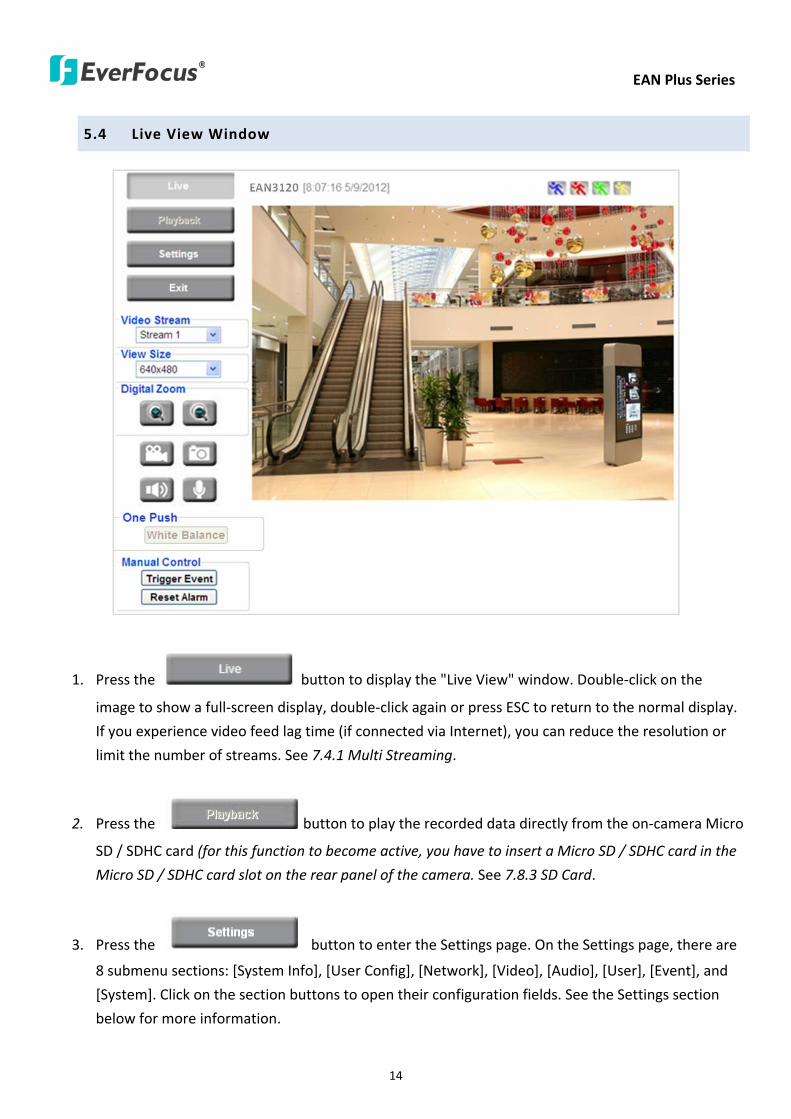
EAN Plus Series
14
54 Live View Window
1 Press the button to display the Live View window Double-click on the
image to show a full-screen display double-click again or press ESC to return to the normal display
If you experience video feed lag time (if connected via Internet) you can reduce the resolution or
limit the number of streams See 741 Multi Streaming
2 Press the button to play the recorded data directly from the on-camera Micro
SD SDHC card (for this function to become active you have to insert a Micro SD SDHC card in the
Micro SD SDHC card slot on the rear panel of the camera See 783 SD Card
3 Press the button to enter the Settings page On the Settings page there are
8 submenu sections [System Info] [User Config] [Network] [Video] [Audio] [User] [Event] and
[System] Click on the section buttons to open their configuration fields See the Settings section
below for more information
EAN Plus Series
15
4 Press the button to exit the system and close this browser page
5 Video Stream
Select the Video Stream (Stream 1 Stream 2 or Stream 3) that will be displayed in the video box on
the right Stream 2 and Stream 3 are only selectable if you have enabled the stream The default
setting is Stream 1 only See 741 Multi Streaming
6 View Size
Use this to select the appropriate view size and shape of the video box on the right A smaller size
might increase transmission speed and video quality
7 Digital Zoom
Click the Zoom In Zoom Out buttons or roll the mouse wheel to zoom in out the camera live view
up to 10x Clicking on a magnified image will re-center the image around that point
8 Record
The Record button is used to record the current video stream Click the Record button to start
stop recording This icon is only for one-minute video recording To record long-period recordings
please set a recording schedule (See 775 Schedule) The location on your computer where the
image files will be saved to and file size can be specified in the submenu (see 72 User Config)
9 Snapshot
Click the Snapshot button to save a snapshot of the video image currently being displayed The
location on your computer where the snapshot data will be saved can be specified in ldquoSettings gt
User Config gt RecordingSnapshotrdquo (see 72 User Config)
10 Play Audio Transmit Audio
Click the ldquoPlay Audiordquo (speaker) and ldquoTransmit Audiordquo (microphone) buttons to switch the sound
onoff for the speaker and microphone respectively (if such external devices have been connected
to the camera directly or via the network)
EAN Plus Series
16
11 One Push
This function is only available for EAN3120 Plus 3220 Plus The One Push button can be displayed
on the live view window by enabling the Show One Push Buttons function on the User Config lt Live
View Config Setting page (see 721 Live View Config) To enable the button (turned from faded to
clear) on the Video lt Advanced Setting page select One Push from the White Balance Settings
Mode drop-down list and click the Apply button Once this is done pressing the One Push button
on the Live View Window will instruct the camera to adjust the white balance settings and these
settings will be active until the button is pushed again This is like a ldquosemi-automaticrdquo way to adjust
white balance to suit the user if the Auto or Manual mode does not give the result the user wants
12 Manual Control
ndash Trigger Event
Press the ldquoTrigger Eventrdquo button to trigger an event directly from the Live page If you have
configured an event (in the Event submenu) that will trigger a reaction (like a recording) when a
Manual Trigger event occurs clicking this button will trigger that reaction You can select what that
reaction will be You can for instance set the camera to record the audiovideo feed to the Micro
SD card on board the camera You can then click on the Playback button to open the Playback page
and search for and play all such recordings that had been stored on the card Such event actions
will be effective once they have been configured in the ldquoEventrdquo menu (see 77 Event)
ndash Reset Alarm
Press the ldquoReset Alarmrdquo button to reset the alarm output remotely
13 Status Display (info lines that can be placed above video box or at bottom of page)
This shows the name of the camera that is currently active or being configured current datetime
and current frame rate You can activate these info displays in the Settings gt User Config page (see
72 User Config)
14 Event Signal Icons (above video screen)
When an alarm or motion event is triggered a signal icon will appear at the top right of the Live
View window to alert the user
Alarm event icon When an alarm is triggered this icon appears
Motion detection icons The colors of these motion event icons correspond to the colors of the motion trigger areas you have configured in the Motion Detection submenu (see 772
Motion Detection)
Recording icon When the camera is recording to a PC-based folder this icon appears
EAN Plus Series
17
6 Playback
You can remotely play back the recordings stored in the on-camera micro SD card on the Web interface
or play back the recordings stored in the computer using the ARV Viewer included in the software CD
Playback is designed as a quick way to check recent recordings that were triggered by Events that were
configured to ldquoRecord to SD Cardrdquo in the Settings gt Event gt Event Settings page (see 771 Event
Settings)
Note Note that the Playback page is only accessible once the on-camera SD card is inserted and
active
61 Remote Playback Using Playback Page
On the Live View Window click the Playback button to open the Playback page
EAN Plus Series
18
Search by File Click the Search button to search for all recording files on the on-camera SD card
Search results will be displayed in the Filename area
Search by Time Click the calendar icon and select the date and time from which you want to search
until the present moment Click search to get your search results which will be displayed in the
Filename area
Search by event Click the type of Event recordings you want to search for (Alarm Motion Manual
Trigger) and then click the calendar icons to select the Start Time datetime and the End Time
datetime of your search Click Search to get your search results which will be displayed in the
Filename area
Multiple Files Check this box if you want the video player to play all the files in the selected folder
The files will be displayed in the Filename area
Loop Again Check this box if you want the video player to play the selected file over and over again
Play Once you have opened the filersquos folder and have clicked on the file to highlight it its details will
be displayed in the File Information area You can now click Play to play that specific file
Pause Click this button to pause the playback
Stop Click this button to stop the playback
【Recording List】
Filename This area will display a list of search results (recording files and folders) Folders (named
with the recorded date) will be displayed first Click on the folder and click on each subfolder until the
recording files (arv) in that folder is listed
File Information Click a file on the Filename list the selected file information will be listed
Copy Click this button to copy the selected file to the computer-based folder of your choice A
browsing box will open so that you can search for the folder of your choice You can use the ARV
Viewer to play back the recordings recorded in your computer For details on ARV Viewer see 63
Playing Back Using ARV Viewer
Lock Click this button to lock the selected file This will protect that file from being overwritten during
any overwrite procedure The file will thus be saved on the micro SD card indefinitely However the
file will still be deleted if the micro SD card is ever formatted
Remove Click this button to delete the selected file
EAN Plus Series
19
62 Setting up the Playback Function
Note that the Playback function will not be active until the user has inserted a micro SD card in the
camerarsquos micro SD card slot The card may also have to be formatted in the Settings submenu
Micro SD Card Slot
621 Preparing the Micro SD Card
Once you insert a functional micro SD card into the slot the Playback button on the Live page should
become active within seconds (see section 622 below ndash the grey letters should turn white) IF NOT
do the following
1 From the Live page click Settings gt System gt SD Card If no card has been inserted yet the
Remove button should be faded indicating that no card is being detected (If a card is
inserted and the Remove button is still faded pull the card out and re-insert it)
2 Slide the card into the slot until it clicks into position
3 The Remove button should become active within a few seconds indicating the card is active
4 If the Remove button stays faded click the Format button to format the card NOTE All data
on the disk will be deleted if the Format button is clicked
622 Testing the Playback Function
1 Once the SD card is detected by the system the button (inactive)
will turn to (active)
2 To test the Playback function (this is not required) set up a ldquoManual Triggerrdquo Recording
Event by clicking Settings gt Event gt Event Settings
3 Click the ldquoAddrdquo button on the middle right side of the page to open an ldquoAdd Eventrdquo box
4 Give the event a name like ldquoTest 1rdquo
EAN Plus Series
20
5 In the ldquoEvent Triggered byrdquo field click on Manual Trigger
6 Below this check ldquoEnable This Eventrdquo ldquoEnable Post-trigger Bufferrdquo and ldquoRecord to SD Cardrdquo
7 To save your settings click OK or close the box by clicking on the red x icon at top right of the
box (in which case you will be asked if you want to save the data to which you should reply OK)
The box will close and the new event will be listed in the list area of the Event Settings page
8 Look at the ldquoPost-trigger Bufferrdquo at the bottom to make sure the buffer time is set to 10 seconds
9 Click ldquoApplyrdquo to make sure all settings are saved
10 Click the Live button to go back to the Live page
11 Get ready to click the Trigger Event button at the bottom of the page Before you do see if you
can find something in the view screen that will give you a visual time marker For instance if you
can get your hand in front of the camerarsquos lens get ready to count down on your fingers
12 Click the Trigger Event button and slowly count down on your fingers in front of the lens (if you
are able to do so ndash if not try to find visual cues on the view screen that will help you to mark the
moment you pushed the trigger) The recording period will be as long as the buffer time you
selected ndash the default period is 10 seconds
13 Click the Playback button to open the Playback page
14 There are different ways to search for recording files on the camerarsquos Micro SD card (ie the
Playback memory) For a recent recording like your test event simply click the ldquoSearchrdquo button
under the ldquoSearch by Filerdquo header
15 If the SD card is active and formatted correctly the recording folderrsquos name (the recording dayrsquos
date) will appear in the Filename box at the bottom Click on this folder to open it If there are
sub-folders click on the bottom one (the most recent would be at the bottom) until you can click
on a file that cannot open to another sub-level and shows data in the File Information box to the
right This would be the file of the most recent recording event
16 To play this file click the Play button below the video box The test footage you have recorded
should start playing Play time should be 10 seconds if you left the Post-trigger Buffer as 10
seconds
EAN Plus Series
21
63 Playing Back Using ARV Viewer
You can play back the recordings stored in the computer using the ARV Viewer included in the
software CD To store the recordings in the computer please refer to Recording List gt Copy in 61
Remote Playback using Playback Page
4 5 6 7 8 9 10
321
No Item Name Descriptions
1 Snapshot Click to take and save a snapshot
2 Load File Click to load the recordings for playing back
3 Convert ARV to AVI Convert the recording from ARV format to AVI format
4 Playback Time Display the playback time
5 Total Time of Recording Display the total time of the recording
6 Stop Click to stop playing the recording
7 Step Reverse Click to display the previous frame
8 Play Click to play back the recording
9 Pause Click to pause the recording
10 Step Forward Click to display the next frame
EAN Plus Series
22
7 Settings
Click the Settings button on the Live View Window to enter the settings submenu There are nine buttons
on the left-side of the submenu Live System Info User Config Network Video Audio User Event and
System Click the Live button can go back to the Live View Window
71 System Info
The System Information and System Log can be checked on this page Click the top tab of the one you
want to see
711 Information
Click the Information tab the following dialog box appears These values cannot be changed on this
page and are for reference only
EAN Plus Series
23
712 Log
Click the Log tab the following dialog box appears The sequence number date time and event
messages of the log event will be displayed in the System Log field The log will display the last 256
log events Click the Export button to export the system log event list into a ldquotxtrdquo file and select the
location where the exported log file will be saved to
EAN Plus Series
24
72 User Config
Each user can set a different configuration for hisher Live page here These settings will be applied to
the logged-in userrsquos Live page every time heshe logs in
721 Live View Config
【VideoAudio Connection Protocol Setting】You can transmit the data stream from the IP cameras
using the RTSP (Real Time Streaming Protocol) on the network The RTSP is a protocol that allows
you to access video streams by using the compatible media players Click Apply to apply the
changes or Reset to reset without saving the changes RTP over UDP The RTSP protocol uses UDP for camera data stream transmission
RTP over TCP The RTSP protocol uses TCP for camera data stream transmission
RTP over HTTP The RTSP protocol uses HTTP for camera data stream transmission
Nevio CGI This is EverFocusrsquo protocol designed for EverFocusrsquo IP devices Select this
protocol for camera data stream transmission
【Text Settings】Check the box of each option (Machine name DateTime Frame Rate) to display
this info on the Live View Page
Foreground Color Slide the Red Green and Blue bars to create your preferred text color for the
info text line
Position Select the position where the text will be displayed Choose from Upper Left Lower
Right Lower Left
Click Apply to apply the changes or Reset to reset without saving the changes
EAN Plus Series
25
【DateTime Format Used in Text】Click the dropdown menu to select datetime format from the
listed options Click on the desired hour format Click Apply to apply the setting changes or Reset to
reset without saving the change
【Live View Layout Settings】 Check the ldquoShow One Push Buttonsrdquo boxes if you want to show these
buttons on the Live View Page Uncheck these boxes to hide these buttons This function is only
available for EAN3120 Plus 3220 Plus
722 Recording Snapshot
This configures where your Record Button and Snapshot Button ( ) files will be saved if
you click one of these buttons Selectable folders will be on the computer only not on the
on-camera SD card
【Recording Snapshot Export Settings】
Enable Event Recording to PC Checking this box will let the system save RecordSnapshot Button
recordings to the folder configured below on the userrsquos PC
Export Folder Select the Export folder for the action above by clicking on the browse (hellip) button
and then select the desired folder
File size The user can limit the size of each recorded file here (in minutes) When a single
recording file exceeds the time you set the system will create a new file to save that data to
Overwrite Select ldquoONrdquo for overwriting recordingsnapshot file when the disk storage capacity is
full The user can set the storage capacity limitation in the in-sentence field in the gray box below
the Overwrite setting ldquoIf the remaining hard disk capacity is less than ____ MB (50~2000) system
will stop recording or start overwriting ldquo
Click Apply to apply the setting changes or Reset to reset without saving the changes
EAN Plus Series
26
723 Language
Select the language to be displayed on the Web interface of the IP camera The default language is
English
To add a new language not listed in the current Language list click the Browse button to locate
the new language file (evb) on your computer and then click the Upload button Updated
language files might be available on the manufacturerrsquos website Contact your vendor if required
Click Apply to apply any changes or Reset to reset without saving the changes
Note Uploading a new language file will cause the system to reboot automatically Please create
a new network connection to the IP camera when the reboot is complete
EAN Plus Series
27
73 Network
This page covers network-related settings including Network DDNS SMTPFTP HTTPS SNMP and
Network Alarm
731 Network
The following information is required to configure the network settings Contact your network
administrator or your internet service provider to get the info
【IP Settings】
IP Type Refer to the network administrator for these settings of the server Default DHCP
DHCP This setting lets the system use an automatically assigned (dynamic) IP address This
address can change under certain circumstances For instance when the camerarsquos network
switchhub has to be rebooted Do not assign to the DHCP server the same IP addresses used
for the other network cameras and PCs with unique IP addresses
Static IP The user can manually set the Static IP address This type of address is stable and
cannot change but the user has to make sure there are no address conflicts with other
network-connected devices
PPPoE This is a DSL-connection application The ISP will ask the user to input a username and
password Contact your ISP for these details
EAN Plus Series
28
Note If PPPoE is selected as the IP type the supplied IP Utility program will not be able to
detect the device
IP address When DHCP is not used the user needs to manually enter the IP address of the
camera Do not enter an IP address that is already used for your computer or other network
cameras
Subnet Mask This field is used to set the netmask for your network so that the IP camera will be
recognized within the network Example 2552552550 When DHCP is selected the DHCP server
will assign this value automatically
Gateway This field is used to set the gateway for your network so that the IP camera will be
recognized within the network When DHCP is selected the DHCP server will assign this value
automatically
Primary DNS Enter the IP address of the DNS server if this is provided by an ISP
Secondary DNS If your ISP provided you with a secondary DNS address please enter it here
Username Enter the accountrsquos username (used only for PPPoE)
Password Used only for PPPoE
IPv6 Enter the IPv6 details in this area if this applies to your system
Click Apply to apply the setting changes or Reset to reset without saving the change
【Port Settings】Enter the HTTP HTTPS and RTSP port numbers and click Apply to save
【Multicast Settings】Enable if required fill in the setting options and click Apply to save
EAN Plus Series
29
732 DDNS
DDNS (Dynamic Domain Name System) is a service used to map a domain name to the dynamic IP
address of a network device You can set up the DDNS service for remote access to the IP camera
DDNS assigns a domain name (URL) to the IP camera so that the user does not need to go through
the trouble of checking if the IP address assigned by DHCP Server has changed Once the IP is
changed the IP camera will automatically update the information to the DDNS to ensure it is always
available for remote access
Before enabling the following DDNS function user should have applied for a host name from the
DDS service providerrsquos website We support these four DDNS server providers
wwweverfocusddnscom wwwsitelutionscom wwwdyndnscom and wwwno-ipcom
Note We highly recommend that you use xxxxeverfocusddnscom for the simplicity of setting up
your IP cameras
【DDNS Settings】
Enable Check this box to enable the DDNS function
Service ISP You can either apply for a host name from EverFocus or other DDNS server providers
If you choose the EverFocus DDNS server you can obtain a free host name from EverFocus by
following the steps below
bull From EverFocus To obtain a free host name from EverFocus type a desired host name in the
textbox click the Register Update button and then click the Apply button
bull From other DDNS server providers To obtain a domain name from one of the three DDNS
server providers you have to register your name with the provider first and then select the
provider and fill in the required information Please refer to the specific DDNS companyrsquos
website for further information
Record ID Type the record ID if provided by the DDNS server provider
EAN Plus Series
30
FQDN Type the fully qualified domain name applied from the DDNS server provider For
example xxxxdyndnscom
Username Password Type the login account of your DDNS server provider
Click Apply to apply the setting changes or Reset to reset without saving the changes
Note
1 In order to support the full functionality of the camera you must open the port numbers (80
554 443) on the router for remote access to the IP camera This function is available on most
routers in the market and is often known as ldquoPort Forwardingrdquo To set up Port Forwarding
please consult the manual of the router
2 In certain router models it is possible that you will not be able to access the camera using
DDNS while inside the routerrsquos network Please try using a PC located outside of your routerrsquos
network
Default Ports on All EverFocus IP Cameras
HTTP 80
RTSP 554
HTTPS 443
EAN Plus Series
31
733 SMTP FTP
【Set SMTP Server (email)】This area is for configuring the mail server that is used to send e-mail
notifications from the camera to predefined addresses via SMTP Note that to enable e-mail
notification function you have to check the Send Mail Notification item on the Event dialog box
(see 771 Event Settings)
SMTP Server Enter the IP address or the host name of the SMTP server used to send e-mails
SMTP Port Enter the port number for SMTP The default is 25
Authentication Check this box if the SMTP server requires authentication (userpassword)
User name Input the userrsquos login ID if the SMTP server requires authentication
Password Input the userrsquos login password if the SMTP server requires authentication
EAN Plus Series
32
Receiver Address Input the e-mail addresses for receiving an e-mail message when an EVENT is
enabled and triggered Please use ldquordquo to separate multiple addresses
Sender Address Input the senderrsquos e-mail address so that the receiver can recognize the sender
when an Event message is received
Attach Image Check this box if you want to attach an image when an alarm is triggered or an IP
camera detects events
Send Test Email Click the Test button to send a testing email to the assigned address
Click Apply to apply the setting changes or Reset to reset without saving the changes
【Set FTP Server】The settings relating to the FTP server used to transmit the alarm images can be
configured here Note that to enable uploading images to the FTP server function you have to
check the Upload to FTP item on the Event dialog box (see 771 Event Settings)
FTP Server Enter the IP address or the host name of the FTP server
FTP Port Enter the port number for the FTP server Default is 21
Recording Path Assign the recording path
User Name Set FTP Userrsquos name
Password Set FTP password
PASV mode Check to enable Passive mode Passive mode is normally enabled If a connection
cannot be established uncheck PASV Moderdquo
Test FTP Server Click the Test button to send a testing file to the assigned FTP server
Click Apply to apply the setting changes or Reset to reset without saving the changes
EAN Plus Series
33
734 HTTPS
Hypertext Transfer Protocol Secure (HTTPS) is a combination of the Hypertext Transfer Protocol
and the SSLTLS protocol and provides encrypted communication and secure identification of a
network web server
Before using the HTTPS function for communication with the IP camera a Certificate must be
created first There are two ways to create and install a certificate Create Self-Signed Certificate
and Create Certificate Request
Create Self-Signed Certificate
Please note that even though self-signed certificates are free and offer some protection true
security is only implemented after the installation of a signed certificate issued by a certificate
authority
1 Click the Create Self-Signed Certificate button the following dialog appears
EAN Plus Series
34
2 Type the required Certificate information and then click the Apply button The subject line will
be displayed in the Installed Certificate Information field
3 Click the Property button a pop-up window appears to display the details of the certificate
4 To optionally create and install other certificates remove the existing one by clicking the
Remove button to erase the certificate
5 On the Web page change the address from ldquohttprdquo to https in the address bar and press
Enter on the keyboard Some Security Alert dialogs will pop up Click OK or Yes to enable HTTPS
Create Certificate Request
You can apply for an official certificate from an issuing Certificate Authority
1 Click the Create Certificate Request button the following dialog appears
EAN Plus Series
35
2 Type the required Certificate information and then click the Apply button The subject line will
be displayed in the Created Request field
3 Click the Property button a pop-up window appears to display the details of the certificate
4 To optionally create and install other certificates or request remove the existing one by clicking
the Remove button to erase the certificate or request
5 Copy the contents of the Certificate request (in PEM format) and paste it to the certificate
request field on the Web page of the 3rd-party certification authority such as Symantec VeriSign
Wait for the certificate authority to issue an SSLTLS certificate and then download the issued
certificate on your computer
6 In the Install Signed Certificate field click the Browse button to search for the issued certificate
and then click the Upload button to import the certificate Once the certificate has been
uploaded this field will show the subject line of the certificate
EAN Plus Series
36
735 SNMP
The default values for SNMP v1v2v2c and SNMP v3 are already filled in Click either of the
Enable buttons to enable either of the two Make your changes as desired Click on the Trap
Address field to enter the digits if required
736 Network Alarm
This function works with EverFocusrsquos CMS software eg the PowerCon or the Power Video Plus For
the setting details please refer to the CMS network alarm protocol
EAN Plus Series
37
74 Video
The settings relating to video such as streaming camera OSD can be configured on this page The
Video page has five tabs Multi-streaming Camera Advanced ROI and Privacy Mask
741 Multi Streaming
【Stream Settings】 This IP camera can output three video streams simultaneously For each of these
streams the user can set the compression format resolution bit rate and frame rate individually
Stream 1 is always enabled for live view To enable Stream 2 andor Stream 3 check the ldquoEnablerdquo
box the header of each stream
Note If you connect to the camera via the Internet and experience a delay (lag time) in the video
feed try to reduce the number of streams and the quality and resolution of the streams ndash but
keep the frame rate at its maximum
EAN Plus Series
38
Format Select the encoding format ndash H264 or MJPEG
Resolution Select the most suitable resolution for your needs
Frame Rate Select from 1 to 30 fps
Bit Rate If required select whether you want the stream to stream a Constant Bit Rate or a
Variable Bit Rate and set the values of whichever option you choose
Click Apply to apply the setting changes or Reset to reset without saving the changes
【Video Recording Settings】Select the stream you want to configure and then select whether you
want the recording files of that stream to be saved in AVI or ARV format Click Apply to apply the
setting changes or Reset to reset without saving the changes
【Time Stamp Settings】 You can select the DateTime format position and add the setting to the
streaming
Click Apply to apply the changes or Reset to reset without saving the changes
EAN Plus Series
39
742 Camera
【Image Settings】Set the Brightness Saturation Contrast or Sharpness of the image Click Apply to
apply the changes or Reset to reset without saving the changes
【Camera Settings】
Mirror Switch Mirror ON to rotate the image horizontally around a vertical axis
Flip Switch Flip ON to rotate the image vertically around a horizontal axis
AE There are two options
ALC Selecting Automatic Light Control allows the camera circuitry to either take bright spots
more into consideration (peak) bringing out detail in bright areas or less into consideration
(average) bringing out detail in shadows
AES Selecting Auto Electronic Shutter disables the Shutter setting below this setting In this
mode the camera measures the light level and decides whether it needs more or less light and
then automatically adjusts the shutter speed accordingly
BLC Back Light Compensation (BLC) is used to make the subject appear clearer when it is set
against a bright background
OFF Select to switch Back Light Compensation functions off
(ON)BLC The BLC can increase the exposure of a dark area surrounded by a brighter area HLC
can decrease the exposure of bright areas surrounded by darker areas This enables the
camera to better display information that would otherwise have been ldquowhited outrdquo like a
license plate between two bright headlights on a dark road
(ON)HLC The Highlight-Suppression BLC is used to reduce the brightness of light sources in a
specific area It is activated only in a low illumination environment to minimize the effects of
glare from bright lights such as spotlights street lights or headlights in the field of view
EAN Plus Series
40
WDR The Wide Dynamic Range (WDR) function provides clearer images when both of the very
bright and dark areas simultaneously appear on the camera view There are four value options
OFF Low Middle and High Note that when WDR is ON some parts of the image may appear
solarized This is normal for WDR and is not a camera malfunction This function is only available
for EAN3120 Plus 3220 Plus
DN Mode
Auto Select to let the camera automatically switch to Night mode (black and white) when the
light levels fall to a specified level and back to Day mode (color) when the light levels rise to a
specified level
Day Select to keep the camera in Day mode (color) even in nighttime
Night Select to keep the camera in Night mode (black and white) even in daytime
EAN Plus Series
41
743 Advanced
EAN Plus Series
42
【Camera Settings】
Lens (IRIS Control) Select DC or Manual for IRIS control This function is only available for EAN3220
Plus
Exposure Settings (AE) This setting is used to adapt to the amount or type of light used by the
camera Note the settings vary among models
Mode This function is not available for EAN3220 Plus
Automatic Light Control (ALC) This option is only available for EAN3120 Plus 3300 Plus The
ALC allows the camera circuitry to either take bright spots more into consideration (peak)
bringing out detail in bright areas or less into consideration (average) bringing out detail in
shadows
Auto Electronic Shutter (AES) This option is only available for EAN3120 Plus 3300 Plus In
this mode the camera measures the light level and decides whether it needs more or less light
and then automatically adjusts the shutter speed accordingly
Manual This option is only available for EAN3300 Plus Select this option to manually set up
the Shutter (Manual) and AGC (Manual) values
Iris Specify the size of the Iris opening here
Shutter If enabled this setting lets you set the shutter speed yourself
Shutter Limit Use this setting to set the maximum shutter speed for the camera This function is
only available for EAN3120 Plus
AGC Set the Auto Gain Control limit here The lower the AGC level the lower the video signal and
the noise However the image will be darker under low-light condition with IR-off if you set up the
Iris to the maximum level
Slow Shutter This option can be switched on when AES Mode is selected in the Exposure Settings
(AE) field This function is only available for EAN3220 Plus 3300 Plus
Flickerless If the Mode field in the Exposure Settings (AE) area has been set to AES then this option
becomes available Choose between OFF 50HZ 60HZ 50HZ (High Luminance) or 60HZ (High
Luminance) This function is only available for EAN3300 Plus
EV Setting Set up the Exposure Value Note the brightness of the screen changes when you change
the EV value This function is only available for EAN3300 Plus
AE Response Set up Auto Exposure Response time This function is only available for EAN3300 Plus
AE Weighting Area Select an AE Weighting area Each setup AE Weighting Area is configured with
the appropriate brightness level on the center and the surrounding areas This function is only
available for EAN3300 Plus
Brightness Set the image brightness here
AE Reference Set the Auto Exposure value here This function is only available for EAN3120 Plus
EAN Plus Series
43
Black Level Set the Black level here This function is only available for EAN3300 Plus
WDR The Wide Dynamic Range (WDR) function provides clearer images when both of the very
bright and dark areas simultaneously appear on the camera view There are four value options OFF
Low Middle and High Note that when WDR is ON some parts of the image may appear solarized
This is normal for WDR and is not a camera malfunction This function is only available for EAN3120
Plus 3220 Plus
Visibility Enhancement (OFFLowMiddleHigh) Images in foggy or rain environments or in
environments with a very strong luminous intensity have a dynamic range that is significantly lower
than ordinary images The user can use this Visibility Enhancement setting to ldquoDEFOGrdquo the image if
such ldquoFOGGINGrdquo is an issue This function is only available for EAN3220 Plus
BLC Settings Back Light Compensation (BLC) is used to make the subject appear clearer when it is
set against a bright background
OFF Select to switch Back Light Compensation functions off
Back Light This option is only available for EAN3300 Plus The Back Light function is useful
when the background of the subject is very bright and the subject itself is dark Select Back
Light and adjust the slide bar to the left right for setting up the back light value The higher
the value the more the backlight compensation
Front Light This option is only available for EAN3300 Plus This function is useful when the
bright highlights such as flashlight or car headlights appear on the camera view Select Front
Light and adjust the slide bar to the left right for setting up the front light value The higher
the value the more the highlight compensation
ON (BLC) This option is only available when you select AES Mode in the Exposure Settings (AE)
field The option is only available for EAN3120 Plus 3220 Plus The BLC function is useful
when the background of the subject is very bright and the subject itself is dark Follow the
instructions below to configure the settings for each model
For EAN3120 Select ON (BLC) the button next to the Mode drop-down list will be
active (see image below) Click the button the green setup areas appear on the left
screen Click on the areas to enable disable the BLC function The selected areas (in green)
will be applied with the BLC function
EAN Plus Series
44
For EAN3220
You can configure one area to apply the BLC function Select ON (BLC) the setup buttons
appears (see image below) Select Low Middle High from the BLC Gain drop-down list To
set up a BLC area click the Edit Area button and then click on the blue color tab to turn your
mouse cursor into a blue pen Move the cursor to the position on the right screen where you
want the BLC rectangle to start and then click Move your cursor to the position (diagonally
opposing corner) where you want the BLC rectangle to end and then click The blue area will
be applied with the BLC function
ON (HLC) This option is only available when you select AES Mode in the Exposure Settings (AE)
field The option is only available for EAN3120 Plus 3220 Plus This function is useful when
the bright highlights such as flashlight or car headlights appear on the camera view Follow
the instructions below to configure the settings for each model
For EAN3120 Select ON (HLC) and then select a level from the drop-down list The higher the
level the more the highlight compensation
For EAN3220
HLC Level Select a level for the HLC setting The higher the level the more the highlight
compensation
HLC Mode Select All Day Night mode to apply the HLC function
HLC Black Mask Select On Off to apply the black mask on the selected areas The
over-exposure portions within the selected areas will be applied with the black mask
Color Tabs You can set up four HLC areas with different colors To set up a HLC area click the
Edit Area button and then click on the color tab to turn your mouse cursor into a pen of that
color Move the cursor to the position on the right screen where you want the HLC rectangle
to start and then click Move your cursor to the position (diagonally opposing corner) where
you want the HLC rectangle to end and then click Select ON from the color tab drop-down list
The rectangular area with the selected color will be applied with the HLC function
EAN Plus Series
45
Back Light This option is only available for EAN3300 Plus The Back Light function is useful
when the background of the subject is very bright and the subject itself is dark Select Back
Light and adjust the slide bar to the left right for setting up the back light value The higher
the value the more the backlight compensation
Front Light This option is only available for EAN3300 Plus This function is useful when the
bright highlights such as flashlight or car headlights appear on the camera view Select Front
Light and adjust the slide bar to the left right for setting up the front light value The higher
the value the more the highlight compensation
Noise Reduction Settings This limits the amount of digital ldquovideo noiserdquo that is usually found in any
video stream and helps to reduce file size The higher the level the more the reduction
For EAN3120 Plus 3300 Plus
Select ON OFF to enable disable the Noise Reduction function Or select Auto to let the camera
automatically enable disable the Noise Reduction function Slide the Level bar to set up the level
The higher the level the more the reduction
For EAN3220 Plus
2D DNR Select ON to enable the 2D DNR function
3D DNR Select ON to enable the 3D DNR function You can further set up the following settings
3D Start AGC Set up the AGC level to automatically start the 3D NR function
3D End AGC Set up the AGC level to automatically stop the 3D NR function
3D Level Set up the 3D DNR level
Smart NR Select ON to enable the Smart NR function The 3D NR function will be
automatically turned on when a motion event occurs
EAN Plus Series
46
White Balance Settings Select the mode that delivers the best quality image for the camerarsquos light
environment There are five options Auto Manual Indoor Outdoor One Push
Auto Select to let the camera automatically adjust the White Balance In the Auto mode the
camera computes the white balance value output using color information from the entire
screen It outputs the proper value using the color temperature radiating from a black subject
based on a range of value from 3000 to 7500K
Manual Select to adjust the Red and Blue values yourself in the fields below this field
Indoor Select to use the default settings for indoor environments In the Indoor mode the
camera uses 3200K as the base value
Outdoor Select to use the default settings for outdoor environment In the Outdoor mode it
uses 5800K as the base value
One Push Select to enable the Push button next to the Mode drop-down field This will allow you to force the camera to readjust the white balance every time you push the Push
button The lens will hold the same focal position until the next trigger command is received
This function helps to prevent incorrect focusing in dark environments This function is only
available for EAN3120 Plus 3220 Plus
Manual Temperature Select to use the optimized Red and Blue settings You can also
optionally adjust the Manual Level below this field for setting up the color temperature The
higher the value the more the color temperature This function is only available for EAN3300
Plus
DayNight Settings
Auto Select to let the camera automatically switch to Night mode (black and white) when the
light levels fall to a specified level and back to Day mode (color) when the light levels rise to a
specified level
Day Select to keep the camera in Day mode (color) even in nighttime
Night Select to keep the camera in Night mode (black and white) even in daytime
IR Smart Settings Select ON and set up the level to enhance the image quality when the images are
over exposure This function is useful when the camera is in the Night mode This function is only
available for EAN3220 Plus
Saturation Set the saturation value This function is not available for EAN3220 Plus
Monitor Type Select a gamma value from Set 1 Set 2 or Set 3 This function is only available for
EAN3120 Plus
Negative Switch this setting ON to view a color negative version of the video image This is useful
at night or when viewing temperature-sensitive images
EAN Plus Series
47
Sharpness Settings Select the sharpness level of the image A low sharpness level will deliver a
softer less detailed image A high level will deliver a sharp highly detailed image Switch Resolution
Enhancement ON to enable the resolution enhancement function
Contrast Select the contrast level of the image
Suppress Function This function is only available for EAN3300 Plus
Aperture Compensation Suppression (OFFLowMiddleHigh) This setting can be activated to
suppress luminance noise when the AGC level increases
Chroma Suppression (OFFLowMiddleHigh) This setting can be activated to suppress
chrominance noise when the AGC level increases
Ygamma (gamma 22standardcontrast enhancehigh light range mode LHigh light range mode
H) Select the Ygamma value for the video quality of the monitor This function is only available for
EAN3300 Plus
Monitor Settings The user can use this field to optimize video quality for his or her specific type of
monitor ndash LCD or CRT This function is only available for EAN3220 Plus
Color Space Standard The options are YUV601 for SD and YUV709 for HD These define the color
space standard required to convert an RGB picture to a YUV picture Generally YUV601 is used for
Standard Definition (720P) devices and the YUV709 is used for High Definition (1080P) devices
Click Apply to save all changes Click Reset to cancel all changes
EAN Plus Series
48
744 ROI (Region of Interest)
The Region of Interest (ROI) function allows users to set up multiple regions within an image with
better quality and less distortion than the rest of the image You can also use this function
together with the Digital Zoom function on the Live View Page to get a better image result Up to
eight ROIs can be configured in the ROI settings page
To set up an ROI region
1 Select an ROI number from the ROI No drop-down list
2 Click the Add button the mouse cursor will turn into a pen when you move it over the live
image on the left
3 Move the cursor to the position where you want the ROI rectangle to start and then click
Move the cursor to the position (diagonally opposing corner) where you want the ROI
rectangle to end and then click
4 Slide the Quality bar to set up the quality value
5 Click the Apply button to apply the settings or click the Reset button to reset without saving
the settings
EAN Plus Series
49
745 Privacy Mask
The Privacy Mask can block out sensitive areas from view covering the areas with colored or black
and white boxes in both live view and recorded clips This feature is useful when usersrsquo donrsquot want
the sensitive information visible Up to four Privacy Masks can be configured
【Privacy Mask Color Settings】The Modes vary among camera models
Mode Click Color to make the masks appear as colored rectangles on the screen Click BW to
make the masks appear as gray rectangles on the screen Click Mosaic to make the masks appear
as mosaic-effect rectangles on the screen
Level Select the color of the masks if you selected Color Mode Select the level of grayness of the
masks if you selected BW Mode Select the level of smallmiddlelarge if you selected Mosaic
Mode
Click Apply to apply the settings or click Reset to reset without saving the settings
Color Tabs Click on a color tab to turn your mouse cursor into a pen of that color
You can now create a block of that color on the video screen Move your cursor to the position
where you want your mask rectangle to start and then click Move your cursor to the position
(diagonally opposing corner) where you want your mask rectangle to end and then click The
rectangular area with the selected color will appear The live image will display the rectangular
area with the color you selected If you want to create another mask use one of the other three
colors Each color denotes a different mask area Only one block per color is allowed As the
number of colors suggests you can configure up to four blocks
EAN Plus Series
50
Select All Click to turn the whole screen into a mask area
Clear All Click to delete all configured mask blocks
Eraser Click to turn the mouse cursor into an eraser to delete any block you click on
Area Shows the color and number of the block
Enable Check this box to enable the related mask block
Click Apply to apply the settings or click Reset to reset without saving the settings
EAN Plus Series
51
75 Audio
The EAN Plus series IP camera can transmit audio to your computer if you have connected an external
microphone to its audio Input cable It can also receive audio input from you and transmit it via an
external speaker if you have connected such a speaker to its audio Output cable
Check the Enable Audio box to enable the camerarsquos audio function The camera will now act as a
digital bridge (via the IP network) between any connected audio input device and any connected
audio device
Adjust the Audio Input Volume if you have external audio input devices (microphones) connected to
the camera and if there are problems with the sound input being too low or high
Click Apply to save all settings or click Reset to cancel
EAN Plus Series
52
76 User
761 User Information
The system administrator can create up to ten user accounts on this page
To set up a user account
1 Highlight a user account and click the Modify button The following dialog box appears
2 Type the account name account description and password for the account Type the password
again in the Confirm field
3 Select an authority level for the user account from the Authority drop-down list
bull Supervisor Administrator The only difference between a supervisor and administrator is
that a supervisor can edit an administratorrsquos account and password but an administrator
cannot edit the supervisorrsquos account and password Multiple administrators can be
configured but there can be only one supervisor The supervisor and administrators all
have unrestricted access to the Settings submenus and can determine the registration of
all other users
EAN Plus Series
53
bull User A user can view the Live View page and view the system network video and audio
information A user can only adjust the User Config page settings The user does not have
access to the User Event and System pages
bull Guest The lowest level of access which only allows the user access to the Live View page
4 Select Active or Disable from the Status drop-down list to active or disable the user account
5 Click On in the SD Card Playback field to allow the user to access the SD card playback
function
6 Click OK
7 Click Apply to save all the settings
EAN Plus Series
54
762 IP Address Filter
Use this page to specify IP addresses that are not allowed to access this camera By default any IP
address can access the camera
Note The Allowed List addresses only become relevant when the Denied List contains a network
or range and the supervisor wants to allow one or more IP addresses within that excluded range
or network In such a scenario the user would enter the excluded range or network in the
Denied List and enter the exceptions in the Allowed List
To set up the IP Address Filter
1 Select Denied List Click the Add button the following dialog box appears
2 Select an IP type from the IP Type drop-down list
3 Select a network rule from the Rule drop-down list type the IP address and click OK
Single Type a single IP address in the IP Address field below
Network Type the IP address and subnet mask in the field below
Range Type a range for the IP addresses
4 If you have set up an IP range in Step 3 you can optionally set up the Allowed List to allow one
or more IP addresses within the setup IP range to access the IP camera
5 Click Apply
EAN Plus Series
55
77 Event
You can set up the Motion Detection event Tamper Detection event or the Alarm IO to automatically
notify the users when an event occurs or an alarm is triggered You can also set up a schedule to
automatically record the videos when an event occurs or an alarm is triggered
771 Event Settings
You can create a total of ten event or alarm settings page in the Event List
【Event List】
Click the Add button and the following Event Configuration Window appears
EAN Plus Series
56
Enter Event Name Type an event name
Event Triggered by Select an event or alarm type for the to-be-specified-below reactions
Alarm Input Select this if you want a reaction trigger coming from any external connected sensor
to activate a to-be-specified-below reactions via the camera system Make sure that a suitable
device is actually connected to the alarm input relay
Manual Trigger Select this option if you want to manually trigger the alarm by clicking the Trigger
Event button on the Live View Page
Motion Detection Select this option if you want motion in a specified part of the camerarsquos viewing
rectangle (the screen image) to trigger the to-be-specified-below reactions
Tampering Detection Select this option if you want the camerarsquos tampering detection sensor to
trigger the to-be-specified-below reactions
Schedule Recording Select this option if you want the Schedule Recording periods configured in
the recording schedule (the Settings gt Event gt Schedule page) to activate this event In this
scenario a preconfigured event reaction like a log entry will list the start and end times of each
period Actual recording will only be triggered if the event is preconfigured to do so
Enable This Event Select to activate the event
Enable Re-trigger Click to set a minimum time after the event is triggered before the event
can be triggered again
Enable Pre-trigger Buffer Click if you want the Event reaction (as selected in the ldquoNotification
Overrdquo field below) to be the activation of the video recording function and if you want the
recording to include the video feed from the time period (configurable on the previous ldquoEvent
Settingsrdquo page) just before the Event trigger occurred
Enable Post-trigger Buffer Click if you want the Event reaction (as selected in the Notification
Over field) to be the activation of the video recording function and if you want the recording
to include the video feed from a time period (configurable on the Event Settings page) just
after the Event trigger occurred
Motion Area Select a setup motion detection area from the drop down list Note this
function only becomes relevant after the Motion Detection areas have been set up (see 772
Motion Detection)
Notification Over Select the desired notification types form the following items
Log Click if you want the camera to list the eventrsquos details in its log if the event is triggered
Trigger Alarm Output Click if you want the camera to relay the event reaction to a device
attached to the alarm relay output wire and then set up the alarm output duration time
EAN Plus Series
57
Send Mail Notification Click if you want the camera to send an Event notification email to the
email address entered in the Set SMTP Server(email) field of the Network gt SMTPFTP page if
the Event occurs (see 733 SMTP FTP)
Upload to FTP Click if you want the camera to upload recorded footage to the FTP server
entered in the Set SMTP Server(email) field of the Network gt SMTPFTP page if the Event
occurs (see 733 SMTP FTP)
Record to SD Card Click if you want the camera to start recording its video feed (when the
event occurs) on an on-camera SD Card (if such a card has been inserted)
Note The recording will only be as long as the combined Pre- and Post-trigger Buffers so
make sure you enable at least one of these buffers especially the Post-trigger Buffer
Record to PC Check this box if you want the camera to start recording its video feed (when
the event occurs) on the same folder on the same PC as configured on the User Config gt
RecordingSnapshot page (if such a folder has been enabled and configured)
Note The recording will only be as long as the combined Pre- and Post-trigger Buffers (and
for as long as the event trigger is happening ndash eg a motion is detected) so make sure you
enable at least one of these buffers especially the Post-trigger Buffer
Network Alarm Check this box if you want the camera to send a network alarm signal (when
the event occurs) to the CMS servers configured on the Network gt Network Alarm page (see
736 Network Alarm)
Click OK to save all settings or click Cancel to cancel
【PrePost Trigger Settings】
Pre-trigger Buffer Select the duration for the buffer This will determine the amount of footage
(length of time) before the event trigger moment that will be included in an event-triggered video
recording if that buffer and video recording has been enabled in the Event Configuration Window
Post-trigger Buffer Select the duration for the buffer This will determine the amount of footage
(length of time) after the event trigger moment that will be included in an event-triggered video
recording if that buffer and video recording has been enabled in the Event Configuration Window
Click Apply to save all settings or click Reset to cancel
EAN Plus Series
58
772 Motion Detection
Use this page to configure up to four areas in which motion will be detected When a motion is
detected by the camera the motion detection icon will appear at the top right of the
Live page to alert the user This function can also be linked with correctly configured Events to
trigger Event reactions like the activation of video recording periods snapshots alarms etc
Color Tabs Click on a color tab to turn your mouse cursor into a pen of that color
You can now create a block of that color on the video screen Move your cursor to the position
where you want your detection rectangle to start and then click Move your cursor to the position
(diagonally opposing corner) where you want your detection rectangle to end and then click The
rectangular area with the selected color will appear This block will be an area inside which the
camera will detect motion If you want to create another detection area use one of the other three
palette colors Each color denotes a different detection area Only one block per color is allowed As
the number of colors suggests you can configure up to four blocks
Select All Click to turn the whole screen into a motion detection area
Clear All Click to delete all configured motion detection blocks
Eraser Click to turn your mouse cursor into an eraser to delete any block you click on
Area Shows the color and numberID of the block
Enable Check this box to enable the related motion detection block
Sensitivity Set the sensitivity of the motion detection sensor function
Click Apply to save all settings or click Reset to cancel
EAN Plus Series
59
773 Tamper Detection
Use this page to set the number of seconds that an alarm signal will be active if the device is
physically tampered (moved covered up or out of focus
774 Alarm IO
Use this page to set the type of trigger input and the type of output contact for the camerarsquos alarm
channel
EAN Plus Series
60
775 Schedule
Use this page to configure a schedule for periods during which the camera should deactivate all
user-activated Events (gray Deselect periods) or when the camera should deactivate all
user-activated Events except Schedule Recording (SR) events (blue Schedule Recording-only
periods) or when the camera should deactivate only SR events (red Event Recording-only periods)
or when it should enable all activated Events (yellow periods)
Event Recording Click this button to make every hour block you click on red A red block represents
an Event Recording-only block which represents an hour when the camera will deactivate all
preconfigured activated Schedule Recording events and keep all the other activated events active
Schedule Recording Click this button to make every hour block you click on blue A blue block
represents a Schedule Recording-only block which represents an hour when the camera will
deactivate all other preconfigured activated events and keep only the preconfigured activated
Schedule Recording events active
Event + Schedule Click this button to make every hour block you click on yellow A yellow block
represents an hour in which all activated events including Schedule Recording events will be
active
Deselect Click this button to make every hour block become grey A grey block represents an hour
in which all activated events including Schedule Recording events will be inactive
Click Apply to save all settings or click Reset to cancel
EAN Plus Series
61
78 System
You can set up the systemrsquos time and SD card settings and to do maintenance and reset actions like
reboots and upgrades
781 DateTime
【Machine Name Settings】If required enter a new name for the machine This name will be visible
in the Machine Name field of the IP Utility software which is included in the software CD
【Set Time Zone】Set the time zone of the camerarsquos location
【Set DateTime Manually】Set the datetime here if you wonrsquot be using an NTP server to update the
datetime (see below)
【Set DateTime Sync】Enter the Network Time Protocol server if applicable The camerarsquos time will
be automatically adjusted by synchronizing with the NTP server
Click Apply to save all settings or click Reset to cancel
EAN Plus Series
62
782 Daylight Saving
Click Enable Daylight Saving to enable this schedule and select the dates when the regionrsquos
daylight saving period begins and ends Click Apply to save all settings or click Reset to cancel
783 SD Card
Use this page to prepare the system for safely removing the SD Card from its slot
【Setup SD Card】
Notification Select the percentage of storage space that should be left on the card before the
camera notifies you of the impending storage shortage or overwrite
Event Recording Select if you want Event Recording only FTP Backup only or both
Overwrite Click ON if you want the card to start writing over recorded footage when its memory is
full Click OFF if you want the card to stop recording new footage when its memory is full
【SD Card Utility】
Capacity This shows you how much card memory has been used and how much memory capacity
remains on the card
Remove Click this button before removing the card from the system
Format Click this button to format the card All data saved on the SD card will be removed if the
card is formatted
EAN Plus Series
63
784 Maintenance
【Maintenance Server】
Reboot Click this button to reboot the unit without changing any of the settings Use this function if
the unit is not behaving as expected
Restore Click this button to restart and reset most of the current settings to their factory default
values The only settings that will not be changed to default are
bull IP settings
bull DDNS settings
Default The Default button should be used with caution Pressing this button will return all of the
cameras settings including the IP address to the factory default values The camera will then have
to be reconfigured
【SaveLoad Configuration Server】
Save To make a backup file of the machinersquos current configurations press Save to save all the
configurations to a config file This will enable the user to reload these configuration settings if the
settings are changed and there is unexpected behavior
Load To load a previously saved configuration press the Browse button to locate the saved config
file (see above) and then click the Load button The systemrsquos settings will be restored to the saved
configuration
EAN Plus Series
64
【SaveLoad Video Configuration Server】
Save To make a backup file of the machinersquos video configurations press Save to save the video
configurations to a config file This will enable the user to reload these configuration settings if the
settings are changed and there is unexpected behavior
Load To load a previously saved video configuration press the Browse button to locate the saved
config file (see above) and then click the Load button The systemrsquos settings will be restored to the
saved video configuration
【Upgrade Firmware】Click the Browse button to find a previously prepared firmware upgrade file
Click Upgrade to install the new firmware
Note
1 Do not disconnect power to the unit during the upgrade sequence The unit will reboot
automatically after the upgrade has completed (1-5 minutes)
2 During the upgrade process all event recording actions will be stopped Event recording
actions will resume after the camera is rebooted
3 If the ldquoFile Error Please re-loginrdquo warning message appears when upgrading the firmware
please try the following instructions
a Go to Internet Explorer gt Tools gt Internet Option gt Security gt Custom
b Find and enable the Include local directory path when uploading files to a server
EAN Plus Series
65
8 Upgrading Firmware Using IP Utility
You can upgrade the Firmware using the IP Utility software included in the software CD
1 Install and then start the IPU program The following dialog box appears
2 Click Find Devices to search the cameras connected in the LAN The default network values of the
cameras will be displayed By default the network protocol of the camera is DHCP
3 Select a camera and click LoginMulti Login to log in the camera
4 Type the user ID and password Click OK
Note
1 The default user ID is user1 and the default password is 11111111
2 If you select more than one camera that has the same user ID password you will be able
to log in several cameras at once
EAN Plus Series
66
5 Highlight the camera and then click Upgrade Firmware A browsing window appears
6 Select the firmware file (evb) and then click Open The IP Utility will automatically upgrade the
firmware
The camera will reboot once the update is complete Click Find Devices the new firmware version
should be displayed in the last part of the Machine Name
EAN Plus Series
67
9 Specifications
Model EAN3120 Plus EAN3220 Plus EAN3300 Plus
Camera
Image Sensor 13 Panasonic CMOS 128 Sony CMOS
Megapixel 13 MP 2 MP 3 MP
Picture Elements (H x V) 1280 x 1024 1944 x 1092 2048 x 1536
Min Illuminations 003 Lux at F14
Electronic Shutter (Sec) 85 ~ 160000 2 ~ 150000 1 ~ 110000
Scanning System NTSC PAL
WDR Yes Yes No
BLC Yes
Gain Control Yes
White Balance Yes
Lens
Mounting Type C CS
Day Night Yes (with removable auto IR-cut filter)
IRIS Control DC Electrical IRIS Lens IRIS
Video
Video Compression H264 MJPEG
Resolution
NTSC
2048 x 1536 1920 x 1200 (for EAN3300 Plus only)
1920 x 1080 (for EAN3300 Plus 3220 Plus only)
1280 x 1024 1280 x 720 1024 x 768 720 x 480 704 x 480 640 x 480
352 x 240 320 x 240 160 x 120
PAL
2048 x 1536 1920 x 1200 (for EAN3300 Plus only)
1920 x 1080 (for EAN3300 Plus 3220 Plus only)
1280 x 1024 1280 x 720 1024 x 768 720 x 576 704 x 576 640 x 480
352 x 288 320 x 240 160 x 120
Frame Rate 30 fps at 1280 x 1024 30 fps at 1920 x 1080 15 fps at 2048 x 1536
Audio
Audio Streaming Two-way audio
Audio Compression G711
EAN Plus Series
68
Network
Interface 10 100 Base-T Ethernet RJ-45 socket
Supported Protocols
TCPIP IPV6 UDP ICMP DHCP NTP DNS DDNS SMTP SNMP FTP
HTTP HTTPs PPPoE UPnP Bonjour RTP RTSP RTCP IGMP ARP ONVIF
PSIA
Connector
Power DC female port PoE
Ethernet RJ-45
Audio 1 In (phone jack for microphone)
1 Out (phone jack for Speaker)
Alarm IO Terminal IO wires
Local Storage Micro SD SDHC memory card slot
TV-Out BNC socket composite 1 V p-p 75 Ω
General
Power Source DC 12V PoE (IEEE8023af)
Power Consumption
(IR LEDs On)
5W (DC 12V)
621W (PoE)
5W (DC 12V)
522W (PoE)
5W (DC 12V)
536W (PoE)
Operating Temperature 0degC ~ +50degC 32degF ~ +122degF
Humidity 20 to 80 (no condensation)
Safety CE FCC
Dimensions (L x W x H) 117 x 56 x 68 mm 46 x 22 x 27 in
Weight 410 g 09 lb
EverFocus Electronics Corp EverFocus Taiwan 12F No79 Sec 1 Shin-Tai Wu Road Hsi-Chih Taipei Taiwan TEL +886 2 2698 2334 FAX +886 2 2698 2380 wwweverfocuscomtw marketingeverfocuscomtw
EverFocus Europe - Germany Albert-Einstein-Strasse 1 D-46446 Emmerich Germany TEL +49 2822 93940 FAX +49 2822 939495 wwweverfocusde infoeverfocusde
EverFocus China - Beijing Room 609 Technology Trade Building Shangdi Information Industry Base Haidian District Beijing 100085 China TEL +86 10 6297 3336~39 FAX +86 10 6297 1423 wwweverfocuscomcn marketingeverfocuscomcn
EverFocus China - Shenzhen 4F No 2 D4 Building Wan Yelong Industrial Park Tangtou Road Shiyan Baoan Shenzhen Guangdong 518101 China TEL +86 755 2765 1313 FAX +86 755 2765 0337 wwweverfocuscomcn marketingeverfocuscomcn
EverFocus USA - California 1801 Highland Avenue Unit A Duarte CA 91010 USA TEL +1 626 844 8888 FAX +1 626 844 8838 wwweverfocuscom saleseverfocuscom
EverFocus USA - New York 415 Oser Avenue Unit S Hauppauge NY 11788 USA TEL +1 631 436 5070 FAX +1 631 436 5027 wwweverfocuscom saleseverfocuscom
EverFocus Japan 5F Kinshicho City Building 2-13-4 Koto-BashiSumida-Ku Tokyo 130-0022 Japan TEL +81 3 5625 8188 FAX +81 3 5625 8189 wwweverfocuscojp infoeverfocuscojp
EverFocus Europe - UK Unit 12 Spitfire Business Park Hawker Road Croydon Surrey CR0 4WD UK TEL +44 20 8649 9757 +44 845 430 9999 FAX +44 20 8649 9907 wwweverfocusukcouk salesukeverfocuscom
EverFocus India Suite 803 Housefin Bhavan C-21 Bandra Kurla Complex Bandra (East) Mumbai 400051 India TEL +91 22 6128 8700 FAX +91 22 6128 8705 wwweverfocusin saleseverfocusin
PN 4605PQ3120B010A-VerC
Your EverFocus product is designed and manufactured with high quality materials and components which can be recycled and reused This symbol means that electrical and electronic equipment at their end-of-life should be disposed of separately from your household waste Please dispose of this equipment at your local community waste collectionrecycling centre In the European Union there are separate collection systems for used electrical and electronic product Please help us to conserve the environment we live in
Ihr EverFocus Produkt wurde entwickelt und hergestellt mit qualitativ hochwertigen Materialien und Komponenten die recycelt und wieder verwendet werden koumlnnen Dieses Symbol bedeutet dass elektrische und elektronische Geraumlte am Ende ihrer Nutzungsdauer vom Hausmuumlll getrennt entsorgt werden sollen Bitte entsorgen Sie dieses Geraumlt bei Ihrer oumlrtlichen kommunalen Sammelstelle oder im Recycling Centre Helfen Sie uns bitte die Umwelt zu erhalten in der wir leben
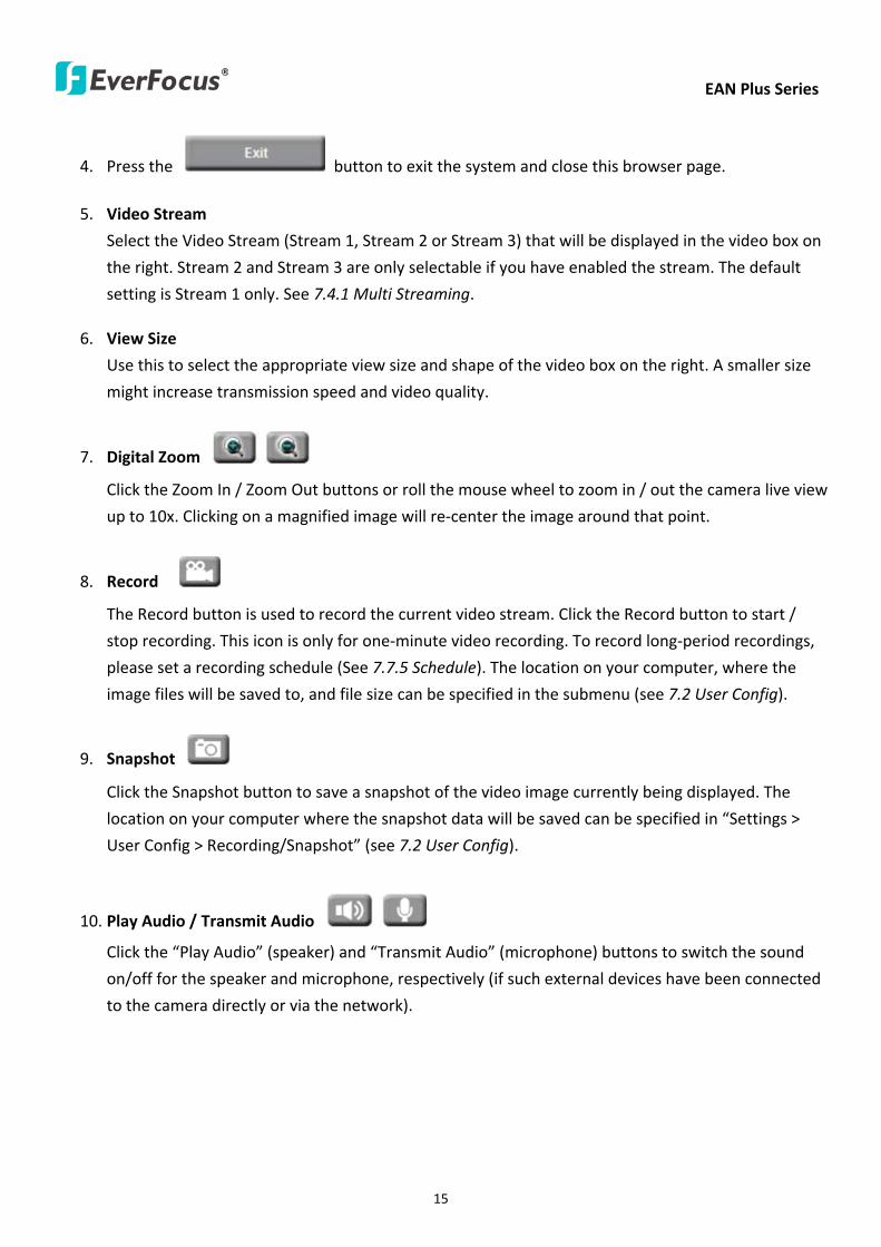
EAN Plus Series
15
4 Press the button to exit the system and close this browser page
5 Video Stream
Select the Video Stream (Stream 1 Stream 2 or Stream 3) that will be displayed in the video box on
the right Stream 2 and Stream 3 are only selectable if you have enabled the stream The default
setting is Stream 1 only See 741 Multi Streaming
6 View Size
Use this to select the appropriate view size and shape of the video box on the right A smaller size
might increase transmission speed and video quality
7 Digital Zoom
Click the Zoom In Zoom Out buttons or roll the mouse wheel to zoom in out the camera live view
up to 10x Clicking on a magnified image will re-center the image around that point
8 Record
The Record button is used to record the current video stream Click the Record button to start
stop recording This icon is only for one-minute video recording To record long-period recordings
please set a recording schedule (See 775 Schedule) The location on your computer where the
image files will be saved to and file size can be specified in the submenu (see 72 User Config)
9 Snapshot
Click the Snapshot button to save a snapshot of the video image currently being displayed The
location on your computer where the snapshot data will be saved can be specified in ldquoSettings gt
User Config gt RecordingSnapshotrdquo (see 72 User Config)
10 Play Audio Transmit Audio
Click the ldquoPlay Audiordquo (speaker) and ldquoTransmit Audiordquo (microphone) buttons to switch the sound
onoff for the speaker and microphone respectively (if such external devices have been connected
to the camera directly or via the network)
EAN Plus Series
16
11 One Push
This function is only available for EAN3120 Plus 3220 Plus The One Push button can be displayed
on the live view window by enabling the Show One Push Buttons function on the User Config lt Live
View Config Setting page (see 721 Live View Config) To enable the button (turned from faded to
clear) on the Video lt Advanced Setting page select One Push from the White Balance Settings
Mode drop-down list and click the Apply button Once this is done pressing the One Push button
on the Live View Window will instruct the camera to adjust the white balance settings and these
settings will be active until the button is pushed again This is like a ldquosemi-automaticrdquo way to adjust
white balance to suit the user if the Auto or Manual mode does not give the result the user wants
12 Manual Control
ndash Trigger Event
Press the ldquoTrigger Eventrdquo button to trigger an event directly from the Live page If you have
configured an event (in the Event submenu) that will trigger a reaction (like a recording) when a
Manual Trigger event occurs clicking this button will trigger that reaction You can select what that
reaction will be You can for instance set the camera to record the audiovideo feed to the Micro
SD card on board the camera You can then click on the Playback button to open the Playback page
and search for and play all such recordings that had been stored on the card Such event actions
will be effective once they have been configured in the ldquoEventrdquo menu (see 77 Event)
ndash Reset Alarm
Press the ldquoReset Alarmrdquo button to reset the alarm output remotely
13 Status Display (info lines that can be placed above video box or at bottom of page)
This shows the name of the camera that is currently active or being configured current datetime
and current frame rate You can activate these info displays in the Settings gt User Config page (see
72 User Config)
14 Event Signal Icons (above video screen)
When an alarm or motion event is triggered a signal icon will appear at the top right of the Live
View window to alert the user
Alarm event icon When an alarm is triggered this icon appears
Motion detection icons The colors of these motion event icons correspond to the colors of the motion trigger areas you have configured in the Motion Detection submenu (see 772
Motion Detection)
Recording icon When the camera is recording to a PC-based folder this icon appears
EAN Plus Series
17
6 Playback
You can remotely play back the recordings stored in the on-camera micro SD card on the Web interface
or play back the recordings stored in the computer using the ARV Viewer included in the software CD
Playback is designed as a quick way to check recent recordings that were triggered by Events that were
configured to ldquoRecord to SD Cardrdquo in the Settings gt Event gt Event Settings page (see 771 Event
Settings)
Note Note that the Playback page is only accessible once the on-camera SD card is inserted and
active
61 Remote Playback Using Playback Page
On the Live View Window click the Playback button to open the Playback page
EAN Plus Series
18
Search by File Click the Search button to search for all recording files on the on-camera SD card
Search results will be displayed in the Filename area
Search by Time Click the calendar icon and select the date and time from which you want to search
until the present moment Click search to get your search results which will be displayed in the
Filename area
Search by event Click the type of Event recordings you want to search for (Alarm Motion Manual
Trigger) and then click the calendar icons to select the Start Time datetime and the End Time
datetime of your search Click Search to get your search results which will be displayed in the
Filename area
Multiple Files Check this box if you want the video player to play all the files in the selected folder
The files will be displayed in the Filename area
Loop Again Check this box if you want the video player to play the selected file over and over again
Play Once you have opened the filersquos folder and have clicked on the file to highlight it its details will
be displayed in the File Information area You can now click Play to play that specific file
Pause Click this button to pause the playback
Stop Click this button to stop the playback
【Recording List】
Filename This area will display a list of search results (recording files and folders) Folders (named
with the recorded date) will be displayed first Click on the folder and click on each subfolder until the
recording files (arv) in that folder is listed
File Information Click a file on the Filename list the selected file information will be listed
Copy Click this button to copy the selected file to the computer-based folder of your choice A
browsing box will open so that you can search for the folder of your choice You can use the ARV
Viewer to play back the recordings recorded in your computer For details on ARV Viewer see 63
Playing Back Using ARV Viewer
Lock Click this button to lock the selected file This will protect that file from being overwritten during
any overwrite procedure The file will thus be saved on the micro SD card indefinitely However the
file will still be deleted if the micro SD card is ever formatted
Remove Click this button to delete the selected file
EAN Plus Series
19
62 Setting up the Playback Function
Note that the Playback function will not be active until the user has inserted a micro SD card in the
camerarsquos micro SD card slot The card may also have to be formatted in the Settings submenu
Micro SD Card Slot
621 Preparing the Micro SD Card
Once you insert a functional micro SD card into the slot the Playback button on the Live page should
become active within seconds (see section 622 below ndash the grey letters should turn white) IF NOT
do the following
1 From the Live page click Settings gt System gt SD Card If no card has been inserted yet the
Remove button should be faded indicating that no card is being detected (If a card is
inserted and the Remove button is still faded pull the card out and re-insert it)
2 Slide the card into the slot until it clicks into position
3 The Remove button should become active within a few seconds indicating the card is active
4 If the Remove button stays faded click the Format button to format the card NOTE All data
on the disk will be deleted if the Format button is clicked
622 Testing the Playback Function
1 Once the SD card is detected by the system the button (inactive)
will turn to (active)
2 To test the Playback function (this is not required) set up a ldquoManual Triggerrdquo Recording
Event by clicking Settings gt Event gt Event Settings
3 Click the ldquoAddrdquo button on the middle right side of the page to open an ldquoAdd Eventrdquo box
4 Give the event a name like ldquoTest 1rdquo
EAN Plus Series
20
5 In the ldquoEvent Triggered byrdquo field click on Manual Trigger
6 Below this check ldquoEnable This Eventrdquo ldquoEnable Post-trigger Bufferrdquo and ldquoRecord to SD Cardrdquo
7 To save your settings click OK or close the box by clicking on the red x icon at top right of the
box (in which case you will be asked if you want to save the data to which you should reply OK)
The box will close and the new event will be listed in the list area of the Event Settings page
8 Look at the ldquoPost-trigger Bufferrdquo at the bottom to make sure the buffer time is set to 10 seconds
9 Click ldquoApplyrdquo to make sure all settings are saved
10 Click the Live button to go back to the Live page
11 Get ready to click the Trigger Event button at the bottom of the page Before you do see if you
can find something in the view screen that will give you a visual time marker For instance if you
can get your hand in front of the camerarsquos lens get ready to count down on your fingers
12 Click the Trigger Event button and slowly count down on your fingers in front of the lens (if you
are able to do so ndash if not try to find visual cues on the view screen that will help you to mark the
moment you pushed the trigger) The recording period will be as long as the buffer time you
selected ndash the default period is 10 seconds
13 Click the Playback button to open the Playback page
14 There are different ways to search for recording files on the camerarsquos Micro SD card (ie the
Playback memory) For a recent recording like your test event simply click the ldquoSearchrdquo button
under the ldquoSearch by Filerdquo header
15 If the SD card is active and formatted correctly the recording folderrsquos name (the recording dayrsquos
date) will appear in the Filename box at the bottom Click on this folder to open it If there are
sub-folders click on the bottom one (the most recent would be at the bottom) until you can click
on a file that cannot open to another sub-level and shows data in the File Information box to the
right This would be the file of the most recent recording event
16 To play this file click the Play button below the video box The test footage you have recorded
should start playing Play time should be 10 seconds if you left the Post-trigger Buffer as 10
seconds
EAN Plus Series
21
63 Playing Back Using ARV Viewer
You can play back the recordings stored in the computer using the ARV Viewer included in the
software CD To store the recordings in the computer please refer to Recording List gt Copy in 61
Remote Playback using Playback Page
4 5 6 7 8 9 10
321
No Item Name Descriptions
1 Snapshot Click to take and save a snapshot
2 Load File Click to load the recordings for playing back
3 Convert ARV to AVI Convert the recording from ARV format to AVI format
4 Playback Time Display the playback time
5 Total Time of Recording Display the total time of the recording
6 Stop Click to stop playing the recording
7 Step Reverse Click to display the previous frame
8 Play Click to play back the recording
9 Pause Click to pause the recording
10 Step Forward Click to display the next frame
EAN Plus Series
22
7 Settings
Click the Settings button on the Live View Window to enter the settings submenu There are nine buttons
on the left-side of the submenu Live System Info User Config Network Video Audio User Event and
System Click the Live button can go back to the Live View Window
71 System Info
The System Information and System Log can be checked on this page Click the top tab of the one you
want to see
711 Information
Click the Information tab the following dialog box appears These values cannot be changed on this
page and are for reference only
EAN Plus Series
23
712 Log
Click the Log tab the following dialog box appears The sequence number date time and event
messages of the log event will be displayed in the System Log field The log will display the last 256
log events Click the Export button to export the system log event list into a ldquotxtrdquo file and select the
location where the exported log file will be saved to
EAN Plus Series
24
72 User Config
Each user can set a different configuration for hisher Live page here These settings will be applied to
the logged-in userrsquos Live page every time heshe logs in
721 Live View Config
【VideoAudio Connection Protocol Setting】You can transmit the data stream from the IP cameras
using the RTSP (Real Time Streaming Protocol) on the network The RTSP is a protocol that allows
you to access video streams by using the compatible media players Click Apply to apply the
changes or Reset to reset without saving the changes RTP over UDP The RTSP protocol uses UDP for camera data stream transmission
RTP over TCP The RTSP protocol uses TCP for camera data stream transmission
RTP over HTTP The RTSP protocol uses HTTP for camera data stream transmission
Nevio CGI This is EverFocusrsquo protocol designed for EverFocusrsquo IP devices Select this
protocol for camera data stream transmission
【Text Settings】Check the box of each option (Machine name DateTime Frame Rate) to display
this info on the Live View Page
Foreground Color Slide the Red Green and Blue bars to create your preferred text color for the
info text line
Position Select the position where the text will be displayed Choose from Upper Left Lower
Right Lower Left
Click Apply to apply the changes or Reset to reset without saving the changes
EAN Plus Series
25
【DateTime Format Used in Text】Click the dropdown menu to select datetime format from the
listed options Click on the desired hour format Click Apply to apply the setting changes or Reset to
reset without saving the change
【Live View Layout Settings】 Check the ldquoShow One Push Buttonsrdquo boxes if you want to show these
buttons on the Live View Page Uncheck these boxes to hide these buttons This function is only
available for EAN3120 Plus 3220 Plus
722 Recording Snapshot
This configures where your Record Button and Snapshot Button ( ) files will be saved if
you click one of these buttons Selectable folders will be on the computer only not on the
on-camera SD card
【Recording Snapshot Export Settings】
Enable Event Recording to PC Checking this box will let the system save RecordSnapshot Button
recordings to the folder configured below on the userrsquos PC
Export Folder Select the Export folder for the action above by clicking on the browse (hellip) button
and then select the desired folder
File size The user can limit the size of each recorded file here (in minutes) When a single
recording file exceeds the time you set the system will create a new file to save that data to
Overwrite Select ldquoONrdquo for overwriting recordingsnapshot file when the disk storage capacity is
full The user can set the storage capacity limitation in the in-sentence field in the gray box below
the Overwrite setting ldquoIf the remaining hard disk capacity is less than ____ MB (50~2000) system
will stop recording or start overwriting ldquo
Click Apply to apply the setting changes or Reset to reset without saving the changes
EAN Plus Series
26
723 Language
Select the language to be displayed on the Web interface of the IP camera The default language is
English
To add a new language not listed in the current Language list click the Browse button to locate
the new language file (evb) on your computer and then click the Upload button Updated
language files might be available on the manufacturerrsquos website Contact your vendor if required
Click Apply to apply any changes or Reset to reset without saving the changes
Note Uploading a new language file will cause the system to reboot automatically Please create
a new network connection to the IP camera when the reboot is complete
EAN Plus Series
27
73 Network
This page covers network-related settings including Network DDNS SMTPFTP HTTPS SNMP and
Network Alarm
731 Network
The following information is required to configure the network settings Contact your network
administrator or your internet service provider to get the info
【IP Settings】
IP Type Refer to the network administrator for these settings of the server Default DHCP
DHCP This setting lets the system use an automatically assigned (dynamic) IP address This
address can change under certain circumstances For instance when the camerarsquos network
switchhub has to be rebooted Do not assign to the DHCP server the same IP addresses used
for the other network cameras and PCs with unique IP addresses
Static IP The user can manually set the Static IP address This type of address is stable and
cannot change but the user has to make sure there are no address conflicts with other
network-connected devices
PPPoE This is a DSL-connection application The ISP will ask the user to input a username and
password Contact your ISP for these details
EAN Plus Series
28
Note If PPPoE is selected as the IP type the supplied IP Utility program will not be able to
detect the device
IP address When DHCP is not used the user needs to manually enter the IP address of the
camera Do not enter an IP address that is already used for your computer or other network
cameras
Subnet Mask This field is used to set the netmask for your network so that the IP camera will be
recognized within the network Example 2552552550 When DHCP is selected the DHCP server
will assign this value automatically
Gateway This field is used to set the gateway for your network so that the IP camera will be
recognized within the network When DHCP is selected the DHCP server will assign this value
automatically
Primary DNS Enter the IP address of the DNS server if this is provided by an ISP
Secondary DNS If your ISP provided you with a secondary DNS address please enter it here
Username Enter the accountrsquos username (used only for PPPoE)
Password Used only for PPPoE
IPv6 Enter the IPv6 details in this area if this applies to your system
Click Apply to apply the setting changes or Reset to reset without saving the change
【Port Settings】Enter the HTTP HTTPS and RTSP port numbers and click Apply to save
【Multicast Settings】Enable if required fill in the setting options and click Apply to save
EAN Plus Series
29
732 DDNS
DDNS (Dynamic Domain Name System) is a service used to map a domain name to the dynamic IP
address of a network device You can set up the DDNS service for remote access to the IP camera
DDNS assigns a domain name (URL) to the IP camera so that the user does not need to go through
the trouble of checking if the IP address assigned by DHCP Server has changed Once the IP is
changed the IP camera will automatically update the information to the DDNS to ensure it is always
available for remote access
Before enabling the following DDNS function user should have applied for a host name from the
DDS service providerrsquos website We support these four DDNS server providers
wwweverfocusddnscom wwwsitelutionscom wwwdyndnscom and wwwno-ipcom
Note We highly recommend that you use xxxxeverfocusddnscom for the simplicity of setting up
your IP cameras
【DDNS Settings】
Enable Check this box to enable the DDNS function
Service ISP You can either apply for a host name from EverFocus or other DDNS server providers
If you choose the EverFocus DDNS server you can obtain a free host name from EverFocus by
following the steps below
bull From EverFocus To obtain a free host name from EverFocus type a desired host name in the
textbox click the Register Update button and then click the Apply button
bull From other DDNS server providers To obtain a domain name from one of the three DDNS
server providers you have to register your name with the provider first and then select the
provider and fill in the required information Please refer to the specific DDNS companyrsquos
website for further information
Record ID Type the record ID if provided by the DDNS server provider
EAN Plus Series
30
FQDN Type the fully qualified domain name applied from the DDNS server provider For
example xxxxdyndnscom
Username Password Type the login account of your DDNS server provider
Click Apply to apply the setting changes or Reset to reset without saving the changes
Note
1 In order to support the full functionality of the camera you must open the port numbers (80
554 443) on the router for remote access to the IP camera This function is available on most
routers in the market and is often known as ldquoPort Forwardingrdquo To set up Port Forwarding
please consult the manual of the router
2 In certain router models it is possible that you will not be able to access the camera using
DDNS while inside the routerrsquos network Please try using a PC located outside of your routerrsquos
network
Default Ports on All EverFocus IP Cameras
HTTP 80
RTSP 554
HTTPS 443
EAN Plus Series
31
733 SMTP FTP
【Set SMTP Server (email)】This area is for configuring the mail server that is used to send e-mail
notifications from the camera to predefined addresses via SMTP Note that to enable e-mail
notification function you have to check the Send Mail Notification item on the Event dialog box
(see 771 Event Settings)
SMTP Server Enter the IP address or the host name of the SMTP server used to send e-mails
SMTP Port Enter the port number for SMTP The default is 25
Authentication Check this box if the SMTP server requires authentication (userpassword)
User name Input the userrsquos login ID if the SMTP server requires authentication
Password Input the userrsquos login password if the SMTP server requires authentication
EAN Plus Series
32
Receiver Address Input the e-mail addresses for receiving an e-mail message when an EVENT is
enabled and triggered Please use ldquordquo to separate multiple addresses
Sender Address Input the senderrsquos e-mail address so that the receiver can recognize the sender
when an Event message is received
Attach Image Check this box if you want to attach an image when an alarm is triggered or an IP
camera detects events
Send Test Email Click the Test button to send a testing email to the assigned address
Click Apply to apply the setting changes or Reset to reset without saving the changes
【Set FTP Server】The settings relating to the FTP server used to transmit the alarm images can be
configured here Note that to enable uploading images to the FTP server function you have to
check the Upload to FTP item on the Event dialog box (see 771 Event Settings)
FTP Server Enter the IP address or the host name of the FTP server
FTP Port Enter the port number for the FTP server Default is 21
Recording Path Assign the recording path
User Name Set FTP Userrsquos name
Password Set FTP password
PASV mode Check to enable Passive mode Passive mode is normally enabled If a connection
cannot be established uncheck PASV Moderdquo
Test FTP Server Click the Test button to send a testing file to the assigned FTP server
Click Apply to apply the setting changes or Reset to reset without saving the changes
EAN Plus Series
33
734 HTTPS
Hypertext Transfer Protocol Secure (HTTPS) is a combination of the Hypertext Transfer Protocol
and the SSLTLS protocol and provides encrypted communication and secure identification of a
network web server
Before using the HTTPS function for communication with the IP camera a Certificate must be
created first There are two ways to create and install a certificate Create Self-Signed Certificate
and Create Certificate Request
Create Self-Signed Certificate
Please note that even though self-signed certificates are free and offer some protection true
security is only implemented after the installation of a signed certificate issued by a certificate
authority
1 Click the Create Self-Signed Certificate button the following dialog appears
EAN Plus Series
34
2 Type the required Certificate information and then click the Apply button The subject line will
be displayed in the Installed Certificate Information field
3 Click the Property button a pop-up window appears to display the details of the certificate
4 To optionally create and install other certificates remove the existing one by clicking the
Remove button to erase the certificate
5 On the Web page change the address from ldquohttprdquo to https in the address bar and press
Enter on the keyboard Some Security Alert dialogs will pop up Click OK or Yes to enable HTTPS
Create Certificate Request
You can apply for an official certificate from an issuing Certificate Authority
1 Click the Create Certificate Request button the following dialog appears
EAN Plus Series
35
2 Type the required Certificate information and then click the Apply button The subject line will
be displayed in the Created Request field
3 Click the Property button a pop-up window appears to display the details of the certificate
4 To optionally create and install other certificates or request remove the existing one by clicking
the Remove button to erase the certificate or request
5 Copy the contents of the Certificate request (in PEM format) and paste it to the certificate
request field on the Web page of the 3rd-party certification authority such as Symantec VeriSign
Wait for the certificate authority to issue an SSLTLS certificate and then download the issued
certificate on your computer
6 In the Install Signed Certificate field click the Browse button to search for the issued certificate
and then click the Upload button to import the certificate Once the certificate has been
uploaded this field will show the subject line of the certificate
EAN Plus Series
36
735 SNMP
The default values for SNMP v1v2v2c and SNMP v3 are already filled in Click either of the
Enable buttons to enable either of the two Make your changes as desired Click on the Trap
Address field to enter the digits if required
736 Network Alarm
This function works with EverFocusrsquos CMS software eg the PowerCon or the Power Video Plus For
the setting details please refer to the CMS network alarm protocol
EAN Plus Series
37
74 Video
The settings relating to video such as streaming camera OSD can be configured on this page The
Video page has five tabs Multi-streaming Camera Advanced ROI and Privacy Mask
741 Multi Streaming
【Stream Settings】 This IP camera can output three video streams simultaneously For each of these
streams the user can set the compression format resolution bit rate and frame rate individually
Stream 1 is always enabled for live view To enable Stream 2 andor Stream 3 check the ldquoEnablerdquo
box the header of each stream
Note If you connect to the camera via the Internet and experience a delay (lag time) in the video
feed try to reduce the number of streams and the quality and resolution of the streams ndash but
keep the frame rate at its maximum
EAN Plus Series
38
Format Select the encoding format ndash H264 or MJPEG
Resolution Select the most suitable resolution for your needs
Frame Rate Select from 1 to 30 fps
Bit Rate If required select whether you want the stream to stream a Constant Bit Rate or a
Variable Bit Rate and set the values of whichever option you choose
Click Apply to apply the setting changes or Reset to reset without saving the changes
【Video Recording Settings】Select the stream you want to configure and then select whether you
want the recording files of that stream to be saved in AVI or ARV format Click Apply to apply the
setting changes or Reset to reset without saving the changes
【Time Stamp Settings】 You can select the DateTime format position and add the setting to the
streaming
Click Apply to apply the changes or Reset to reset without saving the changes
EAN Plus Series
39
742 Camera
【Image Settings】Set the Brightness Saturation Contrast or Sharpness of the image Click Apply to
apply the changes or Reset to reset without saving the changes
【Camera Settings】
Mirror Switch Mirror ON to rotate the image horizontally around a vertical axis
Flip Switch Flip ON to rotate the image vertically around a horizontal axis
AE There are two options
ALC Selecting Automatic Light Control allows the camera circuitry to either take bright spots
more into consideration (peak) bringing out detail in bright areas or less into consideration
(average) bringing out detail in shadows
AES Selecting Auto Electronic Shutter disables the Shutter setting below this setting In this
mode the camera measures the light level and decides whether it needs more or less light and
then automatically adjusts the shutter speed accordingly
BLC Back Light Compensation (BLC) is used to make the subject appear clearer when it is set
against a bright background
OFF Select to switch Back Light Compensation functions off
(ON)BLC The BLC can increase the exposure of a dark area surrounded by a brighter area HLC
can decrease the exposure of bright areas surrounded by darker areas This enables the
camera to better display information that would otherwise have been ldquowhited outrdquo like a
license plate between two bright headlights on a dark road
(ON)HLC The Highlight-Suppression BLC is used to reduce the brightness of light sources in a
specific area It is activated only in a low illumination environment to minimize the effects of
glare from bright lights such as spotlights street lights or headlights in the field of view
EAN Plus Series
40
WDR The Wide Dynamic Range (WDR) function provides clearer images when both of the very
bright and dark areas simultaneously appear on the camera view There are four value options
OFF Low Middle and High Note that when WDR is ON some parts of the image may appear
solarized This is normal for WDR and is not a camera malfunction This function is only available
for EAN3120 Plus 3220 Plus
DN Mode
Auto Select to let the camera automatically switch to Night mode (black and white) when the
light levels fall to a specified level and back to Day mode (color) when the light levels rise to a
specified level
Day Select to keep the camera in Day mode (color) even in nighttime
Night Select to keep the camera in Night mode (black and white) even in daytime
EAN Plus Series
41
743 Advanced
EAN Plus Series
42
【Camera Settings】
Lens (IRIS Control) Select DC or Manual for IRIS control This function is only available for EAN3220
Plus
Exposure Settings (AE) This setting is used to adapt to the amount or type of light used by the
camera Note the settings vary among models
Mode This function is not available for EAN3220 Plus
Automatic Light Control (ALC) This option is only available for EAN3120 Plus 3300 Plus The
ALC allows the camera circuitry to either take bright spots more into consideration (peak)
bringing out detail in bright areas or less into consideration (average) bringing out detail in
shadows
Auto Electronic Shutter (AES) This option is only available for EAN3120 Plus 3300 Plus In
this mode the camera measures the light level and decides whether it needs more or less light
and then automatically adjusts the shutter speed accordingly
Manual This option is only available for EAN3300 Plus Select this option to manually set up
the Shutter (Manual) and AGC (Manual) values
Iris Specify the size of the Iris opening here
Shutter If enabled this setting lets you set the shutter speed yourself
Shutter Limit Use this setting to set the maximum shutter speed for the camera This function is
only available for EAN3120 Plus
AGC Set the Auto Gain Control limit here The lower the AGC level the lower the video signal and
the noise However the image will be darker under low-light condition with IR-off if you set up the
Iris to the maximum level
Slow Shutter This option can be switched on when AES Mode is selected in the Exposure Settings
(AE) field This function is only available for EAN3220 Plus 3300 Plus
Flickerless If the Mode field in the Exposure Settings (AE) area has been set to AES then this option
becomes available Choose between OFF 50HZ 60HZ 50HZ (High Luminance) or 60HZ (High
Luminance) This function is only available for EAN3300 Plus
EV Setting Set up the Exposure Value Note the brightness of the screen changes when you change
the EV value This function is only available for EAN3300 Plus
AE Response Set up Auto Exposure Response time This function is only available for EAN3300 Plus
AE Weighting Area Select an AE Weighting area Each setup AE Weighting Area is configured with
the appropriate brightness level on the center and the surrounding areas This function is only
available for EAN3300 Plus
Brightness Set the image brightness here
AE Reference Set the Auto Exposure value here This function is only available for EAN3120 Plus
EAN Plus Series
43
Black Level Set the Black level here This function is only available for EAN3300 Plus
WDR The Wide Dynamic Range (WDR) function provides clearer images when both of the very
bright and dark areas simultaneously appear on the camera view There are four value options OFF
Low Middle and High Note that when WDR is ON some parts of the image may appear solarized
This is normal for WDR and is not a camera malfunction This function is only available for EAN3120
Plus 3220 Plus
Visibility Enhancement (OFFLowMiddleHigh) Images in foggy or rain environments or in
environments with a very strong luminous intensity have a dynamic range that is significantly lower
than ordinary images The user can use this Visibility Enhancement setting to ldquoDEFOGrdquo the image if
such ldquoFOGGINGrdquo is an issue This function is only available for EAN3220 Plus
BLC Settings Back Light Compensation (BLC) is used to make the subject appear clearer when it is
set against a bright background
OFF Select to switch Back Light Compensation functions off
Back Light This option is only available for EAN3300 Plus The Back Light function is useful
when the background of the subject is very bright and the subject itself is dark Select Back
Light and adjust the slide bar to the left right for setting up the back light value The higher
the value the more the backlight compensation
Front Light This option is only available for EAN3300 Plus This function is useful when the
bright highlights such as flashlight or car headlights appear on the camera view Select Front
Light and adjust the slide bar to the left right for setting up the front light value The higher
the value the more the highlight compensation
ON (BLC) This option is only available when you select AES Mode in the Exposure Settings (AE)
field The option is only available for EAN3120 Plus 3220 Plus The BLC function is useful
when the background of the subject is very bright and the subject itself is dark Follow the
instructions below to configure the settings for each model
For EAN3120 Select ON (BLC) the button next to the Mode drop-down list will be
active (see image below) Click the button the green setup areas appear on the left
screen Click on the areas to enable disable the BLC function The selected areas (in green)
will be applied with the BLC function
EAN Plus Series
44
For EAN3220
You can configure one area to apply the BLC function Select ON (BLC) the setup buttons
appears (see image below) Select Low Middle High from the BLC Gain drop-down list To
set up a BLC area click the Edit Area button and then click on the blue color tab to turn your
mouse cursor into a blue pen Move the cursor to the position on the right screen where you
want the BLC rectangle to start and then click Move your cursor to the position (diagonally
opposing corner) where you want the BLC rectangle to end and then click The blue area will
be applied with the BLC function
ON (HLC) This option is only available when you select AES Mode in the Exposure Settings (AE)
field The option is only available for EAN3120 Plus 3220 Plus This function is useful when
the bright highlights such as flashlight or car headlights appear on the camera view Follow
the instructions below to configure the settings for each model
For EAN3120 Select ON (HLC) and then select a level from the drop-down list The higher the
level the more the highlight compensation
For EAN3220
HLC Level Select a level for the HLC setting The higher the level the more the highlight
compensation
HLC Mode Select All Day Night mode to apply the HLC function
HLC Black Mask Select On Off to apply the black mask on the selected areas The
over-exposure portions within the selected areas will be applied with the black mask
Color Tabs You can set up four HLC areas with different colors To set up a HLC area click the
Edit Area button and then click on the color tab to turn your mouse cursor into a pen of that
color Move the cursor to the position on the right screen where you want the HLC rectangle
to start and then click Move your cursor to the position (diagonally opposing corner) where
you want the HLC rectangle to end and then click Select ON from the color tab drop-down list
The rectangular area with the selected color will be applied with the HLC function
EAN Plus Series
45
Back Light This option is only available for EAN3300 Plus The Back Light function is useful
when the background of the subject is very bright and the subject itself is dark Select Back
Light and adjust the slide bar to the left right for setting up the back light value The higher
the value the more the backlight compensation
Front Light This option is only available for EAN3300 Plus This function is useful when the
bright highlights such as flashlight or car headlights appear on the camera view Select Front
Light and adjust the slide bar to the left right for setting up the front light value The higher
the value the more the highlight compensation
Noise Reduction Settings This limits the amount of digital ldquovideo noiserdquo that is usually found in any
video stream and helps to reduce file size The higher the level the more the reduction
For EAN3120 Plus 3300 Plus
Select ON OFF to enable disable the Noise Reduction function Or select Auto to let the camera
automatically enable disable the Noise Reduction function Slide the Level bar to set up the level
The higher the level the more the reduction
For EAN3220 Plus
2D DNR Select ON to enable the 2D DNR function
3D DNR Select ON to enable the 3D DNR function You can further set up the following settings
3D Start AGC Set up the AGC level to automatically start the 3D NR function
3D End AGC Set up the AGC level to automatically stop the 3D NR function
3D Level Set up the 3D DNR level
Smart NR Select ON to enable the Smart NR function The 3D NR function will be
automatically turned on when a motion event occurs
EAN Plus Series
46
White Balance Settings Select the mode that delivers the best quality image for the camerarsquos light
environment There are five options Auto Manual Indoor Outdoor One Push
Auto Select to let the camera automatically adjust the White Balance In the Auto mode the
camera computes the white balance value output using color information from the entire
screen It outputs the proper value using the color temperature radiating from a black subject
based on a range of value from 3000 to 7500K
Manual Select to adjust the Red and Blue values yourself in the fields below this field
Indoor Select to use the default settings for indoor environments In the Indoor mode the
camera uses 3200K as the base value
Outdoor Select to use the default settings for outdoor environment In the Outdoor mode it
uses 5800K as the base value
One Push Select to enable the Push button next to the Mode drop-down field This will allow you to force the camera to readjust the white balance every time you push the Push
button The lens will hold the same focal position until the next trigger command is received
This function helps to prevent incorrect focusing in dark environments This function is only
available for EAN3120 Plus 3220 Plus
Manual Temperature Select to use the optimized Red and Blue settings You can also
optionally adjust the Manual Level below this field for setting up the color temperature The
higher the value the more the color temperature This function is only available for EAN3300
Plus
DayNight Settings
Auto Select to let the camera automatically switch to Night mode (black and white) when the
light levels fall to a specified level and back to Day mode (color) when the light levels rise to a
specified level
Day Select to keep the camera in Day mode (color) even in nighttime
Night Select to keep the camera in Night mode (black and white) even in daytime
IR Smart Settings Select ON and set up the level to enhance the image quality when the images are
over exposure This function is useful when the camera is in the Night mode This function is only
available for EAN3220 Plus
Saturation Set the saturation value This function is not available for EAN3220 Plus
Monitor Type Select a gamma value from Set 1 Set 2 or Set 3 This function is only available for
EAN3120 Plus
Negative Switch this setting ON to view a color negative version of the video image This is useful
at night or when viewing temperature-sensitive images
EAN Plus Series
47
Sharpness Settings Select the sharpness level of the image A low sharpness level will deliver a
softer less detailed image A high level will deliver a sharp highly detailed image Switch Resolution
Enhancement ON to enable the resolution enhancement function
Contrast Select the contrast level of the image
Suppress Function This function is only available for EAN3300 Plus
Aperture Compensation Suppression (OFFLowMiddleHigh) This setting can be activated to
suppress luminance noise when the AGC level increases
Chroma Suppression (OFFLowMiddleHigh) This setting can be activated to suppress
chrominance noise when the AGC level increases
Ygamma (gamma 22standardcontrast enhancehigh light range mode LHigh light range mode
H) Select the Ygamma value for the video quality of the monitor This function is only available for
EAN3300 Plus
Monitor Settings The user can use this field to optimize video quality for his or her specific type of
monitor ndash LCD or CRT This function is only available for EAN3220 Plus
Color Space Standard The options are YUV601 for SD and YUV709 for HD These define the color
space standard required to convert an RGB picture to a YUV picture Generally YUV601 is used for
Standard Definition (720P) devices and the YUV709 is used for High Definition (1080P) devices
Click Apply to save all changes Click Reset to cancel all changes
EAN Plus Series
48
744 ROI (Region of Interest)
The Region of Interest (ROI) function allows users to set up multiple regions within an image with
better quality and less distortion than the rest of the image You can also use this function
together with the Digital Zoom function on the Live View Page to get a better image result Up to
eight ROIs can be configured in the ROI settings page
To set up an ROI region
1 Select an ROI number from the ROI No drop-down list
2 Click the Add button the mouse cursor will turn into a pen when you move it over the live
image on the left
3 Move the cursor to the position where you want the ROI rectangle to start and then click
Move the cursor to the position (diagonally opposing corner) where you want the ROI
rectangle to end and then click
4 Slide the Quality bar to set up the quality value
5 Click the Apply button to apply the settings or click the Reset button to reset without saving
the settings
EAN Plus Series
49
745 Privacy Mask
The Privacy Mask can block out sensitive areas from view covering the areas with colored or black
and white boxes in both live view and recorded clips This feature is useful when usersrsquo donrsquot want
the sensitive information visible Up to four Privacy Masks can be configured
【Privacy Mask Color Settings】The Modes vary among camera models
Mode Click Color to make the masks appear as colored rectangles on the screen Click BW to
make the masks appear as gray rectangles on the screen Click Mosaic to make the masks appear
as mosaic-effect rectangles on the screen
Level Select the color of the masks if you selected Color Mode Select the level of grayness of the
masks if you selected BW Mode Select the level of smallmiddlelarge if you selected Mosaic
Mode
Click Apply to apply the settings or click Reset to reset without saving the settings
Color Tabs Click on a color tab to turn your mouse cursor into a pen of that color
You can now create a block of that color on the video screen Move your cursor to the position
where you want your mask rectangle to start and then click Move your cursor to the position
(diagonally opposing corner) where you want your mask rectangle to end and then click The
rectangular area with the selected color will appear The live image will display the rectangular
area with the color you selected If you want to create another mask use one of the other three
colors Each color denotes a different mask area Only one block per color is allowed As the
number of colors suggests you can configure up to four blocks
EAN Plus Series
50
Select All Click to turn the whole screen into a mask area
Clear All Click to delete all configured mask blocks
Eraser Click to turn the mouse cursor into an eraser to delete any block you click on
Area Shows the color and number of the block
Enable Check this box to enable the related mask block
Click Apply to apply the settings or click Reset to reset without saving the settings
EAN Plus Series
51
75 Audio
The EAN Plus series IP camera can transmit audio to your computer if you have connected an external
microphone to its audio Input cable It can also receive audio input from you and transmit it via an
external speaker if you have connected such a speaker to its audio Output cable
Check the Enable Audio box to enable the camerarsquos audio function The camera will now act as a
digital bridge (via the IP network) between any connected audio input device and any connected
audio device
Adjust the Audio Input Volume if you have external audio input devices (microphones) connected to
the camera and if there are problems with the sound input being too low or high
Click Apply to save all settings or click Reset to cancel
EAN Plus Series
52
76 User
761 User Information
The system administrator can create up to ten user accounts on this page
To set up a user account
1 Highlight a user account and click the Modify button The following dialog box appears
2 Type the account name account description and password for the account Type the password
again in the Confirm field
3 Select an authority level for the user account from the Authority drop-down list
bull Supervisor Administrator The only difference between a supervisor and administrator is
that a supervisor can edit an administratorrsquos account and password but an administrator
cannot edit the supervisorrsquos account and password Multiple administrators can be
configured but there can be only one supervisor The supervisor and administrators all
have unrestricted access to the Settings submenus and can determine the registration of
all other users
EAN Plus Series
53
bull User A user can view the Live View page and view the system network video and audio
information A user can only adjust the User Config page settings The user does not have
access to the User Event and System pages
bull Guest The lowest level of access which only allows the user access to the Live View page
4 Select Active or Disable from the Status drop-down list to active or disable the user account
5 Click On in the SD Card Playback field to allow the user to access the SD card playback
function
6 Click OK
7 Click Apply to save all the settings
EAN Plus Series
54
762 IP Address Filter
Use this page to specify IP addresses that are not allowed to access this camera By default any IP
address can access the camera
Note The Allowed List addresses only become relevant when the Denied List contains a network
or range and the supervisor wants to allow one or more IP addresses within that excluded range
or network In such a scenario the user would enter the excluded range or network in the
Denied List and enter the exceptions in the Allowed List
To set up the IP Address Filter
1 Select Denied List Click the Add button the following dialog box appears
2 Select an IP type from the IP Type drop-down list
3 Select a network rule from the Rule drop-down list type the IP address and click OK
Single Type a single IP address in the IP Address field below
Network Type the IP address and subnet mask in the field below
Range Type a range for the IP addresses
4 If you have set up an IP range in Step 3 you can optionally set up the Allowed List to allow one
or more IP addresses within the setup IP range to access the IP camera
5 Click Apply
EAN Plus Series
55
77 Event
You can set up the Motion Detection event Tamper Detection event or the Alarm IO to automatically
notify the users when an event occurs or an alarm is triggered You can also set up a schedule to
automatically record the videos when an event occurs or an alarm is triggered
771 Event Settings
You can create a total of ten event or alarm settings page in the Event List
【Event List】
Click the Add button and the following Event Configuration Window appears
EAN Plus Series
56
Enter Event Name Type an event name
Event Triggered by Select an event or alarm type for the to-be-specified-below reactions
Alarm Input Select this if you want a reaction trigger coming from any external connected sensor
to activate a to-be-specified-below reactions via the camera system Make sure that a suitable
device is actually connected to the alarm input relay
Manual Trigger Select this option if you want to manually trigger the alarm by clicking the Trigger
Event button on the Live View Page
Motion Detection Select this option if you want motion in a specified part of the camerarsquos viewing
rectangle (the screen image) to trigger the to-be-specified-below reactions
Tampering Detection Select this option if you want the camerarsquos tampering detection sensor to
trigger the to-be-specified-below reactions
Schedule Recording Select this option if you want the Schedule Recording periods configured in
the recording schedule (the Settings gt Event gt Schedule page) to activate this event In this
scenario a preconfigured event reaction like a log entry will list the start and end times of each
period Actual recording will only be triggered if the event is preconfigured to do so
Enable This Event Select to activate the event
Enable Re-trigger Click to set a minimum time after the event is triggered before the event
can be triggered again
Enable Pre-trigger Buffer Click if you want the Event reaction (as selected in the ldquoNotification
Overrdquo field below) to be the activation of the video recording function and if you want the
recording to include the video feed from the time period (configurable on the previous ldquoEvent
Settingsrdquo page) just before the Event trigger occurred
Enable Post-trigger Buffer Click if you want the Event reaction (as selected in the Notification
Over field) to be the activation of the video recording function and if you want the recording
to include the video feed from a time period (configurable on the Event Settings page) just
after the Event trigger occurred
Motion Area Select a setup motion detection area from the drop down list Note this
function only becomes relevant after the Motion Detection areas have been set up (see 772
Motion Detection)
Notification Over Select the desired notification types form the following items
Log Click if you want the camera to list the eventrsquos details in its log if the event is triggered
Trigger Alarm Output Click if you want the camera to relay the event reaction to a device
attached to the alarm relay output wire and then set up the alarm output duration time
EAN Plus Series
57
Send Mail Notification Click if you want the camera to send an Event notification email to the
email address entered in the Set SMTP Server(email) field of the Network gt SMTPFTP page if
the Event occurs (see 733 SMTP FTP)
Upload to FTP Click if you want the camera to upload recorded footage to the FTP server
entered in the Set SMTP Server(email) field of the Network gt SMTPFTP page if the Event
occurs (see 733 SMTP FTP)
Record to SD Card Click if you want the camera to start recording its video feed (when the
event occurs) on an on-camera SD Card (if such a card has been inserted)
Note The recording will only be as long as the combined Pre- and Post-trigger Buffers so
make sure you enable at least one of these buffers especially the Post-trigger Buffer
Record to PC Check this box if you want the camera to start recording its video feed (when
the event occurs) on the same folder on the same PC as configured on the User Config gt
RecordingSnapshot page (if such a folder has been enabled and configured)
Note The recording will only be as long as the combined Pre- and Post-trigger Buffers (and
for as long as the event trigger is happening ndash eg a motion is detected) so make sure you
enable at least one of these buffers especially the Post-trigger Buffer
Network Alarm Check this box if you want the camera to send a network alarm signal (when
the event occurs) to the CMS servers configured on the Network gt Network Alarm page (see
736 Network Alarm)
Click OK to save all settings or click Cancel to cancel
【PrePost Trigger Settings】
Pre-trigger Buffer Select the duration for the buffer This will determine the amount of footage
(length of time) before the event trigger moment that will be included in an event-triggered video
recording if that buffer and video recording has been enabled in the Event Configuration Window
Post-trigger Buffer Select the duration for the buffer This will determine the amount of footage
(length of time) after the event trigger moment that will be included in an event-triggered video
recording if that buffer and video recording has been enabled in the Event Configuration Window
Click Apply to save all settings or click Reset to cancel
EAN Plus Series
58
772 Motion Detection
Use this page to configure up to four areas in which motion will be detected When a motion is
detected by the camera the motion detection icon will appear at the top right of the
Live page to alert the user This function can also be linked with correctly configured Events to
trigger Event reactions like the activation of video recording periods snapshots alarms etc
Color Tabs Click on a color tab to turn your mouse cursor into a pen of that color
You can now create a block of that color on the video screen Move your cursor to the position
where you want your detection rectangle to start and then click Move your cursor to the position
(diagonally opposing corner) where you want your detection rectangle to end and then click The
rectangular area with the selected color will appear This block will be an area inside which the
camera will detect motion If you want to create another detection area use one of the other three
palette colors Each color denotes a different detection area Only one block per color is allowed As
the number of colors suggests you can configure up to four blocks
Select All Click to turn the whole screen into a motion detection area
Clear All Click to delete all configured motion detection blocks
Eraser Click to turn your mouse cursor into an eraser to delete any block you click on
Area Shows the color and numberID of the block
Enable Check this box to enable the related motion detection block
Sensitivity Set the sensitivity of the motion detection sensor function
Click Apply to save all settings or click Reset to cancel
EAN Plus Series
59
773 Tamper Detection
Use this page to set the number of seconds that an alarm signal will be active if the device is
physically tampered (moved covered up or out of focus
774 Alarm IO
Use this page to set the type of trigger input and the type of output contact for the camerarsquos alarm
channel
EAN Plus Series
60
775 Schedule
Use this page to configure a schedule for periods during which the camera should deactivate all
user-activated Events (gray Deselect periods) or when the camera should deactivate all
user-activated Events except Schedule Recording (SR) events (blue Schedule Recording-only
periods) or when the camera should deactivate only SR events (red Event Recording-only periods)
or when it should enable all activated Events (yellow periods)
Event Recording Click this button to make every hour block you click on red A red block represents
an Event Recording-only block which represents an hour when the camera will deactivate all
preconfigured activated Schedule Recording events and keep all the other activated events active
Schedule Recording Click this button to make every hour block you click on blue A blue block
represents a Schedule Recording-only block which represents an hour when the camera will
deactivate all other preconfigured activated events and keep only the preconfigured activated
Schedule Recording events active
Event + Schedule Click this button to make every hour block you click on yellow A yellow block
represents an hour in which all activated events including Schedule Recording events will be
active
Deselect Click this button to make every hour block become grey A grey block represents an hour
in which all activated events including Schedule Recording events will be inactive
Click Apply to save all settings or click Reset to cancel
EAN Plus Series
61
78 System
You can set up the systemrsquos time and SD card settings and to do maintenance and reset actions like
reboots and upgrades
781 DateTime
【Machine Name Settings】If required enter a new name for the machine This name will be visible
in the Machine Name field of the IP Utility software which is included in the software CD
【Set Time Zone】Set the time zone of the camerarsquos location
【Set DateTime Manually】Set the datetime here if you wonrsquot be using an NTP server to update the
datetime (see below)
【Set DateTime Sync】Enter the Network Time Protocol server if applicable The camerarsquos time will
be automatically adjusted by synchronizing with the NTP server
Click Apply to save all settings or click Reset to cancel
EAN Plus Series
62
782 Daylight Saving
Click Enable Daylight Saving to enable this schedule and select the dates when the regionrsquos
daylight saving period begins and ends Click Apply to save all settings or click Reset to cancel
783 SD Card
Use this page to prepare the system for safely removing the SD Card from its slot
【Setup SD Card】
Notification Select the percentage of storage space that should be left on the card before the
camera notifies you of the impending storage shortage or overwrite
Event Recording Select if you want Event Recording only FTP Backup only or both
Overwrite Click ON if you want the card to start writing over recorded footage when its memory is
full Click OFF if you want the card to stop recording new footage when its memory is full
【SD Card Utility】
Capacity This shows you how much card memory has been used and how much memory capacity
remains on the card
Remove Click this button before removing the card from the system
Format Click this button to format the card All data saved on the SD card will be removed if the
card is formatted
EAN Plus Series
63
784 Maintenance
【Maintenance Server】
Reboot Click this button to reboot the unit without changing any of the settings Use this function if
the unit is not behaving as expected
Restore Click this button to restart and reset most of the current settings to their factory default
values The only settings that will not be changed to default are
bull IP settings
bull DDNS settings
Default The Default button should be used with caution Pressing this button will return all of the
cameras settings including the IP address to the factory default values The camera will then have
to be reconfigured
【SaveLoad Configuration Server】
Save To make a backup file of the machinersquos current configurations press Save to save all the
configurations to a config file This will enable the user to reload these configuration settings if the
settings are changed and there is unexpected behavior
Load To load a previously saved configuration press the Browse button to locate the saved config
file (see above) and then click the Load button The systemrsquos settings will be restored to the saved
configuration
EAN Plus Series
64
【SaveLoad Video Configuration Server】
Save To make a backup file of the machinersquos video configurations press Save to save the video
configurations to a config file This will enable the user to reload these configuration settings if the
settings are changed and there is unexpected behavior
Load To load a previously saved video configuration press the Browse button to locate the saved
config file (see above) and then click the Load button The systemrsquos settings will be restored to the
saved video configuration
【Upgrade Firmware】Click the Browse button to find a previously prepared firmware upgrade file
Click Upgrade to install the new firmware
Note
1 Do not disconnect power to the unit during the upgrade sequence The unit will reboot
automatically after the upgrade has completed (1-5 minutes)
2 During the upgrade process all event recording actions will be stopped Event recording
actions will resume after the camera is rebooted
3 If the ldquoFile Error Please re-loginrdquo warning message appears when upgrading the firmware
please try the following instructions
a Go to Internet Explorer gt Tools gt Internet Option gt Security gt Custom
b Find and enable the Include local directory path when uploading files to a server
EAN Plus Series
65
8 Upgrading Firmware Using IP Utility
You can upgrade the Firmware using the IP Utility software included in the software CD
1 Install and then start the IPU program The following dialog box appears
2 Click Find Devices to search the cameras connected in the LAN The default network values of the
cameras will be displayed By default the network protocol of the camera is DHCP
3 Select a camera and click LoginMulti Login to log in the camera
4 Type the user ID and password Click OK
Note
1 The default user ID is user1 and the default password is 11111111
2 If you select more than one camera that has the same user ID password you will be able
to log in several cameras at once
EAN Plus Series
66
5 Highlight the camera and then click Upgrade Firmware A browsing window appears
6 Select the firmware file (evb) and then click Open The IP Utility will automatically upgrade the
firmware
The camera will reboot once the update is complete Click Find Devices the new firmware version
should be displayed in the last part of the Machine Name
EAN Plus Series
67
9 Specifications
Model EAN3120 Plus EAN3220 Plus EAN3300 Plus
Camera
Image Sensor 13 Panasonic CMOS 128 Sony CMOS
Megapixel 13 MP 2 MP 3 MP
Picture Elements (H x V) 1280 x 1024 1944 x 1092 2048 x 1536
Min Illuminations 003 Lux at F14
Electronic Shutter (Sec) 85 ~ 160000 2 ~ 150000 1 ~ 110000
Scanning System NTSC PAL
WDR Yes Yes No
BLC Yes
Gain Control Yes
White Balance Yes
Lens
Mounting Type C CS
Day Night Yes (with removable auto IR-cut filter)
IRIS Control DC Electrical IRIS Lens IRIS
Video
Video Compression H264 MJPEG
Resolution
NTSC
2048 x 1536 1920 x 1200 (for EAN3300 Plus only)
1920 x 1080 (for EAN3300 Plus 3220 Plus only)
1280 x 1024 1280 x 720 1024 x 768 720 x 480 704 x 480 640 x 480
352 x 240 320 x 240 160 x 120
PAL
2048 x 1536 1920 x 1200 (for EAN3300 Plus only)
1920 x 1080 (for EAN3300 Plus 3220 Plus only)
1280 x 1024 1280 x 720 1024 x 768 720 x 576 704 x 576 640 x 480
352 x 288 320 x 240 160 x 120
Frame Rate 30 fps at 1280 x 1024 30 fps at 1920 x 1080 15 fps at 2048 x 1536
Audio
Audio Streaming Two-way audio
Audio Compression G711
EAN Plus Series
68
Network
Interface 10 100 Base-T Ethernet RJ-45 socket
Supported Protocols
TCPIP IPV6 UDP ICMP DHCP NTP DNS DDNS SMTP SNMP FTP
HTTP HTTPs PPPoE UPnP Bonjour RTP RTSP RTCP IGMP ARP ONVIF
PSIA
Connector
Power DC female port PoE
Ethernet RJ-45
Audio 1 In (phone jack for microphone)
1 Out (phone jack for Speaker)
Alarm IO Terminal IO wires
Local Storage Micro SD SDHC memory card slot
TV-Out BNC socket composite 1 V p-p 75 Ω
General
Power Source DC 12V PoE (IEEE8023af)
Power Consumption
(IR LEDs On)
5W (DC 12V)
621W (PoE)
5W (DC 12V)
522W (PoE)
5W (DC 12V)
536W (PoE)
Operating Temperature 0degC ~ +50degC 32degF ~ +122degF
Humidity 20 to 80 (no condensation)
Safety CE FCC
Dimensions (L x W x H) 117 x 56 x 68 mm 46 x 22 x 27 in
Weight 410 g 09 lb
EverFocus Electronics Corp EverFocus Taiwan 12F No79 Sec 1 Shin-Tai Wu Road Hsi-Chih Taipei Taiwan TEL +886 2 2698 2334 FAX +886 2 2698 2380 wwweverfocuscomtw marketingeverfocuscomtw
EverFocus Europe - Germany Albert-Einstein-Strasse 1 D-46446 Emmerich Germany TEL +49 2822 93940 FAX +49 2822 939495 wwweverfocusde infoeverfocusde
EverFocus China - Beijing Room 609 Technology Trade Building Shangdi Information Industry Base Haidian District Beijing 100085 China TEL +86 10 6297 3336~39 FAX +86 10 6297 1423 wwweverfocuscomcn marketingeverfocuscomcn
EverFocus China - Shenzhen 4F No 2 D4 Building Wan Yelong Industrial Park Tangtou Road Shiyan Baoan Shenzhen Guangdong 518101 China TEL +86 755 2765 1313 FAX +86 755 2765 0337 wwweverfocuscomcn marketingeverfocuscomcn
EverFocus USA - California 1801 Highland Avenue Unit A Duarte CA 91010 USA TEL +1 626 844 8888 FAX +1 626 844 8838 wwweverfocuscom saleseverfocuscom
EverFocus USA - New York 415 Oser Avenue Unit S Hauppauge NY 11788 USA TEL +1 631 436 5070 FAX +1 631 436 5027 wwweverfocuscom saleseverfocuscom
EverFocus Japan 5F Kinshicho City Building 2-13-4 Koto-BashiSumida-Ku Tokyo 130-0022 Japan TEL +81 3 5625 8188 FAX +81 3 5625 8189 wwweverfocuscojp infoeverfocuscojp
EverFocus Europe - UK Unit 12 Spitfire Business Park Hawker Road Croydon Surrey CR0 4WD UK TEL +44 20 8649 9757 +44 845 430 9999 FAX +44 20 8649 9907 wwweverfocusukcouk salesukeverfocuscom
EverFocus India Suite 803 Housefin Bhavan C-21 Bandra Kurla Complex Bandra (East) Mumbai 400051 India TEL +91 22 6128 8700 FAX +91 22 6128 8705 wwweverfocusin saleseverfocusin
PN 4605PQ3120B010A-VerC
Your EverFocus product is designed and manufactured with high quality materials and components which can be recycled and reused This symbol means that electrical and electronic equipment at their end-of-life should be disposed of separately from your household waste Please dispose of this equipment at your local community waste collectionrecycling centre In the European Union there are separate collection systems for used electrical and electronic product Please help us to conserve the environment we live in
Ihr EverFocus Produkt wurde entwickelt und hergestellt mit qualitativ hochwertigen Materialien und Komponenten die recycelt und wieder verwendet werden koumlnnen Dieses Symbol bedeutet dass elektrische und elektronische Geraumlte am Ende ihrer Nutzungsdauer vom Hausmuumlll getrennt entsorgt werden sollen Bitte entsorgen Sie dieses Geraumlt bei Ihrer oumlrtlichen kommunalen Sammelstelle oder im Recycling Centre Helfen Sie uns bitte die Umwelt zu erhalten in der wir leben
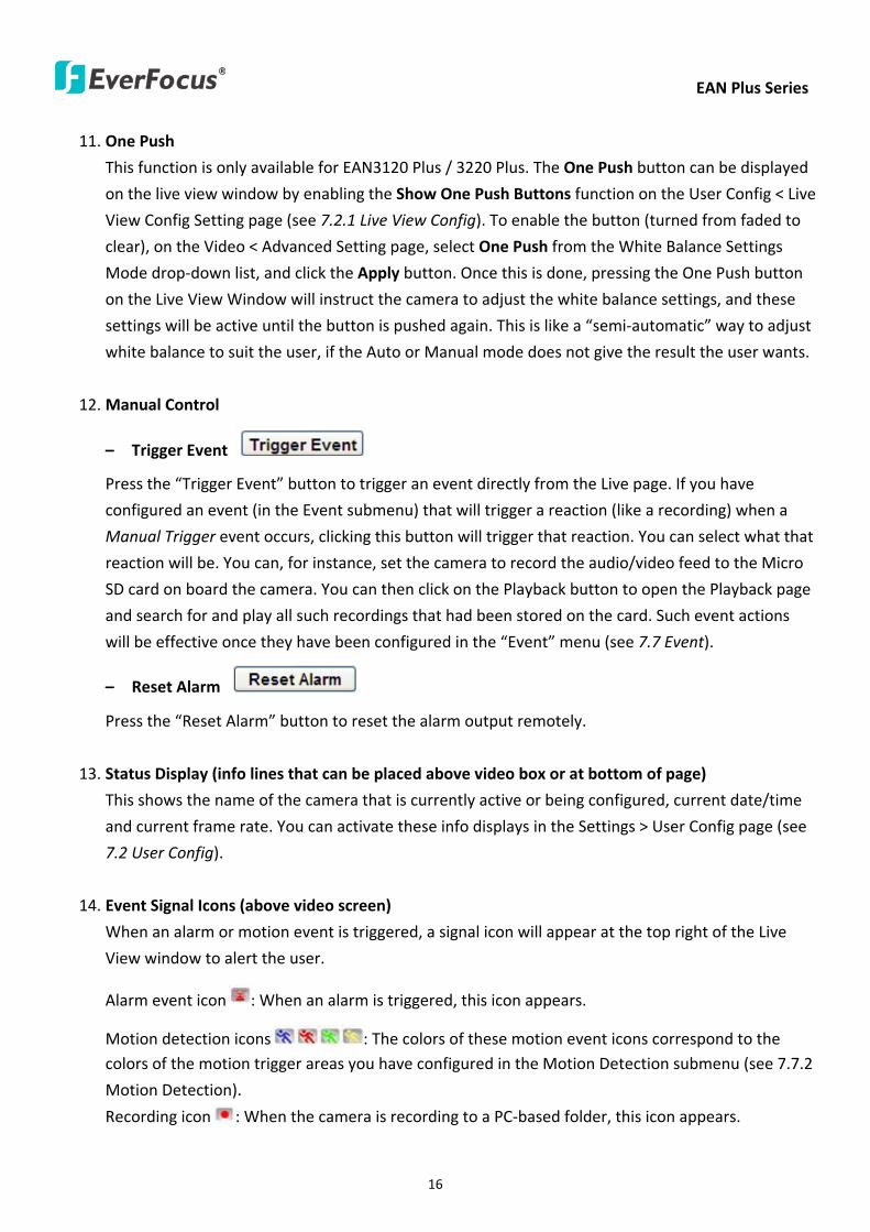
EAN Plus Series
16
11 One Push
This function is only available for EAN3120 Plus 3220 Plus The One Push button can be displayed
on the live view window by enabling the Show One Push Buttons function on the User Config lt Live
View Config Setting page (see 721 Live View Config) To enable the button (turned from faded to
clear) on the Video lt Advanced Setting page select One Push from the White Balance Settings
Mode drop-down list and click the Apply button Once this is done pressing the One Push button
on the Live View Window will instruct the camera to adjust the white balance settings and these
settings will be active until the button is pushed again This is like a ldquosemi-automaticrdquo way to adjust
white balance to suit the user if the Auto or Manual mode does not give the result the user wants
12 Manual Control
ndash Trigger Event
Press the ldquoTrigger Eventrdquo button to trigger an event directly from the Live page If you have
configured an event (in the Event submenu) that will trigger a reaction (like a recording) when a
Manual Trigger event occurs clicking this button will trigger that reaction You can select what that
reaction will be You can for instance set the camera to record the audiovideo feed to the Micro
SD card on board the camera You can then click on the Playback button to open the Playback page
and search for and play all such recordings that had been stored on the card Such event actions
will be effective once they have been configured in the ldquoEventrdquo menu (see 77 Event)
ndash Reset Alarm
Press the ldquoReset Alarmrdquo button to reset the alarm output remotely
13 Status Display (info lines that can be placed above video box or at bottom of page)
This shows the name of the camera that is currently active or being configured current datetime
and current frame rate You can activate these info displays in the Settings gt User Config page (see
72 User Config)
14 Event Signal Icons (above video screen)
When an alarm or motion event is triggered a signal icon will appear at the top right of the Live
View window to alert the user
Alarm event icon When an alarm is triggered this icon appears
Motion detection icons The colors of these motion event icons correspond to the colors of the motion trigger areas you have configured in the Motion Detection submenu (see 772
Motion Detection)
Recording icon When the camera is recording to a PC-based folder this icon appears
EAN Plus Series
17
6 Playback
You can remotely play back the recordings stored in the on-camera micro SD card on the Web interface
or play back the recordings stored in the computer using the ARV Viewer included in the software CD
Playback is designed as a quick way to check recent recordings that were triggered by Events that were
configured to ldquoRecord to SD Cardrdquo in the Settings gt Event gt Event Settings page (see 771 Event
Settings)
Note Note that the Playback page is only accessible once the on-camera SD card is inserted and
active
61 Remote Playback Using Playback Page
On the Live View Window click the Playback button to open the Playback page
EAN Plus Series
18
Search by File Click the Search button to search for all recording files on the on-camera SD card
Search results will be displayed in the Filename area
Search by Time Click the calendar icon and select the date and time from which you want to search
until the present moment Click search to get your search results which will be displayed in the
Filename area
Search by event Click the type of Event recordings you want to search for (Alarm Motion Manual
Trigger) and then click the calendar icons to select the Start Time datetime and the End Time
datetime of your search Click Search to get your search results which will be displayed in the
Filename area
Multiple Files Check this box if you want the video player to play all the files in the selected folder
The files will be displayed in the Filename area
Loop Again Check this box if you want the video player to play the selected file over and over again
Play Once you have opened the filersquos folder and have clicked on the file to highlight it its details will
be displayed in the File Information area You can now click Play to play that specific file
Pause Click this button to pause the playback
Stop Click this button to stop the playback
【Recording List】
Filename This area will display a list of search results (recording files and folders) Folders (named
with the recorded date) will be displayed first Click on the folder and click on each subfolder until the
recording files (arv) in that folder is listed
File Information Click a file on the Filename list the selected file information will be listed
Copy Click this button to copy the selected file to the computer-based folder of your choice A
browsing box will open so that you can search for the folder of your choice You can use the ARV
Viewer to play back the recordings recorded in your computer For details on ARV Viewer see 63
Playing Back Using ARV Viewer
Lock Click this button to lock the selected file This will protect that file from being overwritten during
any overwrite procedure The file will thus be saved on the micro SD card indefinitely However the
file will still be deleted if the micro SD card is ever formatted
Remove Click this button to delete the selected file
EAN Plus Series
19
62 Setting up the Playback Function
Note that the Playback function will not be active until the user has inserted a micro SD card in the
camerarsquos micro SD card slot The card may also have to be formatted in the Settings submenu
Micro SD Card Slot
621 Preparing the Micro SD Card
Once you insert a functional micro SD card into the slot the Playback button on the Live page should
become active within seconds (see section 622 below ndash the grey letters should turn white) IF NOT
do the following
1 From the Live page click Settings gt System gt SD Card If no card has been inserted yet the
Remove button should be faded indicating that no card is being detected (If a card is
inserted and the Remove button is still faded pull the card out and re-insert it)
2 Slide the card into the slot until it clicks into position
3 The Remove button should become active within a few seconds indicating the card is active
4 If the Remove button stays faded click the Format button to format the card NOTE All data
on the disk will be deleted if the Format button is clicked
622 Testing the Playback Function
1 Once the SD card is detected by the system the button (inactive)
will turn to (active)
2 To test the Playback function (this is not required) set up a ldquoManual Triggerrdquo Recording
Event by clicking Settings gt Event gt Event Settings
3 Click the ldquoAddrdquo button on the middle right side of the page to open an ldquoAdd Eventrdquo box
4 Give the event a name like ldquoTest 1rdquo
EAN Plus Series
20
5 In the ldquoEvent Triggered byrdquo field click on Manual Trigger
6 Below this check ldquoEnable This Eventrdquo ldquoEnable Post-trigger Bufferrdquo and ldquoRecord to SD Cardrdquo
7 To save your settings click OK or close the box by clicking on the red x icon at top right of the
box (in which case you will be asked if you want to save the data to which you should reply OK)
The box will close and the new event will be listed in the list area of the Event Settings page
8 Look at the ldquoPost-trigger Bufferrdquo at the bottom to make sure the buffer time is set to 10 seconds
9 Click ldquoApplyrdquo to make sure all settings are saved
10 Click the Live button to go back to the Live page
11 Get ready to click the Trigger Event button at the bottom of the page Before you do see if you
can find something in the view screen that will give you a visual time marker For instance if you
can get your hand in front of the camerarsquos lens get ready to count down on your fingers
12 Click the Trigger Event button and slowly count down on your fingers in front of the lens (if you
are able to do so ndash if not try to find visual cues on the view screen that will help you to mark the
moment you pushed the trigger) The recording period will be as long as the buffer time you
selected ndash the default period is 10 seconds
13 Click the Playback button to open the Playback page
14 There are different ways to search for recording files on the camerarsquos Micro SD card (ie the
Playback memory) For a recent recording like your test event simply click the ldquoSearchrdquo button
under the ldquoSearch by Filerdquo header
15 If the SD card is active and formatted correctly the recording folderrsquos name (the recording dayrsquos
date) will appear in the Filename box at the bottom Click on this folder to open it If there are
sub-folders click on the bottom one (the most recent would be at the bottom) until you can click
on a file that cannot open to another sub-level and shows data in the File Information box to the
right This would be the file of the most recent recording event
16 To play this file click the Play button below the video box The test footage you have recorded
should start playing Play time should be 10 seconds if you left the Post-trigger Buffer as 10
seconds
EAN Plus Series
21
63 Playing Back Using ARV Viewer
You can play back the recordings stored in the computer using the ARV Viewer included in the
software CD To store the recordings in the computer please refer to Recording List gt Copy in 61
Remote Playback using Playback Page
4 5 6 7 8 9 10
321
No Item Name Descriptions
1 Snapshot Click to take and save a snapshot
2 Load File Click to load the recordings for playing back
3 Convert ARV to AVI Convert the recording from ARV format to AVI format
4 Playback Time Display the playback time
5 Total Time of Recording Display the total time of the recording
6 Stop Click to stop playing the recording
7 Step Reverse Click to display the previous frame
8 Play Click to play back the recording
9 Pause Click to pause the recording
10 Step Forward Click to display the next frame
EAN Plus Series
22
7 Settings
Click the Settings button on the Live View Window to enter the settings submenu There are nine buttons
on the left-side of the submenu Live System Info User Config Network Video Audio User Event and
System Click the Live button can go back to the Live View Window
71 System Info
The System Information and System Log can be checked on this page Click the top tab of the one you
want to see
711 Information
Click the Information tab the following dialog box appears These values cannot be changed on this
page and are for reference only
EAN Plus Series
23
712 Log
Click the Log tab the following dialog box appears The sequence number date time and event
messages of the log event will be displayed in the System Log field The log will display the last 256
log events Click the Export button to export the system log event list into a ldquotxtrdquo file and select the
location where the exported log file will be saved to
EAN Plus Series
24
72 User Config
Each user can set a different configuration for hisher Live page here These settings will be applied to
the logged-in userrsquos Live page every time heshe logs in
721 Live View Config
【VideoAudio Connection Protocol Setting】You can transmit the data stream from the IP cameras
using the RTSP (Real Time Streaming Protocol) on the network The RTSP is a protocol that allows
you to access video streams by using the compatible media players Click Apply to apply the
changes or Reset to reset without saving the changes RTP over UDP The RTSP protocol uses UDP for camera data stream transmission
RTP over TCP The RTSP protocol uses TCP for camera data stream transmission
RTP over HTTP The RTSP protocol uses HTTP for camera data stream transmission
Nevio CGI This is EverFocusrsquo protocol designed for EverFocusrsquo IP devices Select this
protocol for camera data stream transmission
【Text Settings】Check the box of each option (Machine name DateTime Frame Rate) to display
this info on the Live View Page
Foreground Color Slide the Red Green and Blue bars to create your preferred text color for the
info text line
Position Select the position where the text will be displayed Choose from Upper Left Lower
Right Lower Left
Click Apply to apply the changes or Reset to reset without saving the changes
EAN Plus Series
25
【DateTime Format Used in Text】Click the dropdown menu to select datetime format from the
listed options Click on the desired hour format Click Apply to apply the setting changes or Reset to
reset without saving the change
【Live View Layout Settings】 Check the ldquoShow One Push Buttonsrdquo boxes if you want to show these
buttons on the Live View Page Uncheck these boxes to hide these buttons This function is only
available for EAN3120 Plus 3220 Plus
722 Recording Snapshot
This configures where your Record Button and Snapshot Button ( ) files will be saved if
you click one of these buttons Selectable folders will be on the computer only not on the
on-camera SD card
【Recording Snapshot Export Settings】
Enable Event Recording to PC Checking this box will let the system save RecordSnapshot Button
recordings to the folder configured below on the userrsquos PC
Export Folder Select the Export folder for the action above by clicking on the browse (hellip) button
and then select the desired folder
File size The user can limit the size of each recorded file here (in minutes) When a single
recording file exceeds the time you set the system will create a new file to save that data to
Overwrite Select ldquoONrdquo for overwriting recordingsnapshot file when the disk storage capacity is
full The user can set the storage capacity limitation in the in-sentence field in the gray box below
the Overwrite setting ldquoIf the remaining hard disk capacity is less than ____ MB (50~2000) system
will stop recording or start overwriting ldquo
Click Apply to apply the setting changes or Reset to reset without saving the changes
EAN Plus Series
26
723 Language
Select the language to be displayed on the Web interface of the IP camera The default language is
English
To add a new language not listed in the current Language list click the Browse button to locate
the new language file (evb) on your computer and then click the Upload button Updated
language files might be available on the manufacturerrsquos website Contact your vendor if required
Click Apply to apply any changes or Reset to reset without saving the changes
Note Uploading a new language file will cause the system to reboot automatically Please create
a new network connection to the IP camera when the reboot is complete
EAN Plus Series
27
73 Network
This page covers network-related settings including Network DDNS SMTPFTP HTTPS SNMP and
Network Alarm
731 Network
The following information is required to configure the network settings Contact your network
administrator or your internet service provider to get the info
【IP Settings】
IP Type Refer to the network administrator for these settings of the server Default DHCP
DHCP This setting lets the system use an automatically assigned (dynamic) IP address This
address can change under certain circumstances For instance when the camerarsquos network
switchhub has to be rebooted Do not assign to the DHCP server the same IP addresses used
for the other network cameras and PCs with unique IP addresses
Static IP The user can manually set the Static IP address This type of address is stable and
cannot change but the user has to make sure there are no address conflicts with other
network-connected devices
PPPoE This is a DSL-connection application The ISP will ask the user to input a username and
password Contact your ISP for these details
EAN Plus Series
28
Note If PPPoE is selected as the IP type the supplied IP Utility program will not be able to
detect the device
IP address When DHCP is not used the user needs to manually enter the IP address of the
camera Do not enter an IP address that is already used for your computer or other network
cameras
Subnet Mask This field is used to set the netmask for your network so that the IP camera will be
recognized within the network Example 2552552550 When DHCP is selected the DHCP server
will assign this value automatically
Gateway This field is used to set the gateway for your network so that the IP camera will be
recognized within the network When DHCP is selected the DHCP server will assign this value
automatically
Primary DNS Enter the IP address of the DNS server if this is provided by an ISP
Secondary DNS If your ISP provided you with a secondary DNS address please enter it here
Username Enter the accountrsquos username (used only for PPPoE)
Password Used only for PPPoE
IPv6 Enter the IPv6 details in this area if this applies to your system
Click Apply to apply the setting changes or Reset to reset without saving the change
【Port Settings】Enter the HTTP HTTPS and RTSP port numbers and click Apply to save
【Multicast Settings】Enable if required fill in the setting options and click Apply to save
EAN Plus Series
29
732 DDNS
DDNS (Dynamic Domain Name System) is a service used to map a domain name to the dynamic IP
address of a network device You can set up the DDNS service for remote access to the IP camera
DDNS assigns a domain name (URL) to the IP camera so that the user does not need to go through
the trouble of checking if the IP address assigned by DHCP Server has changed Once the IP is
changed the IP camera will automatically update the information to the DDNS to ensure it is always
available for remote access
Before enabling the following DDNS function user should have applied for a host name from the
DDS service providerrsquos website We support these four DDNS server providers
wwweverfocusddnscom wwwsitelutionscom wwwdyndnscom and wwwno-ipcom
Note We highly recommend that you use xxxxeverfocusddnscom for the simplicity of setting up
your IP cameras
【DDNS Settings】
Enable Check this box to enable the DDNS function
Service ISP You can either apply for a host name from EverFocus or other DDNS server providers
If you choose the EverFocus DDNS server you can obtain a free host name from EverFocus by
following the steps below
bull From EverFocus To obtain a free host name from EverFocus type a desired host name in the
textbox click the Register Update button and then click the Apply button
bull From other DDNS server providers To obtain a domain name from one of the three DDNS
server providers you have to register your name with the provider first and then select the
provider and fill in the required information Please refer to the specific DDNS companyrsquos
website for further information
Record ID Type the record ID if provided by the DDNS server provider
EAN Plus Series
30
FQDN Type the fully qualified domain name applied from the DDNS server provider For
example xxxxdyndnscom
Username Password Type the login account of your DDNS server provider
Click Apply to apply the setting changes or Reset to reset without saving the changes
Note
1 In order to support the full functionality of the camera you must open the port numbers (80
554 443) on the router for remote access to the IP camera This function is available on most
routers in the market and is often known as ldquoPort Forwardingrdquo To set up Port Forwarding
please consult the manual of the router
2 In certain router models it is possible that you will not be able to access the camera using
DDNS while inside the routerrsquos network Please try using a PC located outside of your routerrsquos
network
Default Ports on All EverFocus IP Cameras
HTTP 80
RTSP 554
HTTPS 443
EAN Plus Series
31
733 SMTP FTP
【Set SMTP Server (email)】This area is for configuring the mail server that is used to send e-mail
notifications from the camera to predefined addresses via SMTP Note that to enable e-mail
notification function you have to check the Send Mail Notification item on the Event dialog box
(see 771 Event Settings)
SMTP Server Enter the IP address or the host name of the SMTP server used to send e-mails
SMTP Port Enter the port number for SMTP The default is 25
Authentication Check this box if the SMTP server requires authentication (userpassword)
User name Input the userrsquos login ID if the SMTP server requires authentication
Password Input the userrsquos login password if the SMTP server requires authentication
EAN Plus Series
32
Receiver Address Input the e-mail addresses for receiving an e-mail message when an EVENT is
enabled and triggered Please use ldquordquo to separate multiple addresses
Sender Address Input the senderrsquos e-mail address so that the receiver can recognize the sender
when an Event message is received
Attach Image Check this box if you want to attach an image when an alarm is triggered or an IP
camera detects events
Send Test Email Click the Test button to send a testing email to the assigned address
Click Apply to apply the setting changes or Reset to reset without saving the changes
【Set FTP Server】The settings relating to the FTP server used to transmit the alarm images can be
configured here Note that to enable uploading images to the FTP server function you have to
check the Upload to FTP item on the Event dialog box (see 771 Event Settings)
FTP Server Enter the IP address or the host name of the FTP server
FTP Port Enter the port number for the FTP server Default is 21
Recording Path Assign the recording path
User Name Set FTP Userrsquos name
Password Set FTP password
PASV mode Check to enable Passive mode Passive mode is normally enabled If a connection
cannot be established uncheck PASV Moderdquo
Test FTP Server Click the Test button to send a testing file to the assigned FTP server
Click Apply to apply the setting changes or Reset to reset without saving the changes
EAN Plus Series
33
734 HTTPS
Hypertext Transfer Protocol Secure (HTTPS) is a combination of the Hypertext Transfer Protocol
and the SSLTLS protocol and provides encrypted communication and secure identification of a
network web server
Before using the HTTPS function for communication with the IP camera a Certificate must be
created first There are two ways to create and install a certificate Create Self-Signed Certificate
and Create Certificate Request
Create Self-Signed Certificate
Please note that even though self-signed certificates are free and offer some protection true
security is only implemented after the installation of a signed certificate issued by a certificate
authority
1 Click the Create Self-Signed Certificate button the following dialog appears
EAN Plus Series
34
2 Type the required Certificate information and then click the Apply button The subject line will
be displayed in the Installed Certificate Information field
3 Click the Property button a pop-up window appears to display the details of the certificate
4 To optionally create and install other certificates remove the existing one by clicking the
Remove button to erase the certificate
5 On the Web page change the address from ldquohttprdquo to https in the address bar and press
Enter on the keyboard Some Security Alert dialogs will pop up Click OK or Yes to enable HTTPS
Create Certificate Request
You can apply for an official certificate from an issuing Certificate Authority
1 Click the Create Certificate Request button the following dialog appears
EAN Plus Series
35
2 Type the required Certificate information and then click the Apply button The subject line will
be displayed in the Created Request field
3 Click the Property button a pop-up window appears to display the details of the certificate
4 To optionally create and install other certificates or request remove the existing one by clicking
the Remove button to erase the certificate or request
5 Copy the contents of the Certificate request (in PEM format) and paste it to the certificate
request field on the Web page of the 3rd-party certification authority such as Symantec VeriSign
Wait for the certificate authority to issue an SSLTLS certificate and then download the issued
certificate on your computer
6 In the Install Signed Certificate field click the Browse button to search for the issued certificate
and then click the Upload button to import the certificate Once the certificate has been
uploaded this field will show the subject line of the certificate
EAN Plus Series
36
735 SNMP
The default values for SNMP v1v2v2c and SNMP v3 are already filled in Click either of the
Enable buttons to enable either of the two Make your changes as desired Click on the Trap
Address field to enter the digits if required
736 Network Alarm
This function works with EverFocusrsquos CMS software eg the PowerCon or the Power Video Plus For
the setting details please refer to the CMS network alarm protocol
EAN Plus Series
37
74 Video
The settings relating to video such as streaming camera OSD can be configured on this page The
Video page has five tabs Multi-streaming Camera Advanced ROI and Privacy Mask
741 Multi Streaming
【Stream Settings】 This IP camera can output three video streams simultaneously For each of these
streams the user can set the compression format resolution bit rate and frame rate individually
Stream 1 is always enabled for live view To enable Stream 2 andor Stream 3 check the ldquoEnablerdquo
box the header of each stream
Note If you connect to the camera via the Internet and experience a delay (lag time) in the video
feed try to reduce the number of streams and the quality and resolution of the streams ndash but
keep the frame rate at its maximum
EAN Plus Series
38
Format Select the encoding format ndash H264 or MJPEG
Resolution Select the most suitable resolution for your needs
Frame Rate Select from 1 to 30 fps
Bit Rate If required select whether you want the stream to stream a Constant Bit Rate or a
Variable Bit Rate and set the values of whichever option you choose
Click Apply to apply the setting changes or Reset to reset without saving the changes
【Video Recording Settings】Select the stream you want to configure and then select whether you
want the recording files of that stream to be saved in AVI or ARV format Click Apply to apply the
setting changes or Reset to reset without saving the changes
【Time Stamp Settings】 You can select the DateTime format position and add the setting to the
streaming
Click Apply to apply the changes or Reset to reset without saving the changes
EAN Plus Series
39
742 Camera
【Image Settings】Set the Brightness Saturation Contrast or Sharpness of the image Click Apply to
apply the changes or Reset to reset without saving the changes
【Camera Settings】
Mirror Switch Mirror ON to rotate the image horizontally around a vertical axis
Flip Switch Flip ON to rotate the image vertically around a horizontal axis
AE There are two options
ALC Selecting Automatic Light Control allows the camera circuitry to either take bright spots
more into consideration (peak) bringing out detail in bright areas or less into consideration
(average) bringing out detail in shadows
AES Selecting Auto Electronic Shutter disables the Shutter setting below this setting In this
mode the camera measures the light level and decides whether it needs more or less light and
then automatically adjusts the shutter speed accordingly
BLC Back Light Compensation (BLC) is used to make the subject appear clearer when it is set
against a bright background
OFF Select to switch Back Light Compensation functions off
(ON)BLC The BLC can increase the exposure of a dark area surrounded by a brighter area HLC
can decrease the exposure of bright areas surrounded by darker areas This enables the
camera to better display information that would otherwise have been ldquowhited outrdquo like a
license plate between two bright headlights on a dark road
(ON)HLC The Highlight-Suppression BLC is used to reduce the brightness of light sources in a
specific area It is activated only in a low illumination environment to minimize the effects of
glare from bright lights such as spotlights street lights or headlights in the field of view
EAN Plus Series
40
WDR The Wide Dynamic Range (WDR) function provides clearer images when both of the very
bright and dark areas simultaneously appear on the camera view There are four value options
OFF Low Middle and High Note that when WDR is ON some parts of the image may appear
solarized This is normal for WDR and is not a camera malfunction This function is only available
for EAN3120 Plus 3220 Plus
DN Mode
Auto Select to let the camera automatically switch to Night mode (black and white) when the
light levels fall to a specified level and back to Day mode (color) when the light levels rise to a
specified level
Day Select to keep the camera in Day mode (color) even in nighttime
Night Select to keep the camera in Night mode (black and white) even in daytime
EAN Plus Series
41
743 Advanced
EAN Plus Series
42
【Camera Settings】
Lens (IRIS Control) Select DC or Manual for IRIS control This function is only available for EAN3220
Plus
Exposure Settings (AE) This setting is used to adapt to the amount or type of light used by the
camera Note the settings vary among models
Mode This function is not available for EAN3220 Plus
Automatic Light Control (ALC) This option is only available for EAN3120 Plus 3300 Plus The
ALC allows the camera circuitry to either take bright spots more into consideration (peak)
bringing out detail in bright areas or less into consideration (average) bringing out detail in
shadows
Auto Electronic Shutter (AES) This option is only available for EAN3120 Plus 3300 Plus In
this mode the camera measures the light level and decides whether it needs more or less light
and then automatically adjusts the shutter speed accordingly
Manual This option is only available for EAN3300 Plus Select this option to manually set up
the Shutter (Manual) and AGC (Manual) values
Iris Specify the size of the Iris opening here
Shutter If enabled this setting lets you set the shutter speed yourself
Shutter Limit Use this setting to set the maximum shutter speed for the camera This function is
only available for EAN3120 Plus
AGC Set the Auto Gain Control limit here The lower the AGC level the lower the video signal and
the noise However the image will be darker under low-light condition with IR-off if you set up the
Iris to the maximum level
Slow Shutter This option can be switched on when AES Mode is selected in the Exposure Settings
(AE) field This function is only available for EAN3220 Plus 3300 Plus
Flickerless If the Mode field in the Exposure Settings (AE) area has been set to AES then this option
becomes available Choose between OFF 50HZ 60HZ 50HZ (High Luminance) or 60HZ (High
Luminance) This function is only available for EAN3300 Plus
EV Setting Set up the Exposure Value Note the brightness of the screen changes when you change
the EV value This function is only available for EAN3300 Plus
AE Response Set up Auto Exposure Response time This function is only available for EAN3300 Plus
AE Weighting Area Select an AE Weighting area Each setup AE Weighting Area is configured with
the appropriate brightness level on the center and the surrounding areas This function is only
available for EAN3300 Plus
Brightness Set the image brightness here
AE Reference Set the Auto Exposure value here This function is only available for EAN3120 Plus
EAN Plus Series
43
Black Level Set the Black level here This function is only available for EAN3300 Plus
WDR The Wide Dynamic Range (WDR) function provides clearer images when both of the very
bright and dark areas simultaneously appear on the camera view There are four value options OFF
Low Middle and High Note that when WDR is ON some parts of the image may appear solarized
This is normal for WDR and is not a camera malfunction This function is only available for EAN3120
Plus 3220 Plus
Visibility Enhancement (OFFLowMiddleHigh) Images in foggy or rain environments or in
environments with a very strong luminous intensity have a dynamic range that is significantly lower
than ordinary images The user can use this Visibility Enhancement setting to ldquoDEFOGrdquo the image if
such ldquoFOGGINGrdquo is an issue This function is only available for EAN3220 Plus
BLC Settings Back Light Compensation (BLC) is used to make the subject appear clearer when it is
set against a bright background
OFF Select to switch Back Light Compensation functions off
Back Light This option is only available for EAN3300 Plus The Back Light function is useful
when the background of the subject is very bright and the subject itself is dark Select Back
Light and adjust the slide bar to the left right for setting up the back light value The higher
the value the more the backlight compensation
Front Light This option is only available for EAN3300 Plus This function is useful when the
bright highlights such as flashlight or car headlights appear on the camera view Select Front
Light and adjust the slide bar to the left right for setting up the front light value The higher
the value the more the highlight compensation
ON (BLC) This option is only available when you select AES Mode in the Exposure Settings (AE)
field The option is only available for EAN3120 Plus 3220 Plus The BLC function is useful
when the background of the subject is very bright and the subject itself is dark Follow the
instructions below to configure the settings for each model
For EAN3120 Select ON (BLC) the button next to the Mode drop-down list will be
active (see image below) Click the button the green setup areas appear on the left
screen Click on the areas to enable disable the BLC function The selected areas (in green)
will be applied with the BLC function
EAN Plus Series
44
For EAN3220
You can configure one area to apply the BLC function Select ON (BLC) the setup buttons
appears (see image below) Select Low Middle High from the BLC Gain drop-down list To
set up a BLC area click the Edit Area button and then click on the blue color tab to turn your
mouse cursor into a blue pen Move the cursor to the position on the right screen where you
want the BLC rectangle to start and then click Move your cursor to the position (diagonally
opposing corner) where you want the BLC rectangle to end and then click The blue area will
be applied with the BLC function
ON (HLC) This option is only available when you select AES Mode in the Exposure Settings (AE)
field The option is only available for EAN3120 Plus 3220 Plus This function is useful when
the bright highlights such as flashlight or car headlights appear on the camera view Follow
the instructions below to configure the settings for each model
For EAN3120 Select ON (HLC) and then select a level from the drop-down list The higher the
level the more the highlight compensation
For EAN3220
HLC Level Select a level for the HLC setting The higher the level the more the highlight
compensation
HLC Mode Select All Day Night mode to apply the HLC function
HLC Black Mask Select On Off to apply the black mask on the selected areas The
over-exposure portions within the selected areas will be applied with the black mask
Color Tabs You can set up four HLC areas with different colors To set up a HLC area click the
Edit Area button and then click on the color tab to turn your mouse cursor into a pen of that
color Move the cursor to the position on the right screen where you want the HLC rectangle
to start and then click Move your cursor to the position (diagonally opposing corner) where
you want the HLC rectangle to end and then click Select ON from the color tab drop-down list
The rectangular area with the selected color will be applied with the HLC function
EAN Plus Series
45
Back Light This option is only available for EAN3300 Plus The Back Light function is useful
when the background of the subject is very bright and the subject itself is dark Select Back
Light and adjust the slide bar to the left right for setting up the back light value The higher
the value the more the backlight compensation
Front Light This option is only available for EAN3300 Plus This function is useful when the
bright highlights such as flashlight or car headlights appear on the camera view Select Front
Light and adjust the slide bar to the left right for setting up the front light value The higher
the value the more the highlight compensation
Noise Reduction Settings This limits the amount of digital ldquovideo noiserdquo that is usually found in any
video stream and helps to reduce file size The higher the level the more the reduction
For EAN3120 Plus 3300 Plus
Select ON OFF to enable disable the Noise Reduction function Or select Auto to let the camera
automatically enable disable the Noise Reduction function Slide the Level bar to set up the level
The higher the level the more the reduction
For EAN3220 Plus
2D DNR Select ON to enable the 2D DNR function
3D DNR Select ON to enable the 3D DNR function You can further set up the following settings
3D Start AGC Set up the AGC level to automatically start the 3D NR function
3D End AGC Set up the AGC level to automatically stop the 3D NR function
3D Level Set up the 3D DNR level
Smart NR Select ON to enable the Smart NR function The 3D NR function will be
automatically turned on when a motion event occurs
EAN Plus Series
46
White Balance Settings Select the mode that delivers the best quality image for the camerarsquos light
environment There are five options Auto Manual Indoor Outdoor One Push
Auto Select to let the camera automatically adjust the White Balance In the Auto mode the
camera computes the white balance value output using color information from the entire
screen It outputs the proper value using the color temperature radiating from a black subject
based on a range of value from 3000 to 7500K
Manual Select to adjust the Red and Blue values yourself in the fields below this field
Indoor Select to use the default settings for indoor environments In the Indoor mode the
camera uses 3200K as the base value
Outdoor Select to use the default settings for outdoor environment In the Outdoor mode it
uses 5800K as the base value
One Push Select to enable the Push button next to the Mode drop-down field This will allow you to force the camera to readjust the white balance every time you push the Push
button The lens will hold the same focal position until the next trigger command is received
This function helps to prevent incorrect focusing in dark environments This function is only
available for EAN3120 Plus 3220 Plus
Manual Temperature Select to use the optimized Red and Blue settings You can also
optionally adjust the Manual Level below this field for setting up the color temperature The
higher the value the more the color temperature This function is only available for EAN3300
Plus
DayNight Settings
Auto Select to let the camera automatically switch to Night mode (black and white) when the
light levels fall to a specified level and back to Day mode (color) when the light levels rise to a
specified level
Day Select to keep the camera in Day mode (color) even in nighttime
Night Select to keep the camera in Night mode (black and white) even in daytime
IR Smart Settings Select ON and set up the level to enhance the image quality when the images are
over exposure This function is useful when the camera is in the Night mode This function is only
available for EAN3220 Plus
Saturation Set the saturation value This function is not available for EAN3220 Plus
Monitor Type Select a gamma value from Set 1 Set 2 or Set 3 This function is only available for
EAN3120 Plus
Negative Switch this setting ON to view a color negative version of the video image This is useful
at night or when viewing temperature-sensitive images
EAN Plus Series
47
Sharpness Settings Select the sharpness level of the image A low sharpness level will deliver a
softer less detailed image A high level will deliver a sharp highly detailed image Switch Resolution
Enhancement ON to enable the resolution enhancement function
Contrast Select the contrast level of the image
Suppress Function This function is only available for EAN3300 Plus
Aperture Compensation Suppression (OFFLowMiddleHigh) This setting can be activated to
suppress luminance noise when the AGC level increases
Chroma Suppression (OFFLowMiddleHigh) This setting can be activated to suppress
chrominance noise when the AGC level increases
Ygamma (gamma 22standardcontrast enhancehigh light range mode LHigh light range mode
H) Select the Ygamma value for the video quality of the monitor This function is only available for
EAN3300 Plus
Monitor Settings The user can use this field to optimize video quality for his or her specific type of
monitor ndash LCD or CRT This function is only available for EAN3220 Plus
Color Space Standard The options are YUV601 for SD and YUV709 for HD These define the color
space standard required to convert an RGB picture to a YUV picture Generally YUV601 is used for
Standard Definition (720P) devices and the YUV709 is used for High Definition (1080P) devices
Click Apply to save all changes Click Reset to cancel all changes
EAN Plus Series
48
744 ROI (Region of Interest)
The Region of Interest (ROI) function allows users to set up multiple regions within an image with
better quality and less distortion than the rest of the image You can also use this function
together with the Digital Zoom function on the Live View Page to get a better image result Up to
eight ROIs can be configured in the ROI settings page
To set up an ROI region
1 Select an ROI number from the ROI No drop-down list
2 Click the Add button the mouse cursor will turn into a pen when you move it over the live
image on the left
3 Move the cursor to the position where you want the ROI rectangle to start and then click
Move the cursor to the position (diagonally opposing corner) where you want the ROI
rectangle to end and then click
4 Slide the Quality bar to set up the quality value
5 Click the Apply button to apply the settings or click the Reset button to reset without saving
the settings
EAN Plus Series
49
745 Privacy Mask
The Privacy Mask can block out sensitive areas from view covering the areas with colored or black
and white boxes in both live view and recorded clips This feature is useful when usersrsquo donrsquot want
the sensitive information visible Up to four Privacy Masks can be configured
【Privacy Mask Color Settings】The Modes vary among camera models
Mode Click Color to make the masks appear as colored rectangles on the screen Click BW to
make the masks appear as gray rectangles on the screen Click Mosaic to make the masks appear
as mosaic-effect rectangles on the screen
Level Select the color of the masks if you selected Color Mode Select the level of grayness of the
masks if you selected BW Mode Select the level of smallmiddlelarge if you selected Mosaic
Mode
Click Apply to apply the settings or click Reset to reset without saving the settings
Color Tabs Click on a color tab to turn your mouse cursor into a pen of that color
You can now create a block of that color on the video screen Move your cursor to the position
where you want your mask rectangle to start and then click Move your cursor to the position
(diagonally opposing corner) where you want your mask rectangle to end and then click The
rectangular area with the selected color will appear The live image will display the rectangular
area with the color you selected If you want to create another mask use one of the other three
colors Each color denotes a different mask area Only one block per color is allowed As the
number of colors suggests you can configure up to four blocks
EAN Plus Series
50
Select All Click to turn the whole screen into a mask area
Clear All Click to delete all configured mask blocks
Eraser Click to turn the mouse cursor into an eraser to delete any block you click on
Area Shows the color and number of the block
Enable Check this box to enable the related mask block
Click Apply to apply the settings or click Reset to reset without saving the settings
EAN Plus Series
51
75 Audio
The EAN Plus series IP camera can transmit audio to your computer if you have connected an external
microphone to its audio Input cable It can also receive audio input from you and transmit it via an
external speaker if you have connected such a speaker to its audio Output cable
Check the Enable Audio box to enable the camerarsquos audio function The camera will now act as a
digital bridge (via the IP network) between any connected audio input device and any connected
audio device
Adjust the Audio Input Volume if you have external audio input devices (microphones) connected to
the camera and if there are problems with the sound input being too low or high
Click Apply to save all settings or click Reset to cancel
EAN Plus Series
52
76 User
761 User Information
The system administrator can create up to ten user accounts on this page
To set up a user account
1 Highlight a user account and click the Modify button The following dialog box appears
2 Type the account name account description and password for the account Type the password
again in the Confirm field
3 Select an authority level for the user account from the Authority drop-down list
bull Supervisor Administrator The only difference between a supervisor and administrator is
that a supervisor can edit an administratorrsquos account and password but an administrator
cannot edit the supervisorrsquos account and password Multiple administrators can be
configured but there can be only one supervisor The supervisor and administrators all
have unrestricted access to the Settings submenus and can determine the registration of
all other users
EAN Plus Series
53
bull User A user can view the Live View page and view the system network video and audio
information A user can only adjust the User Config page settings The user does not have
access to the User Event and System pages
bull Guest The lowest level of access which only allows the user access to the Live View page
4 Select Active or Disable from the Status drop-down list to active or disable the user account
5 Click On in the SD Card Playback field to allow the user to access the SD card playback
function
6 Click OK
7 Click Apply to save all the settings
EAN Plus Series
54
762 IP Address Filter
Use this page to specify IP addresses that are not allowed to access this camera By default any IP
address can access the camera
Note The Allowed List addresses only become relevant when the Denied List contains a network
or range and the supervisor wants to allow one or more IP addresses within that excluded range
or network In such a scenario the user would enter the excluded range or network in the
Denied List and enter the exceptions in the Allowed List
To set up the IP Address Filter
1 Select Denied List Click the Add button the following dialog box appears
2 Select an IP type from the IP Type drop-down list
3 Select a network rule from the Rule drop-down list type the IP address and click OK
Single Type a single IP address in the IP Address field below
Network Type the IP address and subnet mask in the field below
Range Type a range for the IP addresses
4 If you have set up an IP range in Step 3 you can optionally set up the Allowed List to allow one
or more IP addresses within the setup IP range to access the IP camera
5 Click Apply
EAN Plus Series
55
77 Event
You can set up the Motion Detection event Tamper Detection event or the Alarm IO to automatically
notify the users when an event occurs or an alarm is triggered You can also set up a schedule to
automatically record the videos when an event occurs or an alarm is triggered
771 Event Settings
You can create a total of ten event or alarm settings page in the Event List
【Event List】
Click the Add button and the following Event Configuration Window appears
EAN Plus Series
56
Enter Event Name Type an event name
Event Triggered by Select an event or alarm type for the to-be-specified-below reactions
Alarm Input Select this if you want a reaction trigger coming from any external connected sensor
to activate a to-be-specified-below reactions via the camera system Make sure that a suitable
device is actually connected to the alarm input relay
Manual Trigger Select this option if you want to manually trigger the alarm by clicking the Trigger
Event button on the Live View Page
Motion Detection Select this option if you want motion in a specified part of the camerarsquos viewing
rectangle (the screen image) to trigger the to-be-specified-below reactions
Tampering Detection Select this option if you want the camerarsquos tampering detection sensor to
trigger the to-be-specified-below reactions
Schedule Recording Select this option if you want the Schedule Recording periods configured in
the recording schedule (the Settings gt Event gt Schedule page) to activate this event In this
scenario a preconfigured event reaction like a log entry will list the start and end times of each
period Actual recording will only be triggered if the event is preconfigured to do so
Enable This Event Select to activate the event
Enable Re-trigger Click to set a minimum time after the event is triggered before the event
can be triggered again
Enable Pre-trigger Buffer Click if you want the Event reaction (as selected in the ldquoNotification
Overrdquo field below) to be the activation of the video recording function and if you want the
recording to include the video feed from the time period (configurable on the previous ldquoEvent
Settingsrdquo page) just before the Event trigger occurred
Enable Post-trigger Buffer Click if you want the Event reaction (as selected in the Notification
Over field) to be the activation of the video recording function and if you want the recording
to include the video feed from a time period (configurable on the Event Settings page) just
after the Event trigger occurred
Motion Area Select a setup motion detection area from the drop down list Note this
function only becomes relevant after the Motion Detection areas have been set up (see 772
Motion Detection)
Notification Over Select the desired notification types form the following items
Log Click if you want the camera to list the eventrsquos details in its log if the event is triggered
Trigger Alarm Output Click if you want the camera to relay the event reaction to a device
attached to the alarm relay output wire and then set up the alarm output duration time
EAN Plus Series
57
Send Mail Notification Click if you want the camera to send an Event notification email to the
email address entered in the Set SMTP Server(email) field of the Network gt SMTPFTP page if
the Event occurs (see 733 SMTP FTP)
Upload to FTP Click if you want the camera to upload recorded footage to the FTP server
entered in the Set SMTP Server(email) field of the Network gt SMTPFTP page if the Event
occurs (see 733 SMTP FTP)
Record to SD Card Click if you want the camera to start recording its video feed (when the
event occurs) on an on-camera SD Card (if such a card has been inserted)
Note The recording will only be as long as the combined Pre- and Post-trigger Buffers so
make sure you enable at least one of these buffers especially the Post-trigger Buffer
Record to PC Check this box if you want the camera to start recording its video feed (when
the event occurs) on the same folder on the same PC as configured on the User Config gt
RecordingSnapshot page (if such a folder has been enabled and configured)
Note The recording will only be as long as the combined Pre- and Post-trigger Buffers (and
for as long as the event trigger is happening ndash eg a motion is detected) so make sure you
enable at least one of these buffers especially the Post-trigger Buffer
Network Alarm Check this box if you want the camera to send a network alarm signal (when
the event occurs) to the CMS servers configured on the Network gt Network Alarm page (see
736 Network Alarm)
Click OK to save all settings or click Cancel to cancel
【PrePost Trigger Settings】
Pre-trigger Buffer Select the duration for the buffer This will determine the amount of footage
(length of time) before the event trigger moment that will be included in an event-triggered video
recording if that buffer and video recording has been enabled in the Event Configuration Window
Post-trigger Buffer Select the duration for the buffer This will determine the amount of footage
(length of time) after the event trigger moment that will be included in an event-triggered video
recording if that buffer and video recording has been enabled in the Event Configuration Window
Click Apply to save all settings or click Reset to cancel
EAN Plus Series
58
772 Motion Detection
Use this page to configure up to four areas in which motion will be detected When a motion is
detected by the camera the motion detection icon will appear at the top right of the
Live page to alert the user This function can also be linked with correctly configured Events to
trigger Event reactions like the activation of video recording periods snapshots alarms etc
Color Tabs Click on a color tab to turn your mouse cursor into a pen of that color
You can now create a block of that color on the video screen Move your cursor to the position
where you want your detection rectangle to start and then click Move your cursor to the position
(diagonally opposing corner) where you want your detection rectangle to end and then click The
rectangular area with the selected color will appear This block will be an area inside which the
camera will detect motion If you want to create another detection area use one of the other three
palette colors Each color denotes a different detection area Only one block per color is allowed As
the number of colors suggests you can configure up to four blocks
Select All Click to turn the whole screen into a motion detection area
Clear All Click to delete all configured motion detection blocks
Eraser Click to turn your mouse cursor into an eraser to delete any block you click on
Area Shows the color and numberID of the block
Enable Check this box to enable the related motion detection block
Sensitivity Set the sensitivity of the motion detection sensor function
Click Apply to save all settings or click Reset to cancel
EAN Plus Series
59
773 Tamper Detection
Use this page to set the number of seconds that an alarm signal will be active if the device is
physically tampered (moved covered up or out of focus
774 Alarm IO
Use this page to set the type of trigger input and the type of output contact for the camerarsquos alarm
channel
EAN Plus Series
60
775 Schedule
Use this page to configure a schedule for periods during which the camera should deactivate all
user-activated Events (gray Deselect periods) or when the camera should deactivate all
user-activated Events except Schedule Recording (SR) events (blue Schedule Recording-only
periods) or when the camera should deactivate only SR events (red Event Recording-only periods)
or when it should enable all activated Events (yellow periods)
Event Recording Click this button to make every hour block you click on red A red block represents
an Event Recording-only block which represents an hour when the camera will deactivate all
preconfigured activated Schedule Recording events and keep all the other activated events active
Schedule Recording Click this button to make every hour block you click on blue A blue block
represents a Schedule Recording-only block which represents an hour when the camera will
deactivate all other preconfigured activated events and keep only the preconfigured activated
Schedule Recording events active
Event + Schedule Click this button to make every hour block you click on yellow A yellow block
represents an hour in which all activated events including Schedule Recording events will be
active
Deselect Click this button to make every hour block become grey A grey block represents an hour
in which all activated events including Schedule Recording events will be inactive
Click Apply to save all settings or click Reset to cancel
EAN Plus Series
61
78 System
You can set up the systemrsquos time and SD card settings and to do maintenance and reset actions like
reboots and upgrades
781 DateTime
【Machine Name Settings】If required enter a new name for the machine This name will be visible
in the Machine Name field of the IP Utility software which is included in the software CD
【Set Time Zone】Set the time zone of the camerarsquos location
【Set DateTime Manually】Set the datetime here if you wonrsquot be using an NTP server to update the
datetime (see below)
【Set DateTime Sync】Enter the Network Time Protocol server if applicable The camerarsquos time will
be automatically adjusted by synchronizing with the NTP server
Click Apply to save all settings or click Reset to cancel
EAN Plus Series
62
782 Daylight Saving
Click Enable Daylight Saving to enable this schedule and select the dates when the regionrsquos
daylight saving period begins and ends Click Apply to save all settings or click Reset to cancel
783 SD Card
Use this page to prepare the system for safely removing the SD Card from its slot
【Setup SD Card】
Notification Select the percentage of storage space that should be left on the card before the
camera notifies you of the impending storage shortage or overwrite
Event Recording Select if you want Event Recording only FTP Backup only or both
Overwrite Click ON if you want the card to start writing over recorded footage when its memory is
full Click OFF if you want the card to stop recording new footage when its memory is full
【SD Card Utility】
Capacity This shows you how much card memory has been used and how much memory capacity
remains on the card
Remove Click this button before removing the card from the system
Format Click this button to format the card All data saved on the SD card will be removed if the
card is formatted
EAN Plus Series
63
784 Maintenance
【Maintenance Server】
Reboot Click this button to reboot the unit without changing any of the settings Use this function if
the unit is not behaving as expected
Restore Click this button to restart and reset most of the current settings to their factory default
values The only settings that will not be changed to default are
bull IP settings
bull DDNS settings
Default The Default button should be used with caution Pressing this button will return all of the
cameras settings including the IP address to the factory default values The camera will then have
to be reconfigured
【SaveLoad Configuration Server】
Save To make a backup file of the machinersquos current configurations press Save to save all the
configurations to a config file This will enable the user to reload these configuration settings if the
settings are changed and there is unexpected behavior
Load To load a previously saved configuration press the Browse button to locate the saved config
file (see above) and then click the Load button The systemrsquos settings will be restored to the saved
configuration
EAN Plus Series
64
【SaveLoad Video Configuration Server】
Save To make a backup file of the machinersquos video configurations press Save to save the video
configurations to a config file This will enable the user to reload these configuration settings if the
settings are changed and there is unexpected behavior
Load To load a previously saved video configuration press the Browse button to locate the saved
config file (see above) and then click the Load button The systemrsquos settings will be restored to the
saved video configuration
【Upgrade Firmware】Click the Browse button to find a previously prepared firmware upgrade file
Click Upgrade to install the new firmware
Note
1 Do not disconnect power to the unit during the upgrade sequence The unit will reboot
automatically after the upgrade has completed (1-5 minutes)
2 During the upgrade process all event recording actions will be stopped Event recording
actions will resume after the camera is rebooted
3 If the ldquoFile Error Please re-loginrdquo warning message appears when upgrading the firmware
please try the following instructions
a Go to Internet Explorer gt Tools gt Internet Option gt Security gt Custom
b Find and enable the Include local directory path when uploading files to a server
EAN Plus Series
65
8 Upgrading Firmware Using IP Utility
You can upgrade the Firmware using the IP Utility software included in the software CD
1 Install and then start the IPU program The following dialog box appears
2 Click Find Devices to search the cameras connected in the LAN The default network values of the
cameras will be displayed By default the network protocol of the camera is DHCP
3 Select a camera and click LoginMulti Login to log in the camera
4 Type the user ID and password Click OK
Note
1 The default user ID is user1 and the default password is 11111111
2 If you select more than one camera that has the same user ID password you will be able
to log in several cameras at once
EAN Plus Series
66
5 Highlight the camera and then click Upgrade Firmware A browsing window appears
6 Select the firmware file (evb) and then click Open The IP Utility will automatically upgrade the
firmware
The camera will reboot once the update is complete Click Find Devices the new firmware version
should be displayed in the last part of the Machine Name
EAN Plus Series
67
9 Specifications
Model EAN3120 Plus EAN3220 Plus EAN3300 Plus
Camera
Image Sensor 13 Panasonic CMOS 128 Sony CMOS
Megapixel 13 MP 2 MP 3 MP
Picture Elements (H x V) 1280 x 1024 1944 x 1092 2048 x 1536
Min Illuminations 003 Lux at F14
Electronic Shutter (Sec) 85 ~ 160000 2 ~ 150000 1 ~ 110000
Scanning System NTSC PAL
WDR Yes Yes No
BLC Yes
Gain Control Yes
White Balance Yes
Lens
Mounting Type C CS
Day Night Yes (with removable auto IR-cut filter)
IRIS Control DC Electrical IRIS Lens IRIS
Video
Video Compression H264 MJPEG
Resolution
NTSC
2048 x 1536 1920 x 1200 (for EAN3300 Plus only)
1920 x 1080 (for EAN3300 Plus 3220 Plus only)
1280 x 1024 1280 x 720 1024 x 768 720 x 480 704 x 480 640 x 480
352 x 240 320 x 240 160 x 120
PAL
2048 x 1536 1920 x 1200 (for EAN3300 Plus only)
1920 x 1080 (for EAN3300 Plus 3220 Plus only)
1280 x 1024 1280 x 720 1024 x 768 720 x 576 704 x 576 640 x 480
352 x 288 320 x 240 160 x 120
Frame Rate 30 fps at 1280 x 1024 30 fps at 1920 x 1080 15 fps at 2048 x 1536
Audio
Audio Streaming Two-way audio
Audio Compression G711
EAN Plus Series
68
Network
Interface 10 100 Base-T Ethernet RJ-45 socket
Supported Protocols
TCPIP IPV6 UDP ICMP DHCP NTP DNS DDNS SMTP SNMP FTP
HTTP HTTPs PPPoE UPnP Bonjour RTP RTSP RTCP IGMP ARP ONVIF
PSIA
Connector
Power DC female port PoE
Ethernet RJ-45
Audio 1 In (phone jack for microphone)
1 Out (phone jack for Speaker)
Alarm IO Terminal IO wires
Local Storage Micro SD SDHC memory card slot
TV-Out BNC socket composite 1 V p-p 75 Ω
General
Power Source DC 12V PoE (IEEE8023af)
Power Consumption
(IR LEDs On)
5W (DC 12V)
621W (PoE)
5W (DC 12V)
522W (PoE)
5W (DC 12V)
536W (PoE)
Operating Temperature 0degC ~ +50degC 32degF ~ +122degF
Humidity 20 to 80 (no condensation)
Safety CE FCC
Dimensions (L x W x H) 117 x 56 x 68 mm 46 x 22 x 27 in
Weight 410 g 09 lb
EverFocus Electronics Corp EverFocus Taiwan 12F No79 Sec 1 Shin-Tai Wu Road Hsi-Chih Taipei Taiwan TEL +886 2 2698 2334 FAX +886 2 2698 2380 wwweverfocuscomtw marketingeverfocuscomtw
EverFocus Europe - Germany Albert-Einstein-Strasse 1 D-46446 Emmerich Germany TEL +49 2822 93940 FAX +49 2822 939495 wwweverfocusde infoeverfocusde
EverFocus China - Beijing Room 609 Technology Trade Building Shangdi Information Industry Base Haidian District Beijing 100085 China TEL +86 10 6297 3336~39 FAX +86 10 6297 1423 wwweverfocuscomcn marketingeverfocuscomcn
EverFocus China - Shenzhen 4F No 2 D4 Building Wan Yelong Industrial Park Tangtou Road Shiyan Baoan Shenzhen Guangdong 518101 China TEL +86 755 2765 1313 FAX +86 755 2765 0337 wwweverfocuscomcn marketingeverfocuscomcn
EverFocus USA - California 1801 Highland Avenue Unit A Duarte CA 91010 USA TEL +1 626 844 8888 FAX +1 626 844 8838 wwweverfocuscom saleseverfocuscom
EverFocus USA - New York 415 Oser Avenue Unit S Hauppauge NY 11788 USA TEL +1 631 436 5070 FAX +1 631 436 5027 wwweverfocuscom saleseverfocuscom
EverFocus Japan 5F Kinshicho City Building 2-13-4 Koto-BashiSumida-Ku Tokyo 130-0022 Japan TEL +81 3 5625 8188 FAX +81 3 5625 8189 wwweverfocuscojp infoeverfocuscojp
EverFocus Europe - UK Unit 12 Spitfire Business Park Hawker Road Croydon Surrey CR0 4WD UK TEL +44 20 8649 9757 +44 845 430 9999 FAX +44 20 8649 9907 wwweverfocusukcouk salesukeverfocuscom
EverFocus India Suite 803 Housefin Bhavan C-21 Bandra Kurla Complex Bandra (East) Mumbai 400051 India TEL +91 22 6128 8700 FAX +91 22 6128 8705 wwweverfocusin saleseverfocusin
PN 4605PQ3120B010A-VerC
Your EverFocus product is designed and manufactured with high quality materials and components which can be recycled and reused This symbol means that electrical and electronic equipment at their end-of-life should be disposed of separately from your household waste Please dispose of this equipment at your local community waste collectionrecycling centre In the European Union there are separate collection systems for used electrical and electronic product Please help us to conserve the environment we live in
Ihr EverFocus Produkt wurde entwickelt und hergestellt mit qualitativ hochwertigen Materialien und Komponenten die recycelt und wieder verwendet werden koumlnnen Dieses Symbol bedeutet dass elektrische und elektronische Geraumlte am Ende ihrer Nutzungsdauer vom Hausmuumlll getrennt entsorgt werden sollen Bitte entsorgen Sie dieses Geraumlt bei Ihrer oumlrtlichen kommunalen Sammelstelle oder im Recycling Centre Helfen Sie uns bitte die Umwelt zu erhalten in der wir leben
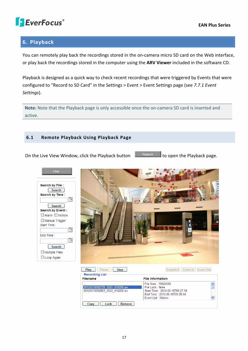
EAN Plus Series
17
6 Playback
You can remotely play back the recordings stored in the on-camera micro SD card on the Web interface
or play back the recordings stored in the computer using the ARV Viewer included in the software CD
Playback is designed as a quick way to check recent recordings that were triggered by Events that were
configured to ldquoRecord to SD Cardrdquo in the Settings gt Event gt Event Settings page (see 771 Event
Settings)
Note Note that the Playback page is only accessible once the on-camera SD card is inserted and
active
61 Remote Playback Using Playback Page
On the Live View Window click the Playback button to open the Playback page
EAN Plus Series
18
Search by File Click the Search button to search for all recording files on the on-camera SD card
Search results will be displayed in the Filename area
Search by Time Click the calendar icon and select the date and time from which you want to search
until the present moment Click search to get your search results which will be displayed in the
Filename area
Search by event Click the type of Event recordings you want to search for (Alarm Motion Manual
Trigger) and then click the calendar icons to select the Start Time datetime and the End Time
datetime of your search Click Search to get your search results which will be displayed in the
Filename area
Multiple Files Check this box if you want the video player to play all the files in the selected folder
The files will be displayed in the Filename area
Loop Again Check this box if you want the video player to play the selected file over and over again
Play Once you have opened the filersquos folder and have clicked on the file to highlight it its details will
be displayed in the File Information area You can now click Play to play that specific file
Pause Click this button to pause the playback
Stop Click this button to stop the playback
【Recording List】
Filename This area will display a list of search results (recording files and folders) Folders (named
with the recorded date) will be displayed first Click on the folder and click on each subfolder until the
recording files (arv) in that folder is listed
File Information Click a file on the Filename list the selected file information will be listed
Copy Click this button to copy the selected file to the computer-based folder of your choice A
browsing box will open so that you can search for the folder of your choice You can use the ARV
Viewer to play back the recordings recorded in your computer For details on ARV Viewer see 63
Playing Back Using ARV Viewer
Lock Click this button to lock the selected file This will protect that file from being overwritten during
any overwrite procedure The file will thus be saved on the micro SD card indefinitely However the
file will still be deleted if the micro SD card is ever formatted
Remove Click this button to delete the selected file
EAN Plus Series
19
62 Setting up the Playback Function
Note that the Playback function will not be active until the user has inserted a micro SD card in the
camerarsquos micro SD card slot The card may also have to be formatted in the Settings submenu
Micro SD Card Slot
621 Preparing the Micro SD Card
Once you insert a functional micro SD card into the slot the Playback button on the Live page should
become active within seconds (see section 622 below ndash the grey letters should turn white) IF NOT
do the following
1 From the Live page click Settings gt System gt SD Card If no card has been inserted yet the
Remove button should be faded indicating that no card is being detected (If a card is
inserted and the Remove button is still faded pull the card out and re-insert it)
2 Slide the card into the slot until it clicks into position
3 The Remove button should become active within a few seconds indicating the card is active
4 If the Remove button stays faded click the Format button to format the card NOTE All data
on the disk will be deleted if the Format button is clicked
622 Testing the Playback Function
1 Once the SD card is detected by the system the button (inactive)
will turn to (active)
2 To test the Playback function (this is not required) set up a ldquoManual Triggerrdquo Recording
Event by clicking Settings gt Event gt Event Settings
3 Click the ldquoAddrdquo button on the middle right side of the page to open an ldquoAdd Eventrdquo box
4 Give the event a name like ldquoTest 1rdquo
EAN Plus Series
20
5 In the ldquoEvent Triggered byrdquo field click on Manual Trigger
6 Below this check ldquoEnable This Eventrdquo ldquoEnable Post-trigger Bufferrdquo and ldquoRecord to SD Cardrdquo
7 To save your settings click OK or close the box by clicking on the red x icon at top right of the
box (in which case you will be asked if you want to save the data to which you should reply OK)
The box will close and the new event will be listed in the list area of the Event Settings page
8 Look at the ldquoPost-trigger Bufferrdquo at the bottom to make sure the buffer time is set to 10 seconds
9 Click ldquoApplyrdquo to make sure all settings are saved
10 Click the Live button to go back to the Live page
11 Get ready to click the Trigger Event button at the bottom of the page Before you do see if you
can find something in the view screen that will give you a visual time marker For instance if you
can get your hand in front of the camerarsquos lens get ready to count down on your fingers
12 Click the Trigger Event button and slowly count down on your fingers in front of the lens (if you
are able to do so ndash if not try to find visual cues on the view screen that will help you to mark the
moment you pushed the trigger) The recording period will be as long as the buffer time you
selected ndash the default period is 10 seconds
13 Click the Playback button to open the Playback page
14 There are different ways to search for recording files on the camerarsquos Micro SD card (ie the
Playback memory) For a recent recording like your test event simply click the ldquoSearchrdquo button
under the ldquoSearch by Filerdquo header
15 If the SD card is active and formatted correctly the recording folderrsquos name (the recording dayrsquos
date) will appear in the Filename box at the bottom Click on this folder to open it If there are
sub-folders click on the bottom one (the most recent would be at the bottom) until you can click
on a file that cannot open to another sub-level and shows data in the File Information box to the
right This would be the file of the most recent recording event
16 To play this file click the Play button below the video box The test footage you have recorded
should start playing Play time should be 10 seconds if you left the Post-trigger Buffer as 10
seconds
EAN Plus Series
21
63 Playing Back Using ARV Viewer
You can play back the recordings stored in the computer using the ARV Viewer included in the
software CD To store the recordings in the computer please refer to Recording List gt Copy in 61
Remote Playback using Playback Page
4 5 6 7 8 9 10
321
No Item Name Descriptions
1 Snapshot Click to take and save a snapshot
2 Load File Click to load the recordings for playing back
3 Convert ARV to AVI Convert the recording from ARV format to AVI format
4 Playback Time Display the playback time
5 Total Time of Recording Display the total time of the recording
6 Stop Click to stop playing the recording
7 Step Reverse Click to display the previous frame
8 Play Click to play back the recording
9 Pause Click to pause the recording
10 Step Forward Click to display the next frame
EAN Plus Series
22
7 Settings
Click the Settings button on the Live View Window to enter the settings submenu There are nine buttons
on the left-side of the submenu Live System Info User Config Network Video Audio User Event and
System Click the Live button can go back to the Live View Window
71 System Info
The System Information and System Log can be checked on this page Click the top tab of the one you
want to see
711 Information
Click the Information tab the following dialog box appears These values cannot be changed on this
page and are for reference only
EAN Plus Series
23
712 Log
Click the Log tab the following dialog box appears The sequence number date time and event
messages of the log event will be displayed in the System Log field The log will display the last 256
log events Click the Export button to export the system log event list into a ldquotxtrdquo file and select the
location where the exported log file will be saved to
EAN Plus Series
24
72 User Config
Each user can set a different configuration for hisher Live page here These settings will be applied to
the logged-in userrsquos Live page every time heshe logs in
721 Live View Config
【VideoAudio Connection Protocol Setting】You can transmit the data stream from the IP cameras
using the RTSP (Real Time Streaming Protocol) on the network The RTSP is a protocol that allows
you to access video streams by using the compatible media players Click Apply to apply the
changes or Reset to reset without saving the changes RTP over UDP The RTSP protocol uses UDP for camera data stream transmission
RTP over TCP The RTSP protocol uses TCP for camera data stream transmission
RTP over HTTP The RTSP protocol uses HTTP for camera data stream transmission
Nevio CGI This is EverFocusrsquo protocol designed for EverFocusrsquo IP devices Select this
protocol for camera data stream transmission
【Text Settings】Check the box of each option (Machine name DateTime Frame Rate) to display
this info on the Live View Page
Foreground Color Slide the Red Green and Blue bars to create your preferred text color for the
info text line
Position Select the position where the text will be displayed Choose from Upper Left Lower
Right Lower Left
Click Apply to apply the changes or Reset to reset without saving the changes
EAN Plus Series
25
【DateTime Format Used in Text】Click the dropdown menu to select datetime format from the
listed options Click on the desired hour format Click Apply to apply the setting changes or Reset to
reset without saving the change
【Live View Layout Settings】 Check the ldquoShow One Push Buttonsrdquo boxes if you want to show these
buttons on the Live View Page Uncheck these boxes to hide these buttons This function is only
available for EAN3120 Plus 3220 Plus
722 Recording Snapshot
This configures where your Record Button and Snapshot Button ( ) files will be saved if
you click one of these buttons Selectable folders will be on the computer only not on the
on-camera SD card
【Recording Snapshot Export Settings】
Enable Event Recording to PC Checking this box will let the system save RecordSnapshot Button
recordings to the folder configured below on the userrsquos PC
Export Folder Select the Export folder for the action above by clicking on the browse (hellip) button
and then select the desired folder
File size The user can limit the size of each recorded file here (in minutes) When a single
recording file exceeds the time you set the system will create a new file to save that data to
Overwrite Select ldquoONrdquo for overwriting recordingsnapshot file when the disk storage capacity is
full The user can set the storage capacity limitation in the in-sentence field in the gray box below
the Overwrite setting ldquoIf the remaining hard disk capacity is less than ____ MB (50~2000) system
will stop recording or start overwriting ldquo
Click Apply to apply the setting changes or Reset to reset without saving the changes
EAN Plus Series
26
723 Language
Select the language to be displayed on the Web interface of the IP camera The default language is
English
To add a new language not listed in the current Language list click the Browse button to locate
the new language file (evb) on your computer and then click the Upload button Updated
language files might be available on the manufacturerrsquos website Contact your vendor if required
Click Apply to apply any changes or Reset to reset without saving the changes
Note Uploading a new language file will cause the system to reboot automatically Please create
a new network connection to the IP camera when the reboot is complete
EAN Plus Series
27
73 Network
This page covers network-related settings including Network DDNS SMTPFTP HTTPS SNMP and
Network Alarm
731 Network
The following information is required to configure the network settings Contact your network
administrator or your internet service provider to get the info
【IP Settings】
IP Type Refer to the network administrator for these settings of the server Default DHCP
DHCP This setting lets the system use an automatically assigned (dynamic) IP address This
address can change under certain circumstances For instance when the camerarsquos network
switchhub has to be rebooted Do not assign to the DHCP server the same IP addresses used
for the other network cameras and PCs with unique IP addresses
Static IP The user can manually set the Static IP address This type of address is stable and
cannot change but the user has to make sure there are no address conflicts with other
network-connected devices
PPPoE This is a DSL-connection application The ISP will ask the user to input a username and
password Contact your ISP for these details
EAN Plus Series
28
Note If PPPoE is selected as the IP type the supplied IP Utility program will not be able to
detect the device
IP address When DHCP is not used the user needs to manually enter the IP address of the
camera Do not enter an IP address that is already used for your computer or other network
cameras
Subnet Mask This field is used to set the netmask for your network so that the IP camera will be
recognized within the network Example 2552552550 When DHCP is selected the DHCP server
will assign this value automatically
Gateway This field is used to set the gateway for your network so that the IP camera will be
recognized within the network When DHCP is selected the DHCP server will assign this value
automatically
Primary DNS Enter the IP address of the DNS server if this is provided by an ISP
Secondary DNS If your ISP provided you with a secondary DNS address please enter it here
Username Enter the accountrsquos username (used only for PPPoE)
Password Used only for PPPoE
IPv6 Enter the IPv6 details in this area if this applies to your system
Click Apply to apply the setting changes or Reset to reset without saving the change
【Port Settings】Enter the HTTP HTTPS and RTSP port numbers and click Apply to save
【Multicast Settings】Enable if required fill in the setting options and click Apply to save
EAN Plus Series
29
732 DDNS
DDNS (Dynamic Domain Name System) is a service used to map a domain name to the dynamic IP
address of a network device You can set up the DDNS service for remote access to the IP camera
DDNS assigns a domain name (URL) to the IP camera so that the user does not need to go through
the trouble of checking if the IP address assigned by DHCP Server has changed Once the IP is
changed the IP camera will automatically update the information to the DDNS to ensure it is always
available for remote access
Before enabling the following DDNS function user should have applied for a host name from the
DDS service providerrsquos website We support these four DDNS server providers
wwweverfocusddnscom wwwsitelutionscom wwwdyndnscom and wwwno-ipcom
Note We highly recommend that you use xxxxeverfocusddnscom for the simplicity of setting up
your IP cameras
【DDNS Settings】
Enable Check this box to enable the DDNS function
Service ISP You can either apply for a host name from EverFocus or other DDNS server providers
If you choose the EverFocus DDNS server you can obtain a free host name from EverFocus by
following the steps below
bull From EverFocus To obtain a free host name from EverFocus type a desired host name in the
textbox click the Register Update button and then click the Apply button
bull From other DDNS server providers To obtain a domain name from one of the three DDNS
server providers you have to register your name with the provider first and then select the
provider and fill in the required information Please refer to the specific DDNS companyrsquos
website for further information
Record ID Type the record ID if provided by the DDNS server provider
EAN Plus Series
30
FQDN Type the fully qualified domain name applied from the DDNS server provider For
example xxxxdyndnscom
Username Password Type the login account of your DDNS server provider
Click Apply to apply the setting changes or Reset to reset without saving the changes
Note
1 In order to support the full functionality of the camera you must open the port numbers (80
554 443) on the router for remote access to the IP camera This function is available on most
routers in the market and is often known as ldquoPort Forwardingrdquo To set up Port Forwarding
please consult the manual of the router
2 In certain router models it is possible that you will not be able to access the camera using
DDNS while inside the routerrsquos network Please try using a PC located outside of your routerrsquos
network
Default Ports on All EverFocus IP Cameras
HTTP 80
RTSP 554
HTTPS 443
EAN Plus Series
31
733 SMTP FTP
【Set SMTP Server (email)】This area is for configuring the mail server that is used to send e-mail
notifications from the camera to predefined addresses via SMTP Note that to enable e-mail
notification function you have to check the Send Mail Notification item on the Event dialog box
(see 771 Event Settings)
SMTP Server Enter the IP address or the host name of the SMTP server used to send e-mails
SMTP Port Enter the port number for SMTP The default is 25
Authentication Check this box if the SMTP server requires authentication (userpassword)
User name Input the userrsquos login ID if the SMTP server requires authentication
Password Input the userrsquos login password if the SMTP server requires authentication
EAN Plus Series
32
Receiver Address Input the e-mail addresses for receiving an e-mail message when an EVENT is
enabled and triggered Please use ldquordquo to separate multiple addresses
Sender Address Input the senderrsquos e-mail address so that the receiver can recognize the sender
when an Event message is received
Attach Image Check this box if you want to attach an image when an alarm is triggered or an IP
camera detects events
Send Test Email Click the Test button to send a testing email to the assigned address
Click Apply to apply the setting changes or Reset to reset without saving the changes
【Set FTP Server】The settings relating to the FTP server used to transmit the alarm images can be
configured here Note that to enable uploading images to the FTP server function you have to
check the Upload to FTP item on the Event dialog box (see 771 Event Settings)
FTP Server Enter the IP address or the host name of the FTP server
FTP Port Enter the port number for the FTP server Default is 21
Recording Path Assign the recording path
User Name Set FTP Userrsquos name
Password Set FTP password
PASV mode Check to enable Passive mode Passive mode is normally enabled If a connection
cannot be established uncheck PASV Moderdquo
Test FTP Server Click the Test button to send a testing file to the assigned FTP server
Click Apply to apply the setting changes or Reset to reset without saving the changes
EAN Plus Series
33
734 HTTPS
Hypertext Transfer Protocol Secure (HTTPS) is a combination of the Hypertext Transfer Protocol
and the SSLTLS protocol and provides encrypted communication and secure identification of a
network web server
Before using the HTTPS function for communication with the IP camera a Certificate must be
created first There are two ways to create and install a certificate Create Self-Signed Certificate
and Create Certificate Request
Create Self-Signed Certificate
Please note that even though self-signed certificates are free and offer some protection true
security is only implemented after the installation of a signed certificate issued by a certificate
authority
1 Click the Create Self-Signed Certificate button the following dialog appears
EAN Plus Series
34
2 Type the required Certificate information and then click the Apply button The subject line will
be displayed in the Installed Certificate Information field
3 Click the Property button a pop-up window appears to display the details of the certificate
4 To optionally create and install other certificates remove the existing one by clicking the
Remove button to erase the certificate
5 On the Web page change the address from ldquohttprdquo to https in the address bar and press
Enter on the keyboard Some Security Alert dialogs will pop up Click OK or Yes to enable HTTPS
Create Certificate Request
You can apply for an official certificate from an issuing Certificate Authority
1 Click the Create Certificate Request button the following dialog appears
EAN Plus Series
35
2 Type the required Certificate information and then click the Apply button The subject line will
be displayed in the Created Request field
3 Click the Property button a pop-up window appears to display the details of the certificate
4 To optionally create and install other certificates or request remove the existing one by clicking
the Remove button to erase the certificate or request
5 Copy the contents of the Certificate request (in PEM format) and paste it to the certificate
request field on the Web page of the 3rd-party certification authority such as Symantec VeriSign
Wait for the certificate authority to issue an SSLTLS certificate and then download the issued
certificate on your computer
6 In the Install Signed Certificate field click the Browse button to search for the issued certificate
and then click the Upload button to import the certificate Once the certificate has been
uploaded this field will show the subject line of the certificate
EAN Plus Series
36
735 SNMP
The default values for SNMP v1v2v2c and SNMP v3 are already filled in Click either of the
Enable buttons to enable either of the two Make your changes as desired Click on the Trap
Address field to enter the digits if required
736 Network Alarm
This function works with EverFocusrsquos CMS software eg the PowerCon or the Power Video Plus For
the setting details please refer to the CMS network alarm protocol
EAN Plus Series
37
74 Video
The settings relating to video such as streaming camera OSD can be configured on this page The
Video page has five tabs Multi-streaming Camera Advanced ROI and Privacy Mask
741 Multi Streaming
【Stream Settings】 This IP camera can output three video streams simultaneously For each of these
streams the user can set the compression format resolution bit rate and frame rate individually
Stream 1 is always enabled for live view To enable Stream 2 andor Stream 3 check the ldquoEnablerdquo
box the header of each stream
Note If you connect to the camera via the Internet and experience a delay (lag time) in the video
feed try to reduce the number of streams and the quality and resolution of the streams ndash but
keep the frame rate at its maximum
EAN Plus Series
38
Format Select the encoding format ndash H264 or MJPEG
Resolution Select the most suitable resolution for your needs
Frame Rate Select from 1 to 30 fps
Bit Rate If required select whether you want the stream to stream a Constant Bit Rate or a
Variable Bit Rate and set the values of whichever option you choose
Click Apply to apply the setting changes or Reset to reset without saving the changes
【Video Recording Settings】Select the stream you want to configure and then select whether you
want the recording files of that stream to be saved in AVI or ARV format Click Apply to apply the
setting changes or Reset to reset without saving the changes
【Time Stamp Settings】 You can select the DateTime format position and add the setting to the
streaming
Click Apply to apply the changes or Reset to reset without saving the changes
EAN Plus Series
39
742 Camera
【Image Settings】Set the Brightness Saturation Contrast or Sharpness of the image Click Apply to
apply the changes or Reset to reset without saving the changes
【Camera Settings】
Mirror Switch Mirror ON to rotate the image horizontally around a vertical axis
Flip Switch Flip ON to rotate the image vertically around a horizontal axis
AE There are two options
ALC Selecting Automatic Light Control allows the camera circuitry to either take bright spots
more into consideration (peak) bringing out detail in bright areas or less into consideration
(average) bringing out detail in shadows
AES Selecting Auto Electronic Shutter disables the Shutter setting below this setting In this
mode the camera measures the light level and decides whether it needs more or less light and
then automatically adjusts the shutter speed accordingly
BLC Back Light Compensation (BLC) is used to make the subject appear clearer when it is set
against a bright background
OFF Select to switch Back Light Compensation functions off
(ON)BLC The BLC can increase the exposure of a dark area surrounded by a brighter area HLC
can decrease the exposure of bright areas surrounded by darker areas This enables the
camera to better display information that would otherwise have been ldquowhited outrdquo like a
license plate between two bright headlights on a dark road
(ON)HLC The Highlight-Suppression BLC is used to reduce the brightness of light sources in a
specific area It is activated only in a low illumination environment to minimize the effects of
glare from bright lights such as spotlights street lights or headlights in the field of view
EAN Plus Series
40
WDR The Wide Dynamic Range (WDR) function provides clearer images when both of the very
bright and dark areas simultaneously appear on the camera view There are four value options
OFF Low Middle and High Note that when WDR is ON some parts of the image may appear
solarized This is normal for WDR and is not a camera malfunction This function is only available
for EAN3120 Plus 3220 Plus
DN Mode
Auto Select to let the camera automatically switch to Night mode (black and white) when the
light levels fall to a specified level and back to Day mode (color) when the light levels rise to a
specified level
Day Select to keep the camera in Day mode (color) even in nighttime
Night Select to keep the camera in Night mode (black and white) even in daytime
EAN Plus Series
41
743 Advanced
EAN Plus Series
42
【Camera Settings】
Lens (IRIS Control) Select DC or Manual for IRIS control This function is only available for EAN3220
Plus
Exposure Settings (AE) This setting is used to adapt to the amount or type of light used by the
camera Note the settings vary among models
Mode This function is not available for EAN3220 Plus
Automatic Light Control (ALC) This option is only available for EAN3120 Plus 3300 Plus The
ALC allows the camera circuitry to either take bright spots more into consideration (peak)
bringing out detail in bright areas or less into consideration (average) bringing out detail in
shadows
Auto Electronic Shutter (AES) This option is only available for EAN3120 Plus 3300 Plus In
this mode the camera measures the light level and decides whether it needs more or less light
and then automatically adjusts the shutter speed accordingly
Manual This option is only available for EAN3300 Plus Select this option to manually set up
the Shutter (Manual) and AGC (Manual) values
Iris Specify the size of the Iris opening here
Shutter If enabled this setting lets you set the shutter speed yourself
Shutter Limit Use this setting to set the maximum shutter speed for the camera This function is
only available for EAN3120 Plus
AGC Set the Auto Gain Control limit here The lower the AGC level the lower the video signal and
the noise However the image will be darker under low-light condition with IR-off if you set up the
Iris to the maximum level
Slow Shutter This option can be switched on when AES Mode is selected in the Exposure Settings
(AE) field This function is only available for EAN3220 Plus 3300 Plus
Flickerless If the Mode field in the Exposure Settings (AE) area has been set to AES then this option
becomes available Choose between OFF 50HZ 60HZ 50HZ (High Luminance) or 60HZ (High
Luminance) This function is only available for EAN3300 Plus
EV Setting Set up the Exposure Value Note the brightness of the screen changes when you change
the EV value This function is only available for EAN3300 Plus
AE Response Set up Auto Exposure Response time This function is only available for EAN3300 Plus
AE Weighting Area Select an AE Weighting area Each setup AE Weighting Area is configured with
the appropriate brightness level on the center and the surrounding areas This function is only
available for EAN3300 Plus
Brightness Set the image brightness here
AE Reference Set the Auto Exposure value here This function is only available for EAN3120 Plus
EAN Plus Series
43
Black Level Set the Black level here This function is only available for EAN3300 Plus
WDR The Wide Dynamic Range (WDR) function provides clearer images when both of the very
bright and dark areas simultaneously appear on the camera view There are four value options OFF
Low Middle and High Note that when WDR is ON some parts of the image may appear solarized
This is normal for WDR and is not a camera malfunction This function is only available for EAN3120
Plus 3220 Plus
Visibility Enhancement (OFFLowMiddleHigh) Images in foggy or rain environments or in
environments with a very strong luminous intensity have a dynamic range that is significantly lower
than ordinary images The user can use this Visibility Enhancement setting to ldquoDEFOGrdquo the image if
such ldquoFOGGINGrdquo is an issue This function is only available for EAN3220 Plus
BLC Settings Back Light Compensation (BLC) is used to make the subject appear clearer when it is
set against a bright background
OFF Select to switch Back Light Compensation functions off
Back Light This option is only available for EAN3300 Plus The Back Light function is useful
when the background of the subject is very bright and the subject itself is dark Select Back
Light and adjust the slide bar to the left right for setting up the back light value The higher
the value the more the backlight compensation
Front Light This option is only available for EAN3300 Plus This function is useful when the
bright highlights such as flashlight or car headlights appear on the camera view Select Front
Light and adjust the slide bar to the left right for setting up the front light value The higher
the value the more the highlight compensation
ON (BLC) This option is only available when you select AES Mode in the Exposure Settings (AE)
field The option is only available for EAN3120 Plus 3220 Plus The BLC function is useful
when the background of the subject is very bright and the subject itself is dark Follow the
instructions below to configure the settings for each model
For EAN3120 Select ON (BLC) the button next to the Mode drop-down list will be
active (see image below) Click the button the green setup areas appear on the left
screen Click on the areas to enable disable the BLC function The selected areas (in green)
will be applied with the BLC function
EAN Plus Series
44
For EAN3220
You can configure one area to apply the BLC function Select ON (BLC) the setup buttons
appears (see image below) Select Low Middle High from the BLC Gain drop-down list To
set up a BLC area click the Edit Area button and then click on the blue color tab to turn your
mouse cursor into a blue pen Move the cursor to the position on the right screen where you
want the BLC rectangle to start and then click Move your cursor to the position (diagonally
opposing corner) where you want the BLC rectangle to end and then click The blue area will
be applied with the BLC function
ON (HLC) This option is only available when you select AES Mode in the Exposure Settings (AE)
field The option is only available for EAN3120 Plus 3220 Plus This function is useful when
the bright highlights such as flashlight or car headlights appear on the camera view Follow
the instructions below to configure the settings for each model
For EAN3120 Select ON (HLC) and then select a level from the drop-down list The higher the
level the more the highlight compensation
For EAN3220
HLC Level Select a level for the HLC setting The higher the level the more the highlight
compensation
HLC Mode Select All Day Night mode to apply the HLC function
HLC Black Mask Select On Off to apply the black mask on the selected areas The
over-exposure portions within the selected areas will be applied with the black mask
Color Tabs You can set up four HLC areas with different colors To set up a HLC area click the
Edit Area button and then click on the color tab to turn your mouse cursor into a pen of that
color Move the cursor to the position on the right screen where you want the HLC rectangle
to start and then click Move your cursor to the position (diagonally opposing corner) where
you want the HLC rectangle to end and then click Select ON from the color tab drop-down list
The rectangular area with the selected color will be applied with the HLC function
EAN Plus Series
45
Back Light This option is only available for EAN3300 Plus The Back Light function is useful
when the background of the subject is very bright and the subject itself is dark Select Back
Light and adjust the slide bar to the left right for setting up the back light value The higher
the value the more the backlight compensation
Front Light This option is only available for EAN3300 Plus This function is useful when the
bright highlights such as flashlight or car headlights appear on the camera view Select Front
Light and adjust the slide bar to the left right for setting up the front light value The higher
the value the more the highlight compensation
Noise Reduction Settings This limits the amount of digital ldquovideo noiserdquo that is usually found in any
video stream and helps to reduce file size The higher the level the more the reduction
For EAN3120 Plus 3300 Plus
Select ON OFF to enable disable the Noise Reduction function Or select Auto to let the camera
automatically enable disable the Noise Reduction function Slide the Level bar to set up the level
The higher the level the more the reduction
For EAN3220 Plus
2D DNR Select ON to enable the 2D DNR function
3D DNR Select ON to enable the 3D DNR function You can further set up the following settings
3D Start AGC Set up the AGC level to automatically start the 3D NR function
3D End AGC Set up the AGC level to automatically stop the 3D NR function
3D Level Set up the 3D DNR level
Smart NR Select ON to enable the Smart NR function The 3D NR function will be
automatically turned on when a motion event occurs
EAN Plus Series
46
White Balance Settings Select the mode that delivers the best quality image for the camerarsquos light
environment There are five options Auto Manual Indoor Outdoor One Push
Auto Select to let the camera automatically adjust the White Balance In the Auto mode the
camera computes the white balance value output using color information from the entire
screen It outputs the proper value using the color temperature radiating from a black subject
based on a range of value from 3000 to 7500K
Manual Select to adjust the Red and Blue values yourself in the fields below this field
Indoor Select to use the default settings for indoor environments In the Indoor mode the
camera uses 3200K as the base value
Outdoor Select to use the default settings for outdoor environment In the Outdoor mode it
uses 5800K as the base value
One Push Select to enable the Push button next to the Mode drop-down field This will allow you to force the camera to readjust the white balance every time you push the Push
button The lens will hold the same focal position until the next trigger command is received
This function helps to prevent incorrect focusing in dark environments This function is only
available for EAN3120 Plus 3220 Plus
Manual Temperature Select to use the optimized Red and Blue settings You can also
optionally adjust the Manual Level below this field for setting up the color temperature The
higher the value the more the color temperature This function is only available for EAN3300
Plus
DayNight Settings
Auto Select to let the camera automatically switch to Night mode (black and white) when the
light levels fall to a specified level and back to Day mode (color) when the light levels rise to a
specified level
Day Select to keep the camera in Day mode (color) even in nighttime
Night Select to keep the camera in Night mode (black and white) even in daytime
IR Smart Settings Select ON and set up the level to enhance the image quality when the images are
over exposure This function is useful when the camera is in the Night mode This function is only
available for EAN3220 Plus
Saturation Set the saturation value This function is not available for EAN3220 Plus
Monitor Type Select a gamma value from Set 1 Set 2 or Set 3 This function is only available for
EAN3120 Plus
Negative Switch this setting ON to view a color negative version of the video image This is useful
at night or when viewing temperature-sensitive images
EAN Plus Series
47
Sharpness Settings Select the sharpness level of the image A low sharpness level will deliver a
softer less detailed image A high level will deliver a sharp highly detailed image Switch Resolution
Enhancement ON to enable the resolution enhancement function
Contrast Select the contrast level of the image
Suppress Function This function is only available for EAN3300 Plus
Aperture Compensation Suppression (OFFLowMiddleHigh) This setting can be activated to
suppress luminance noise when the AGC level increases
Chroma Suppression (OFFLowMiddleHigh) This setting can be activated to suppress
chrominance noise when the AGC level increases
Ygamma (gamma 22standardcontrast enhancehigh light range mode LHigh light range mode
H) Select the Ygamma value for the video quality of the monitor This function is only available for
EAN3300 Plus
Monitor Settings The user can use this field to optimize video quality for his or her specific type of
monitor ndash LCD or CRT This function is only available for EAN3220 Plus
Color Space Standard The options are YUV601 for SD and YUV709 for HD These define the color
space standard required to convert an RGB picture to a YUV picture Generally YUV601 is used for
Standard Definition (720P) devices and the YUV709 is used for High Definition (1080P) devices
Click Apply to save all changes Click Reset to cancel all changes
EAN Plus Series
48
744 ROI (Region of Interest)
The Region of Interest (ROI) function allows users to set up multiple regions within an image with
better quality and less distortion than the rest of the image You can also use this function
together with the Digital Zoom function on the Live View Page to get a better image result Up to
eight ROIs can be configured in the ROI settings page
To set up an ROI region
1 Select an ROI number from the ROI No drop-down list
2 Click the Add button the mouse cursor will turn into a pen when you move it over the live
image on the left
3 Move the cursor to the position where you want the ROI rectangle to start and then click
Move the cursor to the position (diagonally opposing corner) where you want the ROI
rectangle to end and then click
4 Slide the Quality bar to set up the quality value
5 Click the Apply button to apply the settings or click the Reset button to reset without saving
the settings
EAN Plus Series
49
745 Privacy Mask
The Privacy Mask can block out sensitive areas from view covering the areas with colored or black
and white boxes in both live view and recorded clips This feature is useful when usersrsquo donrsquot want
the sensitive information visible Up to four Privacy Masks can be configured
【Privacy Mask Color Settings】The Modes vary among camera models
Mode Click Color to make the masks appear as colored rectangles on the screen Click BW to
make the masks appear as gray rectangles on the screen Click Mosaic to make the masks appear
as mosaic-effect rectangles on the screen
Level Select the color of the masks if you selected Color Mode Select the level of grayness of the
masks if you selected BW Mode Select the level of smallmiddlelarge if you selected Mosaic
Mode
Click Apply to apply the settings or click Reset to reset without saving the settings
Color Tabs Click on a color tab to turn your mouse cursor into a pen of that color
You can now create a block of that color on the video screen Move your cursor to the position
where you want your mask rectangle to start and then click Move your cursor to the position
(diagonally opposing corner) where you want your mask rectangle to end and then click The
rectangular area with the selected color will appear The live image will display the rectangular
area with the color you selected If you want to create another mask use one of the other three
colors Each color denotes a different mask area Only one block per color is allowed As the
number of colors suggests you can configure up to four blocks
EAN Plus Series
50
Select All Click to turn the whole screen into a mask area
Clear All Click to delete all configured mask blocks
Eraser Click to turn the mouse cursor into an eraser to delete any block you click on
Area Shows the color and number of the block
Enable Check this box to enable the related mask block
Click Apply to apply the settings or click Reset to reset without saving the settings
EAN Plus Series
51
75 Audio
The EAN Plus series IP camera can transmit audio to your computer if you have connected an external
microphone to its audio Input cable It can also receive audio input from you and transmit it via an
external speaker if you have connected such a speaker to its audio Output cable
Check the Enable Audio box to enable the camerarsquos audio function The camera will now act as a
digital bridge (via the IP network) between any connected audio input device and any connected
audio device
Adjust the Audio Input Volume if you have external audio input devices (microphones) connected to
the camera and if there are problems with the sound input being too low or high
Click Apply to save all settings or click Reset to cancel
EAN Plus Series
52
76 User
761 User Information
The system administrator can create up to ten user accounts on this page
To set up a user account
1 Highlight a user account and click the Modify button The following dialog box appears
2 Type the account name account description and password for the account Type the password
again in the Confirm field
3 Select an authority level for the user account from the Authority drop-down list
bull Supervisor Administrator The only difference between a supervisor and administrator is
that a supervisor can edit an administratorrsquos account and password but an administrator
cannot edit the supervisorrsquos account and password Multiple administrators can be
configured but there can be only one supervisor The supervisor and administrators all
have unrestricted access to the Settings submenus and can determine the registration of
all other users
EAN Plus Series
53
bull User A user can view the Live View page and view the system network video and audio
information A user can only adjust the User Config page settings The user does not have
access to the User Event and System pages
bull Guest The lowest level of access which only allows the user access to the Live View page
4 Select Active or Disable from the Status drop-down list to active or disable the user account
5 Click On in the SD Card Playback field to allow the user to access the SD card playback
function
6 Click OK
7 Click Apply to save all the settings
EAN Plus Series
54
762 IP Address Filter
Use this page to specify IP addresses that are not allowed to access this camera By default any IP
address can access the camera
Note The Allowed List addresses only become relevant when the Denied List contains a network
or range and the supervisor wants to allow one or more IP addresses within that excluded range
or network In such a scenario the user would enter the excluded range or network in the
Denied List and enter the exceptions in the Allowed List
To set up the IP Address Filter
1 Select Denied List Click the Add button the following dialog box appears
2 Select an IP type from the IP Type drop-down list
3 Select a network rule from the Rule drop-down list type the IP address and click OK
Single Type a single IP address in the IP Address field below
Network Type the IP address and subnet mask in the field below
Range Type a range for the IP addresses
4 If you have set up an IP range in Step 3 you can optionally set up the Allowed List to allow one
or more IP addresses within the setup IP range to access the IP camera
5 Click Apply
EAN Plus Series
55
77 Event
You can set up the Motion Detection event Tamper Detection event or the Alarm IO to automatically
notify the users when an event occurs or an alarm is triggered You can also set up a schedule to
automatically record the videos when an event occurs or an alarm is triggered
771 Event Settings
You can create a total of ten event or alarm settings page in the Event List
【Event List】
Click the Add button and the following Event Configuration Window appears
EAN Plus Series
56
Enter Event Name Type an event name
Event Triggered by Select an event or alarm type for the to-be-specified-below reactions
Alarm Input Select this if you want a reaction trigger coming from any external connected sensor
to activate a to-be-specified-below reactions via the camera system Make sure that a suitable
device is actually connected to the alarm input relay
Manual Trigger Select this option if you want to manually trigger the alarm by clicking the Trigger
Event button on the Live View Page
Motion Detection Select this option if you want motion in a specified part of the camerarsquos viewing
rectangle (the screen image) to trigger the to-be-specified-below reactions
Tampering Detection Select this option if you want the camerarsquos tampering detection sensor to
trigger the to-be-specified-below reactions
Schedule Recording Select this option if you want the Schedule Recording periods configured in
the recording schedule (the Settings gt Event gt Schedule page) to activate this event In this
scenario a preconfigured event reaction like a log entry will list the start and end times of each
period Actual recording will only be triggered if the event is preconfigured to do so
Enable This Event Select to activate the event
Enable Re-trigger Click to set a minimum time after the event is triggered before the event
can be triggered again
Enable Pre-trigger Buffer Click if you want the Event reaction (as selected in the ldquoNotification
Overrdquo field below) to be the activation of the video recording function and if you want the
recording to include the video feed from the time period (configurable on the previous ldquoEvent
Settingsrdquo page) just before the Event trigger occurred
Enable Post-trigger Buffer Click if you want the Event reaction (as selected in the Notification
Over field) to be the activation of the video recording function and if you want the recording
to include the video feed from a time period (configurable on the Event Settings page) just
after the Event trigger occurred
Motion Area Select a setup motion detection area from the drop down list Note this
function only becomes relevant after the Motion Detection areas have been set up (see 772
Motion Detection)
Notification Over Select the desired notification types form the following items
Log Click if you want the camera to list the eventrsquos details in its log if the event is triggered
Trigger Alarm Output Click if you want the camera to relay the event reaction to a device
attached to the alarm relay output wire and then set up the alarm output duration time
EAN Plus Series
57
Send Mail Notification Click if you want the camera to send an Event notification email to the
email address entered in the Set SMTP Server(email) field of the Network gt SMTPFTP page if
the Event occurs (see 733 SMTP FTP)
Upload to FTP Click if you want the camera to upload recorded footage to the FTP server
entered in the Set SMTP Server(email) field of the Network gt SMTPFTP page if the Event
occurs (see 733 SMTP FTP)
Record to SD Card Click if you want the camera to start recording its video feed (when the
event occurs) on an on-camera SD Card (if such a card has been inserted)
Note The recording will only be as long as the combined Pre- and Post-trigger Buffers so
make sure you enable at least one of these buffers especially the Post-trigger Buffer
Record to PC Check this box if you want the camera to start recording its video feed (when
the event occurs) on the same folder on the same PC as configured on the User Config gt
RecordingSnapshot page (if such a folder has been enabled and configured)
Note The recording will only be as long as the combined Pre- and Post-trigger Buffers (and
for as long as the event trigger is happening ndash eg a motion is detected) so make sure you
enable at least one of these buffers especially the Post-trigger Buffer
Network Alarm Check this box if you want the camera to send a network alarm signal (when
the event occurs) to the CMS servers configured on the Network gt Network Alarm page (see
736 Network Alarm)
Click OK to save all settings or click Cancel to cancel
【PrePost Trigger Settings】
Pre-trigger Buffer Select the duration for the buffer This will determine the amount of footage
(length of time) before the event trigger moment that will be included in an event-triggered video
recording if that buffer and video recording has been enabled in the Event Configuration Window
Post-trigger Buffer Select the duration for the buffer This will determine the amount of footage
(length of time) after the event trigger moment that will be included in an event-triggered video
recording if that buffer and video recording has been enabled in the Event Configuration Window
Click Apply to save all settings or click Reset to cancel
EAN Plus Series
58
772 Motion Detection
Use this page to configure up to four areas in which motion will be detected When a motion is
detected by the camera the motion detection icon will appear at the top right of the
Live page to alert the user This function can also be linked with correctly configured Events to
trigger Event reactions like the activation of video recording periods snapshots alarms etc
Color Tabs Click on a color tab to turn your mouse cursor into a pen of that color
You can now create a block of that color on the video screen Move your cursor to the position
where you want your detection rectangle to start and then click Move your cursor to the position
(diagonally opposing corner) where you want your detection rectangle to end and then click The
rectangular area with the selected color will appear This block will be an area inside which the
camera will detect motion If you want to create another detection area use one of the other three
palette colors Each color denotes a different detection area Only one block per color is allowed As
the number of colors suggests you can configure up to four blocks
Select All Click to turn the whole screen into a motion detection area
Clear All Click to delete all configured motion detection blocks
Eraser Click to turn your mouse cursor into an eraser to delete any block you click on
Area Shows the color and numberID of the block
Enable Check this box to enable the related motion detection block
Sensitivity Set the sensitivity of the motion detection sensor function
Click Apply to save all settings or click Reset to cancel
EAN Plus Series
59
773 Tamper Detection
Use this page to set the number of seconds that an alarm signal will be active if the device is
physically tampered (moved covered up or out of focus
774 Alarm IO
Use this page to set the type of trigger input and the type of output contact for the camerarsquos alarm
channel
EAN Plus Series
60
775 Schedule
Use this page to configure a schedule for periods during which the camera should deactivate all
user-activated Events (gray Deselect periods) or when the camera should deactivate all
user-activated Events except Schedule Recording (SR) events (blue Schedule Recording-only
periods) or when the camera should deactivate only SR events (red Event Recording-only periods)
or when it should enable all activated Events (yellow periods)
Event Recording Click this button to make every hour block you click on red A red block represents
an Event Recording-only block which represents an hour when the camera will deactivate all
preconfigured activated Schedule Recording events and keep all the other activated events active
Schedule Recording Click this button to make every hour block you click on blue A blue block
represents a Schedule Recording-only block which represents an hour when the camera will
deactivate all other preconfigured activated events and keep only the preconfigured activated
Schedule Recording events active
Event + Schedule Click this button to make every hour block you click on yellow A yellow block
represents an hour in which all activated events including Schedule Recording events will be
active
Deselect Click this button to make every hour block become grey A grey block represents an hour
in which all activated events including Schedule Recording events will be inactive
Click Apply to save all settings or click Reset to cancel
EAN Plus Series
61
78 System
You can set up the systemrsquos time and SD card settings and to do maintenance and reset actions like
reboots and upgrades
781 DateTime
【Machine Name Settings】If required enter a new name for the machine This name will be visible
in the Machine Name field of the IP Utility software which is included in the software CD
【Set Time Zone】Set the time zone of the camerarsquos location
【Set DateTime Manually】Set the datetime here if you wonrsquot be using an NTP server to update the
datetime (see below)
【Set DateTime Sync】Enter the Network Time Protocol server if applicable The camerarsquos time will
be automatically adjusted by synchronizing with the NTP server
Click Apply to save all settings or click Reset to cancel
EAN Plus Series
62
782 Daylight Saving
Click Enable Daylight Saving to enable this schedule and select the dates when the regionrsquos
daylight saving period begins and ends Click Apply to save all settings or click Reset to cancel
783 SD Card
Use this page to prepare the system for safely removing the SD Card from its slot
【Setup SD Card】
Notification Select the percentage of storage space that should be left on the card before the
camera notifies you of the impending storage shortage or overwrite
Event Recording Select if you want Event Recording only FTP Backup only or both
Overwrite Click ON if you want the card to start writing over recorded footage when its memory is
full Click OFF if you want the card to stop recording new footage when its memory is full
【SD Card Utility】
Capacity This shows you how much card memory has been used and how much memory capacity
remains on the card
Remove Click this button before removing the card from the system
Format Click this button to format the card All data saved on the SD card will be removed if the
card is formatted
EAN Plus Series
63
784 Maintenance
【Maintenance Server】
Reboot Click this button to reboot the unit without changing any of the settings Use this function if
the unit is not behaving as expected
Restore Click this button to restart and reset most of the current settings to their factory default
values The only settings that will not be changed to default are
bull IP settings
bull DDNS settings
Default The Default button should be used with caution Pressing this button will return all of the
cameras settings including the IP address to the factory default values The camera will then have
to be reconfigured
【SaveLoad Configuration Server】
Save To make a backup file of the machinersquos current configurations press Save to save all the
configurations to a config file This will enable the user to reload these configuration settings if the
settings are changed and there is unexpected behavior
Load To load a previously saved configuration press the Browse button to locate the saved config
file (see above) and then click the Load button The systemrsquos settings will be restored to the saved
configuration
EAN Plus Series
64
【SaveLoad Video Configuration Server】
Save To make a backup file of the machinersquos video configurations press Save to save the video
configurations to a config file This will enable the user to reload these configuration settings if the
settings are changed and there is unexpected behavior
Load To load a previously saved video configuration press the Browse button to locate the saved
config file (see above) and then click the Load button The systemrsquos settings will be restored to the
saved video configuration
【Upgrade Firmware】Click the Browse button to find a previously prepared firmware upgrade file
Click Upgrade to install the new firmware
Note
1 Do not disconnect power to the unit during the upgrade sequence The unit will reboot
automatically after the upgrade has completed (1-5 minutes)
2 During the upgrade process all event recording actions will be stopped Event recording
actions will resume after the camera is rebooted
3 If the ldquoFile Error Please re-loginrdquo warning message appears when upgrading the firmware
please try the following instructions
a Go to Internet Explorer gt Tools gt Internet Option gt Security gt Custom
b Find and enable the Include local directory path when uploading files to a server
EAN Plus Series
65
8 Upgrading Firmware Using IP Utility
You can upgrade the Firmware using the IP Utility software included in the software CD
1 Install and then start the IPU program The following dialog box appears
2 Click Find Devices to search the cameras connected in the LAN The default network values of the
cameras will be displayed By default the network protocol of the camera is DHCP
3 Select a camera and click LoginMulti Login to log in the camera
4 Type the user ID and password Click OK
Note
1 The default user ID is user1 and the default password is 11111111
2 If you select more than one camera that has the same user ID password you will be able
to log in several cameras at once
EAN Plus Series
66
5 Highlight the camera and then click Upgrade Firmware A browsing window appears
6 Select the firmware file (evb) and then click Open The IP Utility will automatically upgrade the
firmware
The camera will reboot once the update is complete Click Find Devices the new firmware version
should be displayed in the last part of the Machine Name
EAN Plus Series
67
9 Specifications
Model EAN3120 Plus EAN3220 Plus EAN3300 Plus
Camera
Image Sensor 13 Panasonic CMOS 128 Sony CMOS
Megapixel 13 MP 2 MP 3 MP
Picture Elements (H x V) 1280 x 1024 1944 x 1092 2048 x 1536
Min Illuminations 003 Lux at F14
Electronic Shutter (Sec) 85 ~ 160000 2 ~ 150000 1 ~ 110000
Scanning System NTSC PAL
WDR Yes Yes No
BLC Yes
Gain Control Yes
White Balance Yes
Lens
Mounting Type C CS
Day Night Yes (with removable auto IR-cut filter)
IRIS Control DC Electrical IRIS Lens IRIS
Video
Video Compression H264 MJPEG
Resolution
NTSC
2048 x 1536 1920 x 1200 (for EAN3300 Plus only)
1920 x 1080 (for EAN3300 Plus 3220 Plus only)
1280 x 1024 1280 x 720 1024 x 768 720 x 480 704 x 480 640 x 480
352 x 240 320 x 240 160 x 120
PAL
2048 x 1536 1920 x 1200 (for EAN3300 Plus only)
1920 x 1080 (for EAN3300 Plus 3220 Plus only)
1280 x 1024 1280 x 720 1024 x 768 720 x 576 704 x 576 640 x 480
352 x 288 320 x 240 160 x 120
Frame Rate 30 fps at 1280 x 1024 30 fps at 1920 x 1080 15 fps at 2048 x 1536
Audio
Audio Streaming Two-way audio
Audio Compression G711
EAN Plus Series
68
Network
Interface 10 100 Base-T Ethernet RJ-45 socket
Supported Protocols
TCPIP IPV6 UDP ICMP DHCP NTP DNS DDNS SMTP SNMP FTP
HTTP HTTPs PPPoE UPnP Bonjour RTP RTSP RTCP IGMP ARP ONVIF
PSIA
Connector
Power DC female port PoE
Ethernet RJ-45
Audio 1 In (phone jack for microphone)
1 Out (phone jack for Speaker)
Alarm IO Terminal IO wires
Local Storage Micro SD SDHC memory card slot
TV-Out BNC socket composite 1 V p-p 75 Ω
General
Power Source DC 12V PoE (IEEE8023af)
Power Consumption
(IR LEDs On)
5W (DC 12V)
621W (PoE)
5W (DC 12V)
522W (PoE)
5W (DC 12V)
536W (PoE)
Operating Temperature 0degC ~ +50degC 32degF ~ +122degF
Humidity 20 to 80 (no condensation)
Safety CE FCC
Dimensions (L x W x H) 117 x 56 x 68 mm 46 x 22 x 27 in
Weight 410 g 09 lb
EverFocus Electronics Corp EverFocus Taiwan 12F No79 Sec 1 Shin-Tai Wu Road Hsi-Chih Taipei Taiwan TEL +886 2 2698 2334 FAX +886 2 2698 2380 wwweverfocuscomtw marketingeverfocuscomtw
EverFocus Europe - Germany Albert-Einstein-Strasse 1 D-46446 Emmerich Germany TEL +49 2822 93940 FAX +49 2822 939495 wwweverfocusde infoeverfocusde
EverFocus China - Beijing Room 609 Technology Trade Building Shangdi Information Industry Base Haidian District Beijing 100085 China TEL +86 10 6297 3336~39 FAX +86 10 6297 1423 wwweverfocuscomcn marketingeverfocuscomcn
EverFocus China - Shenzhen 4F No 2 D4 Building Wan Yelong Industrial Park Tangtou Road Shiyan Baoan Shenzhen Guangdong 518101 China TEL +86 755 2765 1313 FAX +86 755 2765 0337 wwweverfocuscomcn marketingeverfocuscomcn
EverFocus USA - California 1801 Highland Avenue Unit A Duarte CA 91010 USA TEL +1 626 844 8888 FAX +1 626 844 8838 wwweverfocuscom saleseverfocuscom
EverFocus USA - New York 415 Oser Avenue Unit S Hauppauge NY 11788 USA TEL +1 631 436 5070 FAX +1 631 436 5027 wwweverfocuscom saleseverfocuscom
EverFocus Japan 5F Kinshicho City Building 2-13-4 Koto-BashiSumida-Ku Tokyo 130-0022 Japan TEL +81 3 5625 8188 FAX +81 3 5625 8189 wwweverfocuscojp infoeverfocuscojp
EverFocus Europe - UK Unit 12 Spitfire Business Park Hawker Road Croydon Surrey CR0 4WD UK TEL +44 20 8649 9757 +44 845 430 9999 FAX +44 20 8649 9907 wwweverfocusukcouk salesukeverfocuscom
EverFocus India Suite 803 Housefin Bhavan C-21 Bandra Kurla Complex Bandra (East) Mumbai 400051 India TEL +91 22 6128 8700 FAX +91 22 6128 8705 wwweverfocusin saleseverfocusin
PN 4605PQ3120B010A-VerC
Your EverFocus product is designed and manufactured with high quality materials and components which can be recycled and reused This symbol means that electrical and electronic equipment at their end-of-life should be disposed of separately from your household waste Please dispose of this equipment at your local community waste collectionrecycling centre In the European Union there are separate collection systems for used electrical and electronic product Please help us to conserve the environment we live in
Ihr EverFocus Produkt wurde entwickelt und hergestellt mit qualitativ hochwertigen Materialien und Komponenten die recycelt und wieder verwendet werden koumlnnen Dieses Symbol bedeutet dass elektrische und elektronische Geraumlte am Ende ihrer Nutzungsdauer vom Hausmuumlll getrennt entsorgt werden sollen Bitte entsorgen Sie dieses Geraumlt bei Ihrer oumlrtlichen kommunalen Sammelstelle oder im Recycling Centre Helfen Sie uns bitte die Umwelt zu erhalten in der wir leben
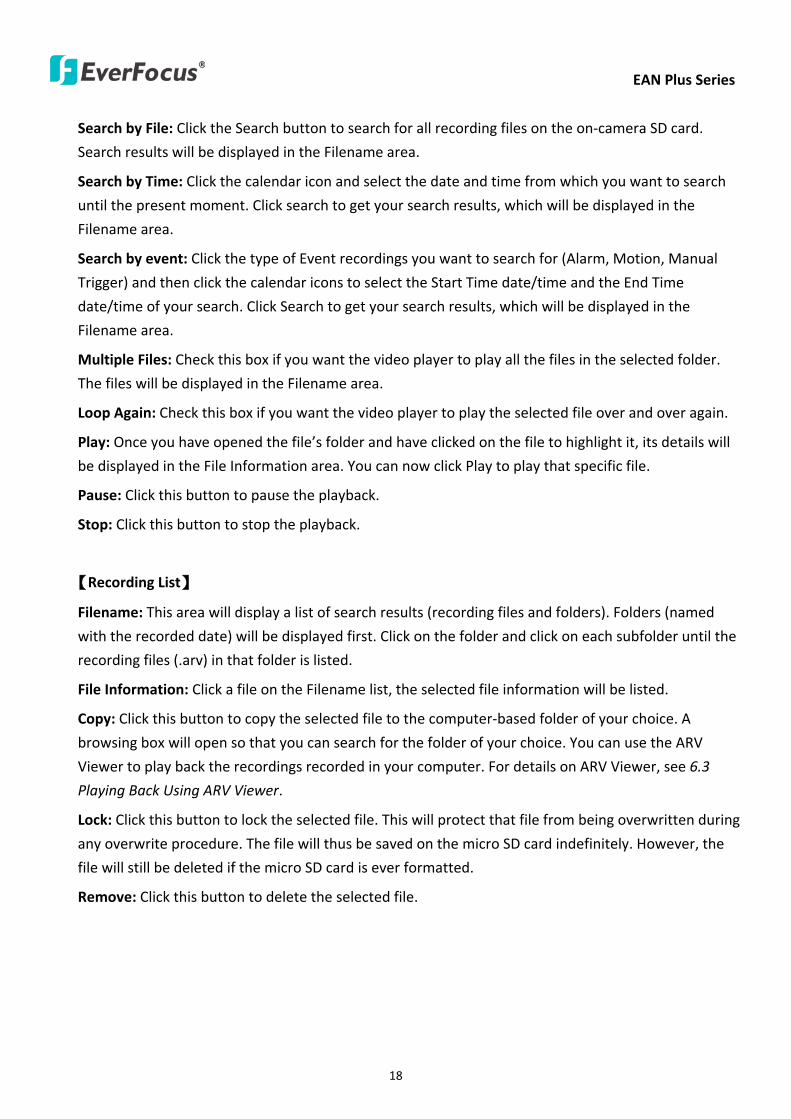
EAN Plus Series
18
Search by File Click the Search button to search for all recording files on the on-camera SD card
Search results will be displayed in the Filename area
Search by Time Click the calendar icon and select the date and time from which you want to search
until the present moment Click search to get your search results which will be displayed in the
Filename area
Search by event Click the type of Event recordings you want to search for (Alarm Motion Manual
Trigger) and then click the calendar icons to select the Start Time datetime and the End Time
datetime of your search Click Search to get your search results which will be displayed in the
Filename area
Multiple Files Check this box if you want the video player to play all the files in the selected folder
The files will be displayed in the Filename area
Loop Again Check this box if you want the video player to play the selected file over and over again
Play Once you have opened the filersquos folder and have clicked on the file to highlight it its details will
be displayed in the File Information area You can now click Play to play that specific file
Pause Click this button to pause the playback
Stop Click this button to stop the playback
【Recording List】
Filename This area will display a list of search results (recording files and folders) Folders (named
with the recorded date) will be displayed first Click on the folder and click on each subfolder until the
recording files (arv) in that folder is listed
File Information Click a file on the Filename list the selected file information will be listed
Copy Click this button to copy the selected file to the computer-based folder of your choice A
browsing box will open so that you can search for the folder of your choice You can use the ARV
Viewer to play back the recordings recorded in your computer For details on ARV Viewer see 63
Playing Back Using ARV Viewer
Lock Click this button to lock the selected file This will protect that file from being overwritten during
any overwrite procedure The file will thus be saved on the micro SD card indefinitely However the
file will still be deleted if the micro SD card is ever formatted
Remove Click this button to delete the selected file
EAN Plus Series
19
62 Setting up the Playback Function
Note that the Playback function will not be active until the user has inserted a micro SD card in the
camerarsquos micro SD card slot The card may also have to be formatted in the Settings submenu
Micro SD Card Slot
621 Preparing the Micro SD Card
Once you insert a functional micro SD card into the slot the Playback button on the Live page should
become active within seconds (see section 622 below ndash the grey letters should turn white) IF NOT
do the following
1 From the Live page click Settings gt System gt SD Card If no card has been inserted yet the
Remove button should be faded indicating that no card is being detected (If a card is
inserted and the Remove button is still faded pull the card out and re-insert it)
2 Slide the card into the slot until it clicks into position
3 The Remove button should become active within a few seconds indicating the card is active
4 If the Remove button stays faded click the Format button to format the card NOTE All data
on the disk will be deleted if the Format button is clicked
622 Testing the Playback Function
1 Once the SD card is detected by the system the button (inactive)
will turn to (active)
2 To test the Playback function (this is not required) set up a ldquoManual Triggerrdquo Recording
Event by clicking Settings gt Event gt Event Settings
3 Click the ldquoAddrdquo button on the middle right side of the page to open an ldquoAdd Eventrdquo box
4 Give the event a name like ldquoTest 1rdquo
EAN Plus Series
20
5 In the ldquoEvent Triggered byrdquo field click on Manual Trigger
6 Below this check ldquoEnable This Eventrdquo ldquoEnable Post-trigger Bufferrdquo and ldquoRecord to SD Cardrdquo
7 To save your settings click OK or close the box by clicking on the red x icon at top right of the
box (in which case you will be asked if you want to save the data to which you should reply OK)
The box will close and the new event will be listed in the list area of the Event Settings page
8 Look at the ldquoPost-trigger Bufferrdquo at the bottom to make sure the buffer time is set to 10 seconds
9 Click ldquoApplyrdquo to make sure all settings are saved
10 Click the Live button to go back to the Live page
11 Get ready to click the Trigger Event button at the bottom of the page Before you do see if you
can find something in the view screen that will give you a visual time marker For instance if you
can get your hand in front of the camerarsquos lens get ready to count down on your fingers
12 Click the Trigger Event button and slowly count down on your fingers in front of the lens (if you
are able to do so ndash if not try to find visual cues on the view screen that will help you to mark the
moment you pushed the trigger) The recording period will be as long as the buffer time you
selected ndash the default period is 10 seconds
13 Click the Playback button to open the Playback page
14 There are different ways to search for recording files on the camerarsquos Micro SD card (ie the
Playback memory) For a recent recording like your test event simply click the ldquoSearchrdquo button
under the ldquoSearch by Filerdquo header
15 If the SD card is active and formatted correctly the recording folderrsquos name (the recording dayrsquos
date) will appear in the Filename box at the bottom Click on this folder to open it If there are
sub-folders click on the bottom one (the most recent would be at the bottom) until you can click
on a file that cannot open to another sub-level and shows data in the File Information box to the
right This would be the file of the most recent recording event
16 To play this file click the Play button below the video box The test footage you have recorded
should start playing Play time should be 10 seconds if you left the Post-trigger Buffer as 10
seconds
EAN Plus Series
21
63 Playing Back Using ARV Viewer
You can play back the recordings stored in the computer using the ARV Viewer included in the
software CD To store the recordings in the computer please refer to Recording List gt Copy in 61
Remote Playback using Playback Page
4 5 6 7 8 9 10
321
No Item Name Descriptions
1 Snapshot Click to take and save a snapshot
2 Load File Click to load the recordings for playing back
3 Convert ARV to AVI Convert the recording from ARV format to AVI format
4 Playback Time Display the playback time
5 Total Time of Recording Display the total time of the recording
6 Stop Click to stop playing the recording
7 Step Reverse Click to display the previous frame
8 Play Click to play back the recording
9 Pause Click to pause the recording
10 Step Forward Click to display the next frame
EAN Plus Series
22
7 Settings
Click the Settings button on the Live View Window to enter the settings submenu There are nine buttons
on the left-side of the submenu Live System Info User Config Network Video Audio User Event and
System Click the Live button can go back to the Live View Window
71 System Info
The System Information and System Log can be checked on this page Click the top tab of the one you
want to see
711 Information
Click the Information tab the following dialog box appears These values cannot be changed on this
page and are for reference only
EAN Plus Series
23
712 Log
Click the Log tab the following dialog box appears The sequence number date time and event
messages of the log event will be displayed in the System Log field The log will display the last 256
log events Click the Export button to export the system log event list into a ldquotxtrdquo file and select the
location where the exported log file will be saved to
EAN Plus Series
24
72 User Config
Each user can set a different configuration for hisher Live page here These settings will be applied to
the logged-in userrsquos Live page every time heshe logs in
721 Live View Config
【VideoAudio Connection Protocol Setting】You can transmit the data stream from the IP cameras
using the RTSP (Real Time Streaming Protocol) on the network The RTSP is a protocol that allows
you to access video streams by using the compatible media players Click Apply to apply the
changes or Reset to reset without saving the changes RTP over UDP The RTSP protocol uses UDP for camera data stream transmission
RTP over TCP The RTSP protocol uses TCP for camera data stream transmission
RTP over HTTP The RTSP protocol uses HTTP for camera data stream transmission
Nevio CGI This is EverFocusrsquo protocol designed for EverFocusrsquo IP devices Select this
protocol for camera data stream transmission
【Text Settings】Check the box of each option (Machine name DateTime Frame Rate) to display
this info on the Live View Page
Foreground Color Slide the Red Green and Blue bars to create your preferred text color for the
info text line
Position Select the position where the text will be displayed Choose from Upper Left Lower
Right Lower Left
Click Apply to apply the changes or Reset to reset without saving the changes
EAN Plus Series
25
【DateTime Format Used in Text】Click the dropdown menu to select datetime format from the
listed options Click on the desired hour format Click Apply to apply the setting changes or Reset to
reset without saving the change
【Live View Layout Settings】 Check the ldquoShow One Push Buttonsrdquo boxes if you want to show these
buttons on the Live View Page Uncheck these boxes to hide these buttons This function is only
available for EAN3120 Plus 3220 Plus
722 Recording Snapshot
This configures where your Record Button and Snapshot Button ( ) files will be saved if
you click one of these buttons Selectable folders will be on the computer only not on the
on-camera SD card
【Recording Snapshot Export Settings】
Enable Event Recording to PC Checking this box will let the system save RecordSnapshot Button
recordings to the folder configured below on the userrsquos PC
Export Folder Select the Export folder for the action above by clicking on the browse (hellip) button
and then select the desired folder
File size The user can limit the size of each recorded file here (in minutes) When a single
recording file exceeds the time you set the system will create a new file to save that data to
Overwrite Select ldquoONrdquo for overwriting recordingsnapshot file when the disk storage capacity is
full The user can set the storage capacity limitation in the in-sentence field in the gray box below
the Overwrite setting ldquoIf the remaining hard disk capacity is less than ____ MB (50~2000) system
will stop recording or start overwriting ldquo
Click Apply to apply the setting changes or Reset to reset without saving the changes
EAN Plus Series
26
723 Language
Select the language to be displayed on the Web interface of the IP camera The default language is
English
To add a new language not listed in the current Language list click the Browse button to locate
the new language file (evb) on your computer and then click the Upload button Updated
language files might be available on the manufacturerrsquos website Contact your vendor if required
Click Apply to apply any changes or Reset to reset without saving the changes
Note Uploading a new language file will cause the system to reboot automatically Please create
a new network connection to the IP camera when the reboot is complete
EAN Plus Series
27
73 Network
This page covers network-related settings including Network DDNS SMTPFTP HTTPS SNMP and
Network Alarm
731 Network
The following information is required to configure the network settings Contact your network
administrator or your internet service provider to get the info
【IP Settings】
IP Type Refer to the network administrator for these settings of the server Default DHCP
DHCP This setting lets the system use an automatically assigned (dynamic) IP address This
address can change under certain circumstances For instance when the camerarsquos network
switchhub has to be rebooted Do not assign to the DHCP server the same IP addresses used
for the other network cameras and PCs with unique IP addresses
Static IP The user can manually set the Static IP address This type of address is stable and
cannot change but the user has to make sure there are no address conflicts with other
network-connected devices
PPPoE This is a DSL-connection application The ISP will ask the user to input a username and
password Contact your ISP for these details
EAN Plus Series
28
Note If PPPoE is selected as the IP type the supplied IP Utility program will not be able to
detect the device
IP address When DHCP is not used the user needs to manually enter the IP address of the
camera Do not enter an IP address that is already used for your computer or other network
cameras
Subnet Mask This field is used to set the netmask for your network so that the IP camera will be
recognized within the network Example 2552552550 When DHCP is selected the DHCP server
will assign this value automatically
Gateway This field is used to set the gateway for your network so that the IP camera will be
recognized within the network When DHCP is selected the DHCP server will assign this value
automatically
Primary DNS Enter the IP address of the DNS server if this is provided by an ISP
Secondary DNS If your ISP provided you with a secondary DNS address please enter it here
Username Enter the accountrsquos username (used only for PPPoE)
Password Used only for PPPoE
IPv6 Enter the IPv6 details in this area if this applies to your system
Click Apply to apply the setting changes or Reset to reset without saving the change
【Port Settings】Enter the HTTP HTTPS and RTSP port numbers and click Apply to save
【Multicast Settings】Enable if required fill in the setting options and click Apply to save
EAN Plus Series
29
732 DDNS
DDNS (Dynamic Domain Name System) is a service used to map a domain name to the dynamic IP
address of a network device You can set up the DDNS service for remote access to the IP camera
DDNS assigns a domain name (URL) to the IP camera so that the user does not need to go through
the trouble of checking if the IP address assigned by DHCP Server has changed Once the IP is
changed the IP camera will automatically update the information to the DDNS to ensure it is always
available for remote access
Before enabling the following DDNS function user should have applied for a host name from the
DDS service providerrsquos website We support these four DDNS server providers
wwweverfocusddnscom wwwsitelutionscom wwwdyndnscom and wwwno-ipcom
Note We highly recommend that you use xxxxeverfocusddnscom for the simplicity of setting up
your IP cameras
【DDNS Settings】
Enable Check this box to enable the DDNS function
Service ISP You can either apply for a host name from EverFocus or other DDNS server providers
If you choose the EverFocus DDNS server you can obtain a free host name from EverFocus by
following the steps below
bull From EverFocus To obtain a free host name from EverFocus type a desired host name in the
textbox click the Register Update button and then click the Apply button
bull From other DDNS server providers To obtain a domain name from one of the three DDNS
server providers you have to register your name with the provider first and then select the
provider and fill in the required information Please refer to the specific DDNS companyrsquos
website for further information
Record ID Type the record ID if provided by the DDNS server provider
EAN Plus Series
30
FQDN Type the fully qualified domain name applied from the DDNS server provider For
example xxxxdyndnscom
Username Password Type the login account of your DDNS server provider
Click Apply to apply the setting changes or Reset to reset without saving the changes
Note
1 In order to support the full functionality of the camera you must open the port numbers (80
554 443) on the router for remote access to the IP camera This function is available on most
routers in the market and is often known as ldquoPort Forwardingrdquo To set up Port Forwarding
please consult the manual of the router
2 In certain router models it is possible that you will not be able to access the camera using
DDNS while inside the routerrsquos network Please try using a PC located outside of your routerrsquos
network
Default Ports on All EverFocus IP Cameras
HTTP 80
RTSP 554
HTTPS 443
EAN Plus Series
31
733 SMTP FTP
【Set SMTP Server (email)】This area is for configuring the mail server that is used to send e-mail
notifications from the camera to predefined addresses via SMTP Note that to enable e-mail
notification function you have to check the Send Mail Notification item on the Event dialog box
(see 771 Event Settings)
SMTP Server Enter the IP address or the host name of the SMTP server used to send e-mails
SMTP Port Enter the port number for SMTP The default is 25
Authentication Check this box if the SMTP server requires authentication (userpassword)
User name Input the userrsquos login ID if the SMTP server requires authentication
Password Input the userrsquos login password if the SMTP server requires authentication
EAN Plus Series
32
Receiver Address Input the e-mail addresses for receiving an e-mail message when an EVENT is
enabled and triggered Please use ldquordquo to separate multiple addresses
Sender Address Input the senderrsquos e-mail address so that the receiver can recognize the sender
when an Event message is received
Attach Image Check this box if you want to attach an image when an alarm is triggered or an IP
camera detects events
Send Test Email Click the Test button to send a testing email to the assigned address
Click Apply to apply the setting changes or Reset to reset without saving the changes
【Set FTP Server】The settings relating to the FTP server used to transmit the alarm images can be
configured here Note that to enable uploading images to the FTP server function you have to
check the Upload to FTP item on the Event dialog box (see 771 Event Settings)
FTP Server Enter the IP address or the host name of the FTP server
FTP Port Enter the port number for the FTP server Default is 21
Recording Path Assign the recording path
User Name Set FTP Userrsquos name
Password Set FTP password
PASV mode Check to enable Passive mode Passive mode is normally enabled If a connection
cannot be established uncheck PASV Moderdquo
Test FTP Server Click the Test button to send a testing file to the assigned FTP server
Click Apply to apply the setting changes or Reset to reset without saving the changes
EAN Plus Series
33
734 HTTPS
Hypertext Transfer Protocol Secure (HTTPS) is a combination of the Hypertext Transfer Protocol
and the SSLTLS protocol and provides encrypted communication and secure identification of a
network web server
Before using the HTTPS function for communication with the IP camera a Certificate must be
created first There are two ways to create and install a certificate Create Self-Signed Certificate
and Create Certificate Request
Create Self-Signed Certificate
Please note that even though self-signed certificates are free and offer some protection true
security is only implemented after the installation of a signed certificate issued by a certificate
authority
1 Click the Create Self-Signed Certificate button the following dialog appears
EAN Plus Series
34
2 Type the required Certificate information and then click the Apply button The subject line will
be displayed in the Installed Certificate Information field
3 Click the Property button a pop-up window appears to display the details of the certificate
4 To optionally create and install other certificates remove the existing one by clicking the
Remove button to erase the certificate
5 On the Web page change the address from ldquohttprdquo to https in the address bar and press
Enter on the keyboard Some Security Alert dialogs will pop up Click OK or Yes to enable HTTPS
Create Certificate Request
You can apply for an official certificate from an issuing Certificate Authority
1 Click the Create Certificate Request button the following dialog appears
EAN Plus Series
35
2 Type the required Certificate information and then click the Apply button The subject line will
be displayed in the Created Request field
3 Click the Property button a pop-up window appears to display the details of the certificate
4 To optionally create and install other certificates or request remove the existing one by clicking
the Remove button to erase the certificate or request
5 Copy the contents of the Certificate request (in PEM format) and paste it to the certificate
request field on the Web page of the 3rd-party certification authority such as Symantec VeriSign
Wait for the certificate authority to issue an SSLTLS certificate and then download the issued
certificate on your computer
6 In the Install Signed Certificate field click the Browse button to search for the issued certificate
and then click the Upload button to import the certificate Once the certificate has been
uploaded this field will show the subject line of the certificate
EAN Plus Series
36
735 SNMP
The default values for SNMP v1v2v2c and SNMP v3 are already filled in Click either of the
Enable buttons to enable either of the two Make your changes as desired Click on the Trap
Address field to enter the digits if required
736 Network Alarm
This function works with EverFocusrsquos CMS software eg the PowerCon or the Power Video Plus For
the setting details please refer to the CMS network alarm protocol
EAN Plus Series
37
74 Video
The settings relating to video such as streaming camera OSD can be configured on this page The
Video page has five tabs Multi-streaming Camera Advanced ROI and Privacy Mask
741 Multi Streaming
【Stream Settings】 This IP camera can output three video streams simultaneously For each of these
streams the user can set the compression format resolution bit rate and frame rate individually
Stream 1 is always enabled for live view To enable Stream 2 andor Stream 3 check the ldquoEnablerdquo
box the header of each stream
Note If you connect to the camera via the Internet and experience a delay (lag time) in the video
feed try to reduce the number of streams and the quality and resolution of the streams ndash but
keep the frame rate at its maximum
EAN Plus Series
38
Format Select the encoding format ndash H264 or MJPEG
Resolution Select the most suitable resolution for your needs
Frame Rate Select from 1 to 30 fps
Bit Rate If required select whether you want the stream to stream a Constant Bit Rate or a
Variable Bit Rate and set the values of whichever option you choose
Click Apply to apply the setting changes or Reset to reset without saving the changes
【Video Recording Settings】Select the stream you want to configure and then select whether you
want the recording files of that stream to be saved in AVI or ARV format Click Apply to apply the
setting changes or Reset to reset without saving the changes
【Time Stamp Settings】 You can select the DateTime format position and add the setting to the
streaming
Click Apply to apply the changes or Reset to reset without saving the changes
EAN Plus Series
39
742 Camera
【Image Settings】Set the Brightness Saturation Contrast or Sharpness of the image Click Apply to
apply the changes or Reset to reset without saving the changes
【Camera Settings】
Mirror Switch Mirror ON to rotate the image horizontally around a vertical axis
Flip Switch Flip ON to rotate the image vertically around a horizontal axis
AE There are two options
ALC Selecting Automatic Light Control allows the camera circuitry to either take bright spots
more into consideration (peak) bringing out detail in bright areas or less into consideration
(average) bringing out detail in shadows
AES Selecting Auto Electronic Shutter disables the Shutter setting below this setting In this
mode the camera measures the light level and decides whether it needs more or less light and
then automatically adjusts the shutter speed accordingly
BLC Back Light Compensation (BLC) is used to make the subject appear clearer when it is set
against a bright background
OFF Select to switch Back Light Compensation functions off
(ON)BLC The BLC can increase the exposure of a dark area surrounded by a brighter area HLC
can decrease the exposure of bright areas surrounded by darker areas This enables the
camera to better display information that would otherwise have been ldquowhited outrdquo like a
license plate between two bright headlights on a dark road
(ON)HLC The Highlight-Suppression BLC is used to reduce the brightness of light sources in a
specific area It is activated only in a low illumination environment to minimize the effects of
glare from bright lights such as spotlights street lights or headlights in the field of view
EAN Plus Series
40
WDR The Wide Dynamic Range (WDR) function provides clearer images when both of the very
bright and dark areas simultaneously appear on the camera view There are four value options
OFF Low Middle and High Note that when WDR is ON some parts of the image may appear
solarized This is normal for WDR and is not a camera malfunction This function is only available
for EAN3120 Plus 3220 Plus
DN Mode
Auto Select to let the camera automatically switch to Night mode (black and white) when the
light levels fall to a specified level and back to Day mode (color) when the light levels rise to a
specified level
Day Select to keep the camera in Day mode (color) even in nighttime
Night Select to keep the camera in Night mode (black and white) even in daytime
EAN Plus Series
41
743 Advanced
EAN Plus Series
42
【Camera Settings】
Lens (IRIS Control) Select DC or Manual for IRIS control This function is only available for EAN3220
Plus
Exposure Settings (AE) This setting is used to adapt to the amount or type of light used by the
camera Note the settings vary among models
Mode This function is not available for EAN3220 Plus
Automatic Light Control (ALC) This option is only available for EAN3120 Plus 3300 Plus The
ALC allows the camera circuitry to either take bright spots more into consideration (peak)
bringing out detail in bright areas or less into consideration (average) bringing out detail in
shadows
Auto Electronic Shutter (AES) This option is only available for EAN3120 Plus 3300 Plus In
this mode the camera measures the light level and decides whether it needs more or less light
and then automatically adjusts the shutter speed accordingly
Manual This option is only available for EAN3300 Plus Select this option to manually set up
the Shutter (Manual) and AGC (Manual) values
Iris Specify the size of the Iris opening here
Shutter If enabled this setting lets you set the shutter speed yourself
Shutter Limit Use this setting to set the maximum shutter speed for the camera This function is
only available for EAN3120 Plus
AGC Set the Auto Gain Control limit here The lower the AGC level the lower the video signal and
the noise However the image will be darker under low-light condition with IR-off if you set up the
Iris to the maximum level
Slow Shutter This option can be switched on when AES Mode is selected in the Exposure Settings
(AE) field This function is only available for EAN3220 Plus 3300 Plus
Flickerless If the Mode field in the Exposure Settings (AE) area has been set to AES then this option
becomes available Choose between OFF 50HZ 60HZ 50HZ (High Luminance) or 60HZ (High
Luminance) This function is only available for EAN3300 Plus
EV Setting Set up the Exposure Value Note the brightness of the screen changes when you change
the EV value This function is only available for EAN3300 Plus
AE Response Set up Auto Exposure Response time This function is only available for EAN3300 Plus
AE Weighting Area Select an AE Weighting area Each setup AE Weighting Area is configured with
the appropriate brightness level on the center and the surrounding areas This function is only
available for EAN3300 Plus
Brightness Set the image brightness here
AE Reference Set the Auto Exposure value here This function is only available for EAN3120 Plus
EAN Plus Series
43
Black Level Set the Black level here This function is only available for EAN3300 Plus
WDR The Wide Dynamic Range (WDR) function provides clearer images when both of the very
bright and dark areas simultaneously appear on the camera view There are four value options OFF
Low Middle and High Note that when WDR is ON some parts of the image may appear solarized
This is normal for WDR and is not a camera malfunction This function is only available for EAN3120
Plus 3220 Plus
Visibility Enhancement (OFFLowMiddleHigh) Images in foggy or rain environments or in
environments with a very strong luminous intensity have a dynamic range that is significantly lower
than ordinary images The user can use this Visibility Enhancement setting to ldquoDEFOGrdquo the image if
such ldquoFOGGINGrdquo is an issue This function is only available for EAN3220 Plus
BLC Settings Back Light Compensation (BLC) is used to make the subject appear clearer when it is
set against a bright background
OFF Select to switch Back Light Compensation functions off
Back Light This option is only available for EAN3300 Plus The Back Light function is useful
when the background of the subject is very bright and the subject itself is dark Select Back
Light and adjust the slide bar to the left right for setting up the back light value The higher
the value the more the backlight compensation
Front Light This option is only available for EAN3300 Plus This function is useful when the
bright highlights such as flashlight or car headlights appear on the camera view Select Front
Light and adjust the slide bar to the left right for setting up the front light value The higher
the value the more the highlight compensation
ON (BLC) This option is only available when you select AES Mode in the Exposure Settings (AE)
field The option is only available for EAN3120 Plus 3220 Plus The BLC function is useful
when the background of the subject is very bright and the subject itself is dark Follow the
instructions below to configure the settings for each model
For EAN3120 Select ON (BLC) the button next to the Mode drop-down list will be
active (see image below) Click the button the green setup areas appear on the left
screen Click on the areas to enable disable the BLC function The selected areas (in green)
will be applied with the BLC function
EAN Plus Series
44
For EAN3220
You can configure one area to apply the BLC function Select ON (BLC) the setup buttons
appears (see image below) Select Low Middle High from the BLC Gain drop-down list To
set up a BLC area click the Edit Area button and then click on the blue color tab to turn your
mouse cursor into a blue pen Move the cursor to the position on the right screen where you
want the BLC rectangle to start and then click Move your cursor to the position (diagonally
opposing corner) where you want the BLC rectangle to end and then click The blue area will
be applied with the BLC function
ON (HLC) This option is only available when you select AES Mode in the Exposure Settings (AE)
field The option is only available for EAN3120 Plus 3220 Plus This function is useful when
the bright highlights such as flashlight or car headlights appear on the camera view Follow
the instructions below to configure the settings for each model
For EAN3120 Select ON (HLC) and then select a level from the drop-down list The higher the
level the more the highlight compensation
For EAN3220
HLC Level Select a level for the HLC setting The higher the level the more the highlight
compensation
HLC Mode Select All Day Night mode to apply the HLC function
HLC Black Mask Select On Off to apply the black mask on the selected areas The
over-exposure portions within the selected areas will be applied with the black mask
Color Tabs You can set up four HLC areas with different colors To set up a HLC area click the
Edit Area button and then click on the color tab to turn your mouse cursor into a pen of that
color Move the cursor to the position on the right screen where you want the HLC rectangle
to start and then click Move your cursor to the position (diagonally opposing corner) where
you want the HLC rectangle to end and then click Select ON from the color tab drop-down list
The rectangular area with the selected color will be applied with the HLC function
EAN Plus Series
45
Back Light This option is only available for EAN3300 Plus The Back Light function is useful
when the background of the subject is very bright and the subject itself is dark Select Back
Light and adjust the slide bar to the left right for setting up the back light value The higher
the value the more the backlight compensation
Front Light This option is only available for EAN3300 Plus This function is useful when the
bright highlights such as flashlight or car headlights appear on the camera view Select Front
Light and adjust the slide bar to the left right for setting up the front light value The higher
the value the more the highlight compensation
Noise Reduction Settings This limits the amount of digital ldquovideo noiserdquo that is usually found in any
video stream and helps to reduce file size The higher the level the more the reduction
For EAN3120 Plus 3300 Plus
Select ON OFF to enable disable the Noise Reduction function Or select Auto to let the camera
automatically enable disable the Noise Reduction function Slide the Level bar to set up the level
The higher the level the more the reduction
For EAN3220 Plus
2D DNR Select ON to enable the 2D DNR function
3D DNR Select ON to enable the 3D DNR function You can further set up the following settings
3D Start AGC Set up the AGC level to automatically start the 3D NR function
3D End AGC Set up the AGC level to automatically stop the 3D NR function
3D Level Set up the 3D DNR level
Smart NR Select ON to enable the Smart NR function The 3D NR function will be
automatically turned on when a motion event occurs
EAN Plus Series
46
White Balance Settings Select the mode that delivers the best quality image for the camerarsquos light
environment There are five options Auto Manual Indoor Outdoor One Push
Auto Select to let the camera automatically adjust the White Balance In the Auto mode the
camera computes the white balance value output using color information from the entire
screen It outputs the proper value using the color temperature radiating from a black subject
based on a range of value from 3000 to 7500K
Manual Select to adjust the Red and Blue values yourself in the fields below this field
Indoor Select to use the default settings for indoor environments In the Indoor mode the
camera uses 3200K as the base value
Outdoor Select to use the default settings for outdoor environment In the Outdoor mode it
uses 5800K as the base value
One Push Select to enable the Push button next to the Mode drop-down field This will allow you to force the camera to readjust the white balance every time you push the Push
button The lens will hold the same focal position until the next trigger command is received
This function helps to prevent incorrect focusing in dark environments This function is only
available for EAN3120 Plus 3220 Plus
Manual Temperature Select to use the optimized Red and Blue settings You can also
optionally adjust the Manual Level below this field for setting up the color temperature The
higher the value the more the color temperature This function is only available for EAN3300
Plus
DayNight Settings
Auto Select to let the camera automatically switch to Night mode (black and white) when the
light levels fall to a specified level and back to Day mode (color) when the light levels rise to a
specified level
Day Select to keep the camera in Day mode (color) even in nighttime
Night Select to keep the camera in Night mode (black and white) even in daytime
IR Smart Settings Select ON and set up the level to enhance the image quality when the images are
over exposure This function is useful when the camera is in the Night mode This function is only
available for EAN3220 Plus
Saturation Set the saturation value This function is not available for EAN3220 Plus
Monitor Type Select a gamma value from Set 1 Set 2 or Set 3 This function is only available for
EAN3120 Plus
Negative Switch this setting ON to view a color negative version of the video image This is useful
at night or when viewing temperature-sensitive images
EAN Plus Series
47
Sharpness Settings Select the sharpness level of the image A low sharpness level will deliver a
softer less detailed image A high level will deliver a sharp highly detailed image Switch Resolution
Enhancement ON to enable the resolution enhancement function
Contrast Select the contrast level of the image
Suppress Function This function is only available for EAN3300 Plus
Aperture Compensation Suppression (OFFLowMiddleHigh) This setting can be activated to
suppress luminance noise when the AGC level increases
Chroma Suppression (OFFLowMiddleHigh) This setting can be activated to suppress
chrominance noise when the AGC level increases
Ygamma (gamma 22standardcontrast enhancehigh light range mode LHigh light range mode
H) Select the Ygamma value for the video quality of the monitor This function is only available for
EAN3300 Plus
Monitor Settings The user can use this field to optimize video quality for his or her specific type of
monitor ndash LCD or CRT This function is only available for EAN3220 Plus
Color Space Standard The options are YUV601 for SD and YUV709 for HD These define the color
space standard required to convert an RGB picture to a YUV picture Generally YUV601 is used for
Standard Definition (720P) devices and the YUV709 is used for High Definition (1080P) devices
Click Apply to save all changes Click Reset to cancel all changes
EAN Plus Series
48
744 ROI (Region of Interest)
The Region of Interest (ROI) function allows users to set up multiple regions within an image with
better quality and less distortion than the rest of the image You can also use this function
together with the Digital Zoom function on the Live View Page to get a better image result Up to
eight ROIs can be configured in the ROI settings page
To set up an ROI region
1 Select an ROI number from the ROI No drop-down list
2 Click the Add button the mouse cursor will turn into a pen when you move it over the live
image on the left
3 Move the cursor to the position where you want the ROI rectangle to start and then click
Move the cursor to the position (diagonally opposing corner) where you want the ROI
rectangle to end and then click
4 Slide the Quality bar to set up the quality value
5 Click the Apply button to apply the settings or click the Reset button to reset without saving
the settings
EAN Plus Series
49
745 Privacy Mask
The Privacy Mask can block out sensitive areas from view covering the areas with colored or black
and white boxes in both live view and recorded clips This feature is useful when usersrsquo donrsquot want
the sensitive information visible Up to four Privacy Masks can be configured
【Privacy Mask Color Settings】The Modes vary among camera models
Mode Click Color to make the masks appear as colored rectangles on the screen Click BW to
make the masks appear as gray rectangles on the screen Click Mosaic to make the masks appear
as mosaic-effect rectangles on the screen
Level Select the color of the masks if you selected Color Mode Select the level of grayness of the
masks if you selected BW Mode Select the level of smallmiddlelarge if you selected Mosaic
Mode
Click Apply to apply the settings or click Reset to reset without saving the settings
Color Tabs Click on a color tab to turn your mouse cursor into a pen of that color
You can now create a block of that color on the video screen Move your cursor to the position
where you want your mask rectangle to start and then click Move your cursor to the position
(diagonally opposing corner) where you want your mask rectangle to end and then click The
rectangular area with the selected color will appear The live image will display the rectangular
area with the color you selected If you want to create another mask use one of the other three
colors Each color denotes a different mask area Only one block per color is allowed As the
number of colors suggests you can configure up to four blocks
EAN Plus Series
50
Select All Click to turn the whole screen into a mask area
Clear All Click to delete all configured mask blocks
Eraser Click to turn the mouse cursor into an eraser to delete any block you click on
Area Shows the color and number of the block
Enable Check this box to enable the related mask block
Click Apply to apply the settings or click Reset to reset without saving the settings
EAN Plus Series
51
75 Audio
The EAN Plus series IP camera can transmit audio to your computer if you have connected an external
microphone to its audio Input cable It can also receive audio input from you and transmit it via an
external speaker if you have connected such a speaker to its audio Output cable
Check the Enable Audio box to enable the camerarsquos audio function The camera will now act as a
digital bridge (via the IP network) between any connected audio input device and any connected
audio device
Adjust the Audio Input Volume if you have external audio input devices (microphones) connected to
the camera and if there are problems with the sound input being too low or high
Click Apply to save all settings or click Reset to cancel
EAN Plus Series
52
76 User
761 User Information
The system administrator can create up to ten user accounts on this page
To set up a user account
1 Highlight a user account and click the Modify button The following dialog box appears
2 Type the account name account description and password for the account Type the password
again in the Confirm field
3 Select an authority level for the user account from the Authority drop-down list
bull Supervisor Administrator The only difference between a supervisor and administrator is
that a supervisor can edit an administratorrsquos account and password but an administrator
cannot edit the supervisorrsquos account and password Multiple administrators can be
configured but there can be only one supervisor The supervisor and administrators all
have unrestricted access to the Settings submenus and can determine the registration of
all other users
EAN Plus Series
53
bull User A user can view the Live View page and view the system network video and audio
information A user can only adjust the User Config page settings The user does not have
access to the User Event and System pages
bull Guest The lowest level of access which only allows the user access to the Live View page
4 Select Active or Disable from the Status drop-down list to active or disable the user account
5 Click On in the SD Card Playback field to allow the user to access the SD card playback
function
6 Click OK
7 Click Apply to save all the settings
EAN Plus Series
54
762 IP Address Filter
Use this page to specify IP addresses that are not allowed to access this camera By default any IP
address can access the camera
Note The Allowed List addresses only become relevant when the Denied List contains a network
or range and the supervisor wants to allow one or more IP addresses within that excluded range
or network In such a scenario the user would enter the excluded range or network in the
Denied List and enter the exceptions in the Allowed List
To set up the IP Address Filter
1 Select Denied List Click the Add button the following dialog box appears
2 Select an IP type from the IP Type drop-down list
3 Select a network rule from the Rule drop-down list type the IP address and click OK
Single Type a single IP address in the IP Address field below
Network Type the IP address and subnet mask in the field below
Range Type a range for the IP addresses
4 If you have set up an IP range in Step 3 you can optionally set up the Allowed List to allow one
or more IP addresses within the setup IP range to access the IP camera
5 Click Apply
EAN Plus Series
55
77 Event
You can set up the Motion Detection event Tamper Detection event or the Alarm IO to automatically
notify the users when an event occurs or an alarm is triggered You can also set up a schedule to
automatically record the videos when an event occurs or an alarm is triggered
771 Event Settings
You can create a total of ten event or alarm settings page in the Event List
【Event List】
Click the Add button and the following Event Configuration Window appears
EAN Plus Series
56
Enter Event Name Type an event name
Event Triggered by Select an event or alarm type for the to-be-specified-below reactions
Alarm Input Select this if you want a reaction trigger coming from any external connected sensor
to activate a to-be-specified-below reactions via the camera system Make sure that a suitable
device is actually connected to the alarm input relay
Manual Trigger Select this option if you want to manually trigger the alarm by clicking the Trigger
Event button on the Live View Page
Motion Detection Select this option if you want motion in a specified part of the camerarsquos viewing
rectangle (the screen image) to trigger the to-be-specified-below reactions
Tampering Detection Select this option if you want the camerarsquos tampering detection sensor to
trigger the to-be-specified-below reactions
Schedule Recording Select this option if you want the Schedule Recording periods configured in
the recording schedule (the Settings gt Event gt Schedule page) to activate this event In this
scenario a preconfigured event reaction like a log entry will list the start and end times of each
period Actual recording will only be triggered if the event is preconfigured to do so
Enable This Event Select to activate the event
Enable Re-trigger Click to set a minimum time after the event is triggered before the event
can be triggered again
Enable Pre-trigger Buffer Click if you want the Event reaction (as selected in the ldquoNotification
Overrdquo field below) to be the activation of the video recording function and if you want the
recording to include the video feed from the time period (configurable on the previous ldquoEvent
Settingsrdquo page) just before the Event trigger occurred
Enable Post-trigger Buffer Click if you want the Event reaction (as selected in the Notification
Over field) to be the activation of the video recording function and if you want the recording
to include the video feed from a time period (configurable on the Event Settings page) just
after the Event trigger occurred
Motion Area Select a setup motion detection area from the drop down list Note this
function only becomes relevant after the Motion Detection areas have been set up (see 772
Motion Detection)
Notification Over Select the desired notification types form the following items
Log Click if you want the camera to list the eventrsquos details in its log if the event is triggered
Trigger Alarm Output Click if you want the camera to relay the event reaction to a device
attached to the alarm relay output wire and then set up the alarm output duration time
EAN Plus Series
57
Send Mail Notification Click if you want the camera to send an Event notification email to the
email address entered in the Set SMTP Server(email) field of the Network gt SMTPFTP page if
the Event occurs (see 733 SMTP FTP)
Upload to FTP Click if you want the camera to upload recorded footage to the FTP server
entered in the Set SMTP Server(email) field of the Network gt SMTPFTP page if the Event
occurs (see 733 SMTP FTP)
Record to SD Card Click if you want the camera to start recording its video feed (when the
event occurs) on an on-camera SD Card (if such a card has been inserted)
Note The recording will only be as long as the combined Pre- and Post-trigger Buffers so
make sure you enable at least one of these buffers especially the Post-trigger Buffer
Record to PC Check this box if you want the camera to start recording its video feed (when
the event occurs) on the same folder on the same PC as configured on the User Config gt
RecordingSnapshot page (if such a folder has been enabled and configured)
Note The recording will only be as long as the combined Pre- and Post-trigger Buffers (and
for as long as the event trigger is happening ndash eg a motion is detected) so make sure you
enable at least one of these buffers especially the Post-trigger Buffer
Network Alarm Check this box if you want the camera to send a network alarm signal (when
the event occurs) to the CMS servers configured on the Network gt Network Alarm page (see
736 Network Alarm)
Click OK to save all settings or click Cancel to cancel
【PrePost Trigger Settings】
Pre-trigger Buffer Select the duration for the buffer This will determine the amount of footage
(length of time) before the event trigger moment that will be included in an event-triggered video
recording if that buffer and video recording has been enabled in the Event Configuration Window
Post-trigger Buffer Select the duration for the buffer This will determine the amount of footage
(length of time) after the event trigger moment that will be included in an event-triggered video
recording if that buffer and video recording has been enabled in the Event Configuration Window
Click Apply to save all settings or click Reset to cancel
EAN Plus Series
58
772 Motion Detection
Use this page to configure up to four areas in which motion will be detected When a motion is
detected by the camera the motion detection icon will appear at the top right of the
Live page to alert the user This function can also be linked with correctly configured Events to
trigger Event reactions like the activation of video recording periods snapshots alarms etc
Color Tabs Click on a color tab to turn your mouse cursor into a pen of that color
You can now create a block of that color on the video screen Move your cursor to the position
where you want your detection rectangle to start and then click Move your cursor to the position
(diagonally opposing corner) where you want your detection rectangle to end and then click The
rectangular area with the selected color will appear This block will be an area inside which the
camera will detect motion If you want to create another detection area use one of the other three
palette colors Each color denotes a different detection area Only one block per color is allowed As
the number of colors suggests you can configure up to four blocks
Select All Click to turn the whole screen into a motion detection area
Clear All Click to delete all configured motion detection blocks
Eraser Click to turn your mouse cursor into an eraser to delete any block you click on
Area Shows the color and numberID of the block
Enable Check this box to enable the related motion detection block
Sensitivity Set the sensitivity of the motion detection sensor function
Click Apply to save all settings or click Reset to cancel
EAN Plus Series
59
773 Tamper Detection
Use this page to set the number of seconds that an alarm signal will be active if the device is
physically tampered (moved covered up or out of focus
774 Alarm IO
Use this page to set the type of trigger input and the type of output contact for the camerarsquos alarm
channel
EAN Plus Series
60
775 Schedule
Use this page to configure a schedule for periods during which the camera should deactivate all
user-activated Events (gray Deselect periods) or when the camera should deactivate all
user-activated Events except Schedule Recording (SR) events (blue Schedule Recording-only
periods) or when the camera should deactivate only SR events (red Event Recording-only periods)
or when it should enable all activated Events (yellow periods)
Event Recording Click this button to make every hour block you click on red A red block represents
an Event Recording-only block which represents an hour when the camera will deactivate all
preconfigured activated Schedule Recording events and keep all the other activated events active
Schedule Recording Click this button to make every hour block you click on blue A blue block
represents a Schedule Recording-only block which represents an hour when the camera will
deactivate all other preconfigured activated events and keep only the preconfigured activated
Schedule Recording events active
Event + Schedule Click this button to make every hour block you click on yellow A yellow block
represents an hour in which all activated events including Schedule Recording events will be
active
Deselect Click this button to make every hour block become grey A grey block represents an hour
in which all activated events including Schedule Recording events will be inactive
Click Apply to save all settings or click Reset to cancel
EAN Plus Series
61
78 System
You can set up the systemrsquos time and SD card settings and to do maintenance and reset actions like
reboots and upgrades
781 DateTime
【Machine Name Settings】If required enter a new name for the machine This name will be visible
in the Machine Name field of the IP Utility software which is included in the software CD
【Set Time Zone】Set the time zone of the camerarsquos location
【Set DateTime Manually】Set the datetime here if you wonrsquot be using an NTP server to update the
datetime (see below)
【Set DateTime Sync】Enter the Network Time Protocol server if applicable The camerarsquos time will
be automatically adjusted by synchronizing with the NTP server
Click Apply to save all settings or click Reset to cancel
EAN Plus Series
62
782 Daylight Saving
Click Enable Daylight Saving to enable this schedule and select the dates when the regionrsquos
daylight saving period begins and ends Click Apply to save all settings or click Reset to cancel
783 SD Card
Use this page to prepare the system for safely removing the SD Card from its slot
【Setup SD Card】
Notification Select the percentage of storage space that should be left on the card before the
camera notifies you of the impending storage shortage or overwrite
Event Recording Select if you want Event Recording only FTP Backup only or both
Overwrite Click ON if you want the card to start writing over recorded footage when its memory is
full Click OFF if you want the card to stop recording new footage when its memory is full
【SD Card Utility】
Capacity This shows you how much card memory has been used and how much memory capacity
remains on the card
Remove Click this button before removing the card from the system
Format Click this button to format the card All data saved on the SD card will be removed if the
card is formatted
EAN Plus Series
63
784 Maintenance
【Maintenance Server】
Reboot Click this button to reboot the unit without changing any of the settings Use this function if
the unit is not behaving as expected
Restore Click this button to restart and reset most of the current settings to their factory default
values The only settings that will not be changed to default are
bull IP settings
bull DDNS settings
Default The Default button should be used with caution Pressing this button will return all of the
cameras settings including the IP address to the factory default values The camera will then have
to be reconfigured
【SaveLoad Configuration Server】
Save To make a backup file of the machinersquos current configurations press Save to save all the
configurations to a config file This will enable the user to reload these configuration settings if the
settings are changed and there is unexpected behavior
Load To load a previously saved configuration press the Browse button to locate the saved config
file (see above) and then click the Load button The systemrsquos settings will be restored to the saved
configuration
EAN Plus Series
64
【SaveLoad Video Configuration Server】
Save To make a backup file of the machinersquos video configurations press Save to save the video
configurations to a config file This will enable the user to reload these configuration settings if the
settings are changed and there is unexpected behavior
Load To load a previously saved video configuration press the Browse button to locate the saved
config file (see above) and then click the Load button The systemrsquos settings will be restored to the
saved video configuration
【Upgrade Firmware】Click the Browse button to find a previously prepared firmware upgrade file
Click Upgrade to install the new firmware
Note
1 Do not disconnect power to the unit during the upgrade sequence The unit will reboot
automatically after the upgrade has completed (1-5 minutes)
2 During the upgrade process all event recording actions will be stopped Event recording
actions will resume after the camera is rebooted
3 If the ldquoFile Error Please re-loginrdquo warning message appears when upgrading the firmware
please try the following instructions
a Go to Internet Explorer gt Tools gt Internet Option gt Security gt Custom
b Find and enable the Include local directory path when uploading files to a server
EAN Plus Series
65
8 Upgrading Firmware Using IP Utility
You can upgrade the Firmware using the IP Utility software included in the software CD
1 Install and then start the IPU program The following dialog box appears
2 Click Find Devices to search the cameras connected in the LAN The default network values of the
cameras will be displayed By default the network protocol of the camera is DHCP
3 Select a camera and click LoginMulti Login to log in the camera
4 Type the user ID and password Click OK
Note
1 The default user ID is user1 and the default password is 11111111
2 If you select more than one camera that has the same user ID password you will be able
to log in several cameras at once
EAN Plus Series
66
5 Highlight the camera and then click Upgrade Firmware A browsing window appears
6 Select the firmware file (evb) and then click Open The IP Utility will automatically upgrade the
firmware
The camera will reboot once the update is complete Click Find Devices the new firmware version
should be displayed in the last part of the Machine Name
EAN Plus Series
67
9 Specifications
Model EAN3120 Plus EAN3220 Plus EAN3300 Plus
Camera
Image Sensor 13 Panasonic CMOS 128 Sony CMOS
Megapixel 13 MP 2 MP 3 MP
Picture Elements (H x V) 1280 x 1024 1944 x 1092 2048 x 1536
Min Illuminations 003 Lux at F14
Electronic Shutter (Sec) 85 ~ 160000 2 ~ 150000 1 ~ 110000
Scanning System NTSC PAL
WDR Yes Yes No
BLC Yes
Gain Control Yes
White Balance Yes
Lens
Mounting Type C CS
Day Night Yes (with removable auto IR-cut filter)
IRIS Control DC Electrical IRIS Lens IRIS
Video
Video Compression H264 MJPEG
Resolution
NTSC
2048 x 1536 1920 x 1200 (for EAN3300 Plus only)
1920 x 1080 (for EAN3300 Plus 3220 Plus only)
1280 x 1024 1280 x 720 1024 x 768 720 x 480 704 x 480 640 x 480
352 x 240 320 x 240 160 x 120
PAL
2048 x 1536 1920 x 1200 (for EAN3300 Plus only)
1920 x 1080 (for EAN3300 Plus 3220 Plus only)
1280 x 1024 1280 x 720 1024 x 768 720 x 576 704 x 576 640 x 480
352 x 288 320 x 240 160 x 120
Frame Rate 30 fps at 1280 x 1024 30 fps at 1920 x 1080 15 fps at 2048 x 1536
Audio
Audio Streaming Two-way audio
Audio Compression G711
EAN Plus Series
68
Network
Interface 10 100 Base-T Ethernet RJ-45 socket
Supported Protocols
TCPIP IPV6 UDP ICMP DHCP NTP DNS DDNS SMTP SNMP FTP
HTTP HTTPs PPPoE UPnP Bonjour RTP RTSP RTCP IGMP ARP ONVIF
PSIA
Connector
Power DC female port PoE
Ethernet RJ-45
Audio 1 In (phone jack for microphone)
1 Out (phone jack for Speaker)
Alarm IO Terminal IO wires
Local Storage Micro SD SDHC memory card slot
TV-Out BNC socket composite 1 V p-p 75 Ω
General
Power Source DC 12V PoE (IEEE8023af)
Power Consumption
(IR LEDs On)
5W (DC 12V)
621W (PoE)
5W (DC 12V)
522W (PoE)
5W (DC 12V)
536W (PoE)
Operating Temperature 0degC ~ +50degC 32degF ~ +122degF
Humidity 20 to 80 (no condensation)
Safety CE FCC
Dimensions (L x W x H) 117 x 56 x 68 mm 46 x 22 x 27 in
Weight 410 g 09 lb
EverFocus Electronics Corp EverFocus Taiwan 12F No79 Sec 1 Shin-Tai Wu Road Hsi-Chih Taipei Taiwan TEL +886 2 2698 2334 FAX +886 2 2698 2380 wwweverfocuscomtw marketingeverfocuscomtw
EverFocus Europe - Germany Albert-Einstein-Strasse 1 D-46446 Emmerich Germany TEL +49 2822 93940 FAX +49 2822 939495 wwweverfocusde infoeverfocusde
EverFocus China - Beijing Room 609 Technology Trade Building Shangdi Information Industry Base Haidian District Beijing 100085 China TEL +86 10 6297 3336~39 FAX +86 10 6297 1423 wwweverfocuscomcn marketingeverfocuscomcn
EverFocus China - Shenzhen 4F No 2 D4 Building Wan Yelong Industrial Park Tangtou Road Shiyan Baoan Shenzhen Guangdong 518101 China TEL +86 755 2765 1313 FAX +86 755 2765 0337 wwweverfocuscomcn marketingeverfocuscomcn
EverFocus USA - California 1801 Highland Avenue Unit A Duarte CA 91010 USA TEL +1 626 844 8888 FAX +1 626 844 8838 wwweverfocuscom saleseverfocuscom
EverFocus USA - New York 415 Oser Avenue Unit S Hauppauge NY 11788 USA TEL +1 631 436 5070 FAX +1 631 436 5027 wwweverfocuscom saleseverfocuscom
EverFocus Japan 5F Kinshicho City Building 2-13-4 Koto-BashiSumida-Ku Tokyo 130-0022 Japan TEL +81 3 5625 8188 FAX +81 3 5625 8189 wwweverfocuscojp infoeverfocuscojp
EverFocus Europe - UK Unit 12 Spitfire Business Park Hawker Road Croydon Surrey CR0 4WD UK TEL +44 20 8649 9757 +44 845 430 9999 FAX +44 20 8649 9907 wwweverfocusukcouk salesukeverfocuscom
EverFocus India Suite 803 Housefin Bhavan C-21 Bandra Kurla Complex Bandra (East) Mumbai 400051 India TEL +91 22 6128 8700 FAX +91 22 6128 8705 wwweverfocusin saleseverfocusin
PN 4605PQ3120B010A-VerC
Your EverFocus product is designed and manufactured with high quality materials and components which can be recycled and reused This symbol means that electrical and electronic equipment at their end-of-life should be disposed of separately from your household waste Please dispose of this equipment at your local community waste collectionrecycling centre In the European Union there are separate collection systems for used electrical and electronic product Please help us to conserve the environment we live in
Ihr EverFocus Produkt wurde entwickelt und hergestellt mit qualitativ hochwertigen Materialien und Komponenten die recycelt und wieder verwendet werden koumlnnen Dieses Symbol bedeutet dass elektrische und elektronische Geraumlte am Ende ihrer Nutzungsdauer vom Hausmuumlll getrennt entsorgt werden sollen Bitte entsorgen Sie dieses Geraumlt bei Ihrer oumlrtlichen kommunalen Sammelstelle oder im Recycling Centre Helfen Sie uns bitte die Umwelt zu erhalten in der wir leben
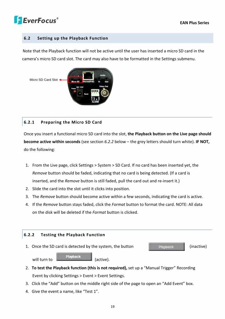
EAN Plus Series
19
62 Setting up the Playback Function
Note that the Playback function will not be active until the user has inserted a micro SD card in the
camerarsquos micro SD card slot The card may also have to be formatted in the Settings submenu
Micro SD Card Slot
621 Preparing the Micro SD Card
Once you insert a functional micro SD card into the slot the Playback button on the Live page should
become active within seconds (see section 622 below ndash the grey letters should turn white) IF NOT
do the following
1 From the Live page click Settings gt System gt SD Card If no card has been inserted yet the
Remove button should be faded indicating that no card is being detected (If a card is
inserted and the Remove button is still faded pull the card out and re-insert it)
2 Slide the card into the slot until it clicks into position
3 The Remove button should become active within a few seconds indicating the card is active
4 If the Remove button stays faded click the Format button to format the card NOTE All data
on the disk will be deleted if the Format button is clicked
622 Testing the Playback Function
1 Once the SD card is detected by the system the button (inactive)
will turn to (active)
2 To test the Playback function (this is not required) set up a ldquoManual Triggerrdquo Recording
Event by clicking Settings gt Event gt Event Settings
3 Click the ldquoAddrdquo button on the middle right side of the page to open an ldquoAdd Eventrdquo box
4 Give the event a name like ldquoTest 1rdquo
EAN Plus Series
20
5 In the ldquoEvent Triggered byrdquo field click on Manual Trigger
6 Below this check ldquoEnable This Eventrdquo ldquoEnable Post-trigger Bufferrdquo and ldquoRecord to SD Cardrdquo
7 To save your settings click OK or close the box by clicking on the red x icon at top right of the
box (in which case you will be asked if you want to save the data to which you should reply OK)
The box will close and the new event will be listed in the list area of the Event Settings page
8 Look at the ldquoPost-trigger Bufferrdquo at the bottom to make sure the buffer time is set to 10 seconds
9 Click ldquoApplyrdquo to make sure all settings are saved
10 Click the Live button to go back to the Live page
11 Get ready to click the Trigger Event button at the bottom of the page Before you do see if you
can find something in the view screen that will give you a visual time marker For instance if you
can get your hand in front of the camerarsquos lens get ready to count down on your fingers
12 Click the Trigger Event button and slowly count down on your fingers in front of the lens (if you
are able to do so ndash if not try to find visual cues on the view screen that will help you to mark the
moment you pushed the trigger) The recording period will be as long as the buffer time you
selected ndash the default period is 10 seconds
13 Click the Playback button to open the Playback page
14 There are different ways to search for recording files on the camerarsquos Micro SD card (ie the
Playback memory) For a recent recording like your test event simply click the ldquoSearchrdquo button
under the ldquoSearch by Filerdquo header
15 If the SD card is active and formatted correctly the recording folderrsquos name (the recording dayrsquos
date) will appear in the Filename box at the bottom Click on this folder to open it If there are
sub-folders click on the bottom one (the most recent would be at the bottom) until you can click
on a file that cannot open to another sub-level and shows data in the File Information box to the
right This would be the file of the most recent recording event
16 To play this file click the Play button below the video box The test footage you have recorded
should start playing Play time should be 10 seconds if you left the Post-trigger Buffer as 10
seconds
EAN Plus Series
21
63 Playing Back Using ARV Viewer
You can play back the recordings stored in the computer using the ARV Viewer included in the
software CD To store the recordings in the computer please refer to Recording List gt Copy in 61
Remote Playback using Playback Page
4 5 6 7 8 9 10
321
No Item Name Descriptions
1 Snapshot Click to take and save a snapshot
2 Load File Click to load the recordings for playing back
3 Convert ARV to AVI Convert the recording from ARV format to AVI format
4 Playback Time Display the playback time
5 Total Time of Recording Display the total time of the recording
6 Stop Click to stop playing the recording
7 Step Reverse Click to display the previous frame
8 Play Click to play back the recording
9 Pause Click to pause the recording
10 Step Forward Click to display the next frame
EAN Plus Series
22
7 Settings
Click the Settings button on the Live View Window to enter the settings submenu There are nine buttons
on the left-side of the submenu Live System Info User Config Network Video Audio User Event and
System Click the Live button can go back to the Live View Window
71 System Info
The System Information and System Log can be checked on this page Click the top tab of the one you
want to see
711 Information
Click the Information tab the following dialog box appears These values cannot be changed on this
page and are for reference only
EAN Plus Series
23
712 Log
Click the Log tab the following dialog box appears The sequence number date time and event
messages of the log event will be displayed in the System Log field The log will display the last 256
log events Click the Export button to export the system log event list into a ldquotxtrdquo file and select the
location where the exported log file will be saved to
EAN Plus Series
24
72 User Config
Each user can set a different configuration for hisher Live page here These settings will be applied to
the logged-in userrsquos Live page every time heshe logs in
721 Live View Config
【VideoAudio Connection Protocol Setting】You can transmit the data stream from the IP cameras
using the RTSP (Real Time Streaming Protocol) on the network The RTSP is a protocol that allows
you to access video streams by using the compatible media players Click Apply to apply the
changes or Reset to reset without saving the changes RTP over UDP The RTSP protocol uses UDP for camera data stream transmission
RTP over TCP The RTSP protocol uses TCP for camera data stream transmission
RTP over HTTP The RTSP protocol uses HTTP for camera data stream transmission
Nevio CGI This is EverFocusrsquo protocol designed for EverFocusrsquo IP devices Select this
protocol for camera data stream transmission
【Text Settings】Check the box of each option (Machine name DateTime Frame Rate) to display
this info on the Live View Page
Foreground Color Slide the Red Green and Blue bars to create your preferred text color for the
info text line
Position Select the position where the text will be displayed Choose from Upper Left Lower
Right Lower Left
Click Apply to apply the changes or Reset to reset without saving the changes
EAN Plus Series
25
【DateTime Format Used in Text】Click the dropdown menu to select datetime format from the
listed options Click on the desired hour format Click Apply to apply the setting changes or Reset to
reset without saving the change
【Live View Layout Settings】 Check the ldquoShow One Push Buttonsrdquo boxes if you want to show these
buttons on the Live View Page Uncheck these boxes to hide these buttons This function is only
available for EAN3120 Plus 3220 Plus
722 Recording Snapshot
This configures where your Record Button and Snapshot Button ( ) files will be saved if
you click one of these buttons Selectable folders will be on the computer only not on the
on-camera SD card
【Recording Snapshot Export Settings】
Enable Event Recording to PC Checking this box will let the system save RecordSnapshot Button
recordings to the folder configured below on the userrsquos PC
Export Folder Select the Export folder for the action above by clicking on the browse (hellip) button
and then select the desired folder
File size The user can limit the size of each recorded file here (in minutes) When a single
recording file exceeds the time you set the system will create a new file to save that data to
Overwrite Select ldquoONrdquo for overwriting recordingsnapshot file when the disk storage capacity is
full The user can set the storage capacity limitation in the in-sentence field in the gray box below
the Overwrite setting ldquoIf the remaining hard disk capacity is less than ____ MB (50~2000) system
will stop recording or start overwriting ldquo
Click Apply to apply the setting changes or Reset to reset without saving the changes
EAN Plus Series
26
723 Language
Select the language to be displayed on the Web interface of the IP camera The default language is
English
To add a new language not listed in the current Language list click the Browse button to locate
the new language file (evb) on your computer and then click the Upload button Updated
language files might be available on the manufacturerrsquos website Contact your vendor if required
Click Apply to apply any changes or Reset to reset without saving the changes
Note Uploading a new language file will cause the system to reboot automatically Please create
a new network connection to the IP camera when the reboot is complete
EAN Plus Series
27
73 Network
This page covers network-related settings including Network DDNS SMTPFTP HTTPS SNMP and
Network Alarm
731 Network
The following information is required to configure the network settings Contact your network
administrator or your internet service provider to get the info
【IP Settings】
IP Type Refer to the network administrator for these settings of the server Default DHCP
DHCP This setting lets the system use an automatically assigned (dynamic) IP address This
address can change under certain circumstances For instance when the camerarsquos network
switchhub has to be rebooted Do not assign to the DHCP server the same IP addresses used
for the other network cameras and PCs with unique IP addresses
Static IP The user can manually set the Static IP address This type of address is stable and
cannot change but the user has to make sure there are no address conflicts with other
network-connected devices
PPPoE This is a DSL-connection application The ISP will ask the user to input a username and
password Contact your ISP for these details
EAN Plus Series
28
Note If PPPoE is selected as the IP type the supplied IP Utility program will not be able to
detect the device
IP address When DHCP is not used the user needs to manually enter the IP address of the
camera Do not enter an IP address that is already used for your computer or other network
cameras
Subnet Mask This field is used to set the netmask for your network so that the IP camera will be
recognized within the network Example 2552552550 When DHCP is selected the DHCP server
will assign this value automatically
Gateway This field is used to set the gateway for your network so that the IP camera will be
recognized within the network When DHCP is selected the DHCP server will assign this value
automatically
Primary DNS Enter the IP address of the DNS server if this is provided by an ISP
Secondary DNS If your ISP provided you with a secondary DNS address please enter it here
Username Enter the accountrsquos username (used only for PPPoE)
Password Used only for PPPoE
IPv6 Enter the IPv6 details in this area if this applies to your system
Click Apply to apply the setting changes or Reset to reset without saving the change
【Port Settings】Enter the HTTP HTTPS and RTSP port numbers and click Apply to save
【Multicast Settings】Enable if required fill in the setting options and click Apply to save
EAN Plus Series
29
732 DDNS
DDNS (Dynamic Domain Name System) is a service used to map a domain name to the dynamic IP
address of a network device You can set up the DDNS service for remote access to the IP camera
DDNS assigns a domain name (URL) to the IP camera so that the user does not need to go through
the trouble of checking if the IP address assigned by DHCP Server has changed Once the IP is
changed the IP camera will automatically update the information to the DDNS to ensure it is always
available for remote access
Before enabling the following DDNS function user should have applied for a host name from the
DDS service providerrsquos website We support these four DDNS server providers
wwweverfocusddnscom wwwsitelutionscom wwwdyndnscom and wwwno-ipcom
Note We highly recommend that you use xxxxeverfocusddnscom for the simplicity of setting up
your IP cameras
【DDNS Settings】
Enable Check this box to enable the DDNS function
Service ISP You can either apply for a host name from EverFocus or other DDNS server providers
If you choose the EverFocus DDNS server you can obtain a free host name from EverFocus by
following the steps below
bull From EverFocus To obtain a free host name from EverFocus type a desired host name in the
textbox click the Register Update button and then click the Apply button
bull From other DDNS server providers To obtain a domain name from one of the three DDNS
server providers you have to register your name with the provider first and then select the
provider and fill in the required information Please refer to the specific DDNS companyrsquos
website for further information
Record ID Type the record ID if provided by the DDNS server provider
EAN Plus Series
30
FQDN Type the fully qualified domain name applied from the DDNS server provider For
example xxxxdyndnscom
Username Password Type the login account of your DDNS server provider
Click Apply to apply the setting changes or Reset to reset without saving the changes
Note
1 In order to support the full functionality of the camera you must open the port numbers (80
554 443) on the router for remote access to the IP camera This function is available on most
routers in the market and is often known as ldquoPort Forwardingrdquo To set up Port Forwarding
please consult the manual of the router
2 In certain router models it is possible that you will not be able to access the camera using
DDNS while inside the routerrsquos network Please try using a PC located outside of your routerrsquos
network
Default Ports on All EverFocus IP Cameras
HTTP 80
RTSP 554
HTTPS 443
EAN Plus Series
31
733 SMTP FTP
【Set SMTP Server (email)】This area is for configuring the mail server that is used to send e-mail
notifications from the camera to predefined addresses via SMTP Note that to enable e-mail
notification function you have to check the Send Mail Notification item on the Event dialog box
(see 771 Event Settings)
SMTP Server Enter the IP address or the host name of the SMTP server used to send e-mails
SMTP Port Enter the port number for SMTP The default is 25
Authentication Check this box if the SMTP server requires authentication (userpassword)
User name Input the userrsquos login ID if the SMTP server requires authentication
Password Input the userrsquos login password if the SMTP server requires authentication
EAN Plus Series
32
Receiver Address Input the e-mail addresses for receiving an e-mail message when an EVENT is
enabled and triggered Please use ldquordquo to separate multiple addresses
Sender Address Input the senderrsquos e-mail address so that the receiver can recognize the sender
when an Event message is received
Attach Image Check this box if you want to attach an image when an alarm is triggered or an IP
camera detects events
Send Test Email Click the Test button to send a testing email to the assigned address
Click Apply to apply the setting changes or Reset to reset without saving the changes
【Set FTP Server】The settings relating to the FTP server used to transmit the alarm images can be
configured here Note that to enable uploading images to the FTP server function you have to
check the Upload to FTP item on the Event dialog box (see 771 Event Settings)
FTP Server Enter the IP address or the host name of the FTP server
FTP Port Enter the port number for the FTP server Default is 21
Recording Path Assign the recording path
User Name Set FTP Userrsquos name
Password Set FTP password
PASV mode Check to enable Passive mode Passive mode is normally enabled If a connection
cannot be established uncheck PASV Moderdquo
Test FTP Server Click the Test button to send a testing file to the assigned FTP server
Click Apply to apply the setting changes or Reset to reset without saving the changes
EAN Plus Series
33
734 HTTPS
Hypertext Transfer Protocol Secure (HTTPS) is a combination of the Hypertext Transfer Protocol
and the SSLTLS protocol and provides encrypted communication and secure identification of a
network web server
Before using the HTTPS function for communication with the IP camera a Certificate must be
created first There are two ways to create and install a certificate Create Self-Signed Certificate
and Create Certificate Request
Create Self-Signed Certificate
Please note that even though self-signed certificates are free and offer some protection true
security is only implemented after the installation of a signed certificate issued by a certificate
authority
1 Click the Create Self-Signed Certificate button the following dialog appears
EAN Plus Series
34
2 Type the required Certificate information and then click the Apply button The subject line will
be displayed in the Installed Certificate Information field
3 Click the Property button a pop-up window appears to display the details of the certificate
4 To optionally create and install other certificates remove the existing one by clicking the
Remove button to erase the certificate
5 On the Web page change the address from ldquohttprdquo to https in the address bar and press
Enter on the keyboard Some Security Alert dialogs will pop up Click OK or Yes to enable HTTPS
Create Certificate Request
You can apply for an official certificate from an issuing Certificate Authority
1 Click the Create Certificate Request button the following dialog appears
EAN Plus Series
35
2 Type the required Certificate information and then click the Apply button The subject line will
be displayed in the Created Request field
3 Click the Property button a pop-up window appears to display the details of the certificate
4 To optionally create and install other certificates or request remove the existing one by clicking
the Remove button to erase the certificate or request
5 Copy the contents of the Certificate request (in PEM format) and paste it to the certificate
request field on the Web page of the 3rd-party certification authority such as Symantec VeriSign
Wait for the certificate authority to issue an SSLTLS certificate and then download the issued
certificate on your computer
6 In the Install Signed Certificate field click the Browse button to search for the issued certificate
and then click the Upload button to import the certificate Once the certificate has been
uploaded this field will show the subject line of the certificate
EAN Plus Series
36
735 SNMP
The default values for SNMP v1v2v2c and SNMP v3 are already filled in Click either of the
Enable buttons to enable either of the two Make your changes as desired Click on the Trap
Address field to enter the digits if required
736 Network Alarm
This function works with EverFocusrsquos CMS software eg the PowerCon or the Power Video Plus For
the setting details please refer to the CMS network alarm protocol
EAN Plus Series
37
74 Video
The settings relating to video such as streaming camera OSD can be configured on this page The
Video page has five tabs Multi-streaming Camera Advanced ROI and Privacy Mask
741 Multi Streaming
【Stream Settings】 This IP camera can output three video streams simultaneously For each of these
streams the user can set the compression format resolution bit rate and frame rate individually
Stream 1 is always enabled for live view To enable Stream 2 andor Stream 3 check the ldquoEnablerdquo
box the header of each stream
Note If you connect to the camera via the Internet and experience a delay (lag time) in the video
feed try to reduce the number of streams and the quality and resolution of the streams ndash but
keep the frame rate at its maximum
EAN Plus Series
38
Format Select the encoding format ndash H264 or MJPEG
Resolution Select the most suitable resolution for your needs
Frame Rate Select from 1 to 30 fps
Bit Rate If required select whether you want the stream to stream a Constant Bit Rate or a
Variable Bit Rate and set the values of whichever option you choose
Click Apply to apply the setting changes or Reset to reset without saving the changes
【Video Recording Settings】Select the stream you want to configure and then select whether you
want the recording files of that stream to be saved in AVI or ARV format Click Apply to apply the
setting changes or Reset to reset without saving the changes
【Time Stamp Settings】 You can select the DateTime format position and add the setting to the
streaming
Click Apply to apply the changes or Reset to reset without saving the changes
EAN Plus Series
39
742 Camera
【Image Settings】Set the Brightness Saturation Contrast or Sharpness of the image Click Apply to
apply the changes or Reset to reset without saving the changes
【Camera Settings】
Mirror Switch Mirror ON to rotate the image horizontally around a vertical axis
Flip Switch Flip ON to rotate the image vertically around a horizontal axis
AE There are two options
ALC Selecting Automatic Light Control allows the camera circuitry to either take bright spots
more into consideration (peak) bringing out detail in bright areas or less into consideration
(average) bringing out detail in shadows
AES Selecting Auto Electronic Shutter disables the Shutter setting below this setting In this
mode the camera measures the light level and decides whether it needs more or less light and
then automatically adjusts the shutter speed accordingly
BLC Back Light Compensation (BLC) is used to make the subject appear clearer when it is set
against a bright background
OFF Select to switch Back Light Compensation functions off
(ON)BLC The BLC can increase the exposure of a dark area surrounded by a brighter area HLC
can decrease the exposure of bright areas surrounded by darker areas This enables the
camera to better display information that would otherwise have been ldquowhited outrdquo like a
license plate between two bright headlights on a dark road
(ON)HLC The Highlight-Suppression BLC is used to reduce the brightness of light sources in a
specific area It is activated only in a low illumination environment to minimize the effects of
glare from bright lights such as spotlights street lights or headlights in the field of view
EAN Plus Series
40
WDR The Wide Dynamic Range (WDR) function provides clearer images when both of the very
bright and dark areas simultaneously appear on the camera view There are four value options
OFF Low Middle and High Note that when WDR is ON some parts of the image may appear
solarized This is normal for WDR and is not a camera malfunction This function is only available
for EAN3120 Plus 3220 Plus
DN Mode
Auto Select to let the camera automatically switch to Night mode (black and white) when the
light levels fall to a specified level and back to Day mode (color) when the light levels rise to a
specified level
Day Select to keep the camera in Day mode (color) even in nighttime
Night Select to keep the camera in Night mode (black and white) even in daytime
EAN Plus Series
41
743 Advanced
EAN Plus Series
42
【Camera Settings】
Lens (IRIS Control) Select DC or Manual for IRIS control This function is only available for EAN3220
Plus
Exposure Settings (AE) This setting is used to adapt to the amount or type of light used by the
camera Note the settings vary among models
Mode This function is not available for EAN3220 Plus
Automatic Light Control (ALC) This option is only available for EAN3120 Plus 3300 Plus The
ALC allows the camera circuitry to either take bright spots more into consideration (peak)
bringing out detail in bright areas or less into consideration (average) bringing out detail in
shadows
Auto Electronic Shutter (AES) This option is only available for EAN3120 Plus 3300 Plus In
this mode the camera measures the light level and decides whether it needs more or less light
and then automatically adjusts the shutter speed accordingly
Manual This option is only available for EAN3300 Plus Select this option to manually set up
the Shutter (Manual) and AGC (Manual) values
Iris Specify the size of the Iris opening here
Shutter If enabled this setting lets you set the shutter speed yourself
Shutter Limit Use this setting to set the maximum shutter speed for the camera This function is
only available for EAN3120 Plus
AGC Set the Auto Gain Control limit here The lower the AGC level the lower the video signal and
the noise However the image will be darker under low-light condition with IR-off if you set up the
Iris to the maximum level
Slow Shutter This option can be switched on when AES Mode is selected in the Exposure Settings
(AE) field This function is only available for EAN3220 Plus 3300 Plus
Flickerless If the Mode field in the Exposure Settings (AE) area has been set to AES then this option
becomes available Choose between OFF 50HZ 60HZ 50HZ (High Luminance) or 60HZ (High
Luminance) This function is only available for EAN3300 Plus
EV Setting Set up the Exposure Value Note the brightness of the screen changes when you change
the EV value This function is only available for EAN3300 Plus
AE Response Set up Auto Exposure Response time This function is only available for EAN3300 Plus
AE Weighting Area Select an AE Weighting area Each setup AE Weighting Area is configured with
the appropriate brightness level on the center and the surrounding areas This function is only
available for EAN3300 Plus
Brightness Set the image brightness here
AE Reference Set the Auto Exposure value here This function is only available for EAN3120 Plus
EAN Plus Series
43
Black Level Set the Black level here This function is only available for EAN3300 Plus
WDR The Wide Dynamic Range (WDR) function provides clearer images when both of the very
bright and dark areas simultaneously appear on the camera view There are four value options OFF
Low Middle and High Note that when WDR is ON some parts of the image may appear solarized
This is normal for WDR and is not a camera malfunction This function is only available for EAN3120
Plus 3220 Plus
Visibility Enhancement (OFFLowMiddleHigh) Images in foggy or rain environments or in
environments with a very strong luminous intensity have a dynamic range that is significantly lower
than ordinary images The user can use this Visibility Enhancement setting to ldquoDEFOGrdquo the image if
such ldquoFOGGINGrdquo is an issue This function is only available for EAN3220 Plus
BLC Settings Back Light Compensation (BLC) is used to make the subject appear clearer when it is
set against a bright background
OFF Select to switch Back Light Compensation functions off
Back Light This option is only available for EAN3300 Plus The Back Light function is useful
when the background of the subject is very bright and the subject itself is dark Select Back
Light and adjust the slide bar to the left right for setting up the back light value The higher
the value the more the backlight compensation
Front Light This option is only available for EAN3300 Plus This function is useful when the
bright highlights such as flashlight or car headlights appear on the camera view Select Front
Light and adjust the slide bar to the left right for setting up the front light value The higher
the value the more the highlight compensation
ON (BLC) This option is only available when you select AES Mode in the Exposure Settings (AE)
field The option is only available for EAN3120 Plus 3220 Plus The BLC function is useful
when the background of the subject is very bright and the subject itself is dark Follow the
instructions below to configure the settings for each model
For EAN3120 Select ON (BLC) the button next to the Mode drop-down list will be
active (see image below) Click the button the green setup areas appear on the left
screen Click on the areas to enable disable the BLC function The selected areas (in green)
will be applied with the BLC function
EAN Plus Series
44
For EAN3220
You can configure one area to apply the BLC function Select ON (BLC) the setup buttons
appears (see image below) Select Low Middle High from the BLC Gain drop-down list To
set up a BLC area click the Edit Area button and then click on the blue color tab to turn your
mouse cursor into a blue pen Move the cursor to the position on the right screen where you
want the BLC rectangle to start and then click Move your cursor to the position (diagonally
opposing corner) where you want the BLC rectangle to end and then click The blue area will
be applied with the BLC function
ON (HLC) This option is only available when you select AES Mode in the Exposure Settings (AE)
field The option is only available for EAN3120 Plus 3220 Plus This function is useful when
the bright highlights such as flashlight or car headlights appear on the camera view Follow
the instructions below to configure the settings for each model
For EAN3120 Select ON (HLC) and then select a level from the drop-down list The higher the
level the more the highlight compensation
For EAN3220
HLC Level Select a level for the HLC setting The higher the level the more the highlight
compensation
HLC Mode Select All Day Night mode to apply the HLC function
HLC Black Mask Select On Off to apply the black mask on the selected areas The
over-exposure portions within the selected areas will be applied with the black mask
Color Tabs You can set up four HLC areas with different colors To set up a HLC area click the
Edit Area button and then click on the color tab to turn your mouse cursor into a pen of that
color Move the cursor to the position on the right screen where you want the HLC rectangle
to start and then click Move your cursor to the position (diagonally opposing corner) where
you want the HLC rectangle to end and then click Select ON from the color tab drop-down list
The rectangular area with the selected color will be applied with the HLC function
EAN Plus Series
45
Back Light This option is only available for EAN3300 Plus The Back Light function is useful
when the background of the subject is very bright and the subject itself is dark Select Back
Light and adjust the slide bar to the left right for setting up the back light value The higher
the value the more the backlight compensation
Front Light This option is only available for EAN3300 Plus This function is useful when the
bright highlights such as flashlight or car headlights appear on the camera view Select Front
Light and adjust the slide bar to the left right for setting up the front light value The higher
the value the more the highlight compensation
Noise Reduction Settings This limits the amount of digital ldquovideo noiserdquo that is usually found in any
video stream and helps to reduce file size The higher the level the more the reduction
For EAN3120 Plus 3300 Plus
Select ON OFF to enable disable the Noise Reduction function Or select Auto to let the camera
automatically enable disable the Noise Reduction function Slide the Level bar to set up the level
The higher the level the more the reduction
For EAN3220 Plus
2D DNR Select ON to enable the 2D DNR function
3D DNR Select ON to enable the 3D DNR function You can further set up the following settings
3D Start AGC Set up the AGC level to automatically start the 3D NR function
3D End AGC Set up the AGC level to automatically stop the 3D NR function
3D Level Set up the 3D DNR level
Smart NR Select ON to enable the Smart NR function The 3D NR function will be
automatically turned on when a motion event occurs
EAN Plus Series
46
White Balance Settings Select the mode that delivers the best quality image for the camerarsquos light
environment There are five options Auto Manual Indoor Outdoor One Push
Auto Select to let the camera automatically adjust the White Balance In the Auto mode the
camera computes the white balance value output using color information from the entire
screen It outputs the proper value using the color temperature radiating from a black subject
based on a range of value from 3000 to 7500K
Manual Select to adjust the Red and Blue values yourself in the fields below this field
Indoor Select to use the default settings for indoor environments In the Indoor mode the
camera uses 3200K as the base value
Outdoor Select to use the default settings for outdoor environment In the Outdoor mode it
uses 5800K as the base value
One Push Select to enable the Push button next to the Mode drop-down field This will allow you to force the camera to readjust the white balance every time you push the Push
button The lens will hold the same focal position until the next trigger command is received
This function helps to prevent incorrect focusing in dark environments This function is only
available for EAN3120 Plus 3220 Plus
Manual Temperature Select to use the optimized Red and Blue settings You can also
optionally adjust the Manual Level below this field for setting up the color temperature The
higher the value the more the color temperature This function is only available for EAN3300
Plus
DayNight Settings
Auto Select to let the camera automatically switch to Night mode (black and white) when the
light levels fall to a specified level and back to Day mode (color) when the light levels rise to a
specified level
Day Select to keep the camera in Day mode (color) even in nighttime
Night Select to keep the camera in Night mode (black and white) even in daytime
IR Smart Settings Select ON and set up the level to enhance the image quality when the images are
over exposure This function is useful when the camera is in the Night mode This function is only
available for EAN3220 Plus
Saturation Set the saturation value This function is not available for EAN3220 Plus
Monitor Type Select a gamma value from Set 1 Set 2 or Set 3 This function is only available for
EAN3120 Plus
Negative Switch this setting ON to view a color negative version of the video image This is useful
at night or when viewing temperature-sensitive images
EAN Plus Series
47
Sharpness Settings Select the sharpness level of the image A low sharpness level will deliver a
softer less detailed image A high level will deliver a sharp highly detailed image Switch Resolution
Enhancement ON to enable the resolution enhancement function
Contrast Select the contrast level of the image
Suppress Function This function is only available for EAN3300 Plus
Aperture Compensation Suppression (OFFLowMiddleHigh) This setting can be activated to
suppress luminance noise when the AGC level increases
Chroma Suppression (OFFLowMiddleHigh) This setting can be activated to suppress
chrominance noise when the AGC level increases
Ygamma (gamma 22standardcontrast enhancehigh light range mode LHigh light range mode
H) Select the Ygamma value for the video quality of the monitor This function is only available for
EAN3300 Plus
Monitor Settings The user can use this field to optimize video quality for his or her specific type of
monitor ndash LCD or CRT This function is only available for EAN3220 Plus
Color Space Standard The options are YUV601 for SD and YUV709 for HD These define the color
space standard required to convert an RGB picture to a YUV picture Generally YUV601 is used for
Standard Definition (720P) devices and the YUV709 is used for High Definition (1080P) devices
Click Apply to save all changes Click Reset to cancel all changes
EAN Plus Series
48
744 ROI (Region of Interest)
The Region of Interest (ROI) function allows users to set up multiple regions within an image with
better quality and less distortion than the rest of the image You can also use this function
together with the Digital Zoom function on the Live View Page to get a better image result Up to
eight ROIs can be configured in the ROI settings page
To set up an ROI region
1 Select an ROI number from the ROI No drop-down list
2 Click the Add button the mouse cursor will turn into a pen when you move it over the live
image on the left
3 Move the cursor to the position where you want the ROI rectangle to start and then click
Move the cursor to the position (diagonally opposing corner) where you want the ROI
rectangle to end and then click
4 Slide the Quality bar to set up the quality value
5 Click the Apply button to apply the settings or click the Reset button to reset without saving
the settings
EAN Plus Series
49
745 Privacy Mask
The Privacy Mask can block out sensitive areas from view covering the areas with colored or black
and white boxes in both live view and recorded clips This feature is useful when usersrsquo donrsquot want
the sensitive information visible Up to four Privacy Masks can be configured
【Privacy Mask Color Settings】The Modes vary among camera models
Mode Click Color to make the masks appear as colored rectangles on the screen Click BW to
make the masks appear as gray rectangles on the screen Click Mosaic to make the masks appear
as mosaic-effect rectangles on the screen
Level Select the color of the masks if you selected Color Mode Select the level of grayness of the
masks if you selected BW Mode Select the level of smallmiddlelarge if you selected Mosaic
Mode
Click Apply to apply the settings or click Reset to reset without saving the settings
Color Tabs Click on a color tab to turn your mouse cursor into a pen of that color
You can now create a block of that color on the video screen Move your cursor to the position
where you want your mask rectangle to start and then click Move your cursor to the position
(diagonally opposing corner) where you want your mask rectangle to end and then click The
rectangular area with the selected color will appear The live image will display the rectangular
area with the color you selected If you want to create another mask use one of the other three
colors Each color denotes a different mask area Only one block per color is allowed As the
number of colors suggests you can configure up to four blocks
EAN Plus Series
50
Select All Click to turn the whole screen into a mask area
Clear All Click to delete all configured mask blocks
Eraser Click to turn the mouse cursor into an eraser to delete any block you click on
Area Shows the color and number of the block
Enable Check this box to enable the related mask block
Click Apply to apply the settings or click Reset to reset without saving the settings
EAN Plus Series
51
75 Audio
The EAN Plus series IP camera can transmit audio to your computer if you have connected an external
microphone to its audio Input cable It can also receive audio input from you and transmit it via an
external speaker if you have connected such a speaker to its audio Output cable
Check the Enable Audio box to enable the camerarsquos audio function The camera will now act as a
digital bridge (via the IP network) between any connected audio input device and any connected
audio device
Adjust the Audio Input Volume if you have external audio input devices (microphones) connected to
the camera and if there are problems with the sound input being too low or high
Click Apply to save all settings or click Reset to cancel
EAN Plus Series
52
76 User
761 User Information
The system administrator can create up to ten user accounts on this page
To set up a user account
1 Highlight a user account and click the Modify button The following dialog box appears
2 Type the account name account description and password for the account Type the password
again in the Confirm field
3 Select an authority level for the user account from the Authority drop-down list
bull Supervisor Administrator The only difference between a supervisor and administrator is
that a supervisor can edit an administratorrsquos account and password but an administrator
cannot edit the supervisorrsquos account and password Multiple administrators can be
configured but there can be only one supervisor The supervisor and administrators all
have unrestricted access to the Settings submenus and can determine the registration of
all other users
EAN Plus Series
53
bull User A user can view the Live View page and view the system network video and audio
information A user can only adjust the User Config page settings The user does not have
access to the User Event and System pages
bull Guest The lowest level of access which only allows the user access to the Live View page
4 Select Active or Disable from the Status drop-down list to active or disable the user account
5 Click On in the SD Card Playback field to allow the user to access the SD card playback
function
6 Click OK
7 Click Apply to save all the settings
EAN Plus Series
54
762 IP Address Filter
Use this page to specify IP addresses that are not allowed to access this camera By default any IP
address can access the camera
Note The Allowed List addresses only become relevant when the Denied List contains a network
or range and the supervisor wants to allow one or more IP addresses within that excluded range
or network In such a scenario the user would enter the excluded range or network in the
Denied List and enter the exceptions in the Allowed List
To set up the IP Address Filter
1 Select Denied List Click the Add button the following dialog box appears
2 Select an IP type from the IP Type drop-down list
3 Select a network rule from the Rule drop-down list type the IP address and click OK
Single Type a single IP address in the IP Address field below
Network Type the IP address and subnet mask in the field below
Range Type a range for the IP addresses
4 If you have set up an IP range in Step 3 you can optionally set up the Allowed List to allow one
or more IP addresses within the setup IP range to access the IP camera
5 Click Apply
EAN Plus Series
55
77 Event
You can set up the Motion Detection event Tamper Detection event or the Alarm IO to automatically
notify the users when an event occurs or an alarm is triggered You can also set up a schedule to
automatically record the videos when an event occurs or an alarm is triggered
771 Event Settings
You can create a total of ten event or alarm settings page in the Event List
【Event List】
Click the Add button and the following Event Configuration Window appears
EAN Plus Series
56
Enter Event Name Type an event name
Event Triggered by Select an event or alarm type for the to-be-specified-below reactions
Alarm Input Select this if you want a reaction trigger coming from any external connected sensor
to activate a to-be-specified-below reactions via the camera system Make sure that a suitable
device is actually connected to the alarm input relay
Manual Trigger Select this option if you want to manually trigger the alarm by clicking the Trigger
Event button on the Live View Page
Motion Detection Select this option if you want motion in a specified part of the camerarsquos viewing
rectangle (the screen image) to trigger the to-be-specified-below reactions
Tampering Detection Select this option if you want the camerarsquos tampering detection sensor to
trigger the to-be-specified-below reactions
Schedule Recording Select this option if you want the Schedule Recording periods configured in
the recording schedule (the Settings gt Event gt Schedule page) to activate this event In this
scenario a preconfigured event reaction like a log entry will list the start and end times of each
period Actual recording will only be triggered if the event is preconfigured to do so
Enable This Event Select to activate the event
Enable Re-trigger Click to set a minimum time after the event is triggered before the event
can be triggered again
Enable Pre-trigger Buffer Click if you want the Event reaction (as selected in the ldquoNotification
Overrdquo field below) to be the activation of the video recording function and if you want the
recording to include the video feed from the time period (configurable on the previous ldquoEvent
Settingsrdquo page) just before the Event trigger occurred
Enable Post-trigger Buffer Click if you want the Event reaction (as selected in the Notification
Over field) to be the activation of the video recording function and if you want the recording
to include the video feed from a time period (configurable on the Event Settings page) just
after the Event trigger occurred
Motion Area Select a setup motion detection area from the drop down list Note this
function only becomes relevant after the Motion Detection areas have been set up (see 772
Motion Detection)
Notification Over Select the desired notification types form the following items
Log Click if you want the camera to list the eventrsquos details in its log if the event is triggered
Trigger Alarm Output Click if you want the camera to relay the event reaction to a device
attached to the alarm relay output wire and then set up the alarm output duration time
EAN Plus Series
57
Send Mail Notification Click if you want the camera to send an Event notification email to the
email address entered in the Set SMTP Server(email) field of the Network gt SMTPFTP page if
the Event occurs (see 733 SMTP FTP)
Upload to FTP Click if you want the camera to upload recorded footage to the FTP server
entered in the Set SMTP Server(email) field of the Network gt SMTPFTP page if the Event
occurs (see 733 SMTP FTP)
Record to SD Card Click if you want the camera to start recording its video feed (when the
event occurs) on an on-camera SD Card (if such a card has been inserted)
Note The recording will only be as long as the combined Pre- and Post-trigger Buffers so
make sure you enable at least one of these buffers especially the Post-trigger Buffer
Record to PC Check this box if you want the camera to start recording its video feed (when
the event occurs) on the same folder on the same PC as configured on the User Config gt
RecordingSnapshot page (if such a folder has been enabled and configured)
Note The recording will only be as long as the combined Pre- and Post-trigger Buffers (and
for as long as the event trigger is happening ndash eg a motion is detected) so make sure you
enable at least one of these buffers especially the Post-trigger Buffer
Network Alarm Check this box if you want the camera to send a network alarm signal (when
the event occurs) to the CMS servers configured on the Network gt Network Alarm page (see
736 Network Alarm)
Click OK to save all settings or click Cancel to cancel
【PrePost Trigger Settings】
Pre-trigger Buffer Select the duration for the buffer This will determine the amount of footage
(length of time) before the event trigger moment that will be included in an event-triggered video
recording if that buffer and video recording has been enabled in the Event Configuration Window
Post-trigger Buffer Select the duration for the buffer This will determine the amount of footage
(length of time) after the event trigger moment that will be included in an event-triggered video
recording if that buffer and video recording has been enabled in the Event Configuration Window
Click Apply to save all settings or click Reset to cancel
EAN Plus Series
58
772 Motion Detection
Use this page to configure up to four areas in which motion will be detected When a motion is
detected by the camera the motion detection icon will appear at the top right of the
Live page to alert the user This function can also be linked with correctly configured Events to
trigger Event reactions like the activation of video recording periods snapshots alarms etc
Color Tabs Click on a color tab to turn your mouse cursor into a pen of that color
You can now create a block of that color on the video screen Move your cursor to the position
where you want your detection rectangle to start and then click Move your cursor to the position
(diagonally opposing corner) where you want your detection rectangle to end and then click The
rectangular area with the selected color will appear This block will be an area inside which the
camera will detect motion If you want to create another detection area use one of the other three
palette colors Each color denotes a different detection area Only one block per color is allowed As
the number of colors suggests you can configure up to four blocks
Select All Click to turn the whole screen into a motion detection area
Clear All Click to delete all configured motion detection blocks
Eraser Click to turn your mouse cursor into an eraser to delete any block you click on
Area Shows the color and numberID of the block
Enable Check this box to enable the related motion detection block
Sensitivity Set the sensitivity of the motion detection sensor function
Click Apply to save all settings or click Reset to cancel
EAN Plus Series
59
773 Tamper Detection
Use this page to set the number of seconds that an alarm signal will be active if the device is
physically tampered (moved covered up or out of focus
774 Alarm IO
Use this page to set the type of trigger input and the type of output contact for the camerarsquos alarm
channel
EAN Plus Series
60
775 Schedule
Use this page to configure a schedule for periods during which the camera should deactivate all
user-activated Events (gray Deselect periods) or when the camera should deactivate all
user-activated Events except Schedule Recording (SR) events (blue Schedule Recording-only
periods) or when the camera should deactivate only SR events (red Event Recording-only periods)
or when it should enable all activated Events (yellow periods)
Event Recording Click this button to make every hour block you click on red A red block represents
an Event Recording-only block which represents an hour when the camera will deactivate all
preconfigured activated Schedule Recording events and keep all the other activated events active
Schedule Recording Click this button to make every hour block you click on blue A blue block
represents a Schedule Recording-only block which represents an hour when the camera will
deactivate all other preconfigured activated events and keep only the preconfigured activated
Schedule Recording events active
Event + Schedule Click this button to make every hour block you click on yellow A yellow block
represents an hour in which all activated events including Schedule Recording events will be
active
Deselect Click this button to make every hour block become grey A grey block represents an hour
in which all activated events including Schedule Recording events will be inactive
Click Apply to save all settings or click Reset to cancel
EAN Plus Series
61
78 System
You can set up the systemrsquos time and SD card settings and to do maintenance and reset actions like
reboots and upgrades
781 DateTime
【Machine Name Settings】If required enter a new name for the machine This name will be visible
in the Machine Name field of the IP Utility software which is included in the software CD
【Set Time Zone】Set the time zone of the camerarsquos location
【Set DateTime Manually】Set the datetime here if you wonrsquot be using an NTP server to update the
datetime (see below)
【Set DateTime Sync】Enter the Network Time Protocol server if applicable The camerarsquos time will
be automatically adjusted by synchronizing with the NTP server
Click Apply to save all settings or click Reset to cancel
EAN Plus Series
62
782 Daylight Saving
Click Enable Daylight Saving to enable this schedule and select the dates when the regionrsquos
daylight saving period begins and ends Click Apply to save all settings or click Reset to cancel
783 SD Card
Use this page to prepare the system for safely removing the SD Card from its slot
【Setup SD Card】
Notification Select the percentage of storage space that should be left on the card before the
camera notifies you of the impending storage shortage or overwrite
Event Recording Select if you want Event Recording only FTP Backup only or both
Overwrite Click ON if you want the card to start writing over recorded footage when its memory is
full Click OFF if you want the card to stop recording new footage when its memory is full
【SD Card Utility】
Capacity This shows you how much card memory has been used and how much memory capacity
remains on the card
Remove Click this button before removing the card from the system
Format Click this button to format the card All data saved on the SD card will be removed if the
card is formatted
EAN Plus Series
63
784 Maintenance
【Maintenance Server】
Reboot Click this button to reboot the unit without changing any of the settings Use this function if
the unit is not behaving as expected
Restore Click this button to restart and reset most of the current settings to their factory default
values The only settings that will not be changed to default are
bull IP settings
bull DDNS settings
Default The Default button should be used with caution Pressing this button will return all of the
cameras settings including the IP address to the factory default values The camera will then have
to be reconfigured
【SaveLoad Configuration Server】
Save To make a backup file of the machinersquos current configurations press Save to save all the
configurations to a config file This will enable the user to reload these configuration settings if the
settings are changed and there is unexpected behavior
Load To load a previously saved configuration press the Browse button to locate the saved config
file (see above) and then click the Load button The systemrsquos settings will be restored to the saved
configuration
EAN Plus Series
64
【SaveLoad Video Configuration Server】
Save To make a backup file of the machinersquos video configurations press Save to save the video
configurations to a config file This will enable the user to reload these configuration settings if the
settings are changed and there is unexpected behavior
Load To load a previously saved video configuration press the Browse button to locate the saved
config file (see above) and then click the Load button The systemrsquos settings will be restored to the
saved video configuration
【Upgrade Firmware】Click the Browse button to find a previously prepared firmware upgrade file
Click Upgrade to install the new firmware
Note
1 Do not disconnect power to the unit during the upgrade sequence The unit will reboot
automatically after the upgrade has completed (1-5 minutes)
2 During the upgrade process all event recording actions will be stopped Event recording
actions will resume after the camera is rebooted
3 If the ldquoFile Error Please re-loginrdquo warning message appears when upgrading the firmware
please try the following instructions
a Go to Internet Explorer gt Tools gt Internet Option gt Security gt Custom
b Find and enable the Include local directory path when uploading files to a server
EAN Plus Series
65
8 Upgrading Firmware Using IP Utility
You can upgrade the Firmware using the IP Utility software included in the software CD
1 Install and then start the IPU program The following dialog box appears
2 Click Find Devices to search the cameras connected in the LAN The default network values of the
cameras will be displayed By default the network protocol of the camera is DHCP
3 Select a camera and click LoginMulti Login to log in the camera
4 Type the user ID and password Click OK
Note
1 The default user ID is user1 and the default password is 11111111
2 If you select more than one camera that has the same user ID password you will be able
to log in several cameras at once
EAN Plus Series
66
5 Highlight the camera and then click Upgrade Firmware A browsing window appears
6 Select the firmware file (evb) and then click Open The IP Utility will automatically upgrade the
firmware
The camera will reboot once the update is complete Click Find Devices the new firmware version
should be displayed in the last part of the Machine Name
EAN Plus Series
67
9 Specifications
Model EAN3120 Plus EAN3220 Plus EAN3300 Plus
Camera
Image Sensor 13 Panasonic CMOS 128 Sony CMOS
Megapixel 13 MP 2 MP 3 MP
Picture Elements (H x V) 1280 x 1024 1944 x 1092 2048 x 1536
Min Illuminations 003 Lux at F14
Electronic Shutter (Sec) 85 ~ 160000 2 ~ 150000 1 ~ 110000
Scanning System NTSC PAL
WDR Yes Yes No
BLC Yes
Gain Control Yes
White Balance Yes
Lens
Mounting Type C CS
Day Night Yes (with removable auto IR-cut filter)
IRIS Control DC Electrical IRIS Lens IRIS
Video
Video Compression H264 MJPEG
Resolution
NTSC
2048 x 1536 1920 x 1200 (for EAN3300 Plus only)
1920 x 1080 (for EAN3300 Plus 3220 Plus only)
1280 x 1024 1280 x 720 1024 x 768 720 x 480 704 x 480 640 x 480
352 x 240 320 x 240 160 x 120
PAL
2048 x 1536 1920 x 1200 (for EAN3300 Plus only)
1920 x 1080 (for EAN3300 Plus 3220 Plus only)
1280 x 1024 1280 x 720 1024 x 768 720 x 576 704 x 576 640 x 480
352 x 288 320 x 240 160 x 120
Frame Rate 30 fps at 1280 x 1024 30 fps at 1920 x 1080 15 fps at 2048 x 1536
Audio
Audio Streaming Two-way audio
Audio Compression G711
EAN Plus Series
68
Network
Interface 10 100 Base-T Ethernet RJ-45 socket
Supported Protocols
TCPIP IPV6 UDP ICMP DHCP NTP DNS DDNS SMTP SNMP FTP
HTTP HTTPs PPPoE UPnP Bonjour RTP RTSP RTCP IGMP ARP ONVIF
PSIA
Connector
Power DC female port PoE
Ethernet RJ-45
Audio 1 In (phone jack for microphone)
1 Out (phone jack for Speaker)
Alarm IO Terminal IO wires
Local Storage Micro SD SDHC memory card slot
TV-Out BNC socket composite 1 V p-p 75 Ω
General
Power Source DC 12V PoE (IEEE8023af)
Power Consumption
(IR LEDs On)
5W (DC 12V)
621W (PoE)
5W (DC 12V)
522W (PoE)
5W (DC 12V)
536W (PoE)
Operating Temperature 0degC ~ +50degC 32degF ~ +122degF
Humidity 20 to 80 (no condensation)
Safety CE FCC
Dimensions (L x W x H) 117 x 56 x 68 mm 46 x 22 x 27 in
Weight 410 g 09 lb
EverFocus Electronics Corp EverFocus Taiwan 12F No79 Sec 1 Shin-Tai Wu Road Hsi-Chih Taipei Taiwan TEL +886 2 2698 2334 FAX +886 2 2698 2380 wwweverfocuscomtw marketingeverfocuscomtw
EverFocus Europe - Germany Albert-Einstein-Strasse 1 D-46446 Emmerich Germany TEL +49 2822 93940 FAX +49 2822 939495 wwweverfocusde infoeverfocusde
EverFocus China - Beijing Room 609 Technology Trade Building Shangdi Information Industry Base Haidian District Beijing 100085 China TEL +86 10 6297 3336~39 FAX +86 10 6297 1423 wwweverfocuscomcn marketingeverfocuscomcn
EverFocus China - Shenzhen 4F No 2 D4 Building Wan Yelong Industrial Park Tangtou Road Shiyan Baoan Shenzhen Guangdong 518101 China TEL +86 755 2765 1313 FAX +86 755 2765 0337 wwweverfocuscomcn marketingeverfocuscomcn
EverFocus USA - California 1801 Highland Avenue Unit A Duarte CA 91010 USA TEL +1 626 844 8888 FAX +1 626 844 8838 wwweverfocuscom saleseverfocuscom
EverFocus USA - New York 415 Oser Avenue Unit S Hauppauge NY 11788 USA TEL +1 631 436 5070 FAX +1 631 436 5027 wwweverfocuscom saleseverfocuscom
EverFocus Japan 5F Kinshicho City Building 2-13-4 Koto-BashiSumida-Ku Tokyo 130-0022 Japan TEL +81 3 5625 8188 FAX +81 3 5625 8189 wwweverfocuscojp infoeverfocuscojp
EverFocus Europe - UK Unit 12 Spitfire Business Park Hawker Road Croydon Surrey CR0 4WD UK TEL +44 20 8649 9757 +44 845 430 9999 FAX +44 20 8649 9907 wwweverfocusukcouk salesukeverfocuscom
EverFocus India Suite 803 Housefin Bhavan C-21 Bandra Kurla Complex Bandra (East) Mumbai 400051 India TEL +91 22 6128 8700 FAX +91 22 6128 8705 wwweverfocusin saleseverfocusin
PN 4605PQ3120B010A-VerC
Your EverFocus product is designed and manufactured with high quality materials and components which can be recycled and reused This symbol means that electrical and electronic equipment at their end-of-life should be disposed of separately from your household waste Please dispose of this equipment at your local community waste collectionrecycling centre In the European Union there are separate collection systems for used electrical and electronic product Please help us to conserve the environment we live in
Ihr EverFocus Produkt wurde entwickelt und hergestellt mit qualitativ hochwertigen Materialien und Komponenten die recycelt und wieder verwendet werden koumlnnen Dieses Symbol bedeutet dass elektrische und elektronische Geraumlte am Ende ihrer Nutzungsdauer vom Hausmuumlll getrennt entsorgt werden sollen Bitte entsorgen Sie dieses Geraumlt bei Ihrer oumlrtlichen kommunalen Sammelstelle oder im Recycling Centre Helfen Sie uns bitte die Umwelt zu erhalten in der wir leben
EAN Plus Series
20
5 In the ldquoEvent Triggered byrdquo field click on Manual Trigger
6 Below this check ldquoEnable This Eventrdquo ldquoEnable Post-trigger Bufferrdquo and ldquoRecord to SD Cardrdquo
7 To save your settings click OK or close the box by clicking on the red x icon at top right of the
box (in which case you will be asked if you want to save the data to which you should reply OK)
The box will close and the new event will be listed in the list area of the Event Settings page
8 Look at the ldquoPost-trigger Bufferrdquo at the bottom to make sure the buffer time is set to 10 seconds
9 Click ldquoApplyrdquo to make sure all settings are saved
10 Click the Live button to go back to the Live page
11 Get ready to click the Trigger Event button at the bottom of the page Before you do see if you
can find something in the view screen that will give you a visual time marker For instance if you
can get your hand in front of the camerarsquos lens get ready to count down on your fingers
12 Click the Trigger Event button and slowly count down on your fingers in front of the lens (if you
are able to do so ndash if not try to find visual cues on the view screen that will help you to mark the
moment you pushed the trigger) The recording period will be as long as the buffer time you
selected ndash the default period is 10 seconds
13 Click the Playback button to open the Playback page
14 There are different ways to search for recording files on the camerarsquos Micro SD card (ie the
Playback memory) For a recent recording like your test event simply click the ldquoSearchrdquo button
under the ldquoSearch by Filerdquo header
15 If the SD card is active and formatted correctly the recording folderrsquos name (the recording dayrsquos
date) will appear in the Filename box at the bottom Click on this folder to open it If there are
sub-folders click on the bottom one (the most recent would be at the bottom) until you can click
on a file that cannot open to another sub-level and shows data in the File Information box to the
right This would be the file of the most recent recording event
16 To play this file click the Play button below the video box The test footage you have recorded
should start playing Play time should be 10 seconds if you left the Post-trigger Buffer as 10
seconds
EAN Plus Series
21
63 Playing Back Using ARV Viewer
You can play back the recordings stored in the computer using the ARV Viewer included in the
software CD To store the recordings in the computer please refer to Recording List gt Copy in 61
Remote Playback using Playback Page
4 5 6 7 8 9 10
321
No Item Name Descriptions
1 Snapshot Click to take and save a snapshot
2 Load File Click to load the recordings for playing back
3 Convert ARV to AVI Convert the recording from ARV format to AVI format
4 Playback Time Display the playback time
5 Total Time of Recording Display the total time of the recording
6 Stop Click to stop playing the recording
7 Step Reverse Click to display the previous frame
8 Play Click to play back the recording
9 Pause Click to pause the recording
10 Step Forward Click to display the next frame
EAN Plus Series
22
7 Settings
Click the Settings button on the Live View Window to enter the settings submenu There are nine buttons
on the left-side of the submenu Live System Info User Config Network Video Audio User Event and
System Click the Live button can go back to the Live View Window
71 System Info
The System Information and System Log can be checked on this page Click the top tab of the one you
want to see
711 Information
Click the Information tab the following dialog box appears These values cannot be changed on this
page and are for reference only
EAN Plus Series
23
712 Log
Click the Log tab the following dialog box appears The sequence number date time and event
messages of the log event will be displayed in the System Log field The log will display the last 256
log events Click the Export button to export the system log event list into a ldquotxtrdquo file and select the
location where the exported log file will be saved to
EAN Plus Series
24
72 User Config
Each user can set a different configuration for hisher Live page here These settings will be applied to
the logged-in userrsquos Live page every time heshe logs in
721 Live View Config
【VideoAudio Connection Protocol Setting】You can transmit the data stream from the IP cameras
using the RTSP (Real Time Streaming Protocol) on the network The RTSP is a protocol that allows
you to access video streams by using the compatible media players Click Apply to apply the
changes or Reset to reset without saving the changes RTP over UDP The RTSP protocol uses UDP for camera data stream transmission
RTP over TCP The RTSP protocol uses TCP for camera data stream transmission
RTP over HTTP The RTSP protocol uses HTTP for camera data stream transmission
Nevio CGI This is EverFocusrsquo protocol designed for EverFocusrsquo IP devices Select this
protocol for camera data stream transmission
【Text Settings】Check the box of each option (Machine name DateTime Frame Rate) to display
this info on the Live View Page
Foreground Color Slide the Red Green and Blue bars to create your preferred text color for the
info text line
Position Select the position where the text will be displayed Choose from Upper Left Lower
Right Lower Left
Click Apply to apply the changes or Reset to reset without saving the changes
EAN Plus Series
25
【DateTime Format Used in Text】Click the dropdown menu to select datetime format from the
listed options Click on the desired hour format Click Apply to apply the setting changes or Reset to
reset without saving the change
【Live View Layout Settings】 Check the ldquoShow One Push Buttonsrdquo boxes if you want to show these
buttons on the Live View Page Uncheck these boxes to hide these buttons This function is only
available for EAN3120 Plus 3220 Plus
722 Recording Snapshot
This configures where your Record Button and Snapshot Button ( ) files will be saved if
you click one of these buttons Selectable folders will be on the computer only not on the
on-camera SD card
【Recording Snapshot Export Settings】
Enable Event Recording to PC Checking this box will let the system save RecordSnapshot Button
recordings to the folder configured below on the userrsquos PC
Export Folder Select the Export folder for the action above by clicking on the browse (hellip) button
and then select the desired folder
File size The user can limit the size of each recorded file here (in minutes) When a single
recording file exceeds the time you set the system will create a new file to save that data to
Overwrite Select ldquoONrdquo for overwriting recordingsnapshot file when the disk storage capacity is
full The user can set the storage capacity limitation in the in-sentence field in the gray box below
the Overwrite setting ldquoIf the remaining hard disk capacity is less than ____ MB (50~2000) system
will stop recording or start overwriting ldquo
Click Apply to apply the setting changes or Reset to reset without saving the changes
EAN Plus Series
26
723 Language
Select the language to be displayed on the Web interface of the IP camera The default language is
English
To add a new language not listed in the current Language list click the Browse button to locate
the new language file (evb) on your computer and then click the Upload button Updated
language files might be available on the manufacturerrsquos website Contact your vendor if required
Click Apply to apply any changes or Reset to reset without saving the changes
Note Uploading a new language file will cause the system to reboot automatically Please create
a new network connection to the IP camera when the reboot is complete
EAN Plus Series
27
73 Network
This page covers network-related settings including Network DDNS SMTPFTP HTTPS SNMP and
Network Alarm
731 Network
The following information is required to configure the network settings Contact your network
administrator or your internet service provider to get the info
【IP Settings】
IP Type Refer to the network administrator for these settings of the server Default DHCP
DHCP This setting lets the system use an automatically assigned (dynamic) IP address This
address can change under certain circumstances For instance when the camerarsquos network
switchhub has to be rebooted Do not assign to the DHCP server the same IP addresses used
for the other network cameras and PCs with unique IP addresses
Static IP The user can manually set the Static IP address This type of address is stable and
cannot change but the user has to make sure there are no address conflicts with other
network-connected devices
PPPoE This is a DSL-connection application The ISP will ask the user to input a username and
password Contact your ISP for these details
EAN Plus Series
28
Note If PPPoE is selected as the IP type the supplied IP Utility program will not be able to
detect the device
IP address When DHCP is not used the user needs to manually enter the IP address of the
camera Do not enter an IP address that is already used for your computer or other network
cameras
Subnet Mask This field is used to set the netmask for your network so that the IP camera will be
recognized within the network Example 2552552550 When DHCP is selected the DHCP server
will assign this value automatically
Gateway This field is used to set the gateway for your network so that the IP camera will be
recognized within the network When DHCP is selected the DHCP server will assign this value
automatically
Primary DNS Enter the IP address of the DNS server if this is provided by an ISP
Secondary DNS If your ISP provided you with a secondary DNS address please enter it here
Username Enter the accountrsquos username (used only for PPPoE)
Password Used only for PPPoE
IPv6 Enter the IPv6 details in this area if this applies to your system
Click Apply to apply the setting changes or Reset to reset without saving the change
【Port Settings】Enter the HTTP HTTPS and RTSP port numbers and click Apply to save
【Multicast Settings】Enable if required fill in the setting options and click Apply to save
EAN Plus Series
29
732 DDNS
DDNS (Dynamic Domain Name System) is a service used to map a domain name to the dynamic IP
address of a network device You can set up the DDNS service for remote access to the IP camera
DDNS assigns a domain name (URL) to the IP camera so that the user does not need to go through
the trouble of checking if the IP address assigned by DHCP Server has changed Once the IP is
changed the IP camera will automatically update the information to the DDNS to ensure it is always
available for remote access
Before enabling the following DDNS function user should have applied for a host name from the
DDS service providerrsquos website We support these four DDNS server providers
wwweverfocusddnscom wwwsitelutionscom wwwdyndnscom and wwwno-ipcom
Note We highly recommend that you use xxxxeverfocusddnscom for the simplicity of setting up
your IP cameras
【DDNS Settings】
Enable Check this box to enable the DDNS function
Service ISP You can either apply for a host name from EverFocus or other DDNS server providers
If you choose the EverFocus DDNS server you can obtain a free host name from EverFocus by
following the steps below
bull From EverFocus To obtain a free host name from EverFocus type a desired host name in the
textbox click the Register Update button and then click the Apply button
bull From other DDNS server providers To obtain a domain name from one of the three DDNS
server providers you have to register your name with the provider first and then select the
provider and fill in the required information Please refer to the specific DDNS companyrsquos
website for further information
Record ID Type the record ID if provided by the DDNS server provider
EAN Plus Series
30
FQDN Type the fully qualified domain name applied from the DDNS server provider For
example xxxxdyndnscom
Username Password Type the login account of your DDNS server provider
Click Apply to apply the setting changes or Reset to reset without saving the changes
Note
1 In order to support the full functionality of the camera you must open the port numbers (80
554 443) on the router for remote access to the IP camera This function is available on most
routers in the market and is often known as ldquoPort Forwardingrdquo To set up Port Forwarding
please consult the manual of the router
2 In certain router models it is possible that you will not be able to access the camera using
DDNS while inside the routerrsquos network Please try using a PC located outside of your routerrsquos
network
Default Ports on All EverFocus IP Cameras
HTTP 80
RTSP 554
HTTPS 443
EAN Plus Series
31
733 SMTP FTP
【Set SMTP Server (email)】This area is for configuring the mail server that is used to send e-mail
notifications from the camera to predefined addresses via SMTP Note that to enable e-mail
notification function you have to check the Send Mail Notification item on the Event dialog box
(see 771 Event Settings)
SMTP Server Enter the IP address or the host name of the SMTP server used to send e-mails
SMTP Port Enter the port number for SMTP The default is 25
Authentication Check this box if the SMTP server requires authentication (userpassword)
User name Input the userrsquos login ID if the SMTP server requires authentication
Password Input the userrsquos login password if the SMTP server requires authentication
EAN Plus Series
32
Receiver Address Input the e-mail addresses for receiving an e-mail message when an EVENT is
enabled and triggered Please use ldquordquo to separate multiple addresses
Sender Address Input the senderrsquos e-mail address so that the receiver can recognize the sender
when an Event message is received
Attach Image Check this box if you want to attach an image when an alarm is triggered or an IP
camera detects events
Send Test Email Click the Test button to send a testing email to the assigned address
Click Apply to apply the setting changes or Reset to reset without saving the changes
【Set FTP Server】The settings relating to the FTP server used to transmit the alarm images can be
configured here Note that to enable uploading images to the FTP server function you have to
check the Upload to FTP item on the Event dialog box (see 771 Event Settings)
FTP Server Enter the IP address or the host name of the FTP server
FTP Port Enter the port number for the FTP server Default is 21
Recording Path Assign the recording path
User Name Set FTP Userrsquos name
Password Set FTP password
PASV mode Check to enable Passive mode Passive mode is normally enabled If a connection
cannot be established uncheck PASV Moderdquo
Test FTP Server Click the Test button to send a testing file to the assigned FTP server
Click Apply to apply the setting changes or Reset to reset without saving the changes
EAN Plus Series
33
734 HTTPS
Hypertext Transfer Protocol Secure (HTTPS) is a combination of the Hypertext Transfer Protocol
and the SSLTLS protocol and provides encrypted communication and secure identification of a
network web server
Before using the HTTPS function for communication with the IP camera a Certificate must be
created first There are two ways to create and install a certificate Create Self-Signed Certificate
and Create Certificate Request
Create Self-Signed Certificate
Please note that even though self-signed certificates are free and offer some protection true
security is only implemented after the installation of a signed certificate issued by a certificate
authority
1 Click the Create Self-Signed Certificate button the following dialog appears
EAN Plus Series
34
2 Type the required Certificate information and then click the Apply button The subject line will
be displayed in the Installed Certificate Information field
3 Click the Property button a pop-up window appears to display the details of the certificate
4 To optionally create and install other certificates remove the existing one by clicking the
Remove button to erase the certificate
5 On the Web page change the address from ldquohttprdquo to https in the address bar and press
Enter on the keyboard Some Security Alert dialogs will pop up Click OK or Yes to enable HTTPS
Create Certificate Request
You can apply for an official certificate from an issuing Certificate Authority
1 Click the Create Certificate Request button the following dialog appears
EAN Plus Series
35
2 Type the required Certificate information and then click the Apply button The subject line will
be displayed in the Created Request field
3 Click the Property button a pop-up window appears to display the details of the certificate
4 To optionally create and install other certificates or request remove the existing one by clicking
the Remove button to erase the certificate or request
5 Copy the contents of the Certificate request (in PEM format) and paste it to the certificate
request field on the Web page of the 3rd-party certification authority such as Symantec VeriSign
Wait for the certificate authority to issue an SSLTLS certificate and then download the issued
certificate on your computer
6 In the Install Signed Certificate field click the Browse button to search for the issued certificate
and then click the Upload button to import the certificate Once the certificate has been
uploaded this field will show the subject line of the certificate
EAN Plus Series
36
735 SNMP
The default values for SNMP v1v2v2c and SNMP v3 are already filled in Click either of the
Enable buttons to enable either of the two Make your changes as desired Click on the Trap
Address field to enter the digits if required
736 Network Alarm
This function works with EverFocusrsquos CMS software eg the PowerCon or the Power Video Plus For
the setting details please refer to the CMS network alarm protocol
EAN Plus Series
37
74 Video
The settings relating to video such as streaming camera OSD can be configured on this page The
Video page has five tabs Multi-streaming Camera Advanced ROI and Privacy Mask
741 Multi Streaming
【Stream Settings】 This IP camera can output three video streams simultaneously For each of these
streams the user can set the compression format resolution bit rate and frame rate individually
Stream 1 is always enabled for live view To enable Stream 2 andor Stream 3 check the ldquoEnablerdquo
box the header of each stream
Note If you connect to the camera via the Internet and experience a delay (lag time) in the video
feed try to reduce the number of streams and the quality and resolution of the streams ndash but
keep the frame rate at its maximum
EAN Plus Series
38
Format Select the encoding format ndash H264 or MJPEG
Resolution Select the most suitable resolution for your needs
Frame Rate Select from 1 to 30 fps
Bit Rate If required select whether you want the stream to stream a Constant Bit Rate or a
Variable Bit Rate and set the values of whichever option you choose
Click Apply to apply the setting changes or Reset to reset without saving the changes
【Video Recording Settings】Select the stream you want to configure and then select whether you
want the recording files of that stream to be saved in AVI or ARV format Click Apply to apply the
setting changes or Reset to reset without saving the changes
【Time Stamp Settings】 You can select the DateTime format position and add the setting to the
streaming
Click Apply to apply the changes or Reset to reset without saving the changes
EAN Plus Series
39
742 Camera
【Image Settings】Set the Brightness Saturation Contrast or Sharpness of the image Click Apply to
apply the changes or Reset to reset without saving the changes
【Camera Settings】
Mirror Switch Mirror ON to rotate the image horizontally around a vertical axis
Flip Switch Flip ON to rotate the image vertically around a horizontal axis
AE There are two options
ALC Selecting Automatic Light Control allows the camera circuitry to either take bright spots
more into consideration (peak) bringing out detail in bright areas or less into consideration
(average) bringing out detail in shadows
AES Selecting Auto Electronic Shutter disables the Shutter setting below this setting In this
mode the camera measures the light level and decides whether it needs more or less light and
then automatically adjusts the shutter speed accordingly
BLC Back Light Compensation (BLC) is used to make the subject appear clearer when it is set
against a bright background
OFF Select to switch Back Light Compensation functions off
(ON)BLC The BLC can increase the exposure of a dark area surrounded by a brighter area HLC
can decrease the exposure of bright areas surrounded by darker areas This enables the
camera to better display information that would otherwise have been ldquowhited outrdquo like a
license plate between two bright headlights on a dark road
(ON)HLC The Highlight-Suppression BLC is used to reduce the brightness of light sources in a
specific area It is activated only in a low illumination environment to minimize the effects of
glare from bright lights such as spotlights street lights or headlights in the field of view
EAN Plus Series
40
WDR The Wide Dynamic Range (WDR) function provides clearer images when both of the very
bright and dark areas simultaneously appear on the camera view There are four value options
OFF Low Middle and High Note that when WDR is ON some parts of the image may appear
solarized This is normal for WDR and is not a camera malfunction This function is only available
for EAN3120 Plus 3220 Plus
DN Mode
Auto Select to let the camera automatically switch to Night mode (black and white) when the
light levels fall to a specified level and back to Day mode (color) when the light levels rise to a
specified level
Day Select to keep the camera in Day mode (color) even in nighttime
Night Select to keep the camera in Night mode (black and white) even in daytime
EAN Plus Series
41
743 Advanced
EAN Plus Series
42
【Camera Settings】
Lens (IRIS Control) Select DC or Manual for IRIS control This function is only available for EAN3220
Plus
Exposure Settings (AE) This setting is used to adapt to the amount or type of light used by the
camera Note the settings vary among models
Mode This function is not available for EAN3220 Plus
Automatic Light Control (ALC) This option is only available for EAN3120 Plus 3300 Plus The
ALC allows the camera circuitry to either take bright spots more into consideration (peak)
bringing out detail in bright areas or less into consideration (average) bringing out detail in
shadows
Auto Electronic Shutter (AES) This option is only available for EAN3120 Plus 3300 Plus In
this mode the camera measures the light level and decides whether it needs more or less light
and then automatically adjusts the shutter speed accordingly
Manual This option is only available for EAN3300 Plus Select this option to manually set up
the Shutter (Manual) and AGC (Manual) values
Iris Specify the size of the Iris opening here
Shutter If enabled this setting lets you set the shutter speed yourself
Shutter Limit Use this setting to set the maximum shutter speed for the camera This function is
only available for EAN3120 Plus
AGC Set the Auto Gain Control limit here The lower the AGC level the lower the video signal and
the noise However the image will be darker under low-light condition with IR-off if you set up the
Iris to the maximum level
Slow Shutter This option can be switched on when AES Mode is selected in the Exposure Settings
(AE) field This function is only available for EAN3220 Plus 3300 Plus
Flickerless If the Mode field in the Exposure Settings (AE) area has been set to AES then this option
becomes available Choose between OFF 50HZ 60HZ 50HZ (High Luminance) or 60HZ (High
Luminance) This function is only available for EAN3300 Plus
EV Setting Set up the Exposure Value Note the brightness of the screen changes when you change
the EV value This function is only available for EAN3300 Plus
AE Response Set up Auto Exposure Response time This function is only available for EAN3300 Plus
AE Weighting Area Select an AE Weighting area Each setup AE Weighting Area is configured with
the appropriate brightness level on the center and the surrounding areas This function is only
available for EAN3300 Plus
Brightness Set the image brightness here
AE Reference Set the Auto Exposure value here This function is only available for EAN3120 Plus
EAN Plus Series
43
Black Level Set the Black level here This function is only available for EAN3300 Plus
WDR The Wide Dynamic Range (WDR) function provides clearer images when both of the very
bright and dark areas simultaneously appear on the camera view There are four value options OFF
Low Middle and High Note that when WDR is ON some parts of the image may appear solarized
This is normal for WDR and is not a camera malfunction This function is only available for EAN3120
Plus 3220 Plus
Visibility Enhancement (OFFLowMiddleHigh) Images in foggy or rain environments or in
environments with a very strong luminous intensity have a dynamic range that is significantly lower
than ordinary images The user can use this Visibility Enhancement setting to ldquoDEFOGrdquo the image if
such ldquoFOGGINGrdquo is an issue This function is only available for EAN3220 Plus
BLC Settings Back Light Compensation (BLC) is used to make the subject appear clearer when it is
set against a bright background
OFF Select to switch Back Light Compensation functions off
Back Light This option is only available for EAN3300 Plus The Back Light function is useful
when the background of the subject is very bright and the subject itself is dark Select Back
Light and adjust the slide bar to the left right for setting up the back light value The higher
the value the more the backlight compensation
Front Light This option is only available for EAN3300 Plus This function is useful when the
bright highlights such as flashlight or car headlights appear on the camera view Select Front
Light and adjust the slide bar to the left right for setting up the front light value The higher
the value the more the highlight compensation
ON (BLC) This option is only available when you select AES Mode in the Exposure Settings (AE)
field The option is only available for EAN3120 Plus 3220 Plus The BLC function is useful
when the background of the subject is very bright and the subject itself is dark Follow the
instructions below to configure the settings for each model
For EAN3120 Select ON (BLC) the button next to the Mode drop-down list will be
active (see image below) Click the button the green setup areas appear on the left
screen Click on the areas to enable disable the BLC function The selected areas (in green)
will be applied with the BLC function
EAN Plus Series
44
For EAN3220
You can configure one area to apply the BLC function Select ON (BLC) the setup buttons
appears (see image below) Select Low Middle High from the BLC Gain drop-down list To
set up a BLC area click the Edit Area button and then click on the blue color tab to turn your
mouse cursor into a blue pen Move the cursor to the position on the right screen where you
want the BLC rectangle to start and then click Move your cursor to the position (diagonally
opposing corner) where you want the BLC rectangle to end and then click The blue area will
be applied with the BLC function
ON (HLC) This option is only available when you select AES Mode in the Exposure Settings (AE)
field The option is only available for EAN3120 Plus 3220 Plus This function is useful when
the bright highlights such as flashlight or car headlights appear on the camera view Follow
the instructions below to configure the settings for each model
For EAN3120 Select ON (HLC) and then select a level from the drop-down list The higher the
level the more the highlight compensation
For EAN3220
HLC Level Select a level for the HLC setting The higher the level the more the highlight
compensation
HLC Mode Select All Day Night mode to apply the HLC function
HLC Black Mask Select On Off to apply the black mask on the selected areas The
over-exposure portions within the selected areas will be applied with the black mask
Color Tabs You can set up four HLC areas with different colors To set up a HLC area click the
Edit Area button and then click on the color tab to turn your mouse cursor into a pen of that
color Move the cursor to the position on the right screen where you want the HLC rectangle
to start and then click Move your cursor to the position (diagonally opposing corner) where
you want the HLC rectangle to end and then click Select ON from the color tab drop-down list
The rectangular area with the selected color will be applied with the HLC function
EAN Plus Series
45
Back Light This option is only available for EAN3300 Plus The Back Light function is useful
when the background of the subject is very bright and the subject itself is dark Select Back
Light and adjust the slide bar to the left right for setting up the back light value The higher
the value the more the backlight compensation
Front Light This option is only available for EAN3300 Plus This function is useful when the
bright highlights such as flashlight or car headlights appear on the camera view Select Front
Light and adjust the slide bar to the left right for setting up the front light value The higher
the value the more the highlight compensation
Noise Reduction Settings This limits the amount of digital ldquovideo noiserdquo that is usually found in any
video stream and helps to reduce file size The higher the level the more the reduction
For EAN3120 Plus 3300 Plus
Select ON OFF to enable disable the Noise Reduction function Or select Auto to let the camera
automatically enable disable the Noise Reduction function Slide the Level bar to set up the level
The higher the level the more the reduction
For EAN3220 Plus
2D DNR Select ON to enable the 2D DNR function
3D DNR Select ON to enable the 3D DNR function You can further set up the following settings
3D Start AGC Set up the AGC level to automatically start the 3D NR function
3D End AGC Set up the AGC level to automatically stop the 3D NR function
3D Level Set up the 3D DNR level
Smart NR Select ON to enable the Smart NR function The 3D NR function will be
automatically turned on when a motion event occurs
EAN Plus Series
46
White Balance Settings Select the mode that delivers the best quality image for the camerarsquos light
environment There are five options Auto Manual Indoor Outdoor One Push
Auto Select to let the camera automatically adjust the White Balance In the Auto mode the
camera computes the white balance value output using color information from the entire
screen It outputs the proper value using the color temperature radiating from a black subject
based on a range of value from 3000 to 7500K
Manual Select to adjust the Red and Blue values yourself in the fields below this field
Indoor Select to use the default settings for indoor environments In the Indoor mode the
camera uses 3200K as the base value
Outdoor Select to use the default settings for outdoor environment In the Outdoor mode it
uses 5800K as the base value
One Push Select to enable the Push button next to the Mode drop-down field This will allow you to force the camera to readjust the white balance every time you push the Push
button The lens will hold the same focal position until the next trigger command is received
This function helps to prevent incorrect focusing in dark environments This function is only
available for EAN3120 Plus 3220 Plus
Manual Temperature Select to use the optimized Red and Blue settings You can also
optionally adjust the Manual Level below this field for setting up the color temperature The
higher the value the more the color temperature This function is only available for EAN3300
Plus
DayNight Settings
Auto Select to let the camera automatically switch to Night mode (black and white) when the
light levels fall to a specified level and back to Day mode (color) when the light levels rise to a
specified level
Day Select to keep the camera in Day mode (color) even in nighttime
Night Select to keep the camera in Night mode (black and white) even in daytime
IR Smart Settings Select ON and set up the level to enhance the image quality when the images are
over exposure This function is useful when the camera is in the Night mode This function is only
available for EAN3220 Plus
Saturation Set the saturation value This function is not available for EAN3220 Plus
Monitor Type Select a gamma value from Set 1 Set 2 or Set 3 This function is only available for
EAN3120 Plus
Negative Switch this setting ON to view a color negative version of the video image This is useful
at night or when viewing temperature-sensitive images
EAN Plus Series
47
Sharpness Settings Select the sharpness level of the image A low sharpness level will deliver a
softer less detailed image A high level will deliver a sharp highly detailed image Switch Resolution
Enhancement ON to enable the resolution enhancement function
Contrast Select the contrast level of the image
Suppress Function This function is only available for EAN3300 Plus
Aperture Compensation Suppression (OFFLowMiddleHigh) This setting can be activated to
suppress luminance noise when the AGC level increases
Chroma Suppression (OFFLowMiddleHigh) This setting can be activated to suppress
chrominance noise when the AGC level increases
Ygamma (gamma 22standardcontrast enhancehigh light range mode LHigh light range mode
H) Select the Ygamma value for the video quality of the monitor This function is only available for
EAN3300 Plus
Monitor Settings The user can use this field to optimize video quality for his or her specific type of
monitor ndash LCD or CRT This function is only available for EAN3220 Plus
Color Space Standard The options are YUV601 for SD and YUV709 for HD These define the color
space standard required to convert an RGB picture to a YUV picture Generally YUV601 is used for
Standard Definition (720P) devices and the YUV709 is used for High Definition (1080P) devices
Click Apply to save all changes Click Reset to cancel all changes
EAN Plus Series
48
744 ROI (Region of Interest)
The Region of Interest (ROI) function allows users to set up multiple regions within an image with
better quality and less distortion than the rest of the image You can also use this function
together with the Digital Zoom function on the Live View Page to get a better image result Up to
eight ROIs can be configured in the ROI settings page
To set up an ROI region
1 Select an ROI number from the ROI No drop-down list
2 Click the Add button the mouse cursor will turn into a pen when you move it over the live
image on the left
3 Move the cursor to the position where you want the ROI rectangle to start and then click
Move the cursor to the position (diagonally opposing corner) where you want the ROI
rectangle to end and then click
4 Slide the Quality bar to set up the quality value
5 Click the Apply button to apply the settings or click the Reset button to reset without saving
the settings
EAN Plus Series
49
745 Privacy Mask
The Privacy Mask can block out sensitive areas from view covering the areas with colored or black
and white boxes in both live view and recorded clips This feature is useful when usersrsquo donrsquot want
the sensitive information visible Up to four Privacy Masks can be configured
【Privacy Mask Color Settings】The Modes vary among camera models
Mode Click Color to make the masks appear as colored rectangles on the screen Click BW to
make the masks appear as gray rectangles on the screen Click Mosaic to make the masks appear
as mosaic-effect rectangles on the screen
Level Select the color of the masks if you selected Color Mode Select the level of grayness of the
masks if you selected BW Mode Select the level of smallmiddlelarge if you selected Mosaic
Mode
Click Apply to apply the settings or click Reset to reset without saving the settings
Color Tabs Click on a color tab to turn your mouse cursor into a pen of that color
You can now create a block of that color on the video screen Move your cursor to the position
where you want your mask rectangle to start and then click Move your cursor to the position
(diagonally opposing corner) where you want your mask rectangle to end and then click The
rectangular area with the selected color will appear The live image will display the rectangular
area with the color you selected If you want to create another mask use one of the other three
colors Each color denotes a different mask area Only one block per color is allowed As the
number of colors suggests you can configure up to four blocks
EAN Plus Series
50
Select All Click to turn the whole screen into a mask area
Clear All Click to delete all configured mask blocks
Eraser Click to turn the mouse cursor into an eraser to delete any block you click on
Area Shows the color and number of the block
Enable Check this box to enable the related mask block
Click Apply to apply the settings or click Reset to reset without saving the settings
EAN Plus Series
51
75 Audio
The EAN Plus series IP camera can transmit audio to your computer if you have connected an external
microphone to its audio Input cable It can also receive audio input from you and transmit it via an
external speaker if you have connected such a speaker to its audio Output cable
Check the Enable Audio box to enable the camerarsquos audio function The camera will now act as a
digital bridge (via the IP network) between any connected audio input device and any connected
audio device
Adjust the Audio Input Volume if you have external audio input devices (microphones) connected to
the camera and if there are problems with the sound input being too low or high
Click Apply to save all settings or click Reset to cancel
EAN Plus Series
52
76 User
761 User Information
The system administrator can create up to ten user accounts on this page
To set up a user account
1 Highlight a user account and click the Modify button The following dialog box appears
2 Type the account name account description and password for the account Type the password
again in the Confirm field
3 Select an authority level for the user account from the Authority drop-down list
bull Supervisor Administrator The only difference between a supervisor and administrator is
that a supervisor can edit an administratorrsquos account and password but an administrator
cannot edit the supervisorrsquos account and password Multiple administrators can be
configured but there can be only one supervisor The supervisor and administrators all
have unrestricted access to the Settings submenus and can determine the registration of
all other users
EAN Plus Series
53
bull User A user can view the Live View page and view the system network video and audio
information A user can only adjust the User Config page settings The user does not have
access to the User Event and System pages
bull Guest The lowest level of access which only allows the user access to the Live View page
4 Select Active or Disable from the Status drop-down list to active or disable the user account
5 Click On in the SD Card Playback field to allow the user to access the SD card playback
function
6 Click OK
7 Click Apply to save all the settings
EAN Plus Series
54
762 IP Address Filter
Use this page to specify IP addresses that are not allowed to access this camera By default any IP
address can access the camera
Note The Allowed List addresses only become relevant when the Denied List contains a network
or range and the supervisor wants to allow one or more IP addresses within that excluded range
or network In such a scenario the user would enter the excluded range or network in the
Denied List and enter the exceptions in the Allowed List
To set up the IP Address Filter
1 Select Denied List Click the Add button the following dialog box appears
2 Select an IP type from the IP Type drop-down list
3 Select a network rule from the Rule drop-down list type the IP address and click OK
Single Type a single IP address in the IP Address field below
Network Type the IP address and subnet mask in the field below
Range Type a range for the IP addresses
4 If you have set up an IP range in Step 3 you can optionally set up the Allowed List to allow one
or more IP addresses within the setup IP range to access the IP camera
5 Click Apply
EAN Plus Series
55
77 Event
You can set up the Motion Detection event Tamper Detection event or the Alarm IO to automatically
notify the users when an event occurs or an alarm is triggered You can also set up a schedule to
automatically record the videos when an event occurs or an alarm is triggered
771 Event Settings
You can create a total of ten event or alarm settings page in the Event List
【Event List】
Click the Add button and the following Event Configuration Window appears
EAN Plus Series
56
Enter Event Name Type an event name
Event Triggered by Select an event or alarm type for the to-be-specified-below reactions
Alarm Input Select this if you want a reaction trigger coming from any external connected sensor
to activate a to-be-specified-below reactions via the camera system Make sure that a suitable
device is actually connected to the alarm input relay
Manual Trigger Select this option if you want to manually trigger the alarm by clicking the Trigger
Event button on the Live View Page
Motion Detection Select this option if you want motion in a specified part of the camerarsquos viewing
rectangle (the screen image) to trigger the to-be-specified-below reactions
Tampering Detection Select this option if you want the camerarsquos tampering detection sensor to
trigger the to-be-specified-below reactions
Schedule Recording Select this option if you want the Schedule Recording periods configured in
the recording schedule (the Settings gt Event gt Schedule page) to activate this event In this
scenario a preconfigured event reaction like a log entry will list the start and end times of each
period Actual recording will only be triggered if the event is preconfigured to do so
Enable This Event Select to activate the event
Enable Re-trigger Click to set a minimum time after the event is triggered before the event
can be triggered again
Enable Pre-trigger Buffer Click if you want the Event reaction (as selected in the ldquoNotification
Overrdquo field below) to be the activation of the video recording function and if you want the
recording to include the video feed from the time period (configurable on the previous ldquoEvent
Settingsrdquo page) just before the Event trigger occurred
Enable Post-trigger Buffer Click if you want the Event reaction (as selected in the Notification
Over field) to be the activation of the video recording function and if you want the recording
to include the video feed from a time period (configurable on the Event Settings page) just
after the Event trigger occurred
Motion Area Select a setup motion detection area from the drop down list Note this
function only becomes relevant after the Motion Detection areas have been set up (see 772
Motion Detection)
Notification Over Select the desired notification types form the following items
Log Click if you want the camera to list the eventrsquos details in its log if the event is triggered
Trigger Alarm Output Click if you want the camera to relay the event reaction to a device
attached to the alarm relay output wire and then set up the alarm output duration time
EAN Plus Series
57
Send Mail Notification Click if you want the camera to send an Event notification email to the
email address entered in the Set SMTP Server(email) field of the Network gt SMTPFTP page if
the Event occurs (see 733 SMTP FTP)
Upload to FTP Click if you want the camera to upload recorded footage to the FTP server
entered in the Set SMTP Server(email) field of the Network gt SMTPFTP page if the Event
occurs (see 733 SMTP FTP)
Record to SD Card Click if you want the camera to start recording its video feed (when the
event occurs) on an on-camera SD Card (if such a card has been inserted)
Note The recording will only be as long as the combined Pre- and Post-trigger Buffers so
make sure you enable at least one of these buffers especially the Post-trigger Buffer
Record to PC Check this box if you want the camera to start recording its video feed (when
the event occurs) on the same folder on the same PC as configured on the User Config gt
RecordingSnapshot page (if such a folder has been enabled and configured)
Note The recording will only be as long as the combined Pre- and Post-trigger Buffers (and
for as long as the event trigger is happening ndash eg a motion is detected) so make sure you
enable at least one of these buffers especially the Post-trigger Buffer
Network Alarm Check this box if you want the camera to send a network alarm signal (when
the event occurs) to the CMS servers configured on the Network gt Network Alarm page (see
736 Network Alarm)
Click OK to save all settings or click Cancel to cancel
【PrePost Trigger Settings】
Pre-trigger Buffer Select the duration for the buffer This will determine the amount of footage
(length of time) before the event trigger moment that will be included in an event-triggered video
recording if that buffer and video recording has been enabled in the Event Configuration Window
Post-trigger Buffer Select the duration for the buffer This will determine the amount of footage
(length of time) after the event trigger moment that will be included in an event-triggered video
recording if that buffer and video recording has been enabled in the Event Configuration Window
Click Apply to save all settings or click Reset to cancel
EAN Plus Series
58
772 Motion Detection
Use this page to configure up to four areas in which motion will be detected When a motion is
detected by the camera the motion detection icon will appear at the top right of the
Live page to alert the user This function can also be linked with correctly configured Events to
trigger Event reactions like the activation of video recording periods snapshots alarms etc
Color Tabs Click on a color tab to turn your mouse cursor into a pen of that color
You can now create a block of that color on the video screen Move your cursor to the position
where you want your detection rectangle to start and then click Move your cursor to the position
(diagonally opposing corner) where you want your detection rectangle to end and then click The
rectangular area with the selected color will appear This block will be an area inside which the
camera will detect motion If you want to create another detection area use one of the other three
palette colors Each color denotes a different detection area Only one block per color is allowed As
the number of colors suggests you can configure up to four blocks
Select All Click to turn the whole screen into a motion detection area
Clear All Click to delete all configured motion detection blocks
Eraser Click to turn your mouse cursor into an eraser to delete any block you click on
Area Shows the color and numberID of the block
Enable Check this box to enable the related motion detection block
Sensitivity Set the sensitivity of the motion detection sensor function
Click Apply to save all settings or click Reset to cancel
EAN Plus Series
59
773 Tamper Detection
Use this page to set the number of seconds that an alarm signal will be active if the device is
physically tampered (moved covered up or out of focus
774 Alarm IO
Use this page to set the type of trigger input and the type of output contact for the camerarsquos alarm
channel
EAN Plus Series
60
775 Schedule
Use this page to configure a schedule for periods during which the camera should deactivate all
user-activated Events (gray Deselect periods) or when the camera should deactivate all
user-activated Events except Schedule Recording (SR) events (blue Schedule Recording-only
periods) or when the camera should deactivate only SR events (red Event Recording-only periods)
or when it should enable all activated Events (yellow periods)
Event Recording Click this button to make every hour block you click on red A red block represents
an Event Recording-only block which represents an hour when the camera will deactivate all
preconfigured activated Schedule Recording events and keep all the other activated events active
Schedule Recording Click this button to make every hour block you click on blue A blue block
represents a Schedule Recording-only block which represents an hour when the camera will
deactivate all other preconfigured activated events and keep only the preconfigured activated
Schedule Recording events active
Event + Schedule Click this button to make every hour block you click on yellow A yellow block
represents an hour in which all activated events including Schedule Recording events will be
active
Deselect Click this button to make every hour block become grey A grey block represents an hour
in which all activated events including Schedule Recording events will be inactive
Click Apply to save all settings or click Reset to cancel
EAN Plus Series
61
78 System
You can set up the systemrsquos time and SD card settings and to do maintenance and reset actions like
reboots and upgrades
781 DateTime
【Machine Name Settings】If required enter a new name for the machine This name will be visible
in the Machine Name field of the IP Utility software which is included in the software CD
【Set Time Zone】Set the time zone of the camerarsquos location
【Set DateTime Manually】Set the datetime here if you wonrsquot be using an NTP server to update the
datetime (see below)
【Set DateTime Sync】Enter the Network Time Protocol server if applicable The camerarsquos time will
be automatically adjusted by synchronizing with the NTP server
Click Apply to save all settings or click Reset to cancel
EAN Plus Series
62
782 Daylight Saving
Click Enable Daylight Saving to enable this schedule and select the dates when the regionrsquos
daylight saving period begins and ends Click Apply to save all settings or click Reset to cancel
783 SD Card
Use this page to prepare the system for safely removing the SD Card from its slot
【Setup SD Card】
Notification Select the percentage of storage space that should be left on the card before the
camera notifies you of the impending storage shortage or overwrite
Event Recording Select if you want Event Recording only FTP Backup only or both
Overwrite Click ON if you want the card to start writing over recorded footage when its memory is
full Click OFF if you want the card to stop recording new footage when its memory is full
【SD Card Utility】
Capacity This shows you how much card memory has been used and how much memory capacity
remains on the card
Remove Click this button before removing the card from the system
Format Click this button to format the card All data saved on the SD card will be removed if the
card is formatted
EAN Plus Series
63
784 Maintenance
【Maintenance Server】
Reboot Click this button to reboot the unit without changing any of the settings Use this function if
the unit is not behaving as expected
Restore Click this button to restart and reset most of the current settings to their factory default
values The only settings that will not be changed to default are
bull IP settings
bull DDNS settings
Default The Default button should be used with caution Pressing this button will return all of the
cameras settings including the IP address to the factory default values The camera will then have
to be reconfigured
【SaveLoad Configuration Server】
Save To make a backup file of the machinersquos current configurations press Save to save all the
configurations to a config file This will enable the user to reload these configuration settings if the
settings are changed and there is unexpected behavior
Load To load a previously saved configuration press the Browse button to locate the saved config
file (see above) and then click the Load button The systemrsquos settings will be restored to the saved
configuration
EAN Plus Series
64
【SaveLoad Video Configuration Server】
Save To make a backup file of the machinersquos video configurations press Save to save the video
configurations to a config file This will enable the user to reload these configuration settings if the
settings are changed and there is unexpected behavior
Load To load a previously saved video configuration press the Browse button to locate the saved
config file (see above) and then click the Load button The systemrsquos settings will be restored to the
saved video configuration
【Upgrade Firmware】Click the Browse button to find a previously prepared firmware upgrade file
Click Upgrade to install the new firmware
Note
1 Do not disconnect power to the unit during the upgrade sequence The unit will reboot
automatically after the upgrade has completed (1-5 minutes)
2 During the upgrade process all event recording actions will be stopped Event recording
actions will resume after the camera is rebooted
3 If the ldquoFile Error Please re-loginrdquo warning message appears when upgrading the firmware
please try the following instructions
a Go to Internet Explorer gt Tools gt Internet Option gt Security gt Custom
b Find and enable the Include local directory path when uploading files to a server
EAN Plus Series
65
8 Upgrading Firmware Using IP Utility
You can upgrade the Firmware using the IP Utility software included in the software CD
1 Install and then start the IPU program The following dialog box appears
2 Click Find Devices to search the cameras connected in the LAN The default network values of the
cameras will be displayed By default the network protocol of the camera is DHCP
3 Select a camera and click LoginMulti Login to log in the camera
4 Type the user ID and password Click OK
Note
1 The default user ID is user1 and the default password is 11111111
2 If you select more than one camera that has the same user ID password you will be able
to log in several cameras at once
EAN Plus Series
66
5 Highlight the camera and then click Upgrade Firmware A browsing window appears
6 Select the firmware file (evb) and then click Open The IP Utility will automatically upgrade the
firmware
The camera will reboot once the update is complete Click Find Devices the new firmware version
should be displayed in the last part of the Machine Name
EAN Plus Series
67
9 Specifications
Model EAN3120 Plus EAN3220 Plus EAN3300 Plus
Camera
Image Sensor 13 Panasonic CMOS 128 Sony CMOS
Megapixel 13 MP 2 MP 3 MP
Picture Elements (H x V) 1280 x 1024 1944 x 1092 2048 x 1536
Min Illuminations 003 Lux at F14
Electronic Shutter (Sec) 85 ~ 160000 2 ~ 150000 1 ~ 110000
Scanning System NTSC PAL
WDR Yes Yes No
BLC Yes
Gain Control Yes
White Balance Yes
Lens
Mounting Type C CS
Day Night Yes (with removable auto IR-cut filter)
IRIS Control DC Electrical IRIS Lens IRIS
Video
Video Compression H264 MJPEG
Resolution
NTSC
2048 x 1536 1920 x 1200 (for EAN3300 Plus only)
1920 x 1080 (for EAN3300 Plus 3220 Plus only)
1280 x 1024 1280 x 720 1024 x 768 720 x 480 704 x 480 640 x 480
352 x 240 320 x 240 160 x 120
PAL
2048 x 1536 1920 x 1200 (for EAN3300 Plus only)
1920 x 1080 (for EAN3300 Plus 3220 Plus only)
1280 x 1024 1280 x 720 1024 x 768 720 x 576 704 x 576 640 x 480
352 x 288 320 x 240 160 x 120
Frame Rate 30 fps at 1280 x 1024 30 fps at 1920 x 1080 15 fps at 2048 x 1536
Audio
Audio Streaming Two-way audio
Audio Compression G711
EAN Plus Series
68
Network
Interface 10 100 Base-T Ethernet RJ-45 socket
Supported Protocols
TCPIP IPV6 UDP ICMP DHCP NTP DNS DDNS SMTP SNMP FTP
HTTP HTTPs PPPoE UPnP Bonjour RTP RTSP RTCP IGMP ARP ONVIF
PSIA
Connector
Power DC female port PoE
Ethernet RJ-45
Audio 1 In (phone jack for microphone)
1 Out (phone jack for Speaker)
Alarm IO Terminal IO wires
Local Storage Micro SD SDHC memory card slot
TV-Out BNC socket composite 1 V p-p 75 Ω
General
Power Source DC 12V PoE (IEEE8023af)
Power Consumption
(IR LEDs On)
5W (DC 12V)
621W (PoE)
5W (DC 12V)
522W (PoE)
5W (DC 12V)
536W (PoE)
Operating Temperature 0degC ~ +50degC 32degF ~ +122degF
Humidity 20 to 80 (no condensation)
Safety CE FCC
Dimensions (L x W x H) 117 x 56 x 68 mm 46 x 22 x 27 in
Weight 410 g 09 lb
EverFocus Electronics Corp EverFocus Taiwan 12F No79 Sec 1 Shin-Tai Wu Road Hsi-Chih Taipei Taiwan TEL +886 2 2698 2334 FAX +886 2 2698 2380 wwweverfocuscomtw marketingeverfocuscomtw
EverFocus Europe - Germany Albert-Einstein-Strasse 1 D-46446 Emmerich Germany TEL +49 2822 93940 FAX +49 2822 939495 wwweverfocusde infoeverfocusde
EverFocus China - Beijing Room 609 Technology Trade Building Shangdi Information Industry Base Haidian District Beijing 100085 China TEL +86 10 6297 3336~39 FAX +86 10 6297 1423 wwweverfocuscomcn marketingeverfocuscomcn
EverFocus China - Shenzhen 4F No 2 D4 Building Wan Yelong Industrial Park Tangtou Road Shiyan Baoan Shenzhen Guangdong 518101 China TEL +86 755 2765 1313 FAX +86 755 2765 0337 wwweverfocuscomcn marketingeverfocuscomcn
EverFocus USA - California 1801 Highland Avenue Unit A Duarte CA 91010 USA TEL +1 626 844 8888 FAX +1 626 844 8838 wwweverfocuscom saleseverfocuscom
EverFocus USA - New York 415 Oser Avenue Unit S Hauppauge NY 11788 USA TEL +1 631 436 5070 FAX +1 631 436 5027 wwweverfocuscom saleseverfocuscom
EverFocus Japan 5F Kinshicho City Building 2-13-4 Koto-BashiSumida-Ku Tokyo 130-0022 Japan TEL +81 3 5625 8188 FAX +81 3 5625 8189 wwweverfocuscojp infoeverfocuscojp
EverFocus Europe - UK Unit 12 Spitfire Business Park Hawker Road Croydon Surrey CR0 4WD UK TEL +44 20 8649 9757 +44 845 430 9999 FAX +44 20 8649 9907 wwweverfocusukcouk salesukeverfocuscom
EverFocus India Suite 803 Housefin Bhavan C-21 Bandra Kurla Complex Bandra (East) Mumbai 400051 India TEL +91 22 6128 8700 FAX +91 22 6128 8705 wwweverfocusin saleseverfocusin
PN 4605PQ3120B010A-VerC
Your EverFocus product is designed and manufactured with high quality materials and components which can be recycled and reused This symbol means that electrical and electronic equipment at their end-of-life should be disposed of separately from your household waste Please dispose of this equipment at your local community waste collectionrecycling centre In the European Union there are separate collection systems for used electrical and electronic product Please help us to conserve the environment we live in
Ihr EverFocus Produkt wurde entwickelt und hergestellt mit qualitativ hochwertigen Materialien und Komponenten die recycelt und wieder verwendet werden koumlnnen Dieses Symbol bedeutet dass elektrische und elektronische Geraumlte am Ende ihrer Nutzungsdauer vom Hausmuumlll getrennt entsorgt werden sollen Bitte entsorgen Sie dieses Geraumlt bei Ihrer oumlrtlichen kommunalen Sammelstelle oder im Recycling Centre Helfen Sie uns bitte die Umwelt zu erhalten in der wir leben
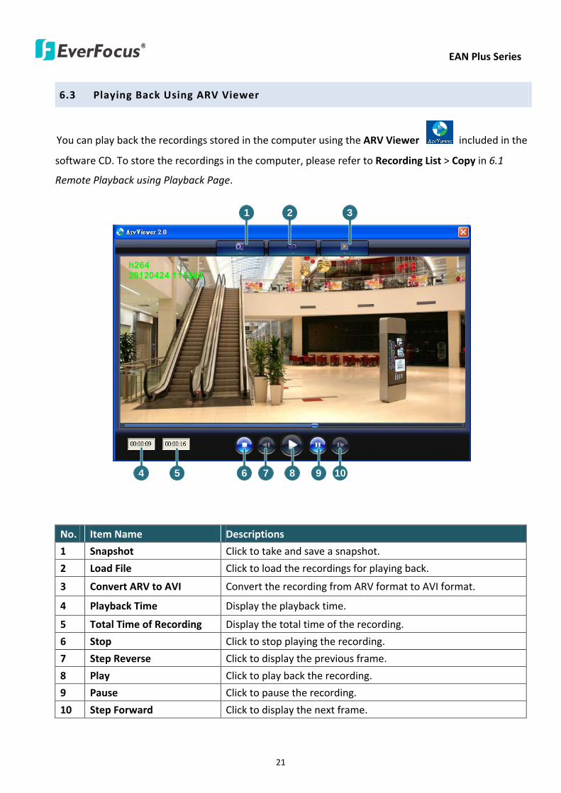
EAN Plus Series
21
63 Playing Back Using ARV Viewer
You can play back the recordings stored in the computer using the ARV Viewer included in the
software CD To store the recordings in the computer please refer to Recording List gt Copy in 61
Remote Playback using Playback Page
4 5 6 7 8 9 10
321
No Item Name Descriptions
1 Snapshot Click to take and save a snapshot
2 Load File Click to load the recordings for playing back
3 Convert ARV to AVI Convert the recording from ARV format to AVI format
4 Playback Time Display the playback time
5 Total Time of Recording Display the total time of the recording
6 Stop Click to stop playing the recording
7 Step Reverse Click to display the previous frame
8 Play Click to play back the recording
9 Pause Click to pause the recording
10 Step Forward Click to display the next frame
EAN Plus Series
22
7 Settings
Click the Settings button on the Live View Window to enter the settings submenu There are nine buttons
on the left-side of the submenu Live System Info User Config Network Video Audio User Event and
System Click the Live button can go back to the Live View Window
71 System Info
The System Information and System Log can be checked on this page Click the top tab of the one you
want to see
711 Information
Click the Information tab the following dialog box appears These values cannot be changed on this
page and are for reference only
EAN Plus Series
23
712 Log
Click the Log tab the following dialog box appears The sequence number date time and event
messages of the log event will be displayed in the System Log field The log will display the last 256
log events Click the Export button to export the system log event list into a ldquotxtrdquo file and select the
location where the exported log file will be saved to
EAN Plus Series
24
72 User Config
Each user can set a different configuration for hisher Live page here These settings will be applied to
the logged-in userrsquos Live page every time heshe logs in
721 Live View Config
【VideoAudio Connection Protocol Setting】You can transmit the data stream from the IP cameras
using the RTSP (Real Time Streaming Protocol) on the network The RTSP is a protocol that allows
you to access video streams by using the compatible media players Click Apply to apply the
changes or Reset to reset without saving the changes RTP over UDP The RTSP protocol uses UDP for camera data stream transmission
RTP over TCP The RTSP protocol uses TCP for camera data stream transmission
RTP over HTTP The RTSP protocol uses HTTP for camera data stream transmission
Nevio CGI This is EverFocusrsquo protocol designed for EverFocusrsquo IP devices Select this
protocol for camera data stream transmission
【Text Settings】Check the box of each option (Machine name DateTime Frame Rate) to display
this info on the Live View Page
Foreground Color Slide the Red Green and Blue bars to create your preferred text color for the
info text line
Position Select the position where the text will be displayed Choose from Upper Left Lower
Right Lower Left
Click Apply to apply the changes or Reset to reset without saving the changes
EAN Plus Series
25
【DateTime Format Used in Text】Click the dropdown menu to select datetime format from the
listed options Click on the desired hour format Click Apply to apply the setting changes or Reset to
reset without saving the change
【Live View Layout Settings】 Check the ldquoShow One Push Buttonsrdquo boxes if you want to show these
buttons on the Live View Page Uncheck these boxes to hide these buttons This function is only
available for EAN3120 Plus 3220 Plus
722 Recording Snapshot
This configures where your Record Button and Snapshot Button ( ) files will be saved if
you click one of these buttons Selectable folders will be on the computer only not on the
on-camera SD card
【Recording Snapshot Export Settings】
Enable Event Recording to PC Checking this box will let the system save RecordSnapshot Button
recordings to the folder configured below on the userrsquos PC
Export Folder Select the Export folder for the action above by clicking on the browse (hellip) button
and then select the desired folder
File size The user can limit the size of each recorded file here (in minutes) When a single
recording file exceeds the time you set the system will create a new file to save that data to
Overwrite Select ldquoONrdquo for overwriting recordingsnapshot file when the disk storage capacity is
full The user can set the storage capacity limitation in the in-sentence field in the gray box below
the Overwrite setting ldquoIf the remaining hard disk capacity is less than ____ MB (50~2000) system
will stop recording or start overwriting ldquo
Click Apply to apply the setting changes or Reset to reset without saving the changes
EAN Plus Series
26
723 Language
Select the language to be displayed on the Web interface of the IP camera The default language is
English
To add a new language not listed in the current Language list click the Browse button to locate
the new language file (evb) on your computer and then click the Upload button Updated
language files might be available on the manufacturerrsquos website Contact your vendor if required
Click Apply to apply any changes or Reset to reset without saving the changes
Note Uploading a new language file will cause the system to reboot automatically Please create
a new network connection to the IP camera when the reboot is complete
EAN Plus Series
27
73 Network
This page covers network-related settings including Network DDNS SMTPFTP HTTPS SNMP and
Network Alarm
731 Network
The following information is required to configure the network settings Contact your network
administrator or your internet service provider to get the info
【IP Settings】
IP Type Refer to the network administrator for these settings of the server Default DHCP
DHCP This setting lets the system use an automatically assigned (dynamic) IP address This
address can change under certain circumstances For instance when the camerarsquos network
switchhub has to be rebooted Do not assign to the DHCP server the same IP addresses used
for the other network cameras and PCs with unique IP addresses
Static IP The user can manually set the Static IP address This type of address is stable and
cannot change but the user has to make sure there are no address conflicts with other
network-connected devices
PPPoE This is a DSL-connection application The ISP will ask the user to input a username and
password Contact your ISP for these details
EAN Plus Series
28
Note If PPPoE is selected as the IP type the supplied IP Utility program will not be able to
detect the device
IP address When DHCP is not used the user needs to manually enter the IP address of the
camera Do not enter an IP address that is already used for your computer or other network
cameras
Subnet Mask This field is used to set the netmask for your network so that the IP camera will be
recognized within the network Example 2552552550 When DHCP is selected the DHCP server
will assign this value automatically
Gateway This field is used to set the gateway for your network so that the IP camera will be
recognized within the network When DHCP is selected the DHCP server will assign this value
automatically
Primary DNS Enter the IP address of the DNS server if this is provided by an ISP
Secondary DNS If your ISP provided you with a secondary DNS address please enter it here
Username Enter the accountrsquos username (used only for PPPoE)
Password Used only for PPPoE
IPv6 Enter the IPv6 details in this area if this applies to your system
Click Apply to apply the setting changes or Reset to reset without saving the change
【Port Settings】Enter the HTTP HTTPS and RTSP port numbers and click Apply to save
【Multicast Settings】Enable if required fill in the setting options and click Apply to save
EAN Plus Series
29
732 DDNS
DDNS (Dynamic Domain Name System) is a service used to map a domain name to the dynamic IP
address of a network device You can set up the DDNS service for remote access to the IP camera
DDNS assigns a domain name (URL) to the IP camera so that the user does not need to go through
the trouble of checking if the IP address assigned by DHCP Server has changed Once the IP is
changed the IP camera will automatically update the information to the DDNS to ensure it is always
available for remote access
Before enabling the following DDNS function user should have applied for a host name from the
DDS service providerrsquos website We support these four DDNS server providers
wwweverfocusddnscom wwwsitelutionscom wwwdyndnscom and wwwno-ipcom
Note We highly recommend that you use xxxxeverfocusddnscom for the simplicity of setting up
your IP cameras
【DDNS Settings】
Enable Check this box to enable the DDNS function
Service ISP You can either apply for a host name from EverFocus or other DDNS server providers
If you choose the EverFocus DDNS server you can obtain a free host name from EverFocus by
following the steps below
bull From EverFocus To obtain a free host name from EverFocus type a desired host name in the
textbox click the Register Update button and then click the Apply button
bull From other DDNS server providers To obtain a domain name from one of the three DDNS
server providers you have to register your name with the provider first and then select the
provider and fill in the required information Please refer to the specific DDNS companyrsquos
website for further information
Record ID Type the record ID if provided by the DDNS server provider
EAN Plus Series
30
FQDN Type the fully qualified domain name applied from the DDNS server provider For
example xxxxdyndnscom
Username Password Type the login account of your DDNS server provider
Click Apply to apply the setting changes or Reset to reset without saving the changes
Note
1 In order to support the full functionality of the camera you must open the port numbers (80
554 443) on the router for remote access to the IP camera This function is available on most
routers in the market and is often known as ldquoPort Forwardingrdquo To set up Port Forwarding
please consult the manual of the router
2 In certain router models it is possible that you will not be able to access the camera using
DDNS while inside the routerrsquos network Please try using a PC located outside of your routerrsquos
network
Default Ports on All EverFocus IP Cameras
HTTP 80
RTSP 554
HTTPS 443
EAN Plus Series
31
733 SMTP FTP
【Set SMTP Server (email)】This area is for configuring the mail server that is used to send e-mail
notifications from the camera to predefined addresses via SMTP Note that to enable e-mail
notification function you have to check the Send Mail Notification item on the Event dialog box
(see 771 Event Settings)
SMTP Server Enter the IP address or the host name of the SMTP server used to send e-mails
SMTP Port Enter the port number for SMTP The default is 25
Authentication Check this box if the SMTP server requires authentication (userpassword)
User name Input the userrsquos login ID if the SMTP server requires authentication
Password Input the userrsquos login password if the SMTP server requires authentication
EAN Plus Series
32
Receiver Address Input the e-mail addresses for receiving an e-mail message when an EVENT is
enabled and triggered Please use ldquordquo to separate multiple addresses
Sender Address Input the senderrsquos e-mail address so that the receiver can recognize the sender
when an Event message is received
Attach Image Check this box if you want to attach an image when an alarm is triggered or an IP
camera detects events
Send Test Email Click the Test button to send a testing email to the assigned address
Click Apply to apply the setting changes or Reset to reset without saving the changes
【Set FTP Server】The settings relating to the FTP server used to transmit the alarm images can be
configured here Note that to enable uploading images to the FTP server function you have to
check the Upload to FTP item on the Event dialog box (see 771 Event Settings)
FTP Server Enter the IP address or the host name of the FTP server
FTP Port Enter the port number for the FTP server Default is 21
Recording Path Assign the recording path
User Name Set FTP Userrsquos name
Password Set FTP password
PASV mode Check to enable Passive mode Passive mode is normally enabled If a connection
cannot be established uncheck PASV Moderdquo
Test FTP Server Click the Test button to send a testing file to the assigned FTP server
Click Apply to apply the setting changes or Reset to reset without saving the changes
EAN Plus Series
33
734 HTTPS
Hypertext Transfer Protocol Secure (HTTPS) is a combination of the Hypertext Transfer Protocol
and the SSLTLS protocol and provides encrypted communication and secure identification of a
network web server
Before using the HTTPS function for communication with the IP camera a Certificate must be
created first There are two ways to create and install a certificate Create Self-Signed Certificate
and Create Certificate Request
Create Self-Signed Certificate
Please note that even though self-signed certificates are free and offer some protection true
security is only implemented after the installation of a signed certificate issued by a certificate
authority
1 Click the Create Self-Signed Certificate button the following dialog appears
EAN Plus Series
34
2 Type the required Certificate information and then click the Apply button The subject line will
be displayed in the Installed Certificate Information field
3 Click the Property button a pop-up window appears to display the details of the certificate
4 To optionally create and install other certificates remove the existing one by clicking the
Remove button to erase the certificate
5 On the Web page change the address from ldquohttprdquo to https in the address bar and press
Enter on the keyboard Some Security Alert dialogs will pop up Click OK or Yes to enable HTTPS
Create Certificate Request
You can apply for an official certificate from an issuing Certificate Authority
1 Click the Create Certificate Request button the following dialog appears
EAN Plus Series
35
2 Type the required Certificate information and then click the Apply button The subject line will
be displayed in the Created Request field
3 Click the Property button a pop-up window appears to display the details of the certificate
4 To optionally create and install other certificates or request remove the existing one by clicking
the Remove button to erase the certificate or request
5 Copy the contents of the Certificate request (in PEM format) and paste it to the certificate
request field on the Web page of the 3rd-party certification authority such as Symantec VeriSign
Wait for the certificate authority to issue an SSLTLS certificate and then download the issued
certificate on your computer
6 In the Install Signed Certificate field click the Browse button to search for the issued certificate
and then click the Upload button to import the certificate Once the certificate has been
uploaded this field will show the subject line of the certificate
EAN Plus Series
36
735 SNMP
The default values for SNMP v1v2v2c and SNMP v3 are already filled in Click either of the
Enable buttons to enable either of the two Make your changes as desired Click on the Trap
Address field to enter the digits if required
736 Network Alarm
This function works with EverFocusrsquos CMS software eg the PowerCon or the Power Video Plus For
the setting details please refer to the CMS network alarm protocol
EAN Plus Series
37
74 Video
The settings relating to video such as streaming camera OSD can be configured on this page The
Video page has five tabs Multi-streaming Camera Advanced ROI and Privacy Mask
741 Multi Streaming
【Stream Settings】 This IP camera can output three video streams simultaneously For each of these
streams the user can set the compression format resolution bit rate and frame rate individually
Stream 1 is always enabled for live view To enable Stream 2 andor Stream 3 check the ldquoEnablerdquo
box the header of each stream
Note If you connect to the camera via the Internet and experience a delay (lag time) in the video
feed try to reduce the number of streams and the quality and resolution of the streams ndash but
keep the frame rate at its maximum
EAN Plus Series
38
Format Select the encoding format ndash H264 or MJPEG
Resolution Select the most suitable resolution for your needs
Frame Rate Select from 1 to 30 fps
Bit Rate If required select whether you want the stream to stream a Constant Bit Rate or a
Variable Bit Rate and set the values of whichever option you choose
Click Apply to apply the setting changes or Reset to reset without saving the changes
【Video Recording Settings】Select the stream you want to configure and then select whether you
want the recording files of that stream to be saved in AVI or ARV format Click Apply to apply the
setting changes or Reset to reset without saving the changes
【Time Stamp Settings】 You can select the DateTime format position and add the setting to the
streaming
Click Apply to apply the changes or Reset to reset without saving the changes
EAN Plus Series
39
742 Camera
【Image Settings】Set the Brightness Saturation Contrast or Sharpness of the image Click Apply to
apply the changes or Reset to reset without saving the changes
【Camera Settings】
Mirror Switch Mirror ON to rotate the image horizontally around a vertical axis
Flip Switch Flip ON to rotate the image vertically around a horizontal axis
AE There are two options
ALC Selecting Automatic Light Control allows the camera circuitry to either take bright spots
more into consideration (peak) bringing out detail in bright areas or less into consideration
(average) bringing out detail in shadows
AES Selecting Auto Electronic Shutter disables the Shutter setting below this setting In this
mode the camera measures the light level and decides whether it needs more or less light and
then automatically adjusts the shutter speed accordingly
BLC Back Light Compensation (BLC) is used to make the subject appear clearer when it is set
against a bright background
OFF Select to switch Back Light Compensation functions off
(ON)BLC The BLC can increase the exposure of a dark area surrounded by a brighter area HLC
can decrease the exposure of bright areas surrounded by darker areas This enables the
camera to better display information that would otherwise have been ldquowhited outrdquo like a
license plate between two bright headlights on a dark road
(ON)HLC The Highlight-Suppression BLC is used to reduce the brightness of light sources in a
specific area It is activated only in a low illumination environment to minimize the effects of
glare from bright lights such as spotlights street lights or headlights in the field of view
EAN Plus Series
40
WDR The Wide Dynamic Range (WDR) function provides clearer images when both of the very
bright and dark areas simultaneously appear on the camera view There are four value options
OFF Low Middle and High Note that when WDR is ON some parts of the image may appear
solarized This is normal for WDR and is not a camera malfunction This function is only available
for EAN3120 Plus 3220 Plus
DN Mode
Auto Select to let the camera automatically switch to Night mode (black and white) when the
light levels fall to a specified level and back to Day mode (color) when the light levels rise to a
specified level
Day Select to keep the camera in Day mode (color) even in nighttime
Night Select to keep the camera in Night mode (black and white) even in daytime
EAN Plus Series
41
743 Advanced
EAN Plus Series
42
【Camera Settings】
Lens (IRIS Control) Select DC or Manual for IRIS control This function is only available for EAN3220
Plus
Exposure Settings (AE) This setting is used to adapt to the amount or type of light used by the
camera Note the settings vary among models
Mode This function is not available for EAN3220 Plus
Automatic Light Control (ALC) This option is only available for EAN3120 Plus 3300 Plus The
ALC allows the camera circuitry to either take bright spots more into consideration (peak)
bringing out detail in bright areas or less into consideration (average) bringing out detail in
shadows
Auto Electronic Shutter (AES) This option is only available for EAN3120 Plus 3300 Plus In
this mode the camera measures the light level and decides whether it needs more or less light
and then automatically adjusts the shutter speed accordingly
Manual This option is only available for EAN3300 Plus Select this option to manually set up
the Shutter (Manual) and AGC (Manual) values
Iris Specify the size of the Iris opening here
Shutter If enabled this setting lets you set the shutter speed yourself
Shutter Limit Use this setting to set the maximum shutter speed for the camera This function is
only available for EAN3120 Plus
AGC Set the Auto Gain Control limit here The lower the AGC level the lower the video signal and
the noise However the image will be darker under low-light condition with IR-off if you set up the
Iris to the maximum level
Slow Shutter This option can be switched on when AES Mode is selected in the Exposure Settings
(AE) field This function is only available for EAN3220 Plus 3300 Plus
Flickerless If the Mode field in the Exposure Settings (AE) area has been set to AES then this option
becomes available Choose between OFF 50HZ 60HZ 50HZ (High Luminance) or 60HZ (High
Luminance) This function is only available for EAN3300 Plus
EV Setting Set up the Exposure Value Note the brightness of the screen changes when you change
the EV value This function is only available for EAN3300 Plus
AE Response Set up Auto Exposure Response time This function is only available for EAN3300 Plus
AE Weighting Area Select an AE Weighting area Each setup AE Weighting Area is configured with
the appropriate brightness level on the center and the surrounding areas This function is only
available for EAN3300 Plus
Brightness Set the image brightness here
AE Reference Set the Auto Exposure value here This function is only available for EAN3120 Plus
EAN Plus Series
43
Black Level Set the Black level here This function is only available for EAN3300 Plus
WDR The Wide Dynamic Range (WDR) function provides clearer images when both of the very
bright and dark areas simultaneously appear on the camera view There are four value options OFF
Low Middle and High Note that when WDR is ON some parts of the image may appear solarized
This is normal for WDR and is not a camera malfunction This function is only available for EAN3120
Plus 3220 Plus
Visibility Enhancement (OFFLowMiddleHigh) Images in foggy or rain environments or in
environments with a very strong luminous intensity have a dynamic range that is significantly lower
than ordinary images The user can use this Visibility Enhancement setting to ldquoDEFOGrdquo the image if
such ldquoFOGGINGrdquo is an issue This function is only available for EAN3220 Plus
BLC Settings Back Light Compensation (BLC) is used to make the subject appear clearer when it is
set against a bright background
OFF Select to switch Back Light Compensation functions off
Back Light This option is only available for EAN3300 Plus The Back Light function is useful
when the background of the subject is very bright and the subject itself is dark Select Back
Light and adjust the slide bar to the left right for setting up the back light value The higher
the value the more the backlight compensation
Front Light This option is only available for EAN3300 Plus This function is useful when the
bright highlights such as flashlight or car headlights appear on the camera view Select Front
Light and adjust the slide bar to the left right for setting up the front light value The higher
the value the more the highlight compensation
ON (BLC) This option is only available when you select AES Mode in the Exposure Settings (AE)
field The option is only available for EAN3120 Plus 3220 Plus The BLC function is useful
when the background of the subject is very bright and the subject itself is dark Follow the
instructions below to configure the settings for each model
For EAN3120 Select ON (BLC) the button next to the Mode drop-down list will be
active (see image below) Click the button the green setup areas appear on the left
screen Click on the areas to enable disable the BLC function The selected areas (in green)
will be applied with the BLC function
EAN Plus Series
44
For EAN3220
You can configure one area to apply the BLC function Select ON (BLC) the setup buttons
appears (see image below) Select Low Middle High from the BLC Gain drop-down list To
set up a BLC area click the Edit Area button and then click on the blue color tab to turn your
mouse cursor into a blue pen Move the cursor to the position on the right screen where you
want the BLC rectangle to start and then click Move your cursor to the position (diagonally
opposing corner) where you want the BLC rectangle to end and then click The blue area will
be applied with the BLC function
ON (HLC) This option is only available when you select AES Mode in the Exposure Settings (AE)
field The option is only available for EAN3120 Plus 3220 Plus This function is useful when
the bright highlights such as flashlight or car headlights appear on the camera view Follow
the instructions below to configure the settings for each model
For EAN3120 Select ON (HLC) and then select a level from the drop-down list The higher the
level the more the highlight compensation
For EAN3220
HLC Level Select a level for the HLC setting The higher the level the more the highlight
compensation
HLC Mode Select All Day Night mode to apply the HLC function
HLC Black Mask Select On Off to apply the black mask on the selected areas The
over-exposure portions within the selected areas will be applied with the black mask
Color Tabs You can set up four HLC areas with different colors To set up a HLC area click the
Edit Area button and then click on the color tab to turn your mouse cursor into a pen of that
color Move the cursor to the position on the right screen where you want the HLC rectangle
to start and then click Move your cursor to the position (diagonally opposing corner) where
you want the HLC rectangle to end and then click Select ON from the color tab drop-down list
The rectangular area with the selected color will be applied with the HLC function
EAN Plus Series
45
Back Light This option is only available for EAN3300 Plus The Back Light function is useful
when the background of the subject is very bright and the subject itself is dark Select Back
Light and adjust the slide bar to the left right for setting up the back light value The higher
the value the more the backlight compensation
Front Light This option is only available for EAN3300 Plus This function is useful when the
bright highlights such as flashlight or car headlights appear on the camera view Select Front
Light and adjust the slide bar to the left right for setting up the front light value The higher
the value the more the highlight compensation
Noise Reduction Settings This limits the amount of digital ldquovideo noiserdquo that is usually found in any
video stream and helps to reduce file size The higher the level the more the reduction
For EAN3120 Plus 3300 Plus
Select ON OFF to enable disable the Noise Reduction function Or select Auto to let the camera
automatically enable disable the Noise Reduction function Slide the Level bar to set up the level
The higher the level the more the reduction
For EAN3220 Plus
2D DNR Select ON to enable the 2D DNR function
3D DNR Select ON to enable the 3D DNR function You can further set up the following settings
3D Start AGC Set up the AGC level to automatically start the 3D NR function
3D End AGC Set up the AGC level to automatically stop the 3D NR function
3D Level Set up the 3D DNR level
Smart NR Select ON to enable the Smart NR function The 3D NR function will be
automatically turned on when a motion event occurs
EAN Plus Series
46
White Balance Settings Select the mode that delivers the best quality image for the camerarsquos light
environment There are five options Auto Manual Indoor Outdoor One Push
Auto Select to let the camera automatically adjust the White Balance In the Auto mode the
camera computes the white balance value output using color information from the entire
screen It outputs the proper value using the color temperature radiating from a black subject
based on a range of value from 3000 to 7500K
Manual Select to adjust the Red and Blue values yourself in the fields below this field
Indoor Select to use the default settings for indoor environments In the Indoor mode the
camera uses 3200K as the base value
Outdoor Select to use the default settings for outdoor environment In the Outdoor mode it
uses 5800K as the base value
One Push Select to enable the Push button next to the Mode drop-down field This will allow you to force the camera to readjust the white balance every time you push the Push
button The lens will hold the same focal position until the next trigger command is received
This function helps to prevent incorrect focusing in dark environments This function is only
available for EAN3120 Plus 3220 Plus
Manual Temperature Select to use the optimized Red and Blue settings You can also
optionally adjust the Manual Level below this field for setting up the color temperature The
higher the value the more the color temperature This function is only available for EAN3300
Plus
DayNight Settings
Auto Select to let the camera automatically switch to Night mode (black and white) when the
light levels fall to a specified level and back to Day mode (color) when the light levels rise to a
specified level
Day Select to keep the camera in Day mode (color) even in nighttime
Night Select to keep the camera in Night mode (black and white) even in daytime
IR Smart Settings Select ON and set up the level to enhance the image quality when the images are
over exposure This function is useful when the camera is in the Night mode This function is only
available for EAN3220 Plus
Saturation Set the saturation value This function is not available for EAN3220 Plus
Monitor Type Select a gamma value from Set 1 Set 2 or Set 3 This function is only available for
EAN3120 Plus
Negative Switch this setting ON to view a color negative version of the video image This is useful
at night or when viewing temperature-sensitive images
EAN Plus Series
47
Sharpness Settings Select the sharpness level of the image A low sharpness level will deliver a
softer less detailed image A high level will deliver a sharp highly detailed image Switch Resolution
Enhancement ON to enable the resolution enhancement function
Contrast Select the contrast level of the image
Suppress Function This function is only available for EAN3300 Plus
Aperture Compensation Suppression (OFFLowMiddleHigh) This setting can be activated to
suppress luminance noise when the AGC level increases
Chroma Suppression (OFFLowMiddleHigh) This setting can be activated to suppress
chrominance noise when the AGC level increases
Ygamma (gamma 22standardcontrast enhancehigh light range mode LHigh light range mode
H) Select the Ygamma value for the video quality of the monitor This function is only available for
EAN3300 Plus
Monitor Settings The user can use this field to optimize video quality for his or her specific type of
monitor ndash LCD or CRT This function is only available for EAN3220 Plus
Color Space Standard The options are YUV601 for SD and YUV709 for HD These define the color
space standard required to convert an RGB picture to a YUV picture Generally YUV601 is used for
Standard Definition (720P) devices and the YUV709 is used for High Definition (1080P) devices
Click Apply to save all changes Click Reset to cancel all changes
EAN Plus Series
48
744 ROI (Region of Interest)
The Region of Interest (ROI) function allows users to set up multiple regions within an image with
better quality and less distortion than the rest of the image You can also use this function
together with the Digital Zoom function on the Live View Page to get a better image result Up to
eight ROIs can be configured in the ROI settings page
To set up an ROI region
1 Select an ROI number from the ROI No drop-down list
2 Click the Add button the mouse cursor will turn into a pen when you move it over the live
image on the left
3 Move the cursor to the position where you want the ROI rectangle to start and then click
Move the cursor to the position (diagonally opposing corner) where you want the ROI
rectangle to end and then click
4 Slide the Quality bar to set up the quality value
5 Click the Apply button to apply the settings or click the Reset button to reset without saving
the settings
EAN Plus Series
49
745 Privacy Mask
The Privacy Mask can block out sensitive areas from view covering the areas with colored or black
and white boxes in both live view and recorded clips This feature is useful when usersrsquo donrsquot want
the sensitive information visible Up to four Privacy Masks can be configured
【Privacy Mask Color Settings】The Modes vary among camera models
Mode Click Color to make the masks appear as colored rectangles on the screen Click BW to
make the masks appear as gray rectangles on the screen Click Mosaic to make the masks appear
as mosaic-effect rectangles on the screen
Level Select the color of the masks if you selected Color Mode Select the level of grayness of the
masks if you selected BW Mode Select the level of smallmiddlelarge if you selected Mosaic
Mode
Click Apply to apply the settings or click Reset to reset without saving the settings
Color Tabs Click on a color tab to turn your mouse cursor into a pen of that color
You can now create a block of that color on the video screen Move your cursor to the position
where you want your mask rectangle to start and then click Move your cursor to the position
(diagonally opposing corner) where you want your mask rectangle to end and then click The
rectangular area with the selected color will appear The live image will display the rectangular
area with the color you selected If you want to create another mask use one of the other three
colors Each color denotes a different mask area Only one block per color is allowed As the
number of colors suggests you can configure up to four blocks
EAN Plus Series
50
Select All Click to turn the whole screen into a mask area
Clear All Click to delete all configured mask blocks
Eraser Click to turn the mouse cursor into an eraser to delete any block you click on
Area Shows the color and number of the block
Enable Check this box to enable the related mask block
Click Apply to apply the settings or click Reset to reset without saving the settings
EAN Plus Series
51
75 Audio
The EAN Plus series IP camera can transmit audio to your computer if you have connected an external
microphone to its audio Input cable It can also receive audio input from you and transmit it via an
external speaker if you have connected such a speaker to its audio Output cable
Check the Enable Audio box to enable the camerarsquos audio function The camera will now act as a
digital bridge (via the IP network) between any connected audio input device and any connected
audio device
Adjust the Audio Input Volume if you have external audio input devices (microphones) connected to
the camera and if there are problems with the sound input being too low or high
Click Apply to save all settings or click Reset to cancel
EAN Plus Series
52
76 User
761 User Information
The system administrator can create up to ten user accounts on this page
To set up a user account
1 Highlight a user account and click the Modify button The following dialog box appears
2 Type the account name account description and password for the account Type the password
again in the Confirm field
3 Select an authority level for the user account from the Authority drop-down list
bull Supervisor Administrator The only difference between a supervisor and administrator is
that a supervisor can edit an administratorrsquos account and password but an administrator
cannot edit the supervisorrsquos account and password Multiple administrators can be
configured but there can be only one supervisor The supervisor and administrators all
have unrestricted access to the Settings submenus and can determine the registration of
all other users
EAN Plus Series
53
bull User A user can view the Live View page and view the system network video and audio
information A user can only adjust the User Config page settings The user does not have
access to the User Event and System pages
bull Guest The lowest level of access which only allows the user access to the Live View page
4 Select Active or Disable from the Status drop-down list to active or disable the user account
5 Click On in the SD Card Playback field to allow the user to access the SD card playback
function
6 Click OK
7 Click Apply to save all the settings
EAN Plus Series
54
762 IP Address Filter
Use this page to specify IP addresses that are not allowed to access this camera By default any IP
address can access the camera
Note The Allowed List addresses only become relevant when the Denied List contains a network
or range and the supervisor wants to allow one or more IP addresses within that excluded range
or network In such a scenario the user would enter the excluded range or network in the
Denied List and enter the exceptions in the Allowed List
To set up the IP Address Filter
1 Select Denied List Click the Add button the following dialog box appears
2 Select an IP type from the IP Type drop-down list
3 Select a network rule from the Rule drop-down list type the IP address and click OK
Single Type a single IP address in the IP Address field below
Network Type the IP address and subnet mask in the field below
Range Type a range for the IP addresses
4 If you have set up an IP range in Step 3 you can optionally set up the Allowed List to allow one
or more IP addresses within the setup IP range to access the IP camera
5 Click Apply
EAN Plus Series
55
77 Event
You can set up the Motion Detection event Tamper Detection event or the Alarm IO to automatically
notify the users when an event occurs or an alarm is triggered You can also set up a schedule to
automatically record the videos when an event occurs or an alarm is triggered
771 Event Settings
You can create a total of ten event or alarm settings page in the Event List
【Event List】
Click the Add button and the following Event Configuration Window appears
EAN Plus Series
56
Enter Event Name Type an event name
Event Triggered by Select an event or alarm type for the to-be-specified-below reactions
Alarm Input Select this if you want a reaction trigger coming from any external connected sensor
to activate a to-be-specified-below reactions via the camera system Make sure that a suitable
device is actually connected to the alarm input relay
Manual Trigger Select this option if you want to manually trigger the alarm by clicking the Trigger
Event button on the Live View Page
Motion Detection Select this option if you want motion in a specified part of the camerarsquos viewing
rectangle (the screen image) to trigger the to-be-specified-below reactions
Tampering Detection Select this option if you want the camerarsquos tampering detection sensor to
trigger the to-be-specified-below reactions
Schedule Recording Select this option if you want the Schedule Recording periods configured in
the recording schedule (the Settings gt Event gt Schedule page) to activate this event In this
scenario a preconfigured event reaction like a log entry will list the start and end times of each
period Actual recording will only be triggered if the event is preconfigured to do so
Enable This Event Select to activate the event
Enable Re-trigger Click to set a minimum time after the event is triggered before the event
can be triggered again
Enable Pre-trigger Buffer Click if you want the Event reaction (as selected in the ldquoNotification
Overrdquo field below) to be the activation of the video recording function and if you want the
recording to include the video feed from the time period (configurable on the previous ldquoEvent
Settingsrdquo page) just before the Event trigger occurred
Enable Post-trigger Buffer Click if you want the Event reaction (as selected in the Notification
Over field) to be the activation of the video recording function and if you want the recording
to include the video feed from a time period (configurable on the Event Settings page) just
after the Event trigger occurred
Motion Area Select a setup motion detection area from the drop down list Note this
function only becomes relevant after the Motion Detection areas have been set up (see 772
Motion Detection)
Notification Over Select the desired notification types form the following items
Log Click if you want the camera to list the eventrsquos details in its log if the event is triggered
Trigger Alarm Output Click if you want the camera to relay the event reaction to a device
attached to the alarm relay output wire and then set up the alarm output duration time
EAN Plus Series
57
Send Mail Notification Click if you want the camera to send an Event notification email to the
email address entered in the Set SMTP Server(email) field of the Network gt SMTPFTP page if
the Event occurs (see 733 SMTP FTP)
Upload to FTP Click if you want the camera to upload recorded footage to the FTP server
entered in the Set SMTP Server(email) field of the Network gt SMTPFTP page if the Event
occurs (see 733 SMTP FTP)
Record to SD Card Click if you want the camera to start recording its video feed (when the
event occurs) on an on-camera SD Card (if such a card has been inserted)
Note The recording will only be as long as the combined Pre- and Post-trigger Buffers so
make sure you enable at least one of these buffers especially the Post-trigger Buffer
Record to PC Check this box if you want the camera to start recording its video feed (when
the event occurs) on the same folder on the same PC as configured on the User Config gt
RecordingSnapshot page (if such a folder has been enabled and configured)
Note The recording will only be as long as the combined Pre- and Post-trigger Buffers (and
for as long as the event trigger is happening ndash eg a motion is detected) so make sure you
enable at least one of these buffers especially the Post-trigger Buffer
Network Alarm Check this box if you want the camera to send a network alarm signal (when
the event occurs) to the CMS servers configured on the Network gt Network Alarm page (see
736 Network Alarm)
Click OK to save all settings or click Cancel to cancel
【PrePost Trigger Settings】
Pre-trigger Buffer Select the duration for the buffer This will determine the amount of footage
(length of time) before the event trigger moment that will be included in an event-triggered video
recording if that buffer and video recording has been enabled in the Event Configuration Window
Post-trigger Buffer Select the duration for the buffer This will determine the amount of footage
(length of time) after the event trigger moment that will be included in an event-triggered video
recording if that buffer and video recording has been enabled in the Event Configuration Window
Click Apply to save all settings or click Reset to cancel
EAN Plus Series
58
772 Motion Detection
Use this page to configure up to four areas in which motion will be detected When a motion is
detected by the camera the motion detection icon will appear at the top right of the
Live page to alert the user This function can also be linked with correctly configured Events to
trigger Event reactions like the activation of video recording periods snapshots alarms etc
Color Tabs Click on a color tab to turn your mouse cursor into a pen of that color
You can now create a block of that color on the video screen Move your cursor to the position
where you want your detection rectangle to start and then click Move your cursor to the position
(diagonally opposing corner) where you want your detection rectangle to end and then click The
rectangular area with the selected color will appear This block will be an area inside which the
camera will detect motion If you want to create another detection area use one of the other three
palette colors Each color denotes a different detection area Only one block per color is allowed As
the number of colors suggests you can configure up to four blocks
Select All Click to turn the whole screen into a motion detection area
Clear All Click to delete all configured motion detection blocks
Eraser Click to turn your mouse cursor into an eraser to delete any block you click on
Area Shows the color and numberID of the block
Enable Check this box to enable the related motion detection block
Sensitivity Set the sensitivity of the motion detection sensor function
Click Apply to save all settings or click Reset to cancel
EAN Plus Series
59
773 Tamper Detection
Use this page to set the number of seconds that an alarm signal will be active if the device is
physically tampered (moved covered up or out of focus
774 Alarm IO
Use this page to set the type of trigger input and the type of output contact for the camerarsquos alarm
channel
EAN Plus Series
60
775 Schedule
Use this page to configure a schedule for periods during which the camera should deactivate all
user-activated Events (gray Deselect periods) or when the camera should deactivate all
user-activated Events except Schedule Recording (SR) events (blue Schedule Recording-only
periods) or when the camera should deactivate only SR events (red Event Recording-only periods)
or when it should enable all activated Events (yellow periods)
Event Recording Click this button to make every hour block you click on red A red block represents
an Event Recording-only block which represents an hour when the camera will deactivate all
preconfigured activated Schedule Recording events and keep all the other activated events active
Schedule Recording Click this button to make every hour block you click on blue A blue block
represents a Schedule Recording-only block which represents an hour when the camera will
deactivate all other preconfigured activated events and keep only the preconfigured activated
Schedule Recording events active
Event + Schedule Click this button to make every hour block you click on yellow A yellow block
represents an hour in which all activated events including Schedule Recording events will be
active
Deselect Click this button to make every hour block become grey A grey block represents an hour
in which all activated events including Schedule Recording events will be inactive
Click Apply to save all settings or click Reset to cancel
EAN Plus Series
61
78 System
You can set up the systemrsquos time and SD card settings and to do maintenance and reset actions like
reboots and upgrades
781 DateTime
【Machine Name Settings】If required enter a new name for the machine This name will be visible
in the Machine Name field of the IP Utility software which is included in the software CD
【Set Time Zone】Set the time zone of the camerarsquos location
【Set DateTime Manually】Set the datetime here if you wonrsquot be using an NTP server to update the
datetime (see below)
【Set DateTime Sync】Enter the Network Time Protocol server if applicable The camerarsquos time will
be automatically adjusted by synchronizing with the NTP server
Click Apply to save all settings or click Reset to cancel
EAN Plus Series
62
782 Daylight Saving
Click Enable Daylight Saving to enable this schedule and select the dates when the regionrsquos
daylight saving period begins and ends Click Apply to save all settings or click Reset to cancel
783 SD Card
Use this page to prepare the system for safely removing the SD Card from its slot
【Setup SD Card】
Notification Select the percentage of storage space that should be left on the card before the
camera notifies you of the impending storage shortage or overwrite
Event Recording Select if you want Event Recording only FTP Backup only or both
Overwrite Click ON if you want the card to start writing over recorded footage when its memory is
full Click OFF if you want the card to stop recording new footage when its memory is full
【SD Card Utility】
Capacity This shows you how much card memory has been used and how much memory capacity
remains on the card
Remove Click this button before removing the card from the system
Format Click this button to format the card All data saved on the SD card will be removed if the
card is formatted
EAN Plus Series
63
784 Maintenance
【Maintenance Server】
Reboot Click this button to reboot the unit without changing any of the settings Use this function if
the unit is not behaving as expected
Restore Click this button to restart and reset most of the current settings to their factory default
values The only settings that will not be changed to default are
bull IP settings
bull DDNS settings
Default The Default button should be used with caution Pressing this button will return all of the
cameras settings including the IP address to the factory default values The camera will then have
to be reconfigured
【SaveLoad Configuration Server】
Save To make a backup file of the machinersquos current configurations press Save to save all the
configurations to a config file This will enable the user to reload these configuration settings if the
settings are changed and there is unexpected behavior
Load To load a previously saved configuration press the Browse button to locate the saved config
file (see above) and then click the Load button The systemrsquos settings will be restored to the saved
configuration
EAN Plus Series
64
【SaveLoad Video Configuration Server】
Save To make a backup file of the machinersquos video configurations press Save to save the video
configurations to a config file This will enable the user to reload these configuration settings if the
settings are changed and there is unexpected behavior
Load To load a previously saved video configuration press the Browse button to locate the saved
config file (see above) and then click the Load button The systemrsquos settings will be restored to the
saved video configuration
【Upgrade Firmware】Click the Browse button to find a previously prepared firmware upgrade file
Click Upgrade to install the new firmware
Note
1 Do not disconnect power to the unit during the upgrade sequence The unit will reboot
automatically after the upgrade has completed (1-5 minutes)
2 During the upgrade process all event recording actions will be stopped Event recording
actions will resume after the camera is rebooted
3 If the ldquoFile Error Please re-loginrdquo warning message appears when upgrading the firmware
please try the following instructions
a Go to Internet Explorer gt Tools gt Internet Option gt Security gt Custom
b Find and enable the Include local directory path when uploading files to a server
EAN Plus Series
65
8 Upgrading Firmware Using IP Utility
You can upgrade the Firmware using the IP Utility software included in the software CD
1 Install and then start the IPU program The following dialog box appears
2 Click Find Devices to search the cameras connected in the LAN The default network values of the
cameras will be displayed By default the network protocol of the camera is DHCP
3 Select a camera and click LoginMulti Login to log in the camera
4 Type the user ID and password Click OK
Note
1 The default user ID is user1 and the default password is 11111111
2 If you select more than one camera that has the same user ID password you will be able
to log in several cameras at once
EAN Plus Series
66
5 Highlight the camera and then click Upgrade Firmware A browsing window appears
6 Select the firmware file (evb) and then click Open The IP Utility will automatically upgrade the
firmware
The camera will reboot once the update is complete Click Find Devices the new firmware version
should be displayed in the last part of the Machine Name
EAN Plus Series
67
9 Specifications
Model EAN3120 Plus EAN3220 Plus EAN3300 Plus
Camera
Image Sensor 13 Panasonic CMOS 128 Sony CMOS
Megapixel 13 MP 2 MP 3 MP
Picture Elements (H x V) 1280 x 1024 1944 x 1092 2048 x 1536
Min Illuminations 003 Lux at F14
Electronic Shutter (Sec) 85 ~ 160000 2 ~ 150000 1 ~ 110000
Scanning System NTSC PAL
WDR Yes Yes No
BLC Yes
Gain Control Yes
White Balance Yes
Lens
Mounting Type C CS
Day Night Yes (with removable auto IR-cut filter)
IRIS Control DC Electrical IRIS Lens IRIS
Video
Video Compression H264 MJPEG
Resolution
NTSC
2048 x 1536 1920 x 1200 (for EAN3300 Plus only)
1920 x 1080 (for EAN3300 Plus 3220 Plus only)
1280 x 1024 1280 x 720 1024 x 768 720 x 480 704 x 480 640 x 480
352 x 240 320 x 240 160 x 120
PAL
2048 x 1536 1920 x 1200 (for EAN3300 Plus only)
1920 x 1080 (for EAN3300 Plus 3220 Plus only)
1280 x 1024 1280 x 720 1024 x 768 720 x 576 704 x 576 640 x 480
352 x 288 320 x 240 160 x 120
Frame Rate 30 fps at 1280 x 1024 30 fps at 1920 x 1080 15 fps at 2048 x 1536
Audio
Audio Streaming Two-way audio
Audio Compression G711
EAN Plus Series
68
Network
Interface 10 100 Base-T Ethernet RJ-45 socket
Supported Protocols
TCPIP IPV6 UDP ICMP DHCP NTP DNS DDNS SMTP SNMP FTP
HTTP HTTPs PPPoE UPnP Bonjour RTP RTSP RTCP IGMP ARP ONVIF
PSIA
Connector
Power DC female port PoE
Ethernet RJ-45
Audio 1 In (phone jack for microphone)
1 Out (phone jack for Speaker)
Alarm IO Terminal IO wires
Local Storage Micro SD SDHC memory card slot
TV-Out BNC socket composite 1 V p-p 75 Ω
General
Power Source DC 12V PoE (IEEE8023af)
Power Consumption
(IR LEDs On)
5W (DC 12V)
621W (PoE)
5W (DC 12V)
522W (PoE)
5W (DC 12V)
536W (PoE)
Operating Temperature 0degC ~ +50degC 32degF ~ +122degF
Humidity 20 to 80 (no condensation)
Safety CE FCC
Dimensions (L x W x H) 117 x 56 x 68 mm 46 x 22 x 27 in
Weight 410 g 09 lb
EverFocus Electronics Corp EverFocus Taiwan 12F No79 Sec 1 Shin-Tai Wu Road Hsi-Chih Taipei Taiwan TEL +886 2 2698 2334 FAX +886 2 2698 2380 wwweverfocuscomtw marketingeverfocuscomtw
EverFocus Europe - Germany Albert-Einstein-Strasse 1 D-46446 Emmerich Germany TEL +49 2822 93940 FAX +49 2822 939495 wwweverfocusde infoeverfocusde
EverFocus China - Beijing Room 609 Technology Trade Building Shangdi Information Industry Base Haidian District Beijing 100085 China TEL +86 10 6297 3336~39 FAX +86 10 6297 1423 wwweverfocuscomcn marketingeverfocuscomcn
EverFocus China - Shenzhen 4F No 2 D4 Building Wan Yelong Industrial Park Tangtou Road Shiyan Baoan Shenzhen Guangdong 518101 China TEL +86 755 2765 1313 FAX +86 755 2765 0337 wwweverfocuscomcn marketingeverfocuscomcn
EverFocus USA - California 1801 Highland Avenue Unit A Duarte CA 91010 USA TEL +1 626 844 8888 FAX +1 626 844 8838 wwweverfocuscom saleseverfocuscom
EverFocus USA - New York 415 Oser Avenue Unit S Hauppauge NY 11788 USA TEL +1 631 436 5070 FAX +1 631 436 5027 wwweverfocuscom saleseverfocuscom
EverFocus Japan 5F Kinshicho City Building 2-13-4 Koto-BashiSumida-Ku Tokyo 130-0022 Japan TEL +81 3 5625 8188 FAX +81 3 5625 8189 wwweverfocuscojp infoeverfocuscojp
EverFocus Europe - UK Unit 12 Spitfire Business Park Hawker Road Croydon Surrey CR0 4WD UK TEL +44 20 8649 9757 +44 845 430 9999 FAX +44 20 8649 9907 wwweverfocusukcouk salesukeverfocuscom
EverFocus India Suite 803 Housefin Bhavan C-21 Bandra Kurla Complex Bandra (East) Mumbai 400051 India TEL +91 22 6128 8700 FAX +91 22 6128 8705 wwweverfocusin saleseverfocusin
PN 4605PQ3120B010A-VerC
Your EverFocus product is designed and manufactured with high quality materials and components which can be recycled and reused This symbol means that electrical and electronic equipment at their end-of-life should be disposed of separately from your household waste Please dispose of this equipment at your local community waste collectionrecycling centre In the European Union there are separate collection systems for used electrical and electronic product Please help us to conserve the environment we live in
Ihr EverFocus Produkt wurde entwickelt und hergestellt mit qualitativ hochwertigen Materialien und Komponenten die recycelt und wieder verwendet werden koumlnnen Dieses Symbol bedeutet dass elektrische und elektronische Geraumlte am Ende ihrer Nutzungsdauer vom Hausmuumlll getrennt entsorgt werden sollen Bitte entsorgen Sie dieses Geraumlt bei Ihrer oumlrtlichen kommunalen Sammelstelle oder im Recycling Centre Helfen Sie uns bitte die Umwelt zu erhalten in der wir leben
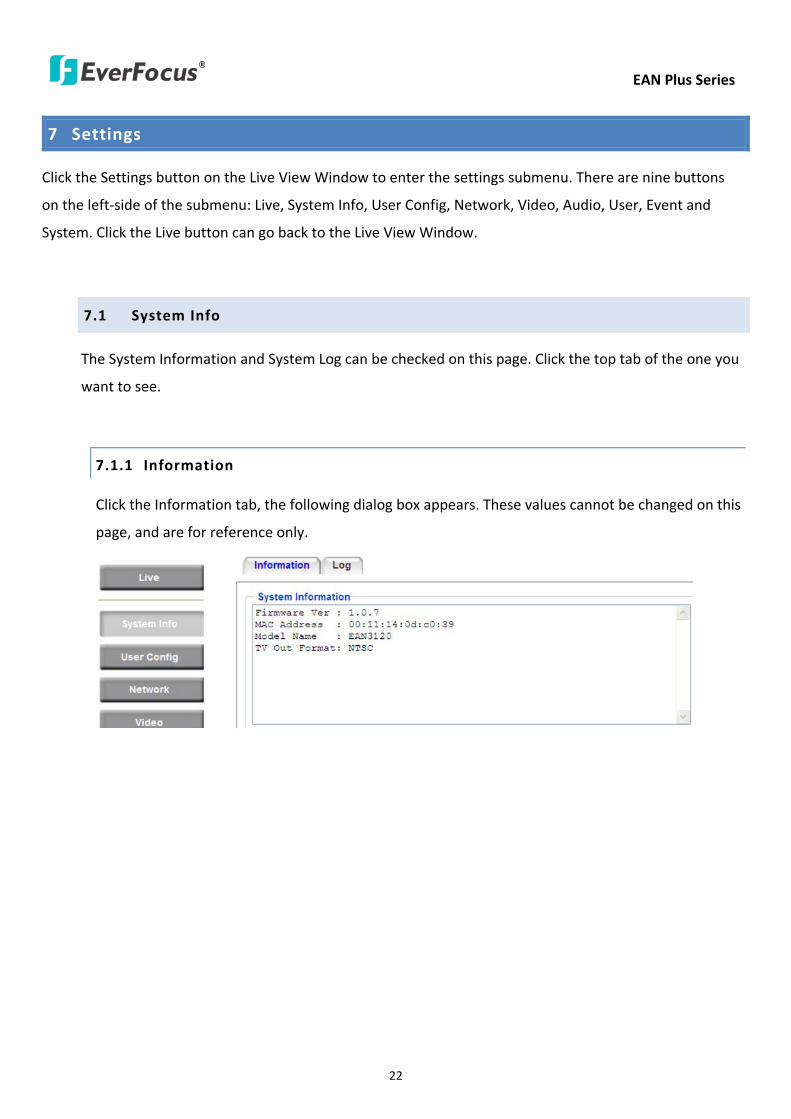
EAN Plus Series
22
7 Settings
Click the Settings button on the Live View Window to enter the settings submenu There are nine buttons
on the left-side of the submenu Live System Info User Config Network Video Audio User Event and
System Click the Live button can go back to the Live View Window
71 System Info
The System Information and System Log can be checked on this page Click the top tab of the one you
want to see
711 Information
Click the Information tab the following dialog box appears These values cannot be changed on this
page and are for reference only
EAN Plus Series
23
712 Log
Click the Log tab the following dialog box appears The sequence number date time and event
messages of the log event will be displayed in the System Log field The log will display the last 256
log events Click the Export button to export the system log event list into a ldquotxtrdquo file and select the
location where the exported log file will be saved to
EAN Plus Series
24
72 User Config
Each user can set a different configuration for hisher Live page here These settings will be applied to
the logged-in userrsquos Live page every time heshe logs in
721 Live View Config
【VideoAudio Connection Protocol Setting】You can transmit the data stream from the IP cameras
using the RTSP (Real Time Streaming Protocol) on the network The RTSP is a protocol that allows
you to access video streams by using the compatible media players Click Apply to apply the
changes or Reset to reset without saving the changes RTP over UDP The RTSP protocol uses UDP for camera data stream transmission
RTP over TCP The RTSP protocol uses TCP for camera data stream transmission
RTP over HTTP The RTSP protocol uses HTTP for camera data stream transmission
Nevio CGI This is EverFocusrsquo protocol designed for EverFocusrsquo IP devices Select this
protocol for camera data stream transmission
【Text Settings】Check the box of each option (Machine name DateTime Frame Rate) to display
this info on the Live View Page
Foreground Color Slide the Red Green and Blue bars to create your preferred text color for the
info text line
Position Select the position where the text will be displayed Choose from Upper Left Lower
Right Lower Left
Click Apply to apply the changes or Reset to reset without saving the changes
EAN Plus Series
25
【DateTime Format Used in Text】Click the dropdown menu to select datetime format from the
listed options Click on the desired hour format Click Apply to apply the setting changes or Reset to
reset without saving the change
【Live View Layout Settings】 Check the ldquoShow One Push Buttonsrdquo boxes if you want to show these
buttons on the Live View Page Uncheck these boxes to hide these buttons This function is only
available for EAN3120 Plus 3220 Plus
722 Recording Snapshot
This configures where your Record Button and Snapshot Button ( ) files will be saved if
you click one of these buttons Selectable folders will be on the computer only not on the
on-camera SD card
【Recording Snapshot Export Settings】
Enable Event Recording to PC Checking this box will let the system save RecordSnapshot Button
recordings to the folder configured below on the userrsquos PC
Export Folder Select the Export folder for the action above by clicking on the browse (hellip) button
and then select the desired folder
File size The user can limit the size of each recorded file here (in minutes) When a single
recording file exceeds the time you set the system will create a new file to save that data to
Overwrite Select ldquoONrdquo for overwriting recordingsnapshot file when the disk storage capacity is
full The user can set the storage capacity limitation in the in-sentence field in the gray box below
the Overwrite setting ldquoIf the remaining hard disk capacity is less than ____ MB (50~2000) system
will stop recording or start overwriting ldquo
Click Apply to apply the setting changes or Reset to reset without saving the changes
EAN Plus Series
26
723 Language
Select the language to be displayed on the Web interface of the IP camera The default language is
English
To add a new language not listed in the current Language list click the Browse button to locate
the new language file (evb) on your computer and then click the Upload button Updated
language files might be available on the manufacturerrsquos website Contact your vendor if required
Click Apply to apply any changes or Reset to reset without saving the changes
Note Uploading a new language file will cause the system to reboot automatically Please create
a new network connection to the IP camera when the reboot is complete
EAN Plus Series
27
73 Network
This page covers network-related settings including Network DDNS SMTPFTP HTTPS SNMP and
Network Alarm
731 Network
The following information is required to configure the network settings Contact your network
administrator or your internet service provider to get the info
【IP Settings】
IP Type Refer to the network administrator for these settings of the server Default DHCP
DHCP This setting lets the system use an automatically assigned (dynamic) IP address This
address can change under certain circumstances For instance when the camerarsquos network
switchhub has to be rebooted Do not assign to the DHCP server the same IP addresses used
for the other network cameras and PCs with unique IP addresses
Static IP The user can manually set the Static IP address This type of address is stable and
cannot change but the user has to make sure there are no address conflicts with other
network-connected devices
PPPoE This is a DSL-connection application The ISP will ask the user to input a username and
password Contact your ISP for these details
EAN Plus Series
28
Note If PPPoE is selected as the IP type the supplied IP Utility program will not be able to
detect the device
IP address When DHCP is not used the user needs to manually enter the IP address of the
camera Do not enter an IP address that is already used for your computer or other network
cameras
Subnet Mask This field is used to set the netmask for your network so that the IP camera will be
recognized within the network Example 2552552550 When DHCP is selected the DHCP server
will assign this value automatically
Gateway This field is used to set the gateway for your network so that the IP camera will be
recognized within the network When DHCP is selected the DHCP server will assign this value
automatically
Primary DNS Enter the IP address of the DNS server if this is provided by an ISP
Secondary DNS If your ISP provided you with a secondary DNS address please enter it here
Username Enter the accountrsquos username (used only for PPPoE)
Password Used only for PPPoE
IPv6 Enter the IPv6 details in this area if this applies to your system
Click Apply to apply the setting changes or Reset to reset without saving the change
【Port Settings】Enter the HTTP HTTPS and RTSP port numbers and click Apply to save
【Multicast Settings】Enable if required fill in the setting options and click Apply to save
EAN Plus Series
29
732 DDNS
DDNS (Dynamic Domain Name System) is a service used to map a domain name to the dynamic IP
address of a network device You can set up the DDNS service for remote access to the IP camera
DDNS assigns a domain name (URL) to the IP camera so that the user does not need to go through
the trouble of checking if the IP address assigned by DHCP Server has changed Once the IP is
changed the IP camera will automatically update the information to the DDNS to ensure it is always
available for remote access
Before enabling the following DDNS function user should have applied for a host name from the
DDS service providerrsquos website We support these four DDNS server providers
wwweverfocusddnscom wwwsitelutionscom wwwdyndnscom and wwwno-ipcom
Note We highly recommend that you use xxxxeverfocusddnscom for the simplicity of setting up
your IP cameras
【DDNS Settings】
Enable Check this box to enable the DDNS function
Service ISP You can either apply for a host name from EverFocus or other DDNS server providers
If you choose the EverFocus DDNS server you can obtain a free host name from EverFocus by
following the steps below
bull From EverFocus To obtain a free host name from EverFocus type a desired host name in the
textbox click the Register Update button and then click the Apply button
bull From other DDNS server providers To obtain a domain name from one of the three DDNS
server providers you have to register your name with the provider first and then select the
provider and fill in the required information Please refer to the specific DDNS companyrsquos
website for further information
Record ID Type the record ID if provided by the DDNS server provider
EAN Plus Series
30
FQDN Type the fully qualified domain name applied from the DDNS server provider For
example xxxxdyndnscom
Username Password Type the login account of your DDNS server provider
Click Apply to apply the setting changes or Reset to reset without saving the changes
Note
1 In order to support the full functionality of the camera you must open the port numbers (80
554 443) on the router for remote access to the IP camera This function is available on most
routers in the market and is often known as ldquoPort Forwardingrdquo To set up Port Forwarding
please consult the manual of the router
2 In certain router models it is possible that you will not be able to access the camera using
DDNS while inside the routerrsquos network Please try using a PC located outside of your routerrsquos
network
Default Ports on All EverFocus IP Cameras
HTTP 80
RTSP 554
HTTPS 443
EAN Plus Series
31
733 SMTP FTP
【Set SMTP Server (email)】This area is for configuring the mail server that is used to send e-mail
notifications from the camera to predefined addresses via SMTP Note that to enable e-mail
notification function you have to check the Send Mail Notification item on the Event dialog box
(see 771 Event Settings)
SMTP Server Enter the IP address or the host name of the SMTP server used to send e-mails
SMTP Port Enter the port number for SMTP The default is 25
Authentication Check this box if the SMTP server requires authentication (userpassword)
User name Input the userrsquos login ID if the SMTP server requires authentication
Password Input the userrsquos login password if the SMTP server requires authentication
EAN Plus Series
32
Receiver Address Input the e-mail addresses for receiving an e-mail message when an EVENT is
enabled and triggered Please use ldquordquo to separate multiple addresses
Sender Address Input the senderrsquos e-mail address so that the receiver can recognize the sender
when an Event message is received
Attach Image Check this box if you want to attach an image when an alarm is triggered or an IP
camera detects events
Send Test Email Click the Test button to send a testing email to the assigned address
Click Apply to apply the setting changes or Reset to reset without saving the changes
【Set FTP Server】The settings relating to the FTP server used to transmit the alarm images can be
configured here Note that to enable uploading images to the FTP server function you have to
check the Upload to FTP item on the Event dialog box (see 771 Event Settings)
FTP Server Enter the IP address or the host name of the FTP server
FTP Port Enter the port number for the FTP server Default is 21
Recording Path Assign the recording path
User Name Set FTP Userrsquos name
Password Set FTP password
PASV mode Check to enable Passive mode Passive mode is normally enabled If a connection
cannot be established uncheck PASV Moderdquo
Test FTP Server Click the Test button to send a testing file to the assigned FTP server
Click Apply to apply the setting changes or Reset to reset without saving the changes
EAN Plus Series
33
734 HTTPS
Hypertext Transfer Protocol Secure (HTTPS) is a combination of the Hypertext Transfer Protocol
and the SSLTLS protocol and provides encrypted communication and secure identification of a
network web server
Before using the HTTPS function for communication with the IP camera a Certificate must be
created first There are two ways to create and install a certificate Create Self-Signed Certificate
and Create Certificate Request
Create Self-Signed Certificate
Please note that even though self-signed certificates are free and offer some protection true
security is only implemented after the installation of a signed certificate issued by a certificate
authority
1 Click the Create Self-Signed Certificate button the following dialog appears
EAN Plus Series
34
2 Type the required Certificate information and then click the Apply button The subject line will
be displayed in the Installed Certificate Information field
3 Click the Property button a pop-up window appears to display the details of the certificate
4 To optionally create and install other certificates remove the existing one by clicking the
Remove button to erase the certificate
5 On the Web page change the address from ldquohttprdquo to https in the address bar and press
Enter on the keyboard Some Security Alert dialogs will pop up Click OK or Yes to enable HTTPS
Create Certificate Request
You can apply for an official certificate from an issuing Certificate Authority
1 Click the Create Certificate Request button the following dialog appears
EAN Plus Series
35
2 Type the required Certificate information and then click the Apply button The subject line will
be displayed in the Created Request field
3 Click the Property button a pop-up window appears to display the details of the certificate
4 To optionally create and install other certificates or request remove the existing one by clicking
the Remove button to erase the certificate or request
5 Copy the contents of the Certificate request (in PEM format) and paste it to the certificate
request field on the Web page of the 3rd-party certification authority such as Symantec VeriSign
Wait for the certificate authority to issue an SSLTLS certificate and then download the issued
certificate on your computer
6 In the Install Signed Certificate field click the Browse button to search for the issued certificate
and then click the Upload button to import the certificate Once the certificate has been
uploaded this field will show the subject line of the certificate
EAN Plus Series
36
735 SNMP
The default values for SNMP v1v2v2c and SNMP v3 are already filled in Click either of the
Enable buttons to enable either of the two Make your changes as desired Click on the Trap
Address field to enter the digits if required
736 Network Alarm
This function works with EverFocusrsquos CMS software eg the PowerCon or the Power Video Plus For
the setting details please refer to the CMS network alarm protocol
EAN Plus Series
37
74 Video
The settings relating to video such as streaming camera OSD can be configured on this page The
Video page has five tabs Multi-streaming Camera Advanced ROI and Privacy Mask
741 Multi Streaming
【Stream Settings】 This IP camera can output three video streams simultaneously For each of these
streams the user can set the compression format resolution bit rate and frame rate individually
Stream 1 is always enabled for live view To enable Stream 2 andor Stream 3 check the ldquoEnablerdquo
box the header of each stream
Note If you connect to the camera via the Internet and experience a delay (lag time) in the video
feed try to reduce the number of streams and the quality and resolution of the streams ndash but
keep the frame rate at its maximum
EAN Plus Series
38
Format Select the encoding format ndash H264 or MJPEG
Resolution Select the most suitable resolution for your needs
Frame Rate Select from 1 to 30 fps
Bit Rate If required select whether you want the stream to stream a Constant Bit Rate or a
Variable Bit Rate and set the values of whichever option you choose
Click Apply to apply the setting changes or Reset to reset without saving the changes
【Video Recording Settings】Select the stream you want to configure and then select whether you
want the recording files of that stream to be saved in AVI or ARV format Click Apply to apply the
setting changes or Reset to reset without saving the changes
【Time Stamp Settings】 You can select the DateTime format position and add the setting to the
streaming
Click Apply to apply the changes or Reset to reset without saving the changes
EAN Plus Series
39
742 Camera
【Image Settings】Set the Brightness Saturation Contrast or Sharpness of the image Click Apply to
apply the changes or Reset to reset without saving the changes
【Camera Settings】
Mirror Switch Mirror ON to rotate the image horizontally around a vertical axis
Flip Switch Flip ON to rotate the image vertically around a horizontal axis
AE There are two options
ALC Selecting Automatic Light Control allows the camera circuitry to either take bright spots
more into consideration (peak) bringing out detail in bright areas or less into consideration
(average) bringing out detail in shadows
AES Selecting Auto Electronic Shutter disables the Shutter setting below this setting In this
mode the camera measures the light level and decides whether it needs more or less light and
then automatically adjusts the shutter speed accordingly
BLC Back Light Compensation (BLC) is used to make the subject appear clearer when it is set
against a bright background
OFF Select to switch Back Light Compensation functions off
(ON)BLC The BLC can increase the exposure of a dark area surrounded by a brighter area HLC
can decrease the exposure of bright areas surrounded by darker areas This enables the
camera to better display information that would otherwise have been ldquowhited outrdquo like a
license plate between two bright headlights on a dark road
(ON)HLC The Highlight-Suppression BLC is used to reduce the brightness of light sources in a
specific area It is activated only in a low illumination environment to minimize the effects of
glare from bright lights such as spotlights street lights or headlights in the field of view
EAN Plus Series
40
WDR The Wide Dynamic Range (WDR) function provides clearer images when both of the very
bright and dark areas simultaneously appear on the camera view There are four value options
OFF Low Middle and High Note that when WDR is ON some parts of the image may appear
solarized This is normal for WDR and is not a camera malfunction This function is only available
for EAN3120 Plus 3220 Plus
DN Mode
Auto Select to let the camera automatically switch to Night mode (black and white) when the
light levels fall to a specified level and back to Day mode (color) when the light levels rise to a
specified level
Day Select to keep the camera in Day mode (color) even in nighttime
Night Select to keep the camera in Night mode (black and white) even in daytime
EAN Plus Series
41
743 Advanced
EAN Plus Series
42
【Camera Settings】
Lens (IRIS Control) Select DC or Manual for IRIS control This function is only available for EAN3220
Plus
Exposure Settings (AE) This setting is used to adapt to the amount or type of light used by the
camera Note the settings vary among models
Mode This function is not available for EAN3220 Plus
Automatic Light Control (ALC) This option is only available for EAN3120 Plus 3300 Plus The
ALC allows the camera circuitry to either take bright spots more into consideration (peak)
bringing out detail in bright areas or less into consideration (average) bringing out detail in
shadows
Auto Electronic Shutter (AES) This option is only available for EAN3120 Plus 3300 Plus In
this mode the camera measures the light level and decides whether it needs more or less light
and then automatically adjusts the shutter speed accordingly
Manual This option is only available for EAN3300 Plus Select this option to manually set up
the Shutter (Manual) and AGC (Manual) values
Iris Specify the size of the Iris opening here
Shutter If enabled this setting lets you set the shutter speed yourself
Shutter Limit Use this setting to set the maximum shutter speed for the camera This function is
only available for EAN3120 Plus
AGC Set the Auto Gain Control limit here The lower the AGC level the lower the video signal and
the noise However the image will be darker under low-light condition with IR-off if you set up the
Iris to the maximum level
Slow Shutter This option can be switched on when AES Mode is selected in the Exposure Settings
(AE) field This function is only available for EAN3220 Plus 3300 Plus
Flickerless If the Mode field in the Exposure Settings (AE) area has been set to AES then this option
becomes available Choose between OFF 50HZ 60HZ 50HZ (High Luminance) or 60HZ (High
Luminance) This function is only available for EAN3300 Plus
EV Setting Set up the Exposure Value Note the brightness of the screen changes when you change
the EV value This function is only available for EAN3300 Plus
AE Response Set up Auto Exposure Response time This function is only available for EAN3300 Plus
AE Weighting Area Select an AE Weighting area Each setup AE Weighting Area is configured with
the appropriate brightness level on the center and the surrounding areas This function is only
available for EAN3300 Plus
Brightness Set the image brightness here
AE Reference Set the Auto Exposure value here This function is only available for EAN3120 Plus
EAN Plus Series
43
Black Level Set the Black level here This function is only available for EAN3300 Plus
WDR The Wide Dynamic Range (WDR) function provides clearer images when both of the very
bright and dark areas simultaneously appear on the camera view There are four value options OFF
Low Middle and High Note that when WDR is ON some parts of the image may appear solarized
This is normal for WDR and is not a camera malfunction This function is only available for EAN3120
Plus 3220 Plus
Visibility Enhancement (OFFLowMiddleHigh) Images in foggy or rain environments or in
environments with a very strong luminous intensity have a dynamic range that is significantly lower
than ordinary images The user can use this Visibility Enhancement setting to ldquoDEFOGrdquo the image if
such ldquoFOGGINGrdquo is an issue This function is only available for EAN3220 Plus
BLC Settings Back Light Compensation (BLC) is used to make the subject appear clearer when it is
set against a bright background
OFF Select to switch Back Light Compensation functions off
Back Light This option is only available for EAN3300 Plus The Back Light function is useful
when the background of the subject is very bright and the subject itself is dark Select Back
Light and adjust the slide bar to the left right for setting up the back light value The higher
the value the more the backlight compensation
Front Light This option is only available for EAN3300 Plus This function is useful when the
bright highlights such as flashlight or car headlights appear on the camera view Select Front
Light and adjust the slide bar to the left right for setting up the front light value The higher
the value the more the highlight compensation
ON (BLC) This option is only available when you select AES Mode in the Exposure Settings (AE)
field The option is only available for EAN3120 Plus 3220 Plus The BLC function is useful
when the background of the subject is very bright and the subject itself is dark Follow the
instructions below to configure the settings for each model
For EAN3120 Select ON (BLC) the button next to the Mode drop-down list will be
active (see image below) Click the button the green setup areas appear on the left
screen Click on the areas to enable disable the BLC function The selected areas (in green)
will be applied with the BLC function
EAN Plus Series
44
For EAN3220
You can configure one area to apply the BLC function Select ON (BLC) the setup buttons
appears (see image below) Select Low Middle High from the BLC Gain drop-down list To
set up a BLC area click the Edit Area button and then click on the blue color tab to turn your
mouse cursor into a blue pen Move the cursor to the position on the right screen where you
want the BLC rectangle to start and then click Move your cursor to the position (diagonally
opposing corner) where you want the BLC rectangle to end and then click The blue area will
be applied with the BLC function
ON (HLC) This option is only available when you select AES Mode in the Exposure Settings (AE)
field The option is only available for EAN3120 Plus 3220 Plus This function is useful when
the bright highlights such as flashlight or car headlights appear on the camera view Follow
the instructions below to configure the settings for each model
For EAN3120 Select ON (HLC) and then select a level from the drop-down list The higher the
level the more the highlight compensation
For EAN3220
HLC Level Select a level for the HLC setting The higher the level the more the highlight
compensation
HLC Mode Select All Day Night mode to apply the HLC function
HLC Black Mask Select On Off to apply the black mask on the selected areas The
over-exposure portions within the selected areas will be applied with the black mask
Color Tabs You can set up four HLC areas with different colors To set up a HLC area click the
Edit Area button and then click on the color tab to turn your mouse cursor into a pen of that
color Move the cursor to the position on the right screen where you want the HLC rectangle
to start and then click Move your cursor to the position (diagonally opposing corner) where
you want the HLC rectangle to end and then click Select ON from the color tab drop-down list
The rectangular area with the selected color will be applied with the HLC function
EAN Plus Series
45
Back Light This option is only available for EAN3300 Plus The Back Light function is useful
when the background of the subject is very bright and the subject itself is dark Select Back
Light and adjust the slide bar to the left right for setting up the back light value The higher
the value the more the backlight compensation
Front Light This option is only available for EAN3300 Plus This function is useful when the
bright highlights such as flashlight or car headlights appear on the camera view Select Front
Light and adjust the slide bar to the left right for setting up the front light value The higher
the value the more the highlight compensation
Noise Reduction Settings This limits the amount of digital ldquovideo noiserdquo that is usually found in any
video stream and helps to reduce file size The higher the level the more the reduction
For EAN3120 Plus 3300 Plus
Select ON OFF to enable disable the Noise Reduction function Or select Auto to let the camera
automatically enable disable the Noise Reduction function Slide the Level bar to set up the level
The higher the level the more the reduction
For EAN3220 Plus
2D DNR Select ON to enable the 2D DNR function
3D DNR Select ON to enable the 3D DNR function You can further set up the following settings
3D Start AGC Set up the AGC level to automatically start the 3D NR function
3D End AGC Set up the AGC level to automatically stop the 3D NR function
3D Level Set up the 3D DNR level
Smart NR Select ON to enable the Smart NR function The 3D NR function will be
automatically turned on when a motion event occurs
EAN Plus Series
46
White Balance Settings Select the mode that delivers the best quality image for the camerarsquos light
environment There are five options Auto Manual Indoor Outdoor One Push
Auto Select to let the camera automatically adjust the White Balance In the Auto mode the
camera computes the white balance value output using color information from the entire
screen It outputs the proper value using the color temperature radiating from a black subject
based on a range of value from 3000 to 7500K
Manual Select to adjust the Red and Blue values yourself in the fields below this field
Indoor Select to use the default settings for indoor environments In the Indoor mode the
camera uses 3200K as the base value
Outdoor Select to use the default settings for outdoor environment In the Outdoor mode it
uses 5800K as the base value
One Push Select to enable the Push button next to the Mode drop-down field This will allow you to force the camera to readjust the white balance every time you push the Push
button The lens will hold the same focal position until the next trigger command is received
This function helps to prevent incorrect focusing in dark environments This function is only
available for EAN3120 Plus 3220 Plus
Manual Temperature Select to use the optimized Red and Blue settings You can also
optionally adjust the Manual Level below this field for setting up the color temperature The
higher the value the more the color temperature This function is only available for EAN3300
Plus
DayNight Settings
Auto Select to let the camera automatically switch to Night mode (black and white) when the
light levels fall to a specified level and back to Day mode (color) when the light levels rise to a
specified level
Day Select to keep the camera in Day mode (color) even in nighttime
Night Select to keep the camera in Night mode (black and white) even in daytime
IR Smart Settings Select ON and set up the level to enhance the image quality when the images are
over exposure This function is useful when the camera is in the Night mode This function is only
available for EAN3220 Plus
Saturation Set the saturation value This function is not available for EAN3220 Plus
Monitor Type Select a gamma value from Set 1 Set 2 or Set 3 This function is only available for
EAN3120 Plus
Negative Switch this setting ON to view a color negative version of the video image This is useful
at night or when viewing temperature-sensitive images
EAN Plus Series
47
Sharpness Settings Select the sharpness level of the image A low sharpness level will deliver a
softer less detailed image A high level will deliver a sharp highly detailed image Switch Resolution
Enhancement ON to enable the resolution enhancement function
Contrast Select the contrast level of the image
Suppress Function This function is only available for EAN3300 Plus
Aperture Compensation Suppression (OFFLowMiddleHigh) This setting can be activated to
suppress luminance noise when the AGC level increases
Chroma Suppression (OFFLowMiddleHigh) This setting can be activated to suppress
chrominance noise when the AGC level increases
Ygamma (gamma 22standardcontrast enhancehigh light range mode LHigh light range mode
H) Select the Ygamma value for the video quality of the monitor This function is only available for
EAN3300 Plus
Monitor Settings The user can use this field to optimize video quality for his or her specific type of
monitor ndash LCD or CRT This function is only available for EAN3220 Plus
Color Space Standard The options are YUV601 for SD and YUV709 for HD These define the color
space standard required to convert an RGB picture to a YUV picture Generally YUV601 is used for
Standard Definition (720P) devices and the YUV709 is used for High Definition (1080P) devices
Click Apply to save all changes Click Reset to cancel all changes
EAN Plus Series
48
744 ROI (Region of Interest)
The Region of Interest (ROI) function allows users to set up multiple regions within an image with
better quality and less distortion than the rest of the image You can also use this function
together with the Digital Zoom function on the Live View Page to get a better image result Up to
eight ROIs can be configured in the ROI settings page
To set up an ROI region
1 Select an ROI number from the ROI No drop-down list
2 Click the Add button the mouse cursor will turn into a pen when you move it over the live
image on the left
3 Move the cursor to the position where you want the ROI rectangle to start and then click
Move the cursor to the position (diagonally opposing corner) where you want the ROI
rectangle to end and then click
4 Slide the Quality bar to set up the quality value
5 Click the Apply button to apply the settings or click the Reset button to reset without saving
the settings
EAN Plus Series
49
745 Privacy Mask
The Privacy Mask can block out sensitive areas from view covering the areas with colored or black
and white boxes in both live view and recorded clips This feature is useful when usersrsquo donrsquot want
the sensitive information visible Up to four Privacy Masks can be configured
【Privacy Mask Color Settings】The Modes vary among camera models
Mode Click Color to make the masks appear as colored rectangles on the screen Click BW to
make the masks appear as gray rectangles on the screen Click Mosaic to make the masks appear
as mosaic-effect rectangles on the screen
Level Select the color of the masks if you selected Color Mode Select the level of grayness of the
masks if you selected BW Mode Select the level of smallmiddlelarge if you selected Mosaic
Mode
Click Apply to apply the settings or click Reset to reset without saving the settings
Color Tabs Click on a color tab to turn your mouse cursor into a pen of that color
You can now create a block of that color on the video screen Move your cursor to the position
where you want your mask rectangle to start and then click Move your cursor to the position
(diagonally opposing corner) where you want your mask rectangle to end and then click The
rectangular area with the selected color will appear The live image will display the rectangular
area with the color you selected If you want to create another mask use one of the other three
colors Each color denotes a different mask area Only one block per color is allowed As the
number of colors suggests you can configure up to four blocks
EAN Plus Series
50
Select All Click to turn the whole screen into a mask area
Clear All Click to delete all configured mask blocks
Eraser Click to turn the mouse cursor into an eraser to delete any block you click on
Area Shows the color and number of the block
Enable Check this box to enable the related mask block
Click Apply to apply the settings or click Reset to reset without saving the settings
EAN Plus Series
51
75 Audio
The EAN Plus series IP camera can transmit audio to your computer if you have connected an external
microphone to its audio Input cable It can also receive audio input from you and transmit it via an
external speaker if you have connected such a speaker to its audio Output cable
Check the Enable Audio box to enable the camerarsquos audio function The camera will now act as a
digital bridge (via the IP network) between any connected audio input device and any connected
audio device
Adjust the Audio Input Volume if you have external audio input devices (microphones) connected to
the camera and if there are problems with the sound input being too low or high
Click Apply to save all settings or click Reset to cancel
EAN Plus Series
52
76 User
761 User Information
The system administrator can create up to ten user accounts on this page
To set up a user account
1 Highlight a user account and click the Modify button The following dialog box appears
2 Type the account name account description and password for the account Type the password
again in the Confirm field
3 Select an authority level for the user account from the Authority drop-down list
bull Supervisor Administrator The only difference between a supervisor and administrator is
that a supervisor can edit an administratorrsquos account and password but an administrator
cannot edit the supervisorrsquos account and password Multiple administrators can be
configured but there can be only one supervisor The supervisor and administrators all
have unrestricted access to the Settings submenus and can determine the registration of
all other users
EAN Plus Series
53
bull User A user can view the Live View page and view the system network video and audio
information A user can only adjust the User Config page settings The user does not have
access to the User Event and System pages
bull Guest The lowest level of access which only allows the user access to the Live View page
4 Select Active or Disable from the Status drop-down list to active or disable the user account
5 Click On in the SD Card Playback field to allow the user to access the SD card playback
function
6 Click OK
7 Click Apply to save all the settings
EAN Plus Series
54
762 IP Address Filter
Use this page to specify IP addresses that are not allowed to access this camera By default any IP
address can access the camera
Note The Allowed List addresses only become relevant when the Denied List contains a network
or range and the supervisor wants to allow one or more IP addresses within that excluded range
or network In such a scenario the user would enter the excluded range or network in the
Denied List and enter the exceptions in the Allowed List
To set up the IP Address Filter
1 Select Denied List Click the Add button the following dialog box appears
2 Select an IP type from the IP Type drop-down list
3 Select a network rule from the Rule drop-down list type the IP address and click OK
Single Type a single IP address in the IP Address field below
Network Type the IP address and subnet mask in the field below
Range Type a range for the IP addresses
4 If you have set up an IP range in Step 3 you can optionally set up the Allowed List to allow one
or more IP addresses within the setup IP range to access the IP camera
5 Click Apply
EAN Plus Series
55
77 Event
You can set up the Motion Detection event Tamper Detection event or the Alarm IO to automatically
notify the users when an event occurs or an alarm is triggered You can also set up a schedule to
automatically record the videos when an event occurs or an alarm is triggered
771 Event Settings
You can create a total of ten event or alarm settings page in the Event List
【Event List】
Click the Add button and the following Event Configuration Window appears
EAN Plus Series
56
Enter Event Name Type an event name
Event Triggered by Select an event or alarm type for the to-be-specified-below reactions
Alarm Input Select this if you want a reaction trigger coming from any external connected sensor
to activate a to-be-specified-below reactions via the camera system Make sure that a suitable
device is actually connected to the alarm input relay
Manual Trigger Select this option if you want to manually trigger the alarm by clicking the Trigger
Event button on the Live View Page
Motion Detection Select this option if you want motion in a specified part of the camerarsquos viewing
rectangle (the screen image) to trigger the to-be-specified-below reactions
Tampering Detection Select this option if you want the camerarsquos tampering detection sensor to
trigger the to-be-specified-below reactions
Schedule Recording Select this option if you want the Schedule Recording periods configured in
the recording schedule (the Settings gt Event gt Schedule page) to activate this event In this
scenario a preconfigured event reaction like a log entry will list the start and end times of each
period Actual recording will only be triggered if the event is preconfigured to do so
Enable This Event Select to activate the event
Enable Re-trigger Click to set a minimum time after the event is triggered before the event
can be triggered again
Enable Pre-trigger Buffer Click if you want the Event reaction (as selected in the ldquoNotification
Overrdquo field below) to be the activation of the video recording function and if you want the
recording to include the video feed from the time period (configurable on the previous ldquoEvent
Settingsrdquo page) just before the Event trigger occurred
Enable Post-trigger Buffer Click if you want the Event reaction (as selected in the Notification
Over field) to be the activation of the video recording function and if you want the recording
to include the video feed from a time period (configurable on the Event Settings page) just
after the Event trigger occurred
Motion Area Select a setup motion detection area from the drop down list Note this
function only becomes relevant after the Motion Detection areas have been set up (see 772
Motion Detection)
Notification Over Select the desired notification types form the following items
Log Click if you want the camera to list the eventrsquos details in its log if the event is triggered
Trigger Alarm Output Click if you want the camera to relay the event reaction to a device
attached to the alarm relay output wire and then set up the alarm output duration time
EAN Plus Series
57
Send Mail Notification Click if you want the camera to send an Event notification email to the
email address entered in the Set SMTP Server(email) field of the Network gt SMTPFTP page if
the Event occurs (see 733 SMTP FTP)
Upload to FTP Click if you want the camera to upload recorded footage to the FTP server
entered in the Set SMTP Server(email) field of the Network gt SMTPFTP page if the Event
occurs (see 733 SMTP FTP)
Record to SD Card Click if you want the camera to start recording its video feed (when the
event occurs) on an on-camera SD Card (if such a card has been inserted)
Note The recording will only be as long as the combined Pre- and Post-trigger Buffers so
make sure you enable at least one of these buffers especially the Post-trigger Buffer
Record to PC Check this box if you want the camera to start recording its video feed (when
the event occurs) on the same folder on the same PC as configured on the User Config gt
RecordingSnapshot page (if such a folder has been enabled and configured)
Note The recording will only be as long as the combined Pre- and Post-trigger Buffers (and
for as long as the event trigger is happening ndash eg a motion is detected) so make sure you
enable at least one of these buffers especially the Post-trigger Buffer
Network Alarm Check this box if you want the camera to send a network alarm signal (when
the event occurs) to the CMS servers configured on the Network gt Network Alarm page (see
736 Network Alarm)
Click OK to save all settings or click Cancel to cancel
【PrePost Trigger Settings】
Pre-trigger Buffer Select the duration for the buffer This will determine the amount of footage
(length of time) before the event trigger moment that will be included in an event-triggered video
recording if that buffer and video recording has been enabled in the Event Configuration Window
Post-trigger Buffer Select the duration for the buffer This will determine the amount of footage
(length of time) after the event trigger moment that will be included in an event-triggered video
recording if that buffer and video recording has been enabled in the Event Configuration Window
Click Apply to save all settings or click Reset to cancel
EAN Plus Series
58
772 Motion Detection
Use this page to configure up to four areas in which motion will be detected When a motion is
detected by the camera the motion detection icon will appear at the top right of the
Live page to alert the user This function can also be linked with correctly configured Events to
trigger Event reactions like the activation of video recording periods snapshots alarms etc
Color Tabs Click on a color tab to turn your mouse cursor into a pen of that color
You can now create a block of that color on the video screen Move your cursor to the position
where you want your detection rectangle to start and then click Move your cursor to the position
(diagonally opposing corner) where you want your detection rectangle to end and then click The
rectangular area with the selected color will appear This block will be an area inside which the
camera will detect motion If you want to create another detection area use one of the other three
palette colors Each color denotes a different detection area Only one block per color is allowed As
the number of colors suggests you can configure up to four blocks
Select All Click to turn the whole screen into a motion detection area
Clear All Click to delete all configured motion detection blocks
Eraser Click to turn your mouse cursor into an eraser to delete any block you click on
Area Shows the color and numberID of the block
Enable Check this box to enable the related motion detection block
Sensitivity Set the sensitivity of the motion detection sensor function
Click Apply to save all settings or click Reset to cancel
EAN Plus Series
59
773 Tamper Detection
Use this page to set the number of seconds that an alarm signal will be active if the device is
physically tampered (moved covered up or out of focus
774 Alarm IO
Use this page to set the type of trigger input and the type of output contact for the camerarsquos alarm
channel
EAN Plus Series
60
775 Schedule
Use this page to configure a schedule for periods during which the camera should deactivate all
user-activated Events (gray Deselect periods) or when the camera should deactivate all
user-activated Events except Schedule Recording (SR) events (blue Schedule Recording-only
periods) or when the camera should deactivate only SR events (red Event Recording-only periods)
or when it should enable all activated Events (yellow periods)
Event Recording Click this button to make every hour block you click on red A red block represents
an Event Recording-only block which represents an hour when the camera will deactivate all
preconfigured activated Schedule Recording events and keep all the other activated events active
Schedule Recording Click this button to make every hour block you click on blue A blue block
represents a Schedule Recording-only block which represents an hour when the camera will
deactivate all other preconfigured activated events and keep only the preconfigured activated
Schedule Recording events active
Event + Schedule Click this button to make every hour block you click on yellow A yellow block
represents an hour in which all activated events including Schedule Recording events will be
active
Deselect Click this button to make every hour block become grey A grey block represents an hour
in which all activated events including Schedule Recording events will be inactive
Click Apply to save all settings or click Reset to cancel
EAN Plus Series
61
78 System
You can set up the systemrsquos time and SD card settings and to do maintenance and reset actions like
reboots and upgrades
781 DateTime
【Machine Name Settings】If required enter a new name for the machine This name will be visible
in the Machine Name field of the IP Utility software which is included in the software CD
【Set Time Zone】Set the time zone of the camerarsquos location
【Set DateTime Manually】Set the datetime here if you wonrsquot be using an NTP server to update the
datetime (see below)
【Set DateTime Sync】Enter the Network Time Protocol server if applicable The camerarsquos time will
be automatically adjusted by synchronizing with the NTP server
Click Apply to save all settings or click Reset to cancel
EAN Plus Series
62
782 Daylight Saving
Click Enable Daylight Saving to enable this schedule and select the dates when the regionrsquos
daylight saving period begins and ends Click Apply to save all settings or click Reset to cancel
783 SD Card
Use this page to prepare the system for safely removing the SD Card from its slot
【Setup SD Card】
Notification Select the percentage of storage space that should be left on the card before the
camera notifies you of the impending storage shortage or overwrite
Event Recording Select if you want Event Recording only FTP Backup only or both
Overwrite Click ON if you want the card to start writing over recorded footage when its memory is
full Click OFF if you want the card to stop recording new footage when its memory is full
【SD Card Utility】
Capacity This shows you how much card memory has been used and how much memory capacity
remains on the card
Remove Click this button before removing the card from the system
Format Click this button to format the card All data saved on the SD card will be removed if the
card is formatted
EAN Plus Series
63
784 Maintenance
【Maintenance Server】
Reboot Click this button to reboot the unit without changing any of the settings Use this function if
the unit is not behaving as expected
Restore Click this button to restart and reset most of the current settings to their factory default
values The only settings that will not be changed to default are
bull IP settings
bull DDNS settings
Default The Default button should be used with caution Pressing this button will return all of the
cameras settings including the IP address to the factory default values The camera will then have
to be reconfigured
【SaveLoad Configuration Server】
Save To make a backup file of the machinersquos current configurations press Save to save all the
configurations to a config file This will enable the user to reload these configuration settings if the
settings are changed and there is unexpected behavior
Load To load a previously saved configuration press the Browse button to locate the saved config
file (see above) and then click the Load button The systemrsquos settings will be restored to the saved
configuration
EAN Plus Series
64
【SaveLoad Video Configuration Server】
Save To make a backup file of the machinersquos video configurations press Save to save the video
configurations to a config file This will enable the user to reload these configuration settings if the
settings are changed and there is unexpected behavior
Load To load a previously saved video configuration press the Browse button to locate the saved
config file (see above) and then click the Load button The systemrsquos settings will be restored to the
saved video configuration
【Upgrade Firmware】Click the Browse button to find a previously prepared firmware upgrade file
Click Upgrade to install the new firmware
Note
1 Do not disconnect power to the unit during the upgrade sequence The unit will reboot
automatically after the upgrade has completed (1-5 minutes)
2 During the upgrade process all event recording actions will be stopped Event recording
actions will resume after the camera is rebooted
3 If the ldquoFile Error Please re-loginrdquo warning message appears when upgrading the firmware
please try the following instructions
a Go to Internet Explorer gt Tools gt Internet Option gt Security gt Custom
b Find and enable the Include local directory path when uploading files to a server
EAN Plus Series
65
8 Upgrading Firmware Using IP Utility
You can upgrade the Firmware using the IP Utility software included in the software CD
1 Install and then start the IPU program The following dialog box appears
2 Click Find Devices to search the cameras connected in the LAN The default network values of the
cameras will be displayed By default the network protocol of the camera is DHCP
3 Select a camera and click LoginMulti Login to log in the camera
4 Type the user ID and password Click OK
Note
1 The default user ID is user1 and the default password is 11111111
2 If you select more than one camera that has the same user ID password you will be able
to log in several cameras at once
EAN Plus Series
66
5 Highlight the camera and then click Upgrade Firmware A browsing window appears
6 Select the firmware file (evb) and then click Open The IP Utility will automatically upgrade the
firmware
The camera will reboot once the update is complete Click Find Devices the new firmware version
should be displayed in the last part of the Machine Name
EAN Plus Series
67
9 Specifications
Model EAN3120 Plus EAN3220 Plus EAN3300 Plus
Camera
Image Sensor 13 Panasonic CMOS 128 Sony CMOS
Megapixel 13 MP 2 MP 3 MP
Picture Elements (H x V) 1280 x 1024 1944 x 1092 2048 x 1536
Min Illuminations 003 Lux at F14
Electronic Shutter (Sec) 85 ~ 160000 2 ~ 150000 1 ~ 110000
Scanning System NTSC PAL
WDR Yes Yes No
BLC Yes
Gain Control Yes
White Balance Yes
Lens
Mounting Type C CS
Day Night Yes (with removable auto IR-cut filter)
IRIS Control DC Electrical IRIS Lens IRIS
Video
Video Compression H264 MJPEG
Resolution
NTSC
2048 x 1536 1920 x 1200 (for EAN3300 Plus only)
1920 x 1080 (for EAN3300 Plus 3220 Plus only)
1280 x 1024 1280 x 720 1024 x 768 720 x 480 704 x 480 640 x 480
352 x 240 320 x 240 160 x 120
PAL
2048 x 1536 1920 x 1200 (for EAN3300 Plus only)
1920 x 1080 (for EAN3300 Plus 3220 Plus only)
1280 x 1024 1280 x 720 1024 x 768 720 x 576 704 x 576 640 x 480
352 x 288 320 x 240 160 x 120
Frame Rate 30 fps at 1280 x 1024 30 fps at 1920 x 1080 15 fps at 2048 x 1536
Audio
Audio Streaming Two-way audio
Audio Compression G711
EAN Plus Series
68
Network
Interface 10 100 Base-T Ethernet RJ-45 socket
Supported Protocols
TCPIP IPV6 UDP ICMP DHCP NTP DNS DDNS SMTP SNMP FTP
HTTP HTTPs PPPoE UPnP Bonjour RTP RTSP RTCP IGMP ARP ONVIF
PSIA
Connector
Power DC female port PoE
Ethernet RJ-45
Audio 1 In (phone jack for microphone)
1 Out (phone jack for Speaker)
Alarm IO Terminal IO wires
Local Storage Micro SD SDHC memory card slot
TV-Out BNC socket composite 1 V p-p 75 Ω
General
Power Source DC 12V PoE (IEEE8023af)
Power Consumption
(IR LEDs On)
5W (DC 12V)
621W (PoE)
5W (DC 12V)
522W (PoE)
5W (DC 12V)
536W (PoE)
Operating Temperature 0degC ~ +50degC 32degF ~ +122degF
Humidity 20 to 80 (no condensation)
Safety CE FCC
Dimensions (L x W x H) 117 x 56 x 68 mm 46 x 22 x 27 in
Weight 410 g 09 lb
EverFocus Electronics Corp EverFocus Taiwan 12F No79 Sec 1 Shin-Tai Wu Road Hsi-Chih Taipei Taiwan TEL +886 2 2698 2334 FAX +886 2 2698 2380 wwweverfocuscomtw marketingeverfocuscomtw
EverFocus Europe - Germany Albert-Einstein-Strasse 1 D-46446 Emmerich Germany TEL +49 2822 93940 FAX +49 2822 939495 wwweverfocusde infoeverfocusde
EverFocus China - Beijing Room 609 Technology Trade Building Shangdi Information Industry Base Haidian District Beijing 100085 China TEL +86 10 6297 3336~39 FAX +86 10 6297 1423 wwweverfocuscomcn marketingeverfocuscomcn
EverFocus China - Shenzhen 4F No 2 D4 Building Wan Yelong Industrial Park Tangtou Road Shiyan Baoan Shenzhen Guangdong 518101 China TEL +86 755 2765 1313 FAX +86 755 2765 0337 wwweverfocuscomcn marketingeverfocuscomcn
EverFocus USA - California 1801 Highland Avenue Unit A Duarte CA 91010 USA TEL +1 626 844 8888 FAX +1 626 844 8838 wwweverfocuscom saleseverfocuscom
EverFocus USA - New York 415 Oser Avenue Unit S Hauppauge NY 11788 USA TEL +1 631 436 5070 FAX +1 631 436 5027 wwweverfocuscom saleseverfocuscom
EverFocus Japan 5F Kinshicho City Building 2-13-4 Koto-BashiSumida-Ku Tokyo 130-0022 Japan TEL +81 3 5625 8188 FAX +81 3 5625 8189 wwweverfocuscojp infoeverfocuscojp
EverFocus Europe - UK Unit 12 Spitfire Business Park Hawker Road Croydon Surrey CR0 4WD UK TEL +44 20 8649 9757 +44 845 430 9999 FAX +44 20 8649 9907 wwweverfocusukcouk salesukeverfocuscom
EverFocus India Suite 803 Housefin Bhavan C-21 Bandra Kurla Complex Bandra (East) Mumbai 400051 India TEL +91 22 6128 8700 FAX +91 22 6128 8705 wwweverfocusin saleseverfocusin
PN 4605PQ3120B010A-VerC
Your EverFocus product is designed and manufactured with high quality materials and components which can be recycled and reused This symbol means that electrical and electronic equipment at their end-of-life should be disposed of separately from your household waste Please dispose of this equipment at your local community waste collectionrecycling centre In the European Union there are separate collection systems for used electrical and electronic product Please help us to conserve the environment we live in
Ihr EverFocus Produkt wurde entwickelt und hergestellt mit qualitativ hochwertigen Materialien und Komponenten die recycelt und wieder verwendet werden koumlnnen Dieses Symbol bedeutet dass elektrische und elektronische Geraumlte am Ende ihrer Nutzungsdauer vom Hausmuumlll getrennt entsorgt werden sollen Bitte entsorgen Sie dieses Geraumlt bei Ihrer oumlrtlichen kommunalen Sammelstelle oder im Recycling Centre Helfen Sie uns bitte die Umwelt zu erhalten in der wir leben
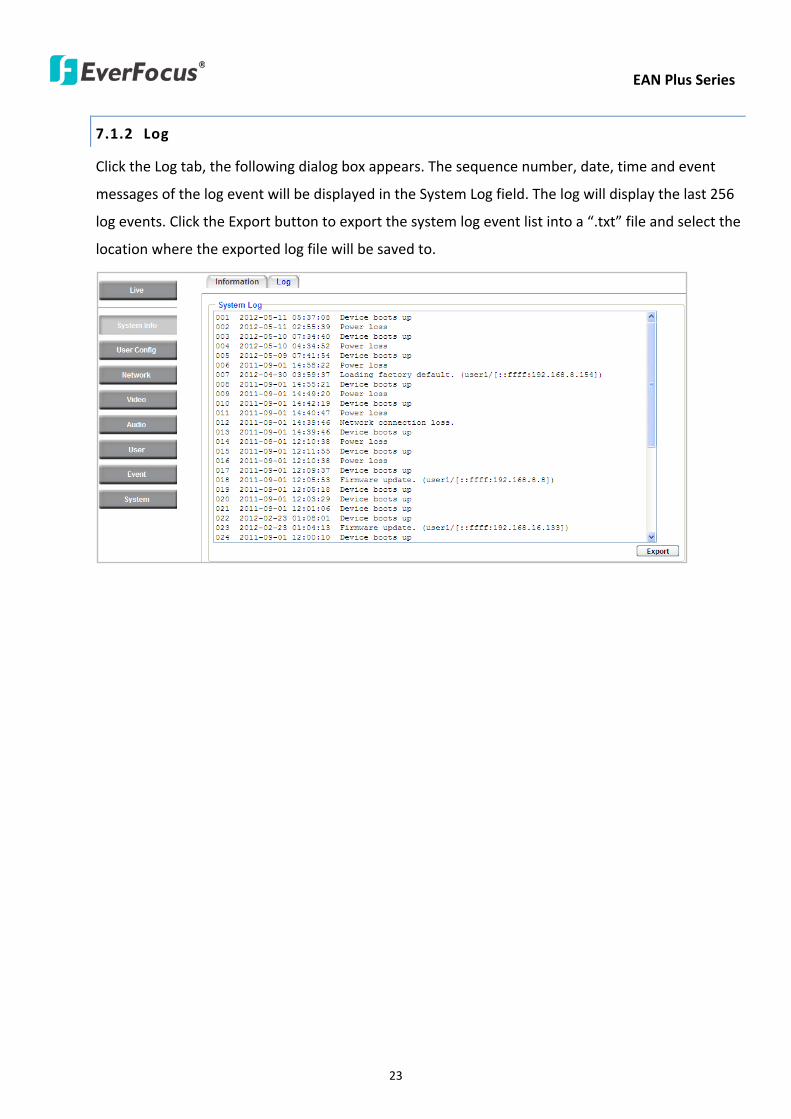
EAN Plus Series
23
712 Log
Click the Log tab the following dialog box appears The sequence number date time and event
messages of the log event will be displayed in the System Log field The log will display the last 256
log events Click the Export button to export the system log event list into a ldquotxtrdquo file and select the
location where the exported log file will be saved to
EAN Plus Series
24
72 User Config
Each user can set a different configuration for hisher Live page here These settings will be applied to
the logged-in userrsquos Live page every time heshe logs in
721 Live View Config
【VideoAudio Connection Protocol Setting】You can transmit the data stream from the IP cameras
using the RTSP (Real Time Streaming Protocol) on the network The RTSP is a protocol that allows
you to access video streams by using the compatible media players Click Apply to apply the
changes or Reset to reset without saving the changes RTP over UDP The RTSP protocol uses UDP for camera data stream transmission
RTP over TCP The RTSP protocol uses TCP for camera data stream transmission
RTP over HTTP The RTSP protocol uses HTTP for camera data stream transmission
Nevio CGI This is EverFocusrsquo protocol designed for EverFocusrsquo IP devices Select this
protocol for camera data stream transmission
【Text Settings】Check the box of each option (Machine name DateTime Frame Rate) to display
this info on the Live View Page
Foreground Color Slide the Red Green and Blue bars to create your preferred text color for the
info text line
Position Select the position where the text will be displayed Choose from Upper Left Lower
Right Lower Left
Click Apply to apply the changes or Reset to reset without saving the changes
EAN Plus Series
25
【DateTime Format Used in Text】Click the dropdown menu to select datetime format from the
listed options Click on the desired hour format Click Apply to apply the setting changes or Reset to
reset without saving the change
【Live View Layout Settings】 Check the ldquoShow One Push Buttonsrdquo boxes if you want to show these
buttons on the Live View Page Uncheck these boxes to hide these buttons This function is only
available for EAN3120 Plus 3220 Plus
722 Recording Snapshot
This configures where your Record Button and Snapshot Button ( ) files will be saved if
you click one of these buttons Selectable folders will be on the computer only not on the
on-camera SD card
【Recording Snapshot Export Settings】
Enable Event Recording to PC Checking this box will let the system save RecordSnapshot Button
recordings to the folder configured below on the userrsquos PC
Export Folder Select the Export folder for the action above by clicking on the browse (hellip) button
and then select the desired folder
File size The user can limit the size of each recorded file here (in minutes) When a single
recording file exceeds the time you set the system will create a new file to save that data to
Overwrite Select ldquoONrdquo for overwriting recordingsnapshot file when the disk storage capacity is
full The user can set the storage capacity limitation in the in-sentence field in the gray box below
the Overwrite setting ldquoIf the remaining hard disk capacity is less than ____ MB (50~2000) system
will stop recording or start overwriting ldquo
Click Apply to apply the setting changes or Reset to reset without saving the changes
EAN Plus Series
26
723 Language
Select the language to be displayed on the Web interface of the IP camera The default language is
English
To add a new language not listed in the current Language list click the Browse button to locate
the new language file (evb) on your computer and then click the Upload button Updated
language files might be available on the manufacturerrsquos website Contact your vendor if required
Click Apply to apply any changes or Reset to reset without saving the changes
Note Uploading a new language file will cause the system to reboot automatically Please create
a new network connection to the IP camera when the reboot is complete
EAN Plus Series
27
73 Network
This page covers network-related settings including Network DDNS SMTPFTP HTTPS SNMP and
Network Alarm
731 Network
The following information is required to configure the network settings Contact your network
administrator or your internet service provider to get the info
【IP Settings】
IP Type Refer to the network administrator for these settings of the server Default DHCP
DHCP This setting lets the system use an automatically assigned (dynamic) IP address This
address can change under certain circumstances For instance when the camerarsquos network
switchhub has to be rebooted Do not assign to the DHCP server the same IP addresses used
for the other network cameras and PCs with unique IP addresses
Static IP The user can manually set the Static IP address This type of address is stable and
cannot change but the user has to make sure there are no address conflicts with other
network-connected devices
PPPoE This is a DSL-connection application The ISP will ask the user to input a username and
password Contact your ISP for these details
EAN Plus Series
28
Note If PPPoE is selected as the IP type the supplied IP Utility program will not be able to
detect the device
IP address When DHCP is not used the user needs to manually enter the IP address of the
camera Do not enter an IP address that is already used for your computer or other network
cameras
Subnet Mask This field is used to set the netmask for your network so that the IP camera will be
recognized within the network Example 2552552550 When DHCP is selected the DHCP server
will assign this value automatically
Gateway This field is used to set the gateway for your network so that the IP camera will be
recognized within the network When DHCP is selected the DHCP server will assign this value
automatically
Primary DNS Enter the IP address of the DNS server if this is provided by an ISP
Secondary DNS If your ISP provided you with a secondary DNS address please enter it here
Username Enter the accountrsquos username (used only for PPPoE)
Password Used only for PPPoE
IPv6 Enter the IPv6 details in this area if this applies to your system
Click Apply to apply the setting changes or Reset to reset without saving the change
【Port Settings】Enter the HTTP HTTPS and RTSP port numbers and click Apply to save
【Multicast Settings】Enable if required fill in the setting options and click Apply to save
EAN Plus Series
29
732 DDNS
DDNS (Dynamic Domain Name System) is a service used to map a domain name to the dynamic IP
address of a network device You can set up the DDNS service for remote access to the IP camera
DDNS assigns a domain name (URL) to the IP camera so that the user does not need to go through
the trouble of checking if the IP address assigned by DHCP Server has changed Once the IP is
changed the IP camera will automatically update the information to the DDNS to ensure it is always
available for remote access
Before enabling the following DDNS function user should have applied for a host name from the
DDS service providerrsquos website We support these four DDNS server providers
wwweverfocusddnscom wwwsitelutionscom wwwdyndnscom and wwwno-ipcom
Note We highly recommend that you use xxxxeverfocusddnscom for the simplicity of setting up
your IP cameras
【DDNS Settings】
Enable Check this box to enable the DDNS function
Service ISP You can either apply for a host name from EverFocus or other DDNS server providers
If you choose the EverFocus DDNS server you can obtain a free host name from EverFocus by
following the steps below
bull From EverFocus To obtain a free host name from EverFocus type a desired host name in the
textbox click the Register Update button and then click the Apply button
bull From other DDNS server providers To obtain a domain name from one of the three DDNS
server providers you have to register your name with the provider first and then select the
provider and fill in the required information Please refer to the specific DDNS companyrsquos
website for further information
Record ID Type the record ID if provided by the DDNS server provider
EAN Plus Series
30
FQDN Type the fully qualified domain name applied from the DDNS server provider For
example xxxxdyndnscom
Username Password Type the login account of your DDNS server provider
Click Apply to apply the setting changes or Reset to reset without saving the changes
Note
1 In order to support the full functionality of the camera you must open the port numbers (80
554 443) on the router for remote access to the IP camera This function is available on most
routers in the market and is often known as ldquoPort Forwardingrdquo To set up Port Forwarding
please consult the manual of the router
2 In certain router models it is possible that you will not be able to access the camera using
DDNS while inside the routerrsquos network Please try using a PC located outside of your routerrsquos
network
Default Ports on All EverFocus IP Cameras
HTTP 80
RTSP 554
HTTPS 443
EAN Plus Series
31
733 SMTP FTP
【Set SMTP Server (email)】This area is for configuring the mail server that is used to send e-mail
notifications from the camera to predefined addresses via SMTP Note that to enable e-mail
notification function you have to check the Send Mail Notification item on the Event dialog box
(see 771 Event Settings)
SMTP Server Enter the IP address or the host name of the SMTP server used to send e-mails
SMTP Port Enter the port number for SMTP The default is 25
Authentication Check this box if the SMTP server requires authentication (userpassword)
User name Input the userrsquos login ID if the SMTP server requires authentication
Password Input the userrsquos login password if the SMTP server requires authentication
EAN Plus Series
32
Receiver Address Input the e-mail addresses for receiving an e-mail message when an EVENT is
enabled and triggered Please use ldquordquo to separate multiple addresses
Sender Address Input the senderrsquos e-mail address so that the receiver can recognize the sender
when an Event message is received
Attach Image Check this box if you want to attach an image when an alarm is triggered or an IP
camera detects events
Send Test Email Click the Test button to send a testing email to the assigned address
Click Apply to apply the setting changes or Reset to reset without saving the changes
【Set FTP Server】The settings relating to the FTP server used to transmit the alarm images can be
configured here Note that to enable uploading images to the FTP server function you have to
check the Upload to FTP item on the Event dialog box (see 771 Event Settings)
FTP Server Enter the IP address or the host name of the FTP server
FTP Port Enter the port number for the FTP server Default is 21
Recording Path Assign the recording path
User Name Set FTP Userrsquos name
Password Set FTP password
PASV mode Check to enable Passive mode Passive mode is normally enabled If a connection
cannot be established uncheck PASV Moderdquo
Test FTP Server Click the Test button to send a testing file to the assigned FTP server
Click Apply to apply the setting changes or Reset to reset without saving the changes
EAN Plus Series
33
734 HTTPS
Hypertext Transfer Protocol Secure (HTTPS) is a combination of the Hypertext Transfer Protocol
and the SSLTLS protocol and provides encrypted communication and secure identification of a
network web server
Before using the HTTPS function for communication with the IP camera a Certificate must be
created first There are two ways to create and install a certificate Create Self-Signed Certificate
and Create Certificate Request
Create Self-Signed Certificate
Please note that even though self-signed certificates are free and offer some protection true
security is only implemented after the installation of a signed certificate issued by a certificate
authority
1 Click the Create Self-Signed Certificate button the following dialog appears
EAN Plus Series
34
2 Type the required Certificate information and then click the Apply button The subject line will
be displayed in the Installed Certificate Information field
3 Click the Property button a pop-up window appears to display the details of the certificate
4 To optionally create and install other certificates remove the existing one by clicking the
Remove button to erase the certificate
5 On the Web page change the address from ldquohttprdquo to https in the address bar and press
Enter on the keyboard Some Security Alert dialogs will pop up Click OK or Yes to enable HTTPS
Create Certificate Request
You can apply for an official certificate from an issuing Certificate Authority
1 Click the Create Certificate Request button the following dialog appears
EAN Plus Series
35
2 Type the required Certificate information and then click the Apply button The subject line will
be displayed in the Created Request field
3 Click the Property button a pop-up window appears to display the details of the certificate
4 To optionally create and install other certificates or request remove the existing one by clicking
the Remove button to erase the certificate or request
5 Copy the contents of the Certificate request (in PEM format) and paste it to the certificate
request field on the Web page of the 3rd-party certification authority such as Symantec VeriSign
Wait for the certificate authority to issue an SSLTLS certificate and then download the issued
certificate on your computer
6 In the Install Signed Certificate field click the Browse button to search for the issued certificate
and then click the Upload button to import the certificate Once the certificate has been
uploaded this field will show the subject line of the certificate
EAN Plus Series
36
735 SNMP
The default values for SNMP v1v2v2c and SNMP v3 are already filled in Click either of the
Enable buttons to enable either of the two Make your changes as desired Click on the Trap
Address field to enter the digits if required
736 Network Alarm
This function works with EverFocusrsquos CMS software eg the PowerCon or the Power Video Plus For
the setting details please refer to the CMS network alarm protocol
EAN Plus Series
37
74 Video
The settings relating to video such as streaming camera OSD can be configured on this page The
Video page has five tabs Multi-streaming Camera Advanced ROI and Privacy Mask
741 Multi Streaming
【Stream Settings】 This IP camera can output three video streams simultaneously For each of these
streams the user can set the compression format resolution bit rate and frame rate individually
Stream 1 is always enabled for live view To enable Stream 2 andor Stream 3 check the ldquoEnablerdquo
box the header of each stream
Note If you connect to the camera via the Internet and experience a delay (lag time) in the video
feed try to reduce the number of streams and the quality and resolution of the streams ndash but
keep the frame rate at its maximum
EAN Plus Series
38
Format Select the encoding format ndash H264 or MJPEG
Resolution Select the most suitable resolution for your needs
Frame Rate Select from 1 to 30 fps
Bit Rate If required select whether you want the stream to stream a Constant Bit Rate or a
Variable Bit Rate and set the values of whichever option you choose
Click Apply to apply the setting changes or Reset to reset without saving the changes
【Video Recording Settings】Select the stream you want to configure and then select whether you
want the recording files of that stream to be saved in AVI or ARV format Click Apply to apply the
setting changes or Reset to reset without saving the changes
【Time Stamp Settings】 You can select the DateTime format position and add the setting to the
streaming
Click Apply to apply the changes or Reset to reset without saving the changes
EAN Plus Series
39
742 Camera
【Image Settings】Set the Brightness Saturation Contrast or Sharpness of the image Click Apply to
apply the changes or Reset to reset without saving the changes
【Camera Settings】
Mirror Switch Mirror ON to rotate the image horizontally around a vertical axis
Flip Switch Flip ON to rotate the image vertically around a horizontal axis
AE There are two options
ALC Selecting Automatic Light Control allows the camera circuitry to either take bright spots
more into consideration (peak) bringing out detail in bright areas or less into consideration
(average) bringing out detail in shadows
AES Selecting Auto Electronic Shutter disables the Shutter setting below this setting In this
mode the camera measures the light level and decides whether it needs more or less light and
then automatically adjusts the shutter speed accordingly
BLC Back Light Compensation (BLC) is used to make the subject appear clearer when it is set
against a bright background
OFF Select to switch Back Light Compensation functions off
(ON)BLC The BLC can increase the exposure of a dark area surrounded by a brighter area HLC
can decrease the exposure of bright areas surrounded by darker areas This enables the
camera to better display information that would otherwise have been ldquowhited outrdquo like a
license plate between two bright headlights on a dark road
(ON)HLC The Highlight-Suppression BLC is used to reduce the brightness of light sources in a
specific area It is activated only in a low illumination environment to minimize the effects of
glare from bright lights such as spotlights street lights or headlights in the field of view
EAN Plus Series
40
WDR The Wide Dynamic Range (WDR) function provides clearer images when both of the very
bright and dark areas simultaneously appear on the camera view There are four value options
OFF Low Middle and High Note that when WDR is ON some parts of the image may appear
solarized This is normal for WDR and is not a camera malfunction This function is only available
for EAN3120 Plus 3220 Plus
DN Mode
Auto Select to let the camera automatically switch to Night mode (black and white) when the
light levels fall to a specified level and back to Day mode (color) when the light levels rise to a
specified level
Day Select to keep the camera in Day mode (color) even in nighttime
Night Select to keep the camera in Night mode (black and white) even in daytime
EAN Plus Series
41
743 Advanced
EAN Plus Series
42
【Camera Settings】
Lens (IRIS Control) Select DC or Manual for IRIS control This function is only available for EAN3220
Plus
Exposure Settings (AE) This setting is used to adapt to the amount or type of light used by the
camera Note the settings vary among models
Mode This function is not available for EAN3220 Plus
Automatic Light Control (ALC) This option is only available for EAN3120 Plus 3300 Plus The
ALC allows the camera circuitry to either take bright spots more into consideration (peak)
bringing out detail in bright areas or less into consideration (average) bringing out detail in
shadows
Auto Electronic Shutter (AES) This option is only available for EAN3120 Plus 3300 Plus In
this mode the camera measures the light level and decides whether it needs more or less light
and then automatically adjusts the shutter speed accordingly
Manual This option is only available for EAN3300 Plus Select this option to manually set up
the Shutter (Manual) and AGC (Manual) values
Iris Specify the size of the Iris opening here
Shutter If enabled this setting lets you set the shutter speed yourself
Shutter Limit Use this setting to set the maximum shutter speed for the camera This function is
only available for EAN3120 Plus
AGC Set the Auto Gain Control limit here The lower the AGC level the lower the video signal and
the noise However the image will be darker under low-light condition with IR-off if you set up the
Iris to the maximum level
Slow Shutter This option can be switched on when AES Mode is selected in the Exposure Settings
(AE) field This function is only available for EAN3220 Plus 3300 Plus
Flickerless If the Mode field in the Exposure Settings (AE) area has been set to AES then this option
becomes available Choose between OFF 50HZ 60HZ 50HZ (High Luminance) or 60HZ (High
Luminance) This function is only available for EAN3300 Plus
EV Setting Set up the Exposure Value Note the brightness of the screen changes when you change
the EV value This function is only available for EAN3300 Plus
AE Response Set up Auto Exposure Response time This function is only available for EAN3300 Plus
AE Weighting Area Select an AE Weighting area Each setup AE Weighting Area is configured with
the appropriate brightness level on the center and the surrounding areas This function is only
available for EAN3300 Plus
Brightness Set the image brightness here
AE Reference Set the Auto Exposure value here This function is only available for EAN3120 Plus
EAN Plus Series
43
Black Level Set the Black level here This function is only available for EAN3300 Plus
WDR The Wide Dynamic Range (WDR) function provides clearer images when both of the very
bright and dark areas simultaneously appear on the camera view There are four value options OFF
Low Middle and High Note that when WDR is ON some parts of the image may appear solarized
This is normal for WDR and is not a camera malfunction This function is only available for EAN3120
Plus 3220 Plus
Visibility Enhancement (OFFLowMiddleHigh) Images in foggy or rain environments or in
environments with a very strong luminous intensity have a dynamic range that is significantly lower
than ordinary images The user can use this Visibility Enhancement setting to ldquoDEFOGrdquo the image if
such ldquoFOGGINGrdquo is an issue This function is only available for EAN3220 Plus
BLC Settings Back Light Compensation (BLC) is used to make the subject appear clearer when it is
set against a bright background
OFF Select to switch Back Light Compensation functions off
Back Light This option is only available for EAN3300 Plus The Back Light function is useful
when the background of the subject is very bright and the subject itself is dark Select Back
Light and adjust the slide bar to the left right for setting up the back light value The higher
the value the more the backlight compensation
Front Light This option is only available for EAN3300 Plus This function is useful when the
bright highlights such as flashlight or car headlights appear on the camera view Select Front
Light and adjust the slide bar to the left right for setting up the front light value The higher
the value the more the highlight compensation
ON (BLC) This option is only available when you select AES Mode in the Exposure Settings (AE)
field The option is only available for EAN3120 Plus 3220 Plus The BLC function is useful
when the background of the subject is very bright and the subject itself is dark Follow the
instructions below to configure the settings for each model
For EAN3120 Select ON (BLC) the button next to the Mode drop-down list will be
active (see image below) Click the button the green setup areas appear on the left
screen Click on the areas to enable disable the BLC function The selected areas (in green)
will be applied with the BLC function
EAN Plus Series
44
For EAN3220
You can configure one area to apply the BLC function Select ON (BLC) the setup buttons
appears (see image below) Select Low Middle High from the BLC Gain drop-down list To
set up a BLC area click the Edit Area button and then click on the blue color tab to turn your
mouse cursor into a blue pen Move the cursor to the position on the right screen where you
want the BLC rectangle to start and then click Move your cursor to the position (diagonally
opposing corner) where you want the BLC rectangle to end and then click The blue area will
be applied with the BLC function
ON (HLC) This option is only available when you select AES Mode in the Exposure Settings (AE)
field The option is only available for EAN3120 Plus 3220 Plus This function is useful when
the bright highlights such as flashlight or car headlights appear on the camera view Follow
the instructions below to configure the settings for each model
For EAN3120 Select ON (HLC) and then select a level from the drop-down list The higher the
level the more the highlight compensation
For EAN3220
HLC Level Select a level for the HLC setting The higher the level the more the highlight
compensation
HLC Mode Select All Day Night mode to apply the HLC function
HLC Black Mask Select On Off to apply the black mask on the selected areas The
over-exposure portions within the selected areas will be applied with the black mask
Color Tabs You can set up four HLC areas with different colors To set up a HLC area click the
Edit Area button and then click on the color tab to turn your mouse cursor into a pen of that
color Move the cursor to the position on the right screen where you want the HLC rectangle
to start and then click Move your cursor to the position (diagonally opposing corner) where
you want the HLC rectangle to end and then click Select ON from the color tab drop-down list
The rectangular area with the selected color will be applied with the HLC function
EAN Plus Series
45
Back Light This option is only available for EAN3300 Plus The Back Light function is useful
when the background of the subject is very bright and the subject itself is dark Select Back
Light and adjust the slide bar to the left right for setting up the back light value The higher
the value the more the backlight compensation
Front Light This option is only available for EAN3300 Plus This function is useful when the
bright highlights such as flashlight or car headlights appear on the camera view Select Front
Light and adjust the slide bar to the left right for setting up the front light value The higher
the value the more the highlight compensation
Noise Reduction Settings This limits the amount of digital ldquovideo noiserdquo that is usually found in any
video stream and helps to reduce file size The higher the level the more the reduction
For EAN3120 Plus 3300 Plus
Select ON OFF to enable disable the Noise Reduction function Or select Auto to let the camera
automatically enable disable the Noise Reduction function Slide the Level bar to set up the level
The higher the level the more the reduction
For EAN3220 Plus
2D DNR Select ON to enable the 2D DNR function
3D DNR Select ON to enable the 3D DNR function You can further set up the following settings
3D Start AGC Set up the AGC level to automatically start the 3D NR function
3D End AGC Set up the AGC level to automatically stop the 3D NR function
3D Level Set up the 3D DNR level
Smart NR Select ON to enable the Smart NR function The 3D NR function will be
automatically turned on when a motion event occurs
EAN Plus Series
46
White Balance Settings Select the mode that delivers the best quality image for the camerarsquos light
environment There are five options Auto Manual Indoor Outdoor One Push
Auto Select to let the camera automatically adjust the White Balance In the Auto mode the
camera computes the white balance value output using color information from the entire
screen It outputs the proper value using the color temperature radiating from a black subject
based on a range of value from 3000 to 7500K
Manual Select to adjust the Red and Blue values yourself in the fields below this field
Indoor Select to use the default settings for indoor environments In the Indoor mode the
camera uses 3200K as the base value
Outdoor Select to use the default settings for outdoor environment In the Outdoor mode it
uses 5800K as the base value
One Push Select to enable the Push button next to the Mode drop-down field This will allow you to force the camera to readjust the white balance every time you push the Push
button The lens will hold the same focal position until the next trigger command is received
This function helps to prevent incorrect focusing in dark environments This function is only
available for EAN3120 Plus 3220 Plus
Manual Temperature Select to use the optimized Red and Blue settings You can also
optionally adjust the Manual Level below this field for setting up the color temperature The
higher the value the more the color temperature This function is only available for EAN3300
Plus
DayNight Settings
Auto Select to let the camera automatically switch to Night mode (black and white) when the
light levels fall to a specified level and back to Day mode (color) when the light levels rise to a
specified level
Day Select to keep the camera in Day mode (color) even in nighttime
Night Select to keep the camera in Night mode (black and white) even in daytime
IR Smart Settings Select ON and set up the level to enhance the image quality when the images are
over exposure This function is useful when the camera is in the Night mode This function is only
available for EAN3220 Plus
Saturation Set the saturation value This function is not available for EAN3220 Plus
Monitor Type Select a gamma value from Set 1 Set 2 or Set 3 This function is only available for
EAN3120 Plus
Negative Switch this setting ON to view a color negative version of the video image This is useful
at night or when viewing temperature-sensitive images
EAN Plus Series
47
Sharpness Settings Select the sharpness level of the image A low sharpness level will deliver a
softer less detailed image A high level will deliver a sharp highly detailed image Switch Resolution
Enhancement ON to enable the resolution enhancement function
Contrast Select the contrast level of the image
Suppress Function This function is only available for EAN3300 Plus
Aperture Compensation Suppression (OFFLowMiddleHigh) This setting can be activated to
suppress luminance noise when the AGC level increases
Chroma Suppression (OFFLowMiddleHigh) This setting can be activated to suppress
chrominance noise when the AGC level increases
Ygamma (gamma 22standardcontrast enhancehigh light range mode LHigh light range mode
H) Select the Ygamma value for the video quality of the monitor This function is only available for
EAN3300 Plus
Monitor Settings The user can use this field to optimize video quality for his or her specific type of
monitor ndash LCD or CRT This function is only available for EAN3220 Plus
Color Space Standard The options are YUV601 for SD and YUV709 for HD These define the color
space standard required to convert an RGB picture to a YUV picture Generally YUV601 is used for
Standard Definition (720P) devices and the YUV709 is used for High Definition (1080P) devices
Click Apply to save all changes Click Reset to cancel all changes
EAN Plus Series
48
744 ROI (Region of Interest)
The Region of Interest (ROI) function allows users to set up multiple regions within an image with
better quality and less distortion than the rest of the image You can also use this function
together with the Digital Zoom function on the Live View Page to get a better image result Up to
eight ROIs can be configured in the ROI settings page
To set up an ROI region
1 Select an ROI number from the ROI No drop-down list
2 Click the Add button the mouse cursor will turn into a pen when you move it over the live
image on the left
3 Move the cursor to the position where you want the ROI rectangle to start and then click
Move the cursor to the position (diagonally opposing corner) where you want the ROI
rectangle to end and then click
4 Slide the Quality bar to set up the quality value
5 Click the Apply button to apply the settings or click the Reset button to reset without saving
the settings
EAN Plus Series
49
745 Privacy Mask
The Privacy Mask can block out sensitive areas from view covering the areas with colored or black
and white boxes in both live view and recorded clips This feature is useful when usersrsquo donrsquot want
the sensitive information visible Up to four Privacy Masks can be configured
【Privacy Mask Color Settings】The Modes vary among camera models
Mode Click Color to make the masks appear as colored rectangles on the screen Click BW to
make the masks appear as gray rectangles on the screen Click Mosaic to make the masks appear
as mosaic-effect rectangles on the screen
Level Select the color of the masks if you selected Color Mode Select the level of grayness of the
masks if you selected BW Mode Select the level of smallmiddlelarge if you selected Mosaic
Mode
Click Apply to apply the settings or click Reset to reset without saving the settings
Color Tabs Click on a color tab to turn your mouse cursor into a pen of that color
You can now create a block of that color on the video screen Move your cursor to the position
where you want your mask rectangle to start and then click Move your cursor to the position
(diagonally opposing corner) where you want your mask rectangle to end and then click The
rectangular area with the selected color will appear The live image will display the rectangular
area with the color you selected If you want to create another mask use one of the other three
colors Each color denotes a different mask area Only one block per color is allowed As the
number of colors suggests you can configure up to four blocks
EAN Plus Series
50
Select All Click to turn the whole screen into a mask area
Clear All Click to delete all configured mask blocks
Eraser Click to turn the mouse cursor into an eraser to delete any block you click on
Area Shows the color and number of the block
Enable Check this box to enable the related mask block
Click Apply to apply the settings or click Reset to reset without saving the settings
EAN Plus Series
51
75 Audio
The EAN Plus series IP camera can transmit audio to your computer if you have connected an external
microphone to its audio Input cable It can also receive audio input from you and transmit it via an
external speaker if you have connected such a speaker to its audio Output cable
Check the Enable Audio box to enable the camerarsquos audio function The camera will now act as a
digital bridge (via the IP network) between any connected audio input device and any connected
audio device
Adjust the Audio Input Volume if you have external audio input devices (microphones) connected to
the camera and if there are problems with the sound input being too low or high
Click Apply to save all settings or click Reset to cancel
EAN Plus Series
52
76 User
761 User Information
The system administrator can create up to ten user accounts on this page
To set up a user account
1 Highlight a user account and click the Modify button The following dialog box appears
2 Type the account name account description and password for the account Type the password
again in the Confirm field
3 Select an authority level for the user account from the Authority drop-down list
bull Supervisor Administrator The only difference between a supervisor and administrator is
that a supervisor can edit an administratorrsquos account and password but an administrator
cannot edit the supervisorrsquos account and password Multiple administrators can be
configured but there can be only one supervisor The supervisor and administrators all
have unrestricted access to the Settings submenus and can determine the registration of
all other users
EAN Plus Series
53
bull User A user can view the Live View page and view the system network video and audio
information A user can only adjust the User Config page settings The user does not have
access to the User Event and System pages
bull Guest The lowest level of access which only allows the user access to the Live View page
4 Select Active or Disable from the Status drop-down list to active or disable the user account
5 Click On in the SD Card Playback field to allow the user to access the SD card playback
function
6 Click OK
7 Click Apply to save all the settings
EAN Plus Series
54
762 IP Address Filter
Use this page to specify IP addresses that are not allowed to access this camera By default any IP
address can access the camera
Note The Allowed List addresses only become relevant when the Denied List contains a network
or range and the supervisor wants to allow one or more IP addresses within that excluded range
or network In such a scenario the user would enter the excluded range or network in the
Denied List and enter the exceptions in the Allowed List
To set up the IP Address Filter
1 Select Denied List Click the Add button the following dialog box appears
2 Select an IP type from the IP Type drop-down list
3 Select a network rule from the Rule drop-down list type the IP address and click OK
Single Type a single IP address in the IP Address field below
Network Type the IP address and subnet mask in the field below
Range Type a range for the IP addresses
4 If you have set up an IP range in Step 3 you can optionally set up the Allowed List to allow one
or more IP addresses within the setup IP range to access the IP camera
5 Click Apply
EAN Plus Series
55
77 Event
You can set up the Motion Detection event Tamper Detection event or the Alarm IO to automatically
notify the users when an event occurs or an alarm is triggered You can also set up a schedule to
automatically record the videos when an event occurs or an alarm is triggered
771 Event Settings
You can create a total of ten event or alarm settings page in the Event List
【Event List】
Click the Add button and the following Event Configuration Window appears
EAN Plus Series
56
Enter Event Name Type an event name
Event Triggered by Select an event or alarm type for the to-be-specified-below reactions
Alarm Input Select this if you want a reaction trigger coming from any external connected sensor
to activate a to-be-specified-below reactions via the camera system Make sure that a suitable
device is actually connected to the alarm input relay
Manual Trigger Select this option if you want to manually trigger the alarm by clicking the Trigger
Event button on the Live View Page
Motion Detection Select this option if you want motion in a specified part of the camerarsquos viewing
rectangle (the screen image) to trigger the to-be-specified-below reactions
Tampering Detection Select this option if you want the camerarsquos tampering detection sensor to
trigger the to-be-specified-below reactions
Schedule Recording Select this option if you want the Schedule Recording periods configured in
the recording schedule (the Settings gt Event gt Schedule page) to activate this event In this
scenario a preconfigured event reaction like a log entry will list the start and end times of each
period Actual recording will only be triggered if the event is preconfigured to do so
Enable This Event Select to activate the event
Enable Re-trigger Click to set a minimum time after the event is triggered before the event
can be triggered again
Enable Pre-trigger Buffer Click if you want the Event reaction (as selected in the ldquoNotification
Overrdquo field below) to be the activation of the video recording function and if you want the
recording to include the video feed from the time period (configurable on the previous ldquoEvent
Settingsrdquo page) just before the Event trigger occurred
Enable Post-trigger Buffer Click if you want the Event reaction (as selected in the Notification
Over field) to be the activation of the video recording function and if you want the recording
to include the video feed from a time period (configurable on the Event Settings page) just
after the Event trigger occurred
Motion Area Select a setup motion detection area from the drop down list Note this
function only becomes relevant after the Motion Detection areas have been set up (see 772
Motion Detection)
Notification Over Select the desired notification types form the following items
Log Click if you want the camera to list the eventrsquos details in its log if the event is triggered
Trigger Alarm Output Click if you want the camera to relay the event reaction to a device
attached to the alarm relay output wire and then set up the alarm output duration time
EAN Plus Series
57
Send Mail Notification Click if you want the camera to send an Event notification email to the
email address entered in the Set SMTP Server(email) field of the Network gt SMTPFTP page if
the Event occurs (see 733 SMTP FTP)
Upload to FTP Click if you want the camera to upload recorded footage to the FTP server
entered in the Set SMTP Server(email) field of the Network gt SMTPFTP page if the Event
occurs (see 733 SMTP FTP)
Record to SD Card Click if you want the camera to start recording its video feed (when the
event occurs) on an on-camera SD Card (if such a card has been inserted)
Note The recording will only be as long as the combined Pre- and Post-trigger Buffers so
make sure you enable at least one of these buffers especially the Post-trigger Buffer
Record to PC Check this box if you want the camera to start recording its video feed (when
the event occurs) on the same folder on the same PC as configured on the User Config gt
RecordingSnapshot page (if such a folder has been enabled and configured)
Note The recording will only be as long as the combined Pre- and Post-trigger Buffers (and
for as long as the event trigger is happening ndash eg a motion is detected) so make sure you
enable at least one of these buffers especially the Post-trigger Buffer
Network Alarm Check this box if you want the camera to send a network alarm signal (when
the event occurs) to the CMS servers configured on the Network gt Network Alarm page (see
736 Network Alarm)
Click OK to save all settings or click Cancel to cancel
【PrePost Trigger Settings】
Pre-trigger Buffer Select the duration for the buffer This will determine the amount of footage
(length of time) before the event trigger moment that will be included in an event-triggered video
recording if that buffer and video recording has been enabled in the Event Configuration Window
Post-trigger Buffer Select the duration for the buffer This will determine the amount of footage
(length of time) after the event trigger moment that will be included in an event-triggered video
recording if that buffer and video recording has been enabled in the Event Configuration Window
Click Apply to save all settings or click Reset to cancel
EAN Plus Series
58
772 Motion Detection
Use this page to configure up to four areas in which motion will be detected When a motion is
detected by the camera the motion detection icon will appear at the top right of the
Live page to alert the user This function can also be linked with correctly configured Events to
trigger Event reactions like the activation of video recording periods snapshots alarms etc
Color Tabs Click on a color tab to turn your mouse cursor into a pen of that color
You can now create a block of that color on the video screen Move your cursor to the position
where you want your detection rectangle to start and then click Move your cursor to the position
(diagonally opposing corner) where you want your detection rectangle to end and then click The
rectangular area with the selected color will appear This block will be an area inside which the
camera will detect motion If you want to create another detection area use one of the other three
palette colors Each color denotes a different detection area Only one block per color is allowed As
the number of colors suggests you can configure up to four blocks
Select All Click to turn the whole screen into a motion detection area
Clear All Click to delete all configured motion detection blocks
Eraser Click to turn your mouse cursor into an eraser to delete any block you click on
Area Shows the color and numberID of the block
Enable Check this box to enable the related motion detection block
Sensitivity Set the sensitivity of the motion detection sensor function
Click Apply to save all settings or click Reset to cancel
EAN Plus Series
59
773 Tamper Detection
Use this page to set the number of seconds that an alarm signal will be active if the device is
physically tampered (moved covered up or out of focus
774 Alarm IO
Use this page to set the type of trigger input and the type of output contact for the camerarsquos alarm
channel
EAN Plus Series
60
775 Schedule
Use this page to configure a schedule for periods during which the camera should deactivate all
user-activated Events (gray Deselect periods) or when the camera should deactivate all
user-activated Events except Schedule Recording (SR) events (blue Schedule Recording-only
periods) or when the camera should deactivate only SR events (red Event Recording-only periods)
or when it should enable all activated Events (yellow periods)
Event Recording Click this button to make every hour block you click on red A red block represents
an Event Recording-only block which represents an hour when the camera will deactivate all
preconfigured activated Schedule Recording events and keep all the other activated events active
Schedule Recording Click this button to make every hour block you click on blue A blue block
represents a Schedule Recording-only block which represents an hour when the camera will
deactivate all other preconfigured activated events and keep only the preconfigured activated
Schedule Recording events active
Event + Schedule Click this button to make every hour block you click on yellow A yellow block
represents an hour in which all activated events including Schedule Recording events will be
active
Deselect Click this button to make every hour block become grey A grey block represents an hour
in which all activated events including Schedule Recording events will be inactive
Click Apply to save all settings or click Reset to cancel
EAN Plus Series
61
78 System
You can set up the systemrsquos time and SD card settings and to do maintenance and reset actions like
reboots and upgrades
781 DateTime
【Machine Name Settings】If required enter a new name for the machine This name will be visible
in the Machine Name field of the IP Utility software which is included in the software CD
【Set Time Zone】Set the time zone of the camerarsquos location
【Set DateTime Manually】Set the datetime here if you wonrsquot be using an NTP server to update the
datetime (see below)
【Set DateTime Sync】Enter the Network Time Protocol server if applicable The camerarsquos time will
be automatically adjusted by synchronizing with the NTP server
Click Apply to save all settings or click Reset to cancel
EAN Plus Series
62
782 Daylight Saving
Click Enable Daylight Saving to enable this schedule and select the dates when the regionrsquos
daylight saving period begins and ends Click Apply to save all settings or click Reset to cancel
783 SD Card
Use this page to prepare the system for safely removing the SD Card from its slot
【Setup SD Card】
Notification Select the percentage of storage space that should be left on the card before the
camera notifies you of the impending storage shortage or overwrite
Event Recording Select if you want Event Recording only FTP Backup only or both
Overwrite Click ON if you want the card to start writing over recorded footage when its memory is
full Click OFF if you want the card to stop recording new footage when its memory is full
【SD Card Utility】
Capacity This shows you how much card memory has been used and how much memory capacity
remains on the card
Remove Click this button before removing the card from the system
Format Click this button to format the card All data saved on the SD card will be removed if the
card is formatted
EAN Plus Series
63
784 Maintenance
【Maintenance Server】
Reboot Click this button to reboot the unit without changing any of the settings Use this function if
the unit is not behaving as expected
Restore Click this button to restart and reset most of the current settings to their factory default
values The only settings that will not be changed to default are
bull IP settings
bull DDNS settings
Default The Default button should be used with caution Pressing this button will return all of the
cameras settings including the IP address to the factory default values The camera will then have
to be reconfigured
【SaveLoad Configuration Server】
Save To make a backup file of the machinersquos current configurations press Save to save all the
configurations to a config file This will enable the user to reload these configuration settings if the
settings are changed and there is unexpected behavior
Load To load a previously saved configuration press the Browse button to locate the saved config
file (see above) and then click the Load button The systemrsquos settings will be restored to the saved
configuration
EAN Plus Series
64
【SaveLoad Video Configuration Server】
Save To make a backup file of the machinersquos video configurations press Save to save the video
configurations to a config file This will enable the user to reload these configuration settings if the
settings are changed and there is unexpected behavior
Load To load a previously saved video configuration press the Browse button to locate the saved
config file (see above) and then click the Load button The systemrsquos settings will be restored to the
saved video configuration
【Upgrade Firmware】Click the Browse button to find a previously prepared firmware upgrade file
Click Upgrade to install the new firmware
Note
1 Do not disconnect power to the unit during the upgrade sequence The unit will reboot
automatically after the upgrade has completed (1-5 minutes)
2 During the upgrade process all event recording actions will be stopped Event recording
actions will resume after the camera is rebooted
3 If the ldquoFile Error Please re-loginrdquo warning message appears when upgrading the firmware
please try the following instructions
a Go to Internet Explorer gt Tools gt Internet Option gt Security gt Custom
b Find and enable the Include local directory path when uploading files to a server
EAN Plus Series
65
8 Upgrading Firmware Using IP Utility
You can upgrade the Firmware using the IP Utility software included in the software CD
1 Install and then start the IPU program The following dialog box appears
2 Click Find Devices to search the cameras connected in the LAN The default network values of the
cameras will be displayed By default the network protocol of the camera is DHCP
3 Select a camera and click LoginMulti Login to log in the camera
4 Type the user ID and password Click OK
Note
1 The default user ID is user1 and the default password is 11111111
2 If you select more than one camera that has the same user ID password you will be able
to log in several cameras at once
EAN Plus Series
66
5 Highlight the camera and then click Upgrade Firmware A browsing window appears
6 Select the firmware file (evb) and then click Open The IP Utility will automatically upgrade the
firmware
The camera will reboot once the update is complete Click Find Devices the new firmware version
should be displayed in the last part of the Machine Name
EAN Plus Series
67
9 Specifications
Model EAN3120 Plus EAN3220 Plus EAN3300 Plus
Camera
Image Sensor 13 Panasonic CMOS 128 Sony CMOS
Megapixel 13 MP 2 MP 3 MP
Picture Elements (H x V) 1280 x 1024 1944 x 1092 2048 x 1536
Min Illuminations 003 Lux at F14
Electronic Shutter (Sec) 85 ~ 160000 2 ~ 150000 1 ~ 110000
Scanning System NTSC PAL
WDR Yes Yes No
BLC Yes
Gain Control Yes
White Balance Yes
Lens
Mounting Type C CS
Day Night Yes (with removable auto IR-cut filter)
IRIS Control DC Electrical IRIS Lens IRIS
Video
Video Compression H264 MJPEG
Resolution
NTSC
2048 x 1536 1920 x 1200 (for EAN3300 Plus only)
1920 x 1080 (for EAN3300 Plus 3220 Plus only)
1280 x 1024 1280 x 720 1024 x 768 720 x 480 704 x 480 640 x 480
352 x 240 320 x 240 160 x 120
PAL
2048 x 1536 1920 x 1200 (for EAN3300 Plus only)
1920 x 1080 (for EAN3300 Plus 3220 Plus only)
1280 x 1024 1280 x 720 1024 x 768 720 x 576 704 x 576 640 x 480
352 x 288 320 x 240 160 x 120
Frame Rate 30 fps at 1280 x 1024 30 fps at 1920 x 1080 15 fps at 2048 x 1536
Audio
Audio Streaming Two-way audio
Audio Compression G711
EAN Plus Series
68
Network
Interface 10 100 Base-T Ethernet RJ-45 socket
Supported Protocols
TCPIP IPV6 UDP ICMP DHCP NTP DNS DDNS SMTP SNMP FTP
HTTP HTTPs PPPoE UPnP Bonjour RTP RTSP RTCP IGMP ARP ONVIF
PSIA
Connector
Power DC female port PoE
Ethernet RJ-45
Audio 1 In (phone jack for microphone)
1 Out (phone jack for Speaker)
Alarm IO Terminal IO wires
Local Storage Micro SD SDHC memory card slot
TV-Out BNC socket composite 1 V p-p 75 Ω
General
Power Source DC 12V PoE (IEEE8023af)
Power Consumption
(IR LEDs On)
5W (DC 12V)
621W (PoE)
5W (DC 12V)
522W (PoE)
5W (DC 12V)
536W (PoE)
Operating Temperature 0degC ~ +50degC 32degF ~ +122degF
Humidity 20 to 80 (no condensation)
Safety CE FCC
Dimensions (L x W x H) 117 x 56 x 68 mm 46 x 22 x 27 in
Weight 410 g 09 lb
EverFocus Electronics Corp EverFocus Taiwan 12F No79 Sec 1 Shin-Tai Wu Road Hsi-Chih Taipei Taiwan TEL +886 2 2698 2334 FAX +886 2 2698 2380 wwweverfocuscomtw marketingeverfocuscomtw
EverFocus Europe - Germany Albert-Einstein-Strasse 1 D-46446 Emmerich Germany TEL +49 2822 93940 FAX +49 2822 939495 wwweverfocusde infoeverfocusde
EverFocus China - Beijing Room 609 Technology Trade Building Shangdi Information Industry Base Haidian District Beijing 100085 China TEL +86 10 6297 3336~39 FAX +86 10 6297 1423 wwweverfocuscomcn marketingeverfocuscomcn
EverFocus China - Shenzhen 4F No 2 D4 Building Wan Yelong Industrial Park Tangtou Road Shiyan Baoan Shenzhen Guangdong 518101 China TEL +86 755 2765 1313 FAX +86 755 2765 0337 wwweverfocuscomcn marketingeverfocuscomcn
EverFocus USA - California 1801 Highland Avenue Unit A Duarte CA 91010 USA TEL +1 626 844 8888 FAX +1 626 844 8838 wwweverfocuscom saleseverfocuscom
EverFocus USA - New York 415 Oser Avenue Unit S Hauppauge NY 11788 USA TEL +1 631 436 5070 FAX +1 631 436 5027 wwweverfocuscom saleseverfocuscom
EverFocus Japan 5F Kinshicho City Building 2-13-4 Koto-BashiSumida-Ku Tokyo 130-0022 Japan TEL +81 3 5625 8188 FAX +81 3 5625 8189 wwweverfocuscojp infoeverfocuscojp
EverFocus Europe - UK Unit 12 Spitfire Business Park Hawker Road Croydon Surrey CR0 4WD UK TEL +44 20 8649 9757 +44 845 430 9999 FAX +44 20 8649 9907 wwweverfocusukcouk salesukeverfocuscom
EverFocus India Suite 803 Housefin Bhavan C-21 Bandra Kurla Complex Bandra (East) Mumbai 400051 India TEL +91 22 6128 8700 FAX +91 22 6128 8705 wwweverfocusin saleseverfocusin
PN 4605PQ3120B010A-VerC
Your EverFocus product is designed and manufactured with high quality materials and components which can be recycled and reused This symbol means that electrical and electronic equipment at their end-of-life should be disposed of separately from your household waste Please dispose of this equipment at your local community waste collectionrecycling centre In the European Union there are separate collection systems for used electrical and electronic product Please help us to conserve the environment we live in
Ihr EverFocus Produkt wurde entwickelt und hergestellt mit qualitativ hochwertigen Materialien und Komponenten die recycelt und wieder verwendet werden koumlnnen Dieses Symbol bedeutet dass elektrische und elektronische Geraumlte am Ende ihrer Nutzungsdauer vom Hausmuumlll getrennt entsorgt werden sollen Bitte entsorgen Sie dieses Geraumlt bei Ihrer oumlrtlichen kommunalen Sammelstelle oder im Recycling Centre Helfen Sie uns bitte die Umwelt zu erhalten in der wir leben
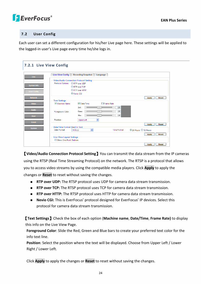
EAN Plus Series
24
72 User Config
Each user can set a different configuration for hisher Live page here These settings will be applied to
the logged-in userrsquos Live page every time heshe logs in
721 Live View Config
【VideoAudio Connection Protocol Setting】You can transmit the data stream from the IP cameras
using the RTSP (Real Time Streaming Protocol) on the network The RTSP is a protocol that allows
you to access video streams by using the compatible media players Click Apply to apply the
changes or Reset to reset without saving the changes RTP over UDP The RTSP protocol uses UDP for camera data stream transmission
RTP over TCP The RTSP protocol uses TCP for camera data stream transmission
RTP over HTTP The RTSP protocol uses HTTP for camera data stream transmission
Nevio CGI This is EverFocusrsquo protocol designed for EverFocusrsquo IP devices Select this
protocol for camera data stream transmission
【Text Settings】Check the box of each option (Machine name DateTime Frame Rate) to display
this info on the Live View Page
Foreground Color Slide the Red Green and Blue bars to create your preferred text color for the
info text line
Position Select the position where the text will be displayed Choose from Upper Left Lower
Right Lower Left
Click Apply to apply the changes or Reset to reset without saving the changes
EAN Plus Series
25
【DateTime Format Used in Text】Click the dropdown menu to select datetime format from the
listed options Click on the desired hour format Click Apply to apply the setting changes or Reset to
reset without saving the change
【Live View Layout Settings】 Check the ldquoShow One Push Buttonsrdquo boxes if you want to show these
buttons on the Live View Page Uncheck these boxes to hide these buttons This function is only
available for EAN3120 Plus 3220 Plus
722 Recording Snapshot
This configures where your Record Button and Snapshot Button ( ) files will be saved if
you click one of these buttons Selectable folders will be on the computer only not on the
on-camera SD card
【Recording Snapshot Export Settings】
Enable Event Recording to PC Checking this box will let the system save RecordSnapshot Button
recordings to the folder configured below on the userrsquos PC
Export Folder Select the Export folder for the action above by clicking on the browse (hellip) button
and then select the desired folder
File size The user can limit the size of each recorded file here (in minutes) When a single
recording file exceeds the time you set the system will create a new file to save that data to
Overwrite Select ldquoONrdquo for overwriting recordingsnapshot file when the disk storage capacity is
full The user can set the storage capacity limitation in the in-sentence field in the gray box below
the Overwrite setting ldquoIf the remaining hard disk capacity is less than ____ MB (50~2000) system
will stop recording or start overwriting ldquo
Click Apply to apply the setting changes or Reset to reset without saving the changes
EAN Plus Series
26
723 Language
Select the language to be displayed on the Web interface of the IP camera The default language is
English
To add a new language not listed in the current Language list click the Browse button to locate
the new language file (evb) on your computer and then click the Upload button Updated
language files might be available on the manufacturerrsquos website Contact your vendor if required
Click Apply to apply any changes or Reset to reset without saving the changes
Note Uploading a new language file will cause the system to reboot automatically Please create
a new network connection to the IP camera when the reboot is complete
EAN Plus Series
27
73 Network
This page covers network-related settings including Network DDNS SMTPFTP HTTPS SNMP and
Network Alarm
731 Network
The following information is required to configure the network settings Contact your network
administrator or your internet service provider to get the info
【IP Settings】
IP Type Refer to the network administrator for these settings of the server Default DHCP
DHCP This setting lets the system use an automatically assigned (dynamic) IP address This
address can change under certain circumstances For instance when the camerarsquos network
switchhub has to be rebooted Do not assign to the DHCP server the same IP addresses used
for the other network cameras and PCs with unique IP addresses
Static IP The user can manually set the Static IP address This type of address is stable and
cannot change but the user has to make sure there are no address conflicts with other
network-connected devices
PPPoE This is a DSL-connection application The ISP will ask the user to input a username and
password Contact your ISP for these details
EAN Plus Series
28
Note If PPPoE is selected as the IP type the supplied IP Utility program will not be able to
detect the device
IP address When DHCP is not used the user needs to manually enter the IP address of the
camera Do not enter an IP address that is already used for your computer or other network
cameras
Subnet Mask This field is used to set the netmask for your network so that the IP camera will be
recognized within the network Example 2552552550 When DHCP is selected the DHCP server
will assign this value automatically
Gateway This field is used to set the gateway for your network so that the IP camera will be
recognized within the network When DHCP is selected the DHCP server will assign this value
automatically
Primary DNS Enter the IP address of the DNS server if this is provided by an ISP
Secondary DNS If your ISP provided you with a secondary DNS address please enter it here
Username Enter the accountrsquos username (used only for PPPoE)
Password Used only for PPPoE
IPv6 Enter the IPv6 details in this area if this applies to your system
Click Apply to apply the setting changes or Reset to reset without saving the change
【Port Settings】Enter the HTTP HTTPS and RTSP port numbers and click Apply to save
【Multicast Settings】Enable if required fill in the setting options and click Apply to save
EAN Plus Series
29
732 DDNS
DDNS (Dynamic Domain Name System) is a service used to map a domain name to the dynamic IP
address of a network device You can set up the DDNS service for remote access to the IP camera
DDNS assigns a domain name (URL) to the IP camera so that the user does not need to go through
the trouble of checking if the IP address assigned by DHCP Server has changed Once the IP is
changed the IP camera will automatically update the information to the DDNS to ensure it is always
available for remote access
Before enabling the following DDNS function user should have applied for a host name from the
DDS service providerrsquos website We support these four DDNS server providers
wwweverfocusddnscom wwwsitelutionscom wwwdyndnscom and wwwno-ipcom
Note We highly recommend that you use xxxxeverfocusddnscom for the simplicity of setting up
your IP cameras
【DDNS Settings】
Enable Check this box to enable the DDNS function
Service ISP You can either apply for a host name from EverFocus or other DDNS server providers
If you choose the EverFocus DDNS server you can obtain a free host name from EverFocus by
following the steps below
bull From EverFocus To obtain a free host name from EverFocus type a desired host name in the
textbox click the Register Update button and then click the Apply button
bull From other DDNS server providers To obtain a domain name from one of the three DDNS
server providers you have to register your name with the provider first and then select the
provider and fill in the required information Please refer to the specific DDNS companyrsquos
website for further information
Record ID Type the record ID if provided by the DDNS server provider
EAN Plus Series
30
FQDN Type the fully qualified domain name applied from the DDNS server provider For
example xxxxdyndnscom
Username Password Type the login account of your DDNS server provider
Click Apply to apply the setting changes or Reset to reset without saving the changes
Note
1 In order to support the full functionality of the camera you must open the port numbers (80
554 443) on the router for remote access to the IP camera This function is available on most
routers in the market and is often known as ldquoPort Forwardingrdquo To set up Port Forwarding
please consult the manual of the router
2 In certain router models it is possible that you will not be able to access the camera using
DDNS while inside the routerrsquos network Please try using a PC located outside of your routerrsquos
network
Default Ports on All EverFocus IP Cameras
HTTP 80
RTSP 554
HTTPS 443
EAN Plus Series
31
733 SMTP FTP
【Set SMTP Server (email)】This area is for configuring the mail server that is used to send e-mail
notifications from the camera to predefined addresses via SMTP Note that to enable e-mail
notification function you have to check the Send Mail Notification item on the Event dialog box
(see 771 Event Settings)
SMTP Server Enter the IP address or the host name of the SMTP server used to send e-mails
SMTP Port Enter the port number for SMTP The default is 25
Authentication Check this box if the SMTP server requires authentication (userpassword)
User name Input the userrsquos login ID if the SMTP server requires authentication
Password Input the userrsquos login password if the SMTP server requires authentication
EAN Plus Series
32
Receiver Address Input the e-mail addresses for receiving an e-mail message when an EVENT is
enabled and triggered Please use ldquordquo to separate multiple addresses
Sender Address Input the senderrsquos e-mail address so that the receiver can recognize the sender
when an Event message is received
Attach Image Check this box if you want to attach an image when an alarm is triggered or an IP
camera detects events
Send Test Email Click the Test button to send a testing email to the assigned address
Click Apply to apply the setting changes or Reset to reset without saving the changes
【Set FTP Server】The settings relating to the FTP server used to transmit the alarm images can be
configured here Note that to enable uploading images to the FTP server function you have to
check the Upload to FTP item on the Event dialog box (see 771 Event Settings)
FTP Server Enter the IP address or the host name of the FTP server
FTP Port Enter the port number for the FTP server Default is 21
Recording Path Assign the recording path
User Name Set FTP Userrsquos name
Password Set FTP password
PASV mode Check to enable Passive mode Passive mode is normally enabled If a connection
cannot be established uncheck PASV Moderdquo
Test FTP Server Click the Test button to send a testing file to the assigned FTP server
Click Apply to apply the setting changes or Reset to reset without saving the changes
EAN Plus Series
33
734 HTTPS
Hypertext Transfer Protocol Secure (HTTPS) is a combination of the Hypertext Transfer Protocol
and the SSLTLS protocol and provides encrypted communication and secure identification of a
network web server
Before using the HTTPS function for communication with the IP camera a Certificate must be
created first There are two ways to create and install a certificate Create Self-Signed Certificate
and Create Certificate Request
Create Self-Signed Certificate
Please note that even though self-signed certificates are free and offer some protection true
security is only implemented after the installation of a signed certificate issued by a certificate
authority
1 Click the Create Self-Signed Certificate button the following dialog appears
EAN Plus Series
34
2 Type the required Certificate information and then click the Apply button The subject line will
be displayed in the Installed Certificate Information field
3 Click the Property button a pop-up window appears to display the details of the certificate
4 To optionally create and install other certificates remove the existing one by clicking the
Remove button to erase the certificate
5 On the Web page change the address from ldquohttprdquo to https in the address bar and press
Enter on the keyboard Some Security Alert dialogs will pop up Click OK or Yes to enable HTTPS
Create Certificate Request
You can apply for an official certificate from an issuing Certificate Authority
1 Click the Create Certificate Request button the following dialog appears
EAN Plus Series
35
2 Type the required Certificate information and then click the Apply button The subject line will
be displayed in the Created Request field
3 Click the Property button a pop-up window appears to display the details of the certificate
4 To optionally create and install other certificates or request remove the existing one by clicking
the Remove button to erase the certificate or request
5 Copy the contents of the Certificate request (in PEM format) and paste it to the certificate
request field on the Web page of the 3rd-party certification authority such as Symantec VeriSign
Wait for the certificate authority to issue an SSLTLS certificate and then download the issued
certificate on your computer
6 In the Install Signed Certificate field click the Browse button to search for the issued certificate
and then click the Upload button to import the certificate Once the certificate has been
uploaded this field will show the subject line of the certificate
EAN Plus Series
36
735 SNMP
The default values for SNMP v1v2v2c and SNMP v3 are already filled in Click either of the
Enable buttons to enable either of the two Make your changes as desired Click on the Trap
Address field to enter the digits if required
736 Network Alarm
This function works with EverFocusrsquos CMS software eg the PowerCon or the Power Video Plus For
the setting details please refer to the CMS network alarm protocol
EAN Plus Series
37
74 Video
The settings relating to video such as streaming camera OSD can be configured on this page The
Video page has five tabs Multi-streaming Camera Advanced ROI and Privacy Mask
741 Multi Streaming
【Stream Settings】 This IP camera can output three video streams simultaneously For each of these
streams the user can set the compression format resolution bit rate and frame rate individually
Stream 1 is always enabled for live view To enable Stream 2 andor Stream 3 check the ldquoEnablerdquo
box the header of each stream
Note If you connect to the camera via the Internet and experience a delay (lag time) in the video
feed try to reduce the number of streams and the quality and resolution of the streams ndash but
keep the frame rate at its maximum
EAN Plus Series
38
Format Select the encoding format ndash H264 or MJPEG
Resolution Select the most suitable resolution for your needs
Frame Rate Select from 1 to 30 fps
Bit Rate If required select whether you want the stream to stream a Constant Bit Rate or a
Variable Bit Rate and set the values of whichever option you choose
Click Apply to apply the setting changes or Reset to reset without saving the changes
【Video Recording Settings】Select the stream you want to configure and then select whether you
want the recording files of that stream to be saved in AVI or ARV format Click Apply to apply the
setting changes or Reset to reset without saving the changes
【Time Stamp Settings】 You can select the DateTime format position and add the setting to the
streaming
Click Apply to apply the changes or Reset to reset without saving the changes
EAN Plus Series
39
742 Camera
【Image Settings】Set the Brightness Saturation Contrast or Sharpness of the image Click Apply to
apply the changes or Reset to reset without saving the changes
【Camera Settings】
Mirror Switch Mirror ON to rotate the image horizontally around a vertical axis
Flip Switch Flip ON to rotate the image vertically around a horizontal axis
AE There are two options
ALC Selecting Automatic Light Control allows the camera circuitry to either take bright spots
more into consideration (peak) bringing out detail in bright areas or less into consideration
(average) bringing out detail in shadows
AES Selecting Auto Electronic Shutter disables the Shutter setting below this setting In this
mode the camera measures the light level and decides whether it needs more or less light and
then automatically adjusts the shutter speed accordingly
BLC Back Light Compensation (BLC) is used to make the subject appear clearer when it is set
against a bright background
OFF Select to switch Back Light Compensation functions off
(ON)BLC The BLC can increase the exposure of a dark area surrounded by a brighter area HLC
can decrease the exposure of bright areas surrounded by darker areas This enables the
camera to better display information that would otherwise have been ldquowhited outrdquo like a
license plate between two bright headlights on a dark road
(ON)HLC The Highlight-Suppression BLC is used to reduce the brightness of light sources in a
specific area It is activated only in a low illumination environment to minimize the effects of
glare from bright lights such as spotlights street lights or headlights in the field of view
EAN Plus Series
40
WDR The Wide Dynamic Range (WDR) function provides clearer images when both of the very
bright and dark areas simultaneously appear on the camera view There are four value options
OFF Low Middle and High Note that when WDR is ON some parts of the image may appear
solarized This is normal for WDR and is not a camera malfunction This function is only available
for EAN3120 Plus 3220 Plus
DN Mode
Auto Select to let the camera automatically switch to Night mode (black and white) when the
light levels fall to a specified level and back to Day mode (color) when the light levels rise to a
specified level
Day Select to keep the camera in Day mode (color) even in nighttime
Night Select to keep the camera in Night mode (black and white) even in daytime
EAN Plus Series
41
743 Advanced
EAN Plus Series
42
【Camera Settings】
Lens (IRIS Control) Select DC or Manual for IRIS control This function is only available for EAN3220
Plus
Exposure Settings (AE) This setting is used to adapt to the amount or type of light used by the
camera Note the settings vary among models
Mode This function is not available for EAN3220 Plus
Automatic Light Control (ALC) This option is only available for EAN3120 Plus 3300 Plus The
ALC allows the camera circuitry to either take bright spots more into consideration (peak)
bringing out detail in bright areas or less into consideration (average) bringing out detail in
shadows
Auto Electronic Shutter (AES) This option is only available for EAN3120 Plus 3300 Plus In
this mode the camera measures the light level and decides whether it needs more or less light
and then automatically adjusts the shutter speed accordingly
Manual This option is only available for EAN3300 Plus Select this option to manually set up
the Shutter (Manual) and AGC (Manual) values
Iris Specify the size of the Iris opening here
Shutter If enabled this setting lets you set the shutter speed yourself
Shutter Limit Use this setting to set the maximum shutter speed for the camera This function is
only available for EAN3120 Plus
AGC Set the Auto Gain Control limit here The lower the AGC level the lower the video signal and
the noise However the image will be darker under low-light condition with IR-off if you set up the
Iris to the maximum level
Slow Shutter This option can be switched on when AES Mode is selected in the Exposure Settings
(AE) field This function is only available for EAN3220 Plus 3300 Plus
Flickerless If the Mode field in the Exposure Settings (AE) area has been set to AES then this option
becomes available Choose between OFF 50HZ 60HZ 50HZ (High Luminance) or 60HZ (High
Luminance) This function is only available for EAN3300 Plus
EV Setting Set up the Exposure Value Note the brightness of the screen changes when you change
the EV value This function is only available for EAN3300 Plus
AE Response Set up Auto Exposure Response time This function is only available for EAN3300 Plus
AE Weighting Area Select an AE Weighting area Each setup AE Weighting Area is configured with
the appropriate brightness level on the center and the surrounding areas This function is only
available for EAN3300 Plus
Brightness Set the image brightness here
AE Reference Set the Auto Exposure value here This function is only available for EAN3120 Plus
EAN Plus Series
43
Black Level Set the Black level here This function is only available for EAN3300 Plus
WDR The Wide Dynamic Range (WDR) function provides clearer images when both of the very
bright and dark areas simultaneously appear on the camera view There are four value options OFF
Low Middle and High Note that when WDR is ON some parts of the image may appear solarized
This is normal for WDR and is not a camera malfunction This function is only available for EAN3120
Plus 3220 Plus
Visibility Enhancement (OFFLowMiddleHigh) Images in foggy or rain environments or in
environments with a very strong luminous intensity have a dynamic range that is significantly lower
than ordinary images The user can use this Visibility Enhancement setting to ldquoDEFOGrdquo the image if
such ldquoFOGGINGrdquo is an issue This function is only available for EAN3220 Plus
BLC Settings Back Light Compensation (BLC) is used to make the subject appear clearer when it is
set against a bright background
OFF Select to switch Back Light Compensation functions off
Back Light This option is only available for EAN3300 Plus The Back Light function is useful
when the background of the subject is very bright and the subject itself is dark Select Back
Light and adjust the slide bar to the left right for setting up the back light value The higher
the value the more the backlight compensation
Front Light This option is only available for EAN3300 Plus This function is useful when the
bright highlights such as flashlight or car headlights appear on the camera view Select Front
Light and adjust the slide bar to the left right for setting up the front light value The higher
the value the more the highlight compensation
ON (BLC) This option is only available when you select AES Mode in the Exposure Settings (AE)
field The option is only available for EAN3120 Plus 3220 Plus The BLC function is useful
when the background of the subject is very bright and the subject itself is dark Follow the
instructions below to configure the settings for each model
For EAN3120 Select ON (BLC) the button next to the Mode drop-down list will be
active (see image below) Click the button the green setup areas appear on the left
screen Click on the areas to enable disable the BLC function The selected areas (in green)
will be applied with the BLC function
EAN Plus Series
44
For EAN3220
You can configure one area to apply the BLC function Select ON (BLC) the setup buttons
appears (see image below) Select Low Middle High from the BLC Gain drop-down list To
set up a BLC area click the Edit Area button and then click on the blue color tab to turn your
mouse cursor into a blue pen Move the cursor to the position on the right screen where you
want the BLC rectangle to start and then click Move your cursor to the position (diagonally
opposing corner) where you want the BLC rectangle to end and then click The blue area will
be applied with the BLC function
ON (HLC) This option is only available when you select AES Mode in the Exposure Settings (AE)
field The option is only available for EAN3120 Plus 3220 Plus This function is useful when
the bright highlights such as flashlight or car headlights appear on the camera view Follow
the instructions below to configure the settings for each model
For EAN3120 Select ON (HLC) and then select a level from the drop-down list The higher the
level the more the highlight compensation
For EAN3220
HLC Level Select a level for the HLC setting The higher the level the more the highlight
compensation
HLC Mode Select All Day Night mode to apply the HLC function
HLC Black Mask Select On Off to apply the black mask on the selected areas The
over-exposure portions within the selected areas will be applied with the black mask
Color Tabs You can set up four HLC areas with different colors To set up a HLC area click the
Edit Area button and then click on the color tab to turn your mouse cursor into a pen of that
color Move the cursor to the position on the right screen where you want the HLC rectangle
to start and then click Move your cursor to the position (diagonally opposing corner) where
you want the HLC rectangle to end and then click Select ON from the color tab drop-down list
The rectangular area with the selected color will be applied with the HLC function
EAN Plus Series
45
Back Light This option is only available for EAN3300 Plus The Back Light function is useful
when the background of the subject is very bright and the subject itself is dark Select Back
Light and adjust the slide bar to the left right for setting up the back light value The higher
the value the more the backlight compensation
Front Light This option is only available for EAN3300 Plus This function is useful when the
bright highlights such as flashlight or car headlights appear on the camera view Select Front
Light and adjust the slide bar to the left right for setting up the front light value The higher
the value the more the highlight compensation
Noise Reduction Settings This limits the amount of digital ldquovideo noiserdquo that is usually found in any
video stream and helps to reduce file size The higher the level the more the reduction
For EAN3120 Plus 3300 Plus
Select ON OFF to enable disable the Noise Reduction function Or select Auto to let the camera
automatically enable disable the Noise Reduction function Slide the Level bar to set up the level
The higher the level the more the reduction
For EAN3220 Plus
2D DNR Select ON to enable the 2D DNR function
3D DNR Select ON to enable the 3D DNR function You can further set up the following settings
3D Start AGC Set up the AGC level to automatically start the 3D NR function
3D End AGC Set up the AGC level to automatically stop the 3D NR function
3D Level Set up the 3D DNR level
Smart NR Select ON to enable the Smart NR function The 3D NR function will be
automatically turned on when a motion event occurs
EAN Plus Series
46
White Balance Settings Select the mode that delivers the best quality image for the camerarsquos light
environment There are five options Auto Manual Indoor Outdoor One Push
Auto Select to let the camera automatically adjust the White Balance In the Auto mode the
camera computes the white balance value output using color information from the entire
screen It outputs the proper value using the color temperature radiating from a black subject
based on a range of value from 3000 to 7500K
Manual Select to adjust the Red and Blue values yourself in the fields below this field
Indoor Select to use the default settings for indoor environments In the Indoor mode the
camera uses 3200K as the base value
Outdoor Select to use the default settings for outdoor environment In the Outdoor mode it
uses 5800K as the base value
One Push Select to enable the Push button next to the Mode drop-down field This will allow you to force the camera to readjust the white balance every time you push the Push
button The lens will hold the same focal position until the next trigger command is received
This function helps to prevent incorrect focusing in dark environments This function is only
available for EAN3120 Plus 3220 Plus
Manual Temperature Select to use the optimized Red and Blue settings You can also
optionally adjust the Manual Level below this field for setting up the color temperature The
higher the value the more the color temperature This function is only available for EAN3300
Plus
DayNight Settings
Auto Select to let the camera automatically switch to Night mode (black and white) when the
light levels fall to a specified level and back to Day mode (color) when the light levels rise to a
specified level
Day Select to keep the camera in Day mode (color) even in nighttime
Night Select to keep the camera in Night mode (black and white) even in daytime
IR Smart Settings Select ON and set up the level to enhance the image quality when the images are
over exposure This function is useful when the camera is in the Night mode This function is only
available for EAN3220 Plus
Saturation Set the saturation value This function is not available for EAN3220 Plus
Monitor Type Select a gamma value from Set 1 Set 2 or Set 3 This function is only available for
EAN3120 Plus
Negative Switch this setting ON to view a color negative version of the video image This is useful
at night or when viewing temperature-sensitive images
EAN Plus Series
47
Sharpness Settings Select the sharpness level of the image A low sharpness level will deliver a
softer less detailed image A high level will deliver a sharp highly detailed image Switch Resolution
Enhancement ON to enable the resolution enhancement function
Contrast Select the contrast level of the image
Suppress Function This function is only available for EAN3300 Plus
Aperture Compensation Suppression (OFFLowMiddleHigh) This setting can be activated to
suppress luminance noise when the AGC level increases
Chroma Suppression (OFFLowMiddleHigh) This setting can be activated to suppress
chrominance noise when the AGC level increases
Ygamma (gamma 22standardcontrast enhancehigh light range mode LHigh light range mode
H) Select the Ygamma value for the video quality of the monitor This function is only available for
EAN3300 Plus
Monitor Settings The user can use this field to optimize video quality for his or her specific type of
monitor ndash LCD or CRT This function is only available for EAN3220 Plus
Color Space Standard The options are YUV601 for SD and YUV709 for HD These define the color
space standard required to convert an RGB picture to a YUV picture Generally YUV601 is used for
Standard Definition (720P) devices and the YUV709 is used for High Definition (1080P) devices
Click Apply to save all changes Click Reset to cancel all changes
EAN Plus Series
48
744 ROI (Region of Interest)
The Region of Interest (ROI) function allows users to set up multiple regions within an image with
better quality and less distortion than the rest of the image You can also use this function
together with the Digital Zoom function on the Live View Page to get a better image result Up to
eight ROIs can be configured in the ROI settings page
To set up an ROI region
1 Select an ROI number from the ROI No drop-down list
2 Click the Add button the mouse cursor will turn into a pen when you move it over the live
image on the left
3 Move the cursor to the position where you want the ROI rectangle to start and then click
Move the cursor to the position (diagonally opposing corner) where you want the ROI
rectangle to end and then click
4 Slide the Quality bar to set up the quality value
5 Click the Apply button to apply the settings or click the Reset button to reset without saving
the settings
EAN Plus Series
49
745 Privacy Mask
The Privacy Mask can block out sensitive areas from view covering the areas with colored or black
and white boxes in both live view and recorded clips This feature is useful when usersrsquo donrsquot want
the sensitive information visible Up to four Privacy Masks can be configured
【Privacy Mask Color Settings】The Modes vary among camera models
Mode Click Color to make the masks appear as colored rectangles on the screen Click BW to
make the masks appear as gray rectangles on the screen Click Mosaic to make the masks appear
as mosaic-effect rectangles on the screen
Level Select the color of the masks if you selected Color Mode Select the level of grayness of the
masks if you selected BW Mode Select the level of smallmiddlelarge if you selected Mosaic
Mode
Click Apply to apply the settings or click Reset to reset without saving the settings
Color Tabs Click on a color tab to turn your mouse cursor into a pen of that color
You can now create a block of that color on the video screen Move your cursor to the position
where you want your mask rectangle to start and then click Move your cursor to the position
(diagonally opposing corner) where you want your mask rectangle to end and then click The
rectangular area with the selected color will appear The live image will display the rectangular
area with the color you selected If you want to create another mask use one of the other three
colors Each color denotes a different mask area Only one block per color is allowed As the
number of colors suggests you can configure up to four blocks
EAN Plus Series
50
Select All Click to turn the whole screen into a mask area
Clear All Click to delete all configured mask blocks
Eraser Click to turn the mouse cursor into an eraser to delete any block you click on
Area Shows the color and number of the block
Enable Check this box to enable the related mask block
Click Apply to apply the settings or click Reset to reset without saving the settings
EAN Plus Series
51
75 Audio
The EAN Plus series IP camera can transmit audio to your computer if you have connected an external
microphone to its audio Input cable It can also receive audio input from you and transmit it via an
external speaker if you have connected such a speaker to its audio Output cable
Check the Enable Audio box to enable the camerarsquos audio function The camera will now act as a
digital bridge (via the IP network) between any connected audio input device and any connected
audio device
Adjust the Audio Input Volume if you have external audio input devices (microphones) connected to
the camera and if there are problems with the sound input being too low or high
Click Apply to save all settings or click Reset to cancel
EAN Plus Series
52
76 User
761 User Information
The system administrator can create up to ten user accounts on this page
To set up a user account
1 Highlight a user account and click the Modify button The following dialog box appears
2 Type the account name account description and password for the account Type the password
again in the Confirm field
3 Select an authority level for the user account from the Authority drop-down list
bull Supervisor Administrator The only difference between a supervisor and administrator is
that a supervisor can edit an administratorrsquos account and password but an administrator
cannot edit the supervisorrsquos account and password Multiple administrators can be
configured but there can be only one supervisor The supervisor and administrators all
have unrestricted access to the Settings submenus and can determine the registration of
all other users
EAN Plus Series
53
bull User A user can view the Live View page and view the system network video and audio
information A user can only adjust the User Config page settings The user does not have
access to the User Event and System pages
bull Guest The lowest level of access which only allows the user access to the Live View page
4 Select Active or Disable from the Status drop-down list to active or disable the user account
5 Click On in the SD Card Playback field to allow the user to access the SD card playback
function
6 Click OK
7 Click Apply to save all the settings
EAN Plus Series
54
762 IP Address Filter
Use this page to specify IP addresses that are not allowed to access this camera By default any IP
address can access the camera
Note The Allowed List addresses only become relevant when the Denied List contains a network
or range and the supervisor wants to allow one or more IP addresses within that excluded range
or network In such a scenario the user would enter the excluded range or network in the
Denied List and enter the exceptions in the Allowed List
To set up the IP Address Filter
1 Select Denied List Click the Add button the following dialog box appears
2 Select an IP type from the IP Type drop-down list
3 Select a network rule from the Rule drop-down list type the IP address and click OK
Single Type a single IP address in the IP Address field below
Network Type the IP address and subnet mask in the field below
Range Type a range for the IP addresses
4 If you have set up an IP range in Step 3 you can optionally set up the Allowed List to allow one
or more IP addresses within the setup IP range to access the IP camera
5 Click Apply
EAN Plus Series
55
77 Event
You can set up the Motion Detection event Tamper Detection event or the Alarm IO to automatically
notify the users when an event occurs or an alarm is triggered You can also set up a schedule to
automatically record the videos when an event occurs or an alarm is triggered
771 Event Settings
You can create a total of ten event or alarm settings page in the Event List
【Event List】
Click the Add button and the following Event Configuration Window appears
EAN Plus Series
56
Enter Event Name Type an event name
Event Triggered by Select an event or alarm type for the to-be-specified-below reactions
Alarm Input Select this if you want a reaction trigger coming from any external connected sensor
to activate a to-be-specified-below reactions via the camera system Make sure that a suitable
device is actually connected to the alarm input relay
Manual Trigger Select this option if you want to manually trigger the alarm by clicking the Trigger
Event button on the Live View Page
Motion Detection Select this option if you want motion in a specified part of the camerarsquos viewing
rectangle (the screen image) to trigger the to-be-specified-below reactions
Tampering Detection Select this option if you want the camerarsquos tampering detection sensor to
trigger the to-be-specified-below reactions
Schedule Recording Select this option if you want the Schedule Recording periods configured in
the recording schedule (the Settings gt Event gt Schedule page) to activate this event In this
scenario a preconfigured event reaction like a log entry will list the start and end times of each
period Actual recording will only be triggered if the event is preconfigured to do so
Enable This Event Select to activate the event
Enable Re-trigger Click to set a minimum time after the event is triggered before the event
can be triggered again
Enable Pre-trigger Buffer Click if you want the Event reaction (as selected in the ldquoNotification
Overrdquo field below) to be the activation of the video recording function and if you want the
recording to include the video feed from the time period (configurable on the previous ldquoEvent
Settingsrdquo page) just before the Event trigger occurred
Enable Post-trigger Buffer Click if you want the Event reaction (as selected in the Notification
Over field) to be the activation of the video recording function and if you want the recording
to include the video feed from a time period (configurable on the Event Settings page) just
after the Event trigger occurred
Motion Area Select a setup motion detection area from the drop down list Note this
function only becomes relevant after the Motion Detection areas have been set up (see 772
Motion Detection)
Notification Over Select the desired notification types form the following items
Log Click if you want the camera to list the eventrsquos details in its log if the event is triggered
Trigger Alarm Output Click if you want the camera to relay the event reaction to a device
attached to the alarm relay output wire and then set up the alarm output duration time
EAN Plus Series
57
Send Mail Notification Click if you want the camera to send an Event notification email to the
email address entered in the Set SMTP Server(email) field of the Network gt SMTPFTP page if
the Event occurs (see 733 SMTP FTP)
Upload to FTP Click if you want the camera to upload recorded footage to the FTP server
entered in the Set SMTP Server(email) field of the Network gt SMTPFTP page if the Event
occurs (see 733 SMTP FTP)
Record to SD Card Click if you want the camera to start recording its video feed (when the
event occurs) on an on-camera SD Card (if such a card has been inserted)
Note The recording will only be as long as the combined Pre- and Post-trigger Buffers so
make sure you enable at least one of these buffers especially the Post-trigger Buffer
Record to PC Check this box if you want the camera to start recording its video feed (when
the event occurs) on the same folder on the same PC as configured on the User Config gt
RecordingSnapshot page (if such a folder has been enabled and configured)
Note The recording will only be as long as the combined Pre- and Post-trigger Buffers (and
for as long as the event trigger is happening ndash eg a motion is detected) so make sure you
enable at least one of these buffers especially the Post-trigger Buffer
Network Alarm Check this box if you want the camera to send a network alarm signal (when
the event occurs) to the CMS servers configured on the Network gt Network Alarm page (see
736 Network Alarm)
Click OK to save all settings or click Cancel to cancel
【PrePost Trigger Settings】
Pre-trigger Buffer Select the duration for the buffer This will determine the amount of footage
(length of time) before the event trigger moment that will be included in an event-triggered video
recording if that buffer and video recording has been enabled in the Event Configuration Window
Post-trigger Buffer Select the duration for the buffer This will determine the amount of footage
(length of time) after the event trigger moment that will be included in an event-triggered video
recording if that buffer and video recording has been enabled in the Event Configuration Window
Click Apply to save all settings or click Reset to cancel
EAN Plus Series
58
772 Motion Detection
Use this page to configure up to four areas in which motion will be detected When a motion is
detected by the camera the motion detection icon will appear at the top right of the
Live page to alert the user This function can also be linked with correctly configured Events to
trigger Event reactions like the activation of video recording periods snapshots alarms etc
Color Tabs Click on a color tab to turn your mouse cursor into a pen of that color
You can now create a block of that color on the video screen Move your cursor to the position
where you want your detection rectangle to start and then click Move your cursor to the position
(diagonally opposing corner) where you want your detection rectangle to end and then click The
rectangular area with the selected color will appear This block will be an area inside which the
camera will detect motion If you want to create another detection area use one of the other three
palette colors Each color denotes a different detection area Only one block per color is allowed As
the number of colors suggests you can configure up to four blocks
Select All Click to turn the whole screen into a motion detection area
Clear All Click to delete all configured motion detection blocks
Eraser Click to turn your mouse cursor into an eraser to delete any block you click on
Area Shows the color and numberID of the block
Enable Check this box to enable the related motion detection block
Sensitivity Set the sensitivity of the motion detection sensor function
Click Apply to save all settings or click Reset to cancel
EAN Plus Series
59
773 Tamper Detection
Use this page to set the number of seconds that an alarm signal will be active if the device is
physically tampered (moved covered up or out of focus
774 Alarm IO
Use this page to set the type of trigger input and the type of output contact for the camerarsquos alarm
channel
EAN Plus Series
60
775 Schedule
Use this page to configure a schedule for periods during which the camera should deactivate all
user-activated Events (gray Deselect periods) or when the camera should deactivate all
user-activated Events except Schedule Recording (SR) events (blue Schedule Recording-only
periods) or when the camera should deactivate only SR events (red Event Recording-only periods)
or when it should enable all activated Events (yellow periods)
Event Recording Click this button to make every hour block you click on red A red block represents
an Event Recording-only block which represents an hour when the camera will deactivate all
preconfigured activated Schedule Recording events and keep all the other activated events active
Schedule Recording Click this button to make every hour block you click on blue A blue block
represents a Schedule Recording-only block which represents an hour when the camera will
deactivate all other preconfigured activated events and keep only the preconfigured activated
Schedule Recording events active
Event + Schedule Click this button to make every hour block you click on yellow A yellow block
represents an hour in which all activated events including Schedule Recording events will be
active
Deselect Click this button to make every hour block become grey A grey block represents an hour
in which all activated events including Schedule Recording events will be inactive
Click Apply to save all settings or click Reset to cancel
EAN Plus Series
61
78 System
You can set up the systemrsquos time and SD card settings and to do maintenance and reset actions like
reboots and upgrades
781 DateTime
【Machine Name Settings】If required enter a new name for the machine This name will be visible
in the Machine Name field of the IP Utility software which is included in the software CD
【Set Time Zone】Set the time zone of the camerarsquos location
【Set DateTime Manually】Set the datetime here if you wonrsquot be using an NTP server to update the
datetime (see below)
【Set DateTime Sync】Enter the Network Time Protocol server if applicable The camerarsquos time will
be automatically adjusted by synchronizing with the NTP server
Click Apply to save all settings or click Reset to cancel
EAN Plus Series
62
782 Daylight Saving
Click Enable Daylight Saving to enable this schedule and select the dates when the regionrsquos
daylight saving period begins and ends Click Apply to save all settings or click Reset to cancel
783 SD Card
Use this page to prepare the system for safely removing the SD Card from its slot
【Setup SD Card】
Notification Select the percentage of storage space that should be left on the card before the
camera notifies you of the impending storage shortage or overwrite
Event Recording Select if you want Event Recording only FTP Backup only or both
Overwrite Click ON if you want the card to start writing over recorded footage when its memory is
full Click OFF if you want the card to stop recording new footage when its memory is full
【SD Card Utility】
Capacity This shows you how much card memory has been used and how much memory capacity
remains on the card
Remove Click this button before removing the card from the system
Format Click this button to format the card All data saved on the SD card will be removed if the
card is formatted
EAN Plus Series
63
784 Maintenance
【Maintenance Server】
Reboot Click this button to reboot the unit without changing any of the settings Use this function if
the unit is not behaving as expected
Restore Click this button to restart and reset most of the current settings to their factory default
values The only settings that will not be changed to default are
bull IP settings
bull DDNS settings
Default The Default button should be used with caution Pressing this button will return all of the
cameras settings including the IP address to the factory default values The camera will then have
to be reconfigured
【SaveLoad Configuration Server】
Save To make a backup file of the machinersquos current configurations press Save to save all the
configurations to a config file This will enable the user to reload these configuration settings if the
settings are changed and there is unexpected behavior
Load To load a previously saved configuration press the Browse button to locate the saved config
file (see above) and then click the Load button The systemrsquos settings will be restored to the saved
configuration
EAN Plus Series
64
【SaveLoad Video Configuration Server】
Save To make a backup file of the machinersquos video configurations press Save to save the video
configurations to a config file This will enable the user to reload these configuration settings if the
settings are changed and there is unexpected behavior
Load To load a previously saved video configuration press the Browse button to locate the saved
config file (see above) and then click the Load button The systemrsquos settings will be restored to the
saved video configuration
【Upgrade Firmware】Click the Browse button to find a previously prepared firmware upgrade file
Click Upgrade to install the new firmware
Note
1 Do not disconnect power to the unit during the upgrade sequence The unit will reboot
automatically after the upgrade has completed (1-5 minutes)
2 During the upgrade process all event recording actions will be stopped Event recording
actions will resume after the camera is rebooted
3 If the ldquoFile Error Please re-loginrdquo warning message appears when upgrading the firmware
please try the following instructions
a Go to Internet Explorer gt Tools gt Internet Option gt Security gt Custom
b Find and enable the Include local directory path when uploading files to a server
EAN Plus Series
65
8 Upgrading Firmware Using IP Utility
You can upgrade the Firmware using the IP Utility software included in the software CD
1 Install and then start the IPU program The following dialog box appears
2 Click Find Devices to search the cameras connected in the LAN The default network values of the
cameras will be displayed By default the network protocol of the camera is DHCP
3 Select a camera and click LoginMulti Login to log in the camera
4 Type the user ID and password Click OK
Note
1 The default user ID is user1 and the default password is 11111111
2 If you select more than one camera that has the same user ID password you will be able
to log in several cameras at once
EAN Plus Series
66
5 Highlight the camera and then click Upgrade Firmware A browsing window appears
6 Select the firmware file (evb) and then click Open The IP Utility will automatically upgrade the
firmware
The camera will reboot once the update is complete Click Find Devices the new firmware version
should be displayed in the last part of the Machine Name
EAN Plus Series
67
9 Specifications
Model EAN3120 Plus EAN3220 Plus EAN3300 Plus
Camera
Image Sensor 13 Panasonic CMOS 128 Sony CMOS
Megapixel 13 MP 2 MP 3 MP
Picture Elements (H x V) 1280 x 1024 1944 x 1092 2048 x 1536
Min Illuminations 003 Lux at F14
Electronic Shutter (Sec) 85 ~ 160000 2 ~ 150000 1 ~ 110000
Scanning System NTSC PAL
WDR Yes Yes No
BLC Yes
Gain Control Yes
White Balance Yes
Lens
Mounting Type C CS
Day Night Yes (with removable auto IR-cut filter)
IRIS Control DC Electrical IRIS Lens IRIS
Video
Video Compression H264 MJPEG
Resolution
NTSC
2048 x 1536 1920 x 1200 (for EAN3300 Plus only)
1920 x 1080 (for EAN3300 Plus 3220 Plus only)
1280 x 1024 1280 x 720 1024 x 768 720 x 480 704 x 480 640 x 480
352 x 240 320 x 240 160 x 120
PAL
2048 x 1536 1920 x 1200 (for EAN3300 Plus only)
1920 x 1080 (for EAN3300 Plus 3220 Plus only)
1280 x 1024 1280 x 720 1024 x 768 720 x 576 704 x 576 640 x 480
352 x 288 320 x 240 160 x 120
Frame Rate 30 fps at 1280 x 1024 30 fps at 1920 x 1080 15 fps at 2048 x 1536
Audio
Audio Streaming Two-way audio
Audio Compression G711
EAN Plus Series
68
Network
Interface 10 100 Base-T Ethernet RJ-45 socket
Supported Protocols
TCPIP IPV6 UDP ICMP DHCP NTP DNS DDNS SMTP SNMP FTP
HTTP HTTPs PPPoE UPnP Bonjour RTP RTSP RTCP IGMP ARP ONVIF
PSIA
Connector
Power DC female port PoE
Ethernet RJ-45
Audio 1 In (phone jack for microphone)
1 Out (phone jack for Speaker)
Alarm IO Terminal IO wires
Local Storage Micro SD SDHC memory card slot
TV-Out BNC socket composite 1 V p-p 75 Ω
General
Power Source DC 12V PoE (IEEE8023af)
Power Consumption
(IR LEDs On)
5W (DC 12V)
621W (PoE)
5W (DC 12V)
522W (PoE)
5W (DC 12V)
536W (PoE)
Operating Temperature 0degC ~ +50degC 32degF ~ +122degF
Humidity 20 to 80 (no condensation)
Safety CE FCC
Dimensions (L x W x H) 117 x 56 x 68 mm 46 x 22 x 27 in
Weight 410 g 09 lb
EverFocus Electronics Corp EverFocus Taiwan 12F No79 Sec 1 Shin-Tai Wu Road Hsi-Chih Taipei Taiwan TEL +886 2 2698 2334 FAX +886 2 2698 2380 wwweverfocuscomtw marketingeverfocuscomtw
EverFocus Europe - Germany Albert-Einstein-Strasse 1 D-46446 Emmerich Germany TEL +49 2822 93940 FAX +49 2822 939495 wwweverfocusde infoeverfocusde
EverFocus China - Beijing Room 609 Technology Trade Building Shangdi Information Industry Base Haidian District Beijing 100085 China TEL +86 10 6297 3336~39 FAX +86 10 6297 1423 wwweverfocuscomcn marketingeverfocuscomcn
EverFocus China - Shenzhen 4F No 2 D4 Building Wan Yelong Industrial Park Tangtou Road Shiyan Baoan Shenzhen Guangdong 518101 China TEL +86 755 2765 1313 FAX +86 755 2765 0337 wwweverfocuscomcn marketingeverfocuscomcn
EverFocus USA - California 1801 Highland Avenue Unit A Duarte CA 91010 USA TEL +1 626 844 8888 FAX +1 626 844 8838 wwweverfocuscom saleseverfocuscom
EverFocus USA - New York 415 Oser Avenue Unit S Hauppauge NY 11788 USA TEL +1 631 436 5070 FAX +1 631 436 5027 wwweverfocuscom saleseverfocuscom
EverFocus Japan 5F Kinshicho City Building 2-13-4 Koto-BashiSumida-Ku Tokyo 130-0022 Japan TEL +81 3 5625 8188 FAX +81 3 5625 8189 wwweverfocuscojp infoeverfocuscojp
EverFocus Europe - UK Unit 12 Spitfire Business Park Hawker Road Croydon Surrey CR0 4WD UK TEL +44 20 8649 9757 +44 845 430 9999 FAX +44 20 8649 9907 wwweverfocusukcouk salesukeverfocuscom
EverFocus India Suite 803 Housefin Bhavan C-21 Bandra Kurla Complex Bandra (East) Mumbai 400051 India TEL +91 22 6128 8700 FAX +91 22 6128 8705 wwweverfocusin saleseverfocusin
PN 4605PQ3120B010A-VerC
Your EverFocus product is designed and manufactured with high quality materials and components which can be recycled and reused This symbol means that electrical and electronic equipment at their end-of-life should be disposed of separately from your household waste Please dispose of this equipment at your local community waste collectionrecycling centre In the European Union there are separate collection systems for used electrical and electronic product Please help us to conserve the environment we live in
Ihr EverFocus Produkt wurde entwickelt und hergestellt mit qualitativ hochwertigen Materialien und Komponenten die recycelt und wieder verwendet werden koumlnnen Dieses Symbol bedeutet dass elektrische und elektronische Geraumlte am Ende ihrer Nutzungsdauer vom Hausmuumlll getrennt entsorgt werden sollen Bitte entsorgen Sie dieses Geraumlt bei Ihrer oumlrtlichen kommunalen Sammelstelle oder im Recycling Centre Helfen Sie uns bitte die Umwelt zu erhalten in der wir leben
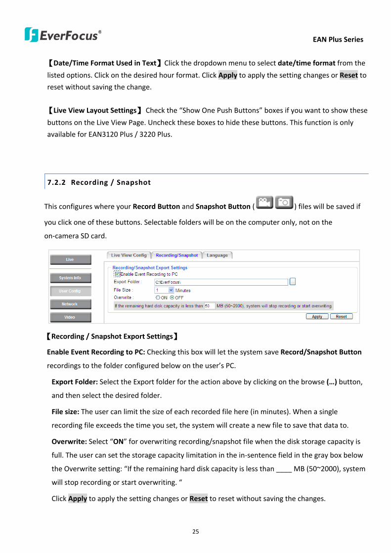
EAN Plus Series
25
【DateTime Format Used in Text】Click the dropdown menu to select datetime format from the
listed options Click on the desired hour format Click Apply to apply the setting changes or Reset to
reset without saving the change
【Live View Layout Settings】 Check the ldquoShow One Push Buttonsrdquo boxes if you want to show these
buttons on the Live View Page Uncheck these boxes to hide these buttons This function is only
available for EAN3120 Plus 3220 Plus
722 Recording Snapshot
This configures where your Record Button and Snapshot Button ( ) files will be saved if
you click one of these buttons Selectable folders will be on the computer only not on the
on-camera SD card
【Recording Snapshot Export Settings】
Enable Event Recording to PC Checking this box will let the system save RecordSnapshot Button
recordings to the folder configured below on the userrsquos PC
Export Folder Select the Export folder for the action above by clicking on the browse (hellip) button
and then select the desired folder
File size The user can limit the size of each recorded file here (in minutes) When a single
recording file exceeds the time you set the system will create a new file to save that data to
Overwrite Select ldquoONrdquo for overwriting recordingsnapshot file when the disk storage capacity is
full The user can set the storage capacity limitation in the in-sentence field in the gray box below
the Overwrite setting ldquoIf the remaining hard disk capacity is less than ____ MB (50~2000) system
will stop recording or start overwriting ldquo
Click Apply to apply the setting changes or Reset to reset without saving the changes
EAN Plus Series
26
723 Language
Select the language to be displayed on the Web interface of the IP camera The default language is
English
To add a new language not listed in the current Language list click the Browse button to locate
the new language file (evb) on your computer and then click the Upload button Updated
language files might be available on the manufacturerrsquos website Contact your vendor if required
Click Apply to apply any changes or Reset to reset without saving the changes
Note Uploading a new language file will cause the system to reboot automatically Please create
a new network connection to the IP camera when the reboot is complete
EAN Plus Series
27
73 Network
This page covers network-related settings including Network DDNS SMTPFTP HTTPS SNMP and
Network Alarm
731 Network
The following information is required to configure the network settings Contact your network
administrator or your internet service provider to get the info
【IP Settings】
IP Type Refer to the network administrator for these settings of the server Default DHCP
DHCP This setting lets the system use an automatically assigned (dynamic) IP address This
address can change under certain circumstances For instance when the camerarsquos network
switchhub has to be rebooted Do not assign to the DHCP server the same IP addresses used
for the other network cameras and PCs with unique IP addresses
Static IP The user can manually set the Static IP address This type of address is stable and
cannot change but the user has to make sure there are no address conflicts with other
network-connected devices
PPPoE This is a DSL-connection application The ISP will ask the user to input a username and
password Contact your ISP for these details
EAN Plus Series
28
Note If PPPoE is selected as the IP type the supplied IP Utility program will not be able to
detect the device
IP address When DHCP is not used the user needs to manually enter the IP address of the
camera Do not enter an IP address that is already used for your computer or other network
cameras
Subnet Mask This field is used to set the netmask for your network so that the IP camera will be
recognized within the network Example 2552552550 When DHCP is selected the DHCP server
will assign this value automatically
Gateway This field is used to set the gateway for your network so that the IP camera will be
recognized within the network When DHCP is selected the DHCP server will assign this value
automatically
Primary DNS Enter the IP address of the DNS server if this is provided by an ISP
Secondary DNS If your ISP provided you with a secondary DNS address please enter it here
Username Enter the accountrsquos username (used only for PPPoE)
Password Used only for PPPoE
IPv6 Enter the IPv6 details in this area if this applies to your system
Click Apply to apply the setting changes or Reset to reset without saving the change
【Port Settings】Enter the HTTP HTTPS and RTSP port numbers and click Apply to save
【Multicast Settings】Enable if required fill in the setting options and click Apply to save
EAN Plus Series
29
732 DDNS
DDNS (Dynamic Domain Name System) is a service used to map a domain name to the dynamic IP
address of a network device You can set up the DDNS service for remote access to the IP camera
DDNS assigns a domain name (URL) to the IP camera so that the user does not need to go through
the trouble of checking if the IP address assigned by DHCP Server has changed Once the IP is
changed the IP camera will automatically update the information to the DDNS to ensure it is always
available for remote access
Before enabling the following DDNS function user should have applied for a host name from the
DDS service providerrsquos website We support these four DDNS server providers
wwweverfocusddnscom wwwsitelutionscom wwwdyndnscom and wwwno-ipcom
Note We highly recommend that you use xxxxeverfocusddnscom for the simplicity of setting up
your IP cameras
【DDNS Settings】
Enable Check this box to enable the DDNS function
Service ISP You can either apply for a host name from EverFocus or other DDNS server providers
If you choose the EverFocus DDNS server you can obtain a free host name from EverFocus by
following the steps below
bull From EverFocus To obtain a free host name from EverFocus type a desired host name in the
textbox click the Register Update button and then click the Apply button
bull From other DDNS server providers To obtain a domain name from one of the three DDNS
server providers you have to register your name with the provider first and then select the
provider and fill in the required information Please refer to the specific DDNS companyrsquos
website for further information
Record ID Type the record ID if provided by the DDNS server provider
EAN Plus Series
30
FQDN Type the fully qualified domain name applied from the DDNS server provider For
example xxxxdyndnscom
Username Password Type the login account of your DDNS server provider
Click Apply to apply the setting changes or Reset to reset without saving the changes
Note
1 In order to support the full functionality of the camera you must open the port numbers (80
554 443) on the router for remote access to the IP camera This function is available on most
routers in the market and is often known as ldquoPort Forwardingrdquo To set up Port Forwarding
please consult the manual of the router
2 In certain router models it is possible that you will not be able to access the camera using
DDNS while inside the routerrsquos network Please try using a PC located outside of your routerrsquos
network
Default Ports on All EverFocus IP Cameras
HTTP 80
RTSP 554
HTTPS 443
EAN Plus Series
31
733 SMTP FTP
【Set SMTP Server (email)】This area is for configuring the mail server that is used to send e-mail
notifications from the camera to predefined addresses via SMTP Note that to enable e-mail
notification function you have to check the Send Mail Notification item on the Event dialog box
(see 771 Event Settings)
SMTP Server Enter the IP address or the host name of the SMTP server used to send e-mails
SMTP Port Enter the port number for SMTP The default is 25
Authentication Check this box if the SMTP server requires authentication (userpassword)
User name Input the userrsquos login ID if the SMTP server requires authentication
Password Input the userrsquos login password if the SMTP server requires authentication
EAN Plus Series
32
Receiver Address Input the e-mail addresses for receiving an e-mail message when an EVENT is
enabled and triggered Please use ldquordquo to separate multiple addresses
Sender Address Input the senderrsquos e-mail address so that the receiver can recognize the sender
when an Event message is received
Attach Image Check this box if you want to attach an image when an alarm is triggered or an IP
camera detects events
Send Test Email Click the Test button to send a testing email to the assigned address
Click Apply to apply the setting changes or Reset to reset without saving the changes
【Set FTP Server】The settings relating to the FTP server used to transmit the alarm images can be
configured here Note that to enable uploading images to the FTP server function you have to
check the Upload to FTP item on the Event dialog box (see 771 Event Settings)
FTP Server Enter the IP address or the host name of the FTP server
FTP Port Enter the port number for the FTP server Default is 21
Recording Path Assign the recording path
User Name Set FTP Userrsquos name
Password Set FTP password
PASV mode Check to enable Passive mode Passive mode is normally enabled If a connection
cannot be established uncheck PASV Moderdquo
Test FTP Server Click the Test button to send a testing file to the assigned FTP server
Click Apply to apply the setting changes or Reset to reset without saving the changes
EAN Plus Series
33
734 HTTPS
Hypertext Transfer Protocol Secure (HTTPS) is a combination of the Hypertext Transfer Protocol
and the SSLTLS protocol and provides encrypted communication and secure identification of a
network web server
Before using the HTTPS function for communication with the IP camera a Certificate must be
created first There are two ways to create and install a certificate Create Self-Signed Certificate
and Create Certificate Request
Create Self-Signed Certificate
Please note that even though self-signed certificates are free and offer some protection true
security is only implemented after the installation of a signed certificate issued by a certificate
authority
1 Click the Create Self-Signed Certificate button the following dialog appears
EAN Plus Series
34
2 Type the required Certificate information and then click the Apply button The subject line will
be displayed in the Installed Certificate Information field
3 Click the Property button a pop-up window appears to display the details of the certificate
4 To optionally create and install other certificates remove the existing one by clicking the
Remove button to erase the certificate
5 On the Web page change the address from ldquohttprdquo to https in the address bar and press
Enter on the keyboard Some Security Alert dialogs will pop up Click OK or Yes to enable HTTPS
Create Certificate Request
You can apply for an official certificate from an issuing Certificate Authority
1 Click the Create Certificate Request button the following dialog appears
EAN Plus Series
35
2 Type the required Certificate information and then click the Apply button The subject line will
be displayed in the Created Request field
3 Click the Property button a pop-up window appears to display the details of the certificate
4 To optionally create and install other certificates or request remove the existing one by clicking
the Remove button to erase the certificate or request
5 Copy the contents of the Certificate request (in PEM format) and paste it to the certificate
request field on the Web page of the 3rd-party certification authority such as Symantec VeriSign
Wait for the certificate authority to issue an SSLTLS certificate and then download the issued
certificate on your computer
6 In the Install Signed Certificate field click the Browse button to search for the issued certificate
and then click the Upload button to import the certificate Once the certificate has been
uploaded this field will show the subject line of the certificate
EAN Plus Series
36
735 SNMP
The default values for SNMP v1v2v2c and SNMP v3 are already filled in Click either of the
Enable buttons to enable either of the two Make your changes as desired Click on the Trap
Address field to enter the digits if required
736 Network Alarm
This function works with EverFocusrsquos CMS software eg the PowerCon or the Power Video Plus For
the setting details please refer to the CMS network alarm protocol
EAN Plus Series
37
74 Video
The settings relating to video such as streaming camera OSD can be configured on this page The
Video page has five tabs Multi-streaming Camera Advanced ROI and Privacy Mask
741 Multi Streaming
【Stream Settings】 This IP camera can output three video streams simultaneously For each of these
streams the user can set the compression format resolution bit rate and frame rate individually
Stream 1 is always enabled for live view To enable Stream 2 andor Stream 3 check the ldquoEnablerdquo
box the header of each stream
Note If you connect to the camera via the Internet and experience a delay (lag time) in the video
feed try to reduce the number of streams and the quality and resolution of the streams ndash but
keep the frame rate at its maximum
EAN Plus Series
38
Format Select the encoding format ndash H264 or MJPEG
Resolution Select the most suitable resolution for your needs
Frame Rate Select from 1 to 30 fps
Bit Rate If required select whether you want the stream to stream a Constant Bit Rate or a
Variable Bit Rate and set the values of whichever option you choose
Click Apply to apply the setting changes or Reset to reset without saving the changes
【Video Recording Settings】Select the stream you want to configure and then select whether you
want the recording files of that stream to be saved in AVI or ARV format Click Apply to apply the
setting changes or Reset to reset without saving the changes
【Time Stamp Settings】 You can select the DateTime format position and add the setting to the
streaming
Click Apply to apply the changes or Reset to reset without saving the changes
EAN Plus Series
39
742 Camera
【Image Settings】Set the Brightness Saturation Contrast or Sharpness of the image Click Apply to
apply the changes or Reset to reset without saving the changes
【Camera Settings】
Mirror Switch Mirror ON to rotate the image horizontally around a vertical axis
Flip Switch Flip ON to rotate the image vertically around a horizontal axis
AE There are two options
ALC Selecting Automatic Light Control allows the camera circuitry to either take bright spots
more into consideration (peak) bringing out detail in bright areas or less into consideration
(average) bringing out detail in shadows
AES Selecting Auto Electronic Shutter disables the Shutter setting below this setting In this
mode the camera measures the light level and decides whether it needs more or less light and
then automatically adjusts the shutter speed accordingly
BLC Back Light Compensation (BLC) is used to make the subject appear clearer when it is set
against a bright background
OFF Select to switch Back Light Compensation functions off
(ON)BLC The BLC can increase the exposure of a dark area surrounded by a brighter area HLC
can decrease the exposure of bright areas surrounded by darker areas This enables the
camera to better display information that would otherwise have been ldquowhited outrdquo like a
license plate between two bright headlights on a dark road
(ON)HLC The Highlight-Suppression BLC is used to reduce the brightness of light sources in a
specific area It is activated only in a low illumination environment to minimize the effects of
glare from bright lights such as spotlights street lights or headlights in the field of view
EAN Plus Series
40
WDR The Wide Dynamic Range (WDR) function provides clearer images when both of the very
bright and dark areas simultaneously appear on the camera view There are four value options
OFF Low Middle and High Note that when WDR is ON some parts of the image may appear
solarized This is normal for WDR and is not a camera malfunction This function is only available
for EAN3120 Plus 3220 Plus
DN Mode
Auto Select to let the camera automatically switch to Night mode (black and white) when the
light levels fall to a specified level and back to Day mode (color) when the light levels rise to a
specified level
Day Select to keep the camera in Day mode (color) even in nighttime
Night Select to keep the camera in Night mode (black and white) even in daytime
EAN Plus Series
41
743 Advanced
EAN Plus Series
42
【Camera Settings】
Lens (IRIS Control) Select DC or Manual for IRIS control This function is only available for EAN3220
Plus
Exposure Settings (AE) This setting is used to adapt to the amount or type of light used by the
camera Note the settings vary among models
Mode This function is not available for EAN3220 Plus
Automatic Light Control (ALC) This option is only available for EAN3120 Plus 3300 Plus The
ALC allows the camera circuitry to either take bright spots more into consideration (peak)
bringing out detail in bright areas or less into consideration (average) bringing out detail in
shadows
Auto Electronic Shutter (AES) This option is only available for EAN3120 Plus 3300 Plus In
this mode the camera measures the light level and decides whether it needs more or less light
and then automatically adjusts the shutter speed accordingly
Manual This option is only available for EAN3300 Plus Select this option to manually set up
the Shutter (Manual) and AGC (Manual) values
Iris Specify the size of the Iris opening here
Shutter If enabled this setting lets you set the shutter speed yourself
Shutter Limit Use this setting to set the maximum shutter speed for the camera This function is
only available for EAN3120 Plus
AGC Set the Auto Gain Control limit here The lower the AGC level the lower the video signal and
the noise However the image will be darker under low-light condition with IR-off if you set up the
Iris to the maximum level
Slow Shutter This option can be switched on when AES Mode is selected in the Exposure Settings
(AE) field This function is only available for EAN3220 Plus 3300 Plus
Flickerless If the Mode field in the Exposure Settings (AE) area has been set to AES then this option
becomes available Choose between OFF 50HZ 60HZ 50HZ (High Luminance) or 60HZ (High
Luminance) This function is only available for EAN3300 Plus
EV Setting Set up the Exposure Value Note the brightness of the screen changes when you change
the EV value This function is only available for EAN3300 Plus
AE Response Set up Auto Exposure Response time This function is only available for EAN3300 Plus
AE Weighting Area Select an AE Weighting area Each setup AE Weighting Area is configured with
the appropriate brightness level on the center and the surrounding areas This function is only
available for EAN3300 Plus
Brightness Set the image brightness here
AE Reference Set the Auto Exposure value here This function is only available for EAN3120 Plus
EAN Plus Series
43
Black Level Set the Black level here This function is only available for EAN3300 Plus
WDR The Wide Dynamic Range (WDR) function provides clearer images when both of the very
bright and dark areas simultaneously appear on the camera view There are four value options OFF
Low Middle and High Note that when WDR is ON some parts of the image may appear solarized
This is normal for WDR and is not a camera malfunction This function is only available for EAN3120
Plus 3220 Plus
Visibility Enhancement (OFFLowMiddleHigh) Images in foggy or rain environments or in
environments with a very strong luminous intensity have a dynamic range that is significantly lower
than ordinary images The user can use this Visibility Enhancement setting to ldquoDEFOGrdquo the image if
such ldquoFOGGINGrdquo is an issue This function is only available for EAN3220 Plus
BLC Settings Back Light Compensation (BLC) is used to make the subject appear clearer when it is
set against a bright background
OFF Select to switch Back Light Compensation functions off
Back Light This option is only available for EAN3300 Plus The Back Light function is useful
when the background of the subject is very bright and the subject itself is dark Select Back
Light and adjust the slide bar to the left right for setting up the back light value The higher
the value the more the backlight compensation
Front Light This option is only available for EAN3300 Plus This function is useful when the
bright highlights such as flashlight or car headlights appear on the camera view Select Front
Light and adjust the slide bar to the left right for setting up the front light value The higher
the value the more the highlight compensation
ON (BLC) This option is only available when you select AES Mode in the Exposure Settings (AE)
field The option is only available for EAN3120 Plus 3220 Plus The BLC function is useful
when the background of the subject is very bright and the subject itself is dark Follow the
instructions below to configure the settings for each model
For EAN3120 Select ON (BLC) the button next to the Mode drop-down list will be
active (see image below) Click the button the green setup areas appear on the left
screen Click on the areas to enable disable the BLC function The selected areas (in green)
will be applied with the BLC function
EAN Plus Series
44
For EAN3220
You can configure one area to apply the BLC function Select ON (BLC) the setup buttons
appears (see image below) Select Low Middle High from the BLC Gain drop-down list To
set up a BLC area click the Edit Area button and then click on the blue color tab to turn your
mouse cursor into a blue pen Move the cursor to the position on the right screen where you
want the BLC rectangle to start and then click Move your cursor to the position (diagonally
opposing corner) where you want the BLC rectangle to end and then click The blue area will
be applied with the BLC function
ON (HLC) This option is only available when you select AES Mode in the Exposure Settings (AE)
field The option is only available for EAN3120 Plus 3220 Plus This function is useful when
the bright highlights such as flashlight or car headlights appear on the camera view Follow
the instructions below to configure the settings for each model
For EAN3120 Select ON (HLC) and then select a level from the drop-down list The higher the
level the more the highlight compensation
For EAN3220
HLC Level Select a level for the HLC setting The higher the level the more the highlight
compensation
HLC Mode Select All Day Night mode to apply the HLC function
HLC Black Mask Select On Off to apply the black mask on the selected areas The
over-exposure portions within the selected areas will be applied with the black mask
Color Tabs You can set up four HLC areas with different colors To set up a HLC area click the
Edit Area button and then click on the color tab to turn your mouse cursor into a pen of that
color Move the cursor to the position on the right screen where you want the HLC rectangle
to start and then click Move your cursor to the position (diagonally opposing corner) where
you want the HLC rectangle to end and then click Select ON from the color tab drop-down list
The rectangular area with the selected color will be applied with the HLC function
EAN Plus Series
45
Back Light This option is only available for EAN3300 Plus The Back Light function is useful
when the background of the subject is very bright and the subject itself is dark Select Back
Light and adjust the slide bar to the left right for setting up the back light value The higher
the value the more the backlight compensation
Front Light This option is only available for EAN3300 Plus This function is useful when the
bright highlights such as flashlight or car headlights appear on the camera view Select Front
Light and adjust the slide bar to the left right for setting up the front light value The higher
the value the more the highlight compensation
Noise Reduction Settings This limits the amount of digital ldquovideo noiserdquo that is usually found in any
video stream and helps to reduce file size The higher the level the more the reduction
For EAN3120 Plus 3300 Plus
Select ON OFF to enable disable the Noise Reduction function Or select Auto to let the camera
automatically enable disable the Noise Reduction function Slide the Level bar to set up the level
The higher the level the more the reduction
For EAN3220 Plus
2D DNR Select ON to enable the 2D DNR function
3D DNR Select ON to enable the 3D DNR function You can further set up the following settings
3D Start AGC Set up the AGC level to automatically start the 3D NR function
3D End AGC Set up the AGC level to automatically stop the 3D NR function
3D Level Set up the 3D DNR level
Smart NR Select ON to enable the Smart NR function The 3D NR function will be
automatically turned on when a motion event occurs
EAN Plus Series
46
White Balance Settings Select the mode that delivers the best quality image for the camerarsquos light
environment There are five options Auto Manual Indoor Outdoor One Push
Auto Select to let the camera automatically adjust the White Balance In the Auto mode the
camera computes the white balance value output using color information from the entire
screen It outputs the proper value using the color temperature radiating from a black subject
based on a range of value from 3000 to 7500K
Manual Select to adjust the Red and Blue values yourself in the fields below this field
Indoor Select to use the default settings for indoor environments In the Indoor mode the
camera uses 3200K as the base value
Outdoor Select to use the default settings for outdoor environment In the Outdoor mode it
uses 5800K as the base value
One Push Select to enable the Push button next to the Mode drop-down field This will allow you to force the camera to readjust the white balance every time you push the Push
button The lens will hold the same focal position until the next trigger command is received
This function helps to prevent incorrect focusing in dark environments This function is only
available for EAN3120 Plus 3220 Plus
Manual Temperature Select to use the optimized Red and Blue settings You can also
optionally adjust the Manual Level below this field for setting up the color temperature The
higher the value the more the color temperature This function is only available for EAN3300
Plus
DayNight Settings
Auto Select to let the camera automatically switch to Night mode (black and white) when the
light levels fall to a specified level and back to Day mode (color) when the light levels rise to a
specified level
Day Select to keep the camera in Day mode (color) even in nighttime
Night Select to keep the camera in Night mode (black and white) even in daytime
IR Smart Settings Select ON and set up the level to enhance the image quality when the images are
over exposure This function is useful when the camera is in the Night mode This function is only
available for EAN3220 Plus
Saturation Set the saturation value This function is not available for EAN3220 Plus
Monitor Type Select a gamma value from Set 1 Set 2 or Set 3 This function is only available for
EAN3120 Plus
Negative Switch this setting ON to view a color negative version of the video image This is useful
at night or when viewing temperature-sensitive images
EAN Plus Series
47
Sharpness Settings Select the sharpness level of the image A low sharpness level will deliver a
softer less detailed image A high level will deliver a sharp highly detailed image Switch Resolution
Enhancement ON to enable the resolution enhancement function
Contrast Select the contrast level of the image
Suppress Function This function is only available for EAN3300 Plus
Aperture Compensation Suppression (OFFLowMiddleHigh) This setting can be activated to
suppress luminance noise when the AGC level increases
Chroma Suppression (OFFLowMiddleHigh) This setting can be activated to suppress
chrominance noise when the AGC level increases
Ygamma (gamma 22standardcontrast enhancehigh light range mode LHigh light range mode
H) Select the Ygamma value for the video quality of the monitor This function is only available for
EAN3300 Plus
Monitor Settings The user can use this field to optimize video quality for his or her specific type of
monitor ndash LCD or CRT This function is only available for EAN3220 Plus
Color Space Standard The options are YUV601 for SD and YUV709 for HD These define the color
space standard required to convert an RGB picture to a YUV picture Generally YUV601 is used for
Standard Definition (720P) devices and the YUV709 is used for High Definition (1080P) devices
Click Apply to save all changes Click Reset to cancel all changes
EAN Plus Series
48
744 ROI (Region of Interest)
The Region of Interest (ROI) function allows users to set up multiple regions within an image with
better quality and less distortion than the rest of the image You can also use this function
together with the Digital Zoom function on the Live View Page to get a better image result Up to
eight ROIs can be configured in the ROI settings page
To set up an ROI region
1 Select an ROI number from the ROI No drop-down list
2 Click the Add button the mouse cursor will turn into a pen when you move it over the live
image on the left
3 Move the cursor to the position where you want the ROI rectangle to start and then click
Move the cursor to the position (diagonally opposing corner) where you want the ROI
rectangle to end and then click
4 Slide the Quality bar to set up the quality value
5 Click the Apply button to apply the settings or click the Reset button to reset without saving
the settings
EAN Plus Series
49
745 Privacy Mask
The Privacy Mask can block out sensitive areas from view covering the areas with colored or black
and white boxes in both live view and recorded clips This feature is useful when usersrsquo donrsquot want
the sensitive information visible Up to four Privacy Masks can be configured
【Privacy Mask Color Settings】The Modes vary among camera models
Mode Click Color to make the masks appear as colored rectangles on the screen Click BW to
make the masks appear as gray rectangles on the screen Click Mosaic to make the masks appear
as mosaic-effect rectangles on the screen
Level Select the color of the masks if you selected Color Mode Select the level of grayness of the
masks if you selected BW Mode Select the level of smallmiddlelarge if you selected Mosaic
Mode
Click Apply to apply the settings or click Reset to reset without saving the settings
Color Tabs Click on a color tab to turn your mouse cursor into a pen of that color
You can now create a block of that color on the video screen Move your cursor to the position
where you want your mask rectangle to start and then click Move your cursor to the position
(diagonally opposing corner) where you want your mask rectangle to end and then click The
rectangular area with the selected color will appear The live image will display the rectangular
area with the color you selected If you want to create another mask use one of the other three
colors Each color denotes a different mask area Only one block per color is allowed As the
number of colors suggests you can configure up to four blocks
EAN Plus Series
50
Select All Click to turn the whole screen into a mask area
Clear All Click to delete all configured mask blocks
Eraser Click to turn the mouse cursor into an eraser to delete any block you click on
Area Shows the color and number of the block
Enable Check this box to enable the related mask block
Click Apply to apply the settings or click Reset to reset without saving the settings
EAN Plus Series
51
75 Audio
The EAN Plus series IP camera can transmit audio to your computer if you have connected an external
microphone to its audio Input cable It can also receive audio input from you and transmit it via an
external speaker if you have connected such a speaker to its audio Output cable
Check the Enable Audio box to enable the camerarsquos audio function The camera will now act as a
digital bridge (via the IP network) between any connected audio input device and any connected
audio device
Adjust the Audio Input Volume if you have external audio input devices (microphones) connected to
the camera and if there are problems with the sound input being too low or high
Click Apply to save all settings or click Reset to cancel
EAN Plus Series
52
76 User
761 User Information
The system administrator can create up to ten user accounts on this page
To set up a user account
1 Highlight a user account and click the Modify button The following dialog box appears
2 Type the account name account description and password for the account Type the password
again in the Confirm field
3 Select an authority level for the user account from the Authority drop-down list
bull Supervisor Administrator The only difference between a supervisor and administrator is
that a supervisor can edit an administratorrsquos account and password but an administrator
cannot edit the supervisorrsquos account and password Multiple administrators can be
configured but there can be only one supervisor The supervisor and administrators all
have unrestricted access to the Settings submenus and can determine the registration of
all other users
EAN Plus Series
53
bull User A user can view the Live View page and view the system network video and audio
information A user can only adjust the User Config page settings The user does not have
access to the User Event and System pages
bull Guest The lowest level of access which only allows the user access to the Live View page
4 Select Active or Disable from the Status drop-down list to active or disable the user account
5 Click On in the SD Card Playback field to allow the user to access the SD card playback
function
6 Click OK
7 Click Apply to save all the settings
EAN Plus Series
54
762 IP Address Filter
Use this page to specify IP addresses that are not allowed to access this camera By default any IP
address can access the camera
Note The Allowed List addresses only become relevant when the Denied List contains a network
or range and the supervisor wants to allow one or more IP addresses within that excluded range
or network In such a scenario the user would enter the excluded range or network in the
Denied List and enter the exceptions in the Allowed List
To set up the IP Address Filter
1 Select Denied List Click the Add button the following dialog box appears
2 Select an IP type from the IP Type drop-down list
3 Select a network rule from the Rule drop-down list type the IP address and click OK
Single Type a single IP address in the IP Address field below
Network Type the IP address and subnet mask in the field below
Range Type a range for the IP addresses
4 If you have set up an IP range in Step 3 you can optionally set up the Allowed List to allow one
or more IP addresses within the setup IP range to access the IP camera
5 Click Apply
EAN Plus Series
55
77 Event
You can set up the Motion Detection event Tamper Detection event or the Alarm IO to automatically
notify the users when an event occurs or an alarm is triggered You can also set up a schedule to
automatically record the videos when an event occurs or an alarm is triggered
771 Event Settings
You can create a total of ten event or alarm settings page in the Event List
【Event List】
Click the Add button and the following Event Configuration Window appears
EAN Plus Series
56
Enter Event Name Type an event name
Event Triggered by Select an event or alarm type for the to-be-specified-below reactions
Alarm Input Select this if you want a reaction trigger coming from any external connected sensor
to activate a to-be-specified-below reactions via the camera system Make sure that a suitable
device is actually connected to the alarm input relay
Manual Trigger Select this option if you want to manually trigger the alarm by clicking the Trigger
Event button on the Live View Page
Motion Detection Select this option if you want motion in a specified part of the camerarsquos viewing
rectangle (the screen image) to trigger the to-be-specified-below reactions
Tampering Detection Select this option if you want the camerarsquos tampering detection sensor to
trigger the to-be-specified-below reactions
Schedule Recording Select this option if you want the Schedule Recording periods configured in
the recording schedule (the Settings gt Event gt Schedule page) to activate this event In this
scenario a preconfigured event reaction like a log entry will list the start and end times of each
period Actual recording will only be triggered if the event is preconfigured to do so
Enable This Event Select to activate the event
Enable Re-trigger Click to set a minimum time after the event is triggered before the event
can be triggered again
Enable Pre-trigger Buffer Click if you want the Event reaction (as selected in the ldquoNotification
Overrdquo field below) to be the activation of the video recording function and if you want the
recording to include the video feed from the time period (configurable on the previous ldquoEvent
Settingsrdquo page) just before the Event trigger occurred
Enable Post-trigger Buffer Click if you want the Event reaction (as selected in the Notification
Over field) to be the activation of the video recording function and if you want the recording
to include the video feed from a time period (configurable on the Event Settings page) just
after the Event trigger occurred
Motion Area Select a setup motion detection area from the drop down list Note this
function only becomes relevant after the Motion Detection areas have been set up (see 772
Motion Detection)
Notification Over Select the desired notification types form the following items
Log Click if you want the camera to list the eventrsquos details in its log if the event is triggered
Trigger Alarm Output Click if you want the camera to relay the event reaction to a device
attached to the alarm relay output wire and then set up the alarm output duration time
EAN Plus Series
57
Send Mail Notification Click if you want the camera to send an Event notification email to the
email address entered in the Set SMTP Server(email) field of the Network gt SMTPFTP page if
the Event occurs (see 733 SMTP FTP)
Upload to FTP Click if you want the camera to upload recorded footage to the FTP server
entered in the Set SMTP Server(email) field of the Network gt SMTPFTP page if the Event
occurs (see 733 SMTP FTP)
Record to SD Card Click if you want the camera to start recording its video feed (when the
event occurs) on an on-camera SD Card (if such a card has been inserted)
Note The recording will only be as long as the combined Pre- and Post-trigger Buffers so
make sure you enable at least one of these buffers especially the Post-trigger Buffer
Record to PC Check this box if you want the camera to start recording its video feed (when
the event occurs) on the same folder on the same PC as configured on the User Config gt
RecordingSnapshot page (if such a folder has been enabled and configured)
Note The recording will only be as long as the combined Pre- and Post-trigger Buffers (and
for as long as the event trigger is happening ndash eg a motion is detected) so make sure you
enable at least one of these buffers especially the Post-trigger Buffer
Network Alarm Check this box if you want the camera to send a network alarm signal (when
the event occurs) to the CMS servers configured on the Network gt Network Alarm page (see
736 Network Alarm)
Click OK to save all settings or click Cancel to cancel
【PrePost Trigger Settings】
Pre-trigger Buffer Select the duration for the buffer This will determine the amount of footage
(length of time) before the event trigger moment that will be included in an event-triggered video
recording if that buffer and video recording has been enabled in the Event Configuration Window
Post-trigger Buffer Select the duration for the buffer This will determine the amount of footage
(length of time) after the event trigger moment that will be included in an event-triggered video
recording if that buffer and video recording has been enabled in the Event Configuration Window
Click Apply to save all settings or click Reset to cancel
EAN Plus Series
58
772 Motion Detection
Use this page to configure up to four areas in which motion will be detected When a motion is
detected by the camera the motion detection icon will appear at the top right of the
Live page to alert the user This function can also be linked with correctly configured Events to
trigger Event reactions like the activation of video recording periods snapshots alarms etc
Color Tabs Click on a color tab to turn your mouse cursor into a pen of that color
You can now create a block of that color on the video screen Move your cursor to the position
where you want your detection rectangle to start and then click Move your cursor to the position
(diagonally opposing corner) where you want your detection rectangle to end and then click The
rectangular area with the selected color will appear This block will be an area inside which the
camera will detect motion If you want to create another detection area use one of the other three
palette colors Each color denotes a different detection area Only one block per color is allowed As
the number of colors suggests you can configure up to four blocks
Select All Click to turn the whole screen into a motion detection area
Clear All Click to delete all configured motion detection blocks
Eraser Click to turn your mouse cursor into an eraser to delete any block you click on
Area Shows the color and numberID of the block
Enable Check this box to enable the related motion detection block
Sensitivity Set the sensitivity of the motion detection sensor function
Click Apply to save all settings or click Reset to cancel
EAN Plus Series
59
773 Tamper Detection
Use this page to set the number of seconds that an alarm signal will be active if the device is
physically tampered (moved covered up or out of focus
774 Alarm IO
Use this page to set the type of trigger input and the type of output contact for the camerarsquos alarm
channel
EAN Plus Series
60
775 Schedule
Use this page to configure a schedule for periods during which the camera should deactivate all
user-activated Events (gray Deselect periods) or when the camera should deactivate all
user-activated Events except Schedule Recording (SR) events (blue Schedule Recording-only
periods) or when the camera should deactivate only SR events (red Event Recording-only periods)
or when it should enable all activated Events (yellow periods)
Event Recording Click this button to make every hour block you click on red A red block represents
an Event Recording-only block which represents an hour when the camera will deactivate all
preconfigured activated Schedule Recording events and keep all the other activated events active
Schedule Recording Click this button to make every hour block you click on blue A blue block
represents a Schedule Recording-only block which represents an hour when the camera will
deactivate all other preconfigured activated events and keep only the preconfigured activated
Schedule Recording events active
Event + Schedule Click this button to make every hour block you click on yellow A yellow block
represents an hour in which all activated events including Schedule Recording events will be
active
Deselect Click this button to make every hour block become grey A grey block represents an hour
in which all activated events including Schedule Recording events will be inactive
Click Apply to save all settings or click Reset to cancel
EAN Plus Series
61
78 System
You can set up the systemrsquos time and SD card settings and to do maintenance and reset actions like
reboots and upgrades
781 DateTime
【Machine Name Settings】If required enter a new name for the machine This name will be visible
in the Machine Name field of the IP Utility software which is included in the software CD
【Set Time Zone】Set the time zone of the camerarsquos location
【Set DateTime Manually】Set the datetime here if you wonrsquot be using an NTP server to update the
datetime (see below)
【Set DateTime Sync】Enter the Network Time Protocol server if applicable The camerarsquos time will
be automatically adjusted by synchronizing with the NTP server
Click Apply to save all settings or click Reset to cancel
EAN Plus Series
62
782 Daylight Saving
Click Enable Daylight Saving to enable this schedule and select the dates when the regionrsquos
daylight saving period begins and ends Click Apply to save all settings or click Reset to cancel
783 SD Card
Use this page to prepare the system for safely removing the SD Card from its slot
【Setup SD Card】
Notification Select the percentage of storage space that should be left on the card before the
camera notifies you of the impending storage shortage or overwrite
Event Recording Select if you want Event Recording only FTP Backup only or both
Overwrite Click ON if you want the card to start writing over recorded footage when its memory is
full Click OFF if you want the card to stop recording new footage when its memory is full
【SD Card Utility】
Capacity This shows you how much card memory has been used and how much memory capacity
remains on the card
Remove Click this button before removing the card from the system
Format Click this button to format the card All data saved on the SD card will be removed if the
card is formatted
EAN Plus Series
63
784 Maintenance
【Maintenance Server】
Reboot Click this button to reboot the unit without changing any of the settings Use this function if
the unit is not behaving as expected
Restore Click this button to restart and reset most of the current settings to their factory default
values The only settings that will not be changed to default are
bull IP settings
bull DDNS settings
Default The Default button should be used with caution Pressing this button will return all of the
cameras settings including the IP address to the factory default values The camera will then have
to be reconfigured
【SaveLoad Configuration Server】
Save To make a backup file of the machinersquos current configurations press Save to save all the
configurations to a config file This will enable the user to reload these configuration settings if the
settings are changed and there is unexpected behavior
Load To load a previously saved configuration press the Browse button to locate the saved config
file (see above) and then click the Load button The systemrsquos settings will be restored to the saved
configuration
EAN Plus Series
64
【SaveLoad Video Configuration Server】
Save To make a backup file of the machinersquos video configurations press Save to save the video
configurations to a config file This will enable the user to reload these configuration settings if the
settings are changed and there is unexpected behavior
Load To load a previously saved video configuration press the Browse button to locate the saved
config file (see above) and then click the Load button The systemrsquos settings will be restored to the
saved video configuration
【Upgrade Firmware】Click the Browse button to find a previously prepared firmware upgrade file
Click Upgrade to install the new firmware
Note
1 Do not disconnect power to the unit during the upgrade sequence The unit will reboot
automatically after the upgrade has completed (1-5 minutes)
2 During the upgrade process all event recording actions will be stopped Event recording
actions will resume after the camera is rebooted
3 If the ldquoFile Error Please re-loginrdquo warning message appears when upgrading the firmware
please try the following instructions
a Go to Internet Explorer gt Tools gt Internet Option gt Security gt Custom
b Find and enable the Include local directory path when uploading files to a server
EAN Plus Series
65
8 Upgrading Firmware Using IP Utility
You can upgrade the Firmware using the IP Utility software included in the software CD
1 Install and then start the IPU program The following dialog box appears
2 Click Find Devices to search the cameras connected in the LAN The default network values of the
cameras will be displayed By default the network protocol of the camera is DHCP
3 Select a camera and click LoginMulti Login to log in the camera
4 Type the user ID and password Click OK
Note
1 The default user ID is user1 and the default password is 11111111
2 If you select more than one camera that has the same user ID password you will be able
to log in several cameras at once
EAN Plus Series
66
5 Highlight the camera and then click Upgrade Firmware A browsing window appears
6 Select the firmware file (evb) and then click Open The IP Utility will automatically upgrade the
firmware
The camera will reboot once the update is complete Click Find Devices the new firmware version
should be displayed in the last part of the Machine Name
EAN Plus Series
67
9 Specifications
Model EAN3120 Plus EAN3220 Plus EAN3300 Plus
Camera
Image Sensor 13 Panasonic CMOS 128 Sony CMOS
Megapixel 13 MP 2 MP 3 MP
Picture Elements (H x V) 1280 x 1024 1944 x 1092 2048 x 1536
Min Illuminations 003 Lux at F14
Electronic Shutter (Sec) 85 ~ 160000 2 ~ 150000 1 ~ 110000
Scanning System NTSC PAL
WDR Yes Yes No
BLC Yes
Gain Control Yes
White Balance Yes
Lens
Mounting Type C CS
Day Night Yes (with removable auto IR-cut filter)
IRIS Control DC Electrical IRIS Lens IRIS
Video
Video Compression H264 MJPEG
Resolution
NTSC
2048 x 1536 1920 x 1200 (for EAN3300 Plus only)
1920 x 1080 (for EAN3300 Plus 3220 Plus only)
1280 x 1024 1280 x 720 1024 x 768 720 x 480 704 x 480 640 x 480
352 x 240 320 x 240 160 x 120
PAL
2048 x 1536 1920 x 1200 (for EAN3300 Plus only)
1920 x 1080 (for EAN3300 Plus 3220 Plus only)
1280 x 1024 1280 x 720 1024 x 768 720 x 576 704 x 576 640 x 480
352 x 288 320 x 240 160 x 120
Frame Rate 30 fps at 1280 x 1024 30 fps at 1920 x 1080 15 fps at 2048 x 1536
Audio
Audio Streaming Two-way audio
Audio Compression G711
EAN Plus Series
68
Network
Interface 10 100 Base-T Ethernet RJ-45 socket
Supported Protocols
TCPIP IPV6 UDP ICMP DHCP NTP DNS DDNS SMTP SNMP FTP
HTTP HTTPs PPPoE UPnP Bonjour RTP RTSP RTCP IGMP ARP ONVIF
PSIA
Connector
Power DC female port PoE
Ethernet RJ-45
Audio 1 In (phone jack for microphone)
1 Out (phone jack for Speaker)
Alarm IO Terminal IO wires
Local Storage Micro SD SDHC memory card slot
TV-Out BNC socket composite 1 V p-p 75 Ω
General
Power Source DC 12V PoE (IEEE8023af)
Power Consumption
(IR LEDs On)
5W (DC 12V)
621W (PoE)
5W (DC 12V)
522W (PoE)
5W (DC 12V)
536W (PoE)
Operating Temperature 0degC ~ +50degC 32degF ~ +122degF
Humidity 20 to 80 (no condensation)
Safety CE FCC
Dimensions (L x W x H) 117 x 56 x 68 mm 46 x 22 x 27 in
Weight 410 g 09 lb
EverFocus Electronics Corp EverFocus Taiwan 12F No79 Sec 1 Shin-Tai Wu Road Hsi-Chih Taipei Taiwan TEL +886 2 2698 2334 FAX +886 2 2698 2380 wwweverfocuscomtw marketingeverfocuscomtw
EverFocus Europe - Germany Albert-Einstein-Strasse 1 D-46446 Emmerich Germany TEL +49 2822 93940 FAX +49 2822 939495 wwweverfocusde infoeverfocusde
EverFocus China - Beijing Room 609 Technology Trade Building Shangdi Information Industry Base Haidian District Beijing 100085 China TEL +86 10 6297 3336~39 FAX +86 10 6297 1423 wwweverfocuscomcn marketingeverfocuscomcn
EverFocus China - Shenzhen 4F No 2 D4 Building Wan Yelong Industrial Park Tangtou Road Shiyan Baoan Shenzhen Guangdong 518101 China TEL +86 755 2765 1313 FAX +86 755 2765 0337 wwweverfocuscomcn marketingeverfocuscomcn
EverFocus USA - California 1801 Highland Avenue Unit A Duarte CA 91010 USA TEL +1 626 844 8888 FAX +1 626 844 8838 wwweverfocuscom saleseverfocuscom
EverFocus USA - New York 415 Oser Avenue Unit S Hauppauge NY 11788 USA TEL +1 631 436 5070 FAX +1 631 436 5027 wwweverfocuscom saleseverfocuscom
EverFocus Japan 5F Kinshicho City Building 2-13-4 Koto-BashiSumida-Ku Tokyo 130-0022 Japan TEL +81 3 5625 8188 FAX +81 3 5625 8189 wwweverfocuscojp infoeverfocuscojp
EverFocus Europe - UK Unit 12 Spitfire Business Park Hawker Road Croydon Surrey CR0 4WD UK TEL +44 20 8649 9757 +44 845 430 9999 FAX +44 20 8649 9907 wwweverfocusukcouk salesukeverfocuscom
EverFocus India Suite 803 Housefin Bhavan C-21 Bandra Kurla Complex Bandra (East) Mumbai 400051 India TEL +91 22 6128 8700 FAX +91 22 6128 8705 wwweverfocusin saleseverfocusin
PN 4605PQ3120B010A-VerC
Your EverFocus product is designed and manufactured with high quality materials and components which can be recycled and reused This symbol means that electrical and electronic equipment at their end-of-life should be disposed of separately from your household waste Please dispose of this equipment at your local community waste collectionrecycling centre In the European Union there are separate collection systems for used electrical and electronic product Please help us to conserve the environment we live in
Ihr EverFocus Produkt wurde entwickelt und hergestellt mit qualitativ hochwertigen Materialien und Komponenten die recycelt und wieder verwendet werden koumlnnen Dieses Symbol bedeutet dass elektrische und elektronische Geraumlte am Ende ihrer Nutzungsdauer vom Hausmuumlll getrennt entsorgt werden sollen Bitte entsorgen Sie dieses Geraumlt bei Ihrer oumlrtlichen kommunalen Sammelstelle oder im Recycling Centre Helfen Sie uns bitte die Umwelt zu erhalten in der wir leben
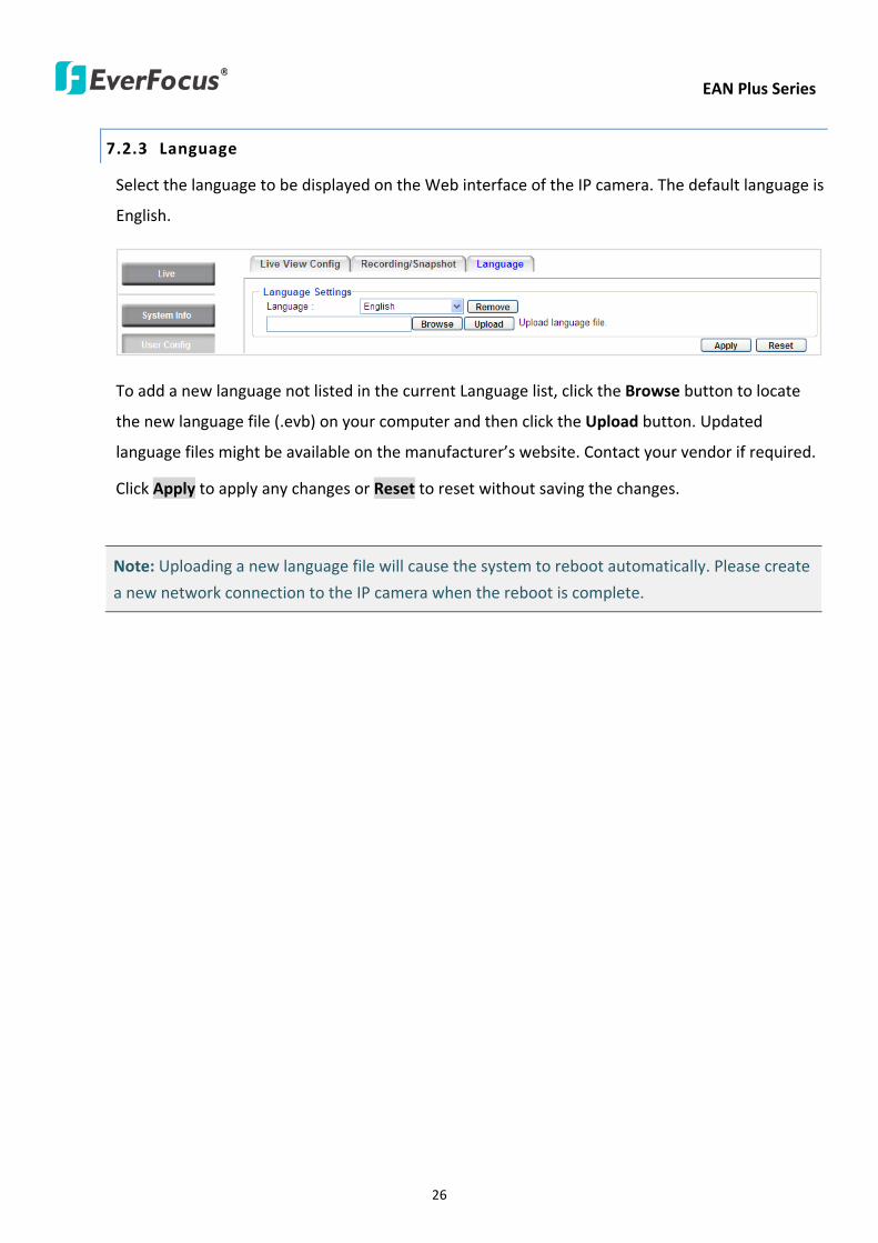
EAN Plus Series
26
723 Language
Select the language to be displayed on the Web interface of the IP camera The default language is
English
To add a new language not listed in the current Language list click the Browse button to locate
the new language file (evb) on your computer and then click the Upload button Updated
language files might be available on the manufacturerrsquos website Contact your vendor if required
Click Apply to apply any changes or Reset to reset without saving the changes
Note Uploading a new language file will cause the system to reboot automatically Please create
a new network connection to the IP camera when the reboot is complete
EAN Plus Series
27
73 Network
This page covers network-related settings including Network DDNS SMTPFTP HTTPS SNMP and
Network Alarm
731 Network
The following information is required to configure the network settings Contact your network
administrator or your internet service provider to get the info
【IP Settings】
IP Type Refer to the network administrator for these settings of the server Default DHCP
DHCP This setting lets the system use an automatically assigned (dynamic) IP address This
address can change under certain circumstances For instance when the camerarsquos network
switchhub has to be rebooted Do not assign to the DHCP server the same IP addresses used
for the other network cameras and PCs with unique IP addresses
Static IP The user can manually set the Static IP address This type of address is stable and
cannot change but the user has to make sure there are no address conflicts with other
network-connected devices
PPPoE This is a DSL-connection application The ISP will ask the user to input a username and
password Contact your ISP for these details
EAN Plus Series
28
Note If PPPoE is selected as the IP type the supplied IP Utility program will not be able to
detect the device
IP address When DHCP is not used the user needs to manually enter the IP address of the
camera Do not enter an IP address that is already used for your computer or other network
cameras
Subnet Mask This field is used to set the netmask for your network so that the IP camera will be
recognized within the network Example 2552552550 When DHCP is selected the DHCP server
will assign this value automatically
Gateway This field is used to set the gateway for your network so that the IP camera will be
recognized within the network When DHCP is selected the DHCP server will assign this value
automatically
Primary DNS Enter the IP address of the DNS server if this is provided by an ISP
Secondary DNS If your ISP provided you with a secondary DNS address please enter it here
Username Enter the accountrsquos username (used only for PPPoE)
Password Used only for PPPoE
IPv6 Enter the IPv6 details in this area if this applies to your system
Click Apply to apply the setting changes or Reset to reset without saving the change
【Port Settings】Enter the HTTP HTTPS and RTSP port numbers and click Apply to save
【Multicast Settings】Enable if required fill in the setting options and click Apply to save
EAN Plus Series
29
732 DDNS
DDNS (Dynamic Domain Name System) is a service used to map a domain name to the dynamic IP
address of a network device You can set up the DDNS service for remote access to the IP camera
DDNS assigns a domain name (URL) to the IP camera so that the user does not need to go through
the trouble of checking if the IP address assigned by DHCP Server has changed Once the IP is
changed the IP camera will automatically update the information to the DDNS to ensure it is always
available for remote access
Before enabling the following DDNS function user should have applied for a host name from the
DDS service providerrsquos website We support these four DDNS server providers
wwweverfocusddnscom wwwsitelutionscom wwwdyndnscom and wwwno-ipcom
Note We highly recommend that you use xxxxeverfocusddnscom for the simplicity of setting up
your IP cameras
【DDNS Settings】
Enable Check this box to enable the DDNS function
Service ISP You can either apply for a host name from EverFocus or other DDNS server providers
If you choose the EverFocus DDNS server you can obtain a free host name from EverFocus by
following the steps below
bull From EverFocus To obtain a free host name from EverFocus type a desired host name in the
textbox click the Register Update button and then click the Apply button
bull From other DDNS server providers To obtain a domain name from one of the three DDNS
server providers you have to register your name with the provider first and then select the
provider and fill in the required information Please refer to the specific DDNS companyrsquos
website for further information
Record ID Type the record ID if provided by the DDNS server provider
EAN Plus Series
30
FQDN Type the fully qualified domain name applied from the DDNS server provider For
example xxxxdyndnscom
Username Password Type the login account of your DDNS server provider
Click Apply to apply the setting changes or Reset to reset without saving the changes
Note
1 In order to support the full functionality of the camera you must open the port numbers (80
554 443) on the router for remote access to the IP camera This function is available on most
routers in the market and is often known as ldquoPort Forwardingrdquo To set up Port Forwarding
please consult the manual of the router
2 In certain router models it is possible that you will not be able to access the camera using
DDNS while inside the routerrsquos network Please try using a PC located outside of your routerrsquos
network
Default Ports on All EverFocus IP Cameras
HTTP 80
RTSP 554
HTTPS 443
EAN Plus Series
31
733 SMTP FTP
【Set SMTP Server (email)】This area is for configuring the mail server that is used to send e-mail
notifications from the camera to predefined addresses via SMTP Note that to enable e-mail
notification function you have to check the Send Mail Notification item on the Event dialog box
(see 771 Event Settings)
SMTP Server Enter the IP address or the host name of the SMTP server used to send e-mails
SMTP Port Enter the port number for SMTP The default is 25
Authentication Check this box if the SMTP server requires authentication (userpassword)
User name Input the userrsquos login ID if the SMTP server requires authentication
Password Input the userrsquos login password if the SMTP server requires authentication
EAN Plus Series
32
Receiver Address Input the e-mail addresses for receiving an e-mail message when an EVENT is
enabled and triggered Please use ldquordquo to separate multiple addresses
Sender Address Input the senderrsquos e-mail address so that the receiver can recognize the sender
when an Event message is received
Attach Image Check this box if you want to attach an image when an alarm is triggered or an IP
camera detects events
Send Test Email Click the Test button to send a testing email to the assigned address
Click Apply to apply the setting changes or Reset to reset without saving the changes
【Set FTP Server】The settings relating to the FTP server used to transmit the alarm images can be
configured here Note that to enable uploading images to the FTP server function you have to
check the Upload to FTP item on the Event dialog box (see 771 Event Settings)
FTP Server Enter the IP address or the host name of the FTP server
FTP Port Enter the port number for the FTP server Default is 21
Recording Path Assign the recording path
User Name Set FTP Userrsquos name
Password Set FTP password
PASV mode Check to enable Passive mode Passive mode is normally enabled If a connection
cannot be established uncheck PASV Moderdquo
Test FTP Server Click the Test button to send a testing file to the assigned FTP server
Click Apply to apply the setting changes or Reset to reset without saving the changes
EAN Plus Series
33
734 HTTPS
Hypertext Transfer Protocol Secure (HTTPS) is a combination of the Hypertext Transfer Protocol
and the SSLTLS protocol and provides encrypted communication and secure identification of a
network web server
Before using the HTTPS function for communication with the IP camera a Certificate must be
created first There are two ways to create and install a certificate Create Self-Signed Certificate
and Create Certificate Request
Create Self-Signed Certificate
Please note that even though self-signed certificates are free and offer some protection true
security is only implemented after the installation of a signed certificate issued by a certificate
authority
1 Click the Create Self-Signed Certificate button the following dialog appears
EAN Plus Series
34
2 Type the required Certificate information and then click the Apply button The subject line will
be displayed in the Installed Certificate Information field
3 Click the Property button a pop-up window appears to display the details of the certificate
4 To optionally create and install other certificates remove the existing one by clicking the
Remove button to erase the certificate
5 On the Web page change the address from ldquohttprdquo to https in the address bar and press
Enter on the keyboard Some Security Alert dialogs will pop up Click OK or Yes to enable HTTPS
Create Certificate Request
You can apply for an official certificate from an issuing Certificate Authority
1 Click the Create Certificate Request button the following dialog appears
EAN Plus Series
35
2 Type the required Certificate information and then click the Apply button The subject line will
be displayed in the Created Request field
3 Click the Property button a pop-up window appears to display the details of the certificate
4 To optionally create and install other certificates or request remove the existing one by clicking
the Remove button to erase the certificate or request
5 Copy the contents of the Certificate request (in PEM format) and paste it to the certificate
request field on the Web page of the 3rd-party certification authority such as Symantec VeriSign
Wait for the certificate authority to issue an SSLTLS certificate and then download the issued
certificate on your computer
6 In the Install Signed Certificate field click the Browse button to search for the issued certificate
and then click the Upload button to import the certificate Once the certificate has been
uploaded this field will show the subject line of the certificate
EAN Plus Series
36
735 SNMP
The default values for SNMP v1v2v2c and SNMP v3 are already filled in Click either of the
Enable buttons to enable either of the two Make your changes as desired Click on the Trap
Address field to enter the digits if required
736 Network Alarm
This function works with EverFocusrsquos CMS software eg the PowerCon or the Power Video Plus For
the setting details please refer to the CMS network alarm protocol
EAN Plus Series
37
74 Video
The settings relating to video such as streaming camera OSD can be configured on this page The
Video page has five tabs Multi-streaming Camera Advanced ROI and Privacy Mask
741 Multi Streaming
【Stream Settings】 This IP camera can output three video streams simultaneously For each of these
streams the user can set the compression format resolution bit rate and frame rate individually
Stream 1 is always enabled for live view To enable Stream 2 andor Stream 3 check the ldquoEnablerdquo
box the header of each stream
Note If you connect to the camera via the Internet and experience a delay (lag time) in the video
feed try to reduce the number of streams and the quality and resolution of the streams ndash but
keep the frame rate at its maximum
EAN Plus Series
38
Format Select the encoding format ndash H264 or MJPEG
Resolution Select the most suitable resolution for your needs
Frame Rate Select from 1 to 30 fps
Bit Rate If required select whether you want the stream to stream a Constant Bit Rate or a
Variable Bit Rate and set the values of whichever option you choose
Click Apply to apply the setting changes or Reset to reset without saving the changes
【Video Recording Settings】Select the stream you want to configure and then select whether you
want the recording files of that stream to be saved in AVI or ARV format Click Apply to apply the
setting changes or Reset to reset without saving the changes
【Time Stamp Settings】 You can select the DateTime format position and add the setting to the
streaming
Click Apply to apply the changes or Reset to reset without saving the changes
EAN Plus Series
39
742 Camera
【Image Settings】Set the Brightness Saturation Contrast or Sharpness of the image Click Apply to
apply the changes or Reset to reset without saving the changes
【Camera Settings】
Mirror Switch Mirror ON to rotate the image horizontally around a vertical axis
Flip Switch Flip ON to rotate the image vertically around a horizontal axis
AE There are two options
ALC Selecting Automatic Light Control allows the camera circuitry to either take bright spots
more into consideration (peak) bringing out detail in bright areas or less into consideration
(average) bringing out detail in shadows
AES Selecting Auto Electronic Shutter disables the Shutter setting below this setting In this
mode the camera measures the light level and decides whether it needs more or less light and
then automatically adjusts the shutter speed accordingly
BLC Back Light Compensation (BLC) is used to make the subject appear clearer when it is set
against a bright background
OFF Select to switch Back Light Compensation functions off
(ON)BLC The BLC can increase the exposure of a dark area surrounded by a brighter area HLC
can decrease the exposure of bright areas surrounded by darker areas This enables the
camera to better display information that would otherwise have been ldquowhited outrdquo like a
license plate between two bright headlights on a dark road
(ON)HLC The Highlight-Suppression BLC is used to reduce the brightness of light sources in a
specific area It is activated only in a low illumination environment to minimize the effects of
glare from bright lights such as spotlights street lights or headlights in the field of view
EAN Plus Series
40
WDR The Wide Dynamic Range (WDR) function provides clearer images when both of the very
bright and dark areas simultaneously appear on the camera view There are four value options
OFF Low Middle and High Note that when WDR is ON some parts of the image may appear
solarized This is normal for WDR and is not a camera malfunction This function is only available
for EAN3120 Plus 3220 Plus
DN Mode
Auto Select to let the camera automatically switch to Night mode (black and white) when the
light levels fall to a specified level and back to Day mode (color) when the light levels rise to a
specified level
Day Select to keep the camera in Day mode (color) even in nighttime
Night Select to keep the camera in Night mode (black and white) even in daytime
EAN Plus Series
41
743 Advanced
EAN Plus Series
42
【Camera Settings】
Lens (IRIS Control) Select DC or Manual for IRIS control This function is only available for EAN3220
Plus
Exposure Settings (AE) This setting is used to adapt to the amount or type of light used by the
camera Note the settings vary among models
Mode This function is not available for EAN3220 Plus
Automatic Light Control (ALC) This option is only available for EAN3120 Plus 3300 Plus The
ALC allows the camera circuitry to either take bright spots more into consideration (peak)
bringing out detail in bright areas or less into consideration (average) bringing out detail in
shadows
Auto Electronic Shutter (AES) This option is only available for EAN3120 Plus 3300 Plus In
this mode the camera measures the light level and decides whether it needs more or less light
and then automatically adjusts the shutter speed accordingly
Manual This option is only available for EAN3300 Plus Select this option to manually set up
the Shutter (Manual) and AGC (Manual) values
Iris Specify the size of the Iris opening here
Shutter If enabled this setting lets you set the shutter speed yourself
Shutter Limit Use this setting to set the maximum shutter speed for the camera This function is
only available for EAN3120 Plus
AGC Set the Auto Gain Control limit here The lower the AGC level the lower the video signal and
the noise However the image will be darker under low-light condition with IR-off if you set up the
Iris to the maximum level
Slow Shutter This option can be switched on when AES Mode is selected in the Exposure Settings
(AE) field This function is only available for EAN3220 Plus 3300 Plus
Flickerless If the Mode field in the Exposure Settings (AE) area has been set to AES then this option
becomes available Choose between OFF 50HZ 60HZ 50HZ (High Luminance) or 60HZ (High
Luminance) This function is only available for EAN3300 Plus
EV Setting Set up the Exposure Value Note the brightness of the screen changes when you change
the EV value This function is only available for EAN3300 Plus
AE Response Set up Auto Exposure Response time This function is only available for EAN3300 Plus
AE Weighting Area Select an AE Weighting area Each setup AE Weighting Area is configured with
the appropriate brightness level on the center and the surrounding areas This function is only
available for EAN3300 Plus
Brightness Set the image brightness here
AE Reference Set the Auto Exposure value here This function is only available for EAN3120 Plus
EAN Plus Series
43
Black Level Set the Black level here This function is only available for EAN3300 Plus
WDR The Wide Dynamic Range (WDR) function provides clearer images when both of the very
bright and dark areas simultaneously appear on the camera view There are four value options OFF
Low Middle and High Note that when WDR is ON some parts of the image may appear solarized
This is normal for WDR and is not a camera malfunction This function is only available for EAN3120
Plus 3220 Plus
Visibility Enhancement (OFFLowMiddleHigh) Images in foggy or rain environments or in
environments with a very strong luminous intensity have a dynamic range that is significantly lower
than ordinary images The user can use this Visibility Enhancement setting to ldquoDEFOGrdquo the image if
such ldquoFOGGINGrdquo is an issue This function is only available for EAN3220 Plus
BLC Settings Back Light Compensation (BLC) is used to make the subject appear clearer when it is
set against a bright background
OFF Select to switch Back Light Compensation functions off
Back Light This option is only available for EAN3300 Plus The Back Light function is useful
when the background of the subject is very bright and the subject itself is dark Select Back
Light and adjust the slide bar to the left right for setting up the back light value The higher
the value the more the backlight compensation
Front Light This option is only available for EAN3300 Plus This function is useful when the
bright highlights such as flashlight or car headlights appear on the camera view Select Front
Light and adjust the slide bar to the left right for setting up the front light value The higher
the value the more the highlight compensation
ON (BLC) This option is only available when you select AES Mode in the Exposure Settings (AE)
field The option is only available for EAN3120 Plus 3220 Plus The BLC function is useful
when the background of the subject is very bright and the subject itself is dark Follow the
instructions below to configure the settings for each model
For EAN3120 Select ON (BLC) the button next to the Mode drop-down list will be
active (see image below) Click the button the green setup areas appear on the left
screen Click on the areas to enable disable the BLC function The selected areas (in green)
will be applied with the BLC function
EAN Plus Series
44
For EAN3220
You can configure one area to apply the BLC function Select ON (BLC) the setup buttons
appears (see image below) Select Low Middle High from the BLC Gain drop-down list To
set up a BLC area click the Edit Area button and then click on the blue color tab to turn your
mouse cursor into a blue pen Move the cursor to the position on the right screen where you
want the BLC rectangle to start and then click Move your cursor to the position (diagonally
opposing corner) where you want the BLC rectangle to end and then click The blue area will
be applied with the BLC function
ON (HLC) This option is only available when you select AES Mode in the Exposure Settings (AE)
field The option is only available for EAN3120 Plus 3220 Plus This function is useful when
the bright highlights such as flashlight or car headlights appear on the camera view Follow
the instructions below to configure the settings for each model
For EAN3120 Select ON (HLC) and then select a level from the drop-down list The higher the
level the more the highlight compensation
For EAN3220
HLC Level Select a level for the HLC setting The higher the level the more the highlight
compensation
HLC Mode Select All Day Night mode to apply the HLC function
HLC Black Mask Select On Off to apply the black mask on the selected areas The
over-exposure portions within the selected areas will be applied with the black mask
Color Tabs You can set up four HLC areas with different colors To set up a HLC area click the
Edit Area button and then click on the color tab to turn your mouse cursor into a pen of that
color Move the cursor to the position on the right screen where you want the HLC rectangle
to start and then click Move your cursor to the position (diagonally opposing corner) where
you want the HLC rectangle to end and then click Select ON from the color tab drop-down list
The rectangular area with the selected color will be applied with the HLC function
EAN Plus Series
45
Back Light This option is only available for EAN3300 Plus The Back Light function is useful
when the background of the subject is very bright and the subject itself is dark Select Back
Light and adjust the slide bar to the left right for setting up the back light value The higher
the value the more the backlight compensation
Front Light This option is only available for EAN3300 Plus This function is useful when the
bright highlights such as flashlight or car headlights appear on the camera view Select Front
Light and adjust the slide bar to the left right for setting up the front light value The higher
the value the more the highlight compensation
Noise Reduction Settings This limits the amount of digital ldquovideo noiserdquo that is usually found in any
video stream and helps to reduce file size The higher the level the more the reduction
For EAN3120 Plus 3300 Plus
Select ON OFF to enable disable the Noise Reduction function Or select Auto to let the camera
automatically enable disable the Noise Reduction function Slide the Level bar to set up the level
The higher the level the more the reduction
For EAN3220 Plus
2D DNR Select ON to enable the 2D DNR function
3D DNR Select ON to enable the 3D DNR function You can further set up the following settings
3D Start AGC Set up the AGC level to automatically start the 3D NR function
3D End AGC Set up the AGC level to automatically stop the 3D NR function
3D Level Set up the 3D DNR level
Smart NR Select ON to enable the Smart NR function The 3D NR function will be
automatically turned on when a motion event occurs
EAN Plus Series
46
White Balance Settings Select the mode that delivers the best quality image for the camerarsquos light
environment There are five options Auto Manual Indoor Outdoor One Push
Auto Select to let the camera automatically adjust the White Balance In the Auto mode the
camera computes the white balance value output using color information from the entire
screen It outputs the proper value using the color temperature radiating from a black subject
based on a range of value from 3000 to 7500K
Manual Select to adjust the Red and Blue values yourself in the fields below this field
Indoor Select to use the default settings for indoor environments In the Indoor mode the
camera uses 3200K as the base value
Outdoor Select to use the default settings for outdoor environment In the Outdoor mode it
uses 5800K as the base value
One Push Select to enable the Push button next to the Mode drop-down field This will allow you to force the camera to readjust the white balance every time you push the Push
button The lens will hold the same focal position until the next trigger command is received
This function helps to prevent incorrect focusing in dark environments This function is only
available for EAN3120 Plus 3220 Plus
Manual Temperature Select to use the optimized Red and Blue settings You can also
optionally adjust the Manual Level below this field for setting up the color temperature The
higher the value the more the color temperature This function is only available for EAN3300
Plus
DayNight Settings
Auto Select to let the camera automatically switch to Night mode (black and white) when the
light levels fall to a specified level and back to Day mode (color) when the light levels rise to a
specified level
Day Select to keep the camera in Day mode (color) even in nighttime
Night Select to keep the camera in Night mode (black and white) even in daytime
IR Smart Settings Select ON and set up the level to enhance the image quality when the images are
over exposure This function is useful when the camera is in the Night mode This function is only
available for EAN3220 Plus
Saturation Set the saturation value This function is not available for EAN3220 Plus
Monitor Type Select a gamma value from Set 1 Set 2 or Set 3 This function is only available for
EAN3120 Plus
Negative Switch this setting ON to view a color negative version of the video image This is useful
at night or when viewing temperature-sensitive images
EAN Plus Series
47
Sharpness Settings Select the sharpness level of the image A low sharpness level will deliver a
softer less detailed image A high level will deliver a sharp highly detailed image Switch Resolution
Enhancement ON to enable the resolution enhancement function
Contrast Select the contrast level of the image
Suppress Function This function is only available for EAN3300 Plus
Aperture Compensation Suppression (OFFLowMiddleHigh) This setting can be activated to
suppress luminance noise when the AGC level increases
Chroma Suppression (OFFLowMiddleHigh) This setting can be activated to suppress
chrominance noise when the AGC level increases
Ygamma (gamma 22standardcontrast enhancehigh light range mode LHigh light range mode
H) Select the Ygamma value for the video quality of the monitor This function is only available for
EAN3300 Plus
Monitor Settings The user can use this field to optimize video quality for his or her specific type of
monitor ndash LCD or CRT This function is only available for EAN3220 Plus
Color Space Standard The options are YUV601 for SD and YUV709 for HD These define the color
space standard required to convert an RGB picture to a YUV picture Generally YUV601 is used for
Standard Definition (720P) devices and the YUV709 is used for High Definition (1080P) devices
Click Apply to save all changes Click Reset to cancel all changes
EAN Plus Series
48
744 ROI (Region of Interest)
The Region of Interest (ROI) function allows users to set up multiple regions within an image with
better quality and less distortion than the rest of the image You can also use this function
together with the Digital Zoom function on the Live View Page to get a better image result Up to
eight ROIs can be configured in the ROI settings page
To set up an ROI region
1 Select an ROI number from the ROI No drop-down list
2 Click the Add button the mouse cursor will turn into a pen when you move it over the live
image on the left
3 Move the cursor to the position where you want the ROI rectangle to start and then click
Move the cursor to the position (diagonally opposing corner) where you want the ROI
rectangle to end and then click
4 Slide the Quality bar to set up the quality value
5 Click the Apply button to apply the settings or click the Reset button to reset without saving
the settings
EAN Plus Series
49
745 Privacy Mask
The Privacy Mask can block out sensitive areas from view covering the areas with colored or black
and white boxes in both live view and recorded clips This feature is useful when usersrsquo donrsquot want
the sensitive information visible Up to four Privacy Masks can be configured
【Privacy Mask Color Settings】The Modes vary among camera models
Mode Click Color to make the masks appear as colored rectangles on the screen Click BW to
make the masks appear as gray rectangles on the screen Click Mosaic to make the masks appear
as mosaic-effect rectangles on the screen
Level Select the color of the masks if you selected Color Mode Select the level of grayness of the
masks if you selected BW Mode Select the level of smallmiddlelarge if you selected Mosaic
Mode
Click Apply to apply the settings or click Reset to reset without saving the settings
Color Tabs Click on a color tab to turn your mouse cursor into a pen of that color
You can now create a block of that color on the video screen Move your cursor to the position
where you want your mask rectangle to start and then click Move your cursor to the position
(diagonally opposing corner) where you want your mask rectangle to end and then click The
rectangular area with the selected color will appear The live image will display the rectangular
area with the color you selected If you want to create another mask use one of the other three
colors Each color denotes a different mask area Only one block per color is allowed As the
number of colors suggests you can configure up to four blocks
EAN Plus Series
50
Select All Click to turn the whole screen into a mask area
Clear All Click to delete all configured mask blocks
Eraser Click to turn the mouse cursor into an eraser to delete any block you click on
Area Shows the color and number of the block
Enable Check this box to enable the related mask block
Click Apply to apply the settings or click Reset to reset without saving the settings
EAN Plus Series
51
75 Audio
The EAN Plus series IP camera can transmit audio to your computer if you have connected an external
microphone to its audio Input cable It can also receive audio input from you and transmit it via an
external speaker if you have connected such a speaker to its audio Output cable
Check the Enable Audio box to enable the camerarsquos audio function The camera will now act as a
digital bridge (via the IP network) between any connected audio input device and any connected
audio device
Adjust the Audio Input Volume if you have external audio input devices (microphones) connected to
the camera and if there are problems with the sound input being too low or high
Click Apply to save all settings or click Reset to cancel
EAN Plus Series
52
76 User
761 User Information
The system administrator can create up to ten user accounts on this page
To set up a user account
1 Highlight a user account and click the Modify button The following dialog box appears
2 Type the account name account description and password for the account Type the password
again in the Confirm field
3 Select an authority level for the user account from the Authority drop-down list
bull Supervisor Administrator The only difference between a supervisor and administrator is
that a supervisor can edit an administratorrsquos account and password but an administrator
cannot edit the supervisorrsquos account and password Multiple administrators can be
configured but there can be only one supervisor The supervisor and administrators all
have unrestricted access to the Settings submenus and can determine the registration of
all other users
EAN Plus Series
53
bull User A user can view the Live View page and view the system network video and audio
information A user can only adjust the User Config page settings The user does not have
access to the User Event and System pages
bull Guest The lowest level of access which only allows the user access to the Live View page
4 Select Active or Disable from the Status drop-down list to active or disable the user account
5 Click On in the SD Card Playback field to allow the user to access the SD card playback
function
6 Click OK
7 Click Apply to save all the settings
EAN Plus Series
54
762 IP Address Filter
Use this page to specify IP addresses that are not allowed to access this camera By default any IP
address can access the camera
Note The Allowed List addresses only become relevant when the Denied List contains a network
or range and the supervisor wants to allow one or more IP addresses within that excluded range
or network In such a scenario the user would enter the excluded range or network in the
Denied List and enter the exceptions in the Allowed List
To set up the IP Address Filter
1 Select Denied List Click the Add button the following dialog box appears
2 Select an IP type from the IP Type drop-down list
3 Select a network rule from the Rule drop-down list type the IP address and click OK
Single Type a single IP address in the IP Address field below
Network Type the IP address and subnet mask in the field below
Range Type a range for the IP addresses
4 If you have set up an IP range in Step 3 you can optionally set up the Allowed List to allow one
or more IP addresses within the setup IP range to access the IP camera
5 Click Apply
EAN Plus Series
55
77 Event
You can set up the Motion Detection event Tamper Detection event or the Alarm IO to automatically
notify the users when an event occurs or an alarm is triggered You can also set up a schedule to
automatically record the videos when an event occurs or an alarm is triggered
771 Event Settings
You can create a total of ten event or alarm settings page in the Event List
【Event List】
Click the Add button and the following Event Configuration Window appears
EAN Plus Series
56
Enter Event Name Type an event name
Event Triggered by Select an event or alarm type for the to-be-specified-below reactions
Alarm Input Select this if you want a reaction trigger coming from any external connected sensor
to activate a to-be-specified-below reactions via the camera system Make sure that a suitable
device is actually connected to the alarm input relay
Manual Trigger Select this option if you want to manually trigger the alarm by clicking the Trigger
Event button on the Live View Page
Motion Detection Select this option if you want motion in a specified part of the camerarsquos viewing
rectangle (the screen image) to trigger the to-be-specified-below reactions
Tampering Detection Select this option if you want the camerarsquos tampering detection sensor to
trigger the to-be-specified-below reactions
Schedule Recording Select this option if you want the Schedule Recording periods configured in
the recording schedule (the Settings gt Event gt Schedule page) to activate this event In this
scenario a preconfigured event reaction like a log entry will list the start and end times of each
period Actual recording will only be triggered if the event is preconfigured to do so
Enable This Event Select to activate the event
Enable Re-trigger Click to set a minimum time after the event is triggered before the event
can be triggered again
Enable Pre-trigger Buffer Click if you want the Event reaction (as selected in the ldquoNotification
Overrdquo field below) to be the activation of the video recording function and if you want the
recording to include the video feed from the time period (configurable on the previous ldquoEvent
Settingsrdquo page) just before the Event trigger occurred
Enable Post-trigger Buffer Click if you want the Event reaction (as selected in the Notification
Over field) to be the activation of the video recording function and if you want the recording
to include the video feed from a time period (configurable on the Event Settings page) just
after the Event trigger occurred
Motion Area Select a setup motion detection area from the drop down list Note this
function only becomes relevant after the Motion Detection areas have been set up (see 772
Motion Detection)
Notification Over Select the desired notification types form the following items
Log Click if you want the camera to list the eventrsquos details in its log if the event is triggered
Trigger Alarm Output Click if you want the camera to relay the event reaction to a device
attached to the alarm relay output wire and then set up the alarm output duration time
EAN Plus Series
57
Send Mail Notification Click if you want the camera to send an Event notification email to the
email address entered in the Set SMTP Server(email) field of the Network gt SMTPFTP page if
the Event occurs (see 733 SMTP FTP)
Upload to FTP Click if you want the camera to upload recorded footage to the FTP server
entered in the Set SMTP Server(email) field of the Network gt SMTPFTP page if the Event
occurs (see 733 SMTP FTP)
Record to SD Card Click if you want the camera to start recording its video feed (when the
event occurs) on an on-camera SD Card (if such a card has been inserted)
Note The recording will only be as long as the combined Pre- and Post-trigger Buffers so
make sure you enable at least one of these buffers especially the Post-trigger Buffer
Record to PC Check this box if you want the camera to start recording its video feed (when
the event occurs) on the same folder on the same PC as configured on the User Config gt
RecordingSnapshot page (if such a folder has been enabled and configured)
Note The recording will only be as long as the combined Pre- and Post-trigger Buffers (and
for as long as the event trigger is happening ndash eg a motion is detected) so make sure you
enable at least one of these buffers especially the Post-trigger Buffer
Network Alarm Check this box if you want the camera to send a network alarm signal (when
the event occurs) to the CMS servers configured on the Network gt Network Alarm page (see
736 Network Alarm)
Click OK to save all settings or click Cancel to cancel
【PrePost Trigger Settings】
Pre-trigger Buffer Select the duration for the buffer This will determine the amount of footage
(length of time) before the event trigger moment that will be included in an event-triggered video
recording if that buffer and video recording has been enabled in the Event Configuration Window
Post-trigger Buffer Select the duration for the buffer This will determine the amount of footage
(length of time) after the event trigger moment that will be included in an event-triggered video
recording if that buffer and video recording has been enabled in the Event Configuration Window
Click Apply to save all settings or click Reset to cancel
EAN Plus Series
58
772 Motion Detection
Use this page to configure up to four areas in which motion will be detected When a motion is
detected by the camera the motion detection icon will appear at the top right of the
Live page to alert the user This function can also be linked with correctly configured Events to
trigger Event reactions like the activation of video recording periods snapshots alarms etc
Color Tabs Click on a color tab to turn your mouse cursor into a pen of that color
You can now create a block of that color on the video screen Move your cursor to the position
where you want your detection rectangle to start and then click Move your cursor to the position
(diagonally opposing corner) where you want your detection rectangle to end and then click The
rectangular area with the selected color will appear This block will be an area inside which the
camera will detect motion If you want to create another detection area use one of the other three
palette colors Each color denotes a different detection area Only one block per color is allowed As
the number of colors suggests you can configure up to four blocks
Select All Click to turn the whole screen into a motion detection area
Clear All Click to delete all configured motion detection blocks
Eraser Click to turn your mouse cursor into an eraser to delete any block you click on
Area Shows the color and numberID of the block
Enable Check this box to enable the related motion detection block
Sensitivity Set the sensitivity of the motion detection sensor function
Click Apply to save all settings or click Reset to cancel
EAN Plus Series
59
773 Tamper Detection
Use this page to set the number of seconds that an alarm signal will be active if the device is
physically tampered (moved covered up or out of focus
774 Alarm IO
Use this page to set the type of trigger input and the type of output contact for the camerarsquos alarm
channel
EAN Plus Series
60
775 Schedule
Use this page to configure a schedule for periods during which the camera should deactivate all
user-activated Events (gray Deselect periods) or when the camera should deactivate all
user-activated Events except Schedule Recording (SR) events (blue Schedule Recording-only
periods) or when the camera should deactivate only SR events (red Event Recording-only periods)
or when it should enable all activated Events (yellow periods)
Event Recording Click this button to make every hour block you click on red A red block represents
an Event Recording-only block which represents an hour when the camera will deactivate all
preconfigured activated Schedule Recording events and keep all the other activated events active
Schedule Recording Click this button to make every hour block you click on blue A blue block
represents a Schedule Recording-only block which represents an hour when the camera will
deactivate all other preconfigured activated events and keep only the preconfigured activated
Schedule Recording events active
Event + Schedule Click this button to make every hour block you click on yellow A yellow block
represents an hour in which all activated events including Schedule Recording events will be
active
Deselect Click this button to make every hour block become grey A grey block represents an hour
in which all activated events including Schedule Recording events will be inactive
Click Apply to save all settings or click Reset to cancel
EAN Plus Series
61
78 System
You can set up the systemrsquos time and SD card settings and to do maintenance and reset actions like
reboots and upgrades
781 DateTime
【Machine Name Settings】If required enter a new name for the machine This name will be visible
in the Machine Name field of the IP Utility software which is included in the software CD
【Set Time Zone】Set the time zone of the camerarsquos location
【Set DateTime Manually】Set the datetime here if you wonrsquot be using an NTP server to update the
datetime (see below)
【Set DateTime Sync】Enter the Network Time Protocol server if applicable The camerarsquos time will
be automatically adjusted by synchronizing with the NTP server
Click Apply to save all settings or click Reset to cancel
EAN Plus Series
62
782 Daylight Saving
Click Enable Daylight Saving to enable this schedule and select the dates when the regionrsquos
daylight saving period begins and ends Click Apply to save all settings or click Reset to cancel
783 SD Card
Use this page to prepare the system for safely removing the SD Card from its slot
【Setup SD Card】
Notification Select the percentage of storage space that should be left on the card before the
camera notifies you of the impending storage shortage or overwrite
Event Recording Select if you want Event Recording only FTP Backup only or both
Overwrite Click ON if you want the card to start writing over recorded footage when its memory is
full Click OFF if you want the card to stop recording new footage when its memory is full
【SD Card Utility】
Capacity This shows you how much card memory has been used and how much memory capacity
remains on the card
Remove Click this button before removing the card from the system
Format Click this button to format the card All data saved on the SD card will be removed if the
card is formatted
EAN Plus Series
63
784 Maintenance
【Maintenance Server】
Reboot Click this button to reboot the unit without changing any of the settings Use this function if
the unit is not behaving as expected
Restore Click this button to restart and reset most of the current settings to their factory default
values The only settings that will not be changed to default are
bull IP settings
bull DDNS settings
Default The Default button should be used with caution Pressing this button will return all of the
cameras settings including the IP address to the factory default values The camera will then have
to be reconfigured
【SaveLoad Configuration Server】
Save To make a backup file of the machinersquos current configurations press Save to save all the
configurations to a config file This will enable the user to reload these configuration settings if the
settings are changed and there is unexpected behavior
Load To load a previously saved configuration press the Browse button to locate the saved config
file (see above) and then click the Load button The systemrsquos settings will be restored to the saved
configuration
EAN Plus Series
64
【SaveLoad Video Configuration Server】
Save To make a backup file of the machinersquos video configurations press Save to save the video
configurations to a config file This will enable the user to reload these configuration settings if the
settings are changed and there is unexpected behavior
Load To load a previously saved video configuration press the Browse button to locate the saved
config file (see above) and then click the Load button The systemrsquos settings will be restored to the
saved video configuration
【Upgrade Firmware】Click the Browse button to find a previously prepared firmware upgrade file
Click Upgrade to install the new firmware
Note
1 Do not disconnect power to the unit during the upgrade sequence The unit will reboot
automatically after the upgrade has completed (1-5 minutes)
2 During the upgrade process all event recording actions will be stopped Event recording
actions will resume after the camera is rebooted
3 If the ldquoFile Error Please re-loginrdquo warning message appears when upgrading the firmware
please try the following instructions
a Go to Internet Explorer gt Tools gt Internet Option gt Security gt Custom
b Find and enable the Include local directory path when uploading files to a server
EAN Plus Series
65
8 Upgrading Firmware Using IP Utility
You can upgrade the Firmware using the IP Utility software included in the software CD
1 Install and then start the IPU program The following dialog box appears
2 Click Find Devices to search the cameras connected in the LAN The default network values of the
cameras will be displayed By default the network protocol of the camera is DHCP
3 Select a camera and click LoginMulti Login to log in the camera
4 Type the user ID and password Click OK
Note
1 The default user ID is user1 and the default password is 11111111
2 If you select more than one camera that has the same user ID password you will be able
to log in several cameras at once
EAN Plus Series
66
5 Highlight the camera and then click Upgrade Firmware A browsing window appears
6 Select the firmware file (evb) and then click Open The IP Utility will automatically upgrade the
firmware
The camera will reboot once the update is complete Click Find Devices the new firmware version
should be displayed in the last part of the Machine Name
EAN Plus Series
67
9 Specifications
Model EAN3120 Plus EAN3220 Plus EAN3300 Plus
Camera
Image Sensor 13 Panasonic CMOS 128 Sony CMOS
Megapixel 13 MP 2 MP 3 MP
Picture Elements (H x V) 1280 x 1024 1944 x 1092 2048 x 1536
Min Illuminations 003 Lux at F14
Electronic Shutter (Sec) 85 ~ 160000 2 ~ 150000 1 ~ 110000
Scanning System NTSC PAL
WDR Yes Yes No
BLC Yes
Gain Control Yes
White Balance Yes
Lens
Mounting Type C CS
Day Night Yes (with removable auto IR-cut filter)
IRIS Control DC Electrical IRIS Lens IRIS
Video
Video Compression H264 MJPEG
Resolution
NTSC
2048 x 1536 1920 x 1200 (for EAN3300 Plus only)
1920 x 1080 (for EAN3300 Plus 3220 Plus only)
1280 x 1024 1280 x 720 1024 x 768 720 x 480 704 x 480 640 x 480
352 x 240 320 x 240 160 x 120
PAL
2048 x 1536 1920 x 1200 (for EAN3300 Plus only)
1920 x 1080 (for EAN3300 Plus 3220 Plus only)
1280 x 1024 1280 x 720 1024 x 768 720 x 576 704 x 576 640 x 480
352 x 288 320 x 240 160 x 120
Frame Rate 30 fps at 1280 x 1024 30 fps at 1920 x 1080 15 fps at 2048 x 1536
Audio
Audio Streaming Two-way audio
Audio Compression G711
EAN Plus Series
68
Network
Interface 10 100 Base-T Ethernet RJ-45 socket
Supported Protocols
TCPIP IPV6 UDP ICMP DHCP NTP DNS DDNS SMTP SNMP FTP
HTTP HTTPs PPPoE UPnP Bonjour RTP RTSP RTCP IGMP ARP ONVIF
PSIA
Connector
Power DC female port PoE
Ethernet RJ-45
Audio 1 In (phone jack for microphone)
1 Out (phone jack for Speaker)
Alarm IO Terminal IO wires
Local Storage Micro SD SDHC memory card slot
TV-Out BNC socket composite 1 V p-p 75 Ω
General
Power Source DC 12V PoE (IEEE8023af)
Power Consumption
(IR LEDs On)
5W (DC 12V)
621W (PoE)
5W (DC 12V)
522W (PoE)
5W (DC 12V)
536W (PoE)
Operating Temperature 0degC ~ +50degC 32degF ~ +122degF
Humidity 20 to 80 (no condensation)
Safety CE FCC
Dimensions (L x W x H) 117 x 56 x 68 mm 46 x 22 x 27 in
Weight 410 g 09 lb
EverFocus Electronics Corp EverFocus Taiwan 12F No79 Sec 1 Shin-Tai Wu Road Hsi-Chih Taipei Taiwan TEL +886 2 2698 2334 FAX +886 2 2698 2380 wwweverfocuscomtw marketingeverfocuscomtw
EverFocus Europe - Germany Albert-Einstein-Strasse 1 D-46446 Emmerich Germany TEL +49 2822 93940 FAX +49 2822 939495 wwweverfocusde infoeverfocusde
EverFocus China - Beijing Room 609 Technology Trade Building Shangdi Information Industry Base Haidian District Beijing 100085 China TEL +86 10 6297 3336~39 FAX +86 10 6297 1423 wwweverfocuscomcn marketingeverfocuscomcn
EverFocus China - Shenzhen 4F No 2 D4 Building Wan Yelong Industrial Park Tangtou Road Shiyan Baoan Shenzhen Guangdong 518101 China TEL +86 755 2765 1313 FAX +86 755 2765 0337 wwweverfocuscomcn marketingeverfocuscomcn
EverFocus USA - California 1801 Highland Avenue Unit A Duarte CA 91010 USA TEL +1 626 844 8888 FAX +1 626 844 8838 wwweverfocuscom saleseverfocuscom
EverFocus USA - New York 415 Oser Avenue Unit S Hauppauge NY 11788 USA TEL +1 631 436 5070 FAX +1 631 436 5027 wwweverfocuscom saleseverfocuscom
EverFocus Japan 5F Kinshicho City Building 2-13-4 Koto-BashiSumida-Ku Tokyo 130-0022 Japan TEL +81 3 5625 8188 FAX +81 3 5625 8189 wwweverfocuscojp infoeverfocuscojp
EverFocus Europe - UK Unit 12 Spitfire Business Park Hawker Road Croydon Surrey CR0 4WD UK TEL +44 20 8649 9757 +44 845 430 9999 FAX +44 20 8649 9907 wwweverfocusukcouk salesukeverfocuscom
EverFocus India Suite 803 Housefin Bhavan C-21 Bandra Kurla Complex Bandra (East) Mumbai 400051 India TEL +91 22 6128 8700 FAX +91 22 6128 8705 wwweverfocusin saleseverfocusin
PN 4605PQ3120B010A-VerC
Your EverFocus product is designed and manufactured with high quality materials and components which can be recycled and reused This symbol means that electrical and electronic equipment at their end-of-life should be disposed of separately from your household waste Please dispose of this equipment at your local community waste collectionrecycling centre In the European Union there are separate collection systems for used electrical and electronic product Please help us to conserve the environment we live in
Ihr EverFocus Produkt wurde entwickelt und hergestellt mit qualitativ hochwertigen Materialien und Komponenten die recycelt und wieder verwendet werden koumlnnen Dieses Symbol bedeutet dass elektrische und elektronische Geraumlte am Ende ihrer Nutzungsdauer vom Hausmuumlll getrennt entsorgt werden sollen Bitte entsorgen Sie dieses Geraumlt bei Ihrer oumlrtlichen kommunalen Sammelstelle oder im Recycling Centre Helfen Sie uns bitte die Umwelt zu erhalten in der wir leben
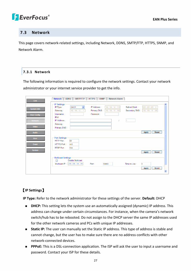
EAN Plus Series
27
73 Network
This page covers network-related settings including Network DDNS SMTPFTP HTTPS SNMP and
Network Alarm
731 Network
The following information is required to configure the network settings Contact your network
administrator or your internet service provider to get the info
【IP Settings】
IP Type Refer to the network administrator for these settings of the server Default DHCP
DHCP This setting lets the system use an automatically assigned (dynamic) IP address This
address can change under certain circumstances For instance when the camerarsquos network
switchhub has to be rebooted Do not assign to the DHCP server the same IP addresses used
for the other network cameras and PCs with unique IP addresses
Static IP The user can manually set the Static IP address This type of address is stable and
cannot change but the user has to make sure there are no address conflicts with other
network-connected devices
PPPoE This is a DSL-connection application The ISP will ask the user to input a username and
password Contact your ISP for these details
EAN Plus Series
28
Note If PPPoE is selected as the IP type the supplied IP Utility program will not be able to
detect the device
IP address When DHCP is not used the user needs to manually enter the IP address of the
camera Do not enter an IP address that is already used for your computer or other network
cameras
Subnet Mask This field is used to set the netmask for your network so that the IP camera will be
recognized within the network Example 2552552550 When DHCP is selected the DHCP server
will assign this value automatically
Gateway This field is used to set the gateway for your network so that the IP camera will be
recognized within the network When DHCP is selected the DHCP server will assign this value
automatically
Primary DNS Enter the IP address of the DNS server if this is provided by an ISP
Secondary DNS If your ISP provided you with a secondary DNS address please enter it here
Username Enter the accountrsquos username (used only for PPPoE)
Password Used only for PPPoE
IPv6 Enter the IPv6 details in this area if this applies to your system
Click Apply to apply the setting changes or Reset to reset without saving the change
【Port Settings】Enter the HTTP HTTPS and RTSP port numbers and click Apply to save
【Multicast Settings】Enable if required fill in the setting options and click Apply to save
EAN Plus Series
29
732 DDNS
DDNS (Dynamic Domain Name System) is a service used to map a domain name to the dynamic IP
address of a network device You can set up the DDNS service for remote access to the IP camera
DDNS assigns a domain name (URL) to the IP camera so that the user does not need to go through
the trouble of checking if the IP address assigned by DHCP Server has changed Once the IP is
changed the IP camera will automatically update the information to the DDNS to ensure it is always
available for remote access
Before enabling the following DDNS function user should have applied for a host name from the
DDS service providerrsquos website We support these four DDNS server providers
wwweverfocusddnscom wwwsitelutionscom wwwdyndnscom and wwwno-ipcom
Note We highly recommend that you use xxxxeverfocusddnscom for the simplicity of setting up
your IP cameras
【DDNS Settings】
Enable Check this box to enable the DDNS function
Service ISP You can either apply for a host name from EverFocus or other DDNS server providers
If you choose the EverFocus DDNS server you can obtain a free host name from EverFocus by
following the steps below
bull From EverFocus To obtain a free host name from EverFocus type a desired host name in the
textbox click the Register Update button and then click the Apply button
bull From other DDNS server providers To obtain a domain name from one of the three DDNS
server providers you have to register your name with the provider first and then select the
provider and fill in the required information Please refer to the specific DDNS companyrsquos
website for further information
Record ID Type the record ID if provided by the DDNS server provider
EAN Plus Series
30
FQDN Type the fully qualified domain name applied from the DDNS server provider For
example xxxxdyndnscom
Username Password Type the login account of your DDNS server provider
Click Apply to apply the setting changes or Reset to reset without saving the changes
Note
1 In order to support the full functionality of the camera you must open the port numbers (80
554 443) on the router for remote access to the IP camera This function is available on most
routers in the market and is often known as ldquoPort Forwardingrdquo To set up Port Forwarding
please consult the manual of the router
2 In certain router models it is possible that you will not be able to access the camera using
DDNS while inside the routerrsquos network Please try using a PC located outside of your routerrsquos
network
Default Ports on All EverFocus IP Cameras
HTTP 80
RTSP 554
HTTPS 443
EAN Plus Series
31
733 SMTP FTP
【Set SMTP Server (email)】This area is for configuring the mail server that is used to send e-mail
notifications from the camera to predefined addresses via SMTP Note that to enable e-mail
notification function you have to check the Send Mail Notification item on the Event dialog box
(see 771 Event Settings)
SMTP Server Enter the IP address or the host name of the SMTP server used to send e-mails
SMTP Port Enter the port number for SMTP The default is 25
Authentication Check this box if the SMTP server requires authentication (userpassword)
User name Input the userrsquos login ID if the SMTP server requires authentication
Password Input the userrsquos login password if the SMTP server requires authentication
EAN Plus Series
32
Receiver Address Input the e-mail addresses for receiving an e-mail message when an EVENT is
enabled and triggered Please use ldquordquo to separate multiple addresses
Sender Address Input the senderrsquos e-mail address so that the receiver can recognize the sender
when an Event message is received
Attach Image Check this box if you want to attach an image when an alarm is triggered or an IP
camera detects events
Send Test Email Click the Test button to send a testing email to the assigned address
Click Apply to apply the setting changes or Reset to reset without saving the changes
【Set FTP Server】The settings relating to the FTP server used to transmit the alarm images can be
configured here Note that to enable uploading images to the FTP server function you have to
check the Upload to FTP item on the Event dialog box (see 771 Event Settings)
FTP Server Enter the IP address or the host name of the FTP server
FTP Port Enter the port number for the FTP server Default is 21
Recording Path Assign the recording path
User Name Set FTP Userrsquos name
Password Set FTP password
PASV mode Check to enable Passive mode Passive mode is normally enabled If a connection
cannot be established uncheck PASV Moderdquo
Test FTP Server Click the Test button to send a testing file to the assigned FTP server
Click Apply to apply the setting changes or Reset to reset without saving the changes
EAN Plus Series
33
734 HTTPS
Hypertext Transfer Protocol Secure (HTTPS) is a combination of the Hypertext Transfer Protocol
and the SSLTLS protocol and provides encrypted communication and secure identification of a
network web server
Before using the HTTPS function for communication with the IP camera a Certificate must be
created first There are two ways to create and install a certificate Create Self-Signed Certificate
and Create Certificate Request
Create Self-Signed Certificate
Please note that even though self-signed certificates are free and offer some protection true
security is only implemented after the installation of a signed certificate issued by a certificate
authority
1 Click the Create Self-Signed Certificate button the following dialog appears
EAN Plus Series
34
2 Type the required Certificate information and then click the Apply button The subject line will
be displayed in the Installed Certificate Information field
3 Click the Property button a pop-up window appears to display the details of the certificate
4 To optionally create and install other certificates remove the existing one by clicking the
Remove button to erase the certificate
5 On the Web page change the address from ldquohttprdquo to https in the address bar and press
Enter on the keyboard Some Security Alert dialogs will pop up Click OK or Yes to enable HTTPS
Create Certificate Request
You can apply for an official certificate from an issuing Certificate Authority
1 Click the Create Certificate Request button the following dialog appears
EAN Plus Series
35
2 Type the required Certificate information and then click the Apply button The subject line will
be displayed in the Created Request field
3 Click the Property button a pop-up window appears to display the details of the certificate
4 To optionally create and install other certificates or request remove the existing one by clicking
the Remove button to erase the certificate or request
5 Copy the contents of the Certificate request (in PEM format) and paste it to the certificate
request field on the Web page of the 3rd-party certification authority such as Symantec VeriSign
Wait for the certificate authority to issue an SSLTLS certificate and then download the issued
certificate on your computer
6 In the Install Signed Certificate field click the Browse button to search for the issued certificate
and then click the Upload button to import the certificate Once the certificate has been
uploaded this field will show the subject line of the certificate
EAN Plus Series
36
735 SNMP
The default values for SNMP v1v2v2c and SNMP v3 are already filled in Click either of the
Enable buttons to enable either of the two Make your changes as desired Click on the Trap
Address field to enter the digits if required
736 Network Alarm
This function works with EverFocusrsquos CMS software eg the PowerCon or the Power Video Plus For
the setting details please refer to the CMS network alarm protocol
EAN Plus Series
37
74 Video
The settings relating to video such as streaming camera OSD can be configured on this page The
Video page has five tabs Multi-streaming Camera Advanced ROI and Privacy Mask
741 Multi Streaming
【Stream Settings】 This IP camera can output three video streams simultaneously For each of these
streams the user can set the compression format resolution bit rate and frame rate individually
Stream 1 is always enabled for live view To enable Stream 2 andor Stream 3 check the ldquoEnablerdquo
box the header of each stream
Note If you connect to the camera via the Internet and experience a delay (lag time) in the video
feed try to reduce the number of streams and the quality and resolution of the streams ndash but
keep the frame rate at its maximum
EAN Plus Series
38
Format Select the encoding format ndash H264 or MJPEG
Resolution Select the most suitable resolution for your needs
Frame Rate Select from 1 to 30 fps
Bit Rate If required select whether you want the stream to stream a Constant Bit Rate or a
Variable Bit Rate and set the values of whichever option you choose
Click Apply to apply the setting changes or Reset to reset without saving the changes
【Video Recording Settings】Select the stream you want to configure and then select whether you
want the recording files of that stream to be saved in AVI or ARV format Click Apply to apply the
setting changes or Reset to reset without saving the changes
【Time Stamp Settings】 You can select the DateTime format position and add the setting to the
streaming
Click Apply to apply the changes or Reset to reset without saving the changes
EAN Plus Series
39
742 Camera
【Image Settings】Set the Brightness Saturation Contrast or Sharpness of the image Click Apply to
apply the changes or Reset to reset without saving the changes
【Camera Settings】
Mirror Switch Mirror ON to rotate the image horizontally around a vertical axis
Flip Switch Flip ON to rotate the image vertically around a horizontal axis
AE There are two options
ALC Selecting Automatic Light Control allows the camera circuitry to either take bright spots
more into consideration (peak) bringing out detail in bright areas or less into consideration
(average) bringing out detail in shadows
AES Selecting Auto Electronic Shutter disables the Shutter setting below this setting In this
mode the camera measures the light level and decides whether it needs more or less light and
then automatically adjusts the shutter speed accordingly
BLC Back Light Compensation (BLC) is used to make the subject appear clearer when it is set
against a bright background
OFF Select to switch Back Light Compensation functions off
(ON)BLC The BLC can increase the exposure of a dark area surrounded by a brighter area HLC
can decrease the exposure of bright areas surrounded by darker areas This enables the
camera to better display information that would otherwise have been ldquowhited outrdquo like a
license plate between two bright headlights on a dark road
(ON)HLC The Highlight-Suppression BLC is used to reduce the brightness of light sources in a
specific area It is activated only in a low illumination environment to minimize the effects of
glare from bright lights such as spotlights street lights or headlights in the field of view
EAN Plus Series
40
WDR The Wide Dynamic Range (WDR) function provides clearer images when both of the very
bright and dark areas simultaneously appear on the camera view There are four value options
OFF Low Middle and High Note that when WDR is ON some parts of the image may appear
solarized This is normal for WDR and is not a camera malfunction This function is only available
for EAN3120 Plus 3220 Plus
DN Mode
Auto Select to let the camera automatically switch to Night mode (black and white) when the
light levels fall to a specified level and back to Day mode (color) when the light levels rise to a
specified level
Day Select to keep the camera in Day mode (color) even in nighttime
Night Select to keep the camera in Night mode (black and white) even in daytime
EAN Plus Series
41
743 Advanced
EAN Plus Series
42
【Camera Settings】
Lens (IRIS Control) Select DC or Manual for IRIS control This function is only available for EAN3220
Plus
Exposure Settings (AE) This setting is used to adapt to the amount or type of light used by the
camera Note the settings vary among models
Mode This function is not available for EAN3220 Plus
Automatic Light Control (ALC) This option is only available for EAN3120 Plus 3300 Plus The
ALC allows the camera circuitry to either take bright spots more into consideration (peak)
bringing out detail in bright areas or less into consideration (average) bringing out detail in
shadows
Auto Electronic Shutter (AES) This option is only available for EAN3120 Plus 3300 Plus In
this mode the camera measures the light level and decides whether it needs more or less light
and then automatically adjusts the shutter speed accordingly
Manual This option is only available for EAN3300 Plus Select this option to manually set up
the Shutter (Manual) and AGC (Manual) values
Iris Specify the size of the Iris opening here
Shutter If enabled this setting lets you set the shutter speed yourself
Shutter Limit Use this setting to set the maximum shutter speed for the camera This function is
only available for EAN3120 Plus
AGC Set the Auto Gain Control limit here The lower the AGC level the lower the video signal and
the noise However the image will be darker under low-light condition with IR-off if you set up the
Iris to the maximum level
Slow Shutter This option can be switched on when AES Mode is selected in the Exposure Settings
(AE) field This function is only available for EAN3220 Plus 3300 Plus
Flickerless If the Mode field in the Exposure Settings (AE) area has been set to AES then this option
becomes available Choose between OFF 50HZ 60HZ 50HZ (High Luminance) or 60HZ (High
Luminance) This function is only available for EAN3300 Plus
EV Setting Set up the Exposure Value Note the brightness of the screen changes when you change
the EV value This function is only available for EAN3300 Plus
AE Response Set up Auto Exposure Response time This function is only available for EAN3300 Plus
AE Weighting Area Select an AE Weighting area Each setup AE Weighting Area is configured with
the appropriate brightness level on the center and the surrounding areas This function is only
available for EAN3300 Plus
Brightness Set the image brightness here
AE Reference Set the Auto Exposure value here This function is only available for EAN3120 Plus
EAN Plus Series
43
Black Level Set the Black level here This function is only available for EAN3300 Plus
WDR The Wide Dynamic Range (WDR) function provides clearer images when both of the very
bright and dark areas simultaneously appear on the camera view There are four value options OFF
Low Middle and High Note that when WDR is ON some parts of the image may appear solarized
This is normal for WDR and is not a camera malfunction This function is only available for EAN3120
Plus 3220 Plus
Visibility Enhancement (OFFLowMiddleHigh) Images in foggy or rain environments or in
environments with a very strong luminous intensity have a dynamic range that is significantly lower
than ordinary images The user can use this Visibility Enhancement setting to ldquoDEFOGrdquo the image if
such ldquoFOGGINGrdquo is an issue This function is only available for EAN3220 Plus
BLC Settings Back Light Compensation (BLC) is used to make the subject appear clearer when it is
set against a bright background
OFF Select to switch Back Light Compensation functions off
Back Light This option is only available for EAN3300 Plus The Back Light function is useful
when the background of the subject is very bright and the subject itself is dark Select Back
Light and adjust the slide bar to the left right for setting up the back light value The higher
the value the more the backlight compensation
Front Light This option is only available for EAN3300 Plus This function is useful when the
bright highlights such as flashlight or car headlights appear on the camera view Select Front
Light and adjust the slide bar to the left right for setting up the front light value The higher
the value the more the highlight compensation
ON (BLC) This option is only available when you select AES Mode in the Exposure Settings (AE)
field The option is only available for EAN3120 Plus 3220 Plus The BLC function is useful
when the background of the subject is very bright and the subject itself is dark Follow the
instructions below to configure the settings for each model
For EAN3120 Select ON (BLC) the button next to the Mode drop-down list will be
active (see image below) Click the button the green setup areas appear on the left
screen Click on the areas to enable disable the BLC function The selected areas (in green)
will be applied with the BLC function
EAN Plus Series
44
For EAN3220
You can configure one area to apply the BLC function Select ON (BLC) the setup buttons
appears (see image below) Select Low Middle High from the BLC Gain drop-down list To
set up a BLC area click the Edit Area button and then click on the blue color tab to turn your
mouse cursor into a blue pen Move the cursor to the position on the right screen where you
want the BLC rectangle to start and then click Move your cursor to the position (diagonally
opposing corner) where you want the BLC rectangle to end and then click The blue area will
be applied with the BLC function
ON (HLC) This option is only available when you select AES Mode in the Exposure Settings (AE)
field The option is only available for EAN3120 Plus 3220 Plus This function is useful when
the bright highlights such as flashlight or car headlights appear on the camera view Follow
the instructions below to configure the settings for each model
For EAN3120 Select ON (HLC) and then select a level from the drop-down list The higher the
level the more the highlight compensation
For EAN3220
HLC Level Select a level for the HLC setting The higher the level the more the highlight
compensation
HLC Mode Select All Day Night mode to apply the HLC function
HLC Black Mask Select On Off to apply the black mask on the selected areas The
over-exposure portions within the selected areas will be applied with the black mask
Color Tabs You can set up four HLC areas with different colors To set up a HLC area click the
Edit Area button and then click on the color tab to turn your mouse cursor into a pen of that
color Move the cursor to the position on the right screen where you want the HLC rectangle
to start and then click Move your cursor to the position (diagonally opposing corner) where
you want the HLC rectangle to end and then click Select ON from the color tab drop-down list
The rectangular area with the selected color will be applied with the HLC function
EAN Plus Series
45
Back Light This option is only available for EAN3300 Plus The Back Light function is useful
when the background of the subject is very bright and the subject itself is dark Select Back
Light and adjust the slide bar to the left right for setting up the back light value The higher
the value the more the backlight compensation
Front Light This option is only available for EAN3300 Plus This function is useful when the
bright highlights such as flashlight or car headlights appear on the camera view Select Front
Light and adjust the slide bar to the left right for setting up the front light value The higher
the value the more the highlight compensation
Noise Reduction Settings This limits the amount of digital ldquovideo noiserdquo that is usually found in any
video stream and helps to reduce file size The higher the level the more the reduction
For EAN3120 Plus 3300 Plus
Select ON OFF to enable disable the Noise Reduction function Or select Auto to let the camera
automatically enable disable the Noise Reduction function Slide the Level bar to set up the level
The higher the level the more the reduction
For EAN3220 Plus
2D DNR Select ON to enable the 2D DNR function
3D DNR Select ON to enable the 3D DNR function You can further set up the following settings
3D Start AGC Set up the AGC level to automatically start the 3D NR function
3D End AGC Set up the AGC level to automatically stop the 3D NR function
3D Level Set up the 3D DNR level
Smart NR Select ON to enable the Smart NR function The 3D NR function will be
automatically turned on when a motion event occurs
EAN Plus Series
46
White Balance Settings Select the mode that delivers the best quality image for the camerarsquos light
environment There are five options Auto Manual Indoor Outdoor One Push
Auto Select to let the camera automatically adjust the White Balance In the Auto mode the
camera computes the white balance value output using color information from the entire
screen It outputs the proper value using the color temperature radiating from a black subject
based on a range of value from 3000 to 7500K
Manual Select to adjust the Red and Blue values yourself in the fields below this field
Indoor Select to use the default settings for indoor environments In the Indoor mode the
camera uses 3200K as the base value
Outdoor Select to use the default settings for outdoor environment In the Outdoor mode it
uses 5800K as the base value
One Push Select to enable the Push button next to the Mode drop-down field This will allow you to force the camera to readjust the white balance every time you push the Push
button The lens will hold the same focal position until the next trigger command is received
This function helps to prevent incorrect focusing in dark environments This function is only
available for EAN3120 Plus 3220 Plus
Manual Temperature Select to use the optimized Red and Blue settings You can also
optionally adjust the Manual Level below this field for setting up the color temperature The
higher the value the more the color temperature This function is only available for EAN3300
Plus
DayNight Settings
Auto Select to let the camera automatically switch to Night mode (black and white) when the
light levels fall to a specified level and back to Day mode (color) when the light levels rise to a
specified level
Day Select to keep the camera in Day mode (color) even in nighttime
Night Select to keep the camera in Night mode (black and white) even in daytime
IR Smart Settings Select ON and set up the level to enhance the image quality when the images are
over exposure This function is useful when the camera is in the Night mode This function is only
available for EAN3220 Plus
Saturation Set the saturation value This function is not available for EAN3220 Plus
Monitor Type Select a gamma value from Set 1 Set 2 or Set 3 This function is only available for
EAN3120 Plus
Negative Switch this setting ON to view a color negative version of the video image This is useful
at night or when viewing temperature-sensitive images
EAN Plus Series
47
Sharpness Settings Select the sharpness level of the image A low sharpness level will deliver a
softer less detailed image A high level will deliver a sharp highly detailed image Switch Resolution
Enhancement ON to enable the resolution enhancement function
Contrast Select the contrast level of the image
Suppress Function This function is only available for EAN3300 Plus
Aperture Compensation Suppression (OFFLowMiddleHigh) This setting can be activated to
suppress luminance noise when the AGC level increases
Chroma Suppression (OFFLowMiddleHigh) This setting can be activated to suppress
chrominance noise when the AGC level increases
Ygamma (gamma 22standardcontrast enhancehigh light range mode LHigh light range mode
H) Select the Ygamma value for the video quality of the monitor This function is only available for
EAN3300 Plus
Monitor Settings The user can use this field to optimize video quality for his or her specific type of
monitor ndash LCD or CRT This function is only available for EAN3220 Plus
Color Space Standard The options are YUV601 for SD and YUV709 for HD These define the color
space standard required to convert an RGB picture to a YUV picture Generally YUV601 is used for
Standard Definition (720P) devices and the YUV709 is used for High Definition (1080P) devices
Click Apply to save all changes Click Reset to cancel all changes
EAN Plus Series
48
744 ROI (Region of Interest)
The Region of Interest (ROI) function allows users to set up multiple regions within an image with
better quality and less distortion than the rest of the image You can also use this function
together with the Digital Zoom function on the Live View Page to get a better image result Up to
eight ROIs can be configured in the ROI settings page
To set up an ROI region
1 Select an ROI number from the ROI No drop-down list
2 Click the Add button the mouse cursor will turn into a pen when you move it over the live
image on the left
3 Move the cursor to the position where you want the ROI rectangle to start and then click
Move the cursor to the position (diagonally opposing corner) where you want the ROI
rectangle to end and then click
4 Slide the Quality bar to set up the quality value
5 Click the Apply button to apply the settings or click the Reset button to reset without saving
the settings
EAN Plus Series
49
745 Privacy Mask
The Privacy Mask can block out sensitive areas from view covering the areas with colored or black
and white boxes in both live view and recorded clips This feature is useful when usersrsquo donrsquot want
the sensitive information visible Up to four Privacy Masks can be configured
【Privacy Mask Color Settings】The Modes vary among camera models
Mode Click Color to make the masks appear as colored rectangles on the screen Click BW to
make the masks appear as gray rectangles on the screen Click Mosaic to make the masks appear
as mosaic-effect rectangles on the screen
Level Select the color of the masks if you selected Color Mode Select the level of grayness of the
masks if you selected BW Mode Select the level of smallmiddlelarge if you selected Mosaic
Mode
Click Apply to apply the settings or click Reset to reset without saving the settings
Color Tabs Click on a color tab to turn your mouse cursor into a pen of that color
You can now create a block of that color on the video screen Move your cursor to the position
where you want your mask rectangle to start and then click Move your cursor to the position
(diagonally opposing corner) where you want your mask rectangle to end and then click The
rectangular area with the selected color will appear The live image will display the rectangular
area with the color you selected If you want to create another mask use one of the other three
colors Each color denotes a different mask area Only one block per color is allowed As the
number of colors suggests you can configure up to four blocks
EAN Plus Series
50
Select All Click to turn the whole screen into a mask area
Clear All Click to delete all configured mask blocks
Eraser Click to turn the mouse cursor into an eraser to delete any block you click on
Area Shows the color and number of the block
Enable Check this box to enable the related mask block
Click Apply to apply the settings or click Reset to reset without saving the settings
EAN Plus Series
51
75 Audio
The EAN Plus series IP camera can transmit audio to your computer if you have connected an external
microphone to its audio Input cable It can also receive audio input from you and transmit it via an
external speaker if you have connected such a speaker to its audio Output cable
Check the Enable Audio box to enable the camerarsquos audio function The camera will now act as a
digital bridge (via the IP network) between any connected audio input device and any connected
audio device
Adjust the Audio Input Volume if you have external audio input devices (microphones) connected to
the camera and if there are problems with the sound input being too low or high
Click Apply to save all settings or click Reset to cancel
EAN Plus Series
52
76 User
761 User Information
The system administrator can create up to ten user accounts on this page
To set up a user account
1 Highlight a user account and click the Modify button The following dialog box appears
2 Type the account name account description and password for the account Type the password
again in the Confirm field
3 Select an authority level for the user account from the Authority drop-down list
bull Supervisor Administrator The only difference between a supervisor and administrator is
that a supervisor can edit an administratorrsquos account and password but an administrator
cannot edit the supervisorrsquos account and password Multiple administrators can be
configured but there can be only one supervisor The supervisor and administrators all
have unrestricted access to the Settings submenus and can determine the registration of
all other users
EAN Plus Series
53
bull User A user can view the Live View page and view the system network video and audio
information A user can only adjust the User Config page settings The user does not have
access to the User Event and System pages
bull Guest The lowest level of access which only allows the user access to the Live View page
4 Select Active or Disable from the Status drop-down list to active or disable the user account
5 Click On in the SD Card Playback field to allow the user to access the SD card playback
function
6 Click OK
7 Click Apply to save all the settings
EAN Plus Series
54
762 IP Address Filter
Use this page to specify IP addresses that are not allowed to access this camera By default any IP
address can access the camera
Note The Allowed List addresses only become relevant when the Denied List contains a network
or range and the supervisor wants to allow one or more IP addresses within that excluded range
or network In such a scenario the user would enter the excluded range or network in the
Denied List and enter the exceptions in the Allowed List
To set up the IP Address Filter
1 Select Denied List Click the Add button the following dialog box appears
2 Select an IP type from the IP Type drop-down list
3 Select a network rule from the Rule drop-down list type the IP address and click OK
Single Type a single IP address in the IP Address field below
Network Type the IP address and subnet mask in the field below
Range Type a range for the IP addresses
4 If you have set up an IP range in Step 3 you can optionally set up the Allowed List to allow one
or more IP addresses within the setup IP range to access the IP camera
5 Click Apply
EAN Plus Series
55
77 Event
You can set up the Motion Detection event Tamper Detection event or the Alarm IO to automatically
notify the users when an event occurs or an alarm is triggered You can also set up a schedule to
automatically record the videos when an event occurs or an alarm is triggered
771 Event Settings
You can create a total of ten event or alarm settings page in the Event List
【Event List】
Click the Add button and the following Event Configuration Window appears
EAN Plus Series
56
Enter Event Name Type an event name
Event Triggered by Select an event or alarm type for the to-be-specified-below reactions
Alarm Input Select this if you want a reaction trigger coming from any external connected sensor
to activate a to-be-specified-below reactions via the camera system Make sure that a suitable
device is actually connected to the alarm input relay
Manual Trigger Select this option if you want to manually trigger the alarm by clicking the Trigger
Event button on the Live View Page
Motion Detection Select this option if you want motion in a specified part of the camerarsquos viewing
rectangle (the screen image) to trigger the to-be-specified-below reactions
Tampering Detection Select this option if you want the camerarsquos tampering detection sensor to
trigger the to-be-specified-below reactions
Schedule Recording Select this option if you want the Schedule Recording periods configured in
the recording schedule (the Settings gt Event gt Schedule page) to activate this event In this
scenario a preconfigured event reaction like a log entry will list the start and end times of each
period Actual recording will only be triggered if the event is preconfigured to do so
Enable This Event Select to activate the event
Enable Re-trigger Click to set a minimum time after the event is triggered before the event
can be triggered again
Enable Pre-trigger Buffer Click if you want the Event reaction (as selected in the ldquoNotification
Overrdquo field below) to be the activation of the video recording function and if you want the
recording to include the video feed from the time period (configurable on the previous ldquoEvent
Settingsrdquo page) just before the Event trigger occurred
Enable Post-trigger Buffer Click if you want the Event reaction (as selected in the Notification
Over field) to be the activation of the video recording function and if you want the recording
to include the video feed from a time period (configurable on the Event Settings page) just
after the Event trigger occurred
Motion Area Select a setup motion detection area from the drop down list Note this
function only becomes relevant after the Motion Detection areas have been set up (see 772
Motion Detection)
Notification Over Select the desired notification types form the following items
Log Click if you want the camera to list the eventrsquos details in its log if the event is triggered
Trigger Alarm Output Click if you want the camera to relay the event reaction to a device
attached to the alarm relay output wire and then set up the alarm output duration time
EAN Plus Series
57
Send Mail Notification Click if you want the camera to send an Event notification email to the
email address entered in the Set SMTP Server(email) field of the Network gt SMTPFTP page if
the Event occurs (see 733 SMTP FTP)
Upload to FTP Click if you want the camera to upload recorded footage to the FTP server
entered in the Set SMTP Server(email) field of the Network gt SMTPFTP page if the Event
occurs (see 733 SMTP FTP)
Record to SD Card Click if you want the camera to start recording its video feed (when the
event occurs) on an on-camera SD Card (if such a card has been inserted)
Note The recording will only be as long as the combined Pre- and Post-trigger Buffers so
make sure you enable at least one of these buffers especially the Post-trigger Buffer
Record to PC Check this box if you want the camera to start recording its video feed (when
the event occurs) on the same folder on the same PC as configured on the User Config gt
RecordingSnapshot page (if such a folder has been enabled and configured)
Note The recording will only be as long as the combined Pre- and Post-trigger Buffers (and
for as long as the event trigger is happening ndash eg a motion is detected) so make sure you
enable at least one of these buffers especially the Post-trigger Buffer
Network Alarm Check this box if you want the camera to send a network alarm signal (when
the event occurs) to the CMS servers configured on the Network gt Network Alarm page (see
736 Network Alarm)
Click OK to save all settings or click Cancel to cancel
【PrePost Trigger Settings】
Pre-trigger Buffer Select the duration for the buffer This will determine the amount of footage
(length of time) before the event trigger moment that will be included in an event-triggered video
recording if that buffer and video recording has been enabled in the Event Configuration Window
Post-trigger Buffer Select the duration for the buffer This will determine the amount of footage
(length of time) after the event trigger moment that will be included in an event-triggered video
recording if that buffer and video recording has been enabled in the Event Configuration Window
Click Apply to save all settings or click Reset to cancel
EAN Plus Series
58
772 Motion Detection
Use this page to configure up to four areas in which motion will be detected When a motion is
detected by the camera the motion detection icon will appear at the top right of the
Live page to alert the user This function can also be linked with correctly configured Events to
trigger Event reactions like the activation of video recording periods snapshots alarms etc
Color Tabs Click on a color tab to turn your mouse cursor into a pen of that color
You can now create a block of that color on the video screen Move your cursor to the position
where you want your detection rectangle to start and then click Move your cursor to the position
(diagonally opposing corner) where you want your detection rectangle to end and then click The
rectangular area with the selected color will appear This block will be an area inside which the
camera will detect motion If you want to create another detection area use one of the other three
palette colors Each color denotes a different detection area Only one block per color is allowed As
the number of colors suggests you can configure up to four blocks
Select All Click to turn the whole screen into a motion detection area
Clear All Click to delete all configured motion detection blocks
Eraser Click to turn your mouse cursor into an eraser to delete any block you click on
Area Shows the color and numberID of the block
Enable Check this box to enable the related motion detection block
Sensitivity Set the sensitivity of the motion detection sensor function
Click Apply to save all settings or click Reset to cancel
EAN Plus Series
59
773 Tamper Detection
Use this page to set the number of seconds that an alarm signal will be active if the device is
physically tampered (moved covered up or out of focus
774 Alarm IO
Use this page to set the type of trigger input and the type of output contact for the camerarsquos alarm
channel
EAN Plus Series
60
775 Schedule
Use this page to configure a schedule for periods during which the camera should deactivate all
user-activated Events (gray Deselect periods) or when the camera should deactivate all
user-activated Events except Schedule Recording (SR) events (blue Schedule Recording-only
periods) or when the camera should deactivate only SR events (red Event Recording-only periods)
or when it should enable all activated Events (yellow periods)
Event Recording Click this button to make every hour block you click on red A red block represents
an Event Recording-only block which represents an hour when the camera will deactivate all
preconfigured activated Schedule Recording events and keep all the other activated events active
Schedule Recording Click this button to make every hour block you click on blue A blue block
represents a Schedule Recording-only block which represents an hour when the camera will
deactivate all other preconfigured activated events and keep only the preconfigured activated
Schedule Recording events active
Event + Schedule Click this button to make every hour block you click on yellow A yellow block
represents an hour in which all activated events including Schedule Recording events will be
active
Deselect Click this button to make every hour block become grey A grey block represents an hour
in which all activated events including Schedule Recording events will be inactive
Click Apply to save all settings or click Reset to cancel
EAN Plus Series
61
78 System
You can set up the systemrsquos time and SD card settings and to do maintenance and reset actions like
reboots and upgrades
781 DateTime
【Machine Name Settings】If required enter a new name for the machine This name will be visible
in the Machine Name field of the IP Utility software which is included in the software CD
【Set Time Zone】Set the time zone of the camerarsquos location
【Set DateTime Manually】Set the datetime here if you wonrsquot be using an NTP server to update the
datetime (see below)
【Set DateTime Sync】Enter the Network Time Protocol server if applicable The camerarsquos time will
be automatically adjusted by synchronizing with the NTP server
Click Apply to save all settings or click Reset to cancel
EAN Plus Series
62
782 Daylight Saving
Click Enable Daylight Saving to enable this schedule and select the dates when the regionrsquos
daylight saving period begins and ends Click Apply to save all settings or click Reset to cancel
783 SD Card
Use this page to prepare the system for safely removing the SD Card from its slot
【Setup SD Card】
Notification Select the percentage of storage space that should be left on the card before the
camera notifies you of the impending storage shortage or overwrite
Event Recording Select if you want Event Recording only FTP Backup only or both
Overwrite Click ON if you want the card to start writing over recorded footage when its memory is
full Click OFF if you want the card to stop recording new footage when its memory is full
【SD Card Utility】
Capacity This shows you how much card memory has been used and how much memory capacity
remains on the card
Remove Click this button before removing the card from the system
Format Click this button to format the card All data saved on the SD card will be removed if the
card is formatted
EAN Plus Series
63
784 Maintenance
【Maintenance Server】
Reboot Click this button to reboot the unit without changing any of the settings Use this function if
the unit is not behaving as expected
Restore Click this button to restart and reset most of the current settings to their factory default
values The only settings that will not be changed to default are
bull IP settings
bull DDNS settings
Default The Default button should be used with caution Pressing this button will return all of the
cameras settings including the IP address to the factory default values The camera will then have
to be reconfigured
【SaveLoad Configuration Server】
Save To make a backup file of the machinersquos current configurations press Save to save all the
configurations to a config file This will enable the user to reload these configuration settings if the
settings are changed and there is unexpected behavior
Load To load a previously saved configuration press the Browse button to locate the saved config
file (see above) and then click the Load button The systemrsquos settings will be restored to the saved
configuration
EAN Plus Series
64
【SaveLoad Video Configuration Server】
Save To make a backup file of the machinersquos video configurations press Save to save the video
configurations to a config file This will enable the user to reload these configuration settings if the
settings are changed and there is unexpected behavior
Load To load a previously saved video configuration press the Browse button to locate the saved
config file (see above) and then click the Load button The systemrsquos settings will be restored to the
saved video configuration
【Upgrade Firmware】Click the Browse button to find a previously prepared firmware upgrade file
Click Upgrade to install the new firmware
Note
1 Do not disconnect power to the unit during the upgrade sequence The unit will reboot
automatically after the upgrade has completed (1-5 minutes)
2 During the upgrade process all event recording actions will be stopped Event recording
actions will resume after the camera is rebooted
3 If the ldquoFile Error Please re-loginrdquo warning message appears when upgrading the firmware
please try the following instructions
a Go to Internet Explorer gt Tools gt Internet Option gt Security gt Custom
b Find and enable the Include local directory path when uploading files to a server
EAN Plus Series
65
8 Upgrading Firmware Using IP Utility
You can upgrade the Firmware using the IP Utility software included in the software CD
1 Install and then start the IPU program The following dialog box appears
2 Click Find Devices to search the cameras connected in the LAN The default network values of the
cameras will be displayed By default the network protocol of the camera is DHCP
3 Select a camera and click LoginMulti Login to log in the camera
4 Type the user ID and password Click OK
Note
1 The default user ID is user1 and the default password is 11111111
2 If you select more than one camera that has the same user ID password you will be able
to log in several cameras at once
EAN Plus Series
66
5 Highlight the camera and then click Upgrade Firmware A browsing window appears
6 Select the firmware file (evb) and then click Open The IP Utility will automatically upgrade the
firmware
The camera will reboot once the update is complete Click Find Devices the new firmware version
should be displayed in the last part of the Machine Name
EAN Plus Series
67
9 Specifications
Model EAN3120 Plus EAN3220 Plus EAN3300 Plus
Camera
Image Sensor 13 Panasonic CMOS 128 Sony CMOS
Megapixel 13 MP 2 MP 3 MP
Picture Elements (H x V) 1280 x 1024 1944 x 1092 2048 x 1536
Min Illuminations 003 Lux at F14
Electronic Shutter (Sec) 85 ~ 160000 2 ~ 150000 1 ~ 110000
Scanning System NTSC PAL
WDR Yes Yes No
BLC Yes
Gain Control Yes
White Balance Yes
Lens
Mounting Type C CS
Day Night Yes (with removable auto IR-cut filter)
IRIS Control DC Electrical IRIS Lens IRIS
Video
Video Compression H264 MJPEG
Resolution
NTSC
2048 x 1536 1920 x 1200 (for EAN3300 Plus only)
1920 x 1080 (for EAN3300 Plus 3220 Plus only)
1280 x 1024 1280 x 720 1024 x 768 720 x 480 704 x 480 640 x 480
352 x 240 320 x 240 160 x 120
PAL
2048 x 1536 1920 x 1200 (for EAN3300 Plus only)
1920 x 1080 (for EAN3300 Plus 3220 Plus only)
1280 x 1024 1280 x 720 1024 x 768 720 x 576 704 x 576 640 x 480
352 x 288 320 x 240 160 x 120
Frame Rate 30 fps at 1280 x 1024 30 fps at 1920 x 1080 15 fps at 2048 x 1536
Audio
Audio Streaming Two-way audio
Audio Compression G711
EAN Plus Series
68
Network
Interface 10 100 Base-T Ethernet RJ-45 socket
Supported Protocols
TCPIP IPV6 UDP ICMP DHCP NTP DNS DDNS SMTP SNMP FTP
HTTP HTTPs PPPoE UPnP Bonjour RTP RTSP RTCP IGMP ARP ONVIF
PSIA
Connector
Power DC female port PoE
Ethernet RJ-45
Audio 1 In (phone jack for microphone)
1 Out (phone jack for Speaker)
Alarm IO Terminal IO wires
Local Storage Micro SD SDHC memory card slot
TV-Out BNC socket composite 1 V p-p 75 Ω
General
Power Source DC 12V PoE (IEEE8023af)
Power Consumption
(IR LEDs On)
5W (DC 12V)
621W (PoE)
5W (DC 12V)
522W (PoE)
5W (DC 12V)
536W (PoE)
Operating Temperature 0degC ~ +50degC 32degF ~ +122degF
Humidity 20 to 80 (no condensation)
Safety CE FCC
Dimensions (L x W x H) 117 x 56 x 68 mm 46 x 22 x 27 in
Weight 410 g 09 lb
EverFocus Electronics Corp EverFocus Taiwan 12F No79 Sec 1 Shin-Tai Wu Road Hsi-Chih Taipei Taiwan TEL +886 2 2698 2334 FAX +886 2 2698 2380 wwweverfocuscomtw marketingeverfocuscomtw
EverFocus Europe - Germany Albert-Einstein-Strasse 1 D-46446 Emmerich Germany TEL +49 2822 93940 FAX +49 2822 939495 wwweverfocusde infoeverfocusde
EverFocus China - Beijing Room 609 Technology Trade Building Shangdi Information Industry Base Haidian District Beijing 100085 China TEL +86 10 6297 3336~39 FAX +86 10 6297 1423 wwweverfocuscomcn marketingeverfocuscomcn
EverFocus China - Shenzhen 4F No 2 D4 Building Wan Yelong Industrial Park Tangtou Road Shiyan Baoan Shenzhen Guangdong 518101 China TEL +86 755 2765 1313 FAX +86 755 2765 0337 wwweverfocuscomcn marketingeverfocuscomcn
EverFocus USA - California 1801 Highland Avenue Unit A Duarte CA 91010 USA TEL +1 626 844 8888 FAX +1 626 844 8838 wwweverfocuscom saleseverfocuscom
EverFocus USA - New York 415 Oser Avenue Unit S Hauppauge NY 11788 USA TEL +1 631 436 5070 FAX +1 631 436 5027 wwweverfocuscom saleseverfocuscom
EverFocus Japan 5F Kinshicho City Building 2-13-4 Koto-BashiSumida-Ku Tokyo 130-0022 Japan TEL +81 3 5625 8188 FAX +81 3 5625 8189 wwweverfocuscojp infoeverfocuscojp
EverFocus Europe - UK Unit 12 Spitfire Business Park Hawker Road Croydon Surrey CR0 4WD UK TEL +44 20 8649 9757 +44 845 430 9999 FAX +44 20 8649 9907 wwweverfocusukcouk salesukeverfocuscom
EverFocus India Suite 803 Housefin Bhavan C-21 Bandra Kurla Complex Bandra (East) Mumbai 400051 India TEL +91 22 6128 8700 FAX +91 22 6128 8705 wwweverfocusin saleseverfocusin
PN 4605PQ3120B010A-VerC
Your EverFocus product is designed and manufactured with high quality materials and components which can be recycled and reused This symbol means that electrical and electronic equipment at their end-of-life should be disposed of separately from your household waste Please dispose of this equipment at your local community waste collectionrecycling centre In the European Union there are separate collection systems for used electrical and electronic product Please help us to conserve the environment we live in
Ihr EverFocus Produkt wurde entwickelt und hergestellt mit qualitativ hochwertigen Materialien und Komponenten die recycelt und wieder verwendet werden koumlnnen Dieses Symbol bedeutet dass elektrische und elektronische Geraumlte am Ende ihrer Nutzungsdauer vom Hausmuumlll getrennt entsorgt werden sollen Bitte entsorgen Sie dieses Geraumlt bei Ihrer oumlrtlichen kommunalen Sammelstelle oder im Recycling Centre Helfen Sie uns bitte die Umwelt zu erhalten in der wir leben
EAN Plus Series
28
Note If PPPoE is selected as the IP type the supplied IP Utility program will not be able to
detect the device
IP address When DHCP is not used the user needs to manually enter the IP address of the
camera Do not enter an IP address that is already used for your computer or other network
cameras
Subnet Mask This field is used to set the netmask for your network so that the IP camera will be
recognized within the network Example 2552552550 When DHCP is selected the DHCP server
will assign this value automatically
Gateway This field is used to set the gateway for your network so that the IP camera will be
recognized within the network When DHCP is selected the DHCP server will assign this value
automatically
Primary DNS Enter the IP address of the DNS server if this is provided by an ISP
Secondary DNS If your ISP provided you with a secondary DNS address please enter it here
Username Enter the accountrsquos username (used only for PPPoE)
Password Used only for PPPoE
IPv6 Enter the IPv6 details in this area if this applies to your system
Click Apply to apply the setting changes or Reset to reset without saving the change
【Port Settings】Enter the HTTP HTTPS and RTSP port numbers and click Apply to save
【Multicast Settings】Enable if required fill in the setting options and click Apply to save
EAN Plus Series
29
732 DDNS
DDNS (Dynamic Domain Name System) is a service used to map a domain name to the dynamic IP
address of a network device You can set up the DDNS service for remote access to the IP camera
DDNS assigns a domain name (URL) to the IP camera so that the user does not need to go through
the trouble of checking if the IP address assigned by DHCP Server has changed Once the IP is
changed the IP camera will automatically update the information to the DDNS to ensure it is always
available for remote access
Before enabling the following DDNS function user should have applied for a host name from the
DDS service providerrsquos website We support these four DDNS server providers
wwweverfocusddnscom wwwsitelutionscom wwwdyndnscom and wwwno-ipcom
Note We highly recommend that you use xxxxeverfocusddnscom for the simplicity of setting up
your IP cameras
【DDNS Settings】
Enable Check this box to enable the DDNS function
Service ISP You can either apply for a host name from EverFocus or other DDNS server providers
If you choose the EverFocus DDNS server you can obtain a free host name from EverFocus by
following the steps below
bull From EverFocus To obtain a free host name from EverFocus type a desired host name in the
textbox click the Register Update button and then click the Apply button
bull From other DDNS server providers To obtain a domain name from one of the three DDNS
server providers you have to register your name with the provider first and then select the
provider and fill in the required information Please refer to the specific DDNS companyrsquos
website for further information
Record ID Type the record ID if provided by the DDNS server provider
EAN Plus Series
30
FQDN Type the fully qualified domain name applied from the DDNS server provider For
example xxxxdyndnscom
Username Password Type the login account of your DDNS server provider
Click Apply to apply the setting changes or Reset to reset without saving the changes
Note
1 In order to support the full functionality of the camera you must open the port numbers (80
554 443) on the router for remote access to the IP camera This function is available on most
routers in the market and is often known as ldquoPort Forwardingrdquo To set up Port Forwarding
please consult the manual of the router
2 In certain router models it is possible that you will not be able to access the camera using
DDNS while inside the routerrsquos network Please try using a PC located outside of your routerrsquos
network
Default Ports on All EverFocus IP Cameras
HTTP 80
RTSP 554
HTTPS 443
EAN Plus Series
31
733 SMTP FTP
【Set SMTP Server (email)】This area is for configuring the mail server that is used to send e-mail
notifications from the camera to predefined addresses via SMTP Note that to enable e-mail
notification function you have to check the Send Mail Notification item on the Event dialog box
(see 771 Event Settings)
SMTP Server Enter the IP address or the host name of the SMTP server used to send e-mails
SMTP Port Enter the port number for SMTP The default is 25
Authentication Check this box if the SMTP server requires authentication (userpassword)
User name Input the userrsquos login ID if the SMTP server requires authentication
Password Input the userrsquos login password if the SMTP server requires authentication
EAN Plus Series
32
Receiver Address Input the e-mail addresses for receiving an e-mail message when an EVENT is
enabled and triggered Please use ldquordquo to separate multiple addresses
Sender Address Input the senderrsquos e-mail address so that the receiver can recognize the sender
when an Event message is received
Attach Image Check this box if you want to attach an image when an alarm is triggered or an IP
camera detects events
Send Test Email Click the Test button to send a testing email to the assigned address
Click Apply to apply the setting changes or Reset to reset without saving the changes
【Set FTP Server】The settings relating to the FTP server used to transmit the alarm images can be
configured here Note that to enable uploading images to the FTP server function you have to
check the Upload to FTP item on the Event dialog box (see 771 Event Settings)
FTP Server Enter the IP address or the host name of the FTP server
FTP Port Enter the port number for the FTP server Default is 21
Recording Path Assign the recording path
User Name Set FTP Userrsquos name
Password Set FTP password
PASV mode Check to enable Passive mode Passive mode is normally enabled If a connection
cannot be established uncheck PASV Moderdquo
Test FTP Server Click the Test button to send a testing file to the assigned FTP server
Click Apply to apply the setting changes or Reset to reset without saving the changes
EAN Plus Series
33
734 HTTPS
Hypertext Transfer Protocol Secure (HTTPS) is a combination of the Hypertext Transfer Protocol
and the SSLTLS protocol and provides encrypted communication and secure identification of a
network web server
Before using the HTTPS function for communication with the IP camera a Certificate must be
created first There are two ways to create and install a certificate Create Self-Signed Certificate
and Create Certificate Request
Create Self-Signed Certificate
Please note that even though self-signed certificates are free and offer some protection true
security is only implemented after the installation of a signed certificate issued by a certificate
authority
1 Click the Create Self-Signed Certificate button the following dialog appears
EAN Plus Series
34
2 Type the required Certificate information and then click the Apply button The subject line will
be displayed in the Installed Certificate Information field
3 Click the Property button a pop-up window appears to display the details of the certificate
4 To optionally create and install other certificates remove the existing one by clicking the
Remove button to erase the certificate
5 On the Web page change the address from ldquohttprdquo to https in the address bar and press
Enter on the keyboard Some Security Alert dialogs will pop up Click OK or Yes to enable HTTPS
Create Certificate Request
You can apply for an official certificate from an issuing Certificate Authority
1 Click the Create Certificate Request button the following dialog appears
EAN Plus Series
35
2 Type the required Certificate information and then click the Apply button The subject line will
be displayed in the Created Request field
3 Click the Property button a pop-up window appears to display the details of the certificate
4 To optionally create and install other certificates or request remove the existing one by clicking
the Remove button to erase the certificate or request
5 Copy the contents of the Certificate request (in PEM format) and paste it to the certificate
request field on the Web page of the 3rd-party certification authority such as Symantec VeriSign
Wait for the certificate authority to issue an SSLTLS certificate and then download the issued
certificate on your computer
6 In the Install Signed Certificate field click the Browse button to search for the issued certificate
and then click the Upload button to import the certificate Once the certificate has been
uploaded this field will show the subject line of the certificate
EAN Plus Series
36
735 SNMP
The default values for SNMP v1v2v2c and SNMP v3 are already filled in Click either of the
Enable buttons to enable either of the two Make your changes as desired Click on the Trap
Address field to enter the digits if required
736 Network Alarm
This function works with EverFocusrsquos CMS software eg the PowerCon or the Power Video Plus For
the setting details please refer to the CMS network alarm protocol
EAN Plus Series
37
74 Video
The settings relating to video such as streaming camera OSD can be configured on this page The
Video page has five tabs Multi-streaming Camera Advanced ROI and Privacy Mask
741 Multi Streaming
【Stream Settings】 This IP camera can output three video streams simultaneously For each of these
streams the user can set the compression format resolution bit rate and frame rate individually
Stream 1 is always enabled for live view To enable Stream 2 andor Stream 3 check the ldquoEnablerdquo
box the header of each stream
Note If you connect to the camera via the Internet and experience a delay (lag time) in the video
feed try to reduce the number of streams and the quality and resolution of the streams ndash but
keep the frame rate at its maximum
EAN Plus Series
38
Format Select the encoding format ndash H264 or MJPEG
Resolution Select the most suitable resolution for your needs
Frame Rate Select from 1 to 30 fps
Bit Rate If required select whether you want the stream to stream a Constant Bit Rate or a
Variable Bit Rate and set the values of whichever option you choose
Click Apply to apply the setting changes or Reset to reset without saving the changes
【Video Recording Settings】Select the stream you want to configure and then select whether you
want the recording files of that stream to be saved in AVI or ARV format Click Apply to apply the
setting changes or Reset to reset without saving the changes
【Time Stamp Settings】 You can select the DateTime format position and add the setting to the
streaming
Click Apply to apply the changes or Reset to reset without saving the changes
EAN Plus Series
39
742 Camera
【Image Settings】Set the Brightness Saturation Contrast or Sharpness of the image Click Apply to
apply the changes or Reset to reset without saving the changes
【Camera Settings】
Mirror Switch Mirror ON to rotate the image horizontally around a vertical axis
Flip Switch Flip ON to rotate the image vertically around a horizontal axis
AE There are two options
ALC Selecting Automatic Light Control allows the camera circuitry to either take bright spots
more into consideration (peak) bringing out detail in bright areas or less into consideration
(average) bringing out detail in shadows
AES Selecting Auto Electronic Shutter disables the Shutter setting below this setting In this
mode the camera measures the light level and decides whether it needs more or less light and
then automatically adjusts the shutter speed accordingly
BLC Back Light Compensation (BLC) is used to make the subject appear clearer when it is set
against a bright background
OFF Select to switch Back Light Compensation functions off
(ON)BLC The BLC can increase the exposure of a dark area surrounded by a brighter area HLC
can decrease the exposure of bright areas surrounded by darker areas This enables the
camera to better display information that would otherwise have been ldquowhited outrdquo like a
license plate between two bright headlights on a dark road
(ON)HLC The Highlight-Suppression BLC is used to reduce the brightness of light sources in a
specific area It is activated only in a low illumination environment to minimize the effects of
glare from bright lights such as spotlights street lights or headlights in the field of view
EAN Plus Series
40
WDR The Wide Dynamic Range (WDR) function provides clearer images when both of the very
bright and dark areas simultaneously appear on the camera view There are four value options
OFF Low Middle and High Note that when WDR is ON some parts of the image may appear
solarized This is normal for WDR and is not a camera malfunction This function is only available
for EAN3120 Plus 3220 Plus
DN Mode
Auto Select to let the camera automatically switch to Night mode (black and white) when the
light levels fall to a specified level and back to Day mode (color) when the light levels rise to a
specified level
Day Select to keep the camera in Day mode (color) even in nighttime
Night Select to keep the camera in Night mode (black and white) even in daytime
EAN Plus Series
41
743 Advanced
EAN Plus Series
42
【Camera Settings】
Lens (IRIS Control) Select DC or Manual for IRIS control This function is only available for EAN3220
Plus
Exposure Settings (AE) This setting is used to adapt to the amount or type of light used by the
camera Note the settings vary among models
Mode This function is not available for EAN3220 Plus
Automatic Light Control (ALC) This option is only available for EAN3120 Plus 3300 Plus The
ALC allows the camera circuitry to either take bright spots more into consideration (peak)
bringing out detail in bright areas or less into consideration (average) bringing out detail in
shadows
Auto Electronic Shutter (AES) This option is only available for EAN3120 Plus 3300 Plus In
this mode the camera measures the light level and decides whether it needs more or less light
and then automatically adjusts the shutter speed accordingly
Manual This option is only available for EAN3300 Plus Select this option to manually set up
the Shutter (Manual) and AGC (Manual) values
Iris Specify the size of the Iris opening here
Shutter If enabled this setting lets you set the shutter speed yourself
Shutter Limit Use this setting to set the maximum shutter speed for the camera This function is
only available for EAN3120 Plus
AGC Set the Auto Gain Control limit here The lower the AGC level the lower the video signal and
the noise However the image will be darker under low-light condition with IR-off if you set up the
Iris to the maximum level
Slow Shutter This option can be switched on when AES Mode is selected in the Exposure Settings
(AE) field This function is only available for EAN3220 Plus 3300 Plus
Flickerless If the Mode field in the Exposure Settings (AE) area has been set to AES then this option
becomes available Choose between OFF 50HZ 60HZ 50HZ (High Luminance) or 60HZ (High
Luminance) This function is only available for EAN3300 Plus
EV Setting Set up the Exposure Value Note the brightness of the screen changes when you change
the EV value This function is only available for EAN3300 Plus
AE Response Set up Auto Exposure Response time This function is only available for EAN3300 Plus
AE Weighting Area Select an AE Weighting area Each setup AE Weighting Area is configured with
the appropriate brightness level on the center and the surrounding areas This function is only
available for EAN3300 Plus
Brightness Set the image brightness here
AE Reference Set the Auto Exposure value here This function is only available for EAN3120 Plus
EAN Plus Series
43
Black Level Set the Black level here This function is only available for EAN3300 Plus
WDR The Wide Dynamic Range (WDR) function provides clearer images when both of the very
bright and dark areas simultaneously appear on the camera view There are four value options OFF
Low Middle and High Note that when WDR is ON some parts of the image may appear solarized
This is normal for WDR and is not a camera malfunction This function is only available for EAN3120
Plus 3220 Plus
Visibility Enhancement (OFFLowMiddleHigh) Images in foggy or rain environments or in
environments with a very strong luminous intensity have a dynamic range that is significantly lower
than ordinary images The user can use this Visibility Enhancement setting to ldquoDEFOGrdquo the image if
such ldquoFOGGINGrdquo is an issue This function is only available for EAN3220 Plus
BLC Settings Back Light Compensation (BLC) is used to make the subject appear clearer when it is
set against a bright background
OFF Select to switch Back Light Compensation functions off
Back Light This option is only available for EAN3300 Plus The Back Light function is useful
when the background of the subject is very bright and the subject itself is dark Select Back
Light and adjust the slide bar to the left right for setting up the back light value The higher
the value the more the backlight compensation
Front Light This option is only available for EAN3300 Plus This function is useful when the
bright highlights such as flashlight or car headlights appear on the camera view Select Front
Light and adjust the slide bar to the left right for setting up the front light value The higher
the value the more the highlight compensation
ON (BLC) This option is only available when you select AES Mode in the Exposure Settings (AE)
field The option is only available for EAN3120 Plus 3220 Plus The BLC function is useful
when the background of the subject is very bright and the subject itself is dark Follow the
instructions below to configure the settings for each model
For EAN3120 Select ON (BLC) the button next to the Mode drop-down list will be
active (see image below) Click the button the green setup areas appear on the left
screen Click on the areas to enable disable the BLC function The selected areas (in green)
will be applied with the BLC function
EAN Plus Series
44
For EAN3220
You can configure one area to apply the BLC function Select ON (BLC) the setup buttons
appears (see image below) Select Low Middle High from the BLC Gain drop-down list To
set up a BLC area click the Edit Area button and then click on the blue color tab to turn your
mouse cursor into a blue pen Move the cursor to the position on the right screen where you
want the BLC rectangle to start and then click Move your cursor to the position (diagonally
opposing corner) where you want the BLC rectangle to end and then click The blue area will
be applied with the BLC function
ON (HLC) This option is only available when you select AES Mode in the Exposure Settings (AE)
field The option is only available for EAN3120 Plus 3220 Plus This function is useful when
the bright highlights such as flashlight or car headlights appear on the camera view Follow
the instructions below to configure the settings for each model
For EAN3120 Select ON (HLC) and then select a level from the drop-down list The higher the
level the more the highlight compensation
For EAN3220
HLC Level Select a level for the HLC setting The higher the level the more the highlight
compensation
HLC Mode Select All Day Night mode to apply the HLC function
HLC Black Mask Select On Off to apply the black mask on the selected areas The
over-exposure portions within the selected areas will be applied with the black mask
Color Tabs You can set up four HLC areas with different colors To set up a HLC area click the
Edit Area button and then click on the color tab to turn your mouse cursor into a pen of that
color Move the cursor to the position on the right screen where you want the HLC rectangle
to start and then click Move your cursor to the position (diagonally opposing corner) where
you want the HLC rectangle to end and then click Select ON from the color tab drop-down list
The rectangular area with the selected color will be applied with the HLC function
EAN Plus Series
45
Back Light This option is only available for EAN3300 Plus The Back Light function is useful
when the background of the subject is very bright and the subject itself is dark Select Back
Light and adjust the slide bar to the left right for setting up the back light value The higher
the value the more the backlight compensation
Front Light This option is only available for EAN3300 Plus This function is useful when the
bright highlights such as flashlight or car headlights appear on the camera view Select Front
Light and adjust the slide bar to the left right for setting up the front light value The higher
the value the more the highlight compensation
Noise Reduction Settings This limits the amount of digital ldquovideo noiserdquo that is usually found in any
video stream and helps to reduce file size The higher the level the more the reduction
For EAN3120 Plus 3300 Plus
Select ON OFF to enable disable the Noise Reduction function Or select Auto to let the camera
automatically enable disable the Noise Reduction function Slide the Level bar to set up the level
The higher the level the more the reduction
For EAN3220 Plus
2D DNR Select ON to enable the 2D DNR function
3D DNR Select ON to enable the 3D DNR function You can further set up the following settings
3D Start AGC Set up the AGC level to automatically start the 3D NR function
3D End AGC Set up the AGC level to automatically stop the 3D NR function
3D Level Set up the 3D DNR level
Smart NR Select ON to enable the Smart NR function The 3D NR function will be
automatically turned on when a motion event occurs
EAN Plus Series
46
White Balance Settings Select the mode that delivers the best quality image for the camerarsquos light
environment There are five options Auto Manual Indoor Outdoor One Push
Auto Select to let the camera automatically adjust the White Balance In the Auto mode the
camera computes the white balance value output using color information from the entire
screen It outputs the proper value using the color temperature radiating from a black subject
based on a range of value from 3000 to 7500K
Manual Select to adjust the Red and Blue values yourself in the fields below this field
Indoor Select to use the default settings for indoor environments In the Indoor mode the
camera uses 3200K as the base value
Outdoor Select to use the default settings for outdoor environment In the Outdoor mode it
uses 5800K as the base value
One Push Select to enable the Push button next to the Mode drop-down field This will allow you to force the camera to readjust the white balance every time you push the Push
button The lens will hold the same focal position until the next trigger command is received
This function helps to prevent incorrect focusing in dark environments This function is only
available for EAN3120 Plus 3220 Plus
Manual Temperature Select to use the optimized Red and Blue settings You can also
optionally adjust the Manual Level below this field for setting up the color temperature The
higher the value the more the color temperature This function is only available for EAN3300
Plus
DayNight Settings
Auto Select to let the camera automatically switch to Night mode (black and white) when the
light levels fall to a specified level and back to Day mode (color) when the light levels rise to a
specified level
Day Select to keep the camera in Day mode (color) even in nighttime
Night Select to keep the camera in Night mode (black and white) even in daytime
IR Smart Settings Select ON and set up the level to enhance the image quality when the images are
over exposure This function is useful when the camera is in the Night mode This function is only
available for EAN3220 Plus
Saturation Set the saturation value This function is not available for EAN3220 Plus
Monitor Type Select a gamma value from Set 1 Set 2 or Set 3 This function is only available for
EAN3120 Plus
Negative Switch this setting ON to view a color negative version of the video image This is useful
at night or when viewing temperature-sensitive images
EAN Plus Series
47
Sharpness Settings Select the sharpness level of the image A low sharpness level will deliver a
softer less detailed image A high level will deliver a sharp highly detailed image Switch Resolution
Enhancement ON to enable the resolution enhancement function
Contrast Select the contrast level of the image
Suppress Function This function is only available for EAN3300 Plus
Aperture Compensation Suppression (OFFLowMiddleHigh) This setting can be activated to
suppress luminance noise when the AGC level increases
Chroma Suppression (OFFLowMiddleHigh) This setting can be activated to suppress
chrominance noise when the AGC level increases
Ygamma (gamma 22standardcontrast enhancehigh light range mode LHigh light range mode
H) Select the Ygamma value for the video quality of the monitor This function is only available for
EAN3300 Plus
Monitor Settings The user can use this field to optimize video quality for his or her specific type of
monitor ndash LCD or CRT This function is only available for EAN3220 Plus
Color Space Standard The options are YUV601 for SD and YUV709 for HD These define the color
space standard required to convert an RGB picture to a YUV picture Generally YUV601 is used for
Standard Definition (720P) devices and the YUV709 is used for High Definition (1080P) devices
Click Apply to save all changes Click Reset to cancel all changes
EAN Plus Series
48
744 ROI (Region of Interest)
The Region of Interest (ROI) function allows users to set up multiple regions within an image with
better quality and less distortion than the rest of the image You can also use this function
together with the Digital Zoom function on the Live View Page to get a better image result Up to
eight ROIs can be configured in the ROI settings page
To set up an ROI region
1 Select an ROI number from the ROI No drop-down list
2 Click the Add button the mouse cursor will turn into a pen when you move it over the live
image on the left
3 Move the cursor to the position where you want the ROI rectangle to start and then click
Move the cursor to the position (diagonally opposing corner) where you want the ROI
rectangle to end and then click
4 Slide the Quality bar to set up the quality value
5 Click the Apply button to apply the settings or click the Reset button to reset without saving
the settings
EAN Plus Series
49
745 Privacy Mask
The Privacy Mask can block out sensitive areas from view covering the areas with colored or black
and white boxes in both live view and recorded clips This feature is useful when usersrsquo donrsquot want
the sensitive information visible Up to four Privacy Masks can be configured
【Privacy Mask Color Settings】The Modes vary among camera models
Mode Click Color to make the masks appear as colored rectangles on the screen Click BW to
make the masks appear as gray rectangles on the screen Click Mosaic to make the masks appear
as mosaic-effect rectangles on the screen
Level Select the color of the masks if you selected Color Mode Select the level of grayness of the
masks if you selected BW Mode Select the level of smallmiddlelarge if you selected Mosaic
Mode
Click Apply to apply the settings or click Reset to reset without saving the settings
Color Tabs Click on a color tab to turn your mouse cursor into a pen of that color
You can now create a block of that color on the video screen Move your cursor to the position
where you want your mask rectangle to start and then click Move your cursor to the position
(diagonally opposing corner) where you want your mask rectangle to end and then click The
rectangular area with the selected color will appear The live image will display the rectangular
area with the color you selected If you want to create another mask use one of the other three
colors Each color denotes a different mask area Only one block per color is allowed As the
number of colors suggests you can configure up to four blocks
EAN Plus Series
50
Select All Click to turn the whole screen into a mask area
Clear All Click to delete all configured mask blocks
Eraser Click to turn the mouse cursor into an eraser to delete any block you click on
Area Shows the color and number of the block
Enable Check this box to enable the related mask block
Click Apply to apply the settings or click Reset to reset without saving the settings
EAN Plus Series
51
75 Audio
The EAN Plus series IP camera can transmit audio to your computer if you have connected an external
microphone to its audio Input cable It can also receive audio input from you and transmit it via an
external speaker if you have connected such a speaker to its audio Output cable
Check the Enable Audio box to enable the camerarsquos audio function The camera will now act as a
digital bridge (via the IP network) between any connected audio input device and any connected
audio device
Adjust the Audio Input Volume if you have external audio input devices (microphones) connected to
the camera and if there are problems with the sound input being too low or high
Click Apply to save all settings or click Reset to cancel
EAN Plus Series
52
76 User
761 User Information
The system administrator can create up to ten user accounts on this page
To set up a user account
1 Highlight a user account and click the Modify button The following dialog box appears
2 Type the account name account description and password for the account Type the password
again in the Confirm field
3 Select an authority level for the user account from the Authority drop-down list
bull Supervisor Administrator The only difference between a supervisor and administrator is
that a supervisor can edit an administratorrsquos account and password but an administrator
cannot edit the supervisorrsquos account and password Multiple administrators can be
configured but there can be only one supervisor The supervisor and administrators all
have unrestricted access to the Settings submenus and can determine the registration of
all other users
EAN Plus Series
53
bull User A user can view the Live View page and view the system network video and audio
information A user can only adjust the User Config page settings The user does not have
access to the User Event and System pages
bull Guest The lowest level of access which only allows the user access to the Live View page
4 Select Active or Disable from the Status drop-down list to active or disable the user account
5 Click On in the SD Card Playback field to allow the user to access the SD card playback
function
6 Click OK
7 Click Apply to save all the settings
EAN Plus Series
54
762 IP Address Filter
Use this page to specify IP addresses that are not allowed to access this camera By default any IP
address can access the camera
Note The Allowed List addresses only become relevant when the Denied List contains a network
or range and the supervisor wants to allow one or more IP addresses within that excluded range
or network In such a scenario the user would enter the excluded range or network in the
Denied List and enter the exceptions in the Allowed List
To set up the IP Address Filter
1 Select Denied List Click the Add button the following dialog box appears
2 Select an IP type from the IP Type drop-down list
3 Select a network rule from the Rule drop-down list type the IP address and click OK
Single Type a single IP address in the IP Address field below
Network Type the IP address and subnet mask in the field below
Range Type a range for the IP addresses
4 If you have set up an IP range in Step 3 you can optionally set up the Allowed List to allow one
or more IP addresses within the setup IP range to access the IP camera
5 Click Apply
EAN Plus Series
55
77 Event
You can set up the Motion Detection event Tamper Detection event or the Alarm IO to automatically
notify the users when an event occurs or an alarm is triggered You can also set up a schedule to
automatically record the videos when an event occurs or an alarm is triggered
771 Event Settings
You can create a total of ten event or alarm settings page in the Event List
【Event List】
Click the Add button and the following Event Configuration Window appears
EAN Plus Series
56
Enter Event Name Type an event name
Event Triggered by Select an event or alarm type for the to-be-specified-below reactions
Alarm Input Select this if you want a reaction trigger coming from any external connected sensor
to activate a to-be-specified-below reactions via the camera system Make sure that a suitable
device is actually connected to the alarm input relay
Manual Trigger Select this option if you want to manually trigger the alarm by clicking the Trigger
Event button on the Live View Page
Motion Detection Select this option if you want motion in a specified part of the camerarsquos viewing
rectangle (the screen image) to trigger the to-be-specified-below reactions
Tampering Detection Select this option if you want the camerarsquos tampering detection sensor to
trigger the to-be-specified-below reactions
Schedule Recording Select this option if you want the Schedule Recording periods configured in
the recording schedule (the Settings gt Event gt Schedule page) to activate this event In this
scenario a preconfigured event reaction like a log entry will list the start and end times of each
period Actual recording will only be triggered if the event is preconfigured to do so
Enable This Event Select to activate the event
Enable Re-trigger Click to set a minimum time after the event is triggered before the event
can be triggered again
Enable Pre-trigger Buffer Click if you want the Event reaction (as selected in the ldquoNotification
Overrdquo field below) to be the activation of the video recording function and if you want the
recording to include the video feed from the time period (configurable on the previous ldquoEvent
Settingsrdquo page) just before the Event trigger occurred
Enable Post-trigger Buffer Click if you want the Event reaction (as selected in the Notification
Over field) to be the activation of the video recording function and if you want the recording
to include the video feed from a time period (configurable on the Event Settings page) just
after the Event trigger occurred
Motion Area Select a setup motion detection area from the drop down list Note this
function only becomes relevant after the Motion Detection areas have been set up (see 772
Motion Detection)
Notification Over Select the desired notification types form the following items
Log Click if you want the camera to list the eventrsquos details in its log if the event is triggered
Trigger Alarm Output Click if you want the camera to relay the event reaction to a device
attached to the alarm relay output wire and then set up the alarm output duration time
EAN Plus Series
57
Send Mail Notification Click if you want the camera to send an Event notification email to the
email address entered in the Set SMTP Server(email) field of the Network gt SMTPFTP page if
the Event occurs (see 733 SMTP FTP)
Upload to FTP Click if you want the camera to upload recorded footage to the FTP server
entered in the Set SMTP Server(email) field of the Network gt SMTPFTP page if the Event
occurs (see 733 SMTP FTP)
Record to SD Card Click if you want the camera to start recording its video feed (when the
event occurs) on an on-camera SD Card (if such a card has been inserted)
Note The recording will only be as long as the combined Pre- and Post-trigger Buffers so
make sure you enable at least one of these buffers especially the Post-trigger Buffer
Record to PC Check this box if you want the camera to start recording its video feed (when
the event occurs) on the same folder on the same PC as configured on the User Config gt
RecordingSnapshot page (if such a folder has been enabled and configured)
Note The recording will only be as long as the combined Pre- and Post-trigger Buffers (and
for as long as the event trigger is happening ndash eg a motion is detected) so make sure you
enable at least one of these buffers especially the Post-trigger Buffer
Network Alarm Check this box if you want the camera to send a network alarm signal (when
the event occurs) to the CMS servers configured on the Network gt Network Alarm page (see
736 Network Alarm)
Click OK to save all settings or click Cancel to cancel
【PrePost Trigger Settings】
Pre-trigger Buffer Select the duration for the buffer This will determine the amount of footage
(length of time) before the event trigger moment that will be included in an event-triggered video
recording if that buffer and video recording has been enabled in the Event Configuration Window
Post-trigger Buffer Select the duration for the buffer This will determine the amount of footage
(length of time) after the event trigger moment that will be included in an event-triggered video
recording if that buffer and video recording has been enabled in the Event Configuration Window
Click Apply to save all settings or click Reset to cancel
EAN Plus Series
58
772 Motion Detection
Use this page to configure up to four areas in which motion will be detected When a motion is
detected by the camera the motion detection icon will appear at the top right of the
Live page to alert the user This function can also be linked with correctly configured Events to
trigger Event reactions like the activation of video recording periods snapshots alarms etc
Color Tabs Click on a color tab to turn your mouse cursor into a pen of that color
You can now create a block of that color on the video screen Move your cursor to the position
where you want your detection rectangle to start and then click Move your cursor to the position
(diagonally opposing corner) where you want your detection rectangle to end and then click The
rectangular area with the selected color will appear This block will be an area inside which the
camera will detect motion If you want to create another detection area use one of the other three
palette colors Each color denotes a different detection area Only one block per color is allowed As
the number of colors suggests you can configure up to four blocks
Select All Click to turn the whole screen into a motion detection area
Clear All Click to delete all configured motion detection blocks
Eraser Click to turn your mouse cursor into an eraser to delete any block you click on
Area Shows the color and numberID of the block
Enable Check this box to enable the related motion detection block
Sensitivity Set the sensitivity of the motion detection sensor function
Click Apply to save all settings or click Reset to cancel
EAN Plus Series
59
773 Tamper Detection
Use this page to set the number of seconds that an alarm signal will be active if the device is
physically tampered (moved covered up or out of focus
774 Alarm IO
Use this page to set the type of trigger input and the type of output contact for the camerarsquos alarm
channel
EAN Plus Series
60
775 Schedule
Use this page to configure a schedule for periods during which the camera should deactivate all
user-activated Events (gray Deselect periods) or when the camera should deactivate all
user-activated Events except Schedule Recording (SR) events (blue Schedule Recording-only
periods) or when the camera should deactivate only SR events (red Event Recording-only periods)
or when it should enable all activated Events (yellow periods)
Event Recording Click this button to make every hour block you click on red A red block represents
an Event Recording-only block which represents an hour when the camera will deactivate all
preconfigured activated Schedule Recording events and keep all the other activated events active
Schedule Recording Click this button to make every hour block you click on blue A blue block
represents a Schedule Recording-only block which represents an hour when the camera will
deactivate all other preconfigured activated events and keep only the preconfigured activated
Schedule Recording events active
Event + Schedule Click this button to make every hour block you click on yellow A yellow block
represents an hour in which all activated events including Schedule Recording events will be
active
Deselect Click this button to make every hour block become grey A grey block represents an hour
in which all activated events including Schedule Recording events will be inactive
Click Apply to save all settings or click Reset to cancel
EAN Plus Series
61
78 System
You can set up the systemrsquos time and SD card settings and to do maintenance and reset actions like
reboots and upgrades
781 DateTime
【Machine Name Settings】If required enter a new name for the machine This name will be visible
in the Machine Name field of the IP Utility software which is included in the software CD
【Set Time Zone】Set the time zone of the camerarsquos location
【Set DateTime Manually】Set the datetime here if you wonrsquot be using an NTP server to update the
datetime (see below)
【Set DateTime Sync】Enter the Network Time Protocol server if applicable The camerarsquos time will
be automatically adjusted by synchronizing with the NTP server
Click Apply to save all settings or click Reset to cancel
EAN Plus Series
62
782 Daylight Saving
Click Enable Daylight Saving to enable this schedule and select the dates when the regionrsquos
daylight saving period begins and ends Click Apply to save all settings or click Reset to cancel
783 SD Card
Use this page to prepare the system for safely removing the SD Card from its slot
【Setup SD Card】
Notification Select the percentage of storage space that should be left on the card before the
camera notifies you of the impending storage shortage or overwrite
Event Recording Select if you want Event Recording only FTP Backup only or both
Overwrite Click ON if you want the card to start writing over recorded footage when its memory is
full Click OFF if you want the card to stop recording new footage when its memory is full
【SD Card Utility】
Capacity This shows you how much card memory has been used and how much memory capacity
remains on the card
Remove Click this button before removing the card from the system
Format Click this button to format the card All data saved on the SD card will be removed if the
card is formatted
EAN Plus Series
63
784 Maintenance
【Maintenance Server】
Reboot Click this button to reboot the unit without changing any of the settings Use this function if
the unit is not behaving as expected
Restore Click this button to restart and reset most of the current settings to their factory default
values The only settings that will not be changed to default are
bull IP settings
bull DDNS settings
Default The Default button should be used with caution Pressing this button will return all of the
cameras settings including the IP address to the factory default values The camera will then have
to be reconfigured
【SaveLoad Configuration Server】
Save To make a backup file of the machinersquos current configurations press Save to save all the
configurations to a config file This will enable the user to reload these configuration settings if the
settings are changed and there is unexpected behavior
Load To load a previously saved configuration press the Browse button to locate the saved config
file (see above) and then click the Load button The systemrsquos settings will be restored to the saved
configuration
EAN Plus Series
64
【SaveLoad Video Configuration Server】
Save To make a backup file of the machinersquos video configurations press Save to save the video
configurations to a config file This will enable the user to reload these configuration settings if the
settings are changed and there is unexpected behavior
Load To load a previously saved video configuration press the Browse button to locate the saved
config file (see above) and then click the Load button The systemrsquos settings will be restored to the
saved video configuration
【Upgrade Firmware】Click the Browse button to find a previously prepared firmware upgrade file
Click Upgrade to install the new firmware
Note
1 Do not disconnect power to the unit during the upgrade sequence The unit will reboot
automatically after the upgrade has completed (1-5 minutes)
2 During the upgrade process all event recording actions will be stopped Event recording
actions will resume after the camera is rebooted
3 If the ldquoFile Error Please re-loginrdquo warning message appears when upgrading the firmware
please try the following instructions
a Go to Internet Explorer gt Tools gt Internet Option gt Security gt Custom
b Find and enable the Include local directory path when uploading files to a server
EAN Plus Series
65
8 Upgrading Firmware Using IP Utility
You can upgrade the Firmware using the IP Utility software included in the software CD
1 Install and then start the IPU program The following dialog box appears
2 Click Find Devices to search the cameras connected in the LAN The default network values of the
cameras will be displayed By default the network protocol of the camera is DHCP
3 Select a camera and click LoginMulti Login to log in the camera
4 Type the user ID and password Click OK
Note
1 The default user ID is user1 and the default password is 11111111
2 If you select more than one camera that has the same user ID password you will be able
to log in several cameras at once
EAN Plus Series
66
5 Highlight the camera and then click Upgrade Firmware A browsing window appears
6 Select the firmware file (evb) and then click Open The IP Utility will automatically upgrade the
firmware
The camera will reboot once the update is complete Click Find Devices the new firmware version
should be displayed in the last part of the Machine Name
EAN Plus Series
67
9 Specifications
Model EAN3120 Plus EAN3220 Plus EAN3300 Plus
Camera
Image Sensor 13 Panasonic CMOS 128 Sony CMOS
Megapixel 13 MP 2 MP 3 MP
Picture Elements (H x V) 1280 x 1024 1944 x 1092 2048 x 1536
Min Illuminations 003 Lux at F14
Electronic Shutter (Sec) 85 ~ 160000 2 ~ 150000 1 ~ 110000
Scanning System NTSC PAL
WDR Yes Yes No
BLC Yes
Gain Control Yes
White Balance Yes
Lens
Mounting Type C CS
Day Night Yes (with removable auto IR-cut filter)
IRIS Control DC Electrical IRIS Lens IRIS
Video
Video Compression H264 MJPEG
Resolution
NTSC
2048 x 1536 1920 x 1200 (for EAN3300 Plus only)
1920 x 1080 (for EAN3300 Plus 3220 Plus only)
1280 x 1024 1280 x 720 1024 x 768 720 x 480 704 x 480 640 x 480
352 x 240 320 x 240 160 x 120
PAL
2048 x 1536 1920 x 1200 (for EAN3300 Plus only)
1920 x 1080 (for EAN3300 Plus 3220 Plus only)
1280 x 1024 1280 x 720 1024 x 768 720 x 576 704 x 576 640 x 480
352 x 288 320 x 240 160 x 120
Frame Rate 30 fps at 1280 x 1024 30 fps at 1920 x 1080 15 fps at 2048 x 1536
Audio
Audio Streaming Two-way audio
Audio Compression G711
EAN Plus Series
68
Network
Interface 10 100 Base-T Ethernet RJ-45 socket
Supported Protocols
TCPIP IPV6 UDP ICMP DHCP NTP DNS DDNS SMTP SNMP FTP
HTTP HTTPs PPPoE UPnP Bonjour RTP RTSP RTCP IGMP ARP ONVIF
PSIA
Connector
Power DC female port PoE
Ethernet RJ-45
Audio 1 In (phone jack for microphone)
1 Out (phone jack for Speaker)
Alarm IO Terminal IO wires
Local Storage Micro SD SDHC memory card slot
TV-Out BNC socket composite 1 V p-p 75 Ω
General
Power Source DC 12V PoE (IEEE8023af)
Power Consumption
(IR LEDs On)
5W (DC 12V)
621W (PoE)
5W (DC 12V)
522W (PoE)
5W (DC 12V)
536W (PoE)
Operating Temperature 0degC ~ +50degC 32degF ~ +122degF
Humidity 20 to 80 (no condensation)
Safety CE FCC
Dimensions (L x W x H) 117 x 56 x 68 mm 46 x 22 x 27 in
Weight 410 g 09 lb
EverFocus Electronics Corp EverFocus Taiwan 12F No79 Sec 1 Shin-Tai Wu Road Hsi-Chih Taipei Taiwan TEL +886 2 2698 2334 FAX +886 2 2698 2380 wwweverfocuscomtw marketingeverfocuscomtw
EverFocus Europe - Germany Albert-Einstein-Strasse 1 D-46446 Emmerich Germany TEL +49 2822 93940 FAX +49 2822 939495 wwweverfocusde infoeverfocusde
EverFocus China - Beijing Room 609 Technology Trade Building Shangdi Information Industry Base Haidian District Beijing 100085 China TEL +86 10 6297 3336~39 FAX +86 10 6297 1423 wwweverfocuscomcn marketingeverfocuscomcn
EverFocus China - Shenzhen 4F No 2 D4 Building Wan Yelong Industrial Park Tangtou Road Shiyan Baoan Shenzhen Guangdong 518101 China TEL +86 755 2765 1313 FAX +86 755 2765 0337 wwweverfocuscomcn marketingeverfocuscomcn
EverFocus USA - California 1801 Highland Avenue Unit A Duarte CA 91010 USA TEL +1 626 844 8888 FAX +1 626 844 8838 wwweverfocuscom saleseverfocuscom
EverFocus USA - New York 415 Oser Avenue Unit S Hauppauge NY 11788 USA TEL +1 631 436 5070 FAX +1 631 436 5027 wwweverfocuscom saleseverfocuscom
EverFocus Japan 5F Kinshicho City Building 2-13-4 Koto-BashiSumida-Ku Tokyo 130-0022 Japan TEL +81 3 5625 8188 FAX +81 3 5625 8189 wwweverfocuscojp infoeverfocuscojp
EverFocus Europe - UK Unit 12 Spitfire Business Park Hawker Road Croydon Surrey CR0 4WD UK TEL +44 20 8649 9757 +44 845 430 9999 FAX +44 20 8649 9907 wwweverfocusukcouk salesukeverfocuscom
EverFocus India Suite 803 Housefin Bhavan C-21 Bandra Kurla Complex Bandra (East) Mumbai 400051 India TEL +91 22 6128 8700 FAX +91 22 6128 8705 wwweverfocusin saleseverfocusin
PN 4605PQ3120B010A-VerC
Your EverFocus product is designed and manufactured with high quality materials and components which can be recycled and reused This symbol means that electrical and electronic equipment at their end-of-life should be disposed of separately from your household waste Please dispose of this equipment at your local community waste collectionrecycling centre In the European Union there are separate collection systems for used electrical and electronic product Please help us to conserve the environment we live in
Ihr EverFocus Produkt wurde entwickelt und hergestellt mit qualitativ hochwertigen Materialien und Komponenten die recycelt und wieder verwendet werden koumlnnen Dieses Symbol bedeutet dass elektrische und elektronische Geraumlte am Ende ihrer Nutzungsdauer vom Hausmuumlll getrennt entsorgt werden sollen Bitte entsorgen Sie dieses Geraumlt bei Ihrer oumlrtlichen kommunalen Sammelstelle oder im Recycling Centre Helfen Sie uns bitte die Umwelt zu erhalten in der wir leben
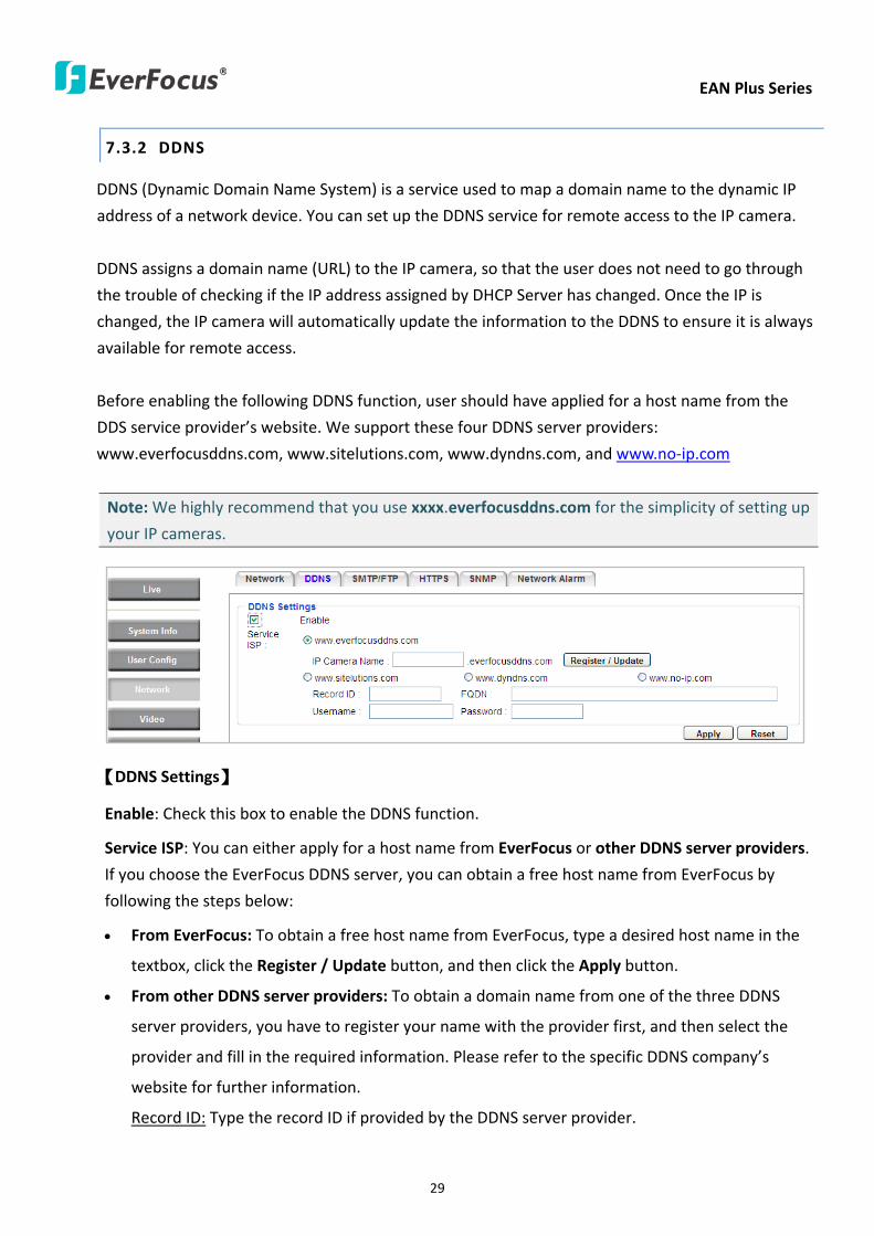
EAN Plus Series
29
732 DDNS
DDNS (Dynamic Domain Name System) is a service used to map a domain name to the dynamic IP
address of a network device You can set up the DDNS service for remote access to the IP camera
DDNS assigns a domain name (URL) to the IP camera so that the user does not need to go through
the trouble of checking if the IP address assigned by DHCP Server has changed Once the IP is
changed the IP camera will automatically update the information to the DDNS to ensure it is always
available for remote access
Before enabling the following DDNS function user should have applied for a host name from the
DDS service providerrsquos website We support these four DDNS server providers
wwweverfocusddnscom wwwsitelutionscom wwwdyndnscom and wwwno-ipcom
Note We highly recommend that you use xxxxeverfocusddnscom for the simplicity of setting up
your IP cameras
【DDNS Settings】
Enable Check this box to enable the DDNS function
Service ISP You can either apply for a host name from EverFocus or other DDNS server providers
If you choose the EverFocus DDNS server you can obtain a free host name from EverFocus by
following the steps below
bull From EverFocus To obtain a free host name from EverFocus type a desired host name in the
textbox click the Register Update button and then click the Apply button
bull From other DDNS server providers To obtain a domain name from one of the three DDNS
server providers you have to register your name with the provider first and then select the
provider and fill in the required information Please refer to the specific DDNS companyrsquos
website for further information
Record ID Type the record ID if provided by the DDNS server provider
EAN Plus Series
30
FQDN Type the fully qualified domain name applied from the DDNS server provider For
example xxxxdyndnscom
Username Password Type the login account of your DDNS server provider
Click Apply to apply the setting changes or Reset to reset without saving the changes
Note
1 In order to support the full functionality of the camera you must open the port numbers (80
554 443) on the router for remote access to the IP camera This function is available on most
routers in the market and is often known as ldquoPort Forwardingrdquo To set up Port Forwarding
please consult the manual of the router
2 In certain router models it is possible that you will not be able to access the camera using
DDNS while inside the routerrsquos network Please try using a PC located outside of your routerrsquos
network
Default Ports on All EverFocus IP Cameras
HTTP 80
RTSP 554
HTTPS 443
EAN Plus Series
31
733 SMTP FTP
【Set SMTP Server (email)】This area is for configuring the mail server that is used to send e-mail
notifications from the camera to predefined addresses via SMTP Note that to enable e-mail
notification function you have to check the Send Mail Notification item on the Event dialog box
(see 771 Event Settings)
SMTP Server Enter the IP address or the host name of the SMTP server used to send e-mails
SMTP Port Enter the port number for SMTP The default is 25
Authentication Check this box if the SMTP server requires authentication (userpassword)
User name Input the userrsquos login ID if the SMTP server requires authentication
Password Input the userrsquos login password if the SMTP server requires authentication
EAN Plus Series
32
Receiver Address Input the e-mail addresses for receiving an e-mail message when an EVENT is
enabled and triggered Please use ldquordquo to separate multiple addresses
Sender Address Input the senderrsquos e-mail address so that the receiver can recognize the sender
when an Event message is received
Attach Image Check this box if you want to attach an image when an alarm is triggered or an IP
camera detects events
Send Test Email Click the Test button to send a testing email to the assigned address
Click Apply to apply the setting changes or Reset to reset without saving the changes
【Set FTP Server】The settings relating to the FTP server used to transmit the alarm images can be
configured here Note that to enable uploading images to the FTP server function you have to
check the Upload to FTP item on the Event dialog box (see 771 Event Settings)
FTP Server Enter the IP address or the host name of the FTP server
FTP Port Enter the port number for the FTP server Default is 21
Recording Path Assign the recording path
User Name Set FTP Userrsquos name
Password Set FTP password
PASV mode Check to enable Passive mode Passive mode is normally enabled If a connection
cannot be established uncheck PASV Moderdquo
Test FTP Server Click the Test button to send a testing file to the assigned FTP server
Click Apply to apply the setting changes or Reset to reset without saving the changes
EAN Plus Series
33
734 HTTPS
Hypertext Transfer Protocol Secure (HTTPS) is a combination of the Hypertext Transfer Protocol
and the SSLTLS protocol and provides encrypted communication and secure identification of a
network web server
Before using the HTTPS function for communication with the IP camera a Certificate must be
created first There are two ways to create and install a certificate Create Self-Signed Certificate
and Create Certificate Request
Create Self-Signed Certificate
Please note that even though self-signed certificates are free and offer some protection true
security is only implemented after the installation of a signed certificate issued by a certificate
authority
1 Click the Create Self-Signed Certificate button the following dialog appears
EAN Plus Series
34
2 Type the required Certificate information and then click the Apply button The subject line will
be displayed in the Installed Certificate Information field
3 Click the Property button a pop-up window appears to display the details of the certificate
4 To optionally create and install other certificates remove the existing one by clicking the
Remove button to erase the certificate
5 On the Web page change the address from ldquohttprdquo to https in the address bar and press
Enter on the keyboard Some Security Alert dialogs will pop up Click OK or Yes to enable HTTPS
Create Certificate Request
You can apply for an official certificate from an issuing Certificate Authority
1 Click the Create Certificate Request button the following dialog appears
EAN Plus Series
35
2 Type the required Certificate information and then click the Apply button The subject line will
be displayed in the Created Request field
3 Click the Property button a pop-up window appears to display the details of the certificate
4 To optionally create and install other certificates or request remove the existing one by clicking
the Remove button to erase the certificate or request
5 Copy the contents of the Certificate request (in PEM format) and paste it to the certificate
request field on the Web page of the 3rd-party certification authority such as Symantec VeriSign
Wait for the certificate authority to issue an SSLTLS certificate and then download the issued
certificate on your computer
6 In the Install Signed Certificate field click the Browse button to search for the issued certificate
and then click the Upload button to import the certificate Once the certificate has been
uploaded this field will show the subject line of the certificate
EAN Plus Series
36
735 SNMP
The default values for SNMP v1v2v2c and SNMP v3 are already filled in Click either of the
Enable buttons to enable either of the two Make your changes as desired Click on the Trap
Address field to enter the digits if required
736 Network Alarm
This function works with EverFocusrsquos CMS software eg the PowerCon or the Power Video Plus For
the setting details please refer to the CMS network alarm protocol
EAN Plus Series
37
74 Video
The settings relating to video such as streaming camera OSD can be configured on this page The
Video page has five tabs Multi-streaming Camera Advanced ROI and Privacy Mask
741 Multi Streaming
【Stream Settings】 This IP camera can output three video streams simultaneously For each of these
streams the user can set the compression format resolution bit rate and frame rate individually
Stream 1 is always enabled for live view To enable Stream 2 andor Stream 3 check the ldquoEnablerdquo
box the header of each stream
Note If you connect to the camera via the Internet and experience a delay (lag time) in the video
feed try to reduce the number of streams and the quality and resolution of the streams ndash but
keep the frame rate at its maximum
EAN Plus Series
38
Format Select the encoding format ndash H264 or MJPEG
Resolution Select the most suitable resolution for your needs
Frame Rate Select from 1 to 30 fps
Bit Rate If required select whether you want the stream to stream a Constant Bit Rate or a
Variable Bit Rate and set the values of whichever option you choose
Click Apply to apply the setting changes or Reset to reset without saving the changes
【Video Recording Settings】Select the stream you want to configure and then select whether you
want the recording files of that stream to be saved in AVI or ARV format Click Apply to apply the
setting changes or Reset to reset without saving the changes
【Time Stamp Settings】 You can select the DateTime format position and add the setting to the
streaming
Click Apply to apply the changes or Reset to reset without saving the changes
EAN Plus Series
39
742 Camera
【Image Settings】Set the Brightness Saturation Contrast or Sharpness of the image Click Apply to
apply the changes or Reset to reset without saving the changes
【Camera Settings】
Mirror Switch Mirror ON to rotate the image horizontally around a vertical axis
Flip Switch Flip ON to rotate the image vertically around a horizontal axis
AE There are two options
ALC Selecting Automatic Light Control allows the camera circuitry to either take bright spots
more into consideration (peak) bringing out detail in bright areas or less into consideration
(average) bringing out detail in shadows
AES Selecting Auto Electronic Shutter disables the Shutter setting below this setting In this
mode the camera measures the light level and decides whether it needs more or less light and
then automatically adjusts the shutter speed accordingly
BLC Back Light Compensation (BLC) is used to make the subject appear clearer when it is set
against a bright background
OFF Select to switch Back Light Compensation functions off
(ON)BLC The BLC can increase the exposure of a dark area surrounded by a brighter area HLC
can decrease the exposure of bright areas surrounded by darker areas This enables the
camera to better display information that would otherwise have been ldquowhited outrdquo like a
license plate between two bright headlights on a dark road
(ON)HLC The Highlight-Suppression BLC is used to reduce the brightness of light sources in a
specific area It is activated only in a low illumination environment to minimize the effects of
glare from bright lights such as spotlights street lights or headlights in the field of view
EAN Plus Series
40
WDR The Wide Dynamic Range (WDR) function provides clearer images when both of the very
bright and dark areas simultaneously appear on the camera view There are four value options
OFF Low Middle and High Note that when WDR is ON some parts of the image may appear
solarized This is normal for WDR and is not a camera malfunction This function is only available
for EAN3120 Plus 3220 Plus
DN Mode
Auto Select to let the camera automatically switch to Night mode (black and white) when the
light levels fall to a specified level and back to Day mode (color) when the light levels rise to a
specified level
Day Select to keep the camera in Day mode (color) even in nighttime
Night Select to keep the camera in Night mode (black and white) even in daytime
EAN Plus Series
41
743 Advanced
EAN Plus Series
42
【Camera Settings】
Lens (IRIS Control) Select DC or Manual for IRIS control This function is only available for EAN3220
Plus
Exposure Settings (AE) This setting is used to adapt to the amount or type of light used by the
camera Note the settings vary among models
Mode This function is not available for EAN3220 Plus
Automatic Light Control (ALC) This option is only available for EAN3120 Plus 3300 Plus The
ALC allows the camera circuitry to either take bright spots more into consideration (peak)
bringing out detail in bright areas or less into consideration (average) bringing out detail in
shadows
Auto Electronic Shutter (AES) This option is only available for EAN3120 Plus 3300 Plus In
this mode the camera measures the light level and decides whether it needs more or less light
and then automatically adjusts the shutter speed accordingly
Manual This option is only available for EAN3300 Plus Select this option to manually set up
the Shutter (Manual) and AGC (Manual) values
Iris Specify the size of the Iris opening here
Shutter If enabled this setting lets you set the shutter speed yourself
Shutter Limit Use this setting to set the maximum shutter speed for the camera This function is
only available for EAN3120 Plus
AGC Set the Auto Gain Control limit here The lower the AGC level the lower the video signal and
the noise However the image will be darker under low-light condition with IR-off if you set up the
Iris to the maximum level
Slow Shutter This option can be switched on when AES Mode is selected in the Exposure Settings
(AE) field This function is only available for EAN3220 Plus 3300 Plus
Flickerless If the Mode field in the Exposure Settings (AE) area has been set to AES then this option
becomes available Choose between OFF 50HZ 60HZ 50HZ (High Luminance) or 60HZ (High
Luminance) This function is only available for EAN3300 Plus
EV Setting Set up the Exposure Value Note the brightness of the screen changes when you change
the EV value This function is only available for EAN3300 Plus
AE Response Set up Auto Exposure Response time This function is only available for EAN3300 Plus
AE Weighting Area Select an AE Weighting area Each setup AE Weighting Area is configured with
the appropriate brightness level on the center and the surrounding areas This function is only
available for EAN3300 Plus
Brightness Set the image brightness here
AE Reference Set the Auto Exposure value here This function is only available for EAN3120 Plus
EAN Plus Series
43
Black Level Set the Black level here This function is only available for EAN3300 Plus
WDR The Wide Dynamic Range (WDR) function provides clearer images when both of the very
bright and dark areas simultaneously appear on the camera view There are four value options OFF
Low Middle and High Note that when WDR is ON some parts of the image may appear solarized
This is normal for WDR and is not a camera malfunction This function is only available for EAN3120
Plus 3220 Plus
Visibility Enhancement (OFFLowMiddleHigh) Images in foggy or rain environments or in
environments with a very strong luminous intensity have a dynamic range that is significantly lower
than ordinary images The user can use this Visibility Enhancement setting to ldquoDEFOGrdquo the image if
such ldquoFOGGINGrdquo is an issue This function is only available for EAN3220 Plus
BLC Settings Back Light Compensation (BLC) is used to make the subject appear clearer when it is
set against a bright background
OFF Select to switch Back Light Compensation functions off
Back Light This option is only available for EAN3300 Plus The Back Light function is useful
when the background of the subject is very bright and the subject itself is dark Select Back
Light and adjust the slide bar to the left right for setting up the back light value The higher
the value the more the backlight compensation
Front Light This option is only available for EAN3300 Plus This function is useful when the
bright highlights such as flashlight or car headlights appear on the camera view Select Front
Light and adjust the slide bar to the left right for setting up the front light value The higher
the value the more the highlight compensation
ON (BLC) This option is only available when you select AES Mode in the Exposure Settings (AE)
field The option is only available for EAN3120 Plus 3220 Plus The BLC function is useful
when the background of the subject is very bright and the subject itself is dark Follow the
instructions below to configure the settings for each model
For EAN3120 Select ON (BLC) the button next to the Mode drop-down list will be
active (see image below) Click the button the green setup areas appear on the left
screen Click on the areas to enable disable the BLC function The selected areas (in green)
will be applied with the BLC function
EAN Plus Series
44
For EAN3220
You can configure one area to apply the BLC function Select ON (BLC) the setup buttons
appears (see image below) Select Low Middle High from the BLC Gain drop-down list To
set up a BLC area click the Edit Area button and then click on the blue color tab to turn your
mouse cursor into a blue pen Move the cursor to the position on the right screen where you
want the BLC rectangle to start and then click Move your cursor to the position (diagonally
opposing corner) where you want the BLC rectangle to end and then click The blue area will
be applied with the BLC function
ON (HLC) This option is only available when you select AES Mode in the Exposure Settings (AE)
field The option is only available for EAN3120 Plus 3220 Plus This function is useful when
the bright highlights such as flashlight or car headlights appear on the camera view Follow
the instructions below to configure the settings for each model
For EAN3120 Select ON (HLC) and then select a level from the drop-down list The higher the
level the more the highlight compensation
For EAN3220
HLC Level Select a level for the HLC setting The higher the level the more the highlight
compensation
HLC Mode Select All Day Night mode to apply the HLC function
HLC Black Mask Select On Off to apply the black mask on the selected areas The
over-exposure portions within the selected areas will be applied with the black mask
Color Tabs You can set up four HLC areas with different colors To set up a HLC area click the
Edit Area button and then click on the color tab to turn your mouse cursor into a pen of that
color Move the cursor to the position on the right screen where you want the HLC rectangle
to start and then click Move your cursor to the position (diagonally opposing corner) where
you want the HLC rectangle to end and then click Select ON from the color tab drop-down list
The rectangular area with the selected color will be applied with the HLC function
EAN Plus Series
45
Back Light This option is only available for EAN3300 Plus The Back Light function is useful
when the background of the subject is very bright and the subject itself is dark Select Back
Light and adjust the slide bar to the left right for setting up the back light value The higher
the value the more the backlight compensation
Front Light This option is only available for EAN3300 Plus This function is useful when the
bright highlights such as flashlight or car headlights appear on the camera view Select Front
Light and adjust the slide bar to the left right for setting up the front light value The higher
the value the more the highlight compensation
Noise Reduction Settings This limits the amount of digital ldquovideo noiserdquo that is usually found in any
video stream and helps to reduce file size The higher the level the more the reduction
For EAN3120 Plus 3300 Plus
Select ON OFF to enable disable the Noise Reduction function Or select Auto to let the camera
automatically enable disable the Noise Reduction function Slide the Level bar to set up the level
The higher the level the more the reduction
For EAN3220 Plus
2D DNR Select ON to enable the 2D DNR function
3D DNR Select ON to enable the 3D DNR function You can further set up the following settings
3D Start AGC Set up the AGC level to automatically start the 3D NR function
3D End AGC Set up the AGC level to automatically stop the 3D NR function
3D Level Set up the 3D DNR level
Smart NR Select ON to enable the Smart NR function The 3D NR function will be
automatically turned on when a motion event occurs
EAN Plus Series
46
White Balance Settings Select the mode that delivers the best quality image for the camerarsquos light
environment There are five options Auto Manual Indoor Outdoor One Push
Auto Select to let the camera automatically adjust the White Balance In the Auto mode the
camera computes the white balance value output using color information from the entire
screen It outputs the proper value using the color temperature radiating from a black subject
based on a range of value from 3000 to 7500K
Manual Select to adjust the Red and Blue values yourself in the fields below this field
Indoor Select to use the default settings for indoor environments In the Indoor mode the
camera uses 3200K as the base value
Outdoor Select to use the default settings for outdoor environment In the Outdoor mode it
uses 5800K as the base value
One Push Select to enable the Push button next to the Mode drop-down field This will allow you to force the camera to readjust the white balance every time you push the Push
button The lens will hold the same focal position until the next trigger command is received
This function helps to prevent incorrect focusing in dark environments This function is only
available for EAN3120 Plus 3220 Plus
Manual Temperature Select to use the optimized Red and Blue settings You can also
optionally adjust the Manual Level below this field for setting up the color temperature The
higher the value the more the color temperature This function is only available for EAN3300
Plus
DayNight Settings
Auto Select to let the camera automatically switch to Night mode (black and white) when the
light levels fall to a specified level and back to Day mode (color) when the light levels rise to a
specified level
Day Select to keep the camera in Day mode (color) even in nighttime
Night Select to keep the camera in Night mode (black and white) even in daytime
IR Smart Settings Select ON and set up the level to enhance the image quality when the images are
over exposure This function is useful when the camera is in the Night mode This function is only
available for EAN3220 Plus
Saturation Set the saturation value This function is not available for EAN3220 Plus
Monitor Type Select a gamma value from Set 1 Set 2 or Set 3 This function is only available for
EAN3120 Plus
Negative Switch this setting ON to view a color negative version of the video image This is useful
at night or when viewing temperature-sensitive images
EAN Plus Series
47
Sharpness Settings Select the sharpness level of the image A low sharpness level will deliver a
softer less detailed image A high level will deliver a sharp highly detailed image Switch Resolution
Enhancement ON to enable the resolution enhancement function
Contrast Select the contrast level of the image
Suppress Function This function is only available for EAN3300 Plus
Aperture Compensation Suppression (OFFLowMiddleHigh) This setting can be activated to
suppress luminance noise when the AGC level increases
Chroma Suppression (OFFLowMiddleHigh) This setting can be activated to suppress
chrominance noise when the AGC level increases
Ygamma (gamma 22standardcontrast enhancehigh light range mode LHigh light range mode
H) Select the Ygamma value for the video quality of the monitor This function is only available for
EAN3300 Plus
Monitor Settings The user can use this field to optimize video quality for his or her specific type of
monitor ndash LCD or CRT This function is only available for EAN3220 Plus
Color Space Standard The options are YUV601 for SD and YUV709 for HD These define the color
space standard required to convert an RGB picture to a YUV picture Generally YUV601 is used for
Standard Definition (720P) devices and the YUV709 is used for High Definition (1080P) devices
Click Apply to save all changes Click Reset to cancel all changes
EAN Plus Series
48
744 ROI (Region of Interest)
The Region of Interest (ROI) function allows users to set up multiple regions within an image with
better quality and less distortion than the rest of the image You can also use this function
together with the Digital Zoom function on the Live View Page to get a better image result Up to
eight ROIs can be configured in the ROI settings page
To set up an ROI region
1 Select an ROI number from the ROI No drop-down list
2 Click the Add button the mouse cursor will turn into a pen when you move it over the live
image on the left
3 Move the cursor to the position where you want the ROI rectangle to start and then click
Move the cursor to the position (diagonally opposing corner) where you want the ROI
rectangle to end and then click
4 Slide the Quality bar to set up the quality value
5 Click the Apply button to apply the settings or click the Reset button to reset without saving
the settings
EAN Plus Series
49
745 Privacy Mask
The Privacy Mask can block out sensitive areas from view covering the areas with colored or black
and white boxes in both live view and recorded clips This feature is useful when usersrsquo donrsquot want
the sensitive information visible Up to four Privacy Masks can be configured
【Privacy Mask Color Settings】The Modes vary among camera models
Mode Click Color to make the masks appear as colored rectangles on the screen Click BW to
make the masks appear as gray rectangles on the screen Click Mosaic to make the masks appear
as mosaic-effect rectangles on the screen
Level Select the color of the masks if you selected Color Mode Select the level of grayness of the
masks if you selected BW Mode Select the level of smallmiddlelarge if you selected Mosaic
Mode
Click Apply to apply the settings or click Reset to reset without saving the settings
Color Tabs Click on a color tab to turn your mouse cursor into a pen of that color
You can now create a block of that color on the video screen Move your cursor to the position
where you want your mask rectangle to start and then click Move your cursor to the position
(diagonally opposing corner) where you want your mask rectangle to end and then click The
rectangular area with the selected color will appear The live image will display the rectangular
area with the color you selected If you want to create another mask use one of the other three
colors Each color denotes a different mask area Only one block per color is allowed As the
number of colors suggests you can configure up to four blocks
EAN Plus Series
50
Select All Click to turn the whole screen into a mask area
Clear All Click to delete all configured mask blocks
Eraser Click to turn the mouse cursor into an eraser to delete any block you click on
Area Shows the color and number of the block
Enable Check this box to enable the related mask block
Click Apply to apply the settings or click Reset to reset without saving the settings
EAN Plus Series
51
75 Audio
The EAN Plus series IP camera can transmit audio to your computer if you have connected an external
microphone to its audio Input cable It can also receive audio input from you and transmit it via an
external speaker if you have connected such a speaker to its audio Output cable
Check the Enable Audio box to enable the camerarsquos audio function The camera will now act as a
digital bridge (via the IP network) between any connected audio input device and any connected
audio device
Adjust the Audio Input Volume if you have external audio input devices (microphones) connected to
the camera and if there are problems with the sound input being too low or high
Click Apply to save all settings or click Reset to cancel
EAN Plus Series
52
76 User
761 User Information
The system administrator can create up to ten user accounts on this page
To set up a user account
1 Highlight a user account and click the Modify button The following dialog box appears
2 Type the account name account description and password for the account Type the password
again in the Confirm field
3 Select an authority level for the user account from the Authority drop-down list
bull Supervisor Administrator The only difference between a supervisor and administrator is
that a supervisor can edit an administratorrsquos account and password but an administrator
cannot edit the supervisorrsquos account and password Multiple administrators can be
configured but there can be only one supervisor The supervisor and administrators all
have unrestricted access to the Settings submenus and can determine the registration of
all other users
EAN Plus Series
53
bull User A user can view the Live View page and view the system network video and audio
information A user can only adjust the User Config page settings The user does not have
access to the User Event and System pages
bull Guest The lowest level of access which only allows the user access to the Live View page
4 Select Active or Disable from the Status drop-down list to active or disable the user account
5 Click On in the SD Card Playback field to allow the user to access the SD card playback
function
6 Click OK
7 Click Apply to save all the settings
EAN Plus Series
54
762 IP Address Filter
Use this page to specify IP addresses that are not allowed to access this camera By default any IP
address can access the camera
Note The Allowed List addresses only become relevant when the Denied List contains a network
or range and the supervisor wants to allow one or more IP addresses within that excluded range
or network In such a scenario the user would enter the excluded range or network in the
Denied List and enter the exceptions in the Allowed List
To set up the IP Address Filter
1 Select Denied List Click the Add button the following dialog box appears
2 Select an IP type from the IP Type drop-down list
3 Select a network rule from the Rule drop-down list type the IP address and click OK
Single Type a single IP address in the IP Address field below
Network Type the IP address and subnet mask in the field below
Range Type a range for the IP addresses
4 If you have set up an IP range in Step 3 you can optionally set up the Allowed List to allow one
or more IP addresses within the setup IP range to access the IP camera
5 Click Apply
EAN Plus Series
55
77 Event
You can set up the Motion Detection event Tamper Detection event or the Alarm IO to automatically
notify the users when an event occurs or an alarm is triggered You can also set up a schedule to
automatically record the videos when an event occurs or an alarm is triggered
771 Event Settings
You can create a total of ten event or alarm settings page in the Event List
【Event List】
Click the Add button and the following Event Configuration Window appears
EAN Plus Series
56
Enter Event Name Type an event name
Event Triggered by Select an event or alarm type for the to-be-specified-below reactions
Alarm Input Select this if you want a reaction trigger coming from any external connected sensor
to activate a to-be-specified-below reactions via the camera system Make sure that a suitable
device is actually connected to the alarm input relay
Manual Trigger Select this option if you want to manually trigger the alarm by clicking the Trigger
Event button on the Live View Page
Motion Detection Select this option if you want motion in a specified part of the camerarsquos viewing
rectangle (the screen image) to trigger the to-be-specified-below reactions
Tampering Detection Select this option if you want the camerarsquos tampering detection sensor to
trigger the to-be-specified-below reactions
Schedule Recording Select this option if you want the Schedule Recording periods configured in
the recording schedule (the Settings gt Event gt Schedule page) to activate this event In this
scenario a preconfigured event reaction like a log entry will list the start and end times of each
period Actual recording will only be triggered if the event is preconfigured to do so
Enable This Event Select to activate the event
Enable Re-trigger Click to set a minimum time after the event is triggered before the event
can be triggered again
Enable Pre-trigger Buffer Click if you want the Event reaction (as selected in the ldquoNotification
Overrdquo field below) to be the activation of the video recording function and if you want the
recording to include the video feed from the time period (configurable on the previous ldquoEvent
Settingsrdquo page) just before the Event trigger occurred
Enable Post-trigger Buffer Click if you want the Event reaction (as selected in the Notification
Over field) to be the activation of the video recording function and if you want the recording
to include the video feed from a time period (configurable on the Event Settings page) just
after the Event trigger occurred
Motion Area Select a setup motion detection area from the drop down list Note this
function only becomes relevant after the Motion Detection areas have been set up (see 772
Motion Detection)
Notification Over Select the desired notification types form the following items
Log Click if you want the camera to list the eventrsquos details in its log if the event is triggered
Trigger Alarm Output Click if you want the camera to relay the event reaction to a device
attached to the alarm relay output wire and then set up the alarm output duration time
EAN Plus Series
57
Send Mail Notification Click if you want the camera to send an Event notification email to the
email address entered in the Set SMTP Server(email) field of the Network gt SMTPFTP page if
the Event occurs (see 733 SMTP FTP)
Upload to FTP Click if you want the camera to upload recorded footage to the FTP server
entered in the Set SMTP Server(email) field of the Network gt SMTPFTP page if the Event
occurs (see 733 SMTP FTP)
Record to SD Card Click if you want the camera to start recording its video feed (when the
event occurs) on an on-camera SD Card (if such a card has been inserted)
Note The recording will only be as long as the combined Pre- and Post-trigger Buffers so
make sure you enable at least one of these buffers especially the Post-trigger Buffer
Record to PC Check this box if you want the camera to start recording its video feed (when
the event occurs) on the same folder on the same PC as configured on the User Config gt
RecordingSnapshot page (if such a folder has been enabled and configured)
Note The recording will only be as long as the combined Pre- and Post-trigger Buffers (and
for as long as the event trigger is happening ndash eg a motion is detected) so make sure you
enable at least one of these buffers especially the Post-trigger Buffer
Network Alarm Check this box if you want the camera to send a network alarm signal (when
the event occurs) to the CMS servers configured on the Network gt Network Alarm page (see
736 Network Alarm)
Click OK to save all settings or click Cancel to cancel
【PrePost Trigger Settings】
Pre-trigger Buffer Select the duration for the buffer This will determine the amount of footage
(length of time) before the event trigger moment that will be included in an event-triggered video
recording if that buffer and video recording has been enabled in the Event Configuration Window
Post-trigger Buffer Select the duration for the buffer This will determine the amount of footage
(length of time) after the event trigger moment that will be included in an event-triggered video
recording if that buffer and video recording has been enabled in the Event Configuration Window
Click Apply to save all settings or click Reset to cancel
EAN Plus Series
58
772 Motion Detection
Use this page to configure up to four areas in which motion will be detected When a motion is
detected by the camera the motion detection icon will appear at the top right of the
Live page to alert the user This function can also be linked with correctly configured Events to
trigger Event reactions like the activation of video recording periods snapshots alarms etc
Color Tabs Click on a color tab to turn your mouse cursor into a pen of that color
You can now create a block of that color on the video screen Move your cursor to the position
where you want your detection rectangle to start and then click Move your cursor to the position
(diagonally opposing corner) where you want your detection rectangle to end and then click The
rectangular area with the selected color will appear This block will be an area inside which the
camera will detect motion If you want to create another detection area use one of the other three
palette colors Each color denotes a different detection area Only one block per color is allowed As
the number of colors suggests you can configure up to four blocks
Select All Click to turn the whole screen into a motion detection area
Clear All Click to delete all configured motion detection blocks
Eraser Click to turn your mouse cursor into an eraser to delete any block you click on
Area Shows the color and numberID of the block
Enable Check this box to enable the related motion detection block
Sensitivity Set the sensitivity of the motion detection sensor function
Click Apply to save all settings or click Reset to cancel
EAN Plus Series
59
773 Tamper Detection
Use this page to set the number of seconds that an alarm signal will be active if the device is
physically tampered (moved covered up or out of focus
774 Alarm IO
Use this page to set the type of trigger input and the type of output contact for the camerarsquos alarm
channel
EAN Plus Series
60
775 Schedule
Use this page to configure a schedule for periods during which the camera should deactivate all
user-activated Events (gray Deselect periods) or when the camera should deactivate all
user-activated Events except Schedule Recording (SR) events (blue Schedule Recording-only
periods) or when the camera should deactivate only SR events (red Event Recording-only periods)
or when it should enable all activated Events (yellow periods)
Event Recording Click this button to make every hour block you click on red A red block represents
an Event Recording-only block which represents an hour when the camera will deactivate all
preconfigured activated Schedule Recording events and keep all the other activated events active
Schedule Recording Click this button to make every hour block you click on blue A blue block
represents a Schedule Recording-only block which represents an hour when the camera will
deactivate all other preconfigured activated events and keep only the preconfigured activated
Schedule Recording events active
Event + Schedule Click this button to make every hour block you click on yellow A yellow block
represents an hour in which all activated events including Schedule Recording events will be
active
Deselect Click this button to make every hour block become grey A grey block represents an hour
in which all activated events including Schedule Recording events will be inactive
Click Apply to save all settings or click Reset to cancel
EAN Plus Series
61
78 System
You can set up the systemrsquos time and SD card settings and to do maintenance and reset actions like
reboots and upgrades
781 DateTime
【Machine Name Settings】If required enter a new name for the machine This name will be visible
in the Machine Name field of the IP Utility software which is included in the software CD
【Set Time Zone】Set the time zone of the camerarsquos location
【Set DateTime Manually】Set the datetime here if you wonrsquot be using an NTP server to update the
datetime (see below)
【Set DateTime Sync】Enter the Network Time Protocol server if applicable The camerarsquos time will
be automatically adjusted by synchronizing with the NTP server
Click Apply to save all settings or click Reset to cancel
EAN Plus Series
62
782 Daylight Saving
Click Enable Daylight Saving to enable this schedule and select the dates when the regionrsquos
daylight saving period begins and ends Click Apply to save all settings or click Reset to cancel
783 SD Card
Use this page to prepare the system for safely removing the SD Card from its slot
【Setup SD Card】
Notification Select the percentage of storage space that should be left on the card before the
camera notifies you of the impending storage shortage or overwrite
Event Recording Select if you want Event Recording only FTP Backup only or both
Overwrite Click ON if you want the card to start writing over recorded footage when its memory is
full Click OFF if you want the card to stop recording new footage when its memory is full
【SD Card Utility】
Capacity This shows you how much card memory has been used and how much memory capacity
remains on the card
Remove Click this button before removing the card from the system
Format Click this button to format the card All data saved on the SD card will be removed if the
card is formatted
EAN Plus Series
63
784 Maintenance
【Maintenance Server】
Reboot Click this button to reboot the unit without changing any of the settings Use this function if
the unit is not behaving as expected
Restore Click this button to restart and reset most of the current settings to their factory default
values The only settings that will not be changed to default are
bull IP settings
bull DDNS settings
Default The Default button should be used with caution Pressing this button will return all of the
cameras settings including the IP address to the factory default values The camera will then have
to be reconfigured
【SaveLoad Configuration Server】
Save To make a backup file of the machinersquos current configurations press Save to save all the
configurations to a config file This will enable the user to reload these configuration settings if the
settings are changed and there is unexpected behavior
Load To load a previously saved configuration press the Browse button to locate the saved config
file (see above) and then click the Load button The systemrsquos settings will be restored to the saved
configuration
EAN Plus Series
64
【SaveLoad Video Configuration Server】
Save To make a backup file of the machinersquos video configurations press Save to save the video
configurations to a config file This will enable the user to reload these configuration settings if the
settings are changed and there is unexpected behavior
Load To load a previously saved video configuration press the Browse button to locate the saved
config file (see above) and then click the Load button The systemrsquos settings will be restored to the
saved video configuration
【Upgrade Firmware】Click the Browse button to find a previously prepared firmware upgrade file
Click Upgrade to install the new firmware
Note
1 Do not disconnect power to the unit during the upgrade sequence The unit will reboot
automatically after the upgrade has completed (1-5 minutes)
2 During the upgrade process all event recording actions will be stopped Event recording
actions will resume after the camera is rebooted
3 If the ldquoFile Error Please re-loginrdquo warning message appears when upgrading the firmware
please try the following instructions
a Go to Internet Explorer gt Tools gt Internet Option gt Security gt Custom
b Find and enable the Include local directory path when uploading files to a server
EAN Plus Series
65
8 Upgrading Firmware Using IP Utility
You can upgrade the Firmware using the IP Utility software included in the software CD
1 Install and then start the IPU program The following dialog box appears
2 Click Find Devices to search the cameras connected in the LAN The default network values of the
cameras will be displayed By default the network protocol of the camera is DHCP
3 Select a camera and click LoginMulti Login to log in the camera
4 Type the user ID and password Click OK
Note
1 The default user ID is user1 and the default password is 11111111
2 If you select more than one camera that has the same user ID password you will be able
to log in several cameras at once
EAN Plus Series
66
5 Highlight the camera and then click Upgrade Firmware A browsing window appears
6 Select the firmware file (evb) and then click Open The IP Utility will automatically upgrade the
firmware
The camera will reboot once the update is complete Click Find Devices the new firmware version
should be displayed in the last part of the Machine Name
EAN Plus Series
67
9 Specifications
Model EAN3120 Plus EAN3220 Plus EAN3300 Plus
Camera
Image Sensor 13 Panasonic CMOS 128 Sony CMOS
Megapixel 13 MP 2 MP 3 MP
Picture Elements (H x V) 1280 x 1024 1944 x 1092 2048 x 1536
Min Illuminations 003 Lux at F14
Electronic Shutter (Sec) 85 ~ 160000 2 ~ 150000 1 ~ 110000
Scanning System NTSC PAL
WDR Yes Yes No
BLC Yes
Gain Control Yes
White Balance Yes
Lens
Mounting Type C CS
Day Night Yes (with removable auto IR-cut filter)
IRIS Control DC Electrical IRIS Lens IRIS
Video
Video Compression H264 MJPEG
Resolution
NTSC
2048 x 1536 1920 x 1200 (for EAN3300 Plus only)
1920 x 1080 (for EAN3300 Plus 3220 Plus only)
1280 x 1024 1280 x 720 1024 x 768 720 x 480 704 x 480 640 x 480
352 x 240 320 x 240 160 x 120
PAL
2048 x 1536 1920 x 1200 (for EAN3300 Plus only)
1920 x 1080 (for EAN3300 Plus 3220 Plus only)
1280 x 1024 1280 x 720 1024 x 768 720 x 576 704 x 576 640 x 480
352 x 288 320 x 240 160 x 120
Frame Rate 30 fps at 1280 x 1024 30 fps at 1920 x 1080 15 fps at 2048 x 1536
Audio
Audio Streaming Two-way audio
Audio Compression G711
EAN Plus Series
68
Network
Interface 10 100 Base-T Ethernet RJ-45 socket
Supported Protocols
TCPIP IPV6 UDP ICMP DHCP NTP DNS DDNS SMTP SNMP FTP
HTTP HTTPs PPPoE UPnP Bonjour RTP RTSP RTCP IGMP ARP ONVIF
PSIA
Connector
Power DC female port PoE
Ethernet RJ-45
Audio 1 In (phone jack for microphone)
1 Out (phone jack for Speaker)
Alarm IO Terminal IO wires
Local Storage Micro SD SDHC memory card slot
TV-Out BNC socket composite 1 V p-p 75 Ω
General
Power Source DC 12V PoE (IEEE8023af)
Power Consumption
(IR LEDs On)
5W (DC 12V)
621W (PoE)
5W (DC 12V)
522W (PoE)
5W (DC 12V)
536W (PoE)
Operating Temperature 0degC ~ +50degC 32degF ~ +122degF
Humidity 20 to 80 (no condensation)
Safety CE FCC
Dimensions (L x W x H) 117 x 56 x 68 mm 46 x 22 x 27 in
Weight 410 g 09 lb
EverFocus Electronics Corp EverFocus Taiwan 12F No79 Sec 1 Shin-Tai Wu Road Hsi-Chih Taipei Taiwan TEL +886 2 2698 2334 FAX +886 2 2698 2380 wwweverfocuscomtw marketingeverfocuscomtw
EverFocus Europe - Germany Albert-Einstein-Strasse 1 D-46446 Emmerich Germany TEL +49 2822 93940 FAX +49 2822 939495 wwweverfocusde infoeverfocusde
EverFocus China - Beijing Room 609 Technology Trade Building Shangdi Information Industry Base Haidian District Beijing 100085 China TEL +86 10 6297 3336~39 FAX +86 10 6297 1423 wwweverfocuscomcn marketingeverfocuscomcn
EverFocus China - Shenzhen 4F No 2 D4 Building Wan Yelong Industrial Park Tangtou Road Shiyan Baoan Shenzhen Guangdong 518101 China TEL +86 755 2765 1313 FAX +86 755 2765 0337 wwweverfocuscomcn marketingeverfocuscomcn
EverFocus USA - California 1801 Highland Avenue Unit A Duarte CA 91010 USA TEL +1 626 844 8888 FAX +1 626 844 8838 wwweverfocuscom saleseverfocuscom
EverFocus USA - New York 415 Oser Avenue Unit S Hauppauge NY 11788 USA TEL +1 631 436 5070 FAX +1 631 436 5027 wwweverfocuscom saleseverfocuscom
EverFocus Japan 5F Kinshicho City Building 2-13-4 Koto-BashiSumida-Ku Tokyo 130-0022 Japan TEL +81 3 5625 8188 FAX +81 3 5625 8189 wwweverfocuscojp infoeverfocuscojp
EverFocus Europe - UK Unit 12 Spitfire Business Park Hawker Road Croydon Surrey CR0 4WD UK TEL +44 20 8649 9757 +44 845 430 9999 FAX +44 20 8649 9907 wwweverfocusukcouk salesukeverfocuscom
EverFocus India Suite 803 Housefin Bhavan C-21 Bandra Kurla Complex Bandra (East) Mumbai 400051 India TEL +91 22 6128 8700 FAX +91 22 6128 8705 wwweverfocusin saleseverfocusin
PN 4605PQ3120B010A-VerC
Your EverFocus product is designed and manufactured with high quality materials and components which can be recycled and reused This symbol means that electrical and electronic equipment at their end-of-life should be disposed of separately from your household waste Please dispose of this equipment at your local community waste collectionrecycling centre In the European Union there are separate collection systems for used electrical and electronic product Please help us to conserve the environment we live in
Ihr EverFocus Produkt wurde entwickelt und hergestellt mit qualitativ hochwertigen Materialien und Komponenten die recycelt und wieder verwendet werden koumlnnen Dieses Symbol bedeutet dass elektrische und elektronische Geraumlte am Ende ihrer Nutzungsdauer vom Hausmuumlll getrennt entsorgt werden sollen Bitte entsorgen Sie dieses Geraumlt bei Ihrer oumlrtlichen kommunalen Sammelstelle oder im Recycling Centre Helfen Sie uns bitte die Umwelt zu erhalten in der wir leben
EAN Plus Series
30
FQDN Type the fully qualified domain name applied from the DDNS server provider For
example xxxxdyndnscom
Username Password Type the login account of your DDNS server provider
Click Apply to apply the setting changes or Reset to reset without saving the changes
Note
1 In order to support the full functionality of the camera you must open the port numbers (80
554 443) on the router for remote access to the IP camera This function is available on most
routers in the market and is often known as ldquoPort Forwardingrdquo To set up Port Forwarding
please consult the manual of the router
2 In certain router models it is possible that you will not be able to access the camera using
DDNS while inside the routerrsquos network Please try using a PC located outside of your routerrsquos
network
Default Ports on All EverFocus IP Cameras
HTTP 80
RTSP 554
HTTPS 443
EAN Plus Series
31
733 SMTP FTP
【Set SMTP Server (email)】This area is for configuring the mail server that is used to send e-mail
notifications from the camera to predefined addresses via SMTP Note that to enable e-mail
notification function you have to check the Send Mail Notification item on the Event dialog box
(see 771 Event Settings)
SMTP Server Enter the IP address or the host name of the SMTP server used to send e-mails
SMTP Port Enter the port number for SMTP The default is 25
Authentication Check this box if the SMTP server requires authentication (userpassword)
User name Input the userrsquos login ID if the SMTP server requires authentication
Password Input the userrsquos login password if the SMTP server requires authentication
EAN Plus Series
32
Receiver Address Input the e-mail addresses for receiving an e-mail message when an EVENT is
enabled and triggered Please use ldquordquo to separate multiple addresses
Sender Address Input the senderrsquos e-mail address so that the receiver can recognize the sender
when an Event message is received
Attach Image Check this box if you want to attach an image when an alarm is triggered or an IP
camera detects events
Send Test Email Click the Test button to send a testing email to the assigned address
Click Apply to apply the setting changes or Reset to reset without saving the changes
【Set FTP Server】The settings relating to the FTP server used to transmit the alarm images can be
configured here Note that to enable uploading images to the FTP server function you have to
check the Upload to FTP item on the Event dialog box (see 771 Event Settings)
FTP Server Enter the IP address or the host name of the FTP server
FTP Port Enter the port number for the FTP server Default is 21
Recording Path Assign the recording path
User Name Set FTP Userrsquos name
Password Set FTP password
PASV mode Check to enable Passive mode Passive mode is normally enabled If a connection
cannot be established uncheck PASV Moderdquo
Test FTP Server Click the Test button to send a testing file to the assigned FTP server
Click Apply to apply the setting changes or Reset to reset without saving the changes
EAN Plus Series
33
734 HTTPS
Hypertext Transfer Protocol Secure (HTTPS) is a combination of the Hypertext Transfer Protocol
and the SSLTLS protocol and provides encrypted communication and secure identification of a
network web server
Before using the HTTPS function for communication with the IP camera a Certificate must be
created first There are two ways to create and install a certificate Create Self-Signed Certificate
and Create Certificate Request
Create Self-Signed Certificate
Please note that even though self-signed certificates are free and offer some protection true
security is only implemented after the installation of a signed certificate issued by a certificate
authority
1 Click the Create Self-Signed Certificate button the following dialog appears
EAN Plus Series
34
2 Type the required Certificate information and then click the Apply button The subject line will
be displayed in the Installed Certificate Information field
3 Click the Property button a pop-up window appears to display the details of the certificate
4 To optionally create and install other certificates remove the existing one by clicking the
Remove button to erase the certificate
5 On the Web page change the address from ldquohttprdquo to https in the address bar and press
Enter on the keyboard Some Security Alert dialogs will pop up Click OK or Yes to enable HTTPS
Create Certificate Request
You can apply for an official certificate from an issuing Certificate Authority
1 Click the Create Certificate Request button the following dialog appears
EAN Plus Series
35
2 Type the required Certificate information and then click the Apply button The subject line will
be displayed in the Created Request field
3 Click the Property button a pop-up window appears to display the details of the certificate
4 To optionally create and install other certificates or request remove the existing one by clicking
the Remove button to erase the certificate or request
5 Copy the contents of the Certificate request (in PEM format) and paste it to the certificate
request field on the Web page of the 3rd-party certification authority such as Symantec VeriSign
Wait for the certificate authority to issue an SSLTLS certificate and then download the issued
certificate on your computer
6 In the Install Signed Certificate field click the Browse button to search for the issued certificate
and then click the Upload button to import the certificate Once the certificate has been
uploaded this field will show the subject line of the certificate
EAN Plus Series
36
735 SNMP
The default values for SNMP v1v2v2c and SNMP v3 are already filled in Click either of the
Enable buttons to enable either of the two Make your changes as desired Click on the Trap
Address field to enter the digits if required
736 Network Alarm
This function works with EverFocusrsquos CMS software eg the PowerCon or the Power Video Plus For
the setting details please refer to the CMS network alarm protocol
EAN Plus Series
37
74 Video
The settings relating to video such as streaming camera OSD can be configured on this page The
Video page has five tabs Multi-streaming Camera Advanced ROI and Privacy Mask
741 Multi Streaming
【Stream Settings】 This IP camera can output three video streams simultaneously For each of these
streams the user can set the compression format resolution bit rate and frame rate individually
Stream 1 is always enabled for live view To enable Stream 2 andor Stream 3 check the ldquoEnablerdquo
box the header of each stream
Note If you connect to the camera via the Internet and experience a delay (lag time) in the video
feed try to reduce the number of streams and the quality and resolution of the streams ndash but
keep the frame rate at its maximum
EAN Plus Series
38
Format Select the encoding format ndash H264 or MJPEG
Resolution Select the most suitable resolution for your needs
Frame Rate Select from 1 to 30 fps
Bit Rate If required select whether you want the stream to stream a Constant Bit Rate or a
Variable Bit Rate and set the values of whichever option you choose
Click Apply to apply the setting changes or Reset to reset without saving the changes
【Video Recording Settings】Select the stream you want to configure and then select whether you
want the recording files of that stream to be saved in AVI or ARV format Click Apply to apply the
setting changes or Reset to reset without saving the changes
【Time Stamp Settings】 You can select the DateTime format position and add the setting to the
streaming
Click Apply to apply the changes or Reset to reset without saving the changes
EAN Plus Series
39
742 Camera
【Image Settings】Set the Brightness Saturation Contrast or Sharpness of the image Click Apply to
apply the changes or Reset to reset without saving the changes
【Camera Settings】
Mirror Switch Mirror ON to rotate the image horizontally around a vertical axis
Flip Switch Flip ON to rotate the image vertically around a horizontal axis
AE There are two options
ALC Selecting Automatic Light Control allows the camera circuitry to either take bright spots
more into consideration (peak) bringing out detail in bright areas or less into consideration
(average) bringing out detail in shadows
AES Selecting Auto Electronic Shutter disables the Shutter setting below this setting In this
mode the camera measures the light level and decides whether it needs more or less light and
then automatically adjusts the shutter speed accordingly
BLC Back Light Compensation (BLC) is used to make the subject appear clearer when it is set
against a bright background
OFF Select to switch Back Light Compensation functions off
(ON)BLC The BLC can increase the exposure of a dark area surrounded by a brighter area HLC
can decrease the exposure of bright areas surrounded by darker areas This enables the
camera to better display information that would otherwise have been ldquowhited outrdquo like a
license plate between two bright headlights on a dark road
(ON)HLC The Highlight-Suppression BLC is used to reduce the brightness of light sources in a
specific area It is activated only in a low illumination environment to minimize the effects of
glare from bright lights such as spotlights street lights or headlights in the field of view
EAN Plus Series
40
WDR The Wide Dynamic Range (WDR) function provides clearer images when both of the very
bright and dark areas simultaneously appear on the camera view There are four value options
OFF Low Middle and High Note that when WDR is ON some parts of the image may appear
solarized This is normal for WDR and is not a camera malfunction This function is only available
for EAN3120 Plus 3220 Plus
DN Mode
Auto Select to let the camera automatically switch to Night mode (black and white) when the
light levels fall to a specified level and back to Day mode (color) when the light levels rise to a
specified level
Day Select to keep the camera in Day mode (color) even in nighttime
Night Select to keep the camera in Night mode (black and white) even in daytime
EAN Plus Series
41
743 Advanced
EAN Plus Series
42
【Camera Settings】
Lens (IRIS Control) Select DC or Manual for IRIS control This function is only available for EAN3220
Plus
Exposure Settings (AE) This setting is used to adapt to the amount or type of light used by the
camera Note the settings vary among models
Mode This function is not available for EAN3220 Plus
Automatic Light Control (ALC) This option is only available for EAN3120 Plus 3300 Plus The
ALC allows the camera circuitry to either take bright spots more into consideration (peak)
bringing out detail in bright areas or less into consideration (average) bringing out detail in
shadows
Auto Electronic Shutter (AES) This option is only available for EAN3120 Plus 3300 Plus In
this mode the camera measures the light level and decides whether it needs more or less light
and then automatically adjusts the shutter speed accordingly
Manual This option is only available for EAN3300 Plus Select this option to manually set up
the Shutter (Manual) and AGC (Manual) values
Iris Specify the size of the Iris opening here
Shutter If enabled this setting lets you set the shutter speed yourself
Shutter Limit Use this setting to set the maximum shutter speed for the camera This function is
only available for EAN3120 Plus
AGC Set the Auto Gain Control limit here The lower the AGC level the lower the video signal and
the noise However the image will be darker under low-light condition with IR-off if you set up the
Iris to the maximum level
Slow Shutter This option can be switched on when AES Mode is selected in the Exposure Settings
(AE) field This function is only available for EAN3220 Plus 3300 Plus
Flickerless If the Mode field in the Exposure Settings (AE) area has been set to AES then this option
becomes available Choose between OFF 50HZ 60HZ 50HZ (High Luminance) or 60HZ (High
Luminance) This function is only available for EAN3300 Plus
EV Setting Set up the Exposure Value Note the brightness of the screen changes when you change
the EV value This function is only available for EAN3300 Plus
AE Response Set up Auto Exposure Response time This function is only available for EAN3300 Plus
AE Weighting Area Select an AE Weighting area Each setup AE Weighting Area is configured with
the appropriate brightness level on the center and the surrounding areas This function is only
available for EAN3300 Plus
Brightness Set the image brightness here
AE Reference Set the Auto Exposure value here This function is only available for EAN3120 Plus
EAN Plus Series
43
Black Level Set the Black level here This function is only available for EAN3300 Plus
WDR The Wide Dynamic Range (WDR) function provides clearer images when both of the very
bright and dark areas simultaneously appear on the camera view There are four value options OFF
Low Middle and High Note that when WDR is ON some parts of the image may appear solarized
This is normal for WDR and is not a camera malfunction This function is only available for EAN3120
Plus 3220 Plus
Visibility Enhancement (OFFLowMiddleHigh) Images in foggy or rain environments or in
environments with a very strong luminous intensity have a dynamic range that is significantly lower
than ordinary images The user can use this Visibility Enhancement setting to ldquoDEFOGrdquo the image if
such ldquoFOGGINGrdquo is an issue This function is only available for EAN3220 Plus
BLC Settings Back Light Compensation (BLC) is used to make the subject appear clearer when it is
set against a bright background
OFF Select to switch Back Light Compensation functions off
Back Light This option is only available for EAN3300 Plus The Back Light function is useful
when the background of the subject is very bright and the subject itself is dark Select Back
Light and adjust the slide bar to the left right for setting up the back light value The higher
the value the more the backlight compensation
Front Light This option is only available for EAN3300 Plus This function is useful when the
bright highlights such as flashlight or car headlights appear on the camera view Select Front
Light and adjust the slide bar to the left right for setting up the front light value The higher
the value the more the highlight compensation
ON (BLC) This option is only available when you select AES Mode in the Exposure Settings (AE)
field The option is only available for EAN3120 Plus 3220 Plus The BLC function is useful
when the background of the subject is very bright and the subject itself is dark Follow the
instructions below to configure the settings for each model
For EAN3120 Select ON (BLC) the button next to the Mode drop-down list will be
active (see image below) Click the button the green setup areas appear on the left
screen Click on the areas to enable disable the BLC function The selected areas (in green)
will be applied with the BLC function
EAN Plus Series
44
For EAN3220
You can configure one area to apply the BLC function Select ON (BLC) the setup buttons
appears (see image below) Select Low Middle High from the BLC Gain drop-down list To
set up a BLC area click the Edit Area button and then click on the blue color tab to turn your
mouse cursor into a blue pen Move the cursor to the position on the right screen where you
want the BLC rectangle to start and then click Move your cursor to the position (diagonally
opposing corner) where you want the BLC rectangle to end and then click The blue area will
be applied with the BLC function
ON (HLC) This option is only available when you select AES Mode in the Exposure Settings (AE)
field The option is only available for EAN3120 Plus 3220 Plus This function is useful when
the bright highlights such as flashlight or car headlights appear on the camera view Follow
the instructions below to configure the settings for each model
For EAN3120 Select ON (HLC) and then select a level from the drop-down list The higher the
level the more the highlight compensation
For EAN3220
HLC Level Select a level for the HLC setting The higher the level the more the highlight
compensation
HLC Mode Select All Day Night mode to apply the HLC function
HLC Black Mask Select On Off to apply the black mask on the selected areas The
over-exposure portions within the selected areas will be applied with the black mask
Color Tabs You can set up four HLC areas with different colors To set up a HLC area click the
Edit Area button and then click on the color tab to turn your mouse cursor into a pen of that
color Move the cursor to the position on the right screen where you want the HLC rectangle
to start and then click Move your cursor to the position (diagonally opposing corner) where
you want the HLC rectangle to end and then click Select ON from the color tab drop-down list
The rectangular area with the selected color will be applied with the HLC function
EAN Plus Series
45
Back Light This option is only available for EAN3300 Plus The Back Light function is useful
when the background of the subject is very bright and the subject itself is dark Select Back
Light and adjust the slide bar to the left right for setting up the back light value The higher
the value the more the backlight compensation
Front Light This option is only available for EAN3300 Plus This function is useful when the
bright highlights such as flashlight or car headlights appear on the camera view Select Front
Light and adjust the slide bar to the left right for setting up the front light value The higher
the value the more the highlight compensation
Noise Reduction Settings This limits the amount of digital ldquovideo noiserdquo that is usually found in any
video stream and helps to reduce file size The higher the level the more the reduction
For EAN3120 Plus 3300 Plus
Select ON OFF to enable disable the Noise Reduction function Or select Auto to let the camera
automatically enable disable the Noise Reduction function Slide the Level bar to set up the level
The higher the level the more the reduction
For EAN3220 Plus
2D DNR Select ON to enable the 2D DNR function
3D DNR Select ON to enable the 3D DNR function You can further set up the following settings
3D Start AGC Set up the AGC level to automatically start the 3D NR function
3D End AGC Set up the AGC level to automatically stop the 3D NR function
3D Level Set up the 3D DNR level
Smart NR Select ON to enable the Smart NR function The 3D NR function will be
automatically turned on when a motion event occurs
EAN Plus Series
46
White Balance Settings Select the mode that delivers the best quality image for the camerarsquos light
environment There are five options Auto Manual Indoor Outdoor One Push
Auto Select to let the camera automatically adjust the White Balance In the Auto mode the
camera computes the white balance value output using color information from the entire
screen It outputs the proper value using the color temperature radiating from a black subject
based on a range of value from 3000 to 7500K
Manual Select to adjust the Red and Blue values yourself in the fields below this field
Indoor Select to use the default settings for indoor environments In the Indoor mode the
camera uses 3200K as the base value
Outdoor Select to use the default settings for outdoor environment In the Outdoor mode it
uses 5800K as the base value
One Push Select to enable the Push button next to the Mode drop-down field This will allow you to force the camera to readjust the white balance every time you push the Push
button The lens will hold the same focal position until the next trigger command is received
This function helps to prevent incorrect focusing in dark environments This function is only
available for EAN3120 Plus 3220 Plus
Manual Temperature Select to use the optimized Red and Blue settings You can also
optionally adjust the Manual Level below this field for setting up the color temperature The
higher the value the more the color temperature This function is only available for EAN3300
Plus
DayNight Settings
Auto Select to let the camera automatically switch to Night mode (black and white) when the
light levels fall to a specified level and back to Day mode (color) when the light levels rise to a
specified level
Day Select to keep the camera in Day mode (color) even in nighttime
Night Select to keep the camera in Night mode (black and white) even in daytime
IR Smart Settings Select ON and set up the level to enhance the image quality when the images are
over exposure This function is useful when the camera is in the Night mode This function is only
available for EAN3220 Plus
Saturation Set the saturation value This function is not available for EAN3220 Plus
Monitor Type Select a gamma value from Set 1 Set 2 or Set 3 This function is only available for
EAN3120 Plus
Negative Switch this setting ON to view a color negative version of the video image This is useful
at night or when viewing temperature-sensitive images
EAN Plus Series
47
Sharpness Settings Select the sharpness level of the image A low sharpness level will deliver a
softer less detailed image A high level will deliver a sharp highly detailed image Switch Resolution
Enhancement ON to enable the resolution enhancement function
Contrast Select the contrast level of the image
Suppress Function This function is only available for EAN3300 Plus
Aperture Compensation Suppression (OFFLowMiddleHigh) This setting can be activated to
suppress luminance noise when the AGC level increases
Chroma Suppression (OFFLowMiddleHigh) This setting can be activated to suppress
chrominance noise when the AGC level increases
Ygamma (gamma 22standardcontrast enhancehigh light range mode LHigh light range mode
H) Select the Ygamma value for the video quality of the monitor This function is only available for
EAN3300 Plus
Monitor Settings The user can use this field to optimize video quality for his or her specific type of
monitor ndash LCD or CRT This function is only available for EAN3220 Plus
Color Space Standard The options are YUV601 for SD and YUV709 for HD These define the color
space standard required to convert an RGB picture to a YUV picture Generally YUV601 is used for
Standard Definition (720P) devices and the YUV709 is used for High Definition (1080P) devices
Click Apply to save all changes Click Reset to cancel all changes
EAN Plus Series
48
744 ROI (Region of Interest)
The Region of Interest (ROI) function allows users to set up multiple regions within an image with
better quality and less distortion than the rest of the image You can also use this function
together with the Digital Zoom function on the Live View Page to get a better image result Up to
eight ROIs can be configured in the ROI settings page
To set up an ROI region
1 Select an ROI number from the ROI No drop-down list
2 Click the Add button the mouse cursor will turn into a pen when you move it over the live
image on the left
3 Move the cursor to the position where you want the ROI rectangle to start and then click
Move the cursor to the position (diagonally opposing corner) where you want the ROI
rectangle to end and then click
4 Slide the Quality bar to set up the quality value
5 Click the Apply button to apply the settings or click the Reset button to reset without saving
the settings
EAN Plus Series
49
745 Privacy Mask
The Privacy Mask can block out sensitive areas from view covering the areas with colored or black
and white boxes in both live view and recorded clips This feature is useful when usersrsquo donrsquot want
the sensitive information visible Up to four Privacy Masks can be configured
【Privacy Mask Color Settings】The Modes vary among camera models
Mode Click Color to make the masks appear as colored rectangles on the screen Click BW to
make the masks appear as gray rectangles on the screen Click Mosaic to make the masks appear
as mosaic-effect rectangles on the screen
Level Select the color of the masks if you selected Color Mode Select the level of grayness of the
masks if you selected BW Mode Select the level of smallmiddlelarge if you selected Mosaic
Mode
Click Apply to apply the settings or click Reset to reset without saving the settings
Color Tabs Click on a color tab to turn your mouse cursor into a pen of that color
You can now create a block of that color on the video screen Move your cursor to the position
where you want your mask rectangle to start and then click Move your cursor to the position
(diagonally opposing corner) where you want your mask rectangle to end and then click The
rectangular area with the selected color will appear The live image will display the rectangular
area with the color you selected If you want to create another mask use one of the other three
colors Each color denotes a different mask area Only one block per color is allowed As the
number of colors suggests you can configure up to four blocks
EAN Plus Series
50
Select All Click to turn the whole screen into a mask area
Clear All Click to delete all configured mask blocks
Eraser Click to turn the mouse cursor into an eraser to delete any block you click on
Area Shows the color and number of the block
Enable Check this box to enable the related mask block
Click Apply to apply the settings or click Reset to reset without saving the settings
EAN Plus Series
51
75 Audio
The EAN Plus series IP camera can transmit audio to your computer if you have connected an external
microphone to its audio Input cable It can also receive audio input from you and transmit it via an
external speaker if you have connected such a speaker to its audio Output cable
Check the Enable Audio box to enable the camerarsquos audio function The camera will now act as a
digital bridge (via the IP network) between any connected audio input device and any connected
audio device
Adjust the Audio Input Volume if you have external audio input devices (microphones) connected to
the camera and if there are problems with the sound input being too low or high
Click Apply to save all settings or click Reset to cancel
EAN Plus Series
52
76 User
761 User Information
The system administrator can create up to ten user accounts on this page
To set up a user account
1 Highlight a user account and click the Modify button The following dialog box appears
2 Type the account name account description and password for the account Type the password
again in the Confirm field
3 Select an authority level for the user account from the Authority drop-down list
bull Supervisor Administrator The only difference between a supervisor and administrator is
that a supervisor can edit an administratorrsquos account and password but an administrator
cannot edit the supervisorrsquos account and password Multiple administrators can be
configured but there can be only one supervisor The supervisor and administrators all
have unrestricted access to the Settings submenus and can determine the registration of
all other users
EAN Plus Series
53
bull User A user can view the Live View page and view the system network video and audio
information A user can only adjust the User Config page settings The user does not have
access to the User Event and System pages
bull Guest The lowest level of access which only allows the user access to the Live View page
4 Select Active or Disable from the Status drop-down list to active or disable the user account
5 Click On in the SD Card Playback field to allow the user to access the SD card playback
function
6 Click OK
7 Click Apply to save all the settings
EAN Plus Series
54
762 IP Address Filter
Use this page to specify IP addresses that are not allowed to access this camera By default any IP
address can access the camera
Note The Allowed List addresses only become relevant when the Denied List contains a network
or range and the supervisor wants to allow one or more IP addresses within that excluded range
or network In such a scenario the user would enter the excluded range or network in the
Denied List and enter the exceptions in the Allowed List
To set up the IP Address Filter
1 Select Denied List Click the Add button the following dialog box appears
2 Select an IP type from the IP Type drop-down list
3 Select a network rule from the Rule drop-down list type the IP address and click OK
Single Type a single IP address in the IP Address field below
Network Type the IP address and subnet mask in the field below
Range Type a range for the IP addresses
4 If you have set up an IP range in Step 3 you can optionally set up the Allowed List to allow one
or more IP addresses within the setup IP range to access the IP camera
5 Click Apply
EAN Plus Series
55
77 Event
You can set up the Motion Detection event Tamper Detection event or the Alarm IO to automatically
notify the users when an event occurs or an alarm is triggered You can also set up a schedule to
automatically record the videos when an event occurs or an alarm is triggered
771 Event Settings
You can create a total of ten event or alarm settings page in the Event List
【Event List】
Click the Add button and the following Event Configuration Window appears
EAN Plus Series
56
Enter Event Name Type an event name
Event Triggered by Select an event or alarm type for the to-be-specified-below reactions
Alarm Input Select this if you want a reaction trigger coming from any external connected sensor
to activate a to-be-specified-below reactions via the camera system Make sure that a suitable
device is actually connected to the alarm input relay
Manual Trigger Select this option if you want to manually trigger the alarm by clicking the Trigger
Event button on the Live View Page
Motion Detection Select this option if you want motion in a specified part of the camerarsquos viewing
rectangle (the screen image) to trigger the to-be-specified-below reactions
Tampering Detection Select this option if you want the camerarsquos tampering detection sensor to
trigger the to-be-specified-below reactions
Schedule Recording Select this option if you want the Schedule Recording periods configured in
the recording schedule (the Settings gt Event gt Schedule page) to activate this event In this
scenario a preconfigured event reaction like a log entry will list the start and end times of each
period Actual recording will only be triggered if the event is preconfigured to do so
Enable This Event Select to activate the event
Enable Re-trigger Click to set a minimum time after the event is triggered before the event
can be triggered again
Enable Pre-trigger Buffer Click if you want the Event reaction (as selected in the ldquoNotification
Overrdquo field below) to be the activation of the video recording function and if you want the
recording to include the video feed from the time period (configurable on the previous ldquoEvent
Settingsrdquo page) just before the Event trigger occurred
Enable Post-trigger Buffer Click if you want the Event reaction (as selected in the Notification
Over field) to be the activation of the video recording function and if you want the recording
to include the video feed from a time period (configurable on the Event Settings page) just
after the Event trigger occurred
Motion Area Select a setup motion detection area from the drop down list Note this
function only becomes relevant after the Motion Detection areas have been set up (see 772
Motion Detection)
Notification Over Select the desired notification types form the following items
Log Click if you want the camera to list the eventrsquos details in its log if the event is triggered
Trigger Alarm Output Click if you want the camera to relay the event reaction to a device
attached to the alarm relay output wire and then set up the alarm output duration time
EAN Plus Series
57
Send Mail Notification Click if you want the camera to send an Event notification email to the
email address entered in the Set SMTP Server(email) field of the Network gt SMTPFTP page if
the Event occurs (see 733 SMTP FTP)
Upload to FTP Click if you want the camera to upload recorded footage to the FTP server
entered in the Set SMTP Server(email) field of the Network gt SMTPFTP page if the Event
occurs (see 733 SMTP FTP)
Record to SD Card Click if you want the camera to start recording its video feed (when the
event occurs) on an on-camera SD Card (if such a card has been inserted)
Note The recording will only be as long as the combined Pre- and Post-trigger Buffers so
make sure you enable at least one of these buffers especially the Post-trigger Buffer
Record to PC Check this box if you want the camera to start recording its video feed (when
the event occurs) on the same folder on the same PC as configured on the User Config gt
RecordingSnapshot page (if such a folder has been enabled and configured)
Note The recording will only be as long as the combined Pre- and Post-trigger Buffers (and
for as long as the event trigger is happening ndash eg a motion is detected) so make sure you
enable at least one of these buffers especially the Post-trigger Buffer
Network Alarm Check this box if you want the camera to send a network alarm signal (when
the event occurs) to the CMS servers configured on the Network gt Network Alarm page (see
736 Network Alarm)
Click OK to save all settings or click Cancel to cancel
【PrePost Trigger Settings】
Pre-trigger Buffer Select the duration for the buffer This will determine the amount of footage
(length of time) before the event trigger moment that will be included in an event-triggered video
recording if that buffer and video recording has been enabled in the Event Configuration Window
Post-trigger Buffer Select the duration for the buffer This will determine the amount of footage
(length of time) after the event trigger moment that will be included in an event-triggered video
recording if that buffer and video recording has been enabled in the Event Configuration Window
Click Apply to save all settings or click Reset to cancel
EAN Plus Series
58
772 Motion Detection
Use this page to configure up to four areas in which motion will be detected When a motion is
detected by the camera the motion detection icon will appear at the top right of the
Live page to alert the user This function can also be linked with correctly configured Events to
trigger Event reactions like the activation of video recording periods snapshots alarms etc
Color Tabs Click on a color tab to turn your mouse cursor into a pen of that color
You can now create a block of that color on the video screen Move your cursor to the position
where you want your detection rectangle to start and then click Move your cursor to the position
(diagonally opposing corner) where you want your detection rectangle to end and then click The
rectangular area with the selected color will appear This block will be an area inside which the
camera will detect motion If you want to create another detection area use one of the other three
palette colors Each color denotes a different detection area Only one block per color is allowed As
the number of colors suggests you can configure up to four blocks
Select All Click to turn the whole screen into a motion detection area
Clear All Click to delete all configured motion detection blocks
Eraser Click to turn your mouse cursor into an eraser to delete any block you click on
Area Shows the color and numberID of the block
Enable Check this box to enable the related motion detection block
Sensitivity Set the sensitivity of the motion detection sensor function
Click Apply to save all settings or click Reset to cancel
EAN Plus Series
59
773 Tamper Detection
Use this page to set the number of seconds that an alarm signal will be active if the device is
physically tampered (moved covered up or out of focus
774 Alarm IO
Use this page to set the type of trigger input and the type of output contact for the camerarsquos alarm
channel
EAN Plus Series
60
775 Schedule
Use this page to configure a schedule for periods during which the camera should deactivate all
user-activated Events (gray Deselect periods) or when the camera should deactivate all
user-activated Events except Schedule Recording (SR) events (blue Schedule Recording-only
periods) or when the camera should deactivate only SR events (red Event Recording-only periods)
or when it should enable all activated Events (yellow periods)
Event Recording Click this button to make every hour block you click on red A red block represents
an Event Recording-only block which represents an hour when the camera will deactivate all
preconfigured activated Schedule Recording events and keep all the other activated events active
Schedule Recording Click this button to make every hour block you click on blue A blue block
represents a Schedule Recording-only block which represents an hour when the camera will
deactivate all other preconfigured activated events and keep only the preconfigured activated
Schedule Recording events active
Event + Schedule Click this button to make every hour block you click on yellow A yellow block
represents an hour in which all activated events including Schedule Recording events will be
active
Deselect Click this button to make every hour block become grey A grey block represents an hour
in which all activated events including Schedule Recording events will be inactive
Click Apply to save all settings or click Reset to cancel
EAN Plus Series
61
78 System
You can set up the systemrsquos time and SD card settings and to do maintenance and reset actions like
reboots and upgrades
781 DateTime
【Machine Name Settings】If required enter a new name for the machine This name will be visible
in the Machine Name field of the IP Utility software which is included in the software CD
【Set Time Zone】Set the time zone of the camerarsquos location
【Set DateTime Manually】Set the datetime here if you wonrsquot be using an NTP server to update the
datetime (see below)
【Set DateTime Sync】Enter the Network Time Protocol server if applicable The camerarsquos time will
be automatically adjusted by synchronizing with the NTP server
Click Apply to save all settings or click Reset to cancel
EAN Plus Series
62
782 Daylight Saving
Click Enable Daylight Saving to enable this schedule and select the dates when the regionrsquos
daylight saving period begins and ends Click Apply to save all settings or click Reset to cancel
783 SD Card
Use this page to prepare the system for safely removing the SD Card from its slot
【Setup SD Card】
Notification Select the percentage of storage space that should be left on the card before the
camera notifies you of the impending storage shortage or overwrite
Event Recording Select if you want Event Recording only FTP Backup only or both
Overwrite Click ON if you want the card to start writing over recorded footage when its memory is
full Click OFF if you want the card to stop recording new footage when its memory is full
【SD Card Utility】
Capacity This shows you how much card memory has been used and how much memory capacity
remains on the card
Remove Click this button before removing the card from the system
Format Click this button to format the card All data saved on the SD card will be removed if the
card is formatted
EAN Plus Series
63
784 Maintenance
【Maintenance Server】
Reboot Click this button to reboot the unit without changing any of the settings Use this function if
the unit is not behaving as expected
Restore Click this button to restart and reset most of the current settings to their factory default
values The only settings that will not be changed to default are
bull IP settings
bull DDNS settings
Default The Default button should be used with caution Pressing this button will return all of the
cameras settings including the IP address to the factory default values The camera will then have
to be reconfigured
【SaveLoad Configuration Server】
Save To make a backup file of the machinersquos current configurations press Save to save all the
configurations to a config file This will enable the user to reload these configuration settings if the
settings are changed and there is unexpected behavior
Load To load a previously saved configuration press the Browse button to locate the saved config
file (see above) and then click the Load button The systemrsquos settings will be restored to the saved
configuration
EAN Plus Series
64
【SaveLoad Video Configuration Server】
Save To make a backup file of the machinersquos video configurations press Save to save the video
configurations to a config file This will enable the user to reload these configuration settings if the
settings are changed and there is unexpected behavior
Load To load a previously saved video configuration press the Browse button to locate the saved
config file (see above) and then click the Load button The systemrsquos settings will be restored to the
saved video configuration
【Upgrade Firmware】Click the Browse button to find a previously prepared firmware upgrade file
Click Upgrade to install the new firmware
Note
1 Do not disconnect power to the unit during the upgrade sequence The unit will reboot
automatically after the upgrade has completed (1-5 minutes)
2 During the upgrade process all event recording actions will be stopped Event recording
actions will resume after the camera is rebooted
3 If the ldquoFile Error Please re-loginrdquo warning message appears when upgrading the firmware
please try the following instructions
a Go to Internet Explorer gt Tools gt Internet Option gt Security gt Custom
b Find and enable the Include local directory path when uploading files to a server
EAN Plus Series
65
8 Upgrading Firmware Using IP Utility
You can upgrade the Firmware using the IP Utility software included in the software CD
1 Install and then start the IPU program The following dialog box appears
2 Click Find Devices to search the cameras connected in the LAN The default network values of the
cameras will be displayed By default the network protocol of the camera is DHCP
3 Select a camera and click LoginMulti Login to log in the camera
4 Type the user ID and password Click OK
Note
1 The default user ID is user1 and the default password is 11111111
2 If you select more than one camera that has the same user ID password you will be able
to log in several cameras at once
EAN Plus Series
66
5 Highlight the camera and then click Upgrade Firmware A browsing window appears
6 Select the firmware file (evb) and then click Open The IP Utility will automatically upgrade the
firmware
The camera will reboot once the update is complete Click Find Devices the new firmware version
should be displayed in the last part of the Machine Name
EAN Plus Series
67
9 Specifications
Model EAN3120 Plus EAN3220 Plus EAN3300 Plus
Camera
Image Sensor 13 Panasonic CMOS 128 Sony CMOS
Megapixel 13 MP 2 MP 3 MP
Picture Elements (H x V) 1280 x 1024 1944 x 1092 2048 x 1536
Min Illuminations 003 Lux at F14
Electronic Shutter (Sec) 85 ~ 160000 2 ~ 150000 1 ~ 110000
Scanning System NTSC PAL
WDR Yes Yes No
BLC Yes
Gain Control Yes
White Balance Yes
Lens
Mounting Type C CS
Day Night Yes (with removable auto IR-cut filter)
IRIS Control DC Electrical IRIS Lens IRIS
Video
Video Compression H264 MJPEG
Resolution
NTSC
2048 x 1536 1920 x 1200 (for EAN3300 Plus only)
1920 x 1080 (for EAN3300 Plus 3220 Plus only)
1280 x 1024 1280 x 720 1024 x 768 720 x 480 704 x 480 640 x 480
352 x 240 320 x 240 160 x 120
PAL
2048 x 1536 1920 x 1200 (for EAN3300 Plus only)
1920 x 1080 (for EAN3300 Plus 3220 Plus only)
1280 x 1024 1280 x 720 1024 x 768 720 x 576 704 x 576 640 x 480
352 x 288 320 x 240 160 x 120
Frame Rate 30 fps at 1280 x 1024 30 fps at 1920 x 1080 15 fps at 2048 x 1536
Audio
Audio Streaming Two-way audio
Audio Compression G711
EAN Plus Series
68
Network
Interface 10 100 Base-T Ethernet RJ-45 socket
Supported Protocols
TCPIP IPV6 UDP ICMP DHCP NTP DNS DDNS SMTP SNMP FTP
HTTP HTTPs PPPoE UPnP Bonjour RTP RTSP RTCP IGMP ARP ONVIF
PSIA
Connector
Power DC female port PoE
Ethernet RJ-45
Audio 1 In (phone jack for microphone)
1 Out (phone jack for Speaker)
Alarm IO Terminal IO wires
Local Storage Micro SD SDHC memory card slot
TV-Out BNC socket composite 1 V p-p 75 Ω
General
Power Source DC 12V PoE (IEEE8023af)
Power Consumption
(IR LEDs On)
5W (DC 12V)
621W (PoE)
5W (DC 12V)
522W (PoE)
5W (DC 12V)
536W (PoE)
Operating Temperature 0degC ~ +50degC 32degF ~ +122degF
Humidity 20 to 80 (no condensation)
Safety CE FCC
Dimensions (L x W x H) 117 x 56 x 68 mm 46 x 22 x 27 in
Weight 410 g 09 lb
EverFocus Electronics Corp EverFocus Taiwan 12F No79 Sec 1 Shin-Tai Wu Road Hsi-Chih Taipei Taiwan TEL +886 2 2698 2334 FAX +886 2 2698 2380 wwweverfocuscomtw marketingeverfocuscomtw
EverFocus Europe - Germany Albert-Einstein-Strasse 1 D-46446 Emmerich Germany TEL +49 2822 93940 FAX +49 2822 939495 wwweverfocusde infoeverfocusde
EverFocus China - Beijing Room 609 Technology Trade Building Shangdi Information Industry Base Haidian District Beijing 100085 China TEL +86 10 6297 3336~39 FAX +86 10 6297 1423 wwweverfocuscomcn marketingeverfocuscomcn
EverFocus China - Shenzhen 4F No 2 D4 Building Wan Yelong Industrial Park Tangtou Road Shiyan Baoan Shenzhen Guangdong 518101 China TEL +86 755 2765 1313 FAX +86 755 2765 0337 wwweverfocuscomcn marketingeverfocuscomcn
EverFocus USA - California 1801 Highland Avenue Unit A Duarte CA 91010 USA TEL +1 626 844 8888 FAX +1 626 844 8838 wwweverfocuscom saleseverfocuscom
EverFocus USA - New York 415 Oser Avenue Unit S Hauppauge NY 11788 USA TEL +1 631 436 5070 FAX +1 631 436 5027 wwweverfocuscom saleseverfocuscom
EverFocus Japan 5F Kinshicho City Building 2-13-4 Koto-BashiSumida-Ku Tokyo 130-0022 Japan TEL +81 3 5625 8188 FAX +81 3 5625 8189 wwweverfocuscojp infoeverfocuscojp
EverFocus Europe - UK Unit 12 Spitfire Business Park Hawker Road Croydon Surrey CR0 4WD UK TEL +44 20 8649 9757 +44 845 430 9999 FAX +44 20 8649 9907 wwweverfocusukcouk salesukeverfocuscom
EverFocus India Suite 803 Housefin Bhavan C-21 Bandra Kurla Complex Bandra (East) Mumbai 400051 India TEL +91 22 6128 8700 FAX +91 22 6128 8705 wwweverfocusin saleseverfocusin
PN 4605PQ3120B010A-VerC
Your EverFocus product is designed and manufactured with high quality materials and components which can be recycled and reused This symbol means that electrical and electronic equipment at their end-of-life should be disposed of separately from your household waste Please dispose of this equipment at your local community waste collectionrecycling centre In the European Union there are separate collection systems for used electrical and electronic product Please help us to conserve the environment we live in
Ihr EverFocus Produkt wurde entwickelt und hergestellt mit qualitativ hochwertigen Materialien und Komponenten die recycelt und wieder verwendet werden koumlnnen Dieses Symbol bedeutet dass elektrische und elektronische Geraumlte am Ende ihrer Nutzungsdauer vom Hausmuumlll getrennt entsorgt werden sollen Bitte entsorgen Sie dieses Geraumlt bei Ihrer oumlrtlichen kommunalen Sammelstelle oder im Recycling Centre Helfen Sie uns bitte die Umwelt zu erhalten in der wir leben
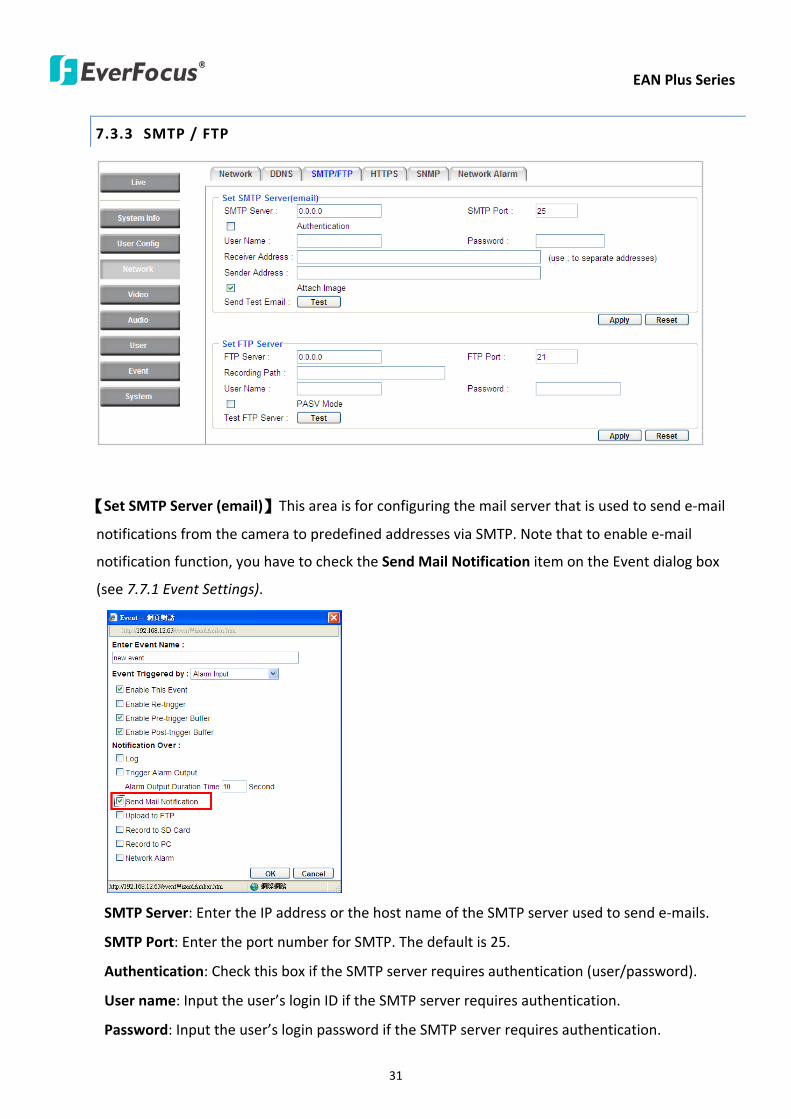
EAN Plus Series
31
733 SMTP FTP
【Set SMTP Server (email)】This area is for configuring the mail server that is used to send e-mail
notifications from the camera to predefined addresses via SMTP Note that to enable e-mail
notification function you have to check the Send Mail Notification item on the Event dialog box
(see 771 Event Settings)
SMTP Server Enter the IP address or the host name of the SMTP server used to send e-mails
SMTP Port Enter the port number for SMTP The default is 25
Authentication Check this box if the SMTP server requires authentication (userpassword)
User name Input the userrsquos login ID if the SMTP server requires authentication
Password Input the userrsquos login password if the SMTP server requires authentication
EAN Plus Series
32
Receiver Address Input the e-mail addresses for receiving an e-mail message when an EVENT is
enabled and triggered Please use ldquordquo to separate multiple addresses
Sender Address Input the senderrsquos e-mail address so that the receiver can recognize the sender
when an Event message is received
Attach Image Check this box if you want to attach an image when an alarm is triggered or an IP
camera detects events
Send Test Email Click the Test button to send a testing email to the assigned address
Click Apply to apply the setting changes or Reset to reset without saving the changes
【Set FTP Server】The settings relating to the FTP server used to transmit the alarm images can be
configured here Note that to enable uploading images to the FTP server function you have to
check the Upload to FTP item on the Event dialog box (see 771 Event Settings)
FTP Server Enter the IP address or the host name of the FTP server
FTP Port Enter the port number for the FTP server Default is 21
Recording Path Assign the recording path
User Name Set FTP Userrsquos name
Password Set FTP password
PASV mode Check to enable Passive mode Passive mode is normally enabled If a connection
cannot be established uncheck PASV Moderdquo
Test FTP Server Click the Test button to send a testing file to the assigned FTP server
Click Apply to apply the setting changes or Reset to reset without saving the changes
EAN Plus Series
33
734 HTTPS
Hypertext Transfer Protocol Secure (HTTPS) is a combination of the Hypertext Transfer Protocol
and the SSLTLS protocol and provides encrypted communication and secure identification of a
network web server
Before using the HTTPS function for communication with the IP camera a Certificate must be
created first There are two ways to create and install a certificate Create Self-Signed Certificate
and Create Certificate Request
Create Self-Signed Certificate
Please note that even though self-signed certificates are free and offer some protection true
security is only implemented after the installation of a signed certificate issued by a certificate
authority
1 Click the Create Self-Signed Certificate button the following dialog appears
EAN Plus Series
34
2 Type the required Certificate information and then click the Apply button The subject line will
be displayed in the Installed Certificate Information field
3 Click the Property button a pop-up window appears to display the details of the certificate
4 To optionally create and install other certificates remove the existing one by clicking the
Remove button to erase the certificate
5 On the Web page change the address from ldquohttprdquo to https in the address bar and press
Enter on the keyboard Some Security Alert dialogs will pop up Click OK or Yes to enable HTTPS
Create Certificate Request
You can apply for an official certificate from an issuing Certificate Authority
1 Click the Create Certificate Request button the following dialog appears
EAN Plus Series
35
2 Type the required Certificate information and then click the Apply button The subject line will
be displayed in the Created Request field
3 Click the Property button a pop-up window appears to display the details of the certificate
4 To optionally create and install other certificates or request remove the existing one by clicking
the Remove button to erase the certificate or request
5 Copy the contents of the Certificate request (in PEM format) and paste it to the certificate
request field on the Web page of the 3rd-party certification authority such as Symantec VeriSign
Wait for the certificate authority to issue an SSLTLS certificate and then download the issued
certificate on your computer
6 In the Install Signed Certificate field click the Browse button to search for the issued certificate
and then click the Upload button to import the certificate Once the certificate has been
uploaded this field will show the subject line of the certificate
EAN Plus Series
36
735 SNMP
The default values for SNMP v1v2v2c and SNMP v3 are already filled in Click either of the
Enable buttons to enable either of the two Make your changes as desired Click on the Trap
Address field to enter the digits if required
736 Network Alarm
This function works with EverFocusrsquos CMS software eg the PowerCon or the Power Video Plus For
the setting details please refer to the CMS network alarm protocol
EAN Plus Series
37
74 Video
The settings relating to video such as streaming camera OSD can be configured on this page The
Video page has five tabs Multi-streaming Camera Advanced ROI and Privacy Mask
741 Multi Streaming
【Stream Settings】 This IP camera can output three video streams simultaneously For each of these
streams the user can set the compression format resolution bit rate and frame rate individually
Stream 1 is always enabled for live view To enable Stream 2 andor Stream 3 check the ldquoEnablerdquo
box the header of each stream
Note If you connect to the camera via the Internet and experience a delay (lag time) in the video
feed try to reduce the number of streams and the quality and resolution of the streams ndash but
keep the frame rate at its maximum
EAN Plus Series
38
Format Select the encoding format ndash H264 or MJPEG
Resolution Select the most suitable resolution for your needs
Frame Rate Select from 1 to 30 fps
Bit Rate If required select whether you want the stream to stream a Constant Bit Rate or a
Variable Bit Rate and set the values of whichever option you choose
Click Apply to apply the setting changes or Reset to reset without saving the changes
【Video Recording Settings】Select the stream you want to configure and then select whether you
want the recording files of that stream to be saved in AVI or ARV format Click Apply to apply the
setting changes or Reset to reset without saving the changes
【Time Stamp Settings】 You can select the DateTime format position and add the setting to the
streaming
Click Apply to apply the changes or Reset to reset without saving the changes
EAN Plus Series
39
742 Camera
【Image Settings】Set the Brightness Saturation Contrast or Sharpness of the image Click Apply to
apply the changes or Reset to reset without saving the changes
【Camera Settings】
Mirror Switch Mirror ON to rotate the image horizontally around a vertical axis
Flip Switch Flip ON to rotate the image vertically around a horizontal axis
AE There are two options
ALC Selecting Automatic Light Control allows the camera circuitry to either take bright spots
more into consideration (peak) bringing out detail in bright areas or less into consideration
(average) bringing out detail in shadows
AES Selecting Auto Electronic Shutter disables the Shutter setting below this setting In this
mode the camera measures the light level and decides whether it needs more or less light and
then automatically adjusts the shutter speed accordingly
BLC Back Light Compensation (BLC) is used to make the subject appear clearer when it is set
against a bright background
OFF Select to switch Back Light Compensation functions off
(ON)BLC The BLC can increase the exposure of a dark area surrounded by a brighter area HLC
can decrease the exposure of bright areas surrounded by darker areas This enables the
camera to better display information that would otherwise have been ldquowhited outrdquo like a
license plate between two bright headlights on a dark road
(ON)HLC The Highlight-Suppression BLC is used to reduce the brightness of light sources in a
specific area It is activated only in a low illumination environment to minimize the effects of
glare from bright lights such as spotlights street lights or headlights in the field of view
EAN Plus Series
40
WDR The Wide Dynamic Range (WDR) function provides clearer images when both of the very
bright and dark areas simultaneously appear on the camera view There are four value options
OFF Low Middle and High Note that when WDR is ON some parts of the image may appear
solarized This is normal for WDR and is not a camera malfunction This function is only available
for EAN3120 Plus 3220 Plus
DN Mode
Auto Select to let the camera automatically switch to Night mode (black and white) when the
light levels fall to a specified level and back to Day mode (color) when the light levels rise to a
specified level
Day Select to keep the camera in Day mode (color) even in nighttime
Night Select to keep the camera in Night mode (black and white) even in daytime
EAN Plus Series
41
743 Advanced
EAN Plus Series
42
【Camera Settings】
Lens (IRIS Control) Select DC or Manual for IRIS control This function is only available for EAN3220
Plus
Exposure Settings (AE) This setting is used to adapt to the amount or type of light used by the
camera Note the settings vary among models
Mode This function is not available for EAN3220 Plus
Automatic Light Control (ALC) This option is only available for EAN3120 Plus 3300 Plus The
ALC allows the camera circuitry to either take bright spots more into consideration (peak)
bringing out detail in bright areas or less into consideration (average) bringing out detail in
shadows
Auto Electronic Shutter (AES) This option is only available for EAN3120 Plus 3300 Plus In
this mode the camera measures the light level and decides whether it needs more or less light
and then automatically adjusts the shutter speed accordingly
Manual This option is only available for EAN3300 Plus Select this option to manually set up
the Shutter (Manual) and AGC (Manual) values
Iris Specify the size of the Iris opening here
Shutter If enabled this setting lets you set the shutter speed yourself
Shutter Limit Use this setting to set the maximum shutter speed for the camera This function is
only available for EAN3120 Plus
AGC Set the Auto Gain Control limit here The lower the AGC level the lower the video signal and
the noise However the image will be darker under low-light condition with IR-off if you set up the
Iris to the maximum level
Slow Shutter This option can be switched on when AES Mode is selected in the Exposure Settings
(AE) field This function is only available for EAN3220 Plus 3300 Plus
Flickerless If the Mode field in the Exposure Settings (AE) area has been set to AES then this option
becomes available Choose between OFF 50HZ 60HZ 50HZ (High Luminance) or 60HZ (High
Luminance) This function is only available for EAN3300 Plus
EV Setting Set up the Exposure Value Note the brightness of the screen changes when you change
the EV value This function is only available for EAN3300 Plus
AE Response Set up Auto Exposure Response time This function is only available for EAN3300 Plus
AE Weighting Area Select an AE Weighting area Each setup AE Weighting Area is configured with
the appropriate brightness level on the center and the surrounding areas This function is only
available for EAN3300 Plus
Brightness Set the image brightness here
AE Reference Set the Auto Exposure value here This function is only available for EAN3120 Plus
EAN Plus Series
43
Black Level Set the Black level here This function is only available for EAN3300 Plus
WDR The Wide Dynamic Range (WDR) function provides clearer images when both of the very
bright and dark areas simultaneously appear on the camera view There are four value options OFF
Low Middle and High Note that when WDR is ON some parts of the image may appear solarized
This is normal for WDR and is not a camera malfunction This function is only available for EAN3120
Plus 3220 Plus
Visibility Enhancement (OFFLowMiddleHigh) Images in foggy or rain environments or in
environments with a very strong luminous intensity have a dynamic range that is significantly lower
than ordinary images The user can use this Visibility Enhancement setting to ldquoDEFOGrdquo the image if
such ldquoFOGGINGrdquo is an issue This function is only available for EAN3220 Plus
BLC Settings Back Light Compensation (BLC) is used to make the subject appear clearer when it is
set against a bright background
OFF Select to switch Back Light Compensation functions off
Back Light This option is only available for EAN3300 Plus The Back Light function is useful
when the background of the subject is very bright and the subject itself is dark Select Back
Light and adjust the slide bar to the left right for setting up the back light value The higher
the value the more the backlight compensation
Front Light This option is only available for EAN3300 Plus This function is useful when the
bright highlights such as flashlight or car headlights appear on the camera view Select Front
Light and adjust the slide bar to the left right for setting up the front light value The higher
the value the more the highlight compensation
ON (BLC) This option is only available when you select AES Mode in the Exposure Settings (AE)
field The option is only available for EAN3120 Plus 3220 Plus The BLC function is useful
when the background of the subject is very bright and the subject itself is dark Follow the
instructions below to configure the settings for each model
For EAN3120 Select ON (BLC) the button next to the Mode drop-down list will be
active (see image below) Click the button the green setup areas appear on the left
screen Click on the areas to enable disable the BLC function The selected areas (in green)
will be applied with the BLC function
EAN Plus Series
44
For EAN3220
You can configure one area to apply the BLC function Select ON (BLC) the setup buttons
appears (see image below) Select Low Middle High from the BLC Gain drop-down list To
set up a BLC area click the Edit Area button and then click on the blue color tab to turn your
mouse cursor into a blue pen Move the cursor to the position on the right screen where you
want the BLC rectangle to start and then click Move your cursor to the position (diagonally
opposing corner) where you want the BLC rectangle to end and then click The blue area will
be applied with the BLC function
ON (HLC) This option is only available when you select AES Mode in the Exposure Settings (AE)
field The option is only available for EAN3120 Plus 3220 Plus This function is useful when
the bright highlights such as flashlight or car headlights appear on the camera view Follow
the instructions below to configure the settings for each model
For EAN3120 Select ON (HLC) and then select a level from the drop-down list The higher the
level the more the highlight compensation
For EAN3220
HLC Level Select a level for the HLC setting The higher the level the more the highlight
compensation
HLC Mode Select All Day Night mode to apply the HLC function
HLC Black Mask Select On Off to apply the black mask on the selected areas The
over-exposure portions within the selected areas will be applied with the black mask
Color Tabs You can set up four HLC areas with different colors To set up a HLC area click the
Edit Area button and then click on the color tab to turn your mouse cursor into a pen of that
color Move the cursor to the position on the right screen where you want the HLC rectangle
to start and then click Move your cursor to the position (diagonally opposing corner) where
you want the HLC rectangle to end and then click Select ON from the color tab drop-down list
The rectangular area with the selected color will be applied with the HLC function
EAN Plus Series
45
Back Light This option is only available for EAN3300 Plus The Back Light function is useful
when the background of the subject is very bright and the subject itself is dark Select Back
Light and adjust the slide bar to the left right for setting up the back light value The higher
the value the more the backlight compensation
Front Light This option is only available for EAN3300 Plus This function is useful when the
bright highlights such as flashlight or car headlights appear on the camera view Select Front
Light and adjust the slide bar to the left right for setting up the front light value The higher
the value the more the highlight compensation
Noise Reduction Settings This limits the amount of digital ldquovideo noiserdquo that is usually found in any
video stream and helps to reduce file size The higher the level the more the reduction
For EAN3120 Plus 3300 Plus
Select ON OFF to enable disable the Noise Reduction function Or select Auto to let the camera
automatically enable disable the Noise Reduction function Slide the Level bar to set up the level
The higher the level the more the reduction
For EAN3220 Plus
2D DNR Select ON to enable the 2D DNR function
3D DNR Select ON to enable the 3D DNR function You can further set up the following settings
3D Start AGC Set up the AGC level to automatically start the 3D NR function
3D End AGC Set up the AGC level to automatically stop the 3D NR function
3D Level Set up the 3D DNR level
Smart NR Select ON to enable the Smart NR function The 3D NR function will be
automatically turned on when a motion event occurs
EAN Plus Series
46
White Balance Settings Select the mode that delivers the best quality image for the camerarsquos light
environment There are five options Auto Manual Indoor Outdoor One Push
Auto Select to let the camera automatically adjust the White Balance In the Auto mode the
camera computes the white balance value output using color information from the entire
screen It outputs the proper value using the color temperature radiating from a black subject
based on a range of value from 3000 to 7500K
Manual Select to adjust the Red and Blue values yourself in the fields below this field
Indoor Select to use the default settings for indoor environments In the Indoor mode the
camera uses 3200K as the base value
Outdoor Select to use the default settings for outdoor environment In the Outdoor mode it
uses 5800K as the base value
One Push Select to enable the Push button next to the Mode drop-down field This will allow you to force the camera to readjust the white balance every time you push the Push
button The lens will hold the same focal position until the next trigger command is received
This function helps to prevent incorrect focusing in dark environments This function is only
available for EAN3120 Plus 3220 Plus
Manual Temperature Select to use the optimized Red and Blue settings You can also
optionally adjust the Manual Level below this field for setting up the color temperature The
higher the value the more the color temperature This function is only available for EAN3300
Plus
DayNight Settings
Auto Select to let the camera automatically switch to Night mode (black and white) when the
light levels fall to a specified level and back to Day mode (color) when the light levels rise to a
specified level
Day Select to keep the camera in Day mode (color) even in nighttime
Night Select to keep the camera in Night mode (black and white) even in daytime
IR Smart Settings Select ON and set up the level to enhance the image quality when the images are
over exposure This function is useful when the camera is in the Night mode This function is only
available for EAN3220 Plus
Saturation Set the saturation value This function is not available for EAN3220 Plus
Monitor Type Select a gamma value from Set 1 Set 2 or Set 3 This function is only available for
EAN3120 Plus
Negative Switch this setting ON to view a color negative version of the video image This is useful
at night or when viewing temperature-sensitive images
EAN Plus Series
47
Sharpness Settings Select the sharpness level of the image A low sharpness level will deliver a
softer less detailed image A high level will deliver a sharp highly detailed image Switch Resolution
Enhancement ON to enable the resolution enhancement function
Contrast Select the contrast level of the image
Suppress Function This function is only available for EAN3300 Plus
Aperture Compensation Suppression (OFFLowMiddleHigh) This setting can be activated to
suppress luminance noise when the AGC level increases
Chroma Suppression (OFFLowMiddleHigh) This setting can be activated to suppress
chrominance noise when the AGC level increases
Ygamma (gamma 22standardcontrast enhancehigh light range mode LHigh light range mode
H) Select the Ygamma value for the video quality of the monitor This function is only available for
EAN3300 Plus
Monitor Settings The user can use this field to optimize video quality for his or her specific type of
monitor ndash LCD or CRT This function is only available for EAN3220 Plus
Color Space Standard The options are YUV601 for SD and YUV709 for HD These define the color
space standard required to convert an RGB picture to a YUV picture Generally YUV601 is used for
Standard Definition (720P) devices and the YUV709 is used for High Definition (1080P) devices
Click Apply to save all changes Click Reset to cancel all changes
EAN Plus Series
48
744 ROI (Region of Interest)
The Region of Interest (ROI) function allows users to set up multiple regions within an image with
better quality and less distortion than the rest of the image You can also use this function
together with the Digital Zoom function on the Live View Page to get a better image result Up to
eight ROIs can be configured in the ROI settings page
To set up an ROI region
1 Select an ROI number from the ROI No drop-down list
2 Click the Add button the mouse cursor will turn into a pen when you move it over the live
image on the left
3 Move the cursor to the position where you want the ROI rectangle to start and then click
Move the cursor to the position (diagonally opposing corner) where you want the ROI
rectangle to end and then click
4 Slide the Quality bar to set up the quality value
5 Click the Apply button to apply the settings or click the Reset button to reset without saving
the settings
EAN Plus Series
49
745 Privacy Mask
The Privacy Mask can block out sensitive areas from view covering the areas with colored or black
and white boxes in both live view and recorded clips This feature is useful when usersrsquo donrsquot want
the sensitive information visible Up to four Privacy Masks can be configured
【Privacy Mask Color Settings】The Modes vary among camera models
Mode Click Color to make the masks appear as colored rectangles on the screen Click BW to
make the masks appear as gray rectangles on the screen Click Mosaic to make the masks appear
as mosaic-effect rectangles on the screen
Level Select the color of the masks if you selected Color Mode Select the level of grayness of the
masks if you selected BW Mode Select the level of smallmiddlelarge if you selected Mosaic
Mode
Click Apply to apply the settings or click Reset to reset without saving the settings
Color Tabs Click on a color tab to turn your mouse cursor into a pen of that color
You can now create a block of that color on the video screen Move your cursor to the position
where you want your mask rectangle to start and then click Move your cursor to the position
(diagonally opposing corner) where you want your mask rectangle to end and then click The
rectangular area with the selected color will appear The live image will display the rectangular
area with the color you selected If you want to create another mask use one of the other three
colors Each color denotes a different mask area Only one block per color is allowed As the
number of colors suggests you can configure up to four blocks
EAN Plus Series
50
Select All Click to turn the whole screen into a mask area
Clear All Click to delete all configured mask blocks
Eraser Click to turn the mouse cursor into an eraser to delete any block you click on
Area Shows the color and number of the block
Enable Check this box to enable the related mask block
Click Apply to apply the settings or click Reset to reset without saving the settings
EAN Plus Series
51
75 Audio
The EAN Plus series IP camera can transmit audio to your computer if you have connected an external
microphone to its audio Input cable It can also receive audio input from you and transmit it via an
external speaker if you have connected such a speaker to its audio Output cable
Check the Enable Audio box to enable the camerarsquos audio function The camera will now act as a
digital bridge (via the IP network) between any connected audio input device and any connected
audio device
Adjust the Audio Input Volume if you have external audio input devices (microphones) connected to
the camera and if there are problems with the sound input being too low or high
Click Apply to save all settings or click Reset to cancel
EAN Plus Series
52
76 User
761 User Information
The system administrator can create up to ten user accounts on this page
To set up a user account
1 Highlight a user account and click the Modify button The following dialog box appears
2 Type the account name account description and password for the account Type the password
again in the Confirm field
3 Select an authority level for the user account from the Authority drop-down list
bull Supervisor Administrator The only difference between a supervisor and administrator is
that a supervisor can edit an administratorrsquos account and password but an administrator
cannot edit the supervisorrsquos account and password Multiple administrators can be
configured but there can be only one supervisor The supervisor and administrators all
have unrestricted access to the Settings submenus and can determine the registration of
all other users
EAN Plus Series
53
bull User A user can view the Live View page and view the system network video and audio
information A user can only adjust the User Config page settings The user does not have
access to the User Event and System pages
bull Guest The lowest level of access which only allows the user access to the Live View page
4 Select Active or Disable from the Status drop-down list to active or disable the user account
5 Click On in the SD Card Playback field to allow the user to access the SD card playback
function
6 Click OK
7 Click Apply to save all the settings
EAN Plus Series
54
762 IP Address Filter
Use this page to specify IP addresses that are not allowed to access this camera By default any IP
address can access the camera
Note The Allowed List addresses only become relevant when the Denied List contains a network
or range and the supervisor wants to allow one or more IP addresses within that excluded range
or network In such a scenario the user would enter the excluded range or network in the
Denied List and enter the exceptions in the Allowed List
To set up the IP Address Filter
1 Select Denied List Click the Add button the following dialog box appears
2 Select an IP type from the IP Type drop-down list
3 Select a network rule from the Rule drop-down list type the IP address and click OK
Single Type a single IP address in the IP Address field below
Network Type the IP address and subnet mask in the field below
Range Type a range for the IP addresses
4 If you have set up an IP range in Step 3 you can optionally set up the Allowed List to allow one
or more IP addresses within the setup IP range to access the IP camera
5 Click Apply
EAN Plus Series
55
77 Event
You can set up the Motion Detection event Tamper Detection event or the Alarm IO to automatically
notify the users when an event occurs or an alarm is triggered You can also set up a schedule to
automatically record the videos when an event occurs or an alarm is triggered
771 Event Settings
You can create a total of ten event or alarm settings page in the Event List
【Event List】
Click the Add button and the following Event Configuration Window appears
EAN Plus Series
56
Enter Event Name Type an event name
Event Triggered by Select an event or alarm type for the to-be-specified-below reactions
Alarm Input Select this if you want a reaction trigger coming from any external connected sensor
to activate a to-be-specified-below reactions via the camera system Make sure that a suitable
device is actually connected to the alarm input relay
Manual Trigger Select this option if you want to manually trigger the alarm by clicking the Trigger
Event button on the Live View Page
Motion Detection Select this option if you want motion in a specified part of the camerarsquos viewing
rectangle (the screen image) to trigger the to-be-specified-below reactions
Tampering Detection Select this option if you want the camerarsquos tampering detection sensor to
trigger the to-be-specified-below reactions
Schedule Recording Select this option if you want the Schedule Recording periods configured in
the recording schedule (the Settings gt Event gt Schedule page) to activate this event In this
scenario a preconfigured event reaction like a log entry will list the start and end times of each
period Actual recording will only be triggered if the event is preconfigured to do so
Enable This Event Select to activate the event
Enable Re-trigger Click to set a minimum time after the event is triggered before the event
can be triggered again
Enable Pre-trigger Buffer Click if you want the Event reaction (as selected in the ldquoNotification
Overrdquo field below) to be the activation of the video recording function and if you want the
recording to include the video feed from the time period (configurable on the previous ldquoEvent
Settingsrdquo page) just before the Event trigger occurred
Enable Post-trigger Buffer Click if you want the Event reaction (as selected in the Notification
Over field) to be the activation of the video recording function and if you want the recording
to include the video feed from a time period (configurable on the Event Settings page) just
after the Event trigger occurred
Motion Area Select a setup motion detection area from the drop down list Note this
function only becomes relevant after the Motion Detection areas have been set up (see 772
Motion Detection)
Notification Over Select the desired notification types form the following items
Log Click if you want the camera to list the eventrsquos details in its log if the event is triggered
Trigger Alarm Output Click if you want the camera to relay the event reaction to a device
attached to the alarm relay output wire and then set up the alarm output duration time
EAN Plus Series
57
Send Mail Notification Click if you want the camera to send an Event notification email to the
email address entered in the Set SMTP Server(email) field of the Network gt SMTPFTP page if
the Event occurs (see 733 SMTP FTP)
Upload to FTP Click if you want the camera to upload recorded footage to the FTP server
entered in the Set SMTP Server(email) field of the Network gt SMTPFTP page if the Event
occurs (see 733 SMTP FTP)
Record to SD Card Click if you want the camera to start recording its video feed (when the
event occurs) on an on-camera SD Card (if such a card has been inserted)
Note The recording will only be as long as the combined Pre- and Post-trigger Buffers so
make sure you enable at least one of these buffers especially the Post-trigger Buffer
Record to PC Check this box if you want the camera to start recording its video feed (when
the event occurs) on the same folder on the same PC as configured on the User Config gt
RecordingSnapshot page (if such a folder has been enabled and configured)
Note The recording will only be as long as the combined Pre- and Post-trigger Buffers (and
for as long as the event trigger is happening ndash eg a motion is detected) so make sure you
enable at least one of these buffers especially the Post-trigger Buffer
Network Alarm Check this box if you want the camera to send a network alarm signal (when
the event occurs) to the CMS servers configured on the Network gt Network Alarm page (see
736 Network Alarm)
Click OK to save all settings or click Cancel to cancel
【PrePost Trigger Settings】
Pre-trigger Buffer Select the duration for the buffer This will determine the amount of footage
(length of time) before the event trigger moment that will be included in an event-triggered video
recording if that buffer and video recording has been enabled in the Event Configuration Window
Post-trigger Buffer Select the duration for the buffer This will determine the amount of footage
(length of time) after the event trigger moment that will be included in an event-triggered video
recording if that buffer and video recording has been enabled in the Event Configuration Window
Click Apply to save all settings or click Reset to cancel
EAN Plus Series
58
772 Motion Detection
Use this page to configure up to four areas in which motion will be detected When a motion is
detected by the camera the motion detection icon will appear at the top right of the
Live page to alert the user This function can also be linked with correctly configured Events to
trigger Event reactions like the activation of video recording periods snapshots alarms etc
Color Tabs Click on a color tab to turn your mouse cursor into a pen of that color
You can now create a block of that color on the video screen Move your cursor to the position
where you want your detection rectangle to start and then click Move your cursor to the position
(diagonally opposing corner) where you want your detection rectangle to end and then click The
rectangular area with the selected color will appear This block will be an area inside which the
camera will detect motion If you want to create another detection area use one of the other three
palette colors Each color denotes a different detection area Only one block per color is allowed As
the number of colors suggests you can configure up to four blocks
Select All Click to turn the whole screen into a motion detection area
Clear All Click to delete all configured motion detection blocks
Eraser Click to turn your mouse cursor into an eraser to delete any block you click on
Area Shows the color and numberID of the block
Enable Check this box to enable the related motion detection block
Sensitivity Set the sensitivity of the motion detection sensor function
Click Apply to save all settings or click Reset to cancel
EAN Plus Series
59
773 Tamper Detection
Use this page to set the number of seconds that an alarm signal will be active if the device is
physically tampered (moved covered up or out of focus
774 Alarm IO
Use this page to set the type of trigger input and the type of output contact for the camerarsquos alarm
channel
EAN Plus Series
60
775 Schedule
Use this page to configure a schedule for periods during which the camera should deactivate all
user-activated Events (gray Deselect periods) or when the camera should deactivate all
user-activated Events except Schedule Recording (SR) events (blue Schedule Recording-only
periods) or when the camera should deactivate only SR events (red Event Recording-only periods)
or when it should enable all activated Events (yellow periods)
Event Recording Click this button to make every hour block you click on red A red block represents
an Event Recording-only block which represents an hour when the camera will deactivate all
preconfigured activated Schedule Recording events and keep all the other activated events active
Schedule Recording Click this button to make every hour block you click on blue A blue block
represents a Schedule Recording-only block which represents an hour when the camera will
deactivate all other preconfigured activated events and keep only the preconfigured activated
Schedule Recording events active
Event + Schedule Click this button to make every hour block you click on yellow A yellow block
represents an hour in which all activated events including Schedule Recording events will be
active
Deselect Click this button to make every hour block become grey A grey block represents an hour
in which all activated events including Schedule Recording events will be inactive
Click Apply to save all settings or click Reset to cancel
EAN Plus Series
61
78 System
You can set up the systemrsquos time and SD card settings and to do maintenance and reset actions like
reboots and upgrades
781 DateTime
【Machine Name Settings】If required enter a new name for the machine This name will be visible
in the Machine Name field of the IP Utility software which is included in the software CD
【Set Time Zone】Set the time zone of the camerarsquos location
【Set DateTime Manually】Set the datetime here if you wonrsquot be using an NTP server to update the
datetime (see below)
【Set DateTime Sync】Enter the Network Time Protocol server if applicable The camerarsquos time will
be automatically adjusted by synchronizing with the NTP server
Click Apply to save all settings or click Reset to cancel
EAN Plus Series
62
782 Daylight Saving
Click Enable Daylight Saving to enable this schedule and select the dates when the regionrsquos
daylight saving period begins and ends Click Apply to save all settings or click Reset to cancel
783 SD Card
Use this page to prepare the system for safely removing the SD Card from its slot
【Setup SD Card】
Notification Select the percentage of storage space that should be left on the card before the
camera notifies you of the impending storage shortage or overwrite
Event Recording Select if you want Event Recording only FTP Backup only or both
Overwrite Click ON if you want the card to start writing over recorded footage when its memory is
full Click OFF if you want the card to stop recording new footage when its memory is full
【SD Card Utility】
Capacity This shows you how much card memory has been used and how much memory capacity
remains on the card
Remove Click this button before removing the card from the system
Format Click this button to format the card All data saved on the SD card will be removed if the
card is formatted
EAN Plus Series
63
784 Maintenance
【Maintenance Server】
Reboot Click this button to reboot the unit without changing any of the settings Use this function if
the unit is not behaving as expected
Restore Click this button to restart and reset most of the current settings to their factory default
values The only settings that will not be changed to default are
bull IP settings
bull DDNS settings
Default The Default button should be used with caution Pressing this button will return all of the
cameras settings including the IP address to the factory default values The camera will then have
to be reconfigured
【SaveLoad Configuration Server】
Save To make a backup file of the machinersquos current configurations press Save to save all the
configurations to a config file This will enable the user to reload these configuration settings if the
settings are changed and there is unexpected behavior
Load To load a previously saved configuration press the Browse button to locate the saved config
file (see above) and then click the Load button The systemrsquos settings will be restored to the saved
configuration
EAN Plus Series
64
【SaveLoad Video Configuration Server】
Save To make a backup file of the machinersquos video configurations press Save to save the video
configurations to a config file This will enable the user to reload these configuration settings if the
settings are changed and there is unexpected behavior
Load To load a previously saved video configuration press the Browse button to locate the saved
config file (see above) and then click the Load button The systemrsquos settings will be restored to the
saved video configuration
【Upgrade Firmware】Click the Browse button to find a previously prepared firmware upgrade file
Click Upgrade to install the new firmware
Note
1 Do not disconnect power to the unit during the upgrade sequence The unit will reboot
automatically after the upgrade has completed (1-5 minutes)
2 During the upgrade process all event recording actions will be stopped Event recording
actions will resume after the camera is rebooted
3 If the ldquoFile Error Please re-loginrdquo warning message appears when upgrading the firmware
please try the following instructions
a Go to Internet Explorer gt Tools gt Internet Option gt Security gt Custom
b Find and enable the Include local directory path when uploading files to a server
EAN Plus Series
65
8 Upgrading Firmware Using IP Utility
You can upgrade the Firmware using the IP Utility software included in the software CD
1 Install and then start the IPU program The following dialog box appears
2 Click Find Devices to search the cameras connected in the LAN The default network values of the
cameras will be displayed By default the network protocol of the camera is DHCP
3 Select a camera and click LoginMulti Login to log in the camera
4 Type the user ID and password Click OK
Note
1 The default user ID is user1 and the default password is 11111111
2 If you select more than one camera that has the same user ID password you will be able
to log in several cameras at once
EAN Plus Series
66
5 Highlight the camera and then click Upgrade Firmware A browsing window appears
6 Select the firmware file (evb) and then click Open The IP Utility will automatically upgrade the
firmware
The camera will reboot once the update is complete Click Find Devices the new firmware version
should be displayed in the last part of the Machine Name
EAN Plus Series
67
9 Specifications
Model EAN3120 Plus EAN3220 Plus EAN3300 Plus
Camera
Image Sensor 13 Panasonic CMOS 128 Sony CMOS
Megapixel 13 MP 2 MP 3 MP
Picture Elements (H x V) 1280 x 1024 1944 x 1092 2048 x 1536
Min Illuminations 003 Lux at F14
Electronic Shutter (Sec) 85 ~ 160000 2 ~ 150000 1 ~ 110000
Scanning System NTSC PAL
WDR Yes Yes No
BLC Yes
Gain Control Yes
White Balance Yes
Lens
Mounting Type C CS
Day Night Yes (with removable auto IR-cut filter)
IRIS Control DC Electrical IRIS Lens IRIS
Video
Video Compression H264 MJPEG
Resolution
NTSC
2048 x 1536 1920 x 1200 (for EAN3300 Plus only)
1920 x 1080 (for EAN3300 Plus 3220 Plus only)
1280 x 1024 1280 x 720 1024 x 768 720 x 480 704 x 480 640 x 480
352 x 240 320 x 240 160 x 120
PAL
2048 x 1536 1920 x 1200 (for EAN3300 Plus only)
1920 x 1080 (for EAN3300 Plus 3220 Plus only)
1280 x 1024 1280 x 720 1024 x 768 720 x 576 704 x 576 640 x 480
352 x 288 320 x 240 160 x 120
Frame Rate 30 fps at 1280 x 1024 30 fps at 1920 x 1080 15 fps at 2048 x 1536
Audio
Audio Streaming Two-way audio
Audio Compression G711
EAN Plus Series
68
Network
Interface 10 100 Base-T Ethernet RJ-45 socket
Supported Protocols
TCPIP IPV6 UDP ICMP DHCP NTP DNS DDNS SMTP SNMP FTP
HTTP HTTPs PPPoE UPnP Bonjour RTP RTSP RTCP IGMP ARP ONVIF
PSIA
Connector
Power DC female port PoE
Ethernet RJ-45
Audio 1 In (phone jack for microphone)
1 Out (phone jack for Speaker)
Alarm IO Terminal IO wires
Local Storage Micro SD SDHC memory card slot
TV-Out BNC socket composite 1 V p-p 75 Ω
General
Power Source DC 12V PoE (IEEE8023af)
Power Consumption
(IR LEDs On)
5W (DC 12V)
621W (PoE)
5W (DC 12V)
522W (PoE)
5W (DC 12V)
536W (PoE)
Operating Temperature 0degC ~ +50degC 32degF ~ +122degF
Humidity 20 to 80 (no condensation)
Safety CE FCC
Dimensions (L x W x H) 117 x 56 x 68 mm 46 x 22 x 27 in
Weight 410 g 09 lb
EverFocus Electronics Corp EverFocus Taiwan 12F No79 Sec 1 Shin-Tai Wu Road Hsi-Chih Taipei Taiwan TEL +886 2 2698 2334 FAX +886 2 2698 2380 wwweverfocuscomtw marketingeverfocuscomtw
EverFocus Europe - Germany Albert-Einstein-Strasse 1 D-46446 Emmerich Germany TEL +49 2822 93940 FAX +49 2822 939495 wwweverfocusde infoeverfocusde
EverFocus China - Beijing Room 609 Technology Trade Building Shangdi Information Industry Base Haidian District Beijing 100085 China TEL +86 10 6297 3336~39 FAX +86 10 6297 1423 wwweverfocuscomcn marketingeverfocuscomcn
EverFocus China - Shenzhen 4F No 2 D4 Building Wan Yelong Industrial Park Tangtou Road Shiyan Baoan Shenzhen Guangdong 518101 China TEL +86 755 2765 1313 FAX +86 755 2765 0337 wwweverfocuscomcn marketingeverfocuscomcn
EverFocus USA - California 1801 Highland Avenue Unit A Duarte CA 91010 USA TEL +1 626 844 8888 FAX +1 626 844 8838 wwweverfocuscom saleseverfocuscom
EverFocus USA - New York 415 Oser Avenue Unit S Hauppauge NY 11788 USA TEL +1 631 436 5070 FAX +1 631 436 5027 wwweverfocuscom saleseverfocuscom
EverFocus Japan 5F Kinshicho City Building 2-13-4 Koto-BashiSumida-Ku Tokyo 130-0022 Japan TEL +81 3 5625 8188 FAX +81 3 5625 8189 wwweverfocuscojp infoeverfocuscojp
EverFocus Europe - UK Unit 12 Spitfire Business Park Hawker Road Croydon Surrey CR0 4WD UK TEL +44 20 8649 9757 +44 845 430 9999 FAX +44 20 8649 9907 wwweverfocusukcouk salesukeverfocuscom
EverFocus India Suite 803 Housefin Bhavan C-21 Bandra Kurla Complex Bandra (East) Mumbai 400051 India TEL +91 22 6128 8700 FAX +91 22 6128 8705 wwweverfocusin saleseverfocusin
PN 4605PQ3120B010A-VerC
Your EverFocus product is designed and manufactured with high quality materials and components which can be recycled and reused This symbol means that electrical and electronic equipment at their end-of-life should be disposed of separately from your household waste Please dispose of this equipment at your local community waste collectionrecycling centre In the European Union there are separate collection systems for used electrical and electronic product Please help us to conserve the environment we live in
Ihr EverFocus Produkt wurde entwickelt und hergestellt mit qualitativ hochwertigen Materialien und Komponenten die recycelt und wieder verwendet werden koumlnnen Dieses Symbol bedeutet dass elektrische und elektronische Geraumlte am Ende ihrer Nutzungsdauer vom Hausmuumlll getrennt entsorgt werden sollen Bitte entsorgen Sie dieses Geraumlt bei Ihrer oumlrtlichen kommunalen Sammelstelle oder im Recycling Centre Helfen Sie uns bitte die Umwelt zu erhalten in der wir leben
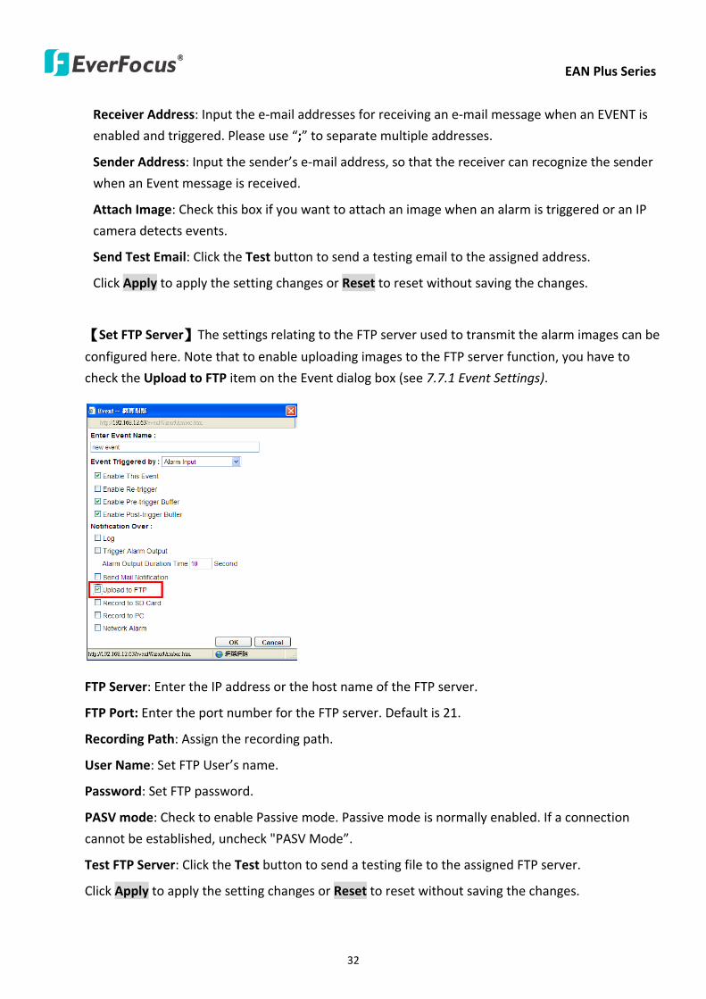
EAN Plus Series
32
Receiver Address Input the e-mail addresses for receiving an e-mail message when an EVENT is
enabled and triggered Please use ldquordquo to separate multiple addresses
Sender Address Input the senderrsquos e-mail address so that the receiver can recognize the sender
when an Event message is received
Attach Image Check this box if you want to attach an image when an alarm is triggered or an IP
camera detects events
Send Test Email Click the Test button to send a testing email to the assigned address
Click Apply to apply the setting changes or Reset to reset without saving the changes
【Set FTP Server】The settings relating to the FTP server used to transmit the alarm images can be
configured here Note that to enable uploading images to the FTP server function you have to
check the Upload to FTP item on the Event dialog box (see 771 Event Settings)
FTP Server Enter the IP address or the host name of the FTP server
FTP Port Enter the port number for the FTP server Default is 21
Recording Path Assign the recording path
User Name Set FTP Userrsquos name
Password Set FTP password
PASV mode Check to enable Passive mode Passive mode is normally enabled If a connection
cannot be established uncheck PASV Moderdquo
Test FTP Server Click the Test button to send a testing file to the assigned FTP server
Click Apply to apply the setting changes or Reset to reset without saving the changes
EAN Plus Series
33
734 HTTPS
Hypertext Transfer Protocol Secure (HTTPS) is a combination of the Hypertext Transfer Protocol
and the SSLTLS protocol and provides encrypted communication and secure identification of a
network web server
Before using the HTTPS function for communication with the IP camera a Certificate must be
created first There are two ways to create and install a certificate Create Self-Signed Certificate
and Create Certificate Request
Create Self-Signed Certificate
Please note that even though self-signed certificates are free and offer some protection true
security is only implemented after the installation of a signed certificate issued by a certificate
authority
1 Click the Create Self-Signed Certificate button the following dialog appears
EAN Plus Series
34
2 Type the required Certificate information and then click the Apply button The subject line will
be displayed in the Installed Certificate Information field
3 Click the Property button a pop-up window appears to display the details of the certificate
4 To optionally create and install other certificates remove the existing one by clicking the
Remove button to erase the certificate
5 On the Web page change the address from ldquohttprdquo to https in the address bar and press
Enter on the keyboard Some Security Alert dialogs will pop up Click OK or Yes to enable HTTPS
Create Certificate Request
You can apply for an official certificate from an issuing Certificate Authority
1 Click the Create Certificate Request button the following dialog appears
EAN Plus Series
35
2 Type the required Certificate information and then click the Apply button The subject line will
be displayed in the Created Request field
3 Click the Property button a pop-up window appears to display the details of the certificate
4 To optionally create and install other certificates or request remove the existing one by clicking
the Remove button to erase the certificate or request
5 Copy the contents of the Certificate request (in PEM format) and paste it to the certificate
request field on the Web page of the 3rd-party certification authority such as Symantec VeriSign
Wait for the certificate authority to issue an SSLTLS certificate and then download the issued
certificate on your computer
6 In the Install Signed Certificate field click the Browse button to search for the issued certificate
and then click the Upload button to import the certificate Once the certificate has been
uploaded this field will show the subject line of the certificate
EAN Plus Series
36
735 SNMP
The default values for SNMP v1v2v2c and SNMP v3 are already filled in Click either of the
Enable buttons to enable either of the two Make your changes as desired Click on the Trap
Address field to enter the digits if required
736 Network Alarm
This function works with EverFocusrsquos CMS software eg the PowerCon or the Power Video Plus For
the setting details please refer to the CMS network alarm protocol
EAN Plus Series
37
74 Video
The settings relating to video such as streaming camera OSD can be configured on this page The
Video page has five tabs Multi-streaming Camera Advanced ROI and Privacy Mask
741 Multi Streaming
【Stream Settings】 This IP camera can output three video streams simultaneously For each of these
streams the user can set the compression format resolution bit rate and frame rate individually
Stream 1 is always enabled for live view To enable Stream 2 andor Stream 3 check the ldquoEnablerdquo
box the header of each stream
Note If you connect to the camera via the Internet and experience a delay (lag time) in the video
feed try to reduce the number of streams and the quality and resolution of the streams ndash but
keep the frame rate at its maximum
EAN Plus Series
38
Format Select the encoding format ndash H264 or MJPEG
Resolution Select the most suitable resolution for your needs
Frame Rate Select from 1 to 30 fps
Bit Rate If required select whether you want the stream to stream a Constant Bit Rate or a
Variable Bit Rate and set the values of whichever option you choose
Click Apply to apply the setting changes or Reset to reset without saving the changes
【Video Recording Settings】Select the stream you want to configure and then select whether you
want the recording files of that stream to be saved in AVI or ARV format Click Apply to apply the
setting changes or Reset to reset without saving the changes
【Time Stamp Settings】 You can select the DateTime format position and add the setting to the
streaming
Click Apply to apply the changes or Reset to reset without saving the changes
EAN Plus Series
39
742 Camera
【Image Settings】Set the Brightness Saturation Contrast or Sharpness of the image Click Apply to
apply the changes or Reset to reset without saving the changes
【Camera Settings】
Mirror Switch Mirror ON to rotate the image horizontally around a vertical axis
Flip Switch Flip ON to rotate the image vertically around a horizontal axis
AE There are two options
ALC Selecting Automatic Light Control allows the camera circuitry to either take bright spots
more into consideration (peak) bringing out detail in bright areas or less into consideration
(average) bringing out detail in shadows
AES Selecting Auto Electronic Shutter disables the Shutter setting below this setting In this
mode the camera measures the light level and decides whether it needs more or less light and
then automatically adjusts the shutter speed accordingly
BLC Back Light Compensation (BLC) is used to make the subject appear clearer when it is set
against a bright background
OFF Select to switch Back Light Compensation functions off
(ON)BLC The BLC can increase the exposure of a dark area surrounded by a brighter area HLC
can decrease the exposure of bright areas surrounded by darker areas This enables the
camera to better display information that would otherwise have been ldquowhited outrdquo like a
license plate between two bright headlights on a dark road
(ON)HLC The Highlight-Suppression BLC is used to reduce the brightness of light sources in a
specific area It is activated only in a low illumination environment to minimize the effects of
glare from bright lights such as spotlights street lights or headlights in the field of view
EAN Plus Series
40
WDR The Wide Dynamic Range (WDR) function provides clearer images when both of the very
bright and dark areas simultaneously appear on the camera view There are four value options
OFF Low Middle and High Note that when WDR is ON some parts of the image may appear
solarized This is normal for WDR and is not a camera malfunction This function is only available
for EAN3120 Plus 3220 Plus
DN Mode
Auto Select to let the camera automatically switch to Night mode (black and white) when the
light levels fall to a specified level and back to Day mode (color) when the light levels rise to a
specified level
Day Select to keep the camera in Day mode (color) even in nighttime
Night Select to keep the camera in Night mode (black and white) even in daytime
EAN Plus Series
41
743 Advanced
EAN Plus Series
42
【Camera Settings】
Lens (IRIS Control) Select DC or Manual for IRIS control This function is only available for EAN3220
Plus
Exposure Settings (AE) This setting is used to adapt to the amount or type of light used by the
camera Note the settings vary among models
Mode This function is not available for EAN3220 Plus
Automatic Light Control (ALC) This option is only available for EAN3120 Plus 3300 Plus The
ALC allows the camera circuitry to either take bright spots more into consideration (peak)
bringing out detail in bright areas or less into consideration (average) bringing out detail in
shadows
Auto Electronic Shutter (AES) This option is only available for EAN3120 Plus 3300 Plus In
this mode the camera measures the light level and decides whether it needs more or less light
and then automatically adjusts the shutter speed accordingly
Manual This option is only available for EAN3300 Plus Select this option to manually set up
the Shutter (Manual) and AGC (Manual) values
Iris Specify the size of the Iris opening here
Shutter If enabled this setting lets you set the shutter speed yourself
Shutter Limit Use this setting to set the maximum shutter speed for the camera This function is
only available for EAN3120 Plus
AGC Set the Auto Gain Control limit here The lower the AGC level the lower the video signal and
the noise However the image will be darker under low-light condition with IR-off if you set up the
Iris to the maximum level
Slow Shutter This option can be switched on when AES Mode is selected in the Exposure Settings
(AE) field This function is only available for EAN3220 Plus 3300 Plus
Flickerless If the Mode field in the Exposure Settings (AE) area has been set to AES then this option
becomes available Choose between OFF 50HZ 60HZ 50HZ (High Luminance) or 60HZ (High
Luminance) This function is only available for EAN3300 Plus
EV Setting Set up the Exposure Value Note the brightness of the screen changes when you change
the EV value This function is only available for EAN3300 Plus
AE Response Set up Auto Exposure Response time This function is only available for EAN3300 Plus
AE Weighting Area Select an AE Weighting area Each setup AE Weighting Area is configured with
the appropriate brightness level on the center and the surrounding areas This function is only
available for EAN3300 Plus
Brightness Set the image brightness here
AE Reference Set the Auto Exposure value here This function is only available for EAN3120 Plus
EAN Plus Series
43
Black Level Set the Black level here This function is only available for EAN3300 Plus
WDR The Wide Dynamic Range (WDR) function provides clearer images when both of the very
bright and dark areas simultaneously appear on the camera view There are four value options OFF
Low Middle and High Note that when WDR is ON some parts of the image may appear solarized
This is normal for WDR and is not a camera malfunction This function is only available for EAN3120
Plus 3220 Plus
Visibility Enhancement (OFFLowMiddleHigh) Images in foggy or rain environments or in
environments with a very strong luminous intensity have a dynamic range that is significantly lower
than ordinary images The user can use this Visibility Enhancement setting to ldquoDEFOGrdquo the image if
such ldquoFOGGINGrdquo is an issue This function is only available for EAN3220 Plus
BLC Settings Back Light Compensation (BLC) is used to make the subject appear clearer when it is
set against a bright background
OFF Select to switch Back Light Compensation functions off
Back Light This option is only available for EAN3300 Plus The Back Light function is useful
when the background of the subject is very bright and the subject itself is dark Select Back
Light and adjust the slide bar to the left right for setting up the back light value The higher
the value the more the backlight compensation
Front Light This option is only available for EAN3300 Plus This function is useful when the
bright highlights such as flashlight or car headlights appear on the camera view Select Front
Light and adjust the slide bar to the left right for setting up the front light value The higher
the value the more the highlight compensation
ON (BLC) This option is only available when you select AES Mode in the Exposure Settings (AE)
field The option is only available for EAN3120 Plus 3220 Plus The BLC function is useful
when the background of the subject is very bright and the subject itself is dark Follow the
instructions below to configure the settings for each model
For EAN3120 Select ON (BLC) the button next to the Mode drop-down list will be
active (see image below) Click the button the green setup areas appear on the left
screen Click on the areas to enable disable the BLC function The selected areas (in green)
will be applied with the BLC function
EAN Plus Series
44
For EAN3220
You can configure one area to apply the BLC function Select ON (BLC) the setup buttons
appears (see image below) Select Low Middle High from the BLC Gain drop-down list To
set up a BLC area click the Edit Area button and then click on the blue color tab to turn your
mouse cursor into a blue pen Move the cursor to the position on the right screen where you
want the BLC rectangle to start and then click Move your cursor to the position (diagonally
opposing corner) where you want the BLC rectangle to end and then click The blue area will
be applied with the BLC function
ON (HLC) This option is only available when you select AES Mode in the Exposure Settings (AE)
field The option is only available for EAN3120 Plus 3220 Plus This function is useful when
the bright highlights such as flashlight or car headlights appear on the camera view Follow
the instructions below to configure the settings for each model
For EAN3120 Select ON (HLC) and then select a level from the drop-down list The higher the
level the more the highlight compensation
For EAN3220
HLC Level Select a level for the HLC setting The higher the level the more the highlight
compensation
HLC Mode Select All Day Night mode to apply the HLC function
HLC Black Mask Select On Off to apply the black mask on the selected areas The
over-exposure portions within the selected areas will be applied with the black mask
Color Tabs You can set up four HLC areas with different colors To set up a HLC area click the
Edit Area button and then click on the color tab to turn your mouse cursor into a pen of that
color Move the cursor to the position on the right screen where you want the HLC rectangle
to start and then click Move your cursor to the position (diagonally opposing corner) where
you want the HLC rectangle to end and then click Select ON from the color tab drop-down list
The rectangular area with the selected color will be applied with the HLC function
EAN Plus Series
45
Back Light This option is only available for EAN3300 Plus The Back Light function is useful
when the background of the subject is very bright and the subject itself is dark Select Back
Light and adjust the slide bar to the left right for setting up the back light value The higher
the value the more the backlight compensation
Front Light This option is only available for EAN3300 Plus This function is useful when the
bright highlights such as flashlight or car headlights appear on the camera view Select Front
Light and adjust the slide bar to the left right for setting up the front light value The higher
the value the more the highlight compensation
Noise Reduction Settings This limits the amount of digital ldquovideo noiserdquo that is usually found in any
video stream and helps to reduce file size The higher the level the more the reduction
For EAN3120 Plus 3300 Plus
Select ON OFF to enable disable the Noise Reduction function Or select Auto to let the camera
automatically enable disable the Noise Reduction function Slide the Level bar to set up the level
The higher the level the more the reduction
For EAN3220 Plus
2D DNR Select ON to enable the 2D DNR function
3D DNR Select ON to enable the 3D DNR function You can further set up the following settings
3D Start AGC Set up the AGC level to automatically start the 3D NR function
3D End AGC Set up the AGC level to automatically stop the 3D NR function
3D Level Set up the 3D DNR level
Smart NR Select ON to enable the Smart NR function The 3D NR function will be
automatically turned on when a motion event occurs
EAN Plus Series
46
White Balance Settings Select the mode that delivers the best quality image for the camerarsquos light
environment There are five options Auto Manual Indoor Outdoor One Push
Auto Select to let the camera automatically adjust the White Balance In the Auto mode the
camera computes the white balance value output using color information from the entire
screen It outputs the proper value using the color temperature radiating from a black subject
based on a range of value from 3000 to 7500K
Manual Select to adjust the Red and Blue values yourself in the fields below this field
Indoor Select to use the default settings for indoor environments In the Indoor mode the
camera uses 3200K as the base value
Outdoor Select to use the default settings for outdoor environment In the Outdoor mode it
uses 5800K as the base value
One Push Select to enable the Push button next to the Mode drop-down field This will allow you to force the camera to readjust the white balance every time you push the Push
button The lens will hold the same focal position until the next trigger command is received
This function helps to prevent incorrect focusing in dark environments This function is only
available for EAN3120 Plus 3220 Plus
Manual Temperature Select to use the optimized Red and Blue settings You can also
optionally adjust the Manual Level below this field for setting up the color temperature The
higher the value the more the color temperature This function is only available for EAN3300
Plus
DayNight Settings
Auto Select to let the camera automatically switch to Night mode (black and white) when the
light levels fall to a specified level and back to Day mode (color) when the light levels rise to a
specified level
Day Select to keep the camera in Day mode (color) even in nighttime
Night Select to keep the camera in Night mode (black and white) even in daytime
IR Smart Settings Select ON and set up the level to enhance the image quality when the images are
over exposure This function is useful when the camera is in the Night mode This function is only
available for EAN3220 Plus
Saturation Set the saturation value This function is not available for EAN3220 Plus
Monitor Type Select a gamma value from Set 1 Set 2 or Set 3 This function is only available for
EAN3120 Plus
Negative Switch this setting ON to view a color negative version of the video image This is useful
at night or when viewing temperature-sensitive images
EAN Plus Series
47
Sharpness Settings Select the sharpness level of the image A low sharpness level will deliver a
softer less detailed image A high level will deliver a sharp highly detailed image Switch Resolution
Enhancement ON to enable the resolution enhancement function
Contrast Select the contrast level of the image
Suppress Function This function is only available for EAN3300 Plus
Aperture Compensation Suppression (OFFLowMiddleHigh) This setting can be activated to
suppress luminance noise when the AGC level increases
Chroma Suppression (OFFLowMiddleHigh) This setting can be activated to suppress
chrominance noise when the AGC level increases
Ygamma (gamma 22standardcontrast enhancehigh light range mode LHigh light range mode
H) Select the Ygamma value for the video quality of the monitor This function is only available for
EAN3300 Plus
Monitor Settings The user can use this field to optimize video quality for his or her specific type of
monitor ndash LCD or CRT This function is only available for EAN3220 Plus
Color Space Standard The options are YUV601 for SD and YUV709 for HD These define the color
space standard required to convert an RGB picture to a YUV picture Generally YUV601 is used for
Standard Definition (720P) devices and the YUV709 is used for High Definition (1080P) devices
Click Apply to save all changes Click Reset to cancel all changes
EAN Plus Series
48
744 ROI (Region of Interest)
The Region of Interest (ROI) function allows users to set up multiple regions within an image with
better quality and less distortion than the rest of the image You can also use this function
together with the Digital Zoom function on the Live View Page to get a better image result Up to
eight ROIs can be configured in the ROI settings page
To set up an ROI region
1 Select an ROI number from the ROI No drop-down list
2 Click the Add button the mouse cursor will turn into a pen when you move it over the live
image on the left
3 Move the cursor to the position where you want the ROI rectangle to start and then click
Move the cursor to the position (diagonally opposing corner) where you want the ROI
rectangle to end and then click
4 Slide the Quality bar to set up the quality value
5 Click the Apply button to apply the settings or click the Reset button to reset without saving
the settings
EAN Plus Series
49
745 Privacy Mask
The Privacy Mask can block out sensitive areas from view covering the areas with colored or black
and white boxes in both live view and recorded clips This feature is useful when usersrsquo donrsquot want
the sensitive information visible Up to four Privacy Masks can be configured
【Privacy Mask Color Settings】The Modes vary among camera models
Mode Click Color to make the masks appear as colored rectangles on the screen Click BW to
make the masks appear as gray rectangles on the screen Click Mosaic to make the masks appear
as mosaic-effect rectangles on the screen
Level Select the color of the masks if you selected Color Mode Select the level of grayness of the
masks if you selected BW Mode Select the level of smallmiddlelarge if you selected Mosaic
Mode
Click Apply to apply the settings or click Reset to reset without saving the settings
Color Tabs Click on a color tab to turn your mouse cursor into a pen of that color
You can now create a block of that color on the video screen Move your cursor to the position
where you want your mask rectangle to start and then click Move your cursor to the position
(diagonally opposing corner) where you want your mask rectangle to end and then click The
rectangular area with the selected color will appear The live image will display the rectangular
area with the color you selected If you want to create another mask use one of the other three
colors Each color denotes a different mask area Only one block per color is allowed As the
number of colors suggests you can configure up to four blocks
EAN Plus Series
50
Select All Click to turn the whole screen into a mask area
Clear All Click to delete all configured mask blocks
Eraser Click to turn the mouse cursor into an eraser to delete any block you click on
Area Shows the color and number of the block
Enable Check this box to enable the related mask block
Click Apply to apply the settings or click Reset to reset without saving the settings
EAN Plus Series
51
75 Audio
The EAN Plus series IP camera can transmit audio to your computer if you have connected an external
microphone to its audio Input cable It can also receive audio input from you and transmit it via an
external speaker if you have connected such a speaker to its audio Output cable
Check the Enable Audio box to enable the camerarsquos audio function The camera will now act as a
digital bridge (via the IP network) between any connected audio input device and any connected
audio device
Adjust the Audio Input Volume if you have external audio input devices (microphones) connected to
the camera and if there are problems with the sound input being too low or high
Click Apply to save all settings or click Reset to cancel
EAN Plus Series
52
76 User
761 User Information
The system administrator can create up to ten user accounts on this page
To set up a user account
1 Highlight a user account and click the Modify button The following dialog box appears
2 Type the account name account description and password for the account Type the password
again in the Confirm field
3 Select an authority level for the user account from the Authority drop-down list
bull Supervisor Administrator The only difference between a supervisor and administrator is
that a supervisor can edit an administratorrsquos account and password but an administrator
cannot edit the supervisorrsquos account and password Multiple administrators can be
configured but there can be only one supervisor The supervisor and administrators all
have unrestricted access to the Settings submenus and can determine the registration of
all other users
EAN Plus Series
53
bull User A user can view the Live View page and view the system network video and audio
information A user can only adjust the User Config page settings The user does not have
access to the User Event and System pages
bull Guest The lowest level of access which only allows the user access to the Live View page
4 Select Active or Disable from the Status drop-down list to active or disable the user account
5 Click On in the SD Card Playback field to allow the user to access the SD card playback
function
6 Click OK
7 Click Apply to save all the settings
EAN Plus Series
54
762 IP Address Filter
Use this page to specify IP addresses that are not allowed to access this camera By default any IP
address can access the camera
Note The Allowed List addresses only become relevant when the Denied List contains a network
or range and the supervisor wants to allow one or more IP addresses within that excluded range
or network In such a scenario the user would enter the excluded range or network in the
Denied List and enter the exceptions in the Allowed List
To set up the IP Address Filter
1 Select Denied List Click the Add button the following dialog box appears
2 Select an IP type from the IP Type drop-down list
3 Select a network rule from the Rule drop-down list type the IP address and click OK
Single Type a single IP address in the IP Address field below
Network Type the IP address and subnet mask in the field below
Range Type a range for the IP addresses
4 If you have set up an IP range in Step 3 you can optionally set up the Allowed List to allow one
or more IP addresses within the setup IP range to access the IP camera
5 Click Apply
EAN Plus Series
55
77 Event
You can set up the Motion Detection event Tamper Detection event or the Alarm IO to automatically
notify the users when an event occurs or an alarm is triggered You can also set up a schedule to
automatically record the videos when an event occurs or an alarm is triggered
771 Event Settings
You can create a total of ten event or alarm settings page in the Event List
【Event List】
Click the Add button and the following Event Configuration Window appears
EAN Plus Series
56
Enter Event Name Type an event name
Event Triggered by Select an event or alarm type for the to-be-specified-below reactions
Alarm Input Select this if you want a reaction trigger coming from any external connected sensor
to activate a to-be-specified-below reactions via the camera system Make sure that a suitable
device is actually connected to the alarm input relay
Manual Trigger Select this option if you want to manually trigger the alarm by clicking the Trigger
Event button on the Live View Page
Motion Detection Select this option if you want motion in a specified part of the camerarsquos viewing
rectangle (the screen image) to trigger the to-be-specified-below reactions
Tampering Detection Select this option if you want the camerarsquos tampering detection sensor to
trigger the to-be-specified-below reactions
Schedule Recording Select this option if you want the Schedule Recording periods configured in
the recording schedule (the Settings gt Event gt Schedule page) to activate this event In this
scenario a preconfigured event reaction like a log entry will list the start and end times of each
period Actual recording will only be triggered if the event is preconfigured to do so
Enable This Event Select to activate the event
Enable Re-trigger Click to set a minimum time after the event is triggered before the event
can be triggered again
Enable Pre-trigger Buffer Click if you want the Event reaction (as selected in the ldquoNotification
Overrdquo field below) to be the activation of the video recording function and if you want the
recording to include the video feed from the time period (configurable on the previous ldquoEvent
Settingsrdquo page) just before the Event trigger occurred
Enable Post-trigger Buffer Click if you want the Event reaction (as selected in the Notification
Over field) to be the activation of the video recording function and if you want the recording
to include the video feed from a time period (configurable on the Event Settings page) just
after the Event trigger occurred
Motion Area Select a setup motion detection area from the drop down list Note this
function only becomes relevant after the Motion Detection areas have been set up (see 772
Motion Detection)
Notification Over Select the desired notification types form the following items
Log Click if you want the camera to list the eventrsquos details in its log if the event is triggered
Trigger Alarm Output Click if you want the camera to relay the event reaction to a device
attached to the alarm relay output wire and then set up the alarm output duration time
EAN Plus Series
57
Send Mail Notification Click if you want the camera to send an Event notification email to the
email address entered in the Set SMTP Server(email) field of the Network gt SMTPFTP page if
the Event occurs (see 733 SMTP FTP)
Upload to FTP Click if you want the camera to upload recorded footage to the FTP server
entered in the Set SMTP Server(email) field of the Network gt SMTPFTP page if the Event
occurs (see 733 SMTP FTP)
Record to SD Card Click if you want the camera to start recording its video feed (when the
event occurs) on an on-camera SD Card (if such a card has been inserted)
Note The recording will only be as long as the combined Pre- and Post-trigger Buffers so
make sure you enable at least one of these buffers especially the Post-trigger Buffer
Record to PC Check this box if you want the camera to start recording its video feed (when
the event occurs) on the same folder on the same PC as configured on the User Config gt
RecordingSnapshot page (if such a folder has been enabled and configured)
Note The recording will only be as long as the combined Pre- and Post-trigger Buffers (and
for as long as the event trigger is happening ndash eg a motion is detected) so make sure you
enable at least one of these buffers especially the Post-trigger Buffer
Network Alarm Check this box if you want the camera to send a network alarm signal (when
the event occurs) to the CMS servers configured on the Network gt Network Alarm page (see
736 Network Alarm)
Click OK to save all settings or click Cancel to cancel
【PrePost Trigger Settings】
Pre-trigger Buffer Select the duration for the buffer This will determine the amount of footage
(length of time) before the event trigger moment that will be included in an event-triggered video
recording if that buffer and video recording has been enabled in the Event Configuration Window
Post-trigger Buffer Select the duration for the buffer This will determine the amount of footage
(length of time) after the event trigger moment that will be included in an event-triggered video
recording if that buffer and video recording has been enabled in the Event Configuration Window
Click Apply to save all settings or click Reset to cancel
EAN Plus Series
58
772 Motion Detection
Use this page to configure up to four areas in which motion will be detected When a motion is
detected by the camera the motion detection icon will appear at the top right of the
Live page to alert the user This function can also be linked with correctly configured Events to
trigger Event reactions like the activation of video recording periods snapshots alarms etc
Color Tabs Click on a color tab to turn your mouse cursor into a pen of that color
You can now create a block of that color on the video screen Move your cursor to the position
where you want your detection rectangle to start and then click Move your cursor to the position
(diagonally opposing corner) where you want your detection rectangle to end and then click The
rectangular area with the selected color will appear This block will be an area inside which the
camera will detect motion If you want to create another detection area use one of the other three
palette colors Each color denotes a different detection area Only one block per color is allowed As
the number of colors suggests you can configure up to four blocks
Select All Click to turn the whole screen into a motion detection area
Clear All Click to delete all configured motion detection blocks
Eraser Click to turn your mouse cursor into an eraser to delete any block you click on
Area Shows the color and numberID of the block
Enable Check this box to enable the related motion detection block
Sensitivity Set the sensitivity of the motion detection sensor function
Click Apply to save all settings or click Reset to cancel
EAN Plus Series
59
773 Tamper Detection
Use this page to set the number of seconds that an alarm signal will be active if the device is
physically tampered (moved covered up or out of focus
774 Alarm IO
Use this page to set the type of trigger input and the type of output contact for the camerarsquos alarm
channel
EAN Plus Series
60
775 Schedule
Use this page to configure a schedule for periods during which the camera should deactivate all
user-activated Events (gray Deselect periods) or when the camera should deactivate all
user-activated Events except Schedule Recording (SR) events (blue Schedule Recording-only
periods) or when the camera should deactivate only SR events (red Event Recording-only periods)
or when it should enable all activated Events (yellow periods)
Event Recording Click this button to make every hour block you click on red A red block represents
an Event Recording-only block which represents an hour when the camera will deactivate all
preconfigured activated Schedule Recording events and keep all the other activated events active
Schedule Recording Click this button to make every hour block you click on blue A blue block
represents a Schedule Recording-only block which represents an hour when the camera will
deactivate all other preconfigured activated events and keep only the preconfigured activated
Schedule Recording events active
Event + Schedule Click this button to make every hour block you click on yellow A yellow block
represents an hour in which all activated events including Schedule Recording events will be
active
Deselect Click this button to make every hour block become grey A grey block represents an hour
in which all activated events including Schedule Recording events will be inactive
Click Apply to save all settings or click Reset to cancel
EAN Plus Series
61
78 System
You can set up the systemrsquos time and SD card settings and to do maintenance and reset actions like
reboots and upgrades
781 DateTime
【Machine Name Settings】If required enter a new name for the machine This name will be visible
in the Machine Name field of the IP Utility software which is included in the software CD
【Set Time Zone】Set the time zone of the camerarsquos location
【Set DateTime Manually】Set the datetime here if you wonrsquot be using an NTP server to update the
datetime (see below)
【Set DateTime Sync】Enter the Network Time Protocol server if applicable The camerarsquos time will
be automatically adjusted by synchronizing with the NTP server
Click Apply to save all settings or click Reset to cancel
EAN Plus Series
62
782 Daylight Saving
Click Enable Daylight Saving to enable this schedule and select the dates when the regionrsquos
daylight saving period begins and ends Click Apply to save all settings or click Reset to cancel
783 SD Card
Use this page to prepare the system for safely removing the SD Card from its slot
【Setup SD Card】
Notification Select the percentage of storage space that should be left on the card before the
camera notifies you of the impending storage shortage or overwrite
Event Recording Select if you want Event Recording only FTP Backup only or both
Overwrite Click ON if you want the card to start writing over recorded footage when its memory is
full Click OFF if you want the card to stop recording new footage when its memory is full
【SD Card Utility】
Capacity This shows you how much card memory has been used and how much memory capacity
remains on the card
Remove Click this button before removing the card from the system
Format Click this button to format the card All data saved on the SD card will be removed if the
card is formatted
EAN Plus Series
63
784 Maintenance
【Maintenance Server】
Reboot Click this button to reboot the unit without changing any of the settings Use this function if
the unit is not behaving as expected
Restore Click this button to restart and reset most of the current settings to their factory default
values The only settings that will not be changed to default are
bull IP settings
bull DDNS settings
Default The Default button should be used with caution Pressing this button will return all of the
cameras settings including the IP address to the factory default values The camera will then have
to be reconfigured
【SaveLoad Configuration Server】
Save To make a backup file of the machinersquos current configurations press Save to save all the
configurations to a config file This will enable the user to reload these configuration settings if the
settings are changed and there is unexpected behavior
Load To load a previously saved configuration press the Browse button to locate the saved config
file (see above) and then click the Load button The systemrsquos settings will be restored to the saved
configuration
EAN Plus Series
64
【SaveLoad Video Configuration Server】
Save To make a backup file of the machinersquos video configurations press Save to save the video
configurations to a config file This will enable the user to reload these configuration settings if the
settings are changed and there is unexpected behavior
Load To load a previously saved video configuration press the Browse button to locate the saved
config file (see above) and then click the Load button The systemrsquos settings will be restored to the
saved video configuration
【Upgrade Firmware】Click the Browse button to find a previously prepared firmware upgrade file
Click Upgrade to install the new firmware
Note
1 Do not disconnect power to the unit during the upgrade sequence The unit will reboot
automatically after the upgrade has completed (1-5 minutes)
2 During the upgrade process all event recording actions will be stopped Event recording
actions will resume after the camera is rebooted
3 If the ldquoFile Error Please re-loginrdquo warning message appears when upgrading the firmware
please try the following instructions
a Go to Internet Explorer gt Tools gt Internet Option gt Security gt Custom
b Find and enable the Include local directory path when uploading files to a server
EAN Plus Series
65
8 Upgrading Firmware Using IP Utility
You can upgrade the Firmware using the IP Utility software included in the software CD
1 Install and then start the IPU program The following dialog box appears
2 Click Find Devices to search the cameras connected in the LAN The default network values of the
cameras will be displayed By default the network protocol of the camera is DHCP
3 Select a camera and click LoginMulti Login to log in the camera
4 Type the user ID and password Click OK
Note
1 The default user ID is user1 and the default password is 11111111
2 If you select more than one camera that has the same user ID password you will be able
to log in several cameras at once
EAN Plus Series
66
5 Highlight the camera and then click Upgrade Firmware A browsing window appears
6 Select the firmware file (evb) and then click Open The IP Utility will automatically upgrade the
firmware
The camera will reboot once the update is complete Click Find Devices the new firmware version
should be displayed in the last part of the Machine Name
EAN Plus Series
67
9 Specifications
Model EAN3120 Plus EAN3220 Plus EAN3300 Plus
Camera
Image Sensor 13 Panasonic CMOS 128 Sony CMOS
Megapixel 13 MP 2 MP 3 MP
Picture Elements (H x V) 1280 x 1024 1944 x 1092 2048 x 1536
Min Illuminations 003 Lux at F14
Electronic Shutter (Sec) 85 ~ 160000 2 ~ 150000 1 ~ 110000
Scanning System NTSC PAL
WDR Yes Yes No
BLC Yes
Gain Control Yes
White Balance Yes
Lens
Mounting Type C CS
Day Night Yes (with removable auto IR-cut filter)
IRIS Control DC Electrical IRIS Lens IRIS
Video
Video Compression H264 MJPEG
Resolution
NTSC
2048 x 1536 1920 x 1200 (for EAN3300 Plus only)
1920 x 1080 (for EAN3300 Plus 3220 Plus only)
1280 x 1024 1280 x 720 1024 x 768 720 x 480 704 x 480 640 x 480
352 x 240 320 x 240 160 x 120
PAL
2048 x 1536 1920 x 1200 (for EAN3300 Plus only)
1920 x 1080 (for EAN3300 Plus 3220 Plus only)
1280 x 1024 1280 x 720 1024 x 768 720 x 576 704 x 576 640 x 480
352 x 288 320 x 240 160 x 120
Frame Rate 30 fps at 1280 x 1024 30 fps at 1920 x 1080 15 fps at 2048 x 1536
Audio
Audio Streaming Two-way audio
Audio Compression G711
EAN Plus Series
68
Network
Interface 10 100 Base-T Ethernet RJ-45 socket
Supported Protocols
TCPIP IPV6 UDP ICMP DHCP NTP DNS DDNS SMTP SNMP FTP
HTTP HTTPs PPPoE UPnP Bonjour RTP RTSP RTCP IGMP ARP ONVIF
PSIA
Connector
Power DC female port PoE
Ethernet RJ-45
Audio 1 In (phone jack for microphone)
1 Out (phone jack for Speaker)
Alarm IO Terminal IO wires
Local Storage Micro SD SDHC memory card slot
TV-Out BNC socket composite 1 V p-p 75 Ω
General
Power Source DC 12V PoE (IEEE8023af)
Power Consumption
(IR LEDs On)
5W (DC 12V)
621W (PoE)
5W (DC 12V)
522W (PoE)
5W (DC 12V)
536W (PoE)
Operating Temperature 0degC ~ +50degC 32degF ~ +122degF
Humidity 20 to 80 (no condensation)
Safety CE FCC
Dimensions (L x W x H) 117 x 56 x 68 mm 46 x 22 x 27 in
Weight 410 g 09 lb
EverFocus Electronics Corp EverFocus Taiwan 12F No79 Sec 1 Shin-Tai Wu Road Hsi-Chih Taipei Taiwan TEL +886 2 2698 2334 FAX +886 2 2698 2380 wwweverfocuscomtw marketingeverfocuscomtw
EverFocus Europe - Germany Albert-Einstein-Strasse 1 D-46446 Emmerich Germany TEL +49 2822 93940 FAX +49 2822 939495 wwweverfocusde infoeverfocusde
EverFocus China - Beijing Room 609 Technology Trade Building Shangdi Information Industry Base Haidian District Beijing 100085 China TEL +86 10 6297 3336~39 FAX +86 10 6297 1423 wwweverfocuscomcn marketingeverfocuscomcn
EverFocus China - Shenzhen 4F No 2 D4 Building Wan Yelong Industrial Park Tangtou Road Shiyan Baoan Shenzhen Guangdong 518101 China TEL +86 755 2765 1313 FAX +86 755 2765 0337 wwweverfocuscomcn marketingeverfocuscomcn
EverFocus USA - California 1801 Highland Avenue Unit A Duarte CA 91010 USA TEL +1 626 844 8888 FAX +1 626 844 8838 wwweverfocuscom saleseverfocuscom
EverFocus USA - New York 415 Oser Avenue Unit S Hauppauge NY 11788 USA TEL +1 631 436 5070 FAX +1 631 436 5027 wwweverfocuscom saleseverfocuscom
EverFocus Japan 5F Kinshicho City Building 2-13-4 Koto-BashiSumida-Ku Tokyo 130-0022 Japan TEL +81 3 5625 8188 FAX +81 3 5625 8189 wwweverfocuscojp infoeverfocuscojp
EverFocus Europe - UK Unit 12 Spitfire Business Park Hawker Road Croydon Surrey CR0 4WD UK TEL +44 20 8649 9757 +44 845 430 9999 FAX +44 20 8649 9907 wwweverfocusukcouk salesukeverfocuscom
EverFocus India Suite 803 Housefin Bhavan C-21 Bandra Kurla Complex Bandra (East) Mumbai 400051 India TEL +91 22 6128 8700 FAX +91 22 6128 8705 wwweverfocusin saleseverfocusin
PN 4605PQ3120B010A-VerC
Your EverFocus product is designed and manufactured with high quality materials and components which can be recycled and reused This symbol means that electrical and electronic equipment at their end-of-life should be disposed of separately from your household waste Please dispose of this equipment at your local community waste collectionrecycling centre In the European Union there are separate collection systems for used electrical and electronic product Please help us to conserve the environment we live in
Ihr EverFocus Produkt wurde entwickelt und hergestellt mit qualitativ hochwertigen Materialien und Komponenten die recycelt und wieder verwendet werden koumlnnen Dieses Symbol bedeutet dass elektrische und elektronische Geraumlte am Ende ihrer Nutzungsdauer vom Hausmuumlll getrennt entsorgt werden sollen Bitte entsorgen Sie dieses Geraumlt bei Ihrer oumlrtlichen kommunalen Sammelstelle oder im Recycling Centre Helfen Sie uns bitte die Umwelt zu erhalten in der wir leben
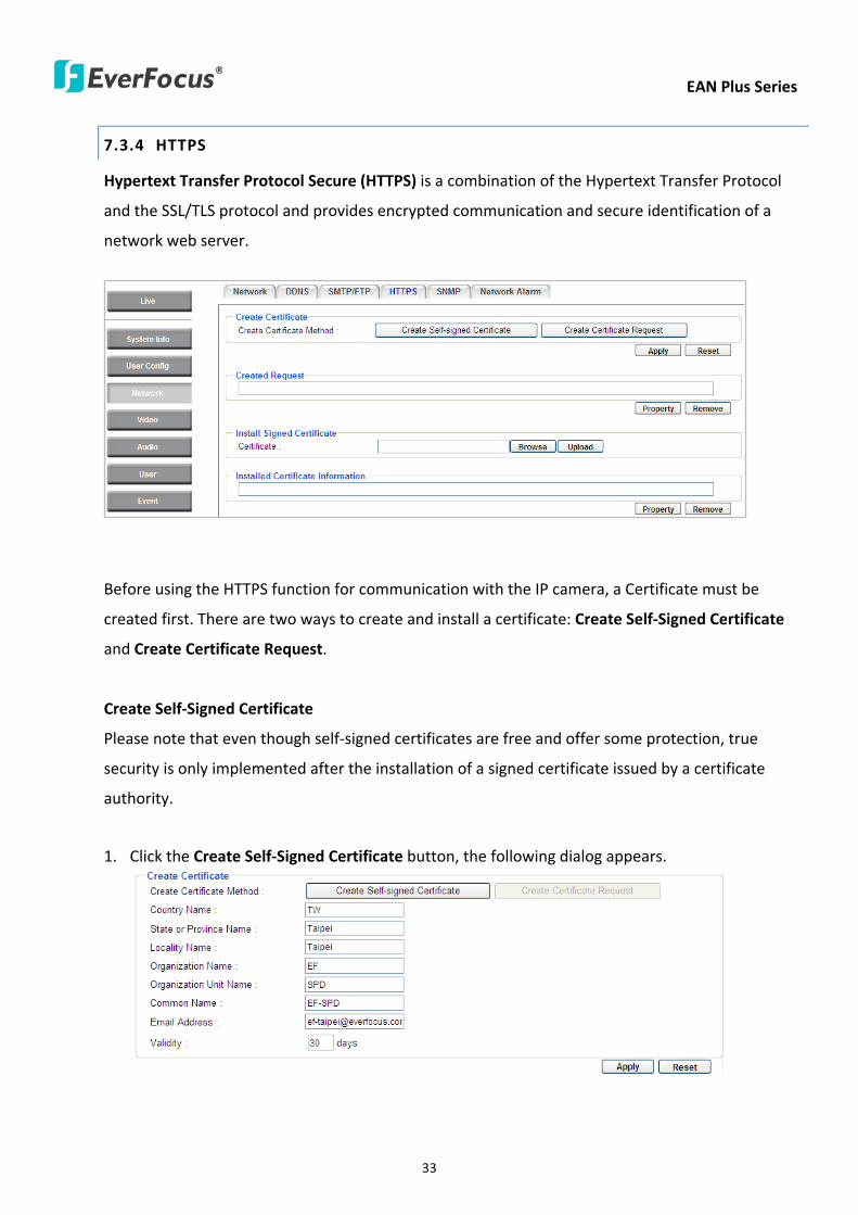
EAN Plus Series
33
734 HTTPS
Hypertext Transfer Protocol Secure (HTTPS) is a combination of the Hypertext Transfer Protocol
and the SSLTLS protocol and provides encrypted communication and secure identification of a
network web server
Before using the HTTPS function for communication with the IP camera a Certificate must be
created first There are two ways to create and install a certificate Create Self-Signed Certificate
and Create Certificate Request
Create Self-Signed Certificate
Please note that even though self-signed certificates are free and offer some protection true
security is only implemented after the installation of a signed certificate issued by a certificate
authority
1 Click the Create Self-Signed Certificate button the following dialog appears
EAN Plus Series
34
2 Type the required Certificate information and then click the Apply button The subject line will
be displayed in the Installed Certificate Information field
3 Click the Property button a pop-up window appears to display the details of the certificate
4 To optionally create and install other certificates remove the existing one by clicking the
Remove button to erase the certificate
5 On the Web page change the address from ldquohttprdquo to https in the address bar and press
Enter on the keyboard Some Security Alert dialogs will pop up Click OK or Yes to enable HTTPS
Create Certificate Request
You can apply for an official certificate from an issuing Certificate Authority
1 Click the Create Certificate Request button the following dialog appears
EAN Plus Series
35
2 Type the required Certificate information and then click the Apply button The subject line will
be displayed in the Created Request field
3 Click the Property button a pop-up window appears to display the details of the certificate
4 To optionally create and install other certificates or request remove the existing one by clicking
the Remove button to erase the certificate or request
5 Copy the contents of the Certificate request (in PEM format) and paste it to the certificate
request field on the Web page of the 3rd-party certification authority such as Symantec VeriSign
Wait for the certificate authority to issue an SSLTLS certificate and then download the issued
certificate on your computer
6 In the Install Signed Certificate field click the Browse button to search for the issued certificate
and then click the Upload button to import the certificate Once the certificate has been
uploaded this field will show the subject line of the certificate
EAN Plus Series
36
735 SNMP
The default values for SNMP v1v2v2c and SNMP v3 are already filled in Click either of the
Enable buttons to enable either of the two Make your changes as desired Click on the Trap
Address field to enter the digits if required
736 Network Alarm
This function works with EverFocusrsquos CMS software eg the PowerCon or the Power Video Plus For
the setting details please refer to the CMS network alarm protocol
EAN Plus Series
37
74 Video
The settings relating to video such as streaming camera OSD can be configured on this page The
Video page has five tabs Multi-streaming Camera Advanced ROI and Privacy Mask
741 Multi Streaming
【Stream Settings】 This IP camera can output three video streams simultaneously For each of these
streams the user can set the compression format resolution bit rate and frame rate individually
Stream 1 is always enabled for live view To enable Stream 2 andor Stream 3 check the ldquoEnablerdquo
box the header of each stream
Note If you connect to the camera via the Internet and experience a delay (lag time) in the video
feed try to reduce the number of streams and the quality and resolution of the streams ndash but
keep the frame rate at its maximum
EAN Plus Series
38
Format Select the encoding format ndash H264 or MJPEG
Resolution Select the most suitable resolution for your needs
Frame Rate Select from 1 to 30 fps
Bit Rate If required select whether you want the stream to stream a Constant Bit Rate or a
Variable Bit Rate and set the values of whichever option you choose
Click Apply to apply the setting changes or Reset to reset without saving the changes
【Video Recording Settings】Select the stream you want to configure and then select whether you
want the recording files of that stream to be saved in AVI or ARV format Click Apply to apply the
setting changes or Reset to reset without saving the changes
【Time Stamp Settings】 You can select the DateTime format position and add the setting to the
streaming
Click Apply to apply the changes or Reset to reset without saving the changes
EAN Plus Series
39
742 Camera
【Image Settings】Set the Brightness Saturation Contrast or Sharpness of the image Click Apply to
apply the changes or Reset to reset without saving the changes
【Camera Settings】
Mirror Switch Mirror ON to rotate the image horizontally around a vertical axis
Flip Switch Flip ON to rotate the image vertically around a horizontal axis
AE There are two options
ALC Selecting Automatic Light Control allows the camera circuitry to either take bright spots
more into consideration (peak) bringing out detail in bright areas or less into consideration
(average) bringing out detail in shadows
AES Selecting Auto Electronic Shutter disables the Shutter setting below this setting In this
mode the camera measures the light level and decides whether it needs more or less light and
then automatically adjusts the shutter speed accordingly
BLC Back Light Compensation (BLC) is used to make the subject appear clearer when it is set
against a bright background
OFF Select to switch Back Light Compensation functions off
(ON)BLC The BLC can increase the exposure of a dark area surrounded by a brighter area HLC
can decrease the exposure of bright areas surrounded by darker areas This enables the
camera to better display information that would otherwise have been ldquowhited outrdquo like a
license plate between two bright headlights on a dark road
(ON)HLC The Highlight-Suppression BLC is used to reduce the brightness of light sources in a
specific area It is activated only in a low illumination environment to minimize the effects of
glare from bright lights such as spotlights street lights or headlights in the field of view
EAN Plus Series
40
WDR The Wide Dynamic Range (WDR) function provides clearer images when both of the very
bright and dark areas simultaneously appear on the camera view There are four value options
OFF Low Middle and High Note that when WDR is ON some parts of the image may appear
solarized This is normal for WDR and is not a camera malfunction This function is only available
for EAN3120 Plus 3220 Plus
DN Mode
Auto Select to let the camera automatically switch to Night mode (black and white) when the
light levels fall to a specified level and back to Day mode (color) when the light levels rise to a
specified level
Day Select to keep the camera in Day mode (color) even in nighttime
Night Select to keep the camera in Night mode (black and white) even in daytime
EAN Plus Series
41
743 Advanced
EAN Plus Series
42
【Camera Settings】
Lens (IRIS Control) Select DC or Manual for IRIS control This function is only available for EAN3220
Plus
Exposure Settings (AE) This setting is used to adapt to the amount or type of light used by the
camera Note the settings vary among models
Mode This function is not available for EAN3220 Plus
Automatic Light Control (ALC) This option is only available for EAN3120 Plus 3300 Plus The
ALC allows the camera circuitry to either take bright spots more into consideration (peak)
bringing out detail in bright areas or less into consideration (average) bringing out detail in
shadows
Auto Electronic Shutter (AES) This option is only available for EAN3120 Plus 3300 Plus In
this mode the camera measures the light level and decides whether it needs more or less light
and then automatically adjusts the shutter speed accordingly
Manual This option is only available for EAN3300 Plus Select this option to manually set up
the Shutter (Manual) and AGC (Manual) values
Iris Specify the size of the Iris opening here
Shutter If enabled this setting lets you set the shutter speed yourself
Shutter Limit Use this setting to set the maximum shutter speed for the camera This function is
only available for EAN3120 Plus
AGC Set the Auto Gain Control limit here The lower the AGC level the lower the video signal and
the noise However the image will be darker under low-light condition with IR-off if you set up the
Iris to the maximum level
Slow Shutter This option can be switched on when AES Mode is selected in the Exposure Settings
(AE) field This function is only available for EAN3220 Plus 3300 Plus
Flickerless If the Mode field in the Exposure Settings (AE) area has been set to AES then this option
becomes available Choose between OFF 50HZ 60HZ 50HZ (High Luminance) or 60HZ (High
Luminance) This function is only available for EAN3300 Plus
EV Setting Set up the Exposure Value Note the brightness of the screen changes when you change
the EV value This function is only available for EAN3300 Plus
AE Response Set up Auto Exposure Response time This function is only available for EAN3300 Plus
AE Weighting Area Select an AE Weighting area Each setup AE Weighting Area is configured with
the appropriate brightness level on the center and the surrounding areas This function is only
available for EAN3300 Plus
Brightness Set the image brightness here
AE Reference Set the Auto Exposure value here This function is only available for EAN3120 Plus
EAN Plus Series
43
Black Level Set the Black level here This function is only available for EAN3300 Plus
WDR The Wide Dynamic Range (WDR) function provides clearer images when both of the very
bright and dark areas simultaneously appear on the camera view There are four value options OFF
Low Middle and High Note that when WDR is ON some parts of the image may appear solarized
This is normal for WDR and is not a camera malfunction This function is only available for EAN3120
Plus 3220 Plus
Visibility Enhancement (OFFLowMiddleHigh) Images in foggy or rain environments or in
environments with a very strong luminous intensity have a dynamic range that is significantly lower
than ordinary images The user can use this Visibility Enhancement setting to ldquoDEFOGrdquo the image if
such ldquoFOGGINGrdquo is an issue This function is only available for EAN3220 Plus
BLC Settings Back Light Compensation (BLC) is used to make the subject appear clearer when it is
set against a bright background
OFF Select to switch Back Light Compensation functions off
Back Light This option is only available for EAN3300 Plus The Back Light function is useful
when the background of the subject is very bright and the subject itself is dark Select Back
Light and adjust the slide bar to the left right for setting up the back light value The higher
the value the more the backlight compensation
Front Light This option is only available for EAN3300 Plus This function is useful when the
bright highlights such as flashlight or car headlights appear on the camera view Select Front
Light and adjust the slide bar to the left right for setting up the front light value The higher
the value the more the highlight compensation
ON (BLC) This option is only available when you select AES Mode in the Exposure Settings (AE)
field The option is only available for EAN3120 Plus 3220 Plus The BLC function is useful
when the background of the subject is very bright and the subject itself is dark Follow the
instructions below to configure the settings for each model
For EAN3120 Select ON (BLC) the button next to the Mode drop-down list will be
active (see image below) Click the button the green setup areas appear on the left
screen Click on the areas to enable disable the BLC function The selected areas (in green)
will be applied with the BLC function
EAN Plus Series
44
For EAN3220
You can configure one area to apply the BLC function Select ON (BLC) the setup buttons
appears (see image below) Select Low Middle High from the BLC Gain drop-down list To
set up a BLC area click the Edit Area button and then click on the blue color tab to turn your
mouse cursor into a blue pen Move the cursor to the position on the right screen where you
want the BLC rectangle to start and then click Move your cursor to the position (diagonally
opposing corner) where you want the BLC rectangle to end and then click The blue area will
be applied with the BLC function
ON (HLC) This option is only available when you select AES Mode in the Exposure Settings (AE)
field The option is only available for EAN3120 Plus 3220 Plus This function is useful when
the bright highlights such as flashlight or car headlights appear on the camera view Follow
the instructions below to configure the settings for each model
For EAN3120 Select ON (HLC) and then select a level from the drop-down list The higher the
level the more the highlight compensation
For EAN3220
HLC Level Select a level for the HLC setting The higher the level the more the highlight
compensation
HLC Mode Select All Day Night mode to apply the HLC function
HLC Black Mask Select On Off to apply the black mask on the selected areas The
over-exposure portions within the selected areas will be applied with the black mask
Color Tabs You can set up four HLC areas with different colors To set up a HLC area click the
Edit Area button and then click on the color tab to turn your mouse cursor into a pen of that
color Move the cursor to the position on the right screen where you want the HLC rectangle
to start and then click Move your cursor to the position (diagonally opposing corner) where
you want the HLC rectangle to end and then click Select ON from the color tab drop-down list
The rectangular area with the selected color will be applied with the HLC function
EAN Plus Series
45
Back Light This option is only available for EAN3300 Plus The Back Light function is useful
when the background of the subject is very bright and the subject itself is dark Select Back
Light and adjust the slide bar to the left right for setting up the back light value The higher
the value the more the backlight compensation
Front Light This option is only available for EAN3300 Plus This function is useful when the
bright highlights such as flashlight or car headlights appear on the camera view Select Front
Light and adjust the slide bar to the left right for setting up the front light value The higher
the value the more the highlight compensation
Noise Reduction Settings This limits the amount of digital ldquovideo noiserdquo that is usually found in any
video stream and helps to reduce file size The higher the level the more the reduction
For EAN3120 Plus 3300 Plus
Select ON OFF to enable disable the Noise Reduction function Or select Auto to let the camera
automatically enable disable the Noise Reduction function Slide the Level bar to set up the level
The higher the level the more the reduction
For EAN3220 Plus
2D DNR Select ON to enable the 2D DNR function
3D DNR Select ON to enable the 3D DNR function You can further set up the following settings
3D Start AGC Set up the AGC level to automatically start the 3D NR function
3D End AGC Set up the AGC level to automatically stop the 3D NR function
3D Level Set up the 3D DNR level
Smart NR Select ON to enable the Smart NR function The 3D NR function will be
automatically turned on when a motion event occurs
EAN Plus Series
46
White Balance Settings Select the mode that delivers the best quality image for the camerarsquos light
environment There are five options Auto Manual Indoor Outdoor One Push
Auto Select to let the camera automatically adjust the White Balance In the Auto mode the
camera computes the white balance value output using color information from the entire
screen It outputs the proper value using the color temperature radiating from a black subject
based on a range of value from 3000 to 7500K
Manual Select to adjust the Red and Blue values yourself in the fields below this field
Indoor Select to use the default settings for indoor environments In the Indoor mode the
camera uses 3200K as the base value
Outdoor Select to use the default settings for outdoor environment In the Outdoor mode it
uses 5800K as the base value
One Push Select to enable the Push button next to the Mode drop-down field This will allow you to force the camera to readjust the white balance every time you push the Push
button The lens will hold the same focal position until the next trigger command is received
This function helps to prevent incorrect focusing in dark environments This function is only
available for EAN3120 Plus 3220 Plus
Manual Temperature Select to use the optimized Red and Blue settings You can also
optionally adjust the Manual Level below this field for setting up the color temperature The
higher the value the more the color temperature This function is only available for EAN3300
Plus
DayNight Settings
Auto Select to let the camera automatically switch to Night mode (black and white) when the
light levels fall to a specified level and back to Day mode (color) when the light levels rise to a
specified level
Day Select to keep the camera in Day mode (color) even in nighttime
Night Select to keep the camera in Night mode (black and white) even in daytime
IR Smart Settings Select ON and set up the level to enhance the image quality when the images are
over exposure This function is useful when the camera is in the Night mode This function is only
available for EAN3220 Plus
Saturation Set the saturation value This function is not available for EAN3220 Plus
Monitor Type Select a gamma value from Set 1 Set 2 or Set 3 This function is only available for
EAN3120 Plus
Negative Switch this setting ON to view a color negative version of the video image This is useful
at night or when viewing temperature-sensitive images
EAN Plus Series
47
Sharpness Settings Select the sharpness level of the image A low sharpness level will deliver a
softer less detailed image A high level will deliver a sharp highly detailed image Switch Resolution
Enhancement ON to enable the resolution enhancement function
Contrast Select the contrast level of the image
Suppress Function This function is only available for EAN3300 Plus
Aperture Compensation Suppression (OFFLowMiddleHigh) This setting can be activated to
suppress luminance noise when the AGC level increases
Chroma Suppression (OFFLowMiddleHigh) This setting can be activated to suppress
chrominance noise when the AGC level increases
Ygamma (gamma 22standardcontrast enhancehigh light range mode LHigh light range mode
H) Select the Ygamma value for the video quality of the monitor This function is only available for
EAN3300 Plus
Monitor Settings The user can use this field to optimize video quality for his or her specific type of
monitor ndash LCD or CRT This function is only available for EAN3220 Plus
Color Space Standard The options are YUV601 for SD and YUV709 for HD These define the color
space standard required to convert an RGB picture to a YUV picture Generally YUV601 is used for
Standard Definition (720P) devices and the YUV709 is used for High Definition (1080P) devices
Click Apply to save all changes Click Reset to cancel all changes
EAN Plus Series
48
744 ROI (Region of Interest)
The Region of Interest (ROI) function allows users to set up multiple regions within an image with
better quality and less distortion than the rest of the image You can also use this function
together with the Digital Zoom function on the Live View Page to get a better image result Up to
eight ROIs can be configured in the ROI settings page
To set up an ROI region
1 Select an ROI number from the ROI No drop-down list
2 Click the Add button the mouse cursor will turn into a pen when you move it over the live
image on the left
3 Move the cursor to the position where you want the ROI rectangle to start and then click
Move the cursor to the position (diagonally opposing corner) where you want the ROI
rectangle to end and then click
4 Slide the Quality bar to set up the quality value
5 Click the Apply button to apply the settings or click the Reset button to reset without saving
the settings
EAN Plus Series
49
745 Privacy Mask
The Privacy Mask can block out sensitive areas from view covering the areas with colored or black
and white boxes in both live view and recorded clips This feature is useful when usersrsquo donrsquot want
the sensitive information visible Up to four Privacy Masks can be configured
【Privacy Mask Color Settings】The Modes vary among camera models
Mode Click Color to make the masks appear as colored rectangles on the screen Click BW to
make the masks appear as gray rectangles on the screen Click Mosaic to make the masks appear
as mosaic-effect rectangles on the screen
Level Select the color of the masks if you selected Color Mode Select the level of grayness of the
masks if you selected BW Mode Select the level of smallmiddlelarge if you selected Mosaic
Mode
Click Apply to apply the settings or click Reset to reset without saving the settings
Color Tabs Click on a color tab to turn your mouse cursor into a pen of that color
You can now create a block of that color on the video screen Move your cursor to the position
where you want your mask rectangle to start and then click Move your cursor to the position
(diagonally opposing corner) where you want your mask rectangle to end and then click The
rectangular area with the selected color will appear The live image will display the rectangular
area with the color you selected If you want to create another mask use one of the other three
colors Each color denotes a different mask area Only one block per color is allowed As the
number of colors suggests you can configure up to four blocks
EAN Plus Series
50
Select All Click to turn the whole screen into a mask area
Clear All Click to delete all configured mask blocks
Eraser Click to turn the mouse cursor into an eraser to delete any block you click on
Area Shows the color and number of the block
Enable Check this box to enable the related mask block
Click Apply to apply the settings or click Reset to reset without saving the settings
EAN Plus Series
51
75 Audio
The EAN Plus series IP camera can transmit audio to your computer if you have connected an external
microphone to its audio Input cable It can also receive audio input from you and transmit it via an
external speaker if you have connected such a speaker to its audio Output cable
Check the Enable Audio box to enable the camerarsquos audio function The camera will now act as a
digital bridge (via the IP network) between any connected audio input device and any connected
audio device
Adjust the Audio Input Volume if you have external audio input devices (microphones) connected to
the camera and if there are problems with the sound input being too low or high
Click Apply to save all settings or click Reset to cancel
EAN Plus Series
52
76 User
761 User Information
The system administrator can create up to ten user accounts on this page
To set up a user account
1 Highlight a user account and click the Modify button The following dialog box appears
2 Type the account name account description and password for the account Type the password
again in the Confirm field
3 Select an authority level for the user account from the Authority drop-down list
bull Supervisor Administrator The only difference between a supervisor and administrator is
that a supervisor can edit an administratorrsquos account and password but an administrator
cannot edit the supervisorrsquos account and password Multiple administrators can be
configured but there can be only one supervisor The supervisor and administrators all
have unrestricted access to the Settings submenus and can determine the registration of
all other users
EAN Plus Series
53
bull User A user can view the Live View page and view the system network video and audio
information A user can only adjust the User Config page settings The user does not have
access to the User Event and System pages
bull Guest The lowest level of access which only allows the user access to the Live View page
4 Select Active or Disable from the Status drop-down list to active or disable the user account
5 Click On in the SD Card Playback field to allow the user to access the SD card playback
function
6 Click OK
7 Click Apply to save all the settings
EAN Plus Series
54
762 IP Address Filter
Use this page to specify IP addresses that are not allowed to access this camera By default any IP
address can access the camera
Note The Allowed List addresses only become relevant when the Denied List contains a network
or range and the supervisor wants to allow one or more IP addresses within that excluded range
or network In such a scenario the user would enter the excluded range or network in the
Denied List and enter the exceptions in the Allowed List
To set up the IP Address Filter
1 Select Denied List Click the Add button the following dialog box appears
2 Select an IP type from the IP Type drop-down list
3 Select a network rule from the Rule drop-down list type the IP address and click OK
Single Type a single IP address in the IP Address field below
Network Type the IP address and subnet mask in the field below
Range Type a range for the IP addresses
4 If you have set up an IP range in Step 3 you can optionally set up the Allowed List to allow one
or more IP addresses within the setup IP range to access the IP camera
5 Click Apply
EAN Plus Series
55
77 Event
You can set up the Motion Detection event Tamper Detection event or the Alarm IO to automatically
notify the users when an event occurs or an alarm is triggered You can also set up a schedule to
automatically record the videos when an event occurs or an alarm is triggered
771 Event Settings
You can create a total of ten event or alarm settings page in the Event List
【Event List】
Click the Add button and the following Event Configuration Window appears
EAN Plus Series
56
Enter Event Name Type an event name
Event Triggered by Select an event or alarm type for the to-be-specified-below reactions
Alarm Input Select this if you want a reaction trigger coming from any external connected sensor
to activate a to-be-specified-below reactions via the camera system Make sure that a suitable
device is actually connected to the alarm input relay
Manual Trigger Select this option if you want to manually trigger the alarm by clicking the Trigger
Event button on the Live View Page
Motion Detection Select this option if you want motion in a specified part of the camerarsquos viewing
rectangle (the screen image) to trigger the to-be-specified-below reactions
Tampering Detection Select this option if you want the camerarsquos tampering detection sensor to
trigger the to-be-specified-below reactions
Schedule Recording Select this option if you want the Schedule Recording periods configured in
the recording schedule (the Settings gt Event gt Schedule page) to activate this event In this
scenario a preconfigured event reaction like a log entry will list the start and end times of each
period Actual recording will only be triggered if the event is preconfigured to do so
Enable This Event Select to activate the event
Enable Re-trigger Click to set a minimum time after the event is triggered before the event
can be triggered again
Enable Pre-trigger Buffer Click if you want the Event reaction (as selected in the ldquoNotification
Overrdquo field below) to be the activation of the video recording function and if you want the
recording to include the video feed from the time period (configurable on the previous ldquoEvent
Settingsrdquo page) just before the Event trigger occurred
Enable Post-trigger Buffer Click if you want the Event reaction (as selected in the Notification
Over field) to be the activation of the video recording function and if you want the recording
to include the video feed from a time period (configurable on the Event Settings page) just
after the Event trigger occurred
Motion Area Select a setup motion detection area from the drop down list Note this
function only becomes relevant after the Motion Detection areas have been set up (see 772
Motion Detection)
Notification Over Select the desired notification types form the following items
Log Click if you want the camera to list the eventrsquos details in its log if the event is triggered
Trigger Alarm Output Click if you want the camera to relay the event reaction to a device
attached to the alarm relay output wire and then set up the alarm output duration time
EAN Plus Series
57
Send Mail Notification Click if you want the camera to send an Event notification email to the
email address entered in the Set SMTP Server(email) field of the Network gt SMTPFTP page if
the Event occurs (see 733 SMTP FTP)
Upload to FTP Click if you want the camera to upload recorded footage to the FTP server
entered in the Set SMTP Server(email) field of the Network gt SMTPFTP page if the Event
occurs (see 733 SMTP FTP)
Record to SD Card Click if you want the camera to start recording its video feed (when the
event occurs) on an on-camera SD Card (if such a card has been inserted)
Note The recording will only be as long as the combined Pre- and Post-trigger Buffers so
make sure you enable at least one of these buffers especially the Post-trigger Buffer
Record to PC Check this box if you want the camera to start recording its video feed (when
the event occurs) on the same folder on the same PC as configured on the User Config gt
RecordingSnapshot page (if such a folder has been enabled and configured)
Note The recording will only be as long as the combined Pre- and Post-trigger Buffers (and
for as long as the event trigger is happening ndash eg a motion is detected) so make sure you
enable at least one of these buffers especially the Post-trigger Buffer
Network Alarm Check this box if you want the camera to send a network alarm signal (when
the event occurs) to the CMS servers configured on the Network gt Network Alarm page (see
736 Network Alarm)
Click OK to save all settings or click Cancel to cancel
【PrePost Trigger Settings】
Pre-trigger Buffer Select the duration for the buffer This will determine the amount of footage
(length of time) before the event trigger moment that will be included in an event-triggered video
recording if that buffer and video recording has been enabled in the Event Configuration Window
Post-trigger Buffer Select the duration for the buffer This will determine the amount of footage
(length of time) after the event trigger moment that will be included in an event-triggered video
recording if that buffer and video recording has been enabled in the Event Configuration Window
Click Apply to save all settings or click Reset to cancel
EAN Plus Series
58
772 Motion Detection
Use this page to configure up to four areas in which motion will be detected When a motion is
detected by the camera the motion detection icon will appear at the top right of the
Live page to alert the user This function can also be linked with correctly configured Events to
trigger Event reactions like the activation of video recording periods snapshots alarms etc
Color Tabs Click on a color tab to turn your mouse cursor into a pen of that color
You can now create a block of that color on the video screen Move your cursor to the position
where you want your detection rectangle to start and then click Move your cursor to the position
(diagonally opposing corner) where you want your detection rectangle to end and then click The
rectangular area with the selected color will appear This block will be an area inside which the
camera will detect motion If you want to create another detection area use one of the other three
palette colors Each color denotes a different detection area Only one block per color is allowed As
the number of colors suggests you can configure up to four blocks
Select All Click to turn the whole screen into a motion detection area
Clear All Click to delete all configured motion detection blocks
Eraser Click to turn your mouse cursor into an eraser to delete any block you click on
Area Shows the color and numberID of the block
Enable Check this box to enable the related motion detection block
Sensitivity Set the sensitivity of the motion detection sensor function
Click Apply to save all settings or click Reset to cancel
EAN Plus Series
59
773 Tamper Detection
Use this page to set the number of seconds that an alarm signal will be active if the device is
physically tampered (moved covered up or out of focus
774 Alarm IO
Use this page to set the type of trigger input and the type of output contact for the camerarsquos alarm
channel
EAN Plus Series
60
775 Schedule
Use this page to configure a schedule for periods during which the camera should deactivate all
user-activated Events (gray Deselect periods) or when the camera should deactivate all
user-activated Events except Schedule Recording (SR) events (blue Schedule Recording-only
periods) or when the camera should deactivate only SR events (red Event Recording-only periods)
or when it should enable all activated Events (yellow periods)
Event Recording Click this button to make every hour block you click on red A red block represents
an Event Recording-only block which represents an hour when the camera will deactivate all
preconfigured activated Schedule Recording events and keep all the other activated events active
Schedule Recording Click this button to make every hour block you click on blue A blue block
represents a Schedule Recording-only block which represents an hour when the camera will
deactivate all other preconfigured activated events and keep only the preconfigured activated
Schedule Recording events active
Event + Schedule Click this button to make every hour block you click on yellow A yellow block
represents an hour in which all activated events including Schedule Recording events will be
active
Deselect Click this button to make every hour block become grey A grey block represents an hour
in which all activated events including Schedule Recording events will be inactive
Click Apply to save all settings or click Reset to cancel
EAN Plus Series
61
78 System
You can set up the systemrsquos time and SD card settings and to do maintenance and reset actions like
reboots and upgrades
781 DateTime
【Machine Name Settings】If required enter a new name for the machine This name will be visible
in the Machine Name field of the IP Utility software which is included in the software CD
【Set Time Zone】Set the time zone of the camerarsquos location
【Set DateTime Manually】Set the datetime here if you wonrsquot be using an NTP server to update the
datetime (see below)
【Set DateTime Sync】Enter the Network Time Protocol server if applicable The camerarsquos time will
be automatically adjusted by synchronizing with the NTP server
Click Apply to save all settings or click Reset to cancel
EAN Plus Series
62
782 Daylight Saving
Click Enable Daylight Saving to enable this schedule and select the dates when the regionrsquos
daylight saving period begins and ends Click Apply to save all settings or click Reset to cancel
783 SD Card
Use this page to prepare the system for safely removing the SD Card from its slot
【Setup SD Card】
Notification Select the percentage of storage space that should be left on the card before the
camera notifies you of the impending storage shortage or overwrite
Event Recording Select if you want Event Recording only FTP Backup only or both
Overwrite Click ON if you want the card to start writing over recorded footage when its memory is
full Click OFF if you want the card to stop recording new footage when its memory is full
【SD Card Utility】
Capacity This shows you how much card memory has been used and how much memory capacity
remains on the card
Remove Click this button before removing the card from the system
Format Click this button to format the card All data saved on the SD card will be removed if the
card is formatted
EAN Plus Series
63
784 Maintenance
【Maintenance Server】
Reboot Click this button to reboot the unit without changing any of the settings Use this function if
the unit is not behaving as expected
Restore Click this button to restart and reset most of the current settings to their factory default
values The only settings that will not be changed to default are
bull IP settings
bull DDNS settings
Default The Default button should be used with caution Pressing this button will return all of the
cameras settings including the IP address to the factory default values The camera will then have
to be reconfigured
【SaveLoad Configuration Server】
Save To make a backup file of the machinersquos current configurations press Save to save all the
configurations to a config file This will enable the user to reload these configuration settings if the
settings are changed and there is unexpected behavior
Load To load a previously saved configuration press the Browse button to locate the saved config
file (see above) and then click the Load button The systemrsquos settings will be restored to the saved
configuration
EAN Plus Series
64
【SaveLoad Video Configuration Server】
Save To make a backup file of the machinersquos video configurations press Save to save the video
configurations to a config file This will enable the user to reload these configuration settings if the
settings are changed and there is unexpected behavior
Load To load a previously saved video configuration press the Browse button to locate the saved
config file (see above) and then click the Load button The systemrsquos settings will be restored to the
saved video configuration
【Upgrade Firmware】Click the Browse button to find a previously prepared firmware upgrade file
Click Upgrade to install the new firmware
Note
1 Do not disconnect power to the unit during the upgrade sequence The unit will reboot
automatically after the upgrade has completed (1-5 minutes)
2 During the upgrade process all event recording actions will be stopped Event recording
actions will resume after the camera is rebooted
3 If the ldquoFile Error Please re-loginrdquo warning message appears when upgrading the firmware
please try the following instructions
a Go to Internet Explorer gt Tools gt Internet Option gt Security gt Custom
b Find and enable the Include local directory path when uploading files to a server
EAN Plus Series
65
8 Upgrading Firmware Using IP Utility
You can upgrade the Firmware using the IP Utility software included in the software CD
1 Install and then start the IPU program The following dialog box appears
2 Click Find Devices to search the cameras connected in the LAN The default network values of the
cameras will be displayed By default the network protocol of the camera is DHCP
3 Select a camera and click LoginMulti Login to log in the camera
4 Type the user ID and password Click OK
Note
1 The default user ID is user1 and the default password is 11111111
2 If you select more than one camera that has the same user ID password you will be able
to log in several cameras at once
EAN Plus Series
66
5 Highlight the camera and then click Upgrade Firmware A browsing window appears
6 Select the firmware file (evb) and then click Open The IP Utility will automatically upgrade the
firmware
The camera will reboot once the update is complete Click Find Devices the new firmware version
should be displayed in the last part of the Machine Name
EAN Plus Series
67
9 Specifications
Model EAN3120 Plus EAN3220 Plus EAN3300 Plus
Camera
Image Sensor 13 Panasonic CMOS 128 Sony CMOS
Megapixel 13 MP 2 MP 3 MP
Picture Elements (H x V) 1280 x 1024 1944 x 1092 2048 x 1536
Min Illuminations 003 Lux at F14
Electronic Shutter (Sec) 85 ~ 160000 2 ~ 150000 1 ~ 110000
Scanning System NTSC PAL
WDR Yes Yes No
BLC Yes
Gain Control Yes
White Balance Yes
Lens
Mounting Type C CS
Day Night Yes (with removable auto IR-cut filter)
IRIS Control DC Electrical IRIS Lens IRIS
Video
Video Compression H264 MJPEG
Resolution
NTSC
2048 x 1536 1920 x 1200 (for EAN3300 Plus only)
1920 x 1080 (for EAN3300 Plus 3220 Plus only)
1280 x 1024 1280 x 720 1024 x 768 720 x 480 704 x 480 640 x 480
352 x 240 320 x 240 160 x 120
PAL
2048 x 1536 1920 x 1200 (for EAN3300 Plus only)
1920 x 1080 (for EAN3300 Plus 3220 Plus only)
1280 x 1024 1280 x 720 1024 x 768 720 x 576 704 x 576 640 x 480
352 x 288 320 x 240 160 x 120
Frame Rate 30 fps at 1280 x 1024 30 fps at 1920 x 1080 15 fps at 2048 x 1536
Audio
Audio Streaming Two-way audio
Audio Compression G711
EAN Plus Series
68
Network
Interface 10 100 Base-T Ethernet RJ-45 socket
Supported Protocols
TCPIP IPV6 UDP ICMP DHCP NTP DNS DDNS SMTP SNMP FTP
HTTP HTTPs PPPoE UPnP Bonjour RTP RTSP RTCP IGMP ARP ONVIF
PSIA
Connector
Power DC female port PoE
Ethernet RJ-45
Audio 1 In (phone jack for microphone)
1 Out (phone jack for Speaker)
Alarm IO Terminal IO wires
Local Storage Micro SD SDHC memory card slot
TV-Out BNC socket composite 1 V p-p 75 Ω
General
Power Source DC 12V PoE (IEEE8023af)
Power Consumption
(IR LEDs On)
5W (DC 12V)
621W (PoE)
5W (DC 12V)
522W (PoE)
5W (DC 12V)
536W (PoE)
Operating Temperature 0degC ~ +50degC 32degF ~ +122degF
Humidity 20 to 80 (no condensation)
Safety CE FCC
Dimensions (L x W x H) 117 x 56 x 68 mm 46 x 22 x 27 in
Weight 410 g 09 lb
EverFocus Electronics Corp EverFocus Taiwan 12F No79 Sec 1 Shin-Tai Wu Road Hsi-Chih Taipei Taiwan TEL +886 2 2698 2334 FAX +886 2 2698 2380 wwweverfocuscomtw marketingeverfocuscomtw
EverFocus Europe - Germany Albert-Einstein-Strasse 1 D-46446 Emmerich Germany TEL +49 2822 93940 FAX +49 2822 939495 wwweverfocusde infoeverfocusde
EverFocus China - Beijing Room 609 Technology Trade Building Shangdi Information Industry Base Haidian District Beijing 100085 China TEL +86 10 6297 3336~39 FAX +86 10 6297 1423 wwweverfocuscomcn marketingeverfocuscomcn
EverFocus China - Shenzhen 4F No 2 D4 Building Wan Yelong Industrial Park Tangtou Road Shiyan Baoan Shenzhen Guangdong 518101 China TEL +86 755 2765 1313 FAX +86 755 2765 0337 wwweverfocuscomcn marketingeverfocuscomcn
EverFocus USA - California 1801 Highland Avenue Unit A Duarte CA 91010 USA TEL +1 626 844 8888 FAX +1 626 844 8838 wwweverfocuscom saleseverfocuscom
EverFocus USA - New York 415 Oser Avenue Unit S Hauppauge NY 11788 USA TEL +1 631 436 5070 FAX +1 631 436 5027 wwweverfocuscom saleseverfocuscom
EverFocus Japan 5F Kinshicho City Building 2-13-4 Koto-BashiSumida-Ku Tokyo 130-0022 Japan TEL +81 3 5625 8188 FAX +81 3 5625 8189 wwweverfocuscojp infoeverfocuscojp
EverFocus Europe - UK Unit 12 Spitfire Business Park Hawker Road Croydon Surrey CR0 4WD UK TEL +44 20 8649 9757 +44 845 430 9999 FAX +44 20 8649 9907 wwweverfocusukcouk salesukeverfocuscom
EverFocus India Suite 803 Housefin Bhavan C-21 Bandra Kurla Complex Bandra (East) Mumbai 400051 India TEL +91 22 6128 8700 FAX +91 22 6128 8705 wwweverfocusin saleseverfocusin
PN 4605PQ3120B010A-VerC
Your EverFocus product is designed and manufactured with high quality materials and components which can be recycled and reused This symbol means that electrical and electronic equipment at their end-of-life should be disposed of separately from your household waste Please dispose of this equipment at your local community waste collectionrecycling centre In the European Union there are separate collection systems for used electrical and electronic product Please help us to conserve the environment we live in
Ihr EverFocus Produkt wurde entwickelt und hergestellt mit qualitativ hochwertigen Materialien und Komponenten die recycelt und wieder verwendet werden koumlnnen Dieses Symbol bedeutet dass elektrische und elektronische Geraumlte am Ende ihrer Nutzungsdauer vom Hausmuumlll getrennt entsorgt werden sollen Bitte entsorgen Sie dieses Geraumlt bei Ihrer oumlrtlichen kommunalen Sammelstelle oder im Recycling Centre Helfen Sie uns bitte die Umwelt zu erhalten in der wir leben
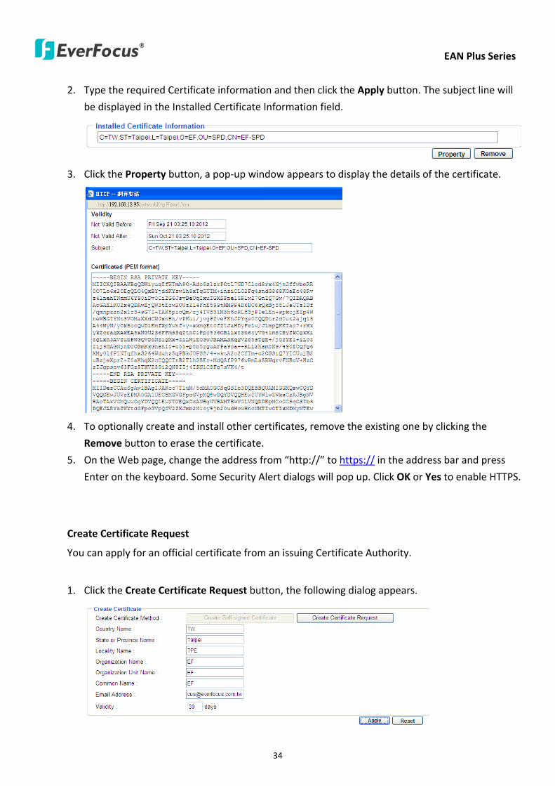
EAN Plus Series
34
2 Type the required Certificate information and then click the Apply button The subject line will
be displayed in the Installed Certificate Information field
3 Click the Property button a pop-up window appears to display the details of the certificate
4 To optionally create and install other certificates remove the existing one by clicking the
Remove button to erase the certificate
5 On the Web page change the address from ldquohttprdquo to https in the address bar and press
Enter on the keyboard Some Security Alert dialogs will pop up Click OK or Yes to enable HTTPS
Create Certificate Request
You can apply for an official certificate from an issuing Certificate Authority
1 Click the Create Certificate Request button the following dialog appears
EAN Plus Series
35
2 Type the required Certificate information and then click the Apply button The subject line will
be displayed in the Created Request field
3 Click the Property button a pop-up window appears to display the details of the certificate
4 To optionally create and install other certificates or request remove the existing one by clicking
the Remove button to erase the certificate or request
5 Copy the contents of the Certificate request (in PEM format) and paste it to the certificate
request field on the Web page of the 3rd-party certification authority such as Symantec VeriSign
Wait for the certificate authority to issue an SSLTLS certificate and then download the issued
certificate on your computer
6 In the Install Signed Certificate field click the Browse button to search for the issued certificate
and then click the Upload button to import the certificate Once the certificate has been
uploaded this field will show the subject line of the certificate
EAN Plus Series
36
735 SNMP
The default values for SNMP v1v2v2c and SNMP v3 are already filled in Click either of the
Enable buttons to enable either of the two Make your changes as desired Click on the Trap
Address field to enter the digits if required
736 Network Alarm
This function works with EverFocusrsquos CMS software eg the PowerCon or the Power Video Plus For
the setting details please refer to the CMS network alarm protocol
EAN Plus Series
37
74 Video
The settings relating to video such as streaming camera OSD can be configured on this page The
Video page has five tabs Multi-streaming Camera Advanced ROI and Privacy Mask
741 Multi Streaming
【Stream Settings】 This IP camera can output three video streams simultaneously For each of these
streams the user can set the compression format resolution bit rate and frame rate individually
Stream 1 is always enabled for live view To enable Stream 2 andor Stream 3 check the ldquoEnablerdquo
box the header of each stream
Note If you connect to the camera via the Internet and experience a delay (lag time) in the video
feed try to reduce the number of streams and the quality and resolution of the streams ndash but
keep the frame rate at its maximum
EAN Plus Series
38
Format Select the encoding format ndash H264 or MJPEG
Resolution Select the most suitable resolution for your needs
Frame Rate Select from 1 to 30 fps
Bit Rate If required select whether you want the stream to stream a Constant Bit Rate or a
Variable Bit Rate and set the values of whichever option you choose
Click Apply to apply the setting changes or Reset to reset without saving the changes
【Video Recording Settings】Select the stream you want to configure and then select whether you
want the recording files of that stream to be saved in AVI or ARV format Click Apply to apply the
setting changes or Reset to reset without saving the changes
【Time Stamp Settings】 You can select the DateTime format position and add the setting to the
streaming
Click Apply to apply the changes or Reset to reset without saving the changes
EAN Plus Series
39
742 Camera
【Image Settings】Set the Brightness Saturation Contrast or Sharpness of the image Click Apply to
apply the changes or Reset to reset without saving the changes
【Camera Settings】
Mirror Switch Mirror ON to rotate the image horizontally around a vertical axis
Flip Switch Flip ON to rotate the image vertically around a horizontal axis
AE There are two options
ALC Selecting Automatic Light Control allows the camera circuitry to either take bright spots
more into consideration (peak) bringing out detail in bright areas or less into consideration
(average) bringing out detail in shadows
AES Selecting Auto Electronic Shutter disables the Shutter setting below this setting In this
mode the camera measures the light level and decides whether it needs more or less light and
then automatically adjusts the shutter speed accordingly
BLC Back Light Compensation (BLC) is used to make the subject appear clearer when it is set
against a bright background
OFF Select to switch Back Light Compensation functions off
(ON)BLC The BLC can increase the exposure of a dark area surrounded by a brighter area HLC
can decrease the exposure of bright areas surrounded by darker areas This enables the
camera to better display information that would otherwise have been ldquowhited outrdquo like a
license plate between two bright headlights on a dark road
(ON)HLC The Highlight-Suppression BLC is used to reduce the brightness of light sources in a
specific area It is activated only in a low illumination environment to minimize the effects of
glare from bright lights such as spotlights street lights or headlights in the field of view
EAN Plus Series
40
WDR The Wide Dynamic Range (WDR) function provides clearer images when both of the very
bright and dark areas simultaneously appear on the camera view There are four value options
OFF Low Middle and High Note that when WDR is ON some parts of the image may appear
solarized This is normal for WDR and is not a camera malfunction This function is only available
for EAN3120 Plus 3220 Plus
DN Mode
Auto Select to let the camera automatically switch to Night mode (black and white) when the
light levels fall to a specified level and back to Day mode (color) when the light levels rise to a
specified level
Day Select to keep the camera in Day mode (color) even in nighttime
Night Select to keep the camera in Night mode (black and white) even in daytime
EAN Plus Series
41
743 Advanced
EAN Plus Series
42
【Camera Settings】
Lens (IRIS Control) Select DC or Manual for IRIS control This function is only available for EAN3220
Plus
Exposure Settings (AE) This setting is used to adapt to the amount or type of light used by the
camera Note the settings vary among models
Mode This function is not available for EAN3220 Plus
Automatic Light Control (ALC) This option is only available for EAN3120 Plus 3300 Plus The
ALC allows the camera circuitry to either take bright spots more into consideration (peak)
bringing out detail in bright areas or less into consideration (average) bringing out detail in
shadows
Auto Electronic Shutter (AES) This option is only available for EAN3120 Plus 3300 Plus In
this mode the camera measures the light level and decides whether it needs more or less light
and then automatically adjusts the shutter speed accordingly
Manual This option is only available for EAN3300 Plus Select this option to manually set up
the Shutter (Manual) and AGC (Manual) values
Iris Specify the size of the Iris opening here
Shutter If enabled this setting lets you set the shutter speed yourself
Shutter Limit Use this setting to set the maximum shutter speed for the camera This function is
only available for EAN3120 Plus
AGC Set the Auto Gain Control limit here The lower the AGC level the lower the video signal and
the noise However the image will be darker under low-light condition with IR-off if you set up the
Iris to the maximum level
Slow Shutter This option can be switched on when AES Mode is selected in the Exposure Settings
(AE) field This function is only available for EAN3220 Plus 3300 Plus
Flickerless If the Mode field in the Exposure Settings (AE) area has been set to AES then this option
becomes available Choose between OFF 50HZ 60HZ 50HZ (High Luminance) or 60HZ (High
Luminance) This function is only available for EAN3300 Plus
EV Setting Set up the Exposure Value Note the brightness of the screen changes when you change
the EV value This function is only available for EAN3300 Plus
AE Response Set up Auto Exposure Response time This function is only available for EAN3300 Plus
AE Weighting Area Select an AE Weighting area Each setup AE Weighting Area is configured with
the appropriate brightness level on the center and the surrounding areas This function is only
available for EAN3300 Plus
Brightness Set the image brightness here
AE Reference Set the Auto Exposure value here This function is only available for EAN3120 Plus
EAN Plus Series
43
Black Level Set the Black level here This function is only available for EAN3300 Plus
WDR The Wide Dynamic Range (WDR) function provides clearer images when both of the very
bright and dark areas simultaneously appear on the camera view There are four value options OFF
Low Middle and High Note that when WDR is ON some parts of the image may appear solarized
This is normal for WDR and is not a camera malfunction This function is only available for EAN3120
Plus 3220 Plus
Visibility Enhancement (OFFLowMiddleHigh) Images in foggy or rain environments or in
environments with a very strong luminous intensity have a dynamic range that is significantly lower
than ordinary images The user can use this Visibility Enhancement setting to ldquoDEFOGrdquo the image if
such ldquoFOGGINGrdquo is an issue This function is only available for EAN3220 Plus
BLC Settings Back Light Compensation (BLC) is used to make the subject appear clearer when it is
set against a bright background
OFF Select to switch Back Light Compensation functions off
Back Light This option is only available for EAN3300 Plus The Back Light function is useful
when the background of the subject is very bright and the subject itself is dark Select Back
Light and adjust the slide bar to the left right for setting up the back light value The higher
the value the more the backlight compensation
Front Light This option is only available for EAN3300 Plus This function is useful when the
bright highlights such as flashlight or car headlights appear on the camera view Select Front
Light and adjust the slide bar to the left right for setting up the front light value The higher
the value the more the highlight compensation
ON (BLC) This option is only available when you select AES Mode in the Exposure Settings (AE)
field The option is only available for EAN3120 Plus 3220 Plus The BLC function is useful
when the background of the subject is very bright and the subject itself is dark Follow the
instructions below to configure the settings for each model
For EAN3120 Select ON (BLC) the button next to the Mode drop-down list will be
active (see image below) Click the button the green setup areas appear on the left
screen Click on the areas to enable disable the BLC function The selected areas (in green)
will be applied with the BLC function
EAN Plus Series
44
For EAN3220
You can configure one area to apply the BLC function Select ON (BLC) the setup buttons
appears (see image below) Select Low Middle High from the BLC Gain drop-down list To
set up a BLC area click the Edit Area button and then click on the blue color tab to turn your
mouse cursor into a blue pen Move the cursor to the position on the right screen where you
want the BLC rectangle to start and then click Move your cursor to the position (diagonally
opposing corner) where you want the BLC rectangle to end and then click The blue area will
be applied with the BLC function
ON (HLC) This option is only available when you select AES Mode in the Exposure Settings (AE)
field The option is only available for EAN3120 Plus 3220 Plus This function is useful when
the bright highlights such as flashlight or car headlights appear on the camera view Follow
the instructions below to configure the settings for each model
For EAN3120 Select ON (HLC) and then select a level from the drop-down list The higher the
level the more the highlight compensation
For EAN3220
HLC Level Select a level for the HLC setting The higher the level the more the highlight
compensation
HLC Mode Select All Day Night mode to apply the HLC function
HLC Black Mask Select On Off to apply the black mask on the selected areas The
over-exposure portions within the selected areas will be applied with the black mask
Color Tabs You can set up four HLC areas with different colors To set up a HLC area click the
Edit Area button and then click on the color tab to turn your mouse cursor into a pen of that
color Move the cursor to the position on the right screen where you want the HLC rectangle
to start and then click Move your cursor to the position (diagonally opposing corner) where
you want the HLC rectangle to end and then click Select ON from the color tab drop-down list
The rectangular area with the selected color will be applied with the HLC function
EAN Plus Series
45
Back Light This option is only available for EAN3300 Plus The Back Light function is useful
when the background of the subject is very bright and the subject itself is dark Select Back
Light and adjust the slide bar to the left right for setting up the back light value The higher
the value the more the backlight compensation
Front Light This option is only available for EAN3300 Plus This function is useful when the
bright highlights such as flashlight or car headlights appear on the camera view Select Front
Light and adjust the slide bar to the left right for setting up the front light value The higher
the value the more the highlight compensation
Noise Reduction Settings This limits the amount of digital ldquovideo noiserdquo that is usually found in any
video stream and helps to reduce file size The higher the level the more the reduction
For EAN3120 Plus 3300 Plus
Select ON OFF to enable disable the Noise Reduction function Or select Auto to let the camera
automatically enable disable the Noise Reduction function Slide the Level bar to set up the level
The higher the level the more the reduction
For EAN3220 Plus
2D DNR Select ON to enable the 2D DNR function
3D DNR Select ON to enable the 3D DNR function You can further set up the following settings
3D Start AGC Set up the AGC level to automatically start the 3D NR function
3D End AGC Set up the AGC level to automatically stop the 3D NR function
3D Level Set up the 3D DNR level
Smart NR Select ON to enable the Smart NR function The 3D NR function will be
automatically turned on when a motion event occurs
EAN Plus Series
46
White Balance Settings Select the mode that delivers the best quality image for the camerarsquos light
environment There are five options Auto Manual Indoor Outdoor One Push
Auto Select to let the camera automatically adjust the White Balance In the Auto mode the
camera computes the white balance value output using color information from the entire
screen It outputs the proper value using the color temperature radiating from a black subject
based on a range of value from 3000 to 7500K
Manual Select to adjust the Red and Blue values yourself in the fields below this field
Indoor Select to use the default settings for indoor environments In the Indoor mode the
camera uses 3200K as the base value
Outdoor Select to use the default settings for outdoor environment In the Outdoor mode it
uses 5800K as the base value
One Push Select to enable the Push button next to the Mode drop-down field This will allow you to force the camera to readjust the white balance every time you push the Push
button The lens will hold the same focal position until the next trigger command is received
This function helps to prevent incorrect focusing in dark environments This function is only
available for EAN3120 Plus 3220 Plus
Manual Temperature Select to use the optimized Red and Blue settings You can also
optionally adjust the Manual Level below this field for setting up the color temperature The
higher the value the more the color temperature This function is only available for EAN3300
Plus
DayNight Settings
Auto Select to let the camera automatically switch to Night mode (black and white) when the
light levels fall to a specified level and back to Day mode (color) when the light levels rise to a
specified level
Day Select to keep the camera in Day mode (color) even in nighttime
Night Select to keep the camera in Night mode (black and white) even in daytime
IR Smart Settings Select ON and set up the level to enhance the image quality when the images are
over exposure This function is useful when the camera is in the Night mode This function is only
available for EAN3220 Plus
Saturation Set the saturation value This function is not available for EAN3220 Plus
Monitor Type Select a gamma value from Set 1 Set 2 or Set 3 This function is only available for
EAN3120 Plus
Negative Switch this setting ON to view a color negative version of the video image This is useful
at night or when viewing temperature-sensitive images
EAN Plus Series
47
Sharpness Settings Select the sharpness level of the image A low sharpness level will deliver a
softer less detailed image A high level will deliver a sharp highly detailed image Switch Resolution
Enhancement ON to enable the resolution enhancement function
Contrast Select the contrast level of the image
Suppress Function This function is only available for EAN3300 Plus
Aperture Compensation Suppression (OFFLowMiddleHigh) This setting can be activated to
suppress luminance noise when the AGC level increases
Chroma Suppression (OFFLowMiddleHigh) This setting can be activated to suppress
chrominance noise when the AGC level increases
Ygamma (gamma 22standardcontrast enhancehigh light range mode LHigh light range mode
H) Select the Ygamma value for the video quality of the monitor This function is only available for
EAN3300 Plus
Monitor Settings The user can use this field to optimize video quality for his or her specific type of
monitor ndash LCD or CRT This function is only available for EAN3220 Plus
Color Space Standard The options are YUV601 for SD and YUV709 for HD These define the color
space standard required to convert an RGB picture to a YUV picture Generally YUV601 is used for
Standard Definition (720P) devices and the YUV709 is used for High Definition (1080P) devices
Click Apply to save all changes Click Reset to cancel all changes
EAN Plus Series
48
744 ROI (Region of Interest)
The Region of Interest (ROI) function allows users to set up multiple regions within an image with
better quality and less distortion than the rest of the image You can also use this function
together with the Digital Zoom function on the Live View Page to get a better image result Up to
eight ROIs can be configured in the ROI settings page
To set up an ROI region
1 Select an ROI number from the ROI No drop-down list
2 Click the Add button the mouse cursor will turn into a pen when you move it over the live
image on the left
3 Move the cursor to the position where you want the ROI rectangle to start and then click
Move the cursor to the position (diagonally opposing corner) where you want the ROI
rectangle to end and then click
4 Slide the Quality bar to set up the quality value
5 Click the Apply button to apply the settings or click the Reset button to reset without saving
the settings
EAN Plus Series
49
745 Privacy Mask
The Privacy Mask can block out sensitive areas from view covering the areas with colored or black
and white boxes in both live view and recorded clips This feature is useful when usersrsquo donrsquot want
the sensitive information visible Up to four Privacy Masks can be configured
【Privacy Mask Color Settings】The Modes vary among camera models
Mode Click Color to make the masks appear as colored rectangles on the screen Click BW to
make the masks appear as gray rectangles on the screen Click Mosaic to make the masks appear
as mosaic-effect rectangles on the screen
Level Select the color of the masks if you selected Color Mode Select the level of grayness of the
masks if you selected BW Mode Select the level of smallmiddlelarge if you selected Mosaic
Mode
Click Apply to apply the settings or click Reset to reset without saving the settings
Color Tabs Click on a color tab to turn your mouse cursor into a pen of that color
You can now create a block of that color on the video screen Move your cursor to the position
where you want your mask rectangle to start and then click Move your cursor to the position
(diagonally opposing corner) where you want your mask rectangle to end and then click The
rectangular area with the selected color will appear The live image will display the rectangular
area with the color you selected If you want to create another mask use one of the other three
colors Each color denotes a different mask area Only one block per color is allowed As the
number of colors suggests you can configure up to four blocks
EAN Plus Series
50
Select All Click to turn the whole screen into a mask area
Clear All Click to delete all configured mask blocks
Eraser Click to turn the mouse cursor into an eraser to delete any block you click on
Area Shows the color and number of the block
Enable Check this box to enable the related mask block
Click Apply to apply the settings or click Reset to reset without saving the settings
EAN Plus Series
51
75 Audio
The EAN Plus series IP camera can transmit audio to your computer if you have connected an external
microphone to its audio Input cable It can also receive audio input from you and transmit it via an
external speaker if you have connected such a speaker to its audio Output cable
Check the Enable Audio box to enable the camerarsquos audio function The camera will now act as a
digital bridge (via the IP network) between any connected audio input device and any connected
audio device
Adjust the Audio Input Volume if you have external audio input devices (microphones) connected to
the camera and if there are problems with the sound input being too low or high
Click Apply to save all settings or click Reset to cancel
EAN Plus Series
52
76 User
761 User Information
The system administrator can create up to ten user accounts on this page
To set up a user account
1 Highlight a user account and click the Modify button The following dialog box appears
2 Type the account name account description and password for the account Type the password
again in the Confirm field
3 Select an authority level for the user account from the Authority drop-down list
bull Supervisor Administrator The only difference between a supervisor and administrator is
that a supervisor can edit an administratorrsquos account and password but an administrator
cannot edit the supervisorrsquos account and password Multiple administrators can be
configured but there can be only one supervisor The supervisor and administrators all
have unrestricted access to the Settings submenus and can determine the registration of
all other users
EAN Plus Series
53
bull User A user can view the Live View page and view the system network video and audio
information A user can only adjust the User Config page settings The user does not have
access to the User Event and System pages
bull Guest The lowest level of access which only allows the user access to the Live View page
4 Select Active or Disable from the Status drop-down list to active or disable the user account
5 Click On in the SD Card Playback field to allow the user to access the SD card playback
function
6 Click OK
7 Click Apply to save all the settings
EAN Plus Series
54
762 IP Address Filter
Use this page to specify IP addresses that are not allowed to access this camera By default any IP
address can access the camera
Note The Allowed List addresses only become relevant when the Denied List contains a network
or range and the supervisor wants to allow one or more IP addresses within that excluded range
or network In such a scenario the user would enter the excluded range or network in the
Denied List and enter the exceptions in the Allowed List
To set up the IP Address Filter
1 Select Denied List Click the Add button the following dialog box appears
2 Select an IP type from the IP Type drop-down list
3 Select a network rule from the Rule drop-down list type the IP address and click OK
Single Type a single IP address in the IP Address field below
Network Type the IP address and subnet mask in the field below
Range Type a range for the IP addresses
4 If you have set up an IP range in Step 3 you can optionally set up the Allowed List to allow one
or more IP addresses within the setup IP range to access the IP camera
5 Click Apply
EAN Plus Series
55
77 Event
You can set up the Motion Detection event Tamper Detection event or the Alarm IO to automatically
notify the users when an event occurs or an alarm is triggered You can also set up a schedule to
automatically record the videos when an event occurs or an alarm is triggered
771 Event Settings
You can create a total of ten event or alarm settings page in the Event List
【Event List】
Click the Add button and the following Event Configuration Window appears
EAN Plus Series
56
Enter Event Name Type an event name
Event Triggered by Select an event or alarm type for the to-be-specified-below reactions
Alarm Input Select this if you want a reaction trigger coming from any external connected sensor
to activate a to-be-specified-below reactions via the camera system Make sure that a suitable
device is actually connected to the alarm input relay
Manual Trigger Select this option if you want to manually trigger the alarm by clicking the Trigger
Event button on the Live View Page
Motion Detection Select this option if you want motion in a specified part of the camerarsquos viewing
rectangle (the screen image) to trigger the to-be-specified-below reactions
Tampering Detection Select this option if you want the camerarsquos tampering detection sensor to
trigger the to-be-specified-below reactions
Schedule Recording Select this option if you want the Schedule Recording periods configured in
the recording schedule (the Settings gt Event gt Schedule page) to activate this event In this
scenario a preconfigured event reaction like a log entry will list the start and end times of each
period Actual recording will only be triggered if the event is preconfigured to do so
Enable This Event Select to activate the event
Enable Re-trigger Click to set a minimum time after the event is triggered before the event
can be triggered again
Enable Pre-trigger Buffer Click if you want the Event reaction (as selected in the ldquoNotification
Overrdquo field below) to be the activation of the video recording function and if you want the
recording to include the video feed from the time period (configurable on the previous ldquoEvent
Settingsrdquo page) just before the Event trigger occurred
Enable Post-trigger Buffer Click if you want the Event reaction (as selected in the Notification
Over field) to be the activation of the video recording function and if you want the recording
to include the video feed from a time period (configurable on the Event Settings page) just
after the Event trigger occurred
Motion Area Select a setup motion detection area from the drop down list Note this
function only becomes relevant after the Motion Detection areas have been set up (see 772
Motion Detection)
Notification Over Select the desired notification types form the following items
Log Click if you want the camera to list the eventrsquos details in its log if the event is triggered
Trigger Alarm Output Click if you want the camera to relay the event reaction to a device
attached to the alarm relay output wire and then set up the alarm output duration time
EAN Plus Series
57
Send Mail Notification Click if you want the camera to send an Event notification email to the
email address entered in the Set SMTP Server(email) field of the Network gt SMTPFTP page if
the Event occurs (see 733 SMTP FTP)
Upload to FTP Click if you want the camera to upload recorded footage to the FTP server
entered in the Set SMTP Server(email) field of the Network gt SMTPFTP page if the Event
occurs (see 733 SMTP FTP)
Record to SD Card Click if you want the camera to start recording its video feed (when the
event occurs) on an on-camera SD Card (if such a card has been inserted)
Note The recording will only be as long as the combined Pre- and Post-trigger Buffers so
make sure you enable at least one of these buffers especially the Post-trigger Buffer
Record to PC Check this box if you want the camera to start recording its video feed (when
the event occurs) on the same folder on the same PC as configured on the User Config gt
RecordingSnapshot page (if such a folder has been enabled and configured)
Note The recording will only be as long as the combined Pre- and Post-trigger Buffers (and
for as long as the event trigger is happening ndash eg a motion is detected) so make sure you
enable at least one of these buffers especially the Post-trigger Buffer
Network Alarm Check this box if you want the camera to send a network alarm signal (when
the event occurs) to the CMS servers configured on the Network gt Network Alarm page (see
736 Network Alarm)
Click OK to save all settings or click Cancel to cancel
【PrePost Trigger Settings】
Pre-trigger Buffer Select the duration for the buffer This will determine the amount of footage
(length of time) before the event trigger moment that will be included in an event-triggered video
recording if that buffer and video recording has been enabled in the Event Configuration Window
Post-trigger Buffer Select the duration for the buffer This will determine the amount of footage
(length of time) after the event trigger moment that will be included in an event-triggered video
recording if that buffer and video recording has been enabled in the Event Configuration Window
Click Apply to save all settings or click Reset to cancel
EAN Plus Series
58
772 Motion Detection
Use this page to configure up to four areas in which motion will be detected When a motion is
detected by the camera the motion detection icon will appear at the top right of the
Live page to alert the user This function can also be linked with correctly configured Events to
trigger Event reactions like the activation of video recording periods snapshots alarms etc
Color Tabs Click on a color tab to turn your mouse cursor into a pen of that color
You can now create a block of that color on the video screen Move your cursor to the position
where you want your detection rectangle to start and then click Move your cursor to the position
(diagonally opposing corner) where you want your detection rectangle to end and then click The
rectangular area with the selected color will appear This block will be an area inside which the
camera will detect motion If you want to create another detection area use one of the other three
palette colors Each color denotes a different detection area Only one block per color is allowed As
the number of colors suggests you can configure up to four blocks
Select All Click to turn the whole screen into a motion detection area
Clear All Click to delete all configured motion detection blocks
Eraser Click to turn your mouse cursor into an eraser to delete any block you click on
Area Shows the color and numberID of the block
Enable Check this box to enable the related motion detection block
Sensitivity Set the sensitivity of the motion detection sensor function
Click Apply to save all settings or click Reset to cancel
EAN Plus Series
59
773 Tamper Detection
Use this page to set the number of seconds that an alarm signal will be active if the device is
physically tampered (moved covered up or out of focus
774 Alarm IO
Use this page to set the type of trigger input and the type of output contact for the camerarsquos alarm
channel
EAN Plus Series
60
775 Schedule
Use this page to configure a schedule for periods during which the camera should deactivate all
user-activated Events (gray Deselect periods) or when the camera should deactivate all
user-activated Events except Schedule Recording (SR) events (blue Schedule Recording-only
periods) or when the camera should deactivate only SR events (red Event Recording-only periods)
or when it should enable all activated Events (yellow periods)
Event Recording Click this button to make every hour block you click on red A red block represents
an Event Recording-only block which represents an hour when the camera will deactivate all
preconfigured activated Schedule Recording events and keep all the other activated events active
Schedule Recording Click this button to make every hour block you click on blue A blue block
represents a Schedule Recording-only block which represents an hour when the camera will
deactivate all other preconfigured activated events and keep only the preconfigured activated
Schedule Recording events active
Event + Schedule Click this button to make every hour block you click on yellow A yellow block
represents an hour in which all activated events including Schedule Recording events will be
active
Deselect Click this button to make every hour block become grey A grey block represents an hour
in which all activated events including Schedule Recording events will be inactive
Click Apply to save all settings or click Reset to cancel
EAN Plus Series
61
78 System
You can set up the systemrsquos time and SD card settings and to do maintenance and reset actions like
reboots and upgrades
781 DateTime
【Machine Name Settings】If required enter a new name for the machine This name will be visible
in the Machine Name field of the IP Utility software which is included in the software CD
【Set Time Zone】Set the time zone of the camerarsquos location
【Set DateTime Manually】Set the datetime here if you wonrsquot be using an NTP server to update the
datetime (see below)
【Set DateTime Sync】Enter the Network Time Protocol server if applicable The camerarsquos time will
be automatically adjusted by synchronizing with the NTP server
Click Apply to save all settings or click Reset to cancel
EAN Plus Series
62
782 Daylight Saving
Click Enable Daylight Saving to enable this schedule and select the dates when the regionrsquos
daylight saving period begins and ends Click Apply to save all settings or click Reset to cancel
783 SD Card
Use this page to prepare the system for safely removing the SD Card from its slot
【Setup SD Card】
Notification Select the percentage of storage space that should be left on the card before the
camera notifies you of the impending storage shortage or overwrite
Event Recording Select if you want Event Recording only FTP Backup only or both
Overwrite Click ON if you want the card to start writing over recorded footage when its memory is
full Click OFF if you want the card to stop recording new footage when its memory is full
【SD Card Utility】
Capacity This shows you how much card memory has been used and how much memory capacity
remains on the card
Remove Click this button before removing the card from the system
Format Click this button to format the card All data saved on the SD card will be removed if the
card is formatted
EAN Plus Series
63
784 Maintenance
【Maintenance Server】
Reboot Click this button to reboot the unit without changing any of the settings Use this function if
the unit is not behaving as expected
Restore Click this button to restart and reset most of the current settings to their factory default
values The only settings that will not be changed to default are
bull IP settings
bull DDNS settings
Default The Default button should be used with caution Pressing this button will return all of the
cameras settings including the IP address to the factory default values The camera will then have
to be reconfigured
【SaveLoad Configuration Server】
Save To make a backup file of the machinersquos current configurations press Save to save all the
configurations to a config file This will enable the user to reload these configuration settings if the
settings are changed and there is unexpected behavior
Load To load a previously saved configuration press the Browse button to locate the saved config
file (see above) and then click the Load button The systemrsquos settings will be restored to the saved
configuration
EAN Plus Series
64
【SaveLoad Video Configuration Server】
Save To make a backup file of the machinersquos video configurations press Save to save the video
configurations to a config file This will enable the user to reload these configuration settings if the
settings are changed and there is unexpected behavior
Load To load a previously saved video configuration press the Browse button to locate the saved
config file (see above) and then click the Load button The systemrsquos settings will be restored to the
saved video configuration
【Upgrade Firmware】Click the Browse button to find a previously prepared firmware upgrade file
Click Upgrade to install the new firmware
Note
1 Do not disconnect power to the unit during the upgrade sequence The unit will reboot
automatically after the upgrade has completed (1-5 minutes)
2 During the upgrade process all event recording actions will be stopped Event recording
actions will resume after the camera is rebooted
3 If the ldquoFile Error Please re-loginrdquo warning message appears when upgrading the firmware
please try the following instructions
a Go to Internet Explorer gt Tools gt Internet Option gt Security gt Custom
b Find and enable the Include local directory path when uploading files to a server
EAN Plus Series
65
8 Upgrading Firmware Using IP Utility
You can upgrade the Firmware using the IP Utility software included in the software CD
1 Install and then start the IPU program The following dialog box appears
2 Click Find Devices to search the cameras connected in the LAN The default network values of the
cameras will be displayed By default the network protocol of the camera is DHCP
3 Select a camera and click LoginMulti Login to log in the camera
4 Type the user ID and password Click OK
Note
1 The default user ID is user1 and the default password is 11111111
2 If you select more than one camera that has the same user ID password you will be able
to log in several cameras at once
EAN Plus Series
66
5 Highlight the camera and then click Upgrade Firmware A browsing window appears
6 Select the firmware file (evb) and then click Open The IP Utility will automatically upgrade the
firmware
The camera will reboot once the update is complete Click Find Devices the new firmware version
should be displayed in the last part of the Machine Name
EAN Plus Series
67
9 Specifications
Model EAN3120 Plus EAN3220 Plus EAN3300 Plus
Camera
Image Sensor 13 Panasonic CMOS 128 Sony CMOS
Megapixel 13 MP 2 MP 3 MP
Picture Elements (H x V) 1280 x 1024 1944 x 1092 2048 x 1536
Min Illuminations 003 Lux at F14
Electronic Shutter (Sec) 85 ~ 160000 2 ~ 150000 1 ~ 110000
Scanning System NTSC PAL
WDR Yes Yes No
BLC Yes
Gain Control Yes
White Balance Yes
Lens
Mounting Type C CS
Day Night Yes (with removable auto IR-cut filter)
IRIS Control DC Electrical IRIS Lens IRIS
Video
Video Compression H264 MJPEG
Resolution
NTSC
2048 x 1536 1920 x 1200 (for EAN3300 Plus only)
1920 x 1080 (for EAN3300 Plus 3220 Plus only)
1280 x 1024 1280 x 720 1024 x 768 720 x 480 704 x 480 640 x 480
352 x 240 320 x 240 160 x 120
PAL
2048 x 1536 1920 x 1200 (for EAN3300 Plus only)
1920 x 1080 (for EAN3300 Plus 3220 Plus only)
1280 x 1024 1280 x 720 1024 x 768 720 x 576 704 x 576 640 x 480
352 x 288 320 x 240 160 x 120
Frame Rate 30 fps at 1280 x 1024 30 fps at 1920 x 1080 15 fps at 2048 x 1536
Audio
Audio Streaming Two-way audio
Audio Compression G711
EAN Plus Series
68
Network
Interface 10 100 Base-T Ethernet RJ-45 socket
Supported Protocols
TCPIP IPV6 UDP ICMP DHCP NTP DNS DDNS SMTP SNMP FTP
HTTP HTTPs PPPoE UPnP Bonjour RTP RTSP RTCP IGMP ARP ONVIF
PSIA
Connector
Power DC female port PoE
Ethernet RJ-45
Audio 1 In (phone jack for microphone)
1 Out (phone jack for Speaker)
Alarm IO Terminal IO wires
Local Storage Micro SD SDHC memory card slot
TV-Out BNC socket composite 1 V p-p 75 Ω
General
Power Source DC 12V PoE (IEEE8023af)
Power Consumption
(IR LEDs On)
5W (DC 12V)
621W (PoE)
5W (DC 12V)
522W (PoE)
5W (DC 12V)
536W (PoE)
Operating Temperature 0degC ~ +50degC 32degF ~ +122degF
Humidity 20 to 80 (no condensation)
Safety CE FCC
Dimensions (L x W x H) 117 x 56 x 68 mm 46 x 22 x 27 in
Weight 410 g 09 lb
EverFocus Electronics Corp EverFocus Taiwan 12F No79 Sec 1 Shin-Tai Wu Road Hsi-Chih Taipei Taiwan TEL +886 2 2698 2334 FAX +886 2 2698 2380 wwweverfocuscomtw marketingeverfocuscomtw
EverFocus Europe - Germany Albert-Einstein-Strasse 1 D-46446 Emmerich Germany TEL +49 2822 93940 FAX +49 2822 939495 wwweverfocusde infoeverfocusde
EverFocus China - Beijing Room 609 Technology Trade Building Shangdi Information Industry Base Haidian District Beijing 100085 China TEL +86 10 6297 3336~39 FAX +86 10 6297 1423 wwweverfocuscomcn marketingeverfocuscomcn
EverFocus China - Shenzhen 4F No 2 D4 Building Wan Yelong Industrial Park Tangtou Road Shiyan Baoan Shenzhen Guangdong 518101 China TEL +86 755 2765 1313 FAX +86 755 2765 0337 wwweverfocuscomcn marketingeverfocuscomcn
EverFocus USA - California 1801 Highland Avenue Unit A Duarte CA 91010 USA TEL +1 626 844 8888 FAX +1 626 844 8838 wwweverfocuscom saleseverfocuscom
EverFocus USA - New York 415 Oser Avenue Unit S Hauppauge NY 11788 USA TEL +1 631 436 5070 FAX +1 631 436 5027 wwweverfocuscom saleseverfocuscom
EverFocus Japan 5F Kinshicho City Building 2-13-4 Koto-BashiSumida-Ku Tokyo 130-0022 Japan TEL +81 3 5625 8188 FAX +81 3 5625 8189 wwweverfocuscojp infoeverfocuscojp
EverFocus Europe - UK Unit 12 Spitfire Business Park Hawker Road Croydon Surrey CR0 4WD UK TEL +44 20 8649 9757 +44 845 430 9999 FAX +44 20 8649 9907 wwweverfocusukcouk salesukeverfocuscom
EverFocus India Suite 803 Housefin Bhavan C-21 Bandra Kurla Complex Bandra (East) Mumbai 400051 India TEL +91 22 6128 8700 FAX +91 22 6128 8705 wwweverfocusin saleseverfocusin
PN 4605PQ3120B010A-VerC
Your EverFocus product is designed and manufactured with high quality materials and components which can be recycled and reused This symbol means that electrical and electronic equipment at their end-of-life should be disposed of separately from your household waste Please dispose of this equipment at your local community waste collectionrecycling centre In the European Union there are separate collection systems for used electrical and electronic product Please help us to conserve the environment we live in
Ihr EverFocus Produkt wurde entwickelt und hergestellt mit qualitativ hochwertigen Materialien und Komponenten die recycelt und wieder verwendet werden koumlnnen Dieses Symbol bedeutet dass elektrische und elektronische Geraumlte am Ende ihrer Nutzungsdauer vom Hausmuumlll getrennt entsorgt werden sollen Bitte entsorgen Sie dieses Geraumlt bei Ihrer oumlrtlichen kommunalen Sammelstelle oder im Recycling Centre Helfen Sie uns bitte die Umwelt zu erhalten in der wir leben
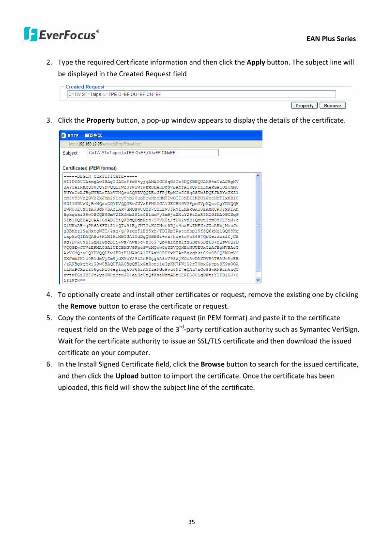
EAN Plus Series
35
2 Type the required Certificate information and then click the Apply button The subject line will
be displayed in the Created Request field
3 Click the Property button a pop-up window appears to display the details of the certificate
4 To optionally create and install other certificates or request remove the existing one by clicking
the Remove button to erase the certificate or request
5 Copy the contents of the Certificate request (in PEM format) and paste it to the certificate
request field on the Web page of the 3rd-party certification authority such as Symantec VeriSign
Wait for the certificate authority to issue an SSLTLS certificate and then download the issued
certificate on your computer
6 In the Install Signed Certificate field click the Browse button to search for the issued certificate
and then click the Upload button to import the certificate Once the certificate has been
uploaded this field will show the subject line of the certificate
EAN Plus Series
36
735 SNMP
The default values for SNMP v1v2v2c and SNMP v3 are already filled in Click either of the
Enable buttons to enable either of the two Make your changes as desired Click on the Trap
Address field to enter the digits if required
736 Network Alarm
This function works with EverFocusrsquos CMS software eg the PowerCon or the Power Video Plus For
the setting details please refer to the CMS network alarm protocol
EAN Plus Series
37
74 Video
The settings relating to video such as streaming camera OSD can be configured on this page The
Video page has five tabs Multi-streaming Camera Advanced ROI and Privacy Mask
741 Multi Streaming
【Stream Settings】 This IP camera can output three video streams simultaneously For each of these
streams the user can set the compression format resolution bit rate and frame rate individually
Stream 1 is always enabled for live view To enable Stream 2 andor Stream 3 check the ldquoEnablerdquo
box the header of each stream
Note If you connect to the camera via the Internet and experience a delay (lag time) in the video
feed try to reduce the number of streams and the quality and resolution of the streams ndash but
keep the frame rate at its maximum
EAN Plus Series
38
Format Select the encoding format ndash H264 or MJPEG
Resolution Select the most suitable resolution for your needs
Frame Rate Select from 1 to 30 fps
Bit Rate If required select whether you want the stream to stream a Constant Bit Rate or a
Variable Bit Rate and set the values of whichever option you choose
Click Apply to apply the setting changes or Reset to reset without saving the changes
【Video Recording Settings】Select the stream you want to configure and then select whether you
want the recording files of that stream to be saved in AVI or ARV format Click Apply to apply the
setting changes or Reset to reset without saving the changes
【Time Stamp Settings】 You can select the DateTime format position and add the setting to the
streaming
Click Apply to apply the changes or Reset to reset without saving the changes
EAN Plus Series
39
742 Camera
【Image Settings】Set the Brightness Saturation Contrast or Sharpness of the image Click Apply to
apply the changes or Reset to reset without saving the changes
【Camera Settings】
Mirror Switch Mirror ON to rotate the image horizontally around a vertical axis
Flip Switch Flip ON to rotate the image vertically around a horizontal axis
AE There are two options
ALC Selecting Automatic Light Control allows the camera circuitry to either take bright spots
more into consideration (peak) bringing out detail in bright areas or less into consideration
(average) bringing out detail in shadows
AES Selecting Auto Electronic Shutter disables the Shutter setting below this setting In this
mode the camera measures the light level and decides whether it needs more or less light and
then automatically adjusts the shutter speed accordingly
BLC Back Light Compensation (BLC) is used to make the subject appear clearer when it is set
against a bright background
OFF Select to switch Back Light Compensation functions off
(ON)BLC The BLC can increase the exposure of a dark area surrounded by a brighter area HLC
can decrease the exposure of bright areas surrounded by darker areas This enables the
camera to better display information that would otherwise have been ldquowhited outrdquo like a
license plate between two bright headlights on a dark road
(ON)HLC The Highlight-Suppression BLC is used to reduce the brightness of light sources in a
specific area It is activated only in a low illumination environment to minimize the effects of
glare from bright lights such as spotlights street lights or headlights in the field of view
EAN Plus Series
40
WDR The Wide Dynamic Range (WDR) function provides clearer images when both of the very
bright and dark areas simultaneously appear on the camera view There are four value options
OFF Low Middle and High Note that when WDR is ON some parts of the image may appear
solarized This is normal for WDR and is not a camera malfunction This function is only available
for EAN3120 Plus 3220 Plus
DN Mode
Auto Select to let the camera automatically switch to Night mode (black and white) when the
light levels fall to a specified level and back to Day mode (color) when the light levels rise to a
specified level
Day Select to keep the camera in Day mode (color) even in nighttime
Night Select to keep the camera in Night mode (black and white) even in daytime
EAN Plus Series
41
743 Advanced
EAN Plus Series
42
【Camera Settings】
Lens (IRIS Control) Select DC or Manual for IRIS control This function is only available for EAN3220
Plus
Exposure Settings (AE) This setting is used to adapt to the amount or type of light used by the
camera Note the settings vary among models
Mode This function is not available for EAN3220 Plus
Automatic Light Control (ALC) This option is only available for EAN3120 Plus 3300 Plus The
ALC allows the camera circuitry to either take bright spots more into consideration (peak)
bringing out detail in bright areas or less into consideration (average) bringing out detail in
shadows
Auto Electronic Shutter (AES) This option is only available for EAN3120 Plus 3300 Plus In
this mode the camera measures the light level and decides whether it needs more or less light
and then automatically adjusts the shutter speed accordingly
Manual This option is only available for EAN3300 Plus Select this option to manually set up
the Shutter (Manual) and AGC (Manual) values
Iris Specify the size of the Iris opening here
Shutter If enabled this setting lets you set the shutter speed yourself
Shutter Limit Use this setting to set the maximum shutter speed for the camera This function is
only available for EAN3120 Plus
AGC Set the Auto Gain Control limit here The lower the AGC level the lower the video signal and
the noise However the image will be darker under low-light condition with IR-off if you set up the
Iris to the maximum level
Slow Shutter This option can be switched on when AES Mode is selected in the Exposure Settings
(AE) field This function is only available for EAN3220 Plus 3300 Plus
Flickerless If the Mode field in the Exposure Settings (AE) area has been set to AES then this option
becomes available Choose between OFF 50HZ 60HZ 50HZ (High Luminance) or 60HZ (High
Luminance) This function is only available for EAN3300 Plus
EV Setting Set up the Exposure Value Note the brightness of the screen changes when you change
the EV value This function is only available for EAN3300 Plus
AE Response Set up Auto Exposure Response time This function is only available for EAN3300 Plus
AE Weighting Area Select an AE Weighting area Each setup AE Weighting Area is configured with
the appropriate brightness level on the center and the surrounding areas This function is only
available for EAN3300 Plus
Brightness Set the image brightness here
AE Reference Set the Auto Exposure value here This function is only available for EAN3120 Plus
EAN Plus Series
43
Black Level Set the Black level here This function is only available for EAN3300 Plus
WDR The Wide Dynamic Range (WDR) function provides clearer images when both of the very
bright and dark areas simultaneously appear on the camera view There are four value options OFF
Low Middle and High Note that when WDR is ON some parts of the image may appear solarized
This is normal for WDR and is not a camera malfunction This function is only available for EAN3120
Plus 3220 Plus
Visibility Enhancement (OFFLowMiddleHigh) Images in foggy or rain environments or in
environments with a very strong luminous intensity have a dynamic range that is significantly lower
than ordinary images The user can use this Visibility Enhancement setting to ldquoDEFOGrdquo the image if
such ldquoFOGGINGrdquo is an issue This function is only available for EAN3220 Plus
BLC Settings Back Light Compensation (BLC) is used to make the subject appear clearer when it is
set against a bright background
OFF Select to switch Back Light Compensation functions off
Back Light This option is only available for EAN3300 Plus The Back Light function is useful
when the background of the subject is very bright and the subject itself is dark Select Back
Light and adjust the slide bar to the left right for setting up the back light value The higher
the value the more the backlight compensation
Front Light This option is only available for EAN3300 Plus This function is useful when the
bright highlights such as flashlight or car headlights appear on the camera view Select Front
Light and adjust the slide bar to the left right for setting up the front light value The higher
the value the more the highlight compensation
ON (BLC) This option is only available when you select AES Mode in the Exposure Settings (AE)
field The option is only available for EAN3120 Plus 3220 Plus The BLC function is useful
when the background of the subject is very bright and the subject itself is dark Follow the
instructions below to configure the settings for each model
For EAN3120 Select ON (BLC) the button next to the Mode drop-down list will be
active (see image below) Click the button the green setup areas appear on the left
screen Click on the areas to enable disable the BLC function The selected areas (in green)
will be applied with the BLC function
EAN Plus Series
44
For EAN3220
You can configure one area to apply the BLC function Select ON (BLC) the setup buttons
appears (see image below) Select Low Middle High from the BLC Gain drop-down list To
set up a BLC area click the Edit Area button and then click on the blue color tab to turn your
mouse cursor into a blue pen Move the cursor to the position on the right screen where you
want the BLC rectangle to start and then click Move your cursor to the position (diagonally
opposing corner) where you want the BLC rectangle to end and then click The blue area will
be applied with the BLC function
ON (HLC) This option is only available when you select AES Mode in the Exposure Settings (AE)
field The option is only available for EAN3120 Plus 3220 Plus This function is useful when
the bright highlights such as flashlight or car headlights appear on the camera view Follow
the instructions below to configure the settings for each model
For EAN3120 Select ON (HLC) and then select a level from the drop-down list The higher the
level the more the highlight compensation
For EAN3220
HLC Level Select a level for the HLC setting The higher the level the more the highlight
compensation
HLC Mode Select All Day Night mode to apply the HLC function
HLC Black Mask Select On Off to apply the black mask on the selected areas The
over-exposure portions within the selected areas will be applied with the black mask
Color Tabs You can set up four HLC areas with different colors To set up a HLC area click the
Edit Area button and then click on the color tab to turn your mouse cursor into a pen of that
color Move the cursor to the position on the right screen where you want the HLC rectangle
to start and then click Move your cursor to the position (diagonally opposing corner) where
you want the HLC rectangle to end and then click Select ON from the color tab drop-down list
The rectangular area with the selected color will be applied with the HLC function
EAN Plus Series
45
Back Light This option is only available for EAN3300 Plus The Back Light function is useful
when the background of the subject is very bright and the subject itself is dark Select Back
Light and adjust the slide bar to the left right for setting up the back light value The higher
the value the more the backlight compensation
Front Light This option is only available for EAN3300 Plus This function is useful when the
bright highlights such as flashlight or car headlights appear on the camera view Select Front
Light and adjust the slide bar to the left right for setting up the front light value The higher
the value the more the highlight compensation
Noise Reduction Settings This limits the amount of digital ldquovideo noiserdquo that is usually found in any
video stream and helps to reduce file size The higher the level the more the reduction
For EAN3120 Plus 3300 Plus
Select ON OFF to enable disable the Noise Reduction function Or select Auto to let the camera
automatically enable disable the Noise Reduction function Slide the Level bar to set up the level
The higher the level the more the reduction
For EAN3220 Plus
2D DNR Select ON to enable the 2D DNR function
3D DNR Select ON to enable the 3D DNR function You can further set up the following settings
3D Start AGC Set up the AGC level to automatically start the 3D NR function
3D End AGC Set up the AGC level to automatically stop the 3D NR function
3D Level Set up the 3D DNR level
Smart NR Select ON to enable the Smart NR function The 3D NR function will be
automatically turned on when a motion event occurs
EAN Plus Series
46
White Balance Settings Select the mode that delivers the best quality image for the camerarsquos light
environment There are five options Auto Manual Indoor Outdoor One Push
Auto Select to let the camera automatically adjust the White Balance In the Auto mode the
camera computes the white balance value output using color information from the entire
screen It outputs the proper value using the color temperature radiating from a black subject
based on a range of value from 3000 to 7500K
Manual Select to adjust the Red and Blue values yourself in the fields below this field
Indoor Select to use the default settings for indoor environments In the Indoor mode the
camera uses 3200K as the base value
Outdoor Select to use the default settings for outdoor environment In the Outdoor mode it
uses 5800K as the base value
One Push Select to enable the Push button next to the Mode drop-down field This will allow you to force the camera to readjust the white balance every time you push the Push
button The lens will hold the same focal position until the next trigger command is received
This function helps to prevent incorrect focusing in dark environments This function is only
available for EAN3120 Plus 3220 Plus
Manual Temperature Select to use the optimized Red and Blue settings You can also
optionally adjust the Manual Level below this field for setting up the color temperature The
higher the value the more the color temperature This function is only available for EAN3300
Plus
DayNight Settings
Auto Select to let the camera automatically switch to Night mode (black and white) when the
light levels fall to a specified level and back to Day mode (color) when the light levels rise to a
specified level
Day Select to keep the camera in Day mode (color) even in nighttime
Night Select to keep the camera in Night mode (black and white) even in daytime
IR Smart Settings Select ON and set up the level to enhance the image quality when the images are
over exposure This function is useful when the camera is in the Night mode This function is only
available for EAN3220 Plus
Saturation Set the saturation value This function is not available for EAN3220 Plus
Monitor Type Select a gamma value from Set 1 Set 2 or Set 3 This function is only available for
EAN3120 Plus
Negative Switch this setting ON to view a color negative version of the video image This is useful
at night or when viewing temperature-sensitive images
EAN Plus Series
47
Sharpness Settings Select the sharpness level of the image A low sharpness level will deliver a
softer less detailed image A high level will deliver a sharp highly detailed image Switch Resolution
Enhancement ON to enable the resolution enhancement function
Contrast Select the contrast level of the image
Suppress Function This function is only available for EAN3300 Plus
Aperture Compensation Suppression (OFFLowMiddleHigh) This setting can be activated to
suppress luminance noise when the AGC level increases
Chroma Suppression (OFFLowMiddleHigh) This setting can be activated to suppress
chrominance noise when the AGC level increases
Ygamma (gamma 22standardcontrast enhancehigh light range mode LHigh light range mode
H) Select the Ygamma value for the video quality of the monitor This function is only available for
EAN3300 Plus
Monitor Settings The user can use this field to optimize video quality for his or her specific type of
monitor ndash LCD or CRT This function is only available for EAN3220 Plus
Color Space Standard The options are YUV601 for SD and YUV709 for HD These define the color
space standard required to convert an RGB picture to a YUV picture Generally YUV601 is used for
Standard Definition (720P) devices and the YUV709 is used for High Definition (1080P) devices
Click Apply to save all changes Click Reset to cancel all changes
EAN Plus Series
48
744 ROI (Region of Interest)
The Region of Interest (ROI) function allows users to set up multiple regions within an image with
better quality and less distortion than the rest of the image You can also use this function
together with the Digital Zoom function on the Live View Page to get a better image result Up to
eight ROIs can be configured in the ROI settings page
To set up an ROI region
1 Select an ROI number from the ROI No drop-down list
2 Click the Add button the mouse cursor will turn into a pen when you move it over the live
image on the left
3 Move the cursor to the position where you want the ROI rectangle to start and then click
Move the cursor to the position (diagonally opposing corner) where you want the ROI
rectangle to end and then click
4 Slide the Quality bar to set up the quality value
5 Click the Apply button to apply the settings or click the Reset button to reset without saving
the settings
EAN Plus Series
49
745 Privacy Mask
The Privacy Mask can block out sensitive areas from view covering the areas with colored or black
and white boxes in both live view and recorded clips This feature is useful when usersrsquo donrsquot want
the sensitive information visible Up to four Privacy Masks can be configured
【Privacy Mask Color Settings】The Modes vary among camera models
Mode Click Color to make the masks appear as colored rectangles on the screen Click BW to
make the masks appear as gray rectangles on the screen Click Mosaic to make the masks appear
as mosaic-effect rectangles on the screen
Level Select the color of the masks if you selected Color Mode Select the level of grayness of the
masks if you selected BW Mode Select the level of smallmiddlelarge if you selected Mosaic
Mode
Click Apply to apply the settings or click Reset to reset without saving the settings
Color Tabs Click on a color tab to turn your mouse cursor into a pen of that color
You can now create a block of that color on the video screen Move your cursor to the position
where you want your mask rectangle to start and then click Move your cursor to the position
(diagonally opposing corner) where you want your mask rectangle to end and then click The
rectangular area with the selected color will appear The live image will display the rectangular
area with the color you selected If you want to create another mask use one of the other three
colors Each color denotes a different mask area Only one block per color is allowed As the
number of colors suggests you can configure up to four blocks
EAN Plus Series
50
Select All Click to turn the whole screen into a mask area
Clear All Click to delete all configured mask blocks
Eraser Click to turn the mouse cursor into an eraser to delete any block you click on
Area Shows the color and number of the block
Enable Check this box to enable the related mask block
Click Apply to apply the settings or click Reset to reset without saving the settings
EAN Plus Series
51
75 Audio
The EAN Plus series IP camera can transmit audio to your computer if you have connected an external
microphone to its audio Input cable It can also receive audio input from you and transmit it via an
external speaker if you have connected such a speaker to its audio Output cable
Check the Enable Audio box to enable the camerarsquos audio function The camera will now act as a
digital bridge (via the IP network) between any connected audio input device and any connected
audio device
Adjust the Audio Input Volume if you have external audio input devices (microphones) connected to
the camera and if there are problems with the sound input being too low or high
Click Apply to save all settings or click Reset to cancel
EAN Plus Series
52
76 User
761 User Information
The system administrator can create up to ten user accounts on this page
To set up a user account
1 Highlight a user account and click the Modify button The following dialog box appears
2 Type the account name account description and password for the account Type the password
again in the Confirm field
3 Select an authority level for the user account from the Authority drop-down list
bull Supervisor Administrator The only difference between a supervisor and administrator is
that a supervisor can edit an administratorrsquos account and password but an administrator
cannot edit the supervisorrsquos account and password Multiple administrators can be
configured but there can be only one supervisor The supervisor and administrators all
have unrestricted access to the Settings submenus and can determine the registration of
all other users
EAN Plus Series
53
bull User A user can view the Live View page and view the system network video and audio
information A user can only adjust the User Config page settings The user does not have
access to the User Event and System pages
bull Guest The lowest level of access which only allows the user access to the Live View page
4 Select Active or Disable from the Status drop-down list to active or disable the user account
5 Click On in the SD Card Playback field to allow the user to access the SD card playback
function
6 Click OK
7 Click Apply to save all the settings
EAN Plus Series
54
762 IP Address Filter
Use this page to specify IP addresses that are not allowed to access this camera By default any IP
address can access the camera
Note The Allowed List addresses only become relevant when the Denied List contains a network
or range and the supervisor wants to allow one or more IP addresses within that excluded range
or network In such a scenario the user would enter the excluded range or network in the
Denied List and enter the exceptions in the Allowed List
To set up the IP Address Filter
1 Select Denied List Click the Add button the following dialog box appears
2 Select an IP type from the IP Type drop-down list
3 Select a network rule from the Rule drop-down list type the IP address and click OK
Single Type a single IP address in the IP Address field below
Network Type the IP address and subnet mask in the field below
Range Type a range for the IP addresses
4 If you have set up an IP range in Step 3 you can optionally set up the Allowed List to allow one
or more IP addresses within the setup IP range to access the IP camera
5 Click Apply
EAN Plus Series
55
77 Event
You can set up the Motion Detection event Tamper Detection event or the Alarm IO to automatically
notify the users when an event occurs or an alarm is triggered You can also set up a schedule to
automatically record the videos when an event occurs or an alarm is triggered
771 Event Settings
You can create a total of ten event or alarm settings page in the Event List
【Event List】
Click the Add button and the following Event Configuration Window appears
EAN Plus Series
56
Enter Event Name Type an event name
Event Triggered by Select an event or alarm type for the to-be-specified-below reactions
Alarm Input Select this if you want a reaction trigger coming from any external connected sensor
to activate a to-be-specified-below reactions via the camera system Make sure that a suitable
device is actually connected to the alarm input relay
Manual Trigger Select this option if you want to manually trigger the alarm by clicking the Trigger
Event button on the Live View Page
Motion Detection Select this option if you want motion in a specified part of the camerarsquos viewing
rectangle (the screen image) to trigger the to-be-specified-below reactions
Tampering Detection Select this option if you want the camerarsquos tampering detection sensor to
trigger the to-be-specified-below reactions
Schedule Recording Select this option if you want the Schedule Recording periods configured in
the recording schedule (the Settings gt Event gt Schedule page) to activate this event In this
scenario a preconfigured event reaction like a log entry will list the start and end times of each
period Actual recording will only be triggered if the event is preconfigured to do so
Enable This Event Select to activate the event
Enable Re-trigger Click to set a minimum time after the event is triggered before the event
can be triggered again
Enable Pre-trigger Buffer Click if you want the Event reaction (as selected in the ldquoNotification
Overrdquo field below) to be the activation of the video recording function and if you want the
recording to include the video feed from the time period (configurable on the previous ldquoEvent
Settingsrdquo page) just before the Event trigger occurred
Enable Post-trigger Buffer Click if you want the Event reaction (as selected in the Notification
Over field) to be the activation of the video recording function and if you want the recording
to include the video feed from a time period (configurable on the Event Settings page) just
after the Event trigger occurred
Motion Area Select a setup motion detection area from the drop down list Note this
function only becomes relevant after the Motion Detection areas have been set up (see 772
Motion Detection)
Notification Over Select the desired notification types form the following items
Log Click if you want the camera to list the eventrsquos details in its log if the event is triggered
Trigger Alarm Output Click if you want the camera to relay the event reaction to a device
attached to the alarm relay output wire and then set up the alarm output duration time
EAN Plus Series
57
Send Mail Notification Click if you want the camera to send an Event notification email to the
email address entered in the Set SMTP Server(email) field of the Network gt SMTPFTP page if
the Event occurs (see 733 SMTP FTP)
Upload to FTP Click if you want the camera to upload recorded footage to the FTP server
entered in the Set SMTP Server(email) field of the Network gt SMTPFTP page if the Event
occurs (see 733 SMTP FTP)
Record to SD Card Click if you want the camera to start recording its video feed (when the
event occurs) on an on-camera SD Card (if such a card has been inserted)
Note The recording will only be as long as the combined Pre- and Post-trigger Buffers so
make sure you enable at least one of these buffers especially the Post-trigger Buffer
Record to PC Check this box if you want the camera to start recording its video feed (when
the event occurs) on the same folder on the same PC as configured on the User Config gt
RecordingSnapshot page (if such a folder has been enabled and configured)
Note The recording will only be as long as the combined Pre- and Post-trigger Buffers (and
for as long as the event trigger is happening ndash eg a motion is detected) so make sure you
enable at least one of these buffers especially the Post-trigger Buffer
Network Alarm Check this box if you want the camera to send a network alarm signal (when
the event occurs) to the CMS servers configured on the Network gt Network Alarm page (see
736 Network Alarm)
Click OK to save all settings or click Cancel to cancel
【PrePost Trigger Settings】
Pre-trigger Buffer Select the duration for the buffer This will determine the amount of footage
(length of time) before the event trigger moment that will be included in an event-triggered video
recording if that buffer and video recording has been enabled in the Event Configuration Window
Post-trigger Buffer Select the duration for the buffer This will determine the amount of footage
(length of time) after the event trigger moment that will be included in an event-triggered video
recording if that buffer and video recording has been enabled in the Event Configuration Window
Click Apply to save all settings or click Reset to cancel
EAN Plus Series
58
772 Motion Detection
Use this page to configure up to four areas in which motion will be detected When a motion is
detected by the camera the motion detection icon will appear at the top right of the
Live page to alert the user This function can also be linked with correctly configured Events to
trigger Event reactions like the activation of video recording periods snapshots alarms etc
Color Tabs Click on a color tab to turn your mouse cursor into a pen of that color
You can now create a block of that color on the video screen Move your cursor to the position
where you want your detection rectangle to start and then click Move your cursor to the position
(diagonally opposing corner) where you want your detection rectangle to end and then click The
rectangular area with the selected color will appear This block will be an area inside which the
camera will detect motion If you want to create another detection area use one of the other three
palette colors Each color denotes a different detection area Only one block per color is allowed As
the number of colors suggests you can configure up to four blocks
Select All Click to turn the whole screen into a motion detection area
Clear All Click to delete all configured motion detection blocks
Eraser Click to turn your mouse cursor into an eraser to delete any block you click on
Area Shows the color and numberID of the block
Enable Check this box to enable the related motion detection block
Sensitivity Set the sensitivity of the motion detection sensor function
Click Apply to save all settings or click Reset to cancel
EAN Plus Series
59
773 Tamper Detection
Use this page to set the number of seconds that an alarm signal will be active if the device is
physically tampered (moved covered up or out of focus
774 Alarm IO
Use this page to set the type of trigger input and the type of output contact for the camerarsquos alarm
channel
EAN Plus Series
60
775 Schedule
Use this page to configure a schedule for periods during which the camera should deactivate all
user-activated Events (gray Deselect periods) or when the camera should deactivate all
user-activated Events except Schedule Recording (SR) events (blue Schedule Recording-only
periods) or when the camera should deactivate only SR events (red Event Recording-only periods)
or when it should enable all activated Events (yellow periods)
Event Recording Click this button to make every hour block you click on red A red block represents
an Event Recording-only block which represents an hour when the camera will deactivate all
preconfigured activated Schedule Recording events and keep all the other activated events active
Schedule Recording Click this button to make every hour block you click on blue A blue block
represents a Schedule Recording-only block which represents an hour when the camera will
deactivate all other preconfigured activated events and keep only the preconfigured activated
Schedule Recording events active
Event + Schedule Click this button to make every hour block you click on yellow A yellow block
represents an hour in which all activated events including Schedule Recording events will be
active
Deselect Click this button to make every hour block become grey A grey block represents an hour
in which all activated events including Schedule Recording events will be inactive
Click Apply to save all settings or click Reset to cancel
EAN Plus Series
61
78 System
You can set up the systemrsquos time and SD card settings and to do maintenance and reset actions like
reboots and upgrades
781 DateTime
【Machine Name Settings】If required enter a new name for the machine This name will be visible
in the Machine Name field of the IP Utility software which is included in the software CD
【Set Time Zone】Set the time zone of the camerarsquos location
【Set DateTime Manually】Set the datetime here if you wonrsquot be using an NTP server to update the
datetime (see below)
【Set DateTime Sync】Enter the Network Time Protocol server if applicable The camerarsquos time will
be automatically adjusted by synchronizing with the NTP server
Click Apply to save all settings or click Reset to cancel
EAN Plus Series
62
782 Daylight Saving
Click Enable Daylight Saving to enable this schedule and select the dates when the regionrsquos
daylight saving period begins and ends Click Apply to save all settings or click Reset to cancel
783 SD Card
Use this page to prepare the system for safely removing the SD Card from its slot
【Setup SD Card】
Notification Select the percentage of storage space that should be left on the card before the
camera notifies you of the impending storage shortage or overwrite
Event Recording Select if you want Event Recording only FTP Backup only or both
Overwrite Click ON if you want the card to start writing over recorded footage when its memory is
full Click OFF if you want the card to stop recording new footage when its memory is full
【SD Card Utility】
Capacity This shows you how much card memory has been used and how much memory capacity
remains on the card
Remove Click this button before removing the card from the system
Format Click this button to format the card All data saved on the SD card will be removed if the
card is formatted
EAN Plus Series
63
784 Maintenance
【Maintenance Server】
Reboot Click this button to reboot the unit without changing any of the settings Use this function if
the unit is not behaving as expected
Restore Click this button to restart and reset most of the current settings to their factory default
values The only settings that will not be changed to default are
bull IP settings
bull DDNS settings
Default The Default button should be used with caution Pressing this button will return all of the
cameras settings including the IP address to the factory default values The camera will then have
to be reconfigured
【SaveLoad Configuration Server】
Save To make a backup file of the machinersquos current configurations press Save to save all the
configurations to a config file This will enable the user to reload these configuration settings if the
settings are changed and there is unexpected behavior
Load To load a previously saved configuration press the Browse button to locate the saved config
file (see above) and then click the Load button The systemrsquos settings will be restored to the saved
configuration
EAN Plus Series
64
【SaveLoad Video Configuration Server】
Save To make a backup file of the machinersquos video configurations press Save to save the video
configurations to a config file This will enable the user to reload these configuration settings if the
settings are changed and there is unexpected behavior
Load To load a previously saved video configuration press the Browse button to locate the saved
config file (see above) and then click the Load button The systemrsquos settings will be restored to the
saved video configuration
【Upgrade Firmware】Click the Browse button to find a previously prepared firmware upgrade file
Click Upgrade to install the new firmware
Note
1 Do not disconnect power to the unit during the upgrade sequence The unit will reboot
automatically after the upgrade has completed (1-5 minutes)
2 During the upgrade process all event recording actions will be stopped Event recording
actions will resume after the camera is rebooted
3 If the ldquoFile Error Please re-loginrdquo warning message appears when upgrading the firmware
please try the following instructions
a Go to Internet Explorer gt Tools gt Internet Option gt Security gt Custom
b Find and enable the Include local directory path when uploading files to a server
EAN Plus Series
65
8 Upgrading Firmware Using IP Utility
You can upgrade the Firmware using the IP Utility software included in the software CD
1 Install and then start the IPU program The following dialog box appears
2 Click Find Devices to search the cameras connected in the LAN The default network values of the
cameras will be displayed By default the network protocol of the camera is DHCP
3 Select a camera and click LoginMulti Login to log in the camera
4 Type the user ID and password Click OK
Note
1 The default user ID is user1 and the default password is 11111111
2 If you select more than one camera that has the same user ID password you will be able
to log in several cameras at once
EAN Plus Series
66
5 Highlight the camera and then click Upgrade Firmware A browsing window appears
6 Select the firmware file (evb) and then click Open The IP Utility will automatically upgrade the
firmware
The camera will reboot once the update is complete Click Find Devices the new firmware version
should be displayed in the last part of the Machine Name
EAN Plus Series
67
9 Specifications
Model EAN3120 Plus EAN3220 Plus EAN3300 Plus
Camera
Image Sensor 13 Panasonic CMOS 128 Sony CMOS
Megapixel 13 MP 2 MP 3 MP
Picture Elements (H x V) 1280 x 1024 1944 x 1092 2048 x 1536
Min Illuminations 003 Lux at F14
Electronic Shutter (Sec) 85 ~ 160000 2 ~ 150000 1 ~ 110000
Scanning System NTSC PAL
WDR Yes Yes No
BLC Yes
Gain Control Yes
White Balance Yes
Lens
Mounting Type C CS
Day Night Yes (with removable auto IR-cut filter)
IRIS Control DC Electrical IRIS Lens IRIS
Video
Video Compression H264 MJPEG
Resolution
NTSC
2048 x 1536 1920 x 1200 (for EAN3300 Plus only)
1920 x 1080 (for EAN3300 Plus 3220 Plus only)
1280 x 1024 1280 x 720 1024 x 768 720 x 480 704 x 480 640 x 480
352 x 240 320 x 240 160 x 120
PAL
2048 x 1536 1920 x 1200 (for EAN3300 Plus only)
1920 x 1080 (for EAN3300 Plus 3220 Plus only)
1280 x 1024 1280 x 720 1024 x 768 720 x 576 704 x 576 640 x 480
352 x 288 320 x 240 160 x 120
Frame Rate 30 fps at 1280 x 1024 30 fps at 1920 x 1080 15 fps at 2048 x 1536
Audio
Audio Streaming Two-way audio
Audio Compression G711
EAN Plus Series
68
Network
Interface 10 100 Base-T Ethernet RJ-45 socket
Supported Protocols
TCPIP IPV6 UDP ICMP DHCP NTP DNS DDNS SMTP SNMP FTP
HTTP HTTPs PPPoE UPnP Bonjour RTP RTSP RTCP IGMP ARP ONVIF
PSIA
Connector
Power DC female port PoE
Ethernet RJ-45
Audio 1 In (phone jack for microphone)
1 Out (phone jack for Speaker)
Alarm IO Terminal IO wires
Local Storage Micro SD SDHC memory card slot
TV-Out BNC socket composite 1 V p-p 75 Ω
General
Power Source DC 12V PoE (IEEE8023af)
Power Consumption
(IR LEDs On)
5W (DC 12V)
621W (PoE)
5W (DC 12V)
522W (PoE)
5W (DC 12V)
536W (PoE)
Operating Temperature 0degC ~ +50degC 32degF ~ +122degF
Humidity 20 to 80 (no condensation)
Safety CE FCC
Dimensions (L x W x H) 117 x 56 x 68 mm 46 x 22 x 27 in
Weight 410 g 09 lb
EverFocus Electronics Corp EverFocus Taiwan 12F No79 Sec 1 Shin-Tai Wu Road Hsi-Chih Taipei Taiwan TEL +886 2 2698 2334 FAX +886 2 2698 2380 wwweverfocuscomtw marketingeverfocuscomtw
EverFocus Europe - Germany Albert-Einstein-Strasse 1 D-46446 Emmerich Germany TEL +49 2822 93940 FAX +49 2822 939495 wwweverfocusde infoeverfocusde
EverFocus China - Beijing Room 609 Technology Trade Building Shangdi Information Industry Base Haidian District Beijing 100085 China TEL +86 10 6297 3336~39 FAX +86 10 6297 1423 wwweverfocuscomcn marketingeverfocuscomcn
EverFocus China - Shenzhen 4F No 2 D4 Building Wan Yelong Industrial Park Tangtou Road Shiyan Baoan Shenzhen Guangdong 518101 China TEL +86 755 2765 1313 FAX +86 755 2765 0337 wwweverfocuscomcn marketingeverfocuscomcn
EverFocus USA - California 1801 Highland Avenue Unit A Duarte CA 91010 USA TEL +1 626 844 8888 FAX +1 626 844 8838 wwweverfocuscom saleseverfocuscom
EverFocus USA - New York 415 Oser Avenue Unit S Hauppauge NY 11788 USA TEL +1 631 436 5070 FAX +1 631 436 5027 wwweverfocuscom saleseverfocuscom
EverFocus Japan 5F Kinshicho City Building 2-13-4 Koto-BashiSumida-Ku Tokyo 130-0022 Japan TEL +81 3 5625 8188 FAX +81 3 5625 8189 wwweverfocuscojp infoeverfocuscojp
EverFocus Europe - UK Unit 12 Spitfire Business Park Hawker Road Croydon Surrey CR0 4WD UK TEL +44 20 8649 9757 +44 845 430 9999 FAX +44 20 8649 9907 wwweverfocusukcouk salesukeverfocuscom
EverFocus India Suite 803 Housefin Bhavan C-21 Bandra Kurla Complex Bandra (East) Mumbai 400051 India TEL +91 22 6128 8700 FAX +91 22 6128 8705 wwweverfocusin saleseverfocusin
PN 4605PQ3120B010A-VerC
Your EverFocus product is designed and manufactured with high quality materials and components which can be recycled and reused This symbol means that electrical and electronic equipment at their end-of-life should be disposed of separately from your household waste Please dispose of this equipment at your local community waste collectionrecycling centre In the European Union there are separate collection systems for used electrical and electronic product Please help us to conserve the environment we live in
Ihr EverFocus Produkt wurde entwickelt und hergestellt mit qualitativ hochwertigen Materialien und Komponenten die recycelt und wieder verwendet werden koumlnnen Dieses Symbol bedeutet dass elektrische und elektronische Geraumlte am Ende ihrer Nutzungsdauer vom Hausmuumlll getrennt entsorgt werden sollen Bitte entsorgen Sie dieses Geraumlt bei Ihrer oumlrtlichen kommunalen Sammelstelle oder im Recycling Centre Helfen Sie uns bitte die Umwelt zu erhalten in der wir leben
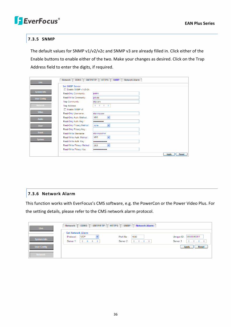
EAN Plus Series
36
735 SNMP
The default values for SNMP v1v2v2c and SNMP v3 are already filled in Click either of the
Enable buttons to enable either of the two Make your changes as desired Click on the Trap
Address field to enter the digits if required
736 Network Alarm
This function works with EverFocusrsquos CMS software eg the PowerCon or the Power Video Plus For
the setting details please refer to the CMS network alarm protocol
EAN Plus Series
37
74 Video
The settings relating to video such as streaming camera OSD can be configured on this page The
Video page has five tabs Multi-streaming Camera Advanced ROI and Privacy Mask
741 Multi Streaming
【Stream Settings】 This IP camera can output three video streams simultaneously For each of these
streams the user can set the compression format resolution bit rate and frame rate individually
Stream 1 is always enabled for live view To enable Stream 2 andor Stream 3 check the ldquoEnablerdquo
box the header of each stream
Note If you connect to the camera via the Internet and experience a delay (lag time) in the video
feed try to reduce the number of streams and the quality and resolution of the streams ndash but
keep the frame rate at its maximum
EAN Plus Series
38
Format Select the encoding format ndash H264 or MJPEG
Resolution Select the most suitable resolution for your needs
Frame Rate Select from 1 to 30 fps
Bit Rate If required select whether you want the stream to stream a Constant Bit Rate or a
Variable Bit Rate and set the values of whichever option you choose
Click Apply to apply the setting changes or Reset to reset without saving the changes
【Video Recording Settings】Select the stream you want to configure and then select whether you
want the recording files of that stream to be saved in AVI or ARV format Click Apply to apply the
setting changes or Reset to reset without saving the changes
【Time Stamp Settings】 You can select the DateTime format position and add the setting to the
streaming
Click Apply to apply the changes or Reset to reset without saving the changes
EAN Plus Series
39
742 Camera
【Image Settings】Set the Brightness Saturation Contrast or Sharpness of the image Click Apply to
apply the changes or Reset to reset without saving the changes
【Camera Settings】
Mirror Switch Mirror ON to rotate the image horizontally around a vertical axis
Flip Switch Flip ON to rotate the image vertically around a horizontal axis
AE There are two options
ALC Selecting Automatic Light Control allows the camera circuitry to either take bright spots
more into consideration (peak) bringing out detail in bright areas or less into consideration
(average) bringing out detail in shadows
AES Selecting Auto Electronic Shutter disables the Shutter setting below this setting In this
mode the camera measures the light level and decides whether it needs more or less light and
then automatically adjusts the shutter speed accordingly
BLC Back Light Compensation (BLC) is used to make the subject appear clearer when it is set
against a bright background
OFF Select to switch Back Light Compensation functions off
(ON)BLC The BLC can increase the exposure of a dark area surrounded by a brighter area HLC
can decrease the exposure of bright areas surrounded by darker areas This enables the
camera to better display information that would otherwise have been ldquowhited outrdquo like a
license plate between two bright headlights on a dark road
(ON)HLC The Highlight-Suppression BLC is used to reduce the brightness of light sources in a
specific area It is activated only in a low illumination environment to minimize the effects of
glare from bright lights such as spotlights street lights or headlights in the field of view
EAN Plus Series
40
WDR The Wide Dynamic Range (WDR) function provides clearer images when both of the very
bright and dark areas simultaneously appear on the camera view There are four value options
OFF Low Middle and High Note that when WDR is ON some parts of the image may appear
solarized This is normal for WDR and is not a camera malfunction This function is only available
for EAN3120 Plus 3220 Plus
DN Mode
Auto Select to let the camera automatically switch to Night mode (black and white) when the
light levels fall to a specified level and back to Day mode (color) when the light levels rise to a
specified level
Day Select to keep the camera in Day mode (color) even in nighttime
Night Select to keep the camera in Night mode (black and white) even in daytime
EAN Plus Series
41
743 Advanced
EAN Plus Series
42
【Camera Settings】
Lens (IRIS Control) Select DC or Manual for IRIS control This function is only available for EAN3220
Plus
Exposure Settings (AE) This setting is used to adapt to the amount or type of light used by the
camera Note the settings vary among models
Mode This function is not available for EAN3220 Plus
Automatic Light Control (ALC) This option is only available for EAN3120 Plus 3300 Plus The
ALC allows the camera circuitry to either take bright spots more into consideration (peak)
bringing out detail in bright areas or less into consideration (average) bringing out detail in
shadows
Auto Electronic Shutter (AES) This option is only available for EAN3120 Plus 3300 Plus In
this mode the camera measures the light level and decides whether it needs more or less light
and then automatically adjusts the shutter speed accordingly
Manual This option is only available for EAN3300 Plus Select this option to manually set up
the Shutter (Manual) and AGC (Manual) values
Iris Specify the size of the Iris opening here
Shutter If enabled this setting lets you set the shutter speed yourself
Shutter Limit Use this setting to set the maximum shutter speed for the camera This function is
only available for EAN3120 Plus
AGC Set the Auto Gain Control limit here The lower the AGC level the lower the video signal and
the noise However the image will be darker under low-light condition with IR-off if you set up the
Iris to the maximum level
Slow Shutter This option can be switched on when AES Mode is selected in the Exposure Settings
(AE) field This function is only available for EAN3220 Plus 3300 Plus
Flickerless If the Mode field in the Exposure Settings (AE) area has been set to AES then this option
becomes available Choose between OFF 50HZ 60HZ 50HZ (High Luminance) or 60HZ (High
Luminance) This function is only available for EAN3300 Plus
EV Setting Set up the Exposure Value Note the brightness of the screen changes when you change
the EV value This function is only available for EAN3300 Plus
AE Response Set up Auto Exposure Response time This function is only available for EAN3300 Plus
AE Weighting Area Select an AE Weighting area Each setup AE Weighting Area is configured with
the appropriate brightness level on the center and the surrounding areas This function is only
available for EAN3300 Plus
Brightness Set the image brightness here
AE Reference Set the Auto Exposure value here This function is only available for EAN3120 Plus
EAN Plus Series
43
Black Level Set the Black level here This function is only available for EAN3300 Plus
WDR The Wide Dynamic Range (WDR) function provides clearer images when both of the very
bright and dark areas simultaneously appear on the camera view There are four value options OFF
Low Middle and High Note that when WDR is ON some parts of the image may appear solarized
This is normal for WDR and is not a camera malfunction This function is only available for EAN3120
Plus 3220 Plus
Visibility Enhancement (OFFLowMiddleHigh) Images in foggy or rain environments or in
environments with a very strong luminous intensity have a dynamic range that is significantly lower
than ordinary images The user can use this Visibility Enhancement setting to ldquoDEFOGrdquo the image if
such ldquoFOGGINGrdquo is an issue This function is only available for EAN3220 Plus
BLC Settings Back Light Compensation (BLC) is used to make the subject appear clearer when it is
set against a bright background
OFF Select to switch Back Light Compensation functions off
Back Light This option is only available for EAN3300 Plus The Back Light function is useful
when the background of the subject is very bright and the subject itself is dark Select Back
Light and adjust the slide bar to the left right for setting up the back light value The higher
the value the more the backlight compensation
Front Light This option is only available for EAN3300 Plus This function is useful when the
bright highlights such as flashlight or car headlights appear on the camera view Select Front
Light and adjust the slide bar to the left right for setting up the front light value The higher
the value the more the highlight compensation
ON (BLC) This option is only available when you select AES Mode in the Exposure Settings (AE)
field The option is only available for EAN3120 Plus 3220 Plus The BLC function is useful
when the background of the subject is very bright and the subject itself is dark Follow the
instructions below to configure the settings for each model
For EAN3120 Select ON (BLC) the button next to the Mode drop-down list will be
active (see image below) Click the button the green setup areas appear on the left
screen Click on the areas to enable disable the BLC function The selected areas (in green)
will be applied with the BLC function
EAN Plus Series
44
For EAN3220
You can configure one area to apply the BLC function Select ON (BLC) the setup buttons
appears (see image below) Select Low Middle High from the BLC Gain drop-down list To
set up a BLC area click the Edit Area button and then click on the blue color tab to turn your
mouse cursor into a blue pen Move the cursor to the position on the right screen where you
want the BLC rectangle to start and then click Move your cursor to the position (diagonally
opposing corner) where you want the BLC rectangle to end and then click The blue area will
be applied with the BLC function
ON (HLC) This option is only available when you select AES Mode in the Exposure Settings (AE)
field The option is only available for EAN3120 Plus 3220 Plus This function is useful when
the bright highlights such as flashlight or car headlights appear on the camera view Follow
the instructions below to configure the settings for each model
For EAN3120 Select ON (HLC) and then select a level from the drop-down list The higher the
level the more the highlight compensation
For EAN3220
HLC Level Select a level for the HLC setting The higher the level the more the highlight
compensation
HLC Mode Select All Day Night mode to apply the HLC function
HLC Black Mask Select On Off to apply the black mask on the selected areas The
over-exposure portions within the selected areas will be applied with the black mask
Color Tabs You can set up four HLC areas with different colors To set up a HLC area click the
Edit Area button and then click on the color tab to turn your mouse cursor into a pen of that
color Move the cursor to the position on the right screen where you want the HLC rectangle
to start and then click Move your cursor to the position (diagonally opposing corner) where
you want the HLC rectangle to end and then click Select ON from the color tab drop-down list
The rectangular area with the selected color will be applied with the HLC function
EAN Plus Series
45
Back Light This option is only available for EAN3300 Plus The Back Light function is useful
when the background of the subject is very bright and the subject itself is dark Select Back
Light and adjust the slide bar to the left right for setting up the back light value The higher
the value the more the backlight compensation
Front Light This option is only available for EAN3300 Plus This function is useful when the
bright highlights such as flashlight or car headlights appear on the camera view Select Front
Light and adjust the slide bar to the left right for setting up the front light value The higher
the value the more the highlight compensation
Noise Reduction Settings This limits the amount of digital ldquovideo noiserdquo that is usually found in any
video stream and helps to reduce file size The higher the level the more the reduction
For EAN3120 Plus 3300 Plus
Select ON OFF to enable disable the Noise Reduction function Or select Auto to let the camera
automatically enable disable the Noise Reduction function Slide the Level bar to set up the level
The higher the level the more the reduction
For EAN3220 Plus
2D DNR Select ON to enable the 2D DNR function
3D DNR Select ON to enable the 3D DNR function You can further set up the following settings
3D Start AGC Set up the AGC level to automatically start the 3D NR function
3D End AGC Set up the AGC level to automatically stop the 3D NR function
3D Level Set up the 3D DNR level
Smart NR Select ON to enable the Smart NR function The 3D NR function will be
automatically turned on when a motion event occurs
EAN Plus Series
46
White Balance Settings Select the mode that delivers the best quality image for the camerarsquos light
environment There are five options Auto Manual Indoor Outdoor One Push
Auto Select to let the camera automatically adjust the White Balance In the Auto mode the
camera computes the white balance value output using color information from the entire
screen It outputs the proper value using the color temperature radiating from a black subject
based on a range of value from 3000 to 7500K
Manual Select to adjust the Red and Blue values yourself in the fields below this field
Indoor Select to use the default settings for indoor environments In the Indoor mode the
camera uses 3200K as the base value
Outdoor Select to use the default settings for outdoor environment In the Outdoor mode it
uses 5800K as the base value
One Push Select to enable the Push button next to the Mode drop-down field This will allow you to force the camera to readjust the white balance every time you push the Push
button The lens will hold the same focal position until the next trigger command is received
This function helps to prevent incorrect focusing in dark environments This function is only
available for EAN3120 Plus 3220 Plus
Manual Temperature Select to use the optimized Red and Blue settings You can also
optionally adjust the Manual Level below this field for setting up the color temperature The
higher the value the more the color temperature This function is only available for EAN3300
Plus
DayNight Settings
Auto Select to let the camera automatically switch to Night mode (black and white) when the
light levels fall to a specified level and back to Day mode (color) when the light levels rise to a
specified level
Day Select to keep the camera in Day mode (color) even in nighttime
Night Select to keep the camera in Night mode (black and white) even in daytime
IR Smart Settings Select ON and set up the level to enhance the image quality when the images are
over exposure This function is useful when the camera is in the Night mode This function is only
available for EAN3220 Plus
Saturation Set the saturation value This function is not available for EAN3220 Plus
Monitor Type Select a gamma value from Set 1 Set 2 or Set 3 This function is only available for
EAN3120 Plus
Negative Switch this setting ON to view a color negative version of the video image This is useful
at night or when viewing temperature-sensitive images
EAN Plus Series
47
Sharpness Settings Select the sharpness level of the image A low sharpness level will deliver a
softer less detailed image A high level will deliver a sharp highly detailed image Switch Resolution
Enhancement ON to enable the resolution enhancement function
Contrast Select the contrast level of the image
Suppress Function This function is only available for EAN3300 Plus
Aperture Compensation Suppression (OFFLowMiddleHigh) This setting can be activated to
suppress luminance noise when the AGC level increases
Chroma Suppression (OFFLowMiddleHigh) This setting can be activated to suppress
chrominance noise when the AGC level increases
Ygamma (gamma 22standardcontrast enhancehigh light range mode LHigh light range mode
H) Select the Ygamma value for the video quality of the monitor This function is only available for
EAN3300 Plus
Monitor Settings The user can use this field to optimize video quality for his or her specific type of
monitor ndash LCD or CRT This function is only available for EAN3220 Plus
Color Space Standard The options are YUV601 for SD and YUV709 for HD These define the color
space standard required to convert an RGB picture to a YUV picture Generally YUV601 is used for
Standard Definition (720P) devices and the YUV709 is used for High Definition (1080P) devices
Click Apply to save all changes Click Reset to cancel all changes
EAN Plus Series
48
744 ROI (Region of Interest)
The Region of Interest (ROI) function allows users to set up multiple regions within an image with
better quality and less distortion than the rest of the image You can also use this function
together with the Digital Zoom function on the Live View Page to get a better image result Up to
eight ROIs can be configured in the ROI settings page
To set up an ROI region
1 Select an ROI number from the ROI No drop-down list
2 Click the Add button the mouse cursor will turn into a pen when you move it over the live
image on the left
3 Move the cursor to the position where you want the ROI rectangle to start and then click
Move the cursor to the position (diagonally opposing corner) where you want the ROI
rectangle to end and then click
4 Slide the Quality bar to set up the quality value
5 Click the Apply button to apply the settings or click the Reset button to reset without saving
the settings
EAN Plus Series
49
745 Privacy Mask
The Privacy Mask can block out sensitive areas from view covering the areas with colored or black
and white boxes in both live view and recorded clips This feature is useful when usersrsquo donrsquot want
the sensitive information visible Up to four Privacy Masks can be configured
【Privacy Mask Color Settings】The Modes vary among camera models
Mode Click Color to make the masks appear as colored rectangles on the screen Click BW to
make the masks appear as gray rectangles on the screen Click Mosaic to make the masks appear
as mosaic-effect rectangles on the screen
Level Select the color of the masks if you selected Color Mode Select the level of grayness of the
masks if you selected BW Mode Select the level of smallmiddlelarge if you selected Mosaic
Mode
Click Apply to apply the settings or click Reset to reset without saving the settings
Color Tabs Click on a color tab to turn your mouse cursor into a pen of that color
You can now create a block of that color on the video screen Move your cursor to the position
where you want your mask rectangle to start and then click Move your cursor to the position
(diagonally opposing corner) where you want your mask rectangle to end and then click The
rectangular area with the selected color will appear The live image will display the rectangular
area with the color you selected If you want to create another mask use one of the other three
colors Each color denotes a different mask area Only one block per color is allowed As the
number of colors suggests you can configure up to four blocks
EAN Plus Series
50
Select All Click to turn the whole screen into a mask area
Clear All Click to delete all configured mask blocks
Eraser Click to turn the mouse cursor into an eraser to delete any block you click on
Area Shows the color and number of the block
Enable Check this box to enable the related mask block
Click Apply to apply the settings or click Reset to reset without saving the settings
EAN Plus Series
51
75 Audio
The EAN Plus series IP camera can transmit audio to your computer if you have connected an external
microphone to its audio Input cable It can also receive audio input from you and transmit it via an
external speaker if you have connected such a speaker to its audio Output cable
Check the Enable Audio box to enable the camerarsquos audio function The camera will now act as a
digital bridge (via the IP network) between any connected audio input device and any connected
audio device
Adjust the Audio Input Volume if you have external audio input devices (microphones) connected to
the camera and if there are problems with the sound input being too low or high
Click Apply to save all settings or click Reset to cancel
EAN Plus Series
52
76 User
761 User Information
The system administrator can create up to ten user accounts on this page
To set up a user account
1 Highlight a user account and click the Modify button The following dialog box appears
2 Type the account name account description and password for the account Type the password
again in the Confirm field
3 Select an authority level for the user account from the Authority drop-down list
bull Supervisor Administrator The only difference between a supervisor and administrator is
that a supervisor can edit an administratorrsquos account and password but an administrator
cannot edit the supervisorrsquos account and password Multiple administrators can be
configured but there can be only one supervisor The supervisor and administrators all
have unrestricted access to the Settings submenus and can determine the registration of
all other users
EAN Plus Series
53
bull User A user can view the Live View page and view the system network video and audio
information A user can only adjust the User Config page settings The user does not have
access to the User Event and System pages
bull Guest The lowest level of access which only allows the user access to the Live View page
4 Select Active or Disable from the Status drop-down list to active or disable the user account
5 Click On in the SD Card Playback field to allow the user to access the SD card playback
function
6 Click OK
7 Click Apply to save all the settings
EAN Plus Series
54
762 IP Address Filter
Use this page to specify IP addresses that are not allowed to access this camera By default any IP
address can access the camera
Note The Allowed List addresses only become relevant when the Denied List contains a network
or range and the supervisor wants to allow one or more IP addresses within that excluded range
or network In such a scenario the user would enter the excluded range or network in the
Denied List and enter the exceptions in the Allowed List
To set up the IP Address Filter
1 Select Denied List Click the Add button the following dialog box appears
2 Select an IP type from the IP Type drop-down list
3 Select a network rule from the Rule drop-down list type the IP address and click OK
Single Type a single IP address in the IP Address field below
Network Type the IP address and subnet mask in the field below
Range Type a range for the IP addresses
4 If you have set up an IP range in Step 3 you can optionally set up the Allowed List to allow one
or more IP addresses within the setup IP range to access the IP camera
5 Click Apply
EAN Plus Series
55
77 Event
You can set up the Motion Detection event Tamper Detection event or the Alarm IO to automatically
notify the users when an event occurs or an alarm is triggered You can also set up a schedule to
automatically record the videos when an event occurs or an alarm is triggered
771 Event Settings
You can create a total of ten event or alarm settings page in the Event List
【Event List】
Click the Add button and the following Event Configuration Window appears
EAN Plus Series
56
Enter Event Name Type an event name
Event Triggered by Select an event or alarm type for the to-be-specified-below reactions
Alarm Input Select this if you want a reaction trigger coming from any external connected sensor
to activate a to-be-specified-below reactions via the camera system Make sure that a suitable
device is actually connected to the alarm input relay
Manual Trigger Select this option if you want to manually trigger the alarm by clicking the Trigger
Event button on the Live View Page
Motion Detection Select this option if you want motion in a specified part of the camerarsquos viewing
rectangle (the screen image) to trigger the to-be-specified-below reactions
Tampering Detection Select this option if you want the camerarsquos tampering detection sensor to
trigger the to-be-specified-below reactions
Schedule Recording Select this option if you want the Schedule Recording periods configured in
the recording schedule (the Settings gt Event gt Schedule page) to activate this event In this
scenario a preconfigured event reaction like a log entry will list the start and end times of each
period Actual recording will only be triggered if the event is preconfigured to do so
Enable This Event Select to activate the event
Enable Re-trigger Click to set a minimum time after the event is triggered before the event
can be triggered again
Enable Pre-trigger Buffer Click if you want the Event reaction (as selected in the ldquoNotification
Overrdquo field below) to be the activation of the video recording function and if you want the
recording to include the video feed from the time period (configurable on the previous ldquoEvent
Settingsrdquo page) just before the Event trigger occurred
Enable Post-trigger Buffer Click if you want the Event reaction (as selected in the Notification
Over field) to be the activation of the video recording function and if you want the recording
to include the video feed from a time period (configurable on the Event Settings page) just
after the Event trigger occurred
Motion Area Select a setup motion detection area from the drop down list Note this
function only becomes relevant after the Motion Detection areas have been set up (see 772
Motion Detection)
Notification Over Select the desired notification types form the following items
Log Click if you want the camera to list the eventrsquos details in its log if the event is triggered
Trigger Alarm Output Click if you want the camera to relay the event reaction to a device
attached to the alarm relay output wire and then set up the alarm output duration time
EAN Plus Series
57
Send Mail Notification Click if you want the camera to send an Event notification email to the
email address entered in the Set SMTP Server(email) field of the Network gt SMTPFTP page if
the Event occurs (see 733 SMTP FTP)
Upload to FTP Click if you want the camera to upload recorded footage to the FTP server
entered in the Set SMTP Server(email) field of the Network gt SMTPFTP page if the Event
occurs (see 733 SMTP FTP)
Record to SD Card Click if you want the camera to start recording its video feed (when the
event occurs) on an on-camera SD Card (if such a card has been inserted)
Note The recording will only be as long as the combined Pre- and Post-trigger Buffers so
make sure you enable at least one of these buffers especially the Post-trigger Buffer
Record to PC Check this box if you want the camera to start recording its video feed (when
the event occurs) on the same folder on the same PC as configured on the User Config gt
RecordingSnapshot page (if such a folder has been enabled and configured)
Note The recording will only be as long as the combined Pre- and Post-trigger Buffers (and
for as long as the event trigger is happening ndash eg a motion is detected) so make sure you
enable at least one of these buffers especially the Post-trigger Buffer
Network Alarm Check this box if you want the camera to send a network alarm signal (when
the event occurs) to the CMS servers configured on the Network gt Network Alarm page (see
736 Network Alarm)
Click OK to save all settings or click Cancel to cancel
【PrePost Trigger Settings】
Pre-trigger Buffer Select the duration for the buffer This will determine the amount of footage
(length of time) before the event trigger moment that will be included in an event-triggered video
recording if that buffer and video recording has been enabled in the Event Configuration Window
Post-trigger Buffer Select the duration for the buffer This will determine the amount of footage
(length of time) after the event trigger moment that will be included in an event-triggered video
recording if that buffer and video recording has been enabled in the Event Configuration Window
Click Apply to save all settings or click Reset to cancel
EAN Plus Series
58
772 Motion Detection
Use this page to configure up to four areas in which motion will be detected When a motion is
detected by the camera the motion detection icon will appear at the top right of the
Live page to alert the user This function can also be linked with correctly configured Events to
trigger Event reactions like the activation of video recording periods snapshots alarms etc
Color Tabs Click on a color tab to turn your mouse cursor into a pen of that color
You can now create a block of that color on the video screen Move your cursor to the position
where you want your detection rectangle to start and then click Move your cursor to the position
(diagonally opposing corner) where you want your detection rectangle to end and then click The
rectangular area with the selected color will appear This block will be an area inside which the
camera will detect motion If you want to create another detection area use one of the other three
palette colors Each color denotes a different detection area Only one block per color is allowed As
the number of colors suggests you can configure up to four blocks
Select All Click to turn the whole screen into a motion detection area
Clear All Click to delete all configured motion detection blocks
Eraser Click to turn your mouse cursor into an eraser to delete any block you click on
Area Shows the color and numberID of the block
Enable Check this box to enable the related motion detection block
Sensitivity Set the sensitivity of the motion detection sensor function
Click Apply to save all settings or click Reset to cancel
EAN Plus Series
59
773 Tamper Detection
Use this page to set the number of seconds that an alarm signal will be active if the device is
physically tampered (moved covered up or out of focus
774 Alarm IO
Use this page to set the type of trigger input and the type of output contact for the camerarsquos alarm
channel
EAN Plus Series
60
775 Schedule
Use this page to configure a schedule for periods during which the camera should deactivate all
user-activated Events (gray Deselect periods) or when the camera should deactivate all
user-activated Events except Schedule Recording (SR) events (blue Schedule Recording-only
periods) or when the camera should deactivate only SR events (red Event Recording-only periods)
or when it should enable all activated Events (yellow periods)
Event Recording Click this button to make every hour block you click on red A red block represents
an Event Recording-only block which represents an hour when the camera will deactivate all
preconfigured activated Schedule Recording events and keep all the other activated events active
Schedule Recording Click this button to make every hour block you click on blue A blue block
represents a Schedule Recording-only block which represents an hour when the camera will
deactivate all other preconfigured activated events and keep only the preconfigured activated
Schedule Recording events active
Event + Schedule Click this button to make every hour block you click on yellow A yellow block
represents an hour in which all activated events including Schedule Recording events will be
active
Deselect Click this button to make every hour block become grey A grey block represents an hour
in which all activated events including Schedule Recording events will be inactive
Click Apply to save all settings or click Reset to cancel
EAN Plus Series
61
78 System
You can set up the systemrsquos time and SD card settings and to do maintenance and reset actions like
reboots and upgrades
781 DateTime
【Machine Name Settings】If required enter a new name for the machine This name will be visible
in the Machine Name field of the IP Utility software which is included in the software CD
【Set Time Zone】Set the time zone of the camerarsquos location
【Set DateTime Manually】Set the datetime here if you wonrsquot be using an NTP server to update the
datetime (see below)
【Set DateTime Sync】Enter the Network Time Protocol server if applicable The camerarsquos time will
be automatically adjusted by synchronizing with the NTP server
Click Apply to save all settings or click Reset to cancel
EAN Plus Series
62
782 Daylight Saving
Click Enable Daylight Saving to enable this schedule and select the dates when the regionrsquos
daylight saving period begins and ends Click Apply to save all settings or click Reset to cancel
783 SD Card
Use this page to prepare the system for safely removing the SD Card from its slot
【Setup SD Card】
Notification Select the percentage of storage space that should be left on the card before the
camera notifies you of the impending storage shortage or overwrite
Event Recording Select if you want Event Recording only FTP Backup only or both
Overwrite Click ON if you want the card to start writing over recorded footage when its memory is
full Click OFF if you want the card to stop recording new footage when its memory is full
【SD Card Utility】
Capacity This shows you how much card memory has been used and how much memory capacity
remains on the card
Remove Click this button before removing the card from the system
Format Click this button to format the card All data saved on the SD card will be removed if the
card is formatted
EAN Plus Series
63
784 Maintenance
【Maintenance Server】
Reboot Click this button to reboot the unit without changing any of the settings Use this function if
the unit is not behaving as expected
Restore Click this button to restart and reset most of the current settings to their factory default
values The only settings that will not be changed to default are
bull IP settings
bull DDNS settings
Default The Default button should be used with caution Pressing this button will return all of the
cameras settings including the IP address to the factory default values The camera will then have
to be reconfigured
【SaveLoad Configuration Server】
Save To make a backup file of the machinersquos current configurations press Save to save all the
configurations to a config file This will enable the user to reload these configuration settings if the
settings are changed and there is unexpected behavior
Load To load a previously saved configuration press the Browse button to locate the saved config
file (see above) and then click the Load button The systemrsquos settings will be restored to the saved
configuration
EAN Plus Series
64
【SaveLoad Video Configuration Server】
Save To make a backup file of the machinersquos video configurations press Save to save the video
configurations to a config file This will enable the user to reload these configuration settings if the
settings are changed and there is unexpected behavior
Load To load a previously saved video configuration press the Browse button to locate the saved
config file (see above) and then click the Load button The systemrsquos settings will be restored to the
saved video configuration
【Upgrade Firmware】Click the Browse button to find a previously prepared firmware upgrade file
Click Upgrade to install the new firmware
Note
1 Do not disconnect power to the unit during the upgrade sequence The unit will reboot
automatically after the upgrade has completed (1-5 minutes)
2 During the upgrade process all event recording actions will be stopped Event recording
actions will resume after the camera is rebooted
3 If the ldquoFile Error Please re-loginrdquo warning message appears when upgrading the firmware
please try the following instructions
a Go to Internet Explorer gt Tools gt Internet Option gt Security gt Custom
b Find and enable the Include local directory path when uploading files to a server
EAN Plus Series
65
8 Upgrading Firmware Using IP Utility
You can upgrade the Firmware using the IP Utility software included in the software CD
1 Install and then start the IPU program The following dialog box appears
2 Click Find Devices to search the cameras connected in the LAN The default network values of the
cameras will be displayed By default the network protocol of the camera is DHCP
3 Select a camera and click LoginMulti Login to log in the camera
4 Type the user ID and password Click OK
Note
1 The default user ID is user1 and the default password is 11111111
2 If you select more than one camera that has the same user ID password you will be able
to log in several cameras at once
EAN Plus Series
66
5 Highlight the camera and then click Upgrade Firmware A browsing window appears
6 Select the firmware file (evb) and then click Open The IP Utility will automatically upgrade the
firmware
The camera will reboot once the update is complete Click Find Devices the new firmware version
should be displayed in the last part of the Machine Name
EAN Plus Series
67
9 Specifications
Model EAN3120 Plus EAN3220 Plus EAN3300 Plus
Camera
Image Sensor 13 Panasonic CMOS 128 Sony CMOS
Megapixel 13 MP 2 MP 3 MP
Picture Elements (H x V) 1280 x 1024 1944 x 1092 2048 x 1536
Min Illuminations 003 Lux at F14
Electronic Shutter (Sec) 85 ~ 160000 2 ~ 150000 1 ~ 110000
Scanning System NTSC PAL
WDR Yes Yes No
BLC Yes
Gain Control Yes
White Balance Yes
Lens
Mounting Type C CS
Day Night Yes (with removable auto IR-cut filter)
IRIS Control DC Electrical IRIS Lens IRIS
Video
Video Compression H264 MJPEG
Resolution
NTSC
2048 x 1536 1920 x 1200 (for EAN3300 Plus only)
1920 x 1080 (for EAN3300 Plus 3220 Plus only)
1280 x 1024 1280 x 720 1024 x 768 720 x 480 704 x 480 640 x 480
352 x 240 320 x 240 160 x 120
PAL
2048 x 1536 1920 x 1200 (for EAN3300 Plus only)
1920 x 1080 (for EAN3300 Plus 3220 Plus only)
1280 x 1024 1280 x 720 1024 x 768 720 x 576 704 x 576 640 x 480
352 x 288 320 x 240 160 x 120
Frame Rate 30 fps at 1280 x 1024 30 fps at 1920 x 1080 15 fps at 2048 x 1536
Audio
Audio Streaming Two-way audio
Audio Compression G711
EAN Plus Series
68
Network
Interface 10 100 Base-T Ethernet RJ-45 socket
Supported Protocols
TCPIP IPV6 UDP ICMP DHCP NTP DNS DDNS SMTP SNMP FTP
HTTP HTTPs PPPoE UPnP Bonjour RTP RTSP RTCP IGMP ARP ONVIF
PSIA
Connector
Power DC female port PoE
Ethernet RJ-45
Audio 1 In (phone jack for microphone)
1 Out (phone jack for Speaker)
Alarm IO Terminal IO wires
Local Storage Micro SD SDHC memory card slot
TV-Out BNC socket composite 1 V p-p 75 Ω
General
Power Source DC 12V PoE (IEEE8023af)
Power Consumption
(IR LEDs On)
5W (DC 12V)
621W (PoE)
5W (DC 12V)
522W (PoE)
5W (DC 12V)
536W (PoE)
Operating Temperature 0degC ~ +50degC 32degF ~ +122degF
Humidity 20 to 80 (no condensation)
Safety CE FCC
Dimensions (L x W x H) 117 x 56 x 68 mm 46 x 22 x 27 in
Weight 410 g 09 lb
EverFocus Electronics Corp EverFocus Taiwan 12F No79 Sec 1 Shin-Tai Wu Road Hsi-Chih Taipei Taiwan TEL +886 2 2698 2334 FAX +886 2 2698 2380 wwweverfocuscomtw marketingeverfocuscomtw
EverFocus Europe - Germany Albert-Einstein-Strasse 1 D-46446 Emmerich Germany TEL +49 2822 93940 FAX +49 2822 939495 wwweverfocusde infoeverfocusde
EverFocus China - Beijing Room 609 Technology Trade Building Shangdi Information Industry Base Haidian District Beijing 100085 China TEL +86 10 6297 3336~39 FAX +86 10 6297 1423 wwweverfocuscomcn marketingeverfocuscomcn
EverFocus China - Shenzhen 4F No 2 D4 Building Wan Yelong Industrial Park Tangtou Road Shiyan Baoan Shenzhen Guangdong 518101 China TEL +86 755 2765 1313 FAX +86 755 2765 0337 wwweverfocuscomcn marketingeverfocuscomcn
EverFocus USA - California 1801 Highland Avenue Unit A Duarte CA 91010 USA TEL +1 626 844 8888 FAX +1 626 844 8838 wwweverfocuscom saleseverfocuscom
EverFocus USA - New York 415 Oser Avenue Unit S Hauppauge NY 11788 USA TEL +1 631 436 5070 FAX +1 631 436 5027 wwweverfocuscom saleseverfocuscom
EverFocus Japan 5F Kinshicho City Building 2-13-4 Koto-BashiSumida-Ku Tokyo 130-0022 Japan TEL +81 3 5625 8188 FAX +81 3 5625 8189 wwweverfocuscojp infoeverfocuscojp
EverFocus Europe - UK Unit 12 Spitfire Business Park Hawker Road Croydon Surrey CR0 4WD UK TEL +44 20 8649 9757 +44 845 430 9999 FAX +44 20 8649 9907 wwweverfocusukcouk salesukeverfocuscom
EverFocus India Suite 803 Housefin Bhavan C-21 Bandra Kurla Complex Bandra (East) Mumbai 400051 India TEL +91 22 6128 8700 FAX +91 22 6128 8705 wwweverfocusin saleseverfocusin
PN 4605PQ3120B010A-VerC
Your EverFocus product is designed and manufactured with high quality materials and components which can be recycled and reused This symbol means that electrical and electronic equipment at their end-of-life should be disposed of separately from your household waste Please dispose of this equipment at your local community waste collectionrecycling centre In the European Union there are separate collection systems for used electrical and electronic product Please help us to conserve the environment we live in
Ihr EverFocus Produkt wurde entwickelt und hergestellt mit qualitativ hochwertigen Materialien und Komponenten die recycelt und wieder verwendet werden koumlnnen Dieses Symbol bedeutet dass elektrische und elektronische Geraumlte am Ende ihrer Nutzungsdauer vom Hausmuumlll getrennt entsorgt werden sollen Bitte entsorgen Sie dieses Geraumlt bei Ihrer oumlrtlichen kommunalen Sammelstelle oder im Recycling Centre Helfen Sie uns bitte die Umwelt zu erhalten in der wir leben
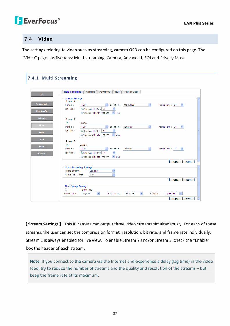
EAN Plus Series
37
74 Video
The settings relating to video such as streaming camera OSD can be configured on this page The
Video page has five tabs Multi-streaming Camera Advanced ROI and Privacy Mask
741 Multi Streaming
【Stream Settings】 This IP camera can output three video streams simultaneously For each of these
streams the user can set the compression format resolution bit rate and frame rate individually
Stream 1 is always enabled for live view To enable Stream 2 andor Stream 3 check the ldquoEnablerdquo
box the header of each stream
Note If you connect to the camera via the Internet and experience a delay (lag time) in the video
feed try to reduce the number of streams and the quality and resolution of the streams ndash but
keep the frame rate at its maximum
EAN Plus Series
38
Format Select the encoding format ndash H264 or MJPEG
Resolution Select the most suitable resolution for your needs
Frame Rate Select from 1 to 30 fps
Bit Rate If required select whether you want the stream to stream a Constant Bit Rate or a
Variable Bit Rate and set the values of whichever option you choose
Click Apply to apply the setting changes or Reset to reset without saving the changes
【Video Recording Settings】Select the stream you want to configure and then select whether you
want the recording files of that stream to be saved in AVI or ARV format Click Apply to apply the
setting changes or Reset to reset without saving the changes
【Time Stamp Settings】 You can select the DateTime format position and add the setting to the
streaming
Click Apply to apply the changes or Reset to reset without saving the changes
EAN Plus Series
39
742 Camera
【Image Settings】Set the Brightness Saturation Contrast or Sharpness of the image Click Apply to
apply the changes or Reset to reset without saving the changes
【Camera Settings】
Mirror Switch Mirror ON to rotate the image horizontally around a vertical axis
Flip Switch Flip ON to rotate the image vertically around a horizontal axis
AE There are two options
ALC Selecting Automatic Light Control allows the camera circuitry to either take bright spots
more into consideration (peak) bringing out detail in bright areas or less into consideration
(average) bringing out detail in shadows
AES Selecting Auto Electronic Shutter disables the Shutter setting below this setting In this
mode the camera measures the light level and decides whether it needs more or less light and
then automatically adjusts the shutter speed accordingly
BLC Back Light Compensation (BLC) is used to make the subject appear clearer when it is set
against a bright background
OFF Select to switch Back Light Compensation functions off
(ON)BLC The BLC can increase the exposure of a dark area surrounded by a brighter area HLC
can decrease the exposure of bright areas surrounded by darker areas This enables the
camera to better display information that would otherwise have been ldquowhited outrdquo like a
license plate between two bright headlights on a dark road
(ON)HLC The Highlight-Suppression BLC is used to reduce the brightness of light sources in a
specific area It is activated only in a low illumination environment to minimize the effects of
glare from bright lights such as spotlights street lights or headlights in the field of view
EAN Plus Series
40
WDR The Wide Dynamic Range (WDR) function provides clearer images when both of the very
bright and dark areas simultaneously appear on the camera view There are four value options
OFF Low Middle and High Note that when WDR is ON some parts of the image may appear
solarized This is normal for WDR and is not a camera malfunction This function is only available
for EAN3120 Plus 3220 Plus
DN Mode
Auto Select to let the camera automatically switch to Night mode (black and white) when the
light levels fall to a specified level and back to Day mode (color) when the light levels rise to a
specified level
Day Select to keep the camera in Day mode (color) even in nighttime
Night Select to keep the camera in Night mode (black and white) even in daytime
EAN Plus Series
41
743 Advanced
EAN Plus Series
42
【Camera Settings】
Lens (IRIS Control) Select DC or Manual for IRIS control This function is only available for EAN3220
Plus
Exposure Settings (AE) This setting is used to adapt to the amount or type of light used by the
camera Note the settings vary among models
Mode This function is not available for EAN3220 Plus
Automatic Light Control (ALC) This option is only available for EAN3120 Plus 3300 Plus The
ALC allows the camera circuitry to either take bright spots more into consideration (peak)
bringing out detail in bright areas or less into consideration (average) bringing out detail in
shadows
Auto Electronic Shutter (AES) This option is only available for EAN3120 Plus 3300 Plus In
this mode the camera measures the light level and decides whether it needs more or less light
and then automatically adjusts the shutter speed accordingly
Manual This option is only available for EAN3300 Plus Select this option to manually set up
the Shutter (Manual) and AGC (Manual) values
Iris Specify the size of the Iris opening here
Shutter If enabled this setting lets you set the shutter speed yourself
Shutter Limit Use this setting to set the maximum shutter speed for the camera This function is
only available for EAN3120 Plus
AGC Set the Auto Gain Control limit here The lower the AGC level the lower the video signal and
the noise However the image will be darker under low-light condition with IR-off if you set up the
Iris to the maximum level
Slow Shutter This option can be switched on when AES Mode is selected in the Exposure Settings
(AE) field This function is only available for EAN3220 Plus 3300 Plus
Flickerless If the Mode field in the Exposure Settings (AE) area has been set to AES then this option
becomes available Choose between OFF 50HZ 60HZ 50HZ (High Luminance) or 60HZ (High
Luminance) This function is only available for EAN3300 Plus
EV Setting Set up the Exposure Value Note the brightness of the screen changes when you change
the EV value This function is only available for EAN3300 Plus
AE Response Set up Auto Exposure Response time This function is only available for EAN3300 Plus
AE Weighting Area Select an AE Weighting area Each setup AE Weighting Area is configured with
the appropriate brightness level on the center and the surrounding areas This function is only
available for EAN3300 Plus
Brightness Set the image brightness here
AE Reference Set the Auto Exposure value here This function is only available for EAN3120 Plus
EAN Plus Series
43
Black Level Set the Black level here This function is only available for EAN3300 Plus
WDR The Wide Dynamic Range (WDR) function provides clearer images when both of the very
bright and dark areas simultaneously appear on the camera view There are four value options OFF
Low Middle and High Note that when WDR is ON some parts of the image may appear solarized
This is normal for WDR and is not a camera malfunction This function is only available for EAN3120
Plus 3220 Plus
Visibility Enhancement (OFFLowMiddleHigh) Images in foggy or rain environments or in
environments with a very strong luminous intensity have a dynamic range that is significantly lower
than ordinary images The user can use this Visibility Enhancement setting to ldquoDEFOGrdquo the image if
such ldquoFOGGINGrdquo is an issue This function is only available for EAN3220 Plus
BLC Settings Back Light Compensation (BLC) is used to make the subject appear clearer when it is
set against a bright background
OFF Select to switch Back Light Compensation functions off
Back Light This option is only available for EAN3300 Plus The Back Light function is useful
when the background of the subject is very bright and the subject itself is dark Select Back
Light and adjust the slide bar to the left right for setting up the back light value The higher
the value the more the backlight compensation
Front Light This option is only available for EAN3300 Plus This function is useful when the
bright highlights such as flashlight or car headlights appear on the camera view Select Front
Light and adjust the slide bar to the left right for setting up the front light value The higher
the value the more the highlight compensation
ON (BLC) This option is only available when you select AES Mode in the Exposure Settings (AE)
field The option is only available for EAN3120 Plus 3220 Plus The BLC function is useful
when the background of the subject is very bright and the subject itself is dark Follow the
instructions below to configure the settings for each model
For EAN3120 Select ON (BLC) the button next to the Mode drop-down list will be
active (see image below) Click the button the green setup areas appear on the left
screen Click on the areas to enable disable the BLC function The selected areas (in green)
will be applied with the BLC function
EAN Plus Series
44
For EAN3220
You can configure one area to apply the BLC function Select ON (BLC) the setup buttons
appears (see image below) Select Low Middle High from the BLC Gain drop-down list To
set up a BLC area click the Edit Area button and then click on the blue color tab to turn your
mouse cursor into a blue pen Move the cursor to the position on the right screen where you
want the BLC rectangle to start and then click Move your cursor to the position (diagonally
opposing corner) where you want the BLC rectangle to end and then click The blue area will
be applied with the BLC function
ON (HLC) This option is only available when you select AES Mode in the Exposure Settings (AE)
field The option is only available for EAN3120 Plus 3220 Plus This function is useful when
the bright highlights such as flashlight or car headlights appear on the camera view Follow
the instructions below to configure the settings for each model
For EAN3120 Select ON (HLC) and then select a level from the drop-down list The higher the
level the more the highlight compensation
For EAN3220
HLC Level Select a level for the HLC setting The higher the level the more the highlight
compensation
HLC Mode Select All Day Night mode to apply the HLC function
HLC Black Mask Select On Off to apply the black mask on the selected areas The
over-exposure portions within the selected areas will be applied with the black mask
Color Tabs You can set up four HLC areas with different colors To set up a HLC area click the
Edit Area button and then click on the color tab to turn your mouse cursor into a pen of that
color Move the cursor to the position on the right screen where you want the HLC rectangle
to start and then click Move your cursor to the position (diagonally opposing corner) where
you want the HLC rectangle to end and then click Select ON from the color tab drop-down list
The rectangular area with the selected color will be applied with the HLC function
EAN Plus Series
45
Back Light This option is only available for EAN3300 Plus The Back Light function is useful
when the background of the subject is very bright and the subject itself is dark Select Back
Light and adjust the slide bar to the left right for setting up the back light value The higher
the value the more the backlight compensation
Front Light This option is only available for EAN3300 Plus This function is useful when the
bright highlights such as flashlight or car headlights appear on the camera view Select Front
Light and adjust the slide bar to the left right for setting up the front light value The higher
the value the more the highlight compensation
Noise Reduction Settings This limits the amount of digital ldquovideo noiserdquo that is usually found in any
video stream and helps to reduce file size The higher the level the more the reduction
For EAN3120 Plus 3300 Plus
Select ON OFF to enable disable the Noise Reduction function Or select Auto to let the camera
automatically enable disable the Noise Reduction function Slide the Level bar to set up the level
The higher the level the more the reduction
For EAN3220 Plus
2D DNR Select ON to enable the 2D DNR function
3D DNR Select ON to enable the 3D DNR function You can further set up the following settings
3D Start AGC Set up the AGC level to automatically start the 3D NR function
3D End AGC Set up the AGC level to automatically stop the 3D NR function
3D Level Set up the 3D DNR level
Smart NR Select ON to enable the Smart NR function The 3D NR function will be
automatically turned on when a motion event occurs
EAN Plus Series
46
White Balance Settings Select the mode that delivers the best quality image for the camerarsquos light
environment There are five options Auto Manual Indoor Outdoor One Push
Auto Select to let the camera automatically adjust the White Balance In the Auto mode the
camera computes the white balance value output using color information from the entire
screen It outputs the proper value using the color temperature radiating from a black subject
based on a range of value from 3000 to 7500K
Manual Select to adjust the Red and Blue values yourself in the fields below this field
Indoor Select to use the default settings for indoor environments In the Indoor mode the
camera uses 3200K as the base value
Outdoor Select to use the default settings for outdoor environment In the Outdoor mode it
uses 5800K as the base value
One Push Select to enable the Push button next to the Mode drop-down field This will allow you to force the camera to readjust the white balance every time you push the Push
button The lens will hold the same focal position until the next trigger command is received
This function helps to prevent incorrect focusing in dark environments This function is only
available for EAN3120 Plus 3220 Plus
Manual Temperature Select to use the optimized Red and Blue settings You can also
optionally adjust the Manual Level below this field for setting up the color temperature The
higher the value the more the color temperature This function is only available for EAN3300
Plus
DayNight Settings
Auto Select to let the camera automatically switch to Night mode (black and white) when the
light levels fall to a specified level and back to Day mode (color) when the light levels rise to a
specified level
Day Select to keep the camera in Day mode (color) even in nighttime
Night Select to keep the camera in Night mode (black and white) even in daytime
IR Smart Settings Select ON and set up the level to enhance the image quality when the images are
over exposure This function is useful when the camera is in the Night mode This function is only
available for EAN3220 Plus
Saturation Set the saturation value This function is not available for EAN3220 Plus
Monitor Type Select a gamma value from Set 1 Set 2 or Set 3 This function is only available for
EAN3120 Plus
Negative Switch this setting ON to view a color negative version of the video image This is useful
at night or when viewing temperature-sensitive images
EAN Plus Series
47
Sharpness Settings Select the sharpness level of the image A low sharpness level will deliver a
softer less detailed image A high level will deliver a sharp highly detailed image Switch Resolution
Enhancement ON to enable the resolution enhancement function
Contrast Select the contrast level of the image
Suppress Function This function is only available for EAN3300 Plus
Aperture Compensation Suppression (OFFLowMiddleHigh) This setting can be activated to
suppress luminance noise when the AGC level increases
Chroma Suppression (OFFLowMiddleHigh) This setting can be activated to suppress
chrominance noise when the AGC level increases
Ygamma (gamma 22standardcontrast enhancehigh light range mode LHigh light range mode
H) Select the Ygamma value for the video quality of the monitor This function is only available for
EAN3300 Plus
Monitor Settings The user can use this field to optimize video quality for his or her specific type of
monitor ndash LCD or CRT This function is only available for EAN3220 Plus
Color Space Standard The options are YUV601 for SD and YUV709 for HD These define the color
space standard required to convert an RGB picture to a YUV picture Generally YUV601 is used for
Standard Definition (720P) devices and the YUV709 is used for High Definition (1080P) devices
Click Apply to save all changes Click Reset to cancel all changes
EAN Plus Series
48
744 ROI (Region of Interest)
The Region of Interest (ROI) function allows users to set up multiple regions within an image with
better quality and less distortion than the rest of the image You can also use this function
together with the Digital Zoom function on the Live View Page to get a better image result Up to
eight ROIs can be configured in the ROI settings page
To set up an ROI region
1 Select an ROI number from the ROI No drop-down list
2 Click the Add button the mouse cursor will turn into a pen when you move it over the live
image on the left
3 Move the cursor to the position where you want the ROI rectangle to start and then click
Move the cursor to the position (diagonally opposing corner) where you want the ROI
rectangle to end and then click
4 Slide the Quality bar to set up the quality value
5 Click the Apply button to apply the settings or click the Reset button to reset without saving
the settings
EAN Plus Series
49
745 Privacy Mask
The Privacy Mask can block out sensitive areas from view covering the areas with colored or black
and white boxes in both live view and recorded clips This feature is useful when usersrsquo donrsquot want
the sensitive information visible Up to four Privacy Masks can be configured
【Privacy Mask Color Settings】The Modes vary among camera models
Mode Click Color to make the masks appear as colored rectangles on the screen Click BW to
make the masks appear as gray rectangles on the screen Click Mosaic to make the masks appear
as mosaic-effect rectangles on the screen
Level Select the color of the masks if you selected Color Mode Select the level of grayness of the
masks if you selected BW Mode Select the level of smallmiddlelarge if you selected Mosaic
Mode
Click Apply to apply the settings or click Reset to reset without saving the settings
Color Tabs Click on a color tab to turn your mouse cursor into a pen of that color
You can now create a block of that color on the video screen Move your cursor to the position
where you want your mask rectangle to start and then click Move your cursor to the position
(diagonally opposing corner) where you want your mask rectangle to end and then click The
rectangular area with the selected color will appear The live image will display the rectangular
area with the color you selected If you want to create another mask use one of the other three
colors Each color denotes a different mask area Only one block per color is allowed As the
number of colors suggests you can configure up to four blocks
EAN Plus Series
50
Select All Click to turn the whole screen into a mask area
Clear All Click to delete all configured mask blocks
Eraser Click to turn the mouse cursor into an eraser to delete any block you click on
Area Shows the color and number of the block
Enable Check this box to enable the related mask block
Click Apply to apply the settings or click Reset to reset without saving the settings
EAN Plus Series
51
75 Audio
The EAN Plus series IP camera can transmit audio to your computer if you have connected an external
microphone to its audio Input cable It can also receive audio input from you and transmit it via an
external speaker if you have connected such a speaker to its audio Output cable
Check the Enable Audio box to enable the camerarsquos audio function The camera will now act as a
digital bridge (via the IP network) between any connected audio input device and any connected
audio device
Adjust the Audio Input Volume if you have external audio input devices (microphones) connected to
the camera and if there are problems with the sound input being too low or high
Click Apply to save all settings or click Reset to cancel
EAN Plus Series
52
76 User
761 User Information
The system administrator can create up to ten user accounts on this page
To set up a user account
1 Highlight a user account and click the Modify button The following dialog box appears
2 Type the account name account description and password for the account Type the password
again in the Confirm field
3 Select an authority level for the user account from the Authority drop-down list
bull Supervisor Administrator The only difference between a supervisor and administrator is
that a supervisor can edit an administratorrsquos account and password but an administrator
cannot edit the supervisorrsquos account and password Multiple administrators can be
configured but there can be only one supervisor The supervisor and administrators all
have unrestricted access to the Settings submenus and can determine the registration of
all other users
EAN Plus Series
53
bull User A user can view the Live View page and view the system network video and audio
information A user can only adjust the User Config page settings The user does not have
access to the User Event and System pages
bull Guest The lowest level of access which only allows the user access to the Live View page
4 Select Active or Disable from the Status drop-down list to active or disable the user account
5 Click On in the SD Card Playback field to allow the user to access the SD card playback
function
6 Click OK
7 Click Apply to save all the settings
EAN Plus Series
54
762 IP Address Filter
Use this page to specify IP addresses that are not allowed to access this camera By default any IP
address can access the camera
Note The Allowed List addresses only become relevant when the Denied List contains a network
or range and the supervisor wants to allow one or more IP addresses within that excluded range
or network In such a scenario the user would enter the excluded range or network in the
Denied List and enter the exceptions in the Allowed List
To set up the IP Address Filter
1 Select Denied List Click the Add button the following dialog box appears
2 Select an IP type from the IP Type drop-down list
3 Select a network rule from the Rule drop-down list type the IP address and click OK
Single Type a single IP address in the IP Address field below
Network Type the IP address and subnet mask in the field below
Range Type a range for the IP addresses
4 If you have set up an IP range in Step 3 you can optionally set up the Allowed List to allow one
or more IP addresses within the setup IP range to access the IP camera
5 Click Apply
EAN Plus Series
55
77 Event
You can set up the Motion Detection event Tamper Detection event or the Alarm IO to automatically
notify the users when an event occurs or an alarm is triggered You can also set up a schedule to
automatically record the videos when an event occurs or an alarm is triggered
771 Event Settings
You can create a total of ten event or alarm settings page in the Event List
【Event List】
Click the Add button and the following Event Configuration Window appears
EAN Plus Series
56
Enter Event Name Type an event name
Event Triggered by Select an event or alarm type for the to-be-specified-below reactions
Alarm Input Select this if you want a reaction trigger coming from any external connected sensor
to activate a to-be-specified-below reactions via the camera system Make sure that a suitable
device is actually connected to the alarm input relay
Manual Trigger Select this option if you want to manually trigger the alarm by clicking the Trigger
Event button on the Live View Page
Motion Detection Select this option if you want motion in a specified part of the camerarsquos viewing
rectangle (the screen image) to trigger the to-be-specified-below reactions
Tampering Detection Select this option if you want the camerarsquos tampering detection sensor to
trigger the to-be-specified-below reactions
Schedule Recording Select this option if you want the Schedule Recording periods configured in
the recording schedule (the Settings gt Event gt Schedule page) to activate this event In this
scenario a preconfigured event reaction like a log entry will list the start and end times of each
period Actual recording will only be triggered if the event is preconfigured to do so
Enable This Event Select to activate the event
Enable Re-trigger Click to set a minimum time after the event is triggered before the event
can be triggered again
Enable Pre-trigger Buffer Click if you want the Event reaction (as selected in the ldquoNotification
Overrdquo field below) to be the activation of the video recording function and if you want the
recording to include the video feed from the time period (configurable on the previous ldquoEvent
Settingsrdquo page) just before the Event trigger occurred
Enable Post-trigger Buffer Click if you want the Event reaction (as selected in the Notification
Over field) to be the activation of the video recording function and if you want the recording
to include the video feed from a time period (configurable on the Event Settings page) just
after the Event trigger occurred
Motion Area Select a setup motion detection area from the drop down list Note this
function only becomes relevant after the Motion Detection areas have been set up (see 772
Motion Detection)
Notification Over Select the desired notification types form the following items
Log Click if you want the camera to list the eventrsquos details in its log if the event is triggered
Trigger Alarm Output Click if you want the camera to relay the event reaction to a device
attached to the alarm relay output wire and then set up the alarm output duration time
EAN Plus Series
57
Send Mail Notification Click if you want the camera to send an Event notification email to the
email address entered in the Set SMTP Server(email) field of the Network gt SMTPFTP page if
the Event occurs (see 733 SMTP FTP)
Upload to FTP Click if you want the camera to upload recorded footage to the FTP server
entered in the Set SMTP Server(email) field of the Network gt SMTPFTP page if the Event
occurs (see 733 SMTP FTP)
Record to SD Card Click if you want the camera to start recording its video feed (when the
event occurs) on an on-camera SD Card (if such a card has been inserted)
Note The recording will only be as long as the combined Pre- and Post-trigger Buffers so
make sure you enable at least one of these buffers especially the Post-trigger Buffer
Record to PC Check this box if you want the camera to start recording its video feed (when
the event occurs) on the same folder on the same PC as configured on the User Config gt
RecordingSnapshot page (if such a folder has been enabled and configured)
Note The recording will only be as long as the combined Pre- and Post-trigger Buffers (and
for as long as the event trigger is happening ndash eg a motion is detected) so make sure you
enable at least one of these buffers especially the Post-trigger Buffer
Network Alarm Check this box if you want the camera to send a network alarm signal (when
the event occurs) to the CMS servers configured on the Network gt Network Alarm page (see
736 Network Alarm)
Click OK to save all settings or click Cancel to cancel
【PrePost Trigger Settings】
Pre-trigger Buffer Select the duration for the buffer This will determine the amount of footage
(length of time) before the event trigger moment that will be included in an event-triggered video
recording if that buffer and video recording has been enabled in the Event Configuration Window
Post-trigger Buffer Select the duration for the buffer This will determine the amount of footage
(length of time) after the event trigger moment that will be included in an event-triggered video
recording if that buffer and video recording has been enabled in the Event Configuration Window
Click Apply to save all settings or click Reset to cancel
EAN Plus Series
58
772 Motion Detection
Use this page to configure up to four areas in which motion will be detected When a motion is
detected by the camera the motion detection icon will appear at the top right of the
Live page to alert the user This function can also be linked with correctly configured Events to
trigger Event reactions like the activation of video recording periods snapshots alarms etc
Color Tabs Click on a color tab to turn your mouse cursor into a pen of that color
You can now create a block of that color on the video screen Move your cursor to the position
where you want your detection rectangle to start and then click Move your cursor to the position
(diagonally opposing corner) where you want your detection rectangle to end and then click The
rectangular area with the selected color will appear This block will be an area inside which the
camera will detect motion If you want to create another detection area use one of the other three
palette colors Each color denotes a different detection area Only one block per color is allowed As
the number of colors suggests you can configure up to four blocks
Select All Click to turn the whole screen into a motion detection area
Clear All Click to delete all configured motion detection blocks
Eraser Click to turn your mouse cursor into an eraser to delete any block you click on
Area Shows the color and numberID of the block
Enable Check this box to enable the related motion detection block
Sensitivity Set the sensitivity of the motion detection sensor function
Click Apply to save all settings or click Reset to cancel
EAN Plus Series
59
773 Tamper Detection
Use this page to set the number of seconds that an alarm signal will be active if the device is
physically tampered (moved covered up or out of focus
774 Alarm IO
Use this page to set the type of trigger input and the type of output contact for the camerarsquos alarm
channel
EAN Plus Series
60
775 Schedule
Use this page to configure a schedule for periods during which the camera should deactivate all
user-activated Events (gray Deselect periods) or when the camera should deactivate all
user-activated Events except Schedule Recording (SR) events (blue Schedule Recording-only
periods) or when the camera should deactivate only SR events (red Event Recording-only periods)
or when it should enable all activated Events (yellow periods)
Event Recording Click this button to make every hour block you click on red A red block represents
an Event Recording-only block which represents an hour when the camera will deactivate all
preconfigured activated Schedule Recording events and keep all the other activated events active
Schedule Recording Click this button to make every hour block you click on blue A blue block
represents a Schedule Recording-only block which represents an hour when the camera will
deactivate all other preconfigured activated events and keep only the preconfigured activated
Schedule Recording events active
Event + Schedule Click this button to make every hour block you click on yellow A yellow block
represents an hour in which all activated events including Schedule Recording events will be
active
Deselect Click this button to make every hour block become grey A grey block represents an hour
in which all activated events including Schedule Recording events will be inactive
Click Apply to save all settings or click Reset to cancel
EAN Plus Series
61
78 System
You can set up the systemrsquos time and SD card settings and to do maintenance and reset actions like
reboots and upgrades
781 DateTime
【Machine Name Settings】If required enter a new name for the machine This name will be visible
in the Machine Name field of the IP Utility software which is included in the software CD
【Set Time Zone】Set the time zone of the camerarsquos location
【Set DateTime Manually】Set the datetime here if you wonrsquot be using an NTP server to update the
datetime (see below)
【Set DateTime Sync】Enter the Network Time Protocol server if applicable The camerarsquos time will
be automatically adjusted by synchronizing with the NTP server
Click Apply to save all settings or click Reset to cancel
EAN Plus Series
62
782 Daylight Saving
Click Enable Daylight Saving to enable this schedule and select the dates when the regionrsquos
daylight saving period begins and ends Click Apply to save all settings or click Reset to cancel
783 SD Card
Use this page to prepare the system for safely removing the SD Card from its slot
【Setup SD Card】
Notification Select the percentage of storage space that should be left on the card before the
camera notifies you of the impending storage shortage or overwrite
Event Recording Select if you want Event Recording only FTP Backup only or both
Overwrite Click ON if you want the card to start writing over recorded footage when its memory is
full Click OFF if you want the card to stop recording new footage when its memory is full
【SD Card Utility】
Capacity This shows you how much card memory has been used and how much memory capacity
remains on the card
Remove Click this button before removing the card from the system
Format Click this button to format the card All data saved on the SD card will be removed if the
card is formatted
EAN Plus Series
63
784 Maintenance
【Maintenance Server】
Reboot Click this button to reboot the unit without changing any of the settings Use this function if
the unit is not behaving as expected
Restore Click this button to restart and reset most of the current settings to their factory default
values The only settings that will not be changed to default are
bull IP settings
bull DDNS settings
Default The Default button should be used with caution Pressing this button will return all of the
cameras settings including the IP address to the factory default values The camera will then have
to be reconfigured
【SaveLoad Configuration Server】
Save To make a backup file of the machinersquos current configurations press Save to save all the
configurations to a config file This will enable the user to reload these configuration settings if the
settings are changed and there is unexpected behavior
Load To load a previously saved configuration press the Browse button to locate the saved config
file (see above) and then click the Load button The systemrsquos settings will be restored to the saved
configuration
EAN Plus Series
64
【SaveLoad Video Configuration Server】
Save To make a backup file of the machinersquos video configurations press Save to save the video
configurations to a config file This will enable the user to reload these configuration settings if the
settings are changed and there is unexpected behavior
Load To load a previously saved video configuration press the Browse button to locate the saved
config file (see above) and then click the Load button The systemrsquos settings will be restored to the
saved video configuration
【Upgrade Firmware】Click the Browse button to find a previously prepared firmware upgrade file
Click Upgrade to install the new firmware
Note
1 Do not disconnect power to the unit during the upgrade sequence The unit will reboot
automatically after the upgrade has completed (1-5 minutes)
2 During the upgrade process all event recording actions will be stopped Event recording
actions will resume after the camera is rebooted
3 If the ldquoFile Error Please re-loginrdquo warning message appears when upgrading the firmware
please try the following instructions
a Go to Internet Explorer gt Tools gt Internet Option gt Security gt Custom
b Find and enable the Include local directory path when uploading files to a server
EAN Plus Series
65
8 Upgrading Firmware Using IP Utility
You can upgrade the Firmware using the IP Utility software included in the software CD
1 Install and then start the IPU program The following dialog box appears
2 Click Find Devices to search the cameras connected in the LAN The default network values of the
cameras will be displayed By default the network protocol of the camera is DHCP
3 Select a camera and click LoginMulti Login to log in the camera
4 Type the user ID and password Click OK
Note
1 The default user ID is user1 and the default password is 11111111
2 If you select more than one camera that has the same user ID password you will be able
to log in several cameras at once
EAN Plus Series
66
5 Highlight the camera and then click Upgrade Firmware A browsing window appears
6 Select the firmware file (evb) and then click Open The IP Utility will automatically upgrade the
firmware
The camera will reboot once the update is complete Click Find Devices the new firmware version
should be displayed in the last part of the Machine Name
EAN Plus Series
67
9 Specifications
Model EAN3120 Plus EAN3220 Plus EAN3300 Plus
Camera
Image Sensor 13 Panasonic CMOS 128 Sony CMOS
Megapixel 13 MP 2 MP 3 MP
Picture Elements (H x V) 1280 x 1024 1944 x 1092 2048 x 1536
Min Illuminations 003 Lux at F14
Electronic Shutter (Sec) 85 ~ 160000 2 ~ 150000 1 ~ 110000
Scanning System NTSC PAL
WDR Yes Yes No
BLC Yes
Gain Control Yes
White Balance Yes
Lens
Mounting Type C CS
Day Night Yes (with removable auto IR-cut filter)
IRIS Control DC Electrical IRIS Lens IRIS
Video
Video Compression H264 MJPEG
Resolution
NTSC
2048 x 1536 1920 x 1200 (for EAN3300 Plus only)
1920 x 1080 (for EAN3300 Plus 3220 Plus only)
1280 x 1024 1280 x 720 1024 x 768 720 x 480 704 x 480 640 x 480
352 x 240 320 x 240 160 x 120
PAL
2048 x 1536 1920 x 1200 (for EAN3300 Plus only)
1920 x 1080 (for EAN3300 Plus 3220 Plus only)
1280 x 1024 1280 x 720 1024 x 768 720 x 576 704 x 576 640 x 480
352 x 288 320 x 240 160 x 120
Frame Rate 30 fps at 1280 x 1024 30 fps at 1920 x 1080 15 fps at 2048 x 1536
Audio
Audio Streaming Two-way audio
Audio Compression G711
EAN Plus Series
68
Network
Interface 10 100 Base-T Ethernet RJ-45 socket
Supported Protocols
TCPIP IPV6 UDP ICMP DHCP NTP DNS DDNS SMTP SNMP FTP
HTTP HTTPs PPPoE UPnP Bonjour RTP RTSP RTCP IGMP ARP ONVIF
PSIA
Connector
Power DC female port PoE
Ethernet RJ-45
Audio 1 In (phone jack for microphone)
1 Out (phone jack for Speaker)
Alarm IO Terminal IO wires
Local Storage Micro SD SDHC memory card slot
TV-Out BNC socket composite 1 V p-p 75 Ω
General
Power Source DC 12V PoE (IEEE8023af)
Power Consumption
(IR LEDs On)
5W (DC 12V)
621W (PoE)
5W (DC 12V)
522W (PoE)
5W (DC 12V)
536W (PoE)
Operating Temperature 0degC ~ +50degC 32degF ~ +122degF
Humidity 20 to 80 (no condensation)
Safety CE FCC
Dimensions (L x W x H) 117 x 56 x 68 mm 46 x 22 x 27 in
Weight 410 g 09 lb
EverFocus Electronics Corp EverFocus Taiwan 12F No79 Sec 1 Shin-Tai Wu Road Hsi-Chih Taipei Taiwan TEL +886 2 2698 2334 FAX +886 2 2698 2380 wwweverfocuscomtw marketingeverfocuscomtw
EverFocus Europe - Germany Albert-Einstein-Strasse 1 D-46446 Emmerich Germany TEL +49 2822 93940 FAX +49 2822 939495 wwweverfocusde infoeverfocusde
EverFocus China - Beijing Room 609 Technology Trade Building Shangdi Information Industry Base Haidian District Beijing 100085 China TEL +86 10 6297 3336~39 FAX +86 10 6297 1423 wwweverfocuscomcn marketingeverfocuscomcn
EverFocus China - Shenzhen 4F No 2 D4 Building Wan Yelong Industrial Park Tangtou Road Shiyan Baoan Shenzhen Guangdong 518101 China TEL +86 755 2765 1313 FAX +86 755 2765 0337 wwweverfocuscomcn marketingeverfocuscomcn
EverFocus USA - California 1801 Highland Avenue Unit A Duarte CA 91010 USA TEL +1 626 844 8888 FAX +1 626 844 8838 wwweverfocuscom saleseverfocuscom
EverFocus USA - New York 415 Oser Avenue Unit S Hauppauge NY 11788 USA TEL +1 631 436 5070 FAX +1 631 436 5027 wwweverfocuscom saleseverfocuscom
EverFocus Japan 5F Kinshicho City Building 2-13-4 Koto-BashiSumida-Ku Tokyo 130-0022 Japan TEL +81 3 5625 8188 FAX +81 3 5625 8189 wwweverfocuscojp infoeverfocuscojp
EverFocus Europe - UK Unit 12 Spitfire Business Park Hawker Road Croydon Surrey CR0 4WD UK TEL +44 20 8649 9757 +44 845 430 9999 FAX +44 20 8649 9907 wwweverfocusukcouk salesukeverfocuscom
EverFocus India Suite 803 Housefin Bhavan C-21 Bandra Kurla Complex Bandra (East) Mumbai 400051 India TEL +91 22 6128 8700 FAX +91 22 6128 8705 wwweverfocusin saleseverfocusin
PN 4605PQ3120B010A-VerC
Your EverFocus product is designed and manufactured with high quality materials and components which can be recycled and reused This symbol means that electrical and electronic equipment at their end-of-life should be disposed of separately from your household waste Please dispose of this equipment at your local community waste collectionrecycling centre In the European Union there are separate collection systems for used electrical and electronic product Please help us to conserve the environment we live in
Ihr EverFocus Produkt wurde entwickelt und hergestellt mit qualitativ hochwertigen Materialien und Komponenten die recycelt und wieder verwendet werden koumlnnen Dieses Symbol bedeutet dass elektrische und elektronische Geraumlte am Ende ihrer Nutzungsdauer vom Hausmuumlll getrennt entsorgt werden sollen Bitte entsorgen Sie dieses Geraumlt bei Ihrer oumlrtlichen kommunalen Sammelstelle oder im Recycling Centre Helfen Sie uns bitte die Umwelt zu erhalten in der wir leben
EAN Plus Series
38
Format Select the encoding format ndash H264 or MJPEG
Resolution Select the most suitable resolution for your needs
Frame Rate Select from 1 to 30 fps
Bit Rate If required select whether you want the stream to stream a Constant Bit Rate or a
Variable Bit Rate and set the values of whichever option you choose
Click Apply to apply the setting changes or Reset to reset without saving the changes
【Video Recording Settings】Select the stream you want to configure and then select whether you
want the recording files of that stream to be saved in AVI or ARV format Click Apply to apply the
setting changes or Reset to reset without saving the changes
【Time Stamp Settings】 You can select the DateTime format position and add the setting to the
streaming
Click Apply to apply the changes or Reset to reset without saving the changes
EAN Plus Series
39
742 Camera
【Image Settings】Set the Brightness Saturation Contrast or Sharpness of the image Click Apply to
apply the changes or Reset to reset without saving the changes
【Camera Settings】
Mirror Switch Mirror ON to rotate the image horizontally around a vertical axis
Flip Switch Flip ON to rotate the image vertically around a horizontal axis
AE There are two options
ALC Selecting Automatic Light Control allows the camera circuitry to either take bright spots
more into consideration (peak) bringing out detail in bright areas or less into consideration
(average) bringing out detail in shadows
AES Selecting Auto Electronic Shutter disables the Shutter setting below this setting In this
mode the camera measures the light level and decides whether it needs more or less light and
then automatically adjusts the shutter speed accordingly
BLC Back Light Compensation (BLC) is used to make the subject appear clearer when it is set
against a bright background
OFF Select to switch Back Light Compensation functions off
(ON)BLC The BLC can increase the exposure of a dark area surrounded by a brighter area HLC
can decrease the exposure of bright areas surrounded by darker areas This enables the
camera to better display information that would otherwise have been ldquowhited outrdquo like a
license plate between two bright headlights on a dark road
(ON)HLC The Highlight-Suppression BLC is used to reduce the brightness of light sources in a
specific area It is activated only in a low illumination environment to minimize the effects of
glare from bright lights such as spotlights street lights or headlights in the field of view
EAN Plus Series
40
WDR The Wide Dynamic Range (WDR) function provides clearer images when both of the very
bright and dark areas simultaneously appear on the camera view There are four value options
OFF Low Middle and High Note that when WDR is ON some parts of the image may appear
solarized This is normal for WDR and is not a camera malfunction This function is only available
for EAN3120 Plus 3220 Plus
DN Mode
Auto Select to let the camera automatically switch to Night mode (black and white) when the
light levels fall to a specified level and back to Day mode (color) when the light levels rise to a
specified level
Day Select to keep the camera in Day mode (color) even in nighttime
Night Select to keep the camera in Night mode (black and white) even in daytime
EAN Plus Series
41
743 Advanced
EAN Plus Series
42
【Camera Settings】
Lens (IRIS Control) Select DC or Manual for IRIS control This function is only available for EAN3220
Plus
Exposure Settings (AE) This setting is used to adapt to the amount or type of light used by the
camera Note the settings vary among models
Mode This function is not available for EAN3220 Plus
Automatic Light Control (ALC) This option is only available for EAN3120 Plus 3300 Plus The
ALC allows the camera circuitry to either take bright spots more into consideration (peak)
bringing out detail in bright areas or less into consideration (average) bringing out detail in
shadows
Auto Electronic Shutter (AES) This option is only available for EAN3120 Plus 3300 Plus In
this mode the camera measures the light level and decides whether it needs more or less light
and then automatically adjusts the shutter speed accordingly
Manual This option is only available for EAN3300 Plus Select this option to manually set up
the Shutter (Manual) and AGC (Manual) values
Iris Specify the size of the Iris opening here
Shutter If enabled this setting lets you set the shutter speed yourself
Shutter Limit Use this setting to set the maximum shutter speed for the camera This function is
only available for EAN3120 Plus
AGC Set the Auto Gain Control limit here The lower the AGC level the lower the video signal and
the noise However the image will be darker under low-light condition with IR-off if you set up the
Iris to the maximum level
Slow Shutter This option can be switched on when AES Mode is selected in the Exposure Settings
(AE) field This function is only available for EAN3220 Plus 3300 Plus
Flickerless If the Mode field in the Exposure Settings (AE) area has been set to AES then this option
becomes available Choose between OFF 50HZ 60HZ 50HZ (High Luminance) or 60HZ (High
Luminance) This function is only available for EAN3300 Plus
EV Setting Set up the Exposure Value Note the brightness of the screen changes when you change
the EV value This function is only available for EAN3300 Plus
AE Response Set up Auto Exposure Response time This function is only available for EAN3300 Plus
AE Weighting Area Select an AE Weighting area Each setup AE Weighting Area is configured with
the appropriate brightness level on the center and the surrounding areas This function is only
available for EAN3300 Plus
Brightness Set the image brightness here
AE Reference Set the Auto Exposure value here This function is only available for EAN3120 Plus
EAN Plus Series
43
Black Level Set the Black level here This function is only available for EAN3300 Plus
WDR The Wide Dynamic Range (WDR) function provides clearer images when both of the very
bright and dark areas simultaneously appear on the camera view There are four value options OFF
Low Middle and High Note that when WDR is ON some parts of the image may appear solarized
This is normal for WDR and is not a camera malfunction This function is only available for EAN3120
Plus 3220 Plus
Visibility Enhancement (OFFLowMiddleHigh) Images in foggy or rain environments or in
environments with a very strong luminous intensity have a dynamic range that is significantly lower
than ordinary images The user can use this Visibility Enhancement setting to ldquoDEFOGrdquo the image if
such ldquoFOGGINGrdquo is an issue This function is only available for EAN3220 Plus
BLC Settings Back Light Compensation (BLC) is used to make the subject appear clearer when it is
set against a bright background
OFF Select to switch Back Light Compensation functions off
Back Light This option is only available for EAN3300 Plus The Back Light function is useful
when the background of the subject is very bright and the subject itself is dark Select Back
Light and adjust the slide bar to the left right for setting up the back light value The higher
the value the more the backlight compensation
Front Light This option is only available for EAN3300 Plus This function is useful when the
bright highlights such as flashlight or car headlights appear on the camera view Select Front
Light and adjust the slide bar to the left right for setting up the front light value The higher
the value the more the highlight compensation
ON (BLC) This option is only available when you select AES Mode in the Exposure Settings (AE)
field The option is only available for EAN3120 Plus 3220 Plus The BLC function is useful
when the background of the subject is very bright and the subject itself is dark Follow the
instructions below to configure the settings for each model
For EAN3120 Select ON (BLC) the button next to the Mode drop-down list will be
active (see image below) Click the button the green setup areas appear on the left
screen Click on the areas to enable disable the BLC function The selected areas (in green)
will be applied with the BLC function
EAN Plus Series
44
For EAN3220
You can configure one area to apply the BLC function Select ON (BLC) the setup buttons
appears (see image below) Select Low Middle High from the BLC Gain drop-down list To
set up a BLC area click the Edit Area button and then click on the blue color tab to turn your
mouse cursor into a blue pen Move the cursor to the position on the right screen where you
want the BLC rectangle to start and then click Move your cursor to the position (diagonally
opposing corner) where you want the BLC rectangle to end and then click The blue area will
be applied with the BLC function
ON (HLC) This option is only available when you select AES Mode in the Exposure Settings (AE)
field The option is only available for EAN3120 Plus 3220 Plus This function is useful when
the bright highlights such as flashlight or car headlights appear on the camera view Follow
the instructions below to configure the settings for each model
For EAN3120 Select ON (HLC) and then select a level from the drop-down list The higher the
level the more the highlight compensation
For EAN3220
HLC Level Select a level for the HLC setting The higher the level the more the highlight
compensation
HLC Mode Select All Day Night mode to apply the HLC function
HLC Black Mask Select On Off to apply the black mask on the selected areas The
over-exposure portions within the selected areas will be applied with the black mask
Color Tabs You can set up four HLC areas with different colors To set up a HLC area click the
Edit Area button and then click on the color tab to turn your mouse cursor into a pen of that
color Move the cursor to the position on the right screen where you want the HLC rectangle
to start and then click Move your cursor to the position (diagonally opposing corner) where
you want the HLC rectangle to end and then click Select ON from the color tab drop-down list
The rectangular area with the selected color will be applied with the HLC function
EAN Plus Series
45
Back Light This option is only available for EAN3300 Plus The Back Light function is useful
when the background of the subject is very bright and the subject itself is dark Select Back
Light and adjust the slide bar to the left right for setting up the back light value The higher
the value the more the backlight compensation
Front Light This option is only available for EAN3300 Plus This function is useful when the
bright highlights such as flashlight or car headlights appear on the camera view Select Front
Light and adjust the slide bar to the left right for setting up the front light value The higher
the value the more the highlight compensation
Noise Reduction Settings This limits the amount of digital ldquovideo noiserdquo that is usually found in any
video stream and helps to reduce file size The higher the level the more the reduction
For EAN3120 Plus 3300 Plus
Select ON OFF to enable disable the Noise Reduction function Or select Auto to let the camera
automatically enable disable the Noise Reduction function Slide the Level bar to set up the level
The higher the level the more the reduction
For EAN3220 Plus
2D DNR Select ON to enable the 2D DNR function
3D DNR Select ON to enable the 3D DNR function You can further set up the following settings
3D Start AGC Set up the AGC level to automatically start the 3D NR function
3D End AGC Set up the AGC level to automatically stop the 3D NR function
3D Level Set up the 3D DNR level
Smart NR Select ON to enable the Smart NR function The 3D NR function will be
automatically turned on when a motion event occurs
EAN Plus Series
46
White Balance Settings Select the mode that delivers the best quality image for the camerarsquos light
environment There are five options Auto Manual Indoor Outdoor One Push
Auto Select to let the camera automatically adjust the White Balance In the Auto mode the
camera computes the white balance value output using color information from the entire
screen It outputs the proper value using the color temperature radiating from a black subject
based on a range of value from 3000 to 7500K
Manual Select to adjust the Red and Blue values yourself in the fields below this field
Indoor Select to use the default settings for indoor environments In the Indoor mode the
camera uses 3200K as the base value
Outdoor Select to use the default settings for outdoor environment In the Outdoor mode it
uses 5800K as the base value
One Push Select to enable the Push button next to the Mode drop-down field This will allow you to force the camera to readjust the white balance every time you push the Push
button The lens will hold the same focal position until the next trigger command is received
This function helps to prevent incorrect focusing in dark environments This function is only
available for EAN3120 Plus 3220 Plus
Manual Temperature Select to use the optimized Red and Blue settings You can also
optionally adjust the Manual Level below this field for setting up the color temperature The
higher the value the more the color temperature This function is only available for EAN3300
Plus
DayNight Settings
Auto Select to let the camera automatically switch to Night mode (black and white) when the
light levels fall to a specified level and back to Day mode (color) when the light levels rise to a
specified level
Day Select to keep the camera in Day mode (color) even in nighttime
Night Select to keep the camera in Night mode (black and white) even in daytime
IR Smart Settings Select ON and set up the level to enhance the image quality when the images are
over exposure This function is useful when the camera is in the Night mode This function is only
available for EAN3220 Plus
Saturation Set the saturation value This function is not available for EAN3220 Plus
Monitor Type Select a gamma value from Set 1 Set 2 or Set 3 This function is only available for
EAN3120 Plus
Negative Switch this setting ON to view a color negative version of the video image This is useful
at night or when viewing temperature-sensitive images
EAN Plus Series
47
Sharpness Settings Select the sharpness level of the image A low sharpness level will deliver a
softer less detailed image A high level will deliver a sharp highly detailed image Switch Resolution
Enhancement ON to enable the resolution enhancement function
Contrast Select the contrast level of the image
Suppress Function This function is only available for EAN3300 Plus
Aperture Compensation Suppression (OFFLowMiddleHigh) This setting can be activated to
suppress luminance noise when the AGC level increases
Chroma Suppression (OFFLowMiddleHigh) This setting can be activated to suppress
chrominance noise when the AGC level increases
Ygamma (gamma 22standardcontrast enhancehigh light range mode LHigh light range mode
H) Select the Ygamma value for the video quality of the monitor This function is only available for
EAN3300 Plus
Monitor Settings The user can use this field to optimize video quality for his or her specific type of
monitor ndash LCD or CRT This function is only available for EAN3220 Plus
Color Space Standard The options are YUV601 for SD and YUV709 for HD These define the color
space standard required to convert an RGB picture to a YUV picture Generally YUV601 is used for
Standard Definition (720P) devices and the YUV709 is used for High Definition (1080P) devices
Click Apply to save all changes Click Reset to cancel all changes
EAN Plus Series
48
744 ROI (Region of Interest)
The Region of Interest (ROI) function allows users to set up multiple regions within an image with
better quality and less distortion than the rest of the image You can also use this function
together with the Digital Zoom function on the Live View Page to get a better image result Up to
eight ROIs can be configured in the ROI settings page
To set up an ROI region
1 Select an ROI number from the ROI No drop-down list
2 Click the Add button the mouse cursor will turn into a pen when you move it over the live
image on the left
3 Move the cursor to the position where you want the ROI rectangle to start and then click
Move the cursor to the position (diagonally opposing corner) where you want the ROI
rectangle to end and then click
4 Slide the Quality bar to set up the quality value
5 Click the Apply button to apply the settings or click the Reset button to reset without saving
the settings
EAN Plus Series
49
745 Privacy Mask
The Privacy Mask can block out sensitive areas from view covering the areas with colored or black
and white boxes in both live view and recorded clips This feature is useful when usersrsquo donrsquot want
the sensitive information visible Up to four Privacy Masks can be configured
【Privacy Mask Color Settings】The Modes vary among camera models
Mode Click Color to make the masks appear as colored rectangles on the screen Click BW to
make the masks appear as gray rectangles on the screen Click Mosaic to make the masks appear
as mosaic-effect rectangles on the screen
Level Select the color of the masks if you selected Color Mode Select the level of grayness of the
masks if you selected BW Mode Select the level of smallmiddlelarge if you selected Mosaic
Mode
Click Apply to apply the settings or click Reset to reset without saving the settings
Color Tabs Click on a color tab to turn your mouse cursor into a pen of that color
You can now create a block of that color on the video screen Move your cursor to the position
where you want your mask rectangle to start and then click Move your cursor to the position
(diagonally opposing corner) where you want your mask rectangle to end and then click The
rectangular area with the selected color will appear The live image will display the rectangular
area with the color you selected If you want to create another mask use one of the other three
colors Each color denotes a different mask area Only one block per color is allowed As the
number of colors suggests you can configure up to four blocks
EAN Plus Series
50
Select All Click to turn the whole screen into a mask area
Clear All Click to delete all configured mask blocks
Eraser Click to turn the mouse cursor into an eraser to delete any block you click on
Area Shows the color and number of the block
Enable Check this box to enable the related mask block
Click Apply to apply the settings or click Reset to reset without saving the settings
EAN Plus Series
51
75 Audio
The EAN Plus series IP camera can transmit audio to your computer if you have connected an external
microphone to its audio Input cable It can also receive audio input from you and transmit it via an
external speaker if you have connected such a speaker to its audio Output cable
Check the Enable Audio box to enable the camerarsquos audio function The camera will now act as a
digital bridge (via the IP network) between any connected audio input device and any connected
audio device
Adjust the Audio Input Volume if you have external audio input devices (microphones) connected to
the camera and if there are problems with the sound input being too low or high
Click Apply to save all settings or click Reset to cancel
EAN Plus Series
52
76 User
761 User Information
The system administrator can create up to ten user accounts on this page
To set up a user account
1 Highlight a user account and click the Modify button The following dialog box appears
2 Type the account name account description and password for the account Type the password
again in the Confirm field
3 Select an authority level for the user account from the Authority drop-down list
bull Supervisor Administrator The only difference between a supervisor and administrator is
that a supervisor can edit an administratorrsquos account and password but an administrator
cannot edit the supervisorrsquos account and password Multiple administrators can be
configured but there can be only one supervisor The supervisor and administrators all
have unrestricted access to the Settings submenus and can determine the registration of
all other users
EAN Plus Series
53
bull User A user can view the Live View page and view the system network video and audio
information A user can only adjust the User Config page settings The user does not have
access to the User Event and System pages
bull Guest The lowest level of access which only allows the user access to the Live View page
4 Select Active or Disable from the Status drop-down list to active or disable the user account
5 Click On in the SD Card Playback field to allow the user to access the SD card playback
function
6 Click OK
7 Click Apply to save all the settings
EAN Plus Series
54
762 IP Address Filter
Use this page to specify IP addresses that are not allowed to access this camera By default any IP
address can access the camera
Note The Allowed List addresses only become relevant when the Denied List contains a network
or range and the supervisor wants to allow one or more IP addresses within that excluded range
or network In such a scenario the user would enter the excluded range or network in the
Denied List and enter the exceptions in the Allowed List
To set up the IP Address Filter
1 Select Denied List Click the Add button the following dialog box appears
2 Select an IP type from the IP Type drop-down list
3 Select a network rule from the Rule drop-down list type the IP address and click OK
Single Type a single IP address in the IP Address field below
Network Type the IP address and subnet mask in the field below
Range Type a range for the IP addresses
4 If you have set up an IP range in Step 3 you can optionally set up the Allowed List to allow one
or more IP addresses within the setup IP range to access the IP camera
5 Click Apply
EAN Plus Series
55
77 Event
You can set up the Motion Detection event Tamper Detection event or the Alarm IO to automatically
notify the users when an event occurs or an alarm is triggered You can also set up a schedule to
automatically record the videos when an event occurs or an alarm is triggered
771 Event Settings
You can create a total of ten event or alarm settings page in the Event List
【Event List】
Click the Add button and the following Event Configuration Window appears
EAN Plus Series
56
Enter Event Name Type an event name
Event Triggered by Select an event or alarm type for the to-be-specified-below reactions
Alarm Input Select this if you want a reaction trigger coming from any external connected sensor
to activate a to-be-specified-below reactions via the camera system Make sure that a suitable
device is actually connected to the alarm input relay
Manual Trigger Select this option if you want to manually trigger the alarm by clicking the Trigger
Event button on the Live View Page
Motion Detection Select this option if you want motion in a specified part of the camerarsquos viewing
rectangle (the screen image) to trigger the to-be-specified-below reactions
Tampering Detection Select this option if you want the camerarsquos tampering detection sensor to
trigger the to-be-specified-below reactions
Schedule Recording Select this option if you want the Schedule Recording periods configured in
the recording schedule (the Settings gt Event gt Schedule page) to activate this event In this
scenario a preconfigured event reaction like a log entry will list the start and end times of each
period Actual recording will only be triggered if the event is preconfigured to do so
Enable This Event Select to activate the event
Enable Re-trigger Click to set a minimum time after the event is triggered before the event
can be triggered again
Enable Pre-trigger Buffer Click if you want the Event reaction (as selected in the ldquoNotification
Overrdquo field below) to be the activation of the video recording function and if you want the
recording to include the video feed from the time period (configurable on the previous ldquoEvent
Settingsrdquo page) just before the Event trigger occurred
Enable Post-trigger Buffer Click if you want the Event reaction (as selected in the Notification
Over field) to be the activation of the video recording function and if you want the recording
to include the video feed from a time period (configurable on the Event Settings page) just
after the Event trigger occurred
Motion Area Select a setup motion detection area from the drop down list Note this
function only becomes relevant after the Motion Detection areas have been set up (see 772
Motion Detection)
Notification Over Select the desired notification types form the following items
Log Click if you want the camera to list the eventrsquos details in its log if the event is triggered
Trigger Alarm Output Click if you want the camera to relay the event reaction to a device
attached to the alarm relay output wire and then set up the alarm output duration time
EAN Plus Series
57
Send Mail Notification Click if you want the camera to send an Event notification email to the
email address entered in the Set SMTP Server(email) field of the Network gt SMTPFTP page if
the Event occurs (see 733 SMTP FTP)
Upload to FTP Click if you want the camera to upload recorded footage to the FTP server
entered in the Set SMTP Server(email) field of the Network gt SMTPFTP page if the Event
occurs (see 733 SMTP FTP)
Record to SD Card Click if you want the camera to start recording its video feed (when the
event occurs) on an on-camera SD Card (if such a card has been inserted)
Note The recording will only be as long as the combined Pre- and Post-trigger Buffers so
make sure you enable at least one of these buffers especially the Post-trigger Buffer
Record to PC Check this box if you want the camera to start recording its video feed (when
the event occurs) on the same folder on the same PC as configured on the User Config gt
RecordingSnapshot page (if such a folder has been enabled and configured)
Note The recording will only be as long as the combined Pre- and Post-trigger Buffers (and
for as long as the event trigger is happening ndash eg a motion is detected) so make sure you
enable at least one of these buffers especially the Post-trigger Buffer
Network Alarm Check this box if you want the camera to send a network alarm signal (when
the event occurs) to the CMS servers configured on the Network gt Network Alarm page (see
736 Network Alarm)
Click OK to save all settings or click Cancel to cancel
【PrePost Trigger Settings】
Pre-trigger Buffer Select the duration for the buffer This will determine the amount of footage
(length of time) before the event trigger moment that will be included in an event-triggered video
recording if that buffer and video recording has been enabled in the Event Configuration Window
Post-trigger Buffer Select the duration for the buffer This will determine the amount of footage
(length of time) after the event trigger moment that will be included in an event-triggered video
recording if that buffer and video recording has been enabled in the Event Configuration Window
Click Apply to save all settings or click Reset to cancel
EAN Plus Series
58
772 Motion Detection
Use this page to configure up to four areas in which motion will be detected When a motion is
detected by the camera the motion detection icon will appear at the top right of the
Live page to alert the user This function can also be linked with correctly configured Events to
trigger Event reactions like the activation of video recording periods snapshots alarms etc
Color Tabs Click on a color tab to turn your mouse cursor into a pen of that color
You can now create a block of that color on the video screen Move your cursor to the position
where you want your detection rectangle to start and then click Move your cursor to the position
(diagonally opposing corner) where you want your detection rectangle to end and then click The
rectangular area with the selected color will appear This block will be an area inside which the
camera will detect motion If you want to create another detection area use one of the other three
palette colors Each color denotes a different detection area Only one block per color is allowed As
the number of colors suggests you can configure up to four blocks
Select All Click to turn the whole screen into a motion detection area
Clear All Click to delete all configured motion detection blocks
Eraser Click to turn your mouse cursor into an eraser to delete any block you click on
Area Shows the color and numberID of the block
Enable Check this box to enable the related motion detection block
Sensitivity Set the sensitivity of the motion detection sensor function
Click Apply to save all settings or click Reset to cancel
EAN Plus Series
59
773 Tamper Detection
Use this page to set the number of seconds that an alarm signal will be active if the device is
physically tampered (moved covered up or out of focus
774 Alarm IO
Use this page to set the type of trigger input and the type of output contact for the camerarsquos alarm
channel
EAN Plus Series
60
775 Schedule
Use this page to configure a schedule for periods during which the camera should deactivate all
user-activated Events (gray Deselect periods) or when the camera should deactivate all
user-activated Events except Schedule Recording (SR) events (blue Schedule Recording-only
periods) or when the camera should deactivate only SR events (red Event Recording-only periods)
or when it should enable all activated Events (yellow periods)
Event Recording Click this button to make every hour block you click on red A red block represents
an Event Recording-only block which represents an hour when the camera will deactivate all
preconfigured activated Schedule Recording events and keep all the other activated events active
Schedule Recording Click this button to make every hour block you click on blue A blue block
represents a Schedule Recording-only block which represents an hour when the camera will
deactivate all other preconfigured activated events and keep only the preconfigured activated
Schedule Recording events active
Event + Schedule Click this button to make every hour block you click on yellow A yellow block
represents an hour in which all activated events including Schedule Recording events will be
active
Deselect Click this button to make every hour block become grey A grey block represents an hour
in which all activated events including Schedule Recording events will be inactive
Click Apply to save all settings or click Reset to cancel
EAN Plus Series
61
78 System
You can set up the systemrsquos time and SD card settings and to do maintenance and reset actions like
reboots and upgrades
781 DateTime
【Machine Name Settings】If required enter a new name for the machine This name will be visible
in the Machine Name field of the IP Utility software which is included in the software CD
【Set Time Zone】Set the time zone of the camerarsquos location
【Set DateTime Manually】Set the datetime here if you wonrsquot be using an NTP server to update the
datetime (see below)
【Set DateTime Sync】Enter the Network Time Protocol server if applicable The camerarsquos time will
be automatically adjusted by synchronizing with the NTP server
Click Apply to save all settings or click Reset to cancel
EAN Plus Series
62
782 Daylight Saving
Click Enable Daylight Saving to enable this schedule and select the dates when the regionrsquos
daylight saving period begins and ends Click Apply to save all settings or click Reset to cancel
783 SD Card
Use this page to prepare the system for safely removing the SD Card from its slot
【Setup SD Card】
Notification Select the percentage of storage space that should be left on the card before the
camera notifies you of the impending storage shortage or overwrite
Event Recording Select if you want Event Recording only FTP Backup only or both
Overwrite Click ON if you want the card to start writing over recorded footage when its memory is
full Click OFF if you want the card to stop recording new footage when its memory is full
【SD Card Utility】
Capacity This shows you how much card memory has been used and how much memory capacity
remains on the card
Remove Click this button before removing the card from the system
Format Click this button to format the card All data saved on the SD card will be removed if the
card is formatted
EAN Plus Series
63
784 Maintenance
【Maintenance Server】
Reboot Click this button to reboot the unit without changing any of the settings Use this function if
the unit is not behaving as expected
Restore Click this button to restart and reset most of the current settings to their factory default
values The only settings that will not be changed to default are
bull IP settings
bull DDNS settings
Default The Default button should be used with caution Pressing this button will return all of the
cameras settings including the IP address to the factory default values The camera will then have
to be reconfigured
【SaveLoad Configuration Server】
Save To make a backup file of the machinersquos current configurations press Save to save all the
configurations to a config file This will enable the user to reload these configuration settings if the
settings are changed and there is unexpected behavior
Load To load a previously saved configuration press the Browse button to locate the saved config
file (see above) and then click the Load button The systemrsquos settings will be restored to the saved
configuration
EAN Plus Series
64
【SaveLoad Video Configuration Server】
Save To make a backup file of the machinersquos video configurations press Save to save the video
configurations to a config file This will enable the user to reload these configuration settings if the
settings are changed and there is unexpected behavior
Load To load a previously saved video configuration press the Browse button to locate the saved
config file (see above) and then click the Load button The systemrsquos settings will be restored to the
saved video configuration
【Upgrade Firmware】Click the Browse button to find a previously prepared firmware upgrade file
Click Upgrade to install the new firmware
Note
1 Do not disconnect power to the unit during the upgrade sequence The unit will reboot
automatically after the upgrade has completed (1-5 minutes)
2 During the upgrade process all event recording actions will be stopped Event recording
actions will resume after the camera is rebooted
3 If the ldquoFile Error Please re-loginrdquo warning message appears when upgrading the firmware
please try the following instructions
a Go to Internet Explorer gt Tools gt Internet Option gt Security gt Custom
b Find and enable the Include local directory path when uploading files to a server
EAN Plus Series
65
8 Upgrading Firmware Using IP Utility
You can upgrade the Firmware using the IP Utility software included in the software CD
1 Install and then start the IPU program The following dialog box appears
2 Click Find Devices to search the cameras connected in the LAN The default network values of the
cameras will be displayed By default the network protocol of the camera is DHCP
3 Select a camera and click LoginMulti Login to log in the camera
4 Type the user ID and password Click OK
Note
1 The default user ID is user1 and the default password is 11111111
2 If you select more than one camera that has the same user ID password you will be able
to log in several cameras at once
EAN Plus Series
66
5 Highlight the camera and then click Upgrade Firmware A browsing window appears
6 Select the firmware file (evb) and then click Open The IP Utility will automatically upgrade the
firmware
The camera will reboot once the update is complete Click Find Devices the new firmware version
should be displayed in the last part of the Machine Name
EAN Plus Series
67
9 Specifications
Model EAN3120 Plus EAN3220 Plus EAN3300 Plus
Camera
Image Sensor 13 Panasonic CMOS 128 Sony CMOS
Megapixel 13 MP 2 MP 3 MP
Picture Elements (H x V) 1280 x 1024 1944 x 1092 2048 x 1536
Min Illuminations 003 Lux at F14
Electronic Shutter (Sec) 85 ~ 160000 2 ~ 150000 1 ~ 110000
Scanning System NTSC PAL
WDR Yes Yes No
BLC Yes
Gain Control Yes
White Balance Yes
Lens
Mounting Type C CS
Day Night Yes (with removable auto IR-cut filter)
IRIS Control DC Electrical IRIS Lens IRIS
Video
Video Compression H264 MJPEG
Resolution
NTSC
2048 x 1536 1920 x 1200 (for EAN3300 Plus only)
1920 x 1080 (for EAN3300 Plus 3220 Plus only)
1280 x 1024 1280 x 720 1024 x 768 720 x 480 704 x 480 640 x 480
352 x 240 320 x 240 160 x 120
PAL
2048 x 1536 1920 x 1200 (for EAN3300 Plus only)
1920 x 1080 (for EAN3300 Plus 3220 Plus only)
1280 x 1024 1280 x 720 1024 x 768 720 x 576 704 x 576 640 x 480
352 x 288 320 x 240 160 x 120
Frame Rate 30 fps at 1280 x 1024 30 fps at 1920 x 1080 15 fps at 2048 x 1536
Audio
Audio Streaming Two-way audio
Audio Compression G711
EAN Plus Series
68
Network
Interface 10 100 Base-T Ethernet RJ-45 socket
Supported Protocols
TCPIP IPV6 UDP ICMP DHCP NTP DNS DDNS SMTP SNMP FTP
HTTP HTTPs PPPoE UPnP Bonjour RTP RTSP RTCP IGMP ARP ONVIF
PSIA
Connector
Power DC female port PoE
Ethernet RJ-45
Audio 1 In (phone jack for microphone)
1 Out (phone jack for Speaker)
Alarm IO Terminal IO wires
Local Storage Micro SD SDHC memory card slot
TV-Out BNC socket composite 1 V p-p 75 Ω
General
Power Source DC 12V PoE (IEEE8023af)
Power Consumption
(IR LEDs On)
5W (DC 12V)
621W (PoE)
5W (DC 12V)
522W (PoE)
5W (DC 12V)
536W (PoE)
Operating Temperature 0degC ~ +50degC 32degF ~ +122degF
Humidity 20 to 80 (no condensation)
Safety CE FCC
Dimensions (L x W x H) 117 x 56 x 68 mm 46 x 22 x 27 in
Weight 410 g 09 lb
EverFocus Electronics Corp EverFocus Taiwan 12F No79 Sec 1 Shin-Tai Wu Road Hsi-Chih Taipei Taiwan TEL +886 2 2698 2334 FAX +886 2 2698 2380 wwweverfocuscomtw marketingeverfocuscomtw
EverFocus Europe - Germany Albert-Einstein-Strasse 1 D-46446 Emmerich Germany TEL +49 2822 93940 FAX +49 2822 939495 wwweverfocusde infoeverfocusde
EverFocus China - Beijing Room 609 Technology Trade Building Shangdi Information Industry Base Haidian District Beijing 100085 China TEL +86 10 6297 3336~39 FAX +86 10 6297 1423 wwweverfocuscomcn marketingeverfocuscomcn
EverFocus China - Shenzhen 4F No 2 D4 Building Wan Yelong Industrial Park Tangtou Road Shiyan Baoan Shenzhen Guangdong 518101 China TEL +86 755 2765 1313 FAX +86 755 2765 0337 wwweverfocuscomcn marketingeverfocuscomcn
EverFocus USA - California 1801 Highland Avenue Unit A Duarte CA 91010 USA TEL +1 626 844 8888 FAX +1 626 844 8838 wwweverfocuscom saleseverfocuscom
EverFocus USA - New York 415 Oser Avenue Unit S Hauppauge NY 11788 USA TEL +1 631 436 5070 FAX +1 631 436 5027 wwweverfocuscom saleseverfocuscom
EverFocus Japan 5F Kinshicho City Building 2-13-4 Koto-BashiSumida-Ku Tokyo 130-0022 Japan TEL +81 3 5625 8188 FAX +81 3 5625 8189 wwweverfocuscojp infoeverfocuscojp
EverFocus Europe - UK Unit 12 Spitfire Business Park Hawker Road Croydon Surrey CR0 4WD UK TEL +44 20 8649 9757 +44 845 430 9999 FAX +44 20 8649 9907 wwweverfocusukcouk salesukeverfocuscom
EverFocus India Suite 803 Housefin Bhavan C-21 Bandra Kurla Complex Bandra (East) Mumbai 400051 India TEL +91 22 6128 8700 FAX +91 22 6128 8705 wwweverfocusin saleseverfocusin
PN 4605PQ3120B010A-VerC
Your EverFocus product is designed and manufactured with high quality materials and components which can be recycled and reused This symbol means that electrical and electronic equipment at their end-of-life should be disposed of separately from your household waste Please dispose of this equipment at your local community waste collectionrecycling centre In the European Union there are separate collection systems for used electrical and electronic product Please help us to conserve the environment we live in
Ihr EverFocus Produkt wurde entwickelt und hergestellt mit qualitativ hochwertigen Materialien und Komponenten die recycelt und wieder verwendet werden koumlnnen Dieses Symbol bedeutet dass elektrische und elektronische Geraumlte am Ende ihrer Nutzungsdauer vom Hausmuumlll getrennt entsorgt werden sollen Bitte entsorgen Sie dieses Geraumlt bei Ihrer oumlrtlichen kommunalen Sammelstelle oder im Recycling Centre Helfen Sie uns bitte die Umwelt zu erhalten in der wir leben
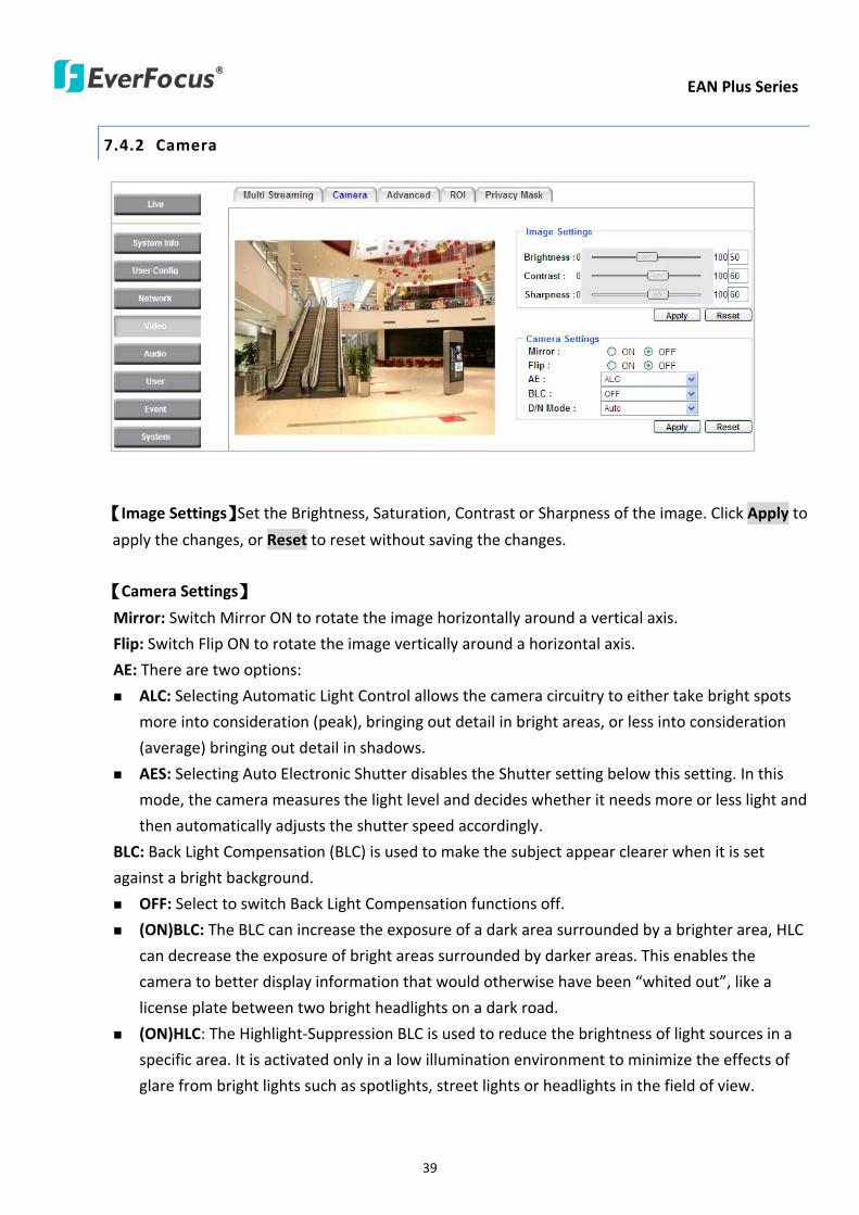
EAN Plus Series
39
742 Camera
【Image Settings】Set the Brightness Saturation Contrast or Sharpness of the image Click Apply to
apply the changes or Reset to reset without saving the changes
【Camera Settings】
Mirror Switch Mirror ON to rotate the image horizontally around a vertical axis
Flip Switch Flip ON to rotate the image vertically around a horizontal axis
AE There are two options
ALC Selecting Automatic Light Control allows the camera circuitry to either take bright spots
more into consideration (peak) bringing out detail in bright areas or less into consideration
(average) bringing out detail in shadows
AES Selecting Auto Electronic Shutter disables the Shutter setting below this setting In this
mode the camera measures the light level and decides whether it needs more or less light and
then automatically adjusts the shutter speed accordingly
BLC Back Light Compensation (BLC) is used to make the subject appear clearer when it is set
against a bright background
OFF Select to switch Back Light Compensation functions off
(ON)BLC The BLC can increase the exposure of a dark area surrounded by a brighter area HLC
can decrease the exposure of bright areas surrounded by darker areas This enables the
camera to better display information that would otherwise have been ldquowhited outrdquo like a
license plate between two bright headlights on a dark road
(ON)HLC The Highlight-Suppression BLC is used to reduce the brightness of light sources in a
specific area It is activated only in a low illumination environment to minimize the effects of
glare from bright lights such as spotlights street lights or headlights in the field of view
EAN Plus Series
40
WDR The Wide Dynamic Range (WDR) function provides clearer images when both of the very
bright and dark areas simultaneously appear on the camera view There are four value options
OFF Low Middle and High Note that when WDR is ON some parts of the image may appear
solarized This is normal for WDR and is not a camera malfunction This function is only available
for EAN3120 Plus 3220 Plus
DN Mode
Auto Select to let the camera automatically switch to Night mode (black and white) when the
light levels fall to a specified level and back to Day mode (color) when the light levels rise to a
specified level
Day Select to keep the camera in Day mode (color) even in nighttime
Night Select to keep the camera in Night mode (black and white) even in daytime
EAN Plus Series
41
743 Advanced
EAN Plus Series
42
【Camera Settings】
Lens (IRIS Control) Select DC or Manual for IRIS control This function is only available for EAN3220
Plus
Exposure Settings (AE) This setting is used to adapt to the amount or type of light used by the
camera Note the settings vary among models
Mode This function is not available for EAN3220 Plus
Automatic Light Control (ALC) This option is only available for EAN3120 Plus 3300 Plus The
ALC allows the camera circuitry to either take bright spots more into consideration (peak)
bringing out detail in bright areas or less into consideration (average) bringing out detail in
shadows
Auto Electronic Shutter (AES) This option is only available for EAN3120 Plus 3300 Plus In
this mode the camera measures the light level and decides whether it needs more or less light
and then automatically adjusts the shutter speed accordingly
Manual This option is only available for EAN3300 Plus Select this option to manually set up
the Shutter (Manual) and AGC (Manual) values
Iris Specify the size of the Iris opening here
Shutter If enabled this setting lets you set the shutter speed yourself
Shutter Limit Use this setting to set the maximum shutter speed for the camera This function is
only available for EAN3120 Plus
AGC Set the Auto Gain Control limit here The lower the AGC level the lower the video signal and
the noise However the image will be darker under low-light condition with IR-off if you set up the
Iris to the maximum level
Slow Shutter This option can be switched on when AES Mode is selected in the Exposure Settings
(AE) field This function is only available for EAN3220 Plus 3300 Plus
Flickerless If the Mode field in the Exposure Settings (AE) area has been set to AES then this option
becomes available Choose between OFF 50HZ 60HZ 50HZ (High Luminance) or 60HZ (High
Luminance) This function is only available for EAN3300 Plus
EV Setting Set up the Exposure Value Note the brightness of the screen changes when you change
the EV value This function is only available for EAN3300 Plus
AE Response Set up Auto Exposure Response time This function is only available for EAN3300 Plus
AE Weighting Area Select an AE Weighting area Each setup AE Weighting Area is configured with
the appropriate brightness level on the center and the surrounding areas This function is only
available for EAN3300 Plus
Brightness Set the image brightness here
AE Reference Set the Auto Exposure value here This function is only available for EAN3120 Plus
EAN Plus Series
43
Black Level Set the Black level here This function is only available for EAN3300 Plus
WDR The Wide Dynamic Range (WDR) function provides clearer images when both of the very
bright and dark areas simultaneously appear on the camera view There are four value options OFF
Low Middle and High Note that when WDR is ON some parts of the image may appear solarized
This is normal for WDR and is not a camera malfunction This function is only available for EAN3120
Plus 3220 Plus
Visibility Enhancement (OFFLowMiddleHigh) Images in foggy or rain environments or in
environments with a very strong luminous intensity have a dynamic range that is significantly lower
than ordinary images The user can use this Visibility Enhancement setting to ldquoDEFOGrdquo the image if
such ldquoFOGGINGrdquo is an issue This function is only available for EAN3220 Plus
BLC Settings Back Light Compensation (BLC) is used to make the subject appear clearer when it is
set against a bright background
OFF Select to switch Back Light Compensation functions off
Back Light This option is only available for EAN3300 Plus The Back Light function is useful
when the background of the subject is very bright and the subject itself is dark Select Back
Light and adjust the slide bar to the left right for setting up the back light value The higher
the value the more the backlight compensation
Front Light This option is only available for EAN3300 Plus This function is useful when the
bright highlights such as flashlight or car headlights appear on the camera view Select Front
Light and adjust the slide bar to the left right for setting up the front light value The higher
the value the more the highlight compensation
ON (BLC) This option is only available when you select AES Mode in the Exposure Settings (AE)
field The option is only available for EAN3120 Plus 3220 Plus The BLC function is useful
when the background of the subject is very bright and the subject itself is dark Follow the
instructions below to configure the settings for each model
For EAN3120 Select ON (BLC) the button next to the Mode drop-down list will be
active (see image below) Click the button the green setup areas appear on the left
screen Click on the areas to enable disable the BLC function The selected areas (in green)
will be applied with the BLC function
EAN Plus Series
44
For EAN3220
You can configure one area to apply the BLC function Select ON (BLC) the setup buttons
appears (see image below) Select Low Middle High from the BLC Gain drop-down list To
set up a BLC area click the Edit Area button and then click on the blue color tab to turn your
mouse cursor into a blue pen Move the cursor to the position on the right screen where you
want the BLC rectangle to start and then click Move your cursor to the position (diagonally
opposing corner) where you want the BLC rectangle to end and then click The blue area will
be applied with the BLC function
ON (HLC) This option is only available when you select AES Mode in the Exposure Settings (AE)
field The option is only available for EAN3120 Plus 3220 Plus This function is useful when
the bright highlights such as flashlight or car headlights appear on the camera view Follow
the instructions below to configure the settings for each model
For EAN3120 Select ON (HLC) and then select a level from the drop-down list The higher the
level the more the highlight compensation
For EAN3220
HLC Level Select a level for the HLC setting The higher the level the more the highlight
compensation
HLC Mode Select All Day Night mode to apply the HLC function
HLC Black Mask Select On Off to apply the black mask on the selected areas The
over-exposure portions within the selected areas will be applied with the black mask
Color Tabs You can set up four HLC areas with different colors To set up a HLC area click the
Edit Area button and then click on the color tab to turn your mouse cursor into a pen of that
color Move the cursor to the position on the right screen where you want the HLC rectangle
to start and then click Move your cursor to the position (diagonally opposing corner) where
you want the HLC rectangle to end and then click Select ON from the color tab drop-down list
The rectangular area with the selected color will be applied with the HLC function
EAN Plus Series
45
Back Light This option is only available for EAN3300 Plus The Back Light function is useful
when the background of the subject is very bright and the subject itself is dark Select Back
Light and adjust the slide bar to the left right for setting up the back light value The higher
the value the more the backlight compensation
Front Light This option is only available for EAN3300 Plus This function is useful when the
bright highlights such as flashlight or car headlights appear on the camera view Select Front
Light and adjust the slide bar to the left right for setting up the front light value The higher
the value the more the highlight compensation
Noise Reduction Settings This limits the amount of digital ldquovideo noiserdquo that is usually found in any
video stream and helps to reduce file size The higher the level the more the reduction
For EAN3120 Plus 3300 Plus
Select ON OFF to enable disable the Noise Reduction function Or select Auto to let the camera
automatically enable disable the Noise Reduction function Slide the Level bar to set up the level
The higher the level the more the reduction
For EAN3220 Plus
2D DNR Select ON to enable the 2D DNR function
3D DNR Select ON to enable the 3D DNR function You can further set up the following settings
3D Start AGC Set up the AGC level to automatically start the 3D NR function
3D End AGC Set up the AGC level to automatically stop the 3D NR function
3D Level Set up the 3D DNR level
Smart NR Select ON to enable the Smart NR function The 3D NR function will be
automatically turned on when a motion event occurs
EAN Plus Series
46
White Balance Settings Select the mode that delivers the best quality image for the camerarsquos light
environment There are five options Auto Manual Indoor Outdoor One Push
Auto Select to let the camera automatically adjust the White Balance In the Auto mode the
camera computes the white balance value output using color information from the entire
screen It outputs the proper value using the color temperature radiating from a black subject
based on a range of value from 3000 to 7500K
Manual Select to adjust the Red and Blue values yourself in the fields below this field
Indoor Select to use the default settings for indoor environments In the Indoor mode the
camera uses 3200K as the base value
Outdoor Select to use the default settings for outdoor environment In the Outdoor mode it
uses 5800K as the base value
One Push Select to enable the Push button next to the Mode drop-down field This will allow you to force the camera to readjust the white balance every time you push the Push
button The lens will hold the same focal position until the next trigger command is received
This function helps to prevent incorrect focusing in dark environments This function is only
available for EAN3120 Plus 3220 Plus
Manual Temperature Select to use the optimized Red and Blue settings You can also
optionally adjust the Manual Level below this field for setting up the color temperature The
higher the value the more the color temperature This function is only available for EAN3300
Plus
DayNight Settings
Auto Select to let the camera automatically switch to Night mode (black and white) when the
light levels fall to a specified level and back to Day mode (color) when the light levels rise to a
specified level
Day Select to keep the camera in Day mode (color) even in nighttime
Night Select to keep the camera in Night mode (black and white) even in daytime
IR Smart Settings Select ON and set up the level to enhance the image quality when the images are
over exposure This function is useful when the camera is in the Night mode This function is only
available for EAN3220 Plus
Saturation Set the saturation value This function is not available for EAN3220 Plus
Monitor Type Select a gamma value from Set 1 Set 2 or Set 3 This function is only available for
EAN3120 Plus
Negative Switch this setting ON to view a color negative version of the video image This is useful
at night or when viewing temperature-sensitive images
EAN Plus Series
47
Sharpness Settings Select the sharpness level of the image A low sharpness level will deliver a
softer less detailed image A high level will deliver a sharp highly detailed image Switch Resolution
Enhancement ON to enable the resolution enhancement function
Contrast Select the contrast level of the image
Suppress Function This function is only available for EAN3300 Plus
Aperture Compensation Suppression (OFFLowMiddleHigh) This setting can be activated to
suppress luminance noise when the AGC level increases
Chroma Suppression (OFFLowMiddleHigh) This setting can be activated to suppress
chrominance noise when the AGC level increases
Ygamma (gamma 22standardcontrast enhancehigh light range mode LHigh light range mode
H) Select the Ygamma value for the video quality of the monitor This function is only available for
EAN3300 Plus
Monitor Settings The user can use this field to optimize video quality for his or her specific type of
monitor ndash LCD or CRT This function is only available for EAN3220 Plus
Color Space Standard The options are YUV601 for SD and YUV709 for HD These define the color
space standard required to convert an RGB picture to a YUV picture Generally YUV601 is used for
Standard Definition (720P) devices and the YUV709 is used for High Definition (1080P) devices
Click Apply to save all changes Click Reset to cancel all changes
EAN Plus Series
48
744 ROI (Region of Interest)
The Region of Interest (ROI) function allows users to set up multiple regions within an image with
better quality and less distortion than the rest of the image You can also use this function
together with the Digital Zoom function on the Live View Page to get a better image result Up to
eight ROIs can be configured in the ROI settings page
To set up an ROI region
1 Select an ROI number from the ROI No drop-down list
2 Click the Add button the mouse cursor will turn into a pen when you move it over the live
image on the left
3 Move the cursor to the position where you want the ROI rectangle to start and then click
Move the cursor to the position (diagonally opposing corner) where you want the ROI
rectangle to end and then click
4 Slide the Quality bar to set up the quality value
5 Click the Apply button to apply the settings or click the Reset button to reset without saving
the settings
EAN Plus Series
49
745 Privacy Mask
The Privacy Mask can block out sensitive areas from view covering the areas with colored or black
and white boxes in both live view and recorded clips This feature is useful when usersrsquo donrsquot want
the sensitive information visible Up to four Privacy Masks can be configured
【Privacy Mask Color Settings】The Modes vary among camera models
Mode Click Color to make the masks appear as colored rectangles on the screen Click BW to
make the masks appear as gray rectangles on the screen Click Mosaic to make the masks appear
as mosaic-effect rectangles on the screen
Level Select the color of the masks if you selected Color Mode Select the level of grayness of the
masks if you selected BW Mode Select the level of smallmiddlelarge if you selected Mosaic
Mode
Click Apply to apply the settings or click Reset to reset without saving the settings
Color Tabs Click on a color tab to turn your mouse cursor into a pen of that color
You can now create a block of that color on the video screen Move your cursor to the position
where you want your mask rectangle to start and then click Move your cursor to the position
(diagonally opposing corner) where you want your mask rectangle to end and then click The
rectangular area with the selected color will appear The live image will display the rectangular
area with the color you selected If you want to create another mask use one of the other three
colors Each color denotes a different mask area Only one block per color is allowed As the
number of colors suggests you can configure up to four blocks
EAN Plus Series
50
Select All Click to turn the whole screen into a mask area
Clear All Click to delete all configured mask blocks
Eraser Click to turn the mouse cursor into an eraser to delete any block you click on
Area Shows the color and number of the block
Enable Check this box to enable the related mask block
Click Apply to apply the settings or click Reset to reset without saving the settings
EAN Plus Series
51
75 Audio
The EAN Plus series IP camera can transmit audio to your computer if you have connected an external
microphone to its audio Input cable It can also receive audio input from you and transmit it via an
external speaker if you have connected such a speaker to its audio Output cable
Check the Enable Audio box to enable the camerarsquos audio function The camera will now act as a
digital bridge (via the IP network) between any connected audio input device and any connected
audio device
Adjust the Audio Input Volume if you have external audio input devices (microphones) connected to
the camera and if there are problems with the sound input being too low or high
Click Apply to save all settings or click Reset to cancel
EAN Plus Series
52
76 User
761 User Information
The system administrator can create up to ten user accounts on this page
To set up a user account
1 Highlight a user account and click the Modify button The following dialog box appears
2 Type the account name account description and password for the account Type the password
again in the Confirm field
3 Select an authority level for the user account from the Authority drop-down list
bull Supervisor Administrator The only difference between a supervisor and administrator is
that a supervisor can edit an administratorrsquos account and password but an administrator
cannot edit the supervisorrsquos account and password Multiple administrators can be
configured but there can be only one supervisor The supervisor and administrators all
have unrestricted access to the Settings submenus and can determine the registration of
all other users
EAN Plus Series
53
bull User A user can view the Live View page and view the system network video and audio
information A user can only adjust the User Config page settings The user does not have
access to the User Event and System pages
bull Guest The lowest level of access which only allows the user access to the Live View page
4 Select Active or Disable from the Status drop-down list to active or disable the user account
5 Click On in the SD Card Playback field to allow the user to access the SD card playback
function
6 Click OK
7 Click Apply to save all the settings
EAN Plus Series
54
762 IP Address Filter
Use this page to specify IP addresses that are not allowed to access this camera By default any IP
address can access the camera
Note The Allowed List addresses only become relevant when the Denied List contains a network
or range and the supervisor wants to allow one or more IP addresses within that excluded range
or network In such a scenario the user would enter the excluded range or network in the
Denied List and enter the exceptions in the Allowed List
To set up the IP Address Filter
1 Select Denied List Click the Add button the following dialog box appears
2 Select an IP type from the IP Type drop-down list
3 Select a network rule from the Rule drop-down list type the IP address and click OK
Single Type a single IP address in the IP Address field below
Network Type the IP address and subnet mask in the field below
Range Type a range for the IP addresses
4 If you have set up an IP range in Step 3 you can optionally set up the Allowed List to allow one
or more IP addresses within the setup IP range to access the IP camera
5 Click Apply
EAN Plus Series
55
77 Event
You can set up the Motion Detection event Tamper Detection event or the Alarm IO to automatically
notify the users when an event occurs or an alarm is triggered You can also set up a schedule to
automatically record the videos when an event occurs or an alarm is triggered
771 Event Settings
You can create a total of ten event or alarm settings page in the Event List
【Event List】
Click the Add button and the following Event Configuration Window appears
EAN Plus Series
56
Enter Event Name Type an event name
Event Triggered by Select an event or alarm type for the to-be-specified-below reactions
Alarm Input Select this if you want a reaction trigger coming from any external connected sensor
to activate a to-be-specified-below reactions via the camera system Make sure that a suitable
device is actually connected to the alarm input relay
Manual Trigger Select this option if you want to manually trigger the alarm by clicking the Trigger
Event button on the Live View Page
Motion Detection Select this option if you want motion in a specified part of the camerarsquos viewing
rectangle (the screen image) to trigger the to-be-specified-below reactions
Tampering Detection Select this option if you want the camerarsquos tampering detection sensor to
trigger the to-be-specified-below reactions
Schedule Recording Select this option if you want the Schedule Recording periods configured in
the recording schedule (the Settings gt Event gt Schedule page) to activate this event In this
scenario a preconfigured event reaction like a log entry will list the start and end times of each
period Actual recording will only be triggered if the event is preconfigured to do so
Enable This Event Select to activate the event
Enable Re-trigger Click to set a minimum time after the event is triggered before the event
can be triggered again
Enable Pre-trigger Buffer Click if you want the Event reaction (as selected in the ldquoNotification
Overrdquo field below) to be the activation of the video recording function and if you want the
recording to include the video feed from the time period (configurable on the previous ldquoEvent
Settingsrdquo page) just before the Event trigger occurred
Enable Post-trigger Buffer Click if you want the Event reaction (as selected in the Notification
Over field) to be the activation of the video recording function and if you want the recording
to include the video feed from a time period (configurable on the Event Settings page) just
after the Event trigger occurred
Motion Area Select a setup motion detection area from the drop down list Note this
function only becomes relevant after the Motion Detection areas have been set up (see 772
Motion Detection)
Notification Over Select the desired notification types form the following items
Log Click if you want the camera to list the eventrsquos details in its log if the event is triggered
Trigger Alarm Output Click if you want the camera to relay the event reaction to a device
attached to the alarm relay output wire and then set up the alarm output duration time
EAN Plus Series
57
Send Mail Notification Click if you want the camera to send an Event notification email to the
email address entered in the Set SMTP Server(email) field of the Network gt SMTPFTP page if
the Event occurs (see 733 SMTP FTP)
Upload to FTP Click if you want the camera to upload recorded footage to the FTP server
entered in the Set SMTP Server(email) field of the Network gt SMTPFTP page if the Event
occurs (see 733 SMTP FTP)
Record to SD Card Click if you want the camera to start recording its video feed (when the
event occurs) on an on-camera SD Card (if such a card has been inserted)
Note The recording will only be as long as the combined Pre- and Post-trigger Buffers so
make sure you enable at least one of these buffers especially the Post-trigger Buffer
Record to PC Check this box if you want the camera to start recording its video feed (when
the event occurs) on the same folder on the same PC as configured on the User Config gt
RecordingSnapshot page (if such a folder has been enabled and configured)
Note The recording will only be as long as the combined Pre- and Post-trigger Buffers (and
for as long as the event trigger is happening ndash eg a motion is detected) so make sure you
enable at least one of these buffers especially the Post-trigger Buffer
Network Alarm Check this box if you want the camera to send a network alarm signal (when
the event occurs) to the CMS servers configured on the Network gt Network Alarm page (see
736 Network Alarm)
Click OK to save all settings or click Cancel to cancel
【PrePost Trigger Settings】
Pre-trigger Buffer Select the duration for the buffer This will determine the amount of footage
(length of time) before the event trigger moment that will be included in an event-triggered video
recording if that buffer and video recording has been enabled in the Event Configuration Window
Post-trigger Buffer Select the duration for the buffer This will determine the amount of footage
(length of time) after the event trigger moment that will be included in an event-triggered video
recording if that buffer and video recording has been enabled in the Event Configuration Window
Click Apply to save all settings or click Reset to cancel
EAN Plus Series
58
772 Motion Detection
Use this page to configure up to four areas in which motion will be detected When a motion is
detected by the camera the motion detection icon will appear at the top right of the
Live page to alert the user This function can also be linked with correctly configured Events to
trigger Event reactions like the activation of video recording periods snapshots alarms etc
Color Tabs Click on a color tab to turn your mouse cursor into a pen of that color
You can now create a block of that color on the video screen Move your cursor to the position
where you want your detection rectangle to start and then click Move your cursor to the position
(diagonally opposing corner) where you want your detection rectangle to end and then click The
rectangular area with the selected color will appear This block will be an area inside which the
camera will detect motion If you want to create another detection area use one of the other three
palette colors Each color denotes a different detection area Only one block per color is allowed As
the number of colors suggests you can configure up to four blocks
Select All Click to turn the whole screen into a motion detection area
Clear All Click to delete all configured motion detection blocks
Eraser Click to turn your mouse cursor into an eraser to delete any block you click on
Area Shows the color and numberID of the block
Enable Check this box to enable the related motion detection block
Sensitivity Set the sensitivity of the motion detection sensor function
Click Apply to save all settings or click Reset to cancel
EAN Plus Series
59
773 Tamper Detection
Use this page to set the number of seconds that an alarm signal will be active if the device is
physically tampered (moved covered up or out of focus
774 Alarm IO
Use this page to set the type of trigger input and the type of output contact for the camerarsquos alarm
channel
EAN Plus Series
60
775 Schedule
Use this page to configure a schedule for periods during which the camera should deactivate all
user-activated Events (gray Deselect periods) or when the camera should deactivate all
user-activated Events except Schedule Recording (SR) events (blue Schedule Recording-only
periods) or when the camera should deactivate only SR events (red Event Recording-only periods)
or when it should enable all activated Events (yellow periods)
Event Recording Click this button to make every hour block you click on red A red block represents
an Event Recording-only block which represents an hour when the camera will deactivate all
preconfigured activated Schedule Recording events and keep all the other activated events active
Schedule Recording Click this button to make every hour block you click on blue A blue block
represents a Schedule Recording-only block which represents an hour when the camera will
deactivate all other preconfigured activated events and keep only the preconfigured activated
Schedule Recording events active
Event + Schedule Click this button to make every hour block you click on yellow A yellow block
represents an hour in which all activated events including Schedule Recording events will be
active
Deselect Click this button to make every hour block become grey A grey block represents an hour
in which all activated events including Schedule Recording events will be inactive
Click Apply to save all settings or click Reset to cancel
EAN Plus Series
61
78 System
You can set up the systemrsquos time and SD card settings and to do maintenance and reset actions like
reboots and upgrades
781 DateTime
【Machine Name Settings】If required enter a new name for the machine This name will be visible
in the Machine Name field of the IP Utility software which is included in the software CD
【Set Time Zone】Set the time zone of the camerarsquos location
【Set DateTime Manually】Set the datetime here if you wonrsquot be using an NTP server to update the
datetime (see below)
【Set DateTime Sync】Enter the Network Time Protocol server if applicable The camerarsquos time will
be automatically adjusted by synchronizing with the NTP server
Click Apply to save all settings or click Reset to cancel
EAN Plus Series
62
782 Daylight Saving
Click Enable Daylight Saving to enable this schedule and select the dates when the regionrsquos
daylight saving period begins and ends Click Apply to save all settings or click Reset to cancel
783 SD Card
Use this page to prepare the system for safely removing the SD Card from its slot
【Setup SD Card】
Notification Select the percentage of storage space that should be left on the card before the
camera notifies you of the impending storage shortage or overwrite
Event Recording Select if you want Event Recording only FTP Backup only or both
Overwrite Click ON if you want the card to start writing over recorded footage when its memory is
full Click OFF if you want the card to stop recording new footage when its memory is full
【SD Card Utility】
Capacity This shows you how much card memory has been used and how much memory capacity
remains on the card
Remove Click this button before removing the card from the system
Format Click this button to format the card All data saved on the SD card will be removed if the
card is formatted
EAN Plus Series
63
784 Maintenance
【Maintenance Server】
Reboot Click this button to reboot the unit without changing any of the settings Use this function if
the unit is not behaving as expected
Restore Click this button to restart and reset most of the current settings to their factory default
values The only settings that will not be changed to default are
bull IP settings
bull DDNS settings
Default The Default button should be used with caution Pressing this button will return all of the
cameras settings including the IP address to the factory default values The camera will then have
to be reconfigured
【SaveLoad Configuration Server】
Save To make a backup file of the machinersquos current configurations press Save to save all the
configurations to a config file This will enable the user to reload these configuration settings if the
settings are changed and there is unexpected behavior
Load To load a previously saved configuration press the Browse button to locate the saved config
file (see above) and then click the Load button The systemrsquos settings will be restored to the saved
configuration
EAN Plus Series
64
【SaveLoad Video Configuration Server】
Save To make a backup file of the machinersquos video configurations press Save to save the video
configurations to a config file This will enable the user to reload these configuration settings if the
settings are changed and there is unexpected behavior
Load To load a previously saved video configuration press the Browse button to locate the saved
config file (see above) and then click the Load button The systemrsquos settings will be restored to the
saved video configuration
【Upgrade Firmware】Click the Browse button to find a previously prepared firmware upgrade file
Click Upgrade to install the new firmware
Note
1 Do not disconnect power to the unit during the upgrade sequence The unit will reboot
automatically after the upgrade has completed (1-5 minutes)
2 During the upgrade process all event recording actions will be stopped Event recording
actions will resume after the camera is rebooted
3 If the ldquoFile Error Please re-loginrdquo warning message appears when upgrading the firmware
please try the following instructions
a Go to Internet Explorer gt Tools gt Internet Option gt Security gt Custom
b Find and enable the Include local directory path when uploading files to a server
EAN Plus Series
65
8 Upgrading Firmware Using IP Utility
You can upgrade the Firmware using the IP Utility software included in the software CD
1 Install and then start the IPU program The following dialog box appears
2 Click Find Devices to search the cameras connected in the LAN The default network values of the
cameras will be displayed By default the network protocol of the camera is DHCP
3 Select a camera and click LoginMulti Login to log in the camera
4 Type the user ID and password Click OK
Note
1 The default user ID is user1 and the default password is 11111111
2 If you select more than one camera that has the same user ID password you will be able
to log in several cameras at once
EAN Plus Series
66
5 Highlight the camera and then click Upgrade Firmware A browsing window appears
6 Select the firmware file (evb) and then click Open The IP Utility will automatically upgrade the
firmware
The camera will reboot once the update is complete Click Find Devices the new firmware version
should be displayed in the last part of the Machine Name
EAN Plus Series
67
9 Specifications
Model EAN3120 Plus EAN3220 Plus EAN3300 Plus
Camera
Image Sensor 13 Panasonic CMOS 128 Sony CMOS
Megapixel 13 MP 2 MP 3 MP
Picture Elements (H x V) 1280 x 1024 1944 x 1092 2048 x 1536
Min Illuminations 003 Lux at F14
Electronic Shutter (Sec) 85 ~ 160000 2 ~ 150000 1 ~ 110000
Scanning System NTSC PAL
WDR Yes Yes No
BLC Yes
Gain Control Yes
White Balance Yes
Lens
Mounting Type C CS
Day Night Yes (with removable auto IR-cut filter)
IRIS Control DC Electrical IRIS Lens IRIS
Video
Video Compression H264 MJPEG
Resolution
NTSC
2048 x 1536 1920 x 1200 (for EAN3300 Plus only)
1920 x 1080 (for EAN3300 Plus 3220 Plus only)
1280 x 1024 1280 x 720 1024 x 768 720 x 480 704 x 480 640 x 480
352 x 240 320 x 240 160 x 120
PAL
2048 x 1536 1920 x 1200 (for EAN3300 Plus only)
1920 x 1080 (for EAN3300 Plus 3220 Plus only)
1280 x 1024 1280 x 720 1024 x 768 720 x 576 704 x 576 640 x 480
352 x 288 320 x 240 160 x 120
Frame Rate 30 fps at 1280 x 1024 30 fps at 1920 x 1080 15 fps at 2048 x 1536
Audio
Audio Streaming Two-way audio
Audio Compression G711
EAN Plus Series
68
Network
Interface 10 100 Base-T Ethernet RJ-45 socket
Supported Protocols
TCPIP IPV6 UDP ICMP DHCP NTP DNS DDNS SMTP SNMP FTP
HTTP HTTPs PPPoE UPnP Bonjour RTP RTSP RTCP IGMP ARP ONVIF
PSIA
Connector
Power DC female port PoE
Ethernet RJ-45
Audio 1 In (phone jack for microphone)
1 Out (phone jack for Speaker)
Alarm IO Terminal IO wires
Local Storage Micro SD SDHC memory card slot
TV-Out BNC socket composite 1 V p-p 75 Ω
General
Power Source DC 12V PoE (IEEE8023af)
Power Consumption
(IR LEDs On)
5W (DC 12V)
621W (PoE)
5W (DC 12V)
522W (PoE)
5W (DC 12V)
536W (PoE)
Operating Temperature 0degC ~ +50degC 32degF ~ +122degF
Humidity 20 to 80 (no condensation)
Safety CE FCC
Dimensions (L x W x H) 117 x 56 x 68 mm 46 x 22 x 27 in
Weight 410 g 09 lb
EverFocus Electronics Corp EverFocus Taiwan 12F No79 Sec 1 Shin-Tai Wu Road Hsi-Chih Taipei Taiwan TEL +886 2 2698 2334 FAX +886 2 2698 2380 wwweverfocuscomtw marketingeverfocuscomtw
EverFocus Europe - Germany Albert-Einstein-Strasse 1 D-46446 Emmerich Germany TEL +49 2822 93940 FAX +49 2822 939495 wwweverfocusde infoeverfocusde
EverFocus China - Beijing Room 609 Technology Trade Building Shangdi Information Industry Base Haidian District Beijing 100085 China TEL +86 10 6297 3336~39 FAX +86 10 6297 1423 wwweverfocuscomcn marketingeverfocuscomcn
EverFocus China - Shenzhen 4F No 2 D4 Building Wan Yelong Industrial Park Tangtou Road Shiyan Baoan Shenzhen Guangdong 518101 China TEL +86 755 2765 1313 FAX +86 755 2765 0337 wwweverfocuscomcn marketingeverfocuscomcn
EverFocus USA - California 1801 Highland Avenue Unit A Duarte CA 91010 USA TEL +1 626 844 8888 FAX +1 626 844 8838 wwweverfocuscom saleseverfocuscom
EverFocus USA - New York 415 Oser Avenue Unit S Hauppauge NY 11788 USA TEL +1 631 436 5070 FAX +1 631 436 5027 wwweverfocuscom saleseverfocuscom
EverFocus Japan 5F Kinshicho City Building 2-13-4 Koto-BashiSumida-Ku Tokyo 130-0022 Japan TEL +81 3 5625 8188 FAX +81 3 5625 8189 wwweverfocuscojp infoeverfocuscojp
EverFocus Europe - UK Unit 12 Spitfire Business Park Hawker Road Croydon Surrey CR0 4WD UK TEL +44 20 8649 9757 +44 845 430 9999 FAX +44 20 8649 9907 wwweverfocusukcouk salesukeverfocuscom
EverFocus India Suite 803 Housefin Bhavan C-21 Bandra Kurla Complex Bandra (East) Mumbai 400051 India TEL +91 22 6128 8700 FAX +91 22 6128 8705 wwweverfocusin saleseverfocusin
PN 4605PQ3120B010A-VerC
Your EverFocus product is designed and manufactured with high quality materials and components which can be recycled and reused This symbol means that electrical and electronic equipment at their end-of-life should be disposed of separately from your household waste Please dispose of this equipment at your local community waste collectionrecycling centre In the European Union there are separate collection systems for used electrical and electronic product Please help us to conserve the environment we live in
Ihr EverFocus Produkt wurde entwickelt und hergestellt mit qualitativ hochwertigen Materialien und Komponenten die recycelt und wieder verwendet werden koumlnnen Dieses Symbol bedeutet dass elektrische und elektronische Geraumlte am Ende ihrer Nutzungsdauer vom Hausmuumlll getrennt entsorgt werden sollen Bitte entsorgen Sie dieses Geraumlt bei Ihrer oumlrtlichen kommunalen Sammelstelle oder im Recycling Centre Helfen Sie uns bitte die Umwelt zu erhalten in der wir leben
EAN Plus Series
40
WDR The Wide Dynamic Range (WDR) function provides clearer images when both of the very
bright and dark areas simultaneously appear on the camera view There are four value options
OFF Low Middle and High Note that when WDR is ON some parts of the image may appear
solarized This is normal for WDR and is not a camera malfunction This function is only available
for EAN3120 Plus 3220 Plus
DN Mode
Auto Select to let the camera automatically switch to Night mode (black and white) when the
light levels fall to a specified level and back to Day mode (color) when the light levels rise to a
specified level
Day Select to keep the camera in Day mode (color) even in nighttime
Night Select to keep the camera in Night mode (black and white) even in daytime
EAN Plus Series
41
743 Advanced
EAN Plus Series
42
【Camera Settings】
Lens (IRIS Control) Select DC or Manual for IRIS control This function is only available for EAN3220
Plus
Exposure Settings (AE) This setting is used to adapt to the amount or type of light used by the
camera Note the settings vary among models
Mode This function is not available for EAN3220 Plus
Automatic Light Control (ALC) This option is only available for EAN3120 Plus 3300 Plus The
ALC allows the camera circuitry to either take bright spots more into consideration (peak)
bringing out detail in bright areas or less into consideration (average) bringing out detail in
shadows
Auto Electronic Shutter (AES) This option is only available for EAN3120 Plus 3300 Plus In
this mode the camera measures the light level and decides whether it needs more or less light
and then automatically adjusts the shutter speed accordingly
Manual This option is only available for EAN3300 Plus Select this option to manually set up
the Shutter (Manual) and AGC (Manual) values
Iris Specify the size of the Iris opening here
Shutter If enabled this setting lets you set the shutter speed yourself
Shutter Limit Use this setting to set the maximum shutter speed for the camera This function is
only available for EAN3120 Plus
AGC Set the Auto Gain Control limit here The lower the AGC level the lower the video signal and
the noise However the image will be darker under low-light condition with IR-off if you set up the
Iris to the maximum level
Slow Shutter This option can be switched on when AES Mode is selected in the Exposure Settings
(AE) field This function is only available for EAN3220 Plus 3300 Plus
Flickerless If the Mode field in the Exposure Settings (AE) area has been set to AES then this option
becomes available Choose between OFF 50HZ 60HZ 50HZ (High Luminance) or 60HZ (High
Luminance) This function is only available for EAN3300 Plus
EV Setting Set up the Exposure Value Note the brightness of the screen changes when you change
the EV value This function is only available for EAN3300 Plus
AE Response Set up Auto Exposure Response time This function is only available for EAN3300 Plus
AE Weighting Area Select an AE Weighting area Each setup AE Weighting Area is configured with
the appropriate brightness level on the center and the surrounding areas This function is only
available for EAN3300 Plus
Brightness Set the image brightness here
AE Reference Set the Auto Exposure value here This function is only available for EAN3120 Plus
EAN Plus Series
43
Black Level Set the Black level here This function is only available for EAN3300 Plus
WDR The Wide Dynamic Range (WDR) function provides clearer images when both of the very
bright and dark areas simultaneously appear on the camera view There are four value options OFF
Low Middle and High Note that when WDR is ON some parts of the image may appear solarized
This is normal for WDR and is not a camera malfunction This function is only available for EAN3120
Plus 3220 Plus
Visibility Enhancement (OFFLowMiddleHigh) Images in foggy or rain environments or in
environments with a very strong luminous intensity have a dynamic range that is significantly lower
than ordinary images The user can use this Visibility Enhancement setting to ldquoDEFOGrdquo the image if
such ldquoFOGGINGrdquo is an issue This function is only available for EAN3220 Plus
BLC Settings Back Light Compensation (BLC) is used to make the subject appear clearer when it is
set against a bright background
OFF Select to switch Back Light Compensation functions off
Back Light This option is only available for EAN3300 Plus The Back Light function is useful
when the background of the subject is very bright and the subject itself is dark Select Back
Light and adjust the slide bar to the left right for setting up the back light value The higher
the value the more the backlight compensation
Front Light This option is only available for EAN3300 Plus This function is useful when the
bright highlights such as flashlight or car headlights appear on the camera view Select Front
Light and adjust the slide bar to the left right for setting up the front light value The higher
the value the more the highlight compensation
ON (BLC) This option is only available when you select AES Mode in the Exposure Settings (AE)
field The option is only available for EAN3120 Plus 3220 Plus The BLC function is useful
when the background of the subject is very bright and the subject itself is dark Follow the
instructions below to configure the settings for each model
For EAN3120 Select ON (BLC) the button next to the Mode drop-down list will be
active (see image below) Click the button the green setup areas appear on the left
screen Click on the areas to enable disable the BLC function The selected areas (in green)
will be applied with the BLC function
EAN Plus Series
44
For EAN3220
You can configure one area to apply the BLC function Select ON (BLC) the setup buttons
appears (see image below) Select Low Middle High from the BLC Gain drop-down list To
set up a BLC area click the Edit Area button and then click on the blue color tab to turn your
mouse cursor into a blue pen Move the cursor to the position on the right screen where you
want the BLC rectangle to start and then click Move your cursor to the position (diagonally
opposing corner) where you want the BLC rectangle to end and then click The blue area will
be applied with the BLC function
ON (HLC) This option is only available when you select AES Mode in the Exposure Settings (AE)
field The option is only available for EAN3120 Plus 3220 Plus This function is useful when
the bright highlights such as flashlight or car headlights appear on the camera view Follow
the instructions below to configure the settings for each model
For EAN3120 Select ON (HLC) and then select a level from the drop-down list The higher the
level the more the highlight compensation
For EAN3220
HLC Level Select a level for the HLC setting The higher the level the more the highlight
compensation
HLC Mode Select All Day Night mode to apply the HLC function
HLC Black Mask Select On Off to apply the black mask on the selected areas The
over-exposure portions within the selected areas will be applied with the black mask
Color Tabs You can set up four HLC areas with different colors To set up a HLC area click the
Edit Area button and then click on the color tab to turn your mouse cursor into a pen of that
color Move the cursor to the position on the right screen where you want the HLC rectangle
to start and then click Move your cursor to the position (diagonally opposing corner) where
you want the HLC rectangle to end and then click Select ON from the color tab drop-down list
The rectangular area with the selected color will be applied with the HLC function
EAN Plus Series
45
Back Light This option is only available for EAN3300 Plus The Back Light function is useful
when the background of the subject is very bright and the subject itself is dark Select Back
Light and adjust the slide bar to the left right for setting up the back light value The higher
the value the more the backlight compensation
Front Light This option is only available for EAN3300 Plus This function is useful when the
bright highlights such as flashlight or car headlights appear on the camera view Select Front
Light and adjust the slide bar to the left right for setting up the front light value The higher
the value the more the highlight compensation
Noise Reduction Settings This limits the amount of digital ldquovideo noiserdquo that is usually found in any
video stream and helps to reduce file size The higher the level the more the reduction
For EAN3120 Plus 3300 Plus
Select ON OFF to enable disable the Noise Reduction function Or select Auto to let the camera
automatically enable disable the Noise Reduction function Slide the Level bar to set up the level
The higher the level the more the reduction
For EAN3220 Plus
2D DNR Select ON to enable the 2D DNR function
3D DNR Select ON to enable the 3D DNR function You can further set up the following settings
3D Start AGC Set up the AGC level to automatically start the 3D NR function
3D End AGC Set up the AGC level to automatically stop the 3D NR function
3D Level Set up the 3D DNR level
Smart NR Select ON to enable the Smart NR function The 3D NR function will be
automatically turned on when a motion event occurs
EAN Plus Series
46
White Balance Settings Select the mode that delivers the best quality image for the camerarsquos light
environment There are five options Auto Manual Indoor Outdoor One Push
Auto Select to let the camera automatically adjust the White Balance In the Auto mode the
camera computes the white balance value output using color information from the entire
screen It outputs the proper value using the color temperature radiating from a black subject
based on a range of value from 3000 to 7500K
Manual Select to adjust the Red and Blue values yourself in the fields below this field
Indoor Select to use the default settings for indoor environments In the Indoor mode the
camera uses 3200K as the base value
Outdoor Select to use the default settings for outdoor environment In the Outdoor mode it
uses 5800K as the base value
One Push Select to enable the Push button next to the Mode drop-down field This will allow you to force the camera to readjust the white balance every time you push the Push
button The lens will hold the same focal position until the next trigger command is received
This function helps to prevent incorrect focusing in dark environments This function is only
available for EAN3120 Plus 3220 Plus
Manual Temperature Select to use the optimized Red and Blue settings You can also
optionally adjust the Manual Level below this field for setting up the color temperature The
higher the value the more the color temperature This function is only available for EAN3300
Plus
DayNight Settings
Auto Select to let the camera automatically switch to Night mode (black and white) when the
light levels fall to a specified level and back to Day mode (color) when the light levels rise to a
specified level
Day Select to keep the camera in Day mode (color) even in nighttime
Night Select to keep the camera in Night mode (black and white) even in daytime
IR Smart Settings Select ON and set up the level to enhance the image quality when the images are
over exposure This function is useful when the camera is in the Night mode This function is only
available for EAN3220 Plus
Saturation Set the saturation value This function is not available for EAN3220 Plus
Monitor Type Select a gamma value from Set 1 Set 2 or Set 3 This function is only available for
EAN3120 Plus
Negative Switch this setting ON to view a color negative version of the video image This is useful
at night or when viewing temperature-sensitive images
EAN Plus Series
47
Sharpness Settings Select the sharpness level of the image A low sharpness level will deliver a
softer less detailed image A high level will deliver a sharp highly detailed image Switch Resolution
Enhancement ON to enable the resolution enhancement function
Contrast Select the contrast level of the image
Suppress Function This function is only available for EAN3300 Plus
Aperture Compensation Suppression (OFFLowMiddleHigh) This setting can be activated to
suppress luminance noise when the AGC level increases
Chroma Suppression (OFFLowMiddleHigh) This setting can be activated to suppress
chrominance noise when the AGC level increases
Ygamma (gamma 22standardcontrast enhancehigh light range mode LHigh light range mode
H) Select the Ygamma value for the video quality of the monitor This function is only available for
EAN3300 Plus
Monitor Settings The user can use this field to optimize video quality for his or her specific type of
monitor ndash LCD or CRT This function is only available for EAN3220 Plus
Color Space Standard The options are YUV601 for SD and YUV709 for HD These define the color
space standard required to convert an RGB picture to a YUV picture Generally YUV601 is used for
Standard Definition (720P) devices and the YUV709 is used for High Definition (1080P) devices
Click Apply to save all changes Click Reset to cancel all changes
EAN Plus Series
48
744 ROI (Region of Interest)
The Region of Interest (ROI) function allows users to set up multiple regions within an image with
better quality and less distortion than the rest of the image You can also use this function
together with the Digital Zoom function on the Live View Page to get a better image result Up to
eight ROIs can be configured in the ROI settings page
To set up an ROI region
1 Select an ROI number from the ROI No drop-down list
2 Click the Add button the mouse cursor will turn into a pen when you move it over the live
image on the left
3 Move the cursor to the position where you want the ROI rectangle to start and then click
Move the cursor to the position (diagonally opposing corner) where you want the ROI
rectangle to end and then click
4 Slide the Quality bar to set up the quality value
5 Click the Apply button to apply the settings or click the Reset button to reset without saving
the settings
EAN Plus Series
49
745 Privacy Mask
The Privacy Mask can block out sensitive areas from view covering the areas with colored or black
and white boxes in both live view and recorded clips This feature is useful when usersrsquo donrsquot want
the sensitive information visible Up to four Privacy Masks can be configured
【Privacy Mask Color Settings】The Modes vary among camera models
Mode Click Color to make the masks appear as colored rectangles on the screen Click BW to
make the masks appear as gray rectangles on the screen Click Mosaic to make the masks appear
as mosaic-effect rectangles on the screen
Level Select the color of the masks if you selected Color Mode Select the level of grayness of the
masks if you selected BW Mode Select the level of smallmiddlelarge if you selected Mosaic
Mode
Click Apply to apply the settings or click Reset to reset without saving the settings
Color Tabs Click on a color tab to turn your mouse cursor into a pen of that color
You can now create a block of that color on the video screen Move your cursor to the position
where you want your mask rectangle to start and then click Move your cursor to the position
(diagonally opposing corner) where you want your mask rectangle to end and then click The
rectangular area with the selected color will appear The live image will display the rectangular
area with the color you selected If you want to create another mask use one of the other three
colors Each color denotes a different mask area Only one block per color is allowed As the
number of colors suggests you can configure up to four blocks
EAN Plus Series
50
Select All Click to turn the whole screen into a mask area
Clear All Click to delete all configured mask blocks
Eraser Click to turn the mouse cursor into an eraser to delete any block you click on
Area Shows the color and number of the block
Enable Check this box to enable the related mask block
Click Apply to apply the settings or click Reset to reset without saving the settings
EAN Plus Series
51
75 Audio
The EAN Plus series IP camera can transmit audio to your computer if you have connected an external
microphone to its audio Input cable It can also receive audio input from you and transmit it via an
external speaker if you have connected such a speaker to its audio Output cable
Check the Enable Audio box to enable the camerarsquos audio function The camera will now act as a
digital bridge (via the IP network) between any connected audio input device and any connected
audio device
Adjust the Audio Input Volume if you have external audio input devices (microphones) connected to
the camera and if there are problems with the sound input being too low or high
Click Apply to save all settings or click Reset to cancel
EAN Plus Series
52
76 User
761 User Information
The system administrator can create up to ten user accounts on this page
To set up a user account
1 Highlight a user account and click the Modify button The following dialog box appears
2 Type the account name account description and password for the account Type the password
again in the Confirm field
3 Select an authority level for the user account from the Authority drop-down list
bull Supervisor Administrator The only difference between a supervisor and administrator is
that a supervisor can edit an administratorrsquos account and password but an administrator
cannot edit the supervisorrsquos account and password Multiple administrators can be
configured but there can be only one supervisor The supervisor and administrators all
have unrestricted access to the Settings submenus and can determine the registration of
all other users
EAN Plus Series
53
bull User A user can view the Live View page and view the system network video and audio
information A user can only adjust the User Config page settings The user does not have
access to the User Event and System pages
bull Guest The lowest level of access which only allows the user access to the Live View page
4 Select Active or Disable from the Status drop-down list to active or disable the user account
5 Click On in the SD Card Playback field to allow the user to access the SD card playback
function
6 Click OK
7 Click Apply to save all the settings
EAN Plus Series
54
762 IP Address Filter
Use this page to specify IP addresses that are not allowed to access this camera By default any IP
address can access the camera
Note The Allowed List addresses only become relevant when the Denied List contains a network
or range and the supervisor wants to allow one or more IP addresses within that excluded range
or network In such a scenario the user would enter the excluded range or network in the
Denied List and enter the exceptions in the Allowed List
To set up the IP Address Filter
1 Select Denied List Click the Add button the following dialog box appears
2 Select an IP type from the IP Type drop-down list
3 Select a network rule from the Rule drop-down list type the IP address and click OK
Single Type a single IP address in the IP Address field below
Network Type the IP address and subnet mask in the field below
Range Type a range for the IP addresses
4 If you have set up an IP range in Step 3 you can optionally set up the Allowed List to allow one
or more IP addresses within the setup IP range to access the IP camera
5 Click Apply
EAN Plus Series
55
77 Event
You can set up the Motion Detection event Tamper Detection event or the Alarm IO to automatically
notify the users when an event occurs or an alarm is triggered You can also set up a schedule to
automatically record the videos when an event occurs or an alarm is triggered
771 Event Settings
You can create a total of ten event or alarm settings page in the Event List
【Event List】
Click the Add button and the following Event Configuration Window appears
EAN Plus Series
56
Enter Event Name Type an event name
Event Triggered by Select an event or alarm type for the to-be-specified-below reactions
Alarm Input Select this if you want a reaction trigger coming from any external connected sensor
to activate a to-be-specified-below reactions via the camera system Make sure that a suitable
device is actually connected to the alarm input relay
Manual Trigger Select this option if you want to manually trigger the alarm by clicking the Trigger
Event button on the Live View Page
Motion Detection Select this option if you want motion in a specified part of the camerarsquos viewing
rectangle (the screen image) to trigger the to-be-specified-below reactions
Tampering Detection Select this option if you want the camerarsquos tampering detection sensor to
trigger the to-be-specified-below reactions
Schedule Recording Select this option if you want the Schedule Recording periods configured in
the recording schedule (the Settings gt Event gt Schedule page) to activate this event In this
scenario a preconfigured event reaction like a log entry will list the start and end times of each
period Actual recording will only be triggered if the event is preconfigured to do so
Enable This Event Select to activate the event
Enable Re-trigger Click to set a minimum time after the event is triggered before the event
can be triggered again
Enable Pre-trigger Buffer Click if you want the Event reaction (as selected in the ldquoNotification
Overrdquo field below) to be the activation of the video recording function and if you want the
recording to include the video feed from the time period (configurable on the previous ldquoEvent
Settingsrdquo page) just before the Event trigger occurred
Enable Post-trigger Buffer Click if you want the Event reaction (as selected in the Notification
Over field) to be the activation of the video recording function and if you want the recording
to include the video feed from a time period (configurable on the Event Settings page) just
after the Event trigger occurred
Motion Area Select a setup motion detection area from the drop down list Note this
function only becomes relevant after the Motion Detection areas have been set up (see 772
Motion Detection)
Notification Over Select the desired notification types form the following items
Log Click if you want the camera to list the eventrsquos details in its log if the event is triggered
Trigger Alarm Output Click if you want the camera to relay the event reaction to a device
attached to the alarm relay output wire and then set up the alarm output duration time
EAN Plus Series
57
Send Mail Notification Click if you want the camera to send an Event notification email to the
email address entered in the Set SMTP Server(email) field of the Network gt SMTPFTP page if
the Event occurs (see 733 SMTP FTP)
Upload to FTP Click if you want the camera to upload recorded footage to the FTP server
entered in the Set SMTP Server(email) field of the Network gt SMTPFTP page if the Event
occurs (see 733 SMTP FTP)
Record to SD Card Click if you want the camera to start recording its video feed (when the
event occurs) on an on-camera SD Card (if such a card has been inserted)
Note The recording will only be as long as the combined Pre- and Post-trigger Buffers so
make sure you enable at least one of these buffers especially the Post-trigger Buffer
Record to PC Check this box if you want the camera to start recording its video feed (when
the event occurs) on the same folder on the same PC as configured on the User Config gt
RecordingSnapshot page (if such a folder has been enabled and configured)
Note The recording will only be as long as the combined Pre- and Post-trigger Buffers (and
for as long as the event trigger is happening ndash eg a motion is detected) so make sure you
enable at least one of these buffers especially the Post-trigger Buffer
Network Alarm Check this box if you want the camera to send a network alarm signal (when
the event occurs) to the CMS servers configured on the Network gt Network Alarm page (see
736 Network Alarm)
Click OK to save all settings or click Cancel to cancel
【PrePost Trigger Settings】
Pre-trigger Buffer Select the duration for the buffer This will determine the amount of footage
(length of time) before the event trigger moment that will be included in an event-triggered video
recording if that buffer and video recording has been enabled in the Event Configuration Window
Post-trigger Buffer Select the duration for the buffer This will determine the amount of footage
(length of time) after the event trigger moment that will be included in an event-triggered video
recording if that buffer and video recording has been enabled in the Event Configuration Window
Click Apply to save all settings or click Reset to cancel
EAN Plus Series
58
772 Motion Detection
Use this page to configure up to four areas in which motion will be detected When a motion is
detected by the camera the motion detection icon will appear at the top right of the
Live page to alert the user This function can also be linked with correctly configured Events to
trigger Event reactions like the activation of video recording periods snapshots alarms etc
Color Tabs Click on a color tab to turn your mouse cursor into a pen of that color
You can now create a block of that color on the video screen Move your cursor to the position
where you want your detection rectangle to start and then click Move your cursor to the position
(diagonally opposing corner) where you want your detection rectangle to end and then click The
rectangular area with the selected color will appear This block will be an area inside which the
camera will detect motion If you want to create another detection area use one of the other three
palette colors Each color denotes a different detection area Only one block per color is allowed As
the number of colors suggests you can configure up to four blocks
Select All Click to turn the whole screen into a motion detection area
Clear All Click to delete all configured motion detection blocks
Eraser Click to turn your mouse cursor into an eraser to delete any block you click on
Area Shows the color and numberID of the block
Enable Check this box to enable the related motion detection block
Sensitivity Set the sensitivity of the motion detection sensor function
Click Apply to save all settings or click Reset to cancel
EAN Plus Series
59
773 Tamper Detection
Use this page to set the number of seconds that an alarm signal will be active if the device is
physically tampered (moved covered up or out of focus
774 Alarm IO
Use this page to set the type of trigger input and the type of output contact for the camerarsquos alarm
channel
EAN Plus Series
60
775 Schedule
Use this page to configure a schedule for periods during which the camera should deactivate all
user-activated Events (gray Deselect periods) or when the camera should deactivate all
user-activated Events except Schedule Recording (SR) events (blue Schedule Recording-only
periods) or when the camera should deactivate only SR events (red Event Recording-only periods)
or when it should enable all activated Events (yellow periods)
Event Recording Click this button to make every hour block you click on red A red block represents
an Event Recording-only block which represents an hour when the camera will deactivate all
preconfigured activated Schedule Recording events and keep all the other activated events active
Schedule Recording Click this button to make every hour block you click on blue A blue block
represents a Schedule Recording-only block which represents an hour when the camera will
deactivate all other preconfigured activated events and keep only the preconfigured activated
Schedule Recording events active
Event + Schedule Click this button to make every hour block you click on yellow A yellow block
represents an hour in which all activated events including Schedule Recording events will be
active
Deselect Click this button to make every hour block become grey A grey block represents an hour
in which all activated events including Schedule Recording events will be inactive
Click Apply to save all settings or click Reset to cancel
EAN Plus Series
61
78 System
You can set up the systemrsquos time and SD card settings and to do maintenance and reset actions like
reboots and upgrades
781 DateTime
【Machine Name Settings】If required enter a new name for the machine This name will be visible
in the Machine Name field of the IP Utility software which is included in the software CD
【Set Time Zone】Set the time zone of the camerarsquos location
【Set DateTime Manually】Set the datetime here if you wonrsquot be using an NTP server to update the
datetime (see below)
【Set DateTime Sync】Enter the Network Time Protocol server if applicable The camerarsquos time will
be automatically adjusted by synchronizing with the NTP server
Click Apply to save all settings or click Reset to cancel
EAN Plus Series
62
782 Daylight Saving
Click Enable Daylight Saving to enable this schedule and select the dates when the regionrsquos
daylight saving period begins and ends Click Apply to save all settings or click Reset to cancel
783 SD Card
Use this page to prepare the system for safely removing the SD Card from its slot
【Setup SD Card】
Notification Select the percentage of storage space that should be left on the card before the
camera notifies you of the impending storage shortage or overwrite
Event Recording Select if you want Event Recording only FTP Backup only or both
Overwrite Click ON if you want the card to start writing over recorded footage when its memory is
full Click OFF if you want the card to stop recording new footage when its memory is full
【SD Card Utility】
Capacity This shows you how much card memory has been used and how much memory capacity
remains on the card
Remove Click this button before removing the card from the system
Format Click this button to format the card All data saved on the SD card will be removed if the
card is formatted
EAN Plus Series
63
784 Maintenance
【Maintenance Server】
Reboot Click this button to reboot the unit without changing any of the settings Use this function if
the unit is not behaving as expected
Restore Click this button to restart and reset most of the current settings to their factory default
values The only settings that will not be changed to default are
bull IP settings
bull DDNS settings
Default The Default button should be used with caution Pressing this button will return all of the
cameras settings including the IP address to the factory default values The camera will then have
to be reconfigured
【SaveLoad Configuration Server】
Save To make a backup file of the machinersquos current configurations press Save to save all the
configurations to a config file This will enable the user to reload these configuration settings if the
settings are changed and there is unexpected behavior
Load To load a previously saved configuration press the Browse button to locate the saved config
file (see above) and then click the Load button The systemrsquos settings will be restored to the saved
configuration
EAN Plus Series
64
【SaveLoad Video Configuration Server】
Save To make a backup file of the machinersquos video configurations press Save to save the video
configurations to a config file This will enable the user to reload these configuration settings if the
settings are changed and there is unexpected behavior
Load To load a previously saved video configuration press the Browse button to locate the saved
config file (see above) and then click the Load button The systemrsquos settings will be restored to the
saved video configuration
【Upgrade Firmware】Click the Browse button to find a previously prepared firmware upgrade file
Click Upgrade to install the new firmware
Note
1 Do not disconnect power to the unit during the upgrade sequence The unit will reboot
automatically after the upgrade has completed (1-5 minutes)
2 During the upgrade process all event recording actions will be stopped Event recording
actions will resume after the camera is rebooted
3 If the ldquoFile Error Please re-loginrdquo warning message appears when upgrading the firmware
please try the following instructions
a Go to Internet Explorer gt Tools gt Internet Option gt Security gt Custom
b Find and enable the Include local directory path when uploading files to a server
EAN Plus Series
65
8 Upgrading Firmware Using IP Utility
You can upgrade the Firmware using the IP Utility software included in the software CD
1 Install and then start the IPU program The following dialog box appears
2 Click Find Devices to search the cameras connected in the LAN The default network values of the
cameras will be displayed By default the network protocol of the camera is DHCP
3 Select a camera and click LoginMulti Login to log in the camera
4 Type the user ID and password Click OK
Note
1 The default user ID is user1 and the default password is 11111111
2 If you select more than one camera that has the same user ID password you will be able
to log in several cameras at once
EAN Plus Series
66
5 Highlight the camera and then click Upgrade Firmware A browsing window appears
6 Select the firmware file (evb) and then click Open The IP Utility will automatically upgrade the
firmware
The camera will reboot once the update is complete Click Find Devices the new firmware version
should be displayed in the last part of the Machine Name
EAN Plus Series
67
9 Specifications
Model EAN3120 Plus EAN3220 Plus EAN3300 Plus
Camera
Image Sensor 13 Panasonic CMOS 128 Sony CMOS
Megapixel 13 MP 2 MP 3 MP
Picture Elements (H x V) 1280 x 1024 1944 x 1092 2048 x 1536
Min Illuminations 003 Lux at F14
Electronic Shutter (Sec) 85 ~ 160000 2 ~ 150000 1 ~ 110000
Scanning System NTSC PAL
WDR Yes Yes No
BLC Yes
Gain Control Yes
White Balance Yes
Lens
Mounting Type C CS
Day Night Yes (with removable auto IR-cut filter)
IRIS Control DC Electrical IRIS Lens IRIS
Video
Video Compression H264 MJPEG
Resolution
NTSC
2048 x 1536 1920 x 1200 (for EAN3300 Plus only)
1920 x 1080 (for EAN3300 Plus 3220 Plus only)
1280 x 1024 1280 x 720 1024 x 768 720 x 480 704 x 480 640 x 480
352 x 240 320 x 240 160 x 120
PAL
2048 x 1536 1920 x 1200 (for EAN3300 Plus only)
1920 x 1080 (for EAN3300 Plus 3220 Plus only)
1280 x 1024 1280 x 720 1024 x 768 720 x 576 704 x 576 640 x 480
352 x 288 320 x 240 160 x 120
Frame Rate 30 fps at 1280 x 1024 30 fps at 1920 x 1080 15 fps at 2048 x 1536
Audio
Audio Streaming Two-way audio
Audio Compression G711
EAN Plus Series
68
Network
Interface 10 100 Base-T Ethernet RJ-45 socket
Supported Protocols
TCPIP IPV6 UDP ICMP DHCP NTP DNS DDNS SMTP SNMP FTP
HTTP HTTPs PPPoE UPnP Bonjour RTP RTSP RTCP IGMP ARP ONVIF
PSIA
Connector
Power DC female port PoE
Ethernet RJ-45
Audio 1 In (phone jack for microphone)
1 Out (phone jack for Speaker)
Alarm IO Terminal IO wires
Local Storage Micro SD SDHC memory card slot
TV-Out BNC socket composite 1 V p-p 75 Ω
General
Power Source DC 12V PoE (IEEE8023af)
Power Consumption
(IR LEDs On)
5W (DC 12V)
621W (PoE)
5W (DC 12V)
522W (PoE)
5W (DC 12V)
536W (PoE)
Operating Temperature 0degC ~ +50degC 32degF ~ +122degF
Humidity 20 to 80 (no condensation)
Safety CE FCC
Dimensions (L x W x H) 117 x 56 x 68 mm 46 x 22 x 27 in
Weight 410 g 09 lb
EverFocus Electronics Corp EverFocus Taiwan 12F No79 Sec 1 Shin-Tai Wu Road Hsi-Chih Taipei Taiwan TEL +886 2 2698 2334 FAX +886 2 2698 2380 wwweverfocuscomtw marketingeverfocuscomtw
EverFocus Europe - Germany Albert-Einstein-Strasse 1 D-46446 Emmerich Germany TEL +49 2822 93940 FAX +49 2822 939495 wwweverfocusde infoeverfocusde
EverFocus China - Beijing Room 609 Technology Trade Building Shangdi Information Industry Base Haidian District Beijing 100085 China TEL +86 10 6297 3336~39 FAX +86 10 6297 1423 wwweverfocuscomcn marketingeverfocuscomcn
EverFocus China - Shenzhen 4F No 2 D4 Building Wan Yelong Industrial Park Tangtou Road Shiyan Baoan Shenzhen Guangdong 518101 China TEL +86 755 2765 1313 FAX +86 755 2765 0337 wwweverfocuscomcn marketingeverfocuscomcn
EverFocus USA - California 1801 Highland Avenue Unit A Duarte CA 91010 USA TEL +1 626 844 8888 FAX +1 626 844 8838 wwweverfocuscom saleseverfocuscom
EverFocus USA - New York 415 Oser Avenue Unit S Hauppauge NY 11788 USA TEL +1 631 436 5070 FAX +1 631 436 5027 wwweverfocuscom saleseverfocuscom
EverFocus Japan 5F Kinshicho City Building 2-13-4 Koto-BashiSumida-Ku Tokyo 130-0022 Japan TEL +81 3 5625 8188 FAX +81 3 5625 8189 wwweverfocuscojp infoeverfocuscojp
EverFocus Europe - UK Unit 12 Spitfire Business Park Hawker Road Croydon Surrey CR0 4WD UK TEL +44 20 8649 9757 +44 845 430 9999 FAX +44 20 8649 9907 wwweverfocusukcouk salesukeverfocuscom
EverFocus India Suite 803 Housefin Bhavan C-21 Bandra Kurla Complex Bandra (East) Mumbai 400051 India TEL +91 22 6128 8700 FAX +91 22 6128 8705 wwweverfocusin saleseverfocusin
PN 4605PQ3120B010A-VerC
Your EverFocus product is designed and manufactured with high quality materials and components which can be recycled and reused This symbol means that electrical and electronic equipment at their end-of-life should be disposed of separately from your household waste Please dispose of this equipment at your local community waste collectionrecycling centre In the European Union there are separate collection systems for used electrical and electronic product Please help us to conserve the environment we live in
Ihr EverFocus Produkt wurde entwickelt und hergestellt mit qualitativ hochwertigen Materialien und Komponenten die recycelt und wieder verwendet werden koumlnnen Dieses Symbol bedeutet dass elektrische und elektronische Geraumlte am Ende ihrer Nutzungsdauer vom Hausmuumlll getrennt entsorgt werden sollen Bitte entsorgen Sie dieses Geraumlt bei Ihrer oumlrtlichen kommunalen Sammelstelle oder im Recycling Centre Helfen Sie uns bitte die Umwelt zu erhalten in der wir leben
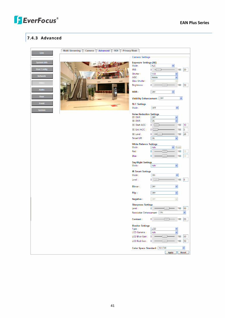
EAN Plus Series
41
743 Advanced
EAN Plus Series
42
【Camera Settings】
Lens (IRIS Control) Select DC or Manual for IRIS control This function is only available for EAN3220
Plus
Exposure Settings (AE) This setting is used to adapt to the amount or type of light used by the
camera Note the settings vary among models
Mode This function is not available for EAN3220 Plus
Automatic Light Control (ALC) This option is only available for EAN3120 Plus 3300 Plus The
ALC allows the camera circuitry to either take bright spots more into consideration (peak)
bringing out detail in bright areas or less into consideration (average) bringing out detail in
shadows
Auto Electronic Shutter (AES) This option is only available for EAN3120 Plus 3300 Plus In
this mode the camera measures the light level and decides whether it needs more or less light
and then automatically adjusts the shutter speed accordingly
Manual This option is only available for EAN3300 Plus Select this option to manually set up
the Shutter (Manual) and AGC (Manual) values
Iris Specify the size of the Iris opening here
Shutter If enabled this setting lets you set the shutter speed yourself
Shutter Limit Use this setting to set the maximum shutter speed for the camera This function is
only available for EAN3120 Plus
AGC Set the Auto Gain Control limit here The lower the AGC level the lower the video signal and
the noise However the image will be darker under low-light condition with IR-off if you set up the
Iris to the maximum level
Slow Shutter This option can be switched on when AES Mode is selected in the Exposure Settings
(AE) field This function is only available for EAN3220 Plus 3300 Plus
Flickerless If the Mode field in the Exposure Settings (AE) area has been set to AES then this option
becomes available Choose between OFF 50HZ 60HZ 50HZ (High Luminance) or 60HZ (High
Luminance) This function is only available for EAN3300 Plus
EV Setting Set up the Exposure Value Note the brightness of the screen changes when you change
the EV value This function is only available for EAN3300 Plus
AE Response Set up Auto Exposure Response time This function is only available for EAN3300 Plus
AE Weighting Area Select an AE Weighting area Each setup AE Weighting Area is configured with
the appropriate brightness level on the center and the surrounding areas This function is only
available for EAN3300 Plus
Brightness Set the image brightness here
AE Reference Set the Auto Exposure value here This function is only available for EAN3120 Plus
EAN Plus Series
43
Black Level Set the Black level here This function is only available for EAN3300 Plus
WDR The Wide Dynamic Range (WDR) function provides clearer images when both of the very
bright and dark areas simultaneously appear on the camera view There are four value options OFF
Low Middle and High Note that when WDR is ON some parts of the image may appear solarized
This is normal for WDR and is not a camera malfunction This function is only available for EAN3120
Plus 3220 Plus
Visibility Enhancement (OFFLowMiddleHigh) Images in foggy or rain environments or in
environments with a very strong luminous intensity have a dynamic range that is significantly lower
than ordinary images The user can use this Visibility Enhancement setting to ldquoDEFOGrdquo the image if
such ldquoFOGGINGrdquo is an issue This function is only available for EAN3220 Plus
BLC Settings Back Light Compensation (BLC) is used to make the subject appear clearer when it is
set against a bright background
OFF Select to switch Back Light Compensation functions off
Back Light This option is only available for EAN3300 Plus The Back Light function is useful
when the background of the subject is very bright and the subject itself is dark Select Back
Light and adjust the slide bar to the left right for setting up the back light value The higher
the value the more the backlight compensation
Front Light This option is only available for EAN3300 Plus This function is useful when the
bright highlights such as flashlight or car headlights appear on the camera view Select Front
Light and adjust the slide bar to the left right for setting up the front light value The higher
the value the more the highlight compensation
ON (BLC) This option is only available when you select AES Mode in the Exposure Settings (AE)
field The option is only available for EAN3120 Plus 3220 Plus The BLC function is useful
when the background of the subject is very bright and the subject itself is dark Follow the
instructions below to configure the settings for each model
For EAN3120 Select ON (BLC) the button next to the Mode drop-down list will be
active (see image below) Click the button the green setup areas appear on the left
screen Click on the areas to enable disable the BLC function The selected areas (in green)
will be applied with the BLC function
EAN Plus Series
44
For EAN3220
You can configure one area to apply the BLC function Select ON (BLC) the setup buttons
appears (see image below) Select Low Middle High from the BLC Gain drop-down list To
set up a BLC area click the Edit Area button and then click on the blue color tab to turn your
mouse cursor into a blue pen Move the cursor to the position on the right screen where you
want the BLC rectangle to start and then click Move your cursor to the position (diagonally
opposing corner) where you want the BLC rectangle to end and then click The blue area will
be applied with the BLC function
ON (HLC) This option is only available when you select AES Mode in the Exposure Settings (AE)
field The option is only available for EAN3120 Plus 3220 Plus This function is useful when
the bright highlights such as flashlight or car headlights appear on the camera view Follow
the instructions below to configure the settings for each model
For EAN3120 Select ON (HLC) and then select a level from the drop-down list The higher the
level the more the highlight compensation
For EAN3220
HLC Level Select a level for the HLC setting The higher the level the more the highlight
compensation
HLC Mode Select All Day Night mode to apply the HLC function
HLC Black Mask Select On Off to apply the black mask on the selected areas The
over-exposure portions within the selected areas will be applied with the black mask
Color Tabs You can set up four HLC areas with different colors To set up a HLC area click the
Edit Area button and then click on the color tab to turn your mouse cursor into a pen of that
color Move the cursor to the position on the right screen where you want the HLC rectangle
to start and then click Move your cursor to the position (diagonally opposing corner) where
you want the HLC rectangle to end and then click Select ON from the color tab drop-down list
The rectangular area with the selected color will be applied with the HLC function
EAN Plus Series
45
Back Light This option is only available for EAN3300 Plus The Back Light function is useful
when the background of the subject is very bright and the subject itself is dark Select Back
Light and adjust the slide bar to the left right for setting up the back light value The higher
the value the more the backlight compensation
Front Light This option is only available for EAN3300 Plus This function is useful when the
bright highlights such as flashlight or car headlights appear on the camera view Select Front
Light and adjust the slide bar to the left right for setting up the front light value The higher
the value the more the highlight compensation
Noise Reduction Settings This limits the amount of digital ldquovideo noiserdquo that is usually found in any
video stream and helps to reduce file size The higher the level the more the reduction
For EAN3120 Plus 3300 Plus
Select ON OFF to enable disable the Noise Reduction function Or select Auto to let the camera
automatically enable disable the Noise Reduction function Slide the Level bar to set up the level
The higher the level the more the reduction
For EAN3220 Plus
2D DNR Select ON to enable the 2D DNR function
3D DNR Select ON to enable the 3D DNR function You can further set up the following settings
3D Start AGC Set up the AGC level to automatically start the 3D NR function
3D End AGC Set up the AGC level to automatically stop the 3D NR function
3D Level Set up the 3D DNR level
Smart NR Select ON to enable the Smart NR function The 3D NR function will be
automatically turned on when a motion event occurs
EAN Plus Series
46
White Balance Settings Select the mode that delivers the best quality image for the camerarsquos light
environment There are five options Auto Manual Indoor Outdoor One Push
Auto Select to let the camera automatically adjust the White Balance In the Auto mode the
camera computes the white balance value output using color information from the entire
screen It outputs the proper value using the color temperature radiating from a black subject
based on a range of value from 3000 to 7500K
Manual Select to adjust the Red and Blue values yourself in the fields below this field
Indoor Select to use the default settings for indoor environments In the Indoor mode the
camera uses 3200K as the base value
Outdoor Select to use the default settings for outdoor environment In the Outdoor mode it
uses 5800K as the base value
One Push Select to enable the Push button next to the Mode drop-down field This will allow you to force the camera to readjust the white balance every time you push the Push
button The lens will hold the same focal position until the next trigger command is received
This function helps to prevent incorrect focusing in dark environments This function is only
available for EAN3120 Plus 3220 Plus
Manual Temperature Select to use the optimized Red and Blue settings You can also
optionally adjust the Manual Level below this field for setting up the color temperature The
higher the value the more the color temperature This function is only available for EAN3300
Plus
DayNight Settings
Auto Select to let the camera automatically switch to Night mode (black and white) when the
light levels fall to a specified level and back to Day mode (color) when the light levels rise to a
specified level
Day Select to keep the camera in Day mode (color) even in nighttime
Night Select to keep the camera in Night mode (black and white) even in daytime
IR Smart Settings Select ON and set up the level to enhance the image quality when the images are
over exposure This function is useful when the camera is in the Night mode This function is only
available for EAN3220 Plus
Saturation Set the saturation value This function is not available for EAN3220 Plus
Monitor Type Select a gamma value from Set 1 Set 2 or Set 3 This function is only available for
EAN3120 Plus
Negative Switch this setting ON to view a color negative version of the video image This is useful
at night or when viewing temperature-sensitive images
EAN Plus Series
47
Sharpness Settings Select the sharpness level of the image A low sharpness level will deliver a
softer less detailed image A high level will deliver a sharp highly detailed image Switch Resolution
Enhancement ON to enable the resolution enhancement function
Contrast Select the contrast level of the image
Suppress Function This function is only available for EAN3300 Plus
Aperture Compensation Suppression (OFFLowMiddleHigh) This setting can be activated to
suppress luminance noise when the AGC level increases
Chroma Suppression (OFFLowMiddleHigh) This setting can be activated to suppress
chrominance noise when the AGC level increases
Ygamma (gamma 22standardcontrast enhancehigh light range mode LHigh light range mode
H) Select the Ygamma value for the video quality of the monitor This function is only available for
EAN3300 Plus
Monitor Settings The user can use this field to optimize video quality for his or her specific type of
monitor ndash LCD or CRT This function is only available for EAN3220 Plus
Color Space Standard The options are YUV601 for SD and YUV709 for HD These define the color
space standard required to convert an RGB picture to a YUV picture Generally YUV601 is used for
Standard Definition (720P) devices and the YUV709 is used for High Definition (1080P) devices
Click Apply to save all changes Click Reset to cancel all changes
EAN Plus Series
48
744 ROI (Region of Interest)
The Region of Interest (ROI) function allows users to set up multiple regions within an image with
better quality and less distortion than the rest of the image You can also use this function
together with the Digital Zoom function on the Live View Page to get a better image result Up to
eight ROIs can be configured in the ROI settings page
To set up an ROI region
1 Select an ROI number from the ROI No drop-down list
2 Click the Add button the mouse cursor will turn into a pen when you move it over the live
image on the left
3 Move the cursor to the position where you want the ROI rectangle to start and then click
Move the cursor to the position (diagonally opposing corner) where you want the ROI
rectangle to end and then click
4 Slide the Quality bar to set up the quality value
5 Click the Apply button to apply the settings or click the Reset button to reset without saving
the settings
EAN Plus Series
49
745 Privacy Mask
The Privacy Mask can block out sensitive areas from view covering the areas with colored or black
and white boxes in both live view and recorded clips This feature is useful when usersrsquo donrsquot want
the sensitive information visible Up to four Privacy Masks can be configured
【Privacy Mask Color Settings】The Modes vary among camera models
Mode Click Color to make the masks appear as colored rectangles on the screen Click BW to
make the masks appear as gray rectangles on the screen Click Mosaic to make the masks appear
as mosaic-effect rectangles on the screen
Level Select the color of the masks if you selected Color Mode Select the level of grayness of the
masks if you selected BW Mode Select the level of smallmiddlelarge if you selected Mosaic
Mode
Click Apply to apply the settings or click Reset to reset without saving the settings
Color Tabs Click on a color tab to turn your mouse cursor into a pen of that color
You can now create a block of that color on the video screen Move your cursor to the position
where you want your mask rectangle to start and then click Move your cursor to the position
(diagonally opposing corner) where you want your mask rectangle to end and then click The
rectangular area with the selected color will appear The live image will display the rectangular
area with the color you selected If you want to create another mask use one of the other three
colors Each color denotes a different mask area Only one block per color is allowed As the
number of colors suggests you can configure up to four blocks
EAN Plus Series
50
Select All Click to turn the whole screen into a mask area
Clear All Click to delete all configured mask blocks
Eraser Click to turn the mouse cursor into an eraser to delete any block you click on
Area Shows the color and number of the block
Enable Check this box to enable the related mask block
Click Apply to apply the settings or click Reset to reset without saving the settings
EAN Plus Series
51
75 Audio
The EAN Plus series IP camera can transmit audio to your computer if you have connected an external
microphone to its audio Input cable It can also receive audio input from you and transmit it via an
external speaker if you have connected such a speaker to its audio Output cable
Check the Enable Audio box to enable the camerarsquos audio function The camera will now act as a
digital bridge (via the IP network) between any connected audio input device and any connected
audio device
Adjust the Audio Input Volume if you have external audio input devices (microphones) connected to
the camera and if there are problems with the sound input being too low or high
Click Apply to save all settings or click Reset to cancel
EAN Plus Series
52
76 User
761 User Information
The system administrator can create up to ten user accounts on this page
To set up a user account
1 Highlight a user account and click the Modify button The following dialog box appears
2 Type the account name account description and password for the account Type the password
again in the Confirm field
3 Select an authority level for the user account from the Authority drop-down list
bull Supervisor Administrator The only difference between a supervisor and administrator is
that a supervisor can edit an administratorrsquos account and password but an administrator
cannot edit the supervisorrsquos account and password Multiple administrators can be
configured but there can be only one supervisor The supervisor and administrators all
have unrestricted access to the Settings submenus and can determine the registration of
all other users
EAN Plus Series
53
bull User A user can view the Live View page and view the system network video and audio
information A user can only adjust the User Config page settings The user does not have
access to the User Event and System pages
bull Guest The lowest level of access which only allows the user access to the Live View page
4 Select Active or Disable from the Status drop-down list to active or disable the user account
5 Click On in the SD Card Playback field to allow the user to access the SD card playback
function
6 Click OK
7 Click Apply to save all the settings
EAN Plus Series
54
762 IP Address Filter
Use this page to specify IP addresses that are not allowed to access this camera By default any IP
address can access the camera
Note The Allowed List addresses only become relevant when the Denied List contains a network
or range and the supervisor wants to allow one or more IP addresses within that excluded range
or network In such a scenario the user would enter the excluded range or network in the
Denied List and enter the exceptions in the Allowed List
To set up the IP Address Filter
1 Select Denied List Click the Add button the following dialog box appears
2 Select an IP type from the IP Type drop-down list
3 Select a network rule from the Rule drop-down list type the IP address and click OK
Single Type a single IP address in the IP Address field below
Network Type the IP address and subnet mask in the field below
Range Type a range for the IP addresses
4 If you have set up an IP range in Step 3 you can optionally set up the Allowed List to allow one
or more IP addresses within the setup IP range to access the IP camera
5 Click Apply
EAN Plus Series
55
77 Event
You can set up the Motion Detection event Tamper Detection event or the Alarm IO to automatically
notify the users when an event occurs or an alarm is triggered You can also set up a schedule to
automatically record the videos when an event occurs or an alarm is triggered
771 Event Settings
You can create a total of ten event or alarm settings page in the Event List
【Event List】
Click the Add button and the following Event Configuration Window appears
EAN Plus Series
56
Enter Event Name Type an event name
Event Triggered by Select an event or alarm type for the to-be-specified-below reactions
Alarm Input Select this if you want a reaction trigger coming from any external connected sensor
to activate a to-be-specified-below reactions via the camera system Make sure that a suitable
device is actually connected to the alarm input relay
Manual Trigger Select this option if you want to manually trigger the alarm by clicking the Trigger
Event button on the Live View Page
Motion Detection Select this option if you want motion in a specified part of the camerarsquos viewing
rectangle (the screen image) to trigger the to-be-specified-below reactions
Tampering Detection Select this option if you want the camerarsquos tampering detection sensor to
trigger the to-be-specified-below reactions
Schedule Recording Select this option if you want the Schedule Recording periods configured in
the recording schedule (the Settings gt Event gt Schedule page) to activate this event In this
scenario a preconfigured event reaction like a log entry will list the start and end times of each
period Actual recording will only be triggered if the event is preconfigured to do so
Enable This Event Select to activate the event
Enable Re-trigger Click to set a minimum time after the event is triggered before the event
can be triggered again
Enable Pre-trigger Buffer Click if you want the Event reaction (as selected in the ldquoNotification
Overrdquo field below) to be the activation of the video recording function and if you want the
recording to include the video feed from the time period (configurable on the previous ldquoEvent
Settingsrdquo page) just before the Event trigger occurred
Enable Post-trigger Buffer Click if you want the Event reaction (as selected in the Notification
Over field) to be the activation of the video recording function and if you want the recording
to include the video feed from a time period (configurable on the Event Settings page) just
after the Event trigger occurred
Motion Area Select a setup motion detection area from the drop down list Note this
function only becomes relevant after the Motion Detection areas have been set up (see 772
Motion Detection)
Notification Over Select the desired notification types form the following items
Log Click if you want the camera to list the eventrsquos details in its log if the event is triggered
Trigger Alarm Output Click if you want the camera to relay the event reaction to a device
attached to the alarm relay output wire and then set up the alarm output duration time
EAN Plus Series
57
Send Mail Notification Click if you want the camera to send an Event notification email to the
email address entered in the Set SMTP Server(email) field of the Network gt SMTPFTP page if
the Event occurs (see 733 SMTP FTP)
Upload to FTP Click if you want the camera to upload recorded footage to the FTP server
entered in the Set SMTP Server(email) field of the Network gt SMTPFTP page if the Event
occurs (see 733 SMTP FTP)
Record to SD Card Click if you want the camera to start recording its video feed (when the
event occurs) on an on-camera SD Card (if such a card has been inserted)
Note The recording will only be as long as the combined Pre- and Post-trigger Buffers so
make sure you enable at least one of these buffers especially the Post-trigger Buffer
Record to PC Check this box if you want the camera to start recording its video feed (when
the event occurs) on the same folder on the same PC as configured on the User Config gt
RecordingSnapshot page (if such a folder has been enabled and configured)
Note The recording will only be as long as the combined Pre- and Post-trigger Buffers (and
for as long as the event trigger is happening ndash eg a motion is detected) so make sure you
enable at least one of these buffers especially the Post-trigger Buffer
Network Alarm Check this box if you want the camera to send a network alarm signal (when
the event occurs) to the CMS servers configured on the Network gt Network Alarm page (see
736 Network Alarm)
Click OK to save all settings or click Cancel to cancel
【PrePost Trigger Settings】
Pre-trigger Buffer Select the duration for the buffer This will determine the amount of footage
(length of time) before the event trigger moment that will be included in an event-triggered video
recording if that buffer and video recording has been enabled in the Event Configuration Window
Post-trigger Buffer Select the duration for the buffer This will determine the amount of footage
(length of time) after the event trigger moment that will be included in an event-triggered video
recording if that buffer and video recording has been enabled in the Event Configuration Window
Click Apply to save all settings or click Reset to cancel
EAN Plus Series
58
772 Motion Detection
Use this page to configure up to four areas in which motion will be detected When a motion is
detected by the camera the motion detection icon will appear at the top right of the
Live page to alert the user This function can also be linked with correctly configured Events to
trigger Event reactions like the activation of video recording periods snapshots alarms etc
Color Tabs Click on a color tab to turn your mouse cursor into a pen of that color
You can now create a block of that color on the video screen Move your cursor to the position
where you want your detection rectangle to start and then click Move your cursor to the position
(diagonally opposing corner) where you want your detection rectangle to end and then click The
rectangular area with the selected color will appear This block will be an area inside which the
camera will detect motion If you want to create another detection area use one of the other three
palette colors Each color denotes a different detection area Only one block per color is allowed As
the number of colors suggests you can configure up to four blocks
Select All Click to turn the whole screen into a motion detection area
Clear All Click to delete all configured motion detection blocks
Eraser Click to turn your mouse cursor into an eraser to delete any block you click on
Area Shows the color and numberID of the block
Enable Check this box to enable the related motion detection block
Sensitivity Set the sensitivity of the motion detection sensor function
Click Apply to save all settings or click Reset to cancel
EAN Plus Series
59
773 Tamper Detection
Use this page to set the number of seconds that an alarm signal will be active if the device is
physically tampered (moved covered up or out of focus
774 Alarm IO
Use this page to set the type of trigger input and the type of output contact for the camerarsquos alarm
channel
EAN Plus Series
60
775 Schedule
Use this page to configure a schedule for periods during which the camera should deactivate all
user-activated Events (gray Deselect periods) or when the camera should deactivate all
user-activated Events except Schedule Recording (SR) events (blue Schedule Recording-only
periods) or when the camera should deactivate only SR events (red Event Recording-only periods)
or when it should enable all activated Events (yellow periods)
Event Recording Click this button to make every hour block you click on red A red block represents
an Event Recording-only block which represents an hour when the camera will deactivate all
preconfigured activated Schedule Recording events and keep all the other activated events active
Schedule Recording Click this button to make every hour block you click on blue A blue block
represents a Schedule Recording-only block which represents an hour when the camera will
deactivate all other preconfigured activated events and keep only the preconfigured activated
Schedule Recording events active
Event + Schedule Click this button to make every hour block you click on yellow A yellow block
represents an hour in which all activated events including Schedule Recording events will be
active
Deselect Click this button to make every hour block become grey A grey block represents an hour
in which all activated events including Schedule Recording events will be inactive
Click Apply to save all settings or click Reset to cancel
EAN Plus Series
61
78 System
You can set up the systemrsquos time and SD card settings and to do maintenance and reset actions like
reboots and upgrades
781 DateTime
【Machine Name Settings】If required enter a new name for the machine This name will be visible
in the Machine Name field of the IP Utility software which is included in the software CD
【Set Time Zone】Set the time zone of the camerarsquos location
【Set DateTime Manually】Set the datetime here if you wonrsquot be using an NTP server to update the
datetime (see below)
【Set DateTime Sync】Enter the Network Time Protocol server if applicable The camerarsquos time will
be automatically adjusted by synchronizing with the NTP server
Click Apply to save all settings or click Reset to cancel
EAN Plus Series
62
782 Daylight Saving
Click Enable Daylight Saving to enable this schedule and select the dates when the regionrsquos
daylight saving period begins and ends Click Apply to save all settings or click Reset to cancel
783 SD Card
Use this page to prepare the system for safely removing the SD Card from its slot
【Setup SD Card】
Notification Select the percentage of storage space that should be left on the card before the
camera notifies you of the impending storage shortage or overwrite
Event Recording Select if you want Event Recording only FTP Backup only or both
Overwrite Click ON if you want the card to start writing over recorded footage when its memory is
full Click OFF if you want the card to stop recording new footage when its memory is full
【SD Card Utility】
Capacity This shows you how much card memory has been used and how much memory capacity
remains on the card
Remove Click this button before removing the card from the system
Format Click this button to format the card All data saved on the SD card will be removed if the
card is formatted
EAN Plus Series
63
784 Maintenance
【Maintenance Server】
Reboot Click this button to reboot the unit without changing any of the settings Use this function if
the unit is not behaving as expected
Restore Click this button to restart and reset most of the current settings to their factory default
values The only settings that will not be changed to default are
bull IP settings
bull DDNS settings
Default The Default button should be used with caution Pressing this button will return all of the
cameras settings including the IP address to the factory default values The camera will then have
to be reconfigured
【SaveLoad Configuration Server】
Save To make a backup file of the machinersquos current configurations press Save to save all the
configurations to a config file This will enable the user to reload these configuration settings if the
settings are changed and there is unexpected behavior
Load To load a previously saved configuration press the Browse button to locate the saved config
file (see above) and then click the Load button The systemrsquos settings will be restored to the saved
configuration
EAN Plus Series
64
【SaveLoad Video Configuration Server】
Save To make a backup file of the machinersquos video configurations press Save to save the video
configurations to a config file This will enable the user to reload these configuration settings if the
settings are changed and there is unexpected behavior
Load To load a previously saved video configuration press the Browse button to locate the saved
config file (see above) and then click the Load button The systemrsquos settings will be restored to the
saved video configuration
【Upgrade Firmware】Click the Browse button to find a previously prepared firmware upgrade file
Click Upgrade to install the new firmware
Note
1 Do not disconnect power to the unit during the upgrade sequence The unit will reboot
automatically after the upgrade has completed (1-5 minutes)
2 During the upgrade process all event recording actions will be stopped Event recording
actions will resume after the camera is rebooted
3 If the ldquoFile Error Please re-loginrdquo warning message appears when upgrading the firmware
please try the following instructions
a Go to Internet Explorer gt Tools gt Internet Option gt Security gt Custom
b Find and enable the Include local directory path when uploading files to a server
EAN Plus Series
65
8 Upgrading Firmware Using IP Utility
You can upgrade the Firmware using the IP Utility software included in the software CD
1 Install and then start the IPU program The following dialog box appears
2 Click Find Devices to search the cameras connected in the LAN The default network values of the
cameras will be displayed By default the network protocol of the camera is DHCP
3 Select a camera and click LoginMulti Login to log in the camera
4 Type the user ID and password Click OK
Note
1 The default user ID is user1 and the default password is 11111111
2 If you select more than one camera that has the same user ID password you will be able
to log in several cameras at once
EAN Plus Series
66
5 Highlight the camera and then click Upgrade Firmware A browsing window appears
6 Select the firmware file (evb) and then click Open The IP Utility will automatically upgrade the
firmware
The camera will reboot once the update is complete Click Find Devices the new firmware version
should be displayed in the last part of the Machine Name
EAN Plus Series
67
9 Specifications
Model EAN3120 Plus EAN3220 Plus EAN3300 Plus
Camera
Image Sensor 13 Panasonic CMOS 128 Sony CMOS
Megapixel 13 MP 2 MP 3 MP
Picture Elements (H x V) 1280 x 1024 1944 x 1092 2048 x 1536
Min Illuminations 003 Lux at F14
Electronic Shutter (Sec) 85 ~ 160000 2 ~ 150000 1 ~ 110000
Scanning System NTSC PAL
WDR Yes Yes No
BLC Yes
Gain Control Yes
White Balance Yes
Lens
Mounting Type C CS
Day Night Yes (with removable auto IR-cut filter)
IRIS Control DC Electrical IRIS Lens IRIS
Video
Video Compression H264 MJPEG
Resolution
NTSC
2048 x 1536 1920 x 1200 (for EAN3300 Plus only)
1920 x 1080 (for EAN3300 Plus 3220 Plus only)
1280 x 1024 1280 x 720 1024 x 768 720 x 480 704 x 480 640 x 480
352 x 240 320 x 240 160 x 120
PAL
2048 x 1536 1920 x 1200 (for EAN3300 Plus only)
1920 x 1080 (for EAN3300 Plus 3220 Plus only)
1280 x 1024 1280 x 720 1024 x 768 720 x 576 704 x 576 640 x 480
352 x 288 320 x 240 160 x 120
Frame Rate 30 fps at 1280 x 1024 30 fps at 1920 x 1080 15 fps at 2048 x 1536
Audio
Audio Streaming Two-way audio
Audio Compression G711
EAN Plus Series
68
Network
Interface 10 100 Base-T Ethernet RJ-45 socket
Supported Protocols
TCPIP IPV6 UDP ICMP DHCP NTP DNS DDNS SMTP SNMP FTP
HTTP HTTPs PPPoE UPnP Bonjour RTP RTSP RTCP IGMP ARP ONVIF
PSIA
Connector
Power DC female port PoE
Ethernet RJ-45
Audio 1 In (phone jack for microphone)
1 Out (phone jack for Speaker)
Alarm IO Terminal IO wires
Local Storage Micro SD SDHC memory card slot
TV-Out BNC socket composite 1 V p-p 75 Ω
General
Power Source DC 12V PoE (IEEE8023af)
Power Consumption
(IR LEDs On)
5W (DC 12V)
621W (PoE)
5W (DC 12V)
522W (PoE)
5W (DC 12V)
536W (PoE)
Operating Temperature 0degC ~ +50degC 32degF ~ +122degF
Humidity 20 to 80 (no condensation)
Safety CE FCC
Dimensions (L x W x H) 117 x 56 x 68 mm 46 x 22 x 27 in
Weight 410 g 09 lb
EverFocus Electronics Corp EverFocus Taiwan 12F No79 Sec 1 Shin-Tai Wu Road Hsi-Chih Taipei Taiwan TEL +886 2 2698 2334 FAX +886 2 2698 2380 wwweverfocuscomtw marketingeverfocuscomtw
EverFocus Europe - Germany Albert-Einstein-Strasse 1 D-46446 Emmerich Germany TEL +49 2822 93940 FAX +49 2822 939495 wwweverfocusde infoeverfocusde
EverFocus China - Beijing Room 609 Technology Trade Building Shangdi Information Industry Base Haidian District Beijing 100085 China TEL +86 10 6297 3336~39 FAX +86 10 6297 1423 wwweverfocuscomcn marketingeverfocuscomcn
EverFocus China - Shenzhen 4F No 2 D4 Building Wan Yelong Industrial Park Tangtou Road Shiyan Baoan Shenzhen Guangdong 518101 China TEL +86 755 2765 1313 FAX +86 755 2765 0337 wwweverfocuscomcn marketingeverfocuscomcn
EverFocus USA - California 1801 Highland Avenue Unit A Duarte CA 91010 USA TEL +1 626 844 8888 FAX +1 626 844 8838 wwweverfocuscom saleseverfocuscom
EverFocus USA - New York 415 Oser Avenue Unit S Hauppauge NY 11788 USA TEL +1 631 436 5070 FAX +1 631 436 5027 wwweverfocuscom saleseverfocuscom
EverFocus Japan 5F Kinshicho City Building 2-13-4 Koto-BashiSumida-Ku Tokyo 130-0022 Japan TEL +81 3 5625 8188 FAX +81 3 5625 8189 wwweverfocuscojp infoeverfocuscojp
EverFocus Europe - UK Unit 12 Spitfire Business Park Hawker Road Croydon Surrey CR0 4WD UK TEL +44 20 8649 9757 +44 845 430 9999 FAX +44 20 8649 9907 wwweverfocusukcouk salesukeverfocuscom
EverFocus India Suite 803 Housefin Bhavan C-21 Bandra Kurla Complex Bandra (East) Mumbai 400051 India TEL +91 22 6128 8700 FAX +91 22 6128 8705 wwweverfocusin saleseverfocusin
PN 4605PQ3120B010A-VerC
Your EverFocus product is designed and manufactured with high quality materials and components which can be recycled and reused This symbol means that electrical and electronic equipment at their end-of-life should be disposed of separately from your household waste Please dispose of this equipment at your local community waste collectionrecycling centre In the European Union there are separate collection systems for used electrical and electronic product Please help us to conserve the environment we live in
Ihr EverFocus Produkt wurde entwickelt und hergestellt mit qualitativ hochwertigen Materialien und Komponenten die recycelt und wieder verwendet werden koumlnnen Dieses Symbol bedeutet dass elektrische und elektronische Geraumlte am Ende ihrer Nutzungsdauer vom Hausmuumlll getrennt entsorgt werden sollen Bitte entsorgen Sie dieses Geraumlt bei Ihrer oumlrtlichen kommunalen Sammelstelle oder im Recycling Centre Helfen Sie uns bitte die Umwelt zu erhalten in der wir leben
EAN Plus Series
42
【Camera Settings】
Lens (IRIS Control) Select DC or Manual for IRIS control This function is only available for EAN3220
Plus
Exposure Settings (AE) This setting is used to adapt to the amount or type of light used by the
camera Note the settings vary among models
Mode This function is not available for EAN3220 Plus
Automatic Light Control (ALC) This option is only available for EAN3120 Plus 3300 Plus The
ALC allows the camera circuitry to either take bright spots more into consideration (peak)
bringing out detail in bright areas or less into consideration (average) bringing out detail in
shadows
Auto Electronic Shutter (AES) This option is only available for EAN3120 Plus 3300 Plus In
this mode the camera measures the light level and decides whether it needs more or less light
and then automatically adjusts the shutter speed accordingly
Manual This option is only available for EAN3300 Plus Select this option to manually set up
the Shutter (Manual) and AGC (Manual) values
Iris Specify the size of the Iris opening here
Shutter If enabled this setting lets you set the shutter speed yourself
Shutter Limit Use this setting to set the maximum shutter speed for the camera This function is
only available for EAN3120 Plus
AGC Set the Auto Gain Control limit here The lower the AGC level the lower the video signal and
the noise However the image will be darker under low-light condition with IR-off if you set up the
Iris to the maximum level
Slow Shutter This option can be switched on when AES Mode is selected in the Exposure Settings
(AE) field This function is only available for EAN3220 Plus 3300 Plus
Flickerless If the Mode field in the Exposure Settings (AE) area has been set to AES then this option
becomes available Choose between OFF 50HZ 60HZ 50HZ (High Luminance) or 60HZ (High
Luminance) This function is only available for EAN3300 Plus
EV Setting Set up the Exposure Value Note the brightness of the screen changes when you change
the EV value This function is only available for EAN3300 Plus
AE Response Set up Auto Exposure Response time This function is only available for EAN3300 Plus
AE Weighting Area Select an AE Weighting area Each setup AE Weighting Area is configured with
the appropriate brightness level on the center and the surrounding areas This function is only
available for EAN3300 Plus
Brightness Set the image brightness here
AE Reference Set the Auto Exposure value here This function is only available for EAN3120 Plus
EAN Plus Series
43
Black Level Set the Black level here This function is only available for EAN3300 Plus
WDR The Wide Dynamic Range (WDR) function provides clearer images when both of the very
bright and dark areas simultaneously appear on the camera view There are four value options OFF
Low Middle and High Note that when WDR is ON some parts of the image may appear solarized
This is normal for WDR and is not a camera malfunction This function is only available for EAN3120
Plus 3220 Plus
Visibility Enhancement (OFFLowMiddleHigh) Images in foggy or rain environments or in
environments with a very strong luminous intensity have a dynamic range that is significantly lower
than ordinary images The user can use this Visibility Enhancement setting to ldquoDEFOGrdquo the image if
such ldquoFOGGINGrdquo is an issue This function is only available for EAN3220 Plus
BLC Settings Back Light Compensation (BLC) is used to make the subject appear clearer when it is
set against a bright background
OFF Select to switch Back Light Compensation functions off
Back Light This option is only available for EAN3300 Plus The Back Light function is useful
when the background of the subject is very bright and the subject itself is dark Select Back
Light and adjust the slide bar to the left right for setting up the back light value The higher
the value the more the backlight compensation
Front Light This option is only available for EAN3300 Plus This function is useful when the
bright highlights such as flashlight or car headlights appear on the camera view Select Front
Light and adjust the slide bar to the left right for setting up the front light value The higher
the value the more the highlight compensation
ON (BLC) This option is only available when you select AES Mode in the Exposure Settings (AE)
field The option is only available for EAN3120 Plus 3220 Plus The BLC function is useful
when the background of the subject is very bright and the subject itself is dark Follow the
instructions below to configure the settings for each model
For EAN3120 Select ON (BLC) the button next to the Mode drop-down list will be
active (see image below) Click the button the green setup areas appear on the left
screen Click on the areas to enable disable the BLC function The selected areas (in green)
will be applied with the BLC function
EAN Plus Series
44
For EAN3220
You can configure one area to apply the BLC function Select ON (BLC) the setup buttons
appears (see image below) Select Low Middle High from the BLC Gain drop-down list To
set up a BLC area click the Edit Area button and then click on the blue color tab to turn your
mouse cursor into a blue pen Move the cursor to the position on the right screen where you
want the BLC rectangle to start and then click Move your cursor to the position (diagonally
opposing corner) where you want the BLC rectangle to end and then click The blue area will
be applied with the BLC function
ON (HLC) This option is only available when you select AES Mode in the Exposure Settings (AE)
field The option is only available for EAN3120 Plus 3220 Plus This function is useful when
the bright highlights such as flashlight or car headlights appear on the camera view Follow
the instructions below to configure the settings for each model
For EAN3120 Select ON (HLC) and then select a level from the drop-down list The higher the
level the more the highlight compensation
For EAN3220
HLC Level Select a level for the HLC setting The higher the level the more the highlight
compensation
HLC Mode Select All Day Night mode to apply the HLC function
HLC Black Mask Select On Off to apply the black mask on the selected areas The
over-exposure portions within the selected areas will be applied with the black mask
Color Tabs You can set up four HLC areas with different colors To set up a HLC area click the
Edit Area button and then click on the color tab to turn your mouse cursor into a pen of that
color Move the cursor to the position on the right screen where you want the HLC rectangle
to start and then click Move your cursor to the position (diagonally opposing corner) where
you want the HLC rectangle to end and then click Select ON from the color tab drop-down list
The rectangular area with the selected color will be applied with the HLC function
EAN Plus Series
45
Back Light This option is only available for EAN3300 Plus The Back Light function is useful
when the background of the subject is very bright and the subject itself is dark Select Back
Light and adjust the slide bar to the left right for setting up the back light value The higher
the value the more the backlight compensation
Front Light This option is only available for EAN3300 Plus This function is useful when the
bright highlights such as flashlight or car headlights appear on the camera view Select Front
Light and adjust the slide bar to the left right for setting up the front light value The higher
the value the more the highlight compensation
Noise Reduction Settings This limits the amount of digital ldquovideo noiserdquo that is usually found in any
video stream and helps to reduce file size The higher the level the more the reduction
For EAN3120 Plus 3300 Plus
Select ON OFF to enable disable the Noise Reduction function Or select Auto to let the camera
automatically enable disable the Noise Reduction function Slide the Level bar to set up the level
The higher the level the more the reduction
For EAN3220 Plus
2D DNR Select ON to enable the 2D DNR function
3D DNR Select ON to enable the 3D DNR function You can further set up the following settings
3D Start AGC Set up the AGC level to automatically start the 3D NR function
3D End AGC Set up the AGC level to automatically stop the 3D NR function
3D Level Set up the 3D DNR level
Smart NR Select ON to enable the Smart NR function The 3D NR function will be
automatically turned on when a motion event occurs
EAN Plus Series
46
White Balance Settings Select the mode that delivers the best quality image for the camerarsquos light
environment There are five options Auto Manual Indoor Outdoor One Push
Auto Select to let the camera automatically adjust the White Balance In the Auto mode the
camera computes the white balance value output using color information from the entire
screen It outputs the proper value using the color temperature radiating from a black subject
based on a range of value from 3000 to 7500K
Manual Select to adjust the Red and Blue values yourself in the fields below this field
Indoor Select to use the default settings for indoor environments In the Indoor mode the
camera uses 3200K as the base value
Outdoor Select to use the default settings for outdoor environment In the Outdoor mode it
uses 5800K as the base value
One Push Select to enable the Push button next to the Mode drop-down field This will allow you to force the camera to readjust the white balance every time you push the Push
button The lens will hold the same focal position until the next trigger command is received
This function helps to prevent incorrect focusing in dark environments This function is only
available for EAN3120 Plus 3220 Plus
Manual Temperature Select to use the optimized Red and Blue settings You can also
optionally adjust the Manual Level below this field for setting up the color temperature The
higher the value the more the color temperature This function is only available for EAN3300
Plus
DayNight Settings
Auto Select to let the camera automatically switch to Night mode (black and white) when the
light levels fall to a specified level and back to Day mode (color) when the light levels rise to a
specified level
Day Select to keep the camera in Day mode (color) even in nighttime
Night Select to keep the camera in Night mode (black and white) even in daytime
IR Smart Settings Select ON and set up the level to enhance the image quality when the images are
over exposure This function is useful when the camera is in the Night mode This function is only
available for EAN3220 Plus
Saturation Set the saturation value This function is not available for EAN3220 Plus
Monitor Type Select a gamma value from Set 1 Set 2 or Set 3 This function is only available for
EAN3120 Plus
Negative Switch this setting ON to view a color negative version of the video image This is useful
at night or when viewing temperature-sensitive images
EAN Plus Series
47
Sharpness Settings Select the sharpness level of the image A low sharpness level will deliver a
softer less detailed image A high level will deliver a sharp highly detailed image Switch Resolution
Enhancement ON to enable the resolution enhancement function
Contrast Select the contrast level of the image
Suppress Function This function is only available for EAN3300 Plus
Aperture Compensation Suppression (OFFLowMiddleHigh) This setting can be activated to
suppress luminance noise when the AGC level increases
Chroma Suppression (OFFLowMiddleHigh) This setting can be activated to suppress
chrominance noise when the AGC level increases
Ygamma (gamma 22standardcontrast enhancehigh light range mode LHigh light range mode
H) Select the Ygamma value for the video quality of the monitor This function is only available for
EAN3300 Plus
Monitor Settings The user can use this field to optimize video quality for his or her specific type of
monitor ndash LCD or CRT This function is only available for EAN3220 Plus
Color Space Standard The options are YUV601 for SD and YUV709 for HD These define the color
space standard required to convert an RGB picture to a YUV picture Generally YUV601 is used for
Standard Definition (720P) devices and the YUV709 is used for High Definition (1080P) devices
Click Apply to save all changes Click Reset to cancel all changes
EAN Plus Series
48
744 ROI (Region of Interest)
The Region of Interest (ROI) function allows users to set up multiple regions within an image with
better quality and less distortion than the rest of the image You can also use this function
together with the Digital Zoom function on the Live View Page to get a better image result Up to
eight ROIs can be configured in the ROI settings page
To set up an ROI region
1 Select an ROI number from the ROI No drop-down list
2 Click the Add button the mouse cursor will turn into a pen when you move it over the live
image on the left
3 Move the cursor to the position where you want the ROI rectangle to start and then click
Move the cursor to the position (diagonally opposing corner) where you want the ROI
rectangle to end and then click
4 Slide the Quality bar to set up the quality value
5 Click the Apply button to apply the settings or click the Reset button to reset without saving
the settings
EAN Plus Series
49
745 Privacy Mask
The Privacy Mask can block out sensitive areas from view covering the areas with colored or black
and white boxes in both live view and recorded clips This feature is useful when usersrsquo donrsquot want
the sensitive information visible Up to four Privacy Masks can be configured
【Privacy Mask Color Settings】The Modes vary among camera models
Mode Click Color to make the masks appear as colored rectangles on the screen Click BW to
make the masks appear as gray rectangles on the screen Click Mosaic to make the masks appear
as mosaic-effect rectangles on the screen
Level Select the color of the masks if you selected Color Mode Select the level of grayness of the
masks if you selected BW Mode Select the level of smallmiddlelarge if you selected Mosaic
Mode
Click Apply to apply the settings or click Reset to reset without saving the settings
Color Tabs Click on a color tab to turn your mouse cursor into a pen of that color
You can now create a block of that color on the video screen Move your cursor to the position
where you want your mask rectangle to start and then click Move your cursor to the position
(diagonally opposing corner) where you want your mask rectangle to end and then click The
rectangular area with the selected color will appear The live image will display the rectangular
area with the color you selected If you want to create another mask use one of the other three
colors Each color denotes a different mask area Only one block per color is allowed As the
number of colors suggests you can configure up to four blocks
EAN Plus Series
50
Select All Click to turn the whole screen into a mask area
Clear All Click to delete all configured mask blocks
Eraser Click to turn the mouse cursor into an eraser to delete any block you click on
Area Shows the color and number of the block
Enable Check this box to enable the related mask block
Click Apply to apply the settings or click Reset to reset without saving the settings
EAN Plus Series
51
75 Audio
The EAN Plus series IP camera can transmit audio to your computer if you have connected an external
microphone to its audio Input cable It can also receive audio input from you and transmit it via an
external speaker if you have connected such a speaker to its audio Output cable
Check the Enable Audio box to enable the camerarsquos audio function The camera will now act as a
digital bridge (via the IP network) between any connected audio input device and any connected
audio device
Adjust the Audio Input Volume if you have external audio input devices (microphones) connected to
the camera and if there are problems with the sound input being too low or high
Click Apply to save all settings or click Reset to cancel
EAN Plus Series
52
76 User
761 User Information
The system administrator can create up to ten user accounts on this page
To set up a user account
1 Highlight a user account and click the Modify button The following dialog box appears
2 Type the account name account description and password for the account Type the password
again in the Confirm field
3 Select an authority level for the user account from the Authority drop-down list
bull Supervisor Administrator The only difference between a supervisor and administrator is
that a supervisor can edit an administratorrsquos account and password but an administrator
cannot edit the supervisorrsquos account and password Multiple administrators can be
configured but there can be only one supervisor The supervisor and administrators all
have unrestricted access to the Settings submenus and can determine the registration of
all other users
EAN Plus Series
53
bull User A user can view the Live View page and view the system network video and audio
information A user can only adjust the User Config page settings The user does not have
access to the User Event and System pages
bull Guest The lowest level of access which only allows the user access to the Live View page
4 Select Active or Disable from the Status drop-down list to active or disable the user account
5 Click On in the SD Card Playback field to allow the user to access the SD card playback
function
6 Click OK
7 Click Apply to save all the settings
EAN Plus Series
54
762 IP Address Filter
Use this page to specify IP addresses that are not allowed to access this camera By default any IP
address can access the camera
Note The Allowed List addresses only become relevant when the Denied List contains a network
or range and the supervisor wants to allow one or more IP addresses within that excluded range
or network In such a scenario the user would enter the excluded range or network in the
Denied List and enter the exceptions in the Allowed List
To set up the IP Address Filter
1 Select Denied List Click the Add button the following dialog box appears
2 Select an IP type from the IP Type drop-down list
3 Select a network rule from the Rule drop-down list type the IP address and click OK
Single Type a single IP address in the IP Address field below
Network Type the IP address and subnet mask in the field below
Range Type a range for the IP addresses
4 If you have set up an IP range in Step 3 you can optionally set up the Allowed List to allow one
or more IP addresses within the setup IP range to access the IP camera
5 Click Apply
EAN Plus Series
55
77 Event
You can set up the Motion Detection event Tamper Detection event or the Alarm IO to automatically
notify the users when an event occurs or an alarm is triggered You can also set up a schedule to
automatically record the videos when an event occurs or an alarm is triggered
771 Event Settings
You can create a total of ten event or alarm settings page in the Event List
【Event List】
Click the Add button and the following Event Configuration Window appears
EAN Plus Series
56
Enter Event Name Type an event name
Event Triggered by Select an event or alarm type for the to-be-specified-below reactions
Alarm Input Select this if you want a reaction trigger coming from any external connected sensor
to activate a to-be-specified-below reactions via the camera system Make sure that a suitable
device is actually connected to the alarm input relay
Manual Trigger Select this option if you want to manually trigger the alarm by clicking the Trigger
Event button on the Live View Page
Motion Detection Select this option if you want motion in a specified part of the camerarsquos viewing
rectangle (the screen image) to trigger the to-be-specified-below reactions
Tampering Detection Select this option if you want the camerarsquos tampering detection sensor to
trigger the to-be-specified-below reactions
Schedule Recording Select this option if you want the Schedule Recording periods configured in
the recording schedule (the Settings gt Event gt Schedule page) to activate this event In this
scenario a preconfigured event reaction like a log entry will list the start and end times of each
period Actual recording will only be triggered if the event is preconfigured to do so
Enable This Event Select to activate the event
Enable Re-trigger Click to set a minimum time after the event is triggered before the event
can be triggered again
Enable Pre-trigger Buffer Click if you want the Event reaction (as selected in the ldquoNotification
Overrdquo field below) to be the activation of the video recording function and if you want the
recording to include the video feed from the time period (configurable on the previous ldquoEvent
Settingsrdquo page) just before the Event trigger occurred
Enable Post-trigger Buffer Click if you want the Event reaction (as selected in the Notification
Over field) to be the activation of the video recording function and if you want the recording
to include the video feed from a time period (configurable on the Event Settings page) just
after the Event trigger occurred
Motion Area Select a setup motion detection area from the drop down list Note this
function only becomes relevant after the Motion Detection areas have been set up (see 772
Motion Detection)
Notification Over Select the desired notification types form the following items
Log Click if you want the camera to list the eventrsquos details in its log if the event is triggered
Trigger Alarm Output Click if you want the camera to relay the event reaction to a device
attached to the alarm relay output wire and then set up the alarm output duration time
EAN Plus Series
57
Send Mail Notification Click if you want the camera to send an Event notification email to the
email address entered in the Set SMTP Server(email) field of the Network gt SMTPFTP page if
the Event occurs (see 733 SMTP FTP)
Upload to FTP Click if you want the camera to upload recorded footage to the FTP server
entered in the Set SMTP Server(email) field of the Network gt SMTPFTP page if the Event
occurs (see 733 SMTP FTP)
Record to SD Card Click if you want the camera to start recording its video feed (when the
event occurs) on an on-camera SD Card (if such a card has been inserted)
Note The recording will only be as long as the combined Pre- and Post-trigger Buffers so
make sure you enable at least one of these buffers especially the Post-trigger Buffer
Record to PC Check this box if you want the camera to start recording its video feed (when
the event occurs) on the same folder on the same PC as configured on the User Config gt
RecordingSnapshot page (if such a folder has been enabled and configured)
Note The recording will only be as long as the combined Pre- and Post-trigger Buffers (and
for as long as the event trigger is happening ndash eg a motion is detected) so make sure you
enable at least one of these buffers especially the Post-trigger Buffer
Network Alarm Check this box if you want the camera to send a network alarm signal (when
the event occurs) to the CMS servers configured on the Network gt Network Alarm page (see
736 Network Alarm)
Click OK to save all settings or click Cancel to cancel
【PrePost Trigger Settings】
Pre-trigger Buffer Select the duration for the buffer This will determine the amount of footage
(length of time) before the event trigger moment that will be included in an event-triggered video
recording if that buffer and video recording has been enabled in the Event Configuration Window
Post-trigger Buffer Select the duration for the buffer This will determine the amount of footage
(length of time) after the event trigger moment that will be included in an event-triggered video
recording if that buffer and video recording has been enabled in the Event Configuration Window
Click Apply to save all settings or click Reset to cancel
EAN Plus Series
58
772 Motion Detection
Use this page to configure up to four areas in which motion will be detected When a motion is
detected by the camera the motion detection icon will appear at the top right of the
Live page to alert the user This function can also be linked with correctly configured Events to
trigger Event reactions like the activation of video recording periods snapshots alarms etc
Color Tabs Click on a color tab to turn your mouse cursor into a pen of that color
You can now create a block of that color on the video screen Move your cursor to the position
where you want your detection rectangle to start and then click Move your cursor to the position
(diagonally opposing corner) where you want your detection rectangle to end and then click The
rectangular area with the selected color will appear This block will be an area inside which the
camera will detect motion If you want to create another detection area use one of the other three
palette colors Each color denotes a different detection area Only one block per color is allowed As
the number of colors suggests you can configure up to four blocks
Select All Click to turn the whole screen into a motion detection area
Clear All Click to delete all configured motion detection blocks
Eraser Click to turn your mouse cursor into an eraser to delete any block you click on
Area Shows the color and numberID of the block
Enable Check this box to enable the related motion detection block
Sensitivity Set the sensitivity of the motion detection sensor function
Click Apply to save all settings or click Reset to cancel
EAN Plus Series
59
773 Tamper Detection
Use this page to set the number of seconds that an alarm signal will be active if the device is
physically tampered (moved covered up or out of focus
774 Alarm IO
Use this page to set the type of trigger input and the type of output contact for the camerarsquos alarm
channel
EAN Plus Series
60
775 Schedule
Use this page to configure a schedule for periods during which the camera should deactivate all
user-activated Events (gray Deselect periods) or when the camera should deactivate all
user-activated Events except Schedule Recording (SR) events (blue Schedule Recording-only
periods) or when the camera should deactivate only SR events (red Event Recording-only periods)
or when it should enable all activated Events (yellow periods)
Event Recording Click this button to make every hour block you click on red A red block represents
an Event Recording-only block which represents an hour when the camera will deactivate all
preconfigured activated Schedule Recording events and keep all the other activated events active
Schedule Recording Click this button to make every hour block you click on blue A blue block
represents a Schedule Recording-only block which represents an hour when the camera will
deactivate all other preconfigured activated events and keep only the preconfigured activated
Schedule Recording events active
Event + Schedule Click this button to make every hour block you click on yellow A yellow block
represents an hour in which all activated events including Schedule Recording events will be
active
Deselect Click this button to make every hour block become grey A grey block represents an hour
in which all activated events including Schedule Recording events will be inactive
Click Apply to save all settings or click Reset to cancel
EAN Plus Series
61
78 System
You can set up the systemrsquos time and SD card settings and to do maintenance and reset actions like
reboots and upgrades
781 DateTime
【Machine Name Settings】If required enter a new name for the machine This name will be visible
in the Machine Name field of the IP Utility software which is included in the software CD
【Set Time Zone】Set the time zone of the camerarsquos location
【Set DateTime Manually】Set the datetime here if you wonrsquot be using an NTP server to update the
datetime (see below)
【Set DateTime Sync】Enter the Network Time Protocol server if applicable The camerarsquos time will
be automatically adjusted by synchronizing with the NTP server
Click Apply to save all settings or click Reset to cancel
EAN Plus Series
62
782 Daylight Saving
Click Enable Daylight Saving to enable this schedule and select the dates when the regionrsquos
daylight saving period begins and ends Click Apply to save all settings or click Reset to cancel
783 SD Card
Use this page to prepare the system for safely removing the SD Card from its slot
【Setup SD Card】
Notification Select the percentage of storage space that should be left on the card before the
camera notifies you of the impending storage shortage or overwrite
Event Recording Select if you want Event Recording only FTP Backup only or both
Overwrite Click ON if you want the card to start writing over recorded footage when its memory is
full Click OFF if you want the card to stop recording new footage when its memory is full
【SD Card Utility】
Capacity This shows you how much card memory has been used and how much memory capacity
remains on the card
Remove Click this button before removing the card from the system
Format Click this button to format the card All data saved on the SD card will be removed if the
card is formatted
EAN Plus Series
63
784 Maintenance
【Maintenance Server】
Reboot Click this button to reboot the unit without changing any of the settings Use this function if
the unit is not behaving as expected
Restore Click this button to restart and reset most of the current settings to their factory default
values The only settings that will not be changed to default are
bull IP settings
bull DDNS settings
Default The Default button should be used with caution Pressing this button will return all of the
cameras settings including the IP address to the factory default values The camera will then have
to be reconfigured
【SaveLoad Configuration Server】
Save To make a backup file of the machinersquos current configurations press Save to save all the
configurations to a config file This will enable the user to reload these configuration settings if the
settings are changed and there is unexpected behavior
Load To load a previously saved configuration press the Browse button to locate the saved config
file (see above) and then click the Load button The systemrsquos settings will be restored to the saved
configuration
EAN Plus Series
64
【SaveLoad Video Configuration Server】
Save To make a backup file of the machinersquos video configurations press Save to save the video
configurations to a config file This will enable the user to reload these configuration settings if the
settings are changed and there is unexpected behavior
Load To load a previously saved video configuration press the Browse button to locate the saved
config file (see above) and then click the Load button The systemrsquos settings will be restored to the
saved video configuration
【Upgrade Firmware】Click the Browse button to find a previously prepared firmware upgrade file
Click Upgrade to install the new firmware
Note
1 Do not disconnect power to the unit during the upgrade sequence The unit will reboot
automatically after the upgrade has completed (1-5 minutes)
2 During the upgrade process all event recording actions will be stopped Event recording
actions will resume after the camera is rebooted
3 If the ldquoFile Error Please re-loginrdquo warning message appears when upgrading the firmware
please try the following instructions
a Go to Internet Explorer gt Tools gt Internet Option gt Security gt Custom
b Find and enable the Include local directory path when uploading files to a server
EAN Plus Series
65
8 Upgrading Firmware Using IP Utility
You can upgrade the Firmware using the IP Utility software included in the software CD
1 Install and then start the IPU program The following dialog box appears
2 Click Find Devices to search the cameras connected in the LAN The default network values of the
cameras will be displayed By default the network protocol of the camera is DHCP
3 Select a camera and click LoginMulti Login to log in the camera
4 Type the user ID and password Click OK
Note
1 The default user ID is user1 and the default password is 11111111
2 If you select more than one camera that has the same user ID password you will be able
to log in several cameras at once
EAN Plus Series
66
5 Highlight the camera and then click Upgrade Firmware A browsing window appears
6 Select the firmware file (evb) and then click Open The IP Utility will automatically upgrade the
firmware
The camera will reboot once the update is complete Click Find Devices the new firmware version
should be displayed in the last part of the Machine Name
EAN Plus Series
67
9 Specifications
Model EAN3120 Plus EAN3220 Plus EAN3300 Plus
Camera
Image Sensor 13 Panasonic CMOS 128 Sony CMOS
Megapixel 13 MP 2 MP 3 MP
Picture Elements (H x V) 1280 x 1024 1944 x 1092 2048 x 1536
Min Illuminations 003 Lux at F14
Electronic Shutter (Sec) 85 ~ 160000 2 ~ 150000 1 ~ 110000
Scanning System NTSC PAL
WDR Yes Yes No
BLC Yes
Gain Control Yes
White Balance Yes
Lens
Mounting Type C CS
Day Night Yes (with removable auto IR-cut filter)
IRIS Control DC Electrical IRIS Lens IRIS
Video
Video Compression H264 MJPEG
Resolution
NTSC
2048 x 1536 1920 x 1200 (for EAN3300 Plus only)
1920 x 1080 (for EAN3300 Plus 3220 Plus only)
1280 x 1024 1280 x 720 1024 x 768 720 x 480 704 x 480 640 x 480
352 x 240 320 x 240 160 x 120
PAL
2048 x 1536 1920 x 1200 (for EAN3300 Plus only)
1920 x 1080 (for EAN3300 Plus 3220 Plus only)
1280 x 1024 1280 x 720 1024 x 768 720 x 576 704 x 576 640 x 480
352 x 288 320 x 240 160 x 120
Frame Rate 30 fps at 1280 x 1024 30 fps at 1920 x 1080 15 fps at 2048 x 1536
Audio
Audio Streaming Two-way audio
Audio Compression G711
EAN Plus Series
68
Network
Interface 10 100 Base-T Ethernet RJ-45 socket
Supported Protocols
TCPIP IPV6 UDP ICMP DHCP NTP DNS DDNS SMTP SNMP FTP
HTTP HTTPs PPPoE UPnP Bonjour RTP RTSP RTCP IGMP ARP ONVIF
PSIA
Connector
Power DC female port PoE
Ethernet RJ-45
Audio 1 In (phone jack for microphone)
1 Out (phone jack for Speaker)
Alarm IO Terminal IO wires
Local Storage Micro SD SDHC memory card slot
TV-Out BNC socket composite 1 V p-p 75 Ω
General
Power Source DC 12V PoE (IEEE8023af)
Power Consumption
(IR LEDs On)
5W (DC 12V)
621W (PoE)
5W (DC 12V)
522W (PoE)
5W (DC 12V)
536W (PoE)
Operating Temperature 0degC ~ +50degC 32degF ~ +122degF
Humidity 20 to 80 (no condensation)
Safety CE FCC
Dimensions (L x W x H) 117 x 56 x 68 mm 46 x 22 x 27 in
Weight 410 g 09 lb
EverFocus Electronics Corp EverFocus Taiwan 12F No79 Sec 1 Shin-Tai Wu Road Hsi-Chih Taipei Taiwan TEL +886 2 2698 2334 FAX +886 2 2698 2380 wwweverfocuscomtw marketingeverfocuscomtw
EverFocus Europe - Germany Albert-Einstein-Strasse 1 D-46446 Emmerich Germany TEL +49 2822 93940 FAX +49 2822 939495 wwweverfocusde infoeverfocusde
EverFocus China - Beijing Room 609 Technology Trade Building Shangdi Information Industry Base Haidian District Beijing 100085 China TEL +86 10 6297 3336~39 FAX +86 10 6297 1423 wwweverfocuscomcn marketingeverfocuscomcn
EverFocus China - Shenzhen 4F No 2 D4 Building Wan Yelong Industrial Park Tangtou Road Shiyan Baoan Shenzhen Guangdong 518101 China TEL +86 755 2765 1313 FAX +86 755 2765 0337 wwweverfocuscomcn marketingeverfocuscomcn
EverFocus USA - California 1801 Highland Avenue Unit A Duarte CA 91010 USA TEL +1 626 844 8888 FAX +1 626 844 8838 wwweverfocuscom saleseverfocuscom
EverFocus USA - New York 415 Oser Avenue Unit S Hauppauge NY 11788 USA TEL +1 631 436 5070 FAX +1 631 436 5027 wwweverfocuscom saleseverfocuscom
EverFocus Japan 5F Kinshicho City Building 2-13-4 Koto-BashiSumida-Ku Tokyo 130-0022 Japan TEL +81 3 5625 8188 FAX +81 3 5625 8189 wwweverfocuscojp infoeverfocuscojp
EverFocus Europe - UK Unit 12 Spitfire Business Park Hawker Road Croydon Surrey CR0 4WD UK TEL +44 20 8649 9757 +44 845 430 9999 FAX +44 20 8649 9907 wwweverfocusukcouk salesukeverfocuscom
EverFocus India Suite 803 Housefin Bhavan C-21 Bandra Kurla Complex Bandra (East) Mumbai 400051 India TEL +91 22 6128 8700 FAX +91 22 6128 8705 wwweverfocusin saleseverfocusin
PN 4605PQ3120B010A-VerC
Your EverFocus product is designed and manufactured with high quality materials and components which can be recycled and reused This symbol means that electrical and electronic equipment at their end-of-life should be disposed of separately from your household waste Please dispose of this equipment at your local community waste collectionrecycling centre In the European Union there are separate collection systems for used electrical and electronic product Please help us to conserve the environment we live in
Ihr EverFocus Produkt wurde entwickelt und hergestellt mit qualitativ hochwertigen Materialien und Komponenten die recycelt und wieder verwendet werden koumlnnen Dieses Symbol bedeutet dass elektrische und elektronische Geraumlte am Ende ihrer Nutzungsdauer vom Hausmuumlll getrennt entsorgt werden sollen Bitte entsorgen Sie dieses Geraumlt bei Ihrer oumlrtlichen kommunalen Sammelstelle oder im Recycling Centre Helfen Sie uns bitte die Umwelt zu erhalten in der wir leben
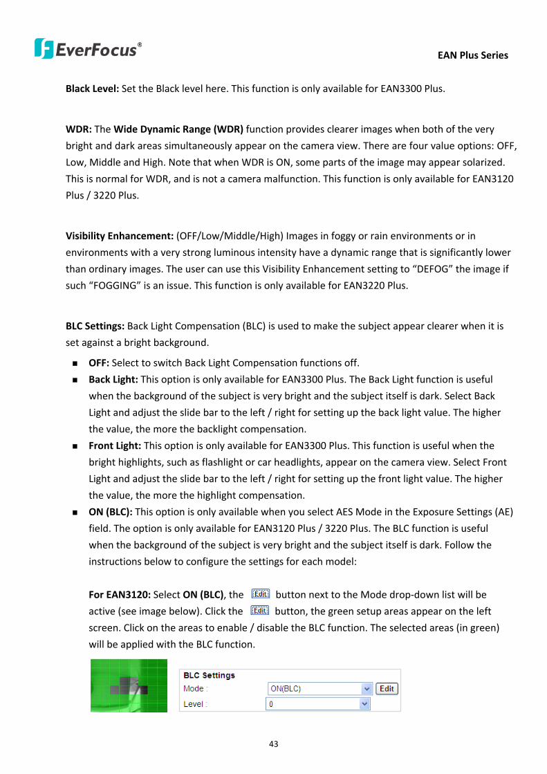
EAN Plus Series
43
Black Level Set the Black level here This function is only available for EAN3300 Plus
WDR The Wide Dynamic Range (WDR) function provides clearer images when both of the very
bright and dark areas simultaneously appear on the camera view There are four value options OFF
Low Middle and High Note that when WDR is ON some parts of the image may appear solarized
This is normal for WDR and is not a camera malfunction This function is only available for EAN3120
Plus 3220 Plus
Visibility Enhancement (OFFLowMiddleHigh) Images in foggy or rain environments or in
environments with a very strong luminous intensity have a dynamic range that is significantly lower
than ordinary images The user can use this Visibility Enhancement setting to ldquoDEFOGrdquo the image if
such ldquoFOGGINGrdquo is an issue This function is only available for EAN3220 Plus
BLC Settings Back Light Compensation (BLC) is used to make the subject appear clearer when it is
set against a bright background
OFF Select to switch Back Light Compensation functions off
Back Light This option is only available for EAN3300 Plus The Back Light function is useful
when the background of the subject is very bright and the subject itself is dark Select Back
Light and adjust the slide bar to the left right for setting up the back light value The higher
the value the more the backlight compensation
Front Light This option is only available for EAN3300 Plus This function is useful when the
bright highlights such as flashlight or car headlights appear on the camera view Select Front
Light and adjust the slide bar to the left right for setting up the front light value The higher
the value the more the highlight compensation
ON (BLC) This option is only available when you select AES Mode in the Exposure Settings (AE)
field The option is only available for EAN3120 Plus 3220 Plus The BLC function is useful
when the background of the subject is very bright and the subject itself is dark Follow the
instructions below to configure the settings for each model
For EAN3120 Select ON (BLC) the button next to the Mode drop-down list will be
active (see image below) Click the button the green setup areas appear on the left
screen Click on the areas to enable disable the BLC function The selected areas (in green)
will be applied with the BLC function
EAN Plus Series
44
For EAN3220
You can configure one area to apply the BLC function Select ON (BLC) the setup buttons
appears (see image below) Select Low Middle High from the BLC Gain drop-down list To
set up a BLC area click the Edit Area button and then click on the blue color tab to turn your
mouse cursor into a blue pen Move the cursor to the position on the right screen where you
want the BLC rectangle to start and then click Move your cursor to the position (diagonally
opposing corner) where you want the BLC rectangle to end and then click The blue area will
be applied with the BLC function
ON (HLC) This option is only available when you select AES Mode in the Exposure Settings (AE)
field The option is only available for EAN3120 Plus 3220 Plus This function is useful when
the bright highlights such as flashlight or car headlights appear on the camera view Follow
the instructions below to configure the settings for each model
For EAN3120 Select ON (HLC) and then select a level from the drop-down list The higher the
level the more the highlight compensation
For EAN3220
HLC Level Select a level for the HLC setting The higher the level the more the highlight
compensation
HLC Mode Select All Day Night mode to apply the HLC function
HLC Black Mask Select On Off to apply the black mask on the selected areas The
over-exposure portions within the selected areas will be applied with the black mask
Color Tabs You can set up four HLC areas with different colors To set up a HLC area click the
Edit Area button and then click on the color tab to turn your mouse cursor into a pen of that
color Move the cursor to the position on the right screen where you want the HLC rectangle
to start and then click Move your cursor to the position (diagonally opposing corner) where
you want the HLC rectangle to end and then click Select ON from the color tab drop-down list
The rectangular area with the selected color will be applied with the HLC function
EAN Plus Series
45
Back Light This option is only available for EAN3300 Plus The Back Light function is useful
when the background of the subject is very bright and the subject itself is dark Select Back
Light and adjust the slide bar to the left right for setting up the back light value The higher
the value the more the backlight compensation
Front Light This option is only available for EAN3300 Plus This function is useful when the
bright highlights such as flashlight or car headlights appear on the camera view Select Front
Light and adjust the slide bar to the left right for setting up the front light value The higher
the value the more the highlight compensation
Noise Reduction Settings This limits the amount of digital ldquovideo noiserdquo that is usually found in any
video stream and helps to reduce file size The higher the level the more the reduction
For EAN3120 Plus 3300 Plus
Select ON OFF to enable disable the Noise Reduction function Or select Auto to let the camera
automatically enable disable the Noise Reduction function Slide the Level bar to set up the level
The higher the level the more the reduction
For EAN3220 Plus
2D DNR Select ON to enable the 2D DNR function
3D DNR Select ON to enable the 3D DNR function You can further set up the following settings
3D Start AGC Set up the AGC level to automatically start the 3D NR function
3D End AGC Set up the AGC level to automatically stop the 3D NR function
3D Level Set up the 3D DNR level
Smart NR Select ON to enable the Smart NR function The 3D NR function will be
automatically turned on when a motion event occurs
EAN Plus Series
46
White Balance Settings Select the mode that delivers the best quality image for the camerarsquos light
environment There are five options Auto Manual Indoor Outdoor One Push
Auto Select to let the camera automatically adjust the White Balance In the Auto mode the
camera computes the white balance value output using color information from the entire
screen It outputs the proper value using the color temperature radiating from a black subject
based on a range of value from 3000 to 7500K
Manual Select to adjust the Red and Blue values yourself in the fields below this field
Indoor Select to use the default settings for indoor environments In the Indoor mode the
camera uses 3200K as the base value
Outdoor Select to use the default settings for outdoor environment In the Outdoor mode it
uses 5800K as the base value
One Push Select to enable the Push button next to the Mode drop-down field This will allow you to force the camera to readjust the white balance every time you push the Push
button The lens will hold the same focal position until the next trigger command is received
This function helps to prevent incorrect focusing in dark environments This function is only
available for EAN3120 Plus 3220 Plus
Manual Temperature Select to use the optimized Red and Blue settings You can also
optionally adjust the Manual Level below this field for setting up the color temperature The
higher the value the more the color temperature This function is only available for EAN3300
Plus
DayNight Settings
Auto Select to let the camera automatically switch to Night mode (black and white) when the
light levels fall to a specified level and back to Day mode (color) when the light levels rise to a
specified level
Day Select to keep the camera in Day mode (color) even in nighttime
Night Select to keep the camera in Night mode (black and white) even in daytime
IR Smart Settings Select ON and set up the level to enhance the image quality when the images are
over exposure This function is useful when the camera is in the Night mode This function is only
available for EAN3220 Plus
Saturation Set the saturation value This function is not available for EAN3220 Plus
Monitor Type Select a gamma value from Set 1 Set 2 or Set 3 This function is only available for
EAN3120 Plus
Negative Switch this setting ON to view a color negative version of the video image This is useful
at night or when viewing temperature-sensitive images
EAN Plus Series
47
Sharpness Settings Select the sharpness level of the image A low sharpness level will deliver a
softer less detailed image A high level will deliver a sharp highly detailed image Switch Resolution
Enhancement ON to enable the resolution enhancement function
Contrast Select the contrast level of the image
Suppress Function This function is only available for EAN3300 Plus
Aperture Compensation Suppression (OFFLowMiddleHigh) This setting can be activated to
suppress luminance noise when the AGC level increases
Chroma Suppression (OFFLowMiddleHigh) This setting can be activated to suppress
chrominance noise when the AGC level increases
Ygamma (gamma 22standardcontrast enhancehigh light range mode LHigh light range mode
H) Select the Ygamma value for the video quality of the monitor This function is only available for
EAN3300 Plus
Monitor Settings The user can use this field to optimize video quality for his or her specific type of
monitor ndash LCD or CRT This function is only available for EAN3220 Plus
Color Space Standard The options are YUV601 for SD and YUV709 for HD These define the color
space standard required to convert an RGB picture to a YUV picture Generally YUV601 is used for
Standard Definition (720P) devices and the YUV709 is used for High Definition (1080P) devices
Click Apply to save all changes Click Reset to cancel all changes
EAN Plus Series
48
744 ROI (Region of Interest)
The Region of Interest (ROI) function allows users to set up multiple regions within an image with
better quality and less distortion than the rest of the image You can also use this function
together with the Digital Zoom function on the Live View Page to get a better image result Up to
eight ROIs can be configured in the ROI settings page
To set up an ROI region
1 Select an ROI number from the ROI No drop-down list
2 Click the Add button the mouse cursor will turn into a pen when you move it over the live
image on the left
3 Move the cursor to the position where you want the ROI rectangle to start and then click
Move the cursor to the position (diagonally opposing corner) where you want the ROI
rectangle to end and then click
4 Slide the Quality bar to set up the quality value
5 Click the Apply button to apply the settings or click the Reset button to reset without saving
the settings
EAN Plus Series
49
745 Privacy Mask
The Privacy Mask can block out sensitive areas from view covering the areas with colored or black
and white boxes in both live view and recorded clips This feature is useful when usersrsquo donrsquot want
the sensitive information visible Up to four Privacy Masks can be configured
【Privacy Mask Color Settings】The Modes vary among camera models
Mode Click Color to make the masks appear as colored rectangles on the screen Click BW to
make the masks appear as gray rectangles on the screen Click Mosaic to make the masks appear
as mosaic-effect rectangles on the screen
Level Select the color of the masks if you selected Color Mode Select the level of grayness of the
masks if you selected BW Mode Select the level of smallmiddlelarge if you selected Mosaic
Mode
Click Apply to apply the settings or click Reset to reset without saving the settings
Color Tabs Click on a color tab to turn your mouse cursor into a pen of that color
You can now create a block of that color on the video screen Move your cursor to the position
where you want your mask rectangle to start and then click Move your cursor to the position
(diagonally opposing corner) where you want your mask rectangle to end and then click The
rectangular area with the selected color will appear The live image will display the rectangular
area with the color you selected If you want to create another mask use one of the other three
colors Each color denotes a different mask area Only one block per color is allowed As the
number of colors suggests you can configure up to four blocks
EAN Plus Series
50
Select All Click to turn the whole screen into a mask area
Clear All Click to delete all configured mask blocks
Eraser Click to turn the mouse cursor into an eraser to delete any block you click on
Area Shows the color and number of the block
Enable Check this box to enable the related mask block
Click Apply to apply the settings or click Reset to reset without saving the settings
EAN Plus Series
51
75 Audio
The EAN Plus series IP camera can transmit audio to your computer if you have connected an external
microphone to its audio Input cable It can also receive audio input from you and transmit it via an
external speaker if you have connected such a speaker to its audio Output cable
Check the Enable Audio box to enable the camerarsquos audio function The camera will now act as a
digital bridge (via the IP network) between any connected audio input device and any connected
audio device
Adjust the Audio Input Volume if you have external audio input devices (microphones) connected to
the camera and if there are problems with the sound input being too low or high
Click Apply to save all settings or click Reset to cancel
EAN Plus Series
52
76 User
761 User Information
The system administrator can create up to ten user accounts on this page
To set up a user account
1 Highlight a user account and click the Modify button The following dialog box appears
2 Type the account name account description and password for the account Type the password
again in the Confirm field
3 Select an authority level for the user account from the Authority drop-down list
bull Supervisor Administrator The only difference between a supervisor and administrator is
that a supervisor can edit an administratorrsquos account and password but an administrator
cannot edit the supervisorrsquos account and password Multiple administrators can be
configured but there can be only one supervisor The supervisor and administrators all
have unrestricted access to the Settings submenus and can determine the registration of
all other users
EAN Plus Series
53
bull User A user can view the Live View page and view the system network video and audio
information A user can only adjust the User Config page settings The user does not have
access to the User Event and System pages
bull Guest The lowest level of access which only allows the user access to the Live View page
4 Select Active or Disable from the Status drop-down list to active or disable the user account
5 Click On in the SD Card Playback field to allow the user to access the SD card playback
function
6 Click OK
7 Click Apply to save all the settings
EAN Plus Series
54
762 IP Address Filter
Use this page to specify IP addresses that are not allowed to access this camera By default any IP
address can access the camera
Note The Allowed List addresses only become relevant when the Denied List contains a network
or range and the supervisor wants to allow one or more IP addresses within that excluded range
or network In such a scenario the user would enter the excluded range or network in the
Denied List and enter the exceptions in the Allowed List
To set up the IP Address Filter
1 Select Denied List Click the Add button the following dialog box appears
2 Select an IP type from the IP Type drop-down list
3 Select a network rule from the Rule drop-down list type the IP address and click OK
Single Type a single IP address in the IP Address field below
Network Type the IP address and subnet mask in the field below
Range Type a range for the IP addresses
4 If you have set up an IP range in Step 3 you can optionally set up the Allowed List to allow one
or more IP addresses within the setup IP range to access the IP camera
5 Click Apply
EAN Plus Series
55
77 Event
You can set up the Motion Detection event Tamper Detection event or the Alarm IO to automatically
notify the users when an event occurs or an alarm is triggered You can also set up a schedule to
automatically record the videos when an event occurs or an alarm is triggered
771 Event Settings
You can create a total of ten event or alarm settings page in the Event List
【Event List】
Click the Add button and the following Event Configuration Window appears
EAN Plus Series
56
Enter Event Name Type an event name
Event Triggered by Select an event or alarm type for the to-be-specified-below reactions
Alarm Input Select this if you want a reaction trigger coming from any external connected sensor
to activate a to-be-specified-below reactions via the camera system Make sure that a suitable
device is actually connected to the alarm input relay
Manual Trigger Select this option if you want to manually trigger the alarm by clicking the Trigger
Event button on the Live View Page
Motion Detection Select this option if you want motion in a specified part of the camerarsquos viewing
rectangle (the screen image) to trigger the to-be-specified-below reactions
Tampering Detection Select this option if you want the camerarsquos tampering detection sensor to
trigger the to-be-specified-below reactions
Schedule Recording Select this option if you want the Schedule Recording periods configured in
the recording schedule (the Settings gt Event gt Schedule page) to activate this event In this
scenario a preconfigured event reaction like a log entry will list the start and end times of each
period Actual recording will only be triggered if the event is preconfigured to do so
Enable This Event Select to activate the event
Enable Re-trigger Click to set a minimum time after the event is triggered before the event
can be triggered again
Enable Pre-trigger Buffer Click if you want the Event reaction (as selected in the ldquoNotification
Overrdquo field below) to be the activation of the video recording function and if you want the
recording to include the video feed from the time period (configurable on the previous ldquoEvent
Settingsrdquo page) just before the Event trigger occurred
Enable Post-trigger Buffer Click if you want the Event reaction (as selected in the Notification
Over field) to be the activation of the video recording function and if you want the recording
to include the video feed from a time period (configurable on the Event Settings page) just
after the Event trigger occurred
Motion Area Select a setup motion detection area from the drop down list Note this
function only becomes relevant after the Motion Detection areas have been set up (see 772
Motion Detection)
Notification Over Select the desired notification types form the following items
Log Click if you want the camera to list the eventrsquos details in its log if the event is triggered
Trigger Alarm Output Click if you want the camera to relay the event reaction to a device
attached to the alarm relay output wire and then set up the alarm output duration time
EAN Plus Series
57
Send Mail Notification Click if you want the camera to send an Event notification email to the
email address entered in the Set SMTP Server(email) field of the Network gt SMTPFTP page if
the Event occurs (see 733 SMTP FTP)
Upload to FTP Click if you want the camera to upload recorded footage to the FTP server
entered in the Set SMTP Server(email) field of the Network gt SMTPFTP page if the Event
occurs (see 733 SMTP FTP)
Record to SD Card Click if you want the camera to start recording its video feed (when the
event occurs) on an on-camera SD Card (if such a card has been inserted)
Note The recording will only be as long as the combined Pre- and Post-trigger Buffers so
make sure you enable at least one of these buffers especially the Post-trigger Buffer
Record to PC Check this box if you want the camera to start recording its video feed (when
the event occurs) on the same folder on the same PC as configured on the User Config gt
RecordingSnapshot page (if such a folder has been enabled and configured)
Note The recording will only be as long as the combined Pre- and Post-trigger Buffers (and
for as long as the event trigger is happening ndash eg a motion is detected) so make sure you
enable at least one of these buffers especially the Post-trigger Buffer
Network Alarm Check this box if you want the camera to send a network alarm signal (when
the event occurs) to the CMS servers configured on the Network gt Network Alarm page (see
736 Network Alarm)
Click OK to save all settings or click Cancel to cancel
【PrePost Trigger Settings】
Pre-trigger Buffer Select the duration for the buffer This will determine the amount of footage
(length of time) before the event trigger moment that will be included in an event-triggered video
recording if that buffer and video recording has been enabled in the Event Configuration Window
Post-trigger Buffer Select the duration for the buffer This will determine the amount of footage
(length of time) after the event trigger moment that will be included in an event-triggered video
recording if that buffer and video recording has been enabled in the Event Configuration Window
Click Apply to save all settings or click Reset to cancel
EAN Plus Series
58
772 Motion Detection
Use this page to configure up to four areas in which motion will be detected When a motion is
detected by the camera the motion detection icon will appear at the top right of the
Live page to alert the user This function can also be linked with correctly configured Events to
trigger Event reactions like the activation of video recording periods snapshots alarms etc
Color Tabs Click on a color tab to turn your mouse cursor into a pen of that color
You can now create a block of that color on the video screen Move your cursor to the position
where you want your detection rectangle to start and then click Move your cursor to the position
(diagonally opposing corner) where you want your detection rectangle to end and then click The
rectangular area with the selected color will appear This block will be an area inside which the
camera will detect motion If you want to create another detection area use one of the other three
palette colors Each color denotes a different detection area Only one block per color is allowed As
the number of colors suggests you can configure up to four blocks
Select All Click to turn the whole screen into a motion detection area
Clear All Click to delete all configured motion detection blocks
Eraser Click to turn your mouse cursor into an eraser to delete any block you click on
Area Shows the color and numberID of the block
Enable Check this box to enable the related motion detection block
Sensitivity Set the sensitivity of the motion detection sensor function
Click Apply to save all settings or click Reset to cancel
EAN Plus Series
59
773 Tamper Detection
Use this page to set the number of seconds that an alarm signal will be active if the device is
physically tampered (moved covered up or out of focus
774 Alarm IO
Use this page to set the type of trigger input and the type of output contact for the camerarsquos alarm
channel
EAN Plus Series
60
775 Schedule
Use this page to configure a schedule for periods during which the camera should deactivate all
user-activated Events (gray Deselect periods) or when the camera should deactivate all
user-activated Events except Schedule Recording (SR) events (blue Schedule Recording-only
periods) or when the camera should deactivate only SR events (red Event Recording-only periods)
or when it should enable all activated Events (yellow periods)
Event Recording Click this button to make every hour block you click on red A red block represents
an Event Recording-only block which represents an hour when the camera will deactivate all
preconfigured activated Schedule Recording events and keep all the other activated events active
Schedule Recording Click this button to make every hour block you click on blue A blue block
represents a Schedule Recording-only block which represents an hour when the camera will
deactivate all other preconfigured activated events and keep only the preconfigured activated
Schedule Recording events active
Event + Schedule Click this button to make every hour block you click on yellow A yellow block
represents an hour in which all activated events including Schedule Recording events will be
active
Deselect Click this button to make every hour block become grey A grey block represents an hour
in which all activated events including Schedule Recording events will be inactive
Click Apply to save all settings or click Reset to cancel
EAN Plus Series
61
78 System
You can set up the systemrsquos time and SD card settings and to do maintenance and reset actions like
reboots and upgrades
781 DateTime
【Machine Name Settings】If required enter a new name for the machine This name will be visible
in the Machine Name field of the IP Utility software which is included in the software CD
【Set Time Zone】Set the time zone of the camerarsquos location
【Set DateTime Manually】Set the datetime here if you wonrsquot be using an NTP server to update the
datetime (see below)
【Set DateTime Sync】Enter the Network Time Protocol server if applicable The camerarsquos time will
be automatically adjusted by synchronizing with the NTP server
Click Apply to save all settings or click Reset to cancel
EAN Plus Series
62
782 Daylight Saving
Click Enable Daylight Saving to enable this schedule and select the dates when the regionrsquos
daylight saving period begins and ends Click Apply to save all settings or click Reset to cancel
783 SD Card
Use this page to prepare the system for safely removing the SD Card from its slot
【Setup SD Card】
Notification Select the percentage of storage space that should be left on the card before the
camera notifies you of the impending storage shortage or overwrite
Event Recording Select if you want Event Recording only FTP Backup only or both
Overwrite Click ON if you want the card to start writing over recorded footage when its memory is
full Click OFF if you want the card to stop recording new footage when its memory is full
【SD Card Utility】
Capacity This shows you how much card memory has been used and how much memory capacity
remains on the card
Remove Click this button before removing the card from the system
Format Click this button to format the card All data saved on the SD card will be removed if the
card is formatted
EAN Plus Series
63
784 Maintenance
【Maintenance Server】
Reboot Click this button to reboot the unit without changing any of the settings Use this function if
the unit is not behaving as expected
Restore Click this button to restart and reset most of the current settings to their factory default
values The only settings that will not be changed to default are
bull IP settings
bull DDNS settings
Default The Default button should be used with caution Pressing this button will return all of the
cameras settings including the IP address to the factory default values The camera will then have
to be reconfigured
【SaveLoad Configuration Server】
Save To make a backup file of the machinersquos current configurations press Save to save all the
configurations to a config file This will enable the user to reload these configuration settings if the
settings are changed and there is unexpected behavior
Load To load a previously saved configuration press the Browse button to locate the saved config
file (see above) and then click the Load button The systemrsquos settings will be restored to the saved
configuration
EAN Plus Series
64
【SaveLoad Video Configuration Server】
Save To make a backup file of the machinersquos video configurations press Save to save the video
configurations to a config file This will enable the user to reload these configuration settings if the
settings are changed and there is unexpected behavior
Load To load a previously saved video configuration press the Browse button to locate the saved
config file (see above) and then click the Load button The systemrsquos settings will be restored to the
saved video configuration
【Upgrade Firmware】Click the Browse button to find a previously prepared firmware upgrade file
Click Upgrade to install the new firmware
Note
1 Do not disconnect power to the unit during the upgrade sequence The unit will reboot
automatically after the upgrade has completed (1-5 minutes)
2 During the upgrade process all event recording actions will be stopped Event recording
actions will resume after the camera is rebooted
3 If the ldquoFile Error Please re-loginrdquo warning message appears when upgrading the firmware
please try the following instructions
a Go to Internet Explorer gt Tools gt Internet Option gt Security gt Custom
b Find and enable the Include local directory path when uploading files to a server
EAN Plus Series
65
8 Upgrading Firmware Using IP Utility
You can upgrade the Firmware using the IP Utility software included in the software CD
1 Install and then start the IPU program The following dialog box appears
2 Click Find Devices to search the cameras connected in the LAN The default network values of the
cameras will be displayed By default the network protocol of the camera is DHCP
3 Select a camera and click LoginMulti Login to log in the camera
4 Type the user ID and password Click OK
Note
1 The default user ID is user1 and the default password is 11111111
2 If you select more than one camera that has the same user ID password you will be able
to log in several cameras at once
EAN Plus Series
66
5 Highlight the camera and then click Upgrade Firmware A browsing window appears
6 Select the firmware file (evb) and then click Open The IP Utility will automatically upgrade the
firmware
The camera will reboot once the update is complete Click Find Devices the new firmware version
should be displayed in the last part of the Machine Name
EAN Plus Series
67
9 Specifications
Model EAN3120 Plus EAN3220 Plus EAN3300 Plus
Camera
Image Sensor 13 Panasonic CMOS 128 Sony CMOS
Megapixel 13 MP 2 MP 3 MP
Picture Elements (H x V) 1280 x 1024 1944 x 1092 2048 x 1536
Min Illuminations 003 Lux at F14
Electronic Shutter (Sec) 85 ~ 160000 2 ~ 150000 1 ~ 110000
Scanning System NTSC PAL
WDR Yes Yes No
BLC Yes
Gain Control Yes
White Balance Yes
Lens
Mounting Type C CS
Day Night Yes (with removable auto IR-cut filter)
IRIS Control DC Electrical IRIS Lens IRIS
Video
Video Compression H264 MJPEG
Resolution
NTSC
2048 x 1536 1920 x 1200 (for EAN3300 Plus only)
1920 x 1080 (for EAN3300 Plus 3220 Plus only)
1280 x 1024 1280 x 720 1024 x 768 720 x 480 704 x 480 640 x 480
352 x 240 320 x 240 160 x 120
PAL
2048 x 1536 1920 x 1200 (for EAN3300 Plus only)
1920 x 1080 (for EAN3300 Plus 3220 Plus only)
1280 x 1024 1280 x 720 1024 x 768 720 x 576 704 x 576 640 x 480
352 x 288 320 x 240 160 x 120
Frame Rate 30 fps at 1280 x 1024 30 fps at 1920 x 1080 15 fps at 2048 x 1536
Audio
Audio Streaming Two-way audio
Audio Compression G711
EAN Plus Series
68
Network
Interface 10 100 Base-T Ethernet RJ-45 socket
Supported Protocols
TCPIP IPV6 UDP ICMP DHCP NTP DNS DDNS SMTP SNMP FTP
HTTP HTTPs PPPoE UPnP Bonjour RTP RTSP RTCP IGMP ARP ONVIF
PSIA
Connector
Power DC female port PoE
Ethernet RJ-45
Audio 1 In (phone jack for microphone)
1 Out (phone jack for Speaker)
Alarm IO Terminal IO wires
Local Storage Micro SD SDHC memory card slot
TV-Out BNC socket composite 1 V p-p 75 Ω
General
Power Source DC 12V PoE (IEEE8023af)
Power Consumption
(IR LEDs On)
5W (DC 12V)
621W (PoE)
5W (DC 12V)
522W (PoE)
5W (DC 12V)
536W (PoE)
Operating Temperature 0degC ~ +50degC 32degF ~ +122degF
Humidity 20 to 80 (no condensation)
Safety CE FCC
Dimensions (L x W x H) 117 x 56 x 68 mm 46 x 22 x 27 in
Weight 410 g 09 lb
EverFocus Electronics Corp EverFocus Taiwan 12F No79 Sec 1 Shin-Tai Wu Road Hsi-Chih Taipei Taiwan TEL +886 2 2698 2334 FAX +886 2 2698 2380 wwweverfocuscomtw marketingeverfocuscomtw
EverFocus Europe - Germany Albert-Einstein-Strasse 1 D-46446 Emmerich Germany TEL +49 2822 93940 FAX +49 2822 939495 wwweverfocusde infoeverfocusde
EverFocus China - Beijing Room 609 Technology Trade Building Shangdi Information Industry Base Haidian District Beijing 100085 China TEL +86 10 6297 3336~39 FAX +86 10 6297 1423 wwweverfocuscomcn marketingeverfocuscomcn
EverFocus China - Shenzhen 4F No 2 D4 Building Wan Yelong Industrial Park Tangtou Road Shiyan Baoan Shenzhen Guangdong 518101 China TEL +86 755 2765 1313 FAX +86 755 2765 0337 wwweverfocuscomcn marketingeverfocuscomcn
EverFocus USA - California 1801 Highland Avenue Unit A Duarte CA 91010 USA TEL +1 626 844 8888 FAX +1 626 844 8838 wwweverfocuscom saleseverfocuscom
EverFocus USA - New York 415 Oser Avenue Unit S Hauppauge NY 11788 USA TEL +1 631 436 5070 FAX +1 631 436 5027 wwweverfocuscom saleseverfocuscom
EverFocus Japan 5F Kinshicho City Building 2-13-4 Koto-BashiSumida-Ku Tokyo 130-0022 Japan TEL +81 3 5625 8188 FAX +81 3 5625 8189 wwweverfocuscojp infoeverfocuscojp
EverFocus Europe - UK Unit 12 Spitfire Business Park Hawker Road Croydon Surrey CR0 4WD UK TEL +44 20 8649 9757 +44 845 430 9999 FAX +44 20 8649 9907 wwweverfocusukcouk salesukeverfocuscom
EverFocus India Suite 803 Housefin Bhavan C-21 Bandra Kurla Complex Bandra (East) Mumbai 400051 India TEL +91 22 6128 8700 FAX +91 22 6128 8705 wwweverfocusin saleseverfocusin
PN 4605PQ3120B010A-VerC
Your EverFocus product is designed and manufactured with high quality materials and components which can be recycled and reused This symbol means that electrical and electronic equipment at their end-of-life should be disposed of separately from your household waste Please dispose of this equipment at your local community waste collectionrecycling centre In the European Union there are separate collection systems for used electrical and electronic product Please help us to conserve the environment we live in
Ihr EverFocus Produkt wurde entwickelt und hergestellt mit qualitativ hochwertigen Materialien und Komponenten die recycelt und wieder verwendet werden koumlnnen Dieses Symbol bedeutet dass elektrische und elektronische Geraumlte am Ende ihrer Nutzungsdauer vom Hausmuumlll getrennt entsorgt werden sollen Bitte entsorgen Sie dieses Geraumlt bei Ihrer oumlrtlichen kommunalen Sammelstelle oder im Recycling Centre Helfen Sie uns bitte die Umwelt zu erhalten in der wir leben
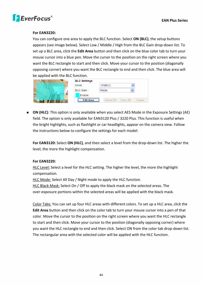
EAN Plus Series
44
For EAN3220
You can configure one area to apply the BLC function Select ON (BLC) the setup buttons
appears (see image below) Select Low Middle High from the BLC Gain drop-down list To
set up a BLC area click the Edit Area button and then click on the blue color tab to turn your
mouse cursor into a blue pen Move the cursor to the position on the right screen where you
want the BLC rectangle to start and then click Move your cursor to the position (diagonally
opposing corner) where you want the BLC rectangle to end and then click The blue area will
be applied with the BLC function
ON (HLC) This option is only available when you select AES Mode in the Exposure Settings (AE)
field The option is only available for EAN3120 Plus 3220 Plus This function is useful when
the bright highlights such as flashlight or car headlights appear on the camera view Follow
the instructions below to configure the settings for each model
For EAN3120 Select ON (HLC) and then select a level from the drop-down list The higher the
level the more the highlight compensation
For EAN3220
HLC Level Select a level for the HLC setting The higher the level the more the highlight
compensation
HLC Mode Select All Day Night mode to apply the HLC function
HLC Black Mask Select On Off to apply the black mask on the selected areas The
over-exposure portions within the selected areas will be applied with the black mask
Color Tabs You can set up four HLC areas with different colors To set up a HLC area click the
Edit Area button and then click on the color tab to turn your mouse cursor into a pen of that
color Move the cursor to the position on the right screen where you want the HLC rectangle
to start and then click Move your cursor to the position (diagonally opposing corner) where
you want the HLC rectangle to end and then click Select ON from the color tab drop-down list
The rectangular area with the selected color will be applied with the HLC function
EAN Plus Series
45
Back Light This option is only available for EAN3300 Plus The Back Light function is useful
when the background of the subject is very bright and the subject itself is dark Select Back
Light and adjust the slide bar to the left right for setting up the back light value The higher
the value the more the backlight compensation
Front Light This option is only available for EAN3300 Plus This function is useful when the
bright highlights such as flashlight or car headlights appear on the camera view Select Front
Light and adjust the slide bar to the left right for setting up the front light value The higher
the value the more the highlight compensation
Noise Reduction Settings This limits the amount of digital ldquovideo noiserdquo that is usually found in any
video stream and helps to reduce file size The higher the level the more the reduction
For EAN3120 Plus 3300 Plus
Select ON OFF to enable disable the Noise Reduction function Or select Auto to let the camera
automatically enable disable the Noise Reduction function Slide the Level bar to set up the level
The higher the level the more the reduction
For EAN3220 Plus
2D DNR Select ON to enable the 2D DNR function
3D DNR Select ON to enable the 3D DNR function You can further set up the following settings
3D Start AGC Set up the AGC level to automatically start the 3D NR function
3D End AGC Set up the AGC level to automatically stop the 3D NR function
3D Level Set up the 3D DNR level
Smart NR Select ON to enable the Smart NR function The 3D NR function will be
automatically turned on when a motion event occurs
EAN Plus Series
46
White Balance Settings Select the mode that delivers the best quality image for the camerarsquos light
environment There are five options Auto Manual Indoor Outdoor One Push
Auto Select to let the camera automatically adjust the White Balance In the Auto mode the
camera computes the white balance value output using color information from the entire
screen It outputs the proper value using the color temperature radiating from a black subject
based on a range of value from 3000 to 7500K
Manual Select to adjust the Red and Blue values yourself in the fields below this field
Indoor Select to use the default settings for indoor environments In the Indoor mode the
camera uses 3200K as the base value
Outdoor Select to use the default settings for outdoor environment In the Outdoor mode it
uses 5800K as the base value
One Push Select to enable the Push button next to the Mode drop-down field This will allow you to force the camera to readjust the white balance every time you push the Push
button The lens will hold the same focal position until the next trigger command is received
This function helps to prevent incorrect focusing in dark environments This function is only
available for EAN3120 Plus 3220 Plus
Manual Temperature Select to use the optimized Red and Blue settings You can also
optionally adjust the Manual Level below this field for setting up the color temperature The
higher the value the more the color temperature This function is only available for EAN3300
Plus
DayNight Settings
Auto Select to let the camera automatically switch to Night mode (black and white) when the
light levels fall to a specified level and back to Day mode (color) when the light levels rise to a
specified level
Day Select to keep the camera in Day mode (color) even in nighttime
Night Select to keep the camera in Night mode (black and white) even in daytime
IR Smart Settings Select ON and set up the level to enhance the image quality when the images are
over exposure This function is useful when the camera is in the Night mode This function is only
available for EAN3220 Plus
Saturation Set the saturation value This function is not available for EAN3220 Plus
Monitor Type Select a gamma value from Set 1 Set 2 or Set 3 This function is only available for
EAN3120 Plus
Negative Switch this setting ON to view a color negative version of the video image This is useful
at night or when viewing temperature-sensitive images
EAN Plus Series
47
Sharpness Settings Select the sharpness level of the image A low sharpness level will deliver a
softer less detailed image A high level will deliver a sharp highly detailed image Switch Resolution
Enhancement ON to enable the resolution enhancement function
Contrast Select the contrast level of the image
Suppress Function This function is only available for EAN3300 Plus
Aperture Compensation Suppression (OFFLowMiddleHigh) This setting can be activated to
suppress luminance noise when the AGC level increases
Chroma Suppression (OFFLowMiddleHigh) This setting can be activated to suppress
chrominance noise when the AGC level increases
Ygamma (gamma 22standardcontrast enhancehigh light range mode LHigh light range mode
H) Select the Ygamma value for the video quality of the monitor This function is only available for
EAN3300 Plus
Monitor Settings The user can use this field to optimize video quality for his or her specific type of
monitor ndash LCD or CRT This function is only available for EAN3220 Plus
Color Space Standard The options are YUV601 for SD and YUV709 for HD These define the color
space standard required to convert an RGB picture to a YUV picture Generally YUV601 is used for
Standard Definition (720P) devices and the YUV709 is used for High Definition (1080P) devices
Click Apply to save all changes Click Reset to cancel all changes
EAN Plus Series
48
744 ROI (Region of Interest)
The Region of Interest (ROI) function allows users to set up multiple regions within an image with
better quality and less distortion than the rest of the image You can also use this function
together with the Digital Zoom function on the Live View Page to get a better image result Up to
eight ROIs can be configured in the ROI settings page
To set up an ROI region
1 Select an ROI number from the ROI No drop-down list
2 Click the Add button the mouse cursor will turn into a pen when you move it over the live
image on the left
3 Move the cursor to the position where you want the ROI rectangle to start and then click
Move the cursor to the position (diagonally opposing corner) where you want the ROI
rectangle to end and then click
4 Slide the Quality bar to set up the quality value
5 Click the Apply button to apply the settings or click the Reset button to reset without saving
the settings
EAN Plus Series
49
745 Privacy Mask
The Privacy Mask can block out sensitive areas from view covering the areas with colored or black
and white boxes in both live view and recorded clips This feature is useful when usersrsquo donrsquot want
the sensitive information visible Up to four Privacy Masks can be configured
【Privacy Mask Color Settings】The Modes vary among camera models
Mode Click Color to make the masks appear as colored rectangles on the screen Click BW to
make the masks appear as gray rectangles on the screen Click Mosaic to make the masks appear
as mosaic-effect rectangles on the screen
Level Select the color of the masks if you selected Color Mode Select the level of grayness of the
masks if you selected BW Mode Select the level of smallmiddlelarge if you selected Mosaic
Mode
Click Apply to apply the settings or click Reset to reset without saving the settings
Color Tabs Click on a color tab to turn your mouse cursor into a pen of that color
You can now create a block of that color on the video screen Move your cursor to the position
where you want your mask rectangle to start and then click Move your cursor to the position
(diagonally opposing corner) where you want your mask rectangle to end and then click The
rectangular area with the selected color will appear The live image will display the rectangular
area with the color you selected If you want to create another mask use one of the other three
colors Each color denotes a different mask area Only one block per color is allowed As the
number of colors suggests you can configure up to four blocks
EAN Plus Series
50
Select All Click to turn the whole screen into a mask area
Clear All Click to delete all configured mask blocks
Eraser Click to turn the mouse cursor into an eraser to delete any block you click on
Area Shows the color and number of the block
Enable Check this box to enable the related mask block
Click Apply to apply the settings or click Reset to reset without saving the settings
EAN Plus Series
51
75 Audio
The EAN Plus series IP camera can transmit audio to your computer if you have connected an external
microphone to its audio Input cable It can also receive audio input from you and transmit it via an
external speaker if you have connected such a speaker to its audio Output cable
Check the Enable Audio box to enable the camerarsquos audio function The camera will now act as a
digital bridge (via the IP network) between any connected audio input device and any connected
audio device
Adjust the Audio Input Volume if you have external audio input devices (microphones) connected to
the camera and if there are problems with the sound input being too low or high
Click Apply to save all settings or click Reset to cancel
EAN Plus Series
52
76 User
761 User Information
The system administrator can create up to ten user accounts on this page
To set up a user account
1 Highlight a user account and click the Modify button The following dialog box appears
2 Type the account name account description and password for the account Type the password
again in the Confirm field
3 Select an authority level for the user account from the Authority drop-down list
bull Supervisor Administrator The only difference between a supervisor and administrator is
that a supervisor can edit an administratorrsquos account and password but an administrator
cannot edit the supervisorrsquos account and password Multiple administrators can be
configured but there can be only one supervisor The supervisor and administrators all
have unrestricted access to the Settings submenus and can determine the registration of
all other users
EAN Plus Series
53
bull User A user can view the Live View page and view the system network video and audio
information A user can only adjust the User Config page settings The user does not have
access to the User Event and System pages
bull Guest The lowest level of access which only allows the user access to the Live View page
4 Select Active or Disable from the Status drop-down list to active or disable the user account
5 Click On in the SD Card Playback field to allow the user to access the SD card playback
function
6 Click OK
7 Click Apply to save all the settings
EAN Plus Series
54
762 IP Address Filter
Use this page to specify IP addresses that are not allowed to access this camera By default any IP
address can access the camera
Note The Allowed List addresses only become relevant when the Denied List contains a network
or range and the supervisor wants to allow one or more IP addresses within that excluded range
or network In such a scenario the user would enter the excluded range or network in the
Denied List and enter the exceptions in the Allowed List
To set up the IP Address Filter
1 Select Denied List Click the Add button the following dialog box appears
2 Select an IP type from the IP Type drop-down list
3 Select a network rule from the Rule drop-down list type the IP address and click OK
Single Type a single IP address in the IP Address field below
Network Type the IP address and subnet mask in the field below
Range Type a range for the IP addresses
4 If you have set up an IP range in Step 3 you can optionally set up the Allowed List to allow one
or more IP addresses within the setup IP range to access the IP camera
5 Click Apply
EAN Plus Series
55
77 Event
You can set up the Motion Detection event Tamper Detection event or the Alarm IO to automatically
notify the users when an event occurs or an alarm is triggered You can also set up a schedule to
automatically record the videos when an event occurs or an alarm is triggered
771 Event Settings
You can create a total of ten event or alarm settings page in the Event List
【Event List】
Click the Add button and the following Event Configuration Window appears
EAN Plus Series
56
Enter Event Name Type an event name
Event Triggered by Select an event or alarm type for the to-be-specified-below reactions
Alarm Input Select this if you want a reaction trigger coming from any external connected sensor
to activate a to-be-specified-below reactions via the camera system Make sure that a suitable
device is actually connected to the alarm input relay
Manual Trigger Select this option if you want to manually trigger the alarm by clicking the Trigger
Event button on the Live View Page
Motion Detection Select this option if you want motion in a specified part of the camerarsquos viewing
rectangle (the screen image) to trigger the to-be-specified-below reactions
Tampering Detection Select this option if you want the camerarsquos tampering detection sensor to
trigger the to-be-specified-below reactions
Schedule Recording Select this option if you want the Schedule Recording periods configured in
the recording schedule (the Settings gt Event gt Schedule page) to activate this event In this
scenario a preconfigured event reaction like a log entry will list the start and end times of each
period Actual recording will only be triggered if the event is preconfigured to do so
Enable This Event Select to activate the event
Enable Re-trigger Click to set a minimum time after the event is triggered before the event
can be triggered again
Enable Pre-trigger Buffer Click if you want the Event reaction (as selected in the ldquoNotification
Overrdquo field below) to be the activation of the video recording function and if you want the
recording to include the video feed from the time period (configurable on the previous ldquoEvent
Settingsrdquo page) just before the Event trigger occurred
Enable Post-trigger Buffer Click if you want the Event reaction (as selected in the Notification
Over field) to be the activation of the video recording function and if you want the recording
to include the video feed from a time period (configurable on the Event Settings page) just
after the Event trigger occurred
Motion Area Select a setup motion detection area from the drop down list Note this
function only becomes relevant after the Motion Detection areas have been set up (see 772
Motion Detection)
Notification Over Select the desired notification types form the following items
Log Click if you want the camera to list the eventrsquos details in its log if the event is triggered
Trigger Alarm Output Click if you want the camera to relay the event reaction to a device
attached to the alarm relay output wire and then set up the alarm output duration time
EAN Plus Series
57
Send Mail Notification Click if you want the camera to send an Event notification email to the
email address entered in the Set SMTP Server(email) field of the Network gt SMTPFTP page if
the Event occurs (see 733 SMTP FTP)
Upload to FTP Click if you want the camera to upload recorded footage to the FTP server
entered in the Set SMTP Server(email) field of the Network gt SMTPFTP page if the Event
occurs (see 733 SMTP FTP)
Record to SD Card Click if you want the camera to start recording its video feed (when the
event occurs) on an on-camera SD Card (if such a card has been inserted)
Note The recording will only be as long as the combined Pre- and Post-trigger Buffers so
make sure you enable at least one of these buffers especially the Post-trigger Buffer
Record to PC Check this box if you want the camera to start recording its video feed (when
the event occurs) on the same folder on the same PC as configured on the User Config gt
RecordingSnapshot page (if such a folder has been enabled and configured)
Note The recording will only be as long as the combined Pre- and Post-trigger Buffers (and
for as long as the event trigger is happening ndash eg a motion is detected) so make sure you
enable at least one of these buffers especially the Post-trigger Buffer
Network Alarm Check this box if you want the camera to send a network alarm signal (when
the event occurs) to the CMS servers configured on the Network gt Network Alarm page (see
736 Network Alarm)
Click OK to save all settings or click Cancel to cancel
【PrePost Trigger Settings】
Pre-trigger Buffer Select the duration for the buffer This will determine the amount of footage
(length of time) before the event trigger moment that will be included in an event-triggered video
recording if that buffer and video recording has been enabled in the Event Configuration Window
Post-trigger Buffer Select the duration for the buffer This will determine the amount of footage
(length of time) after the event trigger moment that will be included in an event-triggered video
recording if that buffer and video recording has been enabled in the Event Configuration Window
Click Apply to save all settings or click Reset to cancel
EAN Plus Series
58
772 Motion Detection
Use this page to configure up to four areas in which motion will be detected When a motion is
detected by the camera the motion detection icon will appear at the top right of the
Live page to alert the user This function can also be linked with correctly configured Events to
trigger Event reactions like the activation of video recording periods snapshots alarms etc
Color Tabs Click on a color tab to turn your mouse cursor into a pen of that color
You can now create a block of that color on the video screen Move your cursor to the position
where you want your detection rectangle to start and then click Move your cursor to the position
(diagonally opposing corner) where you want your detection rectangle to end and then click The
rectangular area with the selected color will appear This block will be an area inside which the
camera will detect motion If you want to create another detection area use one of the other three
palette colors Each color denotes a different detection area Only one block per color is allowed As
the number of colors suggests you can configure up to four blocks
Select All Click to turn the whole screen into a motion detection area
Clear All Click to delete all configured motion detection blocks
Eraser Click to turn your mouse cursor into an eraser to delete any block you click on
Area Shows the color and numberID of the block
Enable Check this box to enable the related motion detection block
Sensitivity Set the sensitivity of the motion detection sensor function
Click Apply to save all settings or click Reset to cancel
EAN Plus Series
59
773 Tamper Detection
Use this page to set the number of seconds that an alarm signal will be active if the device is
physically tampered (moved covered up or out of focus
774 Alarm IO
Use this page to set the type of trigger input and the type of output contact for the camerarsquos alarm
channel
EAN Plus Series
60
775 Schedule
Use this page to configure a schedule for periods during which the camera should deactivate all
user-activated Events (gray Deselect periods) or when the camera should deactivate all
user-activated Events except Schedule Recording (SR) events (blue Schedule Recording-only
periods) or when the camera should deactivate only SR events (red Event Recording-only periods)
or when it should enable all activated Events (yellow periods)
Event Recording Click this button to make every hour block you click on red A red block represents
an Event Recording-only block which represents an hour when the camera will deactivate all
preconfigured activated Schedule Recording events and keep all the other activated events active
Schedule Recording Click this button to make every hour block you click on blue A blue block
represents a Schedule Recording-only block which represents an hour when the camera will
deactivate all other preconfigured activated events and keep only the preconfigured activated
Schedule Recording events active
Event + Schedule Click this button to make every hour block you click on yellow A yellow block
represents an hour in which all activated events including Schedule Recording events will be
active
Deselect Click this button to make every hour block become grey A grey block represents an hour
in which all activated events including Schedule Recording events will be inactive
Click Apply to save all settings or click Reset to cancel
EAN Plus Series
61
78 System
You can set up the systemrsquos time and SD card settings and to do maintenance and reset actions like
reboots and upgrades
781 DateTime
【Machine Name Settings】If required enter a new name for the machine This name will be visible
in the Machine Name field of the IP Utility software which is included in the software CD
【Set Time Zone】Set the time zone of the camerarsquos location
【Set DateTime Manually】Set the datetime here if you wonrsquot be using an NTP server to update the
datetime (see below)
【Set DateTime Sync】Enter the Network Time Protocol server if applicable The camerarsquos time will
be automatically adjusted by synchronizing with the NTP server
Click Apply to save all settings or click Reset to cancel
EAN Plus Series
62
782 Daylight Saving
Click Enable Daylight Saving to enable this schedule and select the dates when the regionrsquos
daylight saving period begins and ends Click Apply to save all settings or click Reset to cancel
783 SD Card
Use this page to prepare the system for safely removing the SD Card from its slot
【Setup SD Card】
Notification Select the percentage of storage space that should be left on the card before the
camera notifies you of the impending storage shortage or overwrite
Event Recording Select if you want Event Recording only FTP Backup only or both
Overwrite Click ON if you want the card to start writing over recorded footage when its memory is
full Click OFF if you want the card to stop recording new footage when its memory is full
【SD Card Utility】
Capacity This shows you how much card memory has been used and how much memory capacity
remains on the card
Remove Click this button before removing the card from the system
Format Click this button to format the card All data saved on the SD card will be removed if the
card is formatted
EAN Plus Series
63
784 Maintenance
【Maintenance Server】
Reboot Click this button to reboot the unit without changing any of the settings Use this function if
the unit is not behaving as expected
Restore Click this button to restart and reset most of the current settings to their factory default
values The only settings that will not be changed to default are
bull IP settings
bull DDNS settings
Default The Default button should be used with caution Pressing this button will return all of the
cameras settings including the IP address to the factory default values The camera will then have
to be reconfigured
【SaveLoad Configuration Server】
Save To make a backup file of the machinersquos current configurations press Save to save all the
configurations to a config file This will enable the user to reload these configuration settings if the
settings are changed and there is unexpected behavior
Load To load a previously saved configuration press the Browse button to locate the saved config
file (see above) and then click the Load button The systemrsquos settings will be restored to the saved
configuration
EAN Plus Series
64
【SaveLoad Video Configuration Server】
Save To make a backup file of the machinersquos video configurations press Save to save the video
configurations to a config file This will enable the user to reload these configuration settings if the
settings are changed and there is unexpected behavior
Load To load a previously saved video configuration press the Browse button to locate the saved
config file (see above) and then click the Load button The systemrsquos settings will be restored to the
saved video configuration
【Upgrade Firmware】Click the Browse button to find a previously prepared firmware upgrade file
Click Upgrade to install the new firmware
Note
1 Do not disconnect power to the unit during the upgrade sequence The unit will reboot
automatically after the upgrade has completed (1-5 minutes)
2 During the upgrade process all event recording actions will be stopped Event recording
actions will resume after the camera is rebooted
3 If the ldquoFile Error Please re-loginrdquo warning message appears when upgrading the firmware
please try the following instructions
a Go to Internet Explorer gt Tools gt Internet Option gt Security gt Custom
b Find and enable the Include local directory path when uploading files to a server
EAN Plus Series
65
8 Upgrading Firmware Using IP Utility
You can upgrade the Firmware using the IP Utility software included in the software CD
1 Install and then start the IPU program The following dialog box appears
2 Click Find Devices to search the cameras connected in the LAN The default network values of the
cameras will be displayed By default the network protocol of the camera is DHCP
3 Select a camera and click LoginMulti Login to log in the camera
4 Type the user ID and password Click OK
Note
1 The default user ID is user1 and the default password is 11111111
2 If you select more than one camera that has the same user ID password you will be able
to log in several cameras at once
EAN Plus Series
66
5 Highlight the camera and then click Upgrade Firmware A browsing window appears
6 Select the firmware file (evb) and then click Open The IP Utility will automatically upgrade the
firmware
The camera will reboot once the update is complete Click Find Devices the new firmware version
should be displayed in the last part of the Machine Name
EAN Plus Series
67
9 Specifications
Model EAN3120 Plus EAN3220 Plus EAN3300 Plus
Camera
Image Sensor 13 Panasonic CMOS 128 Sony CMOS
Megapixel 13 MP 2 MP 3 MP
Picture Elements (H x V) 1280 x 1024 1944 x 1092 2048 x 1536
Min Illuminations 003 Lux at F14
Electronic Shutter (Sec) 85 ~ 160000 2 ~ 150000 1 ~ 110000
Scanning System NTSC PAL
WDR Yes Yes No
BLC Yes
Gain Control Yes
White Balance Yes
Lens
Mounting Type C CS
Day Night Yes (with removable auto IR-cut filter)
IRIS Control DC Electrical IRIS Lens IRIS
Video
Video Compression H264 MJPEG
Resolution
NTSC
2048 x 1536 1920 x 1200 (for EAN3300 Plus only)
1920 x 1080 (for EAN3300 Plus 3220 Plus only)
1280 x 1024 1280 x 720 1024 x 768 720 x 480 704 x 480 640 x 480
352 x 240 320 x 240 160 x 120
PAL
2048 x 1536 1920 x 1200 (for EAN3300 Plus only)
1920 x 1080 (for EAN3300 Plus 3220 Plus only)
1280 x 1024 1280 x 720 1024 x 768 720 x 576 704 x 576 640 x 480
352 x 288 320 x 240 160 x 120
Frame Rate 30 fps at 1280 x 1024 30 fps at 1920 x 1080 15 fps at 2048 x 1536
Audio
Audio Streaming Two-way audio
Audio Compression G711
EAN Plus Series
68
Network
Interface 10 100 Base-T Ethernet RJ-45 socket
Supported Protocols
TCPIP IPV6 UDP ICMP DHCP NTP DNS DDNS SMTP SNMP FTP
HTTP HTTPs PPPoE UPnP Bonjour RTP RTSP RTCP IGMP ARP ONVIF
PSIA
Connector
Power DC female port PoE
Ethernet RJ-45
Audio 1 In (phone jack for microphone)
1 Out (phone jack for Speaker)
Alarm IO Terminal IO wires
Local Storage Micro SD SDHC memory card slot
TV-Out BNC socket composite 1 V p-p 75 Ω
General
Power Source DC 12V PoE (IEEE8023af)
Power Consumption
(IR LEDs On)
5W (DC 12V)
621W (PoE)
5W (DC 12V)
522W (PoE)
5W (DC 12V)
536W (PoE)
Operating Temperature 0degC ~ +50degC 32degF ~ +122degF
Humidity 20 to 80 (no condensation)
Safety CE FCC
Dimensions (L x W x H) 117 x 56 x 68 mm 46 x 22 x 27 in
Weight 410 g 09 lb
EverFocus Electronics Corp EverFocus Taiwan 12F No79 Sec 1 Shin-Tai Wu Road Hsi-Chih Taipei Taiwan TEL +886 2 2698 2334 FAX +886 2 2698 2380 wwweverfocuscomtw marketingeverfocuscomtw
EverFocus Europe - Germany Albert-Einstein-Strasse 1 D-46446 Emmerich Germany TEL +49 2822 93940 FAX +49 2822 939495 wwweverfocusde infoeverfocusde
EverFocus China - Beijing Room 609 Technology Trade Building Shangdi Information Industry Base Haidian District Beijing 100085 China TEL +86 10 6297 3336~39 FAX +86 10 6297 1423 wwweverfocuscomcn marketingeverfocuscomcn
EverFocus China - Shenzhen 4F No 2 D4 Building Wan Yelong Industrial Park Tangtou Road Shiyan Baoan Shenzhen Guangdong 518101 China TEL +86 755 2765 1313 FAX +86 755 2765 0337 wwweverfocuscomcn marketingeverfocuscomcn
EverFocus USA - California 1801 Highland Avenue Unit A Duarte CA 91010 USA TEL +1 626 844 8888 FAX +1 626 844 8838 wwweverfocuscom saleseverfocuscom
EverFocus USA - New York 415 Oser Avenue Unit S Hauppauge NY 11788 USA TEL +1 631 436 5070 FAX +1 631 436 5027 wwweverfocuscom saleseverfocuscom
EverFocus Japan 5F Kinshicho City Building 2-13-4 Koto-BashiSumida-Ku Tokyo 130-0022 Japan TEL +81 3 5625 8188 FAX +81 3 5625 8189 wwweverfocuscojp infoeverfocuscojp
EverFocus Europe - UK Unit 12 Spitfire Business Park Hawker Road Croydon Surrey CR0 4WD UK TEL +44 20 8649 9757 +44 845 430 9999 FAX +44 20 8649 9907 wwweverfocusukcouk salesukeverfocuscom
EverFocus India Suite 803 Housefin Bhavan C-21 Bandra Kurla Complex Bandra (East) Mumbai 400051 India TEL +91 22 6128 8700 FAX +91 22 6128 8705 wwweverfocusin saleseverfocusin
PN 4605PQ3120B010A-VerC
Your EverFocus product is designed and manufactured with high quality materials and components which can be recycled and reused This symbol means that electrical and electronic equipment at their end-of-life should be disposed of separately from your household waste Please dispose of this equipment at your local community waste collectionrecycling centre In the European Union there are separate collection systems for used electrical and electronic product Please help us to conserve the environment we live in
Ihr EverFocus Produkt wurde entwickelt und hergestellt mit qualitativ hochwertigen Materialien und Komponenten die recycelt und wieder verwendet werden koumlnnen Dieses Symbol bedeutet dass elektrische und elektronische Geraumlte am Ende ihrer Nutzungsdauer vom Hausmuumlll getrennt entsorgt werden sollen Bitte entsorgen Sie dieses Geraumlt bei Ihrer oumlrtlichen kommunalen Sammelstelle oder im Recycling Centre Helfen Sie uns bitte die Umwelt zu erhalten in der wir leben
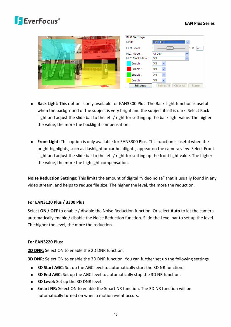
EAN Plus Series
45
Back Light This option is only available for EAN3300 Plus The Back Light function is useful
when the background of the subject is very bright and the subject itself is dark Select Back
Light and adjust the slide bar to the left right for setting up the back light value The higher
the value the more the backlight compensation
Front Light This option is only available for EAN3300 Plus This function is useful when the
bright highlights such as flashlight or car headlights appear on the camera view Select Front
Light and adjust the slide bar to the left right for setting up the front light value The higher
the value the more the highlight compensation
Noise Reduction Settings This limits the amount of digital ldquovideo noiserdquo that is usually found in any
video stream and helps to reduce file size The higher the level the more the reduction
For EAN3120 Plus 3300 Plus
Select ON OFF to enable disable the Noise Reduction function Or select Auto to let the camera
automatically enable disable the Noise Reduction function Slide the Level bar to set up the level
The higher the level the more the reduction
For EAN3220 Plus
2D DNR Select ON to enable the 2D DNR function
3D DNR Select ON to enable the 3D DNR function You can further set up the following settings
3D Start AGC Set up the AGC level to automatically start the 3D NR function
3D End AGC Set up the AGC level to automatically stop the 3D NR function
3D Level Set up the 3D DNR level
Smart NR Select ON to enable the Smart NR function The 3D NR function will be
automatically turned on when a motion event occurs
EAN Plus Series
46
White Balance Settings Select the mode that delivers the best quality image for the camerarsquos light
environment There are five options Auto Manual Indoor Outdoor One Push
Auto Select to let the camera automatically adjust the White Balance In the Auto mode the
camera computes the white balance value output using color information from the entire
screen It outputs the proper value using the color temperature radiating from a black subject
based on a range of value from 3000 to 7500K
Manual Select to adjust the Red and Blue values yourself in the fields below this field
Indoor Select to use the default settings for indoor environments In the Indoor mode the
camera uses 3200K as the base value
Outdoor Select to use the default settings for outdoor environment In the Outdoor mode it
uses 5800K as the base value
One Push Select to enable the Push button next to the Mode drop-down field This will allow you to force the camera to readjust the white balance every time you push the Push
button The lens will hold the same focal position until the next trigger command is received
This function helps to prevent incorrect focusing in dark environments This function is only
available for EAN3120 Plus 3220 Plus
Manual Temperature Select to use the optimized Red and Blue settings You can also
optionally adjust the Manual Level below this field for setting up the color temperature The
higher the value the more the color temperature This function is only available for EAN3300
Plus
DayNight Settings
Auto Select to let the camera automatically switch to Night mode (black and white) when the
light levels fall to a specified level and back to Day mode (color) when the light levels rise to a
specified level
Day Select to keep the camera in Day mode (color) even in nighttime
Night Select to keep the camera in Night mode (black and white) even in daytime
IR Smart Settings Select ON and set up the level to enhance the image quality when the images are
over exposure This function is useful when the camera is in the Night mode This function is only
available for EAN3220 Plus
Saturation Set the saturation value This function is not available for EAN3220 Plus
Monitor Type Select a gamma value from Set 1 Set 2 or Set 3 This function is only available for
EAN3120 Plus
Negative Switch this setting ON to view a color negative version of the video image This is useful
at night or when viewing temperature-sensitive images
EAN Plus Series
47
Sharpness Settings Select the sharpness level of the image A low sharpness level will deliver a
softer less detailed image A high level will deliver a sharp highly detailed image Switch Resolution
Enhancement ON to enable the resolution enhancement function
Contrast Select the contrast level of the image
Suppress Function This function is only available for EAN3300 Plus
Aperture Compensation Suppression (OFFLowMiddleHigh) This setting can be activated to
suppress luminance noise when the AGC level increases
Chroma Suppression (OFFLowMiddleHigh) This setting can be activated to suppress
chrominance noise when the AGC level increases
Ygamma (gamma 22standardcontrast enhancehigh light range mode LHigh light range mode
H) Select the Ygamma value for the video quality of the monitor This function is only available for
EAN3300 Plus
Monitor Settings The user can use this field to optimize video quality for his or her specific type of
monitor ndash LCD or CRT This function is only available for EAN3220 Plus
Color Space Standard The options are YUV601 for SD and YUV709 for HD These define the color
space standard required to convert an RGB picture to a YUV picture Generally YUV601 is used for
Standard Definition (720P) devices and the YUV709 is used for High Definition (1080P) devices
Click Apply to save all changes Click Reset to cancel all changes
EAN Plus Series
48
744 ROI (Region of Interest)
The Region of Interest (ROI) function allows users to set up multiple regions within an image with
better quality and less distortion than the rest of the image You can also use this function
together with the Digital Zoom function on the Live View Page to get a better image result Up to
eight ROIs can be configured in the ROI settings page
To set up an ROI region
1 Select an ROI number from the ROI No drop-down list
2 Click the Add button the mouse cursor will turn into a pen when you move it over the live
image on the left
3 Move the cursor to the position where you want the ROI rectangle to start and then click
Move the cursor to the position (diagonally opposing corner) where you want the ROI
rectangle to end and then click
4 Slide the Quality bar to set up the quality value
5 Click the Apply button to apply the settings or click the Reset button to reset without saving
the settings
EAN Plus Series
49
745 Privacy Mask
The Privacy Mask can block out sensitive areas from view covering the areas with colored or black
and white boxes in both live view and recorded clips This feature is useful when usersrsquo donrsquot want
the sensitive information visible Up to four Privacy Masks can be configured
【Privacy Mask Color Settings】The Modes vary among camera models
Mode Click Color to make the masks appear as colored rectangles on the screen Click BW to
make the masks appear as gray rectangles on the screen Click Mosaic to make the masks appear
as mosaic-effect rectangles on the screen
Level Select the color of the masks if you selected Color Mode Select the level of grayness of the
masks if you selected BW Mode Select the level of smallmiddlelarge if you selected Mosaic
Mode
Click Apply to apply the settings or click Reset to reset without saving the settings
Color Tabs Click on a color tab to turn your mouse cursor into a pen of that color
You can now create a block of that color on the video screen Move your cursor to the position
where you want your mask rectangle to start and then click Move your cursor to the position
(diagonally opposing corner) where you want your mask rectangle to end and then click The
rectangular area with the selected color will appear The live image will display the rectangular
area with the color you selected If you want to create another mask use one of the other three
colors Each color denotes a different mask area Only one block per color is allowed As the
number of colors suggests you can configure up to four blocks
EAN Plus Series
50
Select All Click to turn the whole screen into a mask area
Clear All Click to delete all configured mask blocks
Eraser Click to turn the mouse cursor into an eraser to delete any block you click on
Area Shows the color and number of the block
Enable Check this box to enable the related mask block
Click Apply to apply the settings or click Reset to reset without saving the settings
EAN Plus Series
51
75 Audio
The EAN Plus series IP camera can transmit audio to your computer if you have connected an external
microphone to its audio Input cable It can also receive audio input from you and transmit it via an
external speaker if you have connected such a speaker to its audio Output cable
Check the Enable Audio box to enable the camerarsquos audio function The camera will now act as a
digital bridge (via the IP network) between any connected audio input device and any connected
audio device
Adjust the Audio Input Volume if you have external audio input devices (microphones) connected to
the camera and if there are problems with the sound input being too low or high
Click Apply to save all settings or click Reset to cancel
EAN Plus Series
52
76 User
761 User Information
The system administrator can create up to ten user accounts on this page
To set up a user account
1 Highlight a user account and click the Modify button The following dialog box appears
2 Type the account name account description and password for the account Type the password
again in the Confirm field
3 Select an authority level for the user account from the Authority drop-down list
bull Supervisor Administrator The only difference between a supervisor and administrator is
that a supervisor can edit an administratorrsquos account and password but an administrator
cannot edit the supervisorrsquos account and password Multiple administrators can be
configured but there can be only one supervisor The supervisor and administrators all
have unrestricted access to the Settings submenus and can determine the registration of
all other users
EAN Plus Series
53
bull User A user can view the Live View page and view the system network video and audio
information A user can only adjust the User Config page settings The user does not have
access to the User Event and System pages
bull Guest The lowest level of access which only allows the user access to the Live View page
4 Select Active or Disable from the Status drop-down list to active or disable the user account
5 Click On in the SD Card Playback field to allow the user to access the SD card playback
function
6 Click OK
7 Click Apply to save all the settings
EAN Plus Series
54
762 IP Address Filter
Use this page to specify IP addresses that are not allowed to access this camera By default any IP
address can access the camera
Note The Allowed List addresses only become relevant when the Denied List contains a network
or range and the supervisor wants to allow one or more IP addresses within that excluded range
or network In such a scenario the user would enter the excluded range or network in the
Denied List and enter the exceptions in the Allowed List
To set up the IP Address Filter
1 Select Denied List Click the Add button the following dialog box appears
2 Select an IP type from the IP Type drop-down list
3 Select a network rule from the Rule drop-down list type the IP address and click OK
Single Type a single IP address in the IP Address field below
Network Type the IP address and subnet mask in the field below
Range Type a range for the IP addresses
4 If you have set up an IP range in Step 3 you can optionally set up the Allowed List to allow one
or more IP addresses within the setup IP range to access the IP camera
5 Click Apply
EAN Plus Series
55
77 Event
You can set up the Motion Detection event Tamper Detection event or the Alarm IO to automatically
notify the users when an event occurs or an alarm is triggered You can also set up a schedule to
automatically record the videos when an event occurs or an alarm is triggered
771 Event Settings
You can create a total of ten event or alarm settings page in the Event List
【Event List】
Click the Add button and the following Event Configuration Window appears
EAN Plus Series
56
Enter Event Name Type an event name
Event Triggered by Select an event or alarm type for the to-be-specified-below reactions
Alarm Input Select this if you want a reaction trigger coming from any external connected sensor
to activate a to-be-specified-below reactions via the camera system Make sure that a suitable
device is actually connected to the alarm input relay
Manual Trigger Select this option if you want to manually trigger the alarm by clicking the Trigger
Event button on the Live View Page
Motion Detection Select this option if you want motion in a specified part of the camerarsquos viewing
rectangle (the screen image) to trigger the to-be-specified-below reactions
Tampering Detection Select this option if you want the camerarsquos tampering detection sensor to
trigger the to-be-specified-below reactions
Schedule Recording Select this option if you want the Schedule Recording periods configured in
the recording schedule (the Settings gt Event gt Schedule page) to activate this event In this
scenario a preconfigured event reaction like a log entry will list the start and end times of each
period Actual recording will only be triggered if the event is preconfigured to do so
Enable This Event Select to activate the event
Enable Re-trigger Click to set a minimum time after the event is triggered before the event
can be triggered again
Enable Pre-trigger Buffer Click if you want the Event reaction (as selected in the ldquoNotification
Overrdquo field below) to be the activation of the video recording function and if you want the
recording to include the video feed from the time period (configurable on the previous ldquoEvent
Settingsrdquo page) just before the Event trigger occurred
Enable Post-trigger Buffer Click if you want the Event reaction (as selected in the Notification
Over field) to be the activation of the video recording function and if you want the recording
to include the video feed from a time period (configurable on the Event Settings page) just
after the Event trigger occurred
Motion Area Select a setup motion detection area from the drop down list Note this
function only becomes relevant after the Motion Detection areas have been set up (see 772
Motion Detection)
Notification Over Select the desired notification types form the following items
Log Click if you want the camera to list the eventrsquos details in its log if the event is triggered
Trigger Alarm Output Click if you want the camera to relay the event reaction to a device
attached to the alarm relay output wire and then set up the alarm output duration time
EAN Plus Series
57
Send Mail Notification Click if you want the camera to send an Event notification email to the
email address entered in the Set SMTP Server(email) field of the Network gt SMTPFTP page if
the Event occurs (see 733 SMTP FTP)
Upload to FTP Click if you want the camera to upload recorded footage to the FTP server
entered in the Set SMTP Server(email) field of the Network gt SMTPFTP page if the Event
occurs (see 733 SMTP FTP)
Record to SD Card Click if you want the camera to start recording its video feed (when the
event occurs) on an on-camera SD Card (if such a card has been inserted)
Note The recording will only be as long as the combined Pre- and Post-trigger Buffers so
make sure you enable at least one of these buffers especially the Post-trigger Buffer
Record to PC Check this box if you want the camera to start recording its video feed (when
the event occurs) on the same folder on the same PC as configured on the User Config gt
RecordingSnapshot page (if such a folder has been enabled and configured)
Note The recording will only be as long as the combined Pre- and Post-trigger Buffers (and
for as long as the event trigger is happening ndash eg a motion is detected) so make sure you
enable at least one of these buffers especially the Post-trigger Buffer
Network Alarm Check this box if you want the camera to send a network alarm signal (when
the event occurs) to the CMS servers configured on the Network gt Network Alarm page (see
736 Network Alarm)
Click OK to save all settings or click Cancel to cancel
【PrePost Trigger Settings】
Pre-trigger Buffer Select the duration for the buffer This will determine the amount of footage
(length of time) before the event trigger moment that will be included in an event-triggered video
recording if that buffer and video recording has been enabled in the Event Configuration Window
Post-trigger Buffer Select the duration for the buffer This will determine the amount of footage
(length of time) after the event trigger moment that will be included in an event-triggered video
recording if that buffer and video recording has been enabled in the Event Configuration Window
Click Apply to save all settings or click Reset to cancel
EAN Plus Series
58
772 Motion Detection
Use this page to configure up to four areas in which motion will be detected When a motion is
detected by the camera the motion detection icon will appear at the top right of the
Live page to alert the user This function can also be linked with correctly configured Events to
trigger Event reactions like the activation of video recording periods snapshots alarms etc
Color Tabs Click on a color tab to turn your mouse cursor into a pen of that color
You can now create a block of that color on the video screen Move your cursor to the position
where you want your detection rectangle to start and then click Move your cursor to the position
(diagonally opposing corner) where you want your detection rectangle to end and then click The
rectangular area with the selected color will appear This block will be an area inside which the
camera will detect motion If you want to create another detection area use one of the other three
palette colors Each color denotes a different detection area Only one block per color is allowed As
the number of colors suggests you can configure up to four blocks
Select All Click to turn the whole screen into a motion detection area
Clear All Click to delete all configured motion detection blocks
Eraser Click to turn your mouse cursor into an eraser to delete any block you click on
Area Shows the color and numberID of the block
Enable Check this box to enable the related motion detection block
Sensitivity Set the sensitivity of the motion detection sensor function
Click Apply to save all settings or click Reset to cancel
EAN Plus Series
59
773 Tamper Detection
Use this page to set the number of seconds that an alarm signal will be active if the device is
physically tampered (moved covered up or out of focus
774 Alarm IO
Use this page to set the type of trigger input and the type of output contact for the camerarsquos alarm
channel
EAN Plus Series
60
775 Schedule
Use this page to configure a schedule for periods during which the camera should deactivate all
user-activated Events (gray Deselect periods) or when the camera should deactivate all
user-activated Events except Schedule Recording (SR) events (blue Schedule Recording-only
periods) or when the camera should deactivate only SR events (red Event Recording-only periods)
or when it should enable all activated Events (yellow periods)
Event Recording Click this button to make every hour block you click on red A red block represents
an Event Recording-only block which represents an hour when the camera will deactivate all
preconfigured activated Schedule Recording events and keep all the other activated events active
Schedule Recording Click this button to make every hour block you click on blue A blue block
represents a Schedule Recording-only block which represents an hour when the camera will
deactivate all other preconfigured activated events and keep only the preconfigured activated
Schedule Recording events active
Event + Schedule Click this button to make every hour block you click on yellow A yellow block
represents an hour in which all activated events including Schedule Recording events will be
active
Deselect Click this button to make every hour block become grey A grey block represents an hour
in which all activated events including Schedule Recording events will be inactive
Click Apply to save all settings or click Reset to cancel
EAN Plus Series
61
78 System
You can set up the systemrsquos time and SD card settings and to do maintenance and reset actions like
reboots and upgrades
781 DateTime
【Machine Name Settings】If required enter a new name for the machine This name will be visible
in the Machine Name field of the IP Utility software which is included in the software CD
【Set Time Zone】Set the time zone of the camerarsquos location
【Set DateTime Manually】Set the datetime here if you wonrsquot be using an NTP server to update the
datetime (see below)
【Set DateTime Sync】Enter the Network Time Protocol server if applicable The camerarsquos time will
be automatically adjusted by synchronizing with the NTP server
Click Apply to save all settings or click Reset to cancel
EAN Plus Series
62
782 Daylight Saving
Click Enable Daylight Saving to enable this schedule and select the dates when the regionrsquos
daylight saving period begins and ends Click Apply to save all settings or click Reset to cancel
783 SD Card
Use this page to prepare the system for safely removing the SD Card from its slot
【Setup SD Card】
Notification Select the percentage of storage space that should be left on the card before the
camera notifies you of the impending storage shortage or overwrite
Event Recording Select if you want Event Recording only FTP Backup only or both
Overwrite Click ON if you want the card to start writing over recorded footage when its memory is
full Click OFF if you want the card to stop recording new footage when its memory is full
【SD Card Utility】
Capacity This shows you how much card memory has been used and how much memory capacity
remains on the card
Remove Click this button before removing the card from the system
Format Click this button to format the card All data saved on the SD card will be removed if the
card is formatted
EAN Plus Series
63
784 Maintenance
【Maintenance Server】
Reboot Click this button to reboot the unit without changing any of the settings Use this function if
the unit is not behaving as expected
Restore Click this button to restart and reset most of the current settings to their factory default
values The only settings that will not be changed to default are
bull IP settings
bull DDNS settings
Default The Default button should be used with caution Pressing this button will return all of the
cameras settings including the IP address to the factory default values The camera will then have
to be reconfigured
【SaveLoad Configuration Server】
Save To make a backup file of the machinersquos current configurations press Save to save all the
configurations to a config file This will enable the user to reload these configuration settings if the
settings are changed and there is unexpected behavior
Load To load a previously saved configuration press the Browse button to locate the saved config
file (see above) and then click the Load button The systemrsquos settings will be restored to the saved
configuration
EAN Plus Series
64
【SaveLoad Video Configuration Server】
Save To make a backup file of the machinersquos video configurations press Save to save the video
configurations to a config file This will enable the user to reload these configuration settings if the
settings are changed and there is unexpected behavior
Load To load a previously saved video configuration press the Browse button to locate the saved
config file (see above) and then click the Load button The systemrsquos settings will be restored to the
saved video configuration
【Upgrade Firmware】Click the Browse button to find a previously prepared firmware upgrade file
Click Upgrade to install the new firmware
Note
1 Do not disconnect power to the unit during the upgrade sequence The unit will reboot
automatically after the upgrade has completed (1-5 minutes)
2 During the upgrade process all event recording actions will be stopped Event recording
actions will resume after the camera is rebooted
3 If the ldquoFile Error Please re-loginrdquo warning message appears when upgrading the firmware
please try the following instructions
a Go to Internet Explorer gt Tools gt Internet Option gt Security gt Custom
b Find and enable the Include local directory path when uploading files to a server
EAN Plus Series
65
8 Upgrading Firmware Using IP Utility
You can upgrade the Firmware using the IP Utility software included in the software CD
1 Install and then start the IPU program The following dialog box appears
2 Click Find Devices to search the cameras connected in the LAN The default network values of the
cameras will be displayed By default the network protocol of the camera is DHCP
3 Select a camera and click LoginMulti Login to log in the camera
4 Type the user ID and password Click OK
Note
1 The default user ID is user1 and the default password is 11111111
2 If you select more than one camera that has the same user ID password you will be able
to log in several cameras at once
EAN Plus Series
66
5 Highlight the camera and then click Upgrade Firmware A browsing window appears
6 Select the firmware file (evb) and then click Open The IP Utility will automatically upgrade the
firmware
The camera will reboot once the update is complete Click Find Devices the new firmware version
should be displayed in the last part of the Machine Name
EAN Plus Series
67
9 Specifications
Model EAN3120 Plus EAN3220 Plus EAN3300 Plus
Camera
Image Sensor 13 Panasonic CMOS 128 Sony CMOS
Megapixel 13 MP 2 MP 3 MP
Picture Elements (H x V) 1280 x 1024 1944 x 1092 2048 x 1536
Min Illuminations 003 Lux at F14
Electronic Shutter (Sec) 85 ~ 160000 2 ~ 150000 1 ~ 110000
Scanning System NTSC PAL
WDR Yes Yes No
BLC Yes
Gain Control Yes
White Balance Yes
Lens
Mounting Type C CS
Day Night Yes (with removable auto IR-cut filter)
IRIS Control DC Electrical IRIS Lens IRIS
Video
Video Compression H264 MJPEG
Resolution
NTSC
2048 x 1536 1920 x 1200 (for EAN3300 Plus only)
1920 x 1080 (for EAN3300 Plus 3220 Plus only)
1280 x 1024 1280 x 720 1024 x 768 720 x 480 704 x 480 640 x 480
352 x 240 320 x 240 160 x 120
PAL
2048 x 1536 1920 x 1200 (for EAN3300 Plus only)
1920 x 1080 (for EAN3300 Plus 3220 Plus only)
1280 x 1024 1280 x 720 1024 x 768 720 x 576 704 x 576 640 x 480
352 x 288 320 x 240 160 x 120
Frame Rate 30 fps at 1280 x 1024 30 fps at 1920 x 1080 15 fps at 2048 x 1536
Audio
Audio Streaming Two-way audio
Audio Compression G711
EAN Plus Series
68
Network
Interface 10 100 Base-T Ethernet RJ-45 socket
Supported Protocols
TCPIP IPV6 UDP ICMP DHCP NTP DNS DDNS SMTP SNMP FTP
HTTP HTTPs PPPoE UPnP Bonjour RTP RTSP RTCP IGMP ARP ONVIF
PSIA
Connector
Power DC female port PoE
Ethernet RJ-45
Audio 1 In (phone jack for microphone)
1 Out (phone jack for Speaker)
Alarm IO Terminal IO wires
Local Storage Micro SD SDHC memory card slot
TV-Out BNC socket composite 1 V p-p 75 Ω
General
Power Source DC 12V PoE (IEEE8023af)
Power Consumption
(IR LEDs On)
5W (DC 12V)
621W (PoE)
5W (DC 12V)
522W (PoE)
5W (DC 12V)
536W (PoE)
Operating Temperature 0degC ~ +50degC 32degF ~ +122degF
Humidity 20 to 80 (no condensation)
Safety CE FCC
Dimensions (L x W x H) 117 x 56 x 68 mm 46 x 22 x 27 in
Weight 410 g 09 lb
EverFocus Electronics Corp EverFocus Taiwan 12F No79 Sec 1 Shin-Tai Wu Road Hsi-Chih Taipei Taiwan TEL +886 2 2698 2334 FAX +886 2 2698 2380 wwweverfocuscomtw marketingeverfocuscomtw
EverFocus Europe - Germany Albert-Einstein-Strasse 1 D-46446 Emmerich Germany TEL +49 2822 93940 FAX +49 2822 939495 wwweverfocusde infoeverfocusde
EverFocus China - Beijing Room 609 Technology Trade Building Shangdi Information Industry Base Haidian District Beijing 100085 China TEL +86 10 6297 3336~39 FAX +86 10 6297 1423 wwweverfocuscomcn marketingeverfocuscomcn
EverFocus China - Shenzhen 4F No 2 D4 Building Wan Yelong Industrial Park Tangtou Road Shiyan Baoan Shenzhen Guangdong 518101 China TEL +86 755 2765 1313 FAX +86 755 2765 0337 wwweverfocuscomcn marketingeverfocuscomcn
EverFocus USA - California 1801 Highland Avenue Unit A Duarte CA 91010 USA TEL +1 626 844 8888 FAX +1 626 844 8838 wwweverfocuscom saleseverfocuscom
EverFocus USA - New York 415 Oser Avenue Unit S Hauppauge NY 11788 USA TEL +1 631 436 5070 FAX +1 631 436 5027 wwweverfocuscom saleseverfocuscom
EverFocus Japan 5F Kinshicho City Building 2-13-4 Koto-BashiSumida-Ku Tokyo 130-0022 Japan TEL +81 3 5625 8188 FAX +81 3 5625 8189 wwweverfocuscojp infoeverfocuscojp
EverFocus Europe - UK Unit 12 Spitfire Business Park Hawker Road Croydon Surrey CR0 4WD UK TEL +44 20 8649 9757 +44 845 430 9999 FAX +44 20 8649 9907 wwweverfocusukcouk salesukeverfocuscom
EverFocus India Suite 803 Housefin Bhavan C-21 Bandra Kurla Complex Bandra (East) Mumbai 400051 India TEL +91 22 6128 8700 FAX +91 22 6128 8705 wwweverfocusin saleseverfocusin
PN 4605PQ3120B010A-VerC
Your EverFocus product is designed and manufactured with high quality materials and components which can be recycled and reused This symbol means that electrical and electronic equipment at their end-of-life should be disposed of separately from your household waste Please dispose of this equipment at your local community waste collectionrecycling centre In the European Union there are separate collection systems for used electrical and electronic product Please help us to conserve the environment we live in
Ihr EverFocus Produkt wurde entwickelt und hergestellt mit qualitativ hochwertigen Materialien und Komponenten die recycelt und wieder verwendet werden koumlnnen Dieses Symbol bedeutet dass elektrische und elektronische Geraumlte am Ende ihrer Nutzungsdauer vom Hausmuumlll getrennt entsorgt werden sollen Bitte entsorgen Sie dieses Geraumlt bei Ihrer oumlrtlichen kommunalen Sammelstelle oder im Recycling Centre Helfen Sie uns bitte die Umwelt zu erhalten in der wir leben
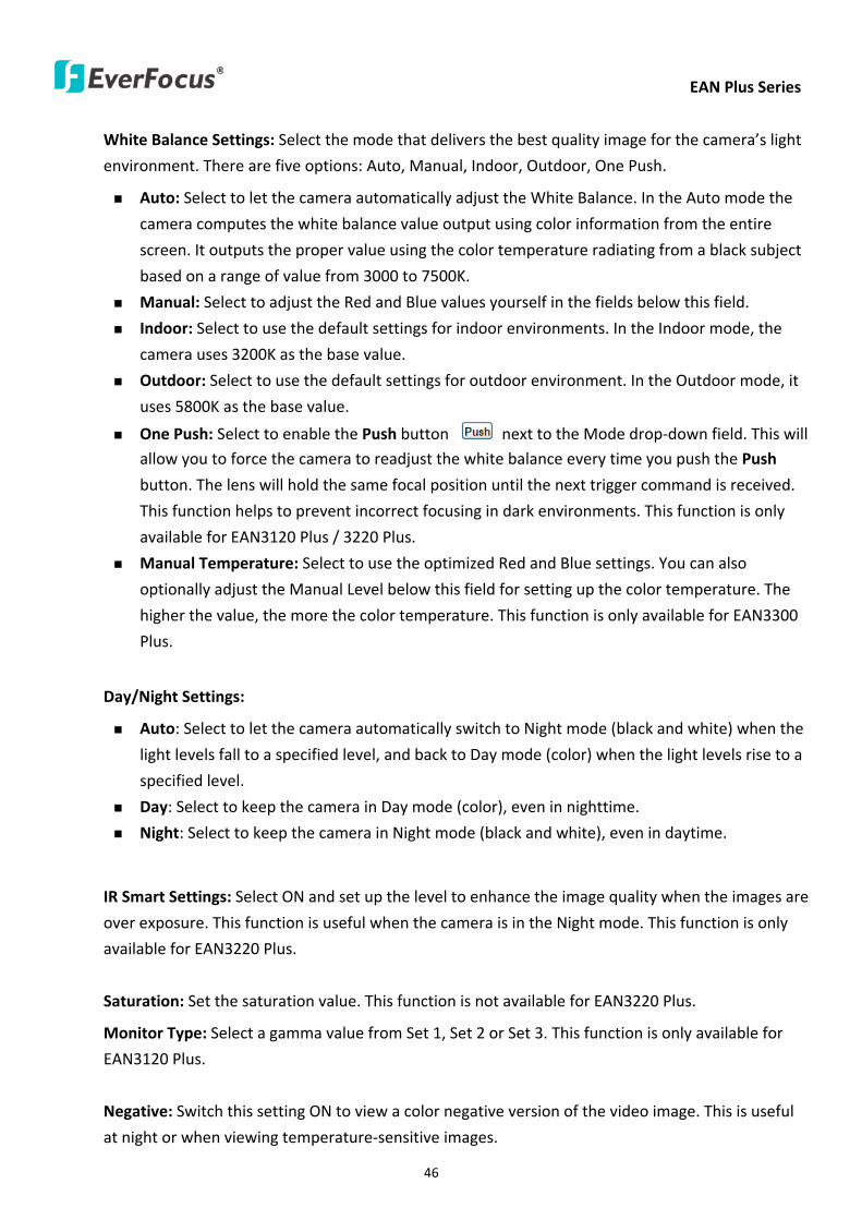
EAN Plus Series
46
White Balance Settings Select the mode that delivers the best quality image for the camerarsquos light
environment There are five options Auto Manual Indoor Outdoor One Push
Auto Select to let the camera automatically adjust the White Balance In the Auto mode the
camera computes the white balance value output using color information from the entire
screen It outputs the proper value using the color temperature radiating from a black subject
based on a range of value from 3000 to 7500K
Manual Select to adjust the Red and Blue values yourself in the fields below this field
Indoor Select to use the default settings for indoor environments In the Indoor mode the
camera uses 3200K as the base value
Outdoor Select to use the default settings for outdoor environment In the Outdoor mode it
uses 5800K as the base value
One Push Select to enable the Push button next to the Mode drop-down field This will allow you to force the camera to readjust the white balance every time you push the Push
button The lens will hold the same focal position until the next trigger command is received
This function helps to prevent incorrect focusing in dark environments This function is only
available for EAN3120 Plus 3220 Plus
Manual Temperature Select to use the optimized Red and Blue settings You can also
optionally adjust the Manual Level below this field for setting up the color temperature The
higher the value the more the color temperature This function is only available for EAN3300
Plus
DayNight Settings
Auto Select to let the camera automatically switch to Night mode (black and white) when the
light levels fall to a specified level and back to Day mode (color) when the light levels rise to a
specified level
Day Select to keep the camera in Day mode (color) even in nighttime
Night Select to keep the camera in Night mode (black and white) even in daytime
IR Smart Settings Select ON and set up the level to enhance the image quality when the images are
over exposure This function is useful when the camera is in the Night mode This function is only
available for EAN3220 Plus
Saturation Set the saturation value This function is not available for EAN3220 Plus
Monitor Type Select a gamma value from Set 1 Set 2 or Set 3 This function is only available for
EAN3120 Plus
Negative Switch this setting ON to view a color negative version of the video image This is useful
at night or when viewing temperature-sensitive images
EAN Plus Series
47
Sharpness Settings Select the sharpness level of the image A low sharpness level will deliver a
softer less detailed image A high level will deliver a sharp highly detailed image Switch Resolution
Enhancement ON to enable the resolution enhancement function
Contrast Select the contrast level of the image
Suppress Function This function is only available for EAN3300 Plus
Aperture Compensation Suppression (OFFLowMiddleHigh) This setting can be activated to
suppress luminance noise when the AGC level increases
Chroma Suppression (OFFLowMiddleHigh) This setting can be activated to suppress
chrominance noise when the AGC level increases
Ygamma (gamma 22standardcontrast enhancehigh light range mode LHigh light range mode
H) Select the Ygamma value for the video quality of the monitor This function is only available for
EAN3300 Plus
Monitor Settings The user can use this field to optimize video quality for his or her specific type of
monitor ndash LCD or CRT This function is only available for EAN3220 Plus
Color Space Standard The options are YUV601 for SD and YUV709 for HD These define the color
space standard required to convert an RGB picture to a YUV picture Generally YUV601 is used for
Standard Definition (720P) devices and the YUV709 is used for High Definition (1080P) devices
Click Apply to save all changes Click Reset to cancel all changes
EAN Plus Series
48
744 ROI (Region of Interest)
The Region of Interest (ROI) function allows users to set up multiple regions within an image with
better quality and less distortion than the rest of the image You can also use this function
together with the Digital Zoom function on the Live View Page to get a better image result Up to
eight ROIs can be configured in the ROI settings page
To set up an ROI region
1 Select an ROI number from the ROI No drop-down list
2 Click the Add button the mouse cursor will turn into a pen when you move it over the live
image on the left
3 Move the cursor to the position where you want the ROI rectangle to start and then click
Move the cursor to the position (diagonally opposing corner) where you want the ROI
rectangle to end and then click
4 Slide the Quality bar to set up the quality value
5 Click the Apply button to apply the settings or click the Reset button to reset without saving
the settings
EAN Plus Series
49
745 Privacy Mask
The Privacy Mask can block out sensitive areas from view covering the areas with colored or black
and white boxes in both live view and recorded clips This feature is useful when usersrsquo donrsquot want
the sensitive information visible Up to four Privacy Masks can be configured
【Privacy Mask Color Settings】The Modes vary among camera models
Mode Click Color to make the masks appear as colored rectangles on the screen Click BW to
make the masks appear as gray rectangles on the screen Click Mosaic to make the masks appear
as mosaic-effect rectangles on the screen
Level Select the color of the masks if you selected Color Mode Select the level of grayness of the
masks if you selected BW Mode Select the level of smallmiddlelarge if you selected Mosaic
Mode
Click Apply to apply the settings or click Reset to reset without saving the settings
Color Tabs Click on a color tab to turn your mouse cursor into a pen of that color
You can now create a block of that color on the video screen Move your cursor to the position
where you want your mask rectangle to start and then click Move your cursor to the position
(diagonally opposing corner) where you want your mask rectangle to end and then click The
rectangular area with the selected color will appear The live image will display the rectangular
area with the color you selected If you want to create another mask use one of the other three
colors Each color denotes a different mask area Only one block per color is allowed As the
number of colors suggests you can configure up to four blocks
EAN Plus Series
50
Select All Click to turn the whole screen into a mask area
Clear All Click to delete all configured mask blocks
Eraser Click to turn the mouse cursor into an eraser to delete any block you click on
Area Shows the color and number of the block
Enable Check this box to enable the related mask block
Click Apply to apply the settings or click Reset to reset without saving the settings
EAN Plus Series
51
75 Audio
The EAN Plus series IP camera can transmit audio to your computer if you have connected an external
microphone to its audio Input cable It can also receive audio input from you and transmit it via an
external speaker if you have connected such a speaker to its audio Output cable
Check the Enable Audio box to enable the camerarsquos audio function The camera will now act as a
digital bridge (via the IP network) between any connected audio input device and any connected
audio device
Adjust the Audio Input Volume if you have external audio input devices (microphones) connected to
the camera and if there are problems with the sound input being too low or high
Click Apply to save all settings or click Reset to cancel
EAN Plus Series
52
76 User
761 User Information
The system administrator can create up to ten user accounts on this page
To set up a user account
1 Highlight a user account and click the Modify button The following dialog box appears
2 Type the account name account description and password for the account Type the password
again in the Confirm field
3 Select an authority level for the user account from the Authority drop-down list
bull Supervisor Administrator The only difference between a supervisor and administrator is
that a supervisor can edit an administratorrsquos account and password but an administrator
cannot edit the supervisorrsquos account and password Multiple administrators can be
configured but there can be only one supervisor The supervisor and administrators all
have unrestricted access to the Settings submenus and can determine the registration of
all other users
EAN Plus Series
53
bull User A user can view the Live View page and view the system network video and audio
information A user can only adjust the User Config page settings The user does not have
access to the User Event and System pages
bull Guest The lowest level of access which only allows the user access to the Live View page
4 Select Active or Disable from the Status drop-down list to active or disable the user account
5 Click On in the SD Card Playback field to allow the user to access the SD card playback
function
6 Click OK
7 Click Apply to save all the settings
EAN Plus Series
54
762 IP Address Filter
Use this page to specify IP addresses that are not allowed to access this camera By default any IP
address can access the camera
Note The Allowed List addresses only become relevant when the Denied List contains a network
or range and the supervisor wants to allow one or more IP addresses within that excluded range
or network In such a scenario the user would enter the excluded range or network in the
Denied List and enter the exceptions in the Allowed List
To set up the IP Address Filter
1 Select Denied List Click the Add button the following dialog box appears
2 Select an IP type from the IP Type drop-down list
3 Select a network rule from the Rule drop-down list type the IP address and click OK
Single Type a single IP address in the IP Address field below
Network Type the IP address and subnet mask in the field below
Range Type a range for the IP addresses
4 If you have set up an IP range in Step 3 you can optionally set up the Allowed List to allow one
or more IP addresses within the setup IP range to access the IP camera
5 Click Apply
EAN Plus Series
55
77 Event
You can set up the Motion Detection event Tamper Detection event or the Alarm IO to automatically
notify the users when an event occurs or an alarm is triggered You can also set up a schedule to
automatically record the videos when an event occurs or an alarm is triggered
771 Event Settings
You can create a total of ten event or alarm settings page in the Event List
【Event List】
Click the Add button and the following Event Configuration Window appears
EAN Plus Series
56
Enter Event Name Type an event name
Event Triggered by Select an event or alarm type for the to-be-specified-below reactions
Alarm Input Select this if you want a reaction trigger coming from any external connected sensor
to activate a to-be-specified-below reactions via the camera system Make sure that a suitable
device is actually connected to the alarm input relay
Manual Trigger Select this option if you want to manually trigger the alarm by clicking the Trigger
Event button on the Live View Page
Motion Detection Select this option if you want motion in a specified part of the camerarsquos viewing
rectangle (the screen image) to trigger the to-be-specified-below reactions
Tampering Detection Select this option if you want the camerarsquos tampering detection sensor to
trigger the to-be-specified-below reactions
Schedule Recording Select this option if you want the Schedule Recording periods configured in
the recording schedule (the Settings gt Event gt Schedule page) to activate this event In this
scenario a preconfigured event reaction like a log entry will list the start and end times of each
period Actual recording will only be triggered if the event is preconfigured to do so
Enable This Event Select to activate the event
Enable Re-trigger Click to set a minimum time after the event is triggered before the event
can be triggered again
Enable Pre-trigger Buffer Click if you want the Event reaction (as selected in the ldquoNotification
Overrdquo field below) to be the activation of the video recording function and if you want the
recording to include the video feed from the time period (configurable on the previous ldquoEvent
Settingsrdquo page) just before the Event trigger occurred
Enable Post-trigger Buffer Click if you want the Event reaction (as selected in the Notification
Over field) to be the activation of the video recording function and if you want the recording
to include the video feed from a time period (configurable on the Event Settings page) just
after the Event trigger occurred
Motion Area Select a setup motion detection area from the drop down list Note this
function only becomes relevant after the Motion Detection areas have been set up (see 772
Motion Detection)
Notification Over Select the desired notification types form the following items
Log Click if you want the camera to list the eventrsquos details in its log if the event is triggered
Trigger Alarm Output Click if you want the camera to relay the event reaction to a device
attached to the alarm relay output wire and then set up the alarm output duration time
EAN Plus Series
57
Send Mail Notification Click if you want the camera to send an Event notification email to the
email address entered in the Set SMTP Server(email) field of the Network gt SMTPFTP page if
the Event occurs (see 733 SMTP FTP)
Upload to FTP Click if you want the camera to upload recorded footage to the FTP server
entered in the Set SMTP Server(email) field of the Network gt SMTPFTP page if the Event
occurs (see 733 SMTP FTP)
Record to SD Card Click if you want the camera to start recording its video feed (when the
event occurs) on an on-camera SD Card (if such a card has been inserted)
Note The recording will only be as long as the combined Pre- and Post-trigger Buffers so
make sure you enable at least one of these buffers especially the Post-trigger Buffer
Record to PC Check this box if you want the camera to start recording its video feed (when
the event occurs) on the same folder on the same PC as configured on the User Config gt
RecordingSnapshot page (if such a folder has been enabled and configured)
Note The recording will only be as long as the combined Pre- and Post-trigger Buffers (and
for as long as the event trigger is happening ndash eg a motion is detected) so make sure you
enable at least one of these buffers especially the Post-trigger Buffer
Network Alarm Check this box if you want the camera to send a network alarm signal (when
the event occurs) to the CMS servers configured on the Network gt Network Alarm page (see
736 Network Alarm)
Click OK to save all settings or click Cancel to cancel
【PrePost Trigger Settings】
Pre-trigger Buffer Select the duration for the buffer This will determine the amount of footage
(length of time) before the event trigger moment that will be included in an event-triggered video
recording if that buffer and video recording has been enabled in the Event Configuration Window
Post-trigger Buffer Select the duration for the buffer This will determine the amount of footage
(length of time) after the event trigger moment that will be included in an event-triggered video
recording if that buffer and video recording has been enabled in the Event Configuration Window
Click Apply to save all settings or click Reset to cancel
EAN Plus Series
58
772 Motion Detection
Use this page to configure up to four areas in which motion will be detected When a motion is
detected by the camera the motion detection icon will appear at the top right of the
Live page to alert the user This function can also be linked with correctly configured Events to
trigger Event reactions like the activation of video recording periods snapshots alarms etc
Color Tabs Click on a color tab to turn your mouse cursor into a pen of that color
You can now create a block of that color on the video screen Move your cursor to the position
where you want your detection rectangle to start and then click Move your cursor to the position
(diagonally opposing corner) where you want your detection rectangle to end and then click The
rectangular area with the selected color will appear This block will be an area inside which the
camera will detect motion If you want to create another detection area use one of the other three
palette colors Each color denotes a different detection area Only one block per color is allowed As
the number of colors suggests you can configure up to four blocks
Select All Click to turn the whole screen into a motion detection area
Clear All Click to delete all configured motion detection blocks
Eraser Click to turn your mouse cursor into an eraser to delete any block you click on
Area Shows the color and numberID of the block
Enable Check this box to enable the related motion detection block
Sensitivity Set the sensitivity of the motion detection sensor function
Click Apply to save all settings or click Reset to cancel
EAN Plus Series
59
773 Tamper Detection
Use this page to set the number of seconds that an alarm signal will be active if the device is
physically tampered (moved covered up or out of focus
774 Alarm IO
Use this page to set the type of trigger input and the type of output contact for the camerarsquos alarm
channel
EAN Plus Series
60
775 Schedule
Use this page to configure a schedule for periods during which the camera should deactivate all
user-activated Events (gray Deselect periods) or when the camera should deactivate all
user-activated Events except Schedule Recording (SR) events (blue Schedule Recording-only
periods) or when the camera should deactivate only SR events (red Event Recording-only periods)
or when it should enable all activated Events (yellow periods)
Event Recording Click this button to make every hour block you click on red A red block represents
an Event Recording-only block which represents an hour when the camera will deactivate all
preconfigured activated Schedule Recording events and keep all the other activated events active
Schedule Recording Click this button to make every hour block you click on blue A blue block
represents a Schedule Recording-only block which represents an hour when the camera will
deactivate all other preconfigured activated events and keep only the preconfigured activated
Schedule Recording events active
Event + Schedule Click this button to make every hour block you click on yellow A yellow block
represents an hour in which all activated events including Schedule Recording events will be
active
Deselect Click this button to make every hour block become grey A grey block represents an hour
in which all activated events including Schedule Recording events will be inactive
Click Apply to save all settings or click Reset to cancel
EAN Plus Series
61
78 System
You can set up the systemrsquos time and SD card settings and to do maintenance and reset actions like
reboots and upgrades
781 DateTime
【Machine Name Settings】If required enter a new name for the machine This name will be visible
in the Machine Name field of the IP Utility software which is included in the software CD
【Set Time Zone】Set the time zone of the camerarsquos location
【Set DateTime Manually】Set the datetime here if you wonrsquot be using an NTP server to update the
datetime (see below)
【Set DateTime Sync】Enter the Network Time Protocol server if applicable The camerarsquos time will
be automatically adjusted by synchronizing with the NTP server
Click Apply to save all settings or click Reset to cancel
EAN Plus Series
62
782 Daylight Saving
Click Enable Daylight Saving to enable this schedule and select the dates when the regionrsquos
daylight saving period begins and ends Click Apply to save all settings or click Reset to cancel
783 SD Card
Use this page to prepare the system for safely removing the SD Card from its slot
【Setup SD Card】
Notification Select the percentage of storage space that should be left on the card before the
camera notifies you of the impending storage shortage or overwrite
Event Recording Select if you want Event Recording only FTP Backup only or both
Overwrite Click ON if you want the card to start writing over recorded footage when its memory is
full Click OFF if you want the card to stop recording new footage when its memory is full
【SD Card Utility】
Capacity This shows you how much card memory has been used and how much memory capacity
remains on the card
Remove Click this button before removing the card from the system
Format Click this button to format the card All data saved on the SD card will be removed if the
card is formatted
EAN Plus Series
63
784 Maintenance
【Maintenance Server】
Reboot Click this button to reboot the unit without changing any of the settings Use this function if
the unit is not behaving as expected
Restore Click this button to restart and reset most of the current settings to their factory default
values The only settings that will not be changed to default are
bull IP settings
bull DDNS settings
Default The Default button should be used with caution Pressing this button will return all of the
cameras settings including the IP address to the factory default values The camera will then have
to be reconfigured
【SaveLoad Configuration Server】
Save To make a backup file of the machinersquos current configurations press Save to save all the
configurations to a config file This will enable the user to reload these configuration settings if the
settings are changed and there is unexpected behavior
Load To load a previously saved configuration press the Browse button to locate the saved config
file (see above) and then click the Load button The systemrsquos settings will be restored to the saved
configuration
EAN Plus Series
64
【SaveLoad Video Configuration Server】
Save To make a backup file of the machinersquos video configurations press Save to save the video
configurations to a config file This will enable the user to reload these configuration settings if the
settings are changed and there is unexpected behavior
Load To load a previously saved video configuration press the Browse button to locate the saved
config file (see above) and then click the Load button The systemrsquos settings will be restored to the
saved video configuration
【Upgrade Firmware】Click the Browse button to find a previously prepared firmware upgrade file
Click Upgrade to install the new firmware
Note
1 Do not disconnect power to the unit during the upgrade sequence The unit will reboot
automatically after the upgrade has completed (1-5 minutes)
2 During the upgrade process all event recording actions will be stopped Event recording
actions will resume after the camera is rebooted
3 If the ldquoFile Error Please re-loginrdquo warning message appears when upgrading the firmware
please try the following instructions
a Go to Internet Explorer gt Tools gt Internet Option gt Security gt Custom
b Find and enable the Include local directory path when uploading files to a server
EAN Plus Series
65
8 Upgrading Firmware Using IP Utility
You can upgrade the Firmware using the IP Utility software included in the software CD
1 Install and then start the IPU program The following dialog box appears
2 Click Find Devices to search the cameras connected in the LAN The default network values of the
cameras will be displayed By default the network protocol of the camera is DHCP
3 Select a camera and click LoginMulti Login to log in the camera
4 Type the user ID and password Click OK
Note
1 The default user ID is user1 and the default password is 11111111
2 If you select more than one camera that has the same user ID password you will be able
to log in several cameras at once
EAN Plus Series
66
5 Highlight the camera and then click Upgrade Firmware A browsing window appears
6 Select the firmware file (evb) and then click Open The IP Utility will automatically upgrade the
firmware
The camera will reboot once the update is complete Click Find Devices the new firmware version
should be displayed in the last part of the Machine Name
EAN Plus Series
67
9 Specifications
Model EAN3120 Plus EAN3220 Plus EAN3300 Plus
Camera
Image Sensor 13 Panasonic CMOS 128 Sony CMOS
Megapixel 13 MP 2 MP 3 MP
Picture Elements (H x V) 1280 x 1024 1944 x 1092 2048 x 1536
Min Illuminations 003 Lux at F14
Electronic Shutter (Sec) 85 ~ 160000 2 ~ 150000 1 ~ 110000
Scanning System NTSC PAL
WDR Yes Yes No
BLC Yes
Gain Control Yes
White Balance Yes
Lens
Mounting Type C CS
Day Night Yes (with removable auto IR-cut filter)
IRIS Control DC Electrical IRIS Lens IRIS
Video
Video Compression H264 MJPEG
Resolution
NTSC
2048 x 1536 1920 x 1200 (for EAN3300 Plus only)
1920 x 1080 (for EAN3300 Plus 3220 Plus only)
1280 x 1024 1280 x 720 1024 x 768 720 x 480 704 x 480 640 x 480
352 x 240 320 x 240 160 x 120
PAL
2048 x 1536 1920 x 1200 (for EAN3300 Plus only)
1920 x 1080 (for EAN3300 Plus 3220 Plus only)
1280 x 1024 1280 x 720 1024 x 768 720 x 576 704 x 576 640 x 480
352 x 288 320 x 240 160 x 120
Frame Rate 30 fps at 1280 x 1024 30 fps at 1920 x 1080 15 fps at 2048 x 1536
Audio
Audio Streaming Two-way audio
Audio Compression G711
EAN Plus Series
68
Network
Interface 10 100 Base-T Ethernet RJ-45 socket
Supported Protocols
TCPIP IPV6 UDP ICMP DHCP NTP DNS DDNS SMTP SNMP FTP
HTTP HTTPs PPPoE UPnP Bonjour RTP RTSP RTCP IGMP ARP ONVIF
PSIA
Connector
Power DC female port PoE
Ethernet RJ-45
Audio 1 In (phone jack for microphone)
1 Out (phone jack for Speaker)
Alarm IO Terminal IO wires
Local Storage Micro SD SDHC memory card slot
TV-Out BNC socket composite 1 V p-p 75 Ω
General
Power Source DC 12V PoE (IEEE8023af)
Power Consumption
(IR LEDs On)
5W (DC 12V)
621W (PoE)
5W (DC 12V)
522W (PoE)
5W (DC 12V)
536W (PoE)
Operating Temperature 0degC ~ +50degC 32degF ~ +122degF
Humidity 20 to 80 (no condensation)
Safety CE FCC
Dimensions (L x W x H) 117 x 56 x 68 mm 46 x 22 x 27 in
Weight 410 g 09 lb
EverFocus Electronics Corp EverFocus Taiwan 12F No79 Sec 1 Shin-Tai Wu Road Hsi-Chih Taipei Taiwan TEL +886 2 2698 2334 FAX +886 2 2698 2380 wwweverfocuscomtw marketingeverfocuscomtw
EverFocus Europe - Germany Albert-Einstein-Strasse 1 D-46446 Emmerich Germany TEL +49 2822 93940 FAX +49 2822 939495 wwweverfocusde infoeverfocusde
EverFocus China - Beijing Room 609 Technology Trade Building Shangdi Information Industry Base Haidian District Beijing 100085 China TEL +86 10 6297 3336~39 FAX +86 10 6297 1423 wwweverfocuscomcn marketingeverfocuscomcn
EverFocus China - Shenzhen 4F No 2 D4 Building Wan Yelong Industrial Park Tangtou Road Shiyan Baoan Shenzhen Guangdong 518101 China TEL +86 755 2765 1313 FAX +86 755 2765 0337 wwweverfocuscomcn marketingeverfocuscomcn
EverFocus USA - California 1801 Highland Avenue Unit A Duarte CA 91010 USA TEL +1 626 844 8888 FAX +1 626 844 8838 wwweverfocuscom saleseverfocuscom
EverFocus USA - New York 415 Oser Avenue Unit S Hauppauge NY 11788 USA TEL +1 631 436 5070 FAX +1 631 436 5027 wwweverfocuscom saleseverfocuscom
EverFocus Japan 5F Kinshicho City Building 2-13-4 Koto-BashiSumida-Ku Tokyo 130-0022 Japan TEL +81 3 5625 8188 FAX +81 3 5625 8189 wwweverfocuscojp infoeverfocuscojp
EverFocus Europe - UK Unit 12 Spitfire Business Park Hawker Road Croydon Surrey CR0 4WD UK TEL +44 20 8649 9757 +44 845 430 9999 FAX +44 20 8649 9907 wwweverfocusukcouk salesukeverfocuscom
EverFocus India Suite 803 Housefin Bhavan C-21 Bandra Kurla Complex Bandra (East) Mumbai 400051 India TEL +91 22 6128 8700 FAX +91 22 6128 8705 wwweverfocusin saleseverfocusin
PN 4605PQ3120B010A-VerC
Your EverFocus product is designed and manufactured with high quality materials and components which can be recycled and reused This symbol means that electrical and electronic equipment at their end-of-life should be disposed of separately from your household waste Please dispose of this equipment at your local community waste collectionrecycling centre In the European Union there are separate collection systems for used electrical and electronic product Please help us to conserve the environment we live in
Ihr EverFocus Produkt wurde entwickelt und hergestellt mit qualitativ hochwertigen Materialien und Komponenten die recycelt und wieder verwendet werden koumlnnen Dieses Symbol bedeutet dass elektrische und elektronische Geraumlte am Ende ihrer Nutzungsdauer vom Hausmuumlll getrennt entsorgt werden sollen Bitte entsorgen Sie dieses Geraumlt bei Ihrer oumlrtlichen kommunalen Sammelstelle oder im Recycling Centre Helfen Sie uns bitte die Umwelt zu erhalten in der wir leben
EAN Plus Series
47
Sharpness Settings Select the sharpness level of the image A low sharpness level will deliver a
softer less detailed image A high level will deliver a sharp highly detailed image Switch Resolution
Enhancement ON to enable the resolution enhancement function
Contrast Select the contrast level of the image
Suppress Function This function is only available for EAN3300 Plus
Aperture Compensation Suppression (OFFLowMiddleHigh) This setting can be activated to
suppress luminance noise when the AGC level increases
Chroma Suppression (OFFLowMiddleHigh) This setting can be activated to suppress
chrominance noise when the AGC level increases
Ygamma (gamma 22standardcontrast enhancehigh light range mode LHigh light range mode
H) Select the Ygamma value for the video quality of the monitor This function is only available for
EAN3300 Plus
Monitor Settings The user can use this field to optimize video quality for his or her specific type of
monitor ndash LCD or CRT This function is only available for EAN3220 Plus
Color Space Standard The options are YUV601 for SD and YUV709 for HD These define the color
space standard required to convert an RGB picture to a YUV picture Generally YUV601 is used for
Standard Definition (720P) devices and the YUV709 is used for High Definition (1080P) devices
Click Apply to save all changes Click Reset to cancel all changes
EAN Plus Series
48
744 ROI (Region of Interest)
The Region of Interest (ROI) function allows users to set up multiple regions within an image with
better quality and less distortion than the rest of the image You can also use this function
together with the Digital Zoom function on the Live View Page to get a better image result Up to
eight ROIs can be configured in the ROI settings page
To set up an ROI region
1 Select an ROI number from the ROI No drop-down list
2 Click the Add button the mouse cursor will turn into a pen when you move it over the live
image on the left
3 Move the cursor to the position where you want the ROI rectangle to start and then click
Move the cursor to the position (diagonally opposing corner) where you want the ROI
rectangle to end and then click
4 Slide the Quality bar to set up the quality value
5 Click the Apply button to apply the settings or click the Reset button to reset without saving
the settings
EAN Plus Series
49
745 Privacy Mask
The Privacy Mask can block out sensitive areas from view covering the areas with colored or black
and white boxes in both live view and recorded clips This feature is useful when usersrsquo donrsquot want
the sensitive information visible Up to four Privacy Masks can be configured
【Privacy Mask Color Settings】The Modes vary among camera models
Mode Click Color to make the masks appear as colored rectangles on the screen Click BW to
make the masks appear as gray rectangles on the screen Click Mosaic to make the masks appear
as mosaic-effect rectangles on the screen
Level Select the color of the masks if you selected Color Mode Select the level of grayness of the
masks if you selected BW Mode Select the level of smallmiddlelarge if you selected Mosaic
Mode
Click Apply to apply the settings or click Reset to reset without saving the settings
Color Tabs Click on a color tab to turn your mouse cursor into a pen of that color
You can now create a block of that color on the video screen Move your cursor to the position
where you want your mask rectangle to start and then click Move your cursor to the position
(diagonally opposing corner) where you want your mask rectangle to end and then click The
rectangular area with the selected color will appear The live image will display the rectangular
area with the color you selected If you want to create another mask use one of the other three
colors Each color denotes a different mask area Only one block per color is allowed As the
number of colors suggests you can configure up to four blocks
EAN Plus Series
50
Select All Click to turn the whole screen into a mask area
Clear All Click to delete all configured mask blocks
Eraser Click to turn the mouse cursor into an eraser to delete any block you click on
Area Shows the color and number of the block
Enable Check this box to enable the related mask block
Click Apply to apply the settings or click Reset to reset without saving the settings
EAN Plus Series
51
75 Audio
The EAN Plus series IP camera can transmit audio to your computer if you have connected an external
microphone to its audio Input cable It can also receive audio input from you and transmit it via an
external speaker if you have connected such a speaker to its audio Output cable
Check the Enable Audio box to enable the camerarsquos audio function The camera will now act as a
digital bridge (via the IP network) between any connected audio input device and any connected
audio device
Adjust the Audio Input Volume if you have external audio input devices (microphones) connected to
the camera and if there are problems with the sound input being too low or high
Click Apply to save all settings or click Reset to cancel
EAN Plus Series
52
76 User
761 User Information
The system administrator can create up to ten user accounts on this page
To set up a user account
1 Highlight a user account and click the Modify button The following dialog box appears
2 Type the account name account description and password for the account Type the password
again in the Confirm field
3 Select an authority level for the user account from the Authority drop-down list
bull Supervisor Administrator The only difference between a supervisor and administrator is
that a supervisor can edit an administratorrsquos account and password but an administrator
cannot edit the supervisorrsquos account and password Multiple administrators can be
configured but there can be only one supervisor The supervisor and administrators all
have unrestricted access to the Settings submenus and can determine the registration of
all other users
EAN Plus Series
53
bull User A user can view the Live View page and view the system network video and audio
information A user can only adjust the User Config page settings The user does not have
access to the User Event and System pages
bull Guest The lowest level of access which only allows the user access to the Live View page
4 Select Active or Disable from the Status drop-down list to active or disable the user account
5 Click On in the SD Card Playback field to allow the user to access the SD card playback
function
6 Click OK
7 Click Apply to save all the settings
EAN Plus Series
54
762 IP Address Filter
Use this page to specify IP addresses that are not allowed to access this camera By default any IP
address can access the camera
Note The Allowed List addresses only become relevant when the Denied List contains a network
or range and the supervisor wants to allow one or more IP addresses within that excluded range
or network In such a scenario the user would enter the excluded range or network in the
Denied List and enter the exceptions in the Allowed List
To set up the IP Address Filter
1 Select Denied List Click the Add button the following dialog box appears
2 Select an IP type from the IP Type drop-down list
3 Select a network rule from the Rule drop-down list type the IP address and click OK
Single Type a single IP address in the IP Address field below
Network Type the IP address and subnet mask in the field below
Range Type a range for the IP addresses
4 If you have set up an IP range in Step 3 you can optionally set up the Allowed List to allow one
or more IP addresses within the setup IP range to access the IP camera
5 Click Apply
EAN Plus Series
55
77 Event
You can set up the Motion Detection event Tamper Detection event or the Alarm IO to automatically
notify the users when an event occurs or an alarm is triggered You can also set up a schedule to
automatically record the videos when an event occurs or an alarm is triggered
771 Event Settings
You can create a total of ten event or alarm settings page in the Event List
【Event List】
Click the Add button and the following Event Configuration Window appears
EAN Plus Series
56
Enter Event Name Type an event name
Event Triggered by Select an event or alarm type for the to-be-specified-below reactions
Alarm Input Select this if you want a reaction trigger coming from any external connected sensor
to activate a to-be-specified-below reactions via the camera system Make sure that a suitable
device is actually connected to the alarm input relay
Manual Trigger Select this option if you want to manually trigger the alarm by clicking the Trigger
Event button on the Live View Page
Motion Detection Select this option if you want motion in a specified part of the camerarsquos viewing
rectangle (the screen image) to trigger the to-be-specified-below reactions
Tampering Detection Select this option if you want the camerarsquos tampering detection sensor to
trigger the to-be-specified-below reactions
Schedule Recording Select this option if you want the Schedule Recording periods configured in
the recording schedule (the Settings gt Event gt Schedule page) to activate this event In this
scenario a preconfigured event reaction like a log entry will list the start and end times of each
period Actual recording will only be triggered if the event is preconfigured to do so
Enable This Event Select to activate the event
Enable Re-trigger Click to set a minimum time after the event is triggered before the event
can be triggered again
Enable Pre-trigger Buffer Click if you want the Event reaction (as selected in the ldquoNotification
Overrdquo field below) to be the activation of the video recording function and if you want the
recording to include the video feed from the time period (configurable on the previous ldquoEvent
Settingsrdquo page) just before the Event trigger occurred
Enable Post-trigger Buffer Click if you want the Event reaction (as selected in the Notification
Over field) to be the activation of the video recording function and if you want the recording
to include the video feed from a time period (configurable on the Event Settings page) just
after the Event trigger occurred
Motion Area Select a setup motion detection area from the drop down list Note this
function only becomes relevant after the Motion Detection areas have been set up (see 772
Motion Detection)
Notification Over Select the desired notification types form the following items
Log Click if you want the camera to list the eventrsquos details in its log if the event is triggered
Trigger Alarm Output Click if you want the camera to relay the event reaction to a device
attached to the alarm relay output wire and then set up the alarm output duration time
EAN Plus Series
57
Send Mail Notification Click if you want the camera to send an Event notification email to the
email address entered in the Set SMTP Server(email) field of the Network gt SMTPFTP page if
the Event occurs (see 733 SMTP FTP)
Upload to FTP Click if you want the camera to upload recorded footage to the FTP server
entered in the Set SMTP Server(email) field of the Network gt SMTPFTP page if the Event
occurs (see 733 SMTP FTP)
Record to SD Card Click if you want the camera to start recording its video feed (when the
event occurs) on an on-camera SD Card (if such a card has been inserted)
Note The recording will only be as long as the combined Pre- and Post-trigger Buffers so
make sure you enable at least one of these buffers especially the Post-trigger Buffer
Record to PC Check this box if you want the camera to start recording its video feed (when
the event occurs) on the same folder on the same PC as configured on the User Config gt
RecordingSnapshot page (if such a folder has been enabled and configured)
Note The recording will only be as long as the combined Pre- and Post-trigger Buffers (and
for as long as the event trigger is happening ndash eg a motion is detected) so make sure you
enable at least one of these buffers especially the Post-trigger Buffer
Network Alarm Check this box if you want the camera to send a network alarm signal (when
the event occurs) to the CMS servers configured on the Network gt Network Alarm page (see
736 Network Alarm)
Click OK to save all settings or click Cancel to cancel
【PrePost Trigger Settings】
Pre-trigger Buffer Select the duration for the buffer This will determine the amount of footage
(length of time) before the event trigger moment that will be included in an event-triggered video
recording if that buffer and video recording has been enabled in the Event Configuration Window
Post-trigger Buffer Select the duration for the buffer This will determine the amount of footage
(length of time) after the event trigger moment that will be included in an event-triggered video
recording if that buffer and video recording has been enabled in the Event Configuration Window
Click Apply to save all settings or click Reset to cancel
EAN Plus Series
58
772 Motion Detection
Use this page to configure up to four areas in which motion will be detected When a motion is
detected by the camera the motion detection icon will appear at the top right of the
Live page to alert the user This function can also be linked with correctly configured Events to
trigger Event reactions like the activation of video recording periods snapshots alarms etc
Color Tabs Click on a color tab to turn your mouse cursor into a pen of that color
You can now create a block of that color on the video screen Move your cursor to the position
where you want your detection rectangle to start and then click Move your cursor to the position
(diagonally opposing corner) where you want your detection rectangle to end and then click The
rectangular area with the selected color will appear This block will be an area inside which the
camera will detect motion If you want to create another detection area use one of the other three
palette colors Each color denotes a different detection area Only one block per color is allowed As
the number of colors suggests you can configure up to four blocks
Select All Click to turn the whole screen into a motion detection area
Clear All Click to delete all configured motion detection blocks
Eraser Click to turn your mouse cursor into an eraser to delete any block you click on
Area Shows the color and numberID of the block
Enable Check this box to enable the related motion detection block
Sensitivity Set the sensitivity of the motion detection sensor function
Click Apply to save all settings or click Reset to cancel
EAN Plus Series
59
773 Tamper Detection
Use this page to set the number of seconds that an alarm signal will be active if the device is
physically tampered (moved covered up or out of focus
774 Alarm IO
Use this page to set the type of trigger input and the type of output contact for the camerarsquos alarm
channel
EAN Plus Series
60
775 Schedule
Use this page to configure a schedule for periods during which the camera should deactivate all
user-activated Events (gray Deselect periods) or when the camera should deactivate all
user-activated Events except Schedule Recording (SR) events (blue Schedule Recording-only
periods) or when the camera should deactivate only SR events (red Event Recording-only periods)
or when it should enable all activated Events (yellow periods)
Event Recording Click this button to make every hour block you click on red A red block represents
an Event Recording-only block which represents an hour when the camera will deactivate all
preconfigured activated Schedule Recording events and keep all the other activated events active
Schedule Recording Click this button to make every hour block you click on blue A blue block
represents a Schedule Recording-only block which represents an hour when the camera will
deactivate all other preconfigured activated events and keep only the preconfigured activated
Schedule Recording events active
Event + Schedule Click this button to make every hour block you click on yellow A yellow block
represents an hour in which all activated events including Schedule Recording events will be
active
Deselect Click this button to make every hour block become grey A grey block represents an hour
in which all activated events including Schedule Recording events will be inactive
Click Apply to save all settings or click Reset to cancel
EAN Plus Series
61
78 System
You can set up the systemrsquos time and SD card settings and to do maintenance and reset actions like
reboots and upgrades
781 DateTime
【Machine Name Settings】If required enter a new name for the machine This name will be visible
in the Machine Name field of the IP Utility software which is included in the software CD
【Set Time Zone】Set the time zone of the camerarsquos location
【Set DateTime Manually】Set the datetime here if you wonrsquot be using an NTP server to update the
datetime (see below)
【Set DateTime Sync】Enter the Network Time Protocol server if applicable The camerarsquos time will
be automatically adjusted by synchronizing with the NTP server
Click Apply to save all settings or click Reset to cancel
EAN Plus Series
62
782 Daylight Saving
Click Enable Daylight Saving to enable this schedule and select the dates when the regionrsquos
daylight saving period begins and ends Click Apply to save all settings or click Reset to cancel
783 SD Card
Use this page to prepare the system for safely removing the SD Card from its slot
【Setup SD Card】
Notification Select the percentage of storage space that should be left on the card before the
camera notifies you of the impending storage shortage or overwrite
Event Recording Select if you want Event Recording only FTP Backup only or both
Overwrite Click ON if you want the card to start writing over recorded footage when its memory is
full Click OFF if you want the card to stop recording new footage when its memory is full
【SD Card Utility】
Capacity This shows you how much card memory has been used and how much memory capacity
remains on the card
Remove Click this button before removing the card from the system
Format Click this button to format the card All data saved on the SD card will be removed if the
card is formatted
EAN Plus Series
63
784 Maintenance
【Maintenance Server】
Reboot Click this button to reboot the unit without changing any of the settings Use this function if
the unit is not behaving as expected
Restore Click this button to restart and reset most of the current settings to their factory default
values The only settings that will not be changed to default are
bull IP settings
bull DDNS settings
Default The Default button should be used with caution Pressing this button will return all of the
cameras settings including the IP address to the factory default values The camera will then have
to be reconfigured
【SaveLoad Configuration Server】
Save To make a backup file of the machinersquos current configurations press Save to save all the
configurations to a config file This will enable the user to reload these configuration settings if the
settings are changed and there is unexpected behavior
Load To load a previously saved configuration press the Browse button to locate the saved config
file (see above) and then click the Load button The systemrsquos settings will be restored to the saved
configuration
EAN Plus Series
64
【SaveLoad Video Configuration Server】
Save To make a backup file of the machinersquos video configurations press Save to save the video
configurations to a config file This will enable the user to reload these configuration settings if the
settings are changed and there is unexpected behavior
Load To load a previously saved video configuration press the Browse button to locate the saved
config file (see above) and then click the Load button The systemrsquos settings will be restored to the
saved video configuration
【Upgrade Firmware】Click the Browse button to find a previously prepared firmware upgrade file
Click Upgrade to install the new firmware
Note
1 Do not disconnect power to the unit during the upgrade sequence The unit will reboot
automatically after the upgrade has completed (1-5 minutes)
2 During the upgrade process all event recording actions will be stopped Event recording
actions will resume after the camera is rebooted
3 If the ldquoFile Error Please re-loginrdquo warning message appears when upgrading the firmware
please try the following instructions
a Go to Internet Explorer gt Tools gt Internet Option gt Security gt Custom
b Find and enable the Include local directory path when uploading files to a server
EAN Plus Series
65
8 Upgrading Firmware Using IP Utility
You can upgrade the Firmware using the IP Utility software included in the software CD
1 Install and then start the IPU program The following dialog box appears
2 Click Find Devices to search the cameras connected in the LAN The default network values of the
cameras will be displayed By default the network protocol of the camera is DHCP
3 Select a camera and click LoginMulti Login to log in the camera
4 Type the user ID and password Click OK
Note
1 The default user ID is user1 and the default password is 11111111
2 If you select more than one camera that has the same user ID password you will be able
to log in several cameras at once
EAN Plus Series
66
5 Highlight the camera and then click Upgrade Firmware A browsing window appears
6 Select the firmware file (evb) and then click Open The IP Utility will automatically upgrade the
firmware
The camera will reboot once the update is complete Click Find Devices the new firmware version
should be displayed in the last part of the Machine Name
EAN Plus Series
67
9 Specifications
Model EAN3120 Plus EAN3220 Plus EAN3300 Plus
Camera
Image Sensor 13 Panasonic CMOS 128 Sony CMOS
Megapixel 13 MP 2 MP 3 MP
Picture Elements (H x V) 1280 x 1024 1944 x 1092 2048 x 1536
Min Illuminations 003 Lux at F14
Electronic Shutter (Sec) 85 ~ 160000 2 ~ 150000 1 ~ 110000
Scanning System NTSC PAL
WDR Yes Yes No
BLC Yes
Gain Control Yes
White Balance Yes
Lens
Mounting Type C CS
Day Night Yes (with removable auto IR-cut filter)
IRIS Control DC Electrical IRIS Lens IRIS
Video
Video Compression H264 MJPEG
Resolution
NTSC
2048 x 1536 1920 x 1200 (for EAN3300 Plus only)
1920 x 1080 (for EAN3300 Plus 3220 Plus only)
1280 x 1024 1280 x 720 1024 x 768 720 x 480 704 x 480 640 x 480
352 x 240 320 x 240 160 x 120
PAL
2048 x 1536 1920 x 1200 (for EAN3300 Plus only)
1920 x 1080 (for EAN3300 Plus 3220 Plus only)
1280 x 1024 1280 x 720 1024 x 768 720 x 576 704 x 576 640 x 480
352 x 288 320 x 240 160 x 120
Frame Rate 30 fps at 1280 x 1024 30 fps at 1920 x 1080 15 fps at 2048 x 1536
Audio
Audio Streaming Two-way audio
Audio Compression G711
EAN Plus Series
68
Network
Interface 10 100 Base-T Ethernet RJ-45 socket
Supported Protocols
TCPIP IPV6 UDP ICMP DHCP NTP DNS DDNS SMTP SNMP FTP
HTTP HTTPs PPPoE UPnP Bonjour RTP RTSP RTCP IGMP ARP ONVIF
PSIA
Connector
Power DC female port PoE
Ethernet RJ-45
Audio 1 In (phone jack for microphone)
1 Out (phone jack for Speaker)
Alarm IO Terminal IO wires
Local Storage Micro SD SDHC memory card slot
TV-Out BNC socket composite 1 V p-p 75 Ω
General
Power Source DC 12V PoE (IEEE8023af)
Power Consumption
(IR LEDs On)
5W (DC 12V)
621W (PoE)
5W (DC 12V)
522W (PoE)
5W (DC 12V)
536W (PoE)
Operating Temperature 0degC ~ +50degC 32degF ~ +122degF
Humidity 20 to 80 (no condensation)
Safety CE FCC
Dimensions (L x W x H) 117 x 56 x 68 mm 46 x 22 x 27 in
Weight 410 g 09 lb
EverFocus Electronics Corp EverFocus Taiwan 12F No79 Sec 1 Shin-Tai Wu Road Hsi-Chih Taipei Taiwan TEL +886 2 2698 2334 FAX +886 2 2698 2380 wwweverfocuscomtw marketingeverfocuscomtw
EverFocus Europe - Germany Albert-Einstein-Strasse 1 D-46446 Emmerich Germany TEL +49 2822 93940 FAX +49 2822 939495 wwweverfocusde infoeverfocusde
EverFocus China - Beijing Room 609 Technology Trade Building Shangdi Information Industry Base Haidian District Beijing 100085 China TEL +86 10 6297 3336~39 FAX +86 10 6297 1423 wwweverfocuscomcn marketingeverfocuscomcn
EverFocus China - Shenzhen 4F No 2 D4 Building Wan Yelong Industrial Park Tangtou Road Shiyan Baoan Shenzhen Guangdong 518101 China TEL +86 755 2765 1313 FAX +86 755 2765 0337 wwweverfocuscomcn marketingeverfocuscomcn
EverFocus USA - California 1801 Highland Avenue Unit A Duarte CA 91010 USA TEL +1 626 844 8888 FAX +1 626 844 8838 wwweverfocuscom saleseverfocuscom
EverFocus USA - New York 415 Oser Avenue Unit S Hauppauge NY 11788 USA TEL +1 631 436 5070 FAX +1 631 436 5027 wwweverfocuscom saleseverfocuscom
EverFocus Japan 5F Kinshicho City Building 2-13-4 Koto-BashiSumida-Ku Tokyo 130-0022 Japan TEL +81 3 5625 8188 FAX +81 3 5625 8189 wwweverfocuscojp infoeverfocuscojp
EverFocus Europe - UK Unit 12 Spitfire Business Park Hawker Road Croydon Surrey CR0 4WD UK TEL +44 20 8649 9757 +44 845 430 9999 FAX +44 20 8649 9907 wwweverfocusukcouk salesukeverfocuscom
EverFocus India Suite 803 Housefin Bhavan C-21 Bandra Kurla Complex Bandra (East) Mumbai 400051 India TEL +91 22 6128 8700 FAX +91 22 6128 8705 wwweverfocusin saleseverfocusin
PN 4605PQ3120B010A-VerC
Your EverFocus product is designed and manufactured with high quality materials and components which can be recycled and reused This symbol means that electrical and electronic equipment at their end-of-life should be disposed of separately from your household waste Please dispose of this equipment at your local community waste collectionrecycling centre In the European Union there are separate collection systems for used electrical and electronic product Please help us to conserve the environment we live in
Ihr EverFocus Produkt wurde entwickelt und hergestellt mit qualitativ hochwertigen Materialien und Komponenten die recycelt und wieder verwendet werden koumlnnen Dieses Symbol bedeutet dass elektrische und elektronische Geraumlte am Ende ihrer Nutzungsdauer vom Hausmuumlll getrennt entsorgt werden sollen Bitte entsorgen Sie dieses Geraumlt bei Ihrer oumlrtlichen kommunalen Sammelstelle oder im Recycling Centre Helfen Sie uns bitte die Umwelt zu erhalten in der wir leben
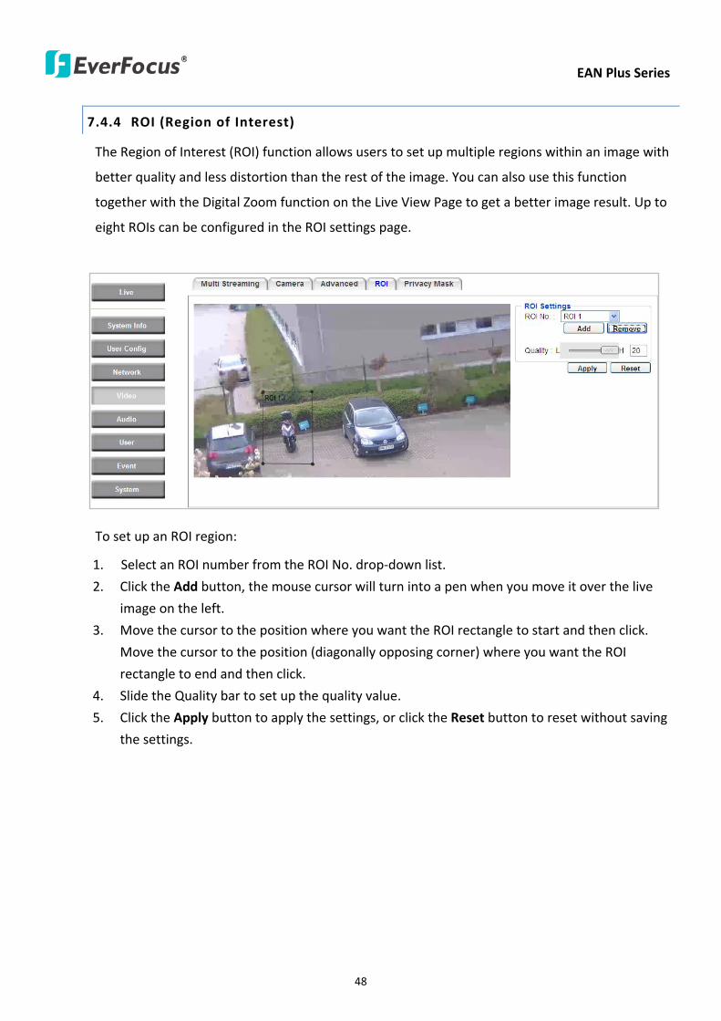
EAN Plus Series
48
744 ROI (Region of Interest)
The Region of Interest (ROI) function allows users to set up multiple regions within an image with
better quality and less distortion than the rest of the image You can also use this function
together with the Digital Zoom function on the Live View Page to get a better image result Up to
eight ROIs can be configured in the ROI settings page
To set up an ROI region
1 Select an ROI number from the ROI No drop-down list
2 Click the Add button the mouse cursor will turn into a pen when you move it over the live
image on the left
3 Move the cursor to the position where you want the ROI rectangle to start and then click
Move the cursor to the position (diagonally opposing corner) where you want the ROI
rectangle to end and then click
4 Slide the Quality bar to set up the quality value
5 Click the Apply button to apply the settings or click the Reset button to reset without saving
the settings
EAN Plus Series
49
745 Privacy Mask
The Privacy Mask can block out sensitive areas from view covering the areas with colored or black
and white boxes in both live view and recorded clips This feature is useful when usersrsquo donrsquot want
the sensitive information visible Up to four Privacy Masks can be configured
【Privacy Mask Color Settings】The Modes vary among camera models
Mode Click Color to make the masks appear as colored rectangles on the screen Click BW to
make the masks appear as gray rectangles on the screen Click Mosaic to make the masks appear
as mosaic-effect rectangles on the screen
Level Select the color of the masks if you selected Color Mode Select the level of grayness of the
masks if you selected BW Mode Select the level of smallmiddlelarge if you selected Mosaic
Mode
Click Apply to apply the settings or click Reset to reset without saving the settings
Color Tabs Click on a color tab to turn your mouse cursor into a pen of that color
You can now create a block of that color on the video screen Move your cursor to the position
where you want your mask rectangle to start and then click Move your cursor to the position
(diagonally opposing corner) where you want your mask rectangle to end and then click The
rectangular area with the selected color will appear The live image will display the rectangular
area with the color you selected If you want to create another mask use one of the other three
colors Each color denotes a different mask area Only one block per color is allowed As the
number of colors suggests you can configure up to four blocks
EAN Plus Series
50
Select All Click to turn the whole screen into a mask area
Clear All Click to delete all configured mask blocks
Eraser Click to turn the mouse cursor into an eraser to delete any block you click on
Area Shows the color and number of the block
Enable Check this box to enable the related mask block
Click Apply to apply the settings or click Reset to reset without saving the settings
EAN Plus Series
51
75 Audio
The EAN Plus series IP camera can transmit audio to your computer if you have connected an external
microphone to its audio Input cable It can also receive audio input from you and transmit it via an
external speaker if you have connected such a speaker to its audio Output cable
Check the Enable Audio box to enable the camerarsquos audio function The camera will now act as a
digital bridge (via the IP network) between any connected audio input device and any connected
audio device
Adjust the Audio Input Volume if you have external audio input devices (microphones) connected to
the camera and if there are problems with the sound input being too low or high
Click Apply to save all settings or click Reset to cancel
EAN Plus Series
52
76 User
761 User Information
The system administrator can create up to ten user accounts on this page
To set up a user account
1 Highlight a user account and click the Modify button The following dialog box appears
2 Type the account name account description and password for the account Type the password
again in the Confirm field
3 Select an authority level for the user account from the Authority drop-down list
bull Supervisor Administrator The only difference between a supervisor and administrator is
that a supervisor can edit an administratorrsquos account and password but an administrator
cannot edit the supervisorrsquos account and password Multiple administrators can be
configured but there can be only one supervisor The supervisor and administrators all
have unrestricted access to the Settings submenus and can determine the registration of
all other users
EAN Plus Series
53
bull User A user can view the Live View page and view the system network video and audio
information A user can only adjust the User Config page settings The user does not have
access to the User Event and System pages
bull Guest The lowest level of access which only allows the user access to the Live View page
4 Select Active or Disable from the Status drop-down list to active or disable the user account
5 Click On in the SD Card Playback field to allow the user to access the SD card playback
function
6 Click OK
7 Click Apply to save all the settings
EAN Plus Series
54
762 IP Address Filter
Use this page to specify IP addresses that are not allowed to access this camera By default any IP
address can access the camera
Note The Allowed List addresses only become relevant when the Denied List contains a network
or range and the supervisor wants to allow one or more IP addresses within that excluded range
or network In such a scenario the user would enter the excluded range or network in the
Denied List and enter the exceptions in the Allowed List
To set up the IP Address Filter
1 Select Denied List Click the Add button the following dialog box appears
2 Select an IP type from the IP Type drop-down list
3 Select a network rule from the Rule drop-down list type the IP address and click OK
Single Type a single IP address in the IP Address field below
Network Type the IP address and subnet mask in the field below
Range Type a range for the IP addresses
4 If you have set up an IP range in Step 3 you can optionally set up the Allowed List to allow one
or more IP addresses within the setup IP range to access the IP camera
5 Click Apply
EAN Plus Series
55
77 Event
You can set up the Motion Detection event Tamper Detection event or the Alarm IO to automatically
notify the users when an event occurs or an alarm is triggered You can also set up a schedule to
automatically record the videos when an event occurs or an alarm is triggered
771 Event Settings
You can create a total of ten event or alarm settings page in the Event List
【Event List】
Click the Add button and the following Event Configuration Window appears
EAN Plus Series
56
Enter Event Name Type an event name
Event Triggered by Select an event or alarm type for the to-be-specified-below reactions
Alarm Input Select this if you want a reaction trigger coming from any external connected sensor
to activate a to-be-specified-below reactions via the camera system Make sure that a suitable
device is actually connected to the alarm input relay
Manual Trigger Select this option if you want to manually trigger the alarm by clicking the Trigger
Event button on the Live View Page
Motion Detection Select this option if you want motion in a specified part of the camerarsquos viewing
rectangle (the screen image) to trigger the to-be-specified-below reactions
Tampering Detection Select this option if you want the camerarsquos tampering detection sensor to
trigger the to-be-specified-below reactions
Schedule Recording Select this option if you want the Schedule Recording periods configured in
the recording schedule (the Settings gt Event gt Schedule page) to activate this event In this
scenario a preconfigured event reaction like a log entry will list the start and end times of each
period Actual recording will only be triggered if the event is preconfigured to do so
Enable This Event Select to activate the event
Enable Re-trigger Click to set a minimum time after the event is triggered before the event
can be triggered again
Enable Pre-trigger Buffer Click if you want the Event reaction (as selected in the ldquoNotification
Overrdquo field below) to be the activation of the video recording function and if you want the
recording to include the video feed from the time period (configurable on the previous ldquoEvent
Settingsrdquo page) just before the Event trigger occurred
Enable Post-trigger Buffer Click if you want the Event reaction (as selected in the Notification
Over field) to be the activation of the video recording function and if you want the recording
to include the video feed from a time period (configurable on the Event Settings page) just
after the Event trigger occurred
Motion Area Select a setup motion detection area from the drop down list Note this
function only becomes relevant after the Motion Detection areas have been set up (see 772
Motion Detection)
Notification Over Select the desired notification types form the following items
Log Click if you want the camera to list the eventrsquos details in its log if the event is triggered
Trigger Alarm Output Click if you want the camera to relay the event reaction to a device
attached to the alarm relay output wire and then set up the alarm output duration time
EAN Plus Series
57
Send Mail Notification Click if you want the camera to send an Event notification email to the
email address entered in the Set SMTP Server(email) field of the Network gt SMTPFTP page if
the Event occurs (see 733 SMTP FTP)
Upload to FTP Click if you want the camera to upload recorded footage to the FTP server
entered in the Set SMTP Server(email) field of the Network gt SMTPFTP page if the Event
occurs (see 733 SMTP FTP)
Record to SD Card Click if you want the camera to start recording its video feed (when the
event occurs) on an on-camera SD Card (if such a card has been inserted)
Note The recording will only be as long as the combined Pre- and Post-trigger Buffers so
make sure you enable at least one of these buffers especially the Post-trigger Buffer
Record to PC Check this box if you want the camera to start recording its video feed (when
the event occurs) on the same folder on the same PC as configured on the User Config gt
RecordingSnapshot page (if such a folder has been enabled and configured)
Note The recording will only be as long as the combined Pre- and Post-trigger Buffers (and
for as long as the event trigger is happening ndash eg a motion is detected) so make sure you
enable at least one of these buffers especially the Post-trigger Buffer
Network Alarm Check this box if you want the camera to send a network alarm signal (when
the event occurs) to the CMS servers configured on the Network gt Network Alarm page (see
736 Network Alarm)
Click OK to save all settings or click Cancel to cancel
【PrePost Trigger Settings】
Pre-trigger Buffer Select the duration for the buffer This will determine the amount of footage
(length of time) before the event trigger moment that will be included in an event-triggered video
recording if that buffer and video recording has been enabled in the Event Configuration Window
Post-trigger Buffer Select the duration for the buffer This will determine the amount of footage
(length of time) after the event trigger moment that will be included in an event-triggered video
recording if that buffer and video recording has been enabled in the Event Configuration Window
Click Apply to save all settings or click Reset to cancel
EAN Plus Series
58
772 Motion Detection
Use this page to configure up to four areas in which motion will be detected When a motion is
detected by the camera the motion detection icon will appear at the top right of the
Live page to alert the user This function can also be linked with correctly configured Events to
trigger Event reactions like the activation of video recording periods snapshots alarms etc
Color Tabs Click on a color tab to turn your mouse cursor into a pen of that color
You can now create a block of that color on the video screen Move your cursor to the position
where you want your detection rectangle to start and then click Move your cursor to the position
(diagonally opposing corner) where you want your detection rectangle to end and then click The
rectangular area with the selected color will appear This block will be an area inside which the
camera will detect motion If you want to create another detection area use one of the other three
palette colors Each color denotes a different detection area Only one block per color is allowed As
the number of colors suggests you can configure up to four blocks
Select All Click to turn the whole screen into a motion detection area
Clear All Click to delete all configured motion detection blocks
Eraser Click to turn your mouse cursor into an eraser to delete any block you click on
Area Shows the color and numberID of the block
Enable Check this box to enable the related motion detection block
Sensitivity Set the sensitivity of the motion detection sensor function
Click Apply to save all settings or click Reset to cancel
EAN Plus Series
59
773 Tamper Detection
Use this page to set the number of seconds that an alarm signal will be active if the device is
physically tampered (moved covered up or out of focus
774 Alarm IO
Use this page to set the type of trigger input and the type of output contact for the camerarsquos alarm
channel
EAN Plus Series
60
775 Schedule
Use this page to configure a schedule for periods during which the camera should deactivate all
user-activated Events (gray Deselect periods) or when the camera should deactivate all
user-activated Events except Schedule Recording (SR) events (blue Schedule Recording-only
periods) or when the camera should deactivate only SR events (red Event Recording-only periods)
or when it should enable all activated Events (yellow periods)
Event Recording Click this button to make every hour block you click on red A red block represents
an Event Recording-only block which represents an hour when the camera will deactivate all
preconfigured activated Schedule Recording events and keep all the other activated events active
Schedule Recording Click this button to make every hour block you click on blue A blue block
represents a Schedule Recording-only block which represents an hour when the camera will
deactivate all other preconfigured activated events and keep only the preconfigured activated
Schedule Recording events active
Event + Schedule Click this button to make every hour block you click on yellow A yellow block
represents an hour in which all activated events including Schedule Recording events will be
active
Deselect Click this button to make every hour block become grey A grey block represents an hour
in which all activated events including Schedule Recording events will be inactive
Click Apply to save all settings or click Reset to cancel
EAN Plus Series
61
78 System
You can set up the systemrsquos time and SD card settings and to do maintenance and reset actions like
reboots and upgrades
781 DateTime
【Machine Name Settings】If required enter a new name for the machine This name will be visible
in the Machine Name field of the IP Utility software which is included in the software CD
【Set Time Zone】Set the time zone of the camerarsquos location
【Set DateTime Manually】Set the datetime here if you wonrsquot be using an NTP server to update the
datetime (see below)
【Set DateTime Sync】Enter the Network Time Protocol server if applicable The camerarsquos time will
be automatically adjusted by synchronizing with the NTP server
Click Apply to save all settings or click Reset to cancel
EAN Plus Series
62
782 Daylight Saving
Click Enable Daylight Saving to enable this schedule and select the dates when the regionrsquos
daylight saving period begins and ends Click Apply to save all settings or click Reset to cancel
783 SD Card
Use this page to prepare the system for safely removing the SD Card from its slot
【Setup SD Card】
Notification Select the percentage of storage space that should be left on the card before the
camera notifies you of the impending storage shortage or overwrite
Event Recording Select if you want Event Recording only FTP Backup only or both
Overwrite Click ON if you want the card to start writing over recorded footage when its memory is
full Click OFF if you want the card to stop recording new footage when its memory is full
【SD Card Utility】
Capacity This shows you how much card memory has been used and how much memory capacity
remains on the card
Remove Click this button before removing the card from the system
Format Click this button to format the card All data saved on the SD card will be removed if the
card is formatted
EAN Plus Series
63
784 Maintenance
【Maintenance Server】
Reboot Click this button to reboot the unit without changing any of the settings Use this function if
the unit is not behaving as expected
Restore Click this button to restart and reset most of the current settings to their factory default
values The only settings that will not be changed to default are
bull IP settings
bull DDNS settings
Default The Default button should be used with caution Pressing this button will return all of the
cameras settings including the IP address to the factory default values The camera will then have
to be reconfigured
【SaveLoad Configuration Server】
Save To make a backup file of the machinersquos current configurations press Save to save all the
configurations to a config file This will enable the user to reload these configuration settings if the
settings are changed and there is unexpected behavior
Load To load a previously saved configuration press the Browse button to locate the saved config
file (see above) and then click the Load button The systemrsquos settings will be restored to the saved
configuration
EAN Plus Series
64
【SaveLoad Video Configuration Server】
Save To make a backup file of the machinersquos video configurations press Save to save the video
configurations to a config file This will enable the user to reload these configuration settings if the
settings are changed and there is unexpected behavior
Load To load a previously saved video configuration press the Browse button to locate the saved
config file (see above) and then click the Load button The systemrsquos settings will be restored to the
saved video configuration
【Upgrade Firmware】Click the Browse button to find a previously prepared firmware upgrade file
Click Upgrade to install the new firmware
Note
1 Do not disconnect power to the unit during the upgrade sequence The unit will reboot
automatically after the upgrade has completed (1-5 minutes)
2 During the upgrade process all event recording actions will be stopped Event recording
actions will resume after the camera is rebooted
3 If the ldquoFile Error Please re-loginrdquo warning message appears when upgrading the firmware
please try the following instructions
a Go to Internet Explorer gt Tools gt Internet Option gt Security gt Custom
b Find and enable the Include local directory path when uploading files to a server
EAN Plus Series
65
8 Upgrading Firmware Using IP Utility
You can upgrade the Firmware using the IP Utility software included in the software CD
1 Install and then start the IPU program The following dialog box appears
2 Click Find Devices to search the cameras connected in the LAN The default network values of the
cameras will be displayed By default the network protocol of the camera is DHCP
3 Select a camera and click LoginMulti Login to log in the camera
4 Type the user ID and password Click OK
Note
1 The default user ID is user1 and the default password is 11111111
2 If you select more than one camera that has the same user ID password you will be able
to log in several cameras at once
EAN Plus Series
66
5 Highlight the camera and then click Upgrade Firmware A browsing window appears
6 Select the firmware file (evb) and then click Open The IP Utility will automatically upgrade the
firmware
The camera will reboot once the update is complete Click Find Devices the new firmware version
should be displayed in the last part of the Machine Name
EAN Plus Series
67
9 Specifications
Model EAN3120 Plus EAN3220 Plus EAN3300 Plus
Camera
Image Sensor 13 Panasonic CMOS 128 Sony CMOS
Megapixel 13 MP 2 MP 3 MP
Picture Elements (H x V) 1280 x 1024 1944 x 1092 2048 x 1536
Min Illuminations 003 Lux at F14
Electronic Shutter (Sec) 85 ~ 160000 2 ~ 150000 1 ~ 110000
Scanning System NTSC PAL
WDR Yes Yes No
BLC Yes
Gain Control Yes
White Balance Yes
Lens
Mounting Type C CS
Day Night Yes (with removable auto IR-cut filter)
IRIS Control DC Electrical IRIS Lens IRIS
Video
Video Compression H264 MJPEG
Resolution
NTSC
2048 x 1536 1920 x 1200 (for EAN3300 Plus only)
1920 x 1080 (for EAN3300 Plus 3220 Plus only)
1280 x 1024 1280 x 720 1024 x 768 720 x 480 704 x 480 640 x 480
352 x 240 320 x 240 160 x 120
PAL
2048 x 1536 1920 x 1200 (for EAN3300 Plus only)
1920 x 1080 (for EAN3300 Plus 3220 Plus only)
1280 x 1024 1280 x 720 1024 x 768 720 x 576 704 x 576 640 x 480
352 x 288 320 x 240 160 x 120
Frame Rate 30 fps at 1280 x 1024 30 fps at 1920 x 1080 15 fps at 2048 x 1536
Audio
Audio Streaming Two-way audio
Audio Compression G711
EAN Plus Series
68
Network
Interface 10 100 Base-T Ethernet RJ-45 socket
Supported Protocols
TCPIP IPV6 UDP ICMP DHCP NTP DNS DDNS SMTP SNMP FTP
HTTP HTTPs PPPoE UPnP Bonjour RTP RTSP RTCP IGMP ARP ONVIF
PSIA
Connector
Power DC female port PoE
Ethernet RJ-45
Audio 1 In (phone jack for microphone)
1 Out (phone jack for Speaker)
Alarm IO Terminal IO wires
Local Storage Micro SD SDHC memory card slot
TV-Out BNC socket composite 1 V p-p 75 Ω
General
Power Source DC 12V PoE (IEEE8023af)
Power Consumption
(IR LEDs On)
5W (DC 12V)
621W (PoE)
5W (DC 12V)
522W (PoE)
5W (DC 12V)
536W (PoE)
Operating Temperature 0degC ~ +50degC 32degF ~ +122degF
Humidity 20 to 80 (no condensation)
Safety CE FCC
Dimensions (L x W x H) 117 x 56 x 68 mm 46 x 22 x 27 in
Weight 410 g 09 lb
EverFocus Electronics Corp EverFocus Taiwan 12F No79 Sec 1 Shin-Tai Wu Road Hsi-Chih Taipei Taiwan TEL +886 2 2698 2334 FAX +886 2 2698 2380 wwweverfocuscomtw marketingeverfocuscomtw
EverFocus Europe - Germany Albert-Einstein-Strasse 1 D-46446 Emmerich Germany TEL +49 2822 93940 FAX +49 2822 939495 wwweverfocusde infoeverfocusde
EverFocus China - Beijing Room 609 Technology Trade Building Shangdi Information Industry Base Haidian District Beijing 100085 China TEL +86 10 6297 3336~39 FAX +86 10 6297 1423 wwweverfocuscomcn marketingeverfocuscomcn
EverFocus China - Shenzhen 4F No 2 D4 Building Wan Yelong Industrial Park Tangtou Road Shiyan Baoan Shenzhen Guangdong 518101 China TEL +86 755 2765 1313 FAX +86 755 2765 0337 wwweverfocuscomcn marketingeverfocuscomcn
EverFocus USA - California 1801 Highland Avenue Unit A Duarte CA 91010 USA TEL +1 626 844 8888 FAX +1 626 844 8838 wwweverfocuscom saleseverfocuscom
EverFocus USA - New York 415 Oser Avenue Unit S Hauppauge NY 11788 USA TEL +1 631 436 5070 FAX +1 631 436 5027 wwweverfocuscom saleseverfocuscom
EverFocus Japan 5F Kinshicho City Building 2-13-4 Koto-BashiSumida-Ku Tokyo 130-0022 Japan TEL +81 3 5625 8188 FAX +81 3 5625 8189 wwweverfocuscojp infoeverfocuscojp
EverFocus Europe - UK Unit 12 Spitfire Business Park Hawker Road Croydon Surrey CR0 4WD UK TEL +44 20 8649 9757 +44 845 430 9999 FAX +44 20 8649 9907 wwweverfocusukcouk salesukeverfocuscom
EverFocus India Suite 803 Housefin Bhavan C-21 Bandra Kurla Complex Bandra (East) Mumbai 400051 India TEL +91 22 6128 8700 FAX +91 22 6128 8705 wwweverfocusin saleseverfocusin
PN 4605PQ3120B010A-VerC
Your EverFocus product is designed and manufactured with high quality materials and components which can be recycled and reused This symbol means that electrical and electronic equipment at their end-of-life should be disposed of separately from your household waste Please dispose of this equipment at your local community waste collectionrecycling centre In the European Union there are separate collection systems for used electrical and electronic product Please help us to conserve the environment we live in
Ihr EverFocus Produkt wurde entwickelt und hergestellt mit qualitativ hochwertigen Materialien und Komponenten die recycelt und wieder verwendet werden koumlnnen Dieses Symbol bedeutet dass elektrische und elektronische Geraumlte am Ende ihrer Nutzungsdauer vom Hausmuumlll getrennt entsorgt werden sollen Bitte entsorgen Sie dieses Geraumlt bei Ihrer oumlrtlichen kommunalen Sammelstelle oder im Recycling Centre Helfen Sie uns bitte die Umwelt zu erhalten in der wir leben
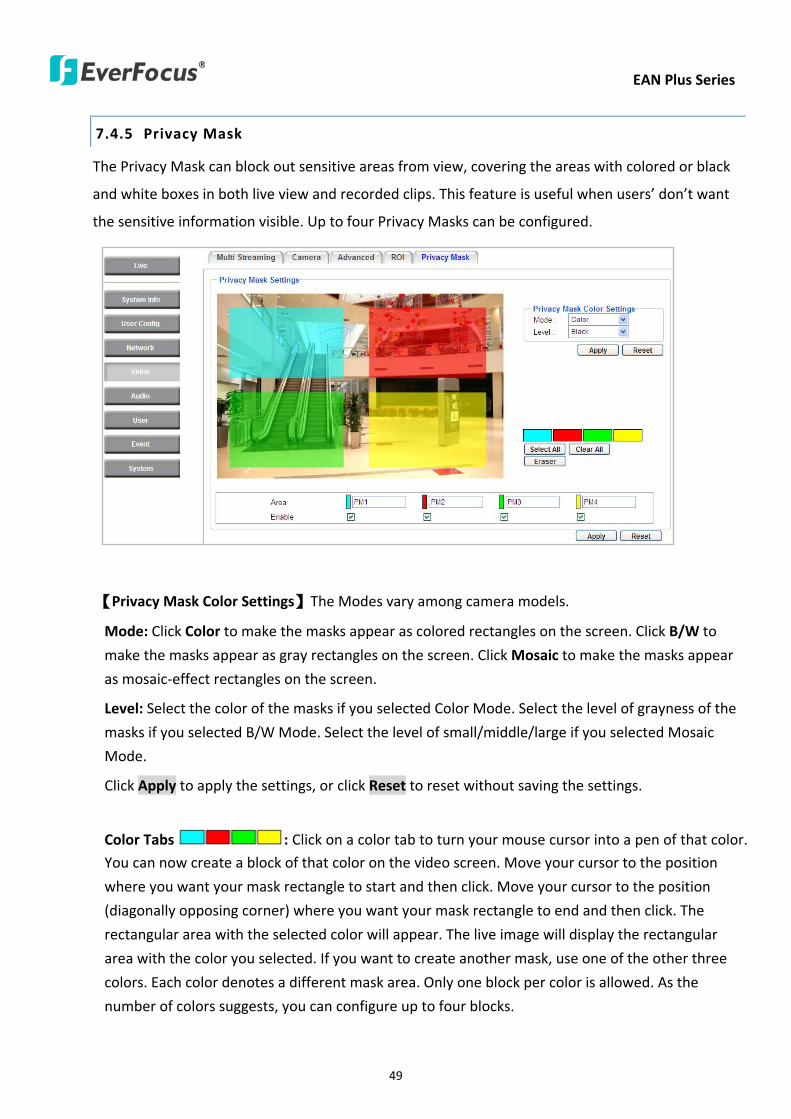
EAN Plus Series
50
Select All Click to turn the whole screen into a mask area
Clear All Click to delete all configured mask blocks
Eraser Click to turn the mouse cursor into an eraser to delete any block you click on
Area Shows the color and number of the block
Enable Check this box to enable the related mask block
Click Apply to apply the settings or click Reset to reset without saving the settings
EAN Plus Series
51
75 Audio
The EAN Plus series IP camera can transmit audio to your computer if you have connected an external
microphone to its audio Input cable It can also receive audio input from you and transmit it via an
external speaker if you have connected such a speaker to its audio Output cable
Check the Enable Audio box to enable the camerarsquos audio function The camera will now act as a
digital bridge (via the IP network) between any connected audio input device and any connected
audio device
Adjust the Audio Input Volume if you have external audio input devices (microphones) connected to
the camera and if there are problems with the sound input being too low or high
Click Apply to save all settings or click Reset to cancel
EAN Plus Series
52
76 User
761 User Information
The system administrator can create up to ten user accounts on this page
To set up a user account
1 Highlight a user account and click the Modify button The following dialog box appears
2 Type the account name account description and password for the account Type the password
again in the Confirm field
3 Select an authority level for the user account from the Authority drop-down list
bull Supervisor Administrator The only difference between a supervisor and administrator is
that a supervisor can edit an administratorrsquos account and password but an administrator
cannot edit the supervisorrsquos account and password Multiple administrators can be
configured but there can be only one supervisor The supervisor and administrators all
have unrestricted access to the Settings submenus and can determine the registration of
all other users
EAN Plus Series
53
bull User A user can view the Live View page and view the system network video and audio
information A user can only adjust the User Config page settings The user does not have
access to the User Event and System pages
bull Guest The lowest level of access which only allows the user access to the Live View page
4 Select Active or Disable from the Status drop-down list to active or disable the user account
5 Click On in the SD Card Playback field to allow the user to access the SD card playback
function
6 Click OK
7 Click Apply to save all the settings
EAN Plus Series
54
762 IP Address Filter
Use this page to specify IP addresses that are not allowed to access this camera By default any IP
address can access the camera
Note The Allowed List addresses only become relevant when the Denied List contains a network
or range and the supervisor wants to allow one or more IP addresses within that excluded range
or network In such a scenario the user would enter the excluded range or network in the
Denied List and enter the exceptions in the Allowed List
To set up the IP Address Filter
1 Select Denied List Click the Add button the following dialog box appears
2 Select an IP type from the IP Type drop-down list
3 Select a network rule from the Rule drop-down list type the IP address and click OK
Single Type a single IP address in the IP Address field below
Network Type the IP address and subnet mask in the field below
Range Type a range for the IP addresses
4 If you have set up an IP range in Step 3 you can optionally set up the Allowed List to allow one
or more IP addresses within the setup IP range to access the IP camera
5 Click Apply
EAN Plus Series
55
77 Event
You can set up the Motion Detection event Tamper Detection event or the Alarm IO to automatically
notify the users when an event occurs or an alarm is triggered You can also set up a schedule to
automatically record the videos when an event occurs or an alarm is triggered
771 Event Settings
You can create a total of ten event or alarm settings page in the Event List
【Event List】
Click the Add button and the following Event Configuration Window appears
EAN Plus Series
56
Enter Event Name Type an event name
Event Triggered by Select an event or alarm type for the to-be-specified-below reactions
Alarm Input Select this if you want a reaction trigger coming from any external connected sensor
to activate a to-be-specified-below reactions via the camera system Make sure that a suitable
device is actually connected to the alarm input relay
Manual Trigger Select this option if you want to manually trigger the alarm by clicking the Trigger
Event button on the Live View Page
Motion Detection Select this option if you want motion in a specified part of the camerarsquos viewing
rectangle (the screen image) to trigger the to-be-specified-below reactions
Tampering Detection Select this option if you want the camerarsquos tampering detection sensor to
trigger the to-be-specified-below reactions
Schedule Recording Select this option if you want the Schedule Recording periods configured in
the recording schedule (the Settings gt Event gt Schedule page) to activate this event In this
scenario a preconfigured event reaction like a log entry will list the start and end times of each
period Actual recording will only be triggered if the event is preconfigured to do so
Enable This Event Select to activate the event
Enable Re-trigger Click to set a minimum time after the event is triggered before the event
can be triggered again
Enable Pre-trigger Buffer Click if you want the Event reaction (as selected in the ldquoNotification
Overrdquo field below) to be the activation of the video recording function and if you want the
recording to include the video feed from the time period (configurable on the previous ldquoEvent
Settingsrdquo page) just before the Event trigger occurred
Enable Post-trigger Buffer Click if you want the Event reaction (as selected in the Notification
Over field) to be the activation of the video recording function and if you want the recording
to include the video feed from a time period (configurable on the Event Settings page) just
after the Event trigger occurred
Motion Area Select a setup motion detection area from the drop down list Note this
function only becomes relevant after the Motion Detection areas have been set up (see 772
Motion Detection)
Notification Over Select the desired notification types form the following items
Log Click if you want the camera to list the eventrsquos details in its log if the event is triggered
Trigger Alarm Output Click if you want the camera to relay the event reaction to a device
attached to the alarm relay output wire and then set up the alarm output duration time
EAN Plus Series
57
Send Mail Notification Click if you want the camera to send an Event notification email to the
email address entered in the Set SMTP Server(email) field of the Network gt SMTPFTP page if
the Event occurs (see 733 SMTP FTP)
Upload to FTP Click if you want the camera to upload recorded footage to the FTP server
entered in the Set SMTP Server(email) field of the Network gt SMTPFTP page if the Event
occurs (see 733 SMTP FTP)
Record to SD Card Click if you want the camera to start recording its video feed (when the
event occurs) on an on-camera SD Card (if such a card has been inserted)
Note The recording will only be as long as the combined Pre- and Post-trigger Buffers so
make sure you enable at least one of these buffers especially the Post-trigger Buffer
Record to PC Check this box if you want the camera to start recording its video feed (when
the event occurs) on the same folder on the same PC as configured on the User Config gt
RecordingSnapshot page (if such a folder has been enabled and configured)
Note The recording will only be as long as the combined Pre- and Post-trigger Buffers (and
for as long as the event trigger is happening ndash eg a motion is detected) so make sure you
enable at least one of these buffers especially the Post-trigger Buffer
Network Alarm Check this box if you want the camera to send a network alarm signal (when
the event occurs) to the CMS servers configured on the Network gt Network Alarm page (see
736 Network Alarm)
Click OK to save all settings or click Cancel to cancel
【PrePost Trigger Settings】
Pre-trigger Buffer Select the duration for the buffer This will determine the amount of footage
(length of time) before the event trigger moment that will be included in an event-triggered video
recording if that buffer and video recording has been enabled in the Event Configuration Window
Post-trigger Buffer Select the duration for the buffer This will determine the amount of footage
(length of time) after the event trigger moment that will be included in an event-triggered video
recording if that buffer and video recording has been enabled in the Event Configuration Window
Click Apply to save all settings or click Reset to cancel
EAN Plus Series
58
772 Motion Detection
Use this page to configure up to four areas in which motion will be detected When a motion is
detected by the camera the motion detection icon will appear at the top right of the
Live page to alert the user This function can also be linked with correctly configured Events to
trigger Event reactions like the activation of video recording periods snapshots alarms etc
Color Tabs Click on a color tab to turn your mouse cursor into a pen of that color
You can now create a block of that color on the video screen Move your cursor to the position
where you want your detection rectangle to start and then click Move your cursor to the position
(diagonally opposing corner) where you want your detection rectangle to end and then click The
rectangular area with the selected color will appear This block will be an area inside which the
camera will detect motion If you want to create another detection area use one of the other three
palette colors Each color denotes a different detection area Only one block per color is allowed As
the number of colors suggests you can configure up to four blocks
Select All Click to turn the whole screen into a motion detection area
Clear All Click to delete all configured motion detection blocks
Eraser Click to turn your mouse cursor into an eraser to delete any block you click on
Area Shows the color and numberID of the block
Enable Check this box to enable the related motion detection block
Sensitivity Set the sensitivity of the motion detection sensor function
Click Apply to save all settings or click Reset to cancel
EAN Plus Series
59
773 Tamper Detection
Use this page to set the number of seconds that an alarm signal will be active if the device is
physically tampered (moved covered up or out of focus
774 Alarm IO
Use this page to set the type of trigger input and the type of output contact for the camerarsquos alarm
channel
EAN Plus Series
60
775 Schedule
Use this page to configure a schedule for periods during which the camera should deactivate all
user-activated Events (gray Deselect periods) or when the camera should deactivate all
user-activated Events except Schedule Recording (SR) events (blue Schedule Recording-only
periods) or when the camera should deactivate only SR events (red Event Recording-only periods)
or when it should enable all activated Events (yellow periods)
Event Recording Click this button to make every hour block you click on red A red block represents
an Event Recording-only block which represents an hour when the camera will deactivate all
preconfigured activated Schedule Recording events and keep all the other activated events active
Schedule Recording Click this button to make every hour block you click on blue A blue block
represents a Schedule Recording-only block which represents an hour when the camera will
deactivate all other preconfigured activated events and keep only the preconfigured activated
Schedule Recording events active
Event + Schedule Click this button to make every hour block you click on yellow A yellow block
represents an hour in which all activated events including Schedule Recording events will be
active
Deselect Click this button to make every hour block become grey A grey block represents an hour
in which all activated events including Schedule Recording events will be inactive
Click Apply to save all settings or click Reset to cancel
EAN Plus Series
61
78 System
You can set up the systemrsquos time and SD card settings and to do maintenance and reset actions like
reboots and upgrades
781 DateTime
【Machine Name Settings】If required enter a new name for the machine This name will be visible
in the Machine Name field of the IP Utility software which is included in the software CD
【Set Time Zone】Set the time zone of the camerarsquos location
【Set DateTime Manually】Set the datetime here if you wonrsquot be using an NTP server to update the
datetime (see below)
【Set DateTime Sync】Enter the Network Time Protocol server if applicable The camerarsquos time will
be automatically adjusted by synchronizing with the NTP server
Click Apply to save all settings or click Reset to cancel
EAN Plus Series
62
782 Daylight Saving
Click Enable Daylight Saving to enable this schedule and select the dates when the regionrsquos
daylight saving period begins and ends Click Apply to save all settings or click Reset to cancel
783 SD Card
Use this page to prepare the system for safely removing the SD Card from its slot
【Setup SD Card】
Notification Select the percentage of storage space that should be left on the card before the
camera notifies you of the impending storage shortage or overwrite
Event Recording Select if you want Event Recording only FTP Backup only or both
Overwrite Click ON if you want the card to start writing over recorded footage when its memory is
full Click OFF if you want the card to stop recording new footage when its memory is full
【SD Card Utility】
Capacity This shows you how much card memory has been used and how much memory capacity
remains on the card
Remove Click this button before removing the card from the system
Format Click this button to format the card All data saved on the SD card will be removed if the
card is formatted
EAN Plus Series
63
784 Maintenance
【Maintenance Server】
Reboot Click this button to reboot the unit without changing any of the settings Use this function if
the unit is not behaving as expected
Restore Click this button to restart and reset most of the current settings to their factory default
values The only settings that will not be changed to default are
bull IP settings
bull DDNS settings
Default The Default button should be used with caution Pressing this button will return all of the
cameras settings including the IP address to the factory default values The camera will then have
to be reconfigured
【SaveLoad Configuration Server】
Save To make a backup file of the machinersquos current configurations press Save to save all the
configurations to a config file This will enable the user to reload these configuration settings if the
settings are changed and there is unexpected behavior
Load To load a previously saved configuration press the Browse button to locate the saved config
file (see above) and then click the Load button The systemrsquos settings will be restored to the saved
configuration
EAN Plus Series
64
【SaveLoad Video Configuration Server】
Save To make a backup file of the machinersquos video configurations press Save to save the video
configurations to a config file This will enable the user to reload these configuration settings if the
settings are changed and there is unexpected behavior
Load To load a previously saved video configuration press the Browse button to locate the saved
config file (see above) and then click the Load button The systemrsquos settings will be restored to the
saved video configuration
【Upgrade Firmware】Click the Browse button to find a previously prepared firmware upgrade file
Click Upgrade to install the new firmware
Note
1 Do not disconnect power to the unit during the upgrade sequence The unit will reboot
automatically after the upgrade has completed (1-5 minutes)
2 During the upgrade process all event recording actions will be stopped Event recording
actions will resume after the camera is rebooted
3 If the ldquoFile Error Please re-loginrdquo warning message appears when upgrading the firmware
please try the following instructions
a Go to Internet Explorer gt Tools gt Internet Option gt Security gt Custom
b Find and enable the Include local directory path when uploading files to a server
EAN Plus Series
65
8 Upgrading Firmware Using IP Utility
You can upgrade the Firmware using the IP Utility software included in the software CD
1 Install and then start the IPU program The following dialog box appears
2 Click Find Devices to search the cameras connected in the LAN The default network values of the
cameras will be displayed By default the network protocol of the camera is DHCP
3 Select a camera and click LoginMulti Login to log in the camera
4 Type the user ID and password Click OK
Note
1 The default user ID is user1 and the default password is 11111111
2 If you select more than one camera that has the same user ID password you will be able
to log in several cameras at once
EAN Plus Series
66
5 Highlight the camera and then click Upgrade Firmware A browsing window appears
6 Select the firmware file (evb) and then click Open The IP Utility will automatically upgrade the
firmware
The camera will reboot once the update is complete Click Find Devices the new firmware version
should be displayed in the last part of the Machine Name
EAN Plus Series
67
9 Specifications
Model EAN3120 Plus EAN3220 Plus EAN3300 Plus
Camera
Image Sensor 13 Panasonic CMOS 128 Sony CMOS
Megapixel 13 MP 2 MP 3 MP
Picture Elements (H x V) 1280 x 1024 1944 x 1092 2048 x 1536
Min Illuminations 003 Lux at F14
Electronic Shutter (Sec) 85 ~ 160000 2 ~ 150000 1 ~ 110000
Scanning System NTSC PAL
WDR Yes Yes No
BLC Yes
Gain Control Yes
White Balance Yes
Lens
Mounting Type C CS
Day Night Yes (with removable auto IR-cut filter)
IRIS Control DC Electrical IRIS Lens IRIS
Video
Video Compression H264 MJPEG
Resolution
NTSC
2048 x 1536 1920 x 1200 (for EAN3300 Plus only)
1920 x 1080 (for EAN3300 Plus 3220 Plus only)
1280 x 1024 1280 x 720 1024 x 768 720 x 480 704 x 480 640 x 480
352 x 240 320 x 240 160 x 120
PAL
2048 x 1536 1920 x 1200 (for EAN3300 Plus only)
1920 x 1080 (for EAN3300 Plus 3220 Plus only)
1280 x 1024 1280 x 720 1024 x 768 720 x 576 704 x 576 640 x 480
352 x 288 320 x 240 160 x 120
Frame Rate 30 fps at 1280 x 1024 30 fps at 1920 x 1080 15 fps at 2048 x 1536
Audio
Audio Streaming Two-way audio
Audio Compression G711
EAN Plus Series
68
Network
Interface 10 100 Base-T Ethernet RJ-45 socket
Supported Protocols
TCPIP IPV6 UDP ICMP DHCP NTP DNS DDNS SMTP SNMP FTP
HTTP HTTPs PPPoE UPnP Bonjour RTP RTSP RTCP IGMP ARP ONVIF
PSIA
Connector
Power DC female port PoE
Ethernet RJ-45
Audio 1 In (phone jack for microphone)
1 Out (phone jack for Speaker)
Alarm IO Terminal IO wires
Local Storage Micro SD SDHC memory card slot
TV-Out BNC socket composite 1 V p-p 75 Ω
General
Power Source DC 12V PoE (IEEE8023af)
Power Consumption
(IR LEDs On)
5W (DC 12V)
621W (PoE)
5W (DC 12V)
522W (PoE)
5W (DC 12V)
536W (PoE)
Operating Temperature 0degC ~ +50degC 32degF ~ +122degF
Humidity 20 to 80 (no condensation)
Safety CE FCC
Dimensions (L x W x H) 117 x 56 x 68 mm 46 x 22 x 27 in
Weight 410 g 09 lb
EverFocus Electronics Corp EverFocus Taiwan 12F No79 Sec 1 Shin-Tai Wu Road Hsi-Chih Taipei Taiwan TEL +886 2 2698 2334 FAX +886 2 2698 2380 wwweverfocuscomtw marketingeverfocuscomtw
EverFocus Europe - Germany Albert-Einstein-Strasse 1 D-46446 Emmerich Germany TEL +49 2822 93940 FAX +49 2822 939495 wwweverfocusde infoeverfocusde
EverFocus China - Beijing Room 609 Technology Trade Building Shangdi Information Industry Base Haidian District Beijing 100085 China TEL +86 10 6297 3336~39 FAX +86 10 6297 1423 wwweverfocuscomcn marketingeverfocuscomcn
EverFocus China - Shenzhen 4F No 2 D4 Building Wan Yelong Industrial Park Tangtou Road Shiyan Baoan Shenzhen Guangdong 518101 China TEL +86 755 2765 1313 FAX +86 755 2765 0337 wwweverfocuscomcn marketingeverfocuscomcn
EverFocus USA - California 1801 Highland Avenue Unit A Duarte CA 91010 USA TEL +1 626 844 8888 FAX +1 626 844 8838 wwweverfocuscom saleseverfocuscom
EverFocus USA - New York 415 Oser Avenue Unit S Hauppauge NY 11788 USA TEL +1 631 436 5070 FAX +1 631 436 5027 wwweverfocuscom saleseverfocuscom
EverFocus Japan 5F Kinshicho City Building 2-13-4 Koto-BashiSumida-Ku Tokyo 130-0022 Japan TEL +81 3 5625 8188 FAX +81 3 5625 8189 wwweverfocuscojp infoeverfocuscojp
EverFocus Europe - UK Unit 12 Spitfire Business Park Hawker Road Croydon Surrey CR0 4WD UK TEL +44 20 8649 9757 +44 845 430 9999 FAX +44 20 8649 9907 wwweverfocusukcouk salesukeverfocuscom
EverFocus India Suite 803 Housefin Bhavan C-21 Bandra Kurla Complex Bandra (East) Mumbai 400051 India TEL +91 22 6128 8700 FAX +91 22 6128 8705 wwweverfocusin saleseverfocusin
PN 4605PQ3120B010A-VerC
Your EverFocus product is designed and manufactured with high quality materials and components which can be recycled and reused This symbol means that electrical and electronic equipment at their end-of-life should be disposed of separately from your household waste Please dispose of this equipment at your local community waste collectionrecycling centre In the European Union there are separate collection systems for used electrical and electronic product Please help us to conserve the environment we live in
Ihr EverFocus Produkt wurde entwickelt und hergestellt mit qualitativ hochwertigen Materialien und Komponenten die recycelt und wieder verwendet werden koumlnnen Dieses Symbol bedeutet dass elektrische und elektronische Geraumlte am Ende ihrer Nutzungsdauer vom Hausmuumlll getrennt entsorgt werden sollen Bitte entsorgen Sie dieses Geraumlt bei Ihrer oumlrtlichen kommunalen Sammelstelle oder im Recycling Centre Helfen Sie uns bitte die Umwelt zu erhalten in der wir leben
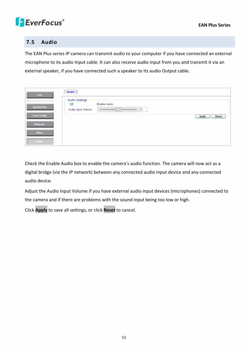
EAN Plus Series
51
75 Audio
The EAN Plus series IP camera can transmit audio to your computer if you have connected an external
microphone to its audio Input cable It can also receive audio input from you and transmit it via an
external speaker if you have connected such a speaker to its audio Output cable
Check the Enable Audio box to enable the camerarsquos audio function The camera will now act as a
digital bridge (via the IP network) between any connected audio input device and any connected
audio device
Adjust the Audio Input Volume if you have external audio input devices (microphones) connected to
the camera and if there are problems with the sound input being too low or high
Click Apply to save all settings or click Reset to cancel
EAN Plus Series
52
76 User
761 User Information
The system administrator can create up to ten user accounts on this page
To set up a user account
1 Highlight a user account and click the Modify button The following dialog box appears
2 Type the account name account description and password for the account Type the password
again in the Confirm field
3 Select an authority level for the user account from the Authority drop-down list
bull Supervisor Administrator The only difference between a supervisor and administrator is
that a supervisor can edit an administratorrsquos account and password but an administrator
cannot edit the supervisorrsquos account and password Multiple administrators can be
configured but there can be only one supervisor The supervisor and administrators all
have unrestricted access to the Settings submenus and can determine the registration of
all other users
EAN Plus Series
53
bull User A user can view the Live View page and view the system network video and audio
information A user can only adjust the User Config page settings The user does not have
access to the User Event and System pages
bull Guest The lowest level of access which only allows the user access to the Live View page
4 Select Active or Disable from the Status drop-down list to active or disable the user account
5 Click On in the SD Card Playback field to allow the user to access the SD card playback
function
6 Click OK
7 Click Apply to save all the settings
EAN Plus Series
54
762 IP Address Filter
Use this page to specify IP addresses that are not allowed to access this camera By default any IP
address can access the camera
Note The Allowed List addresses only become relevant when the Denied List contains a network
or range and the supervisor wants to allow one or more IP addresses within that excluded range
or network In such a scenario the user would enter the excluded range or network in the
Denied List and enter the exceptions in the Allowed List
To set up the IP Address Filter
1 Select Denied List Click the Add button the following dialog box appears
2 Select an IP type from the IP Type drop-down list
3 Select a network rule from the Rule drop-down list type the IP address and click OK
Single Type a single IP address in the IP Address field below
Network Type the IP address and subnet mask in the field below
Range Type a range for the IP addresses
4 If you have set up an IP range in Step 3 you can optionally set up the Allowed List to allow one
or more IP addresses within the setup IP range to access the IP camera
5 Click Apply
EAN Plus Series
55
77 Event
You can set up the Motion Detection event Tamper Detection event or the Alarm IO to automatically
notify the users when an event occurs or an alarm is triggered You can also set up a schedule to
automatically record the videos when an event occurs or an alarm is triggered
771 Event Settings
You can create a total of ten event or alarm settings page in the Event List
【Event List】
Click the Add button and the following Event Configuration Window appears
EAN Plus Series
56
Enter Event Name Type an event name
Event Triggered by Select an event or alarm type for the to-be-specified-below reactions
Alarm Input Select this if you want a reaction trigger coming from any external connected sensor
to activate a to-be-specified-below reactions via the camera system Make sure that a suitable
device is actually connected to the alarm input relay
Manual Trigger Select this option if you want to manually trigger the alarm by clicking the Trigger
Event button on the Live View Page
Motion Detection Select this option if you want motion in a specified part of the camerarsquos viewing
rectangle (the screen image) to trigger the to-be-specified-below reactions
Tampering Detection Select this option if you want the camerarsquos tampering detection sensor to
trigger the to-be-specified-below reactions
Schedule Recording Select this option if you want the Schedule Recording periods configured in
the recording schedule (the Settings gt Event gt Schedule page) to activate this event In this
scenario a preconfigured event reaction like a log entry will list the start and end times of each
period Actual recording will only be triggered if the event is preconfigured to do so
Enable This Event Select to activate the event
Enable Re-trigger Click to set a minimum time after the event is triggered before the event
can be triggered again
Enable Pre-trigger Buffer Click if you want the Event reaction (as selected in the ldquoNotification
Overrdquo field below) to be the activation of the video recording function and if you want the
recording to include the video feed from the time period (configurable on the previous ldquoEvent
Settingsrdquo page) just before the Event trigger occurred
Enable Post-trigger Buffer Click if you want the Event reaction (as selected in the Notification
Over field) to be the activation of the video recording function and if you want the recording
to include the video feed from a time period (configurable on the Event Settings page) just
after the Event trigger occurred
Motion Area Select a setup motion detection area from the drop down list Note this
function only becomes relevant after the Motion Detection areas have been set up (see 772
Motion Detection)
Notification Over Select the desired notification types form the following items
Log Click if you want the camera to list the eventrsquos details in its log if the event is triggered
Trigger Alarm Output Click if you want the camera to relay the event reaction to a device
attached to the alarm relay output wire and then set up the alarm output duration time
EAN Plus Series
57
Send Mail Notification Click if you want the camera to send an Event notification email to the
email address entered in the Set SMTP Server(email) field of the Network gt SMTPFTP page if
the Event occurs (see 733 SMTP FTP)
Upload to FTP Click if you want the camera to upload recorded footage to the FTP server
entered in the Set SMTP Server(email) field of the Network gt SMTPFTP page if the Event
occurs (see 733 SMTP FTP)
Record to SD Card Click if you want the camera to start recording its video feed (when the
event occurs) on an on-camera SD Card (if such a card has been inserted)
Note The recording will only be as long as the combined Pre- and Post-trigger Buffers so
make sure you enable at least one of these buffers especially the Post-trigger Buffer
Record to PC Check this box if you want the camera to start recording its video feed (when
the event occurs) on the same folder on the same PC as configured on the User Config gt
RecordingSnapshot page (if such a folder has been enabled and configured)
Note The recording will only be as long as the combined Pre- and Post-trigger Buffers (and
for as long as the event trigger is happening ndash eg a motion is detected) so make sure you
enable at least one of these buffers especially the Post-trigger Buffer
Network Alarm Check this box if you want the camera to send a network alarm signal (when
the event occurs) to the CMS servers configured on the Network gt Network Alarm page (see
736 Network Alarm)
Click OK to save all settings or click Cancel to cancel
【PrePost Trigger Settings】
Pre-trigger Buffer Select the duration for the buffer This will determine the amount of footage
(length of time) before the event trigger moment that will be included in an event-triggered video
recording if that buffer and video recording has been enabled in the Event Configuration Window
Post-trigger Buffer Select the duration for the buffer This will determine the amount of footage
(length of time) after the event trigger moment that will be included in an event-triggered video
recording if that buffer and video recording has been enabled in the Event Configuration Window
Click Apply to save all settings or click Reset to cancel
EAN Plus Series
58
772 Motion Detection
Use this page to configure up to four areas in which motion will be detected When a motion is
detected by the camera the motion detection icon will appear at the top right of the
Live page to alert the user This function can also be linked with correctly configured Events to
trigger Event reactions like the activation of video recording periods snapshots alarms etc
Color Tabs Click on a color tab to turn your mouse cursor into a pen of that color
You can now create a block of that color on the video screen Move your cursor to the position
where you want your detection rectangle to start and then click Move your cursor to the position
(diagonally opposing corner) where you want your detection rectangle to end and then click The
rectangular area with the selected color will appear This block will be an area inside which the
camera will detect motion If you want to create another detection area use one of the other three
palette colors Each color denotes a different detection area Only one block per color is allowed As
the number of colors suggests you can configure up to four blocks
Select All Click to turn the whole screen into a motion detection area
Clear All Click to delete all configured motion detection blocks
Eraser Click to turn your mouse cursor into an eraser to delete any block you click on
Area Shows the color and numberID of the block
Enable Check this box to enable the related motion detection block
Sensitivity Set the sensitivity of the motion detection sensor function
Click Apply to save all settings or click Reset to cancel
EAN Plus Series
59
773 Tamper Detection
Use this page to set the number of seconds that an alarm signal will be active if the device is
physically tampered (moved covered up or out of focus
774 Alarm IO
Use this page to set the type of trigger input and the type of output contact for the camerarsquos alarm
channel
EAN Plus Series
60
775 Schedule
Use this page to configure a schedule for periods during which the camera should deactivate all
user-activated Events (gray Deselect periods) or when the camera should deactivate all
user-activated Events except Schedule Recording (SR) events (blue Schedule Recording-only
periods) or when the camera should deactivate only SR events (red Event Recording-only periods)
or when it should enable all activated Events (yellow periods)
Event Recording Click this button to make every hour block you click on red A red block represents
an Event Recording-only block which represents an hour when the camera will deactivate all
preconfigured activated Schedule Recording events and keep all the other activated events active
Schedule Recording Click this button to make every hour block you click on blue A blue block
represents a Schedule Recording-only block which represents an hour when the camera will
deactivate all other preconfigured activated events and keep only the preconfigured activated
Schedule Recording events active
Event + Schedule Click this button to make every hour block you click on yellow A yellow block
represents an hour in which all activated events including Schedule Recording events will be
active
Deselect Click this button to make every hour block become grey A grey block represents an hour
in which all activated events including Schedule Recording events will be inactive
Click Apply to save all settings or click Reset to cancel
EAN Plus Series
61
78 System
You can set up the systemrsquos time and SD card settings and to do maintenance and reset actions like
reboots and upgrades
781 DateTime
【Machine Name Settings】If required enter a new name for the machine This name will be visible
in the Machine Name field of the IP Utility software which is included in the software CD
【Set Time Zone】Set the time zone of the camerarsquos location
【Set DateTime Manually】Set the datetime here if you wonrsquot be using an NTP server to update the
datetime (see below)
【Set DateTime Sync】Enter the Network Time Protocol server if applicable The camerarsquos time will
be automatically adjusted by synchronizing with the NTP server
Click Apply to save all settings or click Reset to cancel
EAN Plus Series
62
782 Daylight Saving
Click Enable Daylight Saving to enable this schedule and select the dates when the regionrsquos
daylight saving period begins and ends Click Apply to save all settings or click Reset to cancel
783 SD Card
Use this page to prepare the system for safely removing the SD Card from its slot
【Setup SD Card】
Notification Select the percentage of storage space that should be left on the card before the
camera notifies you of the impending storage shortage or overwrite
Event Recording Select if you want Event Recording only FTP Backup only or both
Overwrite Click ON if you want the card to start writing over recorded footage when its memory is
full Click OFF if you want the card to stop recording new footage when its memory is full
【SD Card Utility】
Capacity This shows you how much card memory has been used and how much memory capacity
remains on the card
Remove Click this button before removing the card from the system
Format Click this button to format the card All data saved on the SD card will be removed if the
card is formatted
EAN Plus Series
63
784 Maintenance
【Maintenance Server】
Reboot Click this button to reboot the unit without changing any of the settings Use this function if
the unit is not behaving as expected
Restore Click this button to restart and reset most of the current settings to their factory default
values The only settings that will not be changed to default are
bull IP settings
bull DDNS settings
Default The Default button should be used with caution Pressing this button will return all of the
cameras settings including the IP address to the factory default values The camera will then have
to be reconfigured
【SaveLoad Configuration Server】
Save To make a backup file of the machinersquos current configurations press Save to save all the
configurations to a config file This will enable the user to reload these configuration settings if the
settings are changed and there is unexpected behavior
Load To load a previously saved configuration press the Browse button to locate the saved config
file (see above) and then click the Load button The systemrsquos settings will be restored to the saved
configuration
EAN Plus Series
64
【SaveLoad Video Configuration Server】
Save To make a backup file of the machinersquos video configurations press Save to save the video
configurations to a config file This will enable the user to reload these configuration settings if the
settings are changed and there is unexpected behavior
Load To load a previously saved video configuration press the Browse button to locate the saved
config file (see above) and then click the Load button The systemrsquos settings will be restored to the
saved video configuration
【Upgrade Firmware】Click the Browse button to find a previously prepared firmware upgrade file
Click Upgrade to install the new firmware
Note
1 Do not disconnect power to the unit during the upgrade sequence The unit will reboot
automatically after the upgrade has completed (1-5 minutes)
2 During the upgrade process all event recording actions will be stopped Event recording
actions will resume after the camera is rebooted
3 If the ldquoFile Error Please re-loginrdquo warning message appears when upgrading the firmware
please try the following instructions
a Go to Internet Explorer gt Tools gt Internet Option gt Security gt Custom
b Find and enable the Include local directory path when uploading files to a server
EAN Plus Series
65
8 Upgrading Firmware Using IP Utility
You can upgrade the Firmware using the IP Utility software included in the software CD
1 Install and then start the IPU program The following dialog box appears
2 Click Find Devices to search the cameras connected in the LAN The default network values of the
cameras will be displayed By default the network protocol of the camera is DHCP
3 Select a camera and click LoginMulti Login to log in the camera
4 Type the user ID and password Click OK
Note
1 The default user ID is user1 and the default password is 11111111
2 If you select more than one camera that has the same user ID password you will be able
to log in several cameras at once
EAN Plus Series
66
5 Highlight the camera and then click Upgrade Firmware A browsing window appears
6 Select the firmware file (evb) and then click Open The IP Utility will automatically upgrade the
firmware
The camera will reboot once the update is complete Click Find Devices the new firmware version
should be displayed in the last part of the Machine Name
EAN Plus Series
67
9 Specifications
Model EAN3120 Plus EAN3220 Plus EAN3300 Plus
Camera
Image Sensor 13 Panasonic CMOS 128 Sony CMOS
Megapixel 13 MP 2 MP 3 MP
Picture Elements (H x V) 1280 x 1024 1944 x 1092 2048 x 1536
Min Illuminations 003 Lux at F14
Electronic Shutter (Sec) 85 ~ 160000 2 ~ 150000 1 ~ 110000
Scanning System NTSC PAL
WDR Yes Yes No
BLC Yes
Gain Control Yes
White Balance Yes
Lens
Mounting Type C CS
Day Night Yes (with removable auto IR-cut filter)
IRIS Control DC Electrical IRIS Lens IRIS
Video
Video Compression H264 MJPEG
Resolution
NTSC
2048 x 1536 1920 x 1200 (for EAN3300 Plus only)
1920 x 1080 (for EAN3300 Plus 3220 Plus only)
1280 x 1024 1280 x 720 1024 x 768 720 x 480 704 x 480 640 x 480
352 x 240 320 x 240 160 x 120
PAL
2048 x 1536 1920 x 1200 (for EAN3300 Plus only)
1920 x 1080 (for EAN3300 Plus 3220 Plus only)
1280 x 1024 1280 x 720 1024 x 768 720 x 576 704 x 576 640 x 480
352 x 288 320 x 240 160 x 120
Frame Rate 30 fps at 1280 x 1024 30 fps at 1920 x 1080 15 fps at 2048 x 1536
Audio
Audio Streaming Two-way audio
Audio Compression G711
EAN Plus Series
68
Network
Interface 10 100 Base-T Ethernet RJ-45 socket
Supported Protocols
TCPIP IPV6 UDP ICMP DHCP NTP DNS DDNS SMTP SNMP FTP
HTTP HTTPs PPPoE UPnP Bonjour RTP RTSP RTCP IGMP ARP ONVIF
PSIA
Connector
Power DC female port PoE
Ethernet RJ-45
Audio 1 In (phone jack for microphone)
1 Out (phone jack for Speaker)
Alarm IO Terminal IO wires
Local Storage Micro SD SDHC memory card slot
TV-Out BNC socket composite 1 V p-p 75 Ω
General
Power Source DC 12V PoE (IEEE8023af)
Power Consumption
(IR LEDs On)
5W (DC 12V)
621W (PoE)
5W (DC 12V)
522W (PoE)
5W (DC 12V)
536W (PoE)
Operating Temperature 0degC ~ +50degC 32degF ~ +122degF
Humidity 20 to 80 (no condensation)
Safety CE FCC
Dimensions (L x W x H) 117 x 56 x 68 mm 46 x 22 x 27 in
Weight 410 g 09 lb
EverFocus Electronics Corp EverFocus Taiwan 12F No79 Sec 1 Shin-Tai Wu Road Hsi-Chih Taipei Taiwan TEL +886 2 2698 2334 FAX +886 2 2698 2380 wwweverfocuscomtw marketingeverfocuscomtw
EverFocus Europe - Germany Albert-Einstein-Strasse 1 D-46446 Emmerich Germany TEL +49 2822 93940 FAX +49 2822 939495 wwweverfocusde infoeverfocusde
EverFocus China - Beijing Room 609 Technology Trade Building Shangdi Information Industry Base Haidian District Beijing 100085 China TEL +86 10 6297 3336~39 FAX +86 10 6297 1423 wwweverfocuscomcn marketingeverfocuscomcn
EverFocus China - Shenzhen 4F No 2 D4 Building Wan Yelong Industrial Park Tangtou Road Shiyan Baoan Shenzhen Guangdong 518101 China TEL +86 755 2765 1313 FAX +86 755 2765 0337 wwweverfocuscomcn marketingeverfocuscomcn
EverFocus USA - California 1801 Highland Avenue Unit A Duarte CA 91010 USA TEL +1 626 844 8888 FAX +1 626 844 8838 wwweverfocuscom saleseverfocuscom
EverFocus USA - New York 415 Oser Avenue Unit S Hauppauge NY 11788 USA TEL +1 631 436 5070 FAX +1 631 436 5027 wwweverfocuscom saleseverfocuscom
EverFocus Japan 5F Kinshicho City Building 2-13-4 Koto-BashiSumida-Ku Tokyo 130-0022 Japan TEL +81 3 5625 8188 FAX +81 3 5625 8189 wwweverfocuscojp infoeverfocuscojp
EverFocus Europe - UK Unit 12 Spitfire Business Park Hawker Road Croydon Surrey CR0 4WD UK TEL +44 20 8649 9757 +44 845 430 9999 FAX +44 20 8649 9907 wwweverfocusukcouk salesukeverfocuscom
EverFocus India Suite 803 Housefin Bhavan C-21 Bandra Kurla Complex Bandra (East) Mumbai 400051 India TEL +91 22 6128 8700 FAX +91 22 6128 8705 wwweverfocusin saleseverfocusin
PN 4605PQ3120B010A-VerC
Your EverFocus product is designed and manufactured with high quality materials and components which can be recycled and reused This symbol means that electrical and electronic equipment at their end-of-life should be disposed of separately from your household waste Please dispose of this equipment at your local community waste collectionrecycling centre In the European Union there are separate collection systems for used electrical and electronic product Please help us to conserve the environment we live in
Ihr EverFocus Produkt wurde entwickelt und hergestellt mit qualitativ hochwertigen Materialien und Komponenten die recycelt und wieder verwendet werden koumlnnen Dieses Symbol bedeutet dass elektrische und elektronische Geraumlte am Ende ihrer Nutzungsdauer vom Hausmuumlll getrennt entsorgt werden sollen Bitte entsorgen Sie dieses Geraumlt bei Ihrer oumlrtlichen kommunalen Sammelstelle oder im Recycling Centre Helfen Sie uns bitte die Umwelt zu erhalten in der wir leben
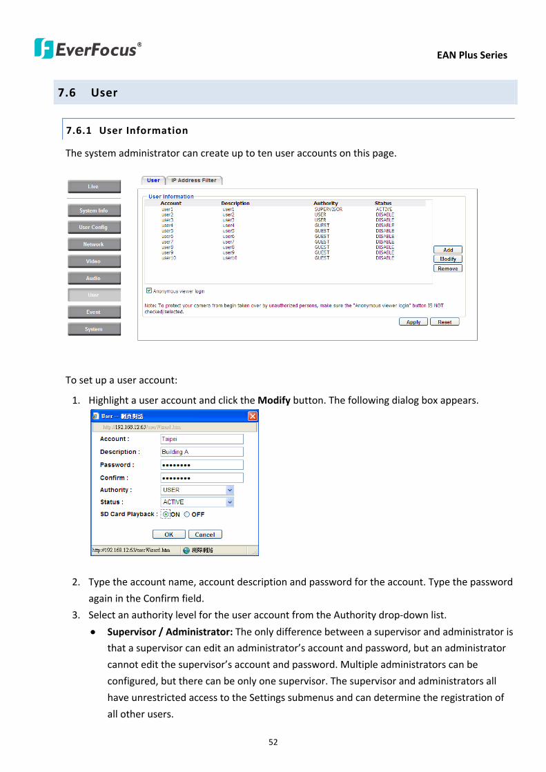
EAN Plus Series
53
bull User A user can view the Live View page and view the system network video and audio
information A user can only adjust the User Config page settings The user does not have
access to the User Event and System pages
bull Guest The lowest level of access which only allows the user access to the Live View page
4 Select Active or Disable from the Status drop-down list to active or disable the user account
5 Click On in the SD Card Playback field to allow the user to access the SD card playback
function
6 Click OK
7 Click Apply to save all the settings
EAN Plus Series
54
762 IP Address Filter
Use this page to specify IP addresses that are not allowed to access this camera By default any IP
address can access the camera
Note The Allowed List addresses only become relevant when the Denied List contains a network
or range and the supervisor wants to allow one or more IP addresses within that excluded range
or network In such a scenario the user would enter the excluded range or network in the
Denied List and enter the exceptions in the Allowed List
To set up the IP Address Filter
1 Select Denied List Click the Add button the following dialog box appears
2 Select an IP type from the IP Type drop-down list
3 Select a network rule from the Rule drop-down list type the IP address and click OK
Single Type a single IP address in the IP Address field below
Network Type the IP address and subnet mask in the field below
Range Type a range for the IP addresses
4 If you have set up an IP range in Step 3 you can optionally set up the Allowed List to allow one
or more IP addresses within the setup IP range to access the IP camera
5 Click Apply
EAN Plus Series
55
77 Event
You can set up the Motion Detection event Tamper Detection event or the Alarm IO to automatically
notify the users when an event occurs or an alarm is triggered You can also set up a schedule to
automatically record the videos when an event occurs or an alarm is triggered
771 Event Settings
You can create a total of ten event or alarm settings page in the Event List
【Event List】
Click the Add button and the following Event Configuration Window appears
EAN Plus Series
56
Enter Event Name Type an event name
Event Triggered by Select an event or alarm type for the to-be-specified-below reactions
Alarm Input Select this if you want a reaction trigger coming from any external connected sensor
to activate a to-be-specified-below reactions via the camera system Make sure that a suitable
device is actually connected to the alarm input relay
Manual Trigger Select this option if you want to manually trigger the alarm by clicking the Trigger
Event button on the Live View Page
Motion Detection Select this option if you want motion in a specified part of the camerarsquos viewing
rectangle (the screen image) to trigger the to-be-specified-below reactions
Tampering Detection Select this option if you want the camerarsquos tampering detection sensor to
trigger the to-be-specified-below reactions
Schedule Recording Select this option if you want the Schedule Recording periods configured in
the recording schedule (the Settings gt Event gt Schedule page) to activate this event In this
scenario a preconfigured event reaction like a log entry will list the start and end times of each
period Actual recording will only be triggered if the event is preconfigured to do so
Enable This Event Select to activate the event
Enable Re-trigger Click to set a minimum time after the event is triggered before the event
can be triggered again
Enable Pre-trigger Buffer Click if you want the Event reaction (as selected in the ldquoNotification
Overrdquo field below) to be the activation of the video recording function and if you want the
recording to include the video feed from the time period (configurable on the previous ldquoEvent
Settingsrdquo page) just before the Event trigger occurred
Enable Post-trigger Buffer Click if you want the Event reaction (as selected in the Notification
Over field) to be the activation of the video recording function and if you want the recording
to include the video feed from a time period (configurable on the Event Settings page) just
after the Event trigger occurred
Motion Area Select a setup motion detection area from the drop down list Note this
function only becomes relevant after the Motion Detection areas have been set up (see 772
Motion Detection)
Notification Over Select the desired notification types form the following items
Log Click if you want the camera to list the eventrsquos details in its log if the event is triggered
Trigger Alarm Output Click if you want the camera to relay the event reaction to a device
attached to the alarm relay output wire and then set up the alarm output duration time
EAN Plus Series
57
Send Mail Notification Click if you want the camera to send an Event notification email to the
email address entered in the Set SMTP Server(email) field of the Network gt SMTPFTP page if
the Event occurs (see 733 SMTP FTP)
Upload to FTP Click if you want the camera to upload recorded footage to the FTP server
entered in the Set SMTP Server(email) field of the Network gt SMTPFTP page if the Event
occurs (see 733 SMTP FTP)
Record to SD Card Click if you want the camera to start recording its video feed (when the
event occurs) on an on-camera SD Card (if such a card has been inserted)
Note The recording will only be as long as the combined Pre- and Post-trigger Buffers so
make sure you enable at least one of these buffers especially the Post-trigger Buffer
Record to PC Check this box if you want the camera to start recording its video feed (when
the event occurs) on the same folder on the same PC as configured on the User Config gt
RecordingSnapshot page (if such a folder has been enabled and configured)
Note The recording will only be as long as the combined Pre- and Post-trigger Buffers (and
for as long as the event trigger is happening ndash eg a motion is detected) so make sure you
enable at least one of these buffers especially the Post-trigger Buffer
Network Alarm Check this box if you want the camera to send a network alarm signal (when
the event occurs) to the CMS servers configured on the Network gt Network Alarm page (see
736 Network Alarm)
Click OK to save all settings or click Cancel to cancel
【PrePost Trigger Settings】
Pre-trigger Buffer Select the duration for the buffer This will determine the amount of footage
(length of time) before the event trigger moment that will be included in an event-triggered video
recording if that buffer and video recording has been enabled in the Event Configuration Window
Post-trigger Buffer Select the duration for the buffer This will determine the amount of footage
(length of time) after the event trigger moment that will be included in an event-triggered video
recording if that buffer and video recording has been enabled in the Event Configuration Window
Click Apply to save all settings or click Reset to cancel
EAN Plus Series
58
772 Motion Detection
Use this page to configure up to four areas in which motion will be detected When a motion is
detected by the camera the motion detection icon will appear at the top right of the
Live page to alert the user This function can also be linked with correctly configured Events to
trigger Event reactions like the activation of video recording periods snapshots alarms etc
Color Tabs Click on a color tab to turn your mouse cursor into a pen of that color
You can now create a block of that color on the video screen Move your cursor to the position
where you want your detection rectangle to start and then click Move your cursor to the position
(diagonally opposing corner) where you want your detection rectangle to end and then click The
rectangular area with the selected color will appear This block will be an area inside which the
camera will detect motion If you want to create another detection area use one of the other three
palette colors Each color denotes a different detection area Only one block per color is allowed As
the number of colors suggests you can configure up to four blocks
Select All Click to turn the whole screen into a motion detection area
Clear All Click to delete all configured motion detection blocks
Eraser Click to turn your mouse cursor into an eraser to delete any block you click on
Area Shows the color and numberID of the block
Enable Check this box to enable the related motion detection block
Sensitivity Set the sensitivity of the motion detection sensor function
Click Apply to save all settings or click Reset to cancel
EAN Plus Series
59
773 Tamper Detection
Use this page to set the number of seconds that an alarm signal will be active if the device is
physically tampered (moved covered up or out of focus
774 Alarm IO
Use this page to set the type of trigger input and the type of output contact for the camerarsquos alarm
channel
EAN Plus Series
60
775 Schedule
Use this page to configure a schedule for periods during which the camera should deactivate all
user-activated Events (gray Deselect periods) or when the camera should deactivate all
user-activated Events except Schedule Recording (SR) events (blue Schedule Recording-only
periods) or when the camera should deactivate only SR events (red Event Recording-only periods)
or when it should enable all activated Events (yellow periods)
Event Recording Click this button to make every hour block you click on red A red block represents
an Event Recording-only block which represents an hour when the camera will deactivate all
preconfigured activated Schedule Recording events and keep all the other activated events active
Schedule Recording Click this button to make every hour block you click on blue A blue block
represents a Schedule Recording-only block which represents an hour when the camera will
deactivate all other preconfigured activated events and keep only the preconfigured activated
Schedule Recording events active
Event + Schedule Click this button to make every hour block you click on yellow A yellow block
represents an hour in which all activated events including Schedule Recording events will be
active
Deselect Click this button to make every hour block become grey A grey block represents an hour
in which all activated events including Schedule Recording events will be inactive
Click Apply to save all settings or click Reset to cancel
EAN Plus Series
61
78 System
You can set up the systemrsquos time and SD card settings and to do maintenance and reset actions like
reboots and upgrades
781 DateTime
【Machine Name Settings】If required enter a new name for the machine This name will be visible
in the Machine Name field of the IP Utility software which is included in the software CD
【Set Time Zone】Set the time zone of the camerarsquos location
【Set DateTime Manually】Set the datetime here if you wonrsquot be using an NTP server to update the
datetime (see below)
【Set DateTime Sync】Enter the Network Time Protocol server if applicable The camerarsquos time will
be automatically adjusted by synchronizing with the NTP server
Click Apply to save all settings or click Reset to cancel
EAN Plus Series
62
782 Daylight Saving
Click Enable Daylight Saving to enable this schedule and select the dates when the regionrsquos
daylight saving period begins and ends Click Apply to save all settings or click Reset to cancel
783 SD Card
Use this page to prepare the system for safely removing the SD Card from its slot
【Setup SD Card】
Notification Select the percentage of storage space that should be left on the card before the
camera notifies you of the impending storage shortage or overwrite
Event Recording Select if you want Event Recording only FTP Backup only or both
Overwrite Click ON if you want the card to start writing over recorded footage when its memory is
full Click OFF if you want the card to stop recording new footage when its memory is full
【SD Card Utility】
Capacity This shows you how much card memory has been used and how much memory capacity
remains on the card
Remove Click this button before removing the card from the system
Format Click this button to format the card All data saved on the SD card will be removed if the
card is formatted
EAN Plus Series
63
784 Maintenance
【Maintenance Server】
Reboot Click this button to reboot the unit without changing any of the settings Use this function if
the unit is not behaving as expected
Restore Click this button to restart and reset most of the current settings to their factory default
values The only settings that will not be changed to default are
bull IP settings
bull DDNS settings
Default The Default button should be used with caution Pressing this button will return all of the
cameras settings including the IP address to the factory default values The camera will then have
to be reconfigured
【SaveLoad Configuration Server】
Save To make a backup file of the machinersquos current configurations press Save to save all the
configurations to a config file This will enable the user to reload these configuration settings if the
settings are changed and there is unexpected behavior
Load To load a previously saved configuration press the Browse button to locate the saved config
file (see above) and then click the Load button The systemrsquos settings will be restored to the saved
configuration
EAN Plus Series
64
【SaveLoad Video Configuration Server】
Save To make a backup file of the machinersquos video configurations press Save to save the video
configurations to a config file This will enable the user to reload these configuration settings if the
settings are changed and there is unexpected behavior
Load To load a previously saved video configuration press the Browse button to locate the saved
config file (see above) and then click the Load button The systemrsquos settings will be restored to the
saved video configuration
【Upgrade Firmware】Click the Browse button to find a previously prepared firmware upgrade file
Click Upgrade to install the new firmware
Note
1 Do not disconnect power to the unit during the upgrade sequence The unit will reboot
automatically after the upgrade has completed (1-5 minutes)
2 During the upgrade process all event recording actions will be stopped Event recording
actions will resume after the camera is rebooted
3 If the ldquoFile Error Please re-loginrdquo warning message appears when upgrading the firmware
please try the following instructions
a Go to Internet Explorer gt Tools gt Internet Option gt Security gt Custom
b Find and enable the Include local directory path when uploading files to a server
EAN Plus Series
65
8 Upgrading Firmware Using IP Utility
You can upgrade the Firmware using the IP Utility software included in the software CD
1 Install and then start the IPU program The following dialog box appears
2 Click Find Devices to search the cameras connected in the LAN The default network values of the
cameras will be displayed By default the network protocol of the camera is DHCP
3 Select a camera and click LoginMulti Login to log in the camera
4 Type the user ID and password Click OK
Note
1 The default user ID is user1 and the default password is 11111111
2 If you select more than one camera that has the same user ID password you will be able
to log in several cameras at once
EAN Plus Series
66
5 Highlight the camera and then click Upgrade Firmware A browsing window appears
6 Select the firmware file (evb) and then click Open The IP Utility will automatically upgrade the
firmware
The camera will reboot once the update is complete Click Find Devices the new firmware version
should be displayed in the last part of the Machine Name
EAN Plus Series
67
9 Specifications
Model EAN3120 Plus EAN3220 Plus EAN3300 Plus
Camera
Image Sensor 13 Panasonic CMOS 128 Sony CMOS
Megapixel 13 MP 2 MP 3 MP
Picture Elements (H x V) 1280 x 1024 1944 x 1092 2048 x 1536
Min Illuminations 003 Lux at F14
Electronic Shutter (Sec) 85 ~ 160000 2 ~ 150000 1 ~ 110000
Scanning System NTSC PAL
WDR Yes Yes No
BLC Yes
Gain Control Yes
White Balance Yes
Lens
Mounting Type C CS
Day Night Yes (with removable auto IR-cut filter)
IRIS Control DC Electrical IRIS Lens IRIS
Video
Video Compression H264 MJPEG
Resolution
NTSC
2048 x 1536 1920 x 1200 (for EAN3300 Plus only)
1920 x 1080 (for EAN3300 Plus 3220 Plus only)
1280 x 1024 1280 x 720 1024 x 768 720 x 480 704 x 480 640 x 480
352 x 240 320 x 240 160 x 120
PAL
2048 x 1536 1920 x 1200 (for EAN3300 Plus only)
1920 x 1080 (for EAN3300 Plus 3220 Plus only)
1280 x 1024 1280 x 720 1024 x 768 720 x 576 704 x 576 640 x 480
352 x 288 320 x 240 160 x 120
Frame Rate 30 fps at 1280 x 1024 30 fps at 1920 x 1080 15 fps at 2048 x 1536
Audio
Audio Streaming Two-way audio
Audio Compression G711
EAN Plus Series
68
Network
Interface 10 100 Base-T Ethernet RJ-45 socket
Supported Protocols
TCPIP IPV6 UDP ICMP DHCP NTP DNS DDNS SMTP SNMP FTP
HTTP HTTPs PPPoE UPnP Bonjour RTP RTSP RTCP IGMP ARP ONVIF
PSIA
Connector
Power DC female port PoE
Ethernet RJ-45
Audio 1 In (phone jack for microphone)
1 Out (phone jack for Speaker)
Alarm IO Terminal IO wires
Local Storage Micro SD SDHC memory card slot
TV-Out BNC socket composite 1 V p-p 75 Ω
General
Power Source DC 12V PoE (IEEE8023af)
Power Consumption
(IR LEDs On)
5W (DC 12V)
621W (PoE)
5W (DC 12V)
522W (PoE)
5W (DC 12V)
536W (PoE)
Operating Temperature 0degC ~ +50degC 32degF ~ +122degF
Humidity 20 to 80 (no condensation)
Safety CE FCC
Dimensions (L x W x H) 117 x 56 x 68 mm 46 x 22 x 27 in
Weight 410 g 09 lb
EverFocus Electronics Corp EverFocus Taiwan 12F No79 Sec 1 Shin-Tai Wu Road Hsi-Chih Taipei Taiwan TEL +886 2 2698 2334 FAX +886 2 2698 2380 wwweverfocuscomtw marketingeverfocuscomtw
EverFocus Europe - Germany Albert-Einstein-Strasse 1 D-46446 Emmerich Germany TEL +49 2822 93940 FAX +49 2822 939495 wwweverfocusde infoeverfocusde
EverFocus China - Beijing Room 609 Technology Trade Building Shangdi Information Industry Base Haidian District Beijing 100085 China TEL +86 10 6297 3336~39 FAX +86 10 6297 1423 wwweverfocuscomcn marketingeverfocuscomcn
EverFocus China - Shenzhen 4F No 2 D4 Building Wan Yelong Industrial Park Tangtou Road Shiyan Baoan Shenzhen Guangdong 518101 China TEL +86 755 2765 1313 FAX +86 755 2765 0337 wwweverfocuscomcn marketingeverfocuscomcn
EverFocus USA - California 1801 Highland Avenue Unit A Duarte CA 91010 USA TEL +1 626 844 8888 FAX +1 626 844 8838 wwweverfocuscom saleseverfocuscom
EverFocus USA - New York 415 Oser Avenue Unit S Hauppauge NY 11788 USA TEL +1 631 436 5070 FAX +1 631 436 5027 wwweverfocuscom saleseverfocuscom
EverFocus Japan 5F Kinshicho City Building 2-13-4 Koto-BashiSumida-Ku Tokyo 130-0022 Japan TEL +81 3 5625 8188 FAX +81 3 5625 8189 wwweverfocuscojp infoeverfocuscojp
EverFocus Europe - UK Unit 12 Spitfire Business Park Hawker Road Croydon Surrey CR0 4WD UK TEL +44 20 8649 9757 +44 845 430 9999 FAX +44 20 8649 9907 wwweverfocusukcouk salesukeverfocuscom
EverFocus India Suite 803 Housefin Bhavan C-21 Bandra Kurla Complex Bandra (East) Mumbai 400051 India TEL +91 22 6128 8700 FAX +91 22 6128 8705 wwweverfocusin saleseverfocusin
PN 4605PQ3120B010A-VerC
Your EverFocus product is designed and manufactured with high quality materials and components which can be recycled and reused This symbol means that electrical and electronic equipment at their end-of-life should be disposed of separately from your household waste Please dispose of this equipment at your local community waste collectionrecycling centre In the European Union there are separate collection systems for used electrical and electronic product Please help us to conserve the environment we live in
Ihr EverFocus Produkt wurde entwickelt und hergestellt mit qualitativ hochwertigen Materialien und Komponenten die recycelt und wieder verwendet werden koumlnnen Dieses Symbol bedeutet dass elektrische und elektronische Geraumlte am Ende ihrer Nutzungsdauer vom Hausmuumlll getrennt entsorgt werden sollen Bitte entsorgen Sie dieses Geraumlt bei Ihrer oumlrtlichen kommunalen Sammelstelle oder im Recycling Centre Helfen Sie uns bitte die Umwelt zu erhalten in der wir leben
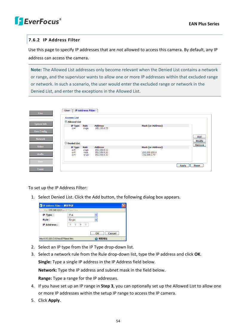
EAN Plus Series
54
762 IP Address Filter
Use this page to specify IP addresses that are not allowed to access this camera By default any IP
address can access the camera
Note The Allowed List addresses only become relevant when the Denied List contains a network
or range and the supervisor wants to allow one or more IP addresses within that excluded range
or network In such a scenario the user would enter the excluded range or network in the
Denied List and enter the exceptions in the Allowed List
To set up the IP Address Filter
1 Select Denied List Click the Add button the following dialog box appears
2 Select an IP type from the IP Type drop-down list
3 Select a network rule from the Rule drop-down list type the IP address and click OK
Single Type a single IP address in the IP Address field below
Network Type the IP address and subnet mask in the field below
Range Type a range for the IP addresses
4 If you have set up an IP range in Step 3 you can optionally set up the Allowed List to allow one
or more IP addresses within the setup IP range to access the IP camera
5 Click Apply
EAN Plus Series
55
77 Event
You can set up the Motion Detection event Tamper Detection event or the Alarm IO to automatically
notify the users when an event occurs or an alarm is triggered You can also set up a schedule to
automatically record the videos when an event occurs or an alarm is triggered
771 Event Settings
You can create a total of ten event or alarm settings page in the Event List
【Event List】
Click the Add button and the following Event Configuration Window appears
EAN Plus Series
56
Enter Event Name Type an event name
Event Triggered by Select an event or alarm type for the to-be-specified-below reactions
Alarm Input Select this if you want a reaction trigger coming from any external connected sensor
to activate a to-be-specified-below reactions via the camera system Make sure that a suitable
device is actually connected to the alarm input relay
Manual Trigger Select this option if you want to manually trigger the alarm by clicking the Trigger
Event button on the Live View Page
Motion Detection Select this option if you want motion in a specified part of the camerarsquos viewing
rectangle (the screen image) to trigger the to-be-specified-below reactions
Tampering Detection Select this option if you want the camerarsquos tampering detection sensor to
trigger the to-be-specified-below reactions
Schedule Recording Select this option if you want the Schedule Recording periods configured in
the recording schedule (the Settings gt Event gt Schedule page) to activate this event In this
scenario a preconfigured event reaction like a log entry will list the start and end times of each
period Actual recording will only be triggered if the event is preconfigured to do so
Enable This Event Select to activate the event
Enable Re-trigger Click to set a minimum time after the event is triggered before the event
can be triggered again
Enable Pre-trigger Buffer Click if you want the Event reaction (as selected in the ldquoNotification
Overrdquo field below) to be the activation of the video recording function and if you want the
recording to include the video feed from the time period (configurable on the previous ldquoEvent
Settingsrdquo page) just before the Event trigger occurred
Enable Post-trigger Buffer Click if you want the Event reaction (as selected in the Notification
Over field) to be the activation of the video recording function and if you want the recording
to include the video feed from a time period (configurable on the Event Settings page) just
after the Event trigger occurred
Motion Area Select a setup motion detection area from the drop down list Note this
function only becomes relevant after the Motion Detection areas have been set up (see 772
Motion Detection)
Notification Over Select the desired notification types form the following items
Log Click if you want the camera to list the eventrsquos details in its log if the event is triggered
Trigger Alarm Output Click if you want the camera to relay the event reaction to a device
attached to the alarm relay output wire and then set up the alarm output duration time
EAN Plus Series
57
Send Mail Notification Click if you want the camera to send an Event notification email to the
email address entered in the Set SMTP Server(email) field of the Network gt SMTPFTP page if
the Event occurs (see 733 SMTP FTP)
Upload to FTP Click if you want the camera to upload recorded footage to the FTP server
entered in the Set SMTP Server(email) field of the Network gt SMTPFTP page if the Event
occurs (see 733 SMTP FTP)
Record to SD Card Click if you want the camera to start recording its video feed (when the
event occurs) on an on-camera SD Card (if such a card has been inserted)
Note The recording will only be as long as the combined Pre- and Post-trigger Buffers so
make sure you enable at least one of these buffers especially the Post-trigger Buffer
Record to PC Check this box if you want the camera to start recording its video feed (when
the event occurs) on the same folder on the same PC as configured on the User Config gt
RecordingSnapshot page (if such a folder has been enabled and configured)
Note The recording will only be as long as the combined Pre- and Post-trigger Buffers (and
for as long as the event trigger is happening ndash eg a motion is detected) so make sure you
enable at least one of these buffers especially the Post-trigger Buffer
Network Alarm Check this box if you want the camera to send a network alarm signal (when
the event occurs) to the CMS servers configured on the Network gt Network Alarm page (see
736 Network Alarm)
Click OK to save all settings or click Cancel to cancel
【PrePost Trigger Settings】
Pre-trigger Buffer Select the duration for the buffer This will determine the amount of footage
(length of time) before the event trigger moment that will be included in an event-triggered video
recording if that buffer and video recording has been enabled in the Event Configuration Window
Post-trigger Buffer Select the duration for the buffer This will determine the amount of footage
(length of time) after the event trigger moment that will be included in an event-triggered video
recording if that buffer and video recording has been enabled in the Event Configuration Window
Click Apply to save all settings or click Reset to cancel
EAN Plus Series
58
772 Motion Detection
Use this page to configure up to four areas in which motion will be detected When a motion is
detected by the camera the motion detection icon will appear at the top right of the
Live page to alert the user This function can also be linked with correctly configured Events to
trigger Event reactions like the activation of video recording periods snapshots alarms etc
Color Tabs Click on a color tab to turn your mouse cursor into a pen of that color
You can now create a block of that color on the video screen Move your cursor to the position
where you want your detection rectangle to start and then click Move your cursor to the position
(diagonally opposing corner) where you want your detection rectangle to end and then click The
rectangular area with the selected color will appear This block will be an area inside which the
camera will detect motion If you want to create another detection area use one of the other three
palette colors Each color denotes a different detection area Only one block per color is allowed As
the number of colors suggests you can configure up to four blocks
Select All Click to turn the whole screen into a motion detection area
Clear All Click to delete all configured motion detection blocks
Eraser Click to turn your mouse cursor into an eraser to delete any block you click on
Area Shows the color and numberID of the block
Enable Check this box to enable the related motion detection block
Sensitivity Set the sensitivity of the motion detection sensor function
Click Apply to save all settings or click Reset to cancel
EAN Plus Series
59
773 Tamper Detection
Use this page to set the number of seconds that an alarm signal will be active if the device is
physically tampered (moved covered up or out of focus
774 Alarm IO
Use this page to set the type of trigger input and the type of output contact for the camerarsquos alarm
channel
EAN Plus Series
60
775 Schedule
Use this page to configure a schedule for periods during which the camera should deactivate all
user-activated Events (gray Deselect periods) or when the camera should deactivate all
user-activated Events except Schedule Recording (SR) events (blue Schedule Recording-only
periods) or when the camera should deactivate only SR events (red Event Recording-only periods)
or when it should enable all activated Events (yellow periods)
Event Recording Click this button to make every hour block you click on red A red block represents
an Event Recording-only block which represents an hour when the camera will deactivate all
preconfigured activated Schedule Recording events and keep all the other activated events active
Schedule Recording Click this button to make every hour block you click on blue A blue block
represents a Schedule Recording-only block which represents an hour when the camera will
deactivate all other preconfigured activated events and keep only the preconfigured activated
Schedule Recording events active
Event + Schedule Click this button to make every hour block you click on yellow A yellow block
represents an hour in which all activated events including Schedule Recording events will be
active
Deselect Click this button to make every hour block become grey A grey block represents an hour
in which all activated events including Schedule Recording events will be inactive
Click Apply to save all settings or click Reset to cancel
EAN Plus Series
61
78 System
You can set up the systemrsquos time and SD card settings and to do maintenance and reset actions like
reboots and upgrades
781 DateTime
【Machine Name Settings】If required enter a new name for the machine This name will be visible
in the Machine Name field of the IP Utility software which is included in the software CD
【Set Time Zone】Set the time zone of the camerarsquos location
【Set DateTime Manually】Set the datetime here if you wonrsquot be using an NTP server to update the
datetime (see below)
【Set DateTime Sync】Enter the Network Time Protocol server if applicable The camerarsquos time will
be automatically adjusted by synchronizing with the NTP server
Click Apply to save all settings or click Reset to cancel
EAN Plus Series
62
782 Daylight Saving
Click Enable Daylight Saving to enable this schedule and select the dates when the regionrsquos
daylight saving period begins and ends Click Apply to save all settings or click Reset to cancel
783 SD Card
Use this page to prepare the system for safely removing the SD Card from its slot
【Setup SD Card】
Notification Select the percentage of storage space that should be left on the card before the
camera notifies you of the impending storage shortage or overwrite
Event Recording Select if you want Event Recording only FTP Backup only or both
Overwrite Click ON if you want the card to start writing over recorded footage when its memory is
full Click OFF if you want the card to stop recording new footage when its memory is full
【SD Card Utility】
Capacity This shows you how much card memory has been used and how much memory capacity
remains on the card
Remove Click this button before removing the card from the system
Format Click this button to format the card All data saved on the SD card will be removed if the
card is formatted
EAN Plus Series
63
784 Maintenance
【Maintenance Server】
Reboot Click this button to reboot the unit without changing any of the settings Use this function if
the unit is not behaving as expected
Restore Click this button to restart and reset most of the current settings to their factory default
values The only settings that will not be changed to default are
bull IP settings
bull DDNS settings
Default The Default button should be used with caution Pressing this button will return all of the
cameras settings including the IP address to the factory default values The camera will then have
to be reconfigured
【SaveLoad Configuration Server】
Save To make a backup file of the machinersquos current configurations press Save to save all the
configurations to a config file This will enable the user to reload these configuration settings if the
settings are changed and there is unexpected behavior
Load To load a previously saved configuration press the Browse button to locate the saved config
file (see above) and then click the Load button The systemrsquos settings will be restored to the saved
configuration
EAN Plus Series
64
【SaveLoad Video Configuration Server】
Save To make a backup file of the machinersquos video configurations press Save to save the video
configurations to a config file This will enable the user to reload these configuration settings if the
settings are changed and there is unexpected behavior
Load To load a previously saved video configuration press the Browse button to locate the saved
config file (see above) and then click the Load button The systemrsquos settings will be restored to the
saved video configuration
【Upgrade Firmware】Click the Browse button to find a previously prepared firmware upgrade file
Click Upgrade to install the new firmware
Note
1 Do not disconnect power to the unit during the upgrade sequence The unit will reboot
automatically after the upgrade has completed (1-5 minutes)
2 During the upgrade process all event recording actions will be stopped Event recording
actions will resume after the camera is rebooted
3 If the ldquoFile Error Please re-loginrdquo warning message appears when upgrading the firmware
please try the following instructions
a Go to Internet Explorer gt Tools gt Internet Option gt Security gt Custom
b Find and enable the Include local directory path when uploading files to a server
EAN Plus Series
65
8 Upgrading Firmware Using IP Utility
You can upgrade the Firmware using the IP Utility software included in the software CD
1 Install and then start the IPU program The following dialog box appears
2 Click Find Devices to search the cameras connected in the LAN The default network values of the
cameras will be displayed By default the network protocol of the camera is DHCP
3 Select a camera and click LoginMulti Login to log in the camera
4 Type the user ID and password Click OK
Note
1 The default user ID is user1 and the default password is 11111111
2 If you select more than one camera that has the same user ID password you will be able
to log in several cameras at once
EAN Plus Series
66
5 Highlight the camera and then click Upgrade Firmware A browsing window appears
6 Select the firmware file (evb) and then click Open The IP Utility will automatically upgrade the
firmware
The camera will reboot once the update is complete Click Find Devices the new firmware version
should be displayed in the last part of the Machine Name
EAN Plus Series
67
9 Specifications
Model EAN3120 Plus EAN3220 Plus EAN3300 Plus
Camera
Image Sensor 13 Panasonic CMOS 128 Sony CMOS
Megapixel 13 MP 2 MP 3 MP
Picture Elements (H x V) 1280 x 1024 1944 x 1092 2048 x 1536
Min Illuminations 003 Lux at F14
Electronic Shutter (Sec) 85 ~ 160000 2 ~ 150000 1 ~ 110000
Scanning System NTSC PAL
WDR Yes Yes No
BLC Yes
Gain Control Yes
White Balance Yes
Lens
Mounting Type C CS
Day Night Yes (with removable auto IR-cut filter)
IRIS Control DC Electrical IRIS Lens IRIS
Video
Video Compression H264 MJPEG
Resolution
NTSC
2048 x 1536 1920 x 1200 (for EAN3300 Plus only)
1920 x 1080 (for EAN3300 Plus 3220 Plus only)
1280 x 1024 1280 x 720 1024 x 768 720 x 480 704 x 480 640 x 480
352 x 240 320 x 240 160 x 120
PAL
2048 x 1536 1920 x 1200 (for EAN3300 Plus only)
1920 x 1080 (for EAN3300 Plus 3220 Plus only)
1280 x 1024 1280 x 720 1024 x 768 720 x 576 704 x 576 640 x 480
352 x 288 320 x 240 160 x 120
Frame Rate 30 fps at 1280 x 1024 30 fps at 1920 x 1080 15 fps at 2048 x 1536
Audio
Audio Streaming Two-way audio
Audio Compression G711
EAN Plus Series
68
Network
Interface 10 100 Base-T Ethernet RJ-45 socket
Supported Protocols
TCPIP IPV6 UDP ICMP DHCP NTP DNS DDNS SMTP SNMP FTP
HTTP HTTPs PPPoE UPnP Bonjour RTP RTSP RTCP IGMP ARP ONVIF
PSIA
Connector
Power DC female port PoE
Ethernet RJ-45
Audio 1 In (phone jack for microphone)
1 Out (phone jack for Speaker)
Alarm IO Terminal IO wires
Local Storage Micro SD SDHC memory card slot
TV-Out BNC socket composite 1 V p-p 75 Ω
General
Power Source DC 12V PoE (IEEE8023af)
Power Consumption
(IR LEDs On)
5W (DC 12V)
621W (PoE)
5W (DC 12V)
522W (PoE)
5W (DC 12V)
536W (PoE)
Operating Temperature 0degC ~ +50degC 32degF ~ +122degF
Humidity 20 to 80 (no condensation)
Safety CE FCC
Dimensions (L x W x H) 117 x 56 x 68 mm 46 x 22 x 27 in
Weight 410 g 09 lb
EverFocus Electronics Corp EverFocus Taiwan 12F No79 Sec 1 Shin-Tai Wu Road Hsi-Chih Taipei Taiwan TEL +886 2 2698 2334 FAX +886 2 2698 2380 wwweverfocuscomtw marketingeverfocuscomtw
EverFocus Europe - Germany Albert-Einstein-Strasse 1 D-46446 Emmerich Germany TEL +49 2822 93940 FAX +49 2822 939495 wwweverfocusde infoeverfocusde
EverFocus China - Beijing Room 609 Technology Trade Building Shangdi Information Industry Base Haidian District Beijing 100085 China TEL +86 10 6297 3336~39 FAX +86 10 6297 1423 wwweverfocuscomcn marketingeverfocuscomcn
EverFocus China - Shenzhen 4F No 2 D4 Building Wan Yelong Industrial Park Tangtou Road Shiyan Baoan Shenzhen Guangdong 518101 China TEL +86 755 2765 1313 FAX +86 755 2765 0337 wwweverfocuscomcn marketingeverfocuscomcn
EverFocus USA - California 1801 Highland Avenue Unit A Duarte CA 91010 USA TEL +1 626 844 8888 FAX +1 626 844 8838 wwweverfocuscom saleseverfocuscom
EverFocus USA - New York 415 Oser Avenue Unit S Hauppauge NY 11788 USA TEL +1 631 436 5070 FAX +1 631 436 5027 wwweverfocuscom saleseverfocuscom
EverFocus Japan 5F Kinshicho City Building 2-13-4 Koto-BashiSumida-Ku Tokyo 130-0022 Japan TEL +81 3 5625 8188 FAX +81 3 5625 8189 wwweverfocuscojp infoeverfocuscojp
EverFocus Europe - UK Unit 12 Spitfire Business Park Hawker Road Croydon Surrey CR0 4WD UK TEL +44 20 8649 9757 +44 845 430 9999 FAX +44 20 8649 9907 wwweverfocusukcouk salesukeverfocuscom
EverFocus India Suite 803 Housefin Bhavan C-21 Bandra Kurla Complex Bandra (East) Mumbai 400051 India TEL +91 22 6128 8700 FAX +91 22 6128 8705 wwweverfocusin saleseverfocusin
PN 4605PQ3120B010A-VerC
Your EverFocus product is designed and manufactured with high quality materials and components which can be recycled and reused This symbol means that electrical and electronic equipment at their end-of-life should be disposed of separately from your household waste Please dispose of this equipment at your local community waste collectionrecycling centre In the European Union there are separate collection systems for used electrical and electronic product Please help us to conserve the environment we live in
Ihr EverFocus Produkt wurde entwickelt und hergestellt mit qualitativ hochwertigen Materialien und Komponenten die recycelt und wieder verwendet werden koumlnnen Dieses Symbol bedeutet dass elektrische und elektronische Geraumlte am Ende ihrer Nutzungsdauer vom Hausmuumlll getrennt entsorgt werden sollen Bitte entsorgen Sie dieses Geraumlt bei Ihrer oumlrtlichen kommunalen Sammelstelle oder im Recycling Centre Helfen Sie uns bitte die Umwelt zu erhalten in der wir leben
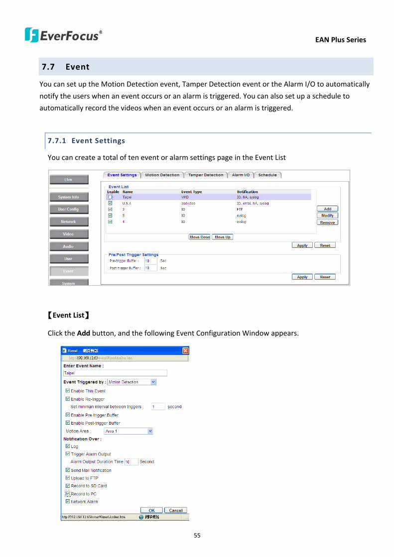
EAN Plus Series
55
77 Event
You can set up the Motion Detection event Tamper Detection event or the Alarm IO to automatically
notify the users when an event occurs or an alarm is triggered You can also set up a schedule to
automatically record the videos when an event occurs or an alarm is triggered
771 Event Settings
You can create a total of ten event or alarm settings page in the Event List
【Event List】
Click the Add button and the following Event Configuration Window appears
EAN Plus Series
56
Enter Event Name Type an event name
Event Triggered by Select an event or alarm type for the to-be-specified-below reactions
Alarm Input Select this if you want a reaction trigger coming from any external connected sensor
to activate a to-be-specified-below reactions via the camera system Make sure that a suitable
device is actually connected to the alarm input relay
Manual Trigger Select this option if you want to manually trigger the alarm by clicking the Trigger
Event button on the Live View Page
Motion Detection Select this option if you want motion in a specified part of the camerarsquos viewing
rectangle (the screen image) to trigger the to-be-specified-below reactions
Tampering Detection Select this option if you want the camerarsquos tampering detection sensor to
trigger the to-be-specified-below reactions
Schedule Recording Select this option if you want the Schedule Recording periods configured in
the recording schedule (the Settings gt Event gt Schedule page) to activate this event In this
scenario a preconfigured event reaction like a log entry will list the start and end times of each
period Actual recording will only be triggered if the event is preconfigured to do so
Enable This Event Select to activate the event
Enable Re-trigger Click to set a minimum time after the event is triggered before the event
can be triggered again
Enable Pre-trigger Buffer Click if you want the Event reaction (as selected in the ldquoNotification
Overrdquo field below) to be the activation of the video recording function and if you want the
recording to include the video feed from the time period (configurable on the previous ldquoEvent
Settingsrdquo page) just before the Event trigger occurred
Enable Post-trigger Buffer Click if you want the Event reaction (as selected in the Notification
Over field) to be the activation of the video recording function and if you want the recording
to include the video feed from a time period (configurable on the Event Settings page) just
after the Event trigger occurred
Motion Area Select a setup motion detection area from the drop down list Note this
function only becomes relevant after the Motion Detection areas have been set up (see 772
Motion Detection)
Notification Over Select the desired notification types form the following items
Log Click if you want the camera to list the eventrsquos details in its log if the event is triggered
Trigger Alarm Output Click if you want the camera to relay the event reaction to a device
attached to the alarm relay output wire and then set up the alarm output duration time
EAN Plus Series
57
Send Mail Notification Click if you want the camera to send an Event notification email to the
email address entered in the Set SMTP Server(email) field of the Network gt SMTPFTP page if
the Event occurs (see 733 SMTP FTP)
Upload to FTP Click if you want the camera to upload recorded footage to the FTP server
entered in the Set SMTP Server(email) field of the Network gt SMTPFTP page if the Event
occurs (see 733 SMTP FTP)
Record to SD Card Click if you want the camera to start recording its video feed (when the
event occurs) on an on-camera SD Card (if such a card has been inserted)
Note The recording will only be as long as the combined Pre- and Post-trigger Buffers so
make sure you enable at least one of these buffers especially the Post-trigger Buffer
Record to PC Check this box if you want the camera to start recording its video feed (when
the event occurs) on the same folder on the same PC as configured on the User Config gt
RecordingSnapshot page (if such a folder has been enabled and configured)
Note The recording will only be as long as the combined Pre- and Post-trigger Buffers (and
for as long as the event trigger is happening ndash eg a motion is detected) so make sure you
enable at least one of these buffers especially the Post-trigger Buffer
Network Alarm Check this box if you want the camera to send a network alarm signal (when
the event occurs) to the CMS servers configured on the Network gt Network Alarm page (see
736 Network Alarm)
Click OK to save all settings or click Cancel to cancel
【PrePost Trigger Settings】
Pre-trigger Buffer Select the duration for the buffer This will determine the amount of footage
(length of time) before the event trigger moment that will be included in an event-triggered video
recording if that buffer and video recording has been enabled in the Event Configuration Window
Post-trigger Buffer Select the duration for the buffer This will determine the amount of footage
(length of time) after the event trigger moment that will be included in an event-triggered video
recording if that buffer and video recording has been enabled in the Event Configuration Window
Click Apply to save all settings or click Reset to cancel
EAN Plus Series
58
772 Motion Detection
Use this page to configure up to four areas in which motion will be detected When a motion is
detected by the camera the motion detection icon will appear at the top right of the
Live page to alert the user This function can also be linked with correctly configured Events to
trigger Event reactions like the activation of video recording periods snapshots alarms etc
Color Tabs Click on a color tab to turn your mouse cursor into a pen of that color
You can now create a block of that color on the video screen Move your cursor to the position
where you want your detection rectangle to start and then click Move your cursor to the position
(diagonally opposing corner) where you want your detection rectangle to end and then click The
rectangular area with the selected color will appear This block will be an area inside which the
camera will detect motion If you want to create another detection area use one of the other three
palette colors Each color denotes a different detection area Only one block per color is allowed As
the number of colors suggests you can configure up to four blocks
Select All Click to turn the whole screen into a motion detection area
Clear All Click to delete all configured motion detection blocks
Eraser Click to turn your mouse cursor into an eraser to delete any block you click on
Area Shows the color and numberID of the block
Enable Check this box to enable the related motion detection block
Sensitivity Set the sensitivity of the motion detection sensor function
Click Apply to save all settings or click Reset to cancel
EAN Plus Series
59
773 Tamper Detection
Use this page to set the number of seconds that an alarm signal will be active if the device is
physically tampered (moved covered up or out of focus
774 Alarm IO
Use this page to set the type of trigger input and the type of output contact for the camerarsquos alarm
channel
EAN Plus Series
60
775 Schedule
Use this page to configure a schedule for periods during which the camera should deactivate all
user-activated Events (gray Deselect periods) or when the camera should deactivate all
user-activated Events except Schedule Recording (SR) events (blue Schedule Recording-only
periods) or when the camera should deactivate only SR events (red Event Recording-only periods)
or when it should enable all activated Events (yellow periods)
Event Recording Click this button to make every hour block you click on red A red block represents
an Event Recording-only block which represents an hour when the camera will deactivate all
preconfigured activated Schedule Recording events and keep all the other activated events active
Schedule Recording Click this button to make every hour block you click on blue A blue block
represents a Schedule Recording-only block which represents an hour when the camera will
deactivate all other preconfigured activated events and keep only the preconfigured activated
Schedule Recording events active
Event + Schedule Click this button to make every hour block you click on yellow A yellow block
represents an hour in which all activated events including Schedule Recording events will be
active
Deselect Click this button to make every hour block become grey A grey block represents an hour
in which all activated events including Schedule Recording events will be inactive
Click Apply to save all settings or click Reset to cancel
EAN Plus Series
61
78 System
You can set up the systemrsquos time and SD card settings and to do maintenance and reset actions like
reboots and upgrades
781 DateTime
【Machine Name Settings】If required enter a new name for the machine This name will be visible
in the Machine Name field of the IP Utility software which is included in the software CD
【Set Time Zone】Set the time zone of the camerarsquos location
【Set DateTime Manually】Set the datetime here if you wonrsquot be using an NTP server to update the
datetime (see below)
【Set DateTime Sync】Enter the Network Time Protocol server if applicable The camerarsquos time will
be automatically adjusted by synchronizing with the NTP server
Click Apply to save all settings or click Reset to cancel
EAN Plus Series
62
782 Daylight Saving
Click Enable Daylight Saving to enable this schedule and select the dates when the regionrsquos
daylight saving period begins and ends Click Apply to save all settings or click Reset to cancel
783 SD Card
Use this page to prepare the system for safely removing the SD Card from its slot
【Setup SD Card】
Notification Select the percentage of storage space that should be left on the card before the
camera notifies you of the impending storage shortage or overwrite
Event Recording Select if you want Event Recording only FTP Backup only or both
Overwrite Click ON if you want the card to start writing over recorded footage when its memory is
full Click OFF if you want the card to stop recording new footage when its memory is full
【SD Card Utility】
Capacity This shows you how much card memory has been used and how much memory capacity
remains on the card
Remove Click this button before removing the card from the system
Format Click this button to format the card All data saved on the SD card will be removed if the
card is formatted
EAN Plus Series
63
784 Maintenance
【Maintenance Server】
Reboot Click this button to reboot the unit without changing any of the settings Use this function if
the unit is not behaving as expected
Restore Click this button to restart and reset most of the current settings to their factory default
values The only settings that will not be changed to default are
bull IP settings
bull DDNS settings
Default The Default button should be used with caution Pressing this button will return all of the
cameras settings including the IP address to the factory default values The camera will then have
to be reconfigured
【SaveLoad Configuration Server】
Save To make a backup file of the machinersquos current configurations press Save to save all the
configurations to a config file This will enable the user to reload these configuration settings if the
settings are changed and there is unexpected behavior
Load To load a previously saved configuration press the Browse button to locate the saved config
file (see above) and then click the Load button The systemrsquos settings will be restored to the saved
configuration
EAN Plus Series
64
【SaveLoad Video Configuration Server】
Save To make a backup file of the machinersquos video configurations press Save to save the video
configurations to a config file This will enable the user to reload these configuration settings if the
settings are changed and there is unexpected behavior
Load To load a previously saved video configuration press the Browse button to locate the saved
config file (see above) and then click the Load button The systemrsquos settings will be restored to the
saved video configuration
【Upgrade Firmware】Click the Browse button to find a previously prepared firmware upgrade file
Click Upgrade to install the new firmware
Note
1 Do not disconnect power to the unit during the upgrade sequence The unit will reboot
automatically after the upgrade has completed (1-5 minutes)
2 During the upgrade process all event recording actions will be stopped Event recording
actions will resume after the camera is rebooted
3 If the ldquoFile Error Please re-loginrdquo warning message appears when upgrading the firmware
please try the following instructions
a Go to Internet Explorer gt Tools gt Internet Option gt Security gt Custom
b Find and enable the Include local directory path when uploading files to a server
EAN Plus Series
65
8 Upgrading Firmware Using IP Utility
You can upgrade the Firmware using the IP Utility software included in the software CD
1 Install and then start the IPU program The following dialog box appears
2 Click Find Devices to search the cameras connected in the LAN The default network values of the
cameras will be displayed By default the network protocol of the camera is DHCP
3 Select a camera and click LoginMulti Login to log in the camera
4 Type the user ID and password Click OK
Note
1 The default user ID is user1 and the default password is 11111111
2 If you select more than one camera that has the same user ID password you will be able
to log in several cameras at once
EAN Plus Series
66
5 Highlight the camera and then click Upgrade Firmware A browsing window appears
6 Select the firmware file (evb) and then click Open The IP Utility will automatically upgrade the
firmware
The camera will reboot once the update is complete Click Find Devices the new firmware version
should be displayed in the last part of the Machine Name
EAN Plus Series
67
9 Specifications
Model EAN3120 Plus EAN3220 Plus EAN3300 Plus
Camera
Image Sensor 13 Panasonic CMOS 128 Sony CMOS
Megapixel 13 MP 2 MP 3 MP
Picture Elements (H x V) 1280 x 1024 1944 x 1092 2048 x 1536
Min Illuminations 003 Lux at F14
Electronic Shutter (Sec) 85 ~ 160000 2 ~ 150000 1 ~ 110000
Scanning System NTSC PAL
WDR Yes Yes No
BLC Yes
Gain Control Yes
White Balance Yes
Lens
Mounting Type C CS
Day Night Yes (with removable auto IR-cut filter)
IRIS Control DC Electrical IRIS Lens IRIS
Video
Video Compression H264 MJPEG
Resolution
NTSC
2048 x 1536 1920 x 1200 (for EAN3300 Plus only)
1920 x 1080 (for EAN3300 Plus 3220 Plus only)
1280 x 1024 1280 x 720 1024 x 768 720 x 480 704 x 480 640 x 480
352 x 240 320 x 240 160 x 120
PAL
2048 x 1536 1920 x 1200 (for EAN3300 Plus only)
1920 x 1080 (for EAN3300 Plus 3220 Plus only)
1280 x 1024 1280 x 720 1024 x 768 720 x 576 704 x 576 640 x 480
352 x 288 320 x 240 160 x 120
Frame Rate 30 fps at 1280 x 1024 30 fps at 1920 x 1080 15 fps at 2048 x 1536
Audio
Audio Streaming Two-way audio
Audio Compression G711
EAN Plus Series
68
Network
Interface 10 100 Base-T Ethernet RJ-45 socket
Supported Protocols
TCPIP IPV6 UDP ICMP DHCP NTP DNS DDNS SMTP SNMP FTP
HTTP HTTPs PPPoE UPnP Bonjour RTP RTSP RTCP IGMP ARP ONVIF
PSIA
Connector
Power DC female port PoE
Ethernet RJ-45
Audio 1 In (phone jack for microphone)
1 Out (phone jack for Speaker)
Alarm IO Terminal IO wires
Local Storage Micro SD SDHC memory card slot
TV-Out BNC socket composite 1 V p-p 75 Ω
General
Power Source DC 12V PoE (IEEE8023af)
Power Consumption
(IR LEDs On)
5W (DC 12V)
621W (PoE)
5W (DC 12V)
522W (PoE)
5W (DC 12V)
536W (PoE)
Operating Temperature 0degC ~ +50degC 32degF ~ +122degF
Humidity 20 to 80 (no condensation)
Safety CE FCC
Dimensions (L x W x H) 117 x 56 x 68 mm 46 x 22 x 27 in
Weight 410 g 09 lb
EverFocus Electronics Corp EverFocus Taiwan 12F No79 Sec 1 Shin-Tai Wu Road Hsi-Chih Taipei Taiwan TEL +886 2 2698 2334 FAX +886 2 2698 2380 wwweverfocuscomtw marketingeverfocuscomtw
EverFocus Europe - Germany Albert-Einstein-Strasse 1 D-46446 Emmerich Germany TEL +49 2822 93940 FAX +49 2822 939495 wwweverfocusde infoeverfocusde
EverFocus China - Beijing Room 609 Technology Trade Building Shangdi Information Industry Base Haidian District Beijing 100085 China TEL +86 10 6297 3336~39 FAX +86 10 6297 1423 wwweverfocuscomcn marketingeverfocuscomcn
EverFocus China - Shenzhen 4F No 2 D4 Building Wan Yelong Industrial Park Tangtou Road Shiyan Baoan Shenzhen Guangdong 518101 China TEL +86 755 2765 1313 FAX +86 755 2765 0337 wwweverfocuscomcn marketingeverfocuscomcn
EverFocus USA - California 1801 Highland Avenue Unit A Duarte CA 91010 USA TEL +1 626 844 8888 FAX +1 626 844 8838 wwweverfocuscom saleseverfocuscom
EverFocus USA - New York 415 Oser Avenue Unit S Hauppauge NY 11788 USA TEL +1 631 436 5070 FAX +1 631 436 5027 wwweverfocuscom saleseverfocuscom
EverFocus Japan 5F Kinshicho City Building 2-13-4 Koto-BashiSumida-Ku Tokyo 130-0022 Japan TEL +81 3 5625 8188 FAX +81 3 5625 8189 wwweverfocuscojp infoeverfocuscojp
EverFocus Europe - UK Unit 12 Spitfire Business Park Hawker Road Croydon Surrey CR0 4WD UK TEL +44 20 8649 9757 +44 845 430 9999 FAX +44 20 8649 9907 wwweverfocusukcouk salesukeverfocuscom
EverFocus India Suite 803 Housefin Bhavan C-21 Bandra Kurla Complex Bandra (East) Mumbai 400051 India TEL +91 22 6128 8700 FAX +91 22 6128 8705 wwweverfocusin saleseverfocusin
PN 4605PQ3120B010A-VerC
Your EverFocus product is designed and manufactured with high quality materials and components which can be recycled and reused This symbol means that electrical and electronic equipment at their end-of-life should be disposed of separately from your household waste Please dispose of this equipment at your local community waste collectionrecycling centre In the European Union there are separate collection systems for used electrical and electronic product Please help us to conserve the environment we live in
Ihr EverFocus Produkt wurde entwickelt und hergestellt mit qualitativ hochwertigen Materialien und Komponenten die recycelt und wieder verwendet werden koumlnnen Dieses Symbol bedeutet dass elektrische und elektronische Geraumlte am Ende ihrer Nutzungsdauer vom Hausmuumlll getrennt entsorgt werden sollen Bitte entsorgen Sie dieses Geraumlt bei Ihrer oumlrtlichen kommunalen Sammelstelle oder im Recycling Centre Helfen Sie uns bitte die Umwelt zu erhalten in der wir leben
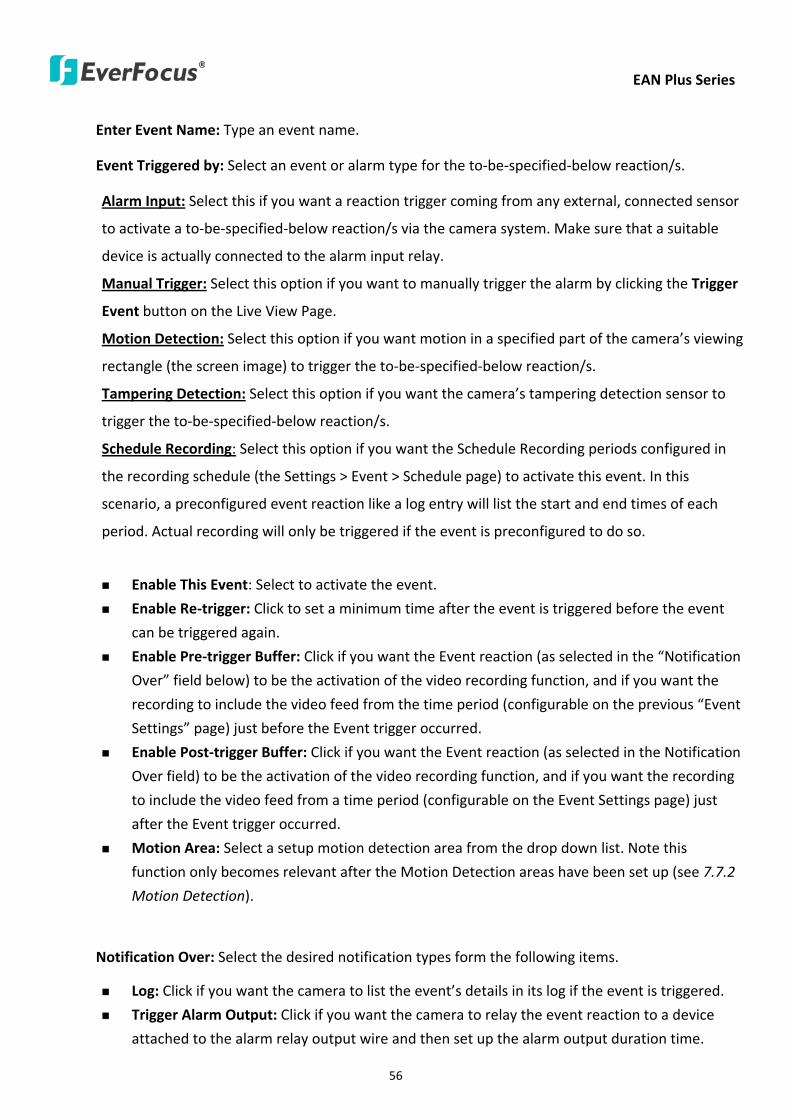
EAN Plus Series
56
Enter Event Name Type an event name
Event Triggered by Select an event or alarm type for the to-be-specified-below reactions
Alarm Input Select this if you want a reaction trigger coming from any external connected sensor
to activate a to-be-specified-below reactions via the camera system Make sure that a suitable
device is actually connected to the alarm input relay
Manual Trigger Select this option if you want to manually trigger the alarm by clicking the Trigger
Event button on the Live View Page
Motion Detection Select this option if you want motion in a specified part of the camerarsquos viewing
rectangle (the screen image) to trigger the to-be-specified-below reactions
Tampering Detection Select this option if you want the camerarsquos tampering detection sensor to
trigger the to-be-specified-below reactions
Schedule Recording Select this option if you want the Schedule Recording periods configured in
the recording schedule (the Settings gt Event gt Schedule page) to activate this event In this
scenario a preconfigured event reaction like a log entry will list the start and end times of each
period Actual recording will only be triggered if the event is preconfigured to do so
Enable This Event Select to activate the event
Enable Re-trigger Click to set a minimum time after the event is triggered before the event
can be triggered again
Enable Pre-trigger Buffer Click if you want the Event reaction (as selected in the ldquoNotification
Overrdquo field below) to be the activation of the video recording function and if you want the
recording to include the video feed from the time period (configurable on the previous ldquoEvent
Settingsrdquo page) just before the Event trigger occurred
Enable Post-trigger Buffer Click if you want the Event reaction (as selected in the Notification
Over field) to be the activation of the video recording function and if you want the recording
to include the video feed from a time period (configurable on the Event Settings page) just
after the Event trigger occurred
Motion Area Select a setup motion detection area from the drop down list Note this
function only becomes relevant after the Motion Detection areas have been set up (see 772
Motion Detection)
Notification Over Select the desired notification types form the following items
Log Click if you want the camera to list the eventrsquos details in its log if the event is triggered
Trigger Alarm Output Click if you want the camera to relay the event reaction to a device
attached to the alarm relay output wire and then set up the alarm output duration time
EAN Plus Series
57
Send Mail Notification Click if you want the camera to send an Event notification email to the
email address entered in the Set SMTP Server(email) field of the Network gt SMTPFTP page if
the Event occurs (see 733 SMTP FTP)
Upload to FTP Click if you want the camera to upload recorded footage to the FTP server
entered in the Set SMTP Server(email) field of the Network gt SMTPFTP page if the Event
occurs (see 733 SMTP FTP)
Record to SD Card Click if you want the camera to start recording its video feed (when the
event occurs) on an on-camera SD Card (if such a card has been inserted)
Note The recording will only be as long as the combined Pre- and Post-trigger Buffers so
make sure you enable at least one of these buffers especially the Post-trigger Buffer
Record to PC Check this box if you want the camera to start recording its video feed (when
the event occurs) on the same folder on the same PC as configured on the User Config gt
RecordingSnapshot page (if such a folder has been enabled and configured)
Note The recording will only be as long as the combined Pre- and Post-trigger Buffers (and
for as long as the event trigger is happening ndash eg a motion is detected) so make sure you
enable at least one of these buffers especially the Post-trigger Buffer
Network Alarm Check this box if you want the camera to send a network alarm signal (when
the event occurs) to the CMS servers configured on the Network gt Network Alarm page (see
736 Network Alarm)
Click OK to save all settings or click Cancel to cancel
【PrePost Trigger Settings】
Pre-trigger Buffer Select the duration for the buffer This will determine the amount of footage
(length of time) before the event trigger moment that will be included in an event-triggered video
recording if that buffer and video recording has been enabled in the Event Configuration Window
Post-trigger Buffer Select the duration for the buffer This will determine the amount of footage
(length of time) after the event trigger moment that will be included in an event-triggered video
recording if that buffer and video recording has been enabled in the Event Configuration Window
Click Apply to save all settings or click Reset to cancel
EAN Plus Series
58
772 Motion Detection
Use this page to configure up to four areas in which motion will be detected When a motion is
detected by the camera the motion detection icon will appear at the top right of the
Live page to alert the user This function can also be linked with correctly configured Events to
trigger Event reactions like the activation of video recording periods snapshots alarms etc
Color Tabs Click on a color tab to turn your mouse cursor into a pen of that color
You can now create a block of that color on the video screen Move your cursor to the position
where you want your detection rectangle to start and then click Move your cursor to the position
(diagonally opposing corner) where you want your detection rectangle to end and then click The
rectangular area with the selected color will appear This block will be an area inside which the
camera will detect motion If you want to create another detection area use one of the other three
palette colors Each color denotes a different detection area Only one block per color is allowed As
the number of colors suggests you can configure up to four blocks
Select All Click to turn the whole screen into a motion detection area
Clear All Click to delete all configured motion detection blocks
Eraser Click to turn your mouse cursor into an eraser to delete any block you click on
Area Shows the color and numberID of the block
Enable Check this box to enable the related motion detection block
Sensitivity Set the sensitivity of the motion detection sensor function
Click Apply to save all settings or click Reset to cancel
EAN Plus Series
59
773 Tamper Detection
Use this page to set the number of seconds that an alarm signal will be active if the device is
physically tampered (moved covered up or out of focus
774 Alarm IO
Use this page to set the type of trigger input and the type of output contact for the camerarsquos alarm
channel
EAN Plus Series
60
775 Schedule
Use this page to configure a schedule for periods during which the camera should deactivate all
user-activated Events (gray Deselect periods) or when the camera should deactivate all
user-activated Events except Schedule Recording (SR) events (blue Schedule Recording-only
periods) or when the camera should deactivate only SR events (red Event Recording-only periods)
or when it should enable all activated Events (yellow periods)
Event Recording Click this button to make every hour block you click on red A red block represents
an Event Recording-only block which represents an hour when the camera will deactivate all
preconfigured activated Schedule Recording events and keep all the other activated events active
Schedule Recording Click this button to make every hour block you click on blue A blue block
represents a Schedule Recording-only block which represents an hour when the camera will
deactivate all other preconfigured activated events and keep only the preconfigured activated
Schedule Recording events active
Event + Schedule Click this button to make every hour block you click on yellow A yellow block
represents an hour in which all activated events including Schedule Recording events will be
active
Deselect Click this button to make every hour block become grey A grey block represents an hour
in which all activated events including Schedule Recording events will be inactive
Click Apply to save all settings or click Reset to cancel
EAN Plus Series
61
78 System
You can set up the systemrsquos time and SD card settings and to do maintenance and reset actions like
reboots and upgrades
781 DateTime
【Machine Name Settings】If required enter a new name for the machine This name will be visible
in the Machine Name field of the IP Utility software which is included in the software CD
【Set Time Zone】Set the time zone of the camerarsquos location
【Set DateTime Manually】Set the datetime here if you wonrsquot be using an NTP server to update the
datetime (see below)
【Set DateTime Sync】Enter the Network Time Protocol server if applicable The camerarsquos time will
be automatically adjusted by synchronizing with the NTP server
Click Apply to save all settings or click Reset to cancel
EAN Plus Series
62
782 Daylight Saving
Click Enable Daylight Saving to enable this schedule and select the dates when the regionrsquos
daylight saving period begins and ends Click Apply to save all settings or click Reset to cancel
783 SD Card
Use this page to prepare the system for safely removing the SD Card from its slot
【Setup SD Card】
Notification Select the percentage of storage space that should be left on the card before the
camera notifies you of the impending storage shortage or overwrite
Event Recording Select if you want Event Recording only FTP Backup only or both
Overwrite Click ON if you want the card to start writing over recorded footage when its memory is
full Click OFF if you want the card to stop recording new footage when its memory is full
【SD Card Utility】
Capacity This shows you how much card memory has been used and how much memory capacity
remains on the card
Remove Click this button before removing the card from the system
Format Click this button to format the card All data saved on the SD card will be removed if the
card is formatted
EAN Plus Series
63
784 Maintenance
【Maintenance Server】
Reboot Click this button to reboot the unit without changing any of the settings Use this function if
the unit is not behaving as expected
Restore Click this button to restart and reset most of the current settings to their factory default
values The only settings that will not be changed to default are
bull IP settings
bull DDNS settings
Default The Default button should be used with caution Pressing this button will return all of the
cameras settings including the IP address to the factory default values The camera will then have
to be reconfigured
【SaveLoad Configuration Server】
Save To make a backup file of the machinersquos current configurations press Save to save all the
configurations to a config file This will enable the user to reload these configuration settings if the
settings are changed and there is unexpected behavior
Load To load a previously saved configuration press the Browse button to locate the saved config
file (see above) and then click the Load button The systemrsquos settings will be restored to the saved
configuration
EAN Plus Series
64
【SaveLoad Video Configuration Server】
Save To make a backup file of the machinersquos video configurations press Save to save the video
configurations to a config file This will enable the user to reload these configuration settings if the
settings are changed and there is unexpected behavior
Load To load a previously saved video configuration press the Browse button to locate the saved
config file (see above) and then click the Load button The systemrsquos settings will be restored to the
saved video configuration
【Upgrade Firmware】Click the Browse button to find a previously prepared firmware upgrade file
Click Upgrade to install the new firmware
Note
1 Do not disconnect power to the unit during the upgrade sequence The unit will reboot
automatically after the upgrade has completed (1-5 minutes)
2 During the upgrade process all event recording actions will be stopped Event recording
actions will resume after the camera is rebooted
3 If the ldquoFile Error Please re-loginrdquo warning message appears when upgrading the firmware
please try the following instructions
a Go to Internet Explorer gt Tools gt Internet Option gt Security gt Custom
b Find and enable the Include local directory path when uploading files to a server
EAN Plus Series
65
8 Upgrading Firmware Using IP Utility
You can upgrade the Firmware using the IP Utility software included in the software CD
1 Install and then start the IPU program The following dialog box appears
2 Click Find Devices to search the cameras connected in the LAN The default network values of the
cameras will be displayed By default the network protocol of the camera is DHCP
3 Select a camera and click LoginMulti Login to log in the camera
4 Type the user ID and password Click OK
Note
1 The default user ID is user1 and the default password is 11111111
2 If you select more than one camera that has the same user ID password you will be able
to log in several cameras at once
EAN Plus Series
66
5 Highlight the camera and then click Upgrade Firmware A browsing window appears
6 Select the firmware file (evb) and then click Open The IP Utility will automatically upgrade the
firmware
The camera will reboot once the update is complete Click Find Devices the new firmware version
should be displayed in the last part of the Machine Name
EAN Plus Series
67
9 Specifications
Model EAN3120 Plus EAN3220 Plus EAN3300 Plus
Camera
Image Sensor 13 Panasonic CMOS 128 Sony CMOS
Megapixel 13 MP 2 MP 3 MP
Picture Elements (H x V) 1280 x 1024 1944 x 1092 2048 x 1536
Min Illuminations 003 Lux at F14
Electronic Shutter (Sec) 85 ~ 160000 2 ~ 150000 1 ~ 110000
Scanning System NTSC PAL
WDR Yes Yes No
BLC Yes
Gain Control Yes
White Balance Yes
Lens
Mounting Type C CS
Day Night Yes (with removable auto IR-cut filter)
IRIS Control DC Electrical IRIS Lens IRIS
Video
Video Compression H264 MJPEG
Resolution
NTSC
2048 x 1536 1920 x 1200 (for EAN3300 Plus only)
1920 x 1080 (for EAN3300 Plus 3220 Plus only)
1280 x 1024 1280 x 720 1024 x 768 720 x 480 704 x 480 640 x 480
352 x 240 320 x 240 160 x 120
PAL
2048 x 1536 1920 x 1200 (for EAN3300 Plus only)
1920 x 1080 (for EAN3300 Plus 3220 Plus only)
1280 x 1024 1280 x 720 1024 x 768 720 x 576 704 x 576 640 x 480
352 x 288 320 x 240 160 x 120
Frame Rate 30 fps at 1280 x 1024 30 fps at 1920 x 1080 15 fps at 2048 x 1536
Audio
Audio Streaming Two-way audio
Audio Compression G711
EAN Plus Series
68
Network
Interface 10 100 Base-T Ethernet RJ-45 socket
Supported Protocols
TCPIP IPV6 UDP ICMP DHCP NTP DNS DDNS SMTP SNMP FTP
HTTP HTTPs PPPoE UPnP Bonjour RTP RTSP RTCP IGMP ARP ONVIF
PSIA
Connector
Power DC female port PoE
Ethernet RJ-45
Audio 1 In (phone jack for microphone)
1 Out (phone jack for Speaker)
Alarm IO Terminal IO wires
Local Storage Micro SD SDHC memory card slot
TV-Out BNC socket composite 1 V p-p 75 Ω
General
Power Source DC 12V PoE (IEEE8023af)
Power Consumption
(IR LEDs On)
5W (DC 12V)
621W (PoE)
5W (DC 12V)
522W (PoE)
5W (DC 12V)
536W (PoE)
Operating Temperature 0degC ~ +50degC 32degF ~ +122degF
Humidity 20 to 80 (no condensation)
Safety CE FCC
Dimensions (L x W x H) 117 x 56 x 68 mm 46 x 22 x 27 in
Weight 410 g 09 lb
EverFocus Electronics Corp EverFocus Taiwan 12F No79 Sec 1 Shin-Tai Wu Road Hsi-Chih Taipei Taiwan TEL +886 2 2698 2334 FAX +886 2 2698 2380 wwweverfocuscomtw marketingeverfocuscomtw
EverFocus Europe - Germany Albert-Einstein-Strasse 1 D-46446 Emmerich Germany TEL +49 2822 93940 FAX +49 2822 939495 wwweverfocusde infoeverfocusde
EverFocus China - Beijing Room 609 Technology Trade Building Shangdi Information Industry Base Haidian District Beijing 100085 China TEL +86 10 6297 3336~39 FAX +86 10 6297 1423 wwweverfocuscomcn marketingeverfocuscomcn
EverFocus China - Shenzhen 4F No 2 D4 Building Wan Yelong Industrial Park Tangtou Road Shiyan Baoan Shenzhen Guangdong 518101 China TEL +86 755 2765 1313 FAX +86 755 2765 0337 wwweverfocuscomcn marketingeverfocuscomcn
EverFocus USA - California 1801 Highland Avenue Unit A Duarte CA 91010 USA TEL +1 626 844 8888 FAX +1 626 844 8838 wwweverfocuscom saleseverfocuscom
EverFocus USA - New York 415 Oser Avenue Unit S Hauppauge NY 11788 USA TEL +1 631 436 5070 FAX +1 631 436 5027 wwweverfocuscom saleseverfocuscom
EverFocus Japan 5F Kinshicho City Building 2-13-4 Koto-BashiSumida-Ku Tokyo 130-0022 Japan TEL +81 3 5625 8188 FAX +81 3 5625 8189 wwweverfocuscojp infoeverfocuscojp
EverFocus Europe - UK Unit 12 Spitfire Business Park Hawker Road Croydon Surrey CR0 4WD UK TEL +44 20 8649 9757 +44 845 430 9999 FAX +44 20 8649 9907 wwweverfocusukcouk salesukeverfocuscom
EverFocus India Suite 803 Housefin Bhavan C-21 Bandra Kurla Complex Bandra (East) Mumbai 400051 India TEL +91 22 6128 8700 FAX +91 22 6128 8705 wwweverfocusin saleseverfocusin
PN 4605PQ3120B010A-VerC
Your EverFocus product is designed and manufactured with high quality materials and components which can be recycled and reused This symbol means that electrical and electronic equipment at their end-of-life should be disposed of separately from your household waste Please dispose of this equipment at your local community waste collectionrecycling centre In the European Union there are separate collection systems for used electrical and electronic product Please help us to conserve the environment we live in
Ihr EverFocus Produkt wurde entwickelt und hergestellt mit qualitativ hochwertigen Materialien und Komponenten die recycelt und wieder verwendet werden koumlnnen Dieses Symbol bedeutet dass elektrische und elektronische Geraumlte am Ende ihrer Nutzungsdauer vom Hausmuumlll getrennt entsorgt werden sollen Bitte entsorgen Sie dieses Geraumlt bei Ihrer oumlrtlichen kommunalen Sammelstelle oder im Recycling Centre Helfen Sie uns bitte die Umwelt zu erhalten in der wir leben
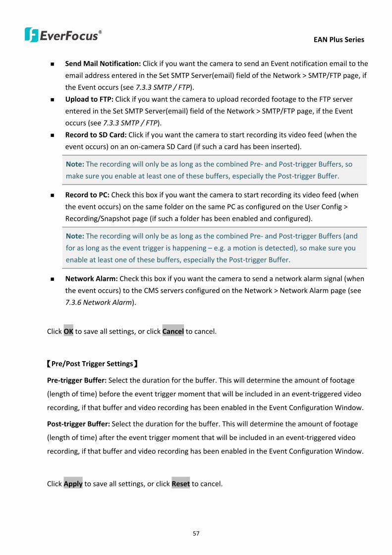
EAN Plus Series
57
Send Mail Notification Click if you want the camera to send an Event notification email to the
email address entered in the Set SMTP Server(email) field of the Network gt SMTPFTP page if
the Event occurs (see 733 SMTP FTP)
Upload to FTP Click if you want the camera to upload recorded footage to the FTP server
entered in the Set SMTP Server(email) field of the Network gt SMTPFTP page if the Event
occurs (see 733 SMTP FTP)
Record to SD Card Click if you want the camera to start recording its video feed (when the
event occurs) on an on-camera SD Card (if such a card has been inserted)
Note The recording will only be as long as the combined Pre- and Post-trigger Buffers so
make sure you enable at least one of these buffers especially the Post-trigger Buffer
Record to PC Check this box if you want the camera to start recording its video feed (when
the event occurs) on the same folder on the same PC as configured on the User Config gt
RecordingSnapshot page (if such a folder has been enabled and configured)
Note The recording will only be as long as the combined Pre- and Post-trigger Buffers (and
for as long as the event trigger is happening ndash eg a motion is detected) so make sure you
enable at least one of these buffers especially the Post-trigger Buffer
Network Alarm Check this box if you want the camera to send a network alarm signal (when
the event occurs) to the CMS servers configured on the Network gt Network Alarm page (see
736 Network Alarm)
Click OK to save all settings or click Cancel to cancel
【PrePost Trigger Settings】
Pre-trigger Buffer Select the duration for the buffer This will determine the amount of footage
(length of time) before the event trigger moment that will be included in an event-triggered video
recording if that buffer and video recording has been enabled in the Event Configuration Window
Post-trigger Buffer Select the duration for the buffer This will determine the amount of footage
(length of time) after the event trigger moment that will be included in an event-triggered video
recording if that buffer and video recording has been enabled in the Event Configuration Window
Click Apply to save all settings or click Reset to cancel
EAN Plus Series
58
772 Motion Detection
Use this page to configure up to four areas in which motion will be detected When a motion is
detected by the camera the motion detection icon will appear at the top right of the
Live page to alert the user This function can also be linked with correctly configured Events to
trigger Event reactions like the activation of video recording periods snapshots alarms etc
Color Tabs Click on a color tab to turn your mouse cursor into a pen of that color
You can now create a block of that color on the video screen Move your cursor to the position
where you want your detection rectangle to start and then click Move your cursor to the position
(diagonally opposing corner) where you want your detection rectangle to end and then click The
rectangular area with the selected color will appear This block will be an area inside which the
camera will detect motion If you want to create another detection area use one of the other three
palette colors Each color denotes a different detection area Only one block per color is allowed As
the number of colors suggests you can configure up to four blocks
Select All Click to turn the whole screen into a motion detection area
Clear All Click to delete all configured motion detection blocks
Eraser Click to turn your mouse cursor into an eraser to delete any block you click on
Area Shows the color and numberID of the block
Enable Check this box to enable the related motion detection block
Sensitivity Set the sensitivity of the motion detection sensor function
Click Apply to save all settings or click Reset to cancel
EAN Plus Series
59
773 Tamper Detection
Use this page to set the number of seconds that an alarm signal will be active if the device is
physically tampered (moved covered up or out of focus
774 Alarm IO
Use this page to set the type of trigger input and the type of output contact for the camerarsquos alarm
channel
EAN Plus Series
60
775 Schedule
Use this page to configure a schedule for periods during which the camera should deactivate all
user-activated Events (gray Deselect periods) or when the camera should deactivate all
user-activated Events except Schedule Recording (SR) events (blue Schedule Recording-only
periods) or when the camera should deactivate only SR events (red Event Recording-only periods)
or when it should enable all activated Events (yellow periods)
Event Recording Click this button to make every hour block you click on red A red block represents
an Event Recording-only block which represents an hour when the camera will deactivate all
preconfigured activated Schedule Recording events and keep all the other activated events active
Schedule Recording Click this button to make every hour block you click on blue A blue block
represents a Schedule Recording-only block which represents an hour when the camera will
deactivate all other preconfigured activated events and keep only the preconfigured activated
Schedule Recording events active
Event + Schedule Click this button to make every hour block you click on yellow A yellow block
represents an hour in which all activated events including Schedule Recording events will be
active
Deselect Click this button to make every hour block become grey A grey block represents an hour
in which all activated events including Schedule Recording events will be inactive
Click Apply to save all settings or click Reset to cancel
EAN Plus Series
61
78 System
You can set up the systemrsquos time and SD card settings and to do maintenance and reset actions like
reboots and upgrades
781 DateTime
【Machine Name Settings】If required enter a new name for the machine This name will be visible
in the Machine Name field of the IP Utility software which is included in the software CD
【Set Time Zone】Set the time zone of the camerarsquos location
【Set DateTime Manually】Set the datetime here if you wonrsquot be using an NTP server to update the
datetime (see below)
【Set DateTime Sync】Enter the Network Time Protocol server if applicable The camerarsquos time will
be automatically adjusted by synchronizing with the NTP server
Click Apply to save all settings or click Reset to cancel
EAN Plus Series
62
782 Daylight Saving
Click Enable Daylight Saving to enable this schedule and select the dates when the regionrsquos
daylight saving period begins and ends Click Apply to save all settings or click Reset to cancel
783 SD Card
Use this page to prepare the system for safely removing the SD Card from its slot
【Setup SD Card】
Notification Select the percentage of storage space that should be left on the card before the
camera notifies you of the impending storage shortage or overwrite
Event Recording Select if you want Event Recording only FTP Backup only or both
Overwrite Click ON if you want the card to start writing over recorded footage when its memory is
full Click OFF if you want the card to stop recording new footage when its memory is full
【SD Card Utility】
Capacity This shows you how much card memory has been used and how much memory capacity
remains on the card
Remove Click this button before removing the card from the system
Format Click this button to format the card All data saved on the SD card will be removed if the
card is formatted
EAN Plus Series
63
784 Maintenance
【Maintenance Server】
Reboot Click this button to reboot the unit without changing any of the settings Use this function if
the unit is not behaving as expected
Restore Click this button to restart and reset most of the current settings to their factory default
values The only settings that will not be changed to default are
bull IP settings
bull DDNS settings
Default The Default button should be used with caution Pressing this button will return all of the
cameras settings including the IP address to the factory default values The camera will then have
to be reconfigured
【SaveLoad Configuration Server】
Save To make a backup file of the machinersquos current configurations press Save to save all the
configurations to a config file This will enable the user to reload these configuration settings if the
settings are changed and there is unexpected behavior
Load To load a previously saved configuration press the Browse button to locate the saved config
file (see above) and then click the Load button The systemrsquos settings will be restored to the saved
configuration
EAN Plus Series
64
【SaveLoad Video Configuration Server】
Save To make a backup file of the machinersquos video configurations press Save to save the video
configurations to a config file This will enable the user to reload these configuration settings if the
settings are changed and there is unexpected behavior
Load To load a previously saved video configuration press the Browse button to locate the saved
config file (see above) and then click the Load button The systemrsquos settings will be restored to the
saved video configuration
【Upgrade Firmware】Click the Browse button to find a previously prepared firmware upgrade file
Click Upgrade to install the new firmware
Note
1 Do not disconnect power to the unit during the upgrade sequence The unit will reboot
automatically after the upgrade has completed (1-5 minutes)
2 During the upgrade process all event recording actions will be stopped Event recording
actions will resume after the camera is rebooted
3 If the ldquoFile Error Please re-loginrdquo warning message appears when upgrading the firmware
please try the following instructions
a Go to Internet Explorer gt Tools gt Internet Option gt Security gt Custom
b Find and enable the Include local directory path when uploading files to a server
EAN Plus Series
65
8 Upgrading Firmware Using IP Utility
You can upgrade the Firmware using the IP Utility software included in the software CD
1 Install and then start the IPU program The following dialog box appears
2 Click Find Devices to search the cameras connected in the LAN The default network values of the
cameras will be displayed By default the network protocol of the camera is DHCP
3 Select a camera and click LoginMulti Login to log in the camera
4 Type the user ID and password Click OK
Note
1 The default user ID is user1 and the default password is 11111111
2 If you select more than one camera that has the same user ID password you will be able
to log in several cameras at once
EAN Plus Series
66
5 Highlight the camera and then click Upgrade Firmware A browsing window appears
6 Select the firmware file (evb) and then click Open The IP Utility will automatically upgrade the
firmware
The camera will reboot once the update is complete Click Find Devices the new firmware version
should be displayed in the last part of the Machine Name
EAN Plus Series
67
9 Specifications
Model EAN3120 Plus EAN3220 Plus EAN3300 Plus
Camera
Image Sensor 13 Panasonic CMOS 128 Sony CMOS
Megapixel 13 MP 2 MP 3 MP
Picture Elements (H x V) 1280 x 1024 1944 x 1092 2048 x 1536
Min Illuminations 003 Lux at F14
Electronic Shutter (Sec) 85 ~ 160000 2 ~ 150000 1 ~ 110000
Scanning System NTSC PAL
WDR Yes Yes No
BLC Yes
Gain Control Yes
White Balance Yes
Lens
Mounting Type C CS
Day Night Yes (with removable auto IR-cut filter)
IRIS Control DC Electrical IRIS Lens IRIS
Video
Video Compression H264 MJPEG
Resolution
NTSC
2048 x 1536 1920 x 1200 (for EAN3300 Plus only)
1920 x 1080 (for EAN3300 Plus 3220 Plus only)
1280 x 1024 1280 x 720 1024 x 768 720 x 480 704 x 480 640 x 480
352 x 240 320 x 240 160 x 120
PAL
2048 x 1536 1920 x 1200 (for EAN3300 Plus only)
1920 x 1080 (for EAN3300 Plus 3220 Plus only)
1280 x 1024 1280 x 720 1024 x 768 720 x 576 704 x 576 640 x 480
352 x 288 320 x 240 160 x 120
Frame Rate 30 fps at 1280 x 1024 30 fps at 1920 x 1080 15 fps at 2048 x 1536
Audio
Audio Streaming Two-way audio
Audio Compression G711
EAN Plus Series
68
Network
Interface 10 100 Base-T Ethernet RJ-45 socket
Supported Protocols
TCPIP IPV6 UDP ICMP DHCP NTP DNS DDNS SMTP SNMP FTP
HTTP HTTPs PPPoE UPnP Bonjour RTP RTSP RTCP IGMP ARP ONVIF
PSIA
Connector
Power DC female port PoE
Ethernet RJ-45
Audio 1 In (phone jack for microphone)
1 Out (phone jack for Speaker)
Alarm IO Terminal IO wires
Local Storage Micro SD SDHC memory card slot
TV-Out BNC socket composite 1 V p-p 75 Ω
General
Power Source DC 12V PoE (IEEE8023af)
Power Consumption
(IR LEDs On)
5W (DC 12V)
621W (PoE)
5W (DC 12V)
522W (PoE)
5W (DC 12V)
536W (PoE)
Operating Temperature 0degC ~ +50degC 32degF ~ +122degF
Humidity 20 to 80 (no condensation)
Safety CE FCC
Dimensions (L x W x H) 117 x 56 x 68 mm 46 x 22 x 27 in
Weight 410 g 09 lb
EverFocus Electronics Corp EverFocus Taiwan 12F No79 Sec 1 Shin-Tai Wu Road Hsi-Chih Taipei Taiwan TEL +886 2 2698 2334 FAX +886 2 2698 2380 wwweverfocuscomtw marketingeverfocuscomtw
EverFocus Europe - Germany Albert-Einstein-Strasse 1 D-46446 Emmerich Germany TEL +49 2822 93940 FAX +49 2822 939495 wwweverfocusde infoeverfocusde
EverFocus China - Beijing Room 609 Technology Trade Building Shangdi Information Industry Base Haidian District Beijing 100085 China TEL +86 10 6297 3336~39 FAX +86 10 6297 1423 wwweverfocuscomcn marketingeverfocuscomcn
EverFocus China - Shenzhen 4F No 2 D4 Building Wan Yelong Industrial Park Tangtou Road Shiyan Baoan Shenzhen Guangdong 518101 China TEL +86 755 2765 1313 FAX +86 755 2765 0337 wwweverfocuscomcn marketingeverfocuscomcn
EverFocus USA - California 1801 Highland Avenue Unit A Duarte CA 91010 USA TEL +1 626 844 8888 FAX +1 626 844 8838 wwweverfocuscom saleseverfocuscom
EverFocus USA - New York 415 Oser Avenue Unit S Hauppauge NY 11788 USA TEL +1 631 436 5070 FAX +1 631 436 5027 wwweverfocuscom saleseverfocuscom
EverFocus Japan 5F Kinshicho City Building 2-13-4 Koto-BashiSumida-Ku Tokyo 130-0022 Japan TEL +81 3 5625 8188 FAX +81 3 5625 8189 wwweverfocuscojp infoeverfocuscojp
EverFocus Europe - UK Unit 12 Spitfire Business Park Hawker Road Croydon Surrey CR0 4WD UK TEL +44 20 8649 9757 +44 845 430 9999 FAX +44 20 8649 9907 wwweverfocusukcouk salesukeverfocuscom
EverFocus India Suite 803 Housefin Bhavan C-21 Bandra Kurla Complex Bandra (East) Mumbai 400051 India TEL +91 22 6128 8700 FAX +91 22 6128 8705 wwweverfocusin saleseverfocusin
PN 4605PQ3120B010A-VerC
Your EverFocus product is designed and manufactured with high quality materials and components which can be recycled and reused This symbol means that electrical and electronic equipment at their end-of-life should be disposed of separately from your household waste Please dispose of this equipment at your local community waste collectionrecycling centre In the European Union there are separate collection systems for used electrical and electronic product Please help us to conserve the environment we live in
Ihr EverFocus Produkt wurde entwickelt und hergestellt mit qualitativ hochwertigen Materialien und Komponenten die recycelt und wieder verwendet werden koumlnnen Dieses Symbol bedeutet dass elektrische und elektronische Geraumlte am Ende ihrer Nutzungsdauer vom Hausmuumlll getrennt entsorgt werden sollen Bitte entsorgen Sie dieses Geraumlt bei Ihrer oumlrtlichen kommunalen Sammelstelle oder im Recycling Centre Helfen Sie uns bitte die Umwelt zu erhalten in der wir leben
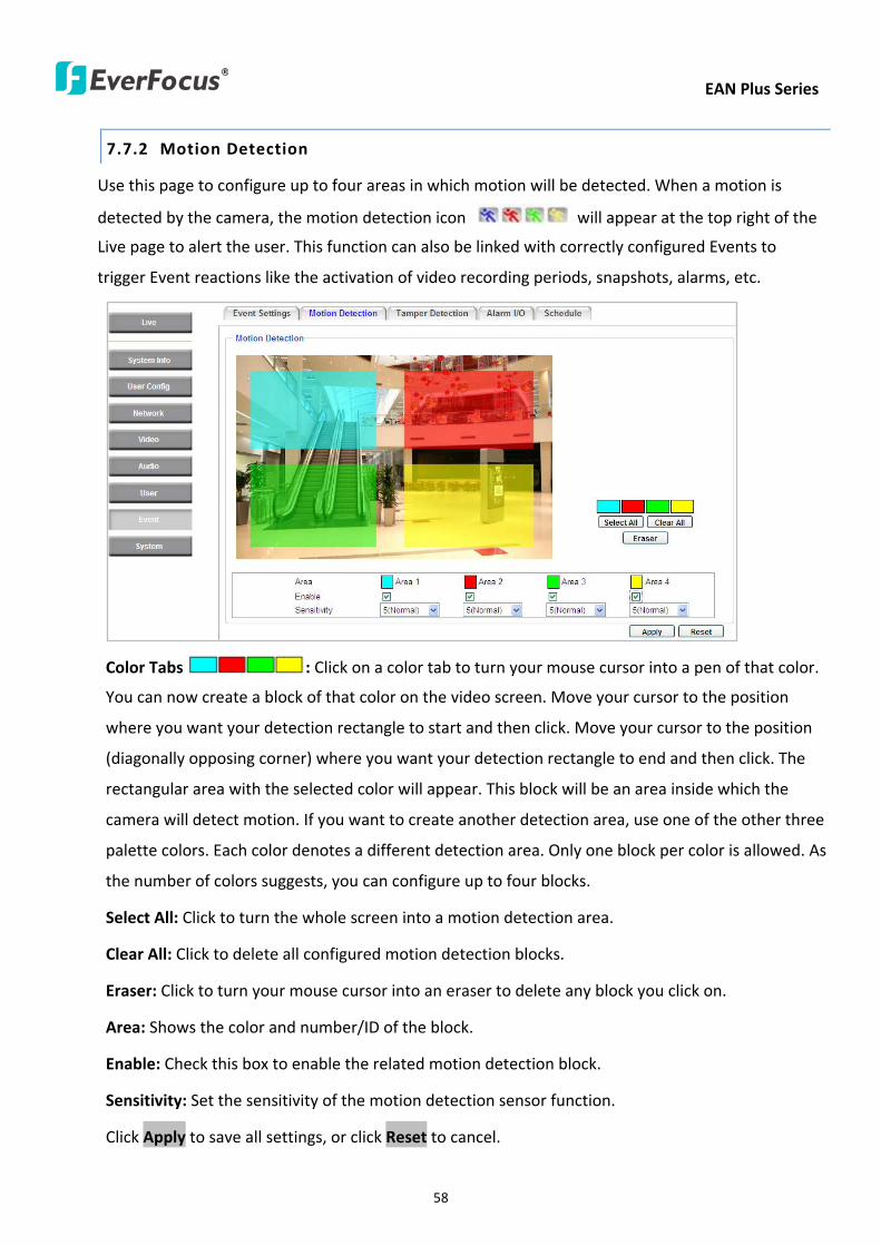
EAN Plus Series
58
772 Motion Detection
Use this page to configure up to four areas in which motion will be detected When a motion is
detected by the camera the motion detection icon will appear at the top right of the
Live page to alert the user This function can also be linked with correctly configured Events to
trigger Event reactions like the activation of video recording periods snapshots alarms etc
Color Tabs Click on a color tab to turn your mouse cursor into a pen of that color
You can now create a block of that color on the video screen Move your cursor to the position
where you want your detection rectangle to start and then click Move your cursor to the position
(diagonally opposing corner) where you want your detection rectangle to end and then click The
rectangular area with the selected color will appear This block will be an area inside which the
camera will detect motion If you want to create another detection area use one of the other three
palette colors Each color denotes a different detection area Only one block per color is allowed As
the number of colors suggests you can configure up to four blocks
Select All Click to turn the whole screen into a motion detection area
Clear All Click to delete all configured motion detection blocks
Eraser Click to turn your mouse cursor into an eraser to delete any block you click on
Area Shows the color and numberID of the block
Enable Check this box to enable the related motion detection block
Sensitivity Set the sensitivity of the motion detection sensor function
Click Apply to save all settings or click Reset to cancel
EAN Plus Series
59
773 Tamper Detection
Use this page to set the number of seconds that an alarm signal will be active if the device is
physically tampered (moved covered up or out of focus
774 Alarm IO
Use this page to set the type of trigger input and the type of output contact for the camerarsquos alarm
channel
EAN Plus Series
60
775 Schedule
Use this page to configure a schedule for periods during which the camera should deactivate all
user-activated Events (gray Deselect periods) or when the camera should deactivate all
user-activated Events except Schedule Recording (SR) events (blue Schedule Recording-only
periods) or when the camera should deactivate only SR events (red Event Recording-only periods)
or when it should enable all activated Events (yellow periods)
Event Recording Click this button to make every hour block you click on red A red block represents
an Event Recording-only block which represents an hour when the camera will deactivate all
preconfigured activated Schedule Recording events and keep all the other activated events active
Schedule Recording Click this button to make every hour block you click on blue A blue block
represents a Schedule Recording-only block which represents an hour when the camera will
deactivate all other preconfigured activated events and keep only the preconfigured activated
Schedule Recording events active
Event + Schedule Click this button to make every hour block you click on yellow A yellow block
represents an hour in which all activated events including Schedule Recording events will be
active
Deselect Click this button to make every hour block become grey A grey block represents an hour
in which all activated events including Schedule Recording events will be inactive
Click Apply to save all settings or click Reset to cancel
EAN Plus Series
61
78 System
You can set up the systemrsquos time and SD card settings and to do maintenance and reset actions like
reboots and upgrades
781 DateTime
【Machine Name Settings】If required enter a new name for the machine This name will be visible
in the Machine Name field of the IP Utility software which is included in the software CD
【Set Time Zone】Set the time zone of the camerarsquos location
【Set DateTime Manually】Set the datetime here if you wonrsquot be using an NTP server to update the
datetime (see below)
【Set DateTime Sync】Enter the Network Time Protocol server if applicable The camerarsquos time will
be automatically adjusted by synchronizing with the NTP server
Click Apply to save all settings or click Reset to cancel
EAN Plus Series
62
782 Daylight Saving
Click Enable Daylight Saving to enable this schedule and select the dates when the regionrsquos
daylight saving period begins and ends Click Apply to save all settings or click Reset to cancel
783 SD Card
Use this page to prepare the system for safely removing the SD Card from its slot
【Setup SD Card】
Notification Select the percentage of storage space that should be left on the card before the
camera notifies you of the impending storage shortage or overwrite
Event Recording Select if you want Event Recording only FTP Backup only or both
Overwrite Click ON if you want the card to start writing over recorded footage when its memory is
full Click OFF if you want the card to stop recording new footage when its memory is full
【SD Card Utility】
Capacity This shows you how much card memory has been used and how much memory capacity
remains on the card
Remove Click this button before removing the card from the system
Format Click this button to format the card All data saved on the SD card will be removed if the
card is formatted
EAN Plus Series
63
784 Maintenance
【Maintenance Server】
Reboot Click this button to reboot the unit without changing any of the settings Use this function if
the unit is not behaving as expected
Restore Click this button to restart and reset most of the current settings to their factory default
values The only settings that will not be changed to default are
bull IP settings
bull DDNS settings
Default The Default button should be used with caution Pressing this button will return all of the
cameras settings including the IP address to the factory default values The camera will then have
to be reconfigured
【SaveLoad Configuration Server】
Save To make a backup file of the machinersquos current configurations press Save to save all the
configurations to a config file This will enable the user to reload these configuration settings if the
settings are changed and there is unexpected behavior
Load To load a previously saved configuration press the Browse button to locate the saved config
file (see above) and then click the Load button The systemrsquos settings will be restored to the saved
configuration
EAN Plus Series
64
【SaveLoad Video Configuration Server】
Save To make a backup file of the machinersquos video configurations press Save to save the video
configurations to a config file This will enable the user to reload these configuration settings if the
settings are changed and there is unexpected behavior
Load To load a previously saved video configuration press the Browse button to locate the saved
config file (see above) and then click the Load button The systemrsquos settings will be restored to the
saved video configuration
【Upgrade Firmware】Click the Browse button to find a previously prepared firmware upgrade file
Click Upgrade to install the new firmware
Note
1 Do not disconnect power to the unit during the upgrade sequence The unit will reboot
automatically after the upgrade has completed (1-5 minutes)
2 During the upgrade process all event recording actions will be stopped Event recording
actions will resume after the camera is rebooted
3 If the ldquoFile Error Please re-loginrdquo warning message appears when upgrading the firmware
please try the following instructions
a Go to Internet Explorer gt Tools gt Internet Option gt Security gt Custom
b Find and enable the Include local directory path when uploading files to a server
EAN Plus Series
65
8 Upgrading Firmware Using IP Utility
You can upgrade the Firmware using the IP Utility software included in the software CD
1 Install and then start the IPU program The following dialog box appears
2 Click Find Devices to search the cameras connected in the LAN The default network values of the
cameras will be displayed By default the network protocol of the camera is DHCP
3 Select a camera and click LoginMulti Login to log in the camera
4 Type the user ID and password Click OK
Note
1 The default user ID is user1 and the default password is 11111111
2 If you select more than one camera that has the same user ID password you will be able
to log in several cameras at once
EAN Plus Series
66
5 Highlight the camera and then click Upgrade Firmware A browsing window appears
6 Select the firmware file (evb) and then click Open The IP Utility will automatically upgrade the
firmware
The camera will reboot once the update is complete Click Find Devices the new firmware version
should be displayed in the last part of the Machine Name
EAN Plus Series
67
9 Specifications
Model EAN3120 Plus EAN3220 Plus EAN3300 Plus
Camera
Image Sensor 13 Panasonic CMOS 128 Sony CMOS
Megapixel 13 MP 2 MP 3 MP
Picture Elements (H x V) 1280 x 1024 1944 x 1092 2048 x 1536
Min Illuminations 003 Lux at F14
Electronic Shutter (Sec) 85 ~ 160000 2 ~ 150000 1 ~ 110000
Scanning System NTSC PAL
WDR Yes Yes No
BLC Yes
Gain Control Yes
White Balance Yes
Lens
Mounting Type C CS
Day Night Yes (with removable auto IR-cut filter)
IRIS Control DC Electrical IRIS Lens IRIS
Video
Video Compression H264 MJPEG
Resolution
NTSC
2048 x 1536 1920 x 1200 (for EAN3300 Plus only)
1920 x 1080 (for EAN3300 Plus 3220 Plus only)
1280 x 1024 1280 x 720 1024 x 768 720 x 480 704 x 480 640 x 480
352 x 240 320 x 240 160 x 120
PAL
2048 x 1536 1920 x 1200 (for EAN3300 Plus only)
1920 x 1080 (for EAN3300 Plus 3220 Plus only)
1280 x 1024 1280 x 720 1024 x 768 720 x 576 704 x 576 640 x 480
352 x 288 320 x 240 160 x 120
Frame Rate 30 fps at 1280 x 1024 30 fps at 1920 x 1080 15 fps at 2048 x 1536
Audio
Audio Streaming Two-way audio
Audio Compression G711
EAN Plus Series
68
Network
Interface 10 100 Base-T Ethernet RJ-45 socket
Supported Protocols
TCPIP IPV6 UDP ICMP DHCP NTP DNS DDNS SMTP SNMP FTP
HTTP HTTPs PPPoE UPnP Bonjour RTP RTSP RTCP IGMP ARP ONVIF
PSIA
Connector
Power DC female port PoE
Ethernet RJ-45
Audio 1 In (phone jack for microphone)
1 Out (phone jack for Speaker)
Alarm IO Terminal IO wires
Local Storage Micro SD SDHC memory card slot
TV-Out BNC socket composite 1 V p-p 75 Ω
General
Power Source DC 12V PoE (IEEE8023af)
Power Consumption
(IR LEDs On)
5W (DC 12V)
621W (PoE)
5W (DC 12V)
522W (PoE)
5W (DC 12V)
536W (PoE)
Operating Temperature 0degC ~ +50degC 32degF ~ +122degF
Humidity 20 to 80 (no condensation)
Safety CE FCC
Dimensions (L x W x H) 117 x 56 x 68 mm 46 x 22 x 27 in
Weight 410 g 09 lb
EverFocus Electronics Corp EverFocus Taiwan 12F No79 Sec 1 Shin-Tai Wu Road Hsi-Chih Taipei Taiwan TEL +886 2 2698 2334 FAX +886 2 2698 2380 wwweverfocuscomtw marketingeverfocuscomtw
EverFocus Europe - Germany Albert-Einstein-Strasse 1 D-46446 Emmerich Germany TEL +49 2822 93940 FAX +49 2822 939495 wwweverfocusde infoeverfocusde
EverFocus China - Beijing Room 609 Technology Trade Building Shangdi Information Industry Base Haidian District Beijing 100085 China TEL +86 10 6297 3336~39 FAX +86 10 6297 1423 wwweverfocuscomcn marketingeverfocuscomcn
EverFocus China - Shenzhen 4F No 2 D4 Building Wan Yelong Industrial Park Tangtou Road Shiyan Baoan Shenzhen Guangdong 518101 China TEL +86 755 2765 1313 FAX +86 755 2765 0337 wwweverfocuscomcn marketingeverfocuscomcn
EverFocus USA - California 1801 Highland Avenue Unit A Duarte CA 91010 USA TEL +1 626 844 8888 FAX +1 626 844 8838 wwweverfocuscom saleseverfocuscom
EverFocus USA - New York 415 Oser Avenue Unit S Hauppauge NY 11788 USA TEL +1 631 436 5070 FAX +1 631 436 5027 wwweverfocuscom saleseverfocuscom
EverFocus Japan 5F Kinshicho City Building 2-13-4 Koto-BashiSumida-Ku Tokyo 130-0022 Japan TEL +81 3 5625 8188 FAX +81 3 5625 8189 wwweverfocuscojp infoeverfocuscojp
EverFocus Europe - UK Unit 12 Spitfire Business Park Hawker Road Croydon Surrey CR0 4WD UK TEL +44 20 8649 9757 +44 845 430 9999 FAX +44 20 8649 9907 wwweverfocusukcouk salesukeverfocuscom
EverFocus India Suite 803 Housefin Bhavan C-21 Bandra Kurla Complex Bandra (East) Mumbai 400051 India TEL +91 22 6128 8700 FAX +91 22 6128 8705 wwweverfocusin saleseverfocusin
PN 4605PQ3120B010A-VerC
Your EverFocus product is designed and manufactured with high quality materials and components which can be recycled and reused This symbol means that electrical and electronic equipment at their end-of-life should be disposed of separately from your household waste Please dispose of this equipment at your local community waste collectionrecycling centre In the European Union there are separate collection systems for used electrical and electronic product Please help us to conserve the environment we live in
Ihr EverFocus Produkt wurde entwickelt und hergestellt mit qualitativ hochwertigen Materialien und Komponenten die recycelt und wieder verwendet werden koumlnnen Dieses Symbol bedeutet dass elektrische und elektronische Geraumlte am Ende ihrer Nutzungsdauer vom Hausmuumlll getrennt entsorgt werden sollen Bitte entsorgen Sie dieses Geraumlt bei Ihrer oumlrtlichen kommunalen Sammelstelle oder im Recycling Centre Helfen Sie uns bitte die Umwelt zu erhalten in der wir leben
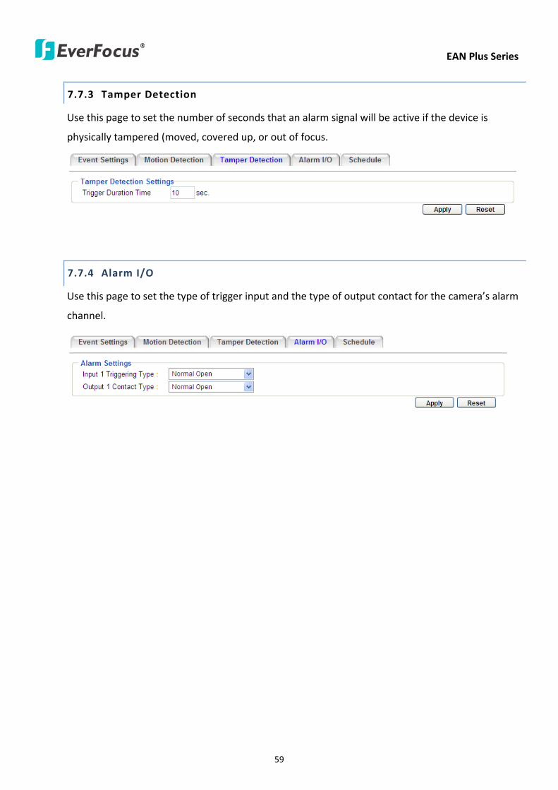
EAN Plus Series
59
773 Tamper Detection
Use this page to set the number of seconds that an alarm signal will be active if the device is
physically tampered (moved covered up or out of focus
774 Alarm IO
Use this page to set the type of trigger input and the type of output contact for the camerarsquos alarm
channel
EAN Plus Series
60
775 Schedule
Use this page to configure a schedule for periods during which the camera should deactivate all
user-activated Events (gray Deselect periods) or when the camera should deactivate all
user-activated Events except Schedule Recording (SR) events (blue Schedule Recording-only
periods) or when the camera should deactivate only SR events (red Event Recording-only periods)
or when it should enable all activated Events (yellow periods)
Event Recording Click this button to make every hour block you click on red A red block represents
an Event Recording-only block which represents an hour when the camera will deactivate all
preconfigured activated Schedule Recording events and keep all the other activated events active
Schedule Recording Click this button to make every hour block you click on blue A blue block
represents a Schedule Recording-only block which represents an hour when the camera will
deactivate all other preconfigured activated events and keep only the preconfigured activated
Schedule Recording events active
Event + Schedule Click this button to make every hour block you click on yellow A yellow block
represents an hour in which all activated events including Schedule Recording events will be
active
Deselect Click this button to make every hour block become grey A grey block represents an hour
in which all activated events including Schedule Recording events will be inactive
Click Apply to save all settings or click Reset to cancel
EAN Plus Series
61
78 System
You can set up the systemrsquos time and SD card settings and to do maintenance and reset actions like
reboots and upgrades
781 DateTime
【Machine Name Settings】If required enter a new name for the machine This name will be visible
in the Machine Name field of the IP Utility software which is included in the software CD
【Set Time Zone】Set the time zone of the camerarsquos location
【Set DateTime Manually】Set the datetime here if you wonrsquot be using an NTP server to update the
datetime (see below)
【Set DateTime Sync】Enter the Network Time Protocol server if applicable The camerarsquos time will
be automatically adjusted by synchronizing with the NTP server
Click Apply to save all settings or click Reset to cancel
EAN Plus Series
62
782 Daylight Saving
Click Enable Daylight Saving to enable this schedule and select the dates when the regionrsquos
daylight saving period begins and ends Click Apply to save all settings or click Reset to cancel
783 SD Card
Use this page to prepare the system for safely removing the SD Card from its slot
【Setup SD Card】
Notification Select the percentage of storage space that should be left on the card before the
camera notifies you of the impending storage shortage or overwrite
Event Recording Select if you want Event Recording only FTP Backup only or both
Overwrite Click ON if you want the card to start writing over recorded footage when its memory is
full Click OFF if you want the card to stop recording new footage when its memory is full
【SD Card Utility】
Capacity This shows you how much card memory has been used and how much memory capacity
remains on the card
Remove Click this button before removing the card from the system
Format Click this button to format the card All data saved on the SD card will be removed if the
card is formatted
EAN Plus Series
63
784 Maintenance
【Maintenance Server】
Reboot Click this button to reboot the unit without changing any of the settings Use this function if
the unit is not behaving as expected
Restore Click this button to restart and reset most of the current settings to their factory default
values The only settings that will not be changed to default are
bull IP settings
bull DDNS settings
Default The Default button should be used with caution Pressing this button will return all of the
cameras settings including the IP address to the factory default values The camera will then have
to be reconfigured
【SaveLoad Configuration Server】
Save To make a backup file of the machinersquos current configurations press Save to save all the
configurations to a config file This will enable the user to reload these configuration settings if the
settings are changed and there is unexpected behavior
Load To load a previously saved configuration press the Browse button to locate the saved config
file (see above) and then click the Load button The systemrsquos settings will be restored to the saved
configuration
EAN Plus Series
64
【SaveLoad Video Configuration Server】
Save To make a backup file of the machinersquos video configurations press Save to save the video
configurations to a config file This will enable the user to reload these configuration settings if the
settings are changed and there is unexpected behavior
Load To load a previously saved video configuration press the Browse button to locate the saved
config file (see above) and then click the Load button The systemrsquos settings will be restored to the
saved video configuration
【Upgrade Firmware】Click the Browse button to find a previously prepared firmware upgrade file
Click Upgrade to install the new firmware
Note
1 Do not disconnect power to the unit during the upgrade sequence The unit will reboot
automatically after the upgrade has completed (1-5 minutes)
2 During the upgrade process all event recording actions will be stopped Event recording
actions will resume after the camera is rebooted
3 If the ldquoFile Error Please re-loginrdquo warning message appears when upgrading the firmware
please try the following instructions
a Go to Internet Explorer gt Tools gt Internet Option gt Security gt Custom
b Find and enable the Include local directory path when uploading files to a server
EAN Plus Series
65
8 Upgrading Firmware Using IP Utility
You can upgrade the Firmware using the IP Utility software included in the software CD
1 Install and then start the IPU program The following dialog box appears
2 Click Find Devices to search the cameras connected in the LAN The default network values of the
cameras will be displayed By default the network protocol of the camera is DHCP
3 Select a camera and click LoginMulti Login to log in the camera
4 Type the user ID and password Click OK
Note
1 The default user ID is user1 and the default password is 11111111
2 If you select more than one camera that has the same user ID password you will be able
to log in several cameras at once
EAN Plus Series
66
5 Highlight the camera and then click Upgrade Firmware A browsing window appears
6 Select the firmware file (evb) and then click Open The IP Utility will automatically upgrade the
firmware
The camera will reboot once the update is complete Click Find Devices the new firmware version
should be displayed in the last part of the Machine Name
EAN Plus Series
67
9 Specifications
Model EAN3120 Plus EAN3220 Plus EAN3300 Plus
Camera
Image Sensor 13 Panasonic CMOS 128 Sony CMOS
Megapixel 13 MP 2 MP 3 MP
Picture Elements (H x V) 1280 x 1024 1944 x 1092 2048 x 1536
Min Illuminations 003 Lux at F14
Electronic Shutter (Sec) 85 ~ 160000 2 ~ 150000 1 ~ 110000
Scanning System NTSC PAL
WDR Yes Yes No
BLC Yes
Gain Control Yes
White Balance Yes
Lens
Mounting Type C CS
Day Night Yes (with removable auto IR-cut filter)
IRIS Control DC Electrical IRIS Lens IRIS
Video
Video Compression H264 MJPEG
Resolution
NTSC
2048 x 1536 1920 x 1200 (for EAN3300 Plus only)
1920 x 1080 (for EAN3300 Plus 3220 Plus only)
1280 x 1024 1280 x 720 1024 x 768 720 x 480 704 x 480 640 x 480
352 x 240 320 x 240 160 x 120
PAL
2048 x 1536 1920 x 1200 (for EAN3300 Plus only)
1920 x 1080 (for EAN3300 Plus 3220 Plus only)
1280 x 1024 1280 x 720 1024 x 768 720 x 576 704 x 576 640 x 480
352 x 288 320 x 240 160 x 120
Frame Rate 30 fps at 1280 x 1024 30 fps at 1920 x 1080 15 fps at 2048 x 1536
Audio
Audio Streaming Two-way audio
Audio Compression G711
EAN Plus Series
68
Network
Interface 10 100 Base-T Ethernet RJ-45 socket
Supported Protocols
TCPIP IPV6 UDP ICMP DHCP NTP DNS DDNS SMTP SNMP FTP
HTTP HTTPs PPPoE UPnP Bonjour RTP RTSP RTCP IGMP ARP ONVIF
PSIA
Connector
Power DC female port PoE
Ethernet RJ-45
Audio 1 In (phone jack for microphone)
1 Out (phone jack for Speaker)
Alarm IO Terminal IO wires
Local Storage Micro SD SDHC memory card slot
TV-Out BNC socket composite 1 V p-p 75 Ω
General
Power Source DC 12V PoE (IEEE8023af)
Power Consumption
(IR LEDs On)
5W (DC 12V)
621W (PoE)
5W (DC 12V)
522W (PoE)
5W (DC 12V)
536W (PoE)
Operating Temperature 0degC ~ +50degC 32degF ~ +122degF
Humidity 20 to 80 (no condensation)
Safety CE FCC
Dimensions (L x W x H) 117 x 56 x 68 mm 46 x 22 x 27 in
Weight 410 g 09 lb
EverFocus Electronics Corp EverFocus Taiwan 12F No79 Sec 1 Shin-Tai Wu Road Hsi-Chih Taipei Taiwan TEL +886 2 2698 2334 FAX +886 2 2698 2380 wwweverfocuscomtw marketingeverfocuscomtw
EverFocus Europe - Germany Albert-Einstein-Strasse 1 D-46446 Emmerich Germany TEL +49 2822 93940 FAX +49 2822 939495 wwweverfocusde infoeverfocusde
EverFocus China - Beijing Room 609 Technology Trade Building Shangdi Information Industry Base Haidian District Beijing 100085 China TEL +86 10 6297 3336~39 FAX +86 10 6297 1423 wwweverfocuscomcn marketingeverfocuscomcn
EverFocus China - Shenzhen 4F No 2 D4 Building Wan Yelong Industrial Park Tangtou Road Shiyan Baoan Shenzhen Guangdong 518101 China TEL +86 755 2765 1313 FAX +86 755 2765 0337 wwweverfocuscomcn marketingeverfocuscomcn
EverFocus USA - California 1801 Highland Avenue Unit A Duarte CA 91010 USA TEL +1 626 844 8888 FAX +1 626 844 8838 wwweverfocuscom saleseverfocuscom
EverFocus USA - New York 415 Oser Avenue Unit S Hauppauge NY 11788 USA TEL +1 631 436 5070 FAX +1 631 436 5027 wwweverfocuscom saleseverfocuscom
EverFocus Japan 5F Kinshicho City Building 2-13-4 Koto-BashiSumida-Ku Tokyo 130-0022 Japan TEL +81 3 5625 8188 FAX +81 3 5625 8189 wwweverfocuscojp infoeverfocuscojp
EverFocus Europe - UK Unit 12 Spitfire Business Park Hawker Road Croydon Surrey CR0 4WD UK TEL +44 20 8649 9757 +44 845 430 9999 FAX +44 20 8649 9907 wwweverfocusukcouk salesukeverfocuscom
EverFocus India Suite 803 Housefin Bhavan C-21 Bandra Kurla Complex Bandra (East) Mumbai 400051 India TEL +91 22 6128 8700 FAX +91 22 6128 8705 wwweverfocusin saleseverfocusin
PN 4605PQ3120B010A-VerC
Your EverFocus product is designed and manufactured with high quality materials and components which can be recycled and reused This symbol means that electrical and electronic equipment at their end-of-life should be disposed of separately from your household waste Please dispose of this equipment at your local community waste collectionrecycling centre In the European Union there are separate collection systems for used electrical and electronic product Please help us to conserve the environment we live in
Ihr EverFocus Produkt wurde entwickelt und hergestellt mit qualitativ hochwertigen Materialien und Komponenten die recycelt und wieder verwendet werden koumlnnen Dieses Symbol bedeutet dass elektrische und elektronische Geraumlte am Ende ihrer Nutzungsdauer vom Hausmuumlll getrennt entsorgt werden sollen Bitte entsorgen Sie dieses Geraumlt bei Ihrer oumlrtlichen kommunalen Sammelstelle oder im Recycling Centre Helfen Sie uns bitte die Umwelt zu erhalten in der wir leben
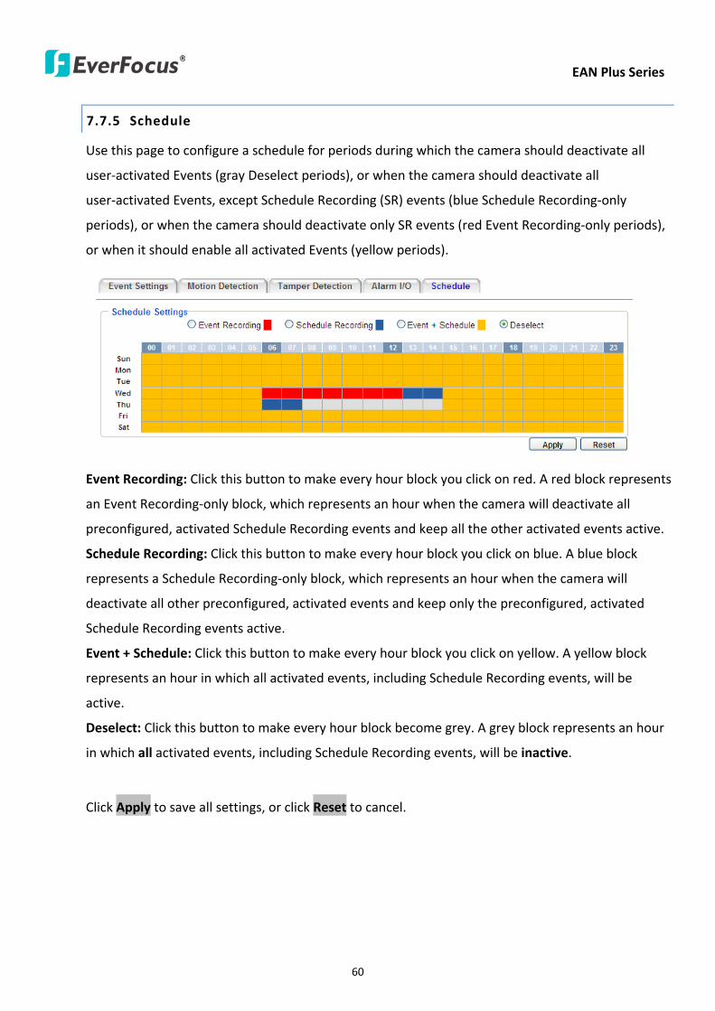
EAN Plus Series
60
775 Schedule
Use this page to configure a schedule for periods during which the camera should deactivate all
user-activated Events (gray Deselect periods) or when the camera should deactivate all
user-activated Events except Schedule Recording (SR) events (blue Schedule Recording-only
periods) or when the camera should deactivate only SR events (red Event Recording-only periods)
or when it should enable all activated Events (yellow periods)
Event Recording Click this button to make every hour block you click on red A red block represents
an Event Recording-only block which represents an hour when the camera will deactivate all
preconfigured activated Schedule Recording events and keep all the other activated events active
Schedule Recording Click this button to make every hour block you click on blue A blue block
represents a Schedule Recording-only block which represents an hour when the camera will
deactivate all other preconfigured activated events and keep only the preconfigured activated
Schedule Recording events active
Event + Schedule Click this button to make every hour block you click on yellow A yellow block
represents an hour in which all activated events including Schedule Recording events will be
active
Deselect Click this button to make every hour block become grey A grey block represents an hour
in which all activated events including Schedule Recording events will be inactive
Click Apply to save all settings or click Reset to cancel
EAN Plus Series
61
78 System
You can set up the systemrsquos time and SD card settings and to do maintenance and reset actions like
reboots and upgrades
781 DateTime
【Machine Name Settings】If required enter a new name for the machine This name will be visible
in the Machine Name field of the IP Utility software which is included in the software CD
【Set Time Zone】Set the time zone of the camerarsquos location
【Set DateTime Manually】Set the datetime here if you wonrsquot be using an NTP server to update the
datetime (see below)
【Set DateTime Sync】Enter the Network Time Protocol server if applicable The camerarsquos time will
be automatically adjusted by synchronizing with the NTP server
Click Apply to save all settings or click Reset to cancel
EAN Plus Series
62
782 Daylight Saving
Click Enable Daylight Saving to enable this schedule and select the dates when the regionrsquos
daylight saving period begins and ends Click Apply to save all settings or click Reset to cancel
783 SD Card
Use this page to prepare the system for safely removing the SD Card from its slot
【Setup SD Card】
Notification Select the percentage of storage space that should be left on the card before the
camera notifies you of the impending storage shortage or overwrite
Event Recording Select if you want Event Recording only FTP Backup only or both
Overwrite Click ON if you want the card to start writing over recorded footage when its memory is
full Click OFF if you want the card to stop recording new footage when its memory is full
【SD Card Utility】
Capacity This shows you how much card memory has been used and how much memory capacity
remains on the card
Remove Click this button before removing the card from the system
Format Click this button to format the card All data saved on the SD card will be removed if the
card is formatted
EAN Plus Series
63
784 Maintenance
【Maintenance Server】
Reboot Click this button to reboot the unit without changing any of the settings Use this function if
the unit is not behaving as expected
Restore Click this button to restart and reset most of the current settings to their factory default
values The only settings that will not be changed to default are
bull IP settings
bull DDNS settings
Default The Default button should be used with caution Pressing this button will return all of the
cameras settings including the IP address to the factory default values The camera will then have
to be reconfigured
【SaveLoad Configuration Server】
Save To make a backup file of the machinersquos current configurations press Save to save all the
configurations to a config file This will enable the user to reload these configuration settings if the
settings are changed and there is unexpected behavior
Load To load a previously saved configuration press the Browse button to locate the saved config
file (see above) and then click the Load button The systemrsquos settings will be restored to the saved
configuration
EAN Plus Series
64
【SaveLoad Video Configuration Server】
Save To make a backup file of the machinersquos video configurations press Save to save the video
configurations to a config file This will enable the user to reload these configuration settings if the
settings are changed and there is unexpected behavior
Load To load a previously saved video configuration press the Browse button to locate the saved
config file (see above) and then click the Load button The systemrsquos settings will be restored to the
saved video configuration
【Upgrade Firmware】Click the Browse button to find a previously prepared firmware upgrade file
Click Upgrade to install the new firmware
Note
1 Do not disconnect power to the unit during the upgrade sequence The unit will reboot
automatically after the upgrade has completed (1-5 minutes)
2 During the upgrade process all event recording actions will be stopped Event recording
actions will resume after the camera is rebooted
3 If the ldquoFile Error Please re-loginrdquo warning message appears when upgrading the firmware
please try the following instructions
a Go to Internet Explorer gt Tools gt Internet Option gt Security gt Custom
b Find and enable the Include local directory path when uploading files to a server
EAN Plus Series
65
8 Upgrading Firmware Using IP Utility
You can upgrade the Firmware using the IP Utility software included in the software CD
1 Install and then start the IPU program The following dialog box appears
2 Click Find Devices to search the cameras connected in the LAN The default network values of the
cameras will be displayed By default the network protocol of the camera is DHCP
3 Select a camera and click LoginMulti Login to log in the camera
4 Type the user ID and password Click OK
Note
1 The default user ID is user1 and the default password is 11111111
2 If you select more than one camera that has the same user ID password you will be able
to log in several cameras at once
EAN Plus Series
66
5 Highlight the camera and then click Upgrade Firmware A browsing window appears
6 Select the firmware file (evb) and then click Open The IP Utility will automatically upgrade the
firmware
The camera will reboot once the update is complete Click Find Devices the new firmware version
should be displayed in the last part of the Machine Name
EAN Plus Series
67
9 Specifications
Model EAN3120 Plus EAN3220 Plus EAN3300 Plus
Camera
Image Sensor 13 Panasonic CMOS 128 Sony CMOS
Megapixel 13 MP 2 MP 3 MP
Picture Elements (H x V) 1280 x 1024 1944 x 1092 2048 x 1536
Min Illuminations 003 Lux at F14
Electronic Shutter (Sec) 85 ~ 160000 2 ~ 150000 1 ~ 110000
Scanning System NTSC PAL
WDR Yes Yes No
BLC Yes
Gain Control Yes
White Balance Yes
Lens
Mounting Type C CS
Day Night Yes (with removable auto IR-cut filter)
IRIS Control DC Electrical IRIS Lens IRIS
Video
Video Compression H264 MJPEG
Resolution
NTSC
2048 x 1536 1920 x 1200 (for EAN3300 Plus only)
1920 x 1080 (for EAN3300 Plus 3220 Plus only)
1280 x 1024 1280 x 720 1024 x 768 720 x 480 704 x 480 640 x 480
352 x 240 320 x 240 160 x 120
PAL
2048 x 1536 1920 x 1200 (for EAN3300 Plus only)
1920 x 1080 (for EAN3300 Plus 3220 Plus only)
1280 x 1024 1280 x 720 1024 x 768 720 x 576 704 x 576 640 x 480
352 x 288 320 x 240 160 x 120
Frame Rate 30 fps at 1280 x 1024 30 fps at 1920 x 1080 15 fps at 2048 x 1536
Audio
Audio Streaming Two-way audio
Audio Compression G711
EAN Plus Series
68
Network
Interface 10 100 Base-T Ethernet RJ-45 socket
Supported Protocols
TCPIP IPV6 UDP ICMP DHCP NTP DNS DDNS SMTP SNMP FTP
HTTP HTTPs PPPoE UPnP Bonjour RTP RTSP RTCP IGMP ARP ONVIF
PSIA
Connector
Power DC female port PoE
Ethernet RJ-45
Audio 1 In (phone jack for microphone)
1 Out (phone jack for Speaker)
Alarm IO Terminal IO wires
Local Storage Micro SD SDHC memory card slot
TV-Out BNC socket composite 1 V p-p 75 Ω
General
Power Source DC 12V PoE (IEEE8023af)
Power Consumption
(IR LEDs On)
5W (DC 12V)
621W (PoE)
5W (DC 12V)
522W (PoE)
5W (DC 12V)
536W (PoE)
Operating Temperature 0degC ~ +50degC 32degF ~ +122degF
Humidity 20 to 80 (no condensation)
Safety CE FCC
Dimensions (L x W x H) 117 x 56 x 68 mm 46 x 22 x 27 in
Weight 410 g 09 lb
EverFocus Electronics Corp EverFocus Taiwan 12F No79 Sec 1 Shin-Tai Wu Road Hsi-Chih Taipei Taiwan TEL +886 2 2698 2334 FAX +886 2 2698 2380 wwweverfocuscomtw marketingeverfocuscomtw
EverFocus Europe - Germany Albert-Einstein-Strasse 1 D-46446 Emmerich Germany TEL +49 2822 93940 FAX +49 2822 939495 wwweverfocusde infoeverfocusde
EverFocus China - Beijing Room 609 Technology Trade Building Shangdi Information Industry Base Haidian District Beijing 100085 China TEL +86 10 6297 3336~39 FAX +86 10 6297 1423 wwweverfocuscomcn marketingeverfocuscomcn
EverFocus China - Shenzhen 4F No 2 D4 Building Wan Yelong Industrial Park Tangtou Road Shiyan Baoan Shenzhen Guangdong 518101 China TEL +86 755 2765 1313 FAX +86 755 2765 0337 wwweverfocuscomcn marketingeverfocuscomcn
EverFocus USA - California 1801 Highland Avenue Unit A Duarte CA 91010 USA TEL +1 626 844 8888 FAX +1 626 844 8838 wwweverfocuscom saleseverfocuscom
EverFocus USA - New York 415 Oser Avenue Unit S Hauppauge NY 11788 USA TEL +1 631 436 5070 FAX +1 631 436 5027 wwweverfocuscom saleseverfocuscom
EverFocus Japan 5F Kinshicho City Building 2-13-4 Koto-BashiSumida-Ku Tokyo 130-0022 Japan TEL +81 3 5625 8188 FAX +81 3 5625 8189 wwweverfocuscojp infoeverfocuscojp
EverFocus Europe - UK Unit 12 Spitfire Business Park Hawker Road Croydon Surrey CR0 4WD UK TEL +44 20 8649 9757 +44 845 430 9999 FAX +44 20 8649 9907 wwweverfocusukcouk salesukeverfocuscom
EverFocus India Suite 803 Housefin Bhavan C-21 Bandra Kurla Complex Bandra (East) Mumbai 400051 India TEL +91 22 6128 8700 FAX +91 22 6128 8705 wwweverfocusin saleseverfocusin
PN 4605PQ3120B010A-VerC
Your EverFocus product is designed and manufactured with high quality materials and components which can be recycled and reused This symbol means that electrical and electronic equipment at their end-of-life should be disposed of separately from your household waste Please dispose of this equipment at your local community waste collectionrecycling centre In the European Union there are separate collection systems for used electrical and electronic product Please help us to conserve the environment we live in
Ihr EverFocus Produkt wurde entwickelt und hergestellt mit qualitativ hochwertigen Materialien und Komponenten die recycelt und wieder verwendet werden koumlnnen Dieses Symbol bedeutet dass elektrische und elektronische Geraumlte am Ende ihrer Nutzungsdauer vom Hausmuumlll getrennt entsorgt werden sollen Bitte entsorgen Sie dieses Geraumlt bei Ihrer oumlrtlichen kommunalen Sammelstelle oder im Recycling Centre Helfen Sie uns bitte die Umwelt zu erhalten in der wir leben
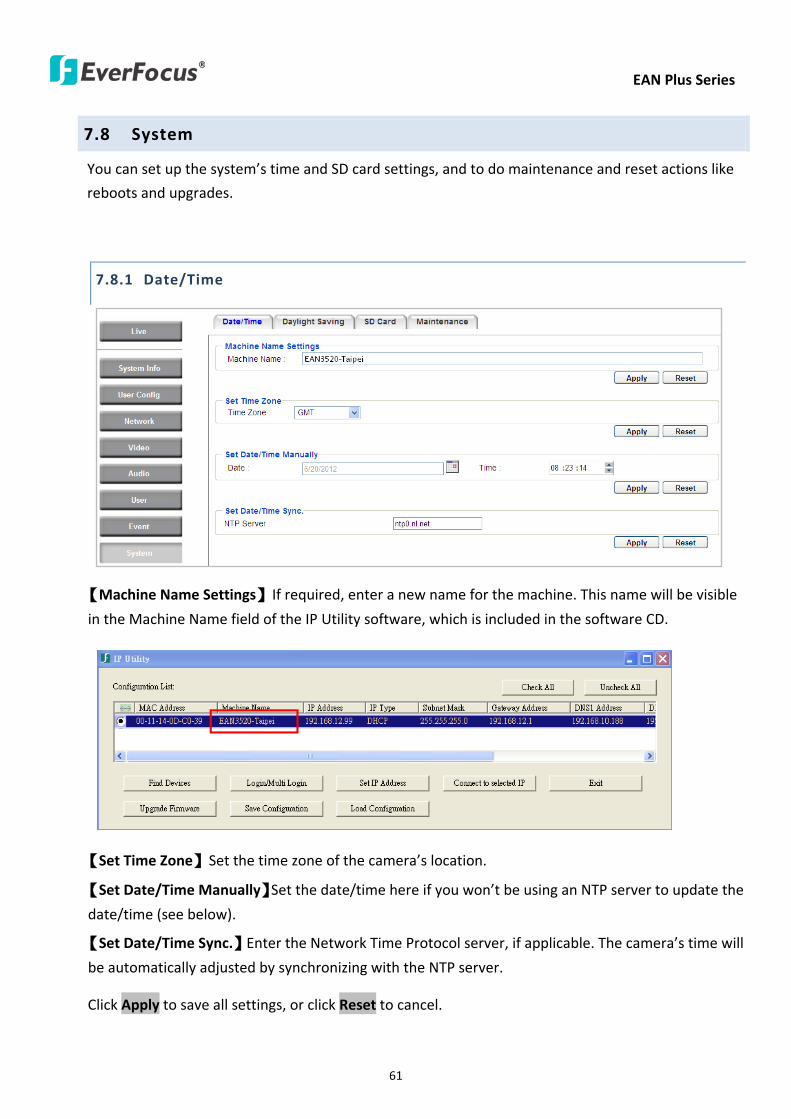
EAN Plus Series
61
78 System
You can set up the systemrsquos time and SD card settings and to do maintenance and reset actions like
reboots and upgrades
781 DateTime
【Machine Name Settings】If required enter a new name for the machine This name will be visible
in the Machine Name field of the IP Utility software which is included in the software CD
【Set Time Zone】Set the time zone of the camerarsquos location
【Set DateTime Manually】Set the datetime here if you wonrsquot be using an NTP server to update the
datetime (see below)
【Set DateTime Sync】Enter the Network Time Protocol server if applicable The camerarsquos time will
be automatically adjusted by synchronizing with the NTP server
Click Apply to save all settings or click Reset to cancel
EAN Plus Series
62
782 Daylight Saving
Click Enable Daylight Saving to enable this schedule and select the dates when the regionrsquos
daylight saving period begins and ends Click Apply to save all settings or click Reset to cancel
783 SD Card
Use this page to prepare the system for safely removing the SD Card from its slot
【Setup SD Card】
Notification Select the percentage of storage space that should be left on the card before the
camera notifies you of the impending storage shortage or overwrite
Event Recording Select if you want Event Recording only FTP Backup only or both
Overwrite Click ON if you want the card to start writing over recorded footage when its memory is
full Click OFF if you want the card to stop recording new footage when its memory is full
【SD Card Utility】
Capacity This shows you how much card memory has been used and how much memory capacity
remains on the card
Remove Click this button before removing the card from the system
Format Click this button to format the card All data saved on the SD card will be removed if the
card is formatted
EAN Plus Series
63
784 Maintenance
【Maintenance Server】
Reboot Click this button to reboot the unit without changing any of the settings Use this function if
the unit is not behaving as expected
Restore Click this button to restart and reset most of the current settings to their factory default
values The only settings that will not be changed to default are
bull IP settings
bull DDNS settings
Default The Default button should be used with caution Pressing this button will return all of the
cameras settings including the IP address to the factory default values The camera will then have
to be reconfigured
【SaveLoad Configuration Server】
Save To make a backup file of the machinersquos current configurations press Save to save all the
configurations to a config file This will enable the user to reload these configuration settings if the
settings are changed and there is unexpected behavior
Load To load a previously saved configuration press the Browse button to locate the saved config
file (see above) and then click the Load button The systemrsquos settings will be restored to the saved
configuration
EAN Plus Series
64
【SaveLoad Video Configuration Server】
Save To make a backup file of the machinersquos video configurations press Save to save the video
configurations to a config file This will enable the user to reload these configuration settings if the
settings are changed and there is unexpected behavior
Load To load a previously saved video configuration press the Browse button to locate the saved
config file (see above) and then click the Load button The systemrsquos settings will be restored to the
saved video configuration
【Upgrade Firmware】Click the Browse button to find a previously prepared firmware upgrade file
Click Upgrade to install the new firmware
Note
1 Do not disconnect power to the unit during the upgrade sequence The unit will reboot
automatically after the upgrade has completed (1-5 minutes)
2 During the upgrade process all event recording actions will be stopped Event recording
actions will resume after the camera is rebooted
3 If the ldquoFile Error Please re-loginrdquo warning message appears when upgrading the firmware
please try the following instructions
a Go to Internet Explorer gt Tools gt Internet Option gt Security gt Custom
b Find and enable the Include local directory path when uploading files to a server
EAN Plus Series
65
8 Upgrading Firmware Using IP Utility
You can upgrade the Firmware using the IP Utility software included in the software CD
1 Install and then start the IPU program The following dialog box appears
2 Click Find Devices to search the cameras connected in the LAN The default network values of the
cameras will be displayed By default the network protocol of the camera is DHCP
3 Select a camera and click LoginMulti Login to log in the camera
4 Type the user ID and password Click OK
Note
1 The default user ID is user1 and the default password is 11111111
2 If you select more than one camera that has the same user ID password you will be able
to log in several cameras at once
EAN Plus Series
66
5 Highlight the camera and then click Upgrade Firmware A browsing window appears
6 Select the firmware file (evb) and then click Open The IP Utility will automatically upgrade the
firmware
The camera will reboot once the update is complete Click Find Devices the new firmware version
should be displayed in the last part of the Machine Name
EAN Plus Series
67
9 Specifications
Model EAN3120 Plus EAN3220 Plus EAN3300 Plus
Camera
Image Sensor 13 Panasonic CMOS 128 Sony CMOS
Megapixel 13 MP 2 MP 3 MP
Picture Elements (H x V) 1280 x 1024 1944 x 1092 2048 x 1536
Min Illuminations 003 Lux at F14
Electronic Shutter (Sec) 85 ~ 160000 2 ~ 150000 1 ~ 110000
Scanning System NTSC PAL
WDR Yes Yes No
BLC Yes
Gain Control Yes
White Balance Yes
Lens
Mounting Type C CS
Day Night Yes (with removable auto IR-cut filter)
IRIS Control DC Electrical IRIS Lens IRIS
Video
Video Compression H264 MJPEG
Resolution
NTSC
2048 x 1536 1920 x 1200 (for EAN3300 Plus only)
1920 x 1080 (for EAN3300 Plus 3220 Plus only)
1280 x 1024 1280 x 720 1024 x 768 720 x 480 704 x 480 640 x 480
352 x 240 320 x 240 160 x 120
PAL
2048 x 1536 1920 x 1200 (for EAN3300 Plus only)
1920 x 1080 (for EAN3300 Plus 3220 Plus only)
1280 x 1024 1280 x 720 1024 x 768 720 x 576 704 x 576 640 x 480
352 x 288 320 x 240 160 x 120
Frame Rate 30 fps at 1280 x 1024 30 fps at 1920 x 1080 15 fps at 2048 x 1536
Audio
Audio Streaming Two-way audio
Audio Compression G711
EAN Plus Series
68
Network
Interface 10 100 Base-T Ethernet RJ-45 socket
Supported Protocols
TCPIP IPV6 UDP ICMP DHCP NTP DNS DDNS SMTP SNMP FTP
HTTP HTTPs PPPoE UPnP Bonjour RTP RTSP RTCP IGMP ARP ONVIF
PSIA
Connector
Power DC female port PoE
Ethernet RJ-45
Audio 1 In (phone jack for microphone)
1 Out (phone jack for Speaker)
Alarm IO Terminal IO wires
Local Storage Micro SD SDHC memory card slot
TV-Out BNC socket composite 1 V p-p 75 Ω
General
Power Source DC 12V PoE (IEEE8023af)
Power Consumption
(IR LEDs On)
5W (DC 12V)
621W (PoE)
5W (DC 12V)
522W (PoE)
5W (DC 12V)
536W (PoE)
Operating Temperature 0degC ~ +50degC 32degF ~ +122degF
Humidity 20 to 80 (no condensation)
Safety CE FCC
Dimensions (L x W x H) 117 x 56 x 68 mm 46 x 22 x 27 in
Weight 410 g 09 lb
EverFocus Electronics Corp EverFocus Taiwan 12F No79 Sec 1 Shin-Tai Wu Road Hsi-Chih Taipei Taiwan TEL +886 2 2698 2334 FAX +886 2 2698 2380 wwweverfocuscomtw marketingeverfocuscomtw
EverFocus Europe - Germany Albert-Einstein-Strasse 1 D-46446 Emmerich Germany TEL +49 2822 93940 FAX +49 2822 939495 wwweverfocusde infoeverfocusde
EverFocus China - Beijing Room 609 Technology Trade Building Shangdi Information Industry Base Haidian District Beijing 100085 China TEL +86 10 6297 3336~39 FAX +86 10 6297 1423 wwweverfocuscomcn marketingeverfocuscomcn
EverFocus China - Shenzhen 4F No 2 D4 Building Wan Yelong Industrial Park Tangtou Road Shiyan Baoan Shenzhen Guangdong 518101 China TEL +86 755 2765 1313 FAX +86 755 2765 0337 wwweverfocuscomcn marketingeverfocuscomcn
EverFocus USA - California 1801 Highland Avenue Unit A Duarte CA 91010 USA TEL +1 626 844 8888 FAX +1 626 844 8838 wwweverfocuscom saleseverfocuscom
EverFocus USA - New York 415 Oser Avenue Unit S Hauppauge NY 11788 USA TEL +1 631 436 5070 FAX +1 631 436 5027 wwweverfocuscom saleseverfocuscom
EverFocus Japan 5F Kinshicho City Building 2-13-4 Koto-BashiSumida-Ku Tokyo 130-0022 Japan TEL +81 3 5625 8188 FAX +81 3 5625 8189 wwweverfocuscojp infoeverfocuscojp
EverFocus Europe - UK Unit 12 Spitfire Business Park Hawker Road Croydon Surrey CR0 4WD UK TEL +44 20 8649 9757 +44 845 430 9999 FAX +44 20 8649 9907 wwweverfocusukcouk salesukeverfocuscom
EverFocus India Suite 803 Housefin Bhavan C-21 Bandra Kurla Complex Bandra (East) Mumbai 400051 India TEL +91 22 6128 8700 FAX +91 22 6128 8705 wwweverfocusin saleseverfocusin
PN 4605PQ3120B010A-VerC
Your EverFocus product is designed and manufactured with high quality materials and components which can be recycled and reused This symbol means that electrical and electronic equipment at their end-of-life should be disposed of separately from your household waste Please dispose of this equipment at your local community waste collectionrecycling centre In the European Union there are separate collection systems for used electrical and electronic product Please help us to conserve the environment we live in
Ihr EverFocus Produkt wurde entwickelt und hergestellt mit qualitativ hochwertigen Materialien und Komponenten die recycelt und wieder verwendet werden koumlnnen Dieses Symbol bedeutet dass elektrische und elektronische Geraumlte am Ende ihrer Nutzungsdauer vom Hausmuumlll getrennt entsorgt werden sollen Bitte entsorgen Sie dieses Geraumlt bei Ihrer oumlrtlichen kommunalen Sammelstelle oder im Recycling Centre Helfen Sie uns bitte die Umwelt zu erhalten in der wir leben
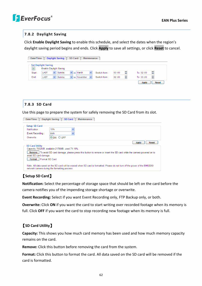
EAN Plus Series
62
782 Daylight Saving
Click Enable Daylight Saving to enable this schedule and select the dates when the regionrsquos
daylight saving period begins and ends Click Apply to save all settings or click Reset to cancel
783 SD Card
Use this page to prepare the system for safely removing the SD Card from its slot
【Setup SD Card】
Notification Select the percentage of storage space that should be left on the card before the
camera notifies you of the impending storage shortage or overwrite
Event Recording Select if you want Event Recording only FTP Backup only or both
Overwrite Click ON if you want the card to start writing over recorded footage when its memory is
full Click OFF if you want the card to stop recording new footage when its memory is full
【SD Card Utility】
Capacity This shows you how much card memory has been used and how much memory capacity
remains on the card
Remove Click this button before removing the card from the system
Format Click this button to format the card All data saved on the SD card will be removed if the
card is formatted
EAN Plus Series
63
784 Maintenance
【Maintenance Server】
Reboot Click this button to reboot the unit without changing any of the settings Use this function if
the unit is not behaving as expected
Restore Click this button to restart and reset most of the current settings to their factory default
values The only settings that will not be changed to default are
bull IP settings
bull DDNS settings
Default The Default button should be used with caution Pressing this button will return all of the
cameras settings including the IP address to the factory default values The camera will then have
to be reconfigured
【SaveLoad Configuration Server】
Save To make a backup file of the machinersquos current configurations press Save to save all the
configurations to a config file This will enable the user to reload these configuration settings if the
settings are changed and there is unexpected behavior
Load To load a previously saved configuration press the Browse button to locate the saved config
file (see above) and then click the Load button The systemrsquos settings will be restored to the saved
configuration
EAN Plus Series
64
【SaveLoad Video Configuration Server】
Save To make a backup file of the machinersquos video configurations press Save to save the video
configurations to a config file This will enable the user to reload these configuration settings if the
settings are changed and there is unexpected behavior
Load To load a previously saved video configuration press the Browse button to locate the saved
config file (see above) and then click the Load button The systemrsquos settings will be restored to the
saved video configuration
【Upgrade Firmware】Click the Browse button to find a previously prepared firmware upgrade file
Click Upgrade to install the new firmware
Note
1 Do not disconnect power to the unit during the upgrade sequence The unit will reboot
automatically after the upgrade has completed (1-5 minutes)
2 During the upgrade process all event recording actions will be stopped Event recording
actions will resume after the camera is rebooted
3 If the ldquoFile Error Please re-loginrdquo warning message appears when upgrading the firmware
please try the following instructions
a Go to Internet Explorer gt Tools gt Internet Option gt Security gt Custom
b Find and enable the Include local directory path when uploading files to a server
EAN Plus Series
65
8 Upgrading Firmware Using IP Utility
You can upgrade the Firmware using the IP Utility software included in the software CD
1 Install and then start the IPU program The following dialog box appears
2 Click Find Devices to search the cameras connected in the LAN The default network values of the
cameras will be displayed By default the network protocol of the camera is DHCP
3 Select a camera and click LoginMulti Login to log in the camera
4 Type the user ID and password Click OK
Note
1 The default user ID is user1 and the default password is 11111111
2 If you select more than one camera that has the same user ID password you will be able
to log in several cameras at once
EAN Plus Series
66
5 Highlight the camera and then click Upgrade Firmware A browsing window appears
6 Select the firmware file (evb) and then click Open The IP Utility will automatically upgrade the
firmware
The camera will reboot once the update is complete Click Find Devices the new firmware version
should be displayed in the last part of the Machine Name
EAN Plus Series
67
9 Specifications
Model EAN3120 Plus EAN3220 Plus EAN3300 Plus
Camera
Image Sensor 13 Panasonic CMOS 128 Sony CMOS
Megapixel 13 MP 2 MP 3 MP
Picture Elements (H x V) 1280 x 1024 1944 x 1092 2048 x 1536
Min Illuminations 003 Lux at F14
Electronic Shutter (Sec) 85 ~ 160000 2 ~ 150000 1 ~ 110000
Scanning System NTSC PAL
WDR Yes Yes No
BLC Yes
Gain Control Yes
White Balance Yes
Lens
Mounting Type C CS
Day Night Yes (with removable auto IR-cut filter)
IRIS Control DC Electrical IRIS Lens IRIS
Video
Video Compression H264 MJPEG
Resolution
NTSC
2048 x 1536 1920 x 1200 (for EAN3300 Plus only)
1920 x 1080 (for EAN3300 Plus 3220 Plus only)
1280 x 1024 1280 x 720 1024 x 768 720 x 480 704 x 480 640 x 480
352 x 240 320 x 240 160 x 120
PAL
2048 x 1536 1920 x 1200 (for EAN3300 Plus only)
1920 x 1080 (for EAN3300 Plus 3220 Plus only)
1280 x 1024 1280 x 720 1024 x 768 720 x 576 704 x 576 640 x 480
352 x 288 320 x 240 160 x 120
Frame Rate 30 fps at 1280 x 1024 30 fps at 1920 x 1080 15 fps at 2048 x 1536
Audio
Audio Streaming Two-way audio
Audio Compression G711
EAN Plus Series
68
Network
Interface 10 100 Base-T Ethernet RJ-45 socket
Supported Protocols
TCPIP IPV6 UDP ICMP DHCP NTP DNS DDNS SMTP SNMP FTP
HTTP HTTPs PPPoE UPnP Bonjour RTP RTSP RTCP IGMP ARP ONVIF
PSIA
Connector
Power DC female port PoE
Ethernet RJ-45
Audio 1 In (phone jack for microphone)
1 Out (phone jack for Speaker)
Alarm IO Terminal IO wires
Local Storage Micro SD SDHC memory card slot
TV-Out BNC socket composite 1 V p-p 75 Ω
General
Power Source DC 12V PoE (IEEE8023af)
Power Consumption
(IR LEDs On)
5W (DC 12V)
621W (PoE)
5W (DC 12V)
522W (PoE)
5W (DC 12V)
536W (PoE)
Operating Temperature 0degC ~ +50degC 32degF ~ +122degF
Humidity 20 to 80 (no condensation)
Safety CE FCC
Dimensions (L x W x H) 117 x 56 x 68 mm 46 x 22 x 27 in
Weight 410 g 09 lb
EverFocus Electronics Corp EverFocus Taiwan 12F No79 Sec 1 Shin-Tai Wu Road Hsi-Chih Taipei Taiwan TEL +886 2 2698 2334 FAX +886 2 2698 2380 wwweverfocuscomtw marketingeverfocuscomtw
EverFocus Europe - Germany Albert-Einstein-Strasse 1 D-46446 Emmerich Germany TEL +49 2822 93940 FAX +49 2822 939495 wwweverfocusde infoeverfocusde
EverFocus China - Beijing Room 609 Technology Trade Building Shangdi Information Industry Base Haidian District Beijing 100085 China TEL +86 10 6297 3336~39 FAX +86 10 6297 1423 wwweverfocuscomcn marketingeverfocuscomcn
EverFocus China - Shenzhen 4F No 2 D4 Building Wan Yelong Industrial Park Tangtou Road Shiyan Baoan Shenzhen Guangdong 518101 China TEL +86 755 2765 1313 FAX +86 755 2765 0337 wwweverfocuscomcn marketingeverfocuscomcn
EverFocus USA - California 1801 Highland Avenue Unit A Duarte CA 91010 USA TEL +1 626 844 8888 FAX +1 626 844 8838 wwweverfocuscom saleseverfocuscom
EverFocus USA - New York 415 Oser Avenue Unit S Hauppauge NY 11788 USA TEL +1 631 436 5070 FAX +1 631 436 5027 wwweverfocuscom saleseverfocuscom
EverFocus Japan 5F Kinshicho City Building 2-13-4 Koto-BashiSumida-Ku Tokyo 130-0022 Japan TEL +81 3 5625 8188 FAX +81 3 5625 8189 wwweverfocuscojp infoeverfocuscojp
EverFocus Europe - UK Unit 12 Spitfire Business Park Hawker Road Croydon Surrey CR0 4WD UK TEL +44 20 8649 9757 +44 845 430 9999 FAX +44 20 8649 9907 wwweverfocusukcouk salesukeverfocuscom
EverFocus India Suite 803 Housefin Bhavan C-21 Bandra Kurla Complex Bandra (East) Mumbai 400051 India TEL +91 22 6128 8700 FAX +91 22 6128 8705 wwweverfocusin saleseverfocusin
PN 4605PQ3120B010A-VerC
Your EverFocus product is designed and manufactured with high quality materials and components which can be recycled and reused This symbol means that electrical and electronic equipment at their end-of-life should be disposed of separately from your household waste Please dispose of this equipment at your local community waste collectionrecycling centre In the European Union there are separate collection systems for used electrical and electronic product Please help us to conserve the environment we live in
Ihr EverFocus Produkt wurde entwickelt und hergestellt mit qualitativ hochwertigen Materialien und Komponenten die recycelt und wieder verwendet werden koumlnnen Dieses Symbol bedeutet dass elektrische und elektronische Geraumlte am Ende ihrer Nutzungsdauer vom Hausmuumlll getrennt entsorgt werden sollen Bitte entsorgen Sie dieses Geraumlt bei Ihrer oumlrtlichen kommunalen Sammelstelle oder im Recycling Centre Helfen Sie uns bitte die Umwelt zu erhalten in der wir leben
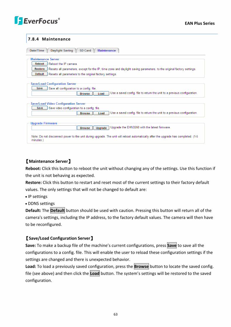
EAN Plus Series
63
784 Maintenance
【Maintenance Server】
Reboot Click this button to reboot the unit without changing any of the settings Use this function if
the unit is not behaving as expected
Restore Click this button to restart and reset most of the current settings to their factory default
values The only settings that will not be changed to default are
bull IP settings
bull DDNS settings
Default The Default button should be used with caution Pressing this button will return all of the
cameras settings including the IP address to the factory default values The camera will then have
to be reconfigured
【SaveLoad Configuration Server】
Save To make a backup file of the machinersquos current configurations press Save to save all the
configurations to a config file This will enable the user to reload these configuration settings if the
settings are changed and there is unexpected behavior
Load To load a previously saved configuration press the Browse button to locate the saved config
file (see above) and then click the Load button The systemrsquos settings will be restored to the saved
configuration
EAN Plus Series
64
【SaveLoad Video Configuration Server】
Save To make a backup file of the machinersquos video configurations press Save to save the video
configurations to a config file This will enable the user to reload these configuration settings if the
settings are changed and there is unexpected behavior
Load To load a previously saved video configuration press the Browse button to locate the saved
config file (see above) and then click the Load button The systemrsquos settings will be restored to the
saved video configuration
【Upgrade Firmware】Click the Browse button to find a previously prepared firmware upgrade file
Click Upgrade to install the new firmware
Note
1 Do not disconnect power to the unit during the upgrade sequence The unit will reboot
automatically after the upgrade has completed (1-5 minutes)
2 During the upgrade process all event recording actions will be stopped Event recording
actions will resume after the camera is rebooted
3 If the ldquoFile Error Please re-loginrdquo warning message appears when upgrading the firmware
please try the following instructions
a Go to Internet Explorer gt Tools gt Internet Option gt Security gt Custom
b Find and enable the Include local directory path when uploading files to a server
EAN Plus Series
65
8 Upgrading Firmware Using IP Utility
You can upgrade the Firmware using the IP Utility software included in the software CD
1 Install and then start the IPU program The following dialog box appears
2 Click Find Devices to search the cameras connected in the LAN The default network values of the
cameras will be displayed By default the network protocol of the camera is DHCP
3 Select a camera and click LoginMulti Login to log in the camera
4 Type the user ID and password Click OK
Note
1 The default user ID is user1 and the default password is 11111111
2 If you select more than one camera that has the same user ID password you will be able
to log in several cameras at once
EAN Plus Series
66
5 Highlight the camera and then click Upgrade Firmware A browsing window appears
6 Select the firmware file (evb) and then click Open The IP Utility will automatically upgrade the
firmware
The camera will reboot once the update is complete Click Find Devices the new firmware version
should be displayed in the last part of the Machine Name
EAN Plus Series
67
9 Specifications
Model EAN3120 Plus EAN3220 Plus EAN3300 Plus
Camera
Image Sensor 13 Panasonic CMOS 128 Sony CMOS
Megapixel 13 MP 2 MP 3 MP
Picture Elements (H x V) 1280 x 1024 1944 x 1092 2048 x 1536
Min Illuminations 003 Lux at F14
Electronic Shutter (Sec) 85 ~ 160000 2 ~ 150000 1 ~ 110000
Scanning System NTSC PAL
WDR Yes Yes No
BLC Yes
Gain Control Yes
White Balance Yes
Lens
Mounting Type C CS
Day Night Yes (with removable auto IR-cut filter)
IRIS Control DC Electrical IRIS Lens IRIS
Video
Video Compression H264 MJPEG
Resolution
NTSC
2048 x 1536 1920 x 1200 (for EAN3300 Plus only)
1920 x 1080 (for EAN3300 Plus 3220 Plus only)
1280 x 1024 1280 x 720 1024 x 768 720 x 480 704 x 480 640 x 480
352 x 240 320 x 240 160 x 120
PAL
2048 x 1536 1920 x 1200 (for EAN3300 Plus only)
1920 x 1080 (for EAN3300 Plus 3220 Plus only)
1280 x 1024 1280 x 720 1024 x 768 720 x 576 704 x 576 640 x 480
352 x 288 320 x 240 160 x 120
Frame Rate 30 fps at 1280 x 1024 30 fps at 1920 x 1080 15 fps at 2048 x 1536
Audio
Audio Streaming Two-way audio
Audio Compression G711
EAN Plus Series
68
Network
Interface 10 100 Base-T Ethernet RJ-45 socket
Supported Protocols
TCPIP IPV6 UDP ICMP DHCP NTP DNS DDNS SMTP SNMP FTP
HTTP HTTPs PPPoE UPnP Bonjour RTP RTSP RTCP IGMP ARP ONVIF
PSIA
Connector
Power DC female port PoE
Ethernet RJ-45
Audio 1 In (phone jack for microphone)
1 Out (phone jack for Speaker)
Alarm IO Terminal IO wires
Local Storage Micro SD SDHC memory card slot
TV-Out BNC socket composite 1 V p-p 75 Ω
General
Power Source DC 12V PoE (IEEE8023af)
Power Consumption
(IR LEDs On)
5W (DC 12V)
621W (PoE)
5W (DC 12V)
522W (PoE)
5W (DC 12V)
536W (PoE)
Operating Temperature 0degC ~ +50degC 32degF ~ +122degF
Humidity 20 to 80 (no condensation)
Safety CE FCC
Dimensions (L x W x H) 117 x 56 x 68 mm 46 x 22 x 27 in
Weight 410 g 09 lb
EverFocus Electronics Corp EverFocus Taiwan 12F No79 Sec 1 Shin-Tai Wu Road Hsi-Chih Taipei Taiwan TEL +886 2 2698 2334 FAX +886 2 2698 2380 wwweverfocuscomtw marketingeverfocuscomtw
EverFocus Europe - Germany Albert-Einstein-Strasse 1 D-46446 Emmerich Germany TEL +49 2822 93940 FAX +49 2822 939495 wwweverfocusde infoeverfocusde
EverFocus China - Beijing Room 609 Technology Trade Building Shangdi Information Industry Base Haidian District Beijing 100085 China TEL +86 10 6297 3336~39 FAX +86 10 6297 1423 wwweverfocuscomcn marketingeverfocuscomcn
EverFocus China - Shenzhen 4F No 2 D4 Building Wan Yelong Industrial Park Tangtou Road Shiyan Baoan Shenzhen Guangdong 518101 China TEL +86 755 2765 1313 FAX +86 755 2765 0337 wwweverfocuscomcn marketingeverfocuscomcn
EverFocus USA - California 1801 Highland Avenue Unit A Duarte CA 91010 USA TEL +1 626 844 8888 FAX +1 626 844 8838 wwweverfocuscom saleseverfocuscom
EverFocus USA - New York 415 Oser Avenue Unit S Hauppauge NY 11788 USA TEL +1 631 436 5070 FAX +1 631 436 5027 wwweverfocuscom saleseverfocuscom
EverFocus Japan 5F Kinshicho City Building 2-13-4 Koto-BashiSumida-Ku Tokyo 130-0022 Japan TEL +81 3 5625 8188 FAX +81 3 5625 8189 wwweverfocuscojp infoeverfocuscojp
EverFocus Europe - UK Unit 12 Spitfire Business Park Hawker Road Croydon Surrey CR0 4WD UK TEL +44 20 8649 9757 +44 845 430 9999 FAX +44 20 8649 9907 wwweverfocusukcouk salesukeverfocuscom
EverFocus India Suite 803 Housefin Bhavan C-21 Bandra Kurla Complex Bandra (East) Mumbai 400051 India TEL +91 22 6128 8700 FAX +91 22 6128 8705 wwweverfocusin saleseverfocusin
PN 4605PQ3120B010A-VerC
Your EverFocus product is designed and manufactured with high quality materials and components which can be recycled and reused This symbol means that electrical and electronic equipment at their end-of-life should be disposed of separately from your household waste Please dispose of this equipment at your local community waste collectionrecycling centre In the European Union there are separate collection systems for used electrical and electronic product Please help us to conserve the environment we live in
Ihr EverFocus Produkt wurde entwickelt und hergestellt mit qualitativ hochwertigen Materialien und Komponenten die recycelt und wieder verwendet werden koumlnnen Dieses Symbol bedeutet dass elektrische und elektronische Geraumlte am Ende ihrer Nutzungsdauer vom Hausmuumlll getrennt entsorgt werden sollen Bitte entsorgen Sie dieses Geraumlt bei Ihrer oumlrtlichen kommunalen Sammelstelle oder im Recycling Centre Helfen Sie uns bitte die Umwelt zu erhalten in der wir leben
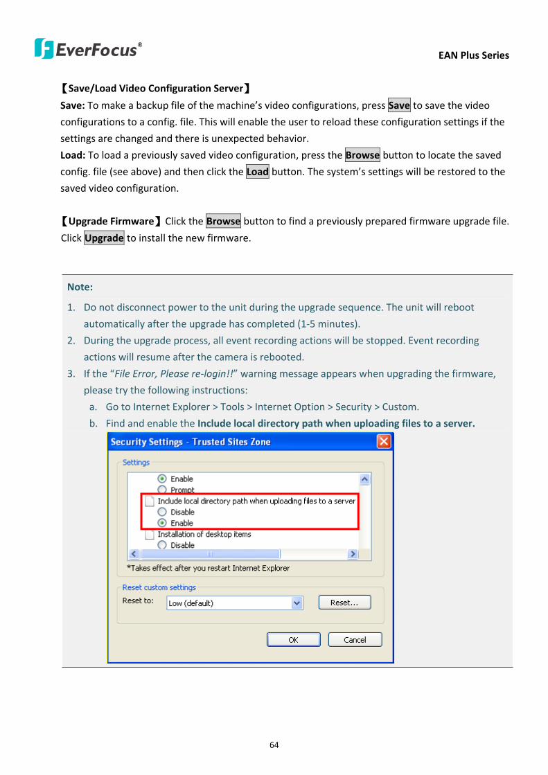
EAN Plus Series
64
【SaveLoad Video Configuration Server】
Save To make a backup file of the machinersquos video configurations press Save to save the video
configurations to a config file This will enable the user to reload these configuration settings if the
settings are changed and there is unexpected behavior
Load To load a previously saved video configuration press the Browse button to locate the saved
config file (see above) and then click the Load button The systemrsquos settings will be restored to the
saved video configuration
【Upgrade Firmware】Click the Browse button to find a previously prepared firmware upgrade file
Click Upgrade to install the new firmware
Note
1 Do not disconnect power to the unit during the upgrade sequence The unit will reboot
automatically after the upgrade has completed (1-5 minutes)
2 During the upgrade process all event recording actions will be stopped Event recording
actions will resume after the camera is rebooted
3 If the ldquoFile Error Please re-loginrdquo warning message appears when upgrading the firmware
please try the following instructions
a Go to Internet Explorer gt Tools gt Internet Option gt Security gt Custom
b Find and enable the Include local directory path when uploading files to a server
EAN Plus Series
65
8 Upgrading Firmware Using IP Utility
You can upgrade the Firmware using the IP Utility software included in the software CD
1 Install and then start the IPU program The following dialog box appears
2 Click Find Devices to search the cameras connected in the LAN The default network values of the
cameras will be displayed By default the network protocol of the camera is DHCP
3 Select a camera and click LoginMulti Login to log in the camera
4 Type the user ID and password Click OK
Note
1 The default user ID is user1 and the default password is 11111111
2 If you select more than one camera that has the same user ID password you will be able
to log in several cameras at once
EAN Plus Series
66
5 Highlight the camera and then click Upgrade Firmware A browsing window appears
6 Select the firmware file (evb) and then click Open The IP Utility will automatically upgrade the
firmware
The camera will reboot once the update is complete Click Find Devices the new firmware version
should be displayed in the last part of the Machine Name
EAN Plus Series
67
9 Specifications
Model EAN3120 Plus EAN3220 Plus EAN3300 Plus
Camera
Image Sensor 13 Panasonic CMOS 128 Sony CMOS
Megapixel 13 MP 2 MP 3 MP
Picture Elements (H x V) 1280 x 1024 1944 x 1092 2048 x 1536
Min Illuminations 003 Lux at F14
Electronic Shutter (Sec) 85 ~ 160000 2 ~ 150000 1 ~ 110000
Scanning System NTSC PAL
WDR Yes Yes No
BLC Yes
Gain Control Yes
White Balance Yes
Lens
Mounting Type C CS
Day Night Yes (with removable auto IR-cut filter)
IRIS Control DC Electrical IRIS Lens IRIS
Video
Video Compression H264 MJPEG
Resolution
NTSC
2048 x 1536 1920 x 1200 (for EAN3300 Plus only)
1920 x 1080 (for EAN3300 Plus 3220 Plus only)
1280 x 1024 1280 x 720 1024 x 768 720 x 480 704 x 480 640 x 480
352 x 240 320 x 240 160 x 120
PAL
2048 x 1536 1920 x 1200 (for EAN3300 Plus only)
1920 x 1080 (for EAN3300 Plus 3220 Plus only)
1280 x 1024 1280 x 720 1024 x 768 720 x 576 704 x 576 640 x 480
352 x 288 320 x 240 160 x 120
Frame Rate 30 fps at 1280 x 1024 30 fps at 1920 x 1080 15 fps at 2048 x 1536
Audio
Audio Streaming Two-way audio
Audio Compression G711
EAN Plus Series
68
Network
Interface 10 100 Base-T Ethernet RJ-45 socket
Supported Protocols
TCPIP IPV6 UDP ICMP DHCP NTP DNS DDNS SMTP SNMP FTP
HTTP HTTPs PPPoE UPnP Bonjour RTP RTSP RTCP IGMP ARP ONVIF
PSIA
Connector
Power DC female port PoE
Ethernet RJ-45
Audio 1 In (phone jack for microphone)
1 Out (phone jack for Speaker)
Alarm IO Terminal IO wires
Local Storage Micro SD SDHC memory card slot
TV-Out BNC socket composite 1 V p-p 75 Ω
General
Power Source DC 12V PoE (IEEE8023af)
Power Consumption
(IR LEDs On)
5W (DC 12V)
621W (PoE)
5W (DC 12V)
522W (PoE)
5W (DC 12V)
536W (PoE)
Operating Temperature 0degC ~ +50degC 32degF ~ +122degF
Humidity 20 to 80 (no condensation)
Safety CE FCC
Dimensions (L x W x H) 117 x 56 x 68 mm 46 x 22 x 27 in
Weight 410 g 09 lb
EverFocus Electronics Corp EverFocus Taiwan 12F No79 Sec 1 Shin-Tai Wu Road Hsi-Chih Taipei Taiwan TEL +886 2 2698 2334 FAX +886 2 2698 2380 wwweverfocuscomtw marketingeverfocuscomtw
EverFocus Europe - Germany Albert-Einstein-Strasse 1 D-46446 Emmerich Germany TEL +49 2822 93940 FAX +49 2822 939495 wwweverfocusde infoeverfocusde
EverFocus China - Beijing Room 609 Technology Trade Building Shangdi Information Industry Base Haidian District Beijing 100085 China TEL +86 10 6297 3336~39 FAX +86 10 6297 1423 wwweverfocuscomcn marketingeverfocuscomcn
EverFocus China - Shenzhen 4F No 2 D4 Building Wan Yelong Industrial Park Tangtou Road Shiyan Baoan Shenzhen Guangdong 518101 China TEL +86 755 2765 1313 FAX +86 755 2765 0337 wwweverfocuscomcn marketingeverfocuscomcn
EverFocus USA - California 1801 Highland Avenue Unit A Duarte CA 91010 USA TEL +1 626 844 8888 FAX +1 626 844 8838 wwweverfocuscom saleseverfocuscom
EverFocus USA - New York 415 Oser Avenue Unit S Hauppauge NY 11788 USA TEL +1 631 436 5070 FAX +1 631 436 5027 wwweverfocuscom saleseverfocuscom
EverFocus Japan 5F Kinshicho City Building 2-13-4 Koto-BashiSumida-Ku Tokyo 130-0022 Japan TEL +81 3 5625 8188 FAX +81 3 5625 8189 wwweverfocuscojp infoeverfocuscojp
EverFocus Europe - UK Unit 12 Spitfire Business Park Hawker Road Croydon Surrey CR0 4WD UK TEL +44 20 8649 9757 +44 845 430 9999 FAX +44 20 8649 9907 wwweverfocusukcouk salesukeverfocuscom
EverFocus India Suite 803 Housefin Bhavan C-21 Bandra Kurla Complex Bandra (East) Mumbai 400051 India TEL +91 22 6128 8700 FAX +91 22 6128 8705 wwweverfocusin saleseverfocusin
PN 4605PQ3120B010A-VerC
Your EverFocus product is designed and manufactured with high quality materials and components which can be recycled and reused This symbol means that electrical and electronic equipment at their end-of-life should be disposed of separately from your household waste Please dispose of this equipment at your local community waste collectionrecycling centre In the European Union there are separate collection systems for used electrical and electronic product Please help us to conserve the environment we live in
Ihr EverFocus Produkt wurde entwickelt und hergestellt mit qualitativ hochwertigen Materialien und Komponenten die recycelt und wieder verwendet werden koumlnnen Dieses Symbol bedeutet dass elektrische und elektronische Geraumlte am Ende ihrer Nutzungsdauer vom Hausmuumlll getrennt entsorgt werden sollen Bitte entsorgen Sie dieses Geraumlt bei Ihrer oumlrtlichen kommunalen Sammelstelle oder im Recycling Centre Helfen Sie uns bitte die Umwelt zu erhalten in der wir leben
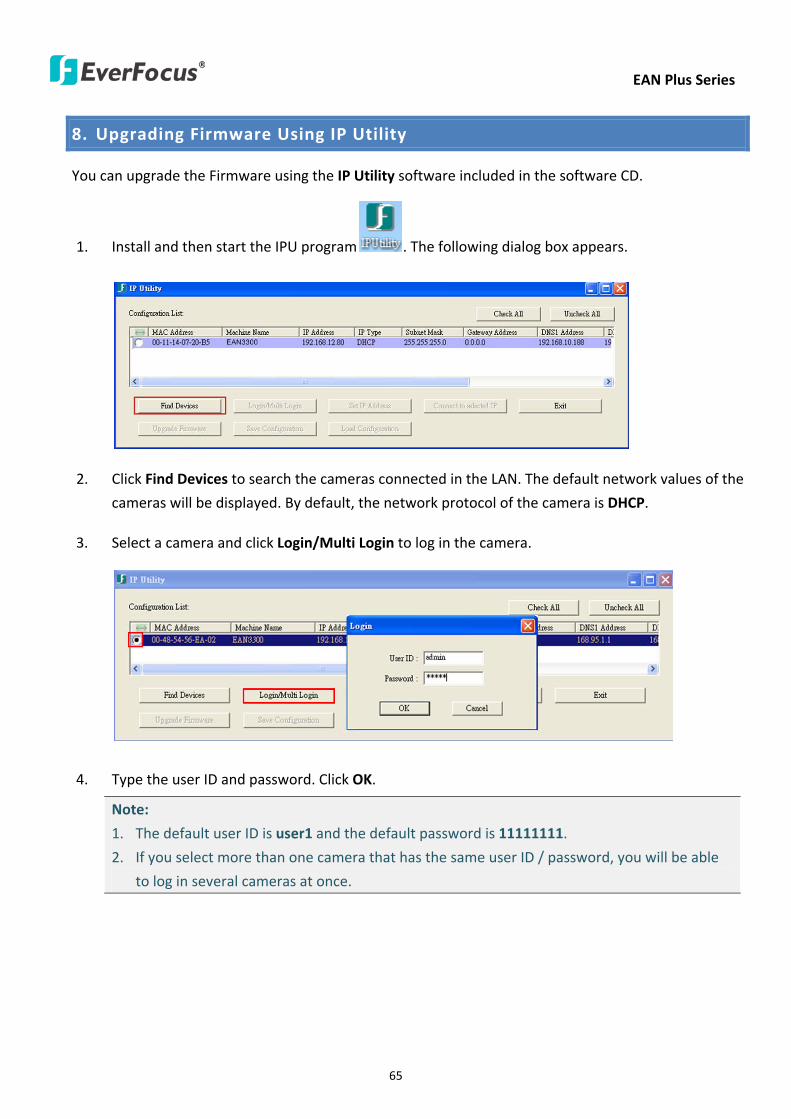
EAN Plus Series
65
8 Upgrading Firmware Using IP Utility
You can upgrade the Firmware using the IP Utility software included in the software CD
1 Install and then start the IPU program The following dialog box appears
2 Click Find Devices to search the cameras connected in the LAN The default network values of the
cameras will be displayed By default the network protocol of the camera is DHCP
3 Select a camera and click LoginMulti Login to log in the camera
4 Type the user ID and password Click OK
Note
1 The default user ID is user1 and the default password is 11111111
2 If you select more than one camera that has the same user ID password you will be able
to log in several cameras at once
EAN Plus Series
66
5 Highlight the camera and then click Upgrade Firmware A browsing window appears
6 Select the firmware file (evb) and then click Open The IP Utility will automatically upgrade the
firmware
The camera will reboot once the update is complete Click Find Devices the new firmware version
should be displayed in the last part of the Machine Name
EAN Plus Series
67
9 Specifications
Model EAN3120 Plus EAN3220 Plus EAN3300 Plus
Camera
Image Sensor 13 Panasonic CMOS 128 Sony CMOS
Megapixel 13 MP 2 MP 3 MP
Picture Elements (H x V) 1280 x 1024 1944 x 1092 2048 x 1536
Min Illuminations 003 Lux at F14
Electronic Shutter (Sec) 85 ~ 160000 2 ~ 150000 1 ~ 110000
Scanning System NTSC PAL
WDR Yes Yes No
BLC Yes
Gain Control Yes
White Balance Yes
Lens
Mounting Type C CS
Day Night Yes (with removable auto IR-cut filter)
IRIS Control DC Electrical IRIS Lens IRIS
Video
Video Compression H264 MJPEG
Resolution
NTSC
2048 x 1536 1920 x 1200 (for EAN3300 Plus only)
1920 x 1080 (for EAN3300 Plus 3220 Plus only)
1280 x 1024 1280 x 720 1024 x 768 720 x 480 704 x 480 640 x 480
352 x 240 320 x 240 160 x 120
PAL
2048 x 1536 1920 x 1200 (for EAN3300 Plus only)
1920 x 1080 (for EAN3300 Plus 3220 Plus only)
1280 x 1024 1280 x 720 1024 x 768 720 x 576 704 x 576 640 x 480
352 x 288 320 x 240 160 x 120
Frame Rate 30 fps at 1280 x 1024 30 fps at 1920 x 1080 15 fps at 2048 x 1536
Audio
Audio Streaming Two-way audio
Audio Compression G711
EAN Plus Series
68
Network
Interface 10 100 Base-T Ethernet RJ-45 socket
Supported Protocols
TCPIP IPV6 UDP ICMP DHCP NTP DNS DDNS SMTP SNMP FTP
HTTP HTTPs PPPoE UPnP Bonjour RTP RTSP RTCP IGMP ARP ONVIF
PSIA
Connector
Power DC female port PoE
Ethernet RJ-45
Audio 1 In (phone jack for microphone)
1 Out (phone jack for Speaker)
Alarm IO Terminal IO wires
Local Storage Micro SD SDHC memory card slot
TV-Out BNC socket composite 1 V p-p 75 Ω
General
Power Source DC 12V PoE (IEEE8023af)
Power Consumption
(IR LEDs On)
5W (DC 12V)
621W (PoE)
5W (DC 12V)
522W (PoE)
5W (DC 12V)
536W (PoE)
Operating Temperature 0degC ~ +50degC 32degF ~ +122degF
Humidity 20 to 80 (no condensation)
Safety CE FCC
Dimensions (L x W x H) 117 x 56 x 68 mm 46 x 22 x 27 in
Weight 410 g 09 lb
EverFocus Electronics Corp EverFocus Taiwan 12F No79 Sec 1 Shin-Tai Wu Road Hsi-Chih Taipei Taiwan TEL +886 2 2698 2334 FAX +886 2 2698 2380 wwweverfocuscomtw marketingeverfocuscomtw
EverFocus Europe - Germany Albert-Einstein-Strasse 1 D-46446 Emmerich Germany TEL +49 2822 93940 FAX +49 2822 939495 wwweverfocusde infoeverfocusde
EverFocus China - Beijing Room 609 Technology Trade Building Shangdi Information Industry Base Haidian District Beijing 100085 China TEL +86 10 6297 3336~39 FAX +86 10 6297 1423 wwweverfocuscomcn marketingeverfocuscomcn
EverFocus China - Shenzhen 4F No 2 D4 Building Wan Yelong Industrial Park Tangtou Road Shiyan Baoan Shenzhen Guangdong 518101 China TEL +86 755 2765 1313 FAX +86 755 2765 0337 wwweverfocuscomcn marketingeverfocuscomcn
EverFocus USA - California 1801 Highland Avenue Unit A Duarte CA 91010 USA TEL +1 626 844 8888 FAX +1 626 844 8838 wwweverfocuscom saleseverfocuscom
EverFocus USA - New York 415 Oser Avenue Unit S Hauppauge NY 11788 USA TEL +1 631 436 5070 FAX +1 631 436 5027 wwweverfocuscom saleseverfocuscom
EverFocus Japan 5F Kinshicho City Building 2-13-4 Koto-BashiSumida-Ku Tokyo 130-0022 Japan TEL +81 3 5625 8188 FAX +81 3 5625 8189 wwweverfocuscojp infoeverfocuscojp
EverFocus Europe - UK Unit 12 Spitfire Business Park Hawker Road Croydon Surrey CR0 4WD UK TEL +44 20 8649 9757 +44 845 430 9999 FAX +44 20 8649 9907 wwweverfocusukcouk salesukeverfocuscom
EverFocus India Suite 803 Housefin Bhavan C-21 Bandra Kurla Complex Bandra (East) Mumbai 400051 India TEL +91 22 6128 8700 FAX +91 22 6128 8705 wwweverfocusin saleseverfocusin
PN 4605PQ3120B010A-VerC
Your EverFocus product is designed and manufactured with high quality materials and components which can be recycled and reused This symbol means that electrical and electronic equipment at their end-of-life should be disposed of separately from your household waste Please dispose of this equipment at your local community waste collectionrecycling centre In the European Union there are separate collection systems for used electrical and electronic product Please help us to conserve the environment we live in
Ihr EverFocus Produkt wurde entwickelt und hergestellt mit qualitativ hochwertigen Materialien und Komponenten die recycelt und wieder verwendet werden koumlnnen Dieses Symbol bedeutet dass elektrische und elektronische Geraumlte am Ende ihrer Nutzungsdauer vom Hausmuumlll getrennt entsorgt werden sollen Bitte entsorgen Sie dieses Geraumlt bei Ihrer oumlrtlichen kommunalen Sammelstelle oder im Recycling Centre Helfen Sie uns bitte die Umwelt zu erhalten in der wir leben
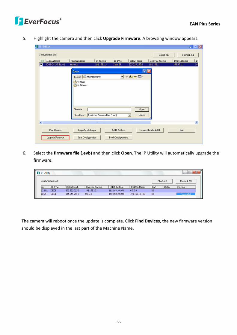
EAN Plus Series
66
5 Highlight the camera and then click Upgrade Firmware A browsing window appears
6 Select the firmware file (evb) and then click Open The IP Utility will automatically upgrade the
firmware
The camera will reboot once the update is complete Click Find Devices the new firmware version
should be displayed in the last part of the Machine Name
EAN Plus Series
67
9 Specifications
Model EAN3120 Plus EAN3220 Plus EAN3300 Plus
Camera
Image Sensor 13 Panasonic CMOS 128 Sony CMOS
Megapixel 13 MP 2 MP 3 MP
Picture Elements (H x V) 1280 x 1024 1944 x 1092 2048 x 1536
Min Illuminations 003 Lux at F14
Electronic Shutter (Sec) 85 ~ 160000 2 ~ 150000 1 ~ 110000
Scanning System NTSC PAL
WDR Yes Yes No
BLC Yes
Gain Control Yes
White Balance Yes
Lens
Mounting Type C CS
Day Night Yes (with removable auto IR-cut filter)
IRIS Control DC Electrical IRIS Lens IRIS
Video
Video Compression H264 MJPEG
Resolution
NTSC
2048 x 1536 1920 x 1200 (for EAN3300 Plus only)
1920 x 1080 (for EAN3300 Plus 3220 Plus only)
1280 x 1024 1280 x 720 1024 x 768 720 x 480 704 x 480 640 x 480
352 x 240 320 x 240 160 x 120
PAL
2048 x 1536 1920 x 1200 (for EAN3300 Plus only)
1920 x 1080 (for EAN3300 Plus 3220 Plus only)
1280 x 1024 1280 x 720 1024 x 768 720 x 576 704 x 576 640 x 480
352 x 288 320 x 240 160 x 120
Frame Rate 30 fps at 1280 x 1024 30 fps at 1920 x 1080 15 fps at 2048 x 1536
Audio
Audio Streaming Two-way audio
Audio Compression G711
EAN Plus Series
68
Network
Interface 10 100 Base-T Ethernet RJ-45 socket
Supported Protocols
TCPIP IPV6 UDP ICMP DHCP NTP DNS DDNS SMTP SNMP FTP
HTTP HTTPs PPPoE UPnP Bonjour RTP RTSP RTCP IGMP ARP ONVIF
PSIA
Connector
Power DC female port PoE
Ethernet RJ-45
Audio 1 In (phone jack for microphone)
1 Out (phone jack for Speaker)
Alarm IO Terminal IO wires
Local Storage Micro SD SDHC memory card slot
TV-Out BNC socket composite 1 V p-p 75 Ω
General
Power Source DC 12V PoE (IEEE8023af)
Power Consumption
(IR LEDs On)
5W (DC 12V)
621W (PoE)
5W (DC 12V)
522W (PoE)
5W (DC 12V)
536W (PoE)
Operating Temperature 0degC ~ +50degC 32degF ~ +122degF
Humidity 20 to 80 (no condensation)
Safety CE FCC
Dimensions (L x W x H) 117 x 56 x 68 mm 46 x 22 x 27 in
Weight 410 g 09 lb
EverFocus Electronics Corp EverFocus Taiwan 12F No79 Sec 1 Shin-Tai Wu Road Hsi-Chih Taipei Taiwan TEL +886 2 2698 2334 FAX +886 2 2698 2380 wwweverfocuscomtw marketingeverfocuscomtw
EverFocus Europe - Germany Albert-Einstein-Strasse 1 D-46446 Emmerich Germany TEL +49 2822 93940 FAX +49 2822 939495 wwweverfocusde infoeverfocusde
EverFocus China - Beijing Room 609 Technology Trade Building Shangdi Information Industry Base Haidian District Beijing 100085 China TEL +86 10 6297 3336~39 FAX +86 10 6297 1423 wwweverfocuscomcn marketingeverfocuscomcn
EverFocus China - Shenzhen 4F No 2 D4 Building Wan Yelong Industrial Park Tangtou Road Shiyan Baoan Shenzhen Guangdong 518101 China TEL +86 755 2765 1313 FAX +86 755 2765 0337 wwweverfocuscomcn marketingeverfocuscomcn
EverFocus USA - California 1801 Highland Avenue Unit A Duarte CA 91010 USA TEL +1 626 844 8888 FAX +1 626 844 8838 wwweverfocuscom saleseverfocuscom
EverFocus USA - New York 415 Oser Avenue Unit S Hauppauge NY 11788 USA TEL +1 631 436 5070 FAX +1 631 436 5027 wwweverfocuscom saleseverfocuscom
EverFocus Japan 5F Kinshicho City Building 2-13-4 Koto-BashiSumida-Ku Tokyo 130-0022 Japan TEL +81 3 5625 8188 FAX +81 3 5625 8189 wwweverfocuscojp infoeverfocuscojp
EverFocus Europe - UK Unit 12 Spitfire Business Park Hawker Road Croydon Surrey CR0 4WD UK TEL +44 20 8649 9757 +44 845 430 9999 FAX +44 20 8649 9907 wwweverfocusukcouk salesukeverfocuscom
EverFocus India Suite 803 Housefin Bhavan C-21 Bandra Kurla Complex Bandra (East) Mumbai 400051 India TEL +91 22 6128 8700 FAX +91 22 6128 8705 wwweverfocusin saleseverfocusin
PN 4605PQ3120B010A-VerC
Your EverFocus product is designed and manufactured with high quality materials and components which can be recycled and reused This symbol means that electrical and electronic equipment at their end-of-life should be disposed of separately from your household waste Please dispose of this equipment at your local community waste collectionrecycling centre In the European Union there are separate collection systems for used electrical and electronic product Please help us to conserve the environment we live in
Ihr EverFocus Produkt wurde entwickelt und hergestellt mit qualitativ hochwertigen Materialien und Komponenten die recycelt und wieder verwendet werden koumlnnen Dieses Symbol bedeutet dass elektrische und elektronische Geraumlte am Ende ihrer Nutzungsdauer vom Hausmuumlll getrennt entsorgt werden sollen Bitte entsorgen Sie dieses Geraumlt bei Ihrer oumlrtlichen kommunalen Sammelstelle oder im Recycling Centre Helfen Sie uns bitte die Umwelt zu erhalten in der wir leben
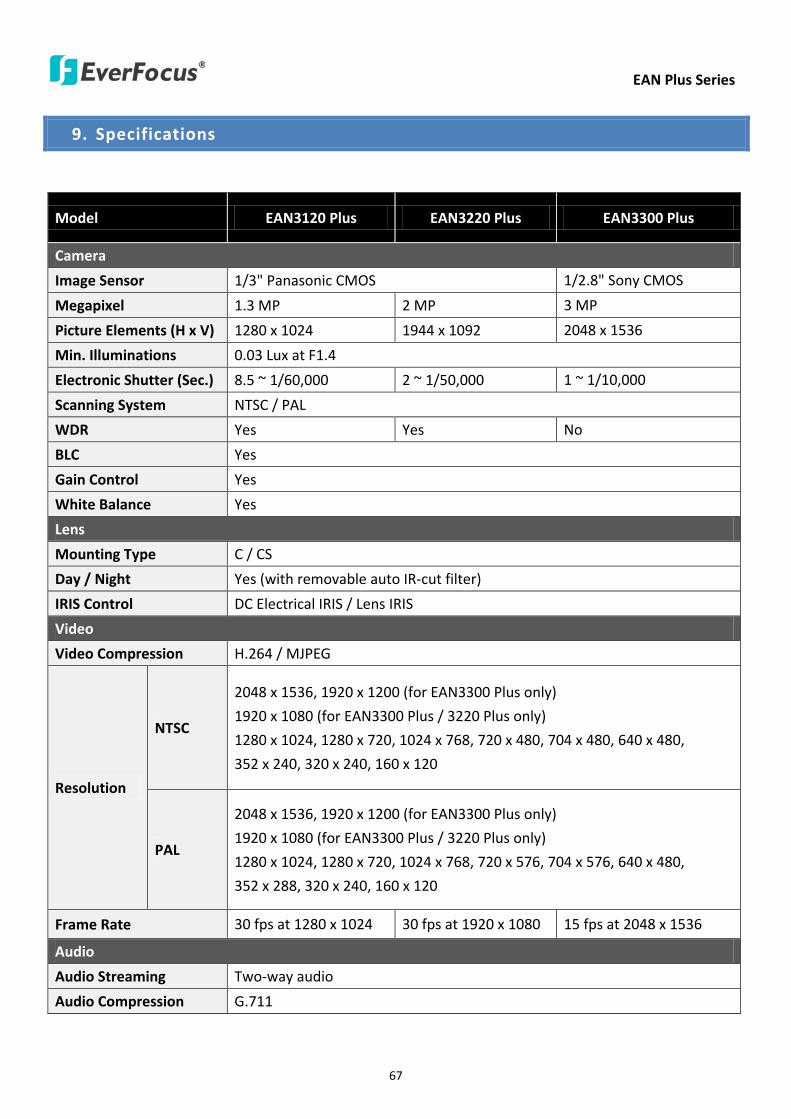
EAN Plus Series
67
9 Specifications
Model EAN3120 Plus EAN3220 Plus EAN3300 Plus
Camera
Image Sensor 13 Panasonic CMOS 128 Sony CMOS
Megapixel 13 MP 2 MP 3 MP
Picture Elements (H x V) 1280 x 1024 1944 x 1092 2048 x 1536
Min Illuminations 003 Lux at F14
Electronic Shutter (Sec) 85 ~ 160000 2 ~ 150000 1 ~ 110000
Scanning System NTSC PAL
WDR Yes Yes No
BLC Yes
Gain Control Yes
White Balance Yes
Lens
Mounting Type C CS
Day Night Yes (with removable auto IR-cut filter)
IRIS Control DC Electrical IRIS Lens IRIS
Video
Video Compression H264 MJPEG
Resolution
NTSC
2048 x 1536 1920 x 1200 (for EAN3300 Plus only)
1920 x 1080 (for EAN3300 Plus 3220 Plus only)
1280 x 1024 1280 x 720 1024 x 768 720 x 480 704 x 480 640 x 480
352 x 240 320 x 240 160 x 120
PAL
2048 x 1536 1920 x 1200 (for EAN3300 Plus only)
1920 x 1080 (for EAN3300 Plus 3220 Plus only)
1280 x 1024 1280 x 720 1024 x 768 720 x 576 704 x 576 640 x 480
352 x 288 320 x 240 160 x 120
Frame Rate 30 fps at 1280 x 1024 30 fps at 1920 x 1080 15 fps at 2048 x 1536
Audio
Audio Streaming Two-way audio
Audio Compression G711
EAN Plus Series
68
Network
Interface 10 100 Base-T Ethernet RJ-45 socket
Supported Protocols
TCPIP IPV6 UDP ICMP DHCP NTP DNS DDNS SMTP SNMP FTP
HTTP HTTPs PPPoE UPnP Bonjour RTP RTSP RTCP IGMP ARP ONVIF
PSIA
Connector
Power DC female port PoE
Ethernet RJ-45
Audio 1 In (phone jack for microphone)
1 Out (phone jack for Speaker)
Alarm IO Terminal IO wires
Local Storage Micro SD SDHC memory card slot
TV-Out BNC socket composite 1 V p-p 75 Ω
General
Power Source DC 12V PoE (IEEE8023af)
Power Consumption
(IR LEDs On)
5W (DC 12V)
621W (PoE)
5W (DC 12V)
522W (PoE)
5W (DC 12V)
536W (PoE)
Operating Temperature 0degC ~ +50degC 32degF ~ +122degF
Humidity 20 to 80 (no condensation)
Safety CE FCC
Dimensions (L x W x H) 117 x 56 x 68 mm 46 x 22 x 27 in
Weight 410 g 09 lb
EverFocus Electronics Corp EverFocus Taiwan 12F No79 Sec 1 Shin-Tai Wu Road Hsi-Chih Taipei Taiwan TEL +886 2 2698 2334 FAX +886 2 2698 2380 wwweverfocuscomtw marketingeverfocuscomtw
EverFocus Europe - Germany Albert-Einstein-Strasse 1 D-46446 Emmerich Germany TEL +49 2822 93940 FAX +49 2822 939495 wwweverfocusde infoeverfocusde
EverFocus China - Beijing Room 609 Technology Trade Building Shangdi Information Industry Base Haidian District Beijing 100085 China TEL +86 10 6297 3336~39 FAX +86 10 6297 1423 wwweverfocuscomcn marketingeverfocuscomcn
EverFocus China - Shenzhen 4F No 2 D4 Building Wan Yelong Industrial Park Tangtou Road Shiyan Baoan Shenzhen Guangdong 518101 China TEL +86 755 2765 1313 FAX +86 755 2765 0337 wwweverfocuscomcn marketingeverfocuscomcn
EverFocus USA - California 1801 Highland Avenue Unit A Duarte CA 91010 USA TEL +1 626 844 8888 FAX +1 626 844 8838 wwweverfocuscom saleseverfocuscom
EverFocus USA - New York 415 Oser Avenue Unit S Hauppauge NY 11788 USA TEL +1 631 436 5070 FAX +1 631 436 5027 wwweverfocuscom saleseverfocuscom
EverFocus Japan 5F Kinshicho City Building 2-13-4 Koto-BashiSumida-Ku Tokyo 130-0022 Japan TEL +81 3 5625 8188 FAX +81 3 5625 8189 wwweverfocuscojp infoeverfocuscojp
EverFocus Europe - UK Unit 12 Spitfire Business Park Hawker Road Croydon Surrey CR0 4WD UK TEL +44 20 8649 9757 +44 845 430 9999 FAX +44 20 8649 9907 wwweverfocusukcouk salesukeverfocuscom
EverFocus India Suite 803 Housefin Bhavan C-21 Bandra Kurla Complex Bandra (East) Mumbai 400051 India TEL +91 22 6128 8700 FAX +91 22 6128 8705 wwweverfocusin saleseverfocusin
PN 4605PQ3120B010A-VerC
Your EverFocus product is designed and manufactured with high quality materials and components which can be recycled and reused This symbol means that electrical and electronic equipment at their end-of-life should be disposed of separately from your household waste Please dispose of this equipment at your local community waste collectionrecycling centre In the European Union there are separate collection systems for used electrical and electronic product Please help us to conserve the environment we live in
Ihr EverFocus Produkt wurde entwickelt und hergestellt mit qualitativ hochwertigen Materialien und Komponenten die recycelt und wieder verwendet werden koumlnnen Dieses Symbol bedeutet dass elektrische und elektronische Geraumlte am Ende ihrer Nutzungsdauer vom Hausmuumlll getrennt entsorgt werden sollen Bitte entsorgen Sie dieses Geraumlt bei Ihrer oumlrtlichen kommunalen Sammelstelle oder im Recycling Centre Helfen Sie uns bitte die Umwelt zu erhalten in der wir leben
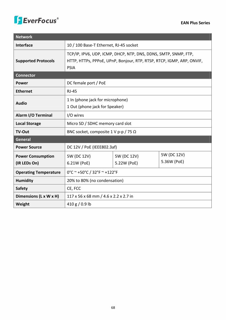
EAN Plus Series
68
Network
Interface 10 100 Base-T Ethernet RJ-45 socket
Supported Protocols
TCPIP IPV6 UDP ICMP DHCP NTP DNS DDNS SMTP SNMP FTP
HTTP HTTPs PPPoE UPnP Bonjour RTP RTSP RTCP IGMP ARP ONVIF
PSIA
Connector
Power DC female port PoE
Ethernet RJ-45
Audio 1 In (phone jack for microphone)
1 Out (phone jack for Speaker)
Alarm IO Terminal IO wires
Local Storage Micro SD SDHC memory card slot
TV-Out BNC socket composite 1 V p-p 75 Ω
General
Power Source DC 12V PoE (IEEE8023af)
Power Consumption
(IR LEDs On)
5W (DC 12V)
621W (PoE)
5W (DC 12V)
522W (PoE)
5W (DC 12V)
536W (PoE)
Operating Temperature 0degC ~ +50degC 32degF ~ +122degF
Humidity 20 to 80 (no condensation)
Safety CE FCC
Dimensions (L x W x H) 117 x 56 x 68 mm 46 x 22 x 27 in
Weight 410 g 09 lb
EverFocus Electronics Corp EverFocus Taiwan 12F No79 Sec 1 Shin-Tai Wu Road Hsi-Chih Taipei Taiwan TEL +886 2 2698 2334 FAX +886 2 2698 2380 wwweverfocuscomtw marketingeverfocuscomtw
EverFocus Europe - Germany Albert-Einstein-Strasse 1 D-46446 Emmerich Germany TEL +49 2822 93940 FAX +49 2822 939495 wwweverfocusde infoeverfocusde
EverFocus China - Beijing Room 609 Technology Trade Building Shangdi Information Industry Base Haidian District Beijing 100085 China TEL +86 10 6297 3336~39 FAX +86 10 6297 1423 wwweverfocuscomcn marketingeverfocuscomcn
EverFocus China - Shenzhen 4F No 2 D4 Building Wan Yelong Industrial Park Tangtou Road Shiyan Baoan Shenzhen Guangdong 518101 China TEL +86 755 2765 1313 FAX +86 755 2765 0337 wwweverfocuscomcn marketingeverfocuscomcn
EverFocus USA - California 1801 Highland Avenue Unit A Duarte CA 91010 USA TEL +1 626 844 8888 FAX +1 626 844 8838 wwweverfocuscom saleseverfocuscom
EverFocus USA - New York 415 Oser Avenue Unit S Hauppauge NY 11788 USA TEL +1 631 436 5070 FAX +1 631 436 5027 wwweverfocuscom saleseverfocuscom
EverFocus Japan 5F Kinshicho City Building 2-13-4 Koto-BashiSumida-Ku Tokyo 130-0022 Japan TEL +81 3 5625 8188 FAX +81 3 5625 8189 wwweverfocuscojp infoeverfocuscojp
EverFocus Europe - UK Unit 12 Spitfire Business Park Hawker Road Croydon Surrey CR0 4WD UK TEL +44 20 8649 9757 +44 845 430 9999 FAX +44 20 8649 9907 wwweverfocusukcouk salesukeverfocuscom
EverFocus India Suite 803 Housefin Bhavan C-21 Bandra Kurla Complex Bandra (East) Mumbai 400051 India TEL +91 22 6128 8700 FAX +91 22 6128 8705 wwweverfocusin saleseverfocusin
PN 4605PQ3120B010A-VerC
Your EverFocus product is designed and manufactured with high quality materials and components which can be recycled and reused This symbol means that electrical and electronic equipment at their end-of-life should be disposed of separately from your household waste Please dispose of this equipment at your local community waste collectionrecycling centre In the European Union there are separate collection systems for used electrical and electronic product Please help us to conserve the environment we live in
Ihr EverFocus Produkt wurde entwickelt und hergestellt mit qualitativ hochwertigen Materialien und Komponenten die recycelt und wieder verwendet werden koumlnnen Dieses Symbol bedeutet dass elektrische und elektronische Geraumlte am Ende ihrer Nutzungsdauer vom Hausmuumlll getrennt entsorgt werden sollen Bitte entsorgen Sie dieses Geraumlt bei Ihrer oumlrtlichen kommunalen Sammelstelle oder im Recycling Centre Helfen Sie uns bitte die Umwelt zu erhalten in der wir leben


