Embed Size (px)
Citation preview

1
Owner’s Manual
Instructions for Assembly, Testing, Operation, Servicing, & Storage
Log Splitter: Outdoor hydraulic powered machine that splits wood logs.
WARNING
READ and UNDERSTAND this manual completely before using log splitter.
All operators of this equipment must read and completely understand all safety information, operating instructions, maintenance and
storage instructions. Failure to properly operate and maintain the log splitter could result in serious injury to the operator and bystanders
from moving parts that can crush or cut, flying objects, burns, fire or explosion, escaping high pressure hydraulic fluid, or carbon
monoxide poisoning in particular, be aware of the following hazards.
Crush and Cut Hazards
Moving parts can crush and cut hands and fingers. Keep hands clear of end plate, wedge, logs, and log strippers while splitting.
High Pressure Hydraulic Fluid Hazards
High fluid pressures and temperatures are developed in hydraulic log splitters. Hydraulic fluid escaping through even a pin-size hole
opening can puncture skin and cause severe blood poisoning. Inspect hydraulic system regularly for possible leaks. Never check for
leaks with your hand while the system is pressurized. Seek medical attention immediately if injured by escaping fluid.
Fire Hazards
If your log splitter is intended for use near an ignitable forest, brush, or grassy covered land, the engine exhaust should be
equipped with a spark arrestor. See the “Specifications” section of this manual to determine if your splitter already has a spark
arrestor. If not equipped, call Powerhorse Product Support for ordering information.
Keep a fire extinguisher with you that is rated for ordinary combustibles and flammable liquids.
STOP!
ADD OIL TO ENGINE BEFORE USING: Engine is shipped without oil. DO NOT start log splitter without first adding oil.
ADD HYDRAULIC OIL: Your log splitter was shipped without hydraulic oil. Refer to Periodic Maintenance section of this manual
for instructions on filling the hydraulic reservoir
INSPECT COMPONENTS: Closely inspect to make sure no components are missing or damaged.
See Initial Unpacking & Set-up for instructions and for whom to contact to report missing or damaged parts.
Prime the Pump: The pump on your log splitter needs to be primed before use. Refer to initial setup for instructions.
Any Questions, Comments, Problems or Parts Orders
Call PowerHorse Product Support 1-866-443-2576
ITEM NUMBER: 1175, 1169
SERIAL NUMBER: _______________ M1175B

2
Hazard Signal Word Definitions

3
Table of Contents
Hazard Signal Word Definitions ................................................................................................................................................................ 2 Table of Contents ....................................................................................................................................................................................... 3 About Your Log Splitter ............................................................................................................................................................................ 4 Safety Label Locations .............................................................................................................................................................................. 5 Machine Component Identification ........................................................................................................................................................... 7 Initial Set-up .............................................................................................................................................................................................. 8 Moving and Towing to the Job Site ......................................................................................................................................................... 10 Before Each Use-Inspection/Maintenance ............................................................................................................................................... 13 Before Each Use - Fueling ....................................................................................................................................................................... 15 Before Each Use – Work Site Selection and Setup .................................................................................................................................. 16 Splitting Operation ................................................................................................................................................................................... 17 Storage ..................................................................................................................................................................................................... 23 Periodic Maintenance............................................................................................................................................................................... 24 Troubleshooting ....................................................................................................................................................................................... 25 Specifications ........................................................................................................................................................................................... 26 Parts Breakdown – Exploded View 1175/1169 – Rev B ......................................................................................................................... 27 Summary of Important Safety Information for Operation ....................................................................................................................... 30 Assembly Instructions .............................................................................................................................................................................. 35 789712 Engine Exploded View ............................................................................................................................................................... 68 789712 Engine Parts List ......................................................................................................................................................................... 69 789712 Engine Kits ................................................................................................................................................................................. 70 790160 Engine Exploded View ............................................................................................................................................................... 71 790160 Engine Parts List ......................................................................................................................................................................... 72 790160 Engine Kits ................................................................................................................................................................................. 73 Engine Manual ......................................................................................................................................................................................... 74 Limited Warranty ..................................................................................................................................................................................... 92
4
About Your Log Splitter
Thank you for purchasing your Powerhorse log splitter!
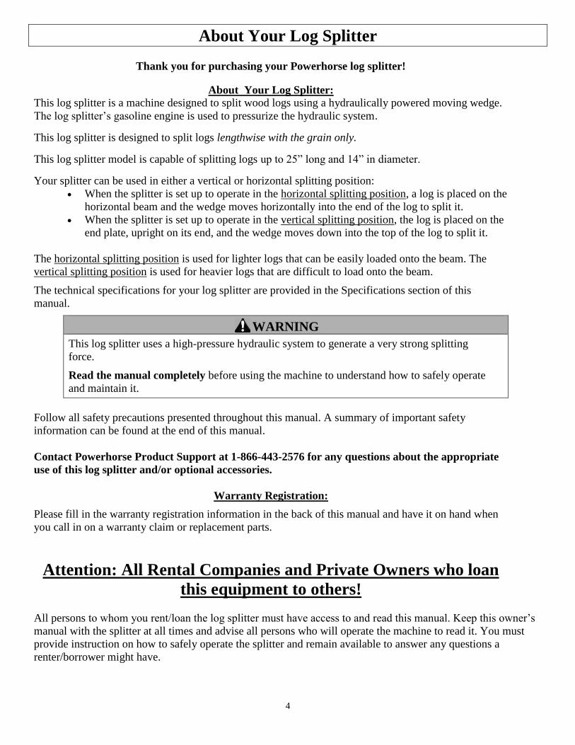
About Your Log Splitter: This log splitter is a machine designed to split wood logs using a hydraulically powered moving wedge.
The log splitter’s gasoline engine is used to pressurize the hydraulic system.
This log splitter is designed to split logs lengthwise with the grain only.
This log splitter model is capable of splitting logs up to 25” long and 14” in diameter.
Your splitter can be used in either a vertical or horizontal splitting position:
When the splitter is set up to operate in the horizontal splitting position, a log is placed on the
horizontal beam and the wedge moves horizontally into the end of the log to split it.
When the splitter is set up to operate in the vertical splitting position, the log is placed on the
end plate, upright on its end, and the wedge moves down into the top of the log to split it.
The horizontal splitting position is used for lighter logs that can be easily loaded onto the beam. The
vertical splitting position is used for heavier logs that are difficult to load onto the beam.
The technical specifications for your log splitter are provided in the Specifications section of this
manual.
WARNING
This log splitter uses a high-pressure hydraulic system to generate a very strong splitting
force.
Read the manual completely before using the machine to understand how to safely operate
and maintain it.
Follow all safety precautions presented throughout this manual. A summary of important safety
information can be found at the end of this manual.
Contact Powerhorse Product Support at 1-866-443-2576 for any questions about the appropriate
use of this log splitter and/or optional accessories.
Warranty Registration:
Please fill in the warranty registration information in the back of this manual and have it on hand when
you call in on a warranty claim or replacement parts.
Attention: All Rental Companies and Private Owners who loan
this equipment to others!
All persons to whom you rent/loan the log splitter must have access to and read this manual. Keep this owner’s
manual with the splitter at all times and advise all persons who will operate the machine to read it. You must
provide instruction on how to safely operate the splitter and remain available to answer any questions a
renter/borrower might have.
5
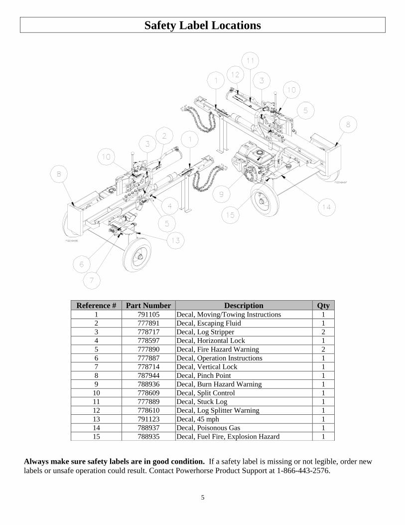
Safety Label Locations
Always make sure safety labels are in good condition. If a safety label is missing or not legible, order new
labels or unsafe operation could result. Contact Powerhorse Product Support at 1-866-443-2576.
Reference # Part Number Description Qty 1 791105 Decal, Moving/Towing Instructions 1
2 777891 Decal, Escaping Fluid 1
3 778717 Decal, Log Stripper 2
4 778597 Decal, Horizontal Lock 1
5 777890 Decal, Fire Hazard Warning 2
6 777887 Decal, Operation Instructions 1
7 778714 Decal, Vertical Lock 1
8 787944 Decal, Pinch Point 1
9 788936 Decal, Burn Hazard Warning 1
10 778609 Decal, Split Control 1
11 777889 Decal, Stuck Log 1
12 778610 Decal, Log Splitter Warning 1
13 791123 Decal, 45 mph 1
14 788937 Decal, Poisonous Gas 1
15 788935 Decal, Fuel Fire, Explosion Hazard 1

6
Safety Label Locations
E
SC
AP
ING
HIG
H P
RE
SS
UR
E H
YD
RA
UL
IC F
LU
ID H
AZ
AR
D
Hig
h f
luid
pre
ssu
res a
nd
te
mp
era
ture
s a
re d
evelo
ped in the
hyd
rau
lic s
yste
m.
Hyd
rau
lic flu
id e
sca
pin
g t
hro
ug
h e
ve
n a
pin
-siz
e
ho
le o
pe
nin
g c
an
pu
nctu
re s
kin
and c
ause b
lood p
ois
onin
g.
In
sp
ect
hyd
rau
lic s
yste
m r
eg
ula
rly fo
r le
aks
N
ever
che
ck fo
r le
aks w
ith y
ou
r h
an
d w
hile
syste
m is p
ressurized.
S
ee
k m
ed
ica
l a
tte
ntio
n im
me
dia
tely
if in
jure
d b
y e
scapin
g flu
id.
©N
ort
he
rn T
oo
l +
Eq
uip
ment C
o. 1-8
00-2
70-0
810
WA
RN
ING
PN
77
7891
PO
ISO
NO
US
GA
S
This
pro
duct's u
se
giv
es o
ff c
arb
on
mo
no
xid
e,
an
od
orl
ess g
as that can
kill
yo
u.
O
NL
Y u
se
ou
tdo
ors
and a
way
fr
om
air
inta
kes.
N
EV
ER
use
in
sid
e h
om
es, gara
ges,
o
r sh
ed
s.
EV
EN
IF
you r
un a
fan o
r
o
pe
n d
oo
rs a
nd w
indow
s.
Se
e p
rod
uct
ma
nu
al fo
r m
ore
deta
ils.
©N
ort
he
rn T
oo
l +
Eq
uip
ment C
o. 1-8
00-2
70-0
810
PN
39
259
WA
RN
ING
Mo
vin
g p
art
s c
an
cru
sh
an
d c
ut.
P
iece
s c
an
fly
ou
t w
hile
sp
littin
g.
Fo
llow
safe
ty r
ule
s f
or
op
era
tin
g t
he
lo
g s
plit
ter
or
se
rio
us in
jury
co
uld
re
su
lt.
R
EA
D t
he
Ow
ne
r's M
an
ua
l co
mp
lete
ly b
efo
re o
pe
ratin
g.
O
nly
on
e p
ers
on
sh
ou
ld o
pe
rate
th
e lo
g s
plit
ter.
If
an
a
ssis
tan
t is
he
lpin
g t
o loa
d lo
gs,
the
op
era
tor
sho
uld
not
a
ctu
ate
co
ntr
ols
un
til th
e a
ssis
tan
t is
at
lea
st
10
ft
aw
ay.
S
tay in
th
e d
esig
na
ted
OP
ER
AT
OR
PO
SIT
ION
wh
ile
a
ctu
atin
g t
he
co
ntr
ols
.
S
plit
wo
od
in
dire
ctio
n o
f th
e g
rain
only
.
H
old
ba
rk s
ide
of
log
s w
he
n loa
din
g.
K
ee
p h
and
s a
wa
y f
rom
we
dg
e,
en
dpla
te/r
am
, a
nd
pa
rtly
sp
lit lo
gs.
N
eve
r le
ave
lo
g s
plit
ter
un
att
en
de
d d
urin
g o
pe
ratio
n.
S
tay o
ff s
lop
es a
nd
slip
pe
ry s
urf
ace
s.
S
ee
ad
ditio
na
l sa
fety
ru
les in t
he
Ow
ne
r's M
anu
al.
©N
ort
he
rn T
oo
l +
Eq
uip
ment C
o. 1-8
00-2
70-0
810
PN
77
8610
WA
RN
ING
LO
G S
TR
IPP
ER
RE
TR
AC
T W
ED
GE
TO
RE
MO
VE
ST
UC
K W
OO
D
PIN
CH
PO
INT
Keep
han
ds c
lear
of
wed
ge a
nd
log
sti
pp
er
©N
ort
hern
Tool &
Eq
uip
men
t C
o. 1-8
00-2
70-0
810
SPLIT CONTROL LEVER OPERATION
1 2
3 4 5
6
7
8
9 10
11
12
14
15
13

7
Machine Component Identification
Ref Description Ref Description
1 End Plate 10 Axle/Hydraulic Tank
2 Log Cradles 11 Vertical Lock
3 Split Control Lever 12 2” Ball Coupler
4 Cylinder 13 Control Valve
5 Safety Chains 14 Wedge
6 Manual Tube 15 Hydraulic Breather/Dipstick
7 Horizontal Lock 16 Engine On/Off Switch
8 Hydraulic Pump 17 Engine
9 Return Line Filter 18 Support Leg
8
Initial Set-up
IMPORTANT!
Engine is shipped without oil. DO NOT start the engine before adding oil.
See Assembly Instructions section of this manual to assemble the log splitter before
setup.
Step One:
Inspect Log
Splitter
Components.
Closely inspect all log splitter components. (See Machine Components section of this manual for diagram of components.)
If you have missing or damaged components, please contact Product Support at
1-866-443-2576.
Step Two:
Add Oil to Engine
Add oil to the engine. Using a funnel, add SAE 10W-30 oil up to the FULL mark
on the dipstick. (See engine Owner’s Manual for oil capacity and location of fill cap.)
Step Three:
Add Hydraulic Oil
to Reservoir and
Prime the Pump
WARNING: High fluid pressures and temperatures are developed in hydraulic log
splitters. Hydraulic fluid escaping through a pin hole sized opening can burn or puncture skin,
resulting in wounds that could cause blood poisoning, infection, disability, gangrene,
amputation, or death. Therefore, the following instructions should be heeded at all times when
inspecting or servicing the hydraulic components of the log splitter.
NEVER check for leaks with your hand. Leaks can be located by holding a piece of
cardboard or wood (at least two feet long) with your hand at one end and passing the
other end over the suspected area (wear eye protection). Look for discoloration of the
cardboard or wood.
NEVER adjust the pressure of the pump or valve.
If injured by escaping fluid, no matter how small the wound is, see a doctor at once. A
typical injection injury may be a small wound that does not look serious. However,
severe infection or reaction can result if proper medical treatment is not administered
immediately by a doctor who is familiar with injection injuries.
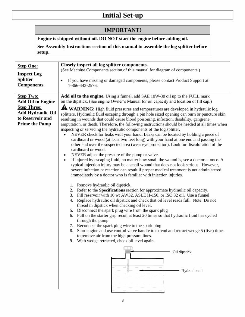
1. Remove hydraulic oil dipstick.
2. Refer to the Specifications section for approximate hydraulic oil capacity.
3. Fill reservoir with 10 wt AW32, ASLE H-150, or ISO 32 oil. Use a funnel
4. Replace hydraulic oil dipstick and check that oil level reads full. Note: Do not
thread in dipstick when checking oil level.
5. Disconnect the spark plug wire from the spark plug
6. Pull on the starter grip recoil at least 20 times so that hydraulic fluid has cycled
through the pump
7. Reconnect the spark plug wire to the spark plug
8. Start engine and use control valve handle to extend and retract wedge 5 (five) times
to remove air from the high pressure lines.
9. With wedge retracted, check oil level again.
Oil dipstick
Hydraulic oil
9
Initial Set-up
10. Replace hydraulic oil fill/vent cap.
11. Start engine and use control valve handle to extend and retract wedge five (5) times
to remove air from the high-pressure lines.
12. With wedge retracted, check oil level again. Fill if necessary.
WARNING: NEVER remove the hydraulic oil dipstick when the engine is
running or hot. Hot oil can escape causing severe burns. Allow log splitter to
cool completely before removing hydraulic oil dipstick.
Note: If the log splitter will be run for long periods of time in outdoor temperatures
above 70°F, we recommend changing the hydraulic oil to DEXRON III.
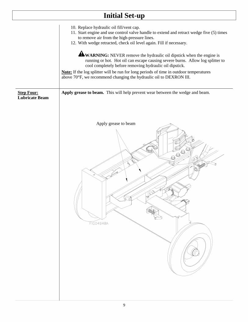
Step Four:
Lubricate Beam
Apply grease to beam. This will help prevent wear between the wedge and beam.
Apply grease to beam
10
Moving and Towing to the Job Site
WARNING
The log splitter is heavy. It can crush and cause serious injury if it rolls out of control or
tips over.
Follow the instructions below for safely moving and towing the log splitter.
Moving the log splitter:
1. Place in
Horizontal
position
Make sure the log splitter is locked in the horizontal position with latch rod
before moving.
NEVER move log splitter when it is in vertical configuration because it will be
unstable and could tip.
2. Engine off. IMPORTANT: Make sure log splitter engine is off.
Never move the log splitter with its engine running.
3. Fuel valve off
(if equipped)
Turn fuel valve off to prevent carburetor flooding and reduce the chance of fuel
leakage. Refer to Engine owner’s manual for fuel valve location.
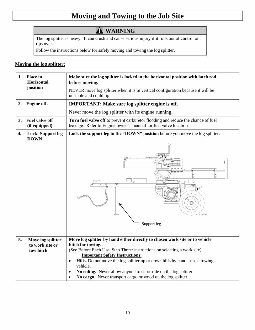
4. Lock: Support leg
DOWN
Lock the support leg in the “DOWN” position before you move the log splitter.
5. Move log splitter
to work site or
tow hitch
Move log splitter by hand either directly to chosen work site or to vehicle
hitch for towing.
(See Before Each Use: Step Three: instructions on selecting a work site)
Important Safety Instructions:
Hills. Do not move the log splitter up or down hills by hand - use a towing
vehicle.
No riding. Never allow anyone to sit or ride on the log splitter.
No cargo. Never transport cargo or wood on the log splitter.
Support leg
11
Moving and Towing to the Job Site
Towing:
1. Read instructions Review towing safety instructions in your vehicle manual.
2. Check tires Make sure tires are fully inflated and in good repair.
WARNING:
Do not over-inflate tires. Serious injury can occur if tire explodes.
When seating a bead after repair, do not exceed 30 PSI. Pressures higher
than 30 PSI can cause the tire and wheel to rupture and explode.
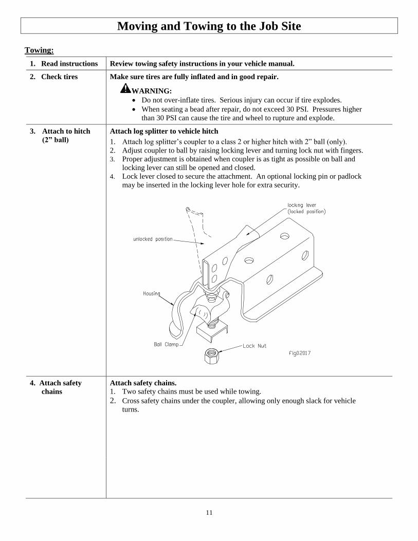
3. Attach to hitch
(2” ball)
Attach log splitter to vehicle hitch
1. Attach log splitter’s coupler to a class 2 or higher hitch with 2” ball (only).
2. Adjust coupler to ball by raising locking lever and turning lock nut with fingers.
3. Proper adjustment is obtained when coupler is as tight as possible on ball and
locking lever can still be opened and closed.
4. Lock lever closed to secure the attachment. An optional locking pin or padlock
may be inserted in the locking lever hole for extra security.
4. Attach safety
chains
Attach safety chains.
1. Two safety chains must be used while towing.
2. Cross safety chains under the coupler, allowing only enough slack for vehicle
turns.
12
Moving and Towing to the Job Site
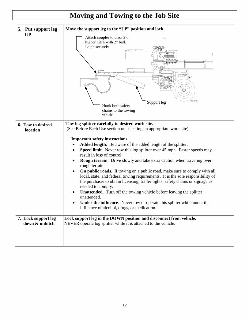
5. Put support leg
UP
Move the support leg to the “UP” position and lock.
6. Tow to desired
location
Tow log splitter carefully to desired work site. (See Before Each Use section on selecting an appropriate work site)
Important safety instructions:
Added length. Be aware of the added length of the splitter.
Speed limit. Never tow this log splitter over 45 mph. Faster speeds may
result in loss of control.
Rough terrain. Drive slowly and take extra caution when traveling over
rough terrain.
On public roads. If towing on a public road, make sure to comply with all
local, state, and federal towing requirements. It is the sole responsibility of
the purchaser to obtain licensing, trailer lights, safety chains or signage as
needed to comply.
Unattended. Turn off the towing vehicle before leaving the splitter
unattended.
Under the influence. Never tow or operate this splitter while under the
influence of alcohol, drugs, or medication.
7. Lock support leg
down & unhitch
Lock support leg in the DOWN position and disconnect from vehicle.
NEVER operate log splitter while it is attached to the vehicle.
Attach coupler to class 2 or
higher hitch with 2” ball.
Latch securely.
Hook both safety
chains to the towing
vehicle
Support leg
13
Before Each Use-Inspection/Maintenance
Step One: Inspect and maintain log splitter before each use
If the log splitter has been used previously, it must be inspected and maintained BEFORE EACH SUBSEQUENT USE.
WARNING
ALWAYS shut off the engine, disconnect the spark plug, and relieve system pressure before
inspecting, cleaning, adjusting, or repairing the splitter. Relieve system pressure by moving Split
Control Lever back and forth several times.
IMPORTANT:
If a part needs replacement, only use parts that meet the manufacturer’s specifications. Replacement parts that do not
meet specifications may result in a safety hazard or poor operation of the log splitter.
1. Engine off /
relieve pressure
Perform all inspections/repairs with the engine off and hydraulic system pressure relieved.
1. Make sure engine is off and cool.
2. Disconnect the spark plug
3. Relieve all hydraulic system pressure by moving the Split Control Lever back and forth
several times.
2. Remove debris
Remove debris from engine, muffler, and moving parts.
1. Engine debris. Debris on a hot engine can be a fire hazard. Clean debris and chaff from
engine cylinder head, cylinder head fins, blower housing rotating screen, and muffler
areas. Avoid contact with hot muffler.
2. Other debris. Debris on moving parts can cause excess wear. Clear debris from the slide
beam, wedge, and endplate.
3. Fuel tank/lines Check fuel tank and fuel lines for leaks.
Any fuel leak is a fire hazard. Fix any fuel leaks before starting engine.
4. Mechanical parts Check to be sure that all nuts and bolts are tight to make sure the log splitter is in safe
working condition.
5. Hydraulic system Check the hydraulic system carefully:
1. Visually inspect all hoses, tubing, clamps/fittings, pump, and cylinder for cracks,
fraying, kinks, or other damage.
2. Check all components for oily residue, which may indicate a leak.
Do NOT operate the log splitter if there is any indication of damage or oily residue. Small
leaks in hydraulic lines can cause severe injuries and can also be an indication of catastrophic
failure in the near future. The life of hydraulic hoses may be from a few months to a few
years, depending on use and storage patterns.
WARNING: High fluid pressures and temperatures are developed in hydraulic log
splitters. Hydraulic fluid escaping through a pin hole sized opening can burn or
puncture skin, resulting in wounds that could cause blood poisoning, infection,
disability, gangrene, amputation, or death. Therefore, the following instructions should
be heeded at all times when inspecting or servicing the hydraulic components of the log
splitter:
14
Before Each Use-Inspection/Maintenance
Stop the engine, disconnect the spark plug, and move all control valve handles back
and forth to relieve pressure before changing or adjusting hydraulic system
components such as hoses, tubing, fittings or other components.
NEVER check for leaks with your hand. Leaks can be located by holding a piece of
cardboard or wood (at least two feet long) with your hand at one end and passing the
other end over the suspected area (wear eye protection). Look for discoloration of the
cardboard or wood.
NEVER adjust the pressure setting of the pump or valve.
If injured by escaping fluid, no matter how small the wound is, see a doctor at once.
A typical injection injury may be a small puncture wound that does not look serious.
However, severe infection or reaction can result if proper medical treatment is not
administered immediately by a doctor who is familiar with injection injuries.
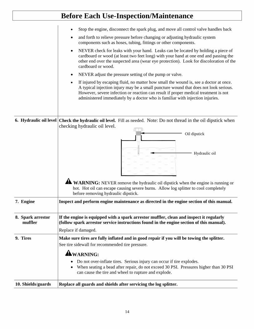
6. Hydraulic oil level Check the hydraulic oil level. Fill as needed. Note: Do not thread in the oil dipstick when
checking hydraulic oil level.
WARNING: NEVER remove the hydraulic oil dipstick when the engine is running or
hot. Hot oil can escape causing severe burns. Allow log splitter to cool completely
before removing hydraulic dipstick.
7. Engine Inspect and perform engine maintenance as directed in the engine section of this manual.
8. Spark arrestor
muffler
If the engine is equipped with a spark arrestor muffler, clean and inspect it regularly
(follow spark arrestor service instructions found in the engine section of this manual).
Replace if damaged.
9. Tires Make sure tires are fully inflated and in good repair if you will be towing the splitter.
See tire sidewall for recommended tire pressure.
WARNING:
Do not over-inflate tires. Serious injury can occur if tire explodes.
When seating a bead after repair, do not exceed 30 PSI. Pressures higher than 30 PSI
can cause the tire and wheel to rupture and explode.
10. Shields/guards Replace all guards and shields after servicing the log splitter.
Oil dipstick
Hydraulic oil
15
Before Each Use - Fueling
Step Two: Fueling
WARNING
Gasoline is highly flammable and explosive. You can be burned or seriously injured when handling
fuel. Use extreme care when handling gasoline.
1. Engine off/cool The engine must be off and allowed to cool at least two minutes before adding fuel.
WARNING: A running engine is hot enough to ignite fuel. Never add fuel or remove gas
cap if engine is running or still hot.
2. Outdoor location Fill fuel tank outdoors – never indoors.
WARNING: Gasoline vapors can ignite if they collect inside an enclosure. Explosion can
result.
3. Remove gas cap Remove engine gas cap.
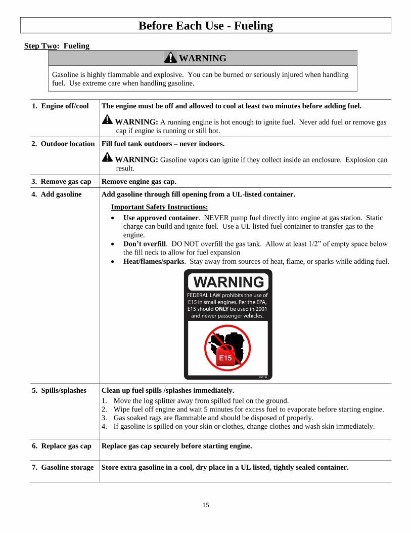
4. Add gasoline Add gasoline through fill opening from a UL-listed container.
Important Safety Instructions:
Use approved container. NEVER pump fuel directly into engine at gas station. Static
charge can build and ignite fuel. Use a UL listed fuel container to transfer gas to the
engine.
Don’t overfill. DO NOT overfill the gas tank. Allow at least 1/2” of empty space below
the fill neck to allow for fuel expansion
Heat/flames/sparks. Stay away from sources of heat, flame, or sparks while adding fuel.
5. Spills/splashes Clean up fuel spills /splashes immediately.
1. Move the log splitter away from spilled fuel on the ground.
2. Wipe fuel off engine and wait 5 minutes for excess fuel to evaporate before starting engine.
3. Gas soaked rags are flammable and should be disposed of properly.
4. If gasoline is spilled on your skin or clothes, change clothes and wash skin immediately.
6. Replace gas cap Replace gas cap securely before starting engine.
7. Gasoline storage Store extra gasoline in a cool, dry place in a UL listed, tightly sealed container.
16
Before Each Use – Work Site Selection and Setup Step Three: Work site selection and log splitter setup
WARNING
It is important to select an appropriate work site and properly set up the log splitter in order to
minimize the risk of slips and falls, equipment rolling or tipping over, carbon monoxide poisoning,
and accidental fires.
1. Select location Select an appropriate location for operating the log splitter.
Requirements:
1. Dry, with a level surface with good footing. Stay clear of areas with mud, ice, tall grass,
weeds, brush, or snow.
2. Outdoors, away from air intakes.
WARNING: The running engine gives off carbon monoxide, a poisonous gas that can
kill you. You CANNOT smell it, see it, or taste it.
ONLY run log splitter OUTDOORS and away from air intakes. NEVER run log splitter
inside homes, garages, sheds, or other buildings or semi-enclosed spaces. These spaces can
trap poisonous gases, EVEN if you run a fan or open windows.
If you start to feel sick, dizzy, or weak while using the log splitter, shut off the engine and
get to fresh air RIGHT AWAY. See a doctor. You may have carbon monoxide poisoning.
2. Fire precautions Take the following precautions against fire:
1. IMPORTANT: If your splitter will be used near any unimproved forest, brush, or
grassy covered land, then engine must be equipped with a spark arrestor.
(See the “Specifications” section of this manual to determine if your splitter already has a
spark arrestor. Contact Powerhorse Product Support at 1-866-443-2576 for information
about obtaining a spark arrestor for your log splitter if it is unequipped.)
2. Make sure you comply with applicable local, state and federal codes.
3. Keep a fire extinguisher available (classified for both ordinary combustibles & flammable
liquids) as a precautionary measure when operating the log splitter in dry areas.
3. Position splitter 7’
from any
combustibles or
flammable liquids
Position muffler at least 7 feet from combustible objects during operation.
Hot exhaust fumes from engine could cause fire. Also, hydraulic oil leaking or spraying on hot
engine can ignite.
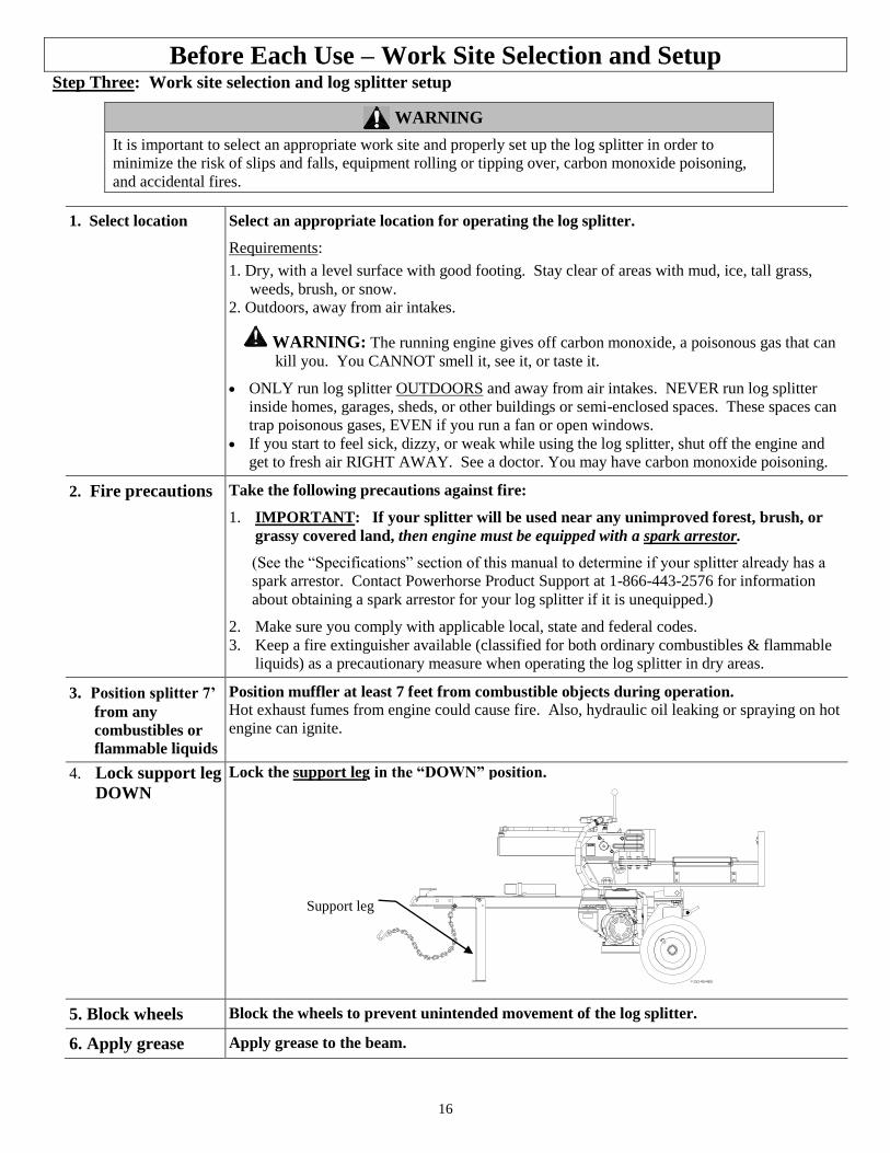
4. Lock support leg
DOWN
Lock the support leg in the “DOWN” position.
5. Block wheels Block the wheels to prevent unintended movement of the log splitter.
6. Apply grease Apply grease to the beam.
Support leg
17
Splitting Operation
WARNING
Before starting this log splitter, review the following instructions and safety information for safe
operation of the log splitter.
Failure to follow these rules may result in serious injury to the operator or bystanders from moving
parts that crush, cut, or entangle from flying objects, burns, fire, falling or tripping, or from carbon
monoxide poisoning.
General safety information:
Read manual. Do not allow anyone to operate the log splitter who has not read the Owner’s Manual or has not
been instructed on the safe use of the splitter. The log splitter owner should instruct all operators in safe log
splitter operation.
Age restrictions. Never allow anyone under 16 years old to operate the log splitter. Anyone 16 years and older
must be trained and supervised by a trained adult.
Intended use. Log splitters should only be used for splitting wood logs, lengthwise with the grain. Do not use for
other purposes as unforeseen hazards may result.
Modifications. Never modify or alter the log splitter in any way. Modifications can create serious safety hazards
and will void the warranty:
Attachments. Never add attachments to the splitter, except for authorized accessories supplied by the
manufacturer with instructions for safe installation and use.
Engine speed. The maximum engine speed is preset at a safe limit. Never attempt to modify the engine speed
setting to run at a higher speed.
Fuel/exhaust system. NEVER modify or add to the exhaust system, fuel tanks, or fuel lines. Fire can result.
Remote control. NEVER attach a rope, cable, or other remote device to the splitting control.
Splitting wedge. NEVER attempt to change the height or speed of the splitting wedge.
Pressure setting. NEVER increase the pressure setting of the pump or control valve.
Safety equipment/controls. Always operate the log splitter with all safety equipment in place and in good
working order, and all controls properly adjusted for safe operation.
Know how to stop. Be thoroughly familiar with all controls and with the proper use of the equipment. Know
how to stop the log splitter and relieve system pressures quickly if needed.
Operating speed. Always operate the log splitter at the manufacturer’s recommended speed. The maximum
speed of the engine pump and wedge are preset within safe limits.
Daylight only. Only use the log splitter in daylight so you can see what you are doing.
Smoking/sparks. Never smoke while operating the log splitter, and never operate near sources of sparks or
flames.
Under the influence. Never operate, or let anyone else operate, the log splitter while under the influence of
alcohol, drugs, or medication.
Unattended. Never leave the machine unattended while the engine is running.
Refueling. Never refuel the engine until it has cooled at least two minutes.
Adjusting/repairing. Always make sure the engine is off before cleaning, repairing or adjusting the splitter,
except as recommended by the manufacturer. In addition, disconnect the spark plug and move all control handles
back and forth to relieve system pressure before changing or adjusting hydraulic system components such as
hoses, tubing, fittings or other components.
Replace labels. Always make sure safety labels are in place and in good condition. If a safety label is missing or
not legible, order new labels because unsafe operation can result. Call 1-866-443-2576 to order new safety labels.
18
Splitting Operation
1. Put on
protective
clothing /
gear
Wear the following protective clothing and safety gear:
1) Eye protection. Always wear safety glasses or goggles when operating the machine. Pieces
of log may fly out and serious eye injury can occur.
2) Boots. Falling logs can crush feet. Always wear safety shoes or heavy boots when operating
or helping to load logs.
3) Gloves. Wear snug fitting gloves without drawstrings or loose cuffs.
4) Hearing protection. The use of earplugs or other hearing protection device is recommended.
5) No Loose/dangling apparel. Loose or dangling apparel can become entangled in moving
parts. Never wear jewelry or loose-fitting clothing.
2. Block wheels Block the wheels to prevent unintended movement of the log splitter.
3. Set to
horizontal
or vertical:
a) Set to
Horizontal
position
Set log splitter into either the horizontal or vertical splitting position
The HORIZONTAL splitting position is used for lighter logs that can be easily loaded onto the beam.
The VERTICAL splitting position is used for light logs as well as heavy logs that are difficult to load
onto the beam.
Note:
Musculoskeletal injury can result from lifting logs onto the log splitter if proper lifting techniques
are not used or the logs are too heavy for a person’s size, weight, or strength. In some cases, logs
as small as 8” in diameter and 14” in length may be heavier than what some persons should be
repeatedly lifting onto the splitter.
The use of the vertical splitting position can greatly reduce the need to lift logs onto the splitter.
Employers are advised to consider NIOSH lifting guidelines when assigning employees to log
splitting tasks for an extended period of time.
WARNING: NEVER change splitting positions with the engine running. You may
contact the muffler and receive serious burns.
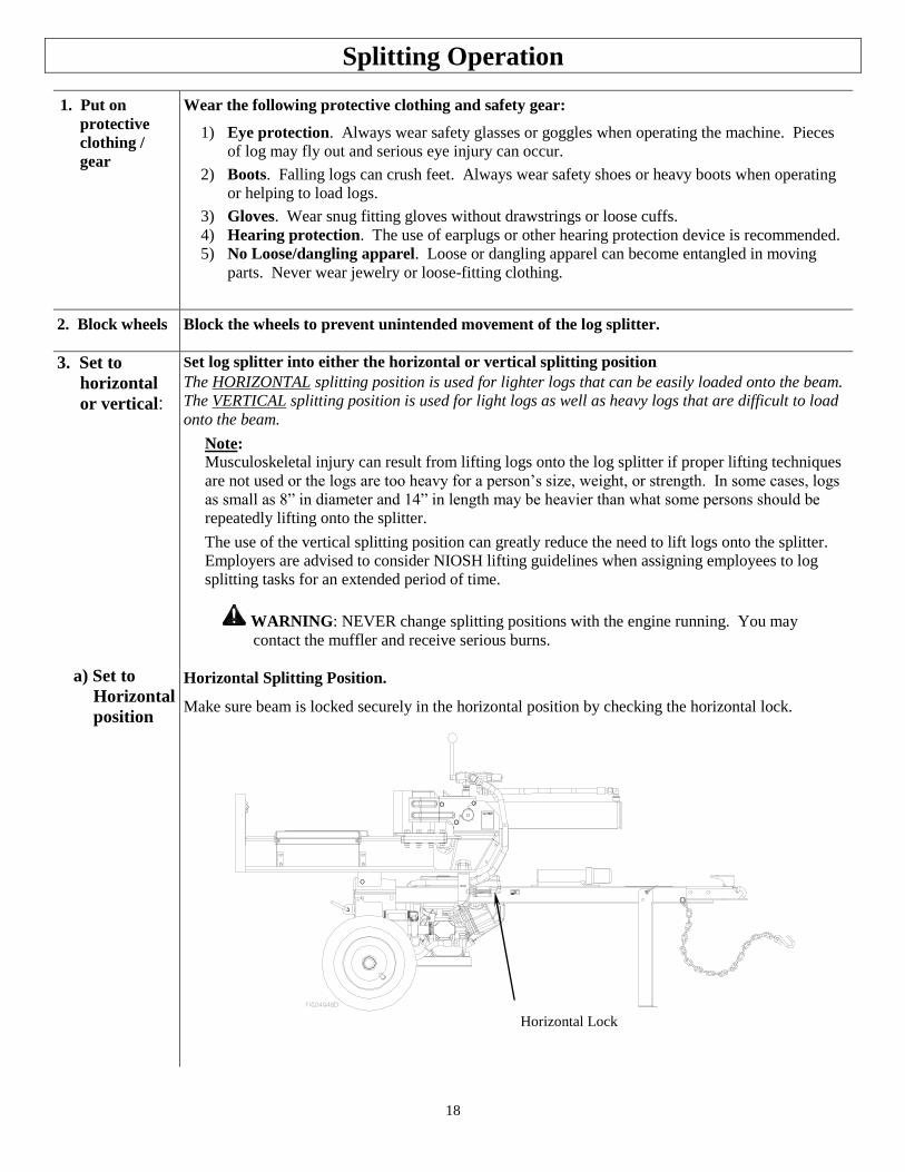
Horizontal Splitting Position.
Make sure beam is locked securely in the horizontal position by checking the horizontal lock.
Horizontal Lock
19
Splitting Operation
b) Set to
Vertical
position
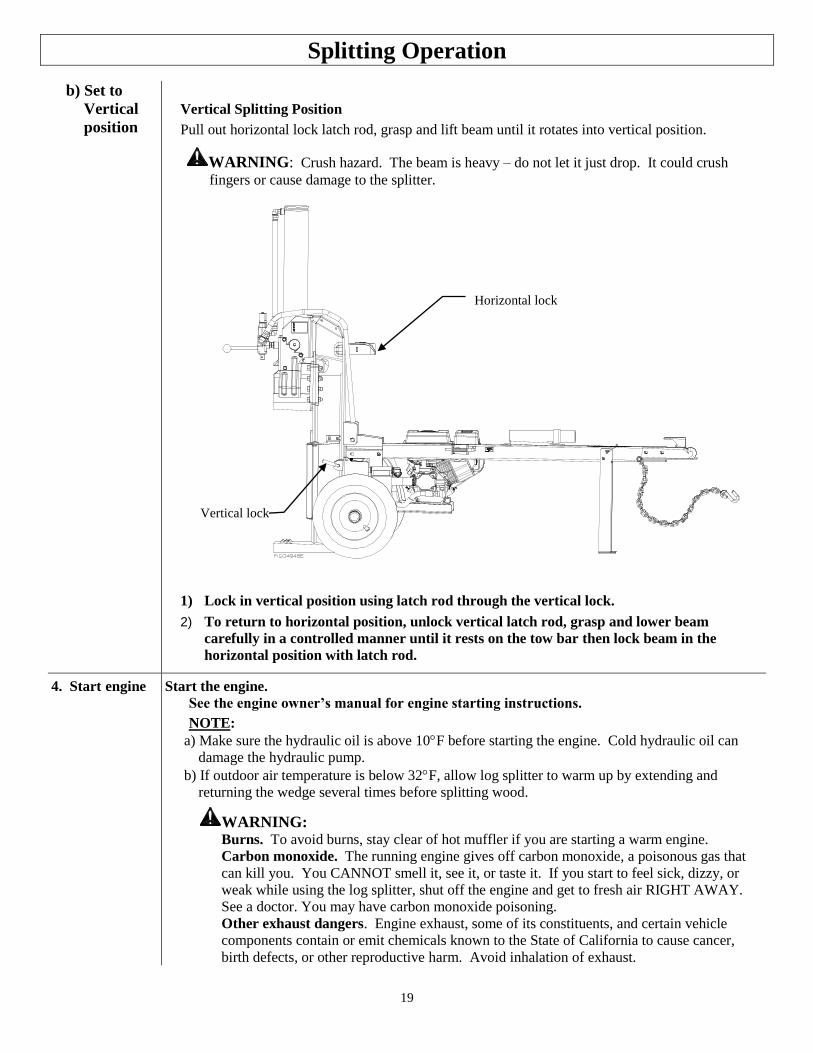
Vertical Splitting Position
Pull out horizontal lock latch rod, grasp and lift beam until it rotates into vertical position.
WARNING: Crush hazard. The beam is heavy – do not let it just drop. It could crush
fingers or cause damage to the splitter.
1) Lock in vertical position using latch rod through the vertical lock.
2) To return to horizontal position, unlock vertical latch rod, grasp and lower beam
carefully in a controlled manner until it rests on the tow bar then lock beam in the
horizontal position with latch rod.
4. Start engine Start the engine.
See the engine owner’s manual for engine starting instructions.
NOTE:
a) Make sure the hydraulic oil is above 10F before starting the engine. Cold hydraulic oil can
damage the hydraulic pump.
b) If outdoor air temperature is below 32F, allow log splitter to warm up by extending and
returning the wedge several times before splitting wood.
WARNING: Burns. To avoid burns, stay clear of hot muffler if you are starting a warm engine.
Carbon monoxide. The running engine gives off carbon monoxide, a poisonous gas that
can kill you. You CANNOT smell it, see it, or taste it. If you start to feel sick, dizzy, or
weak while using the log splitter, shut off the engine and get to fresh air RIGHT AWAY.
See a doctor. You may have carbon monoxide poisoning.
Other exhaust dangers. Engine exhaust, some of its constituents, and certain vehicle
components contain or emit chemicals known to the State of California to cause cancer,
birth defects, or other reproductive harm. Avoid inhalation of exhaust.
Horizontal lock
Vertical lock
20
FIG02218
Splitting Operation
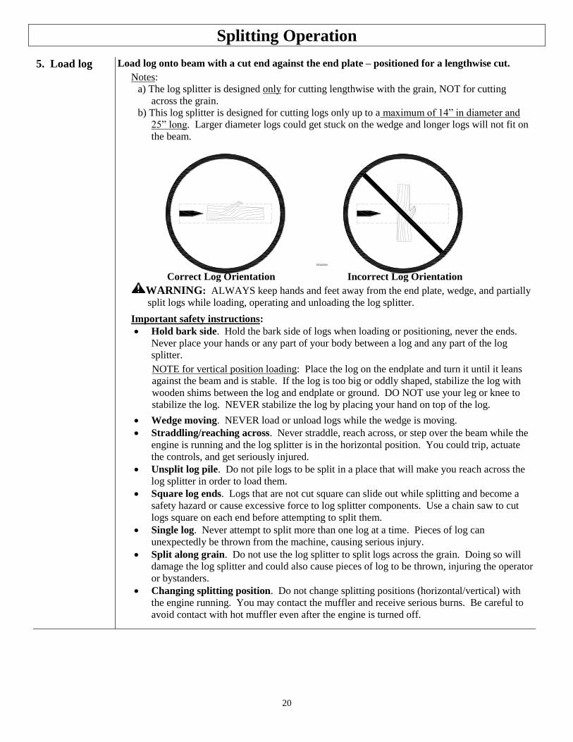
5. Load log Load log onto beam with a cut end against the end plate – positioned for a lengthwise cut.
Notes:
a) The log splitter is designed only for cutting lengthwise with the grain, NOT for cutting
across the grain.
b) This log splitter is designed for cutting logs only up to a maximum of 14” in diameter and
25” long. Larger diameter logs could get stuck on the wedge and longer logs will not fit on
the beam.
Correct Log Orientation Incorrect Log Orientation
WARNING: ALWAYS keep hands and feet away from the end plate, wedge, and partially
split logs while loading, operating and unloading the log splitter.
Important safety instructions:
Hold bark side. Hold the bark side of logs when loading or positioning, never the ends.
Never place your hands or any part of your body between a log and any part of the log
splitter.
NOTE for vertical position loading: Place the log on the endplate and turn it until it leans
against the beam and is stable. If the log is too big or oddly shaped, stabilize the log with
wooden shims between the log and endplate or ground. DO NOT use your leg or knee to
stabilize the log. NEVER stabilize the log by placing your hand on top of the log.
Wedge moving. NEVER load or unload logs while the wedge is moving.
Straddling/reaching across. Never straddle, reach across, or step over the beam while the
engine is running and the log splitter is in the horizontal position. You could trip, actuate
the controls, and get seriously injured.
Unsplit log pile. Do not pile logs to be split in a place that will make you reach across the
log splitter in order to load them.
Square log ends. Logs that are not cut square can slide out while splitting and become a
safety hazard or cause excessive force to log splitter components. Use a chain saw to cut
logs square on each end before attempting to split them.
Single log. Never attempt to split more than one log at a time. Pieces of log can
unexpectedly be thrown from the machine, causing serious injury.
Split along grain. Do not use the log splitter to split logs across the grain. Doing so will
damage the log splitter and could also cause pieces of log to be thrown, injuring the operator
or bystanders.
Changing splitting position. Do not change splitting positions (horizontal/vertical) with
the engine running. You may contact the muffler and receive serious burns. Be careful to
avoid contact with hot muffler even after the engine is turned off.
21
SPLIT CONTROL LEVER OPERATION
SPLIT CONTROL LEVER OPERATION
Splitting Operation
6. Extend
wedge
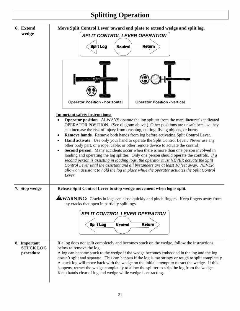
Move Split Control Lever toward end plate to extend wedge and split log.
Important safety instructions:
Operator position. ALWAYS operate the log splitter from the manufacturer’s indicated
OPERATOR POSITION. (See diagram above.) Other positions are unsafe because they
can increase the risk of injury from crushing, cutting, flying objects, or burns.
Remove hands. Remove both hands from log before activating Split Control Lever.
Hand activate. Use only your hand to operate the Split Control Lever. Never use any
other body part, or a rope, cable, or other remote device to actuate the control.
Second person. Many accidents occur when there is more than one person involved in
loading and operating the log splitter. Only one person should operate the controls. If a
second person is assisting in loading logs, the operator must NEVER actuate the Split
Control Lever until the assistant and all bystanders are at least 10 feet away. NEVER
allow an assistant to hold the log in place while the operator actuates the Split Control
Lever.
7. Stop wedge Release Split Control Lever to stop wedge movement when log is split.
WARNING: Cracks in logs can close quickly and pinch fingers. Keep fingers away from
any cracks that open in partially split logs.
8. Important
STUCK LOG
procedure
If a log does not split completely and becomes stuck on the wedge, follow the instructions
below to remove the log.
A log can become stuck to the wedge if the wedge becomes embedded in the log and the log
doesn’t split and separate. This can happen if the log is too stringy or tough to split completely.
A stuck log will move back with the wedge on the initial attempt to retract the wedge. If this
happens, retract the wedge completely to allow the splitter to strip the log from the wedge.
Keep hands clear of log and wedge while wedge is retracting.
22
SPLIT CONTROL LEVER OPERATION
Splitting Operation
WARNING: NEVER attempt to remove a stuck log by:
Modifying the splitter.
Adding attachments to the splitter.
Personal injury could result from log or metal pieces flying out at high speed toward the
operator or bystanders, or the splitter could become damaged.
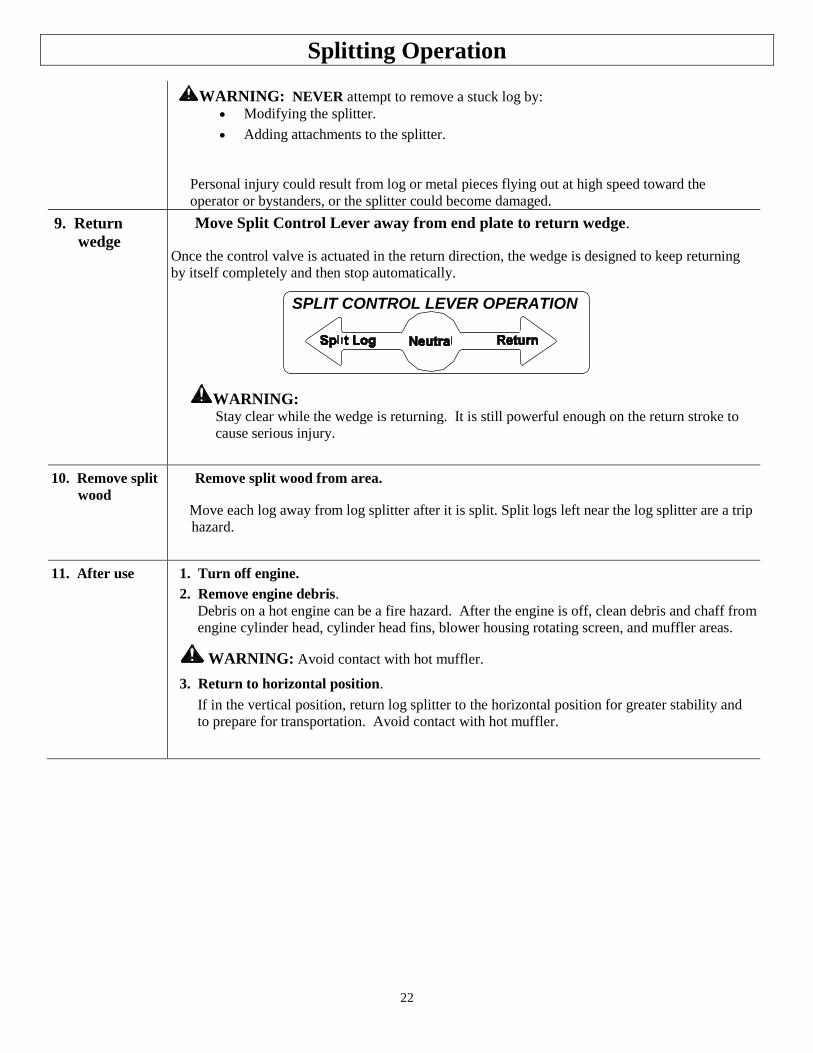
9. Return
wedge
Move Split Control Lever away from end plate to return wedge.
Once the control valve is actuated in the return direction, the wedge is designed to keep returning
by itself completely and then stop automatically.
WARNING: Stay clear while the wedge is returning. It is still powerful enough on the return stroke to
cause serious injury.
10. Remove split
wood
Remove split wood from area.
Move each log away from log splitter after it is split. Split logs left near the log splitter are a trip
hazard.
11. After use 1. Turn off engine.
2. Remove engine debris.
Debris on a hot engine can be a fire hazard. After the engine is off, clean debris and chaff from
engine cylinder head, cylinder head fins, blower housing rotating screen, and muffler areas.
WARNING: Avoid contact with hot muffler.
3. Return to horizontal position.
If in the vertical position, return log splitter to the horizontal position for greater stability and
to prepare for transportation. Avoid contact with hot muffler.
23
Storage
WARNING
Gasoline vapors can ignite and cause a fire. Select a well-ventilated storage away from
sources of heat, flame, or sparks.
Follow the instructions below for storing your log splitter between uses.
1. Retract wedge Retract the wedge completely to keep the rod protected from corrosion.
2. Cool Allow the machine to cool 5 minutes before storing.
WARNING: A hot engine can be a fire hazard.
3. Wipe with oily rag Wipe the beam and wedge with an oily rag to prevent corrosion.
4. Engine manual Refer to the engine manual for proper engine storage instructions.
CAUTION: Gasoline will oxidize and deteriorate in storage. Old gasoline in
the engine will cause hard starting and leave gum deposits that can clog the
fuel systems. Deterioration problems may occur within a few months, or even
less if gasoline was not fresh when you filled the tank.
Short-Term Storage:
1. Consider adding a fuel stabilizer to extend fuel storage life.
2. Leave the fuel valve lever in the OFF position to reduce the possibility of
fuel leakage.
Long-Term Storage: (between infrequent uses and at end of season)
Drain the fuel tank and carburetor as instructed in the engine owner’s manual.
Important Safety Instructions
Always drain fuel from tank in outdoor, well-ventilated area.
Stay away from sources of heat, flame, or sparks while handling fuel.
Clean up fuel spills/splashes immediately.
5. Splitter storage location Store the log splitter in a location away from corrosive material, sources
of heat, open flames, sparks or pilot lights.
WARNING: Never store log splitter inside where there is a source of
heat or an open flame, spark or pilot light – such as water heaters, space
heaters, furnaces, clothes dryers, or other gas appliances – EVEN IF the
log splitter’s gas tank is empty, residual gasoline vapors could ignite.
NOTE: Do not store the log splitter near fertilizer or any other corrosive
material.
6. Gasoline
storage Store gasoline in a cool, dry place in an UL listed tightly sealed container.
WARNING: Gasoline vapors can ignite if they collect inside an enclosure and
explosion can result.
24
Periodic Maintenance
In addition to the maintenance performed with each use, periodic maintenance should also be performed
according to the following schedule.
WARNING
ALWAYS shut off the engine, disconnect the spark plug, and relieve system pressure before
cleaning, adjusting, or repairing the splitter. Relieve system pressure by moving Split Control
Lever back and forth several times.
IMPORTANT:
If a part needs replacement only use parts that meet the manufacturer’s specifications. Replacement parts that
do not meet specifications may result in a safety hazard or poor operation of the log splitter.
1. Engine
maintenance
Perform engine maintenance as specified in engine owner’s manual.
2. Hydraulic Oil
Change
Change Hydraulic Oil Annually or Every 100 Hours.
WARNING: High fluid pressures and temperatures are developed in hydraulic log
splitters. Hydraulic fluid escaping through a pin hole sized opening can burn or
puncture skin, resulting in wounds that could cause blood poisoning, infection,
disability, gangrene, amputation, or death. Therefore, the following instructions should
be heeded at all times when inspecting or servicing the hydraulic components of the
log splitter.
NEVER check for leaks with your hand. Leaks can be located by holding a piece of
cardboard or wood (at least two feet long) with your hand at one end and passing the
other end over the suspected area (wear eye protection). Look for discoloration of the
cardboard or wood.
NEVER adjust the pressure of the pump or valve.
If injured by escaping fluid, no matter how small the wound is, see a doctor at once. A
typical injection injury may be a small wound that does not look serious. However,
severe infection or reaction can result if proper medical treatment is not administered
immediately by a doctor who is familiar with injection injuries.
1. Use 10wt AW32, ASLE H-150, or ISO32 oil.
2. Relieve hydraulic system pressure by moving Split Control Lever back and forth
several times.
3. Remove hydraulic oil fill/vent cap.
WARNING: NEVER remove the hydraulic oil fill/vent cap when the engine is
running or hot. Hot oil can escape causing severe burns. Allow the log splitter to cool
completely before removing hydraulic oil fill/vent cap.
4. Remove the suction strainer from the hydraulic tank to drain the hydraulic oil into a
10-gallon pan.
5. Clean suction strainer and wipe off debris with a dry cloth.
6. Fill the hydraulic tank with wedge retracted.
7. Dispose of used oil at an oil-recycling center. Used hydraulic oil is hazardous waste.
8. Extend and retract wedge five (5) times to purge air from the system.
9. Check hydraulic oil level and fill if necessary.
3. Spark arrestor
muffler
If the engine is equipped with a spark arrestor muffler, clean and inspect it regularly
(follow manufacturer’s service instructions). Replace if damaged.
25
Troubleshooting
WARNING
Before troubleshooting or attempting to service, read the following safety instructions to avoid serious injury
to the operator or bystanders from moving parts that can crush or cut, burns, fire or explosion, or escaping
high pressure hydraulic fluid.
Important Safety Instructions: 1. Engine off. Always make sure the engine is off before cleaning, repairing or adjusting the splitter, except as
recommended by the manufacturer. 2. Hydraulic safety. High fluid pressures and temperatures are developed in the hydraulic log splitters.
Hydraulic fluid escaping through a pin hole sized opening can burn or
puncture skin, resulting in wounds that could cause blood poisoning, infection, disability, gangrene,
amputation, or death. Therefore, the following instructions should be heeded at all times when inspecting or
servicing the hydraulic components of the log splitter: Stop the engine, disconnect the spark plug, and move all control valve handles back and forth to relieve
pressure before changing or adjusting hydraulic components such as hoses, tubing, fittings, or other
components.
Do not remove the hydraulic oil fill cap when the engine is running. Hot oil can escape causing severe
burns. Allow the log splitter to cool completely before removing the hydraulic oil fill cap.
Do not adjust the pressure setting to the pump or valve.
Do not check for leaks with your hands. Leaks can be located by holding a piece of cardboard or wood (at
least 2 feet long) with your hand at one end and passing the other end suspected area (wear eye
protection). Look for discoloration of the cardboard or wood.
If injured by escaping fluid, no matter how small the wound is, see a doctor at once. A typical injection
injury may be a small puncture that does not look serious. However, severe infection or reaction can
result if proper medical treatment is not administered immediately by a doctor who is familiar will
injection injuries.
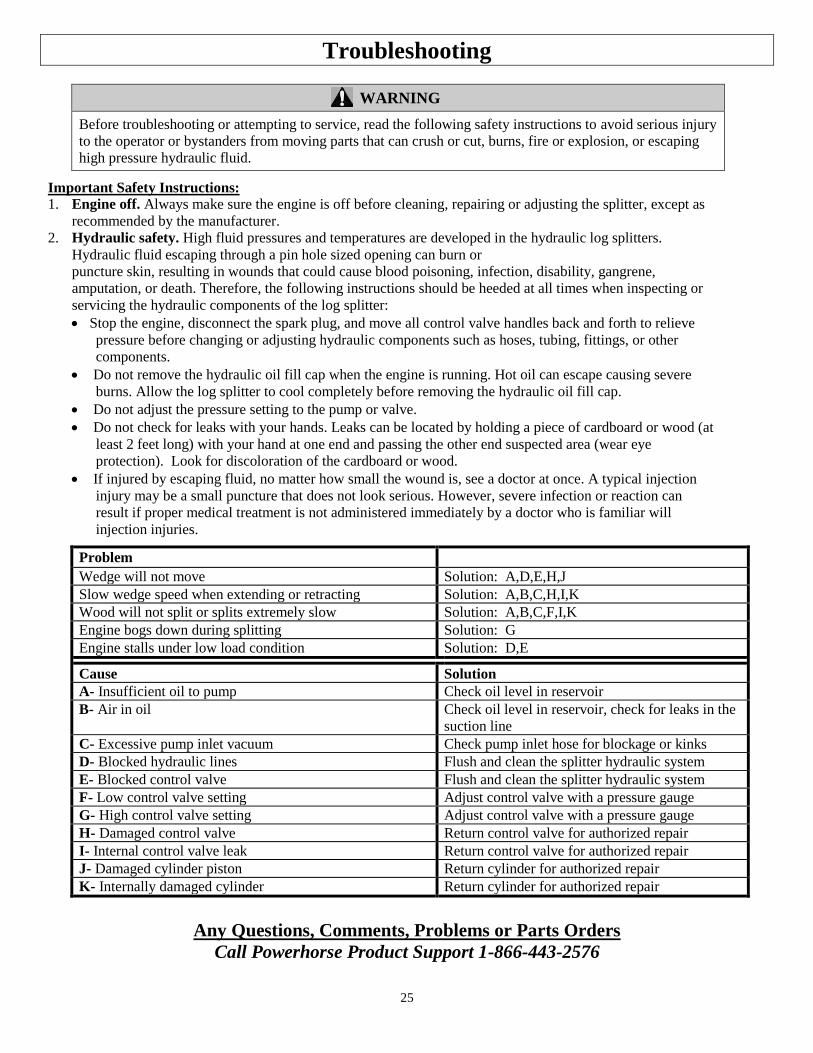
Problem Wedge will not move Solution: A,D,E,H,J
Slow wedge speed when extending or retracting Solution: A,B,C,H,I,K
Wood will not split or splits extremely slow Solution: A,B,C,F,I,K
Engine bogs down during splitting Solution: G
Engine stalls under low load condition Solution: D,E
Cause Solution
A- Insufficient oil to pump Check oil level in reservoir
B- Air in oil Check oil level in reservoir, check for leaks in the
suction line
C- Excessive pump inlet vacuum Check pump inlet hose for blockage or kinks
D- Blocked hydraulic lines Flush and clean the splitter hydraulic system
E- Blocked control valve Flush and clean the splitter hydraulic system
F- Low control valve setting Adjust control valve with a pressure gauge
G- High control valve setting Adjust control valve with a pressure gauge
H- Damaged control valve Return control valve for authorized repair
I- Internal control valve leak Return control valve for authorized repair
J- Damaged cylinder piston Return cylinder for authorized repair
K- Internally damaged cylinder Return cylinder for authorized repair
Any Questions, Comments, Problems or Parts Orders
Call Powerhorse Product Support 1-866-443-2576
26
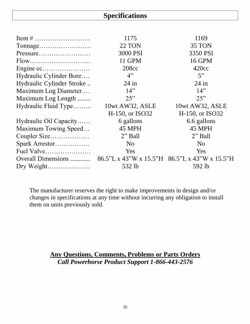
Specifications
Item # …………………….. 1175 1169
Tonnage…………………… 22 TON 35 TON
Pressure…………………… 3000 PSI 3350 PSI
Flow………………………. 11 GPM 16 GPM
Engine cc…………………. 208cc 420cc
Hydraulic Cylinder Bore…. 4” 5”
Hydraulic Cylinder Stroke .. 24 in 24 in
Maximum Log Diameter…. 14” 14”
Maximum Log Length ........ 25” 25”
Hydraulic Fluid Type……... 10wt AW32, ASLE
H-150, or ISO32
10wt AW32, ASLE
H-150, or ISO32
Hydraulic Oil Capacity…… 6 gallons 6.6 gallons
Maximum Towing Speed… 45 MPH 45 MPH
Coupler Size……………… 2” Ball 2” Ball
Spark Arrestor……………. No No
Fuel Valve………………… Yes Yes
Overall Dimensions ............ 86.5”L x 43”W x 15.5”H 86.5”L x 43”W x 15.5”H
Dry Weight……………….. 532 lb 592 lb
The manufacturer reserves the right to make improvements in design and/or
changes in specifications at any time without incurring any obligation to install
them on units previously sold.
Any Questions, Comments, Problems or Parts Orders
Call Powerhorse Product Support 1-866-443-2576
27
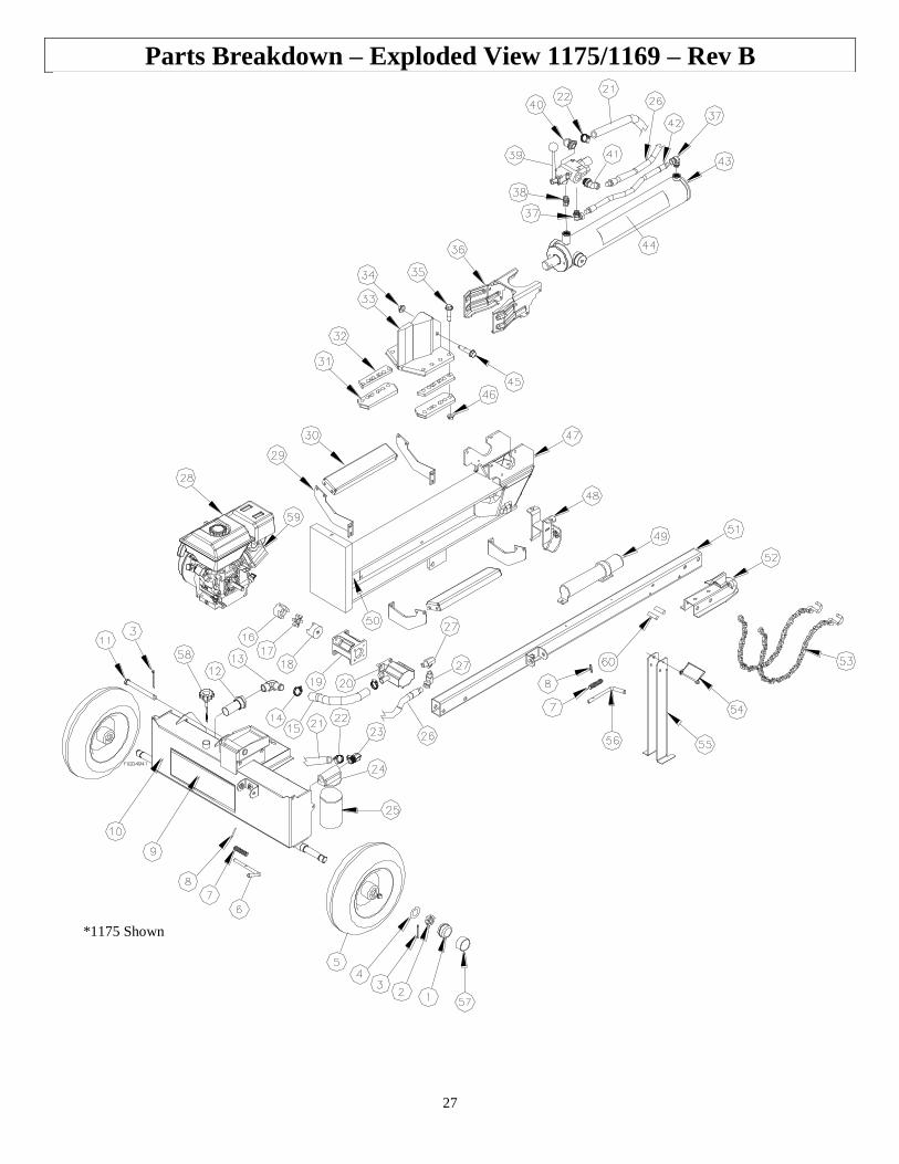
Parts Breakdown – Exploded View 1175/1169 – Rev B
*1175 Shown

28
Parts Breakdown – Exploded View 1175/1169 – Rev B
Item Part No. Description Qty. Model
1 124A Dust cap 2 All
2 777124 Axle nut 2 All
3 778674 1/8” x 2” Cotter pin 3 All
4 778844 Wheel washer 2 All
5 790350 Wheel 2 All
6 790897
Latch rod 1 1175
788243 1 1169
7 788245 Latch spring 2 All
8 788244 Latch rod pin 2 All
9 790805 Powerhorse tank decal 1 All
10 790181 Tank weldment 1 All
11 790472 Pivot pin 1 All
12 790470 Suction strainer 1 All
13 788504 Suction elbow fitting 1 All
14 777835 Hose clamp 2 All
15 790482 Suction hose 1” x 14” 1 1175
790483 Suction hose 1” x 18” 1 1169
16 777910
Engine coupler 1 1175
777911 1 1169
17 777912 Coupler insert 1 All
18 777909 Pump coupler 1 All
19 790747
Pump Mount 1 1175
779683 1 1169
20 790519 11 GPM Pump 1 1175
790520 16 GPM Pump 1 1169
21 790485 3/4” x 59” Return hose 1 All
22 17141 Hose clamp, 3/4” 2 All
23 778829 Return Line Fitting 1 All
24 791244 Return Line Filter Head 1 All
25 791246 Return Line Filter Canister 1 All
26 790489 Supply hose 1/2” x 56” 1 All
27 50RAS8 Pump Fitting 2 1175
1 1169
28 789712 Powerhorse Engine 208cc 1 1175
790160 Powerhorse Engine 420cc 1 1169
29 790533 Log cradle mount 4 All
30 790540 Log cradle face plate 2 All
31 790359 Keeper 2 All
32 790357
Spacer 2 1169
790861 2 1175
33 790514
Wedge 1 1175
790515 1 1169
34 82570 Wedge Nut 1 All
35 82525 Keeper Bolt 8 1175
12 1169

29
Parts Breakdown – Exploded View 1175/1169 – Rev B
Item Part No. Description Qty. Model
36 790560
Log stripper weldment 1 1175
790405 1 1169
37 778827 Small swivel fitting 2 All
38 790488 Valve fitting 1 All
39 791867 Control valve 1 1175
791869 Control valve 1 1169
40 778642 Hose barb fitting 1 All
41 778831 Large swivel fitting 1 All
42 778619 Cylinder extension hose 1 All
43 790420 Cylinder 4” x 24” 1 1175
790228 Cylinder 5” x 24” 1 1169
44 790812 22 Ton Decal 2 1175
790813 35 Ton Decal 2 1169
45 82554
Wedge bolt 1 1175
82573 1 1169
46 82570 Keeper Nut 8 1175
12 1169
47 790510
Beam weldment 1 1175
790511 1 1169
48 790522 Horizontal beam lock 1 All
49 790471 Manual tube, mini 1 All
50 791066 Powerhorse beam decal 2 All
51 790204 Tow bar weldment 1 All
52 778423 Coupler 1 All
53 1130 Safety chains 2 All
54 778916 Pin catch, 5/16” x 3 1/2” 1 All
55 790344 Support leg 1 All
56 788243 Latch rod 1 All
57 780599 Dust cap tool 1 All
58 784470 Breather/Dipstick 1 All
59 N/A Serial Number Decal 1 All
60 791545 Spacer 2 All
30
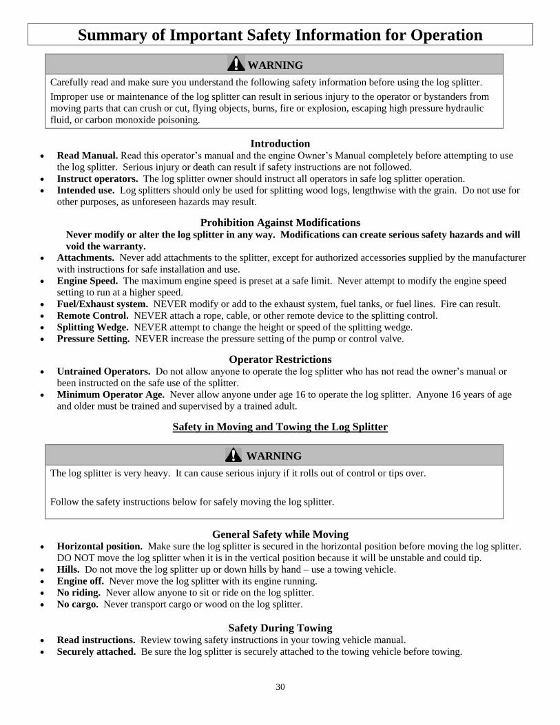
Summary of Important Safety Information for Operation
WARNING
Carefully read and make sure you understand the following safety information before using the log splitter.
Improper use or maintenance of the log splitter can result in serious injury to the operator or bystanders from
moving parts that can crush or cut, flying objects, burns, fire or explosion, escaping high pressure hydraulic
fluid, or carbon monoxide poisoning.
Introduction Read Manual. Read this operator’s manual and the engine Owner’s Manual completely before attempting to use
the log splitter. Serious injury or death can result if safety instructions are not followed.
Instruct operators. The log splitter owner should instruct all operators in safe log splitter operation.
Intended use. Log splitters should only be used for splitting wood logs, lengthwise with the grain. Do not use for
other purposes, as unforeseen hazards may result.
Prohibition Against Modifications Never modify or alter the log splitter in any way. Modifications can create serious safety hazards and will
void the warranty.
Attachments. Never add attachments to the splitter, except for authorized accessories supplied by the manufacturer
with instructions for safe installation and use.
Engine Speed. The maximum engine speed is preset at a safe limit. Never attempt to modify the engine speed
setting to run at a higher speed.
Fuel/Exhaust system. NEVER modify or add to the exhaust system, fuel tanks, or fuel lines. Fire can result.
Remote Control. NEVER attach a rope, cable, or other remote device to the splitting control.
Splitting Wedge. NEVER attempt to change the height or speed of the splitting wedge.
Pressure Setting. NEVER increase the pressure setting of the pump or control valve.
Operator Restrictions Untrained Operators. Do not allow anyone to operate the log splitter who has not read the owner’s manual or
been instructed on the safe use of the splitter.
Minimum Operator Age. Never allow anyone under age 16 to operate the log splitter. Anyone 16 years of age
and older must be trained and supervised by a trained adult.
Safety in Moving and Towing the Log Splitter
WARNING
The log splitter is very heavy. It can cause serious injury if it rolls out of control or tips over.
Follow the safety instructions below for safely moving the log splitter.
General Safety while Moving Horizontal position. Make sure the log splitter is secured in the horizontal position before moving the log splitter.
DO NOT move the log splitter when it is in the vertical position because it will be unstable and could tip.
Hills. Do not move the log splitter up or down hills by hand – use a towing vehicle.
Engine off. Never move the log splitter with its engine running.
No riding. Never allow anyone to sit or ride on the log splitter.
No cargo. Never transport cargo or wood on the log splitter.
Safety During Towing Read instructions. Review towing safety instructions in your towing vehicle manual.
Securely attached. Be sure the log splitter is securely attached to the towing vehicle before towing.
31
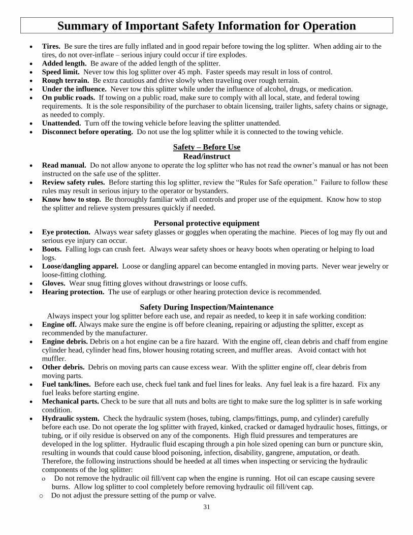
Summary of Important Safety Information for Operation
Tires. Be sure the tires are fully inflated and in good repair before towing the log splitter. When adding air to the
tires, do not over-inflate – serious injury could occur if tire explodes.
Added length. Be aware of the added length of the splitter.
Speed limit. Never tow this log splitter over 45 mph. Faster speeds may result in loss of control.
Rough terrain. Be extra cautious and drive slowly when traveling over rough terrain.
Under the influence. Never tow this splitter while under the influence of alcohol, drugs, or medication.
On public roads. If towing on a public road, make sure to comply with all local, state, and federal towing
requirements. It is the sole responsibility of the purchaser to obtain licensing, trailer lights, safety chains or signage,
as needed to comply.
Unattended. Turn off the towing vehicle before leaving the splitter unattended.
Disconnect before operating. Do not use the log splitter while it is connected to the towing vehicle.
Safety – Before Use
Read/instruct Read manual. Do not allow anyone to operate the log splitter who has not read the owner’s manual or has not been
instructed on the safe use of the splitter.
Review safety rules. Before starting this log splitter, review the “Rules for Safe operation.” Failure to follow these
rules may result in serious injury to the operator or bystanders.
Know how to stop. Be thoroughly familiar with all controls and proper use of the equipment. Know how to stop
the splitter and relieve system pressures quickly if needed.
Personal protective equipment Eye protection. Always wear safety glasses or goggles when operating the machine. Pieces of log may fly out and
serious eye injury can occur.
Boots. Falling logs can crush feet. Always wear safety shoes or heavy boots when operating or helping to load
logs.
Loose/dangling apparel. Loose or dangling apparel can become entangled in moving parts. Never wear jewelry or
loose-fitting clothing.
Gloves. Wear snug fitting gloves without drawstrings or loose cuffs.
Hearing protection. The use of earplugs or other hearing protection device is recommended.
Safety During Inspection/Maintenance Always inspect your log splitter before each use, and repair as needed, to keep it in safe working condition:
Engine off. Always make sure the engine is off before cleaning, repairing or adjusting the splitter, except as
recommended by the manufacturer.
Engine debris. Debris on a hot engine can be a fire hazard. With the engine off, clean debris and chaff from engine
cylinder head, cylinder head fins, blower housing rotating screen, and muffler areas. Avoid contact with hot
muffler.
Other debris. Debris on moving parts can cause excess wear. With the splitter engine off, clear debris from
moving parts.
Fuel tank/lines. Before each use, check fuel tank and fuel lines for leaks. Any fuel leak is a fire hazard. Fix any
fuel leaks before starting engine.
Mechanical parts. Check to be sure that all nuts and bolts are tight to make sure the log splitter is in safe working
condition.
Hydraulic system. Check the hydraulic system (hoses, tubing, clamps/fittings, pump, and cylinder) carefully
before each use. Do not operate the log splitter with frayed, kinked, cracked or damaged hydraulic hoses, fittings, or
tubing, or if oily residue is observed on any of the components. High fluid pressures and temperatures are
developed in the log splitter. Hydraulic fluid escaping through a pin hole sized opening can burn or puncture skin,
resulting in wounds that could cause blood poisoning, infection, disability, gangrene, amputation, or death.
Therefore, the following instructions should be heeded at all times when inspecting or servicing the hydraulic
components of the log splitter:
Do not remove the hydraulic oil fill/vent cap when the engine is running. Hot oil can escape causing severe
burns. Allow log splitter to cool completely before removing hydraulic oil fill/vent cap.
o Do not adjust the pressure setting of the pump or valve.
32
Summary of Important Safety Information for Operation
o Do not check for leaks with your hand. Leaks can be located by holding a piece of cardboard or wood (at least
two feet long) with your hand at one end and passing the other end over the suspected area (wear eye protection).
Look for discoloration of the cardboard or wood.
o Stop the engine, disconnect the spark plug, and move all control valve handles back and forth to relieve pressure
before changing or adjusting hydraulic system components such as hoses, tubing, fittings or other components.
o If injured by escaping fluid, no matter how small the wound is, see a doctor at once. A typical injection injury
may be a small puncture wound that does not look serious. However, severe infection or reaction can result if
proper medical treatment is not administered immediately by a doctor who is familiar with injection injuries
Spark arrestor muffler. If the engine is equipped with a spark arrestor muffler, clean and inspect it regularly
(follow manufacturer’s service instructions). Replace if damaged.
Tires. Be sure tires are fully inflated and in good repair before towing the splitter. When adding air to tires, do not
over-inflate -- serious injury could occur if tire explodes.
Guards/shields. Make sure all guards and shields are replaced after servicing the log splitter.
Replacement parts. If a part needs replacement, only use parts that meet the manufacturer’s specifications.
Replacement parts that do not meet specifications may result in a safety hazard or poor operation of the log splitter.
Safety During Fueling Gasoline is highly flammable and explosive. You can be burned or seriously injured when handling fuel. Use
extreme care when handling gasoline:
Fuel outdoors. Fill fuel tank outdoors – never indoors. Gasoline vapors can ignite if they collect inside an
enclosure. Explosion can result.
Use approved container. Never pump fuel directly into engine at gas station. Static charge can build and ignite
fuel. Use an UL listed fuel container to transfer gas to the engine.
Running/hot engine. A running engine is hot enough to ignite fuel. Never add fuel or remove gas cap if engine is
running or still hot. Stop the engine and allow to cool at least two minutes before adding fuel.
Heat/flames/sparks. Stay away from sources of heat, flame, or sparks while adding fuel.
Don’t overfill. DO NOT overfill the gas tank. Allow at least 1/2” of empty space below the fill neck to allow for
fuel expansion.
Replace cap. Replace gas cap securely before starting engine.
Spills. Clean up fuel spills immediately. Move log splitter away from spilled fuel on the ground. Wipe fuel off
engine and wait 5 minutes for excess fuel to evaporate before starting engine. Gas soaked rags should be disposed
of properly.
On skin/clothes. If gasoline is spilled on your skin or clothes, change clothes and wash skin immediately.
Gasoline storage. Store gasoline in a cool, dry place in an UL listed, tightly sealed container.
Safety in Work Site Selection Spark arrestor. If your splitter will be used near any unimproved forest, brush, or grassy covered land, then engine
should be equipped with a spark arrestor. See the “Specifications” section of this manual to determine if your
splitter already has a spark arrestor. Make sure you comply with applicable local, state and federal codes.
Hot exhaust. Hot exhaust fumes from engine can cause fire. Position muffler at least 7’ from combustible objects
during operation.
Fire extinguisher. Have a Class B fire extinguisher available as a precautionary measure when operating the log
splitter in dry areas.
Level, dry surface. To prevent accidental falls and equipment tip over, make sure the splitter is situated on a dry,
level surface with good footing. Stay clear of areas with mud, ice, tall grass, weeds, brush, or snow.
Block wheels. Always block the wheels to prevent unintended movement of the log splitter.
Carbon monoxide. The running engine gives off carbon monoxide, a poisonous gas that can kill you. You
CANNOT smell it, see it, or taste it. ONLY run log splitter OUTDOORS and away from air intakes. NEVER run
log splitter inside homes, garages, sheds, or other semi-enclosed spaces. These spaces can trap poisonous gases,
EVEN if you run a fan or open windows. If you start to feel sick, dizzy, or weak while using the log splitter, shut
off the engine and get to fresh air RIGHT AWAY. See a doctor. You may have carbon monoxide poisoning.
33
Summary of Important Safety Information for Operation
Safety – During Use
General Safety During Use
WARNING: Before starting this log splitter, review the following rules for safe operation. Failure to
follow these rules may result in serious injury to the operator or bystanders.
Safety equipment / controls. Always operate the log splitter with all safety equipment in place and in good
working order, and all controls properly adjusted for safe operation.
Operating speed. Always operate the log splitter at the manufacturer’s recommended speed. The maximum speed
of the engine, pump and wedge are preset within safe limits.
Know how to stop. Be thoroughly familiar with all controls and with the proper use of the equipment. Know how
to stop the log splitter and relieve system pressures quickly if needed.
Daylight only. Only use the log splitter in daylight so you can see what you are doing.
Smoking/sparks. Never smoke while operating the log splitter, and never operate near sources of sparks or flames.
Hot muffler. If you are starting a warm engine, stay clear of muffler. It may still be hot enough to burn you.
Unattended. Never leave the machine unattended while the engine is running.
Under the influence. Never operate, or let anyone else operate, the log splitter while under the influence of
alcohol, drugs, or medication.
Adjusting/repairing. Always make sure the engine is off before cleaning, repairing or adjusting the splitter, except
as recommended by the manufacturer. In addition, disconnect the spark plug and move all control handles back
and forth to relieve system pressure before changing or adjusting hydraulic system components such as hoses,
tubing, fittings or other components.
Carbon monoxide. The running engine gives off carbon monoxide, a poisonous gas that can kill you. You
CANNOT smell it, see it, or taste it. If you start to feel sick, dizzy, or weak while using the log splitter, shut off the
engine and get to fresh air RIGHT AWAY. See a doctor. You may have carbon monoxide poisoning.
Other exhaust dangers. Engine exhaust, some of its constituents, and certain vehicle components contain or emit
chemicals known to the State of California to cause cancer, birth defects, or other reproductive harm. Avoid
inhalation of exhaust.
Safety in Loading, Operating, and Unloading
Square log ends. Logs that are not cut square can slide out while splitting and become a safety hazard or cause
excessive force to log splitter components. Use a chainsaw to cut logs square on each end before attempting to split
them.
Single log. Never attempt to split more than one log at a time. Pieces of log can unexpectedly be thrown from the
machine causing serious injury.
Split along grain. Do not use the log splitter to split logs across the grain. Doing so will damage the log splitter
and could also cause pieces of log to be thrown, injuring the operator or bystanders.
Keep hands clear. ALWAYS keep hands and feet away from the endplate, wedge, and partially split logs while
loading, operating and unloading the log splitter.
Operator position. ALWAYS operate the log splitter from the manufacturer’s indicated OPERATOR POSITION.
Other positions are unsafe because they can increase the risk of injury from crushing, cutting, flying objects, or
burns.
Straddling/reaching across. Never straddle, reach across, or step over the beam while the engine is running and
the log splitter is in the horizontal position. You could trip, actuate the controls, and get seriously injured.
Second person. Many accidents occur when there is more than one person involved in loading and operating the
log splitter. Only one person should operate the controls. If a second person is assisting in loading logs, the
operator must NEVER actuate the Split Control Lever until the assistant and all bystanders are at least 10 feet
away. NEVER allow an assistant to hold the log in place while the operator actuates the Split Control Lever.
Loading/Unloading Unsplit log pile. Do not pile logs to be split in a place that will make you reach across the log splitter in order to
load them.
Hold bark side. Hold the bark side of logs when loading or positioning, never the ends. Never place your hands or
any part of your body between a log and any part of the log splitter.
34
Summary of Important Safety Information for Operation
NOTE for vertical position loading: Place the log on the endplate and turn it until it leans against the beam and is
stable. If the log is too big or oddly shaped, stabilize the log with wooden shims between the log and endplate or
ground. DO NOT use your leg or knee to stabilize the log. NEVER stabilize the log by placing your hand on top of
the log.
Wedge moving. NEVER load or unload logs while the wedge is moving.
Cracks. Cracks in logs can close quickly and pinch fingers. Keep fingers away from any cracks that open in
partially split logs.
Split log pile. Move each log away from log splitter after it is split. Split logs left near the log splitter are a trip
hazard.
Remove hands. Remove both hands from log before activating Split Control Lever.
Hand activate. Use only your hand to operate the Split Control Lever. Never use any other body part, or a rope,
cable, or other remote device to actuate the control.
Returning wedge. Once the control valve is actuated in the return direction, the wedge is designed to keep
returning by itself completely and then stop automatically. Stay clear while the wedge is returning. It is still
powerful enough on the return stroke to cause serious injury.
Log stuck on wedge. If a log does not split completely and becomes stuck on the wedge, follow the instructions
below to remove the log. A log can become stuck to the wedge if the wedge becomes embedded in the log and the
log doesn’t split and separate. This can happen if the log is too stringy or tough to split completely. A stuck log
will move back with the wedge on the initial attempt to retract the wedge. If this happens, retract the wedge
completely to allow the splitter to strip the log from the wedge. Keep hands clear of log and wedge while wedge is
retracting.
WARNING: NEVER attempt to remove a stuck log by:
Modifying the splitter.
Adding attachments to the splitter.
Personal injury could result from log or metal pieces flying out at high speed toward the operator or bystanders, or the
splitter could become damaged.
Changing splitting position. Do not change splitting positions (horizontal/vertical) with the engine running. You
may contact the muffler and receive serious burns. Be careful to avoid contact with hot muffler even after the engine
is turned off.
Refueling. Never refuel the engine until it has cooled at least two minutes.
Safety – After use Return to horizontal. If in the vertical position, turn off engine and return log splitter to the horizontal position for
greater stability and to prepare for transportation. Avoid contact with hot muffler.
Remove engine debris. Debris on a hot engine can be a fire hazard. With the engine off, clean debris and chaff from
engine cylinder head, cylinder head fins, blower housing rotating screen, and muffler areas. Avoid contact with hot
muffler.
Let engine cool before storing. Let engine cool for at least five minutes before storing. A hot engine can be a fire
hazard.
Storage location. Store the log splitter in a location away from sources of heat, open flames, sparks or pilot lights –
such as water heaters, space heaters, furnaces, clothes dryers, or other gas appliances. Even if the log splitter’s gas
tank is empty, residual gasoline vapors could ignite.
Gasoline storage. Store extra gasoline in a cool, dry place in an UL listed, tightly sealed container. Gasoline vapors
can ignite if they collect inside an enclosure.
Periodic maintenance. Perform periodic maintenance as directed in this manual to keep the log splitter in safe
working condition.
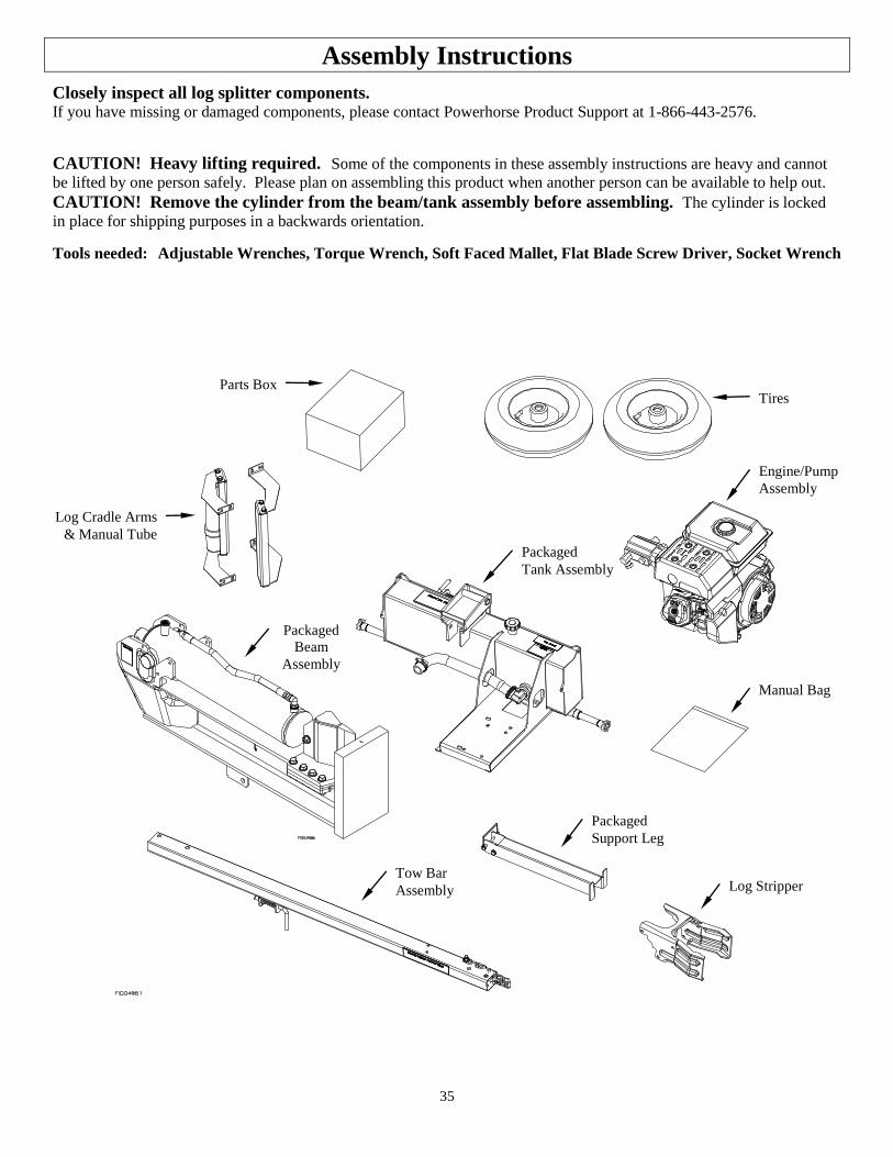
35
Assembly Instructions
Closely inspect all log splitter components. If you have missing or damaged components, please contact Powerhorse Product Support at 1-866-443-2576.
CAUTION! Heavy lifting required. Some of the components in these assembly instructions are heavy and cannot
be lifted by one person safely. Please plan on assembling this product when another person can be available to help out. CAUTION! Remove the cylinder from the beam/tank assembly before assembling. The cylinder is locked
in place for shipping purposes in a backwards orientation. Tools needed: Adjustable Wrenches, Torque Wrench, Soft Faced Mallet, Flat Blade Screw Driver, Socket Wrench
Packaged
Tank Assembly
Engine/Pump
Assembly
Packaged
Support Leg
Tires
Manual Bag
Tow Bar
Assembly
Parts Box
Packaged
Beam
Assembly
Log Cradle Arms
& Manual Tube
Log Stripper
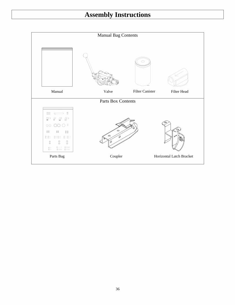
36
Assembly Instructions
Manual Bag Contents
Parts Box Contents
Manual Valve Filter Canister Filter Head
Coupler Horizontal Latch Bracket Parts Bag

37
Assembly Instructions
Fastener Bag Contents:
Part # 791168
Hoses to Beam
Small Zip Tie
Qty: 4
Part # 791167
Hoses
Large Zip Tie
Qty: 1
Part # 791545
Tow Bar Spacer
Qty: 2
Part # 778674
Cotter Pin
Qty: 3
Part # 778829
Return Line Fitting
Qty: 1
Part # 778844
Wheel Washer
Qty: 2
Part # 124A
Dust Cap
Qty: 2
Part # 82545
Log Cradle to Beam
M8-1.25 x 30mm HHSF Bolt
Qty: 4
Part # 82551
Horz. Latch to Beam
M12-1.75 x 35mm HHSF Bolt
Qty: 2
Part # 790472
Beam Pivot Pin
Qty: 1
Part # 790488
Valve Fitting
Qty: 1
Part # 778827
Small Swivel Fitting
Qty: 1
Part # 778831
Large Swivel Fitting
Qty: 1
Part # 778642
Hose Barb Fitting
Qty: 1
Part # 82271
Engine to Tank (1169)
M10-1.5 HHSF Nut
Qty: 4
Part # 82273
Horz. Latch to Beam
M12-1.75 HHSF Nut
Qty: 2
Part # 82570
M14-2 Nyloc Nut
Tow Bar to Tank
Qty: 2
Part # 780599
Dust Cap Tool
Qty: 1
Part # 82529
Manual Tube to Tow Bar
M6 x 20mm Self Tapping Screw
Qty: 2
Part # 82280
Engine to Tank (1175)
M8-1.25 x 40mm HHSF Bolt
Qty: 4
Part # 82536
Engine to Tank (1169)
M10-1.5 x 45mm HHSF Bolt
Qty: 4
Part # 82267
Coupler to Tow Bar
M12-1.75 x 75mm HHSF
Bolt
Qty: 3
Part # 82272
Coupler to Tow Bar
M12-1.75 Nyloc Nut
Qty: 2
Part # 82528
Tow Bar to Tank
M14-2 x 85mm HHSF Bolt
Qty: 2
Part # 82281
Log Cradles to Beam
M8-1.25 HHSF Nut
Qty: 4
Part # 82281
Engine to Tank (1175)
M8-1.25 HHSF Nut
Qty: 4

38
Fastener Bag Contents Cont.:
Part # 82545
Log Stripper to Beam (1169)
M8-1.25 x 30mm HHSF Bolt
Qty: 6
Part # 82561
Log Stripper to Beam (1175)
M8-1.25 x 25mm HHSF Bolt
Qty: 6
Part # 82281
Log Stripper to Beam
M8-1.25 HHSF Nut
Qty: 6
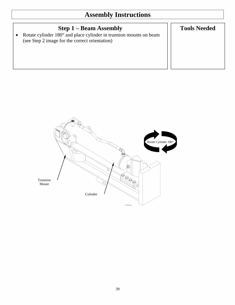
39
Assembly Instructions
Step 1 – Beam Assembly Rotate cylinder 180° and place cylinder in trunnion mounts on beam
(see Step 2 image for the correct orientation)
Tools Needed
Rotate Cylinder 180°
Trunnion
Mount
Cylinder
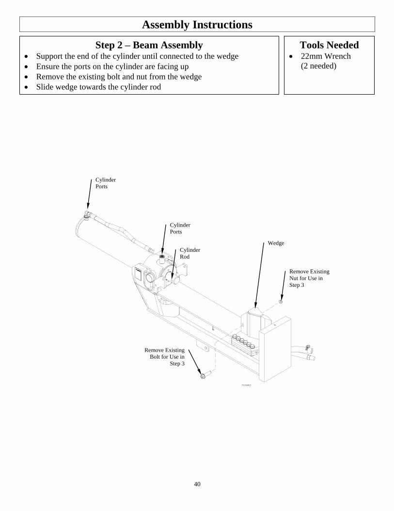
40
Assembly Instructions
Step 2 – Beam Assembly Support the end of the cylinder until connected to the wedge
Ensure the ports on the cylinder are facing up
Remove the existing bolt and nut from the wedge
Slide wedge towards the cylinder rod
Tools Needed 22mm Wrench
(2 needed)
Remove Existing
Bolt for Use in
Step 3
Remove Existing
Nut for Use in
Step 3
Cylinder
Ports
Cylinder
Ports
Wedge
Cylinder
Rod
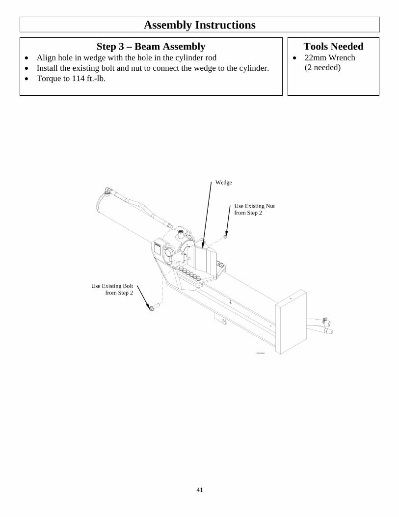
41
Assembly Instructions
Step 3 – Beam Assembly Align hole in wedge with the hole in the cylinder rod
Install the existing bolt and nut to connect the wedge to the cylinder.
Torque to 114 ft.-lb.
Tools Needed 22mm Wrench
(2 needed)
Use Existing Nut
from Step 2
Use Existing Bolt
from Step 2
Wedge
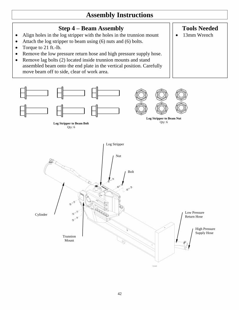
42
Assembly Instructions
Step 4 – Beam Assembly Align holes in the log stripper with the holes in the trunnion mount
Attach the log stripper to beam using (6) nuts and (6) bolts.
Torque to 21 ft.-lb.
Remove the low pressure return hose and high pressure supply hose.
Remove lag bolts (2) located inside trunnion mounts and stand
assembled beam onto the end plate in the vertical position. Carefully
move beam off to side, clear of work area.
Tools Needed 13mm Wrench
Log Stripper
Nut
Bolt
Cylinder Low Pressure
Return Hose
High Pressure
Supply Hose Trunnion
Mount
Log Stripper to Beam Bolt
Qty: 6
Log Stripper to Beam Nut
Qty: 6
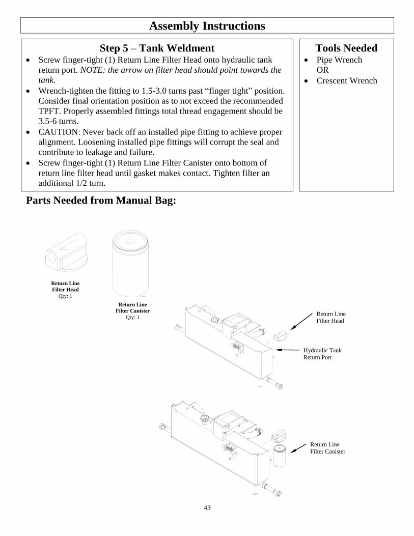
43
Assembly Instructions
Step 5 – Tank Weldment Screw finger-tight (1) Return Line Filter Head onto hydraulic tank
return port. NOTE: the arrow on filter head should point towards the
tank.
Wrench-tighten the fitting to 1.5-3.0 turns past “finger tight” position.
Consider final orientation position as to not exceed the recommended
TPFT. Properly assembled fittings total thread engagement should be
3.5-6 turns.
CAUTION: Never back off an installed pipe fitting to achieve proper
alignment. Loosening installed pipe fittings will corrupt the seal and
contribute to leakage and failure.
Screw finger-tight (1) Return Line Filter Canister onto bottom of
return line filter head until gasket makes contact. Tighten filter an
additional 1/2 turn.
Tools Needed Pipe Wrench
OR
Crescent Wrench
Return Line
Filter Canister
Qty: 1 Return Line
Filter Head
Return Line
Filter Canister
Hydraulic Tank
Return Port
Parts Needed from Manual Bag:
Return Line
Filter Head
Qty: 1
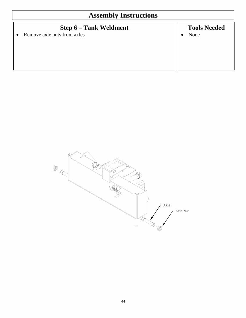
44
Assembly Instructions
Step 6 – Tank Weldment Remove axle nuts from axles
Tools Needed None
Axle Nut
Axle
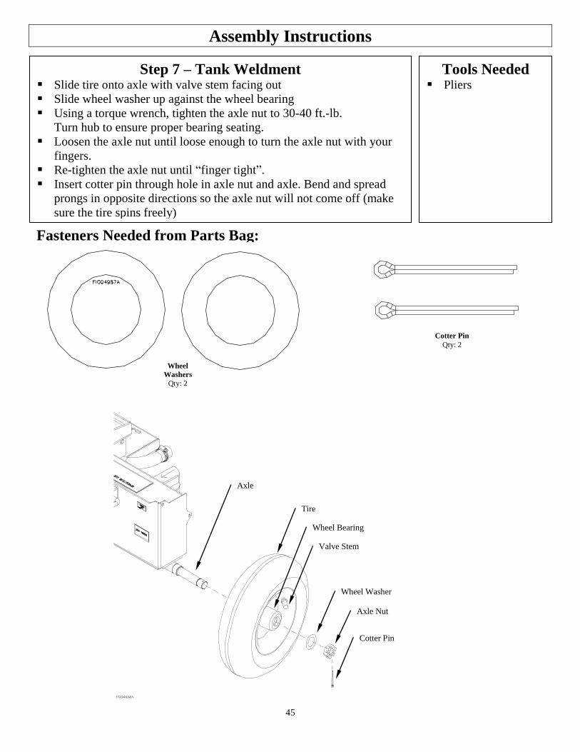
45
Assembly Instructions
Step 7 – Tank Weldment Slide tire onto axle with valve stem facing out
Slide wheel washer up against the wheel bearing
Using a torque wrench, tighten the axle nut to 30-40 ft.-lb.
Turn hub to ensure proper bearing seating.
Loosen the axle nut until loose enough to turn the axle nut with your
fingers.
Re-tighten the axle nut until “finger tight”.
Insert cotter pin through hole in axle nut and axle. Bend and spread
prongs in opposite directions so the axle nut will not come off (make
sure the tire spins freely)
Tools Needed Pliers
Fasteners Needed from Parts Bag:
Wheel
Washers
Qty: 2
Cotter Pin
Qty: 2
Wheel Washer
Cotter Pin
Axle Nut
Wheel Bearing
Valve Stem
Axle
Tire
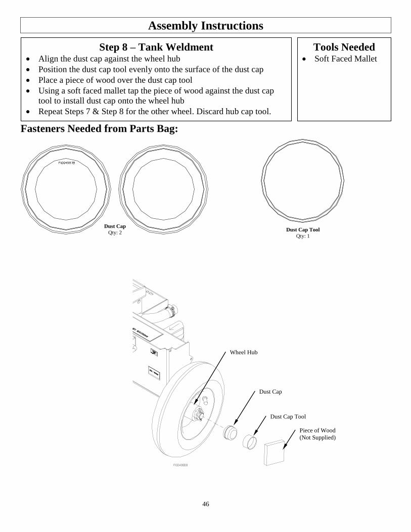
46
Assembly Instructions
Step 8 – Tank Weldment Align the dust cap against the wheel hub
Position the dust cap tool evenly onto the surface of the dust cap
Place a piece of wood over the dust cap tool
Using a soft faced mallet tap the piece of wood against the dust cap
tool to install dust cap onto the wheel hub
Repeat Steps 7 & Step 8 for the other wheel. Discard hub cap tool.
Tools Needed Soft Faced Mallet
Fasteners Needed from Parts Bag:
Dust Cap
Qty: 2 Dust Cap Tool
Qty: 1
Dust Cap
Dust Cap Tool
Wheel Hub
Piece of Wood
(Not Supplied)
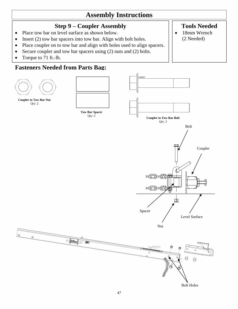
47
Assembly Instructions
Step 9 – Coupler Assembly Place tow bar on level surface as shown below. Insert (2) tow bar spacers into tow bar. Align with bolt holes. Place coupler on to tow bar and align with holes used to align spacers.
Secure coupler and tow bar spacers using (2) nuts and (2) bolts.
Torque to 71 ft.-lb.
Tools Needed 18mm Wrench
(2 Needed)
Nut
Spacer
Bolt
Coupler
Level Surface
Fasteners Needed from Parts Bag:
Coupler to Tow Bar Nut
Qty: 2
Coupler to Tow Bar Bolt
Qty: 2
Tow Bar Spacer
Qty: 2
Bolt Holes
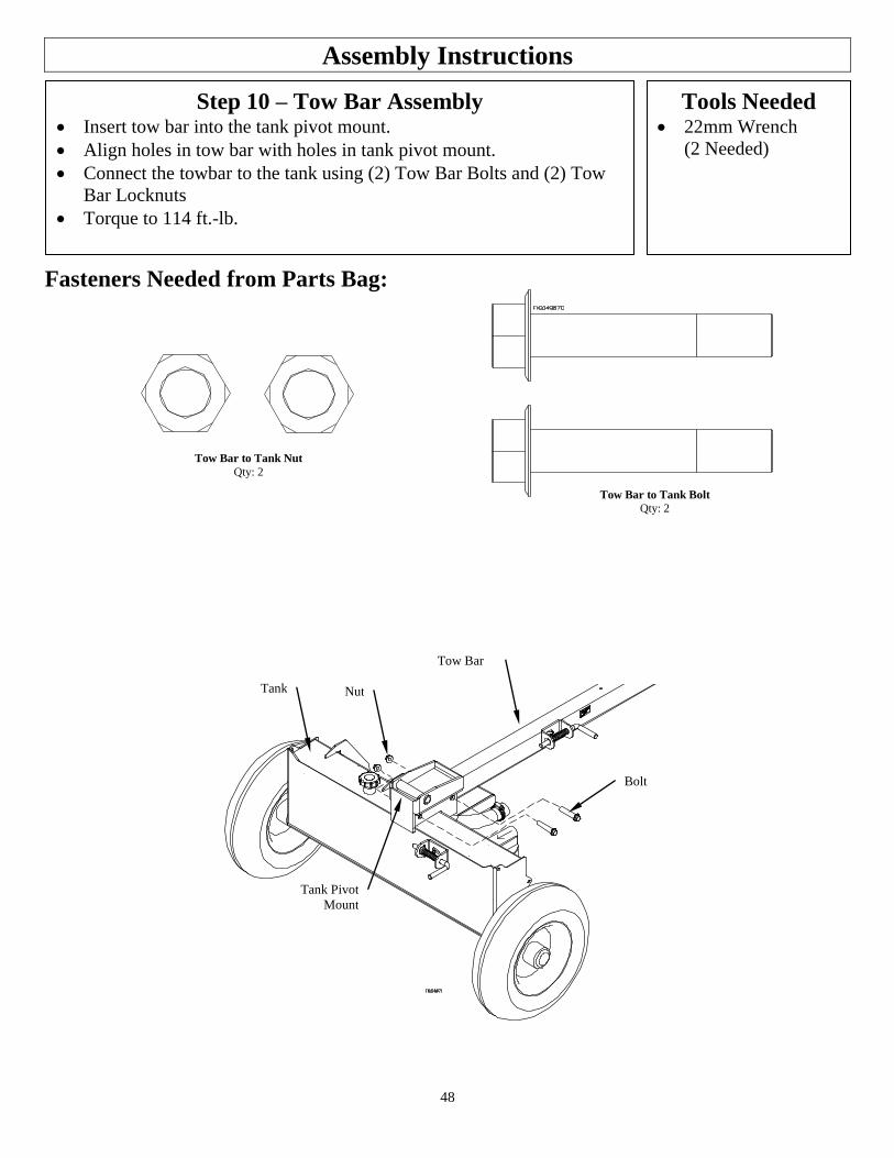
48
Assembly Instructions
Step 10 – Tow Bar Assembly Insert tow bar into the tank pivot mount.
Align holes in tow bar with holes in tank pivot mount.
Connect the towbar to the tank using (2) Tow Bar Bolts and (2) Tow
Bar Locknuts
Torque to 114 ft.-lb.
Tools Needed 22mm Wrench
(2 Needed)
Fasteners Needed from Parts Bag:
Tow Bar to Tank Nut
Qty: 2
Tow Bar to Tank Bolt
Qty: 2
Bolt
Tank Nut
Tow Bar
Tank Pivot
Mount
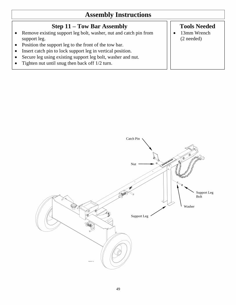
49
Assembly Instructions
Step 11 – Tow Bar Assembly Remove existing support leg bolt, washer, nut and catch pin from
support leg.
Position the support leg to the front of the tow bar.
Insert catch pin to lock support leg in vertical position.
Secure leg using existing support leg bolt, washer and nut.
Tighten nut until snug then back off 1/2 turn.
Tools Needed 13mm Wrench
(2 needed)
Support Leg
Bolt
Catch Pin
Nut
Support Leg
Washer

50
Assembly Instructions
Step 12A – Engine for 1175 Install Engine/Pump Assembly using engine mounting pattern shown
below.
Install Engine/Pump Assembly to tank mount plate using (4) 1175
Engine Bolts and (4) 1175 Engine Flange Nuts
Torque to 21 ft.-lb.
Tools Needed 13mm Wrench
Fasteners Needed from Parts Bag:
Engine Mounting Pattern
Engine to Tank Nut (1175)
Qty: 4
Engine to Tank Bolt (1175)
Qty: 4
Nut
Bolt
Tank Mount Plate
Engine/Pump
Assembly
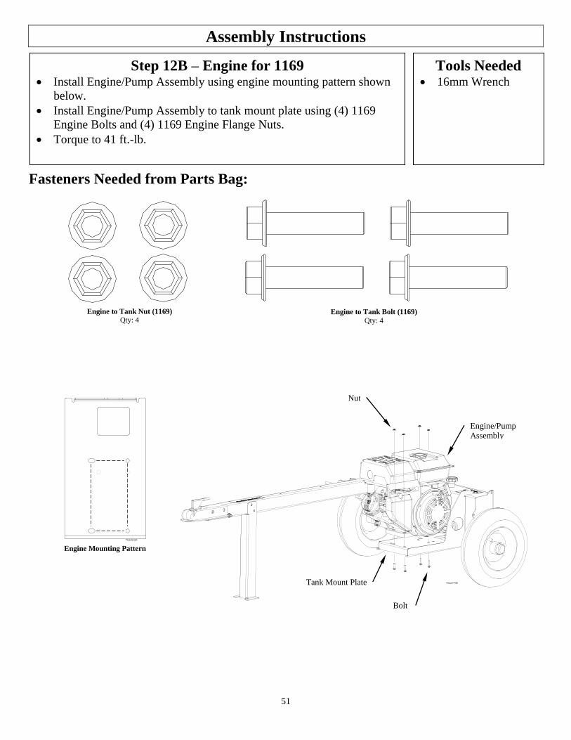
51
Assembly Instructions
Step 12B – Engine for 1169 Install Engine/Pump Assembly using engine mounting pattern shown
below.
Install Engine/Pump Assembly to tank mount plate using (4) 1169
Engine Bolts and (4) 1169 Engine Flange Nuts.
Torque to 41 ft.-lb.
Tools Needed 16mm Wrench
Fasteners Needed from Parts Bag:
Engine Mounting Pattern
Engine to Tank Nut (1169)
Qty: 4
Engine to Tank Bolt (1169)
Qty: 4
Nut
Bolt
Tank Mount Plate
Engine/Pump
Assembly
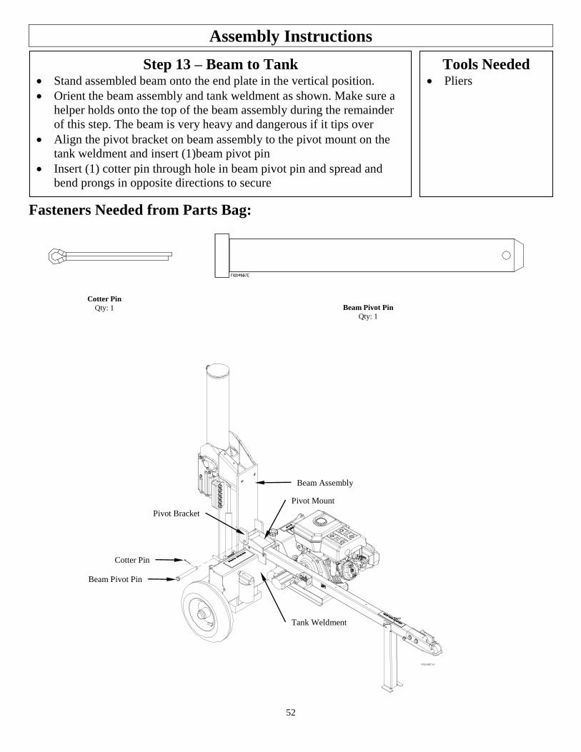
52
Assembly Instructions
Step 13 – Beam to Tank Stand assembled beam onto the end plate in the vertical position.
Orient the beam assembly and tank weldment as shown. Make sure a
helper holds onto the top of the beam assembly during the remainder
of this step. The beam is very heavy and dangerous if it tips over
Align the pivot bracket on beam assembly to the pivot mount on the
tank weldment and insert (1)beam pivot pin
Insert (1) cotter pin through hole in beam pivot pin and spread and
bend prongs in opposite directions to secure
Tools Needed Pliers
Fasteners Needed from Parts Bag:
Cotter Pin
Qty: 1 Beam Pivot Pin
Qty: 1
Beam Assembly
Tank Weldment
Pivot Mount
Beam Pivot Pin
Cotter Pin
Pivot Bracket
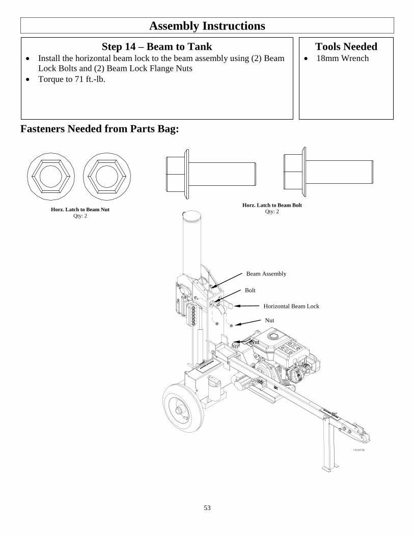
53
Assembly Instructions
Step 14 – Beam to Tank Install the horizontal beam lock to the beam assembly using (2) Beam
Lock Bolts and (2) Beam Lock Flange Nuts
Torque to 71 ft.-lb.
Tools Needed 18mm Wrench
Fasteners Needed from Parts Bag:
Horz. Latch to Beam Nut
Qty: 2
Horz. Latch to Beam Bolt
Qty: 2
Beam Assembly
Horizontal Beam Lock
Nut
Bolt
Nut
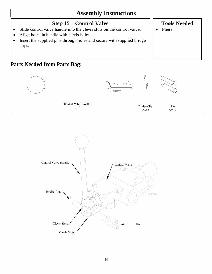
54
Assembly Instructions
Step 15 – Control Valve Slide control valve handle into the clevis slots on the control valve.
Align holes in handle with clevis holes.
Insert the supplied pins through holes and secure with supplied bridge
clips.
Tools Needed Pliers
Parts Needed from Parts Bag:
Pin
Bridge Clip
Control Valve Handle Control Valve
Clevis Slots
Clevis Slots
Control Valve Handle
Qty: 1 Bridge Clip
Qty: 2
Pin
Qty: 2
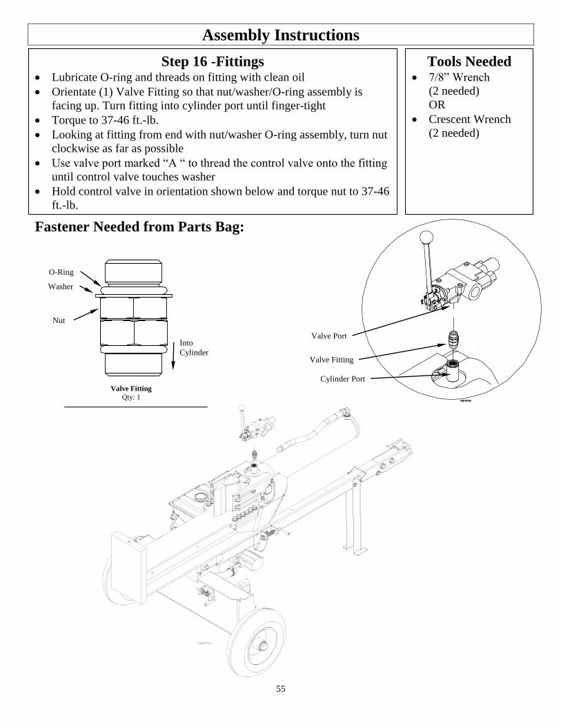
55
Assembly Instructions
Step 16 -Fittings Lubricate O-ring and threads on fitting with clean oil
Orientate (1) Valve Fitting so that nut/washer/O-ring assembly is
facing up. Turn fitting into cylinder port until finger-tight
Torque to 37-46 ft.-lb.
Looking at fitting from end with nut/washer O-ring assembly, turn nut
clockwise as far as possible
Use valve port marked “A “ to thread the control valve onto the fitting
until control valve touches washer
Hold control valve in orientation shown below and torque nut to 37-46
ft.-lb.
Tools Needed 7/8” Wrench
(2 needed)
OR
Crescent Wrench
(2 needed)
Fastener Needed from Parts Bag:
Valve Fitting
Qty: 1
Into
Cylinder
Nut
Washer
O-Ring
Valve Fitting
Cylinder Port
Valve Port
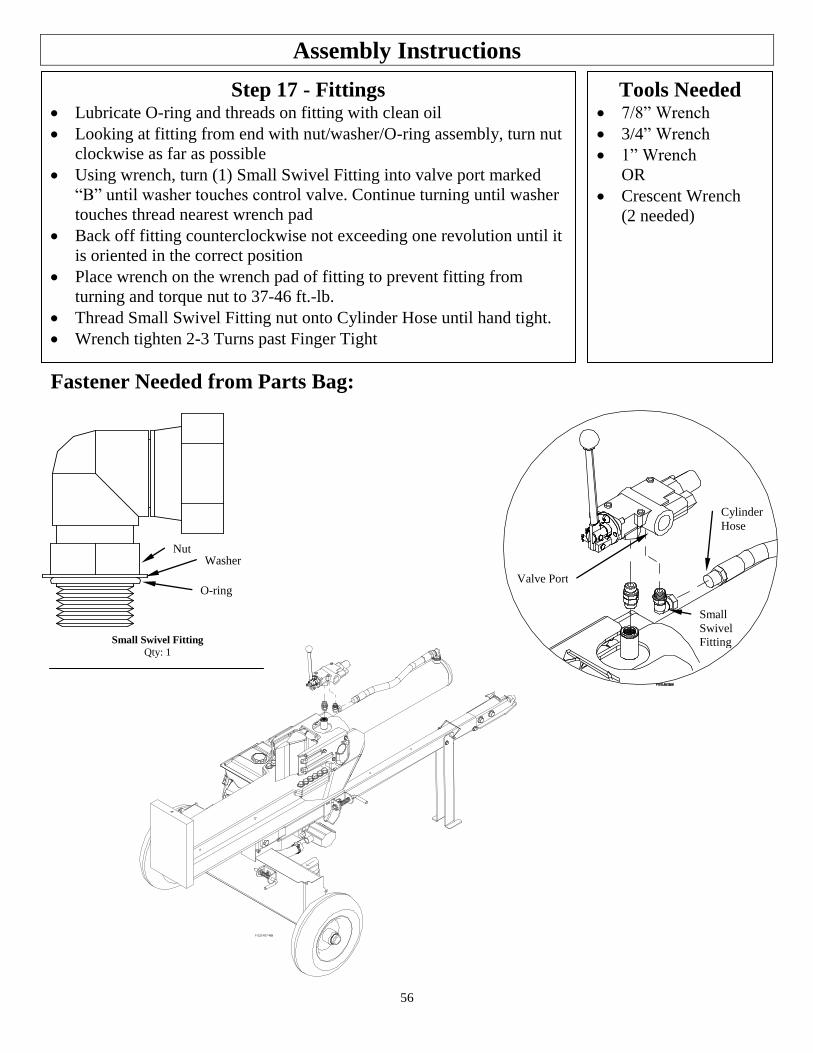
56
Assembly Instructions
Step 17 - Fittings Lubricate O-ring and threads on fitting with clean oil
Looking at fitting from end with nut/washer/O-ring assembly, turn nut
clockwise as far as possible
Using wrench, turn (1) Small Swivel Fitting into valve port marked
“B” until washer touches control valve. Continue turning until washer
touches thread nearest wrench pad
Back off fitting counterclockwise not exceeding one revolution until it
is oriented in the correct position
Place wrench on the wrench pad of fitting to prevent fitting from
turning and torque nut to 37-46 ft.-lb.
Thread Small Swivel Fitting nut onto Cylinder Hose until hand tight.
Wrench tighten 2-3 Turns past Finger Tight
Tools Needed 7/8” Wrench
3/4” Wrench
1” Wrench
OR
Crescent Wrench
(2 needed)
Small
Swivel
Fitting
Cylinder
Hose
Valve Port
Fastener Needed from Parts Bag:
Small Swivel Fitting
Qty: 1
Nut
O-ring
Washer
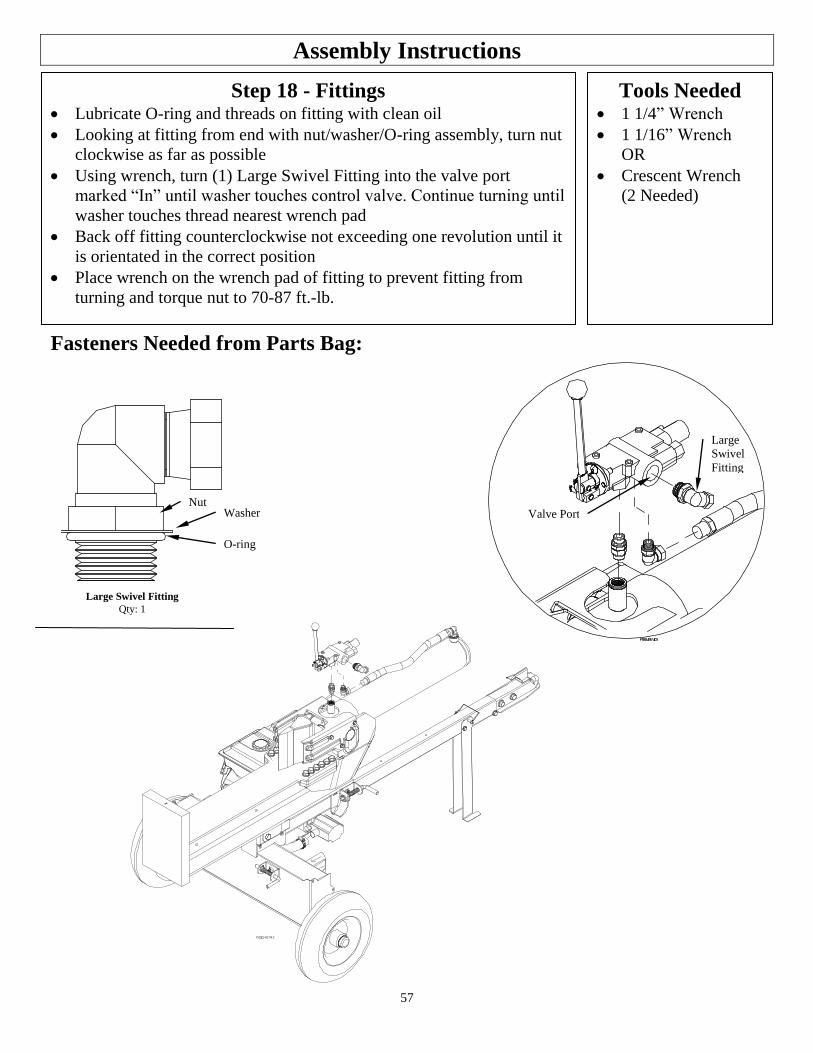
57
Assembly Instructions
Step 18 - Fittings Lubricate O-ring and threads on fitting with clean oil
Looking at fitting from end with nut/washer/O-ring assembly, turn nut
clockwise as far as possible
Using wrench, turn (1) Large Swivel Fitting into the valve port
marked “In” until washer touches control valve. Continue turning until
washer touches thread nearest wrench pad
Back off fitting counterclockwise not exceeding one revolution until it
is orientated in the correct position
Place wrench on the wrench pad of fitting to prevent fitting from
turning and torque nut to 70-87 ft.-lb.
Tools Needed 1 1/4” Wrench
1 1/16” Wrench
OR
Crescent Wrench
(2 Needed)
Fasteners Needed from Parts Bag:
Large
Swivel
Fitting
Valve Port
Large Swivel Fitting
Qty: 1
Nut
O-ring
Washer
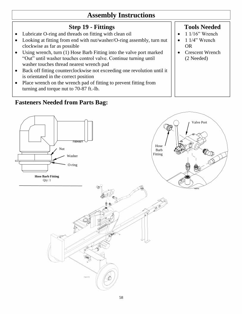
58
Assembly Instructions
Step 19 - Fittings Lubricate O-ring and threads on fitting with clean oil
Looking at fitting from end with nut/washer/O-ring assembly, turn nut
clockwise as far as possible
Using wrench, turn (1) Hose Barb Fitting into the valve port marked
“Out” until washer touches control valve. Continue turning until
washer touches thread nearest wrench pad
Back off fitting counterclockwise not exceeding one revolution until it
is orientated in the correct position
Place wrench on the wrench pad of fitting to prevent fitting from
turning and torque nut to 70-87 ft.-lb.
Tools Needed 1 1/16” Wrench
1 1/4” Wrench
OR
Crescent Wrench
(2 Needed)
Fasteners Needed from Parts Bag:
Hose
Barb
Fitting
Valve Port
Hose Barb Fitting
Qty: 1
Nut
O-ring
Washer
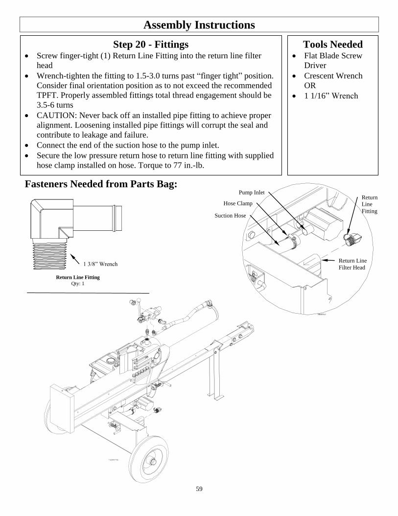
59
Assembly Instructions
Step 20 - Fittings Screw finger-tight (1) Return Line Fitting into the return line filter
head
Wrench-tighten the fitting to 1.5-3.0 turns past “finger tight” position.
Consider final orientation position as to not exceed the recommended
TPFT. Properly assembled fittings total thread engagement should be
3.5-6 turns
CAUTION: Never back off an installed pipe fitting to achieve proper
alignment. Loosening installed pipe fittings will corrupt the seal and
contribute to leakage and failure.
Connect the end of the suction hose to the pump inlet.
Secure the low pressure return hose to return line fitting with supplied
hose clamp installed on hose. Torque to 77 in.-lb.
Tools Needed Flat Blade Screw
Driver
Crescent Wrench
OR
1 1/16” Wrench
Fasteners Needed from Parts Bag:
Return Line Fitting
Qty: 1
1 3/8” Wrench Return Line
Filter Head
Return
Line
Fitting Suction Hose
Hose Clamp
Pump Inlet
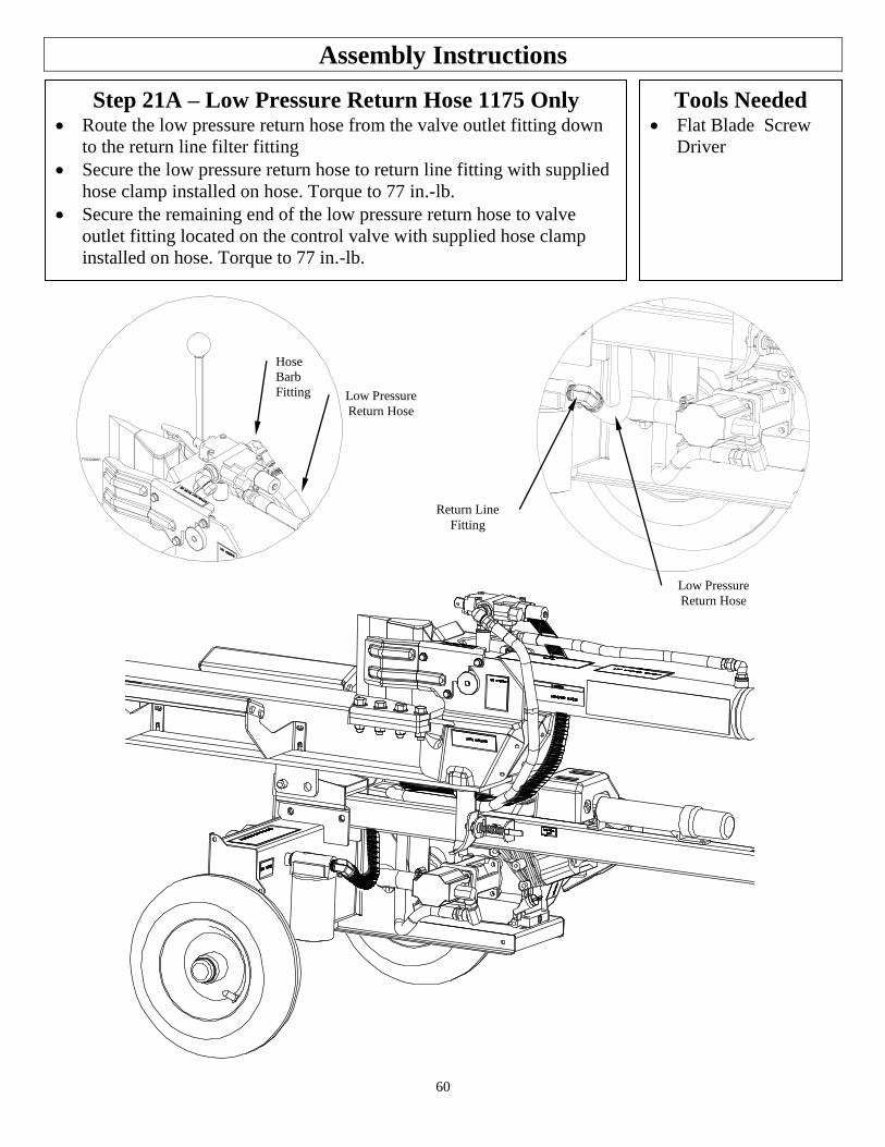
60
Assembly Instructions
Step 21A – Low Pressure Return Hose 1175 Only Route the low pressure return hose from the valve outlet fitting down
to the return line filter fitting
Secure the low pressure return hose to return line fitting with supplied
hose clamp installed on hose. Torque to 77 in.-lb.
Secure the remaining end of the low pressure return hose to valve
outlet fitting located on the control valve with supplied hose clamp
installed on hose. Torque to 77 in.-lb.
Tools Needed Flat Blade Screw
Driver
Hose
Barb
Fitting Low Pressure
Return Hose
Return Line
Fitting
Low Pressure
Return Hose
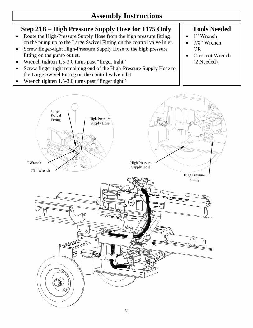
61
Assembly Instructions
Step 21B – High Pressure Supply Hose for 1175 Only Route the High-Pressure Supply Hose from the high pressure fitting
on the pump up to the Large Swivel Fitting on the control valve inlet.
Screw finger-tight High-Pressure Supply Hose to the high pressure
fitting on the pump outlet.
Wrench tighten 1.5-3.0 turns past “finger tight”
Screw finger-tight remaining end of the High-Pressure Supply Hose to
the Large Swivel Fitting on the control valve inlet.
Wrench tighten 1.5-3.0 turns past “finger tight”
Tools Needed 1” Wrench
7/8” Wrench
OR
Crescent Wrench
(2 Needed)
Large
Swivel
Fitting
High Pressure
Supply Hose
High Pressure
Supply Hose
High Pressure
Fitting
7/8” Wrench
1” Wrench
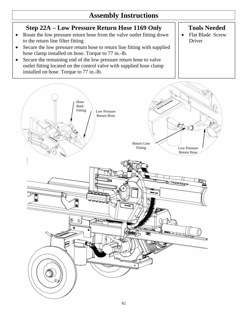
62
Assembly Instructions
Step 22A – Low Pressure Return Hose 1169 Only Route the low pressure return hose from the valve outlet fitting down
to the return line filter fitting
Secure the low pressure return hose to return line fitting with supplied
hose clamp installed on hose. Torque to 77 in.-lb.
Secure the remaining end of the low pressure return hose to valve
outlet fitting located on the control valve with supplied hose clamp
installed on hose. Torque to 77 in.-lb.
Tools Needed Flat Blade Screw
Driver
Hose
Barb
Fitting Low Pressure
Return Hose
Return Line
Fitting Low Pressure
Return Hose
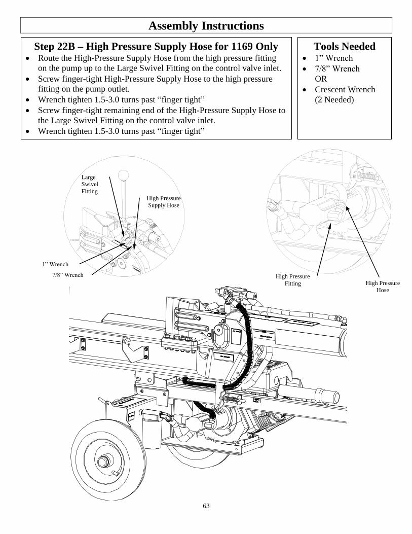
63
Assembly Instructions
Step 22B – High Pressure Supply Hose for 1169 Only Route the High-Pressure Supply Hose from the high pressure fitting
on the pump up to the Large Swivel Fitting on the control valve inlet.
Screw finger-tight High-Pressure Supply Hose to the high pressure
fitting on the pump outlet.
Wrench tighten 1.5-3.0 turns past “finger tight”
Screw finger-tight remaining end of the High-Pressure Supply Hose to
the Large Swivel Fitting on the control valve inlet.
Wrench tighten 1.5-3.0 turns past “finger tight”
Tools Needed 1” Wrench
7/8” Wrench
OR
Crescent Wrench
(2 Needed)
Large
Swivel
Fitting High Pressure
Supply Hose
High Pressure
Fitting High Pressure
Hose
1” Wrench
7/8” Wrench
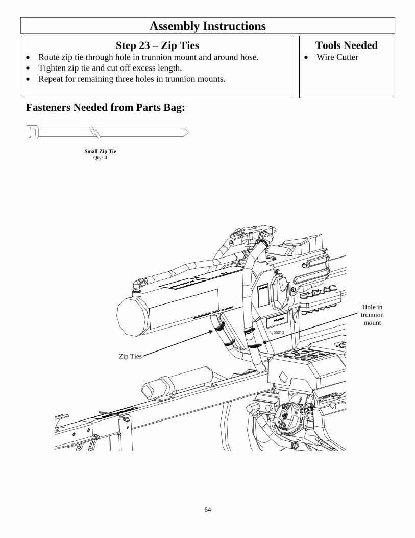
64
Assembly Instructions
Tools Needed Wire Cutter
Step 23 – Zip Ties Route zip tie through hole in trunnion mount and around hose. Tighten zip tie and cut off excess length. Repeat for remaining three holes in trunnion mounts.
Fasteners Needed from Parts Bag:
Small Zip Tie
Qty: 4
Zip Ties
Hole in
trunnion
mount
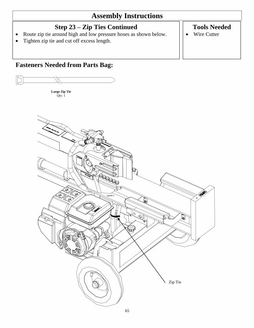
65
Assembly Instructions
Tools Needed Wire Cutter
Step 23 – Zip Ties Continued Route zip tie around high and low pressure hoses as shown below. Tighten zip tie and cut off excess length.
Fasteners Needed from Parts Bag:
Large Zip Tie
Qty: 1
Zip Tie
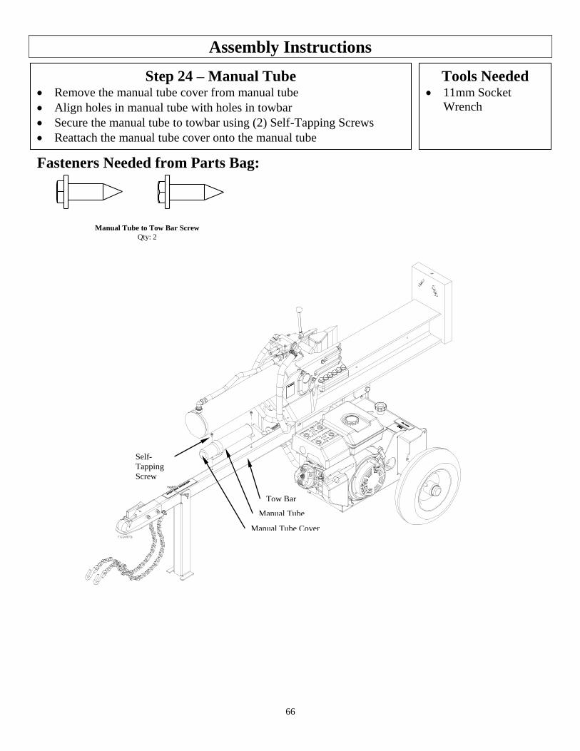
66
Assembly Instructions
Tools Needed 11mm Socket
Wrench
Fasteners Needed from Parts Bag:
Step 24 – Manual Tube Remove the manual tube cover from manual tube
Align holes in manual tube with holes in towbar
Secure the manual tube to towbar using (2) Self-Tapping Screws
Reattach the manual tube cover onto the manual tube
Self-
Tapping
Screw
Manual Tube Cover
Tow Bar
Manual Tube
Manual Tube to Tow Bar Screw
Qty: 2
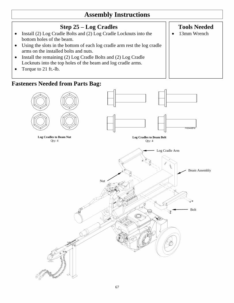
67
Assembly Instructions
Step 25 – Log Cradles Install (2) Log Cradle Bolts and (2) Log Cradle Locknuts into the
bottom holes of the beam.
Using the slots in the bottom of each log cradle arm rest the log cradle
arms on the installed bolts and nuts.
Install the remaining (2) Log Cradle Bolts and (2) Log Cradle
Locknuts into the top holes of the beam and log cradle arms.
Torque to 21 ft.-lb.
Tools Needed 13mm Wrench
Fasteners Needed from Parts Bag:
Log Cradles to Beam Nut
Qty: 4 Log Cradles to Beam Bolt
Qty: 4
Nut
Log Cradle Arm
Beam Assembly
Bolt
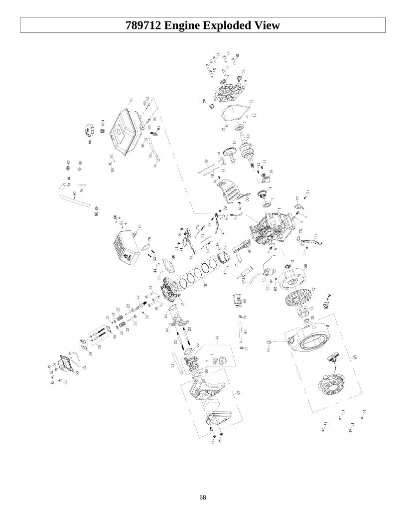
68
789712 Engine Exploded View

69
789712 Engine Parts List
Ref# Part # Description Qty
52
Kit # 8
PACKING, HEADCOVER 1
53 COVER COMP, CYLINDER HEAD
1
54 N/A WIND SHIEL COMP. 1
55 N/A BOLT 1
56 N/A FLYWHEEL ASSEMBLY 1
57
Kit # 1
FAN, RECOIL STARTER 1
58 PULLEY, STARTER 1
59 NUT 1
60 Kit # 9 IGNITION COIL ASSY 1
61 Kit # 1 CLIP 2
62 Kit # 9 BOLT 2
63
Kit # 7
PACKING, INTAKE 1
64 INSULATOR, CARBURETOR 1
65 PACKING, CARBURETOR 1
66 SPACER, CARBURETOR 1
67 Kit # 13 ROD, GOVERNOR 1
68 Kit # 13 SPRING, THROTTLE RETURN 1
69 Kit # 1
RECOIL STARTER ASSEMBLY 1
70 SWITCH ASSEMBLY 1
71 N/A SHROUD ASSY, UPPER 1
72 N/A SPEED REGULATING HANDLE 1
73 Kit # 2
AIR CLEANER ASSEMBLY 1
74 TUBE, BREATHER 1
75 N/A CLIP 1
76 Kit # 13 SPRING, GOVERNOR 1
77 Kit # 10 AMPLIFIER 1
78
Kit # 6
PACKING, EXHAUST 1
79 MUFFLER COMP 1
80 NUT 2
81 SPRING WASHER 2
82 783136 DIPSTICK 1
83 Kit # 5 FUEL TANK ASSEMBLY 1
83.1 Kit # 4, Kit # 5
FUEL FILTER 1
84 789697
& Kit # 5
FUEL COCK 1
85 Kit # 5 SPRING WASHER 3
86 Kit # 4, Kit # 5
FUEL TANK CAP COMP 1
87
Kit # 5
TANK VENT FITTING 1
88 PACKING WASHER, ONE-WAY VALVE
1
89 Kit # 3, Kit # 5
CONNECTING PIPE 1
90 Kit # 3, Kit # 5, Kit # 12
CLIP, FUEL LINE 3
91 Kit # 12
CONNECTING PIPE 1
92 CARBON TANK COMP 1
93 Kit # 5 BOLT 3
94 Kit # 3, Kit # 5
VENTILATION TUBE PROTECTOR
1
Ref# Part # Description Qty
1 N/A CRANKCASE 1
2 N/A BALL BEARING 2
3 N/A OIL SEAL 2
4 N/A GOVERNOR ASSEMBLY 1
5 N/A SHAFT, GOVERNOR ARM 1
6 N/A WASHER, GOVERNOR ARM SHAFT
1
7 N/A PIN, LOCK 1
8 Kit # 11
BOLT, DRAIN PLUG 2
9 WASHER,DRAIN PLUG 2
10 788901 SWITCH ASSEMBLY, OIL LEVEL 1
11 N/A BOLT 2
12 N/A DOWEL PIN,CASECOVER 2
13 Kit # 12 CLIP, FUEL LINE 1
14 N/A PISTON 1
15 N/A SCRAPER RING SET ,PISTON 1
16 N/A ROD ASSEMBLY, CONNECTING 1
17 N/A PIN, PISTON 1
18 N/A CLIP, PISTON 2
19 N/A COVER ASSEMBLY, CRANKCASE
1
20 N/A OIL PLUG 1
21 N/A CYLINDER HEAD 1
22 N/A VALVE, IN 1
23 N/A VALVE EXHAUST 1
24 N/A RETURNER,INTAKE VALVE 1
25 N/A SPRING, VALVE 2
26 N/A SEAT, VALVE SPRING,IN 1
27 N/A SEAT, VALVE SPRING,EX 1
28 N/A PLATE, PUSH ROD GUIDE 1
29 N/A ROCKER FASTENYNG BOLT 2
30 N/A ROCKER 2
31 N/A ROTATOR 1
32 Kit # 7 BOLT, STUD 2
33 Kit # 6 BOLT, STUD 2
34 Kit # 7 CARBURETOR ASSEMBLY 1
35 Kit # 5 FUEL LINE 1
36 Kit # 5 CLIP, FUEL LINE 2
37 N/A GOVERNOR ARM 1
38 N/A BOLT, GOVERNOR ARM 1
39 Kit # 2 NUT 3
40 N/A CRANKSHAFT ASSEMBLY 1
41 N/A LIFTER,VALVE 2
42 N/A PACKING, CASECOVER 1
43 N/A CAMSHAFT ASSEMBLY 1
44 N/A PIN, DOWEL 2
45 N/A BOLT 6
46 N/A GASKET, CYLINDER HEAD 1
47 N/A BOLT 4
48 783127 SPARK PULG 1
49 N/A ROD, PUSH 2
50 N/A SHROUD 1
51 Kit # 1 Kit # 8, Kit # 10
BOLT 13
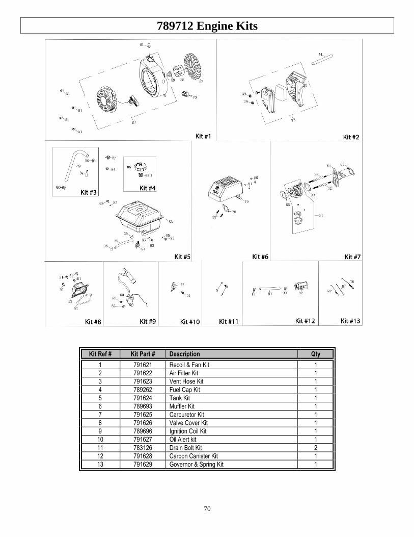
70
789712 Engine Kits
Kit Ref # Kit Part # Description Qty
1 791621 Recoil & Fan Kit 1
2 791622 Air Filter Kit 1
3 791623 Vent Hose Kit 1
4 789262 Fuel Cap Kit 1
5 791624 Tank Kit 1
6 789693 Muffler Kit 1
7 791625 Carburetor Kit 1
8 791626 Valve Cover Kit 1
9 789696 Ignition Coil Kit 1
10 791627 Oil Alert kit 1
11 783126 Drain Bolt Kit 2
12 791628 Carbon Canister Kit 1
13 791629 Governor & Spring Kit 1
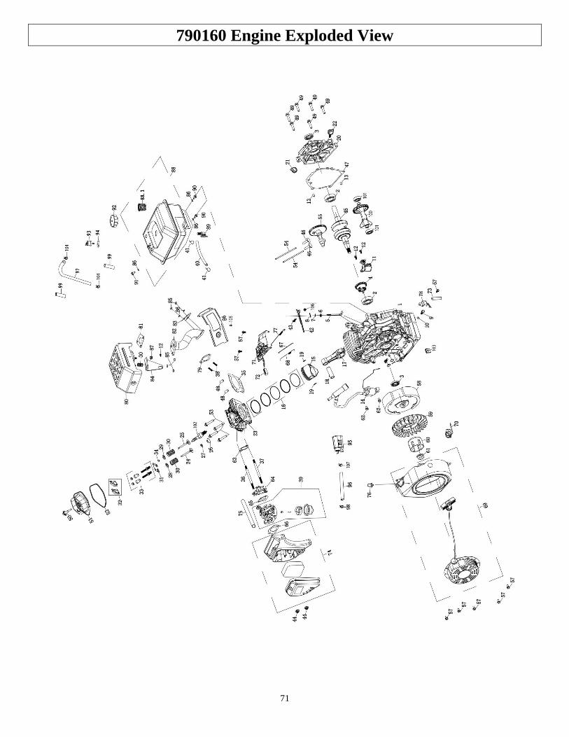
71
790160 Engine Exploded View

72
790160 Engine Parts List
Ref# Part # Description Qty
1 N/A CRANKCASE 1
2 N/A BALL BEARING 2
3 N/A OIL SEAL 2
4 N/A GOVERNOR ASSEMBLY 1
5 N/A SHAFT,GOVERNOR ARM 1
6 N/A SEAL,GOVERNOR ARM SHAFT 1
7 N/A WASHER,GOVERNOR ARM SHAFT 1
8 N/A PIN,LOCK 1
9 Kit # 11
BOLT,DRAIN PLUG 2
10 WASHER,DRAIN PLUG 2
11 788902 SWITCH ASSEMBLY,OIL LEVEL 1
12 Kit # 7 BOLT 3
13 N/A DOWEL PIN,CASECOVER 2
14 Kit # 9 IGNITION COIL ASSY 1
15 N/A PISTON 1
16 N/A SCRAPER RING SET ,PISTON 1
17 N/A ROD ASSEMBLY., CONNECTING 1
18 N/A PIN, PISTON 1
19 N/A CLIP, PISTON 2
20 N/A COVER ASSEMBLY, CRANKCASE
1
21 791586 OIL PLUG 1
22 791587 DIPSTICK 1
23 N/A CYLINDER HEAD 1
24 N/A VALVE,IN 1
25 N/A VALVE EXHAUST 1
26 N/A RETURNER,INTAKE VALVE 1
27 N/A OIL SEAL,VALVE 1
28 N/A SEAT, VALVE SPRING,IN 1
29 N/A SEAT, VALVE SPRING,EX 1
30 Kit # 7 SPRING,VALVE 3
31 N/A PLATE,PUSH ROD GUIDE 1
32 N/A ROCKER 2
33 N/A ROCKER ARM TIGHTENING BOLTS 2
34 N/A ROTATOR 1
35 N/A GASKET,CYLINDER HEAD 1
36 Kit # 6
BOLT, STUD 1
37 BOLT, STUD 1
38 Kit # 14 BOLT, STUD 2
39 Kit # 6 CARBURETOR ASSEMBLY 1
40 Kit # 5
FUEL LINE 1
41 CLIP,FUEL LINE 2
42 N/A GOVERNOR ARM 1
43 N/A BOLT,GOVERNOR ARM 1
44 Kit # 2 NUT 3
45 N/A CRANKSHAFT ASSEMBLY 1
46 N/A LIFTER,VALVE 2
47 N/A PACKING,CASECOVER 1
48 N/A PIN,DOWEL 2
49 N/A BOLT 7
50
Kit # 8
LOCK BOLT 1
51 COVER COMP, CYLINDER HEAD
1
52 PACKING,HEADCOVER 1
53 N/A BOLT 4
54 N/A ROD,PUSH 2
55 N/A CAMSHAFT ASSY 1
56 Kit # 12 SHROUD 1
57 Kit # 1 Kit # 10 Kit # 12
BOLT 9
Ref# Part # Description Qty
58 N/A FLYWHEEL ASSEMBLY 1
59
Kit # 1
FAN,RECOIL STARTER 1
60 PULLEY,STARTER 1
61 NUT 2
62 Kit # 9 BOLT 2
63
Kit # 6
PACKING,INTAKE 1
64 INSULATOR,CARBURETOR 1
65 PACKING,CARBURETOR 1
66 SPACER,CARBURETOR 1
67 Kit # 13
ROD,GOVERNOR 1
68 SPRING,THROTTL RETURN 1
69 Kit # 1 RECOIL STARTER ASSEMBLY 1
70 N/A SWITCH ASSEMBLY 1
71 N/A SHROUD ASSY,UPPER 1
72 N/A SPEED REGULATING HANDLE 1
73 Kit # 10 CLIP,WIRE HARNESS 1
74 Kit # 2
AIR CLEANER ASSEMBLY 1
75 TUBE,BREATHER 1
76 Kit # 1 CLIP 1
77 Kit # 13 SPRING,GOVERNOR 1
78 Kit # 10 AMPLIFIER 1
79 Kit # 14 PACKING,EXHAUST 1
80 Kit # 7 MUFFLER COMP 1
81 Kit # 7 Kit # 14
GASKET,EXHAUST PIPE 1
82 Kit # 14
EXHAUST PIPE 1
83 CLAMP, MUFFLER LOCK 1
84 Kit # 7 MUFFLER BRACKET 1
85 Kit # 7 Kit # 14
NUT 5
86 Kit # 5 Kit # 14
SPRING WASHER 5
87 N/A NUT 1
88 Kit # 5 FUEL TANK ASSEMBLY 1
88.1 Kit # 4 Kit # 5
FUEL FILTER 1
89 Kit # 5
or 789697
FUEL COCK 1
90 Kit # 5 BOLT 2
91 Kit # 5 BOLT 1
92 Kit # 4 Kit # 5
FUEL TANK CAP COMP 1
93 Kit # 5 MANUAL CHOKE ASSEMBLY 1
94 Kit # 5 PACKING WASHER,ONE-WAY VALVE 1
95 Kit # 12 CARBON TANK COMP 1
96 Kit # 12 CONNECTING PIPE 1
97 Kit # 3 Kit # 5
CONNECTING PIPE 1
98 Kit # 12 CLIP,FUEL LINE 1
99 Kit # 3 Kit # 5
VENTILATION TUBE PROTECTOR 2
100 N/A BALANCING SHAFT 1
101 N/A BALL BEARING 2
102 783127 SPARK PLUG 1
103 N/A RUBBER, STARTER ASSY 1
104 Kit # 3 Kit # 5
CLIP,FUEL LINE 2
105 Kit # 14 BOLT 1
106 N/A NUT 1
107 Kit # 12 CLIP,FUEL LINE 1
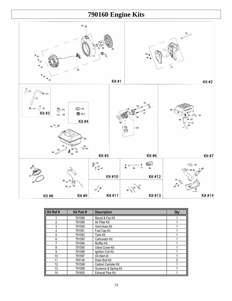
73
790160 Engine Kits
Kit Ref # Kit Part # Description Qty
1 791588 Recoil & Fan Kit 1
2 791589 Air Filter Kit 1
3 791590 Vent Hose Kit 1
4 791591 Fuel Cap Kit 1
5 791592 Tank Kit 1
6 791593 Carburetor Kit 1
7 791594 Muffler Kit 1
8 791595 Valve Cover Kit 1
9 791596 Ignition Coil Kit 1
10 791597 Oil Alert kit 1
11 783146 Drain Bolt Kit 2
12 791598 Carbon Canister Kit 1
13 791599 Governor & Spring Kit 1
14 791600 Exhaust Pipe Kit 1
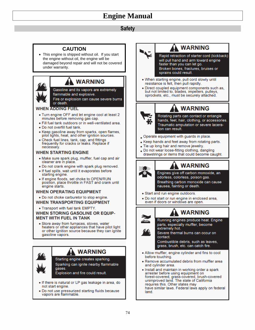
74
Engine Manual
Safety
CAUTION This engine is shipped without oil. If you start
the engine without oil, the engine will be damaged beyond repair and will not be covered under warranty.
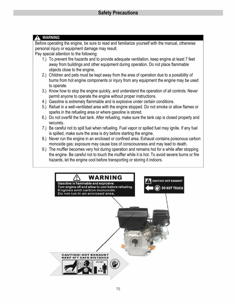
75
Safety Precautions
WARNING
Before operating the engine, be sure to read and familiarize yourself with the manual, otherwise personal injury or equipment damage may result. Pay special attention to the following:
1.) To prevent fire hazards and to provide adequate ventilation, keep engine at least 7 feet away from buildings and other equipment during operation. Do not place flammable objects close to the engine.
2.) Children and pets must be kept away from the area of operation due to a possibility of burns from hot engine components or injury from any equipment the engine may be used to operate.
3.) Know how to stop the engine quickly, and understand the operation of all controls. Never permit anyone to operate the engine without proper instructions.
4.) Gasoline is extremely flammable and is explosive under certain conditions. 5.) Refuel in a well-ventilated area with the engine stopped. Do not smoke or allow flames or
sparks in the refueling area or where gasoline is stored. 6.) Do not overfill the fuel tank. After refueling, make sure the tank cap is closed properly and
securely. 7.) Be careful not to spill fuel when refueling. Fuel vapor or spilled fuel may ignite. If any fuel
is spilled, make sure the area is dry before starting the engine. 8.) Never run the engine in an enclosed or confined area. Exhaust contains poisonous carbon
monoxide gas; exposure may cause loss of consciousness and may lead to death. 9.) The muffler becomes very hot during operation and remains hot for a while after stopping
the engine. Be careful not to touch the muffler while it is hot. To avoid severe burns or fire hazards, let the engine cool before transporting or storing it indoors.
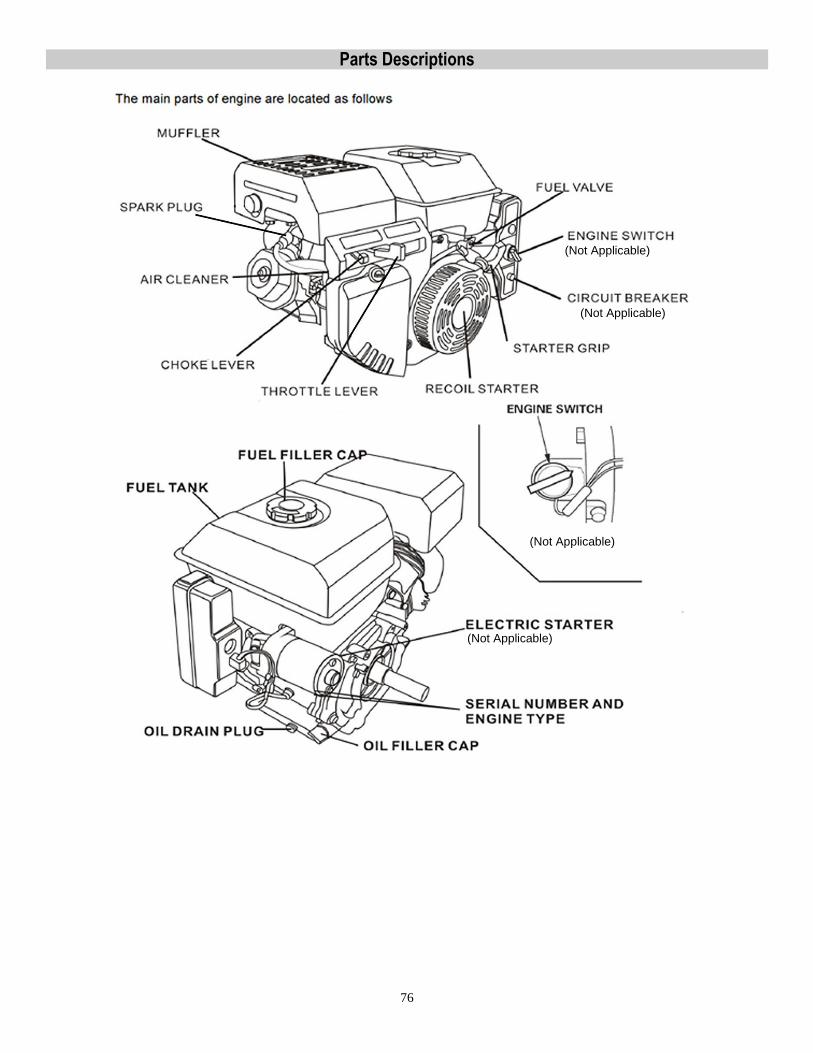
76
Parts Descriptions
(Not Applicable)
(Not Applicable)
(Not Applicable)
(Not Applicable)
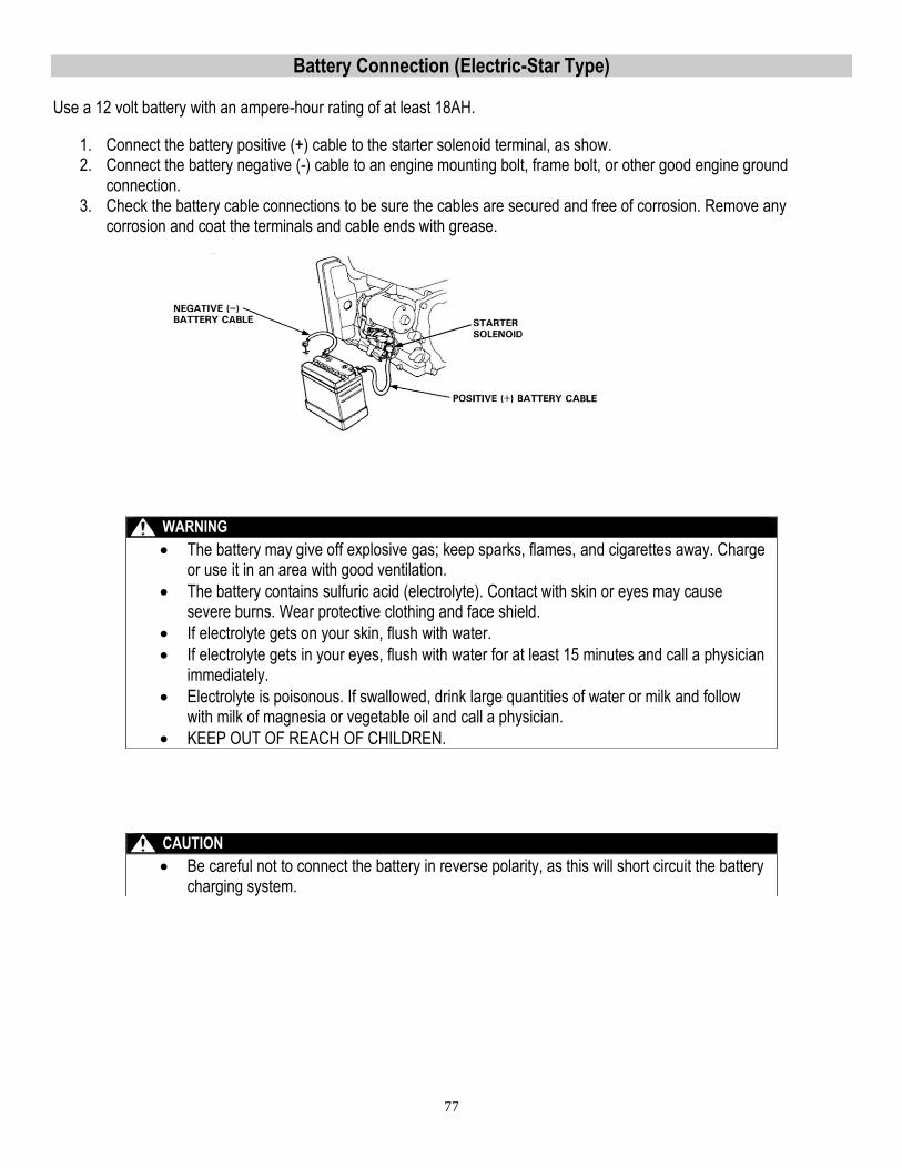
77
Battery Connection (Electric-Star Type) Use a 12 volt battery with an ampere-hour rating of at least 18AH.
1. Connect the battery positive (+) cable to the starter solenoid terminal, as show. 2. Connect the battery negative (-) cable to an engine mounting bolt, frame bolt, or other good engine ground
connection. 3. Check the battery cable connections to be sure the cables are secured and free of corrosion. Remove any
corrosion and coat the terminals and cable ends with grease.
WARNING
The battery may give off explosive gas; keep sparks, flames, and cigarettes away. Charge or use it in an area with good ventilation.
The battery contains sulfuric acid (electrolyte). Contact with skin or eyes may cause severe burns. Wear protective clothing and face shield.
If electrolyte gets on your skin, flush with water.
If electrolyte gets in your eyes, flush with water for at least 15 minutes and call a physician immediately.
Electrolyte is poisonous. If swallowed, drink large quantities of water or milk and follow with milk of magnesia or vegetable oil and call a physician.
KEEP OUT OF REACH OF CHILDREN.
CAUTION
Be careful not to connect the battery in reverse polarity, as this will short circuit the battery charging system.
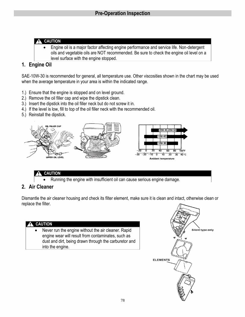
78
Pre-Operation Inspection
1. Engine Oil
SAE-10W-30 is recommended for general, all temperature use. Other viscosities shown in the chart may be used when the average temperature in your area is within the indicated range. 1.) Ensure that the engine is stopped and on level ground. 2.) Remove the oil filler cap and wipe the dipstick clean. 3.) Insert the dipstick into the oil filler neck but do not screw it in. 4.) If the level is low, fill to top of the oil filler neck with the recommended oil. 5.) Reinstall the dipstick.
2. Air Cleaner
Dismantle the air cleaner housing and check its filter element, make sure it is clean and intact, otherwise clean or replace the filter.
CAUTION
Engine oil is a major factor affecting engine performance and service life. Non-detergent oils and vegetable oils are NOT recommended. Be sure to check the engine oil level on a level surface with the engine stopped.
CAUTION
Running the engine with insufficient oil can cause serious engine damage.
CAUTION
Never run the engine without the air cleaner. Rapid engine wear will result from contaminates, such as dust and dirt, being drawn through the carburetor and into the engine.
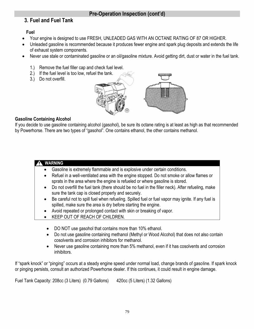
79
Pre-Operation Inspection (cont’d) 3. Fuel and Fuel Tank
Fuel
Your engine is designed to use FRESH, UNLEADED GAS WITH AN OCTANE RATING OF 87 OR HIGHER.
Unleaded gasoline is recommended because it produces fewer engine and spark plug deposits and extends the life of exhaust system components.
Never use stale or contaminated gasoline or an oil/gasoline mixture. Avoid getting dirt, dust or water in the fuel tank.
1.) Remove the fuel filler cap and check fuel level. 2.) If the fuel level is too low, refuel the tank. 3.) Do not overfill.
Gasoline Containing Alcohol If you decide to use gasoline containing alcohol (gasohol), be sure its octane rating is at least as high as that recommended by Powerhorse. There are two types of “gasohol”. One contains ethanol, the other contains methanol.
DO NOT use gasohol that contains more than 10% ethanol.
Do not use gasoline containing methanol (Methyl or Wood Alcohol) that does not also contain cosolvents and corrosion inhibitors for methanol.
Never use gasoline containing more than 5% methanol, even if it has cosolvents and corrosion inhibitors.
If “spark knock” or “pinging” occurs at a steady engine speed under normal load, change brands of gasoline. If spark knock or pinging persists, consult an authorized Powerhorse dealer. If this continues, it could result in engine damage. Fuel Tank Capacity: 208cc (3 Liters) (0.79 Gallons) 420cc (5 Liters) (1.32 Gallons)
WARNING
Gasoline is extremely flammable and is explosive under certain conditions.
Refuel in a well-ventilated area with the engine stopped. Do not smoke or allow flames or sprats in the area where the engine is refueled or where gasoline is stored.
Do not overfill the fuel tank (there should be no fuel in the filler neck). After refueling, make sure the tank cap is closed properly and securely.
Be careful not to spill fuel when refueling. Spilled fuel or fuel vapor may ignite. If any fuel is spilled, make sure the area is dry before starting the engine.
Avoid repeated or prolonged contact with skin or breaking of vapor.
KEEP OUT OF REACH OF CHILDREN.
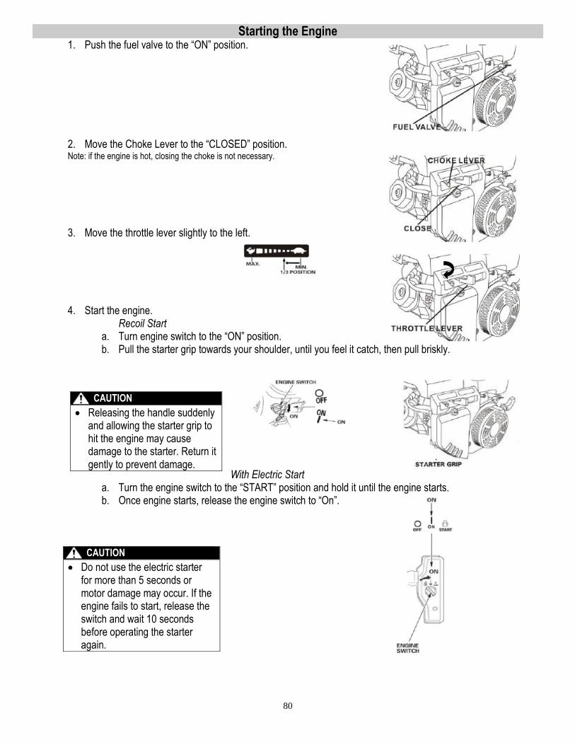
80
Starting the Engine 1. Push the fuel valve to the “ON” position.
2. Move the Choke Lever to the “CLOSED” position. Note: if the engine is hot, closing the choke is not necessary.
3. Move the throttle lever slightly to the left.
4. Start the engine. Recoil Start
a. Turn engine switch to the “ON” position. b. Pull the starter grip towards your shoulder, until you feel it catch, then pull briskly.
With Electric Start a. Turn the engine switch to the “START” position and hold it until the engine starts. b. Once engine starts, release the engine switch to “On”.
CAUTION
Releasing the handle suddenly and allowing the starter grip to hit the engine may cause damage to the starter. Return it gently to prevent damage.
CAUTION
Do not use the electric starter for more than 5 seconds or motor damage may occur. If the engine fails to start, release the switch and wait 10 seconds before operating the starter again.
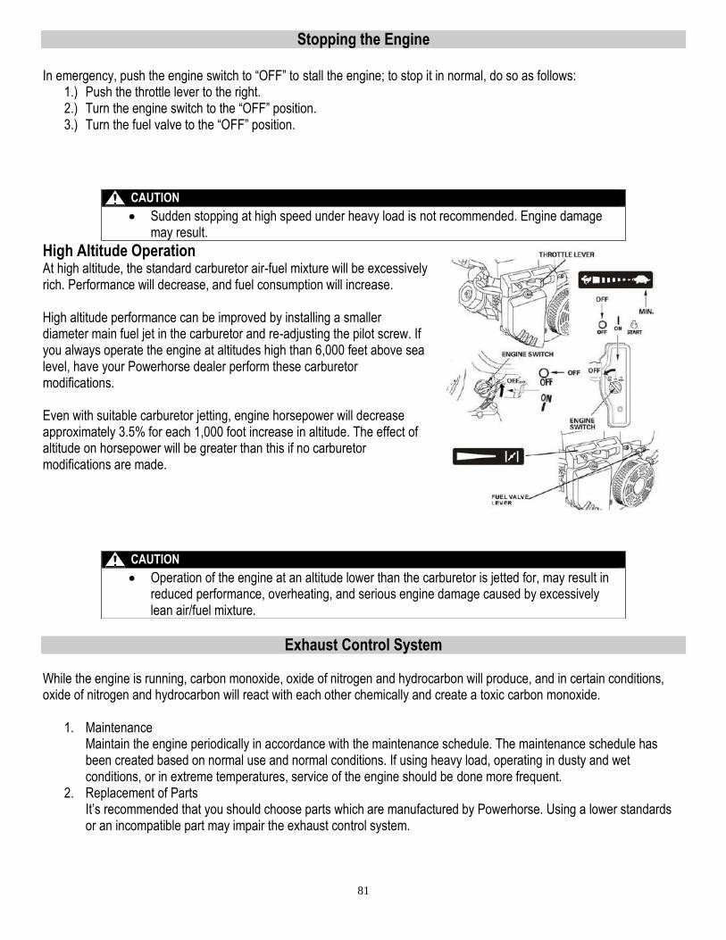
81
Stopping the Engine
In emergency, push the engine switch to “OFF” to stall the engine; to stop it in normal, do so as follows: 1.) Push the throttle lever to the right. 2.) Turn the engine switch to the “OFF” position. 3.) Turn the fuel valve to the “OFF” position.
High Altitude Operation At high altitude, the standard carburetor air-fuel mixture will be excessively rich. Performance will decrease, and fuel consumption will increase. High altitude performance can be improved by installing a smaller diameter main fuel jet in the carburetor and re-adjusting the pilot screw. If you always operate the engine at altitudes high than 6,000 feet above sea level, have your Powerhorse dealer perform these carburetor modifications. Even with suitable carburetor jetting, engine horsepower will decrease approximately 3.5% for each 1,000 foot increase in altitude. The effect of altitude on horsepower will be greater than this if no carburetor modifications are made.
Exhaust Control System While the engine is running, carbon monoxide, oxide of nitrogen and hydrocarbon will produce, and in certain conditions, oxide of nitrogen and hydrocarbon will react with each other chemically and create a toxic carbon monoxide.
1. Maintenance Maintain the engine periodically in accordance with the maintenance schedule. The maintenance schedule has been created based on normal use and normal conditions. If using heavy load, operating in dusty and wet conditions, or in extreme temperatures, service of the engine should be done more frequent.
2. Replacement of Parts It’s recommended that you should choose parts which are manufactured by Powerhorse. Using a lower standards or an incompatible part may impair the exhaust control system.
CAUTION
Sudden stopping at high speed under heavy load is not recommended. Engine damage may result.
CAUTION
Operation of the engine at an altitude lower than the carburetor is jetted for, may result in reduced performance, overheating, and serious engine damage caused by excessively lean air/fuel mixture.
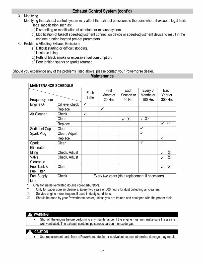
82
Exhaust Control System (cont’d) 3. Modifying
Modifying the exhaust control system may affect the exhaust emissions to the point where it exceeds legal limits. Illegal modification such as: a.) Dismantling or modification of air intake or exhaust system. b.) Modification of takeoff speed-adjustment connection device or speed-adjustment device to result in the
engines running beyond pre-set parameters. 4. Problems Affecting Exhaust Emissions
a.) Difficult starting or difficult stopping. b.) Unstable idling. c.) Puffs of black smoke or excessive fuel consumption. d.) Poor ignition sparks or sparks returned.
Should you experience any of the problems listed above, please contact your Powerhorse dealer.
Maintenance
MAINTENANCE SCHEDULE
Frequency Item
Each Time
First Month of 20 Hrs
Each Season or
50 Hrs
Every 6 Months or 100 Hrs
Each Year or 300 Hrs
Engine Oil Oil level check
Replace
Air Cleaner Check
Clean *
Replace **
Sediment Cup Clean
Spark Plug Clean, Adjust
Replace
Spark Eliminator
Clean
Idling Check, Adjust Valve Clearance
Check, Adjust
Fuel Tank & Fuel Filter
Clean
Fuel Supply Line
Check Every two years (do a replacement if necessary)
* Only for inside-ventilated double core-carburetors. ** Only for paper core air cleaners. Every two years or 600 hours for dust collecting air cleaners.
Service engine more frequent if used in dusty conditions. Should be done by your Powerhorse dealer, unless you are trained and equipped with the proper tools.
WARNING
Shut off the engine before performing any maintenance. If the engine must run, make sure the area is well ventilated. The exhaust contains poisonous carbon monoxide gas.
CAUTION
Use replacement parts from a Powerhorse dealer or equivalent source; otherwise damage may result.
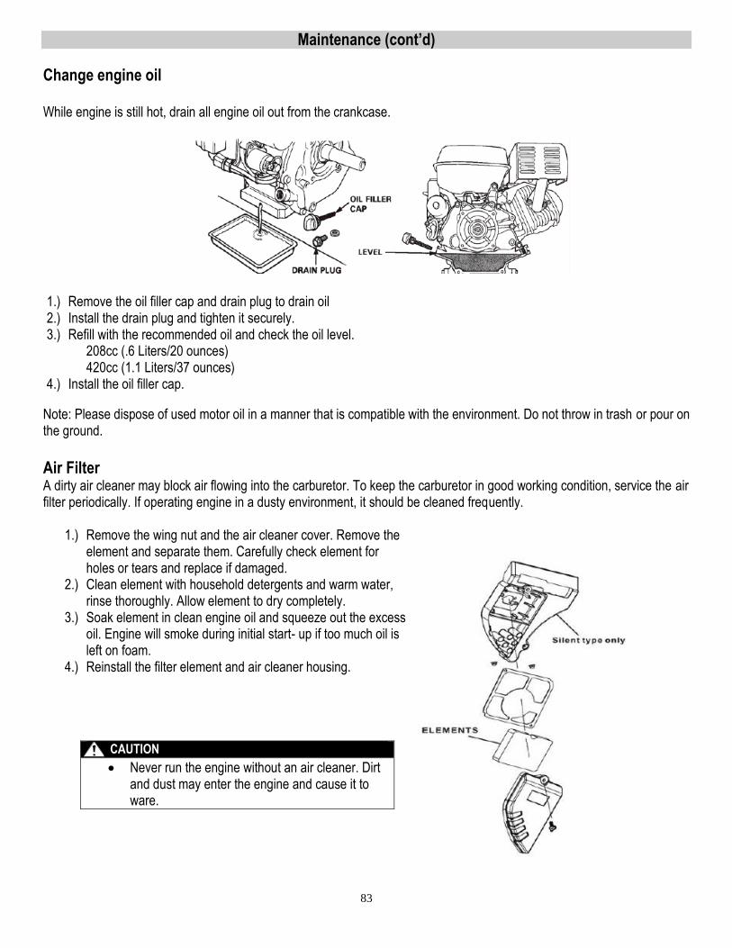
83
Maintenance (cont’d)
Change engine oil While engine is still hot, drain all engine oil out from the crankcase.
1.) Remove the oil filler cap and drain plug to drain oil 2.) Install the drain plug and tighten it securely. 3.) Refill with the recommended oil and check the oil level.
208cc (.6 Liters/20 ounces) 420cc (1.1 Liters/37 ounces)
4.) Install the oil filler cap.
Note: Please dispose of used motor oil in a manner that is compatible with the environment. Do not throw in trash or pour on the ground.
Air Filter A dirty air cleaner may block air flowing into the carburetor. To keep the carburetor in good working condition, service the air filter periodically. If operating engine in a dusty environment, it should be cleaned frequently.
1.) Remove the wing nut and the air cleaner cover. Remove the element and separate them. Carefully check element for holes or tears and replace if damaged.
2.) Clean element with household detergents and warm water, rinse thoroughly. Allow element to dry completely.
3.) Soak element in clean engine oil and squeeze out the excess oil. Engine will smoke during initial start- up if too much oil is left on foam.
4.) Reinstall the filter element and air cleaner housing.
CAUTION
Never run the engine without an air cleaner. Dirt and dust may enter the engine and cause it to ware.
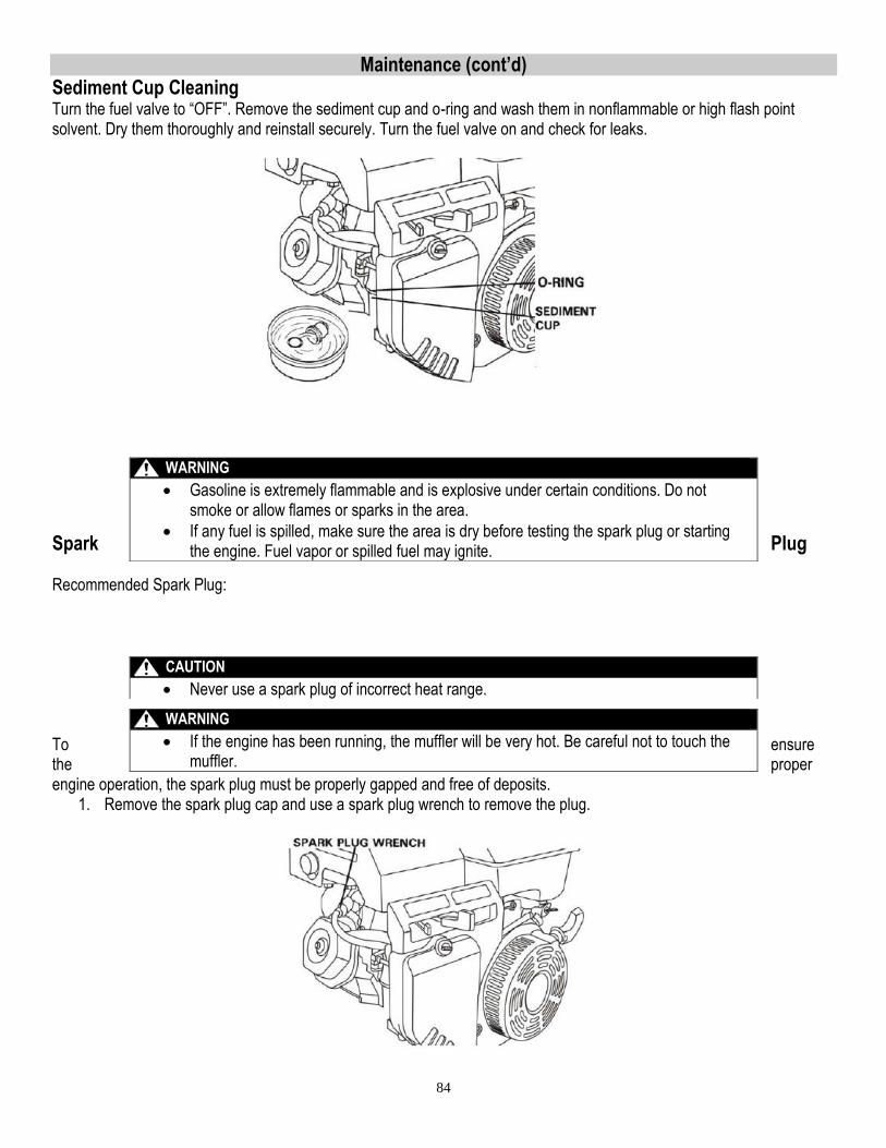
84
Maintenance (cont’d) Sediment Cup Cleaning Turn the fuel valve to “OFF”. Remove the sediment cup and o-ring and wash them in nonflammable or high flash point solvent. Dry them thoroughly and reinstall securely. Turn the fuel valve on and check for leaks.
Spark Plug Recommended Spark Plug: To ensure the proper engine operation, the spark plug must be properly gapped and free of deposits.
1. Remove the spark plug cap and use a spark plug wrench to remove the plug.
WARNING
Gasoline is extremely flammable and is explosive under certain conditions. Do not smoke or allow flames or sparks in the area.
If any fuel is spilled, make sure the area is dry before testing the spark plug or starting the engine. Fuel vapor or spilled fuel may ignite.
CAUTION
Never use a spark plug of incorrect heat range.
WARNING
If the engine has been running, the muffler will be very hot. Be careful not to touch the muffler.
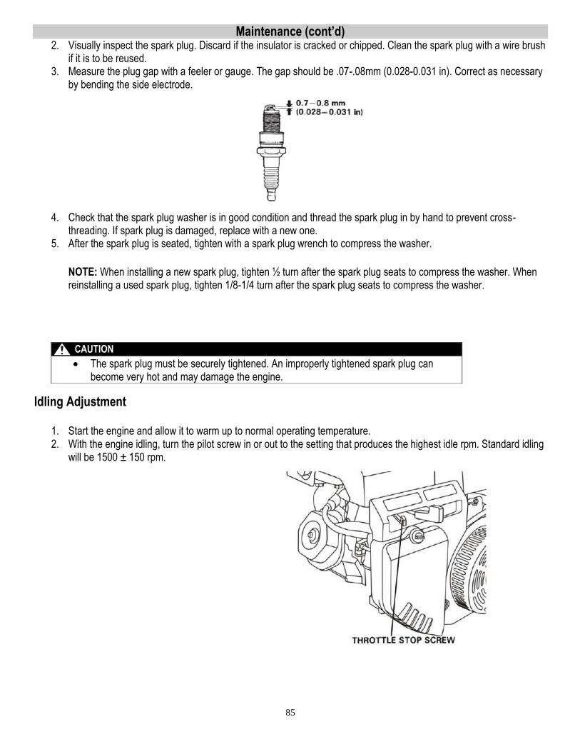
85
Maintenance (cont’d) 2. Visually inspect the spark plug. Discard if the insulator is cracked or chipped. Clean the spark plug with a wire brush
if it is to be reused. 3. Measure the plug gap with a feeler or gauge. The gap should be .07-.08mm (0.028-0.031 in). Correct as necessary
by bending the side electrode.
4. Check that the spark plug washer is in good condition and thread the spark plug in by hand to prevent cross-threading. If spark plug is damaged, replace with a new one.
5. After the spark plug is seated, tighten with a spark plug wrench to compress the washer. NOTE: When installing a new spark plug, tighten ½ turn after the spark plug seats to compress the washer. When reinstalling a used spark plug, tighten 1/8-1/4 turn after the spark plug seats to compress the washer.
Idling Adjustment
1. Start the engine and allow it to warm up to normal operating temperature. 2. With the engine idling, turn the pilot screw in or out to the setting that produces the highest idle rpm. Standard idling
will be 1500 ± 150 rpm.
CAUTION
The spark plug must be securely tightened. An improperly tightened spark plug can become very hot and may damage the engine.
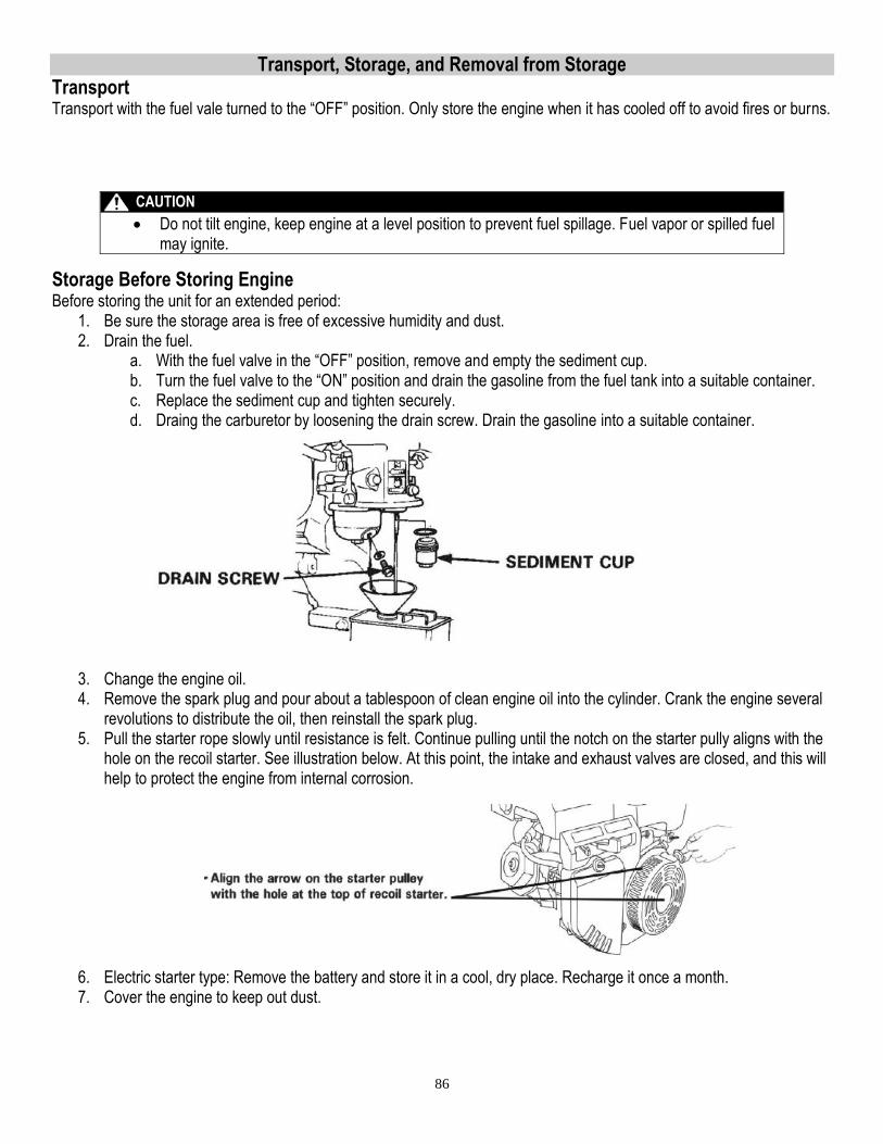
86
Transport, Storage, and Removal from Storage Transport Transport with the fuel vale turned to the “OFF” position. Only store the engine when it has cooled off to avoid fires or burns.
Storage Before Storing Engine Before storing the unit for an extended period:
1. Be sure the storage area is free of excessive humidity and dust. 2. Drain the fuel.
a. With the fuel valve in the “OFF” position, remove and empty the sediment cup. b. Turn the fuel valve to the “ON” position and drain the gasoline from the fuel tank into a suitable container. c. Replace the sediment cup and tighten securely. d. Draing the carburetor by loosening the drain screw. Drain the gasoline into a suitable container.
3. Change the engine oil. 4. Remove the spark plug and pour about a tablespoon of clean engine oil into the cylinder. Crank the engine several
revolutions to distribute the oil, then reinstall the spark plug. 5. Pull the starter rope slowly until resistance is felt. Continue pulling until the notch on the starter pully aligns with the
hole on the recoil starter. See illustration below. At this point, the intake and exhaust valves are closed, and this will help to protect the engine from internal corrosion.
6. Electric starter type: Remove the battery and store it in a cool, dry place. Recharge it once a month. 7. Cover the engine to keep out dust.
CAUTION
Do not tilt engine, keep engine at a level position to prevent fuel spillage. Fuel vapor or spilled fuel may ignite.
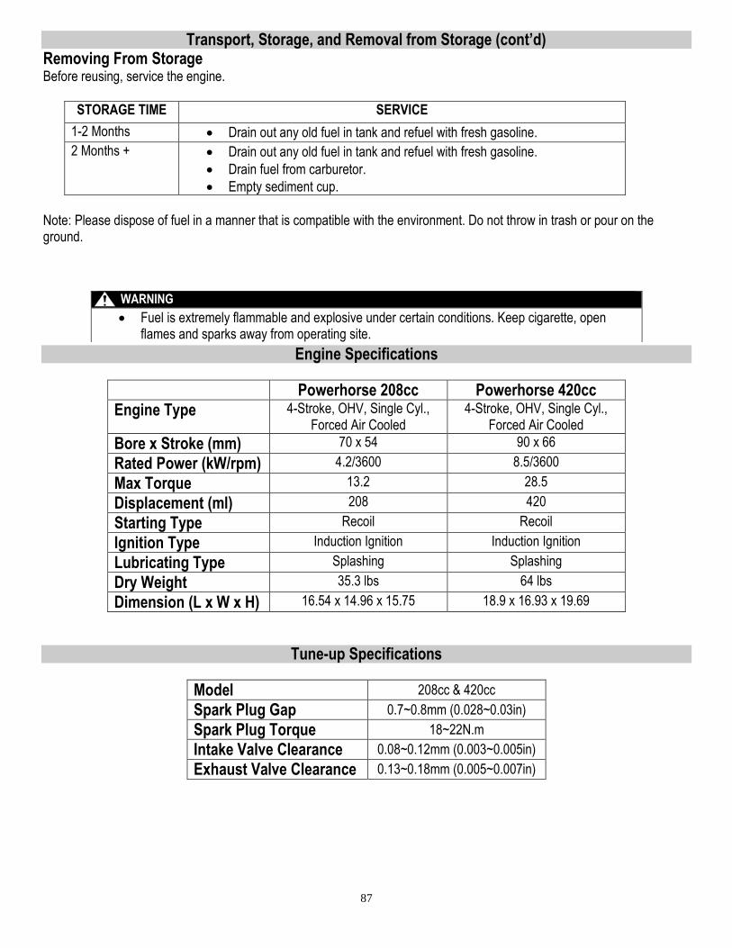
87
Transport, Storage, and Removal from Storage (cont’d) Removing From Storage Before reusing, service the engine.
STORAGE TIME SERVICE
1-2 Months Drain out any old fuel in tank and refuel with fresh gasoline.
2 Months + Drain out any old fuel in tank and refuel with fresh gasoline.
Drain fuel from carburetor.
Empty sediment cup.
Note: Please dispose of fuel in a manner that is compatible with the environment. Do not throw in trash or pour on the ground.
Engine Specifications
Powerhorse 208cc Powerhorse 420cc
Engine Type 4-Stroke, OHV, Single Cyl., Forced Air Cooled
4-Stroke, OHV, Single Cyl., Forced Air Cooled
Bore x Stroke (mm) 70 x 54 90 x 66
Rated Power (kW/rpm) 4.2/3600 8.5/3600
Max Torque 13.2 28.5
Displacement (ml) 208 420
Starting Type Recoil Recoil
Ignition Type Induction Ignition Induction Ignition
Lubricating Type Splashing Splashing
Dry Weight 35.3 lbs 64 lbs
Dimension (L x W x H) 16.54 x 14.96 x 15.75 18.9 x 16.93 x 19.69
Tune-up Specifications
Model 208cc & 420cc
Spark Plug Gap 0.7~0.8mm (0.028~0.03in)
Spark Plug Torque 18~22N.m
Intake Valve Clearance 0.08~0.12mm (0.003~0.005in)
Exhaust Valve Clearance 0.13~0.18mm (0.005~0.007in)
WARNING
Fuel is extremely flammable and explosive under certain conditions. Keep cigarette, open flames and sparks away from operating site.

88
Troubleshooting
Trouble Cause Remedy Engine will not start using recoil starter.
1. Is the engine switch in the “ON” position?
2. Is the fuel valve “ON”?
3. Is there fuel in the fuel tank?
4. Is gasoline reaching the carburetor?
5. Is there spark at the plug?
1. See “Starting Engine” Section.
2. See “Starting Engine” Section.
3. See “Pre-Operating Instructions.”
4. To check, loosen the drain screw with the fuel valve on. See “Storage” Section for instructions.
5. Remove the spark plug cap, clean, then remove spark plug. Install plug in cap, turn engine switch to “ON” position. Ground the side electrode to any engine ground, and pull the recoil starter to see if sparks jump across the gap. If nto spark, replace plug. If OK, reinstall spark plug and try to start engine again.
Engine will not start using electric starter.
1. Are the battery cables securely connected and free of corrosion?
2. Is the battery fully charged?
1. See “Battery Connection” Section.
2. Charge battery.
Engine shut down while running.
1. Engine out of fuel? 2. Is the carburetor
clogged? 3. Is the spark plug bad?
1. Refuel. 2. See “Maintenance” Section. 3. See “Maintenance” Section.
Abnormal Noise or Pinging 1. Does the fuel have an octane rating of 87 or higher?
1. Change brands of fuel.

89

90

91

92
Limited Warranty
Dear Valued Customer: The Powerhorse Product you just purchased is built with the finest material and craftsmanship. Use this product properly and enjoy the benefits from its high performance. By purchasing a Powerhorse product, you show a desire for quality and durability. Like all mechanical equipment this unit requires a due amount of care. Treat this unit like the high quality piece of machinery it is. Neglect and improper handling may impair its performance. Please thoroughly read the instructions and understand the operation before using your product. Always contact Powerhorse Product Support at 1-866-443-2576 prior to having any service or warranty work performed, as some services performed by parties other than Powerhorse approved service centers may void this warranty. This warranty is in lieu of any other warranty expressed or implied and Powerhorse assumes no other responsibility or liability outside that expressed within this warranty.
Limited Warranty
Powerhorse shall warranty any piece of equipment manufactured, or parts of equipment manufactured, to be free from defects in material or workmanship for a period of:
Powerhorse Warranty
Item # Consumer Warranty Period Commercial Warranty Period
1175, 1169 3 years from date of purchase by user N/A
Powerhorse Engine Warranty
Item # Consumer Warranty Period Commercial Warranty Period
1175, 1169 2 years from date of purchase by user N/A
“Consumer use” means personal residential household use by a consumer. “Commercial use” means all other uses, including use for commercial, income producing or rental purposes or when purchased by a business. This warranty applies to the original purchaser of the equipment (verification of purchase, in the form of a receipt, is the responsibility of the buyer), is non-transferable, and covers parts and labor. Parts will be replaced or repaired at no charge, except when the equipment has failed due to lack of proper maintenance. If a part is no longer available, the part may be replaced with a similar part of equal function. Any misuse, abuse, alteration or improper installation or operations will void warranty. Determining whether a part is to be replaced or repaired is the sole decision of Powerhorse. Powerhorse will not provide for replacement of complete products due to defective parts. Any costs incurred due to replacement or repair of items outside of a Powerhorse approved facility is the responsibility of the buyer and not covered under warranty. Transportation costs to and from service center is the responsibility of the customer. In addition to the normal warranty, Powerhorse shall warrant any normal wear item from defects in material or workmanship for a period of 90 days from the date of purchase by user. Normal wear items include, but are not limited to, tires and filter elements. This warranty specifically excludes the following; failure of parts due to damage caused by accident, fire, flood, windstorm, acts of God, applications not approved by Powerhorse in writing, corrosion caused by chemicals, use of replacement parts which do not conform to manufacturer’s specifications, damage related to rodent and/or insect infestation and damage caused by vandalism. Additional exclusions: loss of running time, inconvenience, loss of income, or loss of use, including any implied warranty of merchantability of fitness for a specific use. Also, Outdoor Power Equipment needs periodic parts and service to perform well, and this warranty does not cover instances when normal use has exhausted the life of a component or the engine. This warranty does not cover any personal injury or damage to surrounding property caused by failure of any part. Repair or replacement of parts does not extend the warranty period. The engine warranty is covered under the same terms and conditions as outlined above. Normal engine maintenance such as spark plugs, air filters, adjustments, fuel system cleaning and obstruction due to build up is not covered by this Powerhorse warranty. Please fill in the following information and have it on hand when you call in on a warranty claim.
Customer Number: ______________________________________________________________
Date of Purchase: _______________________________________________________________
Powerhorse Serial Number: _______________________________________________________
Item Number: __________________________________________________________________

93
.
This page has intentionally been left blank.

94
Manufactured by
Northern Tool + Equipment Co.,
2800 SouthCross Drive West
P.O. Box 1499 Burnsville, MN 55337-0499


