Embed Size (px)
Citation preview

®
AVANTI SERVICE LIFT
User’s, Installation and Maintenance Manual
Model SHARK
Original instructions

Manufactured Under Process Patent NO.8,499,896. ® Registered in Europe
Date of publication:14th CE Edition: November 2016 Revision 2: 23/01/2018
Manufacturer:AVANTI Wind Systems A/S Rønnevangs Allé 6 3400 Hillerød DenmarkP: +45 4824 9024F: +45 4824 9124 E: [email protected] I: www.avanti-online.com
Sales & Service:Australia Avanti Wind Systems P/L P: +61 (0) 439 349 350China Avanti Wind Systems P: +86 21 5785 8811Denmark Avanti Wind Systems A/S P: +45 4824 9024Germany Avanti Wind Systems GmbH P: +49 (0) 41 21-7 88 85 – 0Spain Avanti Wind Systems SL P: +34 976 149 524UK Avanti Wind Systems Limited P: +44 0 1254 399923USA Avanti Wind Systems, Inc P: +1 (262) 641-9101India Avanti Wind Systems, PL P: +91 44 6455 5911Brazil Avanti Brazil Sistemas Eólicos. S.L. P: +55 85 9671 6336

4 AVANTI Service Lift for Wind Turbines
PageUser’s manual 1. Limited warranty . . . . . . . . . . . . . . . . . . . . . . . . . . . . . . . . . . . . . . . . . . . . . . . . . . . . . 6 2. Introduction . . . . . . . . . . . . . . . . . . . . . . . . . . . . . . . . . . . . . . . . . . . . . . . . . . . . . . . . . 7 2.1 Symbols . . . . . . . . . . . . . . . . . . . . . . . . . . . . . . . . . . . . . . . . . . . . . . . . . . . . . . . . . 7 2.2 Terms and definitions . . . . . . . . . . . . . . . . . . . . . . . . . . . . . . . . . . . . . . . . . . . . . . . . . 7 3. Cautions . . . . . . . . . . . . . . . . . . . . . . . . . . . . . . . . . . . . . . . . . . . . . . . . . . . . . . . . . . . 8 4. Description of equipment . . . . . . . . . . . . . . . . . . . . . . . . . . . . . . . . . . . . . . . . . . . . . . . 9 4.1 Purpose . . . . . . . . . . . . . . . . . . . . . . . . . . . . . . . . . . . . . . . . . . . . . . . . . . . . . . . . . 9 4.2 Function. . . . . . . . . . . . . . . . . . . . . . . . . . . . . . . . . . . . . . . . . . . . . . . . . . . . . . . . . 9 4.3 Service lift models . . . . . . . . . . . . . . . . . . . . . . . . . . . . . . . . . . . . . . . . . . . . . . . . . . 9 4.4 Temperature . . . . . . . . . . . . . . . . . . . . . . . . . . . . . . . . . . . . . . . . . . . . . . . . . . . . . . 9 4.5 Accessories . . . . . . . . . . . . . . . . . . . . . . . . . . . . . . . . . . . . . . . . . . . . . . . . . . . . . . 9 4.6 Components. . . . . . . . . . . . . . . . . . . . . . . . . . . . . . . . . . . . . . . . . . . . . . . . . . . . . 10 4.6.1 Cabin overview . . . . . . . . . . . . . . . . . . . . . . . . . . . . . . . . . . . . . . . . . . . . . . 10 4.6.2 Technical data for the service lift L . . . . . . . . . . . . . . . . . . . . . . . . . . . . . . . . . 11 4.6.3 Drive system, fall arrest device and controls . . . . . . . . . . . . . . . . . . . . . . . . . . . 12 4.7 Cabin safety devices . . . . . . . . . . . . . . . . . . . . . . . . . . . . . . . . . . . . . . . . . . . . . . . 13 4.7.1 Electromagnetic motor brake . . . . . . . . . . . . . . . . . . . . . . . . . . . . . . . . . . . . 13 4.7.2 EMERGENCY STOP . . . . . . . . . . . . . . . . . . . . . . . . . . . . . . . . . . . . . . . . . . . 13 4.7.3 EMERGENCY STOP fixed (Optional) . . . . . . . . . . . . . . . . . . . . . . . . . . . . . . . . 13 4.7.4 Automatic operation switch . . . . . . . . . . . . . . . . . . . . . . . . . . . . . . . . . . . . . . 13 4.7.5 Overload limiter . . . . . . . . . . . . . . . . . . . . . . . . . . . . . . . . . . . . . . . . . . . . . . 13 4.7.6 Fall arrest device . . . . . . . . . . . . . . . . . . . . . . . . . . . . . . . . . . . . . . . . . . . . . 13 4.7.7 Drop down safety beam (Optional) . . . . . . . . . . . . . . . . . . . . . . . . . . . . . . . . . 13 4.7.8 Yellow flash (Optional). . . . . . . . . . . . . . . . . . . . . . . . . . . . . . . . . . . . . . . . . . 13 4.7.9 Emergency light (Optional) . . . . . . . . . . . . . . . . . . . . . . . . . . . . . . . . . . . . . . . 13 4.7.10 Door stop switch . . . . . . . . . . . . . . . . . . . . . . . . . . . . . . . . . . . . . . . . . . . . . 14 4.7.10.1 Sliding door: . . . . . . . . . . . . . . . . . . . . . . . . . . . . . . . . . . . . . . . . . . 14 4.7.11 Trapped-Key interlock system (Optional): . . . . . . . . . . . . . . . . . . . . . . . . . . . . . 14 4.7.12 Limit stop switch . . . . . . . . . . . . . . . . . . . . . . . . . . . . . . . . . . . . . . . . . . . . . 14 4.7.12.1 Top limit stop switch . . . . . . . . . . . . . . . . . . . . . . . . . . . . . . . . . . . . . 14 4.7.12.2 EMERGENCY top limit stop switch . . . . . . . . . . . . . . . . . . . . . . . . . . . 14 4.7.12.3 Bottom safety stop . . . . . . . . . . . . . . . . . . . . . . . . . . . . . . . . . . . . . . 14 4.7.12.4 Top safety stop (Optional) . . . . . . . . . . . . . . . . . . . . . . . . . . . . . . . . . 14 4.8 Safety devices for fences with door . . . . . . . . . . . . . . . . . . . . . . . . . . . . . . . . . . . . . 14 4.8.1 Guard Locking System . . . . . . . . . . . . . . . . . . . . . . . . . . . . . . . . . . . . . . . . . . 14 4.8.2 Trapped-key Interlock System . . . . . . . . . . . . . . . . . . . . . . . . . . . . . . . . . . . . . 15 5. Daily inspection by the supervisor . . . . . . . . . . . . . . . . . . . . . . . . . . . . . . . . . . . . . . . . 16 5.1 Service lift . . . . . . . . . . . . . . . . . . . . . . . . . . . . . . . . . . . . . . . . . . . . . . . . . . . . . . 16 5.2 Operating area . . . . . . . . . . . . . . . . . . . . . . . . . . . . . . . . . . . . . . . . . . . . . . . . . . . 16 5.3 Control functions . . . . . . . . . . . . . . . . . . . . . . . . . . . . . . . . . . . . . . . . . . . . . . . . . . 16 5.4 Automatic operation test. . . . . . . . . . . . . . . . . . . . . . . . . . . . . . . . . . . . . . . . . . . . . 17 5.5 Remote operation control . . . . . . . . . . . . . . . . . . . . . . . . . . . . . . . . . . . . . . . . . . . . 17 5.6 Fall arrest device . . . . . . . . . . . . . . . . . . . . . . . . . . . . . . . . . . . . . . . . . . . . . . . . . . 17 5.7 Wires ropes . . . . . . . . . . . . . . . . . . . . . . . . . . . . . . . . . . . . . . . . . . . . . . . . . . . . . 17 5.8 Wires ropes after an unusual event . . . . . . . . . . . . . . . . . . . . . . . . . . . . . . . . . . . . . . 18 6. Operation - lift transport . . . . . . . . . . . . . . . . . . . . . . . . . . . . . . . . . . . . . . . . . . . . . . . 19 6.1 Prohibited uses . . . . . . . . . . . . . . . . . . . . . . . . . . . . . . . . . . . . . . . . . . . . . . . . . . . 19 6.2 Entry and exit . . . . . . . . . . . . . . . . . . . . . . . . . . . . . . . . . . . . . . . . . . . . . . . . . . . . 19 6.3 Stop/EMERGENCY STOP . . . . . . . . . . . . . . . . . . . . . . . . . . . . . . . . . . . . . . . . . . . . 19 6.4 Normal operation. . . . . . . . . . . . . . . . . . . . . . . . . . . . . . . . . . . . . . . . . . . . . . . . . . 19 6.5 Automatic operation. . . . . . . . . . . . . . . . . . . . . . . . . . . . . . . . . . . . . . . . . . . . . . . . 19 6.6 Remote operation . . . . . . . . . . . . . . . . . . . . . . . . . . . . . . . . . . . . . . . . . . . . . . . . . 20 6.7 Overload limiter . . . . . . . . . . . . . . . . . . . . . . . . . . . . . . . . . . . . . . . . . . . . . . . . . . . 20 6.8 Override of the bottom obstruction device . . . . . . . . . . . . . . . . . . . . . . . . . . . . . . . . . 20 7. Manual operation . . . . . . . . . . . . . . . . . . . . . . . . . . . . . . . . . . . . . . . . . . . . . . . . . . . 21 7.1 EMERGENCY descent . . . . . . . . . . . . . . . . . . . . . . . . . . . . . . . . . . . . . . . . . . . . . . 21 8. Fall arrest device . . . . . . . . . . . . . . . . . . . . . . . . . . . . . . . . . . . . . . . . . . . . . . . . . . . . 22
Contents

5 User’s Manual
9. Repair in the event of breakdown. . . . . . . . . . . . . . . . . . . . . . . . . . . . . . . . . . . . . . . . . 2310. Out of service . . . . . . . . . . . . . . . . . . . . . . . . . . . . . . . . . . . . . . . . . . . . . . . . . . . . . . . 2611. Removing wires for replacement . . . . . . . . . . . . . . . . . . . . . . . . . . . . . . . . . . . . . . . . . 26 11.1 Parking the service lift . . . . . . . . . . . . . . . . . . . . . . . . . . . . . . . . . . . . . . . . . . . . . . 26 11.2 Wire ends . . . . . . . . . . . . . . . . . . . . . . . . . . . . . . . . . . . . . . . . . . . . . . . . . . . . . . . 26 11.3 Removing the lifting wire . . . . . . . . . . . . . . . . . . . . . . . . . . . . . . . . . . . . . . . . . . . . . 26 11.4 Removing the safety wire . . . . . . . . . . . . . . . . . . . . . . . . . . . . . . . . . . . . . . . . . . . . 2612. Maintenance . . . . . . . . . . . . . . . . . . . . . . . . . . . . . . . . . . . . . . . . . . . . . . . . . . . . . . . 26 12.1 Recommended planning . . . . . . . . . . . . . . . . . . . . . . . . . . . . . . . . . . . . . . . . . . . . . 26 12.2 Alternative planning . . . . . . . . . . . . . . . . . . . . . . . . . . . . . . . . . . . . . . . . . . . . . . . . 27 12.3 Cautions . . . . . . . . . . . . . . . . . . . . . . . . . . . . . . . . . . . . . . . . . . . . . . . . . . . . . . . 27 12.4 Annual inspection . . . . . . . . . . . . . . . . . . . . . . . . . . . . . . . . . . . . . . . . . . . . . . . . . 27 12.4.1 Cabin . . . . . . . . . . . . . . . . . . . . . . . . . . . . . . . . . . . . . . . . . . . . . . . . . . . . . 27 12.4.2 Traction hoist . . . . . . . . . . . . . . . . . . . . . . . . . . . . . . . . . . . . . . . . . . . . . . . . 27 12.4.3 Fall arrest device . . . . . . . . . . . . . . . . . . . . . . . . . . . . . . . . . . . . . . . . . . . . . 28 12.4.4 Traction, safety and guiding wire ropes . . . . . . . . . . . . . . . . . . . . . . . . . . . . . . 28 12.4.5 Electrical cables . . . . . . . . . . . . . . . . . . . . . . . . . . . . . . . . . . . . . . . . . . . . . . 29 12.4.6 Overload check and adjustment . . . . . . . . . . . . . . . . . . . . . . . . . . . . . . . . . . . 29 12.4.7 Information signs and documents . . . . . . . . . . . . . . . . . . . . . . . . . . . . . . . . . . 29 12.5 Repairs . . . . . . . . . . . . . . . . . . . . . . . . . . . . . . . . . . . . . . . . . . . . . . . . . . . . . . . . 29 12.6 Ordering spare parts . . . . . . . . . . . . . . . . . . . . . . . . . . . . . . . . . . . . . . . . . . . . . . . 2913. Transport and storage. . . . . . . . . . . . . . . . . . . . . . . . . . . . . . . . . . . . . . . . . . . . . . . . . 30 Installation manual1. Assembling SHARK cabin . . . . . . . . . . . . . . . . . . . . . . . . . . . . . . . . . . . . . . . . . . . . . . . 31 1.1 Part list - Shark L Sliding door . . . . . . . . . . . . . . . . . . . . . . . . . . . . . . . . . . . . . . . . 32 2. Fitting of wires . . . . . . . . . . . . . . . . . . . . . . . . . . . . . . . . . . . . . . . . . . . . . . . . . . . . . . . 35 2.1 Tower top . . . . . . . . . . . . . . . . . . . . . . . . . . . . . . . . . . . . . . . . . . . . . . . . . . . . . . . 35 2.2 Wire positioning measurements . . . . . . . . . . . . . . . . . . . . . . . . . . . . . . . . . . . . . . . 36 2.3 Securing the guide wire - ground level . . . . . . . . . . . . . . . . . . . . . . . . . . . . . . . . . . . . 37 2.3.1 Method 1: Wedge anchor . . . . . . . . . . . . . . . . . . . . . . . . . . . . . . . . . . . . . . . . 37 2.3.2 Method 2: Tripod . . . . . . . . . . . . . . . . . . . . . . . . . . . . . . . . . . . . . . . . . . . . . . 37 2.3.3 Method 3: Steel beam . . . . . . . . . . . . . . . . . . . . . . . . . . . . . . . . . . . . . . . . . . 38 2.3.4 Tensioning of the guide wires Ø12 mm. . . . . . . . . . . . . . . . . . . . . . . . . . . . . . . . 38 2.4 Electrical connections. . . . . . . . . . . . . . . . . . . . . . . . . . . . . . . . . . . . . . . . . . . . . . . 38 2.4.1 Power supply. . . . . . . . . . . . . . . . . . . . . . . . . . . . . . . . . . . . . . . . . . . . . . . . . 38 2.4.2 Supply cable . . . . . . . . . . . . . . . . . . . . . . . . . . . . . . . . . . . . . . . . . . . . . . . . . 39 2.4.3 Power connection . . . . . . . . . . . . . . . . . . . . . . . . . . . . . . . . . . . . . . . . . . . . . 39 2.5 Installation of drive and safety wire in lift . . . . . . . . . . . . . . . . . . . . . . . . . . . . . . . . . . 40 2.6 Securing the drive and safety wire . . . . . . . . . . . . . . . . . . . . . . . . . . . . . . . . . . . . . . 41 2.6.1 Drive wire contra weight . . . . . . . . . . . . . . . . . . . . . . . . . . . . . . . . . . . . . . . . . 41 2.6.2 Safety wire method 1: Wedge anchor with spring . . . . . . . . . . . . . . . . . . . . . . . . 41 2.6.3 Safety wire method 2: Push spring . . . . . . . . . . . . . . . . . . . . . . . . . . . . . . . . . . 42 2.6.4 Safety wire method 3: Steel beam with spring. . . . . . . . . . . . . . . . . . . . . . . . . . . 42 2.7 Wire fix alignment . . . . . . . . . . . . . . . . . . . . . . . . . . . . . . . . . . . . . . . . . . . . . . . . . 43 2.8 Adjustment of the safe-zone plates . . . . . . . . . . . . . . . . . . . . . . . . . . . . . . . . . . . . . . 44 2.9 Adjustment of top stop disc . . . . . . . . . . . . . . . . . . . . . . . . . . . . . . . . . . . . . . . . . . . 443. Danger zone! sticker . . . . . . . . . . . . . . . . . . . . . . . . . . . . . . . . . . . . . . . . . . . . . . . . . . . 444. Disassembling . . . . . . . . . . . . . . . . . . . . . . . . . . . . . . . . . . . . . . . . . . . . . . . . . . . . . . . 445. Inspection before initial use . . . . . . . . . . . . . . . . . . . . . . . . . . . . . . . . . . . . . . . . . . . . . . 45Appendix A: Regulation of overload limiter . . . . . . . . . . . . . . . . . . . . . . . . . . . . . . . . . . . . . 46 Appendix B: Safety measures . . . . . . . . . . . . . . . . . . . . . . . . . . . . . . . . . . . . . . . . . . . . . . 48Appendix C: Inspection Checklist . . . . . . . . . . . . . . . . . . . . . . . . . . . . . . . . . . . . . . . . . . . 49Appendix D: AVANTI lift anchor . . . . . . . . . . . . . . . . . . . . . . . . . . . . . . . . . . . . . . . . . . . . . 52Appendix E: Inspection log sheet. . . . . . . . . . . . . . . . . . . . . . . . . . . . . . . . . . . . . . . . . . . . 56Appendix F: Stomp-test Instruction . . . . . . . . . . . . . . . . . . . . . . . . . . . . . . . . . . . . . . . . . . 59

6 AVANTI Service Lift for Wind Turbines
1) Avanti service lift (“Product”)
Avanti Wind Systems A/S warrants that com-mencing from the date of shipment to the Customer and continuing for a period of the longer of 365 days thereafter, or the period set forth in the standard AVANTI warranty, the Product1) described in this Manual will be free from defects in material and workmanship under normal use and service when installed and operated in accordance with the provisions of this Manual.
This warranty is made only to the original user of the Product. The sole and exclusive remedy and the entire liability of Avanti under this limited warranty, shall be, at the option of Avanti, a replacement of the Product (including incidental and freight charges paid by the Customer) with a similar new or reconditioned Product of equivalent value, or a refund of the purchase price if the Product is returned to Avanti, freight and insurance prepaid. The obligations of Avanti are expressly conditioned upon return of the Product in strict accordance with the return procedures of Avanti.
This warranty does not apply if the Product (i) has been altered without the authorization of Avanti or its authorized representative; (ii) has not been installed, operated, repaired, or maintained in accordance with this Manual or other instructions from Avanti; (iii) has been subjected to abuse, neglect, casualty, or negligence; (iv) has been furnished by Avanti to Customer without charge; or (v) has been sold on an “AS-IS” basis.
Except as specifically set forth in this Limited Warranty,
ALL EXPRESS OR IMPLIED CONDITIONS, REPRESENTATIONS AND WARRANTIES, INCLUDING, BUT NOT LIMITED TO, ANY IMPLIED WARRANTY OR CONDITION OF MERCHANTABILITY, FITNESS FOR A PAR-TICULAR PURPOSE, NON-INFRINGEMENT, SATISFACTORY QUALITY, COURSE OF DEAL-ING, LAW, USAGE OR TRADE PRACTICE ARE HEREBY EXCLUDED TO THE MAXIMUM EXTENT PERMITTED BY APPLICABLE LAW AND ARE EXPRESSLY DISCLAIMED BY AVANTI. IF, PURSUANT TO ANY APPLICABLE LAW, TO THE EXTENT AN IMPLIED WARRAN-TY CANNOT BE EXCLUDED AS PROVIDED IN THIS LIMITED WARRANTY, ANY IMPLIED WARRANTY IS LIMITED IN TIME TO THE SAME DURATION AS THE EXPRESS WARRANTY PERIOD SET FORTH ABOVE. BECAUSE SOME STATES DO NOT PERMIT LIMITATIONS ON THE DURATION OF IMPLIED WARRANTIES, THIS MAY NOT APPLY TO A GIVEN CUSTOM-ER. THIS LIMITED WARRANTY GIVES CUS-TOMER SPECIFIC LEGAL RIGHTS, AND CUSTOMER MAY HAVE OTHER LEGAL RIGHTS UNDER APPLICABLE LAWS.
This disclaimer shall apply even if the express warranty fails of its essential purpose.
In any cases of dispute the English original shall be taken as authoritative.
1. Limited Warranty

7
STOP
!
!
�User’s Manual
2. IntroductionOnly trained people may use this lift.This manual must be available to staff at all times during installation, maintenance and operation.Additional copies are available from the manufacturer upon request. This manual, including, but not limited to, measurements, procedures, components, descriptions, instructions, recommendations and requirements, is subject to change without prior notice. Please check Avanti website/manuals for the latest revisions of the manuals.Any additional cost related to or arising from any changes in the manuals does not entitle Customer to any form of compensation or other legal remedies.
The pictures and sketches in this manual may not reflect the product aesthetics, colours, arrangement precisely. This has no impact on the function or safety.
2.1 Symbols
Symbol Signal word Meaning Possible injury if not observed
Safety instructions
DANGER!IMMEDIATE orpossibly imminentdanger:
Death or severe injury!
DANGER!IMMEDIATE orpossibly imminentdanger of hazardousvoltage:
Death or severe injury!
CAUTION! Potentially hazardoussituation:
Light injury or material damage.
Additional instructions
ATTENTION! Potentially dangeroussituation:
Damage to equipment or workplace
IMPORTANT!
Useful tips for optimumworking procedure
None
Order
Reference to writtenspecification/documentation

8
�AVANTI Service Lift for Wind Turbines
3. Cautions
Use and daily inspection of the service lift shall only be performed by person who has gone through the relevant training associated with the Avanti service lift use and daily inspection and is in possession of a valid (non expired) certificate for the task. Installation and maintenance of the service lift shall only be performed by Certified technicians.
The personnel must be at least 18 years of age. The staff must be familiar with the relevant accident prevention instructions and must have received proper training in these.
Personnel are obliged to read and understand this User’s Manual.
Personnel shall wear PFPE (safety helmet, full body har-ness, shock absorber, lanyard and slider) at all times.
A copy of the User’s Manual must be handed out to the personnel and must always be available for reference.
If more than one person is entrusted with one of the above tasks, the employer shall appoint a supervisor in charge of the operation.
Electrical connection of the system must be made in accordance with EN 60204-1.
Self-locking nuts must be used at all times. The screw must extend from the nut by at least half of the thread diameter. The nut may not be used once it has become possible to loosen by hand!
If any damage or faults are found during operation, or if circumstances arise which may jeopardize safety: immediately interrupt the work in progress and notify the supervisor or employer!
All tests/repairs of electrical installations may only be performed by a certified technician.
All repairs to the traction, braking and supporting sys-tems may only be performed by a certified technician.
If any supporting parts are repaired or replaced, the operational safety of the system must be tested and verified by a certified technician.
Only original fault-free parts may be used. Use of non-original parts will render the manufacturer’s warranty void and any type approval invalid. No modification, extension or reconstruction of the service lift is allowed without the manufacturer’s prior written consent.
No warranty is provided against damage resulting from reconstruction or modification of equipment or use of non-original parts which are not approved by the manufacturer.
Service lift must be inspected by a certified technician before first use.Service lift must be inspected at least once a year by a certified technician. In case of high operating frequency or severe conditions of use, more frequent inspection is required.
Service lift is designed for a lifetime of 20 years with an operating frequency of approximately 12.5 h/year (250 h in total). Service lift may not be used by persons who are under the influence of alcohol or drugs which may jeopardize working safety.
The service lift shall not be used in case of fire in the tower.Service lift shall ONLY be used when the turbine is not generating power.
All wind farm site specific rules must be followed. Service lift shall not be used during inclement weather, including wind speeds over 18 m/s.
Avoid injury – follow all instructions!
Owner must verify the need for third par ty service lift inspections with the local authority and comply with the standards specified.
2.2 Terms and definitionsTerms Definitions
Certified technician Person who has gone through the relevant training associated with the scheduled task from Avanti or from a certified trainer and is in possession of a valid (non expired) certificate for the task.
User Person who has gone through the relevant training associated with the Avanti service lift use and daily inspection and is in possession of a valid (non expired) certificate for the task.
Manual descentAction performed to descend the lift at a controlled speed without power supply by manually opening the hoist electromagnetic brake. (Also manual no-power descent)

9 User’s Manual
The service lift purpose is to transport persons plus their tools and equipment to the most con-venient height for performing work in wind turbine generators (WTG).
Its use is limited to authorized users.The access to the WTG and consequently to the service lift is controlled and forbidden to public access.
The service lift is used primarily to transport technicians, their tools and spare parts from the bottom platform (or lowest accessible point) to the top platform (or highest accessible point).It is also used to access intermediate platforms where inspection and service of WTG connecting bolts and other equipment is made.
4.2 Function
The service lift uses a traction hoist for ascending and descending on a wire secured to the building.
A fall arrest device secures the service lift to a separate safety wire.
Upward and downward travel is controlled from inside the service lift in manual mode, from the remote control transmitter in remote mode (optional), or from the outside in the automatic mode (optional).
An overload limiter prevents upward travel in the event of an overload of the traction hoist.
Two guide wires on either side of the service lift prevent the lift from swivelling/tilting.
4.3 Service lift models
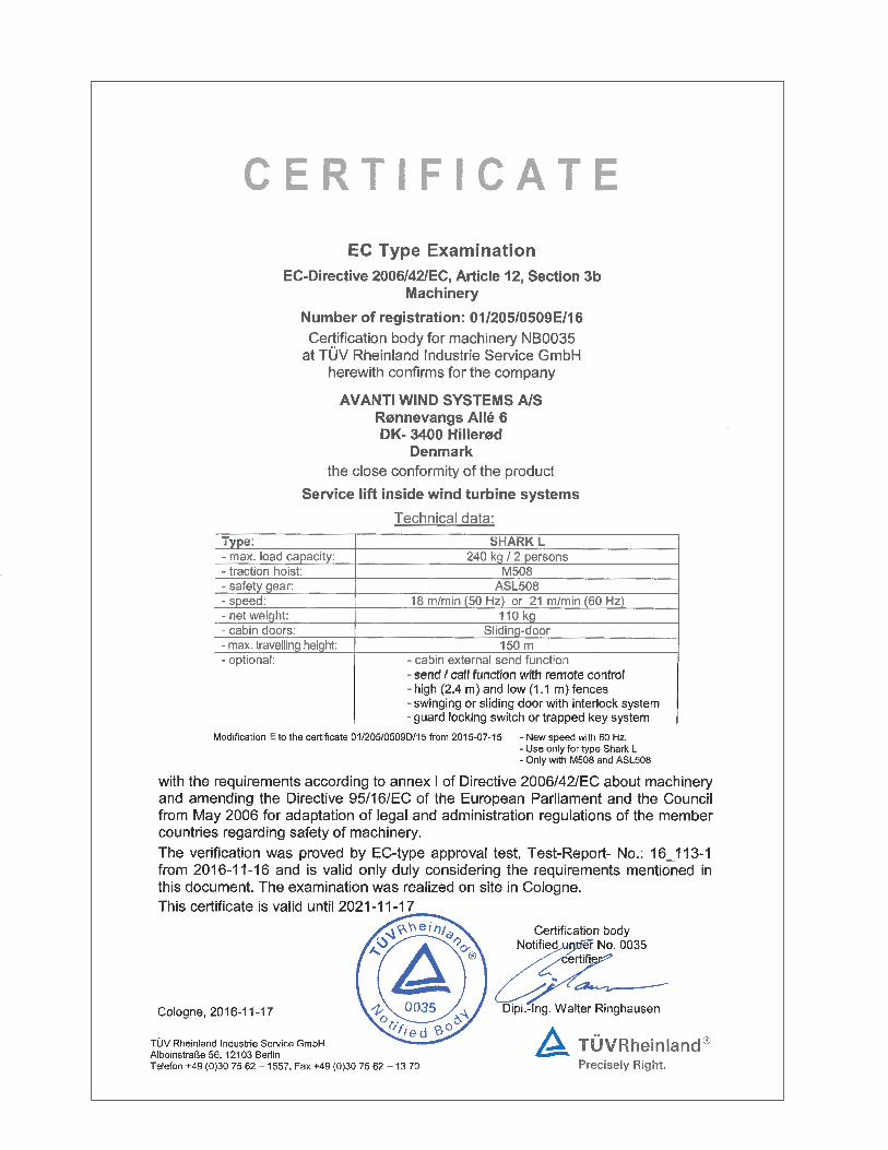
This User’s Manual and Installation Manual describe the following models:
• SHARK L sliding door with 240kg lifting capacity
4.4 Temperature
Operating temperature-15ºC - +60ºC. Survival temperature-25ºC - +80ºC.
Low temperature kit is also available.Operational temperature for low temperature kit -25ºC - +40ºC. 4.5 Accessories
In order to fulfil the essential health and safety requirements from the regulations the design of the wind turbine and its components shall comple-ment the safety systems supplied on the service lift making the ensemble safe as a whole. A detailed evaluation of compliance to the EHSR and a risk assessment shall be completed. Avanti shall verify the compliance to such requirements prior to installation. Systems that may be consid-ered to complement the service lifts are:
4.5.1 Fences & guardsThe service lift hole must be adequately protected to prevent people from falling or being injured by the movement of the service lift. The fences and guards design shall comply with the relevant standards and local regulations.
4.5.2 Safety system for landing access doors The service lift hole must be adequately protected to prevent risk of falling. When the service lift is not at the landing, access doors shall not be able to open. Such function may be achieved by using interlock systems on access doors linked to the position of the service lift.
4. Description of equipment
4.1 Purpose

10 AVANTI Service Lift for Wind Turbines
4.6 Components
4.6.1 Cabin overview
Fig. 1 SHARK L sliding door
1
2
3
4
5
6
1 Cabin2 Sliding door3 Drive and safety wires4 Guide wire 5 Wire guides6 Bottom safety stop

11 User’s Manual
4.6.2 Technical data for the service lift L
Fig. 2 Dimensions, sliding door
Shark L lifting capacity: • Motor M508 240 kg (max 2 person)
Weight of lift: L: 110 kg
The weight of the power supply cable should be added to the weight of the lift (approx. 0.23 kg per m).
Standing height:Under spine: 1980 mmUnder traction hoist: 2100 mm
Sliding door opening:L: 550 mm Noise level emitted: max. 75 dB(A).
Dimensions in mm:
1) Standard wire guide/narrow wire guide.
B
E
NG
D
A
C
F
H
Shark A B C D E F G1) N H
L 380 960 600 650 475 75 1150/1020 990 3000

12
7
8
9
88
77
5
6
1
222
3
4
10
11
12
AVANTI Service Lift for Wind Turbines
4.6.3 Drive system, fall arrest device and controls
Fig. 3 Traction hoist Fig. 4 Fall arrest device
Table 1. Traction hoist
Table 2. Fall arrest device
1 Insertion point for brake lever
2 Motor 3 Wire traction
w/overload protection
4 Drive system/gearbox
5 Unlock lever 6 Lock lever 7 Overide bottom
limit stop switch 8 Ready lamp 9 HAND/AUTOM 10 EMERGENCY
STOP button 11 UP 12 DOWN
Fig. 5 Electrical control boxFor M508
M508 ASL508
Fig. 6 a Pendant control
Fig. 6 b Remote control
HoistLifting
capacityWire speed Effect
Rated current
Traction hoist wire Ø
Unit weight approx.
Traction hoist type Kg m/min kW A mm Kg
M508/400V 50Hz 500 18 1.5 4.1 8.4 50
M508/690V 50Hz 500 18 1.5 2.3 8.4 50
M508/400V 60Hz 500 21 1.8 4.9 8.4 50
M508/690V 60Hz 500 21 1.8 2.8 8.4 50
Fall arrest device Lifting capacityTraction hoist
wire ØUnit weight
approx.
Fall arrest type kg mm kg
ASL508 500 8.4 7
Wire typeWire
diameterSurface
treatmentMark/
featureMin. break resistance
Attached with
AnchoringTighten
to
Guide Wire 12mm galvanised - 55 kN Shackle,2t Min. every 35m 2 to 4 kN
M508/ASL508 8.4mm, 5x19 galvanised none 55 kN 2 t shackle, Form C - -
Table 3. Drive wire, safety wire and guide wire

13 User’s Manual
4.7 Cabin safety devices
4.7.1 Electromagnetic motor brakeElectromagnetic spring-loaded brake which engages automatically– on releasing the up/down push button and– following a power failure.
4.7.2 EMERGENCY STOPWhen the red EMERGENCY STOP (pendant control) switch is pushed in an emergency, all control is interrupted. After remedying the fault, control is reactivated by turning the switch clock-wise, until it pops out again.
4.7.3 EMERGENCY STOP fixed (optional)Only in service lifts with an AUTOMATIC function installed. A backup switch to the pendant control EMERGENCY STOP switch is situated on one of the side panels inside the lift (Fig. 8).
4.7.4 Automatic operation switchA switch situated inside the pendant control holder. It prevents the lift from being controlled from the inside when the control is in automatic mode.
4.7.5 Overload limiterThe overload limiter is built into the wire traction system and will prevent upward travel in the event of an overload. A warning signal (buzzer) is triggered which will stop only when the cause of the overload has been removed.Possible reasons for activation of the limiter:- The service lift is overloaded or- the service lift encounters an obstacle during upward travel.Operator intervention:- Reduce the load to below the overload limit, or - lower the lift until it is free of the obstacle and
remove the obstacle before using the lift again.
4.7.6 Fall arrest deviceService lifts for personnel transportation must be equipped with a fall arrest device which will prevent the load from falling.
Fall arrest device type ASL.The fall arrest devices ASL are opened manually (Fig. 7).
The speed of the safety wire passing through the device is continuously monitored, and the jaws automatically close in the event of sudden excessive speed.
This protects the lift froma) Traction wire rope breaks andb) Hoist failures.The fall arrest device can also be engagedmanually in an emergency by pressing the Emergency stop button. The window is used to monitor the function of the centrifugal force mechanism during operation.
4.7.7 Drop-down safety beam (optional)This device can be installed in sliding door lifts. It provides protection against accidental falls when the door is opened during work between platforms. The beam remains in closed position by means of a latch. The beam is opened by actuating the latch and lifting the beam up slightly (Fig. 9c).See 4.8.1 Guard locking switch for information on how to open the sliding door between platforms.
4.7.8 Yellow flash (optional)An optional set of flashes can be mounted on the top and at the base of the lift. The flashes indicate when the lift is in movement (Fig 9a).
4.7.9 Emergency light (optional)An emergency light can be installed to provide illumination inside the lift with and without electric supply. The operation modes can be selected by means of a switch (Fig. 9b).
Fig. 7Fall arrest device ASL508
LockedUnlocked Window
Fig. 8Emergency stop and bottom stop
switch
Fig. 9a
Fixed Emergencystop button
Fig. 9b Fig. 9c
Automatic operation switch
Wi d

14
!
1
2 3
Switch ON only when the wind turbine generator has been stopped. Switch OFF before start up of the wind turbine generator.
Conectar: Sólo con turbina parada. Desconectar: Antes del arranque de turbina.
ON
OFF
4574
1006
WARNING!
AVANTI Service Lift for Wind Turbines
4.7.10 Door stop switch4.7.10.1 Sliding door:The sliding door is closed by pushing the actuator into the door guard locking switch (Fig. 10). The switch is unlocked by pushing the green button if the cabin is located at a height corresponding to a platform. In case of an emergency evacuation between platforms, the interlock is unlocked by pushing its emergency release red button from outside the cabin as well as using an M5 triangular key from inside the cabin.
4.7.11 Trapped-key interlock system (optional):Control is interrupted by turning the trapped-key switch to OFF. The key can then be removed. The key allows the user to open the platform fence doors. See the Trapped-Key Interlock System Manual for further information.
4.7.12 Limit stop switch 4.7.12.1 Top limit stop switchAt the top of the cabin frame a top limit stop switch will stop upward travel when activated (Fig. 11). Down-ward travel will still be possible. A top stop disc which activates the top stop switch is installed below the traction wire attachment (Fig. 5 section 2 of the installation manual ).
ATTENTION! When the top limit stop switch is engaged, activate the DOWN switch until the top limit stop switch is released.
4.7.12.2 EMERGENCY top limit stop switchDeactivates control if the top limit stop switch fails (Fig. 11). Manual downward travel is possible.
CAUTION! Do not use the service lift until the top limit stop switch fault has been rectified.
4.7.12.3 Bottom safety stop The bottom safety stop switch (Fig. 12a or Fig. 12b which shows an optional configuration) stops down-ward travel if the service lift encounters an obstacle or touches the ground.Upward travel will be possible, for instance to remove the obstacle. In order to put the service lift on the ground, the contact plate’s operation can be by-passed with the key switch in the control box.
4.7.12.4 Top safety stop (optional)The top safety stop switch stops upward travel if the lift:- Type 1: encounters an obstacle (fig. 13).- Type 2: the switch also works as a top limit stop switch. A top stop end bar is installed bellow the guiding wire attachment and activates the top safety stop. In this case the top stop end bar replaces the top stop disc (Fig. 14).Downward travel will be possible, for example, to remove the obstacle.
4.8 Safety devices for fences with doorsSafety devices for fences include devices to prevent people from accessing the service lift area, unless the service lift is safe to be accessed. The device also guarantees that the service lift does not when the protective fence doors are open. There are two types of safety devices for fences:
4.8.1 Guard Locking System The Guard Locking System uses a system of security locking switches installed on the fences. Another position switch detects the correct position of the service lift on the protected platform. The service lift cannot operate until all the protected fences are closed and locked.
Fig. 10
1 Green push button
2 Emergency release red push button
3 Emergency release M5 triangular key
Main Switch Disconnector
Ready Lamp

15 User’s Manual
The fences remain closed and locked until the service lift is stopped and properly positioned on the platform, actuating the position switch of the platform. In this position, the guard locking can be unlocked while pressing the green light button.
The interlock control box has a main switch. Turn the switch to the OFF position to cut the power to the service lift. The main switch must be set to OFF when the lift is not in use, when leaving the wind turbine and while the wind turbine is running. It must be set to OFF before starting an electrical generator. Consult the AVANTI Guard Locking System Manual for further information.
4.8.2 Trapped-key Interlock SystemThe Trapped-key Interlock System uses a system of security locks installed on the fences. These locks can be opened by using a key placed into the lift.The key also activates the On/Off general switch placed into the service lift cabin. The key is linked to the lift by means of a wire rope, and cannot be detached from it except using cutting tools.The key cannot be taken out from the On/Off general switch in the lift, unless it is in Off position, and therefore, the lift is stopped. In the same way, the key cannot be taken out from the fence lock unless the fence door is closed, and the door actuator is put into the door lock.The fences remain closed and locked until the service lift is stopped on the platform, and the key is trans-ferred from the lift cabin to the fence lock.Consult the AVANTI Trapped-key Interlock System Manual for further information.
Position switchFence latch with actuator
Green Light access button
Locking switch
Stop switch,normal operation
Emergency stop switch
Fig. 12a
Fig. 11
Fig. 12b
Bottom safety stop
Fig. 13
Fig. 14
Trapped-key switch
Key Security lock on fence
Actuator

16
!STOP
AVANTI Service Lift for Wind Turbines
If a safety device for fence doors is installed (see chapter 4.7 of the User’s manual), every platform fence door must be closed to be able to drive the cabin. 5.1 Service lift a) Before each operation, ensure that the traction
hoist, the Fall arrest device and all auxiliary components (stoppers, wire guide wheels, etc.) are mounted in accordance with the specifications and without any noticeable defects.
b) Check whether the drive, and safety wires are fed correctly around the two wire guide wheels.
c) Wire ends (of 3 m or more in length) must be coiled separately at the floor and tied with strips in at least 3 places.
d) Check lifting capacity: (see the rating plate or section 4.6.2) – the extra load (persons and materials!) must not exceed the maximum rated lifting capacity.
5.2 Operating area a) Ensure that there are no obstacles within the
service lift’s operating area which may obstruct the travel of the cabin or cause the cabin to hit the ground.
b) Ensure that all relevant and required protection measures below the cabin are in place. Such measures could include pent roofs or barriers to protect the staff from falling objects.
5.3 Control function a) Close the doors. Press the EMERGENCY STOP
button. The lift should remain still when the UP/DOWN button is pressed. To restart, turn the EMERGENCY STOP button clockwise. If a FIXED EMERGENCY STOP button is installed (Fig. 8) test as above.
b) Test the top limit stop switch: During upward travel, press the switch manually, and the service lift should stop immediately. Pressing the limit stop switch should enable the lift to travel down again.
c) Test the EMERGENCY top limit stop switch: During upward travel, press the switch manually, and the service lift should stop immediately. Neither upward nor downward travel should now be possible.
d) Bottom safety stop. Lower the lift; it should stop before the rubber feet of the cabin reach the tower ground level. When the “bypass
switch” is activated, it should be possible to lower the lift all the way to the ground.
e) Door stop switch: Open the door - it should not be possible to move the lift upwards or downwards.
Sliding door service lift: Move the cabin at a height no corresponding to a platform - it should not be possible to open the door. The door will be only able to be opened by pushing the emergency release red button from outside the cabin as well as using a M5 triangular key from inside the cabin.
f) If the optional AUTOMATIC function is installed. Set the HAND/AUTOM. selector to AUTOM. When holding the handle, the lift should remain still when the UP or DOWN buttons are activated.
g) If the Trapped-Key interlock system is installed. Turn the trapped-key switch to OFF - it should be not possible to move the lift upwards or downwards. See the Trapped-Key Interlock System Manual for further information.
Warning! If any faults occur during work, - stop working, - if required secure the workplace and - rectify the fault!
DANGER! Make sure that nobody is exposed to danger below the service lift, for instance from falling parts. Suitable measures: Pent roof or barriers.
Fig. 15Electrical control boxM508
5. Daily inspection by the supervisor
HAND/ AUTOM.
(Optional)
Ready lamp “ON”
Override bottom
safety stop
EMERGENCY STOP
UP
DOWN
Pendant control

17 User’s Manual
5.4 Automatic operation test
Perform this inspection only if the AUTOMATIC function is installed.
a) Press EMERGENCY STOP button on the pendant control. Turn the HAND/AUTOM. switch on the electrical control box to the right to activate automatic operation.
b) Deactivate the EMERGENCY STOP button by turning the button clockwise. (Check the EMERGENCY STOP button fixed is deacti-vated.) The service lift should stand still.
c) DO NOT try to activate the “automatic opera-tion” switch.
d) If the trapped-Key interlock system is installed, turn the trapped-key switch to ON. With the doors closed, press the UP and DOWN buttons. Neither upward nor downward travel should be possible (Switch in pendant control holder blocks the operation).e) Press the EMERGENCY STOP button on the
pendant control. f) Place the pendant control in its holder so it is
operational from the outside.g) Leave the cabin and close the door.h) Deactivate the EMERGENCY STOP button.
The service lift should stand still.i) Press the UP button. The lift should travel
upwards.j) Press the EMERGENCY STOP button. The lift
stops.k) Turn the EMERGENCY STOP button clockwise
and press the DOWN button. The service lift should travel downwards until the EMERGEN-CY STOP bottom stops the service lift.
l) Remove the pendant control from holder.m) Return the HAND/AUTOM. button to HAND.n) Check that the UP and DOWN buttons work
again.
5.5 Remote operation test
Perform this inspection only if the remote control function is installed.
a) Set the electrical control box switch HAND/AUTOM to AUTOM (fig 5).
b) On top of the remote operation receiver switch the device on (fig 6 b).
c) Press the up arrow on the remote operation transmitter. The service lift should ascend.
d) Press the down arrow on the remote operation transmitter. The service lift should descend.
e) Once the test is complete, switch the remote operation function off.
5.6 Fall arrest device
a) Ascend electrically approx. 50 centimeters and observe centrifugal weight during this process. Activate the fall arrest device by turning the lock lever counter clockwise (Fig. 7 section 4.7).b) Verify the engagement with no-power descent and observe centrifugal weight during this process. The FAD must hold the load (if this is not the case, leave the lift and tag it out). Ascend electrically again to unload the FAD. Unlock the fall arrest device by turning the unlock lever clockwise.c) During operation, regularly (at least once per each travel up and down) monitor the centrifugal force regulator relay’s rotation by looking through the window. d) There is an alternative method to check the FAD functionality, called ‘Stomp Test’. The procedure is explained in the ‘Stomp-test Instruction’.
5.7 Wire ropes
a) Follow the 3 steps below to check that the traction and safety wire ropes are not tangled with tower internals. a.1) Open the top hatch and look upwards in search of any unusual trajectory deviation of the traction and safety wire ropes. a.2) Close the top hatch and ascend with the service lift to the following platform. a.3) Repeat steps a.1) and a.2) until the complete length of the wire ropes is inspected. a.4) If any wire rope is found tangled, climb up the ladder and untangle the wire rope by hand. Then, inform AVANTI.
Fig. 16
Emergencystop button
Automatic operation switch

18 AVANTI Service Lift for Wind Turbines
b) During operation, check that the traction and safety wire ropes pass freely through the traction hoist and the fall arrest device.
c) Once the lift is at the top platform, inspect the top tower beam and the wire rope attachments. d) Check that the length (L) between the top end of each wire rope and its ferrule is equal to or more than 0 mm.
5.8 Wire ropes after an unusual event After any unusual event (such as a tower jerk due to the wind turbine going into emergency mode) check that the traction and safety wire ropes have not got tangled with tower internals.
5.8.1 At the bottom platform If the service lift is placed at the bottom platform when the unusual event occurs, follow the steps below.a.1) Open the top hatch and look upwards in search of any unusual trajectory deviation of the traction and safety wire ropes.a.2) Close the top hatch and ascend with the service lift to the following platform.a.3) Repeat steps a.1) and a.2) until the complete length of the wire ropes is inspected.a.4) If any wire rope is found tangled, climb up the ladder and untangle the wire rope by hand. Then, inform AVANTI.
5.8.2 At the top platform If the service lift is at the top platform when the unusual event occurs, follow the steps below.a) From the platform look downwards through the platform hole in search of any unusual trajectory deviation of the traction and the safety wire ropes.b) Enter the lift and descend to the following platform.c) Exit the lift and repeat steps a) and b) until the complete length of the wire ropes is inspected.e) If any wire rope is found tangled, climb down the ladder and untangle the wire rope by hand. Then, contact AVANTI.
X
STOP
Thimble
Ferrule

19 User’s Manual
If a safety device for fence doors is installed (see chap-ter 4.7 of the User’s manual), every platform fence door must be closed to be able to operate the cabin. Transportation of people in AUTOM. mode is forbidden.
6.1 Prohibited usesThe consequences of not following belowprohibitions are extremely hazardous to thephysical integrity of the users.
When using the service lift it is prohibited to:• Use the service lift beyond its intended purpose.• Operate the service lift without following the safetywarnings and operating instructions.• Overload the service lift• Try to repair machine components. Only certified technicians are allowed to perform service on the machine.• To manipulate switches and safeties.• To place objects on service lift roof.• To descend on service lift roof.
6.2 Entry and exit To ensure safe entry and exit: a) Lower the service lift onto the access platform until
the contact plate is activated and the cabin stops, or: bring the lift to a height corresponding to the correct level for exiting from the wind turbine’s platform.
b) Open the door and exit/enter the lift through the door/over the cabin railing.
6.3 Stop/EMERGENCY STOP a) Release the UP/DOWN push button; the service lift
should stop
If it does not:
b) Push the EMERGENCY STOP switch, and all controls should be disabled. Open the door and enter/exit the lift through the door/over the cabin railing.
6.4 Normal operation 6.4.1 Without trapped key system If the trapped key system is not provided, follow the steps below.
a) Close the platform and lift doors.
b) Turn the emergency stop button of the pendant control clockwise until it pops out.
c) Do likewise with the emergency stop button fixed in the cabin (Fig. 8).
d) Press and hold the UP or DOWN button to ascend or descend respectively.
6.4.2 With trapped key system If the trapped key system is provided, follow the steps below.
a) Extract the trapped key from key hole of the platform fence.
b) Insert the trapped key in the key hole of the cabin control box.
c) Turn the trapped key to ON position.
d) Close the platform and lift doors.
e) Turn the emergency stop button of the pendant control clockwise until it pops out.
f) Do likewise with the emergency stop button fixed in the cabin (Fig. 8).
g) Press and hold the UP or DOWN button to ascend or descend respectively.
6.5 Automatic operation Only in service lifts with the AUTOMATIC function installed. a) If the trapped-key interlock system is installed, the trapped-key switch should be ON in order to drive the lift. b) Press the EMERGENCY STOP switch on the pendant control. Turn the HAN/AUTOM switch on the power cabinet to activate the automatic operation. c) Put the pendant control inside the holder. It should engage the automatic operation switch (fig.8). d)Close the door e) Turn the EMERGENCY STOP switch on the pendant control clockwise and the switch should pop out. f) Press the UP or DOWN button respectively and the cabin starts ascending/descending.
6. Operation - lift transport
STOP

20
!STOP
AVANTI Service Lift for Wind Turbines
6.6 Remote operation a) Set the electrical control box switch to AUTOM
(fig.5).
b) On top of the remote operation receiver switch the device on (fig.6b).
c) For ascending press the up arrow on remote operation transmitter.
d) For descending press the down arrow on remote operation transmitter.
e) Once the operation is complete, switch the remote operation function off.
6.7 Overload limiter a) In case of an overload, the lift’s upward travel
should be blocked, and a buzzer should sound in the connection cabinet.
DANGER! Attempting to go up in an overloaded lift is prohibited!
b) Remove enough of the load to make the buzzer stop and enable upward travel.
WARNING! On entering and starting the lift, the buzzer may sound briefly. This is due to temporary load peaks occurring as the lift takes off. The control box is designed not to activate the buzzer or stop the lift because of peak loads caused by the cabin swinging.If problem persists have a certified technician adjust the overload limiter (See “Regulation of overload limiter” Appendix).
6.8 Override of the bottom obstruction device For maintenance tasks only, it is possible to override the bottom obstruction device by means of a key on the cabin control box.
a) Descend the service lift until the the bottom obstruction device reaches the floor.
b) Turn the override key of the cabin control box (fig. 5 section 4.6.3) clockwise and hold.
c) Press and hold the DOWN button until the service lift feet rest on the floor.

21 User’s Manual
If a power failure or an operation fault etc. interrupts the lift, a manual EMERGENCY descent is possible.
7.1 EMERGENCY descent
a) Open the manhole by pushing the lid in the roof and operate the lift from above.b) Pull the lever upwards. The service lift moves downwards. The built-in centrifugal force brake limits the pace of descent.c) To stop, simply loosen the leaver. d) After use, replace the lever in roof hole. For emergency situation only
7. Manual operation (EMERGENCY)
Fig. 17 M508

22
STOP
!
AVANTI Service Lift for Wind Turbines
LOCK
If the fall arrest device engages simply disengage by turning the lever counter clockwise (Fig. 18) until it clicks. However, this is not possible if the service lift is hanging on the wire - if so, see below.
DANGER!In the event of breakages in the wire ropes or failure of the service lift, evacuate personnel from the service lift.
The safety wire suspension and the attachment between the fall arrest device and the service lift are exposed to dynamic loads when a fall is blocked.
If the fall arrest device has locked and the service lift is hanging on the wire, ascending is blocked. Do as follows:
a) Remove the load on the safety wire by taking the service lift upwards a few centimetres by push-ing the UP button.
– In the event of a power failure, evacuate the lift.
b) Manually open the fall arrest device by turning the lever counter clockwise (Fig. 18) until the device disengages. On ground level perform test as specified in section 5. e) of the Installation Manual section and 5.6 of the User’s Manual before resuming normal operation.
ATTENTION!When the service lift has returned to ground level, test the fall arrest device function.
CAUTION! Replace any defective fall arrest device components and return them for repair to the manufacturer.
CAUTION! In case of no power and the fall arrest device is locked with the safety wire rope under tension, evacuate the service lift according to the evacuation procedure.
8. Fall arrest device
Fig. 18
ASL508
Safety wire
Unlock
e

23
STOP
User’s Manual
Breakdown Cause Solution
The service lift will neither go up nor down!
DANGER!Attempting to use the lift will jeopardize work safety
A1 The fixed EMERGENCY STOP button is activated.
Turn this button clockwise until it moves out to deactivate it.
A2 Wire loop on traction hoist. Damaged or defective wire or wire
outlet causes problems.
Stop work immediately!Ask the supplier or manufacturer for help.
A3 The fall arrest device is holding the service lift on the safety wire.
a) Traction wire rope breakageb) Hoist failure
a) + b) Evacuate the service lift and follow the directions in section 8
A4 The service lift is stuck on an obstacle.
Carefully remove the obstacle.Test the operational safety of affected building sections. Inform the supervisor.
A5 Power failurea) The control is not set to ON.b) Grid voltage interruptedc) Supply between grid connection and control interrupted
a) Turn EMERGENCY STOP switch clockwise until it is releasedb) Find the cause and wait for the power to returnc) Test and if necessary repair the supply cable, guide wires, fuses, and/or wiring from the control box
A6 Limit stop switch functionsa) EMERGENCY limit stop switch is
pressed.b) Door limit stop switch is
blocked or is defective.
a) Manually take the lift down until the limit stop switch is released.
b) Close the doors and test the limit stop switch.
A7 Protection switch on overheating
a) A phase is missingb) Motor is not coolingc) Voltage too high/low
a) Test/repair fuses, supply and connec-tion.
b) Clean the hood.c) Measure voltage and power consump-
tion on the loaded motor. If voltage does not obey the specifications, use cable with increased dimensions.
A8 Brake does not open (no click on on/off)
a) Supply, braking coil or rectifier defective.
b) Braking rotor closes.
a) Have an electrician test, repair/replace the supply, braking coil and rectifier.
b) Return the traction hoist to the manufacturer for repair.
9. Repair in the event of breakdown
1. All tests and repairs to the electronic compo-nents should be performed by certified technicians only! The power chart is placed in the traction hoist’s power cabinet.
2. Repairs to the traction hoist, the fall arrest device and to the system’s supporting compo-nents should be performed by certified technicians only!
DANGER!
Unplug the power supply before opening the power cabinet.

24
STOP
!
AVANTI Service Lift for Wind Turbines
Breakdown Cause Solution
The service lift will neither go up nor down
A9 The HAND/AUTOM. switch is on AUTOM.
Turn the HAND/AUTOM. switch back to HAND.
A10 The Trapped-key Interlock System for fences is installed. The Cabin switch of the system is in Off position.
Turn On the trapped-key switch.Consult the AVANTI Trapped-key Interlock System Manual for further information.
A11 The Guard Locking System for fences is installed. The general On/Off switch of the Guard Locking System Control Box at the bottom platform is Off.
Turn On the general On/Off switch of the Guard Locking System Control Box at the bottom platform. Consult the AVANTI Guard Locking System Manual for further informa-tion.
A12 The Guard Locking System for fences is installed. At least one of the protected fences is open.
Close all the protected fence doors. Consult the AVANTI Guard Locking System Manual for further information.
Service lift goesdown but not up
DANGER! Irresponsible behaviour jeopardizes system safety!
B1 The service lift is stuck on an obstacle.
Carefully move the service lift downwards and remove the obstacle. Test the opera-tional safety of affected platform components. Inform the supervisor.
B2 Overload - Buzzer soundsin the connection cabinet.
Test and possibly reduce load until buzzer stops.
B3 Limit stop UP: a) Limit stop defective or not
connected.b) Operation limit stop was
activated.
a) Test the limit stop connection/function. Replace if necessary.
b) Move lift down until the limit stop switch is released.
B4 A phase is missing Test fuses and power supply.
B5 Fault in UP control circuit in control box or traction hoist
Test and possibly repair connections, wiring and relays.
Motor hums loudly or wire ropes squeak,
but the lift can go both up and down.
C1 Overheating For descriptions of individual causes and how to rectify faults
C2 Wire ropes dirty
WARNING! Further use of lift may result in damage to the wire traction.
If possible, immediately replace the traction hoist and return it for test/repair at AVANTI.
DANGER!
Unplug the power supply before opening the power cabinet.

25
STOP
STOP
User’s Manual
Breakdown Cause Solution
Service lift will go up but not down!
DANGER! Irresponsible behaviour
jeopardizes system safety!
D1 The service lift has encountered or is stuck on an obstacle.
Carefully take the service lift up and remove the obstacle.Test the operational safety of affected platform components. Inform the supervisor.
D2 The fall arrest device is holding the service lift on the wire.
a) Excessive hoist speedb) Too low release speed on
fall arrest device.
a) + b) Take the service lift upwards to relieve the safety wire. Open the fall arrest device by pressing the handle, and test its function!
Functional test when the lift is back on the ground: Replace the hoist and fall arrest device and return them for testing.
DANGER! A defective fall arrest device will threaten the safety of the service lift!
Replace immediately!
D3 Fault in down controller circuit on traction hoist
Pull the lever upwards. The service lift moves downwards. (See details in section 7) Test, and if necessary have connections, wiring, and relays repaired.
Green lampnot lit although operation is normal
E The lamp is defective Have an electrician replace the bulb.
Hoist goes down when up button is pressed and up when down button is pressed.
F Two phases changed in the supply
Have an electrician switch the two phases in the plug
Loud noise and / or smoke coming from hoist motor
G Brake closed or partially closed WARNING !Damage of hoist brake leading to brake function lost.
Stop work immediately! Call supervisor for advice and potential repair of hoist.
If these steps do not identify the cause and rectify the fault: Consult a certified technician or contact the manufacturer.
Green lamp
DANGER!
Unplug the power supply before opening the power cabinet.

26
Switch ON only when the wind turbine generator has been stopped. Switch OFF before start up of the wind turbine generator.
Conectar: Sólo con turbina parada. Desconectar: Antes del arranque de turbina.
ON
OFF
4574
1006
WARNING!
AVANTI Service Lift for Wind Turbines
CAUTION!Wear protective gloves when handling wires.
11.1 Parking the service lift
Lower the lift until bottom safety stop engages.
11.2 Wire ends
Beneath the access platform:a) Loosen and uncoil all coiled and secured wire ends.b) Remove the weight and the tightening spring.
11.3 Removing the lifting wire
a) Turn the “override bottom limit stop switch” key to the right and push the DOWN button until the cabin rests on the platform.
b) After having removed the drive wire counter weight turn the DOWN button. The wire now exits the traction hoist at the top.
c) From above the traction hoist remove the wire by hand.
11.4 Removing the safety wire
a) Keep the fall arrest device open and manually pull out the wire.b) Pull out the wire on top of the lift.
12. MaintenanceAll the inspections / maintenance operations (periodical or extraordinary) must be logged in the appropriate In-spection Appendix. All inspections and service tasks made to the hoist and fall arrest device must be carried out by certified technicians. The relevant maintenance instructions are provided to each person during the training.
12.1 Recommended planning Avanti recommends the following maintenance planning:
10. Out of servicea) Securing the service lift: Bring the service lift all the way down, until the contact
plate switch stops the cabin.
b) Disconnect the lift to prevent inadvertent operation: Mark the lift “OUT OF SERVICE” and padlock as necessary. Contact the service technician for repair.
11. Removing wires for replacement
Frequency Performed by Components
Daily User
Overall / Travel zone
Control and safety devices
Fall arrest device
Annually Certified Technician
Overall / Travel zone
Control and safety devices
Cabin
Traction hoist
Fall arrest device
Overload limiter
Traction and safety wire ropes
Guiding system
Electrical system
Information signs and documents
Doors and hatches
Cabin control box
Safety switches
Interlock system
Platforms
Every two years Certified Technician Fall arrest device
Every five years or 50 hours (whatever occurs first) Certified Technician Traction hoist
Every 20 years or 250 hours of operation (whatever occurs first)
At Avanti Workshop Traction hoist
Fall arrest device

27 User’s Manual
12.2 Alternative planning Owners who strictly follow the maintenance program and the daily inspections, and can document it could decide with taking over the responsibility as well to provide the following alternative planning:
Frequency Performed by Components
Daily User
Overall / Travel zone
Control and safety devices
Fall arrest device
Annually Certified Technician
Overall / Travel zone
Control and safety devices
Cabin
Traction hoist
Fall arrest device
Overload limiter
Traction and safety wire ropes
Guiding system
Electrical system
Information signs and documents
Doors and hatches
Cabin control box
Safety switches
Interlock system
Platforms
Every ten years or every 125 hours of operation (whatever occurs first)
Certified Technician Traction hoist
Fall arrest device
Every 20 years or 250 hours of operation (whatever occurs first)
At Avanti Workshop Traction hoist
Fall arrest device
12.3 CautionsBefore any maintenance task, ensure that walkingway surfaces are dry and not slippery. Before any maintenance operation, check that the service lift is properly out of service. In case of a fault, do not use the service lift until it is solved. If required secure workplace.During maintenance tasks, personnel shall:• Wear at least the following PFPE: fall arrest equipment (when falling height is more than 2 m), hand gloves, helmet, safety glasses and working gear.• Place cabin at bottom platform and disconnectpower supply.• Use an electricity measuring tool when performinginspection of electrical components.• Use a hand winch attachable to the ladder whenhandling big/ heavy loads and shall be performedat least by 2 persons.• Panel parts shall be removed to facilitate accessto confined spaces.• Use a cable grip when replacing travelling cable.• Keep cabin doors closed when using a 3-step ladder.
Only certified technicians shall perform electrical installation tasks.
When plugging the servivice lift to the powersupply, ensure that supply phases are correct!
12.4 Annual inspectionHave the entire system tested by a certified technicianat least once a year, especially the traction hoist and the fall arrest device. However, it may be required more frequently depending on use and the conditions of use and operation. The traction hoist and fall arrest device must be inspected ac-cording to intervals included in the sections 12.1 or 12.2 tables (see above). Hour counter is found in the main control box.
A certified technician must carry out the annual inspection following th appropriate Inspection Appendix.
Owner must ensure that the results of all annual and extraordinary inspections are logged in the appropriate Inspection Appendix.
In case of replacement of hoist, Fall Arrest Device and/or 8 mm. wire ropes, the operation/s and the related total hours of use of this/these component/s, must be logged in the appropriate Inspection Appendix.
12.4.1 CabinInspect the cabin structure, joints, attachments and acces-sories.
12.4.2 Traction hoistThe traction hoist shall be maintained according to maintenance planning (please see sections 12.1 or 12.2). Relevant maintenance instructions are provided to each person during the training. These maintenance inspections must be only carried out by a certified technician.
!
!
!�

28 AVANTI Service Lift for Wind Turbines
�
12.4.3 Fall arrest deviceThe fall arrest device shall be maintained accordingto maintenance planning (please see sections 12.1 or 12.2). Relevant maintenance instructions are provided to each person during the training. These maintenance inspections must be only carried out by a certified technician.
If fall arrest device has engaged due to a dynamic fall, a certified technician must verify the safety of the fall arrest device, the wire rope, and wire rope fastenings.
After FAD has engaged, if the FAD damper has moved downwards, the FAD unit must be replacedby a certified technician.
12.4.4 Traction, safety and guiding wire ropesCarry out the following inspections and adjust ifnecessary:1. Inspect all the wire ropes along their entire length.2. Pay special attention to the wire rope ends, parts of the wire ropes running over sheaves and wire ropes under frictional wear by external components.3. When inspecting the wire ropes, consider the following points:type and number of wire breaks, position and time se-quence of wire breaks, decrease of the wire rope diameter during operation, corrosion, abrasion, deformation, influ-ence of heat, and operating time.4. Check that the traction and safety wire ropes are fedcorrectly around the 2 wire rope guide wheels.5. Check that the wire rope ends are coiled separately under the bottom platform and tied with at least 3 cable ties.6. Check that the guiding wire rope tensioning system iscorrectly installed and that the wire rope locks and fixes are properly fastened.7. Check that the compression spring on the safety wirerope is correctly installed and that the wire rope locks are properly fastened.8. Check that the counterweight on the traction wire rope is properly fastened. The traction wire rope coil andcounterweight shall be able to rotate freely. Do not attach them to a fixed part.9. Check that the guiding wire ropes are correctly tensioned.
Record any visible change of the condition of the wireropes on the appropriate Inspection Appendix, andmonitor closely throughout time.
12.4.4.1 Cleaning1. Open the top lift hatch to access the wire ropes from inside the service lift.2. Use a cloth to wipe off the old grease from the wire ropes.3. Close the top lift hatch and ascend the service lift 1 or 2 m.4. Repeat steps 1 to 3 until the entire length of the wire ropes is clean.
Always keep the traction, safety and guiding wireropes clean and slightly greasy.
Only use mechanical means to clean the dirty wireropes, i.e. a cloth or a hand brush. Do not usesolvents or other detergents.
12.4.4.2 LubricationIf the distance between platforms is more than 20 mperform the following procedure:1. Ascend the service lift 20 m.2. Open the top lift hatch.3. Through the top lift hatch and with a spray can,apply lubricant on the wire ropes.4. Close the top lift hatch and ascend the servicelift 1 or 2 m.5. Repeat steps 1 to 4 until the entire length of thewire ropes is lubricated.6. Finally, perform two complete ascends anddescends in order to distribute the new lubricantevenly along the wire ropes.If the distance between platforms is equal or lessthan 20 m perform the following procedure:1. A first person ascends in the service lift severalmeters so that the wire ropes are accessible fromthe platform.2. From the platform and with a spray can, a second person applies lubricant on the wire ropes.3. Both persons ascend in the service lift to the next platform.4. One person egresses to the next platform.5. Repeat steps 1 to 4 on each platform until theentire length of the wire ropes is lubricated.6. Perform two complete ascends and descends inorder to distribute the new lubricant evenly along thewire ropes.
Only use specialised wire rope lubricants. Do not uselubricants based on lithium soap grease or bitumen.Do not use disulphide-containing lubricants likeMolycote ®. Apply lubricant using a spray can, brush, drip applicator or pressurized device.Pay special attention to sections of the wire ropewhere dehydration or denaturation of the lubricantcan be seen.Re-lubricate the wire ropes before they show signs ofcorrosion or run dry, and taking in mind that:• A poor lubrication leads to corrosion and to aquick wear of components.• An excessive lubrication leads to dirt agglomeration on the wire rope surface. As a result, this can lead to quick wear of wire rope, sheaves and drum.• A correct lubrication keeps the efficiency factorof the wire rope, protects against corrosion,helps to elongate their lifetime significantly andensures a safe operation.
12.4.4.3 Measuring of the wire rope diameter When measuring the diameter of the wire ropes, use a digital calliper with broad measuring faces.
STOP
!
!
! Fig. 19

29 User’s Manual
In general, measure the diameter of the wire rope ateach WTG tower platform, and under the service lift,where the wire rope is less loaded. Specifically, if awire rope wear is detected, measure on the affectedarea.
Rotate the calliper around the wire rope tomeasure the minimum and maximum wirerope diameter at each measurement point.
12.4.4.4 Discard criteria
The discard criteria of the wire ropes shouldbe based on ISO 4309: Cranes - Wire ropes -Care and Maintenance, inspection and discard.
Determine and eliminate the cause beforeinstalling a new wire rope.
AVANTI recommends to replace the tractionand safety wire ropes after 250 hours ofoperation corresponding with the refurbishment of the traction hoist and fall arrest device. Please check with your local authority regulations if it’s mandatory in your case.
Check and replace the respective wire rope(s) if one ofthe following defects is found:• For traction and safety wire ropes, if there are morethan one 4-wire strand break on a wire rope length of250 mm. (see Fig. 20).
• For guiding wire ropes, if there are more than one 8-wire strand break on a wire rope length of 360 mm. (see Fig. 20).• If there is severe corrosion on the surface or the inside.• If there is heat damage, evident by the wire rope colour.• For traction and safety wire ropes, if the wire ropediameter is less than 7,6 mm.• For guiding wire ropes, if the wire rope diameter is less than 11,4 mm.• If there is damage on the wire rope surface (see Fig. 21 for most common examples of wire damage).
12.4.5 Electrical cablesCheck and replace the power supply and controlcables if the cable jacket or cable connections aredamaged.
12.4.6 Overload check and adjustmentAnnual test: Test switches and perform overloadtest as specified in the “Adjustment of theoverload limiter” Appendix.
12.4.7 Information signs and documentsVerify availability and legibility of all data plates andinformation signs. Replace missing or illegibleplates and signs!
12.5 RepairsRepairs to traction hoist equipment must ONLY beperformed by AVANTI, and only using original spare parts. If the gearbox oil needs to be replaced, use one of the lubricants specified below, corresponding to the temperature range in which the traction hoistequipment is used.• Amount required: 1,5 l• Traction hoist: M508• Oil: Mobil SHC 632.Each oil has to be verified by AVANTI.
12.6 Ordering spare partsOnly use original parts. Spare part lists are available from AVANTI. Please indicate lift model when requesting a spare part list.
Wire rope strap/loop, which cannot be unwound
Kinks resulting from counterweight of traction wire rope not being able to rotate freely.
Loop knot forming when a wire loop is pulled tight
Bends resulting from inappropriate treatment (e.g. securing the load with the wire)
Damage resulting from crushing, squeezing, running over, etc.
Wire bags
Loop formation
!
!!�
Fig. 20
Fig. 21

30 AVANTI Service Lift for Wind Turbines
13. Transport and storage
Depending on the transport and storage conditions that were agreed with the customer, the following methods are standard ways for the transport of the cabin with the installation accessories:
• Land transport: Rear support over pallet. Non stackable.
• Sea transport: Package using wooden box and plastic shrink on a pallet. Non stackable.
Storage conditions:
• Keep the service lift in its original packaging until it is mounted in the tower section.
• Keep stored in a dry place.
• Storage temperature between -25 º C and 80 º C (survival temperature).
• Non stackable.

31
STOP
! !
Installation Manual
Installation Manual
Please familiarise yourself with these instructions and the User Manual (Model SHARK) before installing the service lift. Ensure that all specified parts are present before commencing installation.
No warranty is provided against damage and injury resulting from not following this “User’s Manual and Installa-tion Manual” i.e. reconstruction or modification of equipment or use of non-original parts which are not approved by the manufacturer.
Assemble the SHARK service lift close to its final place of installation. Assemble sliding doors as follows:
Installation holes have been pre-drilled. Bolts, nuts etc can be found in the plastic bags supplied.
1. Assemble the right, left and bottoms sections with the cabin resting on its back.
2. Mount the roof spine and then slide the roof into position and fit to the cabin.
3. Fit the wire guides.
4. Mount the traction hoist and fall arrest device to the spine.
5. Attach the cabin front.
6. Mount the 4 bottom rubber feet to the bottom of the cabin.
7. Mount the operation limit stop switch and emergency limit stop switch on the roof using the contact bracket.
8. Attach the bottom safety stop beam including the wires that hold the bottom safety stop beam.
9. Bring the cabin to its upright position.
10. Mount the doors on the cabin.
11. Mount the steps and handle inside the cabin.
12. Feed the power cable through the rear hole and fit the socket to the back using the strips.
13. Mount the bottom safety stop switch and adjust. Connect the switch cables to the power cabinet according to the colour code. All wires are secured using strips (max 200mm between strips).
All bolts and nuts are stainless steel.
DANGER!If it is possible to enter underneath the service lift a double button safety stop must be fitted.
1. Assembling the SHARK cabin
Prior to installation, all parts must be tested to ensure their completeness and full functionality.
Prior to installation of the suspension system, ensure that the building sections involved will be able to carry the load.

32
4
26
30
30
24
27
6
18
11
23
9
12
16
17
2
15
29 29
14
25
28
8
8
8
1322
10
2120
19
1
3
5
28
7
AVANTI Service Lift for Wind Turbines
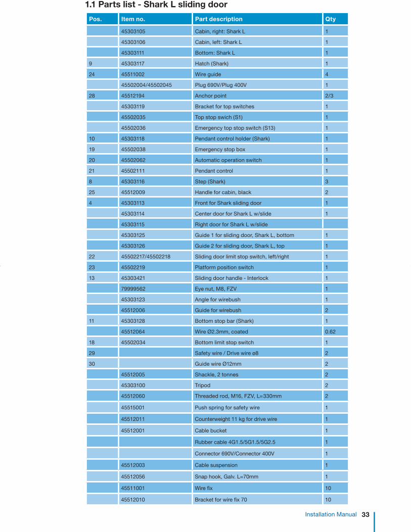
1.1 Parts list - Shark L sliding door
33 Installation Manual
1.1 Parts list - Shark L sliding door
Pos. Item no. Part description Qty
45303105 Cabin, right: Shark L 1
45303106 Cabin, left: Shark L 1
45303111 Bottom: Shark L 1
9 45303117 Hatch (Shark) 1
24 45511002 Wire guide 4
45502004/45502045 Plug 690V/Plug 400V 1
28 45512194 Anchor point 2/3
45303119 Bracket for top switches 1
45502035 Top stop swich (S1) 1
45502036 Emergency top stop switch (S13) 1
10 45303118 Pendant control holder (Shark) 1
19 45502038 Emergency stop box 1
20 45502062 Automatic operation switch 1
21 45502111 Pendant control 1
8 45303116 Step (Shark) 3
25 45512009 Handle for cabin, black 2
4 45303113 Front for Shark sliding door 1
45303114 Center door for Shark L w/slide 1
45303115 Right door for Shark L w/slide
45303125 Guide 1 for sliding door, Shark L, bottom 1
45303126 Guide 2 for sliding door, Shark L, top 1
22 45502217/45502218 Sliding door limit stop switch, left/right 1
23 45502219 Platform position switch 1
13 45303421 Sliding door handle - Interlock 1
79999562 Eye nut, M8, FZV 1
45303123 Angle for wirebush 1
45512006 Guide for wirebush 2
11 45303128 Bottom stop bar (Shark) 1
45512064 Wire Ø2.3mm, coated 0.62
18 45502034 Bottom limit stop switch 1
29 Safety wire / Drive wire ø8 2
30 Guide wire Ø12mm 2
45512005 Shackle, 2 tonnes 2
45303100 Tripod 2
45512060 Threaded rod, M16, FZV, L=330mm 2
45515001 Push spring for safety wire 1
45512011 Counterweight 11 kg for drive wire 1
45512001 Cable bucket 1
Rubber cable 4G1.5/5G1.5/5G2.5 1
Connector 690V/Connector 400V 1
45512003 Cable suspension 1
45512056 Snap hook, Galv. L=70mm 1
45511001 Wire fix 10
45512010 Bracket for wire fix 70 10

34 AVANTI Service Lift for Wind Turbines
1.1 Parts list - Shark L sliding door
Pos Part no. Part description Qty
2 35410095 Landing rubber feet 1
1 35410001 Bolts for wire support bracket 1
6 35710001 Set platform position plate 1
45303101 Top stop disc 1
45541020 Quick-guide, English 1
45541022 Quick-guide, Spanish 1
45541031 Label lift EN/ES 240 kg 1
45541007 Wall label UK/DE 1
45541025 Warning sign - hook on to anchor point 1
45541027 Serial number plate Shark lift 1
45512023 Counterweight 31 kg 1
45541009 Label lift EN/ES 320 kg 1
12 45303112 Top: Shark L 1
5 45303107 Spine: Shark L 1
45303121 Guard small for Spine: Shark L 1
45303120 Guard large for Spine: Shark L 1
3 45570001 Roller 1 for spine (Shark) 2
45547002 Roller 2 for spine (Shark) 2
45408012 M508 400V CE 50Hz 1
45408013 M508 690V CE 50Hz 1
7 45408006 ASL508 1
45511006 Click on wire fix
45511007 Click on wire guide
35499287 Roller wire guide 4
45502142 Remote control transmitter 1
45502140 Remote control receiver 1
16 45502008 Grey connection box 1
17 45502016 Transformer 400 V - 230 V 1
45502001/55020011 Safety light top 1
15 45502002 Safety light bottom 1
35499074/35499075 Drop down safety beam Standard/Reverse 1
35499010 Double button stop: Shark L 1
26 35499012 Top safety stop: Shark L 1
27 45512174 Top safety stop Switch 1
45502146 Emergency light 1

35
!
Installation Manual
2.1 Tower top
Wire lengths depend on the tower height and should be specified when ordering. The coils are marked with their length; check for accuracy prior to mounting. Do not pull wire over any edges. Uncoil correctly (Fig. 5a).
Warning!Do not pull wire over edges.
Important! Place all wire coils on the top platform when tower is raised or use the tower mounting crane to place the wires on the top platform before nacelle is mounted. (It may also be possible to use the internal tower crane to hoist wires).
1) Mount the Ø12 mm guide wire and the Ø8 mm drive and safety wires using the shackles supplied for the suspension beam at the top of the tower, with the guide wire outermost on either side.
2) Fit the nuts and bolts. Lock with cotters. 3) Fit the top stop disc on the suspension wire
leaving at least 200mm between disc and shackle (See Fig. 5).
4) Feed all wires to the bottom of the tower (See Fig. 5).
IMPORTANT!All wires are evenly uncoiled as shown in Fig. 5a to prevent looping.
Fig. 5a
Fig. 5
Shackle, 2t
Guide wire Ø12mm
Shackle, 2t
Safety wire Ø8 (fall arrest device)
Drive wire Ø8 (traction hoist)
Top stop disc
2. Fitting the wires

36
STOP!
AVANTI Service Lift for Wind Turbines
Guiding Wire
Minimun safety gap “S” all around the service lift: 50 mm
Power Cable
Guiding Wire
Traction Wire
Safety Wire
2.2 Wire positioning measurements
Fig. 6 Minimum shaft clearance dimensions required for the service lift to run, and distance between the guide wires.
Dimensions:
Holes in the base platform in the tower for wire bushing are positioned as outlined below.
The holes are positioned with a tolerance of +/-5 mm. Holes with diameter Ø200 mm are fitted with rubber edging.
DANGER!Ensure that lift evacuation to the tower ladder is possible.
Warning!Ensure that no obstacles are in the way of the service lift.
Shark A B1) C D E S
L 250 575/510 960 600 220 50

37 Installation Manual
2.3 Securing the guide wire - ground level
IMPORTANT: Before feeding the guide wires through the platform, fit the correct number of wire fixes on the wire and feed through the wire guides. The wire fixes are fitted during the first run.
Feed the guide wire through the outer Ø20mm holes in the platform. Underneath the platform the guide wires are fastened and tightened using one of the following three methods.
Fig. 8 Method 1: Wedge anchor
Guide wire
Wire grips
Thimble
Rigging screw
Lifting eye bolt
Wedge anchor
Coiled guide wire
2.3.1 Method 1: Wedge anchorMount wire as shown in Fig. 8 following procedure below.
1) Drill 2 Ø16x75mm holes in the floor underneath the outer Ø20mm holes in the platform.
2) Fasten the wedge anchors in the holes and mount an M16 lifting eyebolt.
3) After loosening the rigging screw as much as possible, fasten the rigging screw to the eyebolt in one end and the wire using wire grips in the other.
4) Tighten the wire as described in section 2.3.4. 5) Excess wire is coiled and hung by means of
wire strips. Use at least 3 strips.6) Mount the second wire.
Fig. 7 Wire fix
2.3.2 Method 2: TripodPull the guide wire through the platform and fasten with the tripod (See Fig. 8a.)
1) After feeding the guide wire through the platform continue feeding the wire through the tripod and the Ø16 mm x 1.5 mm aluminium tube.
2) Lock the aluminium tube, the wire, and the treated rod using a wire locking device. Make sure the tube is placed so no contact is made between the wire and treated rod. (See Fig 8a).
3) Tighten the wire locking device bolts4) Mount the second wire.
ATTENTION!Check the distance between the wires so that the wire fix and wires are in the centre of the wire guides (See Fig. 6 section 2.2). Tighten the wire locking device after the first run. !
Fig. 8a Method 2: Tripod

38
!
AVANTI Service Lift for Wind Turbines
1. Mount the preassembled tensioner underneath the bottom platform floor.2. Place the threaded shaft in the toppest position (see Fig. 8b).3. Feed the guiding wire rope by hand through the threaded shaft.4. Stretch the wire rope pulling downwards.5. Install the wire rope grips.6. While locking the threaded shaft with a spanner in the shaft indentations, turn the tensioning nut until dial indicates 2KN – 4KN (see Fig. 8c).7. Fasten the locking nut.8. Mount the second tensioner. 2.3.5 Tensioning the guide wires Ø12 mmTighten the wires by hand and mark with a water-resistant marker. Measure the distance to the floor.
• For 60 m long wires, stretch the wire 60 mm.• For 80 m long wires, stretch the wire 80 mm.• For 100 m long wires, stretch the wire 100 mm.
For each additional 10 m, stretch the wire by a further 10 mm.
After some time it may be necessary to stretch 60 m wire by another 5mm and longer wire by a further 7-10 mm (all wires stretches after some time).
ATTENTION!This will tighten the wires to approximately 2000-4000 N.
2.3.4 Method 4: TensionerMount the guiding wire ropes as shown in follow-ing figures and as explained in procedure below.
2.3.3 Method 3: Steel beamThere may be a steel beam beneath the platform intended for lift mounting. If so, use rigging screws as described in method 2.3.1 for mounting the guide wire to the steel beam.
2.4 Electrical connections 2.4.1 Power supply
DANGER!
The electrical connection of the traction hoist must be made in accordance with EN 60204-1.
The power supply must be protected by a fuse and an earth leak circuit breaker (30mA).
Disconnect the main power supply before han-dling power units.
Verify that the rated grid and motor voltages are identical. The three-phase motor is normally supplied in a star connection configuration:
Necessary equipment to comply with EN60204-1 can be supplied by Avanti as an option.
400 V 50 Hz 3 phases + N + PE I= 4,3 A 1.5 kW400 V 60 Hz 3 phases + N + PE I= 5,1 A 1.8 kW690 V 50 Hz 3 phases + PE I= 2,4 A 1.5 kW690 V 60 Hz 3 phases + PE I= 3 A 1.8 kW
Control voltage: 230 V / 240 V
Locking Nut
Tensioning Nut
Wire rope grips
Spring tensioner
Indicating dial
Indicating dial
Guiding wire ropeBottom platform floor
Base tube
Graduated tube
Indentations
Threaded shaft
Fig. 8c Installation of tensioner - Phase 2
Fig. 8b Installation of tensioner - Phase 1

39 Installation Manual
2.4.2 Supply cablea) The length of the cable depends on the height
of the tower and the positioning of the power outlet. The cable length is determined prior to ordering. The power cable is marked with its length; check for accuracy before installing.
b) Minimum cross-sectional dimension of the supply cable. Important with increased distance between grid connection, generator, and traction hoist, respectively:
c) Use heavy rubber cable ducts for fastening live wire to service lift.
d) An installed generator will have to provide at least 2.5 times the output of the traction hoist.
2.4.3 Power connectiona) Push the EMERGENCY STOP buttonb) Check that the various stop switch cables and
fall arrest device cable are connected to the power cabinet according to colour code.
c) Place or hang the cable collect bin underneath the Ø200 mm hole in the platform.
d) If possible hang the bucket in the full length of the webbing. Keep the webbing as long as possible (Fig. 9c).
e) Cut the transport strips and tape which hold the wire inside the bin and connect the cable suspension (Fig. 9) to the eyebolt underneath the service lift floor.
f) Connect the socket to the lift plug on the back of the lift.
g) Connect the power cable plug to the grid: 400V / 3Ph + 0 + gnd. / 50 - 60 Hz 690V / 3Ph+ gnd. / 50 - 60 Hz
h) Turn the EMERGENCY STOP button (Fig. 10
and Fig. 10a) clockwise to deactivate.i) The power is turned on and the green indicator
on the electrical control box lit. In order for the service lift to be operational the door must be locked and the HAND/AUTOM switch must be in HAND mode.
The wiring diagram is found in the electrical control box.
Important:If the traction hoist does not start, two phases in the supply connection might have been switched around the phase protection relay. Remedy: Have an electrician check the phase lay.
Fig. 9Cable suspension
Fig. 9bPower cabinet M508
Fig. 10aFig. 10
EMERGENCY STOP
UP
DOWN
Power cable inlet plug
Counterweight traction wire
Cable collect bin
Cable collect bin suspension
straps
Spring safety wire
Power cable
outlet socket
Tensioning system
Cable stocking
Fig. 9c
Table 3

40 AVANTI Service Lift for Wind Turbines
CAUTION! Wear protective gloves when handling wires.
2.5.1 Drive wire installationa) Remove protection guard above rollersb) Feed the wire through the roof into the traction
hoist’s wire inlet opening. (Right side seen from front of lift).
c) Push the UP button on the pendant control and feed wire through until the traction hoist starts pulling. Ensure that the wire can exit without obstruction!
d) Continue feeding the wire underneath (round) the front guide wheel, over the back guide wheel, and through the back panel.
e) Let the lift wire pass through until it is slightly tightened.
f) Replace roller protection guard.g) Feed wire through platform floor.
2.5.2 Safety wire installationa) Remove protection guard above rollers.b) Open the fall arrest device by pushing down
the lever until it engages/clicks (Fig. 16 “Regu-lation of overload limiter” Appendix). Feed the safety wire through the roof hole above the fall arrest device and continue by feeding through the fall arrest device.
c) Like the lifting wire, continue feeding the wire underneath (round) the front guide wheel, over the back guide wheel, and through the back panel.
d) On the back of the lift pull the safety wire to tighten it.
e) Replace roller protection guard.f) Feed wire through platform floor.
Fig. 11
ASL508
2.5 Installation of drive and safety wire ropes through lift
Drive wire contra weight
Safety wire push spring
Locked
Unlocked

41 Installation Manual
The traction wire rope is fastened as described in point 2.7.1 below and the safety wire rope is fastened in one of three ways described in point 2.7.2, 2.7.3 and 2.7.4.
Before fastening the safety wire rope, leave the service lift hanging from the safety wire rope for a while so that wire rope stretches. Before fastening the safety wire rope, carry out the fall arrest device test (See Installation Manual section).
Safety wire
Wire lock, 2 pieces
Thimble
Spring
Rigging screw fork/fork
Eye bolt
Wall anchor
2.6 Securing the traction and safety wire ropes
Fig. 13
2.6.1 Counterweight of the traction wire rope 1. Mount an 11 kg counterweight on the traction wire rope (see Fig. 13).
2. If the basement is less than 1500 mm high, place the counterweight approximately 300 mm below the floor.3. If the basement is more than 1500 mm high, place the counterweight approximately 300 mm below the cable bin.4. Coil the excess of the wire rope and fix with at least 3 cable ties.
The traction wire rope shall be able to rotate freely.
2.6.2 Safety wire rope method 1: Wedge anchor with spring
As in point 2.3.1 above the wire is fastened using a rigging screw with spring (See Fig. 13a). Mounting the safety wire without the spring will cause the fall arrest device to block frequently. Excess wire is coiled with at least 3 strips.
• At a wire length of 60 m, tighten the rigging screw so the wire stretches 9 mm.
• At a wire length of 100 m, tighten the rigging screw so the wire stretches 15 mm.
This will tighten the wire to approximately 400-500 N (40-50 kg).
Fig. 13a

42 AVANTI Service Lift for Wind Turbines
Fig. 13b 2.6.3 Safety wire rope method 2: Push spring
1. Feed the safety wire rope through the bottom platform hole.2. Ascend the service lift 50 cm.3. Activate the fall arrest device.4. Perform manual descent so that the weight of the service lift is transmitted to the safety wire rope.5. Compress the spring to 40 mm and fix with cable ties. 6. Feed the safety wire rope through the compressed spring.7. Pull the safety wire rope downwards by hand as much as possible.8. Place and fasten the wire rope grip.9. Cut the cable ties so that the spring decompresses to 55 mm.
2.6.4 Safety wire method 3: Steel beam with spring
There may be a steel beam beneath the platform intended for lift mounting. If so, use wire screws as described in method 2.6.2 for mounting the safety wire to the steel beam.

43
!!
Installation Manual
2.7 Wire fix alignment
Having mounted the service lift, the wires, and the power, the wire fix fittings are adjusted during the initial ascent.
a) Perform the tests prescribed in section 5 of the User’s Manual.
b) Install wires as shown in Fig. 14.
By means of the oblong holes in the wire fix fittings, adjust the fittings so that the two parts pass each other easily, when the lift passes.
Fig. 14
Wire guide
Wire fix
Narrow wire guide
Click-on wire fix
Standard wire guide
Click-on wire guide
Bracket platform (optional)
CAUTION!Wire fixe must be mounted on guide wires on all platforms with max. 30 m between each wire fix.
ATTENTION!During the first run make sure the power cable untwists evenly.
ATTENTION!If tripods are used for guide wire fixing, tighten the wire locking device after the first run.
Roller wire guide

44
STOP
AVANTI Service Lift for Wind Turbines
2.8 Adjustment of the safe-zone plates (Full open door lifts)
2.9 Adjustment of top stop disc
The service lift door should be able to be opened whenever the cabin is in alignment with the platform (tolerance ± 100 mm).
The safe-zone plate is adjusted in relation to the platform position switch fixed on the cabin (see Fig. 15).
The top stop disc is adjusted so the top limit stop switch stops the lift in alignment with the top landing platform, however at least 200 mm before contact with the wire thimble.
The emergency limit stop switch is a backup. It is adjusted so it stops the lift in case the operation limit stop switch fails.
The emergency limit stop shuts off the control, just like an emergency stop. If the emergency limit stop is activated, lowering can only be done manually as described in the User’s Manual. Manual lowering will activate the lift again.
3. Danger zone! sticker
Mount the “Danger Zone” sticker in the towerbehind the lift and the yellow marking ribbon on the floor. Make sure the wall and platform are clean and dry before attaching the sticker and ribbon.
DANGER!Make sure that nobody is exposed to danger below the service lift, for instance from falling parts. Suitable measures: Pent roof or barriers.
The service lift is now ready for use.
Prior to use, however, carry out the inspection specified
in Installation Guide section 5!
4. Disassembling
Disassemble in reverse order and dispose in accordance with local authority regulations.
Fig. 15

45
STOP
�
Installation Manual
ASL508
5. Inspection before initial use
A certified technician must:
a) Inspect the lift as specified in section 12.1 or 12.2 of the User’s Manual.
b) Carry out a test run with the maximum rated load.
c) Overload test: The test load depends on the lift motor. Load the cabin as follows: Motor M508: load kg 320 (125% of lifting capacity + weight of power cable). When an attempt is made to start the lift, the platform should stop, and the buzzer in the connection cabinet should sound. - If not, see “Regulation of overload limiter” Appendix.d) The guide, drive and safety wires as well as the
top and bottom wire fastenings must be tested at full length as part of the initial test run.
e) Testing of the fall arrest device:
Important!Before testing, the tightening spring beneath the access platform must be removed. Remember to secure it again after testing!
DANGER! If the fall arrest device is engaged, it must not
be possible to pull the safety wire upwards!
1) Engage the fall arrest device by pressing the stop button – the handle should jump to the “ON” position (Fig. 15). Should it nevertheless be possible to pull the safety wire upwards, the fall arrest device must be replaced and sent to the supplier for testing.
2) Reopen the fall arrest device by pressing down on the lever. On top of the lift, pull up the safety wire with a quick jerk – the fall arrest device should now engage automati-cally; if it does not, replace it and return to the supplier for testing.
f) If guide wires are mounted using the tripod, tighten the tripod wire locking device.
The results from this test must be recorded in writing and saved for later reference “Inspection Checklist” Appendix.
Fig. 15
Safety wire
UNLOCK
LOCK
Window

46 AVANTI Service Lift for Wind Turbines
Appendix A: Regulation of overload limiter
CAUTION! Avoid injury by strictly following the instructions!
a) Verification and/or adjustment of the overload device on the service lift can only be done by a certified technician, who must have been instructed by AVANTI to perform this task.
b) Verification and/or adjustment must be per formed under the supervision of a certified technician.c) One copy of this instruction must be provided
to the personnel and must always be available.d) Alterations/modifications of the service lift
other than those necessary for adjusting the overload device are not permitted, unless the manufacturer has agreed in writing.
e) AVANTI assumes no liability for damage due to retrofitting/alterations to equipment or where non-original spare parts are used, which have not been approved by the company in writing. This particularly applies to the specified traction hoist wire rope.
f) The manufacturer of the service lift assumes no liability for damage due to retrofitting or alterations to equipment or where non-original spare parts are used, which have not been approved by the company in writing. In the event of violation, the CE certification approval becomes invalid.
g) The result of the verification/adjustment of the overload device must be written down in the “Annual inspection test report” and signed by the supervisor. If only adjusting takes place (no annual inspection) simply fill in point 4.9 and sign.
1 Purpose of this instruction
It is possible that the overload limiter inside the traction hoist of the service lift stops upwards travel even through the service lift is not overload-ed.
Where other causes can be excluded by following the instructions of section 2.2, the overload limiter must be adjusted according to section 3.
2 Instructions for adjustment
2.1 PreparationTools/materials required: - Security TX40 - M508- Ballast for applying the test load;
Note! Before driving to the service lift make sure that the service lift can be loaded with the permissible test load, i.e. “safe working load” + weight of power cable + 25%.
IMPORTANT!Before leaving for the tower, make sure that you have the required test load of 300-400kg.
We recommend:- weighing personnel who may climb into the
lift during the test procedure, and
- taking suitable weighed ballast (sandbags or similar). 2.2 Exclusion of other causes Before modifying the overload limiter settings check if the upwards travel stop is caused by other reasons: a) Check for obstructions on the guiding
device(s) and remove them. b) Check that the wire rope moves freely at
the diverter or similar: - Is the rope blocked/pinched at any point? - Do the pulleys rotate freely? (check with the
service lift set to ground with no load on the ropes, or by a person from outside the cage, when going up and down.)
c) When starting, does the primary brake open? You should hear a “click” or feel a mechanical shock when putting your hand on the motor fan cover.
In the case of b) or c), the problem must be corrected/repaired by a certified technician.

47 Appendix
3 Overload limiter
a) Place the service lift on the lowest travel pointb) Apply the Setup load + 20 Kg from the table depending on the tower height.c) Push the UP button. If the lift can go up modify the adjustment of the overload system until it is no longer possible to go UP following the procedure below: 1. Loosen the set screw (7) in the casing cover with an Allen key (size 2) 2. Remove the cap (8). Place an Allen key (size 41, 150 mm long) into the adjusting screw (6) 3. Turn the adjusting screw (6) clockwise, until the test load can be lifted. 4.Gradually reduce the trigger point of the limit switch (4) by means of the adjusting screw (6), until the test load can no longer be lifted: 1) Turn the adjusting screw by 1/4 turn anticlockwise to reduce the trigger point; 2) Press the UP-button.d) Apply Setup load. Push the UP button and verify the lift can go up. If not, return to b) until the lift is able to go UP with Setup load but is not able to go UP with Setup load + 20 Kge) Apply Lift WLL and verify that it can perform the travel to the top without triggering the overload limit. If it is not possible verify loads used and return to b), otherwise continue with f)f) Go back to the lowest point and apply overload test load.g) Press the UP button and verify the overload is triggered. If it is not triggered verify test loads and return to b), otherwise continue with h)h) Tighten the set screw (7).i) Remove the tools.j) Insert the cap (8) into the casing hole.k) Fill in the “Annual inspection test report” check point 4.9 and sign.
Fig. 16
8
6
7 5
3
2
1
4
OVERLOAD TABLE
LOAD CAPACITY = 240 Kg
LIFT WLL 240 Kg
CABIN WEIGHT 110 Kg
CABLE AND WIRE
ROPE
0,45 Kg/m
HOIST WLL 500 Kg
WTG HEIGHT (m) SETUP LOAD (KG) OVERLOAD TEST
LOAD (KG)
67 290 495
78 295 495
100 305 495
SETUP LOAD = WLL Lift + WTG height x Wire rope linear weight
+ Tolerance Overload device < 1,25 x (WLL Hoist - CABIN WEIGHT)
OVERLOAD TEST LOAD1 = WLL Hoist x 1,25 - CABIN WEIGHT
- TOLERANCE OVERLOAD device
NOTE 1: Acc. To EN1808 8.3.5.5
Tolerance overload device = 20 Kg

48 AVANTI Service Lift for Wind Turbines
General: The Service Lift/Work Cage is only to be used by personnel who has received instructions in operating the Lift/Cage in all predictable situations. These instructions can only be given by a person with the proper knowledge e.g. Avanti Trainer or Trainer approved by Avanti. The following precautions and procedures are to be followed during operation of, and if the Lift/Cage stops and the manual emergency descend cannot be performed.
Operating the Lift/Cage: Anyone going in the Lift/Cage must at all times wear PFPE (safety helmet, full body harness, shock absorber, lanyard and fall protection system on the ladder)
RESCUE of personnel from the Lift/Cage is only necessary in extreme situations. If necessary Avanti recommends the following procedures:
Fig. 1 Fig. 2 Fig. 3 Fig. 4 Fig. 5
1. User(s) attaches shock absorber to the yellow anchor point(s) inside the cabin and open the door.(See Fig.1)
2. User(s) climbs on the ladder and establishes suitable safety with the shock absorber in the ladder area.(See Fig.2)
3. After safe anchoring in the ladder area, user(s) releases his anchor in the Cabin/Cage. (See Fig.3)
4. User(s) climbs to the other side of the ladder with proper safety technique and attaches runner/slider to the present fall protection system on the ladder. ( See Fig.4)
5. User(s) can now climb safely up or down the ladder (See Fig.5)
EVACUATION of personnel from the Lift/Cage is only necessary in extreme situations. If necessary Avanti recommends the following procedures:
1. User is on the work side of the ladder with attached runner/slider to the present fall protections system on the ladder at the same level as the Service lift/Work Cage.
2. User attaches suitable safety with one of the shock absorber hook in the ladder area. After safe anchoring to the ladder area, the runner is released from the Safety Rail.
3. User climbs to the other side of the ladder using the proper safety technique, opens the door and attaches the other shock absorber hook to the yellow point inside the Lift/Cage.
4. Check that the person to rescue is conscious or unconscious.
5. User transfers to the Lift/Cage with proper safety technique. When user is safe inside the cabin release his anchor from Safety ladder.
Appendix B: Safety measures

52 AVANTI Service Lift for Wind Turbines
AVANTI LIFT ANCHOR is an anchor point used for protection against falls from heights intended for use with a full body harness approved according to EN 361 or Z359.1:2007 as applicable. Connection to the LIFT ANCHOR is only allowed by using self-closing connectors according to EN 362 or Z359.1:2007 as applicable.
Use in connection with other equipment than specified, may be potentially dangerous. User shall be equipped with a means of limiting the maximum dynamic forces exerted on the user during the arrest of a fall to a maximum of 6kN. In case of doubt, please contact AVANTI.
The maximum load that can be transmitted in service from the anchor device to the structure is 22.2 kN in ±15º vertical direction. The maximum deflection of the anchor point that can occur in service is 10mm.
AVANTI LIFT ANCHOR is tested and approved only to be mounted on AVANTI lifts. This manual always needs to be represented in language of sale and provided for use by all technicians. Activities at height are dangerous and may lead to severe injury or even death.
Gaining an adequate apprenticeship in appropriate techniques and methods of protection is important and is your own responsibility.
Users are obliged to read and understand this User Manual. Further they need to be proper equipped and instructed with the use of the necessary fall arrest equipment and emergency procedures in case of injury or sudden illness.
Users going to install AVANTI LIFT ANCHOR need to be familiar with the installation section of this manual. It’s essential to the safety, that the user always attach the energy absorber as high as possible above his/her position, to minimize the fall distance most possible in case of a fall.
The position of the anchor point is crucial for fall arrest – the height of the fall, elongation of lanyard and energy absorber or pendulum movement of the user should be considered in order to minimize the risk of impact in obstacles in case of a fall. It’s prohibited for the user to do many modifications or use non original Avanti components when assembling AVANTI LIFT ANCHOR.
Re-use of demounted AVANTI LIFT ANCHORS or parts is not allowed. Any changes or other uses beyond this manual are strictly forbidden.
Any changes or other uses beyond this manual are strictly forbidden. This documentation must be kept in the service lift for the purpose of subsequent examinations of the anchor device.
The AVANTI LIFT ANCHOR is for the use of one person only. It is strictly forbidden to carry out work if the person is in unfit mental or physical condition. Climbing and working under the influence of alcohol, drugs or any medication which can interfere with the safety are also much prohibited.
If there are any doubts to the safety of the AVANTI LIFT ANCHOR, or it isn’t proper fixed, deform or damaged with cracks or similar incompatible harms it may never be used – Please contact the manufacture immediately. In case of corrosion the anchor immediately needs to be removed.
Observations:Only to be used by instructed workers! Instructed workers must be aware, instructed and prepared to utilize site rescue plans.
Only to be used for preventing vertical fall!
Only to be used for fall arrest, not to hoist or hang in goods or similar!Before attaching in the ANCHOR the user needs to check it is sitting fixed and screws are sitting tight and proper.
If AVANTI LIFT ANCHOR has arrested a fall it may never be used again. Part must be removed from service imme-diately.
D.2 Danger
D.1 Caution
Appendix D: AVANTI lift anchor

53 Appendix
The installation must be performed by a competent person following the instructions of this manual.
AVANTI LIFT ANCHOR is tested and approved only to be installed on AVANTI lift. AVANTI LIFT ANCHOR made from AISI 304 Steel has to be screwed with two bolts DIN 933 A2-70 M12 mm, 4 washers DIN 125A A4 and self locking nuts DIN 985 A4 M12. In case of doubt, please contact AVANTI.
Before installing the AVANTI LIFT ANCHOR in heights, assure to be proper secured against fall from height by using relevant fall arrest equipment.
AVANTI LIFT ANCHOR:1. Fix the anchor point to the structure using
the supplied hardware as shown in the picture below.
2. Torque the nuts with 15 N·m (11 lb·ft).
3. Make sure the Anchor is fully seated and properly tightened.
4. Fill in “Installation form”.
5. Carry out yearly inspection by following the procedure in the section “Inspection”.
D.4 Installation
Marking on Lift Anchor plate:
After installation, marking shall be completely accessible; otherwise additional marking near the anchor device will be necessary.
D.3 Marking
Item number
European/ American standard number
Material and Capacity rating
Unique identification number
AVANTI product name
AS/NZS 1891.4:2009
Unique identification number

54 AVANTI Service Lift for Wind Turbines
After installation:An inspection must be carried out by a competent person following the inspection form in this manual.
Before use:Each time using the AVANTI LIFT ANCHOR the user inspects the ANCHOR visual and manually by twisting / pulling. Check the parts are properly fixed and free of deformities, damages, cracks or similar unacceptable defects.
Periodical examination:A periodic examination at least every 12 month is essential for the safety of the AVANTI LIFT ANCHOR. The examination must be performed by a competent person following the inspection form in this manual.
For the AVANTI LIFT ANCHOR the competent person (authorized in writing by AVANTI) only needs to be trained in any metallic component covered by the European/American standard norms for fall arrest equipment.
PPE Anchor:Manufacturer: Avanti
Type / Model: Lift Anchor
Identification no.:
Fixing structure:Lift serial no.:
Lift model:
Wind farm / WTG no.:
Installed by:
Installation company:
OK not OK
1. Lift structure does not show any deterioration.
2. Anchor locking screws are fully inserted and tightened with 15 N·m.
3. Anchor does not show cracks, deformities, corrosion or other damages.
4. Anchor installed on the lift structure according to the instructions.
5. Anchor marking is clearly readable.
D.6 Inspection form
D.5 Inspection
If the AVANTI LIFT ANCHOR is found not OK, it must be removed / replaced by a new AVANTI LIFT ANCHOR! The result of the periodic examination must be recorded in the Registration form of anchor.
Signature of competent:Name of competent in capital letters:Date:
Is the Anchor in good condition to be used? Yes No (Replace)

59 Appendix
Purpose This instruction may be a substituting part of the Daily Lift Checking to be used by authorized users and Certified technicians. The information describes an alternative way of how to check the over speed triggering and arresting function in the Avanti Safety Fall Arrest Device model ASL. Second, the test also documents that the Safety Brake maintains its grip on the Safety Wire after engagement. This testing we name the “Stomp-test”.
This stomp-test-method may replace the given daily obligation in your manual explaining “to descend the lift, manually engage the FAD (Fall Arrest Device), verification by short no-power descent, unloading the FAD again by ascending and observing centrifugal weigh unit through the window during lift use”. With the “Stomp-test” we test the ability of the FAD to trigger in case of over speed and arrest the load.
Tools: None Measurement Equipment: None Validity
It is applicable for testing the installed Safety Fall Arrest Device (ASL) on-site. The test must only be performed by trained users/Certified technicians and always with respect of all the relevant safety regulations.
Cautions Be aware that the instruction only explains the steps of how to execute the “Stomp test” in the lift installation; it doesn’t guide any safety precautions and the necessary use of safety equipment.
Therefore, Avanti strongly recommends you to read and understand what the physical work steps in the “Stomp- test” are, and then execute your own Risk and Hazard Assessment according to the valid safety working procedures in your own organization before starting the test.
1. Test Preparation
The cabin (with 1 person inside) is ascended with a service lift user inside, and the cabin bottom is positioned (“parked”) in a height of app. 3 m/10 ft. above the bottom landing floor platform.
2. Test Step
With the cabin in “parked” position app. 3 m/10 ft. above the bottom landing floor, the Operator starts descending by electrical power using the push down button. When the cabin starts descending the user executes a hard stomp with one foot in the cabin floor – The hard stomp is executed by lifting one foot, so the lower leg is positioned with a knee angle of 90 degrees – Then immediately after the foot is stomped in the cabin floor -The user must make sure to have a solid footing during the foot stomp!
The foot stomp should engage the ASL and arrest the electrical descent of the cabin, the red light (if existing in the control box) should turn “on” and the cabin load should be hanging on the FAD/Safety Wire.
If the ASL doesn´t arrest at the first trial, then re-establish the cabin in the position described in the preparation part mentioned above and execute the “Step” once again stomping a little harder.
3. Test Result
If the ASL activates properly after the stomp, the ASL will now hold the cabin on the Safety Wire.
In order to ensure important maintaining grip by the Safety Brake, the user then activates the manual descent function and result shall be a Safety Fall Arrest Device ASL holding the cabin fixed on the Safety Wire (manual descending is not possible).
- If the activated ASL fixes the cabin on the Safety Wire while manual descent is activated, the Safety Fall Arrest Device (ASL) is in good and operational condition. In order to release the activated ASL push the ascent button up a little before releasing the ASL by the unlocking handle.
- If the ASL can´t activate after first or second “Stomp-test”, or can´t fix the cabin in activated position
- User must immediately bring the cabin down and park it at the bottom landing platform floor.
- Lock Out the installation from use and contact Avanti for further approach!
- Document the execution of the above described procedure in the Daily Inspection Log Appendix.
Any doubts regarding above instruction, please do not hesitate to contact Avanti’s local representative for help. - www.avanti-online.com
Appendix F: Stomp-test Instruction Alternative way to inspect the ASL during Daily Inspection before Operation

AustraliaAvanti Wind Systems P/L
182 Normanby Rd Southbank VIC 3006P: +61 (0) 439 349 350
ChinaAvanti Wind SystemsBuilding 4, No, 518,
Gangde Road, XiaokunshanTownSongjiang District, 201614 Shanghai
P: +86 21 5785 8811 · F: +86 21 5785 8815
DenmarkAvanti Wind Systems A/S
Rønnevangs Allé 6 · DK-3400 HillerødP: +45 4824 9024 · F: +45 4824 9124
GermanyAvanti Wind Systems GmbH
Max-Planck-Str. 8 25335 ElmshornP: +49 (0) 41 21-7 88 85 – 0 · F: +49 (0) 41 21- 7 88 85-20
SpainAvanti Wind Systems SL · Poligono Industrial Centrovia
Calle Los Angeles No 88 nave 1 · 50198 La MuelaP: +34 976 149524 · F: +34 976 149508
UKAvanti Wind Systems Limited
Unit 2, Cunliffe Court Clayton-Le-Moors Accrington BB5 5JG
P: +44 0 1254 399923
USAAvanti Wind Systems, Inc.
11311 West Forest Home Ave. Franklin, Wisconsin 53132P: +1 (262) 641-9101 · F: +1 (262) 641-9161
IndiaAvanti Wind Systems India Private Ltd
Old No. 28, New No. 41,Vellala Street, AiyanambakkamChennai 600095 · Tamil Nadu
P: +91 44 6455 5911
Brazil Avanti Brasil Sistema Eólicos LTDA.
Rua João Paulo II, 131Autódromo Eusébio, Ceará
Brazil 61760-000P: +55 85 9671 6336
I: www.avanti-online.com · E: [email protected]
CE
Ed
ition
: Nov
emb
er 2
016
Rev
isio
n 2
: 23/
01/2
018
4554
0024
– S
hark
Lift
man
ual C
E -
EN


