Embed Size (px)
Citation preview
Operating Instructions
Linear feeder
SLL 175 SLL 400 SLL 800 SLL 804 SLF 1000
Rhein-Nadel Automation GmbH 2 VT_BA_SLL-SLF-EN_2021 / 01.07.2021
Table of Contents
1. Technical data ........................................................................................................................ 4
2. Safety directives ..................................................................................................................... 9
2.1. Applicable directives and standards ............................................................................. 10 3. Design and functional description of linear feeder ................................................................ 10
4. Shipment and installation ..................................................................................................... 11
4.1. Shipment ......................................................................................................................... 11 4.2. Installation ....................................................................................................................... 11
5. Commissioning ..................................................................................................................... 12
5.1. Tuning .............................................................................................................................. 13 5.1.1. Mechanical tuning procedure for use with compact control unit ........................ 14
5.1.2. Tuning procedure for use with frequency-controlled control unit ....................... 14
5.1.3. Changing the spring set on linear feeders ............................................................. 15
5.1.4. Adjusting the desired feeding behaviour / synchronism of the linear feed rail .. 17
6. Feed rail design rules ........................................................................................................... 20
7. Maintenance ......................................................................................................................... 20
8. Spare parts and customer service ........................................................................................ 20
9. What if... (Advice on troubleshooting) .................................................................................. 21
Rhein-Nadel Automation GmbH 3 VT_BA_SLL-SLF-EN_2021 / 01.07.2021
Declaration of Incorporation
according to Machinery Directive 2006/42/EC
We, Company Rhein-Nadel Automation GmbH
Reichsweg 19-23 52068 Aachen Germany
herewith declare under our sole responsibility that with regard to the following product:
Machine designation: (function) Linear feeder
Type designation:
SL(…) GL(…)
Serial number 10865660 0001 2500000 0001
all relevant essential safety and health requirements of Directive 2006/42/EC have been fulfilled up to the battery lim-its. The product to which this declaration refers is furthermore in conformity with following directives and standards or other regulations:
2006/42/EC Machinery
2006/95/EC Low Voltage
2014/30/EU Electromagnetic Compatibility EN 614-1 2006+A1:2009 EN ISO 13857 2008 EN 619 2002+A1:2010 EN ISO 14120 2015 EN 620 2002+A1:2010 EN 60204-1 2006 EN ISO 12100 2010
The relevant technical documentation has been compiled in accordance with Annex VII B of the Machinery Directive and on request, such documentation will be transmitted to the competent authorities in hard copy. Nico Altmeyer, Rhein-Nadel Automation GmbH, Reichsweg 19-23, 52068 Aachen
(Name and address of person authorised to compile the relevant technical documentation)
Notice: This machine must not be put into service until the complete system into which it will be incorporated has been declared to be in conformance with the provisions of the Directive.
Signatory information
Name: Grevenstein
Given name: Jack
Function: Managing Director
Germany
Aachen,
Place and date Signature
Rhein-Nadel Automation GmbH 4 VT_BA_SLL-SLF-EN_2021 / 01.07.2021
1. Technical data
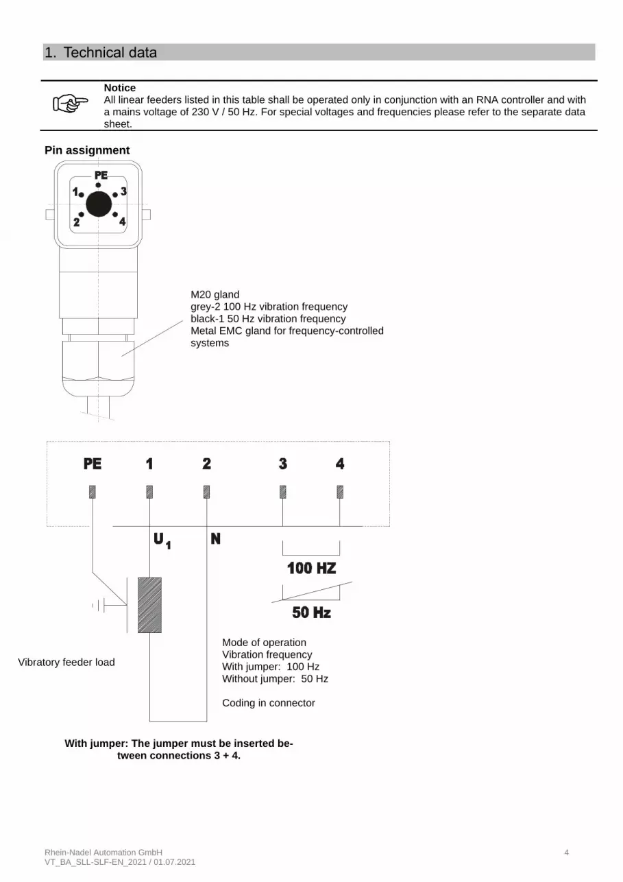
Pin assignment
Notice All linear feeders listed in this table shall be operated only in conjunction with an RNA controller and with a mains voltage of 230 V / 50 Hz. For special voltages and frequencies please refer to the separate data sheet.
With jumper: The jumper must be inserted be-tween connections 3 + 4.
M20 gland grey-2 100 Hz vibration frequency black-1 50 Hz vibration frequency Metal EMC gland for frequency-controlled systems
Mode of operation Vibration frequency With jumper: 100 Hz Without jumper: 50 Hz Coding in connector
Vibratory feeder load
Rhein-Nadel Automation GmbH 5 VT_BA_SLL-SLF-EN_2021 / 01.07.2021
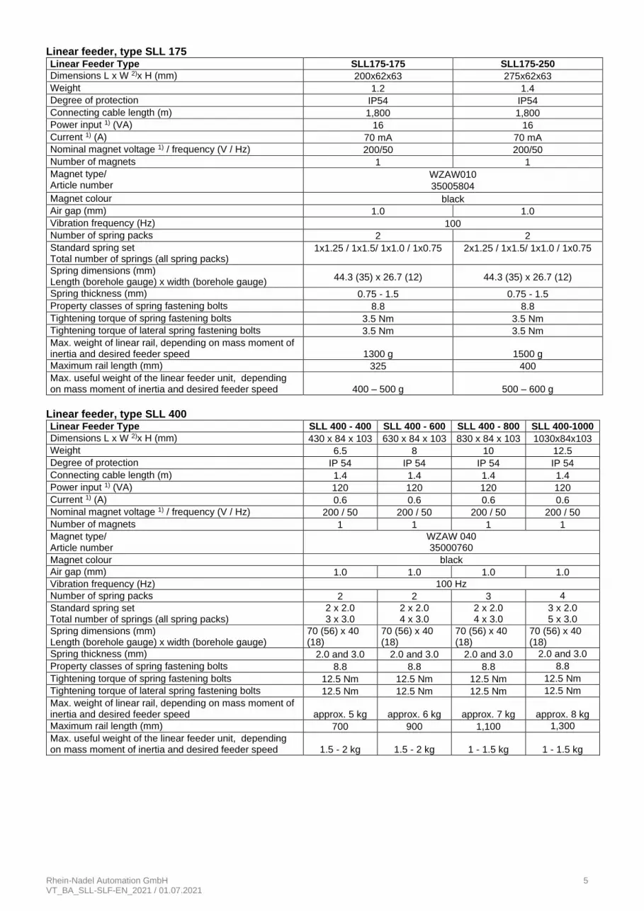
Linear feeder, type SLL 175 Linear Feeder Type SLL175-175 SLL175-250
Dimensions L x W 2)x H (mm) 200x62x63 275x62x63
Weight 1.2 1.4
Degree of protection IP54 IP54
Connecting cable length (m) 1,800 1,800
Power input 1) (VA) 16 16
Current 1) (A) 70 mA 70 mA
Nominal magnet voltage 1) / frequency (V / Hz) 200/50 200/50
Number of magnets 1 1
Magnet type/ Article number
WZAW010
35005804
Magnet colour black
Air gap (mm) 1.0 1.0
Vibration frequency (Hz) 100
Number of spring packs 2 2
Standard spring set Total number of springs (all spring packs)
1x1.25 / 1x1.5/ 1x1.0 / 1x0.75 2x1.25 / 1x1.5/ 1x1.0 / 1x0.75
Spring dimensions (mm) Length (borehole gauge) x width (borehole gauge)
44.3 (35) x 26.7 (12) 44.3 (35) x 26.7 (12)
Spring thickness (mm) 0.75 - 1.5 0.75 - 1.5
Property classes of spring fastening bolts 8.8 8.8
Tightening torque of spring fastening bolts 3.5 Nm 3.5 Nm
Tightening torque of lateral spring fastening bolts 3.5 Nm 3.5 Nm
Max. weight of linear rail, depending on mass moment of inertia and desired feeder speed
1300 g
1500 g
Maximum rail length (mm) 325 400
Max. useful weight of the linear feeder unit, depending on mass moment of inertia and desired feeder speed
400 – 500 g
500 – 600 g
Linear feeder, type SLL 400 Linear Feeder Type SLL 400 - 400 SLL 400 - 600 SLL 400 - 800 SLL 400-1000
Dimensions L x W 2)x H (mm) 430 x 84 x 103 630 x 84 x 103 830 x 84 x 103 1030x84x103
Weight 6.5 8 10 12.5
Degree of protection IP 54 IP 54 IP 54 IP 54
Connecting cable length (m) 1.4 1.4 1.4 1.4
Power input 1) (VA) 120 120 120 120
Current 1) (A) 0.6 0.6 0.6 0.6
Nominal magnet voltage 1) / frequency (V / Hz) 200 / 50 200 / 50 200 / 50 200 / 50
Number of magnets 1 1 1 1
Magnet type/ Article number
WZAW 040 35000760
Magnet colour black
Air gap (mm) 1.0 1.0 1.0 1.0
Vibration frequency (Hz) 100 Hz
Number of spring packs 2 2 3 4
Standard spring set Total number of springs (all spring packs)
2 x 2.0 3 x 3.0
2 x 2.0 4 x 3.0
2 x 2.0 4 x 3.0
3 x 2.0 5 x 3.0
Spring dimensions (mm) Length (borehole gauge) x width (borehole gauge)
70 (56) x 40 (18)
70 (56) x 40 (18)
70 (56) x 40 (18)
70 (56) x 40 (18)
Spring thickness (mm) 2.0 and 3.0 2.0 and 3.0 2.0 and 3.0 2.0 and 3.0
Property classes of spring fastening bolts 8.8 8.8 8.8 8.8
Tightening torque of spring fastening bolts 12.5 Nm 12.5 Nm 12.5 Nm 12.5 Nm
Tightening torque of lateral spring fastening bolts 12.5 Nm 12.5 Nm 12.5 Nm 12.5 Nm
Max. weight of linear rail, depending on mass moment of inertia and desired feeder speed
approx. 5 kg
approx. 6 kg
approx. 7 kg
approx. 8 kg
Maximum rail length (mm) 700 900 1,100 1,300
Max. useful weight of the linear feeder unit, depending on mass moment of inertia and desired feeder speed
1.5 - 2 kg
1.5 - 2 kg
1 - 1.5 kg
1 - 1.5 kg
Rhein-Nadel Automation GmbH 6 VT_BA_SLL-SLF-EN_2021 / 01.07.2021
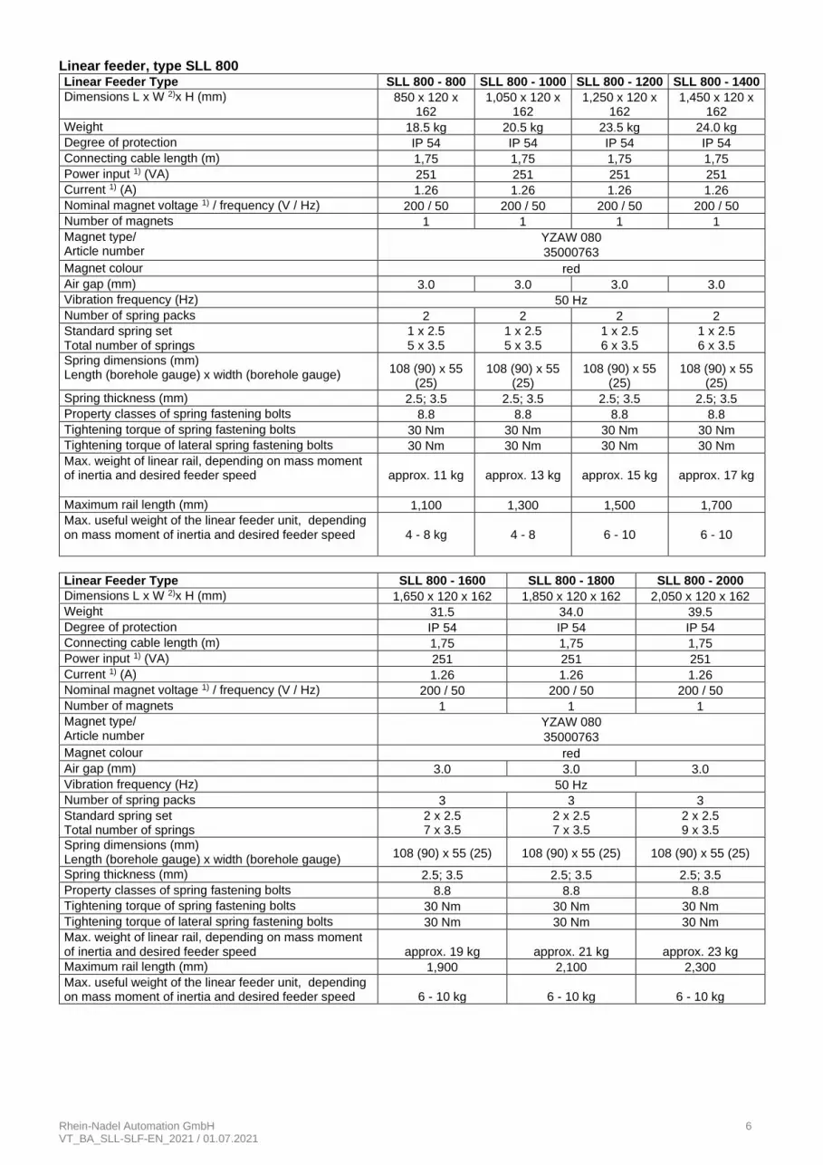
Linear feeder, type SLL 800 Linear Feeder Type SLL 800 - 800 SLL 800 - 1000 SLL 800 - 1200 SLL 800 - 1400
Dimensions L x W 2)x H (mm) 850 x 120 x 162
1,050 x 120 x 162
1,250 x 120 x 162
1,450 x 120 x 162
Weight 18.5 kg 20.5 kg 23.5 kg 24.0 kg
Degree of protection IP 54 IP 54 IP 54 IP 54
Connecting cable length (m) 1,75 1,75 1,75 1,75
Power input 1) (VA) 251 251 251 251
Current 1) (A) 1.26 1.26 1.26 1.26
Nominal magnet voltage 1) / frequency (V / Hz) 200 / 50 200 / 50 200 / 50 200 / 50
Number of magnets 1 1 1 1
Magnet type/ Article number
YZAW 080
35000763
Magnet colour red
Air gap (mm) 3.0 3.0 3.0 3.0
Vibration frequency (Hz) 50 Hz
Number of spring packs 2 2 2 2
Standard spring set Total number of springs
1 x 2.5 5 x 3.5
1 x 2.5 5 x 3.5
1 x 2.5 6 x 3.5
1 x 2.5 6 x 3.5
Spring dimensions (mm) Length (borehole gauge) x width (borehole gauge)
108 (90) x 55 (25)
108 (90) x 55 (25)
108 (90) x 55 (25)
108 (90) x 55 (25)
Spring thickness (mm) 2.5; 3.5 2.5; 3.5 2.5; 3.5 2.5; 3.5
Property classes of spring fastening bolts 8.8 8.8 8.8 8.8
Tightening torque of spring fastening bolts 30 Nm 30 Nm 30 Nm 30 Nm
Tightening torque of lateral spring fastening bolts 30 Nm 30 Nm 30 Nm 30 Nm
Max. weight of linear rail, depending on mass moment of inertia and desired feeder speed
approx. 11 kg
approx. 13 kg
approx. 15 kg
approx. 17 kg
Maximum rail length (mm) 1,100 1,300 1,500 1,700
Max. useful weight of the linear feeder unit, depending on mass moment of inertia and desired feeder speed
4 - 8 kg
4 - 8
6 - 10
6 - 10
Linear Feeder Type SLL 800 - 1600 SLL 800 - 1800 SLL 800 - 2000
Dimensions L x W 2)x H (mm) 1,650 x 120 x 162 1,850 x 120 x 162 2,050 x 120 x 162
Weight 31.5 34.0 39.5
Degree of protection IP 54 IP 54 IP 54
Connecting cable length (m) 1,75 1,75 1,75
Power input 1) (VA) 251 251 251
Current 1) (A) 1.26 1.26 1.26
Nominal magnet voltage 1) / frequency (V / Hz) 200 / 50 200 / 50 200 / 50
Number of magnets 1 1 1
Magnet type/ Article number
YZAW 080
35000763
Magnet colour red
Air gap (mm) 3.0 3.0 3.0
Vibration frequency (Hz) 50 Hz
Number of spring packs 3 3 3
Standard spring set Total number of springs
2 x 2.5 7 x 3.5
2 x 2.5 7 x 3.5
2 x 2.5 9 x 3.5
Spring dimensions (mm) Length (borehole gauge) x width (borehole gauge)
108 (90) x 55 (25) 108 (90) x 55 (25) 108 (90) x 55 (25)
Spring thickness (mm) 2.5; 3.5 2.5; 3.5 2.5; 3.5
Property classes of spring fastening bolts 8.8 8.8 8.8
Tightening torque of spring fastening bolts 30 Nm 30 Nm 30 Nm
Tightening torque of lateral spring fastening bolts 30 Nm 30 Nm 30 Nm
Max. weight of linear rail, depending on mass moment of inertia and desired feeder speed
approx. 19 kg
approx. 21 kg
approx. 23 kg
Maximum rail length (mm) 1,900 2,100 2,300
Max. useful weight of the linear feeder unit, depending on mass moment of inertia and desired feeder speed
6 - 10 kg
6 - 10 kg
6 - 10 kg
Rhein-Nadel Automation GmbH 7 VT_BA_SLL-SLF-EN_2021 / 01.07.2021
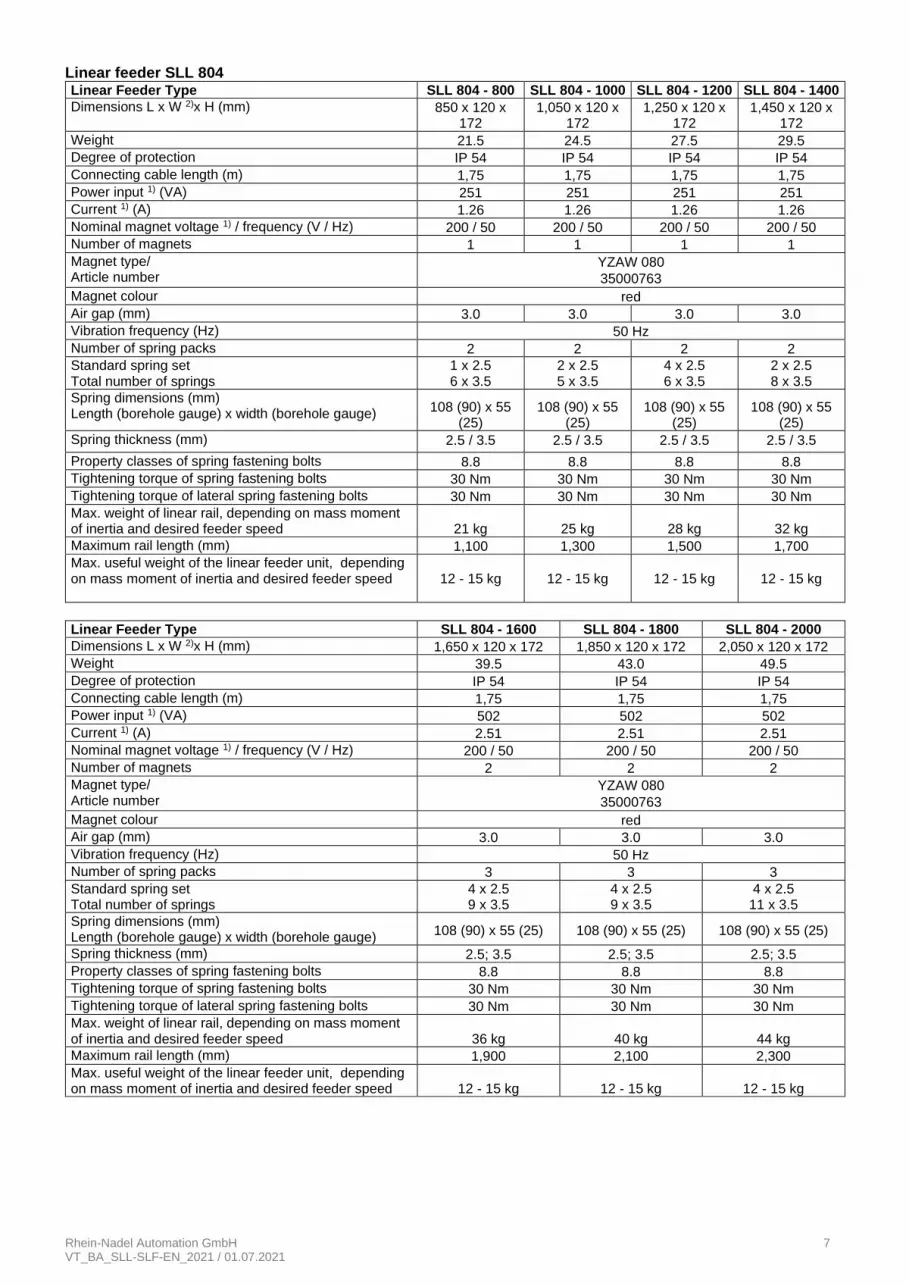
Linear feeder SLL 804 Linear Feeder Type SLL 804 - 800 SLL 804 - 1000 SLL 804 - 1200 SLL 804 - 1400
Dimensions L x W 2)x H (mm) 850 x 120 x 172
1,050 x 120 x 172
1,250 x 120 x 172
1,450 x 120 x 172
Weight 21.5 24.5 27.5 29.5
Degree of protection IP 54 IP 54 IP 54 IP 54
Connecting cable length (m) 1,75 1,75 1,75 1,75
Power input 1) (VA) 251 251 251 251
Current 1) (A) 1.26 1.26 1.26 1.26
Nominal magnet voltage 1) / frequency (V / Hz) 200 / 50 200 / 50 200 / 50 200 / 50
Number of magnets 1 1 1 1
Magnet type/ Article number
YZAW 080
35000763
Magnet colour red
Air gap (mm) 3.0 3.0 3.0 3.0
Vibration frequency (Hz) 50 Hz
Number of spring packs 2 2 2 2
Standard spring set Total number of springs
1 x 2.5 6 x 3.5
2 x 2.5 5 x 3.5
4 x 2.5 6 x 3.5
2 x 2.5 8 x 3.5
Spring dimensions (mm) Length (borehole gauge) x width (borehole gauge)
108 (90) x 55 (25)
108 (90) x 55 (25)
108 (90) x 55 (25)
108 (90) x 55 (25)
Spring thickness (mm) 2.5 / 3.5 2.5 / 3.5 2.5 / 3.5 2.5 / 3.5
Property classes of spring fastening bolts 8.8 8.8 8.8 8.8
Tightening torque of spring fastening bolts 30 Nm 30 Nm 30 Nm 30 Nm
Tightening torque of lateral spring fastening bolts 30 Nm 30 Nm 30 Nm 30 Nm
Max. weight of linear rail, depending on mass moment of inertia and desired feeder speed
21 kg
25 kg
28 kg
32 kg
Maximum rail length (mm) 1,100 1,300 1,500 1,700
Max. useful weight of the linear feeder unit, depending on mass moment of inertia and desired feeder speed
12 - 15 kg
12 - 15 kg
12 - 15 kg
12 - 15 kg
Linear Feeder Type SLL 804 - 1600 SLL 804 - 1800 SLL 804 - 2000
Dimensions L x W 2)x H (mm) 1,650 x 120 x 172 1,850 x 120 x 172 2,050 x 120 x 172
Weight 39.5 43.0 49.5
Degree of protection IP 54 IP 54 IP 54
Connecting cable length (m) 1,75 1,75 1,75
Power input 1) (VA) 502 502 502
Current 1) (A) 2.51 2.51 2.51
Nominal magnet voltage 1) / frequency (V / Hz) 200 / 50 200 / 50 200 / 50
Number of magnets 2 2 2
Magnet type/ Article number
YZAW 080
35000763
Magnet colour red
Air gap (mm) 3.0 3.0 3.0
Vibration frequency (Hz) 50 Hz
Number of spring packs 3 3 3
Standard spring set Total number of springs
4 x 2.5 9 x 3.5
4 x 2.5 9 x 3.5
4 x 2.5 11 x 3.5
Spring dimensions (mm) Length (borehole gauge) x width (borehole gauge)
108 (90) x 55 (25) 108 (90) x 55 (25) 108 (90) x 55 (25)
Spring thickness (mm) 2.5; 3.5 2.5; 3.5 2.5; 3.5
Property classes of spring fastening bolts 8.8 8.8 8.8
Tightening torque of spring fastening bolts 30 Nm 30 Nm 30 Nm
Tightening torque of lateral spring fastening bolts 30 Nm 30 Nm 30 Nm
Max. weight of linear rail, depending on mass moment of inertia and desired feeder speed
36 kg
40 kg
44 kg
Maximum rail length (mm) 1,900 2,100 2,300
Max. useful weight of the linear feeder unit, depending on mass moment of inertia and desired feeder speed
12 - 15 kg
12 - 15 kg
12 - 15 kg

Rhein-Nadel Automation GmbH 8 VT_BA_SLL-SLF-EN_2021 / 01.07.2021
Linear feeder, type SLF 1000
1) For special connected loads (voltage / frequency) see rating plate on the magnet 2) Width indication for version b (= breit/wide)
Linear Feeder Type SLL 804 - 2400 SLL 804 - 2800
Dimensions L x W 2)x H (mm) 2,450 x 120 x 172 2,850 x 120 x 172
Weight 63 76
Degree of protection IP 54 IP 54
Connecting cable length (m) 1,8 1,8
Power input 1) (VA) 502 502
Current 1) (A) 2.51 2.51
Nominal magnet voltage 1) / frequency (V / Hz) 200 / 50 200 / 50
Number of magnets 2 4
Magnet type/ Article number
YZAW 080
35000763
Magnet colour red
Air gap (mm) 3.0 3.0
Vibration frequency (Hz) 50 Hz
Number of spring packs 4 4
Standard spring set Total number of springs (all spring packs)
2 x 2.5
14 x 3.5 2 x 2.5
14 x 3.5
Spring dimensions (mm) Length (borehole gauge) x width (borehole gauge)
108 (90) x 55 (25) 108 (90) x 55 (2)
Spring thickness (mm) 2.5; 3.5 2,53,5
Property classes of spring fastening bolts 8.8 8.8
Tightening torque of spring fastening bolts 30 Nm 30 Nm
Tightening torque of lateral spring fastening bolts 30 Nm 30 Nm
Max. weight of linear rail, depending on mass moment of in-ertia and desired feeder speed
approx. 51 kg
approx. 62 kg
Maximum rail length (mm) 2,700 3,100
Max. useful weight of the linear feeder unit, depending on mass moment of inertia and desired feeder speed
10 - 12 kg
10 - 12 kg
Linear Feeder Type SLF 1000-1000 SLF 1000-1500
Dimensions L x W 2)x H (mm) 1,100 x 244 x 178 1,600 x 244 x 178
Weight 62 80
Degree of protection IP 54 IP 54
Connecting cable length (m) 2,6 2,6
Power input 1) (VA) 504 1,004
Current 1) (A) 2.51 5.0
Nominal magnet voltage 1) / frequency (V / Hz) 200 / 50 200 / 50
Number of magnets 2 4
Magnet type/ Article number
YZAW 080
35000763
Magnet colour red
Air gap (mm) 2.5 2.5
Vibration frequency (Hz) 50 Hz
Number of spring packs 2 3 (4)³
Standard spring set Total number of springs (all spring packs)
8 x 3.5
12 x 3.5
Spring dimensions (mm) Length (borehole gauge) x width (borehole gauge)
128(108) x 160(2x60) 128(108) x 160(2x60)
Spring thickness (mm) 3.5 3.5
Property classes of spring fastening bolts 8.8 8.8
Tightening torque of spring fastening bolts 60 Nm 60 Nm
Tightening torque of lateral spring fastening bolts 80 Nm 80 Nm
Max. weight of linear rail, depending on mass moment of in-ertia and desired feeder speed
approx. 40 kg
approx. 70 kg
Maximum rail length (mm) 2,000 2,500
Max. useful weight of the linear feeder unit, depending on mass moment of inertia and desired feeder speed
20 - 30 kg
40 - 50 kg

Rhein-Nadel Automation GmbH 9 VT_BA_SLL-SLF-EN_2021 / 01.07.2021
2. Safety directives We have taken great care in design and manufacture of our linear feeder in order to ensure smooth and safe opera-tion. You, too, can make an important contribution towards safety at work. We therefore ask you to read the brief oper-ating instructions completely prior to commissioning the system. Observe the safety directives at all times! Make sure that all persons working with or at the equipment also read the following safety directives carefully and fol-low them! These Operating Instructions only apply to the equipment types indicated on the cover page.
Notice This hand indicates useful tips for operation of the linear feeder.
Attention This warning triangle indicates safety notices. Non-observance of such warnings may cause serious injury or even death.
Machine hazards
• Hazards arise mainly from the electrical components of the linear feeder. If the linear feeder comes into contact with moisture or liquids there is risk of electric shock.
• Make sure that protective earthing of the power supply system is in perfect condition! Intended use The intended use of the linear feeder is the driving of feed rails. They serve for linear transfer as well as correctly ori-ented and metered supply of bulk products. Intended use also includes observance of the operating instructions and compliance with the maintenance rules. For the technical data of your linear feeder please refer to 'Technical Data' in Section 1. Make sure that the rating data of the linear feeder, control system and power supply are compatible.
Notice Operate the linear feeder in perfect condition only.
Never operate the linear feeder in areas subject to explosion hazards or in wet areas. Operate the linear feeder only in the configuration of drive unit, control unit and vibratory system agreed with the man-ufacturer. The linear feeder must never be subjected to any loads other than the parts for which this special type has been rated and dimensioned.
Attention It is strictly forbidden to disable any guards or safety devices!
Equipment user's duties
• Observe the directives given in the operating instructions for any kind of work (operation, maintenance, repairs, etc.).
• Refrain from any working practice that affects the safety at the linear feeder.
• Make sure that only authorised personnel work at the linear feeder.
• Give immediate notice to the management of any changes that have occurred on the linear feeder affecting safety.
Rhein-Nadel Automation GmbH 10 VT_BA_SLL-SLF-EN_2021 / 01.07.2021
Attention The linear feeder must be installed, put into operation and maintained by professional personnel only. Ob-serve the legally binding provisions for the qualifications of qualified electrical workers and instructed workers as defined by standards IEC 364 and DIN VDE 0105, part 1.
Caution: Electromagnetic field Magnetic fields may affect a cardiac pacemaker. Therefore, persons wearing a cardiac pacemaker are recommended to keep a distance of at least 25 cm. Continuous operation of the feeding system is permit-ted only with the protective enclosure closed.
Noise emission The noise level at the place of use depends on the complete line into which the hopper will be incorporated and on the material to be conveyed. For this reason, sound pressure levels in accordance with the 'Machinery' directive can only be determined at the place of installation. If the noise level at the place of use exceeds the permissible, sound-insulating hoods can be installed which we can offer on request.
2.1. Applicable directives and standards
The linear feeder has been manufactured in accordance with the following directives: 2006/42/EC Machinery Directive 2014/35/EU Low Voltage Directive 2014/30/EU Electromagnetic Compatibility Directive We assume that our product will be incorporated into a stationary machine. The applicable standards are specified in the Declaration of Incorporation (according to Annex II B of the Machinery Directive).
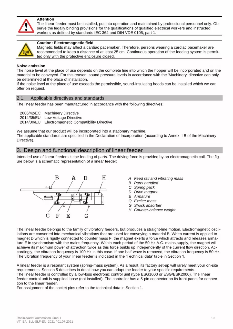
3. Design and functional description of linear feeder Intended use of linear feeders is the feeding of parts. The driving force is provided by an electromagnetic coil. The fig-ure below is a schematic representation of a linear feeder:
The linear feeder belongs to the family of vibratory feeders, but produces a straight-line motion. Electromagnetic oscil-lations are converted into mechanical vibrations that are used for conveying a material B. When current is applied to magnet D which is rigidly connected to counter mass F, the magnet exerts a force which attracts and releases arma-ture E in synchronism with the mains frequency. Within each period of the 50 Hz A.C. mains supply, the magnet will achieve its maximum power of attraction twice as this force builds up independently of the current flow direction. Ac-cordingly, the vibration frequency is 100 Hz in this case. If one half-wave is removed, the vibration frequency is 50 Hz. The vibration frequency of your linear feeder is indicated in the ‘Technical data’ table in Section 1. A linear feeder is a resonant system (spring-mass system). As a result, its factory set-up will rarely meet your on-site requirements. Section 5 describes in detail how you can adapt the feeder to your specific requirements. The linear feeder is controlled by a low-loss electronic control unit (type ESG1000 or ESG/ESK2000). The linear feeder control unit is supplied loose (not installed). The controller has a 5-pin connector on its front panel for connec-tion to the linear feeder. For assignment of the socket pins refer to the technical data in Section 1.
A Feed rail and vibrating mass B Parts handled C Spring pack D Drive magnet E Armature Q Exciter mass G Shock absorber H Counter-balance weight

Rhein-Nadel Automation GmbH 11 VT_BA_SLL-SLF-EN_2021 / 01.07.2021
Notice For comprehensive information on the full range of control devices please refer to the 'Control Units' oper-ating instructions.
All control units have two essential operating elements:
• The power switch is used to energize and de-energize the linear feeder.
• A rotary knob (or buttons) can be used to set the feed rate of the system.
Frequency controller Tuning of the linear feeders can also be done by means of frequency controllers. For detailed description of the tuning procedure refer to the frequency controller operating instructions.
4. Shipment and installation
4.1. Shipment
Notice Take care that the linear feeder cannot collide with other objects and is not subjected to pressure during handling operations.
For the weight of the linear feeder please refer to the table titled 'Technical Data' in Section 1. Shipment ex works The linear feeders are delivered ex works in a box or crate. On-site moving The weight of the linear feeder depends on its dimensions and motor rating. Please refer to the shipping documents for the weight of your specific equipment.
Attention Check all guards when unpacking. Replace any damaged parts before commissioning!
Attention For lifting the conveyors be sure to use only sufficiently dimensioned vehicles, ropes, chains and sling gear.
Attention Handling operations to be carried out only by employees who are capable of performing such work due to their own knowledge and experience in this field.
Warning Warning against suspended loads
4.2. Installation
The linear feeder should be mounted on a stable substructure (available as an accessory) at the point of use. This substructure must be dimensioned to ensure that no vibrations from the linear feeder can be transmitted.
Rhein-Nadel Automation GmbH 12 VT_BA_SLL-SLF-EN_2021 / 01.07.2021
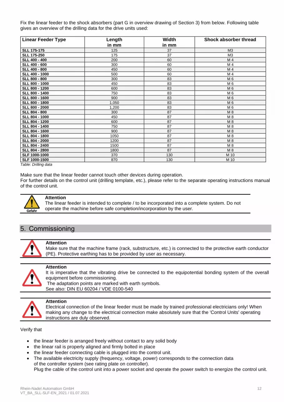
Fix the linear feeder to the shock absorbers (part G in overview drawing of Section 3) from below. Following table gives an overview of the drilling data for the drive units used:
Linear Feeder Type Length in mm
Width in mm
Shock absorber thread
SLL 175-175 125 37 M3
SLL 175-250 175 37 M3
SLL 400 - 400 200 60 M 4
SLL 400 - 600 300 60 M 4
SLL 400 - 800 450 60 M 4
SLL 400 - 1000 500 60 M 4
SLL 800 - 800 300 83 M 6
SLL 800 - 1000 450 83 M 6
SLL 800 - 1200 600 83 M 6
SLL 800 - 1400 750 83 M 6
SLL 800 - 1600 900 83 M 6
SLL 800 - 1800 1,050 83 M 6
SLL 800 - 2000 1,200 83 M 6
SLL 804 - 800 300 87 M 8
SLL 804 - 1000 450 87 M 8
SLL 804 - 1200 600 87 M 8
SLL 804 - 1400 750 87 M 8
SLL 804 - 1600 900 87 M 8
SLL 804 - 1800 1050 87 M 8
SLL 804 - 2000 1200 87 M 8
SLL 804 - 2400 1500 87 M 8
SLL 804 - 2800 1800 87 M 8
SLF 1000-1000 370 130 M 10
SLF 1000-1500 870 130 M 10
Table: Drilling data
Make sure that the linear feeder cannot touch other devices during operation. For further details on the control unit (drilling template, etc.), please refer to the separate operating instructions manual of the control unit.
Attention The linear feeder is intended to complete / to be incorporated into a complete system. Do not operate the machine before safe completion/incorporation by the user.
5. Commissioning
Attention Make sure that the machine frame (rack, substructure, etc.) is connected to the protective earth conductor (PE). Protective earthing has to be provided by user as necessary.
Attention It is imperative that the vibrating drive be connected to the equipotential bonding system of the overall equipment before commissioning. The adaptation points are marked with earth symbols. See also: DIN EU 60204 / VDE 0100-540
Attention Electrical connection of the linear feeder must be made by trained professional electricians only! When making any change to the electrical connection make absolutely sure that the 'Control Units' operating instructions are duly observed.
Verify that
• the linear feeder is arranged freely without contact to any solid body
• the linear rail is properly aligned and firmly bolted in place
• the linear feeder connecting cable is plugged into the control unit.
• The available electricity supply (frequency, voltage, power) corresponds to the connection data of the controller system (see rating plate on controller). Plug the cable of the control unit into a power socket and operate the power switch to energize the control unit.
Rhein-Nadel Automation GmbH 13 VT_BA_SLL-SLF-EN_2021 / 01.07.2021
Notice
For linear feeders that are supplied as a completely set-up system the optimum feed rate has been fac-tory-set. It is marked with a red arrow on the dial of the rotary knob. In this case set the rotary knob to this mark.
5.1. Tuning
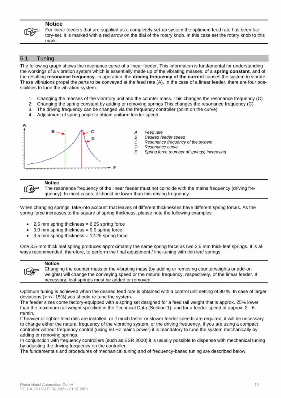
The following graph shows the resonance curve of a linear feeder. This information is fundamental for understanding the workings of a vibration system which is essentially made up of the vibrating masses, of a spring constant, and of the resulting resonance frequency. In operation, the driving frequency of the current causes the system to vibrate. These vibrations propel the parts to be conveyed at the feed rate (A). In the case of a linear feeder, there are four pos-sibilities to tune the vibration system:
1. Changing the masses of the vibratory unit and the counter mass. This changes the resonance frequency (C) 2. Changing the spring constant by adding or removing springs This changes the resonance frequency (C) 3. The driving frequency can be changed via the frequency controller (point on the curve) 4. Adjustment of spring angle to obtain uniform feeder speed.
When changing springs, take into account that leaves of different thicknesses have different spring forces. As the spring force increases to the square of spring thickness, please note the following examples:
• 2.5 mm spring thickness = 6.25 spring force
• 3.0 mm spring thickness = 9.0 spring force
• 3.5 mm spring thickness = 12.25 spring force One 3.5-mm thick leaf spring produces approximately the same spring force as two 2.5 mm thick leaf springs. It is al-ways recommended, therefore, to perform the final adjustment / fine-tuning with thin leaf springs.
Notice Changing the counter mass or the vibrating mass (by adding or removing counterweights or add-on weights) will change the conveying speed or the natural frequency, respectively, of the linear feeder. If necessary, leaf springs must be added or removed.
Optimum tuning is achieved when the desired feed rate is obtained with a control unit setting of 80 %. In case of larger deviations (> +/- 15%) you should re-tune the system. The feeder sizes come factory-equipped with a spring set designed for a feed rail weight that is approx. 25% lower than the maximum rail weight specified in the Technical Data (Section 1), and for a feeder speed of approx. 2 - 6 m/min. If heavier or lighter feed rails are installed, or if much faster or slower feeder speeds are required, it will be necessary to change either the natural frequency of the vibrating system, or the driving frequency. If you are using a compact controller without frequency control (using 50 Hz mains power) it is mandatory to tune the system mechanically by adding or removing springs. In conjunction with frequency controllers (such as ESR 2000) it is usually possible to dispense with mechanical tuning by adjusting the driving frequency on the controller. The fundamentals and procedures of mechanical tuning and of frequency-based tuning are described below.
Notice The resonance frequency of the linear feeder must not coincide with the mains frequency (driving fre-quency). In most cases, it should be lower than this driving frequency.
A Feed rate B Desired feeder speed C Resonance frequency of the system D Resonance curve E Spring force (number of springs) increasing
Rhein-Nadel Automation GmbH 14 VT_BA_SLL-SLF-EN_2021 / 01.07.2021
5.1.1. Mechanical tuning procedure for use with compact control unit
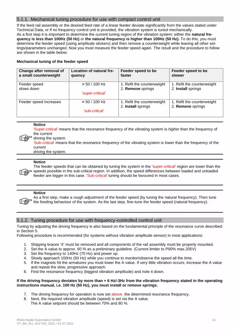
If the feed rail assembly or the desired feed rate of a linear feeder deviate significantly from the values stated under Technical Data, or if no frequency control unit is provided, the vibration system is tuned mechanically. As a first step it is important to determine the current tuning region of the vibration system: either the natural fre-quency is less than 100Hz (50 Hz) or the natural frequency is higher than 100Hz (50 Hz). To do this, you must determine the feeder speed (using amplitude stickers) and then remove a counterweight while leaving all other set-tings/parameters unchanged. Now you must measure the feeder speed again. The result and the procedure to follow are shown in the table below: Mechanical tuning of the feeder speed
Change after removal of a small counterweight
Location of natural fre-quency
Feeder speed to be faster
Feeder speed to be slower
Feeder speed slows down
> 50 / 100 Hz
'super-critical'
1. Refit the counterweight 2. Remove springs
1. Refit the counterweight 2. Install springs
Feeder speed increases < 50 / 100 Hz
'sub-critical'
1. Refit the counterweight 2. Install springs
1. Refit the counterweight 2. Remove springs
Notice 'Super-critical' means that the resonance frequency of the vibrating system is higher than the frequency of the current driving the system. 'Sub-critical' means that the resonance frequency of the vibrating system is lower than the frequency of the current driving the system.
Notice The feeder speeds that can be obtained by tuning the system in the 'super-critical' region are lower than the speeds possible in the sub-critical region. In addition, the speed differences between loaded and unloaded feeder are bigger in this case. 'Sub-critical' tuning should be favoured in most cases.
Notice As a first step, make a rough adjustment of the feeder speed (by tuning the natural frequency). Then tune the feeding behaviour of the system. As the last step, fine-tune the feeder speed (natural frequency).
5.1.2. Tuning procedure for use with frequency-controlled control unit
Tuning by adjusting the driving frequency is also based on the fundamental principle of the resonance curve described in Section 5. Following procedure is recommended (for systems without vibration amplitude sensor) in most applications:
1. Shipping braces 'X' must be removed and all components of the rail assembly must be properly mounted. 2. Set the A value to approx. 60 % as a preliminary guideline. (Current limiter to P90% max.205V) 3. Set the frequency to 140Hz (70 Hz) and power up. 4. Slowly approach 100Hz (50 Hz) while you continue to monitor/observe the speed all the time. 5. If the magnets hit the armatures you must lower the A value. If very little vibration occurs, increase the A value
and repeat the slow, progressive approach. 6. Find the resonance frequency (biggest vibration amplitude) and note it down.
If the driving frequency deviates by more than + 6 Hz/-3Hz from the vibration frequency stated in the operating instructions manual, i.e. 100 Hz (50 Hz), you must install or remove springs.
7. The driving frequency for operation is now set above the determined resonance frequency. 8. Next, the required vibration amplitude (speed) is set via the A value.
The A value setpoint should be between 70% and 80 %.
Rhein-Nadel Automation GmbH 15 VT_BA_SLL-SLF-EN_2021 / 01.07.2021
Notice For the tuning procedure of a vibrating system with amplitude sensor refer to the operating instructions for the respective control unit.
Notice Be sure never to operate a 100 Hz linear feeder on 50 Hz. The increased current input to the linear feeder may destroy the magnet.
5.1.3. Changing the spring set on linear feeders
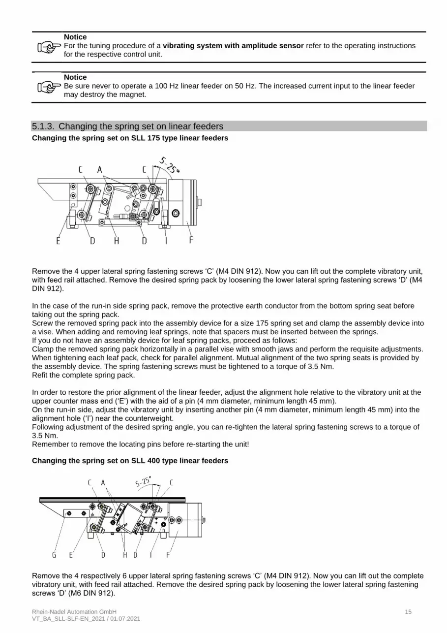
Changing the spring set on SLL 175 type linear feeders
Remove the 4 upper lateral spring fastening screws ‘C’ (M4 DIN 912). Now you can lift out the complete vibratory unit, with feed rail attached. Remove the desired spring pack by loosening the lower lateral spring fastening screws ‘D’ (M4 DIN 912). In the case of the run-in side spring pack, remove the protective earth conductor from the bottom spring seat before taking out the spring pack. Screw the removed spring pack into the assembly device for a size 175 spring set and clamp the assembly device into a vise. When adding and removing leaf springs, note that spacers must be inserted between the springs. If you do not have an assembly device for leaf spring packs, proceed as follows: Clamp the removed spring pack horizontally in a parallel vise with smooth jaws and perform the requisite adjustments. When tightening each leaf pack, check for parallel alignment. Mutual alignment of the two spring seats is provided by the assembly device. The spring fastening screws must be tightened to a torque of 3.5 Nm. Refit the complete spring pack. In order to restore the prior alignment of the linear feeder, adjust the alignment hole relative to the vibratory unit at the upper counter mass end (‘E’) with the aid of a pin (4 mm diameter, minimum length 45 mm). On the run-in side, adjust the vibratory unit by inserting another pin (4 mm diameter, minimum length 45 mm) into the alignment hole (‘I’) near the counterweight. Following adjustment of the desired spring angle, you can re-tighten the lateral spring fastening screws to a torque of 3.5 Nm. Remember to remove the locating pins before re-starting the unit!
Changing the spring set on SLL 400 type linear feeders
Remove the 4 respectively 6 upper lateral spring fastening screws ‘C’ (M4 DIN 912). Now you can lift out the complete vibratory unit, with feed rail attached. Remove the desired spring pack by loosening the lower lateral spring fastening screws ‘D’ (M6 DIN 912).
Rhein-Nadel Automation GmbH 16 VT_BA_SLL-SLF-EN_2021 / 01.07.2021
In the case of the run-in side spring pack, remove the protective earth conductor from the bottom spring seat before taking out the spring pack. Screw the removed spring pack into the assembly device for a size 400 spring set and clamp the assembly device into a vise. When adding and removing leaf springs, note that spacers must be inserted between the springs. If you do not have an assembly device for leaf spring packs, proceed as follows: Clamp the removed spring pack horizontally in a parallel vise with smooth jaws and perform the requisite adjustments. When tightening each leaf pack, check for parallel alignment. Mutual alignment of the two spring seats is provided by the assembly device. The spring fastening screws must be tightened to a torque of 12.5 Nm. Refit the complete spring pack. In order to restore the prior alignment of the linear feeder, adjust the alignment hole relative to the vibratory unit at the upper counter mass end (‘E’) with the aid of a pin (6 mm diameter, minimum length 70 mm). On the run-in side, adjust the vibratory unit by inserting another pin (6 mm diameter, minimum length 70 mm) into the alignment hole (‘I’) near the counterweight. Following adjustment of the desired spring angle, you can re-tighten the lateral spring fastening screws to a torque of 12.5 Nm. Remember to remove the locating pins before re-starting the unit! Changing the spring set on SLL 800 and SLL 804 type linear feeders
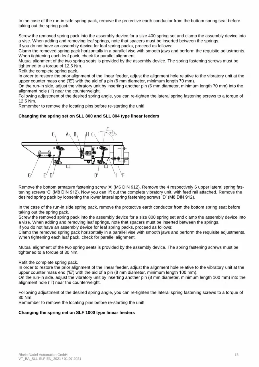
Remove the bottom armature fastening screw 'A' (M6 DIN 912). Remove the 4 respectively 6 upper lateral spring fas-tening screws ‘C’ (M8 DIN 912). Now you can lift out the complete vibratory unit, with feed rail attached. Remove the desired spring pack by loosening the lower lateral spring fastening screws ‘D’ (M8 DIN 912). In the case of the run-in side spring pack, remove the protective earth conductor from the bottom spring seat before taking out the spring pack. Screw the removed spring pack into the assembly device for a size 800 spring set and clamp the assembly device into a vise. When adding and removing leaf springs, note that spacers must be inserted between the springs. If you do not have an assembly device for leaf spring packs, proceed as follows: Clamp the removed spring pack horizontally in a parallel vise with smooth jaws and perform the requisite adjustments. When tightening each leaf pack, check for parallel alignment. Mutual alignment of the two spring seats is provided by the assembly device. The spring fastening screws must be tightened to a torque of 30 Nm. Refit the complete spring pack. In order to restore the prior alignment of the linear feeder, adjust the alignment hole relative to the vibratory unit at the upper counter mass end (‘E’) with the aid of a pin (8 mm diameter, minimum length 100 mm). On the run-in side, adjust the vibratory unit by inserting another pin (8 mm diameter, minimum length 100 mm) into the alignment hole (‘I’) near the counterweight. Following adjustment of the desired spring angle, you can re-tighten the lateral spring fastening screws to a torque of 30 Nm. Remember to remove the locating pins before re-starting the unit! Changing the spring set on SLF 1000 type linear feeders

Rhein-Nadel Automation GmbH 17 VT_BA_SLL-SLF-EN_2021 / 01.07.2021
Remove the 4 upper lateral spring fastening screws ‘C’ (M12 DIN 912). Now you can lift out the complete vibratory unit, with feed rail attached. Remove the desired spring pack by loosening the lower lateral spring fastening screws ‘D’ (M12 DIN 912). In the case of the run-in side spring pack, remove the protective earth conductor from the bottom spring seat before taking out the spring pack. Screw the removed spring pack into the assembly device for a size 1000 spring set and clamp the assembly device into a vise. When adding and removing leaf springs, note that spacers must be inserted between the springs. If you do not have an assembly device for leaf spring packs, proceed as follows: Clamp the removed spring pack horizontally in a parallel vise with smooth jaws and perform the requisite adjustments. When tightening each leaf pack, check for parallel alignment. Mutual alignment of the two spring seats is provided by the assembly device. The spring fastening screws must be tightened to a torque of 80 Nm. Refit the complete spring pack. In order to restore the prior alignment of the linear feeder, adjust the alignment hole relative to the vibratory unit at the upper counter mass end (‘E’) with the aid of a pin (12 mm diameter, minimum length 210 mm). On the run-in side, adjust the vibratory unit by inserting another pin (12 mm diameter, minimum length 210 mm) into the alignment hole (‘I’) near the counterweight. Following adjustment of the desired spring angle, you can re-tighten the lateral spring fastening screws to a torque of 80 Nm. Remember to remove the locating pins before re-starting the unit!
Notice If the linear feeder mounting plate is designed so that crossbars are situated local to the feet, it is possi-ble to dismount the spring packs one by one from below without removing the feeder mass (moving mass).
Notice After any work on the spring packs be sure to check the magnet air gap and re-adjust it as necessary.
5.1.4. Adjusting the desired feeding behaviour / synchronism of the linear feed rail
For a linear feed rail to operate smoothly and in synchronism, the spring angle must be set to be identical to the cen-tre-of-gravity angle. The centre-of-gravity angle is determined by the locations of the centres of gravity of the vibrating mass and of the counter mass.
Rhein-Nadel Automation GmbH 18 VT_BA_SLL-SLF-EN_2021 / 01.07.2021
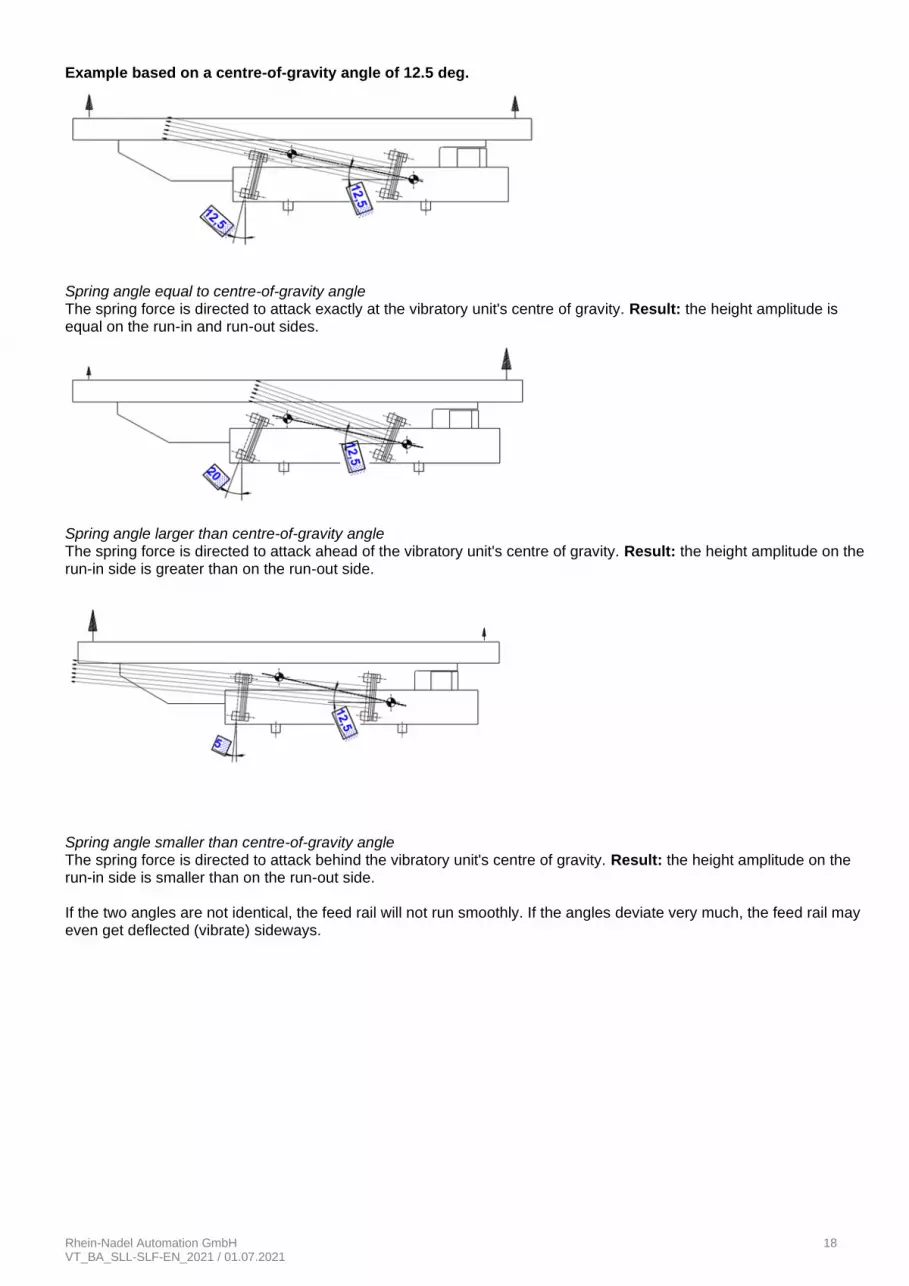
Example based on a centre-of-gravity angle of 12.5 deg.
Spring angle equal to centre-of-gravity angle The spring force is directed to attack exactly at the vibratory unit's centre of gravity. Result: the height amplitude is equal on the run-in and run-out sides.
Spring angle larger than centre-of-gravity angle The spring force is directed to attack ahead of the vibratory unit's centre of gravity. Result: the height amplitude on the run-in side is greater than on the run-out side.
Spring angle smaller than centre-of-gravity angle The spring force is directed to attack behind the vibratory unit's centre of gravity. Result: the height amplitude on the run-in side is smaller than on the run-out side. If the two angles are not identical, the feed rail will not run smoothly. If the angles deviate very much, the feed rail may even get deflected (vibrate) sideways.
Rhein-Nadel Automation GmbH 19 VT_BA_SLL-SLF-EN_2021 / 01.07.2021
You can adjust the centres of gravity or spring angles, respectively, by the following means:
• Add to, or displace, the counterweight (‘F’)
• Select the rail height and track position so as to improve the location of the centre of gravity.
• Minimize the rail weight as much as possible to keep the vibratory unit's centre of gravity as low as possible.
• Add additional counterweight in the vibratory unit's run-out area (‘G’).
• Adjust the spring angle to match the centre-of-gravity angle.
For type SLL 400 and SLF 1.000 linear feeders you can adjust the spring angle between 5 and 25, for type SLL800
and SLL 804 linear feeders adjustment is possible between 5 and 20. If the centre-of-gravity angle lies outside this range, the rail cannot run smoothly and in synchronism. It is necessary in that case to adapt the centres of gravity of the reaction mass and vibrating mass through the measures listed above. Spring angle adjustment Fix the vibratory unit relative to the counter mass (see Section 5.1.2. ‘Changing the spring configuration on linear feed-ers’). You can then loosen the four lateral spring fastening screws (‘C’ + ‘D) so that you can swing the spring pack to the desired spring angle. Now re-tighten the spring fastening screws to the specified tightening torque (see Section 1, ‘Technical Data’) and remove the alignment screws, spacer plate or bolts, respectively. Adjusting the magnet air gap The factory setting of the air gap between armature and magnet is indicated in the ‘Technical data’ (Section 1). Adjustment of this air gap can be performed from the outside without dismounting any components. Slacken the two exterior armature fastening screws very slightly ('A' or 'A' + 'B') (M5 DIN 912 for linear feeder type SLL 400; M6 DIN 912 for linear feeder types SLL 800 and SLL 804, M6 DIN 912 for linear feeder type SLF 1.000, on right and left side).
Insert one wire each in the two holes in the vibratory unit's supporting member ‘H'. Use wire with ( 1 mm, length 80
mm for SLL 400 (when inserting the wire make sure that it doesn't enter the grooves of the armature); use wire with
3 mm, length 80 mm for SLL 800 and SLL 804; use wire with 2.5 mm, length 250 mm for SLF 1.000). Adjust the air gap (see Section 1, ‘Technical Data’) by pressing down the two armature fastening screws against the direction of travel, then tightening them to the specified torque (on SLF 1.000 linear feeders this must be done for both magnets). Pull out the round metal bars. If no round metal bars are on hand, you can adjust the air gap to its specified value from below (possibly after removing the entire linear feeder from its substructure or machine table) using a feeler gauge or shims.
Notice If the rotary knob on the controller is set to 100% and the air gap correctly set, the magnet must not hit the armature upon power-on. If it does, proceed as described under section 5.2. (removal of springs)
Objective of the tuning procedure: When the desired feeding speed is obtained at a controller setting of 80%, it must increase when a weighting plate is removed.
Notice Make sure that the number of springs per spring pack will not deviate by more than 2 – 3 springs.
Rhein-Nadel Automation GmbH 20 VT_BA_SLL-SLF-EN_2021 / 01.07.2021
6. Feed rail design rules As the use of aluminium profiles makes the vibratory unit strong enough, the feed rails should be of very lightweight design. Only the rail projections beyond the vibratory unit (max. 100 mm at the entry and max. 200 mm at the exit) must be designed to resist torsional stresses involved. In order to obtain additional resistance to lateral torsion, a one-piece support plate of 10-12 mm thick aluminium should be bolted onto the linear feeder profiles. By changing the pro-files of the linear feeder you can obtain the narrow 'S' version or the wide 'B' version. The higher the feeding speed the higher the clearance should be made between top of product and bottom of feed rail cover. This clearance should be set to the largest acceptable value. When mounting the feed rail observe the follow-ing:
• Mount it closely above the top of the vibratory unit.
• Locale as precisely as possible on the aluminium profile center.
• Use stable rigid screws (M5 as a minimum).
• In order to obtain a higher feeding speed the linear feeder can be installed with a slight inclination in feeding direction /about 3 to 5 degrees).
• Never use any loose or hinged covers not firmly bolted in place. The feed rail may be made up of several short sections to be joined and screwed in place on the vibratory unit. At the entry, flat chamfers assist product transfer from one feed rail section to another. The split design of several sections is recommended especially for hardened or case-hardened rails (made for low distortion). Lightweighting of feed rails can be realized by using aluminium strips or profiles. The required wear resistance can then be obtained by segments of hardened spring steel strip bolted in or on.
7. Maintenance Linear feeders basically require no maintenance. They should be cleaned when soiled or after coming into contact with liquids.
• First pull and tag out the mains plug to prevent accidental activation.
• Clean the inside of the linear feeder (dismount components as necessary), and in particular the air gap be-tween coil and armature.
• After remounting the components and plugging in the mains plug the linear feeder is again ready for operation.
Attention For installation, maintenance and repair work all poles of the power supply must be disconnected from the linear feeder in compliance with VDE provisions. Any work on electrical equipment of the linear feeder shall be carried out exclusively by a professional electrician, or by instructed persons (see chapter 2) working under the direction and supervision of a professional electrician, according to electrotechnical rules.
Attention Be careful when working on linear feeders! The magnets can get hot during operation. Therefore let mag-nets cool down before working on them. If this is not possible, take suitable protective measures such as the use of gloves. .
Attention If any guards have been removed, be sure to fit them back in place!
8. Spare parts and customer service For an overview of genuine spare parts available please refer to the separate spare parts list. In order to make sure that your order is processed swiftly and correctly please specify the device type (see rating plate), the quantity required, the spare part designation and the spare part number. For a list of Service Center addresses refer to the back cover page of this manual.
Rhein-Nadel Automation GmbH 21 VT_BA_SLL-SLF-EN_2021 / 01.07.2021
9. What if... (Advice on troubleshooting)
Attention Only professional electricians are allowed to open the control unit or connector. Pull the mains plug be-fore opening!
If the rail feeding speed or height amplitude is not uniform but rather higher at the exit than at the entry, this indicates that the spring angle is incorrectly set relative to the centre-of-gravity angle (see Section 5.1.4). In this case proceed as follows:
• Increase the spring angle on all spring packs.
• Displace counterweight ‘F’ against part travel direction.
• Fit additional weighting plates to the counterweight.
• Install additional weight 'G' in the vibratory unit's supporting member. If the rail feeding speed or height amplitude is not uniform but rather higher at the entry than at the exit, this indicates that the spring angle is incorrectly set relative to the centre-of-gravity angle (see Section 5.1.4). In this case proceed as follows:
• Decrease the spring angle on all spring packs.
• Displace counterweight ‘F’ in part travel direction.
• Remove additional weighting plates from the counterweight.
• Remove additional weight 'G' from the vibratory unit's supporting member. If the rail speed is uniform but the running behaviour is unstable and the product jumps too much between rail contact surface and top cover, this indicates that the centre-of-gravity angle and the set spring angle of the overall system and thus the height amplitude is too large. In this case proceed as follows:
• Change the centre-of-gravity angle (more 'flat') by shifting the counterweight 'F' against the feeding direction, attaching additional weighting plates to the counterweight, installing the additional weight into the vibratory unit supporting member and making the feed rail lighter, if necessary.
• Adjust the spring angle to match the new centre-of-gravity angle.
If despite uniform height amplitude the running behaviour is unstable, especially with product having a large contact area or oil-contaminated parts, this indicates that the centre-of-gravity angle and the set spring angle of the entire sys-tem is too small. The height amplitude is too small. This prevents the throwing motion and in case of oily product the adhesive force is higher than the throwing force, i.e. the product cannot take off. In this case proceed as follows:
• Change the centre-of-gravity angle (more 'steep') by shifting the counterweight 'F' in feeding direction, remov-ing weighting plates from the counterweight and removing the additional weight from the vibratory unit sup-porting member.
• Adjust the spring angle to match the new centre-of-gravity angle. If it is impossible to set-up the feed rail properly by following the above procedures and if lateral oscillation occurs or 'dead spots' are found in certain areas, then the stiffness of the rail is insufficient. The abutment joints move relative to one another or non-symmetric rail sections lead to non-uniform running behaviour. In this case proceed as follows:
• Fit additional reinforcing ribs and screw abutment joints together. Counter-balance non-symmetric sections by weights or replace by material lighter in weight.

Rhein-Nadel Automation GmbH 22 VT_BA_SLL-SLF-EN_2021 / 01.07.2021
Fault Potential cause Remedy
Linear feeder does not start on power up
Power switch off Mains connector of control unit not plugged-in Connecting cabled between linear feeder and control unit not plugged-in Defective fuse in control unit
Close power switch Plug in the mains connector Plug 5-pin connector into control unit Replace fuse
Only slight feeder vi-bration
Rotary knob on control unit set at 0 % Shipping locks or braces not removed Wrong vibration frequency Attention If you operate the type SLL 400 linear feeder without having inserted the jumper in the 5-pin connector, there is a risk of damage to the controller and magnet!
Set control unit to 80 % Remove shipping locks or braces. Check that coding in plug connector of the linear feeder is correct (see rating plate and 'Technical Data' (Section 1))
The linear feeder no longer meets the re-quired feed rate af-ter prolonged opera-tion.
Fixing screws of linear rail have come loose. Screws of one or more spring packs have come loose. Misadjusted coil-to-armature gap Vibratory unit displaced towards the counter mass
Re-tighten the screws Tighten screws (for tightening torques see 'Technical Data' in Section 1). Readjust the air gap (for gap size see 'Technical Data' in Section 1). Re-adjust the vibratory unit (see Section 5).
Linear feeder makes loud noises
Foreign matter in air gap Stop linear feeder and remove foreign mat-ter. Then check the coil-to-armature gap.
Linear feeder cannot be tuned to a per-manently constant feeding speed.
The spring constant of the vibrating system has changed. The linear feeder operates close to the resonance point.
Re-tune the linear feeder. Remove springs. See Section 5: Tuning

Rhein-Nadel Automation GmbH 23 VT_BA_SLL-SLF-EN_2021 / 01.07.2021
RNA Group
Headquarters Manufacturing and Sales
Rhein-Nadel Automation GmbH Reichsweg 19-23 D-52068 Aachen
Tel.: +49 (0) 241-5109-0 Fax: +49 (0) 241-5109-219 E-Mail: [email protected] www.RNA.de
Further RNA group companies:
Manufacturing and Sales Focus: Pharmaceutical Industry
PSA Zuführtechnik GmbH Dr.-Jakob-Berlinger-Weg 1 D-74523 Schwäbisch Hall Tel.: +49 (0) 791 9460098-0 Fax: +49 (0) 791 9460098-29 E-Mail: [email protected] www.psa-zt.de
Manufacturing and Sales
RNA Automation Ltd. Unit C Castle Bromwich Business Park Tameside Drive Birmingham B35 7AG United Kingdom Tel.: +44 (0) 121 749-2566 Fax: +44 (0) 121 749-6217 E-Mail: [email protected] www.rnaautomation.com
Manufacturing and Sales
HSH Handling Systems AG Wangenstr. 96 CH-3360 Herzogenbuchsee Schweiz Tel.: +41 (0) 62 956 10-00 Fax: +41 (0) 62 956 10-10 E-Mail: [email protected] www.handling-systems.ch
Manufacturing and Sales
Pol. Ind. Famades c/Energia 23 E-08940 Cornella de Llobregat (Barcelona) Spanien Tel: +34 (0)93 377-7300 Fax.:+34 (0)93 377-6752 E-Mail: [email protected] www.vibrant-RNA.com www.vibrant.es
Sales
Agnes-Pockels-Bogen 1 80992 München Tel.: +49 1515 / 99 28 255 E-Mail: [email protected] www.designforfeeding.com
Further manufacturing sites of the RNA Group:
Manufacturing Lüdenscheid branch
Rhein-Nadel Automation GmbH Nottebohmstraße 57 D-58511 Lüdenscheid Tel.: +49 (0) 2351 41744 Fax: +49 (0) 2351 45582 E-Mail: [email protected] Manufacturing Ergolding branch
Rhein-Nadel Automation GmbH Ahornstraße 122 D-84030 Ergolding Tel.: +49 (0) 871 72812 Fax: +49 (0) 871 77131 E-Mail: [email protected] Manufacturing Remchingen branch
Rhein-Nadel Automation GmbH Im Hölderle 3 D-75196 Remchingen-Wilferdingen Tel.: +49 (0) 7232 - 7355 558 E-Mail: [email protected]


![[VT4] Airlock Feeder Erection Drawing Rev](https://img.dokumen.tips/doc/110x75/635e02f1dcf4a1629e02ff62/vt4-airlock-feeder-erection-drawing-rev.jpg)


