Embed Size (px)
Citation preview
NORMEINTERNATIONALE
CEIIEC
INTERNATIONALSTANDARD
60814Deuxième édition
Second edition1997-08
Isolants liquides – Cartons et papiersimprégnés d'huile –Détermination de la teneur en eau par titragecoulométrique de Karl Fischer automatique
Insulating liquids – Oil-impregnated paperand pressboard –Determination of water by automaticcoulometric Karl Fischer titration
Numéro de référenceReference number
CEI/IEC 60814:1997
Copyrighted m
aterial licensed to Electricity of V
ietnam by T
homson S
cientific, Inc. (ww
w.techstreet.com
). This copy dow
nloaded on 2012-12-02 21:39:26 -0600 by authorized user Khuong T
he anh. N
o further reproduction or distribution is permitted.
Numéros des publications
Depuis le 1er janvier 1997, les publications de la CEIsont numérotées à partir de 60000
Publications consolidées
Les versions consolidées de certaines publications dela CEI incorporant les amendements sont disponibles.Par exemple, les numéros d’édition 1.0, 1.1 et 1.2indiquent respectivement la publication de base, lapublication de base incorporant l’amendement 1, et lapublication de base incorporant les amendements 1et 2.
Validité de la présente publication
Le contenu technique des publications de la CEI estconstamment revu par la CEI afin qu'il reflète l'étatactuel de la technique.
Des renseignements relatifs à la date dereconfirmation de la publication sont disponibles dansle Catalogue de la CEI.
Les renseignements relatifs à ces révisions, à l'établis-sement des éditions révisées et aux amendementspeuvent être obtenus auprès des Comités nationaux dela CEI et dans les documents ci-dessous:
• Bulletin de la CEI
• Annuaire de la CEIAccès en ligne*
• Catalogue des publications de la CEIPublié annuellement et mis à jour régulièrement(Accès en ligne)*
Terminologie, symboles graphiqueset littéraux
En ce qui concerne la terminologie générale, le lecteurse reportera à la CEI 60050: Vocabulaire Electro-technique International (VEI).
Pour les symboles graphiques, les symboles littérauxet les signes d'usage général approuvés par la CEI, lelecteur consultera la CEI 60027: Symboles littéraux àutiliser en électrotechnique, la CEI 60417: Symbolesgraphiques utilisables sur le matériel. Index, relevé etcompilation des feuilles individuelles, et la CEI 60617:Symboles graphiques pour schémas.
Publications de la CEI établies par le même comité d'études
L'attention du lecteur est attirée sur les listes figurantà la fin de cette publication, qui énumèrent lespublications de la CEI préparées par le comitéd'études qui a établi la présente publication.
* Voir adresse «site web» sur la page de titre.
Numbering
As from the 1st January 1997 all IEC publications areissued with a designation in the 60000 series.
Consolidated publications
Consolidated versions of some IEC publicationsincluding amendments are available. For example,edition numbers 1.0, 1.1 and 1.2 refer, respectively, tothe base publication, the base publicationincorporating amendment 1 and the base publicationincorporating amendments 1 and 2.
Validity of this publication
The technical content of IEC publications is kept underconstant review by the IEC, thus ensuring that thecontent reflects current technology.
Information relating to the date of the reconfirmation ofthe publication is available in the IEC catalogue.
Information on the revision work, the issue of revisededitions and amendments may be obtained fromIEC National Committees and from the followingIEC sources:
• IEC Bulletin
• IEC YearbookOn-line access*
• Catalogue of IEC publicationsPublished yearly with regular updates(On-line access)*
Terminology, graphical and lettersymbols
For general terminology, readers are referred toIEC 60050: International Electrotechnical Vocabulary(IEV).
For graphical symbols, and letter symbols and signsapproved by the IEC for general use, readers arereferred to publications IEC 60027: Letter symbols tobe used in electrical technology, IEC 60417: Graphicalsymbols for use on equipment. Index, survey andcompilation of the single sheets and IEC 60617:Graphical symbols for diagrams.
IEC publications prepared by the same technical committee
The attention of readers is drawn to the end pages ofthis publication which list the IEC publications issuedby the technical committee which has prepared thepresent publication.
* See web site address on title page.
Copyrighted m
aterial licensed to Electricity of V
ietnam by T
homson S
cientific, Inc. (ww
w.techstreet.com
). This copy dow
nloaded on 2012-12-02 21:39:26 -0600 by authorized user Khuong T
he anh. N
o further reproduction or distribution is permitted.
NORMEINTERNATIONALE
CEIIEC
INTERNATIONALSTANDARD
60814Deuxième édition
Second edition1997-08
Isolants liquides – Cartons et papiersimprégnés d'huile –Détermination de la teneur en eau par titragecoulométrique de Karl Fischer automatique
Insulating liquids – Oil-impregnated paperand pressboard –Determination of water by automaticcoulometric Karl Fischer titration
Commission Electrotechnique Internationale International Electrotechnical Commission
Pour prix, voir catalogue en vigueurFor price, see current catalogue
IEC 1997 Droits de reproduction réservés Copyright - all rights reserved
Aucune partie de cette publication ne peut être reproduite niutilisée sous quelque forme que ce soit et par aucunprocédé, électronique ou mécanique, y compris la photo-copie et les microfilms, sans l'accord écrit de l'éditeur.
No part of this publication may be reproduced or utilized inany form or by any means, electronic or mechanical,including photocopying and microfilm, without permission inwriting from the publisher.
International Electrotechnical Commission 3, rue de Varembé Geneva, SwitzerlandTelefax: +41 22 919 0300 e-mail: [email protected] IEC web site http: //www.iec.ch
CODE PRIXPRICE CODE S
Copyrighted m
aterial licensed to Electricity of V
ietnam by T
homson S
cientific, Inc. (ww
w.techstreet.com
). This copy dow
nloaded on 2012-12-02 21:39:26 -0600 by authorized user Khuong T
he anh. N
o further reproduction or distribution is permitted.
– 2 – 60814 © CEI:1997
SOMMAIRE
Pages
AVANT-PROPOS............................................................................................................................ 4
Articles
1 Généralités ................................................................................................................................. 6
1.1 Domaine d'application ....................................................................................................... 61.2 Références normatives ..................................................................................................... 6
2 Titrage direct pour les liquides à faible viscosité ........................................................................ 6
2.1 Champ d'application.......................................................................................................... 62.2 Réactions chimiques ......................................................................................................... 82.3 Appareillage ...................................................................................................................... 82.4 Réactifs et produits auxiliaires .......................................................................................... 122.5 Préparation de l'appareil ................................................................................................... 122.6 Méthodes d'échantillonnage.............................................................................................. 122.7 Mode opératoire ................................................................................................................ 142.8 Calcul des résultats........................................................................................................... 142.9 Rapport ............................................................................................................................. 142.10 Fidélité............................................................................................................................... 16
3 Méthode d’entraînement par évaporation pour les liquides à forte viscosité ............................. 16
3.1 Champ d'application.......................................................................................................... 163.2 Esquisse de la méthode.................................................................................................... 163.3 Appareillage et réactifs...................................................................................................... 163.4 Mode opératoire ................................................................................................................ 183.5 Calcul de la teneur en eau ................................................................................................ 183.6 Rapport ............................................................................................................................. 18
4 Détermination de la teneur en eau dans les papiers et cartons imprégnés d’huile.................... 20
4.1 Champ d'application.......................................................................................................... 204.2 Détermination de l'eau par extraction préalable au méthanol........................................... 204.3 Dosage par titrage direct................................................................................................... 224.4 Méthode d'entraînement par évaporation ......................................................................... 24
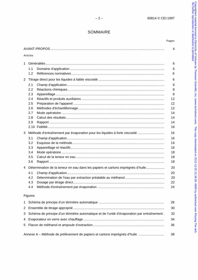
Figures
1 Schéma de principe d’un titrimètre automatique ....................................................................... 28
2 Ensemble de titrage approprié ................................................................................................... 30
3 Schéma de principe d’un titrimètre automatique et de l’unité d’évaporation par entraînement . 32
4 Evaporateur en verre avec chauffage ........................................................................................ 34
5 Flacon de méthanol et ampoule d’extraction.............................................................................. 36
Annexe A – Méthode de prélèvement de papiers et cartons imprégnés d’huile ............................ 38
Copyrighted m
aterial licensed to Electricity of V
ietnam by T
homson S
cientific, Inc. (ww
w.techstreet.com
). This copy dow
nloaded on 2012-12-02 21:39:26 -0600 by authorized user Khuong T
he anh. N
o further reproduction or distribution is permitted.
60814 © IEC:1997 – 3 –
CONTENTS
Page
FOREWORD ................................................................................................................................... 5
Clause
1 General....................................................................................................................................... 7
1.1 Scope ................................................................................................................................ 71.2 Normative references........................................................................................................ 7
2 Direct titration for low viscosity liquids ........................................................................................ 7
2.1 Field of application ............................................................................................................ 72.2 Chemistry .......................................................................................................................... 92.3 Apparatus.......................................................................................................................... 92.4 Reagents and auxiliary materials ...................................................................................... 132.5 Preparation of the apparatus............................................................................................. 132.6 Sampling methods ............................................................................................................ 132.7 Procedure.......................................................................................................................... 152.8 Calculation of the result..................................................................................................... 152.9 Report ............................................................................................................................... 152.10 Precision ........................................................................................................................... 17
3 Evaporative stripping method for high viscosity liquids .............................................................. 17
3.1 Field of application ............................................................................................................ 173.2 Outline of the method........................................................................................................ 173.3 Apparatus and reagents.................................................................................................... 173.4 Procedure.......................................................................................................................... 193.5 Calculation of water content.............................................................................................. 193.6 Report ............................................................................................................................... 19
4 Determination of water in oil-impregnated paper and pressboard ............................................. 21
4.1 Field of application ............................................................................................................ 214.2 Determination of water after previous extraction with methanol ....................................... 214.3 Determination by direct titration......................................................................................... 234.4 Evaporative stripping method............................................................................................ 25
Figures
1 Block diagram of automatic titrator............................................................................................. 29
2 Suitable titration vessel assembly .............................................................................................. 31
3 Block diagram of automatic titrator and evaporation stripping unit ............................................ 33
4 Evaporator glass vessel with heater........................................................................................... 35
5 Methanol container and extraction tube ..................................................................................... 37
Annex A – Method for sampling of oil-impregnated paper and pressboard .................................... 39
Copyrighted m
aterial licensed to Electricity of V
ietnam by T
homson S
cientific, Inc. (ww
w.techstreet.com
). This copy dow
nloaded on 2012-12-02 21:39:26 -0600 by authorized user Khuong T
he anh. N
o further reproduction or distribution is permitted.
– 4 – 60814 © CEI:1997
COMMISSION ÉLECTROTECHNIQUE INTERNATIONALE_________
ISOLANTS LIQUIDES – CARTONS ET PAPIERS IMPRÉGNÉS D’HUILE –
DÉTERMINATION DE LA TENEUR EN EAU PAR TITRAGECOULOMÉTRIQUE DE KARL FISCHER AUTOMATIQUE
AVANT-PROPOS
1) La CEI (Commission Electrotechnique Internationale) est une organisation mondiale de normalisation composéede l'ensemble des comités électrotechniques nationaux (Comités nationaux de la CEI). La CEI a pour objet defavoriser la coopération internationale pour toutes les questions de normalisation dans les domaines del'électricité et de l'électronique. A cet effet, la CEI, entre autres activités, publie des Normes internationales.Leur élaboration est confiée à des comités d'études, aux travaux desquels tout Comité national intéressé par lesujet traité peut participer. Les organisations internationales, gouvernementales et non gouvernementales, enliaison avec la CEI, participent également aux travaux. La CEI collabore étroitement avec l'OrganisationInternationale de Normalisation (ISO), selon des conditions fixées par accord entre les deux organisations.
2) Les décisions ou accords officiels de la CEI concernant les questions techniques représentent, dans la mesuredu possible un accord international sur les sujets étudiés, étant donné que les Comités nationaux intéresséssont représentés dans chaque comité d’études.
3) Les documents produits se présentent sous la forme de recommandations internationales. Ils sont publiéscomme normes, rapports techniques ou guides et agréés comme tels par les Comités nationaux.
4) Dans le but d'encourager l'unification internationale, les Comités nationaux de la CEI s'engagent à appliquer defaçon transparente, dans toute la mesure possible, les Normes internationales de la CEI dans leurs normesnationales et régionales. Toute divergence entre la norme CEI et la norme nationale ou régionalecorrespondante doit être indiquée en termes clairs dans cette dernière.
5) La CEI n’a fixé aucune procédure concernant le marquage comme indication d’approbation et sa responsabilitén’est pas engagée quand un matériel est déclaré conforme à l’une de ses normes.
6) L’attention est attirée sur le fait que certains des éléments de la présente Norme internationale peuvent fairel’objet de droits de propriété intellectuelle ou de droits analogues. La CEI ne saurait être tenue pourresponsable de ne pas avoir identifié de tels droits de propriété et de ne pas avoir signalé leur existence.
La Norme internationale CEI 60814 a été établie par le comités d’études 10 de la CEI: Fluidespour applications électrotechniques.
Cette deuxième édition de la CEI 60814 annule et remplace la première édition parue en 1985dont elle constitue une révision technique.
Elle annule également la CEI 60733, parue en 1982.
Le texte de cette norme est issu des documents suivants:
FDIS Rapport de vote
10/406/FDIS 10/422/RVD
Le rapport de vote indiqué dans le tableau ci-dessus donne toute information sur le vote ayantabouti à l'approbation de cette norme.
L’annexe A est donnée uniquement à titre d’information.
Copyrighted m
aterial licensed to Electricity of V
ietnam by T
homson S
cientific, Inc. (ww
w.techstreet.com
). This copy dow
nloaded on 2012-12-02 21:39:26 -0600 by authorized user Khuong T
he anh. N
o further reproduction or distribution is permitted.
60814 © IEC:1997 – 5 –
INTERNATIONAL ELECTROTECHNICAL COMMISSION_________
INSULATING LIQUIDS – OIL-IMPREGNATED PAPER AND PRESSBOARD –
DETERMINATION OF WATER BY AUTOMATIC COULOMETRICKARL FISCHER TITRATION
FOREWORD
1) The IEC (International Electrotechnical Commission) is a worldwide organization for standardization comprisingall national electrotechnical committees (IEC National Committees). The object of the IEC is to promoteinternational co-operation on all questions concerning standardization in the electrical and electronic fields. Tothis end and in addition to other activities, the IEC publishes International Standards. Their preparation isentrusted to technical committees; any IEC National Committee interested in the subject dealt with mayparticipate in this preparatory work. International, governmental and non-governmental organizations liaisingwith the IEC also participate in this preparation. The IEC collaborates closely with the International Organizationfor Standardization (ISO) in accordance with conditions determined by agreement between the two organizations.
2) The formal decisions or agreements of the IEC on technical matters express, as nearly as possible, aninternational consensus of opinion on the relevant subjects since each technical committee has representationfrom all interested National Committees.
3) The documents produced have the form of recommendations for international use and are published in the formof standards, technical reports or guides and they are accepted by the National Committees in that sense.
4) In order to promote international unification, IEC National Committees undertake to apply IEC InternationalStandards transparently to the maximum extent possible in their national and regional standards. Anydivergence between the IEC Standard and the corresponding national or regional standard shall be clearlyindicated in the latter.
5) The IEC provides no marking procedure to indicate its approval and cannot be rendered responsible for anyequipment declared to be in conformity with one of its standards.
6) Attention is drawn to the possibility that some of the elements of this International Standard may be the subjectof patent rights. The IEC shall not be held responsible for identifying any or all such patent rights.
International Standard IEC 60814 has been prepared by IEC technical committee 10: Fluids forelectrotechnical applications.
This second edition of IEC 60814 cancels and replaces the first edition published in 1985 ofwhich it constitutes a technical revision.
It also cancels IEC 60733, published in 1982.
The text of this standard is based on the following documents:
FDIS Report on voting
10/406/FDIS 10/422/RVD
Full information on the voting for the approval of this standard can be found in the report onvoting indicated in the above table.
Annex A is for information only.
Copyrighted m
aterial licensed to Electricity of V
ietnam by T
homson S
cientific, Inc. (ww
w.techstreet.com
). This copy dow
nloaded on 2012-12-02 21:39:26 -0600 by authorized user Khuong T
he anh. N
o further reproduction or distribution is permitted.
– 6 – 60814 © CEI:1997
ISOLANTS LIQUIDES – CARTONS ET PAPIERS IMPRÉGNÉS D’HUILE –
DÉTERMINATION DE LA TENEUR EN EAU PAR TITRAGECOULOMÉTRIQUE DE KARL FISCHER AUTOMATIQUE
1 Généralités
1.1 Domaine d'application
La présente Norme internationale décrit des méthodes de détermination de la teneur en eaudes isolants liquides et des isolants cellulosiques imprégnés d'huile, par la méthode de titragecoulométrique de Karl Fischer.
La méthode de l’article 2 s'applique aux teneurs en eau supérieures à 2 mg/kg de liquidesayant une viscosité inférieure à 100 mm2/s à 40 °C.
La méthode d'essai de l’article 3, dans laquelle l'eau est extraite par courant d'azote, est laméthode préférentielle pour les liquides isolants de viscosité supérieure à 100 mm2/s.
L’article 4 décrit des méthodes pour déterminer la teneur en eau des papiers et cartonsimprégnés d'huile, dans une gamme comprise entre 0,1 % et 20 % en masse.
1.2 Références normatives
Les documents normatifs suivants contiennent des dispositions qui, par suite de la référencequi y est faite, constituent des dispositions valables pour la présente Norme internationale. Aumoment de la publication, les éditions indiquées étaient en vigueur. Tout document normatifest sujet à révision et les parties prenantes aux accords fondés sur la présente Normeinternationale sont invitées à rechercher la possibilité d’appliquer les éditions les plus récentesdes documents normatifs indiqués ci-après. Les membres de la CEI et de l'ISO possèdent lesregistres des Normes internationales en vigueur.
CEI 60475: 1974, Méthode d'échantillonnage des diélectriques liquides
CEI 60567: 1992, Guide d'échantillonnage de gaz et d'huile dans les matériels électriquesimmergés, pour l'analyse des gaz libres et dissous
ISO 595-1: 1986, Seringues réutilisables en verre ou en verre et métal à usage médical –Partie 1: Dimensions
ISO 595-2: 1987, Seringues réutilisables en verre ou en verre et métal à usage médical –Partie 2: Conception, performances et essais
2 Titrage direct pour les liquides à faible viscosité
2.1 Champ d'application
Cette méthode s'applique aux teneurs en eau supérieures à 2 mg/kg des liquides ayant uneviscosité allant jusqu'à 100 mm2/s à 40 °C. Les données relatives à la fidélité et indiquées en2.10 s'appliquent uniquement aux liquides neufs.
NOTES
1 Pour les liquides en service, la justesse de la méthode peut être affectée par la présence de contaminantset de produits de dégradation.
2 La méthode a été conçue pour convenir particulièrement aux hydrocarbures et aux esters liquides. Pour lesautres liquides, en particulier les fluides silicones, il faut utiliser des réactifs exempts de méthanol.
Copyrighted m
aterial licensed to Electricity of V
ietnam by T
homson S
cientific, Inc. (ww
w.techstreet.com
). This copy dow
nloaded on 2012-12-02 21:39:26 -0600 by authorized user Khuong T
he anh. N
o further reproduction or distribution is permitted.
60814 © IEC:1997 – 7 –
INSULATING LIQUIDS – OIL-IMPREGNATED PAPER AND PRESSBOARD –
DETERMINATION OF WATER BY AUTOMATIC COULOMETRICKARL FISCHER TITRATION
1 General
1.1 Scope
This International Standard describes methods for the determination of water in insulatingliquids and in oil-impregnated cellulosic insulation with coulometrically generated Karl Fischerreagent.
The method in clause 2 is applicable to water concentrations above 2 mg/kg in liquids havingviscosity of less than 100 mm2/s at 40 °C.
The test method in clause 3, where water is extracted by means of a nitrogen stream, is thepreferred method for insulating liquids of viscosity higher than 100 mm2/s.
Clause 4 describes methods for the determination of water content in oil-impregnated paperand pressboard over the range 0,1 % to 20 % by mass.
1.2 Normative references
The following normative documents contain provisions which, through reference in this text,constitute provisions of this International Standard. At the time of publication, the editionsindicated were valid. All normative documents are subject to revision, and parties toagreements based on this International Standard are encouraged to investigate the possibilityof applying the most recent editions of the normative documents indicated below. Members ofIEC and ISO maintain registers of currently valid International Standards.
IEC 60475: 1974, Method of sampling liquid dielectrics
IEC 60567: 1992, Guide for the sampling of gases and of oil from oil-filled electrical equipmentand for the analysis of free and dissolved gases
ISO 595-1: 1986, Reusable all-glass or metal-and-glass syringes for medical use – Part 1:Dimensions
ISO 595-2: 1987, Reusable all-glass or metal-and-glass syringes for medical use – Part 2:Design, performance requirements and tests
2 Direct titration for low viscosity liquids
2.1 Field of application
This method is applicable to water concentrations above 2 mg/kg in liquids having viscosity upto 100 mm2/s at 40 °C. The precision data given in 2.10 apply only to new liquids.
NOTES
1 For liquids in service, the accuracy of the method may be affected by the presence of contaminants anddegradation products.
2 The method has been designed to be particularly suitable to hydrocarbon and ester liquids. With otherliquids, particularly silicone fluids, methanol free reagents must be used.
Copyrighted m
aterial licensed to Electricity of V
ietnam by T
homson S
cientific, Inc. (ww
w.techstreet.com
). This copy dow
nloaded on 2012-12-02 21:39:26 -0600 by authorized user Khuong T
he anh. N
o further reproduction or distribution is permitted.
– 8 – 60814 © CEI:1997
2.2 Réactions chimiques
Il est reconnu que les réactions qui se développent au cours d'un titrage de Karl Fischer sontcomplexes, mais il s'agit essentiellement de la réaction de l'eau avec l'iode en présence de dioxyde desoufre d'une base organique et d'un alcool dans un solvant organique. A l'origine le réactif Karl Fischercomportait de la pyridine et du méthanol, et les réactions pouvaient s'écrire comme suit:
H2O + I2 + SO2 + 3C5H5N → 2C5H5N.HI + C5H5N.SO3 (1)
C5H5N.SO3 + CH3OH → C5H5NH.SO4.CH3 (2)
D'autres associations base-alcool sont possibles et peuvent être nécessaires pour des titragesdans certains liquides isolants.
Dans le titrage coulométrique de Karl Fischer, l'échantillon est mélangé à une solution base-alcool d'ions iodures et de dioxyde de soufre. L'iode est produit par électrolyse et réagit avecl'eau comme cela est montré dans les réactions (1) et (2). Suivant la loi de Faraday, la quantitéd'iode formée est proportionnelle à la quantité d'électricité consommée dans la réaction ci-après:
2 I- – 2 e → I2 (3)
Et comme le montre la réaction (1), une mole d'iode réagit stoechiométriquement avec unemole d'eau, de sorte que 1 mg d'eau correspond à 10,72 C (quantité d'électricité en coulombs).Se fondant sur ce principe, il est possible de calculer la quantité d'eau directement à partir dela quantité d'électricité (en coulombs) consommée par l'électrolyse.
2.3 Appareillage
2.3.1 Principe du fonctionnement
Le récipient de titrage forme une cellule d'électrolyse comportant deux compartiments séparéspar un diaphragme poreux. Le compartiment anodique contient le mélange du réactif-solvant-échantillon (solution anodique), le compartiment cathodique (ensemble générateur) contient leréactif anhydre (solution cathodique). De part et d'autre du diaphragme se trouvent lesélectrodes pour l'électrolyse.
NOTE – Des titrimètres sans diaphragme poreux peuvent être utilisés.
L'iode générée par l'électrolyse, suivant la réaction (3), réagit avec l'eau de manière similaireaux réactions (1) et (2) de Karl Fischer. Le point final de la réaction est décelé par une paired'électrodes en platine immergées dans la solution anodique. A la fin du titrage, l'iode en excèsdépolarise les deux électrodes en platine, modifiant le rapport courant/tension, ce qui actionnel'indicateur de fin de réaction et arrête l'intégrateur de courant.
L'intégrateur de courant somme le courant absorbé au cours de l'électrolyse, calcule la teneuren eau conformément à la loi de Faraday, et finalement l'affiche en microgrammes d'eau.
2.3.2 Description de l'appareil
Les titrimètres coulométriques de Karl Fischer du commerce utilisent des circuits brevetés.La description suivante d'un des principes acceptables d'appareil est donnée uniquement àtitre d'illustration.
Le schéma fonctionnel représenté en figure 1 décrit l'appareil et comprend les éléments ci-dessous.
Copyrighted m
aterial licensed to Electricity of V
ietnam by T
homson S
cientific, Inc. (ww
w.techstreet.com
). This copy dow
nloaded on 2012-12-02 21:39:26 -0600 by authorized user Khuong T
he anh. N
o further reproduction or distribution is permitted.
60814 © IEC:1997 – 9 –
2.2 Chemistry
The reactions occurring in a Karl Fischer titration are known to be complex, but are essentiallyof water with iodine, sulphur dioxide, an organic base and an alcohol in an organic solvent. Theoriginal Karl Fischer reagent used pyridine and methanol, and the reactions may be expressedas:
H2O + I2 + SO2 + 3C5H5N → 2C5H5N.HI + C5H5N.SO3 (1)
C5H5N.SO3 + CH3OH → C5H5NH.SO4.CH3 (2)
Other base-alcohol combinations are possible and may be necessary for titrations on someinsulating liquids.
In coulometric Karl Fischer titration, the sample is mixed with a base/alcohol solution of iodideion and sulphur dioxide. Iodine is generated electrolytically and reacts with water in a similarway to that shown in reactions (1) and (2). Iodine is generated in proportion to the quantity ofelectricity according to Faraday's law, as shown by the following reaction:
2 I- – 2 e → I2 (3)
One mole of iodine reacts with one mole of water stoichiometrically as shown in reactions (1)so that 1 mg of water is equivalent to 10,72 C (number of coulombs). Based on this principle itis possible to determine the amount of water directly from the quantity of electricity (number ofcoulombs) required for the electrolysis.
2.3 Apparatus
2.3.1 Principle of operation
The titration vessel has the configuration of an electrolysis cell with two compartmentsconnected by a porous diaphragm. The anodic compartment contains the mixture of reagent-solvent and sample (anodic solution), the cathodic compartment (generator assembly) containsanhydrous reagent (cathodic solution). On both sides of the diaphragm are located theelectrolysis electrodes.
NOTE – Titrators without the porous diaphragm may be used.
Iodine generated by the electrolysis, as shown in reaction (3), reacts with the water in a similarway to the Karl Fischer reactions (1) and (2). The end-point of the reaction is detected by a pairof platinum electrodes immersed in the anodic solution. At the end of the titration, excessiodine depolarizes the dual platinum electrodes, giving a change in the current/voltage ratiowhich is used to activate the end-point indicator and to stop the current integrator.
The current integrator integrates the current consumed during the electrolysis, calculates thewater equivalent according to Faraday's law, and finally displays it in micrograms of water.
2.3.2 Description of the apparatus
Commercial coulometric Karl Fischer titrators use proprietary circuitry. The followingdescription of one suitable form of apparatus is given for illustrative purposes only.
The block diagram shown in figure 1 illustrates the apparatus and includes the componentsdetailed below.
Copyrighted m
aterial licensed to Electricity of V
ietnam by T
homson S
cientific, Inc. (ww
w.techstreet.com
). This copy dow
nloaded on 2012-12-02 21:39:26 -0600 by authorized user Khuong T
he anh. N
o further reproduction or distribution is permitted.
– 10 – 60814 © CEI:1997
2.3.2.1 Ensemble de titrage
La figure 2 représente un ensemble de titrage approprié. Cependant les modificationstechnologiques de l'appareil sont telles que des conceptions radicalement différentes, etsatisfaisant aux exigences techniques de la présente norme, peuvent devenir disponibles.L'appareil donné à titre d'exemple se compose:
– d'un récipient de titrage en verre à bride (a), muni d'un orifice d'injection (b) del'échantillon, et d'un robinet de vidange (c) (facultatif);
– d'un couvercle en polytétrafluoroéthylène à bride (d) s'adaptant au vase de titrage. Ilpossède trois ouvertures permettant d'y adapter les électrodes et le tube dessiccateur;
– d'un ensemble générateur (cellule d'électrolyse combinée) (e) se composant d'un tube enverre fermé à son extrémité inférieure par un diaphragme et muni, de part et d'autre de cedernier, d'électrodes en platine;
NOTE – Le diaphragme peut être une membrane échangeuse d'ions, un disque en verre fritté, un filtre encéramique ou tout autre système empêchant la diffusion de deux solutions tout en permettant le passage ducourant pour l'électrolyse.
– d'électrodes de détection: une paire d'électrodes en platine pour mesure du potentiel oudu courant (f);
– d'un barreau agitateur recouvert de polytétrafluoréthylène (g);
– de tubes dessiccateurs (h) de l'humidité atmosphérique pour protéger le récipient detitrage et l'ensemble générateur;
– de septums en caoutchouc de silicone, pour fermer l'orifice d'injection. Avant utilisation,il est recommandé que des incisions en croix soient faites dans le septum, pour permettred'utiliser des aiguilles épointées en bout carré pour injecter l'échantillon (voir 2.4.2d)). Ilconvient que les septums soient remplacés, dès que nécessaire, pour éviter les fuites d'aircomme le montrerait une dérive excessive de l'appareil.
2.3.2.2 Circuit de détection
Une tension continue stabilisée ou un courant alternatif constant est appliquée aux électrodesde détection (paire d'électrodes de mesure en platine) de sorte que la fin de la réaction puisseêtre détectée par le changement du courant polarisé ou de la tension.
2.3.2.3 Circuit de stabilisation du courant
Ce circuit commande l'électrolyse conformément au signal provenant du circuit de détection.
2.3.2.4 Alimentation en tension continue
Alimentation en tension continue pour l'électrolyse.
2.3.2.5 Indicateur du point final
Indique quand le point final a été atteint.
2.3.2.6 Intégrateur de courant
Mesure la quantité d'électricité consommée par la cellule d'électrolyse au cours du titrage, puiscalcule et affiche la quantité d'eau correspondante, en microgrammes.
NOTE – Certains appareils ont des possibilités intégrées de calcul et affichent la teneur en eau pour unequantité particulière d'échantillon.
2.3.2.7 Agitateur électromagnétique
Agitateur électromagnétique à vitesse constante et suffisante pour assurer une dispersionadéquate. (En général, le contenu du récipient ne sera pas homogène car les isolants liquidesne sont pas totalement miscibles avec les liquides réactifs.)
Copyrighted m
aterial licensed to Electricity of V
ietnam by T
homson S
cientific, Inc. (ww
w.techstreet.com
). This copy dow
nloaded on 2012-12-02 21:39:26 -0600 by authorized user Khuong T
he anh. N
o further reproduction or distribution is permitted.
60814 © IEC:1997 – 11 –
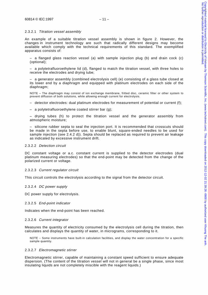
2.3.2.1 Titration vessel assembly
An example of a suitable titration vessel assembly is shown in figure 2. However, thechanges in instrument technology are such that radically different designs may becomeavailable which comply with the technical requirements of this standard. The exemplifiedapparatus consists of:
– a flanged glass reaction vessel (a) with sample injection plug (b) and drain cock (c)(optional);
– a polytetrafluoroethylene lid (d), flanged to match the titration vessel, with three holes toreceive the electrodes and drying tube;
– a generator assembly (combined electrolysis cell) (e) consisting of a glass tube closed atits lower end by a diaphragm and equipped with platinum electrodes on each side of thediaphragm;
NOTE – The diaphragm may consist of ion exchange membrane, fritted disc, ceramic filter or other system toprevent diffusion of both solutions, while allowing enough current for electrolysis.
– detector electrodes: dual platinum electrodes for measurement of potential or current (f);
– a polytetrafluoroethylene coated stirrer bar (g);
– drying tubes (h) to protect the titration vessel and the generator assembly fromatmospheric moisture;
– silicone rubber septa to seal the injection port. It is recommended that crosscuts shouldbe made in the septa before use, to enable blunt, square-ended needles to be used forsample injection (see 2.4.2 d)). Septa should be replaced as required to prevent air leakageas indicated by excessive instrument drift.
2.3.2.2 Detection circuit
DC constant voltage or a.c. constant current is supplied to the detector electrodes (dualplatinum measuring electrodes) so that the end-point may be detected from the change of thepolarized current or voltage.
2.3.2.3 Current regulator circuit
This circuit controls the electrolysis according to the signal from the detector circuit.
2.3.2.4 DC power supply
DC power supply for electrolysis.
2.3.2.5 End-point indicator
Indicates when the end-point has been reached.
2.3.2.6 Current integrator
Measures the quantity of electricity consumed by the electrolysis cell during the titration, thencalculates and displays the quantity of water, in micrograms, corresponding to it.
NOTE – Some instruments have built-in calculation facilities, and display the water concentration for a specificsample quantity.
2.3.2.7 Electromagnetic stirrer
Electromagnetic stirrer, capable of maintaining a constant speed sufficient to ensure adequatedispersion. (The content of the titration vessel will not in general be a single phase, since mostinsulating liquids are not completely miscible with the reagent liquids.)
Copyrighted m
aterial licensed to Electricity of V
ietnam by T
homson S
cientific, Inc. (ww
w.techstreet.com
). This copy dow
nloaded on 2012-12-02 21:39:26 -0600 by authorized user Khuong T
he anh. N
o further reproduction or distribution is permitted.
– 12 – 60814 © CEI:1997
2.4 Réactifs et produits auxiliaires
ATTENTION – Certains réactifs peuvent être nuisibles à la santé et doivent être manipulésavec prudence.
2.4.1 Réactifs
Des réactifs prêts à l'emploi sont disponibles dans le commerce, aussi faut-il s'assurer qu'unde ces réactifs convient au type particulier d'appareil utilisé et au liquide isolant soumis à l'essai.
Des réactions parasites peuvent se produire entre les réactifs à base de méthanol et certainscomposés silicones. En outre, des réactions similaires peuvent avoir lieu avec les aldéhydes,certaines cétones et certains acides organiques insaturés conjugués, qui peuvent être présentsdans les huiles comme produits ou contaminants provenant de la dégradation. Dans ces cas-là, onrecommande des réactifs sans méthanol.
NOTE – L'utilisation de solvants complémentaires ou de substitution peut être nécessaire pour certains liquides isolants.
2.4.2 Produits auxiliaires
a) Solution de neutralisation: méthanol contenant approximativement 20 mg d'eau / cm3.
b) Desséchant, par exemple le perchlorate de magnésium anhydre ou du silicagel avec indicateur.
c) Graisse lubrifiante: à base de polytétrafluoroéthylène ou d'hydrocarbures fluorés. Desgraisses disponibles dans le commerce correspondant à cette description sont considéréescomme satisfaisantes.
d) Seringues en verre pour mesurer et injecter l'échantillon. Des seringues de 10 cm3 et de 5 cm3
suivant l'ISO 595, avec des aiguilles de longueur et de diamètre adaptés. Pour uneutilisation générale, on considère comme satisfaisantes des aiguilles de 100 mm delongueur et de 1 mm de diamètre. Des aiguilles épointées en bout carré sont préférables,afin de limiter les dommages provoqués sur le septum.
2.5 Préparation de l'appareil
Préparer et assembler l'appareil, introduire les réactifs et effectuer la procédure de stabilisationconformément aux instructions du fabricant.
2.6 Méthodes d'échantillonnage
Si les échantillons prélevés sont destinés à des essais autres que celui de la teneur en eau,l'analyse de la teneur en eau doit être effectuée en premier.
2.6.1 Echantillonnage de routine
Pour les essais de routine, les méthodes d'échantillonnage décrites à l'article 2 et en 3.1 de laCEI 60475 doivent être utilisées. Les flacons de prélèvement doivent être séchés parchauffage dans une étuve à 115 °C ± 5 °C, pendant 16 h à 24 h.
2.6.2 Echantillonnage conseillé
Pour obtenir une meilleure précision et plus particulièrement lorsque la teneur en eau est faible,on doit utiliser la méthode décrite à l'article 4 de la CEI 60567. Les flacons d’échantillonnagedoivent être préparés comme spécifié en 2.7.1. Les seringues et les aiguilles doivent êtredémontées, séchées à 115 °C ± 5 °C au moins pendant 8 h, refroidies dans un dessiccateurcontenant du silicagel anhydre puis conservées dans le dessiccateur jusqu'à leur utilisation.
NOTE – La précision des mesures peut être sérieusement altérée par des prélèvements d'échantillons«composites» ou «moyens», et ne sont donc pas recommandés.
Copyrighted m
aterial licensed to Electricity of V
ietnam by T
homson S
cientific, Inc. (ww
w.techstreet.com
). This copy dow
nloaded on 2012-12-02 21:39:26 -0600 by authorized user Khuong T
he anh. N
o further reproduction or distribution is permitted.
60814 © IEC:1997 – 13 –
2.4 Reagents and auxiliary materials
WARNING – Certain reagents may be detrimental to health and must be handled with propercare.
2.4.1 Reagents
Prepared reagents are commercially available, but care is needed that the reagent is suitablefor the particular type of instrument used and the insulating liquid under test.
Interfering reactions may take place between methanol based reagents and some siliconecompounds. In addition, similar reactions may take place with aldehydes, some ketones, andconjugated unsaturated organic acids, which may be present in oils as degradation products orcontaminants. In these cases, reagents not based on methanol are recommended.
NOTE – Some insulating liquids may require the use of additional or alternative solvents.
2.4.2 Auxiliary materials
a) Neutralizing solution, methanol containing approximately 20 mg water/cm3.
b) Desiccant, for example, anhydrous magnesium perchlorate or self-indicating silicagel.
c) Lubricant grease: Polytetrafluoroethylene based or fluorinated hydrocarbon types.Commercially supplied greases to this description have been found satisfactory.
d) Glass syringes for sample measurement and introduction. 10 cm3 and 5 cm3 syringes inaccordance with ISO 595, with needles of suitable length and diameter. Needles of length100 mm and bore 1 mm have been found satisfactory for general use. Blunt, square-endedneedles are preferred, in order to minimize damage to the septa.
2.5 Preparation of the apparatus
Prepare and assemble the apparatus, install the reagents and carry out the stabilizationprocedure in accordance with the manufacturer's instructions.
2.6 Sampling methods
If samples taken are intended for additional tests to water content the water analysis shall becarried out first.
2.6.1 Routine sampling
For routine tests, the sampling methods described in clause 2 and 3.1 of IEC 60475 shall beused. Sample bottles shall be dried by heating in an oven for 16 h to 24 h at 115 °C ± 5 °C.
2.6.2 Recommended sampling
For better accuracy, and particularly where the moisture content is very low, the proceduresdescribed in clause 4 of IEC 60567 shall be used. Sample bottles shall be prepared asspecified in 2.7.1. The syringes and needles shall be dismantled, dried for at least 8 h at115 °C ± 5 °C, cooled in a desiccator with anhydrous silica gel, and kept in the desiccator untilrequired.
NOTE – The accuracy of the determination can be adversely affected by the taking of composite or averagesamples, which is not recommended.
Copyrighted m
aterial licensed to Electricity of V
ietnam by T
homson S
cientific, Inc. (ww
w.techstreet.com
). This copy dow
nloaded on 2012-12-02 21:39:26 -0600 by authorized user Khuong T
he anh. N
o further reproduction or distribution is permitted.
– 14 – 60814 © CEI:1997
2.6.3 Stockage
Les échantillons destinés à l'analyse de l'eau ne doivent à aucun moment être exposés à lalumière directe du jour. Entre l'instant du prélèvement et celui de l'analyse, il convient deconserver les échantillons dans l'obscurité et qu'il ne s'écoule pas plus de sept jours entrel'instant du prélèvement et l'analyse.
2.7 Mode opératoire
a) Pour des échantillons prélevés en flacon
Nettoyer et sécher, dans une étuve bien aérée à la température de 115 °C ± 5 °C, les seringuesen verre et les aiguilles de dimensions adaptées. Laisser refroidir dans un dessiccateur. Remplirla seringue avec le liquide isolant, en maintenant son extrémité bien en dessous de lasurface du liquide. Refermer immédiatement le flacon en verre. Maintenir la seringueverticalement, aiguille vers le haut, et éliminer toutes les bulles d'air. Vider le contenu de laseringue et le mettre au rebut. Remplir à nouveau la seringue et la peser à 0,1 g près.
Pour les échantillons prélevés en seringue
Eliminer environ 2 cm3 de liquide isolant afin de rincer l'aiguille. Ensuite peser la seringueà 0,1 g près.
Le volume à prélever dans l'échantillon dépend de sa teneur en eau supposée. Toutefois etpour la plupart des types de liquides l'isolant, neufs ou usagés, le volume optimal trouvé estde 5 cm3 pour des teneurs en eau comprises entre 2 mg/kg et 100 mg/kg.
b) Agir sur la commande de l'appareil pour mettre en route l'électrolyse suivant les directives dufabricant et injecter rapidement par le septum le volume convenable d'échantillon dans lerécipient de titrage. L'extrémité de l'aiguille ne doit pas toucher la surface du réactif. Peser ànouveau la seringue et noter la masse M, en grammes, du volume injecté.
Vérifier que l'huile est complètement mélangée avec le solvant. La vitesse de l'agitateur nedoit pas être modifiée dès que l'appareil s'est auto-équilibré ou pendant le titrage.
c) En fin de titrage, noter la quantité d'eau, m, affichée (exprimée en microgrammes (µg)).
d) Effectuer une deuxième détermination en rinçant, au préalable, deux fois la seringueavec l'huile de l'échantillon que l'on remplira à nouveau et pèsera en suivant l’alinéa a) puisen effectuant les alinéas b) et c).
e) Après plusieurs déterminations, une quantité importante de liquide isolant peut s'êtreaccumulée dans le récipient de titrage. Enlever le surplus de liquide conformément auxinstructions du fabricant, qu'il convient de suivre également en ce qui concerne les niveauxrelatifs des réactifs anodique et cathodique et la stabilisation de l'appareil.
Après plusieurs vidanges, il convient de remplacer la solution de titrage et la solution del'ensemble générateur par des réactifs neufs, et de répéter le mode opératoire de stabilisation.
2.8 Calcul des résultats
teneur en eau (mg/kg) = mM
où
m est la quantité d'eau titrée, en microgrammes (µg);
M est la masse de liquide isolant, en grammes (g).
2.9 Rapport
La teneur en eau de l'échantillon de liquide isolant est la moyenne des deux déterminations, enmilligrammes d'eau par kilogramme (mg/kg) de liquide isolant et arrondie à l'entier le plus proche.
Copyrighted m
aterial licensed to Electricity of V
ietnam by T
homson S
cientific, Inc. (ww
w.techstreet.com
). This copy dow
nloaded on 2012-12-02 21:39:26 -0600 by authorized user Khuong T
he anh. N
o further reproduction or distribution is permitted.
60814 © IEC:1997 – 15 –
2.6.3 Storage
Samples for water analysis shall at no time be exposed to direct sunlight. Between the time ofcollection and analysis, the samples should be kept in the dark, and the time betweencollection and analysis should be not greater than seven days.
2.7 Procedure
a) With samples which have been collected in bottles
Clean and dry in a well-ventilated oven at 115 °C ± 5 °C a glass syringe and needle of asuitable size. Allow to cool in a desiccator. Fill the syringe with the insulating liquid, keepingthe tip of the needle well below the surface of the liquid. Re-close the glass bottleimmediately. Holding the syringe vertically with the needle uppermost, discharge all airbubbles. Discharge the contents of the syringe to waste. Refill the syringe and weigh to thenearest 0,1 g.
With samples which have been collected in a syringe
Discharge approximately 2 cm3 to flush out the needle and weigh the syringe to thenearest 0,1 g.
The sample size is governed by the expected range of moisture content. However, theoptimum sample size has been found to be 5 cm3 for most types of insulating liquids, newand used, with water contents of between 2 mg/kg and 100 mg/kg.
b) Operate the instrument controls to start the electrolysis according to the manufacturer’sinstructions and quickly inject a suitable quantity of sample into the titration vessel throughthe septum. The tip of the needle shall not be allowed to touch the surface of the reagent.Re-weigh the syringe and record the mass M, in grams, of sample injected.
Ensure that the oil is thoroughly mixed with the solvent. The speed of the stirrer shall not bechanged after the instrument has self-equilibrated or during the titration.
c) Read out the quantity of water titrated, m, (expressed in micrograms (µg)) from thedisplay when the titration is completed.
d) Carry out a duplicate determination by rinsing the syringe twice in the oil sample andrefilling and weighing as in step a). Carry out steps b) and c).
e) After several determinations, a considerable quantity of insulating liquid may haveaccumulated. Remove the excess of liquid in accordance with the manufacturer'sinstructions, which should also be followed with respect to the relative levels of the anodeand cathode reagents and re-stabilization of the instrument.
After several withdrawals, the titration vessel and generator electrode should be recharged withfresh solutions and the stabilization procedure repeated.
2.8 Calculation of the result
water content (mg/kg) = mM
where
m is the quantity of water titrated in micrograms (µg);
M is the mass of insulating liquid in grams (g).
2.9 Report
The water content of the insulating liquid sample is the mean of the duplicate determinations,expressed to the nearest integer in milligrams per kilogram (mg/kg).
Copyrighted m
aterial licensed to Electricity of V
ietnam by T
homson S
cientific, Inc. (ww
w.techstreet.com
). This copy dow
nloaded on 2012-12-02 21:39:26 -0600 by authorized user Khuong T
he anh. N
o further reproduction or distribution is permitted.
– 16 – 60814 © CEI:1997
2.10 Fidélité
NOTE – Les valeurs de fidélité sont établies pour des isolants liquides à base d’hydrocarbures.
2.10.1 Répétabilité
Il convient de considérer comme suspects les essais effectués en double par le mêmeopérateur, à un niveau de confiance de 95 %, s'ils différent de plus de 0,60 x mg/kg, où xest la moyenne des deux déterminations.
2.10.2 Reproductibilité
Lorsque deux laboratoires effectuent des essais sur les mêmes produits, ils doivent fournirdeux résultats et la moyenne de ceux-ci.
Il convient de suspecter ces deux moyennes, à un niveau de confiance de 95 %, si ellesdiffèrent de plus de 1,50 x mg/kg, où x est la moyenne des deux moyennes.
3 Méthode d’entraînement par évaporation pour les liquides à forte viscosité
3.1 Champ d'application
Cette méthode est destinée à la détermination de l'eau dans les liquides isolants neufs deviscosité supérieure à 100 mm2/s à 40 °C. Cette méthode s'applique principalement pour uneteneur en eau supérieure à 2 mg/kg.
NOTE – En alternative, la teneur en eau des liquides à forte viscosité peut être analysée également par laméthode de l’article 2, après les avoir dilués dans un solvant approprié. La fidélité de cette méthode par dilutionest affectée par le degré de dilution, la teneur en eau et la viscosité du solvant choisi.
3.2 Esquisse de la méthode
Une quantité connue de liquide isolant est chauffée dans une étuve fixée à l'appareil de KarlFischer. L'eau dégagée est entraînée complètement par un courant d'azote sec dans lerécipient de titrage où s'effectue le titrage coulométrique.
3.3 Appareillage et réactifs
Le schéma de principe de l'appareil est illustré par la figure 3 et se compose des éléments suivants:
– titrimètre: coulomètre Karl Fischer automatique (voir 2.3);
– évaporateur: récipient en verre de capacité 100 ml, tube d’arrivée d’azote, de diamètreintérieur 1,25 mm (voir figure 4);
– dispositif de chauffage: dispositif en verre clair revêtu d'une couche mince conductricetransparente;
– thermostat: contrôle automatique, précision ± 2 °C;
– gaz vecteur: azote, qualité du commerce, de teneur en eau inférieure à 10 µl/l;
– déshydratant du gaz vecteur: une colonne de silicagel associée à deux colonnesd'anhydride phosphorique;
– réactifs comme indiqué en 2.4.
NOTE – Si des substances interférentes sont présentes, l’utilisation de réactifs appropriés dans le titrimètre estaussi importante que pour le titrage direct.
Copyrighted m
aterial licensed to Electricity of V
ietnam by T
homson S
cientific, Inc. (ww
w.techstreet.com
). This copy dow
nloaded on 2012-12-02 21:39:26 -0600 by authorized user Khuong T
he anh. N
o further reproduction or distribution is permitted.
60814 © IEC:1997 – 17 –
2.10 Precision
NOTE – Precision data have been established for hydrocarbon based insulating liquids.
2.10.1 Repeatability
Duplicate determinations carried out by one operator should be considered suspect at the 95 %confidence level if they differ by more than 0,60 x mg/kg, where x is the average of theduplicate determinations.
2.10.2 Reproducibility
When two laboratories carry out tests on identical test material, each shall produce duplicateresults and report their mean.
The two means should be considered suspect at the 95 % confidence level if they differ bymore than 1,50 x mg/kg, where x is the average of the two means.
3 Evaporative stripping method for high viscosity liquids
3.1 Field of application
This method is designed for the determination of water in unused insulating liquids havingviscosity greater than 100 mm2/s at 40 °C. This method is mainly applicable to water concen-tration above 2 mg/kg.
NOTE – Alternatively, high viscosity liquids may also be analyzed for water content by the method in clause 2after dilution with a suitable solvent. Precision for a dilution procedure will be affected by the degree of dilutionand the water content and viscosity of the chosen solvent.
3.2 Outline of the method
A known amount of the insulating liquid is heated in a closed vessel located next to the KarlFischer apparatus. The water evolved is quantitatively transferred into the titration vessel by astream of dry nitrogen gas where coulometric titration is performed.
3.3 Apparatus and reagents
The block diagram of the apparatus is illustrated in figure 3 and consists of the following items:
– titrator: automatic coulometric Karl Fischer (see 2.3);
– evaporator: glass vessel, 100 ml capacity; nitrogen inlet tube, 1,25 mm inside diameter(see figure 4);
– heater: clear, transparent electro-conductive glass heater;
– temperature controller: automatic control, accuracy ± 2 °C;
– carrier gas: nitrogen gas, commercial grade, less than 10 µl/l water;
– desiccants for carrier gas: one silica gel column plus two phosphorus pentoxide columns;
– reagents as listed in 2.4.
NOTE – When interfering compounds are present, the need for suitable reagents in the titrator is of equalimportance as for direct sample injection.
Copyrighted m
aterial licensed to Electricity of V
ietnam by T
homson S
cientific, Inc. (ww
w.techstreet.com
). This copy dow
nloaded on 2012-12-02 21:39:26 -0600 by authorized user Khuong T
he anh. N
o further reproduction or distribution is permitted.
– 18 – 60814 © CEI:1997
3.4 Mode opératoire
a) Mettre en service le titrimètre de Karl Fischer suivant la procédure spécifiée en 2.5.
b) Injecter un volume suffisant (environ 10 cm3) d'huile de base dans l'évaporateur à traversle septum de l'injecteur, de façon à immerger l'extrémité du tube d'arrivée d'azote etpermettre le barbotage du gaz. Cette huile de base peut être le liquide isolant à essayer outoute autre huile miscible avec l'échantillon et de viscosité similaire à celle de l'huile àanalyser, à la température de fonctionnement.
c) Régler la température de l'évaporateur à 130 °C ± 5 °C et la laisser se stabiliser à cettetempérature. Purger la totalité du système sous azote sec, à un débit de 50 cm3/min à200 cm3/min, pour sécher complètement l'huile de base, ce qui sera obtenu lorsque lecourant correspondant au bruit de fond aura atteint une valeur faible et stable.
d) Fermer l'interrupteur du système de titrage. Effectuer deux opérations à blanc de 10 minchacune sur cette huile de base initiale en suivant les étapes f) et g) de la procédure. Si lesdeux opérations à blanc donnent des résultats semblables à 5 µg d'eau près, retenir lavaleur moyenne à blanc (m1). Si les deux opérations à blanc diffèrent de plus de 5 µg d'eau,il peut être nécessaire d'effectuer un autre séchage de l'huile de base.
e) Introduire une quantité de liquide isolant appropriée (M) dans l'évaporateur, à la seringue(dimension minimale de l'aiguille: diamètre intérieur de 2 mm) ou tout autre moyen d'échantil-lonnage adapté. Peser la seringue avant et après l'injection du liquide pour obtenir la masse exactede l'échantillon. Utiliser un échantillon de 10 g pour des teneurs en eau supérieures à 10 mg/kg etun échantillon de 20 g ± 5 g pour des teneurs en eau inférieures à 10 mg/kg.
f) Ouvrir l'interrupteur du système de titrage de l'unité principale, ou interrompre le titrage demanière différente, pendant 10 min, pour permettre le dégagement de l'humidité dansl'évaporateur et l’accumulation de celle-ci dans la cellule de titrage.
g) Après 10 min, redémarrer le titrage et le laisser se dérouler jusqu'au point de fin du titrage.
h) Lire la quantité d'eau titrée (m2) sur l'appareil de Karl Fischer.
NOTE – Si les teneurs en eau sont supérieures à 50 mg/kg et/ou si la masse de l'échantillon est de 10 g, il estpossible que l'évaporation de l'eau soit incomplète pendant le temps prévu. Il convient, dans ce cas, dereprendre les étapes e) à h) en augmentant la durée du titrage et en diminuant la quantité d'huile. Pour certainstypes de titrimètre, cet objectif peut être atteint en choisissant un temps d'attente suffisamment long.
i) Il est de bonne pratique de confirmer les conditions de stabilité en effectuant une autredétermination à blanc pendant 10 min. Si la valeur ainsi obtenue est égale à la valeur àblanc m1, à 5 µg près, il n'est pas nécessaire d'effectuer un autre titrage.
j) Effectuer une deuxième détermination.
NOTE – Pour des essais de routine, les étapes d) et i) peuvent être omises et la durée de 10 min réduite à 1 min dansles étapes f) et g).
3.5 Calcul de la teneur en eau
Pour chaque détermination individuelle, calculer la teneur en eau comme suit:
teneur en eau (mg/kg) = m mM
2 1−
où
m1 est la moyenne des essais à blanc, en microgrammes (µg);
m2 est la masse de l'eau titrée au cours de l'analyse de l'échantillon, en microgrammes (µg);
M est la masse de l'échantillon, en grammes (g).
3.6 Rapport
La teneur en eau de l'échantillon de liquide isolant est exprimée par la moyenne des deuxdéterminations, arrondie à l'entier le plus proche, en milligrammes par kilogramme.
Copyrighted m
aterial licensed to Electricity of V
ietnam by T
homson S
cientific, Inc. (ww
w.techstreet.com
). This copy dow
nloaded on 2012-12-02 21:39:26 -0600 by authorized user Khuong T
he anh. N
o further reproduction or distribution is permitted.
60814 © IEC:1997 – 19 –
3.4 Procedure
a) Operate the Karl Fischer titrator as per procedures specified in 2.5.
b) Inject a sufficient volume (approximately 10 cm3) of base oil into the evaporator vesselvia the septum of the injection plug so as to immerse the tip of the nitrogen inlet tube topermit bubbling of the gas. This base oil may be the insulating liquid to be tested or anyother miscible oil which does not react with the sample and of similar viscosity at theoperating temperature to the oil being analyzed.
c) Set the temperature of the evaporator unit to 130 °C ± 5 °C and allow the temperatureto stabilize. Purge the whole system with dry nitrogen gas at a flow rate of 50 cm3/minto 200 cm3/min to thoroughly dry the base oil as indicated by a low and stable reading ofbackground current.
d) Turn on the titration switch. Run two blanks of 10 min each on this initial base oil byfollowing steps f) and g) of the procedure. If the two blanks are within 5 µg of water, take theaverage blank value (m1). If the two blanks differ by more than 5 µg of water, further dryingof the base oil may be needed.
e) Introduce a suitable quantity of the insulating liquid (M) into the evaporator vessel using asyringe (minimum needle size: 2 mm inside diameter) or other suitable sampler. Weigh thesyringe before and after liquid injection to obtain the accurate mass of sample. Use a 10 gsample for water contents greater than 10 mg/kg and a 20 g ± 5 g sample for water contentsless than 10 mg/kg.
f) Turn off titration switch on main unit, or otherwise inhibit titration, for a 10 min period toallow moisture released in the evaporator to accumulate in the titration cell.
g) After 10 min, turn on the titration switch and allow to titrate to the end-point.
h) Read the quantity of water titrated (m2) from the Karl Fischer apparatus.
NOTE – When the water contents are higher than 50 mg/kg and/or the mass of sample is 10 g, there is thepossibility that complete evaporation of the water has not taken place. In such cases, the analysis should berepeated as in steps e) to h) but using an increased titration delay time and/or a lower amount of oil. With somedesigns of titrator this purpose can be achieved by setting the delay time sufficiently long.
i) It is good practice to confirm stable operating conditions by carrying out another blankdetermination for a 10 min period. If the value determined is within 5 µg of the original blankvalue m1, no further titration is needed.
j) Carry out a duplicate determination.
NOTE – In the case of routine tests steps d) and i) may be omitted and in steps f) and g) the 10 min may bereduced to 1 min.
3.5 Calculation of water content
For each individual determination, calculate the water content as follows:
water content (mg/kg) = m mM
2 1−
where
m1 is the average blank reading in micrograms (µg);
m2 is the mass of water titrated during sample analysis in micrograms (µg);
M is the mass of the sample in grams (g).
3.6 Report
The water content of the insulating liquid sample is expressed as the average of duplicatedeterminations to the nearest integer in milligrams per kilogram.
Copyrighted m
aterial licensed to Electricity of V
ietnam by T
homson S
cientific, Inc. (ww
w.techstreet.com
). This copy dow
nloaded on 2012-12-02 21:39:26 -0600 by authorized user Khuong T
he anh. N
o further reproduction or distribution is permitted.
– 20 – 60814 © CEI:1997
4 Détermination de la teneur en eau dans les papiers et cartons imprégnés d’huile
4.1 Champ d'application
Ces méthodes s'appliquent au dosage de l'eau dans les matériaux isolants cellulosiquesimprégnés d'huile. Trois modes opératoires sont décrits:
– suivant la procédure de 4.2, l'eau est tout d'abord extraite avec du méthanol pur et ledosage est réalisé sur cet extrait;
– suivant la procédure de 4.3, l'extraction de l'eau est effectuée directement dans lerécipient de titrage (voir note);
NOTE – Ce mode opératoire se limite aux matériaux cellulosiques d’une épaisseur ne dépassant pas 1 mmenviron, car avec un échantillon d’épaisseur supérieure imprégné d'huile l'extraction ne peut jamais êtrecomplète pendant la durée normale du titrage.
– suivant la procédure de 4.4, un échantillon de papier imprégné est chauffé dans un fourattenant à l'appareil de Karl Fischer; la vapeur d'eau produite est complètement transféréedans le récipient de titrage par un courant d'azote sec.
4.2 Détermination de l'eau par extraction préalable au méthanol
4.2.1 Réactifs et produits auxiliaires
ATTENTION – Certains réactifs peuvent être nuisibles à la santé et pour l'environnement etdoivent être manipulés et éliminés avec prudence.
Outre les réactifs et les produits énumérés en 2.4, les produits suivants sont nécessaires:
a) méthanol, qualité pour analyse, de teneur en eau approximative de 0,05 %;
b) solvant approprié sans chlore, de qualité technique;
c) copeaux de magnésium.
4.2.2 Appareillage
a) Titrimètre coulométrique de Karl Fischer, comme indiqué en 2.3.
b) Appareil pour distiller le méthanol.
c) Un flacon à méthanol sec, destiné à recevoir le méthanol distillé et qui peut être protégéde l'humidité atmosphérique au moyen d'un tube dessiccateur. Ce flacon est muni dans sapartie inférieure d'un robinet de vidange et d'un rodage sphérique permettant d'adapterl'ampoule d'extraction (voir figure 5).
d) Ampoule d'extraction, étanche et graduée, d'un volume de 50 cm3 environ.
e) Pinces brucelles métalliques.
4.2.3 Préparation de l'appareil
Il convient de laver toute la verrerie ainsi que les brucelles pour éliminer les traces deséchantillons précédents, au moyen d'une solution détergente appropriée ou d'eau savonneuseou d'un solvant organique chloré, suivi d’un rinçage à l'eau chaude, puis à l'eau déionisée etfinalement après égouttage, au méthanol. Il convient de sécher toute la nuit le matériel nettoyédans une étuve à 115 °C ± 5 °C, ensuite de le refroidir, jusqu'à la température ambiante, dansun dessiccateur.
Copyrighted m
aterial licensed to Electricity of V
ietnam by T
homson S
cientific, Inc. (ww
w.techstreet.com
). This copy dow
nloaded on 2012-12-02 21:39:26 -0600 by authorized user Khuong T
he anh. N
o further reproduction or distribution is permitted.
60814 © IEC:1997 – 21 –
4 Determination of water in oil-impregnated paper and pressboard
4.1 Field of application
These methods apply to the determination of the water content in oil-impregnated cellulosicinsulation materials. Three procedures are described:
– with the procedure in 4.2, water is first extracted with absolute methanol and thedetermination carried out on the extract;
– with the procedure in 4.3, water extraction takes place directly in the titration vessel(see note);
NOTE – This procedure is restricted to cellulosic material of thickness up to approximately 1 mm because anoil-impregnated sample of higher thickness can never be completely extracted within the normal duration of adetermination.
– with the procedure in 4.4, a specimen of impregnated paper is heated in an oven next tothe Karl Fischer apparatus; the water vapour evolved is quantitatively transferred into thetitration vessel by a stream of dry nitrogen gas.
4.2 Determination of water after previous extraction with methanol
4.2.1 Reagents and auxiliary materials
WARNING – Certain reagents may be detrimental to health and the environment and must behandled and disposed of with proper care.
In addition to the reagents and materials listed in 2.4, the following is required:
a) methanol, analytical reagent grade, water content approximately 0,05 %;
b) chlorine free suitable solvent, technical grade;
c) magnesium turnings.
4.2.2 Apparatus
a) Coulometric Karl Fischer titrator as indicated in 2.3.
b) Methanol distilling apparatus.
c) Dried methanol container, to contain the distilled methanol and which can be protectedfrom the atmosphere by a drying tube. The container is fitted at its lower part with a drainingcock and a spherical joint to adapt to the extraction tube (see figure 5).
d) Graduated, gas-tight extraction tubes with an approximate capacity of 50 cm3.
e) Metal tweezers.
4.2.3 Preparation of the apparatus
All the glassware and metal tweezers should be washed free from previous samples, eitherwith a suitable detergent solution or soapy water or a chlorine free solvent, rinsed thoroughlywith warm water, then deionized water and finally, after draining, with methanol. The cleanmaterial should be dried in an oven at 115 °C ± 5 °C overnight, then cooled to roomtemperature in a desiccator.
Copyrighted m
aterial licensed to Electricity of V
ietnam by T
homson S
cientific, Inc. (ww
w.techstreet.com
). This copy dow
nloaded on 2012-12-02 21:39:26 -0600 by authorized user Khuong T
he anh. N
o further reproduction or distribution is permitted.
– 22 – 60814 © CEI:1997
4.2.4 Mode opératoire
a) Distiller le méthanol en présence de copeaux de magnésium pour abaisser sa teneur eneau en dessous de 200 mg/kg. Recueillir le méthanol ainsi distillé dans un récipientconvenable protégé de l'humidité atmosphérique par un tube dessiccateur contenant duperchlorate de magnésium. Déterminer la teneur en eau du méthanol et noter la valeur.
b) Prendre une ampoule d'extraction contenant un échantillon de papier, ou introduire unéchantillon de papier dans l'ampoule d'extraction.
NOTES
1 Choisir la masse du papier de telle sorte que la quantité d'eau à déterminer soit comprise entre 1 mg et 4 mg.
2 Si le papier ou le carton est trop épais, il est recommandé de le diviser en plusieurs morceaux afind'améliorer l'extraction, en prenant soin pendant cette opération d'éviter tout échange d'humidité avecl'environnement.
c) Adapter l'ampoule d'extraction au flacon contenant le méthanol anhydre, ouvrir le robinetsupérieur et, pendant un temps très court, le mettre sous vide au moyen de la pompe àvide. Introduire ensuite, au moyen d'une burette appropriée, 1 cm³ à 10 cm3 de méthanol.Fermer le robinet supérieur et détacher le tube d'extraction.
d) Répéter la procédure décrite au point c) avec une autre ampoule d'extraction qui necontient pas de papier. Ceci servira d'essai à blanc.
e) Agiter l'ampoule contenant l'échantillon de papier et celle de l'essai à blanc pendant 2 h.
f) Préparer l'appareil de titrage Karl Fischer suivant les procédures spécifiées en 2.5.
g) Adapter l'ampoule d'extraction contenant l'échantillon au récipient de titrage; introduire leméthanol dans le solvant et titrer jusqu'au point final. Lire la masse d'eau titrée (m2) affichée.
h) Répéter l'étape g) avec le tube à blanc et noter la lecture affichée (m1).
i) Enlever le papier de l'ampoule de titrage. Dégraisser le papier avec le solvant sanschlore et le sécher au moins pendant 2 h à 110 °C ± 5 °C. Le laisser refroidir dans undessiccateur, ensuite le peser.
Noter la masse M, en grammes, du papier.
j) Effectuer une deuxième détermination.
4.2.5 Calcul des résultats
teneur en eau (% en masse) = ( ) 102 1 4m mM− × −
où
m1 est la masse d'eau mesurée lors de l'essai à blanc, en microgrammes (µg);
m2 est la masse d'eau mesurée lors de l'essai avec échantillon, en microgrammes (µg);
M est la masse de l'échantillon de papier, en grammes (g).
4.2.6 Rapport
La teneur en eau de l'isolant est exprimée par la moyenne des deux déterminations arrondieà 0,01 %. La teneur en eau du méthanol utilisée doit être indiquée.
4.3 Dosage par titrage direct
4.3.1 Réactifs et produits auxiliaires
Outre les réactifs et produits énumérés en 2.4, un solvant convenable, sans chlore, estnécessaire pour déshuiler les échantillons solides.
Copyrighted m
aterial licensed to Electricity of V
ietnam by T
homson S
cientific, Inc. (ww
w.techstreet.com
). This copy dow
nloaded on 2012-12-02 21:39:26 -0600 by authorized user Khuong T
he anh. N
o further reproduction or distribution is permitted.
60814 © IEC:1997 – 23 –
4.2.4 Procedure
a) Distil methanol over magnesium turnings in order to lower its water content below 200mg/kg. Collect the distilled methanol in the appropriate container protected from theatmosphere by a drying tube filled with magnesium perchlorate. Determine the water contentof the methanol and record the value.
b) Take an extraction tube containing a paper sample or put a paper sample in extractiontube.
NOTES
1 Select the mass of the sample so that the amount of water to be measured is within 1 mg to 4 mg.
2 It may be advisable to cut up cellulosic material if it is too thick to ensure better extraction taking care toavoid any exchange of moisture with the surroundings during the operation.
c) Fit the extraction tube to the dry methanol container, open the upper cock, connect to thevacuum line for a very short time and, using an appropriate burette, admit 1 cm³ to 10 cm3
of methanol. Close the upper cock and disconnect the tube.
d) Repeat step c) with another tube that does not contain any paper. This will be used forthe blank test.
e) Shake the sample and blank tubes for 2 h.
f) Operate the Karl Fisher titrator as per procedures specified in 2.5.
g) Fit the sample tube to the titration vessel, transfer the methanol to the solvent and titrateto the end-point. Read the mass of water titrated (m2) from the display on the titrator.
h) Repeat step g) with the blank tube and record the display reading (m1).
i) Remove the paper from the titration tube. Degrease the paper with chlorine free solventand dry at 110 °C ± 5 °C for at least 2 h. Let the paper sample cool in a desiccator and thenweigh. Record the mass M, in grams, of the paper.
j) Carry out a duplicate determination.
4.2.5 Calculation of the results
water content (% by mass) = ( ) 102 1 4m mM− × −
where
m1 is the mass of water measured for blank titration, in micrograms (µg);
m2 is the mass of water measured in the sample titration, in micrograms (µg);
M is the mass of the paper sample, in grams (g).
4.2.6 Report
The water content of the insulation is expressed as the average of duplicate measurements tothe nearest 0,01 %. The water content of the methanol used shall be quoted.
4.3 Determination by direct titration
4.3.1 Reagents and auxiliary materials
In addition to the reagents and materials listed in 2.4, a suitable chlorine-free solvent isrequired for degreasing the sample material.
Copyrighted m
aterial licensed to Electricity of V
ietnam by T
homson S
cientific, Inc. (ww
w.techstreet.com
). This copy dow
nloaded on 2012-12-02 21:39:26 -0600 by authorized user Khuong T
he anh. N
o further reproduction or distribution is permitted.
– 24 – 60814 © CEI:1997
4.3.2 Appareillage
a) Titrimètre coulométrique de Karl Fischer indiqué en 2.3.
b) Brucelles métalliques.
4.3.3 Mode opératoire
a) Mettre en route le titrimètre de Karl Fischer suivant les procédures spécifiées en 2.5.
b) Introduire dans le récipient de titrage, aussi vite que possible, l'échantillon de papier aumoyen de brucelles métalliques sèches.NOTE – Voir notes 1 et 2 du point b) de 4.2.4.
c) Ouvrir l'interrupteur du système de titrage de l'unité principale, ou interrompre le titragede manière différente, pendant un temps compris entre 15 min et 25 min (le temps exactdoit être déterminé par l'opérateur), pour permettre de transférer l'humidité du papier ausolvant. A la fin du temps d'extraction, redémarrer le titrage jusqu'au point final.
d) Lire la quantité d'eau titrée (m2) sur l'appareil de Karl Fischer.
e) Effectuer un essai à blanc de même durée afin d'évaluer l'humidité qui entre dans lesystème pendant l'essai. Noter la masse titrée (m1). Dans certains modèles de titrimètre, ladérive est contrôlée en continue et automatiquement déduite de la lecture de la massed'eau extraite. S'il en est ainsi, l'essai à blanc peut ne pas être nécessaire bien qu'ilconvienne de prendre soin qu'un fonctionnement stable soit assuré tout au long du titrage.NOTE – Il est important de limiter au minimum la durée de la détermination, qui peut être fixée par l'opérateuren fonction de l'expérience et du type d'échantillon examiné. S’il le faut, la période optimale peut êtredéterminée en effectuant à plusieurs reprises la procédure avec des temps d'extraction croissants, jusqu'àl'obtention d'un résultat constant. Pour obtenir des résultats reproductibles sur une série d'essais, il convientd'utiliser la même période d'extraction pour toute la série.
f) Enlever le papier du récipient de titrage. Déshuiler le papier au solvant et le sécher aumoins pendant 2 h à 110 °C. Laisser refroidir l'échantillon dans un dessiccateur, ensuite lepeser. Noter la masse M, en grammes, du papier.
g) Effectuer une deuxième détermination.
4.3.4 Calcul des résultats
teneur en eau (% en masse) = ( ) 102 1 4m mM− × −
où
m1 est la masse d'eau mesurée pour l'essai à blanc, en microgrammes (µg);
m2 est la masse d'eau mesurée pour l'essai avec l’échantillon, en microgrammes (µg);
M est la masse de l'échantillon de papier, en grammes (g).
4.3.5 Rapport
La teneur en eau de l'isolant est exprimée par la moyenne de deux déterminations arrondieà 0,01 %. Le temps d'extraction doit être indiqué.
4.4 Méthode d'entraînement par évaporation
4.4.1 Appareillage
Le schéma fonctionnel de l'appareil est illustré en figure 3 avec les composants énumérés en 3.3.
Un évaporateur de type nacelle fonctionnant pour l'extraction gaz-solide est aussi convenable.
Copyrighted m
aterial licensed to Electricity of V
ietnam by T
homson S
cientific, Inc. (ww
w.techstreet.com
). This copy dow
nloaded on 2012-12-02 21:39:26 -0600 by authorized user Khuong T
he anh. N
o further reproduction or distribution is permitted.
60814 © IEC:1997 – 25 –
4.3.2 Apparatus
a) Coulometric Karl Fischer titrator as described in 2.3.
b) Metal tweezers.
4.3.3 Procedure
a) Operate the Karl Fischer titrator as per procedures specified in 2.5.
b) Introduce, as quickly as possible, the paper sample by means of dried metal tweezersinto the titration vessel.NOTE – See notes 1 and 2 item b) of 4.2.4.
c) Turn off the titration switch on the main unit, or otherwise inhibit titration, for a timeperiod ranging from 15 min to 25 min (the exact time shall be determined by the operator) toallow transfer of moisture from the paper to the solvent. At the end of the extraction time,turn on the titration and titrate to the end-point.
d) Read the quantity of water titrated (m2) from the Karl Fischer apparatus.
e) Carry out a blank test of the same duration in order to evaluate the amount of moisturethat enters the system during the test. Record the mass (m1) titrated.
In some designs of titrator, the drift is continuously monitored and automatically subtractedfrom the water reading. If so the blank test may not be needed though care should be usedto ensure stable operating throughout the titration.NOTE – It is important to limit to a minimum the duration of the determination, which can be fixed by theoperator on the basis of experience and the type of sample examined. If necessary, the optimum period can bedetermined by repeatedly carrying out the procedure using increasing extraction times until a constant result isobtained. To obtain reproducible results over a series of tests, the same extraction period should be usedthroughout the series.
f) Remove the paper from the titration tube. Degrease the paper with the solvent and dryat 110 °C for at least 2 h. Let the paper sample cool in a desiccator and then weigh it.Record the mass M, in grams, of the paper.
g) Carry out a duplicate determination.
4.3.4 Calculation of results
water content (% by mass) = ( ) 102 1 4m mM− × −
where
m1 is the mass of water measured for blank titration in micrograms (µg);
m2 is the mass of water measured in the sample titration in micrograms (µg);
M is the mass of the paper sample in grams (g).
4.3.5 Report
The water content of the insulation is expressed as the average of duplicate measurements tothe nearest 0,01 %. The time of extraction shall be quoted.
4.4 Evaporative stripping method
4.4.1 Apparatus
The block diagram of the apparatus is illustrated in figure 3 with components as listed in 3.3.
The boat type of evaporator using a gas-solid extraction is also suitable.
Copyrighted m
aterial licensed to Electricity of V
ietnam by T
homson S
cientific, Inc. (ww
w.techstreet.com
). This copy dow
nloaded on 2012-12-02 21:39:26 -0600 by authorized user Khuong T
he anh. N
o further reproduction or distribution is permitted.
– 26 – 60814 © CEI:1997
4.4.2 Mode opératoire
a) Mettre en route le titrimètre de Karl Fischer suivant les procédures spécifiées en 2.7.
b) Porter l'évaporateur à la température convenable (130 °C pour les papiers et les cartonsimprégnés d'huile à faible viscosité, 140 °C pour les papiers et les cartons imprégnés d'huileou de composés visqueux).
c) Régler le flux du gaz vecteur de façon à avoir un débit régulier de 50 cm3/min à 100 cm3/min.Introduire l'extrémité du tube de sortie du gaz vecteur dans le récipient de titrage et laisserle système se stabiliser; ce qui sera obtenu lorsque le courant correspondant au bruit defond atteindra une valeur faible et stable.
d) Introduire rapidement dans la nacelle de l'évaporateur l'échantillon de papier pris dans lerécipient de stockage. Pour les papiers à très faible teneur en eau, un échantillon de papierd'environ 0,5 g est adéquat.
e) Ouvrir l'interrupteur du système de titrage de l'unité principale, ou interrompre le titragede manière différente, pendant une période de 20 min, pour permettre à l'eau dégagée dansl'évaporateur de s'accumuler dans le récipient de titrage. A la fin du temps d'extraction,redémarrer le titrage jusqu'au point final. Lire la quantité d'eau titrée (m2) sur l'appareil deKarl Fischer.NOTE – Le temps d'extraction dépendra autant des caractéristiques de l'échantillon que des paramètres dusystème. Bien que dans la plupart des cas une période de 20 min se soit montrée adéquate, l'opérateur aura àdéterminer les conditions optimales de fonctionnement.
f) Réaliser un essai à blanc de même durée, afin d'évaluer la teneur en eau entrant dans lesystème pendant l'essai. Noter la masse (m1) titrée. Dans certains modèles de titrimètre,la dérive est contrôlée en continu et automatiquement déduite de la lecture de la massed'eau extraite. S'il en est ainsi, l'essai à blanc peut ne pas être nécessaire bien qu'ilconvienne de prendre soin qu'un fonctionnement stable soit assuré tout au long du titrage.
g) Retirer le papier de la nacelle du four. Déshuiler le papier avec du solvant sans chlore etle sécher à 110 °C ± 5 °C pendant 2 h au moins. Laisser refroidir l'échantillon de papierdans un dessiccateur, ensuite le peser. Noter la masse du papier M, en grammes.
h) Effectuer une deuxième détermination.
4.4.3 Calcul des résultats
teneur en eau (% en masse) = ( ) 102 1 4m mM− × −
où
m1 est la masse d'eau mesurée pour l'essai à blanc, en microgrammes (µg);
m2 est la masse d'eau mesurée pour l'essai avec l’échantillon, en microgrammes (µg);
M est la masse de l'échantillon de papier, en grammes (g).
4.4.4 Rapport
La teneur en eau de l'isolant est exprimée par la moyenne de deux déterminations arrondieà 0,01 %. Le temps d'extraction doit être indiqué.
Copyrighted m
aterial licensed to Electricity of V
ietnam by T
homson S
cientific, Inc. (ww
w.techstreet.com
). This copy dow
nloaded on 2012-12-02 21:39:26 -0600 by authorized user Khuong T
he anh. N
o further reproduction or distribution is permitted.
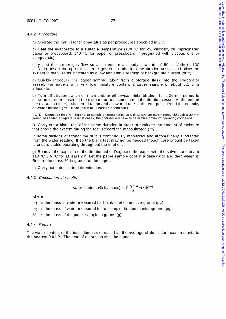
60814 © IEC:1997 – 27 –
4.4.2 Procedure
a) Operate the Karl Fischer apparatus as per procedures specified in 2.7.
b) Heat the evaporator to a suitable temperature (130 °C for low viscosity oil impregnatedpaper or pressboard, 140 °C for paper or pressboard impregnated with viscous oils orcompounds).
c) Adjust the carrier gas flow so as to ensure a steady flow rate of 50 cm3/min to 100cm3/min. Insert the tip of the carrier gas outlet tube into the titration vessel and allow thesystem to stabilize as indicated by a low and stable reading of background current (drift).
d) Quickly introduce the paper sample taken from a storage flask into the evaporatorvessel. For papers with very low moisture content a paper sample of about 0,5 g isadequate.
e) Turn off titration switch on main unit, or otherwise inhibit titration, for a 20 min period toallow moisture released in the evaporator to accumulate in the titration vessel. At the end ofthe extraction time, switch on titration and allow to titrate to the end-point. Read the quantityof water titrated (m2) from the Karl Fischer apparatus.
NOTE – Extraction time will depend on sample characteristics as well as system parameters. Although a 20 minperiod was found adequate in most cases, the operator will have to determine optimum operating conditions.
f) Carry out a blank test of the same duration in order to evaluate the amount of moisturethat enters the system during the test. Record the mass titrated (m1).
In some designs of titrator the drift is continuously monitored and automatically subtractedfrom the water reading. If so the blank test may not be needed though care should be takento ensure stable operating throughout the titration.
g) Remove the paper from the titration tube. Degrease the paper with the solvent and dry at110 °C ± 5 °C for at least 2 h. Let the paper sample cool in a desiccator and then weigh it.Record the mass M, in grams, of the paper.
h) Carry out a duplicate determination.
4.4.3 Calculation of results
water content (% by mass) = ( ) 102 1 4m mM− × −
where
m1 is the mass of water measured for blank titration in micrograms (µg);
m2 is the mass of water measured in the sample titration in micrograms (µg);
M is the mass of the paper sample in grams (g).
4.4.4 Report
The water content of the insulation is expressed as the average of duplicate measurements tothe nearest 0,01 %. The time of extraction shall be quoted.
Copyrighted m
aterial licensed to Electricity of V
ietnam by T
homson S
cientific, Inc. (ww
w.techstreet.com
). This copy dow
nloaded on 2012-12-02 21:39:26 -0600 by authorized user Khuong T
he anh. N
o further reproduction or distribution is permitted.
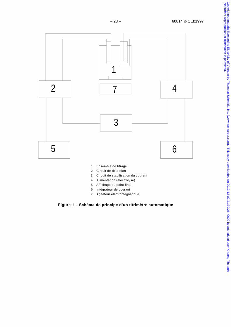
– 28 – 60814 © CEI:1997
1
2
3
4
5 6
7
1 Ensemble de titrage
2 Circuit de détection
3 Circuit de stabilisation du courant
4 Alimentation (électrolyse)
5 Affichage du point final
6 Intégrateur de courant
7 Agitateur électromagnétique
Figure 1 – Schéma de principe d’un titrimètre automatique
Copyrighted m
aterial licensed to Electricity of V
ietnam by T
homson S
cientific, Inc. (ww
w.techstreet.com
). This copy dow
nloaded on 2012-12-02 21:39:26 -0600 by authorized user Khuong T
he anh. N
o further reproduction or distribution is permitted.
60814 © IEC:1997 – 29 –
1
2
3
4
5 6
7
1 Titration cell assembly
2 Detection circuit
3 Current regulator circuit
4 Power circuit (electrolysis)
5 End-point displayer
6 Current integrator
7 Electromagnetic stirrer
Figure 1 – Block diagram of automatic titrator
Copyrighted m
aterial licensed to Electricity of V
ietnam by T
homson S
cientific, Inc. (ww
w.techstreet.com
). This copy dow
nloaded on 2012-12-02 21:39:26 -0600 by authorized user Khuong T
he anh. N
o further reproduction or distribution is permitted.
– 30 – 60814 © CEI:1997
a
b
c
d
e
f
g
h
a Récipient de titrage (compartiment anodique)
b Orifice d’injection
c Robinet de vidange
d Couvercle en polytétrafluoroéthylène
e Ensemble générateur (compartiment cathodique)
f Paire d’électrodes de mesure du potentiel, en platine
g Barreau agitateur recouvert de polytétrafluoroéthylène
h Tubes dessiccateurs
Figure 2 – Ensemble de titrage approprié
Copyrighted m
aterial licensed to Electricity of V
ietnam by T
homson S
cientific, Inc. (ww
w.techstreet.com
). This copy dow
nloaded on 2012-12-02 21:39:26 -0600 by authorized user Khuong T
he anh. N
o further reproduction or distribution is permitted.
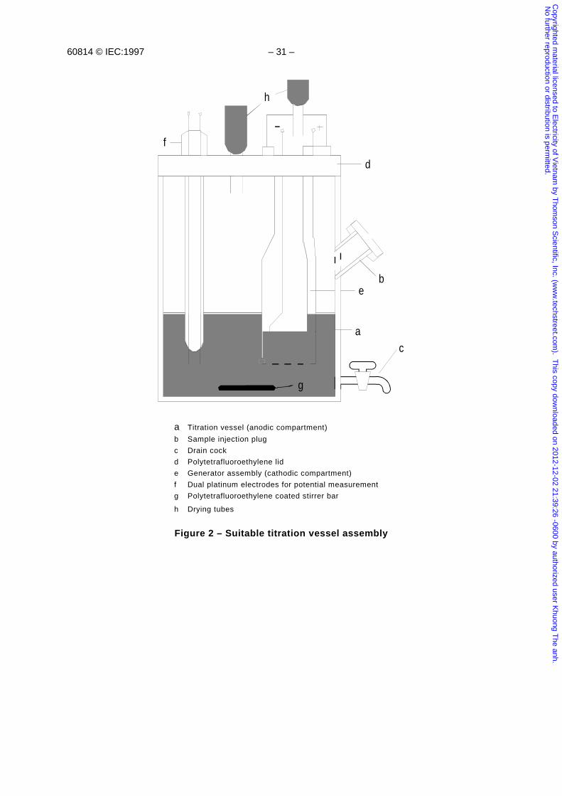
60814 © IEC:1997 – 31 –
a
b
c
d
e
f
g
h
a Titration vessel (anodic compartment)
b Sample injection plug
c Drain cock
d Polytetrafluoroethylene lid
e Generator assembly (cathodic compartment)
f Dual platinum electrodes for potential measurement
g Polytetrafluoroethylene coated stirrer bar
h Drying tubes
Figure 2 – Suitable titration vessel assembly
Copyrighted m
aterial licensed to Electricity of V
ietnam by T
homson S
cientific, Inc. (ww
w.techstreet.com
). This copy dow
nloaded on 2012-12-02 21:39:26 -0600 by authorized user Khuong T
he anh. N
o further reproduction or distribution is permitted.
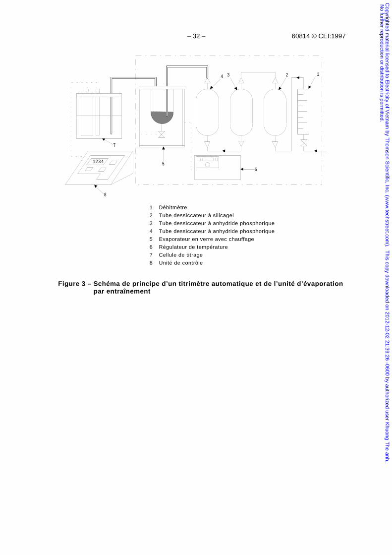
– 32 – 60814 © CEI:1997
1234
1234
56
7
8
1 Débitmètre
2 Tube dessiccateur à silicagel
3 Tube dessiccateur à anhydride phosphorique
4 Tube dessiccateur à anhydride phosphorique
5 Evaporateur en verre avec chauffage
6 Régulateur de température
7 Cellule de titrage
8 Unité de contrôle
Figure 3 – Schéma de principe d’un titrimètre automatique et de l’unité d’évaporationpar entraînement
Copyrighted m
aterial licensed to Electricity of V
ietnam by T
homson S
cientific, Inc. (ww
w.techstreet.com
). This copy dow
nloaded on 2012-12-02 21:39:26 -0600 by authorized user Khuong T
he anh. N
o further reproduction or distribution is permitted.
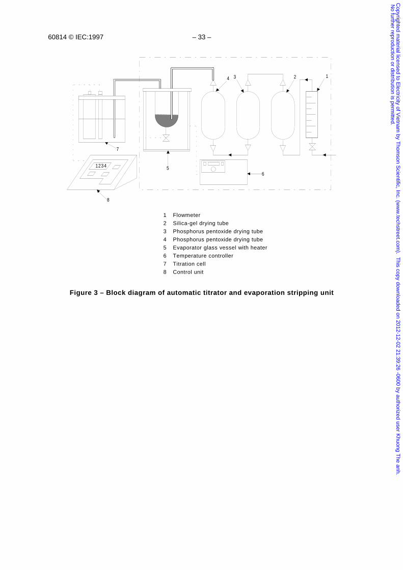
60814 © IEC:1997 – 33 –
1234
1234
56
7
8
1 Flowmeter
2 Silica-gel drying tube
3 Phosphorus pentoxide drying tube
4 Phosphorus pentoxide drying tube
5 Evaporator glass vessel with heater
6 Temperature controller
7 Titration cell
8 Control unit
Figure 3 – Block diagram of automatic titrator and evaporation stripping unit
Copyrighted m
aterial licensed to Electricity of V
ietnam by T
homson S
cientific, Inc. (ww
w.techstreet.com
). This copy dow
nloaded on 2012-12-02 21:39:26 -0600 by authorized user Khuong T
he anh. N
o further reproduction or distribution is permitted.
– 34 – 60814 © CEI:1997
21
34
5
6
D iam .40 m m
1 Tube d’entrée d’azote
2 Thermocouple
3 Orifice d’injection
4 Tube de sortie d’azote et de l’eau évaporée
5 Système de chauffage
6 Robinet de vidange
Figure 4 – Evaporateur en verre avec chauffage
∅ 40 mm
90 mm
Copyrighted m
aterial licensed to Electricity of V
ietnam by T
homson S
cientific, Inc. (ww
w.techstreet.com
). This copy dow
nloaded on 2012-12-02 21:39:26 -0600 by authorized user Khuong T
he anh. N
o further reproduction or distribution is permitted.
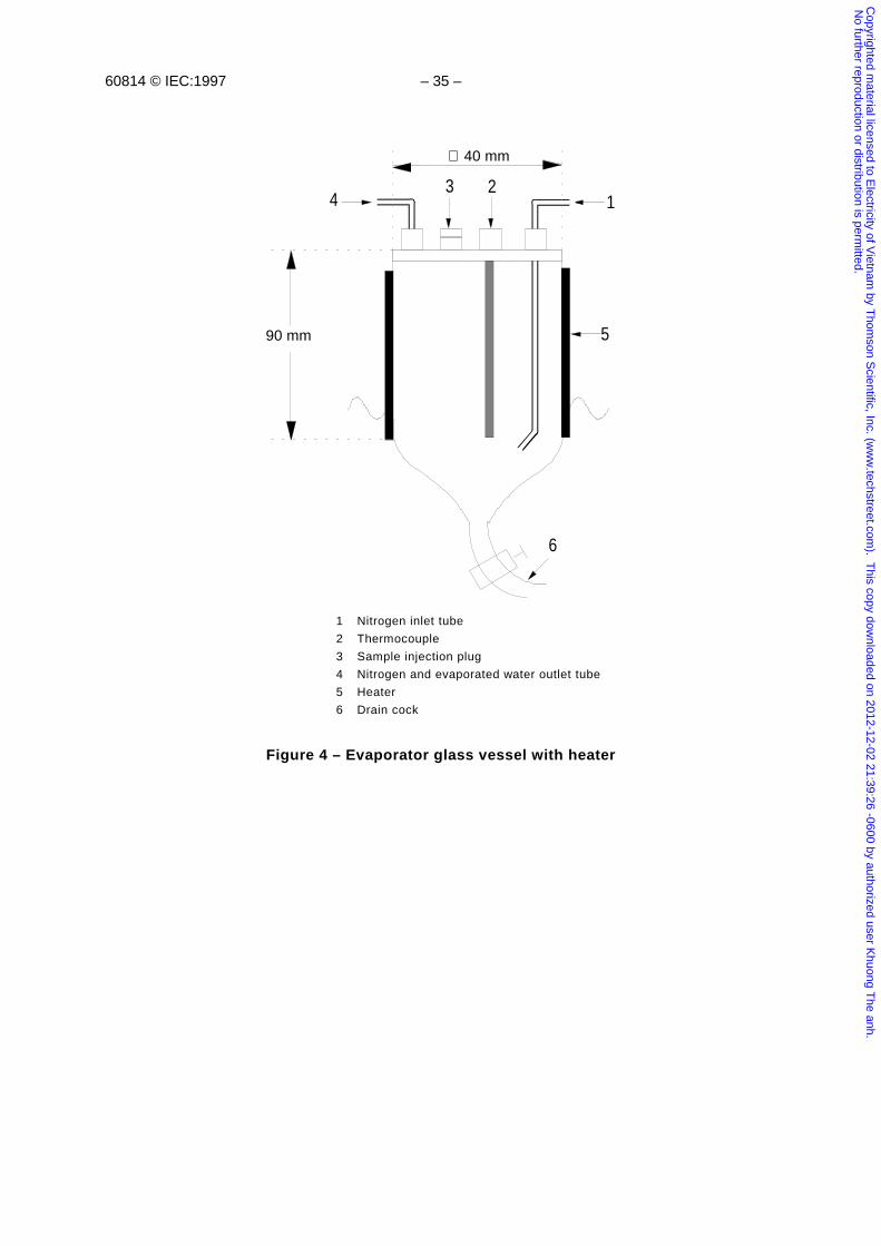
60814 © IEC:1997 – 35 –
21
34
5
6
D iam .40 m m
1 Nitrogen inlet tube
2 Thermocouple
3 Sample injection plug
4 Nitrogen and evaporated water outlet tube
5 Heater
6 Drain cock
Figure 4 – Evaporator glass vessel with heater
∅ 40 mm
90 mm
Copyrighted m
aterial licensed to Electricity of V
ietnam by T
homson S
cientific, Inc. (ww
w.techstreet.com
). This copy dow
nloaded on 2012-12-02 21:39:26 -0600 by authorized user Khuong T
he anh. N
o further reproduction or distribution is permitted.
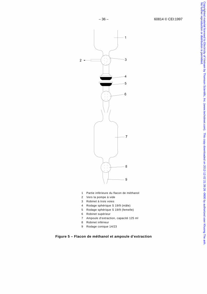
– 36 – 60814 © CEI:1997
1 Partie inférieure du flacon de méthanol
2 Vers la pompe à vide
3 Robinet à trois voies
4 Rodage sphérique S 19/9 (mâle)
5 Rodage sphérique S 19/9 (femelle)
6 Robinet supérieur
7 Ampoule d’extraction, capacité 125 ml
8 Robinet inférieur
9 Rodage conique 14/23
Figure 5 – Flacon de méthanol et ampoule d’extraction
Copyrighted m
aterial licensed to Electricity of V
ietnam by T
homson S
cientific, Inc. (ww
w.techstreet.com
). This copy dow
nloaded on 2012-12-02 21:39:26 -0600 by authorized user Khuong T
he anh. N
o further reproduction or distribution is permitted.
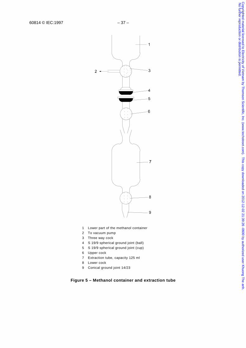
60814 © IEC:1997 – 37 –
1 Lower part of the methanol container
2 To vacuum pump
3 Three way cock
4 S 19/9 spherical ground joint (ball)
5 S 19/9 spherical ground joint (cup)
6 Upper cock
7 Extraction tube, capacity 125 ml
8 Lower cock
9 Conical ground joint 14/23
Figure 5 – Methanol container and extraction tube
Copyrighted m
aterial licensed to Electricity of V
ietnam by T
homson S
cientific, Inc. (ww
w.techstreet.com
). This copy dow
nloaded on 2012-12-02 21:39:26 -0600 by authorized user Khuong T
he anh. N
o further reproduction or distribution is permitted.
– 38 – 60814 © CEI:1997
Annexe A(Informative)
Méthode de prélèvement de papiers et cartons imprégnés d’huile
A.1 Généralités
Cette annexe décrit, parmi quelques méthodes de prélèvement d'échantillons de papier et decartons imprégnés d'huile dans les matériels électriques, les techniques diverses qui se sontrévélées appropriées. Elles sont destinées à fournir des indications à ceux qui ont peud'expérience et précisent les précautions principales qu'il convient de respecter.
La méthode de prélèvement dépend de la nature de l'isolation à examiner (par exemple câbleou transformateur). Cependant, dans tous les cas, il est important d'éviter tout risqued'échange d'humidité entre la zone où l'échantillon est prélevé et l'environnement. Pour cetteraison, il est recommandé de prélever les échantillons lorsque la partie de l'isolation est encoreimmergée dans l'imprégnant ou aussitôt après qu'elle en a été retirée.
Lorsque cela est possible, il est recommandé de prélever les échantillons de papier au moyend'un trépan, et à défaut au moyen de lames de rasoir, de scalpels ou de ciseaux.
A.2 Prélèvement sur des câbles
A.2.1 Prélèvement d'une partie de câble
Le câble est surélevé à l'endroit où il doit être sectionné et la gaine métallique est étamée endeux zones distantes d'au moins 50 cm l'une de l'autre, pour faciliter le scellement de capotsmétalliques aux extrémités lorsque l'échantillon de câble est enlevé.
La première découpe est effectuée à l'endroit approprié dans l'une des zones étamées, enutilisant soit une scie à main soit une scie à moteur ou encore un disque abrasif et l'extrémitéde l'échantillon est immédiatement scellée au moyen d'un capot métallique qu'il convient demunir d'un manchon et d'un écrou permettant de réduire la pression d'huile pendant le scellement.
La deuxième découpe est effectuée dans l'autre zone étamée, distante de la première d'aumoins 50 cm en répétant la procédure de scellement.
Il convient de sceller les deux extrémités coupées du câble de la même manière.
Si l'on ne dispose pas de capots métalliques d'extrémité, on utilisera des gaines thermo-rétractables ou tout autre embout plastique pourvu qu'ils soient fixés fermement sur le câble.Dans ce cas, il est conseillé de placer l'échantillon dans une boite en fer blanc ou tout autrerécipient hermétique, de volume mort minimal, jusqu'à ce que l'échantillon de papier soit prélevé.
A.2.2 Ouverture des câbles et prélèvement de papier
Si possible dès réception de l'échantillon au laboratoire, une partie du câble, de 30 cm de longenviron, est découpée. Pour cela, l'échantillon est mis dans une boîte à gants sous courantd'azote sec. L'azote qui provient d'une bouteille de gaz du commerce est asséché par passagedans un tube dessiccateur contenant du perchlorate de magnésium pour abaisser le point derosée de l'azote jusque –56 °C. Il convient de remplacer régulièrement le desséchant.L'échantillon de câble est découpé dans la boîte à gants.
Il convient de prélever les échantillons de papier, au moyen d'un trépan comme décrit en A.3.2, aumoins en deux endroits localisés à différentes distances du conducteur pour chaque âme du câble.
Copyrighted m
aterial licensed to Electricity of V
ietnam by T
homson S
cientific, Inc. (ww
w.techstreet.com
). This copy dow
nloaded on 2012-12-02 21:39:26 -0600 by authorized user Khuong T
he anh. N
o further reproduction or distribution is permitted.
60814 © IEC:1997 – 39 –
Annex A(Informative)
Method for sampling of oil-impregnated paper and pressboard
A.1 General
This annex describes a few among the various techniques which have been found suitable totake samples of oil-impregnated paper and pressboard from oil-filled electrical equipment.They are intended to provide guidelines for less experienced persons and set out the mainprecautions which should be taken.
The sampling method depends upon the kind of insulation concerned (for example cable ortransformer). However, in every case it is important to avoid any risk of moisture exchangebetween the zone of insulation from which the sample is taken and the surrounding medium.For this reason, it is recommended that samples be taken while this part of the insulation is stillimmersed in the impregnant or as soon as it has been removed from the impregnant.
Where it is practicable, it is recommended to take the paper samples with a trepan, if not, razorblades, scalpels or scissors are used.
A.2 Sampling from cable
A.2.1 Sampling a part of cable
The cable is raised at the position where it is to be cut and the metal sheath tinned at twopositions not less than 50 cm apart to facilitate plumbing on metal end caps when the sampleis removed.
The first cut is made at the appropriate position within one of the tinned areas using a power orhand saw or abrasive cutting disc and the end of the proposed sample closed immediately witha metal end cap which should be provided with a nut and nipple to relieve oil pressure duringplumbing.
The second cut is made within the second of the tinned areas not less than 50 cm from the firstcut and the capping procedure repeated.
The two cut ends of the remaining cable should also be similarly closed.
If metal end caps are not available, heat shrinkable or other plastic caps may be used providedthey are securely taped onto the cable. In this case it is advisable to place the sample in a tinor other closed container with minimum residual air space until the paper sample is to be taken.
A.2.2 Dissection of cables and sampling of papers
A part of cable approximately 30 cm is cut if possible after the sample cable is received inthe laboratory. For this purpose, the sample cable is put in a glove box which is swept bydry nitrogen. The nitrogen is obtained from a commercial gas bottle and passed through adrying tube filled with magnesium perchlorate used as desiccant to lower the dew-point of thenitrogen to –56 °C. The desiccant should be regularly replaced. The sample cable is cut up inthe glove box.
Paper samples should be taken with a trepan as described in A.3.2 from at least two places atdifferent distances from the conductor for each core of the cable.
Copyrighted m
aterial licensed to Electricity of V
ietnam by T
homson S
cientific, Inc. (ww
w.techstreet.com
). This copy dow
nloaded on 2012-12-02 21:39:26 -0600 by authorized user Khuong T
he anh. N
o further reproduction or distribution is permitted.
– 40 – 60814 © CEI:1997
Les deux ou trois couches externes sont éliminées. Les échantillons sont prélevés dans lescinq ou six couches suivantes, et ensuite dans les huit couches les plus proches duconducteur. Il convient d'éliminer les extrémités des échantillons parce qu'elles peuvent avoirabsorbé accidentellement de l'humidité au moment du prélèvement de l'échantillon de câble.Les échantillons de papier sont introduits dans des flacons de prélèvement (voir A.4) qui sontensuite bouchés hermétiquement.
L'ensemble de ces opérations doit être effectué le plus rapidement possible. Les flaconscontenant les échantillons de papier sont retirés de la boîte à gants et les dosages de l'eau dupapier effectués dans les plus brefs délais, suivant la méthode décrite à l’article 4.
A.3 Prélèvement sur des transformateurs
A.3.1 Prélèvement de papier et de carton imprégnés d'huile dans une isolation de faibleépaisseur (épaisseur inférieure à 3 mm)
Les échantillons de papier et de carton sont découpés à l'aide d'un instrument tranchant (lamede rasoir, scalpel, ciseaux). Toutes les manipulations sont effectuées à l'aide de pincesmétalliques préalablement séchées. Les échantillons sont ensuite introduits dans des flaconsbouchés hermétiquement. Les dosages de l'eau sont effectués par la suite suivant la méthodedécrite à l’article 4.
A.3.2 Prélèvement de papier et de carton imprégnés d'huile dans une isolation de forteépaisseur (épaisseur supérieure à 3 mm)
Pour effectuer des prélèvements dans des isolations d'épaisseur supérieure à 3 mm, on opèrede préférence à l'aide d'un trépan. Le trépan se compose d'un tube dont une extrémité esttranchante et d'un piston à l'intérieur du tube. L'outil, fixé sur un vilebrequin, pénètre dansl'isolation par rotation. Les rondelles de papier ainsi découpées s'accumulent dans le tube et yrestent maintenues quand on retire l'outil. Le piston permet de chasser les échantillons depapier hors du tube et de les introduire directement dans un flacon de prélèvement tel quedécrit en A.4.
Avec ce même trépan, il est possible d'obtenir en une seule opération des échantillons jusqu'àune profondeur de 2 mm à 3 mm puis d'atteindre 4 mm à 5 mm dans une deuxième opération.Pour effectuer des prélèvements à des profondeurs supérieures, il est nécessaire depoursuivre l'opération en utilisant successivement des tubes de diamètre décroissant. Lesdosages de l'eau sont effectués suivant la méthode décrite dans l’article 4.
A.4 Stockage des échantillons de papier ou de carton
Différentes procédures de stockage peuvent être envisagées selon que le dosage de l'eau esteffectué immédiatement après le prélèvement ou plus tard. Lorsque l'humidité est doséeimmédiatement après le prélèvement, les échantillons peuvent être introduits dans des flaconsnettoyés et séchés suivant la procédure de 2.6.1. Si le dosage est effectué après extractionpréalable au méthanol, les échantillons de papier sont alors introduits directement dansl'ampoule d'extraction (voir figure 5) et extraits au méthanol.
Lorsque l'eau ne peut être dosée immédiatement après le prélèvement, il est conseilléd'introduire les échantillons de papier ou de carton dans des flacons de stockage remplis del'imprégnant de l'isolation ou, à défaut, d'huile sèche dont la teneur en eau est inférieure à5 mg/kg. L'imprégnant est prélevé en utilisant les méthodes décrites dans la CEI 60567.
Les flacons de stockage doivent être lavés et séchés suivant la procédure décrite en 2.6.1. Cesflacons doivent être aussi petits que possible afin de limiter les risques d'échange d'humidité entrel'imprégnant et le papier (un volume de 50 cm3, par exemple, pour quelques grammes de papier).
Les flacons seront munis d'un bouchon à vis pourvu d'un joint de caoutchouc convenable. Ilconvient de maintenir un faible volume d'air au-dessus du liquide afin de compenser la dilatation dece dernier résultant d'une variation de la température. Dans certains cas, il peut être plus commoded'utiliser des seringues à la fois comme flacons de transport et de stockage.
Copyrighted m
aterial licensed to Electricity of V
ietnam by T
homson S
cientific, Inc. (ww
w.techstreet.com
). This copy dow
nloaded on 2012-12-02 21:39:26 -0600 by authorized user Khuong T
he anh. N
o further reproduction or distribution is permitted.
60814 © IEC:1997 – 41 –
The first two or three layers are discarded. Samples are taken from the next five or six layersand then from the eight layers closest to the conductor. Paper samples should not be takennear the ends of the cable sample because they may have accidently absorbed humidity at thetime the cable sample was taken. The paper samples are put in storage flasks which aresealed hermetically (see clause A.4).
All these operations should be carried out as quickly as possible. The flasks containing thepaper samples are removed from the glove box and the moisture determinations carried outwith the minimum delay according to clause 4.
A.3 Sampling from transformers
A.3.1 Sampling of oil-impregnated paper and pressboard from thin insulation(thickness less than 3 mm)
Samples of oil-impregnated paper or pressboard are cut by means of a sharp instrument (razorblade, scalpel or scissors). All manipulations are carried out using previously dried metalinstruments. The samples are then put in storage flasks which are sealed hermetically. Thenthe water determinations are carried out according to clause 4.
A.3.2 Sampling oil-impregnated paper and pressboard from thick insulation(greater than 3 mm)
When the thickness of the insulation is greater than 3 mm, the samples are best taken with atrepan. The trepan consists of a tube with a cutting edge at one end, and a piston inside thetube. The trepan fitted to a brace is driven into the insulation by rotating it. The paper disks soobtained are stored inside the tube and remain there when the trepan is withdrawn. The papersamples can be pushed out of the tube by means of the piston and put directly in a storageflask as described in clause A.4.
With the same trepan it is possible to obtain in one operation samples down to a depth of 2 mmto 3 mm and in a second operation down to a depth of 4 mm to 5 mm. To obtain samples atgreater depths it is necessary to continue by using successively tubes of decreasing diameter.The water determinations are carried out according to clause 4.
A.4 Storage of paper or pressboard samples
Different storage procedures may be considered, according to whether water determination iscarried out immediately after sampling or later. When moisture can be determined immediatelyafter sampling the paper samples may be put in flasks cleaned and dried as described in 2.6.1.When the determination is carried out after previous extraction with methanol, the papersamples are stored directly in the extraction vessel (see figure 5) and extracted with methanol.
When moisture cannot be determined immediately after sampling it is recommended thatthe samples of paper or pressboard are placed in storage flasks filled with the insulationimpregnant from which the samples were removed or alternatively with dry oil of watercontent less than 5 mg/kg. The insulation impregnant is obtained using techniques describedin IEC 60567.
The storage vessels shall be washed and dried as described in 2.6.1. The flasks shall be assmall as possible so as to limit the risks of moisture exchange between the impregnant and thepaper (e.g. a volume of 50 cm3 for a few grams of paper).
The flasks will be fitted with screwed caps and suitable rubber washers. A small volume of airshould be left above the liquid to compensate for expansion of the latter with changes intemperature. In some cases, syringes may conveniently be used as storage and transportvessels.
Copyrighted m
aterial licensed to Electricity of V
ietnam by T
homson S
cientific, Inc. (ww
w.techstreet.com
). This copy dow
nloaded on 2012-12-02 21:39:26 -0600 by authorized user Khuong T
he anh. N
o further reproduction or distribution is permitted.
– 42 – 60814 © CEI:1997
Lorsque l'on utilise des seringues, la procédure suivante est recommandée:
– remplir la seringue munie d'une aiguille jusqu'à ce que le piston sorte du corps de laseringue;
– obstruer l'aiguille à l'aide d'un embout approprié;
– introduire l'échantillon;
– remettre le piston dans le corps de la seringue; enlever l'embout de l'extrémité del'aiguille et repousser le piston pour évacuer le volume d'huile;
– obstruer à nouveau l'aiguille à l'aide de l'embout. La seringue est alors prête pour letransport.
Pour retirer les échantillons de papier de la seringue, procéder comme suit:
– tenir la seringue, aiguille dirigée vers le haut, enlever l'embout et tirer le piston jusqu'à cequ'il soit prêt à sortir du corps de la seringue;
– obstruer à nouveau l'aiguille à l'aide du bouchon;
– basculer la seringue extrémité en bas;
– sortir le piston du corps de la seringue; prélever les échantillons papiers avec lesbrucelles métalliques préalablement séchées.
__________
Copyrighted m
aterial licensed to Electricity of V
ietnam by T
homson S
cientific, Inc. (ww
w.techstreet.com
). This copy dow
nloaded on 2012-12-02 21:39:26 -0600 by authorized user Khuong T
he anh. N
o further reproduction or distribution is permitted.
60814 © IEC:1997 – 43 –
When syringes are used, the following procedure is recommended:
– with a needle fitted, fill the syringe with oil until the piston emerges from the body of thesyringe;
– block the needle end by means of a suitable cap;
– introduce the sample;
– refit the piston into the body of the syringe, remove the cap from the needle, and depressthe piston until the required volume of oil is drained;
– block the needle end again by means of the cap. The filled syringe is now ready fortransportation.
To remove the paper samples from the syringe proceed as follows:
– hold the syringe with the needle pointing upwards, remove the cap and pull out the pistonuntil it nearly emerges from the body of the syringe;
– block the needle end again by means of the cap;
– turn the syringe upside down;
– remove the piston from the body of the syringe and take out the paper samples withpreviously dried metal tweezers.
__________
Copyrighted m
aterial licensed to Electricity of V
ietnam by T
homson S
cientific, Inc. (ww
w.techstreet.com
). This copy dow
nloaded on 2012-12-02 21:39:26 -0600 by authorized user Khuong T
he anh. N
o further reproduction or distribution is permitted.

Copyrighted m
aterial licensed to Electricity of V
ietnam by T
homson S
cientific, Inc. (ww
w.techstreet.com
). This copy dow
nloaded on 2012-12-02 21:39:26 -0600 by authorized user Khuong T
he anh. N
o further reproduction or distribution is permitted.
Standards Survey
We at the IEC want to know how our standards are used once they are published.
The answers to this survey will help us to improve IEC standards and standard relatedinformation to meet your future needs
Would you please take a minute to answer the survey on the other side and mail or fax to:
Customer Service Centre (CSC)
International Electrotechnical Commission3, rue de VarembéCase postale 131
1211 Geneva 20Switzerland
or
Fax to: CSC at +41 22 919 03 00
Thank you for your contribution to the standards making process.
Non affrancareNo stamp required
Nicht frankierenNe pas affranchir
A Prioritaire
RÉPONSE PAYÉE
SUISSE
Customer Service Centre (CSC)International Electrotechnical Commission3, rue de VarembéCase postale 1311211 GENEVA 20Switzerland
Copyrighted m
aterial licensed to Electricity of V
ietnam by T
homson S
cientific, Inc. (ww
w.techstreet.com
). This copy dow
nloaded on 2012-12-02 21:39:26 -0600 by authorized user Khuong T
he anh. N
o further reproduction or distribution is permitted.
1.
No. of IEC standard:
.......................................................
2.
Tell us why you have the standard.(check as many as apply). I am:
the buyer
the user
a librarian
a researcher
an engineer
a safety expert
involved in testing
with a government agency
in industry
other........................................
3.
This standard was purchased from?
.......................................................
4.
This standard will be used(check as many as apply):
for reference
in a standards library
to develop a new product
to write specifications
to use in a tender
for educational purposes
for a lawsuit
for quality assessment
for certification
for general information
for design purposes
for testing
other........................................
5.
This standard will be used in conjunctionwith (check as many as apply):
IEC
ISO
corporate
other (published by ................... )
other (published by ................... )
other (published by ................... )
6.
This standard meets my needs(check one)
not at all
almost
fairly well
exactly
7.
Please rate the standard in the followingareas as (1) bad, (2) below average,(3) average, (4) above average,(5) exceptional, (0) not applicable:
clearly written
logically arranged
information given by tables
illustrations
technical information
8.
I would like to know how I can legallyreproduce this standard for:
internal use
sales information
product demonstration
other................................
9.
In what medium of standard does yourorganization maintain most of itsstandards (check one):
paper
microfilm/microfiche
mag tapes
CD-ROM
floppy disk
on line
9A.
If your organization currently maintainspart or all of its standards collection inelectronic media, please indicate theformat(s):
raster image
full text
10.
In what medium does your organizationintend to maintain its standards collectionin the future (check all that apply):
paper
microfilm/microfiche
mag tape
CD-ROM
floppy disk
on line
10A.
For electronic media which format will bechosen (check one)
raster image
full text
11.
My organization is in the following sector(e.g. engineering, manufacturing)
...............................................
12.
Does your organization have a standardslibrary:
yes
no
13.
If you said yes to 12 then how manyvolumes:
................................................
14.
Which standards organizationspublished the standards in yourlibrary (e.g. ISO, DIN, ANSI, BSI,etc.):
................................................
15.
My organization supports thestandards-making process (check asmany as apply):
buying standards
using standards
membership in standards organization
serving on standards development committee
other ................................
16.
My organization uses (check one)
French text only
English text only
Both English/French text
17.
Other comments:
........................................................
........................................................
........................................................
........................................................
........................................................
........................................................
18.
Please give us information about youand your company
name: ..............................................
job title:............................................
company: .........................................
address: ...........................................
........................................................
........................................................
........................................................
No. employees at your location:.........
turnover/sales:..................................
Copyrighted m
aterial licensed to Electricity of V
ietnam by T
homson S
cientific, Inc. (ww
w.techstreet.com
). This copy dow
nloaded on 2012-12-02 21:39:26 -0600 by authorized user Khuong T
he anh. N
o further reproduction or distribution is permitted.
Enquête sur les normes
La CEI se préoccupe de savoir comment ses normes sont accueillies et utilisées.
Les réponses que nous procurera cette enquête nous aideront tout à la fois à améliorer nosnormes et les informations qui les concernent afin de toujours mieux répondre à votre attente.
Nous aimerions que vous nous consacriez une petite minute pour remplir le questionnairejoint que nous vous invitons à retourner au:
Centre du Service Clientèle (CSC)
Commission Electrotechnique Internationale3, rue de VarembéCase postale 131
1211 Genève 20Suisse
Télécopie: IEC/CSC +41 22 919 03 00
Nous vous remercions de la contribution que vous voudrez bien apporter ainsià la Normalisation Internationale
Non affrancareNo stamp required
Nicht frankierenNe pas affranchir
A Prioritaire
RÉPONSE PAYÉE
SUISSE
Centre du Service Clientèle (CSC)Commission Electrotechnique Internationale3, rue de VarembéCase postale 1311211 GENÈVE 20Suisse
Copyrighted m
aterial licensed to Electricity of V
ietnam by T
homson S
cientific, Inc. (ww
w.techstreet.com
). This copy dow
nloaded on 2012-12-02 21:39:26 -0600 by authorized user Khuong T
he anh. N
o further reproduction or distribution is permitted.
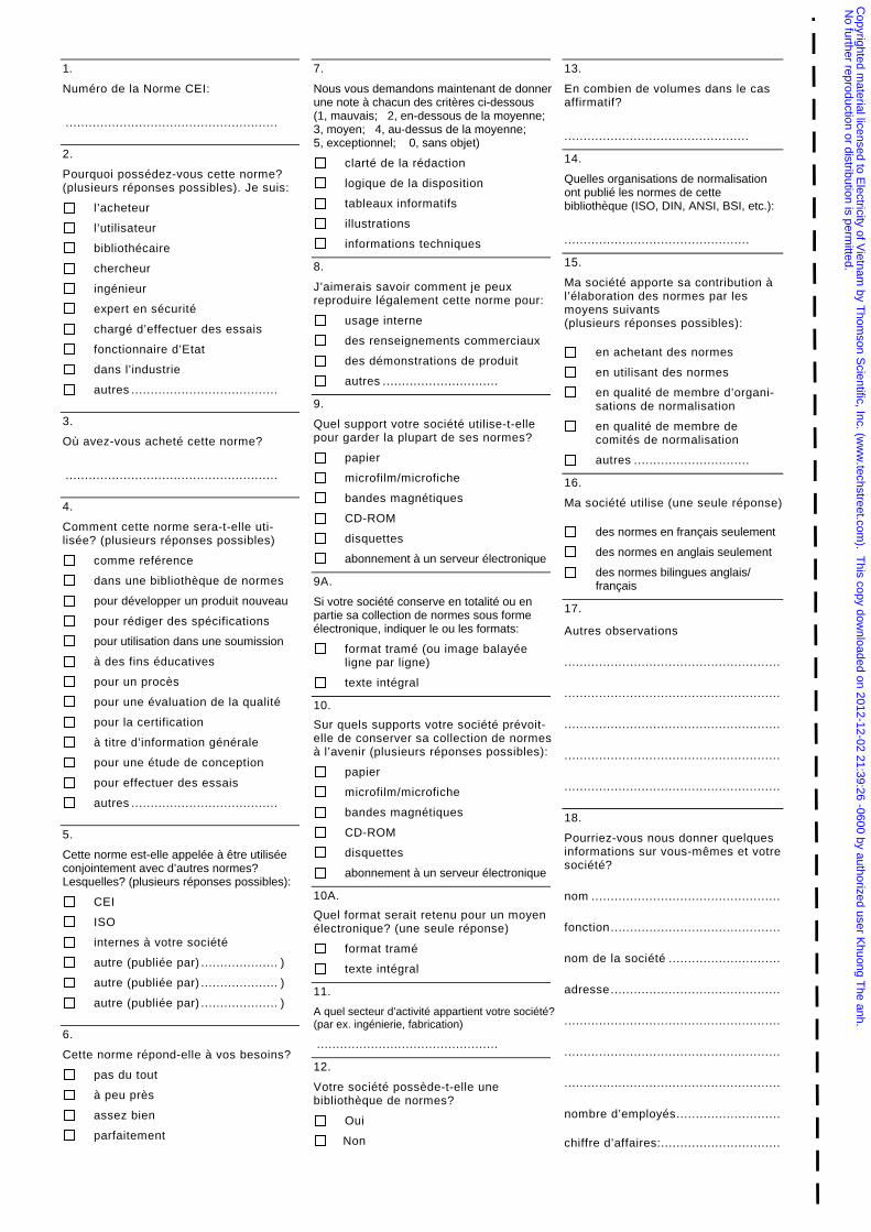
1.
Numéro de la Norme CEI:
.......................................................
2.
Pourquoi possédez-vous cette norme?(plusieurs réponses possibles). Je suis:
l’acheteur
l’utilisateur
bibliothécaire
chercheur
ingénieur
expert en sécurité
chargé d’effectuer des essais
fonctionnaire d’Etat
dans l’industrie
autres ......................................
3.
Où avez-vous acheté cette norme?
.......................................................
4.
Comment cette norme sera-t-elle uti-lisée? (plusieurs réponses possibles)
comme reférence
dans une bibliothèque de normes
pour développer un produit nouveau
pour rédiger des spécifications
pour utilisation dans une soumission
à des fins éducatives
pour un procès
pour une évaluation de la qualité
pour la certification
à titre d’information générale
pour une étude de conception
pour effectuer des essais
autres ......................................
5.
Cette norme est-elle appelée à être utiliséeconjointement avec d’autres normes?Lesquelles? (plusieurs réponses possibles):
CEI
ISO
internes à votre société
autre (publiée par) .................... )
autre (publiée par) .................... )
autre (publiée par) .................... )
6.
Cette norme répond-elle à vos besoins?
pas du tout
à peu près
assez bien
parfaitement
7.
Nous vous demandons maintenant de donnerune note à chacun des critères ci-dessous(1, mauvais; 2, en-dessous de la moyenne;3, moyen; 4, au-dessus de la moyenne;5, exceptionnel; 0, sans objet)
clarté de la rédaction
logique de la disposition
tableaux informatifs
illustrations
informations techniques
8.
J’aimerais savoir comment je peuxreproduire légalement cette norme pour:
usage interne
des renseignements commerciaux
des démonstrations de produit
autres ..............................
9.
Quel support votre société utilise-t-ellepour garder la plupart de ses normes?
papier
microfilm/microfiche
bandes magnétiques
CD-ROM
disquettes
abonnement à un serveur électronique
9A.
Si votre société conserve en totalité ou enpartie sa collection de normes sous formeélectronique, indiquer le ou les formats:
format tramé (ou image balayée ligne par ligne)
texte intégral
10.
Sur quels supports votre société prévoit-elle de conserver sa collection de normesà l’avenir (plusieurs réponses possibles):
papier
microfilm/microfiche
bandes magnétiques
CD-ROM
disquettes
abonnement à un serveur électronique
10A.
Quel format serait retenu pour un moyenélectronique? (une seule réponse)
format tramé
texte intégral
11.
A quel secteur d’activité appartient votre société?(par ex. ingénierie, fabrication)
...............................................
12.
Votre société possède-t-elle unebibliothèque de normes?
Oui
Non
13.
En combien de volumes dans le casaffirmatif?
................................................
14.
Quelles organisations de normalisationont publié les normes de cettebibliothèque (ISO, DIN, ANSI, BSI, etc.):
................................................
15.
Ma société apporte sa contribution àl’élaboration des normes par lesmoyens suivants(plusieurs réponses possibles):
en achetant des normes
en utilisant des normes
en qualité de membre d’organi-sations de normalisation
en qualité de membre de comités de normalisation
autres ..............................
16.
Ma société utilise (une seule réponse)
des normes en français seulement
des normes en anglais seulement
des normes bilingues anglais/ français
17.
Autres observations
........................................................
........................................................
........................................................
........................................................
........................................................
18.
Pourriez-vous nous donner quelquesinformations sur vous-mêmes et votresociété?
nom .................................................
fonction ............................................
nom de la société .............................
adresse............................................
........................................................
........................................................
........................................................
nombre d’employés...........................
chiffre d’affaires:...............................
Copyrighted m
aterial licensed to Electricity of V
ietnam by T
homson S
cientific, Inc. (ww
w.techstreet.com
). This copy dow
nloaded on 2012-12-02 21:39:26 -0600 by authorized user Khuong T
he anh. N
o further reproduction or distribution is permitted.

Copyrighted m
aterial licensed to Electricity of V
ietnam by T
homson S
cientific, Inc. (ww
w.techstreet.com
). This copy dow
nloaded on 2012-12-02 21:39:26 -0600 by authorized user Khuong T
he anh. N
o further reproduction or distribution is permitted.
Publications de la CEI préparées IEC publications preparedpar le Comité d’Etudes n° 10 by Technical Committee No. 10
60156 (1995) Méthode pour la détermination de la rigidité élec-trique des huiles isolantes.
60247 (1978) Mesure de la permittivité relative, du facteur dedissipation diélectrique et de la résistivité (en courantcontinu) des liquides isolants.
60296 (1982) Spécification des huiles minérales isolantes neuvespour transformateurs et appareillage de connexion.Modification n° l (1986).
60376 (1971) Spécifications et réception de l'hexafluorure desoufre neuf.
60376A (1973) Premier complément: Section treize: Taux d'huileminérale.
60376B (1974) Deuxième complément: Article 26.
60422 (1989) Guide de maintenance et de surveillance des huilesminérales isolantes en service dans les matérielsélectriques.
60465 (1988) Spécification pour huiles minérales isolantes neuvespour câbles à circulation d'huile.
60475 (1974) Méthode d'échantillonnage des diélectriques liquides.
60480 (1974) Guide relatif au contrôle de l'hexafluorure de soufre(SF6) prélevé sur le matériel électrique.
60567 (1992) Guide d'échantillonnage de gaz et d'huile dans lesmatériels électriques immergés, pour l'analyse desgaz libres et dissous.
60588: — Askarels pour transformateurs et condensateurs.
60588-1 (1977) Première partie: Généralités.
60588-2 (1978) Deuxième partie: Méthodes d'essai.
60588-3 (1977) Troisième partie: Spécifications pour askarels neufs.
60588-4 (1979) Quatrième partie: Guide pour la maintenance desaskarels dans les transformateurs.
60588-5 (1979) Cinquième partie: Essai éliminatoire pour déterminerla compatibilité des matériaux avec les askarels pourtransformateurs.
60588-6 (1979) Sixième partie: Essai éliminatoire pour déterminerles effets des matériaux sur les askarels pourcondensateurs.
60590 (1977) Détermination de la teneur en hydrocarburesaromatiques des huiles isolantes minérales neuves.
60599 (1978) Interprétation de l'analyse des gaz dans les trans-formateurs et autres matériels électriques remplisd'huile, en service.
60628 (1985) Gassing des isolants liquides sous contrainte élec-trique et ionisation.
60666 (1979) Détection et dosage d'additifs antioxydants spéci-fiques présents dans les huiles isolantes.
60814 (1997) Isolants liquides – Cartons et papiers imprégnésd'huile – Détermination de la teneur en eau partitrage coulométrique de Karl Fischer automatique.
60836 (1988) Spécifications pour liquides silicones pour usagesélectriques.
60867 (1993) Isolants liquides – Spécifications pour liquides neufsà base d'hydrocarbures aromatiques de synthèse.
60897 (1987) Méthodes de détermination de la tension de claquageau choc de foudre des liquides isolants.
60944 (1988) Guide de maintenance des liquides silicones pourtransformateurs.
60962 (1988) Guide de maintenance et d'emploi des huiles lubri-fiantes de pétrole pour turbines à vapeur.
60963 (1988) Spécification pour polybutènes neufs.
60970 (1989) Méthodes de détermination du nombre et de la tailledes particules dans les isolants liquides.
(Suite)
60156 (1995) Method for the determination of the electric strengthof insulating oils.
60247 (1978) Measurement of relative permittivity, dielectricdissipation factor and d.c. resistivity of insulatingliquids.
60296 (1982) Specification for unused mineral insulating oils fortransformers and switchgear.Amendment No. 1 (1986).
60376 (1971) Specification and acceptance of new sulphur hexa-fluoride.
60376A (1973) First supplement: Section Thirteen: Mineral oilcontent.
60376B (1974) Second supplement: Clause 26.
60422 (1989) Supervision and maintenance guide for mineralinsulating oils in electrical equipment.
60465 (1988) Specification for unused insulating mineral oils forcables with oil ducts.
60475 (1974) Method of sampling liquid dielectrics.
60480 (1974) Guide to the checking of sulphur hexafluoride (SF6)taken from electrical equipment.
60567 (1992) Guide for the sampling of gases and of oil from oil-filled electrical equipment and for the analysis of freeand dissolved gases.
60588: — Askarels for transformers and capacitors.
60588-1 (1977) Part l: General.
60588-2 (1978) Part 2: Test methods.
60588-3 (1977) Part 3: Specifications for new askarels.
60588-4 (1979) Part 4: Guide for maintenance of transformer askarelsin equipment.
60588-5 (1979) Part 5: Screening test for compatibility of materialsand transformer askarels.
60588-6 (1979) Part 6: Screening test for effects of materials oncapacitor askarels.
60590 (1977) Determination of the aromatic hydrocarbon contentof new mineral insulating oils.
60599 (1978) Interpretation of the analysis of gases in transformersand other oil-filled electrical equipment in service.
60628 (1985) Gassing of insulating liquids under electrical stressand ionization.
60666 (1979) Detection and determination of specified anti-oxidantadditives in insulating oils.
60814 (1997) Insulating liquids – Oil-impregnated paper andpressboard – Determination of water by automaticcoulometric Karl Fischer titration.
60836 (1988) Specifications for silicone liquids for electricalpurposes.
60867 (1993) Insulating liquids – Specifications for unused liquidsbased on synthetic aromatic hydrocarbons.
60897 (1987) Methods for the determination of the lightningimpulse breakdown voltage of insulating liquids.
60944 (1988) Guide for the maintenance of silicone transformerliquids.
60962 (1988) Maintenance and use guide for petroleum lubricat-ing oils for steam turbines.
60963 (1988) Specification for unused polybutenes.
60970 (1989) Methods for counting and sizing particles ininsulating liquids.
(Continued)
Copyrighted m
aterial licensed to Electricity of V
ietnam by T
homson S
cientific, Inc. (ww
w.techstreet.com
). This copy dow
nloaded on 2012-12-02 21:39:26 -0600 by authorized user Khuong T
he anh. N
o further reproduction or distribution is permitted.
Publications de la CEI préparées IEC publications preparedpar le Comité d’Etudes n° 10 (suite) by Technical Committee No. 10 (continued)
60978 (1989) Guide de maintenance et d'emploi des fluides derégulation esters phosphates de triaryle pour turbine.
60997 (1989) Détermination des polychlorobiphényles (PCB) dansles huiles minérales isolantes par chromatographie enphase gazeuse (CPG) sur colonnes remplies.
61039 (1990) Classification générale des isolants liquides.
61065 (1991) Méthode d'évaluation des propriétés d'écoulement àbasse température des huiles minérales isolantesaprès vieillissement.
61099 (1992) Spécifications pour esters organiques de synthèse àusages électriques.
61100 (1992) Classification des isolants liquides selon le point defeu et le pouvoir calorifique inférieur.
61125 (1992) Isolants liquides neufs à base d'hydrocarbures –Méthodes d'essai pour évaluer la stabilité àl'oxydation.
61144 (1992) Méthode d'essai pour la détermination de l'indiced'oxygène des isolants liquides.
61181 (1993) Matériaux isolants imprégnés – Application del'analyse des gaz dissous (DGA) lors d'essais en usinede matériels électriques.
61197 (1993) Isolants liquides – Propagation linéaire de laflamme – Méthode d'essai utilisant un ruban enfibres de verre.
61198 (1993) Huiles minérales isolantes – Méthodes pour ladétermination du 2-furfural et ses dérivés.
61203 (1992) Esters organiques de synthèse à usages électriques –Guide de maintenance des esters pour trans-formateurs dans les matériels.
61221 (1993) Produits pétroliers et lubrifiants – Fluides de régula-tion pour turbines, esters phosphates de triaryle(catégorie ISO-L-TCD) – Spécifications.
61294 (1993) Isolants liquides – Détermination de la tensiond'apparition des décharges partielles (TADP) –Méthode d'essai.
61619 (1997) Isolants liquides – Contamination par les polychloro-biphényles (PCB) – Méthode de détermination parchromatographie en phase gazeuse sur colonnecapillaire.
60978 (1989) Maintenance and use guide for triaryl phosphate esterturbine control fluids.
60997 (1989) Determination of polychlorinated biphenyls (PCBs)in mineral insulating oils by packed column gaschromatography (GC).
61039 (1990) General classification of insulating liquids.
1065 (1991) Method for evaluating the low temperature flowproperties of mineral insulating oils after ageing.
61099 (1992) Specifications for unused synthetic organic esters forelectrical purposes.
61100 (1992) Classification of insulating liquids according to fire-point and net calorific value.
61125 (1992) Unused hydrocarbon-based insulating liquids – Testmethods for evaluating the oxidation stability.
61144 (1992) Test method for the determination of oxygen index ofinsulating liquids.
61181 (1993) Impregnated insulating materials – Application ofdissolved gas analysis (DGA) to factory tests onelectrical equipment.
61197 (1993) Insulating liquids – Linear flame propagation – Testmethod using a glass-fibre tape.
61198 (1993) Mineral insulating oils – Methods for the deter-mination of 2-furfural and related compounds.
61203 (1992) Synthetic organic esters for electrical purposes –Guide for maintenance of transformer esters inequipment.
61221 (1993) Petroleum products and lubricants – Triarylphosphate ester turbine control fluids (category ISO-L-TCD) – Specifications.
61294 (1993) Insulating liquids – Determination of the partialdischarge inception voltage (PDIV) – Test procedure.
61619 (1997) Insulating liquids – Contamination by polychlo-rinated biphenyls (PCBs) – Method of determinationby capillary column gas chromatography.
Publication 60814
Copyrighted m
aterial licensed to Electricity of V
ietnam by T
homson S
cientific, Inc. (ww
w.techstreet.com
). This copy dow
nloaded on 2012-12-02 21:39:26 -0600 by authorized user Khuong T
he anh. N
o further reproduction or distribution is permitted.

ICS 29.035.40; 17.220.99; 29.035.10
ISBN 2-8318-3986-6
-:HSMINB=]X^][]:Typeset and printed by the IEC Central Office
GENEVA, SWITZERLAND
Copyrighted m
aterial licensed to Electricity of V
ietnam by T
homson S
cientific, Inc. (ww
w.techstreet.com
). This copy dow
nloaded on 2012-12-02 21:39:26 -0600 by authorized user Khuong T
he anh. N
o further reproduction or distribution is permitted.


