Embed Size (px)
Citation preview
Energy Conversion and Management 81 (2014) 41–50
Contents lists available at ScienceDirect
Energy Conversion and Management
journal homepage: www.elsevier .com/ locate /enconman
Numerical investigation of biogas flameless combustion
http://dx.doi.org/10.1016/j.enconman.2014.02.0060196-8904/� 2014 Elsevier Ltd. All rights reserved.
⇑ Corresponding author. Tel.: +60 1112600959.E-mail address: [email protected] (S.E. Hosseini).
Seyed Ehsan Hosseini ⇑, Ghobad Bagheri, Mazlan Abdul WahidHigh-Speed Reacting Flow Laboratory, Faculty of Mechanical Engineering, Universiti Teknologi Malaysia, 81310 UTM Skudai, Johor, Malaysia
a r t i c l e i n f o a b s t r a c t
Article history:Received 27 September 2013Accepted 3 February 2014
Keywords:BiogasFlameless combustionSimulationEntropyFuel consumptionPollutant formation
The purpose of this investigation is to analyze combustion characteristics of biogas flameless mode basedon clean technology development strategies. A three dimensional (3D) computational fluid dynamic(CFD) study has been performed to illustrate various priorities of biogas flameless combustion comparedto the conventional mode. The effects of preheated temperature and wall temperature, reaction zone andpollutant formation are observed and the impacts of combustion and turbulence models on numericalresults are discussed. Although preheated conventional combustion could be effective in terms of fuelconsumption reduction, NOx formation increases. It has been found that biogas is not eligible to beapplied in furnace heat up due to its low calorific value (LCV) and it is necessary to utilize a high calorificvalue fuel to preheat the furnace. The required enthalpy for biogas auto-ignition temperature is suppliedby enthalpy of preheated oxidizer. In biogas flameless combustion, the mean temperature of the furnaceis lower than traditional combustion throughout the chamber. Compared to the biogas flameless combus-tion with uniform temperature, very high and fluctuated temperatures are recorded in conventional com-bustion. Since high entropy generation intensifies irreversibility, exergy loss is higher in biogasconventional combustion compared to the biogas flameless regime. Entropy generation minimizationin flameless mode is attributed to the uniform temperature inside the chamber.
� 2014 Elsevier Ltd. All rights reserved.
1. Introduction
Industrial development is in debt of energy consumption andmore than 80% of the world energy demand is supplied by differentkinds of fossil fuels. However, the resources of fossil fuels are de-pleted day by day and the future energy scenario of the worldhas become one of the main concerns. Indeed, environmental con-cerns have increased due to raising rate of emissions released fromfossil fuel combustion. Global warming (GW) has become one ofthe most important environmental issues due to increasing rateof greenhouse gases (GHGs) generation. Therefore, the requestfor clean alternative fuel and efficient combustion technology hasbecome more important [1–3]. In recent decades, utilization ofrenewable and sustainable energy such as biomass, solar energy,wind energy, hydropower and geothermal has been developedproperly. Furthermore, biogas from wastewater effluent, municipalsolid wastes (MSW), animal waste and agricultural by-productshave been employed for combined heat and power (CHP) genera-tion purposes [4–8]. In the other hand, necessity of biogas collec-tion from aforementioned resources is unavoidable because CH4
and CO2 as the main components of biogas participate in the GW
constitution actively [9]. Since the negative effect of CH4 on theGW is 23 times more than CO2, biogas collection from anaerobicdigestion (AD) has become more highlighted. In most of the AD,the percentage of CH4 is enough to be considered as a clean fuel.The amount of CH4 in biogas components depends on the feedstockis various (from 40% up to 60%) [10]. In biogas conventional com-bustion, pollutant formation mitigates compared to traditionalcombustion of pure CH4. However, biogas traditional combustionencounters some problems due to LCV of biogas. Therefore, biogasshould be upgraded to remove its non-combustible CO2 impurity[11]. Based on the application of biogas, pure biogas can be cleanedand upgraded by some technologies such as water scrubbing, cryo-genic process and membrane. In order to prevent implementationof upgrading equipment, application of flameless combustion wasproposed for pure biogas combustion. Since combustion is still themost important technique for energy generation, flameless com-bustion was introduced to improve the combustion efficiencyand decrease pollutant formation concomitantly [12,13]. Theimportance of flameless combustion technology has become morehighlighted when the inability of other combustion technologies interms of simultaneous pollutant reduction and thermal efficiencyenhancement was proven. Low emission formation in flamelesscombustion is obtained due to dilution of the air combustion byinert gases such as nitrogen (N2) and CO2 [14–16]. Therefore,
Nomenclature
~r position vector~s direction vectorI radiation intensityIk radiation intensity for wavelength kak spectral absorption coefficientIbk black body intensity~s0 scattering direction vectors path lengthn refractive indexrs scattering coefficientr Stephan-Boltzmann constant (5.669 � 10�8 W/m2 K4)U phase functionX0 solid angle
Ts;o outer surface temperatureT1 the ambient temperature set at 300oKh natural convection coefficientr Stephane-Boltzmann constant (5.67 � 10�8 W/m2 K4)e solid surface emissivityx percentage of excess airb mole fraction of CO2 in biogasr density (Kg/m3)kf thermal conductivity of fluidYi mass fraction of species iWi generation or consumption of specious
42 S.E. Hosseini et al. / Energy Conversion and Management 81 (2014) 41–50
combustion instability can be appeared due to low amounts of oxi-dizer and consequently flame quenching occurs. Thus the hightemperature of diluted oxidizer plays an important role to exceedthe auto – ignition temperature of the fuel. It can be construed thatrequired enthalpy is supplied by preheating the oxidizer to achievethe self-ignition temperature of the fuel [17]. Although the greatperformance of flameless combustion has been developed in termsof fossil fuel utilization, various aspects of biogas flameless com-bustion have not been investigated properly. Since computationalanalyses are becoming more important due to their acceptableaccuracy and lower cost, different perspectives of biogas flamelesscombustion can be analyzed numerically. The theoretical studyusing CFD software decreases errors and trials on experimentalinvestigations for development of new models. In this article, aCFD modeling of biogas flameless combustion is investigated toidentify the most important parameters that should be consideredin biogas flameless regime. The effects of chemical kinetic mecha-nisms, turbulence models, radiation heat transfer and differentialdiffusion effects on the accuracy of the model are noted.
2. Conventional combustion of LCV fuels
One of the most important barriers for biogas utilization devel-opment is its low calorific value as well as its corrosive nature. LCVfuels were not taken into account in the energy mix of the worlddue to the abundance of high calorific value fossil fuels and lowerenergy prices in the past. However, recent enhancements of energyprices and concerns of the future energy scenario have attractedmore attention to LCV fuel utilization in power generation. There-fore, combustion characteristics of various combinations of biogashave become more important. It has been claimed that raw biogascannot be utilized in commercial burners directly as the substitu-tion of natural gas (NG) or liquid petroleum gas (LPG). If biogasconducted to the traditional burner orifice at the pressure intendedfor charging NG or LPG, the air fuel ratio is not sufficient for com-bustion stability due to high CO2 content of biogas. Thus, a newburner with the separate control measurement system should beinstalled for biogas. Since water vapor and H2S as the componentsof biogas have corrosive characteristics, the condensation shouldbe prevented by maintaining the furnace temperatures above thedew point temperature. It means that the combustion furnaceshould be heated up by NG or LPG to obtain higher operating tem-perature [18]. Therefore, a dual role burner should be installed inconventional combustion system fueled by biogas. Indeed, in orderto switch over from NG or LPG to biogas some equipment shouldbe employed. Consequently, complicated setting and the lowefficiency of the conventional combustion systems can encourage
biogas users to apply flameless combustion in their combustionprocess [19].
3. Numerical studies of flameless regime
Flameless combustion has been referred as flameless oxidation,colorless distributed combustion, moderate or intense low oxygendilution (MILD) combustion and high-temperature air combustion(HiTac) [20]. In the flameless mode, combustion takes place in adistributed reaction zone with uniform low temperature. The fluc-tuations of temperature are omitted in flameless regime comparedto the conventional flames. Combustion occurs in a low oxygenconcentration atmosphere without visible flame. Indeed, the levelsof the noise, NOx and soot emissions decrease [21]. Due to compli-cated conditions in flameless mode, numerical modeling of theflameless regime has received especial attention. Weber et al.[22] modeled an industrial chamber with square cross section insteady state flameless combustion condition. Very high momen-tum oxidizer was charged through a central hole, NG was enteredto the furnace through two injectors as a fuel and exhaust gaseswere recirculated in the system. In these circumstances, turbu-lence was modeled by standard k–e model [23,24] and RNG k–emodel [25]. The combustion model was simulated with the eddybreakup model and a two-step reaction scheme; the eddy dissipa-tion model (EDM) with the chemical equilibrium and the con-served scalar/prescribed probability density function (pdf) with achemical equilibrium assumption. A similar numerical investiga-tion was done by Kim et al. [26] who applied the standard k–emodel, the eddy-dissipation concept (EDC) and four different glo-bal reaction mechanisms. The characteristics of the MILD combus-tion system included a burner with a central fuel jet surrounded bysix oxidizer jets and exhaust gases recirculation system was inves-tigated numerically using k–e and flamelet model by Coelho andPeters et al. [27] and Dally et al. [28]. It was pointed out that thenumerical temperatures along the centerline of combustor werein good agreement with experimental records for pure CH4 andCH4 diluted with CO2, and in poor agreement for CH4 diluted withN2. Khoshhal et al. [29] investigated NOx formation and heat trans-fer mechanisms in a high temperature air combustion boilernumerically. It was pointed out that the experimental measuredvalues and the CFD results illustrated good agreement. Althoughthe temperatures of preheated oxidizer in flameless combustionmode are higher than conventional conditions, the reaction-con-trolling temperatures are lower than traditional combustion dueto the low oxygen concentration. In the other hand, burner config-uration is very important to achieve flameless conditions. In someinvestigations, burner contains a central inlet jet of fuel and some
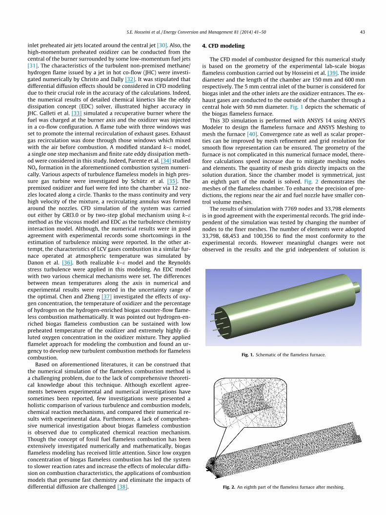
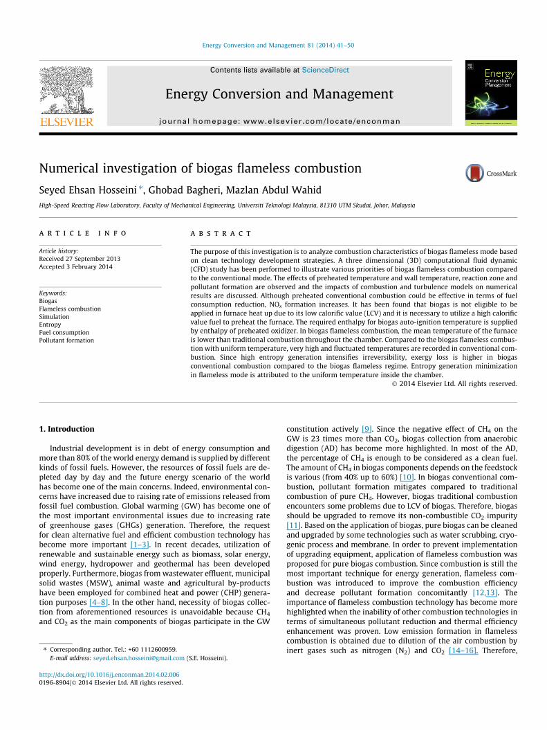
Fig. 1. Schematic of the flameless furnace.
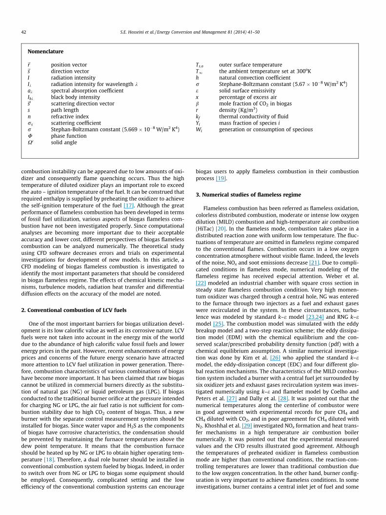
Fig. 2. An eighth part of the flameless furnace after meshing.
S.E. Hosseini et al. / Energy Conversion and Management 81 (2014) 41–50 43
inlet preheated air jets located around the central jet [30]. Also, thehigh-momentum preheated oxidizer can be conducted from thecentral of the burner surrounded by some low-momentum fuel jets[31]. The characteristics of the turbulent non-premixed methane/hydrogen flame issued by a jet in hot co-flow (JHC) were investi-gated numerically by Christo and Dally [32]. It was stipulated thatdifferential diffusion effects should be considered in CFD modelingdue to their crucial role in the accuracy of the calculations. Indeed,the numerical results of detailed chemical kinetics like the eddydissipation concept (EDC) solver, illustrated higher accuracy inJHC. Galleti et al. [33] simulated a recuperative burner where thefuel was charged at the burner axis and the oxidizer was injectedin a co-flow configuration. A flame tube with three windows wasset to promote the internal recirculation of exhaust gases. Exhaustgas recirculation was done through those windows which mixedwith the air before combustion. A modified standard k–e model,a single one step mechanism and finite rate eddy dissipation meth-od were considered in this study. Indeed, Parente et al. [34] studiedNOx formation in the aforementioned combustion system numeri-cally. Various aspects of turbulence flameless models in high pres-sure gas turbine were investigated by Schütz et al. [35]. Thepremixed oxidizer and fuel were fed into the chamber via 12 noz-zles located along a circle. Thanks to the mass continuity and veryhigh velocity of the mixture, a recirculating annulus was formedaround the nozzles. CFD simulation of the system was carriedout either by GRI3.0 or by two-step global mechanism using k–emethod as the viscous model and EDC as the turbulence chemistryinteraction model. Although, the numerical results were in goodagreement with experimental records some shortcomings in theestimation of turbulence mixing were reported. In the other at-tempt, the characteristics of LCV gases combustion in a similar fur-nace operated at atmospheric temperature was simulated byDanon et al. [36]. Both realizable k–e model and the Reynoldsstress turbulence were applied in this modeling. An EDC modelwith two various chemical mechanisms were set. The differencesbetween mean temperatures along the axis in numerical andexperimental results were reported in the uncertainty range ofthe optimal. Chen and Zheng [37] investigated the effects of oxy-gen concentration, the temperature of oxidizer and the percentageof hydrogen on the hydrogen-enriched biogas counter-flow flame-less combustion mathematically. It was pointed out hydrogen-en-riched biogas flameless combustion can be sustained with lowpreheated temperature of the oxidizer and extremely highly di-luted oxygen concentration in the oxidizer mixture. They appliedflamelet approach for modeling the combustion and found an ur-gency to develop new turbulent combustion methods for flamelesscombustion.
Based on aforementioned literatures, it can be construed thatthe numerical simulation of the flameless combustion method isa challenging problem, due to the lack of comprehensive theoreti-cal knowledge about this technique. Although excellent agree-ments between experimental and numerical investigations havesometimes been reported, few investigations were presented aholistic comparison of various turbulence and combustion models,chemical reaction mechanisms, and compared their numerical re-sults with experimental data. Furthermore, a lack of comprehen-sive numerical investigation about biogas flameless combustionis observed due to complicated chemical reaction mechanism.Though the concept of fossil fuel flameless combustion has beenextensively investigated numerically and mathematically, biogasflameless modeling has received little attention. Since low oxygenconcentration of biogas flameless combustion has led the systemto slower reaction rates and increase the effects of molecular diffu-sion on combustion characteristics, the applications of combustionmodels that presume fast chemistry and eliminate the impacts ofdifferential diffusion are challenged [38].
4. CFD modeling
The CFD model of combustor designed for this numerical studyis based on the geometry of the experimental lab-scale biogasflameless combustion carried out by Hosseini et al. [39]. The insidediameter and the length of the chamber are 150 mm and 600 mmrespectively. The 5 mm central inlet of the burner is considered forbiogas inlet and the other inlets are the oxidizer entrances. The ex-haust gases are conducted to the outside of the chamber through acentral hole with 50 mm diameter. Fig. 1 depicts the schematic ofthe biogas flameless furnace.
This 3D simulation is performed with ANSYS 14 using ANSYSModeler to design the flameless furnace and ANSYS Meshing tomesh the furnace [40]. Convergence rate as well as scalar proper-ties can be improved by mesh refinement and grid resolution forsmooth flow representation can be ensured. The geometry of thefurnace is not complicated in this numerical furnace model, there-fore calculations speed increase due to mitigate meshing nodesand elements. The quantity of mesh grids directly impacts on thesolution duration. Since the chamber model is symmetrical, justan eighth part of the model is solved. Fig. 2 demonstrates themeshes of the flameless chamber. To enhance the precision of pre-dictions, the regions near the air and fuel nozzle have smaller con-trol volume meshes.
The results of simulation with 7769 nodes and 33,798 elementsis in good agreement with the experimental records. The grid inde-pendent of the simulation was tested by changing the number ofnodes to the finer meshes. The number of elements were adopted33,798, 68,453 and 100,356 to find the most conformity to theexperimental records. However meaningful changes were notobserved in the results and the grid independent of solution is
Fig. 3. The axial temperature variation of experimental and numerical results.
Table 1The density (kg/m3) of diluted air in various temperatures.
Temperature (K) 5%O2 7%O2 10%O2 15%O2 21%O2
300 1.146 1.15 1.154 1.162 1.177400 0.859 0.862 0.866 0.8717 0.8829500 0.687 0.689 0.692 0.6973 0.7063600 0.573 0.575 0.577 0.5811 0.5886700 0.491 0.492 0.4946 0.4981 0.5046800 0.429 0.431 0.433 0.4358 0.4415900 0.382 0.383 0.3847 0.3874 0.3925
1000 0.344 0.345 0.3462 0.3486 0.35321100 0.312 0.313 0.3147 0.3169 0.32111200 0.286 0.287 0.2885 0.2905 0.2944
44 S.E. Hosseini et al. / Energy Conversion and Management 81 (2014) 41–50
confirmed by this test. Fig. 3 shows the axial temperaturevariations of experimental and simulated data with respect tothe various meshes when preheated air temperature was 900 Kand the concentration of oxygen in the oxidizer was set 7%. Thisfigure confirms that the experimental and simulated data havethe same trend in terms of the temperature profile, and mesh with7769 nodes was selected due to lower computational cost.
The governing equations (transport equations include continu-ity, energy, momentum) are solved using CFD package ANSYS FLU-ENT14 [40]. In Reynolds averaging, the variables in the exactNavier-Stoks equations are converted into he mean and fluctuatingcomponents. For all scalar quantities like energy, pressure andspecies concentration it can be written:
Ø ¼ Øþ Ø0 ð1Þ
Likewise, for velocity:
ui ¼ �ui þ u0i ð2Þ
where �ui and u0i are mean and fluctuating velocity respectively (i = 1,2, 3).
The continuity and momentum equations called Reynolds-aver-age Navier-Stokes (RANS) in turbulent circumstance are written asfollows equations respectively.
@q@tþ @
@xiðquiÞ ¼ 0 ð3Þ
@
@tðquiÞ þ
@
@xjðquiujÞ ¼ �
@p@xiþ @
@xjl @ui
@xjþ @uj
@xi� 2
3dij@ul
@xl
� �� �
þ @
@xjð�qu0iu
0jÞ ð4Þ
Also, energy transfer due to conduction, species diffusion andviscous dissipation is:
@
@tðqEÞ þ r � ~VðqEþ pÞ
� �¼ r � keffrT �
Xj
hj~Jj þ ð�seff � ~VÞ
!þ Sh
ð5Þ
where keff is effective conductivity and~Jj is diffusion flux of species j.On the right hand side of Eq. (5), the first three terms represent
energy transfer due to conduction, species diffusion and viscousdissipation respectively and Sh is a combination of heat chemicalreactant and every other heat resource which are defined.
Second-order discretization scheme is applied to solve all gov-erning equations. The residual of the energy equation should drop
below 10�6 and for all other variables it is set at 10�3 to ensure theconvergence of the solution. The swirl velocity of components iseliminated in this steady-state CFD study. To investigate variousaspects of biogas flameless combustion, the simulation is done instoichiometric equivalence ratios (U = 1) and the results are com-pared by conventional combustion. Equivalence ratio is appliedto show quantitatively whether the fuel–air in a chemical reactionis lean (U < 1), stoichiometric (U = 1) or rich (U > 1) [41]. The den-sity of biogas consists of 60% CH4 and 40% CO2 in 300 K is consid-ered 1.106 Kg/m3. Table 1 demonstrates the densities of preheatedair for different temperatures and various mixtures of N2 and O2
.
The global combustion reaction of biogas, based on a differentmole fraction of CO2 is presented in Eq. (6) [42].
ð1� bÞ½CH4 þ ð2þ xÞðO2 þ 3:76N2Þ� þ bCO2
! CO2 þ 2ð1� bÞ þH2Oþ 7:56ð1� bÞN2 þ xð1� bÞðO2
þ 3:76N2Þ ð6Þ
Which x is the percentage of excess air and b is the mole frac-tion of CO2 in biogas.
For biogas consist of 40% CO2 and 60% CH4, Eq. (2) can be writ-ten as Eq. (7).
0:6CH4 þ 0:4CO2 þ 1:2ðO2 þ 3:76N2Þ! CO2 þ 1:2H2Oþ 4:512N2 ð7Þ
Based on a two step model developed by Westbrook and Dryeret al. [43] (WD model) for CH4 combustion, the model consists oftwo following chemical reactions.
CH4 þ 3=2O2 ! COþ 2H2O ð8Þ
COþ 1=2O2 $ CO2 ð9Þ
In the chemical reaction (8), carbon monoxide (CO) and watervapor (H2O) are formed, while in the chemical reaction (9) oxida-tion of CO to CO2 and its dissociation takes place. This WD reducedmodel illustrates CO, CO2 and H2O formation. A chemical mecha-nism for combustion chemistry modeling has at least three parts:gas phase kinetic file (a list of all chemical reactions of interestto simulation including appropriate Arrhenius), thermodynamicdata base (consist of thermodynamic coefficients for all gas phasekinetic file) and transport data file. The coefficient used for Eqs. (8)and (9) are values of Arrhenius equation coefficients.
kfi ¼ AiTBi exp
�Ei
RcT
� �ð10Þ
where Ai is pre-exponential factor (for Eq. (8), it is equal to 2.8E+9and for Eq. (9) it is 10.00E+14), bi is temperature coefficient (equalzero for both Eqs. (8) and (9)) and Ei is activation energy (for Eq. (8),it is equal to 48.4 and for Eq. (9) it is 40).
S.E. Hosseini et al. / Energy Conversion and Management 81 (2014) 41–50 45
Presented gas phase kinetic file with thermodynamic data baseand transport data file were applied for further simulation as re-duced WD chemical reaction mechanism.
The Reynolds-averaged from of the governing equation is ap-plied in conjunction with a turbulence model. For turbulent kineticenergy (k) and its dissipation (e), the standard k–e formulation isconsidered because of its accuracy and robustness for a wide rangeof turbulent flows. Indeed, since the k–e model is valid for fully tur-bulent flow in CFD modeling and turbulence condition is effectivein flameless combustion formation inside the chamber, this modelcould increase the accuracy of the calculations [44]. The thermalconductivity, specific heat and viscosity are computed with respectto the average of species mass fraction. Since the length of thechamber is longer than the molecular mean-free path of the reac-tants flowing through the chamber, Navier-Stokes equations arevalid in the simulation. Radiation heat transfer between furnace in-ner walls is taken into account. A radiative transfer equation issolved for discrete solid angles across the numerical domain. Also,spatial variation in the total emissivity is calculated as a function ofbiogas composition and temperature because the weighted sum ofthe gray gas model (WSGGM) is incorporated. In WSGGM the totalemissivity is considered as a function of the H2O and CO2 temper-ature and local mass fractions. The heat transfer radiation for spec-tral intensity for position~r in direction~sðIkð~r;~sÞÞ is:
r � ðIkð~r;~sÞ;~sÞ þ ðak þ rsÞIkð~r;~sÞ
¼ akn2Ibk þrs
4p
Z 4p
0Ikð~r;~s0ÞUð~s;~s0ÞdX0 ð11Þ
Since simulation of radiation heat transfer from various thick-nesses is possible by discrete ordinates (DO) model, surface-to-sur-face radiation heat transfer in the studied flameless combustor ismodeled by DO. At the internal walls, non-slip and no species fluxnormal to the surfaces are considered. Moreover, heat loss fromcombustor surfaces to the surroundings is taken into accountthrough Eq. (12) in which, both thermal heat transfer radiationand natural convection are accounted.
q ¼ hðTs;o � T1Þ þ erðT4s;o � T4
1Þ ð12Þ
where Ts;o is the outer surface temperature, T1 is the ambient tem-perature set at 300 K, h is natural convection coefficient consideredconstant value 5 W/m2 K, r = 5.67 � 10�8 W/m2 K4 is Stephane-Boltzmann constant and e is the solid surface emissivity.
The velocity distribution of the inlet oxidizer and fuel are uni-form. The temperature of the inlet biogas is 300 K and the pressureoutlet is 1.013 � 105 Pa. Eddy dissipation model (EDM) and volu-metric reaction-based with respect to the two-step chemical ki-netic mechanisms of biogas combustion is set. Therefore theapplication of an ignition source is not necessary to ignite the reac-tants and combustion proceeds in the presence of turbulence con-dition (k/e > 0). In the literature review it was stipulated thatsimulation of flameless combustion with EDC shows better resultsin the previous documents. However, in some cases, it has beenmentioned that EDC is not appropriate for simulation. For instanceCristo and Dally et al. [32] pointed out that in some simulatedcases EDC has overestimation. Damköhler number distribution(Da), which represents the flow to chemical time-scale ratio couldbe effective for combustion model selection. Large Damköhler va-lue indicates mixing controlled flames and low Damköhler valuecorresponds to slow chemical reactions. It means that reactantsand products are quickly combined by turbulence and the combus-tion system behaves like a perfect stirred reactor. Therefore, calcu-lation of the Damköhler number is required to set proper flow andchemical time-scales. The Damköhler (Da) number characterizesthe behavior between mixing and reaction in a system, given bythe ratio of a mixing or flow time-scale to a chemical time-scale
(sf/sc) [45]. Based Ref. [40], EDM is appropriate when Da > 1. Sincein this study the distance between the centerline of fuel and oxi-dizer inlet is 52.5 mm, mixing time is long and chemical reactiontime is short (due to biogas utilization) and Da is greater thanone. Thus, application of EDM shows acceptable results in this spe-cific geometry. The radial inlet velocity of the oxidizer and fuel isnegligible at the inlet of the furnace boundaries and the uniformaxial velocities of biogas and oxidizer are set from the calculatedbiogas and oxidizer mass with respect to the density of the compo-nents. Turbulence intensity which is defined as Eq. (13) is set 10%and 20% for oxidizer and fuel respectively.
I ¼ u0
Uð13Þ
where u0 is the root-mean-square of the turbulent velocity fluctuationsand U is the mean velocity in averaged Reynolds. In high turbulencemodels, turbulence intensity is considered 5–20% [46]. The dissipationrate inlet values of the turbulent kinetic energy are set based on theVersteeg and Malalasekera [47] applying the inner diameter of the bio-gas inlet and the hydraulic diameter of the oxidizer nozzle as charac-teristic lengths. For pressure-velocity coupling, coupled scheme isapplied in solution methods and for other special discretization, sec-ond order upwind scheme is set. NOx formation mechanisms includethermal NOx and prompt NOx were adopted based on the Ansys Fluentdefaults. The transport equation for NO species formation is:
@
@tðqYNOÞ þ r � ðq~mYNOÞ ¼ r � ðqDrYNOÞ þ SNO ð14Þ
SNO includes thermal NOx determined by Zeldovich equationsand prompt NOx. Zeldovich equations are [48]:
Oþ N2 $ NOþ N ð15Þ
Nþ O2 $ NOþ O
Nþ OH$ NOþH
The reaction rate constants of aforementioned reactions areselected from Ref. [49] and partial equilibrium approach is takeninto consideration to compute the concentration of OH and Oradicals. The calculation of prompt NOx formation is done fromglobal model presented in Ref. [50].
CHþ N2 $ HCNþ N ð16Þ
Nþ O2 $ NOþ O
HCNþ OH$ CNþH2O
CNþ O2 $ NOþ CO
The computed time averaged NOx results is applied in Eq. (14).The computations were done by a core i7 computer with 16 GB ofRAM and the cases solved between the parallel cores.
5. Results and discussion
5.1. Heat up
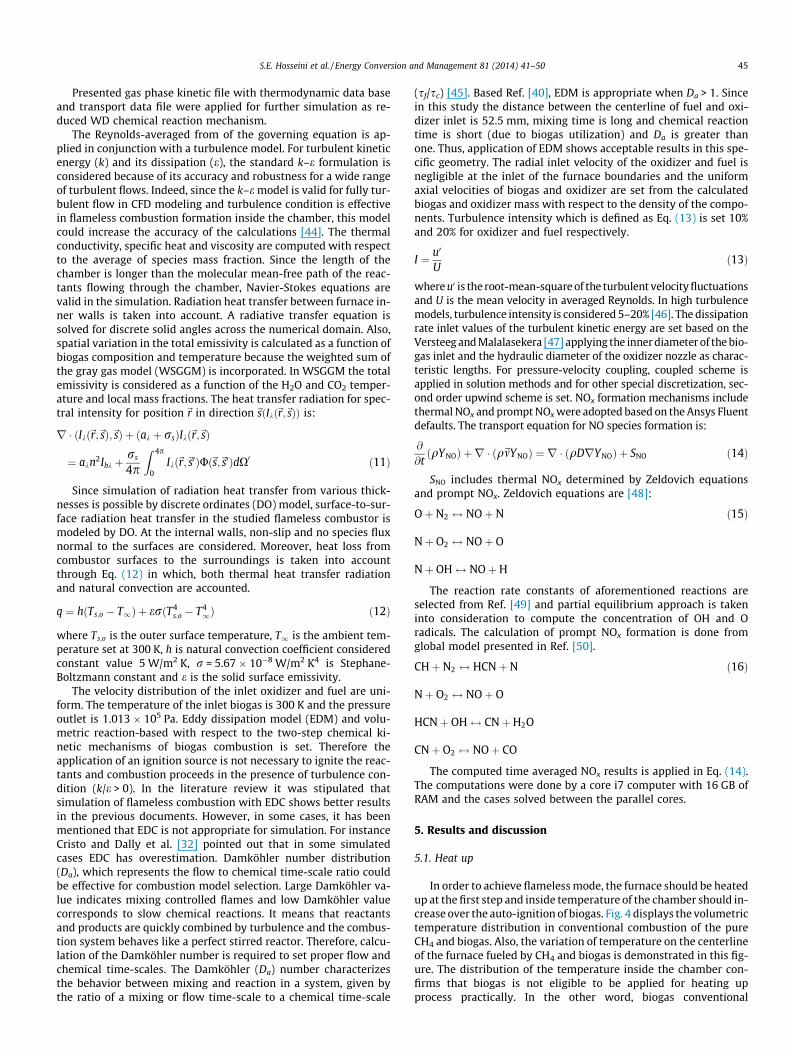
In order to achieve flameless mode, the furnace should be heatedup at the first step and inside temperature of the chamber should in-crease over the auto-ignition of biogas. Fig. 4 displays the volumetrictemperature distribution in conventional combustion of the pureCH4 and biogas. Also, the variation of temperature on the centerlineof the furnace fueled by CH4 and biogas is demonstrated in this fig-ure. The distribution of the temperature inside the chamber con-firms that biogas is not eligible to be applied for heating upprocess practically. In the other word, biogas conventional
(A)
(B)
CH4 conventional combustion
Biogas conventional combustion
Fig. 4. (A) Temperature distribution in conventional combustion of the CH4 andbiogas. (B) Variation of temperature on the centerline of the furnace.
Fig. 5. The effects of preheated air temperature on the fuel consumption inconventional combustion.
(A)
Inlet air temperature (K)
200 300 400 500 600 700 800 900
NO
x (p
pm)
0
50
100
150
200
250
300
Methanebiogas
(B)Fig. 6. (A) The variation of peak temperature in conventional preheated combus-tion. (B) NOx formation in conventional preheated combustion.
46 S.E. Hosseini et al. / Energy Conversion and Management 81 (2014) 41–50
combustion cannot generate high temperatures inside the furnace.Therefore, in order to achieve flameless mode, furnace should beheated up by a high calorific value fuel such as CH4.
5.2. Biogas conventional combustion with preheated air
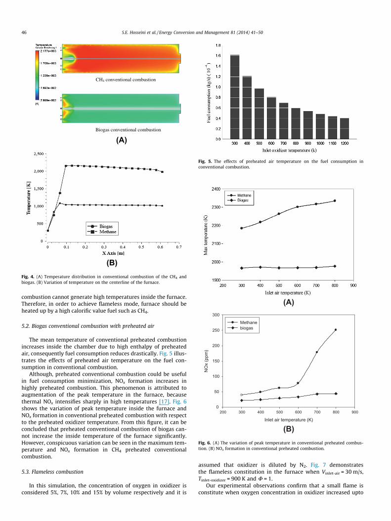
The mean temperature of conventional preheated combustionincreases inside the chamber due to high enthalpy of preheatedair, consequently fuel consumption reduces drastically. Fig. 5 illus-trates the effects of preheated air temperature on the fuel con-sumption in conventional combustion.
Although, preheated conventional combustion could be usefulin fuel consumption minimization, NOx formation increases inhighly preheated combustion. This phenomenon is attributed toaugmentation of the peak temperature in the furnace, becausethermal NOx intensifies sharply in high temperatures [17]. Fig. 6shows the variation of peak temperature inside the furnace andNOx formation in conventional preheated combustion with respectto the preheated oxidizer temperature. From this figure, it can beconcluded that preheated conventional combustion of biogas can-not increase the inside temperature of the furnace significantly.However, conspicuous variation can be seen in the maximum tem-perature and NOx formation in CH4 preheated conventionalcombustion.
5.3. Flameless combustion
In this simulation, the concentration of oxygen in oxidizer isconsidered 5%, 7%, 10% and 15% by volume respectively and it is
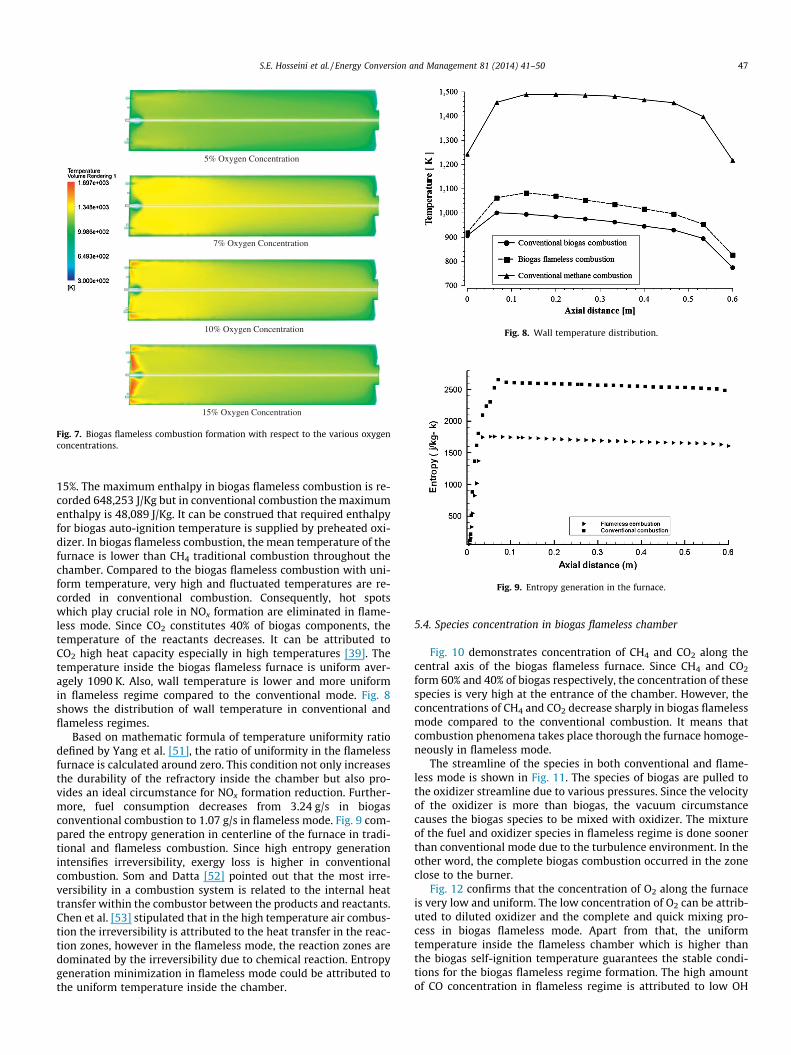
assumed that oxidizer is diluted by N2. Fig. 7 demonstratesthe flameless constitution in the furnace when Vinlet-air = 30 m/s,Tinlet-oxidizer = 900 K and U = 1.
Our experimental observations confirm that a small flame isconstitute when oxygen concentration in oxidizer increased upto
5% Oxygen Concentration
7% Oxygen Concentration
10% Oxygen Concentration
15% Oxygen Concentration
Fig. 7. Biogas flameless combustion formation with respect to the various oxygenconcentrations.
Fig. 8. Wall temperature distribution.
Fig. 9. Entropy generation in the furnace.
S.E. Hosseini et al. / Energy Conversion and Management 81 (2014) 41–50 47
15%. The maximum enthalpy in biogas flameless combustion is re-corded 648,253 J/Kg but in conventional combustion the maximumenthalpy is 48,089 J/Kg. It can be construed that required enthalpyfor biogas auto-ignition temperature is supplied by preheated oxi-dizer. In biogas flameless combustion, the mean temperature of thefurnace is lower than CH4 traditional combustion throughout thechamber. Compared to the biogas flameless combustion with uni-form temperature, very high and fluctuated temperatures are re-corded in conventional combustion. Consequently, hot spotswhich play crucial role in NOx formation are eliminated in flame-less mode. Since CO2 constitutes 40% of biogas components, thetemperature of the reactants decreases. It can be attributed toCO2 high heat capacity especially in high temperatures [39]. Thetemperature inside the biogas flameless furnace is uniform aver-agely 1090 K. Also, wall temperature is lower and more uniformin flameless regime compared to the conventional mode. Fig. 8shows the distribution of wall temperature in conventional andflameless regimes.
Based on mathematic formula of temperature uniformity ratiodefined by Yang et al. [51], the ratio of uniformity in the flamelessfurnace is calculated around zero. This condition not only increasesthe durability of the refractory inside the chamber but also pro-vides an ideal circumstance for NOx formation reduction. Further-more, fuel consumption decreases from 3.24 g/s in biogasconventional combustion to 1.07 g/s in flameless mode. Fig. 9 com-pared the entropy generation in centerline of the furnace in tradi-tional and flameless combustion. Since high entropy generationintensifies irreversibility, exergy loss is higher in conventionalcombustion. Som and Datta [52] pointed out that the most irre-versibility in a combustion system is related to the internal heattransfer within the combustor between the products and reactants.Chen et al. [53] stipulated that in the high temperature air combus-tion the irreversibility is attributed to the heat transfer in the reac-tion zones, however in the flameless mode, the reaction zones aredominated by the irreversibility due to chemical reaction. Entropygeneration minimization in flameless mode could be attributed tothe uniform temperature inside the chamber.
5.4. Species concentration in biogas flameless chamber
Fig. 10 demonstrates concentration of CH4 and CO2 along thecentral axis of the biogas flameless furnace. Since CH4 and CO2
form 60% and 40% of biogas respectively, the concentration of thesespecies is very high at the entrance of the chamber. However, theconcentrations of CH4 and CO2 decrease sharply in biogas flamelessmode compared to the conventional combustion. It means thatcombustion phenomena takes place thorough the furnace homoge-neously in flameless mode.
The streamline of the species in both conventional and flame-less mode is shown in Fig. 11. The species of biogas are pulled tothe oxidizer streamline due to various pressures. Since the velocityof the oxidizer is more than biogas, the vacuum circumstancecauses the biogas species to be mixed with oxidizer. The mixtureof the fuel and oxidizer species in flameless regime is done soonerthan conventional mode due to the turbulence environment. In theother word, the complete biogas combustion occurred in the zoneclose to the burner.
Fig. 12 confirms that the concentration of O2 along the furnaceis very low and uniform. The low concentration of O2 can be attrib-uted to diluted oxidizer and the complete and quick mixing pro-cess in biogas flameless mode. Apart from that, the uniformtemperature inside the flameless chamber which is higher thanthe biogas self-ignition temperature guarantees the stable condi-tions for the biogas flameless regime formation. The high amountof CO concentration in flameless regime is attributed to low OH
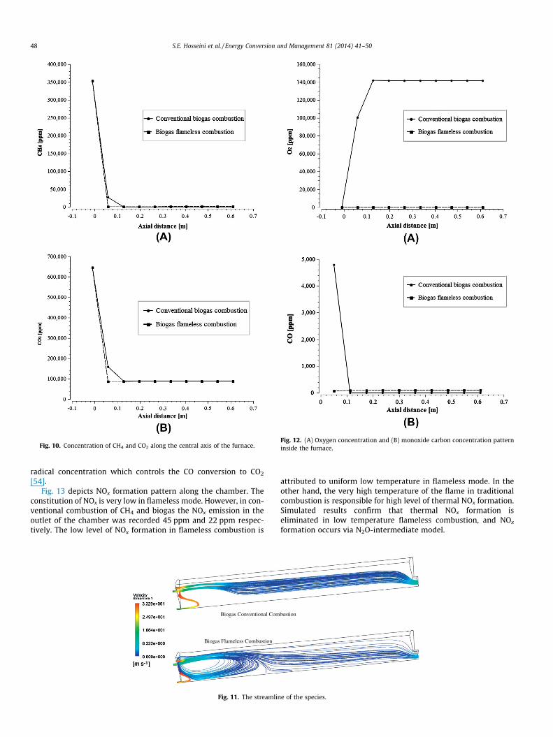
Fig. 10. Concentration of CH4 and CO2 along the central axis of the furnace.Fig. 12. (A) Oxygen concentration and (B) monoxide carbon concentration patterninside the furnace.
48 S.E. Hosseini et al. / Energy Conversion and Management 81 (2014) 41–50
radical concentration which controls the CO conversion to CO2
[54].Fig. 13 depicts NOx formation pattern along the chamber. The
constitution of NOx is very low in flameless mode. However, in con-ventional combustion of CH4 and biogas the NOx emission in theoutlet of the chamber was recorded 45 ppm and 22 ppm respec-tively. The low level of NOx formation in flameless combustion is
Biogas Conventional Com
Biogas Flameless Combustion
Fig. 11. The streamlin
attributed to uniform low temperature in flameless mode. In theother hand, the very high temperature of the flame in traditionalcombustion is responsible for high level of thermal NOx formation.Simulated results confirm that thermal NOx formation iseliminated in low temperature flameless combustion, and NOx
formation occurs via N2O-intermediate model.
bustion
e of the species.
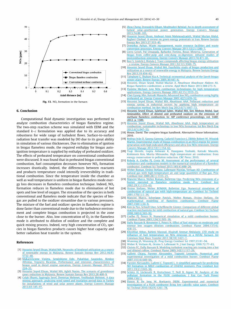
Fig. 13. NOx formation in the furnace.
S.E. Hosseini et al. / Energy Conversion and Management 81 (2014) 41–50 49
6. Conclusion
Computational fluid dynamic investigation was performed toanalyze combustion characteristics of biogas flameless regime.The two-step reaction scheme was simulated with EDM and thestandard k–e formulation was applied due to its accuracy androbustness for wide range of turbulent flows. Surface-to-surfaceradiation heat transfer was modeled by DO due to its great abilityin simulation of various thicknesses. Due to elimination of ignitionin biogas flameless mode, the required enthalpy for biogas auto-ignition temperature is supplied by enthalpy of preheated oxidizer.The effects of preheated temperature on conventional combustionwere discussed. It was found that in preheated biogas conventionalcombustion, fuel consumption decreases however NOx formationincreases drastically. Indeed, the differences between reactantsand products temperature could intensify irreversibility in tradi-tional combustion. Since the temperature inside the chamber aswell as wall temperature is uniform in biogas flameless mode exer-gy loss decreases in flameless combustion technique. Indeed, NOx
formation reduces in flameless mode due to elimination of hotspots and low level of oxygen. The streamline of the species in bothconventional and flameless mode indicate that the species of bio-gas are pulled to the oxidizer streamline due to various pressures.The mixture of the fuel and oxidizer species in flameless regime isdone faster than conventional mode due to the turbulence environ-ment and complete biogas combustion is projected in the zoneclose to the burner. Also, low concentration of O2 in the flamelessmode is attributed to dilution of oxidizer and the complete andquick mixing process. Indeed, very high concentration of CO2 spe-cies in biogas flameless products causes higher heat capacity andbetter radiation heat transfer in the system.
References
[1] Hosseini Seyed Ehsan, Wahid MA. Necessity of biodiesel utilization as a sourceof renewable energy in Malaysia. Renew Sustain Energy Rev 2012;16(8):5732–40.
[2] Makareviciene Violeta, Sendzikiene Egle, Pukalskas Saugirdas, RimkusAlfredas, Vegneris Ricardas. Performance and emission characteristics ofbiogas used in diesel engine operation. Energy Convers Manage 2013;75:224–33.
[3] Hosseini Seyed Ehsan, Wahid MA, Aghili Nasim. The scenario of greenhousegases reduction in Malaysia. Renew Sustain Energy Rev 2013;28:400–9.
[4] Colak Ilhami, Sagiroglu Seref, Demirtas Mehmet, Yesilbudak Mehmet. A datamining approach: analyzing wind speed and insolation period data in Turkeyfor installations of wind and solar power plants. Energy Convers Manage2013;65:185–97.
[5] Zhou Cheng, Doroodchi Elham, Moghtaderi Behdad. An in-depth assessment ofhybrid solar–geothermal power generation. Energy Convers Manage2013;74:88–101.
[6] Hosseini Seyed Ehsan, Andwari Amin Mahmoudzadeh, Wahid Mazlan Abdul,Bagheri Ghobad. A review on green energy potentials in Iran. Renew SustainEnergy Rev 2013;27:533–45.
[7] Demirbas Ayhan. Waste management, waste resource facilities and wasteconversion processes. Energy Convers Manage 2011;52(2):1280–7.
[8] Corro Grisel, Pal Umapada, Bañuelos Fortino, Rosas Minerva. Generation ofbiogas from coffee-pulp and cow-dung co-digestion: infrared studies ofpostcombustion emissions. Energy Convers Manage 2013;74:471–81.
[9] Rasi S, Läntelä J, Rintala J. Trace compounds affecting biogas energy utilisation– a review. Energy Convers Manage 2011;52(12):3369–75.
[10] Hosseini Seyed Ehsan, Wahid MA. Feasibility study of biogas production andutilization as a source of renewable energy in Malaysia. Renew Sustain EnergyRev 2013;19:454–62.
[11] Taleghani G, Shabani Kia A. Technical–economical analysis of the Saveh biogaspower plant. Renew Energy 2005;30:441–6.
[12] Hosseini, Ehsan Seyed, Wahid Mazlan A, Abuelnuor Abuelnuor Abdeen Ali.Biogas flameless combustion: a review. Appl Mech Mater 2013;388:273–9.
[13] Flamme Michael. Low NOx combustion technologies for high temperatureapplications. Energy Convers Manage 2001;42(15):1919–35.
[14] Choi Gyung-Min, Katsuki Masashi. Advanced low NOx combustion using highlypreheated air. Energy Convers Manage 2001;42(5):639–52.
[15] Hosseini Seyed Ehsan, Wahid MA, Abuelnuor AAA. Pollutant reduction andenergy saving in industrial sectors by applying high temperature aircombustion method. Int Rev Mech Eng 2012;6(7):1667–72.
[16] Hosseini Seyed Ehsan, Salehirad Saber, Wahid MA, Sies Mohsin Mohd, SaatAminuddin. Effect of diluted and preheated oxidizer on the emission ofmethane flameless combustion. In: AIP conference proceedings, vol. 1440;2012. p. 1309.
[17] Hosseini Seyed Ehsan, Wahid MA, Abuelnuor AAA. High temperature aircombustion: sustainable technology to low NOx formation. Int Rev Mech Eng2012;6(5):947–53.
[18] House, David. The complete biogas handbook. Alternative House Information;2010.
[19] Bedoya Iván D, Saxena Samveg, Cadavid Francisco J, Dibble Robert W, WissinkMartin. Experimental study of biogas combustion in an HCCI engine for powergeneration with high indicated efficiency and ultra-low NOx emissions. EnergyConvers Manage 2012;53(1):154–62.
[20] Tsuji Hiroshi, Gupta Ashwani K, Hasegawa Toshiaki, Katsuki Masashi,Kishimoto Ken, Morita Mitsunobu. High temperature air combustion: fromenergy conservation to pollution reduction. CRC Press; 2010.
[21] Rebola A, Coelho PJ, Costa M. Assessment of the performance of severalturbulence and combustion models in the numerical simulation of a flamelesscombustor. Combust Sci Technol 2013;185(4):600–26.
[22] Weber Roman, Orsino Stefano, Lallemant Nicolas, Verlaan AD. Combustion ofnatural gas with high-temperature air and large quantities of flue gas. ProcCombust Inst 2000;28(1):1315–21.
[23] Mancini Marco, Weber Roman, Bollettini Ugo. Predicting NOx emissions of aburner operated in flameless oxidation mode. Proc Combust Inst2002;29(1):1155–63.
[24] Orsino Stefano, Weber ROMAN, Bollettini Ugo. Numerical simulation ofcombustion of natural gas with high-temperature air. Combust Sci Technol2001;170(1):1–34.
[25] Mancini Marco, Schwöppe Patrick, Weber Roman, Orsino Stefano. Onmathematical modelling of flameless combustion. Combust Flame2007;150(1):54–9.
[26] Kim Ju Pyo, Schnell Uwe, Scheffknecht Günter. Comparison of different globalreaction mechanisms for mild combustion of natural gas. Combust Sci Technol2008;180(4):565–92.
[27] Coelho PJ, Peters N. Numerical simulation of a mild combustion burner.Combust Flame 2001;124(3):503–18.
[28] Dally Bassam B, Riesmeier E, Peters N. Effect of fuel mixture on moderate andintense low oxygen dilution combustion. Combust Flame 2004;137(4):418–31.
[29] Khoshhal Abbas, Rahimi Masoud, Alsairafi Ammar Abdulaziz. CFD study oninfluence of fuel temperature on NOx emission in a HiTAC furnace. IntCommun Heat Mass Transfer 2011;38(10):1421–7.
[30] Wunning JA, Wunning JG. Prog Energy Combust Sci 1997;23:81–94.[31] Weber R, Verlaan AL, Orsino S, Lallemant N. J Inst Energy 1999;72:77–83.[32] Christo FC, Dally Bassam B. Modeling turbulent reacting jets issuing into a hot
and diluted coflow. Combust Flame 2005;142(1):117–29.[33] Galletti Chiara, Parente Alessandro, Tognotti Leonardo. Numerical and
experimental investigation of a mild combustion burner. Combust Flame2007;151(4):649–64.
[34] Parente Alessandro, Galletti C, Tognotti L. A simplified approach for predictingNO formation in MILD combustion of CH4/H2 mixtures. Proc Combust Inst2011;33(2):3343–50.
[35] Schütz H, Lückerath R, Kretschmer T, Noll B, Aigner M. Analysis of thepollutant formation in the FLOX combustion. J Eng Gas Turb Power2008;130(1).
[36] Danon B, De Jong W, Roekaerts DJEM. Experimental and numericalinvestigation of a FLOX combustor firing low calorific value gases. CombustSci Technol 2010;182(9):1261–78.
50 S.E. Hosseini et al. / Energy Conversion and Management 81 (2014) 41–50
[37] Chen Sheng, Zheng Chuguang. Counterflow diffusion flame of hydrogen-enriched biogas under MILD oxy-fuel condition. Int J Hydrogen Energy2011;36(23):15403–13.
[38] Gassoumi T, Guedri K, Said R. Numerical study of the swirl effect on a coaxialjet combustor flame including radiative heat transfer. Numer Heat Transfer A2009;56(11):897–913.
[39] Hosseini Seyed Ehsan, Wahid MA. Biogas utilization: experimental investigationon biogas flameless combustion in lab-scale furnace. Energy Convers Manage2013;74:426–32.
[40] Fluent Ansys. 14.0 Theory Guide. Ansys Inc., vol. 5; 2012.[41] Turns SR. An introduction to combustion. New York: McGraw-Hill; 1996.[42] Cohé Cécile, Chauveau Christian, Gökalp Iskender, Kurtulus� Dilek Funda. CO2
addition and pressure effects on laminar and turbulent lean premixed CH4 airflames. Proc Combust Inst 2009;32(2):1803–10.
[43] Westbrook Charles K, Dryer Frederick L. Simplified reaction mechanisms forthe oxidation of hydrocarbon fuels in flames. Combust Sci Technol 1981;27(1–2):31–43.
[44] Wilcox David C. Turbulence modeling for CFD, vol. 2. La Canada: DCWIndustries; 1998.
[45] Isaac Benjamin J, Parente Alessandro, Galletti Chiara, Thornock Jeremy N,Smith Philip J, Tognotti Leonardo. A novel methodology for chemical time scale
evaluation with detailed chemical reaction kinetics. Energy Fuels2013;27(4):2255–65.
[46] http://www.cfd-online.com/.[47] Versteeg HK, Malalasekera W. An introduction to computational fluid
dynamics: the finite volume method, 2/E. Pearson Education; 2007.[48] Bowman C. Kinetics of pollutant formation and destruction in combustion.
Prog Energy Combust Sci 1975;1:33–45.[49] Hanson Ronald K, Salimian Siamak. Survey of rate constants in the N/H/O
system. Combustion chemistry. US: Springer; 1984. p. 361–21.[50] DS, GG. Overall reaction rates of NO and N2 formation from fuel nitrogen.
Pittsburg, PA, USA: The Combustion Institute; 1974. p. 1093.[51] Yang Weihong, Blasiak Wlodzimierz. CFD as applied to high temperature air
combustion in industries furnaces. IRFR Combust J; November 2006.[52] Som SK, Datta A. Thermodynamic irreversibilities and exergy balance in
combustion processes. Prog Energy Combust Sci 2008;34(3):351–76.[53] Chen Sheng, Mi Jianchun, Liu Hao, Zheng Chuguang. First and second
thermodynamic-law analyses of hydrogen-air counter-flow diffusioncombustion in various combustion modes. Int J Hydrogen Energy2012;37(6):5234–45.
[54] Szegö GG, Dally BB, Nathan GJ. Operational characteristics of a parallel jetMILD combustion burner system. Combust Flame 2008;156:429–38.


