Embed Size (px)
Citation preview

Tender No. MUM/N/EN/ROB/LC–104
1 | P a g e
DEDICATED FREIGHT CORRIDOR CORPORATION OF INDIA
LIMITED
(A Government of India Enterprises under Ministry of Railways)
E-Tender Document
For
Name of Work :- Construction of Road Over Bridge in lieu of existing LC No.104 at IR KM 208/30-209/02 between Valsad-Dungri Railway station of Virar – Surat Section of Mumbai Division of Western Railway
Tender No. :- MUM/N/EN/ROB/LC 104, dtd. 10.11.2020
(Participation through e-Tender Only)
Visit: www.ireps.gov.in/ itslink at www.dfccil.com
(Help Desk of IREPS : 011-23761525)
November 2020
Employer: CHIEF GENERAL MANAGER / NORTH / MUMBAI
DEDICATED FREIGHT CORRIDOR CORPORATION OF INDIA LIMITED (A GOVERNMENT OF INDIA ENTERPRISE)
Under MINISTRYOF RAILWAYS

Tender No. MUM/N/EN/ROB/LC–104
2 | P a g e
Chapter I of Part I
(i) NOTICE INVITING TENDER (NIT) (Online)
1.0 Chief General Manager /North / Mumbai for and on behalf of DFCCIL invites Tender on prescribed forms for the execution of the following work:
1.1 Tender No. MUM/N/EN/ROB/LC_104, dated 10.11.2020 1.2 Name of Work Construction of Road Over Bridge in lieu of existing LC No.
104 at IR KM 208/30-209/02 between Valsad-Dungri Railway station of Virar – Surat Section of Mumbai Division of Western Railway.
1.3 Type of Tender Open Tender (Single stage two packet).
1.4 Duration of Contract 18 months
1.5 Estimated Cost of Work
Rs. 33,15,14,383.97 (NIT Cost Excluding GST)
1.6 Cost of Tender Document (Non- Refundable)
Rs. 10,000/- Plus GST @ 18% = Rs 11,800/- to be paid online through payment gateway provided at www.ireps.gov.in
1.7 Earnest Money Deposit (EMD) (Tender Security)
Rs. 50,00,000/- to be deposited online through Payment gateway provided at www.ireps.gov.in.
1.8 Uploading of NIT and Tender Document
11.11.2020 at 15.00 hrs. on www.ireps.gov.in
1.9 Last Date and Time of Sub mission of Tender (Online)
24.12.2020 up to 15.00 hrs. on www.ireps.gov.in
1.10 Date and Time of Opening of Tender (Online)
24.12.2020 at 15.30 hrs. on www.ireps.gov.in
1.11 Tender Validity 120 days from the Date of Opening of Tender. 1.12 Address for
Communication Chief General Manager (North) Mumbai, DFCCIL, 7th Floor, New Administrative Building, Central Railway, D N Road, Mumbai – 400001
1.13 Help Desk for E- Tendering
For any clarification, help and registration for E-Tendering & matter relating to Digital Signature contact at Help desk of www.ireps.gov.in and phone No. 011-23761525
1.14 Availability of Tender Documents
The Tender documents can be downloaded from www.ireps.gov.in Tenderer who wishes to view free Notification and Tender Documents can visit www.ireps.gov.in DFCCIL may issue Addendum(s)/Corrigendum(s) to the Tender document, if any, which shall be issued at least seven days in advance of date of opening of tender and placed on the www.ireps.gov.in.only.

Tender No. MUM/N/EN/ROB/LC–104
3 | P a g e
2.0 General
2.1 No request for extension of the Tender Due Date shall be considered.
2.2 The Offer shall be valid for 120 Days from the date of opening of the tender, and extended further if required from time to time. The Contractor cannot withdraw their offer within the period of validity/extended validity lest liable for forfeiture of Ernest Money Deposit (Tender Security).
2.4 Notice Inviting Tender (NIT), Tender Document and Corrigendum/Addendum if any, will be posted on the E-Tendering website www.ireps.gov.in. Tenderer are advised to complete all submission related work well before Time and Date for Submission of Tender Online. Any request for modification in the time/ date of submission of tender due to tenderer’s failure to submit his offer, will not be accepted.

Tender No. MUM/N/EN/ROB/LC–104
4 | P a g e
(i) Format for Covering Letter of Tender.
(On Letter Head of Firm/Company)
To, Chief General Manager /North, DFCCIL, 7th Floor, New Administrative Building, D. N. Road, Mumbai 400 001 Sub.: Construction of Road Over Bridge in lieu of existing LC No. 104 at IR KM 208/30-209/02 between Valsad-Dungri Railway station of Virar – Surat Section of Mumbai Division of Western Railway.
Ref: Tender No. MUM/N/EN/ROB/LC_104, dated 10.11.2020
1. I /We ............................................................................. have read the various terms and conditions of tender attached hereto and hereby agree to adhere by the said terms and conditions. I/We also agree to keep this tender open for acceptance for a period of 120 days from the date fixed for opening the same and if I/We default thereof, I/We will be liable for forfeiture of my/our “Earnest Money”. I/We offer to do the work as set out in the Tender Document. I/We also agree to abide by the Terms and Conditions of the Contract and to carry out the work according to the Scope of Work and Terms and Conditions of Contract as laid down by the DFCCIL Administration for the execution of present contract.
2. A sum of Rs. 50,00,000/- is being deposited as Earnest Money online through payment gateway on www.ireps.gov.in. The value of the earnest money shall stand forfeited without prejudice to any other rights or remedies if:
i) I/We do not execute the Contract Agreement within 30 (thirty) days from the date of issue of Letter of Acceptance; or
ii) I/We do not submit a Performance Security in the form of Bank Guarantee equal to the requisite value (equal to 5% of contract value) as per the Annexure-I of Tender Document, within 15 days of issue of Letter of Acceptance; or
iii) I/We do not commence the work within 7 days after receipt of Letter of Acceptance or from the date as specified in the Letter of Acceptance; or
iv) I/We withdraw the offer during the period of validity/extended validity; or v) When any of the information furnished by the tenderer not found true.
Until a formal agreement is prepared and executed, acceptance of this tender shall constitute a binding contract between us subject to the modifications, as may be mutually agreed to, between us and indicated in the Letter of Acceptance or my/our accepted offer for the work.
(Signature of Bidder) ______________________ ______________________ ______________________ (Name and Address of the Bidder)
_________________________ (Signature of witness) (Name and Address of the Witness)

Tender No. MUM/N/EN/ROB/LC–104
5 | P a g e
CHECK LIST FOR DOCUMENTS TO BE SUBMITTED
S. No. Documents to be Attached Tick Yes/No
1. The Covering Letter as per format given in the Section 2.
2. Power of Attorney of the person signing the tender documents in Original if specific to this work or Attested Copy of the General Power of Attorney of the Company in favour of the person signing the tender.
3. Certified Copy of GST No, PAN Card & Aadhar Card.
4. Certified Copy of Registration of Company/Firm/Agency, Partnership Deed /Memorandum and Articles of Association of the Company/Firm/Agency.
5. Constitution of the Company/Firm/Agency in the form prescribed in Annexure-III
6. Complete Tender Document including Corrigendum/Addendums Signed by the Bidder.
Important Notes:
Documents No. l to 6, should be scanned and uploaded along with offer as attachment at website www.ireps.gov.in.

Tender No. MUM/N/EN/ROB/LC–104
6 | P a g e
Chapter II of Part I
INSTRUCTIONS TO BIDDERS
1.0 The salient features of the contract are as follows:
i. Tender No. MUM/N/EN/ROB/LC_104, dated 10.11.200
ii. Name of work Construction of Road Over Bridge in lieu of existing LC No. 104 at IR KM 208/30-209/02 between Valsad-Dungri Railway station of Virar – Surat Section of Mumbai Division of Western Railway.
iii. Duration of
contract
18 months from the Date as Specified in the Letter of Acceptance
and further Extendable at the Same Rates, Terms and Conditions
at the discretion of DFCCIL from the Date as Specified in the
Letter of Acceptance.
iv. Contract value Rs. 33,82,64,989.51/- (NIT Cost Excluding GST) V.
Earnest money Rs. 50,00,000/- to be deposited online through payment gateway
provided on www.ireps.gov.in. Tenders received without earnest
money shall be summarily rejected.
vi. Performance
Security
5% of Total Contract Value in the form of Bank Guarantee to be
submitted within 15 days from the Date of Issue of Letter of
Acceptance (LOA). vii. Security
deposit/
Retention
Money
Overall Security Deposit is 5% of Contract Value. EMD of
Rs. 50,00,000/- to be adjusted against the Security
Deposit. Balance to be deducted @ 10% from each of the running
bills till realization of the full amount.
2.0 SUBMISSION OF E-TENDER: -
2.1 Tender Document Obtaining Process
2.1.1 It is mandatory for all Tenderers to have Class-III Digital Signature Certified from any of the Licensed Certifying Agencies (‘CA’) to participate in E-Tendering of DFCCIL, (Tenderer can see the list of Licensed CAs from the link www.cca.gov.in ), in the name of the person who will submit the Online tender and is authorized to do so.
2.1.2 To participate in E-Tender, it is mandatory for Tenderers to get themselves registered with the IREPS (www.ireps.gov.in) and to have User ID and Password.
2.1.3 www.ireps.gov.in is the only website for submission of tender. ‘Vender Manual’ containing the detailed guidelines for E-Tendering is available on www.ireps.gov.in.

Tender No. MUM/N/EN/ROB/LC–104
7 | P a g e
2.2 Submission of Offer
2.2.1 Tender shall be submitted through Online mode only at www.ireps.gov.in. Tender submitted by any other mode will not be accepted.
2.2.2 All the required documents (legible) as mentioned in Check list from S. No. 1-6 have to be uploaded along with the offer on www.ireps.gov.in failing which, the bid shall be summarily rejected and shall not be considered for further evaluation.
2.2.3 The detailed instructions of e-tendering can be read through website www.ireps.gov.in
2.2.4 The Addendum/Corrigendum, if any; shall be hosted on the website www.ireps.gov.in
2.2.5 The tender will be accepted only in e-tendering mode and no other mode of submission shall be accepted.
2.2.6 The supporting documents for Eligibility Criteria are essentially required to be uploaded on the website www.ireps.gov.in.
2.2.7 The bid shall be accepted through Online mode only.
2.2.8 Tenderers are required to give Un-Conditional Offers. A Conditional Offer is liable to be rejected. DFCCIL reserves the right to modify, expand, restrict, scrap, reject and re-float tender without assigning any reasons whatsoever.
3.0 The Tenderers shall closely peruse all the clauses, instructions, terms and conditions, scope of work, specification etc. as indicated in the Tender Document before quoting. Should the Contractor have any doubt about the meaning of any portion of the Tender Document or find discrepancies/omissions in the tender document issued or require clarification, he shall at once contact the authority inviting the tender for clarification at least ten days before the due date of submission of the tender.
4.0 Bid Document shall be accompanied by all the documents required to be submitted as specified in the Tender Document along with all Addendums and Corrigendum.
5.0 All Bids shall be submitted in accordance with the instructions contained in the Tender Document (Bid Document). Non-compliance of any of the instructions contained in the Tender Document is liable in Bid being rejected.
6.0 After award of contract to the Successful Contractor, if it is observed that there is any discrepancy or ambiguity about any terms and conditions mentioned in the Tender
Document, the interpretation of same given by DFCCIL shall be considered as final and binding.

Tender No. MUM/N/EN/ROB/LC–104
8 | P a g e
7.0 For the same Item featuring at more than one place in different sections, the order of priority shall be as follows: (i) Financial Bid. (ii) Notice Inviting Tender. (iii) Instructions to Bidders. (iv) Scope of Work. (v) Special Conditions of Contract. (vi) General Conditions of Contract.
For example, if any Item is found common in Special Conditions of Contract and General Conditions of Contract then the provision given in Special Conditions of Contract will prevail over General Conditions of Contract for the same Item.
8.0 Contractor must fill up all the schedules and furnish all the required information on emode as per the instructions given in various sections of the Tender Document.
9.0 Submission of a tender by a tenderer implies that he had read all the tender documents including amendments/corrigendum if any, visited the site and made himself aware of the scope of the work to be done, local conditions and other factors having any bearing on the execution of the work.
10.0 DFCCIL reserves all rights to reject any tender including of those tenders who fail to comply with the instructions without assigning any reason whatsoever and does not bind itself to accept the lowest or any specific tender. The decision of DFCCIL in this regard shall be final and binding. Any failure on the part of the tenderer to observe the prescribed procedure and any attempt to canvass for the work will prejudice the tenderer’s bid.
11.0 Tenderers may note that they are liable to be disqualified at any time during tendering process in case any of the information furnished by them is not found to be true. Earnest Money Deposit (EMD) of such tenderer shall be forfeited. The decision of the DFCCIL in this regard shall be final and binding.
12.0 The evaluation of tenders will be made on the basis of fulfillment of Eligibility Criteria mentioned in the Bid Document. However, DFCCIL reserves the right to seek any clarification from the Contractor.
13.0 Modification/Substitution/Withdrawal of Bids: i) Once bid is submitted, the tenderer will not be allowed to withdraw the offer. ii) The tenderer can however modify their bid till closing time of tender. In case of
revising the bid, the revised bid will supersede earlier bids and the latest bid will be considered for evaluation.
14.0 Opening and Evaluation of Bids:
(i) E-Tender shall be opened Online at the address given below at the time and date as specified in Section -I (Notice Inviting Tender) in the presence of Tenderers or their

Tender No. MUM/N/EN/ROB/LC–104
9 | P a g e
authorized representatives, if they choose to attend the Online Tender Opening. Address: Online Opening of Tender Chief General Manager (North) Mumbai, DFCCIL, 7th Floor, New Administrative Building, Central Railway, D N Road, Mumbai – 400001
(iii) For participating in the tender, the Authorized Signatory holding Power of Attorney shall be the Digital Signatory. In case, the Authorized Signatory holding Power of Attorney and Digital Signatory are not same, the Bid shall be considered Non- Responsive.
(iv) The Authority shall Open Bid Documents received in electronic form Online at 15.30
hours on 24.12.2020.
15.0 Deadline for Submission of Tender:
Tenderer must ensure to complete the tender submission process in time as www.ireps.gov.in will stop accepting any Online Tender after Tender Closing Due Date & Time (15:00 Hrs. of 24.12.2020).
16.0 Contractor may visit the site on any working day to assess the Scope of Work before submitting their offer.
17.0 Cost of Tender Document: The Tenderer shall deposit cost of tender as prescribed in section-I, online through payment gateway of www.ireps.gov.in
18.0 Earnest Money Deposit (Tender Security):
(i) The tenderer must deposit the amount of Earnest Money for the amount prescribed in section-I, online through the payment gateway on www.ireps.gov.in.
(ii) Tenders received without Earnest Money in full in the manner prescribed above shall be summarily rejected.
(iii) The Earnest Money Deposit of the Successful Tenderer, will be retained towards part of Security Deposit.
(iv) In case of Unsuccessful Tenderers, the Earnest Money will be refunded to them without interest after finalization of the Tender as promptly as possible. The Earnest Money of the Successful Tenderer shall be converted to Retention Money/Security Deposit when the Successful Tenderer has furnished the Performance Security and signed the Contract Agreement.
(v) Dedicated Freight Corridor Corporation of India Limited (DFCCIL) reserves the right of forfeiture of Earnest Money Deposit (EMD) in case of Successful Tenderer if:
a) Does not execute the Contract Agreement within 30 (thirty) days from the date of Issue of Letter of Acceptance; or
b) Does not submit Performance Security in the form of Bank Guarantee of the requisite value (equal to 5 % of contract value) as per Annexure-I of Tender

Tender No. MUM/N/EN/ROB/LC–104
10 | P a g e
Document, within 15 days of issue of Letter of Acceptance; or c) Does not commence the work within 7 days after receipt of Letter of Acceptance
or date as specified in the Letter of Acceptance. d) Withdraws the offer during the period of validity/extended validity. e) When any of the information furnished by the tenderer not found true.
(vi) The forfeiture of Earnest Money Deposit (EMD) shall be also applicable if work is terminated at any stage as per terms and conditions of the contract.

Tender No. MUM/N/EN/ROB/LC–104
11 | P a g e
PART- I Chapter- III
PREAMBLE &GENERAL INSTRUCTIONS TO TENDERERS
1.3.1 Introduction
(i) General
Dedicated Freight Corridor Corporation of India Ltd. (DFCCIL), a public sector undertaking has been set up under the Indian Companies Act, 1956 for implementation of Dedicated Freight Corridor Project. Government of India is the sole shareholder of the DFCCIL. Ministry of Railways (MOR), Government of India has planned to construct Dedicated Freight Corridor (DFC) covering about3338routeKilometres on Eastern and Western Corridors. The coverage of Eastern Corridor is from Ludhiana to Dankuni and Western Corridor is planned from Jawaharlal Nehru Port, Mumbai to Rewari / Tughlakabad / Dadri near Delhi. There will be a linkage between two corridors at Dadri.
(ii) Dedicated Freight Corridor
Eastern DFC Route will be approximately 1839 Km long from Dankuni to Ludhiana via Dankuni– Asansole– Dhanbad– Gaya– Sonnagar - Mughalsarai- Allahabad- Kanpur- Tundla- Aligarh- Khurja- Bulandshahr–Meerut– Saharanpur– Ambala- Ludhiana. Western DFC Route will be approximately 1520 Km long from Dadri to JNPT via Rewari – Iqbalgarh - Vadodara-JNPT. Proposed alignment of DFC has been generally kept parallel to existing Indian Railway lineexcept provision of detours at some stations where the existing yards/cities are congested. Level Crossings (LC's) are generally unsafe locations and also a congestion points for road/rail’s users. These LC's are operational bottlenecks for Railways / DFCCIL in terms of loss in punctuality and reduction in line capacity. Construction of ROB(s)/ RUB(s) is financially and operationally beneficial apart from the fact that it improves the safety of Rail/ Road users. Road over bridges (ROB) are being constructed on the level crossings falling on Western Corridor of DFCCIL. These ROBs shall span over the existing railway lines, the proposed DFCC lines and on approaches. The ROBs shall be constructed in Railway and DFCCIL portion with composite girders/ Bow string girders/ Through girders based on Railway GADs and design, and on approach portion, RE wall, RCC girders/ PSC girders etc. based on State Government GADs and detail

Tender No. MUM/N/EN/ROB/LC–104
12 | P a g e
Designs, and suitably designed RCC abutments, piers and foundations including staircases and other allied components. Depth of type of foundation shall be decided/ designed based on detailed geotechnical investigation at ROBs sites. Before execution or during execution, if there is a modification/correction in approved GADs of Railways/State Government, the Agency has to execute the work as per modified/corrected GADs, for which Contractor shall not be entitled to any extra payment or claims.
(iii) Scope of Work
On behalf of President of India, CHIEF GENERAL MANAGER (North) Mumbai herein after referred to as 'DFCCIL' is inviting sealed tenders from Firms/Companies/ Joint Ventures having requisite experience and financial capacity for execution of the following work:
Name of work:- Construction of Road Over Bridge in lieu of existing LC No. 104 at IR KM 208/30-209/02 between Valsad-Dungri Railway station of Virar – Surat Section of Mumbai Division of Western Railway Railway Portion arrangement as per approved GAD:
a) For Approach portion of work as per approved GAD of Gujarat State government.
SL. No.
Level Crossing
No
Chainage of ROB
(km)
Approx. Rly. Span configuration
(m)
Approx. Approach Span
configuration
(m)
1 104 IR chainage KM 208/30-
209/02
1x36m + 2x18 (Composite girders)
28x18 (RCC T-Beam deck
slab )
(iv) Scope of work is as per the requirements given in the Bid document but Not limited to:
(a) Construction of RCC abutments and piers, for Composite girders RCC/PSC girder as per IRC loading, including pile foundations/ open foundation as per GAD/Design.
(b) Fabrication of composite plate girders/ Bow string girders /Open Web girders (skew up to 450) of around 18m, 22m, 24m, 30m, 36m, 48m and 62m etc. clear span including erection with traffic power block as per GAD.
(c) Construction of Approximate 12m/20m etc wide RCC deck slab on

Tender No. MUM/N/EN/ROB/LC–104
13 | P a g e
plate girders (composite) RCC/PSC girder and 7.5m/ 15m etc. width on approaches as per approved GADs.
(d) Providing and fixing in position standard fixed type POT bearing, free
sliding type POT cum PTFE bearings/Elastomeric bearings as per approved drawing.
(e) Providing and laying cement concrete wearing coat, drainage spouts,
footpath, road markings, etc. (f) Providing and fixing RCC crash barrier and RCC railing (As per
MORTH design) and electric lighting poles. (g) Providing and fixing in position single strip seal elastomeric type
expansion joints. (h) Construction of Inspection platform, railing, ladders, etc. (i) Construction of RCC/Steel staircases, providing and fixing of
protection screens. (j) Construction of approaches which includes constructing of RE wall,
RCC slab, piers, crash barrier, earthwork in bank, providing bituminous road & all works related to constructing approaches complete.
(k) Other miscellaneous works for commissioning Railway/ DFCCIL
portion and approach portion of work.
(v) Cost of the work: The estimated cost of the tendered work is approximately 33,15,14,383.97 (NIT Value excluding GST Amount) (vi) The Tenderer shall be governed by General Conditions of Contract (GCC),
Preamble and General Instructions to Tenderers (ITT) and Special Conditions of Contract (SCC). Wherever, there is a conflict in any condition between USSOR conditions, GCC and Special Conditions of Contract mentioned in the tender documents, the condition mentioned in Special Conditions of Contract will prevail. However, Engineer’s decision in this connection shall be final and binding.
Part I, Chapter-IV and V of the tender document contains General Conditions of Contract and Special Conditions of Contract specific to this work and shall be applicable in the contract.
(vii) Location
Works are to be executed in the jurisdiction of Mumbai Division of Western Railway with approaches of ROBs in State Government land. However, DFCCIL reserves right to change the site of work anywhere in adjacent/adjoining area of the work defined in Para 1.3.1(iii) above in the jurisdiction of CGM//NORTH/MUMBAI/DFCCIL a n d the contractor shall be bound to execute the work without any extra cost.

Tender No. MUM/N/EN/ROB/LC–104
14 | P a g e
1.3.2 (A) Tender Bid The Tender Bid shall be submitted online through uploading on e-tender web site
Address:- www.ireps.gov.in as under:- TECHNICALBID Eligibility/Qualifying e l e me n t of t h e Te n de r Bid along with other documents mentioned in para 1.3.2 (b) (i), here in after called “TECHNICALBID “ FINANCIAL BID Price elements of the Tender Bid as per para 1.3.2 (b) (ii), herein after called “FINANCIAL BID”.
The TECHNICAL BIDs received through e-tender along with EMD, Tender Fee and other statutory documents shall be opened on the date of tender opening and the detailed scrutiny of TECHNICAL BID shall be carried out. The “FINANACIAL BID” received through e-tender shall be opened only of those tenderers who qualify in "Technical Bid". The Financial Bid of un-qualified tenderers shall not be process further and not opened. The detailed procedure for tender opening and processing is given in Para 1.3.5.
1.3.2(B) Deleted 1.3.3 Tender Document This tender document consists of following five parts:
PART/CHAPTERS DESCRIPTION
PART – I
Chapter I Notice Inviting Tender (On line)
Chapter II Instructions to Tenderers
Chapter III Preamble and General Instructions to Tenderers
Chapter IV General Conditions of Contract
Pre-Contract Integrity Pact
Chapter V Special Conditions of Contract
PART – II Technical Specifications
Tender No. MUM/N/EN/ROB/LC–104
15 | P a g e
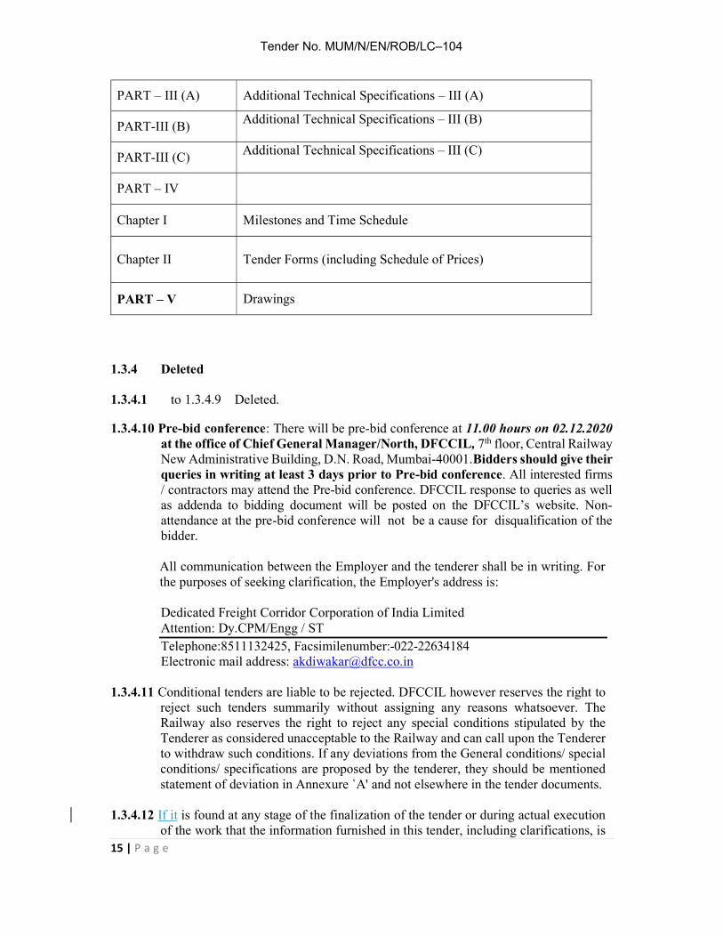
PART – III (A) Additional Technical Specifications – III (A)
PART-III (B) Additional Technical Specifications – III (B)
PART-III (C) Additional Technical Specifications – III (C)
PART – IV
Chapter I Milestones and Time Schedule
Chapter II Tender Forms (including Schedule of Prices)
PART – V Drawings
1.3.4 Deleted 1.3.4.1 to 1.3.4.9 Deleted.
1.3.4.10 Pre-bid conference: There will be pre-bid conference at 11.00 hours on 02.12.2020 at the office of Chief General Manager/North, DFCCIL, 7th floor, Central Railway New Administrative Building, D.N. Road, Mumbai-40001.Bidders should give their queries in writing at least 3 days prior to Pre-bid conference. All interested firms / contractors may attend the Pre-bid conference. DFCCIL response to queries as well as addenda to bidding document will be posted on the DFCCIL’s website. Non-attendance at the pre-bid conference will not be a cause for disqualification of the bidder.
All communication between the Employer and the tenderer shall be in writing. For the purposes of seeking clarification, the Employer's address is:
Dedicated Freight Corridor Corporation of India Limited Attention: Dy.CPM/Engg / ST Telephone:8511132425, Facsimilenumber:-022-22634184 Electronic mail address: [email protected]
1.3.4.11 Conditional tenders are liable to be rejected. DFCCIL however reserves the right to reject such tenders summarily without assigning any reasons whatsoever. The Railway also reserves the right to reject any special conditions stipulated by the Tenderer as considered unacceptable to the Railway and can call upon the Tenderer to withdraw such conditions. If any deviations from the General conditions/ special conditions/ specifications are proposed by the tenderer, they should be mentioned statement of deviation in Annexure `A' and not elsewhere in the tender documents.
1.3.4.12 If it is found at any stage of the finalization of the tender or during actual execution
of the work that the information furnished in this tender, including clarifications, is

Tender No. MUM/N/EN/ROB/LC–104
16 | P a g e
incorrect, the tenders are likely to be rejected. 1.3.4.13 Sales Tax/Commercial Tax/Works Contract Tax: Taxes prescribed by the Central government/State Government/Local bodies at the
rate prescribed by them will be recovered from the bills from time to time. 1.3.4.14 The list of documents (Check list) to be attached along with the tender documents is
as under: -
Various Pro-forma attached with tender document as per chapter II of Part IV. Covering Letter as per Format given in Chapter II. Documents fulfilling the eligibility criteria as per Form No 2A and 2B as per
chapter II of Part IV. List of personnel, organization available on hand and proposed to be engaged
for the subject work. List of plants & machinery available on hand (own) and proposed to be
inducted (Own & hired to be given separately) for the subject work. List of works completed in the last three financial years and current financial
year giving description of work, organization for whom executed, approximate value of contract at the time of award, date of award, date of schedule completion of work, date of actual commencement of work, actual date of completion and completion cost. Supportive documents/certificates from the organizations with whom they had worked should also be enclosed. Certificate from private individuals for whom such works were executed will not be accepted.
List of works on hand indicating description of work, contract value, date of award, value of work executed & approximate value of balance work yet to be done. Supportive documents/certificates from the organizations with whom they are working should also be enclosed. Certificate from private individuals for whom such works are being executed will not be accepted.
Method statement, PERT CHARTS & Construction schedule vis-à-vis deployment resources.
MOU for JV and Partnership deed as per Forms 9,10,11,12 and 13 of Chapter II of Part IV.
Power of Attorneys as per Form 12 & 13 of Chapter II of Part IV. All above documents duly signed & completed in all and signing each and
every page of the document. Pan Card, GSTN Registration.
1.3.5 Opening of Tender:
(a) Tender will be opened online at 15.30 hrs. on 2 4 . 1 2 . 2 0 2 0 , in CHIEF GENERAL MANAGER(North), Dedicated Freight Corridor Corporation of India Limited, 7th floor, Central Railway New Administrative Building, D.N. Road, Mumbai, India, in the presence of the tenderers or their representatives as may be present at the prescribed date and time.

Tender No. MUM/N/EN/ROB/LC–104
17 | P a g e
(b) After the opening of “TECHNICAL BID” of all the tenderers, these Bids shall be scrutinized and analyzed. If found necessary by the Employer, the tenderers shall be asked to furnish clarifications and the Employer may also hold discussions with the tenderers after giving due notice. The names of the tenderers whose Bid are considered complete and meet eligibility criteria shall be shortlisted.
(c) The FINANCIAL BID shall be opened on a subsequent date and time duly
notified well in advance. The Financial Bids of only those tenderers shall be opened who are short listed after scrutiny of their Technical Bid. The Financial Bid of the tenders who do not qualify during scrutiny of Technical Bid shall not be opened. The time of opening, date and venue of online financial Bids of Shortlisted tenderer shall be advised to qualified tenderers well in advance to enable them to depute their representative. The earnest money of non-qualifying tenderers will be returned back within a reasonable period of completion of results of Technical Bid.
1.3.5.1 The Employer (DFCCIL) will notify Bidders in writing who have been rejected on the grounds of their Technical bids being substantially non-responsive to the requirements of the bidding document and their price bids i.e. FINANCIAL BID ( Packet-B) submitted online will not be opened.
1.3.6 Constitution of the Firm: - 1.3.6.1 Tenderer shall clearly specify whether the tender is submitted on his own or on
behalf of a partnership firm / Joint Venture (JV) / Company. The tenderer(s) who is / are constituents of the firm / Company, shall enclose self-attested copies of the constitution of their concern, Partnership Deed and Power of attorney along with their tender. Tender documents in such cases shall be signed by such persons as may be legally competent to sign them on behalf of the firm / company as the case may be.
1.3.6.2 The tenderer shall give full details of the constitution of the Firm / JV / Company
and shall also submit following documents (as applicable), in addition to documents mentioned above:
(a) Sole Proprietorship Firm: The tenderer shall submit the notarized copy of the
affidavit.
(b) Partnership Firm : The tenderer shall submit self-attested copies of (i) registered / notarized Partnership Deed and (ii) Power of Attorney duly authorizing one or more of the partners of the firm or any other person(s), authorized by all the partners to act on behalf of the firm and to submit & sign the tender, sign the agreement, witness measurements, sign measurement books, receive payments, make correspondences, compromise / settle / relinquish any claim (s) preferred by the firm, Sign "No claim Certificate", refer all or any dispute to arbitration and to take similar action in respect of all tenders / contracts or said tender / contract.

Tender No. MUM/N/EN/ROB/LC–104
18 | P a g e
(c) Joint Venture: The tenderer shall submit documents as mentioned in clause 65
of GCC.
(d) Companies registered under Companies Act-1956: The tenderer shall submit (i) the copies of Memorandum of Association (MOA) and Articles of Association (AOA) of the company; and (ii) Power of attorney duly registered / notarized by the company (backed by the resolution of Board of Directors) in favour of the individual, signing the tender on behalf of company.
1.3.6.3 If it is mentioned in the tender submission that it is being submitted on behalf
of / by a sole Proprietorship Firm / Partnership Firm / Joint venture / registered Company etc. but above-mentioned documents (as applicable) are not enclosed along with tender, the tender shall be summarily rejected.
If it is NOT mentioned in the tender submission that it is being submitted on behalf
of / by a Sole Proprietorship Firm / Partnership Firm / Joint Venture / Registered Company etc., then the tender shall be treated as having been submitted by the individual who has signed the tender.
After opening of the tender, any document pertaining to the constitution of the Firm
/ Joint Venture etc. shall neither be asked nor be entertained / considered by DFCCIL.
1.3.6.4 A tender from Joint Venture / Partnership Firm etc. shall be considered only where
permissible as per the tender conditions. 1.3.6.5 The DFCCIL will not be bound by any power of attorney granted by the tenderer
or by changes in the composition of the Firm made subsequent to the submission of tender. It may, however, recognize such power of attorney and changes after obtaining proper legal advice.
1.3.7 Validity of Tender: -
Tenderer shall keep his offer open for a minimum period of 90 days from the date of opening of the tender or as mentioned in the Tender Notice.
1.3.8 Deleted 1.3.9 Execution of Contract Agreement: -
The Tenderer whose tender is accepted shall be required to appear in person at the office of CHIEF GENERAL MANAGER/North, DFCCIL, 7th floor, Central Railway New Administrative Building, D.N. Road, Mumbai-40001or if a firm or corporation, a duly authorized representative shall so appear and execute the contract agreement within 60 days after notice that the contract has been awarded to him. Failure to do so shall constitute a breach of the agreement affected by the acceptance of the tender in which case the full value of the earnest money accompanying the tender shall stand forfeited without prejudice to any other rights or remedies.

Tender No. MUM/N/EN/ROB/LC–104
19 | P a g e
In the event of any tenderer whose tender is accepted refuses to execute the contract agreement as here in before provided, DFCCIL may determine that such tenderer has abandoned the contract and there upon his tender and acceptance thereof shall be treated as cancelled and DFCCIL shall be entitled to forfeit the full amount of the Earnest Money.
1.3.10 Security Deposit on Acceptance of Tender: The security deposit/rate of recovery/mode of recovery on acceptance of tender shall be as per the Para 16.(1) to 16.(3) of General Conditions of Contract(GCC).
1.3.11 Tenderer’s Address
The tenderer should state in the tender his postal address legibly and clearly. Any communication sent in time, to the tenderer by post at his said address shall be deemed to have reached the tenderer duly and in time. Important documents should be sent by registered post.
1.3.12 Right of DFCCIL to Deal with Tenders
(a) The DFCCIL reserves the right of not to invite tenders for any of DFCCIL work or works or to invite open or limited tenders and when tenders are called to accept a tender in whole or in part or t o reject any tender or all tenders without assigning reasons for any such action.
(b) The authority for the acceptance of the tender will rest with the DFCCIL. It shall not be obligatory on the said authority to accept the lowest tender or any other tender and no tenderer(s) shall demand any explanation for the cause of rejection of his/their tender nor the DFCCIL undertake to assign reasons for declining to consider or reject any particular tender or tenders.
1.3.13 (i)Eligibility Criteria (A): Technical Eligibility Criteria
Criteria Compliance Requirement Documents
Requirement Single Entity
Joint venture Submission Requirements
(i) The tenderer / JV firm or Lead Member of JV firm must have satisfactorily completed at least one single work in last three previous financial years and the current financial year upto the date of submission of tender, of construction of any one of the following having minimum value of 35% of the Advertised value of tender:
Must meet requirement
Existing JV - Must meet requirement.
Or
Lead Member of proposed JV-Must meet
The tenderer shall submit the completion certificates / certified completion certificates from the client(s) and or Photostat of original certificates of client.

Tender No. MUM/N/EN/ROB/LC–104
20 | P a g e
1 Railway Bridge*having
superstructure of RCC or PSC or Steel on at least one span.
OR 2 Viaduct of Railway* having
superstructure of RCC or PSC or Steel on at least one span.
OR
3 Bridge*of Metro Railway having superstructure of RCC or PSC or Steel on at least one span
OR 4 Viaduct* of Metro Railway having
superstructure of RCC or PSC or Steel on at least one span.
OR
5 ROB of Railway Portion having superstructure of RCC or PSC or
Steel on at least one span. OR
6 Approach Portion of ROB having superstructure of RCC or PSC or Steel on at least one span.
OR 7 Flyover on Roads having
superstructure of RCC or PSC or Steel on at least one span.
OR 8 Foot Over Bridge Over Railway
Track Note: (a) *Road Under Bridge of box type
shall not be considered as Railway bridge/ viaduct of railway/bridge of metro/viaduct of metro and shall not be considered as similar nature of work for this tender.
(b) For the purpose of technical eligibility criteria, the definition of
requirement All documents either original or photocopy should be attested by Notary.

Tender No. MUM/N/EN/ROB/LC–104
21 | P a g e
ROB means “Road Over Bridges” constructed over Railway line(s).
And
(ii) The tenderer / JV firm or any Member of JV firm must have satisfactorily completed in last three previous financial years and the current financial year upto the date of submission of tender, at least one single work having a component of “fabrication and erection”, of Open Web Steel Girder or Plate Steel Girder or Bow string Steel Girder irrespective of cost of work done. This fabrication and erection must be for Railway Bridge or Metro Railway or ROB or Foot Over Bridge over Railway Track.
Note: (a) *Road Under Bridge of box type shall
not be considered as Railway bridge/ viaduct of railway/bridge of metro/viaduct of metro and shall not be considered as similar nature of work for this tender.
(b) For the purpose of technical eligibility criteria, the definition of ROB means “Road Over Bridges” constructed over Railway line(s).
(c) The single work can be a separate work or same as (i) above
Must meet requirement
Existing JV - Must meet requirement.
Or
Any Member of proposed JV-Must meet requirement.
The tenderer shall submit the completion certificates / certified completion certificates from the client(s) and or Photostat of original certificates of client. All documents either original or photocopy should be attested by Notary.
Note:
1. Value of completed work done by a member in an earlier JV Firm shall be reckoned only to the extent of the concerned member’s share in that JV firm for the purpose of satisfying his / her compliance to the above-mentioned technical eligibility criteria in the tender under consideration.
2. In case the tenderer/s is a partnership firm, the work experience shall be in the name of partnership firm only.

Tender No. MUM/N/EN/ROB/LC–104
22 | P a g e
(B): Financial Eligibility Criteria
Criteria Compliance Requirement Documents
Requirement Single Entity
Joint Venture
Submission Requirements
The contractual payments received by the tenderer / JV firm or the arithmetic sum of contractual payments received by all the members of the JV firm in the previous three financial year and the current financial year up to the date of submission of tender shall be at least 150% of advertised value of tender.
Must meet Requirement
Must meet requirement
TDS certificates/ Audited balance sheets and or Photostat of TDS certificates/Audited Balance sheets clearly indicating the contractual amount received. All documents either original or photocopy should be attested by Notary.
Note:
1. Contractual payments received by a Member in an earlier JV firm shall be reckoned only to extent of the concerned member’s share in that JV Firm for the purpose of satisfying compliance of the above-mentioned financial eligibility criteria in tender for considerations.
2. In case the tenderer/s is a partnership firm, the turnover etc. shall be in the name of partnership firm only.
1.3.13 (ii)Credentials of Tenderer
The tenderer shall provide satisfactory evidence in support of their technical and financial eligibility, which are acceptable to DFCCIL, as follows:
(a) For Technical eligibility criteria, the details will be submitted in Form No.2A along with supporting documents. (b) For Financial eligibility criteria, the details will be submitted in Form No.2B along with supporting documents. (c) The tenderer shall submit the completion certificates/certified completion
certificates from the client(s) or Photostat of original certificates of client. All documents either original or photocopy should be attested by Notary. These

Tender No. MUM/N/EN/ROB/LC–104
23 | P a g e
certificates should indicate the details of works carried out and successful commissioning of similar type of work executed by the tenderer. Completion certificate from Govt. organisation /PSUs/Public Limited Company will be accepted. The certificate from Private individual/Private Company for whom such works are executed shall not be accepted. In case, the work is executed for Public Limited Company, copy of work order, bill of Quantity, TDS certificate payments received and copy of final/last bill paid by client shall be submitted.
The following will be applicable for evaluating the eligibility: (i) Similar nature of work physically completed with in the qualifying period, i.e.
last three financial year and current financial year (even though the work might have commenced be fore the qualifying period) shall only be considered in evaluating the eligibility.
(ii) The total value of similar nature of work completed during the qualifying period
and not the payment received with in qualifying period alone ,shall be considered. Incase, the final bill of similar nature of work has not been passed and final measurements have not been recorded, the paid amount including statutory deductions is to be considered. If final measurements have been recorded and work has been completed with negative variation, then also the paid amount including statutory deductions is to be considered. However, if final measurements have been recorded and work has been completed with positive variation but variation has not been sanctioned, original contract agreement value or last sanctioned contract agreement value which ever is lower, shall be considered for judging eligibility.
(iii) As proof of sufficient financial capacity and organizational resources, contractor
should have received total payments against satisfactory execution of all completed /on-goingworks of all types (not confined to only similar works) during the last three financial years and in the current financial year (upto the date of submission of the tender) of a value not less than150% of advertised tender value.
(iv) Tenderer shall submit a statement of contractual payments received during last
three financial years and current financial year on the prescribed Performa as per Form No. 2B. The details shall be based on the form16-A issued by the employer i.e. the certificate of deduction of tax at source as per IncomeTax Act 1961. The photo copies of Form 16- A shall been closed duly attested by Notary Public with seal and Notarial Stamp there on or a certificate from auditor or audited balance sheet certified by Chartered Accountant clearly indicating the contractual amount received duly attested by Notary Public with seal and

Tender No. MUM/N/EN/ROB/LC–104
24 | P a g e
Notarial Stamp there on. (v) The tenderer shall be considered disqualified/in-eligible if:
(a) The Tenderer or any of its partners and/or subcontractors included in the tender has been banned for business with Ministry of Railways/DFCCIL along with any of its attached and subordinate offices through an order issued by Ministry of Railways as per list available on Website (http: // www. Indian Railways. gov.in / railway board ) of Railway Board pertaining to banning of Business, with the banning being valid as on the date of submission the Tender.
(b) The Tenderer or any of its partners has suffered bankruptcy / in solvency or it is in the process of winding-up or there is a case of insolvency pending be fore any Court on the deadline of submission of application.
(vi) For the purposes of conversion of foreign currency to Indian rupees (INR) Bank
Currency(BC) selling exchange rates as published by State Bank of India on the date 28 days prior to date of submission of tender shall be used. For few of the currencies where BC selling rates are not published by SBI or reserve bank of India, the exchange rate may be obtained from website- http://www.oanda.com/currency/historical-rates or http://www.xe.com.
(vii) For the purpose of evaluation of proposals, all values given in INR in eligible
qualification criteria and the values provided by the applicants in the proposal in the currencies other than INR shall be converted into one i.e. INR as per exchange rate mentioned in para (vi) above.
1.3.14 Period of Completion
The entire work is required to be completed in all respects within 18 months (Eighteen months) from the date of issue of the acceptance letter. Time is the essence of contract. The contractor shall be required to maintain steady and regular progress to the satisfaction of the Engineer to ensure that the work will be completed in all respects within the stipulated time.
1.3.15 If the Tenderer/s deliberately gives any wrong information about credentials /
documents in his / their tenders and thereby create(s) circumstances for acceptance of his /their tender, DFCCIL reserves the right to reject such tender at any stage, besides, shall suspend business with such tenderer. The EMD of such tenderers shall also be forfeited.
1.3.16 Quantum of work and materials:
The indicative schedule of quantities of various items of works is included in Form

Tender No. MUM/N/EN/ROB/LC–104
25 | P a g e
- 4 of the tender documents. 1.3.17 Employer not bound to accept any tender:
The employer shall not be bou nd to accept the lowest or any tender or to a ss ign any reason for non-acceptance or rejection of a tender. The employer reserves the right to accept any tender in respect of the whole or any portion of the work specified in the tender papers or to reduce the work or to accept any tender for less than the tendered quantities without assigning any reason whatsoever.
1.3.18 Schedule of Prices
The Schedule-1 of the tender document l ists out the Schedule of Prices for various items. Based on these, the total tender value has also been worked out.
1.3.19 Performance Guarantee: Refer relevant clause of GCC.
1.3.20 The tenderer shall furnish information for making payment through ECS/ NEFT /
RTGS (Tender Form No. 8 placed at Part IV of the tender documents).
1.3.21 Negotiation: Should DFCCIL decide to negotiate with a view to bring down the rates, the tenderer called for negotiations should furnish the following form of declaration before commencement of negotiations: "I................................................................. do declare that in the event of failure of contemplated negotiations relating to Tender No............................................... dated ............................my original tender shall remain open for acceptance on its original terms and conditions,".
1.3.22 Site Inspection:
Tenderers are requested to inspect the site and carry out careful examination to satisfy them as to the nature of work involved and facilities available at the site. They should note carefully all the existing structures and those under construction through other agencies. They should also study the suitability of utilizing the different equipment and the machinery that they intend to use for the execution of the work. The tenderers should also select suitable sites for the purpose of locating their store yard, laboratory, staff quarters etc., and satisfy themselves with regard to the feasibility of transporting the girders, etc. from the yard to the final site of placement etc.
1.3.23 No form C &D shall be issued to the contractor for this work.
***********

PART - I
CHAPTER - IV
GENERAL CONDITIONS OF CONTRACT

Tender No.MUM/N/EN/ROB/LC–104
26 | P a g e
PART - I CHAPTER IV
GENERAL CONDITIONS OF CONTRACT
DEFINITIONS AND INTERPRETATION
1. (1) Definition:- In these General conditions of Contract, the following terms shall have the
meaning assigned hereunder except where the context otherwise requires:-
(a) “Railway” shall mean the President of the Republic of India or the Administrative Officers of the Railway/DFCCIL or of the Successor Railway / DFCCIL authorized to deal with any matters which these presents are concerned on his behalf.
(b) “General Manager of Railway ” shall mean the officer - in-charge of the General
Superintendence and Control of the Railway and shall mean and include their successors, of the successor Railway;
(c) “Chief Engineer” shall mean the officer - in-charge of the Engineering Department
of Railway and shall also include Chief Engineer (Construction), Chief Signal and Telecommunication Engineer, Chief Signal and Telecommunication Engineer(Construction), Chief Electrical Engineer, Chief Electrical Engineer(Construction) and shall also include GGM/GM/CGM of DFCCIL.
(d) “Divisional Railway Manager” shall mean the Officer in-charge of a Division of the
Railway and shall also mean any officer nominated by Managing Director / DFCCIL and shall mean and include their successors of the successor Railway.
(e) “Engineer” and Employer’s Engineer sha ll mean the CHIEF GENERAL MANAGER of
DFCCIL / PMC appointed by DFCCIL.
(f) “Engineer’s Representative” shall mean the Assistant Engineer, Assistant Signal and Telecommunication Engineer and Assistant Electrical Engineer, APM / PM / Dy.CPM / Add. CPM of DFCCIL in direct charge of the work and shall include any Sr. Sec. / Sec / Jr. Engineer / Executive / Sr. Executive, APM/PM / Dy CPM of DFCCIL of Civil Engineering / Signal & Telecommunication Engineering / Electrical Engineering Department appointed by the Railway / DFCCIL and shall mean and include the Engineer’s
Representative of the successor Railway / DFCCIL.

Tender No.MUM/N/EN/ROB/LC–104
27 | P a g e
(g) “Contractor” shall mean the person / Firm / Company / JV whether incorporated or not who enters into the contract with the DFCCIL and shall include their executors, administrators, and successors and permitted assigns.
(h) “Contract” shall mean and include the Agreement of Work Order, the accepted
schedule of rates of the Schedule or Rates of Railway / DFCCIL modified by the tender percentage for items of work quantified, or not quantified, General Conditions of Contract, Special Conditions of Contracts, if any, Drawings, Specifications, Additional / Special Specifications, if any and tender forms, if any, and all other documents included as part of contract .
(i) “Works” shall mean the works to be executed in accordance with the
contract. (j) “Specifications” shall mean the Specifications for materials and works referred / mentioned
in tender documents. (k) “Schedule of rates of Railway” shall mean the schedule of rates issued under the authority
of the Chief Engineer from time to time and shall also includes Rates specified in tender document. Schedule of rates of State Govt.” shall mean the schedule of rates issued under
the authority of the Chief Engineer/State Govt. Gujarat from time to time and shall also includes Rates specified in tender document
(l) “Drawing” shall mean the maps, drawings, plans and tracings or prints there of annexed to
the contract and shall include any modifications of such drawings and further drawings as may be issued by the Engineer from time to time.
(m) “Constructional Plan” shall mean all appliances or things of whatsoever nature
required for the execution, completion or maintenance of the works or temporary works (as hereinafter defined) but does not include materials or other things intended to form or forming part of the permanent work.
(n) “Temporary Works” shall mean all temporary works of every kind required for the
execution completion and/or maintenance of the works.
(o) “Site” shall mean the lands and other places on, under, in or through which the works are to be carried out and any other lands or places provided by the Railway for the purpose of the contract.
(p) “Period of Maintenance” shall mean the defect liability period from the date of completion of the works as certified by the Engineer.

Tender No.MUM/N/EN/ROB/LC–104
28 | P a g e
1.(2) Singular and Plural:- Words importing the singular number shall also include the
plural and vice versa where the context requires.
1.(3) Headings & marginal headings:-The headings and marginal headings in these general conditions are solely for the purpose of facilitating reference and shall not be deemed to be part thereof or be taken into consideration in the interpretation or construction thereof or the contract.
GENERAL OBLIGATION
2. (1) Execution Co-relation and intent of contract Documents :-The contract documents
shall be signed in triplicate by the DFCCIL and the Contractor. The contract documents are complementary, and what is called for by any one shall be as binding as if called for by all, the intention of the documents is to include all labour and materials, equipment and transportation necessary for the proper execution of work. Materials or work not covered by or properly inferable from any heading or class of the specifications shall not be supplied by the DFCCIL to the contractors unless distinctly specified in the contract documents. Materials or works described in words which so applied have a well-known technical or trade meaning shall be held to refer to such recognized standards.
2.(2) If a work is transferred from the jurisdiction of one Railway to another Railway or
to a Project Authority/ DFCCIL or vice versa while contract is in subsistence, the contract shall be binding on the Contractor and the Successor Railway/Project in the same manner & take effect all respects as if the Contractor and the Successor Railway/Project were parties there to from the inception and the corresponding officer or the Competent Authority in the Successor Railway/Project will exercise the same powers and enjoy the same authority as conferred to the Predecessor Railway/Project under the original contract/agreement entered into.
2.(3) If for administrative or other reasons the contract is transferred to the Successor
Railway/Successor Project Authority of DFCCIL the contract shall not withstanding any things contained herein contrary there to, be binding on the Contractor and the Successor Railway /Project Authority/ DFCCIL in the same manner and take effect in all respect as if the Contractor and the Successor Railway/ successor Project Authority of DFCCIL had been parties thereto from the date of this contract. The contract shall be Administered/Managed by GGM/GM/CGM/nominated by DFCCIL.
3.(1) Law governing the contract:-The contract shall be governed by the law for the time
being in force in the Republic of India.

Tender No.MUM/N/EN/ROB/LC–104
29 | P a g e
3.(2) Compliance to regulations and bye-laws:-The contractor shall conform to the provision
of any statute relating to the works and regulations and by-laws of any location authority and of any water and lighting companies or undertakings, with whose system the work is proposed to be connected and shall before making any variation from the drawings or the specifications that may be necessitated by so confirming give to the Engineer notice specifying the variation proposed to be made and the reasons for making the variation and shall not carry out such variation until he has received instructions from the Engineer in respect thereof. The contractor shall be bound to give all notices required by statute, regulations or bye-laws as aforesaid and to pay all fees and taxes payable to any authority in respect thereof.
4. Communications to be in writing:- All notices, communications, reference and
complaints made by the DFCCIL or the Engineer or the Engineer’s representative or the contractor inters concerning the work shall be in writing and no notice, communication, reference or complaint not in writing shall be recognized.
5. Service of Notices on Contractors:-The contractor shall furnish to the Engineer the
name designation and address of his authorized agent and all complaints, notices, communications and references shall be deemed to have been duly given to the contractor if delivered to the contractor or his authorized agent or left at or posted to the address so given and shall be deemed to have been so given in the case of posting on day on which they would have reached such address in the ordinary course of post or on the day on which they were so delivered or left. In the case of contract by partners, any change in the constitution of the firm shall be forthwith notified by the contractor to the Engineer.
6. Occupation and u s e o f lan d : - No la nd b e l o n g i n g to o r in the possession
of the Railway / DFC CI L/ S t a t e go vt . shall be occupied by the Contractor without the permission of the Railway / DFCCIL. The Contractor shall not use, or allow to be used, the site for any purposes other than that of executing the works. Whenever non-Railway bodies / persons are permitted to use Railway/State Govt. premises with competent authority’s approval, conservancy charges as applicable from time to time may be levied.
7. Assignment or subletting of contract:- The contractor shall not assign or sublet the
contract or any part thereof or allow any person to become interested therein any manner whatsoever without the special permission in writing of the DFCCIL. Any breach of this condition shall entitle the DFCCIL to rescind the contract under clause 62 of these conditions and also render the contractor liable for payment to the DFCCIL in

Tender No.MUM/N/EN/ROB/LC–104
30 | P a g e
respect of any loss or damage arising or ensuing from such cancellation. Provided always that execution of the details of the work by petty contractor under the direct and personal supervision of the Contractor or his agent shall not be deemed to be sub-letting under this clause. The permitted subletting of work by the contractor shall not establish any contractual relationship between the sub- contractor and the DFCCIL and shall not relieve the contractor of any responsibility under the contract.
8. Assistance by the DFCCIL for the Stores to be obtained by the Contractor:- Owing
to difficulty in obtaining certain materials (including Tools & Plant) in the market, the DFCCIL may have agreed without any liability therefore to endeavour to obtain or assist the contractor in obtaining the required quantities of such materials as may be specified in the tender. In the event of delay or failure in obtaining the required quantities of the aforesaid material the contractor shall not be deemed absolved of his own responsibility and shall keep in touch with day to day positions regarding their availability and accordingly adjust progress of works including employment of labour and the DFCCIL shall not in any way be liable for the supply of materials or for the non-supply thereof for any reasons whatsoever nor for any loss or damage arising in consequence of such delay or no supply.
9. Deleted
10. Carriage of materials:- No forwarding orders shall be issued by the DFCCIL for the conveyance of contractor’s materials, tools and plant by Rail which may be required for use in the works and the contractor shall pay full freight charges at public tariff rates therefore.
11. Deleted
12. Representation on Works:- The contractor shall, when he is not personally present on
the site of the works place and keep a responsible agent at the works during working hours who shall on receiving reasonable notice, present himself to the Engineer and orders given by the Engineer or the engineer’s representative to the agent shall be deemed to have the same force as if they had been given to the Contractor. Before absenting himself, the contractor shall furnish the name and address of his agent for the purpose of this clause and failure on the part of the Contractor to comply with this provision at any time will entitle the DFCCIL to rescind the contract under clause 62 of these conditions.
13. Relics and Treasures:- All gold, silver, oil and other minerals of any description
and all precious stones, coins, treasures relics antiquities and other similar things which shall be found in or upon the site shall be the property of the DFCCIL and the Contractor

Tender No.MUM/N/EN/ROB/LC–104
31 | P a g e
shall duly preserve the same to the satisfaction of the DFCCIL and shall from time to time deliver the same to such person or persons as the DFCCIL may appoint to receive the same.
14. Excavated material:-The contractor shall not sell or otherwise dispose of or remove
except for the purpose of this contract, the sand, stones, clay, ballast, earth, rock or other substances or materials which may be obtained from any excavation made for the purpose of the works or any building or produced upon the site at the time of delivery of the possession thereof but all the substances, materials, buildings and produce shall be the property of the DFCCIL provided that the contractor may, with the permission of the Engineer, use the same for the purpose of the works either free of cost or pay the cost of the same at such rates as may be determined by the Engineer.
15. Indemnity by Contractors:- The contractor shall indemnify and save harmless
the Railway/DFCCIL from and against all actions, suit proceedings losses, costs, damages, charges, claims and demands of every nature and description brought or recovered against the Railways /DFCCIL by reason of any act or omission of the contractor, his agents or employees, in the execution of the works or in his guarding of the same. All sums payable by way of compensation under any of these conditions shall be considered as reasonable compensation to be applied to the actual loss or damage sustained, and whether or not any damage shall have been sustained.
16.(1) Security Deposit:- The earnest money deposited by the contractor with this tender will
be retained by the Railways / DFCCIL as part of security for the due and faithful fulfilment of the contract by the contractor. The balance to make up the security deposit, the rates for which are given below, may be deposited by the contractor in cash or may be recovered by percentage deduction from the contractor’s “on account” bills. Provided also that in case of defaulting contractor the DFCCIL may retain any amount due for payment to the contractor on the pending “on account bills” so that the amounts so retained may not exceed 10% of the total value of the contract.
16.(2) Recovery of Security Deposit:- Unless otherwise specified in the special conditions,
if any, the Security Deposit / rate of recovery / mode of recovery shall be as under:- (a) Security Deposit for each work should be 5% of the contract value.
(b) The rate of recovery should be at the rate of 10% of the bill amount till the full security deposit is recovered.
(c) Security Deposits will be recovered only from the running bills of the contract and no other mode of collecting SD such as SD in the form of instruments like BG (except Note
Tender No.MUM/N/EN/ROB/LC–104
32 | P a g e
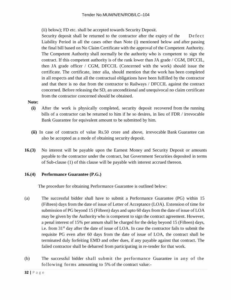
(ii) below); FD etc. shall be accepted towards Security Deposit. Security deposit shall be returned to the contractor after the expiry of the D e fe c t
Liability Period in all the cases other than Note (i) mentioned below and after passing the final bill based on No Claim Certificate with the approval of the Competent Authority. The Competent Authority shall normally be the authority who is competent to sign the contract. If this competent authority is of the rank lower than JA grade / CGM, DFCCIL, then JA grade officer / CGM, DFCCIL (Concerned with the work) should issue the certificate. The certificate, inter alia, should mention that the work has been completed in all respects and that all the contractual obligations have been fulfilled by the contractor and that there is no due from the contractor to Railways / DFCCIL against the contract concerned. Before releasing the SD, an unconditional and unequivocal no claim certificate from the contractor concerned should be obtained.
Note: (i) After the work is physically completed, security deposit recovered from the running
bills of a contractor can be returned to him if he so desires, in lieu of FDR / irrevocable Bank Guarantee for equivalent amount to be submitted by him.
(ii) In case of contracts of value Rs.50 crore and above, irrevocable Bank Guarantee can
also be accepted as a mode of obtaining security deposit.
16.(3) No interest will be payable upon the Earnest Money and Security Deposit or amounts payable to the contractor under the contract, but Government Securities deposited in terms of Sub-clause (1) of this clause will be payable with interest accrued thereon.
16.(4) Performance Guarantee (P.G.)
The procedure for obtaining Performance Guarantee is outlined below: (a) The successful bidder shall have to submit a Performance Guarantee (PG) within 15
(Fifteen) days from the date of issue of Letter of Acceptance (LOA). Extension of time for submission of PG beyond 15 (Fifteen) days and upto 60 days from the date of issue of LOA may be given by the Authority who is competent to sign the contract agreement. However, a penal interest of 15% per annum shall be charged for the delay beyond 15 (Fifteen) days, i.e. from 31st day after the date of issue of LOA. In case the contractor fails to submit the requisite PG even after 60 days from the date of issue of LOA, the contract shall be terminated duly forfeiting EMD and other dues, if any payable against that contract. The failed contractor shall be debarred from participating in re-tender for that work.
(b) The successful bidder shall submit the performance Guarantee in any o f t he
fo llowing forms amounting to 5% of the contract value:-

Tender No.MUM/N/EN/ROB/LC–104
33 | P a g e
(i) Deleted (ii) Irrevocable Bank Guarantees from any Nationalized / Indian all Scheduled
Commercial Banks; (iii) Government Securities including State Loan Bonds at 5 percent below the market
value. (iv) Deposit receipts, pay orders, Demand Drafts. These forms of Performance Guarantee
could be either of the State Bank of India or of any of the Nationalized Banks; (v) Deleted (vi) Deleted (vii) Deleted. (viii) Deleted (ix) Deleted (x) Deleted (xi) Deleted
Note: deleted. (c) The performance Guarantee shall be submitted by the successful bidder after the letter
of acceptance has been issued, but before signing of the contract agreement. The agreement should normally be signed within 30 (thirty) days after the issue of LOA and the Performance Guarantee shall also be submitted within this time limit. This P. G. shall be initially valid up to the stipulated date of completion plus 60 days beyond that. In case, the time limit for completion of work gets extended, the contractor shall get the validity of Performance Guarantee extended to cover such extended time for completion of work plus 60 days.
(d) The value of PG to be submitted by the contractor will not change for variation upto 25 %
(either increase or decrease). In case during the course of execution, value of the contract increases by more than 25 % of the original contract value, an additional performance guarantee amounting to 5 % (five percent) for the excess value over the original contract value shall be deposited by the contractor.
(e) The performance Guarantee (PG) shall be released after the physical completion of
the work based on the ‘completion certificate’ issued by the competent authority stating that the contractor has completed the work in all respects satisfactorily. The security deposit shall, however, be released only after the expiry of the defect liability period and after passing the final bill based on ‘No Claim Certificate’ from the contractor.
(f) Whenever the contract is rescinded, the security deposit shall be forfeited and the Performance Guarantee shall be encashed. The balance work shall be got done

Tender No.MUM/N/EN/ROB/LC–104
34 | P a g e
independently without risk and cost of the failed contractor, the failed contractor shall be debarred from participating in the tender for executing the balance work. If the failed contractor is a JV or a partnership firm, then every member / partner of such a firm shall be debarred from participating in the tender for the balance work in his / her individual capacity or as a partner of any other JV / partnership firm.
(g) The Engineer shall not make a claim under the Performance Guarantee except for
amounts to which the President of India / DFCCIL is entitled under the contract (no withstanding and/or without prejudice to any other provisions in the contract agreement) in the event of:
(i) Failure by the contractor to extend the validity of the Performance Guarantee as
described herein above, in which event the Engineer may claim the full amount of the Performance Guarantee.
(ii) Failure by the contractor to pay President of India / DFCCIL any amount due, either
as agreed by the contractor or determined under any of the Clauses/conditions of the agreement, within 60 days of the service of the notice to the effect by Engineer.
(iii) The contract being determined or rescinded under provision of the GCC the
Performance Guarantee shall be forfeited in full and shall be absolutely at the disposal of the President of India.
17. Force Majeure Clause:- If at any time, during the continuance of this contract,
the Performance in whole or in part by either party of any obligation under this contract shall be prevented or delayed by reason of any war, hostility, acts of public enemy, civil commotion, sabotage, serious loss or damage by fire, explosions, epidemics, strikes, lockouts or act of God (hereinafter, referred to events) provided, notice of the happening of any such event is given by either party to the other within 30 days from the date of occurrence thereof, neither party shall by reason of such event, be entitled to terminate this contract nor shall either party have any claim for damages against the other in respect of such non- performance of delay in performance, and works under the contract shall be resumed as soon as practicable after such event has come to an end or ceased to exist, and the decision of the Engineer as to whether the works have been so resumed or not shall be final and conclusive, PROVIDED FURTHER that if the performance in whole or in part of any obligation under this contract is prevented or delayed by reason of any such event for a period exceeding 120 days, either party may at its option terminate the contract by giving notice to the other party.
17-A Extension of time in Contracts:- Subject to any requirement in the contract as to

Tender No.MUM/N/EN/ROB/LC–104
35 | P a g e
completion of any portion or portions of the works before completion of the whole, the contractor shall fully and finally complete the whole of the works comprised in the contract (with such modifications as may be directed under conditions of this contract) by the date entered in the contract or extended date in terms of the following clauses:-
(i) Extension due to modification:- If any modifications have been ordered which in the
opinion of the Engineer have materially increased the magnitude of the work, then such extension of the contracted date of completion may be granted as shall appear to the Engineer to be reasonable in the circumstances, provided moreover that the Contractor shall be responsible for requesting such extension of the date as may be considered necessary as soon as the cause thereof shall arise and in any case not less than one month before the expiry of the date fixed for completion of the works.
(ii) Extension for delay not due to DFCCIL or Contractor:-If in the opinion of the
Engineer the progress of work has any time been delayed by any act or neglect of DFCCIL's employees or by other contractor employed by the DFCCIL under sub-clause (4) of clause 20 of these conditions or in executing the work not forming part of the contract but on which contractor’s performance necessarily depends or by reasons of proceeding taken or threatened by or dispute with adjoining or to neighbouring owners or public authority arising otherwise through the Contractor’s own default etc. or by the delay authorized by the Engineer pending arbitration or in consequences of the contractor not having received in due time necessary instructions from the DFCCIL for which he shall have specially applied in writing to the Engineer or his authorized representative then upon happening of any such event causing delay, the contractor shall immediately give notice thereof in writing to the Engineer within 15 days of such happening but shall nevertheless make constantly his best endeavours to bring down or make good the delay and shall do all that may be reasonably required of him to the satisfaction of the Engineer to proceed with the works. The contractor may also indicate the period for which the work is likely to be delayed and shall be bound to ask for necessary extension of time. The Engineer on receipt of such request from the contractor shall consider the same and shall grant such extension of time as in his opinion is reasonable having regard to the nature and period of delay and the type and quantum of work affected thereby.
No other compensation shall be payable for works so carried forward to the extended
period of time, the same rates, terms and conditions of contract being applicable as if such extended period of time was originally provided in the original contract itself.
(iii) Extension for delay due to DFCCIL:- In the event of any failure or delay by the

Tender No.MUM/N/EN/ROB/LC–104
36 | P a g e
DFCCIL to hand over the Contractor possession of the lands necessary for the execution of the works or to give the necessary notice to commence the works or to provide the necessary drawings or instructions or any other delay caused by the DFCCIL due to any other cause whatsoever, then such failure or delay shall in no way affect or vitiate the contract or alter the character thereof or entitle the contractor to damages or compensation therefore, but in any such case, the DFCCIL may grant such extension or extensions of the completion date as may be considered reasonable.
17-B Extension of time for delay due to contractor:- The time for the execution of the work or part of the works specified in the contract documents shall be deemed to be the essence of the contract and the works must be completed not later than the date(s) as specified in the contract. If the contractor fails to complete the works within the time as specified in the contract for the reasons other than the reasons specified in clause 17 and 17-A, the DFCCIL may, if satisfied that the works can be completed by the contractor within reasonable short time thereafter, allow the contractor for further extension of (Performa at Form No. 14) time as the Engineer may decide. On such extension the DFCCIL will be entitled without prejudice to any other right and remedy available on that behalf, to recover from the contractor as agreed damages and not by way of penalty a sum equivalent to ½ of 1% of the contract value of the works for each week or part of the week.
For the purpose of this clause, the contract value of the works shall be taken as value of work as per contract agreement including any supplementary work order/contract agreement issued. Provided also, that the total amount of liquidated damages under this condition, shall not exceed the under noted percentage value or of the total value of the item or groups of items of work for which a separate distinct completion period is specified in the contract.
(i) For contract value up to Rs. 2 lakhs - 10% of the total value of the contract (ii) For contracts valued above Rs. 2 lakhs- 10% of the first Rs.2 lakhs and 5% of the balance
Further competent authority while granting extension to the currency of contract under clause 17.(B) of GCC may also consider levy of token penalty as deemed fit based on the merit of the case. Provided further, that if the DFCCIL is not satisfied that the works can be completed by the Contractor and in the event of failure on the part of the contractor to complete the work within further extension of time allowed as aforesaid, the DFCCIL shall be entitled without prejudice to any other right or remedy available in that behalf, to appropriate the contractor’s security deposit and rescind the contract under clause 62 of these conditions, whether or not actual damage is caused by such default.
18.(1) Illegal Gratification:- Any bribe, commission, gift or advantage given, promised or

Tender No.MUM/N/EN/ROB/LC–104
37 | P a g e
offered by or on behalf to the contractor or his partner, agent or servant or, anyone on his behalf, to any officer or employee of the DFCCIL, or to any person on his behalf in relation to obtaining or execution of this or any other contract with the DFCCIL shall, in addition to any criminal liability which he may incur, subject contractor to the rescission of the contract and all other contracts with the DFCCIL and to the payment of any loss or damage resulting from such decision and the DFCCIL shall be entitled to deduct the amounts so payable from any moneys due to the Contractor(s) under this contract or any other contracts with the DFCCIL.
18.(2) The contractor shall not lend or borrow from or have or enter into any monitory
dealings and transactions either directly or indirectly with any employee of the DFCCIL and if he shall do so, the DFCCIL shall be entitled forthwith to rescind the contract and all other contracts with the DFCCIL. Any question or dispute as to the commission or any such offence or compensation payable to the DFCCIL under this clause shall be settled by the General Manager/ROB /CGM of the DFCCIL, in such a manner as he shall consider fit and sufficient and his decision shall be final and conclusive. In the event of rescission of the contract under this clause, the contractor will not be paid any compensation whatsoever except payments for the work done up to the date of rescission.
EXECUTION OF WORKS
19.(1) Contractor’s understanding:- It is understood and agreed that the contractor has, by
careful examination, satisfied himself as to the nature and location of the work, the conformation of the ground, the character, quality and quantity of the materials to be encountered, the character of equipment and facilities needed preliminary to and during the progress of the works, the general and local conditions, the labour conditions prevailing therein and all other matters which can in any way affect the works under the contract.
19.(2) Commencement of works:-The contractor shall commence the works within 15 days
after the receipt by him of an order in writing to this affect from the Engineer and shall proceed with the same with due expedition and without delay.
19.(3) Accepted Programme of work:- The contractor who has been awarded the work
shall as soon as possible but not later than 30 days after the date of receipt of the acceptance letter in respect of contracts with initial completion period of two years or less or not later than 90 days for other contracts have to submit the detailed programme of work indicating the time schedule of various items of works in the form of Bar Chart/PERT/CPM. He shall also submit the details of organization (in terms of labour and supervisors) plant and machinery, that he intends to utilize (from time to time) for

Tender No.MUM/N/EN/ROB/LC–104
38 | P a g e
execution of the work within stipulated date of completion. The programme of work amended as necessary by discussions with the Engineer, shall be treated as the agreed programme of the work for the purpose of this contract and the contractor shall endeavour to fulfill this programme of work. The progress of work will be watched accordingly and the liquidated damages will be with reference to the overall completion date. Nothing stated herein shall preclude the contractor in achieving earlier completion of item or whole of the works than indicated in the programme.
19.(4) Setting out of works:- The contractor shall be responsible for the correct setting out
of all works in relation to original points, lines and levels of reference at his cost. The contractor shall execute the work true to alignment, grade, levels and dimensions as shown in the drawing and as directed by the Engineer’s representative and shall check these at frequent intervals. The contractor shall provide all facilities like labour and instruments and shall co- operate with the Engineer’s representative to check all alignment, grades, levels and dimensions. If, at any time, during the progress of the works any error shall appear or arise in any part of the work, the contractor, on being required so to do by the Engineer’s representative shall, at his own cost rectify such errors, to the satisfaction of the Engineer’s representative. Such checking shall not absolve the contractor of his own responsibility of maintaining accuracy in the work. The contractor shall carefully protect and preserve all bench marks, sight rails, pegs and other things used in setting out the work.
20.(1) Compliance to Engineer’s instructions:-The Engineer shall direct the order in which
the several parts of the works shall be executed and the contractor shall execute without delay all orders given by the Engineer from time to time but the contractor shall not be relieved thereby from responsibility for the due performance of the works in all respects.
20.(2) Alterations to be authorized:- No alterations in or additions to or omissions or
abandonment of any part of the works shall be deemed authorized, except under instructions from the Engineer, and the contractor shall be responsible to obtain such instructions in each and every case in writing from the Engineer.
20.(3) Extra works:- Should works over and above those included in the contract require to be
executed at the site, the contractor shall have no right to be entrusted with the execution of such works which may be carried out by another contractor or contractors or by other means at the option of the DFCCIL.
20.(4) Separate contracts in connection with works:- The DFCCIL shall have the right to let
other contracts in connection with the works. The contractor shall afford other contractors reasonable opportunity for the storage of their materials and the execution of their works

Tender No.MUM/N/EN/ROB/LC–104
39 | P a g e
and shall properly connect and coordinate his work with theirs. If any part of the contractors work depends for proper execution or result upon the work of another contractor(s), the contractor shall inspect and promptly report to the Engineer any defects in such works that render it unsuitable for such proper execution and results. The contractor’s failure so-to inspect and report shall constitute an acceptance of the other contractor’s work as fit and proper for the reception of his work, except as to defects which may develop in the other contractor’s work after the execution of his work.
21. Instruction of Engineer’s Representative:- Any instructions or approval given by the
Engineer’s representative to contractor in connection with the works shall bind the contractor as though it had been given by the Engineer provided always as follows:
(a) Failure of the Engineer’s representative to disapprove any work or materials shall not
prejudice, the power of the Engineer thereafter to disapprove such work or material and to order the removal or breaking up thereof.
(b) If the Contractor shall be dissatisfied by reason of any decision of the Engineer’s
representative, he shall be entitled to refer the matter to the Engineer who shall there upon confirm or vary such decision.
22.(1) Adherence to specifications and drawings:- The whole of the works shall be executed in
perfect conformity with the specifications and drawings of the contract. If contractor performs any works in a manner contrary to the specifications or drawings or any of them and without such reference to the Engineer he shall bear all the costs arising or ensuing therefore and shall be responsible for all loss to the DFCCIL.
22.(2) Drawings and specifications of the works:- The contractor shall keep one copy of drawings
and specifications at the site, in good order, and such contract documents as may be necessary available to the Engineer or the Engineer’s representative.
22.(3) Ownership of drawings and specifications:- All drawings and
specifications and copies thereof furnished by the DFCCIL to the Contractor are deemed to be the property of the DFCCIL. They shall not be used on other works and with the exception of the signed contract set, shall be returned by the contractor to the DFCCIL on completion of the work or termination of the contract.
22.(4) Compliance with Contractor’s request for details:- The Engineer shall furnish with
reasonable promptness, after receipt by him of the contractor’s request for the same, additional instructions by means of drawings or otherwise, necessary for the proper execution of the works or any part thereof. All such drawing and instructions shall be

Tender No.MUM/N/EN/ROB/LC–104
40 | P a g e
consistent with the contract Documents and reasonably inferable there from. 22.(5) Meaning and intent of specification and drawings:- If any ambiguity arises as to
the meaning and intent of any portion of the specifications and drawings or as to execution or quality of any work or material, or as to the measurements of the works the decision of the Engineer thereon shall be final subject to the appeal (within 7 days of such decision being intimated to the contractor) to the Chief Engineer/ General Manager/ROB,/CGM who shall have the power to correct any errors, omissions, or discrepancies in aforementioned items and whose decision in the matter in dispute or doubt shall be final and conclusive.
23 Working during night:- The contractor shall not carry out any work between sun-set and sun-rise without the previous permission of the Engineer. 24. Damage to Railway / DFCCIL property or private life and property:-The contractor
shall be responsible for all risk to the work and for trespass and shall make good at his own expense all loss or damage whether to the works themselves or to any other property of the Railway or the lives, persons or property of others from whatsoever cause in connection with the works until they are taken over by the Railway / DFCCIL and this although all reasonable and proper precautions may have been taken by the contractor, and in case the Railway / D F C C I L shall be called upon to make good any costs, loss or damages, or to pay an compensation, including that payable under the provisions of the Workmen’s Compensation Act or any statutory amendments thereof to any person or persons sustaining damages as aforesaid by reason of any act, or any negligence or omissions on the part of the contractor the amount of any costs or charges including costs and charges in connection with legal proceedings, which the Railway / DFCCIL may incur in reference thereto, shall be charged to the contractor. The Railway / DFCCIL shall have the power and right to pay or to defend or compromise any claim of threatened legal proceedings or in anticipation of legal proceedings being instituted consequent on the action or default of the contractor, to take such steps as may be considered necessary or desirable to ward off or mitigate the effect of such proceedings, charging to contractor, as aforesaid any sum or sums of money which may be paid and any expenses whether for reinstatement or otherwise which may be incurred and the propriety of any such payment, defence or compromise, and the incurring of any such expenses shall not be called in question by the contractor.
25. Sheds, stores houses and Yards:-The contractor shall at his own expense provide himself
with sheds, stores houses and yards in such situations and in such numbers as in the opinion of the Engineer is requisite for carrying on the works and the contractor shall keep at each such sheds, stores houses and yard a sufficient quantity of materials and plant in stock

Tender No.MUM/N/EN/ROB/LC–104
41 | P a g e
as not to delay the carrying out of the works with due expedition and the Engineer and the Engineer’s representative shall have free access to the said sheds, store houses and yards at any time for the purpose of inspecting the stock of materials or plant so kept in hand, and any materials or plan which the Engineer may object to shall not be brought upon or used in the works, but shall be forthwith removed from the sheds, store houses or yards by the contractor. The contractor shall at his own expenses provide and maintain suitable mortar mills, soaking vats or any other equipments necessary for the execution of the works.
26. Provision of efficient and competent Staff at work sites by the Contractor:-
26.1 The contractor shall place and keep on the works at all times efficient and competent staff to give the necessary directions to his workmen and to see that they execute their work in sound and proper manner and shall employ only such supervisors, workmen and labourers in or about the execution of any of these works as are careful and skilled in the various trades.
26.2 The contractor shall at once remove from the works any agents, permitted sub-contractor,
supervisor, workman or labourer who shall be objected to by the Engineer and if and whenever required by the Engineer, he shall submit a correct return showing the names of all staff and workmen employed by him.
26.3 In the event of the Engineer being of the opinion that the contractor is not employing on
the works a sufficient number of staff and workmen as is necessary for the proper completion of the works within the time prescribed, the contractor shall forthwith on receiving intimation to this effect deploy the additional number of staff and labour specified by the Engineer within seven days of being so required and failure on the part of the contractor to comply with such instructions will entitle the DFCCIL to rescind the contract under clause 62 of these conditions.
26A. Deployment of Qualified Engineers at Work Sites by the Contractor :- 26A.1 The contractor shall also employ Qualified Graduate Engineer or Qualified Diploma
Holder Engineer, based on value of contract, as may be prescribed by the Ministry of Railways through separate instructions from time to time.
26A.2 In case the contractor fails to employ the Engineer, as aforesaid in Para 26A.1, he shall be
liable to pay penalty at the rates, as may be prescribed by the Ministry of Railways through separate instructions from time to time for the default period for the provisions, as contained in Para 26A.1.

Tender No.MUM/N/EN/ROB/LC–104
42 | P a g e
26A.3 Deleted 27.(1) Workmanship and testing:- The whole of the works and / or supply of materials specified
and provided in the contract or that may be necessary to be done in order to form and complete any part thereof shall be executed in the best and most substantial workman like manner with materials of the best and most approved quality of their respective kinds, agreeable to the particulars contained in or implied by the specifications and as referred to in and represented by the drawings or in such other additional particulars, instructions and drawings may be found requisite to be given during the carrying on of the works and to the entire satisfaction of the Engineer according to the instructions and directions which the contractors may from time to time receive from the Engineer. The materials may be subjected to tests by means of such machines, instruments and appliances as the Engineer may direct and wholly at the expense of the contractor.
27.(2) Removal of improper work and materials:- The Engineer or the Engineer’s
Representative shall be entitled to order from time to time:
(a) The removal from the site within the time specified in the order of any materials which in his opinion are not in accordance with the specifications or drawings.
(b) the substitution of proper and suitable materials, and
(c) the removal and proper re-execution, notwithstanding any previous tests thereof
or on account payments therefore, of any work which in respect of materials or workmanship; is not in his opinion in accordance with the specifications and in case of default on the part of the contractor in carrying out such order the DFCCIL shall be entitled to rescind the contract under clause 62 of these conditions.
28. Facilities for inspection:- The contractor shall afford the Engineer and the Engineer’s
Representative every facility for entering in and upon every portion of the work at all hours for the purpose of inspection or otherwise and shall provide all labour, materials, planks, ladders, pumps, appliances and things of every kind required for the purpose and the Engineer and the Engineer’s Representative shall at all times have free access to every part of the works and to all places at which materials for the works are stored or being prepared.
29. Examination of work before covering up:- The contractor shall give 7 days’ notice
to the Engineer or the Engineer’s representative whenever any work or materials are intended to be covered up in the earth, in bodies or walls or otherwise to be placed beyond

Tender No.MUM/N/EN/ROB/LC–104
43 | P a g e
the reach of measurements in order that the work may be inspected or that correct dimensions may be taken before being so covered, placed beyond the reach of measurement in default whereof, the same shall at the option of the Engineer or the Engineer’s representative be uncovered and measured at the contractor’s expense or no allowance shall be made for such work or materials.
30. Temporary Works:- All temporary works necessary for the proper execution of the
works shall be provided and maintained by the contractor and subject to the consent of the Engineer shall be removed by him at his expenses when they are no longer required and in such manner as the Engineer shall direct. In the event of failure on the part of the contractor to remove the temporary works, the Engineer will cause them to be removed and cost as increased by supervision and other incidental charges shall be recovered from the contractor. If temporary huts are provided by the contractor on the Railway / DFCCIL land for labour engaged by him for the execution of works, the contractor shall arrange for handing over vacant possession of the said land after the work is completed; if the contractor’s labour refuse to vacate, and have to be rejected by the Railway / DFCCIL necessary expenses incurred by the Railway / DFCCIL in connection therewith shall be borne by the contractor.
31.(1) Contractor to supply water for works:- Unless otherwise provided in the contract, the
contractor shall be responsible for the arrangements to obtain supply of water necessary for the works.
31.(2) Deleted 31.(3) Deleted 31.(4)(a) Contractor to arrange supply of Electric power for works:- Unless otherwise
provided in the contract, the contractor shall be responsible for arrangements to obtain supply of electric power for the works.
31.(4)(b) Deleted
32. Property in materials and plant:- The materials and plant brought by the Contractor upon
the site or on the land occupied by the Contractor in connection with the works and intended to be used for the execution thereof shall immediately, they are brought upon the site of the said land, be deemed to be the property of the Railway / DFCCIL. Such of them as during the progress of the works are rejected by the Engineer under Clause 25 of these conditions or are declared by him not to be needed for the execution of the works or such as on the grant of the certificate of complet ion remain unused shall immediately on such reject ion,

Tender No.MUM/N/EN/ROB/LC–104
44 | P a g e
declaration or grant cease to be deemed the property of the Railway / DFCCIL and the Contractor may then (but not before) remove them from the site or the said land. This clause shall not in any way diminish the liability of the Contractor nor shall the Railway / DFCCIL be in any way answerable for any loss or damage which may happen to or in respect of any such materials or plant either by the same being lost, stolen, injured or destroyed by fire, tempest or otherwise.
33.(1) Tools, Plant and Materials Supplied by DFCCIL:- The Contractor shall take all
reasonable care of all tools, plant and materials or other property whether or a like description or not belonging to the DFCCIL and committed to his charge for the purpose of the works and shall be responsible for all damage or loss caused by him, his agents, permitted subcontractor, or his workmen or others while they are in his charge. The Contractors shall sign accountable receipts for tools, plants and materials made over to him by the engineer and on completion of the works shall hand over the unused balance of the same to the Engineer in good order and repair, fair wear and tear excepted, and shall be responsible for any failure to account for the same or any damage done thereto.
33.(2) Hire of DFCCIL / Railway’s Plant:- The DFCCIL may hire to the Contractor such
plant as concrete mixers, compressors and portable engines for use during execution of the works on such terms as may be specified in the special conditions or in a separate agreement for Hire of Plant.
34.(1) Precaution during progress of works:- During the execution of works, unless otherwise
specified, the Contractor shall at his own cost provide the materials for and execute all shoring, timbering and strutting works as is necessary for the stability and safety of all structures, excavations and works and shall ensure that no damage, injury or loss is caused or likely to be caused to any person or property.
34.(2) Roads and Water courses:- Existing roads or water courses shall not be blocked, cut
through, altered, diverted or obstructed in any way by the Contractor, except with the permission of the Engineer. All compensations claimed for any unauthorized closure, cutting through, alterations, diversion or obstruction to such roads or water courses by the Contractor or his agent or his staff shall be recoverable from the Contractor by deduction from any sums which may become due to him in terms of contract, or otherwise according to law.
34.(3) Provision of access to premises:- During progress of work in any street or thoroughfare,
the Contractor shall make adequate provision for the passage of traffic, for securing safe access to all premises approached from such street or thoroughfare and for any drainage, water supply or means of lighting which may be interrupted by reasons of the

Tender No.MUM/N/EN/ROB/LC–104
45 | P a g e
execution of the works and shall react and maintain at his own cost barriers, lights and other safeguards as prescribed by the Engineer, for the regulation of the traffic, and provide watchmen necessary to prevent accidents. The works shall in such cases be executed night and day if so ordered by the Engineer and with such vigour so that the traffic way be impeded for as short a time as possible.
34.(4) Safety of Public:- The Contractor shall be responsible to take all precautions to
ensure the safety of the public whether on public or DFCCIL/Railway property and shall post such look out men as may in the opinion of the Engineer be required to comply with regulations pertaining to the work.
35. Deleted. 36.(1) Suspension of works:- The Contractor shall on the order of the Engineer, suspend
the progress of the works or any part thereof for such time or times and in such manner as the Engineer may consider necessary and shall during such suspension properly protect and secure the work so far as is necessary in the opinion of the Engineer. If such suspension is:-
(a) Provided for in the contract, or (b) Necessary for the proper execution of the works or by the reason of weather
conditions or by some default on the part of the Contractor, and/or (c) Necessary for the safety of the works or any part thereof.
36.(2) The Contractor shall not be entitled to the extra costs, if any, incurred by him during the
period of suspension of the works, but in the event of any suspension ordered by the Engineer for reasons other than aforementioned and when each such period of suspensions exceeds 14 days, the contractor shall be entitled to such extension of time for completion of the work as the Engineers may consider proper having regard to the period or periods of such suspensions and to such compensations as the Engineer may consider reasonable in respect of salaries or wages paid by the Contractor to his employees during the periods of such suspension.
36.(3) Suspension lasting more than 3 months:- If the progress of the works or any part thereof
is suspended on the order of the Engineer for more than three months at a time, the Contractor may serve a written notice on the Engineer requiring permission within 15 days from the receipt thereof to proceed with the works or that part thereof in regard to which progress is suspended and if such permission is not granted within that time the Contractor by further written notice so served may, but is not bound to, elect to treat the suspension where it affects part only of the works as an omission of such part or where it

Tender No.MUM/N/EN/ROB/LC–104
46 | P a g e
affects the whole of the works, as an abandonment of the contract by the DFCCIL. 37. Rates for items of works:- The rates, entered in the accepted Schedule of Rates of
the Contract are intended to provide for works duly and properly completed in accordance with the general and special (if any) conditions of the contract and the specifications and drawings together with such enlargements, extensions, diminutions, reductions, alterations or additions as may be ordered in terms of Clause 42 of these conditions and without prejudice to the generality thereof and shall be deemed to include and cover superintendence and labour, supply, including full freight, of materials, stores, patterns, profiles, moulds, fittings, centring, scaffolding, shoring props, timber, machinery, barracks, tackle, roads, pegs, posts, tools and all apparatus and plant required on the works, except such tools, plant or materials as may be specified in the contract to be supplied to the Contractor by the DFCCIL, the erection, maintenance and removal of all temporary works and, buildings, all watching, lighting, bailing, pumping and draining, all prevention of or compensation for trespass, all barriers and arrangements for the safety of the public or of employees during the execution of works, all sanitary and medical arrangements for labour camps as may be prescribed by the DFCCIL, the setting of all work and of the construction, repair and upkeep of all centre lines, bench marks and level pegs thereon, site clearance, all fees duties, royalties, rent and compensation to owners for surface damage or taxes and impositions payable to local authorities in respect of land, structures and all material supplied for the work or other duties of expenses for which the Contractor may become liable or may be put to under any provision of law for the purpose of or in connection with the execution of the contract, and all such other incidental charges or contingencies as may have been specially provided for in the specifications.
38. Deleted 39.(1) Rates for extra items of works:- Any type of work carried out by the Contractor on the
instructions of the Engineer which is not included in the accepted schedules of rates shall be executed at the rates set forth in the “Schedule of Rates of Railway” modified by the tender percentage and such items are not contained in the latter, at the rate agreed upon between the Engineer and the Contractor before the execution of such items of work and the Contractors shall be bound to notify the Engineer at least seven days before the necessity arises for the execution of such items of works that the accepted schedule of rates does not include rate or rates for the extra work involved. The rates payable for such items shall be decided at the meeting to be held between the Engineer and Contractor, in as short a period as possible after the need for the special item has come to the notice. In case the Contractor fails to attend the meeting after being notified to do so or in the event of no settlement being arrived at, the DFCCIL shall be entitled to execute the extra works

Tender No.MUM/N/EN/ROB/LC–104
47 | P a g e
by other means and the Contractor shall have no claim for loss or damage that may result from such procedure.
39.(2) Provided that if the Contractor commences work or incurs any expenditure in
regard thereto before the rates as determined and agreed upon as lastly hereunto fore-mentioned, then and in such a case the Contractor shall only be entitled to be paid in respect of the work carried out or expenditure incurred by him prior to the date of determination of rates as aforesaid according to the rates as shall be fixed by the Engineer. However if the Contractor is not satisfied with the decision of the Engineer in this respect he may appeal to the CGM/General Manager/ROB within 30 days of getting the decision of the Engineer, supported by analysis of the rates claimed. The CGM’s/ General
Manager's decision after hearing both the parties in the matter would be final and binding on the Contractor and the DFCCIL.
40.(1) Handing over of works:- The Contractor shall be bound to hand over the works
executed under the contract to the DFCCIL complete in all respects to the satisfaction of the Engineer. The Engineer shall determine the date on which the work is considered to have been completed, in support of which his certificate shall be regarded as sufficient evidence for all purposes. The Engineer shall determine from time to time, the date on which any particular section of the work shall have been completed, and the contractor shall be bound to observe any such determination of the Engineer.
40.(2) Clearance of site on completion:- On completion of works, the Contractor shall
clear away and remove from the site all constructional plant, surplus materials, rubbish and temporary works of every kind and leave the whole of the site and works clean and in a workman like condition to the satisfaction of the Engineer. No final payment in settlement of the accounts for the works shall be paid, held to be due or shall be made to the, Contractor till, in addition to any other condition necessary for final payment, site clearance shall have been affected by him, and such clearance may be made by the Engineer at the expense of the Contractor in the event of his failure to comply with this provision within 7 days after receiving notice to that effect. Should it become necessary for the Engineer to have the site cleared at the expenses of the Contractor, the DFCCIL shall not be held liable for any loss or damage to such of the Contractor’s property as may be on the site and due to such removal there from which removal may be effected by means of public sales of such materials and property or in such a way as deemed fit and convenient to the Engineer.
VARIATIONS IN EXTENT OF CONTRACT
41. Modification to contract to be in writing: - In the event of any of the provisions

Tender No.MUM/N/EN/ROB/LC–104
48 | P a g e
of the contract requiring to be modified after the contract documents have been signed, the modifications shall be made in writing and signed by the DFCCIL and the Contractor and no work shall proceed under such modifications until this has been done. Any verbal or written arrangement abandoning, modifying, extending, reducing or supplementing the contract or any of the terms thereof shall be deemed conditional and shall not be binding on the DFCCIL unless and until the same is incorporated in a formal instrument and signed by the DFCCIL and the Contractor, and till then the DFCCIL shall have the right to repudiate such arrangements.
42.(1) Powers of modification to contract:- The Engineer on behalf of the DFCCIL shall
be entitled by order in writing to enlarge or extend, diminish or reduce the works or make any alterations in their design, character position, site, quantities, dimensions or in the method of their execution or in the combination and use of materials for the execution thereof or to order any additional work to be done or any works not to be done and the contractor will not be entitled, to any compensation for any increase/reduction in the quantities of work but will be paid only for the actual amount of work done and for approved materials supplied against a specific order.
42.(2) (i) Unless otherwise specified in the contract, the accepted variation in quantity of each
individual item of the contract would be up to 25% of the quantity originally contracted, except in case of foundation work. The contractor shall be bound to carry out the work at the agreed rates and shall not be entitled to any claim or any compensation whatsoever up to the limit of 25% variation in quantity of individual item of works. (ii) In case of earthwork, the variation limit of 25% shall apply to the gross quantity of earth work and variation in the quantities of individual classifications of soil shall not be subject to this limit.
(i) In case of foundation work, no variation limit shall apply and the work shall be carried out by the contractor on agreed rated irrespective of any variation.
42.(3) Valuation of variations:- The enlargements, extensions, diminution, reduction,
alterations or additions referred to in sub-clause (2) of this clause shall in no degree affect the validity of the contract but shall be performed by the Contractor as provided therein and be subject to the same conditions, stipulations and obligations as if they had been originally and expressively included and provided for in the specifications and drawings and the amounts to be paid therefore shall be calculated in accordance with the accepted schedule of rates. Any extra items / quantities of work falling outside the purview of the provisions of sub-clause (2) above shall be paid for at the rates determined under

Tender No.MUM/N/EN/ROB/LC–104
49 | P a g e
clause-39 of these conditions. 42.(4) Variations In Quantities During Execution Of Works Contracts:- The procedure
detailed below shall be adopted for dealing with variations in quantities during execution of works contracts:
1. Individual NS items in contracts shall be operated with variation of plus or minus 25%
and payment would be made as per the agreement rate. 2. In case an increase in quantity of an individual item by more than 25% of the
agreement quantity is considered unavoidable, the same shall be got executed by floating a fresh tender. If floating a fresh tender for operating that item is considered not practicable, quantity of that item may be operated in excess of 125% of the agreement quantity subject to the following conditions:
(a) Operation of an item by more than 125% of the agreement quantity needs the
approval of DFCCIL; (i) Quantities operated in excess of 125% but up to 140% of the agreement quantity
of the concerned item, shall be paid at 98% of the rate awarded for that item in that particular tender;
(ii) Quantities operated in excess of 140% but up to 150% of the agreement quantity of the concerned item shall be paid at 96% of the rate awarded for that item in that particular tender;
(iii) Variation in quantities of individual items beyond 150% will be prohibited and would be permitted only in exceptional unavoidable circumstances with the concurrence of associate finance and shall be paid at 96% of the rate awarded for that item in that particular tender.
(b) The variation in quantities as per the above formula will apply only to the Individual items of the contract and not on the overall contract value.
(c) Execution of quantities beyond 150% of the overall agreemental value
should not be permitted and, if found necessary, should be only through fresh tenders or by negotiating with existing contractor, with approval of DFCCIL .
3. In cases where decrease is involved during execution of contract:

Tender No.MUM/N/EN/ROB/LC–104
50 | P a g e
(a) The contract signing authority can decrease the items upto 25% of individual item.
(b) For decrease beyond 25% for individual items or 25% of contract agreement
value, the approval of competent authority, after obtaining 'No Claim Certificate' from the contractor and with finance concurrence, giving detailed reasons for each such decrease in the quantities.
(c) It should be certified that the work proposed to be reduced will not be required in
the same work.
4. The limit for varying quantities for minor value items shall be 100% (as against 25% prescribed for other items). A minor value item for this purpose is defined as an item whose original agreement value is less than 1 % of the total original agreement value.
5. No such quantity variation limit shall apply for foundation items. 6. As far as SOR items are concerned, the limit of 25% would apply to the value of
SOR schedule as a whole and not on individual SOR items. However, in case of NS items, the limit of 25% would apply on the individual items irrespective of the manner of quoting the rate (single percentage rate or individual item rate).
7. - Deleted - 8. - Deleted - 9. - Deleted - 10. The aspect of vitiation of tender with respect to variation in quantities should be
checked and avoided. In case of vitiation of the tender (both for increase as well as decrease of value of contract agreement), sanction of the competent authority as per schedule of power of DFCCIL as per single tender should be obtained.
Note: Variation to be approved should be limited so as not to completely change the scope,
character and purpose of the original contract.
CLAIMS 43.(1) Monthly Statement of Claims:- The Contractor shall prepare and furnish to the Engineer
once in every month an account giving full and detailed particulars of all claims for any
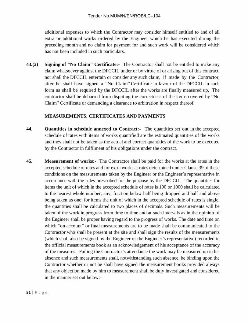
Tender No.MUM/N/EN/ROB/LC–104
51 | P a g e
additional expenses to which the Contractor may consider himself entitled to and of all extra or additional works ordered by the Engineer which he has executed during the preceding month and no claim for payment for and such work will be considered which has not been included in such particulars.
43.(2) Signing of “No Claim” Certificate:- The Contractor shall not be entitled to make any
claim whatsoever against the DFCCIL under or by virtue of or arising out of this contract, nor shall the DFCCIL entertain or consider any such claim, if made by the Contractor, after he shall have signed a “No Claim” Certificate in favour of the DFCCIL in such form as shall be required by the DFCCIL after the works are finally measured up. The contractor shall be debarred from disputing the correctness of the items covered by “No Claim” Certificate or demanding a clearance to arbitration in respect thereof.
MEASUREMENTS, CERTIFICATES AND PAYMENTS
44. Quantities in schedule annexed to Contract:- The quantities set out in the accepted
schedule of rates with items of works quantified are the estimated quantities of the works and they shall not be taken as the actual and correct quantities of the work to be executed by the Contractor in fulfilment of his obligations under the contract.
45. Measurement of works:- The Contractor shall be paid for the works at the rates in the
accepted schedule of rates and for extra works at rates determined under Clause 39 of these conditions on the measurements taken by the Engineer or the Engineer’s representative in accordance with the rules prescribed for the purpose by the DFCCIL. The quantities for items the unit of which in the accepted schedule of rates is 100 or 1000 shall be calculated to the nearest whole number, any; fraction below half being dropped and half and above being taken as one; for items the unit of which in the accepted schedule of rates is single, the quantities shall be calculated to two places of decimals. Such measurements will be taken of the work in progress from time to time and at such intervals as in the opinion of the Engineer shall be proper having regard to the progress of works. The date and time on which “on account” or final measurements are to be made shall be communicated to the Contractor who shall be present at the site and shall sign the results of the measurements (which shall also be signed by the Engineer or the Engineer’s representative) recorded in the official measurements book as an acknowledgement of his acceptance of the accuracy of the measures. Failing the Contractor’s attendance the work may be measured up in his absence and such measurements shall, notwithstanding such absence, be binding upon the Contractor whether or not he shall have signed the measurement books provided always that any objection made by him to measurement shall be duly investigated and considered in the manner set out below:-

Tender No.MUM/N/EN/ROB/LC–104
52 | P a g e
(a) It shall be open to the Contractor to take specific objection to any recorded measurements or Classification on any ground within seven days of the date of such measurements. Any re-measurement taken by the engineer or the Engineer’s representative in the presence of the Contractor or in his absence after due notice has been given to him in consequence of objection made by the Contractor shall be final and binding on the Contractor and no claim whatsoever shall thereafter be entertained regarding the accuracy and classification of the measurements.
(b) If an objection raised by the Contractor is found by the Engineer to be incorrect
the Contractor shall be liable to pay the actual expenses incurred in measurements. 46.(1) “On-Account” Payments:- The Contractor shall be entitled to be paid from time to time
by way of “One-Account” payment only for such works as in the opinion of the Engineer he has executed in terms of the contract.
All payments due on the Engineer’s or the Engineer’s representative’s certificates of
measurements shall be subject to any deductions which may be made under these presents and shall further be subject to, unless otherwise required by Clause 16 of these conditions, a retention of ten percent by way of security deposits, until the amount of security deposit by way of retained earnest money and such retentions shall amount to 10% of the total value of the contract provided always that the Engineer may by any certificate make any correction or modification in any previous certificate which shall have been issued by him and that the Engineer may withhold any certificate if the works or any part thereof are not being carried out to his satisfaction.
46.(2) Rounding off amounts: - The total amount due on each certificate shall be rounded off
to the nearest rupee i.e. sum less than 50 paise shall be omitted and sums of 50 paise and more upto Re. 1/- will be reckoned as Re. 1/-
46.(3) On Account Payments not prejudicial to final settlement: - “On- Account”
payments made to the ‘Contractor shall be without prejudice to the final making up of the accounts (except where measurements are specifically noted in the Measurement Book as “Final Measurements” and as such have been signed by the Contractor) and shall in no respect be considered or used as evidence of any facts stated in or to be inferred from such accounts nor of any particular quantity of work having been executed nor of the manner of its execution being satisfactory.
46.(4) Manner of payment: - Unless otherwise specified payments to the Contractor
will be made by cheque but no cheque will be issued for and amount less than Rs. 100/-

Tender No.MUM/N/EN/ROB/LC–104
53 | P a g e
46A PRICE VARIATION CLAUSE: 46A.1 Applicability: Price variation clause shall be applicable for this contract and irrespective of
the contract completion period. Variation in quantities shall not be taken into account for applicability of PVC in the contract.
Materials supplied free of cost by DFCCIL to the contractors shall fall outside the purview
of price variation clause. If, in any case, accepted offer include some specific payment to be made to consultant or some materials supplied by DFCCIL free or at fixed rate, such payment shall be excluded from the gross value of the work for the purpose of payment /recovery of price variation.
46A.2 Base month: The base month for the 'Price Variation Clause' shall be taken as month of
opening of tender including extensions, if any, unless otherwise stated elsewhere. The quarter of applicability of PVC shall commence from the month following the month of opening of tender. The price variation shall be based on the average price Index of the quarter under consideration.
46A.3 Validity : Rates accepted by DFCCIL shall hold good till completion of work and no
additional claim shall be admissible on account of fluctuations in market rates increase in taxes / any other levies / tolls etc. except that payment recovery for overall market situation shall be made as per Price variation clause given hereunder.
46A.4 Adjustment for variation in prices of material, labour, fuel, explosives detonators, steel,
concreting, ferrous, nonferrous, insulator, zinc and cement shall be determined in the manner prescribed hereunder.
46A.5 Components of various items in a contract on which variation in prices be admissible shall
be material, labour, fuel, explosives detonators, steel, cement and lime, concreting, ferrous, nonferrous, insulator, zinc, erection, etc. However, for fixed component, no price variation shall be admissible.
46A.6 The percentages of labour, material, fuel, component etc. in various types of Engineering
Works shall be as under: Component % age Component % age
(A) Earthwork contracts N.A Labour component - Other material components - Fuel component - Fixed component * - (B) Ballast and Quarry N.A

Tender No.MUM/N/EN/ROB/LC–104
54 | P a g e
products Contracts Labour component - Other material components - Fuel component - Fixed component* - (C) Tunneling Contracts N.A Labour component Detonator Component - Fuel component - Other material components - Explosive Component - Fixed component* - (D) Other work Contracts** Labour component 30% Fuel component 15% Material component 40% Fixed component* 15%
* It shall not be considered for any price variation ** Category of PVC applicable for Schedule A , B , D, E & F (Except for item of cement supply)
46A.7 Formulae: The amount of variation in prices (increase / decrease) in the several components (labour, material etc.) shall be worked out by the following formulae:
(i) L = W x (LQ - LB) x Lc
LB 100
(ii) M = W x (MQ - MB) x M C MB 100
(iii) F = W x (FQ - FB) x Fc FB 100
(iv) S = SW x (SQ - SB) SB
Applicable for Schedule C. No other PVC shall be paid on Schedule C
(v) C = CV x (CQ - CB) CB
Applicable if Cement supply is paid under separate item (In this tender cement is not paid under separate item).

Tender No.MUM/N/EN/ROB/LC–104
55 | P a g e
L Amount of price variation in Labour.
M Amount of price variation in Materials.
F Amount of price variation in Fuel.
S Amount of price variation in Reinforcement Steel.
C Amount of price variation in Cement.
W Gross value of the work done by the contractor as per on account bill(s), excluding cost of materials supplied by DFCCIL at fixed price, minus the price values of cement and steel. This will also exclude specific payment, if any, to be made to the consultants engaged by contractors (such payment shall be indicated in the contractor's offer)
LB Consumer price index number for industrial workers- All India- published in RBI
bulletin for the base period.
LQ Consumer Price Index Number fo r industrial workers -All India- Published in RBI bulletin for the average Price Index of the three months of the quarter under consideration.
MB Index Number of wholesale prices – By groups and sub groups-All commodities-As
published in the RBI Bulletin for the base period
MQ Index Number of wholesale prices – By Groups and sub Groups-All commodities as published in the RBI Bulletin for the average Price Index of the three months of the quarter under consideration.
FB Index Number of wholesale prices – By Groups and sub Groups for fuel, power,
light and lubricants as published in the RBI Bulletin for the base period
FQ Index Number of wholesale prices – By Groups and sub Groups for fuel and power as published in the RBI Bulletin for the average Price Index of the three months of the quarter under consideration.
S Amount of Price Variation in Reinforcement Steel
SW Gross value of the Reinforcement Steel supplied by the contractor as per the ‘on account’ bill for the Month under consideration.

Tender No.MUM/N/EN/ROB/LC–104
56 | P a g e
SQ The index Number of commodities ‘MS Bright Bars of group item (d) Mild Steel-
Long Products under (N) MANUFACTURE OF BASIC METAL’ of Wholesale
Price Index published by Office of Economic Adviser, Govt. of India, Ministry of Commerce & Industry Department of Industrial Policy & Promotion (DIPP) in the month on the day 28 days prior to the last day of the period to which a particular RA Bill is related. (Ref: CO letter No. HQ/EN/ED/WDFC/PVCSteel-ROB/2019 dated 12-03-2019)
SB The index Number of commodities ‘MS Bright Bars of group item (d) Mild Steel-Long
Products under (N) MANUFACTURE OF BASIC METAL’ of Wholesale Price
Index published by Office of Economic Adviser, Govt. of India, Ministry of Commerce & Industry Department of Industrial Policy & Promotion (DIPP) in the month on the day 28 days prior to the closing date of submission of Bids. (Ref: CO letter No. HQ/EN/ED/WDFC/PVCSteel-ROB/2019 dated 12-03-2019)
CV Value of cement supplied by contractor as per on account bill in the quarter
under consideration.
CB Index Number of wholesale prices of sub Group (of cement & lime) as published in the RBI Bulletin for the base period.
CQ Index Number of wholesale prices of sub Group (of cement & lime) as published
in the RBI Bulletin for the average price index of three months of quarter under consideration.
LC % of labour component
MC % of Material component
FC % of Fuel component
46A.8 The demands for escalation of cost shall be allowed on the basis of provisional indices made
available by Reserve Bank of India. Any adjustment needed to be done based on the finally published indices shall be made as and when they become available.
Special Note
(1) It is clearly indicated that price variation implies both increase as well decrease in input
prices and therefore price variation during the currency of the contract may result in extra

Tender No.MUM/N/EN/ROB/LC–104
57 | P a g e
payment or recovery as the case may be. (2) The Index Number for the base period will be the Index Number as obtained for the
month of opening of the tender and the quarter will commence from the month following the month of opening of tender. If the rates quoted in negotiated tenders are accepted, the base month for PVC will be month in which Negotiations are held.
(3) General Conditions of Contract shall be applicable in context of Price variation. However,
decision of Engineer shall be final & finding, in case of any conflict. 46A.10 Price Variation During Extended Period of Contract
The price adjustment as worked out above, i.e. either increase or decrease shall be applicable up to the stipulated date of completion of work including the extended period of completion where such extension has been granted under Clause 17-A of the General Conditions of Contract. However, where extension of time has been granted due to contractor’s failure
under Clause 17-B of the General Conditions of Contract, price adjustment shall be done as follows:
(a) In case the indices increase above the indices applicable to the last month of original
completion period or the extended period under Clause 17-A, the price adjustment for the period of extension granted under Clause 17-B shall be limited to the amount payable as per the Indices applicable to the last month of the original completion period or the extended period under Clause 17-A of the General Conditions of Contract; as the case may be.
(b) In case the indices fall below the indices applicable to the last month of original/extended
period of completion under Clause 17-A, as the case may be; then the lower indices shall be adopted for the price adjustment for the period of extension under Clause 17-B of the General Conditions of Contract.
47.0 Maintenance of works:- The Contractor shall at all times during the progress and
continuance of the works and also for the period of maintenance specified in the Tender Form after the date of passing of the certificate of completion by the Engineer or any other earlier date subsequent to the completion of the works that may be fixed by the Engineer be responsible for and effectively maintain and uphold in good substantial, sound and perfect condition all and every part of the works and shall make good from time to time and at all times as often as the Engineer shall require, any damage or defect that may during the above period arise in or be discovered or be in any way connected with the works, provided that such damage or defect is not directly caused by errors in the contract

Tender No.MUM/N/EN/ROB/LC–104
58 | P a g e
documents, act of providence or insurrection or civil riot, and the contractor shall be liable for and shall pay and make good to the DFCCIL or other persons legally entitled thereto whenever required by the Engineer so to do, all losses, damages, costs and expenses they or any of them may incur or be put or be liable to by reasons or in consequence of the operations of the Contractor or of his failure in any respect.
48.(1) Certificate of completion of works:- As soon as in the opinion of the Engineer, the
works has been completed and has satisfactorily passed any final test or tests that may be prescribed, the Engineer shall issue a certificate of completion duly indicating the date of completion in respect, of the work and the period of maintenance of the work shall commence from the date of completion mentioned in such certificate. The Engineer may also issue such a certificate indicating date of completion with respect to any part of the work (before the completion of the whole of work), which has been both completed to the satisfaction of the Engineer and occupied or used by the DFCCIL. When any such certificate is given in respect of part of a work, such part shall be considered as completed and the period of maintenance of such part shall commence from the date of completion mentioned in the completion certificate issued for that part of the work.
48.(2) Contractor not absolved by completion Certificate:- The Certificate of completion in
respect of the works referred to in sub-clause (1) of this clause shall not absolve the Contractor from his liability to make good any defects imperfections, shrinkages or faults which may appear during the period of maintenance specified in the tender arising in the opinion of the Engineer from materials or workmanship not in accordance with the drawings or specifications or instruction of the Engineer, which defects, imperfections, shrinkages or faults shall upon the direction in writing of the Engineer be amended and made good by the Contractor at his own cost: and in case of default on the part of Contractor the Engineer may employ labour and materials or appoint another Contractor to amend and make good such defects, imperfections, shrinkages and faults and all expenses consequent thereon and incidental thereto shall be borne by the Contractor and shall be recoverable from any moneys due to him under the contract.
49.0 Approval only by maintenance Certificate:- No certificate other than maintenance
certificate referred to in Clause 50 of the conditions shall be deemed to constitute approval of any work or other matter in respect of which it is issued or shall be taken as an admission of the due performance of the contract or any part thereof or of the accuracy of any claim or demand made by the Contractor or of additional varied work having been ordered by the Engineer nor shall any other certificate conclude or prejudice any of the powers of the Engineer.
50.(1) Maintenance Certificate:- The Contract shall not be considered as completed until a

Tender No.MUM/N/EN/ROB/LC–104
59 | P a g e
Maintenance Certificate shall have been signed by the Engineer stating that the works have been completed and maintained to his satisfaction. The Maintenance Certificate shall be given by the Engineer upon the expiration of the period of maintenance or as soon thereafter as any works ordered during such period pursuant to sub clause (2) Clause 48 of these conditions shall have been completed to the satisfaction of the Engineer and full effect shall be given to this Clause notwithstanding the taking possession of or using the works or any part thereof by the DFCCIL.
50.(2) Cessation of DFCCIL Liability: - The DFCCIL shall not be liable to the Contractor for
any matter arising out of or in connection with the contract of the execution of the works unless the contractor shall have made a claim in writing in respect thereof before the issue of the Maintenance Certificate under this clause.
50.(3) Unfulfilled Obligations:- Notwithstanding the issue of the Maintenance certificate the
Contractor and (subject to sub-clause 2 of this clause) the DFCCIL shall remain liable for the fulfilment of any obligation incurred under the provision of the contract prior to the issue of the maintenance Certificate which remains unperformed at the time such certificate is issued and for the purposes of determining the nature and extent of any such obligations the contract shall be deemed to remain in force between the parties thereto.
51.(1) Final Payment:- On the Engineer’s certificate of completion in respect of the works,
adjustment shall be made and the balance of account based on the Engineer or the Engineer’s representative’s certified measurements of the total quantity of work executed by the contractor upto the date of completion and on the accepted schedule or rates and for extra works on rates determined under Clause 39 of these conditions shall be paid to the Contractor subject always to any deduction which may be made under these presents and further subject to the Contactor having delivered to the Engineer either a full account in detail of all claims he may have on the DFCCIL in respect of the works or having delivered “No Claim Certificate" and the Engineer having after the receipt of such account given a certificate in writing that such claims are correct, that the whole of the works to be done under the provisions of the Contracts have been completed, that they have been inspected by him since their completion and found to be in good and substantial order, that all properties, works and things, removed, disturbed or injured in consequence of the woks have been properly replaced and made good and all expenses and demands incurred by or made upon the DFCCIL for or in the respect of damage or loss by from or in consequence of the works, have been satisfied agreeably and in conformity with the contract.
51.(2) Post Payment Audit:- It is an agreed term of contract that the DFCCIL reserves to itself

Tender No.MUM/N/EN/ROB/LC–104
60 | P a g e
the right to carry out a post-payment audit and or technical examination of the works and the final bill including all supporting vouchers, abstracts etc. and to make a claim on the contractor for the refund any excess amount paid to him if as a result of such examination any over-payment to him is discovered to have made in respect of any works done or alleged to have been done by him under the contract.
51A. Production of vouchers etc. by the Contractor:- (i) For a contract of more than one crore of rupees, the contractor shall, whenever required,
produce or cause to be produced for examination by the Engineer any quotation, invoice, cost or other account, book of accounts, voucher, receipt, letter, memorandum, paper of writing or any copy of or extract from any such document and also furnish information and returns verified in such manner as may be required in any way relating to the execution of this contract or relevant for verifying or ascertaining cost of execution of this contract (the decision of the engineer on the question of relevancy of any documents, information or return being final and binding in the parties).The contractor shall similarly produce vouchers; etc., if required to prove to the Engineer, that materials supplied by him, are in accordance with the specifications laid down in the contract.
(ii) If any portion of the work in a contract of value more than one crore of rupees be carried
out by a sub-contractor or any subsidiary or allied firm or company (as per Clause 7 of the General Conditions of Contract),the Engineer shall have power to secure the books of such sub-contract or any subsidiary or allied firm or company, through the contractor, and such books shall be open to his inspection.
(iii) The obligations imposed by sub clause (i) & (ii) above is without prejudice to the
obligations of the contractor under any statute rules or orders binding on the contractor. 52.0 Withholding and lien in respect of sums claimed:- Whenever any claim or claims for
payment of a sum of money arises out of or under the contract against the contractor, the DFCCIL shall be entitled to withhold and also have a lien to retain such sum or sums in whole or in part from the security, if any, deposited by the contractor and for the purpose aforesaid, the DFCCIL shall be entitled to withhold the said cash security deposit or the security if any, furnished as the case may be and also have a lien over the same pending finalization or adjudication of any such claim. In the event of the security being insufficient to cover the claimed amount or amounts or if no security has been taken from the contractor, the DFCCIL shall be entitled to withhold and have a lien to the extent of the such claimed amount or amounts referred to supra, from any sum or sums found payable or which at any time thereafter may become payable to the contractor under the same contract or any other contract with this or any other DFCCIL or any Department of

Tender No.MUM/N/EN/ROB/LC–104
61 | P a g e
the Central Government pending finalization or adjudication of any such claim.
It is an agreed term of the contract that the sum of money or moneys so withheld or retained under the lien referred to above, by the DFCCIL will be kept withheld or retained as such by the DFCCIL till the claim arising out of or under the contract is determined by the arbitrator (if the contract governed by the arbitration clause) or by the competent court as the case may be and that the contractor will have no claim for interest or damages whatsoever on any account in respect of such withholding or retention under the lien referred to supra and duly notified as such to the contractor. For the purpose of this clause, where the contractor is a partnership firm or a limited company, the DFCCIL shall be entitled to withhold and also have a lien to retain towards such claimed amount or amounts in whole or in part from any sum found payable to any partner/limited company, as the case may be whether in his individual capacity or otherwise.
52A. Lien in respect of claims in Other Contracts:-
(i) Any sum of money due and payable to the contractor (including the security deposit returnable to him) under the contract may be withheld or retained by way of lien by the DFCCIL, against any claim of this or any other DFCCIL or any other Department of the Central Government in respect of a payment of a sum of money arising out of or under any other contract made by the contractor with this or any other Department of the Central Government.
(ii) However, recovery of claims of DFCCIL in regard to terminated contracts may be made
from the Final Bills, Security Deposits and Performance Guarantees of other contract or contracts, executed by the contractor. The Performance Guarantees submitted by the Contractor against other contracts, if required, may be withheld and encashed. In addition, 10% of each subsequent ‘on-account bill’ may be withheld, if required, for recovery of
DFCCIL’s dues against the terminated contract.
(iii) It is an agreed term of the contract that the sum of money so withheld or retained under this clause by the DFCCIL will be kept withheld or retained as such by the DFCCIL till the claim arising out of or under any other contract is either mutually settled or determined by arbitration, if the other contract is governed by arbitration clause or by the competent court as the case may be and contractor shall have no claim for interest or damages whatsoever on this account or on any other ground in respect of any sum of money withheld or retained under this clause and duly notified as such to the contractor.
53.0 Signature on Receipts for Amounts:- Every receipt for money which may become
payable or for any security which may become transferable to the Contractors under these presents, shall, if signed in the partnership name by anyone of the partners of a Contractor’s

Tender No.MUM/N/EN/ROB/LC–104
62 | P a g e
firm be a good and sufficient discharge to the DFCCIL in respect of the moneys or security purported to be acknowledged thereby and in the event of death of any of the Contractor, partners during the pendency of the contract it is hereby expressly agreed that every receipt by anyone of the surviving Contractor partners shall if so signed as aforesaid be good a sufficient discharge as aforesaid provided that nothing in this clause contained shall be deemed to prejudice or effect any claim which the DFCCIL may hereafter have against the legal representative of any contractor partner so dying for or in respect to any breach of any of the conditions of the contract, provided also that nothing in this clause contained shall be deemed to prejudice or effect the respective rights or obligations of the Contractor partners and of the legal representatives of any deceased Contractor partners interest.
LABOUR
54.0 Wages to Labour:- The Contractor shall be responsible to ensure compliance with the provision of the Minimum Wages Act, 1948 (hereinafter referred to as the “said Act” and the Rules made there under in respect of any employees directly or through petty contractors or subcontractors employed by him on road construction or in building operations or in stone breaking or stone crushing for the purpose of carrying out this contract.
If, in compliance with the terms of the contract, the Contractor supplied any labour to be used wholly or partly under the direct orders and control of the DFCCIL whether in connection with any work being executed by the Contractor or otherwise for the purpose of the DFCCIL such labour shall, for the purpose of this clause, still be deemed to be persons employed by the Contractor.
If any moneys shall, as a result of any claim or application made under the said Act be directed to be paid by the DFCCIL, such money shall be deemed to be moneys paid by it as aforesaid within seven days after the same shall have been demanded, the DFCCIL shall be entitled to recover the same form any moneys due or accruing to the Contractor under this or any other Contract with the DFCCIL.
54A. Apprentices Act:- The Contractor shall be responsible to ensure compliance with
the provisions of the Apprentices Act, 1961 and the Rules and Orders issued there under from time to time in respect of apprentices directly or through petty contractors or sub-contractors employed by him for the purpose of carrying out the Contract.
If the contractor directly or through petty contractors or sub-contractors fails to do so, his failure will be a breach of the contract and the DFCCIL may, in its discretion, rescind the contract. The contractor shall also be liable for any pecuniary liability arising on account of any violation of the provisions of the Act.

Tender No.MUM/N/EN/ROB/LC–104
63 | P a g e
Note: The contractors are required to engage apprentices when the works undertaken by them last for a period of one year or more and / the cost of works is rupees one lakh or more.
55.0 Provisions of payments of Wages Act: - The Contractor shall comply with the provisions
of the Payment of Wages Act, 1936 and the rules made there under in respect of all employees directly or through petty contractors or sub-contractors employed by him in the works. If In compliance with the terms of the contract, the Contractor directly or through petty contractors of sub-contractors shall supply any labour to be used wholly or partly under the direct orders and control of the Engineer whether in connection with the works to be executed hereunder or otherwise for the purpose of the Engineer such labour shall never the less be deemed to comprise persons employed by the contractor and any moneys which may be ordered to be paid by the Engineer shall be deemed to be moneys payable by the Engineer on behalf of the Contractor and the Engineer may on failure of the contractor to repay such money to the DFCCIL deduct the same from moneys due to contractor in the terms of contract. The DFCCIL shall be entitled to deduct from any moneys due to the contractor (whether under this contract or any other contract) all moneys paid or payable by the DFCCIL by the way of compensation of aforesaid or for costs of expenses in connection with any claim thereto and the decision of the Engineer upon any question arising out of the effect or force of this clause shall be final and binding upon the Contractor.
55A. Provisions of Contract labour (Regulation and Abolition) Act, 1970:
55A.(1) The contractor shall comply with the provision of the contract labour (Regulation and
Abolition) Act, 1970 and the Contract labour (Regulation and Abolition) Central Rules 1971 as modified from time to time, wherever applicable and shall also indemnify the DFCCIL from and against any claims under the aforesaid Act and the Rules.
55A.(2) The Contractor shall obtain a valid licence under the aforesaid Act as modified from
time to time before the commencement of the work and continue to have a valid licence until the completion of the work. Any failure to fulfil the requirement shall attract the penal provision of the Contract arising out of the resultant non-execution of the work.
55A.(3) The Contractor shall pay to the labour employed by him directly or through
subcontractors the wages as per provision of the aforesaid Act and the Rules wherever applicable. The Contractor shall notwithstanding the provisions of the contract to the contrary, cause to be paid the wages to labour indirectly engaged on the works including any engaged by subcontractors in connection with the said work, as if the labour had been

Tender No.MUM/N/EN/ROB/LC–104
64 | P a g e
immediately employed by him.
55A.(4) In respect of all labour directly or indirectly employed in the work for performance of the contractor’s part of, the contract, the Contractor shall comply with or cause to be complied with the provisions of the aforesaid Act and Rules wherever applicable.
55A.(5) In every case in which, by virtue of the provisions of the aforesaid Act or the Rules, the
DFCCIL is obliged to pay any amount of wages to a workman employed by the Contractor or his sub-contractor in execution of the work or to incur any expenditure on account of the Contingent, liability of the DFCCIL due to the contractor’s failure to fulfil his statutory obligations under the aforesaid Act or the rules the DFCCIL will recover from the Contractor, the amount of wages so paid or the amount of expenditure so incurred, and without prejudice to the rights of the DFCCIL under the section 20, sub-section (2) and section 2, sub-section (4) of the aforesaid Act, the DFCCIL shall be at liberty to recover such amount or part thereof by deducting it from the security deposit and/ or from any sum due by the DFCCIL to the contractor whether under the contract or otherwise. The DFCCIL shall not be bound to contest any claim made against it under sub-section (1) of section 20 and sub-section (4) of section 21 of the aforesaid Act except on the written request of the contractor and upon his giving to the DFCCIL full security for all costs for which the DFCCIL might become liable in contesting such claim. The decision of the DFCCIL regarding the amount actually recoverable from the contractor as stated above shall be final and binding on the Contractor.
55B. Provisions of Employees Provident Fund and Miscellaneous Provisions Act, 1952:
The Contractor shall comply with the provisions of Para 30 & 36-B of the Employees Provident Fund Scheme, 1952; Para 3 & 4 of Employees’ Pension Scheme, 1995; and Para 7 & 8 of Employees Deposit Linked Insurance Scheme, 1976; as modified from time to time through enactment of ”Employees Provident Fund & Miscellaneous Provisions
Act, 1952”, wherever applicable and shall also indemnify the DFCCIL from and against any claims under the aforesaid Act and the Rules.
55C. Provisions of “The Building and Other Construction Workers (Regulation of
Employment and Conditions of Service) Act, 1996” and “The Building and Other
Construction Workers’ Welfare Cess Act, 1996” : The tenderers, for carrying out any construction work, must get themselves registered with the Registering Officer under Section-7 of the Building and Other Construction Workers Act, 1996 and rules made thereto by the concerned State Govt. and submit certificate of Registration, issued from the Registering Officer of the concerned State Govt. (Labour Dept.). As per this Act, the tenderer shall be levied a cess @1% of cost of construction work, which would be deducted

Tender No.MUM/N/EN/ROB/LC–104
65 | P a g e
from each bill. Cost of material, when supplied under a separate schedule item, shall be outside the purview of cess.
55D. A) Contractor is to abide by the provision of Payment of wages act & Minimum wages act in terms of clause 54 and 55 of Indian Railways General Condition of contract. In order to ensure the same, an application has been developed and hosted on website ‘www.shramikkalyan.indianrailways.gov.in’. Contractor shall register his firm/company etc. and upload requisite details of labour and their payment in this portal. These details shall be available in public domain. The Registration/Updation of portal shall be done as under:
a) Contractor shall apply for one time registration of his company/firm etc. in the Shramikkalyan portal with requisite details subsequent to issue of Letter of Acceptance. Engineer shall approve the contractor’s registration on the portal
within 7 days of receipt of such request. b) Contractor once approved by any Engineer, can create password with login
ID(Pan No.) for subsequent use of portal for all LOAs issued in his favour. c) The contractor once registered on the portal, shall provide details of this letter
of Acceptance (LOA)/ Contract Agreements on shramikkalyan portal within 15 days of issue of any LOA for approval of concerned engineer. Engineer shall update (if required) and approve the details of LOA filled by contractor within 7 days of receipt of such request.
d) After approval of LOA by Engineer, contractor shall fill the salient details of contract labours engaged in the contract and ensure updating of each wage payment to them on shramikkalyan portal on monthly basis.
e) It shall be mandatory upon the contractor to ensure correct and prompt uploading of all salient details of engaged contractual labour & Payments made thereof after each wage period.
B) While processing payment of any ‘On account bill’ or ‘Final bill’ or release of
‘Advances’ or ‘Performance guarantee/Security deposit’, contractor shall submit a
certificate to the Engineer or Engineer’s representative that “ I have uploaded the correct
details of contract labours engaged in connection with this contract and payments made
to them during the wage period in Railway’s Shramikkalyan portal at
www.shramikkalyan.indianrailways.gov.in’ till …………..Month…………..Year.”
56.0 Reporting of Accidents of Labour:- The Contractor shall be responsible for the safety of all employees directly or through petty contractors or sub- contractor employed by him on the works and shall report serious accidents to any of them however and wherever occurring on the works to the Engineer or the Engineers Representative and shall made every arrangements to render all possible assistance.
57.0 Provision of Workmen’s Compensation Act:- In every case in which by virtue of the
provisions of section 12 sub-section (1) of the Workmen’s Compensation Act 1923, DFCCIL is obliged to pay compensation to a workman directly or through petty contractor

Tender No.MUM/N/EN/ROB/LC–104
66 | P a g e
or subcontractor employed by the Contractor in executing the work, DFCCIL will recover from the Contractor the amount of the compensation so paid, and, without prejudice to the rights of DFCCIL under Section 12 Sub-section (2) of the said Act, DFCCIL shall be at liberty to recover such amount or any part thereof by deducting it from the security deposit or from any sum due by DFCCIL to the Contractor whether under these conditions or otherwise, DFCCIL shall not be bound to contest any claim made against it under Section 12 Sub-section (1) of the said Act except on the written request of the Contractor and upon his giving to DFCCIL full security for all costs for which DFCCIL might become liable in consequence of contesting such claim.
57A. Provision of Mines Act:- The contractor shall observe and perform all the provisions of
the Mines Act, 1952 or any statutory modifications or re-enactment thereof for the time being in force and any rules and regulations made there under in respect of all the persons directly or through the petty contractors or sub-contractors employed by him under this contract and shall indemnify the DFCCIL from and against any claims under the Mines Act, or the rules and regulations framed there under, by or on behalf of any persons employed by him or otherwise.
58.0 DFCCIL not to provide quarters for Contractors:- No quarters shall normally be
provided by the DFCCIL for the accommodation of the contractor or any of his staff employed on the work.
59.(1) Labour Camps:- The contractor shall at his own expense make adequate arrangements
for the housing, supply of drinking water and provision of latrines and urinals for his staff and workmen, directly or through the petty contractors or sub-contractors and for temporary crèche (Bal-mandir) where 50 or more women are employed at a time. Suitable sites on DFCCIL land, if available, may be allotted to the contractor for the erection of labour camps, either free of charge or on such terms and conditions that may be prescribed by the DFCCIL. All camp sites shall be maintained in clean and sanitary conditions by the contractor at his own cost.
59.(2) Compliance to rules for employment of labour:- The contractor(s) shall conform to all
laws, by-laws rules and regulations for the time being in force pertaining to the employment of local or imported labour and shall take all necessary precautions to ensure and preserve the health and safety of all staff employed directly or through petty contractors or sub-contractors on the works.
59.(3) Preservation of peace:- The contractor shall take requisite precautions and use his best
endeavours to prevent any riotous or unlawful behaviour by or amongst his workmen and

Tender No.MUM/N/EN/ROB/LC–104
67 | P a g e
other employed directly or through the petty contractors or sub-contractors on the works and for the preservation of peace and protection of the inhabitants and security of property in the neighbourhood of the works. In the event of the DFCCIL requiring the maintenance of a special Police Force at or in the vicinity of the site during the tenure of works, the expenses thereof shall be borne by the contractor and if paid by the DFCCIL shall be recoverable from the contractor.
59.(4) Sanitary arrangements:- The contractor shall obey all sanitary rules and carry out all
sanitary measures that may from time to time be prescribed by the Railway Medical Authority and permit inspection of all sanitary arrangements at all times by the Engineer, the Engineer’s Representative of the Medical staff of the DFCCIL. Should the contractor fail to make the adequate sanitary arrangements, these will be provided by the DFCCIL and the cost therefore recovered from the contractor.
59.(5) Outbreak of infectious disease:- The contractor shall remove from his camp such labour
and their families as refuse protective inoculation and vaccination when called upon to do so by the Engineer or the Engineer’s representative on the advice of the DFCCIL. Should cholera, plague or other infectious disease break out, the contractor shall burn the huts, beddings, clothes and other belongings of or used by the infected parties and promptly erect new huts on health sites as required by the engineer, failing which within the time specified in the Engineer’s requisition, the work may be done by the DFCCIL and the cost therefore recovered from the contractor.
59.(6) Deleted 59.(7) Medical facilities at site: - The Contractor shall provide medical facilities at the site as
may be prescribed by the Engineer on the advice of the DFCCIL in relation to the strength of the Contractor’s resident staff and workmen.
59.(8) Use of intoxicants: - The sale of ardent spirits or other intoxicating beverages
upon the work or in any of the buildings, encampments or tenements owned, occupied by or within the control of the contractor or any of his employees shall be forbidden and the Contractor shall exercise his influence and authority to the utmost extent to secure strict compliance with this condition.
59.(9) Non-employment of female labour: - The Contactor shall see that the employment
of female labour on / in Cantonment areas, particularly in the neighbourhood of soldier’s barracks, should be avoided as far as possible.

Tender No.MUM/N/EN/ROB/LC–104
68 | P a g e
59.(10) Restrictions On The Employment Of Retired Engineers Of Railway/DFCCIL Services Within one Year Of Their Retirement : The Contractor shall not, if he is a retired Government Engineer of Gazetted rank, himself engage in or employ or associate a retired Government Engineer of Gazetted rank, who has not completed one year from the date of retirement, in connection with this contract in any manner whatsoever without obtaining prior permission of the President and if the Contractor is found to have contravened this provision it will constitute a breach of contract and administration will be entitled to terminate the contract and forfeit Earnest Money Deposits (EMD),Performance Guarantee (PG)and Security Deposits (SD) of that contract.
60.(1) Non-employment of labours below the age of 15:- the Contractor shall not employ children
below the age of 15 as labourers directly or through petty contractors or subcontractors for the execution of work.
60.(2) Medical Certificate of fitness for labour: - It is agreed that the contractor shall not
employ a person above 15 and below 19 years of age for the purpose of execution of work under the contract unless a medical certificate of fitness in the prescribed form (Proforma at Form No.15) granted to him by a certifying surgeon certifying that he is fit to work as an adult is obtained and kept in the custody of the contractor or a person nominated by him in this behalf and the person carries with him, while at work; a token giving a reference to such certificate. It is further agreed that the responsibility for having the adolescent examined medically at the time of appointment or periodically till he attains the age of 19 years shall devolve entirely on the contractor and all the expenses to be incurred on this account shall be borne by him and no fee shall be charged from the adolescent or his parent for such medical examination.
60.(3) Period of validity of medical fitness certificate:- A certificate of fitness granted or
renewed for the above said purposes shall be valid only for a period of one year at a time. The certifying surgeon shall revoke a certificate granted or renewed if in his opinion the holder of it is, no longer fit for work in the capacity stated therein. Where a certifying surgeon refuses to grant or renew a certificate or revoke a certificate, he shall, if so required by the person concerned, state his reasons in writing for doing so.
60.(4) Medical re-examination of labourer:- Where any official appointed in this behalf by
the Ministry of labour is of the opinion that any person employed in connection with the execution of any work under this contract in the age group 15 to 19 years is without a certificate of fitness or is having a certificate of fitness but no longer fit to work in the capacity stated in the certificate, he may serve on the Contractor, or on the person nominated by him in the regard, a notice requiring that such persons shall be examined by a certifying surgeon and such person shall not if the concerned official so directs, be

Tender No.MUM/N/EN/ROB/LC–104
69 | P a g e
employed or permitted to do any work under this contract unless he has been medically examined and certified that he has been granted a certificate of fitness or a fresh certificate of fitness, as the case may be.
EXPLANATIONS:
- (1) Only qualified medical practitioners can be appointed as “Certifying Surgeons”
and the term “Qualified Medical Practitioners” means a person holding a qualification granted by an authority specified in the Schedule to the Indian Medical Degrees Act, 1916 (VII to 1916) or in the Schedule to the Indian Medical Council Act, 1933 (XXVII) of 1933.
(2) The Certifying surgeon may be a medical officer in the service of State or
Municipal Corporation.
DETERMINATION OF CONTRACT 61.(1) Right of DFCCIL of determine the contract:- The DFCCIL shall be entitled to
determine and terminate the contract at any time should, in the DFCCIL’s opinion, the cessation of work becomes necessary owing to paucity of funds or from any other cause whatever, in which case the value of approved materials at site and of work done to date by the Contractor will be paid for in full at the rate specified in the contract. Notice in writing from the DFCCIL of such determination and the reasons therefore shall be conclusive evidence thereof.
61.(2) Payment on determination of contract:- Should the contract be determined under
sub clause (1) of this clause and the Contractor claims payment for expenditure incurred by him in the expectation of completing the whole of the work, the DFCCIL shall admit and consider such claims as are deemed reasonable and are supported by vouchers to the satisfaction of the Engineer. The DFCCIL’s decision on the necessity and propriety of such expenditure shall be final and conclusive.
61.(3) The contractor shall have no claim to any payment of compensation or otherwise,
howsoever on account of any profit or advantage which he might have derived from the execution of the work in full but which he did not derive in consequence of determination of contract.
62.(1) Determination of contract owing to default of contractor:- If the Contractor should:-
(i) Becomes bankrupt or insolvent, or

Tender No.MUM/N/EN/ROB/LC–104
70 | P a g e
(ii) Make an arrangement with of assignment in favour of his creditors, or agree to carry
out the contract under a Committee of Inspection of his creditors, or (iii) Being a Company or Corporation, go into liquidation (other than a voluntary
liquidation for the purposes of amalgamation or reconstruction), or (iv) Have an execution levied on his goods or property on the works, or (v) Assign the contract or any part thereof otherwise than as provided in
Clause 7 of these conditions, or (vi) Abandon the contract, or (vii) Persistently disregard the instructions of the Engineer, or contravene any provision
of the contract, or (viii) Fail to adhere to the agreed programme of work by a margin of 10% of the
stipulated period, or (ix) Fail to remove materials from the site or to pull down and replace work after
receiving from the Engineer notice to the effect that the said materials or works have been condemned or rejected under clause 25 and 27 of these conditions, or
(x) Fail to take steps to employ competent or additional staff and labour as required
under clause 26 of the conditions
(xi) Fail to afford the Engineer or Engineer’s representative proper facilities for inspecting the work or any part thereof as required under clause 28 of the conditions, or
(xii) Promise, offer or give any bribe, commission, gift or advantage either himself
or through his partner, agent or servant to any officer or employee of the DFCCIL or to any person on his or on their behalf in relation to the execution of this or any other contract with this DFCCIL.
(xiii)(A) At any time after the tender relating to the contract, has been signed and
submitted by the Contractor, being a partnership firm admit as one of its partners or employee under it or being an incorporated company elect or nominate or allow to act as one of its directors or employee under it in any capacity whatsoever any retired engineer of the gazetted rank or any other retired gazetted officer working before

Tender No.MUM/N/EN/ROB/LC–104
71 | P a g e
his retirement, whether in the executive or administrative capacity, or whether holding any pensionable post or not, in the DFCCIL for the time being owned and administered by the President of India before the expiry of one year from the date of retirement from the said service of such Engineer or Officer unless such Engineer or Officer has obtained permission from the President of India or any officer duly authorized by him in this behalf to become a partner or a director or to take employment under the contract as the case may be, or
(xiii) (B) Fail to give at the time of submitting the said tender :-
(a) The correct information as to the date of retirement of such retired engineer or retried officer from the said service, or as to whether any such retired engineer or retired officer was under the employment of the Contractor at the time of submitting the said tender, or
(b) The correct information as to such engineers or officers obtaining permission to take employment under the contractor, or
(c) Being a partnership firm, the correct information as to, whether any of its partners was such a retired engineer or a retired officer, or
(d) Being in incorporated company, correct information as to whether any of its directors was such a retired engineer or a retired officer, or
(e) Being such a retired engineer or retried officer suppress and not disclose at the time of submitting the said tender the fact of his being such a retired engineer or a retired officer or make at the time of submitting the said tender a wrong statement in relation to his obtaining permission to take the contract or if the contractor be a partnership firm or an incorporated company to be a partner or director of such firm or company as the case may be or to seek employment under the contractor.
Then and in any of the said clause, the Engineer on behalf of the DFCCIL may serve the Contractor with a notice (Pro-forma at Form No.16) in writing to that effect and if the contractor does not within seven days after the delivery to him of such notice proceed to make good his default in so far as the same is capable of being made good and carry on the work or comply with such directions as aforesaid of the entire satisfaction of the Engineer, the DFCCIL shall be entitled after giving 48 hours notice (Pro-forma at Form No. 17) in writing under the hand of the Engineer to rescind the contract as a whole or in part or parts (as may be specified in such notice) and after expiry of 48 hours notice, a final termination notice (Proforma at Form No. 18) should be issued and adopt the following courses:
To measure up or the whole or part of the work from which the contractor has been removed and get it completed by another contractor, the manner and method in which such work is completed shall be in the entire discretion of the Engineer whose decision shall be final.

Tender No.MUM/N/EN/ROB/LC–104
72 | P a g e
62.(2) Right of DFCCIL after, rescission of contract owing to default of contractor:
In the event of any or several of the courses, referred to in sub-clause (1) of the clause, being adopted.
(a) the contractor shall have no claim to compensation for any loss sustained by
him by reason of his having purchased or procured any materials or entered into any commitments or made any advances on account of or with a view to the execution of the works or the performance of the contract and contractor shall not be entitled to recover or be paid any sum for any work thereto for actually performed under the contract unless and until the Engineer shall have certified the performance of such work and the value payable in respect thereof and the contractor shall only be entitled to be paid the value so certified.
(b) The Engineer or the Engineer’s representative shall be entitled to take possession
of any materials, tools, implements, machinery and buildings on the works or on the property on which these are being or ought to have been executed, and to retain and employ the same in the further execution of the works or any part thereof until the completion of the works without the contractor being entitled to any compensation for the use and employment thereof or for wear and tear or destruction thereof.
(c) The Engineer shall as soon as may be practicable after removal of the contractor fix
and determine ex-parte or by or after reference to the parties or after such investigation or enquiries as he may consider fit to make or institute and shall certify what amount(if any) had at the time of rescission of the contract been reasonably earned by or would reasonably accrue to the contractor in respect of the work then actually done by him under the contract and what was the value of any unused, or partially used materials, any constructional plan and any temporary works upon the site. The legitimate amount due to the contractor after making necessary deductions and certified by the Engineer should be released expeditiously.
STATEMENT OF DISPUTES - INDIAN RAILWAY ARBITRATION RULES
63.0 Matters finally determined by the DFCCIL – All disputes and differences of any kind whatsoever arising out of or in connection with the contract, whether during the progress of the work or after its completion and whether before or after the determination of the contract, shall be referred by the contractor to the Director /General Manager/CGM, DFCCIL and the Director/General Manager/CGM, DFCCIL shall within 120 days after receipt of the contractor’s representation make and notify decisions on all matters referred to by the contractor in writing provided that matter for which provision has been made in

Tender No.MUM/N/EN/ROB/LC–104
73 | P a g e
clauses 8, 18, 22.(5), 39, 43.(2), 45.(a), 55, 55A.(5), 57, 57A, 61.(1), 61.(2) and 62.(1) to (xiii)(B) of General Conditions of contract or in any special clause of the conditions of the contract shall be deemed as ‘excepted matters’ (matters not arbitrable) and decisions of the DFCCIL authority, thereon shall be final and binding on the contractor; provided further that ‘excepted matters’ shall stand specifically excluded from the purview of the arbitration clause.
64. (1) Demand for Arbitration :- 64. (1) (i) In the event of any dispute or difference between the parties hereto as to the
construction or operation of this contract, or the respective rights and liabilities of the parties on any matter in question, dispute or difference on any account or as to the withholding by the DFCCIL of any certificate to which the contractor may claim to be entitled to, or if the DFCCIL fails to make a decision within 120 days, then and in any such case, but except in any of the ‘excepted matters’ referred to in clause 63 of these conditions, the contractor, after 120 days but within 180 days of his presenting his final claim on disputed matters shall demand in writing that the dispute or difference be referred to arbitration.
64.(1) (ii) The demand for arbitration shall specify the matters which are in question, or subject of
the dispute or difference as also the amount of claim item wise. Only such dispute or difference, in respect of which the demand has been made, together with counter claims or set off, given by the DFCCIL, shall be referred to arbitration and other matters shall not be included in the reference.
64.(1) (iii) (a) The arbitration proceedings shall be assumed to have commenced from the
day, a written and valid demand for arbitration is received by the DFCCIL.
(b) The claimant shall submit his claim stating the facts supporting the claims along with all the relevant documents and the relief or remedy sought against each claim within a period of 30 days from the date of appointment of the Arbitral Tribunal.
(c) The DFCCIL shall submit its defence statement and counter claim(s), if any, within a
period of 60 days of receipt of copy of claims from Tribunal thereafter, unless otherwise extension has been granted by Tribunal.
(d) The place of arbitration would be New Delhi/Mumbai. The decision of DFCCIL shall
be final and binding.
64.(1) (iv) No new claim shall be added during proceedings by either party. However, a party may amend or supplement the original claim or defence thereof during the course of

Tender No.MUM/N/EN/ROB/LC–104
74 | P a g e
arbitration proceedings subject to acceptance by Tribunal having due regard to the delay in making it.
64.(1) (v) – If the contractor(s) does/do not prefer his/their specific and final claims in writing,
within a period of 90 days of receiving the intimation from the DFCCIL that the final bill is ready for payment, he/they will be deemed to have waived his/their claim(s) and the DFCCIL shall be discharged and released of all liabilities under the contract in respect of these claims.
64.(2) Obligation During Pendency of Arbitration:– Work under the contract shall, unless
otherwise directed by the Engineer, continue during the arbitration proceedings, and no payment due or payable by the DFCCIL shall be withheld on account of such proceedings, provided, however, it shall be open for Arbitral Tribunal to consider and decide whether or not such work should continue during arbitration proceedings.
64.(3) Appointment of arbitrator 64.(3)(a)(i) In cases where the total value of all claims in question added together does not
exceed Rs.25,00,000 (Rupees twenty five lakhs only), the Arbitral tribunal shall consist of a sole arbitrator nominated by the MD/DFCCIL The sole arbitrator shall be appointed within 60 days from the day when a written and valid demand for arbitrator is received by MD/DFCCIL .
64.(3)(a)(ii) In cases not covered by the clause 64(3)(a)(i), the Arbitral Tribunal shall consist of a
Panel of three officials, as the arbitrators. For this purpose, the DFCCIL will send a panel of more than 3 names of DFCCIL officers wh ic h may also include the name(s) of Officer(s) empanelled to work as Arbitrator to the contractor within 60 days from the day when a written and valid demand for arbitration is received by the MD/DFCCIL. Contractor will be asked to suggest to MD/DFCCIL at least 2 names out of the panel for appointment as contractor’s nominee within 30 days from the date of dispatch of the request by DFCCIL. The MD/DFCCIL shall appoint at least one out of them as the contractor’s nominee and will, also simultaneously appoint the balance number of arbitrators either from the panel or from outside the panel, duly indicating the ‘presiding arbitrator’ from amongst the 3 arbitrators so appointed. MD/DFCCIL shall complete this exercise of appointing the Arbitral Tribunal within 30 days from the receipt of the names of contractor’s nominees. While nominating the arbitrators it will be necessary to ensure that one of them is from the Accounts department. An officer of selection grade of accounts department shall be considered of equal status to the officers in SA grade of other department of DFCCIL for the purpose of appointment of arbitrator.

Tender No.MUM/N/EN/ROB/LC–104
75 | P a g e
64. ( 3)(a)(iii) If one or more of the arbitrators appointed as above refuses to act as arbitrator, withdraws from his office as arbitrator, or vacates his/their office/offices or is/are unable or unwilling to perform his functions as arbitrator for any reason whatsoever or dies or in the opinion of the MD/DFCCIL fails to act without undue delay, the MD/DFCCIL shall appoint new arbitrator/arbitrators to act in his/their place in the same manner in which the earlier arbitrator/arbitrators had been appointed. Such re-constituted tribunal may, at its discretion, proceed with the reference from the stage at which it was left by the previous arbitrator(s).
64.(3) (a) (iv) The arbitral Tribunal shall have power to call for such evidence by way of affidavits
or otherwise as the arbitral Tribunal shall think proper, and it shall be the duty of the parties hereto to do or cause to be done all such things as may be necessary to enable the arbitral Tribunal to make the award without any delay. The arbitral Tribunal should record day-to-day proceedings. The proceedings shall normally be conducted on the basis of documents and written statements.
64.(3)(a)(v) While appointing arbitrator(s) under sub-clause (i), (ii) & (iii) above, due care shall be
taken that he/they is/are not the one/those who had an opportunity to deal with the matters to which the contract relates or who in the course of his/their duties as DFCCIL servant(s) expressed views on all or any of the matters under dispute or differences. The proceedings of the arbitral Tribunal or the award made by such Tribunal will, however, not be invalid merely for the reason that one or more arbitrator had, in the course of his service, opportunity to deal with the matters to which the contract relates or who in the course of his/their duties expressed views on all or any of the matters under dispute.
64.(3)(b)(i) The arbitral award shall state item wise, the sum and reasons upon which it is based.
The analysis and reasons shall be detailed enough so that the award could be inferred there from.
64.(3)(b)(ii) A party may apply for corrections of any computational errors, any typographical or
clerical errors or any other error of similar nature occurring in the award of a tribunal and interpretation of a specific point of award to tribunal within 60 days of receipt of the award.
64.(3)(b)(iii) A party may apply to tribunal within 60 days of receipt of award to make an additional
award as to claims presented in the arbitral proceedings but omitted from the arbitral award.
64.(4) In case of the Tribunal, comprising of three Members, any ruling on award shall be made
by a majority of Members of Tribunal. In the absence of such a majority, the views of the

Tender No.MUM/N/EN/ROB/LC–104
76 | P a g e
Presiding Arbitrator shall prevail. 64.(5) Where the arbitral award is for the payment of money, no interest shall be payable on whole
or any part of the money for any period till the date on which the award is made. 64.(6) The cost of arbitration shall be borne by the respective parties. The cost shall inter-alia
include fee of the arbitrator(s), as per the rates fixed by the DFCCIL from time to time and the fee shall be borne equally by both the parties.
64(7) Subject to the provisions of the aforesaid Arbitration and Conciliation Act 1996 and the
rules there under and any statutory modifications thereof shall apply to the arbitration proceedings under this clause.
JOINT VENTURE (JV) FIRMS IN WORKS TENDERS
65.0 Participation Of Joint Venture (JV) Firms In Works Tender: This Clause shall be
applicable for works tenders of value as approved and communicated by Railway Board /DFCCIL from time to time.
65.1 Separate identity / name shall be given to the Joint Venture Firm. 65.2 Number of members in a JV Firm shall not be more than three. 65.3 A member of JV Firm shall not be permitted to participate either in individual capacity or
as a member of another JV Firm in the same tender. 65.4 The tender form shall be purchased and submitted only in the name of the JV Firm and not
in the name of any constituent member. 65.5 Normally earnest money deposit (EMD) shall be submitted only in the name of Employer
“Dedicated Freight Corridor Corporation of India Limited” A/C JV Firm and not in the name
of constituent member. However, in exceptional cases EMD in the name of Employer “
Dedicated Freight Corridor Corporation of India Limited” A/C JV Firm and not in the name of Lead Member can be accepted subject to written confirmation from JV members to the effect, that EMD submitted by the Lead Member may be deemed as EMD submitted by JV Firm.
65.6 One of the members of the JV Firm shall be its Lead Member who shall have a majority (at
least 51%) share of interest in the JV Firm and also, must have satisfactorily completed in the last three previous financial years and the current financial year upto the date of opening

Tender No.MUM/N/EN/ROB/LC–104
77 | P a g e
of the tender, one similar single work for a minimum value of 35% of advertised tender value and as defined in technical eligibility criteria. The other members shall have a share of not less than 20% each in case of JV Firms with upto three members. In case of JV Firm with foreign member(s), the Lead Member has to be an Indian Firm with a minimum share of 51%.
65.7 A copy of Memorandum of Understanding (MoU) executed by the JV members shall be
submitted by the JV Firm along with the tender. The complete details of the members of the JV Firm, their share and responsibility in the JV Firm etc. particularly with reference to financial, technical and other obligations shall be furnished in the MOU. (The MOU format for this purpose is enclosed along with the tender, Form No. 9).
65.8 Once the tender is submitted, the MoU shall not be modified / altered / terminated during
the validity of the tender. In case the tenderer fails to observe/comply with this stipulation, the full Earnest Money Deposit (EMD) shall be liable to be forfeited.
65.9 Approval for change of constitution of JV Firm shall be at the sole discretion of the Employer
(DFCCIL). The constitution of the JV Firm shall not be allowed to be modified after submission of the tender bid by the JV Firm, except when modification becomes inevitable due to succession laws etc. and in any case the minimum eligibility criteria should not get vitiated. However, the Lead Member shall continue to be the Lead Member of the JV Firm. Failure to observe this requirement would render the offer invalid.
65.10 Similarly, after the contract is awarded, the constitution of JV Firm shall not be allowed to
be altered during the currency of contract except when modification become inevitable due to succession laws etc. and in any case the minimum eligibility criteria should not get vitiated. Failure to observe this stipulation shall be deemed to be breach of contract with all consequential penal action as per contract conditions.
65.11 On award of contract to a JV Firm, a single Performance Guarantee shall be submitted by the
JV Firm as per tender conditions. All the Guarantees like Performance Guarantee, Bank Guarantee for Mobilization Advance, Machinery Advance etc. shall be accepted only in the name of the JV Firm and no splitting of guarantees amongst the members of the JV Firm shall be permitted.
65.12 On issue of LOA (Letter Of Acceptance), an agreement among the members of the JV Firm
(to whom the work has been awarded) shall be executed and got registered before the Registrar of the Companies under Companies Act or before the Registrar/Sub-Registrar under the Registration Act, 1908. This JV Agreement shall be submitted by the JV Firm to the DFCCIL before signing the contract agreement for the work. In case the tenderer fails

Tender No.MUM/N/EN/ROB/LC–104
78 | P a g e
to observe/comply with this stipulation, the full Earnest Money Deposit (EMD) shall be forfeited and other penal actions due shall be taken against partners of the JV and the JV. This Joint Venture Agreement shall have, inter-alia, following Clauses :
65.12.1 Joint and Several Liability - Members of the JV Firm to which the contract is awarded, shall
be jointly and severally liable to the Employer (DFCCIL) for execution of the project in accordance with General and Special Conditions of Contract. The JV members shall also be liable jointly and severally for the loss, damages caused to the Railways / DFCCIL during the course of execution of the contract or due to non-execution of the contract or part thereof.
65.12.2 Duration of the Joint Venture Agreement - It shall be valid during the entire currency of the
contract including the period of extension, if any and the defect liability period after the work is completed.
65.12.3 Governing Laws - The Joint Venture Agreement shall in all respect be governed by and
interpreted in accordance with Indian Laws. 65.13 Authorized Member - Joint Venture members shall authorize one of the members on behalf
of the Joint Venture Firm to deal with the tender, sign the agreement or enter into contract in respect of the said tender, to receive payment, to witness joint measurement of work done, to sign measurement books and similar such action in respect of the said Tender/contract. All notices/correspondences with respect to the contract would be sent only to this authorized member of the JV Firm.
65.14 No member of the Joint Venture Firm shall have the right to assign or transfer the interest
right or liability in the contract without the written consent of the other members and that of the employer (DFCCIL) in respect of the said tender/contract.
65.15 Documents to be enclosed by the JV Firm along with the tender: 65.15.1 In case one or more of the members of the JV Firm is/are partnership firm(s), following
documents shall be submitted: (a) Notary certified copy of the Partnership Deed, (b) Consent of all the partners to enter into the Joint Venture Agreement on a stamp paper
of appropriate value (in original). (c) Power of Attorney (duly registered as per prevailing law) in favour of one of the partners
of the partnership firm to sign the JV Agreement on behalf of the partnership firm and create liability against the firm.

Tender No.MUM/N/EN/ROB/LC–104
79 | P a g e
65.15.2 In case one or more members is/are Proprietary Firm or HUF, the following documents
shall be enclosed: Affidavit on Stamp Paper of appropriate value declaring that his/her Concern is a Proprietary
Concern and he/she is sole proprietor of the Concern OR he/she is in position of "KARTA" of Hindu Undivided Family (HUF) and he/she has the authority, power and consent given by other partners to act on behalf of HUF.
65.15.3 In case one or more members is/are limited companies, the following documents shall be
submitted:
(a) Notary certified copy of resolutions of the Directors of the Company, permitting the company to enter into a JV agreement, authorizing MD or one of the Directors or Managers of the Company to sign JV Agreement, such other documents required to be signed on behalf of the Company and enter into liability against the company and/or do any other act on behalf of the company.
(b) Copy of Memorandum and Articles of Association of the Company. (c) Power of Attorney (duly registered as per prevailing law) by the Company
authorizing the person to do/act mentioned in the para (a) above. 65.15.4 Deleted 65.16 Credentials & Qualifying Criteria : Technical and financial eligibility of the JV Firm shall
be adjudged based on satisfactory fulfillment of the following criteria : 65.16.1 Technical Eligibility Criteria : As defined in Preamble and General Instructions to
tenderers. 65.16.2 Financial Eligibility Criteria : As defined in Preamble and General Instructions to
tenderers.

Tender No.MUM/N/EN/ROB/LC-104
80 | P a g e
PRE CONTRACT INTEGRITY PACT

Tender No.MUM/N/EN/ROB/LC-104
81 | P a g e
PART-I CHAPTER IV (B)
Annexure – I
PRE CONTRACT INTEGRITY PACT 1.4.1 General This pre-bid pre-contract Agreement (hereinafter called the Integrity Pact) is made on _______ day of the month of _______ 2019, between, on one hand, the DFCCIL acting through Shri ________ Designation of the officer, (hereinafter called the CLIENT, which expression shall mean and include, unless the context otherwise requires, his successors in office and assigns) of the First Part and M/s ________ represented by Shri _________, Chief Executive Officer (hereinafter called the “BIDDER/SELLER” which expression shall mean and include, unless the context otherwise requires,
his successors and permitted assigns) of the Second part. WHEREAS the CLIENT proposes to procure (Name of the Stores/Equipment/Item, Name of the Consultancy Service, Name of works Contract, Name of Services) and the [A] is willing to offer/has offered for stores or works. WHEREAS the [A] is a private company/public company/Government undertaking/partnership/ registered export agency, constituted in accordance with the relevant law in the matter and the CLIENT is a PSU performing its functions on behalf of the President of India. NOW, THEREFOR, To avoid all forms of corruption by following a system that is fair, transparent and free from any influence/prejudiced dealings prior to, during and subsequent to the currency of the contract to be entered into with a view to:- Enabling the CLIENT to obtain the desired said (Name of the Stores/Equipment/Items, Name of the Consultancy Service, Name of Works Contract, Name of Services) at a competitive price in conformity with the defined specifications by avoiding the high cost and the distortionary impact of corruption on public procurement, and Enabling BIDDERs to abstain from bribing or including in any corrupt practice in order to secure [B] by providing assurance to them that their competitors will also abstain from bribing and other corrupt practices and the CLIENT will commit to prevent corruption, in any form, by its officials by following transparent procedures.

Tender No.MUM/N/EN/ROB/LC-104
82 | P a g e
The parties hereto hereby agree to enter into Integrity Pact and agree as follows: Commitments of the CLIENT
1.1 The CLIENT undertakes that no official of the CLIENT, connected directly or indirectly with the [B], will demand, take a promise for or accept, directly or through intermediaries, any bribe, consideration, gift, reward, favour or any material or immaterial benefits or any other advantage from the [A] either for themselves or for any person, organization or third party related to the [B], in exchange for the advantage in the bidding process, bid evaluation, contracting or implementation process related to the [B].
1.2 The CLIENT will, during the pre-contract stage, treat all BIDDERs alike, and will
provide to all BIDDERs the same information and will not provide any such information to any particular BIDDER which could afford an advantage to that particular[A] in comparison to other BIDDERs.
1.3 All the officials of the CLIENT will report to the appropriate Government office any
attempted or completed breaches of the above commitments as well as any substantial suspicion of such a breach.
2. In case any such preceding misconduct on the part of such official (s) in reported by the [A]
to the CLIENT with full and verifiable facts and the same is prima facie found to be correct by the CLIENT, necessary disciplinary proceedings, or any other action as deemed fit, including criminal proceedings may be initiated by the CLIENT and such a person shall be debarred from further dealings related to the [B] process. IN such a case while an enquiry is being conducted by the CLIENT the proceedings under the [B] would not be stalled.
Commitments of BIDDERS
3. The [A] commits itself to take all measures necessary to prevent corrupt practices, unfair
means and illegal activities during any stage of its bid or during any pre-contract or post-contract stage in order to secure the [B] contract or in furtherance to secure it and in particular committee itself to the following:-
3.1 The [A] will not offer, directly or through intermediaries any bribe, gift, consideration,
reward, favour, any material or immaterial benefit or other advantage, commission, fees, brokerage or inducement to any official of the CLIENT, conducted directly or indirectly with the bidding process, or to any person, organisation or third party related

Tender No.MUM/N/EN/ROB/LC-104
83 | P a g e
to the [B] in exchange for any advantage in the bidding, evaluation, contracting and implementation of the [B].
3.2 The [A] further undertakes that it has not given, offered or promised to give, directly or indirectly any bribe, gift, consideration, reward, favour, any material or immaterial benefit or other advantage, commission, fees, brokerage or inducement to any official of the CLIENT or otherwise in procuring the Contract of forbearing to do or having done any act in relation to the obtaining or execution of the [B] or any other [B] with the Government for showing or forbearing to show favour or disfavour to any person in relation to the [B] or any other [B] with the Government.
3.3 [A] shall disclose the name and address of agents and representatives and Indian [A] shall disclose their foreign principals or associates.
3.4 [A] shall disclose the payments to be made by them to agents/brokers or any other intermediary, in connection with this bid/document.
3.5 The [A] further confirms and declares to the CLIENT that the [A] is the original manufacturer/integrator/authorized government sponsored export entity of the defence stores and has not engaged any individual or firm or company whether Indian or foreign to intercede, facilitate or in any way to recommend to the CLIENT or any of its functionaries, whether officially or unofficially to the award of the [B] to the [A] nor has any amount been paid, promised or intended to be paid to any such individual, firm or company in respect of any such intercession, facilitation or recommendation.
3.6 The [A] either while presenting the bid or pre-contract negotiations or before signing the [B] shall disclose any payments he has made, is committed to or intends to make to officials of the CLIENT or their family members, agents, brokers or any other intermediaries in connection with the [B] and the details of services agreed upon for such payments.
3.7 The [A] will not collude with other parties interested in the [b] to impair the transparency, fairness and progress of the bidding process, bid evaluation, contracting and implementation of the [B].
3.8 The [A] will not accept any advantage in exchange for any corrupt practice, unfair means and illegal activities.
3.9 The [A] shall not use improperly, for purposes of competition or personal gain, or pass on to others, any information provided by the CLIENT as part of the business relationship, regarding plans, technical proposals and business details, including information contained in any electronic data carrier. The [A] also undertakes to exercise due and adequate care lest any such information is divulged.
3.10 The [A] commits to refrain from giving any complaint directly or through any other manner without supporting it with full and verifiable facts.
3.11 The [A] shall not instigate or cause to instigate any third person to commit any of the actions mentioned above.
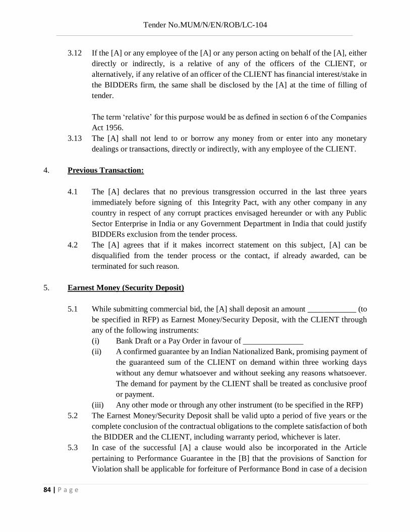
Tender No.MUM/N/EN/ROB/LC-104
84 | P a g e
3.12 If the [A] or any employee of the [A] or any person acting on behalf of the [A], either directly or indirectly, is a relative of any of the officers of the CLIENT, or alternatively, if any relative of an officer of the CLIENT has financial interest/stake in the BIDDERs firm, the same shall be disclosed by the [A] at the time of filling of tender.
The term ‘relative’ for this purpose would be as defined in section 6 of the Companies
Act 1956. 3.13 The [A] shall not lend to or borrow any money from or enter into any monetary
dealings or transactions, directly or indirectly, with any employee of the CLIENT.
4. Previous Transaction:
4.1 The [A] declares that no previous transgression occurred in the last three years immediately before signing of this Integrity Pact, with any other company in any country in respect of any corrupt practices envisaged hereunder or with any Public Sector Enterprise in India or any Government Department in India that could justify BIDDERs exclusion from the tender process.
4.2 The [A] agrees that if it makes incorrect statement on this subject, [A] can be disqualified from the tender process or the contact, if already awarded, can be terminated for such reason.
5. Earnest Money (Security Deposit)
5.1 While submitting commercial bid, the [A] shall deposit an amount ____________ (to be specified in RFP) as Earnest Money/Security Deposit, with the CLIENT through any of the following instruments:
(i) Bank Draft or a Pay Order in favour of _______________ (ii) A confirmed guarantee by an Indian Nationalized Bank, promising payment of
the guaranteed sum of the CLIENT on demand within three working days without any demur whatsoever and without seeking any reasons whatsoever. The demand for payment by the CLIENT shall be treated as conclusive proof or payment.
(iii) Any other mode or through any other instrument (to be specified in the RFP) 5.2 The Earnest Money/Security Deposit shall be valid upto a period of five years or the
complete conclusion of the contractual obligations to the complete satisfaction of both the BIDDER and the CLIENT, including warranty period, whichever is later.
5.3 In case of the successful [A] a clause would also be incorporated in the Article pertaining to Performance Guarantee in the [B] that the provisions of Sanction for Violation shall be applicable for forfeiture of Performance Bond in case of a decision

Tender No.MUM/N/EN/ROB/LC-104
85 | P a g e
by the CLIENT to forfeit the same without assigning any reason for imposing sanction for violation of this pact.
5.4 No interest shall be payable by the CLIENT to the [A] on Earnest Money/Security Deposit for the period of its currency.
6. Sanctions for Violations:
6.1 Any breach of the aforesaid provisions by the [A] or any one employed by it or acting on its behalf (whether with or without the knowledge of the [A] shall entitle the CLIENT to take all or any one or the following actions, wherever required. (i) To immediately call of the pre-contract negotiations without assigning any
reason or giving any compensation to the [A]. However, the proceedings with the BIDDER(s) would continue.
(ii) The Earnest Money Deposit (in pre-contract stage) and /or Security Deposit/performance Bond (after the [B] is signed) shall stand forfeited fully and the CLIENT shall not be required to assign any reason therefore.
(iii) To immediately cancel the [B], if already signed, without giving any compensation to the [A].
(iv) To recover all sums already paid by the CLIENT, and in case of an Indian [A] with interest thereon at 2% higher than the prevailing Prime Lending Rate of State Bank of India, while in case of a [A] from the country other than LIBOR. If any outstanding payment is due to the [A] from the CLIENT in connection with any other [B], such outstanding payment could also be utilized to recover the aforesaid sum and interest.
(v) To encash the advance bank guarantee and performance bond/ warranty bond, if furnished by the [A], in order to recover the payments, already made by the CLIENT, along with interest.
(vi) To cancel all or any other Contracts with the [A]. The [A] shall be liable to
pay compensation for any loss or damage to the CLIENT resulting from such cancellation/ rescission and the CLIENT shall be entitled to deduct the amount so payable from the money(s) due to the [A].
(vii) To debar the [A] from participating in future bidding processes of the Government of India for a minimum period of five years, which may be further extended at the discretion of the CLIENT.
(viii) To recover all sums paid in violation of this Pact by [A] to any middleman or agent or broker with a view to securing [B] the contract.
(ix) In cases where irrevocable Letters of Credit have been received in respect of any [B] signed by the CLIENT with the [A], the same shall not be opened.

Tender No.MUM/N/EN/ROB/LC-104
86 | P a g e
(x) Forfeiture of Performance Bond in case of a decision by the CLIENT to forfeit the same without assigning any reason for imposing sanction for violation of this pact.
6.2 The CLIENT will entitled to take all or any of the actions mentioned at para 6.1(i) to (x) of this Pact also on the Commission by the [A] or any one employed by it or acting on its behalf (whether with or without the knowledge of the [A], of an offence as defined in chapter IX of the Indian Penal Code, 1860 or Prevention of Corruption Act, 1988 or any other stature enacted for prevention of corruption.
6.3 The decision of the CLIENT to the effect that a breach of the provisions of this Pact has been committed by the [A] shall be final and conclusive on the [A]. However, the [A] can approach the independent Monitor(s) appointed for the purposes of this Pact.
7. Fall Clause
7.1 The [A] undertakes that it has not supplied /is not supplying similar product/system or sub systems at a price lower than that offered in the present bid in respect of any other Ministry/Department of the Government of the India or PSU and if it is found at any stage that similar product/ systems or sub systems was supplied by the [A] to any other Ministry/ Department of the Government India or a PSU at a lower price, then that very price, with due allowance for elapsed time, will be applicable to the present case and the difference in the cost would be refunded by the [A] to the CLIENT, if the [B] has already been concluded.
8. Independent Monitors
8.1 The CLIENT has appointed Independent Monitors (hereinafter referred to as Monitors) for this Pact in consultant with the Central Vigilance Commission (Names and Addresses of the Monitors to be given).
8.2 The task of the Monitors shall be to review independently and objectively, whether and to what extent the parties comply with the obligations under this pact.
8.3 The monitors shall not be subject to instructions by the representatives of the parties and perform their functions neutrally and independently.
8.4 Both the parties accept that the Monitors have the right to access all the documents relating to the project/ procurement, including minutes of meetings.
8.5 As soon as the Monitor notices, or has reason to believe, a violation of this Pact, he will so inform the Authority designed by the CLIENT.
8.6 The BIDDER(s) accepts that the Monitors has the right to access without restriction to all project documentation of the CLIENT including that provided by the BIDDER. The [A] will also grant the Monitor, upon his request and demonstration of a valid interest, unrestricted and unconditional access to his project documentation. The same

Tender No.MUM/N/EN/ROB/LC-104
87 | P a g e
is applicable to Subcontractors. The Monitor shall be under contractual obligation to that treat the information and documents of the [A] with confidentially.
8.7 The CLIENT will provide to the Monitor sufficient information about all meetings among the parties related to the Project provided such meetings could have an impact on the contractual relations between the parties. The parties will offer to the Monitor the option to participate in such meetings.
8.8 The Monitor will submit a written report to the MD/DFCCIL within 8 to 10 weeks from the date of reference or intimation to him by the CLIENT/BIDDER and, should the occasion arise, submit proposals for correcting problematic situations.
9. Facilitation of Investigation
In case of any allegation of violation of any provisions of this Pact of payment of commission, the CLIENT or its agencies shall be entitled to examine all the documents including the Books of Accounts of the [A] and the [A] shall provide necessary information and documents in English and shall extend all possible help for the purpose of such examination.
10. Law and Place of Jurisdiction This Pact is subject to Indian Law. The place of performance and jurisdiction is the seat of the CLIENT.
11. Other Legal Actions The action stipulated in this Integrity Pact is without prejudice to any other legal action that may follow in accordance with the provisions of the extant law in force relating to any civil or criminal proceedings.
12. Validity 12.1 The validity of this Integrity Pact shall be from date of its signing and extend upto 5
years or the complete execution of the [B] to the satisfaction of both the CLIENT and the [A], including warranty period, whichever is later. In case [A] is unsuccessful, this Integrity Pact shall expire after six months from the date of the signing of the [B].
12.2 Should one or several provisions of this pact turn out to be invalid; the remainder of this Pact shall remain valid. In this case, the parties will strive to come to an agreement to their original intensions.
13. The parties hereby sign this Integrity Pact at _____________on ___________________ CLEINT BIDDER Name of the Officer CHIEF EXECUTIVE OFFICER Designation Deptt. /Ministry/ PSU Witness Witness 1._____________________________ 1._____________________________ 2._____________________________ 2._____________________________

Tender No.MUM/N/EN/ROB/LC-104
88 | P a g e
SPECIAL CONDITIONS OF CONTRACT

Tender No.MUM/N/EN/ROB/LC-104
89 | P a g e
PART - I CHAPTER V
SPECIAL CONDITIONS OF CONTRACT
1.5.1 This Tender shall be governed by Preamble and General instructions to tenderers,
General condition of Contract, Special conditions of contract, Technical Specifications, Additional Technical specifications (if any), Drawings, Forms, Annexures, etc.
1.5.2 If there are varying or conflicting provisions in the documents forming part of the
contract, Engineer shall be deciding authority with regard to the intentions of the provision and decision of Engineer will be final and binding on the contractor.
1.5.3 Scheme of work:- Within a period of 30 days beginning from the date of issue of Letter
of Acceptance of Tender, the Contractor shall submit the detailed time schedule for execution of work and various documents enumerated in tender papers to the employer.
1.5.4 Quality Assurance Plan for Substructure and foundation
All materials used in the work shall be of the best quality as per codes. Quality Assurance Plan shall include for materials used and for workmanship of work. The contractor shall submit Quality Assurance Plan for the substructure and foundation. The contractor shall also ensure that the Employer’s prescribed Quality Assurance Standards are rigidly
followed in for the construction of substructure and foundation. These are to be approved from the client / DFCCIL
1.5.5 Quality Assurance Plan for Superstructure including bearings (a) All materials used in the work shall be of the best quality as per codes / Specifications
for fabrication and erection of steel girder bridges (B1-2001) amended till date. Quality Assurance Plan shall include for materials used and for workmanship of work. Quality Assurance Plan shall also be prepared for erection of girder and casting of deck slab. The contractor shall submit Quality Assurance Plan for the superstructure and bearing. The contractor shall also ensure that the Employer’s prescribed Quality Assurance Standards are
rigidly followed for the construction of superstructure including bearing. Since, the superstructure is Composite girder. Quality Assurance Plan shall be in line with Quality Assurance plans prepared by RDSO for Open Web Girder and POT & POT-PTFE bearings. These plans are to be approved from the DFCCIL.

Tender No.MUM/N/EN/ROB/LC-104
90 | P a g e
(b) The contractor shall ensure quality at all necessary points, whether at manufacturer’s
works, or in his depot or at work site as well as during erection through Quality Assurance Plan.
(c) The Contractor shall adopt a suitable Quality Assurance Programme
according to approved instructions, drawings, specifications, etc. (d) The erection scheme of composite girder shall be approved by DFCCIL before start of
erection of girder.
(e) Fabrication of composite girder will be inspected by DFCCIL's Engineer in Charge / RDSO / PMC's representative.
1.5.6 Expenses of Employer’ Representative – All the expenses of Engineer’s representative shall be borne by the Employer whether the inspected material is finally utilised in work or not.
1.5.7 The decision of the Engineer shall be final in respect of acceptability or otherwise of any
material, fittings, component or equipment required for the work. 1.5.8 This programme of the Contractor shall generally cover the followings: - 1.5.8.1 The organization to manage and implement the Quality Assurance programme.
1.5.8.2 The documentation control system:
(i) Basic control system. (ii) Adopted at manufacturer’s work (iii) Adopted at the Contractor Depot and work site.
1.5.8.3. Procedure adopted for:
(i) Source Inspection. (ii) Incoming raw material inspection. (iii) Verification of material purchased. (iv) Fabrication Controls. (v) Site erection controls.
1.5.8.4 Inspection and Test Procedure for:
(i) Manufacture and quality control procedure. (ii) Field activity.

Tender No.MUM/N/EN/ROB/LC-104
91 | P a g e
1.5.8.5 System of handling and storage. 1.5.8.6 System of quality audit. 1.5.8.7 System of maintenance of records. 1.5.8.8 For the purpose of obtaining ‘On Account Payment’, the Contractor shall submit along
with the invoice, the documents indicated in the prescribed quality Assurance standards which should inter alia cover the following as may be applicable in each case.
(i) Material test reports on raw materials used. (ii) Material type and routine test report on components specification. (iii) Inspection Plan with reports of the inspection Plan check points. (iv) Routine test report. (v) Factory test results as required under the specification. (vi) Quality audit report including test check report of Employer’s representative if
any.
1.5.9 Traffic Blocks / Power Blocks / Shut Down:
(a) The contractor shall obtain Power / Traffic / Shut down in the name of authorized representative of DFCCIL. Engineer/Engineer’s representative will facilitate to make arrangements to obtain power blocks / shutdown (hereinafter referred to as blocks) for works to be carried out along or adjacent to the track work. Works such as foundations of abutments/piers shall generally be done without blocks. However if block is required due to safety considerations, the construction shall be done under block. The requirement of shut down, power blocks etc. shall be assessed by the contractor and will be submitted to the Engineer/Engineer’s representative. All the erection of girders etc. shall be done under minimum power block/shut down. Contractor will arrange minimum two gangs of labours i.e. expert of TR line fitters, Semi skilled fitters, labours etc. with supervisors and sufficient tools and tackles required as per site conditions. Work will be done day & night with war foot level with the approval of the Engineer/Engineer’s representative. Block will be provided for each ROB individually.
(b) Blocks will be granted during day & night hours continuous. The Contractor shall
confirm that he will equip himself to carry out all construction during night blocks efficiently by suitable special lighting equipments without any extra cost.
(c) Block period shall be counted from the time the TR-line is placed at the

Tender No.MUM/N/EN/ROB/LC-104
92 | P a g e
Contractor’s disposal at the work-spot till it is cleared by the Contractor. (d) Blocks will be subject to normal operating conditions and rules of the Railway.
All formalities of exchanging private number etc. with the traffic control/traction power controller will be carried out by the Engineer staff and for this purpose the Engineer will depute a representative for each ROB, who will be responsible for imposing power blocks/shut down and also removing the same after men, material and equipment have been cleared by the Contractor from running tracks and the same declared safe for traffic by Engineer/Engineer’s representative in case of works involving safety of running tracks.
(e) The works required to be done under traffic block shall be carried out only in the
presence of DFCCIL officials. The Railway supervisor shall certify safe conditions for passage of trains before resumption of traffic. The works to be done under traffic block shall be carried out under the provision of banner flag and protection of engineering flagman.
(f) Any charges which may be levied by IR on account of “Possessions” shall be payable
by the contractor but shall be reimbursed by the Employer. However penalties, if any, levied by Indian Railways caused due to any careless working or otherwise of violation of the Terms and Conditions of the track block, shall be payable by the contractor.
1.5.10 Work By Other Agencies
(a) Any other works undertaken at the same time by the Engineer direct or through
some other agency at the same time or section where the contractor is carrying out his work will not entitle the contractor to prefer any claim regarding any delays or hindrances he may have to face on this account but the Employer shall grant a reasonable extension of time to the contractor. The contractor shall comply with any instruction which may be given to him by the Employer in order to permit simultaneous execution of his own works and those undertaken by other contractors or the DFCCIL without being entitled on this account on any extra charge.
(b) The contractor shall not be entitled to any extra payment due to hindrance resulting
from normal Railway operations, such as delay on account of adequate number of and duration of blocks not being granted, operational delay in movement of work trains extension of time to the contractor.

Tender No.MUM/N/EN/ROB/LC-104
93 | P a g e
1.5.11 Infringement of patents:
(a) The Contractor is forbidden to use any patents or registered drawings, process or pattern in fulfilling his contract without the previous consent in writing of the owner of such patent, drawing, pattern or trade mark, except where these are specified by the Employer himself. Royalties where payable for the use of such patented processes, registered drawings of patterns shall be borne exclusively by the Contractor. The contractor shall advise the Employer of any proprietary right that may exist on such processed drawings or patterns which he may use of his own accord.
(b) In the case of patent taken out by the Contractor of the drawings or patterns registered
by him, or of those patents, drawings, or patents for which he holds a licence, the signing of the Contract automatically gives the Employer the right to repair by himself the purchased articles covered by the patent or by any person or body chosen by him and to obtain from any sources he desires the component parts required by him in carrying out the repair work. In the event of infringement of any patent rights due to above action of the Employer, he shall be entitled to claim damages from the contractor on the grounds of any loss of any nature which he may suffer e.g. in the case of attachment because of counterfeiting.
(a) Indemnification by contractor:- In the event of any claim or demand being made
or action being brought against the Employer for infringement of later patent in respect of any equipment, machine, plant, work or thing used or supplied by the Contractor under this contract or in respect of any methods of using or working by the Employer of such equipment machine, plant work or thing, the contractor shall indemnify the employer and keep him indemnified and harmless against all claims, costs, charges and expenses arising from or incurred by reason of such claim provided that the Employer shall notify the contractor immediately any claim is made and that the contractor shall be at liberty, if he so desires with the assistance of the Employer if required but at the Contractor’s expense, to conduct all negotiations for the settlement of the same or any litigation that may arise there from and provided that no such equipment, machine, plant work or thing, shall be used by the Employer for any purpose or in any manner other than that for which they have been supplied by the Contractor and specified under this contract.

Tender No.MUM/N/EN/ROB/LC-104
94 | P a g e
1.5.12 Insurance:- Before commencing of works, it shall be obligatory for the contractor to obtain, at his own
cost, insurance cover in the joint name of the contractor and employer from reputed companies under the following requirements:
(a) Liability for death of or injury to any person/ employer's staff / animals or things or
loss of or damage to any property / things / the work of other contractor (other than the work) arising out of the performance of the Contract.
(b) Construction Plant, Machinery and equipment brought to site by the Contractor.
(c) Any other insurance cover as may be required by the law of the land. The contractor shall provide evidence to the employer / Engineer before commencement of work at site that the insurances required under the contract have been effected and shall within 60 days of the commencement date, provide the insurance policies to the Employer/Engineer, the contractor shall, whenever, called upon, produce to the engineer or his representative the evidence of payment of premiums paid by him to ensure that the policies indeed continue to be in force. The Contractor shall also obtain any additional insurance cover as per the requirements of the Contract.
The Employer/Engineer shall not be liable for or in respect of any damages or compensation payable to any workman or other person in the employment of the Contractor or his sub-contractor or petty contractor / other contractor working there. The Contractor shall indemnify and keep indemnified the employer / Engineer against all such damages and compensation for which the contractor is liable.
The Policies of the contractor shall remain in force throughout the period of execution of the works and till the expiry of the defect liability period except for any specific insurance covers necessary for shorter period.
If the Contractor fails to effect or keep in force or provide adequate cover as acceptable to the engineer in the insurance policies mentioned above, then in such cases, the engineer may effect and keep in force any such insurance or further insurance on behalf of the Contactor. The recovery shall be made at the rate of 1.5 times the premium/premiums paid by the engineer in this regard from the payment due to the Contractor or from the contractor’s Performance security. However, the Contractor shall not be absolved from his
responsibility and /or liability in this regard.

Tender No.MUM/N/EN/ROB/LC-104
95 | P a g e
1.5.13 Accident:-
(a) The contractor shall, in respect of all staff engaged by him or by his sub-contractor, indemnify and keep the employer at all times indemnified and protected against all claims made and liabilities incurred under Workman’s
Compensation Act, the Factories Act and the Payment of Wages Act, and rules made there under from time to time or under any other labour and Industrial Legislation made from time to time.
(b) The contractor shall indemnify and keep the employer indemnified and
harmless against all actions, suits, claim demands, costs, charges or expenses arising in connection with any death or injury sustained by any person or persons sustained due to the acts or omission of the contractor, his sub-contractors, his agents or his staff during the executions of this contract irrespective of whether such liability arises under the Workman’s Compensation Act, or Fatal Accident Act or any other statute in force for the time being.
(c) The contractor’ liability to meet third party claims of the type outlined above will
be applicable only in cases where accidents have been caused by workmanship, material, execution or negligence on the part of the contractor and further the liability of the contractor will be limited to Rs.5 lakh for any one accident.
(d) The contractor shall be responsible for all repairs and rectification of
damages to completed works or works under execution due to DFCCIL accidents, thefts, pilferage or any other cause, without delay to minimize or to avoid traffic detentions, in a section until the installation are provisionally handed over to the employer.
1.5.14 Safety Measures:-
(a) The contractor shall take all precautionary measures in order to ensure the protection of his own personnel moving about or working on the railway premises, but shall then conform to the rules and regulations of the Railway if and when, in the course of the work there is likely to be any danger to persons in the employment of the contractor due to running traffic while working in the Railway siding and premises, the contractor shall provide flagman or look out men for protection of such persons. The employer shall remain indemnified by the contractor in the event of any accident occurring in the normal course of work, arising out of the failure of contractor or his men to exercise reasonable precaution at all places

Tender No.MUM/N/EN/ROB/LC-104
96 | P a g e
of work. (b) Blasting of rocks for foundation work shall be done only after due notice is given
to the employer and time/s and date /s for blasting operations agreed to by the employer. Blasting, if required to be done in the vicinity of the track, shall no t be undertaken until the Employer’s flagmen on duty t ake necessary step to protect trains and the track is adequately protected by the contractor against damage by blasted rock .The contractor shall follow detailed instructions which will be issued to him regarding blasting operations in the vicinity of tracks.
(c) The contractor shall abide by all Railway regulations in force for the time being
and ensure that the same are followed by his representatives, Agents or sub -contractors or workmen. He shall give due notice to his employees and workers about provision of this para.
(d) The works must be carried out most carefully without any infringement of the
Indian Railway Act or the General and Subsidiary Rules in force on the Railway, in such a way that they do not hinder Railway operation or affect the proper functioning of or damage any DFCCIL equipment, structure or rolling stock except as agreed to by the employer, provided that all damage and disfiguration caused by the contractor at his own cost failing which cost of such repairs shall be recovered from the contractor.
(e) If safety of track or track drainage etc. is affected as a consequence of works undertaken by the contractor, the contractor shall take immediate steps to restore normal conditions. In case of delay, the employer shall, after giving due notice to the contractor in writing, take necessary steps and recover the costs from the contractor.
1.5.15 Guarantee / Defect Liability Period:-
(a) The Contractor shall guarantee that all the works executed under this contract shall be free from all defects and faults in material, workmanship and manufacture and shall be of acceptable standards for the contracted work and in full conformity with the technical specifications, drawings and other contract stipulations, for a period of 6 months from the date of taking over by the Employer
(b) During the period of guarantee the Contractor shall keep available an
experienced engineer / man power to attend to any defective works / installations

Tender No.MUM/N/EN/ROB/LC-104
97 | P a g e
resulting from defective erection and/or defect in the installation supplied by the Contractor. This engineer shall not attend to rectification of defects which arise out of normal wear and tear and come within the purview of routine maintenance work. The contractor shall bear the cost of modifications, additions or substitutions that may be considered necessary due to faulty materials or workmanship for the satisfactory working of the equipment. The final decision shall rest with the Engineer his successor(s)/Nominee.
(c) During the period of Guarantee the Contractor shall be liable for the
replacement at site of any parts which may be found defective in the executed work whether such parts / structural elements of his own manufacture or those of his sub-contractor / supplier whether arising from faulty materials, workmanship or negligence in any manner on the part of the Contractor provided always that such defective parts as are not repairable at site are promptly returned to the Contractor if so required by him at his (Contractor’s) own expenses. In case o f parts of executed work detected during guarantee period, contractor should replace all such items irrespective of the fact whether all such items have failed or not. The Contractor shall bear the cost of repairs carried out on his behalf by the Employer at site. In such a case, the contractor shall be informed in advance of the works proposed to be carried out by the Employer.
(d) If it becomes necessary for the Contractor to replace or renew any defective portion
of the structural elements until the expiration of six month from the date of such replacement or renewal or until the end of the above mentioned period whichever is later.
Such extension shall not apply in case of defects of a minor nature, the decision
of the General Manager/ROB, /CGM or his successor/nominee being final in the matter. If any defect be not remedied within a reasonable time during the aforesaid period the Employer may proceed to do work at the Contractor’s risk and expense, but without prejudice to any other rights and remedies which the Employer may have against the Contractor in respect of such defects or faults.
(e) The repaired or renewal parts structure shall be delivered / supplied and erected
/ executed on site free of charge to the employer. (f) Any materials, fittings, components or equipment’s / structure supplied under items
for supplying / providing and fixing in schedule shall also be covered by the provisions of this paragraph. The liability of the Contractor under the guarantee will be limited to re-supply of components / structure installation and fittings.

Tender No.MUM/N/EN/ROB/LC-104
98 | P a g e
1.5.16 Final Acceptance: -
(a) The final acceptance of the entire work executed shall take effect from the date of
expiry of the period of guarantee / Defect Liability period as defined in paragraph 1.5.15 above of the expiry of the last of the respective periods of guarantee of various ROBs , provided in any case that the Contractor has complied fully with his obligations under clause 1.5.15 in respect of each R O B , provided also that the attention has been paid by way of maintenance by the Employer.
(b) If on the other hand the contractor has not so complied with his obligation under
Para 1.5.15 above in respect of any work, the Employer may either extend the period of guarantee in respect of that work until the necessary works are carried out by the Contractor or carry out those works or got them carried out suo moto on behalf of the Contractor at the Contractor’s expenses. After expiry of the period of guarantee for each work, a certificate of final acceptance for the section shall be issued by the Employer and the last of such certificate will be called the last and final acceptance certificate. The contract shall not be considered as completed until the issue of final acceptance certificate by the Employer.
(c) The Employer shall not be liable to the Contractor for any matter arising out of
or in connection with the contract or execution of the work unless the Contractor shall have made a claim in writing in respect thereof before the issue of final acceptance certificate under this clause.
Not withstanding the issue of final acceptance certificate the Contractor and the Employer (subject to sub-clause as above) shall remain liable for fulfilment of any obligation incurred under the provision of the contract prior to the issue of final acceptance certificate which remains unperformed at the time such certificate is issued and for determining the nature and extent of such obligation the contract shall be deemed to remain in force between the parties hereto.
1.5.17 Payment:-
Payment will be governed by the terms specified in Part-I, Chapter IV and in accordance with accepted schedule of prices, read with relevant para of the other parts and Chapters of the Tender Papers. The employer retains the right to withhold money due to the contractor arising out of this contract for any default of the contractor . (i) The Contractor shall, whenever required, produce or cause to be produced for

Tender No.MUM/N/EN/ROB/LC-104
99 | P a g e
examination by the Employer any quotation / invoice, cost of other account, book of account, voucher, receipt letter, memorandum paper or writing or any copy of or extract from any such document and also furnish information and returns verified in such manner as may be required in anyway relating to the execution of this contract or relevant for verifying or ascertaining the cost of the execution of this Contract (the decision of the employer on the question of relevancy of any documents, information or return being final and binding on the parties). The Contractor shall similarly produce vouchers etc., if required, to prove to the Employer that materials supplied by him are in accordance with the specifications laid down in the contract.
(ii) If any portion of the work be carried out by a sub-contractor or any subsidiary
or allied firm or company the Employer shall have power to secure the books of such sub-contractor or any subsidiary or allied firm or company, through the Contractor, and such books shall be open to his inspection. The Contractor should seek prior permission from the employer for subletting whole and/or part of the work to any sub-contractor.
(iii) The obligations imposed by sub-clause (i) and (ii) above are without prejudice to the
obligation of the Contractor under any statute, rules or order binding to the Contractor or other conditions of the contract.
(iv) It is an agreed term of the contract that the employer reserves t he right to carry out
post-payment Audit and/or technical examination of the works and the final bill, including all supporting vouchers, abstracts etc. and to make a claim on the Contractor for the refund of any excess amount paid to him if as a result of such examination any over payment to him is discovered to have been made in respect of any work done or alleged to have been done by him under the contract.
1.5.18 All payments in respect of the contract during the currency of the contract shall be made through Electronic Clearing System (ECS) / National Electronic Funds Transfer (NEFT/RTGS). The successful tenderer on award of contract must submit ECS/NEFT/RTGS Mandate Form complete in all respects as detailed at Form No. 8 of the tender document. However, if the facility of ECS/NEFT/RTGS is not available at a particular location, the payments shall be made by cheque.
1.5.19 Performance Guarantee:-
(i) The Bank Guarantee for performance Guarantee shall remain valid until a date

Tender No.MUM/N/EN/ROB/LC-104
100 | P a g e
60 days (or as specified in the Contract) after expiry of Defects Liability Period. (ii) The Bank Guarantee for performance Guarantee shall be submitted invariably in
the format given in the bidding document. (iii) The performance Guarantee shall be released 21 days after issue of performance
certificate.
1.5.20 Mobilization Advance:- (Applicable for Advertised tender of value more than Rs. 25.00 crore)
(a) The Tenderer/Contractor may be granted a recoverable interest bearing mobilization advance upto 10% of the contract value provided mobilization advance is admissible as per the tender conditions and he specifically applies for it while tendering. If the tenderer fails to apply specifically for Mobilization Advance while giving his offer at the tendering stage in case where grant of Mobilization Advance is permissible, no subsequent requests from him for grant of this advance will be entertained. The rate of interest is 4.5% per annum above the Base Rate of State Bank of India, as effective on the date of approval of payment of Mobilization Advance by the competent authority.
(b) The advance will be granted in two instalments viz., 5% of the contract value on signing of the contract agreement and the balance 5% on Mobilization of site establishment, setting up offices, bringing in equipment and actual commencing of work. Each instalment will be released on submission of a security in a form acceptable to the DFCCIL (similar to Performance Guarantee notified in Clause 16.(4) (b) of General conditions of contract for the amount of the at least 110% of the value of the sanctioned advance amount covering instalment together with interest charges calculated upto the end of the contract period. The tenderer who seeks Mobilization Advance should be specific about the course of action proposed to be followed in producing the security to the satisfaction of the Railway. Each security should be at least not less than one lakh rupees. These securities shall be returned as and when the value of the advance plus interest is recovered from the running bill.
(c) The recovery of the advance and interest thereon will be made through the every on account bills, pro-rata, commencing from the time the value of the work executed under the contract reaches 15% of the contract value and completed when the value of the work executed under the contract reaches 85% of the contract value or assessed value whichever is less.

Tender No.MUM/N/EN/ROB/LC-104
101 | P a g e
(d) The Mobilization Advance granted shall be returned back to the DFCCIL in case the work is not completed in the original contract completion period.
(e) The Bank Guarantee shall be from a Nationalized Bank in India or State Bank of India,
in a form acceptable to DFCCIL. (Tender Form No. 19 placed at Part IV of the tender documents).
Note: Deleted
1.5.21 Arbitration: - Refer to clause 63 of GCC.

Tender No.MUM/N/EN/ROB/LC-104
102 | P a g e
PART II
TECHNICAL SPECIFICATION

Tender No.MUM/N/EN/ROB/LC-104
103 | P a g e
PART - II
TECHNICAL SPECIFICATIONS
For technical specifications, refer Indian Railways Unified Standard Specifications (Works and Materials), 2010 amended upto date/ Gujarat State SOR/Codes/Manual / NH SOR /Codes/Manual as shall be relevant. and the specification for fabrication and erection of steel girder bridges and Locomotive Turn Table (Fabrication Specification), Serial No B1 - 2001 amended up to date. The decision of DFCCIL is final and binding to the contractor.
Indian Railways Unified Standard Specifications (Works and materials), Volume I & II are
available for sale at the offices of General Managers and DRMs at all Zonal Railways & Production Units.
2.1 GENERAL GUIDELINES REGARDING SPECIFICATIONS AND SPECIAL
CONDITIONS FOR SUPPLY OF CEMENT FOR CONSTRUCTION WORKS
2.1.1 SUPPLY OF CEMENT:
2.1.1.1 Supply of cement to various specifications as required for various items under different schedules will be paid under the items in Schedule.
2.1.1.2 The cement required for various items of work under Schedule shall be supplied by the Contractor at the site of work in accordance with the requirements and specifications.
2.1.1.3 For supply and use of cement in various works, relevant Indian Railways Unified Standard Specifications (Works and Materials), Volume I & II - 2010, IRS codes and IS Specifications will be applicable. Wherever, relevant specifications are not available, decision of the Engineer shall be final and binding on the contractor.
SPECIFICATIONS FOR CEMENT:
2.1.2.1The cement used shall conform to any of the following standards.
(i) 33 Grade Ordinary Portland Cement conforming to IS: 269
(ii) 43 Grade Ordinary Portland Cement conforming to IS: 8112
(iii) 53 Grade Ordinary Portland Cement conforming to IS: 12269
(iv) Rapid Hardening Ordinary Cement conforming to IS: 8041
(v) High Strength Portland Cement conforming to IRS: T: 40
(vi) HydrophobicPortland cement conforming to IS: 8043

Tender No.MUM/N/EN/ROB/LC-104
104 | P a g e
(vii) Low heat Portland cement conforming to IS: 12600
(viii)Sulphate Resistance Cement conforming to IS: 12330
2.1.3 SOURCE AND PACKAGING:
2.1.3.1 Cement to be used on the works shall be procured from the main / reputed cement plants or from their authorized dealers. Decision of DFCCIL regarding reputed firms shall be final and binding on the contractor.
2.1.3.2 Cement shall be packed in jute sacking bags conforming to IS: 2580-1982,double hessian bituminised (CRI type) or woven HDPE conforming to IS:11652-1986, woven polypropylene conforming to is: 11653:1986, Jute synthetic union conforming to IS: 12174:1987,or any other approved composite bags, bearing the following information in legible markings:
Manufacturer’s name or Registered Trade Mark of manufacturer, if any.
Grade of cement
Type of cement
Weight of each bag in Kg.
Date of manufacture,
IS Code No. to which the cement conforms.
2.1.3.3 All cement bags shall have company stitches intact and if any sign of tampering with company stitches is noticed, the same will be rejected without any test and no compensation shall be payable in this regard.
2.1.4 TEST CERTIFICATE REGARDING QUALITY OF CEMENT:
2.1.4.1 Necessary test certificates will have to be produced by the contractor regarding the quality of the cement conforming to the specification in addition to the manufacturer’s certificates.
2.1.4.2 DFCCIL reserves the right to take samples during the course of the work and get the cement tested in reputed laboratories to ascertain the conformity to the specification. Cost of such testing shall be borne by the contractor without any extra payment.
2.1.4.3 Tests on cement shall be done as per relevant IS Codes. These tests are as follows:
(i) Compressive strength
(ii) Initial and final setting time

Tender No.MUM/N/EN/ROB/LC-104
105 | P a g e
(ii) Consistency (iii) Soundness. (iv) Fineness
2.1.4.4 The Contractor shall arrange to carryout above tests for every 100 Tonnes of cement and for every change in lot/batch and the same shall be submitted to the DFCCIL and take approval of the DFCCIL before using in work. No extra payment will be made for conducting such tests.
2.1.4.5 Any temporary structure required for storage of cement, has to be provided by the tenderer at his cost and shall be removed after completion of work. The DFCCIL will only provide suitable land wherever land is available and is free for use. On completion of the work or as directed by the Engineer, the shed if put up by the Contractor, should be removed by the contractor and site cleared at his cost.
2.1.5 CONSUMPTION OF CEMENT:
2.1.5.1 The cement consumption for other than design mix concrete, shall be as per Western Railway Unified Standard Schedule of Rates (Works and Materials), Engineering Department and for approved design mix concrete, the quantity of cement will be decided based on the approved design mix keeping in mind Minimum and Maximum cement content specified for various grades. Excess cement used will not be paid for and the decision of the Engineer in this connection shall be final and binding on the Contractor.
2.1.6 PAYMENT FOR CEMENT:-
Cement supplied for the work and measured under the Schedule will be paid if specified separately only after its use in various works under the Schedules of the contract as per conditions and no advance payment for supply will be admissible.
2.1.7 GENERAL:-
2.1.7.1 No wastage of any of the materials supplied and used in the work by the contractor including cement is payable by DFCCIL, contractor shall make his own arrangements for storing cement for use in work.
2.1.7.2 Contractor should take proper precautionary measures to store the cement in good condition against rains, etc. Storage of cement at the work site shall be at the contractor's expense and risk. Any damage occurring to cement due to faulty storage in contractor's shed or on account of negligence on his part shall be the liability of the contractor.
2.1.7.3 53 Grade/43 Grade/33 Grade of cement should be stacked separately in countable manner.

Tender No.MUM/N/EN/ROB/LC-104
106 | P a g e
2.1.7.4 Admixture as per IS: 9103 of approved manufacturer by the Engineer shall be permitted to be used in concrete wherever required. However, no extra payment for the admixtures used shall be payable unless otherwise specified in the Schedule.
2.1.7.5 Cement for temporary and enabling works shall be arranged by the contractor at his own cost and no extra payment will be paid on this account.
2.1.7.6 Empty Cement bags on release from the work is the property of the Contractor and shall be disposed off by the Contractor himself.
2.2 GENERAL GUIDELINES REGARDING SPECIFICATIONS AND SPECIAL CONDITIONS FOR CONCRETE WORKS
2.2.1 Specifications:-
2.2.1.1 Concrete for PCC, RCC (Including piling and RCC deck slab) shall be as per relevant Indian Railway Unified Standard Specifications (Works & Materials) Volume I & II, Engineering Department, 2010 and IS Specifications. Some important guide lines are listed below. Along with these, all other relevant IRS, IRC and IS specifications with their up to date versions shall also govern. These govern all concrete works in bridges, etc., as applicable.
(i) IRS Concrete Bridge Code.
(ii) IS 456 :Code of Practice for Plain and Reinforced Concrete.
(iii) Relevant Indian Railway Unified Standard Specifications (Works & Materials) Volume I & II, Engineering Department, 2010
(iv) Relevant IRS/IRC/MORTH/IS Specifications/Codes.
(v) Relevant PSC Codes & Specification.
2.2.1.2 Specifications for cement, steel, binding wire, used in concrete construction shall be as per IRS/IRC/MORTH/IS specifications. Any other specifications/rules/guidelines issued from time to time by Railway Board/RDSO shall also govern the works.
2.2.1.3 In all matters of execution, including testing of various components, where the above codes/specifications/guidelines are not clear or explicit or at variance, the directions given by the Engineer shall be final and binding on the contractor.
2.2.2 Cement:-
2.2.2.1 The cement used in concrete construction shall be 43 Grade Ordinary Portland cement as per the design and as specified in the relevant schedules. Specifications for cement are covered under the supply schedule.

Tender No.MUM/N/EN/ROB/LC-104
107 | P a g e
2.2.3 Reinforcement: -
2.2.3.1 All Reinforcement Steel (TMT Bars of Grade Fe 500) shall be procured as per specification mentioned in IS : 1786. Independent tests shall be conducted, wherever required, to ensure that the materials procured conform to the Specifications.
These steel shall be procured only from those firms, which are Established, Reliable, Indigenous & Primary Producers of Steel, having Integrated Steel Plants (ISP), using iron ore as the basic raw material and having in – house iron rolling facilities, followed by production of liquid steel and crude steel, as per Ministry of Steel’s guidelines.
2.2.3.2 Bars shall be cut, bent and placed correctly and accurately to the size and shape as shown in the detailed drawing. Preferably bars of full length shall be used. The reinforcement shall be tied with annealed steel binding wire. Overlapping of bars, where necessary, shall be done as directed by Engineer. Rates quoted include the cost of annealed steel binding wire of appropriate specifications. Rate also include necessary cutting and straightening is also included.
2.2.3.3 Welding of reinforcement will not be generally permitted except in special circumstances under the written approval of the Engineer.
2.2.3.4 A register shall be maintained by the Contractor with full details of reinforcement provided for accountable and payment of steel reinforcement. The contractor should sign a similar such register maintained by DFCCIL before undertaking concreting works, as a token of acceptance of the details of reinforcement steel provided in works, failing which the details as recorded by DFCCIL shall be binding on the contractor for the purpose of payment and no dispute will be entertained by DFCCIL on this account.
2.2.3.5 Contractor shall remove from site any steel materials rejected by the Engineer within a reasonable time as specified by him.
2.2.3.6 Protective Coatings:- In order to offer adequate resistance against corrosion, reinforcement bars may be provided with suitable protective coatings depending upon the environmental conditions In aggressive environments (severe, and extreme ) application of cement slurry coating after removal of rust and other loose material from the surface of the reinforcement bar will generally be sufficient.
2.2.3.7 The steel consumption shall be as per the drawings issued by the DFCCIL. Quantity of steel reinforcement consumption shall be as per reinforcement actually utilized in the work based on approved bar bending schedule. Nothing extra will be paid for wastage or for cut rods, if any, which will be property of the contractor. The weight of the steel will be calculated from the nominal weight given in the producer’s hand / IRUSS (W & M),2010-Volume-I books.
2.2.4 Coarse & Fine Aggregates: -

Tender No.MUM/N/EN/ROB/LC-104
108 | P a g e
2.2.4.1 Aggregates shall comply with the requirements of IS: 383 and shall be subjected to the tests in accordance with IS: 2386. Coarse aggregates shall be from crushed stone from approved quarries. Sand shall be from good river sources of approved quarries only.
2.2.4.2 The size of the coarse aggregates shall beas per relevant IRS / IS specifications.
2.2.4.3 The size of the fine aggregates shall be as per relevant IRS / IS specifications.
2.2.4.4 Coarse aggregate shall be crushed and roughly cubical in shape. Fine aggregate shall be naturally produced. Creek/ Marine sand shall not be used in permanent works.
2.2.4.5 The grading of the sand shall conform to relevant IS specification. The sand shall be screened on a 4.75 mm size screen to eliminate over size particles. The sand, if required, shall be washed in screw type mechanical washers in potable water to remove excess silt, clay and chlorides wherever required. The screening and washing of sand shall be completed at least one day before using it in concrete. The washed sand shall be stored on a sloping platform and in such a manner as to avoid contamination.
2.2.5 Water:
2.2.5.1 Water used for washing of aggregates and for mixing and curing concrete shall be clean, potable and free from injurious amounts of oils, acids, alkalis, salts, sugar, organic materials or other substances that may be deleterious to concrete or steel and shall conform to clause 5.4 of IS : 456.
2.2.5.2 In case of doubt regarding development of strength, the suitability of water for making concrete shall be ascertained by the compressive strength as per IS : 4031 (Part VI) and initial setting time tests IS : 4031 (Part V).
2.2.5.3 Water found satisfactory for mixing is also suitable for curing concrete. However, water used for curing should not produce any objectionable stain or unsightly deposit on the concrete surface. The presence of tannic acid or iron compounds is objectionable.
2.2.6 Admixtures: -
2.2.6.1 In bridges, use of admixtures is governed by clause 4.4 of IRS Concrete Bridge Code.
2.2.6.2 The admixtures, when permitted, shall conform to IS: 9103.Calcium chloride or admixtures containing calcium chloride shall not be used in structural concrete containing reinforcement, pre-stressing tendon or other embedded metal. The admixture containing Cl & SO3 ions shall not be used. Admixtures containing nitrates shall also not be used. Admixtures based on thiocyanate may promote corrosion and therefore shall be prohibited.
2.2.6.3 Concrete admixtures shall be obtained only from established manufactures with proven track record or as per approved list wherever available.

Tender No.MUM/N/EN/ROB/LC-104
109 | P a g e
2.2.6.4 The contractor shall provide the following information concerning each admixture after obtaining the same from the manufacturer before the same is put to use:
(a) The chemical names of the main ingredients in the admixtures.
(b) The chloride iron content, if any, expressed as a percentage by mass of the total admixture.
(c) Values of dry material content, ash content and relative density of the liquid admixture which can be used for Uniformity Tests.
(d) Whether or not the admixture leads to the entrainment of air when used as per the manufacturer’s recommended dosage, and if so to what extent.
(e) Where two or more admixtures are proposed to be used in any one mix, confirmation as to their compatibility.
(f) There would be no increase in risk of corrosion of the reinforcement or other embodiments as a result of using the admixture.
(g) Retardation achieved in initial setting time.
(h) Normal dosage and detrimental effects, if any, of under dosage and over dosage.
(i) Recommended dosages and expected results, including proof for the same wherever required. Independent test results shall be produced by the contractor on demand/as specified.
2.2.7 Storage of materials:-
2.2.7.1 Storage of materials shall be as per IS: 4082. All materials may be stored at proper places so as to prevent their deterioration or intrusion by foreign matter and to ensure their satisfactory quality and fitness for the work. The storage space must also permit easy inspection, removal and restoring of the materials. All such materials even though stored in approved godowns / places, must be subjected to acceptance test prior to their immediate use.
2.2.7.2 Aggregate shall be stored at site on a hard and dry level patch of ground. If such a surface is not available, a platform of planks or of corrugated iron sheets, or a floor of dry bricks, or a thin layer of lean concrete shall be made so as to prevent the admixture of clay, dust, vegetable and other foreign matter.
Stacks of fine and coarse aggregate shall be kept in separate stack piles, sufficiently removed from each other to prevent the materials at the edge of the piles getting intermixed. On a large job it is desirable to construct dividing walls to give each type of aggregate its own compartment. Fine aggregate shall be stacked in place where loss due to the effect of wind is minimum.
Unless specified otherwise or necessitated by site conditions, stacking of aggregate should be carried out in regular sizes.

Tender No.MUM/N/EN/ROB/LC-104
110 | P a g e
2.2.7.3 Cement shall be transported, handled and stored at the site in such a manner as to avoid deterioration or contamination. Cement shall be stored above ground level in perfectly dry and water-tight sheds and shall be stacked not more than eight bags high. Wherever bulk storage containers are used their capacity should be sufficient to cater to the requirement at site and should be cleaned at least once every 3 months. Cement older than 3 months from the date of manufacture shall not be used. Each consignment shall be stored separately so that it may be readily identified and inspected and cement shall be used in the sequence in which it is delivered at site. Any consignment or part of a consignment of cement which had deteriorated in any way, during storage, shall not be used in the works and shall be removed from the site by the Contractor without charge to DFCCIL. For more details regarding stacking and storage of cement, refer clause 17.10.1, 17.10.2 and 26.1.2.7of Indian Railway Unified Standard Specifications (Works & Materials), Volume II, - 2010.
2.2.7.4 The reinforcement bars, when delivered on the job, shall be stored above the surface of the ground level by at least by 150mm and shall ordinarily be stored in such a way as to avoid distortion and to prevent deterioration and corrosion. Every bar shall be inspected before assembling on the works and any defective, brittle, excessively rusted or burnt bars shall be removed. Cracked ends of bars shall be cut out.
2.2.8 Testing of cement & others:-
Cement and other items shall be tested as per specifications. However, the contractor shall also arrange for additional tests at his own cost as required by the Engineer as and when required. The decision of the Engineer shall be final in this regard.
Concreting:
2.2.9.1 The contractor shall make his own arrangements for supply of water and electricity for all his works at his own cost. He shall arrange potable quality water for use in all concrete works and samples of water shall be got tested from approved laboratory/approved by the Engineer before being used in concreting. Apart from water, fine & coarse aggregates and all other materials shall be tested from time to time by the contractor at his cost to ensure proper quality works.
2.2.9.2 Maximum / minimum size of aggregates, standards of quality of materials, minimum cover for concrete, use of admixtures / chemicals, treatment to reinforcement / finished surfaces, etc., shall be as per relevant Codes, IS / IRS specifications and conditions of contract as specified.
2.2.9.3 All exposed concrete surfaces shall be finished smooth by the contractor at his own cost. Shuttering materials for RCC in superstructure shall be strictly of steel only to permit vigorous vibration and to ensure no deviation of finished dimensions by more than +5/-0 mm and wooden shutters are not permitted. For other works also, proper quality of shuttering materials which will permit vibrating and will not require additional finishing shall only be used. If there is any variation in the surface, alignment or lines in the products beyond permissible rejection limits indicated in these conditions, the DFCCIL reserves the right to reject the same and the contractor shall not have any

Tender No.MUM/N/EN/ROB/LC-104
111 | P a g e
claim in this regard and cost of DFCCIL materials involved will be recovered from the contractor including penalties, if any imposed.
2.2.10 Weigh batching, vibrating, curing & testing:
2.2.10.1 All concrete shall be machine batched, machine mixed and machine vibrated, by using appropriate vibrators. Weigh batching plant, mixers, vibrators, etc., of appropriate capacity, as specified/directed by the Engineer, shall be arranged by the contractor at his cost. In this case, Weigh batching plants shall have computerized control for weighing, loading, mixing and delivery.
2.2.10.2 Batching plants, transit mixers, concrete pumps, etc., shall be installed by the contractor necessarily at site. In case of failure of any of the above, standby arrangements for ensuing continuous concreting has to be provided by the contractor at his cost. For piling works concreting shall be done continuously as per the volumes designed without break and accordingly standby arrangements shall be ensured by the contractor.
2.2.10.3 Curing & vibrating shall be arranged by the contractor at all locations/heights at his own cost and no extra payment on this account will be admissible. Curing of concrete shall be done as per relevant IS Codes / Specifications. If curing is not done by the contractor properly, DFCCIL may get it done through any other means at the Contractor’s cost without any notice to him and recover from
his bills the same including penalty if any at the discretion of the Engineer. The concrete shall be kept wet constantly by ponding or covered with a layer of sacking canvas etc.
2.2.10.4 Test cubes shall be cast at regular intervals and tested to ascertain the strength of concrete. The contractor shall establish a cube testing facility along with operator at the site or nearby area to facilitate prompt testing of concrete. Test cube moulds as required as per IS Codes shall be made available by the contractor at his cost.
2.2.11 Design Mix Concrete:
(a)General: Design Mix is mandatory for grades higher than M20. For concrete of compressive strength greater than M55, specialized literature should be consulted. Admixtures may be used while designing. Only design mix shall be used for all items of concrete. Prior to the start of construction, the contractor shall submit details of each trial mix of each grade of concrete to the Engineer for approval. When the proportions of the mix are approved, the contractor shall not vary any of the design parameters or the source of the materials without the approval of the Engineer. Wherever there is a significant change in materials used, fresh trial mix shall be arranged by the contractor as required by the Engineer. The concrete shall be designed keeping in view the minimum cement content and maximum cement content. Minimum cement content depends upon the environmental exposure conditions but maximum Cement Content shall be limited to 500kg/m.3
(b)Mix Design and Proportioning: Recommended guidelines for Concrete Mix Design are given in IS: 10262 which may be referred to for details. As mentioned therein in order that not more

Tender No.MUM/N/EN/ROB/LC-104
112 | P a g e
than the specified proportion of test results is likely to fall below the characteristic strength, the concrete mix has to be designed for a somewhat higher target average compressive strength. In terms of clause 9.2.2 of IS : 456, the Target Mean Strength of Concrete mix should be equal to the characteristic strength plus 1.65 times the Standard Deviation. Mix proportion shall be designed to ensure that the workability of fresh concrete is suitable for conditions of handling and placing, so that after compaction it surrounds all reinforcement and completely fill the form work. When concrete is hardened, it shall have the stipulated strength, durability and impermeability.
Determination of the proportions of by weight of cement, aggregate and water shall be based on design mix.
As a trial the manufacturer of concrete may prepare a preliminary mix according to provisions of SP:23-1982. (Special Publications 23-1982 of Bureau of Indian Standards) Mix design shall be tried and the mix proportions checked on the basis of tests conducted at a recognized laboratory approved by the Engineer. All concrete proportions for various grades of concrete shall be designed separately and mix proportions established keeping in view the workability for various structural elements, methods of placing and compacting.
(c)Standard deviation: Standard deviation calculations of test results based on tests conducted on the same mix design for particular grade designation shall be done in accordance with Clause 9.2.4 of IS 456. Table 8 of IS 456 gives the standard deviation that can be assumed for design of mix in the first instance. The final standard deviation figures may be determined based on test results for the particular grade of concrete when available.
Max size of Aggregate, Target Mean Strength
Grade of
Concrete
Max size
of Aggregate
(mm)
Characteristic
Strength (fck) at 28 days (N/mm2)
Target Mean Strength (fck) 28
days (N/mm2)
M20 20 20 26.60
M25 20 25 31.60
M30 20 30 38.25
M35 20 35 43.25
M40 20 40 48.25
M45 20 45 53.25

Tender No.MUM/N/EN/ROB/LC-104
113 | P a g e
(d) Approval of Design Mix: The contractor shall submit details of each trial mix of each grade of concrete designed for various workability conditions to the Engineer for his comments and approval. Concrete of any particular design mix and grade shall be produced / manufactured for works only on obtaining written approval of the Engineer.
2.2.12 Requirements of Consistency:- The mix shall have the consistency which will allow proper placement and consolidation in the required position. Every attempt shall be made to obtain uniform consistency. The optimum consistency for various types of structures shall be as indicated in table below or as directed by the Engineer.
Slump Required for workability
Type Slump (mm)
1 (a) Structures with exposed inclined surface requiring low slump concrete to allow proper compaction
25
(b) Plain Cement Concrete 25
2 RCC structures with widely spaced reinforcements; e.g. solid columns, piers, abutments, footings, well steining
40-50
3
RCC structures with fair degree of congestion of reinforcement; e.g. pier and abutment caps, box culverts well curb, well cap, walls with thickness greater than 300mm
50-75
4
RCC and PSC structures with highly congested reinforcements e.g. deck slab girders, box girders, walls with thickness less than 300mm
75-125
5 Underwater concreting through tremie e.g. bottom plug, cast-in-situ piling
100-200
The minimum slump of concrete in case of bored cast in situ pile shall be 150 to 200 mm.
2.2.13 Durability:- The durability of concrete depends on its resistance to deterioration & environment in which it is placed. The resistance of concrete to weathering, chemical attack, abrasion, frost and fire depends largely upon its quality and constituent materials. Susceptibility to corrosion of the steel is governed by the cover provided and the permeability of concrete. The cube crushing strength alone is not a reliable guide to the quality and durability of concrete; it must also have

Tender No.MUM/N/EN/ROB/LC-104
114 | P a g e
adequate cement content and a low water-cement ratio. The general environment to which the concrete will be exposed during its working life is classified into three levels of severity that is moderate, severe, and extreme as described below:
Environment Exposure condition
MODERATE Concrete surface protected against weather or aggressive conditions. Concrete surface sheltered from severe rain or freezing whilst wet. Concrete exposed to condensation. Concrete structure continuously under water. Concrete in contact with non aggressive soil /ground water.
SEVERE Concrete surface exposed to severe rain, alternate wetting & drying or occasional freezing or severe condensation. Concrete exposed to aggressive subsoil / ground water or coastal environment.
EXTREME Concrete surface exposed to sea water spray, corrosive fumes or severe freezing conditions whilst wet. Concrete structure surfaces exposed to abrasive action, surfaces of members in tidal zone. All other exposure conditions which are adverse to exposure conditions covered above.
Maximum water-cement ratio, grade of concrete and cementitious material content for various environment conditions for achieving durability are indicated below for guidance:
2.2.13.1 Maximum Water Cement Ratio:-
The limits for maximum water cement ratio for design mix shall be based on environmental conditions as defined in durability clause. The limits for maximum water cement ratio for different environmental conditions shall be as given in Table below:
Environment Maximum Water-Cement Ratio
Plain Concrete
(PCC)
Reinforced Concrete
(RCC)
Pre stressed Concrete
(PSC)
Moderate 0.50 0.45 0.40
Severe 0.45 0.40 0.40
Extreme 0.40 0.35 0.35

Tender No.MUM/N/EN/ROB/LC-104
115 | P a g e
2.2.13.2Grade of Concrete:-From durability consideration, depending upon the environment to which the structure is likely to be exposed during its service life, minimum grade of concrete shall be as given in table below:
Minimum Grade of Concrete
For Bridges in Pre stressed Concrete and important Bridges.
Structural member Moderate exposure Severe Exposure Extreme exposure
PCC member M-25 M-30 M-35
RCC member M-30 M-35 M-40
PSC member M-35 M-40 M-45
For Bridges other than mentioned above and sub-structure
Structural member Moderate exposure Severe Exposure Extreme exposure
PCC Member M-15 M-20 M-25
RCC member M-20 M-25 M-30
2.2.13.3 Cementitious Material Content:-Maximum Cementitious Material Content shall be limited to 500kg/m3. Depending upon the environment to which the structure is likely to be exposed during its service life, minimum Cementitious Material Content in concrete shall be as given in table below:
Minimum Cementitious Material Content
Environment Minimum Cementitious Material Content in Kg/cum
Plain Concrete Reinforced Concrete
(PCC) (RCC)
Grade Content Grade Content

Tender No.MUM/N/EN/ROB/LC-104
116 | P a g e
Moderate M25 240 M30 300
Severe M30 250 M35 350
Extreme M35 300 M40 400
2.2.13.4 Clear cover is the least distance from outer most surface of steel or binding wire or its end to the face of concrete. It is also an dimension used in design and indicated on the drawings. From durability consideration, minimum clear cover shall be as under.
Minimum Covers
Type of structure
Extreme Environment
Severe Environment
Moderate
Environment
Slab 50 35 25
Beam/Girder 60 50 35
Column 75 75 50
Piles 75 75 50
2.2.14 Permeability of concrete: Permeability requirements are as specified in IRS Concrete Bridge Code. Permeability test shall be mandatory for all RCC bridges under severe and extreme environment. Under moderate environment, permeability test shall be mandatory for all major bridges and for other bridges and structures.
2.2.15 Mixing of concrete:
2.2.15.1 Concrete shall be mixed either in a mini mobile batching plant or in a batching and mixing plant as per the specifications. Hand mixing shall not be permitted. The mixer or the plant shall be at an approved location considering the properties of the mixes and the transportation arrangements available with the Contractor. The mixer or the plant shall be approved by the Engineer.
2.2.15.2 Mixing shall be continued till materials are uniformly distributed and a uniform colour of the entire mass is obtained, and each individual particle of the coarse aggregate shows complete coating of mortar containing its proportionate amount of cement.

Tender No.MUM/N/EN/ROB/LC-104
117 | P a g e
2.2.15.3 Mixers which have been out of use for more than 30 minutes shall be thoroughly cleaned before putting in a new batch. The first batch of concrete from the mixer shall contain only two thirds of the normal quantity of coarse aggregate. Mixing plant shall be thoroughly cleaned before changing from one type of mix to another.
2.2.16 Transporting, Placing and Compaction of Concrete:
2.2.16.1 The method of transporting and placing concrete shall be approved by the Engineer. Concrete shall be transported and placed as near as practicable to its final position, so that no contamination, segregation or loss of its constituent materials takes place. Concrete shall not be freely dropped into place from a height exceeding 1.5 metres.
2.2.16.2 When concrete is conveyed by chute, the plant shall be of such size and design as to ensure practically continuous flow. Slope of the chute shall be so adjusted that the concrete flows without the use of excessive quantity of water and without any segregation of its ingredients. The delivery end of the chute shall be as close as possible to the point of deposit. The chute shall be thoroughly flushed with water before and after each working period and the water used for this purpose shall be discharged outside the formwork.
2.2.16.3 All formwork and reinforcement contained in it shall be cleaned and made free from standing water, dust, immediately before placing of concrete.
2.2.16.4 No concrete shall be placed in any part of the structure until approval of the Engineer has been obtained.
2.2.16.5 If concreting is not started within 24 hours of the approval being given, it shall have to be obtained again from the Engineer. Concreting then shall proceed continuously over the area between the construction joints. Fresh concrete shall not be placed against concrete which has been in position for more than 30 minutes unless a proper construction joint is formed.
2.2.16.6 Except where otherwise agreed to by the Engineer, concrete shall be deposited in horizontal layers to a compacted depth of not more than 450 mm when internal vibrators are used and not exceeding 300 mm in all other cases.
2.2.17 Concrete when deposited shall have a temperature of not less than 50 C and not more than 40°C. It shall be compacted in its final position within 30 minutes of its discharge from the mixer, unless carried in properly designed agitators, operating continuously. It may be necessary to add retarding admixtures to concrete if trials shows that the period indicated above are unacceptable. In all such matters, engineer's decision shall be final.
2.2.18 Concrete shall be thoroughly compacted by vibration or other means approved by Engineer, during placing and worked around the reinforcement, embedded fixtures and into corners of the formwork to produce a dense homogenous void-free mass having the required surface finish. When vibrators are used, vibration shall be done continuously during the placing of each batch of concrete

Tender No.MUM/N/EN/ROB/LC-104
118 | P a g e
until the expulsion of air has practically ceased and in a manner that does not promote segregation. Over vibration shall be avoided to minimize the risk of forming a weak surface layer. When external vibrators are used, the design of formwork and disposition of vibrator shall be such as to ensure efficient compaction and to avoid surface blemishes. Vibrators shall not be applied through reinforcement and where vibrators of immersion type are used, contact with reinforcement and all inserts like ducts etc., shall be avoided. The internal vibrators shall be inserted in an orderly manner and the distance between insertions should be about one and half times the radius of the area visibly affected by vibration. Additional vibrators in serviceable condition shall be kept at site so that they can be used in the event of breakdowns.
2.2.19 Mechanical vibrators used shall be of appropriate specifications, type and capacity and as directed by the Engineer.
2.2.20 Equipment and machinery for concreting:
2.2.20.1 For concrete works, the following equipment’s in numbers indicated are considered
necessary for efficient and speedier concreting at each site. However, the actual numbers may be arranged as required by the Engineer, taking into account the site conditions.
Indicative List of Equipment and Machinery
1. Concrete Batching plant (10 to 20 cum/hr capacity) 1 No.
2. Transit Mixers (4 to 7 cum capacity) 2 Nos.
3. Concrete Vibrators (2 HP capacity) 4 Nos.
4. Vibrators of Needles (60mm & 40mm) 4 Nos.
5. Screed vibrator (for ROBs) 2 Nos.
6. Form vibrator (500 watts capacity) 2 Nos.
7. Generator (35 KV capacity) 1 No.
8. Welding set (3 to 5 KV capacity) 1 No.
9. Reinforcement Steel Cutting Machine 2 No.
10. Reinforcement Steel Bending Machine 2 No.

Tender No.MUM/N/EN/ROB/LC-104
119 | P a g e
11. Concrete Pumps (10 to 20 HP capacity with 40m pipe length)
1 No.
12. Hydra 12.0 T capacity crane 1 No.
13. Concrete Funnel Bucket 1 No.
14. Air compressor (100 to 150 cum capacity) 1 No.
15. Concrete Dumpers 2 Nos.
16. Any other including power lifts etc., as required to suit site
Adequate No.
2.2.20.2 All the machinery are required to be arranged by the contractor at his own cost and the agreement rates for concreting include the same. No extra payment is admissible for any machinery arranged by the contractor.
2.2.21 TRANSPORTATION OF CONCRETE & PUMPING OF CONCRETE
2.2.21.1 General
Fresh concrete can be transported to the placement area by a variety of methods. Common among them are:
- Mixer trucks
- Stationary truck bodies with or without agitators.
- Buckets hauled by trucks.
- Conveyor belts.
- Hose or pipe line by pumping.
Each type of transportation has specific advantages and limitations depending on the condition of use, mix, accessibility and location of placing.
2.2.21.2 Transportation by Mixer Trucks
2.2.21.2.1These are essentially revolving drums mounted on truck chassis. Truck mixers used in the job shall be labelled permanently to indicate the manufacturer's specifications for mixing like:-
- Capacity of drum.
- Total number of drum revolutions for complete mixing.

Tender No.MUM/N/EN/ROB/LC-104
120 | P a g e
- Mixing speed
- Maximum time limit before completion of discharge and after cement has entered the drum.
- Reduction in time period of discharge due to warm weather or other variables.
All above information shall only form guidelines for the manufacturer/producer of concrete.
2.2.21.2.2Fulfilment of the stipulated number of revolutions or elapsed time shall not be the acceptable criterion. As long as the mixing water limit is not exceeded and the concrete has satisfactory plastic physical properties and is of satisfactory consistency and homogeneity for satisfactory placement and consolidation and is without initial set, the concrete shall be acceptable.
2.2.21.2.3When the concrete is totally mixed in transporting trucks volume of concrete being transported shall not exceed 63% of the rated capacity of the drum. In case the concrete is totally mixed in the central batching plant, the transporting truck may be loaded up to 80% of the rated capacity of the drum. In this case the drum shall be rotated at charging speed during loading and reduced to agitating speed after loading is complete.
2.2.21.2.4When transporting concrete by truck mixers, delivery time shall be restricted to 90 minutes or initial setting time whichever is less from the time cement has entered the mixer to completion of discharge.
2.2.21.3 Transporting by Agitating / Non-agitating Trucks.
2.2.21.3.1Transporting ready mix concrete by this method shall consist of truck chasis mounted with open top bodies. The metal body shall be smooth and streamlined for easy discharge. Discharge may be from the rear when the body is mechanically titled. Body of the truck shall have a provision of discharge gate. Mechanical vibrators shall be installed at the discharge gate for control of discharge flow.
2.2.21.3.2Agitators, if mounted, also aid in the discharging of concrete from the truck in addition to keeping the concrete alive.
2.2.21.3.3Water shall not be added to concrete in transport through this system.
2.2.21.3.4 Bodies of trucks shall be provided with protective covers during period of inclement weather.
2.2.21.3.5 Delivery period, when adopting this system of transporting concrete shall be restricted to 30 minutes from the moment all ingredients including cement and water enter in mixer to completion of discharge.
2.2.21.4 Transporting by Buckets

Tender No.MUM/N/EN/ROB/LC-104
121 | P a g e
This method of transportation is very common for transportation of centrally mixed concrete. Buckets of suitable capacities may be filled with concrete which is totally mixed in central plant and hauled to the job site. Buckets then may be conveyed to the actual point of placement either with the help of crane/hoist or they may be carted..
As in the case of open truck transportation, extra water shall not be added to concrete transported in buckets. Concrete shall be protected from inclement weather by necessary covering arrangements. Also, maximum delivery period for this system of transportation from the time cement is introduced into the mixer to completion of discharge shall not exceed 30 minutes.
2.2.21.5 Cleaning
Before loading concrete in either truck mixer, open bodied trucks or buckets, the containers shall be thoroughly cleaned, washed and dried, so that there is no water or moisture in the container which may affect the designed water content of the concrete.
2.2.21.6 Other Methods of Transportation
Transportation of concrete either by belt conveyors or by pumping is envisaged in some works.
If, the producer/manufacturer/purchaser/contractor of ready mix concrete desires to use such methods of transportation, they may do so provided their scheme and complete specifications are submitted to the Engineer for his record and approval.
2.2.21.7 Objective
Method of transportation used shall ensure:-
Efficient delivery of concrete
No significant alterations of properties with regard to water cement ratio, slump, air content and homogeneity.
All variables in transportation, considering type and accessibility of placement locations, distance, time interval etc., shall be carefully studied before arriving at the method used.
2.2.21.8 Pump able Concrete (Extracted from Para 8.9 of Concrete Bridge Code, 1997)
General- Pumpable concrete is the concrete which is conveyed by pressure through either rigid pipe or flexible hose and discharged directly into the desired area. It is especially used where space for construction equipment is very limited.
Pumping Rate and Range – Depending on the equipment, pumping rate should be 10 to 70 cum. per hour. Effective pumping range is upto 300m horizontally and 90m vertically.
(i) Proportioning Pumpable Concrete

Tender No.MUM/N/EN/ROB/LC-104
122 | P a g e
Basic Consideration - More emphasis on quality control is essential to the proportioning and use of a dependable pump mix. Concrete mixes for pumping must be plastic. Particular attention must be given to the mortar and to the amounts and sizes of coarse aggregates.
The maximum size of angular coarse aggregate is limited to one-third of smallest inside diameter of the hose or pipe. Provisions should be made for elimination of oversized particles in the concrete by finish screening or by careful selection of aggregates.
(ii) Pumping Concrete
a) Proper planning of concrete supply, pump locations, line layout, placing sequences and the entire pumping operation will result in saving of cost and time. The pump should be placed as near the placing area as practicable and the entire surrounding area must have adequate bearing strength. Lines from the pump to the placing area should be laid out with a minimum of bends. The pipe line shall be rigidly supported.
b) While pumping downward 15m or more, it is desirable to provide an air release valve at the middle of the top bend to prevent vacuum or air build up. When pumping upward, it is desirable to have a valve near the pump to prevent reverse flow.
2.2.22 Construction Joints :-
2.2.22.1 Construction joints shall be avoided as far as possible and in no case the locations of such joints shall be changed or increased from those shown on the drawings, except with express approval of the Engineer. The joints shall be provided in a direction perpendicular to the member axis. Sequencing of concrete placement should be organized in such a way that cold joints are totally eliminated. The sequence of concreting shall be submitted for approval of Engineer prior to concreting of the structural element. Concreting shall be carried out continuously up to the construction joints, the position and arrangement of which shall be predetermined by the designer.
2.2.22.2 Construction joints should be positioned to minimize the effect of the discontinuity on the durability, structural integrity and appearance of the structure. Joints should be located away from regions of maximum stress caused by loading particularly where shear and bond stresses are high.
2.2.22.3 Laitance, both on the horizontal and vertical surfaces of the concrete, should be removed before fresh concrete is cast. The surface should be roughened to promote good adhesion. Various methods for removal can be used but they should not dislodge the course aggregate particles. Concrete may be brushed with a stiff brush soon after casting while the concrete is still fresh and while it has only slightly stiffened. If the concrete has partially hardened, it may be treated by wire brushing or with a high pressure water jet, followed by drying with an air jet, immediately before the new concrete is placed. Fully hardened concrete should be treated with mechanical hand tools or grit blasting, taking care not to split or crack aggregate particles.

Tender No.MUM/N/EN/ROB/LC-104
123 | P a g e
2.2.22.4 Where there is likely to be a delay before placing the next concrete lift, protruding reinforcement should be protected. Before the next lift is placed, rust loose mortar, or other contamination should be removed from the bars and where conditions are particularly aggressive and there has been a substantial delay between lifts, the concrete should be cut back to expose the bars for a length of about 50 mm to ensure that contaminated concrete is removed.
2.2.22.5 In all cases, when construction joints are made, it should be ensured that the joint surface is not contaminated with release agents, dust, or curing membrane and that the reinforcement is fixed firmly in position at the correct cover.
2.2.22.6 When the formwork is fixed for the next lift, it should be inspected to ensure that no leakage can occur from the fresh concrete. It is a good practice to fix a 6 mm thick sponge which seals the gap completely. The practice of first placing a layer of mortar or grout is not recommended. The old surface should be soaked with water without leaving puddles, immediately before starting concreting; then the new concrete should be thoroughly compacted against it. When fresh concrete is cast against existing mature concrete or masonry the older surfaces should be thoroughly cleaned and soaked to prevent the absorption of water from the new concrete. Standing water should be removed shortly before the new concrete is placed and the new concrete should be thoroughly vibrated in the region of the joint.
2.2.23 Finishing of concrete: The finished surface of concrete after removal of formwork shall be such that no touching up is required. All fins/holes caused by form joints, supports, rods etc., shall be ground/filled up effectively using appropriate machinery shutters, formwork etc., used in construction shall be as specified in the conditions and the labour used shall be skilled to suit the quality requirements of the work. Any surface, finished poorly in the opinion of the Engineer shall require repair/remedial measures at the cost of the contractor and the Engineer’s decision in this regard shall
be final. Any structure, which has deficiencies in finishing including product parameters beyond the rejection limits, as specified in these conditions, are liable to be rejected and the decision of the Engineer shall be final in this regard.
2.2.24 Coatings for concrete: Normally finished concrete structures do not require any surface protective coatings in non-aggressive environment (moderate) for all structures. For aggressive environment (severe and extreme conditions), Epoxy phenolic IPN coating or CECRI Integrated four coat system can be used in superstructure of bridges and coal tar epoxy coating for sub structure of bridges (in affected part only).
2.2.25 Shuttering, Formwork & False work:-
2.2.25.1 Shuttering, Formwork & False work shall be designed to meet the requirements of the permanent structure, taking into account the actual conditions of materials, environment and site conditions. Careful attention shall be paid to the detailing of connections and functions. All the materials used for shuttering, formwork & falsework shall conform to the specified quality consistent

Tender No.MUM/N/EN/ROB/LC-104
124 | P a g e
with the intended purpose and actual site condition as applicable. All shuttering, form work, false work, etc., shall be got approved by the Engineer before it is put into use.
2.2.25.2 Forms shall not be struck until the concrete has reached strength at least twice the stress to which the concrete may be subjected at the time of removal of formwork or as approved by the Engineer. In normal circumstances and where Ordinary Portland Cement is used, forms may generally be removed after the expiry of the following periods:-
Stripping Time
a) Walls, columns and vertical faces of all structural members
24 to 48 hours as may be decided by the Engineer
b) Slabs ( props left under) 3 days
c) Beam soffits (props left under) 7 days
d) Removal of props under slabs
1) Spanning up to 4.5 m
2) Spanning over 4.5 m
7 days
14 days
e) Removal of props under beams
1) Spanning up to 6 m
2) Spanning over 6 m
14 days
21 days
Where the shape of the element is such that the formwork has re-entrant angles, the formwork shall be removed as soon as possible after the concrete has set, to avoid shrinkage crack occurring due to the restraint imposed.
2.2.26 Defective Concrete and Measurement of concrete:
2.2.26.1 Should any concrete be found honeycombed or in any way defective which may be, at the discretion of the Engineer suspected to affect the performance of the structure, shall be rejected outright. Contractor shall have no claim in this regard and the decision of the Engineer shall be final. The member, structurally independent, in which the concrete is found to be defective, shall be replaced by the contractor at his cost fully. The damages arising on account of such defective concreting shall also be recoverable from the dues of the contractor, including penalties if any.

Tender No.MUM/N/EN/ROB/LC-104
125 | P a g e
DFCCIL reserves the right to get the member replaced by any means at the cost of the contractor at any cost if the contractor delays reproduction.
2.2.26.2 However, some surface defects, not affecting the structural properties shall, on the instruction of the Engineer, be repaired as per the approved procedures. The complete cost of such repairs shall be borne by the contractor and no compensation shall be payable. Records of such repairs done shall be maintained by the contractor.
Tolerances for Finished Concrete Bridge Structure S
No Description of defects in any part or full member or the structure at the decision of the Engineer.
Permissible limits (unless otherwise specified in designs/drawings)
1 Shift from alignment 1) + 25 mm in member.
2 Deviation from plumb in piers or variation from specified batter.
1 in 250 subjected to a maximum value of 0.5 times the least lateral dimension of pier.
3 Deviation from plumb in abutments or variation from specified batter.
1 in 125
4 Cross sectional dimensions of piers, abutments and girders
+20mm/-5mm
5 Thickness of deck slab of bridges + 6 mm / - 3 mm 6 Size and location of openings + 12 mm 7 Plan dimensions of footings (formed excavation) + 50 mm / - 25 mm
8 Plan dimensions of footings (unformed excavation) + 75 mm / - 00 mm 9 Thickness of footings _ 5%, + No limit 10 Footing eccentricity 0.02 times the width of the footing in the
direction of deviation, but not more than 50 mm
11 Reduced level of top of footing / pier / bed block + 5 mm 12 Centre to centre distance of pier and abutments at
pier top
+ 30 mm
13 Centre to centre distance of bearings along span + 5 mm 14 Centre to centre distance of pier bearings across span + 5 mm

Tender No.MUM/N/EN/ROB/LC-104
126 | P a g e
2.2.26.3 The tolerances for finished concrete bridge structures shall be governed by IRS Concrete Bridge Code and shall be followed; deviations beyond the permissible limits shown are liable to be rejected. These tolerances apply to other structures also appropriately.
2.2.27 Sampling and Strength Testing of Concrete:
2.2.27.1 General: Samples from fresh concrete shall be taken as per IS: 1199 (method of sampling and analysis of concrete). Concrete for making 3 test cubes shall be taken from a batch of concrete at point of delivery into construction according to procedure laid down in IS: 1199 and 150 mm cubes shall be made, cured and tested at the age of 28 days for compressive strength in accordance with IS:516. The 28 days test strength result for each cube shall form an item of sample.
Concrete shall conform to the surface finish and tolerance as prescribed in Unified specifications. Random sampling and lot by lot of acceptance / inspection shall be made for the 28 days cube strength of concrete.
Concrete under acceptance shall be notionally divided into lots for the purpose of sampling, before commencement of work. The delimitation of lots shall be determined by the following:
(i) No individual lot shall be more than 30 cum in volume.
(ii) At least one cube forming an item of the sample representing the lot shall be taken from concrete of the same grade and mix proportions cast on any day.
(iii) Different grades of mixes of concrete shall be divided into separate lots.
(iv) Concrete of a lot shall be used in the same identifiable component of the bridge.
2.2.27.2 Sampling .
2.2.27.2.1 Frequency of Sampling
Sampling procedure: A random sampling procedure shall be adopted to ensure that each concrete batches forming the lot under acceptance / inspection shall have a reasonable chance of being tested that is, sampling should be spread over the entire period of concreting and cover all mixing units.
Frequency: The minimum frequency of sampling of concrete of each grade shall be in accordance with table below. At least one sample shall be taken from each shift of work.
Minimum Frequency of Sample
Quantity of concrete in work, (M3 )
No. of samples

Tender No.MUM/N/EN/ROB/LC-104
127 | P a g e
1-5 1
6-15 2
16-30 3
31-50 4
51 and above 4 plus one additional sample for each additional 50 M3 or part thereof
2.2.27.2.2 Test Specimen: Three test specimens shall be made from each sample for testing at 28 days. Additional samples may be required for various purposes such as to determine the strength of concrete at 7 days or at the time of striking the formwork, or to determine the duration of curing, or to check the testing error. Additional samples may also be required for testing samples cured by accelerated methods as described in IS: 9013. The specimen shall be tested as described in IS: 516.
2.2.28 Test Results of Sample: The test results of the sample shall be the average of the strength of 3 specimens. The individual variation should not be more than + 15 percent of average. If more, test results of the sample are invalid.
2.2.29 Acceptance Criteria of Concrete: Acceptance criteria shall be acceptance of concrete as per Clause No 16 of Annexure 4.2 of Indian Railway Unified Standard Specifications (Works & Materials), Volume I, 2010.Also refer criteria of concrete vide clause no 20.3.11.5 of Indian Railway Unified specifications. The 28 days compressive strength shall be the criterion for acceptance or rejection of the concrete.
The followings shall also be strictly followed.
(i) Whenever a mix is redesigned due to a change in the quality of aggregate or cement or for any other reason, it shall be considered a new mix and initially subject to the acceptability criteria above.
(ii) If the concrete produced at site does not satisfy the above strength requirements, the Engineer shall reserve the right to require the contractor to improve the methods of batching, the quality of the ingredients and redesign the mix with increased cement content, if necessary. The Contractor shall not be entitled to claim any extra cost for the extra cement used for the modifications stipulated by the Engineer for fulfilling the strength requirement specified.
(iii) It is the complete responsibility of the contractor to redesign the concrete mixes by approved standard methods and to produce the reinforced concrete conforming to the

Tender No.MUM/N/EN/ROB/LC-104
128 | P a g e
specification and the strength requirements approved by the Engineer. It is expected that the Contractor will have competent staff to carry out this work.
2.2.30 setting of field laboratory by the Contractor:
2.2.30.1 For all works, the Contractor shall set up a field laboratory of his own for testing of cement/water/concrete at work site, which should be open for use and inspection by the DFCCIL officials at any time and carryout the tests with his own equipment’s,
gauges, machinery, consumables and operators, at his own cost. The laboratory shall be equipped with necessary equipment to carry out various tests such as property tests, sieve analysis, setting time of cement, compression tests on cubes, slump test, workability test etc., on aggregate, cement, water and concrete required for ensuring the required quality. For steel however, test reports of reputed institutes/laboratories are acceptable.
2.2.30.2 The cost of setting up the laboratory, equipping the same, maintaining conducting all tests on materials and cubes shall be borne by the contractor, within his quoted rates for works and no extra payment is eligible for the same.
2.2.30.3 All gauges, machines, equipment’s and other measuring and testing equipment’s of
the laboratory shall be got checked / calibrated regularly and the necessary certificates furnished to the Engineer by the Contractor.
2.2.30.4 All the equipment, machinery etc., shall be kept in good working condition. Contractor shall also maintain the required qualified / experienced staff at the laboratory.
2.2.30.5 The following is the minimum laboratory facilities at the site which are to be provided and operated by the contractor at his cost.
(i) Testing of fine and coarse aggregates as per IS:383 and IS:2386.
(ii) Testing of cement concrete as per IS: 8142 and IS:516.
(iii)Testing of water as per IS: 456 and IS: 3025.
(iv)Certain non-routine testing such as (a) Testing of admixtures, (b) Chemical testing of fine and coarse aggregates (c) Permeability of concrete (permeability test on concrete shall be got done when the mix design is approved / changed of the reputed laboratories as approved by Engineer). The frequency and need for these tests shall be decided by the Engineer, based on stipulations contained in conditions of contract or on the basis of accepted Engineering practice (e.g. whenever source of admixture is changed, tests stipulated in the codes will have to be carried out afresh, etc).
2.2.30.6 As frequently as the Engineer may require, testing shall be carried out in the field for:

Tender No.MUM/N/EN/ROB/LC-104
129 | P a g e
(a) Moisture content and absorption and density of sand and aggregate.
(b) Silt content of sand.
(c) Grading of sand and aggregates.
(d) Slump test of concrete.
(e) Concrete cube test.
(f) Permeability test for concrete
(g) Density of Plasticizer.
(h) PH Value of water
2.2.31 Ladders for inspections: Steel ladders are to be provided at the abutments and all pier locations on both sides of girder bridges to enable inspecting officials to get down from the track level to the top of the piers / abutments.
2.2.32 Expansion joints: Expansion joints – strip seal elastomeric type expansion joint shall be for 80mm expansion gap in RCC deck slab as per drawings.
2.2.33 Seating of foundations:
As far as possible, open foundations should be located on the firm ground having stable strata. The strata shall be well compacted before levelling course and foundations are laid on the levelling.
In case foundations resting on rock, no foundation shall be laid on sloping rock. The rock shall be made level for the width of the foundation before levelling course is laid. Before seating on the rock, capacity of the rock shall be assessed properly and safe bearing capacity assessed in the designs is to be confirmed.
The seating of the rock shall be achieved by cutting into the rock at least by 0.50m depth to ensure removal of all weak layers and for obtaining adequate anchorage in case of open foundations. After level surface is made on the rock, a rich mix layer of 150mm thick shall be laid to even the bedding surface.
If the rock is encountered while piling, pile shall be anchored into rock to the depth as per codal provision.
2.2.34 Drainage outlets: 50mm galvanized GI pipes in case of deck slab in bridges will serve as drainage spouts.

Tender No.MUM/N/EN/ROB/LC-104
130 | P a g e
2.3 GENERAL GUIDELINES AND SPECIFICATIONS FOR BORED CAST-IN-SITU RCC PILE FOUNDATIONS:
2.3.1 The piles shall be bored cast-in-situ. The scope of the work included in relevant schedules is for the provision and testing of bored cast-in-situ RCC pile foundations with the pile cap. Items for piling in soil has been provided in schedule. If any boulder in the form of obstruction comes in the boring, no extra payment for piling in boulders shall be made. Bore log provided by the DFCCIL for construction are only indicative in this regard and it is the contractors’ responsibility to make correct assessment of ground conditions before starting the piling operation Rate of piling is divided into four items (a) item of empty boring (b) payment of concrete in M: 35 from pile item (c) Payment of reinforcement in MT from pile item.(d) Payment of liner in MT. Rate of Item of piling includes cost of all materials, Cement and labour involved in all operations. The Payment of empty boring, concrete M35, reinforcement and liner paid separately in respective items.
2.3.2 CONCRETING IN BORED CAST-IN-SITU PILES
(i) Bored Cast-in-situ concrete piles shall be installed by making a bore into the ground by removal of material. Cast-in-situ concrete piles may be cast in metal liners which may remain permanently in place. The metal casing shall be of sufficient thickness and strength to hold its original form and show no harmful distortion after it and adjacent casings have been driven and the driving core, if any, has been withdrawn.
(ii) Concreting and reinforcement work will be done in accordance with relevant clauses in Chapters 3 and 4 of Indian Railway Unified Standard Specifications (Works & Materials) Volume - I, 2010 supplemented by these specifications. The decision of DFCCIL is final and binding on the contractor.
(iii) Any liner or bore-hole which is improperly located or shows partial collapse that would affect the load carrying capacity of the pile, shall be rejected or repaired as directed by the Engineer at the cost of the Contractor.
(v) Bored cast-in-situ piles in soils which are stable may often be installed with only a small casing length at the top. A minimum of 2.0m length of top of bore shall invariably be provided with casing to prevent any loose soil falling into the bore. In cases in which the side soil lower down can fall into the hole, it is necessary to stabilise the side of the bore hole with drilling mud, or a suitable steel casing. The casing may be left in position permanently specially in cases where the aggressive action of the ground water is to be avoided, or in the cases of piles built in water or in cases where significant length of piles could be exposed due to scour.

Tender No.MUM/N/EN/ROB/LC-104
131 | P a g e
(vi) For bored cast-in-situ piles, casing / liner shall be driven open ended with a pile driving hammer capable of achieving penetration of the liner to the length as approved by the Engineer. Materials inside the casing shall be removed progressively by air lift, grab or percussion equipment or other approved means. Unless otherwise approved by the Engineer, the diameter of the bore-holes shall be not more than the inside diameter of the liner.
(vii) Where bored cast-in-situ piles are used in soils liable to flow, the bottom of the casing shall be kept enough in advance of the boring tool to prevent the entry of soil into the casing, thus preventing the formation of cavities and settlements in the adjoining ground. The water level in the casing should generally be maintained at the natural ground water level for the same reasons. The joints of the casing shall be made as tight as possible to minimise inflow of water or leakage of slurry during concreting. Where mud flow conditions exist, the casing of cast-in-situ piles shall not be allowed to be withdrawn. Prior to the lowering of the reinforcement cage into the pile shaft, the shaft shall be cleaned of all loose materials. Cover to reinforcing steel shall be maintained by suitable spacers, tied in advance to the reinforcement.
(viii) Wherever practicable, concrete should be placed in a clean dry hole. Where concrete is placed in dry condition and there is casing present, the top 3m of the pile shall be compacted using internal vibrators.
(ix) Before concreting under water, the bottom of the hole shall be cleaned of drilling mud and all soft or loose material very carefully. In case a hole is bored with use of drilling mud, concreting should not be taken up when the specific gravity of bottom slurry is more than 1.2. The drilling mud should be maintained at 1.5m above the ground water level.
(x) Where the casing is withdrawn from cohesive soils for the formation of cast-in-situ pile, the concreting should be done with necessary precautions to minimise the softening of the soil by excess water. Care shall be taken during concreting to prevent as far as possible the segregation of the ingredients. The displacement or distortion of reinforcement during concreting and also while extracting the tube shall be avoided.
(xi) The concrete shall be properly graded, shall be self-compacting and shall not get mixed with soil, excess water, or other extraneous matter. Special care shall be taken in silty, clays and other soils with the tendency to squeeze into the newly deposited concrete and cause necking. Sufficient head of green concrete shall be maintained to prevent inflow of soil or water into the concrete.
(xii) The placing of concrete shall be a continuous process from the toe level to the top of the pile. To prevent segregation, a tube or tremie pipe as appropriate shall be used to place concrete in all piles.

Tender No.MUM/N/EN/ROB/LC-104
132 | P a g e
(xiii) To ensure compaction by hydraulic static heads, rate of placing concrete in the pile shaft shall not be less than 6m (length of pile) per hour. Under water concreting should be done with tremie.
(xiv) The maximum water cement ratio shall be 0.50 for cast in situ piles.
(xv) The cement content shall not be less than 400 kg/cum of concrete.
(xvi) The minimum slump of concrete for bored cast-in-situ piles shall 150mm to 200mm, but the slump should not exceed 200mm in any case.
(xvii) Concreting under water:-General requirements and precautions for concreting under water shall be as given in concreting chapter 3 of IR Unified Standard Specifications (Work & Materials), Volume - I, 2010 supplemented by following instructions: The decision of DFCCIL is final and binding on the contractor.
(a) The concreting of a pile must be completed in one continuous operation. Also, for bored holes, the finishing of the bore, cleaning of the bore, lowering of reinforcement cage and concreting of pile for full height must be accomplished in one continuous operation without any stoppage.
(b) The concrete should be coherent, rich in cement with high slump and restricted water cement ratio.
(c) The tremie pipe will have to be large enough with due regard to the size of aggregate. For 20mm aggregate the tremie pipe should be of diameter not less than 150mm and for larger aggregate, larger diameter tremie pipes may be necessary.
(d) The first charge of concrete should be placed with a sliding plug pushed down the tube ahead of it to prevent mixing of water and concrete.
(e) The tremie pipe should always penetrate well into the concrete with an adequate margin of safety against accidental withdrawal if the pipe is surged to discharge the concrete.
(f) The pile should be concreted wholly by tremie and the method of deposition should not be changed part way up the pile to prevent the laitance from being entrapped within the pile.
(g) All tremie tubes should be scrupulously cleaned after use.
(h) In special circumstances, the Engineer may permit use of any other proved method of concrete placement designed for under water concrete. In such cases,a detailed method statement should be prepared and got approved by the Engineer.

Tender No.MUM/N/EN/ROB/LC-104
133 | P a g e
(xviii) The diameter of the finished pile shall not be less than that specified and a continuous record shall be kept by the Engineer as to the volume of concrete placed in relation to the pile length cast.
2.3.3 The schedule of quantities in this contract is based on bored cast-in-situ pile of required capacity and for approximate anticipated depth as indicated in the drawings. Depth of piles is likely to vary and contractor shall have no claim whatsoever irrespective of the depth of piles provided at any and all locations. Installation of piles shall be carried out as per layout drawings, installation criteria and the instructions of the Engineer. The method of installing the piles, including details of the equipment shall be submitted by the contractor and got approved by the Engineer before start of work.
2.3.4 Piling work shall conform to specifications IS : 2911 Parts 1 & 4 unless otherwise specified.
2.3.5 Workmanship of bored cast-in-situ piles includes the provisions for control of piling installation, use of drilling mud, cleaning of borehole, tremie concreting, defective pile, recording of data shall be as per Clause 8 of IS: 2911(Part 1/Section 2).
2.3.6 The specifications for safe load, test load, total displacement, net displacement etc., shall also conform to provisions as per IS: 2911 (Part 4).
2.3.7 The contractor shall set out piles with precision survey duly erecting permanent bench marks and other references. He shall be responsible for correct maintenance of position and plumb thereafter and these shall be checked periodically. The control of alignment and inclination of piles shall be as per IS :2911(Part 1/Section 2). Tolerances as specified in the above code or as specified shall govern.
2.3.8 Level marks shall be put accurately on each pile immediately after it is installed. If any pile shows subsequently a tendency to heave up due to installation of other piles later or due to any other reason, corrective course of action shall be suggested and taken by the contractor after approval by the Engineer at the cost of contractor.
2.3.9 Durability provisions such as clear cover to reinforcements, minimum and maximum cement content, maximum water-cement ratio and permeability of concrete shall be adhered to as mentioned earlier and below. The exposed area of pile above the ground level. In case of harmful chemical constituents found in subsoil and in water such as chlorides and sulphides, special provisions as per relevant codes of practice shall be followed for protection against reinforcement corrosion and disintegration of concrete and for such protection against corrosion and bio-fouling, the pile concrete/liner below cut-off level shall be painted with appropriate material, if ordered by Engineer for which payment will be made separately as specified in relevant schedules.

Tender No.MUM/N/EN/ROB/LC-104
134 | P a g e
2.3.10 Sulphate resistant cement may be used on need based consideration after conducting the soil investigation and water investigation. It shall not be used under such conditions where concrete is exposed to risk of excessive chlorides and sulphate attack both. Requirements of concrete exposed to sulphate attack shall be as per Table 4 of IS :456. Where chloride is encountered along with sulphate in soil or ground water, Ordinary Portland Cementwith C3A contents from 5 to 8 % shall be desirable to be used in concrete instead of sulphate resisting cement. For pH around 4, steel and concrete both have to be specially quoted. If sulphate resistant cement is used which has faster setting properties, curing shall start within five hours of concreting.
2.3.11 Method of boring, namely, Bailer and Chisel, Rotary, Direct Mud Circulation (DMC), Reverse Mud Circulation (RMC), Percussion, etc., shall be chosen as appropriate to strata and site conditions. The agreement rates for piling are inclusive of any type of boring/any type of supporting arrangements adopted by the contractor and no extra payments are admissible for any type of scheme adopted by the contractor.
2.3.12 Borehole stability shall be maintained with casing and/or mud circulation..
2.3.13Use of drilling mud (Bentonite) in stabilizing the sides of bore holes is mandatory in soils of inadequate capacity. The decision on the need of use of Bentonite will be taken by the Engineer which is final. The bentonite slurry shall be maintained at 1.5m above the ground water level during boring operations and till the pile is concreted. The bentonite slurry shall be under constant circulation till start of concreting and shall meet the requirements stipulated in the subsequent clauses. Agreemental rates for piling includes the cost of Bentonite and related operations and the contractor cannot claim any extra cost on this account.
2.3.14 Providing MS Liners: This item is for supply and fixing contractor’s permanent MS liners for the pile from the top of working platform upto the required depth as may be decided by the Engineer. The contractor shall fabricate the MS liners from his own MS sheets to suit the diameter of the pile as directed. Required length of MS liners will be made up by welding each unit outside by the contractor with his own equipment and plants. It shall be clearly noted that the MS sheets required for manufacture of the liners shall not be supplied by the DFCCIL. The welding shall be of proper quality so as to withstand the hammering forces. The payable depth shall however, be measured only from the cut off level though the liner might have been provided right from the level of working platform on practical considerations, since the length above the cut off level has to be necessarily removed by gas cutting for facilitating peeling of the top portion of the pile and for interlacing its reinforcement bars into the capping slab. Therefore, the rate quoted shall cater for the element of cutting and removing the surplus length of MS liners. There is, however, no objection for the surplus pieces, if usable, are united and are re-welded to the required length for reuse on some of the other piles. No claim shall be entertained if the cut pieces cannot be reused by the contractor.

Tender No.MUM/N/EN/ROB/LC-104
135 | P a g e
2.3.15 The contractor shall take all necessary precautions while piling close to existing structures/other foundations/track so as to minimize vibrations and ground movement. Bores shall be encased as directed by the Engineer and boring shall commence only after precautionary measures are taken. While working near the existing track, infringements and other safety aspects shall be specially considered and taken care of.
2.3.16 The contractor shall indemnify the DFCCIL Administration against any claim or obligations
arising out of any damage to structure or out of any injury to any person/persons due to piling working done by him.
2.3.17 The contractor shall mobilize and maintain requisite resources for piling including concreting.
Additional resources, as a standby shall also be available in advance of work, to take care of any eventualities. Admixtures as approved by Engineer, shall be kept in readiness before concreting to meet any exigencies. After boring and/or cage lowering to avoid borehole instability and settlement of bentonite, boreholes shall not be left un-concreted for long.
2.3.18 The spoils arising out of boring shall be disposed off as directed by Engineer within the agree
mental rates. In case of piling close to Railway track or near the existing road, contractor shall make adequate arrangements for disposing the muck away properly. Contractor shall also make adequate drainage arrangement for mud slurry so that the same does not affect the tracks or roads or adjoining properties.
2.3.19 The bored spoils may be dumped in a low lying area as directed by Engineer so that work site is restored back to normal condition after completion of work.
2.3.20 When the bore has reached its final depth, it shall be free from any foreign matter before placing the reinforcement cage and concreting for the pile is started. Reinforcement for the pile shall be carefully placed in position and concreting then started. The cover block used also shall satisfy strength and permeability criteria.
2.3.21 If hard rock is encountered, socketing in hard rock shall also be provided as per codal provision.
2.3.22 In case of sloping bedrock profile, the requisite depth of socketing shall be ensured as minimum all round piling and the payment will be made for the least depth of socketing only and no claims of differential depth of socketing are admissible.
2.3.23The bottom level of pile cap will be decided by Engineer, depending upon capacity and ground level.
2.3.24 Care shall be taken for free flow of concrete through splices and congested reinforcement zones with proper detailing and monitoring.

Tender No.MUM/N/EN/ROB/LC-104
136 | P a g e
2.3.25 The quantity of concrete required for a particular pile shall be calculated as per depth of the pile and nominal diameter of the pile. This quantityshall be checked with the actual quantity of concrete used, which is to be recorded and signed jointly by the contractor and representative of the DFCCIL. Theoretical quantity of concrete, calculated as per depth and nominal diameter of the pile shall form the basis of calculating the cement quantity as per approved design mix, for payment to the contractor,
2.3.26 For the finishing of pile heads, the clearances of reinforcements in the pile cap and the keying
of the pile head into the pile cap shall be as given in IS : 2911. 2.3.27The contractor shall maintain bore log register and bored samples for each pile boring and
concreting. The details shall contain various operations in pile boring with time, type of soil met with depth of penetration with levels, liner welding and lowering details, obstruction to boring, if any, machine down time, rock touch level and final socketed level. The flushing out details before cage lowering and before concreting shall also be recorded. The concreting details such as mix proportions, sounding at various depths vis-à-vis cement / concrete consumption, unusual observations while concreting, interruption to concreting, if any and overflow concrete shall be recorded. The swelling and/or squeezing of borehole in uncased portion shall be specially monitored with recording of sounding depth, quantity concreted actually and quantity theoretically estimated corresponding to that sounding depth.
2.3.28The payable depth of piles shall be taken up to the clear distance from the cut-off level (bottom
of pile cap) to the average bottom of the bore. The depth so measured shall be rounded off to the nearest first decimal of a metre (0.05 metre or more to be reckoned as 0.10 metre whereas below 0.05 metre to be reckoned as 0.00 metre) for the purpose of making payment.
2.3.29 In group of two or more piles, piles of same diameter and same load carrying capacity shall be installed. The distance between centre to centre of such piles shall be governed by IS :2911. In case the contractor offers to install the piles closer than this spacing, he shall state the reduction in the working load of the pile which will be subject to the approval of Engineer. The additional piles required on this account shall be provided by the contractor without any extra cost to the DFCCIL. Also cost of cement and steel reinforcement used on this score will have to be borne by the contractor. New MS liners shall also be to contractors account.
2.3.30If any pile during boring has deviated from the design position or from the verticality or if the safe allowable load of the pile is not obtainable as per the design, all these facts shall be reported promptly to the Engineer during the execution of the work with suggestion from the contractor regarding adequate corrective measures. The Engineer shall consider the suggestions of the contractor and shall give necessary directions for the corrective measure which shall be done by the contractor at his own cost and risk. However, if certain piles are rejected by the Engineer on account of improper location / verticality / alignment / capacity, the Engineer may allow the

Tender No.MUM/N/EN/ROB/LC-104
137 | P a g e
rejected piles to be left in their places and additional piles may be installed to take up the safe working load of the rejected piles with satisfaction of Engineer without any extra cost to the DFCCIL. If any such changes involve additional expenditure due to increase in size of pile cap, etc., the same shall also be borne by the contractor including the extra cost involved in the usage of the extra quantity of cement and steel used in such changes.
2.3.31No payment will be made for rejected piles and also for the cement, steel and the MS liners provided for the rejected piles.
2.3.32 Pile load Test: IS : 2911 (Part 4) prescribes various guidelines and procedures for load tests on piles. Pile load test shall be conducted as per IS : 2911 (Part 4) and as directed by the Engineer. Vertical load tests (compression) and lateral load tests shall be adopted for testing of piles. There shall be two categories of tests on piles for each type of loading (vertical and lateral), namely, initial tests and routine tests. Initial tests should be carried out on test piles which are not to be incorporated in the work. Routine tests shall be carried out as a check on working piles.
Initial load test is carried out to determine the ultimate load capacity and arrival at the safe load by application of factor of safety whereas routine test is conducted to determine the safe load of pile, checking the safety load and extent of safety. In other words, routine test is conducted to check whether the pile is capable of taking the working load assigned to it.
Non-destructive testing i.e. Integrity testing of pile using Low Strain / Sonic Integrity Test / Sonic Echo test method in accordance with IS : 14893 shall be carried out for integrity testing of concrete in the installed pile.
The vertical load test and lateral load test shall be carried out as per clause 6 and 7 of IS : 2911 (Part 4).
Safe load on a pile is derived by applying a factor of safety on ultimate load capacity of pile as determined by a load test whereas working load is the load assigned to pile according to design. The safe loads on single pile and on group of piles for the initial test and routine test shall be in accordance clause 6.1.5 and 6.1.6 of IS : 2911(Part 4). Test load shall be 2.5 times the safe capacity load for Initial Load. For routine test, test load shall be at least 1.5 times the working load for maximum settlement not exceeding 12mm in case of single pile whereas test load shall be equal to the working load for maximum settlement not exceeding 25mm in case of group piles.
The test shall be carried out at cut off level wherever practicable, otherwise suitable allowance shall be made in the interpretation of the test results / test load if the test is not carried out at cut-off level.

Tender No.MUM/N/EN/ROB/LC-104
138 | P a g e
The contractor shall submit all data along with load vs settlement, time vs settlement, interpretation of the pile load test, etc., in a report along with characteristics of the pile as per IS 2911 and as directed by the Engineer.
For any other type of test such as pullout tests, etc. if considered necessary, the contractor shall make arrangements in consultation with the Engineer and payments for the same will be eligible as decided mutually in advance.
Payment for initial vertical load test, routine vertical load test and lateral load test will be made against a separate item provided in the schedule.
2.3.33The contractor is required to carry out load test in pile or group of piles as per provisions contained in IS : 2911 (Part 4) of and shall provide all the designing, testing, loading, supporting, instrumenting, recording & reporting arrangements at the agreement rates. The design, instrumentation etc., shall be approved by the CGM/North, DFCCIL.
2.3.34The payment for the test of the pile or group of piles shall be made to the contractor only when the test is found to be satisfactory. For tests which are found to be unsatisfactory or which are not completed due to any reasons whatsoever, no payment shall be made to the contractor.
2.3.35The agreemental rates for tests include instrumentation, reporting, arranging of necessary kentledge, R.S. Joists, sand bags, etc, required for loading the platform for successful testing of the pile or group of piles and removing the same from the site of work after the test is completed and clearing the site to the satisfaction of the Engineer and no extra payment shall be made on this account.
2.3.36 In case of defective piles, DFCCIL reserves the right to order, at the cost of contractor, non-destructive test for integrity and / or capacity assessment or additional static load tests as confirmatory tests at the cost of the contractor. The test shall be considered satisfactory only if the criteria laid in specifications are satisfied and the behaviour of the pile or pile group during the period of test does not disclose any defects as specified in relevant codes and as directed by the Engineer.
2.3.37Each pile shall be identified with a reference member. Level marks shall be accurately painted on each pile immediately after its installation. The contractor shall record all the information during installation of piles as directed by the Engineer. Pile records in triplicate shall be submitted by the contractor.
2.3.38Approval of the termination depth of the pile by the Engineer shall, in no way, absolve the contractor on the integrity of the pile.
2.3.39Control of Position and Alignment: Piles shall be installed as accurately vertical (for vertical piles) as possible. The permissible limits for deviation with respect to position and alignment shall confirm to IS: 2911 (Part 1/Section 2).

Tender No.MUM/N/EN/ROB/LC-104
139 | P a g e
2.3.40 Working level shall be above the cut-off-level. After the initial boring of about 1m, temporary guide casing of suitable length shall be lowered in the pile bore for vertical pile. The diameter of guide casing shall be such as to give the necessary finished diameter of the concrete pile. The centre line of guide casing shall be checked before continuing further boring. Guide casing shall be minimum of 1.0m length. Additional length of casing may be used depending on the condition of the strata, ground water level etc. The temporary guide casing (if provided) shall be withdrawn cautiously, after concreting is done upto the required level. While withdrawing the casing, concrete shall not be disturbed.
2.3.41 Permanent MS Liners shall be provided for piles upto point of refusal or as directed by the Engineer. The bottom end of the MS Liner shall be stiffened by welding additional plates to withstand the impact during driving.
2.3.42 In case hard rock is encountered, chiseling is essentially required for softening of the rock, the same may be adopted only on approval of the Engineer, at no extra cost to the DFCCIL. Advancement of pile bore shall be done by drilling only, in case of use of rotary hydraulic drilling rig.
2.3.43 Specifications for Bentonite shall be as follows: Liquid limit of bentonite when tested in accordance with IS: 2720 (Part V) shall be 400 percent or more. Bentonite solution should be made by mixing it with fresh water using pump for circulation. The density of the freshly prepared bentonite suspension shall be between 1.03 and 1.10 gm / ml depending upon the pile dimensions and type of soil in which the pile is to be installed. However, the density of bentonite suspension after mixing with deleterious materials in the pile bore may be upto 1.25 gm / ml. The marsh viscosity when tested by a marsh cone shall be between 30 to 60stoke. The pH value of the bentonite suspension shall be between 9 and 11.5.
2.3.44 Cleaning of borehole:- After completion of borehole upto the required depth, the borehole shall be cleaned as per clause 8.3 of IS : 2911 (Part 1/Section 2).
2.3.45 A protocol shall be maintained regarding the strata at the founding level, SPT value, percent core recovery, Unconfined Compressive Strength (UCS) from the nearest borehole, socketing horizon, flushing of pile bore, time interval between end of boring and start of concreting, bentonite density before start of concreting.
2.3.46 Top of Concrete in Pile and Cut off-level (COL):- Cut-off-Level of piles shall be as indicated in drawings released for construction. The top of concrete in pile as cast shall be above the cut-off-level by 1.0 metre (maximum) to remove all laitance and weak concrete and to ensure good concrete at cut-off-level, for proper embedment into the pile cap. The area surrounding the piles shall be excavated up to the bottom of the pile caps. After seven days of concreting of pile, the exposed part of concrete above the COL shall be removed / chipped off and made rough at COL. The projected reinforcement above COL shall be properly cleaned and bent to the required shape and level to be anchored into the pile cap. The pile top shall be embedded

Tender No.MUM/N/EN/ROB/LC-104
140 | P a g e
into the pile cap by 150 mm or clear cover to reinforcement, whichever is higher. All loose material on the top of pile head after chipping to the desired level shall be removed and disposed off as directed by the Engineer.
2.3.47 Reinforcement: The longitudinal reinforcement shall project 50 times its diameter above cut-off-level unless otherwise indicated. Proper cover to reinforcement and central placement of the reinforcement cage in the pile bore shall be ensured by use of suitable concrete spacers or rollers, cast specifically for the purpose. Placement of reinforcement cage to its full length shall be ensured before concreting. Minimum clear cover to the reinforcement shall be 75 mm, unless otherwise mentioned.
2.3.48 Building Up of Piles: If any pile, already cast as per construction drawing, requires any extra casting due to any change in cut-off-level, then the pile shall be built up by using at least one grade higher concrete than specified for piles, ensuring proper continuity with the existing concrete and to the satisfaction of the Engineer. Necessary reinforcement, as per design requirement and suitable shuttering shall be provided, before casting the concrete. Surrounding soil shall also be built up to the required level by proper compaction, to ensure lateral capacity of the pile.
2.3.49 Breaking Off: If any pile already cast requires breaking, due to subsequent change of Pile’s
cut-off-level, then the same shall be carried out, not before seven days of casting without affecting the quality of existing pile, such as loosening, cracking etc., and to the satisfaction of the Engineer. If any pile is cracked, the same shall be replaced by the contractor at his own cost.
2.3.50 Bore Hole testing: Bore hole shall be made as per IS:1892.
2.3.51 IMPORTANT CONSIDERATIONS, INSPECTION / PRECAUTIONS
(i) While concreting uncased piles, voids in concrete shall be avoided and sufficient head of concrete shall be maintained to prevent inflow of soil or water into the concrete. It is also necessary to take precautions during concreting to minimise the softening of the soil by excess water. Uncased cast-in-situ piles shall not be permitted where mudflow conditions exist.
(ii) The drilling mud such as bentonite suspension shall be maintained at a level sufficiently above the surrounding ground water level to ensure the stability of the strata which is being penetrated all through the boring operation and until the pile has been concreted.
(iii) Where bentonite suspension is used to maintain the stability of the bore-hole, it is essential that the properties of the material be carefully controlled at stages of mixing, circulating through the bore-hole and immediately before concrete is placed. It is advisable to limit:
(a) The density of bentonite suspension to 1.05 g/cc and maintain it.

Tender No.MUM/N/EN/ROB/LC-104
141 | P a g e
(b) The marsh cone viscosity between 30 and 40.
(c) The pH value between 9.5 and 11.50
(d) The silt content less than 1 per cent
(e) The liquid limit of bentonite not less than 400 per cent
These aspects shall act as controlling factors for preventing contamination of bentonite slurry by clay and silt.
(iv) The bores shall be washed by bentonite flushing to ensure clean bottom at two stages viz. (a) after completion of boring and (b) prior to concreting after placing of reinforcement cage. Flushing of bentonite shall be done continuously with fresh bentonite slurry till the consistency of inflowing and outflowing slurry is similar.
(v) Tremie of 150mm to 200mm diameter shall be used for concreting. The tremie should have uniform and smooth cross-section inside, and shall be withdrawn slowly ensuring adequate height of concrete outside the tremie pipe at all stages of withdrawal. Other precautions to be taken while tremie concreting are:
(a) The sides of the bore-hole have to be stable throughout
(b) The tremie shall be water tight throughout its length and have a hopper attached at its head by a water tight connection.
(c) The tremie pipe shall be large enough in relation to the size of aggregates. For 20mm aggregate the tremie pipe shall be of diameter not less than 150mm and for larger size aggregate tremie pipe of larger diameter is required.
(d) The tremie pipe shall always be kept full of concrete and shall penetrate well into the concrete in the bore-hole with adequate margin of safety against accidental withdrawal if the pipe is surged to discharge the concrete.
(e) For very long or large diameter piles, use of retarding plasticiser in concrete is desirable.
2.3.52 Pile Data:
The contractor shall submit data in the following proforma for each pile indicating all technical details along with date and time of various operations in adequate permanent forms/copies for record.

Tender No.MUM/N/EN/ROB/LC-104
142 | P a g e
Performa
(i) Reference No. Location (Co-ordinates) __ area.
(ii) Sequence of installation of piles in group
(iii) Pile diameter & type
(iv) Working level (Platform level)
(v) Cut off level (COL)
(vi) Actual length below COL
(vii) Pile termination level
(a) Start of socket (Level)
(b) Termination of pile (Level):
(viii) Top of finished concrete level
(ix) Date and time of start and completion of boring.
(x) Depth of ground water table in the vicinity.
(xi) Type of soil/ rock at pile tip
(xii) Method of boring operation
(xiii) Details of drilling mud (Bentonite) as used:
(a) Freshly supplied mud:
Liquid limit
Sand content
Density
Marsh viscosity
Swelling index,
PH value
(b) Contaminated mud:
Density

Tender No.MUM/N/EN/ROB/LC-104
143 | P a g e
Sand content
(xiv) (a) Standard Penetration Test (SPT) Penetration for 100 blows at Socketing Level for reference pile:
(b) Unconfined Compression Strength (UCS) Value in rock (from the nearest bore hole): Core recovery (from the nearest bore hole):
(c) Rate of drilling in mm / hr:
(1) At start of socketing horizon
(2) At termination level
(xv) Date and time of start and completion of concreting.
(xvi) Method of placing concrete
(xvii) Concrete quantity
Actual:
Theoretical:
(xviii) Ref. number of test cubes
(xix) Grade and slump of concrete
(xx) Results of test cubes
(xxi) Reinforcement details:
Main reinforcement Stirrups: Type
No._______________ No.___________
Dia ______________ Dia ___________
Depth_____________ Spacing________
(xxii) Any other information regarding obstructions, delay and other interruption to the Sequence of work.
(xxiii) Pile bore log details (in brief).
2.3.53 Such structure or parts of the structure which fail or pass the specified tests, shall be removed from the site by the tenderer/contractor at his cost and the contractors shall redo the work.

Tender No.MUM/N/EN/ROB/LC-104
144 | P a g e
Payments made on account of the rejected structure/part structure work shall be recovered from the contractor and the work will be redone by him at the same rates.
2.4 GENERAL GUIDLINES AND SPECIFICATIONS FOR SUPPLY OF REINFORCEMENT AND STRUCTRURAL STEEL
2.4.1 SUPPLY OF STEEL FOR VARIOUS WORKS:
Supply of steel to various specifications as required under various schedules in the contract is governed by the Technical specifications and Special Conditions specified hereunder.
All steel shall be supplied by the Contractor at the site of work and stacked, stored, protected and maintained by him at his cost till they are put into use. Any temporary structure required for storage of steel etc., has to be provided by the Contractor at his cost and should be removed after completion of the work. The DFCCIL will only provide suitable land for construction of the above temporary shed free of cost wherever available.
For supply and use of steel in various works, relevant IRS Codes Specifications, IS Specifications and Railways / MORTH specifications will be applicable or relevant. The decision of DFCCIL shall be final and binding on the contractor. .
2.4.2 SPECIFICATIONS FOR STEEL:
2.4.2.1 The steel supplied by the contractor must satisfy any of the following material specifications as required for the work along with other concerned specifications.
(i) The reinforcement steel shall be Thermo mechanical Treated bars of grade Fe 500 conforming / satisfying to IS 1786 (Upto date).
(ii) The structural steel shall be conforming to IS 2062 (Upto date) as specified. It shall have Sub quality ‘B0’ & Grade E250 (Fe 410 W) as mentioned in the tender schedule and the
requirements of IRS B1-2001 shall be fulfilled for all components for all spans. 12 mm thick & above plates are fully killed and fully normalized / controlled cooled as mentioned in the tender schedule. 'B0' sub quality indicate the requirement of impact test at zero-degree temperature and should conform to Charpy Impact Test at zero-degree temperature in accordance with relevant I.S. Code.
(iii) Relevant other IS and IRS Specifications with regard to properties, testing and use of the above steel items also shall govern.
2.4.2.2 The contractor shall produce the manufacturers test certificate for each lot of supply satisfying the requirements of relevant IS specifications and at the specific frequency as laid down.

Tender No.MUM/N/EN/ROB/LC-104
145 | P a g e
2.4.2.3 The Contractor shall arrange to carryout additional tests on physical properties of steel for every 40 metric tonne (t) of steel and for every change in lot / batch for reinforcement steel and structural steel at his cost. No extra payment will be made for conducting such tests and the agreemental rate is inclusive of above testing charges.
2.4.3 PROCUREMENT OF STEEL:
2.4.3.1 All Reinforcement steel (TMT bars) and Structural Steel shall be procured as per specification mentioned in BIS’s documents – IS:1786 and IS:2062. Independent tests shall be conducted, wherever required, to ensure that the materials procured conform to the Specifications.
These steel shall be procured only from those firms, which are Established, Reliable, Indigenous & Primary Producers of Steel, having Integrated Steel Plants (ISP), using iron ore as the basic raw material and having in–house iron rolling facilities, followed by production of liquid steel and crude steel, as per Ministry of Steel's (Government of India) guidelines.
However, only certain isolated sections of structural steel, not being rolled by ISPs, can be procured from the authorized re-rollers of ISPs or authorized licensee of BIS having traceability system and who use billets produced by ISPs with the approval of Engineer.
2.4.3.2 The contractor shall have to submit the cash memo and challans along with the lot / batch of steel purchased in token of proof of purchase of steel from reputed dealers. Steel shall be approved by Engineer only after production of necessary certificates before use in works.
2.4.4 REINFORCEMENT AND STRUCTURAL STEEL:
2.4.4.1 Payment for supply of all types of steel shall be made for the quantity required / used as per the drawings issued from time to time. No payment will be admissible for quantity supplied in excess of the required quantity as per drawings. However, contractor will be permitted to take the excess quantity back by his own means, but no claim for payment for transportation so involved will be admissible. No payment will be made for more supply of steel at the site / excess used in Construction. No payment will be made for steel used in temporary or enabling works unless explicitly provided for in the Schedules. Steel for enabling/temporary works shall be arranged by the Contractor at his own cost.
2.4.5 STAGE PAYAMENTS FOR STRUCTURAL STEEL:
2.4.5.1 No Advance Payment shall be made. However, stage payment for manufacturer of steel girders shall be made as per Bills of Quantities by the DFCCIL for steel physically brought to site by the contractor.

Tender No.MUM/N/EN/ROB/LC-104
146 | P a g e
2.4.5.2 Stage payment for steel will be released subject to the following conditions:
The steel shall be delivered at site and properly stored under covered sheds in measurable stacks and separately maintained for various sizes, sections and dates of supply.
The quantities of steel shall be brought to the site only in such instalments that would facilitate smooth progress of work and consumed in reasonable time. The payment will be restricted to a maximum of 30% of the schedule quantity at any point of time.
Proper accountable in the Steel Register is to be maintained in the prescribed format at the site for the receipt and use of the steel.
Ownership of such steel shall be deemed to vest with the DFCCIL.
Before releasing the stage payment, the contractor shall insure the steel at his own cost in favour of DFCCIL against theft, misuse, damages, fire etc.
The price variation claim for steel will continue to be governed as per extant PV clause and with reference to delivery at site.
The Stage payment will be made, only when the Engineer or his authorized representative certifies that the said quantity of steel is received at site and entered in the register and that in his opinion the steel is actually required in accordance with the contract.
No Stage payment is permitted for steel required for temporary and enabling works.
2.4.5.3 (i) 60% payment shall be released after fabrication and receiving fabricated component at ROB site.
(ii) 20% payment shall be released after assembling the fabricated components as per drawing at ROB site.
(iii) 20% payment shall be released after erection and completion of item.
2.4.5.4 Any Stage payment found to be made against the materials brought to the site in excess over the actual materials consumed in work shall be recovered from the contractor dues.
2.4.6 OTHERS:
2.4.6.1 Reinforcement steel and structural steel, shall be stored in such a way so as to avoid distortion and to prevent deterioration by corrosion. All steel used should be free from loose Mill scale, loose rust, paints and oil covering / coating etc.

Tender No.MUM/N/EN/ROB/LC-104
147 | P a g e
2.4.6.2 Steel material, for which stage payment has been availed by the Contractor, shall be property of DFCCIL and will be issued to contractor by Engineer whenever required for the work. Contractor will be solely responsible for guarding against theft / misuse of the consignment due to any cause what so ever. The stage payment will be made, only when the Engineer certifies that in his opinion that the materials are actually required in accordance with the contract. It is the responsibility of the agency to ensure that steel as per the requirement is brought to site as per approved drawings / requirements.
2.4.6.3 The contractor shall be bound to store the materials at site of work earmarked for the purpose by the Engineer and shall not remove from the site nor use for any other purposes than exclusively for execution of the work for which the materials are intended for. Safe guarding of the materials is the responsibility of the contractor even if the material is deemed to be owned by the DFCCIL and insurance etc., have been arranged by the contractor.
2.4.6.4 Contractor shall remove from site any steel materials rejected by the Engineer within reasonable time as specified by him.
2.4.6.5 Before the test pieces are selected, the Contractor shall furnish copies of the mill records of the reinforcement steel giving number of coils in each cast with sizes and identity marks to enable identification of the material with the bill produced.
2.5 GENERAL GUIDELINES AND SPECIFICATIONS FOR FABRICATION & ERECTION OF COMPOSITE GIRDER AND SPECIAL CONDITIONS
2.5.1 GENERAL:
This chapter covers the supply of material, fabrication, assembly and erection of Composite Girder/ BOW string/RCC Girders and bearings.
The composite girder shall be fabricated / erected as per approved GAD/ Design and launching scheme provided.
For detailed technical specifications for fabrication and erection of girders, refer special condition and specification for “Schedule-E”, added to superseded by Additional Specifications if any,
appended to or as modified from time to time and Indian Railway Specification for Fabrication and Erection of Steel Girder Bridges and Locomotive Turn-Tables (Serial No B1-2001) shall be followed.
ROB including approaches in lieu of level crossing No. 104 stations of Vaitarna - Surat section of Mumbai division of Western Railway 208/30-209/02 Atul Valsad Virar is to be constructed. The superstructure of these ROBs in Railway portion is composite girder.
Composite girder is a combination of plate girders and deck slab. These girders involve the use of shear connector also. The Width of bridge is as per approved GAD and approved design.

Tender No.MUM/N/EN/ROB/LC-104
148 | P a g e
The RCC deck slab has been designed with design Mix Concrete with grade of Concrete M35. The environmental exposure condition of this area where these ROBs are being constructed is moderate. As per moderate condition, minimum grade of concrete required as per Addendum and Corrigendum slip no 12 of Concrete Bridge Code - 1997 is M30. Minimum grade of concrete requirement is for durability of the structure. Hence, M35 satisfies the codal provisions of Concrete Bridge Code.
SL. No. Level Crossing
No
Chainage of ROB
(km)
Appx Span configuration for Bridge proper
(m)
Appx Span configuration for approaches
(m)
1 104 IR chainage KM 208/30-209/02
2x36 (Composite girders)
14x24 + 1x22 (RCC T-Beam deck slab )
The bearings used in these girders are Elastomeric / POT cum PTFE Bearing as per approved GADs & design. The contractor has to purchase the bearings from the approved manufacturers of Railways/RDSO/State Government as may be applicable or relevant, as per approved drawing. The decision of DFCCIL shall be final and binding to the contractor.
Bearing design shall be done by bearing manufacture are as per load/forces on bearing given in the drawing and design/ drawing of bearing shall be got approved from Consultant. The cost of design of bearing shall be borne by the contractor. The decision of the DFCCIL shall be final and binding two the contractor.
Pin and Metallic Guide bearing have also been shown in the drawings of superstructure of RDSO composite girders. But these are used in Seismic Zone IV and V. For this work, these bearings are not applicable.
The 18m, 22m, 24m, 30m, 36m, 48m and 62m etc as per GADs span Composite plate girder/ Bow string girder/ Open Web Girders are to be fabricated as per Indian Railway Specification for Fabrication and Erection of Steel Girder.
Bridges and Locomotive Turn-Tables (Serial No B1-2001).
High Strength Friction Grip Bolts (HSFGB) shall be used as per drawings of RDSO Notes for use of HSFGB are given in drawing no. RDSO/B-11760/R.
For skew ROBs, please refer drawing no. RDSO/B-11759/R.
Protection screen is to be provided as per RDSO Drawing No RDSO/ETI/0068 in each ROB.

Tender No.MUM/N/EN/ROB/LC-104
149 | P a g e
The protective coating is to be given to the composite girder by metalizing with sprayed aluminium as recommended in RDSO drawings.
The Contractor will be required to develop jigs & Masters for each components of composite Girder and same will be approved by DFCCIL authorized inspecting officials. Masters templates should be stored & handled carefully and should be used only for checking the correctness of the jigs from time to time.
After successful inspection of the fabricated components, appropriate surface treatment i.e. metalizing shall be rendered & components transported to bridge sites.
Contractor will be responsible for making material dumping and girder erection yard as per the requirement for which no extra payment will be made by the DFCCIL to the Contractor
2.5.2 Site Inspection
Tenderers are requested to inspect the site and carry out careful examination to satisfy them as to the nature of work involved and facilities available at the site. They should note carefully all the existing structures and those under construction through other agencies. They should also study the suitability of utilizing the different equipment’s and the machinery that they intend to use for the execution of
the work. The tenderers should also select suitable sites for the purpose of locating their store yard, laboratory, staff quarters etc., and satisfy themselves with regard to the feasibility of transporting the plate girders from the yard to the final site of placement etc.
2.5.3 Brief Design Data
The composite girders has been designed as per relevant IRS / IRC / RDSO codes & other guidelines.
2.5.4 Codes and Specifications:
The materials as well as execution of works shall be confirming to the following specifications and codes of practice (Latest Revision of the Specification /Codes & upto date correction slips to be referred).
2.5.4.1 Indian Railway Standard Codes and Specifications:
(i) IR Specification for Fabrication of steel girder bridge & Locomotives turn tables (fabrication specification) – SERIAL NO. B1-2001 issued by RDSO, Reprint -2008 incorporating A & C slip upto 4 (upto date).
(ii) IRS : Welded Bridge Code (1989)
(iii) IRS : Steel Bridge Code (2003 )
(iv) IRS: M-28 Specifications for electrodes.

Tender No.MUM/N/EN/ROB/LC-104
150 | P a g e
(v) IRS: M-39 Specification for wire flux for SAW.
2.5.4.2 Indian Standard Specification:
(i) IS: 2062-2011 Specification for structural steel.
(ii) IS: 813-1986 Scheme of symbols for welding.
(iii) IS: 800-2007.
(iv) IS: 9595-1996 Manual for metal arc welding.
(v) IS: 818-1968 Code of Practice for safety and Health requirements in electric and gas welding operations.
(vi) IS: 5666-1970 Etch (Pre-treatment) Primer
(vii) IS: 104-1979 Specification for Ready mixed paint, brushing, zinc chrome, Priming
(viii) IS : 2339-1963 : Aluminium paint
(ix) IS: 2004-1991 Carbon steel forgings for general engineering purposes.
(x) IS: 1852-1985 Rolling and cutting tolerances for hot-rolled steel products.
(xi) IS: 1148-2009 Rivet bars for structural purposes.
(xii) IS: 4353-1995 Recommendations of Sub-merged Arc welding of mild steel and low alloy steel.
(xiii) IS: 3935-1966 (shear connector)
2.5.5 Materials
2.5.5.1 Steel (Plates and Rolled sections) should conform to IS: 2062-2011. It shall have Sub quality ‘B0’ & Grade E250/350 (Fe 410 W) as mentioned in the tender schedule and the requirements of IRS B1-2001 shall be fulfilled for all components for all spans. 12 mm thick & above plates are fully killed and fully normalized / controlled cooled as mentioned in the tender schedule. ‘B0’ sub quality indicate the requirement of impact test at zero-degree temperature and should conform to Charpy Impact Test at zero-degree temperature in accordance with relevant I.S. Code.
Material supplied by the manufacturers shall be ultrasonically tested as per codal provisions at the manufacturer’s premises before dispatch. The contractor on receipt of supply in his factory premises/fabrication workshop may have to carryout random USFD testing as per standards laid down in various codes and verify them with the list received from manufacturers, if instructed by the inspection agency/ Site Engineer. Only tested steel shall be used for fabrication. The steel shall comply in all respects with the requirements of approved drawings and relevant codes and

Tender No.MUM/N/EN/ROB/LC-104
151 | P a g e
specifications and it may be noted that quality of steel used for fabrication shall be the essence of the contract & shall be rigidly followed.
2.5.5.2 Structural Steel shall be procured as per specification mentioned in BIS’s documents – IS : 2062-2011. Independent tests shall be conducted, wherever required, to ensure that the materials procured conform to the Specifications.
These steel shall be procured only from those firms, which are Established, Reliable, Indigenous & Primary Producers of Steel, having Integrated Steel Plants (ISP), using iron ore as the basic raw material and having in – house iron rolling facilities, followed by production of liquid steel and crude steel, as per Ministry of Steel's (Government of India) guidelines.
However, only certain isolated sections of structural steel, not being rolled by ISPs, can be procured from the authorized re-rollers of ISPs or authorized licensee of BIS having traceability system and who use billets produced by ISPs with the approval of Engineer.
2.5.6 Test Certificates& Testing
All materials for the work shall pass Mechanical test, Charpy test, Chemical Analysis, etc. prescribed by the relevant IS specifications or such other equivalent specifications.
For all materials including HSFG bolts, the contractor shall furnish copies of test certificates from the manufacturers including proof sheets, mill test certificates, etc. showing that the materials have been tested in accordance with the requirements of various specifications and codal provisions.
If any further testing of materials is required by Engineer in respect of these and other items, it shall be arranged for by the contractor at a reputed laboratory/National test house as approved by Engineer. For this, nothing extra shall be payable and accepted rates in the schedule of items shall be deemed to include this.
Even satisfactory outcome of such tests or analysis shall in no way limit, dilute or interfere with the absolute right of the Engineer to reject the whole or part of such materials supplied, which in the judgement of the inspecting authority does not comply with the conditions of the contract. The decision of the Engineer in this regard shall be final, binding and conclusive for all purposes.
The Engineer shall be empowered, at his/her discretion to make or have made under the supervision, any of the tests specified in the specifications mentioned herein in addition to such other tests as he/she may consider necessary, at any time upto the completion of the contract and to such an extent as he/she may think necessary to determine the quality of all materials used therein. In doing so, he/she shall be at liberty under any reasonable procedure, he/she may think fit to select, identify, have cut-off and take possession of test pieces from the material either before, during or after its being worked up into the finished product.

Tender No.MUM/N/EN/ROB/LC-104
152 | P a g e
The Engineer shall also be empowered to call for a duly authenticated series of mechanical tests to be obtained from the maker for this materials used in the work and to accept the same in lieu of other tests to the extent he/she deems fit. The Contractor shall supply the material required for the test pieces and shall also prepare the test pieces necessary.
The test shall be carried out by the Contractor, for which Contractor shall provide all facilities including supply of labour and plant. Engineer may at his/her discretion direct the Contractor to despatch such tests pieces as he/she may require to the National Test House or elsewhere as he/she may think fit for such testing purposes.
The Engineer may at his/her discretion, check test results obtained at Contractor's work by independent tests at National Test House.
The Engineer shall at all times be empowered to examine and check the working of the Contractor's plant before and after using it. Should the Contractor's plant be found, in the Engineer's opinion, unreliable, he/she is empowered to cancel any tests already carried out in this contract and have these tests carried out at any National Test House or elsewhere, as he/she may think fit.
2.5.7 Packing
All projecting plates or bars shall be kept in shape by timber or angle bars spiked or bolted to them and the ends of chord lengths, end posts etc at their shipping joints shall be protected and stiffened so as to prevent damage or distortion in transit as the Engineer may direct.
All threaded ends and machined surfaces are to be efficiently protected against damage in transit. The parts shall be transported in convenient lengths.
All straight bars and plates except small pieces are to be transported in convenient bundles temporarily riveted or bolted together or bound with wrought iron or suitable wire as the Engineer may direct. All bolts, nuts, washers, plates under 300mm square and small articles generally are to be packed separately for each span in cases each weighing when full not more than 350 kg or in strong petroleum casks, or barrels as approved by Engineer. If not entirely filled by the contents the space left shall be closely packed with wood shaving or other suitable material. HSFG & other temporary Bolts of different sizes shall be separately packed in bags, each bag having a label indicating its contents. A list of contents shall be placed on top of each case or cask.
2.5.8 Stacking Materials:
The materials, on receipt at site, shall be carefully unloaded, examined for defects, checked, sorted and stacked securely on a level bed out of danger from flood and out of contact with water or ground moisture. All materials shall be available for inspection by the Engineer.
The materials shall be verified with the marking shown on the marking plan of part list, which shall be supplied by the manufacturers or the Engineer.

Tender No.MUM/N/EN/ROB/LC-104
153 | P a g e
Any materials found damaged during transit or while unloading should be stacked separately and damaged portions shall be indicated by paint with distinctive colour. All such materials shall be dealt with under the orders of the Engineer without delay. If any component after receipt at site, has in the opinion of the Engineer or Purchaser, been damaged in transit, such component shall be replaced or repaired to the satisfaction of the Engineer or Purchaser free of cost.
All such damaged material shall be dealt with as per the orders of the Engineer. Badly damaged portions may require replacement. Slightly distorted parts may be straightened by gradual pressure without heat or annealing. Badly distorted or broken parts must be dealt with as the case demands and as directed by the Engineer.
Where the work has been passed in the manufacturer’s works as strictly interchangeable, all members
bearing the same marks can be stacked together without reference to any particular span.
The tenderer shall unload the material promptly on delivery; otherwise the tenderer shall be responsible for demurrage charges.
On receipt of rolled steel at workshop or fabrication yard, they shall be carefully unloaded and stacked properly to avoid bending, twisting, corrosion etc.
2.5.9 Manufacturing – The whole work shall be representative of the highest class of workmanship. The greatest accuracy shall be observed in the design, manufacture and erection of every part of the work to ensure that all parts will fit accurately together on erection and similar parts shall be strictly inter changeable as explained interchangeability paragraph. The contractor shall state which of the following alternative methods of manufacture, he intends to adopt.
(i) The whole of work to be erected complete and pieces marked to place.
(ii) All spans to be made strictly interchangeable as specified below.
2.5.10 Interchangeability :
(i) Every span is to be temporarily erected complete in Contractor's works. and all parts as marked to their place, unless the whole of the work is made completely interchangeable by the use of steel jigs and hard steel bushes controlled by master gauges, in which case the first span must be completely erected to test the accuracy of the templates. Further spans or part span assemblies built from parts selected at random by the Engineer shall be erected from time to time to check the accuracy of the work as the Engineer may require.
(ii) If the work is considered interchangeable by the Engineer a simplified scheme of marking will be permitted, i.e. all pieces which are identical shall bear one distinguishing mark irrespective of the span to which they belong. Should the interchangeability not to the satisfaction of the Engineer ,the whole of the spans must be erected complete and all parts marked to their place without additional

Tender No.MUM/N/EN/ROB/LC-104
154 | P a g e
charge. The tenderers must state in their tenders whether they intend to adopt complete interchangeability or not.
(iii) Under special arrangement with the Engineer, it shall be permissible for approved portions of the work to be despatched before complete erection of the first span, provided the Contractor satisfies the Engineer that such portions of the work are strictly interchangeable and will assemble correctly and accurately in the complete structure.
2.5.11 The tenderer may fabricate the steel work at his workshop or at the site of the work as is convenient to him. If the fabrication is done in his own workshop, the transportation of the fabricated materials may be done by Road or Rail transport at his own cost. The tenderer must inspect the approach roads right from the workshop and should ensure that it would be possible for him to transport the materials by Road.
2.5.12 If the tenderer proposes to fabricate the steel at site, land / site would be given to the tenderer to make temporary workshop free of cost, if available, but on completion of work, the site would be restored to normal condition.
2.5.13 HSFG bolts shall be provided as per RDSO drawing.
2.5.14 The responsibility of custody of the materials, in Tenderer’s workshop or site will remain with
tenderer till the completion of work and then handed over to the DFCCIL.
2.5.15 All welding consumables (electrodes, wire, flux etc.) shall be procured only from the manufacturers approved by RDSO subject to final approval by Engineer.
2.5.16 Removal of Unused Materials etc:
The contractor shall take steps as desired by the Engineer to ensure that rejected work is not resubmitted for inspection.
On the completion of the work, the tenderer shall remove all his unused and surplus materials, plant, staging and refuse, or other materials produced by his operations and shall leave the site in a clean and tidy condition.
2.5.17 Fabrication
2.5.17.1 General
The fabrication of the girders and its accessories shall be carried out by the contractor in his factory premises or in a well-established fabrication workshop to be set up by the contractor at bridge site or any other location as approved by the Engineer. The workshop staff shall have requisite experience, proven skill and experience in the technique of fabricating large components. Accuracy of fabrication shall be realized through controlled high precision jigs, fixtures and templates, which shall be inspected and passed by Engineer specifically approved in prior by GM/ROB, CGM/DFCCIL. The

Tender No.MUM/N/EN/ROB/LC-104
155 | P a g e
fabrication shall be preceded by Quality Assurance plans to be submitted by the contractor and every activity shall be documented in detail. The Quality Assurance Plans shall clearly indicate how individual processes such as cutting of raw steel, making, drilling, assembly bolting, welding, painting, handling etc. shall be monitored for quality. The quality parameters for monitoring shall be identified. These identified quality parameters shall also be specified in these quality plans .The contractor shall get these quality plans approved from Engineer before start of fabrication work. The Engineer shall be empowered to check the manufacturing process from time to time to ensure that the work is executed as per approved quality plans. The quality records shall be submitted to Engineer for record, after completion of fabrication work.
The works of fabrication in contractor’s fabrication shop will at all times be open for inspection by
Engineer / agency as nominated by Engineer. Before dispatch of fabricated steel work from the shops, the same will be inspected in the contractor’s fabrication workshop by Engineer who will thereafter issue inspection certificate.
Any defect noticed during inspection in the execution of work shall be rectified or replaced by the contractor at his own cost. The decision of Engineer or any other agency nominated for inspection as to be rectified or replaced, shall be final and conclusive.
2.5.17.2 Fabrication Drawings
The contractor shall prepare detailed shop drawings including drawing office dispatch lists (DODL’s) on the basis of design drawings supplied by Engineer in such size and in such details as may be specified by Engineer. The shop drawings shall be submitted to Engineer in triplicate. No work of fabrication will be started without such approval being obtained. Contractor has to arrange the proof checking of the working fabrication drawings from the nominated Institution / Consultant. The cost will be borne by the contractor. Nomination of the Institution/Consultant for proof checking works will be decided by concerned GM/ROB, CGM/DFCCIL. Engineer will make all efforts to approve the drawings submitted by the contractor within reasonable time but no claim from contractor for any delay on this account shall be entertained by Engineer.
For Engineer’s use and record, the contractor shall supply free of charge, four sets of prints on string
paper and one set of neatly executed tracings of all approved detailed drawings and fabrication drawings, soon after communication of approval for use at site.
2.5.17.3 Maintenance of records by Fabricators
The records of fabrication shall be maintained in the registers such as Jigs register, HSFG bolt checking register, Material offering and inspection register, RDSO inspection notes and compliance register, Welding procedure data register, Radiographic inspection register and Statement of material test certificates, etc. The formats are given in Appendix I of IRS B1 – 2001.

Tender No.MUM/N/EN/ROB/LC-104
156 | P a g e
2.5.17.4 Tolerance in Fabrication
Basically, composite girders are plate girders. Fabrication tolerance for plate girders shall be as stipulated in Appendix II of IRS–B1– 2001.
All members of the girder and joints are to be either welded or bolted as shown in the approved structural drawings. No welding except where approved by the Engineer is to be carried out at site. All welding and bolting are to be carried out as per relevant IRS Specifications.
2.5.18 Steel Tape
The Contractor shall maintain a master steel tape of approved make for which he/she has obtained a certificate of accuracy from any National Test House or Government recognised institutions competent to do so.
2.5.19 Flattening and Straightening
2.5.19.1 All steel materials, plates, bars and structural shall have straight edges, flat surfaces and be free from twist. If necessary, they shall be cold straightened or flattened by pressure before being worked or assembled unless they are required to be of curvilinear form. Pressure applied for straightening or flattening shall be such as it would not injure the material and adjacent surfaces or edges shall be in close contact or at uniform distance throughout.
2.5.19.2 Flattening and straightening under hot condition shall not be carried out unless authorized and approved by the Engineer
2.5.20 Planning and Shearing
2.5.20.1 Except where otherwise indicated, cutting of all plates and sections shall be affected by shearing or sawing. All edges shall be clean, reasonably square and true. Wherever possible the edges shall be cut in a shearing machine, which will take the whole length of the plate in one cut.
2.5.20.2 Should the inspection find it necessary, the cut edges shall be ground afterwards.
2.5.20.3 Planning or machining of the edges or surface shall be carried out when so specified in the contract drawings or where specifically ordered by the Engineer. Where machining is specified, the plates or all sections shall be cut in the first instance to such a size so as to permit not less than 3mm of metal being removed from each sheared edge or end, in the case of plates or sections of 12mm or less in thickness and not less than 6mm of metal being removed in the case of plates and sections exceeding 12mm in thickness.
2.5.20.4 The butting ends of all booms and struts where spliced shall be faced in an end milling machine after members have been completely fabricated. In the case of compression members the face shall be machined so that the faces are at right angle to the axis of the members and the joint

Tender No.MUM/N/EN/ROB/LC-104
157 | P a g e
when made, will be in close contact throughout. At the discretion of the Engineer, a tolerance of 0.4mm may be permitted at isolated places on the butting line.
2.5.21 Flame Cutting
2.5.21.1 Flame cutting by mechanically controlled torch/torches shall be accepted both in the case of mild steel and high tensile steelwork. Provided the edge as given by the torch is reasonably clean and straight, plates may be cut to shape and beams and other sections cut to length with a gas cutting torch, preferably oxyacetylene gas should be used.
2.5.21.2 All flame cut edges shall be ground to obtain reasonably clean square and true edges. Draglines produced by flame cut should be removed.
2.5.21.3 Unless machining has been specifically provided for, special care is to be taken to ensure that ends of all plates and members are reasonably in close contact and the faces are at right angles to the axis of the members and joints, when made, are also reasonably in close contact.
2.5.21.4 Use of multi-head flame cutting machine having multiple oxy acetylene torches is desirable for higher productivity and reducing the distortion due to cutting operation. Plasma-arc cutting method can also be employed. This process offers less heat input causing less distortion.
2.5.22 Method of fabrication
Considering the length and height of span, jigs and fixtures shall be used to guide and support drilling of holes and fixtures during entire fabrication work.
Jigs after manufacture shall be checked and approved by Engineer or any other Inspecting agency as nominated by GM/ROB,/CGM, DFCCIL. Only approved and stamped jigs shall be used for fabrication.
2.5.22.1 Tack Assembly
Tack assembly is the next step in fabrication which assembles the components to get the form of component or girder. This activity is to be done carefully so that the final components/ girders are fabricated to correct geometric shape and the size is within the tolerance specified.
For tack assembly, the components shall be kept on a firm hard bed and shall be held in position using suitable fixtures so that once the measurements are taken to set a component at proper location, these shall not move till the final tack assembly is done. The entire work shall be done in area where arrangements for manipulating the member such turning over, shifting etc can be conveniently done using EOT or other type of cranes and suitable covered shelter for sufficient protection against the weather is available.
Quality of tack Welds: as per clause 24 of Welded Bridge Code,

Tender No.MUM/N/EN/ROB/LC-104
158 | P a g e
(i) Tack welds shall be not less than the throat thickness or leg length of the root run to be used in the joint
(ii) Length of the tack weld shall not be less than four times the thickness of the thicker part or 50mm whichever is the smaller.
(iii) Where tack weld is incorporated in a welded joint, the shape, size and quality shall be suitable for incorporation in the finished weld and it shall be free from all cracks and other welding defects. Tack welds, which have poor quality and can crack, shall be cut out, ground and re-welded.
(iv)Tack welds shall not be made at extreme ends of joints.
(v) Tack welds are equally important in the overall quality and performance of the girder and these shall also be made by qualified welders.
(vi) After the tack assembly is complete, the girder./ component shall be checked for dimensional accuracy as per clause 13 of IRS B1.Drilling Jig and tacked members shall be clamped to a fixture to avoid shifting of jig during handling and drilling.
Tack welding may be permitted only at ends or locations, which will eventually be cut and removed. No active part of the component shall be tack welded as this would initiate crack formation in service.
2.5.23 Template
The contractor shall supply and provide templates at his own cost. No separate payment shall be made for this and accepted rates shall be deemed to include this aspect. The templates throughout the work shall be of steel of similar category. The templates shall be used for marking of cutting materials and as well as for profile machining for girders. Templates shall be used for marking of drilling holes in steel structure. In case where actual materials from a bridge have been used as templates for drilling similar pieces the Engineer will decide whether these are fit to be used as part of finished structure.
2.5.24 Template Shop
Fully covered template shop consisting of uninterrupted steel or concrete floor as approved having true and correct level covering adequate area shall be provided by the contractor.
2.5.25 Drilling and Sub punching
All holes shall be drilled but the Contractor may, if he/she so prefers sub-punch them to a diameter 6mm less than that of finished holes, e.g. a punched hole which is to be drilled out to 25mm in diameter shall not exceed 19mm in diameter at the die end. When the bolt holes are to be sub-punched, they shall be marked with a centre punch and made with a nipple punch or preferably, shall be punched in a machine in which the position of the hole is automatically regulated. The punching shall

Tender No.MUM/N/EN/ROB/LC-104
159 | P a g e
be so accurate that when the work has been put together before drilling, a gauge 1.5mm less in diameter than the size of the punched holes can be passed easily through all the holes.
Holes for turned bolts, should be 1mm under drilled in shop and should be reamed at site to suit the diameter of turned bolt.
The steel bushes shall be case hardened by an approved process and checked for diameter after the heat-treatment. The bores of bushes shall initially have a tolerance of -0mm, 0.1mm. The tolerance shall be checked from time to time and when the bores exceed a tolerance of, -0mm, +0.4mm, the bushes shall be rejected. For this purpose, go and no-go gauges are to be used. Tolerances for checking jigs from master plates shall be +0mm-0.13mm.
The work shall be taken apart after drilling and all burrs left by the drill and the sharp edges of all the bolt holes completely removed.
Drifting to enlarge unfaired holes is prohibited. The holes required to be enlarged shall be reamed provided the Engineer permits such reaming after satisfying himself about the extent of inaccuracy and the effect of reaming on the soundness of the structure. The Engineer reserves the right to reject all steel work if the holes are not properly matched.
On completion of drilling of holes in each component and before shifting the jig, it shall be ensured that all holes are drilled to their correct diameter to reconfirm quality of work.
2.5.26 Temporary Bolts, Nuts & Washers:
Refer Cl.28.1 to CI.28.8 of IR Fabrication specification Serial No. IRS-B1-2001 issued by RDSO.
2.5.27 Alterations in the Work:
The Contractor shall not in any case or in any circumstances have authority to make any alterations in, modifications of, substitution for, addition to, or omission of work or any method or system of construction, unless an alteration order in writing directing such alteration, modification, substitution, addition, omission or change shall have been given by the DFCCIL prior to the commencement of the work or part of work nor shall the Contractor be entitled to any payment for or in respect of any such alteration, modification, substitution, addition, omission or change may have been actually made and executed and no course of conduct shall be taken to be a waiver of the obligation and conditions hereby imposed.
All altered, modified, substituted, additional and changed work, labour and materials and all omitted work shall be valued by the Purchaser on the basis of the rates specified in the schedule.
2.5.28 Welding

Tender No.MUM/N/EN/ROB/LC-104
160 | P a g e
Welded construction work shall be carried out generally in accordance with the provisions of Indian Railway Standard Welded Bridge Code and subject to further specifications given in the following paragraphs.
All welds should be done by submerged-arc welding process either fully automatic or semi-automatic. Carbon di oxide welding or manual metal-arc welding may be done only for welds of very short runs or of minor importance or where access of the locations of weld do not permit automatic or semi-automatic welding.
Except for special types of edge preparation, such as single and double 'U' single and double 'J' the fusion edges of all the plates which are to be joined by welding may be prepared by using mechanically controlled automatic flame cutting equipment and then ground to a smooth finish. Special edge preparation should be made by machining or gouging.
Site welding should not be undertaken except in special circumstances with the approval of the Chief Bridge Engineer/CGM/DFCCIL/Agency/Officers nominated by CGM-DFCCIL. Site welding should be confined to connections having low stresses, secondary members, bracings etc. Manual metal arc welding may be done taking adequate precautions as per IS:9595 and under strict supervision.
2.5.29 Welding Procedure
The welding procedure shall be such as to avoid distortion and minimize residual shrinkage stresses. Properly designed jigs should be used for assembly. The welding techniques and sequences, quality, size of electrodes, voltage and current required shall be as prescribed by manufacturers of the material and welding equipment. The contractor should submit full details of welding procedure in proforma given at Appendix-V of IRS B1-2001.
2.5.30 Sequence of welding and welding pass
For fabrication of welded composite girders, channel shear connectors shall be welded on top flange plate prior to assembly of I-section. This facilitates correction of any distortion of flange plate developed during the welding of channel shear connectors.
In making a typical I-section four fillet welds are to be made. The welding sequence to be followed is indicated by number 1 to 4 as shown in the Fig. 3 of IR Fabrication Specification Serial No. IRS-B1-2001 issued by RDSO.
Whenever a square butt weld in a 10 or 12mm thick plate is required to be made, the sequence to be adopted is shown in Fig. 3 of IR Fabrication Specification Serial No. IRS-B1-2001 issued by RDSO.
2.5.31 Procedure Trials for welding and cutting
Where required by the Engineer, welding and flame cutting trials as per following shall be carried out and completed before fabrication on representative samples of materials to be used in the work, as follows.

Tender No.MUM/N/EN/ROB/LC-104
161 | P a g e
(i) The samples of material shall be selected and marked by the ENGINEER when the materials for the work are inspected at the mills.
(ii) The trials of flame cutting shall be carried out in material representative of all thicknesses to be used in the work.
(iii) The welding & flame cutting trials shall be commensurate to the satisfaction of Engineer and the procedures to be adopted in the fabrication of work which shall include:
(a) Welding procedure in accordance with IRS Welded Bridge Code supplemented by IS 813 and IS 1980.
(b) Heat control techniques required to ensure that the flame cut surface of steel are suitable for inclusion in welds.
(iv) The trials shall include specimen weld details from the actual construction which shall be welded in a manner simulating the most unfavourable instances of fit-up and preparation. After welding the specimens shall be held as long as possible at room temperature but in any case not less than 72 hours, and then shall be sectioned and examined for cracking. Six representative samples of each weld joint similar to joint used in fabrication of all components shall be prepared by qualified and certified welding operators.
(v) Procedure trials: Testing shall be to relevant IS code or if approved to BS 709. The following groups of tests shall be carried out with the type of welds.
Butt welds: Transverse tensile test, transverse & longitudinal bend test with the root of weld in tension and compression respectively, charpy V-notch impact test.
Fillet welds: Fillet weld fracture test.
Track welds: Inspection for cracking.
All welds: Macro examination.
Additional tests may also be carried out as per requirement and instruction of Engineer, the cost of which shall be borne by the contractor.
Shop welded joints will be radio graphically examined for 100 %.
Following tests are normally performed on welds.
(a) Non Destructive Tests (NDT):
- Visual inspection/profile gauge for dimensional check of size and throat thickness of weld.
- Etching test for penetration of joint.

Tender No.MUM/N/EN/ROB/LC-104
162 | P a g e
- Magnetic particle or Ultra Sonic Pulse Velocity (USPV)
- Gamma Radiography & x-ray (only for butt welds)
- Dye penetration of all welds joints.
(b) Destructive Test :
-Tensile test
- Bend test
- Impact test
- Load test.
Once samples representing the weld joint used in fabrication of all components are tested and test results are found satisfactory, then approval shall be taken from the Engineer for the welding of built up components by approved welding operators. Welding Procedure Qualification Records (WPQR’S)
shall include joint details, welding consumables (i.e. electrode/wire & flux combination), weld parameters (i.e. welding current, wire feed speed), welding position, welding equipment carriage speed (for SAW process), are Length, arc voltage etc.
2.5.32 Preparation of Faces
Preparation of joint face: Except for special types of edge preparation such as single or double ‘U’ &
‘J’ joints, the fusion edges of all plates which are to be joined by welding shall be prepared by using
mechanically controlled automatic flame cutting equipment with the cutting allowance.
It shall be ensured by Non-destructive tests that the fusion face and adjacent surface are free from cracks, notches or other irregularities that are likely to cause defects during service or interfere with deposition of the weld.
Fusion faces and the surrounding surface up to 50 mm shall be free from mill scale, moisture, oil, paint dirt or any other substance which may affect the quality of the weld, and same shall be removed by grinding or flame cleaning/grit blasting.
Details of joint, fusion faces, root face and gap shall be as per details given in fabrication drawing or as stipulated in IS:9595.
2.5.33 Welding Operation
Parts to be welded shall be assembled such that the joints to be welded are accessible and visible to the operator. Assembly jig and fixture shall be used for accuracy.

Tender No.MUM/N/EN/ROB/LC-104
163 | P a g e
Manipulators should preferably be used to execute the sequence of welding without disturbance, in the most suitable position. Fixture shall maintain the alignment with minimum restraint in order to reduce the possibility of locked up stresses.
Run in and run out plate shall be provided for fabrication of built up members or truss to ensure that weld will start on run in plate and weld will stop on run out plate and thus avoid crater defects on the components.
The size and length of weld shall not be less than those specified in the drawing nor shall they be in excess of the requirement without prior approval of the Inspecting Officer. The location of weld shall not be changed without prior approval o the Engineer.
During design and detailing of component lengths, care is to be taken to avoid butt weld in built up members of truss. Therefore, it is essential to use only nearest size and length or rolled sections that have been procured to scheduled sizes and lengths by proper planning. No butt weld shall be carried out without approval of Engineer.
Fabrication of components subject to dynamic loading in the structure need careful inspection during fabrication by qualified, experienced and certified Engineer from contractor’s side and final approval
by Inspecting Officer. This inspection shall be carried out as stipulated in Indian Railway Welded Bridge Code before, during and after welding.
2.5.34 Precautions during welding
The Contractor shall submit list of weld joints of different combined thickness for approval of welding procedure for all members.
The welding of built up component shall be carried out only by approved welding operators and in accordance with Welding Procedure Qualification Records. WPQR’s shall be prepared in advance
and approved by the Engineer. Proper welding sequence shall be followed to avoid distortion and minimize residual shrinkage stress, and surface defects, within acceptable tolerance limits.
To ensure sound and defect free welding of built up members, record of welding adopted as per approved qualifying procedure shall be maintained in Performa prescribed in guidelines for welded fabrication issued by TPIA (Third Party Inspecting Agency) specifically approved in prior by GM/ROB/ CGM, DFCCIL.
Any change during welding for fabrication of built up member, such as welding sequence, welding process, positioning, wire and flux combination joint details, increase or decrease in combined thickness of joint by 5 mm etc. shall be carried out only after representative samples test and procedure qualification, is accepted. In no case deviation from WPQR’s without approval of
Engineer shall be adopted.
2.5.35 Additional Precautions during Welding

Tender No.MUM/N/EN/ROB/LC-104
164 | P a g e
Following precautions shall further be observed during fabrication.
(i) All equipments shall be provided with calibrated gauges to observe limits of variation for parameters prescribed in WPQR’S for welding current, arc voltage, speed of travel of equipment etc.
Covered shed for environmental control (particularly against dust, moisture and water) shall be provided to avoid entrapment of hydrogen which is likely to cause crack initiation in weld or under bed of weld (i.e. Heat Affected Zone HAZ). Also baking of flux use for submerged arc welding in oven for an hour at 200 degree C shall be carried out to ensure that no moisture is contained in flux during welding.
All tack weld shall be carried out by qualified and approved welder only. As tack weld will become part of the final weld, it shall be free from all cracks and other welding defects.
If multiple runs are used for fabrication of built up member, inter run cleaning shall be carried out and subsequent weld bed made only after approval of inspecting officer or his authorized representative. This is to check free defects in the weld. Also visible defects such as cracks, cavities, if any, shall be removed by grinding. It shall be ensure during welding that craters are avoided.
Stray arcing of components, which cause local hard spots or cracking of parent metal, shall be avoided.
Flux of approved quality will be permitted for use.
The Auto melt grade wire spools of wires for Submerged Arc Welding and Carbon Dioxide (CO2) consumables of only the approved quality will be permitted.
Pre Heat Treatment will be given to the consumables to remove the moisture if any.
No violation of welding procedure will be permitted on any account.
2.5.36 Technical Organisation/tools, equipments and plants
(A) Contractor should have qualified and trained manpower suitable to do the work in terms of technical specifications and contract conditions.
(B) Contractor should have suitable and adequate plants, machinery and equipments required to execute the work like:
(i) Cutting machine
(ii) Radial drilling machine.
(iii) Edge milling machine, end milling machines.
(iv) Plate/structural steel straightening machine.

Tender No.MUM/N/EN/ROB/LC-104
165 | P a g e
(v) Pneumatic grinding machine, drilling machines, chipping machines and wrenches etc.
(vi) Sand blasting equipment and metalizing equipments.
(vii) Welding machines.
(a) SAW
(b) MIG/MAG
(viii) Welding transformers3+
(ix) Cranes of adequate capacity.
(x) Suitable Jigs and fixtures.
(xi) To test the raw material and girders to conform to relevant specification, testing facilities, for the following should be available either in house or through outsourcing.
(a) Elcometer for measurement of thickness of paints.
(b) Steel measuring taps duly calibrated.
(c) Ultrasonic flow detection testing facilities for checking internal flaws.
(xii) Suitable Welding manipulator.
(xiii)Macro etching/DP or MP testing facilities.
(xiv)Tongue tester for measuring current and voltage.
(xv) Gauges for checking weld size throat thickness and edge preparation etc..
All equipment’s must meet the requirements of corresponding IS, IRS or other international
specifications.
(C) Manpower: Adequate No. of trained qualified welders shall be available with the contractor. The welder must be trained in accordance with the provision of IS: 817. They must be trained either from recognized welding institutes or by in house training, where proper training facilities exist. The welder must be tested as per requirements of IS: 7310 and proper records maintained.
List of equipment’s mentioned above is only indicated and not exhaustive. The firm shall be required
to deploy all other machineries, tools & plants etc. required for successful completion of the work of fabrication, assembly and launching of the girders.
2.5.37 General: Bolting & Welding

Tender No.MUM/N/EN/ROB/LC-104
166 | P a g e
Qualified trained, and experienced supervision is essential at all times during fabrication, and for maintenance of records.
After welding of welded components, they shall be finished finally by grinding or matching with the help of a profile template. All the butting ends of components shall be faced in milling machine after members haven completely fabricated. In the case of compression members, the face shall be machined so that the faces are of proper angle as shown in drawing and the joint when made will be in close contact throughout within a gap tolerance of less than 0.15 mm. The Engineer may permit a tolerance of (-) 0.4 mm at isolated points in butting line.
2.5.38 PAINTING
Specification for metalizing and painting will be done as per Clause no 39.2.1 of Indian Railway Specification for Fabrication and Erection of Steel Girder Bridges and Locomotive Turn-Tables (Serial No B1-2001).
2.5.38.1 Surface Preparation
This is the most important factor in ensuring good performance of the steel girder. The surface should be clean, dry and free from contaminants and it should be rough enough to ensure adhesion of the paint film. However, it should not be so rough that the film cannot cover the surface peaks.
The cleaning of the surface shall be done initially with the use of emery paper, wire brushes, scrapers etc. for spot cleaning to remove rust, scale etc. Subsequently, sand blasting of the surface shall be done to remove rust, mill scale along with some of the base metal. This will be achieved by high velocity impact of abrasive material against the surface in accordance with the provisions of IS: 6586, which will also create a base for good adhesion. The abrasive material once used for cleaning heavily contaminated surface should not be reused even though re-screened. Washed salt free angular silica sand of mesh size 12 to 30 with a minimum of 40% retained on a 20 mesh screen shall be used for blasting. The material specifications and other requirements shall be as provided in Indian Railways Bridge Manual, 1998.
All site bolts, nuts and washers shall be thoroughly cleaned and dipped in boiled linseed oil. All machined surfaces are to be well coated with a mixture of white lead conforming to IS: 34 and Mutton tallow conforming to IS: 887 as per specifications before despatch to site. Nothing extra shall be payable to contractor on this account.
All the components in the floor and deck system in open web girders and all members in plate & composite girders shall be metalized as IRS specifications.
2.5.38.2 Metal Spraying
The metal spraying shall be carried out as soon as possible after surface preparation but in any case within such period that the surface is still completely clean, dry and without visible oxidation. If

Tender No.MUM/N/EN/ROB/LC-104
167 | P a g e
deterioration in the surface to be coated is observed by comparison with a freshly prepared metal surface of similar quality which has undergone the same preparation, the preparation treatment should be repeated on the surface to be coated
The wire method shall be used for the purpose of metallising the diameter of the wire being 3mm or 5mm. Specified thickness of coating shall be applied in multiple layers and in no case less than 2 passes of the metal spraying unit shall be made over every part of the surface. At least one layer of the coating must be applied within 4 hours of blasting and the surface must be completely coated to the specified thickness within 8 hours of blasting.
2.5.38.2.1 Purity of Aluminium
The chemical composition of aluminium to be sprayed shall be 99.5% aluminium conforming to IS: 2590.
2.5.38.2.2Appearance of the Coating
The surface of the sprayed coating shall be of uniform texture and free from lumps, coarse areas and loosely adherent particles.
2.5.38.2.3 Thickness of the Coating
The nominal thickness of the coating shall be 150 μ(microns).The minimum local thickness,
determined in accordance with procedure given in clause 2.5.38.3 below, shall be not less than 110 μ(microns).
2.5.38.3 Shop Painting
Any oil, grease or other contamination should be removed by thorough washing with a suitable thinner until no visible traces exist and the surfaces should be allowed to dry thoroughly before application of paint. The coatings may be applied by brush or spray. If sprayed, pressure type spray guns must be used. One coat of wash primer to IS:5666 shall be applied first. After 4 to 6 hours of the application of the wash primer, one coat of Zinc chrome primer to IS:104 with the additional proviso that zinc chrome to be used in the manufacture of primer shall conform to type 2 of IS:51 shall be applied. After hard drying of zinc chrome primer, one coat of Aluminium paint to IS:2339 (brushing or spraying as required) shall be applied.
2.5.38.4 Site Painting
After the steel work is erected at site a second cover coat of Aluminium paint to IS: 2339 (brushing or spraying as required) shall be applied after touching up the primer and the cover coat given in the shop if damaged in transit
2.5.38.5 Method for the Determination of Local Thickness

Tender No.MUM/N/EN/ROB/LC-104
168 | P a g e
2.5.38.5.1 Equipment
Any magnetic or electro-magnetic thickness meter that will measure local thickness of a known standard with an accuracy of ± 10 percent.
2.5.38.5.2 Calibration of Instrument
Calibrate and check the meter on one of the following standards (as appropriate):
(i) (Applicable to magnetic and elecro-maganeticmeters other than the pull-off type) A soft brass shim ,free from burrs, in contact with the grit-blasted surface of the base metal prior to its being sprayed. The thickness of the shim shall be measured by micro meter and shall be approximately the same as the thickness of the coating.
(ii) A sprayed metal coating of uniform known thickness approximately the same as the thickness of the sprayed coating to be tested, applied to a base of similar composition and thickness to the article being sprayed, grit-blasted in accordance with Clause 2.5.38.1.
2.5.38.5.3 Procedure
For each measurement of local thickness, make an appropriate number of determinations, according to the type of instrument used.
With instrument measuring the average thickness over an area of not less than 0.645 sq cm, the local thickness shall be the result of the one reading.
With instruments having one or more pointed or rounded probes, the local thickness shall be the mean of three readings within a circle of 0.645 cm2 area.
With meters having two such probes, each reading shall be the average of two determinations with the probes reversed position.
2.5.38.6 Method Of Test For Adhesion
Using a straight edge and hardened steel scriber which has been ground to a sharp 30 degree point, scribe two parallel lines at a distance apart equal to approximately 10 times the average coating thickness. In scribing the two lines, apply enough pressure on each occasion to cut through the coating to the base metal in a single stroke.
2.5.38.7 Inspection
2.5.38.7.1 Determination of Local Thickness
The minimum local thickness shall be determined by the method described above.
2.5.38.7.2 Adhesion

Tender No.MUM/N/EN/ROB/LC-104
169 | P a g e
The sprayed metal coating shall be subjected to an adhesion test using the method described above. If any part of the coating between the lines breaks away from the base metal, it shall be deemed to have failed the test Articles, which have been rejected shall have the defective sections blasted clean of all sprayed metal prior to re-spraying. Where the rejection has been solely due to too thin a coating, sprayed metal of the same quality may be added provided that the surface has been kept dry and is free from visible contamination.
2.5.39 Paints: Source & Quality
Paint and other accessories including those for metallising work will be supplied by the contractor. Paints manufactured by the following firms (or more) may be used subject to their being in the approved list of RDSO and final approval by the Engineer.
M/s. Jenson Nicholson. Paints
M/s. British / Barger paints.
M/s. Shalimar Paints
M/s. I.C.I. paints
M/s. Nerolac. Paints
The contractor shall furnish to the Engineer, the date of manufacture of paint as certified by the manufacturers with the necessary container marking and test certificate for paint conforming to relevant IS code. In addition to this, he shall also submit the necessary vouchers in respect of paint purchased by him.
The Engineer reserves the right to get the paint tested at contractor’s expenses as considered necessary
by the Engineer. It the test results do not conform to relevant IS specifications fully, then the lost of paint shall be rejected and got removed from the contractor(s) storage. If the paint has already been applied it shall be removed.
In addition to above, the following tests are required to be carried out in the field.
-Weight per litre
- Consistency test
- Scratch test.
- Flexibility and adhesive test.
The Engineer reserves the right to reject the lot of paint even on the basis of field results.
2.5.40 Painting - General Instructions

Tender No.MUM/N/EN/ROB/LC-104
170 | P a g e
Painting shall not be commenced till the surface preparation has been approved by the Engineer or his representative.
Sealed containers of paint of approved brand shall be used. The paint drums must be rolled, turned upside down and shaken before opening. The paint must be stirred well before use. Over stirring which results in invisible air bubbles etc, shall be avoided.
Where brush painting is accepted, the paint must be applied by means of flat brushes not more than 75 mm in width having soft flexible bristles conforming to IS: 384.
Round and oval brushes of approved quality conforming IS: 487 may also be used as per the instructions of the Engineer or his representative or inspecting officer.
All new brushes should be soaked in raw linseed oil conforming to IS: 77 for at least 24 hours before use.
The date of painting shall be marked with paint on the member.
2.5.41 Care during Painting
Paint should be mixed in small quantities sufficient to be consumed within one hour in the case of red lead paint.
The applied coat of paint shall be uniform, and free from brush marks, sack marks, blemishes, scratching, non-uniform thickness, holes, log marks, fuel staining, cracking, scaling, and other defects.
Paint shall be applied only on dry and clean surface free from moisture or dust (including scrapping dust).
Paint should be used within the prescribed life from the date of manufacture.
2.5.41.1 Each coat of paint shall be left dry till it sufficiently hardens before the subsequent coat is applied. Each coat of paint shall be inspected by the Engineer and certified as satisfactory before applying subsequent coat.
2.5.42 ASSEMBLEY & ERECTION
2.5.42.1General
The contractor shall provide at his own cost all tools, machinery, equipment and erection material, including all temporary works and shall assemble all components in every respect as stipulated in the contract and in accordance with approved drawings and specifications.
Before starting the work the contractor shall seek the Engineer’s approval as to the method he
proposes to follow and the type and suitability of equipment he proposes to use for assembly of girder

Tender No.MUM/N/EN/ROB/LC-104
171 | P a g e
components and launching of girder. The approval of the Engineer shall however not in any way relieve the contractor of the responsibility for the adequacy and safety of methods and/or equipment’s
he proposes to use for carrying our work in full accordance with drawings and specifications.
All temporary work shall be properly designed and substantially constructed for the loads, which it will be called upon to support. Adequate allowance and provision of a lateral forces and wind loads shall be made according to local conditions and ensure that support shall not settle during erection.
When chains are used for lashing care must be taken to protect the edges of members from twisting and distortion, damage to paint and similar effects.
Temporary bracing shall be provided to take care of stresses caused by erection equipment or other incidental loads during erection.
The method use for lifting and slinging flexible members shall be brought to the notice of the Engineer and shall be subject to his approval.
The contractor shall observe sufficient accuracy in the assembly of every part of the work to ensure that all parts fit accurately together.
2.5.42.2 Procedure for Assembly in Workshop & Site
The contractor is required to undertake test assembly of the girders in his fabrication workshop to prove accuracy of templates and Jigs. This assembly can be done in horizontal position. In case the fabrication workshop is set up by the contractor at bridge site itself the test assembly may be done at assembly platform and after testing of accuracy of jigs, fixtures & templates and the same assembly can be launched after bolting.
The test assembly shall be certified by Inspecting agency of the Engineer.
Launching of girders: once sufficient number of girders are assembled and the sub structure has been certified to be ready, launching of girders shall be taken up. The scheme for launching shall be submitted by contractor and approved beforehand by RITES LTD / Railway / or Agency approved by DFCCIL and any statutory clearances such as CRS sanction must be obtained. The decision of DFCCIL shall be final and binding on the contractor.
2.5.43 Care during Assembly at Workshop
2.5.43.1 Drilling & Drifting of Holes
Drilling of joints shall be avoided as far as possible and when necessary should be done with great care and under expert supervision. Hammers not exceeding 1kg (2 lb) in weight may be used with turned barrel drifts and a number of holes drifted simultaneously, the effect of drifting shall be checked by observation of adjacent unfilled hole.
Tender No.MUM/N/EN/ROB/LC-104
172 | P a g e
Any apparent error in shop work which prevents the assembling and fitting of the mating parts by the proper use of drifts shall be investigated immediately.
As all work is rigidly inspected at the fabrication shop before dispatch, these difficulties should not arise and the cause could possibly be due to the use of incorrect components. It is usually important that parts be correctly handed. Should errors still persist, the matter shall be immediately reported to the Engineer who will decide what action is to be taken.
2.5.43.2 Inspection, Testing & Marking
All components shall be offered for inspection prior to painting. All approved components shall be stamped defect free, painted as per specifications prior to dispatch to bridge site.
On final finishing of each component, it shall be marked distinctly with paint with shipping mark for guidance, during assembly of component.
2.5.43.3 Stud shear connectors shall be subjected to the following tests:
The appearance test and test to check the fixing of shear studs shall be as per approved/RDSO drawings.
2.5.44 Transports from Workshop & Stacking at Site
All items fabricated in the workshop shall be marked and packaged with accompanying package list. The items after fabrication shall be transported by contractor to site by Rail/Road in a manner as to cause no damage to the components. Contractor shall be liable for all losses and damages in transit for the materials consigned by him till materials are erected and work completed and taken over by the Engineer. Insurance against loss or damage in transit, if any, shall be the responsibility of the contractor.
After identification & correct marking, all components of each girder shall be dismantled & similar components shall be grouped together & labelled; bolts and plates of each size shall be packed separately, after approval by the Engineer.
The packages shall be of such size by length & weight that they are safely transportable by Rail/Road. The components shall be provided with necessary packing to avoid damage to painting & members in transit.
Dimensions for transport shall be as per standard schedules.
2.5.45 Assembly at site
2.5.45.1 Holes

Tender No.MUM/N/EN/ROB/LC-104
173 | P a g e
After drilling holes in temporary tack assembled components, the components shall be taken apart after match marking and all burrs left by drill and sharp edges of all holes shall be removed by spot grinding to ensure full contact when assembled.
Assembly fixture shall be used to build components for turned bolt connection. These connections will help realize correct position of member and matching of coaxial holes in opposite members besides true alignment and level.
After assembly, all blank holes shall be checked with plug gauge of diameter 0.8mm less than hole diameter, to check fair matching of holes before riveting / bolting.
2.5.45.2 Drifts
Drifts as per IRS specifications may be used for drawing light members into position, but their use on heavy members should be restricted to securing them in their correct position. In no case shall drifting be allowed to such an extent that holes are distorted. Drifting to enlarge unfaired holes is prohibited.
2.5.45.3 Making of joints
Cleaning of permanent contact surfaces:- Surfaces which will have permanent contact shall be removed of paints and mill scale down to bare metal, clean and dried and immediately a coating of zinc chrome red oxide priming to IS:2074 shall be applied. Care shall be taken to see that all burrs are removed and no surface defects exist before the parts are assembled.
2.5.45.3.1 Reaming
No reaming shall be undertaken without the written authority of Engineer or his authorized representative except for under drilled holes meant for turned bolts. The contractor shall supply special bolts to fill reamed hole, where reaming is approved. Record of all such variations shall be kept. However, these provisions should not apply for under drilled holes meant for turned bolts. Copies of all correspondence pertaining to the recourse of reaming and the use of oversize bolts shall be sent by the contractor for information to Engineer.
2.5.45.3.2 Service Bolts & Drifts
Joints shall normally be made by filling not less than 50% of the holes with service bolts and barrel drifts in the ratio of four to one. The service bolts are to be fully tightened up as soon as the joint is assembled.
2.5.45.3.3 In cases where the joints have to withstand stresses arising from special methods of erection, provision is to be made to take the whole stress that will or may occur. Cylindrical drifts and turned bolts shall be used to withstand such stresses and no reliance is to be placed on service bolts

Tender No.MUM/N/EN/ROB/LC-104
174 | P a g e
for this purpose. Up to a maximum of 40 percent of the holes of each member of the joint are to be filled with drifts and balance of strength required is to be attained with turned bolts. The position and number of the drifts and bolts will be decided by Engineer.
2.5.45.4Painting of Joints
All surfaces, which are in permanent contact, shall be thoroughly cleaned down to the bare metal, to remove mill scale, grease etc. They shall be painted immediately before assembly with one coat of suitable primer and raw linseed oil freshly ground and the surface prepared for painting as per painting specification at Clause 2.5.38.
2.5.46 Assembly and Launching
The launching of girders shall be done as per approved drawings. For this purpose, the contractor shall submit in triplicate, detailed launching schemes of all the girders including design calculations, safety procedures and method statement with such plans, sketches and other details as may be necessary to determine the suitability and adequacy of the schemes proposed. The scheme will be checked by RITES Ltd/DFCCIL/Railway/or Agency nominated by the DFCCIL. The Payment for the launching scheme of girders shall be born by contractor. The agency shall provide/arrange all works and full support to obtain CRS sanction. Contractor will be responsible to co-ordinate with Divisional Railway/WR HQ officials to get CRS sanction. The methods adopted shall not, under any circumstances, cause the stresses in various members of girder spans to exceed permissible and safe limits at any stage of launching. One copy duly approved by the Engineer shall be returned to the contractor.
For the Engineer’s use and record, the contractor shall supply free of charge, four sets of prints of
approved detailed drawings of assembly and launching schemes on strong paper with back of linen for use at site and one set of neatly executed tracings.
The launching system & procedure shown on enclosed drawings are purely indicative of the method proposed for launching for which the permanent members of the girders are designed. The contractor shall provide full structural details of the temporary members and their connections to the girder, along with necessary design calculations not only justifying member’s sizes but also for the entire
launching system adopted. Contractor will be responsible for getting approval of launching scheme submitted by him from the Engineer.
In order to ensure perfect fit of the temporary components, holes may be carefully drilled for the connecting members in between the girders in situ and T & F High tension grip bolts used.
The launching system shall be test tried if directed by the Engineer and no separate payment for this shall be made.

Tender No.MUM/N/EN/ROB/LC-104
175 | P a g e
Nothing extra will be paid to the contractor for adopting any scheme for launching. All temporary members shall be removed after launching and may be taken back by the contractor. Erection gussets provided for connecting the members may be cut and edges ground as required by the Engineer.
2.5.47 Field Bolts, Nuts and Service Accessories
2.5.47.1 The work is to include supply of all units, bolts, nuts, washers etc. required to complete erection at site with an allowance for wastage etc. 12.5% of the net number of field bolts and washers required subject to a minimum number of five in each item.
2.5.47.2 The Contractor shall be responsible for supplying site rivets/bolts of approved length. The length of such bolts shall be verified by snapping a few bolts of each length in the presence of the Engineer.
2.5.47.3 Black hexagonal bolts (Service bolts) with nuts and ordinary platter’s washers and drifts for
use in the erection of the work shall also be supplied at 60% (45% bolts and 15% drifts) of the number of field bolts per span in each size (this includes wastage).
2.5.48 Temporary Strengthening
The launching arrangement may include fabrication of launching nose or restraining girders, sway restraining devices such as sway ropes, restraining cables etc. the supply and fixing of members for temporary strengthening of girder members to take care of erection stresses and strains and other relevant components for satisfactory and successful completion of the defined scope of work. Erection stresses must be kept within safe and permissible limits at every stage of erection.
The contractor has to make arrangements at his own cost for the steel for temporary arrangements including sway restraining devices for launching and temporary strengthening of girder, as may be required for the launching operations. The rate quoted should take into account these factors as nothing extra shall be paid.
2.5.49 Inspection and Rectification
During erection of girders, the contractor shall provide all facilities and permit the Engineer to inspect the field assembly, site bolting and erection of spans.
After inspection by the Engineer, the contractor shall identify cause of any defect, imperfection and/or fault noticed during such inspection and initiate corrective action as per the direction of the Engineer. All defects, imperfections of faults for which the contractor is liable under the contract, shall be made good by the contractor to Engineer’ satisfaction and the cost of identifying and rectifying such defects, imperfection or faults shall be borne by the contractor.
A neat casting bearing the name of the contractor, the place and date of manufacture, the contact number and the standard of loading to be specified by the Engineer shall be bolted conspicuously on all girders. The drawing of the name plate shall be approved by the Engineer.

Tender No.MUM/N/EN/ROB/LC-104
176 | P a g e
2.5.50 Erection & Equipment:
2.5.50.1 The Contractor shall provide at his/her own cost all tools, machinery, equipment and erection material necessary for the expeditious execution of the work and shall erect the structural steel and iron work, in every respect as covered by the contract and in accordance with the drawings and specifications.
2.5.50.2 If any labour, material, plant staging haulage and storage facilities are to be provided by the Engineer, details of such items and the conditions under which these are to be supplied shall be clearly specified in the contract agreements. In the absence of any such provisions in the agreement, the Contractor shall make his/her own arrangement for such items.
2.5.50.3 Before starting the work, the Contractor shall advise the Engineer fully as to the method he/she proposes to follow and the amount and character of equipment he/she proposes to use, which shall be subjected to the approval of the Engineer. The approval of the Engineer shall not be considered as relieving the Contractor of the responsibility for the safety of his/her method or equipment or from carrying the work in full accordance with the drawings and specifications. 2.5.50.4 All temporary work shall be properly designed and substantially constructed for the loads, which it will be called upon to support. Adequate allowance and provision of a lateral forces and wind loads shall be made according to local conditions and ensure that support shall not settle during erection. 2.5.50.5 Careful and periodical inspection of plants shall be made by the Contractor to ensure that all tackle, ropes, chains and other important lifting gear and machinery are in good order and fit for service and well upto the capacity for which they are required. 2.5.50.6 When chains are used for lashing, care must be taken to protect the edges of members to avoid the marking and distortion otherwise caused. 2.5.50.7 Span erected upon staging shall be supported upon suitable blocks, which shall ensure that the girders shall be at the correct elevation and alignment when completed. If other methods of erection be adopted where staging in situ is not employed, special means shall be used to ensure this. 2.5.50.8 The method used for lifting and slinging flexible members shall be brought to the notice of the Engineer and shall be subject to his/her approval. 2.5.50.9 Temporary bracing shall be provided to take care of stresses from erection equipment or other loads carried during erection. 2.5.51 ADDITIONAL SPECIAL CONDITIONS: 2.5.51.1 Land:

Tender No.MUM/N/EN/ROB/LC-104
177 | P a g e
DFCCIL will at its discretion, and, if available, arrange land free for use for contractor’s office at
sites, field workshop, stores, assembly and erection yard. Land required by the contractor for labour or staff colony or other purpose will have to be arranged by him at his own cost.
2.5.52.2 Further Drawing and Instructions:
GM/ROB/CGM, DFCCIL shall have full power to make and issue further drawings or instructions or direction from time to time as may appear necessary and proper to the contractor for efficient construction, completion and maintenance of the works . The contractor shall be bound by the same as fully as be if they had been mentioned or referred to in the contract, and the contractor shall not be entitled to any extra payment in respect of any work or materials shown or directed to be done supplied by such further drawings or instructions required for completion of unless the GM/ROB,/CGM, DFCCIL have given an extra order for the same in writing.
The tenderer’s rate should provide for cutting M. S. Plates for making out M. S. Flats from plates, in
case M. S. Flats are not available, No extra payment for such cutting and grinding that may be necessary for converting M. S. Plates to Flats will be admissible.
If the works are required to be done in Railway Yards and Tracks are to be crossed, the tenderer shall inspect the site and make himself thoroughly acquainted with site condition and quote rate considering these aspects.
The work shall have to be done in such a manner that the normal working of the Railway within the railway yard does not get disturbed. No material/temporary structures should be kept adjacent to the running track which may infringe rail traffic. The contractor shall take necessary precaution to prevent/cause damage to the Railway property & staff during the execution of the work.
2.5.52.3 Commencement of the Erection Work at site:
The contractor shall commence the erection work when and as soon as, but not until, he receives instructions from Engineer to do so. On such order being given, possession of site/authority shall be given to the contractor of such portion or portions of the site as the Engineer may determine.
2.5.52.4Contractor to Study Drawing & Specification etc. and His Liability:
The contractor shall be responsible for close scrutiny of the approved drawings supplied by the DFCCIL, For any discrepancies, error or omission in the drawings or other particulars indicated therein, the contractor shall approach the DFCCIL immediately for rectification of indicated therein, the contractor shall approach the DFCCIL immediately for rectification of such discrepancies, errors and omission. If any dimension/figure/features etc. on approved drawings or plans differ from those drawings or plans issued to the contractors at the time of calling the tender, the dimensions as figured upon the approved drawings or plans shall be taken as correct.
2.5.52.5 Contractor to Submit His Time Table:

Tender No.MUM/N/EN/ROB/LC-104
178 | P a g e
The contractor shall submit a monthly progress of work done during the month by the 4th day of the following month. He will also give the programme of coming month by 25 th of each month. The programme will be subject to alteration at the discretion of the DFCCIL officials.
2.5.52.6Any Doubted Points to be referred to the GM/ROB, CGM, DFCCIL:
Should there be any doubt or obscurity as to anything to be done or not to be done by the contractor or as to these instructions or as to any matter or thing, the contractor must set forth such doubt or obscurity in writing and submit the same to GM/ROB,/CGM, DFCCIL. Only such reply as the said GM/ROB,/CGM, DFCCIL may be in writing given shall be taken as the authoritative interpretation of the point in doubt or obscurity.
2.5.52.7Contractor’(s) Liability:
Any fitting, accessory or apparatus which may not have been mentioned in this specification or the drawings, but which are usual or necessary in the execution of such work, are to be provided by the Contractor without extra payment. The whole work must be completed in all details, whether mentioned in this specification or not, with the exception of such work as has been specified in the schedule of items to be separately provided for in the Contract.
Notwithstanding the specifications and conditions stated in the contract, the contractor shall keep the Engineer/ Employer authority fully indemnified and free from all liabilities and risks consequential to any lapse on his part in respect of material quality, standard of workmanship, accuracy of fabrication and the like. He shall provide all labour and material required for execution of the work as per all standards and specifications.
2.5.52.8DFCCIL desires that successful contractor should establish (at his own cost) the fabrication workshop near the site only for close monitoring of all the quality aspects of this contract work. Contractor’s request for establishing workshop/using workshop proposed/located away from the bridge site shall require prior approval.
2.5.52.9Contractor shall establish fully equipped laboratory for all the tests required on materials/processes/products as per provisions of the contract, Specifications and the direction/approval of the Engineer. Costs of these are deemed to be included in the quoted rates. Prior approval of the engineer shall be obtained for non-installation of such testing equipments which can not be installed in normal course due to any reason. However, engineer’s decision (for installation
and non-installation) in this regard shall be final binding and conclusive.
2.5.52.10Site Facilities by the Contractor:
Contractor shall provide office / site facilities at the bridge site / other locations for ensuring smooth and efficient communication and work execution. Cost of these facilities deemed to be included in the quoted rates and nothing extra shall be paid for this item.

Tender No.MUM/N/EN/ROB/LC-104
179 | P a g e
Contractor shall supply round the clock electricity in site offices of DFCCIL located at the bridge during the entire contract work. Contractor shall also maintain the electric fittings/wirings/plants of both the offices in the good condition.
To provide proper communication the contractor shall (at his own cost) establish inter office communication system between DFCCIL office, fabrication workshops and contractor’s offices at
site. Adequate number of intercom / telephone/ mobile sets or are similar suitable equipments as decided/approved by Engineer fully communicable shall be established in each of the above fabrication shops & at site of bridge work. The entire expenditure incidental to running and maintenance of above shall be borne by the contractor within quoted rates.
Contractor shall (at his own cost) depute / nominate safety officers(s) for supervising safety aspects of all works/process including enabling arrangements for execution and inspection of the work. Safety systems/arrangements should be made for each activity of fabrication/erection and its inspection and same should be certified by nominated safety officer. Special care/arrangements are required to be made for supervising the erection/launching process of such high girders and concreting in road deck: arrangements should facilitate satisfactory and fearless inspection of each activity of launching / erection.
2.5.52.11Declaration of designed fabrication/assembly yard as a part of site:
DFCCIL may issue necessary declaration on specific request of the contractor subject in the condition that the workshop area are earmarked exclusively for fabrication of girder components for this bridge with separate entry/exit arrangements. This is with further stipulation that such an arrangement should be acceptable to excise department by way of a no objection certificate. Necessary follow up with Excise Department will be solely the contractor’s responsibility. In the event of excise department
not agreeing to such an arrangement, the contractor shall not have any claims whatsoever, and shall pay excise tax and other extant taxes as per extant rules within quoted rates and nothing extra would be payable to them on this account.
2.5.53 METHOD OF MEASUREMENT FOR PAYMENT
2.5.53.1 Measurement
For the purpose of payment, quoted rates apply to the weights of structural steel work calculated from final working drawings based on theoretical weights given in the producer’s hand books / IRUSS (W
&M),2010-Volume-I and using minimum square overall dimensions, no deductions being made for skew cuts, holes or notches. Each gusset shall be measured as equivalent to the dimension of the smallest enclosing rectangle. The rates items quoted by the tenderer shall include all wastage. The wastage of steel in the form of skew cuts etc shall be the property of the contractor.

Tender No.MUM/N/EN/ROB/LC-104
180 | P a g e
Payment shall be made on the weight to be calculated in the accordance with the nominal weight of the sections as specified on the drawings. No deduction for holes and no addition for rivets/botls/welds etc shall be made.
The drawing office dispatch lists (D.O.D.Ls) when prepared according to procedure shall be submitted by the contractor to the Engineer for approval.
The payment for steel work as per item in the schedule of items shall be released in stages of accepted item rates for quantities executed, as mentioned in the tender schedule. The payment after receipt of material in fabrication shop shall be made on the basis of measurements contained in the supplier’s
vouchers, if required, these measurements shall be further verified by the representative of Engineer in charge by measuring dimensions/sizes of the sections and multiplying the same by standard weight. Sampling for actual weight of the sections shall also be done by him as per procedure and frequency prescribed by Engineer.
The payment for complete metallizing / painting of all components of girders including all accessories, painting of contact surface etc including all labour and material, tools and plants, machinery required for all operations of work is included in the accepted rates of item in the schedule. Nothing extra shall be paid.
In the event of a dispute arising as to a portion of steel work, weighment shall be made in the presence of the engineer.
No separate payment shall be made for the field bolts, nuts and service accessories for temporary works.
The cost of temporary erection and testing at the Contractor’s workshop, marking, packing and delivery at the site of work is to be included in the price quoted on the tender.
Rate include fabrication of all the types of battens, bracings, ties, stiffeners, packing, diaphragms, shop bolts / welding, T&F bolts, drifts, shop welds, templates, jigs, fixtures, back up supports, accessories, transporting various components from fabrication shop to site including loading, unloading, lift and taxes complete including assembly of girders .
Rate of girder item includes assembling of temporary support for side slewing, raising of girders to the bed block level, providing sliding arrangements and slewing the girder in position and lowering of girder on bearings.
Grouting of holes with epoxy based compounds in the bed block for fixing of HD bolts/anchor pins of bed plates as directed by Engineer are included in the bearing rates.
Rate of girder item includes the Assembling, bolting with contractor’s own material, erection,
launching, lowering, aligning and placing at exact position as per approved scheme of steel plate

Tender No.MUM/N/EN/ROB/LC-104
181 | P a g e
girder for required span in proper level and alignment, grip bolts and with all necessary works like making holes.
The rate of girder item will inclusive of supplying /erection and dismantling of staging, scaffolding and other temporary arrangement required for assembling, erection, launching and lowering of the girder.
The rate shall be also inclusive of cold straightening of deformed bent girder parts before the assembling including contractor’s all labour, materials T & P, testing etc. complete.
2.5.54 BEARING
POT-PTFE bearings elastomeric bearing as per approved drawings shall be utilised under the girder as per approved GAD/ design and its special conditions and specification.
2.5.55 DEFLECTION TEST:
The deflection test shall be carried out as per additional specifications. Load testing will be paid separately as per relevant item.

Tender No.MUM/N/EN/ROB/LC-104
182 | P a g e
PART – III (A)
ADDITIONAL
TECHNICAL SPECIFICATION

Tender No.MUM/N/EN/ROB/LC-104
183 | P a g e
PART – III (A)
ADDITIONAL TECHNICAL SPECIFICATIONS - I
3.1 STUD SHEAR CONNECTOR
3.1.1 Material:-
The stud shear connector and ceramic ferrules shall conform to type SD1/UF as per BS EN ISO 13918-2008. The diameter of ceramic ferrule D 7 as per Figure 13/Table 18 of BS EN ISO 13918 shall be 26. Mechanical properties of stud shear connectors shall be as per ISO 6892/BS EN ISO 13918–2008. Shape of tip of stud shear connectors may be chosen by manufacturer. The stud tip shall be supplied with flux in the form of press fitted aluminium ball or Aluminium spray coating
3.1.2 Welding:-
The welding of stud shear connectors shall be done by “Drawn arc stud welding with ceramic ferrule”
Technique. The stud and the surface to which studs are welded shall be free from scale, moisture, rust and other foreign material. The stud base shall not be painted, galvanized or cadmium plated prior to welding. Welding shall not be carried out when temperature is below 10 degrees Celsius or surface is wet or during periods of strong winds unless the work and the welder are adequately protected. The welds shall be visually free from cracks and shall be capable of developing at least the nominal ultimate strength of studs. The procedural trial for welding the stud shall be carried out when specified by the Engineer
3.1.3 Testing:-
(a) Appearance test
The weld to a stud shear connector should form a complete collar around the shank and free from cracks, excessive splashes of weld material, free from injurious laps fins, seams, twist, bends or other injurious defects.
Weld material should have a `Steel Blue’ appearance.
(b) Test to check the fixing of shear studs
All studs need to be checked by a ring test.
1. Ring Test : Involves striking the side of the head of the stud with a 2 kg hammer. A Ringing tone achieved after striking indicates good fusion whereas dull tone indicates a lack of fusion (BS 5400 – 6).
2. Bend Test : Test requires the head of a stud to be displaced laterally by approximate 25% of its height using a 6 kg hammer.

Tender No.MUM/N/EN/ROB/LC-104
184 | P a g e
- The weld should then be checked for signs of cracking or lack of fusion
- Stud should not be bent back as this is likely to damage the weld.
- The testing rate should be 1 in 50 (BG 5400 – 6).
3.1.4 Measurements:-The work shall be enumerated. It's unit is "each".
3.1.5 Rates: -The rate shall include the cost of material, labour, equipments, tools and plants, etc. complete required for all operations described above.
3.2 Load Testing of Bridge
3.2.1 General
These guidelines cover testing of superstructures, excluding arches for evaluation of their flexural capacity. Testing for shear capacity is not considered. This test is not intended to assess ultimate load carrying capacity of bridge superstructure.
3.2.2 Test Procedures – Method of Loading
The method of loading should be such as to either simulate the specific class of vehicle or induce in the member(s) the calculated forces, viz., the bending moments at critical sections.
The test loads may be in the form of static loads on wheel/ track imprints of the specific class of vehicle.
3.2.3 Static Loads
3.2.4 Simulation of the specific IRC vehicle
The load effect on a span can be produced by building up pre weighed units on loading imprints spaced as per codal provisions. The imprints are built either with brick masonry or concrete and rolled steel sections placed across pairs of imprints, so that platforms could be built on a group of four imprints for placement of pre weighed units. The area of each platform depends on the magnitude of the load and unit weight of individual unit. A pre weighed unit normally comprises sand or soil filled gunny bags, concrete cubes, bricks etc., which can be carried manually. Otherwise, large concrete blocks, containers of water or (stone) ballast or steel ingots could be used if mechanical handling facilities are available to load and unload them from test vehicles. Fig. below shows a scheme for building up 2 lanes of IRC Class A loading on the carriageway of a bridge. The loads are placed eccentrically on the carriageway of a bridge in such a way that maximum bending moment is produced in any longitudinal.

Tender No.MUM/N/EN/ROB/LC-104
185 | P a g e
3300
3300
3200 12001100
43001800
350 350 1550 1550
3000
3000
3000
3600
3400
3000
3000
3000
3600
3000
300 300 300 300
3500
400
400
1800
1700
1800
7500
1500
1500
150250
500
8.2T
8.2T 34.8T
34.8T 18.5T 18.5T
18.5T 18.5T
1400
C.L. OF WHEELNEAR CURB
C.L. OF WHEEL
1800
PLACEMENT OF 2-LANES OF IRC CLASS-A LOADING AND FOOT6PATH LOADING ON CARRIAGEWAY
FOOTPATH
FOOTPATH
C.L. OF BEARING
C.L
. OF
PL
AT
FOR
M
200 200
380
3.2.5 Other types of static loads
Any configuration which produces the design forces (load effects) in the member(s) could be adopted, for instance uniformly distributed load. Any of the appropriate methods of load distribution between the girders can be adopted in arriving at the test load and its configuration on the span. But the method of distribution of loads should be the same as adopted in the approved design. However, where the approved designs are not available the owner of the bridge should specify the appropriate method of load distribution. In the case of multiple girders, it is possible that the design moments are simultaneously induced in more than one girder. It may well happen that the magnitude of the test load on the span is greater than that of the design IRC vehicle but the forces induced in any member should be always equal to the specified design force of the load test.
3.2.6 Loading and Unloading Sequence
3.2.6.1The test load shall be applied in stages so that timely action, such as stopping the test, can be taken if any untoward distress is observed at any stage. In most cases, the design live load effect would be equal to or less than that due to dead load. The dead load is already acting the test load it some specified multiple of live load more than one. The suggested stages of test load placement are 30 percent, 50 percent, 70 percent, 80 percent, 90 percent and 100 percent. Unloading should also be in the same stages. The next incremental loading should be added

Tender No.MUM/N/EN/ROB/LC-104
186 | P a g e
only after the deflections under the previous load have stabilized and all the stipulated observations are completed.
3.2.6.2 The selection of first stage of loading depends on the general condition of a bridge and the load carrying capacity theoretically assessed. It is advisable to monitor the appearance and widening of flexural cracks at every stage of loading, so as to decide about placement of next incremental load. It is expected that the load deflection characteristics at every increment are linear and any abnormal behaviour is reflected in the load v/s deflection data. It the deflection observed exceeds the limit prescribed in the code the further loading shall be stopped. Subsequent actions shall be taken in consultation with appropriate authorities. Occasionally, crackling sounds at the locations of expansion joints are heard when the rotation capacity is exceeded, particularly, in balanced cantilever bridges. Spalling of delaminated concrete is also possible during load tests.
3.2.7 Preparatory Work
- All visual defects should be measured, mapped and plotted.
- It should be ensured that bearings are functional.
- Expansion gaps, joints should be cleared of all debris.
- It will be useful to give the surface of the superstructure a coat of white wash, so that appearance of cracks becomes immediately perceptible.
3.2.8 Precautions
- Staging should be stable and safe.
- Staging for instruments and that for observers should be quite independent.
- Staging for instruments should be rigid.
- Due to temperature change, the superstructure may tend to hog or sag; therefore, it should be ensured that when this occurs, contact with the spindle of the dial gauge is not lost. Spindle extensions should be fixed to take care of this.
During the 24 hour retention period of built up load, care shall be taken to cover the pre weighed units with tarpaulin, so that rain or strong winds do not affect the stacking on the platforms.
3.2.9 Observations
The following should be observe, measured and recorded at regular intervals of one hour over a period of 24 hours:

Tender No.MUM/N/EN/ROB/LC-104
187 | P a g e
Deflections at critical sections (for instance for simply supported spans at mid-span and at quarter-span. In box girders, it will be useful to record deflections under each of the external ribs).
Appearance of cracks and their development, length, width, location, orientation correlated with load.
Deformation of bearings.
Ambient temperature and related temperature in the body of the structure.
3.2.10 Measurement of deflections
Deflections could be measured with the following devices:
(a) Dial gauges
(b) Scale and cursor
(c) Deflectometers
(d) Precision level
(e) Water level
The methods (a) to (c) could be used wherever dry bed is available under the span. Otherwise, methods (d) and (e) can be used by using a reference station at the nearby abutment. When girder bridges are subjected to load tests, it is essential to clear debris in the expansion gaps and lubricate steel bearings to permit free translation and rotational movements of the spans.

Tender No.MUM/N/EN/ROB/LC-104
188 | P a g e
The deflection measurement can be done by suspension wire method at the required locations using dial gauges (Fig.). In this method trestles or posts 1.5m tall would be embedded in firm ground and dial gauges of least count 0.01 mm are clamped to them. The spindles of the dial gauges are connected by a pair of adapters in plumb line with a GI or Invar wire. The wire is made taut by attaching a weight at the end. The method could be partly modified by using a (steel) scale and cursor instead of dial gauge, when the order of anticipated deflection exceeds 100mm. Fig. 2 also shown the scale and cursor method for measurement of large defections.
3.2.11 Procedure for Temperature Correction
A set of thermocouples are to be fixed at different locations of deflection measurement for monitoring temperature of the bridge deck. In absence of thermocouples, hand held instruments could be used wherein a probe could be inserted in a preformed hole in concrete surface, for recording temperature. As a last resort, thermometers could also be suspended from trestles used for deflection measurement to measure the shade temperature. The number of thermocouples/thermometers/probes used could be about half the total number of locations for deflection measurement.
The superstructure tends to hog or sag due to variation in ambient temperature and it is necessary to apply correction to the deflection data during static load test. This is so since the duration of loading or unloading operation in static load test could be for 4-5 hours.
For this purpose, the platforms on masonry imprints meant for building up static loads should be placed in respective positions for observing thermal response of the bridge deck prior to load test. The deflection values and ambient temperature data are generally collected from dawn to dusk for two or three consecutive days at 1 hour intervals. The temperature vs. deflection data are collected on these days and a curve drawn for each station (dial gauge location), which is taken as basic curve for temperature correction. Usually the temperature – deflection characteristic would be a best fit obtained from a cluster of readings. The deflection reading at any location and temperature during load test, is super-imposed on the basic curve. The difference between the two values give the true deflection for the location under reference, corresponding to the same temperature. Fig. below shows typical characteristic of thermal response, super imposed on load vs. deflection data during a proof test.

Tender No.MUM/N/EN/ROB/LC-104
189 | P a g e
Precaution
The bridge deck temperature gets affected due to variation in humidity and strong winds on the day. Also, the data gathered on sunny and cloudy days would be different, although the ambient temperature is same.
Therefore, to avoid inconsistencies in the data, it is preferable to choose two identical spans, one for load test and the other for temperature – deflection data and should be monitored simultaneously. This approach reduces the total period of load testing by at least two days.

Tender No.MUM/N/EN/ROB/LC-104
190 | P a g e
3.2.12 Percentage Recovery of Deflection
The percentage recovery could be calculated for values of deflection. The percentage recovery is calculated at 24 hours after removal of load.
The calculation is done as follows after effecting temperature and/or rotation correction to deflection data:
Initial value (on dial gauge) … R1 Final value after placement of test load … R2 [Thereafter, measurements are to be taken at regular intervals of one hour]. Value at 24 hours after placement of test load ... R3 Value immediately after removal of test load … R4 [Thereafter, measurement are to be taken at regular intervals of one hour] Value at 24 hours after removal of test load R5 Total deflection … R3-R1 Total recovery 24 hrs after removal of test load .... R3-R5 Percentage of recovery of deflection … (R3-R5) x 100 24 hrs after removal of test load (R3-R1) 3.2.13 Acceptance Criteria
3.2.13.1 The criterion of acceptance is based on recovery of deflection after removal of test load. It is necessary to specify the quantum of applied load, the duration of the load on the span and the percentage recovery of deflection on removal of load.
3.2.13.2 For bridges designed for IRC Standard loadings, criteria for load testing of steel, PSC and RCC superstructures are given in table below :Table Acceptance Criteria
Sl. No.
Type of Bridges Live Load Intensity for Testing
Duration of Retention of Test Load (Hrs.)
Minimum percentage recovery of Deflection at 24 hrs after removal of Test Load
1 Reinforced concrete * 24 75
2 Prestressed concrete * 24 85
3 Steel * 24 85
4 Composite * 24 75
(* 1.0L plus corresponding impact as per IRC Codes)

Tender No.MUM/N/EN/ROB/LC-104
191 | P a g e
A general acceptance criterion for the behavior of a structure under test load is that it shall not show “visible evidence of failure” which include appearance of cracks of width more than 0.3mm, spalling or deflections which are excessive and incompatible with safety requirements.
3.4 NON-DESTRUCTIVE INTEGRITY TESTING OF PILE
3.4.1 SCOPE
This specifications covers the methods on non-destructive testing as per IS: 14893 of all types of concrete piles covered in IS 2911 (Part I/Sections 1, 2, 3 and 4).
3.4.2 SITE INFORMATION REQUIRED FOR THE TESTS
The following information is generally required to carry out integrity tests:
(a) Location of site
(b) Pile types including size, material and reinforcement
(c) Layout of piles
(d) Details of pile installation (including construction and driving sequence and rest periods)
(e) Number of piles to be tested;
(f) Subsurface profile/driving details of the piles
(More if variations are noted)
(g) Depth of water table and soil investigation report, if any
(h) Density of concrete; Strength of concrete
(i) Abnormal conditions noted while driving/boring or concreting of piles. The normal daily report produced by the piling site should contain this information. In addition, any other information concerning planning and conducting the tests including relevant past experiences covering similar test(s) in the area, and
(j) Details of test piles(s), if any.
3.4.3 TYPES OF TESTS
Various methods are available for checking the integrity of concrete piles after installation. In the most widely used method, impulses or vibrations are applied to the pile and measurements made of timings and attenuation of reflected signals.
The commonly used sonic methods, vibration methods, sonic logging techniques, etc, have been tried within the last 15-20 years in different parts of the world. However, the methods based on One Dimensional Stress Wave approach known as Sonic Integrity Testing, a Low

Tender No.MUM/N/EN/ROB/LC-104
192 | P a g e
Strain Integrity testing or Sonic Echo Testing have been used successfully in various parts of the world. The method is simple and quick enabling dozens of piles to be examined in a single working day without much interference in site activities.
The work carried out on sonic integrity testing of pile in the country has shown its efficiency; in assessing the structural quality of piles and therefore it is appropriate to frame in this code the salient features of this method.
3.4.3.1 The Low Strain Integrity Testing
This is a system of assessing the integrity of piles by the use of low stress wave imparted to the pile shaft and is also known as Sonic Integrity or Sonic Echo Test.. A small metal/hard rubber hammer is used to produce a light tap on top of the pile. The shock travelling down the length of the pile is reflected back from the toe of the pile and recorded through a suitable transducer/accelerometer (also held on top of the pile close to the point of impact) in a computer disk or diskette for subsequent analysis..
The primary shock wave which travels down the length of the shaft is reflected from the toe by the change in density between the concrete and sub-strata. However, if the pile has any imperfections or discontinuities within its length these will set up secondary reflections which will be added to the return signal. (See Fig.).
By a careful analysis of the captured signal and knowledge of the conditions of the ground, age of concrete, etc, a picture of the locations of such problems can be built up. The reflected stress wave can be monitored using either processing technique; the observed signals are amplified and converted into digital display as velocity versus length or frequency versus mobility records, providing information on structural integrity of piles.
The stress wave velocity and approximate pile lengths are provided as input for the integrity testing. The stress wave velocity is dependent on the Young's modulus and mass density of pile concrete. This value generally lies between 3000-4000 meter per second depending on the grade of concrete used (M15-M25).
3.4.3.2 Normally more than one recording of signals is done until repeatability of signals is achieved. If necessary, averaging of signals is also done to achieve more informative signals. In a suspected pile the test should be repeated at more than one location on top of the pile.
3.4.3.3 The tests shall be conducted on piles whose length is correctly recorded or on test piles where available, to determine the value of stress wave velocity and characteristic or reference signal for comparing the signals for testing subsequent piles.
3.4.3.4 The method of testing involves high skill and use of computerized equipment. Therefore, the tests should be performed and interpreted by trained and experienced personnel.

Tender No.MUM/N/EN/ROB/LC-104
193 | P a g e
3.4.4 Data and Reporting
(i) The assessment of structural integrity is based on two equally important aspects:
a) Quality of signals, and
b) Accurate analysis and interpretation of signal.
(ii) Piles requiring remedial measures should be so marked immediately on completion of the field integrity testing, and rectification, measures selected.
(v) The final report should include signals of each integrity test and reflect on the structural condition of piles.
3.4.5 GENERAL REQUIREMENTS OF THE TESTS
(i) Piles shall be trimmed to cut off level or sound concrete level before the test with all laitance removed. No pile cap blindage work should be undertaken prior to the test.

Tender No.MUM/N/EN/ROB/LC-104
194 | P a g e
(ii) The area surrounding the pile should be free from standing water and kept dewatered during the tests.
(iii) The pile head should be accessible.
(iv) Testing should be free of work likely to cause disturbance.
(v) The cast-in-situ piles should not be tested normally before 14 days of casting.
(vi) The test piles, if available at site, can be used to determine the pulse velocity and characteristic or reference signal generated. Where no test pile is available information can be obtained from cast piles whose length is accurately recorded.
3.4.6 LIMITATIONS OF NDT METHODS
(i) Non-Destructive Testing of piles does not provide the load carrying capacity of piles.
(ii) It does not provide information regarding verticality or displacement in position of piles.
(iii) Minor deficiencies like local loss of cover, small intrusions or type of conditions of materials at the base of piles are undetectable. Integrity testing may not identify all imperfections, but it can be useful tool in identifying major defects within the effective lengths. The test may identify minor impedance variations that may not affect the bearing capacity of piles. In such cases, the engineer should use judgment as to the acceptability of these piles considering other factors such as load redistribution to adjacent pile, load transfer to the soil above the defect, applied safety factors and structural load requirements.
(iv) Based on the latest information available, the limitations relating to the depths up to which the integrity tests can be carried on piles depends on the surrounding strata and damping within the concrete.
(v) The present experience of Non-Destructive Testing of piles is up to a diameter of 1500 mm.
(vi) Soil stiffness or founding on rock of similar density as the pile will attenuate the signals such that there will be little or no toe reflection.
(vii) The low strain integrity method is applicable to cast – in – situ concrete bored and driven piles. Conclusive results are rarely obtained in case of segmented precast reinforced concrete driven piles or precast piles in pre bored holes.
3.4.7 METHOD OF MEASUREMENTS: It will be measured in number.
3.4.8 PAYMENTS: The rate includes cost of all materials, labour, equipment’s & operations
required to do this test.

Tender No.MUM/N/EN/ROB/LC-104
195 | P a g e
PART- III (B)
ADDITIONAL TECHNICAL SPECIFICATIONS – III

Tender No.MUM/N/EN/ROB/LC-104
196 | P a g e
PART- III (B)
ADDITIONAL TECHNICAL SPECIFICATIONS – III
1.0 Additional SPECIAL CONDITIONS OF CONTRACT GENERAL: In these Special Conditions of Contract the following terms shall have the meaning hereby assigned to them except where the context otherwise requires: "General Condition of Contract" shall mean General Conditions of Contract – as contained in this Tender/ Bid document vide chapter IV First Sheet. Standard Specifications shall mean "Indian Railways Unified standard specifications (works and materials) Vol –I &II in Tender form (First sheet). Standard Schedule Items/Rates shall mean the Items/Rates in the Unified standard schedule of rates (works & materials)-2011 All other terms shall have the same meaning as assigned to them in the General Conditions of Contract and Standard Specifications. Where there is any conflict in conditions/Specifications contained in various parts, order of precedence will be as given below- Any foot note given by the Railway in the schedule of quantities and rates. Description of item in the Schedule of Quantities and rates. Special Specifications. Additional Special Conditions/of Contract. Standard Specifications. Special Conditions of Contract. General Conditions of Contract. Where there is any conflict in the description, Unit, rate etc. of items based on ussor-2011, as included in the “Schedule of items, Quantities and rate “ incorporated in the tender/Contract document on the
one hand and the USSOR-2011 on the other hand, USSOR-2011 should prevail. Every endeavour has been made to avoid any error which can materially affect the basis of the Tender and it is understood that the Contractor has taken upon himself and provided for the risk of any error which may be subsequently and shall make no subsequent claim on account thereof. 1.2 PRODUCTION OF TEST CERTIFICATES:

Tender No.MUM/N/EN/ROB/LC-104
197 | P a g e
The contractor shall have to produce Test Certificates for any items of material procured by him for use in the work as may be called for by the Engineer or his representative to establish that the materials conform to the specification for the works. The Contractor shall produce Test Certificates issued by an authority acceptable to the Engineer in regard to the relevant properties of high tensile steel wires, reinforcement steel or structural steel (as supplied and used by the Contractor) including the country name of manufacturer) .
1.3. PAYMENT OF ROYALTY CHARGES:
All taxes, royalty charges, etc. of whatever nature in connection with the work including extraction and supply of rubble stone/stone ballast/sand/moorum/earth or any other material used on the work shall have to be borne by the Contractor. The Contractor will be required to obtain a royalty clearance certificate from the concerned Revenue Authorities/Collector and produce the same to the Engineer after completion of the supply but before release of the final bill.
1.4. ROYALTIES AND PATENT RIGHTS:
The Contractor shall defray the cost of all royalties, fees and other payments in respect of patents, patent rights and licenses which may be payable to patentee, licensee or other person or corporation and shall obtain all necessary licenses. The contractor shall indemnify, the Railway or any agent, servant or employee of the Railway against any action, claim or proceedings relating to infringement use of any patent or design any alleged patent or design rights and shall pay any royalties or other charges which may be payable in respect of any articles or materials or part thereof included in the contract. In the event of any claim being made or action being brought against the Railway or any agent, servant or employee of the Railway in respect of any such matters , as aforesaid, The contractor shall indemnify notified thereof. Provided that such indemnify shall not apply when such infringement has taken place in complying with the specific direction issued by the Railway but the contractor shall pay any royalties or other charges payable in respect of any such use.
1.5. INCOME TAX
Income Tax as per rates applicable/amended under the Income Tax Act of work shall be deducted at source unless the contractor is exempted by Income Tax Authorities.
1.6 GST
GST as applicable from time to time on taxable value of each running account bill shall be paid by DFCCIL.

Tender No.MUM/N/EN/ROB/LC-104
198 | P a g e
1.7 PERMITS, FEES, TAXES & ROYALTIES Unless otherwise provided in the contract documents, the contractor shall secure and pay for
all permits, Government fees and licenses necessary for the execution and completion of the works. The contractor shall pay all taxes and duties except GST tax. GST will be paid by DFCCIL as per prevailing rate.
The DFCCIL authorities will not take any responsibility of refund of such taxes/fees. Any violation, in the legal provision of taxes, duties, permits and fees, carried out by the Contractor and detected subsequently shall be sole responsibility of the Contractor and his legal heirs.
1.8 STATUTORY INCREASE IN DUTIES, TAXES ETC
Tenderers will examine the various provisions of the central Goods and services Tax Act, 2017 (CGST)/ Integrated goods and service tax Act, 2017 (IGST)/ Union Territory Goods and services tax Act, 2017/(UTGST)/respective state’s state Goods and services tax Act (SGST)
also, as notified by central/state Govt & as amended from time to time and applicable taxes before bidding. Tenders will ensure that full benefit of input Tax Credit (ITC) likely to be availed by them is duly considered while quoting rates.
All the taxes and duties levied by the State and Central Govt. and by Local Bodies at the prevailing rates applicable on the date of receipt of tender shall be fully borne by the Contractor and shall not be reimbursed to him on any account. The tender shall be inclusive of all taxes levies as mentioned in 1.7 above.
Further DFCCIL shall not honour any claim arising out of any increase in any of the prevailing statutory duties, taxes, levies, octroi, etc except GST. At the time of quoting/bidding contractor should bear the above fact in mind.
The successful tenderer who is liable to be registered under CGST/IGST/UTGST/SGST Act shall submit GSTIN along with other details required under CGST/IGST/UTGST/SGST Act to DFCCIL immediately after the award of contract, without which no payment shall be released to the contractor. The contractor shall be responsible for deposition of applicable GST to the concerned authority.
1.9. EXCISE DUTY OR ANY OTHER TAXES/DUTIES:
The contractor shall bear full taxes /duties other than GST duties levied by state government and / or Central Government/Local bodies from time to time. This would be entirely a matter between the contractor and the State / Central Government./Local bodies. No claim, what so ever, on this account shall be entertained by DFCCIL.
1.10. ROAD TAX CHARGES:

Tender No.MUM/N/EN/ROB/LC-104
199 | P a g e
Road Tax/Charges levied by Government for movement of vehicles of contractor, used in transportation, shall be borne by the contractor and no re-imbursement on this account will be made by the DFCCIL.
1.11. FOREIGN EXCHANGE REQUIREMENTS:
Any demand of foreign exchange for importing of equipment’s and materials shall not be
accepted.
1.12 ANTI PROFITEERING CLAUSE. The contractor should adhere to anti profiteering provisions as per section 171 of the
CGST Act. Where due to change in the rates GST/Change in law, the contractor gets any credits/benefits, the same shall be passed on to DFCCIL by way of reduction in prices.
1.13: EMERGENCY WORKS
In the event of any accident or failure occurring in the execution of work/ arising out of it which in the opinion of the Engineer requires immediate attention, the Railway may bring its own workmen or other agency/agencies to execute or partly execute the necessary work or carry out repairs if the Engineer-in-charge considers that the contractor(s) is/are not in a position to do so in time without giving any notice and charge the cost thereof, to be determined by the Engineer-in-charge, to the contractor.
1.14. CUTTING/UP ROOTING OF TREES:
No extra rate shall be paid for cutting or up-rooting trees but the contractor would be authorised to take away the tree observing the forest laws of the land.
1.15. OBSERVANCE OF BONDED LABOUR SYSTEM (ABOLITION ORDINANCE ACT, 1975):
The “Bonded Labour System (Abolition Ordinance, 1975)” would apply to the present contract. The contractors shall duly observe the provisions thereof.
1.16. JURISDICTION OF COURTS:
If any dispute arises between the parties with respect to this contract, any application or suit shall be instituted only in the court within the local limits of whose jurisdiction, the CGM / NORTH / MUMBAI / DFCCIL Office is situated and both the parties shall be bound by this clause.
2.0 EXTRA SAFETY PRECAUTIONS

Tender No.MUM/N/EN/ROB/LC-104
200 | P a g e
2.1 SAFE METHODS:
The Contractor shall at all times, adopt such safe methods of working as will ensure safety of structures, equipment and labour. Safety rules that should be adhered to are given as guidelines in Annexure C. If at any time, the DFCCIL finds the safety arrangements inadequate or method of working unsafe, the Contractor shall take immediate corrective actions as directed by the Engineer's representative. Any directions in the matter shall in no way absolve the Contractor of his sole responsibility to adopt safe working methods. The Contractor is responsible for providing skilled personnel and adequate expert supervision so as to ensure complete safety. It is the responsibility of the Contractor to ensure safe loading, transportation and unloading of materials and equipment etc. Any loss or damage caused to adjacent Railway property will have to be made good by the contractor at his/their own cost, failing which recoveries shall be effected from the running bill of the contractor as per the Clause No. 46(1) of the General Conditions of Contract. The liability arising out of accidents, if any, to persons will be met by the contractors and the Railway will not be responsible for any damage or compensation thereof. The contractor shall follow the provisions laid down in Contract Labour Act, 1972. The contractor shall be entirely responsible for ensuring safety of his labour, vehicles, plant or equipment while working along or near the track and highways and shall programme his working so as not to interfere with the movement of trains and road traffic. No extra payment shall be allowed to the contractor for all safety precautions to be observed during the execution of the work. The cost of all such precautions shall be deemed to be included in the rates for all items of the schedule.
2.2. PRECAUTIONS WHILE WORKING IN THE VICINITY OF TRACK: 2.2.1 The contractor shall not allow any road vehicle belonging to him or his suppliers etc., to ply in
railway land next to the running line. If for execution of certain works viz. Earthwork for parallel railway line and supply of ballast for new or existing rail line gauge conversion etc. road vehicles are necessary to be used in railway land next to the railway line, the contractor shall apply to the engineer incharge for permission giving the type and no. of individual vehicles, names and license particulars of the drivers, location, duration and timings for such work/movement. The engineer-in charge or his authorised representative will personally counsel examine & certify, the road vehicle drivers, contractor’s flagmen and supervisor and will give written permission giving names of road vehicle drivers, contractor’s flagmen and
supervisor to be deployed on the work, location, period and timing of the work. This permission will be subject to the following obligatory conditions:
The road vehicles and drivers will ply only between sunrise and sunset.

Tender No.MUM/N/EN/ROB/LC-104
201 | P a g e
Nominated vehicles and drivers will be utilized for work in the presence of at least one flagman and one supervisor certified for such work. The vehicles shall ply 6m. Clear of track. Any movement/work at less than 6m and upto minimum 3.5 clear of track centre shall be done only in the presence of DFCIL / Railway employee authorised by the Engineer-incharge. No part of the road; vehicle will be allowed at less than 3.5m from track centre. Cost of such railway employee shall be borne by the railway. The contractor shall remain fully responsible for ensuring safety & in case of any accident, shall bear cost of all damages to this equipment & men and also damages to railway and its passengers. Semi-permanent fencing as approved by the Railway Engineer should be provided by the contractor at his own cost along the running line at a distance of 3.5 metres from the centreline of the nearest track at work sites where vehicles/machineries are likely to ply close to the track. This fencing should remain in position till the vehicles/machinery are required to work adjacent to running line. Engineer-inch rage may impose any other condition necessary for a particular work or site. Suitable scaffolds should be provided for workmen for all works that cannot safely be done from the ground or from solid construction except for such short period work as can be done safely from ladders. when a ladder is used an extra labour shall be engaged for holding the ladder and if the ladder is used for carrying materials as well, suitable foot holds and hand-holds shall be provided on the ladder and the ladder shall be given an inclination not steeper than 1/4 to 1 (1/4 horizontal to one vertical).
2.2.3 Scaffolding or staging more than 3.5 meters above the ground or floor, swung or suspended
from an overhead support or erected with stationary support shall have a guard rail properly attached bolted, braced and otherwise secured at least 1 meter high above the floor or platform or staging and extending along the entire length thereof with only such opening as may be necessary for the delivery of materials. Such scaffolding or staging shall be so fastened as to prevent it from swaying from the building or structure.
2.2.4 Working platform gangways and stairways should be so constructed that they should not sag
unduly or unequally, and where the height of the platform or the gangway or the stairway is more than 3.5 meters above ground level or floor level, they should be closely boarded, should have adequate width and should be suitably fastened as described in the para above.

Tender No.MUM/N/EN/ROB/LC-104
202 | P a g e
2.2.5 Safe means of access shall be provided to all working platform and other working places. Every ladder shall be securely fixed. No portable single ladder shall be over 10 metres in length while the width between side rails in swung ladder shall in no case be less than 300 mm for ladders upto and including 3.5 metres in length. For longer ladders this width should be increased by at least 20 mm for each additional metre of length. Uniform steps spacing shall not exceed 300 mm. Adequate precautions shall be taken to prevent danger from electrical equipments. No materials on any of the sites of work shall be so stacked or placed as to cause danger or inconvenience to any persons or the public. The contractor shall provide all necessary fencing and lights to protect the public from accident and shall be bound to bear the expenses of the defense. of every suit, action or other proceeding at Law that may be brought by any person for injury sustained owing to neglect of the above precautions and to pay any damages and cost which may be awarded in any suits, action or proceedings to any such persons or which may with the consent of the contractor be paid to compromise any claim by any such persons.
2.2.6 Demolition: Before any demolition is commenced and also during the process of the work:
All roads and open areas adjacent to the work site shall either be closed or suitably protected; No electric cable or apparatus which is liable to be a source of danger over a cable or apparatus used by the operator shall remain electrically charged; All practical steps shall be taken to prevent danger to persons employed from risk of fire or explosion or flooding; No floor, roof or other part of the building shall be so overloaded with debris or materials as to render it unsafe. All necessary personal safety equipment as considered adequate by the Engineer should be kept available for the use of the persons employed on the site and maintained in a condition suitable for immediate use, and the Contractor should take adequate steps to ensure proper use of equipment by those concerned. In addition, workers employed on mixing asphalted materials, cement and lime mortar shall be provided with protective goggle. workers engaged in white-washing and mixing or stacking of cement bags or any materials which is injurious to the eyes shall be provided with protective goggles; workers engaged in welding works shall be provided with protective goggles; stone breakers shall be provided with protective goggles and protective clothing and seated at sufficiently safe intervals.
2.2.7 The contractor shall submit the methodology proposed to be adopted for execution of works for approval of the Railway Engineer with a view to ensure safety of trains, passengers &

Tender No.MUM/N/EN/ROB/LC-104
203 | P a g e
workers and he shall also ensure the methods and arrangements are actually available at site before start of work and contractor’s supervisors and workers have clearly understood the
safety aspects and requirements to be adopted / followed while executing the work. 2.2.8 The contractor shall maintain an assurance register at each site, which shall be got signed by
both DFCCIL supervisor as well as contractor’s supervisor in token of their having understood
the safety precautions to be observed at site. 2.2.9 JOINT PROCEDURE ORDER FOR UNDERTAKING DIGGING WORK IN THE VICINITY OF UNDERGROUND SIGNALLING, ELECTRICAL AND TELECOMMUNICATION CABLES. A A number of Engineering works in connection with gauge conversion / doubling / third line
are in progress on various railways, which require extensive digging work near the running track, in close vicinity of the working S&T cables carrying vital safety circuits as well as electrical cables feeding the power supply to Cabins, ASM room, RRI Cabin, Intermediate Block Huts (IBH) etc. Similarly, S&T organization under open line on construction units under CAO/C are executing various signaling and telecommunication works requiring digging of earth for laying of cables or casting of foundations for the erection of signal posts etc. RailTel are also executing the work of laying of quad cable and OFC on various Railways as a part of sanctioned works for exclusive use of Railways for carrying voice and data i.e. administrative and control communication, PRS, FOIS etc. or shared by RailTel Corporation of India Ltd. On certain sections digging is also required for laying of electrical cable and casting of foundation for the erection of OHE masts by Electrical Deptt. Generally, these works are executed by contractors employed by these organizations.
B However, while carrying out these works in the vicinity of working signaling, telecommunication and electrical cables, at times, cable cuts take place due to JCB machines working along the track or during the digging work being done by Contractors carrying out the Civil Engineering Works. Similarly, such cable cuts are also resulting due to works undertaken by S&T or Electrical deptts. Such Cable faults results in the failure of vital signaling and telecommunication circuits.
C Henceforth, the following joint procedure shall be followed by Engineering, Electrical and S&T (and RailTel organization, wherever such works are being done by them) Officers of the respective divisions and by the Construction Organization, while carrying out any digging work near to existing signaling& telecommunication and electrical cables, so that the instances of cable cut due to execution of works can be controlled and minimized.
1 S&T Department (and TailTel, where they have laid the cables) & Electrical Deptts. shall provide a detailed cable route plan showing exact location of cable at an interval of 200m or wherever there is change in alignment so that the same is located easily by the Engineering official/contractor. This cable route plans shall be made available to the DSE/DEN or Dy.

Tender No.MUM/N/EN/ROB/LC-104
204 | P a g e
CE/C as the case may be by Sr.DSTE/DSTE or Sr.DEE/DEE of the divisions or Dy. CSTE/C or Dy.CEE/C within a reasonable time in duplicate. DSE/DEN or Dy.CE/C or Dy.CEE/C within a reasonable time in duplicate. DSE/DEN or Dy.CE/C will send copies to their field unit i.e. AEN/SE/P.Way& Works.
2 Before taking up any digging activity on a particular work by any agency, Sr.DSTE / DSTE or Sr.DEE/DEE of the section shall be approached in writing by the concerned Engg. or S&T or Electrical officer for permitting to undertake the work. After ensuring that the concerned executing agencies, including the contractor have fully understood the S&T and Electrical cable route plan shall permit the work in writing.
3 After getting the permission from S&T or Electrical Deptt. as the case may be, the relevant portion of the cable route plan shall be attached to the letter through which permission is issued to the contractor by concerned Engg. official for commencement of work and ensuring that the contractors have fully understood the cable route plan and precautions to be taken to prevent damage to the underground cables. The contractor shall be asked to study the cable plan and follow it meticulously to ensure that the safety of the cable is not endangered. Such a provision, including any penalty for default, should form part of agreement also. It is advisable that a suitable post of SE (Sig) or SE (Tele) or SE (Elect) shall be created chargeable to the estimates of doubling / Gauge conversion, who can help engg. agencies in the execution of the work. However basic responsibility will be of the Department executing the work and the Contractor.
4 The SE (P.Way) or SE (Works) shall pass on the information to the concerned SE (Sig) or SE (Tele) or SE (Elect) about the works being taken up by the contractors in their sections at least 3 days in advance of the day of the work. In addition Engineering control shall also be informed by SE (P.Way) or SE (Works), which in turn shall pass on the information to the Test Room / Network Operation Centre of RailTel / TPC / Electrical Control.
5 On receiving the above information, SE (Sig) or SE (Tele) or SE (Elect) shall visit the site on or before the date of taking up the work and issue permission to the contractor to commence the work after checking that adequate precautions have been taken to avoid the damage to the cables. The permission shall be granted within 3 days of submission of such requests.
6 The name of the contractor, his contact telephone number, the nature of the work shall be notified in the Engineering Control as soon as the concerned Engg. official issued the letter authorizing commencement of work to the contractor. Test Room be given a copy and Test Room shall collect any further details from the Engineering Control and shall pass it on to S&T / RailTel& Elect. Officials regularly.
7 In case of works being taken up by the State Government, National Highway Authority etc., the details of the permission given i.e. the nature of work, kilometer etc. be given to the Engineering Control including the contract person’s number so that the work can be done in a
planned manner. The permission letter shall indicate the contact numbers of Test Room / Network Operations Centre of RailTel / TPC/ Elect. Control.

Tender No.MUM/N/EN/ROB/LC-104
205 | P a g e
8 Where the nature of the work taken up by the Engineering department is such that the OFC or other S&T cables or Electrical cables is to be shifted and relocated, notice of minimum one week shall be given so that the Division / RailTel / Construction can plan the works properly for shifting. Such shifting works shall, in addition, for security and integrity of the cables, be supervised by S&T supervisors / TailTel supervisors / Electrical Supervisors.
9 The concerned SE(P.Way), SE(Works / SE(Sig) / SE (Tele) SE (Elect) or RailTel supervisors, supervising the work of the contractor shall ensure that the existing emergency sockets are not damaged in view of their importance in providing communication during accident / emergency.
10 In case of minor nature of works where shifting of cable is not required, in order to prevent damage to the cable, the Engineering Contractor shall take out the S&T or optical fibre cable or Electrical cable carefully from the trench and place it properly alongside at a safe location before starting the earthwork under the supervision of SE (Sig) or SE (Tele) or SE (Electrical). The cable shall be reburied soon after completion of excavation with proper care including placement of the brick over the cable by the concerned S&T supervisors or Electrical Supervisors. However, the work will be charged to the concerned engineering works.
11 In all the sections where major project are to be taken up / going on RailTel / S&T Deptt. shall deploy their official to take preventive / corrective action at site of work.
12 No new OFC/Quad cable shall be laid close to existing track. It shall be laid close to Railway boundary as per extant instructions i.e. 1.0 m from the Railway boundary to the extent possible to avoid any interference with future works (doubling etc). It shall be ensured in the new works of cable laying that the cable route is properly identified with electronic or Concrete markers. Henceforth, wherever cable laying is planned and before undertaking the laying work, the cable route plan of the same shall be got approved from the concerned Sr. DEN or Dy. CE / Constn. to avoid possible damages in future. Such approvals shall be granted within 07 days of submission of the requests.
13 The works of excavating the trench and laying of the cable should proceed in quick succession, leaving a minimum time between the two activities.
14 Any damage caused to OFC/Quad cable or Electrical cable during execution of the work, necessary debit shall be raised on Engineering Department who shall bear the cost of the corrective action.
15 All types of bonds i.e. rail bond, cross bond and structure bond shall be restored by the Contractor with a view to keep the rail voltage low to ensure safety of personnel.
16 Above joint circular shall be applicable for construction as well as open line organization of Engineering, S&T & Electrical.
17 The S&T cable and Electrical cable route plan should be got approved from the concerned Sr. DSTE / DSTE & Sr. DEE / DEE respectively, before undertaking the work and completion cable route plan should be finalized Block section by Block section as soon the work is completed.

Tender No.MUM/N/EN/ROB/LC-104
206 | P a g e
2.2.10 FORM FOR ENGINEERING WORK PERMIT (EWP) 1. Name of the Railway Supervisor 2. Location of work 3. Nature of work 4. Agency 5. Machineries deployed 6. Working hours 7. I have personally checked the arrangements of rope barricading, fencing at turning locations,
posting of staff by the railway by the Contractor, erection of display boards training of staff, issue of permits to drivers and I am satisfied that it shall be possible to adhere to the standard safety precautions at site as reproduced in the enclosed Annexure ‘S’ except those indicated
in para 8 below. Further I have made all the departmental arrangement require for adherence of safety precautions.
8. In case of following it shall not be possible to adhere to Annexure ‘S’ provisions as mentioned
below. 9. However in view of Para 8 following extra safety provisions will be taken at site to ensure
safety.
Executive/ DFCCIL
Remarks of APM/DFCCIL
Remarks of Dy. CPM/DFCCIL Based on the above certificate, I hereby permit the above work for a period of ________ days i.e. upto _______. Dy. CPM/Engg/DFCCIL
Date:
C/- Sr. DSO-BCT, Sr. DEN (N) BCT, AEN concerned Sr. Sectional Engineer (P. Way) Sectional Engineer, PWM Concerned (with 5 spare copies). APM/DFCCIL, In-Charge PWI © Safety CGM/North/DFCCIL Notes 1. A copy of this permit on issue shall be pasted on the site order book. 2. Each work location shall require separate EWP

Tender No.MUM/N/EN/ROB/LC-104
207 | P a g e
ANNEXURE 'C' 1.0 Safety precautions: General
Safe working of contractors: A large number of men and machinery are deployed by the contractors for track renewals, gauge conversions, doublings bridge rebuilding etc. it is therefore essential that adequate safety measures are taken for safety of the trains as well as the work force. The following measures should invariably be adopted.
i) The contractor shall not start any work without the presence of DFCCIL / Railway supervisor or his representative and contractors supervisor at site.
ii) Where ever the road vehicles and/or machinery are required to work in the close vicinity of
railway line, the work shall be so carried out that there is no infringement to the railway’s
schedule of dimensions. For this purpose the area where road vehicles and/or machinery are required to ply, shall be demarcated and acknowledged by the Contractor. Special care shall be taken for turning/reversal of road vehicles/machinery without infringing the running track. Barricading shall be provided wherever justified and feasible as per site conditions.
iii) The look out and whistle caution orders shall be issued to the trains and speed restrictions
imposed where considered necessary. Suitable flagmen/detonators shall be provided where necessary for protection of trains.
iv) The supervisor/workmen should be counselled about safety measures. A competent certificate
to the contractor’s supervisor as per proforma annexed shall be issued by APM which will be
valid only for the work for which it has been issued. v) The unloaded ballast/rails/sleepers/other P. Way materials after unloading along track should
be kept clear off moving dimensions and stacked as per the specified heights and distance from the running track.
vi) Supplementary site specific instructions, wherever considered necessary, shall be issued by
the Engineer-in-charge. (vii) The Engineer-in-charge shall approve the methodology proposed to be adopted by the
contractor, with a view to ensure safety of trains, passengers and workers and he shall also ensure that the methods and arrangements are actually available at site before start of the work and the contractor’s supervisors and the workers have clearly understood the safety aspects
and requirements to be adopted/followed while executing the work.

Tender No.MUM/N/EN/ROB/LC-104
208 | P a g e
There shall be an assurance register kept at each site, which will have to be signed by both, i.e. DFCCIL Supervisor or his representative as well as the contractor’s supervisor as a token
of their having understood the safety precautions to be observed at site.” 2.2.11 Supplementary Precautions for working at ROB site. i) A rope having luminous red strip wrapped around it, must be stretched by tying to the OHE
masts to indicate the area not to be infringed under any circumstances. The entire area of work should be demarcated by providing rope barricades and sign boards which will enable the workman posted at site and also the lorry drivers to have clear guidelines on movement of vehicles.
ii) At every 500 mts, locations having adequate space & level for proper turning of vehicles shall
be earmarked and a modular, portable 1 Mt. High steel fencing at a distance of 3.5m shall be erected in a length of 20 mts. for turning of vehicles.
iii) At places of turning of vehicles planned out a safety guard/flagman in special orange colour
luminous/reflective uniform shall be posted during execution of the work who shall supervise the turning of vehicles after seeing the movement of trains and shall ensure that under no circumstances the vehicle touches the fencing erected. These safety guards shall also carry Binoculars so as to watch the vehicles/trains from a distance as well for any necessary action by him if need be. Executive/DFCCIL in charge of the work shall ensure that slopes of the nominated places are kept away from the running lines so as to avoid the possibility of any rolling down of vehicles.
iv) These nominated places shall have the status as of a Station for a run through train and the safety guard/flagman shall stand attentively facing the track and should hold green and red hand signal flags furled up on separate sticks, the green flag in the left hand and red flag in the right hand during day time and a lighted hand signal lamp with white light pointing towards passing trains during night time. If any unsafe condition is noticed on the train he shall attract the attention of Train crew by blowing whistle as well as showing danger or other signal as warranted. At the nominated turning place of each location, a board with text “Vehicle Turning station/W”’ shall be erected by the safety guard .‘W’ indicates the need for
whistling by incoming train motorman / driver on the nearest track. In the event of any untoward incident like say a vehicle infringing the track safety guard/flagman shall arrange to stop the train by planting short circuit operating clip and putting detonators, showing red hand signal as in case of obstruction on a track.
v) At such nominated places temporary “whistle boards” shall be erected so as to invite the
attention of Motorman/drivers to whistle when passing such locations.

Tender No.MUM/N/EN/ROB/LC-104
209 | P a g e
vi) At each site where construction vehicles of the contractor are required to ply along the track
a patrolman by the Contractor shall be deployed to see that the driver do not have any tendency to come closer to the track and infringe.
vii) The Drivers/Motormen of trains plying on the nearest track shall be served with caution orders
to look out for any obstruction at the places of work that infringes the train movements. viii) All the authorized Drivers of the road vehicles/machines shall be given a red flag/ red lamp
so that in the event of any obstruction they atleast stop the incoming trains. ix) The Executive/DFCCIL incharge shall inspect every site every alternate working day and
record his observations in Site order Book clearly indicating if the safety precautions are being adhered to or not /in case of violation or inadequacy, he shall suspend the work and report to APM / DPM or his Superiors.
x) APM incharge shall carry out safety inspection once in a week and record his observations in
the site order book pointing out deficiencies if any. In case he finds that safety precautions being taken are not as per the Standing procedure order he shall suspend the work and report to Dy. CPM/Engg/DFCCIL and all others as listed in the permit to work.
xi) Sectional Engineer as well as APM I/C while taking measurements & recording the bill shall
certify that all safety precautions stipulated in General/Special conditions of Contract have been followed by the Contractor.
xii) Dy. CPM/Engg/DFCCIL incharge shall carry out detailed safety inspection once in a month
of each site and shall scrutinize site order book in respect of adherence to safety precaution once in a fortnight. It shall be the responsibility of each APM to bring his site order books per bearer once in a fortnight to his Dy. CPM/Engg/DFCCIL incharge & put up to him. Dy. CPM/Engg/DFCCIL I/C must return the site order book the same day so as not to keep the site without site order book for more than a working day.
xiii) All the contractors shall be given copy of the procedure order so that they in turn drill/train
their staff. xiv) The Contractor shall not allow any road vehicle (even belonging to him or his suppliers etc.)
to ply in railway land next to the running line. If for execution of certain works viz. Earthwork for parallel railway line and supply of ballast for new or existing rail line gauge conversion etc. road vehicles are necessary to be used in railway land next to the railway line, the contractor shall apply to the engineer-in-charge for permission giving the type & no. of

Tender No.MUM/N/EN/ROB/LC-104
210 | P a g e
individual vehicles, names & licence particulars of the drivers, location, duration & timings for such work/movement. The engineer-in-charge or his authorized representative shall personally check the validity of road vehicles, driving license and counsel, examine & certify, the road vehicle Drivers, contractor’s flagmen & supervisor and will give written permission
giving names or road vehicle drivers, contractor’s flagmen and supervisor to be deployed on the work, stating location, period and timing of the work. This permission will be subject to the following obligatory conditions.
a) The road vehicles shall NOT ply between sunset and sunrise and when visibility is impaired
due to dust storm/for etc. during day hours. b) Nominated vehicles & drivers will be utilized for work in the presence of atleast one flagman
& one supervisor certified for such work. c) The vehicles shall ply 6 m clear of track. Any movement/work at less than 6 m upto minimum
3.5m clear of track centre, shall be done only in the presence of DFCCIL employee authorized by the Engineer-in-charge. No part of the road vehicle will be allowed at less than 3.5m from track centre.
XVII) The movement of lorries near the track shall be prohibited during night as well as during day
when visibility & adequate protective measures including lighting shall be ensured & specific approval of Dy. Chief Engineer obtained for each such occasion.
XVIII) Machines and vehicles which are required to move at less that 8 mts. away from the track, it
shall be in the presence of railway employee authorized by Engineer-in-charge. XIX) The contractor’s representative shall be issued a certificate by DPM/APM to the effect that
they have acquired sufficient knowledge about the Safety precautions that are needed to be followed while working near the track.
2.2.12 On receiving the application for permit to work through APM/DPM,
Dy.CPM/Engg/DFCCIL© shall issue permit to work to the Sectional Engineer. 2.2.13 A copy of the permit to work shall be endorsed to Sr. DSO-BCT Sr.DEN(N), AEN under SR
DEN(N) BCT o, Chief Sectional engineer (P. Way) concerned, Sectional Engineer (P. Way) concerned with 5 spare copies.
3.0 Site Lab

Tender No.MUM/N/EN/ROB/LC-104
211 | P a g e
3.1 The contractor shall be set up a site lab with minimum equipment listed below;
1. IS sieve sets for sieve analysis. 2. 15 X 15 X15 cms cubes minimum 15 nos. 3. Cubes for cement test of 7.09 X 7.09 X cm 4. Vicate apparatus. 5. Cube testing machine of minimum 100 T capacities. 6. Measuring cylinder.
In case they have not brought the aforesaid articles or have not set up the lab, DFCCIL shall set up the same and actual cost plus 10% shall be recovered from the bills.
4.0 Disaster management
1.7.7.1“All the available vehicles and equipment of the contractor can be drafted by the DFC/Railway Administration in case of accidents/natural calamities involving human lives. The payment for such drafting shall be made according to the rates as shall be fixed by the Engineer. However, if the contractor is not satisfied with the decision of the Engineer in this respect he may appeal to the CGM-DFCCIL/Chief Engineer within 30 Days of getting the decision of the Engineer, supported by analysis of the rates claimed. The CGM-DFCCIL/Chief Engineer’s decision after hearing both the parties in
the matter would be final and binding on the contractor and the Railway.”
5.0 Submission of Photographs and Videos: 5.1 The contractor shall arrange to submit three sets of minimum 200 Nos. of photographs of size 5”x7” showing various operations and stages of different activities of the project. The photograph shall be taken for every important activity during execution of work as decided by the Engineer for display and record purpose. In addition, the contractor will submit 3 sets of 2 laminated photographs of size 20”x30”. If the photograph as listed above are not submitted then recovery of Rs.75,000/- shall be made from the contractor’s bill.
5.2 The successful tenderer will be required to prepare video film (on CDROM) recording of entire construction and edit the same with proper commentary. The same shall cover the whole work in duration of about 2 hours. This film shall pictorially represent the entire work of Linking, Various Execution Stages, CRS Inspection and final completion stages. Two copies of video films (On CDROM) shall be handed over to be Railway along with necessary details, instructions, literature etc. The rate includes cost of such filming. Nothing shall be paid on this account. If the contractor fails to submit the Video Film on CDROM then Rs. 1,00,000/- shall be recovered from bill.
6.0 Special Conditions for working of Road Cranes:

Tender No.MUM/N/EN/ROB/LC-104
212 | P a g e
6.1 No machine shall be selected to do any lifting on a specific job until its size and characteristics are considered against the weights, dimensions and lift radii of the heaviest and largest loads.
6.2 The contractor shall ensure that a valid Certificate of Fitness is available before use of Road Cranes.
6.3 Contractor can utilise the services of any competent person as defined in Factories Act, 1948 and approve by Chief Inspector of Factories.
6.4 The laminated photocopies of fitness certificate issued by competent person, the operator’s photo, manufacturer’s load chart and competency certificate shall always be either kept in the operator cabin
or pasted on the visible surface of the lifting appliances.
6.5 All lifting appliances including all parts and gears thereof, whether fixed or movable shall be thoroughly tested and examined by a competent person once at least in every six months or after it has undergone any alterations or repairs liable to affect its strength or stability.
6.6 In addition, it is also advised that for all the works being executed by the Road Cranes, the above stipulations should be checked. These instructions should be strictly observed.
************************

Tender No.MUM/N/EN/ROB/LC-104
213 | P a g e
PART- III (C)
ADDITIONAL TECHNICAL SPECIFICATIONS

Tender No.MUM/N/EN/ROB/LC-104
214 | P a g e
TECHNICAL SPECIFICATIONS
1.0 PREAMBLE:-
1.1 The Technical Specifications contained herein shall be read in conjunction with the other Bidding
Documents as specified in this Volume.
1.2 Site Information:-
1.2.1 The information given here under provided elsewhere is given in good faith by the Employer
but the Contractor shall satisfy himself regarding all aspects of site conditions and no claim will be
entertained on the plea that the information supplied by the Employer is erroneous or insufficient.
2.0 GENERAL REQUIREMENTS:-
The technical specifications in accordance with which the entire work described herein after shall be
constructed and completed by the Contractor shall comprise of the "SPECIFICAITON"
2.1 The "SPECIFICATION" for each item is attached with tender is based on following.
(1) "SPECIFICATION FOR ROAD AND BRIDGE WORKS' (Fifth Revision printed in year 2013)
issued by the Ministry of Road Transport & Highways (MORT & H), Government of India and
Published by the Indian Roads Congress, hereinafter to as MORT & H Specifications.
(2) The General Technical Specifications for Road works.
(3) The General Technical Specifications for Bridge works.
Note:- (2) To (3) are Conventional Specifications Booklets usually attached for (R&B) Works.
2.2 If, a particular clause (which is incorporated in "SPECIFICATION") of specification booklets (1)
to (3) above is Amended / Modified/ Added upon then the Amendment/ Modification/Addition shall
supersede the relevant clause incorporated in " SPECIFICATION"
2.3 In, so far as Amended / Modified / Added Clause may come in conflict or be inconsistent with
any of the provisions of the MORT & H Specifications under reference, the Amended/Modified/
Added Clause and the additional specifications shall always prevail.

Tender No.MUM/N/EN/ROB/LC-104
215 | P a g e
2.4 In the absence of any definite provisions on any particular issue in the aforesaid Specifications,
reference may be made to the latest codes and specification, of IRC and BIS in that order. Where even
these are silent, the construction and completion of the works shall conform to sound engineering
practice as approved by the ' Engineer' and , in case of any dispute arising out of the interpretation of
the above, the decision of the 'Engineer' shall be final and binding on the Contractor.

Tender No.MUM/N/EN/ROB/LC-104
216 | P a g e
DETAILED SPECIFICATIONS AND SPECIAL CONDITIONS
FOR SCHEDULE “A”
Item no.01: Clearing and grubbing road land including uprooting rank vegetation grass bushes, shrubs,sapling and trees girth up to 300 mm removal of stumps of trees cut earlier and disposal of unserviceable materials (C) By mechanical means in area of light jungle.
1. Before starting the work, the site shown on plans shall be cleared of all obstructions, loose stones and materials, rubbish of all kinds as well as all trees and brush wooden except those marked for preservation, the roots being entirely grubbed up. No trees are to be cut down before obtaining the instruction from Engineer-in-charge.
2. The stuff obtained from clearance shall be stacked in such a place and in such a manner as ordered by the Engineer-in-charge and the ground shall be left in a perfectly clean condition.
3. In jungle clearing, all trees, not specifically marked for preservation, bamboos, jungle wood and brush wood shall be cut down, their roots rubbed up. All wood and material available shall be stacked as directed by the Engineer-in-charge.
4. All holes or hollows, whether originally or produced by digging up roots shall be carefully filled up with earth, well rammed and levelled up neatly as directed.
5. After completion of the work, but before its acceptance, the site shall be cleared of all scaffolding, surplus materials and rubbish etc. as per contract. No extra payment shall be made for site.
6. The rate for this item of work shall be for the complete job and shall be paid at the lump sum rate tendered for the work on completion of the entire work.
Measurements for Payment
Clearing the site before commencement and after completion of the work shall be measured on L.S. basis in terms of Job.
Acceptance
Acceptance of clearing the site before commencement and after completion of the work shall be based on visual inspection of the work for compliance with the above specifications to the satisfaction of the Engineer.
Rate
1. The Contract unit rates for the Clearing the site before commencement and after completion of the work shall be paid/payable in full for carrying out the required operations including full compensation for all labour, materials, tools, equipment and

Tender No.MUM/N/EN/ROB/LC-104
217 | P a g e
incidentals necessary to complete the work. These will also include removal of stumps and roots of trees less than 300 mm in girth as well as stumps left over after cutting of trees carried out by another agency of the Contractor or Government, excavation and backfilling to required density, where necessary, and handling, salvaging, piling and disposing of the cleared materials with all lifts and up to a lead of 1000 m.
2. The Contract unit rate for clearing the site before commencement and after completion of the work is on Job basis.
Item no.02: Excavation for foundation in sand, gravel, clay soft soils and murrum etc. including shoring, strutting dewatering as necessary and disposing of the excavated stuff as directed. (A) Depth up to 3.0 M and lead upto 100m for 10Cum with all lead and lift.
MORTH 304.1. Scope
Excavation for structures shall consist of the removal of material for the construction of foundations for bridges, culverts, retaining walls, headwalls, cutoff walls, pipe culverts and other similar structures, in accordance with the requirements of these Specifications and the lines and dimensions shown on the drawings or as indicated by the Engineer, work shall include construction of the necessary cofferdams and cribs their subsequent removal; all necessary sheeting, shoring, bracing, and pumping; the removal of all logs, stumps, grubs and other matter and obstructions, necessary for placing the foundations; trimming bottoms of excavations; backfilling and clearing up the site the disposal of all surplus material.
MORTH 304.2 Classification of Excavation All materials involved in excavation shall be classified by the Engineer in the following manner:
(a) Soil
This shall comprise topsoil, turf, sand, silt, loam, clay, mud, peat, black cotton soil, soft shale or loose moorum, a mixture of these and similar material which yields 10 the ordinary application of pick, spade and/or shovel, rake or other ordinary digging implement. Removal of gravel or any other nodular material having dimension in any one direction not exceeding 75 mm occurring in such strata shall be deemed to be covered under this category.
Authority for classification : The classification of excavation shall be decided by the Engineer and his decision shall be final and binding on the Contractor. Merely the use of explosives in excavation will not be considered as a reason for higher classification unless blasting is clearly necessary in the opinion of the Engineer.
MORTH 304.3. Construction Operations
MORTH 304.3.1. Setting out : After the site has been cleared according to Clause 201, the limits of excavation shall be set out true to lines, curves and slopes to Clause 301.3.1.

Tender No.MUM/N/EN/ROB/LC-104
218 | P a g e
MORTH 304.3.2. Excavation : Excavation shall be taken to the width of die lowest step of the footing and the sides shall be left plumb where the nature of soil allows it. Where the nature of soil or the depth of the trench and season of the year do not permit vertical sides, the Contractor at his own expense shall put up necessary shoring, strutting and planking or cut slopes to a safer angle or both with due regard to the safety of personnel and works and to the satisfaction of the Engineer.
The depth to which the excavation is to be carried out shall be as shown on the drawings, unless the type of material encountered is such as to require changes, in which case the depth shall be as ordered by the Engineer. Propping shall be undertaken when any foundation or stressed zone from an adjoining structure is within a line of 1 vertical to 2 horizontal from the bottom of the excavation.
Where blasting is to be resorted to, the same shall be carried out in accordance with Clause 302 and all precautions indicated therein observed. Where blasting is likely to endanger adjoining foundations or other structures, necessary precautions such as controlled blasting, providing rubber mat cover to prevent flying of debris etc. shall be taken to prevent any damage.
MORTH 304.3.3. Dewatering and protection : Normally, open foundations shall be laid dry. Where water is met with in excavation due to stream flow, seepage, springs, rain or other reasons, the Contractor shall take adequate measures such as bailing, pumping, constructing diversion channels, drainage channels, bunds, depression of water level by well-point system, cofferdams and other necessary works to keep the foundation trenches dry when so required and to protect the green concrete/masonry against damage by erosion or sudden rising of water level. The methods to be adopted in this regard and other details thereof shall be left to the choice of the Contractor but subject to approval of the Engineer. Approval of the Engineer shall, however, not relieve the Contractor of the responsibility for the adequacy of dewatering and protection arrangements and for the quality and safety of the works.
Where cofferdams are required, these shall be carried to adequate depths and heights, be safely designed and constructed and be made as watertight as is necessary for facilitating construction to be carried out inside them. The interior dimensions of the cofferdams shall be such as to give sufficient clearance for the construction and inspection and to permit installation of pumping equipments, etc., inside the enclosed area.
If it is determined beforehand that the foundations cannot be laid dry or the situation is found that the percolation is too heavy for keeping the foundation dry, the foundation concrete shall be laid under water by tremie pipe only. In case of flowing water or artesian springs, the flow shall be stopped or reduced as far as possible at the time of placing the concrete.
Pumping from the interior of any foundation enclosure shall be done in such a manner as to preclude the possibility of the movement of water through any fresh concrete. No pumping shall be permitted during the placing of concrete or for any period of at least 24 hours thereafter, unless it is done from a suitable sump separated from the concrete work by a watertight wall or other similar means.

Tender No.MUM/N/EN/ROB/LC-104
219 | P a g e
At the discretion of the Contractor, cement grouting or other approved methods may be used to prevent or reduce seepage and to protect the excavation area.
The Contractor shall take all precautions in diverting channels and in discharging the drained water as not to cause damage to the works, Crops or any other property.
MORTH 304.3.4. Preparation of foundation: The bottom of the foundation shall be levelled both longitudinally and transversely or stepped as directed by the Engineer. Before footing is laid, the surface shall be slightly watered and rammed. In the event of excavation having been deeper than that shown on the drawings or as otherwise ordered the Engineer, the extra depth shall be made up with concrete masonry of the foundation at the cost of the Contractor. Ordinary filling shall not be used for the purpose to bring the foundation to level.
When rock or other hard strata is encountered, it shall be freed of all soft and loose material, cleaned and cut to a firm surface either level and stepped as directed by the Engineer. All seams shall be denied out and filled with cement mortar or grout to the satisfaction of die Engineer. In the case of excavation in rock, annular space around footing shall be filled with lean concrete (1:3:6 nominal mix) upto the top level of rock.
If the depth of fill required is more than 1.5m above the top of the footing, filling upto 1.5m above top of footing shall be done with lean concrete (1:3:6 nominal mix) followed by boulders grouted with cement.
When foundation piles are used, the excavation of each pit shall be substantially completed before beginning pile-driving operations therein. After pile driving operations in a given pit are completed, all loose and displaced materials therein shall be removed to the elevation of the bottom of the footings.
MORTH 304.3.5. Slips and slip-outs: If there are any slips or slip-outs in the excavation, these shall be removed by the Contractor at his own cost.
MORTH 304.3.6. Public safety: Near towns, villages arid all frequented places, trenches and foundation pits shall be securely fenced, provided with proper caution signs and marked with red lights at night to avoid accidents. The Contractor shall take adequate protective measures to see that the excavation operations do not affect or damage adjoining structures. For safety precautions, guidance may be taken from IS: 3764.
MORTH 304.3.7. Backfilling: Backfilling shall be done with approved material after concrete or masonry is fully set and carried out in such a way as not to cause undue thrust on any part of the structure. All space between foundation masonry or concrete and the sides of excavation shall be refilled to the original surface in layers not exceeding 150 mm compacted thickness. The compaction shall be done with the help of suitable equipment such as mechanical tamper, rammer, plate vibrator

Tender No.MUM/N/EN/ROB/LC-104
220 | P a g e
etc., after necessary watering, so as to achieve a density not less than the field density before excavation.
MORTH 304.3.8. Disposal of surplus excavated materials: All the excavated materials shall either be reused with the approval of the Engineer or disposed off with all leads and lights as directed by the Engineer. Rates quoted by the Contractor deemed to include credit for usable material and salvage value of unusable materials. All the excavated materials shall be the property of the Employer. The material obtained from the excavation of roadway, shoulders, verges, drains, cross-drainage works etc., shall be used for filling up of (i) roadway embankment, (ii) the existing pits in the right-of-way and (iii) for landscaping of the road as directed by the Engineer, including levelling and spreading with all lifts and lead and no extra payment shall be made for the same. All the excavated materials shall be the property of the Government. Where the excavated material is to be used in the construction of embankment as directed by Engineer in-charge. It shall be directly deposited at the required location within 100 meters lead.
All hard materials, such as, hard moorum, rubble, etc., not intended for use as above shall be stacked neatly on specified land as directed by the Engineer with all lifts
Unsuitable and surplus material not intended for use within the lead specified above shall also, if necessary, be transported with all lifts and lead and disposed of or used as directed by the Engineer.
MORTH 304.4. Measurements for Payment
Excavation for structures shall be measured in cu. m. for each class of material encountered, limited to the dimensions shown on the drawings or as directed by the Engineer. Excavation over increased width, cutting of slopes, shoring, shuttering and planking shall be deemed as convenience for the Contractor in executing the work and shall not be measured and paid for separately.
Foundation sealing, dewatering, including pumping shall be deemed to be incidental to the work unless separate provision is made for in the Contract
MORTH 304.5. Rates
MORTH 304.5.1. The Contract unit rate for the items of excavation for structures shall be payment in full for carrying out the required operations including full compensation for:
(i) Setting out;
(ii) Construction of necessary cofferdams, cribs, sheeting, shoring and bracing and their subsequent removal;
(iii) Removal of all logs, stumps, grubs and other deleterious matter and obstructions, for placing the foundations including trimming of bottoms of excavations;

Tender No.MUM/N/EN/ROB/LC-104
221 | P a g e
(iv) Foundation sealing, dewatering including pumping when no separate provision for it is made in the Contract;
(v) Backfilling, clearing up the site and disposal of all surplus material within all lifts and leads and
(vi) All labour, materials, tools, equipment, safety measures, diversion of traffic and incidentals necessary to complete the work to Specification.
MORTH 304.5.2. The Contract unit rate for preparation of rock foundation shall be full compensation for cutting, trimming and cleaning the foundation surface and filling/sealing of all seams with cement grout or mortar including all materials, labour and incidentals required for completing the work.
Item no.03: Excavation for foundation in sand, gravel, clay soft soils and murrum etc. including shoring, strutting dewatering as necessary and disposing of the excavated stuff as directed (A) Depth 3.0 m to 6.0m with all lead and lift.
This work shall consist of Excavation for foundation in sand gravel, clay, soft, soils and murrum including shoring, strutting and dewatering as necessary and disposing of the excavated stuff as directed with Depth 3.0 m to 6.0m and shall be carried out as per relevant detailed specification of Item No. 2 of this contract.
MORTH 304.4. Measurements for Payment
Excavation for structures shall be measured in cu. m. for each class of material encountered, limited to the dimensions shown on the drawings or as directed by the Engineer. Excavation over increased width, cutting of slopes, shoring, shuttering and planking shall be deemed as convenience for the Contractor in executing the work and shall not be measured and paid for separately.
Foundation sealing, dewatering, including pumping shall be deemed to be incidental to the work unless separate provision is made for in the Contract MORTH 304.5. Rates MORTH 304.5.1. The Contract unit rate for the items of excavation for structures shall be payment in full for carrying out the required operations including full compensation for:
(i) Setting out;
(ii) Construction of necessary cofferdams, cribs, sheeting, shoring and bracing and their subsequent removal;
(iii) Removal of all logs, stumps, grubs and other deleterious matter and obstructions, for placing the foundations including trimming of bottoms of excavations;
(iv) Foundation sealing, dewatering including pumping when no separate provision for it is made in the Contract;

Tender No.MUM/N/EN/ROB/LC-104
222 | P a g e
(v) Backfilling, clearing up the site and disposal of all surplus material within all lifts and leads and
(vi) All labour, materials, tools, equipment, safety measures, diversion of traffic and incidentals necessary to complete the work to Specification.
MORTH 304.5.2. The Contract unit rate for preparation of rock foundation shall be included for cutting, trimming and cleaning the foundation surface and filling/sealing of all seams with cement grout or mortar including all materials, labour and incidentals required for completing the work.
Item no. 04: Empty boring through all sorts of strata for providing 1.20 M dia. R.C.C. bored piles to required depth including providing necessary casting pipe with all plants and equipment's as required complete.
Work shall be carried out as per specification/condition as per clause No.2.3 of TECHNICAL SPECIFICATION of the Tender Document.
Mode of measurement shall be as per Para 2.3.28 TECHNICAL SPECIFICATION of the Tender Document
Item no. 05: Providing and laying filter media 600mm thick as directed at the back of abutments, returns, RE Wall and wing walls as per detailed specifications.
2504.2.2 Filter Medium The material for the filter shall consist of coarse sand, gravel or stone. One or more layers of graded materials, to act as a filter medium, shall be provided underneath the pitching, to prevent loss of the embankment material and build up of uplift head on the pitching.
The gradation of the filter material shall satisfy the following requirements:
D 15 (Filter) <5
D 85 (Base)
4< D 15 (Filter) < 20
D 15 (Base)
D 50 (Filter) < 25
D 50 (Base)
Notes: 1) Filter design may not be required if embankment consists of CH or CL soils with liquid limit greater than 30, resistant to surface erosion. In this case, if a layer of material is used as bedding for pitching, it shall be well graded and its D 85 size shall be at least twice the maximum void size in pitching. 2) In the foregoing, D 15 means the size of that sieve which allows 15 percent by weight of the filter material to pass through it and similar is the meaning of D 50 and D 85 (15 being replaced with 50 and 85 respectively).

Tender No.MUM/N/EN/ROB/LC-104
223 | P a g e
3) If more than one filter layer is required, the same requirement as above shall be followed for each layer. The finer filter shall be considered as base material for selection of coarser filter. 4) The filter shall be compacted to a firm condition. The thickness of filter is generally of the order of 200 mm to 300 mm. Where filter is provided in two layers, thickness of each layer shall be 150 mm.
1. Well graded pebbled or metal of 40 mm. to 63 mm. size shall be used, the grading and tolerances of metal of pebbles shall be as under:-
Sr. No. No. of Size Range Sieve designation Percentage by wight passing through
the sieve
1. 63 mm to 40 mm 90 mm 100-00
63 mm 85-100
50 mm 35-70
40 mm 00-15
20 mm 00-05
The size shall be 40 mm. to 63 mm. where in tolerance limit for over size shall be upto 15% and that for lower size should be upto 15% and below 20 mm. it shall be allowable upto 5%. The filter Material shall be tightly placed to a thickness of not less that 600 mm. and provided over the entire surface behind abutments, wings or return walls to the full height as shown on drawing and as directed.
2. Materials shall be first stacked in boxe of 2 m. x 1.½ m. x 0.5 m. size on fairly level ground and measured for cross checking the adequacy of the quantity required.
3. The filter media behind abutment and return wall shall consist of three layers, the first layer of rubble of required size, the second layer of stone aggregates of 40 to 63 mm size and the third layer of coarse sand. The total thickness of the filter media shall not be less than 600mm as specified in the item.
4. The measurement for payment shall be made as finished work on Sqm.. basis 5. The unit rate includes the cost of materials, scaffolding labour and tools to complete the
work.
Item no. 06: Road marking with hot applied thermoplastic compound with reflectorising glass beads on road surface providing and laying hot applied thermoplastic compound 2.5CM thick including reflectorising glass bends @250 gms /sq mt area thickness of surface applied glassbend as per IRC 35 the finished surface to be level uniform and free from streaks and holesMORTH 803ROAD MARKINGS
MORTH 803.1 Scope

Tender No.MUM/N/EN/ROB/LC-104
224 | P a g e
The work shall consist of providing road markings of specified width, layout and design using paint of the required specifications as given in the Contract and as per guidelines contained in from IRC:35-1997. MORTH 803.2 Materials Road markings shall be of ordinary road marking paint hot applied thermoplastic compound, reflectorised paint or cold applied reflective paint as specified in the item and the material shall meet the requirements as specified in these Specifications.
MORTH 803.3 Ordinary Road Marking Paint
MORTH 803.3.1 Ordinary paint used for road marking shall conform to Grade I as per IS:164.
MORTH 803.3.2The road marking shall preferably be laid with appropriate road marking machinery.
MORTH 803.4 Hot Applied Thermoplastic Road Marking
MORTH 803.4.1 Thermoplastic Material
MORTH 803.4.1.1 General
The thermoplastic material shall be homogeneously composed of aggregate, pigment, resins and glass reflectorizing beads. The colour of the compound shall be white or yellow (IS colour No. 356) as specified in the drawings or as directed by the Engineer.
MORTH 803.4.1.2 Requirements :
i) Composition: The pigment, beads, and aggregate shall be uniformly dispersed in the resin. The material shall be free from all skins, dirt and foreign objects and shall comply with requirements indicated in Table 800-9.
Table 800-9 : Proportions of Constituents of Marking Material (Percentage by Weight)
Component White Yellow
Binder 18.0 min. 18.0 min.
Glass Beads 30-30 -
30-30
Titanium Dioxide 10.0 min. —
Calcium Carbonate and Inert Fillers 42.0 max. See Note below
Yellow Pigments - - See Note below

Tender No.MUM/N/EN/ROB/LC-104
225 | P a g e
Note : Amount of yellow pigment, calcium carbonate and inert fillers shall be at the option of the manufacturer, provided all other requirements of this Specification are met.
ii) Properties: The properties of thermoplastic material, when tested in accordance with ASTM D36/BS-3262-(Part I), shall be as below:
a) Luminance :
White: Daylight luminance at 45°-65 percent min. as per AASHTO M 249
Yellow: Daylight luminance at 45°-45 percent min. as per AASHTO M 249
b) Drying time : When applied at a temperature specified by the manufacturer and to the required thickness, the material shall set to bear traffic in not more than 15 minutes.
c) Skid resistance: not less than 45 as per BS:6044.
d) Cracking resistance at low temperature: The material shall show no cracks on application to concrete blocks.
e) Softening point: 102.5°C ± 9.5°C as per ASTM D 36.
f) Flow resistance: Not more than 25 percent as per AASHTO M249
g) Yellowness index (for white thermoplastic paint): not more than 0.12 as per AASHTO M 249
iii) Storage life : The material shall meet the requirements of these Specifications for a period of one year. The thermoplastic material must also melt uniformly with no evidence of skins or unmelted particles for the one year storage period. Any material not meeting the above requirements shall be replaced by the manufacturer/supplier/ Contractor.
iv) Reflectorisation : Shall be achieved by incorporation of beads, the grading and other properties of the beads shall be as specified in Clause 803.4.2.
v) Marking : Each container of the thermoplastic material shall be clearly and indelibly marked with the following information:
1) The name, trade mark or other means of identification of manufacturer
2) Batch number

Tender No.MUM/N/EN/ROB/LC-104
226 | P a g e
3) Date of manufacture
4) Colour (white or yellow)
5) Maximum application temperature and maximum safe heating temperature.
vi) Sampling and Testing : The thermoplastic material shall be sampled and tested in accordance with the appropriate ASTMIBS method. The Contractor shall furnish to the Engineer a copy of certified test reports from the manufacturers of the thermoplastic material showing results of all tests specified herein and shall certify that the material meets all requirements of this Specification.
MORTH 803.4.2 Reflectorizing Glass Beads
MORTH 803.4.2.1 General
This Specification covers two types of glass beads to be used for the production of reflectorised pavement markings.
Type 1 beads are those which are a constituent of the basic thermoplastic compound vide Table 800-9 and Type 2 beads are those which are to be sprayed on the surface vide Clause 803.6.4.
MORTH 803.4.2.2 The glass beads shall be transparent, colourless and free form milkiness, dark particles and excessive air inclusions. These shall conform to the requirements spelt out in Clause 803.4.2.3. MORTH 803.4.2.3 Specific Requirements
a) Gradation : The glass beads shall meet the gradation requirements for the two types as given in Table 800-10.
b)
Table 800-10 : Gradation Requirements for Glass Beads
Sieve Size Percent Retained
Type '1 Type 2
1.18 mm 0 to 3
850 micron 5 to 20 0 to 5
600 micron
_
5 to 20
425 micron 65 to 95 - -
300 micron - - 30 to 75
180 micron 0-10 10 to 30

Tender No.MUM/N/EN/ROB/LC-104
227 | P a g e
Below 180 micron - - 0 t o 1 5
c) Roundness: The glass beads shall have a minimum of 70 percent true spheres.
d) Refractive index: The glass beads shall have a minimum refractive index of 1.50.
e) Free flowing properties: The glass beads shall be free of hard lumps and clusters and shall dispense readily under any conditions suitable for paint striping. They shall pass the free flow-test.
MORTH 803.4.2.4 Test Methods
The specific requirements shall be tested with the following methods:
i) Free-flow test: Spread 100 grams of beads evenly in a 100 mm diameter glass dish. Place the dish in a 250 mm inside diameter dessicator which is filled within 25 mm of the top of a dessicator plate with sulphuric acid water solution (specific gravity 1.10). Cover the dessicator and let it stand for 4 hours at 20°C to 29°C. Remove sample from dessicator, transfer beads to a pan and inspect for lumps or clusters. Then pour beads into a clean, dry glass funnel having a 100 mm stem and 6 mm orifice. If necessary, initiate flow by lightly tapping the funnel. The glass spheres shall be free of lumps and clusters and shall flow freely through the funnel.
ii) The requirements of gradation, roundness and refractive index of glass beads and the amount of glass beads in the compound shall be tested as per BS:6088 and BS:3262 (Part I).
iii) The Contractor shall furnish to the Engineer a copy of certified test reports from the manufacturer of glass beads obtained from a reputed laboratory showing results of all tests specified herein and shall certify that the material meets all requirements of these Specifications. However, if so required, these tests may be carried out as directed by the Engineer.
MORTH 803.4.3 Application Properties of Thermoplastic Material
MORTH 803.4.3.1 The thermoplast ic mater ial shall readily get screeded/extruded at temperatures specified by the manufacturers for respective method of application to produce a line of specified thickness which shall be continuous and uniform in shape having clear and sharp edges. MORTH 803.4.3.2 The material upon heating to application temperatures shall not exude fumes, which are toxic, obnoxious or injurious to persons or property.
MORTH 803.4.4 Preparation
i) The material shall be melted in accordance with the manufacturer's instructions in a heater with a mechanical stirrer to give a smooth consistency to the thermoplastic material to avoid local overheating. The temperature of the mass shall be within the range specified by the manufacturer, and shall on no account be allowed to exceed the maximum temperature stated by the manufacturer. The molten material should be used as expeditiously as possible and for thermoplastic material

Tender No.MUM/N/EN/ROB/LC-104
228 | P a g e
which has natural binders or is otherwise sensitive to prolonged heating, the material shall not be maintained in a molten condition for more than 4 hours.
ii) After transfer to the laying equipment, the material shall be maintained within the temperature range specified by the manufacturer for achieving the desired consistency for laying.
MORTH 803.5 Reflectorised Paint
Reflectorised paint, if used, shall conform to the Specification by the manufacturers and approved by the Engineer. Reflectorising glass beads for reflectorising paints where used shall conform to the requirements of Clause 803.4.2.
MORTH 803.6 Application
MORTH 803.6.1 Marking shall be done by machine. For locations where painting cannot
be done by machine, approved manual methods shall be used with prior approval of the Engineer. The Contractor shall maintain control over traffic while painting operations are in progress so as to cause minimum inconvenience to traffic compatible with protecting the workmen.
MORTH 803.6.2 Where the compound is to be applied to cement concrete pavement, a sealing
primer as recommended by the manufacturer, shall be applied to the pavement in advance of placing of the stripes to ensure proper bonding of the compound. On new concrete surface any laitance and/or curing compound shall be removed before the markings are applied.
MORTH 803.6.3 The thermoplastic material shall be applied hot either by screeding or extrusion
process. After transfer to the laying apparatus, the material shall be laid at a temperature within the range specified by the manufacturer for the particular method of laying being used. The paint shall be applied using a screed or extrusion machine.
MORTH 803.6.4 The pavement temperature shall not be less than 10°C during application. All surfaces to be marked shall be thoroughly cleaned of all dust, dirt, grease, oil and all other foreign matter before application of the paint.
The material, when formed into traffic stripes, must be readily renewable by placing an overlay of new material directly over an old line. Such new material shall so bond itself to the old line that no splitting or separation takes place.
Thermoplastic paint shall be applied in intermittent or continuous lines of uniform thickness of at least 2.5 mm unless specified otherwise. Where arrows or letters are to be provided, thermoplastic

Tender No.MUM/N/EN/ROB/LC-104
229 | P a g e
compound may be hand-sprayed. In addition to the beads included in the material, a further quantity of glass beads of Type 2, conforming to the above noted Specification shall be sprayed uniformly into a mono-layer on to the hot paint line in quick succession of the paint spraying operation. The glass beads shall be applied at the rate of 250 grams per square metre area.
MORTH 803.6.5 The minimum thickness specified is exclusive of surface applied glass beads. The method of thickness measurement shall be in accordance with Appendices B and C of BS:3262 (Part 3).
MORTH 803.6.6 The markings shall be done to accuracy within the tolerances given below:
i) Width of lines and other markings shall not deviate from the specified width by more than 5 percent.
ii) The position of lines, letters, figures, arrows and other markings shall not deviate from the position specified by more than 20 mm
iii) The alignment of any edge of a longitudinal line shall not deviate from the specified alignment by more than 10 mm in 15 m.
iv) The length of segment of broken longitudinal lines shall not deviate from the specified length by more than 150 mm.
In broken lines, the length of segment and the gap between segments shall be as indicated on the drawings; if these lengths are altered by the Engineer, the ratio of the lengths of the painted sections shall remain the same.
MORTH 803.6.7 Properties of Finished Road Markings
The finished lines shall be free from ruggedness on sides and ends and be parallel to the general alignment of the carriageway. The upper surface of the lines shall be level, uniform and free from streaks.
a) The stripe shall not be slippery when wet.
b) The marking shall not lift from the pavement in freezing weather.
c) After application and proper drying, the stripe shall show no appreciable deformation or discoloration under traffic and under road temperatures upto 60°C.
d) The marking shall not deteriorate by contact with sodium chloride, calcium chloride or oil dripping from traffic.

Tender No.MUM/N/EN/ROB/LC-104
230 | P a g e
e) The stripe or marking shall maintain its original dimensions and position. Cold ductility of the material shall be such as to permit normal movement with the road surface without chopping or cracking.
f) The colour of yellow marking shall conform to IS Colour No. 356 as given in IS:164
MORTH 803.6.8 Measurements for Payment
MORTH 803.6.8.1 The painted markings shall be measured in sq. metres of actual area marked (excluding the gaps, if any).
MORTH 803.6.8.2 In respect of markings like directional arrows and lettering, etc., the measurement shall be by numbers. MORTH 803.6.9 Rate
The Contract unit rate for road markings shall be payment in full compensation for furnishing all labour, materials, tools, equipment, including all incidental costs necessary for carrying out the work at the site conforming to these Specifications complete as per the approved drawing(s) or as directed by the Engineer and all other incidental costs necessary to complete the work to these Specifications.
Item no. 07: Providing Weep holes in RCC abutment, Return wall and retaining wall with 100 mm dia AC pipe and non-corrodible grating and geotextile, extending through the full width of the structure with slope of 1V:20H etc. complete as per drawing and technical specification.
Weep holes shall be provided in solid plain concrete/reinforced concrete, brick/stone masonry, abutment, wing wall and return walls as shown .on the drawing or directed by the Engineer to drive moisture from the back filling. Weep holes shall be provided with 100 mm dia A.C. pipe for structures in plain/reinforced concrete or brick masonry. In case of stone masonry, weep holes shall be 80 mm wide, 150 mm high or circular with 150mm diameter. Weep holes shall extend through the full width of concrete/masonry with slope of about 1 vertical:20 horizontal towards the draining face. The spacing of weep holes shall generally be 1m in either direction or as shown in the drawing with the lowest at about 150 mm above the low water level or ground level whichever is higher or as directed by the Engineer.
Weep holes in concrete/brick masonry structure shall be measured in numbers.
The contract unit rate for weep hole shall include the cost of all labour.
Item no. 08: Providing and fixing in position fully moulded restrained elastomeric Bearings as per detailed drawings..
1. The term bearings in this case shall refer to an elastomeric bearing consisting of one or more elastomer slabs bonded to metal plates during manufacture so as to form a sandwich

Tender No.MUM/N/EN/ROB/LC-104
231 | P a g e
arrangement, while Bearings pads shall denote single unreinforced elastomer slabs. 2. The elastomer to be used for bearings shall be made from natural or synthetic rubber and
satisfy the physical properties given below. The test pieces required for the test shall be selected from the centre layer of the bearings while making up the selection.
Table :-
Sr. No.
Items ASTM Designation Requirement
1 Durometer Hardness D-2240 55 to 70
(5 points for the nominated value)
2 Ultimate Tensile Strain percent
D-412 450 to 55 grade 400 for 60 grade 300 for 70 grade
3 Tensile strength kg/cm2 D-412 175 minimum 135 minimum for natural rubber of hardened greater than 65.
4 Adhesion to metal kg/cm D-429 (Method-B) 9
5 Tear resistance kg/cm D-624 40 (DIEC)
6 Compression set 22 hrs. at 70 C%
D-395 (Method-B0 25 maximum
7
Ozone resistance 22% strain 100 hrs. at 380 C -10-C (1 part per million in air by volume)
D-1149 No Cracks
8
Accelerated ageing 70 hours, 1000C hardness increase Tensile strength reduction, Elongation at break reduction.
D-573
10 points
15% of original
25 % of original
9 Law temperature stiffness young’s modulus-40 C kg/cm2
D-797 700maximum
3. Adhesive used in bearing location attachment to bridge decks shall be subject to the approval by the Engineer in charge. It shall be of high viscosity resigns, which are cold setting and free of solvent. Adhesive shall not be used to bond layers of cure elestomer. Mild steel used for plate reinforcement shall comply with the requirements of relevant IS the contractor shall furnish to the Engineer in charge a certificate by the Manufacture that the elastomer and fabric (if used) in the elastomric bearing conforms to all the above requirements. The certification shall be supported by a certified copy of the results of tests, performed by the Manufacturer upon samples of the elastomer and fabric to be used in the bearings.

Tender No.MUM/N/EN/ROB/LC-104
232 | P a g e
The contractor shall whenever required, during the course of manufacture arrange and offer all facilities for the purpose of inspection and test of all or any of the material used therein to any officer as directed by the Engineer in charge and the bearings and similar parts shall be used in the superstructure except on the production of certificate of acceptance thereof from the Directorate of inspection whenever necessary. All the inspection charges shall be payable by the contractor.
4. The thickness of a single layer bearing shall not exceed 20 per cent of the least plan dimension. The total thickness of a laminated bearing shall not exceed 40 percent of the least plan dimension. The thickness of any internal layer of elastomer shall not be less than 6 mm nor greater than 12 mm. The thickness of outer plates shall be not less than 3 mm and that on inner plate not less than 1.5 mm. Metal plates in which dowels are located shall be in general not less than 6 mm thick. The edges of all plates shall be lightly rounded to approximately 5 mm raid. The metal plates referred above should not be composed of thinner plates joined together. Laminate Bearings shall have side cover of elasomer of minimum thickness of 6 mm to protect the ends of the steel plates and to give a reduced surface strain to that occurring at the edge of the bonded plates but shall not be considered in evaluation of deformations. The cover of elastomer at the top and bottom surfaces shall not be less than 3 mm or more than half the thickness of internal layer. The outer cover at top and bottom surfaces having thickness less than half that of a single internal layer and not exceeding 3 mm may be considered as a simple protection and need not therefore be considered in calculating deflections. Where above elastomer covers are provided,, there is no objection to keeping the thickness of top most and bottom most plates same as that of inner plates.
5. Bearing shall be set back from the edge of a bearing surface a distance not less than the thickness of the layer of elastomer in contact with bearing surface to allow for spreading of the elastomer under load. Bearing may be located in position by means of dowels or studs or other devices, or bonded to the structure with approved adhesives which shall generally be of the high viscosity resin type cold setting and free from solvent. For spans on an inclined grade and without hinge bearing the sole plates shall provided and the same beveled so that masonry surfaces and the bearing shall be kept horizontal. To facilitate maintenance, the ends of trusses an plates girders shall preferably by supported on plates or pedestals so that there is at least 15 centimeters clearance between the bottom chord or flange and the substructure.. The plan dimensions of the bearings to be finally adopted shall preferably be selected from series R 20 of IS: 1076. The arrangement of placing only one bearing under a girder shall be permitted. Further bearings of different sizes must not be place next to each other to support a span. The bearings shall be fully moulded when metal laminations are used. These laminated elastomeric bearings shall consist of one or more elastomer slabs bounded to metal plates so as to form a sandwich arrangement. Such fully moulded bearings shall be manufactured to required size. The bond between elastomers and metal or fabric shall be such that when samples are tested for separation failure shall occur within the elastomers and not between the elastomer a metal.
6. The contractor shall get the bearings tested for the physical properties and performance of bearings. The test pieces required for the test shall be selected from the central layer of bearing making up the selection. For the size of the test pieces and method of tests etc. the

Tender No.MUM/N/EN/ROB/LC-104
233 | P a g e
relevant ASTM Standard shall be followed. The tests shall be carried out in a recognized laboratory acceptable to the department for all the necessary tests required by the Department. The specimen for tests as may be required shall be supplied by the contractor at his own cost and the testing charges shall also be fully borne by the contractor. Only those bearings which pass the tests satisfactorily will be accepted and will be permitted to be use. The Departmental shall not accept any responsibility for the cost of bearings rejected.
7. (i) Tolerances on length and width 0, +5 mm. (ii) Tolerances on thickness for single layer pad ±0.5 mm. (iii) Tolerance on total thickness
‘h’ of finished bearings.
10 < h ≤ 30 mm : ±0.5 mm
30 < h ≤ 50 mm : ±0.8 mm
50 < h ≤ 80 mm : ±0.9 mm
80 < h ≤ 120 mm : ±1.1 mm
iv) The parallelism of the individual elastomer laminations for a finished bearings, shall not exceed the tolerances specified at (ii) above when measured at the extremities of the laminations.
8. Proper arrangement shall be made to avoid corrosion of metal plates or deteriorating of adhesive by encasing the bearings totally in elastomer or by some other method approved by the Engineer in charge.
9. (i). When bearing assemblies on plates are shown on the drawing to be placed (not embedded) directly on concrete, the concrete bearing area shall be constructed slightly above grade and shall be finished by grinding.
(ii) It shall be ensured that bearings are set truly level and in exact position as indicated on the drawings so as to have full and even bearing on the seats. Thin mortar pads (not exceeding 12 mm) may be made to meet with this requirement.
(iii) It shall be ensured that the bottoms of the girders to be received on the bearings are plane at the location of these bearings and care shall be taken that the bearing are to displaced while placing the girders.
(iv) Before fixing the elastomeric bearings the concrete surface on which the bearing is to be placed shall be wood float finished to a level plane which shall not vary more than 1.5 mm from a straight edge placed in any direction across the areas.
(v) The position of the bearings shall be accurately marked on the pier/abutment cap and the area where the bearings are to be located leveled accurately.
(vi) The concrete surface shall be free from any loose material and cleared of any grease oil, paint etc. and it shall be dry at the time of fixing.
(vii) The surface of elatomer shall be free any foreign material. (viii) Once prepared, the concrete or elastomer shall not be touched with bare hand. (ix) The bearings shall be covered with canvas or a suitable covering material to protect from
erect sun light and weather until the concrete on superstructure is cast.

Tender No.MUM/N/EN/ROB/LC-104
234 | P a g e
(x) The bearings shall be fixed in position with epoxy resin adhesive of approved quality. (xi) The concreting of superstructure shall be taken up only after ensuring that the adhesive for
fixing the bearings or abutment cap has set. 10. Unit rate shall be cubical contents of the bearing measured in cu. cms. 11. The rate for each type of bearing hall includes the cost of supplying and fixing the bearings in
position complete. The rate shall also include the cost of samples and their testing as desired by the Engineer in charge. The rate shall also include the cost of adhesives for fixing them.
MORTH 2005 ELASTOMERIC BEARINGS
Elastomeric bearings shall cater for translation and/or rotation of the superstructure by elastic
deformation.
MORTH 2005.1 Materials
i) Chloroprene Rubber (CR) only shall be used. ii) Grades of raw elastomer of proven use in elastomeric bearings, with low crystallization rates
and adequate shelf life viz. Neoprene WRT, Neoprene W, Bayprene 110, Bayprene 210, Skyprene B-5, Skyprene B-30, Denka S-40V and Denka M-40, shall be used.
iii) No reclaimed rubber or vulcanized wastes or natural rubber shall be used. iv) The polychloropene content of the compound shall not be lower than 60 per cent. The ash
content shall not exceed 5 per cent of its weight. Polychloropene content shall be determined in accordance with ASTMD297 and ash content as per IS:3400-Part XXII.
v) Use of synthetic rubber-like materials such as Ethyl Propylene Dimonomer (EPDM), lsobutane Isoprene Copolymer (IIR) and ChloroIsoprene Copolymer (CI1R) shall not be permitted. 2005.1.2 Properties of Elastomer
The elastomer shall conform to the properties specified in Table 2000-1.
Table 2000-1 : Properties of Elastomer
Property Unit Value of the Characteristic
Specified
Test Method IS Specification
Reference
(1) (2) (3) (4) 1. Physical properties
1.1 Hardness IRHD 50 ± 5 60 ± 5 70 ± 5 IS:3400 (Part II)
1.2 Minimum tensile strength - Moulded test piece - Test piece from bearing
MPa
17 14
17 14
17 14
1S:3400 (Part I)

Tender No.MUM/N/EN/ROB/LC-104
235 | P a g e
1.3 Minimum elongation at break
- Moulded test piece - Test piece from bearing
% %
450 400
400 350
300 250
IS:3400 (Part II) IS:3400 (Part II)
Property Unit Value of the
Characteristic Specified
Test Method IS Specification
Reference
(1) (2) (3) (4)
2. Maximum compression set (%) (24 h, 100 ± 1 °C)
% < 35 IS:3400 (Part X)
3. Accelerated aging (72 h, 100 ± 1 °C) (Maximum change from un-aged value)
IS:3400 (Part IV)
3.1 Maximum change in hardness
IRHD ± 5
3.2 Maximum change in tensile strength
% ± 15
3.3 Maximum change in elongation
% ± 30
MORTH 2005.1.3 Shear modulus (G) is the apparent "conventional shear modulus" of the elastomer bearing determined by testing. At nominal temperature of 23 °C ± 2°C, the value of G shall comply with the values given in Table 2000-2.
Table 2000-2 : Shear Modulus at Nominal Temperature
Hardness (IRHD) G (MPa) Tolerances of G (MPa)
(1) (2) (3)
50 ± 5 0.7 ±0.15
60 ± 5 0.9 ±0.18
70 ± 5 1.15 ±0.20
MORTH 2005.1.4 The adhesion strength of elastomer to steel plates determined according to IS:3400 (Part XIV) method A, shall not be less than 7 Kn/m.

Tender No.MUM/N/EN/ROB/LC-104
236 | P a g e
MORTH 2005.1.5
For elastomeric bearings (CR) used in adverse climatic conditions, the ozone resistance of elastomer shall be proved satisfactory when assessed by test according to IS:3400 (Part XX). The testing shall be carried out for a duration of 96 hours at a temperature of 40±1°C, strain of 30 per cent and ozone concentration of 100 pphm by volume. If any cracking is detected by visual observation at the end of the test, the material shall be considered unsatisfactory. No specific tests for assessment of low temperature resistance are deemed necessary. Note:
For use of elastomer in extreme cold climates, the Engineer may specify special grade of low temperature resistant elastomer in conformity with operating ambient temperature conditions. The specifications for such special grade elastomer including the tests for low temperature resistance, shall be mutually agreed by the Engineer and the producer/ supplier and are outside the purview of these Specifications.
MORTH 2005.1.6Laminates of mild steel conforming to IS:2062/IS:1079 or equivalent international grade, shall only be permitted. The yield stress of the material shall not be less than 250 MPa. Use of any other material like fibre glass or similar fabric as laminates, shall not be permitted.
MORTH 2005.1.7The manufacturers of elastomeric bearings shall satisfy the Engineer that they have in-house facilities for carrying out the following tests on elastomer in accordance with the relevant provisions of ASTM D-297. a) Identification of polymers : to confirm the usage of
chloroprene (Appendix X-2) b) Ash content : to determine the percentage
(sub-section 34) c) Specific gravity : (sub-section 15) d) Polymer content : (sub-section 1 0)
The Engineer shall invariably get the test (a) performed in his presence or in the presence of his authorized representative. In case of any dispute regarding interpretation of results, the Engineer may carry out test as per ASTM S-3452-78 (chromatography test) at the manufacturer's cost in a recognized test house. The elastomer specimen to conduct the test shall be obtained from the bearing selected at random for destructive test. The remaining part of the test bearing shall be preserved by the Engineer for any test to be done later, if required.
MORTH 2005.2 Manufacturing and Workmanship
i) Plain pad and strip bearing shall be moulded in one piece, or comprise single pieces cut from previously moulded strips or slabs. Cutting shall produce a smooth surface without injurious heating of the elastomer.
ii) Bearing with steel laminates shall be moulded as a single unit in a mould and vulcanised under heat and pressure. Moulding of elements in separate units and subsequent bonding as well as cutting from large sized cast, shall not be permitted.

Tender No.MUM/N/EN/ROB/LC-104
237 | P a g e
iii) The moulds used shall have standard surface finish adequate to produce bearings free from any surface blemishes.
iv) Steel plates for laminates shall be sand/grit blasted, clean of all mill scales and shall be free from all contaminants prior to bonding by vulcanization. Rusted plates with pitting shall not be used. The plates shall be rounded so as to be free of sharp edges.
v) Bonding shall be carried out during vulcanization using suitable bonding agent for bonding of elastomer to steel such that the bond peel strength is at least 7 N/mm width when tested in accordance with 1S:3400 Part XIV method A.
vi) Spacers used in mould to ensure cover and location of laminates shall be of minimum size and number practicable. Any hole at surface or in edge cover shall be filled in subsequently.
vii) Care shall be taken to ensure uniform vulcanizing conditions and homogeneity of elastomer through the surface and body of bearings.
viii) The vulcanizing equipment/press shall be such that between the platens of the press, the pressure and temperature are uniform and capable of being maintained at constant values as required for effecting a uniform vulcanization of the bearing.
ix) The moulding dies utilized for manufacturing the bearings shall be so set inside the platen of the press that the pressure developed during vulcanization of the product is evenly distributed and the thickness maintained at all places are within acceptable tolerance limits taking into consideration the expansion/shrinkage allowance of vulcanized (the product of vulcanization).
x) The raw compound which is introduced inside the metal dies for vulcanization shall be accurately weighed each time and shall be of sufficient quantity to ensure proper flow of material to every part of the die so that a homogeneous and compact bearing is produced without any sign of sponginess or deficiency of material at any place.
xi) Before the rubber mix of any batch is used for producing vulcanized bearings, test pieces in the form of standard slab and buttons shall be prepared in accordance with prescribed standards and salient properties tested and recorded regularly against each batch of production to monitor the quality of the products.
xii) Bearings of similar size to be used in a particular bridge project shall be produced by identical process and in one lot as far as practicable. Phased production may be resorted to only when the total number of bearings is large.
MORTH 2005.3 Manufacturing Tolerances
The bearings shall be fabricated/manufactured with the tolerances specified in Table 2000-3. Tolerances of thickness of individual layer of elastomer, dimension of laminates, and flatness of

Tender No.MUM/N/EN/ROB/LC-104
238 | P a g e
laminates are primarily meant for quality control during production. In order to measure thickness of individual layer of elastomer, dimension of laminates and flatness of laminates of a finished bearing, it is essential to cut the bearing, which may be done if agreed upon between the manufacturer and the buyer.
Table 2000-3: Tolerances
Items Tolerances 11
Overall linear plan dimensions -3 mm, +6 mm ftttghf
Total mean bearing thickness (The mean thickness is the arithmetic average of the thickness measured at five points on the major surface as indicated for various shaped bearings:
Rectangular : corners and centre Circular : corners of inscribed square and centre)
-2.5%, +5%
Parallelism Of top surface of bearing with respect to the bottom surface as datum of one side surface with respect to the other as datum
1 in 200
1 in 100
Thickness of individual layer of elastomer Inner layer of elastomer
Outer layer of elastomer Side cover
±12% (max of 2 mm ) +20%
(max of 1 mm ) -0 mm, +3
mm
Dimension of laminates Plan dimensions of laminates
Thickness of laminate
Parallelism of laminate with respect to bearing base as datum (with respect to diameter for plates circular in plan and shorter side for plates rectangular in plan)
-3 mm, + 0
± 10%
1 in 100
Items Tolerances 6) Flatness
Flatness shall be assessed by placing a straightedge along the diagonal or diameter. The gap between the straightedge and the surface shall not exceed the tolerances specified below

Tender No.MUM/N/EN/ROB/LC-104
239 | P a g e
a) Load bearing surface of the bearing 0.3% of diameter or diagonal or 2% of mean bearing thickness which ever is higher
b) Steel laminate 1% of diameter or diagonal (max of 1.5 mm)
MORTH 2005.4 Acceptance Specifications
The manufacturer shall have all the test facilities required for the process and acceptance control tests installed at his plant to the complete satisfaction of the Engineer. The test facilities and their operation shall be open to inspection by the Engineer on demand.
All acceptance and process control tests shall be conducted at the manufacturer's plant. Cost of all materials, equipment and labour shall be borne by the manufacturer unless otherwise specified or specially agreed to between the manufacturer and Engineer.
A testing programme shall be submitted by the manufacturer to the Engineer and his approval obtained before commencement of acceptance testing.
Any acceptance testing delayed 180 days beyond the date of production shall require special approval of the Engineer and modified acceptance specification, if deemed necessary by him.
All acceptance testing shall be conducted by the inspector with the aid of the manufacturer's personnel having adequate expertise and experience in rubber testing, working under the supervision of the Inspector and to his complete satisfaction.
Inspection and acceptance shall be carried out lot by lot.
MORTH 2005.4.1 Acceptance Lot
A lot under acceptance shaft comprise all bearings, including the pair of extra test bearings where applicable, of equal or near equal size produced under identical conditions of manufacture, to be supplied for a particular project.
The size and composition of acceptance lot shall be got approved by the Engineer.
For the purpose of grading levels of acceptance testing, a lot size of 24 or larger number of bearings shall be defined as a 'large lot', while a lot size of less than 24 number of bearings shall be defined as a 'small lot'.
When the number of bearings of equal or near equal size for a single bridge project is large and phased production and acceptance is permitted, the number of bearings supplied in any single phase of supply shall comprise a lot under acceptance. When such phased supply is made, each such lot shall be considered as a large lot for the purpose of acceptance testing.

Tender No.MUM/N/EN/ROB/LC-104
240 | P a g e
MORTH 2005.4.2 Levels of Acceptance Testing
The following two Levels of acceptance testing shall be adopted, depending on lot size:
Acceptance testing Level 1 is a higher level of inspection and testing and shall be applicable to large lots only, unless otherwise specified. This shall involve manufacture of two extra bearings for each lot to be used as test bearings and eventually consumed in destructive testing.
Acceptance testing Level 2 shall be applicable to small lots only, for which one extra bearing shall be manufactured and shall not involve destructive testing of finished bearing. Out of the lot, one bearing shall be selected at random for carrying out material tests. This bearing shall be excluded from the lot accepted.
Acceptance testing Level 1 may be specified for small lots also at the sole discretion of the Engineer taking into account the special importance of a bridge project. The cost of extra bearings, in such cases shall be borne by the user, while the cost of all other materials, equipment and testing shall be borne by manufacturer.
MORTH 2005.4.3 Testing
Acceptance testing shall comprise general inspection, test on specially moulded test pieces and test on complete bearings or sections for measurement of various quality characteristics detailed below :
MORTH 2005.4.3.1 Acceptance Testing Level 1
General Inspection
i) All bearings of the lot shall be visually inspected for absence of any defects in surface finish, shape, hardness or any other discernible superficial defects.
ii) All bearings of the lot shall be checked for tolerances for overall dimensions, mean bearing thickness, parallelism of bearing surfaces and flatness of load bearing surfaces as specified in Table 2000-3.
iii) The test shall be carried out on all bearings as part of the standard production process. The temperature of the room in which the bearings are tested shall not vary more than 10 °C. The main objective of this test is to eliminate poorly made bearings by visual inspection in a quick and efficient way. All bearings of the lot shall be subjected to an axial load to correspond to the design load at serviceability limit state while visual examination is made to check for discernible defects like:
Misalignment of reinforcing plates
Poor bond at laminate/steel interface
Variation in elastomer layer thickness
Any surface defects developed during testing

Tender No.MUM/N/EN/ROB/LC-104
241 | P a g e
iv) During acceptance testing, complete test data shall be furnished by the manufacturer and one bearing per lot shall be selected at random and the same test shall be repeated. The bearings shall then be visually inspected for defects and the stiffness shall also be measured.
v) During the test, the deflection between 30 percent and 100 percent of the maximum load for the application shall be recorded and used to check the consistency of the stiffness value. Variation in stiffness of any individual bearing from the mean of the measured values for all such bearings of the lot, shall not be larger than 20 percent of the mean value.
vi) In case of any visual defect or unacceptable stiffness during acceptance testing, ail bearings of the lot shall be subjected to the same test again and only the bearing that passes the test in all respects, shall be accepted.
Tests on Specially Moulded Test Pieces
i) Test pieces shall be moulded by the manufacturer with identical compound and under identical vulcanising conditions as used in the manufacture of the bearings of the acceptance lot. The process shall be open to inspection by the Inspector/Engineer.
ii) Test pieces offered for inspection shall be identified by suitable markings and duly certified by the manufacturer.
iii) The quality characteristics to be tested are listed below. The specification reference in parenthesis shall define the corresponding specification for test piece, test method and criterion for acceptance.
Composition (see Note 1 below)
Hardness (Table 2000-1, 1.1)
Tensile strength (Table 2000-1, 1.2)
Elongation at Break (Table 2000-1, 1.3)
Compression Set (Table 2000-1, 2)
Accelerated Ageing (Table 2000-1, 3)
Adhesion Strength (Clause 2005.1.4)
Ozone Resistance (see Note 2 below)
The properties enumerated in Clause 2005.1 and specific gravity of elastomer of test pieces from test bearing, shall be compared with those for corresponding specially moulded test pieces furnished by the manufacturer. The following variations shall be deemed maximum acceptable:
Specific Gravity + 02.
Ash Content + 0.5 per cent (e.g., if the ash content of elastomerfrom test bearing is 4%, the ash content of the specially moulded test piece shall be within 3.5% to 4.5% or vice versa)
Hardness (Table 2000-1, 1.1)

Tender No.MUM/N/EN/ROB/LC-104
242 | P a g e
Tensile strength (Table 2000-1, 1.2)
Elongation at Break (Table 2000-1, 1.3)
Compression Set (Table 2000-1, 2)
Accelerated Ageing (Table 2000-1, 3)
Adhesion Strength (Clause 2005.1)
Ozone resistance test can be waived by the Engineer for bearings of CR when satisfactory results of ozone resistance tests on similar grade of elastomer may be available from process control records or development test data furnished by the manufacturer.
Where such process control data are not available or the frequency of testing not deemed adequate, ozone resistance test shall be mandatory for acceptance of bearings of CR.
However, such tests may not be insisted upon for bearings not located in adverse conditions of exposure and where the test on accelerated ageing could be considered as adequate.
Process and acceptance control tests for ozone resistance by an independent testing agency shall be acceptable.
Tests on Complete Bearings or Samples
i) Two bearings shall be selected at random from the lot as test bearings.The tests to be conducted are:
a) Test for determination of shear modulus (on a pair of bearings) and
b) Test for determination of compression stiffness (on one bearing out of the selected pair).
The test specifications and acceptance criteria shall conform to those given in Appendix-3 of IRC:83 Part II. The tested bearings shall be part of the lot accepted.
ii) The test for determination of shear bond strength shall be conducted on two identical bearings selected at random from the lot as test bearings or on two identical specially moulded sample bearings of plan dimension 200 mm x 300 mm and overall thickness 41 mm (3 elastomer layers of thickness 8 mm each, 4 reinforcing plates of thickness 3 mm each, face cover 2.5 mm, and side cover 4 mm) as agreed upon between the manufacturer and buyer:
The test specifications and acceptance criteria shall conform to those given in Appendix-3 of IRC:83 Part II. This is a destructive test and the test bearings shall not be used in the structure.
MORTH 2005.4.3.2 Acceptance Testing Level 2
General Inspection : This shall conform to the provisions in Clause 2005.4.3.1 in all respects.

Tender No.MUM/N/EN/ROB/LC-104
243 | P a g e
Test on specially moulded test pieces : This shall conform to the provisions in Clause 2005.4.3.1 in all respects.
Test on complete bearings : Test for determination of shear modulus shall be conducted using two bearings of the lot selected at random and conforming to relevant provisions of Clause 2005.4.3.1. These bearings shall, however, be part of the lot accepted. The remaining tests stipulated in aforesaid clause shall be carried out on two bearings selected at random which shall be excluded from the lot accepted.
MORTH 2005.4.4 Special Acceptance Inspection
Special acceptance inspection shall comprise the following :
i) Acceptance testing by a NABL accredited independent external agency with separate or supplemental test facilities provided by it for polymer identification and confirmation about percentage of polymer content and ash content by TGA method.
ii) Acceptance testing on test pieces prepared from the surface or body of the test bearings instead of specially moulded test pieces.
iii) Acceptance testing on cut sample from finished bearing in order to measure thickness of individual layer of elastomer, dimension of laminates and flatness of laminates.
iv) Acceptance test at ULS condition. Bearings tested at ULS condition cannot be used in the structure as its performance at SLS condition cannot be guaranteed after such test.
v) Acceptance tests not covered by these specifications but according to the specifications laid down by the Engineer.
Special acceptance inspection may be specified under the following conditions :
a) Special contract agreement between the manufacturer and the buyer. Cost of additional bearings to be consumed for special acceptance inspection, shall be borne by buyer.
b) Evidence of unsatisfactory process or acceptance control
MORTH 2005.4.5 Inspection Certificate
A lot under inspection shall be accepted by the Inspector and so certified, when no defect is found with respect to any of the quality characteristics tested on samples drawn from the lot, according to specifications laid down to Clause 2005.4.3 covering general inspection tests on specially moulded test pieces and on complete bearings.
In case any bearing is found defective, the lot shall be rejected by the Inspector and so certified.

Tender No.MUM/N/EN/ROB/LC-104
244 | P a g e
In case any bearing is found to be defective with respect to any quality characteristic, discerned by general inspection tests specified in Clauses 2005.4.3.1 and 2005.4.3.2, tests on specially moulded test pieces and complete bearings as applicable according to those Clauses, shall nevertheless be completed. If the said lot, rejected by general inspection, satisfies the acceptance criteria in respect of these other tests, the lot and individual bearings found defective shall be clearly identified in the inspection certificate.
Immediately on completion of inspection by the Inspector authorized by the Engineer, the manufacturer shall obtain an inspection certificate which shall include the details of a lot or lots accepted/rejected by him and records of all test measurements.
MORTH 2005.4.6 Quality Control Certificate
The manufacturer shall certify for each lot of bearings under acceptance that :
a) an adequate system of continuous quality control was operated in his plant.
b) the entire process remained in control during the production of the lot of bearings under acceptance, as verified from the quality control records/charts which shall be open to inspection of Engineer/Inspector on demand.
A certified copy of results of process control testing done on samples of elastomer used in the production of the lot shall be appended and shall include the following information :
Composition of compound — raw elastomer and ash content, the grade of raw elastomer used (including name, source, age on shelf), test results of hardness, tensile strength, elongation at break, compression set, accelerated ageing, etc.
A higher level certification of the process quality control shall be called for at the sole discretion of the Engineer in special cases e.g. where adequate inspection of bearings similar to those comprising the lot under inspection produced in the same plant, is not available with the Engineer or where there is any evidence of process or acceptance control being deemed unsatisfactory. The higher level certification shall comprise submittal of a complete quality control report covering tests as given in Appendix 3 of IRC:83 (Part II), supplementing the quality control certificate.
MORTH 2005.4.7 Acceptance
The manufacturer shall furnish the following to Engineer for obtaining acceptance:
Quality control certificate as laid down in Clause 2005.4.6.
Inspection certificate as laid down in Clause 2005.4.5.
The manufacturer shall furnish any supplementary information on the system of quality control and/or process and acceptance control testing as may be deemed necessary by the Engineer.

Tender No.MUM/N/EN/ROB/LC-104
245 | P a g e
In case of any evidence of process or acceptance control testing being deemed unsatisfactory by him, Engineer at his sole discretion may call for a special acceptance testing of the lot according to specifications laid down by him, without any prejudice to his right to reject the lot. The entire cost of such supplementary inspection shall be borne by the manufacturer. The Engineer shall be the sole authority for acceptance of a lot on scrutiny of the certificates along with any supplementary evidence as mentioned in this Clause, to his complete satisfaction therewith. In case of rejection of a lot, the Engineer shall reserve the right to call for special acceptance inspection for the succeeding lots offered for inspection, according to the specifications laid down by him. The entire cost of such tightened inspection shall be borne by the manufacturer.
MORTH 2005.5 Certification and Marking
Bearings shall be transported to bridge site after final acceptance by Engineer and along with an authenticated copy of the certificate to that effect.
Each bearing shall be uniquely and individually numbered on its external faces for identification. The identification number shall be unique and such as to enable other bearings manufactured at the same time, to be traced through the production control records, should the need arise. The manufacturer's name and unique identification number of the bearing should be vulcanized on the top or bottom of the bearing.
An information card giving the following details for the bearings, duly certified by the manufacturer, shall also be appended :
Name of manufacturer
Date of manufacture
Elastomer grade used
Bearing dimensions
Production batch no.
Acceptance lot no.
Date of testing
Name and specific location of bridge
Explanation of markings used on the bearing
All bearings shall have suitable index markings identifying the information. The markings shall be made in indelible ink or flexible paint and if practicable, should be visible after installation. The top of the bearing and direction of installation shall be indicated.
MORTH 2005.6 Storage and Handling
Each elastomeric bearing shall be clearly labelled or marked. The bearing shall be wrapped in a cover and packed in timber crates with suitable arrangement to prevent movement and to protect corners and edges.

Tender No.MUM/N/EN/ROB/LC-104
246 | P a g e
Care shall be taken to avoid mechanical damage, contamination with oil, grease and dirt, undue exposure to sunlight and weather of the bearings during transport and handling prior to and during installation.
MORTH 2005.7 Installation
i) Bearings shall be installed in the structure as specified or approved by the Engineer to ensure that right bearing is being installed at the right location.
ii) Bearings must be placed between true horizontal surfaces (maximum tolerance 0.2 percent perpendicular to the load) and at true plan position of their control lines marked on receiving surfaces (maximum tolerance ± 3 mm).
iii) Concrete surfaces shall be free from local irregularities (maximum tolerance ± 1 mm in height).
iv) Departures from common planarity of twin or multiple bearings shall be within such tolerance as may be specified or approved by the engineer.
v) Design shall be got checked for the actual inclination in seating if larger inaccuracies than those specified are permitted.
vi) For cast in-situ concrete superstructure, where bearings are installed prior to concreting, the forms around the bearings shall be capable of easy removal. Forms shall also fit the bearings snugly and prevent any leakage of mortar/grout. Any mortar contaminating the bearings during concreting shall be completely removed before setting.
vii) Fixing of bearing to precast concrete or steel superstructure elements, shall be done by application of epoxy resin adhesive to interface, after specified surface preparation. The specifications for adhesive material, workmanship and control shall be approved by the Engineer. Care shall be taken to guard against faulty application and consequent possibility of behavior of the adhesive layer as a lubricant. The bonding by the adhesive shall be deemed effective only as a device for installation and shall not be deemed to secure bearings against displacement for the purpose of design.
viii) Lifting of a cast in-situ post-tensioned bridge deck for relieving time dependent deformation shortly after installation of bearings, should be avoided. In case such lifting is unavoidable, the lifting arrangement, proper seating of the girder on the bearing, etc. shall be rigidly controlled to avoid any risk of misalignment.
ix) Bulging of the rubber layer between the reinforcing steel laminates on free exposed perimeter under load, which is a normal phenomenon, shall be examined carefully for detecting any evidence of crack or bond failure.
x) In case seating of bearings on a non-horizontal plane is required, it shall be carried out in accordance with acceptable practice and particular specifications as may be laid out and directed by the Engineer.
xi) As a measure of ample precaution against accidental displacement, the bearings shall be placed in a recess as shown n Fig. 9 of I RC:83 (Part II).
xii) After installation, bearings and their surrounding areas shall be left clean.

Tender No.MUM/N/EN/ROB/LC-104
247 | P a g e
MORTH 2005.8 Maintenance
i) The maintenance of bearings shall be carried out according to a planned schedule.
ii) The structure should be designed and detailed in such a way that the bearings are easily accessible after installation for inspection and maintenance. Arrangements for insertion of jacks to lift the bridge deck shall be made in detailing of structure.
iii) The exposed bearing surface shall be maintained clean and free from contamination with grease, oil or other deleterious matter.
iv) Annual routine maintenance inspection or special maintenance inspection of all bearings shall be made to check the following aspects and results reported:
The top and bottom load bearing surfaces shall be in full contact with the plinth (bottom supporting surface) and the soffit (top supporting surface). If there is imperfect contact between the bearing surfaces and the soffit and plinth, the angle between the soffit and plinth shall be checked against the design specifications.
The magnitude of the shear deflection of each bearing shall be checked to ensure that it is within the design specifications.
A visual inspection shall be made of all the accessible edges. A note shall be made of the size and position of any cracks, splits or uneven bulges.
The plinth and soffit shall be examined for signs of displacement from original position of bearing which may be indicated by black marks left on the plinth and soffit.
Where applicable, the sliding surfaces shall be examined for cleanliness and for any movements beyond the design range.
Where applicable, protective coating and/or dust protection shall be examined for signs of deterioration.
v) Damaged bearings shall be replaced immediately. To avoid differences in stiffness, all
adjacent bearings on the same line of support shall also be replaced.
MORTH 2006.6 Maintenance
i) Bearings shall be designed and manufactured to make them maintenance free so as to withstand undesirable effects caused by extreme atmosphere or aggressive environmental conditions/ unforeseen events.
ii) Suitable easy access to the bearings shall be provided for inspection and maintenance. Provision shall also be available for jacking up the superstructure so as to allow repair/replacement of bearings.

Tender No.MUM/N/EN/ROB/LC-104
248 | P a g e
iii) The area surrounding the bearings shall be kept clean and dry to avoid damage to the bearings. The bearings shall also be periodically cleaned to remove deposits of salts, debris, dust or other foreign material.
iv) Periodic inspection and nominal maintenance of bearings shall be carried out in order to ensure their better performance and longer life. The bearings are required to be inspected at intervals of one year for the first five years after installation and at intervals of two years thereafter.
v) The bearings shall also be examined carefully after unusual occurrences such as passage of heavy traffic/oversized loads, earthquakes and battering by floating debris in high floods.
MORTH 2007 INSPECTION AND TESTING
Where any patented items are used, the manufacturer's certificate for the same with test proofs shall be submitted along with the design and got approved by the Engineer before their use in work.
MORTH 2008 TEST AND STANDARDS OF ACCEPTANCE
The materials shall be tested in accordance with these Specifications and shall meet the prescribed criteria.
The work shall conform to these Specifications and shall meet the prescribed standards of acceptance.
MORTH 2009 MEASUREMENTS FOR PAYMENT
Bearings shall be measured in numbers, according to their capacities and particular specifications given on the drawings.
The quantity of elastomeric bearings shall be measured in cubic centimetres of finished dimensions.
MORTH 2010 RAT E
The contract unit rate of each type of bearing shall include the cost of manufacturing, supplying and fixing the bearings in position complete as specified on the drawings or as directed by the Engineer.
The rate shall also include the cost of samples and their testing as required under the specifications or as directed by the Engineer.
In case of steel bearings the rate shall include the cost of all nuts, bolts and all tests prescribed in the specifications and shown on the drawings.
Item no.09: Providing Vertical Joints between retaining walls, abutments, etc. (providing Pre- moulded asphalt filler joints as per drawings 12mm) 2604.1 Components
The components of this type of joint shall be corrugated copper plate at least 2 mm thick placed slightly below the wearing coat, 20 mm thick compressible fiber board to protect the edges, 20 mm thick pre-moulded joint filler filling the gap up to the top level of the wearing coat and sealant of suitable joint sealing compound.

Tender No.MUM/N/EN/ROB/LC-104
249 | P a g e
2604.2 Material
i) The material used for filling expansion joint shall be bitumen impregnated felt, elastomer or any other suitable material, as specified on the drawings. Impregnated felt shall conform to the requirements of IS:1838, and shall be got approved from the Engineer. The joint filler shall consist of large pieces. Assembly of small pieces to make up the required size shall be avoided. ii) Expansion joint materials shall be handled with care and stored under cover by the Contractor to prevent damage. iii) Any damage occurring after delivery shall be made good to the satisfaction of the Engineer and at the expense of the Contractor.
2604.3 Fabrication and Installation
i) Joint gaps shall be constructed as shown on the drawings. Surfaces of joint grooves shall be thoroughly cleaned with a wire brush to remove all loose materials, dirt and debris, then washed or jetted out. ii) Pre-moulded expansion joint filler shall not be placed in position until immediately prior to the placing of the abutting material. If the two adjacent faces of the joint are to be installed at different times, the joint filler shall be placed only when the second face is ready to be kept in position iii) Sealants shall be installed in accordance with the manufacturer's recommendations. iv) Sealants shall be finished approximately 3 mm below the upper surfaces of the joint. v) Joint materials spilt or splashed onto finished surfaces of the bridge during joint filling operations shall be removed and the surfaces made good to the Engineer's approval. vi) No joint shall be sealed until inspected by the Engineer and approval is given to proceed with the work.
Mode of Measurment
The expansion joint shall be measured in Square metres. Thickness of the expansion joint will be as per drawing or directed by engineer incharge.
Rates The rate shall include the cost of all materials, labour, equipments & incidental charges for
fixing the joints complete in all respects as per these specifications and as shown on the drawing.
Item no.10: Providing, fabricating and fixing in position GI Drainage Spout arrangements having 100 mm dia. Pipe B class with necessary bend, fixing to GI chamber, GI grating, providing and applying one coat of primer & two coat of anticorrosive paint, etc. complete as per drawing and as per specifications.
This work shall consist of furnishing and fixing in position of drainage spouts and drainage pipes for
bridge decks.

Tender No.MUM/N/EN/ROB/LC-104
250 | P a g e
2705 Drainage along longitudinal direction shall be ensured by sufficient number of drainage fixtures embedded in the deck slab. The spouts shall be of not less than 100 mm in diameter and shall be corrosive resistant material such as galvanized steel with suitable cleanout fixtures. The spacing of drainage spouts shall not exceed 10 m. The discharge from drainage spout shall be kept away from the deck structure by means of suitable down pipes upto 500 mm above High Flood Level. In case of viaducts in urban areas, the drainage spouts should be connected with suitably located runners and down pipes to discharge the surface run-off to drains provided at ground level.
2705.1. Fabrication
The drainage assembly shall be fabricated to the dimensions shown on the drawings. All materials shall be corrosion resistant;. Steel components shall be of mild steel conforming to 18:226. The drainage assembly shall be seam welded for water tightness and then hot-dip galvanized.
2705.2. Placement
The galvanised assembly shall be given two coats of bituminous paint before placement. The whole assembly shall be placed in true position, lines and levels as shown in the drawing with necessary cutouts in the shuttering for deck slab and held in place firmly. Where the reinforcements of the deck are required to be cut, equivalent reinforcements shall be placed at the corners of the cut out.
2705.3. Finishing
After setting of the deck slab concrete, the shrinkage cracks around the assembly shall be sealed with polysulphide sealant or bituminous sealant as per IS: 1834 and the excess sealant trimmed to receive the wearing coat After the wearing coat is completed, similar sealant shall be provided to cover at least 50 mm on the wearing coat surface all round the drainage assembly.
Drainage spouts shall be measured in numbers.
The contract unit rate for each drainage spout shall include the cost of all labour, material, tools and plant required for completing the work as per these Specifications. It shall also include the cost of providing flow drain pipes with all fixtures up to the point of ground drains wherever shown on the drawings.
Item no.11: J type M20 Anchor bolt as per drawing including threading as shown in the drawing for standard octagonal pole type BOP 7030 all complete .
1. 1901 DESCRIPTION This work shall include furnishing, fabricating, transporting, erecting and painting structural steel, rivet steel, cast steel, steel forgings, cast iron and other incidental metal construction of the kind, size and quantity in conformity with the drawings and these Specifications or as directed by the Engineer.

Tender No.MUM/N/EN/ROB/LC-104
251 | P a g e
2. 1902 GENERAL General requirements relating to the supply of material shall conform to the Specifications of IS:1387, for the purpose of which the supplier shall be the Contractor and the purchaser shall be the Engineer. Finished rolled material shall be free from cracks, flaws, injurious seams, laps, blisters, ragged and imperfect edges and other defects. It shall have a smooth and uniform finish, and shall be straightened in the mill before shipment. It shall also be free from loose mill scale, rust, pits or other defects affecting its strength and durability. The acceptance of any material on inspection at the rolling mill, foundry or fabricating plant where material for the work is manufactured, shall not be a bar to its subsequent rejection, if found defective. Unless otherwise specified, high tensile steel rivets conforming to IS:1149 shall be used only for members of high tensile steel conforming to IS:961 and shall not be used for members of mild steel. Unless otherwise specified, bolted connection of structural joints using high tensile friction grip bolts shall comply with requirements of IS:4000. Cast iron shall not be used in any part of the bridge structure, except where it is subject to direct compression. 3. 1903 MATERIALS 1903.1 All materials shall conform to Section 1000 of these Specifications. Special requirements are given below: Mild steel for bolts and nuts shall conform to IS:226 but have a minimum tensile strength of 44 kg/ sq.mm and minimum percentage elongation of 14. High tensile steel for bolts and nuts shall conform to IS:961 but with a minimum tensile strength of 58 kg/ sq.mm. Use of high strength friction grip bolts shall be permitted only on satisfactory evidence of performance to the requirements (not covered by these Specifications) specified by the Engineer or as laid down in special provisions. For cast steel, the yield stress shall be determined and shall not be less than 50 percent of the minimum tensile strength. Plain washers shall be of steel. Tapered or other specially shaped washers shall be of steel or malleable cast iron. Parallel barrel drifts shall have a tensile strength not less than 55 kg/ sq.mm with elongation of not less than 20 percent measured on a gauge length of 4 (So = cross-sectional area). 4. 1903.2 Materials for castings and forgings, fasteners, welding consumables and welding shall be as under : 5. 1903.2.1 Castings and Forgings Steel castings and forgings shall comply with the requirements of the following Indian Standards, as appropriate: IS:1030 Carbon Steel Castings for General Engineering purposes IS:1875 Carbon Steel Billets, blooms, slabs, bars for forgings IS:2004 Carbon Steel Forgings for General Engineering purposes IS:2644 High Tensile Steel Castings IS:2708 1.5 Percent Manganese Steel Castings IS:4367 Alloy and tool steel forgings for general industrial use

Tender No.MUM/N/EN/ROB/LC-104
252 | P a g e
IS:1367 Technical supply conditions for threaded steel fastener (Parts 1 to 18) IS:1929 Hot forged steel rivets for hot closing (12-36 mm dia) I5:2155 Cold forged steel rivets for hot closing (6-16 mm dia) IS:3640 Hexagon fit bolts IS:3757 High strength structural bolts IS:4000 High strength bolts in steel structures 1S:5369 Plain washers and lock washers — general requirements IS:5370 Plain washers with outside dia = 3 X inside dia IS:5372 Taper washers for channels (ISMC) IS:5374 Taper Washers for I beams (ISMB) IS:5624 Foundation bolts IS:6610 Heavy washers for steel structures 6. 1909 RATE The contract unit rate for the completed structural steel work shall include the cost of all materials, labour, tools, plant and equipment required for fabrication, connections, oiling, Painting, temporary erection, inspection, tests and complete final erection as shown on the drawings or as directed by the Engineer and as specified in these Specifications.
Item no.12: Structural Steel :- Base plate of 225 x 225 x 16 mm thick with adujstment of hole. MS plate 6mm thick 20mm wide 150mm long including welding to the base plate all complete.
Work shall be carried out as per specification / condition of above item no. 12 of schedule of the tender document and as per contract conditions 2.4.1 to 2.4.6.
Item no.13: Providing and laying chequered terrazo tiles 22mm thick with marble chips of sizes upto 6mm in floors on 25mm thick bed of Lime mortar 1:1.5 (1-Lime putty : 1.5 coarse sand) or C.M. 1:6 (1 -cement :6 - coarse sand) jointed with neat cement slurry mixed with pigment to match the shade of the tiles including rubbing and polishing complete. (A) Light shades using white cement (upto 10 ton)
1.Chequered tiles :-
Chequered Precast tiles 22mm thick with marble chips of size upto 6mm in floor on 20mm thick bed
or C.M 1:6 jointed with neat cement slurry mixed with pigment to match the shade of the tiles
including rubbing and polishing etc. complete, light shade using white cement.
2.Fixing Tiles
2.1The tiles before laying shall be soaked in water for at least two hours. Neat grey cement grout at
3.3 kg/cement/sq.mt. of honey like consistency shall be spread over the mortar bedding at directed.
The edges of the tile be smeared with neat cement slurry. The tiles shall be well pressed and gently
tapped with a wooden mallet till they are properly bedded and in level with the adjoining tiles.

Tender No.MUM/N/EN/ROB/LC-104
253 | P a g e
There shall be no hollows in bed or joints. The joint between the tiles shall be as thin as possible in
straight line or as per pattern.
2.2 The tiles shall not have staggered joints. The joint shall be true to centre line both ways. The
Nehni trap coming in the flooring shall be so positioned that it granting shall replace only one tile as
far as possible. Where full size tiles cannot be fixed, they shall be cut(sawn) to be required size and
the edges rubbed smooth to ensure straight and true joints. The joint shall be filled with gray cement
grout with wire brush of trowel to a depth of 5mm and loose material removed. White cement shall
be used for pointing the joints. After fixing the tile finally in an even plane the flooring shall be kept
wet and allowed to nature undisturbed for 7 days.
2.3 Cleaning: The surplus cement grout that may have come out of the joint shall be cleared off before
its sets. Once the floor has set, it shall be carefully washed, cleared by dilute acid and dried. Proper
precaution and measure shall be taken to ensure that the tiles are not damaged in any way till the
completion of the construction.
3.0 Mode of measurements and payment:
3.1 The work done shall be measured in sq.mt. for visible area of work done. The length and width
of the flooring shall be measured not-between the faces of skirting or dedos or plastered face of wall
as the case may be The paving under dado or skirting shall not be measured. No deduction shall be
made nor extra paid of any opening in the floor of area upto 0.1 sq.mt. Nothing extra shall be paid for
lying the floors at different levels in the same rooms.
3.2 The rate shall be for a unit of one sq. meter.
Item no.14: Removal of existing asphaltic wearing coat comprising of 50 mm thick asphaltic concrete laid over 12mm thick asphalt including disposal with all lift and lead.
1.0 The layer of the existing layer metalling shall tie excavated and shall be screened on site of work. Stacking of 75% of metal obtained from screening shall be done by filling in the standard steel boxes of 2 m x 1.5 m x 0.5 mt. size which shall be supplied by department if available on rent, otherwise contractor shall make his own arrangements. No deductions for voids shall be made from the gross measurements. Where any doubt exist as to whether the quantity of stacks of metal in any hectometer is not confirming with cubical content of the standard pharas 2 m x 1.5 m x 0.5 m shall be got corrected by the contractor if so ordered by the Engineer-in-charge for which no extra payment shall be claimed by the contractor. If the quantity of metal in any stack in a particular hectometer is found To be less

Tender No.MUM/N/EN/ROB/LC-104
254 | P a g e
then the standard measurements viz. 1.5 cmt the entire collection in the hectometre shall be paid on the basis of the quantity so found. Regular stacks shall be done by the contractor on a fairly level ground. Stacking of the metal shall be done in a manner as directed by the Engineer-in-charge.
2.0 The remaining material except 75% of metal obtained from screening process shall be used in embankment with all lead and lift. It shall be directly deposited at the required location in specified layers. No handling or Conveyance charges shall be paid if the materials is temporarily deposited else where and Subsequently convey to site of deposition. The sequence of operations should be arranged properly. Material not required for any use whatsoever may be disposed off by the contractor at his own cost in manner approved by the Engineer-in-charge. The material utilised in the embankment will be deducted from the net quantity of earthwork in embankment i arrived at within the chainage measured.
3.0 The payment shall be made on sq. mt, basis, the contractor shall maintain all stacks in regular and proper size fill the whole materials shall not be measured and finally accepted by the department. The spreading of materials shall not be allowed till the materials are fully stacked and completed kilometerwise.
4.0 The rate includes the cost of scarifying macadam, screening, deposting conveyance with all lead and lift, filling the boxes including all labour tools, equipments and all other incidental expenses.
Item no.15: Providing PVC. 100 mm. diameter water spouts including necessary iron gratings as per drawings.
1. Material for the water spout shall be as mentioned in the item as per MORTH standard drawing and shall be got approved from the Engineer-in-charge. 2. Water spout shall be 100 mm. internal dia. cast iron grating shall be provided at the entry and shall be fixed in the recess so as to be flush with the road surface. The quality and size of the grating shall be got approved from the Engineer-in-charge. The water spouts shall project at least 10 cm. outside the concrete and shall be rigidly fixed in it. The grating and C.I. pipes shall be painted with two coats of anticorrosive black bitumen paint. 3. Measurement shall be per number of water spout fixed. 4. Unit rate includes cost of all materials, labour and tools to complete the work.
Item no.16: Painting two coats after filling the surface with synthetic enamel paint in all shades on crash barrier concrete surfaces.
Material
(A) Oil paints :
Oil paints shall be of the specified color and as approved The ready mixed paints shall only be used. However, if ready mixed paint of specified shade or tint is not available white ready mixed

Tender No.MUM/N/EN/ROB/LC-104
255 | P a g e
paint with approved stainer will be allowed in such a case the contractor shall ensure that the shade of the paint so allowed shall be uniform.
All the paints shall meet with the following general requirements
(i) Paint shall not show excessive setting in a freshly opened full can and shall easily be ready Spread with a paddle to a smooth homogeneous state. The paint shall show no curdling, levering caking or color separation and shall be free from lumps and skins.
(ii) The paint as received shall brush easily, possess good leveling properties and show no running or sagging tendencies.
(iii) The paint shall not skin within 48 hours in a three quarters filled closed container.
(iv) The paint shall dry to a smooth uniform finish free from roughness, grit unevenness and other imperfections.
Ready mixed paint shall be used exactly as received horn the manufacturers and generally according to their instructions and without any admixtures whatsoever
Enamel paints:
The enamel paint shall satisfy in general requirements in specification of oil paints, Enamel paint shall conform to I.S. 2933-1975.
Workmanship
General : The materials required for work of painting work shall be obtained directly from approved manufactures or approved dealer and brought to the site in maker's drums; kegs. etc. with seal unbroken.
All materials not in actual use shall be kept properly protected, lids of containers shall be kept closed and surface of paint in open or partially open containers covered with a thin layer of turpentine to prevent formation of skin. The materials which have become state or flat due to improper and long storage shall not be used. The paint shall be stirred thoroughly in its container before pouring into small containers. While applying also, the paint shall be continuously stirred in smaller container. No left over paint shall be put back into stock tins. When not in use the containers shall be kept properly closed.
If for any reasons, things is necessary, the brand of thinner recommended by the manufacturer shall be used.
The surface to be painted shall be thoroughly cleaned and dusted. All rust, dirt and grease shall be thoroughly removed before painting is started. No painting on exterior or other exposed part

Tender No.MUM/N/EN/ROB/LC-104
256 | P a g e
o the work shall be carried out in wet, dam p or otherwise unfavorable weather and all the surfaces shall be thoroughly dry before painting work is started.
Application of paint:
Brushing operations are to be adjusted to the spreading capacity advised by the manufacture of particular paint. The paint shall be applied evenly and smoothly by means of crossing and laying off. The crossing and laying off consists of covering the area over with paint, brushing the surface hard for the first time over and then brushing alternately in opposite directions two or three times and then finally brushing lightly in a direction at right angles to the same. In this process, no brush marks shall be left after the -laying off is finished. The full process of crossing and laying off will constitute one coat.
Each coat shall be allowed to dry completely and lightly rubbed with very fine grade of sand-paper and loose particles brushed off before next coat is applied. Each coat shall vary slightly in shade and shall be got approved from Engineer-in-charge before next coat is started.
Each coat the last shall be lightly rubbed down with sand paper of fine pumice stone and cleaned of dust before the next coat is applied. No hair m arks from the brush of logging of paint puddles in the corners of panels, angles of moldings etc. shall be left on the work.
Special care shall be taken while painting over bolts, nuts, rivets, overlaps etc. Approved best quality brushes shall be used.
MODE OF MEASUREMENT & PAYMENT:
The unit rate Painting two coats (including priming coat) on new R.C.C. shall include the cost of all materials, tools and plant required for mixing paint, placing & painting in position, all required specials and jointing adhesive compound, finishing as per direction of the Engineer-in-charge, and all other incidental expenses as shown on the drawings and according to these specifications. They shall also include the cost of making, fixing and removing of all scaffolding and forms required for the work.
The rate of Painting two coats (including priming coat) on new R.C.C. shall include the cost of all labour, materials tools and plant scaffolding and all incidental expenses as described herein above.
The Painting two coats (including priming coat) on new R.C.C. work shall be measured for its length and width or Height limiting dimensions to those specified on plan or as directed.
The payment will be made on square Meter basis of the finished work.
Item no.17: Providing & fixing ordinary Kilometre stone of precast C.C. 1:2:4 including necessary reinforcement as per I.R.C. type design in C.C. 1:4:8 including letter & paints etc.

Tender No.MUM/N/EN/ROB/LC-104
257 | P a g e
complete (For N.H., S.H. & M.D.R.).
1. Kilometer stone shall be of approved quality and shall be either black Rajula stone or of
precast 1:2:4 R.C.C. as specified in the item.
2. The size manner of fixing painting and lettering of K.M. stone specification as per I.RC.
8(Type design for Highway kilometer stones.) The fixing of K.M. stone shall be carried out in
ordinary concrete of grade specified in the item using broken metal field metal or gravel The
measurement for payment shall be made per No of K.M. stone fixed in position.
3. Unit rate for kilometre stone include the cost of all materials, labour, tools, fixing. finishing
curing lettering and painting as directed by the Engineer-in-charge.
Item no.18: Providing and fixing marble slab including engraving and painting complete. (A) size 75 cm x 60 cm x 4 cm
1. Marble plate shall be white and of approved quality and shall be of size as mentioned in the item. Lettering shall be done by V-shape engraving and shall be filled with black paint of approved quality, lettering shall be done as directed by the Engineer-in-charge. The Marble plate shall be fixed in neat cement at a place as directed by the Engineer-in-charge. Cement shall confirm to relevant IS Specification. 2. Measurement shall be per number of marble plate fixed. 3. Unit rates includes cost of all material labour and tools to complete the work.
Item no.19: Providing and fixing post and pipe railing as per detailed drawing including 3 coats of painting to steel works complete. 1.0. MATERIAL
1.0. STRUCTURAL STEEL
1.1. Square pipes
The square pipes shall be of 40 mm size weight of the square pile shall not be less then 2.30 kg / mt .For horizontal members 20 mm size of square pipes shall be used weigh of which shall not be less then .60 kg / mt.
1.2. All structural steel shall confirm I S 226 – 1985. The steel shall be free from the defects mentioned in IS 226-1975 and shall have a smooth finish. The material shall be free from loose mill scale rust pits or other defects affecting the strength and durability
2.0. OIL PAINTS

Tender No.MUM/N/EN/ROB/LC-104
258 | P a g e
2.1. Oil paint shall be of specified color and as approved by the Engineer in charge The ready mix paints shall only be used however, if ready mixed paint of specified shade or tint is not available white ready mixed paint with approved strainer will be allowed in such a case the contractor shall ensure that the shade of the paint so allowed shall be uniform
2.2. All paints shall meet with the following general requirements
2.3 The paint shall not show excessive setting in a freshly opened full can and shall easily be redistricted with a paddle to a smooth homogeneous shade
2.4. The paint shall show no curdling levering caking or color separation and shall be free from lumps and skins
2.5. The paint shall not skin within 48 hours in a three quarters filled closed container
2.6. The paint shall dry to a smooth uniform finish free from roughness grit unevenness and other imperfections
2.7. Ready missed paint shall be used exactly as received from the manufacturers and other imperfections
2.8. Enamel paints shall satisfy in general requirements in specification of oil paints Enamel paint shall confirm to I S 2933-1975
3.0. WORKMAN SHIP
3.1. The railing shall be so welded that welding spots does not appear on the surface. All welding spots shall be grinded by a machine grinder to give a smooth surface
3.2. The railing shall be fabricated in true shape and angles meeting the shape of the location where it is to be fitted
3.3. When railings are supplied by the contractor test certificate of the manufacturers shall be obtained according to IS 226-1975 and other relevant Indian standards
3.4. The railing shall be fitted in position as mentioned in drawing and as directed by Engineer in charge. after railing is fitted in wall or concrete by means of hold fasts etc the wall of concrete shall be finished with necessary cement mortar work etc complete
4.0. PAINTING WITH COLOUR
4.1. Material required for work of painting work shall be obtained directly from approved manufacturers or approved dealer and brought to the site in maker's drums. Kegs. etc. in sealed and unbroken condition.

Tender No.MUM/N/EN/ROB/LC-104
259 | P a g e
4.2. All materials not in actual use shall be kept properly protected lids of containers shall be kept in closed and surface of the paint in open or partially open containers covered with a thin layer of turpentine to prevent formation of skin
4.3. The material which have become state or flat due to improper and long storage shall not be used
4.4. the paint shall be stirred thoroughly in its container before purring into small containers
4.5. While applying also the paint shall be continuously stirred in smaller container,
4.6. No left over paint shall be put back into stock tins When not in use the container shall be kept properly closed
4.7. If for any reason thins is necessary the brand of thinner recommended by the manufacture shall be used
4.8. The surface to be painted shall be thoroughly cleaned and dusted All rust dirt and grease shall be thoroughly removed before painting is started No painting on exterior or other exposed part of the work shall be carried out in wet damp or otherwise unfavorable weather and all the surfaces shall be thoroughly dry before painting work is started.
4.9. Application of paint
4.9.1. Brushing operations are to be adjusted to the spreading capacity advised by the manufacturers of particular paint The paint shall be applied evenly and smoothly by means of crossing and laying off. The crossing and laying off consists of covering the area over with paint, brushing the surface hard for the first time over and then brushing alternatively in apposite direction two or three times and then finally brushing lightly in a direction at right angles to the same in this process no brush marks shall be left after the laying off is finished The full process of crossing and laying off will constitute one coat.
4.9.2. Each coat shall be allowed to dry completely and lightly rubbed with very fine grade of sand paper and loose particles brushed off before next coat is applied Each coat shall very slightly in shade and shall be got approved from Engineer in charge before next coat is started.
4.9.3. Each coat shall be lightly rubbed down with sand paper of fine pumice stone and cleaned of dust before the next coat is applied No hair marks from the brush of clogging of paint puddles in the corners of panels, angles of moldings etc.
4.9.4. Special care shall be taken while painting over bolts nuts rivets overlaps etc Approved best quality brushes shall be used for painting work
5.0 MODE OF MEASUREMENT & PAYMENT :

Tender No.MUM/N/EN/ROB/LC-104
260 | P a g e
5.1. The unit rate of M S Railing shall include the cost of all materials, tools and plant required for fabrication, fitting the same to specified position as per drawings, finishing, painting with three coats including priming coat, etc, and all other incidental expenses for producing M S Railing work to complete the structure or its components as shown on the drawings and according to these specifications. They shall also include the cost of making, fixing and removing of all scaffolding and forms required for the work.
5.2. The rate of M S Railing shall include the cost of all labour, materials tools and plant scaffolding and all incidental expenses as described herein above.
5.3. The plaster work shall be measured for its length and height, limiting dimensions to those specified on plan or as directed. The rate shall be for a unit of one square meter
5.4. The payment will be made on Running meter basis of the finished work.
Work shall be carried out as per specification / condition of above item no. 19 of schedule “A” of the
tender document.
Item no.20: Supplying and fixing reinforced concrete heavy duty non-Pressure pipes with collars for culverts carrying heavy traffic as per IS 458-1991 specifications including setting the pipes in C.M. 1:2 watering and laying (to level or slopes) of class NP3 of following internal daimeters. (vii) 900mm dia.
MORTH 2901 SCOPE
This work shall consist of furnishing and installing reinforced cement concrete pipes, of the
type, diameter and length as per design and details and at locations shown on the drawings or
as ordered by the Engineer and in accordance with the requirements of these Specifications.
MORTH 2902 MATERIALS
All materials used in the construction of pipe culverts shall conform to the requirements of
Section 1000.
Each consignment of cement concrete pipes shall be inspected, tested, if necessary, and
approved by the Engineer either at the place of manufacture or at the site before their
incorporation in the works.
MORTH 2903 EXCAVATION FOR PIPE
The foundation bed for pipe culverts shall he excavated true to the lines and grades shown on
the drawings or as directed by the Engineer. The pipes shall be placed in shallow excavation
of the natural- ground or in open trenches cut in existing embankments, taken down to levels
as shown on the drawings. In case of high embankments where the height of fill is more than
three times the external diameter of the pipe, the embankment shall first be built to an elevation

Tender No.MUM/N/EN/ROB/LC-104
261 | P a g e
above the top of the pipe equal to the external diameter of the pipe, and to width on each side
of the pipe of not less than five times the diameter of pipe, after which a trench shall be
excavated and the pipe shall be laid.
Where trenching is involved, its width on either side of the pipe shall be a minimum of 150
mm or one-fourth of the diameter of the pipe whichever is more and shall not be more than
one-third the diameter of the pipe. The sides of the trench shall be as nearly vertical as
possible.
The pipe shall be placed where the ground for the foundation is reasonably firm. Installation
of pipes under existing bridges or culverts shall be avoided as far as possible. When during
excavation the material encountered is soft, spongy or other unstable soil, and unless other
special construction methods are called for on the drawings or in special provisions, such
unsuitable material shall be removed to such depth, width and length as directed by the
Engineer. The excavation shall then be backfilled with approved granular material which shall
be properly shaped and thoroughly compacted upto the specified level.
Where bed-rock or boulder strata are encountered, excavation shall be taken down to atleast
200 mm below the bottom level of the pipe with prior permission of the Engineer and all rock/
boulders in this area be removed and the space filled with approved earth, free from stone or
fragmented material, shaped to the requirements and thoroughly compacted to provide
adequate support for the pipe.
Trenches shall be kept free from water until the pipes are installed and the joints have
hardened.
MORTH 2904 BEDDING FOR PIPE
The bedding surface shall provide a firm foundation of uniform density throughout the length of
the culvert, shall conform to the specified levels and grade, and shall be of one of the following
two types as specified on the drawings :
(i) First Class Bedding: Under first class bedding, the pipe shall be evenly bedded on a continuous
layer of well compacted approved granular material, shaped concentrically to fit the lower part of
the pipe exterior for atleast ten percent of its overall height or as otherwise shown on the drawings.
The bedding material shall be well graded sand or another granular material passing 5.6 mm sieve

Tender No.MUM/N/EN/ROB/LC-104
262 | P a g e
suitably compacted/rammed. The compacted thickness of the bedding layer shall be as shown on
the drawings and in no case shall it be less than 75 mm
(ii) Concrete Cradle Bedding : When indicated on the drawings or directed by the Engineer, the pipe
shall be bedded in a cradle constructed of concrete having a mix not leaner than M 15 conforming
to Section 1700. The shape and dimensions of the cradle shall be as indicated on the drawings.
The pipes shall be laid on the concrete bedding before the concrete has set.
MORTH 2905 LAYING OF PIPE
No pipe shall be laid in position until the foundation has been approved by the Engineer.
Where two or more pipes are to be laid adjacent to each other, they shall be separated by a
distance equal to at least half the diameter of the pipe subject to a minimum of 450 mm.
The arrangement for lifting, loading and unloading concrete pipes from factory/yard and at
site shall be such that the pipes do not suffer any undue structural strain, any damage due to
fall or impact. The arrangement may be got approved by the Engineer.
Similarly, the arrangement for lowering the pipe in the bed shall be got approved by the
Engineer. It may be with tripod-pulley arrangement or simply by manual labour in a manner
that the pipe is placed in the proper position without damage.
The laying of pipes on the prepared foundation shall start from the outlet and proceed towards
the inlet and be completed to the specified lines and grades. In case of use of pipes with bell-
mouth, the belled end shall face upstream. The pipes shall be fitted and matched so that when
laid in work, they form a culvert with a smooth uniform invert
.Any pipe found defective or damaged during laying shall be removed at the cost of the
Contractor.
MORTH 2906 JOINTING
The pipes shall be jointed either by collar joint or by flush joint. In the former case, the collars
shall be of RCC 150 to 200 mm wide and having the same strength as the pipes to be jointed.
Caulking space shall be between 13 and 20 mm according to the diameter of the pipe. Caulking
material shall be slightly wet mix of cement and sand in the ratio of 1:2 rammed with caulking
irons. Before caulking, the collar shall be so placed that its center coincides with the joint and
an even annular space is left between the collar and the pipe.

Tender No.MUM/N/EN/ROB/LC-104
263 | P a g e
Flush joint may be internal flush joint or external flush joint. In either case, the ends of the
pipes shall be specially shaped to form a self centering joint with a jointing space 13 mm wide.
The jointing space shall be filled with cement mortar, 1 cement to 2 sand, mixed sufficiently
dry to remain in position when forced with a trowel or rammer. Care shall be taken to fill all
voids and excess mortar shall be removed.
For jointing pipe lines under light hydraulic pressure, the recess at the end of the pipe shall be
filled with jute braiding dipped in hot bitumen or other suitable approved compound.
Pipes shall be so jointed that the bitumen ring of one pipe shall set into the recess of the next
pipe. The ring shall be thoroughly compressed by jacking or by any other suitable method.
All joints shall be made with care so that their interior surface is smooth and consistent with
the interior surface of the pipes. After finishing, the joint shall be kept covered and damp for
at least four days.
MORTH 2907 BACKFILLING
Trenches shall be backfilled immediately after the pipes have been laid and the jointing
material has hardened. The backfill soil shall be clean, free from boulders, large roots,
excessive amounts of sods or other vegetable matter, and lumps and shall be approved by the
Engineer. Backfilling upto 300 mm above the top of the pipe shall be carefully done and the
soil thoroughly rammed, tamped or vibrated in layers not exceeding 150 mm, particular care
being taken to thoroughly consolidate the materials under the haunches of the pipe. Approved
pneumatic or light mechanical tamping equipment can be used.
Filling of the trench shall be carried out simultaneously on both sides of the pipe in such a
manner that unequal pressures do not occur.
In case of high embankment, after filling the trench upto the top of the pipe in the above said
manner, a loose fill of a depth equal to external diameter of the pipe shall be placed over the
pipe before further layers are added and compacted.
MORTH 2908 HEADWALLS AND OTHER ANCILLARY WORKS
Headwalls, wing walls, aprons and other ancillary works shall be constructed in accordance
with the details shown on the drawings or as directed by the Engineer. Masonry for the walls

Tender No.MUM/N/EN/ROB/LC-104
264 | P a g e
shall conform to Sections 1300, 1400 or 1700 as applicable. Aprons shall conform to Section
2500.
MORTH 2909 OPENING TO TRAFFIC
No traffic shall be permitted to cross the pipes unless height of filling above the top of the
pipes is atleast 600 mm.
MORTH 2910 MEASUREMENTS FOR PAYMENT
RCC pipe culvert shall he measured as complete work in linear metres along its length
between the inlet and outlet ends. Culverts with multiple rows of pipes shall be measured as
one unit; irrespective of the number of rows.
MORTH 2911 RATE
The Contract unit rate for the pipe culvert shall include the cost of pipes including loading,
unloading, hauling, handling, storing, laying in position and jointing and all ancillary works
such as excavation, bedding for pipes, backfilling, concrete, masonry and aprons and
incidental costs to complete the work as per these Specifications.
Item no.21: Dismentaling the existing structure including removing and stacking the dismantled materials as and where directed. (Chipping and dressing of the RCC piles upto cut-off level (Min. 1 D) including cleaning of reinforcement and removal of dismantled materials, etc. for providing pile caps as directed by Engineer and as per specification. for 1000 & 1200 mm dia. pile.)
3.13.1 The soil surrounding the piles shall be excavated upto the bottom of the ear concrete below the pile cap with provision for working space sufficient enough to place shuttering reinforcement concreting and any other related operations.
3.13.2 The exposed part of concrete above the COL, shall be removed/chipped off and made square at COL not before seven days of casting of pile.
3.13.3 The projected reinforcement above COL shall be properly cleaned and bent to the required shape and level to be anchored into the pile cap.
3.13.4 The pile top shall be embedded into the pile cap by minimum 50mm or clear cover to reinforcement, whichever is higher.
3.13.5 All loose material on the top of pile head after chipping to the desired level shall be removed and disposed off upto a lead of 2km or as directed by the Employer.

Tender No.MUM/N/EN/ROB/LC-104
265 | P a g e
1. The work shall consist of removing existing bridge, pavement kerbs other structure like quards-rails fences utility poles catch basins intels etc. which are in place but interface with the new construction or are not suitable to remain in palce and of salvaging and disposing of the resulting materials and backfilling the resulting trenches and pits. 2. Existing culvers bridge pavements and other structure which are the highways and which are designated to be removed , shall be up to the limits and extent in the drawings or as indicated by the Engineer-in-charges. 3. Dismantling and removal operations shall be carried out with such equipment and in such a manner as to leave undisturbed adjacent pavement, structure and other work to be left intact. 4. All operations necessary for the removal of any existing structure which might endanger construction shall be completed prior to the start of new work. 5. The structure shall be dismantled carefully and the resulting materials so removed as not to cause and damage to the serviceable materials to be salvaged, the part of the structure to be retained any other properties or structure nearby. 6. Unless otherwise specified, the superstructure portion to culverts / bridge shall be entirely removed and other parts removed to below the ground level So as necessary depending up on the interference they cause to the new construction. Removal of overlying of adjacent materials if required on connection with the dismantling of the structure shall be incidental to this item. 7. Where existing culvers/bridge are to be extended or otherwise incorporated in the work only such part of parts of the existing structure shall be removed as are necessary to provide a proper connection to the new work. The connecting edge shall be cut, chipped and trimmed to the required lines and grade without weakening or damaging any part of the structure to be retained. Reinforcing bars, which are to be left in place, so as to project in to new work as dowels or ties shall be injured during removal of concrete. 8. Steel structure shall unless otherwise provided be carefully directed by the Engineer-in-charge that avoid damage to members thereof. If specified in the drawing of that structure is to be removed in a condition suitable for re-erection all members shall be match marked by the contractor with white lead white lead paint before dismantling End pins, nuts loose, plates, etc, shall be painted with mixture of white lead and tallow and loose parts shall be securely wired to adjacent members or packed in boxes. 9. Timber structure shall be removed in such a manner as to avoid damage to such timber to lumber as is designated by the Engineer-in-charge to be salvaged. 10. In removing pavements kerbs, gutters and other structure, like guards rails fences, manholes basins intels etc. Where portions of the existing construction are to be left in the finished work, the same shall be removed to an joints or cut and chipped to a true line with a face perpendicular to the surface of the existing structure, sufficient removal shall be provide for proper grades and connections with the new work directed by the Engineer-in-charge. 11. All concrete pavements base course way and shoulders etc designated for removal shall be broken to pieces whose volumes shall not be exceed 0.02 cubic metre and stockpiled at designated locations if the material to be used later or otherwise arranged for disposal as directed.

Tender No.MUM/N/EN/ROB/LC-104
266 | P a g e
12. Where directed by the Engineer-in-charge holes and depressions caused by dismantling operations shall be backfilled with excavated or other approved materials and thoroughly compacted in line with surrounding area. 13. All materials obtained by dismantling shall be the property of Government Unless otherwise specified. materials having any salvage value shall be placed in neat stack of like material within the right-of way as directed by the Engineer-in-charge for which contractor will remain responsible for its safe custody and preservation for 60 days after recording measurements of the salvaged material. 14. Structural steel removed from old structure shall unless otherwise specified or directed be stored in a neat and presentable manner on blocking in locations suitable for Structures or portions thereof which are specified in the contract for re-erections shall be stored in separate piles. 15. All the products of dismantling which in the opinion of the Engineer-in-charge cannot be used or auctioned shall be disposed as directed within 100 metres. 16. The work of dismantling structure shall be paid for in units indicated below by. taking Measurement before and after as applicable . (i) Dismantling brick/stone/concrete Cubic metre (Plain and Reinforced) masonry (ii) Dismantling flexible and cement Cubic metre concrete pavement (iii) Dismantling steel structure Tonne (iv) Dismantling timber structure Cubic metre (v) Dismantling pipes guard rails Linear metre kerbs gutters and fencing (vi) Utility poles Nos. 17. The contract unit rates does the various items of dismantling shall be for payment in full or carrying out the required operations full compensation for all labour materials tools equipment safeguard and incidentals necessary to complete the work. These will also include excavation and backfilling where necessary and for handing salvaging piling and disposing of the dismantled material within all lifts and upto a lead of 100 metres. Item no.22: Dismantling the existing structure including removing and stacking the dismantled materials as and where directed. (B) Rubble Masonry/ Brick Masonry. The relevant specifications of above item no. 21 shall be followed except that specification shall be executed for rubble masonary instead of R.C.C work. Item no.23: Providing, laying and jointing in true line and level 110 diametre U.P.V.C (Type B) conforming to IS 13592-1992 with one end plain and other end socketed with rubber ring, & fittings conforming to ISI 14735-1999 of approved make for drainage system pipe line, pipe shall be jointed with each other with rubber lubricant, pipe shall be fixed on wall using of PVC clamp of the size 110 mm diameter x 149 mm length x 145 mm height at every 2000 mm centre to centre or shall be concealed in walls as directed including necessary fittings such as bends, shoes etc. including testing of pipes and joints and jointed with adhesive solvent cement including cost of all materials.

Tender No.MUM/N/EN/ROB/LC-104
267 | P a g e
Materials
1.1. The pipes shall be standard I.S.I. mark U.P.V.C. SWR Type B pipe of specified dia.
1.2. The fittings, clamps etc. required for specified dia. bore pipes shall be of best quality and
makes as approved by the Engineer-in-charge. Necessary accessories with inner/ outer brass
thread shall be used as required and instruction by Engineer in charge.
2.0. Workmanship
2.1. Cutting, Laying & Jointing
2.1.1. When the tubes are to be cut or rethreaded, the ends shall be carefully filed out so that no
obstruction to bore in offered. The ends of the tubes shall then be threaded conforming to the
requirements of I.S. 554-1955 with pipe dies and taps carefully in such a manner that it will
not result in slackness of joints when the two pieces are screwed together.
2.1.2. The taps and dies shall be used only for straightening screw threads which have becoming
bent or damaged and shall not be used for turning of the threads so as to make them slack as
the latter procedure may not result in the water tight joint. The screw threads for tube and
fitting shall be protected form edge until they are fitted.
2.1.3. In jointing the tubes, the inside of the socket and the screwed end of the tubes shall be oiled
and smeared with white or red lead and wrapping around with a few turns of fine spun yarn
round the screwed end of the tube. The end shall then be tightly screwed in the socket, tees,
etc. with a pipe wrench. Care shall be taken that all times free from dust and dirt during fixing.
But from the joints shall be removed after screwing. After laying the open ends of the pipes
shall be temperately plugged to prevent access of water, soil, or any other foreign matter.
Jointing shall be carried out with proper chemical adhesive material and allow to dry.
2.1.4. Any threads exposed after jointing shall be painted or in the case of underground piping
thickly coated with approved anti-corrosive paint to prevent corrosion.
2.2. Fixing concealed to wall, ceiling & floors.
2.2.1. In case of fixing concealed cement point to walls or ceilings, these shall run on the surface of
the wall, or ceiling (not in chase) unless otherwise specified. The fixing shall be done by

Tender No.MUM/N/EN/ROB/LC-104
268 | P a g e
means of standard pattern, holder clamps keeping the pipes about 15 mm. clear of the wall.
When it is found necessary to pattern, holder clamps keeping the pipes about 15 mm. clear of
the wall. When it is found necessary to conceal the pipes and when specified so, chasing may
be adopted or pipe fixed inducts or recesses etc. provided that there is sufficient space to work
on the pipe with usual tools. The pipe shall not ordinarily be buried in walls or solid floors,
where unavoidable, pipe may be buried for short distances provided that adequate protection
is given against damage and where so required joints are not buried. Where required M.S. tube
sleeve shall be fixed at a place a pipe is peasant through a wall or floor for expansion and
contraction and other movements. In case the pipe is embedded in walls or floors, it should be
painted with anti-corrosive bitumastic paint of approved quality. The pipe should not come in
contact with lime mortar or lime concrete as the pipe is affected by lime. Under the floors, the
pipe shall be laid in layer of sand filling.
2.2.2. All pipes and fittings shall be fixed truly vertical and horizontal unless unavoidable. The pipes
shall be fixed to walls with standard pattern clamps of required size and shape, one end of
which shall be properly plugged or cemented into walls with cement mortar 1:3 (1 cement : 3
coarse sand) and the other tightened round the pipes to hold it securely. These clamps shall be
spaced at regular intervals in straight lengths at 2 MC/C interval in horizontal run and 2.5 m.
interval in vertical run. For pipe of 15 mm. dia. up to 25 mm. dia the holes in the walls and
floors shall be made by drilling with chisel or jumper and not by dismantling the brick work
or concrete. However for bigger diameter pipes the holes shall be carefully made (1 cement :
3 coarse sand), and properly finished to match the adjacent surface.
2.3. Testing of joints :
2.3.1. After laying and jointing, the pipes and fillings shall be inspected under working conditions
of pressure and flow. Any joints found liken shall be redone, and ail leaking pipes removed
and replaced without extra cost.
2.3.2. The pipes and fittings after they are laid shall be tested to hydraulic pressure of 6 Kg./Sq cm.
The pipe shall be slowly and carefully charged with water allowing all air to escape and
avoiding all shocks and water hammer. The draw off takes and stop cock shall then be closed
and specified hydraulic pressure shall be applied gradually. The pressure gauge must be

Tender No.MUM/N/EN/ROB/LC-104
269 | P a g e
accurate. The pipes and fittings shall be tested in sections as the work laying proceeds,
keeping, the joints exposed for inspection during the testing.
3.0. Mode of measurements and payment
3.1. The description of the item shall, unless otherwise stated be held to include where necessary
conveyance and delivery, handling, unloading, storing fabrication, hoisting, all labour for
finishing to required shape and size, setting, fitting in position straight, cutting and waste
return of packing etc.
3.2. The length shall be measured on running meter basis of finished work. The length shall be
taken along the centre line of the pipe and fittings. The pipes fixed to wall, ceiling. floors etc
shall be measured and paid under this item.
3.3. All the work shall be measured in decimal system as fixed in its place, subject to tolerance
given below unless otherwise stated.
(i) Dimension shall be measured to the nearest 0 01 meter.
(ii) Area shall be worked out to the nearest 0.01 sq. meter.
3.4. All measurements of cutting shall unless otherwise stated by held to include the consequent
waste.
3.5. In case of fitting of unequal bore, the targets bore shall be measured for the test.
3.6. Testing of pipe lines fittings, and joints include for providing all plant appliances necessary
for obtaining access to the work to be tested an carrying out the tests.
3.7. The rate includes U.P.V.C. SWR Type B pipe with screwed socket joints to gather with all
fittings (such as bends, sockets springs, elbows, test, crosses, short pieces, clamps and plugs,
unions etc.) and fixing complete with clamping wall hooks, wooden plug etc. and also curing,
screwing and waste and for making forged (or hand made) bends on piping as required.
Connector shall be inserted where required or directed. The rate also includes cutting through
walls, floors etc. and their making good and painting exposed threads with anti-corrosive paint
as above and testing where tubes are to be fixed to wall, ceiling and flooring, the rates shall

Tender No.MUM/N/EN/ROB/LC-104
270 | P a g e
not include painting of pipes, providing sleeves and sand filling under floor for which separate
payment shall be made.
3.8. The rate shall be for a unit of one running meter.
Item no.24: Providing & Fixing Village name boards made out of 2mm. Aluminium sheet size 90 x 60 cms rectangle per the design of IRC - 67 - 2015 Pre treated with phosphating process & acid etching : coated with one coat of epoxy primer and two coats of best quality epoxy paint reflectorised with retro reflective sheeting as per latest M.O.S.T Specification :Letters and numerals sound be as per IRC-30-1968, 3.1 M long ( 2 no's) Stand post and frame fabricated from suitable size iron angle of 50 x 50 x 5mm : painted with best quality epoxy coating in black and white bends the details of symbol or inscription / numerals for each board shall be as per the instruction for of Engineer-in-charge, The fixing at site shall be in 1;2;4 CC block of size 45 x 45 x 60cms. for each leg. including excavation curing etc. comp. under the supervision of engineer in charge.(B) High intensity Grade.
801.1. General
The work shall consist of the fabrication, supply and installation of ground mounted traffic signs on roads. The details of the signs shall be as shown in the drawings and in conformity with the Code of Practice for Road Signs, IRC:67-2010.
801.2. Materials
The various materials and fabrication of the traffic signs shall conform to the following requirements:
801.2.1. Concrete : Concrete for foundation shall be of M 15 Grade as per Section 1700 or the grade shown on the drawings or otherwise as directed by the Engineer.
801.2.2. Reinforcing steel: Reinforcing steel shall conform to the requirement of IS:1786 unless otherwise shown on the drawing.
801.2.3. Bolts, nuts, washers: High strength bolts shall conform to IS : 1367 whereas precision bolts, nuts, etc., shall conform to IS: 1364.
801.2.4. Plates and supports: Plates and support sections for the sign posts shall conform to IS: 226 and IS: 2062 or any other relevant IS Specifications.
801.2.5 Substrate
Sign panels shall be fabricated on aluminium sheet, aluminium composite panel, fibre glass sheeting, or sheet moulding compound. Aluminum sheets used for sign boards shall be of smooth, hard and corrosion resistant aluminium alloy conforming to IS:736-Material Designation 24345 or 1900.Aiuminium Composite Material (ACM) sheets shall be sandwiched construction with a thermoplastic core of Low Density Polyethylene (LOPE) between two thick skins/sheets of
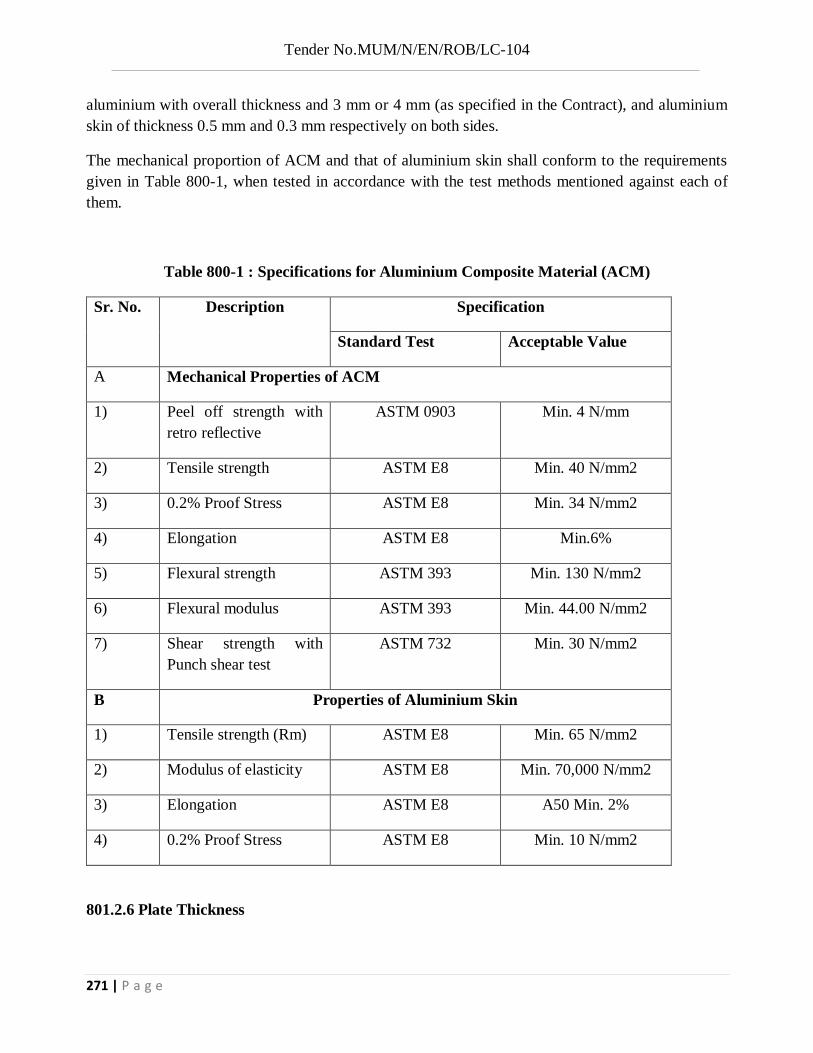
Tender No.MUM/N/EN/ROB/LC-104
271 | P a g e
aluminium with overall thickness and 3 mm or 4 mm (as specified in the Contract), and aluminium skin of thickness 0.5 mm and 0.3 mm respectively on both sides.
The mechanical proportion of ACM and that of aluminium skin shall conform to the requirements given in Table 800-1, when tested in accordance with the test methods mentioned against each of them.
Table 800-1 : Specifications for Aluminium Composite Material (ACM)
Sr. No. Description Specification
Standard Test Acceptable Value
A Mechanical Properties of ACM
1) Peel off strength with retro reflective
ASTM 0903 Min. 4 N/mm
2) Tensile strength ASTM E8 Min. 40 N/mm2
3) 0.2% Proof Stress ASTM E8 Min. 34 N/mm2
4) Elongation ASTM E8 Min.6%
5) Flexural strength ASTM 393 Min. 130 N/mm2
6) Flexural modulus ASTM 393 Min. 44.00 N/mm2
7) Shear strength with Punch shear test
ASTM 732 Min. 30 N/mm2
B Properties of Aluminium Skin
1) Tensile strength (Rm) ASTM E8 Min. 65 N/mm2
2) Modulus of elasticity ASTM E8 Min. 70,000 N/mm2
3) Elongation ASTM E8 A50 Min. 2%
4) 0.2% Proof Stress ASTM E8 Min. 10 N/mm2
801.2.6 Plate Thickness

Tender No.MUM/N/EN/ROB/LC-104
272 | P a g e
Shoulder mounted ground sings with a maximum side dimension not exceeding 600 mm shall not be less than 1.5 mm thick with Aluminium and 3 mm thick with Aluminium Composite Material. All other signs be at least 2 mm thick with Aluminium and 4 mm thick with Aluminium Composite Material. The thickness of the sheet shall be related to the size of the sign and its support and shall be such that it does not bend or deform under prevailing wind and other loads.
801.2.7 In respect of sign sizes not covered by IRC:67, the structural details (thickness, etc.) shall be as per the approved drawings or as directed by the Engineer.
801.3 Traffic Signs having Retro-Reflective Sheeting
801.3.1 General Requirements
The retro-reflective sheeting used on the sign shall consist of the white or coloured sheeting having a smooth outer surface which has the property of retro-reflection over its entire surface.
It shall be weather-resistant and show colour fastness. It shall be new and unused and shall show no evidence of cracking, scaling, pitting, blistering, edge lifting or curling and shall have negligible shrinkage or expansion. A certificate of having tested the sheeting for co-efficient of retro-reflection, day/night time colour luminous, shrinkage, flexibility, linear removal, adhesion, impact resistance, specular gloss and fungus resistance and its having- passed these tests shall be obtained from a Government Laboratory/Institute, by the manufacturer of the sheeting. The retro-reflective sheeting shall be either of Engineering Grade material with enclosed lens, High Intensity Grade with encapsulated lens or Micro-prismatic Grade retro-reflective element material as given in Clauses 801.3.2 to 801.3. 7. Guidance on the recommended application of each class of sheeting may be taken from IRC:67.
801.3.2 High Intensity Grade Sheeting
801.3.2.1 High Intensity Grade (Type Ill)
This high intensity retro reflective sheeting shall be of encapsulated lens type consisting of spherical glass lens, elements adhered to a synthetic resin and encapsulated by a flexible, transparent waterproof plastic having a smooth surface or as an unmetallised micro prismatic
reflective material element. The retro-reflective surface after cleaning with soap and water and in dry condition shall have the minimum co-efficient of retro-reflection (determined in accordance with ASTM 0:4956-09) as indicated in Table 800-2.
Table 800-2 : Acceptable Minimum Co-efficient of Retro-Reflection for High
Intensity Grade Sheeting (Type Ill) (Encapsulated Lens Type)

Tender No.MUM/N/EN/ROB/LC-104
273 | P a g e
(Candelas Per Lux Per Square Metre)
Observation Angle in Degrees
Entrance Angle in Degrees
White Yellow Orange Green Red Blue Brown
0.10B -40 300 200 120 54 54 24 14
0.10B -300 180 120 72 32 32 14 10
0.20 -40 250 170 100 45 45 20 12
0.20 -300 150 100 60 25 25 11 8.5
0.50 -40 95 62 30 15 15 7.5 5.0
0.50 -300 65 45 25 10 10 5.0 3.5
A minimum of Coefficient of Retro-reflection (RA)cd/fc/ft²(cd-xl-1m²).
B Values for 0.1ᵒ observation angles are supplementary requirement that shall apply only
when specified by the purchaser in the Contract or order. When totally wet, the sheeting shall show not less than 90 percent, of the values of retro reflectance indicated in above Table. At the end of 7 years, the sheeting shall retain at least 80 percent of its original retro-reflectance.
801.3.4 Prismatic Grade Sheeting
801.3.4.1 Prismatic Grade Sheeting (Type VIII)
The reflective sheeting shall be retro reflective sheeting made of micro prismatic retro reflective material. The retro reflective surface, after cleaning with soap and water and in dry condition shall have the minimum co-efficient of retro reflection (determined in accordance with ASTM E 810) as indicated in Table 800-4.
801.3.4.2 Prismatic Grade Sheeting (Type IX)
The reflective sheeting shall be retro-reflective sheeting made of micro prismatic retro-reflective material. The retro-reflective surface, after cleaning with soap and water and in dry condition shall have the minimum co-efficient of retro-reflection (determined in accordance with ASTM E 810) as indicated in Table 800-5.
Table 800-4: Acceptable Minimum Co-efficient of Retro-Reflection for Prismatic Grade Sheeting (Type VIII) (Candelas Per Lux Per Square Metre)

Tender No.MUM/N/EN/ROB/LC-104
274 | P a g e
Observation
Angle in Degrees
Entrance Angle
in Degrees
White Yellow Orange Green Red Blue Brown Fluor-escent
Yellow/ Green
Fluor-escent Yellow
Fluor-escent Orang
e
0.1ᵒᴮ -4ᵒ 1000 750 375 100 150 45 30 800 600 300
0.1ᵒᴮ +30ᵒ 460 345 175 46 69 21 14 370 280 135
0.2ᵒ -4ᵒ 700 525 265 70 105 32 21 560 420 210
0.2ᵒ +30ᵒ 325 245 120 33 49 15 10 260 200 95
0.5ᵒ -4ᵒ 250 190 94 25 38 11 7.5 200 150 75
0.5ᵒ +30ᵒ 115 86 43 12 17 5 3.5 62 69 35
A Minimum Coefficient of Retro reflection (R^A) cd/fc/ft² (cd-Ix- 1m²).
B Values for 0.1ᵒ observation angles are supplementary requirements that shall apply only when
specified by the purchaser in the contract or order. When totally wet, the sheeting shall show not less than 90 percent of the values of retro reflection indicated in above Table. At the end of 10 years, the sheeting shall retain at least 80 percent of its original retro-reflectance.
Table 800-5: Acceptable Minimum Co-efficient of Retro-Reflection for Prismatic Grade Sheeting (Type IX) (Candelas Per Lux Per Square Metre)
Observation Angle in Degrees
Entrance Angle in Degrees
White Yellow
Orange
Green Red Blue Fluorescent Yellow/Green
Fluor-scent Yellow
Fluor-scent Orange
0.1ᵒᴮ -4ᵒ 600 500 250 66 130 130 530 400 200
0.1ᵒᴮ +30ᵒ 370 280 140 37 74 17 300 220 110
0.2ᵒ -4ᵒ 380 285 145 38 76 17 300 230 114
0.2ᵒ +30ᵒ 215 162 82 22 43 10 170 130 65

Tender No.MUM/N/EN/ROB/LC-104
275 | P a g e
0.5ᵒ -4ᵒ 240 180 90 24 48 11 190 145 72
0.5ᵒ +30ᵒ 135 100 50 14 27 6.0 110 81 41
0.1ᵒ -4ᵒ 80 60 30 8.0 16 3.6 64 48 24
0.1ᵒ +30ᵒ 45 34 17 4.5 9.0 2.0 36 27 14
A Minimum Coefficient of Retro reflection (RA) cd/fc/ft² (cd-Ix- 1m²).
B Values for 0.1ᵒ observation angles are supplementary requirements that shall apply only when specified by the purchaser in the contract or order. When totally wet, the sheeting shall show not less than 90 percent of the values of retro reflection indicated in above Table. At the end of 10 years, the sheeting shall retain at least 80 percent of its original retro-reflectance.
801.3.4.3 Prismatic Grade Sheeting (Type XI)
A Retro-reflective sheeting typically manufactured as a cube corner. The reflective sheeting shall be retro-reflective sheeting made of micro prismatic retro-reflective material. The retro-reflective surface, after cleaning with soap and water and in dry condition shall have the minimum co-efficient of retro-reflective (determined in accordance with ASTM E 810) as indicated in Table 800-6.
Table 800-5: Acceptable Minimum Co-efficient of Retro-Reflection for Prismatic Grade Sheeting (Type IX) (Candelas Per Lux Per Square Metre)
Observation Angle in Degrees
Entrance Angle in Degrees
White Yellow
Orange Green Red Blue Brown
Fluorescent Yellow/Green
Fluor-scent Yellow
Fluor-scent Orange
0.1ᵒᴮ -4ᵒ 830 620 290 83 125 37 25 680 500 250
0.1ᵒᴮ +30ᵒ 325 245 115 33 50 15 10 260 200 100
0.2ᵒ -4ᵒ 580 435 200 58 87 26 1 460 350 175
0.2ᵒ +30ᵒ 220 165 77 22 33 10 7.0 180 130 66
0.5ᵒ -4ᵒ 420 315 150 42 63 19 13 340 250 125
0.5ᵒ +30ᵒ 150 110 53 15 23 7.0 5.0 120 90 45
0.1ᵒ -4ᵒ 120 90 42 12 18 5.0 4.0 96 72 36

Tender No.MUM/N/EN/ROB/LC-104
276 | P a g e
0.1ᵒ +30ᵒ 45 34 16 5.0 7.0 2.0 1.0 36 27 14
A Minimum Coefficient of Retro reflection (RA) cd/fc/ft² (cd-Ix- 1m²).
B Values for 0.1ᵒ observation angles are supplementary requirements that shall apply only when
specified by the purchaser in the contract or order. When totally wet, the sheeting shall show not less than 90 percent of the values of retro reflection indicated in above Table. At the end of 10 years, the sheeting shall retain at least 80 percent of its original retro-reflectance.
801.3.5 Adhesives
The sheeting shall have a pressure-sensitive adhesive of the aggressive-tack type requiring no heat, solvent other preparation for adhesion to a smooth clean surface, in a manner recommended by the sheering manufacturer. The adhesive shall be protected by an easily removable liner (removable by peeling without soaking in water or other solvent) and shall be suitable for the type of material of the base plate used for the sign. The adhesive shall form a durable bond to smooth, corrosion and weather resistant surface of the base plate such that it shall not be possible to remove the sheeting from the sign base in one piece by use of sharp instrument. The sheeting shall be applied in accordance with the manufacturer’s specification.
801.3.6 Fabrication
Surface to be reflectorised shall be effectively prepared to receive the retro-reflective sheeting. The aluminum sheeting shall be de-greased either by acid or hot alkaline etching and all Traffic Signs, Marking and other Road Appurtenances.
Scale/dust removed to obtain a smooth plain surface before the application of retro-reflective sheeting. If the surface is rough, approved surface primer may be used. After cleaning, metal shall not be handled, except by suitable device or clean canvas gloves, between all cleaning and preparation operation and application of reflective sheeting/primer. There shall be no opportunity for metal to come in contact with grease, oil or other contaminants prior to the application of retro-reflective sheeting. Complete sheets of the material shall be used on the sings except where it is unavoidable. At splices, sheeting with pressure-sensitive adhesives shall be overlapped not less than 5mm. Where screen printing with transparent colors is proposed, only butt joint shall be used. The material shall cover the sign surface evenly and shall be free from twists, cracks and flods, Cut-outs to produce legends and broders shall be bonded with the manner specified by the manufacturer.
801.3.7 Messages/Borders

Tender No.MUM/N/EN/ROB/LC-104
277 | P a g e
The messages (legends, letter, numerals etc.) and borders shall either be screen-printed or of cut out from durable transparent overlay or cut out from the same type of reflective sheeting for the cautionary/mandatory sign boards. Screen Printing shall be processed and finished with material and in a manner specified by the sheeting manufacture. For the informatory and other sign boards, the messages (legends, letters, numerals, etc.) and broders shall be cut out from durable transparent overlay film or cut-out from the same reflective sheeting only. Cut-outs shall be from durable transparent overlay materials as specified by the manufacturer and shall be bonded with the sheeting in the manner specified by the manufacturer. For screen-printed transparent colored area on white sheeting, the co-efficient of retro-reflective shall be less than 50 percent of the values of corresponding color in Table 800-2 to 800-8 as applicable. Cut-out messages and borders, wherever used, shall be either made out of retro-reflective sheeting or made out of durable transparent overlay except those in black which shall be of non- reflective sheeting or opaque in case of durable transparent overlay.
801.3.8 Color for Signs
801.3.8.1 Signs shall be provided with retro-reflective sheeting and or overlay film screening ink. The reverse side of all signs shall be painted grey.
801.3.8.2 Except in the case of railway level crossing signs the sign posts shall be painted in 250mm side bands , alternately black and white . The lowest band next to be ground shall be in black.
801.3.8.3 The color of the material shall be located within the area defined by the chromaticity coordinates in Table 800-7 and comply with the luminance factor when measured as per ASTM D-4956.
Table 800-5: Colour Specified Limits (Daytime)
Colour
1
2
3
4
Daytime
Luminance
Factor(Y%)
x y x y x y x y Min. Max.
White 0.303 0.300 0.368 0.366 0.340 0.3939 0.274 0.329 15 --
Yellow 0.498 0.412 0.557 0.442 0.479 0.520 0.438 0.472 24 45
Green 0.026 0.399 0.166 0.364 0.286 0.446 0.207 0.771 2.5 11
Red 0.648 0.351 0.35 0.265 0.629 0.281 0.565 0.346 2.5 11

Tender No.MUM/N/EN/ROB/LC-104
278 | P a g e
Blue 0.140 0.035 0.244 0.210 0.190 0.255 0.065 0.216 1 10
Orange 0.558 0.352 0.636 0.364 0.570 0.429 0.506 0.404 12 30
Brown 0.430 0.340 0.610 0.390 0.550 0.450 0.430 0.390 1 6
Fluorescent
Yellow-Green
0.387 0.610 0.369 0.546 0.428 0.496 0.460 0.540 60 --
Fluorescent
Yellow
0.479 0.520 0.446 0.483 0.512 0.421 0.557 0.442 45 --
Fluorescent
Orange
0.583 0.416 0.535 0.400 0.595 0.351 0.645 0.355 25 --
The colour shall be durable and uniform in acceptable hue when viewed in day light or under normal headlights at night.
801.3.8.4 The Regulatory/Prohibitor and warning signs shall be provided with white background and red border. The legend/symbol for these signs shall be in black colour. The Mandatory sign shall be provided with Blue background and white Symbol/letter.
801.3.8.5 The colours chosen for informatory or guide sings shall be distinct for different classes of roads. For National Highways, these signs shall be of green background and for Expressways these signs shall be of blue background with white border, legends and word messages.
801.3.9 Refurbishment
Where existing signs are specified for refurbishment, the sheeting shall have a semi-rigid aluminum backing or materials as per Clause 801.2.5,per-coated with aggressive-tack type pressure sensitive adhesive. The adhesive shall be suitable for the type of material used for the sign and should thoroughly bond with that material.
801.3.9 Sizes of Letters

Tender No.MUM/N/EN/ROB/LC-104
279 | P a g e
801.3.10.1 Letter size should be chosen with due regard to the speed, classification and location of the road, so that the sign is of adequate size for legibility but without being too large or obtrusive. The size of the letter, in terms of x-height, to be chosen as per the design speed is given in Table 800-8
Table 800-8: Acceptable Limits for Sizes of Letters
The thickness of the letters and their relation to the x-heights are indicated in Table IV (a) of the Annexure-4 of IRC:67 to facilitate the design of the informatory signs and definition plates.
801.3.10.2 For advance direction signs on non-urban roads, the letter size (‘x’ height) should be
minimum of 150 mm for Expressway, National and State Highways and 100 mm for other roads. In case of overhead signs, the size (‘X’ height) of letters may be minimum 300 mm. Thickness of the
letter could be varied from 1/6 to 1/5 of the letter ‘x’ size. The size of the initial uppercase letter shall
be 1-1/3 times x-height. In urban areas, letter size shall be 100 mm on all directional signs. For easy and better comprehension, the word message shall be written in upper case letters only.
801.3.10.3 Letter size on definition plates attached with normal sized signs should be 100 mm or 150 mm. In the case of small signs, it should be 100 mm. Where the message id long, as for instance in “NO PARKING” and “NO STOPPING” signs, the message may be broken into two lines and size
of letters may be varied in the lines so that the definition plate is not too large. The lettering on definition plates will be in upper case letters.
801.3.11 Warranty and Durability
Design
Speed
(Km./hr.)
Minimum ‘x’Height
of the letters
(mm)
Minimum Sight Distance/Clear
Visibility Distance
(m)
Minimum Distance from Center Line
(m)
40 100 45 12
50 125 50 14
65 150 60 16
80 250 80 21
100 300 90 24
120 400 115 32

Tender No.MUM/N/EN/ROB/LC-104
280 | P a g e
The Contractor shall obtain from the manufacturer a ten year warranty for satisfactory field performance including stipulated retro-reflectance of the retro-reflectance sheeting of micro-prismatic sheeting and a seven-year warranty for high intensity grade and submit the same to the Engineer. The warranty shall be inclusive of the screen printed or cut out letters/legends and their bonding to the retro-reflective sheeting. The Contractor/supplier shall also furnish the LOT numbers and certification that the signs and materials supplied against the assigned work meets all the stipulated requirements and carry the stipulated warranty and that the contractor/supplier is the authorized converter of the particular sheeting.
All signs shall be dated during fabrication with indelible markings to indicate the start of warranty. The warranty shall also cover the replacement obligation by the sheeting manufacturer as well as contractor for replacemenUrepair/restoration of the retro-reflective efficiency.
A certificate in original shall be given by the sheeting manufacturer that its offered retroreflective sheeting has been tested for various parameters such as co-efficient of retroreflection, day/night time colour and luminance, shrinkage, flexibility, linear removal, adhesion, impact resistance, specular gloss and fungus resistance; the tests shall be carried out by a Government Laboratory in accordance with various ASTM procedures and the results must show that the sheeting has passed the requirements for all the above mentioned parameters. A copy of the test reports shall be attached with the certificate.
801.4 Installation
801.4.1 The traffic signs shall be mounted on support posts, which may be of Gl pipes conforming to IS:1239, Rectangular Hollow Section conforming to IS:4923 or Square Hollow Section conforming to IS:3589. Sign posts, their foundations and sign mountings shall be so constructed as to hold these in a proper and permanent position against the normal storm wind loads or displacement by vandalism. Normally, signs with an area up to 0.9 sq.m shall be mounted on a single post, and for greater area two or more supports shall be provided. Post-end(s) shall be firmly fixed to the ground by means of properly designed foundation. The work of foundation shall conform to relevant Specifications as specified.
801.4.2 All components of signs (including its back side) and supports, other than the reflective portion and G. I. posts shall be thoroughly de-scaled, cleaned, primed and painted with two coats of epoxy/ fibre glass/ powder coated paint. Any part of support post below ground shall be painted with protective paint.
801.4.3 The signs shall be fixed to the posts by welding in the case of steel posts and by bolts and washers of suitable size. After the nuts have been tightened, the tails of the bolts shall be furred over with a hammer to prevent removal.

Tender No.MUM/N/EN/ROB/LC-104
281 | P a g e
801.5. Measurements for Payment The measurement of standard cautionary, mandatory and information signs shall be in numbers of different types of signs supplied and fixed, while for direction and place identification signs, these shall be measured by area in square metres.
A warranty for 7 years for the retro reflective sheeting from original manufacturer and certified copy of three years outdoor exposure test report from third party test lab for the product offered shall be submitted by contractor.
801.6. Rate The Contract unit rate shall be payment in full for the cost of making the road sign, including all materials, installing it at the site and incidentals to complete the work in accordance with the Specifications.
Item no.25: Providing & Fixing sign boards made out of 2mm. Aluminium sheet size 1 Meter x 1 Meter cms as per the design given by engineer in charge, Pre treated with phosphating process & acid etching : coated with one coat of epoxy primer and two coats of best quality epoxy paint reflectorised with retro reflective sheeting as per latest M.O.S.T Specification, Letters and numerals should be as per IRC -30-2015, 3.1 M long ( 2 nos) Stand post and frame fabricated from suitable size iron angle of 35 x 35 3mm & 50 x 50 x 5mm 75 x 75 x 6mm : painted with best quality epoxy coating in black and white bends the details of symbol or inscription / numerals for each board shall be as per the instruction for of Engineer-in-charge, The fixing at site shall be in 1;2;4 CC block of size 45 x 45 x 60cms. for each leg. including excavation curing etc. comp. under the supervision of engineer in charge.(B) High intensity Grade
This work shall consist of Providing and fixing Sign Board and shall be carried out as per relevant detailed specification of Item No. 24 of this contract. Item no.26: Providing and fixing Junction Board made out of 2mm aluminium sheet, size 244 x 122 cms rectangle, as per the design of IRC-67-2015. Pre treated with phosphating process and acid etching coated with one coat of epoxy primer and two coats of best quality epoxy paint, refloctrorized with retro reflective sheeting as per the latest M.O.S.T. specification, Letters and numerals should be as per IRC-30-1968. 3.1 Mt. long (2 nos.) stand post and frame fabricated from suitable size iron angle of 50 x 50 x 5 mm, 75 x 75 x 6 mm; painted with best quality epoxy coating in black and white bends. The details of symbol or inscription/ numerals for each board shall be as per the instruction of engineer in charge. The fixing at site shall be in 1:2:4 CC block of size 45 x 45 x 60 cms for each leg, including excavation curing etc. complete under the supervision of Engineer-In-Charge (B) . High intensity Grade.
This work shall consist of Providing and fixing Junction Board and shall be carried out as per relevant detailed specification of Item No. 24 of this contract.
Item no.27: Hazard Marker Sign :-Providing and fixing sign boards made out of 2mm aluminium sheet; size 90 x 30cms. rectangle as as per the design/drawing attached (IRC) pretreated with phospheting process & acid etching; coated with one coat of epoxy primer and two coats of best quality epoxy paint; reflectorised with retro refiective sheeting as per latest M.O.S.T. Specifications; 3.1m long stand post and frame fabricated from suitable size iron angle of 35 x 35 x 3mm & 50 x 50 x 5mm painted with best quality epoxy coatings The fixing at site shall be in 1:2:4 CC block of size 45x45x 60cms. for each leg. including excavation

Tender No.MUM/N/EN/ROB/LC-104
282 | P a g e
curing etc. complete under the supervision of engineer in charge.(B)High Intensity Grade .....................
This work shall consist of Providing and fixing Hazard marker sign Board and shall be carried out as per relevant detailed specification of Item No. 24 of this contract.
Item no.28: Providing and fixing cautionay warning sign board made of 2mm aluminium sheet size 90X90X90 cms. Equilateral traingle as per the design of IRC-67-2015 pretreated with phospheting process & acid catching with one coat of epoxy primer and two coats of best quality epoxy paint reflectioned with retro reflective sheeting as per latest MOST specification 3.1 mt. long stand post and frame fabricated from suitable size iron angle of 35x35x3mm. 75x75x6mm as required .painted with best quality epoxy coating in black and white bends, the details of symbol for board shall be as per the instruction of engineer-in-charge. the fixing at site shall be in 1;2:4 cc block of size 45X45X60 cms for each leg including excavation curing etc. complete under the supervision of engineer in charge (high intensity grade).
This work shall consist of Providing and fixing Cautionary sign Board and shall be carried out as per relevant detailed specification of Item No. 24 of this contract.
Item no.29: Box cutting the road surface to proper slope and chamber for making a base for road work including removing the excavated stuff and depositing on the road side slope as directed.
1.This work shall consist of excavation, removal and satisfactory disposal of all materials necessary for the construction of widening carriageway in accordance with requirements of these specifications and the lines, grades and cross sections shown in the drawings or as indicated by the Engineer.
2.After the site has been cleared the limits of excavation/ box cutting the road surface shall be set out true to lines, curves, slopes, grades and sections as shown on the drawings or as directed by the Engineer.
3.Box cutting shall be carried out in conformity with the directions laid here in under and in a manner approved by the Engineer. The work shall be so done that the suitable materials available from box cutting/ excavation are satisfactorily utilized as directed.
4.The contractor shall not excavate outside the limits of box cutting. Subject to the permitted tolerances, any excess depth/ width excavated beyond the specified levels/ dimensions on the drawings shall be made good at the cost of the contractor with suitable material of characteristics similar to that removed and compacted as directed.
5.Cutting shall be done in proper grade & camber as per measurements given. Care must be taken that all slopes are evenly and truly dressed. Cutting shall be done to the exact depth required and shall be as per formation level in proper grade and the camber. If extra depth of cutting is done due to negligence of contractor the same shall be refilled with approved quality of materials duly consolidated to the satisfaction of the Engineer-in-charge (without extra cost).

Tender No.MUM/N/EN/ROB/LC-104
283 | P a g e
6.The stuff received from the cutting shall be used for filling and correcting side slopes of bank as directed by the Engineer in charge.
7.The measurement of box cutting shall be taken on level basis & level shall be taken at 10 mt. interval. Volume shall be computed in cubic meters by average area method.
8.The payment shall be made on Cum. basis.
9. The rate includes cost of all labour, machineries required, cost of carting the cutting stuff with all lead and lift and leveling the dumping ground etc. complete.
Item no.30: Supplying and fixing cat eye with nail less surface (Stimsonite) made out from Acrylic butyle styrene high compression injection moulding with reflector made of MMC (prismatic type of size 12cm x 6cm x 2.5cm) provided with bituminous adhesive 100g. with each unit for fixing. (High Intensity grade).
1.1 General Reflective Pavement marker (RPM) or road stud is device which is bonded to or
anchored within the road surface for lane marking and delineation for night time visibility. It reflects incident light in directions close to the direction from which it came.
1.2 Definitions 1.2.1 Description of Terms Specific to this standard 1.2.1.1 Coefficient of luminous intensity (CIL) or specific intensity = the ratio of luminous
intensity of the retro-reflector in the direction of observation to luminance at the retro-reflector on a plane perpendicular to the direction of the incident light expressed in terms of Milaca deal as per incident lux (med/ lx).
1.2.1.2 Horizontal entrance angle – the angle in the horizontal plant between the direction of incident light and the normal to the leading edge of the marker.
1.2.1.3 Observation angle – the angle in the reflector between the illumination axis and the observation axis.
1.2.1.4 Retro – reflection – reflection in which the radiation is returned in direction close to the direction from which it came, this property being maintained over were variations of the direction of incident radiation.
1.2.1.5 Head – that part of a road stud which is above the road surface where the road stud is fixed in position in the road.
1.2.1.6 Upper surface – that part of the external surface of road stud which is visible when the road stud is fixed in position in the road.
1.2.1.7 Anchorage – that part of a road stud which is below the road surface above the road stud is fixed position in the road.
1.3 Material 1.3.1 Plastic body of RPM road stud shall be moulded from ASA (Acrylic Sterner
Acrylonitrile) or HIPS (Impacts polystyrene) or ABS or any other suitable material approved by the Engineer-in-charge. The marker shall support a load of 13635 kg tested in accordance with ASTM D4280.

Tender No.MUM/N/EN/ROB/LC-104
284 | P a g e
1.3.2 Reflective panels shall consist if number of lenses containing single or dual prismatic cubes capable of providing total internal reflection of the light entering the lens face. Lenses shall be moulded of methyl methecrylate conforming to ASTMD 788 or equivalent.
1.4 Design 1.4.1 The slope or retro-reflecting surface shall preferably be 35 + 5 degree to base. 1.4.2 The area of each retro-reflecting surface shall not be less than 13.0 Sq.cm. 1.5 Optical Performance 1.5.1 Unidirectional and bi-directional studs 1.5.1.1 Each reflector or combination of reflectors on each face of the stud shall have a CIL
not less than given in Table 1 or 2 as appropriate.
Table 1 Minimum C.I.L. Values for Category "A" studs. Entrance angle Observation angle C.I.L. in med 1 x
White Amber Red
0" U 5" L & R 0.3" 220 110 44
0" U 10" L & R 0.5" 120 60 24
Table 1 Minimum C.I.L. Values for Category "B" studs.
Entrance angle Observation angle C.I.L. in med 1 x
White Amber Red
0" U 6" L & R 0.3" 20 10 4
0" U 10" L & R 0.5" 15 7.5 3
Note: The entrance angle of 0"U corresponds to the normal aspect of the reflectors when the reflecting road stud is installed in horizontal road surface.
1.5.1.2 A stud that incorporates one or more corner cube reflectors shall be considered to be included in category "A". A stud that incorporates one or more biconvex reflectors shall be considered to be included in category "B".
1.5.2 Omni – directional studs Each Omni-directional stud shall have a minimum C.I.L. of not less than med/ lx. 1.5.3 Tests 1.5.3.1 Coefficient of luminance intensity can be measured by produced described in ASTMD
809 "Practice for Measuring Photometric Characteristics" or as recommended in BS 873 Part 4:1973.
1.5.3.2 Under test conditions a stud shall not be considered to fall the photometric requirements of the measured C.I.L. at any one position of measurement is less than the values specified in Table 1 or 2 provided that.
(A) The value is not less than 80% of the specified minimum, and (B) The average of the left and right measurements for the specific angle is greater than
the specified minimum.

Tender No.MUM/N/EN/ROB/LC-104
285 | P a g e
1.6 Fixing of Reflective Markers 1.6.1 Requirements 1.6.1.1 The enveloping profile of the head of the stud shall be smooth and the suds shall not
present any sharp edges to traffic. 1.6.1.2 The reflecting portions of the studs shall be free from crevice or ledges where dirt
might accumulate. 1.6.1.3 All road studs shall be legibly marked with the name, trade mark of other means of
identification of the manufacture. 1.6.1.4 Marker height shall not exceed 20 mm. 1.6.1.5 Marker width shall not exceed 130 mm. 1.6.1.6 The base of the marker shall be flat within 1.3 mm. If the bottom of the marker is
configured. The outermost faces of the configurations shall not deviate more than 1.3 mm form a flat surface.
1.6.2 Placement 1.6.2.1 The reflective marker shall be fixed to the road surface using the adhesives and the
produced recommended by the manufacturer. No nails shall be used to affix the marker as nails are hazardous for the roads.
1.6.2.2 Regardless of the type of adhesive used. The markers shall not be fixed if the pavement is not surface dry and on new asphalt concrete surfacing unit the surfacing has been opened to traffic for a period of not less than 14 hours.
1.6.2.3 The portions of the highway surface, to which the marker is to be bonded by the adhesive, shall be free of dirt, curing compound, grease, oil, moisture, loose of unsound layers, paint and any other material which would adversely affect the bond of the adhesive.
1.6.2.4 Use a wire brush, if necessary to loosen and remove dirt. Then brush or blow clean. 1.6.2.5 The adhesive shall be places uniformly on the cleaned pavement surface or on the
bottom to the marker in a quantity sufficient to result in complete coverage of the area of contact of the marker with no voids present and with a slight excess after the marker has been lightly pressed in place.
1.6.2.6 For epoxy installations, excess adhesive around the edge of the marker, excess adhesive on the pavement and adhesive on the exposed surfaces of the markers shall be immediately removed. Soft rags moistened with mineral spirits of kerosene may be used a necessary to remove adhesive from exposed faces of pavement marker.
1.7 Warranty and durability The contractor shall obtain from the manufacturer a two year warranty for satisfactory light performance including stipulated retro-reflectance of the reflecting panel and submit the same to the Engineer. In addition, a two year warranty for satisfactory infield performance of the finished road marker shall also be given by the contractor who carried out the work of fixing of reflective road markers. In case the markers are displaced, damaged get worn out or lose their reflectivity compared to stipulated standards, the contractor would be required to replaced all such markers within 15 days of the intimation from the Engineer at his own cost and with no extra remuneration to be paid for such works.
1.8 Measurement for Payment

Tender No.MUM/N/EN/ROB/LC-104
286 | P a g e
The measurement of Cats eye (MMC) shall be in numbers of markers supplied and fixed.
1.9 Rate The contact unit rate for Cats eye (MMC) shall be payment in full compensation for furnishing all labour, material, tools, equipment including incidental costs necessary for carrying out the work at site conforming to the specifications complete as per approved drawings or as directed.

Tender No.MUM/N/EN/ROB/LC-104
287 | P a g e
FOR SCHEDULE “B”
Item no. 01: Marking out the centre line of the bridge and various other components structures and complete lining out and levelling with Total Station, theodolite, level including construction necessary masonry pillars for lines and levels and establishing necessary benchmark etc. complete as directed.
The Centre line axis of the Rail Over Bridge with approaches shall be surveyed along their lengths. Centre line pegs for Rail Over Bridge with approaches including foundation pegs at each location and at suitable distance of 3.0 m c/c along the approach on each side shall be fixed.
All deviation angles of the central line axis for the Rail Over Bridge with approaches including tangent distances shall be demarcated with pegs fixed in to the ground.
The rate on Lump sum basis shall include all equipment/theodolite/total station survey instruments, necessary survey party, supply and fixing of pegs including, fixing of pillars for intermediate stations labour, materials required in completing the job as required, as per direction of Engineer-in-charge.
The rate shall be paid on lump sum basis for completed item as directed.
Item no. 02: Earth work for embankment including breaking clods dressing with all lead and lift and including watering, rolling, and consolidation of sub-grade in layers at O.MC. to required dry density including filling the depressing which occur during the process using Vibratory roller 8.T. to 10 T.
305 EMBANKMENT CONSTRUCTION
305.1 GENERAL:
305.1.1 Description: These Specifications shall apply to the construction of embankments including sub grades, earthen shoulders and miscellaneous backfills with approved materials obtained from contractor’s own earth. No railway land / Gujarat State land to be used as source of earth,
contractor shall arrange own earth. All embankments, sub grades, earthen shoulders and miscellaneous backfills shall be constructed in accordance with the requirements of these specifications and in conformity with the lines, grades, and cross-sections shown on the drawings or as directed by the Engineer.
305.2 MATERIALS AND GENERAL REQUIREMENTS
305.2.1 Physical requirements:
305.2.1.1 The materials used in embankments sub grades, earthen shoulders and miscellaneous back fills shall be soil, murrum, gravel a mixture of these or any other material approved by the Engineer. Such materials shall be free of logs, stumps, roots, rubbish or any other ingredient likely to deteriorate or affect the stability of the embankment.
The following types of material shall be considered unsuitable for embankment:
(a) Materials from swamps, marshes and bogs;

Tender No.MUM/N/EN/ROB/LC-104
288 | P a g e
(b) Peat, log, stump and perishable material and soil that classifies as OL, 01, OH or Pt in accordance with IS: 1498
(c) Materials susceptible to spontaneous combustion
(d) Materials in a frozen condition
(e) Clay having liquid limit exceeding 70 and plasticity index exceeding 45; and
(f) Materials with salts resulting in leaching in the embankment.
305.2.1.2 Expansive clay exhibiting marked swell and shrinkage, properties ("free swelling index" exceeding 50 percent when tested as per IS:2720-Part 40) shall not be used as a fill materia1.Where an expansive clay with acceptable "free swelling index" value is used as a fill material, sub grade and top 500 mm portion of the embankment just below sub grade shall be non-expansive in nature.
305.2.1.3 Any fill material with a soluble sulphate content exceeding 1.9 grams of sulphate (expressed as S03) per liter when tested in accordance with BS:1377 Test 10, but using a 2: 1 water-soil ratio shall not be & deposited within 500 mm or other distance described in the Contract, of concrete, cement bound materials or other cementious materials forming part of the Permanent Works.
Materials with a total sulphate content (expressed as S03) exceeding 0.5 per cent by mass, when tested in accordance with BS: 1377 Test 9 shall not be deposited within 500 mm, or other distances described in the contract, of metallic items farming part of the Permanent Work
305.2.1.4 The size of the coarse material in the mixture of earth shall ordinarily not exceed 75mm when being placed in the embankment and 50 mm when placed in the sub grade. However the Engineer may at his discretion permit the use of material coarser than this also. If he is Satisfied that the same will not present any difficulty as regards the placement of fill material and its compaction to the requirements of these specifications. The maximum particle size shall not be more than two third of the compacted layer thickness.
305.2.1.5 Ordinarily, only the materials satisfying the density requirements given in MORTH Table 300-1 shall be employed for the Construction of the embankment and the sub grade.
MORTH TABLE 300-1:- DENSITY REQUIREMENTS OF EMBANKMENT AND SUBGRADE MATERIALS
Sr. No. Type of work Maximum Laboratory dry unit weight when tested as per IS:2720(part 8)
1. Embankments up to. 3 meters height, not subjected to extensive flooding.
Not less than 15.2 kN/cum.
2. Embankments exiting 3 meters height of embankments of any height subject to long period of inundation
Not less than 16.0 kN/cum.
3. Sub grade and earthen shoulders/ Verges/backfill
Not less than 17.5 kN/cu.m.
Notes:

Tender No.MUM/N/EN/ROB/LC-104
289 | P a g e
(1) This Table is not applicable for lightweight fill materials e.g. cinder, fly ash etc.
(2) The Engineer may relax these requirements at his discretion taking into account the availability of materials for construction and other relevant factors.
(3) The materials to be used in sub grade should also. Satisfy design CBR at the dry unit weight Applicable as per Table 300-2 of MORT&H.
305.2.1.6 The material to be used in subgrade shall conform to the design CBR value at the specified dry density and moisture content of the test specimen. In case the available materials fails to meet the requirement of CBR, use of stabilization methods in accordance with Clauses 403 and 404 or by any stabilization method approved by the Engineer or by the IRC Accreditation Committee shall be followed.
305.2.1. 7 The material to be used in high embankment construction shall satisfy the specified requirements of strength parameters.
305.2.2 GENERAL REQUIREMENTS:
305.2.2.1 The materials for embankment shall be obtained from approved sources with preference given to materials becoming available from nearby roadway excavation or any other excavation under the same Contract.
The work shall be so planned and executed that the best available materials are saved for the sub grade and the embankment portion just below the sub grade.
305.2.2.2 Borrow materials: The arrangement for the source of supply of the material for embankment and sub-grade and compliance with the guidelines, and environmental requirements, in respect of excavation and borrow areas as stipulated, from time to time by the Ministry of Environment and Forests, Government of India and the local bodies, as applicable shall be the sole responsibility of the Contractor.
Borrow pits along the road shall be discouraged. If permitted by the Engineer, these shall not be dug continuously. Ridges of not less than 8 m width should be left at intervals not exceeding 300m. Small drains shall be cut through the ridges to facilitate drainage.The depth of the pits shall be so regulated that their bottom does not cut an imaginary line having a slope of 1 vertical to 4 horizontal projected from the edge of the final section of the bank, the maximum depth in any case being limited to 1.5 m. Also, no pit shall be dug within the offset width from the toe of the embankment required as per the consideration of stability with a minimum width of 10m.
Haulage of material to embankments or other areas of fill shall proceed only when sufficient spreading and compaction plant is operating at the place of deposition.
Where the excavation reveals a combination of acceptable and unacceptable materials, the Contractor shall, unless otherwise agreed by the Engineer, carry out the excavation in such a manner that the acceptable materials are excavated separately for use in the permanent works without contamination by the unacceptable materials. The acceptable materials shall be stockpiled separately.
The Contractor shall ensure that he does not adversely affect the stability of excavation or fills by the methods of stockpiling materials, use of plants or sitting of temporary buildings or structures.
305.2.2.4 The Contractor shall obtain representative samples from each of the identified borrow areas and have these tested at the site laboratory following a testing programme approved by the Engineer

Tender No.MUM/N/EN/ROB/LC-104
290 | P a g e
shall be ensured that the sub grade material when compacted to the density requirements as in MORTH Table 300-2 shall yield the design CBR value of the sub grade.
MORTH TABLE 300-2:- COMPACTION REQUIREMENTS FOR EMBANKMENT AND SUB GRADE
Sr. No. Type of work/material
Relative compaction as percentage of max.1aboratory dry density as per IS:2720 (part 8)
1 Sub-grade and earthen shoulders Not less than 97%
2 Embankment Not less than 95%
3 Expansive clay
a) Sub grade and 500 mm portion Just below the sub-grade
Not allowed.
b) Remaining portion of embankment 90-95%
The Contractor shall at least 7 working days before commencement of compaction submit the following to the Engineer for approval:
(i) The value of maximum dry density and optimum content obtained in accordance with IS: 2720 (part 8), appropriate for each of the fill materials he intends to use.
(ii) A graph of density plotted against moisture content from which each of the values in (i) above of maximum dry density and optimum moisture content were determined.
The maximum dry density and optimum moisture content approved by the Engineer shall form the basis for compaction.
305.3 CONSTRUCTION OPERATIONS:
305.3.1 Setting Out: After the site has been cleared to Clause 201, the work shall be set out to Clause 301.3. 1. The limits of embankment/sub grade shall be marked by fixing batter pegs on both sides at regular intervals as guides before commencing the earthwork. The embankment/sub grade shall be built sufficiently wider than the design dimension so that surplus material may be trimmed; ensuring that the remaining material is to be desired density and the position specified and conforms to the specified side slopes.
305.3.2 Dewatering: If the foundation of the embankment is in an area with stagnant water, and in the opinion of the Engineer it is feasible to remove it, the same shall be removed by bailing out or pumping, as directed by the Engineer and the area of the embankment foundation shall be kept dry. Care shall be taken to discharge the drained water so as not to cause damage to the works, crops or any other property. Due to any negligence on the Part of the Contractor, if any such damage is caused, it shall be the sole responsibility of the Contractor to repair restore it to original condition or compensate the damage at his own cost.
If the embankment is to be constructed under water, MORTH Clause 305.4.6 shall apply.

Tender No.MUM/N/EN/ROB/LC-104
291 | P a g e
305.3.3 Stripping and Storing topsoil: When so directed by the Engineer, the topsoil from all areas of cutting and from all areas to be covered by embankment foundation shall be stripped to specified depths not exceeding 150 mm and stored in stockpiles of height not exceeding 2 m for covering embankment slopes, cut slopes and other disturbed areas where re-vegetation is desired. Topsoil shall not be unnecessarily subjected to traffic either before stripping or when in a stockpile. Stockpiles shall not be surcharged or otherwise loaded and multiple handling shall be kept to a minimum.
305.3.4 Compacting ground supporting embankment Sub grade: Where necessary, the original ground shall be levelled to facilitate placement of first layer of embankment, scarified, mixed with water and then compacted by rolling so as to achieve minimum dry density as given in MORTH Table 300-2.
In case where the difference between the sub grade level (Top of the sub grade on which pavement rests) and ground level is less than 0.5 m and the ground does not have 97 per cent relative compaction with respect to the dry density as given in MORTH Table 300-2, the ground shall be loosened up to a level 0.5 m below the sub grade level, watered and compacted in layers in accordance with MORTH Clauses 305.3.5 and 305.3.6 to not less than 97 per cent of dry density as given in Table 300-2.
Where so directed by the Engineer, any unsuitable material occurring in the embankment foundation shall be removed and replaced by approved materials laid in layers to the required degree of compaction.
Embankment or sub grade work shall not proceed until the foundations for Embankment/sub grade have been inspected by the Engineer for satisfactory condition and approved.
Any foundation treatment specified for embankments especially high embankments, resting on suspect foundations as revealed by borehole logs .shall be carried out in a manner and to the depth as desired by the Engineer. Where the ground on which an embankment is to be built has any of the ,material types (a) to (f) in MORTH Clause 305.2.1.1,atleast 500 mm. of such material must be removed and replaced by acceptable fill material before embankment construction commences.
305.3.5 Spreading material in layers and bringing to appropriate moisture content
305.3.5.1 The embankment and sub grade material shall be spread in layers of uniform thickness not exceeding 200mm.compacted thickness over the entire width of embankment by mechanical means, finished by a motor grader and compacted as per MORTH Clause 305.3.6.The motor grader blade shall have hydraulic control suitable for initial adjustment and maintain the same so, as to achieve the specific slope and grade. Successive layers shall not be placed until the layer under construction has been thoroughly compacted to the specified requirements as in MORTH Table 300-2 and got approved by the Engineer. Each compacted layer shall be finished parallel to the final cross-section of the embankment.
305.3.5.2 Moisture content of the material shall be checked at the site of placement prior to commencement of compaction; if found to be out of agreed limits, the same shall be made good. Where water is required to be added in such constructions, water shall be sprinkled from a water tanker fitted with sprinkler capable of applying water uniformly with a controllable rate of flow to variable widths of surface but without any flooding. The water shall be added uniformly and thoroughly mixed in soil by balding, dicing or harrowing until uniform moisture content is obtained throughout the depth of the layer.
If the material delivered to the roadbed is too wet, it shall be dried, by aeration and exposure to the sun, till the moisture content is acceptable for compaction. Should circumstances arise, where owing

Tender No.MUM/N/EN/ROB/LC-104
292 | P a g e
to wet weather, the moisture content cannot be reduced to the required amount by the above procedure, compaction work shall be suspended. Moisture content of each layer of soil shall be checked in accordance with IS: 2720. (part , 2),and unless otherwise mentioned, shall be so adjusted, making due allowance for evaporation losses, that at the time of compaction it is in the range of 1 per cent above to 2 per cent below the optimum moisture content determined in accordance with IS:2720 (Part 7) or IS: 2720 (part 8) as the case may be. Expansive clays shall however, be compacted at moisture content corresponding to the specified dry density, but on the wet side of the optimum moisture content obtained, from the laboratory compaction curve.
After adding the required amount of water, the soil shall be processed by means of graders, harrows, rotary mixers or as otherwise approved by the Engineer until the layer is uniformly wet.
clods or hard lumps of earth shall be broken to have a maximum size of 75 mm when being placed in the embankment and a maximum size of 50 mm when being placed in the sub grade.
305.3.5.3 Embankment and other areas of fill shall, unless otherwise required in the Contract or permitted by the Engineer, be constructed evenly over their full width and their fullest possible extent and the Contractor shall control and direct construction plant and other vehicular traffic uniformly over them. Damage by construction plant and other vehicular traffic shall be made good by the Contractor with material having the same characteristics and strength as the material had before it was damaged.
Embankments and other areas of unsupported fills shall not be constructed with steeper side slopes, or to greater widths than those shown in the Contract, except to permit adequate compaction at the edges before trimming back, or to obtain the final profile following any settlement of the fill and the underlying material.
Whenever fill is to be deposited' against the face of a natural slope, or sloping earthworks face including embankments, cutting, other fills and excavations steeper than 1 vertical on 4 horizontal, such faces shall be benched as per MORTH Clause 305.4.1 immediately before placing the subsequent fill.
All permanent faces of side slopes of embankments and other areas of fill formed shall, subsequent to any trimming operations, be reworked and sealed to the satisfaction of the Engineer by tracking a tracked vehicle, considered suitable by the Engineer, on the slope or any other method approved by the Engineer.
305.3.6 Compaction: Only the compaction equipment approved by the Engineer shall be employed to compact the different material types encountered during construction. Vibratory rollers of suitable size and capacity as approved by the Engineer shall be used for the different types and grades of materials required to be compacted either individually or in suitable combinations.
The compaction shall be done with the help of vibratory roller of 80 to 100 kN static weight with plain or pad foot drum or heavy pneumatic tyred roller of adequate capacity capable of achieving required compaction.
The Contractor shall demonstrate the efficacy of the equipment he intends to use by carrying out compaction trials. The procedure to be adopted for this site trials hall first be submitted to the Engineer for approva1.
Each layer of the material shall be thoroughly compacted to the densities specified in MORTH Table 300-2. Subsequent layers shall be placed only after the finished layer has been tested according to

Tender No.MUM/N/EN/ROB/LC-104
293 | P a g e
MORTH Clause 903.2} and accepted by the Engineer. The Engineer may permit measurement of field dry density by a nuclear moisture/density gauge used in accordance with agreed procedure and the gauge is calibrated to provide results identical to that obtained from tests in accordance with IS: 2720 (Part 28). A record of the same shall be maintained by the Contractor.
When density measurements reveal any soft areas in the embankments /sub grade /earthen shoulders, further compaction shall be carried out as directed by the Engineer. If in spite of that the specified compaction is not achieved, the material in the soft areas shall be removed and replaced by approved material, compacted to the density requirements and satisfaction of the Engineer.
305.3.7 Drainage: The surface of the embankment/ sub grade at all times during construction shall be maintained at such a cross fall (not flatter than that required for effective drainage of an earthen surface) as will shed water and prevent ponding.
305.3.8 Repairing of damages caused by rain/spillage of water
The soil in the affected portion shall be removed in such areas as directed by the Engineer before next layer is laid and refilled in layers and compacted using appropriate mechanical means such as small vibratory roller, plate compactor or power rammer to achieve the required density in accordance with MORTH Clause 305.3.6 If the cut is not sufficiently wide for use of required mechanical means for compaction, the same shall be widened suitably to permit their use for proper compaction. Tests shall be carried out as directed by the Engineer to ascertain the density requirements of the repaired area. The' work of repairing the damages including widening of the cut, if any, shall be carried out by the Contractor at his own cost, including the arranging of machinery/equipment for the purpose.
305.3.9 Finishing operations:
Finishing operations shall include the work of shaping and dressing the shoulders/verge/roadbed and side slopes to conform to the alignment, levels, and cross sections and dimensions shown on the drawings' or as directed by the Engineer subject to the surface tolerance described in MORTH Clause 902. Both the upper and lower ends of the side slopes shall be rounded off to improve appearance and to merge the embankment with the adjacent terrain.
The topsoil, removed and conserved earlier (MORTH Clause 301.3.2 and 305.3.3) shall be spread over the fill slopes as per directions of the Engineer to facilitate the growth of vegetation. Slopes shall be roughened and moisture slightly prior to the application of the topsoil in order to provide satisfactory bond. The depth of the top soil shall be sufficient to sustain plant growth, the usual thickness being from 75 mm to 150 mm.
Where directed, the slopes shall be turfed with sods in accordance with MORTH Clause 307. If seeding and mulching of slopes is prescribed, this shall be done to the requirement of MORTH Clause 308.
When earthwork operations have been substantially completed, the road area shall be cleared of all debris, and ugly scars in the construction area responsible for objectionable appearance eliminated.
305.4 Construction of Embankment and sub grade under special conditions
305.4.1 Earthwork for widening existing road embankment:
When an existing embankment and/or sub grade is to be Widened and its slopes are steeper than I vertical on 4 horizontal, continuous horizontal benches, each at least 300 mm wide, shall be cut into the old slope for ensuring adequate bond with the fresh embankment/sub grade material to be added.

Tender No.MUM/N/EN/ROB/LC-104
294 | P a g e
The material obtained from cutting of benches could be utilized in the widening of the embankment/sub grade. However when the existing slope against which the fresh material is to be placed is flatter than 1 vertical on 4 horizontal, the slope surface may only be ploughed or scarified instead of resorting to benching.
Where the width of the widened portions is insufficient to permit the use of conventional rollers, compaction shall be carried out with the help of small vibratory rollers/plate compactors/power rammers or any other appropriate equipment approved by the Engineer. And dumping of material from trucks for widening operations shall be avoided except in difficult circumstances when the extra width is too narrow to permit the movement of any other types of hauling equipment.
305.4.2 Earthwork for embankment and sub grade to be placed against sloping ground:
Where an embankment /sub grade to be place against sloping ground, the latter shall be appropriately benched or ploughed/scarified as required in MORTH Clause 305.4.1 before placing the embankment /sub grade material. Extra earthwork involved in benching or due to ploughing /scarifying etc. shall be considered incidental to the work.
For wet conditions, benches with slightly inward fall and subsoil drains at the lowest point shall be provided as per the drawings, before the fill is placed against sloping ground.
Where the contract requires construction of transverse subsurface drain at the cut-fill interface, work on the same shall be carried out to MORTH Clause 309 in proper sequence with the embankment and sub grade work as approved by the Engineer.
305.4.3 Earthwork over existing road surface:
Where the embankment is to be placed over an existing road surface, the work shall be carried out as indicated below,
(i) If the existing road surface is of granular or bituminous type and lies within 1 m of the new sub grade level, the same shall be scarified to a depth of 50 Rm or more if specified, o as to provide ample bond between the old and new material ensuring that at least 500 mm portion below the top of new sub grade level is compacted to the desired density.
(ii) If the existing road surface is of cement concrete type and lies within 1 m of the new sub grade level the same shall be removed completely.
(iii)If the level difference between the existing road surface and the new formation level is more than 1 m, the existing surface shall be roughened after ensuring that the minimum thickness of 500 mm of subgrade is available.
305.4.4 Embankment and sub grade around structures:
To avoid interference with the construction of abutments, wing walls or return walls of culvert/bridge structures, the Contractor shall, at points to be determined by the Engineer suspend work on embankment forming approaches to such structures, until such time as the construction of the latter is sufficiently advanced to permit the completion of approaches without the risk of damage to the structure.
Unless directed otherwise, the filling around culverts, bridges and other structures up to a distance of twice the height of the road from the back of the abutment shall be carried out independent of the work on the main embankment. The fill material shall not be placed against any abutment or wing wall, unless permission has been given by the Engineer but in any case not until the concrete or

Tender No.MUM/N/EN/ROB/LC-104
295 | P a g e
masonry has been in position for 14 days. The embankment and sub grade shall be brought up simultaneously in equal layers on each side of the structure to avoid displacement and unequal pressure. The sequence of work in this regard shall be got approved from the Engineer.
The material used for backfill shall not be all' organic soil or highly plastic clay having plasticity index and liquid limit more than 20 and 40 respectively when tested according to IS: 2720 (part 5) .Filling behind abutments and wing walls for all structures shall conform to the general guidelines given in Appendix 6 of IRC: 78 (Standard Specifications and Code of Practice for Road Bridges-Section VII) in respect of the Just below the sub grade type of material, the extent of backfill, its laying d compaction etc. The fill material shall be deposited in horizontal layers in loose thickness and compacted thoroughly to the requirements of MORTH Table 300-2.
Where the provision of any filter medium is specified behind the abutment, the same shall be laid in layers simultaneously with the laying of fill material. The material used for filter shall conform to the requirements' for filter medium spelt out in MORTH Clause 2502/309.3.2 (B) unless otherwise specified in the Contract.
Where it may be impracticable to use conventional rollers, the compaction shall be carried out by appropriate mec4anical means such as small vibratory roller, plate compactor or power rammer. Care shall be t en to see that the compaction equipment does not hit or come too close to any structural member so as to cause any damage to them or excessive pressure against the structure.
305.4.5 Construction of embankment over ground incapable of supporting construction equipment
Where embankment is to be constructed across ground which will not support the weight of repeated heavy loads of construction equipment, the first layer of the fill may be constructed by placing successive loads of material in a uniformly distributed layer of a minimum thickness required to support the construction equipment as permitted by the Engineer. The Contractor, if so desired by him, may also use suitable geo synthetic material to increase the bearing capacity of the foundation. This exception to normal procedure will not be permitted where, in the opinion of the Engineer, the embankments could be constructed in the approved manner over such ground by the use of lighter or modified equipment after proper ditching and drainage have been provided. Where this' exception is' permitted, the selection of the material and the construction procedure to obtain an acceptable layer shall be the responsibility of the Contractor. The cost of providing suitable traffic conditions for. Construction equipment over any area of the Contract will be the responsibility of the Contractor and no extra payment will be made to him. The remainder of the embankment shall be constructed as specified in MORTH Clause 305.3.
305.4.6 Embankment Construction under Water and Waterlogged Areas
305.4.6.1 Embankment construction under water:
Where filling or backfilling is to be placed under water, only acceptable granular material or rock shall be used unless otherwise approved by the Engineer. Acceptable granular material shall consist of graded, hard durable 'particles with maximum particle size not exceeding 75mm. The material should be non-plastic having uniformity coefficient of not less than 10. The material placed in open water shall be deposited' by end tipping without compaction.
305.4.6.2 Embankment Construction in Waterlogged and Marshy Areas
The work shall be done as per IRC:34.

Tender No.MUM/N/EN/ROB/LC-104
296 | P a g e
305.4.7Earthwork for high Embankment:
The material for high embankment construction shall conform to Clause 305.2.1. 7. In the case of high embankments (more than 6 m), the Contractor shall normally use fly ash in conformity with Clause 305.2.1.1 or the material from the approved borrow area.
Where provided, stage construction of embankment and controlled rates of filling shall be carried out in accordance with the Contract including installation of instruments and its monitoring.
Where required, the Contractor shall surcharge embankments or other areas of fill with approved material for the periods specified in the Contract. If settlement of surcharged fill results the Contractor shall bring the resultant level up to formation level with acceptable material for use in fill.
305.4.8 Settlement period: - Where settlement period is specified in the Contract, the embankment shall remain in place for the required settlement period before excavating for abutment, wing wall, retaining wall, footings, etc. or driving foundation piles. The duration of the required settlement period at each location shall be as provided for in the contract or as directed by the Engineer.
Rolling and watering of earth work in layers with power roller including filling in depression which occur during the process.
1. For spreading materials in layers and bringing the appropriate moisture content, the embankment materials shall be spread uniformly over the entire width of the embankment in layers not exceeding 250mm in loose thickness, Successive layers of embankment shall not be placed until the layer under construction has been thoroughly compacted to the requirements set down here under
Moisture content of the materials shall be checked at the source of supply arid it found less than that specified for compaction; the same shall be made good either at the source or after spreading the soil in loose thickness for compaction. In the latter case, water shall be sprinkled directly from a houseline or from a truck mounted water tank and flooding shall not be permitted under any circumstances.
If the materials delivered to the road bed is too wet it shall be dried, by evaporation arid exposure to the sun, till the moisture content is brought done to acceptable standard for compaction should circumstances arise, where owing to wet weather, the moisture content cannot be reduced to the required level by the above procedure. Work of compaction shall be suspended.
Moisture content of each layer of soil shall be checked in accordance with IST 2720 (Part-II) and unless otherwise mentioned shall be so adjusted, making due allowance for evaporation losses, that at the time of the compaction it is in the range of 1 percent to 2 percent below the optimum Moisture content determined in accordance with ISI (Part-VII). Highly expansive clays shall however be compacted at 2 to 4 percent above the optimum moisture content.
After adding the required amount of water, the soil shall be processed by means, of harrows. Rotary mixers or as otherwise approved until the layer is uniformly wet. Clods or hard lumps of earth shall be broken to have maximum size of 150mm when being placed lower layers of the embankment arid a maximum size of 60mm when being placed in the top 0.5 meter portion of the embankment below the sub grade.
Hauling equipment shall be dispersed uniformly over entire surface of the previously constructed layer to minimize cutting of uneven compaction.

Tender No.MUM/N/EN/ROB/LC-104
297 | P a g e
Where the embankment is to be constructed on low area ground that will not support the weight of trucks of other hauling equipment the lower part of the fill should be constructed by dumping Successive loads in a uniformly distributed layers of a thickness not greater than that necessary to support the hauling equipment while placing subsequent layers.
2. COMPACTION: Only compacting equipment approved by the Engineer-in-charge shall be employed to compact the materials. The contractor shall demonstrate the efficiency of the plants he intends to use for carrying out compaction trials.
Each layer of the materials shall be thoroughly compacted to the densities specified in Table below:
Table :-
Sr. No.
Type of Work / Materials
Field dry density/MDD as percentage of maximum laboratory dry density as per IS : 2720 (Part VII)
1 Top 0.5 meter portion of embankment below sub grade level and shoulders
Not less than 97.
2 Other portion of embankment Not less than 95.
3 Highly expensive class 85 to 90.
Subsequent layers shall be placed only after finished layer has been tested according to M.O.S.T. specification clause 902 and accepted by the Engineer-in-charge.
When density measurements reveal any soft areas in the embankment further compaction shall be carried out as directed by the Engineer-in-charge If insight of that the specified compaction is not achieved, the materials in the soft areas shall be removed and replaced by approved materials and compacted to the density requirement, to the satisfaction of the Engineer-in-charge.
3. The contract unit rate includes cost of mechanical roller required for consolidation including all labour equipment fuel, hire charges, tolls, and incidentals necessary.
305.4.8 Plying of Traffic:
Construction and other vehicular traffic shall not use the prepared surface of the embankment and/or sub grade without the prior permission of the Engineer. Any damage arising out of such use shall, however, be made good by the Contractor at his own expense as directed by the Engineer.
305.6 Surface Finish and Quality Control of Work:
The surface finish of construction of sub grade shall conform to the requirements of MORTH Clause 902. Control on the quality of materials and works shall be exercised in accordance with MORTH Clause 903.
305.7 Sub grade Strength:
305.7.1 It shall be ensured prior to actual execution that the borrow area material to be used in the sub grade satisfies the requirements of design CBR.
305.7.2 Sub grade shall be compacted and. finished to the design strength consistent with other physical requirements. The actual laboratory CBR values of constructed sub grade shall be

Tender No.MUM/N/EN/ROB/LC-104
298 | P a g e
determined on undisturbed samples cut out from the compacted sub grade in CBR mould fitted with cutting shoe or on remoulded samples, compacted to the field density at the field moisture content.
305.8 MEASUREMENTS FOR PAYMENT:
305.8.1 Earth embankment/ sub grade construction shall be measured separately by taking cross sections at intervals in the original position before the work starts and after its completion and computing the volumes of earthwork in cubic meters by the method of average end areas.
305.8.2 The measurement of fill material from borrow areas shall be the difference between the net quantities of compacted fill and the net quantities of suitable material brought from roadway and drainage excavation. For this purpose, it shall be ass med that one cum. of suitable material brought to site from road and drainage excavation forms one cum. of compacted fill and all bulking or shrinkage shall be ignored.
305.8.4 Construction of embankment under water shall be measured in cum.
305.8.5 Construction of high embankment with specified material and in specified manner shall be measured in cum.
305.8.6 Stripping including storing and reapplication of topsoil shall be measured in Cum.
305.8.7 Work involving loosening and re-compacting of ground supporting embankment /sub grade shall be measured in cum.
305.8.8 Removal of unsuitable material at embankment/sub grade foundation and replacement with suitable material shall be measured in Cum.
305.8.9 Scarifying existing granular /bituminous road surface shall be measured in Square metres.
305.8.10 Dismantling and removal of existing cement concrete pavement shall be measured vide MORTH Clause 202.6.
305.8.11 Filter medium and backfill material behind abutments, wing walls and other retaining structures shall be measured as finished work in position in cum.
305.9 RATES:
305.9.1 The Contract unit rates for the items of embankment and sub grade construction shall be payment in full for carrying out the required operations including full compensation for:
(i) Cost of arrangement of land as a source of supply of material of required quantity for construction, unless provided otherwise in the contract.
(ii) Setting out.
(iii)Compacting ground supporting embankment/sub grade except where removal and replacement of unsuitable material or loosening and re-compacting is involved;
(iv) Scarifying or cutting continuous horizontal benches 300mm wide on slopes of existing embankment and sub grade as applicable;
(v) Cost of watering or drying of material in borrow areas and/or embankment and sub grade during construction as required.
(vi) Spreading in layers, bringing to appropriate moisture content and compacting to specification requirements

Tender No.MUM/N/EN/ROB/LC-104
299 | P a g e
(vii) Shaping and dressing top and slopes of the embankment and sub grade including rounding of corners;
(viii) Restricted working at sites of structures
(ix) Working on narrow width or embankment and sub grade;
(x) Excavation in all soils from borrow pits/designated borrow areas in jungle Clearing and grubbing and transporting the material to embankment sub grade site with all lifts and leads unless otherwise provided for contractor.
(xi) All labour, material, tools, equipment and incidentals necessary to com etc. the work to the Specifications;
(xii) Dewatering and
(xiii) Keeping the embankment/completed formation free of water as per Clause 311.
In case the Contract unit rate specified is inclusive of all leads, the unit rate for transporting material beyond the initial lead, as specified in the contract for construction of embankment and sub grade shall be inclusive of full compensation for all labour, equipment, tools and incidentals necessary on account of the additional haul or transportation involved beyond the specified initial lead.
Item no. 03: Providing and laying controlled cement concrete M 35 for R.C.C. bored piles of 1.20M dia. including ramming, vibrating and finishing excluding cost of T.M.T reinforcement etc. complete.
a) Work shall be carried out as per specification/condition as per clause No.2.1 and 2.2 TECHNICAL SPECIFICATION of the Tender Document.
b) All necessary labour, materials, cement equipment, etc., for sampling, preparing test cubes, curing etc., shall be provided by the Contractor. Testing of the materials and concrete may be arranged by the Engineer-in-charge in an approved laboratory at the cost of the contractor.
c) The payment shall be made on cum. basis of the finished work. The unit rate of concrete shall include the cost of all materials, cement, labour, tools and plant required for mixing, placing in position, vibrating and compacting finishing etc. complete.
d) The payment for steel will be paid separately under relevant item.
Item no. 04: Providing and casting in-situ controlled cement concrete of M35 grade for RCC work for Pile cap, foundation for pier, abutment, RCC Stair Case and retaining walls with 20mm down coarse aggregate of the required size for any depth including dewatering, scaffolding centring, shuttering, mixing, placing in position, consolidating with mechanical vibrators, curing, deshuttering carefully, making good the damages, fixing embedment, inserts, pockets, wherever necessary as per specification and drawing.
Same as Item No.3
Item no. 05: Providing & filling in foundation with ordinary cement concrete M 15 mix and providing necessary vertical pin headers including formwork vibrating ramming & curing complete.

Tender No.MUM/N/EN/ROB/LC-104
300 | P a g e
a) Work shall be carried out as per specification/condition as per clause No.2.1 and 2.2 of TECHNICAL SPECIFICATION of the Tender Document
b) All necessary labour, materials, cement equipment, etc., for sampling, preparing test cubes, curing etc., shall be provided by the Contractor. Testing of the materials and concrete may be arranged by the Engineer-in-charge in an approved laboratory at the cost of the contractor.
c) The payment shall be made on cum. basis of the finished work. The unit rate of concrete shall include the cost of all materials, cement, labour, tools and plant required for mixing, placing in position, vibrating and compacting finishing etc. complete.
Item no. 06: providing and casting in sit controlled cement M35 for RCC work in piers and abutment return wall as per drawing including centering shuttering scaffolding where necessary currying vibrating curing and finishing complete. A)height from 0.0 to 5.0 m.
Same as Item No.3
Item no. 07: Providing and casting in situ controlled cement M35 for RCC work in piers and abutment return wall as per drawing including centring shuttering scaffolding where necessary laying vibrating curing and finishing complete. A) height Above 5.0m.
Same as Item No.3
Item no. 08: Providing and casting in situ controlled cement concrete M35 for RCC works on pier cap, abutment cap and dirt wall including controlled cementconcrete or pedestals of required drawings, centering shuttering, scaffolding wherever necessary laying vibrating curing and finishing complete.
Same as Item No.3
Item no. 09: Providing and casting in situ controlled cement concrete M40 for RCC works for Pedestal, Seismic Arrestor, Wearing Coat and Deck Slab including controlled cement concrete or pedestals of required drawings, centering shuttering, scaffolding wherever necessary laying vibrating curing and finishing complete .
Same as Item No.3
Item no. 10: Providing and casting in situ controlled cement concrete M-35 for R.C.C. work in superstructure including centering, shuttering scaffolding, ramming, vibrating curing and finishing complete.
(A) T-Beam and Deck slab type of superstructure. (I) Deck slab (II)Main and cross Girder.
Same as Item No.3
Item no. 11: Providing and casting in -situ controlled cement concrete of M 30 grade for Parapet with 20 mm down coarse aggregate of the required size including formwork, shuttering, placing in position, consolidation with mechanical vibrators curing finishing, deshuttering carefully, marking good the damages, fixing embedment, inserts, pockets,

Tender No.MUM/N/EN/ROB/LC-104
301 | P a g e
wherever necessary as directed and as per drawing with F3 type exposed concrete finish and formwork as directed by Engineer - in -charge, etc. complete as per specification.
Same as Item No.3
Item no. 12: Reinforced earth Retaining wall(Reinforced Earth Retaining Walls for have for main components as under: a)Excavation for foundation, Foundation concrete & cement concrete grooved seatingin the foundation for facing elements (facia material) ,b)Facia material & its placement c)Assembling,joining with facing elements and laying of the reinforcing elements, d) earthfill with granular material which is to be retained by the wall. Facing elements of RCC
TECHNICAL SPECIFICATIONS FOR REINFORCED SOIL STRUCTURES 1.0 SCOPE 1.1 The work includes detailed layout and design & drawings for the entire reinforced soil
structure for different sectional heights, supply of soil reinforcing elements, facia panels, accessories and fittings and construction of reinforced soil structure including placement of facia panels, reinforcing elements, providing and placing earthwork in layers and all associated components in conformity with the design & specifications and in compliance with the lines, grades, design and dimensions as per approved drawings including supervision of all work. The work also includes preparing, submitting & getting approval to all the designs and drawings and method statement along with program to match with over all completion of the work.
1.2 The reinforced soil shall be designed for a service life of 100 years. 1.3 The reinforced soil structure shall be designed to cater for all the design loads including
earth pressure, surcharge, live loads, seismic loads etc. The design of reinforced soil structure shall be based on the actual site conditions and shall match with the approved
1. Excavation for foundation, foundation concrete (CC grade M15) with cement concrete grooved seating in foundation for facia panel.
2. Facia panel in concrete grade M 35 and reinforcement FE 500D with hooks, tackles and placement thereof.
3. Assembling & joining with non-oven geotextile at facial panel joints with facia elements and laying of the PP Geosynthetic reinforcement element along with 600mm thick filter media conforming to the specifications and in accordance to the design as approved.
4. RCC coping (M 35) and levelling pad (PCC M 15) at top and bottom of facial panel as per approved layout.

Tender No.MUM/N/EN/ROB/LC-104
302 | P a g e
construction drawings of ROB . The work shall be done in conformity with the specifications of contract and latest MORTH Specifications for Road and Bridge works (fifth revision, Reprint 2013.)
1.4 The Contractor shall submit within three months from the date of commencement to the Engineer, the complete design, computation and working drawing, and also the methodology proposed to be adopted for the works and approval from competent authority.
2. DESIGN OF REINFORCED SOIL WALL STRUCTURE
The approved agency shall submit details of technology, its design principles, durability and details of its adoption on at least one Project in India, as a published literature. The design shall ensure internal and external stability of the reinforced soil wall, meeting the requirements of BS 8006. For external and internal stability analysis under seismic loading IRC SP– 102 – 2014 shall be followed.
Design Loads The following loads shall also be considered while designing the Reinforced Soil Wall structures apart from all applicable loads for its tendered use. For Walls i.) Traffic Live load surcharge: 24 kPa. ii.) Dead load surcharge: 12 kPa or higher as per design. iii.) Traffic impact load on crash barrier: 7.5kN/m for pull-out resistance 30 KN/m for
tensile strength. iv.) Seismic loads as per maximum acceleration expected at site as per IRC- 6:2014.
3. REINFORCED SOIL BACKFILL
The reinforced soil backfill shall be the select granular fill having high frictional resistance, low compressibility and free draining. Coarse-grained soils with limited fines adequately satisfying these requirements. For design, effective cohesion of backfill shall be taken as zero. The plasticity index shall not exceed the backfill shall also be free from organic or otherwise deleterious materials so as not to cause corrosion of the soil reinforcement and the facia panels. The select backfill shall be compacted to ensure achieving peak angle of friction not lower than that considered in design as established from test as per IS 2720 – Part.
4. REINFORCING ELEMENTS The reinforcing materials shall be PP geo synthetics material of the strength as per design. Geo synthetics in the form of high tenacity polyester geo strips or geo grids with polyethylene coating shall be used as reinforcing element. The reinforcing element shall

Tender No.MUM/N/EN/ROB/LC-104
303 | P a g e
be as per specifications given in the document (MORTH SEC 700 & 3100) and shall be approved by the Engineer in charge. The high strength reinforcement material will be geo grid manufactured by bonding strips by laser or ultrasonic process, extruded, woven and or knitted. The resisting core can be PET, HDPE and /or PVA. If geo strip or geogrid reinforcement is made by using a resisting structure of polyester, it shall be composed of high molecular weight, high tenacity polyester yarns. The molecular weight of the polymer shall be >25,000 g/mol in accordance with GRI-GG8 and the carboxyl end group (CEG) count shall be <30 meq/kg in accordance with GRI-GG7. Other than extruded HDPE geogrid all the other cores like PET and PVA will have to be protected by a polymeric coating; the best and preferable is a PE (polyethylene) coating which provides higher performances in term of durability and resistance. Other polymeric coating like PVC or others are also common and acceptable but provided that they guarantee a good coverage and protection of the reinforcing material; samples will be submitted for approval in combination with tests related to their performances in term of chemical and installation damage protection. The design temperature shall be considered as 30°C and design life shall be 100 years. The reinforcement geogrid used shall have a reduction factor (RF) determined as per ISO TR 20432 for a design life of 100 years for different soils and temperature conditions (such parameter will include the all safety factors to be applied with reference to creep, installation damage, chemical, biological and environmental aggression); such data will be provided by the manufacturer but will have to be validated by a third party accredited certification institution (e.g. BBA, British Board of Agreement or NTPEP) or – with reference to creep values - based on at least 10,000 hours creeping test data. In case of no third party accreditation (laboratory test are not considered to be third party accreditation certificates) for creep data based on less than 10,000 hours creeping test data an additional factor fs (as per ISO TR 20432) equal to 1.2 will be adopted as incremental factor of safety on the creep value proposed by the manufacturer.
Connection Connection between the facia and the reinforcing element shall be cavity connectors. If polymeric connections are used or any components of connections are made of polymeric material, the agency shall provide the results of tests carried out on the connection to establish the connection strength between the facia and reinforcing elements from independent body as per the requirement of BS 8006.
5. Facia units

Tender No.MUM/N/EN/ROB/LC-104
304 | P a g e
The facia units, which help maintain a vertical face of the reinforced soil structure, avoid erosion of the fill and provide aesthetic appearance to the reinforced soil, shall be of the pre-cast reinforced concrete panels. The type and shape of the facia units to be finally adopted shall be subject to approval by the Engineer.
Pre-cast Reinforced Concrete Panels The pre-cast concrete facing units shall be a discrete panel having maximum longitudinal, transversal and rotational flexibility to cater high static and dynamic loads, and ground movements. Pre-cast concrete facing elements shall conform to the details and dimensions shown on the approved drawing. Concrete shall be of M-35 grade and shall conform to the requirements as specified in section 1700 "Structural Concrete" of MORT&H Specifications. The thickness of the panel shall be as per design with reinforcement and designed for the connections with soil reinforcing structural elements and shall be placed as shown on the drawing and shall conform to the requirements specified in Section 1600 of the MORT&H Specifications.
Casting
The elements shall be cast on a flat area. Connecting pins/ loops, PVC pipes and dowel bars and lifting anchors etc., shall be set in the mould to the dimensions and tolerances shown on the drawing prior to casting. The concrete in each unit shall be placed without interruption and shall be compacted by the use of an approved vibrator supplemented by hand-tamping as may be necessary to ensure that the concrete reaches into the corners of the forms and prevent formation of stone pockets. Clear form oil of the same manufacturer shall be used throughout the casting operations.
Curing The precast elements shall be cured for a sufficient length of time as approved by Engineer so that the concrete develops the required compressive strength. Only fresh potable water shall be used for curing.
Concrete Finish
The front (exposed) face of the elements shall have the finish approved by the Engineer and painted with cement based waterproof paint or as decided by the Engineer. The rear face shall have the finish of unformed surface and shall be roughly screened to eliminate open pockets of aggregates.
Tolerances All elements shall be manufactured within the following tolerances: - All dimensions within: ± 5mm
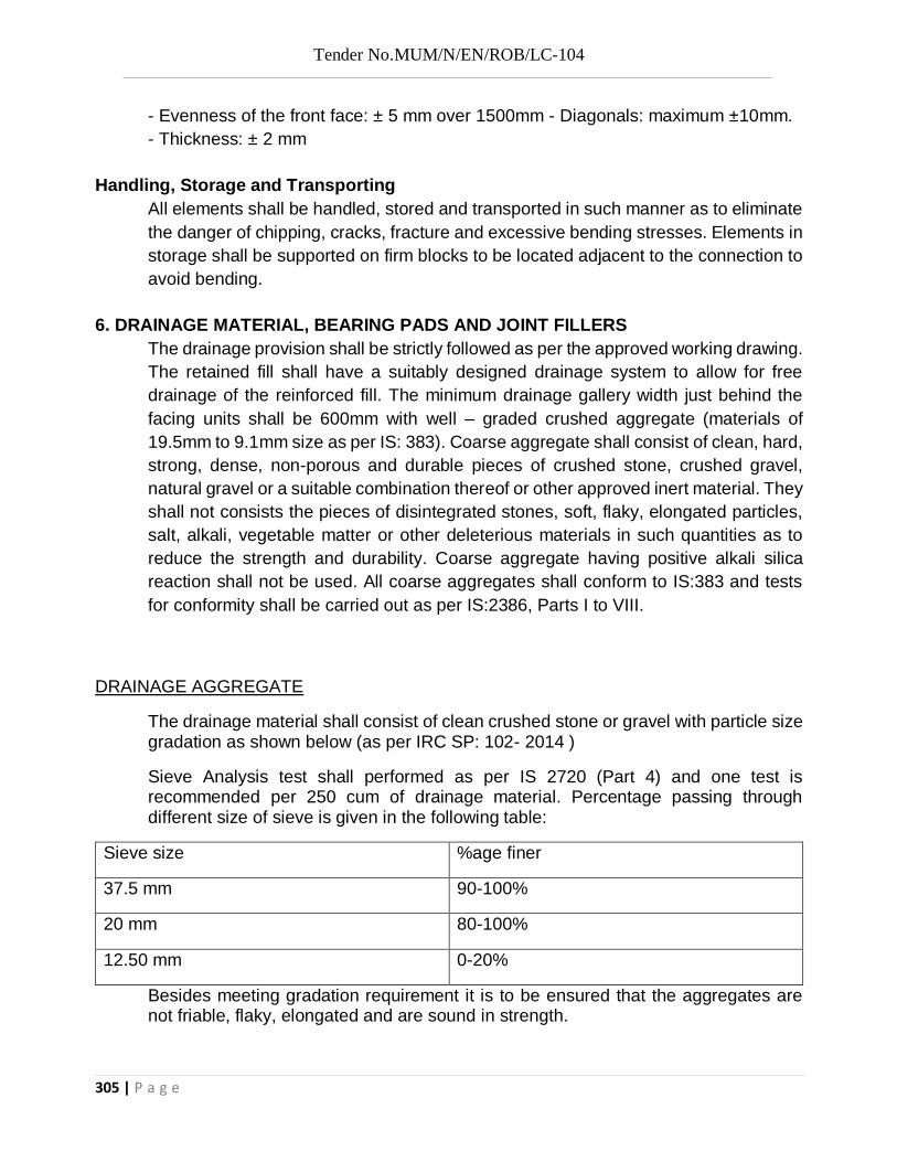
Tender No.MUM/N/EN/ROB/LC-104
305 | P a g e
- Evenness of the front face: ± 5 mm over 1500mm - Diagonals: maximum ±10mm. - Thickness: ± 2 mm
Handling, Storage and Transporting All elements shall be handled, stored and transported in such manner as to eliminate the danger of chipping, cracks, fracture and excessive bending stresses. Elements in storage shall be supported on firm blocks to be located adjacent to the connection to avoid bending.
6. DRAINAGE MATERIAL, BEARING PADS AND JOINT FILLERS The drainage provision shall be strictly followed as per the approved working drawing. The retained fill shall have a suitably designed drainage system to allow for free drainage of the reinforced fill. The minimum drainage gallery width just behind the facing units shall be 600mm with well – graded crushed aggregate (materials of 19.5mm to 9.1mm size as per IS: 383). Coarse aggregate shall consist of clean, hard, strong, dense, non-porous and durable pieces of crushed stone, crushed gravel, natural gravel or a suitable combination thereof or other approved inert material. They shall not consists the pieces of disintegrated stones, soft, flaky, elongated particles, salt, alkali, vegetable matter or other deleterious materials in such quantities as to reduce the strength and durability. Coarse aggregate having positive alkali silica reaction shall not be used. All coarse aggregates shall conform to IS:383 and tests for conformity shall be carried out as per IS:2386, Parts I to VIII.
DRAINAGE AGGREGATE
The drainage material shall consist of clean crushed stone or gravel with particle size gradation as shown below (as per IRC SP: 102- 2014 )
Sieve Analysis test shall performed as per IS 2720 (Part 4) and one test is recommended per 250 cum of drainage material. Percentage passing through different size of sieve is given in the following table:
Sieve size %age finer
37.5 mm 90-100%
20 mm 80-100%
12.50 mm 0-20%
Besides meeting gradation requirement it is to be ensured that the aggregates are not friable, flaky, elongated and are sound in strength.

Tender No.MUM/N/EN/ROB/LC-104
306 | P a g e
The main collection drainpipe just behind the precast facing, if used, shall be a minimum of 150mm in diameter. The secondary collection drain pipes should be sloped a minimum of two percent to provide gravity flow into the main collection drainpipe. Drainage laterals shall be spaced at a maximum 15 meters spacing along the wall face. The drainage collection pipe shall be a perforated or slotted, PVC or corrugated HDPE pipe. The drainage pipes shall be wrapped with geotextile. A gap of not more than 20mm shall be maintained all around the facing units after erection. Bearing pads for horizontal joints between panels shall be made of elastomer with vulcanized EPDM. Fillers of vertical joints between panels shall be flexible open/ close cell polyurethane foam strips or non-woven fabric strips /geotextiles (the latter used as joint cover) as per specifications given below and approved by Engineer.
General:
All works shall be done strictly according to section 702.1 specifications of MORTH. In the event of any discrepancy of above, the decision of Engineer–in-charge shall be final and binding on the contractor. Good workmanship and neat appearance is the prerequisite for all sections of work. The total planning and sequence of different activities must be got approved by the Engineer – in – charge.
Specification of Geotextile:
The product should have ‘CE’ certification and the manufacturer should be ISO
certified. The non-woven PP geotextile should be thermally bonded and should be manufactured using continuous polypropylene filaments coated with polypropylene without using any glues or chemical binders. The product should not contain any color or dyes so as to prevent any possible ground / ground water contamination.
The geotextile to be used for the work should be a Non-woven continuous filament thermally bonded geotextile, in white colour and having a minimum roll width of 4.5 m without joints – meeting the following specifications:-
Table 1 Properties of thermally bonded nonwoven geotextile
PROPERTIES: Value Tolerance Test Method
Mechanical Properties:
Mean Peak Strength 8.0 kN/m - 2 kN/m EN ISO 10319

Tender No.MUM/N/EN/ROB/LC-104
307 | P a g e
Elongation 24 % ± 15% EN ISO 10319
Mass Per Unit Area 120 gsm
Tensile Strength @ 5% Elongation
3.4 kN/m NA EN ISO 10319
CBR Puncture Resistance 1500 N -270 N EN ISO 12236
Dynamic Cone Puncture 38 mm NA EN ISO 13433
Opening Size O90 150 µ.m ≤ 110 µ.m EN ISO 12956
Permeability (H50) 100 l/m2.s - 10% EN ISO 11058
Minimum Roll width 4.5 m
Minimum Roll Length 100 m
Note: Values indicated in above table are typical
Construction Requirements A. Geotextile packaging and storing – Geotextile materials should not be left directly exposed to sunlight for a period longer than the period recommended by the manufacturer. If stored outdoors, they shall be elevated and protected with a waterproof cover. Prevent excessive mud, wet concrete, epoxy, or other deleterious materials from coming in contact with and affixing to the geogrid materials.
B. Site preparation – The subgrade or natural ground shall be prepared as indicated on the construction drawings or as directed by the Engineer.
C. Installation – The geotextile shall be laid at the proper elevation and alignment as shown on the construction drawings. The geotextile shall be installed in accordance with the installation guidelines provided by the manufacturer or as directed by the Engineer. The geotextile may be temporarily secured in place with sand bags or backfill as required by fill properties, fill placement procedures or weather conditions or as directed by the Engineer.
D. Overlap – An overlap of 300 mm or as indicated by Engineer shall be provided between the adjacent rolls..
7. DESIGN, WORKING DRAWING & DETAILING

Tender No.MUM/N/EN/ROB/LC-104
308 | P a g e
The scope of work shall also cover the supply of detailed design, engineering submission of working drawings by the specialized agency for reinforced soil works. The designs and drawings shall be got approved from the competent authority and/or its representative before execution of work.
8. INSPECTION
Engineer and/or the representative shall verify the materials supplied and quality of work to ensure that all the requirements of the specifications are satisfactorily met with. This includes all submittals and proper installation of the system. The reinforced soil structure system supplier shall provide one qualified and experienced representative at site on full time basis during the entire working phase to ensure that the quality of the works performed by the Contractor is in accordance with the specifications and to assist the Contractor regarding proper wall installation.
9. QUALITY CONTROL AND TESTING OF MATERIALS
Testing shall be done as stated elsewhere in this specification on all materials required for reinforced soil structure construction. The tests shall be done from a reputed independent agency or at the manufacturer’s facility under the presence of
Engineer or his representative as and when required. All tests and testing certificates shall be submitted to the Engineer at least 7 working days prior to use of any material.
10 MEASUREMENTS FOR PAYMENTS 10.1 Basis of Payment
Payment for the execution of reinforced earth wall shall be made in sqm of each face, certified by engineer in charges, which includes:
1. Excavation for foundation, foundation concrete (CC grade M15) with cement concrete grooved seating in foundation for facia panel.
2. Facia panel in concrete grade M 35 and reinforcement FE 500D with hooks, tackles and placement thereof.
3. Assembling & joining with non-oven geotextile at facial panel joints with facia elements and laying of the PP Geosynthetic reinforcement element along with 600mm thick filter media conforming to the specifications and in accordance to the design as approved.
4. RCC coping (M 35) and levelling pad (PCC M 15) at top and bottom of facial panel as per approved layout.
10.2 Stage payment for precast RCC facia panel shall be as under.

Tender No.MUM/N/EN/ROB/LC-104
309 | P a g e
1. 40 % after casting in casting yard/site of facia panels.
2. 60 % after placing & erecting and completion of item.
Item no. 13: Backfilling, grading and compaction with selected backfill soil in layers in soil Reinforced works with peak internal angle of firction as per adopted design parameters, complete as per drawings and Technical Specifications or as directed by Engineer.
REINFORCED FILL SPECIFICATIONS
The reinforced fill shall be a select granular fill with the following properties:
Peak drained or effective angle of friction of compacted fill (as per IS 2720: part 13) shall be minimum 28°.
% fines (passing 75 micron sieve) shall be less than 15%. Sieve Analysis test shall performed as per IS 2720 (part 4), Material with more than 15% passing 75 micron sieve, but less than 10% of of particle smaller than 15 microns are acceptable provided PI is less than 6 and angle of friction is not less than 280
The fill material shall be free from organic and any other deleterious matter and shall not react adversely (chemically, electrically or biologically) with the reinforcement material and / or facia material.
Liquid limit & Plastic Limit test shall performed as per IS 2720 (Part 5). Plasticity index shall be less than 6.
Co-efficient of uniformity (Cu) shall be ≥ 2. Top 500 mm of fill below Sub grade shall satisfy the effective CBR criteria with Sub grade
material in addition to the above requirement. Recommended guidelines for gradation of the reinforced soil are given below:
Sieve Size (mm) % Finer
75 100
4.75 85-100
0.425 60-90
0.075 < 15
Plasticity Index (PI) shall not exceed 6 and Cu > 2
RETAINED FILL SPECIFICATIONS
Peak drained or effective angle of friction of compacted fill (as per IS 2720: Part 13) shall be minimum of 30°.
The fill shall be compacted to 95% of the maximum laboratory density obtained from modified protocol compaction test performed as per IS 2720 (Part 8)
Fill within 0.5m of the bottom of pavement (sub grade) shall be compacted to a minimum of 98% of the MDD.

Tender No.MUM/N/EN/ROB/LC-104
310 | P a g e
The liquid limit and plasticity index (performed as per IS 2720: Part 5) of the fill shall be restricted to 40 and 20 respectively.
The organic content shall be limited to 5% and the fill shall be free from deleterious matter. If Fly ash is used as retained fill then it shall be in conformity with IRC-SP 58. Top 500 mm of
retained fill below Sub grade shall satisfy the effective CBR criteria with Sub grade material in addition to the above requirements.
DRAINAGE BAY
Drainage Bay shall be provided as shown in the approved drawings.
Backfill and drainage material to be separated by permeable non-oven geo textile.
TESTS FOR REINFORCED AND RETAINED FILL
The soil which is proposed to be used as reinforced fill shall be tested to ascertain the suitability for required quantity, grading, type and availability of required quantity etc. The soil to be used as retained fill behind the reinforced fill, in case it is not natural soil, shall be tested for its shear characteristics and permeability to evaluate earth pressure, drainage characteristics etc. for external stability of the wall.
The backfill is tested at two stages. The first stage is to ascertain the suitability of the fill while the second stage to ensure that the backfill envisaged in design is used during construction. To ascertain the suitability of the fill, samples should be drawn from the borrow area by drawing a grid of 25 m c/c to full depth, logging and sampling for ascertaining suitability of the borrow material as per MORTH 2013 Specifications. Following tests shall be carried out as per Indian Standards.
i) Sieve Analysis - IS: 2720 Part - 2 tests per 3000 cum. of soil
ii) Atterberg Limit Tests- IS: 2720 Part- 5-2 tests per 3000 cum. of soil
iii) Compaction Tests - IS: 2720 relevant part corresponding to modified as well
as Standard Proctor test - 2 tests per 3000 cum. of soil
iv)Direct Shear Tests - IS: 2720 Part 13 & 39 to ascertain the peak angle of shearing resistance. The tests should be done at 95 percent of Modified Proctor Density at -2 percent of OMC at a frequency of 1 per 3000 cum. of fill.
During construction the quality control should be exercised by conducting one set of density test of 3000 sqm. of compacted area considering the importance of compaction in reinforced soil walls. (Clause 903.2.2 of MORTH 201 3) One set shall consist of 6 tests. The density tests shall be carried out in accordance with IS-2720 Part 28. Density measurement by nuclear gauge may be carried out as an alternative. For such a test the number of tests per set shall be doubled. If the retained fill is borrowed tests mentioned above should be carried out at same frequency of reinforced fill. Frequency during construction shall be as per MORTH 2013 Specifications.
6.1 Method of Measurement and Payment
The Earth fill / Sand & filling shall be measured and pay in the Cubic meter basis of finished work.

Tender No.MUM/N/EN/ROB/LC-104
311 | P a g e
Rate:
The Contract unit rates for the items of all labour, material, tools, equipment and incidentals necessary to com etc. the work to the Specifications & payment shall be done in Cu.m.
Item no. 14: providing and fixing 100 dia runner and downtake GI pipe to drain water from drainage spout with necessary fixtures including cost of all materials, labours, bends, fixtures, specials etc. Complete as per drawing and Sp. And as per direction of engineer.
2705 DRAINAGE SPOUTS
Drainage along longitudinal direction shall be ensured by sufficient number of drainage fixtures embedded in the deck slab. The spouts shall be of not less than 100 mm in diameter and shall be of corrosive resistant material such as galvanised steel with suitable cleanout fixtures. The spacing of drainage spouts shall not exceed 10 m. The discharge from drainage spout shall be kept away from the deck structure by means of suitable down pipes upto 500 mm above High Flood Level, in case of viaducts in urban areas, the drainage spouts should be connected with suitably located runners and down pipes to discharge the surface run-off into drains provided at ground level.
2705.1 Fabrication
The drainage assembly shall be fabricated to the dimensions shown on the drawings. All materials shall be corrosion resistant;. Steel components shall be of mild steel conforming to IS:226. The drainage assembly shall be seam welded for water tightness and then hot-dip galvanized.
2705.2Placement
The galvanized assembly shall be given two coats of bituminous paint before placement. The whole assembly shall be placed in true position, lines and levels as shown on the drawings with necessary cutouts in the shuttering for deck slab and held in place firmly. Where the reinforcements of the deck are required to be cut, equivalent reinforcements shall be placed at the corners of the cut out.
2705.3Finishing
After setting of the deck slab concrete, the shrinkage cracks around the assembly shall be sealed with polysulphide sealant or bituminous sealant as per I5:1834 and the excess sealant trimmed to receive the wearing coat. After the wearing coat is completed, similar sealant shall be provided to cover at least 50 mm on the wearing coat surface all round the drainage assembly.
Item no. 15: Construction of 300 mm thick Granular Coarse Sub Base (GSB) (Grade - I crushed B.T materials of 53mm to 9.5mm @ 50% 9.5mm to 2.36mm @ 20%, below 2.36mm @ 30%) by

Tender No.MUM/N/EN/ROB/LC-104
312 | P a g e
providing coarse graded material mixing in a mechanical mix plant at OMC, carriage of a mix material to work site spreading in uniform layers with motor grader on prepared surface, and compacting with vibratory rollers to achieve the desired density, complete as per MORTH specification401.1
This work shall consist of laying and compacting well graded material on prepared sub grade in accordance with the requirements of these specifications. The material shall be laid in one or more layers sub base and upper sub base (termed as sub base herein after) as necessary according to lines, grades and cross sections shown on the drawings or as directed by the Engineer.
MORTH 401.2 Materials:
MORTH 401.2.1 The materials to be used for the work shall be crushed stone of required grading. The material shall be free from organic or other deleterious constituents and confirm to the coarse graded granular sub base grading II as mentioned below.
MORTH TABLE 400-2.
GRADING FOR COARSE GRADED GRANULAR SUB-BASE
MATERIALS.
IS sieve Designation Percent by weight passing the IS sieve. Grading I
75.0 mm 100
53.0 mm –
26.5 mm 55 – 75
9.5 mm –
4.75 mm 10 – 30
2.365 mm
0.425 mm
0.075 mm < 10
CBR Value (Minimum) 30

Tender No.MUM/N/EN/ROB/LC-104
313 | P a g e
Material passing 425 micron (0.425 mm) sieve for all the three grading when tested according to IS : 2720 (Part 5) shall have liquid limit and plasticity index not more than 25 and 6 percent respectively.
MORTH 401.2.2 Physical requirements:
The materials hall have a 10 percent fines value of 50 KN or more (for sample in soaked condition) when tested in compliance with B.S.: 812 (Part 111). The water absorption value of the coarse aggregate shall be determined as per IS : 2386 (Part 3) : if this value is greater than 2 percent, the soundness test shall be carried out on the material delivered to site as per IS : 383. For grading II and III materials, the CBR shall be determined at the density and moisture content likely to be developed in equilibrium conditions which shall be taken as being the density relating to a uniform air voids content of 5 percent.
MORTH 401.3 Strength of sub-base.
It shall be ensured prior to actual execution that the material to be used in the sub base satisfies the requirements of CBR and other physical requirements when compacted and finished.
When directed by the Engineer, this shall be verified by performing CBR tests in the laboratory as required on specimens remoulded at field dry density and moisture content and any other tests for the "Quality" of materials, as may be necessary.
MORTH 401.4 Construction Operations:
MORTH 401.4.1 Preparation of Sub grade:
Immediately prior to the laying of sub-base, the sub grade already finished to Clause 301 or 305 as applicable shall be prepared by removing all vegetation and other extraneous matter, lightly sprinkled with water, if necessary and rolled with two passes of 80-100 KN smooth wheeled roller.
MORTH 401.4.2 Spreading and compacting:
The sub-base material of grading specified in the Contract shall be spread on the prepared sub grade with the help of a motor grader of adequate capacity, its blade having hydraulic controls suitable for initial adjustment and for maintaining the required slope and grade during the operation or other means as approved by the Engineer.
When the sub-base material consists of combination of materials mentioned in MORTH Clause 401.2.1, of this item mixing shall be done mechanically by the mix in place method.

Tender No.MUM/N/EN/ROB/LC-104
314 | P a g e
Manual mixing shall be permitted only where the width of laying is not adequate for mechanical operations, as in small-sized jobs. The equipment used for mix-in-place construction shall be a rotator or similar approved equipment capable of mixing the material to the desired degree. If so desired by the Engineer, trial runs with the equipment shall be carried out to establish its suitability for the work.
Moisture content of the loose material shall be checked in accordance with IS:2720 (Part 2) and suitably adjusted by sprinkling additional water from a truck mounted or trailer mounted water tank and suitable for applying water uniformly and at controlled quantities to variable widths of surface of other means approved by the Engineer so that, at the time of compaction, it is from 1 percent above to 2 percent below the optimum moisture content corresponding to IS:2720 (Part 8). While adding water, due allowance shall be made for evaporation losses. After water has been added, the material shall be processed by mechanical or other approved means like disc barrows, rotators until the layer is uniformly wet.
Immediately thereafter, rolling shall start. If the thickness of the compacted layer does not exceed 100 mm, a smooth wheeled roller of 80 to 100 KN weight may be used. For a compacted single layer up to 225 mm the compaction shall be done with help of a vibratory roller of minimum 80 to 100 KN static weight with plain drum or pad foot drum or heavy pneumatic tyred roller of minimum 200 to 300 KN weight having a minimum tyre pressure of 0.7 MN/ M2 or equivalent capacity roller capable of achieving the required compaction. Rolling shall commence at the lower edge and proceed towards the upper edge longitudinally for portions having unidirectional cross fall and super elevation and shall commence at the edges and progress towards the centre for portions having cross fall on both sides each pass of the roller shall uniformly overlap not less than one third of the track made in the preceding pass. During rolling, the grade and cross fall (camber) shall be checked and any high sports or depressions, which become apparent, corrected by removing or adding fresh material. The speed of the roller shall not exceed 5 Km per hour. Rolling shall be continued till the density achieved is at least 98 percent of the maximum dry density for the material determined as per IS: 2720 (Part 8). The surface of any layer of material on completion of compaction shall be well closed, free from movement under compaction equipment and from compaction planes, ridges, cracks or lose material. All loose, segregated or otherwise defective areas shall be made good to the full thickness of layer and re-compacted.
401.5 Surface Finish and Quality Control of work: The surface finish of construction shall conform to the requirements of Clause 902 of MORT & H specifications. Control on the quality of materials and works shall be exercised by the Engineer in accordance with Section 900 of MORT & H specifications.

Tender No.MUM/N/EN/ROB/LC-104
315 | P a g e
MORTH 401.6 Arrangements for Traffic:
During the period of construction, arrangement of traffic shall be maintained in accordance with Clause 112 of MORT & H specifications.
MORTH 401.7 Measurements for Payment: Granular sub base shall be paid as finished work in position on cross sectional measurements and computing the volume of GSB work in cubic meters by average area method.
The protection of edges of granular sub base extended over the full formation as shown in the drawing shall be considered incidental to the work of providing granular sub-base and as such no extra payment shall be made for the same.
MORTH 401.8 Rate:
The Contract unit rate for granular sub base shall be payment in full for carrying out the required operations including full compensation for:
[i] Making arrangements for traffic to Clause 112 as above except for initial treatment to verges, shoulders and construction of diversions.
[ii] Furnishing all materials to be in corporate in the work including all royalties, fees, rents where necessary and all leads and lift.
[iii] All labour, tools, equipment and incidentals to complete the work to the specifications.
[iv] Carrying out the work in part widths of road where directed, and
[v] Carrying out the required tests for quality control.
Item no. 16: Providing and laying wet mix base course macadam(WMM) 300 mm in Two layer using machine crushed chips as per required gradation mixing with required optimum quantity of water conveying the mix to site and spreading to grade and camber with mechanical paver consolidation by vibratory roller including material, labour, plant and machinery and equipment etc complate.as per MORT&H Specifications
406.1 SCOPE
This work shall consist of laying and compacting clean, crushed, graded aggregate and granular material, premixed with water, to a dense mass on a prepared subgrade sub base/ base or existing pavement as the case may be in accordance with the requirements of these specifications. The material shall be laid in one or more layers as necessary to lines, grades and cross-sections shown on the approved drawings or as directed by the Engineer.

Tender No.MUM/N/EN/ROB/LC-104
316 | P a g e
The thickness of a single compacted Wet Mix Macadam layer shall not be less than 75mm. When vibrating or other approved types of compacting equipment are used, the compacted depth of a single layer of the sub-base course may be increased to 20cm upon approval of the Engineer.
406.2 MATERIALS
406.2.1 AGGREGATES
406.2.1.1 PHYSICAL REQUIREMENTS :
Course aggregates shall be crushed stone. If crushed gravel / shingle is used, not less than 90 percent by weight of the gravel / shingle pieces retained on 4.75 mm sieve shall have at least two fractured faces. The aggregates shall conform to the physical requirements set forth in Table 400-12 below.
If the water absorption value of the coarse aggregate is greater than 2 percent, the soundness test shall be carried out on the material delivered to site as per IS:2386 (Part-5).
TABLE 400-12 PHYSICAL REQUIREMENT OF COARSE AGGREGATES FOR WET MIX MACADAM FOR SUB-BASE / BASE COURSES
Test Test Method Requirements
1.*Los Angeles Abrasion value IS : 2386 (Part-4) 40 percent (Max)
Aggregate impact value IS : 2386 (Part-4) or IS : 5640
30 percent (Max)
2. Combined Flakiness and Elongation indices ( Total )**
IS : 2386(PART-1) 35 percent (Max)
* To determine this combined proportion, the flaky stone from a representative sample should first be separated out. Flakiness index is weight of flaky stone metal divided by weight of stone sample only the elongated particles be separated out from the remaining (non flaky stone metal. Elongation index is weight of elongated particles divided by total non flaky particles. The value of flakiness index and elongation index so found are added up.
406.2.1.2 Grading requirements :
The aggregates shall conform to the grading given in Table 400-13
TABLE 400-13. GRADING REQUIREMENTS OF AGGREGATES FOR WET MIX MACADAM.

Tender No.MUM/N/EN/ROB/LC-104
317 | P a g e
Is Sieve Designation Percent by weight Passing the IS sieve
53.00 mm 100
45.00 mm 95-100
26.50 mm -
22.40 mm 60-80
11.20 mm 40-60
4.75 mm 25-40
2.36 mm 15-30
600.00 micron 8-22
75.00 micron 0-5
Materials finer than 425 micron shall have plasticity index (P.I ) not exceeding 6.
The final gradation approved within these limits shall be well graded from coarse to fine and shall not very from the low limit on one sieve to the high limit on the adjacent sieve or vice- versa.
406.3 Construction Operation :
406.3.1 Preparation of base:
The surface of the sub-grade/sub-base/base to receive the water bound macadam course shall be prepared to the specified grade and camber and cleaned of dust, dirt and other extraneous material. Any ruts or soft yielding places shall be corrected in an approved manner
and rolled until firm surface is obtained.
Where the WBM is to be laid on an existing metalled road, damaged area including depressions and potholes shall be repaired and made good with the suitable material. The existing surface shall be scarified and re-shaped to the required grade and camber before spreading the coarse aggregate for WBM.
As far as possible, laying water bound macadam course over existing bituminous layer may be avoided since it will cause problems of internal drainage of the pavement at the interface of two courses. It is desirable to completely pick out the existing thin bituminous wearing course where water bound macadam is proposed to be laid over it.
406.3.2 Provision of lateral confinement of aggregates :

Tender No.MUM/N/EN/ROB/LC-104
318 | P a g e
While constructing wet mix macadam arrangement shall be made for the lateral confinement of wet mix. This shall be done by laying materials in adjoining shoulders along with that of wet mix macadam layer and following the sequence of operations described in Clause 404.3.3 as below.
404.3.3 Lateral Confinement of Aggregates
For construction ofWBM, arrangement shall be made for the lateral confinement of aggregates. This shall be done by building adjoining shoulders along with WBM layers. The practice of constructing WBM in a trench section excavated in the finished formation must be completely avoided.
Where the WBM course is to be constructed in narrow widths for widening of an existing pavement, the existing shoulders should be excavated to their full depth and width up to the sub-grade level except where widening specifications envisages laying of a stablised sub-base using in-situ operations in which case the same should be removed only up to the sub-base level.
406.3.3 Preparation of mix:
Wet Mix Macadam shall be prepared in an approved mixing plant of suitable capacity having provision for controlled addition of water and forced/ positive mixing arrangement like pugmill or pan type mixer of concrete batching plant. The plant shall have following features:
i) For feeding aggregates- three/ four bin feeders with variable speed motor
ii) Vibrating screen for removal of oversize aggregates
iii) Conveyor Belt
iv) Controlled system for addition of water
v) Forced/positive mixing arrangement like pug-mill or pan type mixer
vi) Centralized control panel for sequential operation of various devices and precise process control
vii) Safety devices
Optimum moisture for mixing shall be determined in accordance with IS:2720 (Part-8) after replacing the aggregate fraction retained on 22.4 mm sieve with material of 4.75 mm to 22.4 mm size. While adding water, due allowance should be made for evaporation losses. However, at the time of compaction, water in the wet mix should not vary from the optimum value by more than agreed limits. The mixed material should be uniformly wet and no segregation should be permitted.
406.3.4 Spreading of mix:

Tender No.MUM/N/EN/ROB/LC-104
319 | P a g e
Immediately after mixing, the aggregates shall be spread uniformly and evenly upon the prepared sub-grade/sub-base/base in required quantities. In no case shall these be dumped in heaps directly on the area where these are to be laid nor shall their hauling over a partly completed stretch be permitted.
The mix may be spread by a paver finisher. The paver finisher shall be self-propelled of adequate capacity with following features:
i) Loading hoppers and suitable distribution system, so as to provide a smooth uninterrupted material flow for different layer thicknesses from the tipper to the screed.
ii) Hydraulically operated telescopic screed for paving width upto to 8.5 m and fixed screed beyond this. The screed shall have tamping and vibrating arrangement for initial compaction of the layer.
iii) Automatic levelling control system with electronic sensing device to maintain mat thickness and cross slope of mat during laying procedure.
In exceptional cases where it is not possible for the paver to be utilized, mechanical means like motor grader may be used with the prior approval of the Engineer. The motor grader shall
be capable of spreading the material uniformly all over the surface.
The surface of the aggregate shall be carefully checked with templates and all high or low spots remedied by removing or adding aggregate as may be required. The layer may be tested by depth blocks during construction. No segregation of larger and fine particles should be allowed. The aggregates as spread should be of uniform gradation with no pockets of fine materials.
The Engineer may permit manual mixing and /or laying of wet mix macadam where small quantity of wet mix macadam is to be executed. Manual mixing/laying in inaccessible/ remote locations and in situations where use of machinery is not feasible can also be permitted. Where manual mixing/laying is intended to be used, the same shall be done with the approval of the Engineer.
406.3.5 Compaction
After the mix has been laid to the required thickness, grade and crossfall/camber the same shall be uniformly compacted to the full depth with suitable roller. If the thickness of single compacted layer does not exceed 100 mm, a smooth wheel roller of 80 to 1 OOkN weight may be used. For a compacted single layer upto 200 mm, the compaction shall be done with the help of vibratory roller of minimum static weight of 80 to 100 kN with an arrangement for adjusting the frequency and amplitude. An appropriate frequency and amplitude may be selected. The speed of the roller shall not exceed 5 km/h.
In portions having unidirectional cross fall/superelevation, rolling shall commence from the lower edge and progress gradually towards the upper edge. Thereafter, roller should progress parallel to the

Tender No.MUM/N/EN/ROB/LC-104
320 | P a g e
center line of the road, uniformly over-lapping each preceding track by at least one-third width until the entire surface has been rolled. Alternate trips of the roller shall be terminated in stops at least 1 m away from any preceding stop.
In portions in camber, rolling should begin at the edge with the roller running forward and backward until the edges have been firmly compacted. The roller shall then progress gradually
towards the center parallel to the center line of the road uniformly overlapping each of the preceding track by at least one-third width until the entire surface has been rolled.
Any displacement occurring as a result of reversing of the direction of a roller or from any other cause shall be corrected at once as specified and/or removed and made good.
Along forms, kerbs, walls or other places not accessible to the roller, the mixture shall be thoroughly compacted with mechanical tampers or a plate compactor. Skin patching of an area without scarifying the surface to permit proper bonding of the added material shall not be permitted.
Rolling should not be done when the sub-grade is soft or yielding or when it causes a wavelike
motion in the sub-base/base course or sub-grade. If irregularities develop during rolling which exceed 12 mm when tested with a 3m straight edge, the surface should be loosened and premixed material added or removed as required before rolling again so as to achieve a uniform surface conforming to the desired grade and crossfall. In no case shall the use of unmixed material be permitted to make up the depressions.
Rolling shall be continued till the density achieved is at least 98 percent of the maximum dry density for the material as determined by the method outlined in IS:2720 (Part-8).
After completion, the surface of any finished layer shall be well-closed, free from movement under compaction equipment or any compaction planes, ridges, cracks and loose material. All loose, segregated or otherwise defective areas shall be made good to the full thickness of the layer and recompacted.
406.3.6 Setting and Drying
After final compaction of wet mix macadam course, the road shall be allowed to dry for 24 hours.
406.4 Opening to Traffic
No vehicular traffic shall be allowed on the finished wet mix macadam surface. Construction equipment may be allowed with the approval of the Engineer.
406.5 Surface Finish and Quality Control of Work
406.5.1 Surface Evenness

Tender No.MUM/N/EN/ROB/LC-104
321 | P a g e
The surface finish of construction shall conform to the requirements of Clause 902.
406.5.2 Quality Control
Control on the quality of materials and works shall be exercised by the Engineer in accordance
with Section 900.
406.6 Rectification of Surface Irregularity
Where the surface irregularity of the wet mix macadam course exceeds the permissible tolerances or where the course is otherwise defective due to sub-grade soil getting mixed with the aggregates, the full thickness of the layer shall be scarified over the affected area, re-shaped with added premixed material or removed and replaced with fresh premixed material as applicable and recompacted in accordance with Clause 406.3. The area treated in the aforesaid manner shall not be less than 5 m long and 2 m wide. In no case shall depressions be filled up with unmixed and ungraded material or fines.
406.7 Arrangement for Traffic
During the period of construction, arrangements for traffic shall be done as per Clause 112.
406.8 Measurements for Payment
Wet mix macadam shall be measured as finished work in position in cubic metres.
406.9 Rate
The Contract unit rate for wet mix macadam shall be payment in full for carrying out the required operations including full compensation for all components listed in Clause 401.7.
The Contract unit rate for Wet mix macadam shall be payment in full for carrying out the required operations including full compensation for:
i) making arrangements for traffic to Clause 112 except for initial treatment to verges, shoulders and construction of diversions;
ii) supplying all materials to be incorporated in the work including all royalties, fees, rents where applicable with all leads and lifts;
iii) all labour, tools, equipment and incidentals to complete the work to the Specifications;
iv) carrying out the work in part widths of road where directed; and
v) carrying out the required tests for quality control.

Tender No.MUM/N/EN/ROB/LC-104
322 | P a g e
Item no.17: Providing & laying DENSE GRADED BITUMINOUS MACADAM with batch type Drum Mix Plant (DMP) using crushed aggregates of specified grading, premix with bitumen grade 60/70 , bituminous binder @ 5.0 per cent by weight of total mix and filler, transporting the hot mix to work site, laying with a hydrostatic paver finisher with sensor control to the required grade, level and alignment, rolling with smooth wheeled, vibratory and tandem rollers to achieve the desired compaction complete, including providing & laying tack coat 2.5kg /10sqm all as per MORTH specification.
MORTH 507. DENSE GRADED BITUMINOUS MACADAM
MORTH 507.1. Scope
This clause specifies the construction of Dense Graded Bituminous Macadam, (DBM) for use mainly, but not exclusively, in base/binder and profile corrective course, DBM is also intended for use a road base material. This work shall consist of construction in a single or multiple layers of DBM on a previously prepared base or sub-base. The thickness of a single layer shall be 50mm to 100mm.
MORTH 507.2. Materials
MORTH 507.2.1 Bitumen:
MORTH 507.2.2 Course aggregates: The aggregates shall satisfy the physical requirements specifies in Table 500-8, for dense bituminous macadam. The requirement shall be similar to that of Clause 504 except that aggregates shall satisfy physical requirements specifies on Table 500-8.
When crushed gravels is proposed for use in aggregates, not less than 90% by weight of the crushed material retained on the 4.75 mm sieve shall be have at least two fractured faces.
MORTH 507.2.3 Fine aggregates: Fine aggregates shall consists of crushed or naturally occurring mineral material, or a combination of the two, passing the 2.36mm sieve and retained on the 75 micron sieve. The fine aggregate shall have a sand equivalent value of not less than 50 when tested in accordance with the requirement of IS:2720 (Part 37) The plasticity index of the fraction passing the 0.425 mm sieve shall not exceed 4, when tested in accordance with IS:2720 (Part 5)
MORTH TABLE 500-8. PHYSICLE REQUIREMENTS FOR COARSE AGGREGATE FOR DENSE GRADED BITUMINOUS MACADAM
Property Test Specification
Cleanliness (dust) Grain size analysis¹ Max 5% passing 0.075 mm sieve

Tender No.MUM/N/EN/ROB/LC-104
323 | P a g e
Particle shape Flakiness and elongation Index (combined)²
Max 30%
Strength Los Angeles Abrasion Value ³
Aggregate Impact Value4
Max 30%
Max 24%
Polishing Polished Stone Value5 Min 55
Durability Soundness6
Sodium Sulphate
Magnesium Sulphate
Max 12%
Max 18%
Water Absorption Water Absorption7 Max 2%
Stripping Coating and stripping of bitumen aggregate mixtures9
Minimum retained coating 95%
Water sensitivity** Retained tensile strength8 Min 80%
Notes:
1. IS:2386 Part 1 6. IS: 2386 Part 5
2. IS:2386 Part 1 7. IS:2386 Part 3
(the elongation test may be done only on non-flaky aggregates in the samples)
3. IS:2386 Part 4* 8. AASHTO T 283**
4. IS:2386 Part 4* 9. IS: 6241
5. BS: 812 Part 114
* Aggregate may satisfy requirements of either of these two tests
**The water sensitivity test is only required if the minimum retained coating in the stripping test is less than 95%.
MORTH 507.2.3 Fine aggregates: Fine aggregates shall be the fraction passing 2.36 mm sieve and retained on 75 micron sieve, consisting of crusher-run screening, gravel sand or a mixture of both. These shall be clean, hard, durable uncoated, dry and free from any injurious, soft or flaky pieces and organic or other deleterious substances.
MORTH 507.2.4 Filler

Tender No.MUM/N/EN/ROB/LC-104
324 | P a g e
Filler shall consist of finely divided minerals matter such as rock dust, hydrated lime or cement as approved by the Engineer.
The filler shall be graded within the following limits:
MORTH TABLE 509-9. GRADING REQUIREMENTS FOR MINERAL FILLER
IS Sieve (mm) Cumulative percent passing by weight
of total aggregate
0.6 100
0.3 95-100
0.075 85-100
Mineral filler shall consist of rock dust, hydrated lime or Portland cement, or after inert mineral matter approved by the Engineer. It shall be dry and free from lumps.
The filler shall be free from organic impurities and have a Plasticity Index not greater than 4. The Plasticity Index requirement shall not apply if filler is cement or lime. When the coarse aggregate is gravel, 2 percent by mass of total aggregate of port land cement or hydrated lime shall be added and the percentage of fine aggregate reduced accordingly. Cement or hydrated lime is not required when the gravel is limestone.
MORTH 507.2.5 Aggregate grading and binder content : When tested in accordance with IS:2386 Part 1 (Wet sieving method), the combined grading of the coarse and fine aggregates and added filler shall fail within the limits shown in Table 500-10 for dense bituminous macadam gradings 1 or 2 as specified on the Contract. The type and quantity of bitumen, and appropriate thickness are also indicated for each mixture type.
MORTH TABLE 509-10. COMPOSITION OF DENSE GRADED BITUMINOUS MACADAM PAVEMENT LAYERS
Grading 1 2
Nominal aggregate size 400mm 25mm
Layer Thickness 80-100 mm 50-75 mm
IS Sieve1 (mm) Cumulative % by weight if total aggregate passing
45 100
37.5 95-100 100

Tender No.MUM/N/EN/ROB/LC-104
325 | P a g e
26.5 63-95 90-100
19 - 71-95
13.2 55-75 56-80
9.5 - -
4.75 38-54 38-54
2.36 28-42 28-42
1.18 - -
0.6 - -
0.3 7-21 7-21
0.15 - -
0.075 2-8 2-8
Bitumen content % by mass of total mix2
Min 4.0 Min 4.5
Bitumen grade (pen) 65 to 90 65 o 90
Notes: 1.The combined aggregate grading shall not vary from the low limit on one sieve to the high limit on the adjacent sieve. Determined by the Marshall method.
MORTH 507.3. Mixture Design
MORTH 507.3.1 Requirements for the mixture: Apart from conformity with the grading and quality requirements for individual ingredients, the mixture shall meet the requirements set out in MORTH Table 500-11. The requirements for minimum percent voids in mineral aggregate (VMA) are set out in MORTH Table 500-12. MORTH TABLE 500-11. REQUIREMENTS FOR DENSE GRADED BITUMOUS MACADAM
Minimum stability (kN at 60°C) 9.0
Minimum flow (mm) 2
Maximum flow (mm) 4

Tender No.MUM/N/EN/ROB/LC-104
326 | P a g e
Compaction level (Number of blows) 75 blows on each of the two faces of the specimen
Percent air voids 3-6
Percent voids in mineral aggregate (VMA)
See table 500-12
Percent voids filled with bitumen (VFB) 65-75
MORTH 507.3.2 Binder content: The binder content shall be optimized to achieve the requirements of the mixture set out in Table 500-11 and the traffic volume as specified in the contract. Where 40mm dense bituminous macadam mixture is specified, the modified Marshall Method described in MS-2 shall be used. This method requires modified equipment and procedures; particularly the minimum stability values in Table 500-11 shall be multiplied by 2.25, and the minimum flow shall be 3 mm. MORTH 507.3.3 Job mix formula: The contractor shall inform the Engineer in writing at least 20 days before the start of the work. The approved job mix formula shall remain effective unless and until a revised Job Mix Formula is approved. Should a change in the source of materials be proposed, a new job mix formula shall be forwarded to the engineer for approval before the placing of the material. MORTH 507.3.4 Permissible Variation from Job Mix Formula: It shall be the responsibility of the contractor to produce a uniform mix conforming to the approved Job Mix Formula subject to the permissible variations of the individual percentages of the various ingredients in the actual mix from the job mix formula to be used within the limits as specified in Table 500-11. These variations are intended to apply to individual specimens taken for quality control tests vide Section 900.
MORTH TABLE 500-13 PERMISSIBLE VARIATIONS FROM THE JOB MIX FORMULA
S.No. Description of Ingredients Permissible Variation
Base/binder course
Wearing course
1. Aggregate passing 19mm sieve or larger ±8% ±7%
2. Aggregate passing 13.2mm, 9.5mm ±7% ±6%
3. Aggregate passing 4.75mm ±6% ±5%

Tender No.MUM/N/EN/ROB/LC-104
327 | P a g e
4. Aggregate passing 2.36mm, 1.18mm, 0.6mm
±5% ±4%
5. Aggregate passing 0.3mm, 0.15mm ±4% ±3%
6. Aggregate passing 0.075 mm ±2% ±1.5%
7. Binder content ±0.3% ±0.3%
8. Mixing temperature ±10°C ±10%
MORTH 507.3.5 Laying Trials: Once the plant trails have been successfully completed and approved, the Contractor shall carry out laying trails, to demonstrate that the proposed mix can be successfully laid, and completed all in accordance with Clause 501.
The Contractor shall previously inform the Engineer of the proposed method for laying and compaction the material. The plant trails shall then establish if the proposed laying plant, compaction plant, and methodology is capable of producing satisfactory results. The density of the finished paving layer shall be determined by taking cores, no sooner than 24 hours after laying, or by other approved method.
Once the laying trails have been approved, the same plat and methodology shall be applied to the laying of the material on the project, and no variation of either shall be acceptable, unless approved in writing by the Engineer who may at his discretion require further laying trials.
MORTH 507.4. Construction Operations
MORTH 507.4.1. Weather and seasonal limitations: The provisions of Clause 501.5.1 shall apply.
MORTH 507.4.2 Preparation of base: The base on which Dense Graded Bituminous Macadam is to be laid shall be prepared in accordance with Clause 501 or as directed by the Engineer. The surface shall be thoroughly swept clean free from dust and foreign matter using mechanical broom and dust removed or blown off by compressed air. In portions where mechanical broom cannot reach, other approved method shall be used as directed by the Engineer.
MORTH 507.4.3 Geo-synthetics: Where Geo-synthetics are specified in the Contact this shall be in accordance with the requirements stated in clause 70.3
MORTH 507.4.4 Stress absorbing layer: Where a stress absorbing layer is specified in the contract, this shall be applied in accordance with the requirements of Clause 522.
MORTH 507.4.5 Prime Coat: Where the material on which the dense bituminous macadam is to be laid is other than a bitumen bound layer, a prime coat shall be applied as specified, in accordance with the provisions of Clause 502 or as directed by the Engineer.

Tender No.MUM/N/EN/ROB/LC-104
328 | P a g e
MORTH 507.4.6 Tack Coat: Where the material on which the dense bituminous macadam is to be placed is bitumen surface, a tack coat shall be applied as specified, in accordance with the provisions of Clause 503 or as directed by the Engineer.
MORTH 507.4.7 Mixing and transportation of the mixture: The provisions as specified in Clause 501.3 and 501.4 shall apply.
MORTH 507.4.8 Spreading: The provisions of Clause 501.5.3 and 501.5.4 shall apply.
MORTH 507.4.9 Rolling: The general provisions of Clause 501.6 and 501.7 shall apply, as modify by the approved laying trails the compaction process shall be carried out by the same plant, and using the same method, as approved in the laying trials, which may be varied only with the express approval of the Engineer in writing.
MORTH 507.5 Opening Traffic: The newly laid surface shall not be open to traffic for at least 24hrs after laying and completion, without the express approval of the Engineer in writing.
MORTH 507.6. Surface Finish and Quality Control of Work: The surface finish of construction shall conform to the requirements of Clause 902. Control on the quality of materials and work shall be exercised by the Engineer in accordance with Section 900.
MORTH 507.7. Arrangements for Traffic: During the period of construction, arrangements for the traffic shall be done to Clause 112.
MORTH 507.8 Measurement for Payment: Dense Graded Bituminous Materials shall be measured as finished work either in cubic metres, tons or by the square metre at a specified thickness as detailed on the Contract drawings, or documents, or as directed by the Engineer.
MORTH 507.9 Rate: The Contract unit rate for Dense Graded Bituminous Macadam shall be payment in full for carrying out the all required operations as specified, and shall include, but not necessarily limited to all components listed in Clause 501.8.8.2(i) to (xi). The rate shall include the provision of bitumen, at 4.25 per cent by weight of the total mixture.
The Variance in actual percentage of bitumen used will be assessed and the payment adjusted up or down accordingly.
Item no. 18: Providing and laying 40 mm Bitumen concrete using crushed stone aggregate BT chips as per required gradation and using emulsion asphalt as a tack coat @ 2.5 kg / 10 sqmt and the VG 30 grade asphalt at 55 kg/MT)by total weight of mix hot laid process using drum mix plant including heating and mixing asphalt & materials by drum mix process transporting the mix and laying by paver finisher including consolidation with vibratory roller including cost of material, labour, machinery equipment and fuel , oil , lubricant for plant and machinery using contractor's own plant and machineries etc. complete as per MORTH Specifications
MORTH 509. BITUMINOUS CONCRETE
MORTH 509.1. Scope

Tender No.MUM/N/EN/ROB/LC-104
329 | P a g e
This clause specifies the construction of Bituminous Concrete, for use in wearing and profile corrective courses. This work shall consist of construction in a single or multiple layers of bituminous concrete on a previously prepared bituminous bound surface. A single layer shall be 40 mm in thickness.
MORTH 509.2. Materials
MORTH 509.2.1. Bitumen: The bitumen shall be paving bitumen of Penetration grade complying with Indian Standard Specification for Paving Bitumen, IS: 73 and of the penetration indicated in Table 500-18. for bituminous concrete, or this bitumen as modified by one of the methods specified in Clause 521, or as otherwise specified in the Contract. Guidance on the selection of an appropriate grade of bitumen is given in The Manual for Construction and Supervision of Bituminous Works.
MORTH 509.2.2. Coarse aggregates: The coarse aggregates shall be generally as specified in MORTH Clause 507.2.2, except that the aggregates shall satisfy the physical requirements of MORTH Table 500-17.
MORTH TABLE 500-17. PHYSICAL REQUIREMENTS FOR COARSE AGGREGATE FOR BITUMINOUS CONCRETE PAVEMENT LAYERS
Property Test
Cleanliness (dust) Grain size analysis1 Max5%passing
0.075mm sieve
Panicle shape Flakiness and Elongation Index Max 30%
(Combined)2
Strength* Los Angeles Abrasion Value3 Max 30%
Aggregate Impact Value4 Max 24%
Polishing Polished Stone Value5 Min 55
Durability Soundness:6
Sodium Sulphate Max 12%
Magnesium Sulphate Max 18%
Water Absorption Water absorption7 Max 2%

Tender No.MUM/N/EN/ROB/LC-104
330 | P a g e
Stripping Coating and Stripping of Bitumen Aggregate Mixtures9
Minimum Retained
Coating 95%
Water Sensitivity** Retained Tensile Strength8 Min80%
Notes: 1. IS: 2386 Part 1 6. IS: 2386 Part 5
2. IS: 2386 Part 1 7. IS: 2386 Part 3
(the elongation test may be done only on non-flaky aggregates in the sample)
3. IS: 2386 Part 4* 8. AASHTOT283**
4. IS: 2386 Part 4* 9. IS: 6241
5. BS: 812 Part 114
* Aggregate may satisfy requirements of cither of these two tests.
** The water sensitivity test is only required if the minimum retained coating in the stripping test is less than 95%.
mix formula shall be generally as specified in Clause 507.3.3 and the results of tests enumerated in Table 500-19 as obtained by the Contractors.
MORTH 509.2.3.Fine aggregates: The fine aggregates shall be all as specified in Clause 507.2.3.
MORTH 509.2.4. Filler: Filler shall be generally as specified in Clause 507.2.4. Where the aggregates fail to meet the requirements of the water sensitivity test in Table 500-17 then 2 per cent by total weight of aggregate, of hydrated lime shall be added without additional cost.
MORTH 509.2.5. Aggregate grading and binder content: When tested in accordance with IS:2386 Part 1 (Wet grading method), the combined grading of the coarse and fine aggregates and added filler shall fall within the limits shown in Table 500-18 for gradings 1 or 2 as specified in the Contract.
MORTH 509.3. Mixture Design
MORTH 509.3.1. Requirements for the mixture: Apart from conformity with the grading and quality requirements for individual ingredients, the mixture shall meet the requirements set out in MORTH Table 500-19.

Tender No.MUM/N/EN/ROB/LC-104
331 | P a g e
The requirements for minimum per cent voids in mineral aggregate (VMA) are set out in MORTH Table 500-12.
MORTH 509.3.2. Binder content: The binder content shall be optimised to achieve the requirements of the mixture set out in Table 500-19 and the traffic volume as specified in the Contract. The Marshall method for determining the optimum binder content shall be adopted as described in the Asphalt Institute Manual MS-2, replacing the aggregates retained on the 26.5mrn sieve and retained on the 22.4mm sieve, where approved by the Engineer.
MORTH 509.3.3. Job mix formula: The procedure for formulating the job
MORTH 509.3.4.Plant trials - permissible variation in job mix formula:
The requirements for plant trials shall be all as specified in Clause 507.3.4, and permissible limits for variation as shown in Table 500-13.
MORTH 509.3.5. Laying trials: The requirements for laying trials shall be all as specified in Clause 507.3.5.
MORTH 509.4. Construction Operations
MORTH 509.4.1. Weather and seasonal limitations: The provisions of Clause 501.5.1 shall apply.
MORTH TABLE 500-18. COMPOSITION OF BITUMINOUS CONCRETE PAVEMENT LAYERS
Grading 1 2
Nominal aggregate size 19mm 13mm
Layer Thickness 50-65 mm 40 mm
IS Sieve1 (mm) Cumulative % by weight of total aggregate passing
45
37.5
26.5 100
19 79-100 100
13.2 59-79 79-100

Tender No.MUM/N/EN/ROB/LC-104
332 | P a g e
9.5 52-72 70-88
4.75 35-55 53-71
2.36 28-44 42-58
1.18 20-34 34-48
0.6 15-27 26-38
0.3 10-20 18-28
0.15 5-13 12.20
0.075 2-8 4.10
Bitumen content % by mass of total mix2
5.0-6.0 5.50
Bitumen grade (pen) 60 60 (VG-30)
Notes: 1. The combined aggregate grading shall not vary from the low limit on one sieve to the high limit on the adjacent sieve.
2. Determined by the Marshall method.
MORTH TABLE 500-19. REQUIREMENTS FOR BITUMINOUS PAVEMENT LAYERS
Minimum stability (kN at 60°C) 9.0
Minimum flow (mm) 2
Maximum flow (mm) 4
Compaction level (Number of blows) 75 blows on each of the two
faces of the specimen
Per cent air voids 3-6
Per cent voids in mineral aggregate (VMA)
See Table 500-12
Per cent voids filled with bitumen (VFB) 65-75

Tender No.MUM/N/EN/ROB/LC-104
333 | P a g e
Loss of stability on immersion in water at 60°C (ASTM D 1075)
Min. 75 per cent
retained strength
MORTH 509.4.2. Preparation of base: The surface on which the bituminous concrete is to be laid shall be prepared in accordance with Clauses 501 and 902 as appropriate, or as directed by the Engineer. The surface shall be thoroughly swept clean by mechanical broom and dust removed by compressed air. In locations where a mechanical broom cannot access, other approved methods shall be used as directed by the Engineer.
509.4.3. Geosynthetics: Where Geosynthetics are specified in the Contract this shall be in accordance with the requirements stated in Clause 703.
509.4.4. Stress absorbing layer :Where a stress absorbing layer is specified in the Contract, this shall be applied in accordance with the requirements of Clause 522 of MORT & H specifications
MORTH 509.4.5.Tack coat: Where specified in the Contract, or otherwise required by the Engineer, a tack coat shall be applied in accordance with the requirements of Clause 503 of MORT & H specifications.
MORTH 509.4.6.Mixing and transportation of the mixture: The provisions as specified in Clauses 501.3 and 501.4 shall apply.
MORTH 509.4.7.Spreading: The general provisions of clauses 501.5.3 and 501.5.4 of MORT & H specifications shall apply.
MORTH 509.4.8.Rolling: The general provisions of clauses 501.6 and 501.7 shall apply, as modified by the approved laying trials.
MORTH 509.5.Opening to Traffic
The newly laid surface shall not be open to traffic for at least 24 hours after laying and the completion of compaction, without the express approval of the Engineer in writing.
MORTH 509.6.Surface Finish and Quality Control
The surface finish of the completed construction shall conform to the requirements of Clause 902. All materials and workmanship shall comply with the provisions set out in Section 900 of this Specification.
MORTH 509.7.Arrangements for Traffic

Tender No.MUM/N/EN/ROB/LC-104
334 | P a g e
During the period of construction, arrangements for traffic shall be made in accordance with the provisions of Clause 112 of MORT & H specifications
MORTH 509.8.Measurement for Payment
The payment shall be made on the tonnage basis of the weight of mix aggregates and bitumen. For this purpose, the contractor shall have to install a weigh-bridge of suitable capacity for the purpose of weighing dumpers at suitable place at his cost as directed. Weight of empty dumpers and weight of loaded dumper will be recorded in bound and numbered register on plant site.
Department will be free to get some loaded dumpers test checked at other weigh bridge. Weigh bridge will be periodically got calibrated and verified from weight and measure authorities.
For the purpose of application of tack coat, if the theoretical area as per sanctioned estimate for basic of tonne differs with the actual area of work done in the field then the reduction in or addition to payment shall have to be effected to the contractor on pro-rata basis depending upon the area reduced or exceeded respectively.
Weight of mix materials will be done in presence of responsible person, not less than the rank of Supervisor of Department and the measurements shall be recorded by the Deputy Executive Engineer or Assistant Engineer or Additional Assistant Engineer, if so authorized. Record of each dumper will be mentioned separately in bond and numbered register which will be maintained by the Department representatives and signed by the contractor. Proper gate pass system shall be established for the vehicle coming to the plant site and going from the site. The location of the K.M. hectometre and meter in which individual dumpers are unloaded shall be recorded carefully.
MORTH 504.8 Rate :- The contract unit rate for Bituminous Concrete shall be payment in full for carrying out the required operations as specified. The rate shall include for all components listed below.
(i) Making arrangements for traffic to clause 112 except for initial treatment to verge, shoulders and construction of diversions.
(ii) Preparation of the surface to revive the materials. (iii) Providing all materials to be incorporated in the work including arrangement for
stock yards. All royalties, fees rents where necessary and all leads and lifts. (iv) Mixing transporting, laying and compacting the mix as specified. (v) All labour, tools equipment, plant including installation of hot mix plant, power
supply units and all machinery incidental to complete the work to these specification.
(vi) Carrying out the work in part widths of the road where directed.

Tender No.MUM/N/EN/ROB/LC-104
335 | P a g e
(vii) Carrying out all tests for control of quality, and (viii) The rate shall cover the provision of bitumen at the rate specified in the contract,
with the provision that the variation in actual percentage of bitumen used will be assessed and the payment adjusted accordingly.
(ix) The rate for premixed material are to include for all wastage in cutting of joints etc. (x) The rates are to include for all necessary testing mix design transporting and
testing of samples, and cores. If there is not a project specific : laboratory, the contractor must arrange to carry out all necessary testing at an outside laboratory approved by the Engineer, and all costs incurred are deemed to be included in the rate quoted for the material.
(xi) The cost of all plant and laying trials as specified to prove the mixing and laying methods is deemed, to be included in the contractor’s rates for the materials.
The contract unit rate shall include the provision of bitumen at 5.50 per cent, by weight of total mixture. The variance in actual percentage of bitumen used will be assessed and the payment adjusted up or down, accordingly.
Item no.19: Providing and applying priming coat with emulsion SS1 grade at the rate of 7.50
kg/ 10 Sq.mt. including cost of asphalt and preparing the surface heating, and applying etc.
complete.
MORTH 502.1 Scope
This work shall consist of the application of a single coat of low viscosity liquid bituminous material to a porous granular surface preparatory to the superimposition of bituminous treatment or mix..
MORTH 502.2 Materials
MORTH 502.2.1 Primer: The choice of a emulsion bituminous primer shall depend upon the porosity characteristics of the surface to be primed as classified in IRC : 16 These are :
(i) Surface of low porosity: such as wet mix macadam and water bound macadam. (ii) Surfaces of medium porosity; such as cement stabilized soil base, (iii) Surfaces of high porosity; such as a gravel base.
MORTH 502.2.2 Primer viscosity :
The type and viscosity of the primer shall comply with the requirements of IS 8887, as sampled and tested for bituminous primer in accordance with the standards. Guidance on viscosity and rate of spray is given in MORTH Table 500-1.
MORTH TABLE 500-1. VISCOSITY REQUIREMENT AND QUANTITY OF
LIQUID BITUMINOUS PRIMER

Tender No.MUM/N/EN/ROB/LC-104
336 | P a g e
Type of Surface Kinematic Viscosity of Primer at 60o C
( Centistokes )
Quantity of Liquid Bituminous
Material per 10 Sq.M. (kg)
Low porosity 30 – 60 6 to 9
Medium porosity 70 – 140 9 to 12
High porosity 250 – 500 12 to 15
MORTH 502.2.3 Choice of primer : The primer shall be emulsion bitumen complying with IS 8887 of a type and grade as specified in the Contact or as directed by the Engineer. The use of medium curing cutback as per IS 217 shall be restricted only for sites at sub-zero temperatures or for emergency applications as directed by the Engineer. MORTH 502.3 Weather and Seasonal Limitations Bituminous primer shall not be applied to a wet surface (see 502.4.2) or during a dust storm or when the weather is foggy, rainy or windy or when the temperature in the shade is less than 10o C. Surfaces which are to receive emulsion primer should be damp. But no free or standing water shall be present.
Construction:
MORTH 502.4.1.1 Equipment: The Primer distributor shall be a self-propelled or towed bitumen pressure sprayer equipped for spraying the material uniformly at specified rates and temperatures. Hand spraying of small areas. Inaccessible to the distributor, or as directed by the Engineer.
MORTH 502.4.2 Preparation of road surface :The surface to be primed shall be prepared in accordance with Clauses 501.8 .
MORTH 501.8 This work shall consist of preparing an existing granular surface and shall be performed on such widths and lengths as shown on the drawing or as directed by the Engineer
Immediately prior to applying the primer the surface shall be carefully swept clean of dust and loose particles, care being taken not to disturb the inter locked aggregate. This is best achieved when the surface layer is slightly moist (lightly sprayed with water and the surface allowed to dry) and the surface should be kept moist until the primer is applied.
MORTH 502.4.3 Application of emulsion bituminous primer : The viscosity and rate of application of the primer shall be at rate of 7.5 Kg / 10 Sq.m. as directed. The bituminous primer shall be sprayed uniformly in accordance with Clause 501. The method for application of the primer will depend on the type of equipment to be used,

Tender No.MUM/N/EN/ROB/LC-104
337 | P a g e
size of nozzles, pressure at the spray bar and speed of forward movement. The Contractor shall demonstrate at a spraying trial, that the equipment and method to be used is capable of producing a uniform spray, within the tolerances specified.
MORTH 502.4.4 Curing of primer and opening to traffic : A primed surface shall be allowed to cure for at least 24 hours or such other period as is found to be necessary to allow all the volatiles to evaporate before any subsequent surface treatment or mix is laid. Any unabsorbed primer shall first be blotted with an application of sand, using the minimum quantity possible. A primed surface shall not be opened to traffic other than that necessary to lay the next course. A very thin layer of clean sand may be applied to the surface of the primer, to prevent the primer picking up under the wheels of the paver and the trucks delivering bituminous material to the paver.
MORTH 502.5 Quality Control of Work : For control of the quality of materials supplied and the works carried out, the relevant provisions of Section 901 of MORT & H specifications shall apply.
MORTH 502.6 Arrangements for Traffic
During construction operations, arrangements for traffic shall be made in accordance with the provisions of Clause 112 of MORT & H specifications.
MORTH 502.7 Measurement for Payment
Prime coat shall be measured in terms of surface area of application in square meters.
MORTH 502.8 Rate:-
The contract unit rate for prime coat with adjustments as described in Clause 502.7 of MORT&H specification shall be payment in full for carrying out the required operations including full compensation for all components listed below
[i] Making arrangements for traffic to Clause 112 as above except for initial treatment to verges, shoulders and construction of diversions.
[ii] Furnishing all materials to be in corporate in the work including all royalties, fees, rents where necessary and all leads and lift.
[iii] All labour, tools, equipment and incidentals to complete the work to the specifications.
[iv] Carrying out the work in part widths of road where directed, and
[v] Carrying out the required tests for quality control.
Payment shall be made on the basis of the provision of prime coat at an application rate of 7.5 kg per 10 square meter, with adjustment, plus or minus, for the variation between this amount and the actual amount approved by the Engineer after the preliminary trials referred to in Clause 502.4.3. of MORT&H specification stated above.

Tender No.MUM/N/EN/ROB/LC-104
338 | P a g e
Item no.20: Providing and casting in situ controlled cement concrete concrete M-30 for
approach slab including formwork curing and finishing complete.
a) Work shall be carried out as per specification/condition as per clause No.2.1 and 2.2 of TECHNICAL SPECIFICATION of the Tender Document.
b) All necessary labour, materials, cement equipment, etc., for sampling, preparing test cubes, curing etc., shall be provided by the Contractor. Testing of the materials and concrete may be arranged by the Engineer-in-charge in an approved laboratory at the cost of the contractor.
c) The payment shall be made on cum. basis of the finished work. The unit rate of concrete shall include the cost of all materials, cement, labour, tools and plant required for mixing, placing in position, vibrating and compacting finishing etc. complete.
d) The payment for steel will be paid separately under relevant item.
Item no. 21: Providing and applying one coat of Epoxy phenolic primer of DFT 50 microns and two coats of Epoxy phenolic coating of DFT 100 microns each for RCC Element or any other equivalent epoxy coating system to all concrete surfaces exposed to atmosphere in substructure and superstructure including cost of material labour, transportation, scaffolding and preparing the surface by cleaning, washing, brushing, sand/grit blasting etc complete and as directed by engineer and as per specification. (Paint shall be approved from Engineer and tested from approved Laboratory) (Total DFT = 50+100+100 = 250 microns) (As per ASTM D – 4541).
1. Unless otherwise specifically stated, the detailed scope of this item shall be deemed to include the cost of the under mentioned works including cost of all epoxy paints to be supplied and used, T&P, Equipments, paints, consumables, labour, scaffolding supervisors, all taxes, all lead and lift etc. complete as required for the successful completion of the work at contractor’s cost.
2. The tendered will have to make his own arrangements for supply of power, water etc., required for the work at his own costs.
3. This item includes the application & mixing of approved epoxy painting formulation by method of as per Manufacture’s specifications, including preparing surface, applications of paint coat,
cost of materials, equipments and labour etc. and all taxes. The work shall be carried out as per the detailed specification of the product.
4. The surface over which epoxy is to be applied has to be dried and cleaned. It has to be made free from oil, grease, loose materials, laitance, dust and debris. If necessary, compressed air can be used to remove the external materials from surface.
5. The surface to be treated shall be cleaned of oil, dust, grease, chemical contamination, corrosion deposits and loose concrete. . Prior to application of epoxy painting, water should be sprayed and allowed to dry.
6. The following epoxy paint formulations or equivalent may be used. i) Nitomortar S of M/s FOSROC India Ltd. or equivalent ii) SAMMOR E of M/s SAMROCK Pvt. Ltd. or equivalent
7. Epoxy Paint Formulation: The epoxy paint formulation shall be a blend of silica aggregates with solvent free epoxy resin supplied in three-pack system consisting of base, filler and hardener.
Table :

Tender No.MUM/N/EN/ROB/LC-104
339 | P a g e
PROPERTIES At 20o C At 35o C
Pot Life
Cure time
Time between coats
Initial Hardness
Full cure
3hr.
4-7hrs.
5-7hrs
24hrs
7days
1 1/2hr
2-5hr
3-5hrs
18hrs
5days
Note- Below 20o C these times will be increased.
8. Surface preparation: The surface to be treated shall be cleaned of all grease, oil, chemical contamination, dust laitance and loose concrete. The surface shall be washed with clean water and allowed to dry. Paint as per manufacturer’s specifications shall be mixed, adding the hardener to base and shall
be applied to the concrete, and after the absorption of the resin, a second coat of paint shall be applied.
9. Mixing Epoxy Paint Formulation: Before mixing, the content of each cane should thoroughly stirred to disperse any settlement which may have taken place during storage. The entire content of the smaller hardener cane should be poured into the base container and the materials thoroughly mixed for at least 3minutes. Mechanical mixing using a slow speed (300-500rpm) flameproof drill fitted with a mixing paddle is recommended.
10. Application of Epoxy paint: Apply the mixed paint on to the dry, prepared substrate making sure a continuous film is achieved using a standard paint brush, good quality lamswool roller or spray equipment. Test certificates: Manufacturer’s test certificates for each batch shall be supplied along with the
material. Material shall not be older than 6 month from the date of manufacture.
11. Safety Measures: All the safety measures which are essentially required to be taken shall be taken by the contractor and for any mishaps; DFCCIL/Railways shall not be responsible. The contractor shall take all safety precautions to avoid damages to life and property and shall give due regard to manufacturer’s recommendations for safety. The work shall be carried out in the sequence as
shown in tender drawing or as directed by the Engineer in Charge as per site requirements. 12. Mode of Measurements & Payments: The mode of measurement shall be Sq m. The rate shall be
inclusive of all taxes, lead, lift, transportation and phase works if any.
Item no. 22: Providing and fixing in position Strip Seal Type Expansion Joint (for movement upto 60mm) as per detailed drawing MORTH specification. The rate is inclusive of supplying, fixing with contractor's own materials, equipments, machineries, labour, transport, testing, bolts, socket tubes, neoprene sheet/cap etc. complete. The rate is finished item complete and will be paid after fixing in all respect. The Contractor shall procure Strip Seal Expansion Joint, confirming to relevant MORTH specification from M/s.Sanfield (India) Ltd. /METCO or from reputed manufactures of Strip Seal Expansion Joint with prior approval of Engineer-incharge.
2607.1. Components

Tender No.MUM/N/EN/ROB/LC-104
340 | P a g e
Strip seal expansion joint shall comprise the following items:
a)Edge beams - This special claw leg profiled member shall be of extruded rolled steel section combining good weldability with notch toughness.
b)Strip seal - This shall be of chloroprene with high tear strength, insensitive to oil, gasoline, and ozone. It shall have high resistance to aging. This component, provided to ensure water tightness, shall have bulbous shape of the pan of the seal which is inserted into the groove, provided in the edge beam. The seal should be vulcanized in single operation for minimum full length of joint.
c)Rigid Anchorage - This shall be welded to the edge beam at staggered distance.
d)Anchor loops - This shall be made of weld able steel connecting the rigid anchorage with, deck reinforcement
2607.2. Material
a) Edge beams of this special section are at present being directly imported in India. The steel shall conform to steel grade Rst 37-2 of German Standard or equivalent.
b) Chloroprene of strip seal shall conform to clause 915.1 of RC:83 (Pan II). The properties of chloroprene shall conform to Table 2600-1
c) Anchorage steel shall conform to IS:2061
d) Anchor loop shall conform to 13:2062.
TABLE 2600-1. STRIP SEAL ELEMENT SPECIFICATION
Scaling element is made of chloroprene and must be a extruded section. The working movement range of the sealing element shall be at least 80 nun with a maximum of 100 mm at right angles to the joint and ±40 mm parallel to the joint
PROPERTY
SPECIFIED VALUE
Hardness
Tensile Strength
Elongation at fracture
Tear Propagation Strength
Longitudinal
Transverse
Shock Elasticity
63±5 Shore A
Min 11 MPa
Min 350 per cent
Min 10 N/mm
Min 10 N/mm
Min 25 per cent

Tender No.MUM/N/EN/ROB/LC-104
341 | P a g e
Abrasion
Residual Compressive Strain
(22 h/70 deg C/30 per cent strain)
Ageing in hot air
(14 days/70 deg C)
Change in hardness
Change in tensile strength
Change in elongation at fracture
Ageing in ozone
(24 h/50pphm/25 deg C/20 per cent strain)
Swelling behavior in Oil
(116 h/25 per cent Q ASTM Oil no.
Volume Change
Change in hardness
ASTM Oil no.3
Volume Change
Change in hardness
Cold Hardening Point
Min 220 mm3
Max 28 per cent
Max +5 Shore A
Max -20 per cent
Max -20 per cent
No cracks
Max 5per cent
Max 10 Shore A
Max 25 per cent
Max 20 Shore A
Min -35 deg C
26073. Fabrication (Pre-installation)
a) Rolled steel profiles for edge beams shall be long enough to cater for a 2-lane carriageway. These shall be cut to size of actual requirements by meant of a metre box saw. Alignment of the cut-to-size steel profiles shall then be made in accordance with the actual bridge cross-section on work tablet. For this purpose, the contour of bridge cross-section shall be sketched onto these tables. After the steel profiles are aligned, they will be chucked to the tables by means of screw clamps and tacked by arc welding.
b)Anchor plates shall be cut to the required size by gat cutting. These shall be welded to the edge beams.
c)Anchor loops shall be bent to the required shape and welded to anchor plates.
d)The finally assembled joints shall then be clamped and transported to the work site.

Tender No.MUM/N/EN/ROB/LC-104
342 | P a g e
2607.4. Handling and Storage
a)For transportation and storage, auxiliary brackets shall be provided to hold the joint assembly together.
b)The manufacturer shall supply either directly to the Engineer . or to the Bridge Contractor all the materials of strip seal joints including sealants and all other accessories for the effective installation of the jointing.
c)Expansion joint material shall be handled with care. It shall be stored under cover on suitable lumber padding by the Contractor to prevent damage. Any damage occurring after delivery shall be made good at the Bridge Contractor’s expense to the satisfaction of the Engineer.
2607.5.Installation
2607.5.1. The width of the gap to cater for movement due to thermal effect, prestress, shrinkage and creep, superstructure deformations (if any) and sub-structure deformations (if any) shall be determined and intimated to the manufacturer. Depending upon the temperature at which the joint is likely to be installed, the gap dimension shall be preset.
2607.5.2.Taking the width of gap for movement of the joint into account, the dimensions of the recess in the decking shall be established in accordance with the drawings or design data of the manufacturer. The surfaces of the recess shall be thoroughly cleaned and all dust and debris removed. The exposed reinforcement shall be suitably adjusted to permit unobstructed lowering of the joint into the recess.
2607.5.3. The recess shall be shuttered in such a way that dimensions in the joint drawing are maintained. The formwork shall be tight.
2607.5.4. Immediately prior to placing the joint, the presetting shall be inspected. Should the actual temperature of the structure be different from the temperature provided for presetting, correction of the presetting shall be done. After adjustment, the brackets shall be tightened again.
2607.5.5. The joint shall be lowered in a pre-determined position. Following placement, of the joint in the prepared recess, the joint shall be levelled and finally aligned and the anchor loops on one side of the joint welded to the exposed reinforcement bars of the structure. Upon completion, the same procedure shall be followed for the other side of the joint. With the expansion joint finally held at both sides, the auxiliary brackets shall be released, allowing the joint to take up the movement of the structure.
2607.5.6. High quality concrete shall then be filled into the recess. The packing concrete must feature low shrinkage and have the same strength as that of the superstructure, but in any case not less than M 35 grade. Good compaction and careful curing of concrete is particularly important. After die concrete has cured, the movable installation brackets still in place shall be removed.
2607.5.7. Rolled up neoprene strip seal shall be cut into the required length and inserted between the edge beams by using a crow bar pushing the bulb of the seal into the steel grooves of the edge beams. A landing to a bead shall be formed in the thickened end of the edges of the seal which would force the thickened end against the steel beam due to wedge effect when the strip seal is buttoned in place.

Tender No.MUM/N/EN/ROB/LC-104
343 | P a g e
2607.5.8. As soon as the concrete in the recess has become initially set, a sturdy ramp shall be placed over the joint to protect the exposed steel beams and neoprene seals from site traffic. Expansion joint shall not be exposed to traffic loading before the carriageway surfacing is placed.
2607.5.9. The carriageway surfacing shall be finished flush with the top of the steel sections. The actual junction of the surfacing/wearing coat with the steel edge section shall be formed by a wedge shaped joint with a sealing compound. The horizontal leg of the edge beam shall be cleaned beforehand. It is particularly important to ensure thorough and careful compaction of the surfacing in order to prevent any premature depression forming in it.
Acceptance Test
a)All steel elements shell be finished with conform corrosion protection system.
b)For neoprene seat, the acceptance test shall conform to the requirement & Stipulated in Table 2600-1. It shall also be stretch tested. If a manufacturer is to supply this type of joint, they will have to produce a test certificate accordingly conducted in a recognised laboratory, in India or abroad.
c)In view of the importance of the built up edge beam*, special investigation of fatigue strength of this section with anchorages to withstand 2x10* load change cycles without showing signs of damage, will be required. The supplier shall have to produce a test certificate in this regard, conducted in a recognised laboratory, in India or abroad.
d)The manufacturer shall produce test certificates indicating that anchorage system had been tested in a recognised laboratory to determine optimum configuration of anchorage assembly under dynamic bating.
e)The manufacturer shall satisfy the Engineer that water tightness test for the type of joint has been carried out in a recognised laboratory to check the water tightness trader a water pressure of 4 bars.
f)As strip seal type of joint if specialised in nature generally of the proprietarytype, the manufacturer shall be required to produce evidence of satisfactory performance of this type of joint.
2608. TESTS AND STANDARDS OF ACCEPTANCE
The materials shall be tested in accordance with these specifications and shall meet the prescribed criteria.
The work shall conform to these specifications and shall meet the prescribed standards of acceptance.
2609. MEASUREMENTS FOR PAYMENT
The expansion joint shall be measured in running metres. For filled joints, the rate per running metre shall include the cost of sealant for the depth provided in this drawing.
2610. RATE
The contract unit rate shall include the cost of all material, labour, equipment and other incidental charges for fixing the joints complete in all respects as per these specifications in the case of Bridge Contractor supplying the expansion joint. If the manufacturer supplies the

Tender No.MUM/N/EN/ROB/LC-104
344 | P a g e
expansion joint directly to the Engineer, the cost of installation, handling and fixing shall be borne by the Bridge Contractor.
Construction joints and keys
1.Construction joints will be as shown on the drawing or as approved by Engineer.
2.Concrete shall be placed without interruption until completion of work between construction joints. If stopping of concreting becomes unavoidable anywhere, a properly formed construction joint shall be made with the approved of Engineer.
3.Dowels for concrete work, not likely to be taken up in the near future, shall be coated with cement slurry and encased in lean concrete as indicated on the drawings or as directed by Engineer.
4.Before resuming concreting on a surface which has hardened all laitance and loose stone shall be thoroughly removed by wire brushing / hacking and surface washed with high pressure water jet and treated with thin layer of cement slurry for vertical joints and a 15 mm thick layer of cement sand mortar for horizontal layers, the ratio of cement and sand being the same as in the concrete mix.
5.When concreting is to be resumed on a surface which has not fully hardened, all laitance shall be removed by wire brushing, the surface wetted, free water removed and a coat of cement slurry applied. On this a layer of concrete not exceeding 150 mm thickness shall be placed and well rammed against the old work. Thereafter work shall proceed in the normal way.
Item no. 24: Providing and casting in situ reinforced cement concrete M30 grade controlled cement concrete in kerb, protection wall around pier, etc. using 6mm to 20mm machine crushed well graded stone aggregate, sand of approved quality, OPC 53 grade cement with contractor's own concrete mix design as approved by client etc complete as per specification.
The rate is inclusive of all materials, including necessary mixing in fully automatic batch mix plant, transportation, curing, vibrating, placing in position, shuttering, formwork, deshuttering carefully , making good the damages, fixing embedment, inserts, pockets, wherever necessary, with all lead & lift with contractors labour, tools & plants machineries, as required with F3/U3 type exposed concrete finish and form mark
a) Work shall be carried out as per specification/condition as per clause No.2.1 and 2.2 of
TECHNICAL SPECIFICATION of the Tender Document
b) All necessary labour, materials, cement equipment, etc., for sampling, preparing test cubes, curing etc., shall be provided by the Contractor. Testing of the materials and concrete may be arranged by the Engineer-in-charge in an approved laboratory at the cost of the contractor.
c) The payment shall be made on cum. basis of the finished work. The unit rate of concrete shall include the cost of all materials, cement, labour, tools and plant required for mixing, placing in position, vibrating and compacting finishing etc. complete.
d) The payment for steel will be paid separately under relevant item.
Item no.25: Reinforced Cement Concrete Crash Barrier (Provision of an Reinforced cement concrete crash barrier at the edges of the road, approaches to bridge structures and medians, constructed with M-40 grade concrete with TMT reinforcement conforming to IRC:21 and

Tender No.MUM/N/EN/ROB/LC-104
345 | P a g e
dowel bars 25 mm dia, 450 mm long at expansion joints filled with pre-moulded asphalt filler board, keyed to the structure on which it is built and installed as per design given in the enclosure to MOST circular No. RW/NH - 33022/1/94-DO III dated 24 June 1994 as per dimensions in the approved drawing and at locations directed by the Engineer, all as specified) & Provide 150 mm dia PVC pipe for utility services etc complete (A) Only crash barrierThe rate is inclusive of all materials, including necessary mixing in fully automatic batch mix plant, transportation, curing, vibrating, placing in position, shuttering, formwork, deshuttering carefully , making good the damages, fixing embedment, inserts, pockets, wherever necessary, with all lead & lift with contractors labour, tools & plants machineries, as required with F3/U3 type exposed concrete finish and form mark
a) Work shall be carried out as per specification/condition as per clause No.2.1 and 2.2 of TECHNICAL SPECIFICATION of the Tender Document
b) All necessary labour, materials, cement equipment, etc., for sampling, preparing test cubes, curing etc., shall be provided by the Contractor. Testing of the materials and concrete may be arranged by the Engineer-in-charge in an approved laboratory at the cost of the contractor.
c) The payment shall be made on Rmt. basis of the finished work. The unit rate of concrete shall include the cost of all materials, cement, labour, tools and plant required for mixing, placing in position, vibrating and compacting finishing etc. complete.
Item no.26: Reinforced Cement Concrete Crash Barrier (Provision of an Reinforced cement concrete crash barrier at the edges of the road, approaches to bridge structures and medians, constructed with M-40 grade concrete with TMT reinforcement conforming to IRC:21 and dowel bars 25 mm dia, 450 mm long at expansion joints filled with pre-moulded asphalt filler board, keyed to the structure on which it is built and installed as per design given in the enclosure to MOST circular No. RW/NH - 33022/1/94-DO III dated 24 June 1994 as per dimensions in the approved drawing and at locations directed by the Engineer, all as specified) & Provide 150 mm dia PVC pipe for utility services etc complete (A) crash barrier with Friction slab This work shall consist of providing and cast in situ controlled cement concrete M 40 grade for crash barrier shall be carried out as per relevant detailed specification of item no. 6 of schedule B of this contract and steel shall be as per item no. 2 of schedule of this contract. The other material shall be
1. GI C-class pipe with 50 mm dia and 4 mm thick.
2. 12 mm thick MS plate.
3. Lugs – 16 mm dia U bolts and nuts.
All above material shall be used as per complete working drawing and sanctioned by engineer in charge.
The item shall be measured and paid as finished work in RMT.
The surface of concrete to weather must be done with necessary embossing/Developing

Tender No.MUM/N/EN/ROB/LC-104
346 | P a g e
design given by CPM/DFC and SE/R&B/Design circle /Gandhinagar.
Crash barrier shall be measured in running metres including all work and its PCC. Reinforcement in the crash barrier shall not be paid separately.
Unit rate includes cost of all materials including cement, steel, form work, labour, tools and plants to complete the job.
Item no.27: PRIMER & PROTECTIVE COATING-providing and laying the external decoative waterproff & Protective coating system for concrete and masonary shall be MASTERSEAL 200H , a single component elastomeric crack bridging acrylic coating applied at an average thickness of 50 micro DFT in two coat the product shall be applied on ssuitability primed substate using MASTERSEAL 399 as primer . The product must be crack bridging elongation type with elongation at break , exceeding 200% & tensile strength exceeding 2 MPa The system shall exhibit exellant bond strength with the substrate at least exceeding 1.0 MPa , when tested as per ASTMD 4541. Scope and specifications of work to be done as per the details in item above and test results of ASTMD 4541 and as desired by Engineer-in-Charge.
DETAILED SPECIFICATIONS AND SPECIAL CONDITIONS
FOR SCHEDULE “C”
Item no. 01 Providing and installing 6 mm MS liner for bored-cast-in-situ concrete piles including applying protective coating as per drawing and specification and as directed by Engineer.
Work shall be carried out as per specification/condition as per clause No.2.3.14 of TECHNICAL SPECIFICATION of the Tender Document.
a) Mode of measurement shall be in MT basis of liner provided as directed by Engineer in Charge.
Item no. 02 to 07: Providing and placing in position High Yield Strength Deformed (HYSD) bars reinforcement (TMT Fe 500D grade) conforming to IS 1786 of all categories.....etc.
1.0 GENERAL
a) This work shall consist of furnishing and placing TMT Fe 500D Conforming to IS 1786 -2008 reinforcement, bars (intentioned) of the shape and dimensions shown on the drawings and

Tender No.MUM/N/EN/ROB/LC-104
347 | P a g e
conforming to these Specifications or as approved by the Engineer in charge.
b) The work shall be carried out as per clause 2.4.1, 2.4.2, 2.4.3 and 2.4.4 TECHNICAL SPECIFICATION of the Tender Document.
c) The payment shall be made for over lapping beyond the standard length of bar only.
d) The payment for steel will be paid separately under relevant item.
2.0 Binding wire 2.1 Mild steel binding wire shall be of 1.63 mm or 1.22 mm (16 to 18 gauge diameter and shall
conform IS 280-1972. 2.2 The use of black wire will be permitted for binding reinforcement bars. It shall be free from dirt,
paint, grease or oil, oil scale or loose or thick rust and any other undesirable coating which may prevent adhesion of cement mortar at the time of binding.
2.3 Only new binding wire shall be delivered to the site all binding wire shall be inspected before binding to its position and defective brittle, rusted, used wire, shall be discarded.
3.0 MODE OF MEASUREMENTS & PAYMENT
3.1 For the purpose of payment the bar shall be measured correct up to 10 mm length and weight
payable works out at the rate specified below,
1. 6 mm. 0.22 Kg./Rmt. 8. 20 mm 2.47 Kg./Rmt.
2. 8 mm 0.39 Kg./Rmt. 9. 22 mm 2.98 Kg./Rmt.
3. 10 mm 0.62 Kg./Rmt. 10. 25 mm 3.86 Kg./Rmt.
4. 12 mm 0.89 Kg./Rmt. 11. 28 mm 4.84 Kg./Rmt.
5. 14 mm 1.21 Kg./Rmt. 12. 32 mm 6.32 Kg./Rmt.
6. 16 mm 1.58 Kg./Rmt. 13. 36 mm 7.99 Kg./Rmt.
7. 18 mm 2.00 Kg./Rmt. 14. 40 mm 9.87 Kg./Rmt.
3.2 The rate for reinforcement includes cost of steel binding wires, with all leads and lifts, cutting, bending, binding, and placing in position as shown on the drawings and as directed.
3.3 The rate shall be for a unit of one M.T.
Item no. 08: Providing and erecting a "Thrie" metal beam crash barrier comprising of 3 mm thick corrugated sheet metal beam rail, 85 cm above road/ground level, fixed on ISMC series channel vertical post, 150 x 75 x 5 mm spaced 2 m centre to centre, 2 m high with 1.15 m below ground level, all steel parts and fitments to be galvanised by hot dip process, all fittings to conform to IS:1367 and IS:1364, metal beam rail to be fixed on the vertical post with a space of channel section 150 x 75 x 5 mm, 546 mm long complete as per clause 810.

Tender No.MUM/N/EN/ROB/LC-104
348 | P a g e
1.0 The work shall consist of furnishing and erection of metal crash barrier of dimensions and at locations as shown on the drawing, ‘or’ as directed by the
Engineer-in-charge.
2.0 Materials
2.1 Metal beam rail shall be corrugated sheet of galvanized iron of the class, type section and thickness and shall be provided in one row as indicated in the item and shown on plan. Railing post shall be of steel section 150 mm x 75 mm x 5 mm. All complete steel rail elements, terminal sections, bolts, nuts, hardware and other fittings shall be galvanized. All elements of the railing shall be free from abrasion, rough or sharp edges and shall not be kinked twisted or bent, and shall confirm to the IS 1367 and LS 1364.
2.2 Concrete for anchor assembly shall be in proportion of 1:2:4 (1 cement : 2 coarse sand : 4 graded stone aggregate 20 mm size) which includes concrete foundation block of size 0.45 x 0.45 x 0.65 mt for each post. The concrete work shall be carried out in accordance with the relevant MORT&H specifications
3.0 Construction Operation :
3.1 Installation of posts :
3.1.0.Workmanship
3.1.1.The ground shall be roughly leveled and after making the position of post, at 2.0
mt. C/C the foundation pit shall be excavated in true line and level as shown on
drawing or as directed by the Engineer in charge.
3.2 The Pit shall be back filled with R.C.C. 1:2:4 as shown on drawing or as directed.
3.3 While casting foundation concrete, steel post shall be embedded in concrete work at 2.0mt C/C with necessary hold fast. The line and grade of railing shall be true to that shown on the plan. The railing shall be carefully adjusted to fixing in place to ensure proper matching at abutting joints and correct alignments and caber throughout their length. Holes for field connection shall be drilled with the railing in place in the structure at proper grade and alignment.
3.4 Railing steel post shall be given one coat of primer and two coats of paint on structural steel after erection if the sections are not galvanized. Any part of assembly below ground shall be painted with two coats of red lead paint.
4.0 Erection :

Tender No.MUM/N/EN/ROB/LC-104
349 | P a g e
4.1 All ground rail anchors shall be set and attachment made and placed as indicated in the item and shown on the plan or as directed by the Engineer-in-charge.
4.2 All bolts or clips used for fastening the guard rail or fittings to the posts shall be drawn up tightly, Each bolt shall have sufficient length to extend at least 6 mm through and beyond the full nut, except where such extensions might interfere with or endanger traffic in which case the bolts shall be cut off flush with the nut.
4.3 All railings shall be erected, drawn and adjusted so that the longitudinal tension will be uniform throughout the entire length of the rail.
4.4 The post shall be vertical with a tolerance not exceeding 6 mm in a length of 3 meter. The railing barrier shall be erected true to line and grade.
5.0 Measurement for payment :
5.1 Meal beam crash barrier will be measured and paid by liner meter of completed length as per plans and accepted in place.
5.2 No measurement for payment shall be made for excavation, back filling with concrete etc. performed in connection with this construction.
5.3 The contract unit rate shall include full compensation for furnishing of labour, material, tools, equipments works involved in constructing the “W” type crash
barrier complete in place in all respect as per these specification.

Tender No.MUM/N/EN/ROB/LC-104
350 | P a g e
DETAILED SPECIFICATIONS AND SPECIAL CONDITIONS
FOR SCHEDULE “D”
(A) The work of fabrication, launching etc shall be carried out as per specifications/conditions mentioned at clause no.2.4 and 2.5. of TECHNICAL SPECIFICATION of the Tender Document and as per approved structural drawing/design
(B) Contractor should inform in writing to Engineer in charge from time to time regarding fabrication stages of the girder in work shop and should provide all facilities to the representative of engineer in charge for frequent inspections during fabrication.
(C) Stage of Payment: Payment shall be made as per clause 2.4.5.2(ii) and 2.4.5.3 of
TECHNICAL SPECIFICATION of the Tender Document.
1. All the parts of the girder shall be metalized and the girder parts which are not to be metalized
shall be advised by the Engineer in-charge.
2. Metalizing: The entire surface to be metalized shall be sand blasted before metalizing so that surface is thoroughly clean and free from grease, oil, rust, moisture and any other foreign matter.
3. Clean prior to Blasting: Grease, paint and other foreign matter should be removed from the area to be sprayed as well as the adjoining areas.
4. Sand Blasting: The surface shall be thoroughly cleaned and roughened by compressed air
blasting or centrifugal blasting with a suitable abrasive material like sharp, coarse sand of grain size between 600 microns and 1.7 mm a minimum of 40% should be retained on a 850 micron sieve.
5. The surface shall be comparable in roughness with a reference surface produced in accordance
Item no. NS/1 & NS/3
Supply, Fabrication and Launching of steel girder……..etc.
Item no. NS/2
Metallizing of Girder Components……etc.

Tender No.MUM/N/EN/ROB/LC-104
351 | P a g e
with Appendix a of IS: 5905 and shall provide an adequate key for the subsequently sprayed metal coating. The girder components shall have one coat of primer when received at site from Manmade and shall have to be cleaned as above.
6. Metal spraying: The metal spraying shall be carried out as soon as possible after surface
preparation but, in any case, within such period that the surface is still completely clean, dry and without visible oxidation. It deterioration in the surface to be coated is observed by comparison with a freshly prepared metal surface or similar quality which has undergone the same preparation, the preparation treatment should be repeated on the surface to be coated.
7. The wire method shall be used for the purpose of metalising, the diameter of the wire being 3mm
to 5 mm. Specified thickness of coating shall be applied within 4 hours or blasting and the surface must be completely coated to the specified thickness within 8 hours of blasting.
8. Purity of Aluminum: The chemical composition of aluminum to be sprayed shall be 99.5%
aluminum conforming to IS: 2590-1964. 9. Appearance of the coating: The surface of the sprayed coating shall be of uniform texture and free
from lumps, coarse areas and loosely adherent particulars. 10. Thickness of coating: The nominal thickness of the coating shall be 150 microns. The minimum
thickness shall not less than 115 microns.
11. Inspection: Determination of local thickness: The minimum local thickness shall be determined by the method of described below.
Equipment for measuring thickness: Any magnetic or electromagnetic thickness meter that will measure local thickness of a known standard with an accuracy of +/- 10%.
Magnetic thickness measuring gauge : Electrometer may be used for measuring the thickness of coating as specified in IS 5203-1965.
Method of Test for Adhesion: The sprayed metal coating shall be subjected to an adhesion test using the method as described below.
Using a straight edge and hardened steel scriber which has been ground to a sharp 30 degree point, scribe two parallel lines at a distance apart equal to approximately 10 times the average coating thickness. Inscribing the two lines, apply enough pressure on each occasion to cut through the coating to the base metal in a single stroke.
If any part of the coating between the lines breaks away from the base metal, it shall be deemed to have failed the test.

Tender No.MUM/N/EN/ROB/LC-104
352 | P a g e
12. Re-treatment of defective areas: Any defective area shall be cleaned of all sprayed metal by blasting or other suitable means and re-prepared to conform to the requirement of para 1 of re-spraying, where the defect has been solely due to too thin a coating, sprayed metal of the same quality may be added, provided that the surface has been kept dry and is free from visible contamination, as specified in para 6.1 of IS 5905. a) 1st coat with wash primer/Etch primer of SSPCT/IS-5666 and 2nd coat of zinc chrome primer
to IS: 104. b) After hard drying of zinc chrome primer, one coat of aluminum paint to IS 2339 (brushing or
spraying as required) shall be applied. c) Corrosion pits and caps between members connected together should be filled with putty
before applying final coating. The putty shall conform to IS 419-1967 or other suitable compound approved by the department.
d) Linseed oil, raw or boiled, used for mixing paints shall correspond to IS: 77-1976.
13. Site painting: After steel work is erected at site, a second cover coat of aluminum paint to IS: 2339 (brushing or spraying as required) shall be applied after touching up the primer.
14. In case of metalizing at site, priming coat as well as both the coats of aluminum paint will be applied at the site and each coat will be applied after drying of the previous coat.
15. Thickness of coating: Minimum thickness of all the coatings, including metalising will be 175
microns. 16. Safety precautions: Safety precautions should be taken as specified in IS: 6586 which is described
below. 17. The normal precautions against fumes and dust hazards, such as wearing of mask and proper
ventilation should be observed and that no special dangers arise during the spraying of aluminum and zinc.
18. Any warning printed on the containers by the pain manufacturer should be strictly observed and
the user should consult him in all cases of doubt regarding health and fire hazards arising from the use of the product.
1. The work shall be carried out as per specifications/conditions mentioned at clause no.2.4.
Item no. NS/4
Supplying, fabricating and fixing of mild steel of any size such as M.S. steel angles, plates, I-beams, channels, pipes etc.

Tender No.MUM/N/EN/ROB/LC-104
353 | P a g e
2. This item includes fabricating Girders / Rail clusters, bearing plate, etc. with contractor’s own
mild steel of various rolled section including I beam and channels as per drawing/ details given by the Engineer in charge and assembling etc. All the mild steel sections shall be procured by the contractor and shall conform to IS 226 of 1975. The fabrication of steel work will be done strictly as per Indian Railway Unified standard specification Vol-I (2010) to the extent applicable to this work.
3. Weight of the structural member to be fabricated and erected will be worked out on the basis of
the length of different structural steel members shown in the DFCCIL/Railways final fabrication drawing and book weight of the section actually used.
4. No separate payment for nuts and bolts and other fittings/fastenings shall be made and the rate is
deemed to have been included, while taking measurement weight of the same shall not be accounted for.
5. In case the structural sections and nuts, bolts specified in the approved DFCCIL/Railway’s
fabrication drawings are not available, the tenderer/s will be at liberty to use alternate sections with the approval of the DFCCIL/Railway Administration in each case. However it may please be noted that no extra payment for the difference in weight on account of the use of alternate higher section will be paid. The payment will be made for the weight of the steel sections as per approved final fabrication drawings. Only difference of weight on account of use of alternative heavier sections can however be allowed, for payment, subject to certification by the main producer that the prescribed sections are not being manufactured. The rate includes making the surface good for application of one coat of approved quality red oxide and two or more coats ( to achieve good and even surface) of good quality synthetic enamel paints , transportation , labour, T&P, welding, bolting and riveting , erection etc. complete.
6. The contractor has to produce the test certificate for the steel brought to site and for test check
same may be sent for testing. In case the testing material does not conform to the relevant IS Specifications, it will be summarily rejected. The cost of all such tests is to be borne by the contractor. The contractor at his own cost shall do one test per 50 MT of steel or part thereof from approved Govt. Laboratory.
7. The weight shall be calculated as per the standard unit weight of the section as per the ISI Hand
Book. If any extra quantity of steel over and above shown in the drawing and over the standard scale laid down has been used by the contractor or for any other reasons such as wastage or bad workmanship, the cost of this excess will not be paid by the DFCCIL. The overlap shall be paid only if the length of section exceeds the standard length available in market.

Tender No.MUM/N/EN/ROB/LC-104
354 | P a g e
8. The rate quoted by the contractor includes all labour, T&P, machinery, taxes, electricity etc. 9. MODE OF PAYMENT/MEASUREMENT
(i) 90 % payment will be done after erection and application of one coat of red oxide. (ii) 10 % payment will be done after painting the sections with two coats of good quality synthetic
enamel paint.
10. The payment shall be made on the prorata basis i.e. actual work done at site and MT shall be the basis of the measurement. No payment shall be released under this item unless the test certificate produced by the contractor and the same is got approved by the Engineer in Charge.
Pot cum PTFE Bearings…… Pot type bearing shall consist of metal piston supported by a disc or unreinforced elastomer confined within a metal cylinder to take care of rotation. Horizontal movement, if required, shall with a system of sealing rings be provided by sliding surfaces of PTFE pads sliding against stainless steel mating surfaces. The pot bearings shall consist of cast steel assemblies or fabricated structural steel assemblies. Provision of IRC-983 (Part I) shall be applicable for all metallic elements. Provisions of IRC: 83 (Part II) shall be applicable for all elastomer elements. When any items are not converted by IRC: 83 (Parts I and II), the same shall be as per guidelines given hereunder and BS: 5400 (Sections 9.1. and 9.2), except that no natural rubber shall be permitted. If there is any conflict between BS on the one hand and IRC on the other, the provisions of IRC will be guiding. Combination bearings using any judicious combination and sliding element shall be permitted. As for example.
Name Rotation element Sliding Element
Generally for
POT POT None Vertical load.
Item no. NS/5
Pot cum PTFE Bearings……etc.

Tender No.MUM/N/EN/ROB/LC-104
355 | P a g e
Elastomer Elastomer None * Horizontal Buffer
POT PTFE POT PTFE-SS ** Vertical load and horizontal load.
Spherical Knuckle PTEE
Spherical Knuckle
PTFE-SS** Vertical load and horizontal load.
Elastomer PTFE Elastomer PTFE-SS ** Transverse Guide.
Elastomer SS ** Elastomer SS-SS ** Transverse Guide.
Elastomer shall permit movement by shear. ** Stainless Steel. Fabrication. The surface mating with the PTFE in the sliding pair shall be corrosion resistant stainless steel, normally, the stainless steel from the upper component. The stainless steel shall overlap the PTFEE after full movement on all sides. If stainless steel sheet is used, it should be bonded by continuous welding along the edges. Adhesive or any other bonding can be approved by the Engineer in charge. The surface shall be prepared by thorough cleaning to remove grease, dust or any other foreign substance. PTFE modular sheets of then sliding pair shall be located by confinement assisted by bonding. Confined PTFE shall be recessed into the metal backing plate. The shoulders of the recess shall be sharp and square to restrict the flow of PTFE. The thickness of the PTFE shall not be less than 4.5 mm with projection above the recess not exceeding 2.0 mm. When the piston is subjected to tilting, the seal must slide along the wall and alter its shape according to the angle of tilt. At the same time, it must be sufficiently rigid to bridge the gap between the piston and the wall of the pot. However, the percentage of plan area of the lubrication capacities to the gross area shall not exceed 25 per cent. The depth of the cavity shall not exceed 2.0mm. The diameter to thickness ratio of the confined elastomer shall not exceed 15. The surface of the confined elastomer shall be smooth. A seal shall be provided to prevent extrusion of the confined elastomer between the piston and the pot wall. The seal should stay functional under the loads and rotations acting on it. Additional seal must slide along the wall and after its shape according to the angle of tilt. At the same time, it must be sufficiently rigid to bridge the gap between the piston and the wall of the post.

Tender No.MUM/N/EN/ROB/LC-104
356 | P a g e
The hardness of the piston and pot wall at their contact region shall be minimum 350 BHN to reduce wear. The surface finish of the post base in contact with the confined elastomer shall be very smooth. All bearings shall be installed with anchor and anchor screws or some similar device such that while replacing, the bearings can be removed with minimum lifting of the superstructure. The external surfaces of the assemblies shall be completely cleaned by sand blasting. After sane blasting, dust shall be removed from the surface using clean and dry compressed air or a clean brush after which suitable coating shall be applied. Pot bearings including all parts as shown on the drawings shall be fully assembled at the manufacturer’s works to ensure proper fitting of all parts. Materials. The pot PTFE bearings shall be purchased through the RDSO approved suppliers / manufactures only. Steels. Structural steel shall conform to IS : 2062, as applicable. Cast steel shall conform to Gr.280-520 W of IS 1030. 00 to 0.5 per cent copper may be added to increase the corrosion resistance properties. Stainless steel shall conform to AISI : 304 to X04crl 8 Nilo of IS : 6911 for ordinary applications. For applications with adverse/corrosive environment, the stainless steel shall conform to ASISI : 316 L. Or 02Crl 17Nil 2 MO2 of IS :6911. PTFE PTFE (poly tetra fluoro ethylene) shall be of unfilled pure virgin quality. It shall be free sintered. The mechanical properties of unfilled PTFE shall comply with Grade A of BS : 3784. Elastomer. The confined elastomer inside pot will have the following properties : (a) Hardness IRHD : IS : 3400 (Part II) 50 + 5 b ) Min tensile strength Mpa IS : 3400 (Part I) 15.5 c) Min elongation at break,) shall be as per Table Max compression set and) “Properties of Elastomer”.
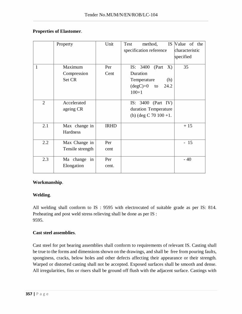
Tender No.MUM/N/EN/ROB/LC-104
357 | P a g e
Properties of Elastomer.
Property Unit Test method, IS specification reference
Value of the characteristic specified
1 Maximum Compression Set CR
Per Cent
IS: 3400 (Part X) Duration Temperature (h) (degC)+0 to 24.2 100+1
35
2 Accelerated ageing CR
IS: 3400 (Part IV) duration Temperature (h) (deg C 70 100 +1.
2.1 Max change in Hardness
IRHD + 15
2.2 Max Change in Tensile strength
Per cent
- 15
2.3 Ma change in Elongation
Per cent.
- 40
Workmanship. Welding. All welding shall conform to IS : 9595 with electrocuted of suitable grade as per IS: 814. Preheating and post weld stress relieving shall be done as per IS : 9595. Cast steel assemblies. Cast steel for pot bearing assemblies shall conform to requirements of relevant IS. Casting shall be true to the forms and dimensions shown on the drawings, and shall be free from pouring faults, sponginess, cracks, below holes and other defects affecting their appearance or their strength. Warped or distorted casting shall not be accepted. Exposed surfaces shall be smooth and dense. All irregularities, fins or risers shall be ground off flush with the adjacent surface. Castings with

Tender No.MUM/N/EN/ROB/LC-104
358 | P a g e
visible cracks, blow holes, or similar blemishes shall be rejected if the imperfections are located on bearing surface or cannot be remedied to the satisfaction of the Engineer in Charge. Imperfections which are not located on bearings surfaces shall be cleaned out, filled with weld metal of the appropriate composition and ground flush with adjacent surfaces. Structural Steel Assemblies. Defects arising from the fabrication of the steel shall be inspected by the Engineer, who will decide whether the materials may be repaired by the Contractor or will be rejected. The cost of repairs or replacement shall be borne by the Contractor. All steel whether fabricated or not, shall be stored above the ground on platforms, skids, or other supports, and adequately protected against corrosion. Excessively rusted, bent or damaged steel shall be rejected. All plates shall be rejected. All plates shall be flat and rolled bars and shapes straight before marking out or being worked. Straightening shall be done by methods which shall not damage the material. Sharp kinks and bends shall be the cause for rejection. Steel may be flame cut to shape and length so that a regular surface, free from excessive gouges and striations is obtained. Flame cutting by hand shall be done only with the approval of the Engineer in charge. Exposed corners shall be machined or ground.
Tolerances:
I) Plan dimensions - 0 to + 5 mm
II) Overall height -0 to + 3 mm
III) Height of elastomer + 5 per cent.
IV) Height of any steel component
a) Machined
0 to +1mm
Class 2 of IS : 4897
V) Stainless sliding surface
a) flatness
b Surface Finish
0.004L, where L=Length in direction of measurement.
Ra <=0.25pm per IS:3073.

Tender No.MUM/N/EN/ROB/LC-104
359 | P a g e
Painting: All non-working surfaces be coated with two coats of epoxy primer and one more coat each of epoxy intermediate and finish, total thickness <= 0.150 mm or any other painting scheme as approved by the Engineer. Silicon severs shall be cement coated at the manufacturer’s works. Test. Raw Materials Necessary test certificates for all raw materials as in above shall be furnished by manufacturers, reference may also be made to for tests on elastomers. Test on Casting Tests specified in IS: 1030 shall be performed. Castings shall be ultrasonically tested and certificates submitted. Quality level of castings shall be level 3 as per IS: 9565. Testing on Welding. All welding shall be tested by Dye Penetration method. But welding shall be tested by Ultrasonic method. Soundness of welding shall be certificate by the manufacturer .Acceptance test on bearings. All bearings shall be checked for overall dimensions. All bearings shall be load tested to 1.1 times maximum design capacity including seismic force. Bearing tested at higher loads cannot be used. A pair of bearing selected at random will undergo testing in order to determine the coefficient of friction “u”. The coefficient of friction shall be < = 0.05 at the design load. Two bearings selected at the design load. Two bearings selected at random shall be tested for permissible rotation. Installation of POT-cum-PTFE Bearings General In-Situ Casting of Superstructure. Seating of Bearing.

Tender No.MUM/N/EN/ROB/LC-104
360 | P a g e
Care shall be taken during installation of the bearings to permit their correct functioning in accordance with the design scheme. To prevent contamination, dismantling of the bearings at site shall not be done. The total shall be transferred on to the bearings only when the bedding material has developed sufficient strength. The props for the form work shall only be removed after lapse of appropriate time. In special cases, this can be ensured by suitable devices like jacks, etc. Temporary clamps and shims (introduced to maintain working clearance) shall be removed at an appropriate time, before the bearing is required to permit movement. Cement based non-shrink grout with air releasing additive and epoxy based grouts, whichever is specified shall be first at the site. For the proprietary grout mixes, appropriate instruction form the manufacturer shall be followed specially with regards of the followings. Preparation > concrete cleaning, roughening, pre-soaking, etc. Forms > sturdiness, leak proofing, shape, header funnel vents, etc. Bearings Base >cleaning , etc. Placement –curing, consistency, time period, finishing etc., Protection > curing, ambient temperature, etc. Formwork around the bearing shall be carefully sealed to prevent leakage. Sliding plates shall be fully supported and care taken to prevent tilting, displacement or distortion of the bearings under the weight of wet concrete. Bearing shall be protected during concreting operation. Any mortar contaminating the bearing shall be completely removed before it sets. Using Template. Template with required and matching holes corresponding to the base of the bearings shall be used. All the anchors shall be fitted to the lower face of the template using the anchor screws but with steel washer replacing the elastomer washers. Separate screw may be used in case of inconvenience in the length of the original anchor screws.

Tender No.MUM/N/EN/ROB/LC-104
361 | P a g e
The template assembly shall be located with regard to level and alignment. It shall be ensured that the tops of the anchors lie in a horizontal plane at the required elevation. The anchors shall be tied/welded to reinforcements to avoid displacement during concreting. Concreting of the pedestal / pier cap shall be done to a level leaving a gap of 25-50 mm below the template. The template and steel washers shall be removed prior to placement of the bearing assembly with temporary clamps. The bearing assembly shall. The gap below the bearing assembly shall be grouted with cement based grout. Reference may be made to clause 8.17.6.1(VI). B. Without Template with Gap. Pockets commensurate with the sizes of the anchors shall be kept pedestals during concreting of the same. The pedestal shall be cast approximately 25 mm short of the required finished level. Anchors shall be fitted to the bearing bottom with elastomer washers and anchor screws. The bearing assembly shall be seated in the location on steel chairs/packs. The anchors fitted below the bearing shall go into pockets in the bed block. Level and alignment of the bearing shall be checked. It shall be ensured that the bearing sits in a horizontal plane. The gap below the bearing assembly including anchor pockets shall be grouted with cement based grout. Reference may be made to Clause 8.17.6.1. (VI). Without Template Without Gap. Elongated pockets commensurate with the size of the anchors shall be kept in pedestals during concreting of the same. The geometry and location of the anchor pockets (with tapered funnel extension, if required) shall be such that after placement of the bearing the pockets can be successfully grouted. The pedestal shall be cast 5mm – 15mm short of the required finished level. The required level shall be achieved by chipping before placement of the bearing. Careful control shall be exercised to cast at the exact finished level or 1 mm-3 mm down from the required finished level. Seating of bearings shall be as per manufacturer’s instructions. Inspection and Testing.

Tender No.MUM/N/EN/ROB/LC-104
362 | P a g e
Where any patents are used, the manufacturer’s certificate with test proof shall be submitted along
with the design and got approved by the Engineer In Charge before their use in work. Measurement for Payment. Bearings shall be measured in numbers, according to their capacities and particular specifications given on the drawings. The rate given is AS per MT capacity of bearing. The contract unit rate of bearing shall include the cost of all nuts, bolts, tests, prescribed in the specifications and shown on the drawings. | The cost of supplying and fixing the bearings in position complete as specified on the drawings and as directed by the Engineer in charge. The rate shall also include the cost of samples and their testing when desired by the Engineer-In-Charge.
Work shall be carried out as per specification / condition mention above.
1. The Engineer-in-charges shall instruct that a load test be made on any part of the super
structure if any his opinion such a test is deemed necessary for one on more of reasons specified
below.
(a) The works test cubes failing to attain the specified strength.
(b) The shuttering being prematurely removed.
(c) Over loading during construction of the structure or part there of.
(d) Concrete improperly cured.
(e) Any other circumstances attributable to negligence on the part of the contractor,
which, in the option of the Engineer-in-charges results in the reduction of, required strength of the
structure of part thereof.
Item no. NS/6
Load testing of one composite steel /Span Designing and Load testing of one composite girder/ Span as selected by the Engineer confirming to Rly. Standard's with loads to be applied and removed incrementally etc. complete as per special condition and specification of contract, as per relevant IS/IRC codes with all contactors labour supervisor, T & P's all taxes, equipment, leading materials instruction of load test jacks etc., dial gauges, including all lead and lift.

Tender No.MUM/N/EN/ROB/LC-104
363 | P a g e
(f) Any reason other the foregoing.
2. If the load test be ordered to be made solely or in part for the resons (a) to (e) the test shall
be carried out at the contractor's own cost. If test is required to be carried out of or the reasons
specified at (f) hereinbefore, the contractors shall make the test and shall be paid for the same.
3. The test lead shall not be applied earlier than 28 days of the completion of placing of the
concrete in the part of the structure to be tested and the shall not be supported during the test by the
shuttering other non-permanent support. Necessary care shall, however, be taken to ensure than in the
event of failure under test temporary support of the loaded member shall be immediately available.
4. If the result of the load test for the reasons mentioned at (a) to (e) is not satisfactory in the
opinion of the Engineer-in-charges he shall instruct that the part of the structure concerned shall be
taken down or cut out and reconstructed to his satisfaction or that other remedial measures shall be
taken to make the structure secure and strong as per requirement at the contractor's own risk and cost
or the work may be accepted as sub-standard work and paid at reduced rate as may be decided by the
Engineer-in-charges his decision in the matter shall be binding, on the contractor. The contractor shall
provide necessary materials, instruments, equipments observations platforms, plant and labour
needed for carrying out test the as required. The load in general shall be in the from of sand bags.
However, the contractor may apply the test load in any other suitable manner as may be approved by
the Engineer-in-charges. The contractor shall make all necessary arrangements for observations,
platforms, centering, taking, and deflection by electrometers etc. to the entire satisfaction of the
Engineer-in-charges. The test load shall be kept at least 24 hours or as directed before removal. Test
load of superstructure shall be 1.5 times the equivalent load including maximum stresses at sections
of maximum bending moment and or shear force for which the superstructure is designed.
5. The item for the purpose of payment shall be measured per number of load test placed on
the superstructure and the payment of the same made on completion of the test.
6. Unit rate shall include all materials labour, measuring, instruments, tools and plants necessary to carry out the load test.
Item no. NS/7
Conducting Pile low strain integrity test as per ASTM D 5882- 96 code of American Society for Testing on cast -in situ RCC pile of 1200 mm diameter inclusive of analysis with all contractor's equipment, manpower, site preparation,

Tender No.MUM/N/EN/ROB/LC-104
364 | P a g e
Work shall be carried out as per specification/condition as per clause No. 2.3.32 of TECHNICAL
SPECIFICATION of the Tender Document.
PILE INTEGRITY TEST
1. General Remarks
Pile Integrity Testing (PIT) is a Non Destructive integrity test method for foundation piles. It is a “Low Strain” Method (since it requires the impact of only a small handheld hammer). The evaluation of PIT records is conducted either according to the Pulse Echo (or Sonic Echo – a time domain analysis) or the Transient Response (frequency domain analysis) Procedure. This test is standardized by ASTM D5882 Standard Test Method for Low Strain Impact Integrity Testing of Deep Foundations. Pile Integrity Test is performed to check that a pile is free of major cracks and voids, prior to construction of the superstructure.
2. Scope
2.1 This test method covers the procedure for determining the integrity of individual vertical or inclined piles by measuring and analyzing the velocity (required) and force (optional) response of the pile induced by an (hand held hammer or other similar type) impact device usually applied axially and perpendicularly to the pile head surface. This test method is applicable to long structural elements that function in a manner similar to any deep foundation units (such as driven piles, augured piles, or drilled shafts), regardless of their method of installation provided that they are receptive to low strain impact testing.
2.2 This standard provides minimum requirements for low strain impact testing of piles. Plans, specifications, and/or provisions prepared by a qualified engineer, and approved by the agency requiring the test(s), may provide additional requirements and procedures as needed to satisfy the objectives of a particular test program.
2.3 The values stated in SI units are to be regarded as standard. No other units of measurement are included in this standard.
2.4 All observed and calculated values shall conform to the guidelines for significant digits and rounding established in Code of Practice ASTM D 6026.
2.5 The method used to specify how data are collected, calculated, or recorded in this standard is not directly related to the accuracy to which the data can be applied in design or other uses, or both. How one applies the results obtained using this standard is beyond its scope.
lead and lifts etc. complete as per standard procedure, and as directed by the Engineer in charge. Note:- Rate is inclusive All equipment, All labour and consumable required & Mobilization of equipment

Tender No.MUM/N/EN/ROB/LC-104
365 | P a g e
This standard may involve hazardous materials, operations, and equipment. This standard does not purport to address all of the safety concerns, if any, associated with its use. It is the responsibility of the user of this standard to establish appropriate safety and health practices and determine the applicability of regulatory limitations prior to use.
Note:
The quality of the result produced by this test method is dependent on the competence of the personnel performing it, and the suitability of the equipment and facilities used. Agencies that meet the criteria of Practice D 3740 are generally considered capable of competent and objective testing/ sampling/ inspection/etc. Users of this test method are cautioned that compliance with Practice D 3740 does not in itself assure reliable results. Reliable results depend on many factors; Practice D 3740 provides a means of evaluating some of those factors.
3. Description of Method
Low Strain Integrity Testing may be applied to any concreted pile (e.g. concrete piles, drilled shafts, augured cast in place piles, concrete filled pipe piles). The test requires the impact of a small hand held hammer on n the shaft top and the measurement of the shaft top p motion (acceleration or velocity). The input compression wave from the hammer is reflected from pile toe (or a change in cross sectional area or pile material quality) and returns to the pile top at a time related to the speed of travel of the wave in the pile material.
The pile top velocity is displayed as a function of time with an exponentially increasing magnitude such that the pile toe reflection is enhanced. The averaged, amplified velocity, a averaged for several impacts, is the standard result of the Pulse Echo Method. The force as a function of time, if available, provides additional information as to the pile quality near the pile to op.
The Transient Response Method result shows the ratio of velocity to force transforms for all relevant frequencies in a plot called Mobility. It should be shown together with t the related low frequency pile stiffness. Transient Response requires that hammer force is measured.
4. Test Equipment
Provide a Pile Integrity Tester (PIT) or an equivalent equipment. following minimum requirements:
The analog to digital res solution shall be at least 24 bits.
The sampling frequency y shall be at least 25,000 Hz.
Data shall be stored such that additional processing or further wave analysis s is possible.
Data shall be displayed d in the field for evaluations of preliminary data quality and interpretation.

Tender No.MUM/N/EN/ROB/LC-104
366 | P a g e
The equipment shall all low attachment of a motion sensing device capable of measuring acceleration, velocity or displacement due to the impact of the pile top with a hand held hammer.
The equipment shall have the PIT (Pile Integrity Tester) performs the wave equation based non-destructive test known as Pulse or Sonic Echo Test, or r Low Strain Dynamic Test.
The PIT test consists of attaching one or two accelerometers to the foundation, a and using a hand held hammer to impact it. T The PIT collects the acceleration data and displays curves that reveal any significant changes in c cross section that may exist along the pile. The software post processes the data and generates repo orts, while the software simulates a PIT test and performs simplified signal matching to assess the he shape of the pile.
5. Test Personnel
The field testing shall be performed by an experienced technician with at least one year experience in integrity testing. The interpretation of the records requires extensive experience by a graduated engineer with a at least Three years experience in integrity testing.
6. Test Preparation
For the cast in place piles, integrity testing shall not be performed until the concrete has cured c for a minimum of seven (7) days unless otherwise approved by the engineer. Thee pile head shall be free from water, dirt or o other debris. The concrete at the pile top surface must be relatively smooth and provide sufficient space for attaching the motion sensing device and for the hammer impact area.
50% of total piles shall be integrity tested. The location of piles for designated for integrity testing shall be specified by the engineer after pile installation. Additional piles may be e selected for testing at the discretion of the engineer if circumstances either during or after pile installation should make a piles' integrity suspect, or if the initial tests reveal major defects.
7. Result Presentation
The testing engineer shall present a report 5 working days after performing the field test to provide the final test results and integrity evaluation. For each pile tested, the averaged, amplified velocity versus time record shall be included in the report, with a table summarizing results and conclusions. Additional plots and analyses can be included as required or suggested by the testing engineer.
8. Acceptance and Rejection
Shafts with no significant reflections from locations above the pile toe and with a clear pile toe reflection may be accepted. Where no clear toe reflection is apparent, the experienced test engineer shall state to which shaft depth the test appears to be conclusive. Where reflections from locations with significant reductions in pile area or pile material strength or stiffness above the pile toe are observed, the pile has a serious defect. If the record is complex, the results may be deemed

Tender No.MUM/N/EN/ROB/LC-104
367 | P a g e
inconclusive. Construction records (concrete usage, grout pressure records, soil borings) may be valuable in result interpretations or additional numerical analysis modeling may be used to quantify the record. The decision to reject and replace, or repair, any defective shaft is at the sole responsibility of the engineer of record for the foundation.
9. Remedial Action
Rejected or questionable piles may be replaced. Questionable piles may also be subjected to further testing, e.g., static load testing, dynamic load testing, core drilling, ultrasonic logging, etc. Remedial action may include pressure grouting through core holes. If the pile top appears questionable, further pile top cutoff and retesting may be advisable. If a majority of piles diagnose as "inconclusive", partial or even complete pile excavation or another test method may be necessary for pile acceptance.
Related ASTM Standards
D653 Terminology Relating to Soil, Rock, and Contained Fluids
D3740 Practice for Minimum Requirements for Agencies Engaged in Testing and/or Inspection of Soil and Rock as Used in Engineering Design and Construction
D6026 Practice for using significant digits in Geotechnical Data.
10. The rate shall be for a unit of Numbers of pile.
DETAILED SPECIFICATIONS AND SPECIAL CONDITIONS
FOR SCHEDULE “E”

Tender No.MUM/N/EN/ROB/LC-104
368 | P a g e
Work shall be carried out as per specification / condition mention above.
SITE OFFICE FOR EMPLOYER
1. The Contractor has to provide a reasonable office accommodation of suitable size at each ROB’s site (about 500 sqft) as approved by the Engineer as far as possible close to ROB location under this contract for supervisory staff of the Employer and Consultants. The office accommodation shall be maintained by the contractor by providing all required furniture as mentioned in technical specification along with a gas connection for office pantry. The contractor will also provide round the clock watch & ward, one Messenger for communication between site & officers and one for maintaining the pantry etc. the cost is incidental & deemed inclusive in cost to complete the contract and no separate payment shall be made for the above mentioned provisions except relevant SOR item. The rentals along with electrical, water supply and other charges shall be arranged by the contractor for accommodation/s provided by the contractor during entire contract period as directed & decided by the Engineer. The Contractor shall take away all material, furniture &equipment provided at accommodation/s after completion of contract but upon obtaining written approval from the Engineer and/ or as decided by the Engineer.
Item no. NS/1
AutoCAD Drawings: Preparation / Alternation and submission of drawings such as general arrangement drawings, phase drawings, scheme plan, structural drawings etc. On Auto Cad as per details and directions given by the Engineer in charge including plotting and submitting in standard inklet film of 50 micron and CD, submitting check prints on A3/A2/A0 size papers and final print complete and as per instructions of Engineer in charge.
Item no. NS/2
Site Office Providing, arranging, managing and maintaining 500 sq.ft. well-furnished AC office and well equipped Laboratory with 3 tables, 10 chairs, 2 steel Almira, one computer with printer & operator, sufficient number of display etc. to the satisfaction of the Project Manager including Electrical, Water expenses etc. For execution of this item the date of start shall be considered only when the Contractor has actually rented/constructed the required premises established the office & Laboratory as per requirement. This item shall remain valid only for original contact period; no additional payment shall be made for whatsoever reason even if time extension if provided or date of completion is extended. This office and laboratory including furniture and all other equipment shall be property of contractor after completion of Project.

Tender No.MUM/N/EN/ROB/LC-104
369 | P a g e
2. The office, accommodation/s shall be arranged at strategically suitable location as decided by the Engineer at each ROB site.
3. The Contractor shall arrange & provide reasonable furnished office, accommodation/s, good for the Employer’s supervisory staff, having with required accessories and compatible UPS/
Inverter power backup. The Contractor shall provide the office accommodation within one month from the date of LOA. The rentals for accommodation/s provided, Telephone, electric & water charges etc. will be arranged by the contractor on time. The list of furniture and equipment’s is given below, which are to be provided and maintained foe site office under
this contractor package. All Cost towards provision of stationary, photocopy, printing of drawings, record maintenance etc. will be incurred by contractor as part of office maintenance.
4. Following furniture shall be provided and maintained by the contractor at his own cost at each site of ROB to the satisfaction of the Engineer including Electrical, Water expenses etc. for execution.
Sr.No Item reqd. at site office
Specification Nos. reqd.
1 Office table As approved by Engineer 3
2 Office chair As approved by Engineer 3
3 Visitor chair As approved by Engineer 4
4 Ordinary chair As approved by Engineer 6
5 Stools As approved by Engineer 2
6 Steel Almirah Make- Godrej store well 1890x900x590 mm plain with locker or equivalent as approved by Engineer
1
7 Air Conditioner As approved by Engineer 1
8 Telephone & Fax Machine
Telephone and Fax machine with STD and internet facility.
1
9 Laptop (Core- i7 ) with printer
HP/HCL/DELL/SONY or equivalent including with applicable soft wares as 1Auto CAD, MS Project etc. along with one printer four in one- type print, fac scan & photo copy
1
10 Refrigerator Make Godrej or equivalent 185 ltr. Minimum 1

Tender No.MUM/N/EN/ROB/LC-104
370 | P a g e
11 Fire Extinguisher
As per requirement for Office 1 Set
5. Site office shall be furnished as per requirement of the Employer. The contractor shall supply new furniture, equipment, pantry utensils, reasonable Crockery & Cutlery etc. as decided by the Engineer. All the furniture etc. shall become the property of the contractor after the completion of the contractor the same shall be taken away by the contractor as decided by the Engineer. The cost for providing & maintenance of office, accommodation is incidental to work & no separate payment shall be made.
This item is for providing, fabricating and fixing in position safety screen conforming to IS: 800-1984 of approved quality/make including painting.
The rate quoted shall be for safety screen with all materials, labour, tools and plants etc. including painting with one coat of red oxide and two coats of synthetic enamel paint of approved make and color as directed by Engineer in charge and approved drawing.
1. The work of fabricating check rails of any length by machining shall be carried out strictly as per the Railway’s standard drawings, instructions laid down in Indian Railway permanent way
manual and the instructions of the Engineer in charge whose decisions shall be final and conclusive.
2. The work shall be carried out only under the supervision of the Engineer in charge or his representative.
3. The rails and other fitting will be supplied to the contractor at the nearest PWI depot.
4. The quantities shall be responsible for all P. way material supplied to him till completion of work and properly accounted.
Item no. NS/3
Providing & fixing Safety Screen as per RDSO Drg. No. EL / C / 0068 MOD " E " , on the Parapet with necessary fixtures etc. as per detailed drawing including contractor's own materials, labours, tools and plants, etc. complete.
Item no. NS/4
Making and supplying of check rails of 52 kg/ 60 kg rails of various lengths for level crossing as per approval drawings.

Tender No.MUM/N/EN/ROB/LC-104
371 | P a g e
5. The surplus material shall be returned in the depot in good condition and no transportation charges either transporting it to site or returning back shall be payable. Waste material shall be also returned.
Mode of payment
The unit for measurement is each level crossing consist 2 check rails. Payment shall be made as per actual work done at site. Nothing extra shall be paid other than the rate accepted.
Providing, fixing and maintaining MS fabricated traffic barricading of 2.50 m height on either side of carriage way closed to the traffic including provision of all sign board/bollards and warning lights etc. as per direction of Engineer in charge at site. Rate is inclusive of all labour, materials, tools and plants, taxes, lead & lift and transportation, erection and dismantling etc. Nothing extra shall be payable other than the rate quoted by the contractor.
The barricading shall be got erected just prior to commencement of the work and will remain erected till the work is completed in all respect or as decided by Engineer in charge at site.
The length of barricading shall be decided by Engineer in charge/Site Supervisor at site and shall be final and binding. The design of barricading shall be as approved by competent authority / Engineer in charge.
Measurement shall be for the finished item. Nothing extra shall be payable for overlapping. However, overlapping has to be provided so that GI sheets perfectly anchor to each other.
After completion of the work, all the material utilized in barricading shall be the contractor's property, however, nothing extra shall be paid for transporting including loading and unloading.
Before erection, the material utilized for barricading shall be got approved by the DFCCIL supervisor at site.
Rate is also inclusive of PCC meant for insertion of MS pipe. However, PCC shall not be done in the grade lower than 1:2:4 mix.
Quantity shown above is approximate; however, actual length of barricading may differ as per the site condition. Whatever length of barricading is decided by Engineer in charge/Site supervisor shall be provided by the contractor.
Item no. NS/5
Providing, fixing and maintaining MS fabricated traffic barricading of 2.50m height on either side of the carriage way / portion of the carriage way closed to the traffic including provision of all sign boards/ bollards and warning lights etc. as per the Engineer in charge.

Tender No.MUM/N/EN/ROB/LC-104
372 | P a g e
Note :-
1. In the event of conflict between special condition /Technical specification /other guidelines, (available in the tender) the decision of the DFCCIL administration is final and binding to the contractor. No claim in this regard shall be entertained.
2. The Contractor and concerned staff, PMC shall ensure that every 1st, 3rd, 5th etc. Running bill
& Final Bill shall be technically checked before making payment.
3. Earthwork register, level books, steel registers, Hrs, Test certificates where as required etc. shall be maintained carefully and shall submit along with all Running / final bill for technical checking

Tender No.MUM/N/EN/ROB/LC-104
373 | P a g e
DETAILED SPECIFICATIONS AND SPECIAL CONDITIONS FOR SCHEDULE “F”
Item No. NS/1: Conducting load testing of a single pile upto following capacity in accordance with IS 2911 (Part IV) including installation of loading platform and preparation of pile head or construction of test cap and dismantling of test cap after test etc with all labour material, tool & plant , equipment, machinery etc complete as per drawing and specification as directed by the Engineer.
A) Initial load test above 100 ton capacity up to 250 ton capacity. USSOR 2011 western railway item no.192103
B) Extra for every increase of 50 t in a pile capacity or part thereof over 250 ton.
The work shall be carried out as per Indian Railways Unified Standard Specifications for works and materials 2010.
1. Piles find application in foundation to transfer loads from a structure to competent subsurface strata having adequate load bearing capacity. The load transfer mechanism from a pile to the surrounding ground is complicated and could not yet be fully ascertained, although ugh application of piled foundations is in practice over many decades. Broadly, piles transfer axial loads either substantially by skin friction along its shaft or substantially by the end bearing. Piles are used where either of the above load transfer mechanism is possible depending upon the subsoil stratification at a particular site. Construction of pile foundations require a careful choice of piling system depending upon the subsoil conditions, the load characteristics of a structure and the limitations of total settlement, differential settlement and any other special requirement of a project. The installation of piles demands careful control on position, alignment, depth and involve specialized skill and experience.
Pile load test is the most direct method for determining the safe loads on piles including its structural capacity with respect to soil in which it is installed. It is considered more reliable on account of its being in-situ test than the capacities computed by other methods, such as static formula, dynamic formulae and penetration test data. There are widely varying practices followed for load tests on piles. Particularly, the difficulties regarding the establishment of an acceptable criterion, for determining the ultimate and safe bearing capacity of piles, and predicing the pile group behaviour from the test data obtained from individual load test on single piles, cannot be under-estimated as the factors affecting are many. However, an attempt is made to bring out an unified approach to the various aspect of load test on piles.
2. TERMINOLOGY
2.0 For the purpose of this standard, the following definitions shall apply.
2.1 Cut-Off Level — The level where the installed pile is cut-off to support the pile caps or beams or any other structural components at that level.
2.2 Datum Bar — A rigid bar placed on immovable supports.
2.3 Factor of Safety — The ratio of the ultimate load capacity of a pile to the safe load of a pile.

Tender No.MUM/N/EN/ROB/LC-104
374 | P a g e
2.4 Initial Test — It is carried with a view to determine ultimate load capacity and the safe load capacity.
2.5 Kentledge — Dead-weight used for applying a test load on piles.
2.6 Net Displacement — Net movement of the pile top from the original position after the pile has been subjected to a test load and subsequently released.
2.7 Routine Test — It is carried out on a working pile with a view to check whether pile is capable of taking the working load assigned to it.
2.8 Test Pile — A pile which is meant for initial test.
2.9 Total Displacement (Gross) — The total movement of the pile top under a given load.
2.10 Total Elastic Displacement — This is magnitude of the displacement of the pile due to rebound caused at the top after removal of a given test load. This comprises two components as follows:
a) Elastic displacement of the soil participating in load transfer, and
b) Elastic displacement of the pile shaft.
2.11 Ultimate Load Capacity — The maximum load which a pile or pile shaft can carry before failure of ground (when the soil fails by shear as evidenced from the load settlement curves) or failure of pile.
2.12 Safe Load — It is a load on a pile derived by applying a factor of safety on ultimate load capacity of pile as determined by load test.
2.13 Working Load — The load assigned to a pile according to design.
2.14 Working Pile — A pile forming part of foundation of a structural system which may be used for routine load test.
3. NECESSARY INFORMATION
3.1 The following information is necessary for pile(s) on which test is proposed:
a) Pile type including material and reinforcement details, group of piles, if any;
b) Method of driving with driving record or installation;
c) Pile depth(s) and details of cross-section(s);
d) Type of test desired;
e) Layout of the pile(s) — space available around and position in the group for single pile test;

Tender No.MUM/N/EN/ROB/LC-104
375 | P a g e
f ) Depth of water table and soil strata details with soil test results;
g) Safe load and ultimate load capacity, and the method(s) on which based;
h) Availability and provision of type of piles or anchors or kentledge for reaction;
j ) Nature of loading/loading plan with a particularly mention of pile(s) which may be free standing when scour is expected; and
k) Any other information concerning planning and conducting the tests including the relevant past experience concerning similar test(s).
4. TYPES OF TESTS
4.1 There are two types of tests for each type of loading (that is, vertical, lateral and pullout), namely, initial and routine test.
4.2 Initial Test — This test is required for one or more of the following purposes. This is done in case of important and/or major projects and number of tests may be one or more depending upon the number of piles required.
NOTE — In case specific information about strata and past guiding experience is not available, there should be a minimum of two tests.
a) Determination of ultimate load capacities and arrival at safe load by application of factor of safety,
b) To provide guidelines for setting up the limits of acceptance for routine tests,
c) To study the effect of piling on adjacent existing structures and take decision for the suitability of type of piles to be used,
d) To get an idea of suitability of piling system, and
e) To have a check on calculated load by dynamic or static approaches.
5 GENERAL REQUIREMENTS APPLICABLE TO ALL TYPES OF TESTS
5.1 Pile test may be carried out on a single pile or a group of piles as required. In case of pile groups, caps will be provided such that the required conditions of actual use are fulfilled.
5.2 Generally the load application and deflection observation will be made at the pile top.
5.3 In particular cases where upper part of pile is likely to be exposed later on due to scour, dredging or otherwise then capacity contributed by that portion of the pile during load test shall be duly accounted for. The pile groups in these conditions shall be tested without their cap resting on the ground.

Tender No.MUM/N/EN/ROB/LC-104
376 | P a g e
5.4 The test should be carried out at cut-off level wherever practicable, otherwise suitable allowance shall be made in the interpretation of the test results/test load if the test is not carried out at cut-off level.
This work shall include carrying out Initial pile load test on test piles which are not to be incorporated in the work. The methodology of carrying out load tests and of arriving at safe load on piles shall conform to IS:2911 (Part IV).
1. Load test may be carried out as decided by the Engineer-in- charge on one or more working piles. Preloading shall be not less than one and a half times the estimated safe load carrying capacity of the pile in case of sandy soils and two times the estimated safe load in the case of clayey soils.
2. The test shall commence as early as possible after casting/driving of the piles. The test shall be carried out by applying a series of load on R.C.C. Cap over a pile or a
group of piles unaided by any other support. The load shall preferably be applied by means of hydraulic jack reacting against a loaded platform or against heavy R.S. Joists or a suitable load frame held down by anchor piles or other anchorages, which shall be pre-loaded to not less than one and-a-half times the estimated safe load carrying capacity of the pile. The load applied by the jack should be co-axial with the test pile Wherever tension piles or other suitable anchors are used to sustain the loaded platform, the centre distance between the test pile and anchor pile should be minimum of 5 times the test pile diameter. The hydraulic jack used shall be of adequate capacity and shall have a pressure gauge and a remote control pump.
3. Before load test is performed, the proposed set up and the load frame shall be got approved from the Engineer-in-charge. Readings of settlement and. rebound shall be recorded with the help of at least two dial gauges (preferably four)of 0.02 mm. sensitivity and resting on a diametrically opposite ends of the pile cap. The dial gauges shall be fixed in a datum bar whose ends rest upon non-movable supports. The supports for datum bar with reference to which the settlement of the pile would be measured shall be at least 5 'd' away, clear from the piles, where 'd' is the diameter of the pile subject to a minimum of 2 meters for good sandy soils and 5 metres for loose soils.
4. The test load shall be applied in equal increments of about one fifth of the estimated safe load and reduced to smaller increments at the final stages as or directed by the Engineer-in- charge. Alternate loading and unloading of each load increment shall be performed and the elastic and plastic settlement recorded.
5. Each stage of loading or unloading shall be maintained till the rate of movement of the pile top is not more than 0.02 mm. per hour in case of clay soil and 0.1 mm. per hour for sandy soil..
6. The loading shall be continued upto 1 1/2 times the estimated safe load on the pile or when the total settlement of pile top/cap equals the value specified below.
Assessment of safe load shall be as under: (a) Two-thirds of the final load at which the total settlement attain a value of 12 mm unless
it is established that a total settlement different from 12 mm. is permissible in a given case on the basis of nature and type of the structure, in the latter case the actual total settlement permissible shall be used for assessing the safe load instead of 12 mm.

Tender No.MUM/N/EN/ROB/LC-104
377 | P a g e
(b) For a group of piles, two-thirds of the final load at which the total settlement attains a value of 40 mm.
7. Lateral load test:-This test shall be carried out at the cut off level of the piles, Two or more test pile which may be part of the working piles driven to the required depth and spacing shall be used for the tests. The lateral load at the cut off level shall either be applied by a jack inserted between the piles or by some other arrangement capable of facilitating the application of desired pull. The loading shall be applied in increments of about 20 percent of the estimated safe load, reducing to smaller increments in the final stages of the test. The next increment shall be applied after the rate of displacement is about 0.05 mm. per hour in sandy soils and 0.02 mm. per hour in clayey soils or two hours whichever is earlier. Lateral displacement shall be recorded by using at least two dial gauges spaced at 30 cm and kept horizontally one above the other on each pile. Where it is not possible to locate the dial gauges in line of the jack axis, then the two dial gauges be kept at a distance of 30 cm. at a suitable height and the displacement at load point, interpolated from similar triangles. The safe lateral load on the pile shall be taken as the least of the following (a) 50 per cent of the final load at which total displacement increases to 12 mm. (b) Final load at which total displacement corresponds to 5 mm and. (c) Load corresponding to any other specified displacement due to performance requirements. 8. The measurement for payment shall be in number of load test on piles. 9. The Unit includes all materials, labour, equipment plant, platform and gauges for the
purpose of recording result to complete the job.
Item No. NS/2: Conducting load testing of a single pile upto following capacity in accordance with IS 2911 (Part IV) including installation of loading platform and preparation of pile head or construction of test cap and dismantling of test cap after test etc with all labour material, tool & plant , equipment, machinery etc complete as per drawing and specification as directed by the Engineer.
A) Routine load test above 100 ton capacity up to 250 ton capacity pile.USSOR 2011 western railway item no.192
B) Extra for every increase of 50 t in a pile capacity or part thereof over 250 ton.
The work shall be carried out as per Indian Railways Unified Standard Specifications for works and materials 2010.
1. Piles find application in foundation to transfer loads from a structure to competent subsurface strata having adequate load bearing capacity. The load transfer mechanism from a pile to the surrounding ground is complicated and could not yet be fully ascertained, although ugh application of piled foundations is in practice over many decades. Broadly, piles transfer axial loads either substantially by skin friction along its shaft or substantially by the end bearing. Piles are used where either of the above load transfer mechanism is possible depending upon the subsoil stratification at a particular site. Construction of pile foundations require a careful choice of piling system depending upon the subsoil conditions, the load characteristics of a structure and the limitations of total settlement, differential settlement and any other special requirement of a project. The installation of

Tender No.MUM/N/EN/ROB/LC-104
378 | P a g e
piles demands careful control on position, alignment, depth and involve specialized skill and experience.
Pile load test is the most direct method for determining the safe loads on piles including its structural capacity with respect to soil in which it is installed. It is considered more reliable on account of its being in-situ test than the capacities computed by other methods, such as static formula, dynamic formulae and penetration test data. There are widely varying practices followed for load tests on piles. Particularly, the difficulties regarding the establishment of an acceptable criterion, for determining the ultimate and safe bearing capacity of piles, and predicting the pile group behavior from the test data obtained from individual load test on single piles, cannot be under-estimated as the factors affecting are many. However, an attempt is made to bring out an unified approach to the various aspect of load test on piles.
2. TERMINOLOGY
2.0 For the purpose of this standard, the following definitions shall apply.
2.1 Cut-Off Level — The level where the installed pile is cut-off to support the pile caps or beams or any other structural components at that level.
2.2 Datum Bar — A rigid bar placed on immovable supports.
2.3 Factor of Safety — The ratio of the ultimate load capacity of a pile to the safe load of a pile.
2.4 Initial Test — It is carried with a view to determine ultimate load capacity and the safe load capacity.
2.5 Kentledge — Dead-weight used for applying a test load on piles.
2.6 Net Displacement — Net movement of the pile top from the original position after the pile has been subjected to a test load and subsequently released.
2.7 Routine Test — It is carried out on a working pile with a view to check whether pile is capable of taking the working load assigned to it.
2.8 Test Pile — A pile which is meant for initial test.
2.9 Total Displacement (Gross) — The total movement of the pile top under a given load.
2.10 Total Elastic Displacement — This is magnitude of the displacement of the pile due to rebound caused at the top after removal of a given test load. This comprises two components as follows:
a) Elastic displacement of the soil participating in load transfer, and
b) Elastic displacement of the pile shaft.

Tender No.MUM/N/EN/ROB/LC-104
379 | P a g e
2.11 Ultimate Load Capacity — The maximum load which a pile or pile shaft can carry before failure of ground (when the soil fails by shear as evidenced from the load settlement curves) or failure of pile.
2.12 Safe Load — It is a load on a pile derived by applying a factor of safety on ultimate load capacity of pile as determined by load test.
2.13 Working Load — The load assigned to a pile according to design.
2.14 Working Pile — A pile forming part of foundation of a structural system which may be used for routine load test.
3. NECESSARY INFORMATION
3.1 The following information is necessary for pile(s) on which test is proposed:
a) Pile type including material and reinforcement details, group of piles, if any;
b) Method of driving with driving record or installation;
c) Pile depth(s) and details of cross-section(s);
d) Type of test desired;
e) Layout of the pile(s) — space available around and position in the group for single pile test;
f ) Depth of water table and soil strata details with soil test results;
g) Safe load and ultimate load capacity, and the method(s) on which based;
h) Availability and provision of type of piles or anchors or kentledge for reaction;
j ) Nature of loading/loading plan with a particularly mention of pile(s) which may be free standing when scour is expected; and
k) Any other information concerning planning and conducting the tests including the relevant past experience concerning similar test(s).
4. TYPES OF TESTS
4.1 There are two types of tests for each type of loading (that is, vertical, lateral and pullout), namely, initial and routine test.
4.2 Routine Test — This test is required for one or more of the following purposes. The number of tests may generally be one-half percent of the total number of piles required. The number of the test may be increased up to 2 percent in a particular case depending upon nature, type of structure and strata condition:
One of the criteria to determine the safe load of the pile;

Tender No.MUM/N/EN/ROB/LC-104
380 | P a g e
Checking safe load and extent of safety for the specific functional
requirement of the pile at working load.
NOTE — In case specific information about strata and past guiding experience is not available, there should be a minimum of two tests.
a) Determination of ultimate load capacities and arrival at safe load by application of factor of safety,
b) To provide guidelines for setting up the limits of acceptance for routine tests,
c) To study the effect of piling on adjacent existing structures and take decision for the suitability of type of piles to be used,
d) To get an idea of suitability of piling system, and
e) To have a check on calculated load by dynamic or static approaches.
5 GENERAL REQUIREMENTS APPLICABLE TO ALL TYPES OF TESTS
5.1 Pile test may be carried out on a single pile or a group of piles as required. In case of pile groups, caps will be provided such that the required conditions of actual use are fulfilled.
5.2 Generally the load application and deflection observation will be made at the pile top.
5.3 In particular cases where upper part of pile is likely to be exposed later on due to scour, dredging or otherwise then capacity contributed by that portion of the pile during load test shall be duly accounted for. The pile groups in these conditions shall be tested without their cap resting on the ground.
5.4 The test should be carried out at cut-off level wherever practicable, otherwise suitable allowance shall be made in the interpretation of the test results/test load if the test is not carried out at cut-off level.
The contractor shall be required to carry out routine load tests as directed by the Engineer-in-charge on an individual pile or on a group of piles or on both. The routine load tests shall be carried out generally as per IS 2911 (Part-IV). Report on routine load tests shall be submitted in an approved format for Department’s approval at no extra cost. In case the tests on the routine piles reveal safe
capacity less than specified, the contractor shall, at his own cost, provide suitable modifications to the pile or other remedial measures after obtaining approval of the Engineer-in-Charge. In case of an unsatisfactory results being revealed on any routine tests it shall be the contractor’s responsibility to
carry out additional routine tests, at his own cost till the criteria laid down are fulfilled.
Rate for routine load test shall be inclusive of providing kentledges, making other arrangements for the test loading platforms, providing tools and plants, equipments like hydraulic jack, dial gauges etc. other measuring instruments and all labour involved in carrying out tests.

Tender No.MUM/N/EN/ROB/LC-104
381 | P a g e
The measurement for payment shall be per number of load test on piles. The Unit includes all materials, labour, equipment plant, platform and gauges for the purpose of recording result to complete the job.
Item No. NS/3: Conducting in situ size Plate Load Test (PLT) at selected location as per IS : 1888 including making loading arrangments & casting of RCC/cast in situ concrete footing as per codal provisions including excavation and refilling of trial pit.
The work shall be carried out as per Indian Railways Unified Standard Specifications for works and materials 2010.
Item No. NS/4: Lateral Load Testing of single pile in accordance with " IS Code of practice IS: 2911 (Part IV) for determining safe allowable lateral load of pile" with all labour, material, tool & plants, equipment, machinery, etc complete as per drawing and specification as directed by the engineer.
The work shall be carried out as per Indian Railways Unified Standard Specifications for works and materials 2010.
Item No. NS/5: Providing and fixing in position of standard performed sealed and slab type or Strip Seal elastomeric Type Expansion Joints (80 mm expansion) for railway bridge or Road over Bridge as per approved drawing and latest MORTH/IRC 69 specification. The rate are inclusive of supplying, fixing with contractor's own materials e.g. inserts, bolts, socket tubes, neoprene sheet/cap etc. equipments, machineries, labour, all taxes, royalty, all lead and lift, transport, testing, surface preparations, complete.
2601 DESCRIPTION
The work shall consist of fabrication and installation of expansion joints. The filler joint, asphaltic plug joint, compression seal joint and reinforced elastomeric joint of slab seal, strip seal and box seal type shall conform to these Specifications.
2602 GENERAL
2602.1 The type of expansion joint proposed to be used shall conform to the design and got approved by the Engineer.
2602.2 Expansion joints shall be robust, durable, water-tight and easy for inspection, maintenance and replacement. Site fabricated expansion joints shall be prohibited. Expansion joints shall be procured from approved manufacturers and shall be of proven type.
2602.3 Alternative proprietary type deck joints proposed by the Contractor in lieu of the type specified shall comply in all respects with the manufacturer's specifications and meet the

Tender No.MUM/N/EN/ROB/LC-104
382 | P a g e
required range of movements and rotations and be fit for the purpose of ensuring satisfactory long term performance. For such proprietary type deck joints the following information shall be provided.
i) Name and location of the proposed manufacturer.
ii) Dimensions and general details of the joint including material specifications, holding down bolt or anchorage details and installation procedures.
iii) Evidence of satisfactory performance under similar environmental conditions of similar joints being produced by the manufacturer.
Acceptance of any alternative type of expansion joint shall be at the sole discretion of the Engineer. Such deck joints shall be installed in accordance with the manufacturer's recommendations and to the requirements of these Specifications.
Vehicular traffic shall not be allowed over expansion joints after their installation for such period as may be determined by the Engineer.
2602.4 The expansion joint shall be provided to cover the entire carriageway, kerb and footpath, wherever provided. It shall follow the profile of the deck including the kerb, footway and facia. The expansion joint for kerb, footway and facia may be of different type and specification from that used for the carriageway and it shall cater to all movements and rotations for which the carriageway expansion joint is designed and shall be water tight.
2603 PERFORMANCE REQUIREMENTS
2603.1 The expansion joint proper and the transition zone (the zone of connection of joint assembly and the adjoining deck) shall satisfy the performance requirements specified herein. The expansion joint proper shall satisfy the performance requirements of both the bridge structure and the road users.
2603.2 Performance Requirements with Respect to Bridge Structure
The expansion joint shall:
i) withstand the imposed loads including the impact load from live load and other sources,
ii) allow expansion and contraction movement due to temperature, creep, shrinkage, pre-stressing and structural deformations,
iii) permit relative rotation in elevation and plan due to the causes mentioned above, iv) be waterproof, v) be properly sealed, vi) ensure long life by being resistant to corrosion, vii) be easy to install, viii) be easy to maintain. ix) be easy to replace. and x) be resistant to the materials likely to collect/spill over the deck in its normal service.

Tender No.MUM/N/EN/ROB/LC-104
383 | P a g e
2603.3Performance Requirements with Respect to User
The expansion joint shall:
i) provide smooth continuity at the top of the deck for riding comfort,
ii) be skid resistant,
iii) be non-damaging to rubber tyres,
iv) make little or no noise during passage of vehicules,
v) ensure that animal paws and hooves do not get entangled when used by animal drawn traffic,
vi) permit passage of steel tyre of bullock carts without being damaged, and
vii) look good aesthetically.
2606.1. Components
Strip seal expansion joint shall comprise the following items:
i) Edge beams: This shall be either extruded or hot rolled steel section including
continuously shop welded section with suitable profile to mechanically lock the sealing
element in place throughout the normal movement cycle. Further, the configuration shall
be such that the section has a minimum thickness of 1 0 mm all along its cross section
(flange and web). Thickness of lips holding the seal shall not be less than 6 mm. The
minimum height of the edge beam section shall be 80 mm. The minimum cross sectional
area of the edge beam shall be 1500 mm2.
ii) Anchorage : The edge beams of single strip/box seal joints shall be anchored in the
concrete with rigid loop anchorage. The anchor loops shall be connected to the edge beam
by means of anchor plate welded to the edge beam. Total cross sectional area of anchor
loop on each side of the joint shall not be less than 1600 mm2 per metre length of the joint
and the centre to centre spacing shall not exceed 250 mm. The thickness of anchor plate
shall not be less than 0. 7 times the diameter of anchor loop or 12 mm whichever is higher.
The anchor loop at the edge profiles should be at right angles to the joint. Planned
deviations of this direction are allowable only for the range of 90° ± 20°. The anchoring
reinforcement of the construction must lie parallel to the anchor loops.
iii) Sealing Element - This shall be a preformed/extruded single strip of such a shape as to

Tender No.MUM/N/EN/ROB/LC-104
384 | P a g e
promote self-removal of foreign material during normal joint operation. The seal shall
possess high tear strength and be insensitive to oil, gasoline and ozone. It shall have high
resistance to ageing. The specially designed proprietary type of locking system of seal in
the housing of edge beam shall be such as to ensure 100% water tightness as well as ease
of installation and replacement. Mechanical fastening of sealing element with edge beam
shall not be permitted. Sealing element shall be continuous over the entire joint.
The working movement range of the sealing element shall be at least 80 mm with a
maximum of 100 mm at right angles to the joint and ± 40 mm parallel to the joint.
Minimum gap for inserting the Chloroprene seals in the expansion joint shall be 25 mm.
2606.2. Material
i) The steel for edge beams shall conform to any of the steel grade equivalent to RST 37-2 or 37-3
(DIN), S235JRG2 or S355K2G3 of EN10025 (DIN 17100), ASTM A 36 or A 588, CAN/CSA
Standard G40.21 Grade 300 Wand Grade B of IS:2062. For subzero condition, material for steel
shall conform to IS:2062 Grade C.
ii) The sealing element shall be made of Choloroprene Rubber (CR). The properties of CR shall be
as specified in Table 2600-1.
iii) Anchorage steel shall conform to Grade B of IS:2062 or equivalent standard.
TABLE 2600-1. STRIP SEAL ELEMENT SPECIFICATION

Tender No.MUM/N/EN/ROB/LC-104
385 | P a g e
Property Standard Specific Value
Hardness DIN 53505
ASTM D2240 *
63 + 5 Shore A
55+ 5 Shore A
Tensile Strength DIN 53504
ASTM D412*
Min 11 MPa
Min 13.8 MPa
Elongation at fracture DIN 53504
ASTM D 412*
Min 350%
Min 250%
Tear propagation strength longitudinal transverse
DIN 53507
ASTM D 624* (Dia C)
Min 10N/mm
Min 10N/mm
Shock elasticity DIN 53512 Min 25%
Abrasion DIN 53516 Max 220 mm3
Residual compression strain (22h/70°C/30% strain)
DIN 53517
ASTM D 395* (Method B)
Max 28%
Ageing in hot air
( 14 days/70°C)
Change in hardness
Change in tensile strength
change in elongation at fracture
DIN 53508 Max + 7 Shore A
Max-20%
Max-20%
Ageing in ozone
(24h/50pphm/25°C/20% strain)
DIN 53509 No cracks
Swelling behaviour in oil
(168h/25°C)
ASTM oil No.1
Volume Change
DIN 53521
Max+ 5%

Tender No.MUM/N/EN/ROB/LC-104
386 | P a g e
Change in hardness
ASTM oil No. 3
Volume Change
Change in hardness
Max- 10 Shore A
Max+ 25%
Max- 20 Shore A
Cold hardening point ASTM D 1043 Min -35°C
2606.3. Fabrication (Pre-installation)
a) Rolled steel profiles for edge beams shall be long enough to cater for a 2-lane carriageway. These
shall be cut to size of actual requirements by meant of a metre box saw. Alignment of the cut-to-
size steel profiles shall then be made in accordance with the actual bridge cross-section on work tablet.
For this purpose, the contour of bridge cross-section shall be sketched onto these tables. After the
steel profiles are aligned, they will be chucked to the tables by means of screw clamps and tacked
by arc welding.
b) Anchor plates shall be cut to the required size by gat cutting. These shall be welded to the
edge beams.
c) Anchor loops shall be bent to the required shape and welded to anchor plates.
d) The finally assembled joints shall then be clamped and transported to the work site.
2606.4. Handling and Storage
a) For transportation and storage, auxiliary brackets shall be provided to hold the joint assembly
together.
b) The manufacturer shall supply either directly to the Engineer . or to the Bridge Contractor
all the materials of strip seal joints including sealants and all other accessories for the effective
installation of the jointing.
c) Expansion joint material shall be handled with care. It shall be stored under cover on suitable
lumber padding by the Contractor to prevent damage. Any damage occurring after delivery shall
be made good at the Bridge Contractor’s expense to the satisfaction of the Engineer.
2607 MODULAR STRIP/BOX SEAL EXPANSION JOINTS

Tender No.MUM/N/EN/ROB/LC-104
387 | P a g e
2607.1Components
A modular expansion joint shall consist of two or more modules/cells of individual capacity 80 mm to cater to a horizontal movement in excess of 80 mm. It shall allow movements in all three directions and rotation about all three axes as per the design requirements. The structural system shall consist of two edge beams, one or more central/separation beams or lamellas and cross support bars supporting individuals or multiple central beams to transfer the loads to the bridge deck through the anchorage system.
Edge Beams and Central Beams/Lamella : These shall be as per Clause 2606.1(i).
Anchorage : Anchorage of edge beam shall be as per Clause 2606.1 (ii). Studs and/or loop anchors with anchor plate may be used as anchorage of other components like joist box and covers of controlling system.
Sealing Element : This shall be as per Clause 2606.1 (iii). Minimum gap for inserting the neoprene seals in the expansion joint shall be 25 mm.
Support and Control System : The control system should allow closing and opening of the joint and also ensure that all modules open and close equally during all movement cycles of the joint. The overall support and control system shall be either single/multiple support bar control system or swivel joint system comprising of resilient/shock absorption components and elastic/sliding control system conforming to the specifications recommended by the manufacturer. The gap between the consecutive centre beams at the joint surface shall be limited to 80 mm when the joint opens fully due to maximum contraction of deck.
2607.2.Material
i) The steel for edge beams, centre beam/lamella, transverse support bar and other steel components shall conform to any of the steel grade corresponding to RST 37-2 or 37-3 or 52-3 (DIN), S235JRG2 or S355K2G3 of EN10025 (DIN 17100), ASTM A36 or A588, CAN/CSA standard G40.21 Grade 300 W.
ii) The sealing element shall be of Chloroprene Rubber (CR). The properties of CR shall be as specified in Table 2600-1.
iii) The specification for all other materials shall be as per manufacturer's recommendation.
2607.3Fabrication (Pre-installation)
i) Profile of edge beam, centre beam/lamella shall be long enough to cater for full carriageway width.

Tender No.MUM/N/EN/ROB/LC-104
388 | P a g e
ii) The fabrication of all components of the joints including anchorage system and transportation of assembled joints shall be as per manufacturer's specification.
iii) All steel sections shall be suitably protected against corrosion as stated in Clause 2606.3 (iv).
iv) All surfaces of the steel inserts and anchorage including the surfaces to be in contact with or embedded in concrete shall be given treatment as mentioned in Clause 2605.3 (i).
2607.4 HANDALING AND STORAGE
i) Arrangement for transportation and storage shall be as per manufacture’s
Specification.
ii)The manufacturer shall supply either directly to the engineer or to the bridge contractor all the materials of strip seal joints including sealants and all other accessories for the effective installation of the joint.
2610 INSTALLATION OF EXPANSION JOINTS
2610.1General Procedure
i) Expansion Joints shall be installed under close supervision of the manufacturer's/supplier's engineer in order to ensure the quality of installation and its function as intended during the entire life span. Detailed Installation Manual shall be supplied by the manufacturer/ supplier.
ii) The dimensions of the recess in the deck shall be established in accordance with the drawings or design data of the manufacturer, taking into account the width of gap for movement of the joint.
iii) The pre-setting of expansion joint shall be done by means of an auxiliary construction.
iv) The road surfacing/wearing coat shall be laid before commencing installation of joint. Before laying wearing coat, the recess portion shall be filled with sand and wearing coat shall be laid in a continuous manner over the deck slabs and recess portion. Prior to installation of the joints, portion of wearing coat over the recess shall be removed by a suitable method e.g. saw cutting and the infill sand shall also be removed.
v) Preparation of the Recess : The size and form of recess shall suit the geometry of the expansion joint. However, the width shall not be less than the specified value for a particular type of joint. In order to avoid difficulties during installation, the following points must be checked and considered: a) Dimension of recess
b) Levels

Tender No.MUM/N/EN/ROB/LC-104
389 | P a g e
c) Skew and slope
d) Designed gap between bridge deck and abutment and/or between adjoining decks
e) Existing structural reinforcement according to the drawings
Reinforcing bars that would obstruct the installation of expansion joint shall be bent to accommodate the expansion joint anchorages. Cutting off or removal of interfering reinforcing bars shall only be done after consultation with the Engineer.
The recess shall be cleaned thoroughly. If necessary, the surface should be roughened. All loose dirt and debris shall be removed by wire brushing, air blowing and dried with hot compressed air.
vi) Shuttering : Shuttering must be used to seal the space between the underside of the joint and the vertical face of the recess. The shuttering must be fitted in such a way that it forms an appropriate seal against the edge of the recess. The recess shall be shuttered in such a way that dimensions shown on the drawing are maintained. The formwork shall be rigid and firm.
vii) Placing in the Recess : Level marks shall be set next to the recess. This enables a controlled leveling of the expansion joint. Lowering the expansion joint/joint construction/insert into the recess shall be done in such a way that the entire length of the joint is evenly lowered into the recess. Thereafter, the joint/joint construction/insert is precisely leveled and adjusted in the longitudinal, transverse and vertical planes. If required, the joint must also be adjusted to the gradient of the final surface level.
viii) Connection a) The expansion joint/joint construction/insert shall be installed preferably in
the early morning when the temperature is distributed almost uniformly over the whole bridge. Immediately before the installation, the actual temperature of the bridge shall be measured. If it is not within the considered tolerance, the pre Set adjustment shall be corrected. The joint/joint construction/insert shall be lowered in a predetermined position. Following placement of the joint/joint construction/insert in the prepared recess, the joint/joint construction/insert shall be leveled and finally aligned and the anchorage steel on one side of the joint welded to the exposed reinforcement bars of the structure. Upon completion, the same procedure shall be followed for the other side. With the expansion joint/joint construction/ insert finally held at both sides, the auxiliary brackets shall be released, allowing it to take up the movement of the structure. After carrying out the final fixing, the .protection against corrosion shall be completed.
b) For fully assembled joints with one end fixed and other end movable e.g. modular strip/box seal joint, connection shall be as detailed below:
The 1st side : The fixed side of the assembled joint (either the abutment or the bridge deck side) is designated the 1st side for connecting the joint. The

Tender No.MUM/N/EN/ROB/LC-104
390 | P a g e
preliminary fixing is made by evenly placing and welding of reinforcing bars over the entire length between the anchor loops and the deck reinforcement. To facilitate concreting, it the gap between recess and shuttering is sealed by a grout seam. The seam must be left to dry prior to final concreting. After this, additional reinforcing bars are welded until all anchor loops are firmly connected to the deck reinforcement. The expansion joint shall be considered sufficiently fixed when no vibration is noted when it is lightly tapped. The expansion joint shall not be subjected to any loads that could in any way displace the precise location of this fixing.
The 2nd side : Depending on the size of the expansion joint and the expected movement during installation, the most suitable time must be determined for fixing of the 2nd (moveable) side. Usually this is the early morning hours with the smallest temperature deviations. The procedure is identical to that for the 'I st side. The joint shall be provisionally fixed to the reinforcement as fast as possible.
Immediately afterwards, the fixation brackets shall be removed. Thereafter, the gap between recess and shuttering shall be sealed with grout seam and the remaining reinforcing bars welded as described previously.
ix) Concreting
a) Prior to final concreting, the position of the joint/joint construction/ insert must be recorded. The Engineer must give written confirmation of the correct position of the joint and recess concreting. The recess shall be thoroughly watered. Before pouring the concrete the joint construction should be protected by a cover. Controlled concrete having strength not less than that in superstructure subject to a minimum of M35, shall be filled into the recess. The water cement ratio shall not be more than 0.4. If necessary, admixtures may be used to improve workability. The concrete must exhibit low shrinkage. The freshly placed concrete shall be properly vibrated. Damage to the shuttering shall be avoided during vibration. The concrete shall be finished flush with the carriageway surfacing. The concrete shall be kept damp until it has cured in order to avoid fissures caused by drying too fast. After the concrete has cured, the movable installation brackets and shuttering still in place shall be removed.
b) For modular strip seal joint the space beneath the joint boxes shall be completely filled with concrete. So that traffic loads are safely transmitted into the structure.
x) As soon as the concrete in the recess has become initially set, a sturdy ramp shall be placed over the joint to protect it from traffic at site.

Tender No.MUM/N/EN/ROB/LC-104
391 | P a g e
Expansion joint shall not be exposed to traffic loading before completion of carriageway surfacing.
xi) The elastomeric sealing element may be field installed. For strip seal and modular strip seal joints the sealing element shall be in continuous lengths spanning the full carriageway width. Proper fit of the seal of the sealing element must be ensured. The seal shall be installed by suitable methods in such a way that it is not damaged.
2610.5 Specific procedure for Modular Strip/Box Seal Joint
a) The procedure given Clause 2610.4 (i) and (ii) applies to modular strip/box seal joint also.
b) To ensure proper fit of the seal, dirt, spatter or standing water shall be removed from the steel cavity using a brush, scraper or compressed air.
c) The actual junction of the surfacing/wearing coat with the block out concrete/steel edge section shall be cleaned beforehand. It is particularly important to ensure thorough and careful compaction of the surfacing in order to prevent any premature depression forming in it.
2610.6 Specific Procedure for Reinforced Elastomeric Joint
Expansion joints shall be installed as per approved drawing. The procedure for installation of various components shall be as follows:
i) Steel Inserts
a) Deck casting shall be done leaving pockets or recesses for steel inserts and anchors of the expansion joint as per drawing.
b) Steel inserts shall be lowered at the appropriate location inside the pocket.
c) The top of the insert shall be flush with the finished level of wearing course maintaining the camber.
d) Spacer bars, duly set appropriately to the month of installation, shall be fitted under proper supervision.
e) Anchor rods shall be tied/welded with the existing deck main reinforcement, maintaining level and alignment.
f) Welding between anchor rods and deck reinforcement is preferable. If welding is not possible, strong steel tie wires shall be used for fastening under proper supervision.
ii) Spacer Bar

Tender No.MUM/N/EN/ROB/LC-104
392 | P a g e
a) Spacer bars shall be used to ensure proper positioning of bolts and also leveling of the steel inserts during fixing of the same with the deck reinforcement and casting second stage concreting in the pocket thereafter.
b) The 2nd stage concreting operation shall preferably be started within 24 hours of fixing the steel inserts. In such cases, spacer bars should be removed just after concreting is finished. If there is a substantial time lag between fixing of inserts and concreting, then any one of the following methods shall be adopted, depending on the support condition:
For simply supported bridge resting on simple elastomeric bearings, (with no dowel pins), insert shall be placed in position with spacer bars at every alternate joints. Such joints shall be called restrained joints hereafter. In other words, inserts shall not be fixed simultaneously at two ends of one span. If the above condition is satisfied, inserts with spacer bars shall be kept in position for a substantially longer period at such restrained joints. Spacer bars shall be removed after concreting of such restrained joints and inserts placed in position with spacer bars at the other unrestrained joints thereafter.
For bridges resting on other than elastomeric bearings (including bearings with dowel pins at one end), after placing and aligning the inserts and securing the same, the spacer bars shall be removed. Concreting shall be done with great care so that inserts are not dislocated or distorted.
c) While removing the spacer bar after concreting, one must take care to see that the concrete is not damaged during withdrawal of spacer bar. If the spacer bar happens to be snugly fitted, it shall not be pulled by any means; it shall be gas cut in two pieces and then removed.
iii) Concreting of Pocket
a) Concreting of pocket shall be done with great care using proper mix conforming to grade similar to that of the deck casting besides ensuring efficient bonding between deck and steel insert. Also proper care shall be given for ensuring efficient bonding with the already cast concrete. Requirement of concrete as per Clause 2610.9.1 shall be followed.
b) Needle vibrators shall be used. Care shall be taken so that the position of steel insert is not disturbed during vibration.
c) Spacer bar shall be removed within an appropriate time before the joint is required to permit movement.
iv) Fixing of Elastomeric Slab Unit (ESU)

Tender No.MUM/N/EN/ROB/LC-104
393 | P a g e
a) Special jig shall be used to preset the ESU during installation
b) ESU (mounted on the jig, if preset) shall be lowered to position.
c) The line and level on the ESU should be adjusted.
d) ESU shall be removed and coated with special adhesive
e) ESU shall be placed in position again, ensuring waterproof joining at required faces.
f) ESU shall be tightened with stainless steel nuts an lock washers in position. Tightened nuts shall be locked with lock washers.
g) Special sealant shall be poured inside the plug holes.
h) The elastomeric plugs shall be pressed in position after applying adhesive on the appropriate surface.
i) ESU shall be fitted in position after completion of wearing course. While completing this part of the wearing course, adequate care shall be taken to ensure a waterproof joining with the already existing wearing course.
v) Pre-setting
a) The main purpose of pre-setting of the steel inserts at the time of its installation is to ensure as closely as possible the condition that in the long run at the mean average annual temperature, the ESU remains at its nominal state.
The steel insert unit of expansion joint can be fixed in any month of the year. The expansion gap between bridge super structures may vary from time to time; hence the initial fixing distance between fixing points will obviously depend on the month of installation of steel insert. The c/c distance between stainless steel fixing of bolts as indicated in the drawing can be taken as only nominal. The same shall be modified by pre-setting depending on:
The difference between the mean temperature of the month of fixing of steel insert and the annual average temperature, and
The elapsed period between the casting and/or pre-stressing and fixing of steel insert for calculating the remnant creep and shrinkage.
vi) Special Requirements for Installation
i) The supplier shall provide detailed working drawings showing the location of all bolts, recesses and holes necessary for the installation of the joint shall

Tender No.MUM/N/EN/ROB/LC-104
394 | P a g e
be obtained from the supplier before construction of bridge deck area adjacent to the joint. If required detailing of reinforcing bars in superstructure shall be modified to ensure that there will be no interference in the installation of the joint.
ii) All bearing surfaces and recesses which are in contact with the joint assembly shall be checked with a straight edge to ensure flatness of profile.
iii) No holes shall be drilled for fixing bolts within 7 days of concreting. Holes for the bolts shall be drilled to the size and depth shown on the drawings.
iv) Sections of the jointing making the completed joint shall follow a straight line.
v) The fixing bolts shall not be placed in a position until at least 4 weeks after stressing is completed in post-tensioned box or beam and slab structures. Prior to placing sections of jointing, contact surfaces shall be cleaned to remove all grease, tar, paint, oil, mud or any other foreign material that may affect adhesion of the sealant.
vi) Sealant shall only be applied to dry contact surfaces. Sufficient quantity shall be applied to the contact surfaces so that sealant is extruded when the jointing is fixed in position.
vii) Final sealing of the finished expansion joint shall be completed immediately after installation. All exposed ends, joints between units, other areas of possible leakage, voids between the sides of the jointing and concrete or plates, shall be filled with sealant.
viii) Bolt cavities shall be cleaned and plugged with neoprene cavity plugs. Prior to placing the plugs sufficient sealant shall be placed in the cavities to cause extrusion of the sealant by the plugs.
ix) All excess sealant shall be removed from the jointing and adjacent areas.
2611 Procedure for installation of various joints, shall also take into account suppliers own specific procedures for installation of each type of joint as the suppliers shall be responsible for performance of the joints for the period of guarantee.
2612 TESTING AND ACCEPTANCE STANDARDS
2612.1 Before installing joints in a bridge, sufficient evidence of the reliability of the proprietary products shall be furnished. A copy of the fatigue and wear test reports, as applicable depending upon the type of joint, carried out by a recognized laboratory/university/ institute on the

Tender No.MUM/N/EN/ROB/LC-104
395 | P a g e
joint components as a part of product development test, shall be furnished once for the entire lot of supply. The tests covered in Clauses 2612.1. 0) to 2612.1. (vi) need not be carried out on the materials of the joints of supply lot but shall be carried out from time to time by the original manufacturer as per their product development and quality plan for the same type of joints to ensure the performance requirement of the particular joint component against fatigue and/or wear.
i) For single strip seal and modular strip seal joints, the manufacturer shall produce complete report of the test of anchorage system from a recognized laboratory to determine optimum configuration of anchorage assembly under dynamic loading in support of the efficacy of the anchorage system adopted for the entire lot of joints.
ii) For modular strip seal joints the manufacturer shall produce a test report from a recognized laboratory that the sliding bearings (suspension system) have been fatigue tested for six million load cycles with a frequency of 5 Hz and the loads of 80 kN, 120 kN and 160 kN.
iii) For modular strip seal joints the manufacturer shall produce a test report from a recognized laboratory that the wearing of sliding interface of bearings of modular joints has been tested for a total sliding distance of 5000 m at a load of 48 kN.
iv) For modular strip seal joints the manufacturer shall also produce a test report from a recognized laboratory that the sliding material of sliding springs of expansion joints has been tested for a total sliding distance of 20,000 m with a load equivalent to a stress of 30 MPa.
v) For modular strip seal joints the manufacturer shall also produce a test report from a recognised laboratory that the butt-welded splicing of centre beams has been tested with two million load cycles with a load equivalent to a stress of 165 MPa.
vi) In case of reinforced elastomeric joints abrasion resistance test shall be carried out in accordance with IS:3400 (Part 3) or DIN 53516.
2612.2 Pre-installation Criteria
The pre-installation criteria shall include the routine tests and acceptance tests as described below:
2612.2.1 Routine Tests
Routine tests including tests for materials conforming to specifications shall be carried out by the original manufacturer i.e., in case of imported joints, by the foreign manufacturer as part of their quality control procedure for all joints to be supplied by them. Detailed documentation of all the tests

Tender No.MUM/N/EN/ROB/LC-104
396 | P a g e
and inspection data as per complete quality control procedure shall be supplied by the original manufacturer in the form of Quality Control Report. Routine tests shall include:
Raw materials inspection,
Process inspection, and
Complete dimensional check as per approved drawings.
i) Raw Material Inspection : Test on all raw materials used for the manufacturing of joints as per relevant material standard based on these Specifications shall be carried out by the manufacturer.
a. Confirmation of the Grade of Steel : Grade of the steel for the edge beam shall be confirmed by conducting tests for yield stress, tensile strength and elongation. Corresponding to RST 37-2 or 37-3 or 52-3 (DIN), 5235 JRG2 or S355K2G3 of EN10025 (DIN 17100), ASTM A36 or A 588, CAN/CSA standard G 40.21 grade 300 W or equivalent to Grade B of IS: 2062. The manufacturers/ suppliers shall have in-house testing facilities for conducting these tests.
b. Tests for steel for the anchorage shall conform to IS:2062.
c. The tests as indicated in Table 2600-1 shall be made for checking the following properties of the chloroprene seal: (a) hardness, (b) tensile strength, (c) elongation at fracture, (d) tear propagation strength, (e) residual compressive strain, (f) change in hardness, (g) change in tensile strength, (h) change in elongation at fracture, (I) ageing in ozone, and (j) swelling behaviour in oil. The manufacturers/suppliers shall have in-house testing facilities for conducting these tests.
ii) Process Inspection : Process inspection including inspection of all manufacturing processes adopted to manufacture the joints e.g., welding, corrosion protection, clamping, pre-setting, greasing, bonding by adhesives and riveting, as appropriate, shall be carried out by the manufacturer.
iii) Complete Dimensional Check : Complete dimensional check of all components of joint as well as the assembled joint with respect to the approved drawings and tolerances as per these Specifications, shall be carried out by the manufacturer.
2612.3 Acceptance Tests

Tender No.MUM/N/EN/ROB/LC-104
397 | P a g e
2612.3.1 In addition to the tests specified under Clause 2612.1, the manufacturer as well as the local supplier in case of imported joints shall have complete in-house testing facilities for the following tests. The Engineer shall insist upon these tests before acceptance of the joint.
i) Cyclic Motion : Cyclic motion test may be carried out once on one complete joint assembly or one meter sample piece selected at random from the entire lot of supply for each type of joint irrespective of movement capacity. The test sample shall be subjected to 5000 expansion and contraction cycles at minimum 30 cycles per hour. The test movement shall be 10 percent more than the design expansion/ contraction movement. Any sign of distress or permanent set of any component or the assembly due to fatigue, will lead to rejection of entire lot of supply.
ii) Ponding : Prior to acceptance, 25 percent of the completed and installed joints, subject to a minimum of one joint, shall be subjected to water tightness test. Water shall be continuously ponded along the entire length for a minimum period of 4 hours for a depth of 25 mm above the highest point of deck. The width of ponding shall be at least 50 mm beyond the anchorage block of the joint on either side. The depth of water shall not fall below 25 mm anytime during the test. A close inspection of the underside of the joint shall not reveal any leakage.
iii) Debris Expelling Test : Debris expelling test shall be carried out on one metre sample piece selected at random from the entire lot of supply. The fully open gap shall be filled flush with granular debris and cycled 25 times for full opening and closing. The mass of debris repelled after 25 cycles shall be expressed as the percentage of initial mass. The percentage expelled shall not be less than 75.
iv) Pull-out Test : Pull-out test shall be carried out on one meter sample piece selected at random from the entire lot of supply. The joint shall then be stretched until the sealing element slips off from its housing. The minimum stretching of the joint before slip-off shall be least 150 percent of the rated movement capacity of the seal.
v) Vehicular Braking/Traction Test : This is the only initial acceptance (in-house) test. This test may be carried out once on one complete joint assembly or one metre sample piece selected at random from the entire lot of supply for each type of Joint irrespective of movement capacity. The test sample shall be installed between two blocks of concrete in its mean position. A truck wheel load of 40 kN shall be drawn across the specimen with an engaged ratchet with wheel locked to stimulate locked brakes and then rolled back. The cycle shall be repeated for 50,000 times with a period

Tender No.MUM/N/EN/ROB/LC-104
398 | P a g e
of 2 seconds. Continuous water cooling will be necessary to control excessive heat generated during the test.
vi) Erosion Protection Test : Adequacy of the treatment for protection of steel sections against corrosion should be checked.
2612.3.2 Applicability of Acceptance Tests on Different Types of Joints
The acceptance tests described in Clause 2612.2.1 shall be applicable as per Table 2600-5 for different types of joints.
Table 2600-5 : Applicability of Acceptance Tests on Different Types of Joints
Performance Evaluation
Tests
Asphaltic Plug Joint
Compression Seal Joint
Reinforced Elastomeric
Joint
Single Gap Strip/Box Seal Joint
Modular Strip/Box Seal Joint
Cyclic motion Not Applicable Applicable Applicable Applicable Applicable
Ponding Not Applicable Applicable Applicable Applicable Applicable*
Debris expelling test
Not Applicable Applicable Applicable Applicable Applicable*
Pull-out test Not Applicable Not Applicable Not Applicable Applicable Applicable*
Vehicular braking/
traction test
Not Applicable Not Applicable Applicable Applicable Applicable*
For modular strip seal expansion joint ponding test, debris expelling test, pull-out test and vehicular braking/tractor test shall be carried out on one metre edge beam samples only, complete with sealing element and anchorage, to be supplied by manufacturer.
Note: For all expansion joints which are proprietary a minimum guarantee of 10 years for their satisfactory performance shall be given by the contractor.
2613 TESTS AND STANDARDS OF ACCEPTANCE
The materials shall be tested in accordance with these Specifications and shall meet the prescribed criteria.

Tender No.MUM/N/EN/ROB/LC-104
399 | P a g e
The work shall conform to these Specifications and shall meet the prescribed standards of acceptance.
2614 MEASUREMENTS FOR PAYMENT
The expansion joint shall be measured in running metres.
2615 RATE
In the case of supply and installation contract, the contract unit rate shall include the cost of all material, labour, equipment and other incidental charges for procuring and fixing the joints complete in all respects as per these Specifications. For filler joints, the rate per running metre shall include the cost of sealant for the depth provided in the drawing.
In the case of supply contract, the contract unit rate shall include cost of all components of expansion joint including anchorage system, pre-installation fabrication, transportation of assembled joints, handling and other incidental charges.
In the case of installation only contract, the contract unit rate shall include the cost of all material, labour, equipment and other incidental charges for installation of the joints complete in all respects as per these Specifications.
SCHEDULE FOR TESTING OF MATERIALS :-
SN Brief description of materials to be tested
Qty of material
Prescription of test which shall be carried out
Frequency at which test shall be carried out
Total No of test to be taken.

Tender No.MUM/N/EN/ROB/LC-104
400 | P a g e
1] Coarse Aggregate
- Gradation test 1 to 100 cm 1 test
- Impact value 100 to 500 cm 3 test
- Flakiness and elongation
500 to 1500 cm 5 test
1500 to 5000 cm
7 test
Minimum 1 test/ work
2] Grit - Stripping value As above
3] Granular materials
- Gradation
- Atterbeg limits
As above
4] Murrum - P I Value One test per 50 cum.
5] Sand/ quarry spall
- Silt content
- Gradation
- CBR test
One test per work/ season
One test per 200 cmt.
One test per work
6] Asphalt 1 Penetration test as per IS 1203
1 to 10 tanker
11 to 20 tanker
21 to 50 "
51 to 100 "
Remaining every 50"
1 test
2 test
3 test
4 test
1 test
2 Ductility test as per IS 1208
3 Specific gravity test as per IS 1202
4 Softening point test as per IS 1204
5 Viscosity test as per IS 1206

Tender No.MUM/N/EN/ROB/LC-104
401 | P a g e
and 8 test for larger consignment
8] CC Cubes - Compressive Strength
(I.S. 519 – 1959)
1 to 5 cms 1 No
6 to 15 cms 2 No
16 to 30 cms 3 No
30 to 50 cms 4 No
51 and above 4 + 1
(For each additional 50 m3 or part thereof)
9] Water - Chemical test Once for approval of source of supply
10] Steel - Tensile Strength
- Yield Stress
- Elongation
- Size
1 test/ 40 tonnes/ per category
11] Bricks - Water absorption
- Efflorence
1 test per 50,000 bricks

Tender No.MUM/N/EN/ROB/LC-104
402 | P a g e
- Size
- Compressive Strength
12] Prime coat/ Tack coat
- Quality of binder Number of samples per lot and test as per IS:73
- Binder temperature
for application At regular close intervals
- Rate of spread of binder
Two test per 500 m2 and not less than two test per day
13] Carpet and Seal coat mix/ B.M/ M.S.S.
- Quality of binder Number of samples per lot and test as per IS:73
- Grading 1 test on individual contents and mix aggregate from the dryer for each 100 tonns of mix subject to minimum of two test per plant per day
- Temperature of binder
At regular close intervals
- Binder content vide 45 IMD 2172
One test for each 100 tonnes of mix subject to mini. of Two per day
- Rate of spread of mix materials
Regular control through checks on layer thickness
14] Granular Sub-base
````` - Gradation As mentioned under serial number 3
- Atterberg limits As mentioned under serial number 3
- Moisture content prior to compaction
As mentioned under serial number 3

Tender No.MUM/N/EN/ROB/LC-104
403 | P a g e
- Density of compacted layer
One test per 500 m2
- Deleterious constituents
As required
- C.B.R. As required
15] Wet Mix Macadam
- Aggregate Impact Value
As mentioned under serial number 1
- Grading As mentioned under serial number 1
- Flakiness and Elongation Index
As mentioned under serial number 1
- Atterberg limits of portion of aggregate passing 425 micron sieve
As mentioned under serial number 3
- Density of compacted layer
One test per 500 m2
16] Water Bound Macadam
- Aggregate Impact Value
- Grading - Flakiness Index and
Elongation index - Atterberg limits of
binding material - Atterberg limits of
portion of aggregate passing 425 micron sieve
As mentioned under serial number 1
As mentioned under serial No.1 As mentioned under serial number 1
As mentioned under serial number 1
As mentioned under serial number 1

Tender No.MUM/N/EN/ROB/LC-104
404 | P a g e
17] Earthwork - Sand Content [IS: 2720 (Part-4)]
- Plasticity Test[IS:2720 (Part-5)]
- Density Test [IS:2720 (Part-8)]
- Moisture Content Test [IS :2720 (Part-2) ]
- CBR Test
2 tests per 3000 cubic metres of soil
2 tests per 3000 cub. metres of soil.
2 tests per 3000 cubic metres of soil.
One test for every 250 cubic metres of soil.
One CBR test for every 3000 cum. at least or closer as and when required by the Engineer.
If directed by the Engineer in charge, the materials intended to be used for the work but not included in the above schedule shall also be got tested at Government recognized Laboratory or field Laboratory.
PART- IV

Tender No.MUM/N/EN/ROB/LC-104
405 | P a g e
MILESTONES AND TIME SCHEDULE
PART-IV
CHAPTER - I
MILESTONES AND TIME SCHEDULE

Tender No.MUM/N/EN/ROB/LC-104
406 | P a g e
4.1.1 Time Schedule:
4.1.1.1 Time of start and completion:
The time allowed for execution of the works is 18 (Eighteen months) from the date of issue of letter of acceptance from DFCCIL.
The contractor shall be expected to mobilize to the site of works and commence execution of the works within 10(days) from issue of Acceptance Letter by DFCCIL.
The contractor shall be expected to complete the whole work ordered on the contractor within 18 months (Eighteen months) from the date of issue of Acceptance Letter by DFCCIL.
If the contractor commits defaults in commencing execution of the works as afore stated, DFCCIL shall without prejudice to any other right to remedy, be at liberty to forfeit fully the Earnest Money Deposit and performance guarantee of the contractor.
4.1.1.2 Progress of works:
The contractor shall submit a programme of work in the form of a Bar Chart of all the activities in consistence with milestone target envisaged below. In case this bar chart requires to be modified, the Engineer and the contractor shall agree upon a time and progress chart. The chart shall be prepared in direct relation to the time stated as 15 months for the completion of the works as the milestone targets specified below of these special conditions. It shall indicate the forecast of the dates of commencement and completion of various activities of the work and may be amended as necessary by agreements between the Engineer and the contractor within the limitation of 15 months as overall completion period.
4.1.2 Achievement of milestone progress:
In order to ensure progress during the execution of the work the contractor will be expected to achieve the following milestone targets ahead of dates mentioned against each. Failure to achieve accomplished milestone targets within allocated timeframe, save for reason accepted as laid by the Engineer shall create and constitute the ground for failure on the part of contractor for maintaining progress of the work as per agreed programme.
Milestone Targets Time allocated within which to achieve completion in total 18 (Eighteen) month’s
Time (a) Physical commencement of work D + 10 days

Tender No.MUM/N/EN/ROB/LC-104
407 | P a g e
(b) Mobilization of equipment’s D + 20 days (c) Full mobilization of plant , machinery, men
and material D + 30 days
(d)Construction of diversion of Road D + 60 days (e) Construction of foundation D + 150 days (f) Construction of substructure (Abutments &
Piers) D+150 to D+240 days
(g) Construction of stair cases D + 120 to D + 270 days (h) Fabrication and launching of steel
superstructure D + 60 to D + 330 days
(i) Construction of deck slab including foot path, crash barrier, RE wall, RCC slab/Girder, railing, etc.
D +330 to D + 390 days
(j)Earthwork in embankment, Asphalted road,rolling etc. complete
D +390 to D + 450 days
(k) Completion of providing & fixing of protection screens, cables, testing, etc,
D +390 to D + 470 days
(l)Providing and fixing Road sign boards, Lighting arrangements, painting etc. final Finishing and clearance / tidying up of site completely.
D +470 to D + 540 days
Note: “D” is the date of issue of Letter of Acceptance by DFCCIL to the contactor.

Tender No.MUM/N/EN/ROB/LC-104
408 | P a g e
PART- IV
CHAPTER II
TENDER FORMS (INCLUDING SCHEDULE OF PRICES)
PART- IV CHAPTER II
TENDER FORMS
FORM No. SUBJECT
Form No. 1 Offer Letter Form No. 2 Tenderer’s Credentials Form No. 2A Technical Eligibility Criteria Details Form No. 2B Financial Eligibility Criteria Details

Tender No.MUM/N/EN/ROB/LC-104
409 | P a g e
Form No. 2C Applicant's Party Information Form Form No. 3 Summary of Prices Form No. 4 Schedule of Prices and Total Prices Form No. 5 Contract Agreement Form No. 6 Performance Guarantee Bond Form No. 7 Standing in demnity bond for on account payment. Form No. 8 ECS / NEFT / RTGS Form No. 9 Draft MOU for Joint Venture Participation FormNo.10 Draft Agreementfor JV FormNo.11 Pro-forma of Participation from each partner of JV FormNo.12 Power of Attorneyfor authorizedsignatoryofJV Partners FormNo.13 Power of AttorneytoleadpartnerofJV Form No. 14 Proforma for Time Extension Form No. 15 Certificate of Fitness Form No. 16 Proforma of 7 days’ Notice Form No. 17 Proforma of 48 Hours’ Notice Form No. 18 Proforma of Termination Notice Form No. 19 Format of Bank Guarantee for Mobilisation Advance

Tender No.MUM/N/EN/ROB/LC-104
410 | P a g e
FORM No. 1
OFFER LETTER Tender No.MUM/N/EN/ROB/LC-96
Name of the Work: NAME OF WORK:- Construction of Road Over Bridge in lieu of existing LC No.96 at IR KM 196/26-28 between Atul-Valsad Railway station of Virar – Surat Section of Mumbai Division of Western Railway
To, The Managing Director, DFCCIL, New Delhi
We, the undersigned, declare that:
(a) We h a v e examined and have no reservations to the Bidding
Documents, including Addenda. (b) We o f f e r to execute the Works in conformity with the Bidding
Documents; (c) Our bid shall be valid for a period of 90 days from the date fixed for the bid
submission deadline in accordance with the Bidding Documents, and it shall remain binding upon us and may be accepted at any time before the expiration of that period;
(d) We have not been blacklisted/banned in accordance with para.1.3.13 (ii)(v)(a) of Preamble and General Instructions to tenderers.
(e) We are neither Bankrupt/Insolvent nor in the process of winding-up nor there is a case pending before any Court on deadline of submission of the Bid in accordance with para. 1.3.13 (ii) (v) (b) of Preamble and General Instructions to tenderers.
(f) If our bid is accepted, we commit to obtain a Performance Guarantee in accordance with the Bidding Documents;
(g) If our bid is accepted, we commit to deploy key equipment and key personnel consistent with the requirements of the work.
(h) We understand that this bid, together with your written acceptance thereof included in your notification of award/Letter of Acceptance (LOA), shall

Tender No.MUM/N/EN/ROB/LC-104
411 | P a g e
constitute a binding contract between us, until a formal contract is prepared and executed; and
(i) All information, statements and description in this bid are in all respect true, correct and complete to the best of our knowledge and belief and we have not made any tampering or changes in the bidding documents on which the bid is being submitted and if any tampering or changes/incorrect information are detected at any stage, we understand the bid will invite summarily rejection and forfeiture of bid security, the contract will be liable to be terminated along with forfeiture of performance security, even if LOA has been issued.
(j) We understand that you are not bound to accept the lowest bid or any other bid that you may receive.
Name ..................................................................................................................... In the capacity of .................................................................................................... Signed .................................................................................................................... Duly authorized to sign the Bid for and on behalf of .............................................. Date .......................................................................................................................

Tender No.MUM/N/EN/ROB/LC-104
412 | P a g e
FORM No. 2
TENDERER'S CREDENTIALS
S. No Description 1. For technical experience/competence, give details of similar completed
works during the last three financial years (i.e. current Financial year and three previous Financial Years) in the proforma given in Form-2A
2. For financial capacity and organizational resources, give details of contractual payments received for the last three financial years (i.e current Financial year and three previous financial years) as per audited balance sheet certified by Chartered Accountant in the proforma given in Form-2B
3. Give constitution of your firm. Attach certified copies of legal documents in support thereof. Form-2C

Tender No.MUM/N/EN/ROB/LC-104
413 | P a g e
FORM No. 2A TECHNICAL ELIGIBILITY CRITERIA DETAILS
Details of the similar works completed (asper Para1.3.13 (i) of
Preamble and General Instructions to Tenderers)
Similar Contract No.
Contract Identification
Award date
Completion date
Role in Contract Prime Contractor
Member in JV
Total Contract Amount (Rs.)
If member in a JV , specify participation in total Contract amount
[insert a percentage amount]
Total contract amount in Rs.
Employer's Name: Address: Telephone/fax number E-mail:
Description of the similarity in accordance with Criteria 1.3.13(i)(A)
Thebidder shallattach Certified completion certificates issued by the client duly attested by Notary as per Eligibility Criteria of the tender documents.
Signature ofthe Tenderer with Seal

Tender No.MUM/N/EN/ROB/LC-104
414 | P a g e
FORM No. 2B
FINANCIAL ELIGIBILITY CRITERIA DETAILS
Each Bidder or each member of JV must fill in this form separately. Name of Bidder/JV Partner
Details of contractual payments (Construction only) received during the last three financial years and current financial year
Contractual payments received (Construction only)
Year Value of payment received in Rs. (Contract Receipts)
Current Year (2020-2021)
2019-2020
2018- 2019
2017- 2018
Total Contractual Payment
Note: The details should be extracted from the audited balance sheet Certified by the Chartered Accountant orform16-Aissued by the Employer asper clause 1.3.13 of Preamble and General Instructions to Tenderers. The bidder shall attach necessary documents in support of the above.
Signature of the Tenderer with Seal

Tender No.MUM/N/EN/ROB/LC-104
415 | P a g e
APPLICANT'S PARTY INFORMATION FORM
FORM No.2C
Applicant name:
[insert full name]
Applicant's Party name:
[insert full name of Applicant's Party]
Applicant's Party country of registration:
[indicate country of registration]
Applicant Party's year of constitution:
[indicate year of constitution]
Applicant Party's legal address in country of constitution:
[insert street/ number/ town or city/ country]
Applicant Party's authorized representative information
Name: [insert full name]
Address: [insert street/ number/ town or city/ country]
Telephone/Fax numbers: [insert telephone/fax numbers, including country and city codes]
E-mail address: [indicate e-mail address]
1. Attached are copies of original documents of
Articles of Incorporation (or equivalent documents of constitution or association), and/or registration documents of the legal entity named above.
In case of a Government-owned enterprise or institution, documents establishing legal and financial autonomy, operation in accordance with commercial law, and absence of dependent status.
2. Included are the organizational chart, a list of Board of Directors, and the beneficial ownership.

Tender No.MUM/N/EN/ROB/LC-104
416 | P a g e
Signature ofthe
Tenderer with Seal

Tender No.MUM/N/EN/ROB/LC-104
417 | P a g e
FORM No. 3 SUMMARYOF PRICES
(Summary of Prices has been separately attached in Financial Packet "B")

Tender No.MUM/N/EN/ROB/LC-104
418 | P a g e
FORM No. 4
SCHEDULE -1 SCHEDULE OF PRICES & TOTAL PRICES
(Schedule of Prices & Total Prices have been separately attached in Financial Packet "B").

Tender No.MUM/N/EN/ROB/LC-104
419 | P a g e
FORM No. 5
SAMPLE
A G R E E M E N T
CONTRACT AGREEMENT THIS AGREEMENT (“Agreement”) is made at New Delhi on the day of BETWEEN
(1) Dedicated Freight Corridor Corporation of India Limited, incorporated under the laws of India and having its principal place of business at, Pragati Maidan Metro Station Building Complex, New Delhi, India – 110001 (hereinafter called ‘the Employer’), and ------------------------------------------, a company / corporation / JV incorporated under the laws of ------------having its principal place of business at ----------------------------------- (hereinafter called “the Contractor”).
WHEREAS in reference to a call for Tender for Construction of Construction of __ nos ROBs (excluding/including approaches) in lieu of level crossings for LC No. _______________________________________________ as per Tender paper ________________________ at Annexure “A” here to, the Contractor has submitted a Tender hereto and whereas the said Tender of the contractor has been accepted for Construction of __ nos ROBs (excluding/including approaches) in lieu of level crossings for LC No. _______________________________________________.
as per copy of the Letter of Acceptance of Tender No-------- dated ---- complete with enclosure at the accepted rates and at an estimated contract value of Rs._________(Rupees _only). Now the agreement with witnesseth to that in consideration of the premises and the payment to be made by the Employer to the Contractor provided for herein below the Contractor shall supply all equipments and materials and execute and perform all works for which the said Tender of the Contractor has been accepted, strictly according to the various provisions in Annexure ‘A’ and ‘B’ hereto and upon such supply, execution and performance to the satisfaction of the Purchaser, the Purchaser shall pay to the contractor at the several rates accepted as per the said Annexure ‘B’ and in terms of the provisions therein.

Tender No.MUM/N/EN/ROB/LC-104
420 | P a g e
IN WITNESS WHEREOF the parties hereto have caused their respective Common Seals to be hereunto affixed/ (or have hereunto set their respective hands and seals) the day and year first above written.
For and on behalf of the Contractor For and on behalf of the Employer
Signature of the authorized official Signature of the authorized official Name of the official Name of the official
Stamp/seal of the Contractor Stamp/Seal of the Employer
SIGNED, SEALED AND DELIVERED By the said By the said Name
Name on behalf of the Contractor in the on behalf of the Employer in the presence of: presence of: Witness Name Address
Witness Name Address
Enclosures:-
1. Annexure ‘A’ - Tender Papers No. 2. Annexure ‘B’ - Letter of Acceptance of Tender No. Dated
along with Summary of Prices

Tender No.MUM/N/EN/ROB/LC-104
421 | P a g e
FORM No. 6 SAMPLE
Name of the Bank
Managing Director/ DFCCIL Bank Guarantee Bond No. Acting through (Designation Dated and address of contract signing authority)
PERFORMANCE GUARANTEE BOND
In consideration of the Managing Director/ DFCCIL acting through ________________ (Designation & Address of Contract Signing Authority), Dedicated Freight Corridor Corporation of India Limited, New Delhi hereinafter called “DFCCIL”) having agreed under the terms and conditions of agreement/Contract Acceptance letter No. ___________ dated made between ________(Designation & address of contract signing Authority) and ___________(hereinafter called “the said contractor(s)” for the work________ (hereinafter called “the said agreement”) having agreed for submission of a irrevocable Bank Guarantee Bond for Rs.___________ (Rs. only) as a performance security Guarantee Bond from the contractor(s) for compliance of his obligations in accordance with the terms & conditions in the said agreement.
1. We (indicate the name of the Bank) hereinafter referred to as the Bank,
undertake to pay to the Government an amount not exceeding Rs. (Rs. only) on demand by the Government.
2. We (indicate the name of the bank, further agree that (and promise) to pay the amounts due and payable under this guarantee without any demur merely on a demand from the Government through the GROUP GENERAL MANAGER/ FINANCE Dedicated Freight Corridor Corporation of India Limited, New Delhi or _ (Designation & Address of contract signing authority) DFCCIL, stating that the amount claimed is due by way of loss or damage caused to or would be caused or suffered by the Government by reason of any breach by the said contractor of any of the terms or conditions contained in the said agreement or by reason of the contractor failure to perform the said agreement. Any such demand made on the Bank shall be conclusive as regards the amount due and payable by the Bank under this guarantee. However, our liability under this guarantee shall be restricted to an amount not exceeding Rs. (Rs. only)
3 (a) We, ( indicate the name of Bank ) further undertake to pay to the Government any money so demanded notwithstanding any dispute or dispute

Tender No.MUM/N/EN/ROB/LC-104
422 | P a g e
raised by the contractor (s) in any suit or proceeding pending before any court or Tribunal relating to liability under this present being absolute and unequivocal.
(b) The payment so made by us under this bond shall be valid discharge of our liability for payment there under and the contractor(s) shall have no claim against us for making such payment.
4. We, (indicate the name of bank ) to further agree that the guarantee
herein contained shall remain in full force and effect during the period that would be taken for the performance of the said agreement and that it shall continue to be enforceable till all the dues of the Government under or by virtue of the said agreement have been fully paid and its claims satisfied or discharged by ___________ (Designation & Address of contract signing authority) on behalf of the Government, certify that the terms and conditions of the said agreement have been fully and properly carried out by the said contractor (s) and accordingly discharges this guarantee.
5. (a) Not withstanding any thing to the contrary contained herein the liability of the bank under this guarantee will remain in force and effect until such time as this guarantee is discharged in writing by the Government or until ( date of validity/extended validity) whichever is earlier and no claim shall be valid under this guarantee unless notice in writing thereof is given by the Government within validity / extended period of validity of guarantee from the date aforesaid.
(b) Provided always that we (indicate the name of the Bank ) unconditionally undertakes to renew this guarantee to extend the period of guarantee form year to year before the expiry of the period or the extended period of the guarantee, as the case may be on being called upon to do so by the Government. If the guarantee is not renewed or the period extended on demand, we (indicate the name of the Bank) shall pay the Government the full amount guarantee on demand and without demur.
6. We, (indicate the name of Bank) further agree with the Government that the Government shall have the fullest liberty without our consent and without effecting in any manner out of obligations hereunder to vary any of the terms and conditions of the said contract from time to time or to postpone for any time or from time to time any to the powers exercisable by the Government against the said contractor (s) and to forbear or enforce any of the terms and conditions of the said agreement and we shall not be relieved from our liability by reason of any such variation, or extension being granted to the said contractor (s) or for any bearance

Tender No.MUM/N/EN/ROB/LC-104
423 | P a g e
act or omission on the part of the Government or any indulgence by the Government to the said contractor (s) or by any such matter or thing whatsoever which under the law relating to sureties for the said reservation would relive us from the liability.
7. This guarantee will not be discharged by any change in the constitution of the Bank or the Contractor (s).
8. We, (indicate the name of the Bank) lastly undertake not to
revoke this guarantee except with the previous consent of the Government in writing.
9. This guarantee shall be valid upto (Date of completion plus
60 days beyond that). Unless extended on demand by Government. Notwithstanding anything to the contrary contained herein before, our liability under this guarantee is restricted to Rs. (Rs.
only) unless a demand under this guarantee is made on us in writing on or before discharged from our liabilities under this guarantee thereafter.
we, shall be
Dated the day of for
(indicate the name of bank)
Witness: 1.
Signature of Bank Authorize official (Name):
Designation: Full Address.
2.

Tender No.MUM/N/EN/ROB/LC-104
424 | P a g e
FORM No. 7 SAMPLE
STANDING INDEMNITY BOND FOR “ON ACCOUNT” PAYMENTS
(On paper of requisite stamp value)
We, M/s hereby undertake that we hold at our stores Depot/s at for and on behalf of the Managing Director/ DFCCIL acting in the premises through the Chief Project Manager /North/Mumbai/ DFCCIL or his successor (hereinafter referred to as “The Employer”) all materials for which “On Account” payments have been made to us against the Contract for ( ) on the section DFCCIL also referred to as Group/s vide letter of Acceptance of Tender ______ dated _______ and material handed over to us by the employer for the purpose of execution of the said contract, until such time the materials are duly erected or otherwise handed over to him. We shall be entirely responsible for the safe custody and protection of the said materials against all risk till they are duly delivered as erected equipment to the employer or as he may direct otherwise and shall indemnify the employer against any loss /damage or deterioration whatsoever in respect of the said material while in our possession and against disposal of surplus materials. The said materials shall at all times be open to inspection by any officer authorized by the Chief Project Manager/North/Mumbai/DFCCIL in charge of Dedicated Freight Corridor Corporation of India Limited (Whose address will be intimated in due course). Should any loss, damage or deterioration of materials occur or surplus material disposed off and refund becomes due, the Employer shall be entitled to recover from us the 85% of supply portion of Part IV, Chapter – II (Form - 4) to the Contract (as applicable) and also compensation for such loss or damage if any long with the amount to be refunded without prejudice to any other remedies available to him by deduction from any sum due or any sum which at any time hereafter becomes due to us under the said or any other Contract.
Dated this day day of 2016 for and on behalf of M/s (Contractor) Signature of witness Name of witness in Block letter. Address.

Tender No.MUM/N/EN/ROB/LC-104
425 | P a g e
FORM No. 8 ECS / NEFT / RTGS MANDATE FORM
Date :- To, GM (F) / GGM (F) DFCCIL, New Delhi. Sub : ECS / NEFT / RTGS payments We refer to the ECS / NEFT / RTGS set up by DFCCIL for remittance of our payments using RBI's NEFT / RTGS scheme, our payments may be made through the above scheme to our under noted account.
Name of Bank Name of City Bank Code No Name of Bank Branch Branch Code No Address of Bank Branch Telephone Number of Bank Branch Fax No of Bank Branch Name of customer / Tenderer as per account Account Number of Tenderer appearing on cheque book
Type of Account (S. B. / Current / Cash credit) IFSC code for NEFT IFSC code for RTGS 9-Digit-code number of the bank and branch appearing on the MICR cheque issued by the bank.
Details of Cancelled Cheque leaf Telephone no of tenderer Cell Phone Number of the tenderer to whom details with regard to the status of bill submitted to Accounts Office i.e Co6 & Co7 & Cheque Purchase Orders particulars can be intimated through SMS
Tenderer's E - mail ID Confirmed by Bank signature of tenderer With stamp and address Enclose a copy of crossed chequ

Tender No.MUM/N/EN/ROB/LC-104
426 | P a g e
FORM No. 9
DRAFT MEMORANDUM OF UNDERSTANDING (MOU) For JOINT VENTURE PARTICIPATION
BETWEEN M/s ……………….. having its registered office at ………………… (hereinafter referred to as …………………) acting as the Lead Partner of the first part, and M/s ………………………….having its registered office at ……………. (hereinafter referred to as `……………….’) in the capacity of a Joint Partner of the other part. and M/s ………………………….having its registered office at ……………. (hereinafter referred to as `……………….’) in the capacity of a Joint Partner of the other part. The expressions of …………….. and ………….. shall wherever the context admits, mean and include their respective legal representatives, successors-in-interest and assigns and shall collectively be referred to as “the Parties” and individually as “ the Party” WHEREAS: Dedicated Freight Corridor Corporation of India Limited (DFCCIL) [hereinafter referred to as “Client”] has invited bids for … “[Insert name of work]…………………...” NOW, THEREFORE, THE PARTIES AGREE AS FOLLOWS: 1. The following documents shall be deemed to form and be read and construed as
an integral part of this MOU. (i) Notice for Bid, and (ii) Bidding document (iii) Any Addendum/Corrigendum issued by Dedicated Freight Corridor
Corporation of India Limited (iv) The bid submitted on our behalf jointly by the Lead Partner. 2. The `Parties’ have studied the documents and have agreed to participate in
submitting a `bid’ jointly. 3. M/s ………shall be the lead member of the JV for all intents and purpose and shall
represent the Joint Venture in its dealing with the Client. For the purpose of submission of bid proposals, the parties agree to nominate …….. as the leader duly authorized to sign and submit all documents and subsequent clarifications, if any, to the Client. However M/s ……… shall not submit any such proposals, clarifications or commitments before securing the written clearance of the other partner which shall be expeditiously given by M/s……..…….to M/s………….
4. The `Parties’ have resolved that the distribution of responsibilities and their
proportionate share in the Joint Venture is as under: (a) Lead Partner; (i) ………

Tender No.MUM/N/EN/ROB/LC-104
427 | P a g e
(ii) ………. (iii) ….. (b) Joint Venture Partner (i) ……… (ii) ………. (iii) ….. [Similar details to be given for each partner]
5. JOINT AND SEVERAL RESPONSIBILITY The Parties undertake that they shall be jointly and severally liable to the Client in the
discharge of all the obligations and liabilities as per the contract with the Client and for the performance of contract awarded to their JV.
6. ASSIGNMENT AND THIRD PARTIES The parties shall co-operate throughout the entire period of this MOU on the basis of
exclusivity and neither of the Parties shall make arrangement or enter into agreement either directly or indirectly with any other party or group of parties on matters relating to the Project except with prior written consent of the other party.
7. EXECUTIVE AUTHORITY The said Joint Venture through its authorized representative shall receive instructions,
payments from the Client. The management structure for the project shall be prepared by mutual consultations to enable completion of project to quality requirements within permitted cost and time.
8. BID SECURITIES Till the award of the work, JV firm/Lead Partner of JV firm shall furnish Bid Security
to the Client on behalf of the joint venture which shall be legally binding on all the members of the Joint Venture.
9. BID SUBMISSION Each Party shall bear its own cost and expenses for preparation and submission of
the bid and all costs until conclusion of a contract with the Client for the Project. Common expenses shall be shared by all the parties in the ratio of their actual participation.
10. INDEMNITY Each party hereto agrees to indemnify the other party against its respective parts in
case of breach/default of the respective party of the contract works of any liabilities sustained by the Joint Venture.
11. For the execution of the respective portions of works, the parties shall make their own arrangements to bring the required finance, plants and equipment, materials, manpower and other resources.
12. DOCUMENTS & CONFIDENTIALITY Each Party shall maintain in confidence and not use for any purpose related to the
Project all commercial and technical information received or generated in the

Tender No.MUM/N/EN/ROB/LC-104
428 | P a g e
course of preparation and submission of the bid. 13. ARBITRATION Any dispute, controversy or claim arising out of or relating to this agreement shall be
settled in the first instance amicably between the parties. If an amicable settlement cannot be reached as above, it will be settled by arbitration in accordance with the Indian Arbitration and Conciliation Act 1996 or any amendments thereof. The venue of the arbitration shall be Delhi.
14. VALIDITY This Agreement shall remain in force till the occurrence of the earliest to occur of the
following, unless by mutual consent, the Parties agree in writing to extend the validity for a further period.
a. The bid submitted by the Joint Venture is declared unsuccessful, or b. Cancellation/ shelving of the Project by the client for any reasons prior to
award of work c. Execution of detailed JV agreement by the parties, setting out detailed
terms after award of work by the Client.
15. This MOU is drawn in ….. number of copies with equal legal strength and status. One copy is held by M/s ………… and the other by M/s………….& …….M/s ……….. and a copy submitted with the proposal.
16. This MOU shall be construed under the laws of India. 17. NOTICES Notices shall be given in writing by fax confirmed by registered mail or commercial courier to the following fax numbers and addresses:
Lead Partner Other Partner(s) …………………………. ………………… (Name & Address) (Name & Address)
IN WITNESS WHEREOF THE PARTIES, have executed this MOU the day, month and year first before written. M/s…………………………….. M/s………………………. …….…………………………… ………………………….. (Seal) (Seal)
Witness 1…………………..(Name & Address) 2………………….. (Name & Address)
Notes: (1) In case of existing joint venture, the certified copy of JV Agreement may
be furnished.

Tender No.MUM/N/EN/ROB/LC-104
429 | P a g e
FORM No. 10
DRAFT FORMAT OF JOINT VENTURE AGREEMENT To be executed on non-judicial stamp paper of appropriate value in accordance with relevant Stamp Act and to be registered with appropriate authority under Registration Act.
The JV agreement shall be structured generally as per contents list given below: A. CONDITIONS AND TERMS OF JV AGREEMENT
1. Definitions and Interpretation 2. Joint Venture – Include Equity of members, transferability of shareholding of
equity of a partner leaving during the subsistence of the contract. 3. Proposal Submission 4. Performance – To indicate scope of responsibility of each member 5. Language and Law 6. Exclusively 7. Executive Authority 8. Documents 9. Personnel 10. Assignment and Third Parties 11. Severability 12. Member in Default 13. Duration of the Agreement 14 Liability and sharing of risks 15. Insurance 16. Sharing of Promotion and Project Costs, Profits, Losses and Remuneration 17. Financial Administration and Accounting 18. Guarantees and Bonds 19. Arbitration 20. Notices 21. Sole Agreement and Variation
B. SCHEDULES 1. Project and Agreement Particulars 2. Financial Administration Services 3. Allocation of the obligations 4. Financial Policy and Remuneration
*****

Tender No.MUM/N/EN/ROB/LC-104
430 | P a g e
FORM No. 11
PRO-FORMA LETTER OF PARTICIPATION FROM EACH PARTNER OF JOINT VENTURE (JV)
(To be executed on non-judicial stamp paper of appropriate value in accordance with relevant Stamp Act and to be registered with appropriate authority under Registration Act.)
No…. Dated
From: …………………….. ………………..
To, The Managing Director, Dedicated Freight Corridor Corporation of India Limited Pragati Maidan Metro Stn. Building Complex., New Delhi 110001.
Gentlemen,
Re: …“[Insert name of work]…………………………………………..”.
Ref: Your notice for Invitation for Bid No. ___________________________ dated …………..
1. We wish to confirm that our company/firm has formed a Joint Venture
with(i)……………. & ii)……………….. for the purposes associated with IFB referred to above.
(Members who are not the lead partner of the JV should add the following paragraph)*.
2. ‘The JV is led by … whom we hereby authorise to act on our behalf for the purposes of submission of Bid for ………. and authorise to incur liabilities and receive instructions for and on behalf of any and all the partners or constituents of the Joint Venture.’
OR
(Member(s) being the lead member of the group should add the following paragraph)*
2. ‘In this group we act as leader and, for the purposes of applying for Bid, represent the Joint Venture:

Tender No.MUM/N/EN/ROB/LC-104
431 | P a g e
3. In the event of our JV being awarded the contract, we agree to be jointly with i) & ii) ……… (names of other members of our JV) and severally liable to the Dedicated Freight Corridor Corporation of India Limited, its successors and assigns for all obligations, duties and responsibilities arising from or imposed by the contract subsequently entered into between Dedicated Freight Corridor Corporation of India Limited and our JV.
4. *I/We, further agree that entire execution of the contract shall be carried
out exclusively through the lead partner.
Yours faithfully, (Signature) (Name of Signatory)…………………. (Capacity of Signatory)………………… Company Seal * Delete as applicable
Note : In case of existing joint venture, the certified copy of JV Agreement may be
furnished.

Tender No.MUM/N/EN/ROB/LC-104
432 | P a g e
FORM No. 12
FORMAT FOR POWER OF ATTORNEY FOR AUTHORISED SIGNATORY OF JOINT VENTURE (JV) PARTNERS
POWER OF ATTORNEY*
(To be executed on non-judicial stamp paper of the appropriate value in
accordance with relevant stamp Act. The stamp paper to be in the name of the company who is issuing the power of Attorney)
Know all men by these presents, we … do hereby constitute, appoint and authorise Mr/Ms. …. who is presently employed with us and holding the position of ……as our attorney, to do in our name and on our behalf, all such acts, deeds and things necessary in connection with or incidental to our bid for the work of … Including signing and submission of all documents and providing information / responses to Dedicated Freight Corridor Corporation of India Limited , representing us in all matters, dealing with Dedicated Freight Corridor Corporation of India Limited in all matters in connection with our bid for the said project. We hereby agree to ratify all acts, deeds and things lawfully done by our said attorney pursuant to this Power of Attorney and that all acts, deeds and things done by our aforesaid attorney shall and shall always be deemed to have been done by us.
Dated this the ……… day of …………. 2017.
(Signature of authorised Signatory)
Signature of Lead Partner Signature of JV Partner(s)
……………………………………… ………………………. (Signature and Name in Block letters of Signatory)
Seal of Company Witness
Witness 1: Name:
Address: Occupation:
*Notes:
Witness 2: Name:
Address: Occupation:
i) To be executed by all the partners jointly, in case of a Joint Venture.
Tender No.MUM/N/EN/ROB/LC-104
433 | P a g e
FORM No. 13
FORMAT FOR POWER OF ATTORNEY TO LEAD PARTNER OF JOINT VENTURE (JV)
(To be executed on non-judicial stamp paper of the appropriate value in
accordance with relevant stamp Act. The stamp paper to be in the name of the company who is issuing the power of Attorney)
POWER OF ATTORNEY*
Whereas Dedicated Freight Corridor Corporation of India Limited has invited Bids for the work of “Construction of one ROB including approaches complete in
lieu of existing LC no. 106 at KM 212/10-12 between Dungari - Bilimora Railway station of Virar – Surat Section of Mumbai Division of Western Railway”.
Whereas, the members of the Joint Venture comprising of M/s. …, M/s. …, M/s. ……, and M/s. …. are interested in submission of bid for the work of …[Insert name of work]… in accordance with the terms and conditions contained in the bidding documents.
Whereas, it is necessary for the members of the Joint Venture to designate one of them as the Lead Partner, with all necessary power and authority to do, for and on behalf of the Joint Venture, all acts, deeds and things as may be necessary in connection with the Joint Venture's bid for the project, as may be necessary in connection the Joint Venture's bid for the project.
NOW THIS POWER OF ATTORNEY WITNESSETH THAT: We, M/s. ………………, hereby designate M/s. ………………………………, being one of the partners of the Joint Venture, as the lead partner of the Joint Venture, to do on behalf of the Joint Venture, all or any of the acts, deeds or things necessary or incidental to the Joint Venture's bid for the contract, including submission of bid, participating in conferences, responding to queries, submission of information/ documents and generally to represent the Joint Venture in all its dealings with the DFCCIL or any other Government Agency or any person, in connection with the Bid/contract for the said work until culmination of the process of bidding till the contract agreement if successful, is entered into with the Dedicated Freight Corridor Corporation of India Limited and thereafter till the expiry of the contract agreement.
*To be executed by all the members of the JV except the lead member.

Tender No.MUM/N/EN/ROB/LC-104
434 | P a g e
The mode of execution of the Power of Attorney should be in accordance with the procedure, if any, laid down by the applicable law and the charter documents of the executant(s) and when it is so required the same should be under common seal affixed in accordance with the required procedure.
We hereby agree to ratify all acts, deeds and things lawfully done by lead member, our said attorney, pursuant to this power of attorney and that all acts deeds and things done by our aforesaid attorney shall and shall always be deemed to have been done by us/ Joint Venture.
Dated this the ………… Day of ……….. 2017
……………………. (Signature) ……………………………………… (Name in Block letters of Executants) Seal of Company Witness 1 Name: Address: Occupation: Witness 2 Name: Address: Occupation:

Tender No.MUM/N/EN/ROB/LC-104
435 | P a g e
FORM No. 14 Registered Acknowledgement Due
PROFORMA FOR TIME EXTENSION
No. _______________________ Dated : ____________ __________________________________ __________________________________ Sub : (i) __________________________________________________(name of work).
(ii) Acceptance letter no. __________________________________________ (iii) Understanding/Agreement no. ___________________________________
Ref: _______________________________________(Quote specific application of Contractor for extension to the date received)________________________________ Dear Sir, 1. The stipulated date for completion of the work mentioned above is
_______________.From the progress made so far and the present rate of progress, it is unlikely that the work will be completed by the above date (or ‘However, the work was not completed on this date’).
2. Expecting that you may be able to complete the work, if some more time is given, the competent authority, although not bound to do so, hereby extends the time for completion from_________________ to ___________________.
3. Please note that an amount equal to the liquidated damages for delay in the
completion of the work after the expiry of _______________________(give here the stipulated date for completion with/without any penalty fixed earlier)will be recovered from you as mentioned in Clause, 17-B of the Standard General Conditions of Contract for the extended period, notwithstanding the grant of this extension. You may proceed with the work accordingly.
4. The above extension of the completion date will also be subject to the further
condition that no increase in rates on any account will be payable to you. 5. Please intimate within a week of the receipt of this letter your acceptance of the
extension of the conditions stated above.

Tender No.MUM/N/EN/ROB/LC-104
436 | P a g e
6. Please note that in the event of your declining to accept the extension on the above
said conditions or in the event of your failure after accepting or acting upto this extension to complete the work by ______________ (here mention the extended date), further action will be taken in terms of Clause 62 of the Standard General Conditions of Contract.
Yours faithfully
For and on behalf of the Employer Name of the Official:- Stamp/Seal of the Employer

Tender No.MUM/N/EN/ROB/LC-104
437 | P a g e
FORM No. 15
CERTIFICATE OF FITNESS 1. (a) Serial Number ______________ (b) Date _______________ 2. Name of person examined ________________________
I certify that I have personally examined (name)_______________________
3. Father’s Name: son/daughter of _____________________________________ , residing at ________________________________________________________
4. Sex ___________ 5. Residence: _______________________________________________ 6. Date of birth, if available, and/or certified age
____________________________ 7. Physical fitness _______________________ 8. Identification marks ___________________
_____________________________________
9. Reasons for:
(a) refusal to grant certificate, or __________________________ (b) revoking the Certificate _________________________
____________________ Signature or Left Hand
Thumb Impression of the person Examined
_________________________ Signature of Certifying Surgeon
Note :In case of physical disability, the exact details of the cause of the physical disability
should be clearly stated
Who is desirous of being employed in a factory or on a work requiring manual labour and that his / her age as nearly as can be ascertained from my examination, is _______ years and that he/she is fit for employment in a factory or on a work requiring manual labour as an adult/child.

Tender No.MUM/N/EN/ROB/LC-104
438 | P a g e
FORM No. 16 Registered Acknowledgement Due
PROFORMA OF 7 DAYS NOTICE DFCCIL
(Without Prejudice) To
M/s _____________________________ _____________________________
Dear Sir,
Contract Agreement No. _____________________________________________ In connection with _________________________________________________
1. In spite of repeated instructions to you by the subordinate offices as well as by this office in various letters of even no. ________________, dated __________; you have failed to start work/show adequate progress and/or submit detailed programme for completing the work.
2. Your attention is invited to this office/Chief Engineer’s office letter no. ___________ ________, dated __________ in reference to your representation, dated ____________.
3. As you have failed to abide by the instructions issued to commence the work/to
show adequate progress of work you are hereby given 7 days’ notice in accordance with Clause 62 of Standard General Conditions of Contract to commence works / to make good the progress, failing which further action as provided in Clause 62 of the Standard General Conditions of Contract viz. to terminate your Contract and complete the balance work without your participation will be taken.
Kindly acknowledge receipt.
Yours faithfully
For and on behalf of the Employer Name of the Official:-

Tender No.MUM/N/EN/ROB/LC-104
439 | P a g e
Stamp/Seal of the Employer
FORM No. 17
Registered Acknowledgement Due
PROFORMA OF 48 HRS. NOTICE DFCCIL
(Without Prejudice) To
M/s _____________________________ _________________________________
Dear Sir,
Contract Agreement No. _____________________________________________ In connection with _________________________________________________
1. Seven days’ notice under Clause 62 of Standard General Conditions of Contract was given to you under this office letter of even no., dated ____________; but you have taken no action to commence the work/show adequate progress of the work.
2. You are hereby given 48 hours’ notice in terms of Clause 62 of Standard General Conditions of Contract to commence works / to make good the progress of works, failing which and on expiry of this period your above contract will stand rescinded and the work under this contract will be carried out independently without your participation and your Security Deposit shall be forfeited and Performance Guarantee shall also be encashed and consequences which may please be noted.
Kindly acknowledge receipt.
Yours faithfully
For and on behalf of the Employer
Name of the Official:- Stamp/Seal of the Employer
FORM No. 18 Registered Acknowledgement Due

Tender No.MUM/N/EN/ROB/LC-104
440 | P a g e
PROFORMA OF TERMINATION NOTICE
DFCCIL (Without Prejudice)
No. ________________________________ Dated ____________ To
M/s _____________________________ _________________________________
Dear Sir,
Contract Agreement No. _____________________________________________ In connection with _________________________________________________
Forty eight hours (48 hrs.) notice was given to you under this office letter of even no., dated _______________; but you have taken no action to commence the work/show adequate progress of the work. Since the period of 48 hours’ notice has already expired, the above contract stands rescinded in terms of Clause 62 of Standard General Conditions of Contract and the balance work under this contract will be carried out independently without your participation. Your participation as well as participation of every member/partner in any manner as an individual or a partnership firm/JV is hereby debarred from participation in the tender for executing the balance work and your Security Deposit shall be forfeited and Performance Guarantee shall also be encashed.
Kindly acknowledge receipt.
Yours faithfully
For and on behalf of the Employer Name of the Official:- Stamp/Seal of the Employer

Tender No.MUM/N/EN/ROB/LC-104
441 | P a g e
FORM No. 19 SAMPLE
FORMAT OF BANK GUARANTEE FOR MOBILISATION ADVANCE
(Clause 1.5.20, Part - I, Chapter - V)
Bank guarantee made on this …………………………………. Between ……………………… (hereinafter called “the Bank”) of the One Part and Dedicated Freight Corridor Corporation of India Limited. (hereinafter called “the Employer”) of the other Part.
WHEREAS Dedicated Freight Corridor Corporation of India Limited has awarded the Contract no…………. for “………………………………….” (hereinafter called “the Contractor”), having its registered office at ………………………………..
AND WHEREAS vide Clause 1.5.20 of Part - I, Chapter V , Special Conditions of Contract, Mobilization Advance up to ___% (___ percent) of the original contract value of Rs………………….. is payable to the contractor against Bank Guarantees, the contractor hereby applies for Mobilization Advance of ___% (___ percent) amounting to Rs……………………../- (Rupees…………………………………..) of the Contract Price,
Now, we the undersigned, Bank of …………., being fully authorized to sign and to incur obligations for and on behalf of and in the name of Bank of ……………..hereby declare that the said Bank will guarantee the Employer the full amount of Rs. …………………../- (Rupees……………………………………..) as stated above.
We, Bank of ………………., do hereby unconditionally, irrevocably and without demur guarantee and undertake to pay the Employer immediately on demand any or all money payable by the contractor to the extent of Rs. ………………./-(Rupees………………………..) without any demur, reservation, context, recourse or protest and/or without any reference to the contractor. Any such demand made by the Employer on the Bank shall be conclusive and binding notwithstanding any difference between the Employer and the contractor on any dispute pending before any court, Tribunal, Arbitrator or any other authority. We agree that the guarantee herein contained shall be irrevocable and shall continue to be enforceable till the Employer discharges this guarantee.
This guarantee is valid till ……………………………..
At any time during the period in which this guarantee still valid of the contractor fails to fulfil its obligation under the Contract, it is understood that the Bank will extend this guarantee under the same condition for the required time on demand by the Employer at the cost of the contractor.

Tender No.MUM/N/EN/ROB/LC-104
442 | P a g e
The Guarantee hereinbefore contained shall not be affected by any change in the constitution of the Bank or of the contractor.
The neglect or forbearance of the Employer in enforcement of payment of any money, the payment whereof is intended to be hereby secured or the giving of time by the Employer for the payment hereof shall in no way relieve the Bank of their liability under this Deed. The expressions “the Employer”, “the Bank” and “the contractor” hereinbefore used shall include their respective successors and assigns. Notwithstanding anything contained herein:
Our liability under this Bank Guarantee shall not exceed Rs………………./- (Rupees…………….)
this bank Guarantee shall be valid up to………………….
We are liable to pay the guaranteed amount or any part thereof under this Bank Guarantee only and only if you serve upon us a written claim or demand on or before ……………(date of expiry of Guarantee).
In witness whereof we of the Bank have signed and sealed this Guarantee on the …………………day of ………….. being herewith duly authorized. For and on behalf of the Bank of .................. Signature of Authorized Bank Official Name ............................................ Designation ............................................ Stamp/Seal of the bank ............................................. Signed, sealed and delivered for and on Behalf of the bank by the above named ......................... in the presence of Witness 1 Signature ........................................ Name ........................................ Address ........................................ Witness 2 Signature ........................................ Name ........................................ Address ........................................

DedicatedFreight Corridor Corporation of India Ltd..f
s" Floor, Pragati Maidan, Metro Station Building Complex, New Delhi- 110001
Registered Office: 101 A, Rail Bhawan, New Delhi-ll0001, Web: www.dfccil.org
No:- HQjLaw/SFBG/2013 (FMTS 201302187) Dated15.01.2014
All GGMs/GMs Corporate office·1
All CPMs WC/EC
Subject:-Formats of Bank Guarantee
Enclosed please find herewith standard Pro forma of Bank Guarantees against (a) Mobilisation
Advance (b) Performance Security and (c) Security Deposit.
The competent authority has approved these formats after vetting by Finance. These Formats will
apply in Works /Projects other than JICA/World Bank Funded Projects.
You are hereby advised to follow the extant guideline/rule for obtaining bank guarantee.
This issue with the approval of the competent authority. •~\hG!\1~
Manager/Law Is\e \
Copyforwarded for information to
r Secretary to MD
2 Secretaries to Director Finance/OPBD/PP/INFRA

/
Format of Bank Guarantee for Mobilization Advance Payment
Bank Guarantee No.:- - - - - - - - - - - - - - - - - Dated:----------
To,
Dedicated Freight Corridor Corporation of India limited
Metro Station Building Complex 5th Floor,
Pragati Maidan, New Delhi
Reference:- Contract No. - - - - - - - - - - - - - - - - - - - , awarded on - - - - - - - - - - - - .
This bank guarantee made on this -----day of -------- (month) -------- (year) between (name of bank)
carrying on its banking business under banking regulation act 1949 having registered office
at. .
and one of its branches at (hereinafter called the "Bank" which
expression shall, unless repugnant to the context or meaning thereof, include its successors and
permitted assigns) of the one part and Dedicated Freight Corridor Corporation of India Limited (
hereinafter called lithe Employer") of the other part.
Whereas Dedicated Freight Corridor Corporation of India Limited has awarded the contract no. ------------------------ fo r constru ct io n of --------------------------------------------( here inafte r caIIed "the Contra ct" )
To M/ s.----------~--------------------------havi rig its registered office at ----~------------------------------------------
-------(hereinafter called "the Contractor").
And Whereas vide Clause -------- of the General Condition of Contract, Mobilization Advance up to
10% (ten percent) of the original contract value of Rs. ------------------- (Rs in words) is payable to the
contractor against Bank Guarantee, the contractor hereby applies for Mobilization Advance of 5%
(five percent) amounting to Rs------------(Rs in words)of the contract price, as per Appendix to
Tender.
And Whereas this Bank Guarantee isfor Rs. --------------- (Rs. in words) against the above mobilization
Advance amount of Rs. -------------- (Rs. in words).
Now, we the undersigned of the bank being fully authorized to sign and to incur obligations for and
on behalf of the Bank hereby declare that the said Bank will guarantee the Employer the full amount
of Rs. ---------------------- (Rs. in words) as stated above.
~it~ We, the Bank, do hereby unconditionally and without demur guarantee and undertake to pay
the Employer immediately on demand any or all money payable by the contractor to the extent of
Rs. ------(total guaranty amount in figure & words),without any demur, reservation, context, recourse
or protest and/or without any reference to the Contractor. . . . .
Any such demand made by the Employer on the Bank shall be conclusive and binding
notwithstanding any difference between the Employer and the contractor on any dispute pending
before any court, Tribunal, Arbitrator or any other authority. We agree that the guarantee herein
contained shall be irrevocable and shall continue to be enforceable till the Employer discharges this
guarantee. This guarantee is valid till .
At any time during the period in which this guarantee is valid the Employer may request tor its
extension and the Bank will extend this guarantee under the same condition for the required time at
the cost of the Contractor.
The Guarantee hereinbefore contained shall not be affected by any change in the constitution
of Bank or of the Contractor.
The expressions "the Employer", "the Bank" and lithe Contractor" hereinbefore used shall include
their respective successors and assigns.
NJ.
S·N·~\
oJ
II
"

(continue from page 1, BG No , Dated )
We ---------------- (name of the bank) lastly undertake not to revoke this guarantee except with the
previous consent of the Employer in writing.
Notwithstanding anything to the contrary contained hereinbefore:i) Our liability under this Bank Guarantee shall not exceed and restricted to Rs. ----------------
(in words).ii) This Bank Guarantee shall be valid up. to -------------, unless extended on demand by
Employer.
iii) The Bank is liable to pay the guaranteed amount or any part thereof under this Bank
Guarantee only if Employer serve a written claim or demand on or before --------------- .
IN WITNESS WHEREOF we of the Bank have signed and stamped this guarantee on this
day of being herewith duly authorized. .Signature of Bank Authorize Official with seal.
Bank Seal Name: .
Designation:
Address:
Witness:1. Name: .
Designation:
Address:2. Name: .
Designation:
Address:
(Note:-If as per contract agreement interest is applicable on Mobilization Advance, the
bank guarantee may be made including interest amount for said period.)
~.-,
S.N·4!2
j

.:
Format of Bank Guarantee for Performance Security
Bank Guarantee No.:- - - - - - - - -.- - - ~- - -- Dated:----------
To,
Dedicated Freight Corridor Corporation of India limited
Metro Station Building Complex 5th Floor,
Pragati Maidan, New Delhi
Reference:- Contract No. - - - - - - - - - - - - - - - - - - - , awarded on - - - - - - - - - - - - •
This deed of Guaranty made this day of -------------------between -------- (name of Bank) having
registered office at and branch office at ----------------- (hereinafter referred to as "Bank")
of the one part and
Dedicated Freight Corridor Corporation of India Limited (hereinafter called the Employer) of theother part.
Whereas Dedicated Freight Corridor Corporation of India Limited has awarded the contract no. -------
-----------------for construction of --------------------------------------------( hereinafter called "the Contract")To Mis -------------------------------------------its registered office at ---------------------------------------------------
(hereinafter called "the Contractor").
Whereas the contractor is bound by the said Contract to submit to the Employer an irrevocable
performance security guarantee bond for a total amount of Rs----------- (Rs in words).
1\.;J
Now, we the undersigned (Name of Bank official), of the bank being fully authorized to sign and to
incur obligations for and on behalf of the Bank hereby declare that the said Bank will guarantee the
Employer the full amount of Rs. ---------------------- (Rs. in words) as stated above.
After the Contractor has signed the aforesaid contract with the Employer, the Bank further agree
and promise to pay the amount due and payable under this guarantee without any demure merely
on a demand from the Employer stating that the amount claimed is due by way of loss or damage
cause to or would be caused or suffered by the Employer by reason of any breach by the said
contractor of any of the terms or conditions contained in the said agreement or by reason of the
contractor failure to perform the said agreement. Any such demand made on the Bank shall be
conclusive as regards the amount due and payable by the Bank under this guarantee. However our
liability under this guarantee shall be restricted to an amount not exceeding Rs. --------------(in words)
only ..
We --------------(indicate the name of Bank), further undertake to pay to the Employer any
money so demanded notwithstanding any dispute or dispute raised by the contractor in any suit or
proceeding pending before any court or Tribunal relating to liability under this present being
absolute, and unequivocal.
The payment so made by us (name of Bank) under this bond shall be a valid discharge of our
liability for payment there under and the Contractor shall have no claim against us for making such
payment.
We (indicate the name of bank), to further agree that the guarantee herein contained
shall remain in full force and effect during the period that would be taken for the performance of the
said agreement and that it shall continue to be enforceable till all the dues of the Employer under or
by virtue of the said agreement have been fully paid and its claims satisfied or discharged by .
(Designation & address of contract signing authority) on behalf of Employer certify that the terms
and conditions of the said agreement have been fully and properly carried out by the said contractor
and accordingly discharges this guarantee.
~.
SlY 311
-'
:c.',

7
(Continue from page 1, BG No , Dated )
Notwithstanding anything to the contrary contained herein the liability of the bank under this
guarantee will remain in force and effect until such time as this guarantee is discharged in writing by
the Employer or until (date of validity/extended validity) whichever is earlier and no claim shall be
valid under the guarantee unless notice in writing thereof is given by the Employer within
validity/extended validity period of guarantee from the date aforesaid.
Provided always that we (name of bank) unconditionally undertakes to renew this
guarantee or to extend the period of guarantee from year to year before the expiry of the period or
the extended period of guarantee, as the case may be on being called upon to do so by the
Employer. If the guarantee is not renewed or the period extended on demand, we (name of
bank) shall pay the Employer the full amount of the guarantee on demand without demur.
We ----------- (indicate the name of Bank), to further agree with the Employer that the Employer
shall have the fullest liberty without our consent and without effecting in any manner out of
obligation hereunder to vary any of the terms and conditions of the said contract from time to time
or to postpone for any time or from time to time any to power exercisable by the Employer against
the said contractor and to forbear or enforce any of the terms and conditions of the said agreement
and we shall not be relieved from our liabilities by reason of such variation, or extension being
granted to the said contractor for any bearance act or omission on the part of the Empolyer or any
indulgence by the Employer to the said contractor or by any such matter or thing whatsoever which
under the law relating to sureties for the said reservation would relieve us from the liability.
The Guarantee hereinbefore contained shall not be affected by any change in the constitution ofBank or of the Contractor. '
The expressions "the Employer", "the Bank" and "the Contractor" hereinbefore used shall include
their respective successors and assigns.
We ---------------- (name of the bank) lastly undertake not to revoke this guarantee during its currency
except with the previous consent of the Employer in writing.
Notwithstanding anything to the contrary contained hereinbefore:
i) Our liability under this Bank Guarantee shall not exceed and restricted to Rs. ----------------
(in words).
ii) This Bank Guarantee shall be valid up to -------------, unless extended on demand byEmployer.
iii) The Bank is liable to pay the guaranteed amount or any part thereof under this Bank
Guarantee only if Employer serve a written claim or demand on or before ----~---~------ .
IN WITNESS WHEREOF we of the Bank have signed and stamped this guarantee on this
day of being herewith duly authorized.
Bank Seal Signature of Bank Authorize Official with seal
Name: .
Designation:
Address:
Witness:
1. Name: .
Designation:
Address:
2. Name: Designation:
Address:
~,
,sN 3/2-
-'

./.»
/"
(Guarantee-Bond offered by-Banks to OFCCin connection with the execution of Contracts) (SO)
GUARANTEEBOND FORMAT(To be usedby approved ScheduleBanks)
I. In considerationof the Employer DFCCIL (hereinaftercalled "The Employer") having agreedto exempt .(hereinafter called "The said Contractor(s)")from the demand, under the terms and conditions of an Agreement no. dated
made between and for___ -,- (hereinafter called the."The said Agreement") of securitydeposit for the due fulfillments by the saidcontractor(s)of the termsandconditions containedinthe said Agreement, on production of a Bank Guarantee forRs. (Rupees only), we, (indicate
. the nameof the bank) (hereinafterreferredto as "The Bank") at the requestof contractor(s)dohereby undertake to pay to the Employer an amount not exceedingRs. againstany lossor damagecausedto or sufferedorwould be causedto or sufferedby the Employerby reasonof any breachby the saidcontractor(s)of any of the termsandconditionscontainedin the saidAgreement.
2. We (indicatethe nameof the Bank)do herebyundertaketo paythe amountsdueandpayableunderthis Guaranteewithout any demurmerely on ~ demandfrom the DFCCIL statingthat the amountclaimed is due by way of loss ordamagescausedto or would be causedto or sufferedby the DFCCIL by reasonof any breachbythe said Contractor(s)of any of the terms or conditions contained in the said Agreementor byreasonof the Contractor(s)failure to performthe saidAgreement.Any suchdemandmadeon theBank shall be conclusive as regards the amount due and payable by the Bank under thisGuarantee.However, our liability under this Guaranteeshall be restricted to an amount notexceedingR~. ---,- ~ _
3. We undertaketo pay to the Employer any money so demandednotwithstandingany disputeordisputes raised by the Contractor(s)/Suppliers(s)in any suit or proceedingpending before anyCourt or Tribunal relating theretoour liability underthis presentbeingabsoluteandunequivocal.The paymentso madeby us underthis Bond shall be valid dischargeof our liability for paymentthere-underthe Contractor(s)/Supplier(s)shall haveno claim againstus for making suchpayment4. We (indicatethe nameof Bank)
!:L
SoN.2-[
.:

. "
._._.______ 1
further agree that the guarantee herein contained shall remain in full force and effect during the.period that would be taken for the performance of the said Agreement and that it shall continue tobe enforceable till all the dues of the Employer under or by virtue of the said Agreement havebeen fully paid and its claims satisfied or discharged or till_________ the Employer/DFCCIL certify that the terms and conditions of the saidAgreement have been fully and properly carried out by the said Contractor(s) and accordinglydischarges the Guarantee. Unless a demand or claim under this Guarantee is made on us inwriting on or before the , weshall be discharged from all liability under this Guarantee thereafter.
5. At any time during the period in which this guarantee is valid the Employer may request for itsextension and the Bank will extend this guaranteeunder the same condition for the required time atthe cost of the Contractor.
6. We (indicate the name of Bank) further agree with theDFCC that the DFCC shall have the fullest liberty without our consent and without affecting in
any manner our obligations hereunder to vary any of the terms and conditions of the saidAgreement or to extent time of performance by the said Contractor(s) from time-to-time any ofthe powers exercisable by the DFCCIL against the said Contractor(s) and to forbear or enforceany of terms and conditions relating to the said Agreement and we shall not be relieved from ourliability by reason of any such variation or extension being granted to the said Contractor(s) or forany forbearance, act or omission on the part of the DFCCIL or any indulgence by the DFCCIL tothe said Contrator(s) or by any such matter or thing whatsoever which under .the law relating tosureties for the said reservation would relieve us from the liability.7. This Guarantee will not be discharged due to the change in the constitution of the Bank or thecontractor(s)/Supplier(s).8. We ,(indicate the name of Bank)lastly undertake not to revoke this Bank Guarantee during its currency except with the previous
consent of the DFCCIL in writing.IN WITNESS WHEREOF we of the Bank have signed and stampedthis guaranteeon thisday of being herewith duly authorized.
BankSealseal
Signature of Bank Authorize Official with
,\!
Name: .Designation:Address:
Witness:1. Name: .
Designation:Address:
2. Name: Designation:Address:
~,
5\"'\ :J.. \z.,
"

Tender No.MUM/N/EN/ROB/LC-104
443 | P a g e
PART V
DRAWINGS

Tender No.MUM/N/EN/ROB/LC-104
444 | P a g e
PART V
DRAWINGS
5.1 General Arrangement Drawings with Key Plan:
SL. No. Level Crossing
No
Chainage of ROB
(km)
Appox Rly. Span configuration
(m)
Approx. Approach Span configuration
(m)
GAD No.
1 104 IR chainage
KM 208/30-209/02
2x36 (Composite
girders)
14x24 + 1x22 (RCC T-Beam deck slab )
1)Railway portion GAD 2)Approach portion GAD
Notes:
1. General Arrangement Drawings of Railway portion and approaches portion are attached as a part of tender document.
2. These GADs are indicative and for reference only.
3. The work shall be done as per final / detailed drawings.


