Embed Size (px)
Citation preview

Non-Parametric Image Subtraction using GreyLevel Scattergrams
P. A. Bromiley, N.A.Thacker and P. CourtneyImaging Science and Biomedical Engineering, Stopford Building
University of Manchester, Oxford RoadManchester, M13 9PT
Abstract
Image subtraction is used in many areas of machine vision to identifysmall changes between equivalent pairs of images. Often only a small subsetof the differences will be of interest. In motion analysis only those differ-ences caused by motion are important, and differences due to other sourcesonly serve to complicate interpretation. Simple image subtraction detects alldifferences regardless of their source, and is therefore problematic to use.Superior techniques, analogous to standard statistical tests, can isolate lo-calised differences due to motion from global differences due, for example,to illumination changes. Four such techniques are described. In particular,we introduce a new non-parametric statistical measure which allows a di-rect probabilistic interpretation of image differences. We expect this to beapplicable to a wide range of image formation processes. Its application tomedical images is discussed.
1 Introduction
Image subtraction is a common tool for the analysis of change in pairs of images. Themethod is used in varying circumstances ranging from surveillance to interpretation ofmedical image data [1] [2] [3] [4]. Though this standard tool is quite simple, most re-searchers will already be familiar with the difficulties of interpreting the resulting differ-ence image [5]. Taking a simple subtraction between two images and identifying regionsof change using a threshold is directly equivalent to forming a null hypothesis test statis-tic, with the assumption of a single distribution for the expected level of change due onlyto noise that is the same across the entire image. In order for the technique to be usedsuccessfully great care has to be taken to ensure that the only changes taking place be-tween the two images are due to the physical mechanisms that we are interested in. Thismay require that image data sets are realigned or pre-processed in order to remove grosschanges before a subtraction can be performed. The result can always be used immedi-ately to identify regions of maximal change, but ultimately we would also like to be ableto put a quantitative statistical interpretation on the significance of the observed change.The problem that stands in the way of forming such an interpretation using conventionalstatistics is generally the lack of a known model of the expected scene contents or perhaps
even the imaging system. However, most images contain a sufficiently large quantity ofdata that in theory we might be able to extract sensible models of data behaviour fromthe data itself. This approach has been used widely in recent image registration tech-niques [6], particular in medical applications [7]. The technique generally referred to asmaximisation of mutual entropy is in fact a boot-strap approach to the construction of amaximum-likelihood statistic [8]. It therefore seems reasonable to attempt to adapt thesemeasures, and equivalent approaches, to the problem of image subtraction in order to in-vestigate the possibility of getting quantitative and statistically well-defined measures ofdifference for arbitrary image pairs for use in image interpretation tasks.
The image subtraction techniques described here are based on the use of an imagescattergram from a sample of image data as a basis for a statistical model. In order toconstruct the scattergramS(g1; g2) from a pair of images corresponding pixels were takenand their grey levelsg1; g2 were used to define co-ordinates for entries in the scattergram.The two images are referred to below as the first and second images, and in each casethe first image grey levels were plotted on the abscissa of the scattergram, and the secondimage grey levels on the ordinate. A vertical cut on the scattergramF (g1 = const; g2)isolates a set of pixels in the first image with the same grey level. The distribution of thisdata then gives the relative frequency of grey levels for pixels in the second image.
Iterative tangential smoothing was applied to the scattergram to ensure that the surfacein grey-level space was smooth and continuous. This technique applies local averaging ofthree grey level values lying on tangents to the local direction of maximum gradient in thescattergram. By definition there should be no change in the tangential direction, other thanthat due to noise, for a 2D data set. This technique therefore smooths the surface in grey-level space in a way that preserves the original data distribution. The main advantage ofiterative tangential smoothing over Gaussian smoothing in the application described hereis that the former does not increase the overall size of features in the grey level space,an effect that was found to be detrimental to the performance of some of the subtractionalgorithms described below.
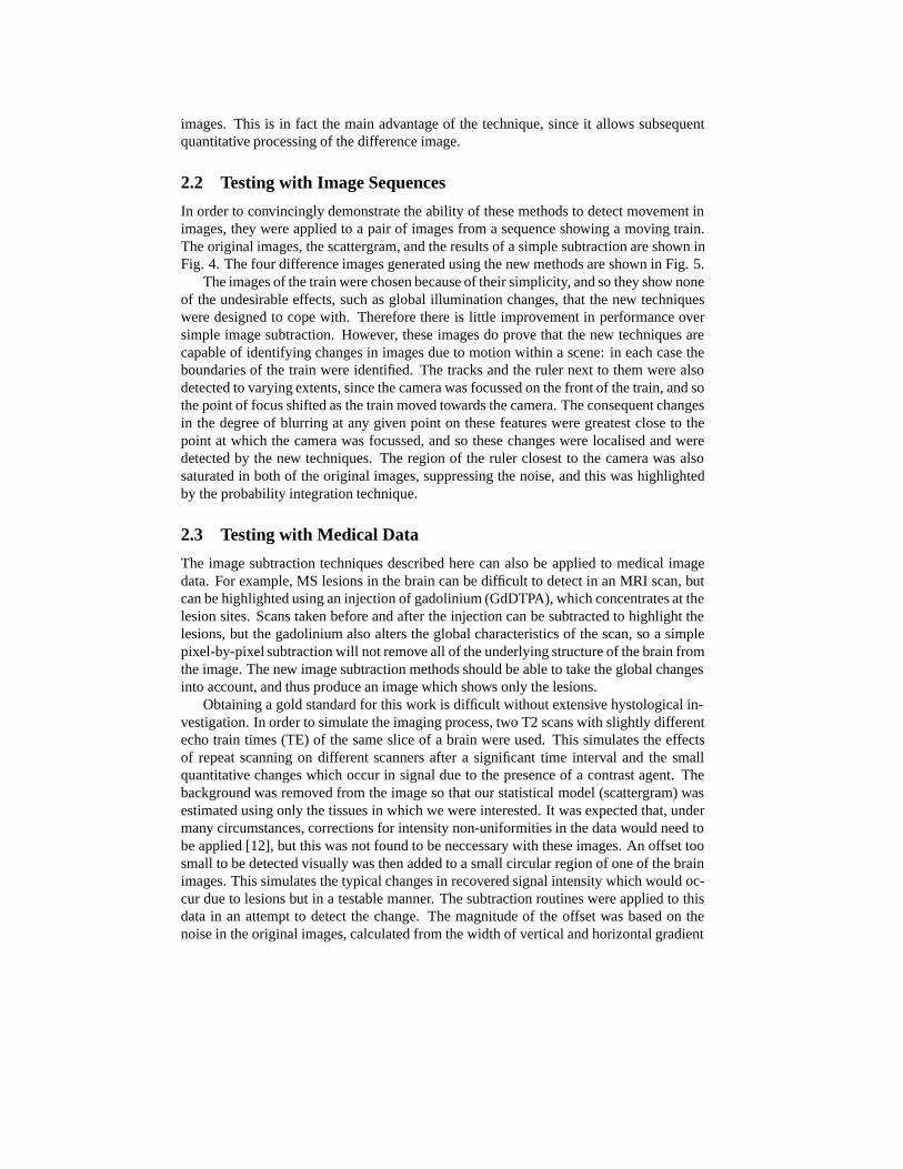
For similar images, the ridge in the scattergram provides a model describing the globalvariations between the two images. For instance, if the level of illumination in the secondimage was increased, the ridge would move upwards in the scattergram. The ridge cantherefore be used to differentiate between global differences due to illumination changesand localised differences caused by motion. Four image subtraction methods based onimage scattergrams were investigated, and each of these is described in detail below. Fig.1 shows a schematic diagram of the new image subtraction methods.
Methods
1.1 Spline Ridges
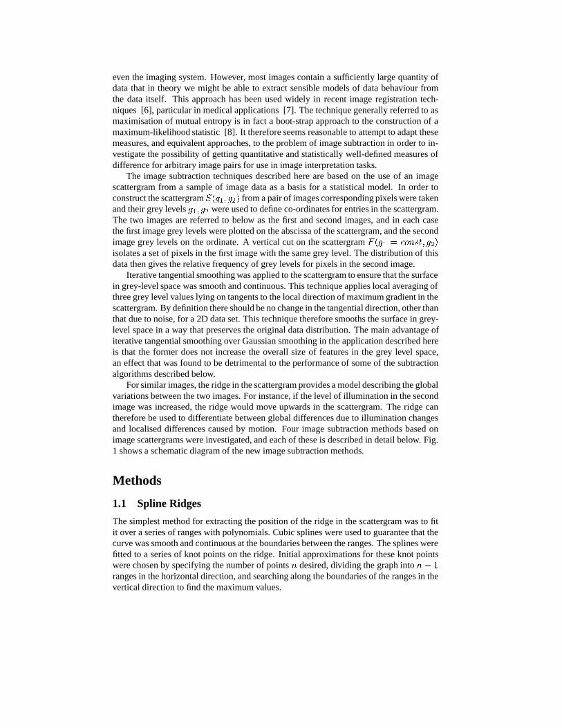
The simplest method for extracting the position of the ridge in the scattergram was to fitit over a series of ranges with polynomials. Cubic splines were used to guarantee that thecurve was smooth and continuous at the boundaries between the ranges. The splines werefitted to a series of knot points on the ridge. Initial approximations for these knot pointswere chosen by specifying the number of pointsn desired, dividing the graph inton� 1ranges in the horizontal direction, and searching along the boundaries of the ranges in thevertical direction to find the maximum values.
Once the initial approximations to the knot points had been found, simplex minimisa-tion was used to optimise the fit [9]. The cost function for the spline fit was defined as thenegative sum of the grey levels of the pixelsi lying under the spline curveC(g1;g
max
2)
in the scattergram.Cost = �
X
i
F (gi; C(gi;gmax
2))
Once the spline fit had been optimised in this way, it was used to produce a new versionof the second image. The grey levels of pixels from the first image were used to define avertical cut on the scattergram, and the corresponding vertical ordinates for the ridge inthe scattergram were found using the spline curves. The vertical ordinates were then usedas grey levels in the new second image, which could then be subtracted from the originalsecond image to give a difference image.
D1(x; y) = I2(x; y) � C(I1(x; y);gmax
2)
The new second image is an estimate of the first image, scaled to remove the global varia-tions between the original images encoded in the ridge in the scattergram. The subtractionof the new second image from the original second image therefore effectively removedany global mapping between grey level values in the two images.
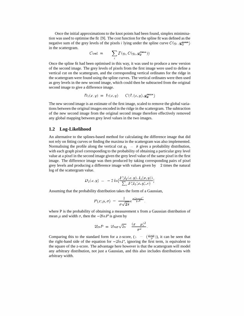
1.2 Log-Likelihood
An alternative to the splines-based method for calculating the difference image that didnot rely on fitting curves or finding the maxima in the scattergram was also implemented.Normalising the profile along the vertical cutg1 = k gives a probability distribution,with each graph pixel corresponding to the probability of obtaining a particular grey levelvalue at a pixel in the second image given the grey level value of the same pixel in the firstimage. The difference image was then produced by taking corresponding pairs of pixelgrey levels and producing a difference image with values given by�2 times the naturallog of the scattergram value.
D2(x; y) = � 2 ln[F (I1(x; y); I2(x; y))P
c F (I1(x; y); c)]
Assuming that the probability distribution takes the form of a Gaussian,
P (x;�; �) =1
�p2�
e�(x��)2
2�2 ;
where P is the probability of obtaining a measurement x from a Gaussian distribution ofmean� and width�, then the�2lnP is given by
�2lnP = 2ln�p2� +
(x � �)2
�2:
Comparing this to the standard form for a z-score, (z = (x���
)), it can be seen thatthe right-hand side of the equation for�2lnP , ignoring the first term, is equivalent tothe square of the z-score. The advantage here however is that the scattergram will modelany arbitrary distribution, not just a Gaussian, and this also includes distributions witharbitrary width.
This difference image, when summed, gives an overall difference statistic which isdirectly equivalent to the mutual entropy measures used for image co-registration. Wemay therefore expect that the returned values can be of use in terms of arriving at sensiblestatistical decisions regarding the level of difference between the two images. Unfortu-nately, this is only the case when the spread of measured values is the same for all meanvalues. We must therefore seek another measure if we wish to make statistical decisionsregarding individual pixels.
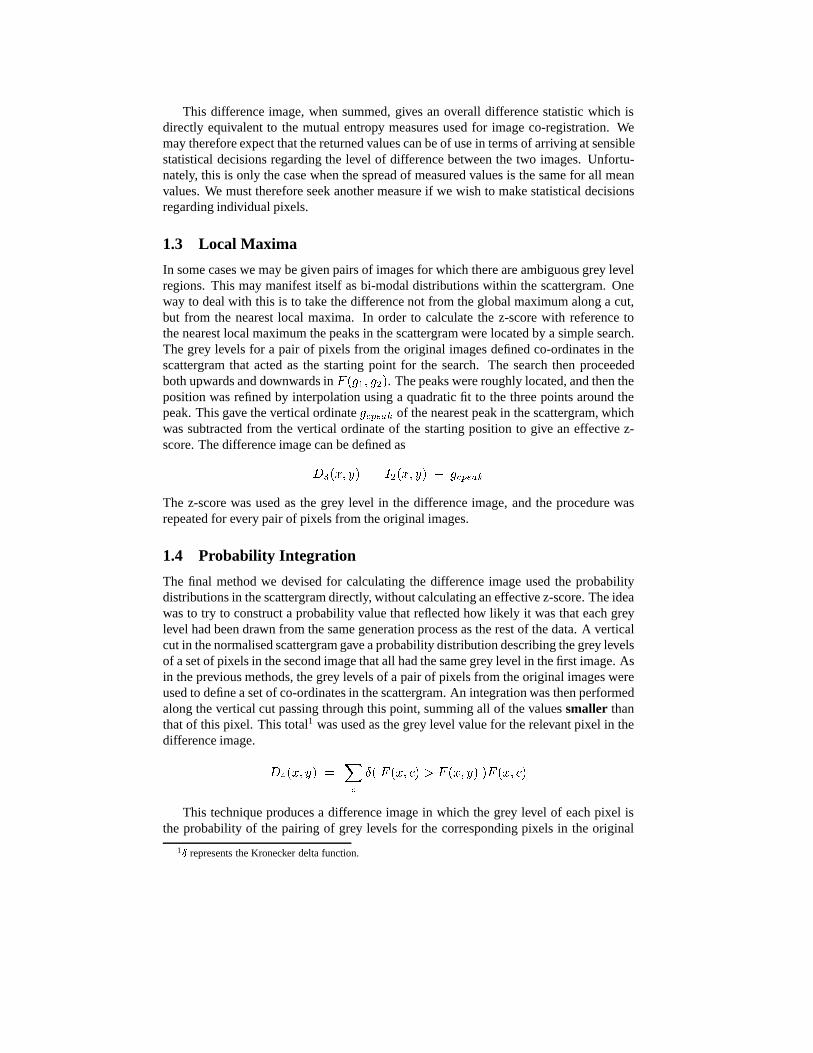
1.3 Local Maxima
In some cases we may be given pairs of images for which there are ambiguous grey levelregions. This may manifest itself as bi-modal distributions within the scattergram. Oneway to deal with this is to take the difference not from the global maximum along a cut,but from the nearest local maxima. In order to calculate the z-score with reference tothe nearest local maximum the peaks in the scattergram were located by a simple search.The grey levels for a pair of pixels from the original images defined co-ordinates in thescattergram that acted as the starting point for the search. The search then proceededboth upwards and downwards inF (g1; g2). The peaks were roughly located, and then theposition was refined by interpolation using a quadratic fit to the three points around thepeak. This gave the vertical ordinategcpeak of the nearest peak in the scattergram, whichwas subtracted from the vertical ordinate of the starting position to give an effective z-score. The difference image can be defined as
D3(x; y) = I2(x; y) � gcpeak
The z-score was used as the grey level in the difference image, and the procedure wasrepeated for every pair of pixels from the original images.
1.4 Probability Integration
The final method we devised for calculating the difference image used the probabilitydistributions in the scattergram directly, without calculating an effective z-score. The ideawas to try to construct a probability value that reflected how likely it was that each greylevel had been drawn from the same generation process as the rest of the data. A verticalcut in the normalised scattergram gave a probability distribution describing the grey levelsof a set of pixels in the second image that all had the same grey level in the first image. Asin the previous methods, the grey levels of a pair of pixels from the original images wereused to define a set of co-ordinates in the scattergram. An integration was then performedalong the vertical cut passing through this point, summing all of the valuessmaller thanthat of this pixel. This total1 was used as the grey level value for the relevant pixel in thedifference image.
D4(x; y) =X
c
�( F (x; c) > F (x; y) )F (x; c)
This technique produces a difference image in which the grey level of each pixel isthe probability of the pairing of grey levels for the corresponding pixels in the original
1� represents the Kronecker delta function.
images. The distribution of grey levels in the difference image is by definition flat fordata drawn from the mean distribution. Such probability distributions arehonest [10],i.e. a 1% probability implies that data will be generated worse than this only 1/100 thof the time. The measure has the same interpretation as the conventional “chi-squaredprobability”, except we do not need to specify a particular distribution which means thatit is essentially non-parametric. Low probabilities indicate that the pairings of pixelsare expected to be uncommon. This is exactly the type of measure we need in orderto identify outlying combinations of pixel values in an automatic manner, solving theproblems inherent in the likelihood-based approach.
The distribution of grey levels in the difference images produced using this methodcan act as a self-test: ignoring the low-probability pixels generated by localised differ-ences, it should be flat. Any significant departure from a flat distribution therefore in-dicates inappropriate behaviour of the two data sets and therefore unsuitability of thestatistic for that comparison.
2 Results
2.1 Testing with Synthetic Data
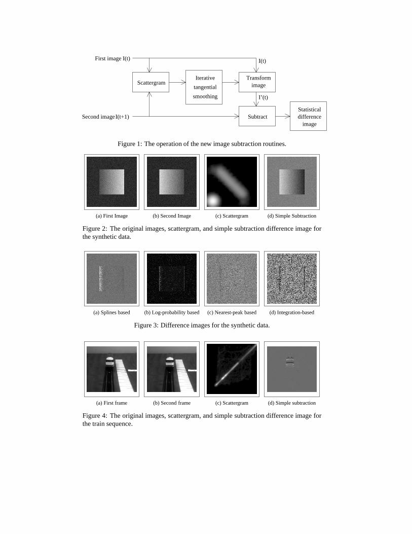
The four routines described above were tested using synthetic data to ensure that they wereworking as predicted. They were designed to be able to ignore effects such as changes inthe shading or illumination of features, and focus only on movement of features betweenimages. Two test images were prepared using the image creation tool in TINA [11].Each was an 8bpp greyscale image, 256 by 256 pixels in size, of a 128 by 128 pixelrectangle in the centre of the frame. The rectangles were shaded so that their grey levelsvaried smoothly between 30 on one vertical edge and 200 on the other, with the shadingbeing uniform in the vertical direction. The direction of shading was reversed betweenthe two images. Finally, Gaussian noise with a standard deviation of 10 grey levels wasadded to both images. The resultant test images are shown in Fig. 2, together with thescattergram and the results of a simple pixel-by-pixel subtraction. It was anticipated thatthe image subtraction techniques described above should be capable of detecting thatthe rectangle did not move between the two images, despite the difference in shading,and return difference images containing uniform random noise. The difference imagesproduced by the four methods are shown in Fig. 3.
The splines-based method shows the greatest departure from the expected results, andthis was due to a failure in the spline fitting. The fit was good for the peak close to(0; 0),which corresponded to the background, and close to the central part of the scattergram.However, it failed in the regions corresponding to the highest and lowest grey level valuesin the rectangle in the first image due to the discontinuities in the scattergram at thesepoints. Therefore, the difference image departs from the expected output around the ver-tical edges of the rectangle.
The difference images generated by the remaining three methods all closely match theexpected output. The vertical features at the vertical edges of the rectangles correspond toa slight difference in the positioning of the rectangle between the two frames and, in thatrespect, show the capability of these methods for detecting movement of image featureswhilst ignoring other effects. The difference image returned by the probability integrationtechnique has a flat probability distribution and so appears noisier than the other difference
images. This is in fact the main advantage of the technique, since it allows subsequentquantitative processing of the difference image.
2.2 Testing with Image Sequences
In order to convincingly demonstrate the ability of these methods to detect movement inimages, they were applied to a pair of images from a sequence showing a moving train.The original images, the scattergram, and the results of a simple subtraction are shown inFig. 4. The four difference images generated using the new methods are shown in Fig. 5.
The images of the train were chosen because of their simplicity, and so they show noneof the undesirable effects, such as global illumination changes, that the new techniqueswere designed to cope with. Therefore there is little improvement in performance oversimple image subtraction. However, these images do prove that the new techniques arecapable of identifying changes in images due to motion within a scene: in each case theboundaries of the train were identified. The tracks and the ruler next to them were alsodetected to varying extents, since the camera was focussed on the front of the train, and sothe point of focus shifted as the train moved towards the camera. The consequent changesin the degree of blurring at any given point on these features were greatest close to thepoint at which the camera was focussed, and so these changes were localised and weredetected by the new techniques. The region of the ruler closest to the camera was alsosaturated in both of the original images, suppressing the noise, and this was highlightedby the probability integration technique.
2.3 Testing with Medical Data
The image subtraction techniques described here can also be applied to medical imagedata. For example, MS lesions in the brain can be difficult to detect in an MRI scan, butcan be highlighted using an injection of gadolinium (GdDTPA), which concentrates at thelesion sites. Scans taken before and after the injection can be subtracted to highlight thelesions, but the gadolinium also alters the global characteristics of the scan, so a simplepixel-by-pixel subtraction will not remove all of the underlying structure of the brain fromthe image. The new image subtraction methods should be able to take the global changesinto account, and thus produce an image which shows only the lesions.
Obtaining a gold standard for this work is difficult without extensive hystological in-vestigation. In order to simulate the imaging process, two T2 scans with slightly differentecho train times (TE) of the same slice of a brain were used. This simulates the effectsof repeat scanning on different scanners after a significant time interval and the smallquantitative changes which occur in signal due to the presence of a contrast agent. Thebackground was removed from the image so that our statistical model (scattergram) wasestimated using only the tissues in which we were interested. It was expected that, undermany circumstances, corrections for intensity non-uniformities in the data would need tobe applied [12], but this was not found to be neccessary with these images. An offset toosmall to be detected visually was then added to a small circular region of one of the brainimages. This simulates the typical changes in recovered signal intensity which would oc-cur due to lesions but in a testable manner. The subtraction routines were applied to thisdata in an attempt to detect the change. The magnitude of the offset was based on thenoise in the original images, calculated from the width of vertical and horizontal gradient

histograms of the original images around zero. Fig. 6 shows the brain images with anoffset of2� added to a small region of one image, together with the scattergram and theresults of a simple subtraction. The altered region cannot be detected visually in the orig-inal images, and is barely visible in the pixel-by-pixel difference image. Fig. 7 shows thedifference images generated using the methods described above, and the altered regionshows up clearly in the output from the log-probability and integration-based methods.The altered region ceased to be detectable when the magnitude of the offset was reducedbelow around1�. Fig. 8 shows a histogram generated from the integration-based differ-ence image demonstrating that, as expected, this method produced an honest probabilitydistribution, confirming that this statistical measure is appropriate for this MR data.
3 Conclusions
Simple pixel-by-pixel image subtraction, when considered as a statistical test, makesmany assumptions regarding the information contained in a pair of images. These as-sumptions are rarely valid and as a consequence simple image subtraction cannot be usedreliably [5]. However, there is often considerable information available within a pair ofimages, which can be used to avoid having to make all of these assumptions. The newimage subtraction techniques described here used a scattergram of the grey levels in a pairof images to extract this information. The scattergram is effectively used as a model of theglobal variations between the images, allowing the new techniques to focus only on thelocalised variations. They are therefore superior in applications such as motion detection.
The splines-based method was the simplest of the four new techniques, but also themost inaccurate, due to failures in the spline to model the ridge in the scattergram. In prac-tice the technique will always be susceptible to this effect, as there is no fitting method thatcan guarantee to fit to any arbitrary data set. The main result for this method was thereforeto demonstrate that a more sophisticated technique was needed (though the method mayhave some merit on small datasets).
An attempt to model bi-modal distributions seemed to give results which were notparticularly informative. Selection of the nearest peak simply allowed all data to be rea-sonably consistent with the model.
The capabilities of the log-probability and integration-based techniques were clearlydemonstrated using the synthetic data. The images of the moving train were chosen fortheir simplicity, and did not exhibit any of the undesirable effects that the new techniqueswere designed to avoid, so there was little improvement over simple subtraction for theseimages. However, when both sets of results are considered together, it is clear that thenew techniques will be superior for motion detection in more complex and realistic envi-ronments. These techniques were also shown to be superior in detecting abnormalities inmedical images, demonstrating the wide range of potential applications.
One of the most important features of the log-probability and integration-based meth-ods is that the grey levels in the difference images correspond to well-defined quantities:the square of the z-score and a probability respectively. This is in sharp contrast to pixel-by-pixel image subtraction, where the grey levels in the difference image are arbitrarymeasures of difference in units of grey levels, and have no objective meaning.
The log-probability and integration-based techniques can be considered as the defi-nitions of new non-parametric statistical tests, with theoretically predictable properties.

In particular the probability integration technique is capable of self-test. As such, thesemethods are firmly grounded in the existing body of statistical decision theory and canbe used in combination with methods designed for more restrictive parametric techniquesfor the testing of hypotheses. This fact makes extensive quantiative analysis redundant,though the results presented here already demonstrate the applicability of these measuresto motion analysis and subtraction of MR datasets. These measures could also have a rolein the analysis of co-occurence of spatially distributed values and may thus also be usedfor analysis of texture, this is an area that we now intend to investigate.
References[1] D. Murray and A Basu, Motion Tracking with an Active Camera, IEEE Trans. Pattern
Analysis and Machine Intell., 16(5), 1994, 449-459.
[2] S. Rowe and A. Blake, Statistical Mosaics for Tracking, Image and Vision Computing,14(8), 1996, 549-564.
[3] D. Koller, J. Weber and J. Malik, Robust Multiple Car Tracking with Occlusion Reasoning,Proc. ECCV 1994, J-O. Ekhlund (Ed), Stockholm, pp189-196, 1994.
[4] A. Baumberg and D. Hogg, Learning Flexible Models from Image Sequences, Proc. ECCV1994, J-O. Ekhlund (Ed), Stockholm, pp299-308, 1994.
[5] J.V. Hajnal, I.R. Young and G.M. Bydder, Contrast Mechanisms in Functional MRI of theBrain, Advanced MR Imaging Techniques, Ed’s W. G. Bradley Jr and G. M. Bydder, MartinDunitz Ltd London, 195-207, 1997.
[6] P. Viola, Alignment by Maximisation of Mutual Information. PhD. Thesis, MIT, ArtificialIntelligence laboratory, 1995.
[7] J.West et al. Comparison and Evaluation of Retrospective Intermodality Image RegistrationTechniques. J.Comp.Assist.Tom, 21(4), 554-566, 1997.
[8] A. Roche, G. Malandain, N.Ayache, S.Prima. Towards a Better Comprehension of Similar-ity Measures Used in Medical Image Registration. Proc. MICCAI, 99. Cambridge, pp555-565, Sept. 1999.
[9] W.H. Press, S.A. Teukolsky, W.T. Vetterling and B.P. Flannery, Numerical Recipies in C2nd Ed., Cambridge University Press, 1992.
[10] A.P. Dawid, Probability Forecasting, Encyclopedia of Statistical Science, 7, Wiley, 210-218, 1986
[11] N.A.Thacker, A.Lacey, E.Vokurka, X.P.Zhu , K.L.Li and A.Jackson, “TINA an Image Anal-ysis and Computer Vision Application for Medical Imaging Research. Proc. ECR, s566,Vienna, 1999.
[12] E.Vokurka, N.Thacker, A.Jackson, A Fast Model Independant Method for Automatic Cor-rection of Intensity Non-Uniformity in MRI Data, JMRI, 10, 4, 550-562, 1999.
4 Acknowledgements
The authors would like to acknowledge the support of the MEDLINK programme, grantno. P169, in funding part of this work. All software is freely avalable from the TINAwebsite www.niac.man.ac.uk/Tina.
I(t)
I’(t)
SubtractStatisticaldifference
image
TransformimageScattergram
I(t)First image
I(t+1)Second image
Iterative
tangential
smoothing
Figure 1: The operation of the new image subtraction routines.
(a) First Image (b) Second Image (c) Scattergram (d) Simple Subtraction
Figure 2: The original images, scattergram, and simple subtraction difference image forthe synthetic data.
(a) Splines based (b) Log-probability based (c) Nearest-peak based (d) Integration-based
Figure 3: Difference images for the synthetic data.
(a) First frame (b) Second frame (c) Scattergram (d) Simple subtraction
Figure 4: The original images, scattergram, and simple subtraction difference image forthe train sequence.

(a) Splines based (b) Log-probability based (c) Nearest-peak based (d) Integration based
Figure 5: Difference images for the train sequence. The apparent extra noise in the inte-gration based difference image is in fact a consequence of its flat probability distribution.
(a) (b) (c) Scattergram (d) Simple subtraction
Figure 6: The original MRI brain images, scattergram, and simple subtraction differenceimage, with a2� offset added to a small region of image (b).
(a) Splines based (b) Log-probability based (c) Nearest-peak based (d) Integration-based
Figure 7: Difference images for the MRI brain scan images. The log-likelihood andintegration-based difference images clearly show the altered region in the upper-left areaof the image.
Figure 8: Histogram of the integration-based difference image generated from the MRIbrain images, showing the flat probability distribution.


![Risk Design [Grey Room]](https://img.dokumen.tips/doc/110x75/631796e0bc8291e22e0e535c/risk-design-grey-room.jpg)
