Embed Size (px)
Citation preview
Dearborn, Michigan
NOISE-CON 2008 2008 July 28-30
Noise and vibration control for a residential geothermal heat pump installation Jeffrey L Fullerton
a
Acentech 33 Moulton St. Cambridge, MA 02138
ABSTRACT The installation of a geothermal heat pump in the basement of a 1900 era home introduced
significant noise and vibration to a bedroom above. The primary cause of the noise and vibration
transmission related to the rigid connections between the heat pump piping and the wood
structure of the bedroom floor. Various measurements were conducted to assess the conditions,
followed by different attempts to isolate the noise and vibration from the structure. A secondary
airborne path was also studied with an attempt at mitigation. This paper will discuss the
conditions of the installation, various methods of reducing the noise and future research and
mitigation.
a Email address: [email protected]
1. EQUIPMENT DESCRIPTION AND INSTALLATION CONDITIONS Geothermal heat pumps are becoming a popular type of equipment for heating and cooling on
projects where energy efficiency is a goal. These systems utilize a fluid loop, which typically
consists of water, to transfer heat between the conditioned spaces and the ground. The thermal
energy is exchanged between the fluid and the occupied space by using a reverse cycle heat
pump. Depending on the season, the heat pump is used to transfer heat either (in cold weather)
from the ground to the occupied space, or (in warm weather) from the occupied spaces to the
ground. For this installation, both heat pumps are connected to the same open loop well that is
about 20 feet from the house.
The equipment discussed in this paper consists of two geothermal heat pumps that each have a
cooling capacity of approximately 3-tons, and which are designed for forced air heat transfer in a
residential application. Both of the heat pumps studied are ClimateMaster Genesis systems,
though one is a packaged unit (the heat pump and fan coil in one piece), while the second is a
split system, with the heat pump and fan coil components separated; the split system components
are connected via a refrigerant line of approximately 35 feet in length.
Both heat pumps are mounted in the basement of the 1900 era residence. The basement floor is
concrete. The first floor structure is a wooden joist construction, with 2”x8” joists (which are a
true 2 inches by 8 inches) spaced unevenly between 16 and 17 inches on center. The flooring
consists of a nominal 1-inch thick plank subfloor perpendicular to the direction of the joists,
topped with a finished floor of 1-inch thick pine flooring.
Mechanical and plumbing contractors, who are well experienced at their trades, installed the
systems. They used traditional mechanical and plumbing practices during the installation. These
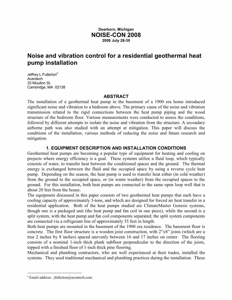
Figures 1 & 2: Rigid clamps between copper ground water piping and wood joist structure of first floor residence.
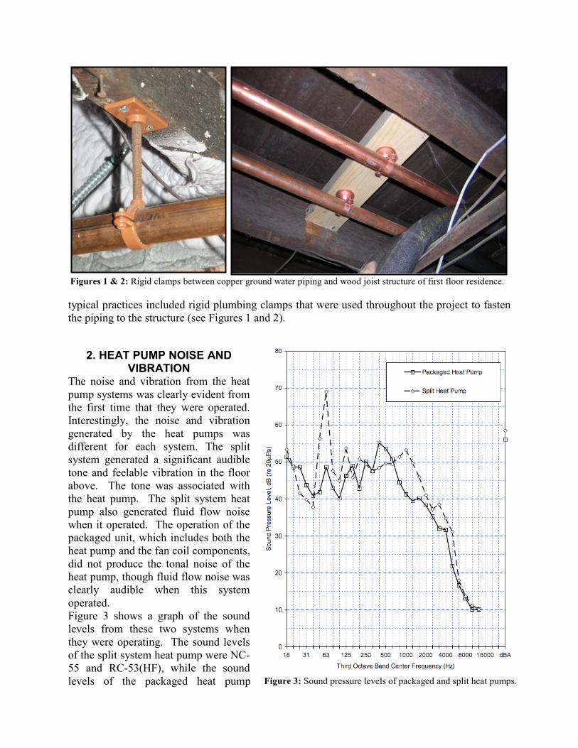
Figure 3: Sound pressure levels of packaged and split heat pumps.
typical practices included rigid plumbing clamps that were used throughout the project to fasten
the piping to the structure (see Figures 1 and 2).
2. HEAT PUMP NOISE AND VIBRATION
The noise and vibration from the heat
pump systems was clearly evident from
the first time that they were operated.
Interestingly, the noise and vibration
generated by the heat pumps was
different for each system. The split
system generated a significant audible
tone and feelable vibration in the floor
above. The tone was associated with
the heat pump. The split system heat
pump also generated fluid flow noise
when it operated. The operation of the
packaged unit, which includes both the
heat pump and the fan coil components,
did not produce the tonal noise of the
heat pump, though fluid flow noise was
clearly audible when this system
operated.
Figure 3 shows a graph of the sound
levels from these two systems when
they were operating. The sound levels
of the split system heat pump were NC-
55 and RC-53(HF), while the sound
levels of the packaged heat pump
system were approximately NC-55 and RC-49(MF). The tone at 63 Hz generated by the split
system was extremely prominent and very annoying.
The most concerning aspect of the noise and vibration was its significant impact to a bedroom
directly above the location where the split system heat pump was installed. The noise level was
clearly intrusive and would be bothersome to anyone who might attempt to sleep in this
bedroom. The packaged heat pump was located below an office space; while the fluid flow noise
from this system was clearly audible and intrusive, it would not contribute to the issue of sleep
disturbance and was tolerable for an office space. Regardless, mitigation of the noise and
vibration from both systems was necessary.
3. HEAT PUMP NOISE AND VIBRATION SOURCES AND PATHS
A. Sources One of the primary components of the heat pump system is the compressor. The compressor
introduces energy into the system to facilitate the heat transfer process between the heat source
and the heat sink. The compressor is also the main component within the heat pump assembly
that can produce noise and vibration that might be a concern to the building’s occupants. The
compressor is connected to the casing of the equipment at its base, often through vibration
isolation, such as spring or neoprene isolators. In addition to the connection at the compressor’s
base, there are numerous rigid connections between compressor and the fluid and refrigerant
piping, which are connected to the equipment casing and the structure. Interestingly, a standard
practice during the heat pump installation is to mount the casings on 50-mm (2-inch) thick foam
insulation, which is purported to provide vibration isolation between the heat pump and the
flooring.
The heat pump is connected to the ground piping loop via 2 pipes, which carry the supply and
return fluid. The fluid noise passing through these pipes is another potential noise and vibration
source, depending on the fluid velocity. In these systems, the fluid (water) flowrate was limited
to approximately 0.57 l/sec (9 US gal/min). When the systems operated, this fluid velocity
produced fluid borne noise, presumably due to turbulence generated at the fittings and elbows as
the fluid passes through the system. This fluid borne noise included airborne and structureborne
transmission to the adjacent space and structure.
Some designers of geothermal systems also incorporate automatic balance valves to ensure that
the water flow through the system optimizes the rate of heat transfer between the fluid and the
heat exchanger. In this case, it was the automatic balance valve that restricted the flowrate to
0.57 l/s (9 US gal/min). These balance valves are another potential noise and vibration source,
since as they restrict the water flow through the device, the valves also produce turbulent fluid
flow. Similar to the fluid borne noise in the piping, the balance valves transmitted the noise via
both airborne and structureborne transmission.
B. Transmission Paths Though there are several transmission paths, the piping connections between the heat pump and
the structure were the most significant on this project. This is because there are a large number of
piping connections between the geothermal systems, the associated plumbing components and
the structure. Each of these piping connections represents a potential path for noise and vibration
transmission to the building structure. These piping connections are described below.
Geothermal systems connect to a well or external closed loop via supply and return pipes. These
two pipes are typical of every geothermal system installation. Some manufacturers and

Figure 4: Piping wrapped with foam
insulation and supported with pipe
strapping.
contractors allow this piping to be PVC, while others prefer to use traditional copper piping. On
these systems, the piping between the well equipment and the heat pumps consists of copper.
These copper pipes were supported from the wood joist structure of the first floor using
traditional rigid piping clamps, as shown in Figures 1 and 2.
Another feature that some geothermal systems have is the ability to pre-heat domestic hot water.
This feature involves routing the domestic water service for the building to the inlet of a
“desuperheater”, which transfers excess heat from the heat pump to the incoming domestic hot
water supply. The domestic water lines on this project are copper. These domestic water lines
are routed to the hot water tanks, which are approximately 25 feet away from the heat pumps.
These domestic water lines, to and from the hot water tanks, are also supported from the wood
joist structure of the first floor.
Another rigid connection between the heat pump and the building structure is the supply and
return refrigerant lines. These are used between the split system heat pump and the fan coil unit.
Both of these lines consist of bendable copper tubing. The supply refrigerant line is typically
insulated. These lines were clamped to the wood joists.
Due to their connections with the compressor and equipment casing, these pipes often are very
effective transmission paths for the compressor vibrations.
In this project, there is also a concern for airborne sound transmission. The flooring consists of
merely two layers of nominal 1-inch thick wood planks that are not well sealed. There is also no
ceiling in the basement at this time, though a gypsum board ceiling is planned in the future.
3. NOISE AND VIBRATION CONTROL
A. Piping Isolation – Homemade The rigid piping connections to the wood joist structure were observed to be the most significant
transmission path between the heat pump and the first floor residence above. Modifications of
the rigid piping connections were needed to improve the isolation of the heat pump and fluid
noise and vibration. Ideally, the connections between the
piping and the structure would be removed all together;
however, this condition would leave the piping without
any support, which over time might cause the soldered
joints between the copper pipe fittings to fail.
To introduce a resilient connection between the piping and
the wood structure, the rigid clamps were individually
removed and replaced with a homemade resilient pipe
clamp detail. This detail consisted of foam insulation,
often used for thermal insulation, fitted around the copper
pipe with bendable steel pipe strapping loosely wrapped
around the insulation to secure the piping to the wood joist
structure. This arrangement allowed the pipe to be
separated from the wood joist with the foam insulation,
while being held into place with the steel pipe strapping
(see Figure 4).
The sound levels with this option were noticeably lower
and more acceptable. The ratings for the new sound
levels were NC-38 and RC-29(N), which represent
significant reductions in the audible sound levels. The
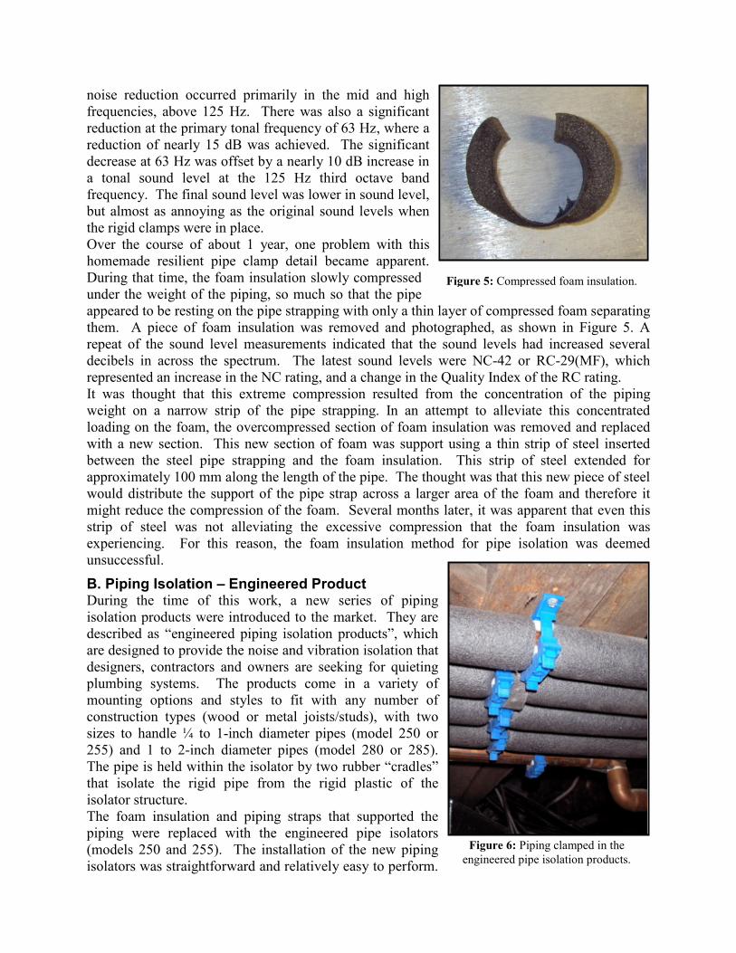
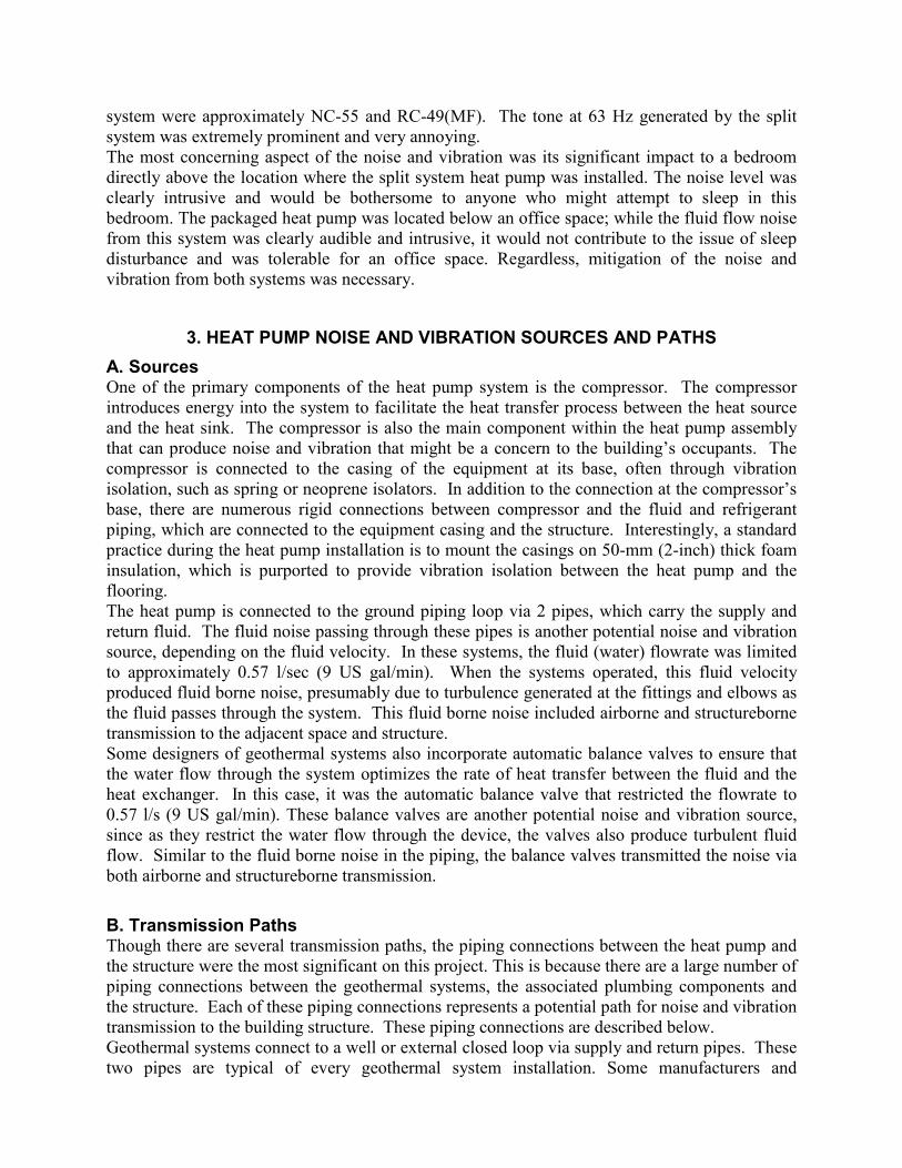
Figure 5: Compressed foam insulation.
Figure 6: Piping clamped in the
engineered pipe isolation products.
noise reduction occurred primarily in the mid and high
frequencies, above 125 Hz. There was also a significant
reduction at the primary tonal frequency of 63 Hz, where a
reduction of nearly 15 dB was achieved. The significant
decrease at 63 Hz was offset by a nearly 10 dB increase in
a tonal sound level at the 125 Hz third octave band
frequency. The final sound level was lower in sound level,
but almost as annoying as the original sound levels when
the rigid clamps were in place.
Over the course of about 1 year, one problem with this
homemade resilient pipe clamp detail became apparent.
During that time, the foam insulation slowly compressed
under the weight of the piping, so much so that the pipe
appeared to be resting on the pipe strapping with only a thin layer of compressed foam separating
them. A piece of foam insulation was removed and photographed, as shown in Figure 5. A
repeat of the sound level measurements indicated that the sound levels had increased several
decibels in across the spectrum. The latest sound levels were NC-42 or RC-29(MF), which
represented an increase in the NC rating, and a change in the Quality Index of the RC rating.
It was thought that this extreme compression resulted from the concentration of the piping
weight on a narrow strip of the pipe strapping. In an attempt to alleviate this concentrated
loading on the foam, the overcompressed section of foam insulation was removed and replaced
with a new section. This new section of foam was support using a thin strip of steel inserted
between the steel pipe strapping and the foam insulation. This strip of steel extended for
approximately 100 mm along the length of the pipe. The thought was that this new piece of steel
would distribute the support of the pipe strap across a larger area of the foam and therefore it
might reduce the compression of the foam. Several months later, it was apparent that even this
strip of steel was not alleviating the excessive compression that the foam insulation was
experiencing. For this reason, the foam insulation method for pipe isolation was deemed
unsuccessful.
B. Piping Isolation – Engineered Product During the time of this work, a new series of piping
isolation products were introduced to the market. They are
described as “engineered piping isolation products”, which
are designed to provide the noise and vibration isolation that
designers, contractors and owners are seeking for quieting
plumbing systems. The products come in a variety of
mounting options and styles to fit with any number of
construction types (wood or metal joists/studs), with two
sizes to handle ¼ to 1-inch diameter pipes (model 250 or
255) and 1 to 2-inch diameter pipes (model 280 or 285).
The pipe is held within the isolator by two rubber “cradles”
that isolate the rigid pipe from the rigid plastic of the
isolator structure.
The foam insulation and piping straps that supported the
piping were replaced with the engineered pipe isolators
(models 250 and 255). The installation of the new piping
isolators was straightforward and relatively easy to perform.
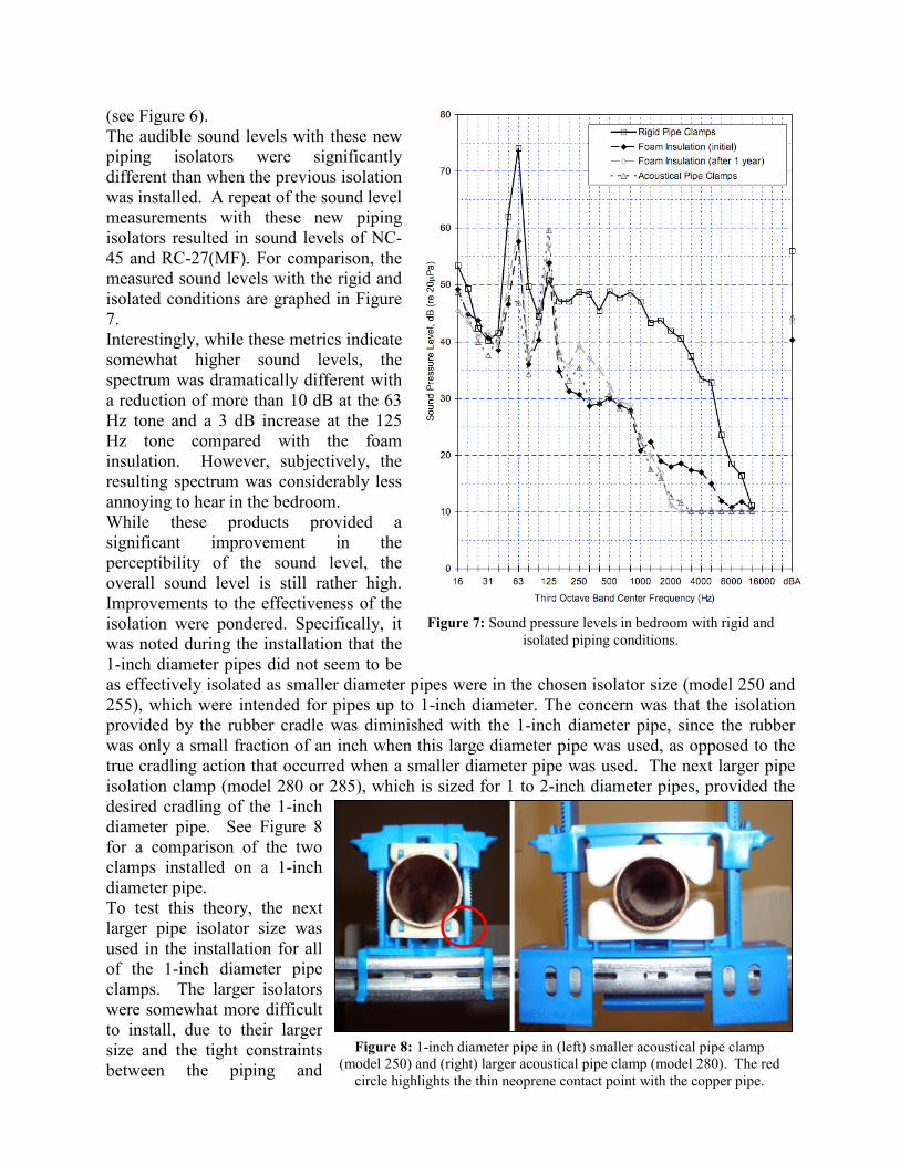
Figure 7: Sound pressure levels in bedroom with rigid and
isolated piping conditions.
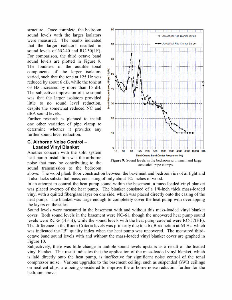
Figure 8: 1-inch diameter pipe in (left) smaller acoustical pipe clamp
(model 250) and (right) larger acoustical pipe clamp (model 280). The red
circle highlights the thin neoprene contact point with the copper pipe.
(see Figure 6).
The audible sound levels with these new
piping isolators were significantly
different than when the previous isolation
was installed. A repeat of the sound level
measurements with these new piping
isolators resulted in sound levels of NC-
45 and RC-27(MF). For comparison, the
measured sound levels with the rigid and
isolated conditions are graphed in Figure
7.
Interestingly, while these metrics indicate
somewhat higher sound levels, the
spectrum was dramatically different with
a reduction of more than 10 dB at the 63
Hz tone and a 3 dB increase at the 125
Hz tone compared with the foam
insulation. However, subjectively, the
resulting spectrum was considerably less
annoying to hear in the bedroom.
While these products provided a
significant improvement in the
perceptibility of the sound level, the
overall sound level is still rather high.
Improvements to the effectiveness of the
isolation were pondered. Specifically, it
was noted during the installation that the
1-inch diameter pipes did not seem to be
as effectively isolated as smaller diameter pipes were in the chosen isolator size (model 250 and
255), which were intended for pipes up to 1-inch diameter. The concern was that the isolation
provided by the rubber cradle was diminished with the 1-inch diameter pipe, since the rubber
was only a small fraction of an inch when this large diameter pipe was used, as opposed to the
true cradling action that occurred when a smaller diameter pipe was used. The next larger pipe
isolation clamp (model 280 or 285), which is sized for 1 to 2-inch diameter pipes, provided the
desired cradling of the 1-inch
diameter pipe. See Figure 8
for a comparison of the two
clamps installed on a 1-inch
diameter pipe.
To test this theory, the next
larger pipe isolator size was
used in the installation for all
of the 1-inch diameter pipe
clamps. The larger isolators
were somewhat more difficult
to install, due to their larger
size and the tight constraints
between the piping and
structure. Once complete, the bedroom
sound levels with the larger isolators
were measured. The results indicated
that the larger isolators resulted in
sound levels of NC-40 and RC-30(LF).
For comparison, the third octave band
sound levels are plotted in Figure 9.
The loudness of the audible tonal
components of the larger isolators
varied, such that the tone at 125 Hz was
reduced by about 6 dB, while the tone at
63 Hz increased by more than 15 dB.
The subjective impression of the sound
was that the larger isolators provided
little to no sound level reduction,
despite the somewhat reduced NC and
dBA sound levels.
Further research is planned to install
one other variation of pipe clamp to
determine whether it provides any
further sound level reduction.
C. Airborne Noise Control – Loaded Vinyl Blanket
Another concern with the split system
heat pump installation was the airborne
noise that may be contributing to the
sound transmission to the bedroom
above. The wood plank floor construction between the basement and bedroom is not airtight and
it also lacks substantial mass, consisting of only about 1¾-inches of wood.
In an attempt to control the heat pump sound within the basement, a mass-loaded vinyl blanket
was placed overtop of the heat pump. The blanket consisted of a 1/8-inch thick mass-loaded
vinyl with a quilted fiberglass layer on one side, which was placed directly onto the casing of the
heat pump. The blanket was large enough to completely cover the heat pump with overlapping
the layers on the sides.
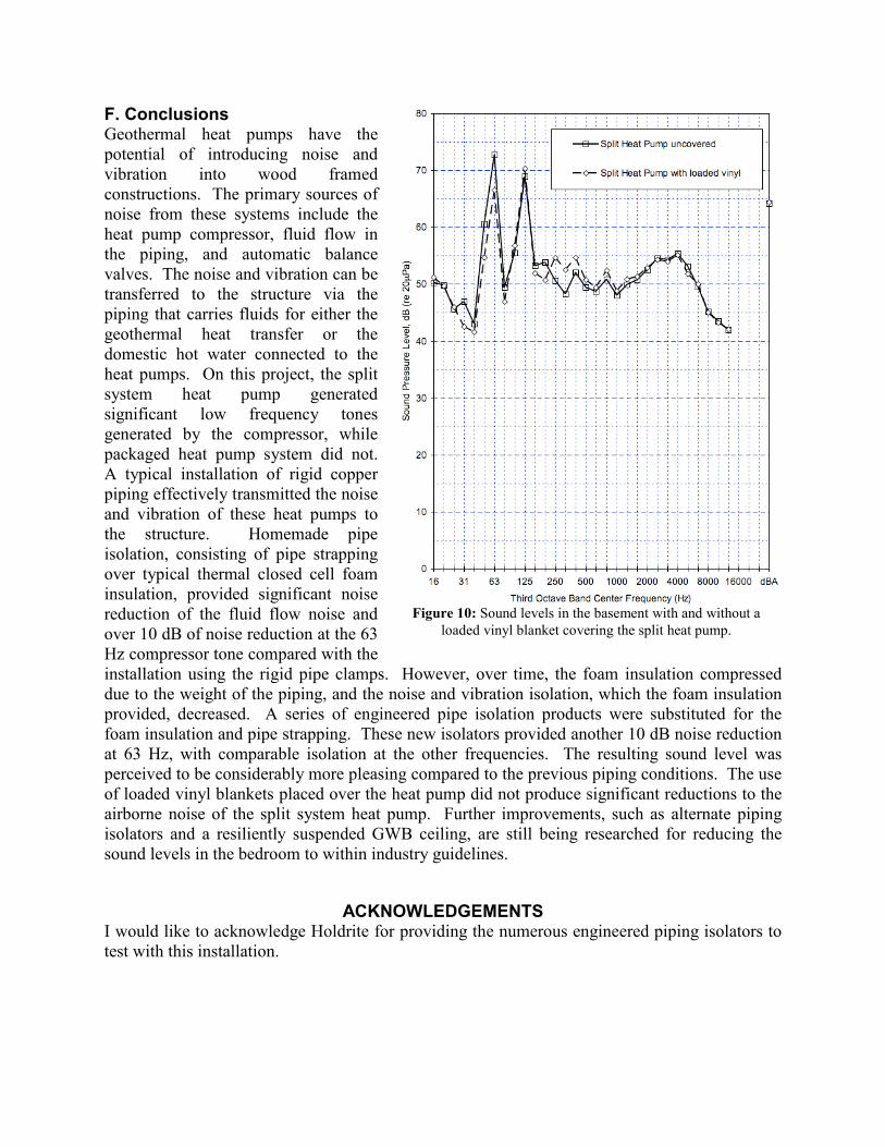
Sound levels were measured in the basement with and without this mass-loaded vinyl blanket
cover. Both sound levels in the basement were NC-61, though the uncovered heat pump sound
levels were RC-56(HF B), while the sound levels with the heat pump covered were RC-57(HF).
The difference in the Room Criteria levels was primarily due to a 6 dB reduction at 63 Hz, which
was indicated the “B” quality index when the heat pump was uncovered. The measured third-
octave band sound levels with and without the mass-loaded vinyl blanket cover are graphed in
Figure 10.
Subjectively, there was little change in audible sound levels upstairs as a result of the loaded
vinyl blanket. This result indicates that the application of the mass-loaded vinyl blanket, which
is laid directly onto the heat pump, is ineffective for significant noise control of the tonal
compressor noise. Various upgrades to the basement ceiling, such as suspended GWB ceilings
on resilient clips, are being considered to improve the airborne noise reduction further for the
bedroom above.
Figure 9: Sound levels in the bedroom with small and large
acoustical pipe clamps.
F. Conclusions Geothermal heat pumps have the
potential of introducing noise and
vibration into wood framed
constructions. The primary sources of
noise from these systems include the
heat pump compressor, fluid flow in
the piping, and automatic balance
valves. The noise and vibration can be
transferred to the structure via the
piping that carries fluids for either the
geothermal heat transfer or the
domestic hot water connected to the
heat pumps. On this project, the split
system heat pump generated
significant low frequency tones
generated by the compressor, while
packaged heat pump system did not.
A typical installation of rigid copper
piping effectively transmitted the noise
and vibration of these heat pumps to
the structure. Homemade pipe
isolation, consisting of pipe strapping
over typical thermal closed cell foam
insulation, provided significant noise
reduction of the fluid flow noise and
over 10 dB of noise reduction at the 63
Hz compressor tone compared with the
installation using the rigid pipe clamps. However, over time, the foam insulation compressed
due to the weight of the piping, and the noise and vibration isolation, which the foam insulation
provided, decreased. A series of engineered pipe isolation products were substituted for the
foam insulation and pipe strapping. These new isolators provided another 10 dB noise reduction
at 63 Hz, with comparable isolation at the other frequencies. The resulting sound level was
perceived to be considerably more pleasing compared to the previous piping conditions. The use
of loaded vinyl blankets placed over the heat pump did not produce significant reductions to the
airborne noise of the split system heat pump. Further improvements, such as alternate piping
isolators and a resiliently suspended GWB ceiling, are still being researched for reducing the
sound levels in the bedroom to within industry guidelines.
ACKNOWLEDGEMENTS I would like to acknowledge Holdrite for providing the numerous engineered piping isolators to
test with this installation.
Figure 10: Sound levels in the basement with and without a
loaded vinyl blanket covering the split heat pump.


