Embed Size (px)
Citation preview
1
CIT 305: NETWORKING AND COMMUNICATION TECHNOLOGY
2
NATIONAL OPEN UNIVERSITY OF NIGERIA
FACULTY OF SCIENCE
DEPARTMENT OF COMPUTER SCIENCE
COURSE CODE: CIT305
COURSE TITLE:
NETWORKING AND COMMUNICATION TECHNOLOGY
3
COURSE
GUIDE
CIT305
NETWORKING AND COMMUNICATION TECHNOLOGY
CourseTeam Prof A.S. Sodiya (Developer/Writer)–FUNAAB
Dr. A. A. Afolorunso (Coordinator)-NOUN
5
CONTENTS PAGE
Introduction........................................................................................ 1
WhatYouWillLearnin ThisCourse................................................ 1
Course Aims...................................................................................... 1
CourseObjectives…………………………………………….……. 1
WorkingthroughThisCourse............................................................ 2
CourseMaterials.................................................................................
StudyUnits........................................................................................
2 2
AssignmentFile.................................................................................. 3
Tutor-MarkedAssignments(TMAs)................................................. 3
ExaminationandGrading................................................................... 4
PresentationSchedule........................................................................ 4
CourseMarkingScheme.................................................................... 5
CourseOverview…………………………………………………… 5
Howto Getthe MostfromThisCourse............................................ 6
Facilitators/TutorsandTutorials........................................................ 7
Summary……………………………………………………............. 8
Introduction
CIT305–Networking andCommunicationTechnologyisathree[3]
creditunitcourseoffifteenunits.Itteaches thevarious formsof
networking,networkdesign,communicationtechnologyusedbypeople to
accomplishdifferentorganisationalor individualtask.
It also givesan insightinto variousforms of computernetworking
rangingfromLANtoWANandevengo asfaraslookingintothe
wirelessnetworks thatareinuseintoday‘stechnology. Thecoursealso
explainstheenterprise network,whichformsabranchcomputer
networkingtechnology.
WhatYouWillLearninThisCourse
Themain purposeofthiscourseistoprovidethenecessary toolsfor
designingandmanaginginformationsystems.Itmakesavailablethe steps and
tools that will enable you to make proper and accurate decisionon
databasedesignsandoperationswheneverthe needarises.
CourseAims
Thiscoursesetsoutto achievethefollowingaims:
introduce the concepts associated with information systems
development;
providenecessarytoolsforanalysing,designing,developinga
databaseof anysize;
provide you with the necessary foundation in Database
programming
introductionof webservicesandtheirarchitecturalframeworks;
CourseObjectives
Certainobjectiveshavebeensetouttoensurethatthecourseachieves
itsaims.Apartfrom thecourseobjectives,everyunitofthiscoursehas
setobjectives.In thecourseof thestudy,youwillneedto confirm,at the
endofeachunit,ifyouhavemettheobjectivessetatthebeginning of
eachunit.Bytheendof thiscourseyoushouldbe ableto:
explainthefundamentalofNetworking
definetheterm―datalinks‖
explainnetworkprotocols
CIT305 NETWORKINGANDCOMMUNICATIONTECHNOLOGY CIT305 NETWORKINGANDCOMMUNICATIONTECHNOLOGY
22
222
discusswhatisinvolvedinthebuildingofinternetworksusing
TCP/IPandrouters
explainthenetworkstandards(IEEE802Standards)
statethefundamentalsofenterprisenetwork
discusswhatis involvedinsignaltransmissionandimpairment
explaindigitaltechnology
describetheconceptof packetswitching
WorkingthroughThisCourse
Inordertohaveathoroughunderstanding ofthestudyunits,youwill
needtoreadandunderstandthecontents,practisethestepsbydesigning
aninformationsystemofyourown,andbecommittedtolearning and
implementingyourknowledge.
Thiscourseis designedto coverapproximatelyseventeenweeks,andit
willrequireyourdevotedattention.Youshoulddotheexercises inthe Tutor-
MarkedAssignments(TMAs)andsubmitto yourtutors.
CourseMaterials
Theseincludethelistbelow:
1. Course guide
2. Studyunits
3. Recommendedtexts
CIT305 NETWORKINGANDCOMMUNICATIONTECHNOLOGY CIT305 NETWORKINGANDCOMMUNICATIONTECHNOLOGY
33
333
4. Afile for yourassignmentsand for recordsto monitoryour
progress.
StudyUnits
Thereare Twentythreestudyunitsin thiscourse-as listedbelow.
Module 1 Networking
Unit 1 Introduction to Networking
Unit 2 Data Links
Unit 3 Deploying Physical Media
Unit 4 Network Protocols
Module2 NetworkDesign
Unit1 HarnessingWififorUserMobility
Unit2 BuildingInternetworksUsingTcp/IpandRouters
Unit3 NetworkStandards(Ieee802Standards)
Unit4 ImplementingSecurityBestPractices
CIT305 NETWORKINGANDCOMMUNICATIONTECHNOLOGY CIT305 NETWORKINGANDCOMMUNICATIONTECHNOLOGY
44
444
Module3 EnterpriseNetwork
Unit1 CreatingEnterpriseNetwork
Unit2 PlanningandSelectionof EnterpriseNetwork
Unit3 LANandWAN
Module4 CommunicationTechnology
Unit1 ModemandModulationConcepts
Unit2 Multiplexers
Unit3 DigitalTechnologies
Unit4 SignalTransmissionandImpairment
Module5 NetworkTechnologies
Unit1 ISDN
Unit2 DSL
Unit3 SONET
Unit4 Packet Switching
Unit5 InternetandTCP/IP
CIT305 NETWORKINGANDCOMMUNICATIONTECHNOLOGY CIT305 NETWORKINGANDCOMMUNICATIONTECHNOLOGY
55
555
Make use of the course materials, do the exercises to enhance your
learning.
Assignments File
Theseareoftwotypes-theself-assessment exercisesandtheTutor-
MarkedAssignments(TMAs).Theself-assessmentexerciseswillenable
youmonitoryourperformance byyourself,whiletheTutor-Marked
Assignment (TMA)isasupervisedassignment.Theassignments takea
certainpercentage ofyourtotalscoreinthiscourse.Thetutor-marked
assignmentswillbeassessedbyyourtutorwithinaspecifiedperiod.
Theexaminationattheendofthiscoursewillaimatdetermining the
levelofmasteryofthesubject matter.Thiscourse includestwelvetutor-
markedassignments andeachmustbedoneandsubmittedaccordingly.
Yourbestscoreshowever,willberecordedforyou.Besuretosend
theseassignments toyourtutorbeforethedeadlinetoavoidlossof marks.
Tutor-MarkedAssignments(TMAS)
Therearetwelvetutor-marked assignmentsinthiscourse.Youneedto submit
alltheassignments. Thetotalmarksforthebestfour(4) assignmentswillbe
30%of yourtotalcoursemark.
CIT305 NETWORKINGANDCOMMUNICATIONTECHNOLOGY CIT305 NETWORKINGANDCOMMUNICATIONTECHNOLOGY
66
666
Assignment questionsfortheunitsinthiscoursearecontainedinthe
AssignmentFile. Youshouldbeabletocompleteyourassignments
fromtheinformation andmaterialscontainedinyoursettextbooks,
readingandstudyunits. However,youmaywishto useotherreferences
tobroadenyourviewpointandprovideadeeperunderstanding ofthe subject.
Whenyouhavecompletedeachassignment,sendittogetherwithform
toyourtutor. Makesurethateachassignment reachesyourtutoronor before
thedeadlinegiven.If,however, youcannot completeyourwork
ontime,contactyourtutorbeforetheassignment isdonetodiscussthe
possibilityof an extension.
ExaminationandGrading
Thefinalexamination forthecoursewillcarry70%percentageofthe
totalmarksavailableforthiscourse.Theexamination willcoverevery
aspectofthecourse,soyouareadvised toreviseallyourcorrected
assignmentsbeforetheexamination.
Thiscourseendowsyouwiththestatusof ateacherandthatof alearner.
Thismeans thatyouteachyourselfandthatyoulearn,asyourlearning
capabilitieswouldallow.Italsomeansthatyouareinabetterposition
todetermine andtoascertainthewhat,thehow,andthewhenofyour
languagelearning.Noteacherimposesanymethodoflearningonyou.
CIT305 NETWORKINGANDCOMMUNICATIONTECHNOLOGY CIT305 NETWORKINGANDCOMMUNICATIONTECHNOLOGY
77
777
Thecourseunitsaresimilarlydesignedwiththeintroduction following
thetableofcontents,thenasetofobjectivesandthenthedialogueand so on.
Theobjectivesguide youasyougothroughtheunitstoascertainyour
knowledgeof therequiredtermsandexpressions.
PresentationSchedule
Thisgivesyoutheimportantdatesforthecompletion oftutor-marked
assignmentsandtutorials.Remember,youarerequiredtosubmitall
yourassignmentsbytheduedate. Youshouldguardagainstlagging behindin
yourwork.
CIT305 NETWORKINGANDCOMMUNICATIONTECHNOLOGY CIT305 NETWORKINGANDCOMMUNICATIONTECHNOLOGY
5 5
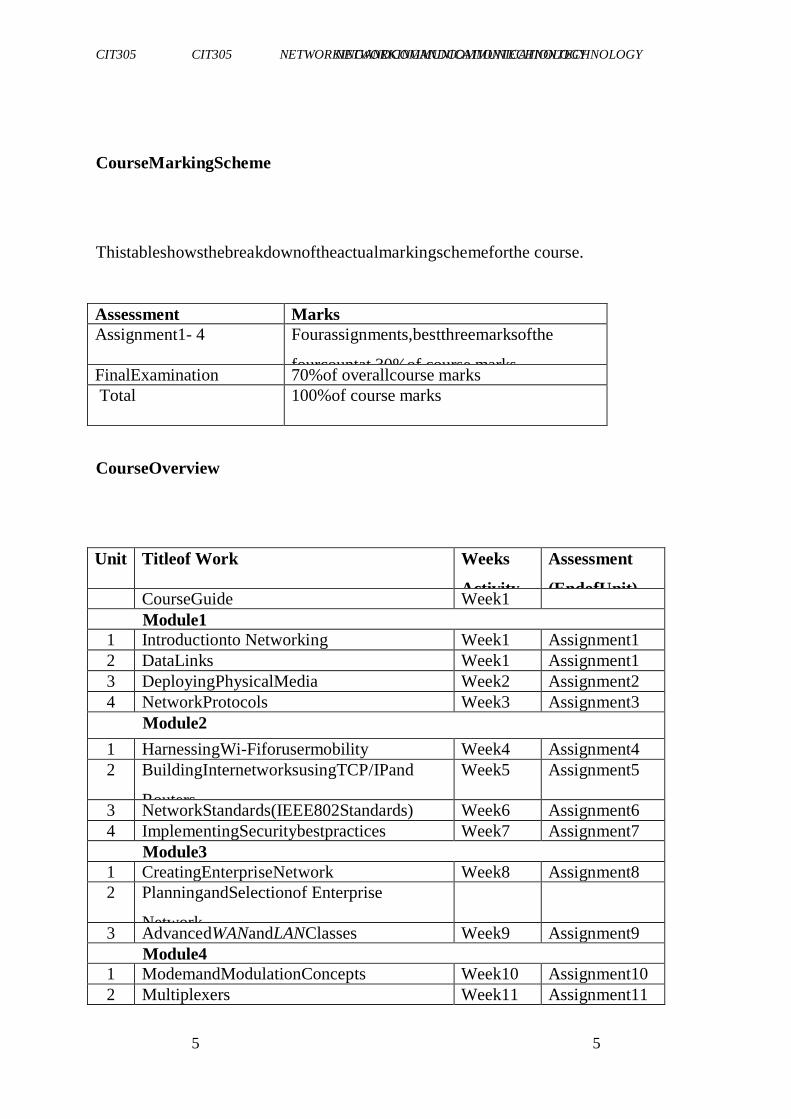
CourseMarkingScheme
Thistableshowsthebreakdownoftheactualmarkingschemeforthe course.
Assessment Marks
Assignment1- 4 Fourassignments,bestthreemarksofthe
fourcountat 30%of course marks FinalExamination 70%of overallcourse marks
Total 100%of course marks
CourseOverview
Unit Titleof Work Weeks
Activity
Assessment
(EndofUnit) CourseGuide Week1
Module1
1 Introductionto Networking Week1 Assignment1
2 DataLinks Week1 Assignment1
3 DeployingPhysicalMedia Week2 Assignment2
4 NetworkProtocols Week3 Assignment3
Module2
1 HarnessingWi-Fiforusermobility Week4 Assignment4
2 BuildingInternetworksusingTCP/IPand
Routers
Week5 Assignment5
3 NetworkStandards(IEEE802Standards) Week6 Assignment6
4 ImplementingSecuritybestpractices Week7 Assignment7
Module3
1 CreatingEnterpriseNetwork Week8 Assignment8
2 PlanningandSelectionof Enterprise
Network
3 AdvancedWANandLANClasses Week9 Assignment9
Module4
1 ModemandModulationConcepts Week10 Assignment10
2 Multiplexers Week11 Assignment11
CIT305 NETWORKINGANDCOMMUNICATIONTECHNOLOGY CIT305 NETWORKINGANDCOMMUNICATIONTECHNOLOGY
6 6
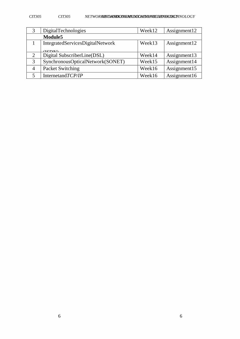
3 DigitalTechnologies Week12 Assignment12
Module5
1 IntegratedServicesDigitalNetwork
(ISDN)
Week13 Assignment12
2 Digital SubscriberLine(DSL) Week14 Assignment13
3 SynchronousOpticalNetwork(SONET) Week15 Assignment14
4 Packet Switching Week16 Assignment15
5 InternetandTCP/IP Week16 Assignment16
CIT305 NETWORKINGANDCOMMUNICATIONTECHNOLOGY CIT305 NETWORKINGANDCOMMUNICATIONTECHNOLOGY
7 7
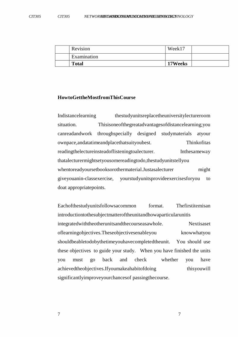
Revision Week17
Examination
Total 17Weeks
HowtoGettheMostfromThisCourse
Indistancelearning thestudyunitsreplacetheuniversitylectureroom
situation. Thisisoneofthegreatadvantagesofdistancelearning;you
canreadandwork throughspecially designed studymaterials atyour
ownpace,andatatimeandplacethatsuityoubest. Thinkofitas
readingthelectureinsteadoflisteningtoalecturer. Inthesameway
thatalecturermightsetyousomereadingtodo,thestudyunitstellyou
whentoreadyoursetbooksorothermaterial.Justasalecturer might
giveyouanin-classexercise, yourstudyunitsprovideexercisesforyou to
doat appropriatepoints.
Eachofthestudyunitsfollowsacommon format. Thefirstitemisan
introductiontothesubjectmatteroftheunitandhowaparticularunitis
integratedwiththeotherunitsandthecourseasawhole. Nextisaset
oflearningobjectives.Theseobjectivesenableyou knowwhatyou
shouldbeabletodobythetimeyouhavecompletedtheunit. You should use
these objectives to guide your study. When you have finished the units
you must go back and check whether you have
achievedtheobjectives.Ifyoumakeahabitofdoing thisyouwill
significantlyimproveyourchancesof passingthecourse.
CIT305 NETWORKINGANDCOMMUNICATIONTECHNOLOGY CIT305 NETWORKINGANDCOMMUNICATIONTECHNOLOGY
8 8
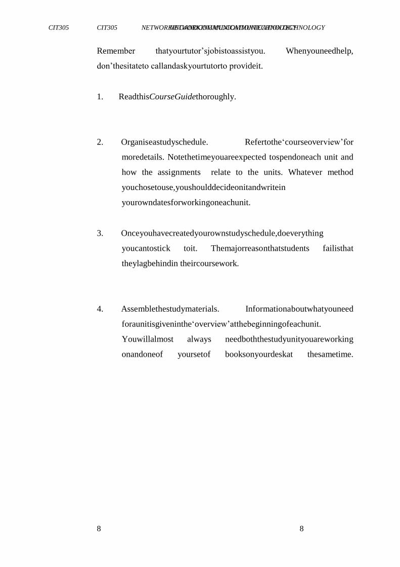
Remember thatyourtutor‘sjobistoassistyou. Whenyouneedhelp,
don‘thesitateto callandaskyourtutorto provideit.
1. ReadthisCourseGuidethoroughly.
2. Organiseastudyschedule. Refertothe‗courseoverview‘for
moredetails. Notethetimeyouareexpected tospendoneach unit and
how the assignments relate to the units. Whatever method
youchosetouse,youshoulddecideonitandwritein
yourowndatesforworkingoneachunit.
3. Onceyouhavecreatedyourownstudyschedule,doeverything
youcantostick toit. Themajorreasonthatstudents failisthat
theylagbehindin theircoursework.
4. Assemblethestudymaterials. Informationaboutwhatyouneed
foraunitisgiveninthe‗overview‘atthebeginningofeachunit.
Youwillalmost always needboththestudyunityouareworking
onandoneof yoursetof booksonyourdeskat thesametime.
CIT305 NETWORKINGANDCOMMUNICATIONTECHNOLOGY CIT305 NETWORKINGANDCOMMUNICATIONTECHNOLOGY
77 777
5. Workthroughtheunit. Thecontentoftheunititselfhasbeen
arrangedtoprovideasequenceforyoutofollow. Asyouwork
throughtheunityouwillbe instructedto readsectionsfromyour
setbooksor otherarticles.Usetheunitto guideyourreading.
6. Reviewtheobjectivesforeachstudyunittoconfirmthatyou
haveachieved them.Ifyoufeelunsureaboutanyofthe
objectives,reviewthestudymaterialor consultyourtutor.
7. When you are confident that you have achieved a unit‘s
objectives,youcanthenstartonthenextunit.Proceedunitby
unitthroughthecourseandtrytopaceyourstudysothatyou
keepyourselfonschedule.
8. When you have submitted an assignment to your tutor for
marking,donotwaitforitsreturnbeforestartingonthenext unit.
Keeptoyourschedule. When theassignment isreturned,
payparticular attentiontoyour tutor‘scomments,bothonthe tutor-
marked assignment form and also written on the assignment.
Consultyourtutorassoonaspossible ifyouhave anyquestionsor
problems.
9. Aftercompletingthelast unit,reviewthe courseandprepare
yourselfforthefinalexamination. Check thatyouhaveachieved
theunitobjectives(listedatthebeginning ofeachunit)andthe
courseobjectives(listedin thisCourseGuide).
CIT305 NETWORKINGANDCOMMUNICATIONTECHNOLOGY CIT305 NETWORKINGANDCOMMUNICATIONTECHNOLOGY
88 888
Facilitators/TutorsandTutorials
Thereare12hoursoftutorialsprovided insupportofthiscourse.You will be
notified of the dates, times and location of these tutorials,
togetherwiththenameandphonenumber ofyourtutor,assoonasyou
areallocatedatutorial group.
Yourtutorwillmark andcommentonyourassignments,keepaclose
watchonyourprogressandonanydifficulties youmightencounterand
provideassistancetoyouduring thecourse. Youmustmailorsubmit
yourtutor-markedassignmentstoyourtutorwellbefore theduedate(at
leasttwoworkingdaysarerequired).Theywillbemarkedbyyourtutor
andreturnedto youas soonaspossible.
Donothesitatetocontactyourtutor bytelephone,ore-mailifyouneed help.
Thefollowingmaybecircumstancesinwhichyouwouldfind
helpnecessary.Contactyourtutorif:
CIT305 NETWORKINGANDCOMMUNICATIONTECHNOLOGY CIT305 NETWORKINGANDCOMMUNICATIONTECHNOLOGY
99 999
youdonotunderstandanypartofthestudyunitsortheassigned
readings,
youhavedifficultywiththeself-testsor exercises,
youhaveaquestionorproblemwithanassignment,withyour
tutor‘scommentsonanassignmentorwiththegrading ofan
assignment.
Youshould tryyourbesttoattendthetutorials. Thisistheonlychance
tohavefacetofacecontactwithyourtutorandtoaskquestions which
areansweredinstantly.Youcanraiseanyproblem encounteredinthe course
of your study. To gain the maximum benefit from course
tutorials,prepareaquestionlistbeforeattending them.Youwilllearna
lotfromparticipatingin discussionsactively.
Summary
NetworkingandCommunication Technologyintroducesyoutothe concepts
associated with computer network development which is critical in
understandingthe various computer technology and data
communicationstechnology.Thecontentof the coursematerialhas
beenplanned andwrittentoensurethatyouacquiretheproper
knowledgeandskillsfortheappropriatesituations.Theessenceisto helpyou
in acquiringthe necessaryknowledgeand competenceby
equippingyouwiththenecessarytoolsto accomplishthis.

CIT305 NETWORKINGANDCOMMUNICATIONTECHNOLOGY CIT305 NETWORKINGANDCOMMUNICATIONTECHNOLOGY
1010
101010
Wehopethatbytheendofthiscourseyouwouldhaveacquired the
requiredknowledgeto viewComputerNetworkin anewway.
Iwishyousuccess withthecourseandhopethatyouwillfinditboth
interestinganduseful.
CIT305 NETWORKINGANDCOMMUNICATIONTECHNOLOGY CIT305 NETWORKINGANDCOMMUNICATIONTECHNOLOGY
1111
11
CourseCode CIT305
CourseTitle NetworkingandCommunicationTechnology
CourseTeam P r o f . A.S.Sodiya(Developer/Writer)-
FUNAAB
Afolorunso,A.A.(Coordinator)-NOUN
CIT305 NETWORKINGANDCOMMUNICATIONTECHNOLOGY CIT305 NETWORKINGANDCOMMUNICATIONTECHNOLOGY
1212
12
NATIONALOPENUNIVERSITYOFNIGERIA
NationalOpenUniversityof Nigeria
Headquarters
14/16AhmaduBelloWay
VictoriaIsland
Lagos
AbujaOffice
5DaresSalaamStreet
OffAminuKanoCrescent
WuseII,Abuja
e-mail:[email protected]
URL: www.nou.edu.ng
PublishedBy:
NationalOpenUniversityof Nigeria
FirstPrinted2012
Reviewed 2020
ISBN:978-058-910-4
All RightsReserved
CIT305 NETWORKINGANDCOMMUNICATIONTECHNOLOGY CIT305 NETWORKINGANDCOMMUNICATIONTECHNOLOGY
11
CONTENTS PAGE
Module1 Networking……………………..…………..………... 1
Unit1 Introductionto Networking…………..………..…….. 1
Unit2 DataLinks…………………………………….……….14
Unit3 DeployingPhysicalMedia……………….....................20
Unit4 NetworkProtocols……………………………………..24
Module2 NetworkDesign……………………………………….31
Unit1 HarnessingWififorUserMobility…………………... 31
Unit2 BuildingInternetworksUsingTcp/IpandRouters…... 38
Unit3 NetworkStandards(Ieee802Standards)…………….. 46
Unit4 ImplementingSecurityBestPractices……………….. 49
Module3
EnterpriseNetwork………………………………….
53
Unit1
CreatingEnterpriseNetwork………………………....
53 Unit2 PlanningandSelectionof EnterpriseNetwork………. 57
Unit3 LanandWan……………………………………….…. 63
Module4
CommunicationTechnology………………………..
67
Unit1
ModemandModulationConcept…………………....
67 Unit2 Multiplexers…………………………………….……. 79
Unit3 DigitalTechnologies…………………………….….... 87
Unit4 SignalTransmissionandImpairment………………... 91
Module5
NetworkTechnologies………………………………
98
Unit1 ISDN…………………………………………………..98
Unit2 DSL……………………………………………………108
Unit3 SONET………………………………………………...115

CIT305 NETWORKINGANDCOMMUNICATIONTECHNOLOGY CIT305 NETWORKINGANDCOMMUNICATIONTECHNOLOGY
12
Unit4 Switching…………………………...................122
Unit5 InternetandTCP/IP……………………………….…127
CIT305 NETWORKINGANDCOMMUNICATIONTECHNOLOGY CIT305 NETWORKINGANDCOMMUNICATIONTECHNOLOGY
1 1
MODULE1 NETWORKING
Unit1 Introductionto Networking
Unit2 Datalinks
Unit3 DeployingPhysicalMedia
Unit4 NetworkProtocols
UNIT1 INTRODUCTIONTONETWORKING
CONTENTS
1.0 Introduction
2.0 Objectives
3.0 MainContent
3.1 Overview
3.2 Definitionof Networking
3.3 Historyof ComputerNetworks
3.4 Purposeof ComputerNetworks
3.5 How Network Affect our lives
3.6 Network Representations
3.7NetworkClassification
3.8Typesof NetworkBasedonPhysicalScope
3.9Introductionto TelecommunicationCircuit
4.0 Conclusion
5.0 Summary
6.0 Tutor-MarkedAssignment
CIT305 NETWORKINGANDCOMMUNICATIONTECHNOLOGY CIT305 NETWORKINGANDCOMMUNICATIONTECHNOLOGY
2 2
7.0 References/FurtherReading
1.0 INTRODUCTION
Having readthroughthecourseguide,youwillhaveageneral
understandingof whatthisunitis aboutandhowitfitsintothecourseas
awhole.Thisunitwilldescribethegeneralconceptofnetworking,types andits
applicationareas.
2.0 OBJECTIVES
At theendthisunit,youshouldbe ableto:
explainthetermnetworkingsystem
identifythevarioustypesofnetworking
highlightthehistoryofnetworking
discuss how network can affect
lives
describetheareasof workofnetworking.
CIT305 NETWORKINGANDCOMMUNICATIONTECHNOLOGY CIT305 NETWORKINGANDCOMMUNICATIONTECHNOLOGY
3 3
3.0 MAINCONTENT
3.1 Overview
Theconceptofanetworkisprettysimple.Acoupleofcomputers have
somecablestrungbetween them,and senddataback andforthusing
electricalsignalingoverthecable.Moreorlessthesameastelephones do or, in
a veryroughsense, like two kidsspeakingintotin cans connectedby
astring; buthowdoesthe dataactually movefrom computer Atocomputer
B?Howdoescomputer Afindthephysical locationof computerB on the
network?If theycommunicatewith electricalsignaling,sothedataistraveling
"atthespeedoflight";why doesittakeso longto
sendabigfileacrossthenetwork?
Theinternetisnotonesingleentity;itisamassiveinterconnection of
hostssuchasyourcomputer,andanother-halfwayacrosstheworld.We
understand thatourInternetServiceProviders(ISPs)provideinternet
accesstoourhost,butitmaynotnecessarilyprovideservicetothe
serverthatyouarecommunicating with.Inthiscase,howdoes
informationmakeitswayfromyourhosttotheotherhostandvice versa?
TheanswerliesintheinterconnectionofmanyISPsthemselves.ISPs
canbecategorised intoTier1,2and3ISPs.Tier1ISPsaremajor
internetserviceproviders thatusuallysellaccesstosmallerTier2ISPs.
Tier2ISPsmayserviceentirecountries orcities,butnottherestofthe
world.Tier3ISPsarealsocustomersof Tier2ISPs,andusuallyservice
enduserssuchasyou. ISPspeerwitheachotherto allowdatafromyour
hosttoreachtheotherhost.Fromthis,weunderstand thatdatapasses
throughmultipleISPsinordertobedelivered from onelocationto another.
CIT305 NETWORKINGANDCOMMUNICATIONTECHNOLOGY CIT305 NETWORKINGANDCOMMUNICATIONTECHNOLOGY
4 4
3.2 DefinitionofNetworking
Acomputer network,oftensimplyreferredtoasanetwork,isa
collectionofcomputersanddevicesinterconnected bycommunications
channelsthatfacilitatecommunicationsamongusersandallows usersto
shareresources.
Anetwork canaswellbedefineasacollectionofcomputersorother
hardwaredevicesthatareconnected together,eitherphysically or
logically,using specialhardwareandsoftware,toallowthemto
exchangeinformationandcooperate.Networking isthetermthat
describestheprocessesinvolvedindesigning,implementing,upgrading,
managing andotherwiseworkingwithnetworksandnetwork technologies.
CIT305 NETWORKINGANDCOMMUNICATIONTECHNOLOGY CIT305 NETWORKINGANDCOMMUNICATIONTECHNOLOGY
5 5
3.3 HistoryofComputerNetworks
Beforetheadventof computernetworksthatwerebaseduponsometype
oftelecommunications system,communicationbetweencalculation
machinesandearlycomputers wasperformed byhumanusersby
carryinginstructions betweenthem.Manyofthesocialbehavioursseen
intoday'sInternetweredemonstrably presentinthenineteenthcentury
andarguablyin evenearliernetworksusingvisualsignals.
InSeptember 1940,GeorgeStibitzusedateletypemachinetosend
instructionsforaproblemsetfromhisModelatDartmouthCollegeto
hisComplexNumberCalculator inNewYorkandreceivedresultsback
bythesamemeans.Linking outputsystemsliketeletypestocomputers
wasaninterestattheAdvanced ResearchProjectsAgency(ARPA)
when,in1962,J.C.R.Lickliderwashiredanddevelopedaworking
grouphecalledthe"Intergalactic Network",aprecursor tothe ARPANET.
In1964,researchersatDartmouth developedtheDartmouth Time
SharingSystemfordistributed usersoflargecomputersystems.The
sameyear,atMassachusetts InstituteofTechnology,aresearchgroup
supportedbyGeneralElectricandBellLabsusedacomputertoroute
andmanagetelephoneconnections.
Throughout the1960s,LeonardKleinrock,PaulBaranandDonald
Daviesindependentlyconceptualised anddevelopednetworksystems
whichusedpacketsthatcouldbeusedinanetwork betweencomputer
systems.In1965,ThomasMerrillandLawrence G.Robertscreatedthe
firstwideareanetwork(WAN).
CIT305 NETWORKINGANDCOMMUNICATIONTECHNOLOGY CIT305 NETWORKINGANDCOMMUNICATIONTECHNOLOGY
6 6
Thefirstwidelyusedtelephone switchthatusedtruecomputer control
wasintroducedbyWesternElectricin1965.In1969,theUniversity of
CaliforniaatLosAngeles, theStanfordResearchInstitute, Universityof
California atSantaBarbara,andtheUniversity ofUtahwereconnected
asthebeginning oftheARPANETnetworkusing50kbit/scircuits.
Commercial servicesusingX.25weredeployedin1972,andlaterused as an
underlyinginfrastructureforexpandingTCP/IPnetworks.
Today,computer networks arethecoreofmoderncommunication. All
modernaspectsofthePublicSwitchedTelephoneNetwork (PSTN)are
computer-controlled, andtelephonyincreasinglyrunsovertheInternet
Protocol,althoughnot necessarilythe publicInternet.Thescopeof
communication hasincreasedsignificantlyinthepastdecade,andthis
boomincommunications wouldnothavebeenpossiblewithoutthe
progressivelyadvancingcomputernetwork. Computernetworksandthe
technologiesneededtoconnectandcommunicatethroughandbetween
CIT305 NETWORKINGANDCOMMUNICATIONTECHNOLOGY CIT305 NETWORKINGANDCOMMUNICATIONTECHNOLOGY
7 7
them,continuetodrivecomputer hardware,software,andperipherals
industries.Thisexpansion ismirroredbygrowthinthenumbersand typesof
usersof networksfromtheresearcherto thehomeuser.
3.4 PurposeofComputerNetworks
Computernetworkscanbeusedforavarietyofpurposes;theseare listedbelow.
i. Facilitatingcommunications
Usinganetwork,peoplecancommunicate efficientlyandeasilyvia
email,instantmessaging, chatrooms,telephone,videotelephone calls,
andvideoconferencing.
ii. Sharinghardware
Inanetworkedenvironment, eachcomputeronanetworkmayaccess
andusehardwareresourcesonthenetwork, suchasprintingadocument
onasharednetworkprinter.
iii. Sharingfiles,data,andinformation
Inanetworkenvironment, authorizedusermayaccessdataand
informationstoredonothercomputersonthenetwork. Thecapabilityof
providingaccess todataandinformationonshared storagedevicesisan
importantfeatureof manynetworks.
iv. Sharingsoftware
Usersconnectedtoanetworkmayrunapplication programsonremote
computers.
3.5 How Network Affect our lives
The followings are ways in which network can affect our lives:
1. Network connect us
CIT305 NETWORKINGANDCOMMUNICATIONTECHNOLOGY CIT305 NETWORKINGANDCOMMUNICATIONTECHNOLOGY
8 8
Communication is almost as important to us as our reliance on air, water, food, and
shelter. In today‘s world, through the use of networks, we are connected like never
before.
2. Education
Networks Support the Way We Learn. The internet and personal computing have
transformed the modern world. You do not have to be in school anymore to take a
class, you do not have to be in a classroom to have a teacher.
3. Business
Network technology also is an essential part in business. It affects the way
companies communicate and establish relations with their clients. In a fast moving
and business environment, it is vital for them to interact with clients regularly and
quickly to gain their trust and to obtain customer loyalty. With the use of Internet and
online social networks, firms interact with consumers and answer all their queries
about the product. Establishing effective communication with customers not only
creates rapport with them, but it also creates strong public image
4. Television and Radio
Rapid growth of network technology affects the innovation of television and radio
broadcasting causing the rapid increase in numbers cable, satellite television, fiber
lines, satellite radio, video-on-demand and pay-per-view
5. Communication
Communication is an important part of the human‘s life. Nowadays, technology
evolves rapidly and communication becomes easier than before. The effects of
modern technology on how we communicate with one another are vast and varied,
with both negative and positive impacts for our business and personal lives.
6. Internet
The Internet changed our life enormously; there is no doubt about that. Many
advantages of the Internet show you the importance of this new medium. Internet
CIT305 NETWORKINGANDCOMMUNICATIONTECHNOLOGY CIT305 NETWORKINGANDCOMMUNICATIONTECHNOLOGY
9 9
changed our life in many positive ways. One of the advantages of the internet is that
we can create new social contact all around the world which we could not do it easily
without the Internet. Such communities can also help people who cannot go out to
find friends in the real life because they are disabled.
3.6 Network Components
A network can be as simple as a single cable connecting two computers or as
complex as a collection of networks that span the globe.
Network infrastructure contains three broad categories of network components:
i. Devices
ii. Media
iii. Services
1. End Devices
An end device is where a message originates from or where it is received.
Data originates with an end device, flows through the network, and arrives at an
end device
ii. Intermediary Network Devices
An intermediary device interconnects end devices in a network. Examples include:
switches, wireless access points, routers, and firewalls.
The management of data as it flows through a network is also the role of an
intermediary device including:
Regenerate and retransmit data signals.
Maintain information about what pathways exist through the network and
internetwork.
Notify other devices of errors and communication failures.
2. Network Media
CIT305 NETWORKINGANDCOMMUNICATIONTECHNOLOGY CIT305 NETWORKINGANDCOMMUNICATIONTECHNOLOGY
10 10
Communication across a network is carried through a medium which allows a
message to travel from source to destination.
Networks typically use three types of media:
Metallic wires within cables, such as copper
Glass, such as fiber optic cables
Wireless transmission
3.6 Network Representations
Network diagrams, often called topology diagrams, use symbols to represent devices
within the network.In addition to the device representations on the right, it is
important to remember and understand the following terms:
Network Interface Card (NIC)
Physical Port
Interface
3.7NetworkClassification
Thefollowinglistpresentscategoriesusedforclassifyingnetworks.
a. Connectionmethod
Computernetworkscanbeclassifiedaccording tothehardwareand
softwaretechnologythatis usedto interconnecttheindividualdevicesin
thenetwork, suchasopticalfiber,Ethernet, wirelessLAN,HomePNA,
powerlinecommunicationorG.hn.
Ethernet,asitisdefinedbyIEEE802,utilisesvariousstandards and mediums
that enable communication between devices. Frequently
CIT305 NETWORKINGANDCOMMUNICATIONTECHNOLOGY CIT305 NETWORKINGANDCOMMUNICATIONTECHNOLOGY
11 11
deployed devicesincludehubs,switches,bridges,orrouters.Wireless
LANtechnology isdesignedtoconnectdeviceswithoutwiring.These devices
useradiowavesorinfrared signalsasatransmission medium. ITU-T
G.hntechnologyusesexistinghomewiring(coaxialcable,phone
linesandpowerlines)tocreateahigh-speed(upto1Gigabit/s) local
areanetwork.
b. Wiredtechnologies
i. Twistedpairwireisthemostwidelyusedmedium for
telecommunication.Twisted-paircablingconsistof copperwiresthatare
twistedintopairs.Ordinarytelephone wiresconsistoftwoinsulated copper
wirestwisted
intopairs.Computernetworkingcablingconsistof4pairsofcoppercabling
thatcanbeutilisedforbothvoiceanddata transmission.
Theuseoftwowirestwistedtogetherhelpstoreduce
crosstalkandelectromagnetic induction.Thetransmissionspeedranges
from 2millionbitspersecondto100millionbitspersecond.Twisted
paircabling comesintwoformswhichareUnshieldedTwistedPair
(UTP)andShieldedtwisted-pair (STP)whichareratedincategories
whicharemanufacturedin differentincrementsforvariousscenarios.
ii. Coaxialcableiswidelyusedforcabletelevision systems,office buildings,
and other work-sitesfor local area networks. The cables consist of
copper or aluminumwire wrapped with insulating layer
typicallyofaflexiblematerialwithahighdielectric constant,allof
whicharesurroundedbyaconductivelayer.Thelayersofinsulation help
minimiseinterferenceand distortion.Transmissionspeedrange
from200millionto morethan500millionbitspersecond.
CIT305 NETWORKINGANDCOMMUNICATIONTECHNOLOGY CIT305 NETWORKINGANDCOMMUNICATIONTECHNOLOGY
12 12
iii. Opticalfibercableconsistsofoneormore filamentsofglassfiber wrapped
inprotectivelayers.Ittransmitslightwhichcantravelover extended
distances. Fiber-optic cables are not affected by
electromagneticradiation.Transmissionspeedmayreachtrillionsof bits
persecond.Thetransmission speedoffiberopticsishundredsoftimes faster
than for coaxial cables and thousandsof times faster than a twisted-
pairwire.
SELF-ASSESSMENTEXERCISE1
Identifythekeyproblemswithwiredmedia.
CIT305 NETWORKINGANDCOMMUNICATIONTECHNOLOGY CIT305 NETWORKINGANDCOMMUNICATIONTECHNOLOGY
13 13
c. Wirelesstechnologies
Takenoteofthefollowing.
i. Terrestrialmicrowave –terrestrialmicrowavesuseEarth-based
transmitterandreceiver.Theequipment
lookssimilartosatellitedishes. Terrestrialmicrowavesuselow-
gigahertz range,whichlimitsall communicationsto line-of-
sight.Path between relay stations spaced
approx,30milesapart.Microwaveantennasareusuallyplacedontopof
buildings,towers,hills,andmountainpeaks.
ii. Communicationssatellites–
thesatellitesusemicrowaveradioastheir
telecommunicationsmediumwhich are not deflectedby the Earth's
atmosphere. Thesatellitesarestationed
inspace,typically22,000miles (forgeosynchronous
satellites)abovetheequator.TheseEarth-orbiting systems are
capable of receivingand relaying voice, data, and TV signals.
iii. Cellular andPCSsystems–useseveralradiocommunications
technologies.Thesystemsaredividedtodifferentgeographicareas.
Eachareahasalow-power transmitter orradiorelayantennadeviceto
relaycallsfromoneareato thenextarea.
iv. WirelessLANs–wirelesslocalareanetworkuseahigh-frequency
radiotechnologysimilartodigitalcellularandalow-frequency radio
technology.WirelessLANsusespreadspectrum technologytoenable
communicationbetweenmultipledevicesinalimitedarea.Anexampl
e of open-standardswirelessradio-wavetechnologyisIEEE.
CIT305 NETWORKINGANDCOMMUNICATIONTECHNOLOGY CIT305 NETWORKINGANDCOMMUNICATIONTECHNOLOGY
14 14
v. Infraredcommunication- thiscantransmitsignalsbetweendevices
withinsmalldistances notmorethan10meterspeertopeeror(faceto
face)withoutanybodyin thelineof transmitting.
3.8TypesofNetworksBasedonPhysicalScope
Commontypesof computernetworksmaybe identifiedbytheirscale.
a. Localareanetwork
Alocalareanetwork (LAN)isanetwork thatconnectscomputersand
devicesinalimitedgeographical areasuchashome,school,computer
laboratory,officebuilding,orcloselypositionedgroupofbuildings.
Eachcomputerordeviceonthenetworkisanode.CurrentwiredLANs
aremostlikelytobebasedonEthernettechnology, although new standards likeITU-
TG.hnalsoprovideawaytocreateawiredLAN
usingexistinghomewires(coaxialcables,phonelinesandpower lines).
Typicallibrarynetwork,inabranching treetopologyandcontrolled access to
resources All interconnecteddevices must understand the network
layer(layer3),because theyarehandlingmultiple subnets(the
differentcolors).
Thoseinsidethelibrary,whichhaveonly10/100 Mbit/s Ethernet
connections totheuserdeviceandaGigabitEthernetconnectiontothe central
router,couldbecalled"layer3switches"becausetheyonlyhave
Ethernetinterfaces andmustunderstandIP.Itwouldbemore correctto
callthem accessrouters,wheretherouteratthetopisadistribution
routerthatconnectstotheInternetandacademicnetworks' customer access
routers. The defining characteristics of LANs, in contrast to
CIT305 NETWORKINGANDCOMMUNICATIONTECHNOLOGY CIT305 NETWORKINGANDCOMMUNICATIONTECHNOLOGY
15 15
WANs(WideAreaNetworks), includetheirhigherdatatransferrates,
smallergeographic range,andnoneedforleasedtelecommunication
lines.CurrentEthernetor otherIEEE802.3LANtechnologiesoperateat
speedsupto10Gbit/s.Thisisthedatatransfer rate.IEEEhasprojects
investigatingthestandardizationof 40and100Gbit/s.
b. Personalareanetwork
APersonalAreaNetwork(PAN)isacomputernetwork usedfor
communication among computer and different information
technologicaldevicesclosetooneperson.Someexamplesofdevices
thatareusedinaPANarepersonalcomputers, printers,faxmachines,
telephones,PDAs,scanners,andevenvideogameconsoles.APANmay
include wired and wireless devices. The reach of a PAN typically
extendsto10meters.A wiredPANisusuallyconstructedwithUSBand
Firewireconnectionswhiletechnologies suchasBluetoothandinfrared
communicationtypicallyformawirelessPAN.
c. Homeareanetwork
AHomeAreaNetwork(HAN)isaresidential LANwhichisusedfor
communication betweendigitaldevicestypicallydeployedinthehome,
usuallyasmallnumberofpersonalcomputers andaccessories,suchas
printersandmobilecomputing devices.Animportantfunctionisthe
sharingofInternetaccess,oftenabroadbandservicethroughaCATVor
DigitalSubscriberLine(DSL)provider.Itcanalsobereferred toasan
officeareanetwork(OAN).
d. Wideareanetwork
AWideAreaNetwork(WAN)is acomputernetworkthatcoversalarge
geographic areasuchasacity,country,orspansevenintercontinental
distances,usingacommunicationschannelthatcombinesmanytypesof
mediasuchastelephonelines,cables,andairwaves.AWANoftenuses
CIT305 NETWORKINGANDCOMMUNICATIONTECHNOLOGY CIT305 NETWORKINGANDCOMMUNICATIONTECHNOLOGY
16 16
transmission facilitiesprovidedbycommoncarriers,suchastelephone companies.
WAN technologies generallyfunction at the lower three layersof
theOSIreferencemodel:thephysicallayer,thedatalinklayer, andthenetworklayer.
e. Campusnetwork
Acampusnetworkis a computernetworkmadeupof an interconnection
oflocalareanetworks(LAN's)withinalimitedgeographical area.The networking
equipments(switches,routers)andtransmissionmedia
(opticalfiber,copperplant,Cat5cablingetc.)arealmost entirelyowned
(bythecampustenant/owner:anenterprise, university, government etc.).
Inthecaseofauniversitycampus-basedcampusnetwork,thenetwork is likelyto linka
variety of campusbuildingsincluding;academic
departments,theuniversitylibraryandstudentresidencehalls.
f. Metropolitanareanetwork
AMetropolitanareanetworkisalargecomputernetwork thatusually spansacityor
alargecampus.
g. Enterpriseprivatenetwork
Anenterpriseprivatenetwork isanetworkbuildbyanenterpriseto
interconnectvariouscompanysites,e.g.,production sites,headoffices,
remoteoffices,shops,in orderto sharecomputerresources.
CIT305 NETWORKINGANDCOMMUNICATIONTECHNOLOGY CIT305 NETWORKINGANDCOMMUNICATIONTECHNOLOGY
17 17
h. Virtualprivatenetwork
AVirtualPrivate Network(VPN) isacomputernetworkinwhichsome
ofthelinksbetweennodesare carriedbyopenconnections orvirtual
circuitsinsomelargernetwork(e.g.,theInternet)instead ofbyphysical
wires.Thedatalinklayerprotocolsofthevirtualnetworkaresaidtobe
tunneledthroughthelargernetworkwhenthisisthecase.Onecommon
applicationissecuredcommunicationsthroughthepublicinternet;buta
VPNneednothaveexplicitsecurityfeatures,suchasauthentication or
contentencryption.VPNs,forexample,can beusedtoseparatethe
trafficofdifferentusercommunitiesoveranunderlying networkwith
strongsecurityfeatures.
VPNmayhavebest-effortperformance, ormayhaveadefinedservice
levelagreement(SLA)between theVPNcustomerandtheVPNservice
provider.Generally, aVPNhasatopologymorecomplexthanpoint-to- point.
i. Internetwork
Aninternetwork istheconnectionoftwoormoreprivatecomputer
networksviaacommonroutingtechnology(OSILayer3)usingrouters.
Theinternetisanaggregationofmanyinternetworks;henceitsname
hasbeenshortenedtointernet.
j. Backbonenetwork
ABack-BoneNetwork (BBN)-ornetworkbackbone,ispartofa
computernetworkinfrastructurethat interconnectsvariouspieces of
network,providingapathforthe exchangeofinformationbetween
differentLANsorsubnetworks.Abackbone cantietogetherdiverse networks
inthesamebuilding,indifferentbuildings inacampus environment,
CIT305 NETWORKINGANDCOMMUNICATIONTECHNOLOGY CIT305 NETWORKINGANDCOMMUNICATIONTECHNOLOGY
18 18
oroverwideareas.Normally,thebackbone's capacityis
greaterthanthenetworksconnectedto it.
A large corporationthat has many locationsmay have a backbone
networkthattiesallofthelocationstogether,forexample,ifaserver
clusterneedstobeaccessedbydifferentdepartmentsofacompanythat
arelocatedat differentgeographicallocations.Thepiecesof thenetwork
connections (for example: Ethernet, wireless) that bring these
departmentstogetherisoftenmentionedasnetworkbackbone.Network
congestionis oftentakenintoconsiderationwhiledesigningbackbones.
Backbonenetworksshouldnotbe confusedwiththeinternetbackbone.
k. Globalareanetwork
A GlobalAreaNetwork(GAN) isanetworkusedforsupportingmobile communications
acrossanarbitrarynumberofwirelessLANs,satellite
coverageareas,etc.Thekeychallengeinmobilecommunications is
handingofftheusercommunicationsfromonelocalcoverageareato
thenext.InIEEEProject802,thisinvolvesasuccession ofterrestrial wirelessLANs.
l. Internet
Theinternetisaglobalsystemofinterconnected governmental,
academic,corporate,public,andprivatecomputer networks.Itisbased onthenetworking
technologiesoftheInternetProtocolSuite.Itisthe successoroftheAdvanced
ResearchProjectsAgencyNetwork (ARPANET)
developedbyDARPAoftheUnitedStatesDepartmentof
Defense.TheInternetisalsothecommunications backboneunderlying
theWorldWideWeb(WWW).
CIT305 NETWORKINGANDCOMMUNICATIONTECHNOLOGY CIT305 NETWORKINGANDCOMMUNICATIONTECHNOLOGY
19 19
Participants intheinternetuseadiversearrayofmethodsofseveral hundreddocumented,
andoftenstandardised,protocolscompatiblewith the InternetProtocol Suiteand an
addressingsystem(IP addresses) administered
bytheInternetAssignedNumbersAuthorityandaddress
registries.Serviceprovidersandlargeenterprises exchangeinformation
aboutthereachability oftheiraddressspacesthroughtheBorder
GatewayProtocol(BGP),forming aredundantworldwidemeshof transmissionpaths.
m. Intranetsandextranets
Intranetsandextranetsarepartsorextensions ofacomputernetwork,
usuallyalocalareanetwork.
Anintranetis asetof networks,usingtheInternetProtocolandIP-based
tools,suchaswebbrowsersandfiletransferapplications, whichare
underthecontrolofasingleadministrative entity.Thatadministrative entitycloses the
intranetto all but specific, authorisedusers. Most commonly,an
intranetistheinternalnetworkof anorganisation.Alarge
intranetwilltypicallyhaveatleastonewebservertoprovide userswith
organisationalinformation.
Anextranetisanetworkthatislimitedinscopetoasingleorganisation or
entityandalsohaslimitedconnectionsto theother networks. A company's customers
maybegivenaccesstosomepartofitsintranet
whileatthesametimethecustomersmaynotbeconsideredtrusted from a security
standpoint. Technically, an extranet may also becategorisedas aCAN,MAN,WAN,or
othertypeof network,althoughan extranet
cannotconsistofasingleLAN;itmusthaveatleastone connectionwithan externalnetwork.
CIT305 NETWORKINGANDCOMMUNICATIONTECHNOLOGY CIT305 NETWORKINGANDCOMMUNICATIONTECHNOLOGY
20 20
n. Overlaynetwork
Anoverlaynetworkisavirtualcomputernetworkthatisbuiltontopof another
network. Nodes in the overlay are connectedby virtual or
logicallinks,eachofwhichcorrespondsto apath,perhapsthrough
manyphysicallinks,in theunderlyingnetwork.
Asampleoverlaynetwork:IPoverSONEToverOptical
Forexample,manypeer-to-peernetworksareoverlaynetworksbecause
theyareorganisedasnodesofavirtual system oflinksrunontopofthe
Internet.TheInternet wasinitially builtasanoverlay onthetelephone
network.Overlaynetworks havebeenaroundsincetheinventionof
networkingwhen computer systems were connected over telephone
linesusingmodem,beforeanydatanetworkexisted.
Nowadaystheinternetisthebasisformanyoverlaidnetworksthatcan be
constructedto permitroutingofmessagestodestinationsspecifiedby
anIPaddress.Forexample,distributed hashtablescanbeusedtoroute
messagestoanodehavingaspecificlogicaladdress,whoseIPaddress is
knownin advance.
Overlaynetworkshavealsobeenproposedasawaytoimproveinternet
routing,suchasthroughquality ofserviceguaranteestoachievehigher-
qualitystreaming media.PreviousproposalssuchasIntServ,DiffServ,
andIPMulticasthavenotseenwideacceptance largelybecausethey
requiremodificationofallroutersinthenetwork.Ontheotherhand,an
overlaynetworkcanbe incrementallydeployedonend-hostsrunningthe
overlayprotocolsoftware,withoutcooperation fromInternetservice
providers.Theoverlayhasnocontroloverhowpacketsareroutedinthe
CIT305 NETWORKINGANDCOMMUNICATIONTECHNOLOGY CIT305 NETWORKINGANDCOMMUNICATIONTECHNOLOGY
21 21
underlying networkbetweentwooverlaynodes,butitcancontrol,for
example,thesequenceof overlaynodesa messagetraversesbefore
reachingits destination.
SELF-ASSESSMENTEXERCISE2
WhatistherelevanceofISPin internetconnections?
3.9IntroductiontoTelecommunicationCircuit
Atelecommunicationcircuitis anyline,conductor,or otherconduitby
whichinformationistransmitted.Adedicatedcircuit,privatecircuit,orleas
ed lineisalinethatisdedicatedtoonlyoneuse.Originally,this
wasanalog,andwasoftenusedbyradiostations asastudio/transmitter
link(STL)orremotepickupunit(RPU)fortheiraudio,sometimes asa
backuptoothermeans. Laterlines weredigital, andusedforprivate
corporatedatanetworks.
Atelecommunicationcircuitmaybe definedas follows.
Thecompletepathbetweentwoterminalsoverwhichone-wayor two-
waycommunicationsmaybeprovided.Seecommunications protocol.
An electronic path between two or more points, capable of
providinganumberofchannels.
Anumberofconductorsconnectedtogetherforthepurposeof
carryinganelectriccurrent.
Anelectronicclosed-looppathamongtwoormorepointsusedforsignaltransfer.
CIT305 NETWORKINGANDCOMMUNICATIONTECHNOLOGY CIT305 NETWORKINGANDCOMMUNICATIONTECHNOLOGY
22 22
A number of electrical components, such as resistors, inductances,
capacitors,transistors,andpowersourcesconnected togetherin oneor
moreclosedloops.
4.0 CONCLUSION
Inthisunit,youhavebeenintroducedtothefundamentals of
Networking.YouhavealsolearntthedifferenttypesofNetworkingand its
classification.Youareadvisedto gooverthisunitagainsinceitis the
basisforunderstandingthecourse.
5.0 SUMMARY
In thisunit, youhavelearntthat:
computernetwork,oftensimplyreferredtoasanetwork,isa collection of
computers and devices interconnected by communications
channelsthatfacilitatecommunications among usersandallowsusersto
shareresources.
a telecommunication circuit is any line, conductor, or other
conduitbywhichinformationis transmitted.
typesoftelecommunicationcircuitarededicatedcircuit,private circuit,or
leasedline
CIT305 NETWORKINGANDCOMMUNICATIONTECHNOLOGY CIT305 NETWORKINGANDCOMMUNICATIONTECHNOLOGY
23 23
6.0 TUTOR-MARKEDASSIGNMENT
1. Brieflydescribethefollowing:- i.
Internetwork
ii. BackboneNetwork
iii. Intranet
2. Stateandexplainallthetypesofnetworksbasedontheirphysical scope.
7.0 REFERENCES/FURTHERREADING
Hafner,Katie.(1998).Where WizardsStayUpLate:TheOriginsofThe
Internet.
CCNA Routing and Switching. "Introduction to Networks" www.netacad.com
"How Does the Internet Work?"http://tldp.org/HOWTO/Unix-and-
Internet-Fundamentals-HOWTO/internet.html.RetrievedSSJune
15,2009.
Johna,Till,Johnson."Netwasbornofeconomicnecessity,notfear".
http://www.networkworld.com/columnists/2004/0607johnson.htm
l.RetrievedJune15,2009.URLis sufficientattribution.
Leonard, Kleinrock (2005). The History of the Internet.
http://www.lk.cs.ucla.edu/personal_history.html.Retrieved2009-
05-28.
CIT305 NETWORKINGANDCOMMUNICATIONTECHNOLOGY CIT305 NETWORKINGANDCOMMUNICATIONTECHNOLOGY
24 24
UNIT2 DATALINKS
CONTENTS
1.0 Introduction
2.0 Objectives
3.0 MainContent
3.1 Introductionto OpenSystemInterconnection(OSI)Model
3.2 DataLinkLayer
3.3 CategoriesofDataLink
3.4 TypesofDataLink
4.0 Conclusion
5.0 Summary
6.0 Tutor-MarkedAssignment
7.0 References/FurtherReading
1.0 INTRODUCTION
Inthepreviousunit,youhavebeenintroduced tothebasicconceptof
networking. Inthisunit,youwilllearnaboutanotherconceptof networking-
whichisdatalink.Intelecommunication,adatalinkisthe meansofconnecting
onelocationtoanotherforthepurposeof
transmittingandreceivingdigitalinformation.Itcanalsoreferto asetof
electronicsassembly,consistingofatransmitterandareceiver[two
DataTerminalEquipments(DTEs)]andtheinterconnecting data
telecommunication circuit.Thesearegovernedbyalinkprotocol
enablingdigitaldatato be transferredfromadatasourceto adatasink.
CIT305 NETWORKINGANDCOMMUNICATIONTECHNOLOGY CIT305 NETWORKINGANDCOMMUNICATIONTECHNOLOGY
25 25
2.0 OBJECTIVES
At theendof thisunit,youshouldbeableto:
discussOSImodel
explaintheterm―datalink‖
identifythevarioustypeofdatalink
statethe relevanceof datalinkto networking.
3.0 MAINCONTENT
3.1 Introductionto Open System Interconnection (OSI) Model
OSI is not a physical model, though, it is a set of guidelinesthat
application developerscanusetocreate andimplementapplicationthat run
on a network. It also provides a framework for creating and
CIT305 NETWORKINGANDCOMMUNICATIONTECHNOLOGY CIT305 NETWORKINGANDCOMMUNICATIONTECHNOLOGY
26 26
implementing networkingstandards,devicesandinternetworking schemes.
OSIhassevendifferentlayers,divided intotwogroups.Thetopthree
layersdefinehowtheapplications withintheendstationswill communicate
witheachotherandwithotherusers.Thebottomfour layersdefinehowdatais
transmittedendto end.
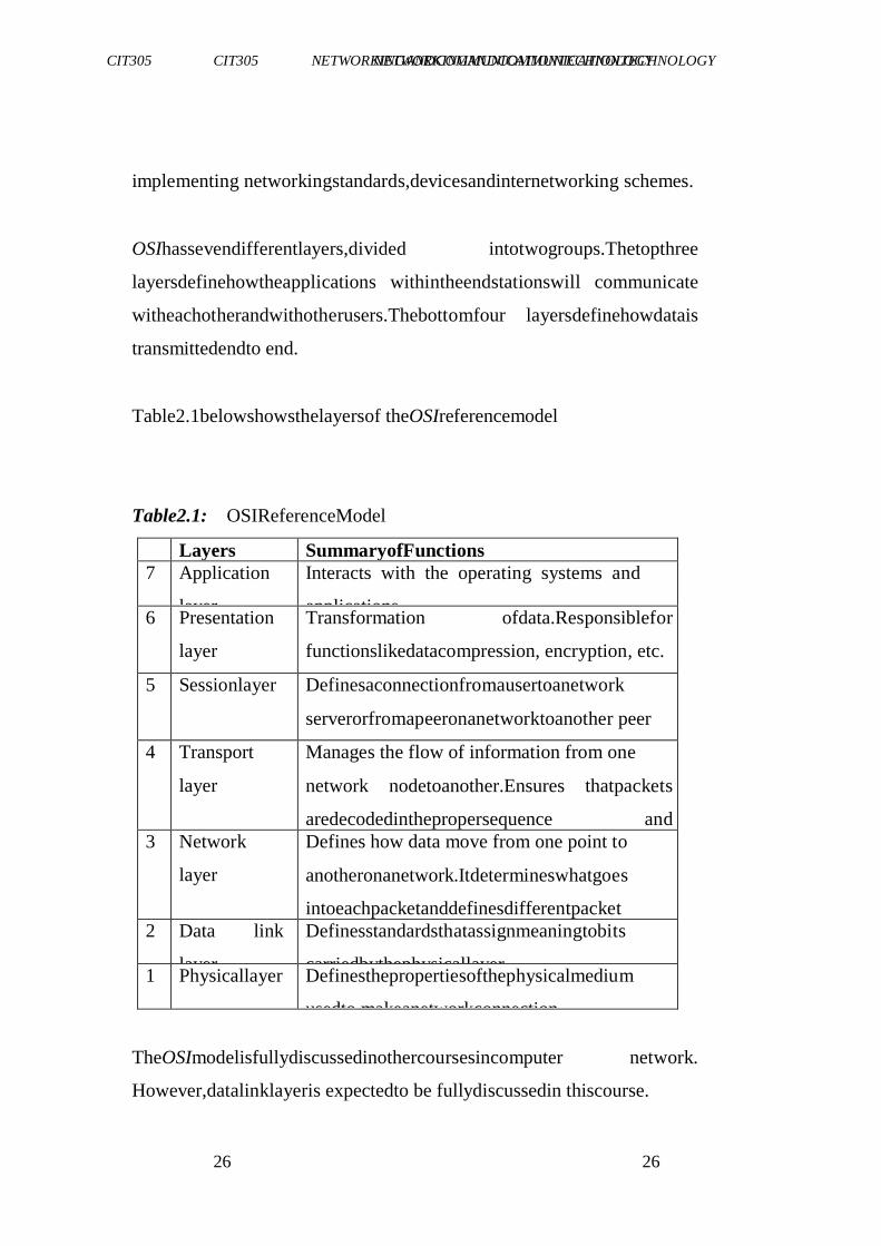
Table2.1belowshowsthelayersof theOSIreferencemodel
Table2.1: OSIReferenceModel
Layers SummaryofFunctions
7 Application
layer
Interacts with the operating systems and
applications 6 Presentation
layer
Transformation ofdata.Responsiblefor
functionslikedatacompression, encryption, etc.
5 Sessionlayer Definesaconnectionfromausertoanetwork
serverorfromapeeronanetworktoanother peer
4 Transport
layer
Manages the flow of information from one
network nodetoanother.Ensures thatpackets
aredecodedinthepropersequence and
receivedlogically 3 Network
layer
Defines how data move from one point to
anotheronanetwork.Itdetermineswhatgoes
intoeachpacketanddefinesdifferentpacket
protocols. 2 Data link
layer
Definesstandardsthatassignmeaningtobits
carriedbythephysicallayer 1 Physicallayer Definesthepropertiesofthephysicalmedium
usedto makeanetworkconnection
TheOSImodelisfullydiscussedinothercoursesincomputer network.
However,datalinklayeris expectedto be fullydiscussedin thiscourse.
CIT305 NETWORKINGANDCOMMUNICATIONTECHNOLOGY CIT305 NETWORKINGANDCOMMUNICATIONTECHNOLOGY
27 27
3.2 DataLinkLayer
Thedatalink layeristhesecondlayerintheOpenSystem Interconnection
(OSI)referencemodel.Thedatalinklayerdefinesthe rulesforaccessing
andusingthephysicallayer.Thedatalinklayer
providesthephysicaltransmission ofthedataandhandleserror
notification,networktopologyandflowcontrol.Thismeansthatthe
datalinklayerwillensurethatmessagesaredeliveredtotheproperdeviceonaLA
Nusing hardwareaddressesandwilltranslatemessages
fromtheNetworklayerintobitsforthephysicallayertotransmit.
Thedatalinklayerinthemodelcombinepacketsandbytesintoframes, itaswellprovides
accesstomediausingMACaddress.Thedatalink
layerdoesperformtheerrordetectionbutitshouldbenotedthatitdoes
notperformtheerrorcorrectionprocess.
Thedatalayerformatsthemessageintopieces,eachcalledadataframe,
andaddsacustomisedheadercontaining thehardwaredestinationand sourceaddress.
3.3 CategoriesofDataLink
Thereareatleastthreecategoriesofbasicdata-linkconfigurations that canbe conceivedof
andused:
simplexcommunications-referringtoallcommunicationsinone
directiononlye.g. radiotransmission.
half-duplexcommunications- referringto
communicationsinbothdirections,butnotbothwayssimultaneously,e.g.walkie-
talkie.
CIT305 NETWORKINGANDCOMMUNICATIONTECHNOLOGY CIT305 NETWORKINGANDCOMMUNICATIONTECHNOLOGY
28 28
duplex communications, communications in both directions
simultaneously,e.g. telephoneconversation.
3.4 TypesofDataLinks
Letus considertheseoneaftertheother a.
IndustrialEthernet
Industrial ethernetisusedtoprovidedatalinksolutionsforthe
communications andautomationindustry.Traditionalofficegrade
ethernetcannotmeetthereliabilitydemandedbyindustrialapplications.
Abrieflossofserviceinanofficeenvironment maynotbesuchabig
issue,butinanindustrialenvironmentitmayrepresentsignificantloss
onyourcapitalinvestment.
Industrialethernetisspecifically designedtooperateinharsh environments
suchasfactoryfloorautomation,processcontrol,HVAC, medical,
manufacturing. Typically, industrial automation devices include,
rugged case, din rail attachment,wide temperature specification,
broadpowersourceinput,thesefeaturesgiveusareliable
ethernetconnectionin demandingenvironments.
CIT305 NETWORKINGANDCOMMUNICATIONTECHNOLOGY CIT305 NETWORKINGANDCOMMUNICATIONTECHNOLOGY
29 29
b. Radiomodems
Radiomodemsareradiofrequency transceiversforserialdata
communications. TheyconnecttoserialportsRS232,RS422/485and
transmitto and receivesignalsfromothermatchingradio(pointto
point)orradios(multidrop)network.
Wirelessradiomodemsaredesignedtobetransparent tothesystems
withinwhichtheyoperate.All communicationappearsto yoursystemas if
communicating across directly connected cables; no special
preparationofyourdataisneeded.MaxStream unitsprovideyoutrue plug-
and-communicate wirelesscapabilityoperatinginthe
internationallyrecognised2.4GHzlicensefreeband.
c. EthernettoRS232,RS485serialdeviceservers
AnethernettoRS232orRS485deviceserverallowsyournetwork to
enablevirtuallyanyserialRS232/422/485portdevice.Theyprovidethe
abilitytoremotelymonitor,controlordiagnoseyourequipment over
yourLANorevenWAN(internet/web)link.Allowingyoutomaintain
theexistinginvestmentyouhavemadein serialinterfaceplantand
machineequipment.
d. WirelessRS232link
Whencreating anRS-232wirelesslink,youcanreplaceconventional
expensiveRS232 serialcableruns,allowingforaneasytouse,invisible
connection. Handywavebluetooth isthecablereplacementsolutionfor RS-
232.SimplyplugoneunitintoyourRS-232device andtheotherinto
yourPCforaninstantwirelesslinkwithminimalsetupandalsogives
theaddedflexibility andmobilitynotavailablewithtraditional wired
RS232links.
CIT305 NETWORKINGANDCOMMUNICATIONTECHNOLOGY CIT305 NETWORKINGANDCOMMUNICATIONTECHNOLOGY
30 30
e. GSMandGPRS
AGSMmodem isawirelessmodemthatworkswithaGSMwireless
network.Awirelessmodem behaveslikeadial-upmodem.Themain
differencebetweenthemis thatadial-up modemsendsandreceivesdata
throughafixedtelephonelinewhileawirelessmodem sendsand
receivesdatathroughradiowaves.GPRSmodem isaGSMmodem
which,additionally,supportsthe GPRS technologyfor data transmission.
GPRSstandsforGeneralPacketRadioService.Itisa packet-switched
technologythatisanextensionofGSM.(GSMisa circuit-
switchedtechnology.)AkeyadvantageofGPRSoverGSMis
thatGPRShasahigherdatatransmissionspeed.ThisTechnologyis
idealforM2M(machinetomachinecommunications)applicationssuchasmet
erreading,remotemaintenance, trafficcontrolsystems,vending machines
and building management systems HVAC
f. PowerOverEthernet(POE)
Power OverEthernetorPOEtechnologydescribesanysystem to
transmitelectricalpower,along withdata,toremotedevicesover standardtwisted-
paircablein an
Ethernetnetwork.ThestandardisIEEE802.3afwhichcallsfor48VoltsDCovertwopairsof
afour-paircableata maximumcurrentof350AMPfor a maximumloadpowerof16Watts.
g. OutdoorEthernetswitches
CIT305 NETWORKINGANDCOMMUNICATIONTECHNOLOGY CIT305 NETWORKINGANDCOMMUNICATIONTECHNOLOGY
31 31
Anoutdoorethernetswitchisspecifically designedforthetoughest
industrialenvironments.Anoutdoorswitchisconstructedfromarugged
weathertightaluminum caseandthedesignusuallycarriesanIPrating
whichprovideawaterproof anddust-tightconnection.Anoutdoor Ethernet
switchcanbeeasilyadoptedinalmostallkindsofindustrial
applicationsandprovidesthemostreliablesolutionsforyournetworkin
outdoorenvironments, typicalapplications includes:railway,moving
vehicles,factoryautomation,andmarine(DNVApproval).
3.5 Function of Data-link Layer
Data link layer does many tasks on behalf of upper layer. These are:
i. Framing
Data-link layer takes packets from Network Layer and encapsulates them into
Frames. Then, it sends each frame bit-by-bit on the hardware. At receiver end, data
link layer picks up signals from hardware and assembles them into frames.
ii. Addressing
Data-link layer provides layer-2 hardware addressing mechanism. Hardware address
is assumed to be unique on the link. It is encoded into hardware at the time of
manufacturing.
iii. Synchronization
When data frames are sent on the link, both machines must be synchronized in order
to transfer to take place.
Error Control
Sometimes signals may have encountered problem in transition and the bits are
flipped. These errors are detected and attempted to recover actual data bits. It also
provides error reporting mechanism to the sender.
iv. Flow Control
Stations on same link may have different speed or capacity. Data-link layer ensures
flow control that enables both machine to exchange data on same speed.
CIT305 NETWORKINGANDCOMMUNICATIONTECHNOLOGY CIT305 NETWORKINGANDCOMMUNICATIONTECHNOLOGY
32 32
v. Multi-Access
When host on the shared link tries to transfer the data, it has a high probability of
collision. Data-link layer provides mechanism such as CSMA/CD to equip capability
of accessing a shared media among multiple Systems.
3.6 Error Detection
Besides framing, datalink layers also include mechanisms to detect and sometimes
even recover from transmission error. To allow a receiver to detect transmission
errors, a sender must add some redundant information as an error detection code to
the frame sent. This error detection code is computed by the sender on the frame that
it transmits.
When the receiver receives a frame with an error detection code, it recomputes it and
verifies whether the received error detection code matches the computer error
detection code. If they match, the frame is considered to be valid.
Many error detection schemes exist and entire books have been written on the
subject. A detailed discussion of these techniques is outside the scope of this book,
and we will only discuss some examples to illustrate the key principles.
To understand error detection codes, let us consider two devices that exchange bit
strings containing N bits. To allow the receiver to detect a transmission error, the
sender converts each string of N bits into a string of N+r bits. Usually, the r
redundant bits are added at the beginning or the end of the transmitted bit string, but
some techniques interleave redundant bits with the original bits. An error detection
code can be defined as a function that computes the r redundant bits corresponding to
each string of N bits. The simplest error detection code is the parity bit. There are
two types of parity schemes : even and odd parity. With the even (resp. odd) parity
scheme,
the redundant bit is chosen so that an even (resp. odd) number of bits are set to 1 in
the transmitted bit string of N+r bits. The receiver can easily recompute the parity of
each received bit string and discard the strings with an invalid parity. The parity
scheme is often used when 7-bit characters are exchanged. In this case, the eighth bit
is
CIT305 NETWORKINGANDCOMMUNICATIONTECHNOLOGY CIT305 NETWORKINGANDCOMMUNICATIONTECHNOLOGY
33 33
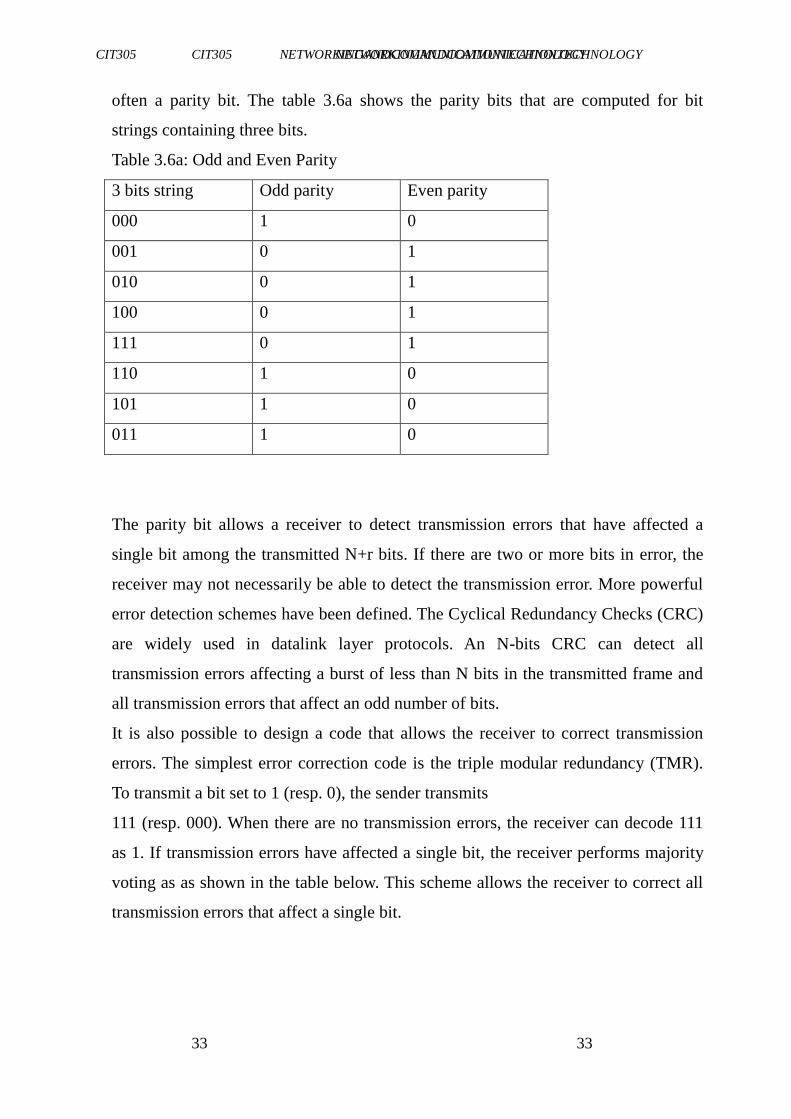
often a parity bit. The table 3.6a shows the parity bits that are computed for bit
strings containing three bits.
Table 3.6a: Odd and Even Parity
3 bits string Odd parity Even parity
000 1 0
001 0 1
010 0 1
100 0 1
111 0 1
110 1 0
101 1 0
011 1 0
The parity bit allows a receiver to detect transmission errors that have affected a
single bit among the transmitted N+r bits. If there are two or more bits in error, the
receiver may not necessarily be able to detect the transmission error. More powerful
error detection schemes have been defined. The Cyclical Redundancy Checks (CRC)
are widely used in datalink layer protocols. An N-bits CRC can detect all
transmission errors affecting a burst of less than N bits in the transmitted frame and
all transmission errors that affect an odd number of bits.
It is also possible to design a code that allows the receiver to correct transmission
errors. The simplest error correction code is the triple modular redundancy (TMR).
To transmit a bit set to 1 (resp. 0), the sender transmits
111 (resp. 000). When there are no transmission errors, the receiver can decode 111
as 1. If transmission errors have affected a single bit, the receiver performs majority
voting as as shown in the table below. This scheme allows the receiver to correct all
transmission errors that affect a single bit.
CIT305 NETWORKINGANDCOMMUNICATIONTECHNOLOGY CIT305 NETWORKINGANDCOMMUNICATIONTECHNOLOGY
34 34
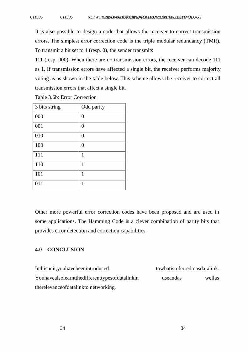
It is also possible to design a code that allows the receiver to correct transmission
errors. The simplest error correction code is the triple modular redundancy (TMR).
To transmit a bit set to 1 (resp. 0), the sender transmits
111 (resp. 000). When there are no transmission errors, the receiver can decode 111
as 1. If transmission errors have affected a single bit, the receiver performs majority
voting as as shown in the table below. This scheme allows the receiver to correct all
transmission errors that affect a single bit.
Table 3.6b: Error Correction
3 bits string Odd parity
000 0
001 0
010 0
100 0
111 1
110 1
101 1
011 1
Other more powerful error correction codes have been proposed and are used in
some applications. The Hamming Code is a clever combination of parity bits that
provides error detection and correction capabilities.
4.0 CONCLUSION
Inthisunit,youhavebeenintroduced towhatisreferredtoasdatalink.
Youhavealsolearntthedifferenttypesofdatalinkin useandas wellas
therelevanceofdatalinkto networking.
CIT305 NETWORKINGANDCOMMUNICATIONTECHNOLOGY CIT305 NETWORKINGANDCOMMUNICATIONTECHNOLOGY
35 35
5.0 SUMMARY
In thisunit,youhavelearntabout:
OSImodel-whichhas7layers:application,presentation,session,
transport,network,datalinkandphysical.
data link layer which defines rules for accessing and using physicallayer
7typesofdatalinkwhichincludesindustrialEthernet,radio modems,Ethernet
toRS232,wireless RS232link,GSMand GPRS, Power Over Ethernet (POE)
and outdoor Ethernet
Error -detection
CIT305 NETWORKINGANDCOMMUNICATIONTECHNOLOGY CIT305 NETWORKINGANDCOMMUNICATIONTECHNOLOGY
36 36
6.0 TUTOR-MARKEDASSIGNMENT
1. Whatdoyouunderstandbytheterm―datalink‖?
2. Howrelevantisdatalinkto networkingof computers?
3. Statesomeprotocolsthataredefinedbythedatalinklayer.
7.0 REFERENCES/FURTHERREADING
Bates, R., & Gregory, D. (2006). Voice & Data Communications Handbook, Fifth
Edition: Mcgraw-hill.
Mike,Meyers(2007).(6thEd.).AllinOneCompTIAA+Certification
ExamGuide.McGrawHill.
Olivier Bonaventure (2011), Computer Networking: Principles, Protocols and
Practice Release 0.25. Saylor URL: http://www.saylor.org/courses/cs402/
http://www.apan.net/meetings/busan03/cs-history.htm.Retrieved
December25,2005.
"APRICOTwebpage".Apricot.net.2009-05-04.http://www.apricot.net/.
Retrieved2009-05-28.
"ABriefHistoryoftheInternetin China".ChinaCelebrates10Yearsof
BeingConnectedto theInternet.
http://www.pcworld.idg.com.au/index.php/id;854351844;pp;2;fp;2;fpid;

CIT305 NETWORKINGANDCOMMUNICATIONTECHNOLOGY CIT305 NETWORKINGANDCOMMUNICATIONTECHNOLOGY
37 37
1.RetrievedDecember25,2005.
CIT305 NETWORKINGANDCOMMUNICATIONTECHNOLOGY CIT305 NETWORKINGANDCOMMUNICATIONTECHNOLOGY
38 38
UNIT3 DEPLOYINGPHYSICALMEDIA
CONTENTS
1.0 Introduction
2.0 Objectives
3.0 MainContent
3.1 Introductionto PhysicalMedia
3.2 PhysicalMediaComparison
4.0 Conclusion
5.0 Summary
6.0 Tutor-MarkedAssignment
7.0 References/FurtherReading
1.0 INTRODUCTION
Inthepreviousunits,youhavebeenintroducedtonetworkanddatalink layer of
the OSI reference model. This unit will introduce you to
physicalmediausedinthenetworking ofcomputeranditwill,aswell,
teachyouhowto deploythephysicalmedia.
2.0 OBJECTIVES
At theendof thisunit,youshouldbeableto:
CIT305 NETWORKINGANDCOMMUNICATIONTECHNOLOGY CIT305 NETWORKINGANDCOMMUNICATIONTECHNOLOGY
39 39
explainthetermphysicalmedia
identifythevarioustypeofphysicalmedia
identifywhichphysicalmediaisgoodforeachofthenetwork types.
3.0 MAINCONTENT
3.1 IntroductiontoPhysicalMedia
IntheOSIreferencemodel,anyphysicalmeansfortransmittingdatais referred
to as the physical media. The bottom of the OSI model‘s
physicallayerprovidesan interfaceto suchmedia.Specificationsforthe
physicalmediathemselvesarenotpartof theOSImodel.
3.2 Typesof PhysicalMedia
Letus lookat theseoneafteranother.
a. Twistedpair-wiretwistedtoavoidcrosstalkinterference.It maybe
shieldedor unshielded.
CIT305 NETWORKINGANDCOMMUNICATIONTECHNOLOGY CIT305 NETWORKINGANDCOMMUNICATIONTECHNOLOGY
40 40
UTP-UnshieldedTwistedPair.NormallyUTPcontains8wiresor
4pair;100metermaximumlength;4-100Mbpsspeed.
STP-ShieldedTwistedPair.100metermaximumlength;16-155
Mbpsspeed;lowerelectricalinterferencethanUTP.
b. Coaxial-twoconductors separatedbyinsulationsuchasTV75
ohmcable;maximum lengthof185to500meters;Itisoftwo
types,namely:
thinnet-thinnetusesaBritishNavalConnector(BNC)oneachend.
ThinnetispartoftheRG-58familyofcable.Maximumcablelengthis
185meters.Transmissionspeedis10Mbps.Thinnetcableshouldhave
50ohmsimpedance;anditsterminatorhas50ohmsimpedance;barrel
connectorwillhavenoimpedance.Maximumthinnetnodesare30ona
segment.Oneendof eachcableis grounded.
thicknet-halfinchrigidcable;maximum cablelengthis500meters.
Transmission speedis10Mbps;itisexpensiveandisnotcommonly used-
(RG-11orRG-8).Avampire taporpiercing tapisusedwitha transceiver
attachedtoconnectcomputerstothecable.100connections
maybemade.ThecomputerhasanAttachmentUnitInterface(AUI)on
itsnetwork cardwhichisa15pinDB-15connector.Thecomputeris
connectedtothetransceiveratthecablefromitsAUIonitsnetwork
cardusingadropcable.Maximumthicknetnodesare100onasegment.
Oneendof eachcableis grounded.
TheRGvalueforcabletypesreferstoitssize.Coaxcabletypesare listedbelow.
CIT305 NETWORKINGANDCOMMUNICATIONTECHNOLOGY CIT305 NETWORKINGANDCOMMUNICATIONTECHNOLOGY
41 41
RG-58/U - 50 ohm, with a solidcopper wirecorefor thin ethernet.
RG-58 A/U-50ohm,withastrandedwirecore.
RG-58C/U-Militaryversionof RG-58 A/U.
RG-59-75ohm,forbroadbandtransmissionsuchas cableTV.
RG-62-93ohm,primarilyusedforArcNet.
RG-6-usedforsatellitecable(ifyouwanttorunacabletoa satellite).
RG-8-50ohmthickethernet.
RG-11-75ohmthickethernet.
c. Fiber-optic-dataistransmittedusinglightratherthanelectrons.
Usually therearetwofibers,oneforeachdirection. Cablelength
of2Kilometers; speedfrom100Mbpsto2Gbps.Thisisthemost
expensive andmostdifficulttoinstall,butisnotsubjectto
interference.Therearetwotypesofcables:
CIT305 NETWORKINGANDCOMMUNICATIONTECHNOLOGY CIT305 NETWORKINGANDCOMMUNICATIONTECHNOLOGY
42 42
single mode cables for use with lasers have greater
bandwidthand cost more. Injectionlaser diodes (ILD)
workwithsinglemodecable.
multimode cables for use with Light Emitting Diode
(LED)drivers;allsignalsappeartoarriveatthesame time. P
intrinsic N diodes or photodiodesare used to convertlightto
electricsignalswhenusingmultimode.
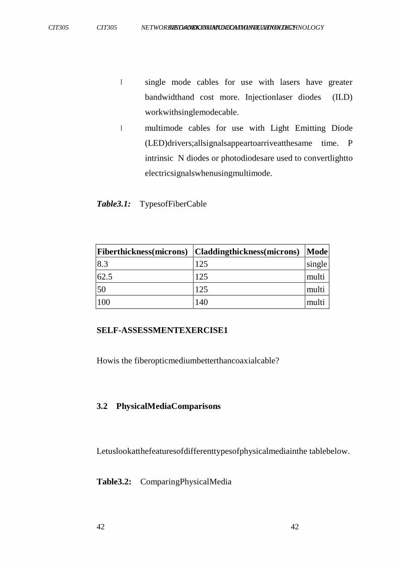
Table3.1: TypesofFiberCable
Fiberthickness(microns) Claddingthickness(microns) Mode
8.3 125 single
62.5 125 multi
50 125 multi
100 140 multi
SELF-ASSESSMENTEXERCISE1
Howis the fiberopticmediumbetterthancoaxialcable?
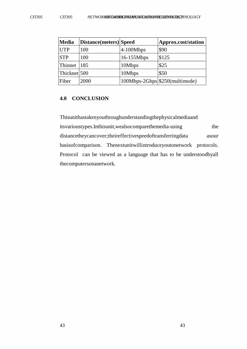
3.2 PhysicalMediaComparisons
Letuslookatthefeaturesofdifferenttypesofphysicalmediainthe tablebelow.
Table3.2: ComparingPhysicalMedia
CIT305 NETWORKINGANDCOMMUNICATIONTECHNOLOGY CIT305 NETWORKINGANDCOMMUNICATIONTECHNOLOGY
43 43
Media Distance(meters) Speed Approx.cost/station
UTP 100 4-100Mbps $90
STP 100 16-155Mbps $125
Thinnet 185 10Mbps $25
Thicknet 500 10Mbps $50
Fiber 2000 100Mbps-2Gbps $250(multimode)
4.0 CONCLUSION
Thisunithastakenyouthroughunderstandingthephysicalmediaand
itsvarioustypes.Inthisunit,wealsocomparethemedia-using the
distancetheycancover;theireffectivespeedoftransferringdata asour
basisofcomparison. Thenextunitwillintroduceyoutonetwork protocols.
Protocol can be viewed as a language that has to be understoodbyall
thecomputersonanetwork.
CIT305 NETWORKINGANDCOMMUNICATIONTECHNOLOGY CIT305 NETWORKINGANDCOMMUNICATIONTECHNOLOGY
44 44
5.0 SUMMARY
In thisunit, youhavelearntthat:
aphysicalmediumis anyphysicalmeansfortransmittingdata
the3typesofphysicalmediaaretwistedpair,coaxialcableand
fiberoptic.
6.0 TUTOR-MARKEDASSIGNMENT
1. Discussthevarioustypesof physicalmediaas regardthedistance
theycancover.
2. Statethefeaturesof 8typesof coaxialcable.
3. Explainthetwotypesof fiberopticcable.
7.0 REFERENCES/FURTHERREADING
DavidRoessner,BarryBozeman,IrwinFeller,ChristopherHill,Nils
Newman(1997).TheRoleofNSF'sSupportofEngineeringin
Enabling Technological Innovation.
http://www.sri.com/policy/csted/reports/techin/inter2.html.
Retrieved2009-05-28.
Hauben,Ronda(2004)."TheInternet: OnitsInternationalOriginsand
Collaborative
CIT305 NETWORKINGANDCOMMUNICATIONTECHNOLOGY CIT305 NETWORKINGANDCOMMUNICATIONTECHNOLOGY
45 45
Vision".AmateurComputerist12(2).http://www.ais.org/~jrh/acn/A
Cn12-2.a03.txt.Retrieved2009-05-
29.
"RFC675-Specificationofinternettransmissioncontrolprogram".
Tools.ietf.org. http://tools.ietf.org/html/rfc675.Retrieved 2009-
05-28.
Tanenbaum,AndrewS.(1996).ComputerNetworks.PrenticeHall.
CIT305 NETWORKINGANDCOMMUNICATIONTECHNOLOGY CIT305 NETWORKINGANDCOMMUNICATIONTECHNOLOGY
46 46
UNIT4 NETWORKPROTOCOLS
CONTENTS
1.0 Introduction
2.0 Objectives
3.0 MainContent
3.1 Introductionto NetworkProtocols
3.2 NetworkProtocolOverview
3.3 Typesof NetworkProtocols
4.0 Conclusion
5.0 Summary
6.0 Tutor-MarkedAssignment
7.0 References/FurtherReading
1.0 INTRODUCTION
Inthisunit,youwillbetakenthroughNetworkProtocolanditsgeneral
concepts.
2.0 OBJECTIVES
At theendof thisunit,youshouldbeableto:
explainthemeaningof networkprotocols
CIT305 NETWORKINGANDCOMMUNICATIONTECHNOLOGY CIT305 NETWORKINGANDCOMMUNICATIONTECHNOLOGY
47 47
statethetypesof networkprotocols.
3.0 MAINCONTENT
3.1 IntroductiontoNetworkProtocols
Aprotocolisasetofrulesthatgovernsthecommunications between
computersonanetwork. Theserulesincludeguidelinesthatregulatethe
following characteristicsofanetwork:accessmethod,allowedphysical
topologies,typesof cabling,andspeedof datatransfer.
Packetscanbetransmitted acrossnetworksorovertelephonelines.In fact,
network protocols and several communications protocols use
packetswitchingtoestablishaconnectionandrouteinformation. The
formatofapacketdepends ontheprotocol thatcreatesthepacketthe network
computermusthaveanetwork protocol driverloaded.This
programmaybereferredtoasthetransportprotocol, orjustasprotocol.
Itoperatesbetweentheadapterandtheinitiallayerofnetworksoftware to
packageandunpackdatafortheLAN.
CIT305 NETWORKINGANDCOMMUNICATIONTECHNOLOGY CIT305 NETWORKINGANDCOMMUNICATIONTECHNOLOGY
48 48
3.2 NetworkProtocolOverview
TheOSImodel,andanyothernetworkcommunication model,provides
onlyaconceptualframeworkforcommunicationbetweencomputers, but
the model itself does not provide specific methods of
communication.Actualcommunication isdefinedbyvarious
communication protocols.Inthecontextofdatacommunication,a
protocolisaformalsetofrules,conventions anddatastructurethat governs
how computers and other network devices exchange information
overanetwork.Inotherwords,aprotocolisastandard
procedureandformatthattwodatacommunication devicesmust
understand,acceptanduseto beable to talkto eachother.
Inmodernprotocoldesign,protocolsare"layered"accordingtotheOSI
7layermodelorasimilarlayeredmodel.Layeringisadesignprinciple
whichdividestheprotocol designintoanumberofsmallerparts,each
partaccomplishingaparticularsub-taskandinteractingwiththeother
partsoftheprotocolonlyinasmallnumberofwell-defined ways.
Layeringallowsthepartsof aprotocoltobe designedandtestedwithout
acombinatorial explosionofcases,keepingeachdesignrelatively simple.
Layering also permits familiar protocols to be adapted to
unusualcircumstances.
Theheader and/ortrailerateachlayerreflect thestructureofthe
protocol.Detailedrulesandprocedures ofaprotocolorprotocolgroup
areoftendefined byalengthydocument.Forexample,IETFusesRFCs
CIT305 NETWORKINGANDCOMMUNICATIONTECHNOLOGY CIT305 NETWORKINGANDCOMMUNICATIONTECHNOLOGY
49 49
(Request For Comments) to define protocols and updates to the
protocols.
A widevarietyof communicationprotocolsexists.Theseprotocolswere
definedbymanydifferentstandardorganisations throughouttheworld and
by technology vendors over years of technologyevolutionand
development. OneofthemostpopularprotocolsuitesisTCP/IP,which is the
heart of Internetworking communications. The IP- Internet
Protocolisresponsibleforexchanging informationbetweenrouters,so
thattherouters canselecttheproper pathfornetworktraffic;whileTCP
isresponsible forensuringthatdatapacketsaretransmitted acrossthe
network,reliably,and error free. LANand WANprotocolsare also
criticalprotocolsinnetworkcommunications.TheLANprotocolssuite
isforthephysicalanddatalinklayersofcommunications overvarious
LANmedia,suchasethernetwiresandwireless radiowaves.TheWAN
protocol suiteisforthelowestthreelayersanddefinescommunication
overvariouswide-areamedia,suchas fiberopticandcoppercables.
Network communicationhasslowlyevolved.Today'snewtechnologies
arebasedontheaccumulationoftechnologiesovertheyears-which
CIT305 NETWORKINGANDCOMMUNICATIONTECHNOLOGY CIT305 NETWORKINGANDCOMMUNICATIONTECHNOLOGY
50 50
maybeeitherstillexistingorobsolete.Asaresultofthis,theprotocols
whichdefinenetwork communicationarehighlyinter-related.Many
protocols relyonothersforoperation.Forexample,manyrouting
protocolsuseothernetwork protocolstoexchangeinformation between
routers.
Inadditiontostandardsforindividualprotocolsintransmission,there
arenowalsointerface standardsfordifferentlayerstotalktotheones
aboveorbelow(usuallyoperating systemspecific).Forexample, Winsock
andBerkeleysocketbetweenlayers4and5;NDISandODI
betweenlayers2and3.
Theprotocolsfordatacommunication coverallareasasdefinedinthe
OSImodel.However,theOSImodel is onlyloosely defined.A protocol
mayperform thefunctionsofoneormoreoftheOSIlayers,which
introducescomplexitytounderstanding protocolsrelevanttotheOSI7
layermodel.Inreal-worldprotocols,thereis someargumentas towhere
thedistinctionsbetweenlayersaredrawn;thereisnooneblackand
whiteanswer.
Todevelopacompletetechnology thatisusefulfortheindustry,very
oftenagroupofprotocolsisrequired inthesamelayeroracrossmany
differentlayers.Different protocols oftendescribedifferentaspectsofa
singlecommunication; takentogether,theseformaprotocolsuite.For
example,VoiceoverIP(VOIP),agroupofprotocolsdevelopedby
manyvendorsandstandardorganisations,hasmanyprotocolsacrossthe
CIT305 NETWORKINGANDCOMMUNICATIONTECHNOLOGY CIT305 NETWORKINGANDCOMMUNICATIONTECHNOLOGY
51 51
4toplayersin the OSImodel.
Protocols can be implemented either in hardware or software or a
mixtureofboth.Typically,thelowerlayersareimplemented in
hardware,withthehigherlayersbeingimplementedin software.
Protocols couldbegroupedintosuites(orfamilies,orstacks)bytheir
technicalfunctions,ororiginoftheprotocolintroduction, orboth.A
protocolmaybelongtooneormultipleprotocolsuites,depending on
howyoucategoriseit.Forexample,theGigabitethernetprotocolIEEE
802.3zisaLAN(LocalAreaNetwork)protocolanditcanalsobeused
in MAN(MetropolitanAreaNetwork)communications.
MostrecentprotocolsaredesignedbytheIETF forinternetworking
communications andbytheIEEEforlocalareanetworking and metropolitan
areanetworking.TheITU-TcontributesmostlytoWide
AreaNetworking(WAN)andtelecommunicationsprotocols.ISOhasits
ownsuiteofprotocolsforinternetworking communications,whichis
mainlydeployedin Europeancountries.
CIT305 NETWORKINGANDCOMMUNICATIONTECHNOLOGY CIT305 NETWORKINGANDCOMMUNICATIONTECHNOLOGY
52 52
3.4 TypesofNetworkProtocols
Themostcommonnetworkprotocolsareas listedbelow.
TCP/IP
FTP
AppleTalk
HTTP
SHTTP
DHCP
i. TCP/IP Protocols
The TCP/IP protocol suite establishes the technical foundation of the Internet. It is
the conceptual model and set of communications protocols used in the Internet and
similar computer networks
The TCP/IP suite‘s core functions are addressing and routing (IP/IPv6 inthe
networking layer) and transportation control (TCP, UDP in the transportlayer).
IP - Internet Protocol
The Internet Protocol is the principal communications protocol in the Internet
protocol suite for relaying datagrams across network boundaries.
On a LAN, messages are sent between machines by supplying the six bytes unique
identifier (the ―MAC‖ address). In an SNA network,every machine has Logical Units
with their own network addresses. DECNET, AppleTalk, and Novell IPX all have a
scheme for assigning numbers toeach local network and to each workstation attached
to the network.
TCP - Transmission Control Protocol
CIT305 NETWORKINGANDCOMMUNICATIONTECHNOLOGY CIT305 NETWORKINGANDCOMMUNICATIONTECHNOLOGY
53 53
TCP provides a reliable stream delivery and virtual connection service to
applications through the use of sequenced acknowledgment with retransmission of
packets when necessary. TCP provides stream data transfer, transportation reliability,
efficient flow control, full-duplex operation,and multiplexing. Check the TCP section
for more details
ii. FTP: File Transfer Protocol
File Transfer Protocol (FTP) enables file sharing between hosts.
FTP uses TCP to create a virtual connection for control information and then creates
a separate TCP connection for data transfers. The control connection uses an image
of the TELNET protocol to exchange commands and messages between hosts.
The key functions of FTP are:
1. to promote sharing of files (computer programs and/ordata);
2. to encourage indirect or implicit (via programs) use ofremote computers;
3. to shield a user from variations in file storage systemsamong hosts; and
4. to transfer data reliably and efficiently.
FTP, though usable directly by a user at a terminal, is designedmainly for use by
programs. FTP control frames are TELNETexchanges and can contain TELNET
commands and option negotiation. However, most FTP control frames are simple
ASCIItext and can be classified as FTP commands or FTP messages.FTP messages
are responses to FTP commands and consist ofa response code followed by
explanatory text.
iii. HTTP: Hypertext Transfer
The Hypertext Transfer Protocol (HTTP) is an application-levelprotocol with the
lightness and speed necessary for distributed,collaborative, hypermedia information
systems. HTTP has beenin use by the World-Wide Web global information initiative
since1990.
HTTP allows an open-ended set of methods to be used to indicate the purpose of a
request. It builds on the discipline ofreference provided by the Uniform Resource
Identifier (URI), asa location (URL) or name (URN), for indicating the resource on
CIT305 NETWORKINGANDCOMMUNICATIONTECHNOLOGY CIT305 NETWORKINGANDCOMMUNICATIONTECHNOLOGY
54 54
which a method is to be applied. Messages are passed in aformat similar to that used
by Internet Mail and the MultipurposeInternet Mail Extensions (MIME).
HTTP is also used as a generic protocol for communication between user agents and
proxies/gateways to other Internet protocols, such as SMTP, NNTP, FTP, Gopher
and WAIS, allowingbasic hypermedia access to resources available from
diverseapplications and simplifying the implementation of user agents.
The HTTP protocol is a request/response protocol. A client sendsa request to the
server in the form of a request method, URI, andprotocol version, followed by a
MIME-like message containingrequest modifiers, client information, and possible
body contentover a connection with a server. The server responds with astatus line,
including the message‘s protocol version and a success or error code, followed by a
MIME-like message containingserver information, entity meta information, and
possible entitybody content.
iv. DHCP: Dynamic Host Configuration Protocol
Dynamic Host Configuration Protocol (DHCP) is a communications protocol
enabling network administrators manage centrallyand to automate the assignment of
IP addresses in a network.
In an IP network, each device connecting to the Internet needsa unique IP address.
DHCP lets a network administrator supervise and distribute IP addresses from a
central point and automatically sends a new IP address when a computer is
pluggedinto a different place in the network.
DHCP uses the concept of a ―lease‖ or amount of time that agiven IP address will be
valid for a computer. The lease timecan vary depending on how long a user is likely
to require theInternet connection at a particular location. It‘s especially usefulin
education and other environments where users change frequently. Using very short
leases, DHCP can dynamically reconfigure networks in which there are more
computers than thereare available IP addresses.
DHCP supports static addresses for computers containing Webservers that need a
permanent IP address.
CIT305 NETWORKINGANDCOMMUNICATIONTECHNOLOGY CIT305 NETWORKINGANDCOMMUNICATIONTECHNOLOGY
55 55
v. S-HTTP: Secure Hypertext
Secure HTTP (S-HTTP) is a secure message-oriented communications protocol
designed for use in conjunction with HTTP.
S-HTTP is designed to coexist with HTTP‘s messaging modeland to be easily
integrated with HTTP applications.
Secure HTTP provides a variety of security mechanisms toHTTP clients and servers,
providing the security service optionsappropriate to the wide range of potential end
uses possible forthe World-Wide Web (WWW). S-HTTP provides symmetric
capabilities to both client and server (in that equal treatment is
given to both requests and replies, as well as for the preferences of both parties)
while preserving the transaction modeland implementation characteristics of HTTP.
Several cryptographic message format standards may be incorporated into S-HTTP
clients and servers. S-HTTP supportsinteroperation among a variety of
implementations and is compatible with HTTP. S-HTTP aware clients can
communicate withS-HTTP oblivious servers and vice-versa, although such
transactions obviously would not use S-HTTP security features.
vi. AppleTalk
AppleTalk is a routable protocol that is used primarily in Macintosh
environments to connect multiple systems in a network environment.
Phase 1 This was designed for small work group environments and
therefore supports a much smaller number of nodes on the network.
Phase 1 supports non-extended networks. Each network segment can
be assigned only a single network number, and only one zones is
allowed in non-extended network.
Phase 2 This was designed for larger networks and supports more
than 200 hosts on the network. Phase 2 supports extended networks,
CIT305 NETWORKINGANDCOMMUNICATIONTECHNOLOGY CIT305 NETWORKINGANDCOMMUNICATIONTECHNOLOGY
56 56
thereby allowing one network segment to be assigned multiple
network numbers and allowing for multiple zones on that network
segment.
4.0 CONCLUSION
Thisunithasintroduced basicrudiments ofnetworkprotocols,under which
you have learnt different types of network protocols which
includeTCP/IP,HTTP, FTPetc.
5.0 SUMMARY
In thisunit,youhavelearntabout:
network protocol, which is a set of rules that governs
communicationbetweencomputersonanetwork
typesofnetworkprotocols,namely-FTP, DHCP, HTTP and TCP/IP
Comparisonbetweendifferentnetworkprotocols.
6.0 TUTOR-MARKEDASSIGNMENT
1. Whatis thesignificanceofnetworkprotocol?
2. Differentiatebetween5typesof networkprotocols.
3. StatethemainfeaturesofHTTP andSHTTP
CIT305 NETWORKINGANDCOMMUNICATIONTECHNOLOGY CIT305 NETWORKINGANDCOMMUNICATIONTECHNOLOGY
57 57
7.0 REFERENCES/FURTHERREADING
OGC-00-33R DepartmentofCommerce:RelationshipwiththeInternet Corporation
forAssignedNamesandNumbers.Government Accountability Office. 7
July 2000. p.5. http://www.gao.gov/new.items/og00033r.pdf.
"DDNNIC".IABRecommendedPolicyonDistributing Internet Identifier
Assignment. http://www.rfc-editor.org/rfc/rfc1174.txt.
RetrievedDecember26,2005.
Olivier Bonaventure (2011), Computer Networking: Principles, Protocols and
Practice Release 0.25. Saylor URL: http://www.saylor.org/courses/cs402/
CIT305 NETWORKINGANDCOMMUNICATIONTECHNOLOGY CIT305 NETWORKINGANDCOMMUNICATIONTECHNOLOGY
58 58
MODULE2 NETWORKDESIGN
Unit1 HarnessingWi-FiforUserMobility
Unit2 BuildingInternetworksUsingTCP/IPandRouters
Unit3 NetworkStandards(IEEE802Standards)
Unit4 ImplementingSecurityBestPractices
UNIT1 HARNESSINGWI-FIFORUSERMOBILITY
CONTENTS
1.0 Introduction
2.0 Objectives
3.0 MainContent
3.1 OverviewofWi-FiTechnology
3.2 Introductionto Wi-FiTechnology
3.3 WLANPerformanceMetrics
3.4 TestingMethodologyforWirelessNetworks
3.5 TestSetupandSampleResults
4.0 Conclusion
5.0 Summary
6.0 Tutor-MarkedAssignment
7.0 References/FurtherReading
1.0 INTRODUCTION
CIT305 NETWORKINGANDCOMMUNICATIONTECHNOLOGY CIT305 NETWORKINGANDCOMMUNICATIONTECHNOLOGY
59 59
Thisunitwillexposeyoutotheconceptofwi-fitechnologyandits features.
2.0 OBJECTIVES
At theendof thisunit,youshouldbeableto:
definetheconceptof wi-fitechnology
explainthedetailsof whatbroughtaboutwi-fitechnology.
3.0 MAINCONTENT
3.1 OverviewofWi-FiTechnology
Testing techniquesdevelopedforwireddevicesandnetworksfallshort
whenappliedtotheWLANmarket.Theinherentinstability ofthe
unwiredmedium—air—inwhichthewirelessworldoperatesandthe
constantmobilityoftheWLANusermakethe802.11protocolanorder of
magnitude more complex than equivalent wired protocols. As a
CIT305 NETWORKINGANDCOMMUNICATIONTECHNOLOGY CIT305 NETWORKINGANDCOMMUNICATIONTECHNOLOGY
60 60
result,themetricsusedtobenchmarkwiredprotocolsareonlyastarting
pointforthe WLANindustry.
Differences betweenwiredandwirelessnetworksrequiremetricsand
methodologyforperformancebenchmarkingthataddresstheintricacies
ofthe802.11protocol.Thisunitaddresseswireless-specific functions central
to business-criticalapplicationson a wi-fi infrastructureand
includestypicalresultsandinterpretations.
3.2 IntroductiontoWi-FiTechnology
TheIEEE802.11bstandardispopularlyknownas―WirelessFidelity‖ (orWi-
Fi- forshort).Ithasbecomewidely popularforwirelessLANsin
officeenvironments.Proponentsofthistechnologyconsiderit great
competition tothirdgenerationwirelessnetworks,whichalsoprovide
highdatarate,mobileinternet access.Wi-ficanbeusedtoprovide
broadbandwirelessinternetaccess.
Access Points (APs)canbeinstalledatvariouslocationsinthecity.The APs
are also called ―hotspot‖. All the APs in a city can be interconnected
through an ATM-based backbone network. As the wirelessdevice
movesfromonelocationto another,themobiledeviceis connectedto
thenearestAP.
3.3 WLANPerformanceMetrics
CIT305 NETWORKINGANDCOMMUNICATIONTECHNOLOGY CIT305 NETWORKINGANDCOMMUNICATIONTECHNOLOGY
61 61
Wi-fi protocols address differences between wired and wireless
networks,andtheimplementation ofthemoreadvancedwireless protocol
demands performance validation. Algorithms used in a network's
clientsandAPs(andthecapacityofthesedevicestoprocess thealgorithms)
limitthenetwork'sperformance. Theobjectiveofthe validation
processandtestmetricsistoidentifycriticaltestparameters andfindthecorrect
methodof testingthem.
TestingEthernetnetworkperformanceis essentiallyameasureof packet
forwardingrate.In additionto packetforwardingmeasurements,WLANs
mustundergo testsrelatedtotheunstable physical layerand end-user
mobility;includingautomaticdatarateadaptation,roaming,verification
ofsecurity,QOSandoverlapping BSSs,aswellasbehavioralteststhat
measureperformance underabnormalnetworkconditions.Theprimary
focusofthetestingeffortshouldbeparameters thateventuallyaffect
networkefficiencyandoperation.
Datarateadaptation-wiredLANssupportfixeddatarates:10/100/1000
Mb/s.Wirelessnetworkssupportmultipledatarates:11/5.5/2/1Mb/sfor
802.11b;54/48/36/24/18/12/9/6Mb/s for 802.11a and 802.11g.The
CIT305 NETWORKINGANDCOMMUNICATIONTECHNOLOGY CIT305 NETWORKINGANDCOMMUNICATIONTECHNOLOGY
62 62
criticaldifferenceisthatWLANssupportdynamicrateadaptationand
canoperateatmultipledataratesautomatically determinedbytheend
point(APor client).
Inaddition,because the802.11standarddoesnotspecifyexactcriteria
fordatarateadaptation,thealgorithms canvaryfromdevicetodevice. The
rate adaptation algorithm should be based on optimising
throughput; thatis,whenthenumberoferrorsataspecificdatarate increases
tothepointwherethroughputisseverelyaffected,thedevice
shoulddroptoalowerdataratetorecoverthebestthroughput atthat
distancefromthe AP.
Thechallengeishowtomeasurethisrepeatedly,whilecreatingametric
thatcanbesetasthegoldenstandard.Tomeasure throughputatfixed
points,manyvendorsoftenuseaninterference-freeenvironmentwitha
long,directline-of-siteareawheretheycansimulatedatarateadaptation
bywheelingaclientupanddownonacart.Thismethod,however, lacks
accurate rate adaptationdata and is less efficient than newer
devicesthatoffercontrolledRFenvironments andaccuratesignal
attenuationthroughtestsetupautomation.Whilecharacterisingrange vs.
data rate, the test should simultaneouslycharacterise range vs.
throughputandrangevs.packeterrorrate.
Roaming-asaclientmovesoutofrangeofoneAP,itdissociates from
theAPandmustassociate andauthenticatewithanother.Iftheclient predicts
this roam will occur by noticing the drop in signal and
CIT305 NETWORKINGANDCOMMUNICATIONTECHNOLOGY CIT305 NETWORKINGANDCOMMUNICATIONTECHNOLOGY
63 63
searchingforanalternateAPbeforeitisactuallydisassociatedfromthe
first,itcanoptimisetheroamtimeandnetworkdisruptioncausedbythe roam.
Theclientdevicemakesthedecisiontoroam basedonitsposition relative
todifferent APsandtheirsignalstrengths. Theclientmight
periodicallyanalysesignalstrengthof the APsthat surroundit and decide
which onetoassociatewithifitneedstoroam.Load-sharing protocols
usedbysomeWLANnetworkvendorsdepartfrom the traditionalclient-
baseddecisionprocess,orchestrating clientdevicesto
associatewithspecificAPsandspreading theloadevenlyamongAPs
andoptimising theentirenetworkthroughput.Inaddition,theIEEEis
advancingitsworkonroaming throughbetterRFmeasurement
(802.11k)andfastroamingprocesses(802.11r).Astheroamingprocess
increasesincomplexity,itiscriticaltohavestandardroamingmetrics
fortestingWLANnetworksandequipment.
Roamingiscriticalbecauseittakestime,whichcancausedatalossthat
canultimatelydisrupt acommunicationsession.Datalossisparticularly
importantfortime-sensitiveenterpriseapplications,suchasVoWLAN,
CIT305 NETWORKINGANDCOMMUNICATIONTECHNOLOGY CIT305 NETWORKINGANDCOMMUNICATIONTECHNOLOGY
64 64
thatareespeciallysusceptible topacket delaycausedbyroaming. Roaming
metricsincluderoamingtime,packetlossandsession
continuity.Roamingtimecanbebroken downintothefollowingstages-
scanning,associatingto thenew AP, authenticationwiththenewAPand
dataflow.Analysing thetimeofeachphaseofthisprocesswillhelp
ensurethemostefficientroamtime.
Packetforwarding-forwarding rateisafunctionofadevice:inwired
networks,theethernetswitch;inWLANs,theAP. Packetforwardingrate
testing isalwaysdoneatthehighestsignalstrengthandatthehighest
dataratebecausethisputsthemostdemandonthedeviceandmeasures its
packetprocessingpowerin themostextremecase.
Likewiredthroughputtests,awirelesspacketforwardingtestvariesthe
packetsizetoensuretheabilityofthedevicetoworkwithdiverse traffic;
butunlikewireddevices,thereareotherfactors toconsider. The
mostcriticalissecurity,because wireless network devicesmustencrypt
eachpacket.Thisadditionaloverheadmustbeaddedtoevaluateits
effectonthepacketforwarding rate.Anotherimportantfactorisclient
capacity. RunningthetestwithalargenumberofusersstressestheAP's
abilitytohandlealargenumberofusers,eachsending aportionofthe
bandwidth. This also affects how the AP functions under such
conditions.
CIT305 NETWORKINGANDCOMMUNICATIONTECHNOLOGY CIT305 NETWORKINGANDCOMMUNICATIONTECHNOLOGY
65 65
Security-thisisacriticalconsiderationforenterprisenetworks;because
theyaresusceptible tointruders,wirelessnetworkshavemorestringent
securityrequirements thantheirwiredcounterparts.Wireless security
protocols(802.11i)relyheavilyonauthenticationandencryption,which
dependontheprocessingpoweroftheAPandclient,andcryptography
accelerators fordataencryption.Theefficiencywithwhichthedevices
handlekeymanagement andencryptionwillhaveaneffecton performance
measurements, such as forwarding rate and roaming.
Whenaclientinitiallyaccesses thenetwork orroamsbetweenAPs,
authentication occursusingprotocolssuchasEAP-TLS,EAP-TTLSand
LEAP.Complexkeyderivation algorithms canoverloadAPsifmultiple
simultaneousauthenticationrequestsaremade.Authentication of
wirelessnetworksistestedbymeasuringhowefficientlyandquicklyan
APmanagessimultaneousauthenticationrequests.
Encryptionprotocolsusedinwi-fi,suchasWEP,TKIPandAES/CCMP,
canalsoimpactthroughput performance.Thesecuritymetricis
performedbymakingaseriesofcomparativethroughputmeasurements
usingdifferentencryptionmethods.
QualityofService(QOS)-because802.11isasharedmediaprotocol
CIT305 NETWORKINGANDCOMMUNICATIONTECHNOLOGY CIT305 NETWORKINGANDCOMMUNICATIONTECHNOLOGY
66 66
withoutQOS,WLANscannotprioritisereal-timeapplications suchas
voiceandvideo,overdataapplications.QOSprotocolsforWLANsmust
accountforjitter,delayandpacket loss,whichhaverequiredminimums
forreal-timeapplications includingVOIPandmultimediastreaming.
Jitter,or inter-packetdelay,is particularlycriticalin packetisedvoice.
3.4 Testing Methodology for Wireless Networks
Traditionally, wirelesssystemdesignershavehadavarietyoftesting
options.Mostarehome-grown orcustom-built,andincludeisolated
screenroomsforRFcontrol,largeopenspacesfortestingmobility and
expensiveoff-the-shelfmetersthatfocusonpoint-to-point testsofthe
physical layer.Anotherapproachisemerging forintegratedchassis-
basedwi-fitesting.Theoldermethods arecostly,andinmanycasesdo
notprovidethesystemslevelconfigurationneededtoaccurately and
usefullyproviderelevantinformationaboutthemetricsdiscussedabove.
Isolatedscreenroomsforcontrolling RFinterference—WLANsystem
developersreduce theeffects ofRFinterferencebyconductingtestsina
largescreenroom thatisolatesdevicesundertestfrom extraneousRF
interference. Itisthewirelessequivalent ofa"cleanroom."Although
screenroomscaneliminateinterference effects,theycannottestreal-
worldnetwork conditionssuchasmobilityandroaming.Screenrooms
canbeexpensivetoerectandmaintain;andarenotportable,which
limitstheiruseandeffectiveness.
SELF-ASSESSMENTEXERCISE
CIT305 NETWORKINGANDCOMMUNICATIONTECHNOLOGY CIT305 NETWORKINGANDCOMMUNICATIONTECHNOLOGY
67 67
Describetheperformanceof Wi-fitechnology.
3.5 TestSetupandSampleResults
Theroaming testisanexamplethatshows theefficiencythatcanbe
achievedusingachassis-basedtestplatform.Usingtwotestmodules—
aWLAandanRFM—aphoneoraPCclientisconnected betweenthe
twoAPsthroughtwo80dBprogrammable attenuators.Theattenuators
areprogrammedtoforcetheclienttoroaminacontrolledwayfromone AP to
another. Data collection is performed on the source and
destinationchannelsimultaneously bytheintegrateddual-channelWLA
module.Theroaming testisfullyautomatedandcanbeconfiguredto
repeatthemeasurementsforasetperiod.
Oneattenuatorisinitiallysettominimumandtheothertomaximumso
thattheclientreceivesastrong signalfromAP1andassociates withit;
whileAP2isoutoftheclient'srange.Theattenuator betweenAP1and
theclientisthengraduallyincreased,eventuallymakingAP1invisible to
theclientwhiletheattenuatorbetweentheclientandAP2isgradually
CIT305 NETWORKINGANDCOMMUNICATIONTECHNOLOGY CIT305 NETWORKINGANDCOMMUNICATIONTECHNOLOGY
68 68
decreased,"moving" AP2withinrangeandforcingaroam.Theranges
andtherateofchangeofattenuatorsareconfigurable withinthetest
script.Attheendoftheroamingtest,thetestscripttabulatesthedetails of
eachroam.
This automatedroamingtest implementationprovides accurate time
measurements and identifies specific time intervals in a way that
emulatesreal-life roamingto the clients and access points: gradual
signalstrengthdecrease andincrease.Theentiretest canberepeated as
manytimesas is needed,andmultipleroamscanbe performedin ashort
periodwithouthumaninvolvement.
4.0 CONCLUSION
Thisunitintroducesyoutowi-fitechnology andalsoteachesthe
advantageofthetechnology overwiredtechnology. Thisunithasalso
exposedyouto thetestingmethodologyforwirelessnetworks.
5.0 SUMMARY
In thisunit,youhavelearntthat:
The IEEE802.11bstandardis popularlyknownas ‗Wireless
Fidelity‘(orWi-Fi).
CIT305 NETWORKINGANDCOMMUNICATIONTECHNOLOGY CIT305 NETWORKINGANDCOMMUNICATIONTECHNOLOGY
69 69
Wi-fi protocols address the differences between wired and wirelessnetworks
Wi-ficanbe usedto providebroadbandwirelessinternetaccess.
WLAN must be tested continually; the primary focus of the testing
effortshouldbeparametersthateventuallyaffectnetwork efficiencyandoperation.
Wi-fitechnology hasbecomepopularforwirelessLANsinoffice environment
6.0 TUTOR-MARKEDASSIGNMENT
1. Whatdoyouunderstandbytheterm―wi-fi?‖
2. In atabularform,compareandcontrastwi-fiandthe WLAN.
3. StateandexplainthemetricsfortestingWLAN
CIT305 NETWORKINGANDCOMMUNICATIONTECHNOLOGY CIT305 NETWORKINGANDCOMMUNICATIONTECHNOLOGY
70 70
7.0 REFERENCES/FURTHERREADING
―NASASuccessfullyTestsFirstDeepSpaceInternet‖.NASAmedia
release08-298,November18,2008Archived.
Prasad,K.V.(2009).PrinciplesofDigitalCommunicationSystemsand
ComputerNetworks.DreamtechPress.
http://www.azimuthsystems.com/
CIT305 NETWORKINGANDCOMMUNICATIONTECHNOLOGY CIT305 NETWORKINGANDCOMMUNICATIONTECHNOLOGY
71 71
UNIT2 BUILDINGINTERNETWORKSUSING
TRANSPORTCONTROLPROTOCOL
(TCP)/INTERNETPROTOCOL(IP)AND
ROUTERS
CONTENTS
1.0 Introduction
2.0 Objectives
3.0 MainContent
3.1 TCPTechnology
3.1.1 InternetProtocol
3.2 Routingin IPEnvironments
4.0 Conclusion
5.0 Summary
6.0 Tutor-MarkedAssignment
7.0 References/FurtherReading
1.0 INTRODUCTION
Thelanguage oftheinternetisTransportControlProtocol/Internet
Protocol(TCP/IP).Nomatterwhattypeofcomputerplatform or
softwareisbeingused,theinformation mustmoveacross theinternetin this
format.Thisprotocolcalls for data to be grouped together,in
bundles,callednetworkpackets.
CIT305 NETWORKINGANDCOMMUNICATIONTECHNOLOGY CIT305 NETWORKINGANDCOMMUNICATIONTECHNOLOGY
72 72
2.0 OBJECTIVES
At theendof thisunit,youshouldbeableto:
explainthefundamentalsof theTCP/IP
statetherelevanceofTCP/IPin internetworks.
3.0 MAINCONTENT
3.1 TCPTechnology
TCPisaconnection−oriented transportprotocolthatsendsdataasan
unstructured streamofbytes.Byusingsequencenumbersand
acknowledgment messages,TCPcanprovideasendingnodewith
deliveryinformation aboutpacketstransmittedtoadestinationnode.
Wheredatahasbeenlostintransitfrom sourcetodestination,TCP can
retransmit thedatauntileitheratimeoutconditionisreachedoruntil
successfuldeliveryhasbeenachieved.TCPcanalsorecogniseduplicate
messagesandwilldiscardthemappropriately.If thesendingcomputeris
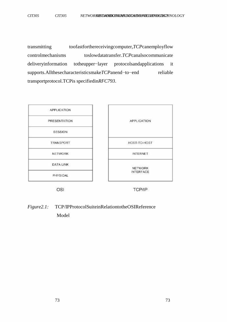
CIT305 NETWORKINGANDCOMMUNICATIONTECHNOLOGY CIT305 NETWORKINGANDCOMMUNICATIONTECHNOLOGY
73 73
transmitting toofastforthereceivingcomputer,TCPcanemployflow
controlmechanisms toslowdatatransfer.TCPcanalsocommunicate
deliveryinformation totheupper−layer protocolsandapplications it
supports.AllthesecharacteristicsmakeTCPanend−to−end reliable
transportprotocol.TCPis specifiedinRFC793.
Figure2.1: TCP/IPProtocolSuiteinRelationtotheOSIReference
Model
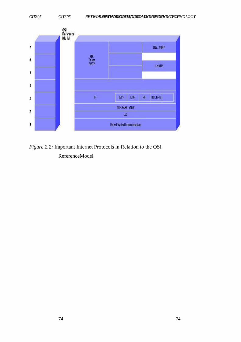
CIT305 NETWORKINGANDCOMMUNICATIONTECHNOLOGY CIT305 NETWORKINGANDCOMMUNICATIONTECHNOLOGY
74 74
Figure 2.2: Important Internet Protocols in Relation to the OSI
ReferenceModel
CIT305 NETWORKINGANDCOMMUNICATIONTECHNOLOGY CIT305 NETWORKINGANDCOMMUNICATIONTECHNOLOGY
75 75
3.1.1 InternetProtocol(IP)
IPistheprimarylayer3protocol intheinternetsuite.Inaddition to
internetworkrouting,IPprovideserrorreportingandfragmentationand re-
assemblyofinformationunitscalleddatagramsfortransmissionover
networkswithdifferentmaximumdataunitsizes. IPrepresentstheheart
oftheinternetprotocolsuite(note: thetermIPinthesectionrefersto
IPv4unlessotherwisestatedexplicitly).
IPaddresses aregloballyunique,32−bitnumbersassignedbythe network
information center.GloballyuniqueaddressespermitIP
networksanywhereintheworldtocommunicatewitheachother.AnIP
addressisdividedintotwoparts.Thefirstpartdesignates thenetwork address
while the second part designates the host address. The IP addressspaceis
dividedintodifferentnetworkclasses.ClassA networks
areintendedmainlyforusewithafewverylargenetworks,because
theyprovideonly8bitsforthenetworkaddressfield.ClassBnetworks
allocate16bits,andClassCnetworks allocate24bitsforthenetwork address
field.ClassCnetworksonlyprovide8bitsforthehostfield
however,sothenumberofhostspernetworkmaybealimitingfactor.
Inallthreecases,theleftmostbit(s)indicatethenetwork class.IP addresses
arewrittenindotteddecimalformat;forexample,34.0.0.1.
Figure2.3belowshowstheaddress formatsforClassA,B,andCIP networks.
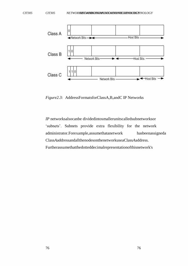
CIT305 NETWORKINGANDCOMMUNICATIONTECHNOLOGY CIT305 NETWORKINGANDCOMMUNICATIONTECHNOLOGY
76 76
Figure2.3: AddressFormatsforClassA,B,andC IP Networks
IP networksalsocanbe dividedintosmallerunitscalledsubnetworksor
‗subnets‘. Subnets provide extra flexibility for the network
administrator.Forexample,assumethatanetwork hasbeenassigneda
ClassAaddressandallthenodesonthenetworkuseaClassAaddress.
Furtherassumethatthedotteddecimalrepresentationofthisnetwork's
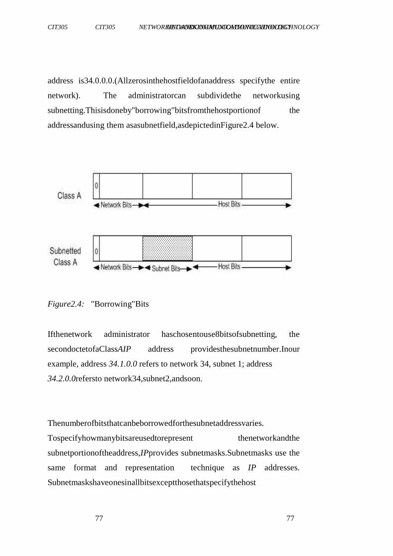
CIT305 NETWORKINGANDCOMMUNICATIONTECHNOLOGY CIT305 NETWORKINGANDCOMMUNICATIONTECHNOLOGY
77 77
address is34.0.0.0.(Allzerosinthehostfieldofanaddress specifythe entire
network). The administratorcan subdividethe networkusing
subnetting.Thisisdoneby"borrowing"bitsfromthehostportionof the
addressandusing them asasubnetfield,asdepictedinFigure2.4 below.
Figure2.4: "Borrowing"Bits
Ifthenetwork administrator haschosentouse8bitsofsubnetting, the
secondoctetofaClassAIP address providesthesubnetnumber.Inour
example, address 34.1.0.0 refers to network 34, subnet 1; address
34.2.0.0refersto network34,subnet2,andsoon.
Thenumberofbitsthatcanbeborrowedforthesubnetaddressvaries.
Tospecifyhowmanybitsareusedtorepresent thenetworkandthe
subnetportionoftheaddress,IPprovides subnetmasks.Subnetmasks use the
same format and representation technique as IP addresses.
Subnetmaskshaveonesinallbitsexceptthosethatspecifythehost

CIT305 NETWORKINGANDCOMMUNICATIONTECHNOLOGY CIT305 NETWORKINGANDCOMMUNICATIONTECHNOLOGY
78 78
field.Forexample,thesubnet maskthatspecifies8bitsof subnettingfor
ClassAaddress34.0.0.0is255.255.0.0.Thesubnetmaskthatspecifies
16bitsofsubnettingforClassA address34.0.0.0is 255.255.255.0.Both
ofthesesubnetmasksarepicturedinFigure2.5below.Subnetmasks canbe
passedthroughanetworkondemandso thatnewnodescanlearn
howmanybitsof subnettingarebeingusedontheirnetwork.
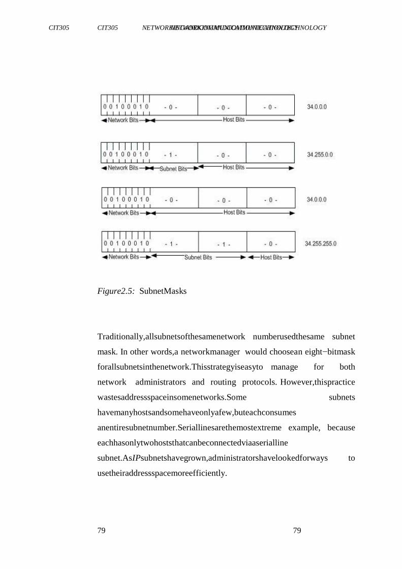
CIT305 NETWORKINGANDCOMMUNICATIONTECHNOLOGY CIT305 NETWORKINGANDCOMMUNICATIONTECHNOLOGY
79 79
Figure2.5: SubnetMasks
Traditionally,allsubnetsofthesamenetwork numberusedthesame subnet
mask. In other words,a networkmanager would choosean eight−bitmask
forallsubnetsinthenetwork.Thisstrategyiseasyto manage for both
network administrators and routing protocols. However,thispractice
wastesaddressspaceinsomenetworks.Some subnets
havemanyhostsandsomehaveonlyafew,buteachconsumes
anentiresubnetnumber.Seriallinesarethemostextreme example, because
eachhasonlytwohoststhatcanbeconnectedviaaserialline
subnet.AsIPsubnetshavegrown,administratorshavelookedforways to
usetheiraddressspacemoreefficiently.
CIT305 NETWORKINGANDCOMMUNICATIONTECHNOLOGY CIT305 NETWORKINGANDCOMMUNICATIONTECHNOLOGY
80 80
Oneofthetechniquesofsubnetting iscalledVariableLengthSubnet
Masks(VLSM).WithVLSM,anetworkadministrator canusealong
maskonnetworkswithfewhostsandashortmaskonsubnetswith
manyhosts.However,thistechniqueis morecomplexthanmakingthem
allonesize;andaddressesmustbe assignedcarefully.
OfcourseinordertouseVLSM,anetwork administrator mustusea
routingprotocolthatsupportsit.CiscorouterssupportVLSM withOpen
ShortestPathFirst(OSPF),IntegratedIntermediate Systemto Intermediate
System (IntegratedIS−IS),EnhancedInteriorGateway
RoutingProtocol(EnhancedIGRP),andstaticrouting.Onsomemedia,
suchasIEEE802LANs,IPaddressesaredynamically discovered
throughtheuseoftwoothermembers oftheinternetprotocolsuite:
AddressResolution Protocol(ARP)andReverseAddressResolution
Protocol (RARP). ARP uses broadcast messages to determine the
CIT305 NETWORKINGANDCOMMUNICATIONTECHNOLOGY CIT305 NETWORKINGANDCOMMUNICATIONTECHNOLOGY
81 81
hardware(MAClayer)addresscorresponding toaparticular network−layer
address.ARPissufficientlygenerictoallowuseofIP
withvirtuallyanytypeofunderlying mediaaccessmechanism.RARP
usesbroadcastmessagestodeterminethenetwork−layer address associated
withaparticularhardwareaddress.RARP isespecially
importanttodisklessnodes,forwhichnetwork−layer addressesusually
areunknownat boottime.
3.2 RoutinginIPEnvironments
Aninternetisagroupofinterconnected networks.Theinternet,onthe
otherhand,isthecollection ofnetworksthatpermitscommunication
betweenmostresearchinstitutions, universities, andmanyother
organisations around the world. Routers within the internet are
organised hierarchically.Someroutersareusedtomoveinformation
throughoneparticular groupofnetworks under thesameadministrative
authorityandcontrol.(Suchanentityiscalledanautonomous system.)
Routersusedforinformation exchangewithinautonomous systemsare
calledinterior routers,andtheyuseavarietyofInterior Gateway
Protocols(IGPs)toaccomplish thisend.Routersthatmoveinformation
betweenautonomous systemsarecalledexteriorrouters;theyusethe
ExteriorGatewayProtocol(EGP)or BorderGatewayProtocol(BGP).
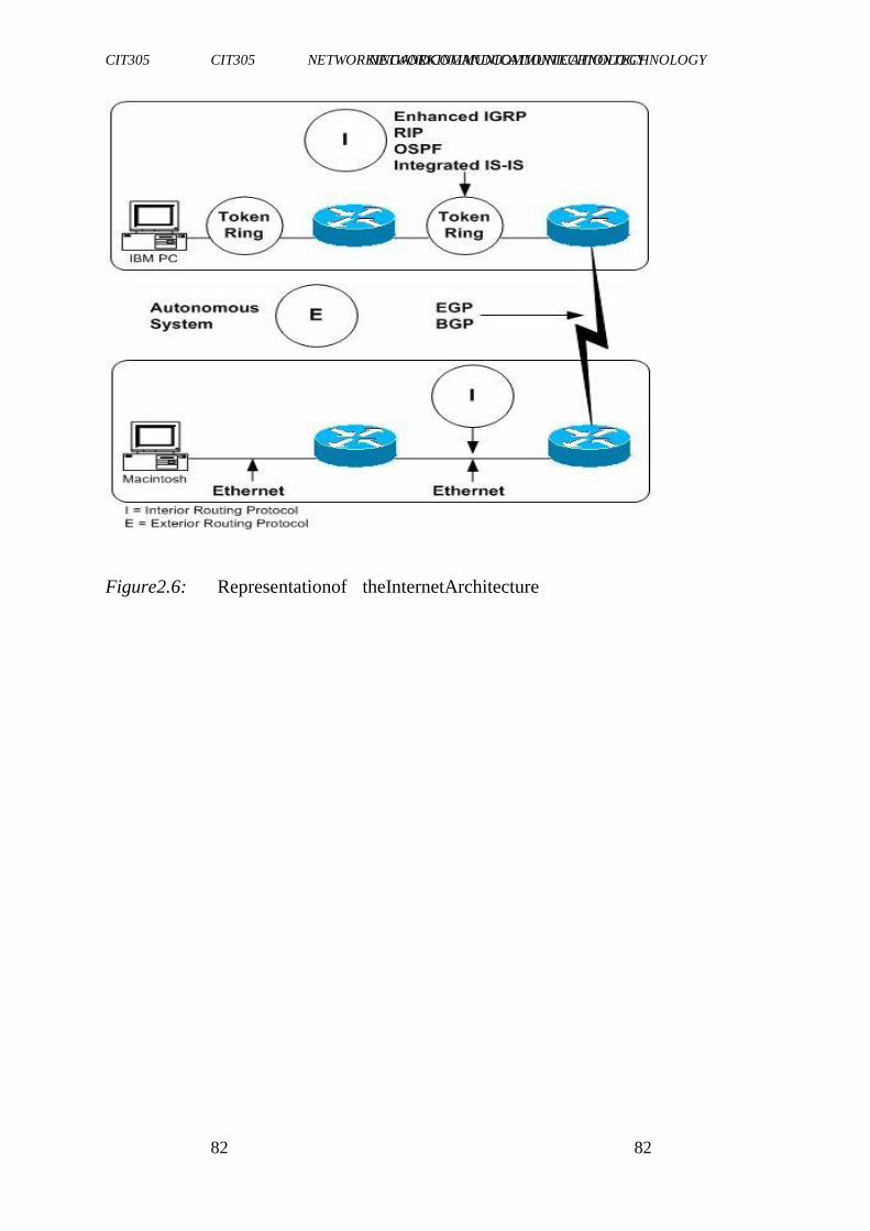
CIT305 NETWORKINGANDCOMMUNICATIONTECHNOLOGY CIT305 NETWORKINGANDCOMMUNICATIONTECHNOLOGY
82 82
Figure2.6: Representationof theInternetArchitecture
CIT305 NETWORKINGANDCOMMUNICATIONTECHNOLOGY CIT305 NETWORKINGANDCOMMUNICATIONTECHNOLOGY
83 83
RoutingprotocolsusedwithIParedynamicinnature.Dynamicrouting
requiresthesoftwareintheroutingdevicestocalculateroutes.Dynamic
routingalgorithmsadapttochanges inthenetwork andautomatically
selectthebestroutes.Incontrastwithdynamic routing,staticrouting
callsforroutestobeestablishedbythenetwork administrator.Static
routesdonotchangeuntilthenetwork administrator changesthem.IP
routingtablesconsistof destinationaddress/nexthoppairs.
4.0 CONCLUSION
ThisunithastakenyouthroughtheTCP/IPnetworks,itsmodeland
implementationprocedure.
5.0 SUMMARY
In thisunit,youhavelearntthat:
TCPisaconnection−orientedtransportprotocolthatsendsdata
as an unstructuredstreamof bytes
IPistheprimarylayer3protocolintheinternetprotocolsuite
andIPrepresentstheheartof theprotocol
oneofthetechniquesofsubnettingiscalledVariableLength
Subnet Masks(VLSM);withVLSM,anetworkadministratorcan
usealongmask onnetworkswithfewhostsandashortmask on
subnetswithmanyhosts
CIT305 NETWORKINGANDCOMMUNICATIONTECHNOLOGY CIT305 NETWORKINGANDCOMMUNICATIONTECHNOLOGY
84 84
IP networks also can be divided into smaller units called
subnetworksorsubnets.Subnetsprovideextraflexibilityforthe
networkadministrator
routingprotocolsusedwithIParedynamicin nature.
6.0 TUTOR-MARKEDASSIGNMENT
1. Explainthe TCP/IPmodelof networking.
2. Withtheaidof diagram,explaininternetarchitecture.
3. WhatarethedifferencesbetweentheClassA,ClassBandClass
C IPnetworks?
7.0 REFERENCES/FURTHERREADING
"Events in British Telecoms History". Events in British
TelecommsHistory.Archivedfromtheoriginalon2003-04-05.
http://web.archive.org/web/20030405153523/http://www.sigtel.com/tel_
hist_brief.html.RetrievedNovember25,2005.
CIT305 NETWORKINGANDCOMMUNICATIONTECHNOLOGY CIT305 NETWORKINGANDCOMMUNICATIONTECHNOLOGY
85 85
A Brief History of Internet.
http://www.isoc.org/internet/history/brief.shtml.Retrieved2009-
05-28.
Prasad,K.V.(2009).PrinciplesofDigitalCommunicationSystemsand
ComputerNetworks.DreamtechPress.
CIT305 NETWORKINGANDCOMMUNICATIONTECHNOLOGY CIT305 NETWORKINGANDCOMMUNICATIONTECHNOLOGY
86 86
UNIT3 NETWORKSTANDARDS(IEEE802
STANDARDS)
CONTENTS
1.0 Introduction
2.0 Objectives
3.0 MainContent
3.1 OverviewofIEEE802
4.0 Conclusion
5.0 Summary
6.0 Tutor-MarkedAssignment
7.0 References/FurtherReading
1.0 INTRODUCTION
IEEE802referstoafamilyofIEEEstandardsdealingwithlocalarea
networksandmetropolitanareanetworks.
2.0 OBJECTIVES
At theendof thisunit,youshouldbeableto:
CIT305 NETWORKINGANDCOMMUNICATIONTECHNOLOGY CIT305 NETWORKINGANDCOMMUNICATIONTECHNOLOGY
87 87
statewhattheIEEE802standardstandsfor
explainthevariousIEEE802standardsandtheirdescriptions.
3.0 MAINCONTENT
3.1 OverviewofIEEE802
Specifically, theIEEE802standards arerestricted tonetworkscarrying
variable-sizepackets. (By contrast, in cell relay networks, data are
transmittedin short, uniformlysized units called cells. Isochronous
networks,wheredataistransmitted asasteadystream ofoctets,or
groupsofoctets,atregulartimeintervals,arealsooutofthescopeof
thisstandard).Thenumber 802wassimplythenextfreenumberIEEE
couldassign,though―802‖issometimesassociatedwiththedatethe
firstmeetingwasheld—February1980.
Theservicesandprotocols specified inIEEE802maptothelowertwo
layers(datalinkandphysical)oftheseven-layer OSInetworking
referencemodel.In fact,IEEE802splitstheOSIdatalinklayerintotwo sub-
layers named Logical Link Control (LLC) and Media Access
Control(MAC),so thatthelayerscanbe listedlikethis:
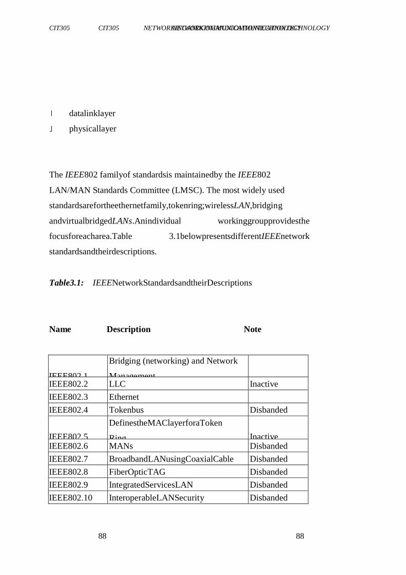
CIT305 NETWORKINGANDCOMMUNICATIONTECHNOLOGY CIT305 NETWORKINGANDCOMMUNICATIONTECHNOLOGY
88 88
datalinklayer
physicallayer
The IEEE802 familyof standardsis maintainedby the IEEE802
LAN/MAN Standards Committee (LMSC). The most widely used
standardsarefortheethernetfamily,tokenring;wirelessLAN,bridging
andvirtualbridgedLANs.Anindividual workinggroupprovidesthe
focusforeacharea.Table 3.1belowpresentsdifferentIEEEnetwork
standardsandtheirdescriptions.
Table3.1: IEEENetworkStandardsandtheirDescriptions
Name Description Note
IEEE802.1
Bridging (networking) and Network
Management
IEEE802.2 LLC Inactive
IEEE802.3 Ethernet
IEEE802.4 Tokenbus Disbanded
IEEE802.5
DefinestheMAClayerforaToken
Ring
Inactive IEEE802.6 MANs Disbanded
IEEE802.7 BroadbandLANusingCoaxialCable Disbanded
IEEE802.8 FiberOpticTAG Disbanded
IEEE802.9 IntegratedServicesLAN Disbanded
IEEE802.10 InteroperableLANSecurity Disbanded
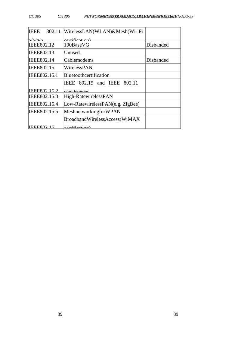
CIT305 NETWORKINGANDCOMMUNICATIONTECHNOLOGY CIT305 NETWORKINGANDCOMMUNICATIONTECHNOLOGY
89 89
IEEE 802.11
a/b/g/n
WirelessLAN(WLAN)&Mesh(Wi- Fi
certification)
IEEE802.12 100BaseVG Disbanded
IEEE802.13 Unused
IEEE802.14 Cablemodems Disbanded
IEEE802.15 WirelessPAN
IEEE802.15.1 Bluetoothcertification
IEEE802.15.2
IEEE 802.15 and IEEE 802.11
coexistence
IEEE802.15.3 High-RatewirelessPAN
IEEE802.15.4 Low-RatewirelessPAN(e.g. ZigBee)
IEEE802.15.5 MeshnetworkingforWPAN
IEEE802.16
BroadbandWirelessAccess(WiMAX
certification)
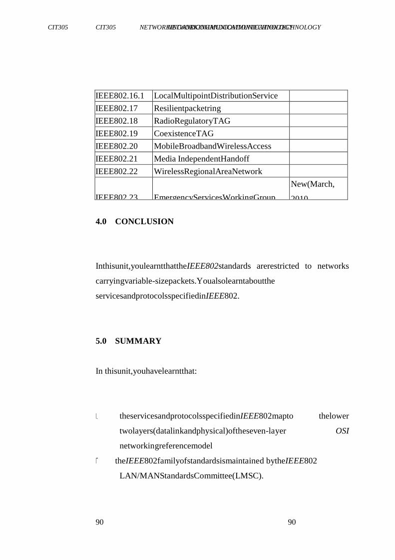
CIT305 NETWORKINGANDCOMMUNICATIONTECHNOLOGY CIT305 NETWORKINGANDCOMMUNICATIONTECHNOLOGY
90 90
IEEE802.16.1 LocalMultipointDistributionService
IEEE802.17 Resilientpacketring
IEEE802.18 RadioRegulatoryTAG
IEEE802.19 CoexistenceTAG
IEEE802.20 MobileBroadbandWirelessAccess
IEEE802.21 Media IndependentHandoff
IEEE802.22 WirelessRegionalAreaNetwork
IEEE802.23
EmergencyServicesWorkingGroup
New(March,
2010
4.0 CONCLUSION
Inthisunit,youlearntthattheIEEE802standards arerestricted to networks
carryingvariable-sizepackets.Youalsolearntaboutthe
servicesandprotocolsspecifiedinIEEE802.
5.0 SUMMARY
In thisunit,youhavelearntthat:
theservicesandprotocolsspecifiedinIEEE802mapto thelower
twolayers(datalinkandphysical)oftheseven-layer OSI
networkingreferencemodel
theIEEE802familyofstandardsismaintained bytheIEEE802
LAN/MANStandardsCommittee(LMSC).
CIT305 NETWORKINGANDCOMMUNICATIONTECHNOLOGY CIT305 NETWORKINGANDCOMMUNICATIONTECHNOLOGY
91 91
IEEE802standardsarewidelyusedfortheethernetfamily,token
ring;wirelessLAN,bridgingandvirtualbridgedLANs.
therearevariationsofIEEE802standards.
6.0 TUTOR-MARKEDASSIGNMENT
1. DescribetheimportanceofIEEE802standards.
2. StatealltheworkinggroupoftheIEEE802standardandtheir
description.
7.0 REFERENCES/FURTHERREADING
TheIEEEstandardSourcebook.
"TheFirstNetworkEmail".TheFirstNetworkEmail.
http://openmap.bbn.com/~tomlinso/ray/firstemailframe.html. Retrieved
December23,2005.
CIT305 NETWORKINGANDCOMMUNICATIONTECHNOLOGY CIT305 NETWORKINGANDCOMMUNICATIONTECHNOLOGY
92 92
UNIT4 IMPLEMENTINGSECURITYBEST
PRACTICES
CONTENTS
1.0 Introduction
2.0 Objectives
3.0 MainContent
3.1 Overviewof BestNetworkSecurity
3.2 StrategiesforBestNetworkSecurity
4.0 Conclusion
5.0 Summary
6.0 Tutor-MarkedAssignment
7.0 References/FurtherReading
1.0 INTRODUCTION
Networksecurity involves maintainingConfidentiality,Integrity and
Availability(CIA)ofnetwork.Confidentiality involvespreventing
unauthoriseddisclosureof resourcesorinformationon thenetwork.
Integritymeanspreventionofunauthorisedmodificationofresourcesor
information on the network. Integrity involves prevention of
unauthoriseddenialof resourcesor informationonthecomputersystem.
CIT305 NETWORKINGANDCOMMUNICATIONTECHNOLOGY CIT305 NETWORKINGANDCOMMUNICATIONTECHNOLOGY
93 93
2.0 OBJECTIVES
At theendof thisunit,youshouldbeableto:
explainwhatnetworksecurityis allabout
statethebestnetworksecurity
highlightthefeaturesof bestsecuritypractices.
3.0 MAINCONTENT
3.1 OverviewofBestNetworkSecurity
Efficientnetwork securityisneededforcorporations,universities,
schools,publiclibraries,internetcafesand otherapplicationswhere
administrator hastosecureandmaintainalotofnetwork workstations
locatedindifferentplaces.Administratordoesnotneedtophysically visit
workstationsto change security settings or install patches. An
efficientnetworksecurityprogrammeisneeded forsecuring, protecting,
andmaintainingPCworkstationswithina corporatenetwork.There
existnetwork-basedpassword-protectedsecuritysoftwarethatallows
youtocompletelysecureworkstationsoveryournetworkaswellas
CIT305 NETWORKINGANDCOMMUNICATIONTECHNOLOGY CIT305 NETWORKINGANDCOMMUNICATIONTECHNOLOGY
94 94
maintainthembyuploading andinstallinganyexecutablepatches
remotely.Theysupporttonsofsecurityrestrictions, optionsandtweaks to
controlaccessto everybitof windows.
Youcandenyaccesstoeachindividualcomponent ofseveralcontrol
panelapplets,including display,network,passwords,printers,system
andinternet options; disablethebootkeys,contextmenus,Disk Operating
System (DOS) windows, registry editing, internet and
networkaccess.Youcanalsohidedesktopicons,individualdrives,start
menuitems,andtaskbar;applypasswordprotection towindowsand
restrictusersto runningspecificapplicationsonly,controlinternetusage
andmuchmore.Intotal,bestnetwork securitysupportsover600
differentsecurity restrictions,optionsand tweaks that allowyou to
restrictaccessto almosteverycornerof windows.
Afterinstalling theremoteclientserviceapplicationonyour
workstations,themaintenance becomesabsolutelyhassle-free.Youjust
connectyouradministrator's computertothenetfromanyplaceand
remotelychange securitysettings, upload andexecutepatchesaswellas
schedule reboots,shutdowns, andwindows explorer restartsjustwitha
clickof the mouse.Thebestsolutionfor corporations,universities,
schools,publiclibraries,internet cafesetc.,istouploadandinstallany
executablepatchesremotely,applysecurity restrictions,optionsand
tweaks.Itsupportsover600differentsecurityrestrictions.
There are two main types of network security that must be addressed:
Network infrastructure security
Physical security of network devices
CIT305 NETWORKINGANDCOMMUNICATIONTECHNOLOGY CIT305 NETWORKINGANDCOMMUNICATIONTECHNOLOGY
95 95
Preventing unauthorized access to the management software on
those devices
Information Security
Protection of the information or data transmitted over the network
Goals of network security
There are three main goals of network security:
i. Confidentiality – only intended recipients can read the data
ii. Integrity – assurance that the data has not be altered with during transmission
iii. Availability – assurance of timely and reliable access to data for authorized
users
3.2 StrategiesforBestNetworkSecurity
Theten(10)keystrategiesforensuringefficientnetworksecurityare as
listedbelow.
i.
Createsecuritytrainingandawarenessprogrammewithintheorgan
isation.Letthepersonnelin yourorganisationbe awareof:
emergingthreats
possibleconsequencesof asinglesecuritybreach.
securityrequirement
CIT305 NETWORKINGANDCOMMUNICATIONTECHNOLOGY CIT305 NETWORKINGANDCOMMUNICATIONTECHNOLOGY
96 96
Theremustberegularsecuritytraining.Collaborationswithothercyber
securityorganisationsarealsonecessary.
ii. Haveanefficientaccesscontrolsystem
Inordertocontrolinsiderthreats,theremustbecleardefinition ofroles
andresponsibilities inorganisations.Efficientauthorisationsystem
shouldbe implementedin orderto limittheactivitiesof personnel.
CIT305 NETWORKINGANDCOMMUNICATIONTECHNOLOGY CIT305 NETWORKINGANDCOMMUNICATIONTECHNOLOGY
97 97
iii. Implement trusted and efficient intrusion prevention
anddetectionsystems
Toeffectively presentcyberattacks,atrustedandadaptiveintrusion
prevention anddetectionsystemmustbeimplemented.Nowadays,itis
alsonecessaryto implementintrusionforecastingsystem.
iv. Identifyanddocumentallresourcesonthenetwork
All categoriesof resourcesonthenetworkmustbe welldocumentedand
theirstatusmonitoredandreported.
v.
Allconnectionstothenetworkmustbeknown,documentedandmonito
red
Identifyandmonitorallconnections (cable,wireless,localorinternet)
andensurethattheseconnections arewellprotected.Allunwantedor
unnecessaryconnectionsshouldbe disconnected.
vi. Haveaneffectiveprogrammefortheriskanalysisandincidentbuilding
Aperiodicandthoroughanalysisofpotentialriskstonetworkresources
andvulnerability assessmentisanessentialrequirementforeffective
cybersecuritymanagement.
vii. Preventunknownapplications
CIT305 NETWORKINGANDCOMMUNICATIONTECHNOLOGY CIT305 NETWORKINGANDCOMMUNICATIONTECHNOLOGY
98 98
Implementstrategiesthatdisallowanyunknownapplicationtorunon
yoursystem.
viii. Usesecurityapplicationsfromreliablevendors
Trustedsecuritytoolsfromknownvendorsshould beused.Thevendors
mustimplementsecurityfeaturesin formof patchesandupgrades.
ix. Establisheffectiveconfigurationmanagementprocesses
Sincechangesinhardwareandsoftwareconfigurations canintroduce
vulnerabilities,anassessment ofthesecurityimplicationsofallchanges
shouldbe carriedout.
x. Ensureperiodicevaluationofallsecurityapparatus
Organisations should ensure periodic testing and evaluation of all
securityapparatus.
CIT305 NETWORKINGANDCOMMUNICATIONTECHNOLOGY CIT305 NETWORKINGANDCOMMUNICATIONTECHNOLOGY
99 99
SELF-ASSESSMENTEXERCISE
Whatdoyouunderstandbycybersecurity?
4.0 CONCLUSION
Thisunitdiscussesthesecurityissuesinanetwork;andyouhavealso
learntaboutthebestsecuritypractices.
5.0 SUMMARY
In thisunit,youhavelearntthat:
networksecurityinvolvesmaintainingconfidentiality,integrity
andavailability(CIA)of network
efficientnetworksecurityis neededforcorporations,universities,
schools,publiclibraries,internet cafesandotherapplications
whereadministrator hastosecureandmaintainalotofnetwork
workstationslocatedin differentplaces.
therearecertain keystrategiesrequiredforensuringbestnetwork
securitypractices
6.0 TUTOR-MARKEDASSIGNMENT
CIT305 NETWORKINGANDCOMMUNICATIONTECHNOLOGY CIT305 NETWORKINGANDCOMMUNICATIONTECHNOLOGY
100 100
1. Whydoweneedto protectanetwork?
2. Describehowthenetworkwithinyourorganisationis protected.
7.0 REFERENCES/FURTHERREADING
http://www.azimuthsystems.com/
NASA Successfully Tests First Deep Space Internet. NASA media
release08-298,November18,2008Archived.
CIT305 NETWORKINGANDCOMMUNICATIONTECHNOLOGY CIT305 NETWORKINGANDCOMMUNICATIONTECHNOLOGY
101 101
MODULE3 ENTERPRISENETWORK
Unit1 CreatingEnterpriseNetwork
Unit2 PlanningandSelectionof EnterpriseNetwork
Unit3 LANandWAN
UNIT1 CREATINGENTERPRISENETWORK
CONTENTS
1.0 Introduction
2.0 Objectives
3.0 MainContent
3.1 Overviewof EnterpriseNetwork
3.2 PredefinedEnterpriseNetwork
3.2.1 ResidualNetworks
3.4 Threatto EnterpriseNetwork
3.4.1TypesofThreat
4.0 Conclusion
5.0 Summary
6.0 Tutor-MarkedAssignment
7.0 References/FurtherReading
1.0 INTRODUCTION
CIT305 NETWORKINGANDCOMMUNICATIONTECHNOLOGY CIT305 NETWORKINGANDCOMMUNICATIONTECHNOLOGY
102 102
Thisunitintroducesyoutoenterprisenetwork. Anenterprisenetworkis used
to connect computers and other digital equipment of an
organisationtogether.
2.0 OBJECTIVES
At theendof thisunit,youshouldbeableto:
explainenterprisenetwork
describepredefinedenterprisenetwork.
3.0 MAINCONTENT
3.1 OverviewofEnterpriseNetwork
Anenterpriseprivatenetwork isanetworkbuiltbyanenterpriseto
interconnectvariouscompanysites,e.g.,production sites,headoffices,
remoteoffices,shops, inordertosharecomputer resources.Enterprise
networksareusedforconfiguringaccessrulesinanenterprisepolicy
CIT305 NETWORKINGANDCOMMUNICATIONTECHNOLOGY CIT305 NETWORKINGANDCOMMUNICATIONTECHNOLOGY
103 103
thatcanbeappliedtoanyarrayintheenterprise andforconfiguring
enterprisenetwork rulesthatapplytoallarraysintheenterprise.Only
enterprisenetworkscanbeusedtocreateenterprise-level rules.
Enterprisenetworkscanalsobeusedfordefiningarray-levelaccessand
publishing rulesandfordefiningarray-levelnetworkrules.However, you
cannot use array-level networks when creating enterprise-level rules.
Anynumberofuser-definedenterprisenetworkscanalsobeincludedin
anetworkdefinedin anarraybyincludingreferencesto them. An
enterprisenetworkwhichitssetofIP addressrangecorrespondsexactly
totheIPaddresses includedinaprotected array-levelnetwork,such as
theInternalnetwork,definedinonearraycanbeusedtoreference that
networkin alltheotherarraysof theenterprise.
When you configure enterprise networks, you specify only the IP
addressrangesanddonotspecifyanyoftheotherproperties thatyou would
define for array-level networks. In particular, you cannot
configureNetworkLoadBalancing orCacheArrayRoutingProtocol
(CARP)foran enterprisenetwork.
TheIPaddressesthatareincludedinan enterprisenetworkareexcluded
fromthedefaultexternalnetworkineacharrayintheenterprise,evenif
theenterprisenetwork isnotincludedinanynetworkdefinedinthe array.
3.2 PredefinedEnterpriseNetworks
CIT305 NETWORKINGANDCOMMUNICATIONTECHNOLOGY CIT305 NETWORKINGANDCOMMUNICATIONTECHNOLOGY
104 104
Thefollowing predefinedenterprisenetworksarecreatedupon installation:
External
LocalHost
QuarantinedVPNClients
VPNClients
These predefinedenterprisenetworks implicitlydefine the same IP
addresssets as theirarray-levelcounterparts.Theycan be usedfor
definingrulesin an enterprisepolicyandfordefiningenterprisenetwork
rules.Whenanenterprisepolicy isassignedtoanarray,eachpredefined
enterprise network in a rule will be interpreted as the array-level
network ofthesamename.Forexample,youcancreateanenterprise
accessrulethatappliestorequestssentto thelocalhostenterprise
network.Whenarequestishandled inanarraytowhichtheenterprise
policycontainingthisaccessruleisassigned,therulewillapplytothe
CIT305 NETWORKINGANDCOMMUNICATIONTECHNOLOGY CIT305 NETWORKINGANDCOMMUNICATIONTECHNOLOGY
105 105
IP addressesinthelocalhostnetworkonthearraymemberhandlingthe
request.
3.2.1 ResidualNetworks
IPaddressesthatbelongtoaconfigurableenterprisenetwork,butdonot
belongto anyconfigurablearray-levelnetworkareconsideredtobepart of
aresidualnetwork.
3.4 ThreattoEnterpriseNetwork
Today,thereisanever-growing dependencyoncomputernetworksfor
businesstransactions.Withthefreeflowofinformation andthehigh
availability ofmanyresources,managersofenterprisenetworkshaveto
understand allthepossiblethreatstotheirnetworks.Thesethreatstake
manyforms,butallresultinlossof privacytosomedegreeandpossibly
maliciousdestructionofinformation orresourcesthatcanleadtolarge
monetarylosses.
3.4.1 TypesofThreat
Listedbelowaresomecommontypesofthreats-especially when the
enterprisenetworkis connectedto theinternet.
a. Insiderthreats
CIT305 NETWORKINGANDCOMMUNICATIONTECHNOLOGY CIT305 NETWORKINGANDCOMMUNICATIONTECHNOLOGY
106 106
An insider attack involves someone from the inside, such as a
disgruntledemployee,attacking thenetwork. Insiderattackscanbe
maliciousornotmalicious.Maliciousinsidersintentionally eavesdrop,
steal,or damageinformation;useinformationin afraudulentmanner;or
denyaccessto otherauthorisedusers.Thiscanbecontrolledusing
efficientauthenticationandauthorisationsystemsandIDS.
b. Malware
Oneofthebiggestthreatstocomputer usersontheinternettodayis
malware.Malwarearemaliciouscodesthatcancausedistortiononyour
browserandeventuallycrippleyoursystem.Theycanhijack your
browser,redirect yoursearchattempts, serveupnastypop-upads,track
whatwebsites you visit, and prevent you fromperformingcertain
functions.Examplesareworm,viruses,Trojanhorse,spyware, adware,
dialers,hijackers,etc.Theyarecontrolled usingfrequently updatedand
highly rated antivirus, antispyware, etc. Efficient management of
patches,SPAM filtersandtwo-wayauthenticationarealsousedfortheir
control.
CIT305 NETWORKINGANDCOMMUNICATIONTECHNOLOGY CIT305 NETWORKINGANDCOMMUNICATIONTECHNOLOGY
107 107
c. Sociallyengineeredattacks
Mosttraditionalsocialengineering attackscapitaliseonthis vulnerability.
Examplesarephishing,pharming,masquerading.General
technicalcontrolssuchasafirewall,internet contentfiltering,antivirus
software,anti-spamsoftware,securityawarenessandpatchmanagement
canhelpreduceor eliminatemanyphishingattacks.
d. Authenticationattacks
Anattackertriestocrackthepasswordsstoredinanetwork account
databaseorapassword-protected file.Examplesincludedictionary,a brute-
force,shouldersurfing,keylogging andhybridattacks.Theyare
controlledusingrobustandmultifactorauthentication andauthorisation
systems.
SELF-ASSESSMENTEXERCISE
Mentionothertypesof threatsthatarenotlistedhere
4.0 CONCLUSION
Thisunithastakenyouthroughtherudimentofenterprisenetwork.It
hasalsointroducedyoutoresidualnetworks.
5.0 SUMMARY
In thisunit,youhavelearntthat:
CIT305 NETWORKINGANDCOMMUNICATIONTECHNOLOGY CIT305 NETWORKINGANDCOMMUNICATIONTECHNOLOGY
108 108
anenterpriseprivatenetworkisanetworkbuiltbyanenterprise to
interconnectvariouscompanysites,e.g., productionsites,head
offices,remote offices,shops,inordertosharecomputer resources.
commontypesof threatsto enterprisenetworkareinsiderattacks,
sociallyengineered,malwareandauthenticationattacks.
predefinedenterprisenetworkareusedfordefiningrulesinan
enterprisepolicyandfordefiningenterprisenetworkrules.
6.0 TUTOR-MARKEDASSIGNMENT
1. Discussthethreetypesof threatto enterprisenetwork.
2. Whatdoyouunderstandbyenterprisenetwork?
7.0 REFERENCES/FURTHERREADING
Abbate,Janet(1999).InventingtheInternet.Cambridge:MIT.
Bemer,Bob,"AHistoryofSourceConceptsfortheInternet/Web".
CIT305 NETWORKINGANDCOMMUNICATIONTECHNOLOGY CIT305 NETWORKINGANDCOMMUNICATIONTECHNOLOGY
109 109
UNIT2 PLANNINGANDSELECTIONOF
ENTERPRISENETWORK
CONTENTS
1.0 Introduction
2.0 Objectives
3.0 MainContent
3.1 Overview
3.2 Stepsto EffectiveNetworkPlanningDesign
4.0 Conclusion
5.0 Summary
6.0 Tutor-MarkedAssignment
7.0 References/FurtherReading
1.0 INTRODUCTION
Thisunitgivesyouanoverviewofnetworkandthestepsinvolvedin
planningandselectingenterprisenetwork.
2.0 OBJECTIVES
At theendof thisunit,youshouldbeableto:
highlighthowtomakeproperplanningforeveryphaseofan
enterprisenetwork
CIT305 NETWORKINGANDCOMMUNICATIONTECHNOLOGY CIT305 NETWORKINGANDCOMMUNICATIONTECHNOLOGY
110 110
explainthedesignphasesin enterprisenetworks.
3.0 MAINCONTENT
3.1 Overview
Networkplanninganddesignmethodologydescribesaprocesswith9
specificstepsandasequenceforthoseactivities.Itis an engineeringlife
cyclethatsupportstechnicalinitiativessuchaswindowsmigration,IP
telephony andwirelessdesign,tonameafewexamples.The
methodologybeginswithexamining companybusinessrequirements.It
isabsolutelyessentialthatyouunderstand thecompanybusinessmodel,
businessdrivers andhowtheyaregrowingfromabusinessperspective.
Thatwillbuildthefoundation foradesignproposalthatservesthe
business,technicalandoperationalrequirementsof thecompany.
CIT305 NETWORKINGANDCOMMUNICATIONTECHNOLOGY CIT305 NETWORKINGANDCOMMUNICATIONTECHNOLOGY
111 111
3.2 StepstoEffectiveNetworkPlanningand Design
Here,letus lookat thefollowingsteps.
Step1- Businessrequirements
Anydesignprojectstartswithanunderstanding ofwhatthecompany
doesandwhattheyneedtoaccomplishfromabusinessperspective.
Thisbeginswithanunderstandingoftheirbusinessmodel,whichreally
describeshowtheircompanyworksfromanoperational andbusiness
perspective togeneraterevenuesandreducecosts.Manyvendorstoday
haveconductedtheirownreturnoninvestment (ROI)studiesfornew
implementationssuchasunifiedcommunicationsandtelephony.Itisan
effectivesalestoolthatillustrates thecostbenefitscompared with
investmentoveraspecifiedperiodof time.
Sometypicalbusinessdriversarelistedbelow.
• Reduceoperatingcosts
• Generaterevenue
• Clientsatisfaction
• Employeeproductivity
Thisis alistof sometypicalprojectbusinessrequirements.
CIT305 NETWORKINGANDCOMMUNICATIONTECHNOLOGY CIT305 NETWORKINGANDCOMMUNICATIONTECHNOLOGY
112 112
Budgetconstraints
Officeconsolidations
Companymergersandacquisitions
Businesspartnerconnectivity
Telecommuterremoteaccess
Newofficesandemployees
Newdatacenterapplications
Reducenetworkoutagecosts
Costeffectivenetworkmanagement
Vendorcontracts
Step2- Designrequirements
Nowthatyouhavelearntthebasicbusinessrequirements ofthe
company,youcandetermine thestandardandspecificdesign
requirements.Thedesignrequirements processisfocusedondefining
requirements fromatechnicalperspective.Thoserequirementsalong
withthebusinessrequirementswillbuildtheframework thatisusedto
defineinfrastructure,securityandmanagement.Designrequirementsare
definedas standardand miscellaneous.Thestandarddesign
requirementsare generic and representthose consideredwith many
CIT305 NETWORKINGANDCOMMUNICATIONTECHNOLOGY CIT305 NETWORKINGANDCOMMUNICATIONTECHNOLOGY
113 113
design projects. Miscellaneous requirements are those that are not
definedwithanyof thestandardrequirements.
Standarddesignrequirementsare:
• performance
• availability
• scalability
• standardscompatibility
• rapiddeployment
Step3- Networkassessment
Anetwork assessmentisconductedafterwehavefinishedthebusiness and
design requirements of the company. A network assessment
providesaquicksnapshotof the current networkwithanexaminationof
theinfrastructure,performance,availability,management andsecurity.
Thatinformationisutilised formaking effectivestrategy
recommendationsanddesignproposalstotheclientconcerning specific
information systems modifications. The network assessment model
hasthree sequential activities, which are- assessment, analysis and
recommendations. Thecurrentnetworkisexaminedusingfiveprimary
surveys,namely-infrastructure, performance,availability,management
andsecurity. Whenthesurveysarecompleted,theinformationcollected
isthenreviewed fortrends,problemsandissuesthatarenegatively
affectingthenetwork.
CIT305 NETWORKINGANDCOMMUNICATIONTECHNOLOGY CIT305 NETWORKINGANDCOMMUNICATIONTECHNOLOGY
114 114
Step4- Infrastructureselection
Afterdoinganetworkassessmentwearereadyto startselectingspecific
infrastructure components for the networkdesign. This phase starts
building theinfrastructure withaspecificsequencethatpromotes
effectiveequipment selectionanddesign.Itisimportantthatyou
considerbusinessrequirements,designrequirements andthenetwork
assessmentwhenbuildingyourinfrastructure.
The following numbered list describes the specific infrastructure
componentsandtheirparticularsequence.
a. EnterpriseWANtopology
b. Campustopology
c. Traffic model
d. Equipmentselection
e. Circuits
f. Routingprotocoldesign g.
Addressing
CIT305 NETWORKINGANDCOMMUNICATIONTECHNOLOGY CIT305 NETWORKINGANDCOMMUNICATIONTECHNOLOGY
115 115
h. Namingconventions
i. IOSServices
j. Domainnameservices k.
DHCPservices
Step5: Securitystrategy
Wemustnowdefineasecuritystrategyforsecuring theinfrastructure.
Theneedforenterprisenetworksecurityshouldnotbeignoredwiththe
proliferationoftheInternet.Companiesarecontinuing toleveragethe
publicinfrastructureforconnecting nationalandinternationaloffices,
businesspartnersandnewcompanyacquisitions. Thesecurity
requirementsandnetworkassessmentrecommendationsshoulddrivethe
selection ofsecurityequipment, protocols andprocesses.Itidentifies
whatassetsmustbeprotected, whatusersareallowed accessandhow
thoseassetswillbe secured.
Step6- Networkmanagementstrategy
Thissectionwilldefineanetworkmanagementstrategyformanaging
allequipmentdefinedfrominfrastructureandsecurity. Itisnecessaryto
definehowtheequipment isgoing tobemonitored anddetermineifthe
currentmanagement strategyisadequateorifnewapplications,
equipment,protocolsandprocessesmustbe identified.Management
componentsarethenintegratedwithinfrastructureandsecuritytofinish
building theproposeddesign.Theseprimaryelementscompriseany well-
CIT305 NETWORKINGANDCOMMUNICATIONTECHNOLOGY CIT305 NETWORKINGANDCOMMUNICATIONTECHNOLOGY
116 116
definedmanagement strategyandshouldbeconsideredwhen
developingyourstrategy.
• Managementgroups
• SNMPapplications
• Monitoreddevicesandevents
Step7- Proofofconcept
Allinfrastructure, securityandmanagementcomponentsmustnowbe
testedwithaproofofconceptplan.Itisimportant totestthecurrent
design,configurationandIOSversionsinanon-productionenvironment
orontheproductionnetworkwithlimiteddisruption.Implementationof
newernetworkmodules atarouter,forinstance,couldrequirethatyou
changethecurrentIOSversionthatisimplemented.Making those
changescanaffectWANorcampusmodules alreadyinstalled at
productionrouters.Thatis therealvalueof doingaproofof conceptand
certifying thatthenewequipmentandIOSversionsintegratewitheach device
as well as the network. The following list describes the
advantagesofdoingaproofofconceptwithyournetworkdesign. The
CIT305 NETWORKINGANDCOMMUNICATIONTECHNOLOGY CIT305 NETWORKINGANDCOMMUNICATIONTECHNOLOGY
117 117
proofofconcepttestresultsshouldbeexamined andusedtomodify
currentinfrastructure,securityandmanagementspecifications before
generatingadesignproposal.Theproofofconceptmodelsuggested
hereinvolvesprototypedesign,equipmentprovisioning,defining tests,
buildingequipmentscriptsandexaminingtestresults.
1. Prototypedesign
2. Provisionof equipment
3. Definetests
4. Buildequipmentscripts
5. Reviewtestresults
Step8- Designproposal/review
Withtheproofofconcept finished,youarenowreadytobuildadesign
proposalforthedesignreviewmeeting.Yourintendedaudiencecould be the
Director, CIO, CTO, Seniornetwork engineer, Consultantor
anyonethatisapproving abudgetfortheproject.Itisimportantto
presentyourideaswithclarityandprofessionalism.Ifapresentation is
required,Powerpoint slidesworkwellandcouldbeusedtosupport
conceptsfrom thedesignproposaldocument.Thefocusisonwhat
comprisesastandarddesignproposalandthesequenceforpresenting
thatinformation.
CIT305 NETWORKINGANDCOMMUNICATIONTECHNOLOGY CIT305 NETWORKINGANDCOMMUNICATIONTECHNOLOGY
118 118
Theworking designproposalispresentedtotheclientafteraddressing any
concerns from proof of concept assurance testing. The design
reviewisanopportunity foryoutopresent yourdesignproposaltothe
clientand discussany issues. It is an opportunityfor the clientto
identifyconcernstheyhaveandforthedesignengineertoclarify issues. The
focus is to agree on any modifications,if required, and make
changestotheinfrastructure,security andmanagement before
implementation starts.Businessanddesignrequirementscanchange
fromwhentheprojectstartedwhichsometimes willnecessitate changes
toinfrastructure,securityandmanagement specifications.Anychanges
should then go through proof of concept testingagain before final
changesto thedesignproposal.
Step9- Implementation
Thefinalstepentailsdefininganimplementation processforthe specified
design.Thisdescribes asuggestedimplementation methodology
oftheproposeddesign,whichshouldhaveminimal
disruptiontotheproductionnetwork.Aswellitshouldbeefficientand
ascosteffectiveaspossible.Aswithpreviousmethodologies thereisa
sequencethatshouldbe utilisedas well.
CIT305 NETWORKINGANDCOMMUNICATIONTECHNOLOGY CIT305 NETWORKINGANDCOMMUNICATIONTECHNOLOGY
119 119
Oncetheimplementationis finished,thenetworkhasto be monitoredto
checkmate problemswhichmayarise.Designandconfiguration
modificationsarethenmadeto addressanyproblemsor concerns.
SELF-ASSESSMENTEXERCISE
A manufacturing company is interested in setting up a network.
Describe howyouwillcarryoutnetworkplanning anddesignforthe
organisation.
4.0 CONCLUSION
Inthisunit,youhavelearntthenecessary stepstoconsiderin implementingan
enterprisenetwork.
5.0 SUMMARY
In thisunit,youhavelearntthat:
network planning and design methodology is an important
activitytowardshavingan efficientnetwork
networkplanninganddesign involveninespecificsteps,namely-
identification of business requirements, design requirements,
CIT305 NETWORKINGANDCOMMUNICATIONTECHNOLOGY CIT305 NETWORKINGANDCOMMUNICATIONTECHNOLOGY
120 120
network assessment,infrastructureselection, security strategy,
networkmanagement strategy,proofofconceptand implementation.
6.0 TUTOR-MARKEDASSIGNMENT
1. Whatarethepossibleconsequencesoflackofeffectivenetwork
planning?
2. Stateandexplainthephasesinvolvedincreatinganenterprise network
7.0 REFERENCES/FURTHERREADING
Krol,Ed.(1992).WholeInternetUser's
GuideandCatalog.O'Reilly&Associates,1992.
ScientificAmericanSpecialIssueonCommunications,Computers,and
Networks,September,1991.
http://www.eBookmall.com
Prasad,K.V.(2009).―PrinciplesofDigitalCommunicationSystems
andComputerNetworks‖,DreamtechPress.
CIT305 NETWORKINGANDCOMMUNICATIONTECHNOLOGY CIT305 NETWORKINGANDCOMMUNICATIONTECHNOLOGY
121 121
UNIT3 LOCALAREANETWORK(LAN)ANDWIDE
AREANETWORK(WAN)
CONTENTS
1.0 Introduction
2.0 Objectives
3.0 MainContent
3.1 UnderstandingWANandLAN
3.2 DifferencebetweenLANandWAN
4.0 Conclusion
5.0 Summary
6.0 Tutor-MarkedAssignment
7.0 References/FurtherReading
1.0 INTRODUCTION
Computersnetworkedtogetherinaself-contained groupformaLocal
AreaNetwork orLAN.ALANtypicallyiscontainedwithinasingle
buildingoragroupofneighbouring buildings.Twocomputerslinked
togetherat homeare the simplestformof a LAN. Severalhundred
computerscabledtogetheracrossseveralbuildingsatschoolforma
morecomplexLAN.LANsareusuallyconnected withcoaxialorCAT5 cable.
Ontheotherhand,aWANisgeographically large.Itisoftenformedby
thejoining togetherofLANsindistantplaces.Anationalbanking
CIT305 NETWORKINGANDCOMMUNICATIONTECHNOLOGY CIT305 NETWORKINGANDCOMMUNICATIONTECHNOLOGY
122 122
organisation,forexample,mayuseaWANtoconnectallofitsbranches
acrossthecountry.Thedifference betweenLANsandWANsisgetting
blurryasfibreopticcableshaveallowedLANtechnologies toconnect
devicesmanykilometers apart.WANsareusuallyconnected using the
internet,ISDNlandlinesor satellite.
2.0 OBJECTIVES
At theendof thisunit,youshouldbeableto:
discussthebackgroundofLANandWAN
explainthedifferencesbetweenLANandWAN
statetherelationshipbetweenLANandWAN.
CIT305 NETWORKINGANDCOMMUNICATIONTECHNOLOGY CIT305 NETWORKINGANDCOMMUNICATIONTECHNOLOGY
123 123
3.0 MAINCONTENT
3.1 UnderstandingWANandLAN
ALocalAreaNetwork(LAN)existsinahouseorauniversitycampus,
whileaWideAreaNetwork(WAN)existsacrossmanyofficebuildings
separated byavastdistance.Theofficebuildings inaWANmaybein
differentcountries orevencontinents. Forexample,theheadquarters
buildingmaybe inUSA,theregionalofficebuildingmaybeinUK,and
thebranchofficebuilding maybeinIndia.Theworkers inthethree
buildingscanuseWANtocollaboratewithoneanother.Theinternetcan alsobe
consideredas aWAN.
3.2 DifferencesbetweenLANandWAN
Oneofthedifferences betweenLANandWAN,isthespeedofthe
network.ThemaximumspeedofaLANcanbe10megabitspersecond,
whilethespeedofaWANcangoupto150megabits persecond.This
meansthespeedofaWAN,isone-tenthofthespeedofaLAN.AWAN is
usuallyslowerbecauseithaslowerbandwidth.
ComputersinaLANcanshareaprinter,iftheyareallinthesameLAN.
Ontheotherhand,aWANcannot shareaprinter,soacomputerinone country
cannotuseaprinterinanother country.ALANdoesnotneeda
dedicatedcomputer todirecttraffictoandfromtheinternet,unlikea
CIT305 NETWORKINGANDCOMMUNICATIONTECHNOLOGY CIT305 NETWORKINGANDCOMMUNICATIONTECHNOLOGY
124 124
WANthatneedsaspecial-purpose computer,whoseonlypurposeisto
sendandreceivedatafromtheinternet.
AnotherbasisforcomparingLANandWANisthecostof thenetwork.A
WANismoreexpensive thanaLAN.ItiseasiertoexpandaLANthana
WAN.Theequipment neededforaLANisaNetworkInterfaceCard
(NIC),aswitchandahub.Ontheotherhand,theequipment neededto
connectaWANto theinternetis amodemandarouter.Themodemmay
beacablemodemoraDSLmodemthatisconnectedtoawalljack,
whiletheroutershouldbeconfigured sothatitcanhandlethepackets
travelingbetweenthe WANandtheinternet.
Also,betweenLANandWAN,thereisadifference inthenetworking
standardused.ALANusestheethernetstandard,whileaWANusesthe
t1standard.Beforeethernet,theprotocols usedforLANwereAttached
ResourceComputerNetwork (ARCNET)andtokenring.Theprotocols used
for WAN are frame relay and Asynchronous Transfer Mode
(ATM).AnotherprotocolforWANisPacketOverSONET/SDH(POS),
whereSONETstandsforSynchronousOpticalNetworking andSDH
standsforSynchronous DigitalHierarchy.ThefirstWANprotocolwas
x.25,whileanadvancedWANprotocolismultiprotocollabelswitching
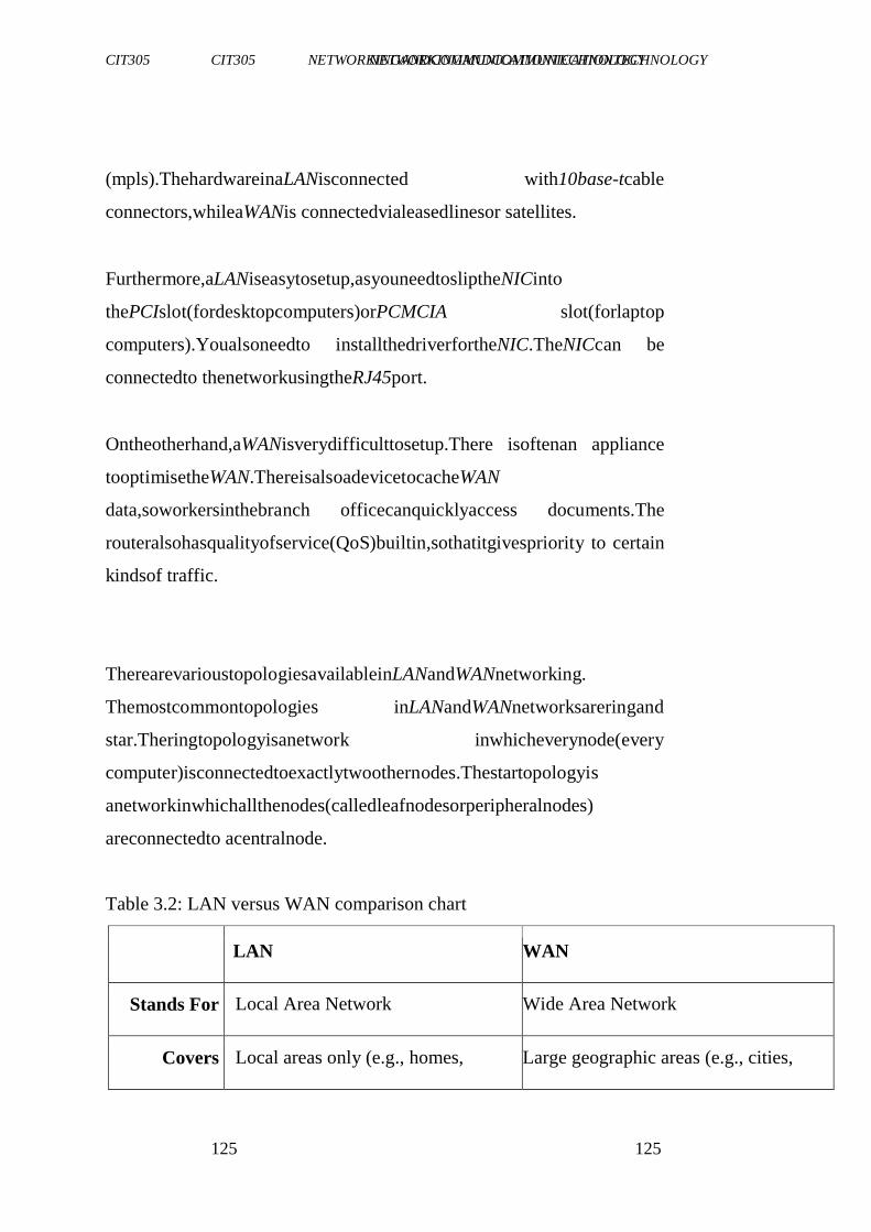
CIT305 NETWORKINGANDCOMMUNICATIONTECHNOLOGY CIT305 NETWORKINGANDCOMMUNICATIONTECHNOLOGY
125 125
(mpls).ThehardwareinaLANisconnected with10base-tcable
connectors,whileaWANis connectedvialeasedlinesor satellites.
Furthermore,aLANiseasytosetup,asyouneedtosliptheNICinto
thePCIslot(fordesktopcomputers)orPCMCIA slot(forlaptop
computers).Youalsoneedto installthedriverfortheNIC.TheNICcan be
connectedto thenetworkusingtheRJ45port.
Ontheotherhand,aWANisverydifficulttosetup.There isoftenan appliance
tooptimisetheWAN.ThereisalsoadevicetocacheWAN
data,soworkersinthebranch officecanquicklyaccess documents.The
routeralsohasqualityofservice(QoS)builtin,sothatitgivespriority to certain
kindsof traffic.
TherearevarioustopologiesavailableinLANandWANnetworking.
Themostcommontopologies inLANandWANnetworksareringand
star.Theringtopologyisanetwork inwhicheverynode(every
computer)isconnectedtoexactlytwoothernodes.Thestartopologyis
anetworkinwhichallthenodes(calledleafnodesorperipheralnodes)
areconnectedto acentralnode.
Table 3.2: LAN versus WAN comparison chart
LAN WAN
Stands For Local Area Network Wide Area Network
Covers Local areas only (e.g., homes, Large geographic areas (e.g., cities,
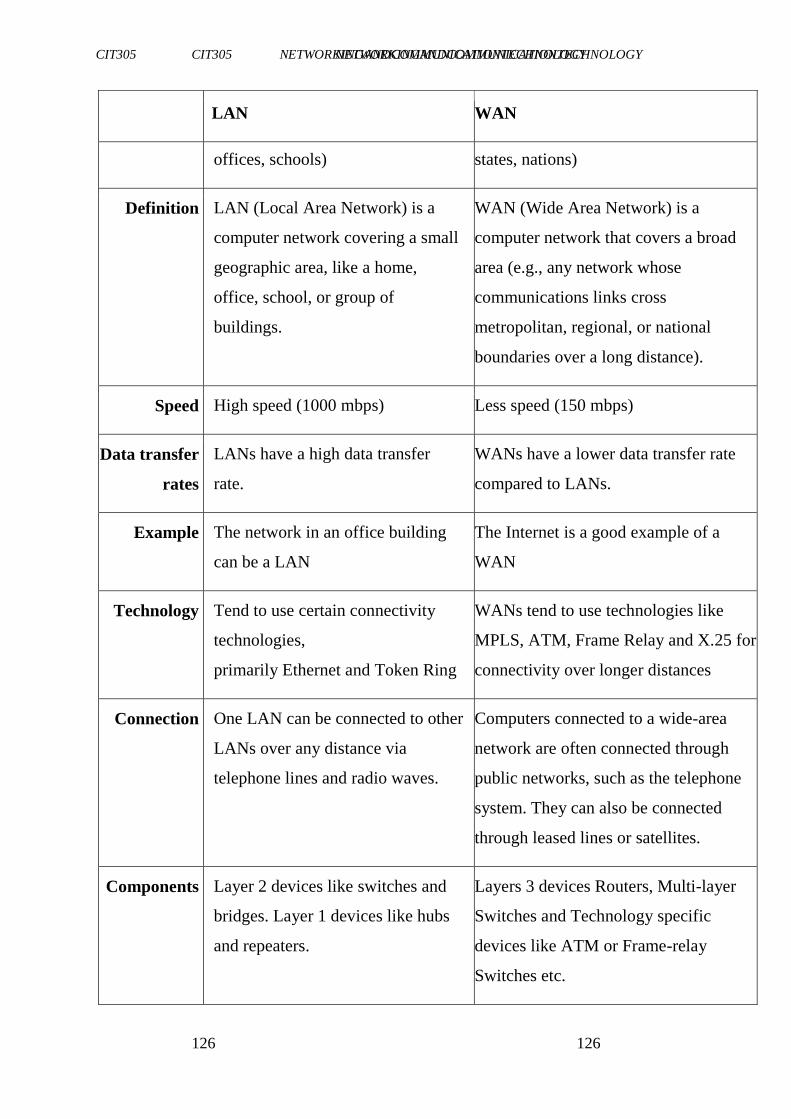
CIT305 NETWORKINGANDCOMMUNICATIONTECHNOLOGY CIT305 NETWORKINGANDCOMMUNICATIONTECHNOLOGY
126 126
LAN WAN
offices, schools) states, nations)
Definition LAN (Local Area Network) is a
computer network covering a small
geographic area, like a home,
office, school, or group of
buildings.
WAN (Wide Area Network) is a
computer network that covers a broad
area (e.g., any network whose
communications links cross
metropolitan, regional, or national
boundaries over a long distance).
Speed High speed (1000 mbps) Less speed (150 mbps)
Data transfer
rates
LANs have a high data transfer
rate.
WANs have a lower data transfer rate
compared to LANs.
Example The network in an office building
can be a LAN
The Internet is a good example of a
WAN
Technology Tend to use certain connectivity
technologies,
primarily Ethernet and Token Ring
WANs tend to use technologies like
MPLS, ATM, Frame Relay and X.25 for
connectivity over longer distances
Connection One LAN can be connected to other
LANs over any distance via
telephone lines and radio waves.
Computers connected to a wide-area
network are often connected through
public networks, such as the telephone
system. They can also be connected
through leased lines or satellites.
Components Layer 2 devices like switches and
bridges. Layer 1 devices like hubs
and repeaters.
Layers 3 devices Routers, Multi-layer
Switches and Technology specific
devices like ATM or Frame-relay
Switches etc.
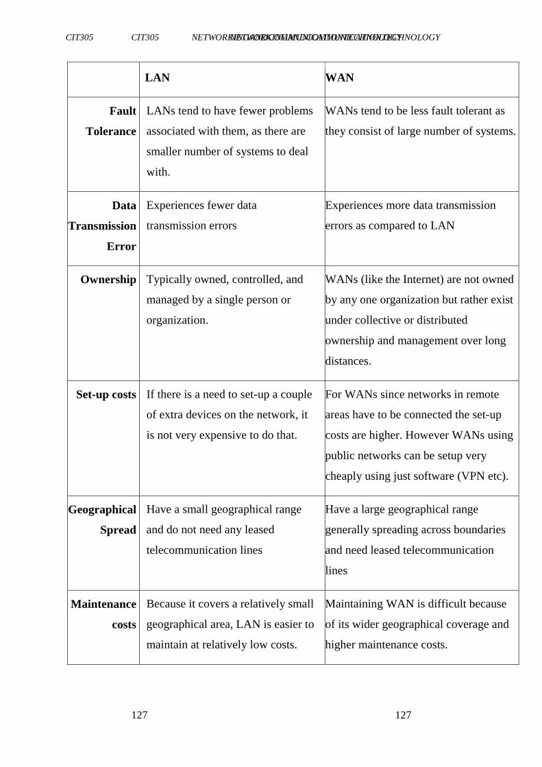
CIT305 NETWORKINGANDCOMMUNICATIONTECHNOLOGY CIT305 NETWORKINGANDCOMMUNICATIONTECHNOLOGY
127 127
LAN WAN
Fault
Tolerance
LANs tend to have fewer problems
associated with them, as there are
smaller number of systems to deal
with.
WANs tend to be less fault tolerant as
they consist of large number of systems.
Data
Transmission
Error
Experiences fewer data
transmission errors
Experiences more data transmission
errors as compared to LAN
Ownership Typically owned, controlled, and
managed by a single person or
organization.
WANs (like the Internet) are not owned
by any one organization but rather exist
under collective or distributed
ownership and management over long
distances.
Set-up costs If there is a need to set-up a couple
of extra devices on the network, it
is not very expensive to do that.
For WANs since networks in remote
areas have to be connected the set-up
costs are higher. However WANs using
public networks can be setup very
cheaply using just software (VPN etc).
Geographical
Spread
Have a small geographical range
and do not need any leased
telecommunication lines
Have a large geographical range
generally spreading across boundaries
and need leased telecommunication
lines
Maintenance
costs
Because it covers a relatively small
geographical area, LAN is easier to
maintain at relatively low costs.
Maintaining WAN is difficult because
of its wider geographical coverage and
higher maintenance costs.
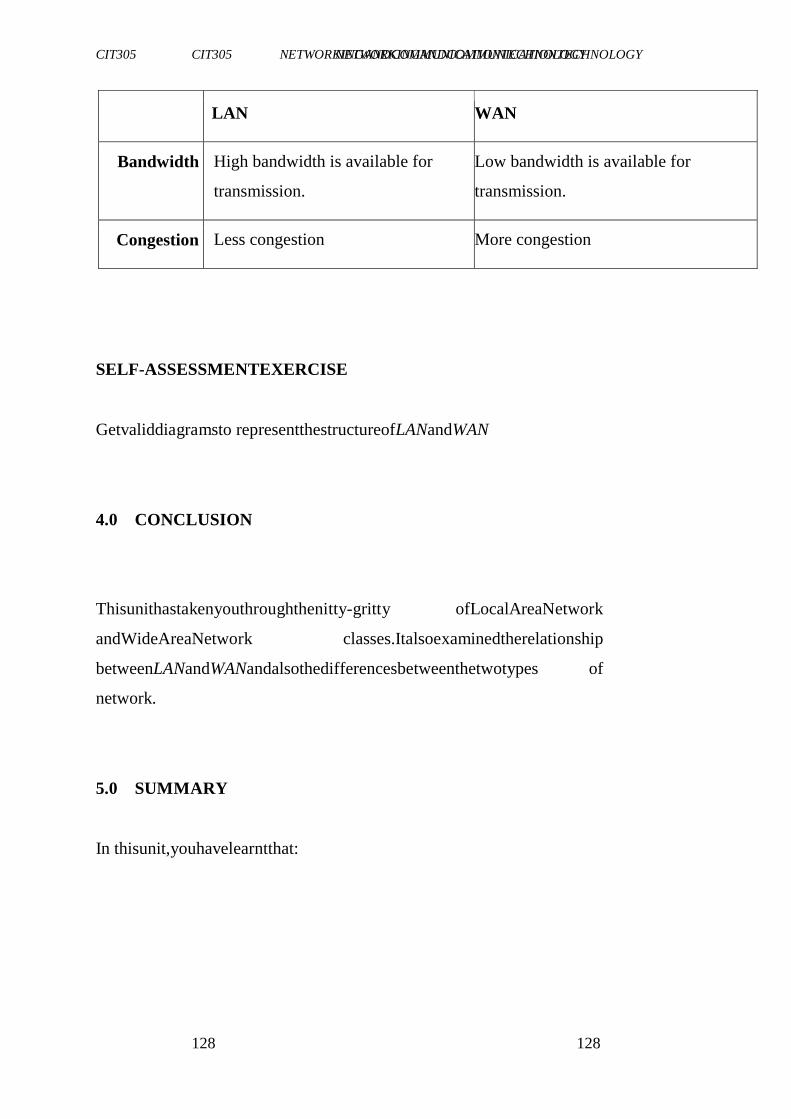
CIT305 NETWORKINGANDCOMMUNICATIONTECHNOLOGY CIT305 NETWORKINGANDCOMMUNICATIONTECHNOLOGY
128 128
LAN WAN
Bandwidth High bandwidth is available for
transmission.
Low bandwidth is available for
transmission.
Congestion Less congestion More congestion
SELF-ASSESSMENTEXERCISE
Getvaliddiagramsto representthestructureofLANandWAN
4.0 CONCLUSION
Thisunithastakenyouthroughthenitty-gritty ofLocalAreaNetwork
andWideAreaNetwork classes.Italsoexaminedtherelationship
betweenLANandWANandalsothedifferencesbetweenthetwotypes of
network.
5.0 SUMMARY
In thisunit,youhavelearntthat:
CIT305 NETWORKINGANDCOMMUNICATIONTECHNOLOGY CIT305 NETWORKINGANDCOMMUNICATIONTECHNOLOGY
129 129
alocalareanetwork(LAN)existsinahouseorauniversity
campus,whileawideareanetwork (WAN)existsacrossmany
officebuildingsseparatedbyavastdistance.
oneofthedifferencesbetweenLANandWAN,isthespeedofthe
network.
betweenLANandWAN,as well,thereisa differenceinthe
networkingstandardused.
CIT305 NETWORKINGANDCOMMUNICATIONTECHNOLOGY CIT305 NETWORKINGANDCOMMUNICATIONTECHNOLOGY
130 130
6.0 TUTOR-MARKEDASSIGNMENT
1. DiscussthedifferencesbetweentheLANandthe WANclasses.
2. Discussothertypesof networksapartfromLANandWAN
7.0 REFERENCES/FURTHERREADING
"http://en.wikipedia.org/wiki/History_of_the_Internet
Prasad,K.V.(2009).PrinciplesofDigitalCommunicationSystemsand
ComputerNetworks.DreamtechPress.
CIT305 NETWORKINGANDCOMMUNICATIONTECHNOLOGY CIT305 NETWORKINGANDCOMMUNICATIONTECHNOLOGY
131 131
MODULE4 COMMUNICATIONTECHNOLOGY
Unit1 ModemandModulationConcepts
Unit2 Multiplexers
Unit3 DigitalTechnologies
Unit4 SignalTransmissionandImpairment
UNIT1 MODEMANDMODULATIONCONCEPTS
CONTENTS
1.0 Introduction
2.0 Objectives
3.0 MainContent
3.1 History
3.2 Significanceof DigitalModulation
3.3 AnalogModulationMethods
3.4 DigitalModulationMethods
3.5 CommonDigitalModulationTechniques
3.6 FundamentalDigitalModulationMethods
3.7 ModulatorandDetectorPrinciplesof Operation
3.8 ListofknownDigitalModulationTechniques
4.0 Conclusion
5.0 Summary
6.0 Tutor-MarkedAssignment
7.0 References/FurtherReading
CIT305 NETWORKINGANDCOMMUNICATIONTECHNOLOGY CIT305 NETWORKINGANDCOMMUNICATIONTECHNOLOGY
132 132
1.0 INTRODUCTION
A modem (modulator-demodulator)is a device that modulates an
analogcarriersignalto encodedigitalinformation,andalsodemodulates
suchacarriersignaltodecodethetransmittedinformation.Thegoalis
toproduceasignalthatcanbetransmitted easilyanddecodedto
reproducetheoriginaldigital data.Modemscanbeusedoveranymeans
oftransmitting analogsignals,fromdrivendiodestoradio.Themost
familiarexampleisavoicebandmodem thatturnsthedigitaldataofa
personalcomputerintomodulatedelectrical signalsinthevoice frequency
range of a telephone channel. These signals can be
transmittedovertelephonelinesanddemodulated byanothermodemat
thereceiversideto recoverthedigitaldata.
Modulation istheprocessoffacilitatingthetransferofinformation over
amedium. Soundtransmissionin airhaslimitedrangeforthe amountof
poweryourlungscangenerate.Toextendtherangeyourvoicecan
reach,weneedtotransmititthroughamediumotherthanair,suchasa
CIT305 NETWORKINGANDCOMMUNICATIONTECHNOLOGY CIT305 NETWORKINGANDCOMMUNICATIONTECHNOLOGY
133 133
phonelineorradio.Theprocessofconvertinginformation(voice inthis
case)sothatitcanbesuccessfullysentthroughamedium(wireorradio
waves)is calledmodulation.
2.0 OBJECTIVES
At theendof thisunit,youshouldbeableto:
definea modem
explainmodulation
statethetypesof modulation
describecommondigital modulationtechniques.
3.0 MAINCONTENT
3.1 History
Newswireservicesin1920susedmultiplexequipmentthatmetthe
definition,butthemodemfunctionwasincidentaltothemultiplexing
function,so theyarenotcommonlyincludedinthehistoryof modems.
Modems grew out of the need to connect teletype machines over
ordinaryphonelinesinsteadofmoreexpensiveleasedlineswhichhad
previouslybeenusedforcurrentloop-basedteleprintersandautomated
telegraphs.GeorgeStibitzconnectedaNewHampshireteletypetoa
computerin NewYorkCitybyasubscribertelephonelinein 1940.
CIT305 NETWORKINGANDCOMMUNICATIONTECHNOLOGY CIT305 NETWORKINGANDCOMMUNICATIONTECHNOLOGY
134 134
In1943,IBMadaptedthistechnologytotheirunitrecord equipmentand
wasabletotransmitpunchedcardsat25bits/second. Mass-produced modems
intheUnitedStatesbeganaspartoftheSAGEair-defense
systemin1958;connectingterminalsatvariousairbases,radarsites,and
command-and-controlcentersto theSAGEdirectorcentersscattered around
theU.S.andCanada.SAGEmodemsweredescribedbyAT&T's BellLabsas
conformingto their newlypublishedBell101 dataset
standard.Whiletheyranondedicatedtelephonelines,thedevicesat
eachendwerenodifferentfromcommercialacousticallycoupledBell
101,110baudmodems.
Inthesummerof1960,thenameData-phonewasintroduced toreplace
theearliertermdigitalsubset.The202data-phone wasahalf-duplex
asynchronousservicethatwasmarketedextensivelyinlate1960.In
1962, the 201Aand 201Bdata-phoneswereintroduced.Theywere
synchronous modemsusingtwo-bit-per-baudphase-shiftkeying(PSK).
The201Aoperatedhalf-duplexat2,000bit/sovernormalphonelines,
whilethe201Bprovidedfullduplex2,400bit/sserviceonfour-wire
leasedlines,thesendandreceivechannelsrunning ontheirownsetof
twowireseach.
CIT305 NETWORKINGANDCOMMUNICATIONTECHNOLOGY CIT305 NETWORKINGANDCOMMUNICATIONTECHNOLOGY
135 135
ThefamousBell103AdatasetstandardwasalsointroducedbyBell
Labsin1962.Itprovidedfull-duplex serviceat300baudovernormal
phonelines.Frequency-shift keyingwasusedwiththecalloriginator
transmittingat 1,070or 1,270Hzandtheansweringmodemtransmitting
at2,025or2,225Hz.Thereadilyavailable103A2gaveanimportant
boosttotheuseofremotelow-speed terminalssuchastheKSR33,the
ASR33,andtheIBM2741.AT&Treducedmodem costsbyintroducing
theoriginate-only113Dandtheanswer-only113B/Cmodems.
3.2 SignificanceofDigitalModulation
Theaimofdigitalmodulationistotransferadigitalbitstream overan analog
bandpasschannel;forexampleoverthepublicswitched
telephonenetwork(whereabandpassfilterlimitsthefrequencyrange to
between300and3400Hz),or overalimitedradiofrequencyband.
Theaimof analog modulationisto transferananalogbaseband(orlow
pass)signal,forexample anaudiosignalorTVsignal,overananalog
bandpasschannel,forexamplealimitedradiofrequencybandora
cableTVnetworkchannel.
Analog anddigitalmodulationfacilitateFrequencyDivision Multiplexing
(FDM),whereseverallowpassinformationsignalsare
transferredsimultaneouslyoverthesamesharedphysicalmedium,using
separatepassbandchannels.
CIT305 NETWORKINGANDCOMMUNICATIONTECHNOLOGY CIT305 NETWORKINGANDCOMMUNICATIONTECHNOLOGY
136 136
Theaimofdigitalbaseband modulationmethods,alsoknownasline
coding,is to transfera digitalbit streamovera basebandchannel, typically
anon-filteredcopperwiresuchasaserialbusorawiredlocal areanetwork.
Theaimof pulse modulationmethodsis to transfera narrowband
analogsignal, for examplea phonecall overa widebandbaseband
channelor,insomeoftheschemes,asabitstream overanotherdigital
transmissionsystem.
Inmusicsynthesisers,modulation maybeusedtosynthesisewaveforms
withadesiredovertonespectrum.Inthiscasethecarrierfrequency is typically
in the same order or much lower than the modulating waveform. See for
example frequencymodulationsynthesis or ring modulation.
3.3 AnalogModulationMethods
In analog modulation, the modulation is applied continuously in
responseto theanaloginformationsignal.
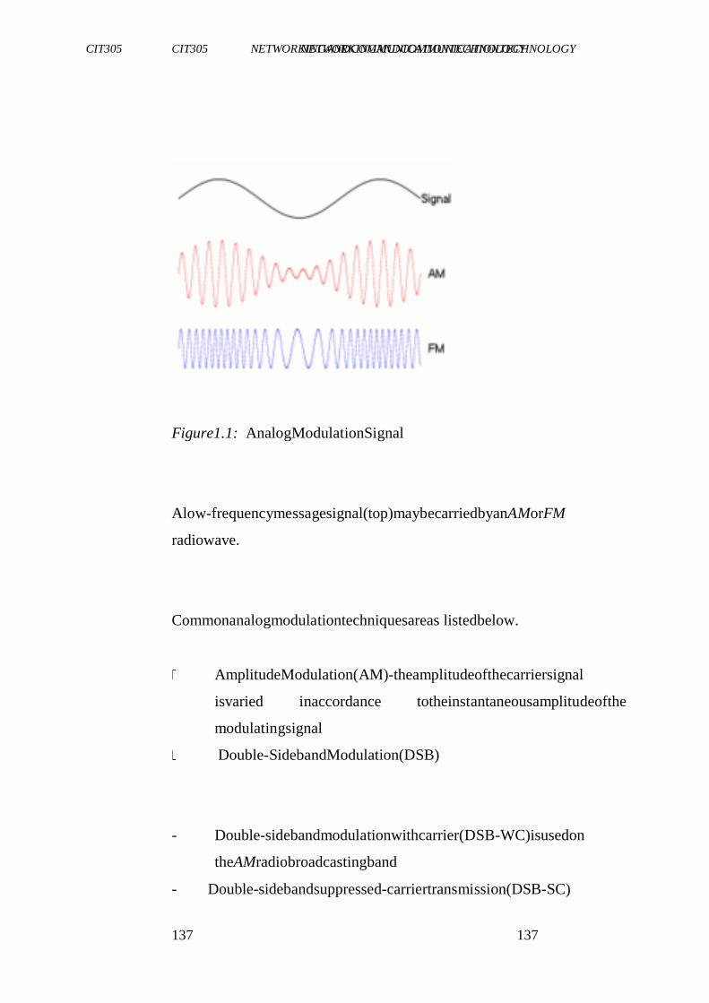
CIT305 NETWORKINGANDCOMMUNICATIONTECHNOLOGY CIT305 NETWORKINGANDCOMMUNICATIONTECHNOLOGY
137 137
Figure1.1: AnalogModulationSignal
Alow-frequencymessagesignal(top)maybecarriedbyanAMorFM
radiowave.
Commonanalogmodulationtechniquesareas listedbelow.
AmplitudeModulation(AM)-theamplitudeofthecarriersignal
isvaried inaccordance totheinstantaneousamplitudeofthe
modulatingsignal
Double-SidebandModulation(DSB)
- Double-sidebandmodulationwithcarrier(DSB-WC)isusedon
theAMradiobroadcastingband
- Double-sidebandsuppressed-carriertransmission(DSB-SC)
CIT305 NETWORKINGANDCOMMUNICATIONTECHNOLOGY CIT305 NETWORKINGANDCOMMUNICATIONTECHNOLOGY
138 138
- Double-sidebandreducedcarriertransmission(DSB-RC)
Single-sidebandmodulation(SSB,or SSB-AM),
- SSBwithcarrier(SSB-WC)
- SSBsuppressedcarrier modulation(SSB-SC)
Vestigialsidebandmodulation(VSB,or VSB-AM)
QuadratureAmplitudeModulation(QAM)
Anglemodulation
FrequencyModulation(FM)-herethefrequencyofthecarrier
signalisvariedinaccordancetotheinstantaneousamplitudeof
themodulatingsignal.
CIT305 NETWORKINGANDCOMMUNICATIONTECHNOLOGY CIT305 NETWORKINGANDCOMMUNICATIONTECHNOLOGY
139 139
PhaseModulation (PM)-herethephaseshiftofthecarriersignal
isvaried inaccordance totheinstantaneousamplitudeofthe
modulatingsignal
Theaccompanyingfigureshowstheresultsof (amplitude-)modulatinga
signalontoacarrier(bothofwhicharesinewaves).Atanypoint along they-
axis,theamplitude ofthemodulatedsignalisequaltothesumof
thecarriersignal.
3.4 DigitalModulationMethods
Indigitalmodulation,ananalog carriersignalismodulatedbyadigital
bitstream.Digitalmodulationmethodscanbeconsidered asdigital-to-
analogconversion,andthecorresponding demodulationordetectionas
analog-to-digital conversion. The changes in the carrier signal are
chosenfrom afinitenumberofMalternativesymbols(themodulation
alphabet).
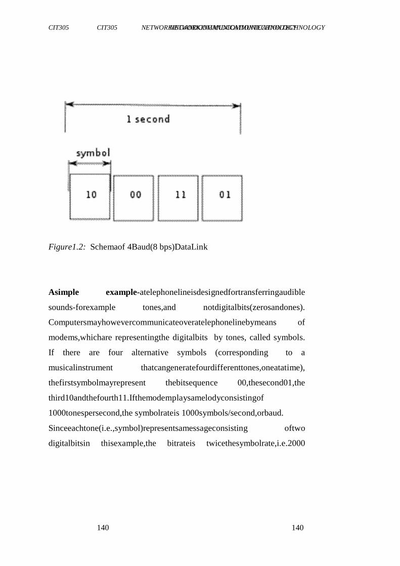
CIT305 NETWORKINGANDCOMMUNICATIONTECHNOLOGY CIT305 NETWORKINGANDCOMMUNICATIONTECHNOLOGY
140 140
Figure1.2: Schemaof 4Baud(8 bps)DataLink
Asimple example-atelephonelineisdesignedfortransferringaudible
sounds-forexample tones,and notdigitalbits(zerosandones).
Computersmayhowevercommunicateoveratelephonelinebymeans of
modems,whichare representingthe digitalbits by tones, called symbols.
If there are four alternative symbols (corresponding to a
musicalinstrument thatcangeneratefourdifferenttones,oneatatime),
thefirstsymbolmayrepresent thebitsequence 00,thesecond01,the
third10andthefourth11.Ifthemodemplaysamelodyconsistingof
1000tonespersecond,the symbolrateis 1000symbols/second,orbaud.
Sinceeachtone(i.e.,symbol)representsamessageconsisting oftwo
digitalbitsin thisexample,the bitrateis twicethesymbolrate,i.e.2000
CIT305 NETWORKINGANDCOMMUNICATIONTECHNOLOGY CIT305 NETWORKINGANDCOMMUNICATIONTECHNOLOGY
141 141
bitspersecond.Thisissimilartothetechniqueusedbydialupmodems as
opposedtoDSLmodems.
3.5 CommonDigitalModulationTechniques
Thesearelistedbelow:
Amplitude-ShiftKeying(ASK)
Frequency-ShiftKeying(FSK)
Phase-ShiftKeying(PSK)
i. Amplitude-ShiftKeying(ASK)
InASK,theamplitude ofthecarrierischangedinresponseto
information,andallelseiskeptfixed.Bit1istransmittedbyacarrier of one
particular amplitude. To transmit 0, we change the amplitude
keepingthefrequencyconstant.On-OffKeying(OOK)isaspecialform of
ASK.
Advantages
Schemeissimple,soitiseasytoimplementtransmitterandreceiver
withseveralcomponents.
Lowbandwidthrequirements
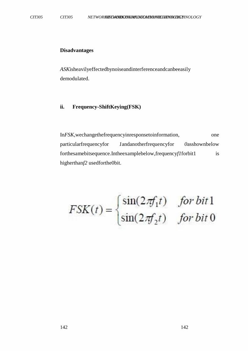
CIT305 NETWORKINGANDCOMMUNICATIONTECHNOLOGY CIT305 NETWORKINGANDCOMMUNICATIONTECHNOLOGY
142 142
Disadvantages
ASKisheavilyeffectedbynoiseandinterferenceandcanbeeasily
demodulated.
ii. Frequency-ShiftKeying(FSK)
InFSK,wechangethefrequencyinresponsetoinformation, one
particularfrequencyfor 1andanotherfrequencyfor 0asshownbelow
forthesamebitsequence.Intheexamplebelow,frequencyf1forbit1 is
higherthanf2 usedforthe0bit.
CIT305 NETWORKINGANDCOMMUNICATIONTECHNOLOGY CIT305 NETWORKINGANDCOMMUNICATIONTECHNOLOGY
143 143
Advantages
FSKisinsensitivetochannelfluctuationsandnoteasilyeffectedby noise.
Resilientto signalstrengthvariations
Doesnotrequirelinearamplifiersin thetransmitter
Disadvantages
FSKis alowperformancetypeof digitalmodulation.
iii. Phase-ShiftKeying(PSK)
InPSK,wechangethephaseofthesinusoidal carriertoindicate
information.Phase,inthiscontext,isthestarting angleatwhichthe sinusoid
starts.Totransmit0,weshiftthephaseofthesinusoid by180.
Phaseshiftrepresentsthechangeinthestateoftheinformation inthis case.
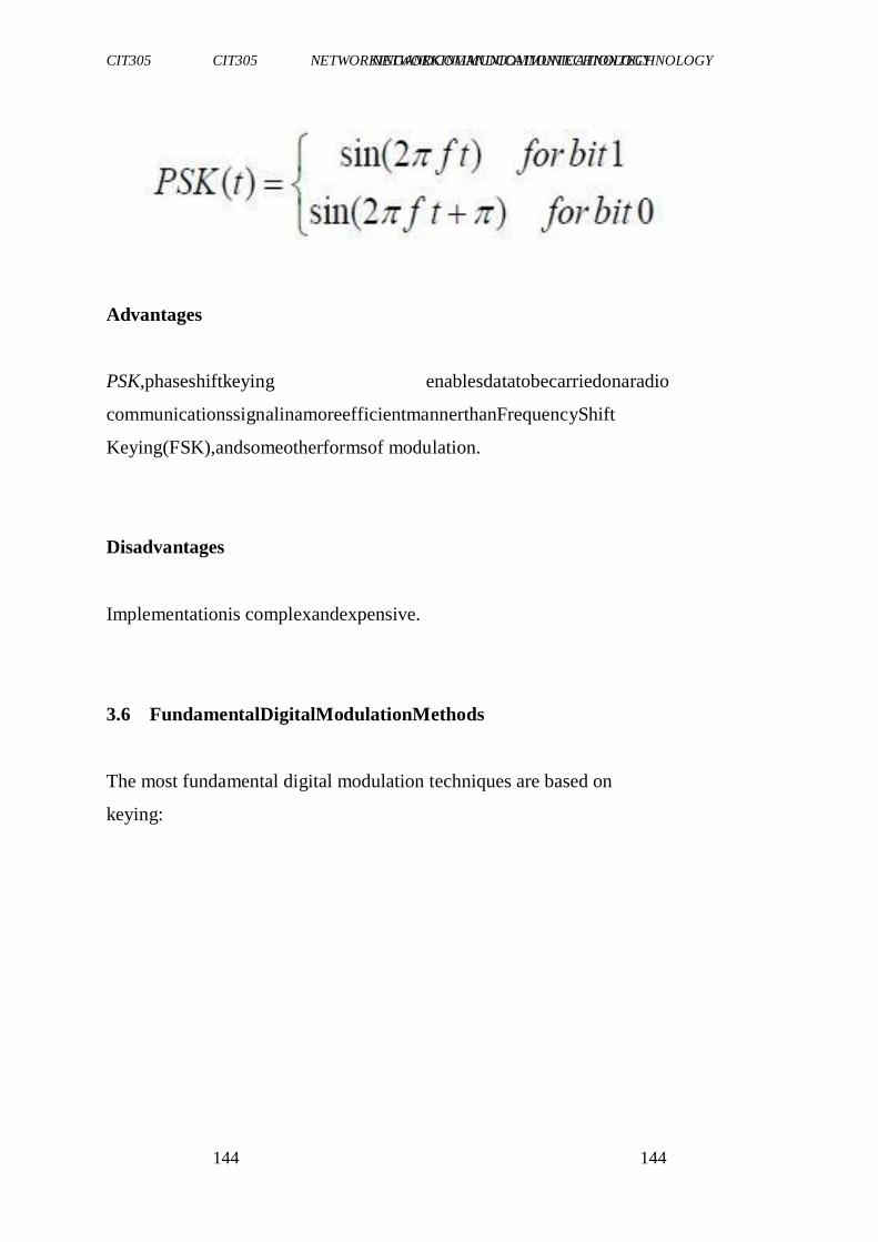
CIT305 NETWORKINGANDCOMMUNICATIONTECHNOLOGY CIT305 NETWORKINGANDCOMMUNICATIONTECHNOLOGY
144 144
Advantages
PSK,phaseshiftkeying enablesdatatobecarriedonaradio
communicationssignalinamoreefficientmannerthanFrequencyShift
Keying(FSK),andsomeotherformsof modulation.
Disadvantages
Implementationis complexandexpensive.
3.6 FundamentalDigitalModulationMethods
The most fundamental digital modulation techniques are based on
keying:
CIT305 NETWORKINGANDCOMMUNICATIONTECHNOLOGY CIT305 NETWORKINGANDCOMMUNICATIONTECHNOLOGY
145 145
inthecaseofPSK(phase-shift keying), afinitenumberofphases
areused.
inthecaseofFSK(frequency-shiftkeying),afinitenumberof
frequenciesareused.
inthecaseofASK(amplitude-shiftkeying),afinitenumberof
amplitudesareused.
inthecaseofQAM(quadratureamplitudemodulation),afinite
numberofatleasttwophases,andatleasttwoamplitudes are used.
In QAM, an in-phase signal (the I signal, for example a cosine
waveform) andaquadrature phasesignal(theQsignal,forexamplea
sinewave)areamplitudemodulated withafinitenumberofamplitudes,
andsummed. Itcanbe seenas atwo-channelsystem,eachchannelusing
ASK.TheresultingsignalisequivalenttoacombinationofPSKand ASK.
Inalloftheabovemethods,eachofthesephases,frequencies or amplitudes
areassignedauniquepatternofbinarybits.Usually,each phase,frequency
oramplitudeencodesanequalnumberofbits.This numberof
bitscomprisesthe symbolthatis representedbytheparticular
phase,frequencyor amplitude.
IfthealphabetconsistsofM=2N
alternativesymbols,eachsymbol
representsamessageconsistingofN bits. If the symbolrate(alsoknown
asthebaudrate)isfS symbols/second(orbaud),thedatarateisNfS bit/second.
CIT305 NETWORKINGANDCOMMUNICATIONTECHNOLOGY CIT305 NETWORKINGANDCOMMUNICATIONTECHNOLOGY
146 146
Forexample,withan alphabetconsistingof16alternativesymbols,each
symbolrepresents4bits.Thus,thedatarateisfourtimesthebaudrate.
InthecaseofPSK,ASKorQAM,wherethecarrierfrequency ofthe
modulatedsignalisconstant,themodulation alphabetisoften conveniently
representedonaconstellationdiagram,showing the
amplitudeoftheIsignalatthex-axis,andtheamplitudeoftheQsignal at they-
axis,foreachsymbol.
3.7 ModulatorandDetectorPrinciplesofOperation
PSK and ASK, and sometimes also FSK, are often generated and detected
usingthe principleof QAM. The I and Q signals can be
combinedintoacomplex-valuedsignalI+jQ(wherejistheimaginary
unit).Theresultingsocalledequivalentlow-passsignalorequivalent
basebandsignalisacomplex-valuedrepresentationofthereal-valued
modulatedphysicalsignal(theso calledpassbandsignalor RFsignal).
Thesearethegeneralstepsusedbythemodulatorto transmitdata.
CIT305 NETWORKINGANDCOMMUNICATIONTECHNOLOGY CIT305 NETWORKINGANDCOMMUNICATIONTECHNOLOGY
147 147
1. Groupthe incomingdata bits intocodewords,one for each
symbolthatwillbe transmitted.
2. Mapthecodewordstoattributes,forexampleamplitudesoftheI
andQsignals(theequivalent lowpasssignal),orfrequency or
phasevalues.
3. Adapt pulse shaping or some other filtering to limit the
bandwidthandformthespectrum oftheequivalentlowpass
signal,typicallyusingdigitalsignalprocessing.
4. PerformDigital-to-AnalogConversion(DAC)oftheI and Q
signals(since,today,alloftheaboveisnormallyachievedusing
Digital SignalProcessingDSP).
5. Generate a high-frequency sine wave carrier waveform, and
perhaps also a cosine quadrature component. Carry out the
modulation,forexamplebymultiplyingthesineandcosine wave
formwiththeIandQsignals,resultinginthattheequivalentlow
passsignalisfrequencyshiftedintoamodulatedpassbandsignal
orRFsignal.Sometimes thisisachievedusingDSPtechnology,
forexampledirectdigitalsynthesisusingawaveform table,
insteadofanalog signalprocessing.Inthatcase,theaboveDAC
stepshouldbe doneafterthisstep.
6. Amplificationandanalogbandpassfilteringtoavoidharmonic
distortionandperiodicspectrum
Atthereceiverside,thedemodulatortypicallyperformsthefollowing
functions.
1. Bandpassfiltering.
CIT305 NETWORKINGANDCOMMUNICATIONTECHNOLOGY CIT305 NETWORKINGANDCOMMUNICATIONTECHNOLOGY
148 148
2. AutomaticGainControl-AGC(tocompensateforattenuation,
forexamplefading).
3. ShiftingtheRFsignaltotheequivalentbasebandIandQsignals,
ortoanIntermediateFrequency(IF)signal,bymultiplyingthe
RFsignalwitha localoscillatorsinewave and cosinewave
frequency(seethesuperheterodynereceiverprinciple).
4. Samplingan Analog-to-DigitalConversion (ADC) Sometimes
beforeorinstead oftheabovepoint,forexample, bymeansof
undersampling.
5. Equalisationfiltering;forexampleamatchedfilter,compensation
formultipathpropagation, timespreading,phasedistortionand
frequencyselectivefading,toavoidsymbolinterference and
symboldistortion.
6. Detection of the amplitudes of the I and Q signals, or the
frequencyor phaseof theIFsignals.
7. Quantisation of the amplitudes, frequencies or phases to the
nearestallowedsymbolvalues.
8. Mappingofthequantisedamplitudes,frequenciesorphasesto
codewords(bitgroups).
CIT305 NETWORKINGANDCOMMUNICATIONTECHNOLOGY CIT305 NETWORKINGANDCOMMUNICATIONTECHNOLOGY
149 149
9. Parallel-to-serialconversionof thecodewordsintoabitstream.
10. Passtheresultantbitstreamonforfurtherprocessingsuchas
removalof anyerror-correctingcodes.
Asiscommontoalldigitalcommunication systems,thedesignofboth
themodulatoranddemodulatormustbedonesimultaneously. Digital
modulationschemesarepossiblebecausethetransmitter-receiver pair
havepriorknowledgeofhowdataisencodedandrepresented inthe
communicationssystem.Inalldigitalcommunication systems,boththe
modulatoratthetransmitterandthedemodulator atthereceiverare
structuredso thattheyperforminverseoperations.
Non-coherent modulationmethods donotrequireareceiverreference
clocksignalthatisphasesynchronized withthesendercarrierwave.In
thiscase,modulation symbols(ratherthanbits,characters,ordata
packets)areasynchronously transferred.Theoppositeiscoherent
modulation.
3.8 List ofKnownDigitalModulationTechniques
Themostcommondigital modulationtechniquesarelistedbelow.
Phase-ShiftKeying(PSK)-
- BinaryPSK(BPSK),usingM=2symbols
- QuadraturePSK(QPSK),usingM=4symbols
CIT305 NETWORKINGANDCOMMUNICATIONTECHNOLOGY CIT305 NETWORKINGANDCOMMUNICATIONTECHNOLOGY
150 150
- 8PSK,usingM=8symbols
- 16PSK,usingM=16symbols
- DifferentialPSK(DPSK)
- DifferentialQPSK(DQPSK)
- OffsetQPSK(OQPSK)
- π/4–QPSK
Frequency-ShiftKeying(FSK)-
- AudioFrequency-ShiftKeying(AFSK)
- Multi-FrequencyShiftKeying(M-aryFSKor MFSK)
- Dual-ToneMulti-Frequency(DTMF)
- Continuous-PhaseFrequency-ShiftKeying(CPFSK)
Amplitude-ShiftKeying(ASK)
On-OffKeying(OOK),themostcommonASKform
- M-aryvestigialsidebandmodulation,forexample8VSB
CIT305 NETWORKINGANDCOMMUNICATIONTECHNOLOGY CIT305 NETWORKINGANDCOMMUNICATIONTECHNOLOGY
151 151
Quadratureamplitude modulation(QAM) - a combinationof
PSKandASK-
- PolarmodulationlikeQAMacombinationofPSKandASK.
ContinuousPhaseModulation(CPM) methods-
- Minimum-ShiftKeying(MSK)
- GaussianMinimum-ShiftKeying(GMSK)
Orthogonal Frequency-Division Multiplexing (OFDM)
modulation-
- DiscreteMulti-Tone(DMT)-includingadaptivemodulation and bit-
loading.
Waveletmodulation
Trellis Coded Modulation (TCM), also known as trellis
modulation
Spread-spectrumtechniques
- Direct-SequenceSpreadSpectrum(DSSS)
- ChirpSpreadSpectrum(CSS)accordingtoIEEE802.15.4aCSS
usespseudo-stochasticcoding
- Frequency-HoppingSpreadSpectrum(FHSS)appliesaspecial
schemeforchannelrelease
CIT305 NETWORKINGANDCOMMUNICATIONTECHNOLOGY CIT305 NETWORKINGANDCOMMUNICATIONTECHNOLOGY
152 152
SELF-ASSESSMENTEXERCISE
DifferentiatebetweenAmplitude-ShiftKeying(ASK)andFrequency-
ShiftKeying(FSK).
4.0 CONCLUSION
Inthisunit,youhavebeenintroducedtothefundamental conceptsof
modemandmodulation.Youalsolearntabouttypesofmodulation;you
werealsointroducedtovariousmethodsofmodulation.Thisknowledge
willboostyourunderstandingofICTconcepts.
5.0 SUMMARY
In thisunit,youhavelearntthat:
amodem(modulator-demodulator)isadevicethatmodulates an
analog carriersignaltoencodedigitalinformation,andalso
demodulates suchacarriersignaltodecodethetransmitted
information.
CIT305 NETWORKINGANDCOMMUNICATIONTECHNOLOGY CIT305 NETWORKINGANDCOMMUNICATIONTECHNOLOGY
153 153
theaimofdigitalmodulationistotransferadigitalbitstream overan
analogchannel
common digital modulation techniques are Amplitude-Shift
Keying(ASK),Frequency-ShiftKeying(FSK)andPhase-Shift
Keying(PSK).
6.0 TUTOR-MARKEDASSIGNMENT
1. Howdoesthemodemperformits function?
2. Explainwhatyouunderstandbytheterm―modulation‖.
3. Describethedifferenttypesof modulation.
7.0 REFERENCES/FURTHERREADING
Barry, J. R. E.; Lee, A. &Messerschmidt, D.G. (2004). Digital
Communication.KluwerAcademicPublishers.
CIT305 NETWORKINGANDCOMMUNICATIONTECHNOLOGY CIT305 NETWORKINGANDCOMMUNICATIONTECHNOLOGY
154 154
UNIT2 MULTIPLEXERS
CONTENT
1.0 Introduction
2.0 Objectives
3.0 MainContent
3.1 Typesof Multiplexing
3.1.1 SpaceDivisionMultiplexing
3.1.2 Frequency-DivisionMultiplexing
3.1.3 Time-DivisionMultiplexing
3.1.4 Code-DivisionMultiplexing
3.1.5 Wavelength-Division Multiplexing
3.1.6 Synchronous Time-Division Multiplexing
3.1.7 Statistical Time-Division Multiplexing
3.2 Relationto MultipleAccess
3.3 ApplicationAreas
4.0 Conclusion
5.0 Summary
6.0 Tutor-MarkedAssignment
7.0 References/FurtherReading
1.0 INTRODUCTION
Inelectronics,amultiplexer ormuxisadevicethatselectsoneof
severalanalogordigitalinputsignalsandforwardstheselectedinput
intoasingleline.A multiplexerof2n
inputshasnselectlines, whichare
CIT305 NETWORKINGANDCOMMUNICATIONTECHNOLOGY CIT305 NETWORKINGANDCOMMUNICATIONTECHNOLOGY
155 155
usedtoselect which inputlinetosendtotheoutput.Anelectronic
multiplexermakesitpossible for severalsignalstoshareonedeviceor
resource-forexample,oneA/Dconverteroronecommunication line,
insteadof havingone deviceper inputsignal. On the otherend, a
demultiplexer (ordemux)isadevicetakingasingleinputsignaland
selectingoneof manydata-output-lines,whichis connectedto thesingle
input.Amultiplexerisoftenusedwithacomplementary demultiplexer
onthereceiving end.Anelectronicmultiplexercanbeconsideredasa
multiple-input,single-outputswitch,andademultiplexer asasingle-
input,multiple-outputswitch.
2.0 OBJECTIVES
At theendof thisunit,youshouldbeableto:
explainthemeaningof amultiplexer
describethetypesof multiplexers
statetheareasof applicationsof multiplexers.
CIT305 NETWORKINGANDCOMMUNICATIONTECHNOLOGY CIT305 NETWORKINGANDCOMMUNICATIONTECHNOLOGY
156 156
3.0 MAINCONTENT
3.1 TypesofMultiplexing
Multiplexingtechnologiesmaybe dividedinto severaltypes, all of
whichhavesignificantvariations,namely-Space-DivisionMultiplexing
(SDM),Frequency-Division Multiplexing(FDM),Time-Division
Multiplexing(TDM),andCodeDivisionMultiplexing(CDM).Variable
bitratedigitalbitstreamsmaybetransferred efficientlyoverafixed
bandwidthchannelbymeansofstatisticalmultiplexing, forexample
packetmodecommunication.Packetmodecommunication isan
asynchronousmodetime-domainmultiplexing whichresemblestime-
divisionmultiplexing.
Digitalbitstreamscanbetransferredoverananalogchannelbymeans of
code-divisionmultiplexing(CDM)techniquessuchas frequency-
hoppingspreadspectrum(FHSS)anddirect-sequence spreadspectrum
(DSSS).
In wirelesscommunications,multiplexingcan alsobe accomplished
throughalternatingpolarization(horizontal/vertical or
clockwise/counterclockwise) oneachadjacentchannelandsatellite,or
through phased multi-antennaarray combinedwith a Multiple-input
multiple-outputcommunications(MIMO)scheme.
3.1.1 Space-DivisionMultiplexing
CIT305 NETWORKINGANDCOMMUNICATIONTECHNOLOGY CIT305 NETWORKINGANDCOMMUNICATIONTECHNOLOGY
157 157
In wiredcommunication,space-divisionmultiplexingsimplyimplies
differentpoint-to-pointwiresfordifferentchannels.Examplesinclude an
analoguestereoaudiocable, withone pairof wiresfor the left
channelandanotherfortherightchannel,andamulti-pair telephone
cable.Anotherexampleisaswitchedstarnetwork suchastheanalog
telephoneaccessnetwork (althoughinsidethetelephoneexchangeor
betweentheexchanges,othermultiplexing techniquesaretypically
employed) oraswitchedethernetnetwork.Athirdexampleisamesh
network.Wiredspace-divisionmultiplexingistypicallynotconsidered as
multiplexing.
Inwirelesscommunication,space-divisionmultiplexing isachievedby
multipleantennaelementsformingaphasedarrayantenna.Examples
areMultiple-Input andMultiple-Output(MIMO),Single-Inputand
Multiple-Output(SIMO)andMultiple-InputandSingle-Output(MISO)
multiplexing.For example, a IEEE 802.11n wireless router with N
antennas makes it possible to communicate with N multiplexed
channels,eachwithapeakbitrateof54Mbit/s,thusincreasingthetotal
peakbitratewithafactorN.Differentantennaswillgivedifferent
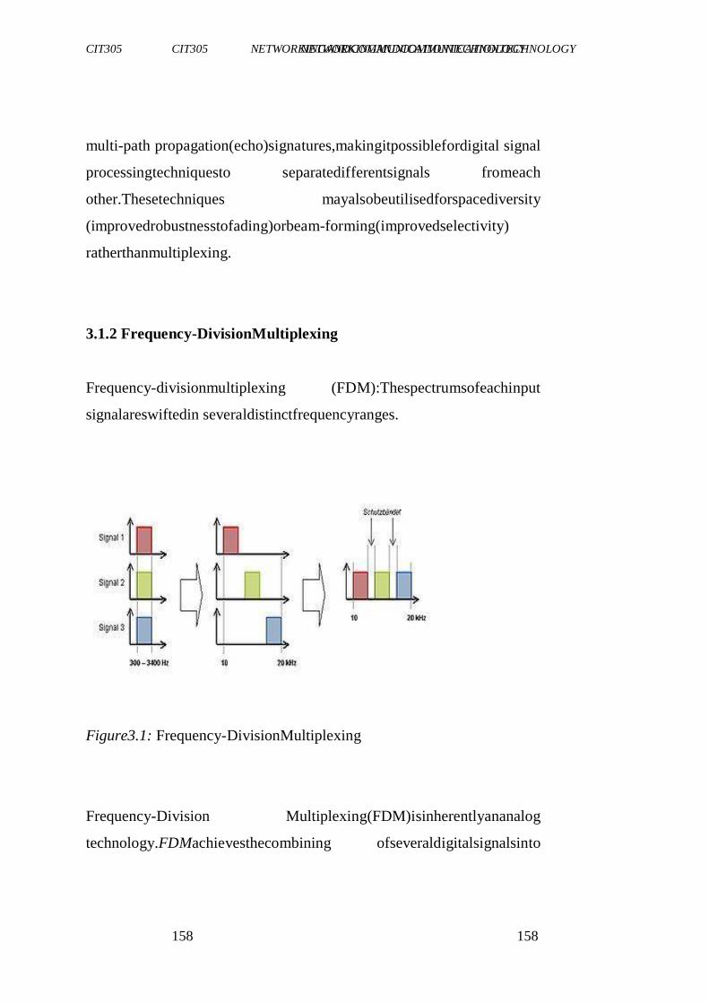
CIT305 NETWORKINGANDCOMMUNICATIONTECHNOLOGY CIT305 NETWORKINGANDCOMMUNICATIONTECHNOLOGY
158 158
multi-path propagation(echo)signatures,makingitpossiblefordigital signal
processingtechniquesto separatedifferentsignals fromeach
other.Thesetechniques mayalsobeutilisedforspacediversity
(improvedrobustnesstofading)orbeam-forming(improvedselectivity)
ratherthanmultiplexing.
3.1.2 Frequency-DivisionMultiplexing
Frequency-divisionmultiplexing (FDM):Thespectrumsofeachinput
signalareswiftedin severaldistinctfrequencyranges.
Figure3.1: Frequency-DivisionMultiplexing
Frequency-Division Multiplexing(FDM)isinherentlyananalog
technology.FDMachievesthecombining ofseveraldigitalsignalsinto
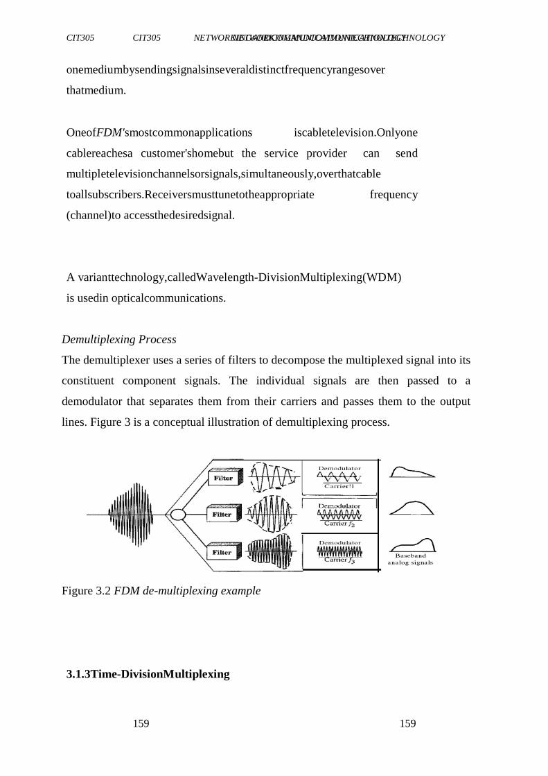
CIT305 NETWORKINGANDCOMMUNICATIONTECHNOLOGY CIT305 NETWORKINGANDCOMMUNICATIONTECHNOLOGY
159 159
onemediumbysendingsignalsinseveraldistinctfrequencyrangesover
thatmedium.
OneofFDM'smostcommonapplications iscabletelevision.Onlyone
cablereachesa customer'shomebut the service provider can send
multipletelevisionchannelsorsignals,simultaneously,overthatcable
toallsubscribers.Receiversmusttunetotheappropriate frequency
(channel)to accessthedesiredsignal.
A varianttechnology,calledWavelength-DivisionMultiplexing(WDM)
is usedin opticalcommunications.
Demultiplexing Process
The demultiplexer uses a series of filters to decompose the multiplexed signal into its
constituent component signals. The individual signals are then passed to a
demodulator that separates them from their carriers and passes them to the output
lines. Figure 3 is a conceptual illustration of demultiplexing process.
Figure 3.2 FDM de-multiplexing example
3.1.3Time-DivisionMultiplexing

CIT305 NETWORKINGANDCOMMUNICATIONTECHNOLOGY CIT305 NETWORKINGANDCOMMUNICATIONTECHNOLOGY
160 160
Time-DivisionMultiplexing (TDM)isadigitaltechnology.TDM
involvessequencing groupsofafewbitsorbytesfromeachindividual input
stream,oneaftertheother,andinsuchawaythattheycanbe associated with the
appropriate receiver. If done sufficiently and
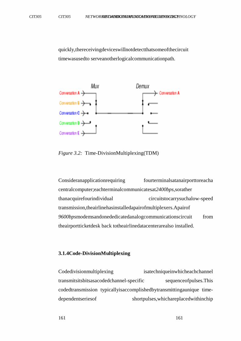
CIT305 NETWORKINGANDCOMMUNICATIONTECHNOLOGY CIT305 NETWORKINGANDCOMMUNICATIONTECHNOLOGY
161 161
quickly,thereceivingdeviceswillnotdetectthatsomeofthecircuit
timewasusedto serveanotherlogicalcommunicationpath.
Figure 3.2: Time-DivisionMultiplexing(TDM)
Consideranapplicationrequiring fourterminalsatanairporttoreacha
centralcomputer;eachterminalcommunicatesat2400bps,sorather
thanacquirefourindividual circuitstocarrysuchalow-speed
transmission,theairlinehasinstalledapairofmultiplexers.Apairof
9600bpsmodemsandonededicatedanalogcommunicationscircuit from
theairportticketdesk back totheairlinedatacenterarealso installed.
3.1.4Code-DivisionMultiplexing
Codedivisionmultiplexing isatechniqueinwhicheachchannel
transmitsitsbitsasacodedchannel-specific sequenceofpulses.This
codedtransmission typicallyisaccomplishedbytransmittingaunique time-
dependentseriesof shortpulses,whichareplacedwithinchip
CIT305 NETWORKINGANDCOMMUNICATIONTECHNOLOGY CIT305 NETWORKINGANDCOMMUNICATIONTECHNOLOGY
162 162
timeswithinthelargerbittime.Allchannels,eachwithadifferentcode,
canbetransmittedonthesamefiberandasynchronouslydemultiplexed. Other
widely used multiple access techniques are Time Division
MultipleAccess(TDMA) andFrequencyDivision MultipleAccess
(FDMA).
CodeDivisionMultiplexing (CDM)techniquesareusedasanaccess
technology, namelyCodeDivisionMultipleAccess(CDMA),in
UniversalMobileTelecommunicationsSystem(UMTS)standardforthe
third generation(3G) mobile communicationidentifiedby the ITU.
Anotherimportantapplication oftheCDMAistheGlobalPositioning
System(GPS).
However,thetermCodeDivisionMultipleAccessisalsowidely usedto refer
to a group of specific implementationsof CDMA defined by
Qualcommforuseindigital cellulartelephony,whichincludeIS-95and IS-
2000.Thetwodifferentusesofthistermcanbeconfusing.Actually,CDMA(the
Qualcomm standard)andUMTShavebeencompetingfor adoptionin
manymarkets.
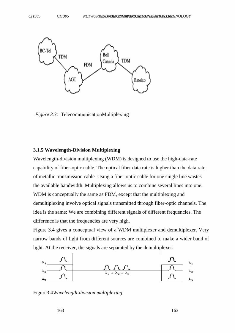
CIT305 NETWORKINGANDCOMMUNICATIONTECHNOLOGY CIT305 NETWORKINGANDCOMMUNICATIONTECHNOLOGY
163 163
Figure 3.3: TelecommunicationMultiplexing
3.1.5 Wavelength-Division Multiplexing
Wavelength-division multiplexing (WDM) is designed to use the high-data-rate
capability of fiber-optic cable. The optical fiber data rate is higher than the data rate
of metallic transmission cable. Using a fiber-optic cable for one single line wastes
the available bandwidth. Multiplexing allows us to combine several lines into one.
WDM is conceptually the same as FDM, except that the multiplexing and
demultiplexing involve optical signals transmitted through fiber-optic channels. The
idea is the same: We are combining different signals of different frequencies. The
difference is that the frequencies are very high.
Figure 3.4 gives a conceptual view of a WDM multiplexer and demultiplexer. Very
narrow bands of light from different sources are combined to make a wider band of
light. At the receiver, the signals are separated by the demultiplexer.
Figure3.4Wavelength-division multiplexing
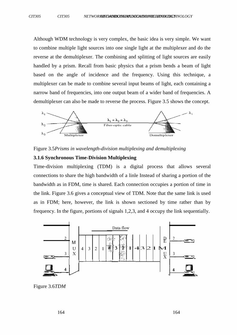
CIT305 NETWORKINGANDCOMMUNICATIONTECHNOLOGY CIT305 NETWORKINGANDCOMMUNICATIONTECHNOLOGY
164 164
Although WDM technology is very complex, the basic idea is very simple. We want
to combine multiple light sources into one single light at the multiplexer and do the
reverse at the demultiplexer. The combining and splitting of light sources are easily
handled by a prism. Recall from basic physics that a prism bends a beam of light
based on the angle of incidence and the frequency. Using this technique, a
multiplexer can be made to combine several input beams of light, each containing a
narrow band of frequencies, into one output beam of a wider band of frequencies. A
demultiplexer can also be made to reverse the process. Figure 3.5 shows the concept.
Figure 3.5Prisms in wavelength-division multiplexing and demultiplexing
3.1.6 Synchronous Time-Division Multiplexing
Time-division multiplexing (TDM) is a digital process that allows several
connections to share the high bandwidth of a linle Instead of sharing a portion of the
bandwidth as in FDM, time is shared. Each connection occupies a portion of time in
the link. Figure 3.6 gives a conceptual view of TDM. Note that the same link is used
as in FDM; here, however, the link is shown sectioned by time rather than by
frequency. In the figure, portions of signals 1,2,3, and 4 occupy the link sequentially.
Figure 3.6TDM

CIT305 NETWORKINGANDCOMMUNICATIONTECHNOLOGY CIT305 NETWORKINGANDCOMMUNICATIONTECHNOLOGY
165 165
Note that in Figure 3.6 we are concerned with only multiplexing, not switching. This
means that all the data in a message from source 1 always go to one specific
destination, be it 1, 2, 3, or 4. The delivery is fixed and unvarying, unlike switching.
We also need to remember thatTDM is, in principle, a digital multiplexing technique.
Digital data from different sources are combined into one timeshared link. However,
this does not mean that the sources cannot produce analog data; analog data can be
sampled, changed to digital data, and then multiplexed by using TDM.
We can divide TDM into two different schemes: synchronous and statistical.
In synchronous TDM, each input connection has an allotment in the output even if it
is not sending data.
Time Slots and Frames
In synchronous TDM, the data flow of each input connection is divided into units,
where each input occupies one input time slot. A unit can be 1 bit, one character, or
one block of data. Each input unit becomes one output unit and occupies one output
time slot. However, the duration of an output time slot is n times shorter than the
duration of an input time slot. If an input time slot is T s, the output time slot is Tin s,
where n is the number of connections. In other words, a unit in the output
connection has a shorter duration; it travels faster. Figure 3.7 shows an example of
synchronous TDM where n is 3.
Figure 3.7Synchronous time-division multiplexing
In synchronous TDM, a round of data units from each input connection is collected
into a frame (we will see the reason for this shortly). If we have n connections, a
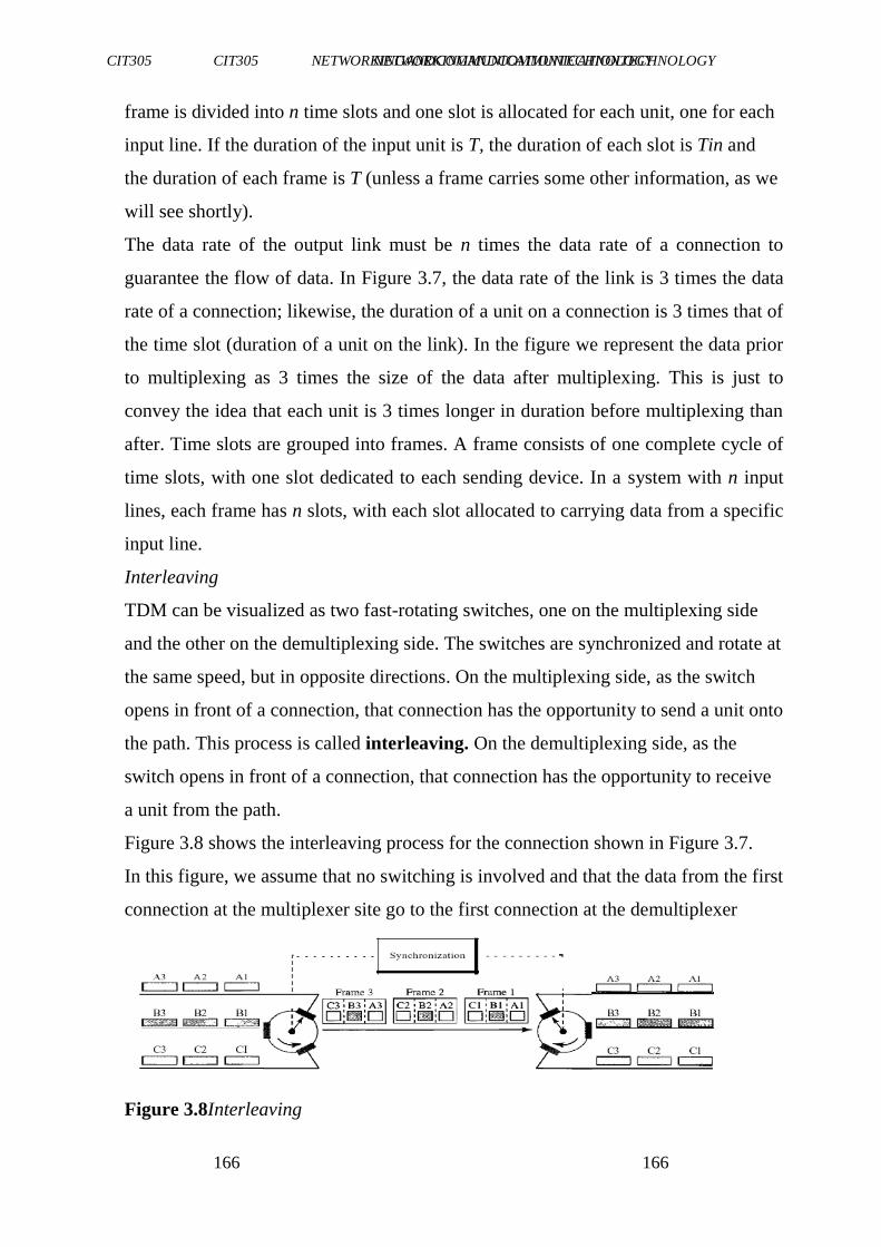
CIT305 NETWORKINGANDCOMMUNICATIONTECHNOLOGY CIT305 NETWORKINGANDCOMMUNICATIONTECHNOLOGY
166 166
frame is divided into n time slots and one slot is allocated for each unit, one for each
input line. If the duration of the input unit is T, the duration of each slot is Tin and
the duration of each frame is T (unless a frame carries some other information, as we
will see shortly).
The data rate of the output link must be n times the data rate of a connection to
guarantee the flow of data. In Figure 3.7, the data rate of the link is 3 times the data
rate of a connection; likewise, the duration of a unit on a connection is 3 times that of
the time slot (duration of a unit on the link). In the figure we represent the data prior
to multiplexing as 3 times the size of the data after multiplexing. This is just to
convey the idea that each unit is 3 times longer in duration before multiplexing than
after. Time slots are grouped into frames. A frame consists of one complete cycle of
time slots, with one slot dedicated to each sending device. In a system with n input
lines, each frame has n slots, with each slot allocated to carrying data from a specific
input line.
Interleaving
TDM can be visualized as two fast-rotating switches, one on the multiplexing side
and the other on the demultiplexing side. The switches are synchronized and rotate at
the same speed, but in opposite directions. On the multiplexing side, as the switch
opens in front of a connection, that connection has the opportunity to send a unit onto
the path. This process is called interleaving. On the demultiplexing side, as the
switch opens in front of a connection, that connection has the opportunity to receive
a unit from the path.
Figure 3.8 shows the interleaving process for the connection shown in Figure 3.7.
In this figure, we assume that no switching is involved and that the data from the first
connection at the multiplexer site go to the first connection at the demultiplexer
Figure 3.8Interleaving
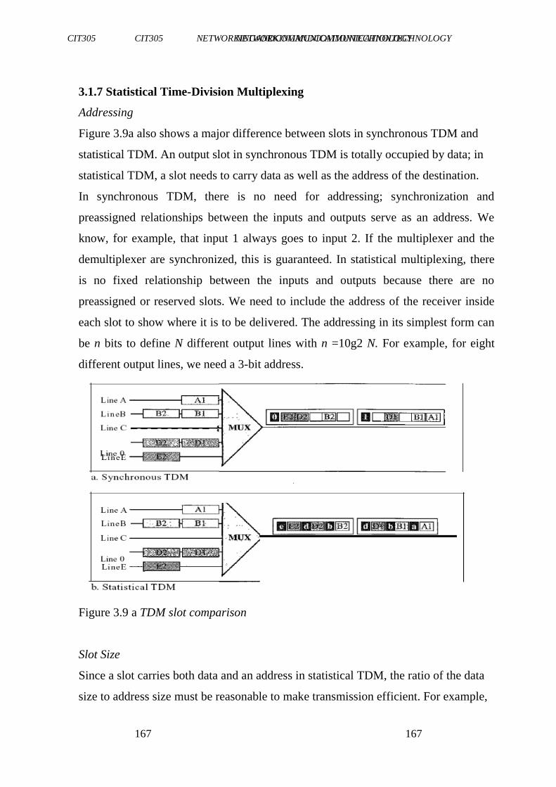
CIT305 NETWORKINGANDCOMMUNICATIONTECHNOLOGY CIT305 NETWORKINGANDCOMMUNICATIONTECHNOLOGY
167 167
3.1.7 Statistical Time-Division Multiplexing
Addressing
Figure 3.9a also shows a major difference between slots in synchronous TDM and
statistical TDM. An output slot in synchronous TDM is totally occupied by data; in
statistical TDM, a slot needs to carry data as well as the address of the destination.
In synchronous TDM, there is no need for addressing; synchronization and
preassigned relationships between the inputs and outputs serve as an address. We
know, for example, that input 1 always goes to input 2. If the multiplexer and the
demultiplexer are synchronized, this is guaranteed. In statistical multiplexing, there
is no fixed relationship between the inputs and outputs because there are no
preassigned or reserved slots. We need to include the address of the receiver inside
each slot to show where it is to be delivered. The addressing in its simplest form can
be n bits to define N different output lines with n =10g2 N. For example, for eight
different output lines, we need a 3-bit address.
Figure 3.9 a TDM slot comparison
Slot Size
Since a slot carries both data and an address in statistical TDM, the ratio of the data
size to address size must be reasonable to make transmission efficient. For example,
CIT305 NETWORKINGANDCOMMUNICATIONTECHNOLOGY CIT305 NETWORKINGANDCOMMUNICATIONTECHNOLOGY
168 168
it would be inefficient to send 1 bit per slot as data when the address is 3 bits. This
would mean an overhead of 300 percent. In statistical TDM, a block of data is
usually many bytes while the address is just a few bytes.
No Synchronization Bit
There is another difference between synchronous and statistical TDM, but this time it
is at the frame level. The frames in statistical TDM need not be synchronized, so we
do not need synchronization bits.
Bandwidth
In statistical TDM, the capacity of the link is normally less than the sum of the
capacities of each channel. The designers of statistical TDM define the capacity of
the link based on the statistics of the load for each channel. If on average only x
percent of the input slots are filled, the capacity of the link reflects this. Of course,
during peak times, some slots need to wait.
CIT305 NETWORKINGANDCOMMUNICATIONTECHNOLOGY CIT305 NETWORKINGANDCOMMUNICATIONTECHNOLOGY
169 169
SELF-ASSESSMENTEXERCISE
Findoutaboutspreadspectrummultiplexing.
3.2 Relationtomultipleaccess
A multiplexingtechniquemaybe furtherextendedintoamultipleaccess
methodor channelaccess method,forexampleTDMintoTime-Division
MultipleAccess (TDMA)andstatisticalmultiplexingintoCarrierSense
MultipleAccess(CSMA).Amultiple accessmethodmakesitpossible
forseveraltransmitters connectedtothesamephysicalmediumtoshare its
capacity.
Multiplexing isprovidedbythephysicallayeroftheOSImodel,while
multiple accessalsoinvolves amediaaccesscontrolprotocol,whichis
partofthedatalinklayer.ThetransportlayerintheOSImodelaswell
asTCP/IPmodelprovidesstatisticalmultiplexingofseveralapplication
layerdataflowsto/fromthesamecomputer.
3.3 ApplicationAreas
Letus considerthefollowingareas.

CIT305 NETWORKINGANDCOMMUNICATIONTECHNOLOGY CIT305 NETWORKINGANDCOMMUNICATIONTECHNOLOGY
170 170
a. Telegraphy
Theearliestcommunication technology-usingelectricalwires,and therefore
sharinganinterestintheeconomiesaffordedbymultiplexing, was the
electric telegraph. Early experiments allowed two separate
CIT305 NETWORKINGANDCOMMUNICATIONTECHNOLOGY CIT305 NETWORKINGANDCOMMUNICATIONTECHNOLOGY
171 171
messagestotravelinoppositedirectionssimultaneously, firstusingan
electricbatteryat bothends,thenat onlyoneend.
ÉmileBaudotdevelopedatime-multiplexingsystemofmultiple
Hughesmachinesin the1870s.
In1874,thequadruplextelegraphdevelopedbyThomasEdison
transmittedtwomessagesineachdirectionsimultaneously,fora
totalof fourmessagestransitingthesamewireat thesametime.
Several workers were investigating acoustic telegraphy, a
frequency-division multiplexing technique, which led to the
inventionof thetelephone.
b. Telephony
In telephony,a customer'stelephoneline nowtypicallyendsat the
remoteconcentrator boxdownthestreet,whereitismultiplexed along
withothertelephonelinesforthatneighborhood orothersimilararea.
Themultiplexedsignalisthencarriedtothecentralswitching officeon
significantly fewer wires and for much further distances than a
customer'slinecanpracticallygo.Thisislikewise alsotrueforDigital
SubscriberLines(DSL).
FiberInTheLoop(FITL)isacommonmethodofmultiplexing, which
usesopticalfiberasthebackbone.ItnotonlyconnectsPOTSphone
lineswiththerestofthePSTN,butalsoreplaces DSLbyconnecting
directlytoethernetwiredintothehome.AsynchronousTransferMode is
oftenthe communicationsprotocolused.
CIT305 NETWORKINGANDCOMMUNICATIONTECHNOLOGY CIT305 NETWORKINGANDCOMMUNICATIONTECHNOLOGY
172 172
Sinceall of thephone(anddata)lineshavebeenclumpedtogether,none
ofthemcanbeaccessedexceptthroughademultiplexer. Thisprovides
formore-securedcommunications, thoughtheyarenottypically encrypted.
TheconceptisalsonowusedincableTV, whichis increasinglyoffering
thesameservicesastelephone companies.IPTValsodependson
multiplexing.
c. Videoprocessing
In video editingand processingsystems, multiplexingrefers to the
processofinterleaving audioandvideointoonecoherentMPEG
transportstream(time-divisionmultiplexing).
In digitalvideo,suchatransportstreamis normallya featureof a
containerformatwhichmayincludemetadata andotherinformation,
suchassubtitles.Theaudioandvideostreamsmayhavevariablebit
CIT305 NETWORKINGANDCOMMUNICATIONTECHNOLOGY CIT305 NETWORKINGANDCOMMUNICATIONTECHNOLOGY
173 173
rate.Softwarethatproducessuchatransportstream and/orcontaineris
commonly calledastatisticalmultiplexorormuxer.Ademuxerisa software
thatextractsor,otherwise,makesavailable forseparate
processingthecomponentsof suchastreamor container.
d. Digitalbroadcasting
Indigitaltelevision anddigitalradio systems,severalvariablebit-rate
datastreamsaremultiplexedtogethertoafixedbitratetransportstream
bymeansofstatisticalmultiplexing. Thismakesitpossibletotransfer several
video and audio channels simultaneously over the same
frequencychannel,togetherwithvariousservices.
In the digital televisionsystems,this may involve several Standard
DefinitionTelevision(SDTV)programmes(particularly onDVB-T, DVB-
S2,ISDBand ATSC-C),or oneHDTV,possiblywithasingle
SDTVcompanionchannelover6to 8MHz-wideTVchannel.Thedevice
thataccomplishes thisiscalledastatisticalmultiplexer.Inseveralof
thesesystems,themultiplexingresultsinanMPEGtransportstream.
ThenewerDVBstandardsDVB-S2andDVB-T2hasthecapacityto
carryseveralHDTVchannelsinonemultiplex. EventheoriginalDVB
standards cancarrymoreHDTVchannelsinamultiplex ifthemost
advancedMPEG-4compressionshardwareis used.
Oncommunicationssatelliteswhichcarrybroadcasttelevisionnetworks
andradionetworks,thisisknownasMultipleChannelsPerCarrieror
CIT305 NETWORKINGANDCOMMUNICATIONTECHNOLOGY CIT305 NETWORKINGANDCOMMUNICATIONTECHNOLOGY
174 174
MCPC.Wheremultiplexing isnotpractical(suchaswherethereare different
sourcesusingasingletransponder),singlechannelpercarrier modeis used.
Signal multiplexing of satellite TV and radio channels is typically
carriedoutinacentralsignalplayoutanduplink centre,suchasASTRA
Platform Services in Germany, which provides play out, digital
archiving,encryption,andsatelliteuplinks,aswellasmultiplexing, for
hundredsof digitalTVandradiochannels.
In digital radio, both the Eureka 147 system of digital audio
broadcastingand the in-band on-channel HD Radio, FMeXtra, and
digital radio mondiale systems can multiplex channels. This is
essentiallyrequiredwithDAB-typetransmissions (whereamultiplexis
calledanensemble),butis entirelyoptionalwithIBOCsystems.
e. Analogbroadcasting
InFMbroadcastingandotheranalogradiomedia,multiplexingisaterm
commonlygiventotheprocessofaddingsubcarrierstotheaudiosignal
CIT305 NETWORKINGANDCOMMUNICATIONTECHNOLOGY CIT305 NETWORKINGANDCOMMUNICATIONTECHNOLOGY
175 175
beforeitentersthetransmitter,wheremodulationoccurs.Multiplexing
inthissenseissometimesknown asMPX,whichinturnisalsoanold termfor
stereophonicFM, seenon stereosystemssincethe1960s.
4.0 CONCLUSION
Inthisunit,youhavebeenintroducedtothefundamental conceptsof
Multiplexers. Youalsolearntaboutthetypesofmultiplexers. Youwere
alsointroducedtothe variousapplicationareasof multiplexers.All
thesewillgoalongwaytoenrich yourunderstandingofthiscourse asa whole.
5.0 SUMMARY
In thisunit,youhavelearntthat:
amultiplexerisadevicethatselectsoneofseveralanalogor
digitalinputsignalsandforwards theselectedinputintoasingle line
typesofmultiplexingareSpace-DivisionMultiplexing(SDM),
Frequency-Division Multiplexing(FDM),Time-Division
Multiplexing(TDM),andCodeDivisionMultiplexing(CDM),
Wavelength-Division Multiplexing (WDM), Synchronous Time-
Division Multiplexing (STDM), Statistical Time-Division
Multiplexing (SDTM).
Someapplicationareasofmultiplexingaretelegraphy,telephony,
videoprocessing,digitalbroadcasting,analogbroadcasting.
CIT305 NETWORKINGANDCOMMUNICATIONTECHNOLOGY CIT305 NETWORKINGANDCOMMUNICATIONTECHNOLOGY
176 176
6.0 TUTOR-MARKEDASSIGNMENT
1. Howisspace-divisionmultiplexing isachievedinwireless
communication?
2. DescribetheimplementationofFDMin cabletelevision
3. Howis multiplexingrelatedtoOSImodel?
7.0 REFERENCES/FURTHERREADING
"Federal Standard 1037C: Glossary of TelecommunicationsTerms".
Institute for Telecommunication Services.
http://www.its.bldrdoc.gov/fs-1037/fs-1037c.htm. Retrieved
2009-10-19.
Morris,ManoM.&Charles,Kime,R.(2008).LogicandComputer
Design Fundamentals(4 Ed.). PrenticeHall.
VoiceandDataCommunications.
http://www.perlfect.com/articles/select.shtml.
Vishnu Universal
Learninghttps://www.coursehero.com/file/13176989/Doc
s-CSECDLNotes2013/
CIT305 NETWORKINGANDCOMMUNICATIONTECHNOLOGY CIT305 NETWORKINGANDCOMMUNICATIONTECHNOLOGY
177 177
UNIT3 DIGITALTECHNOLOGIES
1.0 Introduction
2.0 Objectives
3.0 MainContent
3.1 History
3.2 Propertiesof Digital Information
4.0 Conclusion
5.0 Summary
6.0 Tutor-MarkedAssignment
7.0 References/FurtherReading
1.0 INTRODUCTION
Adigitalsystemisadatatechnology thatusesdiscrete(discontinuous)
values.Bycontrast,non-digital (oranalog)systemsuseacontinuous range of
values to represent information. Although digital representations
arediscrete,theinformationrepresentedcanbeeither discrete, such as
numbers, letters or icons, or continuous, such as
sounds,images,andothermeasurements ofcontinuoussystems.The
worddigitalcomesfrom thesamesourceastheworddigitanddigitus
(theLatinwordfor finger),as fingers areusedfordiscretecounting.Itis
mostcommonlyusedincomputing andelectronics,especiallywhere real-
world informationisconvertedtobinarynumericformasindigital
audioanddigitalphotography.
CIT305 NETWORKINGANDCOMMUNICATIONTECHNOLOGY CIT305 NETWORKINGANDCOMMUNICATIONTECHNOLOGY
178 178
2.0 OBJECTIVES
At theendof thisunit,youshouldbeableto:
explainthemeaningof adigitalsystem
statethepropertiesof digitalinformation.
3.0 MAINCONTENT
3.1 History
Although,digitalsignalsaregenerallyassociated withthebinary
electronicdigitalsystemsusedinmodernelectronics andcomputing,
digitalsystemsareactuallyancient,andneednotbe binaryor electronic.
Below aresomeexamplesofdigitalsignals thatareneitherbinarynor
electronic.
Writtentextinbooks(duetothelimitedcharactersetandtheuse of
discretesymbols-thealphabetin mostcases)
CIT305 NETWORKINGANDCOMMUNICATIONTECHNOLOGY CIT305 NETWORKINGANDCOMMUNICATIONTECHNOLOGY
179 179
Anabacuswascreatedsometimebetween1000BCand500BC;
itlaterbecameaformofcalculation frequency.Nowadays itcan
beusedasaveryadvanced,yet,basicdigitalcalculator thatuses
beadsonrowstorepresentnumbers.Beadsonlyhavemeaningin
discreteupanddownstates,notin analogin-betweenstates.
Abeaconisperhapsthesimplestnon-electronicdigitalsignal,
withjusttwostates(onandoff).Inparticular,smoke signals are
oneoftheoldestexamples ofadigitalsignal,whereananalog
"carrier"(smoke)ismodulatedwithablanketto generateadigital
signal(puffs)thatconveysinformation.
Morsecodeusessixdigitalstates—dot,dash,intra-charactergap
(betweeneach dot or dash), short gap (between each letter),
medium gap (between words), and long gap (between
sentences)—to sendmessagesviaavarietyofpotentialcarriers
suchaselectricity orlight,forexampleusinganelectrical telegraphor
aflashinglight.
The Braille system was the first binary format for character
encoding,usingasix-bitcoderenderedas dotpatterns.
Flagsemaphoreusesrodsorflagsheldinparticularpositionsto send
messages to the receiver watching them some distance
away.
Internationalmaritimesignalflagshavedistinctivemarkingsthat
representlettersofthealphabettoallowshipstosendmessages
to eachother.
Morerecentlyinvented,amodemmodulatesananalog"carrier"
signal(suchassound)toencodebinaryelectrical digital
information,asaseriesofbinarydigitalsoundpulses.Aslightly
CIT305 NETWORKINGANDCOMMUNICATIONTECHNOLOGY CIT305 NETWORKINGANDCOMMUNICATIONTECHNOLOGY
180 180
earlier,surprisingly reliableversionofthesameconceptwasto
bundleasequence ofaudiodigital"signal"and"nosignal"
information(i.e. "sound"and"silence")onmagneticcassettetape
forusewithearlyhomecomputers.
3.2 PropertiesofDigitalInformation
Alldigitalinformationpossessescommonpropertiesthatdistinguishit
fromanalogcommunicationsmethods. Letus considertheseonebyone.
Synchronisation-sincedigitalinformationisconveyedbythe
sequence inwhichsymbolsareordered,alldigitalschemeshave
somemethodfordetermining thebeginningofasequence.In
writtenorspokenhumanlanguagessynchronisation istypically
provided bypauses(spaces),capitalisation,andpunctuation.
Machinecommunications typicallyusespecialsynchronisation
sequences.
Language- alldigitalcommunicationsrequirealanguage,which
inthiscontextconsistsofalltheinformationthatthesenderand
CIT305 NETWORKINGANDCOMMUNICATIONTECHNOLOGY CIT305 NETWORKINGANDCOMMUNICATIONTECHNOLOGY
181 181
receiverofthedigitalcommunication mustbothpossess,in
advance,inorderforthecommunication tobesuccessful.
Languagesaregenerallyarbitraryandspecifythemeaning tobe
assignedtoparticular symbolsequences,theallowedrangeof
values,methodsto be usedforsynchronisation,etc.
Errors- disturbances (noise) in analog communications
invariably introducesome,generallysmalldeviationorerror
betweentheintendedandactualcommunication.Disturbancesin
adigitalcommunication donotresultinerrorsunlessthe disturbance
issolargeastoresultinasymbolbeing misinterpreted
asanothersymbolordisturbthesequenceof
symbols.Itistherefore,generally, possible tohaveanentirely error-
freedigitalcommunication.Furthermore,techniquessuch ascheck
codesmaybeusedtodetecterrorsandguarantee error- free
communications through redundancy or retransmission. Errorsin
digitalcommunicationscantaketheformofsubstitution errorsin
whicha symbolis replacedby anothersymbol,or insertion/deletion
errorsinwhichanextraincorrectsymbolis inserted into or deleted
from a digital message. Uncorrected errors in digital
communications have unpredictable and
generallylargeimpactontheinformation contentofthe
communication.
Copying-becauseoftheinevitablepresenceofnoise,making
manysuccessivecopiesofananalogcommunication isnot
feasiblebecauseeachgenerationincreasesthenoise.Sincedigital
communicationsaregenerallyerror-free,copiesofcopiescanbe
madeindefinitely.
CIT305 NETWORKINGANDCOMMUNICATIONTECHNOLOGY CIT305 NETWORKINGANDCOMMUNICATIONTECHNOLOGY
182 182
Granularity- when a continuously variable analog value is
represented indigitalformthereisalwaysadecisionastothe
numberofsymbolstobeassigned tothatvalue.Thenumber of
symbolsdeterminestheprecisionorresolution oftheresulting
datum.Thedifference betweentheactualanalogvalueandthe
digitalrepresentationis knownasquantisationerror.
SELF-ASSESSMENTEXERCISE
Stateotherpropertiesof digitalinformationapartfromthosestated.
4.0 CONCLUSION
Inthisunit,youhavebeenintroducedtothefundamental conceptsof
digitaltechnologies. Youhavealsolearntthehistoryofdigital
technologiesandsomeof thepropertiesof digitaltechnologies.
CIT305 NETWORKINGANDCOMMUNICATIONTECHNOLOGY CIT305 NETWORKINGANDCOMMUNICATIONTECHNOLOGY
183 183
5.0 SUMMARY
In thisunit,youhavelearntthat:
a digital system is a data technology that uses discrete
(discontinuous) values;andthatnon-digital(oranalog)systems
useacontinuousrangeof valuesto representinformation.
digitalsignalsaregenerallyassociatedwiththebinaryelectronic
digitalsystemsusedinmodernelectronicsandcomputing
some properties of digital information are synchronisation,
languagerequirement,lowerrors,highreplication capabilityand
granularity.
6.0 TUTOR-MARKEDASSIGNMENT
1. Whatarethedifferencesbetweendigitalandanalogsignals?
2. Whatpropertyofthedigitalsignalmakesitbetterthananalog
signal?
7.0 REFERENCES/FURTHERREADING
Clark,DavidD.(1988)."TheDesignPhilosophyof theDARPAInternet
Protocols".ComputerCommunicationsReview,18(4),pp.106–
114.

CIT305 NETWORKINGANDCOMMUNICATIONTECHNOLOGY CIT305 NETWORKINGANDCOMMUNICATIONTECHNOLOGY
184 184
"Internet History: People". Internet History People.
http://www.unc.edu/depts/jomc/academics/dri/pioneers2d.html.
RetrievedJuly3,2006.
"The Risks Digest". Great moments in e-mail history.
http:/catless.ncl.ac.uk/Risks/20.25.html#subj3. Retrieved April
27,2006.
CIT305 NETWORKINGANDCOMMUNICATIONTECHNOLOGY CIT305 NETWORKINGANDCOMMUNICATIONTECHNOLOGY
185 185
UNIT4 SIGNALTRANSMISSIONANDIMPAIRMENT
CONTENT
1.0 Introduction
2.0 Objectives
3.0 MainContent
3.1 Typesof Impairment
3.1.1 Attenuation
3.1.2 DelayDistortion
3.1.3 Noise
3.2 NoiseTypes
3.3 BitErrorRate
3.4 AnalogandDigitalTransmission
3.4.1Advantagesof DigitalTransmissionoverAnalogue
3.5 SignalTransmissionAnalysis
4.0 Conclusion
5.0 Summary
6.0 Tutor-MarkedAssignment
7.0 References/FurtherReading
1.0 INTRODUCTION
Transmissionimpairmentisapropertyofatransmissionmediumwhich
causesthesignaltobedegraded,reducedinamplitude, distorted or
contaminated.Impairment canintroduceerrorsintodigitalsignals.
Examplesoftransmission impairmentsareattenuation,delaydistortion,
CIT305 NETWORKINGANDCOMMUNICATIONTECHNOLOGY CIT305 NETWORKINGANDCOMMUNICATIONTECHNOLOGY
186 186
andseveralsourcesof noiseincluding,thermalnoise,impulsenoise,and inter-
modulation noise.Itisimportanttounderstandtransmission
impairmentsforseveralreasons.Understanding thesourceofa transmission
impairmentlikeattenuationordispersion willenablethe usertopartially
correctfor(equalizethesignal)theseeffects. Understanding
thesourceoftransmissionimpairments(dispersion, attenuation,
impulsenoise,andthermalnoise)canalsohelptheuser
understandsomeoftheconstraintsplaced onthetransmissionofdataas
aresultof theseeffects.Suchconstraintsincludethemaximumlengthof
networklinks,thechoiceofphysicaltransmission media,thechoiceof
encodingmethods,andthedataratesupportedbythemedium.
Attenuation isapropertyofthetransmissionmedium.Itmeasureshow
muchenergyis absorbedand/orradiatedfromthetravelingsignaldueto
it‘sinteractionwiththetransmissionmedium.Attenuationismeasured
asafunction ofthedistance traveled throughthetransmissionmedium.
Thetransmissionmedium absorbsenergybecausethesignalis
influencedbysmallimpuritieswithinit.Suchimpuritieshavedifferent
CIT305 NETWORKINGANDCOMMUNICATIONTECHNOLOGY CIT305 NETWORKINGANDCOMMUNICATIONTECHNOLOGY
187 187
sizesanddistributionsdependingonthetypeofmedium.Impuritiesof
differentsizeseffectdifferentfrequenciesin thesignal.
Theeffectofattenuation is,therefore,afunctionoffrequency.The frequency
variation of attenuation can be partially corrected, or
equalised,byapplying correctionsbasedonaphysicalmodel.Whena
signalisattenuated,itsamplitudeisreduced.Theinterpretation ofa
receivedsignaldependsonbeing abletotellthedifference between
differentsignallevels.Iftheamplitude isreducedtoomuchby attenuation
itbecomesimpossibletoaccuratelytellthedifference
betweenthedifferentsignallevels,andtheinformation inthesignalis lost.
2.0 OBJECTIVES
At theendof thisunit,youshouldbeableto:
definetransmissionimpairment
describethetypesof transmissionimpairment
statetheeffectsof noise
explainthebiterrorrate
highlightthedifferencesbetweenanaloganddigitaltransmission.
3.0 MAINCONTENT
3.1 TypesofImpairment
CIT305 NETWORKINGANDCOMMUNICATIONTECHNOLOGY CIT305 NETWORKINGANDCOMMUNICATIONTECHNOLOGY
188 188
Thedifferenttypesof impairmentwhichshallbe treatedin detailsin this
unitare:
attenuation
delaydistortion
noise
Letus nowconsiderthisoneaftertheother.
3.1.1 Attenuation
Signalamplitudedecreasealongatransmission medium.Thisisknown
assignalattenuation.Amplifiers(incaseofanalog signals)orrepeaters
(incaseofdigitalsignal)areinsertedatintervalsalongthemedium to
improvethereceivedsignalasclosedasto itsoriginallevel.Attenuation
andamplification aremeasuredindecibel(db),whichisexpressedasa
constantnumberof decibelsperunitdistance.
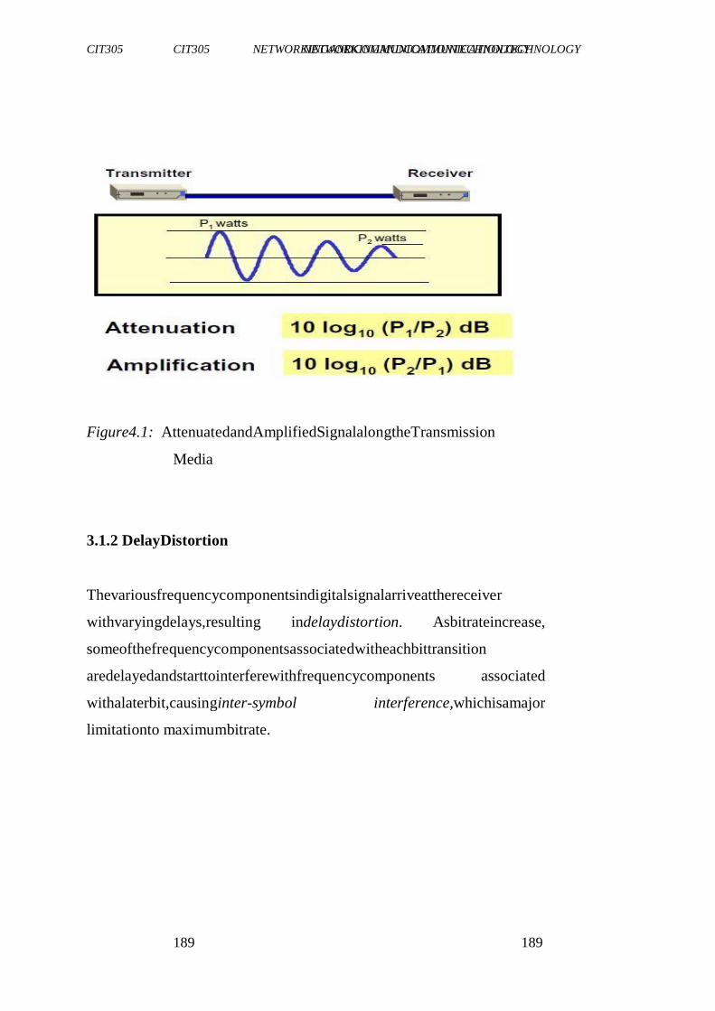
CIT305 NETWORKINGANDCOMMUNICATIONTECHNOLOGY CIT305 NETWORKINGANDCOMMUNICATIONTECHNOLOGY
189 189
Figure4.1: AttenuatedandAmplifiedSignalalongtheTransmission
Media
3.1.2 DelayDistortion
Thevariousfrequencycomponentsindigitalsignalarriveatthereceiver
withvaryingdelays,resulting indelaydistortion. Asbitrateincrease,
someofthefrequencycomponentsassociatedwitheachbittransition
aredelayedandstarttointerferewithfrequencycomponents associated
withalaterbit,causinginter-symbol interference,whichisamajor
limitationto maximumbitrate.
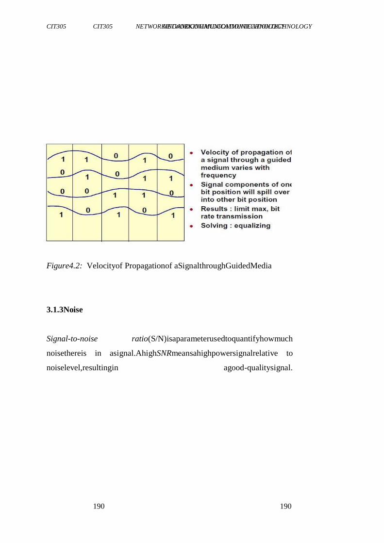
CIT305 NETWORKINGANDCOMMUNICATIONTECHNOLOGY CIT305 NETWORKINGANDCOMMUNICATIONTECHNOLOGY
190 190
Figure4.2: Velocityof Propagationof aSignalthroughGuidedMedia
3.1.3Noise
Signal-to-noise ratio(S/N)isaparameterusedtoquantifyhowmuch
noisethereis in asignal.AhighSNRmeansahighpowersignalrelative to
noiselevel,resultingin agood-qualitysignal.
CIT305 NETWORKINGANDCOMMUNICATIONTECHNOLOGY CIT305 NETWORKINGANDCOMMUNICATIONTECHNOLOGY
191 191
S/Nisgivenas
S/Ndb=10log10S/N
Where S=averagesignalpower
N =noisepower
3.2 NoiseTypes
Here,wearegoingtoconsidersomecommonexamples.
Atmosphericnoise
Lightning-staticdischargeof clouds
Solarnoise-sun‘sionisedgases
Cosmicnoise-distantstarsradiatehighfrequencysignal
Gaussiannoise
Thermalnoise-generatedbyrandommotionof freeelectrons
Impulsenoise-suddenburstsof irregularlypulses
Crosstalk-thisis interferencegeneratedwhenmagneticfieldsor current
nearbywiresinterruptelectrical currentinawire.Aselectrical current
travelsthroughawire,thecurrentgenerates amagnetic field.Magnetic
fieldfrom wiresthatareclosedtogethercaninterferewitheachother.
CIT305 NETWORKINGANDCOMMUNICATIONTECHNOLOGY CIT305 NETWORKINGANDCOMMUNICATIONTECHNOLOGY
192 192
Shieldingthe wire and twisting wire pairs around each other help
decreasecrosstalk
NEXT(near-endcrosstalk)
interferenceinawireatthetransmittingendofasignalsentona
differentwireFEXT(far-endcrosstalk)
interferenceinawireatthereceivingendofasignalsentona
differentwire
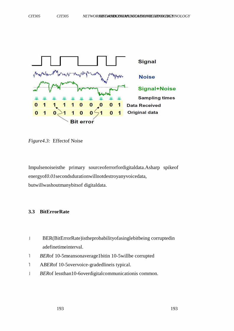
CIT305 NETWORKINGANDCOMMUNICATIONTECHNOLOGY CIT305 NETWORKINGANDCOMMUNICATIONTECHNOLOGY
193 193
Figure4.3: Effectof Noise
Impulsenoiseisthe primary sourceoferrorfordigitaldata.Asharp spikeof
energyof0.01secondsdurationwillnotdestroyanyvoicedata,
butwillwashoutmanybitsof digitaldata.
3.3 BitErrorRate
BER(BitErrorRate)istheprobabilityofasinglebitbeing corruptedin
adefinetimeinterval.
BERof 10-5meansonaverage1bitin 10-5willbe corrupted
ABERof 10-5overvoice-gradedlineis typical.
BERof lessthan10-6overdigitalcommunicationis common.
CIT305 NETWORKINGANDCOMMUNICATIONTECHNOLOGY CIT305 NETWORKINGANDCOMMUNICATIONTECHNOLOGY
194 194
ABitErrorRate(BER)isasignificantmeasureofsystemperformance
intermsofnoise.ABERof10-6,forexample, meansthatonebitof
everymillionmaybedestroyedduringtransmission.Severalfactors that
affectBERareas listedbelow.
• Bandwidth
• S/N
• Transmissionmedium
• Transmissiondistance
• Environment
• Performanceof transmitterandreceiver
3.4 AnalogandDigitalTransmission
Analogsignalis characterisedby beingcontinuouslyvariablealong
amplitudeandfrequency.Digitalsignalischaracterised byseriesof
discretepulses,representing oneandzerobits.Table4.1presentsthe
comparisonbetweenanaloganddigitaltransmission.
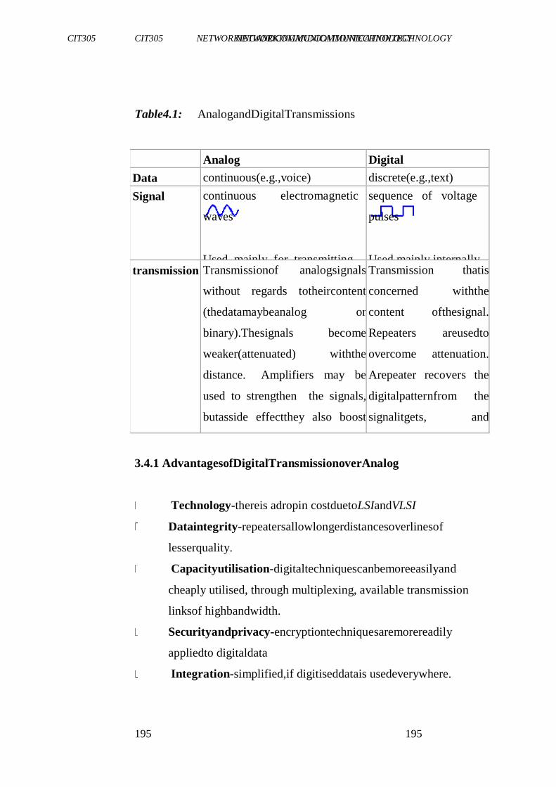
CIT305 NETWORKINGANDCOMMUNICATIONTECHNOLOGY CIT305 NETWORKINGANDCOMMUNICATIONTECHNOLOGY
195 195
Table4.1: AnalogandDigitalTransmissions
Analog Digital
Data continuous(e.g.,voice) discrete(e.g.,text)
Signal continuous electromagnetic
waves
Used mainly for transmitting
dataacrossanetwork.
sequence of voltage
pulses
Used mainly internally
withincomputers. transmission Transmissionof analogsignals
without regards totheircontent
(thedatamaybeanalog or
binary).Thesignals become
weaker(attenuated) withthe
distance. Amplifiers may be
used to strengthen the signals,
butasside effectthey also boost
thenoise. Thismightnotbea
problem foranalogdata,suchas
voice, but is a problem for
digitaldata.
Transmission thatis
concerned withthe
content ofthesignal.
Repeaters areusedto
overcome attenuation.
Arepeater recovers the
digitalpatternfrom the
signalitgets, and
resubmitsanewsignal.
3.4.1 AdvantagesofDigitalTransmissionoverAnalog
Technology-thereis adropin costduetoLSIandVLSI
Dataintegrity-repeatersallowlongerdistancesoverlinesof
lesserquality.
Capacityutilisation-digitaltechniquescanbemoreeasilyand
cheaply utilised, through multiplexing, available transmission
linksof highbandwidth.
Securityandprivacy-encryptiontechniquesaremorereadily
appliedto digitaldata
Integration-simplified,if digitiseddatais usedeverywhere.
CIT305 NETWORKINGANDCOMMUNICATIONTECHNOLOGY CIT305 NETWORKINGANDCOMMUNICATIONTECHNOLOGY
196 196
SELF-ASSESSMENTEXERCISE
Statetheadvantagesof analogtransmissionoverdigital.
3.5 SignalTransmissionAnalysis
Theanalysis ofelectricalsignalsisafundamentalproblem formany
engineers and scientists. Even, if the immediate problem is not
electrical, thebasicparametersofinterestareoftenchanged into
electricalsignalsbymeansoftransducers.Commontransducers include
accelerometersandloadcellsinmechanicalwork,EEGelectrodesand
CIT305 NETWORKINGANDCOMMUNICATIONTECHNOLOGY CIT305 NETWORKINGANDCOMMUNICATIONTECHNOLOGY
197 197
bloodpressureprobes in biologyandmedicine,andpHandconductivity
probesinchemistry.Therewardsfortransformingphysicalparameters
toelectricalsignalsaregreat,asmanyinstruments areavailableforthe
analysisofelectricalsignalsinthetime,frequency andmodaldomains. The
powerful measurement and analysis capabilities of these
instrumentscanleadto rapidunderstandingof thesystemunderstudy.
4.0 CONCLUSION
Inthisunit,youhavebeenintroducedtothefundamental conceptsof
transmission impairment.Youalsolearntthetypesoftransmission
impairments. Youwerealsointroducedtobiterrorrateandsomeofthe
majordifferencesbetweenanaloganddigitaltransmissions.
5.0 SUMMARY
In thisunit,youhavelearntthat:
Transmissionimpairmentisapropertyofatransmissionmedium
whichcausesthesignaltobedegraded, reduced inamplitude,
distortedor contaminated.
Examples of transmissionimpairmentsare attenuation,delay
distortion,andnoise
Typesofnoiseincludethermalnoise,impulsenoise,andinter-
modulationnoise
CIT305 NETWORKINGANDCOMMUNICATIONTECHNOLOGY CIT305 NETWORKINGANDCOMMUNICATIONTECHNOLOGY
198 198
Analogsignalischaracterisedby beingcontinuouslyvariable
alongamplitudeandfrequency.Digitalsignalischaracterisedby
seriesof discretepulses,representingoneandzerobits.
6.0 TUTOR-MARKEDASSIGNMENT
a. Whatdoyouunderstandbytransmissionimpairment b.
Whatis thedifferencebetweenFEXTandNEXT?
c. Whatdoyouunderstandbytheterm―noise‖?
7.0 REFERENCES/FURTHERREADING
Friedhelm,Hillebrand(2002).GSMandUMTS-TheCreationofGlobal
MobileCommunications(Ed.).JohnWiley& Sons.
"Brazil, Russia, India and China to Lead Internet Growth Through
2011".Clickz. com.
http://clickz.com/showPage.html?page=3626274. Retrieved
2009-05-28.
CIT305 NETWORKINGANDCOMMUNICATIONTECHNOLOGY CIT305 NETWORKINGANDCOMMUNICATIONTECHNOLOGY
199 199
MODULE5 NETWORKTECHNOLOGIES
Unit1 IntegratedServiceDigitalNetwork(ISDN)
Unit2 Digital SubscriberLine(DSL)
Unit3 SONET
Unit4 Packet Switching
Unit5 InternetandTCP/IP
UNIT1 INTEGRATEDSERVICEDIGITALNETWORK (ISDN)
CONTENTS
1.0 Introduction
2.0 Objectives
3.0 MainCONTENTS
3.1 WhatisISDN?
3.2 History
3.3 ComponentsofISDN
3.3.1ISDNAccessTypes
3.4 ISDNDevices
3.5 ISDNInterfaces
3.5.1 TheR Interface
3.5.2 TheSInterface
3.5.3 TheTInterface
3.5.4 TheU interface
3.6 HowDoesISDNwork?
CIT305 NETWORKINGANDCOMMUNICATIONTECHNOLOGY CIT305 NETWORKINGANDCOMMUNICATIONTECHNOLOGY
200 200
3.6 TheUsefulnessofISDN
4.0 Conclusion
5.0 Summary
6.0 Tutor-MarkedAssignment
7.0 References/FurtherReading
1.0 INTRODUCTION
Having readthroughthecourseguide,youwillhaveageneral
understandingof whatthisunitis aboutandhowitfitsintothecourseas
awhole.ThisunitwilldescribethegeneralconceptofISDN.
CIT305 NETWORKINGANDCOMMUNICATIONTECHNOLOGY CIT305 NETWORKINGANDCOMMUNICATIONTECHNOLOGY
201 201
2.0 OBJECTIVES
At theendof thisunit,youshouldbeable to:
explainthetermISDN
describeISDNinterfaces
discusshowISDNworks
statetheusefulnessofISDN
3.0 MAINCONTENT
3.1 WhatisIntegratedServicesDigitalNetwork(ISDN)?
IntegratedServicesDigitalNetwork(ISDN)isadigitalcommunications
technology thatenablesasmallbusinessoranindividualtoconnect
directlytotheinternetandothersites/users(forvideoconferencing, for
instance). ISDN provides a standard interfacefor voice, fax, video,
graphics,anddata–allonasingletelephoneline.
―Integrated services‖ refers to ISDN's ability to deliver two
simultaneous connections,inanycombinationofvoice,fax,data,and
video,overasingleline.Multipledevicescanbeattachedtotheline, andusedas
needed.
CIT305 NETWORKINGANDCOMMUNICATIONTECHNOLOGY CIT305 NETWORKINGANDCOMMUNICATIONTECHNOLOGY
202 202
―Digital‖referstothefactthatitisapurelydigitaltransmission, as
opposedtotheanalog transmissionmethodusedbyconventional
telephonelines.
―Network‖ referstothefactthatISDNisnotsimplyapoint-to-point
connectionlikealeasedtelephoneline –ISDNnetworksextendfromthe local
telephone exchange to the remote user, and include all the
switchingequipment in between. If your ISDN equipment includes
analog capabilities,youcanalsoconnecttotelephones,faxmachines,
andanalogmodems –eventhoughtheymaybeconnectedtostandard
analogtelephonelines.
ISDNserviceisprovidedbythesamecompanies thatprovidetelephone
service–yougetmuchfaster,moredependableconnections forvoice,
fax,data,andvideo–allthroughasingleconnection. Whilenotnew
(ISDNhasbeeninuseforover15years),theadvent ofinternational
standardshasmadeISDNviableastelephonecompanies aroundthe
worldhaveupgradedtheirequipment totheseISDNstandards.Itisnow
commonly availableinEurope,Japan,Australia,andfrommostmajor
NorthAmerican telephone companies–AT&T,MCI,andSprintcan
providelong-distanceISDNlinesforglobalconnections.Oneofthe
CIT305 NETWORKINGANDCOMMUNICATIONTECHNOLOGY CIT305 NETWORKINGANDCOMMUNICATIONTECHNOLOGY
203 203
reasonsforitswidespreaduseisthatitworksontheordinarycopper
wirealreadyin placein thetelephonesystem.
OneadvantageofISDNoverotherdigitalcommunicationstechnologies
isitsabilitytohandlealltypesofinformation suchasvoice,computer
data,studio-qualitysound,andvideo.
3.2 History
Theearlyphonenetwork consistedofapureanalogsystemthat
connectedtelephoneusersdirectlybyamechanicalinterconnection of
wires.Thissystem wasveryinefficient,wasverypronetobreakdown
andnoise,anddidnotlenditselfeasilytolong-distance connections.
Beginning in the 1960s, the telephone system gradually began
converting itsinternalconnectionstoapacket-based,digitalswitching
system.Today,nearlyallvoiceswitching intheUnitedStates(U.S.)is
digitalwithinthetelephonenetwork.Still,thefinalconnection fromthe
localcentralofficetothecustomerequipmentwas,andstilllargelyis, an
analogPlain-OldTelephoneService(POTS)line.
AstandardsmovementwasstartedbytheInternational Telephoneand
TelegraphConsultative Committee(CCITT),nowknownasthe
InternationalTelecommunications Union(ITU).TheITUisaUnited
Nationsorganisation thatcoordinatesandstandardises international
telecommunications.OriginalrecommendationsofISDNwereinCCITT
CIT305 NETWORKINGANDCOMMUNICATIONTECHNOLOGY CIT305 NETWORKINGANDCOMMUNICATIONTECHNOLOGY
204 204
Recommendation I.120(1984)whichdescribedsomeinitialguidelines
forimplementingISDN.
Localphonenetworks,especiallytheregionalBelloperatingcompanies,
havelonghailedthesystem,buttheyhadbeencriticisedforbeing slow
toimplementISDN.Onegoodreasonforthedelayisthefactthatthe two
majorswitchmanufacturers,NorthernTelecom(now knownas
NortelNetworks), andAT&T(whoseswitchbusiness isnowownedby
LucentTechnologies), selecteddifferentwaystoimplementtheCCITT
standards.Thesestandardsdidn'talwaysinter-operate.Thissituationhas
beenlikenedtothatofearlier19thcenturyrailroading- "peoplehad
differentgauges,differenttracks...nothingworkedwell".
Intheearly1990s,an‗industry-wide‘ effortwasinitiatedtoestablisha
specificimplementation forISDNintheU.S.Membersoftheindustry
agreedtocreatetheNationalISDN1(NI-1)standard sothatendusers
wouldnothavetoknowthebrandofswitchtheyareconnected toin
ordertobuyequipmentandsoftwarecompatiblewithit.However,there
wereproblemsagreeing onthisstandard.Infact,manywesternstates
wouldnotimplementNI-1.BothSouthwesternBellandU.S.West(now
Qwest)saidthattheydidnotplantodeployNI-1softwareintheir
CIT305 NETWORKINGANDCOMMUNICATIONTECHNOLOGY CIT305 NETWORKINGANDCOMMUNICATIONTECHNOLOGY
205 205
centralofficeswitchesduetoincompatibilitieswiththeirexistingISDN
networks.
Ultimately,alltheRegionalBellOperatingCompanies (RBOCs)did
supportNI-1.Amorecomprehensivestandardisationinitiative,National
ISDN2(NI-2),waslateradopted.Somemanufacturers ofISDN
communication equipment-suchasMotorolaandU.S.Robotics(now
ownedby3Com),worked withtheRBOCstodevelop configuration
standardsfortheirequipment.Thesekindsofactions,along withmore
competitivepricing,inexpensiveISDNconnection equipment,andthe
desireforpeopletohaverelativelylow-costhigh-bandwidth internet
accesshavemadeISDNmorepopularin recentyears.
Mostrecently,ISDNservicehaslargelybeendisplaced bybroadband
internetservice,suchasxDSLandcablemodemservice.Theseservices
arefaster,lessexpensive,andeasiertosetupandmaintain thanISDN.
Still,ISDNhasitsplace,asbackuptodedicated lines,andinlocations
wherebroadbandserviceis notyetavailable
3.3 ComponentsofISDN
Whileindividualoperatingcompaniesand ministrieswilldefinethe
specificservices,withintheISDNarchitecturetheITUstandardsdefine
anumberof componentpartsandfunctionsas listedbelow.
CIT305 NETWORKINGANDCOMMUNICATIONTECHNOLOGY CIT305 NETWORKINGANDCOMMUNICATIONTECHNOLOGY
206 206
ISDNChannels
AccessTypes
Devices
Interfaces
Protocols
ISDNChannels
ACHANNEL isthebasicunitofISDNservice.TheISDNStandards
definethreebasictypesof channels:
Bearerchannels(Bchannels)
Delta(or"Demand")channels(Dchannels)
High-capacitychannels(Hchannels)
B Channel
ABchannelisa64-Kbps unitofcleardigitalbandwidth. Basedonthe
dataraterequiredtocarryonedigitalvoiceconversation,aBchannel
cancarryanytypeofdigitalinformation (voice,data,orvideo)withno
restrictionsonformator protocolimposedbythe ISDNcarrier.
CIT305 NETWORKINGANDCOMMUNICATIONTECHNOLOGY CIT305 NETWORKINGANDCOMMUNICATIONTECHNOLOGY
207 207
D Channel
ADchannelisasignalingchannel.Itcarriestheinformationneededto
connectordisconnectcallsandtonegotiatespecialcalling parameters
(i.e.,automatic numberID,callwaiting,dataprotocol).TheDchannel
canalsocarrypacket-switcheddatausingthe X.25protocol.
TheDchannelisnotaclearchannel.Itoperatesaccording toawell-
definedpairof layeredprotocols:
Q.921(LAPD)at thedatalinklayer(Layer2)
Q.931at theupperlayers(Layers3andabove)
ThedatarateofaDchannelvariesaccording tothetypeofaccessit serves-a
basicrateaccessDchanneloperatesat16Kbpsandaprimary rateaccessD
channeloperatesat 64Kbps.
SignalingontheD Channel
The ISDN D channel carries all signaling between the customer's
terminaldeviceandthecarrier'sendswitchingoffice.
Signaling informationwithend-to-endsignificance(i.e.,whichmustbe
receivedbytheterminaldevice at acall'sdestination,suchasAutomatic
CallingNumberIdentificationinformation)travelsbetweenthecarrier's
switchingofficesonthecarrier'scommon-channelsignalingnetwork
andontothedestinationterminal,throughthereceiving user'sD channel.
CIT305 NETWORKINGANDCOMMUNICATIONTECHNOLOGY CIT305 NETWORKINGANDCOMMUNICATIONTECHNOLOGY
208 208
H Channel
AnHchannel isaspecial,high-speedclearchannel.Hchannels,
designedprimarilyforfull-motion colorvideo,arenotyetincommon use.
Therearecurrentlythreekindsof H channel:
H0("H-zero")
H11("H-one-one")
H12("H-one-two")
AnH0channeloperates at384Kbps(roughly onefourthofaNorth American
primaryrateaccessoronefifthofaEuropean primaryrate
access).AnH1channeloperatesat1.536Mbpsandoccupiesonewhole
NorthAmericanprimaryrateaccess.AnH12channeloccupiesanentire
Europeanprimaryrateaccess.
CIT305 NETWORKINGANDCOMMUNICATIONTECHNOLOGY CIT305 NETWORKINGANDCOMMUNICATIONTECHNOLOGY
209 209
3.3.1 ISDNAccessTypes
ISDNofferstwogeneraltypesof access:
BASICRATE ACCESS(BRA)
PRIMARYRATE ACCESS(PRA)
Thesedifferfromoneanotherbythe amountofinformation theycan carry.
Basicrateaccess
Basicrateaccessisbasedonnewtechnologyconceived especially for
ISDN.Designed toprovideservicetoindividualusersorsmall
businesses,basicrateaccessprovidestwo64-KbpsBchannelsandone
16-Kbps Dchannel(referredtoas2B+D).Inotherwords,itprovides
transmissionfacilitiesforonevoiceconversation (oneBchannel),one
medium-speeddatasession(theother Bchannel),andthesignaling
exchangesneededto makethemwork(the D channel).
TwoBchannelsat64KbpsplusoneDchannel at16Kbpsequals 144K
bps.TheISDNbasicratetransmissionprotocolusesanadditional48
Kbpsofbandwidthformaintenanceandsynchronisation,soanISDN
basicrateaccessactuallyuses192Kbps.
Primaryrateaccess
CIT305 NETWORKINGANDCOMMUNICATIONTECHNOLOGY CIT305 NETWORKINGANDCOMMUNICATIONTECHNOLOGY
210 210
Primaryrateaccess,whichisbasedonpre-ISDN digitalcarrier
technology,isdesignedtoprovidehigh-capacity servicetolarge
customersforapplicationssuchasPBX-to-PBXtrunking. Therearetwo
kindsofprimary rateaccess:23B+Dand30B+D.Eachdepends onthe kindof
digitalcarrieravailablein agivencountry.
InNorthAmericaandJapan,23B+Dprimaryrateaccessoperatesat
1.544 Mbps and offers 23 B channels plus 1 64-Kbps D channel
(usuallylocated intime-slot23),or4H0channels,or1H11channel. In
mostoftherestoftheworld,30B+Dprimaryrateaccessoperatesat
2.048 Mbps and offers 30 B channels plus 1 64-Kbps D channel
(locatedin time-slot16), or 5H0channels,or1H12channel.
3.4 ISDNDevices
InthecontextofISDNstandards,standard devicesrefernottoactual
hardware,buttostandardcollections offunctionsthatcanusuallybe
performed byindividualhardwareunits.TheISDNstandarddevicesare
listedbelow.
CIT305 NETWORKINGANDCOMMUNICATIONTECHNOLOGY CIT305 NETWORKINGANDCOMMUNICATIONTECHNOLOGY
211 211
TerminalEquipment(TE)
TerminalAdapter(TA)
NetworkTermination1(NT1)
NetworkTermination2(NT2)
ExchangeTermination(ET)
TerminalEquipment(TE)
ATEisanypieceofcommunicating equipmentthatcomplieswiththe
ISDNstandards.Examples includedigitaltelephones,ISDNdata
terminals,Group IVFaxmachines,and ISDN-equippedcomputers.
Inmostcases,aTEshouldbeabletoprovideafullbasicrateaccess
(2B+D),althoughsomeTEsmayuseonly1B+DorevenonlyaD
channel.
TerminalAdapter(TA)
ATAis aspecialinterface-conversiondevicethatallowscommunicating
devicesthatdon'tconformtoISDNstandardstocommunicate overthe ISDN.
Themostcommon TAsprovide basicrateaccessandhaveoneRJ-type
modularjackforvoiceandoneRS-232orV.35connector fordata(with
eachportabletoconnecttoeitheroftheavailableBchannels).Some
TAshaveaseparatedataconnectorfortheD channel.
CIT305 NETWORKINGANDCOMMUNICATIONTECHNOLOGY CIT305 NETWORKINGANDCOMMUNICATIONTECHNOLOGY
212 212
NetworkTermination(NT1andNT2)
TheNTdevices,NT1andNT2,form thephysical andlogicalboundary
between the customer's premises and the carrier's network. NT1
performsthelogicalinterfacefunctionsofswitching andlocal-device
control(localsignaling).NT2performsthephysicalinterfaceconversion
betweenthedissimilarcustomerandnetworksidesof theinterface.
Inmostcases,asingledevice,suchasaPBXordigitalmultiplexer,
performs bothphysicalandlogicalinterfacefunctions.InISDNterms,
suchadeviceis calledNT12("NT-one-two")or simplyNT.
ExchangeTermination(ET)
TheETformsthephysicalandlogicalboundarybetweenthedigital
localloopandthecarrier'sswitching office.Itperformsthesame functions
attheendofficethattheNTperforms atthecustomer's premises.
CIT305 NETWORKINGANDCOMMUNICATIONTECHNOLOGY CIT305 NETWORKINGANDCOMMUNICATIONTECHNOLOGY
213 213
In addition,the ET:
separates B channels, placing them on the proper interoffice
trunksto theirultimatedestinations
terminates the signaling path of the customer's D channel,
convertinganynecessaryend-to-endsignalingfromtheISDND-
channelsignalingprotocoltothecarrier'sswitch-to-switchtrunk
signalingprotocol
3.5 ISDNInterfaces(StandardReferencePoints)
TheISDNstandardsspecifyfourdistinctinterfaces inthecustomer's
connectiontothenetwork:R,S,T,andU,asdiscussedinsubsection
3.5.1through3.5.4
Fromthestandardsviewpoint,thesearenot"real"physicalinterfaces,
butsimply ‗standardreferencepoints’wherephysicalinterfacesmaybe
necessary.However,incommonpractice,thenamesofreference points
areusedto referto physicalinterfaces.
3.5.1TheRInterface
Theinterface atreferencepointRisthephysical andlogicalinterface
betweenanon-ISDNterminaldeviceandaTerminalAdapter(TA).The
RinterfaceisnotreallypartoftheISDN;itcanconform toanyofthe
commontelephoneor datainterfacestandards.
CIT305 NETWORKINGANDCOMMUNICATIONTECHNOLOGY CIT305 NETWORKINGANDCOMMUNICATIONTECHNOLOGY
214 214
3.5.2TheSInterface
Theinterfaceatreference pointSisthephysicalandlogicalinterface between
aTE(orTA)andanNT.TheSinterface usesfourwiresand employsa
bipolartransmissiontechniqueknownas AlternateMark Inversion(AMI).
AspecialfeatureoftheSinterface isthe"shortpassivebus"
configuration,whichallowsuptoeightISDNdevices(TEorTA)to
contend forpacketaccesstotheDchannel inaprioritised, round-robin
fashion.Onlyonedeviceat atimecanuseagivenB channel.
3.5.3 TheTInterface
Theinterfaceatreference pointTisthephysicalandlogicalinterface
betweenNT1and NT2, wheneverthe two NTsare implementedas
separatepiecesofhardware.Thespecification fortheTinterfaceis identicalto
thespecificationfortheSinterface.
In most implementations,NT1 and NT2 exist in the same physical
device,so thereis norealTinterface.
CIT305 NETWORKINGANDCOMMUNICATIONTECHNOLOGY CIT305 NETWORKINGANDCOMMUNICATIONTECHNOLOGY
215 215
3.5.4 TheUInterface
Theinterfaceatreference pointUisthephysicalandlogicalinterface
betweenNT(orNT2)andtheISDNcarrier'slocaltransmissionloop.It is also
the legal demarcation between the carrier's loop and the
customer'spremises.
The U interfaceis implementedwithtwo wiresand usesa special
quaternarysignalformat(i.e.,fourpossible electricalstates,withone
pulseencoding apredefinedcombinationof2bits)called2B1Q. Quaternary
encodingallowstheUinterfacetocarrydatawithalogical
bitrateof192Kbpsoverasignalwithaphysicalpulserateofonly96
Kbps.Theslower pulserateisbettersuitedtotheless-predictable
environmentof theoutside-plantloopcarriersystem.
3.6 HowDoesISDNWork?
ThesimplestISDNconnection(calledBasicRateorBRI)consistsof
two64Kbps(kilobits-per-second)datachannels(calledB-channels) plus a
16 Kbps control channel (called the D-channel). This is
sometimesreferredtoas―2B+D.‖Ontheotherendofthespectrum is
primaryrateISDN(called PRI)with23B-channels plusaD-
channel(i.e.:―23B+D‖).
To connectto the ISDNline,you needablack-boxcalledan NT1
Network Terminator–apowersupply(whichyoualsoneed)isoften built-
in.YouwillalsoneedaTerminalAdapter(oftencalleda―TA‖) to connectnon-
ISDNequipment(suchas yourcomputeror faxmachine)to
CIT305 NETWORKINGANDCOMMUNICATIONTECHNOLOGY CIT305 NETWORKINGANDCOMMUNICATIONTECHNOLOGY
216 216
theline–thesearealso available asplug-incardsforPC’s.SomeTA’s
workasethernetbridgessothatyoucanconnectyourLANdirectlyto
theISDNline.
3.7 TheUsefulnessofISDN
Oneofthemostcommonusesforthistechnology todayis videoconferencing.
ByusingfromonetofourBRIlines,a
videoconferencecanbeestablishedbetweentwoormoresites–the
morelines,thefastertheconnection.Foravideoconferenceapplication,
higherconnectionspeedtranslatestohigherresolution andvideoframe
rates.Thetelephonecompanyinfrastructureallowstheseconnections to
bemadeinasimilarfashiontodialingatelephone. Whilevideo
conferencinghasbeenaroundforalongtime, in thepastithasprimarily
beenconfinedto largecorporations.Theabilityto transmitqualityvoice
andvideo overlongdistancesusedtorequireexpensive equipmentand
costlyleasedlines–thesecouldonlybejustified bythelargestof
companies.Duetothisdependency onleasedlines,videoconferences
werepoint-to-point(e.g.headquartersmaybe,permanently,linkedtoa
CIT305 NETWORKINGANDCOMMUNICATIONTECHNOLOGY CIT305 NETWORKINGANDCOMMUNICATIONTECHNOLOGY
217 217
manufacturing plant). Videoconferencing on the scale of
teleconferencingwassimplyimpractical.
Theadventofnewlow-costvideoconference hardwarethatcanutilise
ISDNisrapidlychangingthis.Bothdesktopconferencing(aparticipant
usesaPCequippedwithamicrophone, asmallvideocamera,andan
ISDNinterface)andtruevideoconferencing (wheremoresophisticated
equipmentandremotecontrolcamerasallowgroupparticipation) have
become as easy to set up as voice conferencing. Due to ISDN's
versatility,videoconferences canincludethesharingofgraphicimages and
presentations, computer applications, documents, and computer files.
This capability is proving popular for telecommuting, long
distancemeetings,workgroup collaboration,securityandsurveillance,
anddozensof otherinnovativeapplications.
4.0 CONCLUSION
Inthisunit,youhavebeenintroducedtothefundamental conceptsof
ISDN.Youhavealsolearntthedifferentcomponents andinterfacesof ISDN.
5.0 SUMMARY
In thisunit,youhavelearntabout:
thetermISDN
ISDNinterfaces
howISDNworks
theusefulnessofISDN.
CIT305 NETWORKINGANDCOMMUNICATIONTECHNOLOGY CIT305 NETWORKINGANDCOMMUNICATIONTECHNOLOGY
218 218
6.0 TUTOR-MARKEDASSIGNMENT
a. AccordingtoITU,describeISDNarchitecture. b.
DescribeISDNaccesstypes.
7.0 REFERENCES/FURTHERREADING
Friedhelm,Hillebrand(2002).GSMandUMTS:TheCreationofGlobal
MobileCommunications(Ed.).JohnWiley& Sons.
Sodiya,A.S.(2008).DigitalCommunicationandComputerNetwork–
AnIntroduction(Ahandbook).
"Brazil, Russia, India and China to Lead Internet Growth Through
2011". Clickz.com.
http://clickz.com/showPage.html?page=3626274. Retrieved
2009-05-28.
CIT305 NETWORKINGANDCOMMUNICATIONTECHNOLOGY CIT305 NETWORKINGANDCOMMUNICATIONTECHNOLOGY
219 219
UNIT2 DIGITALSUBSCRIBERLINE(DSL)
CONTENTS
1.0 Introduction
2.0 Objectives
3.0 MainContent
3.1 Whatis Digital SubscriberLine(DSL)?
3.2 HistoryofDSL
3.3 FeaturesofDSL
3.4 BenefitsofDSL
3.5 HowDSLworks
4.0 Conclusion
5.0 Summary
6.0 Tutor-MarkedAssignment
7.0 References/FurtherReading
1.0 INTRODUCTION
DSL is a specialised and problem-orientedlanguage. Contrary to a
GeneralPurpose Language(GPL) (e.g.UML,JavaorC#),aDSLserves to
accuratelydescribeadomainofknowledge.Theinteresttocombinea
DSLandatransformation functionistoraisetheabstractionlevelof
software.ADSLuserconcentratesher/his efforts ondomaindescription
whilecomplexity, designandimplementation decisionsanddetailsare
hidden.Thestakeis to improveproductivityandsoftwarequality.
CIT305 NETWORKINGANDCOMMUNICATIONTECHNOLOGY CIT305 NETWORKINGANDCOMMUNICATIONTECHNOLOGY
220 220
However,whatisthenextconsensusbeyondthisgeneraldefinition?An
experienceconsistsinstartingthedevelopmentofaDSLeditorcoupled
toagenerator. Quickly,theissueofthevariants ofDSLeditorsand
generatorsemerges.Regarding thelanguage,isitatree-basedDSLora
setofdatawithoutrealstructure?Isitagraphicalortextual notation?Is
itadeclarative orimperativestyle? Answerstomostofthesequestions willbe
providedin thisunit
2.0 OBJECTIVES
At theendof thisunit,youshouldbeableto:
explainthetermDSL
statethefeaturesofDSL
illustratehow DSLworks
highlighttheadvantagesanddisadvantagesofDSL
CIT305 NETWORKINGANDCOMMUNICATIONTECHNOLOGY CIT305 NETWORKINGANDCOMMUNICATIONTECHNOLOGY
221 221
3.0 MAINCONTENT
3.1 WhatisDSL?
DSLisatelephonelooptechnologythatusesexisting copperphones
lines,andprovides adedicated,highspeedinternetconnection. Thebig
advantageof someDSLs(notablyADSL),isthattheycanco-existonthe
samelinewithatraditionalvoiceservicesuchas"POTS" (PlainOld
TelephoneService),andevenISDN.Thisisaccomplished byutilising
differentfrequencyranges abovethevoicerange(voice isupto4KHz).
Essentially,thisgivestwolinesinone-oneforvoice,andonefor
internetconnectivity.Whenallisworking normally,thereshouldbeno
interferencebetweenthetwo"lines".ThisgivesDSLapotentiallybroad
consumerbase,andhelpsminimisecostsforserviceproviders.
DSLis positionedfortheHomeandSmallOffice(SOHO)marketthatis
lookingforhighspeedinternetaccessatreasonable prices.Sinceitalso
typically providesdedicated, "alwayson" access,itcanbeusedfor
interconnectinglowtomidrangebandwidthservers,andprovidesa
greataccesssolution for smallLANs.ItisalsogreatforthoseLinux
powerusersthatjustwantafatpipe).
Phonecompanies,andotherindependenttelecommunications providers
(CLECs),arenowdeployingDSLto stayaheadof thecablecompanies-
themainconsumerandSOHO competitionforDSLproviders.Thismad
rushtoget"apieceofthepie"isbringingmuchcompetition (agood
CIT305 NETWORKINGANDCOMMUNICATIONTECHNOLOGY CIT305 NETWORKINGANDCOMMUNICATIONTECHNOLOGY
222 222
thing!),muchdiversity,andsomeconfusion, intotheconsumermarket.
TheDSLprovider(often,butnot always,thephonecompany)will
providetheDSLinfrastructure.Thiswillincludeyourline,theDSLAM,
andphysicalconnection totheoutsideworld.Fromthere,itistypically
pickedupbyanISP, whoprovidesthetraditionalinternetservices.
ConsumerDSLplansaretypically"besteffort" services. Whileboasting
speedsapproachingT1,andevensurpassingthatinsomecases,itisnot
necessarily asreliableasT1,however.BusinessclassDSLoffersmore
reliability atahighercostthanconsumerplans,andisagood
compromisewherebothreliabilityandbandwidthareatapremium.All
inall,thecostofDSLcomparedtotraditionaltelecomservices,suchas
T1,isattractiveandsubstantiallymoreaffordable forhomeandsmall
businessusers.
DSLprovidersoftendonothaveservicecontractsforhomeusers,while
business classDSLservicestypically doincludesimilarSLAs(Service
LevelAgreements)to thatofferedforaT1line.
CIT305 NETWORKINGANDCOMMUNICATIONTECHNOLOGY CIT305 NETWORKINGANDCOMMUNICATIONTECHNOLOGY
223 223
ThedownsideisthatDSLisnotavailableeverywhere.Availability, and
availablebitrate(speed),arepurely afunctionofwhereyoulive,where
thetelecomfirmhasinstalledtheprerequisitehardware,howfaryouare
fromtheDSLAM/CO, andthequalityofyourphoneline(loop).Notall loops
are created equal, unfortunately. The primary limitation is distance.
3.2 HistoryofDSL
Implementationofdigitalsubscriberlinetechnologyoriginallywaspart
oftheIntegratedServicesDigitalNetwork (ISDN)specification published
in1984bytheCCITTandITUaspartofrecommendation
I.120,laterreusedasISDNDigitalSubscriber Line(IDSL).Engineers have
developed higher-speed DSL facilities such as High (bit rate)
DigitalSubscriber Line(HDSL)andSymmetric DigitalSubscriberLine
(SDSL) toprovidetraditionalDigitalSignal1(DS1)services over
standardcopperpairfacilities.Consumer-oriented AsymmetricDigital
SubscriberLine(ADSL),firsttestedatBellcorein1988,wasdesigned
tooperateonexisting linesalreadyconditioned forBRIISDNservices.
Thisitselfis aswitcheddigitalservice(non-IP),thoughmostIncumbent
LocalExchangeCarriers(ILECs)provideRate-Adaptive Digital
SubscriberLine(RADSL)to workonvirtuallyanyavailablecopperpair
facility—whetherconditionedfor BRIor not.
ThedevelopmentofDSL,likemanyotherformsofcommunication,can
betracedbacktoClaudeShannon's 1948seminal paper-'A
MathematicalTheoryofCommunication''. Employees atBellcore(now
CIT305 NETWORKINGANDCOMMUNICATIONTECHNOLOGY CIT305 NETWORKINGANDCOMMUNICATIONTECHNOLOGY
224 224
TelcordiaTechnologies)developedADSLin 1988byplacingwide-band
digital signalsabovetheexisting(baseband])analog voicesignalcarried
betweenTelephone Company(centraloffices)andcustomers on
conventional(twistedpair)cablingfacilities.ADSLcircuitprovides
''digitalservice''.Theunderlying technologyoftransportacrossDSL
facilitiesuseshigh-frequency (sinusoidal-carrierwave)modulation,
whichis an analogsignaltransmission.
ADSLcircuitterminates ateachendina(modem)whichmodulates
patternsofBinarydigit(bits)intocertainhigh-frequency impulsesfor
transmission totheopposingmodem.Signalsreceivedfromthefar-end
modemaredemodulatedtoyieldacorresponding bitpatternthatthe
modemretransmits,indigitalform,toitsinterfacedequipment,suchas a
computer, router, switch, etc. Unlike traditional dial-up modems,
whichmodulatebitsintosignalsinthe300–3400 Hzbaseband
(voiceservice),DSLmodemsmodulatefrequenciesfrom4000
Hztoashighas4 MHz.Thisfrequency bandseparation enables
DSLserviceandplainoldtelephone service(POTS)tocoexistonthe same
copper pair facility. Generally, higher bit rate transmissions
CIT305 NETWORKINGANDCOMMUNICATIONTECHNOLOGY CIT305 NETWORKINGANDCOMMUNICATIONTECHNOLOGY
111111
111
require awiderfrequencyband,though theratioofbitrateto bandwidth
arenotlineardueto significantinnovationsin digitalsignalprocessing.
EarlyDSLservicerequiredadedicated dryloop,butwhentheU.S.
FederalCommunications Commission(FCC)requiredILECstolease
theirlinestocompetingDSLservice providers,shared-lineDSLbecame
available.AlsoknownasDSLover(Unbundled NetworkElement),this
unbundlingof servicesallowsasinglesubscriberto receivetwoseparate
servicesfromtwoseparateprovidersononecablepair.TheDSLservice
provider'sequipmentisco-locatedinthesamecentralofficeasthatof
theILECsupplying thecustomer'spre-existingvoiceservice.The
subscriber'scircuitisthenrewiredtointerfacewithhardwaresupplied
bytheILECwhichcombinesaDSLfrequencyandPOTSfrequencyona
singlecopperpairfacility.
Onthesubscriber's endofthecircuit,inlinelow-passDSLfilters (splitters)
areinstalledoneachtelephone tofilterthehigh-frequency "hiss" that would
otherwise be heard. Conversely,High-passfilters alreadyincorporated
inthecircuitryofDSLmodemsfilteroutvoice
frequencies.AlthoughADSLandRADSLmodulation donotusethe voice-
frequency band,nonlinearelementsinthephonecouldotherwise
generateaudibleinter-modulation andmayimpairtheoperationofthe
datamodemin theabsenceof low-passfilters
3.3 FeaturesofDSL
Letus lookat theseinrelationtothefollowing
CIT305 NETWORKINGANDCOMMUNICATIONTECHNOLOGY CIT305 NETWORKINGANDCOMMUNICATIONTECHNOLOGY
112112
112
Languagefeature
Transformationfeature
Toolfeature
Processfeature
Attherootlevel,languageandtransformation aremandatoryfeatures
becausetheyarepartsoftheDSLdefinition. Toolisalsomandatory because it
serves to automate transformation from a domain, the
problemspace,downtolowerabstraction levels,thesolutionspace. Processis
optionalbecauseitcanbe undefinedor implicit.
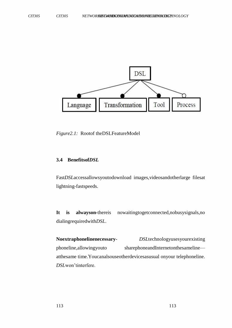
CIT305 NETWORKINGANDCOMMUNICATIONTECHNOLOGY CIT305 NETWORKINGANDCOMMUNICATIONTECHNOLOGY
113113
113
Figure2.1: Rootof theDSLFeatureModel
3.4 BenefitsofDSL
FastDSLaccessallowsyoutodownload images,videosandotherlarge filesat
lightning-fastspeeds.
It is alwayson-thereis nowaitingtogetconnected,nobusysignals,no
dialingrequiredwithDSL.
Noextraphonelinenecessary- DSLtechnologyusesyourexisting
phoneline,allowingyouto sharephoneandInternetonthesameline—
atthesame time.Youcanalsouseotherdevicesasusual onyour telephoneline.
DSLwon‘tinterfere.
CIT305 NETWORKINGANDCOMMUNICATIONTECHNOLOGY CIT305 NETWORKINGANDCOMMUNICATIONTECHNOLOGY
114114
114
Fastinternetconnection- youwillbeabletodownloadinformation,
graphics andvideofrom theinternetatspeedsupto2.3Mb/s;and,you
canuploadinformationas fastas 2.3Mb/s.
Dedicated line-youwillbetheonlypersonusingyourconnectionand
line.Unlikecableormodems,youdoyounotshareyourconnection
withotherusers,soyourInternet speedwillbemoreprivate,stableand
willhavefewerdelays.
Availableinlimitedareas-DSLusersmustbewithinacertainradius of
theareatelephoneswitch.
In essence,DSLhasthefollowingadvantages:
thespeedis muchhigherthanaregular modem
DSLdoesnotnecessarilyrequirenewwiring
thecompanythatoffersDSLwillusuallyprovidethemodemas partof
theinstallation
CIT305 NETWORKINGANDCOMMUNICATIONTECHNOLOGY CIT305 NETWORKINGANDCOMMUNICATIONTECHNOLOGY
115115
115
DisadvantagesofDSL
Theserviceis notavailableeverywhere
Theconnectionisfastforreceivingdatathanitisforsending
dataovertheinternet
A DSLworksbetterwhenyouareclosertotheprovider‘scentral office
3.5 HowDSLWorks
DSLisaninnovativetechnology thatallowsyourcomputertotransmit
informationoverexisting phoneline,butatahigherfrequencythan
telephones, faxmachines andotherdevices.Sinceitutilisesthehigher
frequencies,youcanusethesamephonelinefortelephonecallsand
yourinternetconnectionatthesametime,withoutanyinterference.
Yourtelephonecallswillstillbeclearand crisp,andyourInternet
connectionwillseemlikelightning comparedtoa56Kmodem connection.
4.0 CONCLUSION
ADSLisaproblem-oriented language,which-combinedto transformation
tools,suchasgenerators,servestoraisetheabstraction level of software and
ease software development; but beyond this
generaldefinition,DSLandDSLtoolvariantsarenumerous.Thereason
ofaDSLfeaturemodelistoformaliseDSLandDSLtoolvariants.A
firstapplicationof this featuremodelis a DSLtoolfactory,which
appliesvariationsduring production ofDSLtools.Asecond application
CIT305 NETWORKINGANDCOMMUNICATIONTECHNOLOGY CIT305 NETWORKINGANDCOMMUNICATIONTECHNOLOGY
116116
116
istheselection ofpertinentDSLfamiliesamongallpossiblefamilies
fromthefeaturemodel.Athirdapplication isthedefinitionofDSLtool
foundations. AfourthusageistheselectionofDSLtools.Thefeature model,
combinedwith classificationcriteria, contains needed information
toevaluateDSLtools.DSLfeaturemodelisinthescopeof
domainanalysisofDSLs.Itsclarification becomesaprerequisite for long-
termandlargescaleDSLdevelopments.
5.0 SUMMARY
In thisunit,youhavelearntthat:
the implementation of Digital Subscriber Line technology
originally waspartoftheIntegratedServicesDigitalNetwork
(ISDN)specificationpublishedin1984bytheCCITT andITUas
partofrecommendation I.120,laterreusedasISDNDigital
SubscriberLine(IDSL)
CIT305 NETWORKINGANDCOMMUNICATIONTECHNOLOGY CIT305 NETWORKINGANDCOMMUNICATIONTECHNOLOGY
117117
117
DSLisatelephonelooptechnologythatusesexistingcopper
phoneslines,andprovides adedicated,highspeedInternet connection
DSL feature model consist of language, transformation, tool,
process
DSLisaninnovativetechnologythatallowsyourcomputerto
transmitinformationoverexistingphoneline,butatahigher
frequencythantelephones,faxmachinesandotherdevices
ADSLisaproblem-orientedlanguage,which-combinedwith
transformation tools,suchasgenerators,servestoraisethe
abstractionlevelof softwareandeasesoftwaredevelopment
6.0 TUTOR-MARKEDASSIGNMENT
WhataretheadvantagesanddisadvantagesofDSL?
7.0 REFERENCES/FURTHERREADING
ANT,ApacheProject,http://ant.apache.org/
ATL,AtlasTransformationLanguage,officialweb-site.
http://www.sciences.univnantes.fr/lina/atl.
Bass,L.;Clements,P.&Kazman,R.(2003).SoftwareArchitecturein
Practice.AddisonWesley.
CIT305 NETWORKINGANDCOMMUNICATIONTECHNOLOGY CIT305 NETWORKINGANDCOMMUNICATIONTECHNOLOGY
118118
118
Czarnecki,K.&Eisenecker,U.W.(2000).GenerativeProgramming.
Addison-Wesley.
Czarnecki, K. &Helsen, S. (2003). ―Classification of Model
TransformationApproaches‖.OOPSLA 2003,Workshopon
GenerativeTechniques intheContextofModel-Driven Architecture.
‗Eclipse‘.http://www.eclipse.org/gmf/
Greenfield, J.; Short, K.; Cook, S. &Kent, S. (2004). Software
Factories,Assembling applicationswithPatterns,Models,
Framework,andTools.Wiley.
IEEE.‗IEEERecommendedPracticeforArchitecturalDescriptionof
Software-IntensiveSystems‘. IEEEStd1471-2000,21September
2000.
CIT305 NETWORKINGANDCOMMUNICATIONTECHNOLOGY CIT305 NETWORKINGANDCOMMUNICATIONTECHNOLOGY
119119
119
UNIT3 SYNCHRONOUS OPTICAL NETWORK
(SONET)
CONTENT
S
1.0 Introduction
2.0 Objectives
3.0 MainContent
3.1 DefinitionofSONET
3.2 InceptionofSONET
3.3 SONETStandards
3.4 SONETTopology
3.4.1 Pointto PointConfiguration
3.4.2 HubbedConfiguration
3.4.3 Linear Add/Dropconfiguration
3.4.4 Self-healingringconfiguration
3.5 SONETEquipmentLayers
3.6 TheImportanceofSynchronisedTiming
4.0 Conclusion
5.0 Summary
6.0 Tutor-MarkedAssignment
7.0 References/FurtherReading
1.0 INTRODUCTION
CIT305 NETWORKINGANDCOMMUNICATIONTECHNOLOGY CIT305 NETWORKINGANDCOMMUNICATIONTECHNOLOGY
120120
120
Intoday‘sbusinessworld,eachindustryislookingfordifferentwaysto
createcompetitive advantagestodeliver information,productsand
servicesin amoretimelyandcosteffectivemanner.End-to-end SONET
(Synchronous OpticalNetworking)networksolutionsareoneimportant
ingredientincreatingacompetitiveedge.Asaconvergencetechnology,
SONETprovidesfortheunification ofvoice,dataandvideooverthe
sametransportservice.
Thisunitgivesyouanoperational overviewofSONET(Synchronous
OpticalNetworking).Here,an importantpointtorememberisthis- SONETis
a powerful,highlyscalabletechnology.Althoughit may
appeartobecomplex,mostofwhatgoesoninaSONETnetwork is transparent
totheuser.Also,thisunitbrieflydiscussesWaveDivision Multiplexing
(WDM)forawarenesspurposesonly,sinceWDMis
anotherhighperformance transporttechnologythatalsoleveragesfiber
optics.
SONETisatransporttechnology, designedtoprovideenterprise and
government users –as well as service providers – a network
infrastructure withsurvivabilitycharacteristics,sothatbusiness
operationscancontinueuninterrupted.SONET’sself-healing fiberoptic
CIT305 NETWORKINGANDCOMMUNICATIONTECHNOLOGY CIT305 NETWORKINGANDCOMMUNICATIONTECHNOLOGY
121121
121
ringfunctionalityenablesautomaticnetworkrecoveryduetofailures
thatcanbecausedbyafiber optic cablecut,lostsignal, ordegraded
signal(e.g.duetoaginglaser)ornode/system failure.SONETisalsoa
technologythatisdesignedtoensurenetworktrafficisrestoredwithin
60millisecondsin theeventof afailure.
2.0 OBJECTIVES
At theendof thisunit,youshouldbeableto:
definethetermSONET
statethestandardsofSONET
discussthetopologyof SONET
describethe SONETequipmentlayers
explainSONETsynchronisationandtiming
3.0 MAINCONTENT
3.1 DefinitionofSONET
Synchronous opticalnetwork (SONET)isastandardforoptical
telecommunications transportformulated bytheExchangeCarriers
StandardsAssociation(ECSA)for the AmericanNationalStandards
Institute(ANSI),whichsetsindustrystandards intheU.S.for
CIT305 NETWORKINGANDCOMMUNICATIONTECHNOLOGY CIT305 NETWORKINGANDCOMMUNICATIONTECHNOLOGY
122122
122
telecommunications andotherindustries.ThecomprehensiveSONET
standard is expected to provide the transport infrastructure for
worldwide telecommunications for at least the next two or three
decades.
3.2 InceptionofSONET
SONETwasconceived ofandwrittenaboutbackintheearly1980‘s,
whensubmittedtothemembersofAmericanNationalStandardInstitute
(ANSI) T1 Committeeas a universaltransportsystem. In the mid-
1980‘s,theT1Committeefurtherenhancedthestandardtoarriveatthe
SynchronousTransportSignalOne(STS-1)asthebase-signaling rate.
Aroundthistime,theITU-T(InternationalTelecommunication Union-
Telecommunicationsstandard)(formerlyCCITT)adoptedSONETas the
basisoforitsinternational standardreferredtoasSDH(Synchronous
DigitalHierarchy) transportsystem,wheretheSTS-1rate(51.84Mbps) was
to be a factor of 3 in terms of the European base rate of
155.52Mbps.
CIT305 NETWORKINGANDCOMMUNICATIONTECHNOLOGY CIT305 NETWORKINGANDCOMMUNICATIONTECHNOLOGY
123123
123
3.3 SONETStandards
ThebasestandardforSONETistheT1.105-1991American National
Standard(ANSI) for Telecommunications-Digital Hierarchy-Optical
InterfaceRatesandFormatsSpecification (SONET).SONETstandards
defineratesandformatsaswellasopticalinterfaces. Thefollowing
AmericanNationalStandardsInstitute(ANSI)specificationsprovidethe
primarystandards,whichdefineSONET:
ANSIT1.106-1998specificationforopticalparameters
ANSIT1.102-1993specificationforelectricalparameters
ANSIT1.105-1991specificationformultiplexingmethodstomap
existingDigital Signals(e.g.DS1)intoSONETpayloadsignals
ANSI T1.105-1991 specification for criteria for optical line
automatic
Protectionswitching
ANSIT1.105-1991specificationforoverheadchannelstosupport
standard
Operation,AdministrationandProvisioning(OAM&P)
SELF-ASSESSMENTEXERCISE1
Describethestructureof SONET
3.4 SONETTopology
CIT305 NETWORKINGANDCOMMUNICATIONTECHNOLOGY CIT305 NETWORKINGANDCOMMUNICATIONTECHNOLOGY
124124
124
SONETtechnologyenablesanumberofdifferentnetworktopologiesto
solvenetworking requirements,includingsurvivability,cost,and
bandwidthefficiencies.Thefollowing providesadescriptionof3
differentSONETconfigurations,whichare deployedina varietyof
enterprisesituations.SONETconfigurationsinclude:
point-to-pointconfiguration
hubbedconfiguration
linearadd/dropconfiguration
ringconfiguration
3.4.1 Point-to-PointConfiguration
SONETpoint-to-pointconfigurations createasimpletopologythat
terminates aSONETpayloadateachpointofafiberopticcablespan. Point-to-
point configurations aretypicallydeployedintransport
applications,whichrequirea single SONET multiplexerin a single route.
Point-to-point configurations can be enhanced to increase
CIT305 NETWORKINGANDCOMMUNICATIONTECHNOLOGY CIT305 NETWORKINGANDCOMMUNICATIONTECHNOLOGY
125125
125
survivabilitybydeploying aprotectionpath(secondfiberspan)overa
differentpathbetweentwoor moreSONETmultiplexers.
3.4.2 HubbedConfiguration
Hubbedconfigurations consolidatetrafficfrommultiplesitesontoa
singleoptical channel,whichthencanbe forwardedto anothersite. This
topology is often used in applications where the user wants to
consolidate trafficfrommultiplesatellitesitestoasinglesitesuchas
corporateheadquarters,beforeextending it,insomecasestoacentral
office.Thistopology helpstoreducethenumberofhopsaswellasthe
equipmentrequiredto createamultisitetopology.
3.4.3 LinearAdd/DropConfiguration
Intheasynchronous digitalsignalhierarchyenvironment,everytimea
digitalsignal isaccessedtheentiresignal needs to be
multiplexed/demultiplexed,costingtimeandmoneyateachsitealonga
givenpath. However,a linearadd/dropconfigurationenablesdirect
accesstoVTS/STSchannelsateachintermediate sitealongafiberoptic
path.Thereforethelinearadd/dropconfiguration eliminatestheneedto
process (multiplex/demultiplex) the entire optical signal for pass-
throughtraffic.
3.4.4 Self-HealingRingConfiguration
CIT305 NETWORKINGANDCOMMUNICATIONTECHNOLOGY CIT305 NETWORKINGANDCOMMUNICATIONTECHNOLOGY
126126
126
In a self-healing ring configuration, a mechanism referred to as
automaticprotectionswitching isemployed.Therearetwotypesof
protectionring-thefirstisUPSR(UnidirectionalPathSwitchedRing),
theotherisBLSR (Bi-DirectionalLineSwitchedRing).Eachoftheseis
discussed later. The self-healing ring configuration is the most
commonlydeployedSONETtopologyinmissioncriticalgovernment
andenterprisebackbones,duetoitssurvivability characteristics.
Automaticprotectionswitchingisa mechanismprovidedwithinthe
SONETspecification thatisdesignedtoprovideduplicatefinerspan
paths.Inthisconfiguration, abackupfiberspan(protectionring)is enabled
whenandifthereisafailurewithinthefiberspancurrently carrying
trafficonaSONETnetwork.Itshouldbenotedthatduring normaloperating
conditions, bothfiberspansarealwaysactive,anda SONETmultiplexer
selectswhichfiberspantoreceivetraffic,basedon
aninternalalgorithm(e.g.basedonwhichfibermodulewasinstalledin
themultiplexerfirst).TheSONETstandard specifies thattheprotection ring
should automaticallybecome the fiber span (ring) the SONET
multiplexerreceivestrafficfromwithin60milliseconds(unnoticeableto
theuser)in theeventof afailureontheotherfiberspan.
CIT305 NETWORKINGANDCOMMUNICATIONTECHNOLOGY CIT305 NETWORKINGANDCOMMUNICATIONTECHNOLOGY
127127
127
3.5 SONETEquipmentLayers
SONETdefinestheend-to-end connectionasbeingmadeupof3
differentequipmentlayers,includingPathTerminating Equipment
(PTE),LineTerminating Equipment(LTE),andSectionTerminating
Equipment(STE).
a. PathTerminatingEquipment(PTE)
STS(SynchronousTransportSignal)pathterminating equipment
providesthemultiplexinganddemultiplexingfunctionswithin aSONET
network.Pathterminating equipmentcanoriginateaccess,modify,or
terminatepathoverheadin anycombination.
b. LineTerminatingEquipment(LTE)
SONETlineterminatingequipmentprovidesthefunctionthatoriginates and
terminatesline signals. SONET line terminatingequipmentcan
originate,access,modify,or terminatelineoverheadin anycombination
c. SectionTerminatingEquipment(STE)
ASONET―section‖isanytwoneighboring SONETnetworkelements.
SONETsectionterminating equipmentcanbeanetworkelementora SONET
CIT305 NETWORKINGANDCOMMUNICATIONTECHNOLOGY CIT305 NETWORKINGANDCOMMUNICATIONTECHNOLOGY
128128
128
regenerator. SONET section terminating equipment can originate,
access,modify,orterminatesectionoverheadinany combination
3.6 ImportanceofSynchronisedTiming
Network timingbetweenSONETdevicesisanintegralpartof
maintainingaccurateinformationtransmittedoveraSONETnetwork.In
theearlierdaysofnetworking,themethodusedintiming was
Asynchronous.InAsynchronoustimingeachswitchrunsitsownclock.
InSynchronous timing,switchescanuseasinglecommonclockto
maintaintiming.Thissinglecommonclock isreferredtoasaPrimary
Reference Source (PRS) or Master Clock. Synchronous timing
maintainsbetteraccuracythanAsynchronoustiming becauseitusesa single
common clocking scheme to maintain timing. This accurate
timingoftenbecomesimportanttogovernment andenterprise
applications,particularlywhentheyarerunning timesensitive
applications(e.g.videostreamingapplications).Therearethreemethods
typicallyusedinobtaining synchronoustiminginSONETmultiplexers
(e.g.LucentDDM-2000Multiplexer),theyare:
CIT305 NETWORKINGANDCOMMUNICATIONTECHNOLOGY CIT305 NETWORKINGANDCOMMUNICATIONTECHNOLOGY
129129
129
timingfroman onboardinternaloscillator
timing from an incoming optical signal from a high-speed
interface
timing from an external source coming from a DS1 timing
referencethatcanbe stratum3or higherclocking
SELF-ASSESSMENTEXERCISE2
Whatdoyouunderstandbysynchronoustiming?
4.0 CONCLUSION
Inthisunit,youhavebeenintroducedtothefundamental conceptsof SONET.
You also learnt the historical background of SONET, the
variousstandardsofSONET.Youwerealsointroduced tovarious
topologiesofSONET.
5.0 SUMMARY
In thisunit,youhavelearntthat:
SONETisatransporttechnology,designedtoprovideenterprise
andgovernmentusersas wellas serviceproviders
SONET is a network infrastructure with survivability
characteristics,so thatbusinessoperationscontinueuninterrupted
CIT305 NETWORKINGANDCOMMUNICATIONTECHNOLOGY CIT305 NETWORKINGANDCOMMUNICATIONTECHNOLOGY
130130
130
Synchronousopticalnetwork(SONET)isastandardforoptical
telecommunications transport formulated by the Exchange
Carriers Standards Association (ECSA) for the American
National Standards Institute (ANSI), which sets industry
standardsin theU.S.fortelecommunicationsandotherindustries
Statethestandardsof SONET
The base standard for SONET is the T1.105-1991 American
NationalStandard(ANSI)forTelecommunications- Digital
Hierarchy-Optical InterfaceRatesandFormatsSpecification
(SONET)
SONETconsistof3differentequipmentlayers,includingPath
Terminating Equipment(PTE),LineTerminatingEquipment
(LTE),andSectionTerminatingEquipment(STE).
CIT305 NETWORKINGANDCOMMUNICATIONTECHNOLOGY CIT305 NETWORKINGANDCOMMUNICATIONTECHNOLOGY
131131
131
6.0 TUTOR-MARKEDASSIGNMENT
ExplainSONETtopologies.
7.0 REFERENCES/FURTHERREADING
"About Rand". Paul Baran and the Origins of the Internet.
http://www.rand.org/about/history/baran.html.RetrievedJanuary
14,2006.
"How does the Internet Work?". http://tldp.org/HOWTO/Unix-and-
Internet-Fundamentals-HOWTO/internet.html. Retrieved June
15,2009.
JohnaTillJohnson."Netwasbornofeconomicnecessity,notfear".
http://www.networkworld.com/columnists/2004/0607johnson.ht
ml.RetrievedJune15,2009.URLis sufficientattribution
Leonard Kleinrock (2005). The history of the Internet.
http://www.lk.cs.ucla.edu/personal_history.html.Retrieved2009-
05-28.
CIT305 NETWORKINGANDCOMMUNICATIONTECHNOLOGY CIT305 NETWORKINGANDCOMMUNICATIONTECHNOLOGY
132132
132
UNIT4 SWITCHING
CONTENTS
1.0 Introduction
2.0 Objectives
3.0 MainContent
3.1 Overview
3.2 Taxonomy of switched networks
3.2.1Circuit-Switched Networks
3.2.2Packet-switched Networks
3.2.3Message-Switched Networks
4.0 Conclusion
5.0 Summary
6.0 Tutor-MarkedAssignment
7.0 References/FurtherReading
1.0 INTRODUCTION
Network switching is the process of channeling data received from any number of
input ports to another designated port that will transmit the data to its desired
destination. The device through witch the input data passes is called a switch. Data
entering a port is referred to as ingress, while data leaving the port is referred to as
egress. The switch represents the medium through which the data is routed to its
final destination. There are different types of network switching. To better
understand this let us examine the following illustration.
2.0 OBJECTIVES
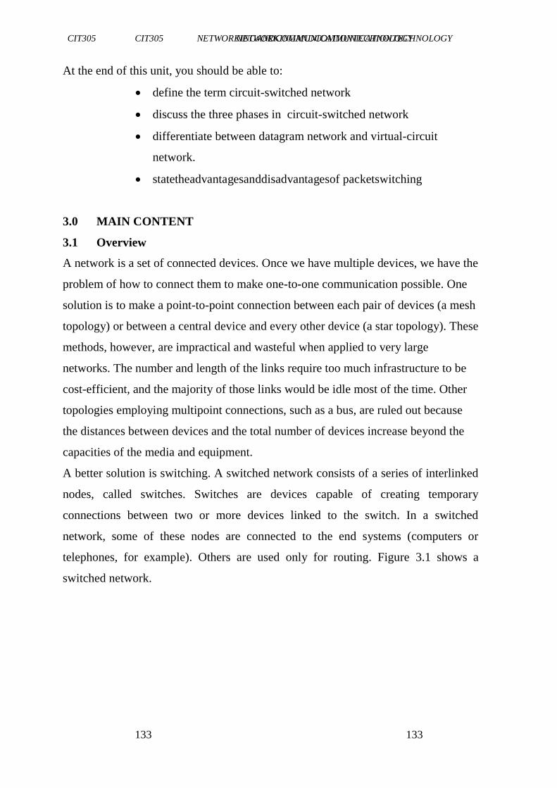
CIT305 NETWORKINGANDCOMMUNICATIONTECHNOLOGY CIT305 NETWORKINGANDCOMMUNICATIONTECHNOLOGY
133133
133
At the end of this unit, you should be able to:
define the term circuit-switched network
discuss the three phases in circuit-switched network
differentiate between datagram network and virtual-circuit
network.
statetheadvantagesanddisadvantagesof packetswitching
3.0 MAIN CONTENT
3.1 Overview
A network is a set of connected devices. Once we have multiple devices, we have the
problem of how to connect them to make one-to-one communication possible. One
solution is to make a point-to-point connection between each pair of devices (a mesh
topology) or between a central device and every other device (a star topology). These
methods, however, are impractical and wasteful when applied to very large
networks. The number and length of the links require too much infrastructure to be
cost-efficient, and the majority of those links would be idle most of the time. Other
topologies employing multipoint connections, such as a bus, are ruled out because
the distances between devices and the total number of devices increase beyond the
capacities of the media and equipment.
A better solution is switching. A switched network consists of a series of interlinked
nodes, called switches. Switches are devices capable of creating temporary
connections between two or more devices linked to the switch. In a switched
network, some of these nodes are connected to the end systems (computers or
telephones, for example). Others are used only for routing. Figure 3.1 shows a
switched network.
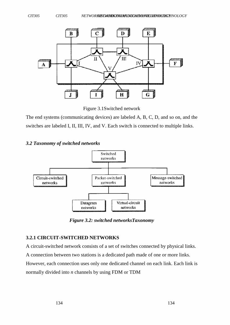
CIT305 NETWORKINGANDCOMMUNICATIONTECHNOLOGY CIT305 NETWORKINGANDCOMMUNICATIONTECHNOLOGY
134134
134
Figure 3.1Switched network
The end systems (communicating devices) are labeled A, B, C, D, and so on, and the
switches are labeled I, II, III, IV, and V. Each switch is connected to multiple links.
3.2 Taxonomy of switched networks
Figure 3.2: switched networksTaxonomy
3.2.1 CIRCUIT-SWITCHED NETWORKS
A circuit-switched network consists of a set of switches connected by physical links.
A connection between two stations is a dedicated path made of one or more links.
However, each connection uses only one dedicated channel on each link. Each link is
normally divided into n channels by using FDM or TDM
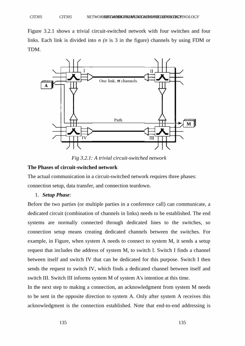
CIT305 NETWORKINGANDCOMMUNICATIONTECHNOLOGY CIT305 NETWORKINGANDCOMMUNICATIONTECHNOLOGY
135135
135
Figure 3.2.1 shows a trivial circuit-switched network with four switches and four
links. Each link is divided into n (n is 3 in the figure) channels by using FDM or
TDM.
Fig 3.2.1: A trivial circuit-switched network
The Phases of circuit-switched network
The actual communication in a circuit-switched network requires three phases:
connection setup, data transfer, and connection teardown.
1. Setup Phase:
Before the two parties (or multiple parties in a conference call) can communicate, a
dedicated circuit (combination of channels in links) needs to be established. The end
systems are normally connected through dedicated lines to the switches, so
connection setup means creating dedicated channels between the switches. For
example, in Figure, when system A needs to connect to system M, it sends a setup
request that includes the address of system M, to switch I. Switch I finds a channel
between itself and switch IV that can be dedicated for this purpose. Switch I then
sends the request to switch IV, which finds a dedicated channel between itself and
switch III. Switch III informs system M of system A's intention at this time.
In the next step to making a connection, an acknowledgment from system M needs
to be sent in the opposite direction to system A. Only after system A receives this
acknowledgment is the connection established. Note that end-to-end addressing is
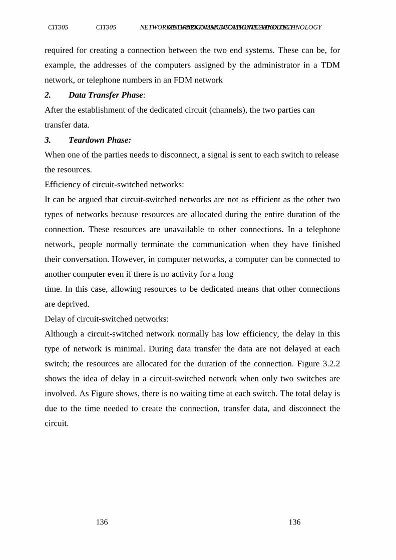
CIT305 NETWORKINGANDCOMMUNICATIONTECHNOLOGY CIT305 NETWORKINGANDCOMMUNICATIONTECHNOLOGY
136136
136
required for creating a connection between the two end systems. These can be, for
example, the addresses of the computers assigned by the administrator in a TDM
network, or telephone numbers in an FDM network
2. Data Transfer Phase:
After the establishment of the dedicated circuit (channels), the two parties can
transfer data.
3. Teardown Phase:
When one of the parties needs to disconnect, a signal is sent to each switch to release
the resources.
Efficiency of circuit-switched networks:
It can be argued that circuit-switched networks are not as efficient as the other two
types of networks because resources are allocated during the entire duration of the
connection. These resources are unavailable to other connections. In a telephone
network, people normally terminate the communication when they have finished
their conversation. However, in computer networks, a computer can be connected to
another computer even if there is no activity for a long
time. In this case, allowing resources to be dedicated means that other connections
are deprived.
Delay of circuit-switched networks:
Although a circuit-switched network normally has low efficiency, the delay in this
type of network is minimal. During data transfer the data are not delayed at each
switch; the resources are allocated for the duration of the connection. Figure 3.2.2
shows the idea of delay in a circuit-switched network when only two switches are
involved. As Figure shows, there is no waiting time at each switch. The total delay is
due to the time needed to create the connection, transfer data, and disconnect the
circuit.
CIT305 NETWORKINGANDCOMMUNICATIONTECHNOLOGY CIT305 NETWORKINGANDCOMMUNICATIONTECHNOLOGY
137137
137
Fig3.2.2: Delay in a circuit-switched network
The delay caused by the setup is the sum of four parts. The propagation time of the
source computer request (slope of the first gray box), the request signal transfer time
(height of the first gray box), the propagation time of the acknowledgment from the
destination computer (slope of the second gray box), and the signal transfer time of
the acknowledgment (height of the second gray box). The delay due to data transfer
is the sum of two parts: the propagation time (slope of the colored box) and data
transfer time (height of the colored box), which can be very long. The third box
shows the time needed to tear down the circuit. We have shown the case in which the
receiver requests disconnection, which creates the maximum delay.
3.2.2Packet Switching
Packet switching is dividing of messages into packets before they are sent,
transmitting each packet individually, and then reassembling them into the original
message once all of them have arrived at the intended destination.
Packets are the fundamental unit of information transport in all modern computer
networks, and increasingly in other communications networks as well. Each packet,
which can be of fixed or variable size depending on the protocol, consists of a
header, body (also called a payload) and a trailer. The body contains a segment of
the message being transmitted.
3.2.2.1 Advantages of Packet Switching
CIT305 NETWORKINGANDCOMMUNICATIONTECHNOLOGY CIT305 NETWORKINGANDCOMMUNICATIONTECHNOLOGY
138138
138
The following are some advantages of packet switching:
Share link usage and greater link efficiency
Links can transmit at different rates
Under heavy load, calls can still be accepted but with greater delay
Can prioritize packet transmission
3.2.2.2 Disadvantages of Packet Switching
Despite its great advantages, packet switching has the followingdisadvantages:
Packet delay at each node (Processing, Queuing, Transmission)
A packet can acquire jitter while passing through the network
Packets may contain metadata i.e Higher overhead than circuit
Switching (e.g., telephone system)
More processing required at each node in the network.
3.2.3 Packet Switching Methods
3.2.3.1 DATAGRAM NETWORKS (Connectionless)
In a datagram network, each packet is treated independently of all others. Even if a
packet is part of a multi-packet transmission, the network treats it as though it
existed alone. Packets in this approach are referred to as datagrams.
Datagram switching is normally done at the network layer. We briefly discuss
datagram networks here as a comparison with circuit-switched and virtual-circuit
switched networks
Figure 3.2.3.1 shows how the datagram approach is used to deliver four packets from
station A to station X. The switches in a datagram network are traditionally referred
to as routers. That is why we use a different symbol for the switches in the figure.
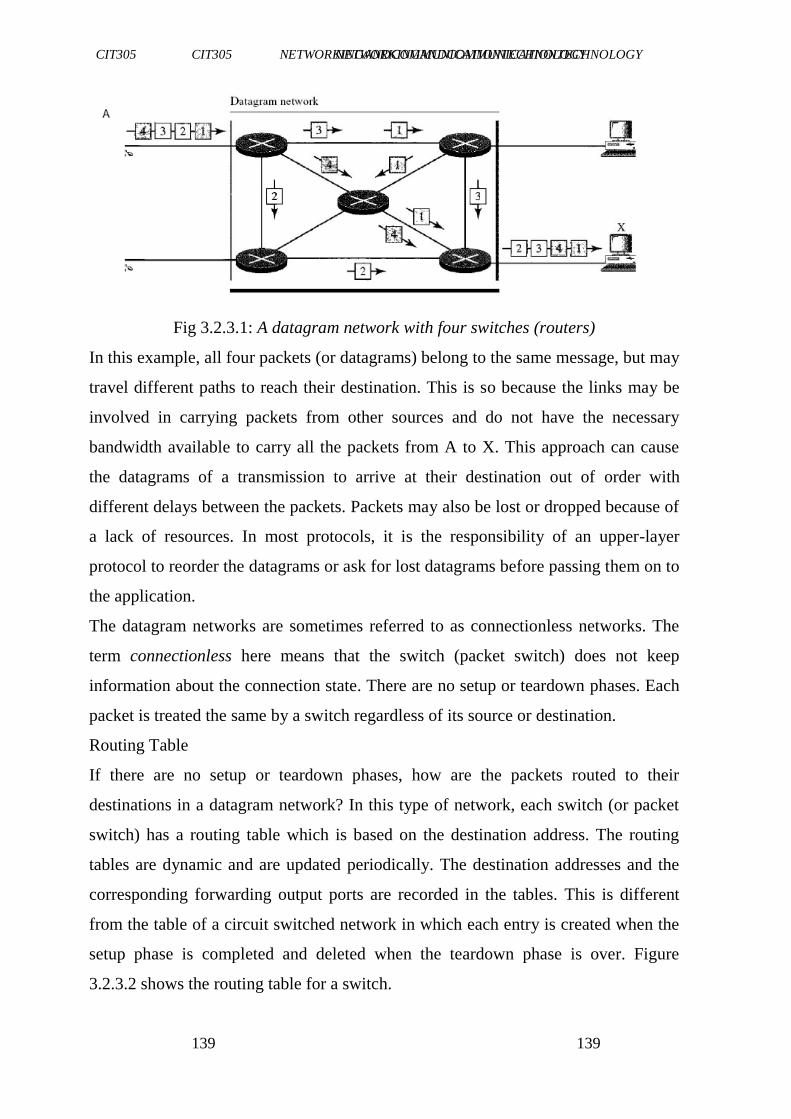
CIT305 NETWORKINGANDCOMMUNICATIONTECHNOLOGY CIT305 NETWORKINGANDCOMMUNICATIONTECHNOLOGY
139139
139
Fig 3.2.3.1: A datagram network with four switches (routers)
In this example, all four packets (or datagrams) belong to the same message, but may
travel different paths to reach their destination. This is so because the links may be
involved in carrying packets from other sources and do not have the necessary
bandwidth available to carry all the packets from A to X. This approach can cause
the datagrams of a transmission to arrive at their destination out of order with
different delays between the packets. Packets may also be lost or dropped because of
a lack of resources. In most protocols, it is the responsibility of an upper-layer
protocol to reorder the datagrams or ask for lost datagrams before passing them on to
the application.
The datagram networks are sometimes referred to as connectionless networks. The
term connectionless here means that the switch (packet switch) does not keep
information about the connection state. There are no setup or teardown phases. Each
packet is treated the same by a switch regardless of its source or destination.
Routing Table
If there are no setup or teardown phases, how are the packets routed to their
destinations in a datagram network? In this type of network, each switch (or packet
switch) has a routing table which is based on the destination address. The routing
tables are dynamic and are updated periodically. The destination addresses and the
corresponding forwarding output ports are recorded in the tables. This is different
from the table of a circuit switched network in which each entry is created when the
setup phase is completed and deleted when the teardown phase is over. Figure
3.2.3.2 shows the routing table for a switch.
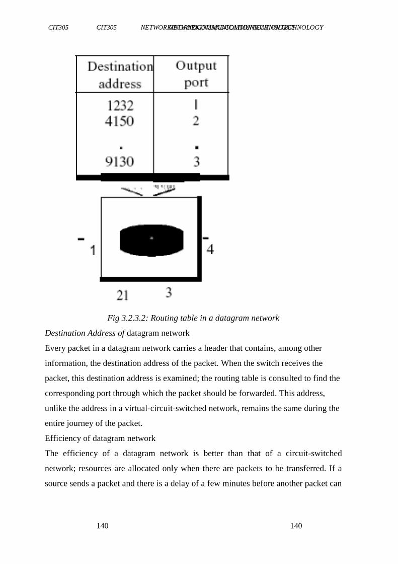
CIT305 NETWORKINGANDCOMMUNICATIONTECHNOLOGY CIT305 NETWORKINGANDCOMMUNICATIONTECHNOLOGY
140140
140
Fig 3.2.3.2: Routing table in a datagram network
Destination Address of datagram network
Every packet in a datagram network carries a header that contains, among other
information, the destination address of the packet. When the switch receives the
packet, this destination address is examined; the routing table is consulted to find the
corresponding port through which the packet should be forwarded. This address,
unlike the address in a virtual-circuit-switched network, remains the same during the
entire journey of the packet.
Efficiency of datagram network
The efficiency of a datagram network is better than that of a circuit-switched
network; resources are allocated only when there are packets to be transferred. If a
source sends a packet and there is a delay of a few minutes before another packet can
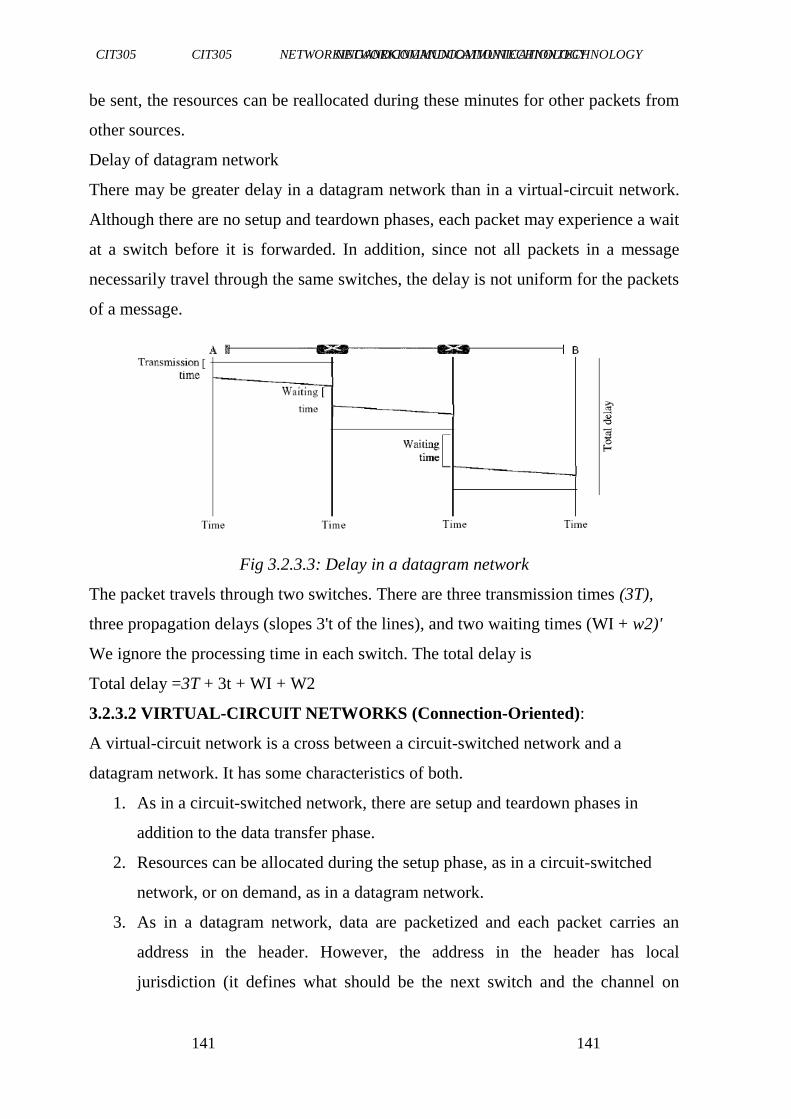
CIT305 NETWORKINGANDCOMMUNICATIONTECHNOLOGY CIT305 NETWORKINGANDCOMMUNICATIONTECHNOLOGY
141141
141
be sent, the resources can be reallocated during these minutes for other packets from
other sources.
Delay of datagram network
There may be greater delay in a datagram network than in a virtual-circuit network.
Although there are no setup and teardown phases, each packet may experience a wait
at a switch before it is forwarded. In addition, since not all packets in a message
necessarily travel through the same switches, the delay is not uniform for the packets
of a message.
Fig 3.2.3.3: Delay in a datagram network
The packet travels through two switches. There are three transmission times (3T),
three propagation delays (slopes 3't of the lines), and two waiting times (WI + w2)'
We ignore the processing time in each switch. The total delay is
Total delay =3T + 3t + WI + W2
3.2.3.2 VIRTUAL-CIRCUIT NETWORKS (Connection-Oriented):
A virtual-circuit network is a cross between a circuit-switched network and a
datagram network. It has some characteristics of both.
1. As in a circuit-switched network, there are setup and teardown phases in
addition to the data transfer phase.
2. Resources can be allocated during the setup phase, as in a circuit-switched
network, or on demand, as in a datagram network.
3. As in a datagram network, data are packetized and each packet carries an
address in the header. However, the address in the header has local
jurisdiction (it defines what should be the next switch and the channel on
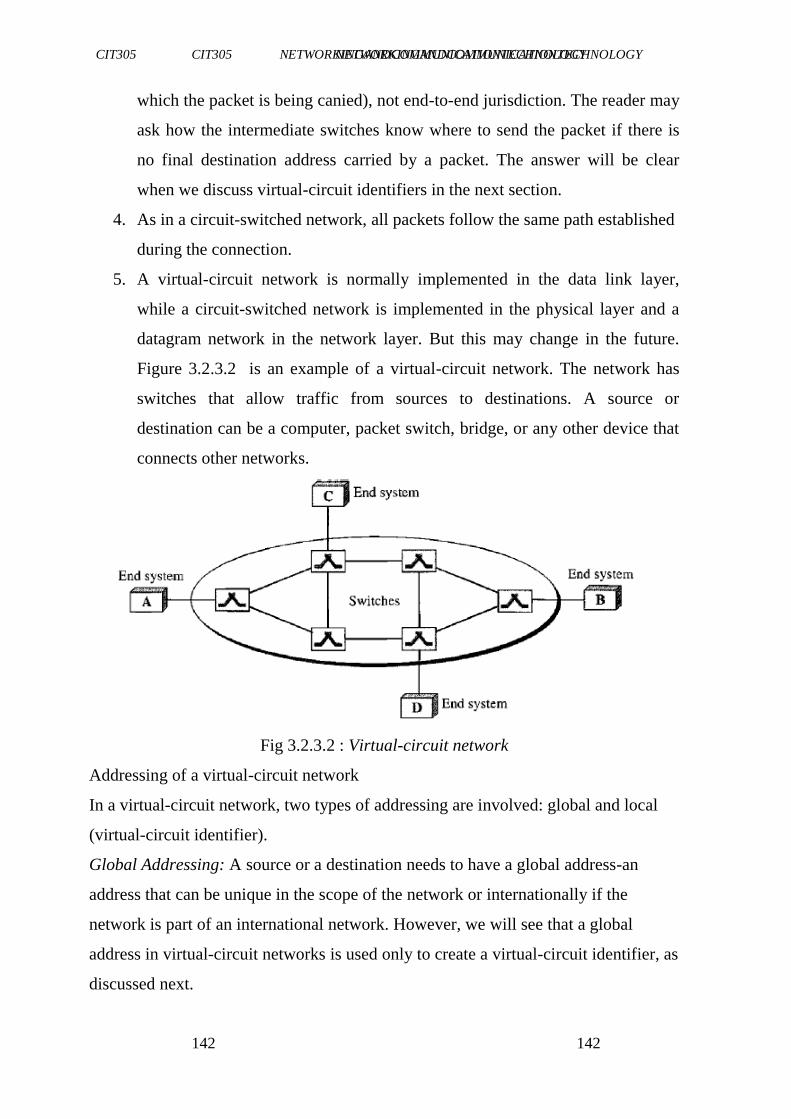
CIT305 NETWORKINGANDCOMMUNICATIONTECHNOLOGY CIT305 NETWORKINGANDCOMMUNICATIONTECHNOLOGY
142142
142
which the packet is being canied), not end-to-end jurisdiction. The reader may
ask how the intermediate switches know where to send the packet if there is
no final destination address carried by a packet. The answer will be clear
when we discuss virtual-circuit identifiers in the next section.
4. As in a circuit-switched network, all packets follow the same path established
during the connection.
5. A virtual-circuit network is normally implemented in the data link layer,
while a circuit-switched network is implemented in the physical layer and a
datagram network in the network layer. But this may change in the future.
Figure 3.2.3.2 is an example of a virtual-circuit network. The network has
switches that allow traffic from sources to destinations. A source or
destination can be a computer, packet switch, bridge, or any other device that
connects other networks.
Fig 3.2.3.2 : Virtual-circuit network
Addressing of a virtual-circuit network
In a virtual-circuit network, two types of addressing are involved: global and local
(virtual-circuit identifier).
Global Addressing: A source or a destination needs to have a global address-an
address that can be unique in the scope of the network or internationally if the
network is part of an international network. However, we will see that a global
address in virtual-circuit networks is used only to create a virtual-circuit identifier, as
discussed next.
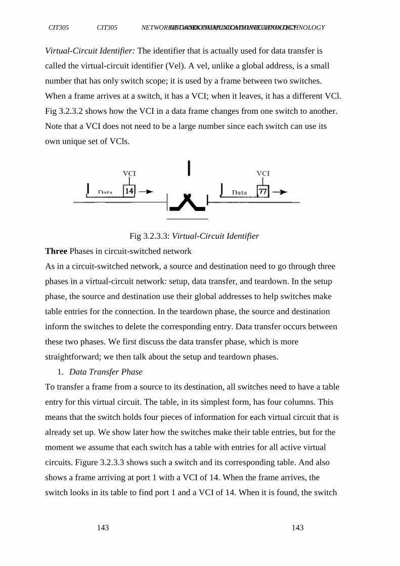
CIT305 NETWORKINGANDCOMMUNICATIONTECHNOLOGY CIT305 NETWORKINGANDCOMMUNICATIONTECHNOLOGY
143143
143
Virtual-Circuit Identifier: The identifier that is actually used for data transfer is
called the virtual-circuit identifier (Vel). A vel, unlike a global address, is a small
number that has only switch scope; it is used by a frame between two switches.
When a frame arrives at a switch, it has a VCI; when it leaves, it has a different VCl.
Fig 3.2.3.2 shows how the VCI in a data frame changes from one switch to another.
Note that a VCI does not need to be a large number since each switch can use its
own unique set of VCls.
Fig 3.2.3.3: Virtual-Circuit Identifier
Three Phases in circuit-switched network
As in a circuit-switched network, a source and destination need to go through three
phases in a virtual-circuit network: setup, data transfer, and teardown. In the setup
phase, the source and destination use their global addresses to help switches make
table entries for the connection. In the teardown phase, the source and destination
inform the switches to delete the corresponding entry. Data transfer occurs between
these two phases. We first discuss the data transfer phase, which is more
straightforward; we then talk about the setup and teardown phases.
1. Data Transfer Phase
To transfer a frame from a source to its destination, all switches need to have a table
entry for this virtual circuit. The table, in its simplest form, has four columns. This
means that the switch holds four pieces of information for each virtual circuit that is
already set up. We show later how the switches make their table entries, but for the
moment we assume that each switch has a table with entries for all active virtual
circuits. Figure 3.2.3.3 shows such a switch and its corresponding table. And also
shows a frame arriving at port 1 with a VCI of 14. When the frame arrives, the
switch looks in its table to find port 1 and a VCI of 14. When it is found, the switch
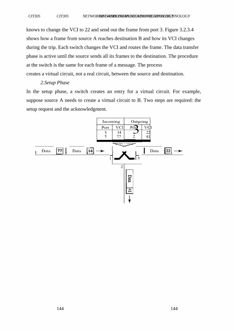
CIT305 NETWORKINGANDCOMMUNICATIONTECHNOLOGY CIT305 NETWORKINGANDCOMMUNICATIONTECHNOLOGY
144144
144
knows to change the VCI to 22 and send out the frame from port 3. Figure 3.2.3.4
shows how a frame from source A reaches destination B and how its VCI changes
during the trip. Each switch changes the VCI and routes the frame. The data transfer
phase is active until the source sends all its frames to the destination. The procedure
at the switch is the same for each frame of a message. The process
creates a virtual circuit, not a real circuit, between the source and destination.
2.Setup Phase
In the setup phase, a switch creates an entry for a virtual circuit. For example,
suppose source A needs to create a virtual circuit to B. Two steps are required: the
setup request and the acknowledgment.
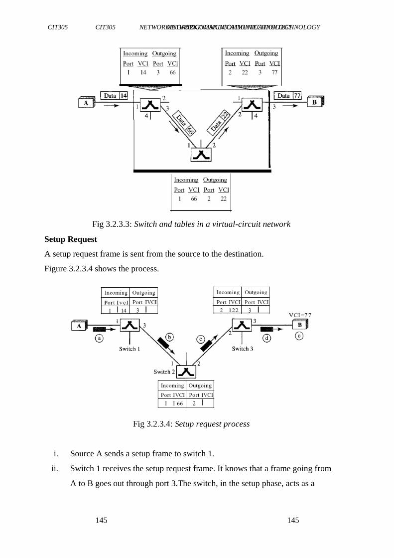
CIT305 NETWORKINGANDCOMMUNICATIONTECHNOLOGY CIT305 NETWORKINGANDCOMMUNICATIONTECHNOLOGY
145145
145
Fig 3.2.3.3: Switch and tables in a virtual-circuit network
Setup Request
A setup request frame is sent from the source to the destination.
Figure 3.2.3.4 shows the process.
Fig 3.2.3.4: Setup request process
i. Source A sends a setup frame to switch 1.
ii. Switch 1 receives the setup request frame. It knows that a frame going from
A to B goes out through port 3.The switch, in the setup phase, acts as a
CIT305 NETWORKINGANDCOMMUNICATIONTECHNOLOGY CIT305 NETWORKINGANDCOMMUNICATIONTECHNOLOGY
146146
146
packet switch; it has a routing table which is different from the switching
table. For the moment, assume that it knows the output port. The switch
creates an entry in its table for this virtual circuit, but it is only able to fill
three of the four columns. The switch assigns the incoming port (1) and
chooses an available incoming VCI (14) and the outgoing port (3). It does not
yet know the outgoing VCI, which will be found during the acknowledgment
step. The switch then forwards the frame through port 3 to switch 2.
iii. Switch 2 receives the setup request frame. The same events happen here as at
switch 1; three columns of the table are completed: in this case, incoming
port (l), incoming VCI (66), and outgoing port (2).
iv. Switch 3 receives the setup request frame. Again, three columns are
completed: incoming port (2), incoming VCI (22), and outgoing port (3).
v. Destination B receives the setup frame, and if it is ready to receive frames
from A, it assigns a VCI to the incoming frames that come from A, in this
case 77. This VCI lets the destination know that the frames come from A,
and not other sources.
Acknowledgment A special frame, called the acknowledgment frame, completes the
entries in the switching tables. Figure 3.2.3.5 shows the process.
i. The destination sends an acknowledgment to switch 3. The acknowledgment
carries the global source and destination addresses so the switch knows which
entry in the table is to be completed. The frame also carries VCI 77, chosen
by the destination as the incoming VCI for frames from A. Switch 3 uses this
VCI to complete the outgoing VCI column for this entry. Note that 77 is the
incoming VCI for destination B, but the outgoing VCI for switch 3.
ii. Switch 3 sends an acknowledgment to switch 2 that contains its incoming
VCI in the table, chosen in the previous step. Switch 2 uses this as the
outgoing VCI in the table.
iii. Switch 2 sends an acknowledgment to switch 1 that contains its incoming
VCI in the table, chosen in the previous step. Switch 1 uses this as the
outgoing VCI in the table.
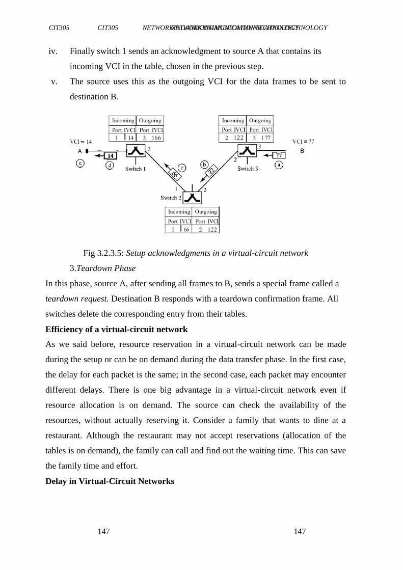
CIT305 NETWORKINGANDCOMMUNICATIONTECHNOLOGY CIT305 NETWORKINGANDCOMMUNICATIONTECHNOLOGY
147147
147
iv. Finally switch 1 sends an acknowledgment to source A that contains its
incoming VCI in the table, chosen in the previous step.
v. The source uses this as the outgoing VCI for the data frames to be sent to
destination B.
Fig 3.2.3.5: Setup acknowledgments in a virtual-circuit network
3.Teardown Phase
In this phase, source A, after sending all frames to B, sends a special frame called a
teardown request. Destination B responds with a teardown confirmation frame. All
switches delete the corresponding entry from their tables.
Efficiency of a virtual-circuit network
As we said before, resource reservation in a virtual-circuit network can be made
during the setup or can be on demand during the data transfer phase. In the first case,
the delay for each packet is the same; in the second case, each packet may encounter
different delays. There is one big advantage in a virtual-circuit network even if
resource allocation is on demand. The source can check the availability of the
resources, without actually reserving it. Consider a family that wants to dine at a
restaurant. Although the restaurant may not accept reservations (allocation of the
tables is on demand), the family can call and find out the waiting time. This can save
the family time and effort.
Delay in Virtual-Circuit Networks
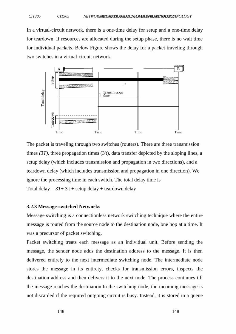
CIT305 NETWORKINGANDCOMMUNICATIONTECHNOLOGY CIT305 NETWORKINGANDCOMMUNICATIONTECHNOLOGY
148148
148
In a virtual-circuit network, there is a one-time delay for setup and a one-time delay
for teardown. If resources are allocated during the setup phase, there is no wait time
for individual packets. Below Figure shows the delay for a packet traveling through
two switches in a virtual-circuit network.
The packet is traveling through two switches (routers). There are three transmission
times (3T), three propagation times (3't), data transfer depicted by the sloping lines, a
setup delay (which includes transmission and propagation in two directions), and a
teardown delay (which includes transmission and propagation in one direction). We
ignore the processing time in each switch. The total delay time is
Total delay = 3T+ 3't + setup delay + teardown delay
3.2.3 Message-switched Networks
Message switching is a connectionless network switching technique where the entire
message is routed from the source node to the destination node, one hop at a time. It
was a precursor of packet switching.
Packet switching treats each message as an individual unit. Before sending the
message, the sender node adds the destination address to the message. It is then
delivered entirely to the next intermediate switching node. The intermediate node
stores the message in its entirety, checks for transmission errors, inspects the
destination address and then delivers it to the next node. The process continues till
the message reaches the destination.In the switching node, the incoming message is
not discarded if the required outgoing circuit is busy. Instead, it is stored in a queue
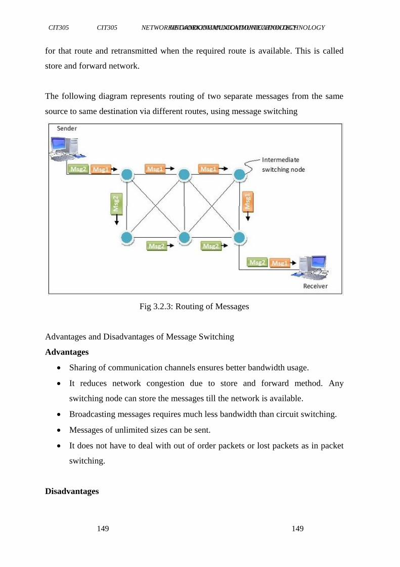
CIT305 NETWORKINGANDCOMMUNICATIONTECHNOLOGY CIT305 NETWORKINGANDCOMMUNICATIONTECHNOLOGY
149149
149
for that route and retransmitted when the required route is available. This is called
store and forward network.
The following diagram represents routing of two separate messages from the same
source to same destination via different routes, using message switching
Fig 3.2.3: Routing of Messages
Advantages and Disadvantages of Message Switching
Advantages
Sharing of communication channels ensures better bandwidth usage.
It reduces network congestion due to store and forward method. Any
switching node can store the messages till the network is available.
Broadcasting messages requires much less bandwidth than circuit switching.
Messages of unlimited sizes can be sent.
It does not have to deal with out of order packets or lost packets as in packet
switching.
Disadvantages
CIT305 NETWORKINGANDCOMMUNICATIONTECHNOLOGY CIT305 NETWORKINGANDCOMMUNICATIONTECHNOLOGY
150150
150
In order to store many messages of unlimited sizes, each intermediate
switching node requires large storage capacity.
Store and forward method introduces delay at each switching node. This
renders it unsuitable for real time applications.
Exercise1:Whataretheadvantagesanddisadvantagesofthepacket
switchingmethods?
4.0 CONCLUSION
Inthisunit,youhavebeenintroducedtothefundamental conceptsof
Switching.Youalsolearnttheadvantagesanddisadvantages of
packetswitching, Message switching.Youwerealsointroduced
tovariouspacketswitching methods.
5.0 SUMMARY
In thisunit,youhavelearntthat:
Theconceptofswitchingwasfirstexplored
The taxonomy of network switching was discussed
Packet switchingisdividingofmessagesintopacketsbefore they are
sent, transmitting each packet individually, and then
reassemblingthemintotheoriginalmessageonceallofthem
havearrivedat theintendeddestination
Packetswitchingmethodsdatagram,virtualcircuitandsource routing.

CIT305 NETWORKINGANDCOMMUNICATIONTECHNOLOGY CIT305 NETWORKINGANDCOMMUNICATIONTECHNOLOGY
151151
151
6.0 TUTOR-MARKEDASSIGNMENT
1. Statetheadvantagesandthedisadvantagesof Packet Switching.
2. Whatdoyouunderstandbytheterm―Virtual-circuit
network‖
CIT305 NETWORKINGANDCOMMUNICATIONTECHNOLOGY CIT305 NETWORKINGANDCOMMUNICATIONTECHNOLOGY
152152
152
c
7.0 REFERENCES/FURTHERREADING
Samuel Sam (2018). ―Message
Switching‖https://www.tutorialspoint.com/message-switching
Stephen Cooper (2018).―A guide to message switched
networks‖https://www.comparitech.com/net-admin/message-
switched-networks-guide/
Vishnu Universal Learning. ―Computer
Networks‖https://www.coursehero.com/file/13176989/Docs-
CSECDLNotes2013/
Ronda Hauben (2001). From the ARPANET to the Internet.
http://www.columbia.edu/~rh120/other/tcpdigest_paper.txt.Retrie
ved2009-05-28.
"NORSARandtheInternet".NORSAR.http://www.norsar.no/pc-5-30-
NORSAR-and-the-Internet.aspx.Retrieved2009-06-05.
"HistoryofX.25,CCITTPlenaryAssemblies andBookColors".Itu.int.
http://www.itu.int/ITU-
T/studygroups/com17/history.html.Retrieved2009-06-05.
Prasad,K.V.(2009).―PrinciplesofDigitalCommunicationSystems
andComputerNetworks‖,DreamtechPress.
CIT305 NETWORKINGANDCOMMUNICATIONTECHNOLOGY CIT305 NETWORKINGANDCOMMUNICATIONTECHNOLOGY
153153
153
UNIT5 INTERNETANDTCP/IP
CONTENTS
1.0 Introduction
2.0 Objectives
3.0 MainContent
3.1 HistoricalBackground
3.2.1 InternetStandardProcess
3.3 TCP/IPTerminologies
3.4 TCP/IPProtocolSuite
3.5 NetworkInterfaceLayer
3.6 InternetLayerInterface
3.7 ApplicationLayerInterface
4.0 Conclusion
5.0 Summary
6.0 Tutor-MarkedAssignment
7.0 References/FurtherReading
1.0 INTRODUCTION
The'''internetprotocolsuite'''is thesetof communicationprotocolsused
fortheinternetandothersimilarnetworks.Itiscommonlyalsoknown as
'''TCP/IP''',namedfromtwoof themostimportantprotocolsin it-the
Transmission ControlProtocol(TCP)andtheInternetProtocol(IP),
whichwerethefirsttwonetworking protocolsdefinedinthisstandard.
ModernIPnetworking representsasynthesisofseveraldevelopments
CIT305 NETWORKINGANDCOMMUNICATIONTECHNOLOGY CIT305 NETWORKINGANDCOMMUNICATIONTECHNOLOGY
154154
154
thatbegantoevolve inthe1960sand1970s,namelytheinternetand
localareanetworks,whichemergedduring the1980s,togetherwiththe
adventoftheWorld WideWeb(WWW)intheearly1990s.Theinternet
protocolsuiteconsistsoffourabstraction layers.Fromthelowesttothe
highestlayer,thesearethelink layer,theinternet layer,thetransport
layer,andtheapplicationlayer.
The link layer contains communication technologies for the local
network thehostisconnectedtodirectly,thelink.Itprovidesthebasic
connectivityfunctionsinteractingwiththenetworking hardwareofthe
computer andtheassociatedmanagementofinterface-to-interface
messaging. The internet layer provides communication methods
betweenmultiplelinksofacomputer andfacilitates theinterconnection
ofnetworks.Assuch,thislayerestablishestheinternet.It contains primarily
the internet protocol, which defines the fundamental addressing
namespaces,IPv4InternetProtocolVersion4(IPv4)and
IPv6|InternetProtocolVersion6(IPv6) usedtoidentifyandlocatehosts
onthenetwork.Directhost-to-hostcommunication tasksarehandledin
thetransportlayer,whichprovidesageneralframeworktotransmit data
CIT305 NETWORKINGANDCOMMUNICATIONTECHNOLOGY CIT305 NETWORKINGANDCOMMUNICATIONTECHNOLOGY
155155
155
betweenhostsusingprotocolslikethetransmissioncontrol protocoland
theuserdatagram.
2.0 OBJECTIVES
At theendof thisunit,youshouldbeableto:
describetheinternetstandardsprocess
definecommontermsusedinTCP/IP
statetheadvantagesof includingTCP/IPcomponentsin windows
explainhowthe TCP/IPprotocolsuitemapstotheDepartmentof
Defense Advanced Research Projects Agency (DARPA) and
OpenSystemInterconnection(OSI)models.
3.0 MAINCONTENT
3.1 HistoricalBackground
The internet protocol suite resulted fromresearch and development
conducted bytheDefenseAdvanced ResearchProjectsAgency
(DARPA)intheearly1970s.AfterinitiatingthepioneeringARPANET
in1969,DARPAstartedwork onanumberofotherdatatransmission
technologies. In1972,RobertE.KahnjoinedtheDARPAinformation
processing technologyoffice,whereheworkedonbothsatellitepacket
CIT305 NETWORKINGANDCOMMUNICATIONTECHNOLOGY CIT305 NETWORKINGANDCOMMUNICATIONTECHNOLOGY
156156
156
networksandground-based radiopacketnetworks,andrecognisedthe
valueofbeingabletocommunicate acrossboth. Inthespringof1973,
VintonCerf,thedeveloperoftheexistingARPANETNetwork Control
Program(NCP)protocol,joinedKahnto workonopen-architecture
interconnectionmodelswiththe goalofdesigningthenextprotocol
generationforthe ARPANET.
Bythesummer of1973,KahnandCerfhadworkedoutafundamental
reformulation,wherethedifferencesbetweennetwork protocolswere
hidden byusingacommon[[internetworkprotocol]],and,instead ofthe
networkbeingresponsible forreliability,asintheARPANET,thehosts
becameresponsible.
The design of the network included the recognition that it should
provideonlythefunctionsofefficientlytransmitting androutingtraffic
betweenendnodesandthatallotherintelligenceshouldbelocatedat
theedgeofthenetwork, intheendnodes.Usingasimple design,it
becamepossibletoconnect almostanynetwork totheARPANET,
irrespectiveoftheirlocalcharacteristics, therebysolvingKahn'sinitial
problem.Onepopularexpressionis thatTCP/IP,theeventualproductof
CerfandKahn's work,willrunover"twotincansandastring''.A
computer,calledarouter,isprovidedwithaninterfacetoeachnetwork.
CIT305 NETWORKINGANDCOMMUNICATIONTECHNOLOGY CIT305 NETWORKINGANDCOMMUNICATIONTECHNOLOGY
157157
157
Itforwardspacketsbackandforthbetweenthem.Originallyarouter wascalled
''gateway'',butthetermwaschangedtoavoidconfusionwith othertypesof
gateway(computernetworking)computers.
Theideawasworkedoutinmoredetailedform byCerf'snetworking
researchgroupatStanfordwithin1973–74,resulting inthefirstTCP
specification. Theinternetprotocolsuiteresultedfromresearchand
development conductedbytheDefenseAdvancedResearchProjects
Agency(DARPA)intheearly1970s.Afterinitiating thepioneering
ARPANET in1969,DARPAstartedworkonanumberofotherdata
transmission technologies.In1972,RobertE.KahnjoinedtheDARPA
information processingtechnologyoffice,whereheworkedonboth
satellitepacketnetworksandground-based radiopacketnetworks,and
recognizedthevalueofbeingabletocommunicate acrossboth. Inthe
springof1973,VintonCerf,thedeveloperoftheexisting ARPANET
NetworkControlProgram(NCP)protocol,joinedKahntoworkon open-
architectureinterconnection modelswiththegoalofdesigningthe
nextprotocol.
3.2 InternetStandardProcess
TCP/IPistheprotocol oftheInternet,ithas evolvedbasedon
fundamentalstandardsthathavebeencreatedandadoptedovermore than30
years. Thefutureof TCP/IPis closelyassociatedwiththe
advancesandadministration oftheInternetasadditionalstandards
continuetobedeveloped.Although,nooneorganisation ownsthe
Internetoritstechnologies,severalorganizations overseeandmanage
CIT305 NETWORKINGANDCOMMUNICATIONTECHNOLOGY CIT305 NETWORKINGANDCOMMUNICATIONTECHNOLOGY
158158
158
thesenewstandards, suchastheInternet SocietyandtheInternet
ArchitectureBoard.
TheInternetSociety (ISOC) wascreated in1992andisaglobal
organisationresponsiblefortheinternetworking technologiesand
applicationsoftheinternet.Althoughthesociety‘sprincipalpurposeis
toencouragethedevelopment andavailabilityoftheinternet,itisalso
responsibleforthefurtherdevelopment ofthestandardsandprotocols that
allowthe Internetto function.The ISOCsponsorsthe Internet Architecture
Board(IAB),atechnicaladvisorygroupthatsetsinternet
standards,publishesRFCs,andoverseestheInternetstandards process.
TheIABgovernsthefollowingbodies:
theInternetAssignedNumberAuthority(IANA)overseesand
coordinates theassignment ofprotocolidentifiersusedonthe
Internet.
theInternetResearchTask Force(IRTF)coordinates allTCP/IP-
relatedresearchprojects.
CIT305 NETWORKINGANDCOMMUNICATIONTECHNOLOGY CIT305 NETWORKINGANDCOMMUNICATIONTECHNOLOGY
159159
159
the Internet Engineering Task Force (IETF) solves technical
problems andneedsastheyariseontheinternetanddevelops
internetstandardsand protocols.IETFworkinggroupsdefine
standardsknownasRFC.
3.3 TCP/IPTerminology
Theinternetstandardsuseaspecificsetoftermswhenreferring to
networkelementsandconceptsrelatedtoTCP/IPnetworking.Common
termsandconceptsinTCP/IParedefinedas follows:
Node-anydevice,includingroutersandhosts,whichrunsan
implementationof IP.
Router- a node that can forward IP packets not explicitly
addressed toitself.OnanIPv6network,aRouteralsotypically
advertisesits presenceandhostconfigurationinformation.
Host- a node that cannot forward IP packets not explicitly
addressed toitself(anon-router).Ahostistypicallythesource
andthedestinationofIPtraffic.Ahostsilentlydiscardstraffic
thatitreceivesbutthatis notexplicitlyaddressedto it.
Upper-layerprotocol:aprotocolaboveIPthatusesIPasits
transport.Examples includeinternetlayerprotocolssuchasthe
InternetControlMessage Protocol(ICMP)andtransport layer
protocolssuchastheTransmission ControlProtocol(TCP)and
UserDatagram Protocol(UDP).(However,applicationlayer
protocolsthat use TCP and UDPas their transportsare not
CIT305 NETWORKINGANDCOMMUNICATIONTECHNOLOGY CIT305 NETWORKINGANDCOMMUNICATIONTECHNOLOGY
160160
160
considered upper-layerprotocols.FileTransferProtocol[FTP]
andDomainNameSystem[DNS]fallintothiscategory).
LAN segment-a portion of a subnet consisting of a single
mediumthatis boundedbybridgesor layer2switches.
Subnet-oneormoreLANsegmentsthatareboundedbyrouters
andusethesameIPaddress prefix.Othertermsforsubnetare
networksegmentandlink.
Network-twoormoresubnetsconnectedbyrouters.Another
termfornetworkis internetwork.
Neighbour-a nodeconnectedto the same subnetas another node.
Interface-therepresentationofaphysicalorlogicalattachment
ofanodetoasubnet.Anexampleofaphysical interface isa
networkadapter.Anexampleofalogicalinterfaceisatunnel
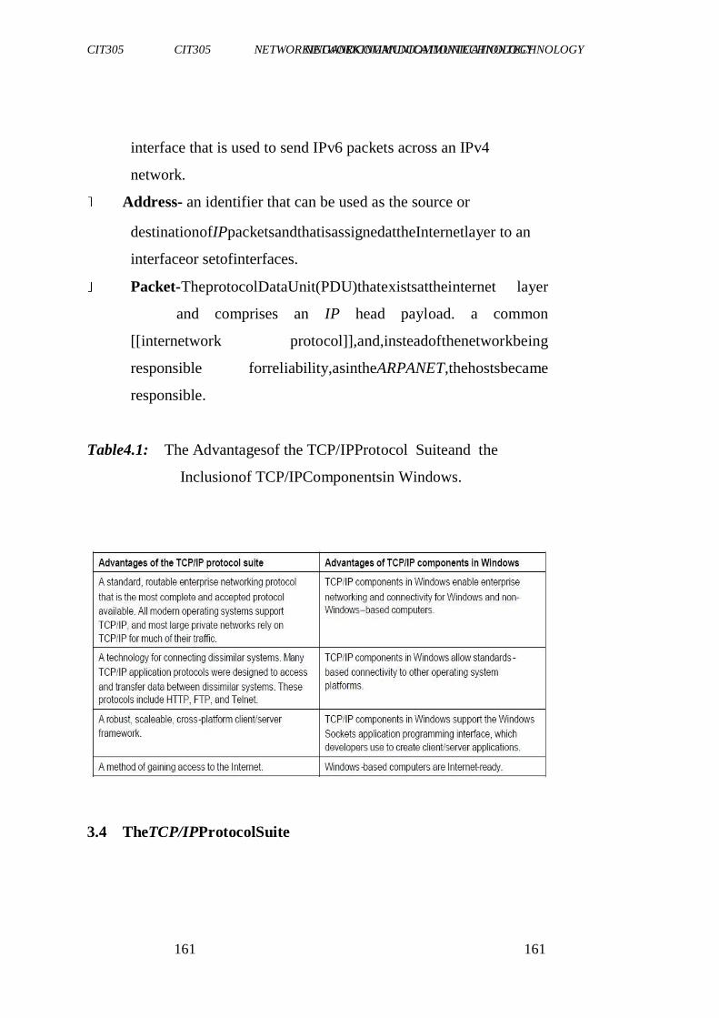
CIT305 NETWORKINGANDCOMMUNICATIONTECHNOLOGY CIT305 NETWORKINGANDCOMMUNICATIONTECHNOLOGY
161161
161
interface that is used to send IPv6 packets across an IPv4
network.
Address- an identifier that can be used as the source or
destinationofIPpacketsandthatisassignedattheInternetlayer to an
interfaceor setofinterfaces.
Packet-TheprotocolDataUnit(PDU)thatexistsattheinternet layer
and comprises an IP head payload. a common
[[internetwork protocol]],and,insteadofthenetworkbeing
responsible forreliability,asintheARPANET,thehostsbecame
responsible.
Table4.1: The Advantagesof the TCP/IPProtocol Suiteand the
Inclusionof TCP/IPComponentsin Windows.
3.4 TheTCP/IPProtocolSuite

CIT305 NETWORKINGANDCOMMUNICATIONTECHNOLOGY CIT305 NETWORKINGANDCOMMUNICATIONTECHNOLOGY
162162
162
The TCP/IP protocol suite maps to a four-layer conceptual model
known astheDARPAmodel,whichwasnamed aftertheU.S. government
agencythatinitiallydevelopedTCP/IP.Thefourlayersof
theDARPAmodelare:Application, Transport,Internet,andNetwork
Interface.EachlayerintheDARPAmodelcorresponds tooneormore layersof
theseven-layerOSImodel.
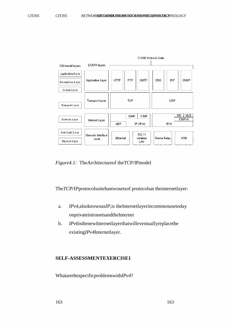
CIT305 NETWORKINGANDCOMMUNICATIONTECHNOLOGY CIT305 NETWORKINGANDCOMMUNICATIONTECHNOLOGY
163163
163
Figure4.1: TheArchitectureof theTCP/IPmodel
TheTCP/IPprotocolsuitehastwosetsof protocolsat theinternetlayer:
a. IPv4,alsoknownasIP,is theInternetlayerincommonusetoday
onprivateintranetsandtheInternet
b. IPv6isthenewInternetlayerthatwilleventuallyreplacethe
existingIPv4Internetlayer.
SELF-ASSESSMENTEXERCISE1
WhatarethespecificproblemswithIPv4?
CIT305 NETWORKINGANDCOMMUNICATIONTECHNOLOGY CIT305 NETWORKINGANDCOMMUNICATIONTECHNOLOGY
164164
164
3.5 NetworkInterfaceLayer
Thenetworkinterfacelayer(alsocalledthenetworkaccesslayer)sends
TCP/IPpacketsonthenetworkmediumandreceivesTCP/IPpackets
offthenetworkmedium.TCP/IPwasdesignedtobeindependentofthe
network accessmethod,frameformat,andmedium.Therefore,youcan
useTCP/IPto communicateacrossdifferingnetworktypesthatuseLAN
technologies—such asethernetand802.11wirelessLAN—andWAN
technologies—such asFrameRelayandAsynchronous TransferMode
(ATM).Bybeingindependentofanyspecificnetwork technology,
TCP/IPcanbe adaptedto newtechnologies.Thenetworkinterfacelayer
oftheDARPAmodelencompassesthedatalinkandphysicallayersof
theOSImodel.Theinternet layeroftheDARPAmodeldoesnottake
advantageofsequencingandacknowledgment servicesthatmightbe
presentin the datalinklayerof the OSImodel.Theinternetlayer
CIT305 NETWORKINGANDCOMMUNICATIONTECHNOLOGY CIT305 NETWORKINGANDCOMMUNICATIONTECHNOLOGY
165165
165
assumesanunreliable networkinterfacelayerandthatreliable
communications throughsessionestablishmentandthesequencingand
acknowledgment ofpacketsistheresponsibilityofeitherthetransport layeror
theapplicationlayer.
3.6 InternetLayer
Theinternetlayerresponsibilities includeaddressing,packaging,and
routingfunctions. Theinternetlayerisanalogoustothenetworklayer
oftheOSImodel.ThecoreprotocolsfortheIPv4internetlayerconsist of
thefollowing:
i. theAddressResolutionProtocol(ARP)resolvestheinternetlayer
addresstoanetwork interfacelayeraddresssuchasahardware
address.
ii. theInternetProtocol(IP)isaroutableprotocolthataddresses,
routes,fragments,andreassemblespackets.
iii. theInternetControlMessageProtocol(ICMP)reportserrorsand
otherinformationtohelpyoudiagnoseunsuccessful packet delivery.
SELF-ASSESSMENTEXERCISE2
Whatisthedifferencebetweeninternetlayerandnetworklayerofthe
OSImodel?

CIT305 NETWORKINGANDCOMMUNICATIONTECHNOLOGY CIT305 NETWORKINGANDCOMMUNICATIONTECHNOLOGY
166166
166
3.7 ApplicationLayerInterface
Theapplicationlayerallowsapplications toaccesstheservicesofthe other
layers, and it defines the protocols that applications use to
exchangedata.Theapplicationlayercontainsmanyprotocols,andmore
arealwaysbeingdeveloped.
Themostwidelyknown applicationlayerprotocolshelpusersexchange
information.Someof theseare:
i. theHypertextTransferProtocol(HTTP)transfersfilesthatmake
uppagesontheWorldWideWeb(WWW).
ii. the File Transfer Protocol (FTP) transfers individual files,
typicallyforan interactiveusersession
iii. the Simple Mail Transfer Protocol (SMTP) transfers mail
messagesandattachments.
Additionally, thefollowingapplication layerprotocolshelpyouuseand
manageTCP/IPnetworks:
CIT305 NETWORKINGANDCOMMUNICATIONTECHNOLOGY CIT305 NETWORKINGANDCOMMUNICATIONTECHNOLOGY
167167
167
i. theDomainNameSystem(DNS)protocolresolvesahostname,
suchas‗www.microsoft.com‘,toanIPaddressandcopiesname
informationbetweenDNSservers.
ii. theRoutingInformationProtocol(RIP)isaprotocolthatrouters
usetoexchangerouting information onanIPnetwork.,calleda
router,is providedwithan interfaceto eachnetwork.
4.0 CONCLUSION
Inthisunit,youhavebeenintroducedtothefundamental conceptsof
internetTCP/IP.Youalsolearnttheinternet standard processandsome
TCP/IP terminologies.YouwerealsointroducedtoVariousTCP/IP
protocolsuites.
5.0 SUMMARY
In thisunit,youhavelearntthat:
the ''internet protocol suite'' is the set of communications
protocolsusedfortheinternetandothersimilarnetworks
theTCP/IPis theprotocolof theinternet;ithasevolvedbasedon
fundamentalstandardsthathavebeencreatedandadoptedover
morethan30years
CIT305 NETWORKINGANDCOMMUNICATIONTECHNOLOGY CIT305 NETWORKINGANDCOMMUNICATIONTECHNOLOGY
168168
168
theTCP/IPprotocolsuitemapstoafour-layerconceptualmodel
known as theDARPAmodel,whichwasnamed aftertheU.S.
governmentagencythatinitiallydevelopedTCP/IP
theTCP/IPprotocolsuitehastwosetsofprotocolsattheinternet layer-
namelyIPv4andIPv6
thenetworkinterfacelayer(alsocalledthenetworkaccesslayer)
sends TCP/IP packets on the network medium and receives
TCP/IPpacketsoffthenetworkmedium
theinternetlayerresponsibilitiesincludeaddressing,packaging,
androutingfunctions
theapplication layerallowsapplicationstoaccesstheservicesof
theotherlayers,anditdefinestheprotocolsthatapplicationsuse
to exchangedata.
6.0 TUTOR-MARKEDASSIGNMENT
1. Discussthehistoryof the TCP/IPmodel.
2. Whatis thefunctionof theinternetandtheapplicationlayer?
CIT305 NETWORKINGANDCOMMUNICATIONTECHNOLOGY CIT305 NETWORKINGANDCOMMUNICATIONTECHNOLOGY
169169
169
7.0 REFERENCES/FURTHERREADING
"About Rand". Paul Baran and the Origins of the Internet.
http://www.rand.org/about/history/baran.html.RetrievedJanuary
14,2006.
http://tldp.org/HOWTO/Unix-and-Internet-Fundamentals-
HOWTO/internet.html.RetrievedJune15,2009.
John,Till,Johnson."Netwasbornofeconomicnecessity,notfear".
http://www.networkworld.com/columnists/2004/0607johnson.ht
ml.RetrievedJune15,2009.
Prasad,K.V.(2009).PrinciplesofDigitalCommunicationSystemsand
ComputerNetworks.DreamtechPress.


