Embed Size (px)
Citation preview
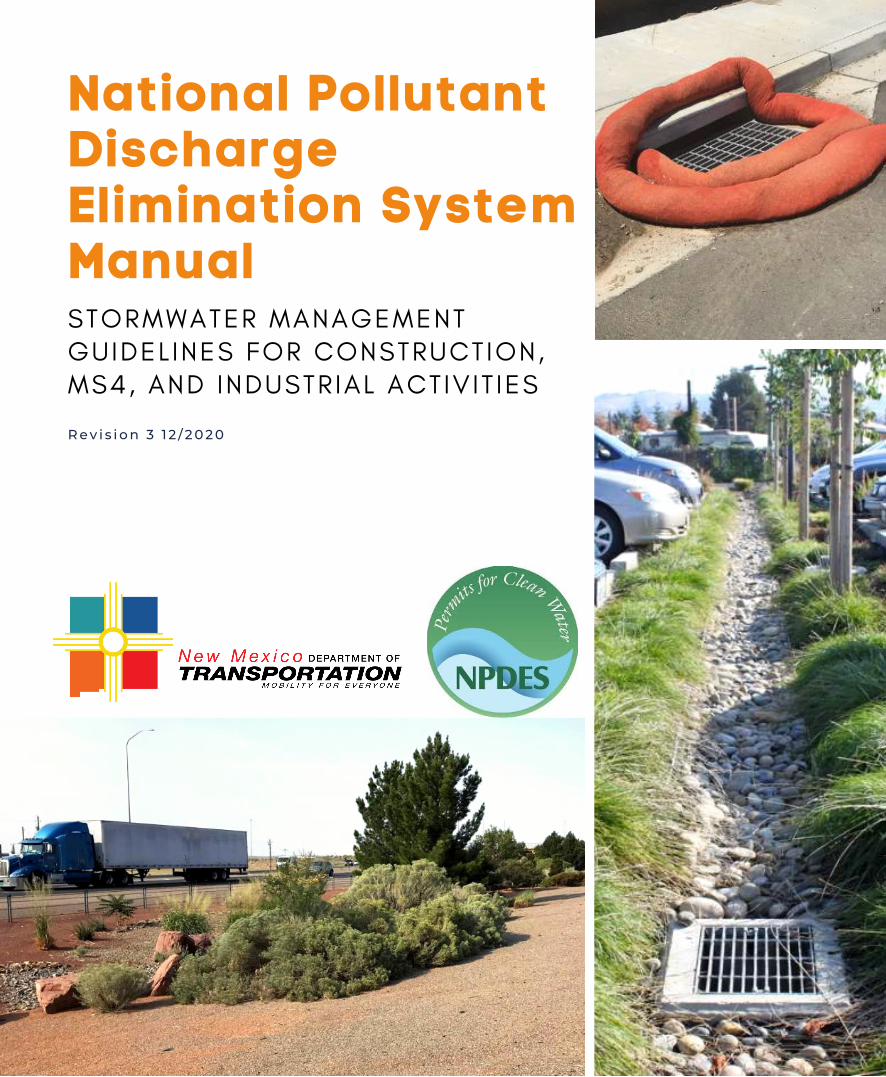
National PollutantDischargeElimination SystemManualSTORMWATER MANAGEMENT
GUIDEL INES FOR CONSTRUCTION,
MS4, AND INDUSTRIAL ACT IV IT IES
R e v i s i o n 3 1 2 / 2 0 2 0
National Pollutant Discharge Elimination System Manual
STORMWATER MANAGEMENT GUIDELINES FOR CONSTRUCTION, MS4, AND INDUSTRIAL ACTIVITIES
Revision 3 December 2020
New Mexico Department of Transportation Environmental Bureau
PO Box 1149 Santa Fe, New Mexico 87504-1149
NATIONAL POLLUTANT DISCHARGE ELIMINATION SYSTEM MANUAL REVISION 3 DECEMBER 2020
FORWARD
This December 2020 edition of the Stormwater Management Guidelines for Construction, MS4, and Industrial Activities is to be used as guidance for addressing National Pollutant Discharge System (NPDES) requirements for stormwater runoff from construction projects, municipal separate storm sewer system (MS4) areas, and industrial activities. The Manual is designed to be used in all parts of the state of New Mexico, both in urban and rural areas. This Manual was created to provide NPDES stormwater compliance guidance for the New Mexico Department of Transportation (NMDOT) and other government agency staff, design engineers, planners, landscape architects, and developers for use on both public and private projects. The use of this Manual is encouraged for any entity that has the potential to generate stormwater runoff through either construction, MS4, or industrial activities with exposure to stormwater. This revision to the NPDES Manual was necessitated by multiple regulatory NPDES changes, including:
• 2017 Construction General Permit (CGP) as modified 2019, dated June 27, 2019;
• 2014 General Permit for the Middle Rio Grande Watershed MS4s in New Mexico – #NMR04A000, currently in administrative continuance; and
• Multi-Sector General Permit (MSGP) for Stormwater Discharges from Industrial Activities – 2015 MSGP and Proposed 2020 MSGP. The 2015 MSGP is currently under administrative continuance.
In addition to the regulatory changes, this Manual revision includes a new, separate MS4 section (refer to Section II). The revision also updates Appendix A - Best Management Practice (BMPs) and includes BMPs with a focus on Green Stormwater Infrastructure (GSI) and Low Impact Development (LID). Appendix A is intended to encourage the use of, as well as assist with understanding and choosing appropriate BMP practices, including GSI. This Manual is intended to provide guidance in meeting the current NPDES regulations for General Permits; however, changes in regulatory prerogatives of state and federal agencies and other affected parties may be more recent that the information presented in this Manual. The user should be aware of and verify if updated regulatory information supersede information within this Manual. This Manual does not address obtaining a site-specific, individual NPDES Permit, where required. Comments regarding the content of this Manual are welcome and should be addressed to:
MS4 Program Manager, Environmental Bureau New Mexico Department of Transportation P.O. Box 1149 Santa Fe, NM 87504-1149
NATIONAL POLLUTANT DISCHARGE ELIMINATION SYSTEM MANUAL REVISION 3 DECEMBER 2020
ACKNOWLEDGEMENTS
The Manual revision was performed by the New Mexico Department of Transportation (NMDOT) Environmental and Drainage Design Bureaus with the assistance of Bohannan Huston, Inc., Daniel B. Stephens & Associates, Dekker/Perich/Sabatini, and Sites Southwest. The original Manual was the result of a collaborative effort between the NMDOT and the following agencies:
• City of Albuquerque,
• Albuquerque Metropolitan Arroyo Flood Control Authority (AMAFCA),
• University of New Mexico (UNM),
• Southern Sandoval County Arroyo Flood Control Authority (SSCAFCA),
• City of Rio Rancho,
• Bernalillo County, and
• New Mexico Environment Department (NMED) Surface Water Quality Bureau.
NMDOT led the updates to the Manual in 2012 and 2020 (current). This 2020 Manual revision has been provided for review to the original collaborative agencies listed above as well as to:
• Amigos Bravos,
• Arid LID Coalition,
• Associated Contractors of New Mexico (ACNM), through which 814 Solutions LLC provided review comments,
• Middle Rio Grande Technical Advisory Group, which includes most of the original collaborative member agencies listed above,
• City of Santa Fe,
• Santa Fe County,
• City of Farmington,
• San Juan County,
• City of Las Cruces,
• Town of Mesilla,
• New Mexico State University (NMSU),
• City of Sunland Park,
• City of Anthony, and
• Doña Ana County. The statewide feedback and collaborative contributions received are greatly appreciated and have been reviewed and reflected in the Manual, where applicable.
NATIONAL POLLUTANT DISCHARGE ELIMINATION SYSTEM MANUAL REVISION 3 DECEMBER 2020
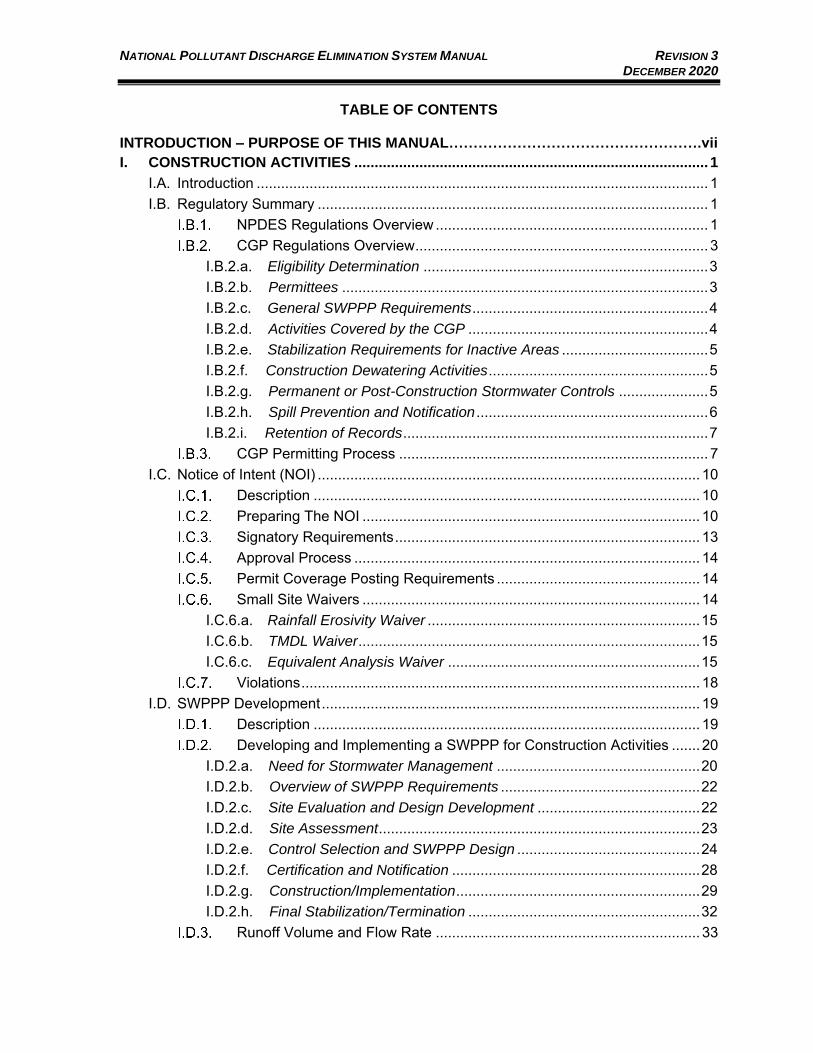
TABLE OF CONTENTS
INTRODUCTION – PURPOSE OF THIS MANUAL…………………………………………….vii
I. CONSTRUCTION ACTIVITIES ....................................................................................... 1 I.A. Introduction ............................................................................................................... 1 I.B. Regulatory Summary ................................................................................................ 1
NPDES Regulations Overview ................................................................... 1 CGP Regulations Overview ........................................................................ 3
I.B.2.a. Eligibility Determination ...................................................................... 3 I.B.2.b. Permittees .......................................................................................... 3 I.B.2.c. General SWPPP Requirements .......................................................... 4 I.B.2.d. Activities Covered by the CGP ........................................................... 4 I.B.2.e. Stabilization Requirements for Inactive Areas .................................... 5 I.B.2.f. Construction Dewatering Activities ...................................................... 5 I.B.2.g. Permanent or Post-Construction Stormwater Controls ...................... 5 I.B.2.h. Spill Prevention and Notification ......................................................... 6 I.B.2.i. Retention of Records ........................................................................... 7 CGP Permitting Process ............................................................................ 7
I.C. Notice of Intent (NOI) .............................................................................................. 10 Description ............................................................................................... 10 Preparing The NOI ................................................................................... 10 Signatory Requirements ........................................................................... 13 Approval Process ..................................................................................... 14 Permit Coverage Posting Requirements .................................................. 14 Small Site Waivers ................................................................................... 14
I.C.6.a. Rainfall Erosivity Waiver ................................................................... 15 I.C.6.b. TMDL Waiver .................................................................................... 15 I.C.6.c. Equivalent Analysis Waiver .............................................................. 15 Violations .................................................................................................. 18
I.D. SWPPP Development ............................................................................................. 19 Description ............................................................................................... 19 Developing and Implementing a SWPPP for Construction Activities ....... 20
I.D.2.a. Need for Stormwater Management .................................................. 20 I.D.2.b. Overview of SWPPP Requirements ................................................. 22 I.D.2.c. Site Evaluation and Design Development ........................................ 22 I.D.2.d. Site Assessment ............................................................................... 23 I.D.2.e. Control Selection and SWPPP Design ............................................. 24 I.D.2.f. Certification and Notification ............................................................. 28 I.D.2.g. Construction/Implementation ............................................................ 29 I.D.2.h. Final Stabilization/Termination ......................................................... 32 Runoff Volume and Flow Rate ................................................................. 33
NATIONAL POLLUTANT DISCHARGE ELIMINATION SYSTEM MANUAL REVISION 3 DECEMBER 2020
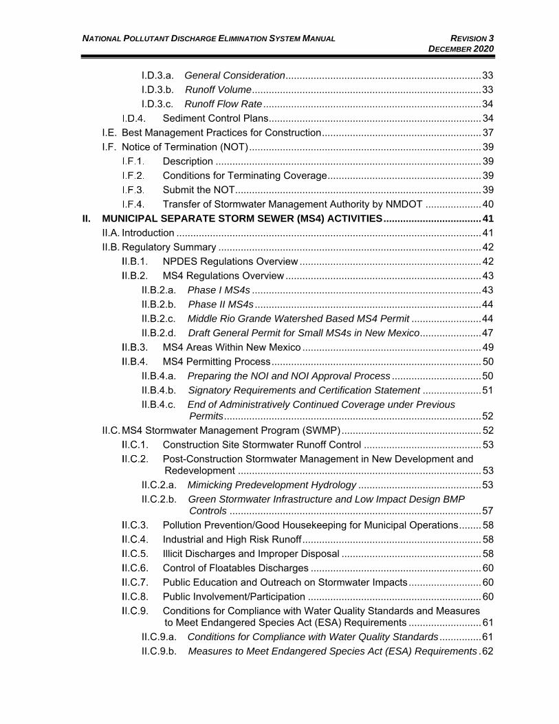
I.D.3.a. General Consideration ...................................................................... 33 I.D.3.b. Runoff Volume .................................................................................. 33 I.D.3.c. Runoff Flow Rate .............................................................................. 34 Sediment Control Plans ............................................................................ 34
I.E. Best Management Practices for Construction ......................................................... 37 I.F. Notice of Termination (NOT) ................................................................................... 39
Description ............................................................................................... 39 Conditions for Terminating Coverage ....................................................... 39 Submit the NOT ........................................................................................ 39 Transfer of Stormwater Management Authority by NMDOT .................... 40
II. MUNICIPAL SEPARATE STORM SEWER (MS4) ACTIVITIES ................................... 41 II.A. Introduction ............................................................................................................. 41 II.B. Regulatory Summary .............................................................................................. 42
NPDES Regulations Overview ................................................................. 42 MS4 Regulations Overview ...................................................................... 43
II.B.2.a. Phase I MS4s .................................................................................. 43 II.B.2.b. Phase II MS4s ................................................................................. 44 II.B.2.c. Middle Rio Grande Watershed Based MS4 Permit ......................... 44 II.B.2.d. Draft General Permit for Small MS4s in New Mexico ...................... 47
MS4 Areas Within New Mexico ................................................................ 49 MS4 Permitting Process ........................................................................... 50
II.B.4.a. Preparing the NOI and NOI Approval Process ................................ 50 II.B.4.b. Signatory Requirements and Certification Statement ..................... 51 II.B.4.c. End of Administratively Continued Coverage under Previous
Permits ............................................................................................ 52 II.C. MS4 Stormwater Management Program (SWMP) .................................................. 52
Construction Site Stormwater Runoff Control .......................................... 53 Post-Construction Stormwater Management in New Development and
Redevelopment ....................................................................................... 53 II.C.2.a. Mimicking Predevelopment Hydrology ............................................ 53 II.C.2.b. Green Stormwater Infrastructure and Low Impact Design BMP
Controls .......................................................................................... 57 Pollution Prevention/Good Housekeeping for Municipal Operations ........ 58 Industrial and High Risk Runoff ................................................................ 58 Illicit Discharges and Improper Disposal .................................................. 58 Control of Floatables Discharges ............................................................. 60 Public Education and Outreach on Stormwater Impacts .......................... 60 Public Involvement/Participation .............................................................. 60 Conditions for Compliance with Water Quality Standards and Measures
to Meet Endangered Species Act (ESA) Requirements .......................... 61 II.C.9.a. Conditions for Compliance with Water Quality Standards ............... 61 II.C.9.b. Measures to Meet Endangered Species Act (ESA) Requirements . 62
NATIONAL POLLUTANT DISCHARGE ELIMINATION SYSTEM MANUAL REVISION 3 DECEMBER 2020
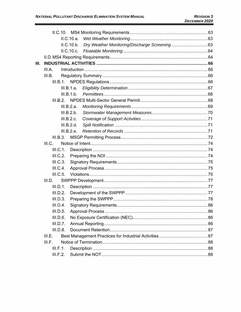
MS4 Monitoring Requirements ................................................................ 63 II.C.10.a. Wet Weather Monitoring ................................................................ 63 II.C.10.b. Dry Weather Monitoring/Discharge Screening .............................. 63 II.C.10.c. Floatable Monitoring ...................................................................... 64
II.D. MS4 Reporting Requirements ................................................................................. 64 III. INDUSTRIAL ACTIVITIES ............................................................................................ 66
III.A. Introduction ...................................................................................................... 66 III.B. Regulatory Summary ....................................................................................... 66
NPDES Regulations ................................................................................. 66 III.B.1.a. Eligibility Determination .................................................................. 67 III.B.1.b. Permittees ...................................................................................... 68
NPDES Multi-Sector General Permit ........................................................ 68 III.B.2.a. Monitoring Requirements ............................................................... 69 III.B.2.b. Stormwater Management Measures .............................................. 70 III.B.2.c. Coverage of Support Activities ....................................................... 71 III.B.2.d. Spill Notification ............................................................................. 71 III.B.2.e. Retention of Records ..................................................................... 71
MSGP Permitting Process ........................................................................ 72 III.C. Notice of Intent ................................................................................................. 74
Description ............................................................................................... 74 Preparing the NOI .................................................................................... 74 Signatory Requirements ........................................................................... 75 Approval Process ..................................................................................... 75 Violations .................................................................................................. 75
III.D. SWPPP Development ...................................................................................... 77 Description ............................................................................................... 77 Development of the SWPPP .................................................................... 77 Preparing the SWPPP .............................................................................. 78 Signatory Requirements ........................................................................... 86 Approval Process ..................................................................................... 86 No Exposure Certification (NEC) .............................................................. 86 Annual Reporting ...................................................................................... 86 Document Retention ................................................................................. 87
III.E. Best Management Practices for Industrial Activities ........................................ 87 III.F. Notice of Termination ....................................................................................... 88
Description ............................................................................................... 88 Submit the NOT ........................................................................................ 88
NATIONAL POLLUTANT DISCHARGE ELIMINATION SYSTEM MANUAL REVISION 3 DECEMBER 2020
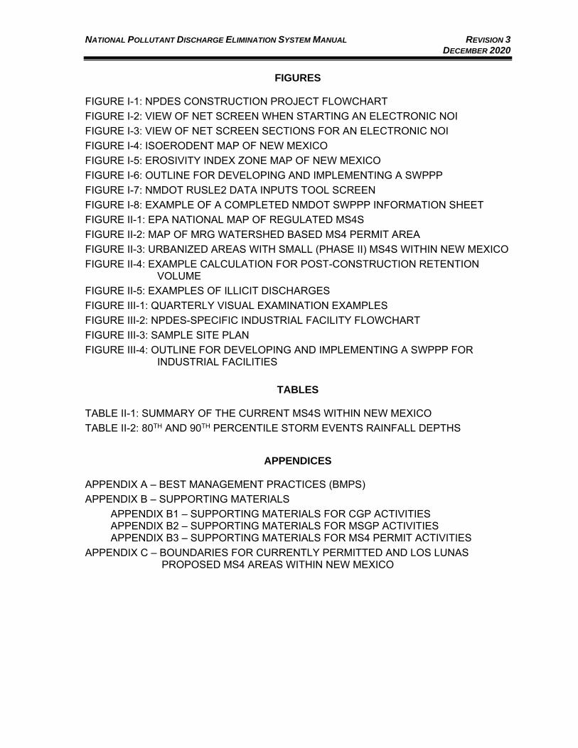
FIGURES
FIGURE I-1: NPDES CONSTRUCTION PROJECT FLOWCHART
FIGURE I-2: VIEW OF NET SCREEN WHEN STARTING AN ELECTRONIC NOI FIGURE I-3: VIEW OF NET SCREEN SECTIONS FOR AN ELECTRONIC NOI FIGURE I-4: ISOERODENT MAP OF NEW MEXICO
FIGURE I-5: EROSIVITY INDEX ZONE MAP OF NEW MEXICO
FIGURE I-6: OUTLINE FOR DEVELOPING AND IMPLEMENTING A SWPPP
FIGURE I-7: NMDOT RUSLE2 DATA INPUTS TOOL SCREEN
FIGURE I-8: EXAMPLE OF A COMPLETED NMDOT SWPPP INFORMATION SHEET
FIGURE II-1: EPA NATIONAL MAP OF REGULATED MS4S
FIGURE II-2: MAP OF MRG WATERSHED BASED MS4 PERMIT AREA
FIGURE II-3: URBANIZED AREAS WITH SMALL (PHASE II) MS4S WITHIN NEW MEXICO
FIGURE II-4: EXAMPLE CALCULATION FOR POST-CONSTRUCTION RETENTION VOLUME
FIGURE II-5: EXAMPLES OF ILLICIT DISCHARGES
FIGURE III-1: QUARTERLY VISUAL EXAMINATION EXAMPLES
FIGURE III-2: NPDES-SPECIFIC INDUSTRIAL FACILITY FLOWCHART
FIGURE III-3: SAMPLE SITE PLAN
FIGURE III-4: OUTLINE FOR DEVELOPING AND IMPLEMENTING A SWPPP FOR INDUSTRIAL FACILITIES
TABLES
TABLE II-1: SUMMARY OF THE CURRENT MS4S WITHIN NEW MEXICO
TABLE II-2: 80TH AND 90TH PERCENTILE STORM EVENTS RAINFALL DEPTHS
APPENDICES
APPENDIX A – BEST MANAGEMENT PRACTICES (BMPS) APPENDIX B – SUPPORTING MATERIALS
APPENDIX B1 – SUPPORTING MATERIALS FOR CGP ACTIVITIES APPENDIX B2 – SUPPORTING MATERIALS FOR MSGP ACTIVITIES APPENDIX B3 – SUPPORTING MATERIALS FOR MS4 PERMIT ACTIVITIES
APPENDIX C – BOUNDARIES FOR CURRENTLY PERMITTED AND LOS LUNAS PROPOSED MS4 AREAS WITHIN NEW MEXICO
NATIONAL POLLUTANT DISCHARGE ELIMINATION SYSTEM MANUAL REVISION 3 DECEMBER 2020
ACRONYMS
i
AIM Additional Implementation Measures AMAFCA Albuquerque Metropolitan Arroyo Flood Control Authority BMP Best Management Practice CDX Central Data Exchange, an EPA Electronic Reporting System
CERCLA Comprehensive Environmental Response, Compensation, and Liability Act
CFR Code of Federal Regulations CGP Construction General Permit CN Curve Number COA City of Albuquerque CWA Clean Water Act DMR Discharge Monitoring Report DPM Development Process Manual EPA U.S. Environmental Protection Agency ESA Endangered Species Act FR Federal Register GSI Green Stormwater Infrastructure GWQB Ground Water Quality Bureau, Division of NMED LANL Los Alamos National Laboratory LID Low Impact Development MCM Minimum Control Measure MEP Maximum Extent Practicable MRG Middle Rio Grande MS4 Municipal Separate Storm Sewer System MSGP Multi-Sector General Permit NEC No Exposure Certification NeT NPDES Electronic Reporting Tool NMAC New Mexico Administrative Code NMDOT New Mexico Department of Transportation NMED New Mexico Environment Department NMSU New Mexico State University NOAA National Oceanic and Atmospheric Administration NOI Notice of Intent NOT Notice of Termination NPDES National Pollutant Discharge Elimination System NRC National Response Center
NATIONAL POLLUTANT DISCHARGE ELIMINATION SYSTEM MANUAL REVISION 3 DECEMBER 2020
ACRONYMS
ii
NRCS Natural Resources Conservation Service OSE Office of the State Engineer OSHA Occupational Safety and Health Administration PDE NMDOT Project Development Engineer POTW Publicly Owned Treatment Works ROW Right-of-Way RQ Reportable Quantity RUSLE Revised Universal Soil Loss Equation SCP Sediment Control Plan, refer also to TESCP SSCAFCA Southern Sandoval County Arroyo Flood Control Authority SIC Standard Industrial Classification SWMP Stormwater Management Plan SWPPP Stormwater Pollution Prevention Plan
TESCP Temporary Erosion and Sediment Control Plan (term specific to NMDOT)
The Services U.S. Fish and Wildlife Service and National Marine Fisheries Services
TMDL Total Maximum Daily Load UA Urbanized Area UNM University of New Mexico USACE U.S. Army Corps of Engineers USGS U.S. Geological Survey WLA Waste Load Allocation
NATIONAL POLLUTANT DISCHARGE ELIMINATION SYSTEM MANUAL REVISION 3 DECEMBER 2020
iii
REFERENCES
City of Albuquerque. (2020). Development Process Manual (DPM). Albuquerque: City of Albuquerque. EPA 2017 Construction General Permit (as modified in 2019) – Website link includes the NPDES General Permit for Discharges from Construction Activities (as modified), appendices, and fact sheet. EPA NPDES Middle Rio Grande Watershed Based MS4 Permit – Website link has NPDES General Permit for the Middle Rio Grande Watershed MS4s, #NMR04A000 (2014), Fact Sheet, and MS4 Annual Report Form. EPA NPDES Stormwater General Permit for Discharges from Small MS4s in New Mexico – Website link has NPDES General Permit for Discharges from Small MS4s in New Mexico, #NMR040000 (2007), Fact Sheet, Proposal to Reissue NMR040000 (2015), and 2015 Draft General Permit for Discharges from Small MS4s in New Mexico: EPA NPDES Multi Sector General Permit (MSGP) for Stormwater Discharges from Industrial Activity – Website link has an overview of the program, 2015 MSGP, and Proposed 2020 MSGP. The 2015 MSGP is currently under administrative continuance. EPA. (2014). Estimating Predevelopment Hydrology in the Middle Rio Grande Watershed, New Mexico, John Kosco, P.E., Khalid Alvi, P.E., and Mustafa Faizullabhoy, P.E., EPA Office of Wastewater Management, Water Permits Division, Municipal Branch. EPA. (2015). Estimating Predevelopment Hydrology for Urbanized Areas in New Mexico, Tetra Tech and EPA Office of Wastewater Management, Water Permits Division, Municipal Branch. NMDOT. (2018). NMDOT Drainage Design Manual, Smith Engineering Company, Occam Engineers Inc. with NMDOT Drainage Design Bureau engineers and Thompson Engineering Consultants, Inc. New Mexico Environment Department (NMED) in coordination with New Mexico Office of the State Engineer (OSE). (2017). Green Infrastructure Implementation in New Mexico. United States Department of Agriculture, Agriculture Research Service, Agriculture Handbook Number 703. (1997). Predicting Soil Erosion by Water: A Guide to Conservation Planning With the Revised Universal Soil Loss Equation (RUSLE).
NATIONAL POLLUTANT DISCHARGE ELIMINATION SYSTEM MANUAL REVISION 3 DECEMBER 2020
iv
GLOSSARY OF TERMS
Throughout the Manual, the reader will find references to specific terms. To understand the process and goal of the stormwater program, these specific terms are listed below with definitions.
Arid Area – Areas with an average annual rainfall of 0 to 10 inches. Best Management Practices (BMPs) – Management measures or practices used to protect air, soil, or water quality or reduce the potential for pollution associated with stormwater runoff. BMPs may be a structural device or non-structural practice, including processes, land use alternatives, activities, or physical structures. Bioretention – The use of ecological processes incorporating vegetation and organic soils to treat and infiltrate stormwater runoff. In addition to transpiring and infiltrating significant stormwater volumes, vegetation and healthy soil can enhance pollutant removal from stormwater, improve permeability, and provide ecological and aesthetic value. Examples of bioretention practices include bioswales, raingardens, tree trenches, and contour swales. Also known as bioinfiltration. Construction General Permit (CGP) – This refers to the NPDES General Permit for Discharges from Construction Activities. This is an umbrella permit that authorizes the discharge of stormwater (and certain authorized non-stormwater discharges) from construction sites that disturb one (1) or more acres of land, and from smaller sites that are part of a larger, common plan of development or sale that will ultimately disturb one (1) or more acres of land. Detention Facility – A pond or stormwater facility that holds or detains runoff in a basin for a limited time, releasing it very slowly and allowing much of the sediment to drop out. Evapotranspiration – The process by which water is transferred from the land to the atmosphere by evaporation from the soil and other surfaces and by transpiration from plants. Gray Stormwater Infrastructure – Traditional "gray" stormwater infrastructure is designed to quickly move stormwater away from the built environment and includes concrete, curbs, gutters, drains, piping, and collection systems that ultimately discharge untreated stormwater into a local water body. Green Stormwater Infrastructure (GSI) – A method of stormwater management that is as sustainable, environmentally friendly, and cost-effective as possible. GSI focuses on creating ecosystems to treat polluted stormwater runoff prior to it entering aquifers, streams, or other waterways. On-site management of stormwater is the first choice, with neighborhood or regional management options as the next preferable solutions. Impervious Surface – A material or layer that prevents fluid from passing through. Typical examples are roofs, asphalt surfaces, sidewalks, and concrete structures. Low Impact Development (LID) – A method of building design and community development with the intention of keeping stormwater runoff as uncontaminated as possible. “Slow it down, spread it out, soak it in” is the motto of LID. Spreading stormwater out reduces both the speed of the stormwater and erosion. Allowing the stormwater to soak into the ground recharges underground aquifers and fosters environmental growth.
NATIONAL POLLUTANT DISCHARGE ELIMINATION SYSTEM MANUAL REVISION 3 DECEMBER 2020
v
Minimum Control Measures (MCM) – minimum control measures include six elements that, when implemented in concert, are expected to result in significant reductions of pollutants discharged into receiving waterbodies from MS4s. The standard six minimum control measures that must be included in MS4 SWMPs include: 1) Construction Site Stormwater Runoff Control; 2) Post-Construction Stormwater Management in New Development and Redevelopment; 3) Pollution Prevention and Good Housekeeping for Municipal Operations; 4) Illicit Discharges and Improper Disposal; 5) Public Education and Outreach on Stormwater Impacts; and 6) Public Involvement/Participation. Multi-Sector General Permit (MSGP) – This refers to the NPDES Multi-Sector General Permit for Stormwater Discharges Associated with Industrial Activity. This is an umbrella permit under which certain Standard Industrial Classification (SIC) industries may be granted a permit to discharge stormwater associated with industrial activities by notifying EPA of their intent to do so, in compliance with the regulatory provisions of the General Permit. Municipal Separate Storm Sewer System (MS4) – A conveyance or system of conveyances (including roads with drainage systems and municipal streets) that is “owned or operated by a state, city, town, borough, county, parish, district, association, or other public body designed or used for collecting or conveying stormwater.” National Pollutant Discharge Elimination System (NPDES) – The national program for administering and regulating Sections 307, 318, 402, and 405 of the Clean Water Act. The EPA administers the NPDES program through issuance and enforcement of permits that authorize discharges to waters of the U.S. A stormwater permit issued under NPDES is authorization by EPA to discharge stormwater under certain specified conditions. Non-Exposure Certification (NEC) – A permit exemption for certain outfalls or pollutant constituents, granted to facilities that can demonstrate no discharge or absence of particular constituents through monitoring. Notice of Intent (NOI) – A formal notice to EPA that, under the NPDES General Permit, a stormwater discharge will take place. The NOI provides information on the permittee, location of discharge, and the type of discharge. It also certifies that the permittee will comply with certain specified conditions as outlined in the General Permit. Notice of Termination (NOT) – A formal notice to EPA that a specific site permitted under the NPDES Program is no longer discharging stormwater. Permeable / Pervious / Porous Surface – A material or layer that permits fluid to pass through the material and allows stormwater to infiltrate where it falls. Phytoremediation – A biological process by which various plants remove, stabilize, and uptake pollutants and contaminants from soil and water. Qualified Person – A person knowledgeable in the principles and practices of stormwater controls, pollution prevention, practice of erosion and sediment controls, and possesses the education and ability to assess conditions at an industrial facility or construction site that could impact stormwater quality, and the education and ability to assess the effectiveness of stormwater controls (BMPs) selected and installed to meet the requirements of the applicable NPDES Permit. For NMDOT, the Standard Specifications of Highway and Bridge Construction, Section 603, Temporary Erosion and Sediment Control, requires a qualified person to conduct SWPPP inspections on NMDOT construction projects. Other New Mexico agencies may have similar requirements.
NATIONAL POLLUTANT DISCHARGE ELIMINATION SYSTEM MANUAL REVISION 3 DECEMBER 2020
vi
Retention Facility – A pond or stormwater facility that holds runoff in a reservoir without release except by means of evaporation, infiltration, or emergency bypass. Semi-Arid Area – Areas with an average annual rainfall of 10 to 20 inches. Stormwater Pollution Prevention Plan (SWPPP) – A plan consisting of site maps, construction/contractor activities that could cause pollutants in stormwater, and a description of measures or practices to control those pollutants. SWPPP documents are required by both the CGP and the MSGP. Temporary Erosion and Sediment Control Plan (TESCP) – The formal compilation of required erosion- and sediment-control activities prepared for a specific construction site and project. TESCP is an NMDOT term. Treatment Train – A stormwater treatment train is the combination of multiple, sequential stormwater best management practices (BMPs) that collectively deliver better overall results compared to use of a single BMP for reducing pollutants reaching the downstream receiving waters. Urbanized Area (UA) – A U.S. Census Bureau term, a UA is a continuously built-up area with a population of 50,000 or more. It comprises one or more places and the adjacent densely settled surrounding area of other places and nonplace territory.
NATIONAL POLLUTANT DISCHARGE ELIMINATION SYSTEM MANUAL REVISION 3 DECEMBER 2020
vii
INTRODUCTION – PURPOSE OF THIS MANUAL
This Stormwater Management Guidelines for Construction, MS4, and Industrial Activities is to be used as a guidance document to assist with understanding National Pollutant Discharge System (NPDES) General Permit requirements for stormwater runoff from construction projects, municipal separate storm sewer system (MS4) areas, and industrial activities. The NPDES Stormwater Permit Program is a federal program developed under Section 402 of the Clean Water Act (CWA). New Mexico currently does not have primacy for its NPDES program; the U.S. Environmental Protection Agency (EPA), Region 6 regulates New Mexico’s NPDES programs. Users are encouraged to check the EPA Region 6 website for updated permits and forms. Users with complex sites, issues, or questions should consult with the local or state regulatory agencies or an expert in NPDES requirements. This NPDES Manual was created to:
• Assist NPDES regulated entities in understanding the importance of stormwater management related to protecting surface water quality;
• Assist NPDES regulated entities in understanding the permitting, notification, compliance, and reporting processes for the General Permit for Discharges from Construction Activities (referred to as the Construction General Permit, or CGP) and the Multi-Sector General Permit (MSGP) for Stormwater Discharges Associated with Industrial Activity;
• Assist Municipal Separate Storm Sewer Systems (MS4s), along with entities working within MS4s, with understanding their programmatic requirements, some of which are associated with the NPDES permitting requirements for the CGP and the MSGP; and
• Provide the basics of planning and design for stormwater management including a focus on incorporating Green Stormwater Infrastructure (GSI) and Low Impact Development (LID) Best Management Practices (BMPs). This Manual is meant to highlight that GSI/LID BMPs are an encouraged approach for projects in New Mexico. o These BMP conceptual guidelines are intended to assist NMDOT and other
agencies across the state in increasing the resilience of New Mexico’s built infrastructure and reducing the negative impact of stormwater runoff on the environment; and Provide the basic information regarding the development of Stormwater Pollution Prevention Plans (SWPPPs), as well as the application of BMPs for construction and industrial facilities.
o This Manual describes many BMP options in detail within Appendix A. The BMPs in this update offer general methodologies and conceptual layouts in order to provide designers with some leeway in terms of their applicability to specific project sites. The suggested BMPs provided in this Manual should be used as a guide and, along with good engineering judgment and design, will produce a better product for NMDOT, other agencies, and the public.
NATIONAL POLLUTANT DISCHARGE ELIMINATION SYSTEM MANUAL REVISION 3 DECEMBER 2020
1
I. CONSTRUCTION ACTIVITIES
I.A. INTRODUCTION
Stormwater from construction sites can be a major cause of surface water pollution. Stormwater includes rainfall, melting snow, surface runoff and drainage, and rainfall or snowmelt from an adjacent site running onto or through a construction site. Pollution in stormwater from construction sites can include soil, sand, natural debris (leaves, grass, etc.), construction debris (woodchips, insulation scraps, cement, etc.), and chemicals (fuel, oil, lubricants, paint, tar, etc.).
When soil, vegetative cover, tree canopies, etc. are disturbed on a construction site, soil is loosened, making it easier for stormwater to carry the soil off the site, along with any debris or chemicals on the soil. Additionally, any new or existing paved surfaces onto which dirt and debris are tracked, or on which construction materials or chemicals are stored or spilled, make it easier for stormwater to collect and carry those materials off the site.
Once stormwater leaves a construction site, it can run directly into a river or lake, or can be carried to a nearby river or lake through an arroyo, ditch, storm sewer, or other conveyance. If the stormwater is polluted, it will carry those pollutants into the receiving waters and degrade the quality of that water. Construction site operators can protect the community’s surface water and the surrounding environment by making sure they implement proper stormwater controls.
The three main goals of the NPDES permitting program for stormwater discharges associated with construction activities are 1) reduce erosion, 2) minimize sedimentation, and 3) minimize the discharge of pollutants.
This Manual will assist users in developing a construction stormwater management plan tailored to the needs of their particular project while meeting regulatory requirements of stormwater management. Although runoff control measures are required by law in most instances, these measures are applicable anywhere soil is disturbed, and erosion and sedimentation are potential problems.
Users should also consult with their local government authority to determine the local construction permitting requirements and processing procedures for construction Stormwater Pollution Prevention Plans (SWPPPs). For example, SWPPPs for construction activities within the City of Albuquerque must conform to the submission procedures outlined in the City of Albuquerque’s Development Process Manual (DPM).
I.B. REGULATORY SUMMARY
NPDES Regulations Overview
The NPDES Stormwater Permitting Program in New Mexico is administered by the EPA Region 6 Office. Requirements for NPDES Stormwater Discharge Permits are defined by federal law in Section 402(p) of the CWA and added by Section 405 of the Water Quality Act of 1987.
NATIONAL POLLUTANT DISCHARGE ELIMINATION SYSTEM MANUAL REVISION 3 DECEMBER 2020
2
The NPDES General Permits are termed umbrella permits and are designed to consolidate permit compliance requirements for many common sources of pollutants, activities, and sites under one permit. The coverage of these umbrella permits is typically broad, with general compliance requirements, and the permits are typically effective for five (5) years. In order to effectively manage the permit process, EPA has produced a General Permit for Discharges from Construction Activities – referred to as the Construction General Permit (CGP), which defines specific conditions and requirements for stormwater management related to construction activities. The CGP establishes the procedures required for proper coverage, the requirement for a SWPPP, and requirements for termination of permit coverage. Currently, construction activities that disturb one (1) or more acres by grading, clearing, grubbing, or other construction activity, or smaller sites that are a part of a common development or plan of sale that will ultimately disturb one (1) or more acres of land, are subject to the requirements of the CGP. Failure to abide by the terms of the CGP or failure to develop and implement a site-specific NPDES Permit is a violation of federal law, which can subject the owner and/or operator to severe fines or imprisonment.
NPDES permitting requirements have been in effect for the last 30 years. In
November 1990, EPA published regulations for NPDES Permits for certain stormwater discharges. On September 9, 1992, EPA issued an NPDES General Permit that applied to the majority of stormwater discharges associated with specific industrial activities, including construction activities that disturbed five (5) acres or more. In July 2003, EPA published a new General Permit for discharges from large and small construction activities, which changed the requirement for a Permit for disturbed areas from five (5) acres to one (1) acre or more and included some small Municipal Separate Storm Sewer Systems (MS4s). Typically, every five (5) years a revised version of the CGP has been issued by EPA. The current version of the CGP was released in January 2017. On June 27, 2019, EPA issued modifications to the 2017 CGP pursuant to the CWA for stormwater discharges associated with construction activity. The current 2017 CGP (modified in 2019) expires in February 2022.
In addition to NPDES Permits for construction activities, large, medium, and some small sized municipalities (as identified by EPA) are required to obtain NPDES Permits for their MS4s to control stormwater runoff into waters of the United States (refer to Section II of this Manual for MS4 Permit requirements). The MS4 Permits require these local jurisdictions to take an active role in monitoring and controlling pollution due to stormwater runoff from a variety of sources, including construction activities. Construction activities within MS4s are covered by separate NPDES General Permits with distinct conditions, but the federal compliance requirements for these two NPDES Permits (CGP and MS4) include related activities. Therefore, in addition to meeting the requirements for the CGP, the site operator is obligated to review the local MS4 jurisdiction requirements to determine if additional requirements must be met in addition to CGP coverage.
Any user of this Manual should be aware that EPA regulations are periodically amended. The user is referred to EPA’s NPDES Stormwater Program website for Region 6 (www.epa.gov/npdes-permits/npdes-stormwater-program-region-6 to investigate possible amendments or updates to the regulations copied herein.
NATIONAL POLLUTANT DISCHARGE ELIMINATION SYSTEM MANUAL REVISION 3 DECEMBER 2020
3
CGP Regulations Overview
Compliance with the requirements of the CGP consists of four major components that must be accomplished:
• Determination of eligibility – refer to Section I.B.2.a of this Manual;
• Preparation and implementation of a SWPPP – refer to Section I.D of this Manual;
• Submission of a Notice of Intent (NOI) – refer to Section I.C of this Manual; and
• Submission of a Notice of Termination (NOT) – refer to Section I.F of this Manual.
I.B.2.a. Eligibility Determination
Permittees are only eligible for coverage under the CGP if their stormwater discharges and stormwater discharge-related activities do not adversely impact federally listed endangered or threatened species, critical habitats, or historic properties. Applicants are required to conduct an assessment of the impacts of their stormwater discharges and stormwater discharge-related activities on endangered and threatened species and critical habitat. Appendix D of the CGP provides detailed instructions to assist applicants in conducting an assessment and pursuing formal consultation with federal wildlife protection agencies, if necessary. Applicants must also complete a Historic Property Screening process as outlined in Appendix E of the CGP to determine the potential impact of the project on designated historic properties.
I.B.2.b. Permittees
The operator(s) of a construction site, the permittee(s), are responsible for submitting an NOI and complying with the NPDES CGP. The term operator is defined by EPA, for the purpose of the CGP and in the context of stormwater discharges associated with construction activity, as any party associated with a construction project that meets either of the following two criteria:
1) The party has operational control over construction plans and
specifications, including the ability to make modifications to those plans and specifications; or
2) The party has day-to-day operational control of those activities at a project
that are necessary to ensure compliance with the Permit conditions (e.g., they are authorized to direct workers at a site to carry out activities required by the Permit).
The operator may be the owner, developer, engineer, or contractor. For NMDOT projects, the first criteria listed above refers to the owner while the second refers to the contractor. Any other parties responsible for construction activities must also obtain CGP coverage. For example, in the case of an NMDOT project, both the general contractor and the NMDOT, as the owner, must submit a NOI. The construction contract is an appropriate place for the all CGP permittees to be identified, and their respective responsibilities listed.
NATIONAL POLLUTANT DISCHARGE ELIMINATION SYSTEM MANUAL REVISION 3 DECEMBER 2020
4
I.B.2.c. General SWPPP Requirements
The permittee must adhere to general compliance requirements established in the CGP and the SWPPP is the tool established by EPA to assist with the compliance requirements. The program is intended to be self-regulating and requires the permittee to prepare and implement the project SWPPP. Additional details on SWPPP development are provided in Section I.D of this Manual. The SWPPP is considered a living document and is required to be reviewed and updated throughout the duration of construction. During the construction phase, the permittee is responsible for:
• Maintaining a current copy of the SWPPP on-site;
• Inspecting the site to ensure that SWPPP improvements are in place and functional;
• Revising the SWPPP as site conditions and construction activities change;
• Maintaining temporary erosion and sediment controls and housekeeping measures; and
• Keeping records. Note: The SWPPP is usually prepared in conjunction with the construction design documents for the site and must be completed before the submission of the NOI to EPA.
I.B.2.d. Activities Covered by the CGP
Each construction project will vary in scope and responsible parties. For the purpose of pollution controls for stormwater discharges, the construction project site and construction activities to be covered by the SWPPP include:
• Areas cleared or disturbed for installation of improvements;
• Areas cleared for construction activities, such as temporary construction yards, material storage, and preparation areas;
• On-site and offsite areas excavated for fill or borrow material;
• Disposal areas, when not within a controlled landfill;
• Transportation of loose fill, materials, or debris to and from the site; and
• Construction dewatering requirements, if applicable. The CGP also authorizes stormwater discharges from support activities, including concrete or asphalt batch plants, equipment staging yards, material storage areas, excavated material disposal areas, and borrow areas, provided that:
• The support activity is directly related to a construction site having CGP coverage for discharges of stormwater associated with construction activity;
• The support activity is not a commercial operation serving multiple unrelated construction projects by different operators, and does not operate beyond the completion of the construction activity at the last construction project it supports; and
NATIONAL POLLUTANT DISCHARGE ELIMINATION SYSTEM MANUAL REVISION 3 DECEMBER 2020
5
• Appropriate controls and measures are identified in the SWPPP covering the discharges from the support activity.
I.B.2.e. Stabilization Requirements for Inactive Areas
During construction, some exposed areas may be inactive for long periods of time. The CGP, Section 2.2.14, requires areas inactive for more than fourteen (14) days to be temporarily stabilized. Thus, appropriate sequencing and phasing within a project can minimize or eliminate the need for temporary stabilization. The timeline to complete stabilization measures is seven (7) days if more than five (5) acres are disturbed and fourteen (14) days if less than five (5) acres are disturbed. There are special provisions for this requirement when construction occurs during the seasonally dry period for arid, semi-arid, and drought stricken areas. The dates defining the seasonally dry period are not specified in the CGP, rather the dates must be indicated in the SWPPP.
I.B.2.f. Construction Dewatering Activities
If the groundwater in the area of the construction site is contaminated, construction dewatering activities could transport this contamination to nearby surface waters. If a project site will require dewatering, the CGP requires that investigative information be included in the SWPPP. This is a specific requirement for New Mexico and is outlined in Part 9.4.1 of the CGP. The project location should be checked relative to potential groundwater contamination sources, such as leaking underground storage tanks and brownfield sites, as examples, by referring to the New Mexico Environment Department (NMED) Groundwater Quality Bureau (GWQB) Mapper at https://gis.web.env.nm.gov/oem/?map=gwqb and the Petroleum Storage Tank Bureau (PSTB) Mapper at https://gis.web.env.nm.gov/GoNM/, or by contacting the NMED GWQB at 505-827-2965.
A table outlining the constituents likely to require testing in dewatering based on distance from a potential contamination sites is outlined in Part 9.4.1 of the CGP. Dewatering testing should be coordinated with the NMED Surface Water Quality Bureau prior to starting dewatering activities and must also include measurement of pH and hardness. Test results will be sent to EPA Region 6 and the NMED Surface Water Quality Bureau. If testing proves exceedance of water quality standards, discharge must be conducted under a separate individual NPDES Permit. If discharge from dewatering will be to an unlined pond or on the ground surface, a NOI must be submitted to the NMED Ground Water Quality Bureau.
I.B.2.g. Permanent or Post-Construction Stormwater Controls
As part of the SWPPP, stormwater management measures must be addressed to reduce pollutants in stormwater runoff from the site once construction is complete and the development is occupied or placed in operation. Although sometimes referred to as post-construction or permanent controls, BMPs to control the quality of stormwater runoff from developed areas need to be considered during the earliest stages of planning for the project. These types of post-construction measures often tie to requirements within MS4 Permits for urbanized areas. Additional information related to MS4 post-construction
NATIONAL POLLUTANT DISCHARGE ELIMINATION SYSTEM MANUAL REVISION 3 DECEMBER 2020
6
stormwater controls is provided in Section II.C.2 of the Manual. Practices such as reducing the amount of impervious surface, bioretention drainage swales, stormwater harvesting basins, and others should be given consideration. Appropriate long-term measures must be incorporated into project plans and are often also part of the SWPPP. BMP options to consider are provided in Appendix A.
I.B.2.h. Spill Prevention and Notification
Procedures for stopping, containing, and cleaning up spills, leaks, and other releases as well as a list of agencies/individuals to be notified in the event of a spill is required to be specified in the SWPPP. Employees are responsible for immediately reporting any spill or leak, and other releases of material to their supervisor. The supervisor will immediately notify the designated Pollution Prevention and Spill Response Coordinator. The Pollution Prevention and Spill Response Coordinator is responsible for assessing the spill, gathering the information required for notification requirements, making the proper notifications in a timely manner, and implementing the spill response procedures. If the project is an NMDOT project, the NMDOT project manager shall be notified in a timely manner. Small or incidental spills (less than [<] 5 gallons) may be contained and cleaned by facility personnel if they are able to do so without risking safety or injury. Large or reportable spills (greater than [>] 5 gallons) will be cleaned by emergency responders and/or clean-up contractors. Per EPA, oil spill reporting does not depend on the specific amount of oil spilled, but on the presence of a visible sheen created by the spilled oil. EPA has established requirements to report oil spills to navigable waters or adjoining shorelines. Reporting requirements can be found on the EPA website (https://www.epa.gov/emergency-response/oil-discharge-reporting-requirements). For releases of hazardous substances, the federal government has established Superfund Reportable Quantities (RQs). If a hazardous substance is released to the environment in an amount that equals or exceeds its RQ, the release must be reported to federal authorities, unless certain reporting exemptions for hazardous substance releases also apply. Information on RQs can be found on the EPA website (https://www.epa.gov/epcra/cercla-and-epcra-continuous-release-reporting). In the event of a spill of a hazardous substance, the Pollution Prevention and Spill Response Coordinator is required to notify the National Response Center at (800) 424-8802, the NMED at (505) 827-9329, and the local fire department to properly report the spill. A written description of the release must be provided to the EPA Region 6 Office, which includes the date and circumstances of the release.
If fuels, oils, hazardous chemicals, or other similar substances are to be present on-site, it is imperative that they are stored in closed containers and have properly sized secondary containment areas. Hazardous chemicals include
NATIONAL POLLUTANT DISCHARGE ELIMINATION SYSTEM MANUAL REVISION 3 DECEMBER 2020
7
fertilizers, paints, oils, grease, pesticides, and fuels, along with other construction chemicals. While much of this Manual focuses on the sediment- and erosion-control aspects of the SWPPP, there is high potential for damaging pollution from chemicals. Provisions must be made to address prevention of potential pollution through the use of the BMPs.
I.B.2.i. Retention of Records
As part of the CGP, the SWPPP and supporting documentation must be retained for a period of three (3) years after the completion of the project, which is considered as complete after final site stabilization. This is to protect the owner/operator of the site from future claims concerning water quality and measures implemented at the site. It is recommended that each of the owner/operators maintains a copy of the SWPPP for the three (3) year period to protect against potential lawsuits.
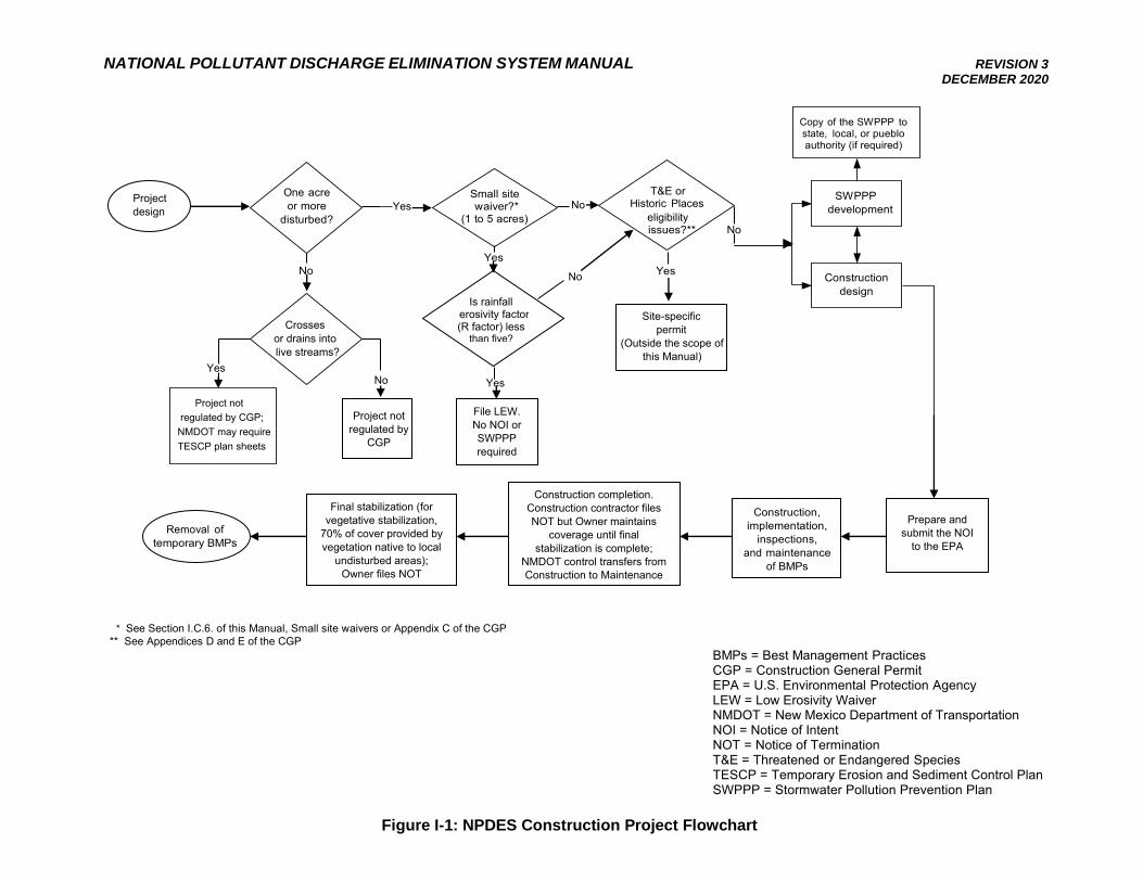
CGP Permitting Process
Figure I-1 shows a typical construction project sequence, including permitting requirements. Determining if the project site will be regulated under the CGP begins during the design of a project. Currently, if the area to be disturbed is one (1) or more acres, or from smaller sites that are part of a larger, common plan of development or sale that will ultimately disturb one (1) or more acres of land, the CGP requirements will need to be met, and coverage obtained under the CGP is required by obtaining an individual NPDES Permit (which is not covered by this Manual).
If the site meets the above listed disturbed area requirements, then a determination
must be made if there are any threatened and endangered species or historic properties issues for the site (see Appendices D and E of the CGP). If any issues arise with the eligibility requirements, an individual NPDES Permit application is required and this Manual’s guidance is not applicable. If these eligibility items are not an issue, proceed with the preparation of a SWPPP for the construction project to obtain coverage under the CGP.
The SWPPP should be prepared and completed prior to filing the NOI, which must be
completed prior to the start of construction of a project. Once the SWPPP is prepared, each operator (owner, developer, engineer, or contractor; refer to Section I.B.2.b of this Manual for operator definition) must prepare and submit an NOI to EPA. NMDOT construction projects will have a minimum of two (2) NOIs filed – one by the owner (NMDOT) and one by the contractor.
If the preparer of the SWPPP intends to delegate any of the responsibilities outlined in
the SWPPP to a builder/subcontractor, these actions need to be specifically addressed in the SWPPP. Once a SWPPP has been prepared and an NOI has been filed and acknowledged by EPA, project construction may begin within fourteen (14) calendar days after acknowledgement of receipt of the complete NOI is posted on EPA’s NPDES website (https://e-enterprise.gov/workbench - use the Permit Lookup Tool).
During construction, the measures and inspections that are outlined in the SWPPP
need to be completed as they are defined in the SWPPP. If site conditions, design changes, or construction sequencing warrant a change in the type, design, or scheduling of the stormwater pollution control measures, then the SWPPP needs to be revised, signed, and
NATIONAL POLLUTANT DISCHARGE ELIMINATION SYSTEM MANUAL REVISION 3 DECEMBER 2020
8
dated. The SWPPP is considered a living document and should be updated as the site conditions change and warrant BMP updates. Inspections of the construction site will be conducted, and any maintenance to BMPs/controls will be made, as necessary, to ensure that the SWPPP is being followed.
Upon completion of the construction project, an NOT must be prepared and submitted to EPA by the contractor/operator within 30 days after project completion. The owner/operator shall prepare and submit the NOT to EPA within 30 days of determining when final stabilization is established. Final stabilization for vegetative stabilization is when 70 percent of cover provided by vegetation native to local undisturbed areas has been established at the project site. Additional details on when and how to file the NOT are provided in Section I.F of this Manual.
For NMDOT projects, after construction completion, the contractor, the NMDOT Project Manager and the NMDOT Assistant District Engineer (ADE) - Construction will conduct an inspection. After any noted deficiencies are corrected by the contractor, the contractor will sign the NMDOT Transfer of Stormwater Management Authority Form – Contractor to NMDOT Project Manager (refer to Appendix B1 of this Manual), thus transferring the SWPPP responsibilities to NMDOT. The transfer form must be signed by the NMDOT Project Manager and the ADE - Construction or designee. A copy of the transfer form must be placed in both SWPPP binders. After completion of the transfer form, the construction contractor can then file their CGP NOT; a copy of the contractor’s NOT shall be placed in both SWPPP binders. The NMDOT Project Manager shall ensure that the contractor has provided two (2) identical copies of the completed SWPPP PRIOR to paying the final progress payment (NMDOT Item 603280, SWPPP Management).
NMDOT will maintain the CGP coverage until it is determined that final stabilization has been established, which for vegetative stabilization is when 70 percent of cover provided by vegetation native to local undisturbed areas has been established at the project site. Once final stabilization is established, the owner, in this case NMDOT, will file the NOT. Attachments in the NMDOT CGP Guide in Appendix B1 of this Manual contain NMDOT transfer forms that are required as the stormwater management and inspection responsibilities under the CGP transfer between departments.
NATIONAL POLLUTANT DISCHARGE ELIMINATION SYSTEM MANUAL REVISION 3 DECEMBER 2020
Copy of the SWPPP to state, local, or pueblo authority (if required)
Project design
One acre or more
disturbed?
No
Yes
Small site waiver?*
(1 to 5 acres) Yes
T&E or No Historic Places
eligibility issues?** No
Yes
SWPPP development
Construction
design
Crosses or drains into
live streams?
Project not regulated by CGP; NMDOT may require TESCP plan sheets
Removal of temporary BMPs
* See Section I.C.6. of this Manual, Small site waivers or Appendix C of the CGP ** See Appendices D and E of the CGP
BMPs = Best Management Practices CGP = Construction General Permit EPA = U.S. Environmental Protection Agency LEW = Low Erosivity Waiver NMDOT = New Mexico Department of Transportation NOI = Notice of Intent NOT = Notice of Termination T&E = Threatened or Endangered Species TESCP = Temporary Erosion and Sediment Control Plan SWPPP = Stormwater Pollution Prevention Plan
Figure I-1: NPDES Construction Project Flowchart
No Yes
Final stabilization (for vegetative stabilization,
70% of cover provided by vegetation native to local
undisturbed areas); Owner files NOT
Construction, implementation,
inspections, and maintenance
of BMPs
Construction completion. Construction contractor files NOT but Owner maintains
coverage until final stabilization is complete;
NMDOT control transfers from Construction to Maintenance
Prepare and submit the NOI
to the EPA
File LEW. No NOI or SWPPP required
Is rainfall erosivity factor (R factor) less
than five?
Site-specific permit
(Outside the scope of this Manual)
Project not regulated by
CGP
Yes
No
NATIONAL POLLUTANT DISCHARGE ELIMINATION SYSTEM MANUAL REVISION 3 DECEMBER 2020
10
I.C. NOTICE OF INTENT (NOI)
Description
The NOI is the primary document used by EPA to monitor and enforce compliance with the NPDES permitting requirements. The NOI is to be submitted after preparation of construction plans and the SWPPP. Discharge of stormwater from construction activities is authorized under the terms and conditions of the CGP fourteen (14) calendar days after acknowledgement of receipt of the complete NOI is posted on EPA’s NPDES website (https://e-enterprise.gov/workbench - use Permit Lookup Tool), except as noted below.
EPA may delay the authorization based on eligibility considerations of Part 1.1 of the
CGP (e.g., Endangered Species Act concerns). In these instances, coverage is not authorized under the CGP until notice is received from EPA of eligibility.
The operator of the site, see Section I.1.a of the Manual for the definition, is required
to submit a complete and accurate NOI and is ultimately responsible for the effective reduction of pollution and sediment loss from the site. A NOI or permit number must be placed at the site throughout the construction and until final stabilization.
An exception to the submission and authorization timeline is applicable for
construction projects occurring in response to a public emergency. These exceptions are likely relevant to NMDOT flooding-related roadway repairs. For an emergency-related project, immediate construction related stormwater discharge is allowable under the condition that a complete and accurate NOI is submitted within 30 days of commencing construction activities. Documentation supporting the occurrence of a public emergency must be included in the SWPPP.
Please note that in New Mexico, all pueblos require that the NOI and NOT be
submitted to their governing offices. Pueblo specific requirements are outlined in Part 9.4.2 of the CGP. Also note that local agencies may have construction related permits that need to be obtained independently of the CGP NOI (example: City of Albuquerque Erosion Sediment Control (ECS) Permit).
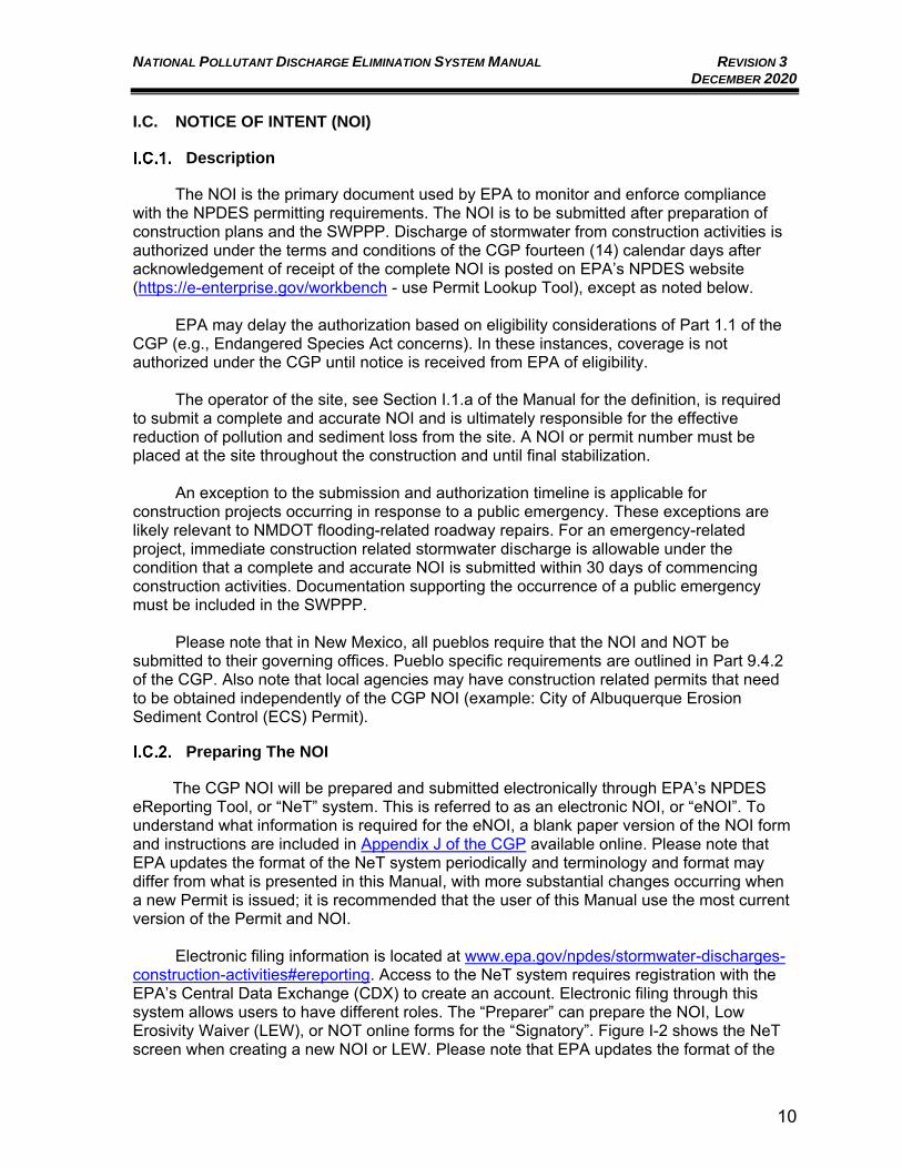
Preparing The NOI
The CGP NOI will be prepared and submitted electronically through EPA’s NPDES eReporting Tool, or “NeT” system. This is referred to as an electronic NOI, or “eNOI”. To understand what information is required for the eNOI, a blank paper version of the NOI form and instructions are included in Appendix J of the CGP available online. Please note that EPA updates the format of the NeT system periodically and terminology and format may differ from what is presented in this Manual, with more substantial changes occurring when a new Permit is issued; it is recommended that the user of this Manual use the most current version of the Permit and NOI.
Electronic filing information is located at www.epa.gov/npdes/stormwater-discharges-construction-activities#ereporting. Access to the NeT system requires registration with the EPA’s Central Data Exchange (CDX) to create an account. Electronic filing through this system allows users to have different roles. The “Preparer” can prepare the NOI, Low Erosivity Waiver (LEW), or NOT online forms for the “Signatory”. Figure I-2 shows the NeT screen when creating a new NOI or LEW. Please note that EPA updates the format of the
NATIONAL POLLUTANT DISCHARGE ELIMINATION SYSTEM MANUAL REVISION 3 DECEMBER 2020
11
NeT system periodically and the image in this Manual from July 2020 may differ from the online NeT system. The “Signatory” can also prepare, but in addition can certify and submit, the NOI, LEW, or NOT online forms. The “Signatory” must meet the signatory requirements for the CGP (refer to Section I.C.3 below). Registering as a “Signatory” in the NeT system will require additional authentication and security questions.
Figure I-2: View of NeT Screen When Starting an Electronic NOI
(Note: NeT screen shot taken in July 2020; actual online NeT system appearance may differ from figure image as NeT formatting is updated by EPA.)
The EPA Region 6 Office may give an applicant a waiver to use a paper NOI form
under extraordinary circumstances. If the user has computer access or capability limitations that will keep them from completing an eNOI, a waiver must be requested from the EPA Region 6 Office. If a waiver is granted for the use of a paper form, the NOI form provided in Appendix J of the CGP (or a photocopy thereof) must be used. If EPA makes other NOI forms available (either directly, by public notice, or by making information available on the Internet), the user may take advantage of any of those options to satisfy the NOI application requirement.
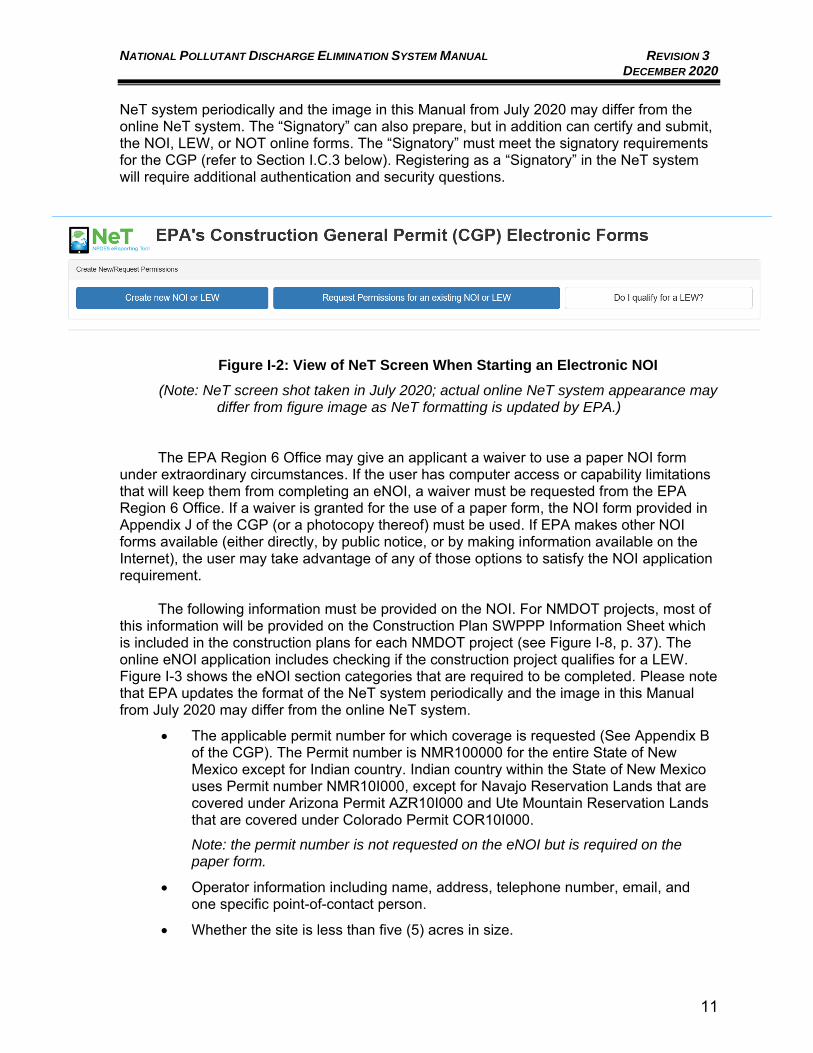
The following information must be provided on the NOI. For NMDOT projects, most of this information will be provided on the Construction Plan SWPPP Information Sheet which is included in the construction plans for each NMDOT project (see Figure I-8, p. 37). The online eNOI application includes checking if the construction project qualifies for a LEW. Figure I-3 shows the eNOI section categories that are required to be completed. Please note that EPA updates the format of the NeT system periodically and the image in this Manual from July 2020 may differ from the online NeT system.
• The applicable permit number for which coverage is requested (See Appendix B of the CGP). The Permit number is NMR100000 for the entire State of New Mexico except for Indian country. Indian country within the State of New Mexico uses Permit number NMR10I000, except for Navajo Reservation Lands that are covered under Arizona Permit AZR10I000 and Ute Mountain Reservation Lands that are covered under Colorado Permit COR10I000.
Note: the permit number is not requested on the eNOI but is required on the paper form.
• Operator information including name, address, telephone number, email, and one specific point-of-contact person.
• Whether the site is less than five (5) acres in size.
NATIONAL POLLUTANT DISCHARGE ELIMINATION SYSTEM MANUAL REVISION 3 DECEMBER 2020
12
Note: sites less than five (5) acres in size may be eligible for a LEW. Additional information on the LEW is provided in the Small Site Waivers, Rainfall Erosivity Waiver, Section I.C.6 of the Manual.
If the project site is less than five (5) acres in size, a website link provided in the eNOI application (https://lew.epa.gov/) can be used to determine the rainfall erosivity factor, or R-factor for the project. The project start date, end date, and address or latitude/longitude are required for the on-line widget to compute the R-factor.
• Whether polymers, flocculants, or other treatment chemicals will be utilized in construction.
• Whether the SWPPP has been prepared in advance of filing of this NOI and the location where the applicable SWPPP may be viewed.
Note: applicant cannot continue the eNOI process if the SWPPP is not completed.
• Whether any federally-listed threatened or endangered species, or federally-designated critical habitat are in the project area to be covered by this permit, and the basis for certifying eligibility for permit coverage based on the instructions in Appendix D of the CGP.
• Determination of the effect of the proposed stormwater controls on historic properties, if applicable. See Appendix E of the CGP for the Historic Properties Screening Process.
• Project/Site information including site name, address, county or similar governmental subdivision, and latitude/longitude of the construction project site. The eNOI has an online map tool that allows you to choose the site location and it fills in the latitude/longitude of the construction project site. Also, the NOI requests the estimated dates of commencement of construction activity and final stabilization (i.e., project start and completion dates) and total acreage to be disturbed, type of construction, as well as some questions about the predevelopment use of the land.
• Whether the site is located in Indian country and if so, the name of the Indian reservation or tribe associated with the property, if applicable. This information is used to determine the applicable Permit number described in item a. above.
• Whether the site will discharge to an MS4.
• Whether there any waters of the U.S. within 50 feet of the project’s earth disturbances.
• If applicable, the name of the receiving water(s) of the U.S. into which the site discharges, including adjacent surface water information, impaired waters information, and if any total maximum daily loads (TMDLs) have been completed for the receiving water.
• A certification statement, signed and dated by an authorized representative meeting the signatory requirements defined in Appendix I, Part I.11, of the CGP. Remember, that the eNOI “Signatory” must have their own CDX registration to certify and submit the NOI electronically, refer to Section I.C.2 above.
NATIONAL POLLUTANT DISCHARGE ELIMINATION SYSTEM MANUAL REVISION 3 DECEMBER 2020
13
Figure I-3: View of NeT Screen Sections for an Electronic NOI
(Note: NeT screen shot taken in July 2020; actual online NeT system appearance may differ from figure image as NeT formatting is updated by EPA.)
Signatory Requirements
The site operator (contractor/owner) must file the NOI. Operators are defined as those individuals having day-to-day operational control over activities that are necessary to ensure compliance with the SWPPP, or who have operational control over construction plans and specifications and the ability to modify same – refer to Section I.B.2.b of this Manual. Operator changes or additions require the filing of a new NOI.
If the operator is a corporation, a responsible corporate officer must sign the NOI. If the operator is a partnership or sole proprietorship, a general partner or the sole proprietor must sign the form. For any governmental entity, the signing person must be a principal executive, officer, or ranking elected official. The signatory requirements apply to both paper/hard-copy and electronic submittals. Appendix I, Part I.11, of the CGP provides a detailed description of signatory requirements.
NATIONAL POLLUTANT DISCHARGE ELIMINATION SYSTEM MANUAL REVISION 3 DECEMBER 2020
14
Approval Process
Unless notified to the contrary by EPA, operators who submit a completed and accurate eNOI, in accordance with the requirements of the CGP, are authorized to discharge stormwater from construction activities under the terms and conditions of the General Permit fourteen (14) calendar days after acknowledgement of receipt of the NOI is posted on EPA’s NPDES website (https://e-enterprise.gov/workbench - use Permit Lookup Tool). EPA may deny coverage under the CGP and require submittal of an application for an individual NPDES Permit, based on a review of the NOI or other information. Such an alternate application would be submitted to the EPA Region 6 Office.
Permit Coverage Posting Requirements
Notice of coverage must be made available to the public. A sign or other notice of the permit coverage is to be placed near the construction site so that it is at a safe, publicly accessible location in close proximity to the construction site and visible from the public road that is nearest to the active part of the construction site. The posting must include:
• Font large enough to be readily viewed from a public right-of-way;
• The NPDES ID assigned by EPA;
• A contact name and phone number for obtaining additional construction site information;
• The Uniform Resource Locator (URL) for the SWPPP (if available), or the statement: “If you would like to obtain a copy of the Stormwater Pollution Prevention Plan (SWPPP) for this site, contact the EPA Region 6 Office at [enter email and phone numbers for EPA Region 6 – available at https://www.epa.gov/npdes/contact-us-stormwater#regional]”; and
• The following statement: “If you observe indicators of stormwater pollutants in the discharge or in the receiving waterbody, contact EPA through the following website https://echo.epa.gov/report-environmental-violations.”
Small Site Waivers
The Construction Activities General Permit dated June 27, 2019 provides waivers for small construction activities, where the area to be disturbed is between one (1) and five (5) acres, in the case of three scenarios. The three waivers associated with the scenarios are:
• Rainfall Erosivity Waiver; • TMDL Waiver; and • Equivalent Analysis Waiver.
On all of these waivers, the permittee is not allowed to proceed with construction activities until approval is received from EPA. The waiver approval should be posted and retained on-site. These waivers are in lieu of having to obtain CGP coverage.
NATIONAL POLLUTANT DISCHARGE ELIMINATION SYSTEM MANUAL REVISION 3 DECEMBER 2020
15
I.C.6.a. Rainfall Erosivity Waiver
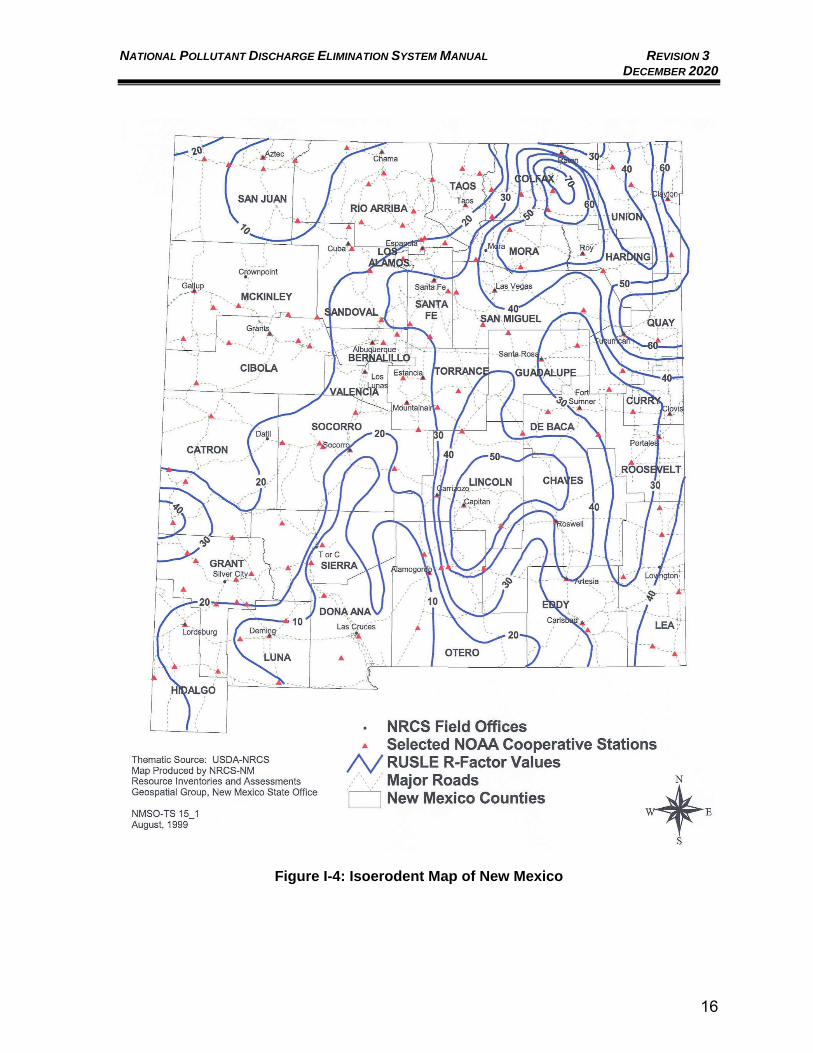
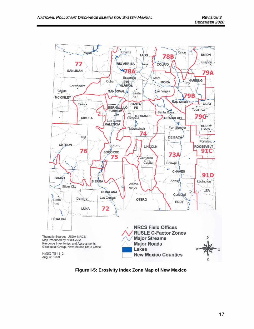
The Rainfall Erosivity Waiver is the most commonly viable in New Mexico. This waiver is often referred to as the Low Erosivity Waiver (LEW) and LEW is the term used in the NeT eNOI process. The waiver procedure involves calculating a rainfall erosivity factor based on several factors presented here to facilitate the calculation. EPA has developed an online rainfall erosivity calculator to help small construction sites determine potential eligibility for the rainfall erosivity waiver. The calculator can be accessed from EPA’s LEW website at https://lew.epa.gov/. This website is also accessible while completing the eNOI forms. The website calculator uses the methodology from EPA which references Chapter 2 of Agriculture Handbook Number 703 (1997). Predicting Soil Erosion by Water: A Guide to Conservation Planning With the Revised Universal Soil Loss Equation (pp. 21-64). United States Department of Agriculture, Agriculture Research Service. Details on how to calculate the R-factor manually are provided here: https://www.epa.gov/sites/production/files/2015-10/documents/fact3-1.pdf. The referenced handbook calculation process requires the determination of an “R” value from the Isoerodent Map of New Mexico (Figure I-4) for the site location and a determination of the erosivity index zone for the site location from the Erosivity Index Zone Map (Figure I-5). Please note that if the project is not completed during the originally prescribed period, a new calculation of the “R” value must be determined. If the new R-value is greater than 5, a NOI for the project will need to be submitted. As mentioned above, a Rainfall Erosivity Waiver, also called a LEW, can be submitted electronically via EPA’s NeT tool. The Pueblo of Sandia and the Ohkay Owingeh Reservation in New Mexico will not allow the Rainfall Erosivity Waiver to be granted for small construction activities. These restrictions have the potential to impact NMDOT projects on roadways through Tribal lands and these types of projects may require additional coordination. Also note that local agencies may have construction related permits that need to be obtained independently of the CGP NOI, and a rainfall erosivity waiver may not be recognized by local agencies.
I.C.6.b. TMDL Waiver
This waiver is available only when EPA has determined that the pollutant(s) of concern require no stormwater controls at the site to protect water quality.
I.C.6.c. Equivalent Analysis Waiver
This waiver is available for non-impaired waters only and requires the permittee to develop an equivalent analysis showing that no allocations for the pollutants of concern are required to protect water quality. This waiver is not likely to apply in New Mexico.
NATIONAL POLLUTANT DISCHARGE ELIMINATION SYSTEM MANUAL REVISION 3 DECEMBER 2020
16
Figure I-4: Isoerodent Map of New Mexico
NATIONAL POLLUTANT DISCHARGE ELIMINATION SYSTEM MANUAL REVISION 3 DECEMBER 2020
17
Figure I-5: Erosivity Index Zone Map of New Mexico
NATIONAL POLLUTANT DISCHARGE ELIMINATION SYSTEM MANUAL REVISION 3 DECEMBER 2020
18
Violations
The permittee(s) must comply with all conditions of the EPA CGP Permit. Any Permit noncompliance constitutes a violation of the CWA and is grounds for enforcement action by the EPA; Permit coverage termination, revocation, and re-issuance or modification; or denial of a Permit renewal application. Penalties for violations of Permit conditions fall into the following general categories:
• Criminal: o Negligent violations:
A fine of not less than $2,500 and not more than $25,000 per day of violation, or imprisonment of not more than one (1) year, or both. In the case of a second or subsequent conviction, a fine of not more than $50,000 per day of violation, or by imprisonment for not more than two (2) years, or both.
o Knowing violations: A fine of not less than $5,000 and not more than $50,000 per day of violation, or imprisonment of not more than three (3) years, or both. In the case of a second or subsequent conviction, a fine of not more than $100,000 per day of violation, or imprisonment for not more than six (6) years, or both.
o Knowing endangerment: A fine of not more than $250,000 or imprisonment of not more than 15 years, or both. In the case of a second or subsequent conviction, a fine of not more than $500,000 per day of violation, or by imprisonment for not more than 30 years, or both. An organization convicted of violating the imminent danger provision will be subject to a fine of not more than $1,000,000 and up to $2,000,000 for a second or subsequent conviction.
o False statement: A fine of not more than $10,000 or imprisonment of not more than two (2) years, or both. Upon a second conviction, a fine of not more than $20,000 per day of violation, or imprisonment of not more than four (4) years, or both.
• Civil: A fine of not more than $37,500 (currently) per day per violation.
• Administrative: o Class I penalty
Not to exceed the maximum amounts authorized by Section 309(g)(2)(A) of the CWA and the Federal Civil Penalties Inflation Adjustment Act (28 U.S.C. § 2461 note) as amended by the Debt Collection Improvement Act (31 U.S.C. § 3701 note) (currently $16,000 per violation, with the maximum amount of any Class I penalty assessed not to exceed $37,500).
o Class II penalty Not to exceed the maximum amounts authorized by Section 309(g)(2)(B) of the CWA and the Federal Civil Penalties Inflation Adjustment Act (28 U.S.C. § 2461 note) as amended by the Debt Collection Improvement Act (31 U.S.C. § 3701 note) (currently $11,000 per day for each day during which the violation continues, with the maximum amount of any Class II penalty not to exceed $177,500).
NATIONAL POLLUTANT DISCHARGE ELIMINATION SYSTEM MANUAL REVISION 3 DECEMBER 2020
19
The specific dollar amounts for each of the above types of violations and any associated imprisonment of guilty parties are specified Appendix I of the CGP. I.D. SWPPP DEVELOPMENT
Description
The SWPPP is a document that defines the construction activities and corresponding BMPs/controls to be employed to control the release of pollution from the construction site. The SWPPP consists of two components: a narrative description of the project and a drawing of the site showing the limits of soil disturbance, stormwater drainages, and locations and types of BMPs/controls.
The SWPPP identifies the techniques that the operator will use to reduce site erosion and sediment loss and manage construction-related wastes. It identifies the maintenance procedures that the operator will perform to preserve the efficiency of the technique used. The SWPPP must clearly describe the control measures, the timing and sequence of implementation, and which permittee (typically the contractor) is responsible for implementation and maintenance of the control measures.
The SWPPP is very likely to change during the course of construction due to
variations in construction techniques and/or site conditions. Conditions warranting corrective actions include the need for repair or replacement of a stormwater control beyond regular maintenance, incorrect or incomplete installation of a stormwater control, site discharges causing an exceedance of applicable water quality standards, or if a prohibited discharge has occurred. In order to maintain the effectiveness of the original SWPPP design, these modifications should be made by personnel experienced in the design of erosion- and sediment-control systems. EPA requires that the SWPPP documents be updated within seven (7) calendar days of any change in the pollution prevention systems employed on the site.
The SWPPP is not submitted to EPA as part of the NOI; instead, it must be available
on-site or nearby for inspection by EPA personnel, state and/or local jurisdiction staff, and the public upon request.
The SWPPP must also contain the following:
• All Site Operators; • Stormwater Team; • Nature of Construction Activities; • Site Map; • Authorized Non-Stormwater Discharges; • Description of Stormwater Controls; • Procedures for Inspection, Maintenance, and Corrective Action; • Staff Training; • Compliance with Other Requirements; • SWPPP Certification; and • Post-Authorization Additions to the SWPPP.
NATIONAL POLLUTANT DISCHARGE ELIMINATION SYSTEM MANUAL REVISION 3 DECEMBER 2020
20
Please note that in New Mexico, all pueblos require that a copy of the SWPPP be sent to the pueblos’ governing offices and some require copies of inspection reports and corrective action reports. Pueblo specific requirements are outlined in Part 9.4.2 of the CGP.
Developing and Implementing a SWPPP for Construction Activities
An outline of a step-wise SWPPP preparation process is given in Figure I-6. If a SWPPP is going to be prepared from scratch, it is recommended that this outline be followed to ensure completeness and to expedite the SWPPP review. A detailed explanation of this outline follows in Sections I.D.2.a. through h. of this Manual, derived from the 2007 EPA guidance document, Developing Your Stormwater Pollution Prevention Plan, A Guide for Construction Sites. SWPPP related forms are provided in Appendix B1. Note, the forms in the NMDOT CGP Guide in Appendix B1 of this Manual are specific to NMDOT projects while other forms in Appendix B1 are applicable to all projects covered by the CGP. Any reporting forms that meet or exceed EPA requirements may be used; the forms and templates provided in Appendix B1 are provided as references to assist the users of this Manual.
I.D.2.a. Need for Stormwater Management
Stormwater runoff is part of the natural hydrologic cycle. However, human activities, particularly urbanization, can alter natural drainage patterns and add pollutants to the rainwater and snowmelt that run off the earth’s surface and enter our nation’s rivers, lakes, streams, and coastal waters. In fact, recent studies have shown that stormwater runoff is a major source of the pollutants that are damaging our sport and commercial fisheries, restricting swimming, and affecting the navigability of many of our nation’s waters. Soil exposed by construction activities is especially vulnerable to erosion. Runoff from an unstabilized construction site can result in the loss of approximately 35 –45 tons of sediment per acre each year (EPA, 2007. Developing your Stormwater Pollution Prevention Plan, A Guide for Construction Sites. ). Even during a short period of time, construction sites can contribute more sediment to streams than would be deposited naturally over several decades. The best way to stop erosion is to keep the soil in place through vegetation, erosion control blankets, or other methods that prevent the soil from becoming dislodged during storm events. Appendix A of this Manual provides several BMP options for erosion control. Under the CGP, EPA requires the development and implementation of a SWPPP designed to reduce pollution at the source, before it can cause environmental problems that cost the public and private sectors in terms of lost resources and the expense of environmental restoration activities.
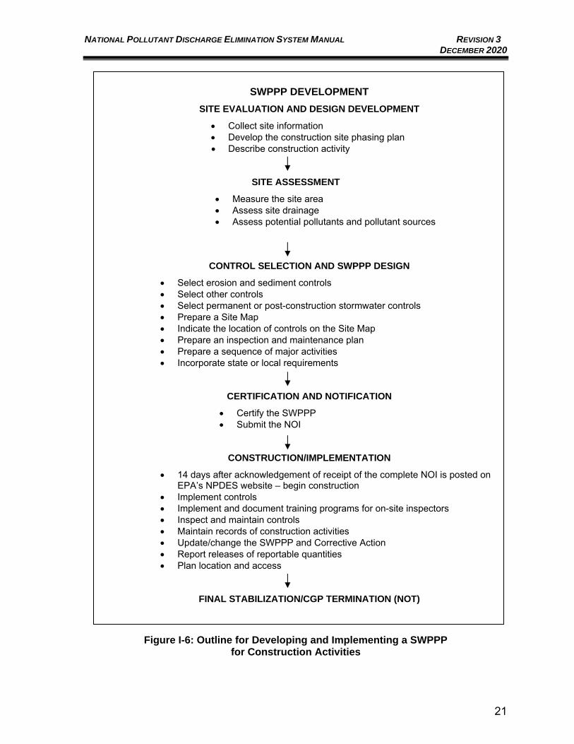
NATIONAL POLLUTANT DISCHARGE ELIMINATION SYSTEM MANUAL REVISION 3 DECEMBER 2020
21
SWPPP DEVELOPMENT
SITE EVALUATION AND DESIGN DEVELOPMENT
• Collect site information • Develop the construction site phasing plan • Describe construction activity
SITE ASSESSMENT
• Measure the site area • Assess site drainage • Assess potential pollutants and pollutant sources
CONTROL SELECTION AND SWPPP DESIGN
• Select erosion and sediment controls • Select other controls • Select permanent or post-construction stormwater controls • Prepare a Site Map • Indicate the location of controls on the Site Map • Prepare an inspection and maintenance plan • Prepare a sequence of major activities • Incorporate state or local requirements
CERTIFICATION AND NOTIFICATION
• Certify the SWPPP • Submit the NOI
CONSTRUCTION/IMPLEMENTATION
• 14 days after acknowledgement of receipt of the complete NOI is posted on EPA’s NPDES website – begin construction
• Implement controls • Implement and document training programs for on-site inspectors • Inspect and maintain controls • Maintain records of construction activities • Update/change the SWPPP and Corrective Action • Report releases of reportable quantities • Plan location and access
FINAL STABILIZATION/CGP TERMINATION (NOT)
Figure I-6: Outline for Developing and Implementing a SWPPP
for Construction Activities
NATIONAL POLLUTANT DISCHARGE ELIMINATION SYSTEM MANUAL REVISION 3 DECEMBER 2020
22
I.D.2.b. Overview of SWPPP Requirements
The following sections are organized according to the phases of the pollution prevention planning and implementation process. As shown in Figure I-6, pollution prevention planning requirements have been organized to provide users with a step-by-step process for ensuring that pollutants are not making their way into the stormwater discharges from a construction site. The six major phases of the process are: 1. Site evaluation and design development; 2. Site Assessment; 3. Control selection and SWPPP design; 4. Certification and notification; 5. Construction/implementation; and 6. Final stabilization/CGP termination. The following sections provide background information on pollution prevention planning requirements for CGP applicants. An EPA developed SWPPP template is provided in Appendix B1 of this Manual to assist with developing a SWPPP. EPA’s SWPPP template is also available online: https://www.epa.gov/npdes/construction-general-permit-resources-tools-and-templates#discharge.
I.D.2.c. Site Evaluation and Design Development
The first phase in preparing a SWPPP for a construction project is to define the characteristics of the site and the type of construction that will be occurring. This phase includes the following: i. Collect site information
In evaluating a site, the following existing information must be collected:
• Site map – The map should be a drawing, preferably to scale and preferably topographic, of the construction site. The best way to obtain a site map is to have the site surveyed by a professional surveyor. Alternatively, topographic maps may be available from state or local governments, or United States Geological Survey (USGS) topographical maps may be used. A site map will be used in subsequent steps of the development of the SWPPP. The scale of the map should be small enough so that important features, such as drainage swales and control measures that will be added later, can be easily distinguished.
• Soils information – Soils information should be based on information from the specific site. Sources of soils information could include soil borings or other geotechnical investigations. Natural Resources Conservation Service (NRCS) soil surveys may also be used. NRCS surveys typically indicate whether a soil is erodible.
• Stormwater runoff quality – Stormwater runoff quality data may sometimes be available from a state or local government (e.g., the local MS4). Runoff quality information may also be available from the USGS,
NATIONAL POLLUTANT DISCHARGE ELIMINATION SYSTEM MANUAL REVISION 3 DECEMBER 2020
23
state, or local watershed protection agencies.
• Name of receiving water – Identify the name and location of the body of water (e.g., stream, creek, run, wetland, river, lake, bay, ocean) that will receive the runoff from the construction site. If the receiving water is a tributary, include the name of the ultimate receiving body of water if possible. If the site drains into an MS4, identify the MS4 and indicate the receiving water to which the system discharges. One tool for assisting with determining receiving water information is available for New Mexico through the NMED Surface Water Bureau Mapper - https://gis.web.env.nm.gov/oem/?map=swqb – toggle on the National Hydrography Dataset on the map legend and use the Identify Feature tool to select the receiving body of water and determine the name. Determining whether a receiving water is considered a “waters of the U.S.” can be a complicated task, as the definition of a “waters of the U.S.” is dynamic due to recent rule changes and associated lawsuits. It is recommended that the NMED Surface Water Quality Bureau be contacted to assist with determining the locations of “waters of the U.S.” under the current rules and interpretation, relevant to the construction project.
ii. Develop the construction site phasing plan The next step is to develop a phasing plan based primarily on the goals and objectives of the proposed facility. The SWPPP should include estimated dates for major construction activities. There are several pollution prevention principles that should be considered when developing the site phasing plan for the project:
• Disturb the smallest vegetated area possible;
• Minimize the amount of cut and fill; and
• Limit impacts to sensitive areas such as: o Steep and/or unstable slopes; o Surface waters, including wetlands; o Areas with erodible soils; and o Existing drainage channels.
iii. Describe construction activity In preparing the plan, describe the purpose or goal of the construction project (e.g., a single-family residential development, a multi-story office building, or a highway interchange) and list the earth disturbing activities necessary to complete the project. Earth disturbing activities might include clearing, excavation and stockpiling, rough grading, final or finish grading, preparation for seeding or planting, excavation of trenches, demolition, etc.
I.D.2.d. Site Assessment
Once the characteristics of the site and the construction have been defined, the next phase in developing a SWPPP is to measure the size of the land disturbance and estimate the impact the project will have on stormwater runoff from the site,
NATIONAL POLLUTANT DISCHARGE ELIMINATION SYSTEM MANUAL REVISION 3 DECEMBER 2020
24
based on information collected during site evaluation and design. This phase includes the following: i. Measure the site area
The CGP requires that the SWPPP indicate estimates of the total site area and the area that will be disturbed.
ii. Assess site drainage Determine the size of each drainage area for each point where concentrated flow will leave the site. Drainage areas are portions of the site where runoff will flow in one particular direction or to a particular discharge point. These data will help in the selection and design of the sediment control and stormwater management measures for the project in the next phase of the plan. Use the drainage patterns indicated on the site map to determine the drainage areas. Note, drainage areas are not required by the CGP to be included in the SWPPP but are useful in selecting stormwater controls. Prior versions of the CGP have included a requirement for an estimation of the construction project’s impact on runoff using the Rational Method runoff coefficient of the site for pre- and post-construction conditions. Though runoff values are not currently specifically required, estimating runoff will assist with selection of stormwater controls for the construction project. This method, or others, may be useful for determining quantity of runoff which will impact the selection and design of the sediment control and stormwater management measures for the project in the next phase of the plan. The Rational Method runoff coefficient is an estimate of the fraction of total rainfall that will appear as runoff. For example, the “C” value of lawn area is 0.2, which indicates that only 20 percent of the water that falls on grassed areas will end up as surface runoff. In contrast, the “C” value of a paved area can be 0.9 or higher, indicating that 90 percent of the rain falling on this type of surface will run off. See EPA’s (2007) Developing Your Stormwater Pollution Prevention Plan, A Guide for Construction Sites, Appendix C for information on calculating the Rational Method runoff coefficient.
iii. Assess potential pollutants and pollutant sources Identify the pollutants and sources that are likely to be found on the construction site. The principal pollutant of concern at construction sites will most commonly be sediment. There are, however, other pollutants that may be found, usually in substantially smaller amounts, in stormwater runoff from construction sites. These can include nutrients, heavy metals, organic compounds, pesticides, oil and grease, bacteria and viruses, trash and debris, and other chemicals.
I.D.2.e. Control Selection and SWPPP Design
After collecting the information and assessing the site, the next phase is to design a pollution prevention plan to control pollution of stormwater runoff from the construction site. This phase includes the following:
i. Select erosion and sediment controls The SWPPP must include a description of the measures to be used for erosion and sediment controls throughout the construction project. These
NATIONAL POLLUTANT DISCHARGE ELIMINATION SYSTEM MANUAL REVISION 3 DECEMBER 2020
25
controls include stabilization measures for disturbed areas and structural controls to divert runoff and control sediment. Erosion and sediment controls are implemented during the construction period to control the loss of soil from the construction site into the receiving waters. The selection of the most appropriate erosion and sediment controls depends on a number of factors but is most dependent on site conditions. The information collected in the site evaluation, design development, and assessment phases is used to select controls. See Appendix A of this Manual for options for control measures.
ii. Select other controls In addition to erosion and sediment controls, the SWPPP must address the other potential pollutant sources that may exist on a construction site. These include proper waste disposal; compliance with applicable state or local waste disposal, sanitary sewer, or septic system regulations; control of offsite vehicle tracking; and control of allowable non-stormwater discharges, as explained in the following bullets:
• Ensure proper disposal of construction site waste materials.
• Treat or dispose of sanitary wastes that are generated on-site in accordance with state or local requirements. Contact the local government or state regulatory agency.
• Prevent offsite tracking of sediments and generation of dust. Stabilized construction entrances or vehicle washing racks should be installed at locations where vehicles leave the site. Where dust is a problem, implement dust control measures such as irrigation.
• Identify and prevent contamination of non-stormwater discharges. Where non-stormwater discharges allowed by the CGP exist, they should be identified, and steps should be taken to prevent contamination of these discharges.
iii. Select permanent or post-construction stormwater controls Permanent or post-construction stormwater controls are constructed to control pollution of stormwater after the construction is completed. These types of post-construction measures often tie to requirements within MS4 Permits for urbanized areas. Additional information related to MS4 post-construction stormwater controls is provided in Section II.C.5 of this Manual. A SWPPP compiled in support of coverage under the CGP needs to include a description of all permanent stormwater controls that will be constructed. The project should incorporate sediment and erosion controls into the SWPPP for areas where permanent stormwater controls, such as ponds, swales, and bioretention cells are to be constructed. Examples of permanent or post-construction stormwater controls include the following:
• Retention facility – A pond or stormwater facility that holds runoff in a reservoir without release except by means of evaporation, infiltration, or emergency bypass.
• Detention facility – A pond or stormwater facility that holds or detains runoff in a basin for a limited time, releasing it very slowly and allowing much of the sediments to drop out.
NATIONAL POLLUTANT DISCHARGE ELIMINATION SYSTEM MANUAL REVISION 3 DECEMBER 2020
26
• Infiltration measures – Measures that allow the percolation of water though the ground surface into subsurface soil. Specific measures include infiltration trenches, basins, and dry wells.
• Vegetated swales and natural depressions – vegetation-lined ditches or depressions that transport runoff, filter sediments from the runoff, and enhance infiltration of the runoff.
The CGP details specific requirements for sediment basins including that a sediment basin must provide at least 3,600 cubic feet of storage for every acre of land that drains to it or provide the calculated volume from a 2-year, 24-hour storm. Appendix H of the CGP provides guidance on how to determine the 2-year, 24-hour storm for the construction site area. Appendix A of this Manual, Best Management Practices, provides additional details on sediment basins. Selection of the most appropriate stormwater management measures depends upon a number of factors, but most of all upon site conditions. EPA expects that most measures can be designed to remove 80 percent of the total suspended solids from post-construction runoff. When stormwater management measures are selected for a development project, consider the impacts of these measures on other environmental media (e.g., land, air, and groundwater). For example, if the water table is high in the area, a retention pond for contaminated stormwater could lead to contamination of a groundwater source unless special preventive measures are taken. EPA strongly discourages the transfer of pollution from one environmental medium to another and prohibits the adoption of any stormwater management practice that results in a violation of other federal, state, or local environmental laws. In addition to pollutant removal, the stormwater management portion of the SWPPP must address velocity dissipation at discharge locations. Development usually means an increase in velocity with which the site will drain because of the addition of paved areas, storm sewers, curbs, gutters, etc. The CGP requires that velocity dissipation devices be placed along the length of any outfall where erosive conditions exist. The potential for erosion is primarily dependent upon the velocity of the stormwater discharge and the type of material that lines the channel. One example of a velocity dissipation device is riprap outlet protection, which is stone or riprap placed at the discharge point to reduce the speed of concentrated stormwater flows.
iv. Prepare a Site Map The Site Map shall include, but is not limited to, the following:
• Boundaries of the property;
• Locations of construction activities including: o Earth-disturbing locations with notes indicating phasing, including any
demolition activities; o Approximate slopes before and after grading with notes indicating
steep slopes;
NATIONAL POLLUTANT DISCHARGE ELIMINATION SYSTEM MANUAL REVISION 3 DECEMBER 2020
27
o Locations of stockpiles of sediment, soil, or other construction materials;
o Any water of the U.S. crossings; o Vehicle access locations from paved roads; o Locations of structures and impervious surfaces upon completion of
construction; and o Locations of on-site and off-site construction support activity areas
under CGP Permit coverage.
• Locations of all waters of the U.S. within the project area and extending to one (1) mile downstream of the site’s discharge point with notes indicating any that are impaired;
• Areas of federally listed critical habitat within the site and/or at discharge locations;
• Type and extent of pre-construction cover on the site;
• Drainage patterns of stormwater and authorized non-stormwater flows before and after major grading activities;
• Stormwater and authorized non-stormwater discharge locations, including locations where stormwater and/or authorized non-stormwater will be discharged to storm drain inlets or to directly to waters of the U.S.;
• Locations of all potential pollutant-generating activities;
• Locations of stormwater controls, including natural buffer areas and any shared controls utilized to comply with the CGP Permit; and
• Locations where polymers, flocculants, or other treatment chemicals will be stored.
v. Indicate the location of controls on the Site Map Pollution prevention measures must be shown in the Site Map, including the location of each measure used for erosion and sediment control, stormwater management, and other controls. When this has been done, the Site Map is ready to be included in the SWPPP.
vi. Prepare an inspection and maintenance plan After the permittee is responsible for inspecting and maintaining them. The CGP requires preparation of a description of the procedures to maintain the pollution prevention measures on-site. For NMDOT projects, an inspection and maintenance report (refer to Appendix B1 of this Manual, NMDOT CGP Guide), which indicates each of the control measures proposed for the construction site, should be included in the SWPPP prior to starting construction.
vii. Prepare a sequence of major activities A sequence of major activities should be prepared that includes the installation of all the controls, earth-disturbing activities, stabilization activities, and maintenance required for the controls. The sequence should clearly indicate the order in which each of the activities described takes place.
NATIONAL POLLUTANT DISCHARGE ELIMINATION SYSTEM MANUAL REVISION 3 DECEMBER 2020
28
Several general principles are helpful in developing the sequence of major activities:
• Install downslope and side slope perimeter controls before the earth disturbing activity occurs;
• Do not disturb an area until it is necessary for construction to proceed;
• Cover or stabilize disturbed areas as soon as possible;
• Time activities to limit impact from seasonal climate changes or weather events;
• Delay construction of infiltration measures until the end of the construction project when upstream drainage areas have been stabilized.; and
• Do not remove temporary perimeter controls until after all upstream areas are finally stabilized.
viii. Incorporate state or local requirements The plan must be in compliance with applicable state or local stormwater management, erosion and sediment control requirements. This is done by incorporating the state or local requirements (by reference) into the plan, thereby allowing states and localities the flexibility to maintain their existing programs and provide additional authority for enforcement. The state or local sediment control or stormwater management program requirements may be identical to requirements in the CGP. In New Mexico, the requirement for a Temporary Erosion and Sediment Control Plan (TESCP) has been added to the other CGP requirements. The SWPPP components ensure that a minimum level of pollution prevention is required.
I.D.2.f. Certification and Notification
Once the site description and controls portion of the SWPPP have been prepared, the following must be completed: i. Certify the SWPPP
Construction activities often have a number of different short-term contractors and subcontractors coming on-site during each phase of the project development. The CGP requires that the contractors and subcontractors responsible for implementing measures in the SWPPP be listed in the plan, and that all parties sign a certification statement that they understand the CGP requirements. This requirement holds each contractor/subcontractor responsible for meeting Permit conditions. The SWPPP should identify the authorized representative. The authorized representative should be someone at or near the top of the management chain, such as the president, vice president, or a general partner, who has been delegated the authority to sign and certify this type of document. In signing the plan, the authorized representative certifies that the information is true, and assumes liability for the plan. Please note that Section 309 of the CWA provides for significant penalties (see Appendix I of the CGP) where
NATIONAL POLLUTANT DISCHARGE ELIMINATION SYSTEM MANUAL REVISION 3 DECEMBER 2020
29
information is false or where the permittee violates Permit requirements, either knowingly or negligently.
ii. Submit the NOI The CGP requires that a NOI be submitted before construction activities begin. See Part I.C.2 for discussion of the NOI preparation and submittal process. The party or parties who have day-to-day responsibilities for site operations, and the party or parties who have control over the designs and specifications necessary to ensure compliance with SWPPP requirements and CGP conditions, must submit a NOI. For example, on NMDOT projects both the general contractor and the NMDOT, as the owner, must submit a NOI.
I.D.2.g. Construction/Implementation
Operators who submit a completed and accurate eNOI, in accordance with the requirements of the CGP, are authorized to discharge stormwater from construction activities under the terms and conditions of the General Permit fourteen (14) calendar days after acknowledgement of receipt of the NOI is posted on EPA’s NPDES website (https://e-enterprise.gov/workbench - use Permit Lookup Tool). However, not all requirements of the Permit have been met with just the SWPPP preparation and NOI filing – the SWPPP must now be implemented. The construction/implementation phase includes the following: i. Implement controls
The first action that should be taken is to construct or perform the controls that were selected for the SWPPP. The controls should be constructed or applied in accordance with state or local specifications. If there are no state or local specifications for control measures, then the controls should be constructed in accordance with good engineering practices. The controls should be constructed, and the stabilization measures should be applied in the order indicated in the SWPPP in the sequence of major activities. To ensure that controls are adequately implemented, it is important that the work crews who install the measures are experienced and/or adequately trained. Improperly installed controls can have little or no effect and may actually increase the pollution of stormwater. It is also important that all other workers on the construction site be made aware of the controls so that they do not inadvertently disturb or remove them.
ii. Implement and document training programs for on-site inspectors It is the responsibility of the operator to provide trained inspectors and training of new inspectors.
iii. Inspect and maintain controls As discussed previously, inspection and maintenance of the protective measures that are part of this plan are as important to pollution prevention as proper planning, design/selection, and installation.
• Inspection – The CGP for New Mexico requires inspection at least every seven (7) days or once every fourteen (14) days and within 24 hours of a storm event of 0.25 inches or greater.
NATIONAL POLLUTANT DISCHARGE ELIMINATION SYSTEM MANUAL REVISION 3 DECEMBER 2020
30
Increased inspection frequency is required for any portion of the site that discharges to a sediment or nutrient-impaired water or to a water that is identified by NM, tribe, or EPA as Tier 2 or Tier 3 for antidegradation purposes. Inspections for areas reaching these sensitive waters are required at least every seven (7) calendar days and within 24 hours of the occurrence of a storm event of 0.25 inches or greater, or the occurrence of runoff from snowmelt sufficient to cause a discharge. To determine if a storm event of 0.25 inches or greater has occurred on the site, either keep a properly maintained rain gauge on-site, or obtain the storm event information from a weather station that is representative of the location. For any day of rainfall during normal business hours that measures 0.25 inches or greater, record the total rainfall measured for that day. All disturbed areas of the site, areas for material storage, and all of the erosion and sediment controls that were identified as part of the plan, should be inspected. Controls must be in good operating condition until the areas they protect have been completely stabilized and the construction activity is complete. EPA has created an Inspection Report Template to assist with the documentation required for CGP compliance. This Inspection Report Template, specifically developed to follow the 2017 CGP (modified in 2019), is provided as a reference in Appendix B1 of this Manual and is also available online: https://www.epa.gov/npdes/construction-general-permit-resources-tools-and-templates#discharge. Any reporting forms that meet or exceed the EPA requirements may be used; the forms and templates in Appendix B1 are provided as references to assist the users of this Manual. For NMDOT, the inspection must be verified by an NMDOT Project Qualified Person. NMDOT has several specific inspection forms and some districts have created district-specific inspection forms. Appendix B1 contains general NMDOT inspection forms as well as several specific NMDOT district procedures and forms. Appendix B1 of this Manual also includes NMDOT’s District 3 NPDES Procedures Manual for the CGP which has several forms attached specific to SWPPP inspections including: SWPPP Inspector Checklist, NMDOT SWPPP Inspection and Maintenance Report, and NPDES New Mexico Qualification Form.
• Maintenance/repairs – The inspector should note any damages or deficiencies in the control measures on the inspection report forms provided for this purpose (refer to Appendix B1 of this Manual). These reports document the inspection of the pollution prevention measures. These same forms can be used to request maintenance and repair and to prove that inspection and maintenance were performed. The operator should correct damage or deficiencies as soon as practicable after the inspection, and any changes that may be required to correct deficiencies in the SWPPP should be made as soon as practicable after the inspection.
NATIONAL POLLUTANT DISCHARGE ELIMINATION SYSTEM MANUAL REVISION 3 DECEMBER 2020
31
iv. Maintain records of construction activities In addition to the inspection and maintenance reports, the operator should keep records of the construction activity on the site. In particular, the operator should keep a record of the following information:
• Dates when major grading activities occur in a particular area;
• Dates when construction activities cease in an area, temporarily or permanently; and
• Dates when an area is stabilized, temporarily or permanently. These records can be used to make sure that areas where there is no
construction activity will be stabilized within the required timeframe. v. Update/change the SWPPP and Corrective Action
For a construction activity to be in full compliance with its CGP, and for the SWPPP to be effective, the SWPPP must accurately reflect up-to-date site features and operations. When it does not, the SWPPP must be changed. The SWPPP must also be changed if the operator observes that it is not effective in minimizing pollutant discharge from the site. EPA has created a Corrective Action Form to assist with the documentation required for CGP compliance. This Corrective Action Form, specifically developed to follow the 2017 CGP (modified in 2019), is provided in Appendix B1 of this Manual and is also available online: https://www.epa.gov/npdes/construction-general-permit-resources-tools-and-templates#discharge The CGP defines Corrective Actions in Part 5.2. Deficiencies, as defined in this section, must be noted in Corrective Action Reports, which are required to be included within the SWPPP document. Required schedule for SWPPP and physical BMP modifications vary but are generally required within seven (7) calendar days of noting a deficiency.
vi. Report releases of reportable quantities Because construction activities may handle certain hazardous substances over the course of the project, spills of these substances in amounts that equal or exceed reportable quantity (RQ) levels are a possibility. EPA has issued regulations that define the RQ levels for oil and hazardous substances. These regulations are found at 40 Code of Federal Regulations (CFR) Part 110, 40 CFR Part 117, or 40 CFR Part 302. If there is an RQ release during the construction period, the following steps must be taken:
• Immediately notify the NRC at (800) 424-8802; NMED at (505) 827-9329; and the local fire department;
• Submit a written description of the release to the EPA Region 6 office providing the date and circumstances of the release and the steps to be taken to prevent another release; and
• Modify the SWPPP to include the information listed above.
NATIONAL POLLUTANT DISCHARGE ELIMINATION SYSTEM MANUAL REVISION 3 DECEMBER 2020
32
vii. Plan location and access The CGP has specific requirements regarding the SWPPP location and access.
• SWPPP location – A copy of the SWPPP, a copy of the Permit, the NOI, and EPA acknowledgement letter must be kept at the construction site, or at an easily accessible location so that it can be made available at the time of an on-site inspection, from the time construction begins until the site is finally stabilized.
• Retention of records – Copies of the SWPPP and all other reports required by the Permit, as well as all of the data used to complete the NOI, must be retained for three (3) years after the completion of final site stabilization.
• Access – Although plans and associated records are not necessarily required to be submitted to EPA, these documents are considered to be “reports” according to Section 308(b) of the CWA. Upon request, the owner or operator must make these plans available to EPA, to any state or local agency that is approving erosion and TESCPs or stormwater management plans, to the U.S. Fish and Wildlife Service, or to the National Marine Fisheries Service. The documents should be available from the date of commencement of construction activities to the date of final stabilization.
The SWPPP copy that is required to be kept on-site or at an easily accessible location must be accessible to EPA staff for inspections. If site stormwater runoff is discharged to an MS4, the plans must be made available upon request to the municipal operator of the system.
• Additional submittals – Discharge Monitoring Reports (DMRs), Permit applications, and all other reports required by the Permit are also required to be submitted to the NMED Surface Water Quality Bureau:
Program Manager Point Source Regulation Section Surface Water Quality Bureau New Mexico Environment Department PO Box 26110 Santa Fe, New Mexico 87502
I.D.2.h. Final Stabilization/Termination
Coverage under the CGP will remain in effect until the construction is completed and final stabilization is established. The CGP defines final stabilization as uniform, perennial vegetative cover with a density of 70 percent or more of the cover that is provided by vegetation native to local undisturbed areas; and/or equivalent non-vegetative stabilization measures, such as riprap, for the areas of the site not covered by permanent structures or pavement. There are several exceptions to these criteria, outlined in Part 2.2.14.b of the CGP, with the most relevant exception for New Mexico being the arid, semi-arid, and drought-stricken areas exception. For arid, semi-arid, and drought-stricken areas, the final stabilization is met if the area has been seeded or planted to establish vegetation
NATIONAL POLLUTANT DISCHARGE ELIMINATION SYSTEM MANUAL REVISION 3 DECEMBER 2020
33
that provides 70 percent or more of the cover that is provided by vegetation native to local undisturbed areas within three (3) years and, to the extent necessary to prevent erosion on the seeded or planted area, non-vegetative erosion controls have been applied that provide cover for at least three (3) years without active maintenance. Typically, the stormwater discharge associated with a construction activity is eliminated when the site is finally stabilized. When stormwater discharge associated with a construction activity ceases, the owner/operator of the facility can be relieved of responsibilities under the CGP Permit by submitting an NOT. The NOT cannot be submitted until all construction activities for the project have been completed and all areas are finally stabilized. See Section I.F of this Manual for further discussion of the CGP NOT preparation and submittal requirements.
Runoff Volume and Flow Rate
I.D.3.a. General Consideration
The performance of structural erosion control measures is governed by the total volume of runoff or the peak rate of runoff from the area tributary to the measure. The tributary area to an erosion and sediment control measure could include both disturbed and undisturbed areas subject to the adjustments addressed in the following sections.
I.D.3.b. Runoff Volume
The direct runoff volume to a structural erosion control measure is the sum of the total undisturbed tributary area multiplied by the direct runoff (for the undisturbed area) and the total disturbed area multiplied by the direct runoff (for the disturbed area). The NMDOT Drainage Design Manual provides guidance for calculating the direct runoff from the project limits using the NRCS Curve Number (CN) Technique. Following the CGP guidance, the direct runoff from both disturbed and undisturbed areas shall be based on the 2-year, 24-hour precipitation event for the design of sediment basins and sediment traps. The precipitation amount should be obtained from the National Oceanic and Atmospheric Administration (NOAA) Precipitation-Frequency Atlas of the Western United States. Go to NOAA Precipitation Frequency Data Server (PFDS) at this website link: http://hdsc.nws.noaa.gov/hdsc/pfds/pfds_map_cont.html?bkmrk=nm.
The runoff volume (Q) is obtained using Equation 404-3 from the 2018 NMDOT Drainage Design Manual.
Qv = (Q x A) / 12
Where:
Q = direct runoff, inches
Qv = runoff volume from the watershed, ac-ft
A = drainage area, acres
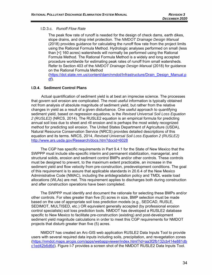
NATIONAL POLLUTANT DISCHARGE ELIMINATION SYSTEM MANUAL REVISION 3 DECEMBER 2020
34
I.D.3.c. Runoff Flow Rate
The peak flow rate of runoff is needed for the design of check dams, earth dikes, slope drains, and drop inlet protection. The NMDOT Drainage Design Manual (2018) provides guidance for calculating the runoff flow rate from the project limits using the Rational Formula Method. Hydrologic analyses performed on small (less than [<] 160 acres) watersheds will normally be performed using the Rational Formula Method. The Rational Formula Method is a widely and long accepted procedure worldwide for estimating peak rates of runoff from small watersheds. Refer to Section 403 of the NMDOT Drainage Design Manual (2018) for guidance on the Rational Formula Method (https://dot.state.nm.us/content/dam/nmdot/Infrastructure/Drain_Design_Manual.pdf).
Sediment Control Plans
Actual quantification of sediment yield is at best an imprecise science. The processes that govern soil erosion are complicated. The most useful information is typically obtained not from analysis of absolute magnitude of sediment yield, but rather from the relative changes in yield as a result of a given disturbance. One useful approach to quantifying sediment yield, based on regression equations, is the Revised Universal Soil Loss Equation 2 (RUSLE2) (NRCS, 2014). The RUSLE2 equation is an empirical formula for predicting annual soil loss due to sheet and rill erosion and is perhaps the most widely recognized method for predicting soil erosion. The United States Department of Agriculture (USDA), Natural Resource Conservation Service (NRCS) provides detailed descriptions of this equation and its terms. NRCS, 2014, Revised Universal Soil Loss Equation 2 (RUSLE2) http://www.ars.usda.gov/Research/docs.htm?docid=6028
The CGP has specific requirements in Part 9.4.1 for the State of New Mexico that the
SWPPP must include site-specific interim and permanent stabilization, managerial, and structural solids, erosion and sediment control BMPs and/or other controls. These controls must be designed to prevent, to the maximum extent practicable, an increase in the sediment yield and flow velocity from pre-construction, predevelopment conditions. The goal of this requirement is to assure that applicable standards in 20.6.4 of the New Mexico Administrative Code (NMAC), including the antidegradation policy and TMDL waste load allocations (WLAs) are met. This requirement applies to discharges both during construction and after construction operations have been completed.
The SWPPP must identify and document the rationale for selecting these BMPs and/or
other controls. For sites greater than five (5) acres in size, BMP selection must be made based on the use of appropriate soil loss prediction models (e.g., SEDCAD, RUSLE, SEDIMOT, MULTISED, etc.) OR equivalent generally accepted (by professional erosion control specialists) soil loss prediction tools. NMDOT has developed a RUSLE2 database specific to New Mexico to facilitate pre-construction (existing) and post-development sediment yield magnitude calculations in order to meet this CGP requirements for NMDOT projects that disturb greater than five (5) acres.
NMDOT has created an Arc-GIS web application RUSLE2 Data Inputs Tool to provide
users with several required data inputs including soils, precipitation, and revegetation zones (https://nmdot.maps.arcgis.com/apps/webappviewer/index.html?id=aa3f2fb132cb414e881dbc1ed42b6d6d). Figure I-7 provides a screen shot of the NMDOT RUSLE2 Data Inputs Tool.
NATIONAL POLLUTANT DISCHARGE ELIMINATION SYSTEM MANUAL REVISION 3 DECEMBER 2020
35
The data is a single clickable layer for areas that overlie NMDOT routes. The layer is rendered light blue (this will become visible when zoomed in) and is 400 feet in width, 200 feet on each side of the route's centerline. To view the information, click the location of the slope of concern to bring up a popup. If users would like to view the precipitation or revegetation zone data independently, each is provided as its own operational layer in the web application (accessible via the layers map icon), although they are turned off by default. NMDOT also can provide the current RUSLE2 database to users – requests should be directed to the Drainage Bureau.
NMDOT requires projects that disturb greater than five (5) acres to provide the
RUSLE2 calculations on the SWPPP Information Sheet, which is part of the NMDOT Construction Plan Set. A template of the SWPPP Information Sheet is provided in Appendix B1 in this Manual. RUSLE2 calculations should compare calculated soil loss for pre-construction (existing) to post-construction conditions. NMDOT requires that the results include a run with the pre-construction existing undisturbed vegetative cover, post-construction worst case condition with Class A seeding, and worst case condition with Class C seeding (if Class C seeding is used). The worst case condition could be steepest slope or longest slope and will be determined using engineering judgment. RUSLE2 post-construction results for all four seasons (fall, spring, summer, and winter) should be shown on the SWPPP Information Sheet. All post-construction conditions RUSLE2 calculations must generate the same or less soil loss than existing conditions. If model output results in sediment delivery less than 1 ton/acre/year, conditions will be considered equal since the level of accuracy suggests the sediment delivery from the site would remain constant. Class A and Class C seeding are defined in NMDOT’s Standard Specifications for Highway and Bridge Construction, 2019 Edition, Section 632: Revegetation. (https://dot.state.nm.us/content/dam/nmdot/Plans_Specs_Estimates/2019_Specs.pdf).
NATIONAL POLLUTANT DISCHARGE ELIMINATION SYSTEM MANUAL REVISION 3 DECEMBER 2020
36
Figure I-7: NMDOT RUSLE2 Data Inputs Tool Screen
NATIONAL POLLUTANT DISCHARGE ELIMINATION SYSTEM MANUAL REVISION 3 DECEMBER 2020
37
I.E. BEST MANAGEMENT PRACTICES FOR CONSTRUCTION
In selecting BMPs to be incorporated into the SWPPP, the user must understand the causes of pollution. Again, the three goals of the NPDES stormwater permitting program are 1) reduce erosion, 2) minimize sedimentation, and 3) minimize the discharge of pollutants. Understanding how these processes occur will help the permittee choose the best BMPs for a site.
Two types of erosion can occur: surface erosion and stream erosion. Surface erosion is caused by the impact of raindrops on the soil, and the very shallow sheet flow at low velocities across the soil. Surface erosion is best controlled using stabilization practices, minimizing the area disturbed (including tree/brush/vegetative clearing and grubbing), and minimizing the time that disturbed areas are exposed. Minimizing surface erosion results in less sediment being transported by stormwater leaving the site. Stream erosion occurs when water collects and moves through rills, gullies, arroyos, and channels that can develop and enlarge by the concentrated flow. Stream erosion is usually controlled using structural controls or leveling. The key to reducing stream erosion is to reduce the velocity of the flow.
Sedimentation is the particles of sand, soil, and debris collected and suspended in the
stormwater as it travels across the surface or in stream flow. Again, the less erosion that occurs, the less sediment there will be in the water. Once suspended in water, sediments are most easily removed by settling or filtration methods. Reducing the velocity of the water in a sediment trap or pond allows the heavier particles to settle out of the water due to gravity. Passing the water through filtering devices such as composite mulch socks will also reduce the amount of sediment in the water. These are some examples of different types of structural controls.
The discharge of non-stormwater pollutants occurs when chemicals or non-natural
materials come in contact with and are picked up and carried offsite by stormwater. This can include a wide variety of materials such as trash, paint, fuels, lubricants, adhesives, and raw cement. Non-stormwater pollution is controlled through good housekeeping practices. Storing these materials in protected storage areas or containers prevents contact with the stormwater. Picking up and removing trash on a regular basis are important to good housekeeping. Cleaning up spills immediately lessens the chance of contact with stormwater. Keeping equipment maintained reduces the likelihood of leaks. The goal is to prevent contact of these materials with stormwater because, if there is no contact, the materials cannot be carried offsite by the stormwater. Appendix A of this Manual provides summaries of current BMPs to be considered for adoption into SWPPPs. BMPs should be used, combined, and/or modified using good engineering judgment to meet the NPDES stormwater permitting program goals. BMPs must also conform to all federal, state, local, and other authorities’ requirements.
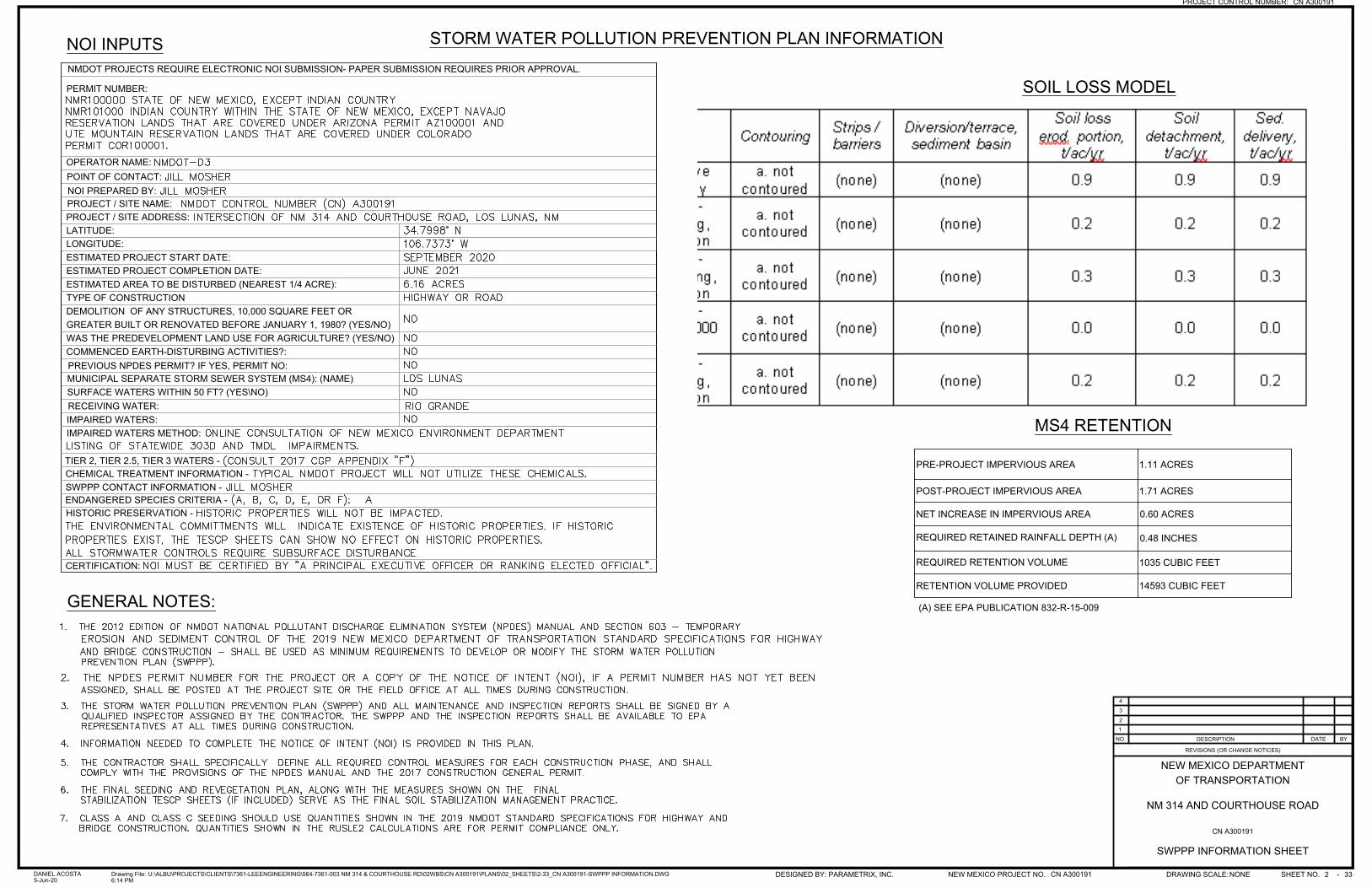
PREVIOUS NPDES PERMIT? IF YES, PERMIT NO:
RECEIVING WATER:
LATITUDE:LONGITUDE:
NMDOT PROJECTS REQUIRE ELECTRONIC NOI SUBMISSION- PAPER SUBMISSION REQUIRES PRIOR APPROVAL.
PERMIT NUMBER:
OPERATOR NAME:POINT OF CONTACT:NOI PREPARED BY:
MUNICIPAL SEPARATE STORM SEWER SYSTEM (MS4): (NAME)
IMPAIRED WATERS:
ESTIMATED PROJECT START DATE:ESTIMATED PROJECT COMPLETION DATE:ESTIMATED AREA TO BE DISTURBED (NEAREST 1/4 ACRE):
COMMENCED EARTH-DISTURBING ACTIVITIES?:
SURFACE WATERS WITHIN 50 FT? (YES\NO)
IMPAIRED WATERS METHOD:
CHEMICAL TREATMENT INFORMATION - SWPPP CONTACT INFORMATION -
CERTIFICATION:
HISTORIC PRESERVATION - ENDANGERED SPECIES CRITERIA -
TIER 2, TIER 2.5, TIER 3 WATERS -
PROJECT / SITE NAME:PROJECT / SITE ADDRESS:
For sites greater than 5 acres in size, BMP selection must bemade based on the use of appropriate soil loss predictionmodels. (2017 CGP)Add RUSLE or RUSLE2 (SOIL LOSS MODEL) calculations,comparing pre-construction to post-construction conditionshere. Results should include:
Existing Undisturbed Vegetative CoverWorst case Class A seeding, all four seasonsWorst case Class C seeding, all four seasons
TYPE OF CONSTRUCTIONDEMOLITION OF ANY STRUCTURES, 10,000 SQUARE FEET OR GREATER BUILT OR RENOVATED BEFORE JANUARY 1, 1980? (YES/NO)WAS THE PREDEVELOPMENT LAND USE FOR AGRICULTURE? (YES/NO)
GENERAL NOTES:
STORM WATER POLLUTION PREVENTION PLAN INFORMATION
SOIL LOSS MODEL
NOI INPUTS
PRE-PROJECT IMPERVIOUS AREA 1.11 ACRES
POST-PROJECT IMPERVIOUS AREA 1.71 ACRES
NET INCREASE IN IMPERVIOUS AREA 0.60 ACRES
REQUIRED RETAINED RAINFALL DEPTH (A) 0.48 INCHES
REQUIRED RETENTION VOLUME 1035 CUBIC FEET
RETENTION VOLUME PROVIDED 14593 CUBIC FEET
(A) SEE EPA PUBLICATION 832-R-15-009
MS4 RETENTION
43
21
NO. DESCRIPTION DATE BY
REVISIONS (OR CHANGE NOTICES)
OF TRANSPORTATIONNEW MEXICO DEPARTMENT
PROJECT CONTROL NUMBER: CN A300191
SHEET NO. 33 -NEW MEXICO PROJECT NO. CN A300191DESIGNED BY: PARAMETRIX, INC. DRAWING SCALE:NONE
NM 314 AND COURTHOUSE ROAD
26:14 PM
DANIEL ACOSTA5-Jun-20
U:\ALBU\PROJECTS\CLIENTS\7361-LEEENGINEERING\564-7361-003 NM 314 & COURTHOUSE RD\02WBS\CN A300191\PLANS\02_SHEETS\2-33_CN A300191-SWPPP INFORMATION.DWGDrawing File:
CN A300191
SWPPP INFORMATION SHEET
NATIONAL POLLUTANT DISCHARGE ELIMINATION SYSTEM MANUAL REVISION 3 DECEMBER 2020
39
I.F. NOTICE OF TERMINATION (NOT)
Description
Submission of the NOT releases the permittee from the requirements and conditions of the CGP. The NOT must be submitted within 30 days of the construction activities being completed and after the project has met the conditions for terminating coverage as outlined below. The NOT filing for the operator/contractor and for the owner will likely occur at different times, as detailed in the sections below. The permittee’s coverage under the CGP is terminated at midnight on the day the NOT is submitted.
Conditions for Terminating Coverage
An NOT must be submitted if construction activities have been completed on the site and the following requirements have been met:
• Areas that were disturbed during construction, or are not covered by permanent structures, or over which the permittee had control of during construction activities have been revegetated (70 percent of cover provided by vegetation native to local undisturbed areas has been established at the project site) or meet the requirements for non-vegetative stabilization as defined in Part 2.2.14.b of the CGP;
• All construction materials have been properly disposed of and all vehicles used in construction activities have been removed from the site;
• All temporary stormwater controls used during construction, except those intended for long term use have been removed from the site; and
• All pollutants have been removed from the site and all pollutant generating activities have ceased.
Other circumstances requiring termination of coverage can occur if control over all
areas covered by the Permit is transferred to another operator that has submitted an NOI and obtained coverage, or if coverage under an individual or another NPDES Permit has been obtained.
Submit the NOT
The NOT must include the name and address of both the owner and operator, as well as a certification signed by both parties. It will note that construction activities are complete, the site has been finally stabilized, and the site no longer has a discharge associated with a construction activity covered under the Permit. When coverage under the Permit is terminated, it will relieve the permittees of their responsibility. The NOT must be submitted using EPA’s NPDES eReporting Tool (NeT) which can be accessed at www.epa.gov/npdes/stormwater-discharges-construction-activities#ereporting. The EPA Region 6 Office, however, may give an operator a waiver to use a paper NOT form under extraordinary circumstances. If the user has computer access limitations or capability limitations that will keep them from completing an eNOT, a waiver must be requested from the EPA Region 6 Office. If the waiver is granted, the form in Appendix K of the CGP must be used.
NATIONAL POLLUTANT DISCHARGE ELIMINATION SYSTEM MANUAL REVISION 3 DECEMBER 2020
40
For NMDOT projects, after construction completion, the contractor, who is the operator during the construction phase, must fill out the NMDOT Transfer of Stormwater Management Authority Form (see Section I.F.4 of this Manual). NMDOT will maintain the CGP coverage until it is determined that final stabilization, which for vegetative stabilization is when 70 percent of cover provided by vegetation native to local undisturbed areas has been established at the project site. Once final stabilization is established, the owner, in this case NMDOT, will file the NOT. Concurrent with filing the NOT, temporary BMPs shall be removed from the project site.
Transfer of Stormwater Management Authority by NMDOT
For NMDOT projects, once a construction project is completed by the contractor (operator during the construction phase), inspected by NMDOT and the contractor, and any noted deficiencies are corrected, an NMDOT Transfer of Stormwater Management Authority Form – Contractor to NMDOT Project Manager (Appendix B1, NMDOT GCP Guide) is used to formally transfer the SWPPP to NMDOT. A copy of the transfer form must be placed in each of the SWPPP Binders.
NATIONAL POLLUTANT DISCHARGE ELIMINATION SYSTEM MANUAL REVISION 3 DECEMBER 2020
41
II. MUNICIPAL SEPARATE STORM SEWER (MS4) ACTIVITIES
II.A. INTRODUCTION
An MS4 is a conveyance or system of conveyances that is:
• Owned by a state, city, town, village, or other public entity that discharges to waters of the U.S.;
• Designed or used to collect or convey stormwater (e.g., storm drains, pipes, ditches);
• Not a combined sewer (sanitary and storm); and
• Not part of a sewage treatment plant, or publicly owned treatment works (POTW).
Areas that require MS4 Permits are typically based on population size as defined by the U.S. Census Bureau’s Urbanized Area (UA) delineations. The Census Bureau’s urban-rural classification is a delineation of geographical areas, identifying both individual urban areas and the rural areas of the nation. The Census Bureau’s urban areas represent densely developed areas, and encompass residential, commercial, and other non-residential urban land uses. Urbanized Areas (UAs) are currently defined as areas with populations of 50,000 or more.
Stormwater runoff from urbanized areas can be a major cause of surface water pollution. Rain and snow melt run over the abundant impervious surfaces in densely populated urbanized areas – roads, sidewalks, driveways, parking lots, roof tops, etc. – and pick up pesticides, fertilizers, oils, metals, pathogens, salt, sediment, trash, and other pollutants and carry them into storm drains or other storm conveyances. In addition, pollutants can be accidently or purposely dumped into MS4 systems. These storm conveyance systems discharge directly into lakes, rivers, streams, and wetlands where polluted stormwater runoff can lead to surface water pollution. Local public entities that own or operate MS4s play a key role in preventing and minimizing stormwater runoff pollution. Figure II-1 shows a national map of regulated MS4s in the United States and demonstrates that though MS4s represent 4 percent of the US land area they represent over 80 percent of the population.
The primary impacts of MS4 Permits on NMDOT projects include the following: 1)
post-construction runoff retention pond requirements for controlling runoff on-site from increased impervious areas. This post-construction stormwater management requirement is currently required in the MRG Watershed Based MS4 Permit and is included in Draft General Permit for Discharges from Small MS4s in New Mexico; 2) post-construction stormwater management requirement of including water quality BMPs as permanent features in projects; and 3) increased focus on opportunities for retrofits to existing storm systems with a GSI/LID focus.
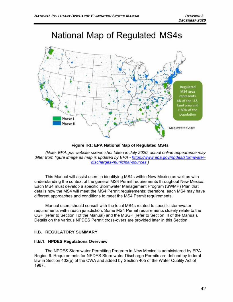
NATIONAL POLLUTANT DISCHARGE ELIMINATION SYSTEM MANUAL REVISION 3 DECEMBER 2020
42
Figure II-1: EPA National Map of Regulated MS4s
(Note: EPA.gov website screen shot taken in July 2020; actual online appearance may differ from figure image as map is updated by EPA - https://www.epa.gov/npdes/stormwater-
discharges-municipal-sources.)
This Manual will assist users in identifying MS4s within New Mexico as well as with
understanding the context of the general MS4 Permit requirements throughout New Mexico. Each MS4 must develop a specific Stormwater Management Program (SWMP) Plan that details how the MS4 will meet the MS4 Permit requirements; therefore, each MS4 may have different approaches and conditions to meet the MS4 Permit requirements.
Manual users should consult with the local MS4s related to specific stormwater requirements within each jurisdiction. Some MS4 Permit requirements closely relate to the CGP (refer to Section I of the Manual) and the MSGP (refer to Section III of the Manual). Details on the various NPDES Permit cross-overs are provided later in this Section. II.B. REGULATORY SUMMARY
NPDES Regulations Overview
The NPDES Stormwater Permitting Program in New Mexico is administered by EPA Region 6. Requirements for NPDES Stormwater Discharge Permits are defined by federal law in Section 402(p) of the CWA and added by Section 405 of the Water Quality Act of 1987.
NATIONAL POLLUTANT DISCHARGE ELIMINATION SYSTEM MANUAL REVISION 3 DECEMBER 2020
43
NPDES Permits for regulated MS4s require permittees to develop a SWMP, which describes the stormwater control practices that will be implemented consistent with Permit requirements to minimize the discharge of pollutants from the stormwater sewer system.
NPDES permitting requirements have been in effect for the last 30 years. Section 402(p)(2) of the CWA requires NPDES Permits for five categories of stormwater discharges, commonly referred to as Phase I of the NPDES Stormwater Program. Included in Phase I were discharges from large MS4s (systems serving a population of 250,000 or more) and medium MS4s (systems serving a population of 100,000 to 250,000).
EPA promulgated final Phase II stormwater regulations on December 8, 1999 (64 FR 68722). These regulations set forth the additional categories of discharges to be permitted under the MS4 program. The additional discharges to be permitted included Small MS4s located in UAs designated by the Census Bureau and those designated by the EPA Director on a case-by-case basis to protect surface water quality. Provisions and criteria for waivers were included for MS4s with a population under 1,000 (40 CFR 122.32(d) and under 10,000 (40 CFR 122.32 (e).
MS4 Regulations Overview
Below is a brief history of the MS4 program within New Mexico. Table II-1 provides a list of the current MS4s within New Mexico. Note that Los Lunas and Los Alamos are not included in this list as the MS4 Permits have not yet been issued (as of December 2020) by EPA for these two areas; MS4 Permits are being developed by EPA Region 6 to include both of these areas. EPA has proposed that the Los Lunas Urbanized Area will be added to the Draft General Permit for Small MS4s in New Mexico (refer to Section II.B.2.d. below). EPA is also currently pursuing a separate MS4 Permit for the Los Alamos Urban Cluster, which is proposed to include: Los Alamos National Laboratory (LANL) property, Los Alamos County within the Los Alamos Townsite, and NMDOT District 5 within the Los Alamos Townsite and within LANL. EPA’s timeframe and requirements for an MS4 Permit for the Los Alamos Urban Cluster are not known at this time.
II.B.2.a. Phase I MS4s
Issued by EPA in 1990, Phase I regulations required medium and large cities, or certain counties with populations of 100,000 or more, to obtain NPDES MS4 Permit coverage for their stormwater discharges.
• There are approximately 855 Phase I MS4s nationwide (EPA, July 2020);
• Originally, Phase I MS4s were covered by Individual Permits with a move over time to General Permits;
• In New Mexico, Phase I MS4 regulations originally only included the Albuquerque metropolitan area, which included four (4) MS4s located within the corporate boundary of the City of Albuquerque: o City of Albuquerque; o University of New Mexico; o NMDOT District 3; and o Albuquerque Metropolitan Arroyo Flood Control Authority (AMAFCA).
NATIONAL POLLUTANT DISCHARGE ELIMINATION SYSTEM MANUAL REVISION 3 DECEMBER 2020
44
• The four (4) Phase I MS4s listed above were co-permittees under their first MS4 Permit NMS000101 in 2003, which expired and entered administrative continuance in 2008;
• The four (4) Phase I MS4s listed above then became co-permittees under MS4 Permit NMS000101, issued on March 1, 2012; and
• The Middle Rio Grande Watershed Based MS4 Permit NMR04A000 replaced MS4 Permit NMS000101 on December 22, 2014. This MS4 Watershed Based Permit included the four (4) MS4s listed above as well as several Phase II, or Small MS4s, located within the watershed; refer to Section II.B.2.c below for additional details on the current MS4 Permit for the Middle Rio Grande Watershed, and Table II-1, pages 47-48 of this Manual for a list of current MS4 permittees in New Mexico.
II.B.2.b. Phase II MS4s
Issued by EPA in 1999, Phase II regulations required regulated Small MS4s in urbanized areas, as well as Small MS4s outside the urbanized areas that are designated by the permitting authority, to obtain NPDES MS4 Permit coverage for their stormwater discharges.
• There are approximately 6,700 Phase II MS4s nationwide (EPA, July 2020).
• Generally, Phase II MS4s are covered by statewide General Permits.
• The Phase II stormwater regulations in New Mexico originally used the 2000 Census to designate five (5) UAs and the permittees within each UA as requiring Small MS4 Permits. These Phase II MS4s were covered under General Permit for Discharges from Small MS4s in New Mexico, Permit No. NMR040000 issued on July 1, 2007 and administratively continued since July 1, 2012. Refer to Section II.B.2.d below in this Manual for additional details on the Draft General Permit for Discharges from Small MS4s which is intended to replace the 2007 Permit for Small MS4s located outside of the Middle Rio Grande.
• The current Phase II MS4s in New Mexico, outside of the Middle Rio Grande Watershed, covered under the 2007 General Permit for Discharges from Small MS4s in New Mexico, NMR040000 are listed in Table II-1, pages 47-48 of this Manual.
• The Phase II MS4s in the Middle Rio Grande Watershed, that are covered under the current Middle Rio Grande Watershed Based MS4 Permit NMR04A000, effective Dec. 22, 2014 are listed in Table II-1, pages 47-48 of this Manual.
II.B.2.c. Middle Rio Grande Watershed Based MS4 Permit
On December 11, 2014, EPA Region 6 Water Quality Protection Division announced the issuance of the NPDES General Permit for stormwater discharges from MS4s located in the Middle Rio Grande Watershed in the State of New Mexico (MRG Watershed Based MS4 Permit). The Permit offers discharge authorization and requires an MS4 Permit for regulated MS4s within the boundaries of the Census Bureau designated 2000 and 2010 Albuquerque Urbanized Areas and any other MS4s in the watershed designated by the EPA
NATIONAL POLLUTANT DISCHARGE ELIMINATION SYSTEM MANUAL REVISION 3 DECEMBER 2020
45
Director. This Permit replaced both the Individual NPDES Permit NMS000101 (Phase I permittees) issued on January 31, 2012, and the expired General Permit for Discharges from Small MS4s in New Mexico, NMR040000 (Phase II permittees) for MS4 dischargers in this watershed area. It also added two new Phase II MS4 permittees - Eastern Sandoval County Arroyo Flood Control Authority (ESCAFCA) and Sandia National Laboratories, Department of Energy. Refer to Figure II-2, page 46 of this Manual, for a map showing the various MS4 permittees to the MRG Watershed Based MS4 Permit. The MS4 permittees covered by this Watershed Based Permit are also listed in Table II-1, pages 47-48 of this Manual. The MRG Watershed Based MS4 Permit is unique in the United States because of its watershed based approach. EPA and NMED worked with the Middle Rio Grande stakeholders for several years to develop the watershed based MS4 Permit approach with Albuquerque serving as a permitting pilot study for this type of MS4 Permit. The pilot program designated a watershed, within an urbanized area, as the MS4 Permit boundary as opposed to using a political jurisdiction boundary. The watershed permitting approach recognizes that drainage basins do not follow political and jurisdictional boundaries, and cooperative efforts of MS4s within a watershed can lead to improved water quality results and potential program efficiencies, which can lead to cost savings as well as improved Permit compliance. The MS4 Permit is lengthy and complex but may be summarized to the extent that it establishes minimum pollution control measures for the area covered by the Permit and for the entities covered under the Permit. As mentioned above, each MS4 develops a specific SWMP that details how the MS4 will meet the MS4 Permit minimum control measure (MCM) requirements; therefore, each MS4 may have different approaches and conditions to meet the MS4 Permit requirements. MCMs comprise eight (8) elements that, when implemented in concert, are aimed at significantly reducing pollutants discharged into receiving waterbodies from MS4s.
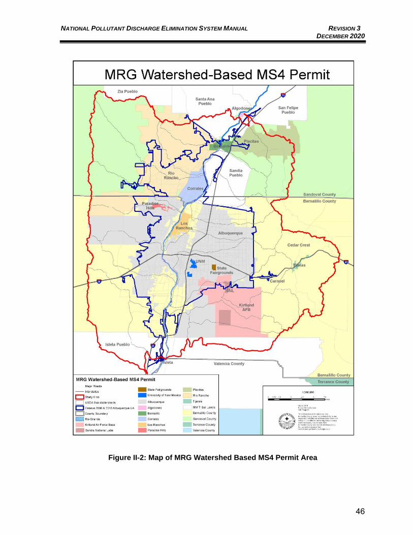
NATIONAL POLLUTANT DISCHARGE ELIMINATION SYSTEM MANUAL REVISION 3 DECEMBER 2020
46
Figure II-2: Map of MRG Watershed Based MS4 Permit Area
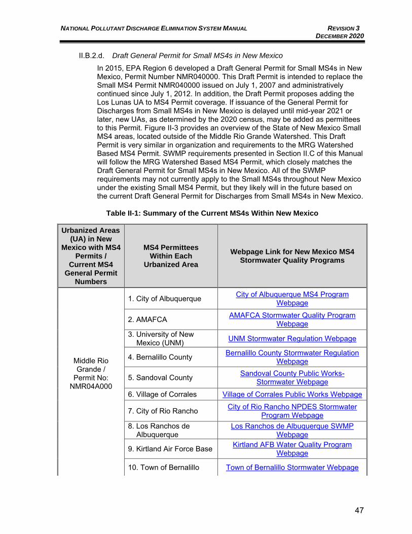
NATIONAL POLLUTANT DISCHARGE ELIMINATION SYSTEM MANUAL REVISION 3 DECEMBER 2020
47
II.B.2.d. Draft General Permit for Small MS4s in New Mexico
In 2015, EPA Region 6 developed a Draft General Permit for Small MS4s in New Mexico, Permit Number NMR040000. This Draft Permit is intended to replace the Small MS4 Permit NMR040000 issued on July 1, 2007 and administratively continued since July 1, 2012. In addition, the Draft Permit proposes adding the Los Lunas UA to MS4 Permit coverage. If issuance of the General Permit for Discharges from Small MS4s in New Mexico is delayed until mid-year 2021 or later, new UAs, as determined by the 2020 census, may be added as permittees to this Permit. Figure II-3 provides an overview of the State of New Mexico Small MS4 areas, located outside of the Middle Rio Grande Watershed. This Draft Permit is very similar in organization and requirements to the MRG Watershed Based MS4 Permit. SWMP requirements presented in Section II.C of this Manual will follow the MRG Watershed Based MS4 Permit, which closely matches the Draft General Permit for Small MS4s in New Mexico. All of the SWMP requirements may not currently apply to the Small MS4s throughout New Mexico under the existing Small MS4 Permit, but they likely will in the future based on the current Draft General Permit for Discharges from Small MS4s in New Mexico.
Table II-1: Summary of the Current MS4s Within New Mexico
Urbanized Areas (UA) in New
Mexico with MS4 Permits /
Current MS4 General Permit
Numbers
MS4 Permittees Within Each
Urbanized Area
Webpage Link for New Mexico MS4 Stormwater Quality Programs
Middle Rio Grande /
Permit No: NMR04A000
1. City of Albuquerque City of Albuquerque MS4 Program Webpage
2. AMAFCA AMAFCA Stormwater Quality Program Webpage
3. University of New Mexico (UNM) UNM Stormwater Regulation Webpage
4. Bernalillo County Bernalillo County Stormwater Regulation Webpage
5. Sandoval County Sandoval County Public Works-Stormwater Webpage
6. Village of Corrales Village of Corrales Public Works Webpage
7. City of Rio Rancho City of Rio Rancho NPDES Stormwater Program Webpage
8. Los Ranchos de Albuquerque
Los Ranchos de Albuquerque SWMP Webpage
9. Kirtland Air Force Base Kirtland AFB Water Quality Program Webpage
10. Town of Bernalillo Town of Bernalillo Stormwater Webpage
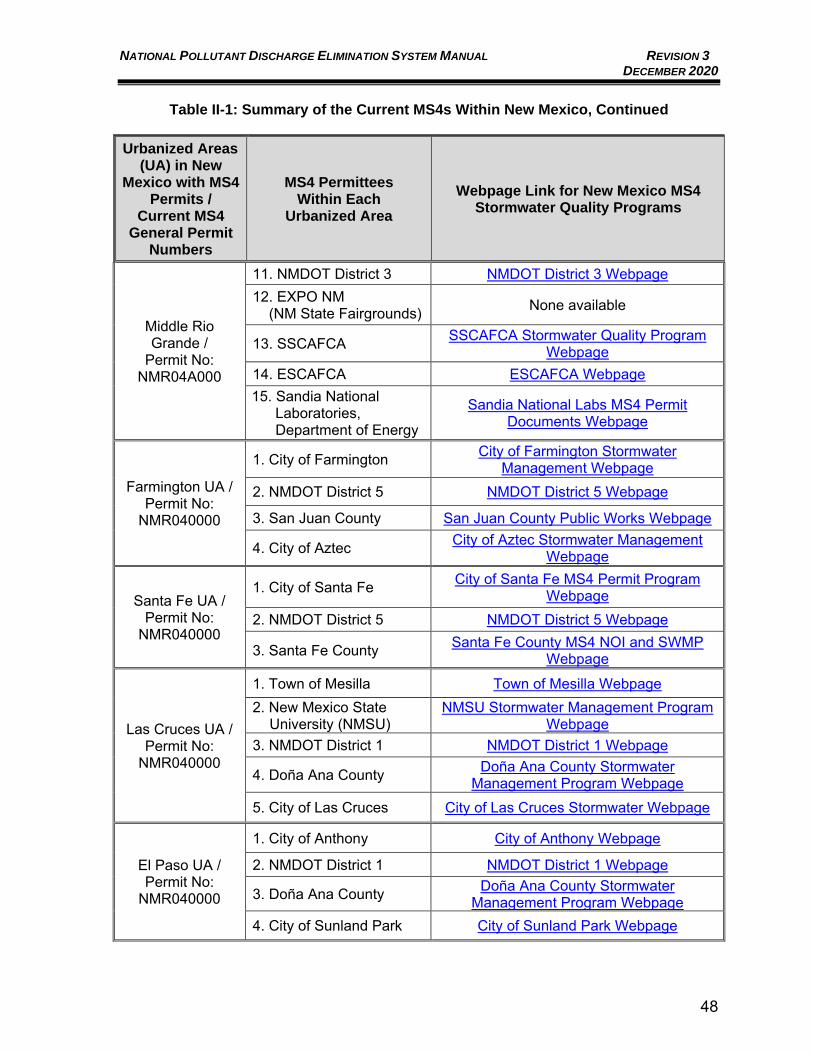
NATIONAL POLLUTANT DISCHARGE ELIMINATION SYSTEM MANUAL REVISION 3 DECEMBER 2020
48
Table II-1: Summary of the Current MS4s Within New Mexico, Continued
Urbanized Areas (UA) in New
Mexico with MS4 Permits /
Current MS4 General Permit
Numbers
MS4 Permittees Within Each
Urbanized Area
Webpage Link for New Mexico MS4 Stormwater Quality Programs
Middle Rio Grande /
Permit No: NMR04A000
11. NMDOT District 3 NMDOT District 3 Webpage 12. EXPO NM (NM State Fairgrounds) None available
13. SSCAFCA SSCAFCA Stormwater Quality Program Webpage
14. ESCAFCA ESCAFCA Webpage 15. Sandia National
Laboratories, Department of Energy
Sandia National Labs MS4 Permit Documents Webpage
Farmington UA / Permit No:
NMR040000
1. City of Farmington City of Farmington Stormwater Management Webpage
2. NMDOT District 5 NMDOT District 5 Webpage
3. San Juan County San Juan County Public Works Webpage
4. City of Aztec City of Aztec Stormwater Management Webpage
Santa Fe UA / Permit No:
NMR040000
1. City of Santa Fe City of Santa Fe MS4 Permit Program Webpage
2. NMDOT District 5 NMDOT District 5 Webpage
3. Santa Fe County Santa Fe County MS4 NOI and SWMP Webpage
Las Cruces UA / Permit No:
NMR040000
1. Town of Mesilla Town of Mesilla Webpage 2. New Mexico State
University (NMSU) NMSU Stormwater Management Program
Webpage 3. NMDOT District 1 NMDOT District 1 Webpage
4. Doña Ana County Doña Ana County Stormwater Management Program Webpage
5. City of Las Cruces City of Las Cruces Stormwater Webpage
El Paso UA / Permit No:
NMR040000
1. City of Anthony City of Anthony Webpage
2. NMDOT District 1 NMDOT District 1 Webpage
3. Doña Ana County Doña Ana County Stormwater Management Program Webpage
4. City of Sunland Park City of Sunland Park Webpage
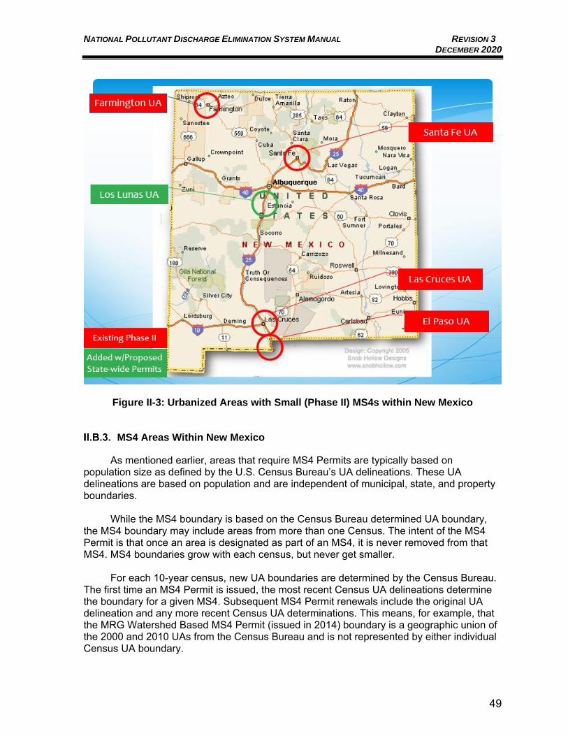
NATIONAL POLLUTANT DISCHARGE ELIMINATION SYSTEM MANUAL REVISION 3 DECEMBER 2020
49
Figure II-3: Urbanized Areas with Small (Phase II) MS4s within New Mexico
MS4 Areas Within New Mexico
As mentioned earlier, areas that require MS4 Permits are typically based on population size as defined by the U.S. Census Bureau’s UA delineations. These UA delineations are based on population and are independent of municipal, state, and property boundaries.
While the MS4 boundary is based on the Census Bureau determined UA boundary,
the MS4 boundary may include areas from more than one Census. The intent of the MS4 Permit is that once an area is designated as part of an MS4, it is never removed from that MS4. MS4 boundaries grow with each census, but never get smaller.
For each 10-year census, new UA boundaries are determined by the Census Bureau.
The first time an MS4 Permit is issued, the most recent Census UA delineations determine the boundary for a given MS4. Subsequent MS4 Permit renewals include the original UA delineation and any more recent Census UA determinations. This means, for example, that the MRG Watershed Based MS4 Permit (issued in 2014) boundary is a geographic union of the 2000 and 2010 UAs from the Census Bureau and is not represented by either individual Census UA boundary.
NATIONAL POLLUTANT DISCHARGE ELIMINATION SYSTEM MANUAL REVISION 3 DECEMBER 2020
50
On the other hand, MS4 boundaries are not updated mid-Permit term. This scenario impacts Small MS4s in New Mexico located outside of the Middle Rio Grande Watershed, which are covered by the General Permit for Discharges from Small MS4s in New Mexico, Permit No. NMR040000, issued on July 1, 2007, and administratively continued since July 1, 2012. Even though the Census Bureau issued new UA delineations in 2010, the Small MS4 Permit has not been renewed since 2007. The MS4 boundaries for the Small MS4s are based solely on the UA delineations from the 2000 Census.
If new MS4 Permits are issued after publication of the UA delineations for the 2020
Census, those 2020 UA delineations will likely be incorporated into the new MS4 Permits, and MS4 boundaries will have to be determined by union with the previous UA delineations. If issuance of the General Permit for Discharges from Small MS4s in New Mexico is delayed until mid-year 2021 or later, when the 2020 Census UA delineations are released, new UAs boundaries, as determined by the 2020 Census, may be added as permittees to this Permit.
Appendix C provides maps of the MS4 boundaries for each designated MS4 area
within New Mexico that currently has an MS4 Permit. These maps have NMDOT mile marker information to show the MS4 boundary extent relative to the NMDOT roadways. For all MS4 areas, these maps can assist the Manual user in understanding if their area of interest is within a current MS4 boundary.
Portable Document Format (PDF) files of the Census 2010 urbanized areas are available at http://water.epa.gov/polwaste/npdes/stormwater/Urbanized-Area-Maps-for-NPDES-MS4-Phase-ll-StormwaterPermits.cfm. UA boundaries are also available to download from the U.S. Census Bureau (https://www.census.gov/geographies/mapping-files.html) as shapefiles, which are a geospatial data format for use in geographic information system (GIS) software. On the U.S. Census Bureau website, beginning in 2013, KML files which can be used in Google products (i.e., Google Earth) are available, however all MS4 boundaries in New Mexico are based on earlier Census data and boundaries, so the KML files could be helpful for a general understanding of MS4 areas but may not represent the correct MS4 Permit boundaries.
MS4 Permitting Process
As mentioned earlier in this Manual, New Mexico currently does not have primacy for its NPDES program; EPA Region 6 regulates New Mexico’s NPDES programs. MS4 Permits for New Mexico are developed by EPA Region 6 with input and participation from NMED, U.S. Fish and Wildlife Service, affected Indian Pueblos, as well as the State’s MS4 permittees. Historically EPA, in coordination with NMED, has met with New Mexico MS4s throughout the MS4 Permit development process to solicit input and keep the permittees informed of the process as well as requirements.
II.B.4.a. Preparing the NOI and NOI Approval Process
To obtain coverage under an MS4 Permit, the permittee must file an NOI. The MS4 Permit has a specific schedule defined for submitting the NOI. In Late 2016, EPA modified the NOI process for MS4s to follow the MS4 General Permit Remand Rule. This change is intended to promote greater public engagement through clarifying requirements on the opportunities for public participation in the permitting process. The permittee is required to provide a local public notice for the filing of the NOI and to provide a copy of the draft NOI submittal available
NATIONAL POLLUTANT DISCHARGE ELIMINATION SYSTEM MANUAL REVISION 3 DECEMBER 2020
51
locally or digitally, online for public review. EPA Region 6 will also post basic information from all NOIs received for an MS4 Permit on the Internet and will provide a website link for this in the MS4 Permit. To meet the MS4 General Permit Remand Rule requirements, EPA has stated that it will follow a two-step General Permit NOI process for new MS4 General Permits. For the two-step General Permit NOI, after issuing the base General Permit that includes the requirements that apply to all MS4s covered by the Permit, EPA will establish additional Permit conditions for each MS4 seeking authorization to discharge under the General Permit. These additional terms and conditions supplement the requirements of the General Permit, resulting in a complete Permit meeting the MS4 Permit standard for each individual MS4 permittee under the General Permit. The first step of the NOI will consist of providing basic MS4 information to EPA including meeting the National Historic Properties Act eligibility requirements. Cooperative programs and partners for MS4 programs will also be indicated in this first NOI step. EPA Region 6 indicated that the first step would not include detailed information related to the MCMs. Approval by EPA of the first step of the NOI would provide the permittee with provisional authorization for all program elements under the MS4 Permit except for those requiring specific plans in step two of the NOI. The second NOI step, or supplemental NOI, is anticipated to be more detailed, and EPA Region 6 indicated that this step would include information on the MS4 control measures within, as applicable, an Impaired Waters/TMDL Plan; an Impaired Waters without TMDL Plan; a Wet Weather Monitoring Plan; and specific details related to Post-Construction Stormwater Management. The second NOI step may also need to include schedules to fully develop and implement the stormwater program consistent with the MS4 Permit requirements. Upon completion of the two-step NOI process and receipt of written notification from EPA, the MS4 permittee is authorized to discharge subject to the terms of the General Permit and the additional requirements that apply individually to that MS4.
II.B.4.b. Signatory Requirements and Certification Statement
For a municipality, State, or other public agency, all DMRs, SWMPs, reports (including Annual Reports), certifications or information either submitted to EPA or that the Permit requires be maintained by the permittee(s), shall be signed by either: a) The principal executive officer or ranking elected official; or b) Duly authorized representative of that person. A person is a duly authorized
representative only if: 1) the authorization is made in writing by the person described in item (a) above and submitted to the EPA; and 2) the authorization specifies either an individual or a position having responsibility for the overall operation of the regulated facility or activity, such as the position of manager, operator, or superintendent. A duly authorized representative may be either a named individual or any individual occupying a named position.
NATIONAL POLLUTANT DISCHARGE ELIMINATION SYSTEM MANUAL REVISION 3 DECEMBER 2020
52
If an authorization is no longer accurate because a different individual or position has responsibility for the overall operation of the facility, a new written authorization satisfying the Permit requirements must be submitted to EPA prior to or together with any reports, information, or applications to be signed by an authorized representative. The signatory requirements apply to both paper/hard-copy and electronic submittals. Any person signing MS4 Permit related documents shall make the following certification: "I certify under penalty of law that this document and all attachments were prepared under my direction or supervision in accordance with a system designed to assure that qualified personnel properly gather and evaluate the information submitted. Based on my inquiry of the person or persons who manage the system, or those persons directly responsible for gathering the information, the information submitted is, to the best of my knowledge and belief, true, accurate, and complete. I am aware that there are significant penalties for submitting false information, including the possibility of fine and imprisonment for knowing violations."
II.B.4.c. End of Administratively Continued Coverage under Previous Permits
Currently, all MS4 General Permits in the State of New Mexico are expired and the MS4s continued coverage under the expired MS4 General Permits is in administrative continuance. The end of administrative continuance for the expired MS4 General Permits will be triggered by a timely reapplication to newly issued MS4 General Permits. MS4s submitting an NOI for coverage under newly issued MS4 General Permits will be considered to have met the timely reapplication requirement if the NOI is submitted by the deadlines included in the newly issued MS4 General Permits. For MS4s previously covered under expired MS4 Permits NMR040000 and NMR04A000, continued coverage under those permits ends: a) the day after the applicable deadline for submittal of an NOI, if a complete NOI is not submitted, or b) upon notice of authorization from EPA under the newly issued MS4 General Permits, if a complete and timely NOI is submitted. The NOI submitted is anticipated to be a two-step NOI process, as discussed in Section II.B.4.a above.
II.C. MS4 STORMWATER MANAGEMENT PROGRAM (SWMP)
MS4 permittees develop a SWMP in order to implement the MS4 Permit requirements. Each MS4 Permit details the applicable stormwater management requirements to meet the CWA regulations. SWMPs are enforceable documents, approved by EPA and incorporated by reference into the MS4 Permit itself. The general SWMP requirements below are specific to the MRG Watershed Based MS4 Permit; all SWMP requirements may not currently apply to the small MS4s throughout New Mexico, but they likely will in the future. The MS4 Permits contain many interrelated details regarding specific compliance that is beyond the scope of this Manual to list or discuss in depth. The sections below discuss the various MCMs and other requirements in MS4 Permits.
NATIONAL POLLUTANT DISCHARGE ELIMINATION SYSTEM MANUAL REVISION 3 DECEMBER 2020
53
Construction Site Stormwater Runoff Control
This MCM includes developing, implementing, and enforcing an erosion and sediment control program for construction activities that disturb one (1) or more acres of land or smaller sites that are part of a common plan of development or sale that will ultimately disturb one (1) or more acres of land. The MS4 Permit requirements are related to some of the CGP requirements as discussed in Section I of this Manual. An MS4 Construction Site Stormwater Runoff Control program should include: an ordinance or other mechanism to require erosion and sediment controls with enforcement mechanisms; requirements for construction sites to control other types of waste (e.g., concrete washout); site plan reviews; a method to accept public information about construction sites; and procedures to inspect and enforce erosion and sediment controls on regulated sites. Sediment and erosion caused by construction activities, such as grading and grubbing, can cause lack of soil stabilization which can lead to pollutant discharge into the MS4s during storm events.
Post-Construction Stormwater Management in New Development and
Redevelopment
This MCM includes developing, implementing, and enforcing a program to address discharges of post-construction stormwater runoff from new development and redevelopment areas. Applicable controls could include preventative actions such as protecting sensitive areas (e.g., wetlands) or the use of structural BMPs such as grassed swales or porous pavement. Appendix A of this Manual provides additional resources on stormwater controls and BMPs.
II.C.2.a. Mimicking Predevelopment Hydrology
The current 2007 Small MS4 Permit does not require specific management of the 80th/90th percentile storm on-site to mimic predevelopment hydrology, as detailed in this Section of the Manual. The MRG Watershed Based MS4 Permit does require management of the 80th/90th percentile storm on-site to mimic predevelopment runoff. The 2015 Draft General Permit for Discharges from Small MS4s in New Mexico has similar requirements for controls that mimic predevelopment runoff to the MRG Watershed Based MS4 Permit. Current MS4 Permit regulations for the MRG and the Draft General Permit for Discharges from Small MS4s in New Mexico conditions include requiring controls that mimic predevelopment runoff. One effective and efficient way to mimic predevelopment hydrology begins with minimizing and disconnecting impervious areas. Another effective step is to distribute stormwater runoff and stormwater facilities throughout the site to generate a more hydrologically functional site. For purposes of the MS4 Permit, the predevelopment hydrology can also be met by retention of the storm volume associated with the 90th percentile storm event for new development sites, and the 80th percentile storm event for redevelopment sites. This MCM relates to projects that disturb one (1) or more acres or smaller sites that are a part of a larger common plan of development or sale that will ultimately disturb one (1) or more acres of land. The MRG Watershed Based MS4 Permit requires that the projects: “Incorporate a stormwater quality design standard that manages on-site the 90th percentile storm event discharge volume associated with new development sites and 80th percentile storm event discharge volume associated with
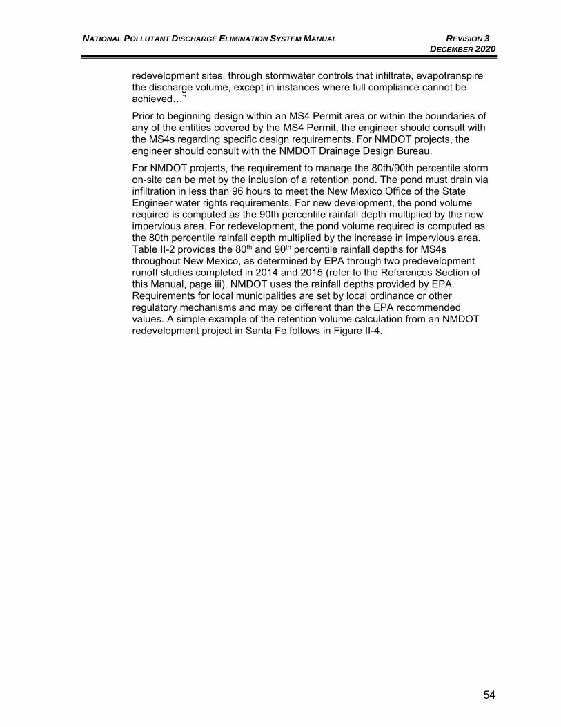
NATIONAL POLLUTANT DISCHARGE ELIMINATION SYSTEM MANUAL REVISION 3 DECEMBER 2020
54
redevelopment sites, through stormwater controls that infiltrate, evapotranspire the discharge volume, except in instances where full compliance cannot be achieved…” Prior to beginning design within an MS4 Permit area or within the boundaries of any of the entities covered by the MS4 Permit, the engineer should consult with the MS4s regarding specific design requirements. For NMDOT projects, the engineer should consult with the NMDOT Drainage Design Bureau. For NMDOT projects, the requirement to manage the 80th/90th percentile storm on-site can be met by the inclusion of a retention pond. The pond must drain via infiltration in less than 96 hours to meet the New Mexico Office of the State Engineer water rights requirements. For new development, the pond volume required is computed as the 90th percentile rainfall depth multiplied by the new impervious area. For redevelopment, the pond volume required is computed as the 80th percentile rainfall depth multiplied by the increase in impervious area. Table II-2 provides the 80th and 90th percentile rainfall depths for MS4s throughout New Mexico, as determined by EPA through two predevelopment runoff studies completed in 2014 and 2015 (refer to the References Section of this Manual, page iii). NMDOT uses the rainfall depths provided by EPA. Requirements for local municipalities are set by local ordinance or other regulatory mechanisms and may be different than the EPA recommended values. A simple example of the retention volume calculation from an NMDOT redevelopment project in Santa Fe follows in Figure II-4.
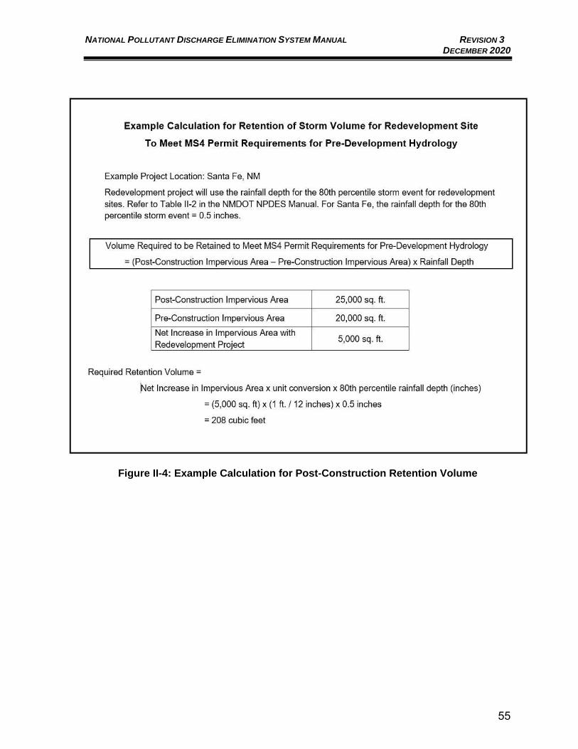
NATIONAL POLLUTANT DISCHARGE ELIMINATION SYSTEM MANUAL REVISION 3 DECEMBER 2020
55
Figure II-4: Example Calculation for Post-Construction Retention Volume
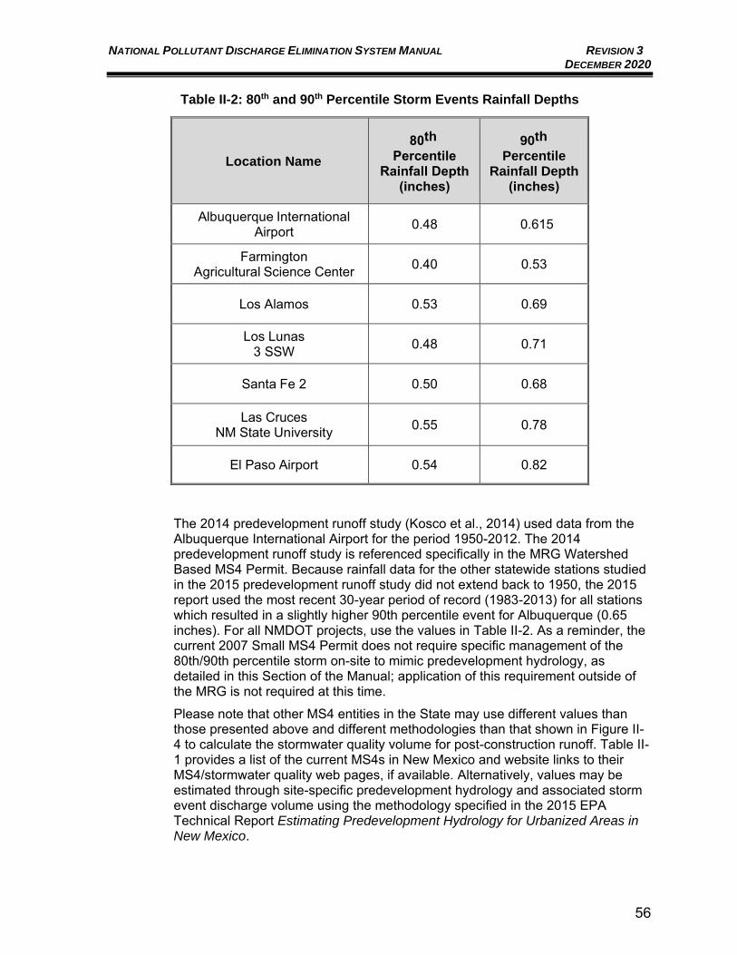
NATIONAL POLLUTANT DISCHARGE ELIMINATION SYSTEM MANUAL REVISION 3 DECEMBER 2020
56
Table II-2: 80th and 90th Percentile Storm Events Rainfall Depths
Location Name 80th
Percentile Rainfall Depth
(inches)
90th Percentile
Rainfall Depth (inches)
Albuquerque International Airport 0.48 0.615
Farmington Agricultural Science Center 0.40 0.53
Los Alamos 0.53 0.69
Los Lunas 3 SSW 0.48 0.71
Santa Fe 2 0.50 0.68
Las Cruces NM State University 0.55 0.78
El Paso Airport 0.54 0.82
The 2014 predevelopment runoff study (Kosco et al., 2014) used data from the Albuquerque International Airport for the period 1950-2012. The 2014 predevelopment runoff study is referenced specifically in the MRG Watershed Based MS4 Permit. Because rainfall data for the other statewide stations studied in the 2015 predevelopment runoff study did not extend back to 1950, the 2015 report used the most recent 30-year period of record (1983-2013) for all stations which resulted in a slightly higher 90th percentile event for Albuquerque (0.65 inches). For all NMDOT projects, use the values in Table II-2. As a reminder, the current 2007 Small MS4 Permit does not require specific management of the 80th/90th percentile storm on-site to mimic predevelopment hydrology, as detailed in this Section of the Manual; application of this requirement outside of the MRG is not required at this time. Please note that other MS4 entities in the State may use different values than those presented above and different methodologies than that shown in Figure II-4 to calculate the stormwater quality volume for post-construction runoff. Table II-1 provides a list of the current MS4s in New Mexico and website links to their MS4/stormwater quality web pages, if available. Alternatively, values may be estimated through site-specific predevelopment hydrology and associated storm event discharge volume using the methodology specified in the 2015 EPA Technical Report Estimating Predevelopment Hydrology for Urbanized Areas in New Mexico.
NATIONAL POLLUTANT DISCHARGE ELIMINATION SYSTEM MANUAL REVISION 3 DECEMBER 2020
57
II.C.2.b. Green Stormwater Infrastructure and Low Impact Design BMP Controls
Green Stormwater Infrastructure (GSI) and Low Impact Development (LID) are two terms that often arise during discussions about stormwater runoff in urban areas. GSI is a stormwater management technique that uses vegetation and soil to manage rainwater where it falls. By weaving natural processes into the built environment, GSI provides not only stormwater management, but also flood mitigation, air quality management, and much more. LID is an approach to land development (or redevelopment) that works with nature to manage stormwater as close to its source as possible. LID employs principles such as preserving and recreating natural landscape features, minimizing effective imperviousness to create functional and appealing site drainage that treats stormwater as a resource rather than a waste product. As these two definitions show, GSI and LID have a lot in common, and in fact, the terms are often used interchangeably. One requirement in both the Draft General Permit for Discharges from Small MS4s in New Mexico and the existing MRG Watershed Based MS4 Permit, is that GSI and LID practices and control measures shall be implemented under the Post-Construction Stormwater Management, for New Development and Redevelopment MCM. The MRG Watershed Based MS4 Permit states :
“The [MS4] permittee must ensure the appropriate implementation of the structural BMPs by considering some or all of the following: pre-construction review of BMP designs; inspections during construction to verify BMPs are built as designed; post-construction inspection and maintenance of BMPs; and penalty provisions for the noncompliance with preconstruction BMP design; failure to construct BMPs in accordance with the agreed upon pre-construction design; and ineffective post-construction operation and maintenance of BMPs.”
GSI/LID treats the runoff to improve water quality and reduce runoff flow rates and volumes. The stated objective of GSI/LID is to encourage drainage facilities such that the post-developed project hydrology mimics the predevelopment hydrology to the Maximum Extent Practicable (MEP). The MRG Watershed Based MS4 Permit requires that GSI/LID principles be considered whenever they are practicable. It is anticipated that the final General Permit for Discharges from Small MS4s in New Mexico will include similar requirements. The primary differences in designing GSI/LID principles compared to providing for adequate capacity for a bridge, crossing structure, or storm drainage system for flood control is the magnitude and frequency of the rainfall events that are addressed. GSI/LID practices typically address the small, more frequent storm events (typically less than the 2-year storm event) while flood control drainage structures are typically designed for the larger, less-frequent storm events such as the 100-year storm event. Appendix A of this Manual provides several GSI/LID BMP options to consider for stormwater management during project development. EPA has several useful resources on GSI and LID, including studies showing that these techniques can be more cost-effective than traditional, “gray infrastructure”. Gray infrastructure is the term used for traditional forms of stormwater management such as concrete curbs, pipes and storm drains designed to convey stormwater away from the built environment and ultimately discharge untreated stormwater into a local water
NATIONAL POLLUTANT DISCHARGE ELIMINATION SYSTEM MANUAL REVISION 3 DECEMBER 2020
58
body. New Mexico has also developed several resources on GSI and LID. Resources include: EPA Green Infrastructure https://www.epa.gov/green-infrastructure Los Alamos Low Impact Development Standards https://permalink.lanl.gov/object/tr?what=info:lanl-repo/eprr/ESHID-603280 Bernalillo County Green Stormwater Infrastructure – Low Impact Design Strategies for Desert Communities https://www.bernco.gov/uploads/FileLinks/590808d5c7dd4e0cbfaf3009cf1affb9/Green_Infrastructure_and_Low_Impact_Design_Guide_1.pdf
Pollution Prevention/Good Housekeeping for Municipal Operations
This MCM includes developing and implementing a program with the goal of preventing or reducing pollutant runoff from municipal operations. The program must include municipal staff training on pollution prevention measures and techniques (e.g., regular street sweeping, reduction in the use of pesticides or street salt, or frequent catch-basin cleaning).
The MS4 Permit requirements for this MCM are related to some of the MSGP
requirements as discussed in Section III of this Manual. For example, some municipal operation facilities may require a MSGP. Appendix A BMPs in this Manual include several good housekeeping BMPs that are applicable to this MCM. As a second example, any measures required by the MRG Watershed Based MS4 Permit will be applied to MSGP sites located within the City of Albuquerque to augment measures already in place under the MSGP.
Industrial and High Risk Runoff
The MS4 permittee must control through ordinance, permit, contract, order or similar means, the contribution of pollutants to the MS4 by stormwater discharges associated with industrial activity and the quality of stormwater discharged from sites of industrial activity. This MCM includes requirements for monitoring, enforcement, and prioritization. This MCM has cross-over with the MSGP, refer to Section III of this Manual.
The current 2007 Small MS4 Permit and the 2015 Draft Permit for Small MS4s in the
State of New Mexico do not include this MCM. Currently, only the MRG Watershed Based MS4 Permit includes this MCM and it is currently only applicable to the City of Albuquerque.
Illicit Discharges and Improper Disposal
This MCM includes developing and implementing a plan to detect and eliminate illicit discharges to the storm sewer system. The plan includes developing a system map, screening system outfalls, and informing the community about hazards associated with illegal discharges and improper disposal of waste. In general, illicit discharges include any discharge into a storm drain system that is not entirely composed of stormwater, including solid waste such as garbage thrown into dry arroyos. The exceptions, allowed non-stormwater discharges, include water from firefighting activities and discharges from facilities already covered under an NPDES Permit. Illicit discharges are a problem because,
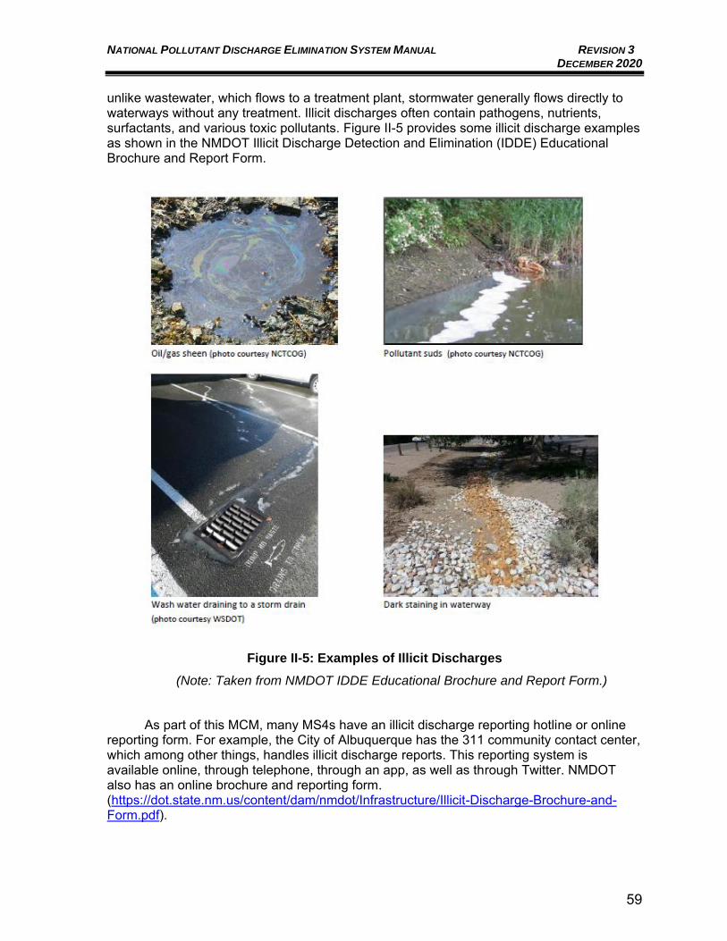
NATIONAL POLLUTANT DISCHARGE ELIMINATION SYSTEM MANUAL REVISION 3 DECEMBER 2020
59
unlike wastewater, which flows to a treatment plant, stormwater generally flows directly to waterways without any treatment. Illicit discharges often contain pathogens, nutrients, surfactants, and various toxic pollutants. Figure II-5 provides some illicit discharge examples as shown in the NMDOT Illicit Discharge Detection and Elimination (IDDE) Educational Brochure and Report Form.
Figure II-5: Examples of Illicit Discharges
(Note: Taken from NMDOT IDDE Educational Brochure and Report Form.)
As part of this MCM, many MS4s have an illicit discharge reporting hotline or online reporting form. For example, the City of Albuquerque has the 311 community contact center, which among other things, handles illicit discharge reports. This reporting system is available online, through telephone, through an app, as well as through Twitter. NMDOT also has an online brochure and reporting form. (https://dot.state.nm.us/content/dam/nmdot/Infrastructure/Illicit-Discharge-Brochure-and-Form.pdf).
NATIONAL POLLUTANT DISCHARGE ELIMINATION SYSTEM MANUAL REVISION 3 DECEMBER 2020
60
Control of Floatables Discharges
This MCM includes developing and implementing a program with the goal of controlling floatable discharges into the MS4. The program can include source controls such as litter reduction outreach programs as well as structural controls, such as constructed ported riser outfalls in ponds to prevent floatables from discharging. This MCM also requires that each MS4 estimate the annual volume of floatables and trash removed from each control facility and characterize the floatable type.
The current 2007 Small MS4 Permit does not include this MCM. However, the MRG
Watershed Based MS4 Permit and the 2015 Draft General Permit for Small MS4s in New Mexico currently includes the Control of Floatables Discharges MCM. There is cross-over within the NM MS4 General Permits between this MCM and the Pollution Prevention/Good Housekeeping MCM, which also has several requirements focused on reducing floatables within stormwater runoff.
Public Education and Outreach on Stormwater Impacts
This MCM includes distributing educational materials and performing outreach to inform and educate the community, employees, businesses, and the general public about the impacts polluted stormwater runoff can have on water quality. Convincing others to change their behaviors and properly dispose of materials is a part of controlling stormwater pollution. It is important that the public be aware of the significance of their behavior and that their actions can either pollute or protect our waterways. This MCM is typically addressed by each MS4 through Internet resources, billboards, participation in community events, and brochures, as well as through cooperative efforts. There is cross-over within the NM MS4 Permits between this MCM and education/training requirements specific to other MCMs.
As an example, in the MRG Watershed, a cooperative Mid Rio Grande Stormwater
Quality Team (http://www.keeptheriogrand.org/), was formed in 2004 to meet the requirements of this MCM by educating individuals and businesses on how to reduce stormwater pollution by keeping trash and other pollution out of the stormwater system. This cooperative group focuses on educating children, adults and businesses on how to reduce stormwater pollution to keep the Rio Grande clean. The Stormwater Quality Team includes City of Albuquerque, Bernalillo County, City of Rio Rancho, Sandoval County, Ciudad Soil and Water Conservation District, NMDOT – District 3, AMAFCA, SSCAFCA, ESCAFCA, Town of Bernalillo, Village of Corrales, and the Village of Los Ranchos. The Lower Rio Grande MS4s have followed a similar cooperative format and created the Lower Rio Grande Stormwater Coalition (http://keepitrio.org/background/), which includes the following MS4s: New Mexico State University (NMSU), City of Las Cruces, NMDOT-District 1, Doña Ana County, City of Anthony, City of Sunland Park, Santa Teresa, and the Town of Mesilla. This group recognizes that once the Statewide Small MS4 permit is finalized, MS4 program components such as stormwater quality sampling and education and outreach are areas that may benefit from a shared collaborative approach.
Public Involvement/Participation
This MCM includes providing opportunities for citizens to participate in MS4 program development and implementation, including effectively publicizing public hearings and/or encouraging the participation of citizen representatives on stormwater management panels. Encouraging community participation, forming partnerships, and combining efforts of other
NATIONAL POLLUTANT DISCHARGE ELIMINATION SYSTEM MANUAL REVISION 3 DECEMBER 2020
61
groups in the community will encourage everyone to work towards the same stormwater goals. This MCM is typically addressed by each MS4 through publishing public notices for meetings and document reviews, ensuring website availability of SWMP and Annual Reports, and planning community clean-up events. MS4s also often use cooperative efforts to meet the MCM requirements. As mentioned above the MRG Watershed utilizes the cooperative Mid Rio Grande Stormwater Quality Team to meet MCM requirements for both Public Education and Outreach on Stormwater Impacts and the Public Involvement/Participation.
Conditions for Compliance with Water Quality Standards and Measures to
Meet Endangered Species Act (ESA) Requirements
In addition to MCMs, MS4 Permit conditions typically include required measures to address compliance with water quality standards and Endangered Species Act (ESA) requirements.
II.C.9.a. Conditions for Compliance with Water Quality Standards
The State of New Mexico has EPA-approved water quality standards for surface water. The goal of the MS4 Permits is for implementation of the approved SWMP and other permit conditions to provide a reasonable assurance that the permitted activity will be conducted in a manner which will not violate applicable Water Quality Management Plans and Water Quality Standards, including but not limited to the following:
• No discharge of toxic pollutants in toxic amounts: The State of New Mexico Standards for Interstate and Intrastate Surface Waters (20.6.4.13 F) state that “Surface waters of the State shall be free of toxic pollutants from other than natural causes in amounts, concentrations or combinations that affect the propagation of fish or that are toxic to humans, livestock or other animals, fish or other aquatic organisms, wildlife using aquatic environments for habitation or aquatic organisms for food, or that will or can be reasonably expected to bio-accumulate in tissues of fish, shellfish, and other aquatic organisms to levels that will impair the health of aquatic organisms or wildlife or result in unacceptable tastes, odor or health risks to human consumers of aquatic organisms”.
• No discharge of pollutants in quantities that would cause a violation of State or Tribal water quality standards: NPDES Permits must include limitations, including those necessary to meet water quality standards, established pursuant to State law or regulations. This supports MS4 Permit MCMs to control pollutants to support protection of water quality standards and compliance with TMDLs.
• No discharge of floatable debris, oils, scum, foam, or grease in other than trace amounts: The State of New Mexico Standards for Interstate and Intrastate Surface Waters (20.6.4.13 B) states that “Surface waters of the State shall be free of oils, scum, grease and other floating materials resulting from other than natural causes that would cause the formation of a visible sheen or visible deposits on the bottom or shoreline, or would damage or impair the normal growth, function or reproduction of human, animal, plant or aquatic life”.
NATIONAL POLLUTANT DISCHARGE ELIMINATION SYSTEM MANUAL REVISION 3 DECEMBER 2020
62
• No discharge of non-stormwater from the municipal separate storm sewer system, except in accordance with Part I.A.4: Permits issued to MS4s are specifically required by Section 402(p)(3)(B) of the CWA to “include a requirement to effectively prohibit non-stormwater discharges into the storm sewers.” Certain non-stormwater discharges are allowed where they have not been identified as significant sources of pollutants.
• No degradation or loss of State or Tribal-designated uses of receiving waters as a result of stormwater discharges from MS4s (unless authorized in accordance with the State or Tribal Antidegradation Policy): The State of New Mexico and many New Mexico Tribes have adopted Antidegradation Policies and Implementation Plans as part of their Water Quality Standards which provide for maintenance of existing instream water uses; existing water quality levels where existing water quality exceeds the levels necessary to support propagation of fish, shellfish, and wildlife, and recreation in and on the water (except where the State or Tribe has determined that lowering water quality is necessary to accommodate important economic or social development in the area where the waters are located); existing water quality where high-quality waters constitute an outstanding national or tribal resource (e.g., waters of National and State parks and wildlife refuges or exceptional recreational or ecological significance); and compliance with Section 316 of the CWA where potential water quality impairment is associated with a thermal discharge.
EPA Region 6 is unaware of any direct discharges to waters under the jurisdiction of a Tribe (Tribal waters), but Tribal waters may be located downstream of direct discharge points. MS4 Permit conditions are expected to be protective of downstream Tribal waters. A few examples of Tribal waters downstream of UAs are:
• Runoff from the Farmington UA discharges to the San Juan River and downstream of the Farmington UA, the San Juan River flows through the Navajo Nation.
• Some Santa Fe UA arroyos and drains may flow downstream of the Santa Fe UA to the Pueblo of Cochiti’s waters.
• Runoff from the MRG Watershed discharges to the Rio Grande and downstream of the Albuquerque UA, the Rio Grande flows through the Pueblo of Isleta’s waters.
II.C.9.b. Measures to Meet Endangered Species Act (ESA) Requirements
MS4 Permits can also have requirements to ensure actions required by the MS4 Permit are not likely to jeopardize the continued existence of any currently listed as endangered or threatened species or adversely affect its critical habitat. Typically, EPA will coordinate with the U.S. FWS who will conduct a Biological Opinion and provide a report with requirements for the MS4 Permit. For the MRG Watershed Based MS4 Permit, the ESA requirements include that MS4s include a dissolved oxygen strategy, critical habitat verification, and a sediment load reduction strategy in their SWMPs. The 2015 Draft General Permit for Small MS4s in New Mexico ESA requires that MS4s include a critical habitat
NATIONAL POLLUTANT DISCHARGE ELIMINATION SYSTEM MANUAL REVISION 3 DECEMBER 2020
63
verification and a sediment load reduction strategy (applicable only for the Santa Fe and Los Lunas UAs) in their SWMPs.
MS4 Monitoring Requirements
The goal of the implementation of the SWMP and monitoring requirements of the MS4 Permits is to reduce pollutants in MS4 discharges reaching receiving waters and help guide adaptive management changes by the permittees. Monitoring and assessment are required for Permit compliance and to assist the MS4 permittees with evaluating the progress toward achieving the measurables goals defined in their MS4 SWMP.
Part III of the MRG Watershed Based MS4 Permit and the Draft General Permit for
Discharges from Small MS4s in New Mexico detail the monitoring and assessment requirements, which include wet weather monitoring, dry weather monitoring, and floatables assessment. The MRG Watershed Based MS4 Permit also includes Industrial and High Risk Runoff Monitoring, which like the Industrial and High Risk Runoff MCM (refer to Section II.C.4 of this Manual), currently only applies to the City of Albuquerque.
The MS4 permittee must develop a monitoring and assessment program. This
program must be developed in consultation with NMED and EPA, as well as with affected Indian tribes if the monitoring locations are located on Tribal lands. The monitoring program can be developed and implemented as a cooperative program with other MS4 permittees, which can reduce duplicated efforts and save resources for the involved permittees.
II.C.10.a. Wet Weather Monitoring
Wet weather monitoring is designed to gather information on the response of the receiving water(s) to storm event discharges from the MS4s. Guidance on selecting monitoring locations in the MS4 Permits states that the waters entering a watershed (upstream) and leaving a watershed (downstream) should be monitored; Appendix D of the MRG Watershed Based MS4 Permit and the Draft General Permit for Discharges from Small MS4s in New Mexico provides guidance on choosing sampling locations. The MS4 Permits define seasonal monitoring periods as a wet season (July 1 – Oct. 31) and a dry season (Nov. 1 – June 3) and set monitoring requirements that define the number of events to monitor during the Permit term for each the wet and dry seasons. Details on the required parameter list, rainfall magnitude required for sampling, monitoring methodology, field sampling requirements, and analytical methods are detailed in each MS4 Permit. The MS4 Permits also provide the compliance requirements for individual monitoring and cooperative monitoring programs. As an incentive to pursue cooperative monitoring programs, the MRG Watershed Based MS4 Permit and the Draft General Permit for Discharges from Small MS4s in New Mexico require fewer monitoring events per Permit term as well as, typically, fewer total monitoring locations for cooperative programs compared to individual programs.
II.C.10.b. Dry Weather Monitoring/Discharge Screening
Dry weather monitoring is designed to gather information on non-storm event pollutant contributions from the MS4 to receiving waters. MS4s will identify, investigate, and address areas within their jurisdiction that may be contributing
NATIONAL POLLUTANT DISCHARGE ELIMINATION SYSTEM MANUAL REVISION 3 DECEMBER 2020
64
excessive levels of pollutants to the MS4 as a result of dry weather discharges (i.e., discharges that occur without the direct influence of runoff from storm events, e.g., illicit discharges, allowable non-stormwater, groundwater infiltration, etc.). Due to the arid and semi-arid conditions in New Mexico, the dry weather discharges screening program may be carried out during both wet season (July 1 through Oct. 31) and dry season (Nov. 1 through June 30). This monitoring requirement has cross-over with and should be coordinated with the Illicit Discharges and Improper Disposal MCM (refer to Section II.C.5 of this Manual). Details on the screening parameter list, antecedent dry period required for sampling, and sampling methodology are detailed in each MS4 Permit.
II.C.10.c. Floatable Monitoring
This monitoring requirement should be coordinated with the Control of Floatables Discharges MCM (refer to Section II.C.6 of this Manual). Both the MRG Watershed Based MS4 Permit and the Draft General Permit for Discharges from Small MS4s in New Mexico require floatable monitoring. Details on the number of stations to monitor, number of times per year to monitor, and sampling methodology are detailed in each MS4 Permit. As with other MS4 Permit requirements, EPA encourages a cooperative monitoring program to assess floatable material in discharges.
II.D. MS4 REPORTING REQUIREMENTS
The primary reporting mechanism for MS4 Permits is the submittal of MS4 Annual Reports to EPA. For both the MRG Watershed Based MS4 Permit and the Draft General Permit for Discharges from Small MS4s in New Mexico, MS4 Annual Reports are due to EPA no later than December 1 of each year and report on the time frame for the previous year from July 1 to June 30. For the 2007 Small MS4 Permit, MS4 Annual Reports are due to EPA no later than October 1 of each year and report on the time frame for the previous year from July 1 to June 30.
The MS4 Annual Reports review and report on the status of compliance and implementation of the goals established in the SWMP. The MS4 Annual Reports also provide an assessment of the measurable goals and provide a summary of supporting data to EPA. An estimate of the annual expenditures for the reporting period for the major elements of the stormwater management program as well as a budget for the next year are also required to be submitted. Appendix B3 of this Manual provides the current EPA MS4 Annual Report Form which is the suggested Annual Report format from EPA.
Prior to submitting each Annual Report, the MS4s must provide public notice of and make available for public review and comment a draft copy of the Annual Report. All public input must be considered in preparation of the final Annual Reports. The 2007 Small MS4 Permit requires the public notice be at least thirty (30) days prior to the Annual Report submission. Both the MRG Watershed Based MS4 Permit and the Draft General Permit for Discharges from Small MS4s in New Mexico requires the public notice to be at least forty-five (45) days prior to the Annual Report submission. Identical to the NOI submittal, the Annual Report must be signed and certified before submittal to EPA; refer to Section II.B.4.b of this Manual for a summary of the signatory requirements.
NATIONAL POLLUTANT DISCHARGE ELIMINATION SYSTEM MANUAL REVISION 3 DECEMBER 2020
65
In addition to Annual Reports, monitoring results must be reported using Discharge Monitoring Reports (DMRs). Currently, the DMR information must be entered into the netDMR system, which is part of the EPA NeT system, and submitted electronically. DMRs must be entered, certified, and submitted on the same schedule as the Annual Reports. Typically, in New Mexico, MS4s will submit a PDF copy of the DMR electronic submittals with their electronic version of each Annual Report.
Throughout the MS4 Permits, additional submittals and schedules for those submittals will be identified. Typically, submittals will follow the Annual Report time frame, but not always. The MS4 Permits also define schedules for SWMP revisions, procedures for SWMP modifications, and submittal requirements to EPA. For example, in the Draft General Permit for Discharges from Small MS4s in New Mexico, the year one (1) and year four (4) Annual Reports shall include submittal of a complete SWMP revision.
NATIONAL POLLUTANT DISCHARGE ELIMINATION SYSTEM MANUAL REVISION 3 DECEMBER 2020
66
III. INDUSTRIAL ACTIVITIES
III.A. INTRODUCTION
Stormwater runoff from industrial activities can be a major cause of water pollution. Stormwater can include rainfall, melting snow, surface runoff and drainage, and rainfall or snowmelt from adjacent sites running onto and/or through a facility. Stormwater can pick up and carry materials and debris from uncovered material storage areas and areas where chemicals or industrial materials have been spilled, even if the material has been cleaned up and only a residue remains. Unless mitigation measures are designed and implemented appropriately, industrial locations are subject to transporting on-site pollutants to surface waterways by stormwater runoff.
The permit for stormwater discharges from industrial facilities, the NPDES Multi-Sector General Permit for Stormwater Discharges Associated with Industrial Activity (MSGP), requires the development of a Stormwater Pollution Prevention Plan (SWPPP), which is the documentation of the control measures that will be implemented to minimize stormwater pollution. There are requirements in the MSGP for industry-specific BMPs, and for monitoring and analytical activities, based on Standard Industrial Classification (SIC)-code determinations for the particular industrial activity. The analytical requirements ensure that industrial activity-specific pollutants aren’t being transported in stormwater runoff. The SWPPP itself serves as the self-generated tracking mechanism developed for EPA by the individual facility operator.
Facilities can apply for No Exposure Certification (NEC) exclusion from the MSGP if conditions of no exposure exist at the industrial facility. No exposure exists when all industrial materials and activities are protected by a storm resistant shelter to prevent exposure to rain, snow, snowmelt, and/or runoff. Industrial materials or activities include, but are not limited to, material handling equipment or activities, industrial machinery, raw materials, intermediate products, by-products, final products, or waste products. If any industrial activities or materials are or will be exposed to precipitation, the facility is not eligible for the no exposure exclusion. By signing and submitting the NEC form the operator is certifying that a condition of no exposure exists at its facility, and is obligated to comply with the terms and conditions of 40 CFR 122.26(g). The certification will exempt the facility from Permit MSGP coverage requirements; therefore a SWPPP is not required for the facility.
This Manual will assist users in developing a SWPPP tailored to the needs of their
particular industrial facility while meeting regulatory requirements of stormwater management. Users will also be assisted in meeting regulatory requirements of stormwater management. III.B. REGULATORY SUMMARY
NPDES Regulations
The NPDES Stormwater Permitting Program in New Mexico is administered by EPA Region 6. Requirements for NPDES Stormwater Discharge Permits are defined by federal law in Section 402(p) of the CWA and added by Section 405 of the Water Quality Act of 1987.
NATIONAL POLLUTANT DISCHARGE ELIMINATION SYSTEM MANUAL REVISION 3 DECEMBER 2020
67
As part of the Water Quality Act of 1987, stormwater discharge associated with industrial activity from a point source to waters of the United States is unlawful, unless authorized by a National Pollutant Discharge Elimination System (NPDES) Permit. In order to effectively manage the permit process, EPA has produced an MSGP for industrial activities, which defines specific conditions and requirements to be met as part of the Permit. The MSGP establishes the procedures required for proper coverage, the requirement for an SWPPP, and requirements for termination of Permit coverage. In addition to meeting the requirements for the MSGP, the facility operator may be obligated to contact the local MS4, if requested, to determine if local requirements must be met in addition to MSGP coverage, although at present there are no MS4s in New Mexico that require such notification.
In November 1990, EPA published regulations for NPDES Permits for certain stormwater discharges. On October 30, 1995, EPA issued the first NPDES MSGP that applied to the majority of stormwater discharges associated with specific industrial activities. It also added provisions to protect threatened and endangered species and designated national historic preservation sites from industrial stormwater runoff. EPA issued a new MSGPs in 2005, 2008, and 2015 followed by the most recent proposed MSGP issued in March 2020. Based on EPA’s settlement agreement deadlines, the proposed March 2020 Permit should be finalized in November 2020. Facilities must file a new NOI to renew coverage at least two days prior to the expiration date of their current Permit. In order to allow adequate time for processing and confirmation, it is recommended to reapply at least two or three weeks prior to the expiration date of the Permit.
As noted above, all industrial activities that discharge stormwater are subject to the NPDES Permit requirements. Failure to abide by the terms of the MSGP, or failure to develop and implement a site-specific NPDES Permit, is a violation of federal law, which can subject the owner or operator to severe fines or imprisonment.
Compliance with the requirements of the MSGP consists of seven major components that must be accomplished:
• Determination of eligibility;
• Preparation and implementation of an SWPPP;
• Submission of an NOI;
• Monitoring and analytical requirements;
• Description of the facility and pollution potential;
• Submission of Annual Reports; and
• Submission of an NOT.
Note: The SWPPP is prepared in conjunction with the site design, before the submission of the NOI to EPA.
III.B.1.a. Eligibility Determination
Eligibility under the Permit is summarized in Part 1.1. of the MSGP. Permittees are only eligible for coverage under the MSGP if their stormwater discharges and stormwater discharge-related activities are not likely to adversely impact the following:
NATIONAL POLLUTANT DISCHARGE ELIMINATION SYSTEM MANUAL REVISION 3 DECEMBER 2020
68
• Federally listed threatened and endangered species and designated critical habitat
Applicants are required to conduct an assessment of the impacts of their stormwater discharges and stormwater discharge-related activities on threatened and endangered species and designated critical habitat. Appendix E of the MSGP provides procedures to assist applicants in conducting an assessment and pursuing formal consultation with federal wildlife protection agencies, if necessary. A copy of the most recent MSGP is available on EPA’s NPDES website (https://www.epa.gov/npdes/stormwater-discharges-industrial-activities).
• Historic Properties Appendix F of the MSGP provides procedures to assist applicants in
conducting an assessment and pursuing formal consultation with the State Historic Preservation Office if necessary.
• New Discharges to Water Quality Impaired Waters No new discharges to water quality impaired waters are permitted without a
determination by EPA Region 6, see Part 1.1.4.7 of the MSGP. Permittees must receive a determination from the EPA Region 6 Office that the facility discharge will meet applicable water quality standards, and this must be documented in the SWPPP. If the EPA Region 6 Office fails to respond within 30 days after submission of data, the facility is considered to be eligible for coverage.
III.B.1.b. Permittees
The operator of an industrial facility is the permittee and is responsible for submitting an NOI and complying with the NPDES Permit. The term operator is defined by EPA as “any entity with a stormwater discharge associated with industrial activity that meets either of the following two criteria: 1) The entity has operational control over industrial activities, including the ability to
make modifications to those activities; or
2) The entity has day-to-day operational control of activities at a facility necessary to ensure compliance with the permit (e.g., the entity is authorized to direct workers at a facility to carry out activities required by the permit).”
The operator may be the owner, developer, engineer, or general contractor. Other parties responsible for industrial activities and their respective responsibilities on the facility may be identified on the operations contract.
NPDES Multi-Sector General Permit
The MSGP will consolidate permit compliance requirements for many common sources of pollutants, activities, and facilities under one Permit. The coverage of the Permits is broad, with general compliance requirements, and is typically effective for five (5) years. The original federal baseline industrial MSGP was discontinued in September 1998. Future permitting strategies will be more specific to individual facilities, specific types of activities, and watershed areas. The
NATIONAL POLLUTANT DISCHARGE ELIMINATION SYSTEM MANUAL REVISION 3 DECEMBER 2020
69
permitting strategy developed by EPA outlines the method of compliance and the role of the permittee.
MSGPs were issued on September 29, 1995, expired October 1, 2000, and were
continued until October 30, 2000, when they were republished. The 2000 MSGP was continued until 2008. The 2008 MSGP was published on September 29, 2008, and was administratively continued from September 29, 2013 until June 3, 2015. The 2015 MSGP became effective on June 4, 2015, and expired on June 4, 2020. The 2015 MSGP is currently under administrative continuance. The proposed 2020 MSGP can be found on EPA’s NPDES website. (https://www.epa.gov/npdes/proposed-2020-msgp-public-comment).
The MSGP has established general compliance requirements that the permittee must
observe. The program is intended to be self-regulating and requires the permittee to prepare and implement the facility SWPPP. During the Permit term, the permittee is responsible for:
• Maintaining the description of the facility and potential pollution sources;
• Maintaining a copy of the SWPPP on-site;
• Inspecting the facility to ensure that SWPPP improvements are in place and functional;
• Revising the SWPPP as facility conditions and industrial activities change;
• Performing monitoring and analytical activities as specified;
• Filing Annual Reports; and
• Keeping records.
Each industrial facility will vary in activity and responsible party. In addition to the general filing requirements of the MSGP, there are other requirements
that may impact industrial activities. These items follow, along with methods used to address the requirements, where applicable.
III.B.2.a. Monitoring Requirements
Under the MSGP, the following three monitoring types are required: 1) Analytical Monitoring - Analytical monitoring requirements involve laboratory
chemical analysis of samples collected by the permittee. Analytical results (data) are compared to other sampling events, other facilities, or national benchmarks. A listing of SIC codes eligible for Permit coverage under the MSGP is found in Appendix D of the MSGP. The list identifies those SIC-code activities that require analytical monitoring due to the likelihood of discharging pollutants at concentrations of concern. EPA has established material benchmark concentrations for specific pollutants. Part 8 of the MSGP, Sector Specific Requirements contains lists of monitoring concentration limits in SIC-code categories. Such monitoring takes place quarterly until the average of four consecutive quarterly monitoring values is below the benchmark value. If constituent values are above national benchmarks, analytical monitoring continues until the average of four consecutive quarterly monitoring values is below the benchmark value, or a
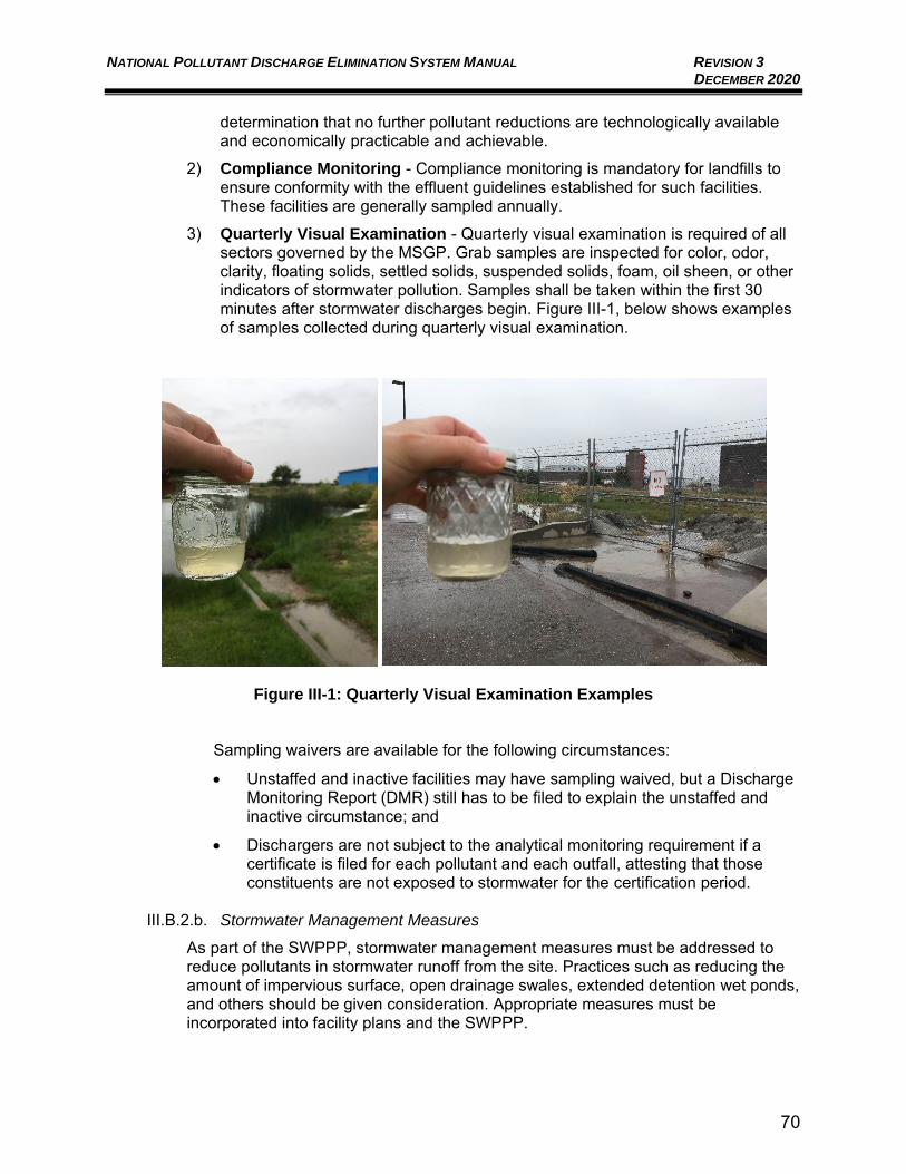
NATIONAL POLLUTANT DISCHARGE ELIMINATION SYSTEM MANUAL REVISION 3 DECEMBER 2020
70
determination that no further pollutant reductions are technologically available and economically practicable and achievable.
2) Compliance Monitoring - Compliance monitoring is mandatory for landfills to ensure conformity with the effluent guidelines established for such facilities. These facilities are generally sampled annually.
3) Quarterly Visual Examination - Quarterly visual examination is required of all sectors governed by the MSGP. Grab samples are inspected for color, odor, clarity, floating solids, settled solids, suspended solids, foam, oil sheen, or other indicators of stormwater pollution. Samples shall be taken within the first 30 minutes after stormwater discharges begin. Figure III-1, below shows examples of samples collected during quarterly visual examination.
Figure III-1: Quarterly Visual Examination Examples
Sampling waivers are available for the following circumstances:
• Unstaffed and inactive facilities may have sampling waived, but a Discharge Monitoring Report (DMR) still has to be filed to explain the unstaffed and inactive circumstance; and
• Dischargers are not subject to the analytical monitoring requirement if a certificate is filed for each pollutant and each outfall, attesting that those constituents are not exposed to stormwater for the certification period.
III.B.2.b. Stormwater Management Measures
As part of the SWPPP, stormwater management measures must be addressed to reduce pollutants in stormwater runoff from the site. Practices such as reducing the amount of impervious surface, open drainage swales, extended detention wet ponds, and others should be given consideration. Appropriate measures must be incorporated into facility plans and the SWPPP.
NATIONAL POLLUTANT DISCHARGE ELIMINATION SYSTEM MANUAL REVISION 3 DECEMBER 2020
71
Specific techniques listed in the Permit include stormwater detention (dry sedimentation basins), retention structures, measures to allow for infiltration (trenches, open drainage swales), and velocity dissipation. Specific SIC-code requirements are listed for permitted industrial activities in Part 8 of the MSGP, Sector Specific Requirements
III.B.2.c. Coverage of Support Activities
The Permit also authorizes stormwater discharges from support activities, including equipment staging yards, material storage areas, excavated material disposal areas, and borrow areas, provided that:
• The support activity is directly related to an industrial facility having NPDES Permit coverage for discharges of stormwater associated with the activity;
• The support activity is not a commercial operation serving multiple unrelated sites of different operators, and does not operate beyond the completion of the activity it supports; and
• Appropriate controls and measures are identified in the SWPPP covering the discharges from the support activity.
III.B.2.d. Spill Notification
The MSGP allows for stormwater discharge from industrial facilities only. Discharges of other substances from industrial activities are not permitted, see Part 2.1.2.4 of the MSGP. In the event of a spill of a hazardous substance, the operator is required to notify the National Response Center (NRC) at (800) 424-8802, the New Mexico Environment Department (NMED) at (505) 827-9329, and the local fire department to properly report the spill. A written description of the release must be provided to the EPA Region 6 Office, which includes the date and circumstances of the release, mitigation measures, and steps taken to prevent another release. In addition, the SWPPP must be revised within 14 calendar days after the release to reflect the release, stating the type and quantity of material released, the date of the release, the circumstances of the release, and actions to be taken to prevent further spills. If fuels, oils, or other substances are to be present on-site, it is imperative that closed containers be provided along with containment areas for large-quantity spills. Hazardous chemicals include fertilizers, paints, oils, grease, pesticides, and fuels, along with other industrial chemicals. If these materials are not subjected to stormwater flows, a NEC may be filled out and filed with the intent of exempting these materials from management and monitoring requirements. Provisions must be made to address potential pollution through the use of the BMPs, as well as compliance with OSHA and other regulatory requirements.
III.B.2.e. Retention of Records
As a requirement of the MSGP, the SWPPP (including any modifications), additional documentation, all reports and certifications required, monitoring data, and records of all data used to complete the NOI to be covered by the Permit must be retained for a period of at least three (3) years from the date coverage under the Permit expires or is terminated. This is to protect the operator of the site from future claims concerning water quality and measures implemented at the site.
NATIONAL POLLUTANT DISCHARGE ELIMINATION SYSTEM MANUAL REVISION 3 DECEMBER 2020
72
MSGP Permitting Process
Figure III-2 shows a typical simplified analysis procedure for determining if a specific facility’s stormwater discharge requires an MSGP, and how the permitting process flows. The first task for a facility is to determine if it is regulated. If the facility has stormwater runoff, it will require an NPDES Permit, and the process is outlined in this Manual.
The second step for a regulated facility is to identify the industry’s SIC code and check
Appendix D of the MSGP for that SIC code. If the SIC code is listed, the industry is eligible for coverage under the MSGP, following the guidance in this Manual. If it is not listed, the facility will have to obtain a site-specific NPDES Permit, which is outside the scope of this Manual.
The third step for regulated facilities is to check for threatened and endangered species,
historic places, and water quality impaired waters eligibility requirements. The process for investigating these issues is covered in Section III.B.1.a of this Manual. If a facility’s discharge will have an effect on any of these issues, a site-specific Permit may be required, which is outside the scope of this Manual. If no such issues are present, a Permit under the MSGP is required, and the process is detailed in the remaining sections of this Manual.
The facility must then develop a facility description, including an assessment of potential
pollution sources. After a facility assessment is complete, an SWPPP must be developed responsive to the need to mitigate the transport by stormwater, those constituents characteristic of the specific industry. Figure III-4 shows, step-wise, the operating requirements, including monitoring, for any permitted facility.
Once the SWPPP is complete and contains the requirements for each specific SIC
category (as detailed in Part 8 of the MSGP), including a monitoring plan, the NOI is prepared and sent to EPA. If no comments are received about the NOI, legal discharge can begin under NPDES Permit coverage.
A facility that can demonstrate no exposure to stormwater by the industrial activity can file
an NEC form, which may exempt the facility from Permit coverage requirements. All NECs, NOIs, NOTs, Annual Reports, Discharge Monitoring Reports (DMRs), and other
reporting information must be summited electronically, unless the EPA Region 6 Office grants a waiver. All required information is submitted via EPA’s electronic NPDES eReporting tool (NeT). To access NeT-MSGP, go to https://cdxnodengn.epa.gov/net-msgp/action/login.
Example forms and instructions are contained in the MSGP appendices: the NOI is in
Appendix G, NOT in Appendix H, Annual Report in Appendix I, NEC in Appendix K, and DMR is Appendix M.
During operation of the facility, the measures and procedures detailed in the SWPPP will
be followed, including all monitoring and inspections, at the frequency specified. If site conditions or operations change, or if monitoring or inspections indicate a need to change practices, the SWPPP shall be modified to facilitate meeting the benchmark constituent concentrations in the runoff discharge.
If and when the facility is no longer discharging stormwater, or the facility’s operator
changes, an NOT must be prepared and filed with EPA. A certification is made that there are no longer discharges, that the site activity has ceased, and that there is no longer exposure of materials or activities to stormwater and runoff.
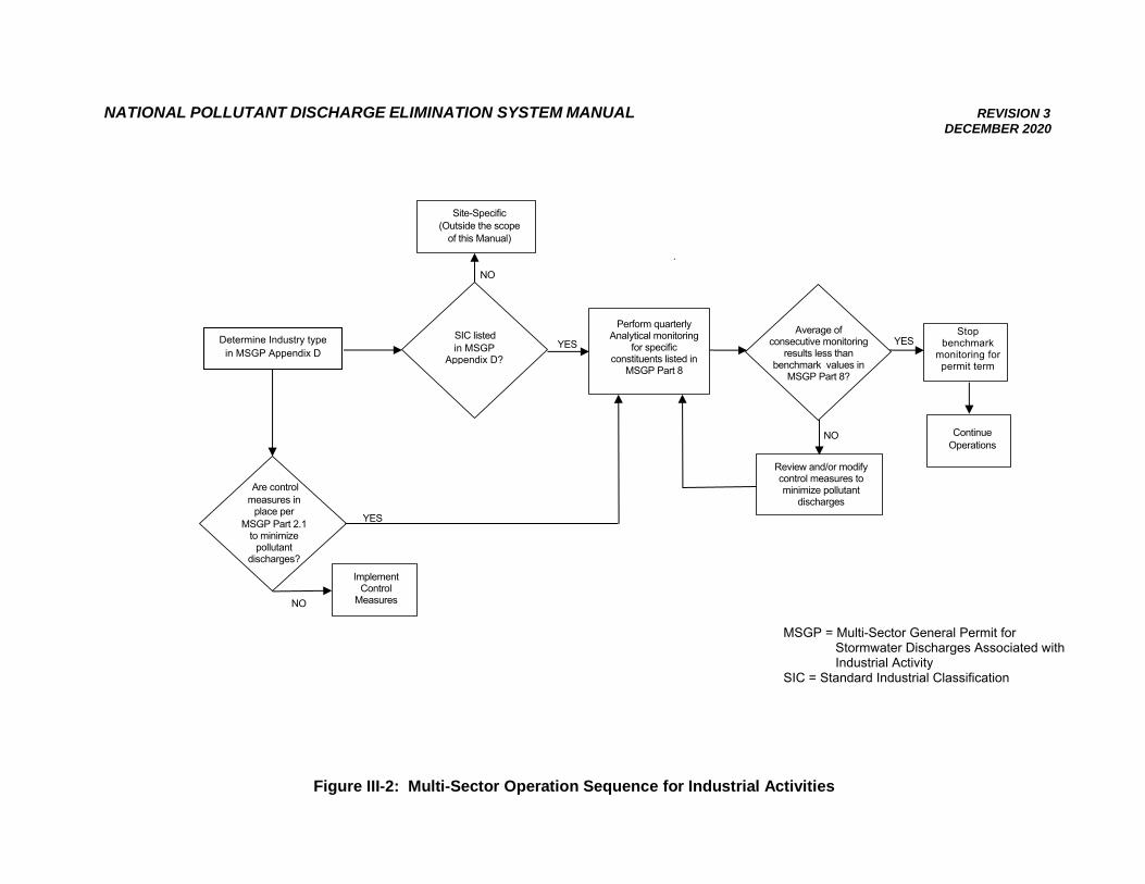
NATIONAL POLLUTANT DISCHARGE ELIMINATION SYSTEM MANUAL REVISION 3
DECEMBER 2020
.
Figure III-2: Multi-Sector Operation Sequence for Industrial Activities
MSGP = Multi-Sector General Permit for
Stormwater Discharges Associated with Industrial Activity
SIC = Standard Industrial Classification
Implement Control
Measures
YES
Determine Industry type in MSGP Appendix D
SIC listed in MSGP
Appendix D?
Site-Specific (Outside the scope
of this Manual)
Continue Operations
Review and/or modify control measures to minimize pollutant
discharges
Stop benchmark
monitoring for permit term
Average of consecutive monitoring
results less than benchmark values in
MSGP Part 8?
Perform quarterly Analytical monitoring
for specific constituents listed in
MSGP Part 8
Are control measures in
place per MSGP Part 2.1
to minimize pollutant
discharges?
NO
YES
NO
NO
YES
NATIONAL POLLUTANT DISCHARGE ELIMINATION SYSTEM MANUAL REVISION 3 DECEMBER 2020
74
III.C. NOTICE OF INTENT
Description
The NOI is the primary document used by EPA to monitor and enforce compliance with the NPDES permitting requirements. The NOI is to be submitted after development of the facility description, identification of potential pollution sources, and development of the SWPPP. Unless notified by EPA, the NOI is considered acceptable, and discharging stormwater may begin 30 days following the posting of the NOI on EPA’s website, under assumed coverage of the NPDES MSGP.
The operator of the facility, see Section III.B.1.b of this Manual, is required to submit the
NOI and is ultimately responsible for the effective reduction of pollution from the facility. The NOI must be in place for the facility throughout the time the facility is active.
Preparing the NOI
The operator must use EPA’s NPDES eReporting Tool for the MSGP (NeT-MSGP) to electronically prepare and submit to EPA a complete and accurate NOI by the deadline applicable to your facility. The NOI certifies to EPA that the facility is eligible for coverage and provides information on industrial activities and related discharges. The facility operator must submit the NOI electronically via NeT-MSGP, unless the EPA Region 6 Office grants a waiver from electronic reporting, in which case you may use the paper NOI form (see Appendix G of the MSGP). To access NeT-MSGP, go to https://www.epa.gov/npdes/stormwater-discharges-industrial-activities.
Blank copies of the NOI form and instructions can be obtained by:
• Downloading the form from EPA’s website - check for the latest version at https://www.epa.gov/npdes/stormwater-discharges-industrial-activities
• Downloading the form from NeT-MSGP, go to https://cdxnodengn.epa.gov/net-msgp/action/login
In the event of a change of operator for the facility permitted, a new NOI must be filed. If
the industrial facility is located within an MS4, the permittee is required to provide a copy of the NOI to the MS4 if the stormwater discharges into an MS4.
The 2020 MSGP states the NOI must include 1) location information for each stormwater
outfall, 2) the hardness of the receiving waterbody (if subject to benchmark monitoring for metals), 3) whether the facility discharges to a federal Superfund site, and 4) general information from the SWPPP if the SWPPP is not posted online. EPA NPDES Electronic Reporting Tool (NeT) uses outfall latitude and longitude information for each outfall to automatically determine the receiving waters that the facility discharges to and the receiving waters’ impairment status.
The 2020 MGSP requires permittees to provide either a URL for their SWPPP or selected
information from the SWPPP on the NOI form. The purpose of this is to provide greater SWPPP access to the public, EPA, and the U.S. Fish and Wildlife Service and National Marine Fisheries Services (the Services). The selected information from the SWPPP that currently (2020 MSGP) needs to be included in the NOI form includes:
NATIONAL POLLUTANT DISCHARGE ELIMINATION SYSTEM MANUAL REVISION 3 DECEMBER 2020
75
• On-site industrial activities that are exposed to stormwater, including potential spill and leak areas, pollutants or pollutant constituents associated with each industrial activity exposed to stormwater that could be discharged in stormwater, and any authorized non-stormwater discharges listed in 2020 MSGP Part 1.2.2;
• Control measures employed to comply with the non-numeric technology based effluent limits required in 2020 MSGP Part 2.1.2 and Part 8, and any other measures taken to comply with the requirements in 2020 MSGP Part 2.2 Water Quality-Based Effluent Limitations;
• Schedule for good housekeeping and maintenance (see 2020 MSGP Part 5.2.5.1); and
• Schedule for all inspections required in Part 4 (see 2020 MSGP Part 5.2.5.2). Signatory Requirements
The facility operator must file the NOI. Operators are defined by EPA as any entity with a stormwater discharge associated with industrial activity that meets either of the following two criteria:
• The entity has operational control over industrial activities, including the ability to make modifications to those activities; or
• The entity has day-to-day operational control of activities at a facility necessary to ensure compliance with the permit (e.g., the entity is authorized to direct workers at a facility to carry out activities required by the permit).
If the operator is a corporation, a responsible corporate officer must sign the NOI. If the
operator is a partnership or sole proprietorship, a general partner or the sole proprietor, respectively, must sign the forms. For any governmental entity, the signing person must be a principal executive official or ranking elected official. Additional signatory requirements are available in Part B.11 of Appendix B of the MSGP.
Approval Process
Unless notified to the contrary by EPA, operators who submit a correctly completed NOI, in accordance with the requirements of the MSGP, are authorized to discharge stormwater from industrial activities under the terms and conditions of the MSGP thirty (30) days after the date the NOI is posted on EPA website. EPA may deny coverage under the MSGP and require submittal of an application for an individual NPDES Permit, based on a review of the NOI or other information. Such alternate application would be submitted to EPA Region 6 in Dallas, Texas. After an NOI is submitted, the NOI would be accessible via EPA’s Integrated Compliance Information System (ICIS) and Enforcement and Compliance History Online (ECHO) System.
Violations
The permittee must comply with all conditions of the Permit. Any Permit noncompliance constitutes a violation of the CWA and is grounds for enforcement action by EPA; for Permit termination, revocation, and re-issuance or modification; or for denial of a Permit renewal application. Penalties for violations of Permit conditions fall into the following general categories:
NATIONAL POLLUTANT DISCHARGE ELIMINATION SYSTEM MANUAL REVISION 3 DECEMBER 2020
76
• Criminal: o Negligent violations:
A fine of not less than $2,500 and not more than $25,000 per day of violation, or imprisonment of not more than one (1) year, or both. In the case of a second or subsequent conviction, a fine of not more than $50,000 per day of violation, or by imprisonment for not more than two (2) years, or both.
o Knowing violations: A fine of not less than $5,000 and not more than $50,000 per day of violation, or imprisonment of not more than three (3) years, or both. In the case of a second or subsequent conviction, a fine of not more than $100,000 per day of violation, or imprisonment for not more than six (6) years, or both.
o Knowing endangerment: A fine of not more than $250,000 or imprisonment of not more than 15 years, or both. In the case of a second or subsequent conviction, a fine of not more than $500,000 per day of violation, or by imprisonment for not more than 30 years, or both. An organization convicted of violating the imminent danger provision will be subject to a fine of not more than $1,000,000 and up to $2,000,000 for a second or subsequent conviction.
o False statement: A fine of not more than $10,000 or imprisonment of not more than two (2) years, or both. Upon a second conviction, a fine of not more than $20,000 per day of violation, or imprisonment of not more than four (4) years, or both.
• Civil: A fine of not more than $37,500 (currently) per day per violation.
• Administrative: o Class I penalty: Not to exceed the maximum amounts authorized by Section 309(g)(2)(A) of the
CWA and the Federal Civil Penalties Inflation Adjustment Act (28 U.S.C. § 2461 note) as amended by the Debt Collection Improvement Act (31 U.S.C. § 3701 note) (currently $16,000 per violation, with the maximum amount of any Class I penalty assessed not to exceed $37,500).
o Class II penalty: Not to exceed the maximum amounts authorized by Section 309(g)(2)(B) of the
CWA and the Federal Civil Penalties Inflation Adjustment Act (28 U.S.C. § 2461 note) as amended by the Debt Collection Improvement Act (31 U.S.C. § 3701 note) (currently $11,000 per day for each day during which the violation continues, with the maximum amount of any Class II penalty not to exceed $177,500).
The specific dollar amounts for each of the above types of violations and any associated
imprisonment of guilty parties are specified Appendix B of the MSGP.
NATIONAL POLLUTANT DISCHARGE ELIMINATION SYSTEM MANUAL REVISION 3 DECEMBER 2020
77
III.D. SWPPP DEVELOPMENT
Description
The SWPPP is the document that defines the measures to be employed to minimize the release of pollution from an industrial facility. The SWPPP consists of two components: a narrative description of the facility, and a drawing of the site with proposed improvements and pollution reduction methods shown.
The SWPPP identifies the techniques that the operator will use to reduce and manage activity-related wastes, and maintenance procedures that the operator will perform to preserve the efficiency of the technique used. The SWPPP must clearly describe the control measures, the timing and sequence of implementation, and the personnel that are responsible for implementation of the control measures.
Development of the SWPPP
The SWPPP is very likely to change during the course of the life of the industrial activity, due to variations in site conditions and activities. In order to maintain the effectiveness of the original SWPPP design, these modifications should be made by the original preparer of the SWPPP or someone else experienced in the design of erosion- and sediment-control systems. EPA requires that the SWPPP documents be updated within seven (7) days of any change in the pollution prevention system employed on the site.
The SWPPP is prepared in accordance with good engineering practices and to industry standards. The SWPPP may be developed by either an agency’s staff member or an experienced third party, but it must be developed by a qualified person. Per EPA’s definition, qualified personnel are those who are knowledgeable in the principles and practices of industrial stormwater controls and pollution prevention, and who possess the education and ability to assess conditions at the industrial facility that could impact stormwater quality, and the education and ability to assess the effectiveness of stormwater controls selected and installed to meet the requirements of the permit.
The SWPPP is prepared before submittal of the NOI. The SWPPP is not submitted to EPA as part of the NOI; instead, it must be available on-site or nearby for inspection by EPA personnel, state and/or local jurisdiction staff, and the public upon request. The operator must post an updated SWPPP at least once a year, no later than 45 days after conducting the final routine facility inspection for the year. The MSGP requires permittees to provide either a URL for the SWPPP or selected information from the SWPPP on the NOI form. The purpose of this requirement is to provide greater SWPPP access to the public, EPA, and the Services.
An outline of a step-wise SWPPP preparation process is given in Figure III-5. To ensure that each of the above issues is addressed, a suggested table of contents for an industrial SWPPP is also included in Appendix B2 of this Manual.
NATIONAL POLLUTANT DISCHARGE ELIMINATION SYSTEM MANUAL REVISION 3 DECEMBER 2020
78
Preparing the SWPPP
For coverage under the MSGP, the SWPPP must contain all of the following elements:
• Stormwater pollution prevention team;
• Site description;
• Summary of potential pollutant sources;
• Description of control measures;
• Schedules and procedures
• Documentation to support eligibility considerations under other federal laws; and
• Signatory requirements. In preparing the SWPPP, the following information must be presented: 1) Stormwater Pollution Prevention Team
a) Identify the staff members (by name or title) that comprise the facility’s stormwater pollution prevention team as well as their individual responsibilities. The stormwater pollution prevention team is responsible for overseeing development of the SWPPP, any modifications to it, and for implementing and maintaining control measures and taking corrective actions when required. Each member of the stormwater pollution prevention team must have ready access to either an electronic or paper copy of applicable portions of the Permit, the most updated copy of the SWPPP, and other relevant documents or information that must be kept with the SWPPP.
2) Site Description
a) Activities at the facility. Provide a description of the nature of the industrial activities at the facility.
b) General location map. Provide a general location map (e.g., U.S. Geological Survey (USGS) quadrangle map) with enough detail to identify the location of the facility and all receiving waters for stormwater discharges.
c) Site Map (refer to Figure III-3). Provide a map showing: • The boundaries and size of the property in acres;
• The location and extent of significant structures and impervious surfaces;
• Directions of stormwater flow (use arrows);
• Locations of all existing structural control measures;
• Locations of all receiving waters in the immediate vicinity of the facility, indicating if any of the waters are impaired and which are identified by your state, tribe, or EPA as Tier 2, Tier 2.5, or Tier 3 waters;
• Locations of all stormwater conveyances including ditches, pipes, and swales;
• Locations of potential pollutant sources identified under MSGP Part 6.2.3.2.2;
NATIONAL POLLUTANT DISCHARGE ELIMINATION SYSTEM MANUAL REVISION 3 DECEMBER 2020
79
• Locations where significant spills or leaks identified under MSGP Part 6.2.3.3 have occurred;
• Locations of all stormwater monitoring points;
• Locations of stormwater inlets and discharge points, with a unique identification code for each outfall (e.g., 001, 002, etc.), indicating if you are treating one or more discharge points as “substantially identical” under Parts 3.2.3, 5.2.5.3, and 6.1.1 of the MSGP, and an approximate outline of the areas draining to each discharge point;
• If applicable, identify adjacent MS4s and where the facility stormwater discharges to the MS4s;
• Areas of designated critical habitat for endangered or threatened species, if applicable; and
• Locations of the following activities where such activities are exposed to precipitation: o fueling stations; o vehicle and equipment maintenance and/or cleaning areas; o loading/unloading areas; o locations used for the treatment, storage, or disposal of wastes; o liquid storage tanks; o processing and storage areas; o immediate access roads and rail lines used or traveled by carriers of
raw materials, manufactured products, waste material, or by-products used or created by the facility;
o transfer areas for substances in bulk; o machinery; and o locations and sources of run-on to the site from adjacent property that
contains significant quantities of pollutants.
3) Summary of Potential Pollutant Sources Describe areas at the facility where industrial materials or activities are exposed to stormwater or from which authorized non-stormwater discharges originate. a) Industrial materials or activities include but are not limited to: material handling
equipment or activities; industrial machinery; raw materials; industrial production and processes; and intermediate products, by-products, final products, and waste products.
b) Material handling activities include, but are not limited to: the storage, loading and unloading, transportation, disposal, or conveyance of any raw material, intermediate product, final product or waste product.
For structures located in areas of industrial activity, the permittee must be aware that the structures themselves are potential sources of pollutants. This could occur, for example, when metals such as aluminum or copper are leached from the structures as a result of acid rain.
NATIONAL POLLUTANT DISCHARGE ELIMINATION SYSTEM MANUAL REVISION 3 DECEMBER 2020
80
For each area identified, the description must include: i. Activities in the Area:
A list of the industrial activities exposed to stormwater (e.g., material storage; equipment fueling, maintenance, and cleaning; cutting steel beams).
ii. Pollutants: A list of the pollutant(s) or pollutant constituents (e.g., crankcase oil, zinc,
sulfuric acid, cleaning solvents) associated with each identified activity, which could be exposed to rainfall or snowmelt and could be discharged from your facility. The pollutant list must include all significant materials that have been handled, treated, stored or disposed, and that have been exposed to stormwater in the three (3) years prior to the date you prepare or amend the SWPPP.
iii. Spills and Leaks: The permittee must document where potential spills and leaks could occur
that could contribute pollutants to stormwater discharges, and the corresponding discharge point(s) that would be affected by such spills and leaks. The permittee must document all significant spills and leaks of oil or toxic or hazardous substances that actually occurred at exposed areas, or that drained to a stormwater conveyance, in the three (3) years prior to the date the SWPPP was prepared or amended.
iv. Unauthorized Non-Stormwater Discharges Evaluation: By the end of the first year of MSG coverage, all discharge points must be
inspected and evaluated. Documentation of the evaluation must include:
• The date of the evaluation; • A description of the evaluation criteria used; • A list of the discharge points or on-site drainage points that were directly
observed during the evaluation; • If there are any unauthorized non-stormwater discharges (see MSGP
Part 1.2.2 for the list of authorized non-stormwater discharges), the operator must immediately take action(s), such as implementing control measures, to eliminate those discharges or seek an individual Wastewater Permit. The operator must then document that coverage under a Permit was obtained. A few examples include: a floor drain was sealed, a sink drain was re-routed to sanitary, or an individual NPDES permit application was submitted for an unauthorized cooling water discharge; and
• If applicable, an explanation of everything done to immediately eliminate the unauthorized non-stormwater per Part 5 of the MSGP, Corrective Actions.
v. Salt Storage: The permittee must document the location of any storage piles containing
salt used for deicing or other commercial or industrial purposes.
NATIONAL POLLUTANT DISCHARGE ELIMINATION SYSTEM MANUAL REVISION 3 DECEMBER 2020
81
vi. Sampling Data: Existing permitted facilities must summarize all stormwater discharge
sampling data collected at the facility during the previous Permit term. The summary shall include a narrative description (and may include data tables/figures) that adequately summarizes the collected sampling data to support identification of potential pollution sources at the facility. For any new dischargers or new sources, the permittee must provide a summary of any available stormwater runoff data.
4) Description of Control Measures to Meet Technology-Based and Water Quality- Based Effluent Limits
a) The permittee must document the location and type of control measures that have been specifically chosen and/or designed to comply with effluent limits in MSGP, Parts 2.12, 2.13, 2.2, 2.3,8 and 9.
b) Included in the description of the development of control measures, the following must be documented as appropriate: • How the control measures address the selection and design
considerations in MSGP Part 2.1.1; and • How the control measures address the pollutant sources identified in
MSGP Part 6.2.3. c) BMPs outlined in Appendix A of this Manual provide references of control
measures that may be useful during the facility SWPPP development.
5) Schedules and Procedures Pertaining to Control Measures Used to Comply with the Effluent Limits in MSGP Part 2. The following must be documented in the SWPPP: a) Good Housekeeping: A schedule or the convention used for determining when pickup and disposal of
waste materials occurs and provide a schedule for routine inspections for leaks and conditions of drums, tanks and containers.
b). Maintenance: Preventative maintenance procedures, including regular inspections, testing,
maintenance and repair of all control measures to avoid situations that may result in leaks, spills, and other releases, and any back-up practices in place should a runoff event occur while a control measure is off-line. The SWPPP shall include the schedule or frequency for maintaining all control measures used to comply with the effluent limits.
c) Spill Prevention and Response Procedures: Procedures for preventing and responding to spills and leaks, including
notification procedures. For preventing spills, include in the SWPPP the control measures for material handling and storage, and the procedures for preventing spills that can contaminate stormwater. Also specify cleanup equipment, procedures and spill logs, as appropriate, in the event of spills.
NATIONAL POLLUTANT DISCHARGE ELIMINATION SYSTEM MANUAL REVISION 3 DECEMBER 2020
82
d) Erosion and Sediment Controls: If polymers and/or other chemical treatments are used as part of the control
measures, you must identify the polymers and/or chemicals used, and their purpose must be identified. The most effective control measure in an industrial setting is to prevent activities and materials (vehicle washing and fueling, paint, oil and grease, etc.) and other potential pollutants from coming into contact with rainfall or stormwater runoff. Examples of control measures that may be used at the facility include: i. Erosion and sediment controls: o Stabilization practices; o Structural controls; o Stormwater management controls; o Flow and pollutant reduction practices; and o Velocity dissipation devices.
ii. Other controls: o Solid material discharge; o Compliance with state and local requirements for waste disposal; o Waste materials storage; o Pollutant sources from support activities; o Protection measures for listed species or critical habitat; and o Spill prevention measures of non-aqueous petroleum liquids.
e) Employee Training:
• The content of the training;
• The frequency/schedule of training for employees who work in areas where industrial materials or activities are exposed to stormwater, or who are responsible for implementing activities necessary to meet the conditions of this permit; and
• A log of the dates on which specific employees received training. f) Procedures for Each Type of Monitoring: Documentation must be included in the SWPPP procedures for conducting the
five (5) types of analytical monitoring specified by the Permit, where applicable to the facility, including Benchmark monitoring (MSGP Part 4.2.1); Effluent limitations guidelines monitoring (MSGP Part 4.2.2); State- or tribal-specific monitoring (MSGP Part 4.2.3); Impaired waters monitoring (MSGP Part 4.2.4); Other monitoring as required by EPA (MSGP Part 4.2.5).
g) Documentation for Each Type of Monitoring: For each type of monitoring, documentation included in the SWPPP must
include:
• Locations where samples are collected, including any determination that two or more discharge points are substantially identical;
NATIONAL POLLUTANT DISCHARGE ELIMINATION SYSTEM MANUAL REVISION 3 DECEMBER 2020
83
• Parameters for sampling and the frequency of sampling for each parameter;
• Schedules for monitoring at the facility, including schedule for alternate monitoring periods for climates with irregular stormwater discharges (see MSGP Part 4.1.6);
• Any numeric control values (benchmarks, effluent limitations guidelines, TMDL- related requirements, or other requirements) applicable to discharges from each discharge point; and
• Procedures (e.g., responsible staff, logistics, laboratory to be used) for gathering storm event data, as specified in MSGP Part 4.1.
6) Documentation to Support Eligibility Pertaining to Other Federal Laws
• Documentation must be kept with the SWPPP supporting the determination of the facility with regard to endangered and threatened species and critical habitat protection and historic properties preservation.
7) Signatory Requirements
• The SWPPP must be signed and dated in accordance with the MSGP, Appendix B, Subsection 11.
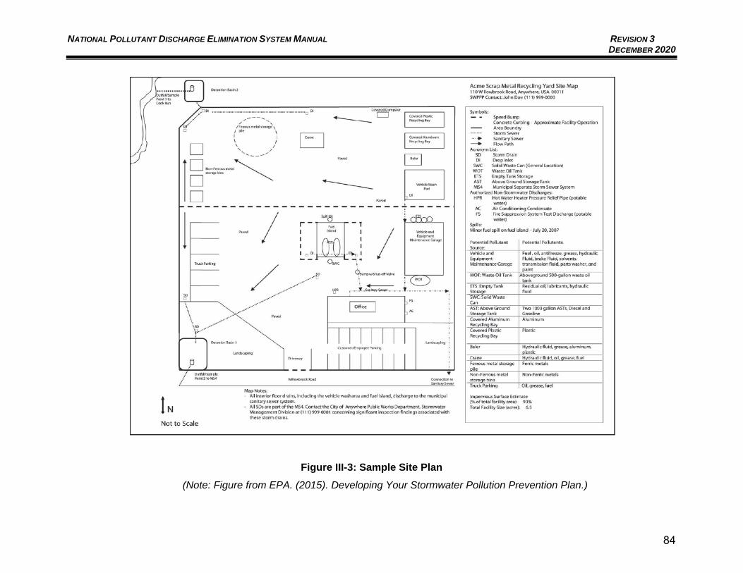
NATIONAL POLLUTANT DISCHARGE ELIMINATION SYSTEM MANUAL REVISION 3 DECEMBER 2020
84
Figure III-3: Sample Site Plan
(Note: Figure from EPA. (2015). Developing Your Stormwater Pollution Prevention Plan.)
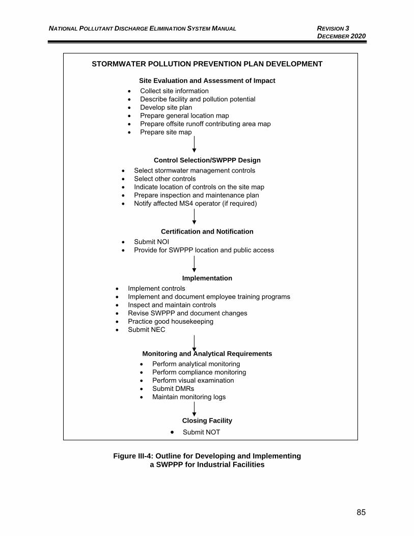
NATIONAL POLLUTANT DISCHARGE ELIMINATION SYSTEM MANUAL REVISION 3 DECEMBER 2020
85
STORMWATER POLLUTION PREVENTION PLAN DEVELOPMENT
Site Evaluation and Assessment of Impact
• Collect site information • Describe facility and pollution potential • Develop site plan • Prepare general location map • Prepare offsite runoff contributing area map • Prepare site map
Control Selection/SWPPP Design
• Select stormwater management controls • Select other controls • Indicate location of controls on the site map • Prepare inspection and maintenance plan • Notify affected MS4 operator (if required)
Certification and Notification
• Submit NOI • Provide for SWPPP location and public access
Implementation
• Implement controls • Implement and document employee training programs • Inspect and maintain controls • Revise SWPPP and document changes • Practice good housekeeping • Submit NEC
Monitoring and Analytical Requirements
• Perform analytical monitoring • Perform compliance monitoring • Perform visual examination • Submit DMRs • Maintain monitoring logs
Closing Facility
• Submit NOT
Figure III-4: Outline for Developing and Implementing a SWPPP for Industrial Facilities
NATIONAL POLLUTANT DISCHARGE ELIMINATION SYSTEM MANUAL REVISION 3 DECEMBER 2020
86
Signatory Requirements
The facility operator must sign the SWPPP. Operators are defined as those individuals having day-to-day operational control over activities that are necessary to ensure compliance with the SWPPP or having operational control over industrial activities, including the ability to make modifications to those activities. Operator changes or additions require the filing of a new NOI. The operator must sign a certification for the routine inspections (monthly, quarterly, etc.) and Comprehensive Site Compliance Evaluation reports.
If the operator is a corporation, a responsible corporate officer must sign the SWPPP. If
the operator is a partnership or sole proprietorship, a general partner or the sole proprietor must sign the forms. For any governmental entity, the signing person must be a principal executive official or ranking elected official. The signatory requirements apply to both paper/hard-copy and electronic submittals.
Approval Process
The SWPPP is retained at the industrial facility office and is to be available for inspection and review by EPA and affected state, local, and public entities. The SWPPP is intended to be a dynamic document that will be changed, modified, and updated as site conditions change. The permittee is required to amend the SWPPP whenever there is a change in design, operation, or maintenance that affects the potential for discharge of pollutants, or if the SWPPP is found to be ineffective. If the plan does not meet Permit conditions of EPA or an appropriate state or local agency, the operator has seven (7) days to provide certification that the requested changes have been made.
The SWPPP has no formal approval process other than its continued usefulness in
pollution prevention at the industrial facility.
No Exposure Certification (NEC)
A facility that can demonstrate no exposure to stormwater by the industrial activity can file an NEC form, which may exempt the facility from MSGP coverage requirements. A discussion of the process for a NEC for exclusion from the MSGP is found in Appendix K of the MSGP. Electronic reporting also applies NEC forms.
Annual Reporting
The facility operator must submit an Annual Report to EPA electronically, per Part 7.2 of the MSGP, by January 30th for each year of Permit coverage containing information generated from the past calendar year. The Annual Report for Stormwater Discharge associated with Industrial Activity Under the NPDES MSGP is found in Appendix I of the MSGP. Appendix I of the MSGP provides the paper version of an Annual Report form which is allowed only with a waiver from EPA. Otherwise, NeT online submittal of Annual Reports is required. The Annual Report must include the following information:
• A summary of the past calendar year’s routine facility inspection documentation required;
• A summary of the past calendar year’s quarterly visual assessment documentation required;
NATIONAL POLLUTANT DISCHARGE ELIMINATION SYSTEM MANUAL REVISION 3 DECEMBER 2020
87
• A summary of the past calendar year’s corrective action and any required documentation. If corrective action or additional implementation measures (AIM) responses are not completed at the time of submittal, the status of any outstanding corrective action(s) or AIM responses must be described. Also describe any incidents of noncompliance in the past year or any incidents currently ongoing; if none, provide a statement that the permittee is in compliance with the Permit;
• For any four-sample (minimum) average benchmark monitoring exceedance, if after reviewing the selection, design, installation, and implementation of control measures and considering whether any modifications are necessary to meet the effluent limits in the Permit, it is determined that no further pollutant reductions are technologically available and economically practicable and achievable in light of best industry practice, provide rationale as why no further reductions are achievable; and
• The Annual Report must also include a statement, signed and certified in accordance with the signatory requirements outlined in Appendix B of the MSGP, Subsection 11.
Electronic reporting of monitoring data is required. All monitoring data collected must be
submitted to EPA using EPA’s NetDMR system at www.epa.gov/netdmr - unless a waiver from electronic reporting has been granted. If a waiver has been granted, the permittee may submit a paper DMR form, no later than 30 days after the complete laboratory results for all monitoring outfalls for the reporting period have been received. Monitoring requirements (e.g, parameters required to be monitored and sample frequency) will be prepopulated on the electronic DMR form based on the information reported on the NOI through the NDPES Electronic Reporting Tool (NeT).
Document Retention
All Permit related documents (NOIs, NECs, NOTs, SWPPP, Annual Reports, and DMRs) must be retained on-site for the duration of permitted activities and are subject to the three (3) year record-keeping requirement mentioned in the MSGP, see Part 7.8.e. All records must be retained for a period of at least three (3) years from the date that your coverage under the Permit expires or is terminated.
III.E. BEST MANAGEMENT PRACTICES FOR INDUSTRIAL ACTIVITIES
As mentioned previously, there are specific BMP requirements identified in the MSGP regulations (see Part 8 of the MSGP), which are separate and distinct requirements from BMPs that might be necessary for pollution prevention activities. The most effective control measure in an industrial setting is to prevent activities and materials (vehicle washing and fueling, paint, oil and grease, etc.) and other potential pollutants from coming into contact with rainfall or stormwater runoff. Example BMPs are found in Appendix A of this Manual.
NATIONAL POLLUTANT DISCHARGE ELIMINATION SYSTEM MANUAL REVISION 3 DECEMBER 2020
88
III.F. NOTICE OF TERMINATION
Description
The operator of a facility may file an NOT if and when:
• A new owner or operator has taken over responsibility for the facility.
• Operations have ceased at the facility, meaning that there are not or no longer will be discharges of stormwater associated with industrial activity from the facility, and the facility has already implemented necessary sediment and erosion controls; or
• The facility obtained coverage under an individual or alternative general permit for all discharges required to be covered by an NPDES permit.
Submit the NOT
The information required on the NOT is similar to that on the NOI. The NOT must be submitted to EPA using EPA’s NetDMR system (www.epa.gov/netdmr) unless a waiver for submitting a paper copy has been granted. The NOT must include the MSGP Permit number that was assigned to the industrial facility by EPA after the submittal of the NOI. The NOT also requires a certification that the operator is no longer authorized to discharge stormwater from the industrial facility. The certification states that the NOT does not release an operator from liability for any violation of the MSGP or the CWA.
Blank copies of the NOT form and instructions can be obtained by:
• Downloading the form from EPA’s website - check for the latest version at https://www.epa.gov/npdes/stormwater-discharges-industrial-activities
• Downloading the form from NeT-MSGP, go to https://cdxnodengn.epa.gov/net-msgp/action/login
The facility operator must file the NOT. Refer to Section III.C.3 in this Manual for signatory
requirements.
APPENDIX A – BEST MANAGEMENT PRACTICES
(BMPs)
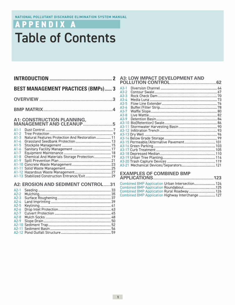
1
NATIONAL POLLUTANT DISCHARGE ELIMINATION SYSTEM MANUAL
A P P E N D I X A
Table of Contents
INTRODUCTION .................................................... 2
BEST MANAGEMENT PRACTICES (BMPS) ...... 3
OVERVIEW .........................................................3
BMP MATRIX ......................................................4
A1: CONSTRUCTION PLANNING, MANAGEMENT AND CLEANUP .......................5A1-1 Dust Control .......................................................................... 7A1-2 Tree Protection ..................................................................... 9A1-3 Natural Features Protection And Restoration ................ 11A1-4 Grassland Seedbank Protection ....................................... 13A1-5 Stockpile Management ...................................................... 15A1-6 Sanitary Facility Management .......................................... 17A1-7 Equipment Maintenance .................................................... 18A1-8 Chemical And Materials Storage Protection ................... 19A1-9 Spill Prevention Plan ......................................................... 21A1-10 Concrete Waste Management ........................................... 23A1-11 Solid Waste Management .................................................. 25A1-12 Hazardous Waste Management ........................................ 27A1-13 Stabilized Construction Entrance/Exit ............................ 29
A2: EROSION AND SEDIMENT CONTROL .....31A2-1 Seeding ................................................................................ 33A2-2 Mulching............................................................................... 35A2-3 Surface Roughening ........................................................... 37A2-4 Land Imprinting .................................................................. 39A2-5 Keylining .............................................................................. 41A2-6 Drop Inlet Protection .......................................................... 43A2-7 Culvert Protection .............................................................. 45A2-8 Mulch Socks ........................................................................ 48A2-9 Slope Drain .......................................................................... 50A2-10 Sediment Trap ..................................................................... 52A2-11 Sediment Basin ................................................................... 56A2-12 Pond Outfall Structure ....................................................... 59
A3: LOW IMPACT DEVELOPMENT AND POLLUTION CONTROL ....................................62A3-1 Diversion Channel .............................................................. 64A3-2 Contour Swale ..................................................................... 67A3-3 Rock Check Dam ................................................................. 70A3-4 Media Luna .......................................................................... 73A3-5 Flow Line Extender ............................................................. 76A3-6 Buffer/Filter Strip............................................................... 78A3-7 Waffle Slope ......................................................................... 80A3-8 Live Wattle ........................................................................... 82A3-9 Detention Basin ................................................................... 84A3-10 Bio(Retention) Swale .......................................................... 86A3-11 Stormwater Harvesting Basin .......................................... 90A3-12 Infiltration Trench ............................................................... 93A3-13 Dry Well ................................................................................ 96A3-14 Below Grade Storage .......................................................... 99A3-15 Permeable/Alternative Pavement .................................. 101A3-16 Green Parking .................................................................... 103A3-17 Curb Treatment ................................................................. 105A3-18 Depressed Median ............................................................. 110A3-19 Urban Tree Planting.......................................................... 114A3-20 Trash Capture Devices ..................................................... 119A3-21 Mechanical Devices/Separators ..................................... 121
EXAMPLES OF COMBINED BMP APPLICATIONS ...............................................123Combined BMP Application Urban Intersection ....................... 124Combined BMP Application Roundabout ............................. ......125Combined BMP Application Rural Roadway ............................. 126Combined BMP Application Highway Interchange .................. 127
2
NATIONAL POLLUTANT DISCHARGE ELIMINATION SYSTEM MANUAL
A P P E N D I X A
Introduction
The Best Management Practices (BMPs) summarized on the following pages are intended to provide NMDOT personnel, consultants, and contractors with a range of options for reducing or eliminating air and water pollution resulting from transportation-related construction activities in New Mexico. From fugitive dust to accidental discharges of fuels or lubricants, construction activities and post-construction uses can be major sources of pollution that, if left untreated, eventually end up in rivers, lakes, or groundwater. Appendix A includes a broad sampling of proven techniques collected from local, regional, and national sources that can be used in various combinations to help meet National Pollutant Discharge Elimination System (NPDES) requirements for developing a Stormwater Pollution Prevention Plan (SWPPP) in the short term, as well as offering longer term solutions to meet MS4 pollution control requirements.
Since the introduction of the NPDES program under the Clean Water Act of 1972, an entire industry has sprung up to try to simplify the process of addressing its requirements. Over time, those mitigation measures have become increasingly standardized, using largely off-the-shelf products. Unfortunately, many of those products - such as silt fence - are not biodegradable, so if they are not removed upon completion of a project (as is often the case) they become eyesores at best, and potential sources of pollution themselves. At the same time, the design of traditional (“gray”) drainage infrastructure has perpetuated the approach of collecting and moving stormwater away from roadways and the built environment as quickly as possible. Those conventional collection systems often discharge untreated, pollutant-laden, storm runoff directly into local drainageways and water bodies.
In contrast, the BMPs illustrated here include a variety of green stormwater infrastructure (GSI) solutions that treat stormwater as a resource that can increase environmental sustainability while achieving regulatory compliance. A GSI/Low Impact Development (LID) approach more closely mimics nature by capturing water further up the stormwater chain, slowing and spreading it so that it can be used by plants, filtered and cleaned, and encouraged to infiltrate into the ground before it makes its way into waterways and aquifers. Additional derivative benefits from this approach can include reduced localized flooding; increases in vegetation and tree canopies, which in turn help reduce the heat island effect and provide improved wildlife and migratory bird habitat; and improving the overall visual character of communities.
As presented in this appendix, the BMPs are fairly general in nature, and should be supported by sound engineering judgement. Designers should ensure that proposed BMPs will not conflict with other design features – such as through potential inundation of nearby underground utility boxes or structural subgrades. Nonetheless, while the BMPs include both traditional engineering solutions along with newer GSI/LID techniques, designers are encouraged to consider a GSI/LID approach first, and revert to more traditional practices only as a last resort.
It should also be noted that a different kind of management and maintenance regime will accompany some of these newer BMPs. Just as runoff is captured higher up in the watershed in a more decentralized manner, maintenance will also need to be conducted in a more dispersed manner and on a smaller scale, at those points of capture. Both designers and user agencies should be cognizant of those differing requirements and associated costs, which may include both equipment and training.

3
OVERVIEW
NATIONAL POLLUTANT DISCHARGE ELIMINATION SYSTEM MANUAL
A P P E N D I X A
Best Management Practices (BMPs)
Appendix A includes 46 Best Management Practices (BMPs) which are divided into three overall categories:
A1: CONSTRUCTION PLANNING, MANAGEMENT AND CLEAN UPBMPs included in the Construction Planning, Management and Clean Up category are related to site and natural features protection, management, and good housekeeping. These BMPs typically occur in all construction phases of a project. Several of these BMPs are also applicable to stormwater management for industrial facilities.
A2: EROSION AND SEDIMENT CONTROLThe Erosion and Sediment Control category includes BMPs addressing protection from erosion and sedimentation. These BMPs are typically included during site preparation and construction and can serve as both short and long term protection from erosion. The included BMPs are suitable for both rural and urban conditions.
A3: LOW IMPACT DEVELOPMENT AND POLLUTION CONTROL The Low Impact Development and Pollution Control category features BMPs ranging from low-scale intervention to elaborate techniques. Several BMPs in this category are considered part of Green Stormwater Infrastructure (GSI) principles. Several listed BMPs are specifically developed to fit urban conditions.
The BMP Matrix (page 4) includes a complete listing of all BMP’s in this Manual. The matrix is designed to function as a dashboard - a selection tool that facilitates quick BMP comparisons for application (urban or rural), general cost, maintenance level, and where it is typically applied in the construction process. There are additional Function Overview tables at the beginning of each category A1-A3 that provide information on typical BMP application and targeted constituents designed to address.
Each BMP sheet includes the following information:
» Description - describes the BMP . » Primary Use - lists where and why to use the BMP. » Application - describes how to use the BMP and what are the main design consideration.
» Limitations - list any major limitations. » Maintenance Requirements - outline main steps needed to maintain the BMP.
The descriptive information is followed by graphics in a plan view, section view, and/or isometric view, where applicable. The shown graphics are schematic in nature and not intended to be construction drawings. Actual installations should be designed by qualified personnel. NMDOT Standard Drawings are referenced where applicable.
EXAMPLES OF COMBINED BMP APPLICATIONSFollowing the individual BMP sheets, four examples are provided that show how some of these BMPs can be used effectively in various combinations. The combined applications in this Manual focus on BMP applications within typical roadway projects.
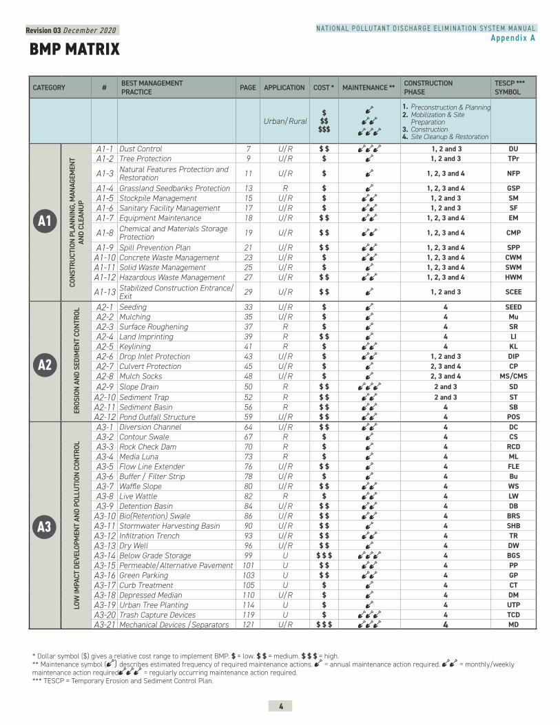
Revision 03 December 2020
4
N A T I O N A L P O L L U T A N T D I S C H A R G E E L I M I N A T I O N S Y S T E M M A N U A LAppendix A
CATEGORY # BEST MANAGEMENT PRACTICE PAGE APPLICATION COST * MAINTENANCE ** CONSTRUCTION
PHASETESCP ***SYMBOL
Urban/Rural $
$$$$$
1. Preconstruction & Planning2. Mobilization & Site
Preparation3. Construction4. Site Cleanup & Restoration
CONS
TRU
CTIO
N PL
ANNI
NG, M
ANAG
EMEN
T AN
D CL
EANU
P
A1-1 Dust Control 7 U/R $ $ 1, 2 and 3 DUA1-2 Tree Protection 9 U/R $ 1, 2 and 3 TPr
A1-3 Natural Features Protection and Restoration 11 U/R $ 1, 2, 3 and 4 NFP
A1-4 Grassland Seedbanks Protection 13 R $ 1, 2, 3 and 4 GSPA1-5 Stockpile Management 15 U/R $ 1, 2 and 3 SMA1-6 Sanitary Facility Management 17 U/R $ 1, 2 and 3 SFA1-7 Equipment Maintenance 18 U/R $ $ 1, 2, 3 and 4 EM
A1-8 Chemical and Materials Storage Protection 19 U/R $ $ 1, 2, 3 and 4 CMP
A1-9 Spill Prevention Plan 21 U/R $ $ 1, 2, 3 and 4 SPPA1-10 Concrete Waste Management 23 U/R $ 1, 2, 3 and 4 CWMA1-11 Solid Waste Management 25 U/R $ 1, 2, 3 and 4 SWMA1-12 Hazardous Waste Management 27 U/R $ $ 1, 2, 3 and 4 HWM
A1-13 Stabilized Construction Entrance/Exit 29 U/R $ $ 1, 2 and 3 SCEE
ERO
SION
AND
SED
IMEN
T CO
NTRO
L A2-1 Seeding 33 U/R $ 4 SEEDA2-2 Mulching 35 U/R $ 4 MuA2-3 Surface Roughening 37 R $ 4 SRA2-4 Land Imprinting 39 R $ $ 4 LIA2-5 Keylining 41 R $ 4 KLA2-6 Drop Inlet Protection 43 U/R $ 1, 2 and 3 DIPA2-7 Culvert Protection 45 U/R $ 2, 3 and 4 CPA2-8 Mulch Socks 48 U/R $ 2, 3 and 4 MS/CMSA2-9 Slope Drain 50 R $ $ 2 and 3 SDA2-10 Sediment Trap 52 R $ $ 2 and 3 STA2-11 Sediment Basin 56 R $ $ 4 SBA2-12 Pond Outfall Structure 59 U/R $ $ 4 POS
LOW
IMPA
CT D
EVEL
OPM
ENT
AND
POLL
UTI
ON C
ONTR
OL
A3-1 Diversion Channel 64 U/R $ $ 4 DCA3-2 Contour Swale 67 R $ 4 CSA3-3 Rock Check Dam 70 R $ 4 RCDA3-4 Media Luna 73 R $ 4 MLA3-5 Flow Line Extender 76 U/R $ $ 4 FLEA3-6 Buffer / Filter Strip 78 U/R $ 4 BuA3-7 Waffle Slope 80 U/R $ $ 4 WSA3-8 Live Wattle 82 R $ 4 LWA3-9 Detention Basin 84 U/R $ $ 4 DBA3-10 Bio(Retention) Swale 86 U/R $ $ 4 BRSA3-11 Stormwater Harvesting Basin 90 U/R $ $ 4 SHBA3-12 Infiltration Trench 93 U/R $ $ 4 TRA3-13 Dry Well 96 U/R $ $ 4 DWA3-14 Below Grade Storage 99 U $ $ $ 4 BGSA3-15 Permeable/Alternative Pavement 101 U $ $ 4 PPA3-16 Green Parking 103 U $ $ 4 GPA3-17 Curb Treatment 105 U $ 4 CTA3-18 Depressed Median 110 U/R $ 4 DMA3-19 Urban Tree Planting 114 U $ 4 UTPA3-20 Trash Capture Devices 119 U $ 4 TCDA3-21 Mechanical Devices /Separators 121 U/R $ $ $ 4 MD
BMP MATRIX
A3
A2
A1
* Dollar symbol ($) gives a relative cost range to implement BMP. $ = low. $ $ = medium. $ $ $ = high.** Maintenance symbol ( ) describes estimated frequency of required maintenance actions. = annual maintenance action required. = monthly/weekly maintenance action required = regularly occurring maintenance action required.*** TESCP = Temporary Erosion and Sediment Control Plan.

5
BEST MANAGEMENT PRACTICESA1-1 Dust Control .............................................................. 7A1-2 Tree Protection ......................................................... 9A1-3 Natural Features Protection & Restoration 11A1-4 Grassland Seedbank Protection........................ 13A1-5 Stockpile Management......................................... 15A1-6 Sanitary Facility Management ........................... 17A1-7 Equipment Maintenance ...................................... 18A1-8 Chemical And Materials Storage Protection 19A1-9 Spill Prevention Plan ............................................ 21A1-10 Concrete Waste Management ............................ 23A1-11 Solid Waste Management ................................... 25A1-12 Hazardous Waste Management ........................ 27A1-13 Stabilized Construction Entrance/Exit ............ 29
NATIONAL POLLUTANT DISCHARGE ELIMINATION SYSTEM MANUAL
A P P E N D I X A 1
Construction Planning, Management and Cleanup
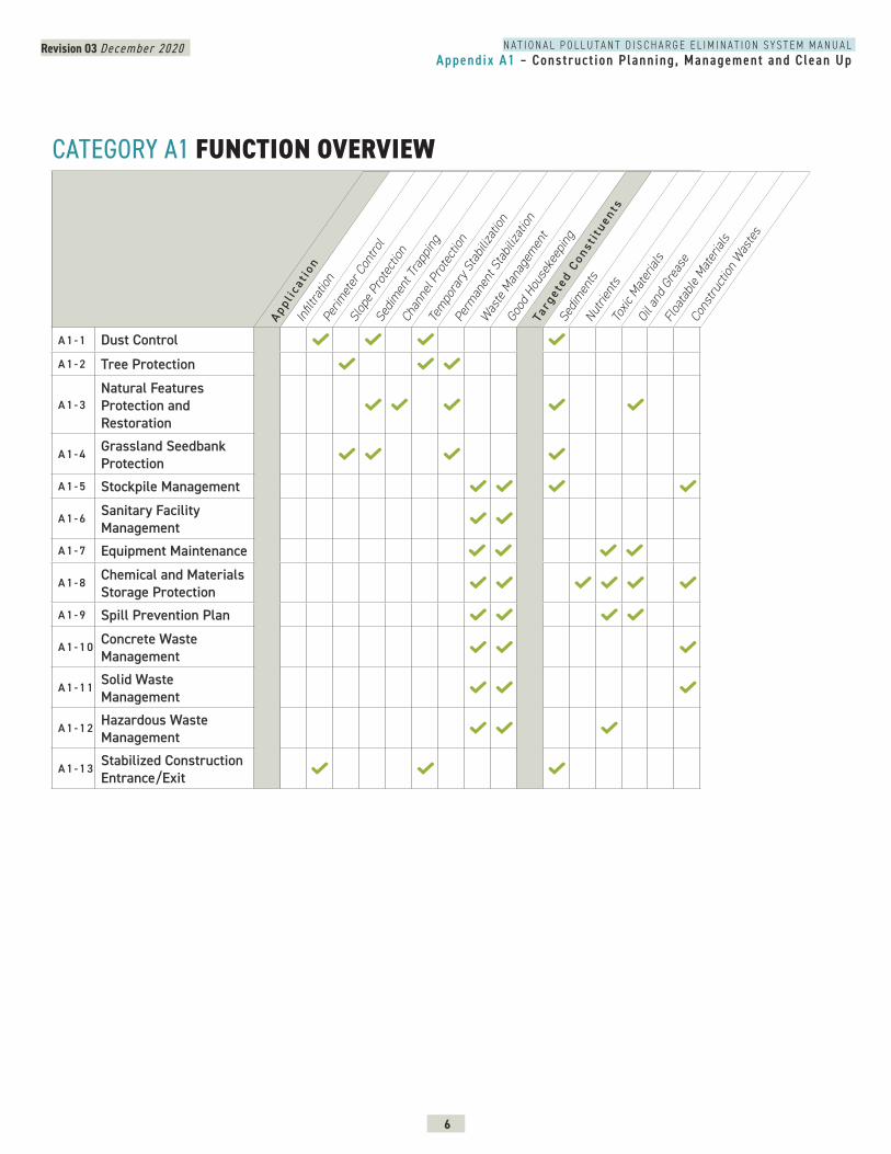
Revision 03 December 2020
6
N A T I O N A L P O L L U T A N T D I S C H A R G E E L I M I N A T I O N S Y S T E M M A N U A LAppendix A1 – Construct ion Planning, Management and Clean Up
CATEGORY A1 FUNCTION OVERVIEW
A 1 - 1 Dust ControlA 1 - 2 Tree Protection
A 1 - 3Natural Features Protection and Restoration
A 1 - 4 Grassland Seedbank Protection
A 1 - 5 Stockpile Management
A 1 - 6 Sanitary Facility Management
A 1 - 7 Equipment Maintenance
A 1 - 8 Chemical and Materials Storage Protection
A 1 - 9 Spill Prevention Plan
A 1 - 1 0 Concrete Waste Management
A 1 - 1 1 Solid Waste Management
A 1 - 1 2 Hazardous Waste Management
A 1 - 1 3 Stabilized Construction Entrance/Exit
Appl i
cat i
onIn
filtra
tion
Perim
eter
Con
trol
Slop
e Pro
tect
ion
Sedim
ent T
rapp
ing
Chan
nel P
rote
ction
Tem
pora
ry S
tabil
izatio
n
Perm
anen
t Sta
biliza
tion
Was
te M
anag
emen
t
Good
Hou
seke
epin
g
Targ
e ted
Con
s ti t
uents
Sedim
ents
Nutri
ents
Toxic
Mat
erial
sOi
l and
Gre
ase
Floa
tabl
e Mat
erial
s
Cons
truct
ion W
aste
s
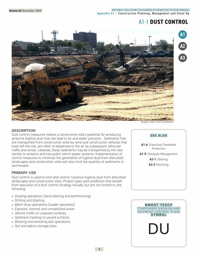
Revision 03 December 2020
7
N A T I O N A L P O L L U T A N T D I S C H A R G E E L I M I N A T I O N S Y S T E M M A N U A LAppendix A1 – Construct ion Planning, Management and Clean Up
A1-1 DUST CONTROL
A1
A3
N M D O T T E S C P ( T E M P O R A RY E R O S I O N A N D S E D I M E N T C O N T R O L P L A N )
SY M B O L
DESCRIPTION Dust control measures reduce a construction site’s potential for producing airborne fugitive dust that can lead to air and water pollution. Sediments that are transported from construction sites by wind and construction vehicles that have left the site, are often re-dispersed to the air by subsequent vehicular traffic and winds. Likewise, these sediments may be transported by the next rainfall to streams and into public storm sewer systems. Implementation of control measures to minimize the generation of fugitive dust from disturbed landscapes and construction sites will also limit the quantity of sediments in stormwater.
PRIMARY USEDust control is used to limit and control nuisance fugitive dust from disturbed landscapes and construction sites. Project types and conditions that benefit from execution of a dust control strategy include, but are not limited to, the following:
» Grading operations (land clearing and earthmoving). » Drilling and blasting. » Batch drop operations (loader operation). » Exposed, cleared, and unstabilized areas. » Vehicle traffic on unpaved surfaces. » Sediment tracking on paved surfaces. » Blasting and wrecking ball operations. » Soil and debris storage piles.
A2
Image credit: Sites Southwest
S E E A L S O
A1-4 Grassland Seedbank Protection
A1-5 Stockpile Management
A2-1 Seeding
A2-2 Mulching
DU
Revision 03 December 2020
8
N A T I O N A L P O L L U T A N T D I S C H A R G E E L I M I N A T I O N S Y S T E M M A N U A LAppendix A1 – Construct ion Planning, Management and Clean Up
A1-1 DUST CONTROL CONTINUEDAPPLICATIONDust control measures vary widely and should be selected alone or in combination for the specific project type, conditions, and resource availability. Dust control measures include, but are not limited to, the following: » Provide covers for trucks transporting materials that contribute dust. » Pave, apply gravel, vegetate or chemically stabilize large disturbed areas. » Immediately water disturbed areas. » Regularly water and dampen unstabilized areas.
Additionally, if the contractor is responsible for complying with the requirements of the air pollution control permit, the following is typically required:
» Provide dust control plans for construction or land-clearing projects. » Conduct enforcement activities with priority given to citizen complaints. » Conduct documentation of maintenance.
LIMITATIONS Some dust control measures may be of limited use due to lack of resources at the site, construction sequencing, and the need to repeatedly re-implement measures during the course of construction. Limitations may include:
» Access to water. » Availability of equipment. » Drought. » Frequent disturbance during construction.
MAINTENANCE REQUIREMENTS » Inspect stabilized soils for disturbance on a regular basis. » Wet soil and soils treated with stabilization agents. » Regrade and reapply soil stabilizing agents.
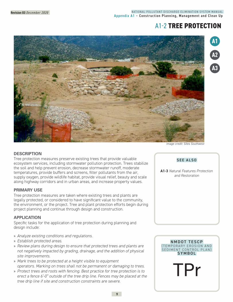
Revision 03 December 2020
9
N A T I O N A L P O L L U T A N T D I S C H A R G E E L I M I N A T I O N S Y S T E M M A N U A LAppendix A1 – Construct ion Planning, Management and Clean Up
A1-2 TREE PROTECTION
A3
DESCRIPTION Tree protection measures preserve existing trees that provide valuable ecosystem services, including stormwater pollution protection. Trees stabilize the soil and help prevent erosion, decrease stormwater runoff, moderate temperatures, provide buffers and screens, filter pollutants from the air, supply oxygen, provide wildlife habitat, provide visual relief, beauty and scale along highway corridors and in urban areas, and increase property values.
PRIMARY USETree protection measures are taken where existing trees and plants are legally protected, or considered to have significant value to the community, the environment, or the project. Tree and plant protection efforts begin during project planning and continue through design and construction.
APPLICATIONSpecific tasks for the application of tree protection during planning and design include:
» Analyze existing conditions and regulations. » Establish protected areas. » Review plans during design to ensure that protected trees and plants are not negatively impacted by grading, drainage, and the addition of physical site improvements.
» Mark trees to be protected at a height visible to equipment operators. Marking on trees shall not be permanent or damaging to trees.
» Protect trees and roots with fencing. Best practice for tree protection is to erect a fence 6’-0” outside of the tree drip line. Fences may be placed at the tree drip line if site and construction constraints are severe.
A1
A2
Image credit: Sites Southwest
N M D O T T E S C P ( T E M P O R A RY E R O S I O N A N D S E D I M E N T C O N T R O L P L A N )
SY M B O L
S E E A L S O
A1-3 Natural Features Protection and Restoration
TPr
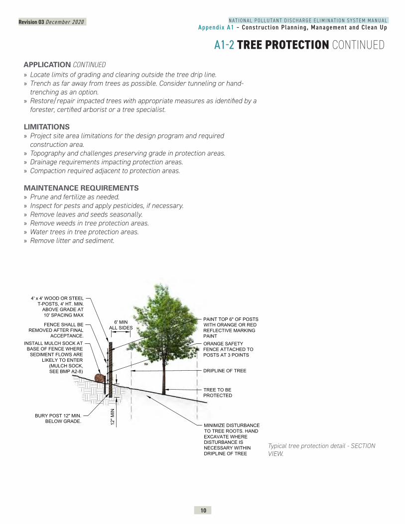
Revision 03 December 2020
10
N A T I O N A L P O L L U T A N T D I S C H A R G E E L I M I N A T I O N S Y S T E M M A N U A LAppendix A1 – Construct ion Planning, Management and Clean Up
A1-2 TREE PROTECTION CONTINUED
» Locate limits of grading and clearing outside the tree drip line. » Trench as far away from trees as possible. Consider tunneling or hand-trenching as an option.
» Restore/repair impacted trees with appropriate measures as identified by a forester, certified arborist or a tree specialist.
LIMITATIONS » Project site area limitations for the design program and required construction area.
» Topography and challenges preserving grade in protection areas. » Drainage requirements impacting protection areas. » Compaction required adjacent to protection areas.
MAINTENANCE REQUIREMENTS » Prune and fertilize as needed. » Inspect for pests and apply pesticides, if necessary. » Remove leaves and seeds seasonally. » Remove weeds in tree protection areas. » Water trees in tree protection areas. » Remove litter and sediment. -2
PAINT TOP 6" OF POSTSWITH ORANGE OR REDREFLECTIVE MARKINGPAINTORANGE SAFETYFENCE ATTACHED TOPOSTS AT 3 POINTS
6' MINALL SIDES
4' x 4' WOOD OR STEELT-POSTS, 4' HT. MIN.
ABOVE GRADE AT10' SPACING MAX
INSTALL MULCH SOCK ATBASE OF FENCE WHERE
SEDIMENT FLOWS ARELIKELY TO ENTER
(MULCH SOCK,SEE BMP A2-8)
BURY POST 12" MIN.BELOW GRADE. 12
" MIN
DRIPLINE OF TREE
FENCE SHALL BEREMOVED AFTER FINAL
ACCEPTANCE.
MINIMIZE DISTURBANCETO TREE ROOTS. HANDEXCAVATE WHEREDISTURBANCE ISNECESSARY WITHINDRIPLINE OF TREE
TREE TO BEPROTECTED
APPLICATION CONTINUED
Typical tree protection detail - SECTION VIEW.
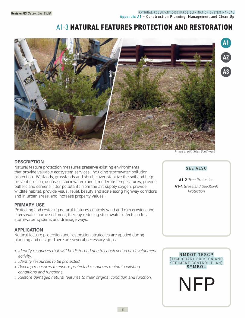
Revision 03 December 2020
11
N A T I O N A L P O L L U T A N T D I S C H A R G E E L I M I N A T I O N S Y S T E M M A N U A LAppendix A1 – Construct ion Planning, Management and Clean Up
A1-3 NATURAL FEATURES PROTECTION AND RESTORATION
A3
DESCRIPTION Natural feature protection measures preserve existing environments that provide valuable ecosystem services, including stormwater pollution protection. Wetlands, grasslands and shrub cover stabilize the soil and help prevent erosion, decrease stormwater runoff, moderate temperatures, provide buffers and screens, filter pollutants from the air, supply oxygen, provide wildlife habitat, provide visual relief, beauty and scale along highway corridors and in urban areas, and increase property values.
PRIMARY USEProtecting and restoring natural features controls wind and rain erosion, and filters water borne sediment, thereby reducing stormwater effects on local stormwater systems and drainage ways.
APPLICATIONNatural feature protection and restoration strategies are applied during planning and design. There are several necessary steps:
» Identify resources that will be disturbed due to construction or development activity.
» Identify resources to be protected. » Develop measures to ensure protected resources maintain existing conditions and functions.
» Restore damaged natural features to their original condition and function.
A1
A2
Image credit: Sites Southwest
N M D O T T E S C P ( T E M P O R A RY E R O S I O N A N D S E D I M E N T C O N T R O L P L A N )
SY M B O L
S E E A L S O
A1-2 Tree Protection
A1-4 Grassland Seedbank Protection
NFP
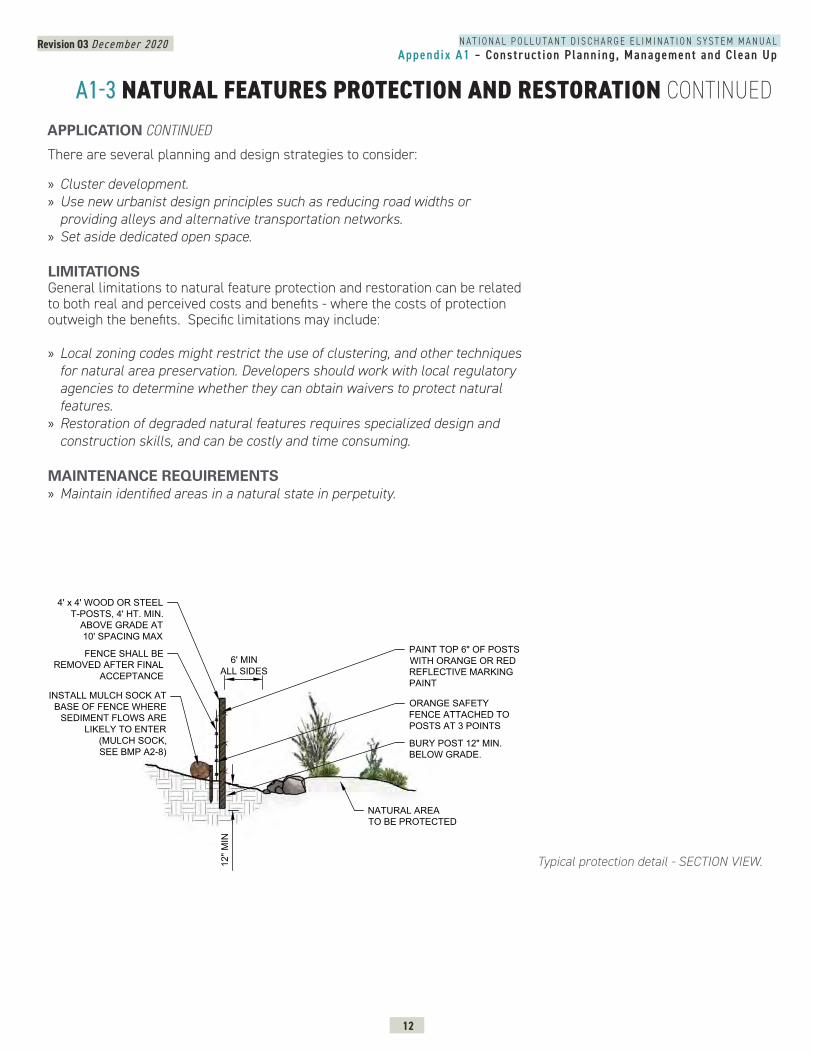
Revision 03 December 2020
12
N A T I O N A L P O L L U T A N T D I S C H A R G E E L I M I N A T I O N S Y S T E M M A N U A LAppendix A1 – Construct ion Planning, Management and Clean Up
A1-3 NATURAL FEATURES PROTECTION AND RESTORATION CONTINUED
There are several planning and design strategies to consider:
» Cluster development. » Use new urbanist design principles such as reducing road widths or providing alleys and alternative transportation networks.
» Set aside dedicated open space.
LIMITATIONSGeneral limitations to natural feature protection and restoration can be related to both real and perceived costs and benefits - where the costs of protection outweigh the benefits. Specific limitations may include:
» Local zoning codes might restrict the use of clustering, and other techniques for natural area preservation. Developers should work with local regulatory agencies to determine whether they can obtain waivers to protect natural features.
» Restoration of degraded natural features requires specialized design and construction skills, and can be costly and time consuming.
MAINTENANCE REQUIREMENTS » Maintain identified areas in a natural state in perpetuity.
Typical protection detail - SECTION VIEW.
NATURAL FEATURES PROTECTION AND RESTORATION - SECTION
PAINT TOP 6" OF POSTSWITH ORANGE OR REDREFLECTIVE MARKINGPAINT
6' MINALL SIDES
4' x 4' WOOD OR STEELT-POSTS, 4' HT. MIN.
ABOVE GRADE AT10' SPACING MAX
BURY POST 12" MIN.BELOW GRADE.
12" M
IN
NATURAL AREATO BE PROTECTED
ORANGE SAFETYFENCE ATTACHED TOPOSTS AT 3 POINTS
INSTALL MULCH SOCK ATBASE OF FENCE WHERE
SEDIMENT FLOWS ARELIKELY TO ENTER
(MULCH SOCK,SEE BMP A2-8)
FENCE SHALL BEREMOVED AFTER FINAL
ACCEPTANCE
-3
APPLICATION CONTINUED
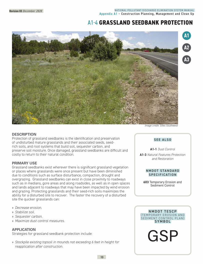
Revision 03 December 2020
13
N A T I O N A L P O L L U T A N T D I S C H A R G E E L I M I N A T I O N S Y S T E M M A N U A LAppendix A1 – Construct ion Planning, Management and Clean Up
A1-4 GRASSLAND SEEDBANK PROTECTION
DESCRIPTION Protection of grassland seedbanks is the identification and preservation of undisturbed mature grasslands and their associated seeds, seed-rich soils, and root systems that build soil, sequester carbon, and preserve soil moisture. Once damaged, grassland seedbanks are difficult and costly to return to their natural condition.
PRIMARY USEGrassland seedbanks exist wherever there is significant grassland vegetation or places where grasslands were once present but have been diminished due to conditions such as surface disturbance, compaction, drought and overgrazing. Grassland seedbanks can exist in close proximity to roadways such as in medians, gore areas and along roadsides, as well as in open spaces and lands adjacent to roadways that may have been impacted by wind erosion and grazing. Protecting grasslands and their seed-rich soils maximizes the ability for a disturbed site to recover. The faster the recovery of a disturbed site the quicker grasslands can:
» Decrease erosion. » Stabilize soil. » Sequester carbon. » Maximize dust control measures.
APPLICATIONStrategies for grassland seedbank protection include:
» Stockpile existing topsoil in mounds not exceeding 6 feet in height for reapplication after construction.
Image credit: Sites Southwest
A3
A1
A2
N M D O T T E S C P ( T E M P O R A RY E R O S I O N A N D S E D I M E N T C O N T R O L P L A N )
SY M B O L
S E E A L S O
A1-1 Dust Control
A1-3 Natural Features Protection and Restoration
N M D O T S TA N D A R D S P E C I F I C AT I O N
603 Temporary Erosion and Sediment Control
GSP
Revision 03 December 2020
14
N A T I O N A L P O L L U T A N T D I S C H A R G E E L I M I N A T I O N S Y S T E M M A N U A LAppendix A1 – Construct ion Planning, Management and Clean Up
A1-4 GRASSLAND SEEDBANK PROTECTION CONTINUED
» Cover stockpiled soil with filter fabric . » Limit heavy machinery on sub soils during construction. » Reapply stockpiled topsoil after tilling/roughening subsoil. » Conduct reseeding operations as determined by construction work.
LIMITATIONS » Project site area may be limited to accommodate the design program, required construction area, and protection areas.
» Stockpiling soils with existing seedbanks may be limited by laydown yard and construction staging area constraints.
MAINTENANCE REQUIREMENTS » Water and moisten stockpile of seedbank topsoil. » Mow native grass stands that were protected during construction in the fall and let stubble, seeds and stems remain.
» Weed site for a recommended maintenance period of one year. » Follow Stormwater Pollution Prevention Plan (SWPPP) requirements where applicable.
APPLICATION CONTINUED
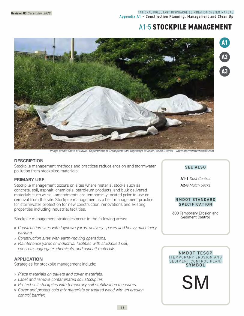
Revision 03 December 2020
15
N A T I O N A L P O L L U T A N T D I S C H A R G E E L I M I N A T I O N S Y S T E M M A N U A LAppendix A1 – Construct ion Planning, Management and Clean Up
A1-5 STOCKPILE MANAGEMENT
DESCRIPTION Stockpile management methods and practices reduce erosion and stormwater pollution from stockpiled materials.
PRIMARY USEStockpile management occurs on sites where material stocks such as concrete, soil, asphalt, chemicals, petroleum products, and bulk delivered materials such as soil amendments are temporarily located prior to use or removal from the site. Stockpile management is a best management practice for stormwater protection for new construction, renovations and existing properties including industrial facilities.
Stockpile management strategies occur in the following areas:
» Construction sites with laydown yards, delivery spaces and heavy machinery parking.
» Construction sites with earth-moving operations. » Maintenance yards or industrial facilities with stockpiled soil, concrete, aggregate, chemicals, and asphalt materials.
APPLICATIONStrategies for stockpile management include:
» Place materials on pallets and cover materials. » Label and remove contaminated soil stockpiles. » Protect soil stockpiles with temporary soil stabilization measures. » Cover and protect cold mix materials or treated wood with an erosion control barrier.
Image credit: State of Hawaii Department of Transportation, Highways Division, Oahu District - www.stormwaterhawaii.com
A3
A1
A2
N M D O T T E S C P ( T E M P O R A RY E R O S I O N A N D S E D I M E N T C O N T R O L P L A N )
SY M B O L
S E E A L S O
A1-1 Dust Control
A2-8 Mulch Socks
N M D O T S TA N D A R D S P E C I F I C AT I O N
603 Temporary Erosion and Sediment Control
SM
Revision 03 December 2020
16
N A T I O N A L P O L L U T A N T D I S C H A R G E E L I M I N A T I O N S Y S T E M M A N U A LAppendix A1 – Construct ion Planning, Management and Clean Up
A1-5 STOCKPILE MANAGEMENT CONTINUED
» Fence stockpile areas to limit wind-blown debris and applying perimeter erosion barriers.
» Limit temporarily stockpiled materials such as topsoil, compost and wood mulch to use within 48 hours after delivery.
» Cover, secure and protect long-term stockpiled materials (longer than 48 hours) from wind and water erosion.
» Install temporary erosion control measures such as mulch socks or staked hay bales around stockpiles.
LIMITATIONS » Site constraints may complicate strict adherence to measures. » Stockpile protection measures such as plastic tarps can increase runoff volumes.
» Stockpiles shall not be located in areas of concentrated stormwater flows and shall be a minimum of 50 feet away from all drainage inlets.
MAINTENANCE REQUIREMENTS » Inspect erosion control measures surrounding the stockpile areas according to the Stormwater Pollution Prevention Plan (SWPPP).
» Inspect stockpile areas and protection measures weekly and after storm events.
APPLICATION CONTINUED
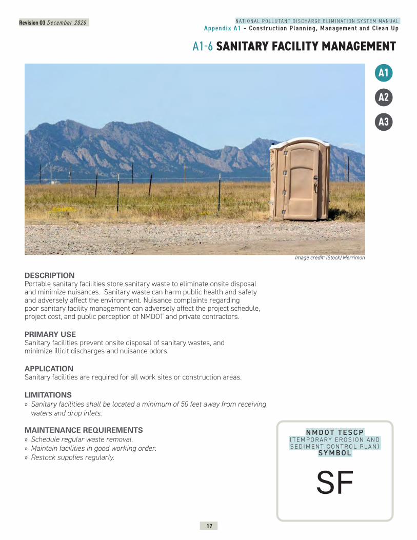
Revision 03 December 2020
17
N A T I O N A L P O L L U T A N T D I S C H A R G E E L I M I N A T I O N S Y S T E M M A N U A LAppendix A1 – Construct ion Planning, Management and Clean Up
A1-6 SANITARY FACILITY MANAGEMENT
DESCRIPTION Portable sanitary facilities store sanitary waste to eliminate onsite disposal and minimize nuisances. Sanitary waste can harm public health and safety and adversely affect the environment. Nuisance complaints regarding poor sanitary facility management can adversely affect the project schedule, project cost, and public perception of NMDOT and private contractors.
PRIMARY USESanitary facilities prevent onsite disposal of sanitary wastes, and minimize illicit discharges and nuisance odors.
APPLICATIONSanitary facilities are required for all work sites or construction areas.
LIMITATIONS » Sanitary facilities shall be located a minimum of 50 feet away from receiving waters and drop inlets.
MAINTENANCE REQUIREMENTS » Schedule regular waste removal. » Maintain facilities in good working order. » Restock supplies regularly.
Image credit: iStock/Merrimon
A3
A1
A2
N M D O T T E S C P ( T E M P O R A RY E R O S I O N A N D S E D I M E N T C O N T R O L P L A N )
SY M B O L
SF
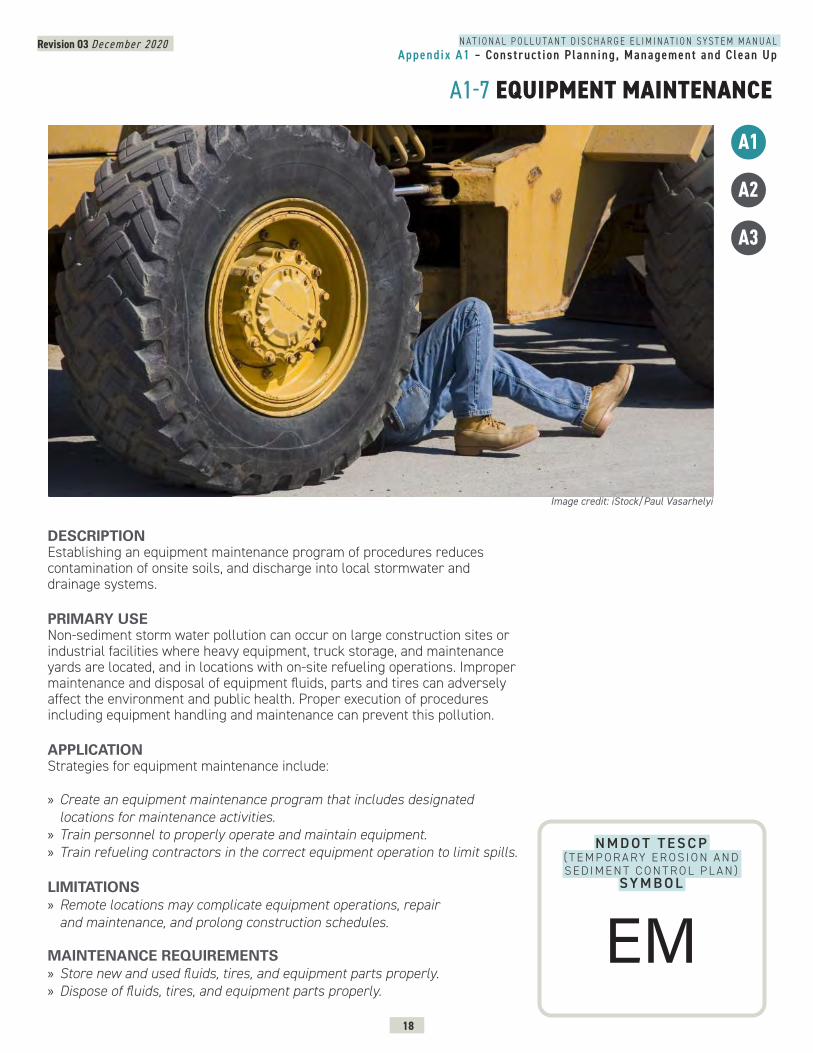
Revision 03 December 2020
18
N A T I O N A L P O L L U T A N T D I S C H A R G E E L I M I N A T I O N S Y S T E M M A N U A LAppendix A1 – Construct ion Planning, Management and Clean Up
A1-7 EQUIPMENT MAINTENANCE
DESCRIPTION Establishing an equipment maintenance program of procedures reduces contamination of onsite soils, and discharge into local stormwater and drainage systems.
PRIMARY USENon-sediment storm water pollution can occur on large construction sites or industrial facilities where heavy equipment, truck storage, and maintenance yards are located, and in locations with on-site refueling operations. Improper maintenance and disposal of equipment fluids, parts and tires can adversely affect the environment and public health. Proper execution of procedures including equipment handling and maintenance can prevent this pollution.
APPLICATIONStrategies for equipment maintenance include:
» Create an equipment maintenance program that includes designated locations for maintenance activities.
» Train personnel to properly operate and maintain equipment. » Train refueling contractors in the correct equipment operation to limit spills.
LIMITATIONS » Remote locations may complicate equipment operations, repair and maintenance, and prolong construction schedules.
MAINTENANCE REQUIREMENTS » Store new and used fluids, tires, and equipment parts properly. » Dispose of fluids, tires, and equipment parts properly.
Image credit: iStock/Paul Vasarhelyi
A3
A1
A2
N M D O T T E S C P ( T E M P O R A RY E R O S I O N A N D S E D I M E N T C O N T R O L P L A N )
SY M B O L
EM
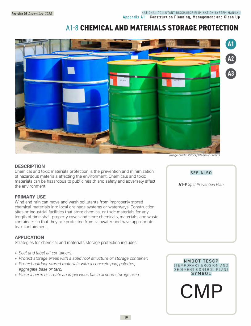
Revision 03 December 2020
19
N A T I O N A L P O L L U T A N T D I S C H A R G E E L I M I N A T I O N S Y S T E M M A N U A LAppendix A1 – Construct ion Planning, Management and Clean Up
A1-8 CHEMICAL AND MATERIALS STORAGE PROTECTION
DESCRIPTION Chemical and toxic materials protection is the prevention and minimization of hazardous materials affecting the environment. Chemicals and toxic materials can be hazardous to public health and safety and adversely affect the environment.
PRIMARY USEWind and rain can move and wash pollutants from improperly stored chemical materials into local drainage systems or waterways. Construction sites or industrial facilities that store chemical or toxic materials for any length of time shall properly cover and store chemicals, materials, and waste containers so that they are protected from rainwater and have appropriate leak containment.
APPLICATIONStrategies for chemical and materials storage protection includes:
» Seal and label all containers. » Protect storage areas with a solid roof structure or storage container. » Protect outdoor stored materials with a concrete pad, palettes, aggregate base or tarp.
» Place a berm or create an impervious basin around storage area.
Image credit: iStock/Vladimir Liverts
A3
A1
A2
N M D O T T E S C P ( T E M P O R A RY E R O S I O N A N D S E D I M E N T C O N T R O L P L A N )
SY M B O L
S E E A L S O
A1-9 Spill Prevention Plan
CMP
Revision 03 December 2020
20
N A T I O N A L P O L L U T A N T D I S C H A R G E E L I M I N A T I O N S Y S T E M M A N U A LAppendix A1 – Construct ion Planning, Management and Clean Up
A1-8 CHEMICAL AND MATERIALS STORAGE PROTECTION CONTINUED
Specific strategies for salt storage need to be applied to prevent the migration of salt into groundwater. Strategies include, but are not limited to:
» Pave the area directly outside the salt storage building. » Regularly sweep up salt outside salt storage. » Install perimeter controls outside salt storage areas.
LIMITATIONS » Chemical and materials storage areas shall not be located within the drip line of trees, in protected grasslands or natural areas to be preserved.
» Chemical and materials storage areas shall be located a minimum of 50 feet away from low-lying areas, drainage ways, receiving waters, and drop inlets.
MAINTENANCE REQUIREMENTS » Inspect storage protection areas weekly and after storm events. » Keep record of stored potential contaminants. » Remove concrete pad, solid covering and protective measures at construction closure.
APPLICATION CONTINUED
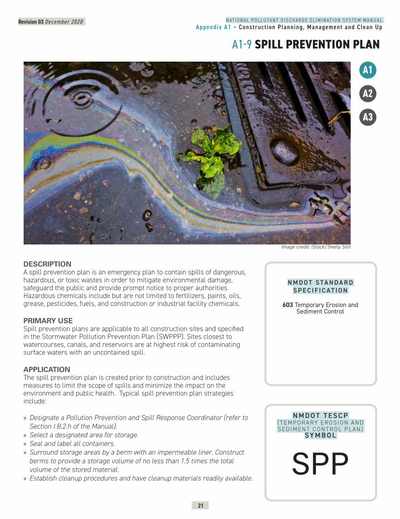
Revision 03 December 2020
21
N A T I O N A L P O L L U T A N T D I S C H A R G E E L I M I N A T I O N S Y S T E M M A N U A LAppendix A1 – Construct ion Planning, Management and Clean Up
A1-9 SPILL PREVENTION PLAN
DESCRIPTION A spill prevention plan is an emergency plan to contain spills of dangerous, hazardous, or toxic wastes in order to mitigate environmental damage, safeguard the public and provide prompt notice to proper authorities. Hazardous chemicals include but are not limited to fertilizers, paints, oils, grease, pesticides, fuels, and construction or industrial facility chemicals.
PRIMARY USESpill prevention plans are applicable to all construction sites and specified in the Stormwater Pollution Prevention Plan (SWPPP). Sites closest to watercourses, canals, and reservoirs are at highest risk of contaminating surface waters with an uncontained spill.
APPLICATIONThe spill prevention plan is created prior to construction and includes measures to limit the scope of spills and minimize the impact on the environment and public health. Typical spill prevention plan strategies include:
» Designate a Pollution Prevention and Spill Response Coordinator (refer to Section I.B.2.h of the Manual).
» Select a designated area for storage. » Seal and label all containers. » Surround storage areas by a berm with an impermeable liner. Construct berms to provide a storage volume of no less than 1.5 times the total volume of the stored material.
» Establish cleanup procedures and have cleanup materials readily available.
Image credit: iStock/Shelly Still
A3
A1
A2
N M D O T T E S C P ( T E M P O R A RY E R O S I O N A N D S E D I M E N T C O N T R O L P L A N )
SY M B O L
N M D O T S TA N D A R D S P E C I F I C AT I O N
603 Temporary Erosion and Sediment Control
SPP
Revision 03 December 2020
22
N A T I O N A L P O L L U T A N T D I S C H A R G E E L I M I N A T I O N S Y S T E M M A N U A LAppendix A1 – Construct ion Planning, Management and Clean Up
A1-9 SPILL PREVENTION PLAN CONTINUED
» Post cleanup procedures near where dangerous, hazardous or toxic materials are stored or used.
» Dispose of contaminated material in accordance with state or local requirements.
Other strategies for specific situations include:
» Small or incidental spills (<5 gallons): contain and clean the spill using facility personnel if they are able to do so without risking safety and injury.
» Large or reportable spills (> 5 gallons): clean the spill using emergency responders and/or clean up contractors. For releases of hazardous substances, the federal government has established Superfund Reportable Quantities (RQs).
» Releases of Hazardous Substances: if a hazardous substance is released to the environment in an amount that equals or exceeds its RQs, the release must be reported to federal authorities, unless certain reporting exemptions for hazardous substances releases also apply. Information on RQs can be found on the EPA website (https://www.epa.gov/epcra/cercla-and-epcra-continuous-release-reporting). In the event of a spill of a hazardous substance, notify the National Response Center (NRC) at (800) 424-8802, the New Mexico Environment Department (NMED) at (505) 827-9329, and the local fire department.
LIMITATIONS » No major limitations.
MAINTENANCE REQUIREMENTS » Inspect hazardous material storage areas frequently and after storm events. » Maintain storage areas in a clean and orderly fashion. » Maintain records of stored hazardous materials.
APPLICATION CONTINUED
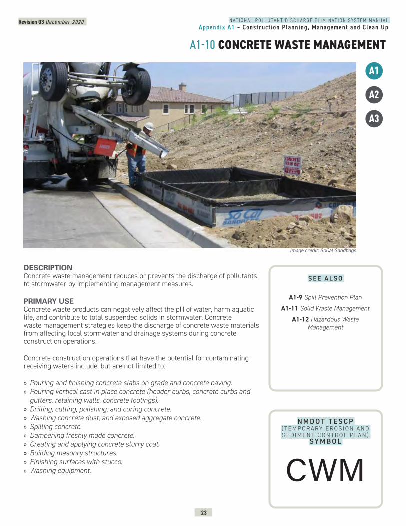
Revision 03 December 2020
23
N A T I O N A L P O L L U T A N T D I S C H A R G E E L I M I N A T I O N S Y S T E M M A N U A LAppendix A1 – Construct ion Planning, Management and Clean Up
A1-10 CONCRETE WASTE MANAGEMENT
DESCRIPTION Concrete waste management reduces or prevents the discharge of pollutants to stormwater by implementing management measures.
PRIMARY USEConcrete waste products can negatively affect the pH of water, harm aquatic life, and contribute to total suspended solids in stormwater. Concrete waste management strategies keep the discharge of concrete waste materials from affecting local stormwater and drainage systems during concrete construction operations.
Concrete construction operations that have the potential for contaminating receiving waters include, but are not limited to:
» Pouring and finishing concrete slabs on grade and concrete paving. » Pouring vertical cast in place concrete (header curbs, concrete curbs and gutters, retaining walls, concrete footings).
» Drilling, cutting, polishing, and curing concrete. » Washing concrete dust, and exposed aggregate concrete. » Spilling concrete. » Dampening freshly made concrete. » Creating and applying concrete slurry coat. » Building masonry structures. » Finishing surfaces with stucco. » Washing equipment.
Image credit: SoCal Sandbags
A3
A1
A2
N M D O T T E S C P ( T E M P O R A RY E R O S I O N A N D S E D I M E N T C O N T R O L P L A N )
SY M B O L
S E E A L S O
A1-9 Spill Prevention Plan
A1-11 Solid Waste Management
A1-12 Hazardous Waste Management
CWM
Revision 03 December 2020
24
N A T I O N A L P O L L U T A N T D I S C H A R G E E L I M I N A T I O N S Y S T E M M A N U A LAppendix A1 – Construct ion Planning, Management and Clean Up
A1-10 CONCRETE WASTE MANAGEMENT CONTINUED
APPLICATION Concrete waste management strategies include:
» Avoid mixing excess amounts of fresh concrete or cement onsite. » Perform washout of concrete trucks offsite or in designated areas on site at least 50 feet from storm drains, open ditches or bodies of water.
» Block drop inlets and direct concrete wastewater into temporary pits where the concrete can set, be broken up, and then disposed of properly.
» Collect and return sweepings to aggregate base stockpile or dispose of properly.
» Train employees and subcontractors in proper concrete waste management.
LIMITATIONS » Offsite washout of concrete wastes may not always be possible.
MAINTENANCE REQUIREMENTS » Ensure subcontractors properly manage concrete wastes. » Dispose of hardened concrete on a regular basis. » Regularly inspect drop inlet protection measures.
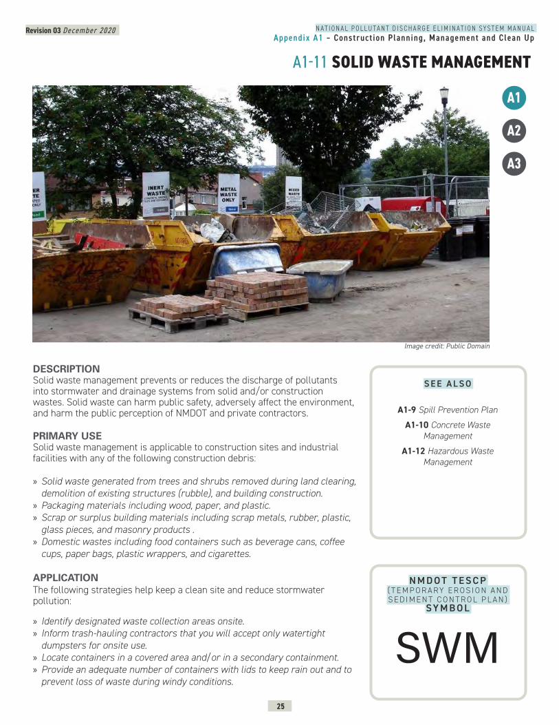
Revision 03 December 2020
25
N A T I O N A L P O L L U T A N T D I S C H A R G E E L I M I N A T I O N S Y S T E M M A N U A LAppendix A1 – Construct ion Planning, Management and Clean Up
A1-11 SOLID WASTE MANAGEMENT
DESCRIPTION Solid waste management prevents or reduces the discharge of pollutants into stormwater and drainage systems from solid and/or construction wastes. Solid waste can harm public safety, adversely affect the environment, and harm the public perception of NMDOT and private contractors. PRIMARY USESolid waste management is applicable to construction sites and industrial facilities with any of the following construction debris: » Solid waste generated from trees and shrubs removed during land clearing, demolition of existing structures (rubble), and building construction.
» Packaging materials including wood, paper, and plastic. » Scrap or surplus building materials including scrap metals, rubber, plastic, glass pieces, and masonry products .
» Domestic wastes including food containers such as beverage cans, coffee cups, paper bags, plastic wrappers, and cigarettes.
APPLICATIONThe following strategies help keep a clean site and reduce stormwater pollution:
» Identify designated waste collection areas onsite. » Inform trash-hauling contractors that you will accept only watertight dumpsters for onsite use.
» Locate containers in a covered area and/or in a secondary containment. » Provide an adequate number of containers with lids to keep rain out and to prevent loss of waste during windy conditions.
Image credit: Public Domain
A3
A1
A2
N M D O T T E S C P ( T E M P O R A RY E R O S I O N A N D S E D I M E N T C O N T R O L P L A N )
SY M B O L
S E E A L S O
A1-9 Spill Prevention Plan
A1-10 Concrete Waste Management
A1-12 Hazardous Waste Management
SWM
Revision 03 December 2020
26
N A T I O N A L P O L L U T A N T D I S C H A R G E E L I M I N A T I O N S Y S T E M M A N U A LAppendix A1 – Construct ion Planning, Management and Clean Up
A1-11 SOLID WASTE MANAGEMENT CONTINUED
» Plan for additional containers and more frequent pickup during the demolition phase of construction.
» Regularly and promptly remove solid waste from erosion and sediment control devices.
» Salvage or recycle useful material. » Clean dumpsters offsite. » Collect waste regularly and clean up spills immediately. » Train employees and subcontractors in proper solid waste management.
LIMITATIONS » No major limitations.
MAINTENANCE REQUIREMENTS » Collect site trash daily. » Inspect waste area regularly. » Arrange for regular waste collection. » Inspect dumpsters for leaks and repair or replace dumpsters that are not watertight.
APPLICATION CONTINUED
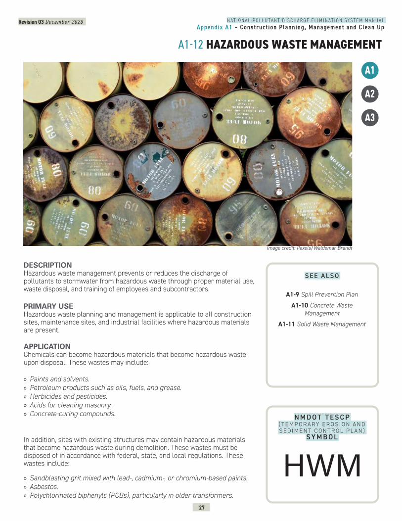
Revision 03 December 2020
27
N A T I O N A L P O L L U T A N T D I S C H A R G E E L I M I N A T I O N S Y S T E M M A N U A LAppendix A1 – Construct ion Planning, Management and Clean Up
A1-12 HAZARDOUS WASTE MANAGEMENT
DESCRIPTION Hazardous waste management prevents or reduces the discharge of pollutants to stormwater from hazardous waste through proper material use, waste disposal, and training of employees and subcontractors.
PRIMARY USE Hazardous waste planning and management is applicable to all construction sites, maintenance sites, and industrial facilities where hazardous materials are present.
APPLICATIONChemicals can become hazardous materials that become hazardous waste upon disposal. These wastes may include: » Paints and solvents. » Petroleum products such as oils, fuels, and grease. » Herbicides and pesticides. » Acids for cleaning masonry. » Concrete-curing compounds.
In addition, sites with existing structures may contain hazardous materials that become hazardous waste during demolition. These wastes must be disposed of in accordance with federal, state, and local regulations. These wastes include:
» Sandblasting grit mixed with lead-, cadmium-, or chromium-based paints. » Asbestos. » Polychlorinated biphenyls (PCBs), particularly in older transformers.
Image credit: Pexels/Waldemar Brandt
A3
A1
A2
N M D O T T E S C P ( T E M P O R A RY E R O S I O N A N D S E D I M E N T C O N T R O L P L A N )
SY M B O L
S E E A L S O
A1-9 Spill Prevention Plan
A1-10 Concrete Waste Management
A1-11 Solid Waste Management
HWM
Revision 03 December 2020
28
A1-12 HAZARDOUS WASTE MANAGEMENT CONTINUED
N A T I O N A L P O L L U T A N T D I S C H A R G E E L I M I N A T I O N S Y S T E M M A N U A LAppendix A1 – Construct ion Planning, Management and Clean Up
The following strategies will help reduce stormwater pollution from hazardous wastes:
Material Use » Use all of the product before disposing of the container. » Do not remove the original product label containing important safety and disposal information.
» Apply herbicides and pesticides correctly in the amounts recommended by the manufacturer and only apply the materials in the recommended temperature, wind, and humidity climate conditions.
» Clean brushes and containers in a clean out area. » Rinse water-based paints to the sanitary sewer. » Dispose of excess oil-based paints and sludge as hazardous waste and filter and reuse thinners and solvents.
Waste Recycling/Disposal » Identify designated hazardous waste collection areas onsite. » Store hazardous materials and waste in covered containers protected from vandalism or in a secondary containment.
» Dispose of waste separately - mixed waste can cause chemical reactions, make recycling impossible, and complicate disposal.
» Recycle any useful material such as used oil or water-based paint. » Make sure that toxic liquid wastes (used oils, solvents, paints) and chemicals (acids, pesticides, additives, curing compounds) are not disposed of in dumpsters designated for construction debris.
» Arrange for regular waste collection before containers overflow. » Collect, remove and dispose of hazardous waste (e.g. excess oil-based paint and sludges) at authorized disposal areas.
LIMITATIONS » A licensed hazardous waste hauler must dispose of hazardous waste that cannot be reused or recycled.
MAINTENANCE REQUIREMENTS » Inspect the hazardous waste area and receptacles regularly. » Collect hazardous waste regularly. » Train personnel about proper hazardous material use, storage, and disposal. » Keep record of stored potential contaminants.
APPLICATION CONTINUED
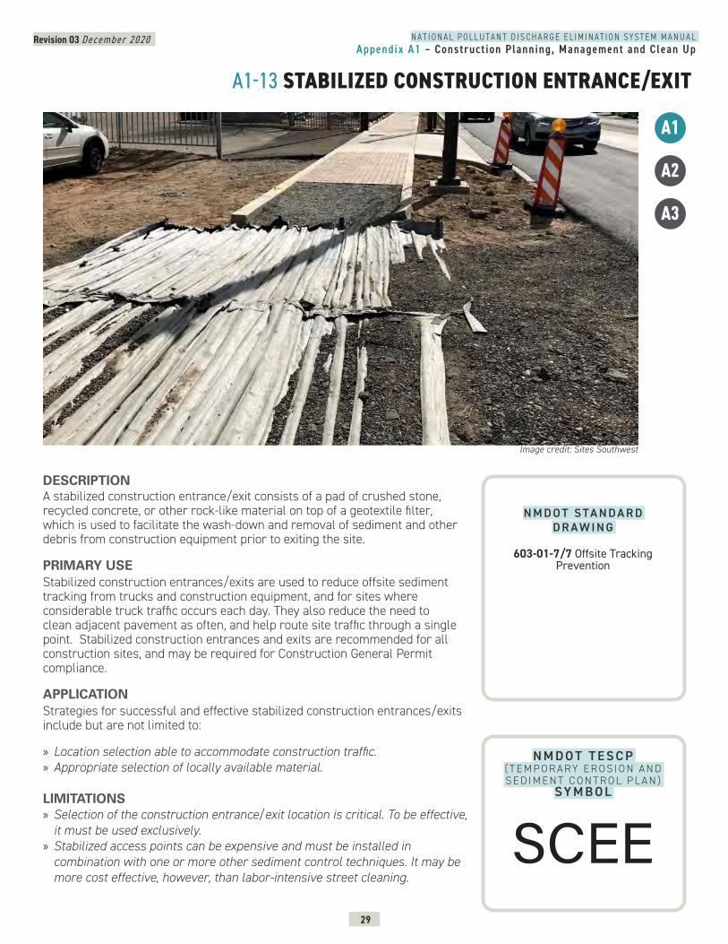
Revision 03 December 2020
29
N A T I O N A L P O L L U T A N T D I S C H A R G E E L I M I N A T I O N S Y S T E M M A N U A LAppendix A1 – Construct ion Planning, Management and Clean Up
A1-13 STABILIZED CONSTRUCTION ENTRANCE/EXIT
N M D O T T E S C P ( T E M P O R A RY E R O S I O N A N D S E D I M E N T C O N T R O L P L A N )
SY M B O L
DESCRIPTION A stabilized construction entrance/exit consists of a pad of crushed stone, recycled concrete, or other rock-like material on top of a geotextile filter, which is used to facilitate the wash-down and removal of sediment and other debris from construction equipment prior to exiting the site.
PRIMARY USEStabilized construction entrances/exits are used to reduce offsite sediment tracking from trucks and construction equipment, and for sites where considerable truck traffic occurs each day. They also reduce the need to clean adjacent pavement as often, and help route site traffic through a single point. Stabilized construction entrances and exits are recommended for all construction sites, and may be required for Construction General Permit compliance.
APPLICATIONStrategies for successful and effective stabilized construction entrances/exits include but are not limited to:
» Location selection able to accommodate construction traffic. » Appropriate selection of locally available material.
LIMITATIONS » Selection of the construction entrance/exit location is critical. To be effective, it must be used exclusively.
» Stabilized access points can be expensive and must be installed in combination with one or more other sediment control techniques. It may be more cost effective, however, than labor-intensive street cleaning.
Image credit: Sites Southwest
A3
A1
A2
N M D O T S TA N D A R D D R A W I N G
603-01-7/7 Offsite Tracking Prevention
SCEE
Revision 03 December 2020
30
N A T I O N A L P O L L U T A N T D I S C H A R G E E L I M I N A T I O N S Y S T E M M A N U A LAppendix A1 – Construct ion Planning, Management and Clean Up
A1-13 STABILIZED CONSTRUCTION ENTRANCE/EXIT CONTINUED
» Site constraints may limit the recommended 50 feet entrance/exit drive length.
MAINTENANCE REQUIREMENTS » Inspect the stabilized construction entrance after major storm events to ascertain sediment and pollution are being effectively captured on site. When sediment or debris has substantially clogged the void area between the rocks, the aggregate mat must be washed down or replaced.
» Re-grade and top dress stone periodically to retain the effectiveness of the entrance/exit.
LIMITATIONS CONTINUED
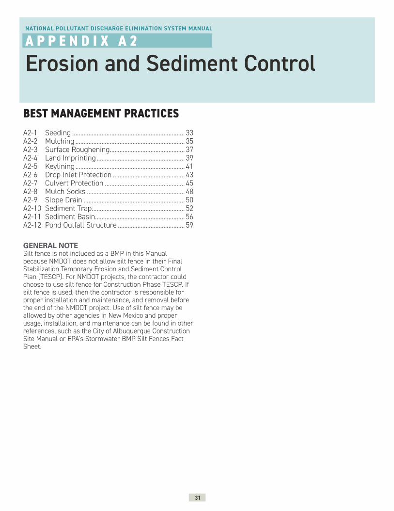
31
BEST MANAGEMENT PRACTICES
NATIONAL POLLUTANT DISCHARGE ELIMINATION SYSTEM MANUAL
A P P E N D I X A 2
Erosion and Sediment Control
A2-1 Seeding ..................................................................... 33A2-2 Mulching ................................................................... 35A2-3 Surface Roughening.............................................. 37A2-4 Land Imprinting ...................................................... 39A2-5 Keylining ................................................................... 41A2-6 Drop Inlet Protection ............................................ 43A2-7 Culvert Protection ................................................. 45A2-8 Mulch Socks ............................................................ 48A2-9 Slope Drain .............................................................. 50A2-10 Sediment Trap ......................................................... 52A2-11 Sediment Basin....................................................... 56A2-12 Pond Outfall Structure ......................................... 59
GENERAL NOTE Silt fence is not included as a BMP in this Manual because NMDOT does not allow silt fence in their Final Stabilization Temporary Erosion and Sediment Control Plan (TESCP). For NMDOT projects, the contractor could choose to use silt fence for Construction Phase TESCP. If silt fence is used, then the contractor is responsible for proper installation and maintenance, and removal before the end of the NMDOT project. Use of silt fence may be allowed by other agencies in New Mexico and proper usage, installation, and maintenance can be found in other references, such as the City of Albuquerque Construction Site Manual or EPA’s Stormwater BMP Silt Fences Fact Sheet.
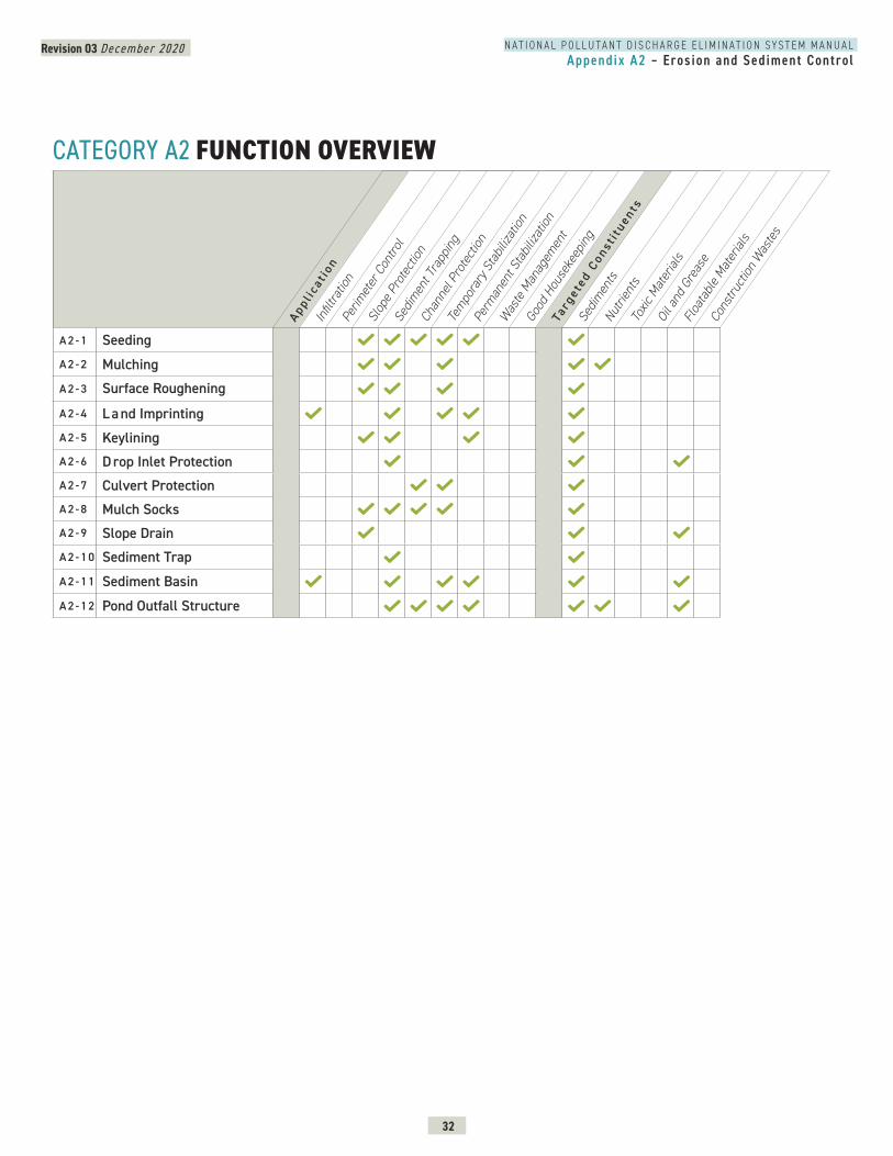
Revision 03 December 2020
32
N A T I O N A L P O L L U T A N T D I S C H A R G E E L I M I N A T I O N S Y S T E M M A N U A LAppendix A2 – Erosion and Sediment Control
CATEGORY A2 FUNCTION OVERVIEW
A 2 - 1 SeedingA 2 - 2 Mulching
A 2 - 3 Surface Roughening
A 2 - 4 L a nd ImprintingA 2 - 5 KeyliningA 2 - 6 D rop Inlet ProtectionA 2 - 7 Culvert ProtectionA 2 - 8 Mulch SocksA 2 - 9 Slope DrainA 2 - 1 0 Sediment Trap
A 2 - 1 1 Sediment Basin
A 2 - 1 2 Pond Outfall Structure
Appl i
cat i
onIn
filtra
tion
Perim
eter
Con
trol
Slop
e Pro
tect
ion
Sedim
ent T
rapp
ing
Chan
nel P
rote
ction
Tem
pora
ry S
tabil
izatio
n
Perm
anen
t Sta
biliza
tion
Was
te M
anag
emen
t
Good
Hou
seke
epin
g
Targ
e ted
Con
s ti t
uents
Sedim
ents
Nutri
ents
Toxic
Mat
erial
sOi
l and
Gre
ase
Floa
tabl
e Mat
erial
s
Cons
truct
ion W
aste
s
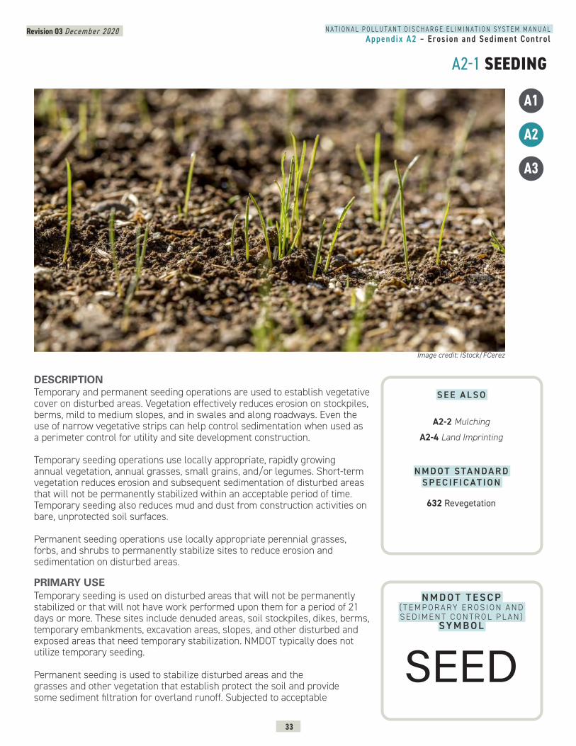
Revision 03 December 2020
33
N A T I O N A L P O L L U T A N T D I S C H A R G E E L I M I N A T I O N S Y S T E M M A N U A LAppendix A2 – Erosion and Sediment Control
A2-1 SEEDING
A1
A2
A3
N M D O T T E S C P ( T E M P O R A RY E R O S I O N A N D S E D I M E N T C O N T R O L P L A N )
SY M B O L
DESCRIPTION Temporary and permanent seeding operations are used to establish vegetative cover on disturbed areas. Vegetation effectively reduces erosion on stockpiles, berms, mild to medium slopes, and in swales and along roadways. Even the use of narrow vegetative strips can help control sedimentation when used as a perimeter control for utility and site development construction.
Temporary seeding operations use locally appropriate, rapidly growing annual vegetation, annual grasses, small grains, and/or legumes. Short-term vegetation reduces erosion and subsequent sedimentation of disturbed areas that will not be permanently stabilized within an acceptable period of time. Temporary seeding also reduces mud and dust from construction activities on bare, unprotected soil surfaces.
Permanent seeding operations use locally appropriate perennial grasses, forbs, and shrubs to permanently stabilize sites to reduce erosion and sedimentation on disturbed areas.
PRIMARY USETemporary seeding is used on disturbed areas that will not be permanently stabilized or that will not have work performed upon them for a period of 21 days or more. These sites include denuded areas, soil stockpiles, dikes, berms, temporary embankments, excavation areas, slopes, and other disturbed and exposed areas that need temporary stabilization. NMDOT typically does not utilize temporary seeding.
Permanent seeding is used to stabilize disturbed areas and the grasses and other vegetation that establish protect the soil and provide some sediment filtration for overland runoff. Subjected to acceptable
Image credit: iStock/FCerez
S E E A L S O
A2-2 Mulching
A2-4 Land Imprinting
N M D O T S TA N D A R D S P E C I F I C AT I O N
632 Revegetation
SEED
Revision 03 December 2020
34
N A T I O N A L P O L L U T A N T D I S C H A R G E E L I M I N A T I O N S Y S T E M M A N U A LAppendix A2 – Erosion and Sediment Control
A2-1 SEEDING CONTINUED
runoff velocities, seeding is an effective method of permanent stormwater management that can also serve as habitat and a visual amenity.
APPLICATIONPermanent vegetation techniques can and should apply to every construction project, with few exceptions. Seeding operations should be planned for when conditions are most favorable for germination and growth and on areas that are impacted by construction or maintenance disturbance. Strategies for successful seeding installations include the following:
Surface Preparation » Complete interim or final grading prior to seeding, minimizing steep slopes. » Install necessary erosion structures such as dikes, swales, diversions, etc. prior to seeding.
» Groove or furrow slopes steeper than 3:1 on the contour line before seeding. » Provide 4-6 inches of topsoil over rock, gravel, or otherwise unsuitable soils. » Ensure seedbed is well pulverized, loose, and uniform.
Seed Selection, Fertilization and Irrigation » Use only high quality, U.S. Department of Agriculture (USDA)-certified seed. » Use an appropriate species or species mix adapted to local climate, soil conditions, and season. Consult with the local Natural Resources Conservation Service (NRCS) office or local County Extension Service as necessary for selection of proper species and application techniques.
» Follow NRCS or Extension Service recommendations on seeding rates. » Apply fertilizer according to the manufacturer’s recommendation with proper spreading equipment. Typical application rate for 10-10-10 grade fertilizer is 700-1000 lb/acre. Do not overapply fertilizer.
» Do not mix seed and fertilizer more than 30 minutes before application, if using hydroseeding.
» Evenly apply seed using cyclone seeder, seed drill, cultipacker or hydroseeder.
» Provide adequate water to aid in establishment of vegetation. Consider establishing a temporary irrigation system if possible as it contributes to more successful germination.
» Use appropriate mulching techniques where necessary.
LIMITATIONS » Temporary seeding may not be an effective practice in arid and semi-arid regions where the climate prevents fast plant establishment. In those areas, or when seasonal planting restrictions prohibit seeding, temporary mulching may be a better short-term solution.
MAINTENANCE REQUIREMENTS » Inspect seeded areas for germination. » Reseed areas not germinating with additional seed as soon as possible. » Mow permanently seeded areas once a year leaving seeds and straw for soil protection.
PRIMARY USE CONTINUED
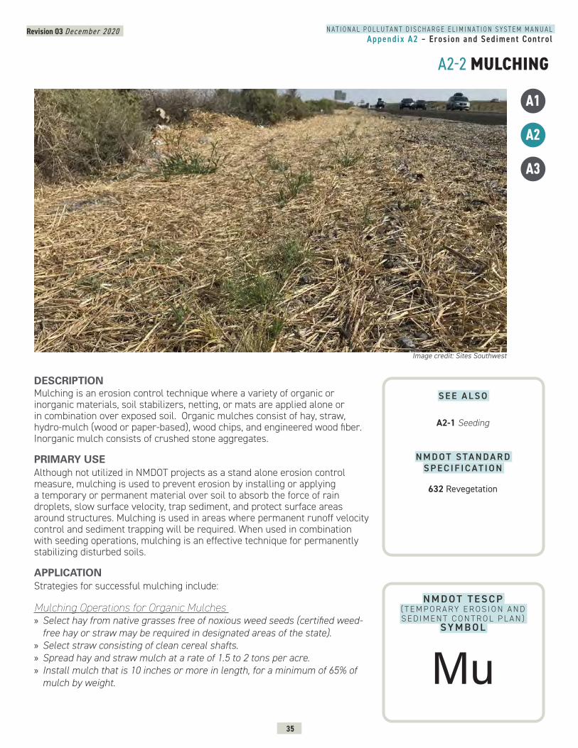
Revision 03 December 2020
35
N A T I O N A L P O L L U T A N T D I S C H A R G E E L I M I N A T I O N S Y S T E M M A N U A LAppendix A2 – Erosion and Sediment Control
A2-2 MULCHING
A1
A2
A3
N M D O T T E S C P ( T E M P O R A RY E R O S I O N A N D S E D I M E N T C O N T R O L P L A N )
SY M B O L
DESCRIPTION Mulching is an erosion control technique where a variety of organic or inorganic materials, soil stabilizers, netting, or mats are applied alone or in combination over exposed soil. Organic mulches consist of hay, straw, hydro-mulch (wood or paper-based), wood chips, and engineered wood fiber. Inorganic mulch consists of crushed stone aggregates.
PRIMARY USEAlthough not utilized in NMDOT projects as a stand alone erosion control measure, mulching is used to prevent erosion by installing or applying a temporary or permanent material over soil to absorb the force of rain droplets, slow surface velocity, trap sediment, and protect surface areas around structures. Mulching is used in areas where permanent runoff velocity control and sediment trapping will be required. When used in combination with seeding operations, mulching is an effective technique for permanently stabilizing disturbed soils.
APPLICATIONStrategies for successful mulching include:
Mulching Operations for Organic Mulches » Select hay from native grasses free of noxious weed seeds (certified weed-free hay or straw may be required in designated areas of the state).
» Select straw consisting of clean cereal shafts. » Spread hay and straw mulch at a rate of 1.5 to 2 tons per acre. » Install mulch that is 10 inches or more in length, for a minimum of 65% of mulch by weight.
Image credit: Sites Southwest
S E E A L S O
A2-1 Seeding
N M D O T S TA N D A R D S P E C I F I C AT I O N
632 Revegetation
Mu
Revision 03 December 2020
36
N A T I O N A L P O L L U T A N T D I S C H A R G E E L I M I N A T I O N S Y S T E M M A N U A LAppendix A2 – Erosion and Sediment Control
A2-2 MULCHING CONTINUED
» Apply organic mulches to depth required by drawings and specifications. The mulch should be uniformly applied so that no more than 10% of the soil surface is exposed.
» Anchor hay and straw mulch to the soil surface using tackifiers, blankets, or nets, or with a mulch-crimping machine. Mechanical anchoring, or crimping, is preferred and recommended for slopes flatter than 2:1. Blankets or nets on slopes steeper than 2:1 should be anchored to the soil.
» Use tackifiers (for anchoring) that consist of a free-flowing non-corrosive powder. This material shall not contain any mineral filler, recycled cellulose fiber, clays, or other substances that may inhibit germination or growth of plants.
» Apply tackifiers (for anchoring) in a slurry with water and wood fiber (100 lbs of powder and 150 lbs of fiber per 700 gallons of water). Application rate of powder should be between 80 and 200 lbs per acre.
Mulching Operations for Inorganic Mulches » Apply inorganic mulches to depth required by drawings and specifications.
LIMITATIONS » Use of organic mulches is not recommended in low-lying areas or areas with stormwater flows.
» Organic mulches can increase the germination of weeds and maintenance.
MAINTENANCE REQUIREMENTS » Replenish mulch in eroded areas.
APPLICATION CONTINUED

Revision 03 December 2020
37
N A T I O N A L P O L L U T A N T D I S C H A R G E E L I M I N A T I O N S Y S T E M M A N U A LAppendix A2 – Erosion and Sediment Control
A2-3 SURFACE ROUGHENING
N M D O T T E S C P ( T E M P O R A RY E R O S I O N A N D S E D I M E N T C O N T R O L P L A N )
SY M B O L
DESCRIPTION Surface roughening provides a rough soil surface with a series of horizontal ridges and depressions, running perpendicular to the slope, creating micro-environments for seeding and water infiltration. Slopes can be roughened by furrows or by stair cutting. Furrows are small depressions on slopes usually formed with by tilling operations. Stair cutting is a more aggressive steep slope roughening treatment that cuts steps into soil.
PRIMARY USESurface roughening is used to slow surface flow, increase material deposition, and trap water which encourages plant growth. Surface roughening is used on steep slopes prior to or in conjunction with seeding or mulching; and on slopes where seeding and mulching cannot be accomplished due to seasonal conditions or lack of water.
APPLICATIONStrategies for successful surface roughening include:
» Operate the machinery to leave horizontal depressions in the soil. » Make as few passes as possible to minimize compaction. » Seed and mulch roughened areas the same day.
LIMITATIONS » No major limitations.
Image credit: 4AG
A1
A2
A3
S E E A L S O
A2-4 Land Imprinting
N M D O T S TA N D A R D D R A W I N G
603-01-6/7 Surface Roughening
SR
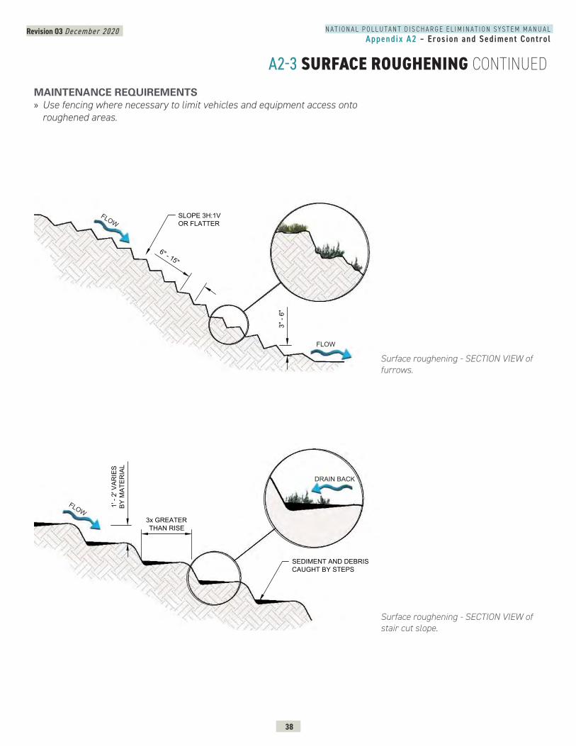
Revision 03 December 2020
38
N A T I O N A L P O L L U T A N T D I S C H A R G E E L I M I N A T I O N S Y S T E M M A N U A LAppendix A2 – Erosion and Sediment Control
A2-3 SURFACE ROUGHENING CONTINUED
Surface roughening - SECTION VIEW of furrows.
MAINTENANCE REQUIREMENTS » Use fencing where necessary to limit vehicles and equipment access onto roughened areas.
SURFACE ROUGHING - FURROWSSECTION
6" - 15"
3" -
6"
SLOPE 3H:1VOR FLATTER
FLOW
FLOW
SURFACE ROUGHING - STAIRCUT SLOPE SECTION
3x GREATERTHAN RISE
1' -
2' V
ARIE
SBY
MAT
ERIA
L
SEDIMENT AND DEBRISCAUGHT BY STEPS
DRAIN BACK
FLOW
Surface roughening - SECTION VIEW of stair cut slope.
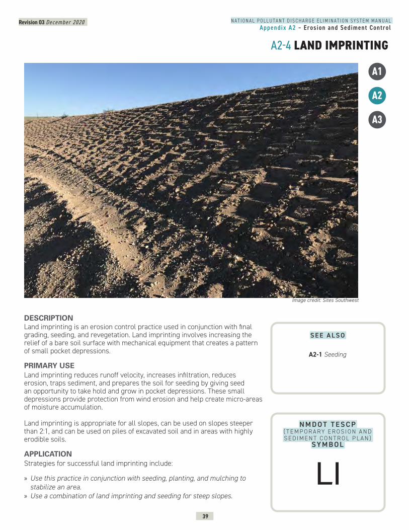
Revision 03 December 2020
39
N A T I O N A L P O L L U T A N T D I S C H A R G E E L I M I N A T I O N S Y S T E M M A N U A LAppendix A2 – Erosion and Sediment Control
A2-4 LAND IMPRINTING
A1
A2
A3
N M D O T T E S C P ( T E M P O R A RY E R O S I O N A N D S E D I M E N T C O N T R O L P L A N )
SY M B O L
DESCRIPTION Land imprinting is an erosion control practice used in conjunction with final grading, seeding, and revegetation. Land imprinting involves increasing the relief of a bare soil surface with mechanical equipment that creates a pattern of small pocket depressions.
PRIMARY USE Land imprinting reduces runoff velocity, increases infiltration, reduces erosion, traps sediment, and prepares the soil for seeding by giving seed an opportunity to take hold and grow in pocket depressions. These small depressions provide protection from wind erosion and help create micro-areas of moisture accumulation.
Land imprinting is appropriate for all slopes, can be used on slopes steeper than 2:1, and can be used on piles of excavated soil and in areas with highly erodible soils.
APPLICATIONStrategies for successful land imprinting include:
» Use this practice in conjunction with seeding, planting, and mulching to stabilize an area.
» Use a combination of land imprinting and seeding for steep slopes.
Image credit: Sites Southwest
S E E A L S O
A2-1 Seeding
LI
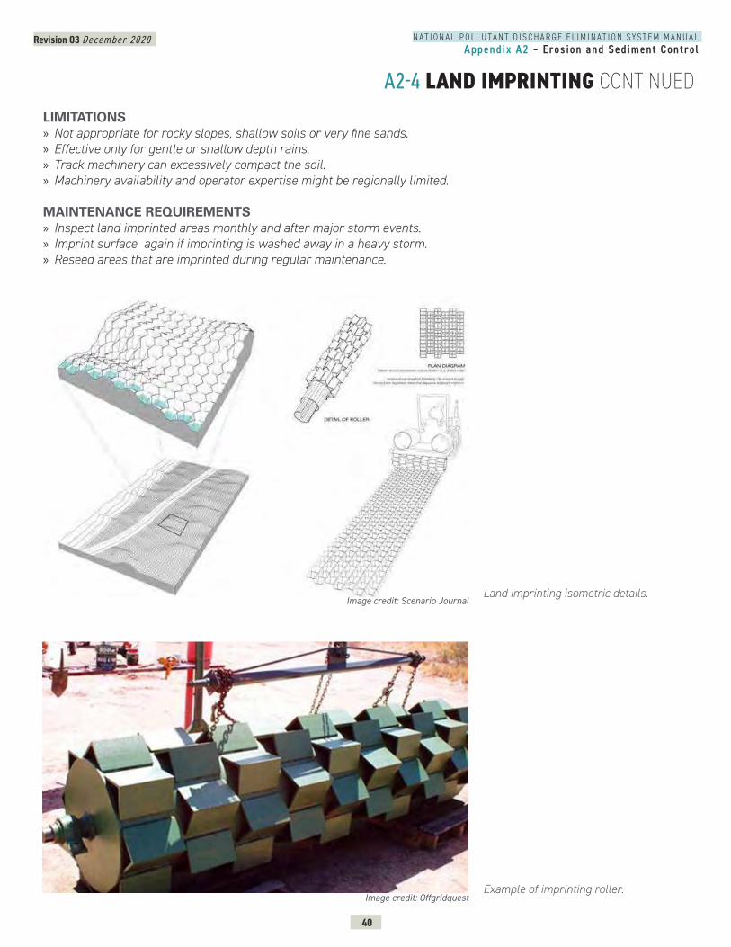
Revision 03 December 2020
40
N A T I O N A L P O L L U T A N T D I S C H A R G E E L I M I N A T I O N S Y S T E M M A N U A LAppendix A2 – Erosion and Sediment Control
A2-4 LAND IMPRINTING CONTINUEDLIMITATIONS » Not appropriate for rocky slopes, shallow soils or very fine sands. » Effective only for gentle or shallow depth rains. » Track machinery can excessively compact the soil. » Machinery availability and operator expertise might be regionally limited.
MAINTENANCE REQUIREMENTS » Inspect land imprinted areas monthly and after major storm events. » Imprint surface again if imprinting is washed away in a heavy storm. » Reseed areas that are imprinted during regular maintenance.
Image credit: Scenario Journal
Image credit: Offgridquest
Land imprinting isometric details.
Example of imprinting roller.
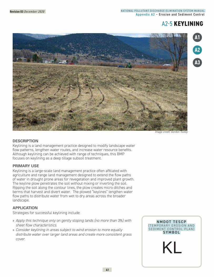
Revision 03 December 2020
41
N A T I O N A L P O L L U T A N T D I S C H A R G E E L I M I N A T I O N S Y S T E M M A N U A LAppendix A2 – Erosion and Sediment Control
A2-5 KEYLINING
A1
A2
A3
N M D O T T E S C P ( T E M P O R A RY E R O S I O N A N D S E D I M E N T C O N T R O L P L A N )
SY M B O L
DESCRIPTION Keylining is a land management practice designed to modify landscape water flow patterns, lengthen water routes, and increase water resource benefits. Although keylining can be achieved with range of techniques, this BMP focuses on keylining as a deep tillage subsoil treatment.
PRIMARY USEKeylining is a large-scale land management practice often affiliated with agriculture and range land management designed to extend the flow paths of water in drought prone areas for revegetation and improved plant growth. The keyline plow penetrates the soil without mixing or inverting the soil. Ripping the soil along the contour lines, the plow creates micro ditches and berms that harvest and divert water. The plowed “keylines” lengthen water flow paths to distribute water from wet to dry areas across the broader landscape.
APPLICATIONStrategies for successful keylining include:
» Apply this technique only on gently sloping lands (no more than 3%) with sheet flow characteristics.
» Consider keylining in areas subject to wind erosion to more equally distribute water over larger land areas and create more consistent grass cover.
Image credit: Gordon Tooley
KL
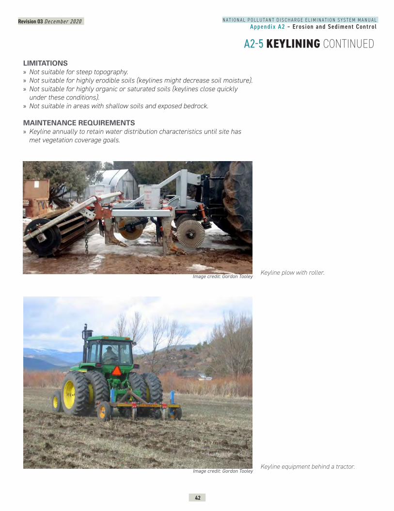
Revision 03 December 2020
42
N A T I O N A L P O L L U T A N T D I S C H A R G E E L I M I N A T I O N S Y S T E M M A N U A LAppendix A2 – Erosion and Sediment Control
A2-5 KEYLINING CONTINUED
Image credit: Gordon TooleyKeyline plow with roller.
LIMITATIONS » Not suitable for steep topography. » Not suitable for highly erodible soils (keylines might decrease soil moisture). » Not suitable for highly organic or saturated soils (keylines close quickly under these conditions).
» Not suitable in areas with shallow soils and exposed bedrock.
MAINTENANCE REQUIREMENTS » Keyline annually to retain water distribution characteristics until site has met vegetation coverage goals.
Image credit: Gordon TooleyKeyline equipment behind a tractor.
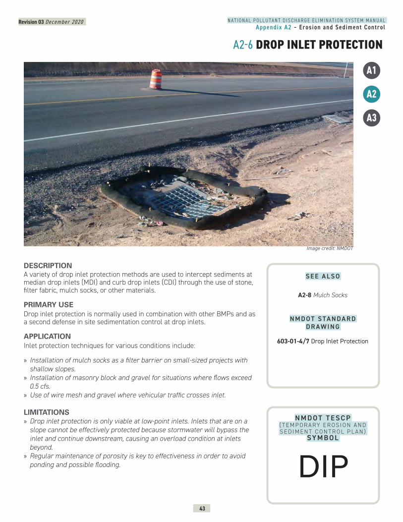
Revision 03 December 2020
43
N A T I O N A L P O L L U T A N T D I S C H A R G E E L I M I N A T I O N S Y S T E M M A N U A LAppendix A2 – Erosion and Sediment Control
A2-6 DROP INLET PROTECTION
A1
A2
A3
N M D O T T E S C P ( T E M P O R A RY E R O S I O N A N D S E D I M E N T C O N T R O L P L A N )
SY M B O L
DESCRIPTION A variety of drop inlet protection methods are used to intercept sediments at median drop inlets (MDI) and curb drop inlets (CDI) through the use of stone, filter fabric, mulch socks, or other materials.
PRIMARY USEDrop inlet protection is normally used in combination with other BMPs and as a second defense in site sedimentation control at drop inlets.
APPLICATIONInlet protection techniques for various conditions include:
» Installation of mulch socks as a filter barrier on small-sized projects with shallow slopes.
» Installation of masonry block and gravel for situations where flows exceed 0.5 cfs.
» Use of wire mesh and gravel where vehicular traffic crosses inlet.
LIMITATIONS » Drop inlet protection is only viable at low-point inlets. Inlets that are on a slope cannot be effectively protected because stormwater will bypass the inlet and continue downstream, causing an overload condition at inlets beyond.
» Regular maintenance of porosity is key to effectiveness in order to avoid ponding and possible flooding.
Image credit: NMDOT
S E E A L S O
A2-8 Mulch Socks
N M D O T S TA N D A R D D R A W I N G
603-01-4/7 Drop Inlet Protection
DIP
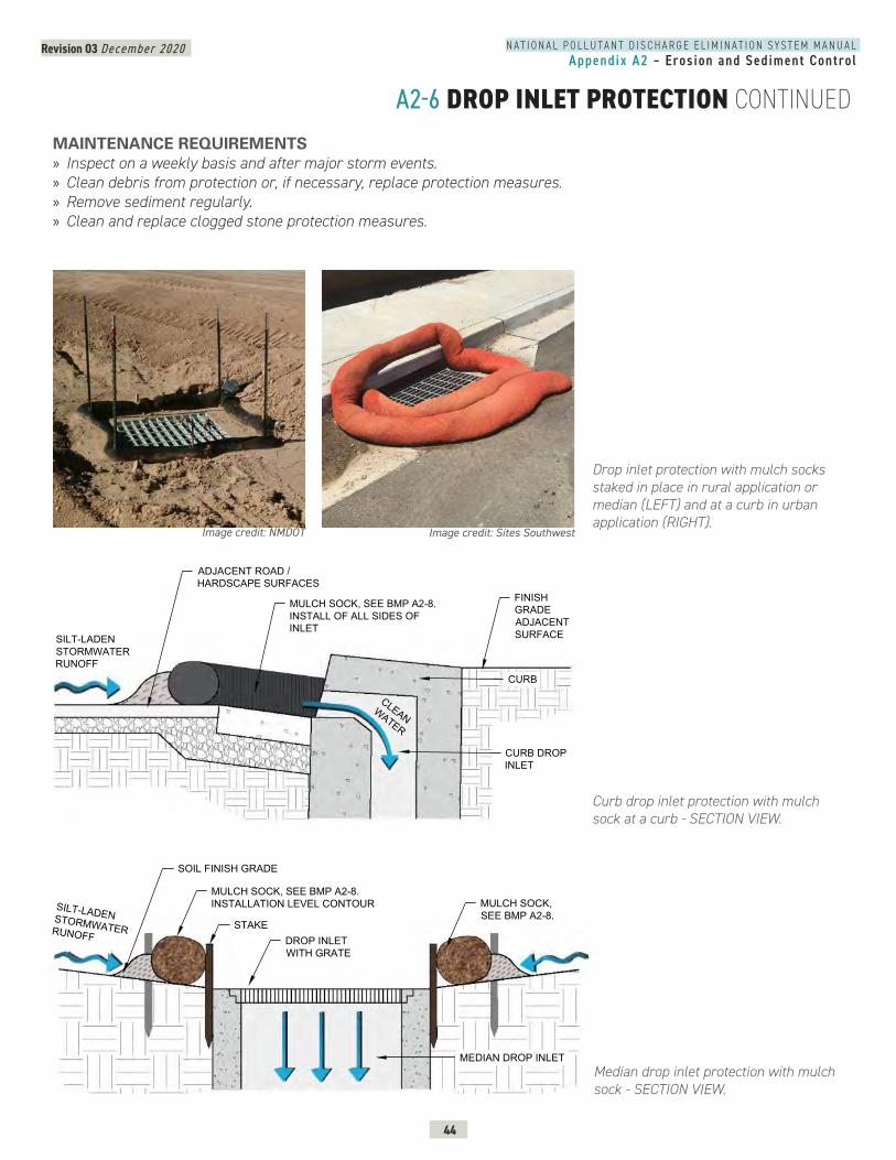
Revision 03 December 2020
44
N A T I O N A L P O L L U T A N T D I S C H A R G E E L I M I N A T I O N S Y S T E M M A N U A LAppendix A2 – Erosion and Sediment Control
A2-6 DROP INLET PROTECTION CONTINUEDMAINTENANCE REQUIREMENTS » Inspect on a weekly basis and after major storm events. » Clean debris from protection or, if necessary, replace protection measures. » Remove sediment regularly. » Clean and replace clogged stone protection measures.
Curb drop inlet protection with mulch sock at a curb - SECTION VIEW.
Median drop inlet protection with mulch sock - SECTION VIEW.
Drop inlet protection with mulch socks staked in place in rural application or median (LEFT) and at a curb in urban application (RIGHT).
MULCH SOCK, SEE BMP A2-8.INSTALL OF ALL SIDES OFINLET
ADJACENT ROAD /HARDSCAPE SURFACES
SILT-LADENSTORMWATERRUNOFF
CURB DROPINLET
DROP INLET PROTECTION WITH COMPOST MULCH SOCKS @ CURB
CURB
FINISHGRADEADJACENTSURFACE
CLEANWATER
DROP INLET PROTECTION WITH COMPOST MULCH SOCKS @ CURB
A2-6
STAKE
SOIL FINISH GRADE
MULCH SOCK, SEE BMP A2-8.INSTALLATION LEVEL CONTOUR
DROP INLETWITH GRATE
SILT-LADENSTORMWATERRUNOFF
MEDIAN DROP INLET
MEDIAN-TYPE DROP INLET PROTECTION WITH COMPOST MULCH SOCKS
MULCH SOCK,SEE BMP A2-8.
2-6
Image credit: Sites SouthwestImage credit: NMDOT
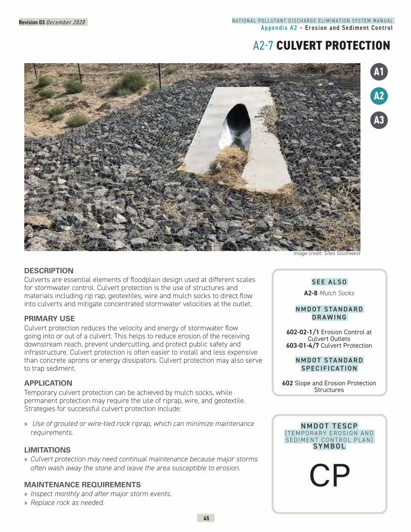
Revision 03 December 2020
45
N A T I O N A L P O L L U T A N T D I S C H A R G E E L I M I N A T I O N S Y S T E M M A N U A LAppendix A2 – Erosion and Sediment Control
A2-7 CULVERT PROTECTION
A1
A2
A3
N M D O T T E S C P ( T E M P O R A RY E R O S I O N A N D S E D I M E N T C O N T R O L P L A N )
SY M B O L
DESCRIPTION Culverts are essential elements of floodplain design used at different scales for stormwater control. Culvert protection is the use of structures and materials including rip rap, geotextiles, wire and mulch socks to direct flow into culverts and mitigate concentrated stormwater velocities at the outlet.
PRIMARY USECulvert protection reduces the velocity and energy of stormwater flow going into or out of a culvert. This helps to reduce erosion of the receiving downstream reach, prevent undercutting, and protect public safety and infrastructure. Culvert protection is often easier to install and less expensive than concrete aprons or energy dissipators. Culvert protection may also serve to trap sediment.
APPLICATIONTemporary culvert protection can be achieved by mulch socks, while permanent protection may require the use of riprap, wire, and geotextile. Strategies for successful culvert protection include:
» Use of grouted or wire-tied rock riprap, which can minimize maintenance requirements.
LIMITATIONS » Culvert protection may need continual maintenance because major storms often wash away the stone and leave the area susceptible to erosion.
MAINTENANCE REQUIREMENTS » Inspect monthly and after major storm events. » Replace rock as needed.
Image credit: Sites Southwest
S E E A L S O
A2-8 Mulch Socks
N M D O T S TA N D A R D D R A W I N G
602-02-1/1 Erosion Control at Culvert Outlets
603-01-4/7 Culvert Protection
N M D O T S TA N D A R D S P E C I F I C AT I O N
602 Slope and Erosion Protection Structures
CP
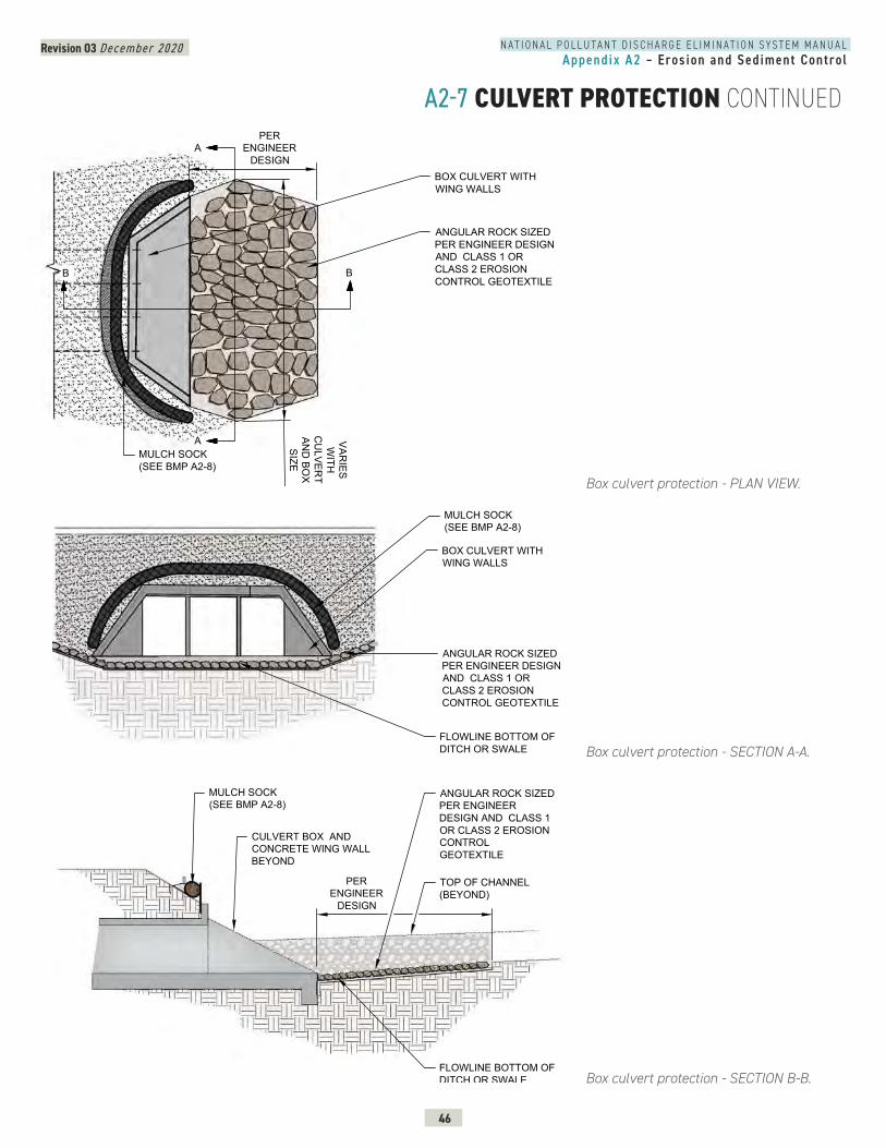
Revision 03 December 2020
46
N A T I O N A L P O L L U T A N T D I S C H A R G E E L I M I N A T I O N S Y S T E M M A N U A LAppendix A2 – Erosion and Sediment Control
A2-7 CULVERT PROTECTION CONTINUED
Box culvert protection - PLAN VIEW.
Box culvert protection - SECTION A-A.
Box culvert protection - SECTION B-B.
CULVERT PROTECTION PLAN VIEW - BOX CULVERT
BOX CULVERT WITHWING WALLS
PERENGINEER
DESIGN
VARIES
WITH
CU
LVERT
AND
BOX
SIZE
A
B
ANGULAR ROCK SIZEDPER ENGINEER DESIGNAND CLASS 1 ORCLASS 2 EROSIONCONTROL GEOTEXTILE
MULCH SOCK(SEE BMP A2-8)
B
A
-7
CULVERT PROTECTION SECTION AA - BOX CULVERT
MULCH SOCK(SEE BMP A2-8)
FLOWLINE BOTTOM OFDITCH OR SWALE
ANGULAR ROCK SIZEDPER ENGINEER DESIGNAND CLASS 1 ORCLASS 2 EROSIONCONTROL GEOTEXTILE
BOX CULVERT WITHWING WALLS
2-7
CULVERT BOX ANDCONCRETE WING WALLBEYOND
ANGULAR ROCK SIZEDPER ENGINEERDESIGN AND CLASS 1OR CLASS 2 EROSIONCONTROLGEOTEXTILE
PERENGINEER
DESIGN
MULCH SOCK(SEE BMP A2-8)
FLOWLINE BOTTOM OFDITCH OR SWALE
TOP OF CHANNEL(BEYOND)
2-7
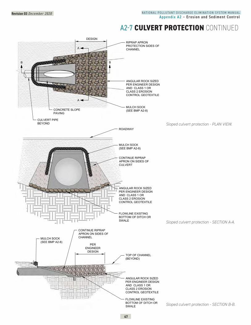
Revision 03 December 2020
47
N A T I O N A L P O L L U T A N T D I S C H A R G E E L I M I N A T I O N S Y S T E M M A N U A LAppendix A2 – Erosion and Sediment Control
A2-7 CULVERT PROTECTION CONTINUED
Sloped culvert protection - PLAN VIEW.
Sloped culvert protection - SECTION A-A.
Sloped culvert protection - SECTION B-B.
CULVERT PROTECTION PLAN VIEW - SLOPE PAVING
-7
PERENGINEER
DESIGN
A
BB
A
ANGULAR ROCK SIZEDPER ENGINEER DESIGNAND CLASS 1 ORCLASS 2 EROSIONCONTROL GEOTEXTILE
CULVERT PIPEBEYOND
RIPRAP APRONPROTECTION SIDES OFCHANNEL
CONCRETE SLOPEPAVING
MULCH SOCK(SEE BMP A2-8)
CULVERT PROTECTION SECTION AA - SLOPE PAVING
7
CONTINUE RIPRAPAPRON ON SIDES OFCULVERT
FLOWLINE EXISTINGBOTTOM OF DITCH ORSWALE
ANGULAR ROCK SIZEDPER ENGINEER DESIGNAND CLASS 1 ORCLASS 2 EROSIONCONTROL GEOTEXTILE
ROADWAY
MULCH SOCK(SEE BMP A2-8)
-7
ANGULAR ROCK SIZEDPER ENGINEER DESIGNAND CLASS 1 ORCLASS 2 EROSIONCONTROL GEOTEXTILE
PERENGINEER
DESIGN
FLOWLINE EXISTINGBOTTOM OF DITCH ORSWALE
CONTINUE RIPRAPAPRON ON SIDES OFCHANNEL
TOP OF CHANNEL(BEYOND)
MULCH SOCK(SEE BMP A2-8)
Revision 03 December 2020
48
N A T I O N A L P O L L U T A N T D I S C H A R G E E L I M I N A T I O N S Y S T E M M A N U A LAppendix A2 – Erosion and Sediment Control
A2-8 MULCH SOCKS
N M D O T T E S C P ( T E M P O R A RY E R O S I O N A N D S E D I M E N T C O N T R O L P L A N )
SY M B O L
DESCRIPTION Mulch socks are erosion and sediment control materials made typically of high density polyethylene (HDPE) or biodegradable plastic filament mesh tubes filled with compost or other organic media.
PRIMARY USEMulch socks are primarily used to filter and slow stormwater. Uses include:
» Filter sediment and silts from sheet stormwater flowing from disturbed sites.
» Protect inlets from sediment. » Create temporary ponding areas behind socks to facilitate the deposition of suspended solids.
» Slow stormwater runoff and reduce peak flows. » Filter heavy metals, pollutants and oil from stormwater when socks are filled with adsorbent media.
» Provide temporary protection at drop inlets or culverts. » Create check dams or sediment traps at concrete washout areas. » Provide perimeter control, runoff diversion, and slope interruption. » Reinforce stream banks and aid in the protection and establishment of stabilizing watercourse vegetation.
APPLICATIONStrategies for successful use of mulch socks include:
» Lay the sock upon the surface and stake the tube every 10 feet. » Lay the tube along contours, vegetated channels, and outside of the toes of slopes.
A1
A2
A3
Image credit: NMDOT
MS CMS
Revision 03 December 2020
49
N A T I O N A L P O L L U T A N T D I S C H A R G E E L I M I N A T I O N S Y S T E M M A N U A LAppendix A2 – Erosion and Sediment Control
A2-8 MULCH SOCKS CONTINUED
Mulch sock - PLAN VIEW.
Mulch sock - SECTION A-A.
LIMITATIONS » Mulch socks do not provide long-term solutions for stormwater storage. » Mulch socks have limited usefulness in concentrated flow conditions. » On NMDOT projects composted mulch socks (CMS) are used exclusively; wood chip mulch socks are not allowed.
MAINTENANCE REQUIREMENTS » Inspect mulch socks periodically, especially after major storm events. » Remove sediments from behind socks after accumulation is 1/3 sock height. » Restake and overlap socks that are displaced due to storm events or construction disturbance.
CKS - PLAN VIEW
PER
MAN
UFA
CTU
RER
MULCH SOCKINSTALL ONLEVEL CONTOUR
VARIESDEPENDENT ON SLOPE
STAKES (TYP.)
SOILSURFACE
INSTALLADDITIONALMULCH MATERIALTO FILL GAPBETWEENGROUND ANDSOCK
A A
FLOW
FLOW
VARIESDEPENDENT ON SLOPE
DOWNHILL STAKE
SOIL FINISHGRADE
INSTALL ADDITIONALMULCH MATERIAL TO FILLGAP BETWEEN GROUNDAND SOCK
MULCH SOCK.INSTALL ON LEVELCONTOUR
UPHILL STAKE(BEYOND)
FLOW
FLOW
Revision 03 December 2020
50
N A T I O N A L P O L L U T A N T D I S C H A R G E E L I M I N A T I O N S Y S T E M M A N U A LAppendix A2 – Erosion and Sediment Control
A2-9 SLOPE DRAIN
N M D O T T E S C P ( T E M P O R A RY E R O S I O N A N D S E D I M E N T C O N T R O L P L A N )
SY M B O L
DESCRIPTION A slope drain is a temporary pipeline that conveys flow from diversion channels, dikes, or other areas with concentrated flows down an unstabilized slope. The drain is anchored on the upstream end with a form of headwall and diversion dike to limit erosion and secure the pipe.
PRIMARY USESlope drains are used on long, unstabilized, steep slopes subject to erosion from overland flow. Slope drains are useful on sites with large berms or grade changes.
APPLICATIONStrategies for successful slope drain use include:
» Grade upstream area to ensure flow is directed into the slope drain. » Install a riprap apron or other energy dissipater at the outlet to reduce velocity and spread the flow.
» Direct flow from slope drain to a sediment trap or basin.
LIMITATIONS » Drains must be located away from construction areas, since the drain can easily be damaged by construction traffic.
» Securing the pipe to the slope can be difficult and require significant maintenance during the life of the system.
Image credit: Google Street View
A1
A2
A3
N M D O T S TA N D A R D D R A W I N G
603-01-6/7 Slope Drain
SD
Revision 03 December 2020
51
-9
INTERCEPTOR DIKE
STAKED ALONGSLOPE
STANDARD FLAREDPIPE END SECTIONCORRUGATED PIPE
WITH WATERTIGHTFITTINGS
RIPRAP APRONENERGY DISSIPATOR
12" MIN
EARTHWORKEMBANKMENT
4' MIN LESSTHAN 1%SLOPE
FLOW
N A T I O N A L P O L L U T A N T D I S C H A R G E E L I M I N A T I O N S Y S T E M M A N U A LAppendix A2 – Erosion and Sediment Control
A2-9 SLOPE DRAIN CONTINUED
» In situations where slope drains convey sediment-laden runoff, pipes can become clogged during major storm events, causing water to overtop the diversion dike and thereby creating a serious erosion condition.
» Grading is normally required upstream of the pipe slope drain in order to direct flow into the system. This can cause additional cost and maintenance.
» A pipe slope drain reduces erosion but does not prevent it or reduce the amount of sediment in the runoff. Additional measures should be used in conjunction with the pipe slope drain to treat the flow.
MAINTENANCE REQUIREMENTS » Inspect slope drain after (>0.5 inch) storm events to locate and repair any damage to joints or clogging of the pipe.
» Reinforce the dike with sandbags or install a concrete collar where the diversion channel has deteriorated from around the entrance of the pipe.
» Regrade and reconstruct drain if erosion occurs by stabilizing the area with erosion control mats, crushed stone, concrete, or other acceptable method.
Typical slope drain detail - SECTION VIEW.
Typical slope drain detail - ISOMETRIC VIEW.
LIMITATIONS CONTINUED
SLOPE DRAIN - APROX
-9
INTERCEPTOR DIKECOMPACTED TO 90%MOD PROCTORDENSITY
CORRUGATED PIPEWITH WATERTIGHTFITTINGS. STAKEALONG SLOPE
DISCHARGE TO ASTABILIZEDWATERCOURSE,SEDIMENT BASIN,RETENTION FACILITYOR RIPRAP PROTECTEDOUTLET
RIPRAP APRONENERGY DISSIPATOR
FLOW
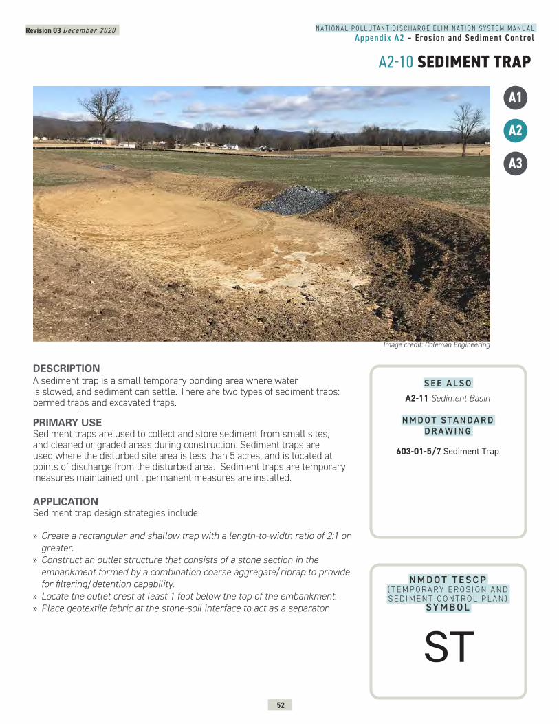
Revision 03 December 2020
52
N A T I O N A L P O L L U T A N T D I S C H A R G E E L I M I N A T I O N S Y S T E M M A N U A LAppendix A2 – Erosion and Sediment Control
A2-10 SEDIMENT TRAP
A1
A2
A3
N M D O T T E S C P ( T E M P O R A RY E R O S I O N A N D S E D I M E N T C O N T R O L P L A N )
SY M B O L
DESCRIPTION A sediment trap is a small temporary ponding area where water is slowed, and sediment can settle. There are two types of sediment traps: bermed traps and excavated traps.
PRIMARY USESediment traps are used to collect and store sediment from small sites, and cleaned or graded areas during construction. Sediment traps are used where the disturbed site area is less than 5 acres, and is located at points of discharge from the disturbed area. Sediment traps are temporary measures maintained until permanent measures are installed.
APPLICATIONSediment trap design strategies include:
» Create a rectangular and shallow trap with a length-to-width ratio of 2:1 or greater.
» Construct an outlet structure that consists of a stone section in the embankment formed by a combination coarse aggregate/riprap to provide for filtering/detention capability.
» Locate the outlet crest at least 1 foot below the top of the embankment. » Place geotextile fabric at the stone-soil interface to act as a separator.
Image credit: Coleman Engineering
S E E A L S O
A2-11 Sediment Basin
N M D O T S TA N D A R D D R A W I N G
603-01-5/7 Sediment Trap
ST
Revision 03 December 2020
53
N A T I O N A L P O L L U T A N T D I S C H A R G E E L I M I N A T I O N S Y S T E M M A N U A LAppendix A2 – Erosion and Sediment Control
A2-10 SEDIMENT TRAP CONTINUEDLIMITATIONS » The amount of land required may limit sediment trap use. » Sediment traps can cause minor flooding upstream of a dam, impacting construction operations.
» Sediment traps are a temporary measure during construction and should not be used for more than 18 months due to reduced efficiency.
MAINTENANCE REQUIREMENTS » Remove sediment and re-grade to its original dimensions when the capacity of the impoundment has been reduced to one-half of its original storage capacity. Stockpile sediment or redistribute in areas that are protected from erosion.
» Inspect trap after major storm events to check for clogging of the void spaces between stones. If the aggregate appears to be silted in such that efficiency is diminished, the stone should be replaced.
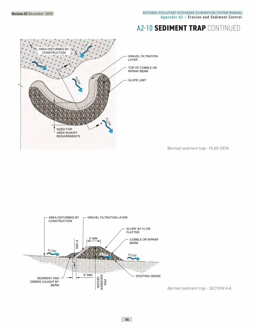
Revision 03 December 2020
54
N A T I O N A L P O L L U T A N T D I S C H A R G E E L I M I N A T I O N S Y S T E M M A N U A LAppendix A2 – Erosion and Sediment Control
A2-10 SEDIMENT TRAP CONTINUED
Bermed sediment trap - PLAN VIEW.
Bermed sediment trap - SECTION A-A.
TOP OF COBBLE ORRIPRAP BERM
SLOPE LIMIT
GRAVEL FILTRATIONLAYER
AREA DISTURBED BYCONSTRUCTION
SIZED FORAREA RUNOFFREQUIREMENTS
A
A
EDIMENT TRAP- PLAN VIEW 1
FLOW
FLOW
FLOW
FLOW10
FLOWFLOW FLOW
COBBLE OR RIPRAPBERM
SLOPE 3H:1V ORFLATTER
EXISTING GRADE
2' MIN
PEREN
GIN
EERD
ESIGN
6" MIN
AREA DISTURBED BYCONSTRUCTION
SEDIMENT ANDDEBRIS CAUGHT BY
BERM
6" MIN
GRAVEL FILTRATION LAYER
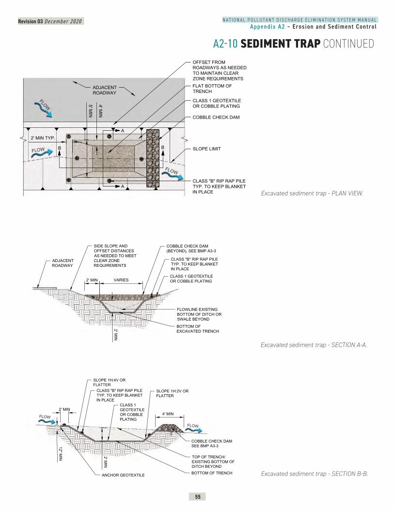
Revision 03 December 2020
55
N A T I O N A L P O L L U T A N T D I S C H A R G E E L I M I N A T I O N S Y S T E M M A N U A LAppendix A2 – Erosion and Sediment Control
A2-10 SEDIMENT TRAP CONTINUED
Excavated sediment trap - PLAN VIEW.
Excavated sediment trap - SECTION A-A.
Excavated sediment trap - SECTION B-B.
FLOW
FLOW
FLOW
CLASS 1 GEOTEXTILEOR COBBLE PLATING
SLOPE LIMIT
COBBLE CHECK DAM
FLAT BOTTOM OFTRENCH
ADJACENTROADWAY
2' MIN TYP.
5' MIN
4' MIN
CLASS "B" RIP RAP PILETYP. TO KEEP BLANKETIN PLACE
A
A
B B
OFFSET FROMROADWAYS AS NEEDEDTO MAINTAIN CLEARZONE REQUIREMENTS
EDIMENT TRAP- PLAN VIEW 2
CLASS 1 GEOTEXTILEOR COBBLE PLATING
BOTTOM OFEXCAVATED TRENCH
2' MIN2' M
IN
ADJACENTROADWAY
FLOWLINE EXISTINGBOTTOM OF DITCH ORSWALE BEYOND
COBBLE CHECK DAM(BEYOND), SEE BMP A3-3
VARIES
SIDE SLOPE ANDOFFSET DISTANCESAS NEEDED TO MEETCLEAR ZONEREQUIREMENTS
CLASS "B" RIP RAP PILETYP. TO KEEP BLANKETIN PLACE
SEDIMENT TRAP- SECTION 2A
0
FLOW
FLOW
SLOPE 1H:2V ORFLATTER
2' MIN
2' MIN4' MIN
SLOPE 1H:4V ORFLATTER
TOP OF TRENCH/EXISTING BOTTOM OFDITCH BEYONDBOTTOM OF TRENCH
COBBLE CHECK DAMSEE BMP A3-3
CLASS 1GEOTEXTILEOR COBBLEPLATING
12" MIN
ANCHOR GEOTEXTILE
CLASS "B" RIP RAP PILETYP. TO KEEP BLANKETIN PLACE
0
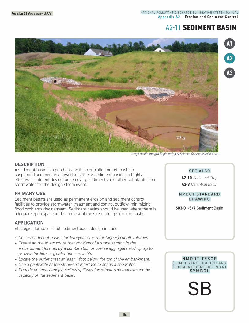
Revision 03 December 2020
56
N A T I O N A L P O L L U T A N T D I S C H A R G E E L I M I N A T I O N S Y S T E M M A N U A LAppendix A2 – Erosion and Sediment Control
A2-11 SEDIMENT BASIN
A1
A2
A3
N M D O T T E S C P ( T E M P O R A RY E R O S I O N A N D S E D I M E N T C O N T R O L P L A N )
SY M B O L
DESCRIPTION A sediment basin is a pond area with a controlled outlet in which suspended sediment is allowed to settle. A sediment basin is a highly effective treatment device for removing sediments and other pollutants from stormwater for the design storm event.
PRIMARY USESediment basins are used as permanent erosion and sediment control facilities to provide stormwater treatment and control outflow, minimizing flood problems downstream. Sediment basins should be used where there is adequate open space to direct most of the site drainage into the basin.
APPLICATIONStrategies for successful sediment basin design include:
» Design sediment basins for two-year storm (or higher) runoff volumes. » Create an outlet structure that consists of a stone section in the embankment formed by a combination of coarse aggregate and riprap to provide for filtering/detention capability.
» Locate the outlet crest at least 1 foot below the top of the embankment. » Use a geotextile at the stone-soil interface to act as a separator. » Provide an emergency overflow spillway for rainstorms that exceed the capacity of the sediment basin.
Image credit: Integra Engineering & Science Services/Julie Coco
S E E A L S O
A2-10 Sediment Trap
A3-9 Detention Basin
N M D O T S TA N D A R D D R A W I N G
603-01-5/7 Sediment Basin
SB
Revision 03 December 2020
57
N A T I O N A L P O L L U T A N T D I S C H A R G E E L I M I N A T I O N S Y S T E M M A N U A LAppendix A2 – Erosion and Sediment Control
A2-11 SEDIMENT BASIN CONTINUEDLIMITATIONS » Sediment basins can be rather large, depending on site conditions. » Sediment basins require comprehensive planning for construction phasing prior to implementation.
» Storm events that exceed the design storm event can cause damage to the spillway structure of the basin and cause unexpected flooding around and downstream of the basin.
MAINTENANCE REQUIREMENTS » Remove sediment and re-grade basin to its original dimensions when the capacity of the impoundment has been reduced significantly from its original storage capacity. The removed sediment shall be stockpiled or redistributed in areas that are protected from erosion.
» Inspect basin outlet structure and emergency spillway (if present) after major storm events to inspect for damage and to ensure that obstructions are not diminishing the effectiveness of the structures.
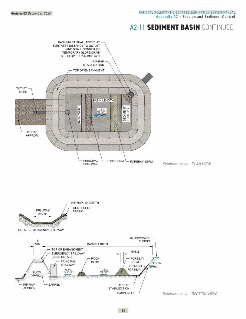
Revision 03 December 2020
58
N A T I O N A L P O L L U T A N T D I S C H A R G E E L I M I N A T I O N S Y S T E M M A N U A LAppendix A2 – Erosion and Sediment Control
A2-11 SEDIMENT BASIN CONTINUED
Sediment basin - SECTION VIEW.
RIP-RAPAPPRON
TOP OF EMBANKMENT
5'MIN. BASIN LENGTH
BASIN INLET
RIP-RAPSTABILIZATION
SEDIMENTFOREBAY
FOREBAYBERM
ROCKBERMPRINCIPAL
SPILLWAY
MIN. 2'
STORMWATERRUNOFF
BARREL
EMERGENCY SPILLWAY(SEEN DETAIL)
RIP-RAP, 10" DEPTH
GEOTEXTILEFABRICSPILLWAY
WIDTH
DETAIL - EMERGENCY SPILLWAY
0.5% SLOPE
0.5% SLOPE
FLOW
FLOW
Sediment basin - PLAN VIEW.
SEDIMENT BASIN - PLAN VIEW
RIP-RAPAPPRON
TOP OF EMBANKMENT
BASIN INLET SHALL ENTER ATFURTHEST DISTANCE TO OUTLET
AND SHALL CONSIST OFTEMPORARY SLOPE DRAIN
SEE SLOPE DRAIN BMP A2-9
RIP-RAPSTABILIZATION
OUTLETBASIN
PRINCIPALSPILLWAY
ROCK BERM FOREBAY BERM
SED
IMEN
TFO
REB
AY
BASIN LENGTH
BASI
N W
IDTH
11
0.5% SLOPE
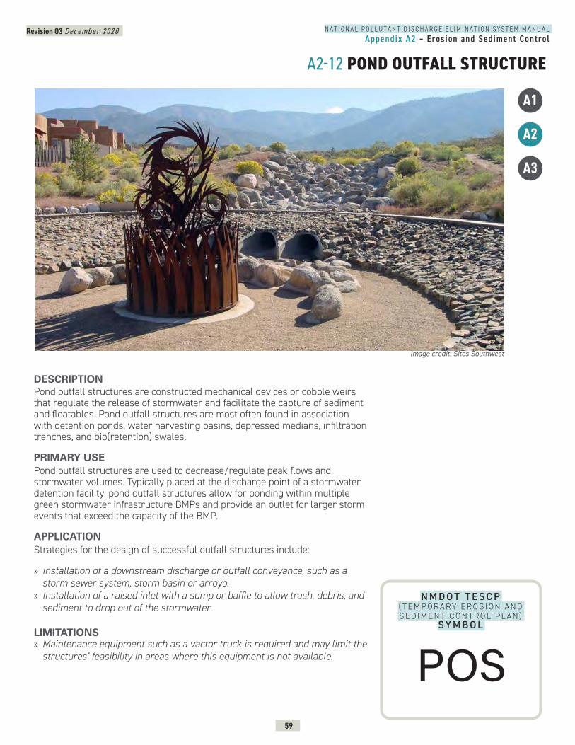
Revision 03 December 2020
59
N A T I O N A L P O L L U T A N T D I S C H A R G E E L I M I N A T I O N S Y S T E M M A N U A LAppendix A2 – Erosion and Sediment Control
A2-12 POND OUTFALL STRUCTURE
A1
A2
A3
N M D O T T E S C P ( T E M P O R A RY E R O S I O N A N D S E D I M E N T C O N T R O L P L A N )
SY M B O L
DESCRIPTION Pond outfall structures are constructed mechanical devices or cobble weirs that regulate the release of stormwater and facilitate the capture of sediment and floatables. Pond outfall structures are most often found in association with detention ponds, water harvesting basins, depressed medians, infiltration trenches, and bio(retention) swales.
PRIMARY USEPond outfall structures are used to decrease/regulate peak flows and stormwater volumes. Typically placed at the discharge point of a stormwater detention facility, pond outfall structures allow for ponding within multiple green stormwater infrastructure BMPs and provide an outlet for larger storm events that exceed the capacity of the BMP.
APPLICATIONStrategies for the design of successful outfall structures include:
» Installation of a downstream discharge or outfall conveyance, such as a storm sewer system, storm basin or arroyo.
» Installation of a raised inlet with a sump or baffle to allow trash, debris, and sediment to drop out of the stormwater.
LIMITATIONS » Maintenance equipment such as a vactor truck is required and may limit the structures’ feasibility in areas where this equipment is not available.
Image credit: Sites Southwest
POS
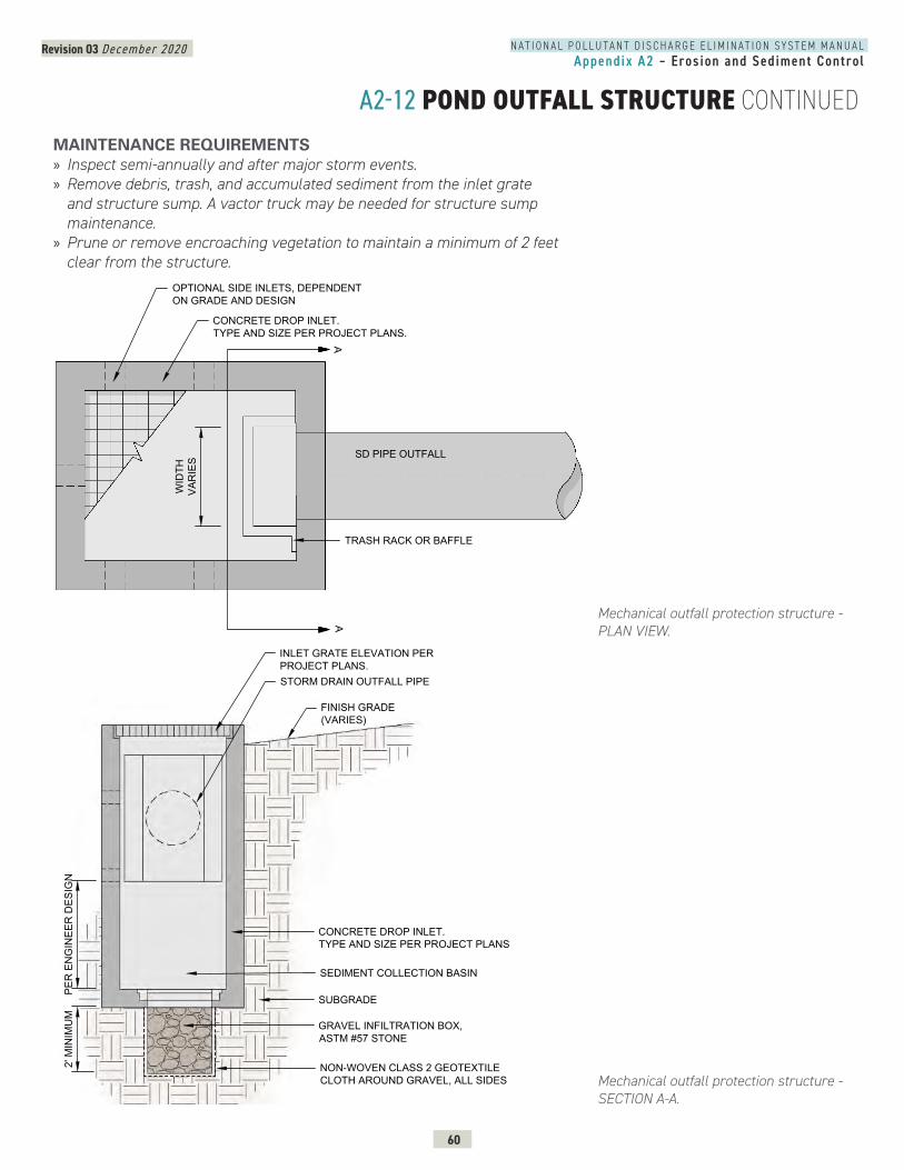
Revision 03 December 2020
60
N A T I O N A L P O L L U T A N T D I S C H A R G E E L I M I N A T I O N S Y S T E M M A N U A LAppendix A2 – Erosion and Sediment Control
A2-12 POND OUTFALL STRUCTURE CONTINUEDMAINTENANCE REQUIREMENTS » Inspect semi-annually and after major storm events. » Remove debris, trash, and accumulated sediment from the inlet grate and structure sump. A vactor truck may be needed for structure sump maintenance.
» Prune or remove encroaching vegetation to maintain a minimum of 2 feet clear from the structure.
Mechanical outfall protection structure - PLAN VIEW.
Mechanical outfall protection structure - SECTION A-A.
POND OUTFALL STRUCTURE - PLAN VIEW
WID
THVA
RIE
S SD PIPE OUTFALL
AA
CONCRETE DROP INLET.TYPE AND SIZE PER PROJECT PLANS.
OPTIONAL SIDE INLETS, DEPENDENTON GRADE AND DESIGN
TRASH RACK OR BAFFLE
POND OUTFALL STRUCTURE - SECTION AA
STORM DRAIN OUTFALL PIPE
2' M
INIM
UM
PER
EN
GIN
EER
DES
IGN
GRAVEL INFILTRATION BOX,ASTM #57 STONE
NON-WOVEN CLASS 2 GEOTEXTILECLOTH AROUND GRAVEL, ALL SIDES
CONCRETE DROP INLET.TYPE AND SIZE PER PROJECT PLANS
INLET GRATE ELEVATION PERPROJECT PLANS.
FINISH GRADE(VARIES)
SEDIMENT COLLECTION BASIN
SUBGRADE
-12
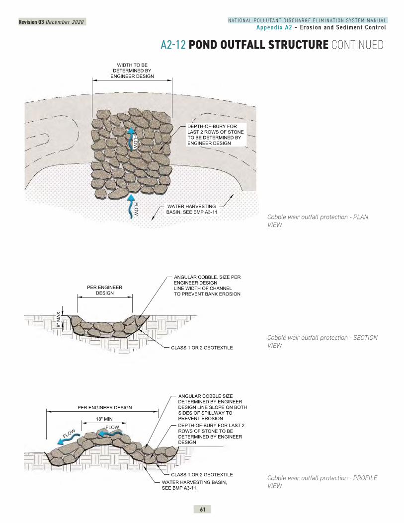
Revision 03 December 2020
61
N A T I O N A L P O L L U T A N T D I S C H A R G E E L I M I N A T I O N S Y S T E M M A N U A LAppendix A2 – Erosion and Sediment Control
A2-12 POND OUTFALL STRUCTURE CONTINUED
Cobble weir outfall protection - PLAN VIEW.
Cobble weir outfall protection - SECTION VIEW.
Cobble weir outfall protection - PROFILE VIEW.
DEPTH-OF-BURY FORLAST 2 ROWS OF STONETO BE DETERMINED BYENGINEER DESIGN
WATER HARVESTINGBASIN, SEE BMP A3-11
WIDTH TO BEDETERMINED BY
ENGINEER DESIGN
COBBLE WEIR OUTFALL PROTECTION - PLAN VIEW
FLOW
FLOW
ANGULAR COBBLE. SIZE PERENGINEER DESIGNLINE WIDTH OF CHANNELTO PREVENT BANK EROSION
WATER HARVESTING BASIN,SEE BMP A3-11.
ANGULAR COBBLE SIZEDETERMINED BY ENGINEERDESIGN LINE SLOPE ON BOTHSIDES OF SPILLWAY TOPREVENT EROSIONDEPTH-OF-BURY FOR LAST 2ROWS OF STONE TO BEDETERMINED BY ENGINEERDESIGN
6" M
AX.
PER ENGINEERDESIGN
18" MIN
PER ENGINEER DESIGN
CLASS 1 OR 2 GEOTEXTILE
CLASS 1 OR 2 GEOTEXTILE
FLOW
FLOW
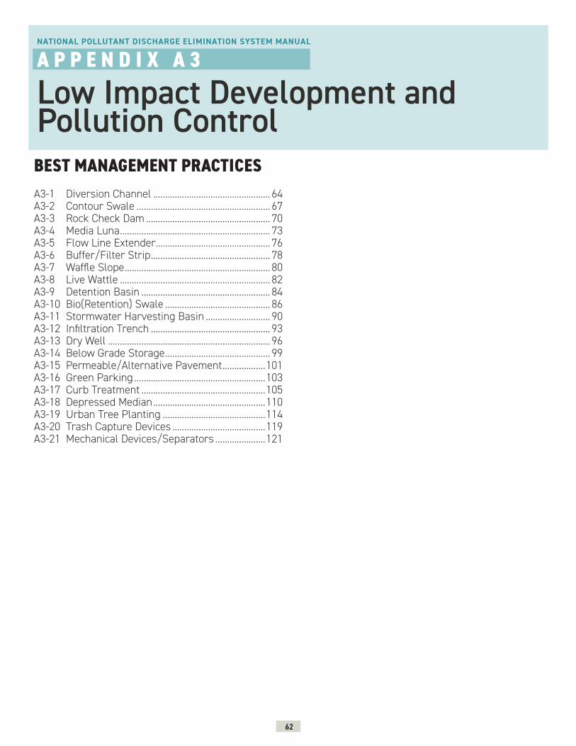
62
BEST MANAGEMENT PRACTICES
NATIONAL POLLUTANT DISCHARGE ELIMINATION SYSTEM MANUAL
A P P E N D I X A 3
Low Impact Development and Pollution Control
A3-1 Diversion Channel ................................................. 64A3-2 Contour Swale ........................................................ 67A3-3 Rock Check Dam .................................................... 70A3-4 Media Luna ............................................................... 73A3-5 Flow Line Extender ................................................ 76A3-6 Buffer/Filter Strip .................................................. 78A3-7 Waffle Slope ............................................................. 80A3-8 Live Wattle ............................................................... 82A3-9 Detention Basin ...................................................... 84A3-10 Bio(Retention) Swale ............................................ 86A3-11 Stormwater Harvesting Basin ........................... 90A3-12 Infiltration Trench .................................................. 93A3-13 Dry Well .................................................................... 96A3-14 Below Grade Storage ............................................ 99A3-15 Permeable/Alternative Pavement ..................101A3-16 Green Parking .......................................................103A3-17 Curb Treatment ....................................................105A3-18 Depressed Median ...............................................110A3-19 Urban Tree Planting ...........................................114A3-20 Trash Capture Devices .......................................119A3-21 Mechanical Devices/Separators .....................121
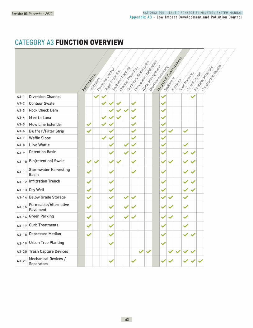
N A T I O N A L P O L L U T A N T D I S C H A R G E E L I M I N A T I O N S Y S T E M M A N U A LAppendix A3 – Low Impact Development and Pol lut ion Control
Revision 03 December 2020
63
CATEGORY A3 FUNCTION OVERVIEW
A 3 - 1 Diversion ChannelA 3 - 2 Contour Swale
A 3 - 3 Rock Check Dam
A 3 - 4 M e d i a LunaA 3 - 5 Flow Line ExtenderA 3 - 6 B u f f e r /Filter StripA 3 - 7 Waffle Slope
A 3 - 8 L i ve Wattle
A 3 - 9 Detention Basin
A 3 - 1 0 Bio(retention) Swale
A 3 - 1 1 Stormwater Harvesting Basin
A 3 - 1 2 Infiltration Trench
A 3 - 1 3 Dry Well
A 3 - 1 4 Below Grade Storage
A 3 - 1 5 Permeable/Alternative Pavement
A 3 - 1 6 Green Parking
A 3 - 1 7 Curb Treatments
A 3 - 1 8 Depressed Median
A 3 - 1 9 Urban Tree Planting
A 3 - 2 0 Trash Capture Devices
A 3 - 2 1 Mechanical Devices / Separators
Appl i
cat i
onIn
filtra
tion
Perim
eter
Con
trol
Slop
e Pro
tect
ion
Sedim
ent T
rapp
ing
Chan
nel P
rote
ction
Tem
pora
ry S
tabil
izatio
n
Perm
anen
t Sta
biliza
tion
Was
te M
anag
emen
t
Good
Hou
seke
epin
g
Targ
e ted
Con
s ti t
uents
Sedim
ents
Nutri
ents
Toxic
Mat
erial
sOi
l and
Gre
ase
Floa
tabl
e Mat
erial
s
Cons
truct
ion W
aste
s

N A T I O N A L P O L L U T A N T D I S C H A R G E E L I M I N A T I O N S Y S T E M M A N U A LAppendix A3 – Low Impact Development and Pol lut ion Control
Revision 03 December 2020
64
A3-1 DIVERSION CHANNEL
N M D O T T E S C P ( T E M P O R A RY E R O S I O N A N D S E D I M E N T C O N T R O L P L A N )
SY M B O L
DESCRIPTION Diversion channels are constructed conveyances that concentrate and route stormwater flow away from construction areas or toward desired locations. They can be constructed as either dikes (berms) or swales.
PRIMARY USEDiversion channels are typically used to collect and direct flow around disturbed areas into a controlled outlet. Diversion channels are useful when significant offsite flow could disturb a site; when flow needs to be directed away from staging, storage, or fueling areas; or where routing is required for treatment.
APPLICATIONBerms and diversions should be constructed of compacted soil or coarse aggregate. Strategies for successful diversion channel design include:
Earth Dike (Berm) » Provide immediate stabilization of compacted earth dikes upon placement to avoid contributing to site erosion and sedimentation.
» Design berms with a minimum height of 18 inches, side slopes of 2:1 or flatter, and a minimum base width of 6 feet.
» Design berms to include uninterrupted positive grade to a stabilized outlet.
Diversion Channel (Swale) » Quickly stabilize interceptor swales upon excavation to avoid contributing to site erosion and sedimentation.
» Excavate and shape diversion channels to line, grade, and cross section as indicated in the plans and as required to meet the criteria specified.
Image credit: iStock/Olga Ihnatsyeva
A1
A2
A3
S E E A L S O
A3-2 Contour Swale
N M D O T S TA N D A R D D R A W I N G
603-01-5/7 Earth Dike (Berm)603-01-7/7 Diversion Dike
DC
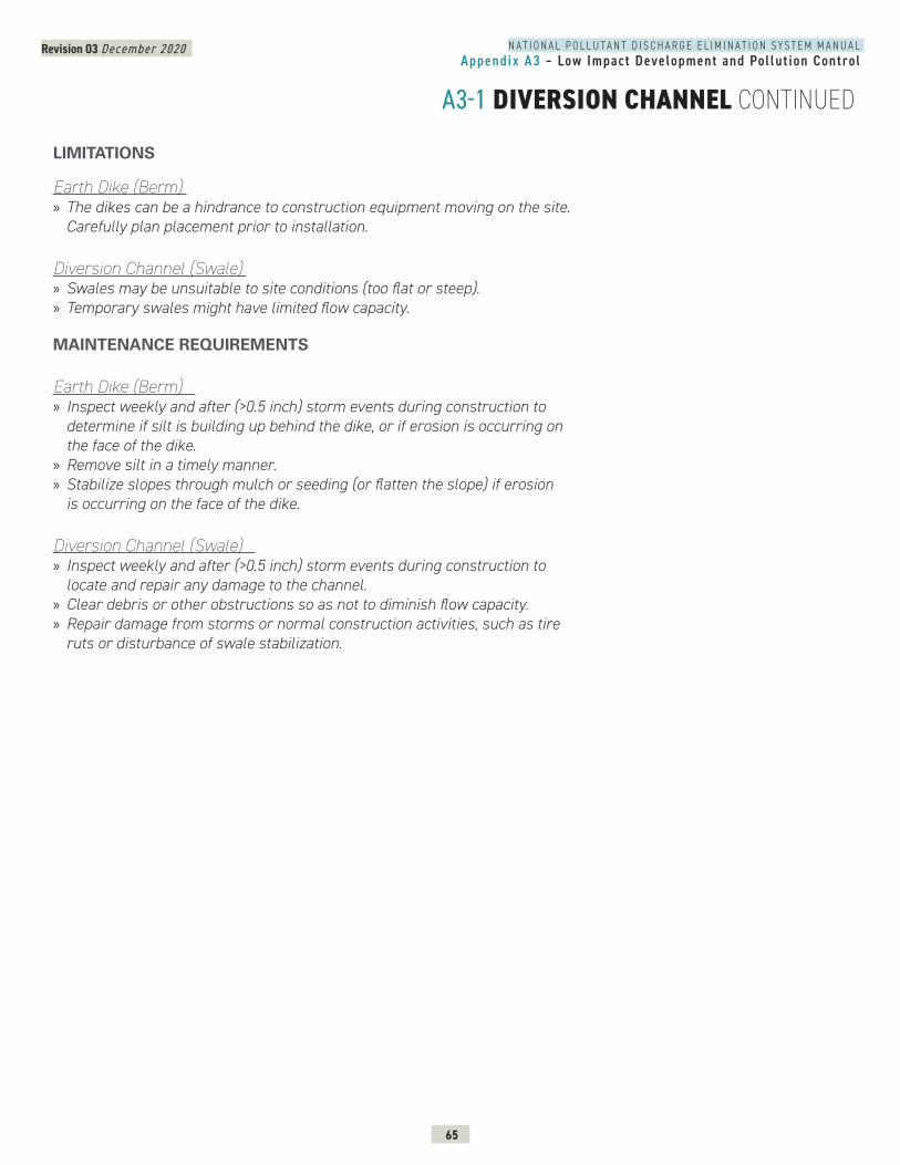
N A T I O N A L P O L L U T A N T D I S C H A R G E E L I M I N A T I O N S Y S T E M M A N U A LAppendix A3 – Low Impact Development and Pol lut ion Control
Revision 03 December 2020
65
A3-1 DIVERSION CHANNEL CONTINUED
LIMITATIONS
Earth Dike (Berm) » The dikes can be a hindrance to construction equipment moving on the site. Carefully plan placement prior to installation.
Diversion Channel (Swale) » Swales may be unsuitable to site conditions (too flat or steep). » Temporary swales might have limited flow capacity.
MAINTENANCE REQUIREMENTS
Earth Dike (Berm) » Inspect weekly and after (>0.5 inch) storm events during construction to determine if silt is building up behind the dike, or if erosion is occurring on the face of the dike.
» Remove silt in a timely manner. » Stabilize slopes through mulch or seeding (or flatten the slope) if erosion is occurring on the face of the dike.
Diversion Channel (Swale) » Inspect weekly and after (>0.5 inch) storm events during construction to locate and repair any damage to the channel.
» Clear debris or other obstructions so as not to diminish flow capacity. » Repair damage from storms or normal construction activities, such as tire ruts or disturbance of swale stabilization.
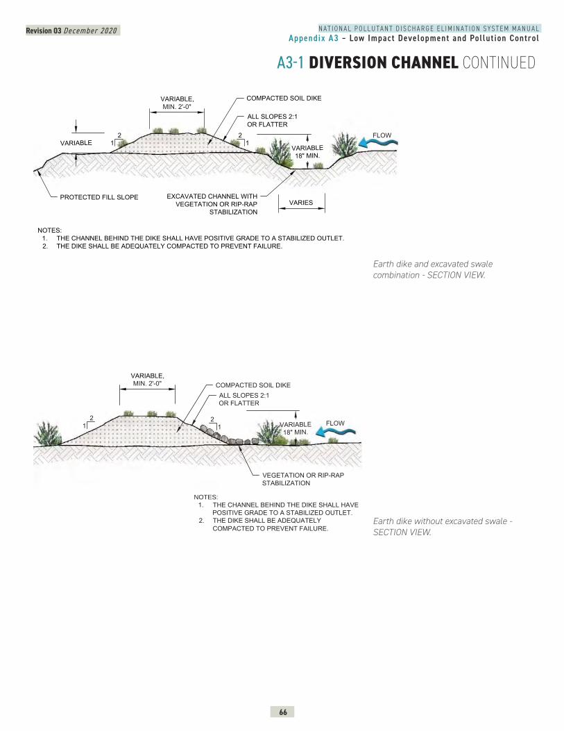
N A T I O N A L P O L L U T A N T D I S C H A R G E E L I M I N A T I O N S Y S T E M M A N U A LAppendix A3 – Low Impact Development and Pol lut ion Control
Revision 03 December 2020
66
A3-1 DIVERSION CHANNEL CONTINUED
Earth dike without excavated swale - SECTION VIEW.
RSION CHANNEL DIKE AND SWALE-SECTION_TEMPORARY DIVERSION DIKE
VARIABLE,MIN. 2'-0"
VEGETATION OR RIP-RAPSTABILIZATION
ALL SLOPES 2:1OR FLATTER
COMPACTED SOIL DIKE
NOTES:
1. THE CHANNEL BEHIND THE DIKE SHALL HAVEPOSITIVE GRADE TO A STABILIZED OUTLET.
2. THE DIKE SHALL BE ADEQUATELYCOMPACTED TO PREVENT FAILURE.
21 VARIABLE
18" MIN.
21 FLOW
DIVERSION CHANNEL DIKE AND SWALE-SECTION FILL DIVERSION
VARIABLE,MIN. 2'-0"
VARIABLE18" MIN.
EXCAVATED CHANNEL WITHVEGETATION OR RIP-RAP
STABILIZATION
ALL SLOPES 2:1OR FLATTER
COMPACTED SOIL DIKE
PROTECTED FILL SLOPE
NOTES:1. THE CHANNEL BEHIND THE DIKE SHALL HAVE POSITIVE GRADE TO A STABILIZED OUTLET.2. THE DIKE SHALL BE ADEQUATELY COMPACTED TO PREVENT FAILURE.
VARIABLE2
12
1
VARIES
FLOW
Earth dike and excavated swale combination - SECTION VIEW.
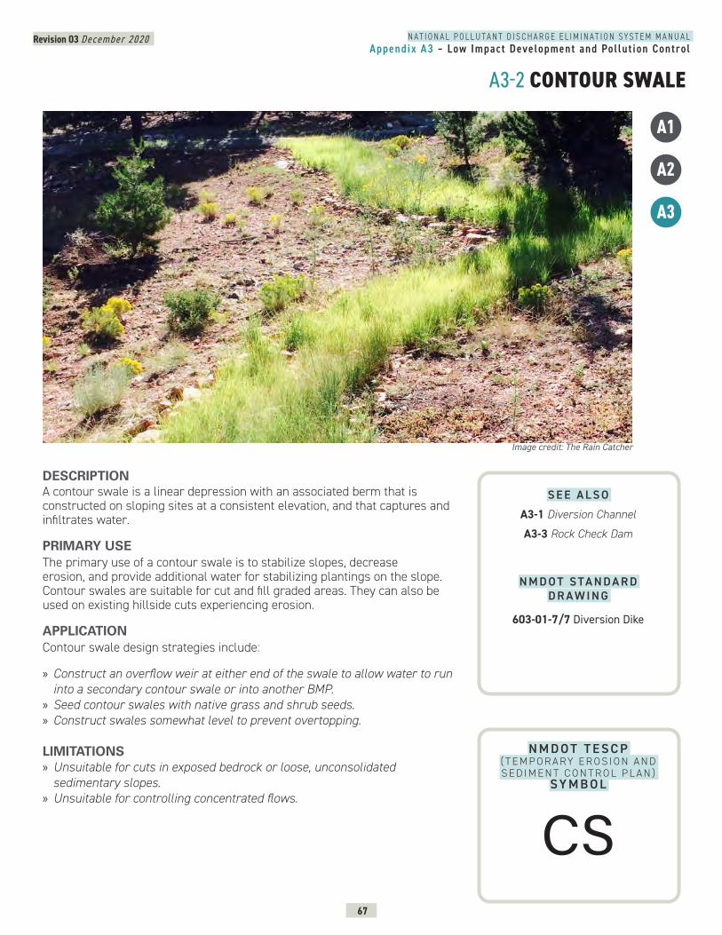
N A T I O N A L P O L L U T A N T D I S C H A R G E E L I M I N A T I O N S Y S T E M M A N U A LAppendix A3 – Low Impact Development and Pol lut ion Control
Revision 03 December 2020
67
A3-2 CONTOUR SWALE
N M D O T T E S C P ( T E M P O R A RY E R O S I O N A N D S E D I M E N T C O N T R O L P L A N )
SY M B O L
DESCRIPTION A contour swale is a linear depression with an associated berm that is constructed on sloping sites at a consistent elevation, and that captures and infiltrates water.
PRIMARY USEThe primary use of a contour swale is to stabilize slopes, decrease erosion, and provide additional water for stabilizing plantings on the slope. Contour swales are suitable for cut and fill graded areas. They can also be used on existing hillside cuts experiencing erosion.
APPLICATIONContour swale design strategies include:
» Construct an overflow weir at either end of the swale to allow water to run into a secondary contour swale or into another BMP.
» Seed contour swales with native grass and shrub seeds. » Construct swales somewhat level to prevent overtopping.
LIMITATIONS » Unsuitable for cuts in exposed bedrock or loose, unconsolidated sedimentary slopes.
» Unsuitable for controlling concentrated flows.
Image credit: The Rain Catcher
A1
A2
A3
S E E A L S O
A3-1 Diversion Channel
A3-3 Rock Check Dam
N M D O T S TA N D A R D D R A W I N G
603-01-7/7 Diversion Dike
CS
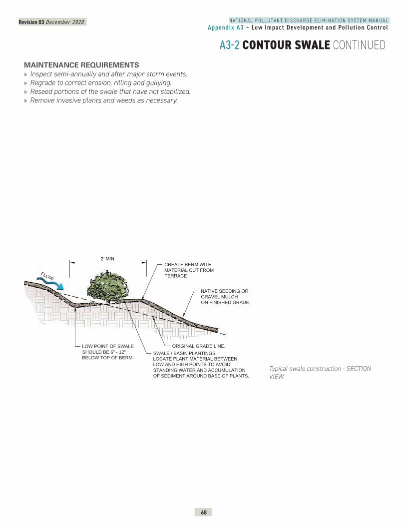
N A T I O N A L P O L L U T A N T D I S C H A R G E E L I M I N A T I O N S Y S T E M M A N U A LAppendix A3 – Low Impact Development and Pol lut ion Control
Revision 03 December 2020
68
A3-2 CONTOUR SWALE CONTINUEDMAINTENANCE REQUIREMENTS » Inspect semi-annually and after major storm events. » Regrade to correct erosion, rilling and gullying. » Reseed portions of the swale that have not stabilized. » Remove invasive plants and weeds as necessary.
Typical swale construction - SECTION VIEW.
CONTOUR SWALE - SECTION TYPICAL
2' MIN.
CREATE BERM WITHMATERIAL CUT FROMTERRACE
LOW POINT OF SWALESHOULD BE 6" - 12"
BELOW TOP OF BERM.SWALE / BASIN PLANTINGS.
LOCATE PLANT MATERIAL BETWEENLOW AND HIGH POINTS TO AVOIDSTANDING WATER AND ACCUMULATIONOF SEDIMENT AROUND BASE OF PLANTS.
NATIVE SEEDING ORGRAVEL MULCHON FINISHED GRADE.
ORIGINAL GRADE LINE.
2
FLOW
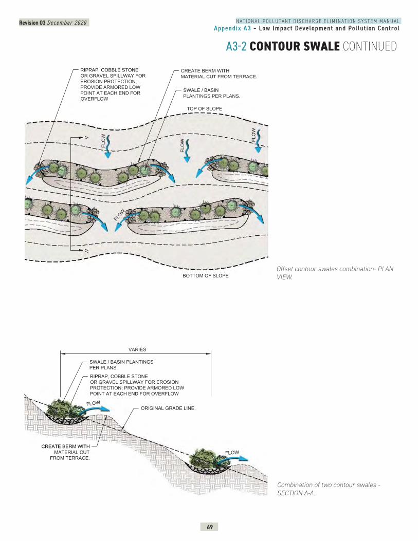
N A T I O N A L P O L L U T A N T D I S C H A R G E E L I M I N A T I O N S Y S T E M M A N U A LAppendix A3 – Low Impact Development and Pol lut ion Control
Revision 03 December 2020
69
A3-2 CONTOUR SWALE CONTINUED
Combination of two contour swales - SECTION A-A.
Offset contour swales combination- PLAN VIEW.
CREATE BERM WITHMATERIAL CUT
FROM TERRACE.
SWALE / BASIN PLANTINGSPER PLANS.
ORIGINAL GRADE LINE.
RIPRAP, COBBLE STONEOR GRAVEL SPILLWAY FOR EROSIONPROTECTION; PROVIDE ARMORED LOWPOINT AT EACH END FOR OVERFLOW
VARIES
2
FLOW
FLOW
CONTOUR SWALE - PLAN VIEW
RIPRAP, COBBLE STONE
OR GRAVEL SPILLWAY FOREROSION PROTECTION;PROVIDE ARMORED LOWPOINT AT EACH END FOROVERFLOW
TOP OF SLOPE
BOTTOM OF SLOPE
AA
'
CREATE BERM WITHMATERIAL CUT FROM TERRACE.
SWALE / BASINPLANTINGS PER PLANS.
FLO
W
FLO
W FLO
W
FLOW
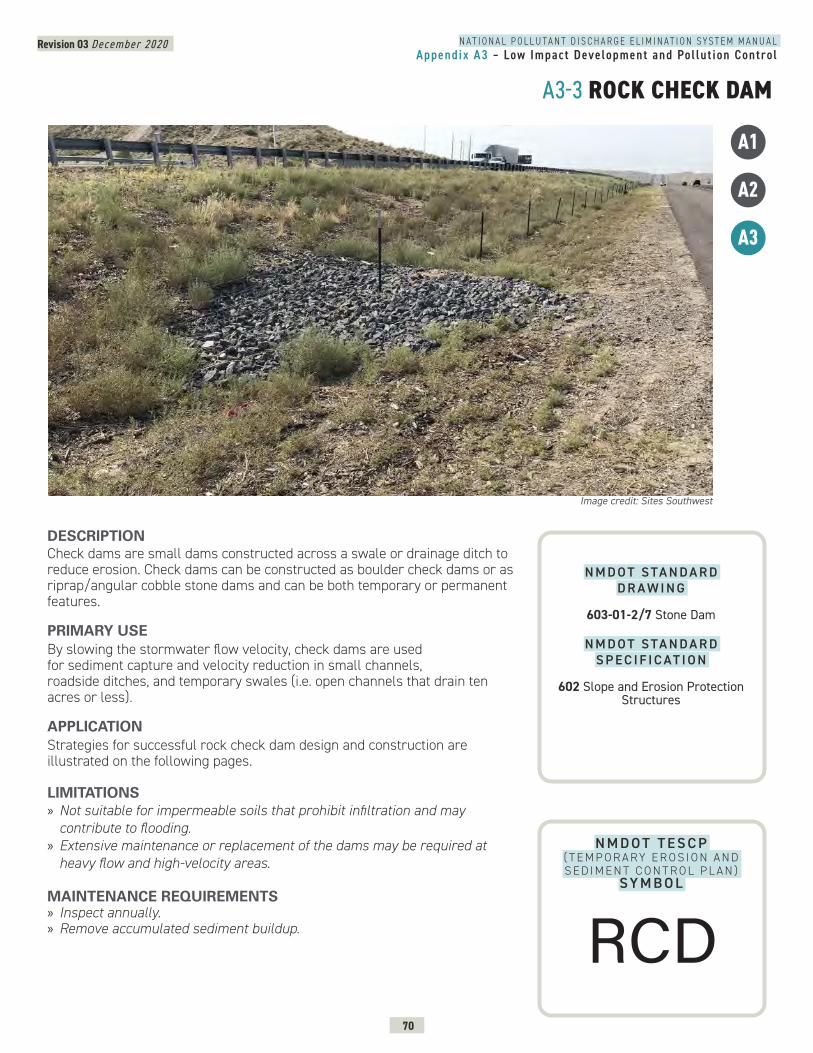
N A T I O N A L P O L L U T A N T D I S C H A R G E E L I M I N A T I O N S Y S T E M M A N U A LAppendix A3 – Low Impact Development and Pol lut ion Control
Revision 03 December 2020
70
A3-3 ROCK CHECK DAM
N M D O T T E S C P ( T E M P O R A RY E R O S I O N A N D S E D I M E N T C O N T R O L P L A N )
SY M B O L
DESCRIPTION Check dams are small dams constructed across a swale or drainage ditch to reduce erosion. Check dams can be constructed as boulder check dams or as riprap/angular cobble stone dams and can be both temporary or permanent features.
PRIMARY USEBy slowing the stormwater flow velocity, check dams are used for sediment capture and velocity reduction in small channels, roadside ditches, and temporary swales (i.e. open channels that drain ten acres or less).
APPLICATIONStrategies for successful rock check dam design and construction are illustrated on the following pages.
LIMITATIONS » Not suitable for impermeable soils that prohibit infiltration and may contribute to flooding.
» Extensive maintenance or replacement of the dams may be required at heavy flow and high-velocity areas.
MAINTENANCE REQUIREMENTS » Inspect annually. » Remove accumulated sediment buildup.
Image credit: Sites Southwest
A1
A2
A3
N M D O T S TA N D A R D D R A W I N G
603-01-2/7 Stone Dam
N M D O T S TA N D A R D S P E C I F I C AT I O N
602 Slope and Erosion Protection Structures
RCD
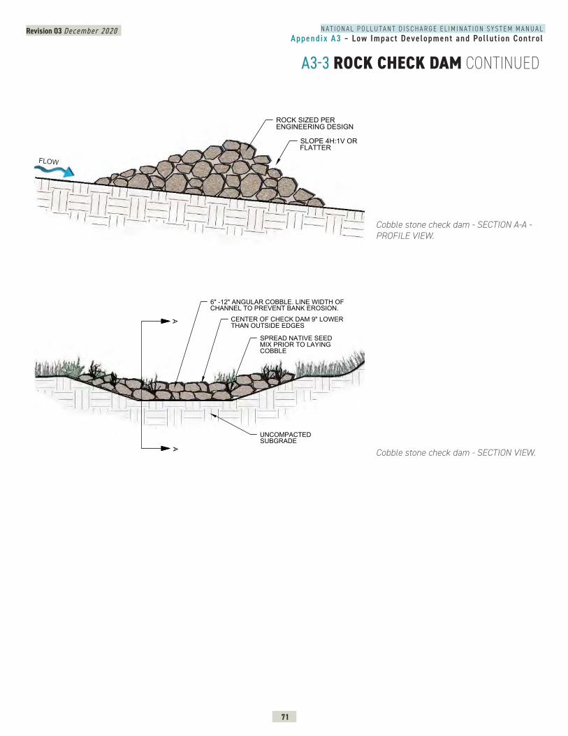
N A T I O N A L P O L L U T A N T D I S C H A R G E E L I M I N A T I O N S Y S T E M M A N U A LAppendix A3 – Low Impact Development and Pol lut ion Control
Revision 03 December 2020
71
A3-3 ROCK CHECK DAM CONTINUED
Cobble stone check dam - SECTION A-A - PROFILE VIEW.
Cobble stone check dam - SECTION VIEW.
ROCK SIZED PERENGINEERING DESIGN
SLOPE 4H:1V ORFLATTER
FLOW
3
CROSS SECTION - COBBLE CHECK DAM
6" -12" ANGULAR COBBLE. LINE WIDTH OFCHANNEL TO PREVENT BANK EROSION.
CENTER OF CHECK DAM 9" LOWERTHAN OUTSIDE EDGES
SPREAD NATIVE SEEDMIX PRIOR TO LAYINGCOBBLE
AA
UNCOMPACTEDSUBGRADE
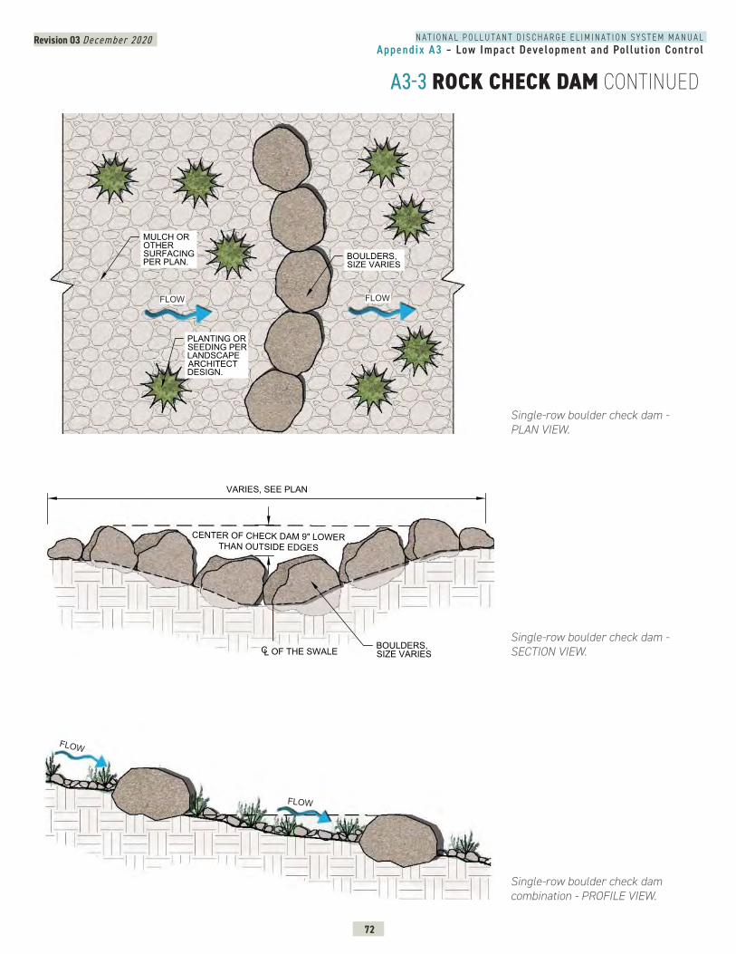
N A T I O N A L P O L L U T A N T D I S C H A R G E E L I M I N A T I O N S Y S T E M M A N U A LAppendix A3 – Low Impact Development and Pol lut ion Control
Revision 03 December 2020
72
A3-3 ROCK CHECK DAM CONTINUED
Single-row boulder check dam - PLAN VIEW.
Single-row boulder check dam combination - PROFILE VIEW.
Single-row boulder check dam - SECTION VIEW.
FLOW FLOW
BOULDER CHECK DAM - PLAN VIEW & SECTION
BOULDERS,SIZE VARIES
PLANTING ORSEEDING PERLANDSCAPEARCHITECTDESIGN.
MULCH OROTHERSURFACINGPER PLAN.
BOULDERS,SIZE VARIES
PLANTING ORSEEDING PERLANDSCAPEARCHITECTDESIGN.
MULCH OROTHERSURFACINGPER PLAN.
3
BOULDER CHECK DAM INSTALLATION - SECTION (TYP.)
SECTION - BOULDER CHECK DAM
OF THE SWALECL
CENTER OF CHECK DAM 9" LOWERTHAN OUTSIDE EDGES
BOULDERS,SIZE VARIES
VARIES, SEE PLAN
FLOW
FLOW
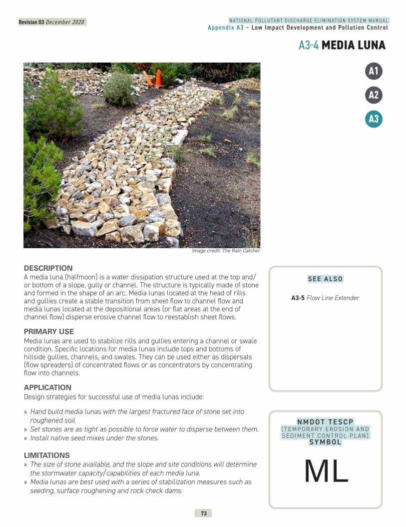
N A T I O N A L P O L L U T A N T D I S C H A R G E E L I M I N A T I O N S Y S T E M M A N U A LAppendix A3 – Low Impact Development and Pol lut ion Control
Revision 03 December 2020
73
A3-4 MEDIA LUNA
N M D O T T E S C P ( T E M P O R A RY E R O S I O N A N D S E D I M E N T C O N T R O L P L A N )
SY M B O L
DESCRIPTION A media luna (halfmoon) is a water dissipation structure used at the top and/or bottom of a slope, gully or channel. The structure is typically made of stone and formed in the shape of an arc. Media lunas located at the head of rills and gullies create a stable transition from sheet flow to channel flow and media lunas located at the depositional areas (or flat areas at the end of channel flow) disperse erosive channel flow to reestablish sheet flows.
PRIMARY USEMedia lunas are used to stabilize rills and gullies entering a channel or swale condition. Specific locations for media lunas include tops and bottoms of hillside gullies, channels, and swales. They can be used either as dispersals (flow spreaders) of concentrated flows or as concentrators by concentrating flow into channels.
APPLICATIONDesign strategies for successful use of media lunas include:
» Hand build media lunas with the largest fractured face of stone set into roughened soil.
» Set stones are as tight as possible to force water to disperse between them. » Install native seed mixes under the stones.
LIMITATIONS » The size of stone available, and the slope and site conditions will determine the stormwater capacity/capabilities of each media luna.
» Media lunas are best used with a series of stabilization measures such as seeding, surface roughening and rock check dams.
Image credit: The Rain Catcher
A1
A2
A3
S E E A L S O
A3-5 Flow Line Extender
ML
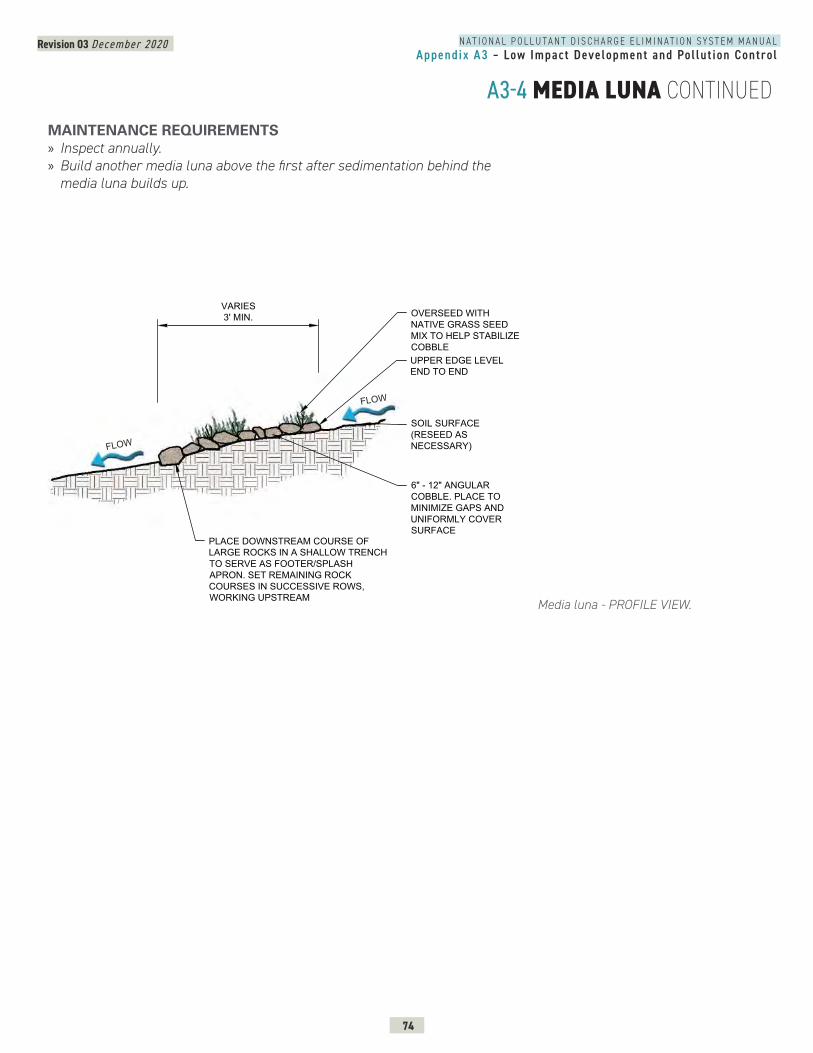
N A T I O N A L P O L L U T A N T D I S C H A R G E E L I M I N A T I O N S Y S T E M M A N U A LAppendix A3 – Low Impact Development and Pol lut ion Control
Revision 03 December 2020
74
A3-4 MEDIA LUNA CONTINUED
Media luna - PROFILE VIEW.
MEDIA LUNA - SECTION
UPPER EDGE LEVELEND TO END
6" - 12" ANGULARCOBBLE. PLACE TOMINIMIZE GAPS ANDUNIFORMLY COVERSURFACE
SOIL SURFACE(RESEED ASNECESSARY)
OVERSEED WITHNATIVE GRASS SEEDMIX TO HELP STABILIZECOBBLE
PLACE DOWNSTREAM COURSE OFLARGE ROCKS IN A SHALLOW TRENCHTO SERVE AS FOOTER/SPLASHAPRON. SET REMAINING ROCKCOURSES IN SUCCESSIVE ROWS,WORKING UPSTREAM
VARIES3' MIN.
FLOW
FLOW
MAINTENANCE REQUIREMENTS » Inspect annually. » Build another media luna above the first after sedimentation behind the media luna builds up.
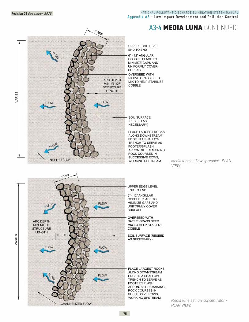
N A T I O N A L P O L L U T A N T D I S C H A R G E E L I M I N A T I O N S Y S T E M M A N U A LAppendix A3 – Low Impact Development and Pol lut ion Control
Revision 03 December 2020
75
A3-4 MEDIA LUNA CONTINUED
Media luna as flow spreader - PLAN VIEW.
Media luna as flow concentrator - PLAN VIEW.
MEDIA LUNA AS FLOW SPREADER - PLAN VIEW
3' MIN
VAR
IES
UPPER EDGE LEVELEND TO END
6" - 12" ANGULARCOBBLE. PLACE TOMINIMIZE GAPS ANDUNIFORMLY COVERSURFACE
SOIL SURFACE(RESEED ASNECESSARY)
OVERSEED WITHNATIVE GRASS SEEDMIX TO HELP STABILIZECOBBLE
PLACE LARGEST ROCKSALONG DOWNSTREAMEDGE IN A SHALLOWTRENCH TO SERVE ASFOOTER/SPLASHAPRON. SET REMAININGROCK COURSES INSUCCESSIVE ROWS,WORKING UPSTREAMSHEET FLOW
ARC DEPTHMIN 1/8 OF
STRUCTURELENGTH
FLOW FLOW
FLOW
FLOW
UPPER EDGE LEVELEND TO END
6" - 12" ANGULARCOBBLE. PLACE TOMINIMIZE GAPS ANDUNIFORMLY COVERSURFACE
SOIL SURFACE (RESEEDAS NECESSARY)
OVERSEED WITHNATIVE GRASS SEEDMIX TO HELP STABILIZECOBBLE
ARC DEPTHMIN 1/8 OF
STRUCTURELENGTH
PLACE LARGEST ROCKSALONG DOWNSTREAMEDGE IN A SHALLOWTRENCH TO SERVE ASFOOTER/SPLASHAPRON. SET REMAININGROCK COURSES INSUCCESSIVE ROWS,WORKING UPSTREAM
CHANNELIZED FLOW
3' MIN
VAR
IES
FLOW FLOW
FLOW
FLOW
FLOWFLOW
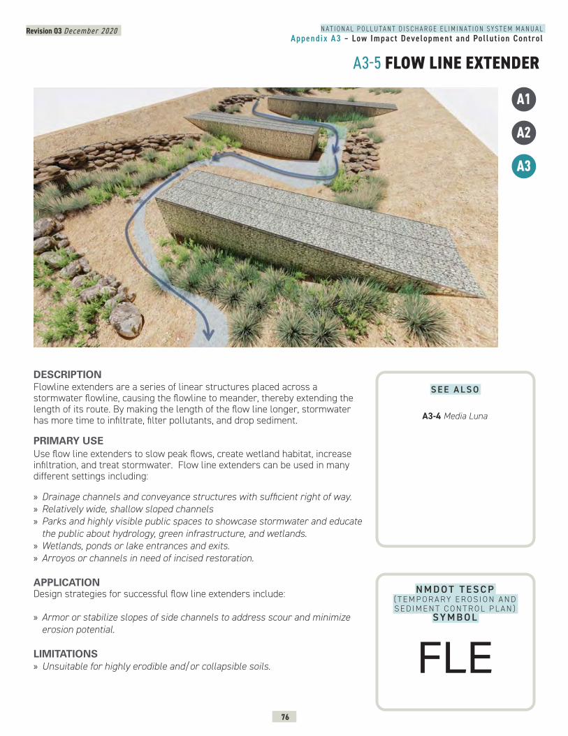
N A T I O N A L P O L L U T A N T D I S C H A R G E E L I M I N A T I O N S Y S T E M M A N U A LAppendix A3 – Low Impact Development and Pol lut ion Control
Revision 03 December 2020
76
A3-5 FLOW LINE EXTENDER
N M D O T T E S C P ( T E M P O R A RY E R O S I O N A N D S E D I M E N T C O N T R O L P L A N )
SY M B O L
DESCRIPTION Flowline extenders are a series of linear structures placed across a stormwater flowline, causing the flowline to meander, thereby extending the length of its route. By making the length of the flow line longer, stormwater has more time to infiltrate, filter pollutants, and drop sediment.
PRIMARY USEUse flow line extenders to slow peak flows, create wetland habitat, increase infiltration, and treat stormwater. Flow line extenders can be used in many different settings including:
» Drainage channels and conveyance structures with sufficient right of way. » Relatively wide, shallow sloped channels » Parks and highly visible public spaces to showcase stormwater and educate the public about hydrology, green infrastructure, and wetlands.
» Wetlands, ponds or lake entrances and exits. » Arroyos or channels in need of incised restoration.
APPLICATIONDesign strategies for successful flow line extenders include:
» Armor or stabilize slopes of side channels to address scour and minimize erosion potential.
LIMITATIONS » Unsuitable for highly erodible and/or collapsible soils.
A1
A2
A3
S E E A L S O
A3-4 Media Luna
FLE
N A T I O N A L P O L L U T A N T D I S C H A R G E E L I M I N A T I O N S Y S T E M M A N U A LAppendix A3 – Low Impact Development and Pol lut ion Control
Revision 03 December 2020
77
A3-5 FLOW LINE EXTENDER CONTINUEDMAINTENANCE REQUIREMENTS » Inspect after major storm events for scour, erosion and performance. » Maintain planting as needed including pruning, weeding, mowing, fertilization, replacement, and pest control.
» Remove invasive plant material. » Remove sediment.
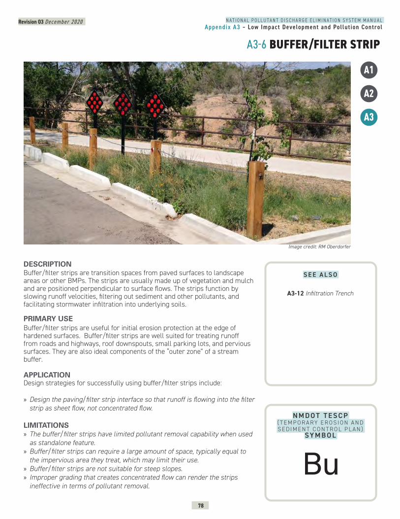
N A T I O N A L P O L L U T A N T D I S C H A R G E E L I M I N A T I O N S Y S T E M M A N U A LAppendix A3 – Low Impact Development and Pol lut ion Control
Revision 03 December 2020
78
A3-6 BUFFER/FILTER STRIP
N M D O T T E S C P ( T E M P O R A RY E R O S I O N A N D S E D I M E N T C O N T R O L P L A N )
SY M B O L
DESCRIPTION Buffer/filter strips are transition spaces from paved surfaces to landscape areas or other BMPs. The strips are usually made up of vegetation and mulch and are positioned perpendicular to surface flows. The strips function by slowing runoff velocities, filtering out sediment and other pollutants, and facilitating stormwater infiltration into underlying soils.
PRIMARY USEBuffer/filter strips are useful for initial erosion protection at the edge of hardened surfaces. Buffer/filter strips are well suited for treating runoff from roads and highways, roof downspouts, small parking lots, and pervious surfaces. They are also ideal components of the “outer zone” of a stream buffer.
APPLICATIONDesign strategies for successfully using buffer/filter strips include:
» Design the paving/filter strip interface so that runoff is flowing into the filter strip as sheet flow, not concentrated flow.
LIMITATIONS » The buffer/filter strips have limited pollutant removal capability when used as standalone feature.
» Buffer/filter strips can require a large amount of space, typically equal to the impervious area they treat, which may limit their use.
» Buffer/filter strips are not suitable for steep slopes. » Improper grading that creates concentrated flow can render the strips ineffective in terms of pollutant removal.
A1
A2
A3
S E E A L S O
A3-12 Infiltration Trench
Image credit: RM Oberdorfer
Bu
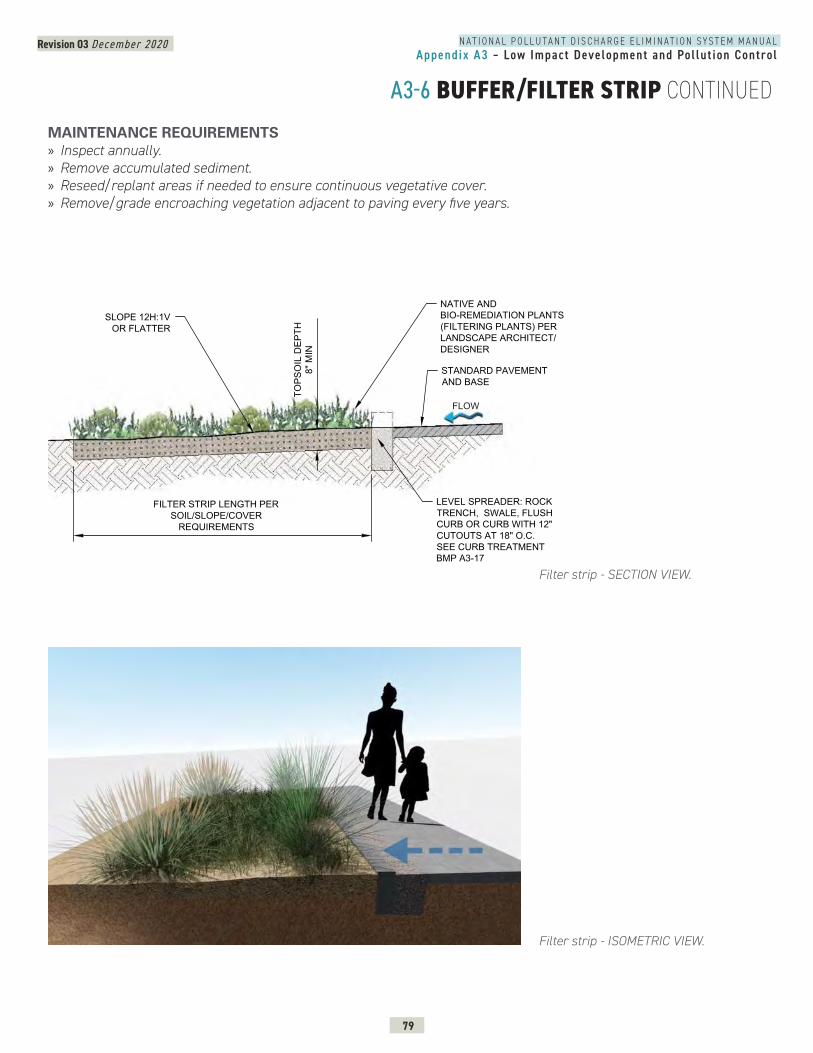
N A T I O N A L P O L L U T A N T D I S C H A R G E E L I M I N A T I O N S Y S T E M M A N U A LAppendix A3 – Low Impact Development and Pol lut ion Control
Revision 03 December 2020
79
A3-6 BUFFER/FILTER STRIP CONTINUED
Filter strip - SECTION VIEW.
MAINTENANCE REQUIREMENTS » Inspect annually. » Remove accumulated sediment. » Reseed/replant areas if needed to ensure continuous vegetative cover. » Remove/grade encroaching vegetation adjacent to paving every five years.
Filter strip - ISOMETRIC VIEW.
BUFFER/FILTER STRIP - SECTION
TOPS
OIL
DEP
TH8"
MIN
NATIVE ANDBIO-REMEDIATION PLANTS(FILTERING PLANTS) PERLANDSCAPE ARCHITECT/DESIGNER
LEVEL SPREADER: ROCKTRENCH, SWALE, FLUSHCURB OR CURB WITH 12"CUTOUTS AT 18" O.C.SEE CURB TREATMENTBMP A3-17
SLOPE 12H:1VOR FLATTER
STANDARD PAVEMENTAND BASE
FILTER STRIP LENGTH PERSOIL/SLOPE/COVER
REQUIREMENTS
FLOW
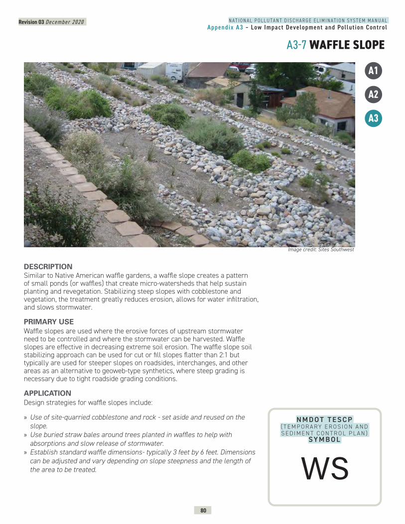
N A T I O N A L P O L L U T A N T D I S C H A R G E E L I M I N A T I O N S Y S T E M M A N U A LAppendix A3 – Low Impact Development and Pol lut ion Control
Revision 03 December 2020
80
A3-7 WAFFLE SLOPE
N M D O T T E S C P ( T E M P O R A RY E R O S I O N A N D S E D I M E N T C O N T R O L P L A N )
SY M B O L
DESCRIPTION Similar to Native American waffle gardens, a waffle slope creates a pattern of small ponds (or waffles) that create micro-watersheds that help sustain planting and revegetation. Stabilizing steep slopes with cobblestone and vegetation, the treatment greatly reduces erosion, allows for water infiltration, and slows stormwater.
PRIMARY USEWaffle slopes are used where the erosive forces of upstream stormwater need to be controlled and where the stormwater can be harvested. Waffle slopes are effective in decreasing extreme soil erosion. The waffle slope soil stabilizing approach can be used for cut or fill slopes flatter than 2:1 but typically are used for steeper slopes on roadsides, interchanges, and other areas as an alternative to geoweb-type synthetics, where steep grading is necessary due to tight roadside grading conditions.
APPLICATIONDesign strategies for waffle slopes include:
» Use of site-quarried cobblestone and rock - set aside and reused on the slope.
» Use buried straw bales around trees planted in waffles to help with absorptions and slow release of stormwater.
» Establish standard waffle dimensions- typically 3 feet by 6 feet. Dimensions can be adjusted and vary depending on slope steepness and the length of the area to be treated.
Image credit: Sites Southwest
A1
A2
A3
WS
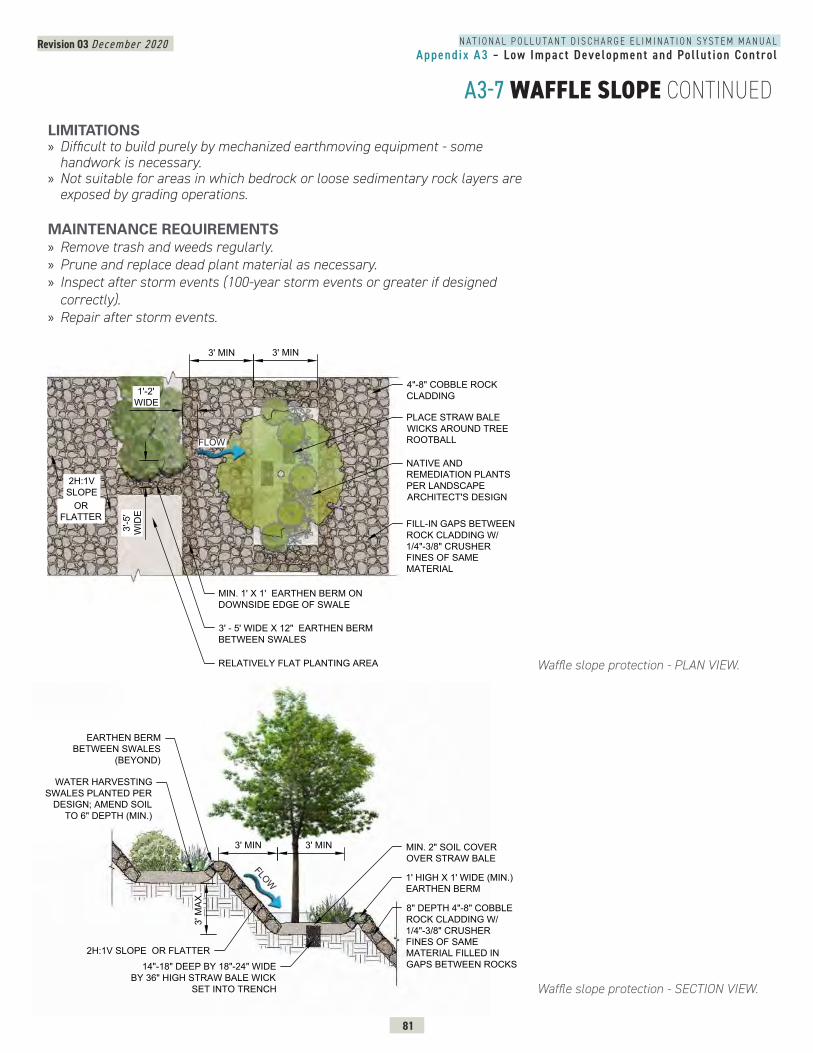
N A T I O N A L P O L L U T A N T D I S C H A R G E E L I M I N A T I O N S Y S T E M M A N U A LAppendix A3 – Low Impact Development and Pol lut ion Control
Revision 03 December 2020
81
A3-7 WAFFLE SLOPE CONTINUED
Waffle slope protection - PLAN VIEW.
Waffle slope protection - SECTION VIEW.
WAFFLE SLOPE - PLAN VIEW
PLACE STRAW BALEWICKS AROUND TREEROOTBALL
NATIVE ANDREMEDIATION PLANTSPER LANDSCAPEARCHITECT'S DESIGN
4"-8" COBBLE ROCKCLADDING
FILL-IN GAPS BETWEENROCK CLADDING W/1/4"-3/8" CRUSHERFINES OF SAMEMATERIAL
3' MIN
2H:1VSLOPE
3' - 5' WIDE X 12" EARTHEN BERMBETWEEN SWALES
RELATIVELY FLAT PLANTING AREA
MIN. 1' X 1' EARTHEN BERM ONDOWNSIDE EDGE OF SWALE
3' MIN
ORFLATTER
1'-2'WIDE
3'-5
'W
IDE
FLOW
FLOW
2H:1V SLOPE OR FLATTER
MIN. 2" SOIL COVEROVER STRAW BALE
3' MIN
WATER HARVESTINGSWALES PLANTED PER
DESIGN; AMEND SOILTO 6" DEPTH (MIN.)
EARTHEN BERMBETWEEN SWALES
(BEYOND)
1' HIGH X 1' WIDE (MIN.)EARTHEN BERM
14"-18" DEEP BY 18"-24" WIDEBY 36" HIGH STRAW BALE WICK
SET INTO TRENCH
3' MIN
8" DEPTH 4"-8" COBBLEROCK CLADDING W/1/4"-3/8" CRUSHERFINES OF SAMEMATERIAL FILLED INGAPS BETWEEN ROCKS
3' M
AX.
LIMITATIONS » Difficult to build purely by mechanized earthmoving equipment - some handwork is necessary.
» Not suitable for areas in which bedrock or loose sedimentary rock layers are exposed by grading operations.
MAINTENANCE REQUIREMENTS » Remove trash and weeds regularly. » Prune and replace dead plant material as necessary. » Inspect after storm events (100-year storm events or greater if designed correctly).
» Repair after storm events.
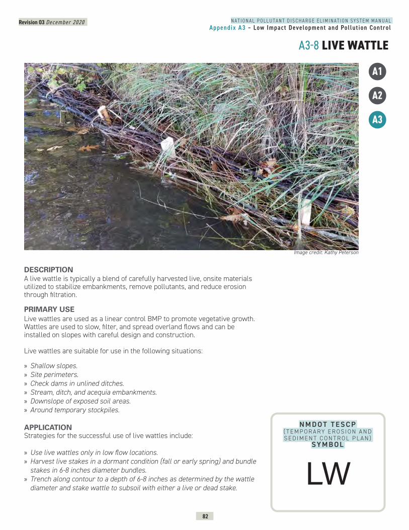
N A T I O N A L P O L L U T A N T D I S C H A R G E E L I M I N A T I O N S Y S T E M M A N U A LAppendix A3 – Low Impact Development and Pol lut ion Control
Revision 03 December 2020
82
A3-8 LIVE WATTLE
N M D O T T E S C P ( T E M P O R A RY E R O S I O N A N D S E D I M E N T C O N T R O L P L A N )
SY M B O L
DESCRIPTION A live wattle is typically a blend of carefully harvested live, onsite materials utilized to stabilize embankments, remove pollutants, and reduce erosion through filtration.
PRIMARY USELive wattles are used as a linear control BMP to promote vegetative growth. Wattles are used to slow, filter, and spread overland flows and can be installed on slopes with careful design and construction.
Live wattles are suitable for use in the following situations:
» Shallow slopes. » Site perimeters. » Check dams in unlined ditches. » Stream, ditch, and acequia embankments. » Downslope of exposed soil areas. » Around temporary stockpiles.
APPLICATIONStrategies for the successful use of live wattles include:
» Use live wattles only in low flow locations. » Harvest live stakes in a dormant condition (fall or early spring) and bundle stakes in 6-8 inches diameter bundles.
» Trench along contour to a depth of 6-8 inches as determined by the wattle diameter and stake wattle to subsoil with either a live or dead stake.
Image credit: Kathy Peterson
A1
A2
A3
LW

N A T I O N A L P O L L U T A N T D I S C H A R G E E L I M I N A T I O N S Y S T E M M A N U A LAppendix A3 – Low Impact Development and Pol lut ion Control
Revision 03 December 2020
83
A3-8 LIVE WATTLE CONTINUED
Wood stakes alternative to live cuttings.
LIMITATIONS » Can be disturbed or moved by high flows. » Need to be used with perennial flows. » Use may be limited by lack of available live vegetation in some regions.
MAINTENANCE REQUIREMENTS » Inspect wattles bi-weekly. » Reconstruct wattles if undermined or eroded.
1. DIG TRENCH AND LINE WITH BIODEGRADABLE FABRIC
OPEN-WEAVEBIODEGRADABLEFABRICTRENCH
2. FILL WITH GRASS CLUMPS, GRUB MATERIALS, AND SEED MIX
3. FOLD BIODEGRADABLE FABRIC OVER GRASS CLUMPS SOCLUMPS ARE SNUG AGAINST EACHOTHER
4. GRASSES WILL GROW THROUGH FABRIC
LIVE CUTTINGS ALTERNATIVE
BUNDLED WILLOWCUTTINGS
WOOD STAKES AT5' O.C.(+-)
BIODEGRADABLETWINE
Installation sequence for fabric-wrapped live wattle.
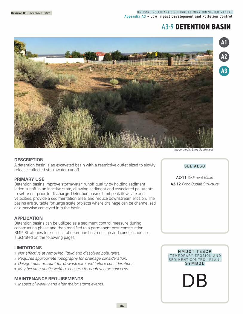
N A T I O N A L P O L L U T A N T D I S C H A R G E E L I M I N A T I O N S Y S T E M M A N U A LAppendix A3 – Low Impact Development and Pol lut ion Control
Revision 03 December 2020
84
A3-9 DETENTION BASIN
N M D O T T E S C P ( T E M P O R A RY E R O S I O N A N D S E D I M E N T C O N T R O L P L A N )
SY M B O L
DESCRIPTION A detention basin is an excavated basin with a restrictive outlet sized to slowly release collected stormwater runoff.
PRIMARY USEDetention basins improve stormwater runoff quality by holding sediment laden runoff in an inactive state, allowing sediment and associated pollutants to settle out prior to discharge. Detention basins limit peak flow rate and velocities, provide a sedimentation area, and reduce downstream erosion. The basins are suitable for large scale projects where drainage can be channelized or otherwise conveyed into the basin.
APPLICATIONDetention basins can be utilized as a sediment control measure during construction phase and then modified to a permanent post-construction BMP. Strategies for successful detention basin design and construction are illustrated on the following pages.
LIMITATIONS » Not effective at removing liquid and dissolved pollutants. » Requires appropriate topography for drainage consideration. » Design must account for downstream and failure considerations. » May become public welfare concern through vector concerns.
MAINTENANCE REQUIREMENTS » Inspect bi-weekly and after major storm events.
Image credit: Sites Southwest
A1
A2
A3
S E E A L S O
A2-11 Sediment Basin
A2-12 Pond Outfall Structure
DB
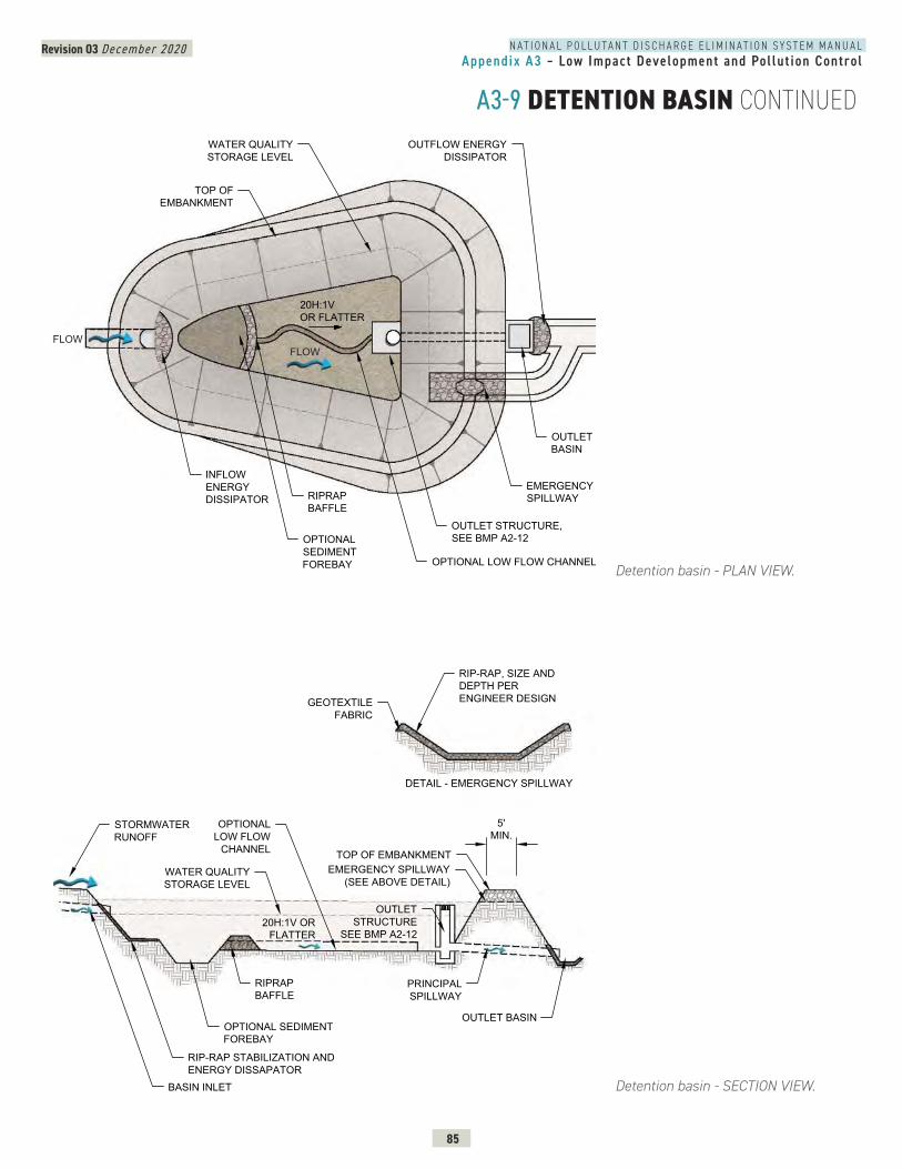
N A T I O N A L P O L L U T A N T D I S C H A R G E E L I M I N A T I O N S Y S T E M M A N U A LAppendix A3 – Low Impact Development and Pol lut ion Control
Revision 03 December 2020
85
A3-9 DETENTION BASIN CONTINUED
Detention basin - PLAN VIEW.
Detention basin - SECTION VIEW.
DETENTION BASIN - PLAN VIEW
TOP OFEMBANKMENT
OUTFLOW ENERGYDISSIPATOR
OUTLET STRUCTURE,SEE BMP A2-12
OUTLETBASIN
OPTIONALSEDIMENTFOREBAY
20H:1VOR FLATTER
OPTIONAL LOW FLOW CHANNEL
EMERGENCYSPILLWAYRIPRAP
BAFFLE
INFLOWENERGYDISSIPATOR
WATER QUALITYSTORAGE LEVEL
FLOWFLOW
OUTLET BASIN
TOP OF EMBANKMENT
5'MIN.
BASIN INLET
RIP-RAP STABILIZATION ANDENERGY DISSAPATOR
OPTIONALLOW FLOW
CHANNEL
WATER QUALITYSTORAGE LEVEL
OUTLETSTRUCTURE
SEE BMP A2-12
STORMWATERRUNOFF
PRINCIPALSPILLWAY
EMERGENCY SPILLWAY(SEE ABOVE DETAIL)
RIP-RAP, SIZE ANDDEPTH PERENGINEER DESIGNGEOTEXTILE
FABRIC
DETAIL - EMERGENCY SPILLWAY
20H:1V ORFLATTER
OPTIONAL SEDIMENTFOREBAY
RIPRAPBAFFLE
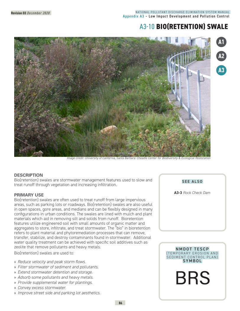
N A T I O N A L P O L L U T A N T D I S C H A R G E E L I M I N A T I O N S Y S T E M M A N U A LAppendix A3 – Low Impact Development and Pol lut ion Control
Revision 03 December 2020
86
A3-10 BIO(RETENTION) SWALE
N M D O T T E S C P ( T E M P O R A RY E R O S I O N A N D S E D I M E N T C O N T R O L P L A N )
SY M B O L
DESCRIPTION Bio(retention) swales are stormwater management features used to slow and treat runoff through vegetation and increasing infiltration.
PRIMARY USE Bio(retention) swales are often used to treat runoff from large impervious areas, such as parking lots or roadways. Bio(retention) swales are also useful in open spaces, gore areas, and medians and can be flexibly designed in many configurations in urban conditions. The swales are lined with mulch and plant materials which aid in removing silt and solids from runoff. Bioretention features utilize engineered soil with small amounts of organic matter and aggregates to store, infiltrate, and treat stormwater. The “bio” in bioretention refers to plant material and phytoremediation processes that can remove, transfer, stabilize, and destroy contaminants found in stormwater. Additional water quality treatment can be achieved with specific soil additives such as zeolite that remove pollutants and heavy metals. Bio(retention) swales are used to:
» Reduce velocity and peak storm flows. » Filter stormwater of sediment and pollutants. » Extend stormwater detention and storage. » Adsorb some pollutants and heavy metals. » Provide supplemental water for plantings. » Convey excess stormwater. » Improve street side and parking lot aesthetics.
Image credit: University of California, Santa Barbara: Cheadle Center for Biodiversity & Ecological Restoration
A1
A2
A3
S E E A L S O
A3-3 Rock Check Dam
BRS
N A T I O N A L P O L L U T A N T D I S C H A R G E E L I M I N A T I O N S Y S T E M M A N U A LAppendix A3 – Low Impact Development and Pol lut ion Control
Revision 03 December 2020
87
A3-10 BIO(RETENTION) SWALE CONTINUEDAPPLICATIONStrategies for successful bio (retention) swale design include:
» Use a hard edge like a flush curb or raised concrete curbs with curb cuts where drainage occurs along the interface of paving and the swale.
» Identify and use a suitable soil blend - typically 85% sand, 8-12% fines and under 2-5% plant-derived organic material with a recommended minimum infiltration rate of 6 inches per hour.
» Provide a 10 foot setback from structural foundations. » Limit the grades of slopes draining to the bio(retention) swale to 15% or less. Side slopes should be 3H:1V or flatter and the longitudinal slope of the swale shall be determined by the storm event flow velocity.
» Construct a rock-armored forebay for trash/sediment removal and velocity reduction at concentrated inflow locations.
» Add check dams within the swale to pond water for increased infiltration.
LIMITATIONS » Site investigation is important for successful implementation. » Infiltration of ponded water in the bio(retention) swales is dependent on the porosity of subsurface soils. Impermeable subsoil layers may require an underdrain. Underdrains shall be connected to other BMP features, stormwater sewers or drainage facilities.
» Governing codes, standards and regulations may not allow stormwater harvesting on top of utilities.
» Supplemental irrigation is recommended to establish and maintain vegetative health in arid southwest regions.
» Not suitable for steep slopes with high velocity flows. Maximum flow velocity should not exceed 3 feet per second.
» Not suitable at locations with high water tables that will reduce infiltration below acceptable rates.
» Not suitable for installation where contaminated soil is a concern.
MAINTENANCE REQUIREMENTS » Inspect swales after major storm events during and post-construction. » Inspect and maintain swales semi-annually for excessive sediment and debris build-up, significant mulch relocation due to water velocity, damaged vegetation and berm damage.
» Remove and replace dead vegetation. » Restore surface soils by scarifying surface to improve percolation. » Maintain planting as needed including pruning, weeding, mowing, fertilization, replacement, and pest control.
» Remove trash regularly.
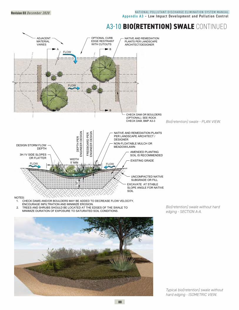
N A T I O N A L P O L L U T A N T D I S C H A R G E E L I M I N A T I O N S Y S T E M M A N U A LAppendix A3 – Low Impact Development and Pol lut ion Control
Revision 03 December 2020
88
A3-10 BIO(RETENTION) SWALE CONTINUED
Bio(retention) swale - PLAN VIEW.
ENTION) SWALE - PLAN VIEW
CHECK DAM OR BOULDERS(OPTIONAL). SEE ROCKCHECK DAM, BMP A3-3
OPTIONAL CURBEDGE RESTRAINTWITH CUTOUTS
NATIVE AND REMEDIATIONPLANTS PER LANDSCAPEARCHITECT/DESIGNER
ADJACENTMATERIALVARIES
A
A
B
B
FLOW
FLOW
Typical bio(retention) swale without hard edging - ISOMETRIC VIEW.
Bio(retention) swale without hard edging - SECTION A-A.
O(RETENTION) SWALE - SECTION AA
WIDTH5' MIN
DEP
TH P
EREN
GIN
EER
DES
IGN
NON-FLOATABLE MULCH ORMEADOW/LAWN
NATIVE AND REMEDIATION PLANTSPER LANDSCAPE ARCHITECT /DESIGNER
AMENDED PLANTINGSOIL IS RECOMMENDED
NOTES:1. CHECK DAMS AND/OR BOULDERS MAY BE ADDED TO DECREASE FLOW VELOCITY,
ENCOURAGE INFILTRATION AND MINIMIZE EROSION.2. TREES AND SHRUBS SHOULD BE LOCATED AT THE EDGES OF THE SWALE TO
MINIMIZE DURATION OF EXPOSURE TO SATURATED SOIL CONDITIONS.
DESIGN STORM FLOWDEPTH
3H:1V SIDE SLOPESOR FLATTER
FREE
BOAR
D P
EREN
GIN
EER
DES
IGN
EXISTING GRADE
EXCAVATE AT STABLESLOPE ANGLE FOR NATIVESOIL
UNCOMPACTED NATIVESUBGRADE OR FILL
18"
FLOW FLOW
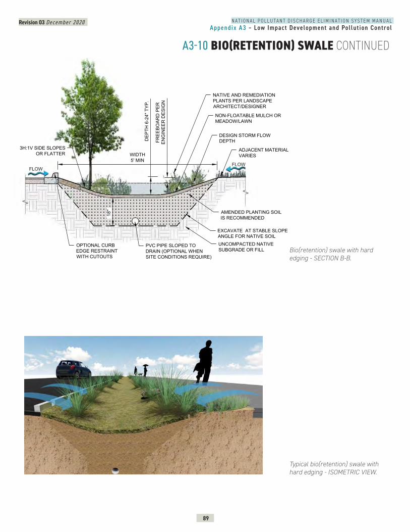
N A T I O N A L P O L L U T A N T D I S C H A R G E E L I M I N A T I O N S Y S T E M M A N U A LAppendix A3 – Low Impact Development and Pol lut ion Control
Revision 03 December 2020
89
A3-10 BIO(RETENTION) SWALE CONTINUED
TENTION) SWALE - SECTION BB
WIDTH5' MIN
DEP
TH 6
-24"
TYP
.
NON-FLOATABLE MULCH ORMEADOW/LAWN
NATIVE AND REMEDIATIONPLANTS PER LANDSCAPEARCHITECT/DESIGNER
AMENDED PLANTING SOILIS RECOMMENDED
OPTIONAL CURBEDGE RESTRAINTWITH CUTOUTS
EXCAVATE AT STABLE SLOPEANGLE FOR NATIVE SOIL
18"
UNCOMPACTED NATIVESUBGRADE OR FILL
ADJACENT MATERIALVARIES
FREE
BOAR
D P
EREN
GIN
EER
DES
IGN
DESIGN STORM FLOWDEPTH
PVC PIPE SLOPED TODRAIN (OPTIONAL WHENSITE CONDITIONS REQUIRE)
3H:1V SIDE SLOPESOR FLATTER
FLOWFLOW
Typical bio(retention) swale with hard edging - ISOMETRIC VIEW.
Bio(retention) swale with hard edging - SECTION B-B.
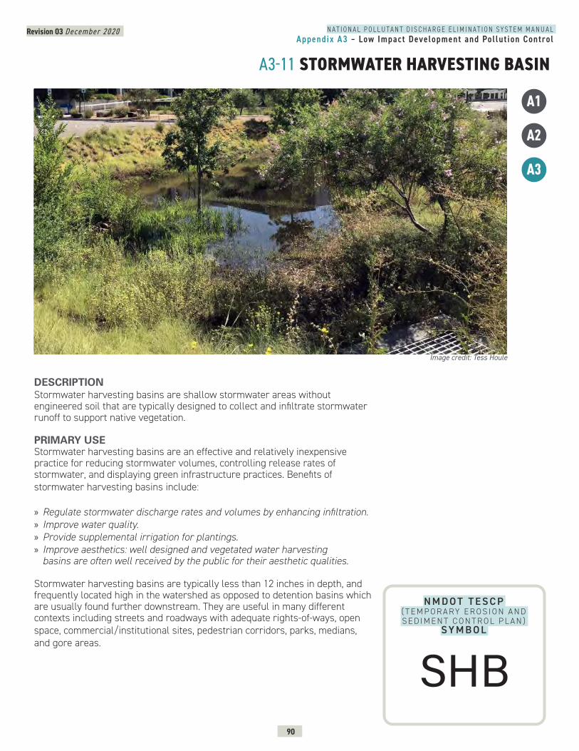
N A T I O N A L P O L L U T A N T D I S C H A R G E E L I M I N A T I O N S Y S T E M M A N U A LAppendix A3 – Low Impact Development and Pol lut ion Control
Revision 03 December 2020
90
A3-11 STORMWATER HARVESTING BASIN
N M D O T T E S C P ( T E M P O R A RY E R O S I O N A N D S E D I M E N T C O N T R O L P L A N )
SY M B O L
DESCRIPTION Stormwater harvesting basins are shallow stormwater areas without engineered soil that are typically designed to collect and infiltrate stormwater runoff to support native vegetation.
PRIMARY USEStormwater harvesting basins are an effective and relatively inexpensive practice for reducing stormwater volumes, controlling release rates of stormwater, and displaying green infrastructure practices. Benefits of stormwater harvesting basins include: » Regulate stormwater discharge rates and volumes by enhancing infiltration. » Improve water quality. » Provide supplemental irrigation for plantings. » Improve aesthetics: well designed and vegetated water harvesting basins are often well received by the public for their aesthetic qualities.
Stormwater harvesting basins are typically less than 12 inches in depth, and frequently located high in the watershed as opposed to detention basins which are usually found further downstream. They are useful in many different contexts including streets and roadways with adequate rights-of-ways, open space, commercial/institutional sites, pedestrian corridors, parks, medians, and gore areas.
Image credit: Tess Houle
A1
A2
A3
SHB
N A T I O N A L P O L L U T A N T D I S C H A R G E E L I M I N A T I O N S Y S T E M M A N U A LAppendix A3 – Low Impact Development and Pol lut ion Control
Revision 03 December 2020
91
A3-11 STORMWATER HARVESTING BASIN CONTINUEDAPPLICATION Strategies for successful stormwater harvesting basin design include:
» Design an upstream inlet bypass mechanism for flood events. » Consider sediment traps at the inlet(s) to decrease sediment load. » Follow AASHTO roadway clear zone requirements if the stormwater harvesting basin is next to a travel lane.
» Design an overflow directing flows to a watercourse or other green infrastructure feature for major storm events.
» Provide interpretative signage at the basin to provide an opportunity to educate the public about stormwater.
» Design basins to be compliant with local and state provisions to infiltrate stormwater in specified amounts of time.
» Design side slopes no steeper than 3H:1V and line slopes with rock lining or other erosion control measures as necessary.
» Consider climate conditions and periodic saturated soil conditions when selecting and placing plant materials at stormwater harvesting basins.
» Include supplemental irrigation to establish plant materials and maintain plant health in arid conditions. Under certain conditions, the irrigation systems may be removed/disconnected after plant establishment.
» Design plant and mulch installation without filter fabric at stormwater harvesting basins.
» Protect soils from compaction during construction.
LIMITATIONS » Supplemental irrigation is recommended to establish and maintain plant health in arid conditions.
» Not suitable in poorly drained soils, caliche, bedrock or near sensitive infrastructure.
» Not suitable for installation where contaminated soil is a concern. » Prolonged surface water storage can be a vector concern and can harm plants.
» Governing codes, standards and regulations may not allow stormwater harvesting on top of utilities.
MAINTENANCE REQUIREMENTS » Inspect basins after major storm events. » Inspect and maintain basins semi-annually for excessive sediment and debris build-up, significant mulch relocation due to water velocity, prolonged surface water storage, damaged vegetation and side slope damage.
» Remove invasive/advantageous plant material. » Remove sediment, debris, and floatables. » Maintain planting as needed including pruning, weeding, mowing, fertilization, replacement, and pest control.
» Stabilize and repair minor erosion. » Regrade pond bottom if significant sedimentation occurs.
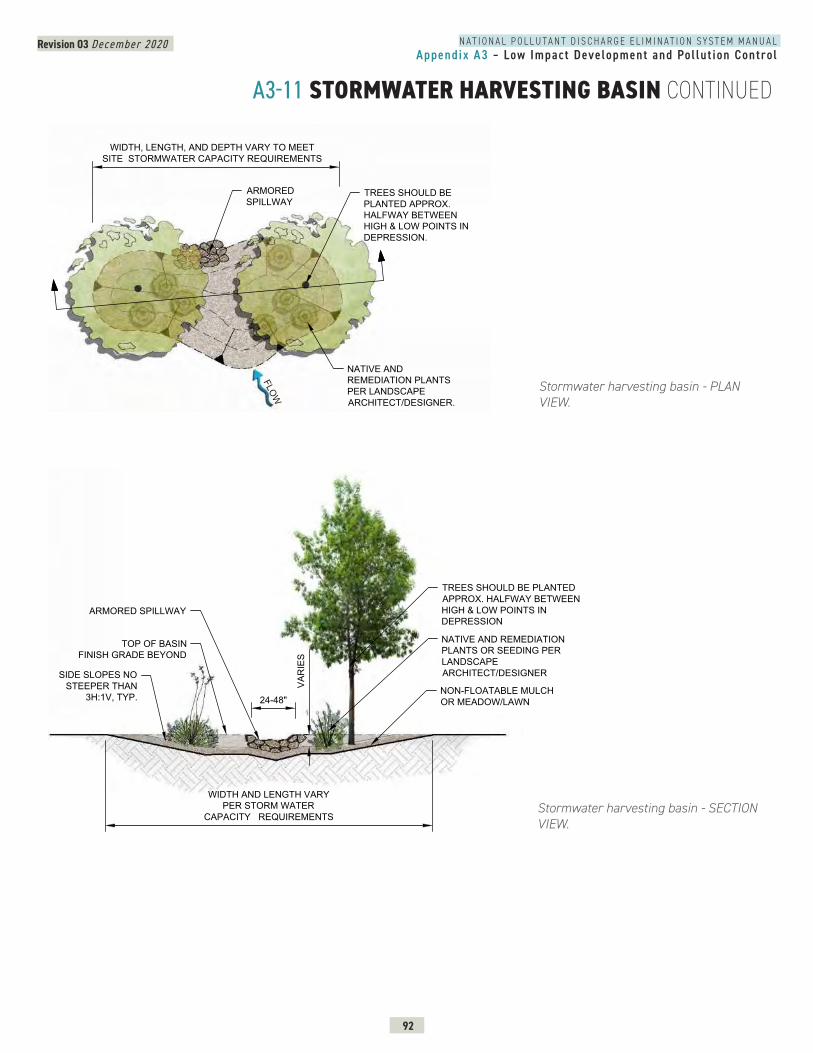
N A T I O N A L P O L L U T A N T D I S C H A R G E E L I M I N A T I O N S Y S T E M M A N U A LAppendix A3 – Low Impact Development and Pol lut ion Control
Revision 03 December 2020
92
A3-11 STORMWATER HARVESTING BASIN CONTINUED
Stormwater harvesting basin - SECTION VIEW.
Stormwater harvesting basin - PLAN VIEW.
WATER HARVESTING BASIN - PLAN VIEW
WIDTH, LENGTH, AND DEPTH VARY TO MEETSITE STORMWATER CAPACITY REQUIREMENTS
TREES SHOULD BEPLANTED APPROX.HALFWAY BETWEENHIGH & LOW POINTS INDEPRESSION.
ARMOREDSPILLWAY
NATIVE ANDREMEDIATION PLANTSPER LANDSCAPEARCHITECT/DESIGNER.
FLOW
WIDTH AND LENGTH VARYPER STORM WATER
CAPACITY REQUIREMENTS
TOP OF BASINFINISH GRADE BEYOND
SIDE SLOPES NOSTEEPER THAN
3H:1V, TYP.
ARMORED SPILLWAY
24-48"
TREES SHOULD BE PLANTEDAPPROX. HALFWAY BETWEENHIGH & LOW POINTS INDEPRESSION
NATIVE AND REMEDIATIONPLANTS OR SEEDING PERLANDSCAPEARCHITECT/DESIGNER
VAR
IES
NON-FLOATABLE MULCHOR MEADOW/LAWN
1
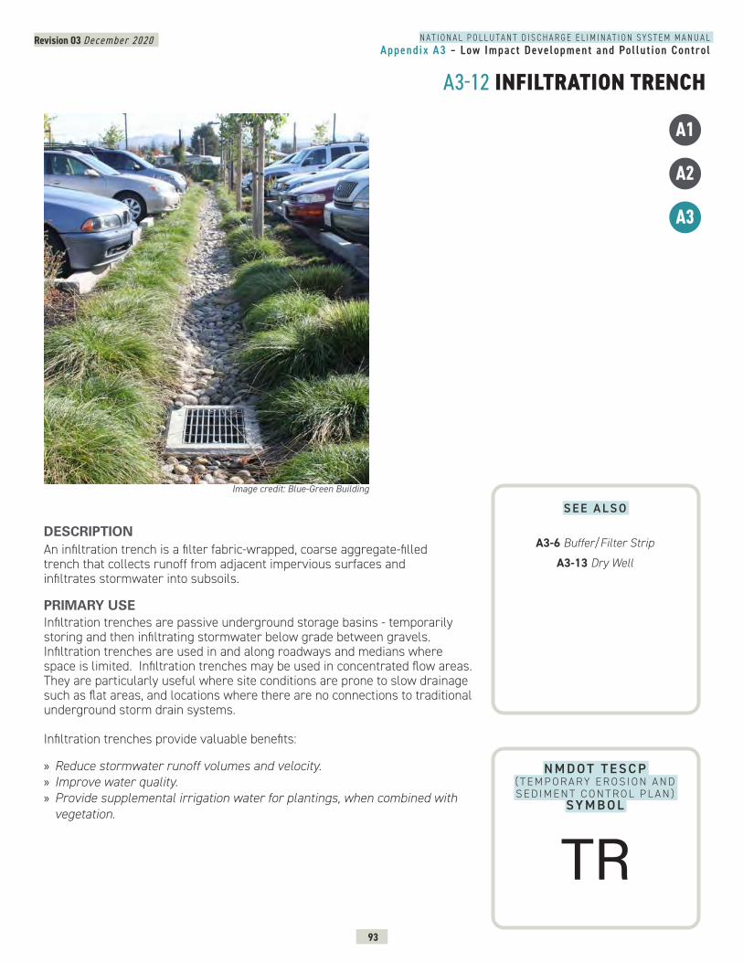
N A T I O N A L P O L L U T A N T D I S C H A R G E E L I M I N A T I O N S Y S T E M M A N U A LAppendix A3 – Low Impact Development and Pol lut ion Control
Revision 03 December 2020
93
A3-12 INFILTRATION TRENCH
N M D O T T E S C P ( T E M P O R A RY E R O S I O N A N D S E D I M E N T C O N T R O L P L A N )
SY M B O L
DESCRIPTION An infiltration trench is a filter fabric-wrapped, coarse aggregate-filled trench that collects runoff from adjacent impervious surfaces and infiltrates stormwater into subsoils.
PRIMARY USEInfiltration trenches are passive underground storage basins - temporarily storing and then infiltrating stormwater below grade between gravels. Infiltration trenches are used in and along roadways and medians where space is limited. Infiltration trenches may be used in concentrated flow areas. They are particularly useful where site conditions are prone to slow drainage such as flat areas, and locations where there are no connections to traditional underground storm drain systems.
Infiltration trenches provide valuable benefits:
» Reduce stormwater runoff volumes and velocity. » Improve water quality. » Provide supplemental irrigation water for plantings, when combined with vegetation.
Image credit: Blue-Green Building
A1
A2
A3
S E E A L S O
A3-6 Buffer/Filter Strip
A3-13 Dry Well
TR
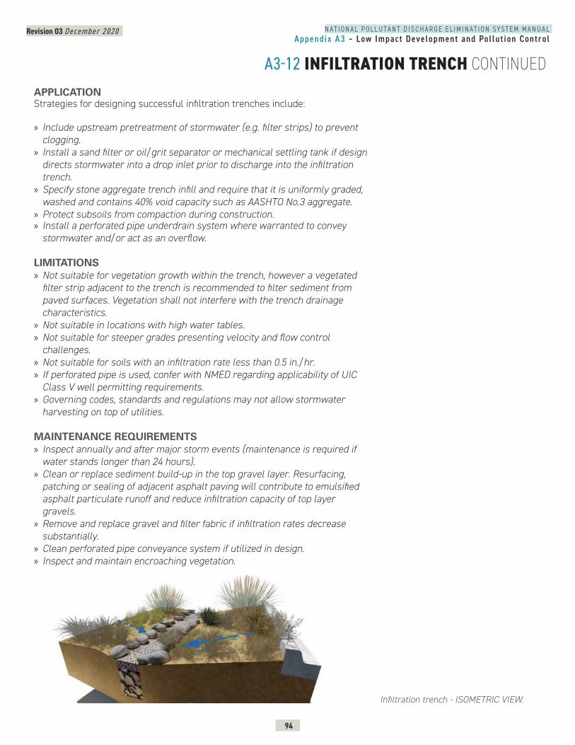
N A T I O N A L P O L L U T A N T D I S C H A R G E E L I M I N A T I O N S Y S T E M M A N U A LAppendix A3 – Low Impact Development and Pol lut ion Control
Revision 03 December 2020
94
A3-12 INFILTRATION TRENCH CONTINUED
Infiltration trench - ISOMETRIC VIEW.
APPLICATION Strategies for designing successful infiltration trenches include:
» Include upstream pretreatment of stormwater (e.g. filter strips) to prevent clogging.
» Install a sand filter or oil/grit separator or mechanical settling tank if design directs stormwater into a drop inlet prior to discharge into the infiltration trench.
» Specify stone aggregate trench infill and require that it is uniformly graded, washed and contains 40% void capacity such as AASHTO No.3 aggregate.
» Protect subsoils from compaction during construction. » Install a perforated pipe underdrain system where warranted to convey stormwater and/or act as an overflow.
LIMITATIONS » Not suitable for vegetation growth within the trench, however a vegetated filter strip adjacent to the trench is recommended to filter sediment from paved surfaces. Vegetation shall not interfere with the trench drainage characteristics.
» Not suitable in locations with high water tables. » Not suitable for steeper grades presenting velocity and flow control challenges.
» Not suitable for soils with an infiltration rate less than 0.5 in./hr. » If perforated pipe is used, confer with NMED regarding applicability of UIC Class V well permitting requirements.
» Governing codes, standards and regulations may not allow stormwater harvesting on top of utilities.
MAINTENANCE REQUIREMENTS » Inspect annually and after major storm events (maintenance is required if water stands longer than 24 hours).
» Clean or replace sediment build-up in the top gravel layer. Resurfacing, patching or sealing of adjacent asphalt paving will contribute to emulsified asphalt particulate runoff and reduce infiltration capacity of top layer gravels.
» Remove and replace gravel and filter fabric if infiltration rates decrease substantially.
» Clean perforated pipe conveyance system if utilized in design. » Inspect and maintain encroaching vegetation.
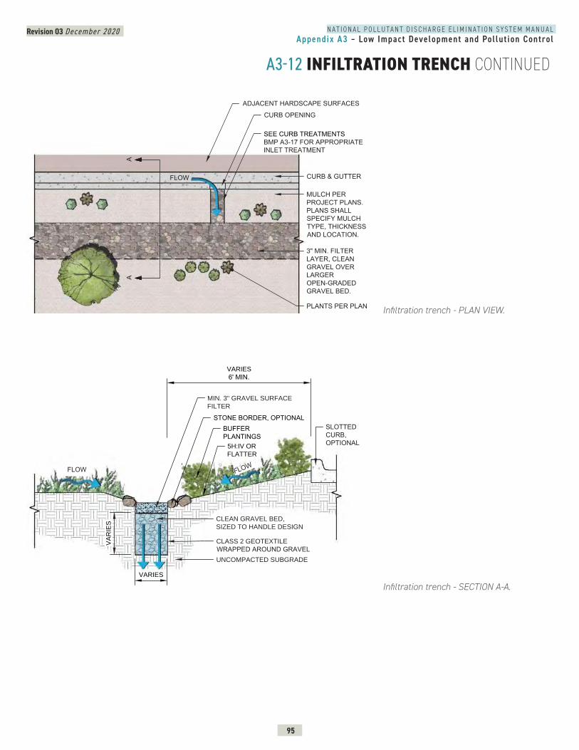
N A T I O N A L P O L L U T A N T D I S C H A R G E E L I M I N A T I O N S Y S T E M M A N U A LAppendix A3 – Low Impact Development and Pol lut ion Control
Revision 03 December 2020
95
A3-12 INFILTRATION TRENCH CONTINUED
Infiltration trench - SECTION A-A.
INFILTRATION TRENCH - PLAN VIEW
SEE CURB TREATMENTSBMP A3-17 FOR APPROPRIATEINLET TREATMENT
ADJACENT HARDSCAPE SURFACES
CURB & GUTTER
CURB OPENING
AA
MULCH PERPROJECT PLANS.PLANS SHALLSPECIFY MULCHTYPE, THICKNESSAND LOCATION.
3" MIN. FILTERLAYER, CLEANGRAVEL OVERLARGEROPEN-GRADEDGRAVEL BED.
PLANTS PER PLAN
FLOW
A3-18
FLOW
INFILTRATION TRENCH - SECTION AA
STONE BORDER, OPTIONALSLOTTEDCURB,OPTIONAL
CLASS 2 GEOTEXTILE
WRAPPED AROUND GRAVELUNCOMPACTED SUBGRADE
MIN. 3" GRAVEL SURFACE
FILTER
CLEAN GRAVEL BED,
SIZED TO HANDLE DESIGN
VA
RIE
S
VARIES
BUFFERPLANTINGS
VARIES
6' MIN.
5H:IV OR
FLATTER
A3-12
FLOW
Infiltration trench - PLAN VIEW.
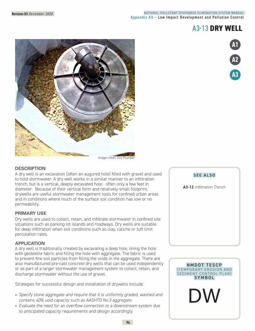
N A T I O N A L P O L L U T A N T D I S C H A R G E E L I M I N A T I O N S Y S T E M M A N U A LAppendix A3 – Low Impact Development and Pol lut ion Control
Revision 03 December 2020
96
A3-13 DRY WELL
N M D O T T E S C P ( T E M P O R A RY E R O S I O N A N D S E D I M E N T C O N T R O L P L A N )
SY M B O L
DESCRIPTION A dry well is an excavation (often an augured hole) filled with gravel and used to hold stormwater. A dry well works in a similar manner to an infiltration trench, but is a vertical, deeply excavated hole - often only a few feet in diameter. Because of their vertical form and relatively small footprint, drywells are useful stormwater management tools for confined urban areas and in conditions where much of the surface soil condition has low or no permeability.
PRIMARY USEDry wells are used to collect, retain, and infiltrate stormwater in confined site situations such as parking lot islands and roadways. Dry wells are suitable for deep infiltration when soil conditions such as clay, caliche or tuft limit percolation rates.
APPLICATION A dry well is traditionally created by excavating a deep hole, lining the hole with geotextile fabric and filling the hole with aggregate. The fabric is used to prevent fine soil particles from filling the voids in the aggregate. There are also manufactured pre-cast concrete dry wells that can be used independently or as part of a larger stormwater management system to collect, retain, and discharge stormwater without the use of gravel.
Strategies for successful design and installation of drywells include: » Specify stone aggregate and require that it is uniformly graded, washed and contains 40% void capacity such as AASHTO No.3 aggregate.
» Evaluate the need for an overflow connection to a downstream system due to anticipated capacity requirements and design accordingly.
Image credit: Eco Plumber
A1
A2
A3
S E E A L S O
A3-12 Infiltration Trench
DW
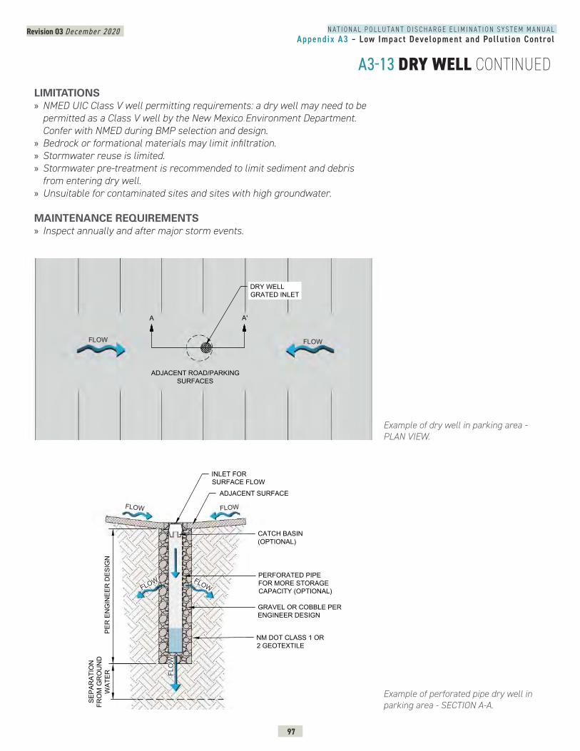
N A T I O N A L P O L L U T A N T D I S C H A R G E E L I M I N A T I O N S Y S T E M M A N U A LAppendix A3 – Low Impact Development and Pol lut ion Control
Revision 03 December 2020
97
A3-13 DRY WELL CONTINUEDLIMITATIONS » NMED UIC Class V well permitting requirements: a dry well may need to be permitted as a Class V well by the New Mexico Environment Department. Confer with NMED during BMP selection and design.
» Bedrock or formational materials may limit infiltration. » Stormwater reuse is limited. » Stormwater pre-treatment is recommended to limit sediment and debris from entering dry well.
» Unsuitable for contaminated sites and sites with high groundwater.
MAINTENANCE REQUIREMENTS » Inspect annually and after major storm events.
Example of dry well in parking area - PLAN VIEW.
Example of perforated pipe dry well in parking area - SECTION A-A.
3
PERFORATED PIPEFOR MORE STORAGECAPACITY (OPTIONAL)
SEPA
RAT
ION
FRO
M G
RO
UN
DW
ATER
GRAVEL OR COBBLE PERENGINEER DESIGN
INLET FORSURFACE FLOW
ADJACENT SURFACE
PER
EN
GIN
EER
DES
IGN
NM DOT CLASS 1 OR2 GEOTEXTILE
CATCH BASIN(OPTIONAL)
FLOW
FLOW FLOW
FLOW
FLO
W
-13
DRY WELL - PLAN VIEW
A A'
DRY WELLGRATED INLET
ADJACENT ROAD/PARKINGSURFACES
FLOWFLOW
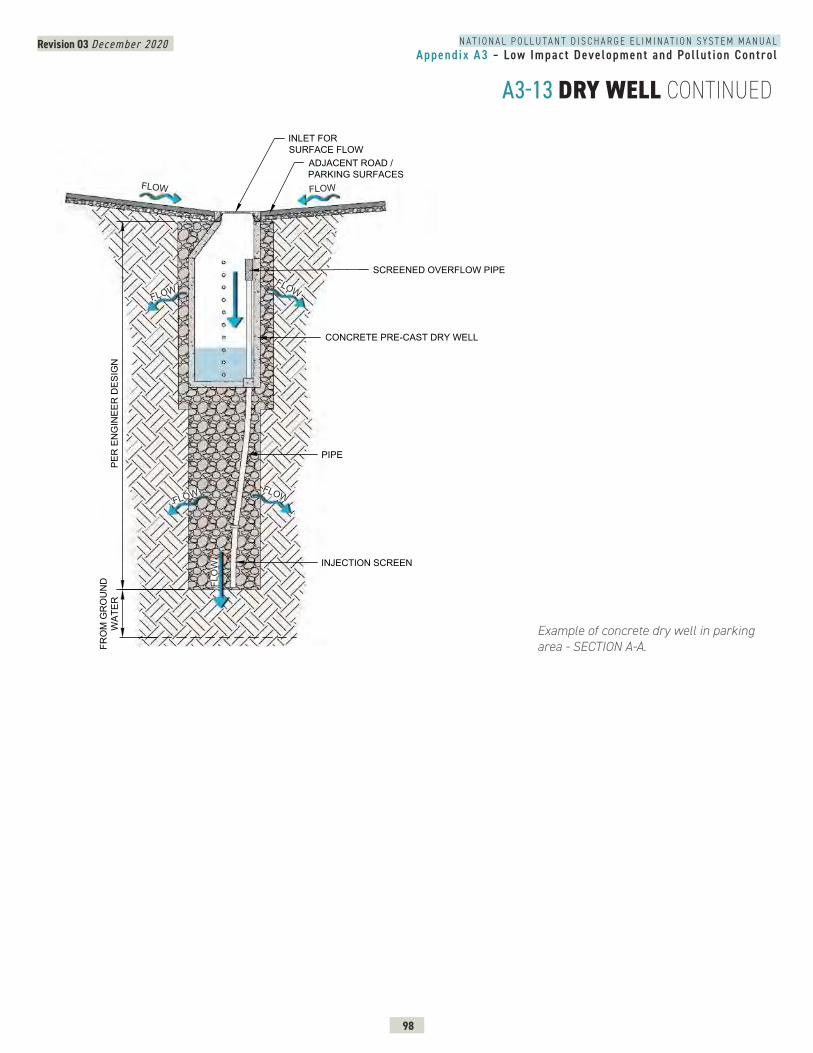
N A T I O N A L P O L L U T A N T D I S C H A R G E E L I M I N A T I O N S Y S T E M M A N U A LAppendix A3 – Low Impact Development and Pol lut ion Control
Revision 03 December 2020
98
A3-13 DRY WELL CONTINUED
Example of concrete dry well in parking area - SECTION A-A.
ELL - SECTION AA
SCREENED OVERFLOW PIPE
SEPA
RAT
ION
FRO
M G
RO
UN
DW
ATER
PIPE
INJECTION SCREEN
CONCRETE PRE-CAST DRY WELL
INLET FORSURFACE FLOW
ADJACENT ROAD /PARKING SURFACES
PER
EN
GIN
EER
DES
IGN
FLOW
FLOW
FLOW
FLOW
FLOW
FLOW
FLO
W
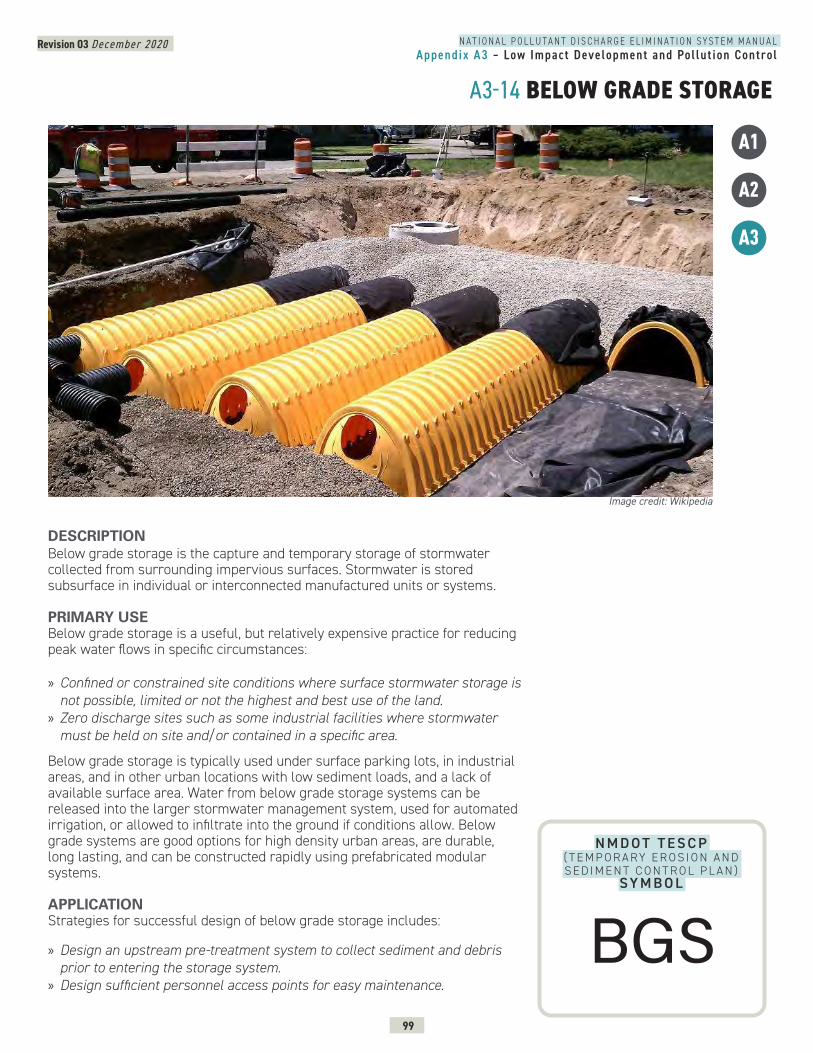
N A T I O N A L P O L L U T A N T D I S C H A R G E E L I M I N A T I O N S Y S T E M M A N U A LAppendix A3 – Low Impact Development and Pol lut ion Control
Revision 03 December 2020
99
A3-14 BELOW GRADE STORAGE
N M D O T T E S C P ( T E M P O R A RY E R O S I O N A N D S E D I M E N T C O N T R O L P L A N )
SY M B O L
DESCRIPTION Below grade storage is the capture and temporary storage of stormwater collected from surrounding impervious surfaces. Stormwater is stored subsurface in individual or interconnected manufactured units or systems.
PRIMARY USEBelow grade storage is a useful, but relatively expensive practice for reducing peak water flows in specific circumstances:
» Confined or constrained site conditions where surface stormwater storage is not possible, limited or not the highest and best use of the land.
» Zero discharge sites such as some industrial facilities where stormwater must be held on site and/or contained in a specific area.
Below grade storage is typically used under surface parking lots, in industrial areas, and in other urban locations with low sediment loads, and a lack of available surface area. Water from below grade storage systems can be released into the larger stormwater management system, used for automated irrigation, or allowed to infiltrate into the ground if conditions allow. Below grade systems are good options for high density urban areas, are durable, long lasting, and can be constructed rapidly using prefabricated modular systems.
APPLICATIONStrategies for successful design of below grade storage includes:
» Design an upstream pre-treatment system to collect sediment and debris prior to entering the storage system.
» Design sufficient personnel access points for easy maintenance.
Image credit: Wikipedia
A1
A2
A3
BGS
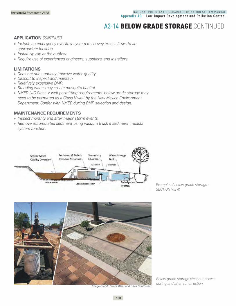
N A T I O N A L P O L L U T A N T D I S C H A R G E E L I M I N A T I O N S Y S T E M M A N U A LAppendix A3 – Low Impact Development and Pol lut ion Control
Revision 03 December 2020
100
A3-14 BELOW GRADE STORAGE CONTINUED
Example of below grade storage - SECTION VIEW.
Below grade storage cleanout access during and after construction.
» Include an emergency overflow system to convey excess flows to an appropriate location.
» Install rip rap at the outflow. » Require use of experienced engineers, suppliers, and installers.
LIMITATIONS » Does not substantially improve water quality. » Difficult to inspect and maintain. » Relatively expensive BMP. » Standing water may create mosquito habitat. » NMED UIC Class V well permitting requirements: below grade storage may need to be permitted as a Class V well by the New Mexico Environment Department. Confer with NMED during BMP selection and design.
MAINTENANCE REQUIREMENTS » Inspect monthly and after major storm events. » Remove accumulated sediment using vacuum truck if sediment impacts system function.
APPLICATION CONTINUED
Image credit: Tierra West and Sites Southwest
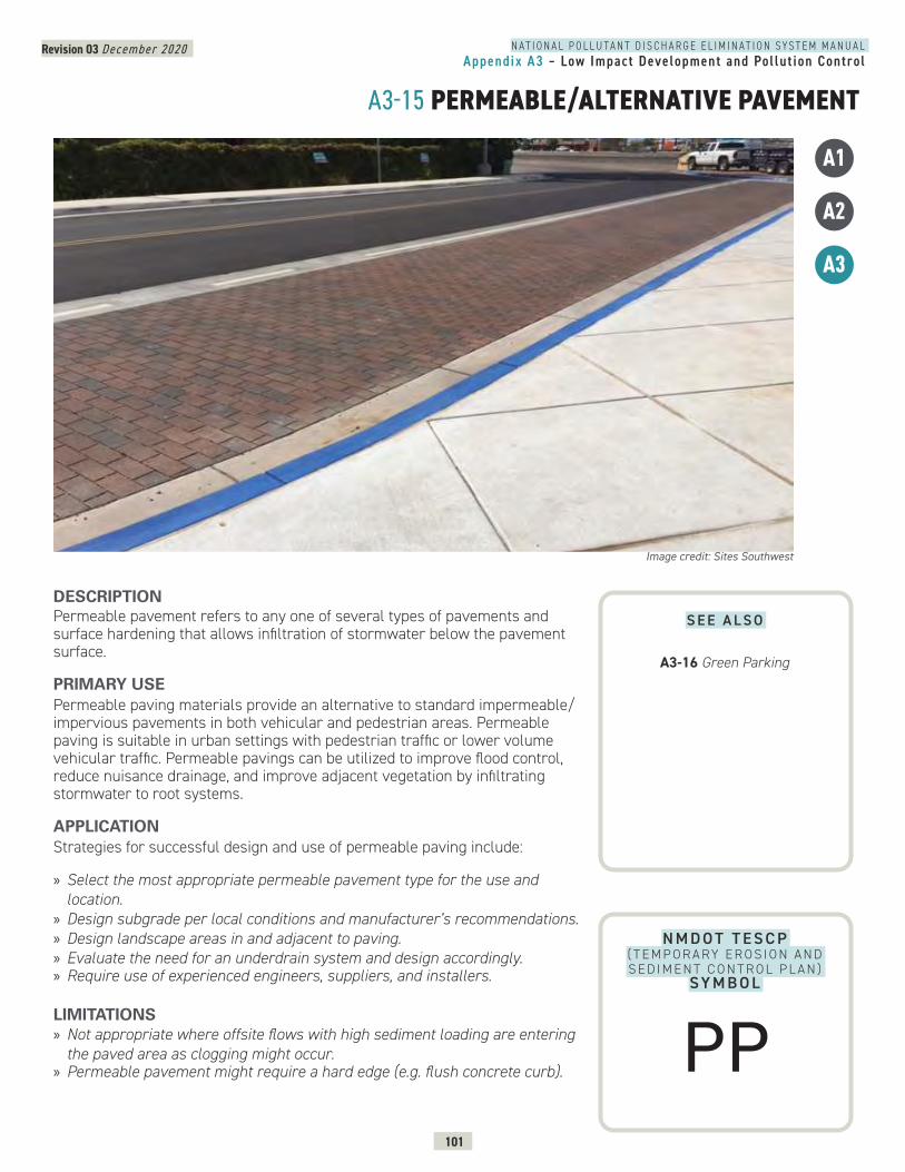
N A T I O N A L P O L L U T A N T D I S C H A R G E E L I M I N A T I O N S Y S T E M M A N U A LAppendix A3 – Low Impact Development and Pol lut ion Control
Revision 03 December 2020
101
A3-15 PERMEABLE/ALTERNATIVE PAVEMENT
N M D O T T E S C P ( T E M P O R A RY E R O S I O N A N D S E D I M E N T C O N T R O L P L A N )
SY M B O L
DESCRIPTION Permeable pavement refers to any one of several types of pavements and surface hardening that allows infiltration of stormwater below the pavement surface.
PRIMARY USEPermeable paving materials provide an alternative to standard impermeable/impervious pavements in both vehicular and pedestrian areas. Permeable paving is suitable in urban settings with pedestrian traffic or lower volume vehicular traffic. Permeable pavings can be utilized to improve flood control, reduce nuisance drainage, and improve adjacent vegetation by infiltrating stormwater to root systems.
APPLICATIONStrategies for successful design and use of permeable paving include:
» Select the most appropriate permeable pavement type for the use and location.
» Design subgrade per local conditions and manufacturer’s recommendations. » Design landscape areas in and adjacent to paving. » Evaluate the need for an underdrain system and design accordingly. » Require use of experienced engineers, suppliers, and installers.
LIMITATIONS » Not appropriate where offsite flows with high sediment loading are entering the paved area as clogging might occur.
» Permeable pavement might require a hard edge (e.g. flush concrete curb).
Image credit: Sites Southwest
A1
A2
A3
S E E A L S O
A3-16 Green Parking
PP
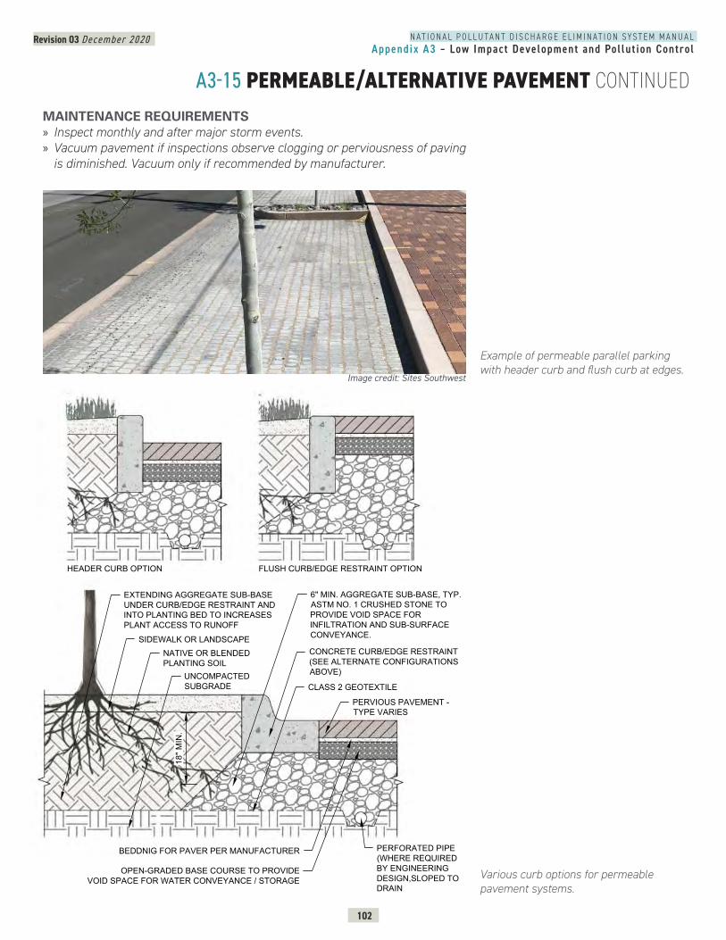
N A T I O N A L P O L L U T A N T D I S C H A R G E E L I M I N A T I O N S Y S T E M M A N U A LAppendix A3 – Low Impact Development and Pol lut ion Control
Revision 03 December 2020
102
A3-15 PERMEABLE/ALTERNATIVE PAVEMENT CONTINUED
Various curb options for permeable pavement systems.
PERMEABLE PAVER - SECTION
SIDEWALK OR LANDSCAPENATIVE OR BLENDEDPLANTING SOIL
CONCRETE CURB/EDGE RESTRAINT(SEE ALTERNATE CONFIGURATIONSABOVE)
PERVIOUS PAVEMENT -TYPE VARIES
18" M
IN.
EXTENDING AGGREGATE SUB-BASEUNDER CURB/EDGE RESTRAINT ANDINTO PLANTING BED TO INCREASESPLANT ACCESS TO RUNOFF
BEDDNIG FOR PAVER PER MANUFACTURER
OPEN-GRADED BASE COURSE TO PROVIDEVOID SPACE FOR WATER CONVEYANCE / STORAGE
6" MIN. AGGREGATE SUB-BASE, TYP.ASTM NO. 1 CRUSHED STONE TOPROVIDE VOID SPACE FORINFILTRATION AND SUB-SURFACECONVEYANCE.
HEADER CURB OPTION FLUSH CURB/EDGE RESTRAINT OPTION
CLASS 2 GEOTEXTILEUNCOMPACTEDSUBGRADE
PERFORATED PIPE(WHERE REQUIREDBY ENGINEERINGDESIGN,SLOPED TODRAIN
Example of permeable parallel parking with header curb and flush curb at edges.
MAINTENANCE REQUIREMENTS » Inspect monthly and after major storm events. » Vacuum pavement if inspections observe clogging or perviousness of paving is diminished. Vacuum only if recommended by manufacturer.
Image credit: Sites Southwest
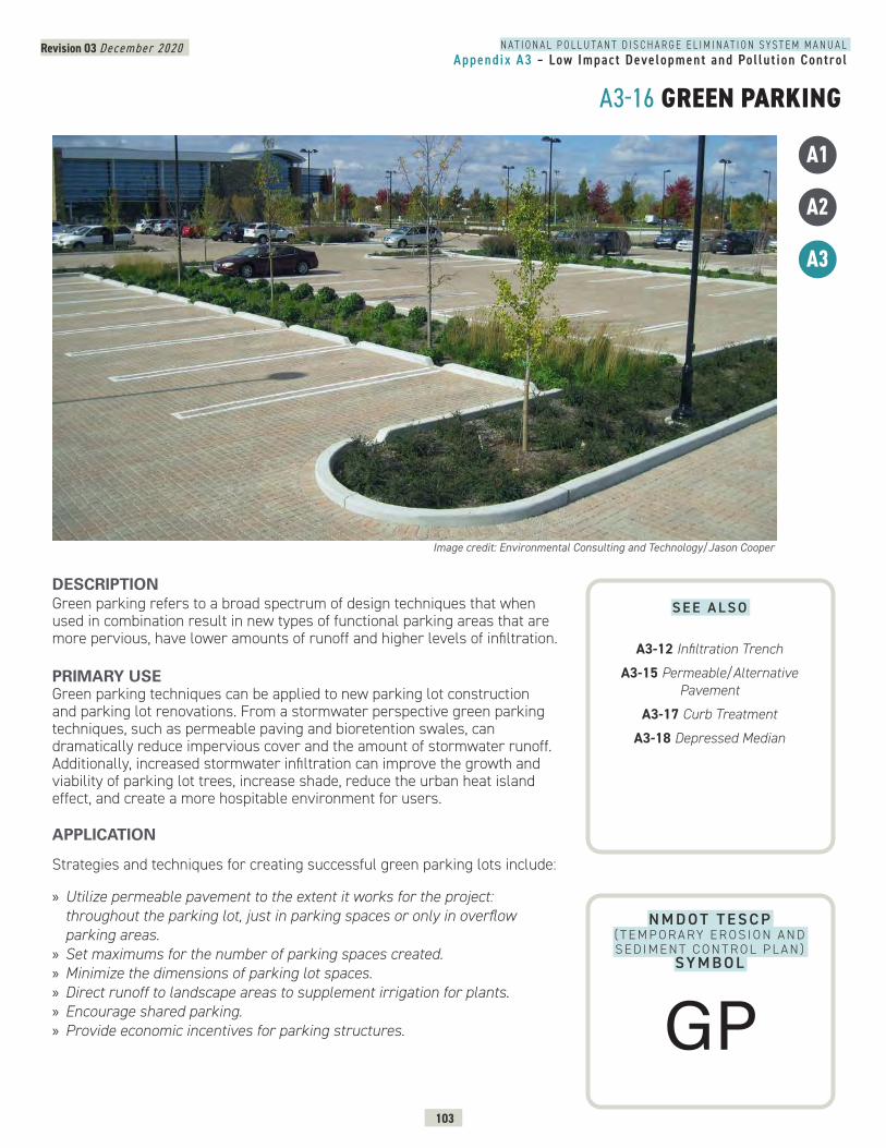
N A T I O N A L P O L L U T A N T D I S C H A R G E E L I M I N A T I O N S Y S T E M M A N U A LAppendix A3 – Low Impact Development and Pol lut ion Control
Revision 03 December 2020
103
A3-16 GREEN PARKING
N M D O T T E S C P ( T E M P O R A RY E R O S I O N A N D S E D I M E N T C O N T R O L P L A N )
SY M B O L
DESCRIPTION Green parking refers to a broad spectrum of design techniques that when used in combination result in new types of functional parking areas that are more pervious, have lower amounts of runoff and higher levels of infiltration.
PRIMARY USEGreen parking techniques can be applied to new parking lot construction and parking lot renovations. From a stormwater perspective green parking techniques, such as permeable paving and bioretention swales, can dramatically reduce impervious cover and the amount of stormwater runoff. Additionally, increased stormwater infiltration can improve the growth and viability of parking lot trees, increase shade, reduce the urban heat island effect, and create a more hospitable environment for users.
APPLICATION
Strategies and techniques for creating successful green parking lots include:
» Utilize permeable pavement to the extent it works for the project: throughout the parking lot, just in parking spaces or only in overflow parking areas.
» Set maximums for the number of parking spaces created. » Minimize the dimensions of parking lot spaces. » Direct runoff to landscape areas to supplement irrigation for plants. » Encourage shared parking. » Provide economic incentives for parking structures.
A1
A2
A3
Image credit: Environmental Consulting and Technology/Jason Cooper
S E E A L S O
A3-12 Infiltration Trench
A3-15 Permeable/Alternative Pavement
A3-17 Curb Treatment
A3-18 Depressed Median
GP
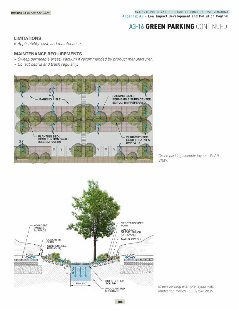
N A T I O N A L P O L L U T A N T D I S C H A R G E E L I M I N A T I O N S Y S T E M M A N U A LAppendix A3 – Low Impact Development and Pol lut ion Control
Revision 03 December 2020
104
A3-16 GREEN PARKING CONTINUED
Green parking example layout - PLAN VIEW.
Green parking example layout with infiltration trench - SECTION VIEW.
GREEN PARKING - PLAN VIEW
PARKING STALL:PERMEABLE SURFACE (SEEBMP A3-15) PREFERRED
CURB-CUT (SEECURB TREATMENTBMP A3-17)
PARKING AISLE
PLANTING BED /BIORETENTION SWALE(SEE BMP A3-10)
6FL
OW
FLO
W
3-16
FLO
W
FLOWFLOW
CONCRETECURBCURB-CUT(SEEBMP A3-17)
31
31
MAX. SLOPE 3:1
ADJACENTPARKINGSURFACE
24"
MIN. 5'-0"
LANDSCAPEGRAVEL MULCH(OPTIONAL )
BIORETENTIONSOIL MIX
VEGETATION PERPLAN.
UNCOMPACTEDSUBGRADE
LIMITATIONS » Applicability, cost, and maintenance.
MAINTENANCE REQUIREMENTS » Sweep permeable areas. Vacuum if recommended by product manufacturer. » Collect debris and trash regularly.
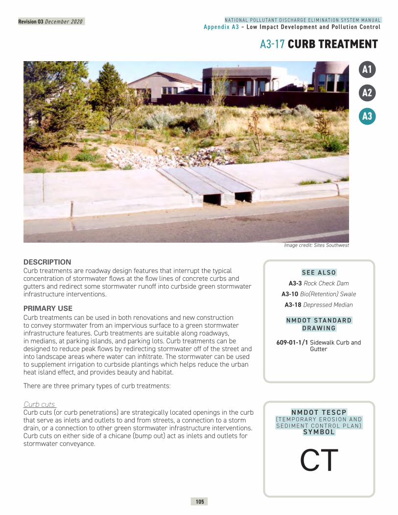
N A T I O N A L P O L L U T A N T D I S C H A R G E E L I M I N A T I O N S Y S T E M M A N U A LAppendix A3 – Low Impact Development and Pol lut ion Control
Revision 03 December 2020
105
A3-17 CURB TREATMENT
N M D O T T E S C P ( T E M P O R A RY E R O S I O N A N D S E D I M E N T C O N T R O L P L A N )
SY M B O L
DESCRIPTION Curb treatments are roadway design features that interrupt the typical concentration of stormwater flows at the flow lines of concrete curbs and gutters and redirect some stormwater runoff into curbside green stormwater infrastructure interventions.
PRIMARY USECurb treatments can be used in both renovations and new construction to convey stormwater from an impervious surface to a green stormwater infrastructure features. Curb treatments are suitable along roadways, in medians, at parking islands, and parking lots. Curb treatments can be designed to reduce peak flows by redirecting stormwater off of the street and into landscape areas where water can infiltrate. The stormwater can be used to supplement irrigation to curbside plantings which helps reduce the urban heat island effect, and provides beauty and habitat.
There are three primary types of curb treatments:
Curb cuts Curb cuts (or curb penetrations) are strategically located openings in the curb that serve as inlets and outlets to and from streets, a connection to a storm drain, or a connection to other green stormwater infrastructure interventions. Curb cuts on either side of a chicane (bump out) act as inlets and outlets for stormwater conveyance.
Image credit: Sites Southwest
A1
A2
A3
S E E A L S O
A3-3 Rock Check Dam
A3-10 Bio(Retention) Swale
A3-18 Depressed Median
N M D O T S TA N D A R D D R A W I N G
609-01-1/1 Sidewalk Curb and Gutter
CT
N A T I O N A L P O L L U T A N T D I S C H A R G E E L I M I N A T I O N S Y S T E M M A N U A LAppendix A3 – Low Impact Development and Pol lut ion Control
Revision 03 December 2020
106
A3-17 CURB TREATMENT CONTINUED
Flush CurbsFlush curbs are sometimes referred to as estate curbs and consist of curbs that are flush with adjacent pavement. The flush surface, as opposed to typical gutters, helps to decrease the concentration of stormwater flows by allowing water to sheet flow into permeable areas such as gravel shoulders, landscaped areas and basins, and vegetated filter strips.
Chicanes Chicanes are stormwater curb extensions or bump outs that add curves to an otherwise straight roadway. The bump out space is capable of infiltrating stormwater and accommodating streetscape planting. Chicanes also serve as traffic calming devices and have been used on many New Mexico mainstreets.
APPLICATIONSStrategies for designing curb treatments include: » Protect inlets from scour with angular riprap or stone, sediment traps or sediment cleanout forebays.
» Consider use of short fences or other barriers to prevent pedestrians stepping into a recessed area.
» Limit potential effects of soil saturation adjacent to roadway paving and infrastructure.
» Consider use of permeable gutter pans: a curb treatment option that is less common but potentially beneficial for use independently or in combination with the other curb treatments.
» Design planting to reflect water availability. Plant selections and density shall be dependent on local climate and conditions and use or absence of supplemental irrigation.
» Design planting so that it does not block sight lines. » Reference the AASHTO Roadside Design Guide for safety requirements and design guideance when placing and designing curb openings adjacent to travel ways.
LIMITATIONS » Curb cuts can become blocked/clogged with floating debris, leaves and sediment.
» Governing codes, standards and regulations may not allow stormwater harvesting on top of utilities.
MAINTENANCE REQUIREMENTS » Maintain openings at curb cuts free of debris, sediment and trash. » Inspect semi-annually post construction. » Inspect after major storm events.
PRIMARY USE CONTINUED
N A T I O N A L P O L L U T A N T D I S C H A R G E E L I M I N A T I O N S Y S T E M M A N U A LAppendix A3 – Low Impact Development and Pol lut ion Control
Revision 03 December 2020
107
Concrete curb cut - PLAN VIEW.
Sediment cleanout forebay at concrete curb cut - SECTION VIEW.
2"
4" NON-FLOATABLEMULCH LAYER
FILTER FABRICCOBBLESTONE AS SEDIMENT TRAP
CONCRETE SEDIMENT REMOVAL FOREBAY,LEVEL AND CENTERED ON CURB-CUT
ADJACENT PARKING / ROAD SURFACESCONCRETE CURB WITH PENETRATIONSFOR INFLOW AND OVERFLOW
12" MIN. 8"-12"
7
FLOW
Concrete curb cut - ISOMETRIC VIEW.
CURB TREATMENT - PLAN VIEW CLEANOUT
PLAN VIEW
4" NON-FLOATABLEMULCH LAYER
CONCRETE CURB
CURB CUT TAPERED 1:1(SEE ISOMETRIC VIEW)
18" MIN.
12" M
IN.
ADJACENT PARKING/ROADSURFACE
COBBLE BORDER TOTRAP SEDIMENT
CONCRETECLEANOUT / FOREBAYTO SIMPLIFYSEDIMENT REMOVAL
17
FLOW
FLOW
ISOMETRIC CLEANOUT
CURB CUT FLUSH WITHADJACENT PAVING
ASPHALT PAVING
VARIES
2" M
IN.
EXISTING CURB
CONCRETE SEDIMENT REMOVALFOREBAY, LEVEL AND CENTEREDON CURB-CUT
4" NON-FLOATABLEMULCH LAYER
11
COBBLESTONE ASSEDIMENT TRAP
17
CURB TREATMENT - ISOMETRIC CLEANOUT
A3-17 CURB TREATMENT CONTINUED
N A T I O N A L P O L L U T A N T D I S C H A R G E E L I M I N A T I O N S Y S T E M M A N U A LAppendix A3 – Low Impact Development and Pol lut ion Control
Revision 03 December 2020
108
A3-17 CURB TREATMENT CONTINUED
CURB TREATMENT - PLAN VIEWSTORMWATER CURB EXTENSION RETROFIT
AA'
PLAN VIEW - STORMWATER CURB EXTENSION RETROFIT
VARIES, 6' MIN.
CHECK DAM (REFER TO PERMEABLE CHECK DAMDETAIL, BMP A3-3 FOR ADDITIONAL INFORMATION).
MATCH EXISTINGCURB AND GUTTER
FOR RETROFIT APPLICATIONS, SAWCUT ANDREMOVE GUTTER PAN FLUSH WITH CURB FACE(SEE SECTION A-A)
CONCRETE SPLASHPAD /SEDIMENT REMOVAL
TRANSITION FROMSTANDARD CURB ANDGUTTER TO MEDIAN CURBAND GUTTER
18"12"
EXISTING SIDEWALKAT BACK OF CURB
PLANTING BED WITH4" NON- FLOATABLE MULCH
FLOW FLOW
Chicane (stormwater curb extension retrofit) - PLAN VIEW.
CURB TREATMENT - SECTION AASTORMWATER CURB EXTENSION RETROFIT
SECTION AA - STORMWATER CURB EXTENSION RETROFIT
EXISTING SIDEWALKAT BACK OF CURB
FOR RETROFITAPPLICATIONS, SAWCUTAND REMOVE GUTTERPAN FLUSH WITH CURBFACE
COBBLE OR CRUSHED GRAVEL CHECK DAM, FULLWIDTH. (SEE BMP CHECK DAM A3-3 FORADDITIONAL INFORMATION).
6" MEDIANCURB & GUTTER
FOR RETROFIT APPLICATIONS, SAWCUT ANDREPLACE 12" ASPHALT ADJACENTTO NEW CURB TO CREATE SMOOTH TRANSITIONBETWEEN SURFACES.
COMPACTED SUBGRADE PLANTING BED WITH4" NON-FLOATABLE MULCH
UNCOMPACTEDSUBGRADE
PLANTING SOIL MIX
18" MIN.
3" MIN.
VARIES
7
FLOW
Chicane (stormwater curb extension retrofit) - SECTION A-A.
N A T I O N A L P O L L U T A N T D I S C H A R G E E L I M I N A T I O N S Y S T E M M A N U A LAppendix A3 – Low Impact Development and Pol lut ion Control
Revision 03 December 2020
109
A3-17 CURB TREATMENT CONTINUED
Chicane (stormwater curb extension retrofit) - PROFILE VIEW.
CURB TREATMENT - LONGITUDINAL SECTION STORMWATER CURB EXTENSION RETROFIT
COBBLE OR CRUSHEDGRAVEL CHECK DAM, FULLWIDTH (SEE BMP CHECKDAM A3-3 FOR ADDITIONALINFORMATION)
TRANSITION FROM STANDARD CURB ANDGUTTER TO MEDIAN CURB AND
GUTTER (TYP. BOTH ENDS)
LONGITUDINAL SECTION - STORMWATER CURB EXTENSION RETROFIT
6" MEDIAN CURB & GUTTER
PLANTING SOIL MIXNON- FLOATABLE MULCH
CURB EXTENSION
LOOSEN COMPACTED SUBGRADETO ENCOURAGE INFILTRATION
CURB CUTS SIZEDTO ACCOMMODATEANTICIPATED FLOW
Flush curb - SECTION VIEW.
CURB TREATMENT - FLUSH CURB SECTION
2"
4" NON-FLOATABLEMULCH LAYER
AMENDED PLANTINGSUBSTRATE
ADJACENT PARKING/ROAD SURFACES
CONCRETE FLUSH CURB /EDGE RESTRAINT
12" MIN. SMALL BOULDERS ORCOBBLE CONTINUOUSALONG LENGTH OFFLUSH CURB (OPTIONAL)
17
FLOW
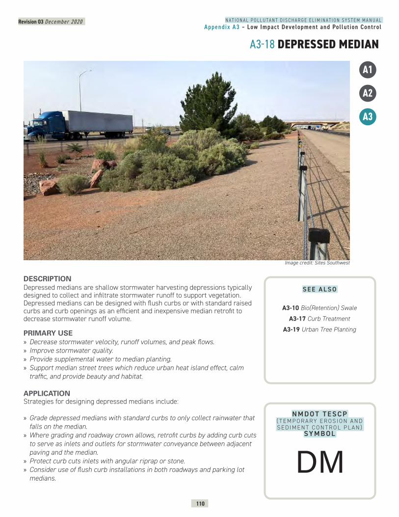
N A T I O N A L P O L L U T A N T D I S C H A R G E E L I M I N A T I O N S Y S T E M M A N U A LAppendix A3 – Low Impact Development and Pol lut ion Control
Revision 03 December 2020
110
A3-18 DEPRESSED MEDIAN
N M D O T T E S C P ( T E M P O R A RY E R O S I O N A N D S E D I M E N T C O N T R O L P L A N )
SY M B O L
DESCRIPTION Depressed medians are shallow stormwater harvesting depressions typically designed to collect and infiltrate stormwater runoff to support vegetation. Depressed medians can be designed with flush curbs or with standard raised curbs and curb openings as an efficient and inexpensive median retrofit to decrease stormwater runoff volume.
PRIMARY USE » Decrease stormwater velocity, runoff volumes, and peak flows. » Improve stormwater quality. » Provide supplemental water to median planting. » Support median street trees which reduce urban heat island effect, calm traffic, and provide beauty and habitat.
APPLICATION Strategies for designing depressed medians include:
» Grade depressed medians with standard curbs to only collect rainwater that falls on the median.
» Where grading and roadway crown allows, retrofit curbs by adding curb cuts to serve as inlets and outlets for stormwater conveyance between adjacent paving and the median.
» Protect curb cuts inlets with angular riprap or stone. » Consider use of flush curb installations in both roadways and parking lot medians.
Image credit: Sites Southwest
A1
A2
A3
S E E A L S O
A3-10 Bio(Retention) Swale
A3-17 Curb Treatment
A3-19 Urban Tree Planting
DM
N A T I O N A L P O L L U T A N T D I S C H A R G E E L I M I N A T I O N S Y S T E M M A N U A LAppendix A3 – Low Impact Development and Pol lut ion Control
Revision 03 December 2020
111
A3-18 DEPRESSED MEDIAN CONTINUED
Strategies for successful planting depressed medians include:
» Create a planting design that is suited for the site’s water availability. Plant selections and density shall be dependent on local climate and conditions, including an absence of supplemental irrigation.
» Choose and place plants to reflect potential periodic wet soil conditions and/or standing water in slow infiltrating soils.
» Limit potential effects of soil saturation adjacent to roadway paving and infrastructure.
» Create a planting design that will not encroach upon vehicle sight lines.
LIMITATIONS » Supplemental irrigation is recommended to establish and maintain vegetative health in arid conditions.
» Depressed medians are not well-suited for use in poorly-drained soils including soils with caliche and shallow bedrock.
» Special planting considerations include proximity to infrastructure and AASHTO Roadside Design Guide safety zones.
» Governing codes, standards and regulations may not allow stormwater harvesting on top of utilities.
» Ponding depths vary depending on the width of the median. » Governing codes, standards and regulations may not allow stormwater harvesting on top of utilities.
MAINTENANCE REQUIREMENTS » Inspect quarterly post construction. » Remove debris, litter, and sediment. » Maintain planting as needed including pruning, weeding, mowing, fertilization, replacement, and pest control.
» Repair irrigation system, if installed, and make seasonal watering adjustments where applicable.
» Repair and regrade surface where it has been disturbed. » Redistribute and replace mulches as needed.
APPLICATION CONTINUED
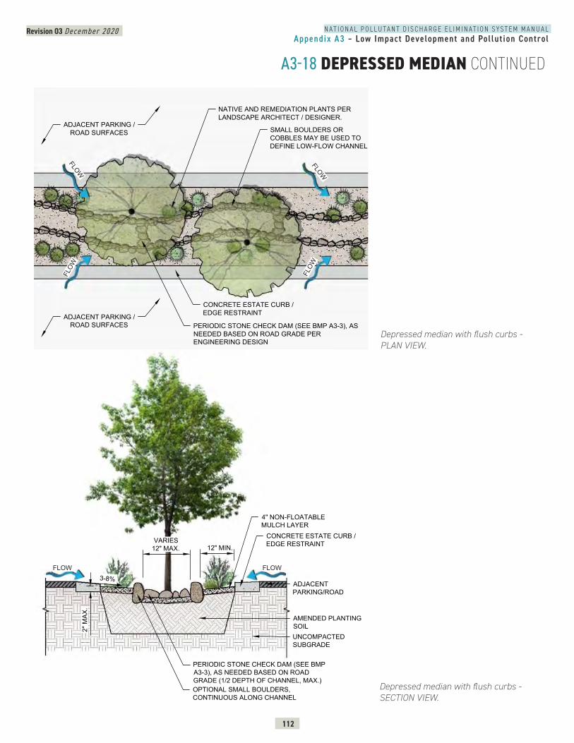
N A T I O N A L P O L L U T A N T D I S C H A R G E E L I M I N A T I O N S Y S T E M M A N U A LAppendix A3 – Low Impact Development and Pol lut ion Control
Revision 03 December 2020
112
A3-18 DEPRESSED MEDIAN CONTINUED
DEPRESSED MEDIAN - FLUSH CURBPLAN VIEW
NATIVE AND REMEDIATION PLANTS PERLANDSCAPE ARCHITECT / DESIGNER.
SMALL BOULDERS ORCOBBLES MAY BE USED TODEFINE LOW-FLOW CHANNEL
PERIODIC STONE CHECK DAM (SEE BMP A3-3), ASNEEDED BASED ON ROAD GRADE PERENGINEERING DESIGN
CONCRETE ESTATE CURB /EDGE RESTRAINT
ADJACENT PARKING /ROAD SURFACES
ADJACENT PARKING /ROAD SURFACES
FLOW
FLOW
FLOW
FLOW
FLOW
Depressed median with flush curbs - PLAN VIEW.
Depressed median with flush curbs - SECTION VIEW.
4" NON-FLOATABLEMULCH LAYER
VARIES12" MAX. 12" MIN.
2" M
AX.
3-8%
CONCRETE ESTATE CURB /EDGE RESTRAINT
ADJACENTPARKING/ROAD
AMENDED PLANTINGSOILUNCOMPACTEDSUBGRADE
PERIODIC STONE CHECK DAM (SEE BMPA3-3), AS NEEDED BASED ON ROADGRADE (1/2 DEPTH OF CHANNEL, MAX.)OPTIONAL SMALL BOULDERS,CONTINUOUS ALONG CHANNEL
FLOW FLOW
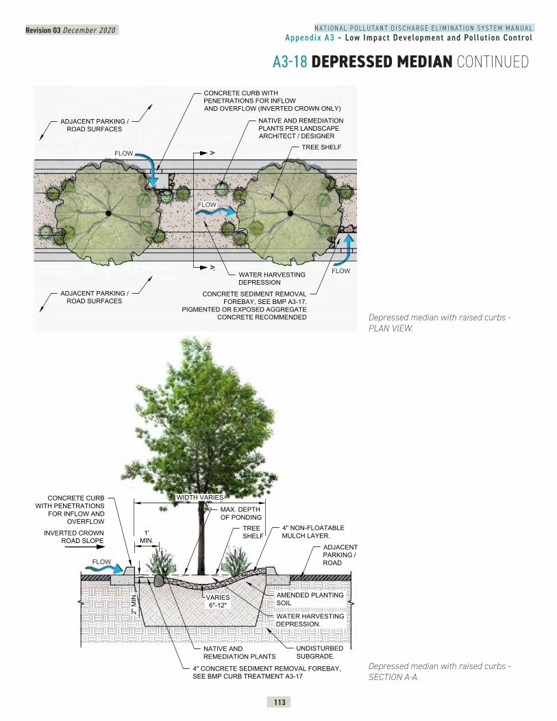
N A T I O N A L P O L L U T A N T D I S C H A R G E E L I M I N A T I O N S Y S T E M M A N U A LAppendix A3 – Low Impact Development and Pol lut ion Control
Revision 03 December 2020
113
A3-18 DEPRESSED MEDIAN CONTINUED
Depressed median with raised curbs - SECTION A-A.
Depressed median with raised curbs - PLAN VIEW.
DEPRESSED MEDIAN - RAISED CURBPLAN VIEW
AA'
NATIVE AND REMEDIATIONPLANTS PER LANDSCAPEARCHITECT / DESIGNER
TREE SHELF
WATER HARVESTINGDEPRESSION
CONCRETE SEDIMENT REMOVALFOREBAY, SEE BMP A3-17.
PIGMENTED OR EXPOSED AGGREGATECONCRETE RECOMMENDED
CONCRETE CURB WITHPENETRATIONS FOR INFLOWAND OVERFLOW (INVERTED CROWN ONLY)
ADJACENT PARKING /ROAD SURFACES
ADJACENT PARKING /ROAD SURFACES
FLOW
FLOW
FLOW
WIDTH VARIES
1'MIN.
INVERTED CROWNROAD SLOPE
2" M
IN.
TREESHELF
WATER HARVESTINGDEPRESSION.
AMENDED PLANTINGSOIL
UNDISTURBEDSUBGRADE
4" NON-FLOATABLEMULCH LAYER.
ADJACENTPARKING /ROAD
CONCRETE CURBWITH PENETRATIONS
FOR INFLOW ANDOVERFLOW
4" CONCRETE SEDIMENT REMOVAL FOREBAY,SEE BMP CURB TREATMENT A3-17
MAX. DEPTHOF PONDING
NATIVE ANDREMEDIATION PLANTS
VARIES6"-12"
18
FLOW
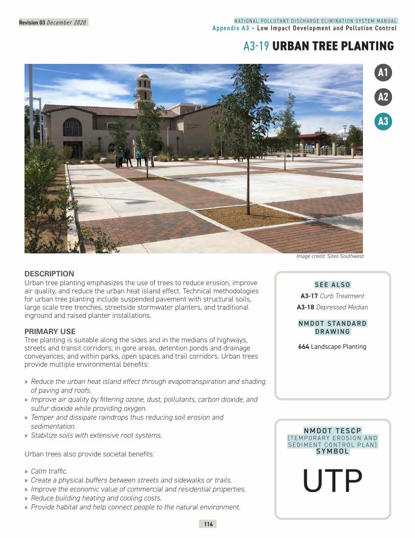
N A T I O N A L P O L L U T A N T D I S C H A R G E E L I M I N A T I O N S Y S T E M M A N U A LAppendix A3 – Low Impact Development and Pol lut ion Control
Revision 03 December 2020
114
A3-19 URBAN TREE PLANTING
N M D O T T E S C P ( T E M P O R A RY E R O S I O N A N D S E D I M E N T C O N T R O L P L A N )
SY M B O L
DESCRIPTION Urban tree planting emphasizes the use of trees to reduce erosion, improve air quality, and reduce the urban heat island effect. Technical methodologies for urban tree planting include suspended pavement with structural soils, large scale tree trenches, streetside stormwater planters, and traditional inground and raised planter installations.
PRIMARY USETree planting is suitable along the sides and in the medians of highways, streets and transit corridors; in gore areas, detention ponds and drainage conveyances; and within parks, open spaces and trail corridors. Urban trees provide multiple environmental benefits:
» Reduce the urban heat island effect through evapotranspiration and shading of paving and roofs.
» Improve air quality by filtering ozone, dust, pollutants, carbon dioxide, and sulfur dioxide while providing oxygen.
» Temper and dissipate raindrops thus reducing soil erosion and sedimentation.
» Stabilize soils with extensive root systems.
Urban trees also provide societal benefits:
» Calm traffic. » Create a physical buffers between streets and sidewalks or trails. » Improve the economic value of commercial and residential properties. » Reduce building heating and cooling costs. » Provide habitat and help connect people to the natural environment.
Image credit: Sites Southwest
A1
A2
A3
S E E A L S O
A3-17 Curb Treatment
A3-18 Depressed Median
N M D O T S TA N D A R D D R A W I N G
664 Landscape Planting
UTP

N A T I O N A L P O L L U T A N T D I S C H A R G E E L I M I N A T I O N S Y S T E M M A N U A LAppendix A3 – Low Impact Development and Pol lut ion Control
Revision 03 December 2020
115
A3-19 URBAN TREE PLANTING CONTINUEDIn addition to traditional urban tree planting in the ground or raised planters, there are three ancillary BMPs that fall under urban tree planting: Suspended Pavement/Structural Soils Suspended pavements are systems designed to create void space under the pavement for water retention/infiltration and adequate volume for tree root growth. Structural soils are a blend of crushed stone and planting soils that rely on the interlocking nature of the stone to support pavement, while uncompacted planting soil fills the void spaces. Both systems offer greatly improved soil porosity for water retention, oxygen transfer, and resulting root growth where space is limited in urban areas.
Tree Trench/Pit: Tree trenches or tree pits are curbside vaults, typically constructed from concrete. The vaults accept stormwater from curb cuts or drain pipes, filter stormwater through a variety of media to remove sediment and pollutants, and provide adequate root space for curbside tree planting.
Streetside Stormwater Planter: Streetside stormwater planters are constructed features immediately behind the curb that accept stormwater from curb cuts or flush curbs. These planters filter stormwater through a variety of media to remove sediment and pollutants and provide soil and space to accommodate curbside trees and shrubs. “First flush” runoff can be absorbed into these planting beds, helping reduce pollutant levels and overall runoff volumes. Streetside stormwater planters can be installed in bulb-outs in retrofit applications.
Tree planting in suspended pavement - ISOMETRIC VIEW.
N A T I O N A L P O L L U T A N T D I S C H A R G E E L I M I N A T I O N S Y S T E M M A N U A LAppendix A3 – Low Impact Development and Pol lut ion Control
Revision 03 December 2020
116
A3-19 URBAN TREE PLANTING CONTINUED
APPLICATIONSPlanning and design strategies for successful urban tree planting include: » Consider local climate, soil conditions and water availability when selecting the best trees for site conditions. Consult local sources for a list of trees suitable to the area.
» Consider use of short fences, barriers or curbs at recessed areas that are not grated or flush with adjacent paving.
» Design permanent, well-constructed irrigation systems in association with urban tree planting.
» Ensure that suspended pavements provide adequate soil volume for mature street trees.
» Consider designing permeable pavements adjacent to tree plantings to provide additional water and soil porosity.
» Avoid and/or eliminate soil compaction under and adjacent to tree canopies.
LIMITATIONS » Water availability for irrigation. » Trees must be selected and planted in urban locations to minimize effects on paving and infrastructure. Poorly located and selected trees can lift pavement, effect water/sewer lines, and grow into overhead and underground utilities.
» Surface roots can pose tripping hazards in the landscape.
MAINTENANCE REQUIREMENTS » Inspect trees quarterly for pests, dead and dying limbs, and general health. » Train, prune, and fertilize trees annually. » Inspect irrigation system quarterly. Repair broken components and adjust watering requirements seasonally.
» Rake and collect debris including leaves, twigs, branches, nuts, flowers, and berries seasonally.
» Replenish mulch around trees bi-annually.
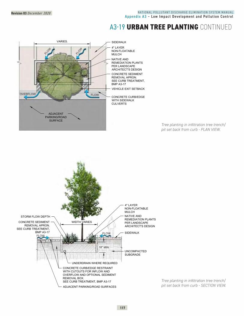
N A T I O N A L P O L L U T A N T D I S C H A R G E E L I M I N A T I O N S Y S T E M M A N U A LAppendix A3 – Low Impact Development and Pol lut ion Control
Revision 03 December 2020
117
A3-19 URBAN TREE PLANTING CONTINUED
Tree planting in infiltration tree trench/pit set back from curb - PLAN VIEW.
Tree planting in infiltration tree trench/pit set back from curb - SECTION VIEW.
URBAN TREE PLANTING
9
4" LAYERNON-FLOATABLEMULCH
CONCRETE SEDIMENTREMOVAL APRON.SEE CURB TREATMENT,BMP A3-17
NATIVE ANDREMEDIATION PLANTSPER LANDSCAPEARCHITECT'S DESIGN
SIDEWALK
CONCRETE CURB/EDGEWITH SIDEWALKCULVERTS
VARIES.
ADJACENTPARKING/ROAD
SURFACE
VEHICLE EXIT SETBACK
TREE TRENCH / PIT - PLAN VIEW
FLOW
FLOW
FLOW
OVERFLOW
4" LAYERNON-FLOATABLEMULCHNATIVE ANDREMEDIATION PLANTSPER LANDSCAPEARCHITECT'S DESIGN
SIDEWALK
WIDTH VARIES
ADJACENT PARKING/ROAD SURFACES
STORM FLOW DEPTH
CONCRETE SEDIMENTREMOVAL APRON.
SEE CURB TREATMENT,BMP A3-17
18" MINUNCOMPACTEDSUBGRADE
CONCRETE CURB/EDGE RESTRAINTWITH CUTOUTS FOR INFLOW ANDOVERFLOW AND OPTIONAL SEDIMENTREMOVAL BOX.SEE CURB TREATMENT, BMP A3-17
TREE TRENCH / PIT - SECTION
UNDERDRAIN WHERE REQUIRED
9
FLOW
FLOWFLOW
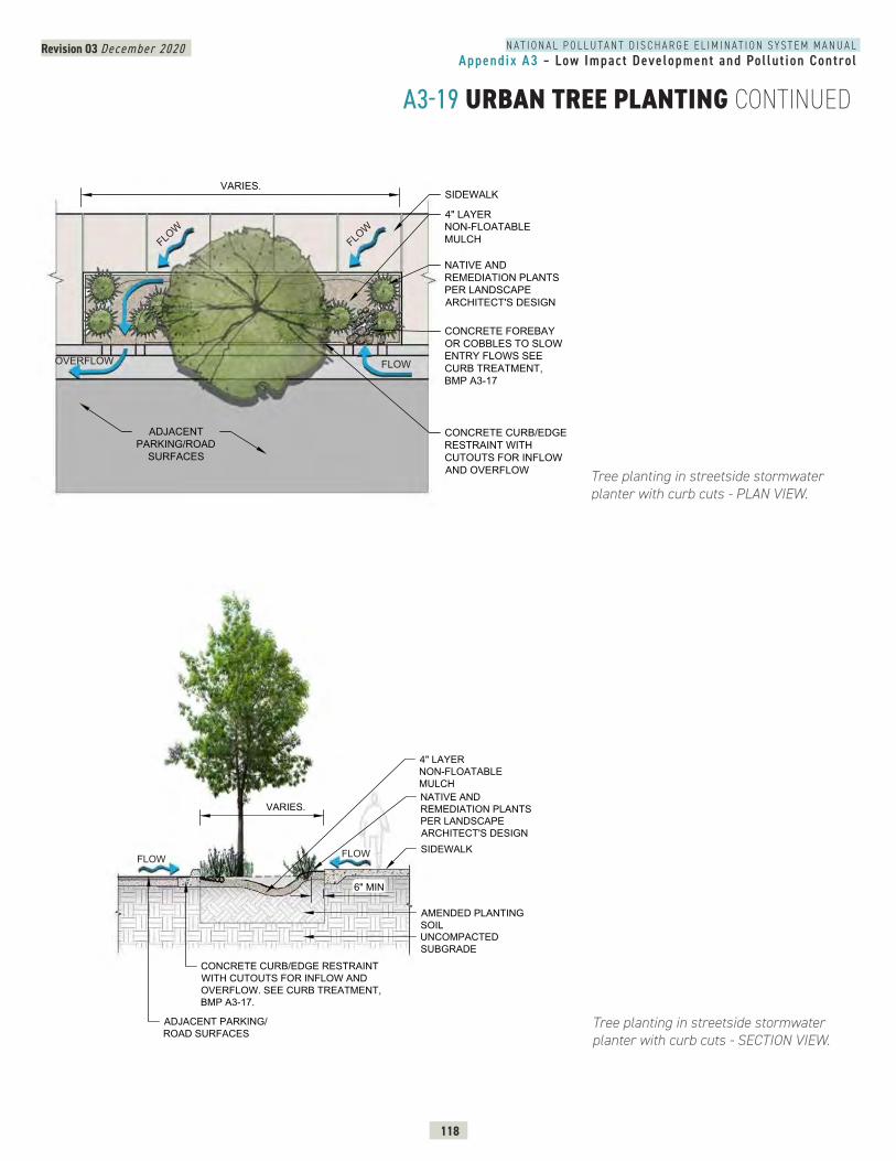
N A T I O N A L P O L L U T A N T D I S C H A R G E E L I M I N A T I O N S Y S T E M M A N U A LAppendix A3 – Low Impact Development and Pol lut ion Control
Revision 03 December 2020
118
A3-19 URBAN TREE PLANTING CONTINUED
Tree planting in streetside stormwater planter with curb cuts - PLAN VIEW.
Tree planting in streetside stormwater planter with curb cuts - SECTION VIEW.
SURBAN TREE PLANTING
-19
4" LAYERNON-FLOATABLEMULCH
CONCRETE FOREBAYOR COBBLES TO SLOWENTRY FLOWS SEECURB TREATMENT,BMP A3-17
NATIVE ANDREMEDIATION PLANTSPER LANDSCAPEARCHITECT'S DESIGN
SIDEWALK
CONCRETE CURB/EDGERESTRAINT WITHCUTOUTS FOR INFLOWAND OVERFLOW
VARIES.
ADJACENTPARKING/ROAD
SURFACES
STREET SIDE STORMWATER PLANTER - PLAN VIEW
FLOW
FLOW
FLOWOVERFLOW
9
4" LAYERNON-FLOATABLEMULCHNATIVE ANDREMEDIATION PLANTSPER LANDSCAPEARCHITECT'S DESIGNSIDEWALK
CONCRETE CURB/EDGE RESTRAINTWITH CUTOUTS FOR INFLOW ANDOVERFLOW. SEE CURB TREATMENT,BMP A3-17.
VARIES.
ADJACENT PARKING/ROAD SURFACES
6" MIN
UNCOMPACTEDSUBGRADE
AMENDED PLANTINGSOIL
STREET SIDE STORMWATER PLANTER - SECTION
FLOWFLOW
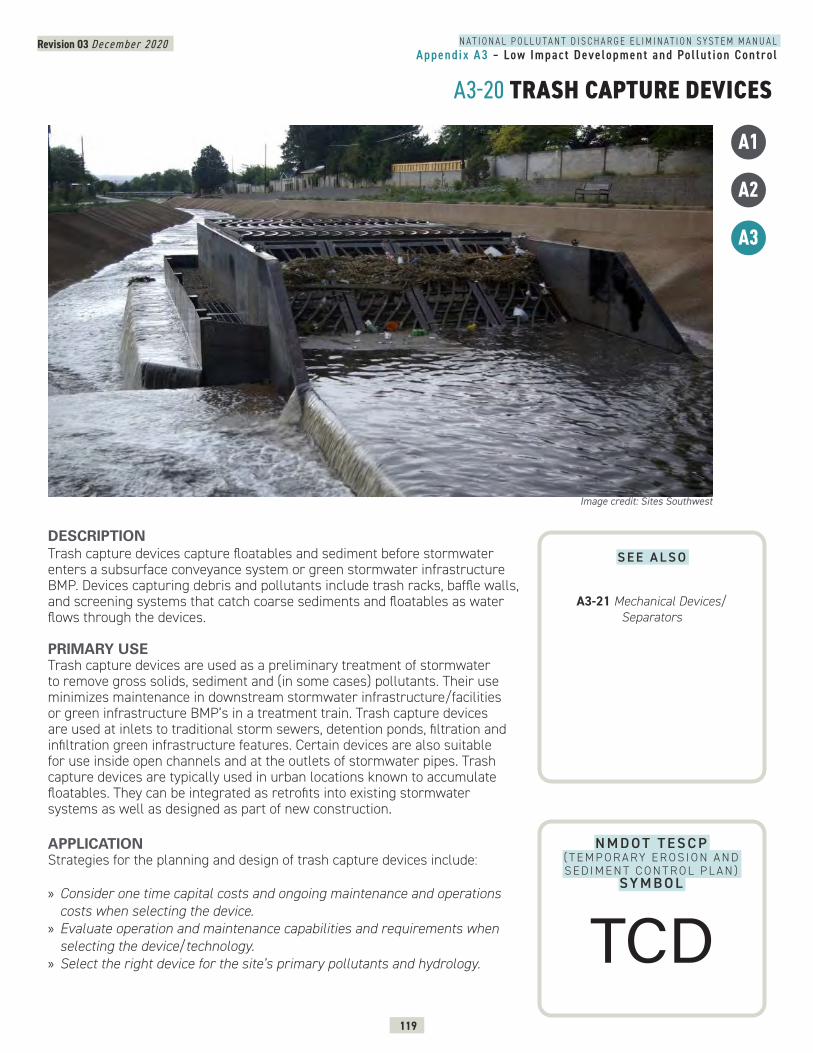
N A T I O N A L P O L L U T A N T D I S C H A R G E E L I M I N A T I O N S Y S T E M M A N U A LAppendix A3 – Low Impact Development and Pol lut ion Control
Revision 03 December 2020
119
A3-20 TRASH CAPTURE DEVICES
N M D O T T E S C P ( T E M P O R A RY E R O S I O N A N D S E D I M E N T C O N T R O L P L A N )
SY M B O L
DESCRIPTION Trash capture devices capture floatables and sediment before stormwater enters a subsurface conveyance system or green stormwater infrastructure BMP. Devices capturing debris and pollutants include trash racks, baffle walls, and screening systems that catch coarse sediments and floatables as water flows through the devices.
PRIMARY USETrash capture devices are used as a preliminary treatment of stormwater to remove gross solids, sediment and (in some cases) pollutants. Their use minimizes maintenance in downstream stormwater infrastructure/facilities or green infrastructure BMP’s in a treatment train. Trash capture devices are used at inlets to traditional storm sewers, detention ponds, filtration and infiltration green infrastructure features. Certain devices are also suitable for use inside open channels and at the outlets of stormwater pipes. Trash capture devices are typically used in urban locations known to accumulate floatables. They can be integrated as retrofits into existing stormwater systems as well as designed as part of new construction.
APPLICATIONStrategies for the planning and design of trash capture devices include:
» Consider one time capital costs and ongoing maintenance and operations costs when selecting the device.
» Evaluate operation and maintenance capabilities and requirements when selecting the device/technology.
» Select the right device for the site’s primary pollutants and hydrology.
Image credit: Sites Southwest
A1
A2
A3
S E E A L S O
A3-21 Mechanical Devices/Separators
TCD
N A T I O N A L P O L L U T A N T D I S C H A R G E E L I M I N A T I O N S Y S T E M M A N U A LAppendix A3 – Low Impact Development and Pol lut ion Control
Revision 03 December 2020
120
A3-20 TRASH CAPTURE DEVICES CONTINUEDLIMITATIONS » Ongoing maintenance is needed to remove accumulated debris and trash. » Some devices have a high capital cost, but if used in areas with heavy trash loads, they can be an effective and efficient management practice.
» Clearance may be required near device for service vehicle access.
MAINTENANCE REQUIREMENTS » Remove sediment and debris regularly. » Inspect and maintain devices in good operational condition. » Remove and replace filtration media depending upon the media type, stormwater quality, and manufacturer’s maintenance instructions.
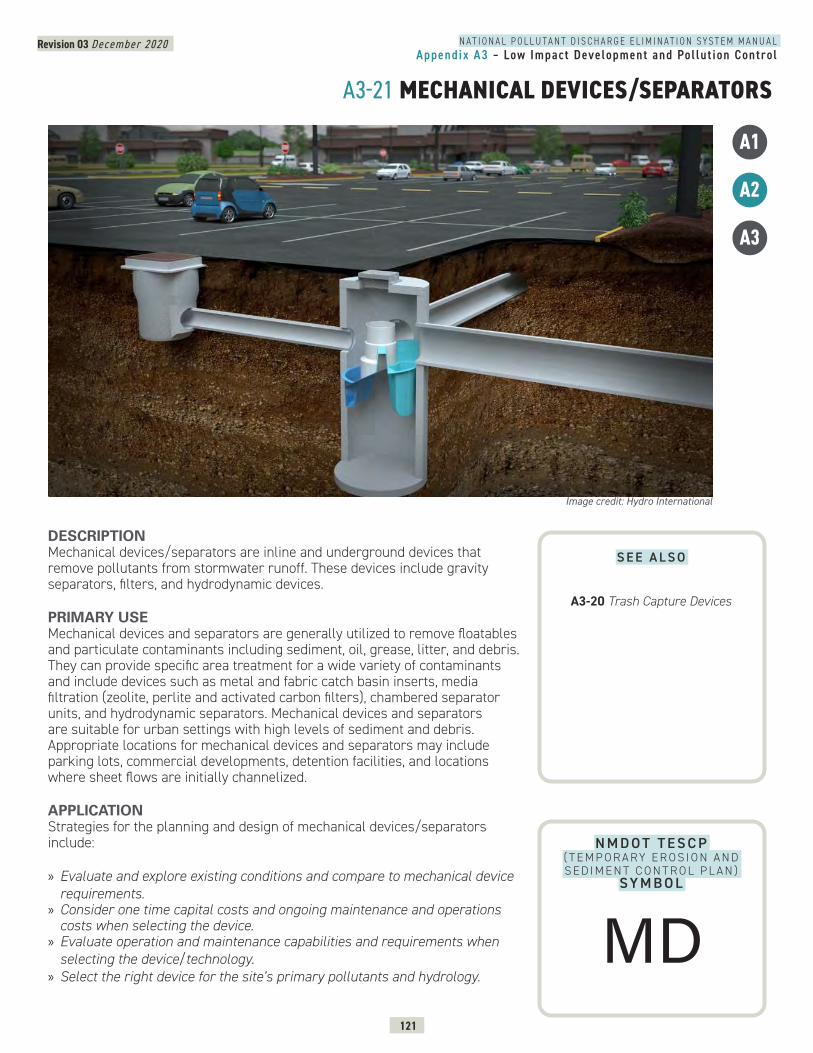
Revision 03 December 2020
121
N A T I O N A L P O L L U T A N T D I S C H A R G E E L I M I N A T I O N S Y S T E M M A N U A LAppendix A3 – Low Impact Development and Pol lut ion Control
A3-21 MECHANICAL DEVICES/SEPARATORS
A1
A2
A3
N M D O T T E S C P ( T E M P O R A RY E R O S I O N A N D S E D I M E N T C O N T R O L P L A N )
SY M B O L
DESCRIPTION Mechanical devices/separators are inline and underground devices that remove pollutants from stormwater runoff. These devices include gravity separators, filters, and hydrodynamic devices. PRIMARY USEMechanical devices and separators are generally utilized to remove floatables and particulate contaminants including sediment, oil, grease, litter, and debris. They can provide specific area treatment for a wide variety of contaminants and include devices such as metal and fabric catch basin inserts, media filtration (zeolite, perlite and activated carbon filters), chambered separator units, and hydrodynamic separators. Mechanical devices and separators are suitable for urban settings with high levels of sediment and debris. Appropriate locations for mechanical devices and separators may include parking lots, commercial developments, detention facilities, and locations where sheet flows are initially channelized. APPLICATIONStrategies for the planning and design of mechanical devices/separators include:
» Evaluate and explore existing conditions and compare to mechanical device requirements.
» Consider one time capital costs and ongoing maintenance and operations costs when selecting the device.
» Evaluate operation and maintenance capabilities and requirements when selecting the device/technology.
» Select the right device for the site’s primary pollutants and hydrology.
Image credit: Hydro International
S E E A L S O
A3-20 Trash Capture Devices
MD
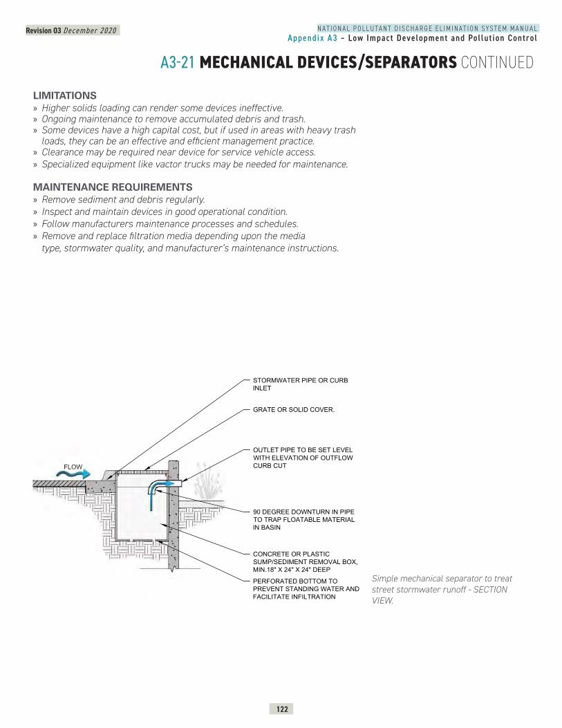
Revision 03 December 2020
122
N A T I O N A L P O L L U T A N T D I S C H A R G E E L I M I N A T I O N S Y S T E M M A N U A LAppendix A3 – Low Impact Development and Pol lut ion Control
A3-21 MECHANICAL DEVICES/SEPARATORS CONTINUED
Simple mechanical separator to treat street stormwater runoff - SECTION VIEW.
GRATE OR SOLID COVER.
OUTLET PIPE TO BE SET LEVELWITH ELEVATION OF OUTFLOWCURB CUT
CONCRETE OR PLASTICSUMP/SEDIMENT REMOVAL BOX,MIN.18" X 24" X 24" DEEP
PERFORATED BOTTOM TOPREVENT STANDING WATER ANDFACILITATE INFILTRATION
STORMWATER PIPE OR CURBINLET
90 DEGREE DOWNTURN IN PIPETO TRAP FLOATABLE MATERIALIN BASIN
FLOW
LIMITATIONS » Higher solids loading can render some devices ineffective. » Ongoing maintenance to remove accumulated debris and trash. » Some devices have a high capital cost, but if used in areas with heavy trash loads, they can be an effective and efficient management practice.
» Clearance may be required near device for service vehicle access. » Specialized equipment like vactor trucks may be needed for maintenance.
MAINTENANCE REQUIREMENTS » Remove sediment and debris regularly. » Inspect and maintain devices in good operational condition. » Follow manufacturers maintenance processes and schedules. » Remove and replace filtration media depending upon the media type, stormwater quality, and manufacturer’s maintenance instructions.
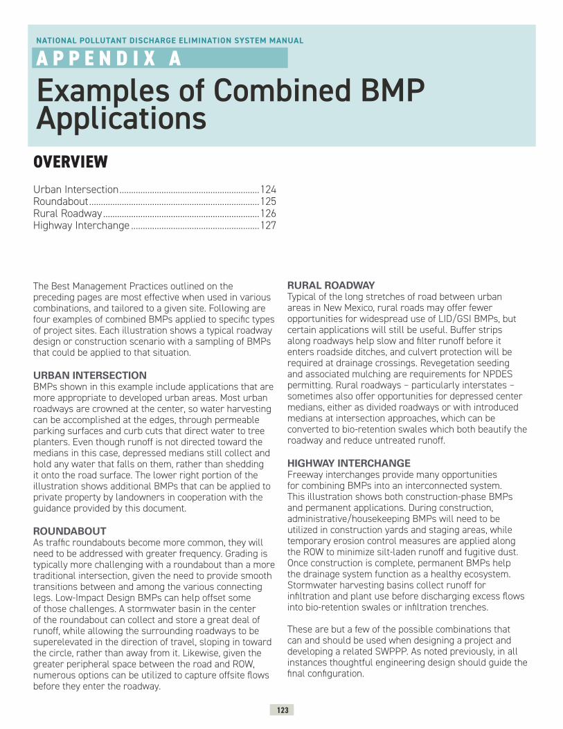
123
Urban Intersection ............................................................124Roundabout .........................................................................125Rural Roadway ...................................................................126Highway Interchange .......................................................127
OVERVIEW
NATIONAL POLLUTANT DISCHARGE ELIMINATION SYSTEM MANUAL
A P P E N D I X A
Examples of Combined BMP Applications
The Best Management Practices outlined on the preceding pages are most effective when used in various combinations, and tailored to a given site. Following are four examples of combined BMPs applied to specific types of project sites. Each illustration shows a typical roadway design or construction scenario with a sampling of BMPs that could be applied to that situation.
URBAN INTERSECTIONBMPs shown in this example include applications that are more appropriate to developed urban areas. Most urban roadways are crowned at the center, so water harvesting can be accomplished at the edges, through permeable parking surfaces and curb cuts that direct water to tree planters. Even though runoff is not directed toward the medians in this case, depressed medians still collect and hold any water that falls on them, rather than shedding it onto the road surface. The lower right portion of the illustration shows additional BMPs that can be applied to private property by landowners in cooperation with the guidance provided by this document.
ROUNDABOUTAs traffic roundabouts become more common, they will need to be addressed with greater frequency. Grading is typically more challenging with a roundabout than a more traditional intersection, given the need to provide smooth transitions between and among the various connecting legs. Low-Impact Design BMPs can help offset some of those challenges. A stormwater basin in the center of the roundabout can collect and store a great deal of runoff, while allowing the surrounding roadways to be superelevated in the direction of travel, sloping in toward the circle, rather than away from it. Likewise, given the greater peripheral space between the road and ROW, numerous options can be utilized to capture offsite flows before they enter the roadway.
RURAL ROADWAYTypical of the long stretches of road between urban areas in New Mexico, rural roads may offer fewer opportunities for widespread use of LID/GSI BMPs, but certain applications will still be useful. Buffer strips along roadways help slow and filter runoff before it enters roadside ditches, and culvert protection will be required at drainage crossings. Revegetation seeding and associated mulching are requirements for NPDES permitting. Rural roadways – particularly interstates – sometimes also offer opportunities for depressed center medians, either as divided roadways or with introduced medians at intersection approaches, which can be converted to bio-retention swales which both beautify the roadway and reduce untreated runoff.
HIGHWAY INTERCHANGEFreeway interchanges provide many opportunities for combining BMPs into an interconnected system. This illustration shows both construction-phase BMPs and permanent applications. During construction, administrative/housekeeping BMPs will need to be utilized in construction yards and staging areas, while temporary erosion control measures are applied along the ROW to minimize silt-laden runoff and fugitive dust. Once construction is complete, permanent BMPs help the drainage system function as a healthy ecosystem. Stormwater harvesting basins collect runoff for infiltration and plant use before discharging excess flows into bio-retention swales or infiltration trenches.
These are but a few of the possible combinations that can and should be used when designing a project and developing a related SWPPP. As noted previously, in all instances thoughtful engineering design should guide the final configuration.
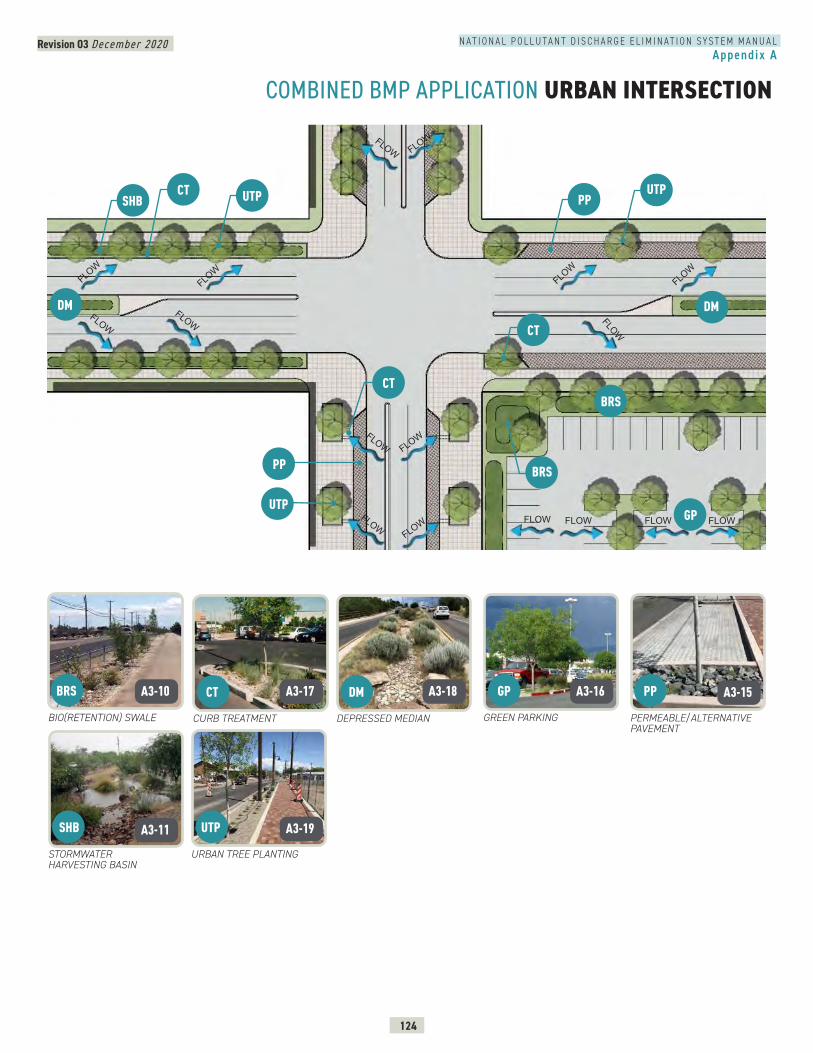
Revision 03 December 2020
124
N A T I O N A L P O L L U T A N T D I S C H A R G E E L I M I N A T I O N S Y S T E M M A N U A LAppendix A
COMBINED BMP APPLICATION URBAN INTERSECTION
CURB TREATMENTBIO(RETENTION) SWALE GREEN PARKING
URBAN TREE PLANTING
PERMEABLE/ALTERNATIVE PAVEMENT
DEPRESSED MEDIAN
STORMWATER HARVESTING BASIN
SHB
GP CT BRS PP DM
UTP
DM DM
PP
GP
BRS
UTP
FLOW
FLOW FLOWFLOW FLOW
FLOWFLOW
FLOW
FLOW FLOW
FLOW
FLOW
FLOW
FLOW
FLOW
FLOW
FLOW
PP
CT
UTP
BRS
UTP CT SHB
CT
A3-10 A3-17 A3-18 A3-16 A3-15
A3-11 A3-19
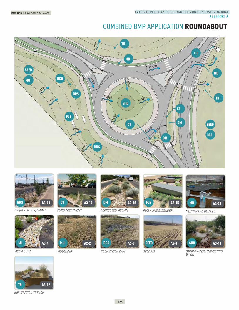
Revision 03 December 2020
125
N A T I O N A L P O L L U T A N T D I S C H A R G E E L I M I N A T I O N S Y S T E M M A N U A LAppendix A
COMBINED BMP APPLICATION ROUNDABOUT
FLOW LINE EXTENDER
MEDIA LUNA
CURB TREATMENT
INFILTRATION TRENCH
MECHANICAL DEVICES
STORMWATER HARVESTING BASIN
DEPRESSED MEDIAN
ROCK CHECK DAM SEEDINGMULCHING
BIO(RETENTION) SWALE
RCD SHB
TR
MD DM
ML
FLE
MU
BRS
SEED
CT
CT
FLOW
FLOW
FLOW
FLOW
FLOW
FLOW
FLOW
FLOW
FLOW
FLO
WFL
OW
FLOWFLOW
FLOW
FLOW
FLO
W
SHB
MD
TR
CT
BRS
BRS
SEED
SEED
MU
MU
FLE
DM
DM
CT
TR
MD RCD
A3-10 A3-17 A3-18 A3-15 A3-21
A3-4 A2-2 A3-3 A2-1 A3-11
A3-12
Revision 03 December 2020
126
N A T I O N A L P O L L U T A N T D I S C H A R G E E L I M I N A T I O N S Y S T E M M A N U A LAppendix A
COMBINED BMP APPLICATION RURAL ROADWAY
MULCHINGDEPRESSED MEDIAN
SEEDING
CULVERT PROTECTIONBIO(RETENTION) SWALE BUFFER/FILTER STRIP
DM MU BU CP BRS
SEED
FLOWFLOW
FLOW
R.O.W.
R.O.W.
FLOWFLOW
FLOW
FLOW
FLOW
FLO
W
DM BRS
BRS
SEED MU
BU CP
CP
A3-10 A3-6 A2-7 A3-18 A2-2
A2-1
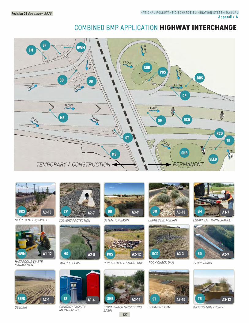
Revision 03 December 2020
127
N A T I O N A L P O L L U T A N T D I S C H A R G E E L I M I N A T I O N S Y S T E M M A N U A LAppendix A
COMBINED BMP APPLICATION HIGHWAY INTERCHANGE
DEPRESSED MEDIANDETENTION BASIN
SANITARY FACILITY MANAGEMENT
SLOPE DRAINHAZARDOUS WASTE MANAGEMENT
ROCK CHECK DAM
SEEDING
BIO(RETENTION) SWALE
MULCH SOCKS
EQUIPMENT MAINTENANCE
SEDIMENT TRAP
CULVERT PROTECTION
POND OUTFALL STRUCTURE
INFILTRATION TRENCHSTORMWATER HARVESTING BASIN
SF
RCD
EM DM
HWM
CP
SEED
BRS
SHB ST TR
DB
SD POSMS
TEMPORARY / CONSTRUCTION PERMANENT
FLOWFLOW
FLOWFLOW
FLOW
FLOW
FLOW
FLOW
FLOW
FLOW
FLOW
FLOW
FLOW
SEED
SHB
SHB
DB
DM RCD
MS
MS
ST
CP
SF EM
BRS
RCD
TR
SD
POS
HWM
A3-10 A2-7 A3-9 A3-18 A1-7
A1-12 A2-8 A2-12 A3-3 A2-9
A2-1 A1-6 A3-11 A2-10 A3-12

APPENDIX B – SUPPORTING MATERIALS
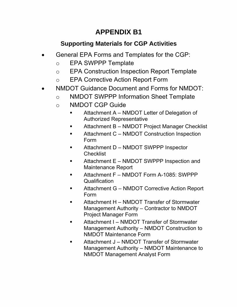
APPENDIX B1
Supporting Materials for CGP Activities
• General EPA Forms and Templates for the CGP: o EPA SWPPP Template o EPA Construction Inspection Report Template o EPA Corrective Action Report Form
• NMDOT Guidance Document and Forms for NMDOT: o NMDOT SWPPP Information Sheet Template o NMDOT CGP Guide
▪ Attachment A – NMDOT Letter of Delegation of Authorized Representative
▪ Attachment B – NMDOT Project Manager Checklist ▪ Attachment C – NMDOT Construction Inspection
Form ▪ Attachment D – NMDOT SWPPP Inspector
Checklist ▪ Attachment E – NMDOT SWPPP Inspection and
Maintenance Report ▪ Attachment F – NMDOT Form A-1085: SWPPP
Qualification ▪ Attachment G – NMDOT Corrective Action Report
Form ▪ Attachment H – NMDOT Transfer of Stormwater
Management Authority – Contractor to NMDOT Project Manager Form
▪ Attachment I – NMDOT Transfer of Stormwater Management Authority – NMDOT Construction to NMDOT Maintenance Form
▪ Attachment J – NMDOT Transfer of Stormwater Management Authority – NMDOT Maintenance to NMDOT Management Analyst Form
Stormwater Pollution Prevention Plan (SWPPP) INSERT PROJECT NAME
EPA SWPPP Template, Version 2.1 i
Construction Stormwater Pollution Prevention Plan Template
To be covered under the U.S. Environmental Protection Agency’s (EPA) Construction General Permit (CGP), all construction operators are required to develop a “Stormwater Pollution
Prevention Plan” (or “SWPPP”) prior to submitting a Notice of Intent (NOI) for permit coverage. EPA created this SWPPP Template to help you develop a SWPPP that is compliant with the minimum requirements of Part 7 of EPA’s 2017 Construction General Permit (“2017 CGP”), and is customizable to your specific project and site.
Instructions for Using the SWPPP Template
Each section of the SWPPP Template includes instructions and space for your project and site information. Read the instructions for each section before you complete that section. Specific instructions on what information to include is indicated in each text field in blue text. Click on the blue text and the instructions will disappear once you start typing. The SWPPP Template is an editable document file so that you can easily add tables and additional text, and delete unneeded or non-applicable fields. Note that some sections may require only a brief description while others may require several pages of explanation.
The following tips for using this template will help ensure that you meet the minimum permit requirements:
• Read the 2017 CGP thoroughly before you begin preparation of your SWPPP to ensure that you have a working understanding of the permit’s underlying requirements. You will also need to consult Part 9 of the permit to determine if your state or tribe has included additional requirements that affect you.
• Complete the SWPPP prior to submitting your Notice of Intent (NOI) for permit coverage. This is required in Parts 1.4 and 7.1.
• If you prepared a SWPPP under a previous version of EPA’s CGP, you must update your
SWPPP to ensure that the 2017 CGP requirements are addressed prior to submitting your NOI.
• If there is more than one construction operator for your project, consider coordinating development of your SWPPP with the other operators.
• Once EPA has provided you coverage under the CGP, include your NOI, your authorization email, and a copy of the CGP as attachments to the SWPPP. See Appendices B and C of the SWPPP Template.
While EPA has made every effort to ensure the accuracy of all instructions contained in the SWPPP Template, it is the permit, not the template, that determines the actual obligations of regulated construction stormwater discharges. In the event of a conflict between the SWPPP Template and any corresponding provision of the 2017 CGP, you must abide by the requirements in the permit. EPA welcomes comments on the SWPPP Template at any time and will consider those comments in any future revision of this document. You may contact EPA for CGP-related inquiries at [email protected].
Stormwater Pollution Prevention Plan (SWPPP) INSERT PROJECT NAME
EPA SWPPP Template, Version 2.1 ii
Stormwater Pollution Prevention Plan (SWPPP)
For Construction Activities At:
Insert Project/Site Name Insert Project Site Location/Address
Insert City, State, Zip Code Insert Project/Site Telephone Number
SWPPP Prepared For:
Insert Operator Company or Organization Name Insert Name
Insert Address Insert City, State, Zip Code Insert Telephone Number
Insert Fax/Email
SWPPP Prepared By:
Insert Company or Organization Name Insert Name
Insert Address Insert City, State, Zip Code Insert Telephone Number
Insert Fax/Email
SWPPP Preparation Date:
Insert Date
Estimated Project Dates:
Project Start Date: Insert Date
Project Completion Date: Insert Date
Stormwater Pollution Prevention Plan (SWPPP) INSERT PROJECT NAME
EPA SWPPP Template, Version 2.1 iii
Contents
SECTION 1: CONTACT INFORMATION/RESPONSIBLE PARTIES ................................................. 5 1.1 Operator(s) / Subcontractor(s) ................................................................................. 5 1.2 Stormwater Team ....................................................................................................... 6 SECTION 2: SITE EVALUATION, ASSESSMENT, AND PLANNING ................................................ 7 2.1 Project/Site Information ............................................................................................. 7 2.2 Discharge Information ............................................................................................... 8 2.3 Nature of the Construction Activity .......................................................................... 5 2.4 Sequence and Estimated Dates of Construction Activities .................................... 7 2.5 Allowable Non-Stormwater Discharges .................................................................... 8 2.6 Site Maps ................................................................................................................... 10 SECTION 3: DOCUMENTATION OF COMPLIANCE WITH OTHER FEDERAL REQUIREMENTS .... 11 3.1 Endangered Species Protection ............................................................................. 11 3.2 Historic Preservation ................................................................................................. 14 3.3 Safe Drinking Water Act Underground Injection Control Requirements ............. 16 SECTION 4: EROSION AND SEDIMENT CONTROLS .................................................................. 17 4.1 Natural Buffers or Equivalent Sediment Controls ................................................... 17 4.2 Perimeter Controls .................................................................................................... 20 4.3 Sediment Track-Out ................................................................................................. 20 4.4 Stockpiled Sediment or Soil ..................................................................................... 21 4.5 Minimize Dust ............................................................................................................ 22 4.6 Minimize the Disturbance of Steep Slopes ............................................................. 22 4.7 Topsoil ........................................................................................................................ 23 4.8 Soil Compaction ....................................................................................................... 23 4.9 Storm Drain Inlets ...................................................................................................... 24 4.10 Constructed Stormwater Conveyance Channels ................................................. 24 4.11 Sediment Basins ........................................................................................................ 25 4.12 Chemical Treatment ................................................................................................ 25 4.13 Dewatering Practices .............................................................................................. 26 4.14 Other Stormwater Controls ...................................................................................... 27 4.15 Site Stabilization ........................................................................................................ 27 SECTION 5: POLLUTION PREVENTION STANDARDS ................................................................. 30 5.1 Potential Sources of Pollution .................................................................................. 30 5.2 Spill Prevention and Response ................................................................................ 31 5.3 Fueling and Maintenance of Equipment or Vehicles ........................................... 31 5.4 Washing of Equipment and Vehicles ..................................................................... 32 5.5 Storage, Handling, and Disposal of Construction Products, Materials, and Wastes ................................................................................................................................... 32 5.6 Washing of Applicators and Containers used for Paint, Concrete or Other Materials .................................................................................................................................. 34 5.7 Fertilizers .................................................................................................................... 35 5.8 Other Pollution Prevention Practices ...................................................................... 36 SECTION 6: INSPECTION AND CORRECTIVE ACTION ............................................................. 37 6.1 Inspection Personnel and Procedures .................................................................... 37 6.2 Corrective Action ..................................................................................................... 39 6.3 Delegation of Authority ........................................................................................... 39

Stormwater Pollution Prevention Plan (SWPPP) INSERT PROJECT NAME
EPA SWPPP Template, Version 2.1 iv
SECTION 7: TRAINING .............................................................................................................. 40 SECTION 8: CERTIFICATION AND NOTIFICATION ................................................................... 41 SWPPP APPENDICES ................................................................................................................. 42
Stormwater Pollution Prevention Plan (SWPPP) INSERT PROJECT NAME
EPA SWPPP Template, Version 2.1 5
SECTION 1: CONTACT INFORMATION/RESPONSIBLE PARTIES
1.1 Operator(s) / Subcontractor(s)
Operator(s):
Insert Company or Organization Name Insert Name Insert Address Insert City, State, Zip Code Insert Telephone Number Insert Fax/Email Insert area of control (if more than one operator at site) [Repeat as necessary.]
Subcontractor(s):
Insert Company or Organization Name Insert Name Insert Address Insert City, State, Zip Code Insert Telephone Number Insert Fax/Email Insert area of control (if more than one operator at site) [Repeat as necessary.]
Emergency 24-Hour Contact:
Insert Company or Organization Name Insert Name Insert Telephone Number
Instructions (see definition of “operator” at CGP Part 1.1.1):
― Identify the operator(s) who will be engaged in construction activities at the site. Indicate respective responsibilities, where appropriate. Also include the 24-hour emergency contact.
― List subcontractors expected to work on-site. Notify subcontractors of stormwater requirements applicable to their work.
― Consider using Subcontractor Agreements such as the type included as a sample in Appendix G of the Template.
Stormwater Pollution Prevention Plan (SWPPP) INSERT PROJECT NAME
EPA SWPPP Template, Version 2.1 6
1.2 Stormwater Team
Stormwater Team
Name and/or position, and contact Responsibilities I Have Read the CGP and Understand the Applicable
Requirements Insert name of responsible person Insert Position Insert Telephone Number Insert Email
Insert Responsibility ☐ Yes Date: Click here to enter a date.
Insert name of responsible person Insert Position Insert Telephone Number Insert Email
Insert Responsibility ☐ Yes Date: Click here to enter a date.
Insert name of responsible person Insert Position Insert Telephone Number Insert Email
Insert Responsibility ☐ Yes Date: Click here to enter a date.
[Insert or delete rows as necessary.]
Instructions (see CGP Part 7.2.2):
― Identify the individuals (by name or position) that are part of the project’s stormwater
team, their individual responsibilities, and which members are responsible for inspections. At a minimum the stormwater team is comprised of individuals who are responsible for overseeing the development of the SWPPP, any later modifications to it, and for compliance with the permit requirements (i.e., installing and maintaining stormwater controls, conducting site inspections, and taking corrective actions where required).
― Each member of the stormwater team must have ready access to either an electronic or paper copy of applicable portions of the 2017 CGP and the SWPPP.
Stormwater Pollution Prevention Plan (SWPPP) INSERT PROJECT NAME
EPA SWPPP Template, Version 2.1 7
SECTION 2: SITE EVALUATION, ASSESSMENT, AND PLANNING
2.1 Project/Site Information
Project Name and Address
Project/Site Name: Insert Text Here Project Street/Location: Insert Text Here City: Insert Text Here State: Insert Text Here ZIP Code: Insert Text Here County or Similar Subdivision: Insert Text Here Business days and hours for the project: Insert Text Here
Project Latitude/Longitude
Latitude: __ __. __ __ __ __º N (decimal degrees)
Longitude: - __ __. __ __ __ __ º W (decimal degrees)
Latitude/longitude data source:
☐ Map ☐ GPS ☐ Other (please specify): __________________________________________ Horizontal Reference Datum:
☐ NAD 27 ☐ NAD 83 ☐ WGS 84 Additional Project Information
Are you requesting permit coverage as a “federal operator” as defined
in Appendix A of the 2017 CGP? ☐ Yes ☐ No
Is the project/site located on Indian country lands, or located on a property of religious or cultural significance to an Indian tribe?
☐ Yes ☐ No
If yes, provide the name of the Indian tribe associated with the area of Indian country (including the name of Indian reservation if applicable), or if not in Indian country, provide the name of the Indian tribe associated with the property: Insert Text Here
Instructions (see “Project/Site Information” section of Appendix J – NOI form):
― In this section, you are asked to compile basic site information that will be helpful when you file your NOI.
Stormwater Pollution Prevention Plan (SWPPP) INSERT PROJECT NAME
EPA SWPPP Template, Version 2.1 8
If you are conducting earth-disturbing activities in response to a public emergency, document the cause of the public emergency (e.g., natural disaster, extreme flooding conditions), information substantiating its occurrence (e.g., state disaster declaration), and a description of the construction necessary to reestablish effective public services: Insert Text Here
2.2 Discharge Information
Does your project/site discharge stormwater into a Municipal Separate Storm Sewer System (MS4)?
☐ Yes ☐ No
Are there any waters of the U.S. within 50 feet of your project’s earth
disturbances? ☐ Yes ☐ No
Instructions (see “Discharge Information” section of Appendix J – NOI form):
― In this section, include information relating to your site’s discharge. This information corresponds to the “Discharge Information” section of the NOI form.
― List all of the stormwater points of discharge from your site. Identify each point of discharge with a unique 3-digit ID (e.g., 001, 002).
― For each unique point of discharge you list, specify the name of the first water of the U.S. that receives stormwater directly from the point of discharge and/or from the MS4 that the point of discharge discharges to. You may have multiple points of discharge that discharge to the same receiving water.
― Next, specify whether any waters of the U.S. that you discharge to are listed as “impaired” as defined in Appendix A, and the pollutants causing the impairment. Identify any Total Maximum Daily Loads (TMDL) that have been completed for any of the waters of the U.S. that you discharge to and the pollutants for which there is a TMDL. For more information on impaired waters and TMDLs, including a list of TMDL contacts and links by state, visit https://www.epa.gov/tmdl.
― Finally, indicate whether any water of the U.S. that you discharge to is designated as a Tier 2, Tier 2.5, or Tier 3 water and if so, what the designation is (2, 2.5, or 3). A list of Tier 2, 2.5, and 3 waters is provided in Appendix F.
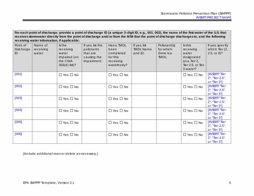
Stormwater Pollution Prevention Plan (SWPPP) INSERT PROJECT NAME
EPA SWPPP Template, Version 2.1 5
For each point of discharge, provide a point of discharge ID (a unique 3-digit ID, e.g., 001, 002), the name of the first water of the U.S. that
receives stormwater directly from the point of discharge and/or from the MS4 that the point of discharge discharges to, and the following
receiving water information, if applicable: Point of Discharge ID
Name of receiving water:
Is the receiving water impaired (on the CWA 303(d) list)?
If yes, list the pollutants that are causing the impairment:
Has a TMDL been completed for this receiving waterbody?
If yes, list TMDL Name and ID:
Pollutant(s) for which there is a TMDL:
Is this receiving water designated as a Tier 2, Tier 2.5, or Tier 3 water?
If yes, specify which Tier (2, 2.5, or 3)?
[001] ☐ Yes ☐ No ☐ Yes ☐ No ☐ Yes ☐ No [INSERT "Tier 2", "Tier 2.5", or "Tier 3"]
[002] ☐ Yes ☐ No ☐ Yes ☐ No ☐ Yes ☐ No [INSERT "Tier 2", "Tier 2.5", or "Tier 3"]
[003] ☐ Yes ☐ No ☐ Yes ☐ No ☐ Yes ☐ No [INSERT "Tier 2", "Tier 2.5", or "Tier 3"]
[004] ☐ Yes ☐ No ☐ Yes ☐ No ☐ Yes ☐ No [INSERT "Tier 2", "Tier 2.5", or "Tier 3"]
[005] ☐ Yes ☐ No ☐ Yes ☐ No ☐ Yes ☐ No [INSERT "Tier 2", "Tier 2.5", or "Tier 3"]
[006] ☐ Yes ☐ No ☐ Yes ☐ No ☐ Yes ☐ No [INSERT "Tier 2", "Tier 2.5", or "Tier 3"]
[Include additional rows or delete as necessary.]
Stormwater Pollution Prevention Plan (SWPPP) INSERT PROJECT NAME
EPA SWPPP Template, Version 2.1 5
2.3 Nature of the Construction Activities
General Description of Project
Provide a general description of the nature of your construction activities, including the age dates of past renovations for structures that are undergoing demolition: INSERT TEXT HERE Size of Construction Site
Size of Property INSERT SIZE OF PROPERTY (in acres or in miles if a linear construction site)
Total Area Expected to be Disturbed by Construction Activities
INSERT TOTAL AREA OF CONSTRUCTION DISTURBANCES (to the nearest quarter acre or quarter mile if a linear construction site)
Maximum Area Expected to be Disturbed at Any One Time
INSERT MAXIMUM AREA TO BE DISTURBED AT ANY ONE TIME (in acres)
[Repeat as necessary for individual project phases.]
Type of Construction Site (check all that apply):
☐ Single-Family Residential ☐ Multi-Family Residential ☐ Commercial ☐ Industrial
☐ Institutional ☐ Highway or Road ☐ Utility ☐ Other ____________________________ Will there be demolition of any structure built or renovated before January 1, 1980? ☐ Yes ☐ No
If yes, do any of the structures being demolished have at least 10,000 square feet of floor space?
☐ Yes ☐ No ☐ N/A
Instructions (see CGP Parts 1.2.1.c and 7.2.3):
― Provide a general description of the nature of the construction activities at your site. ― Describe the size of the property (in acres or in miles if a linear construction site), the
total area expected to be disturbed by the construction activities (to the nearest quarter acre or quarter mile if a linear construction site), and the maximum area expected to be disturbed at any one time.
― Indicate the type of construction site, whether there will be certain demolition activities, and whether the predevelopment land use was for agriculture.
― Provide a list and description of all pollutant-generating activities (e.g., paving operations; concrete, paint, and stucco washout and waste disposal; solid waste storage and disposal; and dewatering operations) and indicate for each activity the type of pollutant that will be generated (e.g., sediment, fertilizers, pesticides, paints, caulks, sealants, fluorescent light ballasts, contaminated substrates, solvents, fuels) and could be discharged in stormwater from your site.
― Describe the construction support activities covered by this permit (see Part 1.2.1.c of the permit).
―
Stormwater Pollution Prevention Plan (SWPPP) INSERT PROJECT NAME
EPA SWPPP Template, Version 2.1 6
Was the pre-development land use used for agriculture (see Appendix A for definition of “agricultural land”)?
☐ Yes ☐ No
Pollutant-Generating Activities
― List and describe all pollutant-generating activities and indicate for each activity the type of pollutant that will be generated. Take into account where potential spills and leaks could occur that contribute pollutants to stormwater discharges, and any known hazardous or toxic substances, such as PCBs and asbestos, that will be disturbed during construction.
Pollutant-Generating Activity
(e.g., paving operations; concrete, paint, and stucco washout and waste disposal; solid waste storage and disposal; and dewatering operations)
Pollutants or Pollutant Constituents
(e.g., sediment, fertilizers, pesticides, paints, caulks, sealants, fluorescent light ballasts, contaminated substrates, solvents, fuels)
INSERT POLLUTANT-GENERATING ACTIVITY INSERT POLLUTANT(S) INSERT POLLUTANT-GENERATING ACTIVITY INSERT POLLUTANT(S) INSERT POLLUTANT-GENERATING ACTIVITY INSERT POLLUTANT(S)
[Include additional rows or delete as necessary.]
Construction Support Activities (only provide if applicable)
Describe any construction support activities for the project (e.g., concrete or asphalt batch plants, equipment staging yards, material storage areas, excavated material disposal areas, borrow areas): INSERT DESCRIPTION OF CONSTRUCTION SUPPORT ACTIVITY
Contact information for construction support activity: INSERT NAME INSERT TELEPHONE NO. INSERT EMAIL INSERT ADDRESS AND/OR LATITUDE/LONGITUDE
[Repeat as necessary.]
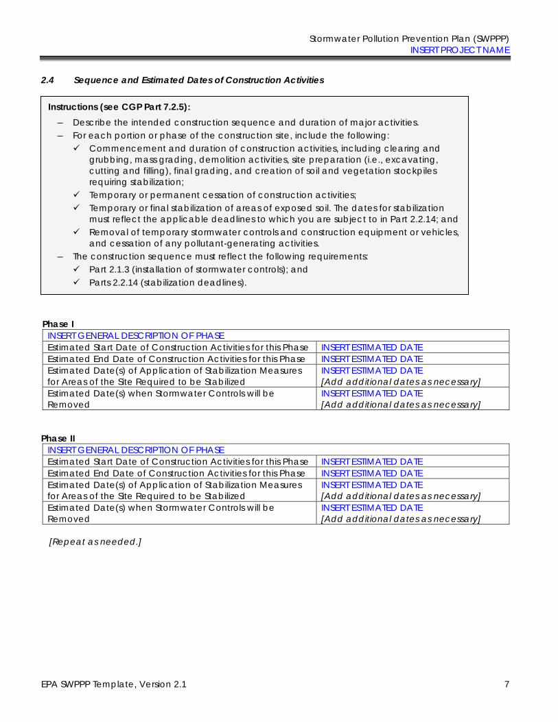
Stormwater Pollution Prevention Plan (SWPPP) INSERT PROJECT NAME
EPA SWPPP Template, Version 2.1 7
2.4 Sequence and Estimated Dates of Construction Activities
Phase I
INSERT GENERAL DESCRIPTION OF PHASE
Estimated Start Date of Construction Activities for this Phase INSERT ESTIMATED DATE Estimated End Date of Construction Activities for this Phase INSERT ESTIMATED DATE
Estimated Date(s) of Application of Stabilization Measures for Areas of the Site Required to be Stabilized
INSERT ESTIMATED DATE [Add additional dates as necessary]
Estimated Date(s) when Stormwater Controls will be Removed
INSERT ESTIMATED DATE [Add additional dates as necessary]
Phase II
INSERT GENERAL DESCRIPTION OF PHASE
Estimated Start Date of Construction Activities for this Phase INSERT ESTIMATED DATE Estimated End Date of Construction Activities for this Phase INSERT ESTIMATED DATE
Estimated Date(s) of Application of Stabilization Measures for Areas of the Site Required to be Stabilized
INSERT ESTIMATED DATE [Add additional dates as necessary]
Estimated Date(s) when Stormwater Controls will be Removed
INSERT ESTIMATED DATE [Add additional dates as necessary]
[Repeat as needed.]
Instructions (see CGP Part 7.2.5):
― Describe the intended construction sequence and duration of major activities. ― For each portion or phase of the construction site, include the following:
✓ Commencement and duration of construction activities, including clearing and grubbing, mass grading, demolition activities, site preparation (i.e., excavating, cutting and filling), final grading, and creation of soil and vegetation stockpiles requiring stabilization;
✓ Temporary or permanent cessation of construction activities; ✓ Temporary or final stabilization of areas of exposed soil. The dates for stabilization
must reflect the applicable deadlines to which you are subject to in Part 2.2.14; and ✓ Removal of temporary stormwater controls and construction equipment or vehicles,
and cessation of any pollutant-generating activities. ― The construction sequence must reflect the following requirements:
✓ Part 2.1.3 (installation of stormwater controls); and ✓ Parts 2.2.14 (stabilization deadlines).
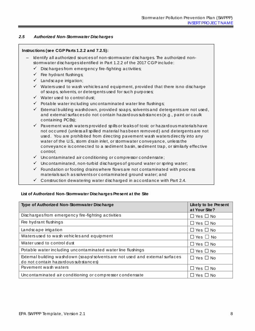
Stormwater Pollution Prevention Plan (SWPPP) INSERT PROJECT NAME
EPA SWPPP Template, Version 2.1 8
2.5 Authorized Non-Stormwater Discharges
List of Authorized Non-Stormwater Discharges Present at the Site
Type of Authorized Non-Stormwater Discharge Likely to be Present
at Your Site?
Discharges from emergency fire-fighting activities ☐ Yes ☐ No
Fire hydrant flushings ☐ Yes ☐ No
Landscape irrigation ☐ Yes ☐ No
Waters used to wash vehicles and equipment ☐ Yes ☐ No
Water used to control dust ☐ Yes ☐ No
Potable water including uncontaminated water line flushings ☐ Yes ☐ No
External building washdown (soaps/solvents are not used and external surfaces do not contain hazardous substances)
☐ Yes ☐ No
Pavement wash waters ☐ Yes ☐ No
Uncontaminated air conditioning or compressor condensate ☐ Yes ☐ No
Instructions (see CGP Parts 1.2.2 and 7.2.5):
― Identify all authorized sources of non-stormwater discharges. The authorized non-stormwater discharges identified in Part 1.2.2 of the 2017 CGP include: ✓ Discharges from emergency fire-fighting activities; ✓ Fire hydrant flushings; ✓ Landscape irrigation; ✓ Waters used to wash vehicles and equipment, provided that there is no discharge
of soaps, solvents, or detergents used for such purposes; ✓ Water used to control dust; ✓ Potable water including uncontaminated water line flushings; ✓ External building washdown, provided soaps, solvents and detergents are not used,
and external surfaces do not contain hazardous substances (e.g., paint or caulk containing PCBs);
✓ Pavement wash waters provided spills or leaks of toxic or hazardous materials have not occurred (unless all spilled material has been removed) and detergents are not used. You are prohibited from directing pavement wash waters directly into any water of the U.S., storm drain inlet, or stormwater conveyance, unless the conveyance is connected to a sediment basin, sediment trap, or similarly effective control;
✓ Uncontaminated air conditioning or compressor condensate; ✓ Uncontaminated, non-turbid discharges of ground water or spring water; ✓ Foundation or footing drains where flows are not contaminated with process
materials such as solvents or contaminated ground water; and ✓ Construction dewatering water discharged in accordance with Part 2.4.

Stormwater Pollution Prevention Plan (SWPPP) INSERT PROJECT NAME
EPA SWPPP Template, Version 2.1 9
Uncontaminated, non-turbid discharges of ground water or spring water ☐ Yes ☐ No
Foundation or footing drains ☐ Yes ☐ No
Construction dewatering water ☐ Yes ☐ No
(Note: You are required to identify the likely locations of these authorized non-stormwater discharges
on your site map. See Section 2.6, below, of the SWPPP Template.)

Stormwater Pollution Prevention Plan (SWPPP) INSERT PROJECT NAME
EPA SWPPP Template, Version 2.1 10
2.6 Site Maps
Instructions (see CGP Part 7.2.4):
― Attach site maps in Appendix A of the Template. For most projects, a series of site maps is necessary and recommended. The first should show the undeveloped site and its current features. An additional map or maps should be created to show the developed site or, for more complicated sites, show the major phases of development.
These maps must include the following features:
― Boundaries of the property and of the locations where construction will occur, including: ✓ Locations where earth-disturbing activities will occur, noting any phasing of
construction activities and any demolition activities; ✓ Approximate slopes before and after major grading activities. Note areas of steep
slopes, as defined in CGP Appendix A; ✓ Locations where sediment, soil, or other construction materials will be stockpiled; ✓ Locations of any crossings of waters of the U.S.; ✓ Designated points where vehicles will exit onto paved roads; ✓ Locations of structures and other impervious surfaces upon completion of
construction; and ✓ Locations of on-site and off-site construction support activity areas covered by this
permit (see Part 1.2.1.c). ― Locations of all waters of the U.S., including wetlands, on your site and within one mile
downstream of the site’s discharge point. Indicate which waterbodies are listed as impaired, and which are identified by your state, tribe, or EPA as Tier 2, Tier 2.5, or Tier 3 waters.
― Areas of federally-listed critical habitat for endangered or threatened species within the site and/or at discharge locations.
― Type and extent of pre-construction cover on the site (e.g., vegetative cover, forest, pasture, pavement, structures)
― Drainage pattern(s) of stormwater and authorized non-stormwater before and after major grading activities.
― Stormwater and authorized non-stormwater discharge locations, including: ✓ Locations where stormwater and/or authorized non-stormwater will be discharged
to storm drain inlets; and ✓ Locations where stormwater or allowable non-stormwater will be discharged to
waters of the U.S. (including wetlands). ― Locations of all potential pollutant-generating activities. ― Locations of stormwater controls, including natural buffer areas and any shared controls
utilized to comply with the permit. ― Locations where polymers, flocculants, or other treatment chemicals will be used and
stored.
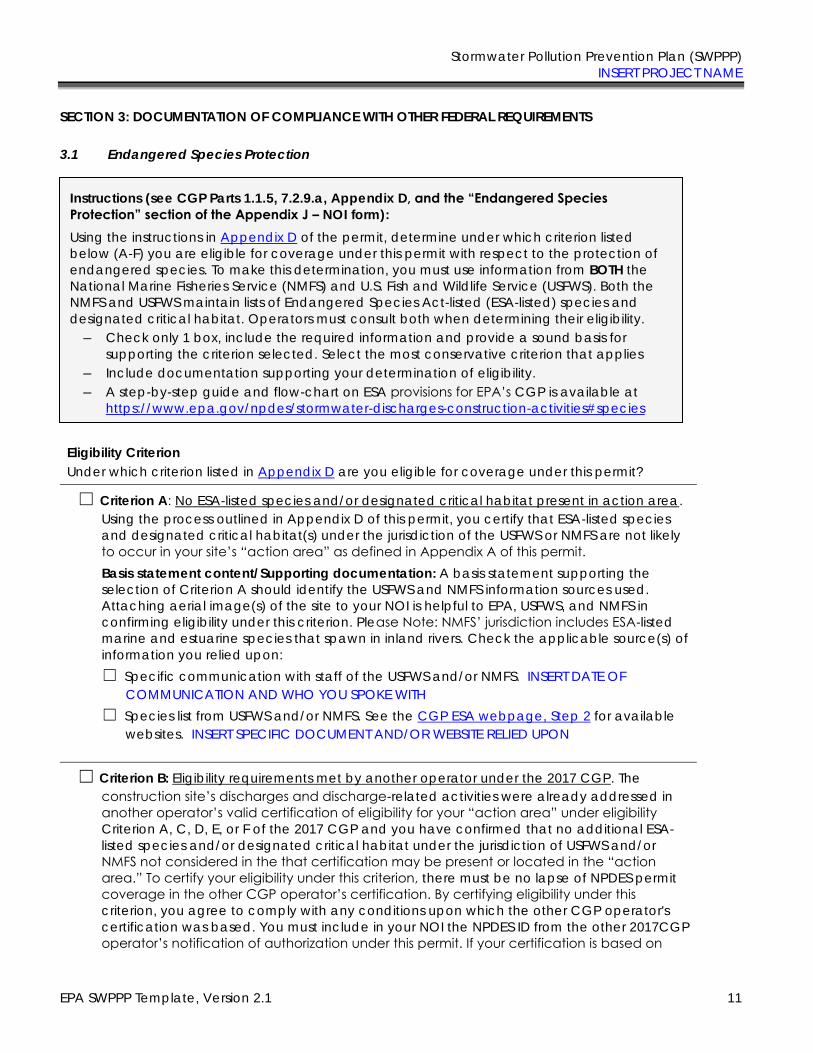
Stormwater Pollution Prevention Plan (SWPPP) INSERT PROJECT NAME
EPA SWPPP Template, Version 2.1 11
SECTION 3: DOCUMENTATION OF COMPLIANCE WITH OTHER FEDERAL REQUIREMENTS
3.1 Endangered Species Protection
Eligibility Criterion
Under which criterion listed in Appendix D are you eligible for coverage under this permit?
☐ Criterion A: No ESA-listed species and/or designated critical habitat present in action area. Using the process outlined in Appendix D of this permit, you certify that ESA-listed species and designated critical habitat(s) under the jurisdiction of the USFWS or NMFS are not likely to occur in your site’s “action area” as defined in Appendix A of this permit. Basis statement content/Supporting documentation: A basis statement supporting the selection of Criterion A should identify the USFWS and NMFS information sources used. Attaching aerial image(s) of the site to your NOI is helpful to EPA, USFWS, and NMFS in confirming eligibility under this criterion. Please Note: NMFS’ jurisdiction includes ESA-listed marine and estuarine species that spawn in inland rivers. Check the applicable source(s) of information you relied upon: ☐ Specific communication with staff of the USFWS and/or NMFS. INSERT DATE OF
COMMUNICATION AND WHO YOU SPOKE WITH ☐ Species list from USFWS and/or NMFS. See the CGP ESA webpage, Step 2 for available
websites. INSERT SPECIFIC DOCUMENT AND/OR WEBSITE RELIED UPON
☐ Criterion B: Eligibility requirements met by another operator under the 2017 CGP. The construction site’s discharges and discharge-related activities were already addressed in another operator’s valid certification of eligibility for your “action area” under eligibility
Criterion A, C, D, E, or F of the 2017 CGP and you have confirmed that no additional ESA-listed species and/or designated critical habitat under the jurisdiction of USFWS and/or NMFS not considered in the that certification may be present or located in the “action
area.” To certify your eligibility under this criterion, there must be no lapse of NPDES permit coverage in the other CGP operator’s certification. By certifying eligibility under this
criterion, you agree to comply with any conditions upon which the other CGP operator's certification was based. You must include in your NOI the NPDES ID from the other 2017CGP operator’s notification of authorization under this permit. If your certification is based on
Instructions (see CGP Parts 1.1.5, 7.2.9.a, Appendix D, and the “Endangered Species
Protection” section of the Appendix J – NOI form):
Using the instructions in Appendix D of the permit, determine under which criterion listed below (A-F) you are eligible for coverage under this permit with respect to the protection of endangered species. To make this determination, you must use information from BOTH the National Marine Fisheries Service (NMFS) and U.S. Fish and Wildlife Service (USFWS). Both the NMFS and USFWS maintain lists of Endangered Species Act-listed (ESA-listed) species and designated critical habitat. Operators must consult both when determining their eligibility.
― Check only 1 box, include the required information and provide a sound basis for supporting the criterion selected. Select the most conservative criterion that applies
― Include documentation supporting your determination of eligibility. ― A step-by-step guide and flow-chart on ESA provisions for EPA’s CGP is available at
https://www.epa.gov/npdes/stormwater-discharges-construction-activities#species
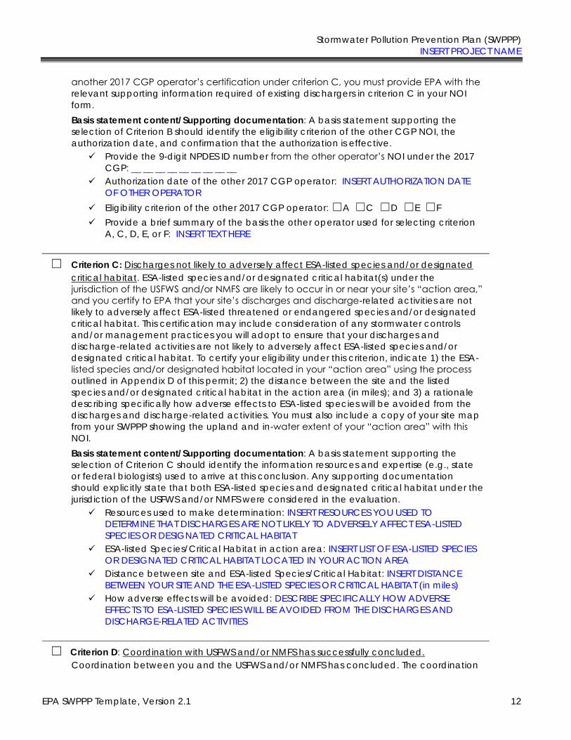
Stormwater Pollution Prevention Plan (SWPPP) INSERT PROJECT NAME
EPA SWPPP Template, Version 2.1 12
another 2017 CGP operator’s certification under criterion C, you must provide EPA with the
relevant supporting information required of existing dischargers in criterion C in your NOI form. Basis statement content/Supporting documentation: A basis statement supporting the selection of Criterion B should identify the eligibility criterion of the other CGP NOI, the authorization date, and confirmation that the authorization is effective.
✓ Provide the 9-digit NPDES ID number from the other operator’s NOI under the 2017 CGP: __ __ __ __ __ __ __ __ __
✓ Authorization date of the other 2017 CGP operator: INSERT AUTHORIZATION DATE OF OTHER OPERATOR
✓ Eligibility criterion of the other 2017 CGP operator: ☐A ☐C ☐D ☐E ☐F ✓ Provide a brief summary of the basis the other operator used for selecting criterion
A, C, D, E, or F: INSERT TEXT HERE
☐ Criterion C: Discharges not likely to adversely affect ESA-listed species and/or designated critical habitat. ESA-listed species and/or designated critical habitat(s) under the jurisdiction of the USFWS and/or NMFS are likely to occur in or near your site’s “action area,”
and you certify to EPA that your site’s discharges and discharge-related activities are not likely to adversely affect ESA-listed threatened or endangered species and/or designated critical habitat. This certification may include consideration of any stormwater controls and/or management practices you will adopt to ensure that your discharges and discharge-related activities are not likely to adversely affect ESA-listed species and/or designated critical habitat. To certify your eligibility under this criterion, indicate 1) the ESA-listed species and/or designated habitat located in your “action area” using the process
outlined in Appendix D of this permit; 2) the distance between the site and the listed species and/or designated critical habitat in the action area (in miles); and 3) a rationale describing specifically how adverse effects to ESA-listed species will be avoided from the discharges and discharge-related activities. You must also include a copy of your site map from your SWPPP showing the upland and in-water extent of your “action area” with this
NOI. Basis statement content/Supporting documentation: A basis statement supporting the selection of Criterion C should identify the information resources and expertise (e.g., state or federal biologists) used to arrive at this conclusion. Any supporting documentation should explicitly state that both ESA-listed species and designated critical habitat under the jurisdiction of the USFWS and/or NMFS were considered in the evaluation.
✓ Resources used to make determination: INSERT RESOURCES YOU USED TO DETERMINE THAT DISCHARGES ARE NOT LIKELY TO ADVERSELY AFFECT ESA-LISTED SPECIES OR DESIGNATED CRITICAL HABITAT
✓ ESA-listed Species/Critical Habitat in action area: INSERT LIST OF ESA-LISTED SPECIES OR DESIGNATED CRITICAL HABITAT LOCATED IN YOUR ACTION AREA
✓ Distance between site and ESA-listed Species/Critical Habitat: INSERT DISTANCE BETWEEN YOUR SITE AND THE ESA-LISTED SPECIES OR CRITICAL HABITAT (in miles)
✓ How adverse effects will be avoided: DESCRIBE SPECIFICALLY HOW ADVERSE EFFECTS TO ESA-LISTED SPECIES WILL BE AVOIDED FROM THE DISCHARGES AND DISCHARGE-RELATED ACTIVITIES
☐ Criterion D: Coordination with USFWS and/or NMFS has successfully concluded. Coordination between you and the USFWS and/or NMFS has concluded. The coordination
Stormwater Pollution Prevention Plan (SWPPP) INSERT PROJECT NAME
EPA SWPPP Template, Version 2.1 13
must have addressed the effects of your site’s discharges and discharge-related activities on ESA-listed species and/or designated critical habitat under the jurisdiction of USFWS and/or NMFS, and resulted in a written concurrence from USFWS and/or NMFS that your site’s discharges and discharge-related activities are not likely to adversely affect listed species and/or critical habitat. You must include copies of the correspondence with the participating agencies in your SWPPP and this NOI. Basis statement content/Supporting documentation: A basis statement supporting the selection of Criterion D should identify whether USFWS or NMFS or both agencies participated in coordination, the field office/regional office(s) providing that coordination, and the date that coordination concluded.
✓ Agency coordinated with: ☐USFWS ☐ NMFS ✓ Field/regional office(s) providing coordination: INSERT FIELD/REGIONAL OFFICE(S)
PROVIDING COORDINATION ✓ Date coordination concluded: INSERT DATE COORDINATION CONCLUDED ✓ Attach copies of any letters or other communication between you and the U.S. Fish
& Wildlife Service or National Marine Fisheries Service concluding coordination activities.
☐ Criterion E: ESA Section 7 consultation has successfully concluded. Consultation between a Federal Agency and the USFWS and/or NMFS under section 7 of the ESA has concluded. The consultation must have addressed the effects of the construction site’s discharges and
discharge-related activities on ESA-listed species and/or designated critical habitat under the jurisdiction of USFWS and/or NMFS. To certify eligibility under this criterion, Indicate the result of the consultation:
☐ Biological opinion from USFWS and/or NMFS that concludes that the action in question (taking into account the effects of your site’s discharges and discharge-related activities) is not likely to jeopardize the continued existence of listed species, nor the destruction or adverse modification of critical habitat; or
☐ Written concurrence from USFWS and/or NMFS with a finding that the site’s
discharges and discharge-related activities are not likely to adversely affect ESA-listed species and/or designated critical habitat. You must include copies of the correspondence between yourself and the USFWS and/or NMFS in your SWPPP and this NOI.
Basis statement content/Supporting documentation: A basis statement supporting the selection of Criterion E should identify the federal action agency(ies) involved, the field office/regional office(s) providing that consultation, any tracking numbers of identifiers associated with that consultation (e.g., IPaC number, PCTS number), and the date the consultation was completed.
✓ Federal agency(ies) involved: INSERT FEDERAL AGENCY(IES) INVOLVED ✓ Field/regional office(s) providing consultation: INSERT FIELD/REGIONAL OFFICE(S)
PROVIDING CONSULTATION ✓ Tracking numbers associated with consultation: INSERT CONSULTATION TRACKING
NUMBER(S) ✓ Date consultation completed: INSERT DATE CONSULTATION COMPLETED ✓ Attach copies of any letters or other communication between you and the U.S. Fish
& Wildlife Service or National Marine Fisheries Service concluding consultation.
Stormwater Pollution Prevention Plan (SWPPP) INSERT PROJECT NAME
EPA SWPPP Template, Version 2.1 14
☐ Criterion F: Issuance of section 10 permit. Potential take is authorized through the issuance of a permit under section 10 of the ESA by the USFWS and/or NMFS, and this authorization addresses the effects of the site’s discharges and discharge-related activities on ESA-listed species and designated critical habitat. You must include copies of the correspondence between yourself and the participating agencies in your SWPPP and your NOI. Basis statement content/Supporting documentation: A basis statement supporting the selection of Criterion F should identify whether USFWS or NMFS or both agencies provided a section 10 permit, the field office/regional office(s) providing permit(s), any tracking numbers of identifiers associated with that consultation (e.g., IPaC number, PCTS number), and the date the permit was granted.
✓ Agency providing section 10 permit: ☐USFWS ☐NMFS ✓ Field/regional office(s) providing permit: INSERT FIELD/REGIONAL OFFICE(S)
PROVIDING PERMIT ✓ Tracking numbers associated with consultation: INSERT CONSULTATION TRACKING
NUMBER(S) ✓ Date permit granted: INSERT DATE PERMIT GRANTED ✓ Attach copies of any letters or other communication between you and the U.S. Fish
& Wildlife Service or National Marine Fisheries Service.
3.2 Historic Preservation
Appendix E, Step 1
Do you plan on installing any of the following stormwater controls at your site? Check all that apply below, and proceed to Appendix E, Step 2. ☐ Dike
☐ Berm
☐ Catch Basin
☐ Pond
☐ Stormwater Conveyance Channel (e.g., ditch, trench, perimeter drain, swale, etc.)
☐ Culvert
☐ Other type of ground-disturbing stormwater control: INSERT SPECIFIC TYPE OF STORMWATER CONTROL
(Note: If you will not be installing any ground-disturbing stormwater controls, no further documentation is required for Section 3.2 of the Template.)
Instructions (see CGP Part 1.1.6, 7.2.9.b, Appendix E, and the “Historic Preservation” section of
the Appendix J – NOI form):
Follow the screening process in Appendix E of the permit for determining whether your installation of subsurface earth-disturbing stormwater controls will have an effect on historic properties.
― Include documentation supporting your determination of eligibility. ― To contact your applicable state or tribal historic preservation office, information is
available at www.achp.gov/programs/html.
Stormwater Pollution Prevention Plan (SWPPP) INSERT PROJECT NAME
EPA SWPPP Template, Version 2.1 15
Appendix E, Step 2 If you answered yes in Step 1, have prior surveys or evaluations conducted on the site already determined that historic properties do not exist, or that prior disturbances at the site have precluded the existence of historic properties? ☐ YES ☐ NO
▪ If yes, no further documentation is required for Section 3.2 of the Template. ▪ If no, proceed to Appendix E, Step 3.
Appendix E, Step 3 If you answered no in Step 2, have you determined that your installation of subsurface earth-disturbing stormwater controls will have no effect on historic properties? ☐ YES ☐ NO If yes, provide documentation of the basis for your determination. INSERT REFERENCES TO DOCUMENTS, STUDIES, OR OTHER SOURCES RELIED UPON If no, proceed to Appendix E, Step 4. Appendix E, Step 4 If you answered no in Step 3, did the State Historic Preservation Officer (SHPO), Tribal Historic Preservation Office (THPO), or other tribal representative (whichever applies) respond to you within 15 calendar days to indicate whether the subsurface earth disturbances caused by the installation of stormwater controls affect historic properties? ☐ YES ☐ NO If no, no further documentation is required for Section 3.2 of the Template. If yes, describe the nature of their response: ☐ Written indication that no historic properties will be affected by the installation of
stormwater controls. INSERT COPIES OF LETTERS, EMAILS, OR OTHER COMMUNICATION BETWEEN YOU AND THE APPLICABLE SHPO, THPO, OR OTHER TRIBAL REPRESENTATIVE
☐ Written indication that adverse effects to historic properties from the installation of stormwater controls can be mitigated by agreed upon actions. INSERT COPIES OF LETTERS, EMAILS, OR OTHER COMMUNICATION BETWEEN YOU AND THE APPLICABLE SHPO, THPO, OR OTHER TRIBAL REPRESENTATIVE
☐ No agreement has been reached regarding measures to mitigate effects to historic properties from the installation of stormwater controls. INSERT COPIES OF LETTERS, EMAILS, OR OTHER COMMUNICATION BETWEEN YOU AND THE APPLICABLE SHPO, THPO, OR OTHER TRIBAL REPRESENTATIVE
☐ Other: INSERT COPIES OF LETTERS, EMAILS, OR OTHER COMMUNICATION BETWEEN YOU AND THE APPLICABLE SHPO, THPO, OR OTHER TRIBAL REPRESENTATIVE
Stormwater Pollution Prevention Plan (SWPPP) INSERT PROJECT NAME
EPA SWPPP Template, Version 2.1 16
3.3 Safe Drinking Water Act Underground Injection Control Requirements
Do you plan to install any of the following controls? Check all that apply below.
☐ Infiltration trenches (if stormwater is directed to any bored, drilled, driven shaft or dug hole that is deeper than its widest surface dimension, or has a subsurface fluid distribution system)
☐ Commercially manufactured pre-cast or pre-built proprietary subsurface detention vaults, chambers, or other devices designed to capture and infiltrate stormwater flow
☐ Drywells, seepage pits, or improved sinkholes (if stormwater is directed to any bored, drilled, driven shaft or dug hole that is deeper than its widest surface dimension, or has a subsurface fluid distribution system)
IF YES, INSERT COPIES OF LETTERS, EMAILS, OR OTHER COMMUNICATION BETWEEN YOU AND THE STATE AGENCY OR EPA REGIONAL OFFICE
Instructions (see CGP Part 7.2.9.c):
― If you will use any of the identified controls in this section, include documentation of contact between you and the applicable state agency or EPA Regional Office responsible for implementing the requirements for underground injection wells in the Safe Drinking Water Act and EPA’s implementing regulations at 40 CFR Parts 144-147. \
― For state UIC program contacts, refer to the following EPA website: https://www.epa.gov/uic.
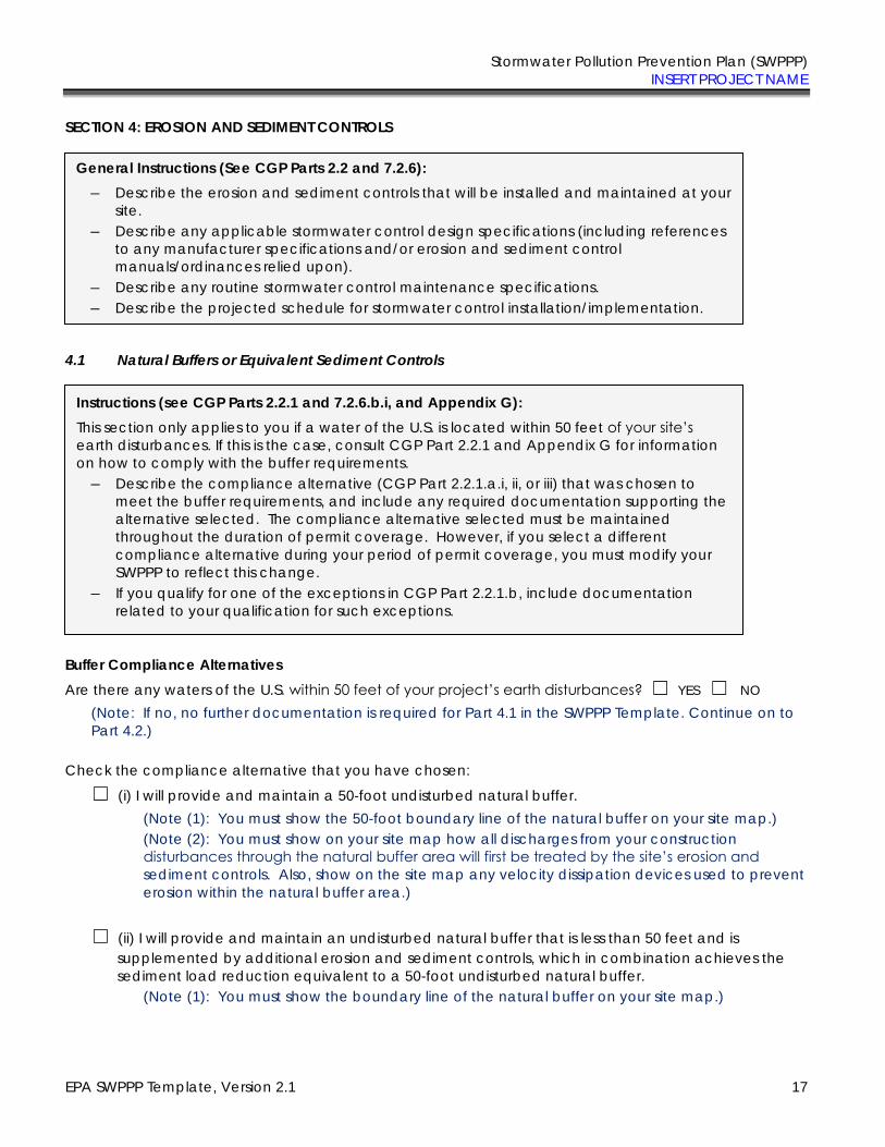
Stormwater Pollution Prevention Plan (SWPPP) INSERT PROJECT NAME
EPA SWPPP Template, Version 2.1 17
SECTION 4: EROSION AND SEDIMENT CONTROLS
4.1 Natural Buffers or Equivalent Sediment Controls
Buffer Compliance Alternatives
Are there any waters of the U.S. within 50 feet of your project’s earth disturbances? ☐ YES ☐ NO
(Note: If no, no further documentation is required for Part 4.1 in the SWPPP Template. Continue on to Part 4.2.)
Check the compliance alternative that you have chosen:
☐ (i) I will provide and maintain a 50-foot undisturbed natural buffer. (Note (1): You must show the 50-foot boundary line of the natural buffer on your site map.) (Note (2): You must show on your site map how all discharges from your construction disturbances through the natural buffer area will first be treated by the site’s erosion and
sediment controls. Also, show on the site map any velocity dissipation devices used to prevent erosion within the natural buffer area.)
☐ (ii) I will provide and maintain an undisturbed natural buffer that is less than 50 feet and is supplemented by additional erosion and sediment controls, which in combination achieves the sediment load reduction equivalent to a 50-foot undisturbed natural buffer.
(Note (1): You must show the boundary line of the natural buffer on your site map.)
General Instructions (See CGP Parts 2.2 and 7.2.6):
― Describe the erosion and sediment controls that will be installed and maintained at your site.
― Describe any applicable stormwater control design specifications (including references to any manufacturer specifications and/or erosion and sediment control manuals/ordinances relied upon).
― Describe any routine stormwater control maintenance specifications. ― Describe the projected schedule for stormwater control installation/implementation.
Instructions (see CGP Parts 2.2.1 and 7.2.6.b.i, and Appendix G):
This section only applies to you if a water of the U.S. is located within 50 feet of your site’s
earth disturbances. If this is the case, consult CGP Part 2.2.1 and Appendix G for information on how to comply with the buffer requirements.
― Describe the compliance alternative (CGP Part 2.2.1.a.i, ii, or iii) that was chosen to meet the buffer requirements, and include any required documentation supporting the alternative selected. The compliance alternative selected must be maintained throughout the duration of permit coverage. However, if you select a different compliance alternative during your period of permit coverage, you must modify your SWPPP to reflect this change.
― If you qualify for one of the exceptions in CGP Part 2.2.1.b, include documentation related to your qualification for such exceptions.
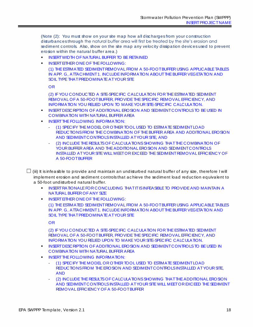
Stormwater Pollution Prevention Plan (SWPPP) INSERT PROJECT NAME
EPA SWPPP Template, Version 2.1 18
(Note (2): You must show on your site map how all discharges from your construction disturbances through the natural buffer area will first be treated by the site’s erosion and
sediment controls. Also, show on the site map any velocity dissipation devices used to prevent erosion within the natural buffer area.) ▪ INSERT WIDTH OF NATURAL BUFFER TO BE RETAINED ▪ INSERT EITHER ONE OF THE FOLLOWING:
(1) THE ESTIMATED SEDIMENT REMOVAL FROM A 50-FOOT BUFFER USING APPLICABLE TABLES IN APP. G, ATTACHMENT 1. INCLUDE INFORMATION ABOUT THE BUFFER VEGETATION AND SOIL TYPE THAT PREDOMINATE AT YOUR SITE
OR
(2) IF YOU CONDUCTED A SITE-SPECIFIC CALCULATION FOR THE ESTIMATED SEDIMENT REMOVAL OF A 50-FOOT BUFFER, PROVIDE THE SPECIFIC REMOVAL EFFICIENCY, AND INFORMATION YOU RELIED UPON TO MAKE YOUR SITE-SPECIFIC CALCULATION.
▪ INSERT DESCRIPTION OF ADDITIONAL EROSION AND SEDIMENT CONTROLS TO BE USED IN COMBINATION WITH NATURAL BUFFER AREA
▪ INSERT THE FOLLOWING INFORMATION: - (1) SPECIFY THE MODEL OR OTHER TOOL USED TO ESTIMATE SEDIMENT LOAD
REDUCTIONS FROM THE COMBINATION OF THE BUFFER AREA AND ADDITIONAL EROSION AND SEDIMENT CONTROLS INSTALLED AT YOUR SITE, AND
- (2) INCLUDE THE RESULTS OF CALCULATIONS SHOWING THAT THE COMBINATION OF YOUR BUFFER AREA AND THE ADDITIONAL EROSION AND SEDIMENT CONTROLS INSTALLED AT YOUR SITE WILL MEET OR EXCEED THE SEDIMENT REMOVAL EFFICIENCY OF A 50-FOOT BUFFER
☐ (iii) It is infeasible to provide and maintain an undisturbed natural buffer of any size, therefore I will implement erosion and sediment controls that achieve the sediment load reduction equivalent to a 50-foot undisturbed natural buffer.
▪ INSERT RATIONALE FOR CONCLUDING THAT IT IS INFEASIBLE TO PROVIDE AND MAINTAIN A NATURAL BUFFER OF ANY SIZE
▪ INSERT EITHER ONE OF THE FOLLOWING: (1) THE ESTIMATED SEDIMENT REMOVAL FROM A 50-FOOT BUFFER USING APPLICABLE TABLES IN APP. G, ATTACHMENT 1. INCLUDE INFORMATION ABOUT THE BUFFER VEGETATION AND SOIL TYPE THAT PREDOMINATE AT YOUR SITE
OR
(2) IF YOU CONDUCTED A SITE-SPECIFIC CALCULATION FOR THE ESTIMATED SEDIMENT REMOVAL OF A 50-FOOT BUFFER, PROVIDE THE SPECIFIC REMOVAL EFFICIENCY, AND INFORMATION YOU RELIED UPON TO MAKE YOUR SITE-SPECIFIC CALCULATION.
▪ INSERT DESCRIPTION OF ADDITIONAL EROSION AND SEDIMENT CONTROLS TO BE USED IN COMBINATION WITH NATURAL BUFFER AREA
▪ INSERT THE FOLLOWING INFORMATION: - (1) SPECIFY THE MODEL OR OTHER TOOL USED TO ESTIMATE SEDIMENT LOAD
REDUCTIONS FROM THE EROSION AND SEDIMENT CONTROLS INSTALLED AT YOUR SITE, AND
- (2) INCLUDE THE RESULTS OF CALCULATIONS SHOWING THAT THE ADDITIONAL EROSION AND SEDIMENT CONTROLS INSTALLED AT YOUR SITE WILL MEET OR EXCEED THE SEDIMENT REMOVAL EFFICIENCY OF A 50-FOOT BUFFER
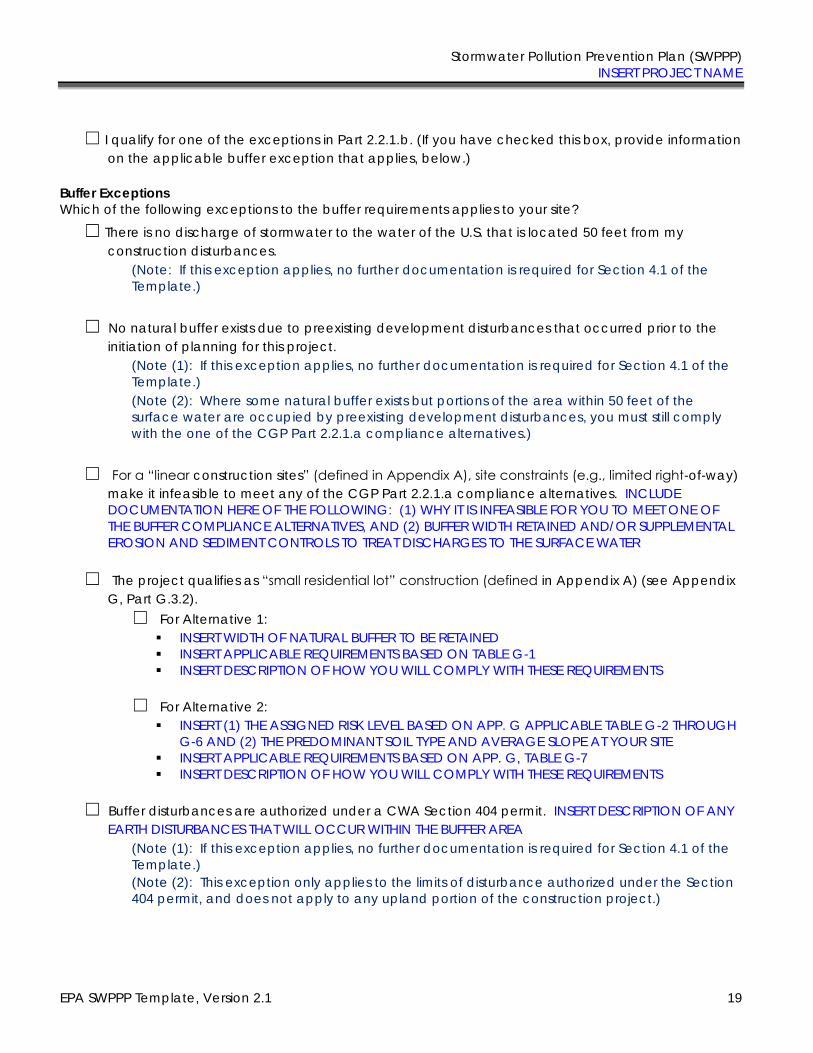
Stormwater Pollution Prevention Plan (SWPPP) INSERT PROJECT NAME
EPA SWPPP Template, Version 2.1 19
☐ I qualify for one of the exceptions in Part 2.2.1.b. (If you have checked this box, provide information on the applicable buffer exception that applies, below.)
Buffer Exceptions
Which of the following exceptions to the buffer requirements applies to your site?
☐ There is no discharge of stormwater to the water of the U.S. that is located 50 feet from my construction disturbances.
(Note: If this exception applies, no further documentation is required for Section 4.1 of the Template.)
☐ No natural buffer exists due to preexisting development disturbances that occurred prior to the initiation of planning for this project.
(Note (1): If this exception applies, no further documentation is required for Section 4.1 of the Template.) (Note (2): Where some natural buffer exists but portions of the area within 50 feet of the surface water are occupied by preexisting development disturbances, you must still comply with the one of the CGP Part 2.2.1.a compliance alternatives.)
☐ For a “linear construction sites” (defined in Appendix A), site constraints (e.g., limited right-of-way) make it infeasible to meet any of the CGP Part 2.2.1.a compliance alternatives. INCLUDE DOCUMENTATION HERE OF THE FOLLOWING: (1) WHY IT IS INFEASIBLE FOR YOU TO MEET ONE OF THE BUFFER COMPLIANCE ALTERNATIVES, AND (2) BUFFER WIDTH RETAINED AND/OR SUPPLEMENTAL EROSION AND SEDIMENT CONTROLS TO TREAT DISCHARGES TO THE SURFACE WATER
☐ The project qualifies as “small residential lot” construction (defined in Appendix A) (see Appendix
G, Part G.3.2). ☐ For Alternative 1:
▪ INSERT WIDTH OF NATURAL BUFFER TO BE RETAINED ▪ INSERT APPLICABLE REQUIREMENTS BASED ON TABLE G-1 ▪ INSERT DESCRIPTION OF HOW YOU WILL COMPLY WITH THESE REQUIREMENTS
☐ For Alternative 2:
▪ INSERT (1) THE ASSIGNED RISK LEVEL BASED ON APP. G APPLICABLE TABLE G-2 THROUGH G-6 AND (2) THE PREDOMINANT SOIL TYPE AND AVERAGE SLOPE AT YOUR SITE
▪ INSERT APPLICABLE REQUIREMENTS BASED ON APP. G, TABLE G-7 ▪ INSERT DESCRIPTION OF HOW YOU WILL COMPLY WITH THESE REQUIREMENTS
☐ Buffer disturbances are authorized under a CWA Section 404 permit. INSERT DESCRIPTION OF ANY
EARTH DISTURBANCES THAT WILL OCCUR WITHIN THE BUFFER AREA (Note (1): If this exception applies, no further documentation is required for Section 4.1 of the Template.) (Note (2): This exception only applies to the limits of disturbance authorized under the Section 404 permit, and does not apply to any upland portion of the construction project.)
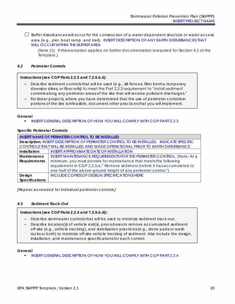
Stormwater Pollution Prevention Plan (SWPPP) INSERT PROJECT NAME
EPA SWPPP Template, Version 2.1 20
☐ Buffer disturbances will occur for the construction of a water-dependent structure or water access area (e.g., pier, boat ramp, and trail). INSERT DESCRIPTION OF ANY EARTH DISTURBANCES THAT WILL OCCUR WITHIN THE BUFFER AREA
(Note (1): If this exception applies, no further documentation is required for Section 4.1 of the Template.)
4.2 Perimeter Controls
General ▪ INSERT GENERAL DESCRIPTION OF HOW YOU WILL COMPLY WITH CGP PART 2.2.3
Specific Perimeter Controls
INSERT NAME OF PERIMETER CONTROL TO BE INSTALLED
Description: INSERT DESCRIPTION OF PERIMETER CONTROL TO BE INSTALLED. INDICATE SPECIFIC CONTROLS THAT WILL BE INSTALLED AND MADE OPERATIONAL PRIOR TO EARTH DISTURBANCE Installation INSERT APPROXIMATE DATE OF INSTALLATION Maintenance
Requirements INSERT MAINTENANCE REQUIREMENTS FOR THE PERIMETER CONTROL. (Note: At a minimum, you must provide for maintenance that meets the following requirement in CGP 2.2.3.a:” Remove sediment before it has accumulated to one-half of the above-ground height of any perimeter control.")
Design
Specifications
INCLUDE COPIES OF DESIGN SPECIFICATIONS HERE
[Repeat as needed for individual perimeter controls.]
4.3 Sediment Track-Out
General
▪ INSERT GENERAL DESCRIPTION OF HOW YOU WILL COMPLY WITH CGP PART 2.2.4
Instructions (see CGP Parts 2.2.3 and 7.2.6.b.ii):
― Describe sediment controls that will be used (e.g., silt fences, filter berms, temporary diversion dikes, or fiber rolls) to meet the Part 2.2.3 requirement to “install sediment
controls along any perimeter areas of the site that will receive pollutant discharges.” ― For linear projects, where you have determined that the use of perimeter controls in
portions of the site is infeasible, document other practices that you will implement.
Instructions (see CGP Parts 2.2.4 and 7.2.6.b.iii):
― Describe stormwater controls that will be used to minimize sediment track-out. ― Describe location(s) of vehicle exit(s), procedures to remove accumulated sediment
off-site (e.g., vehicle tracking), and stabilization practices (e.g., stone pads or wash racks or both) to minimize off-site vehicle tracking of sediment. Also include the design, installation, and maintenance specifications for each control.
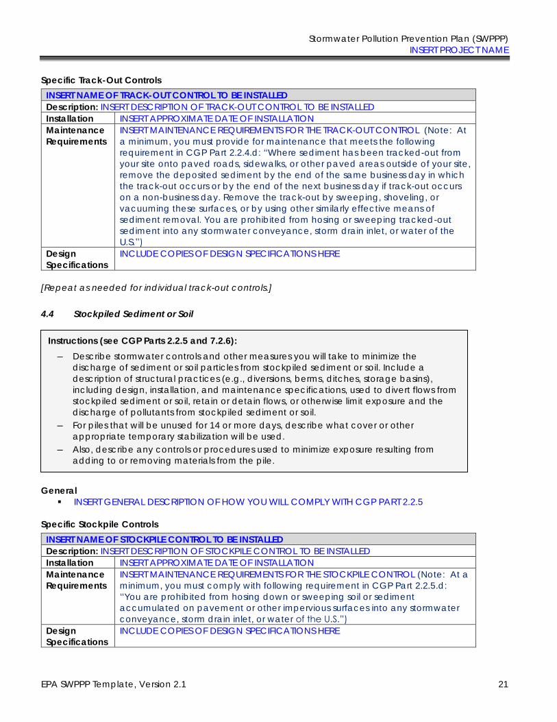
Stormwater Pollution Prevention Plan (SWPPP) INSERT PROJECT NAME
EPA SWPPP Template, Version 2.1 21
Specific Track-Out Controls
INSERT NAME OF TRACK-OUT CONTROL TO BE INSTALLED
Description: INSERT DESCRIPTION OF TRACK-OUT CONTROL TO BE INSTALLED Installation INSERT APPROXIMATE DATE OF INSTALLATION Maintenance
Requirements INSERT MAINTENANCE REQUIREMENTS FOR THE TRACK-OUT CONTROL (Note: At a minimum, you must provide for maintenance that meets the following requirement in CGP Part 2.2.4.d: “Where sediment has been tracked-out from your site onto paved roads, sidewalks, or other paved areas outside of your site, remove the deposited sediment by the end of the same business day in which the track-out occurs or by the end of the next business day if track-out occurs on a non-business day. Remove the track-out by sweeping, shoveling, or vacuuming these surfaces, or by using other similarly effective means of sediment removal. You are prohibited from hosing or sweeping tracked-out sediment into any stormwater conveyance, storm drain inlet, or water of the U.S.”)
Design
Specifications
INCLUDE COPIES OF DESIGN SPECIFICATIONS HERE
[Repeat as needed for individual track-out controls.]
4.4 Stockpiled Sediment or Soil
General ▪ INSERT GENERAL DESCRIPTION OF HOW YOU WILL COMPLY WITH CGP PART 2.2.5
Specific Stockpile Controls
INSERT NAME OF STOCKPILE CONTROL TO BE INSTALLED
Description: INSERT DESCRIPTION OF STOCKPILE CONTROL TO BE INSTALLED Installation INSERT APPROXIMATE DATE OF INSTALLATION Maintenance
Requirements INSERT MAINTENANCE REQUIREMENTS FOR THE STOCKPILE CONTROL (Note: At a minimum, you must comply with following requirement in CGP Part 2.2.5.d: “You are prohibited from hosing down or sweeping soil or sediment accumulated on pavement or other impervious surfaces into any stormwater conveyance, storm drain inlet, or water of the U.S.”)
Design
Specifications
INCLUDE COPIES OF DESIGN SPECIFICATIONS HERE
Instructions (see CGP Parts 2.2.5 and 7.2.6):
― Describe stormwater controls and other measures you will take to minimize the discharge of sediment or soil particles from stockpiled sediment or soil. Include a description of structural practices (e.g., diversions, berms, ditches, storage basins), including design, installation, and maintenance specifications, used to divert flows from stockpiled sediment or soil, retain or detain flows, or otherwise limit exposure and the discharge of pollutants from stockpiled sediment or soil.
― For piles that will be unused for 14 or more days, describe what cover or other appropriate temporary stabilization will be used.
― Also, describe any controls or procedures used to minimize exposure resulting from adding to or removing materials from the pile.
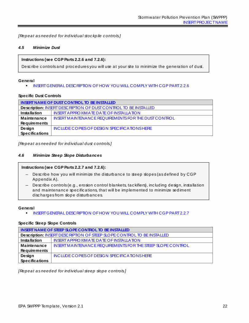
Stormwater Pollution Prevention Plan (SWPPP) INSERT PROJECT NAME
EPA SWPPP Template, Version 2.1 22
[Repeat as needed for individual stockpile controls.]
4.5 Minimize Dust
General ▪ INSERT GENERAL DESCRIPTION OF HOW YOU WILL COMPLY WITH CGP PART 2.2.6
Specific Dust Controls
INSERT NAME OF DUST CONTROL TO BE INSTALLED
Description: INSERT DESCRIPTION OF DUST CONTROL TO BE INSTALLED Installation INSERT APPROXIMATE DATE OF INSTALLATION Maintenance
Requirements INSERT MAINTENANCE REQUIREMENTS FOR THE DUST CONTROL
Design
Specifications
INCLUDE COPIES OF DESIGN SPECIFICATIONS HERE
[Repeat as needed for individual dust controls.]
4.6 Minimize Steep Slope Disturbances
General ▪ INSERT GENERAL DESCRIPTION OF HOW YOU WILL COMPLY WITH CGP PART 2.2.7
Specific Steep Slope Controls
INSERT NAME OF STEEP SLOPE CONTROL TO BE INSTALLED
Description: INSERT DESCRIPTION OF STEEP SLOPE CONTROL TO BE INSTALLED Installation INSERT APPROXIMATE DATE OF INSTALLATION Maintenance
Requirements INSERT MAINTENANCE REQUIREMENTS FOR THE STEEP SLOPE CONTROL
Design
Specifications
INCLUDE COPIES OF DESIGN SPECIFICATIONS HERE
[Repeat as needed for individual steep slope controls.]
Instructions (see CGP Parts 2.2.6 and 7.2.6):
Describe controls and procedures you will use at your site to minimize the generation of dust.
Instructions (see CGP Parts 2.2.7 and 7.2.6):
― Describe how you will minimize the disturbance to steep slopes (as defined by CGP Appendix A).
― Describe controls (e.g., erosion control blankets, tackifiers), including design, installation and maintenance specifications, that will be implemented to minimize sediment discharges from slope disturbances.
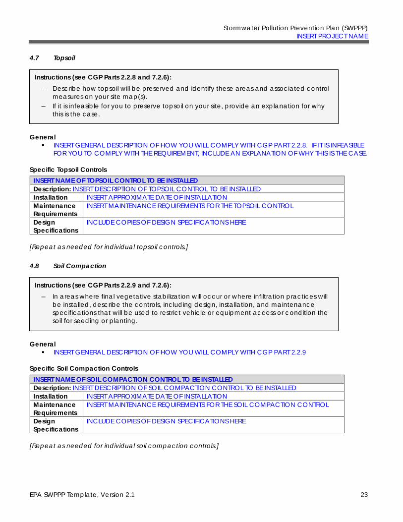
Stormwater Pollution Prevention Plan (SWPPP) INSERT PROJECT NAME
EPA SWPPP Template, Version 2.1 23
4.7 Topsoil
General ▪ INSERT GENERAL DESCRIPTION OF HOW YOU WILL COMPLY WITH CGP PART 2.2.8. IF IT IS INFEASIBLE
FOR YOU TO COMPLY WITH THE REQUIREMENT, INCLUDE AN EXPLANATION OF WHY THIS IS THE CASE.
Specific Topsoil Controls
INSERT NAME OF TOPSOIL CONTROL TO BE INSTALLED
Description: INSERT DESCRIPTION OF TOPSOIL CONTROL TO BE INSTALLED Installation INSERT APPROXIMATE DATE OF INSTALLATION Maintenance
Requirements INSERT MAINTENANCE REQUIREMENTS FOR THE TOPSOIL CONTROL
Design
Specifications
INCLUDE COPIES OF DESIGN SPECIFICATIONS HERE
[Repeat as needed for individual topsoil controls.]
4.8 Soil Compaction
General ▪ INSERT GENERAL DESCRIPTION OF HOW YOU WILL COMPLY WITH CGP PART 2.2.9
Specific Soil Compaction Controls
INSERT NAME OF SOIL COMPACTION CONTROL TO BE INSTALLED
Description: INSERT DESCRIPTION OF SOIL COMPACTION CONTROL TO BE INSTALLED Installation INSERT APPROXIMATE DATE OF INSTALLATION Maintenance
Requirements INSERT MAINTENANCE REQUIREMENTS FOR THE SOIL COMPACTION CONTROL
Design
Specifications
INCLUDE COPIES OF DESIGN SPECIFICATIONS HERE
[Repeat as needed for individual soil compaction controls.]
Instructions (see CGP Parts 2.2.8 and 7.2.6):
― Describe how topsoil will be preserved and identify these areas and associated control measures on your site map(s).
― If it is infeasible for you to preserve topsoil on your site, provide an explanation for why this is the case.
Instructions (see CGP Parts 2.2.9 and 7.2.6):
― In areas where final vegetative stabilization will occur or where infiltration practices will be installed, describe the controls, including design, installation, and maintenance specifications that will be used to restrict vehicle or equipment access or condition the soil for seeding or planting.

Stormwater Pollution Prevention Plan (SWPPP) INSERT PROJECT NAME
EPA SWPPP Template, Version 2.1 24
4.9 Storm Drain Inlets
General ▪ INSERT GENERAL DESCRIPTION OF HOW YOU WILL COMPLY WITH CGP PART 2.2.10
Specific Storm Drain Inlet Controls
INSERT NAME OF STORM DRAIN INLET CONTROL TO BE INSTALLED
Description: INSERT DESCRIPTION OF STORM DRAIN INLET CONTROL TO BE INSTALLED Installation INSERT APPROXIMATE DATE OF INSTALLATION Maintenance
Requirements INSERT MAINTENANCE REQUIREMENTS FOR THE STORM DRAIN INLET CONTROL (Note: At a minimum, you must comply with following requirement in CGP Part 2.2.10.b: “Clean, or remove and replace the protection measures as sediment accumulates, the filter becomes clogged, and/or performance is compromised. Where there is evidence of sediment accumulation adjacent to the inlet protection measure, remove the deposited sediment by the end of the same business day in which it is found or by the end of the following business day if removal by the same business day is not feasible.”)
Design
Specifications
INCLUDE COPIES OF DESIGN SPECIFICATIONS HERE
[Repeat as needed for individual storm drain inlet controls.]
4.10 Stormwater Conveyance Channels
General ▪ INSERT GENERAL DESCRIPTION OF HOW YOU WILL COMPLY WITH CGP PART 2.2.11
Specific Conveyance Channel Controls
INSERT NAME OF CONVEYANCE CHANNEL CONTROL TO BE INSTALLED
Description: INSERT DESCRIPTION OF CONVEYANCE CHANNEL CONTROL TO BE INSTALLED Installation INSERT APPROXIMATE DATE OF INSTALLATION Maintenance
Requirements INSERT MAINTENANCE REQUIREMENTS FOR THE CONVEYANCE CHANNEL CONTROL
Design
Specifications
INCLUDE COPIES OF DESIGN SPECIFICATIONS HERE
[Repeat as needed for individual stormwater conveyance channel controls.]
Instructions (see CGP Parts 2.2.10 and 7.2.6):
― Describe controls (e.g., inserts, rock-filled bags, or block and gravel) including design, installation, and maintenance specifications that will be implemented to protect all inlets that carry stormwater flow from your site to a water of the U.S., provided you have the authority to access the storm drain inlet.
Instructions (see CGP Parts 2.2.11 and 7.2.6):
If you will be installing a stormwater conveyance channel, describe control practices (e.g., velocity dissipation devices), including design specifications and details (volume, dimensions, outlet structure), that will be implemented at the construction site.
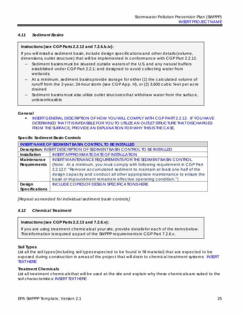
Stormwater Pollution Prevention Plan (SWPPP) INSERT PROJECT NAME
EPA SWPPP Template, Version 2.1 25
4.11 Sediment Basins
General ▪ INSERT GENERAL DESCRIPTION OF HOW YOU WILL COMPLY WITH CGP PART 2.2.12. IF YOU HAVE
DETERMINED THAT IT IS INFEASIBLE FOR YOU TO UTILIZE AN OUTLET STRUCTURE THAT DISCHARGES FROM THE SURFACE, PROVIDE AN EXPLANATION FOR WHY THIS IS THE CASE.
Specific Sediment Basin Controls
INSERT NAME OF SEDIMENT BASIN CONTROL TO BE INSTALLED
Description: INSERT DESCRIPTION OF SEDIMENT BASIN CONTROL TO BE INSTALLED Installation INSERT APPROXIMATE DATE OF INSTALLATION Maintenance
Requirements INSERT MAINTENANCE REQUIREMENTS FOR THE SEDIMENT BASIN CONTROL. (Note: At a minimum, you must comply with following requirement in CGP Part 2.2.12.f: “Remove accumulated sediment to maintain at least one-half of the design capacity and conduct all other appropriate maintenance to ensure the basin or impoundment remains in effective operating condition.”)
Design
Specifications
INCLUDE COPIES OF DESIGN SPECIFICATIONS HERE
[Repeat as needed for individual sediment basin controls.]
4.12 Chemical Treatment
Soil Types
List all the soil types (including soil types expected to be found in fill material) that are expected to be exposed during construction in areas of the project that will drain to chemical treatment systems: INSERT TEXT HERE
Treatment Chemicals
List all treatment chemicals that will be used at the site and explain why these chemicals are suited to the soil characteristics: INSERT TEXT HERE
Instructions (see CGP Parts 2.2.12 and 7.2.6.b.iv):
If you will install a sediment basin, include design specifications and other details (volume, dimensions, outlet structure) that will be implemented in conformance with CGP Part 2.2.12.
― Sediment basins must be situated outside waters of the U.S. and any natural buffers established under CGP Part 2.2.1; and designed to avoid collecting water from wetlands.
― At a minimum, sediment basins provide storage for either (1) the calculated volume of runoff from the 2-year, 24-hour storm (see CGP App. H), or (2) 3,600 cubic feet per acre drained
― Sediment basins must also utilize outlet structures that withdraw water from the surface, unless infeasible
Instructions (see CGP Parts 2.2.13 and 7.2.6.v):
If you are using treatment chemicals at your site, provide details for each of the items below. This information is required as part of the SWPPP requirements in CGP Part 7.2.6.v.
Stormwater Pollution Prevention Plan (SWPPP) INSERT PROJECT NAME
EPA SWPPP Template, Version 2.1 26
Describe the dosage of all treatment chemicals you will use at the site or the methodology you will use to determine dosage: INSERT TEXT HERE
Provide information from any applicable Safety Data Sheets (SDS): INSERT TEXT HERE
Describe how each of the chemicals will stored: INSERT TEXT HERE
Include references to applicable state or local requirements affecting the use of treatment chemicals, and copies of applicable manufacturer’s specifications regarding the use of your specific treatment chemicals and/or chemical treatment systems: INSERT TEXT HERE
Special Controls for Cationic Treatment Chemicals (if applicable) If the applicable EPA Regional Office authorized you to use cationic treatment chemicals, include the official EPA authorization letter or other communication, and identify the specific controls and implementation procedures designed to ensure that your use of cationic treatment chemicals will not lead to an exceedance of water quality standards: INSERT (1) ANY LETTERS OR OTHER DOCUMENTS SENT FROM THE EPA REGIONAL OFFICE CONCERNING YOUR USE OF CATIONIC TREATMENT CHEMICALS, AND (2) DESCRIPTION OF ANY SPECIFIC CONTROLS YOU ARE REQUIRED TO IMPLEMENT
Schematic Drawings of Stormwater Controls/Chemical Treatment Systems
Provide schematic drawings of any chemically-enhanced stormwater controls or chemical treatment systems to be used for application of treatment chemicals: INSERT DRAWINGS HERE
Training Describe the training that personnel who handle and apply chemicals have received prior to permit coverage, or will receive prior to the use of treatment chemicals: INSERT TEXT HERE
4.13 Dewatering Practices
General ▪ INSERT GENERAL DESCRIPTION OF HOW YOU WILL COMPLY WITH CGP PART 2.4
Specific Dewatering Practices
INSERT NAME OF DEWATERING PRACTICE TO BE INSTALLED
Description: INSERT DESCRIPTION OF DEWATERING PRACTICE TO BE INSTALLED Installation INSERT APPROXIMATE DATE OF INSTALLATION Maintenance
Requirements INSERT MAINTENANCE REQUIREMENTS FOR THE DEWATERING PRACTICE. (Note: At a minimum, you must comply with following requirement in CGP Part 2.4: “With backwash water, either haul it away for disposal or return it to the beginning of the treatment process; and replace and clean the filter media used in dewatering devices when the pressure differential equals or exceeds the manufacturer’s specifications.”)
Design
Specifications
INCLUDE COPIES OF DESIGN SPECIFICATIONS HERE
Instructions (see CGP Parts 2.4 and 7.2.6):
If you will be discharging ground water or accumulated stormwater that is removed from excavations, trenches, foundations, vaults, or other similar points of accumulation, include design specifications and details of all dewatering practices that are installed and maintained to comply with CGP Part 2.4.
Stormwater Pollution Prevention Plan (SWPPP) INSERT PROJECT NAME
EPA SWPPP Template, Version 2.1 27
[Repeat as needed for individual dewatering practices.]
4.14 Other Stormwater Controls
General
▪ INSERT GENERAL DESCRIPTION OF THE PROBLEM THIS CONTROL IS DESIGNED TO ADDRESS
Specific Stormwater Control Practices
INSERT NAME OF OTHER STORMWATER CONTROLE TO BE INSTALLED
Description: INSERT DESCRIPTION OF STORMWATER CONTROL TO BE INSTALLED Installation INSERT APPROXIMATE DATE OF INSTALLATION Maintenance
Requirements INSERT MAINTENANCE REQUIREMENTS FOR THE STORMWATER CONTROL
Design
Specifications
IF APPLICABLE, INCLUDE COPIES OF DESIGN SPECIFICATIONS HERE
[Repeat as needed.]
4.15 Site Stabilization
Total Amount of Land Disturbance Occurring at Any One Time
☐ Five Acres or less
☐ More than Five Acres
Instructions:
― Describe any other stormwater controls that do not fit into the above categories.
Instructions (see CGP Parts 2.2.14 and 7.2.6.vi):
The CGP requires you to immediately initiate stabilization when work in an area of your site has permanently or temporarily stopped, and to complete certain stabilization activities within prescribed deadlines. Construction projects disturbing more than 5 acres at any one time have a different deadline than projects disturbing 5 acres or less at any one time. See CGP Part 2.2.14.a. The CGP also requires that stabilization measures meet certain minimum criteria. See CGP Part 2.2.14.b. For your SWPPP, you must include the following:
― Describe the specific vegetative and/or non-vegetative practices that will be used to stabilize exposed soils where construction activities have temporarily or permanently ceased. Avoid using impervious surfaces for stabilization whenever possible.
― The stabilization deadline(s) that will be met in accordance with Part 2.2.14.a ― Once you begin construction, consider using the Grading/Stabilization Activities log in
Appendix H of the Template to document your compliance with the stabilization requirements in CGP Part 2.2.14.
Stormwater Pollution Prevention Plan (SWPPP) INSERT PROJECT NAME
EPA SWPPP Template, Version 2.1 28
Use this template box if you are not located in an arid, semi-arid, or drought-stricken area
INSERT NAME OF SITE STABILIZATION PRACTICE
☐ Vegetative ☐ Non-Vegetative
☐ Temporary ☐ Permanent
Description: ▪ INSERT DESCRIPTION OF STABILIZATION PRACTICE TO BE INSTALLED ▪ NOTE HOW DESIGN WILL MEET REQUIREMENTS OF PART 2.2.14.b
Installation INSERT APPROXIMATE DATE OF INSTALLATION Completion INSERT APPROXIMATE COMPLETION DATE
Maintenance
Requirements INSERT MAINTENANCE REQUIREMENTS FOR THE STABILIZATION PRACTICE
Design
Specifications
INCLUDE COPIES OF DESIGN SPECIFICATIONS HERE
[Repeat as needed for additional stabilization practices.]
Use this template box if you are located in an arid, semi-arid, or drought-stricken area.
INSERT NAME OF SITE STABILIZATION PRACTICE
☐ Vegetative ☐ Non-Vegetative
☐ Temporary ☐ Permanent
Description: ▪ INSERT DESCRIPTION OF STABILIZATION PRACTICE TO BE INSTALLED ▪ NOTE HOW DESIGN WILL MEET REQUIREMENTS OF PART 2.2.14.b
Dry Period ▪ Beginning date of seasonally dry period: INSERT APPROXIMATE DATE
▪ Ending date of seasonally dry period: INSERT APPROXIMATE DATE
▪ Site conditions during this period: DESCRIBE YOUR SITE CONDITIONS DURING THIS PERIOD
Installation
and
completion
schedule
DESCRIBE THE SCHEDULE YOU WILL FOLLOW FOR INITIATING AND COMPLETING VEGETATIVE STABILIZATION ▪ Approximate installation date: INSERT APPROXIMATE DATE ▪ Approximate completion date: INSERT APPROXIMATE DATE
Maintenance
Requirements INSERT MAINTENANCE REQUIREMENTS FOR THE STABILIZATION PRACTICE
Design
Specifications
INCLUDE COPIES OF DESIGN SPECIFICATIONS HERE
[Repeat as needed for additional stabilization practices.]
Stormwater Pollution Prevention Plan (SWPPP) INSERT PROJECT NAME
EPA SWPPP Template, Version 2.1 29
Use this template box if unforeseen circumstances have delayed the initiation and/or completion of
vegetative stabilization. Note: You will not be able to include this information in your initial SWPPP. If you are affected by circumstances such as those described in CGP Part 2.2.14.a.iii, you will need to modify your SWPPP to include this information.
INSERT NAME OF SITE STABILIZATION PRACTICE
☐ Vegetative
☐ Temporary ☐ Permanent
Description: ▪ INSERT DESCRIPTION OF STABILIZATION PRACTICE TO BE INSTALLED ▪ NOTE HOW DESIGN WILL MEET REQUIREMENTS OF PART 2.2.14.b
Justification
INSERT DESCRIPTION OF CIRCUMSTANCES THAT PREVENT YOU FROM MEETING THE DEADLINES REQUIRED IN CGP PARTS 2.2.14.a
Installation
and
completion
schedule
Vegetative Measures:
DESCRIBE THE SCHEDULE YOU WILL FOLLOW FOR INITIATING AND COMPLETING VEGETATIVE STABILIZATION ▪ Approximate installation date: INSERT APPROXIMATE DATE ▪ Approximate completion date: INSERT APPROXIMATE DATE Non-Vegetative Measures:
(must be completed within 14 days of the cessation of construction if disturbing
5 acres or less; within 7 days if disturbing more than 5 acres)
▪ Approximate installation date: INSERT APPROXIMATE DATE ▪ Approximate completion date: INSERT APPROXIMATE DATE
Maintenance
Requirements INSERT MAINTENANCE REQUIREMENTS FOR THE STABILIZATION PRACTICE
Design
Specifications
INCLUDE COPIES OF DESIGN SPECIFICATIONS HERE
[Repeat as needed for additional stabilization practices.]
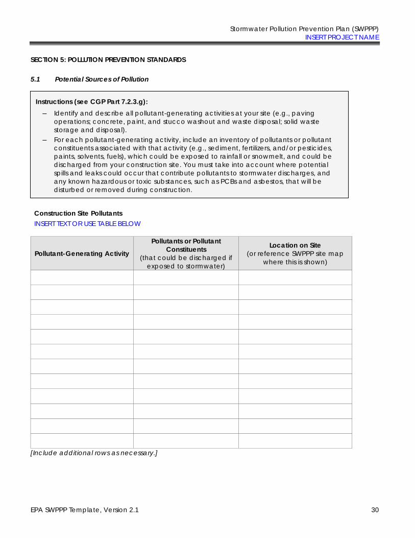
Stormwater Pollution Prevention Plan (SWPPP) INSERT PROJECT NAME
EPA SWPPP Template, Version 2.1 30
SECTION 5: POLLUTION PREVENTION STANDARDS
5.1 Potential Sources of Pollution
Construction Site Pollutants INSERT TEXT OR USE TABLE BELOW
Pollutant-Generating Activity
Pollutants or Pollutant
Constituents (that could be discharged if
exposed to stormwater)
Location on Site (or reference SWPPP site map
where this is shown)
[Include additional rows as necessary.]
Instructions (see CGP Part 7.2.3.g):
― Identify and describe all pollutant-generating activities at your site (e.g., paving operations; concrete, paint, and stucco washout and waste disposal; solid waste storage and disposal).
― For each pollutant-generating activity, include an inventory of pollutants or pollutant constituents associated with that activity (e.g., sediment, fertilizers, and/or pesticides, paints, solvents, fuels), which could be exposed to rainfall or snowmelt, and could be discharged from your construction site. You must take into account where potential spills and leaks could occur that contribute pollutants to stormwater discharges, and any known hazardous or toxic substances, such as PCBs and asbestos, that will be disturbed or removed during construction.
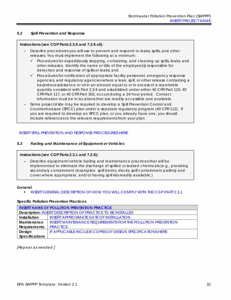
Stormwater Pollution Prevention Plan (SWPPP) INSERT PROJECT NAME
EPA SWPPP Template, Version 2.1 31
5.2 Spill Prevention and Response
INSERT SPILL PREVENTION AND RESPONSE PROCEDURES HERE
5.3 Fueling and Maintenance of Equipment or Vehicles
General ▪ INSERT GENERAL DESCRIPTION OF HOW YOU WILL COMPLY WITH THE CGP PART 2.3.1
Specific Pollution Prevention Practices
INSERT NAME OF POLLUTION PREVENTION PRACTICE
Description: INSERT DESCRIPTION OF PRACTICE TO BE INSTALLED Installation INSERT APPROXIMATE DATE OF INSTALLATION Maintenance
Requirements INSERT MAINTENANCE REQUIREMENTS FOR THE POLLUTION PREVENTION PRACTICE
Design
Specifications
IF APPLICABLE INCLUDE COPIES OF DESIGN SPECIFICATIONS HERE
[Repeat as needed.]
Instructions (see CGP Parts 2.3.6 and 7.2.6.vii):
― Describe procedures you will use to prevent and respond to leaks, spills, and other releases. You must implement the following at a minimum: ✓ Procedures for expeditiously stopping, containing, and cleaning up spills, leaks, and
other releases. Identify the name or title of the employee(s) responsible for detection and response of spills or leaks; and
✓ Procedures for notification of appropriate facility personnel, emergency response agencies, and regulatory agencies where a leak, spill, or other release containing a hazardous substance or oil in an amount equal to or in excess of a reportable quantity consistent with Part 2.3.6 and established under either 40 CFR Part 110, 40 CFR Part 117, or 40 CFR Part 302, occurs during a 24-hour period. Contact information must be in locations that are readily accessible and available.
― Some projects/site may be required to develop a Spill Prevention Control and Countermeasure (SPCC) plan under a separate regulatory program (40 CFR 112). If you are required to develop an SPCC plan, or you already have one, you should include references to the relevant requirements from your plan.
Instructions (see CGP Parts 2.3.1 and 7.2.6):
― Describe equipment/vehicle fueling and maintenance practices that will be implemented to eliminate the discharge of spilled or leaked chemicals (e.g., providing secondary containment (examples: spill berms, decks, spill containment pallets) and cover where appropriate, and/or having spill kits readily available.)
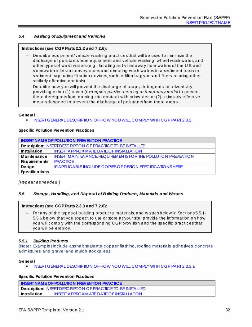
Stormwater Pollution Prevention Plan (SWPPP) INSERT PROJECT NAME
EPA SWPPP Template, Version 2.1 32
5.4 Washing of Equipment and Vehicles
General ▪ INSERT GENERAL DESCRIPTION OF HOW YOU WILL COMPLY WITH CGP PART 2.3.2
Specific Pollution Prevention Practices
INSERT NAME OF POLLUTION PREVENTION PRACTICE
Description: INSERT DESCRIPTION OF PRACTICE TO BE INSTALLED Installation INSERT APPROXIMATE DATE OF INSTALLATION Maintenance
Requirements INSERT MAINTENANCE REQUIREMENTS FOR THE POLLUTION PREVENTION PRACTICE
Design
Specifications
IF APPLICABLE INCLUDE COPIES OF DESIGN SPECIFICATIONS HERE
[Repeat as needed.]
5.5 Storage, Handling, and Disposal of Building Products, Materials, and Wastes
5.5.1 Building Products
(Note: Examples include asphalt sealants, copper flashing, roofing materials, adhesives, concrete admixtures, and gravel and mulch stockpiles.)
General
▪ INSERT GENERAL DESCRIPTION OF HOW YOU WILL COMPLY WITH CGP PART 2.3.3.a
Specific Pollution Prevention Practices
INSERT NAME OF POLLUTION PREVENTION PRACTICE
Description: INSERT DESCRIPTION OF PRACTICE TO BE INSTALLED Installation INSERT APPROXIMATE DATE OF INSTALLATION
Instructions (see CGP Parts 2.3.2 and 7.2.6):
― Describe equipment/vehicle washing practices that will be used to minimize the discharge of pollutants from equipment and vehicle washing, wheel wash water, and other types of wash waters (e.g., locating activities away from waters of the U.S. and stormwater inlets or conveyances and directing wash waters to a sediment basin or sediment trap, using filtration devices, such as filter bags or sand filters, or using other similarly effective controls).
― Describe how you will prevent the discharge of soaps, detergents, or solvents by providing either (1) cover (examples: plastic sheeting or temporary roofs) to prevent these detergents from coming into contact with rainwater, or (2) a similarly effective means designed to prevent the discharge of pollutants from these areas.
Instructions (see CGP Parts 2.3.3 and 7.2.6):
― For any of the types of building products, materials, and wastes below in Sections 5.5.1-5.5.6 below that you expect to use or store at your site, provide the information on how you will comply with the corresponding CGP provision and the specific practices that you will be employ.
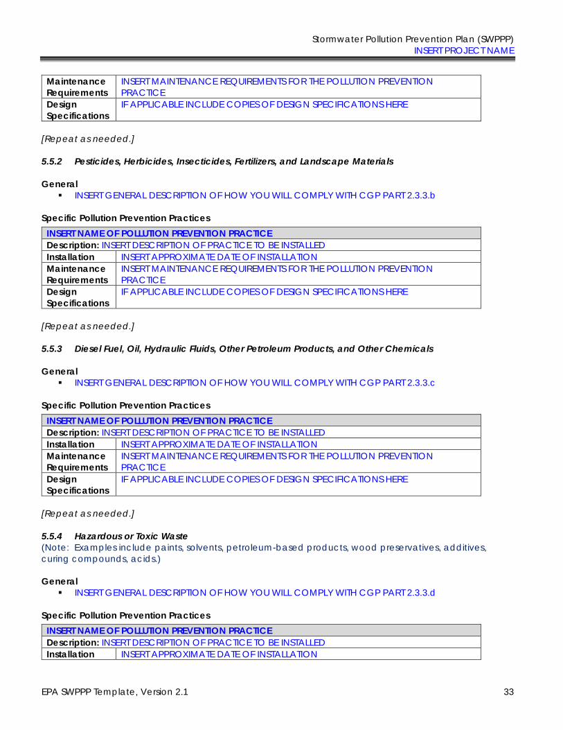
Stormwater Pollution Prevention Plan (SWPPP) INSERT PROJECT NAME
EPA SWPPP Template, Version 2.1 33
Maintenance
Requirements INSERT MAINTENANCE REQUIREMENTS FOR THE POLLUTION PREVENTION PRACTICE
Design
Specifications
IF APPLICABLE INCLUDE COPIES OF DESIGN SPECIFICATIONS HERE
[Repeat as needed.]
5.5.2 Pesticides, Herbicides, Insecticides, Fertilizers, and Landscape Materials
General
▪ INSERT GENERAL DESCRIPTION OF HOW YOU WILL COMPLY WITH CGP PART 2.3.3.b
Specific Pollution Prevention Practices
INSERT NAME OF POLLUTION PREVENTION PRACTICE
Description: INSERT DESCRIPTION OF PRACTICE TO BE INSTALLED Installation INSERT APPROXIMATE DATE OF INSTALLATION Maintenance
Requirements INSERT MAINTENANCE REQUIREMENTS FOR THE POLLUTION PREVENTION PRACTICE
Design
Specifications
IF APPLICABLE INCLUDE COPIES OF DESIGN SPECIFICATIONS HERE
[Repeat as needed.]
5.5.3 Diesel Fuel, Oil, Hydraulic Fluids, Other Petroleum Products, and Other Chemicals
General
▪ INSERT GENERAL DESCRIPTION OF HOW YOU WILL COMPLY WITH CGP PART 2.3.3.c
Specific Pollution Prevention Practices
INSERT NAME OF POLLUTION PREVENTION PRACTICE
Description: INSERT DESCRIPTION OF PRACTICE TO BE INSTALLED Installation INSERT APPROXIMATE DATE OF INSTALLATION Maintenance
Requirements INSERT MAINTENANCE REQUIREMENTS FOR THE POLLUTION PREVENTION PRACTICE
Design
Specifications
IF APPLICABLE INCLUDE COPIES OF DESIGN SPECIFICATIONS HERE
[Repeat as needed.]
5.5.4 Hazardous or Toxic Waste
(Note: Examples include paints, solvents, petroleum-based products, wood preservatives, additives, curing compounds, acids.)
General
▪ INSERT GENERAL DESCRIPTION OF HOW YOU WILL COMPLY WITH CGP PART 2.3.3.d
Specific Pollution Prevention Practices
INSERT NAME OF POLLUTION PREVENTION PRACTICE
Description: INSERT DESCRIPTION OF PRACTICE TO BE INSTALLED Installation INSERT APPROXIMATE DATE OF INSTALLATION
Stormwater Pollution Prevention Plan (SWPPP) INSERT PROJECT NAME
EPA SWPPP Template, Version 2.1 34
Maintenance
Requirements INSERT MAINTENANCE REQUIREMENTS FOR THE POLLUTION PREVENTION PRACTICE
Design
Specifications
IF APPLICABLE INCLUDE COPIES OF DESIGN SPECIFICATIONS HERE
[Repeat as needed.]
5.5.5 Construction and Domestic Waste
(Note: Examples include packaging materials, scrap construction materials, masonry products, timber, pipe and electrical cuttings, plastics, styrofoam, concrete, and other trash or building materials.)
General
▪ INSERT GENERAL DESCRIPTION OF HOW YOU WILL COMPLY WITH CGP PART 2.3.3.e
Specific Pollution Prevention Practices
INSERT NAME OF POLLUTION PREVENTION PRACTICE
Description: INSERT DESCRIPTION OF PRACTICE TO BE INSTALLED Installation INSERT APPROXIMATE DATE OF INSTALLATION Maintenance
Requirements INSERT MAINTENANCE REQUIREMENTS FOR THE POLLUTION PREVENTION PRACTICE
Design
Specifications
IF APPLICABLE INCLUDE COPIES OF DESIGN SPECIFICATIONS HERE
[Repeat as needed.]
5.5.6 Sanitary Waste
General
▪ INSERT GENERAL DESCRIPTION OF HOW YOU WILL COMPLY WITH CGP PART 2.3.3.f
Specific Pollution Prevention Practices
INSERT NAME OF POLLUTION PREVENTION PRACTICE
Description: INSERT DESCRIPTION OF PRACTICE TO BE INSTALLED Installation INSERT APPROXIMATE DATE OF INSTALLATION Maintenance
Requirements INSERT MAINTENANCE REQUIREMENTS FOR THE POLLUTION PREVENTION PRACTICE
Design
Specifications
IF APPLICABLE INCLUDE COPIES OF DESIGN SPECIFICATIONS HERE
[Repeat as needed.]
Stormwater Pollution Prevention Plan (SWPPP) INSERT PROJECT NAME
EPA SWPPP Template, Version 2.1 35
5.6 Washing of Applicators and Containers used for Paint, Concrete or Other Materials
General
▪ INSERT GENERAL DESCRIPTION OF HOW YOU WILL COMPLY WITH CGP PART 2.3.4
Specific Pollution Prevention Practices
INSERT NAME OF POLLUTION PREVENTION PRACTICE
Description: INSERT DESCRIPTION OF PRACTICE TO BE INSTALLED Installation INSERT APPROXIMATE DATE OF INSTALLATION Maintenance
Requirements INSERT MAINTENANCE REQUIREMENTS FOR THE POLLUTION PREVENTION PRACTICE
Design
Specifications
IF APPLICABLE INCLUDE COPIES OF DESIGN SPECIFICATIONS HERE
[Repeat as needed.]
5.7 Fertilizers
General
▪ INSERT GENERAL DESCRIPTION OF HOW YOU WILL COMPLY WITH CGP PART 2.3.5
Specific Pollution Prevention Practices
INSERT NAME OF POLLUTION PREVENTION PRACTICE
Description: INSERT DESCRIPTION OF PRACTICE TO BE INSTALLED Installation INSERT APPROXIMATE DATE OF INSTALLATION Maintenance
Requirements INSERT MAINTENANCE REQUIREMENTS FOR THE POLLUTION PREVENTION PRACTICE
Design
Specifications
IF APPLICABLE INCLUDE COPIES OF DESIGN SPECIFICATIONS HERE
[Repeat as needed for individual fertilizer practices.]
Instructions (see CGP Parts 2.3.4 and 7.2.6):
― Describe how you will comply with the CGP Part 2.3.4 requirement for washing applications and containers.
Instructions (CGP Parts 2.3.5 and 7.2.6.ix):
Describe how you will comply with the CGP Part 2.3.5 requirement for the application of fertilizers.
Stormwater Pollution Prevention Plan (SWPPP) INSERT PROJECT NAME
EPA SWPPP Template, Version 2.1 36
5.8 Other Pollution Prevention Practices
General
▪ INSERT GENERAL DESCRIPTION OF THE PROBLEM THIS CONTROL IS DESIGNED TO ADDRESS
Specific Pollution Prevention Practices
INSERT NAME OF POLLUTION PREVENTION PRACTICE
Description: INSERT DESCRIPTION OF PRACTICE TO BE INSTALLED Installation INSERT APPROXIMATE DATE OF INSTALLATION Maintenance
Requirements INSERT MAINTENANCE REQUIREMENTS FOR THE POLLUTION PREVENTION PRACTICE
Design
Specifications
IF APPLICABLE INCLUDE COPIES OF DESIGN SPECIFICATIONS HERE
[Repeat as needed.]
Instructions:
Describe any additional pollution prevention practices that do not fit into the above categories. ―
Stormwater Pollution Prevention Plan (SWPPP) INSERT PROJECT NAME
EPA SWPPP Template, Version 2.1 37
SECTION 6: INSPECTION, MAINTENANCE, AND CORRECTIVE ACTION
6.1 Inspection Personnel and Procedures
Personnel Responsible for Inspections
INSERT NAMES OF PERSONNEL OR TYPES OF PERSONNEL WHO WILL BE CONDUCTING SITE INSPECTIONS HERE
Note: All personnel conducting inspections must be considered a “qualified person.” CGP
Part 4.1 clarifies that a “qualified person” is a person knowledgeable in the principles and
practices of erosion and sediment controls and pollution prevention, who possesses the appropriate skills and training to assess conditions at the construction site that could impact stormwater quality, and the appropriate skills and training to assess the effectiveness of any stormwater controls selected and installed to meet the requirements of this permit.
Inspection Schedule
Select the inspection frequency(ies) that applies, based on CGP Parts 4.2, 4.3, or 4.4 (Note: you may be subject to different inspection frequencies in different areas of the site. Check all that apply)
Standard Frequency:
☐ Every 7 days ☐ Every 14 days and within 24 hours of a 0.25” rain or the occurrence of runoff from snowmelt
sufficient to cause a discharge
Increased Frequency (if applicable):
For areas of sites discharging to sediment or nutrient-impaired waters or to waters designated as
Tier 2, Tier 2.5, or Tier 3
☐ Every 7 days and within 24 hours of a 0.25” rain
Reduced Frequency (if applicable)
For stabilized areas
☐ Twice during first month, no more than 14 calendar days apart; then once per month after first month; ▪ SPECIFY LOCATIONS WHERE STABILIZATION STEPS HAVE BEEN COMPLETED ▪ INSERT DATE THAT THEY WERE COMPLETED
(Note: It is likely that you will not be able to include this in your initial SWPPP. If you qualify for this reduction (see CGP Part 4.4.1), you will need to modify your SWPPP to include this information.)
For stabilized areas on “linear construction sites”
☐ Twice during first month, no more than 14 calendar days apart; then once more within 24 hours of a 0.25” rain ▪ SPECIFY LOCATIONS WHERE STABILIZATION STEPS HAVE BEEN COMPLETED ▪ INSERT DATE THAT THEY WERE COMPLETED
Instructions (see CGP Parts 3.2, 4, 5, and 7.2.7):
Describe the procedures you will follow for conducting inspections in accordance with CGP Parts 3.2, 4, 5, and 7.2.7.
Stormwater Pollution Prevention Plan (SWPPP) INSERT PROJECT NAME
EPA SWPPP Template, Version 2.1 38
(Note: It is likely that you will not be able to include this in your initial SWPPP. If you qualify for this reduction (see CGP Part 4.4.1), you will need to modify your SWPPP to include this information.)
For arid, semi-arid, or drought-stricken areas during seasonally dry periods or during drought
☐ Once per month and within 24 hours of a 0.25” rain
Insert beginning and ending dates of the seasonally-defined dry period for your area or the valid period of drought:
▪ Beginning date of seasonally dry period: INSERT APPROXIMATE DATE
▪ Ending date of seasonally dry period: INSERT APPROXIMATE DATE
For frozen conditions where earth-disturbing activities are being conducted
☐ Once per month
Insert beginning and ending dates of frozen conditions on your site: ▪ Beginning date of frozen conditions: INSERT APPROXIMATE DATE
▪ Ending date of frozen conditions: INSERT APPROXIMATE DATE
Rain Gauge Location (if applicable) SPECIFY LOCATION(S) OF RAIN GAUGE TO BE USED FOR DETERMINING WHETHER A RAIN EVENT OF 0.25 INCHES OR GREATER HAS OCCURRED (only applies to inspections conducted for Part 4.2.2, 4.3, or 4.4.2)
Inspection Report Forms
INSERT COPY OF ANY INSPECTION REPORT FORMS YOU WILL USE HERE OR IN APPENDIX D OF THIS SWPPP TEMPLATE (Note: EPA has developed a sample inspection form that CGP operators can use. The form is available at https://www.epa.gov/npdes/stormwater-discharges-construction-activities#resources)
Stormwater Pollution Prevention Plan (SWPPP) INSERT PROJECT NAME
EPA SWPPP Template, Version 2.1 39
6.2 Corrective Action
Personnel Responsible for Corrective Actions
INSERT NAMES OF PERSONNEL OR TYPES OF PERSONNEL RESPONSIBLE FOR CORRECTIVE ACTIONS
Corrective Action Forms
INSERT A COPY OF ANY CORRECTIVE ACTION FORMS YOU WILL USE HERE OR IN APPENDIX E OF THIS SWPPP TEMPLATE (Note: EPA has developed a sample corrective action form that CGP operators can use. The form is available at https://www.epa.gov/npdes/stormwater-discharges-construction-activities#resources)
6.3 Delegation of Authority
Duly Authorized Representative(s) or Position(s):
Insert Company or Organization Name Insert Name Insert Position Insert Address Insert City, State, Zip Code Insert Telephone Number Insert Fax/Email
Instructions (CGP Parts 5 and 7.2.7):
― Describe the procedures for taking corrective action in compliance with CGP Part 5.
Instructions:
― Identify the individual(s) or positions within the company who have been delegated authority to sign inspection reports.
― Attach a copy of the signed delegation of authority (see example in Appendix J of the Template.)
― For more on this topic, see Appendix I, Subsection 11 of EPA’s CGP.
Stormwater Pollution Prevention Plan (SWPPP) INSERT PROJECT NAME
EPA SWPPP Template, Version 2.1 40
SECTION 7: TRAINING
Table 7-1: Documentation for Completion of Training
Name Describe Training Date Training Completed
INSERT NAME OF PERSONNEL INSERT COMPLETION DATE INSERT NAME OF PERSONNEL INSERT COMPLETION DATE INSERT NAME OF PERSONNEL INSERT COMPLETION DATE INSERT NAME OF PERSONNEL INSERT COMPLETION DATE INSERT NAME OF PERSONNEL INSERT COMPLETION DATE INSERT NAME OF PERSONNEL INSERT COMPLETION DATE INSERT NAME OF PERSONNEL INSERT COMPLETION DATE INSERT NAME OF PERSONNEL INSERT COMPLETION DATE INSERT NAME OF PERSONNEL INSERT COMPLETION DATE INSERT NAME OF PERSONNEL INSERT COMPLETION DATE INSERT NAME OF PERSONNEL INSERT COMPLETION DATE INSERT NAME OF PERSONNEL INSERT COMPLETION DATE INSERT NAME OF PERSONNEL INSERT COMPLETION DATE INSERT NAME OF PERSONNEL INSERT COMPLETION DATE INSERT NAME OF PERSONNEL INSERT COMPLETION DATE
Instructions (see CGP Part 6 and 7.2.8):
― Complete the table below to provide documentation that the personnel required to be trained in CGP Part 6 completed the appropriate training
― If personnel will be taking course training (which is not required as part of the CGP), consider using Appendix I of this SWPPP template to track completion of this training
― The following personnel, at a minimum, must receive training, and therefore should be listed out individually in the table below:
✓ Personnel who are responsible for the design, installation, maintenance, and/or repair of stormwater controls (including pollution prevention measures);
✓ Personnel responsible for the application and storage of treatment chemicals (if applicable);
✓ Personnel who are responsible for conducting inspections as required in Part 4.1; and
✓ Personnel who are responsible for taking corrective actions as required in Part 5.
― CGP Part 6 requires that the required personnel must be trained to understand the following if related to the scope of their job duties: ✓ The permit deadlines associated with installation, maintenance, and removal of
stormwater controls and with stabilization; ✓ The location of all stormwater controls on the site required by this permit, and how
they are to be maintained; ✓ The proper procedures to follow with respect to the permit’s pollution prevention
requirements; and ✓ When and how to conduct inspections, record applicable findings, and take
corrective actions.

Stormwater Pollution Prevention Plan (SWPPP) INSERT PROJECT NAME
EPA SWPPP Template, Version 2.1 41
SECTION 8: CERTIFICATION AND NOTIFICATION
I certify under penalty of law that this document and all attachments were prepared under my direction or supervision in accordance with a system designed to assure that qualified personnel properly gathered and evaluated the information submitted. Based on my inquiry of the person or persons who manage the system, or those persons directly responsible for gathering the information, the information submitted is, to the best of my knowledge and belief, true, accurate, and complete. I have no personal knowledge that the information submitted is other than true, accurate, and complete. I am aware that there are significant penalties for submitting false information, including the possibility of fine and imprisonment for knowing violations.
Name: Title:
Signature: Date:
[Repeat as needed for multiple construction operators at the site.]
Instructions (CGP Appendix I, Part I.11.b):
― The following certification statement must be signed and dated by a person who meets the requirements of Appendix I, Part I.11.b.
― This certification must be re-signed in the event of a SWPPP Modification.
Stormwater Pollution Prevention Plan (SWPPP) INSERT PROJECT NAME
EPA SWPPP Template, Version 2.1 42
SWPPP APPENDICES
Attach the following documentation to the SWPPP:
Appendix A – Site Maps
Appendix B – Copy of 2017 CGP
(Note: The 2017 CGP is available at https://www.epa.gov/npdes/epas-2017-construction-general-permit-cgp-and-related-documents)
Appendix C – NOI and EPA Authorization Email
Appendix D – Inspection Form
(Note: EPA has developed a sample inspection form that CGP operators can use. The form is available at https://www.epa.gov/npdes/stormwater-discharges-construction-activities#resources)
Appendix E – Corrective Action Form
(Note: EPA has developed a sample corrective action form that CGP operators can use. The form is available at https://www.epa.gov/npdes/stormwater-discharges-construction-activities#resources)
Appendix F – SWPPP Amendment Log
Appendix G – Subcontractor Certifications/Agreements
Appendix H – Grading and Stabilization Activities Log
Appendix I – Training Log
Appendix J – Delegation of Authority
Appendix K – Endangered Species Documentation
Appendix L – Historic Preservation Documentation
Stormwater Pollution Prevention Plan (SWPPP) INSERT PROJECT NAME
EPA SWPPP Template, Version 2.1
Appendix A – Site Maps
INSERT SITE MAPS CONSISTENT WITH TEMPLATE SECTION 2.6
Stormwater Pollution Prevention Plan (SWPPP) INSERT PROJECT NAME
EPA SWPPP Template, Version 2.1
Appendix B – Copy of 2017 CGP
INSERT COPY OF 2017 CGP (Note: The 2017 CGP is available at https://www.epa.gov/npdes/epas-2017-construction-general-permit-cgp-and-related-documents)
Stormwater Pollution Prevention Plan (SWPPP) INSERT PROJECT NAME
EPA SWPPP Template, Version 2.1
Appendix C – Copy of NOI and EPA Authorization email
INSERT COPY OF NOI AND EPA'S AUTHORIZATION EMAIL PROVIDING COVERAGE UNDER THE CGP
Stormwater Pollution Prevention Plan (SWPPP) INSERT PROJECT NAME
EPA SWPPP Template, Version 2.1
Appendix D – Copy of Inspection Form
INSERT COPY OF ANY INSPECTION FORMS YOU WILL USE TO PREPARE INSPECTION REPORTS (Note: EPA has developed a sample inspection form that CGP operators can use. The form is available at https://www.epa.gov/npdes/stormwater-discharges-construction-activities#resources)
Stormwater Pollution Prevention Plan (SWPPP) INSERT PROJECT NAME
EPA SWPPP Template, Version 2.1
Appendix E – Copy of Corrective Action Form
INSERT COPY OF CORRECTIVE ACTION FORMS YOU WILL USE
(Note: EPA has developed a sample corrective action form that CGP operators can use. The form is available at https://www.epa.gov/npdes/stormwater-discharges-construction-activities#resources)
Stormwater Pollution Prevention Plan (SWPPP) INSERT PROJECT NAME
EPA SWPPP Template, Version 2.1
Appendix F – Sample SWPPP Amendment Log
No. Description of the Amendment Date of
Amendment
Amendment Prepared by
[Name(s) and Title]
INSERT DATE
INSERT DATE
INSERT DATE
INSERT DATE
INSERT DATE
INSERT DATE
INSERT DATE
INSERT DATE
Instructions (see CGP Part 7.4):
― Create a log here of changes and updates to the SWPPP. You may use the table below to track these modifications.
― SWPPP modifications are required pursuant to CGP Part 7.4.1 in the following circumstances: ✓ Whenever new operators become active in construction activities on your site, or
you make changes to your construction plans, stormwater controls, or other activities at your site that are no longer accurately reflected in your SWPPP;
✓ To reflect areas on your site map where operational control has been transferred (and the date of transfer) since initiating permit coverage;
✓ If inspections or investigations determine that SWPPP modifications are necessary for compliance with this permit;
✓ Where EPA determines it is necessary to install and/or implement additional controls at your site in order to meet requirements of the permit; and
― To reflect any revisions to applicable federal, state, tribal, or local requirements that affect the stormwater control measures implemented at the site.
― If applicable, if a change in chemical treatment systems or chemically-enhanced stormwater control is made, including use of a different treatment chemical, different dosage rate, or different area of application.

Stormwater Pollution Prevention Plan (SWPPP) INSERT PROJECT NAME
EPA SWPPP Template, Version 2.1
Appendix G – Sample Subcontractor Certifications/Agreements
SUBCONTRACTOR CERTIFICATION STORMWATER POLLUTION PREVENTION PLAN
Project Number: Project Title: Operator(s): As a subcontractor, you are required to comply with the Stormwater Pollution Prevention Plan (SWPPP) for any work that you perform on-site. Any person or group who violates any condition of the SWPPP may be subject to substantial penalties or loss of contract. You are encouraged to advise each of your employees working on this project of the requirements of the SWPPP. A copy of the SWPPP is available for your review at the office trailer. Each subcontractor engaged in activities at the construction site that could impact stormwater must be identified and sign the following certification statement: I certify under the penalty of law that I have read and understand the terms and conditions of
the SWPPP for the above designated project and agree to follow the practices described in the
SWPPP.
This certification is hereby signed in reference to the above named project: Company: Address: Telephone Number: Type of construction service to be provided: Signature: Title: Date:
Stormwater Pollution Prevention Plan (SWPPP) INSERT PROJECT NAME
EPA SWPPP Template, Version 2.1
Appendix H – Sample Grading and Stabilization Activities Log
Date
Grading
Activity
Initiated
Description of Grading Activity Description of Stabilization Measure
and Location Date Grading
Activity Ceased
(Indicate Temporary or Permanent)
Date When
Stabilization
Measures
Initiated
INSERT DATE INSERT DATE ☐ Temporary ☐ Permanent
INSERT DATE
INSERT DATE INSERT DATE ☐ Temporary ☐ Permanent
INSERT DATE
INSERT DATE INSERT DATE ☐ Temporary ☐ Permanent
INSERT DATE
INSERT DATE INSERT DATE ☐ Temporary ☐ Permanent
INSERT DATE
INSERT DATE INSERT DATE ☐ Temporary ☐ Permanent
INSERT DATE
INSERT DATE INSERT DATE ☐ Temporary ☐ Permanent
INSERT DATE
INSERT DATE INSERT DATE ☐ Temporary ☐ Permanent
INSERT DATE
INSERT DATE INSERT DATE ☐ Temporary ☐ Permanent
INSERT DATE
Stormwater Pollution Prevention Plan (SWPPP) INSERT PROJECT NAME
EPA SWPPP Template, Version 2.1
Appendix I – Sample SWPPP Training Log
Stormwater Pollution Prevention Training Log
Project Name:
Project Location:
Instructor’s Name(s):
Instructor’s Title(s):
Course Location: Date: Course Length (hours): Stormwater Training Topic: (check as appropriate) ☐ Sediment and Erosion Controls ☐ Emergency Procedures
☐ Stabilization Controls ☐ Inspections/Corrective Actions
☐ Pollution Prevention Measures
Specific Training Objective:
Attendee Roster: (attach additional pages as necessary)
No. Name of Attendee Company
1 2 3 4 5 6 7 8
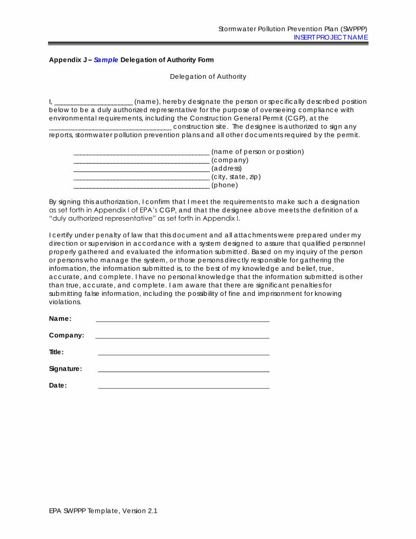
Stormwater Pollution Prevention Plan (SWPPP) INSERT PROJECT NAME
EPA SWPPP Template, Version 2.1
Appendix J – Sample Delegation of Authority Form
Delegation of Authority
I, _______________________ (name), hereby designate the person or specifically described position below to be a duly authorized representative for the purpose of overseeing compliance with environmental requirements, including the Construction General Permit (CGP), at the ____________________________________ construction site. The designee is authorized to sign any reports, stormwater pollution prevention plans and all other documents required by the permit.
________________________________________ (name of person or position) ________________________________________ (company) ________________________________________ (address) ________________________________________ (city, state, zip) ________________________________________ (phone)
By signing this authorization, I confirm that I meet the requirements to make such a designation as set forth in Appendix I of EPA’s CGP, and that the designee above meets the definition of a “duly authorized representative” as set forth in Appendix I. I certify under penalty of law that this document and all attachments were prepared under my direction or supervision in accordance with a system designed to assure that qualified personnel properly gathered and evaluated the information submitted. Based on my inquiry of the person or persons who manage the system, or those persons directly responsible for gathering the information, the information submitted is, to the best of my knowledge and belief, true, accurate, and complete. I have no personal knowledge that the information submitted is other than true, accurate, and complete. I am aware that there are significant penalties for submitting false information, including the possibility of fine and imprisonment for knowing violations. Name: Company: Title: Signature: Date:
Stormwater Pollution Prevention Plan (SWPPP) INSERT PROJECT NAME
EPA SWPPP Template, Version 2.1
Appendix K – Endangered Species Documentation
INSERT DOCUMENTATION CONSISTENT WITH SWPPP TEMPLATE SECTION 3.1 AND CGP APPENDIX D
Stormwater Pollution Prevention Plan (SWPPP) INSERT PROJECT NAME
EPA SWPPP Template, Version 2.1
Appendix L – Historic Properties Documentation
INSERT DOCUMENTATION CONSISTENT WITH SWPPP TEMPLATE SECTION 3.2 AND CGP APPENDIX E
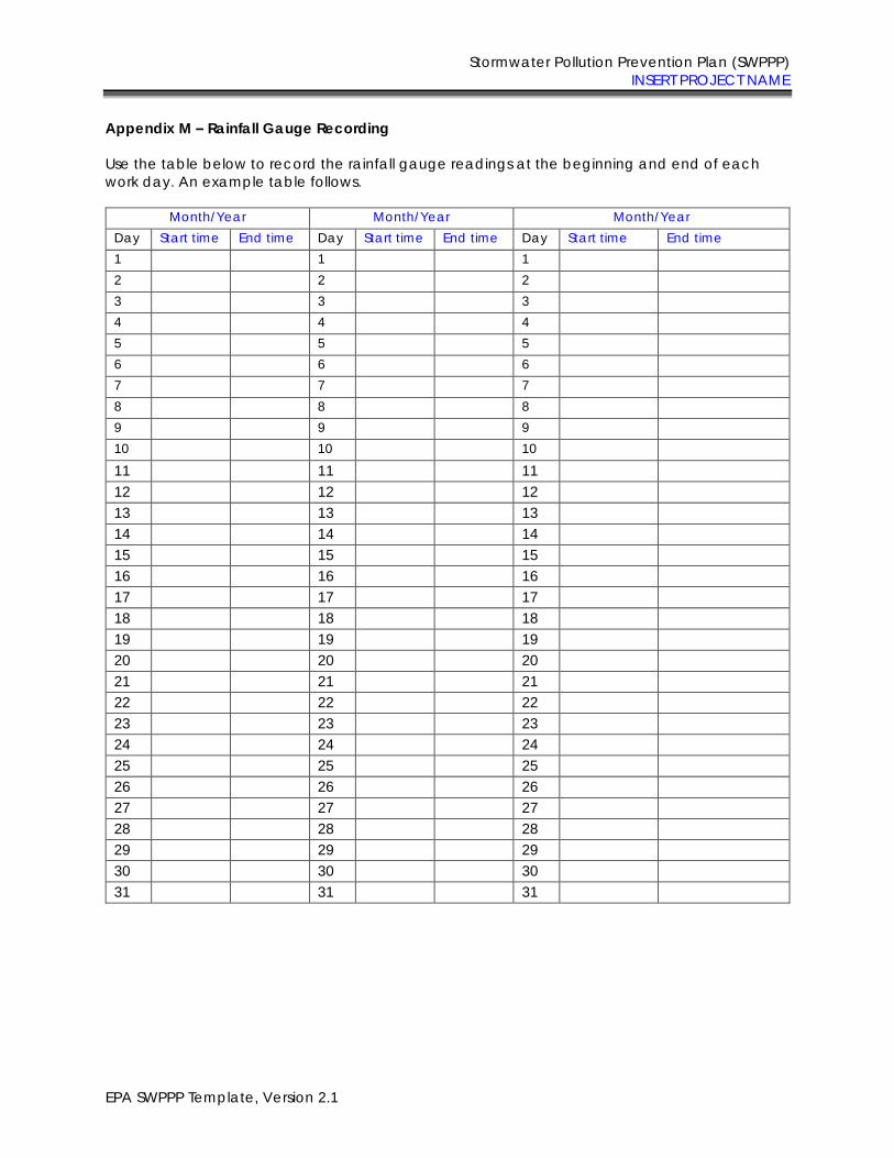
Stormwater Pollution Prevention Plan (SWPPP) INSERT PROJECT NAME
EPA SWPPP Template, Version 2.1
Appendix M – Rainfall Gauge Recording
Use the table below to record the rainfall gauge readings at the beginning and end of each work day. An example table follows.
Month/Year Month/Year Month/Year Day Start time End time Day Start time End time Day Start time End time 1 1 1 2 2 2 3 3 3 4 4 4 5 5 5 6 6 6 7 7 7 8 8 8 9 9 9 10 10 10
11 11 11 12 12 12 13 13 13 14 14 14 15 15 15 16 16 16 17 17 17 18 18 18 19 19 19 20 20 20 21 21 21 22 22 22 23 23 23 24 24 24 25 25 25 26 26 26 27 27 27 28 28 28 29 29 29 30 30 30 31 31 31
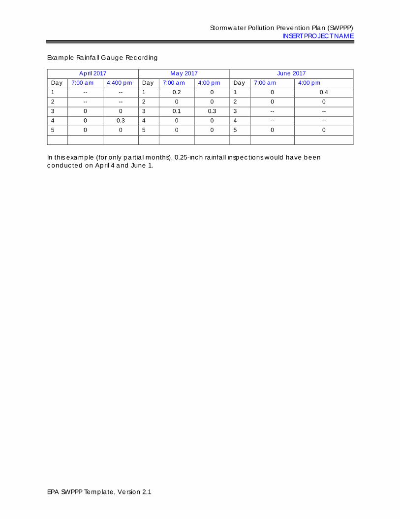
Stormwater Pollution Prevention Plan (SWPPP) INSERT PROJECT NAME
EPA SWPPP Template, Version 2.1
Example Rainfall Gauge Recording
April 2017 May 2017 June 2017 Day 7:00 am 4:400 pm Day 7:00 am 4:00 pm Day 7:00 am 4:00 pm 1 -- -- 1 0.2 0 1 0 0.4 2 -- -- 2 0 0 2 0 0 3 0 0 3 0.1 0.3 3 -- -- 4 0 0.3 4 0 0 4 -- -- 5 0 0 5 0 0 5 0 0
In this example (for only partial months), 0.25-inch rainfall inspections would have been conducted on April 4 and June 1.
i
2017 Construction General Permit
Inspection Report Template – Field Version Purpose
This Inspection Report Template (or “template”) is to assist you in preparing inspection reports for EPA’s 2017 Construction General Permit (CGP). If you are covered under the 2017 CGP, you can use this template to create an inspection report form that is customized to the specific circumstances of your site and that complies with the minimum reporting requirements of Part 4.7 of the permit. Note that the use of this form is optional; you may use your own inspection report form provided it includes the minimum information required in Part 4.7 of the CGP.
If you are covered under a state CGP, this template may be helpful in developing a form that can be used for that permit; however, it will need to be modified to meet the specific requirements of that permit. If your permitting authority requires you to use a specific inspection report form, you should not use this form.
Notes:
While EPA has made every effort to ensure the accuracy of all instructions contained in the Inspection Report Template, it is the permit, not the template, that determines the actual obligations of regulated construction stormwater discharges. In the event of a conflict between the Inspection Report Template and any corresponding provision of the 2017 CGP, you must abide by the requirements in the permit. EPA welcomes comments on the Inspection Report Template at any time and will consider those comments in any future revision of this document. You may contact EPA for CGP-related inquiries at [email protected].
Overview of Inspection Requirements (see CGP Part 4)
Construction operators covered under the 2017 CGP are subject to the following inspection requirements:
Person(s) Responsible for Inspecting the Site (see Part 4.1)
The person(s) inspecting your site must be a “qualified person” who may be either on your staff or a third party you hire to conduct such inspections. • A “qualified person” is a person knowledgeable in the principles and practice of erosion and sediment controls
and pollution prevention, who possesses the appropriate skills and training to assess conditions at the construction site that could impact stormwater quality, and the appropriate skills and training to assess the effectiveness of any stormwater controls selected and installed to meet the requirements of this permit.
Inspection Frequency (see Part 4.2) You are required to conduct inspections either: • Once every 7 calendar days; or • Once every 14 calendar days and within 24 hours of a storm event of 0.25 inches or greater or the occurrence of
runoff from snowmelt sufficient to cause a discharge. Your inspection frequency is increased if the site discharges to a sensitive water. See Part 4.3. Your inspection frequency may be decreased to account for stabilized areas, or for arid, semi-arid, or drought-stricken conditions, or for frozen conditions. See Part 4.4.
Areas That Need to Be Inspected (see Part 4.5) During each inspection, you must inspect the following areas of your site: • Cleared, graded, or excavated areas of the site; • Stormwater controls (e.g., perimeter controls, sediment basins, inlets, exit points etc.) and pollution prevention
practices (e.g., pollution prevention practices for vehicle fueling/maintenance and washing, construction product storage, handling, and disposal, etc.) at the site;
• Material, waste, or borrow areas covered by the permit, and equipment storage and maintenance areas; • Areas where stormwater flows within the site; • Stormwater discharge points; and • Areas where stabilization has been implemented.
What to Check For During Your Inspection (see Part 4.6) During your site inspection, you are required to check: • Whether stormwater controls or pollution prevention practices are properly installed, require maintenance or
corrective action, or whether new or modified controls are required; • For the presence of conditions that could lead to spills, leaks, or other pollutant accumulations and discharges; • For locations where new or modified stormwater controls are necessary to meet requirements of the permit;
• Whether there are visible signs of erosion and sediment accumulation at points of discharge and to the channels and streambanks that are in the immediate vicinity of the discharge;
• If a stormwater discharge is occurring at the time of the inspection, whether there are obvious, visual signs of pollutant discharges; and
• If any permit violations have occurred on the site.
Inspection Reports (see Part 4.7)
Within 24 hours of completing each inspection, you are required to complete an inspection report that includes: • Date of inspection; • Names and titles of person(s) conducting the inspection; • Summary of inspection findings; • Rain gauge or weather station readings if your inspection is triggered by the 0.25-inch storm threshold; and • If you determine that a portion of your site is unsafe to access for the inspection, documentation of what
conditions prevented the inspection and where these conditions occurred on the site
Instructions for Using This Template
This Field Version of the Inspection Report Template is intended to be used in the field and filled out by hand. If you will be filling out the Inspection Report Template electronically (i.e., you will be typing in your findings), please use the Electronic Version of the Inspection Report Template available at https://www.epa.gov/npdes/stormwater-discharges-construction-activities#resources. The Electronic Version includes text fields with instructions for what to enter.
Keep in mind that this document is a template and not an “off-the-shelf” inspection report that is ready to use without some modification. You must first customize this form to include the specifics of your project in order for it to be useable for your inspection reports. Once you have entered all of your site-specific information into these fields, you may print out this form for use in the field to complete inspection reports. The following tips for using this template will help you ensure that the minimum permit requirements are met:
• Review the inspection requirements. Before you start developing your inspection report form, read the CGP’s Part 4 inspection requirements. This will ensure that you have a working understanding of the permit’s underlying inspection requirements.
• Complete all required text fields. Fill out all text fields. Only by filling out all fields will the template be compliant with the requirements of the permit. (Note: Where you do not need the number of rows provided in the template form for your inspection, you may leave those rows blank. Or, if you need more space to document your findings, you may add an additional sheet.)
• Use your site map to document inspection findings. In several places in the template, you are directed to specify the location of certain features of your site, including where stormwater controls are installed and where you will be stabilizing exposed soil. You are also asked to fill in location information for unsafe conditions and the locations of any discharges occurring during your inspections. Where you are asked for location information, EPA encourages you to reference the point on your SWPPP site map that corresponds to the requested location on the inspection form. Using the site map as a tool in this way will help you conduct efficient inspections, will assist you in evaluating problems found, and will ensure proper documentation.
• Sign and certify each inspection report. The operator or a duly authorized representative (see Appendix I, Part I.11.2) must sign and certify each inspection report for it to be considered complete. Where a contractor or subcontractor carries out your inspections, it is recommended that you also have the inspector sign and certify the form, in addition to the signature and certification required of the permitted operator. The template includes a signature block for both parties.
• Include the inspection form with your SWPPP. Once your form is complete, make sure to include a copy of the inspection form in your SWPPP in accordance with Part 7.2.7.e of the CGP.
• Retain copies of all inspection reports with your records. You must also retain in your records copies of all inspection reports in accordance with the requirements in Part 4.7.3 of the 2017 CGP. These reports must be retained for at least 3 years from the date your permit coverage expires or is terminated.
Section-by-Section Instructions You will find specific instructions corresponding to each section of the report form on the reverse side of each page. These instructions provide you with more details in terms of what EPA expects to be documented in these reports.
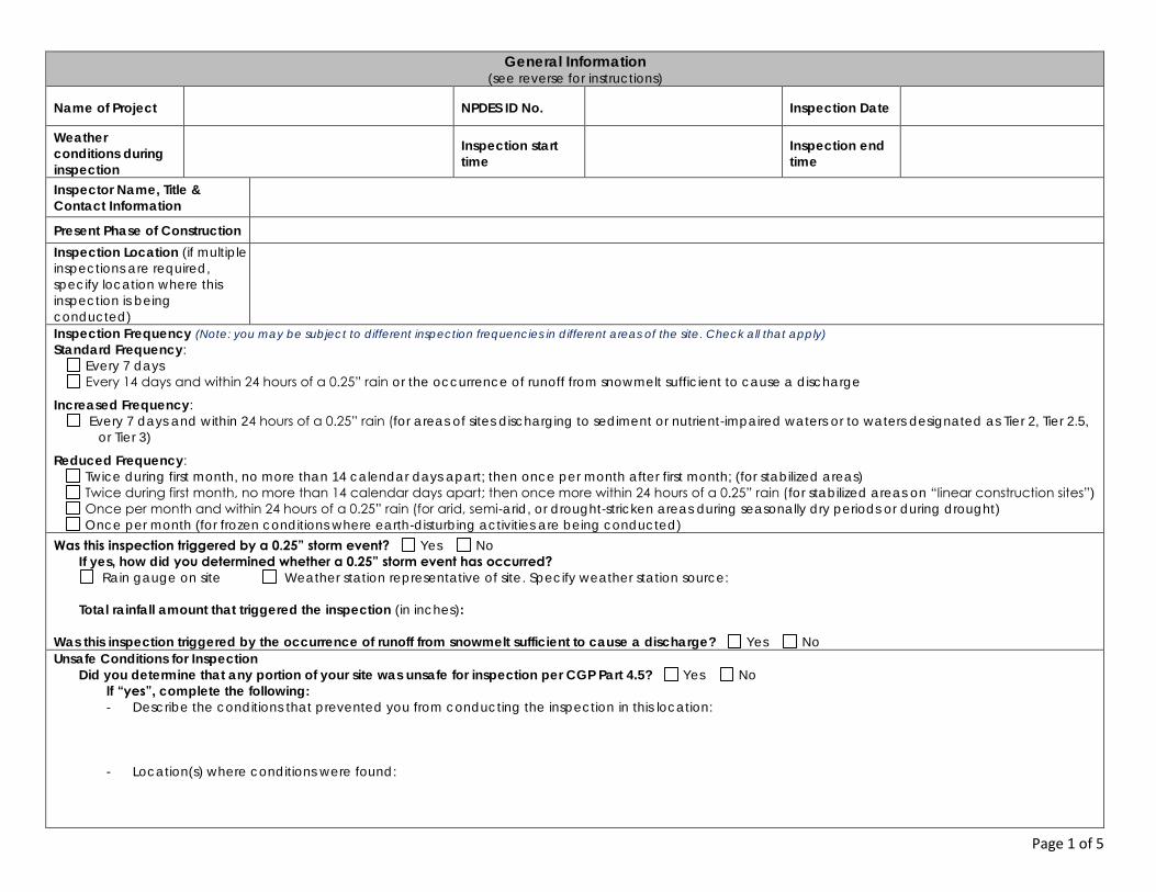
Page 1 of 5
General Information (see reverse for instructions)
Name of Project NPDES ID No. Inspection Date
Weather
conditions during
inspection
Inspection start
time Inspection end
time
Inspector Name, Title &
Contact Information
Present Phase of Construction Inspection Location (if multiple inspections are required, specify location where this inspection is being conducted)
Inspection Frequency (Note: you may be subject to different inspection frequencies in different areas of the site. Check all that apply)
Standard Frequency: Every 7 days Every 14 days and within 24 hours of a 0.25” rain or the occurrence of runoff from snowmelt sufficient to cause a discharge
Increased Frequency: Every 7 days and within 24 hours of a 0.25” rain (for areas of sites discharging to sediment or nutrient-impaired waters or to waters designated as Tier 2, Tier 2.5,
or Tier 3)
Reduced Frequency: Twice during first month, no more than 14 calendar days apart; then once per month after first month; (for stabilized areas) Twice during first month, no more than 14 calendar days apart; then once more within 24 hours of a 0.25” rain (for stabilized areas on “linear construction sites”) Once per month and within 24 hours of a 0.25” rain (for arid, semi-arid, or drought-stricken areas during seasonally dry periods or during drought) Once per month (for frozen conditions where earth-disturbing activities are being conducted)
Was this inspection triggered by a 0.25” storm event? Yes No
If yes, how did you determined whether a 0.25” storm event has occurred? Rain gauge on site Weather station representative of site. Specify weather station source:
Total rainfall amount that triggered the inspection (in inches):
Was this inspection triggered by the occurrence of runoff from snowmelt sufficient to cause a discharge? Yes No
Unsafe Conditions for Inspection Did you determine that any portion of your site was unsafe for inspection per CGP Part 4.5? Yes No
If “yes”, complete the following:
- Describe the conditions that prevented you from conducting the inspection in this location:
- Location(s) where conditions were found:
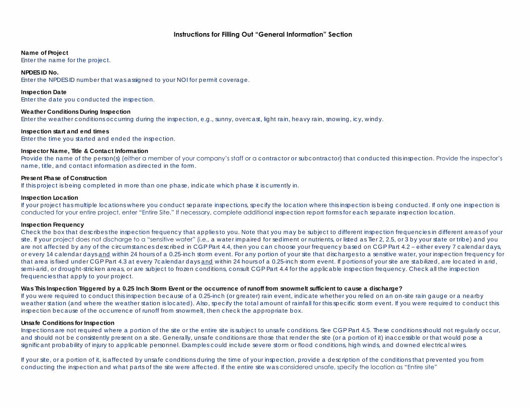
Instructions for Filling Out “General Information” Section
Name of Project
Enter the name for the project.
NPDES ID No.
Enter the NPDES ID number that was assigned to your NOI for permit coverage.
Inspection Date Enter the date you conducted the inspection.
Weather Conditions During Inspection
Enter the weather conditions occurring during the inspection, e.g., sunny, overcast, light rain, heavy rain, snowing, icy, windy.
Inspection start and end times
Enter the time you started and ended the inspection.
Inspector Name, Title & Contact Information Provide the name of the person(s) (either a member of your company’s staff or a contractor or subcontractor) that conducted this inspection. Provide the inspector’s
name, title, and contact information as directed in the form.
Present Phase of Construction
If this project is being completed in more than one phase, indicate which phase it is currently in.
Inspection Location
If your project has multiple locations where you conduct separate inspections, specify the location where this inspection is being conducted. If only one inspection is conducted for your entire project, enter “Entire Site.” If necessary, complete additional inspection report forms for each separate inspection location.
Inspection Frequency Check the box that describes the inspection frequency that applies to you. Note that you may be subject to different inspection frequencies in different areas of your site. If your project does not discharge to a “sensitive water” (i.e., a water impaired for sediment or nutrients, or listed as Tier 2, 2.5, or 3 by your state or tribe) and you are not affected by any of the circumstances described in CGP Part 4.4, then you can choose your frequency based on CGP Part 4.2 – either every 7 calendar days, or every 14 calendar days and within 24 hours of a 0.25-inch storm event. For any portion of your site that discharges to a sensitive water, your inspection frequency for that area is fixed under CGP Part 4.3 at every 7calendar days and within 24 hours of a 0.25-inch storm event. If portions of your site are stabilized, are located in arid, semi-arid, or drought-stricken areas, or are subject to frozen conditions, consult CGP Part 4.4 for the applicable inspection frequency. Check all the inspection frequencies that apply to your project.
Was This Inspection Triggered by a 0.25 Inch Storm Event or the occurrence of runoff from snowmelt sufficient to cause a discharge? If you were required to conduct this inspection because of a 0.25-inch (or greater) rain event, indicate whether you relied on an on-site rain gauge or a nearby weather station (and where the weather station is located). Also, specify the total amount of rainfall for this specific storm event. If you were required to conduct this inspection because of the occurrence of runoff from snowmelt, then check the appropriate box.
Unsafe Conditions for Inspection
Inspections are not required where a portion of the site or the entire site is subject to unsafe conditions. See CGP Part 4.5. These conditions should not regularly occur, and should not be consistently present on a site. Generally, unsafe conditions are those that render the site (or a portion of it) inaccessible or that would pose a significant probability of injury to applicable personnel. Examples could include severe storm or flood conditions, high winds, and downed electrical wires. If your site, or a portion of it, is affected by unsafe conditions during the time of your inspection, provide a description of the conditions that prevented you from conducting the inspection and what parts of the site were affected. If the entire site was considered unsafe, specify the location as “Entire site”
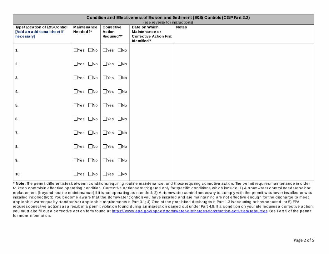
Page 2 of 5
Condition and Effectiveness of Erosion and Sediment (E&S) Controls (CGP Part 2.2) (see reverse for instructions)
Type/Location of E&S Control
[Add an additional sheet if
necessary]
Maintenance
Needed?*
Corrective
Action
Required?*
Date on Which
Maintenance or
Corrective Action First
Identified?
Notes
1.
2.
3.
4.
5.
6.
7.
8.
9.
10.
Yes No
Yes No
Yes No
Yes No
Yes No
Yes No
Yes No
Yes No
Yes No
Yes No
Yes No
Yes No
Yes No
Yes No
Yes No
Yes No
Yes No
Yes No
Yes No
Yes No
* Note: The permit differentiates between conditions requiring routine maintenance, and those requiring corrective action. The permit requires maintenance in order to keep controls in effective operating condition. Corrective actions are triggered only for specific conditions, which include: 1) A stormwater control needs repair or replacement (beyond routine maintenance) if it is not operating as intended; 2) A stormwater control necessary to comply with the permit was never installed or was installed incorrectly; 3) You become aware that the stormwater controls you have installed and are maintaining are not effective enough for the discharge to meet applicable water quality standards or applicable requirements in Part 3.1; 4) One of the prohibited discharges in Part 1.3 is occurring or has occurred; or 5) EPA requires corrective actions as a result of a permit violation found during an inspection carried out under Part 4.8. If a condition on your site requires a corrective action, you must also fill out a corrective action form found at https://www.epa.gov/npdes/stormwater-discharges-construction-activities#resources. See Part 5 of the permit for more information.
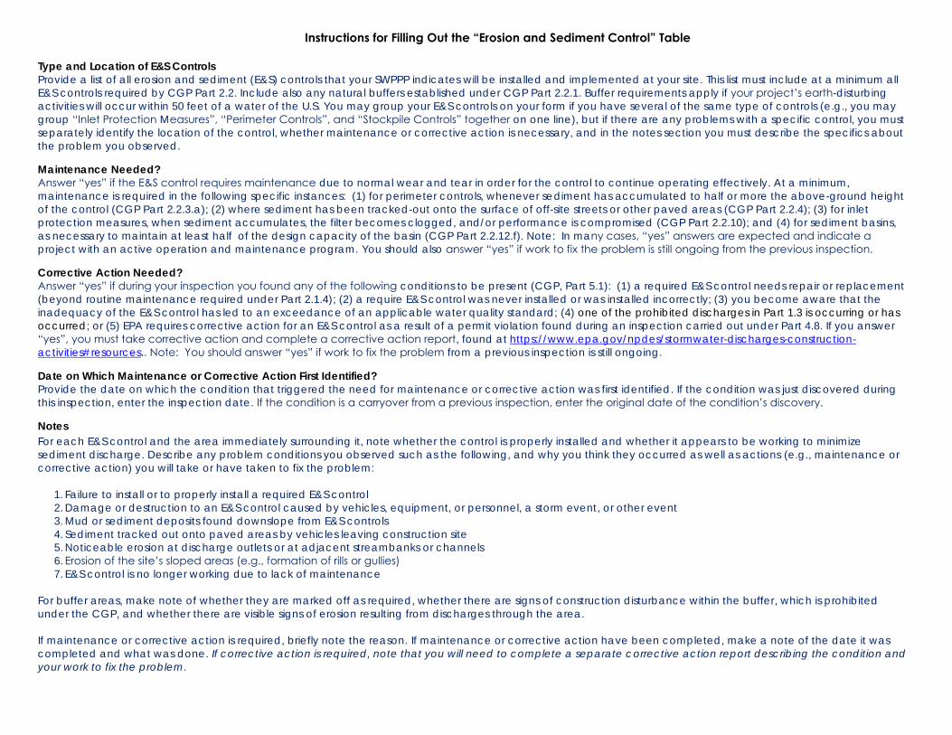
Instructions for Filling Out the “Erosion and Sediment Control” Table
Type and Location of E&S Controls Provide a list of all erosion and sediment (E&S) controls that your SWPPP indicates will be installed and implemented at your site. This list must include at a minimum all E&S controls required by CGP Part 2.2. Include also any natural buffers established under CGP Part 2.2.1. Buffer requirements apply if your project’s earth-disturbing activities will occur within 50 feet of a water of the U.S. You may group your E&S controls on your form if you have several of the same type of controls (e.g., you may group “Inlet Protection Measures”, “Perimeter Controls”, and “Stockpile Controls” together on one line), but if there are any problems with a specific control, you must separately identify the location of the control, whether maintenance or corrective action is necessary, and in the notes section you must describe the specifics about the problem you observed.
Maintenance Needed? Answer “yes” if the E&S control requires maintenance due to normal wear and tear in order for the control to continue operating effectively. At a minimum, maintenance is required in the following specific instances: (1) for perimeter controls, whenever sediment has accumulated to half or more the above-ground height of the control (CGP Part 2.2.3.a); (2) where sediment has been tracked-out onto the surface of off-site streets or other paved areas (CGP Part 2.2.4); (3) for inlet protection measures, when sediment accumulates, the filter becomes clogged, and/or performance is compromised (CGP Part 2.2.10); and (4) for sediment basins, as necessary to maintain at least half of the design capacity of the basin (CGP Part 2.2.12.f). Note: In many cases, “yes” answers are expected and indicate a
project with an active operation and maintenance program. You should also answer “yes” if work to fix the problem is still ongoing from the previous inspection. Corrective Action Needed?
Answer “yes” if during your inspection you found any of the following conditions to be present (CGP, Part 5.1): (1) a required E&S control needs repair or replacement (beyond routine maintenance required under Part 2.1.4); (2) a require E&S control was never installed or was installed incorrectly; (3) you become aware that the inadequacy of the E&S control has led to an exceedance of an applicable water quality standard; (4) one of the prohibited discharges in Part 1.3 is occurring or has occurred; or (5) EPA requires corrective action for an E&S control as a result of a permit violation found during an inspection carried out under Part 4.8. If you answer “yes”, you must take corrective action and complete a corrective action report, found at https://www.epa.gov/npdes/stormwater-discharges-construction-activities#resources.. Note: You should answer “yes” if work to fix the problem from a previous inspection is still ongoing. Date on Which Maintenance or Corrective Action First Identified?
Provide the date on which the condition that triggered the need for maintenance or corrective action was first identified. If the condition was just discovered during this inspection, enter the inspection date. If the condition is a carryover from a previous inspection, enter the original date of the condition’s discovery. Notes
For each E&S control and the area immediately surrounding it, note whether the control is properly installed and whether it appears to be working to minimize sediment discharge. Describe any problem conditions you observed such as the following, and why you think they occurred as well as actions (e.g., maintenance or corrective action) you will take or have taken to fix the problem:
1. Failure to install or to properly install a required E&S control 2. Damage or destruction to an E&S control caused by vehicles, equipment, or personnel, a storm event, or other event 3. Mud or sediment deposits found downslope from E&S controls 4. Sediment tracked out onto paved areas by vehicles leaving construction site 5. Noticeable erosion at discharge outlets or at adjacent streambanks or channels 6. Erosion of the site’s sloped areas (e.g., formation of rills or gullies) 7. E&S control is no longer working due to lack of maintenance
For buffer areas, make note of whether they are marked off as required, whether there are signs of construction disturbance within the buffer, which is prohibited under the CGP, and whether there are visible signs of erosion resulting from discharges through the area. If maintenance or corrective action is required, briefly note the reason. If maintenance or corrective action have been completed, make a note of the date it was completed and what was done. If corrective action is required, note that you will need to complete a separate corrective action report describing the condition and
your work to fix the problem.
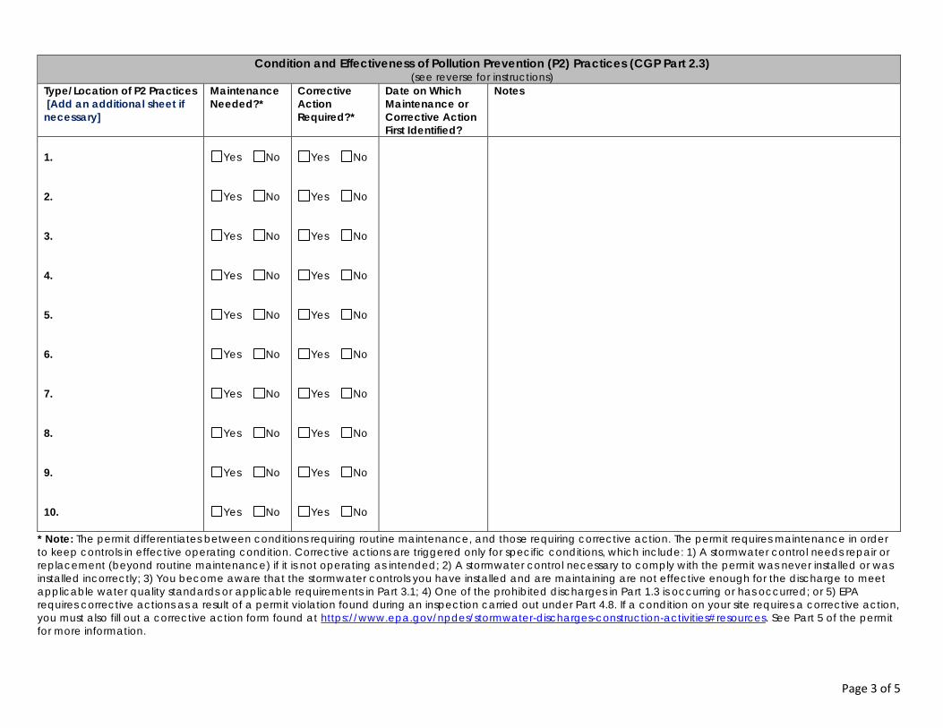
Page 3 of 5
Condition and Effectiveness of Pollution Prevention (P2) Practices (CGP Part 2.3)
(see reverse for instructions) Type/Location of P2 Practices
[Add an additional sheet if
necessary]
Maintenance
Needed?*
Corrective
Action
Required?*
Date on Which
Maintenance or
Corrective Action
First Identified?
Notes
1.
2.
3.
4.
5.
6.
7.
8.
9.
10.
Yes No
Yes No
Yes No
Yes No
Yes No
Yes No
Yes No
Yes No
Yes No
Yes No
Yes No
Yes No
Yes No
Yes No
Yes No
Yes No
Yes No
Yes No
Yes No
Yes No
* Note: The permit differentiates between conditions requiring routine maintenance, and those requiring corrective action. The permit requires maintenance in order to keep controls in effective operating condition. Corrective actions are triggered only for specific conditions, which include: 1) A stormwater control needs repair or replacement (beyond routine maintenance) if it is not operating as intended; 2) A stormwater control necessary to comply with the permit was never installed or was installed incorrectly; 3) You become aware that the stormwater controls you have installed and are maintaining are not effective enough for the discharge to meet applicable water quality standards or applicable requirements in Part 3.1; 4) One of the prohibited discharges in Part 1.3 is occurring or has occurred; or 5) EPA requires corrective actions as a result of a permit violation found during an inspection carried out under Part 4.8. If a condition on your site requires a corrective action, you must also fill out a corrective action form found at https://www.epa.gov/npdes/stormwater-discharges-construction-activities#resources. See Part 5 of the permit for more information.
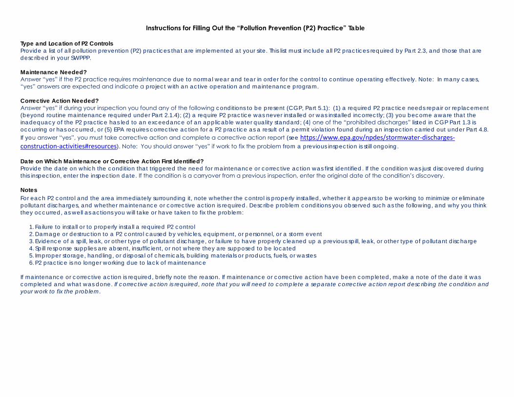
Instructions for Filling Out the “Pollution Prevention (P2) Practice” Table
Type and Location of P2 Controls Provide a list of all pollution prevention (P2) practices that are implemented at your site. This list must include all P2 practices required by Part 2.3, and those that are described in your SWPPP.
Maintenance Needed? Answer “yes” if the P2 practice requires maintenance due to normal wear and tear in order for the control to continue operating effectively. Note: In many cases, “yes” answers are expected and indicate a project with an active operation and maintenance program. Corrective Action Needed?
Answer “yes” if during your inspection you found any of the following conditions to be present (CGP, Part 5.1): (1) a required P2 practice needs repair or replacement (beyond routine maintenance required under Part 2.1.4); (2) a require P2 practice was never installed or was installed incorrectly; (3) you become aware that the inadequacy of the P2 practice has led to an exceedance of an applicable water quality standard; (4) one of the “prohibited discharges” listed in CGP Part 1.3 is occurring or has occurred, or (5) EPA requires corrective action for a P2 practice as a result of a permit violation found during an inspection carried out under Part 4.8. If you answer “yes”, you must take corrective action and complete a corrective action report (see https://www.epa.gov/npdes/stormwater-discharges-construction-activities#resources). Note: You should answer “yes” if work to fix the problem from a previous inspection is still ongoing.
Date on Which Maintenance or Corrective Action First Identified?
Provide the date on which the condition that triggered the need for maintenance or corrective action was first identified. If the condition was just discovered during this inspection, enter the inspection date. If the condition is a carryover from a previous inspection, enter the original date of the condition’s discovery. Notes
For each P2 control and the area immediately surrounding it, note whether the control is properly installed, whether it appears to be working to minimize or eliminate pollutant discharges, and whether maintenance or corrective action is required. Describe problem conditions you observed such as the following, and why you think they occurred, as well as actions you will take or have taken to fix the problem:
1. Failure to install or to properly install a required P2 control 2. Damage or destruction to a P2 control caused by vehicles, equipment, or personnel, or a storm event 3. Evidence of a spill, leak, or other type of pollutant discharge, or failure to have properly cleaned up a previous spill, leak, or other type of pollutant discharge 4. Spill response supplies are absent, insufficient, or not where they are supposed to be located 5. Improper storage, handling, or disposal of chemicals, building materials or products, fuels, or wastes 6. P2 practice is no longer working due to lack of maintenance
If maintenance or corrective action is required, briefly note the reason. If maintenance or corrective action have been completed, make a note of the date it was completed and what was done. If corrective action is required, note that you will need to complete a separate corrective action report describing the condition and
your work to fix the problem.
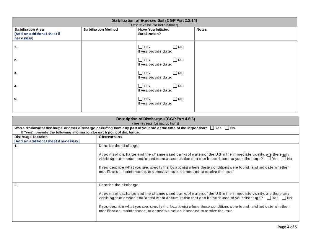
Page 4 of 5
Stabilization of Exposed Soil (CGP Part 2.2.14)
(see reverse for instructions) Stabilization Area
[Add an additional sheet if
necessary]
Stabilization Method
Have You Initiated
Stabilization?
Notes
1.
2.
3.
4.
5.
YES NO
If yes, provide date:
YES NO If yes, provide date:
YES NO If yes, provide date:
YES NO If yes, provide date:
YES NO If yes, provide date:
Description of Discharges (CGP Part 4.6.6)
(see reverse for instructions) Was a stormwater discharge or other discharge occurring from any part of your site at the time of the inspection? Yes No
If “yes”, provide the following information for each point of discharge:
Discharge Location
[Add an additional sheet if necessary]
Observations
1.
Describe the discharge:
At points of discharge and the channels and banks of waters of the U.S. in the immediate vicinity, are there any visible signs of erosion and/or sediment accumulation that can be attributed to your discharge? Yes No If yes, describe what you see, specify the location(s) where these conditions were found, and indicate whether modification, maintenance, or corrective action is needed to resolve the issue:
2.
Describe the discharge:
At points of discharge and the channels and banks of waters of the U.S. in the immediate vicinity, are there any visible signs of erosion and/or sediment accumulation that can be attributed to your discharge? Yes No If yes, describe what you see, specify the location(s) where these conditions were found, and indicate whether modification, maintenance, or corrective action is needed to resolve the issue:
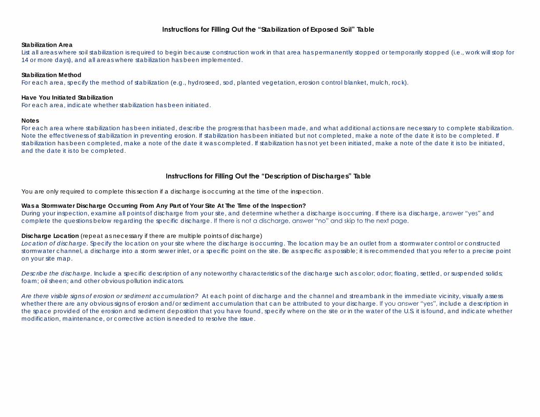
Instructions for Filling Out the “Stabilization of Exposed Soil” Table Stabilization Area List all areas where soil stabilization is required to begin because construction work in that area has permanently stopped or temporarily stopped (i.e., work will stop for 14 or more days), and all areas where stabilization has been implemented.
Stabilization Method For each area, specify the method of stabilization (e.g., hydroseed, sod, planted vegetation, erosion control blanket, mulch, rock). Have You Initiated Stabilization
For each area, indicate whether stabilization has been initiated.
Notes
For each area where stabilization has been initiated, describe the progress that has been made, and what additional actions are necessary to complete stabilization. Note the effectiveness of stabilization in preventing erosion. If stabilization has been initiated but not completed, make a note of the date it is to be completed. If stabilization has been completed, make a note of the date it was completed. If stabilization has not yet been initiated, make a note of the date it is to be initiated, and the date it is to be completed.
Instructions for Filling Out the “Description of Discharges” Table You are only required to complete this section if a discharge is occurring at the time of the inspection.
Was a Stormwater Discharge Occurring From Any Part of Your Site At The Time of the Inspection? During your inspection, examine all points of discharge from your site, and determine whether a discharge is occurring. If there is a discharge, answer “yes” and complete the questions below regarding the specific discharge. If there is not a discharge, answer “no” and skip to the next page. Discharge Location (repeat as necessary if there are multiple points of discharge) Location of discharge. Specify the location on your site where the discharge is occurring. The location may be an outlet from a stormwater control or constructed stormwater channel, a discharge into a storm sewer inlet, or a specific point on the site. Be as specific as possible; it is recommended that you refer to a precise point on your site map. Describe the discharge. Include a specific description of any noteworthy characteristics of the discharge such as color; odor; floating, settled, or suspended solids; foam; oil sheen; and other obvious pollution indicators. Are there visible signs of erosion or sediment accumulation? At each point of discharge and the channel and streambank in the immediate vicinity, visually assess whether there are any obvious signs of erosion and/or sediment accumulation that can be attributed to your discharge. If you answer “yes”, include a description in the space provided of the erosion and sediment deposition that you have found, specify where on the site or in the water of the U.S. it is found, and indicate whether modification, maintenance, or corrective action is needed to resolve the issue.
Page 5 of 5
Contractor or Subcontractor Signature and Certification
(see reverse for instructions) “I certify under penalty of law that this document and all attachments were prepared under my direction or supervision in accordance with a system designed to assure that qualified personnel properly gathered and evaluated the information submitted. Based on my inquiry of the person or persons who manage the system, or those persons directly responsible for gathering the information, the information submitted is, to the best of my knowledge and belief, true, accurate, and complete. I have no personal knowledge that the information submitted is other than true, accurate, and complete. I am aware that there are significant penalties for submitting false information, including the possibility of fine and imprisonment for knowing violations.”
Signature of Contractor or Subcontractor: ________________________________________________ Date:
Printed Name and Affiliation: ________________________________________________
Operator Signature and Certification
(see reverse for instructions) “I certify under penalty of law that this document and all attachments were prepared under my direction or supervision in accordance with a system designed to assure that qualified personnel properly gathered and evaluated the information submitted. Based on my inquiry of the person or persons who manage the system, or those persons directly responsible for gathering the information, the information submitted is, to the best of my knowledge and belief, true, accurate, and complete. I have no personal knowledge that the information submitted is other than true, accurate, and complete. I am aware that there are significant penalties for submitting false information, including the possibility of fine and imprisonment for knowing violations.”
Signature of Operator or “Duly Authorized Representative”: ________________________________________________ Date:
Printed Name and Affiliation: ________________________________________________
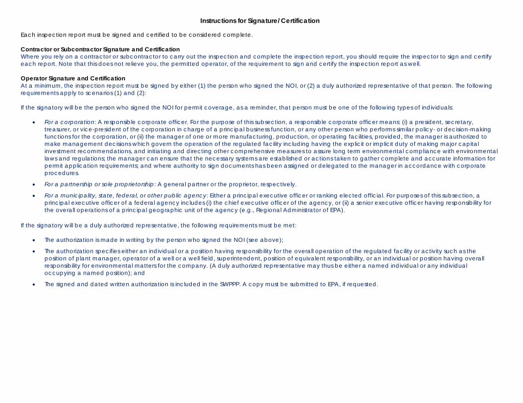
Instructions for Signature/Certification Each inspection report must be signed and certified to be considered complete.
Contractor or Subcontractor Signature and Certification Where you rely on a contractor or subcontractor to carry out the inspection and complete the inspection report, you should require the inspector to sign and certify each report. Note that this does not relieve you, the permitted operator, of the requirement to sign and certify the inspection report as well. Operator Signature and Certification
At a minimum, the inspection report must be signed by either (1) the person who signed the NOI, or (2) a duly authorized representative of that person. The following requirements apply to scenarios (1) and (2): If the signatory will be the person who signed the NOI for permit coverage, as a reminder, that person must be one of the following types of individuals:
• For a corporation: A responsible corporate officer. For the purpose of this subsection, a responsible corporate officer means: (i) a president, secretary, treasurer, or vice-president of the corporation in charge of a principal business function, or any other person who performs similar policy- or decision-making functions for the corporation, or (ii) the manager of one or more manufacturing, production, or operating facilities, provided, the manager is authorized to make management decisions which govern the operation of the regulated facility including having the explicit or implicit duty of making major capital investment recommendations, and initiating and directing other comprehensive measures to assure long term environmental compliance with environmental laws and regulations; the manager can ensure that the necessary systems are established or actions taken to gather complete and accurate information for permit application requirements; and where authority to sign documents has been assigned or delegated to the manager in accordance with corporate procedures.
• For a partnership or sole proprietorship: A general partner or the proprietor, respectively.
• For a municipality, state, federal, or other public agency: Either a principal executive officer or ranking elected official. For purposes of this subsection, a principal executive officer of a federal agency includes (i) the chief executive officer of the agency, or (ii) a senior executive officer having responsibility for the overall operations of a principal geographic unit of the agency (e.g., Regional Administrator of EPA).
If the signatory will be a duly authorized representative, the following requirements must be met:
• The authorization is made in writing by the person who signed the NOI (see above);
• The authorization specifies either an individual or a position having responsibility for the overall operation of the regulated facility or activity such as the position of plant manager, operator of a well or a well field, superintendent, position of equivalent responsibility, or an individual or position having overall responsibility for environmental matters for the company. (A duly authorized representative may thus be either a named individual or any individual occupying a named position); and
• The signed and dated written authorization is included in the SWPPP. A copy must be submitted to EPA, if requested.
i
2017 Construction General Permit
Corrective Action Report Form – Field Version Purpose
This Corrective Action Report Form is to assist you in preparing corrective action reports for EPA’s 2017 Construction General Permit (CGP). If you are covered under EPA’s 2017 CGP, you can use this form to create a corrective action report that complies with the minimum reporting requirements of Part 5.4 of the permit. You are only required to fill out this form if one of the conditions triggering corrective action in Part 5.1 or 5.3 occurs on your site. Routine maintenance is generally not considered to trigger corrective action. Corrective actions are triggered only for specific conditions that are identified below in the “Overview of Corrective Action Requirements.” If you are covered under a state CGP, this form may be helpful in developing a report that can be used for that permit; however, it will need to be modified to meet the specific requirements of the permit. If your permitting authority requires you to use a specific corrective action report form, you should not use this form. Notes
While EPA has made every effort to ensure the accuracy of all instructions contained in the Corrective Action Report Form, it is the permit, not the form, that determines the actual obligations of regulated construction stormwater discharges. In the event of a conflict between the Corrective Action Report Form and any corresponding provision of the 2017 CGP, you must abide by the requirements in the permit. EPA welcomes comments on the Corrective Action Report Form at any time and will consider those comments in any future revision of this document. You may contact EPA for CGP-related inquiries at [email protected]. Overview of Corrective Action Requirements
Construction operators covered under the 2017 CGP are required to conduct corrective actions and report on progress made in correcting the problem condition(s) in accordance with the following requirements:
Conditions Triggering Corrective Action (Parts 5.1 and 5.3)
Corrective action is required whenever any of the following conditions occur at your site: • A stormwater control needs repair or replacement (beyond routine maintenance required under Part 2.1.4); or • A stormwater control necessary to comply with the requirements of this permit was never installed, or was
installed incorrectly; or • Discharges are causing an exceedance of applicable water quality standards; or • A Part 1.3 prohibited discharge has occurred; or • EPA requires corrective action as a result of permit violations found during an inspection carried out under Part
4.8. Deadlines for Completing Corrective Actions (Part 5.2)
For any condition triggering corrective action: • You must immediately take all reasonable steps to address the condition (e.g. cleaning up contaminated
surfaces so the material(s) is not discharged in subsequent storm events); • If the problem does not require a new or replacement control or significant repair, you must complete the
corrective action by the close of the next business day • If the problem does require a new or replacement control or significant repair, you must complete corrective
action (e.g., installing and making operational any new or modified control, completing repairs) by no later than 7 calendar days from the time of discovery of the condition. If infeasible to complete the installation or repair within 7 calendar days, you must document why it is infeasible and document your schedule for completing the corrective action as soon as practicable. If any of these actions result in changes to the stormwater controls documented in your SWPPP, you must modify your SWPPP within 7 calendar days.
ii
Deadlines for Documenting Corrective Actions in a Report (Part 5.4)
You are required to complete a corrective action report for each corrective action you take in accordance with the following deadlines.
• Within 24 hours of identifying the corrective action condition, you must document the following: - The condition identified at your site; and
- The date and time you identified the condition
• Within 24 hours of completing the corrective action, you must document the following: - The actions you took to address the condition, and - Whether any SWPPP modifications are required.
Instructions for Using This Report Form
This Field Version of the Corrective Action Report Form is intended to be used in the field and filled out by hand. If you will be filling out the Corrective Action Report Form electronically (i.e., you will be typing in your findings), please use the Electronic Version of the Corrective Action Report Form available at https://www.epa.gov/npdes/stormwater-discharges-construction-activities#resources. The Electronic Version includes text fields with instructions for what to enter. The following tips for using this form will help you ensure that the minimum permit requirements are met:
• Review the corrective action requirements. Before you fill out this corrective action report form, read the CGP’s Part 5 corrective action requirements. This will ensure that you have a working understanding of the
permit’s underlying corrective action requirements. • Complete a separate report for each condition that triggers corrective action. For each triggering
condition on your site, you will need to fill out a separate corrective action report form.
• Complete all required text fields. Fill out all text fields. Only by filling out all fields will the form be compliant with the requirements of the permit. (Note: Where you do not need the number of rows provided in the corrective action report form, you may leave those rows blank. Or, if you need more space to document your findings, you may add an additional sheet.)
• Sign and certify each corrective action report. The operator or a duly authorized representative (see Appendix I, Part I.11.2) must sign and certify each corrective action report form for it to be considered complete. Where a contractor or subcontractor carries out your corrective actions, it is recommended that you also have that individual sign and certify the form, in addition to the signature and certification required of the permitted operator. The form includes a signature block for both parties.
• Include the corrective action report form with your SWPPP. Once your form is complete, make sure to include a copy of the corrective action report form in your SWPPP in accordance with Part 7.2.7.e of the CGP.
• Retain copies of all corrective action reports with your records. You must retain copies of your corrective action reports in your records in accordance with the requirements in Part 5.4.4 of the 2017 CGP. These reports must be retained for at least 3 years from the date your permit coverage expires or is terminated.
Section-by-Section Instructions You will find specific instructions corresponding to each section of the report form on the reverse side of each page. These instructions were written in order to provide you with more details in terms of what EPA expects to be documented in these reports
Page 1 of 2
Section A – Initial Report (CGP Part 5.4.1)
(Complete this section within 24 hours of identifying the condition that triggered corrective action) Name of Project NPDES ID No. Today’s Date
Date Problem First Discovered Time Problem First Discovered
Name and Contact Information of
Individual Completing this Form
What site conditions triggered the requirement to conduct corrective action (check the box that applies):
A stormwater control needs repair or replacement (beyond routine maintenance required under Part 2.1.4) A stormwater control necessary to comply with the requirements of this permit was never installed, or was installed
incorrectly A discharge is causing an exceedance of applicable water quality standards A Part 1.3 prohibited discharge has occurred EPA requires corrective action as a result of permit violations found during an EPA inspection carried out under Part 4.8
Provide a description of the problem:
Deadline for completing corrective action (check the box that applies):
Immediately take all reasonable steps to address the condition, including cleaning up any contaminated surfaces so the material will not discharge in subsequent storm events
Complete by close of the next business day when problem does not require a new or replacement control or significant repair
No later than 7 calendar days from the time of discovery for problems that require a new or replacement control or significant repair
Infeasible to complete the installation or repair within 7 calendar days. Explain why it is infeasible and document schedule for installing control:
Enter date of corrective action completion: _______________________
Section B – Corrective Action Completion (CGP Part 5.4.2) (Complete this section no later than 24 hours after completing the corrective action)
Section B.1 – Why the Problem Occurred
Cause(s) of Problem
(Add an additional sheet if necessary) How You Determined the Cause and the Date You
Determined the Cause
1.
1.
2.
2.
Section B.2 – Stormwater Control Modifications Implemented to Correct the Problem
List of Stormwater Control Modification(s)
Needed to Correct Problem
(Add an additional sheet if necessary)
Date of
Completion
SWPPP Update
Necessary?
Notes
1.
Yes No If yes, provide date SWPPP modified:
2.
Yes No If yes, provide date SWPPP modified:
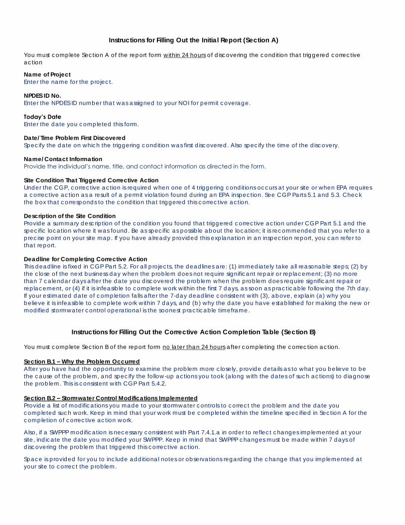
Instructions for Filling Out the Initial Report (Section A) You must complete Section A of the report form within 24 hours of discovering the condition that triggered corrective action
Name of Project
Enter the name for the project. NPDES ID No.
Enter the NPDES ID number that was assigned to your NOI for permit coverage.
Today’s Date
Enter the date you completed this form. Date/Time Problem First Discovered Specify the date on which the triggering condition was first discovered. Also specify the time of the discovery. Name/Contact Information
Provide the individual’s name, title, and contact information as directed in the form. Site Condition That Triggered Corrective Action
Under the CGP, corrective action is required when one of 4 triggering conditions occurs at your site or when EPA requires a corrective action as a result of a permit violation found during an EPA inspection. See CGP Parts 5.1 and 5.3. Check the box that corresponds to the condition that triggered this corrective action. Description of the Site Condition Provide a summary description of the condition you found that triggered corrective action under CGP Part 5.1 and the specific location where it was found. Be as specific as possible about the location; it is recommended that you refer to a precise point on your site map. If you have already provided this explanation in an inspection report, you can refer to that report. Deadline for Completing Corrective Action
This deadline is fixed in CGP Part 5.2. For all projects, the deadlines are: (1) immediately take all reasonable steps; (2) by the close of the next business day when the problem does not require significant repair or replacement; (3) no more than 7 calendar days after the date you discovered the problem when the problem does require significant repair or replacement, or (4) if it is infeasible to complete work within the first 7 days, as soon as practicable following the 7th day. If your estimated date of completion falls after the 7-day deadline consistent with (3), above, explain (a) why you believe it is infeasible to complete work within 7 days, and (b) why the date you have established for making the new or modified stormwater control operational is the soonest practicable timeframe.
Instructions for Filling Out the Corrective Action Completion Table (Section B) You must complete Section B of the report form no later than 24 hours after completing the correction action. Section B.1 – Why the Problem Occurred After you have had the opportunity to examine the problem more closely, provide details as to what you believe to be the cause of the problem, and specify the follow-up actions you took (along with the dates of such actions) to diagnose the problem. This is consistent with CGP Part 5.4.2. Section B.2 – Stormwater Control Modifications Implemented Provide a list of modifications you made to your stormwater controls to correct the problem and the date you completed such work. Keep in mind that your work must be completed within the timeline specified in Section A for the completion of corrective action work.
Also, if a SWPPP modification is necessary consistent with Part 7.4.1.a in order to reflect changes implemented at your site, indicate the date you modified your SWPPP. Keep in mind that SWPPP changes must be made within 7 days of discovering the problem that triggered this corrective action.
Space is provided for you to include additional notes or observations regarding the change that you implemented at your site to correct the problem.
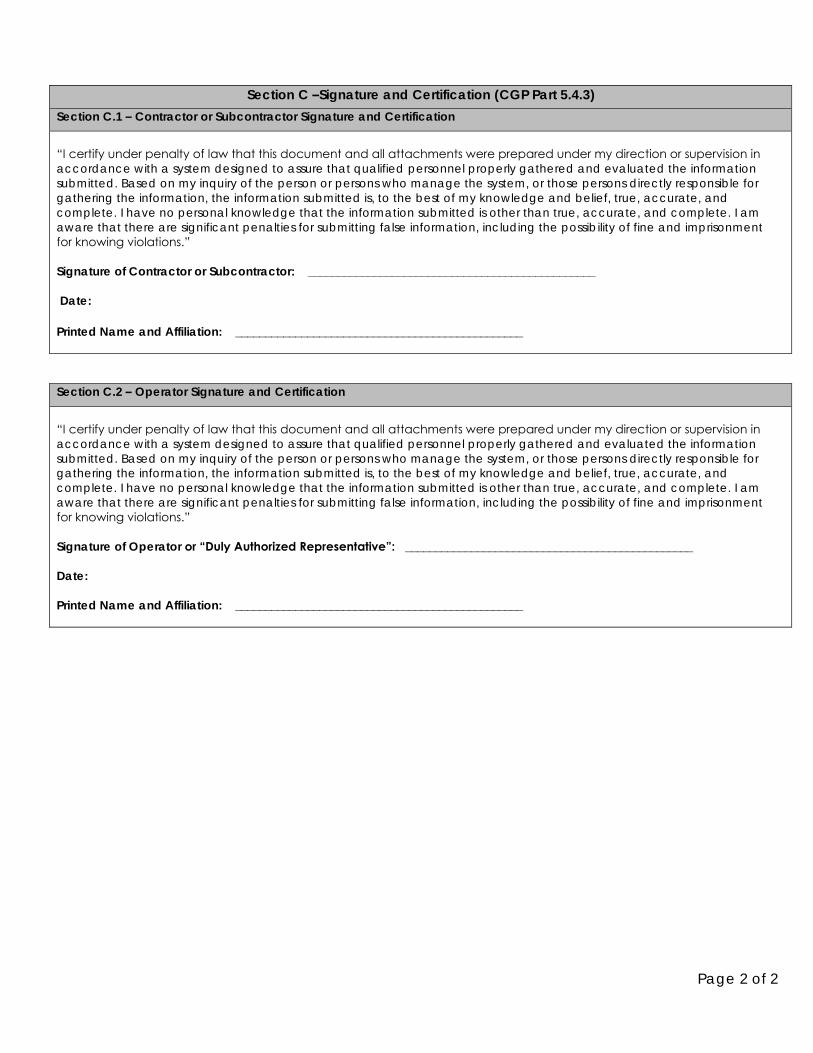
Page 2 of 2
Section C –Signature and Certification (CGP Part 5.4.3) Section C.1 – Contractor or Subcontractor Signature and Certification
“I certify under penalty of law that this document and all attachments were prepared under my direction or supervision in
accordance with a system designed to assure that qualified personnel properly gathered and evaluated the information submitted. Based on my inquiry of the person or persons who manage the system, or those persons directly responsible for gathering the information, the information submitted is, to the best of my knowledge and belief, true, accurate, and complete. I have no personal knowledge that the information submitted is other than true, accurate, and complete. I am aware that there are significant penalties for submitting false information, including the possibility of fine and imprisonment for knowing violations.” Signature of Contractor or Subcontractor: ________________________________________________
Date:
Printed Name and Affiliation: ________________________________________________
Section C.2 – Operator Signature and Certification
“I certify under penalty of law that this document and all attachments were prepared under my direction or supervision in
accordance with a system designed to assure that qualified personnel properly gathered and evaluated the information submitted. Based on my inquiry of the person or persons who manage the system, or those persons directly responsible for gathering the information, the information submitted is, to the best of my knowledge and belief, true, accurate, and complete. I have no personal knowledge that the information submitted is other than true, accurate, and complete. I am aware that there are significant penalties for submitting false information, including the possibility of fine and imprisonment for knowing violations.” Signature of Operator or “Duly Authorized Representative”: ________________________________________________
Date:
Printed Name and Affiliation: ________________________________________________
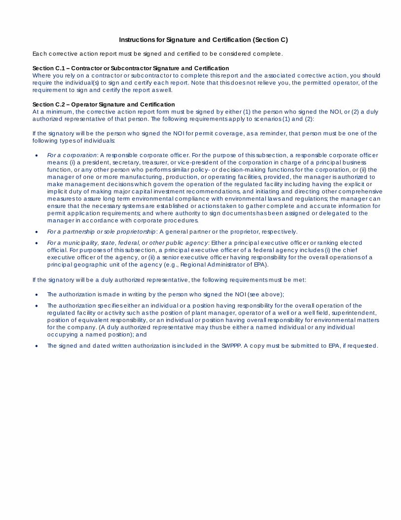
Instructions for Signature and Certification (Section C)
Each corrective action report must be signed and certified to be considered complete.
Section C.1 – Contractor or Subcontractor Signature and Certification Where you rely on a contractor or subcontractor to complete this report and the associated corrective action, you should require the individual(s) to sign and certify each report. Note that this does not relieve you, the permitted operator, of the requirement to sign and certify the report as well. Section C.2 – Operator Signature and Certification
At a minimum, the corrective action report form must be signed by either (1) the person who signed the NOI, or (2) a duly authorized representative of that person. The following requirements apply to scenarios (1) and (2): If the signatory will be the person who signed the NOI for permit coverage, as a reminder, that person must be one of the following types of individuals: • For a corporation: A responsible corporate officer. For the purpose of this subsection, a responsible corporate officer
means: (i) a president, secretary, treasurer, or vice-president of the corporation in charge of a principal business function, or any other person who performs similar policy- or decision-making functions for the corporation, or (ii) the manager of one or more manufacturing, production, or operating facilities, provided, the manager is authorized to make management decisions which govern the operation of the regulated facility including having the explicit or implicit duty of making major capital investment recommendations, and initiating and directing other comprehensive measures to assure long term environmental compliance with environmental laws and regulations; the manager can ensure that the necessary systems are established or actions taken to gather complete and accurate information for permit application requirements; and where authority to sign documents has been assigned or delegated to the manager in accordance with corporate procedures.
• For a partnership or sole proprietorship: A general partner or the proprietor, respectively.
• For a municipality, state, federal, or other public agency: Either a principal executive officer or ranking elected official. For purposes of this subsection, a principal executive officer of a federal agency includes (i) the chief executive officer of the agency, or (ii) a senior executive officer having responsibility for the overall operations of a principal geographic unit of the agency (e.g., Regional Administrator of EPA).
If the signatory will be a duly authorized representative, the following requirements must be met: • The authorization is made in writing by the person who signed the NOI (see above);
• The authorization specifies either an individual or a position having responsibility for the overall operation of the regulated facility or activity such as the position of plant manager, operator of a well or a well field, superintendent, position of equivalent responsibility, or an individual or position having overall responsibility for environmental matters for the company. (A duly authorized representative may thus be either a named individual or any individual occupying a named position); and
• The signed and dated written authorization is included in the SWPPP. A copy must be submitted to EPA, if requested.
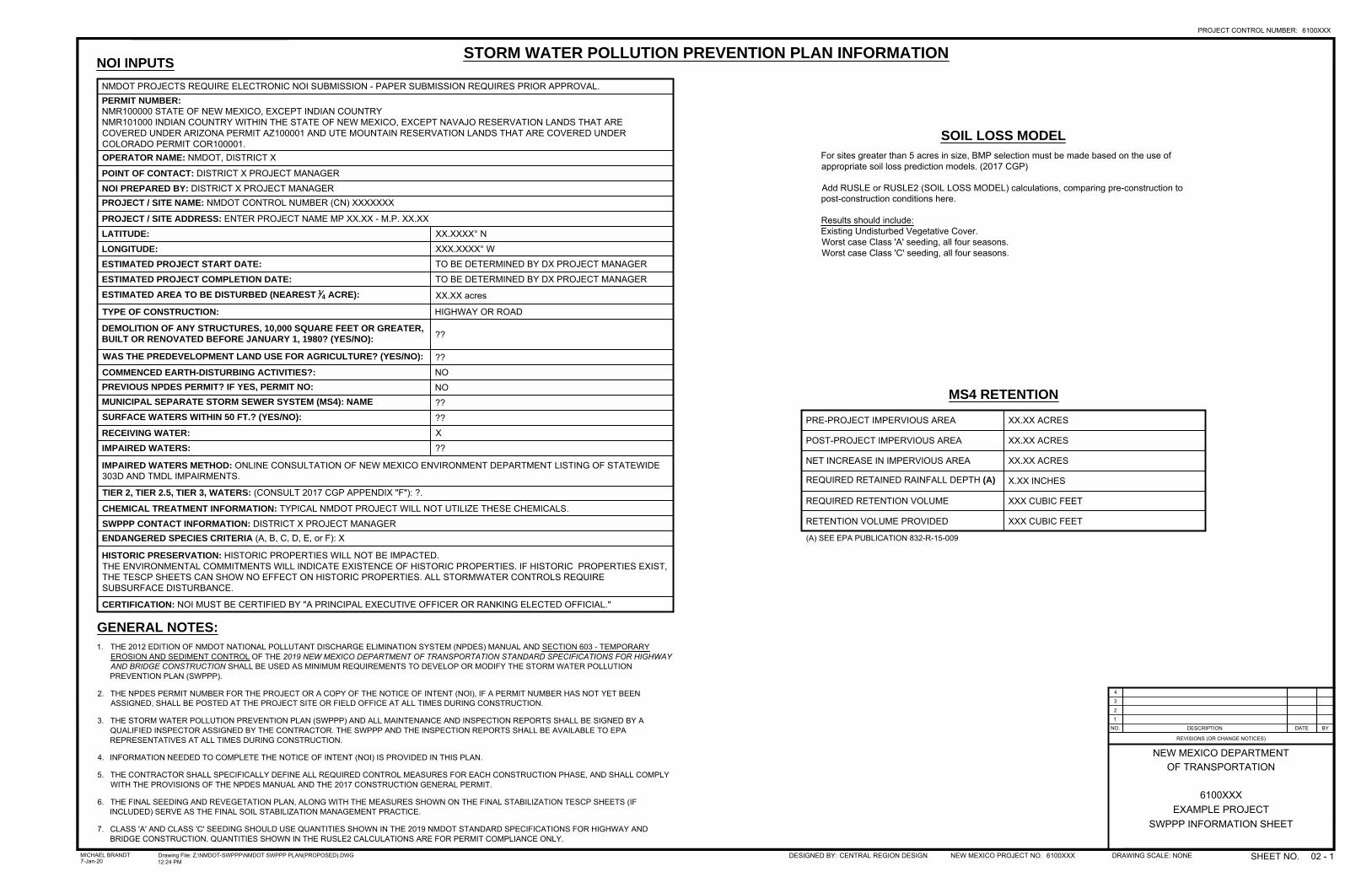
4
3
2
1
NO. DESCRIPTION DATE BY
REVISIONS (OR CHANGE NOTICES)
OF TRANSPORTATIONNEW MEXICO DEPARTMENT
EXAMPLE PROJECT6100XXX
SWPPP INFORMATION SHEET
STORM WATER POLLUTION PREVENTION PLAN INFORMATION
GENERAL NOTES:
1. THE 2012 EDITION OF NMDOT NATIONAL POLLUTANT DISCHARGE ELIMINATION SYSTEM (NPDES) MANUAL AND SECTION 603 - TEMPORARYEROSION AND SEDIMENT CONTROL OF THE 2019 NEW MEXICO DEPARTMENT OF TRANSPORTATION STANDARD SPECIFICATIONS FOR HIGHWAYAND BRIDGE CONSTRUCTION SHALL BE USED AS MINIMUM REQUIREMENTS TO DEVELOP OR MODIFY THE STORM WATER POLLUTIONPREVENTION PLAN (SWPPP).
2. THE NPDES PERMIT NUMBER FOR THE PROJECT OR A COPY OF THE NOTICE OF INTENT (NOI), IF A PERMIT NUMBER HAS NOT YET BEENASSIGNED, SHALL BE POSTED AT THE PROJECT SITE OR FIELD OFFICE AT ALL TIMES DURING CONSTRUCTION.
3. THE STORM WATER POLLUTION PREVENTION PLAN (SWPPP) AND ALL MAINTENANCE AND INSPECTION REPORTS SHALL BE SIGNED BY AQUALIFIED INSPECTOR ASSIGNED BY THE CONTRACTOR. THE SWPPP AND THE INSPECTION REPORTS SHALL BE AVAILABLE TO EPAREPRESENTATIVES AT ALL TIMES DURING CONSTRUCTION.
4. INFORMATION NEEDED TO COMPLETE THE NOTICE OF INTENT (NOI) IS PROVIDED IN THIS PLAN.
5. THE CONTRACTOR SHALL SPECIFICALLY DEFINE ALL REQUIRED CONTROL MEASURES FOR EACH CONSTRUCTION PHASE, AND SHALL COMPLYWITH THE PROVISIONS OF THE NPDES MANUAL AND THE 2017 CONSTRUCTION GENERAL PERMIT.
6. THE FINAL SEEDING AND REVEGETATION PLAN, ALONG WITH THE MEASURES SHOWN ON THE FINAL STABILIZATION TESCP SHEETS (IFINCLUDED) SERVE AS THE FINAL SOIL STABILIZATION MANAGEMENT PRACTICE.
7. CLASS 'A' AND CLASS 'C' SEEDING SHOULD USE QUANTITIES SHOWN IN THE 2019 NMDOT STANDARD SPECIFICATIONS FOR HIGHWAY ANDBRIDGE CONSTRUCTION. QUANTITIES SHOWN IN THE RUSLE2 CALCULATIONS ARE FOR PERMIT COMPLIANCE ONLY.
NMDOT PROJECTS REQUIRE ELECTRONIC NOI SUBMISSION - PAPER SUBMISSION REQUIRES PRIOR APPROVAL.PERMIT NUMBER:
NMR100000 STATE OF NEW MEXICO, EXCEPT INDIAN COUNTRYNMR101000 INDIAN COUNTRY WITHIN THE STATE OF NEW MEXICO, EXCEPT NAVAJO RESERVATION LANDS THAT ARECOVERED UNDER ARIZONA PERMIT AZ100001 AND UTE MOUNTAIN RESERVATION LANDS THAT ARE COVERED UNDERCOLORADO PERMIT COR100001.OPERATOR NAME: NMDOT, DISTRICT X
POINT OF CONTACT: DISTRICT X PROJECT MANAGERNOI PREPARED BY: DISTRICT X PROJECT MANAGERPROJECT / SITE NAME: NMDOT CONTROL NUMBER (CN) XXXXXXX
PROJECT / SITE ADDRESS: ENTER PROJECT NAME MP XX.XX - M.P. XX.XXLATITUDE: XX.XXXX° NLONGITUDE: XXX.XXXX° WESTIMATED PROJECT START DATE: TO BE DETERMINED BY DX PROJECT MANAGERESTIMATED PROJECT COMPLETION DATE: TO BE DETERMINED BY DX PROJECT MANAGERESTIMATED AREA TO BE DISTURBED (NEAREST
1
4
ACRE): XX.XX acres
TYPE OF CONSTRUCTION: HIGHWAY OR ROAD
DEMOLITION OF ANY STRUCTURES, 10,000 SQUARE FEET OR GREATER,
BUILT OR RENOVATED BEFORE JANUARY 1, 1980? (YES/NO):
??
WAS THE PREDEVELOPMENT LAND USE FOR AGRICULTURE? (YES/NO): ??COMMENCED EARTH-DISTURBING ACTIVITIES?: NOPREVIOUS NPDES PERMIT? IF YES, PERMIT NO: NOMUNICIPAL SEPARATE STORM SEWER SYSTEM (MS4): NAME ??SURFACE WATERS WITHIN 50 FT.? (YES/NO): ??RECEIVING WATER: XIMPAIRED WATERS: ??
IMPAIRED WATERS METHOD: ONLINE CONSULTATION OF NEW MEXICO ENVIRONMENT DEPARTMENT LISTING OF STATEWIDE303D AND TMDL IMPAIRMENTS.
TIER 2, TIER 2.5, TIER 3, WATERS: (CONSULT 2017 CGP APPENDIX "F"): ?.
CHEMICAL TREATMENT INFORMATION: TYPICAL NMDOT PROJECT WILL NOT UTILIZE THESE CHEMICALS.SWPPP CONTACT INFORMATION: DISTRICT X PROJECT MANAGERENDANGERED SPECIES CRITERIA (A, B, C, D, E, or F): X
HISTORIC PRESERVATION: HISTORIC PROPERTIES WILL NOT BE IMPACTED.THE ENVIRONMENTAL COMMITMENTS WILL INDICATE EXISTENCE OF HISTORIC PROPERTIES. IF HISTORIC PROPERTIES EXIST,THE TESCP SHEETS CAN SHOW NO EFFECT ON HISTORIC PROPERTIES. ALL STORMWATER CONTROLS REQUIRESUBSURFACE DISTURBANCE.
CERTIFICATION: NOI MUST BE CERTIFIED BY "A PRINCIPAL EXECUTIVE OFFICER OR RANKING ELECTED OFFICIAL."
NOI INPUTS
PRE-PROJECT IMPERVIOUS AREA XX.XX ACRES
POST-PROJECT IMPERVIOUS AREA XX.XX ACRES
NET INCREASE IN IMPERVIOUS AREA XX.XX ACRES
REQUIRED RETAINED RAINFALL DEPTH (A) X.XX INCHES
REQUIRED RETENTION VOLUME XXX CUBIC FEET
RETENTION VOLUME PROVIDED XXX CUBIC FEET
(A) SEE EPA PUBLICATION 832-R-15-009
MS4 RETENTION
SOIL LOSS MODEL
For sites greater than 5 acres in size, BMP selection must be made based on the use ofappropriate soil loss prediction models. (2017 CGP)
Add RUSLE or RUSLE2 (SOIL LOSS MODEL) calculations, comparing pre-construction topost-construction conditions here.
Results should include:Existing Undisturbed Vegetative Cover.Worst case Class 'A' seeding, all four seasons.Worst case Class 'C' seeding, all four seasons.
PROJECT CONTROL NUMBER: 6100XXX
SHEET NO.NEW MEXICO PROJECT NO. 6100XXXDESIGNED BY: DRAWING SCALE: NONEDrawing File: Z:\NMDOT-SWPPP\NMDOT SWPPP PLAN(PROPOSED).DWG12:24 PM
MICHAEL BRANDT7-Jan-20 02 - 1CENTRAL REGION DESIGN

National Pollutant Discharge Elimination System (NPDES)
Construction General Permit (CGP) Guide
1 | P a g e NMDOT CGP Guide
The following procedures provide guidance for all NMDOT construction projects requiring permits under the National Pollutant Discharge Elimination System (NPDES) General Permit for Discharges from Construction Activities requirements. This General Permit is referred to as the Construction General Permit (CGP).
1. The Project Office will complete the following: a. Provide photographs of area PRIOR to any ground disturbance. (Photos will be
used for future reference by Maintenance Personnel to compare/verify 70% original vegetation growth).
b. Give copies of Contractor Notice of Intent (NOI) to Construction Management Analyst.
2. The Contractor shall present the following to the Project Office:
a. Contractor-prepared Stormwater Pollution Prevention Plan (SWPPP) per Section 603, 2019 NMDOT Standard Specifications and the CGP. SWPPP copies to be placed in 3-ring binders. Check with the NMDOT District to determine the number of SWPPP copies required. The Contractor must provide updated information for all SWPPP Binders throughout the life of the project. The SWPPP must be verified prior to Final Project Acceptance and SWPPP payment.
b. NOI prepared by Contractor. c. Any other documentation of compliance with other Federal Requirements, if
applicable: • Endangered Species Act (refer to the CGP, Appendix D - Eligibility
Procedures Relating to Threatened and Endangered Species Protection) • Historic Properties (refer to the CGP, Appendix E - Historic Property
Screening Process) • Safe Drinking Water Act
3. At least fourteen (14) days prior to the start of construction activity, the Designee of the
Project Manager in coordination with the Drainage Engineer (only applicable to
District 3) will: a. Forward a copy of the Contractor's NOI to the Maintenance Management Analyst
for submittal of the Department's NOI. Information on the CGP NOI form is available online.
4. The Maintenance Management Analyst will:
a. Build a preliminary SWPPP file. b. Prepare NMDOT's NOI online at https://cdx.epa.gov/CDX/Login.
• The Maintenance Management Analyst will first have to register with the site to obtain a username and password.
• The NOI will be prepared utilizing the Contractor's NOI and the NMDOT - NPDES Information Sheet from the construction plan set.
• Once the District Engineer or designee (refer to Attachment A of this document) has certified the NOI, the Maintenance Management Analyst
2 | P a g e NMDOT CGP Guide
will email the acknowledgement from EPA and the NOI with tracking number to the Project Manager and Construction Management Analyst. Then the Maintenance Management Analyst will place a copy in the preliminary SWPPP file.
5. The Designee of the Project Manager will prepare a letter of delegation (Attachment A
of this document) for the District Engineer's signature in accordance with CGP, Appendix I, Part I.11, Signatory Requirements. The designee will ensure that the Project Office receives copy of the delegation letter for inclusion in the SWPPP Binders. It will be placed in tab 1 of the Binder.
6. The Project Manager will ensure the Notice of Permit Coverage is completed. Post a sign or other notice of CGP coverage at a safe, publicly accessible location in close proximity to the construction site. The notice must be located so that it is visible from a public road that is nearest to the active part of the construction site, and it must use a font large enough to be readily viewed from a public right-of-way. At a minimum, the notice must include:
a. The NPDES ID (i.e., permit tracking number assigned to the project's NOI); b. A contact name and phone number for obtaining additional construction site
information; c. The Uniform Resource Locator (URL) for the SWPPP (if available), or the
following statement: "If you would like to obtain a copy of the SWPPP for this site, contact the EPA Regional Office at [include the appropriate CGP Regional Office contact information found at https://www.epa.gov/npdes/contact-us-stormwater#regional];" and
d. The following statement "If you observe indicators of stormwater pollutants in the discharge or in the receiving waterbody, contact the EPA through the following website: https://www.epa.gov/enforcement/report-environmental-violations."
The Project Manager will utilize the Project Manager Checklist (Attachment B of this document) to check the Contractor's SWPPP. Any noted deficiencies shall be corrected by the Contractor PRIOR to any ground disturbance, as required by Section 603, 2019 NMDOT Standard Specifications.
7. Upon commencement of construction activities, the Contractor's Qualified Person and
the Project Manager/NMDOT Project Qualified Person will jointly inspect the project to ensure compliance with Section 603, 2019 NMDOT Standard Specifications.
(Note: Consistent with standards set in the 2017 EPA Construction General Permit, a “Qualified” stormwater person is someone that has knowledge of the principles and practice of erosion and sediment controls and pollution prevention, that is also able to ensure construction site conditions meet the requirements of the permit.)
The following forms will be used to verify and document any findings: a. Construction Inspection Form (Attachment C of this document).
3 | P a g e NMDOT CGP Guide
• For Districts 1, 3, and 5 (MS4 areas) - A copy of this form should be emailed to the MS4 Coordinator at the NMDOT Environmental Bureau following completion, so it may be used in the EPA MS4 Annual Reports.
b. SWPPP Inspector Checklist (Attachment D of this document). c. NMDOT SWPPP Inspection and Maintenance Report (Attachment E of this
document). • A copy of NMDOT Form A-1085 (Attachment F of this document) must be
completed along with the inclusion of training certificates for Qualified Personnel from both NMDOT and Contractor. Both documents will be placed in each SWPPP Binder.
• An inspection must be conducted by the Contractor's Qualified Person at least every seven (7) days OR every fourteen (14) days and within 24 hours of a 0.25 inches or greater storm event. The inspection must be verified by the NMDOT Project Qualified Person.
• Soil stabilization measures must be initiated immediately whenever earth-disturbing activities have permanently or temporarily ceased on any portion of the site in accordance with the CGP Section 2.2.14.
• The inspection frequency may be reduced for the following conditions: o For stabilized areas, the SWPPP inspections will be reduced to
twice per month for the first month, no more than fourteen (14) days apart, then once per month in any area of the site where the stabilization steps have been completed in accordance with Section 2.2.14a of the CGP. If construction activity resumes in this portion of the site at a later date, the inspection frequency immediately increases as stated on Section 7.c.ii. of this document. Please include documentation in the SWPPP Binders indicating the beginning and ending dates of any reduced inspection period.
o For linear construction sites (as defined in CGP Appendix A), where disturbed portions have undergone final stabilization at the same time active construction continues on others, you may reduce the frequency of inspections to twice per month for the first month, no more than fourteen (14) calendar days apart, in any area of the site where final stabilization have been completed. After the first month, inspect once more within 24 hours of the occurrence of a storm event of 0.25 inches or greater. If there are no issues or evidence of stabilization problems, you may suspend further inspections. If wash-out of stabilization materials and/or sediment is observed, following re-stabilization, inspections must resume at the inspection frequency required above until final stabilization is visually confirmed following a storm event of 0.25 inches or greater.
o If a project is in FULL suspension due to frozen ground, the SWPPP inspections can be temporarily suspended until thawing

4 | P a g e NMDOT CGP Guide
conditions (two or more days with daytime temperatures greater than 32°F (as defined in CGP Appendix A) begin to occur if:
▪ Runoff is unlikely due to continuous frozen conditions that are likely to continue at your site for at least three (3) months based on historic seasonal averages. If unexpected weather conditions (such as above freezing temperatures or storm events) make discharges likely, you must immediately resume your regular inspection frequency as described in CGP Parts 4.2 and 4.3, as applicable;
▪ Land disturbances have been suspended; and ▪ All disturbed areas of the site have been stabilized in
accordance with CGP Part 2.2.14a. i. If a project is in PARTIAL suspension due to frozen
ground, the SWPPP inspections can be reduced to once per month if:
➢ Runoff is unlikely due to continuous frozen conditions that are likely to continue at your site for at least three (3) months based on historic seasonal averages. If unexpected weather conditions (such as above freezing temperatures or storm events) make discharges likely, you must immediately resume your regular inspection frequency as described in CGP Parts 4.2 and 4.3, as applicable; and
➢ Except for areas in which you are actively conducting construction activities, disturbed areas of the site have been stabilized in accordance with CGP Part 2.2.14a.
ii. Ensure documentation is included in the SWPPP Binders indicating the beginning and ending dates of frozen conditions on your project.
• Erosion and Sediment Control Requirements (refer to the CGP, Appendix G – Buffer Requirements for additional information):
o Provide and maintain natural buffer and/or equivalent erosion and sediment controls when a water of the U.S. is located within 50 feet of the site’s earth disturbances.
▪ Compliance Alternatives. For any discharges to waters of the U.S. located within 50 feet of your site’s earth disturbances, you must comply with one of the following alternatives:
i. Provide and maintain a 50-foot undisturbed natural buffer; or
ii. Provide and maintain an undisturbed natural buffer that is less than 50 feet and is supplemented by
5 | P a g e NMDOT CGP Guide
erosion and sediment controls that achieve, in combination, the sediment load reduction equivalent to a 50-foot undisturbed natural buffer; or
iii. If infeasible to provide and maintain an undisturbed natural of any size, implement erosion and sediment controls to achieve the sediment load reduction equivalent to a 50-foot undisturbed natural buffer.
(Note: See Appendix G, Part G.2 of the CGP for additional conditions applicable to each compliance alternative)
o Exceptions – See Appendix G, Part G.2 of the CGP for exceptions to the compliance alternatives.
d. NMDOT Corrective Action Report Form (Attachment G of this document). Corrective action is required whenever any of the following conditions occur at your site in accordance with Section 5 of the CGP:
1) A stormwater control needs repair or replacement (beyond routine maintenance required under CGP Part 2.1.4); or
2) A stormwater control necessary to comply with the requirements of this permit was never installed, or was installed incorrectly; or
3) Your discharges are causing an exceedance of applicable water quality standards; or
4) A prohibited discharge has occurred (see CGP Part 1.3). • Immediately take all reasonable steps to address the condition, including
cleaning up any contaminated surfaces so the material will not discharge in subsequent storm events;
o When the problem does not require a new or replacement control or significant repair, the corrective action must be completed by the close of the next business day;
o When the problem requires a new or replacement control or significant repair, install the new or modified control and make it operational, or complete the repair, by no later than seven (7)
calendar days from the time of discovery. If it is infeasible to complete the installation or repair within seven (7) calendar days, you must document in your records why it is infeasible to complete the installation or repair within the 7-day timeframe and document your schedule for installing the stormwater control(s) and making it operational as soon as feasible after the 7-day timeframe. Where these actions result in changes to any of the stormwater controls or procedures documented in your SWPPP, you must modify your SWPPP accordingly within seven (7) calendar days of completing this work.
• For each corrective action taken in accordance with this Part, you must complete a report in accordance with the following:
6 | P a g e NMDOT CGP Guide
o Within 24 hours of identifying the corrective action condition, document the specific condition and the date and time it was identified.
o Within 24 hours of completing the corrective action (in accordance with the deadlines in CGP Part 5.2), document the actions taken to address the condition, including whether any SWPPP modifications are required.
o You must keep a copy of all corrective action reports at the site or at an easily accessible location, so that it can be made available at the time of an on-site inspection or upon request by EPA.
8. Upon completion of a project, the Contractor, Project Manager and ADE-
Construction will conduct an inspection. After any noted deficiencies are corrected, the Contractor will sign the NMDOT Transfer of Stormwater Management Authority Form (Attachment J of this document), thus transferring the SWPPP to the Project Manager. The transfer must also be signed by the Assistant District Engineer - Construction or
designee. A copy must be placed in each of the SWPPP Binders.
9. Once construction is complete, the Project Manager shall ensure that the Contractor has provided two (2) identical copies of the completed SWPPP PRIOR to paying the final progress payment (Item 603280, SWPPP Management). The Project Office will verify that all Inspection and Maintenance Reports (Attachment E of this document) and Pollution Prevention Procedures are documented and current.
a. Each SWPPP Binder will be tabbed and contain the following (in this order): • Letter of Delegation (Attachment A of this document). • Photographs prior to any ground disturbance. • Contractor Notice of Intent (NOI). • Contractor Notice of Termination (NOT). • NMDOT Notice of Intent (NOI). • Photocopies of certificates for Contractor and NMDOT Project Qualified
Person (Attachment F of this document). • Project Manager Checklist (Attachment B of this document). • Contractor Inspection and Maintenance Reports - utilizing stations as
locations (Attachment E of this document). • Blank Inspection and Maintenance Reports - utilizing mile markers as
locations for Maintenance personnel to continue inspections (Attachment E of this document).
• Plan set showing SWPPP progression throughout life of project. • Any other required documentation such as Endangered Species Act, Use
of treatment chemicals, etc. • NMDOT Transfer of Stormwater Management Authority – Contractor to
NMDOT Project Manager Form (Attachment H of this document).
7 | P a g e NMDOT CGP Guide
• Blank NMDOT Transfer of Stormwater Management Authority – NMDOT Construction to NMDOT Maintenance Form (Attachment I of this document).
• Blank NPDES Maintenance to Management Analyst Form (Attachment J of this document).
b. One (1) SWPPP Binder will be become part of the project files and submitted with all final documents.
c. One (1) SWPPP Binder will be provided to the appropriate Patrol Supervisor.
10. The Project Manager will schedule a SWPPP final inspection/transfer meeting and invite the following: Patrol Supervisor, Area Maintenance Superintendent (AMS), ADE- Maintenance, ADE- Construction, Designee of the Project Manager, and Maintenance Management Analysts.
a. Maintenance personnel (Qualified Person) will inspect and note any deficiencies that require attention before transfer is made. If all SWPPP BMPs/devices are acceptable, the Maintenance and Construction Qualified
Person will sign the NMDOT Transfer of Stormwater Management Authority – NMDOT Construction to NMDOT Maintenance Form (Attachment I of this document).
11. Maintenance Patrol Qualified Person will be responsible for conducting routine
inspections of the NPDES features. Since temporary stabilization (seeding) has occurred on the project, inspections will be required once per month or after 0.25 inches or greater storm event.
a. A copy of the Maintenance Qualified Person training certificates will be placed in the SWPPP Binder.
b. All inspection results will be documented utilizing the NMDOT SWPPP Inspection and Maintenance Report Form (Attachment E of this document). The completed forms will be added to the SWPPP Binder.
c. If any corrective works needs to be performed on the SWPPP BMPs/devices, Maintenance personnel will do so and document the work performed on the NMDOT SWPPP Inspection and Maintenance Report Form (Attachment E of this document).
d. When 70% of original vegetation (compared to original photographs) has been obtained, the Patrol Supervisor will complete the NMDOT Maintenance to NMDOT Management Analyst Transfer Form (Attachment J of this document), for a review of the project. The Patrol Supervisor will schedule the review with the Maintenance Management Analyst and the AMS.
12. Maintenance Management Analyst will perform periodic inspections of Maintenance Patrol documentation in the SWPPP Binders.
a. Once a review has been scheduled by the Maintenance Patrol Supervisor, the Maintenance Management Analyst and AMS will complete a final inspection of the SWPPP Binder to ensure the Patrol has completed all required documentation for the project.

8 | P a g e NMDOT CGP Guide
b. Photographs of re-vegetation (to be taken at inspection) will be placed in the SWPPP Binder for final documentation.
c. A Notice of Termination (NOT) for NMDOT will be filed by the Maintenance Management Analyst.
d. The SWPPP Binder will be maintained by the Maintenance Management Analyst for three (3) years from the NOT.
9 | P a g e NMDOT CGP Guide
SUPPLEMENTAL REFERENCES
I. Areas that Must be Inspected (Construction General Permit Part 4.5)
At a minimum, site inspection should include: ➢ All areas that have been cleared, graded or excavated and that have not yet
completed stabilization consistent with CGP part 2.2.14a; ➢ All stormwater controls (including pollution prevention controls) installed at the site
to comply with this permit; ➢ Material, waste, borrow, and equipment storage and maintenance areas that are
covered by this permit; ➢ All areas where stormwater typically flows within the site, including drainage ways
designed to divert, convey, and/or treat stormwater; ➢ All points of discharge from the site; and ➢ All locations where stabilization measures have been implemented.
You are not required to inspect areas that, at the time of the inspection, are considered unsafe to your inspection personnel.
II. Requirement for Inspections (Construction General Permit Part 4.6)
During your site inspection, you must at a minimum: ➢ Check whether all stormwater controls (i.e., erosion and sediment controls and
pollution prevention controls) are properly installed, appear to be operational, and are working as intended to minimize pollutant discharges;
➢ Check for the presence of conditions that could lead to spills, leaks, or other accumulations of pollutants on the site;
➢ Identify any locations where new or modified stormwater controls are necessary to meet the requirements of CGP Parts 2 and/or 3;
➢ Check for signs of visible erosion and sedimentation (i.e., sediment deposits) that have occurred and are attributable to your discharge at points of discharge and, if applicable, the banks of any waters of the U.S. flowing within or immediately adjacent to the site;
➢ Identify any incidents of noncompliance observed; ➢ If a discharge is occurring during your inspection: ➢ Identify all discharge points at the site; and ➢ Observe and document the visual quality of the discharge, and take note of the
characteristics of the stormwater discharge, including color; odor; floating, settled, or suspended solids; foam; oil sheen; and other indicators of stormwater pollutants.
➢ Based on the results of your inspection, complete any necessary maintenance under CGP Part 2.1.4 and corrective action under CGP Part 5.
10 | P a g e NMDOT CGP Guide
III. Inspection Report (Construction General Permit Part 4.7)
You must complete an inspection report within 24 hours of completing any site inspection. Each inspection report must include:
➢ The inspection date; ➢ Names and titles of personnel making the inspection; ➢ A summary of your inspection findings, covering at a minimum the observations
you made in accordance with CGP Part 4.6, including any necessary maintenance or corrective actions;
➢ If you are inspecting your site at the frequency specified in CGP Part 4.2.2, CGP Part 4.3, or CGP Part 4.4.1b, and you conducted an inspection because of a storm event measuring 0.25 inches or greater, you must include the applicable rain gauge or weather station readings that triggered the inspection.
➢ If you determined that it is unsafe to inspect a portion of your site, you must describe the reason you found it to be unsafe and specify the locations to which this condition applies.
➢ Each inspection report must be signed in accordance with CGP Appendix I, Part I.11 of this permit.
You must keep a copy of all inspection reports at the site or at an easily accessible location so that it can be made available at the time of an on-site inspection or upon request by EPA.
You must retain all inspection reports completed for this Part for at least three (3) years from the date that your permit coverage expires or is terminated.
IV. Prohibited Discharges
➢ Wastewater from washout of concrete, unless managed by an appropriate control as described in Part 2.3.4 of the CGP;
➢ Wastewater from washout and cleanout of stucco, paint, form release oils, curing compounds, and other construction materials;
➢ Fuels, oils, or other pollutants used in vehicle and equipment operation and maintenance;
➢ Soaps, solvents, or detergents used in vehicle and equipment washing or external building washdown; and
➢ Toxic or hazardous substances from a spill or other release.
To prevent the above-listed prohibited non-stormwater discharges, operators must comply with the applicable pollution prevention requirements in Part 2.3 of the CGP.
11 | P a g e NMDOT CGP Guide
ATTACHMENTS
Attachment A – NMDOT Letter of Delegation of Authorized Representative
Attachment B – NMDOT Project Manager Checklist
Attachment C – NMDOT Construction Inspection Form
Attachment D – NMDOT SWPPP Inspector Checklist
Attachment E – NMDOT SWPPP Inspection and Maintenance Report
Attachment F – NMDOT Form A-1085: SWPPP Qualification
Attachment G – NMDOT Corrective Action Report Form
Attachment H – NMDOT Transfer of Stormwater Management Authority – Contractor to NMDOT Project Manager Form
Attachment I – NMDOT Transfer of Stormwater Management Authority – NMDOT Construction to NMDOT Maintenance Form
Attachment J – NMDOT Transfer of Stormwater Management Authority – NMDOT Maintenance to NMDOT Management Analyst Form
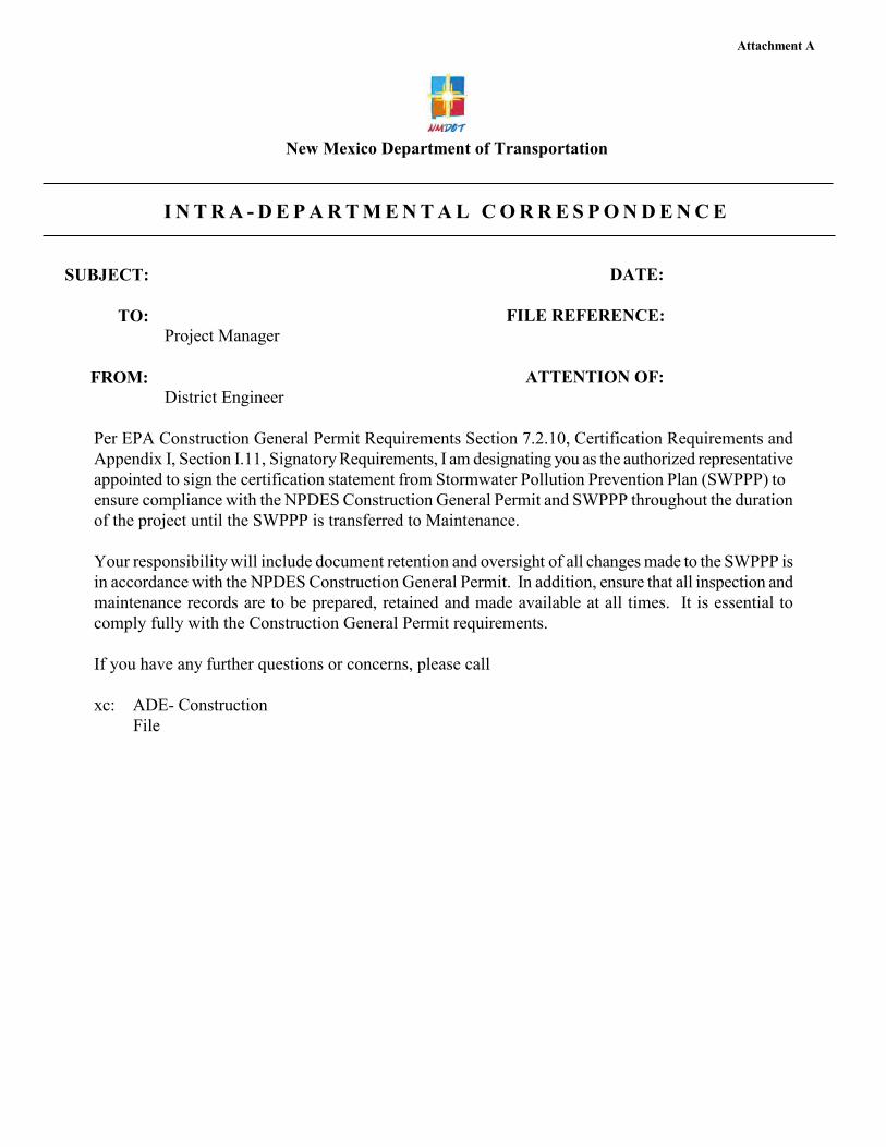
Attachment A
New Mexico Department of Transportation
I N T R A - D E P A R T M E N T A L C O R R E S P O N D E N C E
SUBJECT:
TO:
DATE:
FILE REFERENCE: Project Manager
FROM: ATTENTION OF: District Engineer
Per EPA Construction General Permit Requirements Section 7.2.10, Certification Requirements and Appendix I, Section I.11, Signatory Requirements, I am designating you as the authorized representative appointed to sign the certification statement from Stormwater Pollution Prevention Plan (SWPPP) to ensure compliance with the NPDES Construction General Permit and SWPPP throughout the duration of the project until the SWPPP is transferred to Maintenance.
Your responsibility will include document retention and oversight of all changes made to the SWPPP is in accordance with the NPDES Construction General Permit. In addition, ensure that all inspection and maintenance records are to be prepared, retained and made available at all times. It is essential to comply fully with the Construction General Permit requirements.
If you have any further questions or concerns, please call
xc: ADE- Construction File
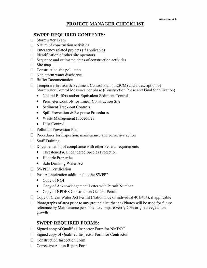
Attachment B
PROJECT MANAGER CHECKLIST
SWPPP REQUIRED CONTENTS: � Stormwater Team � Nature of construction activities � Emergency related projects (if applicable) � Identification of other site operators � Sequence and estimated dates of construction activities � Site map � Construction site pollutants � Non-storm water discharges � Buffer Documentation � Temporary Erosion & Sediment Control Plan (TESCM) and a description of
Stormwater Control Measures per phase (Construction Phase and Final Stabilization) • Natural Buffers and/or Equivalent Sediment Controls• Perimeter Controls for Linear Construction Site• Sediment Track-out Controls• Spill Prevention & Response Procedures• Waste Management Procedures• Dust Control
� Pollution Prevention Plan � Procedures for inspection, maintenance and corrective action � Staff Training � Documentation of compliance with other Federal requirements
• Threatened & Endangered Species Protection• Historic Properties• Safe Drinking Water Act
� SWPPP Certification � Post Authorization additional to the SWPPP
• Copy of NOI• Copy of Acknowledgement Letter with Permit Number• Copy of NPDES Construction General Permit
� Copy of Clean Water Act Permit (Nationwide or individual 401/404), if applicable � Photographs of area prior to any ground disturbance (Photos will be used for future
reference by Maintenance personnel to compare/verify 70% original vegetation growth).
SWPPP REQUIRED FORMS: � Signed copy of Qualified Inspector Form for NMDOT � Signed copy of Qualified Inspector Form for Contractor � Construction Inspection Form � Corrective Action Report Form

Attachment C
Construction Inspection Form
General Information Inspections must conform to Construction General Permit (CGP) issued February 16, 2017. Permit Number(s)
Signature and Certification in accordance with Appendix I, Part 1.11.4 of the permit for Contractor and Subcontractor:
Signature: Date:
Signature: Date:
Signature and Certification in accordance with Appendix I, Part 1.11.4 of the permit for Permittee:
Signature: Date:
Date of Inspection Inspection Personnel Name(s) and Title(s)
Inspection Frequency Standard Once every 7
calendar days Every 14 days & within 24
hours of ¼” rain
Increased Frequency Every 7 days & within 24 hours of ¼” rain (for areas discharging to
sediment or nutrient-impaired waters or to waters designated as Tier 2, Tier 2.5 or Tier 3)
Reduced Frequency Once per month (for stabilized areas and after the first month) Once per month (for arid, semi-arid or drought stricken areas) Once per month (for frozen conditions)
Was this inspection triggered by ¼” storm event?
Yes No
If yes, how was the amount of rain determined?
Rain gauge on site Weather station representative of site and specify weather station source:
Total rainfall amount that triggered the inspection (inches): _____
The permit differentiates between conditions requiring repairs and maintenance, and those requiring corrective action. The permit requires maintenance in order to keep controls in effective operating condition and requires repairs if controls are not operating as intended. Corrective actions are triggered only for specific, more serious conditions including: BMP’s that needs repair or replacement beyond routine maintenance; A required BMP not installed or installed incorrectly; you become aware the BMPs are not effective enough for the discharge to meet applicable water quality standards; one of the prohibited discharges in Part 1.3 has occurred; or EPA requires corrective actions.
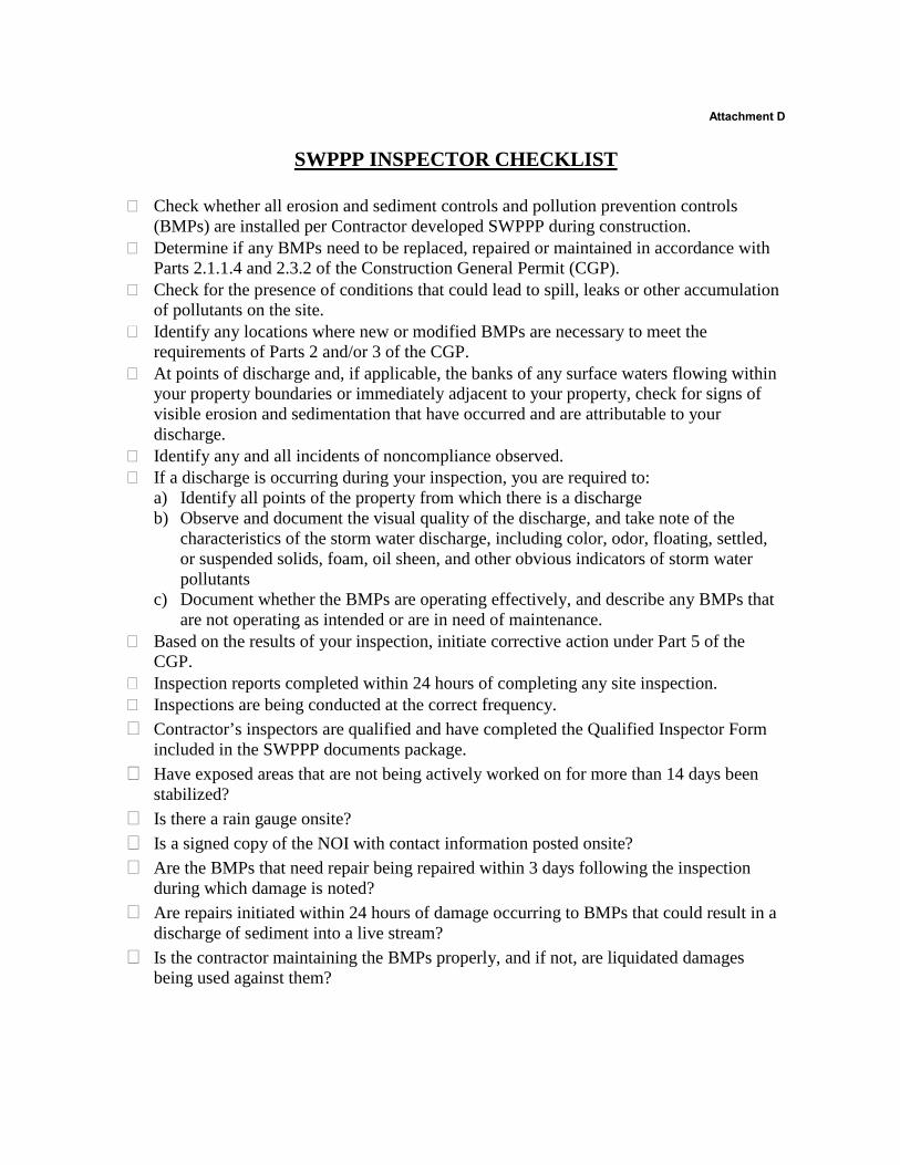
Attachment D
SWPPP INSPECTOR CHECKLIST
� Check whether all erosion and sediment controls and pollution prevention controls (BMPs) are installed per Contractor developed SWPPP during construction.
� Determine if any BMPs need to be replaced, repaired or maintained in accordance with Parts 2.1.1.4 and 2.3.2 of the Construction General Permit (CGP).
� Check for the presence of conditions that could lead to spill, leaks or other accumulation of pollutants on the site.
� Identify any locations where new or modified BMPs are necessary to meet the requirements of Parts 2 and/or 3 of the CGP.
� At points of discharge and, if applicable, the banks of any surface waters flowing within your property boundaries or immediately adjacent to your property, check for signs of visible erosion and sedimentation that have occurred and are attributable to your discharge.
� Identify any and all incidents of noncompliance observed. � If a discharge is occurring during your inspection, you are required to:
a) Identify all points of the property from which there is a dischargeb) Observe and document the visual quality of the discharge, and take note of the
characteristics of the storm water discharge, including color, odor, floating, settled,or suspended solids, foam, oil sheen, and other obvious indicators of storm waterpollutants
c) Document whether the BMPs are operating effectively, and describe any BMPs thatare not operating as intended or are in need of maintenance.
� Based on the results of your inspection, initiate corrective action under Part 5 of the CGP.
� Inspection reports completed within 24 hours of completing any site inspection. � Inspections are being conducted at the correct frequency. � Contractor’s inspectors are qualified and have completed the Qualified Inspector Form
included in the SWPPP documents package. � Have exposed areas that are not being actively worked on for more than 14 days been
stabilized? � Is there a rain gauge onsite? � Is a signed copy of the NOI with contact information posted onsite? � Are the BMPs that need repair being repaired within 3 days following the inspection
during which damage is noted? � Are repairs initiated within 24 hours of damage occurring to BMPs that could result in a
discharge of sediment into a live stream? � Is the contractor maintaining the BMPs properly, and if not, are liquidated damages
being used against them?
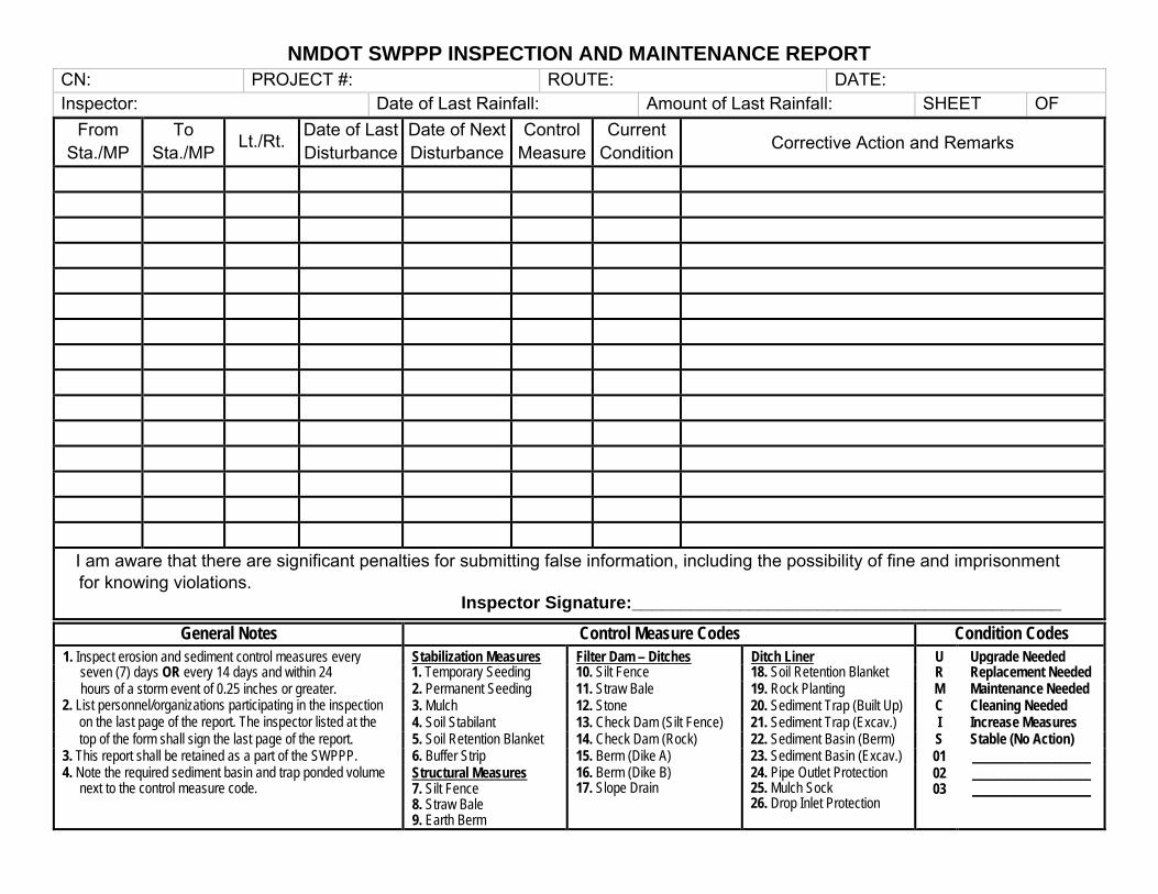
NMDOT SWPPP INSPECTION AND MAINTENANCE REPORT
CN: PROJECT #: ROUTE: DATE: Inspector: Date of Last Rainfall: Amount of Last Rainfall: SHEET OF
From Sta./MP
To Sta./MP Lt./Rt. Date of Last
Disturbance Date of Next Disturbance
Control Measure
Current Condition Corrective Action and Remarks
I am aware that there are significant penalties for submitting false information, including the possibility of fine and imprisonment for knowing violations.
Inspector Signature:____________________________________________
General Notes Control Measure Codes Condition Codes
1. Inspect erosion and sediment control measures every Stabilization Measures Filter Dam – Ditches Ditch Liner U Upgrade Needed seven (7) days OR every 14 days and within 24 1. Temporary Seeding 10. Silt Fence 18. Soil Retention Blanket R Replacement Needed hours of a storm event of 0.25 inches or greater. 2. Permanent Seeding 11. Straw Bale 19. Rock Planting M Maintenance Needed
2. List personnel/organizations participating in the inspection 3. Mulch 12. Stone 20. Sediment Trap (Built Up) C Cleaning Needed on the last page of the report. The inspector listed at the 4. Soil Stabilant 13. Check Dam (Silt Fence) 21. Sediment Trap (Excav.) I Increase Measures top of the form shall sign the last page of the report. 5. Soil Retention Blanket 14. Check Dam (Rock) 22. Sediment Basin (Berm) S Stable (No Action)
3. This report shall be retained as a part of the SWPPP. 6. Buffer Strip 15. Berm (Dike A) 23. Sediment Basin (Excav.) 01 __________________ 4. Note the required sediment basin and trap ponded volume
next to the control measure code. Structural Measures 7. Silt Fence 8. Straw Bale 9. Earth Berm
16. Berm (Dike B) 17. Slope Drain
24. Pipe Outlet Protection 25. Mulch Sock 26. Drop Inlet Protection
02 03
__________________ __________________
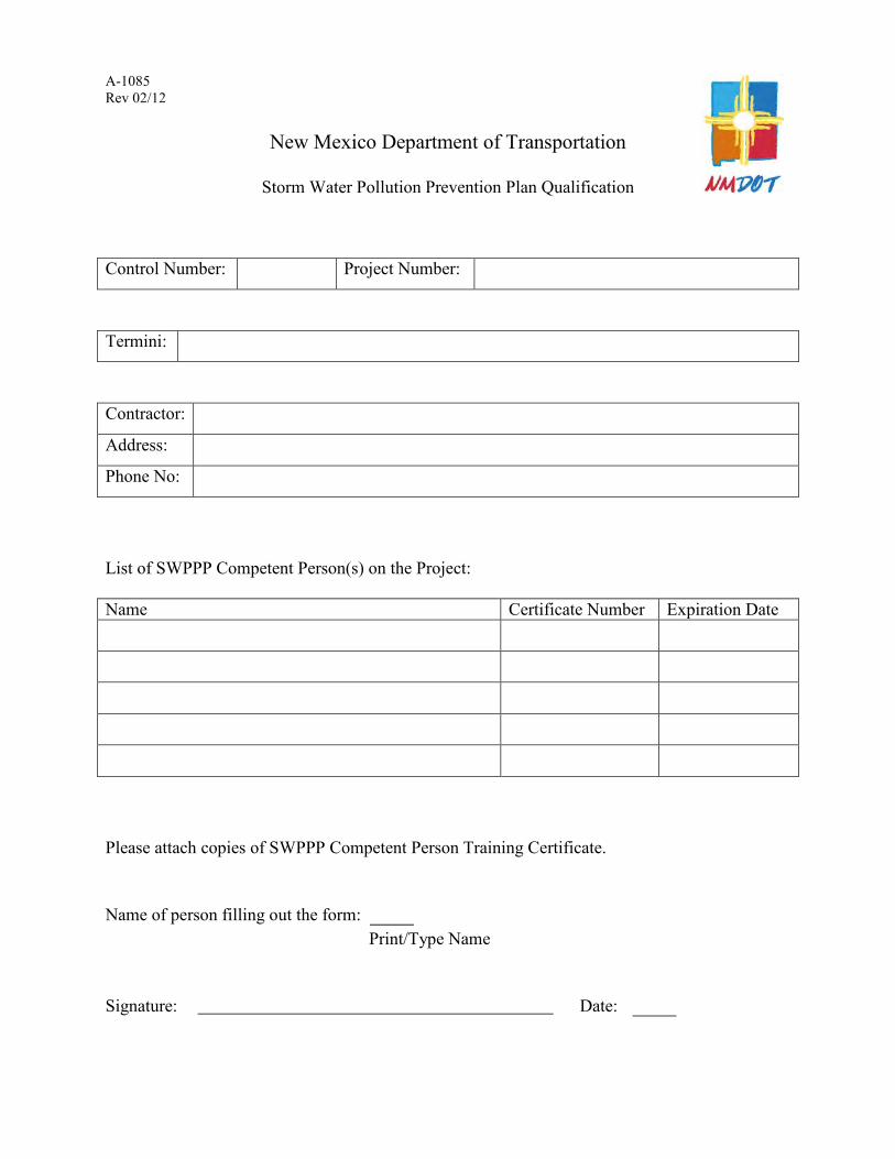
A-1085 Rev 02/12
New Mexico Department of Transportation
Storm Water Pollution Prevention Plan Qualification
Control Number: Project Number: Termini: Contractor: Address: Phone No: List of SWPPP Competent Person(s) on the Project: Name Certificate Number Expiration Date
Please attach copies of SWPPP Competent Person Training Certificate. Name of person filling out the form: Print/Type Name Signature: Date:
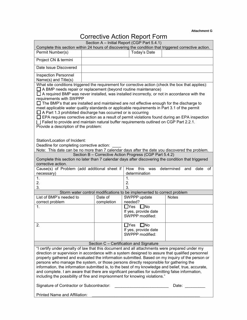
Attachment G
Corrective Action Report Form Section A – Initial Report (CGP Part 5.4.1)
Complete this section within 24 hours of discovering the condition that triggered corrective action. Permit Number(s) Today’s Date
Project CN & termini
Date Issue Discovered
Inspection Personnel Name(s) and Title(s) What site conditions triggered the requirement for corrective action (check the box that applies):
A BMP needs repair or replacement (beyond routine maintenance) A required BMP was never installed, was installed incorrectly, or not in accordance with the
requirements with SWPPP The BMP’s that are installed and maintained are not effective enough for the discharge to
meet applicable water quality standards or applicable requirements in Part 3.1 of the permit A Part 1.3 prohibited discharge has occurred or is occurring EPA requires corrective action as a result of permit violations found during an EPA inspection
Provide a description of the problem:
Station/Location of Incident: Deadline for completing corrective action: ____ Note: This date can be no more than 7 calendar days after the date you discovered the problem.
Section B – Corrective Action Progress (CGP Part 5.4.2) Complete this section no later than 7 calendar days after discovering the condition that triggered corrective action. Cause(s) of Problem (add additional sheet if necessary)
How this was determined and date of determination
1. 2. 3.
1. 2. 3.
Storm water control modifications to be implemented to correct problem List of BMP’s needed to correct problem
Date of completion
SWPPP update needed?
Notes
1. Yes No If yes, provide date SWPPP modified:
2. Yes No If yes, provide date SWPPP modified:
Section C – Certification and Signature “I certify under penalty of law that this document and all attachments were prepared under my direction or supervision in accordance with a system designed to assure that qualified personnel properly gathered and evaluated the information submitted. Based on my inquiry of the person or persons who manage the system, or those persons directly responsible for gathering the information, the information submitted is, to the best of my knowledge and belief, true, accurate, and complete. I am aware that there are significant penalties for submitting false information, including the possibility of fine and imprisonment for knowing violations.”
Signature of Contractor or Subcontractor: ________________________ Date: _________
Printed Name and Affiliation: ________________________________________________
Failed to provide and maintain natural buffer requirements outlined on CGP Part 2.2.1.
Certification and Signature by Permittee “I certify under penalty of law that this document and all attachments were prepared under my direction or supervision in accordance with a system designed to assure that qualified personnel properly gathered and evaluated the information submitted. Based on my inquiry of the person or persons who manage the system, or those persons directly responsible for gathering the information, the information submitted is, to the best of my knowledge and belief, true, accurate, and complete. I am aware that there are significant penalties for submitting false information, including the possibility of fine and imprisonment for knowing violations.”
Signature of Permittee or “Duly Authorized Representative”: _______________________________ Date: __________
Printed Name and Affiliation: ________________________________________________
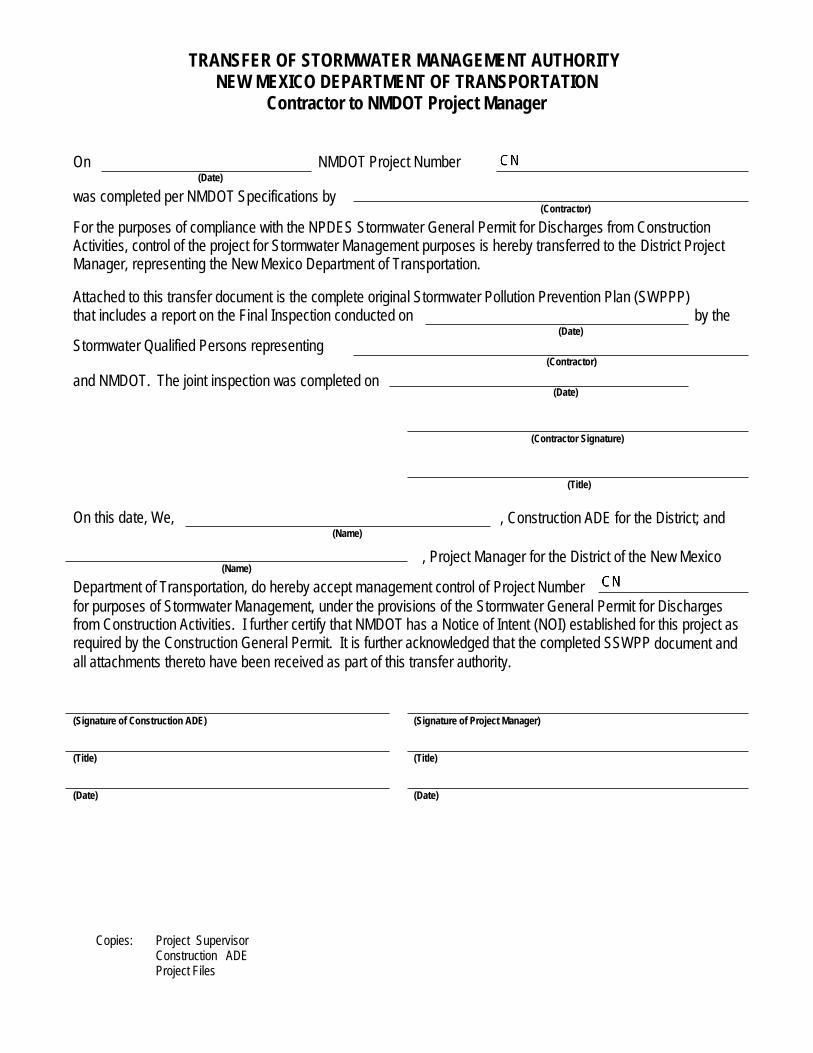
TRANSFER OF STORMWATER MANAGEMENT AUTHORITY NEW MEXICO DEPARTMENT OF TRANSPORTATION
Contractor to NMDOT Project Manager
On NMDOT Project Number
(Date)
was completed per NMDOT Specifications by
(Contractor)
For the purposes of compliance with the NPDES Stormwater General Permit for Discharges from Construction Activities, control of the project for Stormwater Management purposes is hereby transferred to the District Project Manager, representing the New Mexico Department of Transportation.
Attached to this transfer document is the complete original Stormwater Pollution Prevention Plan (SWPPP) that includes a report on the Final Inspection conducted on by the
(Date)
Stormwater Qualified Persons representing
and NMDOT. The joint inspection was completed on
(Contractor)
(Date)
(Contractor Signature)
(Title)
On this date, We,
(Name)
(Name)
, Construction ADE for the District; and
, Project Manager for the District of the New Mexico
Department of Transportation, do hereby accept management control of Project Number
for purposes of Stormwater Management, under the provisions of the Stormwater General Permit for Discharges from Construction Activities. I further certify that NMDOT has a Notice of Intent (NOI) established for this project as required by the Construction General Permit. It is further acknowledged that the completed SSWPP document and all attachments thereto have been received as part of this transfer authority.
(Signature of Construction ADE) (Signature of Project Manager)
(Title) (Title)
(Date) (Date)
Copies: Project Supervisor Construction ADE Project Files

Responsibility for routine maintenance of NPDES installed features is hereby transferred as follows:
Project Number: Control Number:
Project Termini:
TRANSFER OF STORMWATER MANAGEMENT AUTHORITY
NEW MEXICO DEPARTMENT OF TRANSPORTATION
NMDOT Construction to NMDOT Maintenance
From:
Project Manager: Date:
Org. No. (Crew):
To:
Signature
Patrol Supervisor: Date:
Org. No. (Crew):
Signature
The following documentation is included: (check as appropriate) SWPPP (Stormwater Pollution Prevention Plan) with set of small project plan sheets showing location of each feature
Copy of Contractor’s NOI (Notice of Intent) and NOT (Notice of Termination)
Copy of NMDOT Construction Bureau’s NOI (Notice of Intent)
Completed Inspection Reports to Date
Blank Inspection Report Forms pre-filled with locations and descriptions of features converted to mile markers
The above listed documentation shall be maintained in an appropriately labeled binder along with all maintenance inspection reports and shall be readily available for inspection upon request.
Important Note: These NPDES features are to be inspected at a minimum of once per month. Maintenance of the features is to continue until an NOT (Notice of Termination) form is issued by the District Engineer or District Engineer Designee. A copy of the NOT shall be filed with the NPDES file folder.
Copies: Construction ADE
Maintenance ADE
Project Supervisor
Patrol Supervisor
Area Maintenance Superintendent
District Audit Unit
Project Files

TRANSFER OF STORMWATER MANAGEMENT AUTHORITY
NEW MEXICO DEPARTMENT OF TRANSPORTATION
NMDOT Maintenance to NMDOT Management Analyst for NOT Filing
(This form is to be filled out when Patrol Supervisor is ready to file the NOT with achievement of 70% ground cover compared to local undisturbed areas.)
Project Number: Control Number:
Project Termini:
From:
Patrol Supervisor: Date:
Org. No. (Crew):
To:
Signature
Management Analyst Date:
Org. No. (Crew):
Signature
The SWPPP Binder with the following completed documents should be submitted to the Maintenance Management Analyst (check as appropriate)
Completed Inspection Reports to Date
Photos of current condition
Copies: Maintenance ADE
Project Supervisor
Patrol Supervisor
Area Maintenance Superintendent
District Audit Unit
Project Files
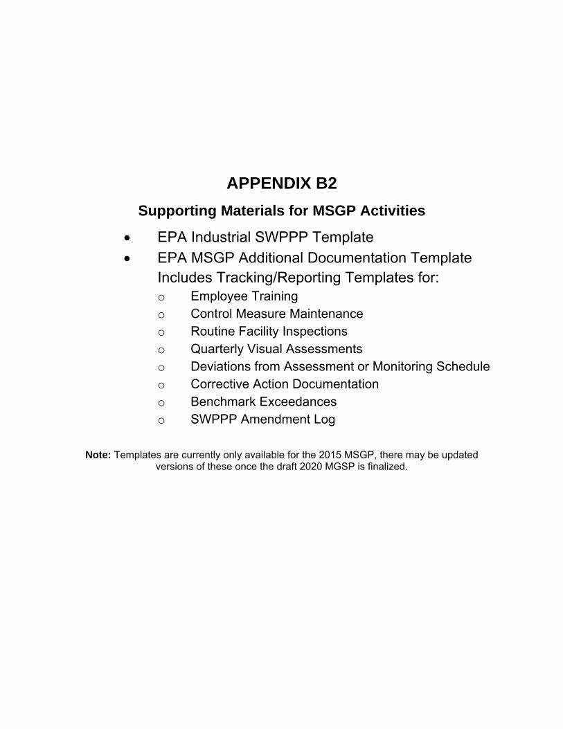
APPENDIX B2
Supporting Materials for MSGP Activities
• EPA Industrial SWPPP Template • EPA MSGP Additional Documentation Template
Includes Tracking/Reporting Templates for: o Employee Training o Control Measure Maintenance o Routine Facility Inspections o Quarterly Visual Assessments o Deviations from Assessment or Monitoring Schedule o Corrective Action Documentation o Benchmark Exceedances o SWPPP Amendment Log
Note: Templates are currently only available for the 2015 MSGP, there may be updated
versions of these once the draft 2020 MGSP is finalized.
Stormwater Pollution Prevention Plan (SWPPP)
INSERT FACILITY NAME and DATE
EPA Industrial SWPPP Template, June 26, 2015 i
Industrial SWPPP Template Introduction
To help you develop a Stormwater Pollution Prevention Plan (SWPPP) that is consistent with the 2015 Multi-Sector General Permit (MSGP), the U.S Environmental Protection Agency (EPA) has created this Industrial SWPPP Template (or, “the Template”). Use of the Template will help ensure that your SWPPP addresses all the necessary elements required in Part 5 of the 2015 MSGP. Part 2 of the 2015 MSGP includes requirements (or effluent limits) that tell what you must physically do on-site to control pollutants in your stormwater discharges and that drive some of what is documented in your SWPPP.
Before completing the Template, make sure you read and understand the requirements in the 2015 MSGP. A copy of the MSGP is available at www.epa.gov/npdes/stormwater/msgp.
Using the Industrial SWPPP Template
Tips for completing the Template:
• This Template is designed for use by all facilities eligible for coverage under the 2015 MSGP. The Template is NOT tailored to your individual industrial sector. Depending upon your industrial sector (see Appendix D of the 2015 MSGP) and where your facility is located (see Appendix C of the 2015 MSGP), you may need to address additional SWPPP requirements outlined in Part 8 (Sector Specific Requirements) and/or Part 9 (State/Tribal Specific Requirements) of the permit, respectively.
• Complete a SWPPP before submitting your Notice of Intent (NOI) for permit coverage.
• Each section includes “instructions” and space for your facility’s specific information. You should read the instructions for each section before you complete that section.
• The Template was developed in Microsoft Word so that you can easily add tables and additional text. Some sections may require only a brief description while others may require several pages of explanation.
• To make it easier to complete, the Template generally uses blue text where the operator is expected to enter information.
EPA notes that while EPA has made every effort to ensure the accuracy of all instructions and guidance contained in the Template, the actual obligations of regulated industrial facilities are determined by the relevant provisions of the permit, not by the Template. In the event of a conflict between the Template and any corresponding provision of the MSGP, the permit controls. EPA welcomes comments on the Template at any time and will consider those comments in any future revision of this document.

Stormwater Pollution Prevention Plan (SWPPP)
INSERT FACILITY NAME and DATE
EPA Industrial SWPPP Template, June 26, 2015 i
Page Intentionally Blank
Stormwater Pollution Prevention Plan (SWPPP)
INSERT FACILITY NAME and DATE
EPA Industrial SWPPP Template, June 26, 2015 ii
Stormwater Pollution Prevention Plan
for:
Insert Facility Name
Insert Facility Address
Insert City, State, Zip Code
Insert Facility Telephone Number (if applicable)
SWPPP Contact(s):
Insert Facility Operator
Insert Name
Insert Address
Insert City, State, Zip Code
Insert Telephone Number
Insert Fax/Email
SWPPP Preparation Date:
__ __/ __ __ / __ __ __ __

Stormwater Pollution Prevention Plan (SWPPP)
INSERT FACILITY NAME and DATE
EPA Industrial SWPPP Template, June 26, 2015 iii
Page Intentionally Blank
Stormwater Pollution Prevention Plan (SWPPP)
INSERT FACILITY NAME and DATE
EPA Industrial SWPPP Template, June 26, 2015 iv
Contents
Table of Contents SECTION 1: FACILITY DESCRIPTION AND CONTACT INFORMATION. .................................................. 6 1.1 Facility Information. .........................................................................................................6 1.2 Contact Information/Responsible Parties. ........................................................................8 1.3 Stormwater Pollution Prevention Team. ...........................................................................9 1.4 Site Description. ................................................................................................................9 1.5 General Location Map. ...................................................................................................10
1.6 Site Map. .........................................................................................................................11
SECTION 2: POTENTIAL POLLUTANT SOURCES. ................................................................................. 11 2.1 Potential Pollutants Associated with Industrial Activity. ...............................................12 2.2 Spills and Leaks. .............................................................................................................12 2.3 Unauthorized Non-stormwater Discharges Documentation. ..........................................13 2.4 Salt Storage. ....................................................................................................................14
2.5 Sampling Data Summary. ...............................................................................................14 SECTION 3: STORMWATER CONTROL MEASURES. ............................................................................. 14 3.1 Non-numeric Technology-based Effluent Limits (BPT/BAT/BCT) ..............................14
3.1.1 Minimize Exposure. ................................................................................................ 15 3.1.2 Good Housekeeping. ............................................................................................... 15
3.1.3 Maintenance. ........................................................................................................... 15 3.1.4 Spill Prevention and Response................................................................................ 16 3.1.5 Erosion and Sediment Controls. ............................................................................. 16
3.1.6 Management of Runoff. .......................................................................................... 17
3.1.7 Salt Storage Piles or Piles Containing Salt. ............................................................ 17 3.1.8 Dust Generation and Vehicle Tracking of Industrial Materials. ............................. 17
3.2 Sector-Specific Non-Numeric Effluent Limits. ..............................................................17
3.3 Numeric Effluent Limitations Based on Effluent Limitations Guidelines. ....................17 3.4 Water Quality-based Effluent Limitations and Water Quality Standards. .....................18
SECTION 4: SCHEDULES AND PROCEDURES. ...................................................................................... 19 4.1 Good Housekeeping. .......................................................................................................19 4.2 Maintenance. ...................................................................................................................19 4.3 Spill Prevention and Response Procedures. ....................................................................19 4.4 Erosion and Sediment Control. .......................................................................................19
4.5 Employee Training..........................................................................................................20 4.6 Inspections and Assessments. .........................................................................................20
4.6.1 Routine Facility Inspections. .................................................................................. 21 4.6.2 Quarterly Visual Assessment of Stormwater Discharges. ...................................... 22 4.6.3 Exception to Routine Facility Inspections and Quarterly Visual Assessments for
Inactive and Unstaffed Sites. .................................................................................. 23 4.7 Monitoring. .....................................................................................................................24
SECTION 5: DOCUMENTATION TO SUPPORT ELIGIBILITY CONSIDERATIONS UNDER OTHER FEDERAL LAWS. ....................................................................................................................................... 26 5.1 Documentation Regarding Endangered Species. ............................................................26
Stormwater Pollution Prevention Plan (SWPPP)
INSERT FACILITY NAME and DATE
EPA Industrial SWPPP Template, June 26, 2015 v
5.2 Documentation Regarding Historic Properties. ..............................................................26
SECTION 6: CORRECTIVE ACTIONS. ...................................................................................................... 26 SECTION 7: SWPPP CERTIFICATION. ..................................................................................................... 27 SECTION 8: SWPPP MODIFICATIONS. .................................................................................................... 28 SWPPP ATTACHMENTS ........................................................................................................................... 28
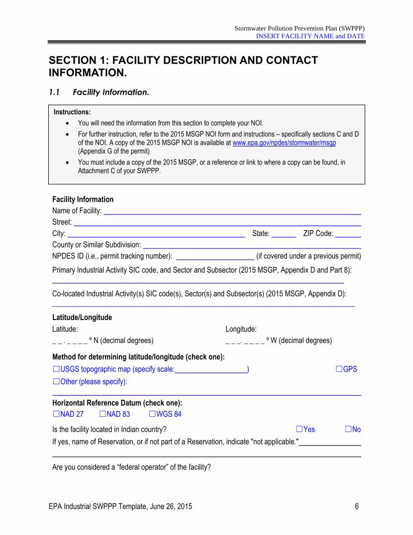
Stormwater Pollution Prevention Plan (SWPPP)
INSERT FACILITY NAME and DATE
EPA Industrial SWPPP Template, June 26, 2015 6
SECTION 1: FACILITY DESCRIPTION AND CONTACT INFORMATION.
1.1 Facility Information.
Facility Information
Name of Facility:
Street:
City: State: ZIP Code:
County or Similar Subdivision:
NPDES ID (i.e., permit tracking number): (if covered under a previous permit)
Primary Industrial Activity SIC code, and Sector and Subsector (2015 MSGP, Appendix D and Part 8):
Co-located Industrial Activity(s) SIC code(s), Sector(s) and Subsector(s) (2015 MSGP, Appendix D): __________________________________________________________________________________
Latitude/Longitude
Latitude: Longitude:
_ _ . _ _ _ _ º N (decimal degrees) _ _ _. _ _ _ _ º W (decimal degrees)
Method for determining latitude/longitude (check one):
☐USGS topographic map (specify scale: ) ☐GPS
☐Other (please specify):
Horizontal Reference Datum (check one):
☐NAD 27 ☐NAD 83 ☐WGS 84
Is the facility located in Indian country? ☐Yes ☐No
If yes, name of Reservation, or if not part of a Reservation, indicate "not applicable."
Are you considered a “federal operator” of the facility?
Instructions:
• You will need the information from this section to complete your NOI.
• For further instruction, refer to the 2015 MSGP NOI form and instructions – specifically sections C and D of the NOI. A copy of the 2015 MSGP NOI is available at www.epa.gov/npdes/stormwater/msgp (Appendix G of the permit)
• You must include a copy of the 2015 MSGP, or a reference or link to where a copy can be found, in Attachment C of your SWPPP.
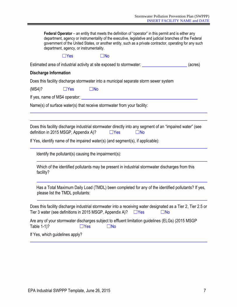
Stormwater Pollution Prevention Plan (SWPPP)
INSERT FACILITY NAME and DATE
EPA Industrial SWPPP Template, June 26, 2015 7
Federal Operator – an entity that meets the definition of “operator” in this permit and is either any department, agency or instrumentality of the executive, legislative and judicial branches of the Federal government of the United States, or another entity, such as a private contractor, operating for any such department, agency, or instrumentality.
☐Yes ☐No
Estimated area of industrial activity at site exposed to stormwater: (acres)
Discharge Information
Does this facility discharge stormwater into a municipal separate storm sewer system
(MS4)? ☐Yes ☐No
If yes, name of MS4 operator:
Name(s) of surface water(s) that receive stormwater from your facility:
Does this facility discharge industrial stormwater directly into any segment of an “impaired water” (see
definition in 2015 MSGP, Appendix A)? ☐Yes ☐No
If Yes, identify name of the impaired water(s) (and segment(s), if applicable):
Identify the pollutant(s) causing the impairment(s):
Which of the identified pollutants may be present in industrial stormwater discharges from this facility?
Has a Total Maximum Daily Load (TMDL) been completed for any of the identified pollutants? If yes, please list the TMDL pollutants:
Does this facility discharge industrial stormwater into a receiving water designated as a Tier 2, Tier 2.5 or
Tier 3 water (see definitions in 2015 MSGP, Appendix A)? ☐Yes ☐No
Are any of your stormwater discharges subject to effluent limitation guidelines (ELGs) (2015 MSGP
Table 1-1)? ☐Yes ☐No
If Yes, which guidelines apply?
Stormwater Pollution Prevention Plan (SWPPP)
INSERT FACILITY NAME and DATE
EPA Industrial SWPPP Template, June 26, 2015 8
1.2 Contact Information/Responsible Parties.
Facility Operator(s):
Name: Insert Name
Address: Insert Address
City, State, Zip Code: Insert City, State, Zip Code
Telephone Number: Insert Telephone Number
Email address: Insert email address
Fax number: Insert fax number (optional)
(repeat for multiple operators by copying and pasting the above rows) Facility Owner(s):
Name: Insert Name
Address: Insert Address
City, State, Zip Code: Insert City, State, Zip Code
Telephone Number: Insert Telephone Number
Email address: Insert email address
Fax number: Insert fax number (optional)
(repeat for multiple operators by copying and pasting the above rows) SWPPP Contact(s):
SWPPP Contact Name (Primary): Insert SWPPP Contact Name, Primary
Telephone number: Insert Telephone Number
Email address: Insert email address
Fax number: Insert fax number (optional)
SWPPP Contact Name (Backup): Insert SWPPP Contact Name, Backup
Telephone number: Insert Telephone Number
Email address: Insert email address
Fax number: Insert fax number (optional)
Instructions:
• List the facility operator(s), facility owner and SWPPP contact(s). Indicate respective responsibilities, where appropriate.
• You will need the information from this section of the SWPPP Template for your NOI.
• Refer to Section B of the NOI instructions (available in Appendix G of the 2015 MSGP).
Stormwater Pollution Prevention Plan (SWPPP)
INSERT FACILITY NAME and DATE
EPA Industrial SWPPP Template, June 26, 2015 9
1.3 Stormwater Pollution Prevention Team.
Staff Names Individual Responsibilities
Insert name and/or title of SWPPP team member
Insert explanation of that staff person’s responsibilities relating to compliance with the permit
[Repeat as necessary] [Repeat as necessary]
[Repeat as necessary] [Repeat as necessary]
[Repeat as necessary] [Repeat as necessary]
[Repeat as necessary] [Repeat as necessary]
[Repeat as necessary] [Repeat as necessary]
1.4 Site Description.
LIST AND DESCRIBE FACILITY INDUSTRIAL ACTIVITIES HERE.
Instructions (see 2015 MSGP Part 5.2.1):
The stormwater pollution prevention team is responsible for overseeing development of and any modifications to the SWPPP, implementing and maintaining control measures/BMPs, and taking corrective actions when required. Each member of the stormwater pollution prevention team must have ready access to the 2015 MSGP, the most updated copy of the facility SWPPP, and other relevant documents.
• Identify the staff members (by name and/or title) that comprise the facility’s stormwater pollution prevention team as well as their individual responsibilities.
• EPA recommends, but does not require, the stormwater pollution prevention team include at least one individual from each shift to ensure that there is always a stormwater pollution prevention team member on-site.
Instructions (see 2015 MSGP Part 5.2.2):
Provide a general description of the “industrial activities” conducted at your facility. For the MSGP industrial activities consist of: manufacturing and processing; material handling activities including storage, loading and unloading, transportation, or conveyance of any raw material, intermediate product, final product, by-product or waste product; and vehicle and equipment fueling, maintenance and cleaning. Industrial activities may occur at any of the following areas (list not exhaustive): industrial plant yards; immediate access roads and rail lines used or traveled by carriers of raw materials, manufactured products, waste material, or by-products used or created by the facility; material handling sites; refuse sites; sites used for the application or disposal of process waste waters sites used for the storage and maintenance of material handling equipment; sites used for residual treatment, storage, or disposal; shipping and receiving areas; manufacturing buildings; storage areas (including tank farms) for raw materials, and intermediate and final products; and areas where industrial activity has taken place in the past and significant materials remain and are exposed to stormwater. EPA recommends that you differentiate activities that occur indoors from those that occur outdoors and could be exposed to stormwater, or under cover but that could be exposed to run-on. Don’t overlook processes that are vented and may contribute pollutants to the roof.
Stormwater Pollution Prevention Plan (SWPPP)
INSERT FACILITY NAME and DATE
EPA Industrial SWPPP Template, June 26, 2015 10
1.5 General Location Map.
The general location map for this facility can be found in Attachment A.
Instructions (see 2015 MSGP Part 5.2.2):
Provide a general location map (e.g., U.S. Geological Survey (USGS) quadrangle map or aerial image from the internet) with enough detail to identify the location of your facility and all receiving waters for your stormwater discharges (include as Attachment A of this SWPPP Template).
Stormwater Pollution Prevention Plan (SWPPP)
INSERT FACILITY NAME and DATE
EPA Industrial SWPPP Template, June 26, 2015 11
1.6 Site Map.
The site map for this facility can be found in Attachment B.
SECTION 2: POTENTIAL POLLUTANT SOURCES. Section 2 will describe all areas at your facility where industrial materials or activities are exposed to stormwater or from which allowable non-stormwater discharges originate. Industrial materials or activities include, but are not limited to: material handling equipment or activities; industrial machinery; raw materials; industrial production and processes; and intermediate products, by-products, final products, and waste
Instructions (see 2015 MSGP Part 5.2.2):
Prepare a site map showing the following information. The site map will be included as Attachment B of the finished SWPPP.
• Boundaries of the property and the size of the property in acres;
• Location and extent of significant structures and impervious surfaces;
• Directions of stormwater flow (use arrows);
• Locations of all stormwater control measures;
• Locations of all receiving waters, including wetlands, in the immediate vicinity of your facility. Indicate which waterbodies are listed as impaired and which are identified by your state, tribe or EPA as Tier 2, Tier 2.5, or Tier 3 waters;
• Locations of all stormwater conveyances including ditches, pipes and swales;
• Locations of potential pollutant sources identified under Part 5.2.3.2;
• Locations where significant spills or leaks identified under Part 5.2.3.3 have occurred;
• Locations of all stormwater monitoring points;
• Locations of stormwater inlets and discharge points, with a unique identification code for each discharge point (e.g., Discharge points001, 002), indicating if you are treating one or more discharge points as “substantially identical” under Parts 3.2.3, 5.2.5.3, and 6.1.1, and an approximate outline of the areas draining to each discharge point;
• If applicable, MS4s and where your stormwater discharges to them;
• Areas of designated critical habitat for endangered or threatened species, if applicable.
• Locations of the following activities where such activities are exposed to precipitation:
o fueling stations;
o vehicle and equipment maintenance and/or cleaning areas;
o loading/unloading areas;
o locations used for the treatment, storage or disposal of wastes;
o liquid storage tanks;
o processing and storage areas;
o immediate access roads and rail lines used or traveled by carriers of raw materials, manufactured products, waste material, or by-products used or created by the facility;
o transfer areas for substances in bulk;
o machinery; and
o locations and sources of run-on to your site from adjacent property that contains significant quantities of pollutants.
Stormwater Pollution Prevention Plan (SWPPP)
INSERT FACILITY NAME and DATE
EPA Industrial SWPPP Template, June 26, 2015 12
products. Material handling activities include, but are not limited to: the storage, loading and unloading, transportation, disposal or conveyance of any raw material, intermediate product, final product or waste product. For structures located in areas of industrial activity, you must be aware that the structures themselves are potential sources of pollutants. This could occur, for example, when metals such as aluminum or copper are leached from the structures as a result of acid rain.
For each area identified, the SWPPP must include industrial activities, potential pollutants, spills and leaks, unauthorized non-stormwater discharges, salt storage, stormwater sampling data and descriptions of control measures.
2.1 Potential Pollutants Associated with Industrial Activity.
Industrial Activity Associated Pollutants
Insert specific industrial activity Insert names of pollutants or pollutant constituents that could be associated with this activity and released in stormwater
[Repeat as necessary] [Repeat as necessary]
[Repeat as necessary] [Repeat as necessary]
[Repeat as necessary] [Repeat as necessary]
[Repeat as necessary] [Repeat as necessary]
[Repeat as necessary] [Repeat as necessary]
[Repeat as necessary] [Repeat as necessary]
2.2 Spills and Leaks.
Areas of Site Where Potential Spills/Leaks Could Occur
Instructions (see 2015 MSGP Parts 5.2.3.1 and 5.2.3.2):
For the industrial activities identified in section 1.4 above, list the potential pollutants or pollutant constituents (e.g., motor oil, fuel, battery acid, and cleaning solvents).
In your list of pollutants associated with your industrial activities, include all significant materials that have been handled, treated, stored, or disposed, and that have been exposed to stormwater in the three years prior to the date you prepare your SWPPP.
Instructions (See 2015 MSGP Part 5.2.3.3):
Include the following in this section:
• Potential spills and leaks: A description of where potential spills and leaks could occur at your site that could contribute pollutants to your stormwater discharge, and specify which discharge points are likely to be affected by such spills and leaks.
• Past spills and leaks: A description of significant spills and leaks in the past three years of oil or toxic or hazardous substances that actually occurred at exposed areas, or that drained to a stormwater conveyance.
Note: Significant spills and leaks include, but are not limited to, releases of oil or hazardous substances in excess of quantities that are reportable under CWA Section 311 (see 40 CFR 110.6 and 40 CFR 117.21) or Section 102 of the Comprehensive Environmental Response, Compensation and Liability Act (CERCLA), 42 USC §9602.
Stormwater Pollution Prevention Plan (SWPPP)
INSERT FACILITY NAME and DATE
EPA Industrial SWPPP Template, June 26, 2015 13
Location Discharge Points
Insert description of area where spill/leak could occur Specify which discharge point(s) would be affected
[Repeat as necessary] [Repeat as necessary]
[Repeat as necessary] [Repeat as necessary]
[Repeat as necessary] [Repeat as necessary]
Description of Past Spills/Leaks
Date Description Discharge Points
Insert date of spill/leak
Insert description of spill/leak (where it occurred, what happened, types of pollutants, extent of damage)
Specify which discharge point(s) were affected
[Repeat as necessary]
[Repeat as necessary] [Repeat as necessary]
[Repeat as necessary]
[Repeat as necessary] [Repeat as necessary]
[Repeat as necessary]
[Repeat as necessary] [Repeat as necessary]
2.3 Unauthorized Non-stormwater Discharges Documentation.
Description of this facility’s unauthorized non-stormwater discharge evaluation:
• Date of evaluation: Insert the date(s) of your evaluation.
• Description of the evaluation criteria used: Describe the method used to conduct the evaluation and determine which non-stormwater discharges are authorized or unauthorized.
• List of the drainage points that were directly observed during the evaluation: Insert drainage points observed.
• Action(s) taken, such as a list of control measures used to eliminate unauthorized discharge(s), or documentation that a separate NPDES permit was obtained. For example, a floor drain was sealed, a sink drain was re-routed to the sanitary sewer or an NPDES permit application was submitted for an unauthorized cooling water discharge: Describe actions taken to eliminate unauthorized non-stormwater discharges and the corresponding drainage point affected.
Instructions (see 2015 MSGP Part 5.2.3.4):
Part 1.1.3 of the 2015 MSGP identifies allowable non-stormwater discharges. The questions below require you to provide documentation of the following:
• Evaluation for the presence of unauthorized non-stormwater discharges at your site; and
• Elimination of any unauthorized non-stormwater discharges.
Stormwater Pollution Prevention Plan (SWPPP)
INSERT FACILITY NAME and DATE
EPA Industrial SWPPP Template, June 26, 2015 14
2.4 Salt Storage.
INSERT DESCRIPTION OF THE LOCATION OF ANY STORAGE PILES CONTAINING SALT.
2.5 Sampling Data Summary.
INSERT SUMMARY OF STORMWATER SAMPLING DATA COLLECTED FOR THE PAST PERMIT, AND/OR ATTACH DISCHARGE MONITORING REPORTS OR LABORATORY RESULTS.
SECTION 3: STORMWATER CONTROL MEASURES.
3.1 Non-numeric Technology-based Effluent Limits (BPT/BAT/BCT)
You must comply with the following non-numeric effluent limits (except where otherwise specified in Part 8) as well as any sector-specific non-numeric effluent limits in Part 8.
Instructions (see 2015 MSGP Part 5.2.3.5):
Document the location of any storage piles containing salt used for deicing or other commercial or industrial purposes.
Note: you will be asked additional questions concerning salt storage in Section 3.1.7 of this SWPPP template, below.
Instructions (See 2015 MSGP Part 5.2.3.6):
Summarize all stormwater sampling data collected from your permitted discharge points during the previous permit term. Include a narrative description that summarizes the collected data to support identification of potential pollution sources. Note that data tables and/or figures may be used to aid the summary.
Instructions (See 2015 MSGP Parts 2.1.2, Part 8, and 5.2.4):
In Sections 3.1 - 3.11 of this SWPPP template, you are asked to describe the stormwater control measures that you have installed at your site to meet each of the permit’s
• Non-numeric technology-based effluent limits in Part 2.1.2;
• Applicable numeric effluent limitations guidelines-based limits in Part 2.1.3 and Part 8;
• Water quality-based effluent limits in Part 2.2;
• Any additional measures that formed the basis of eligibility regarding threatened and endangered species, historic properties, and/or federal CERCLA site requirements in Part 2.3; and
• Applicable effluent limits in Parts 8 and 9.
In addition to your control measure descriptions, include explanations of how the controls fulfill the following
requirements (see 2015 MSGP Part 2.1.1):
• The selection and design considerations; and
• How they address the pollutant sources identified in section 2.1 of the Template.
Stormwater Pollution Prevention Plan (SWPPP)
INSERT FACILITY NAME and DATE
EPA Industrial SWPPP Template, June 26, 2015 15
3.1.1 Minimize Exposure.
INSERT DESCRIPTION OF CONTROL MEASURES USED TO MINIMIZE EXPOSURE.
3.1.2 Good Housekeeping.
INSERT DESCRIPTION OF GOOD HOUSEKEEPING PRACTICES.
3.1.3 Maintenance.
INSERT DESCRIPTION OF MAINTENANCE PROCEDURES.
Instructions (see 2015 MSGP Part 2.1.2.1):
Describe any structural controls or practices used to minimize the exposure of industrial activities to rain, snow, snowmelt and runoff. Describe where the controls or practices are being implemented at your site.
Instructions (see 2015 MSGP Parts 2.1.2.2 and 5.2.5.1):
Describe any practices you are implementing to keep exposed areas of your site clean. Describe where each
practice is being implemented at your site. Include here your schedule for: (1) regular pickup and disposal of
waste materials, and (2) routine inspections for leaks and of the condition of drums, tanks and containers. Note:
There are specific requirements for facilities that handle pre-production plastic.
Instructions (see 2015 MSGP Parts 2.1.2.3 and 5.2.5.1):
Describe procedures (1) to maintain industrial equipment so that spills/leaks are avoided and (2) to keep control measures in effective operating condition. Include the schedule you will follow for such maintenance activities. Describe where each applicable procedure is being implemented at the site.
Stormwater Pollution Prevention Plan (SWPPP)
INSERT FACILITY NAME and DATE
EPA Industrial SWPPP Template, June 26, 2015 16
3.1.4 Spill Prevention and Response.
INSERT DESCRIPTION OF SPILL PREVENTION AND RESPONSE MEASURES.
3.1.5 Erosion and Sediment Controls.
INSERT DESCRIPTION OF EROSION AND SEDIMENT CONTROLS.
Instructions (see 2015 MSGP Parts 2.1.2.4 and 5.2.5.1):
Describe any structural controls or procedures used to minimize the potential for leaks, spills and other releases. You must implement the following at a minimum:
• Plainly label containers (e.g., “Used Oil,” “Spent Solvents,” “Fertilizers and Pesticides”) that could be susceptible to spillage or leakage to encourage proper handling and facilitate rapid response if spills or leaks occur;*
• Implement procedures for material storage and handling, including the use of secondary containment and barriers between material storage and traffic areas, or a similarly effective means designed to prevent the discharge of pollutants from these areas;
• Develop training and train all staff on procedures to quickly stop, contain and clean up leaks, spills, and other releases. As appropriate, execute such procedures as soon as possible;
• Keep spill kits on-site, located near areas where spills may occur or where a rapid response can be made; and
• Notify appropriate facility personnel when a leak, spill or other release occurs.
Describe where each control is to be located or where applicable procedures will be implemented.
Note: some facilities may be required to develop a Spill Prevention Control and Countermeasure (SPCC) plan under a separate regulatory program (40 CFR 112). If you are required to develop an SPCC plan, or you already have one, you should include references to the relevant requirements from your plan.
EPA recommends you include:
Where a leak, spill or other release containing a hazardous substance or oil in an amount equal to or in excess of
a reportable quantity established under either 40 CFR Part 110, 40 CFR Part 117, or 40 CFR Part 302 occurs
during a 24-hour period, you must notify the National Response Center (NRC) at (800) 424-8802 or, in the
Washington, DC, metropolitan area, call (202) 267-2675 in accordance with the requirements of 40 CFR Part
110, 40 CFR Part 117, and 40 CFR Part 302 as soon as you have knowledge of the discharge. State or local
requirements may necessitate reporting spills or discharges to local emergency response, public health, or
drinking water supply agencies. Contact information must be in locations that are readily accessible and
available.
Instructions (see 2015 MSGP Parts 2.1.2.5 and 5.2.5.1):
Describe activities and processes for stabilizing exposed soils to minimize erosion. Describe flow velocity dissipation devices placed at all discharge locations and all structural and non-structural control measures to prevent the discharge of sediment. If applicable, describe the type and purpose of any polymers and/or chemical treatments used to control erosion and the location at your site where each control is implemented.
Stormwater Pollution Prevention Plan (SWPPP)
INSERT FACILITY NAME and DATE
EPA Industrial SWPPP Template, June 26, 2015 17
3.1.6 Management of Runoff.
INSERT DESCRIPTION OF HOW RUNOFF FROM YOUR SITE WILL BE MANAGED.
3.1.7 Salt Storage Piles or Piles Containing Salt.
INSERT DESCRIPTION OF HOW SALT STORAGE PILES OR PILES CONTAINING SALT WILL BE MANAGED.
3.1.8 Dust Generation and Vehicle Tracking of Industrial Materials.
INSERT DESCRIPTION OF CONTROL MEASURES TO MINIMIZE DUST GENERATION AND VEHICLE TRACKING.
3.2 Sector-Specific Non-Numeric Effluent Limits.
INSERT DESCRIPTION OF CONTROL MEASURES THAT WILL BE USED TO COMPLY WITH SECTOR-SPECIFIC REQUREMENTS.
3.3 Numeric Effluent Limitations Based on Effluent Limitations Guidelines.
INSERT DESCRIPTION OF CONTROL MEASURES TO MEET ELG(S).
Instructions (See 2015 MSGP Part 2.1.2.6):
Describe controls used at your site to divert, infiltrate, reuse, contain or otherwise reduce stormwater runoff. Describe the location at your site where each control is implemented.
Instructions (see 2015 MSGP Part 2.1.2.7):
If applicable, describe structures at your site that either cover or enclose salt storage piles or piles containing salt, and any controls that minimize or prevent the discharge of stormwater from such piles. Also, describe any controls or procedures used to minimize exposure resulting from adding to or removing materials from the pile. Describe the location at your site where each control and/or procedure is implemented.
Instructions (see 2015 MSGP Part 2.1.2.10):
Describe controls and procedures that will be used at your site to minimize generation of dust and off-site tracking of raw, final or waste materials in order to minimize pollutant discharges.
Instructions (see 2015 MSGP Part 8):
Describe any controls or procedures that will be used at your site to comply with any sector-specific requirements that apply to you in Part 8 of the 2015 MSGP. Describe the location at your site where each control and/or procedure will be implemented.
Note: Sector-specific effluent limits apply to Sectors A, E, F, G, H, I, J, L, M, N, O, P, Q, R, S, T, U, V, X, Y, Z and AA.
Instructions (see 2015 MSGP Part 2.1.3):
If you are in an industrial category subject to one of the effluent limitations guidelines identified in the table below (Table 2-1 of the 2015 MSGP), describe controls or procedures that will be implemented at your site to meet these effluent limitations guidelines.
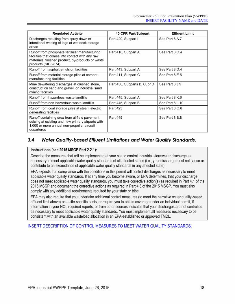
Stormwater Pollution Prevention Plan (SWPPP)
INSERT FACILITY NAME and DATE
EPA Industrial SWPPP Template, June 26, 2015 18
Regulated Activity 40 CFR Part/Subpart Effluent Limit
Discharges resulting from spray down or intentional wetting of logs at wet deck storage areas
Part 429, Subpart I See Part 8.A.7
Runoff from phosphate fertilizer manufacturing facilities that comes into contact with any raw materials, finished product, by-products or waste products (SIC 2874)
Part 418, Subpart A See Part 8.C.4
Runoff from asphalt emulsion facilities Part 443, Subpart A See Part 8.D.4 Runoff from material storage piles at cement manufacturing facilities
Part 411, Subpart C See Part 8.E.5
Mine dewatering discharges at crushed stone, construction sand and gravel, or industrial sand mining facilities
Part 436, Subparts B, C, or D See Part 8.J.9
Runoff from hazardous waste landfills Part 445, Subpart A See Part 8.K.6 Runoff from non-hazardous waste landfills Part 445, Subpart B See Part 8.L.10 Runoff from coal storage piles at steam electric generating facilities
Part 423 See Part 8.O.8
Runoff containing urea from airfield pavement deicing at existing and new primary airports with 1,000 or more annual non-propeller aircraft departures
Part 449 See Part 8.S.8
3.4 Water Quality-based Effluent Limitations and Water Quality Standards.
INSERT DESCRIPTION OF CONTROL MEASURES TO MEET WATER QUALITY STANDARDS.
Instructions (see 2015 MSGP Part 2.2.1):
Describe the measures that will be implemented at your site to control industrial stormwater discharge as necessary to meet applicable water quality standards of all affected states (i.e., your discharge must not cause or contribute to an exceedance of applicable water quality standards in any affected state).
EPA expects that compliance with the conditions in this permit will control discharges as necessary to meet applicable water quality standards. If at any time you become aware, or EPA determines, that your discharge does not meet applicable water quality standards, you must take corrective action(s) as required in Part 4.1 of the 2015 MSGP and document the corrective actions as required in Part 4.3 of the 2015 MSGP. You must also comply with any additional requirements required by your state or tribe.
EPA may also require that you undertake additional control measures (to meet the narrative water quality-based effluent limit above) on a site-specific basis, or require you to obtain coverage under an individual permit, if information in your NOI, required reports, or from other sources indicates that your discharges are not controlled as necessary to meet applicable water quality standards. You must implement all measures necessary to be consistent with an available wasteload allocation in an EPA-established or approved TMDL.
Stormwater Pollution Prevention Plan (SWPPP)
INSERT FACILITY NAME and DATE
EPA Industrial SWPPP Template, June 26, 2015 19
SECTION 4: SCHEDULES AND PROCEDURES.
4.1 Good Housekeeping.
INSERT GOOD HOUSEKEEPING SCHEDULES AND PROCEDURES.
4.2 Maintenance.
INSERT MAINTENANCE SCHEDULES AND PROCEDURES.
4.3 Spill Prevention and Response Procedures.
DESCRIBE SPILL PREVENTION AND RESPONSE PROCEDURES.
4.4 Erosion and Sediment Control.
DESCRIBE POLYMERS AND CHEMICALS USED FOR EROSION AND SEDIMENT CONTROL.
Instructions (see 2015 MSGP Part 5.2.5.1):
Document a schedule or the process used for determining when pickup and disposal of waste materials occurs (e.g., roll off dumpsters are collected when full). Provide a schedule for routine inspections for leaks and conditions of drums, tanks and containers.
Instructions (see 2015 MSGP Part 5.2.5.1):
Document preventative maintenance procedures, including regular inspections, testing, maintenance and repair of all control measures to avoid situations that may result in leaks, spills, and other releases, and any back-up practices in place should a runoff event occur while a control measure is off-line. Include the schedule or frequency for maintaining all control measures used to comply with the effluent limits in Part 2 of the 2015 MSGP.
Instructions (see 2015 MSGP Part 5.2.5.1):
Document procedures for preventing and responding to spills and leaks, including notification procedures. For preventing spills, include control measures for material handling and storage, and the procedures for preventing spills that can contaminate stormwater. Also specify cleanup equipment, procedures and spill logs, as appropriate, in the event of spills. You may reference the existence of other plans for Spill Prevention Control and Countermeasure (SPCC) developed for the facility under Section 311 of the CWA or BMP programs otherwise required by an NPDES permit for the facility.
Instructions (see 2015 MSGP Part 5.2.5.1):
Document if polymers and/or other chemical treatments are used for erosion and sediment control and identify the polymers and/or chemicals used and the purpose.
Stormwater Pollution Prevention Plan (SWPPP)
INSERT FACILITY NAME and DATE
EPA Industrial SWPPP Template, June 26, 2015 20
4.5 Employee Training.
DESCRIBE EMPLOYEE TRAINING PLAN AND SCHEDULES.
4.6 Inspections and Assessments.
Instructions (see 2015 MSGP Part 2.1.2.8 and Part 5.2.5.1):
Instructions (see 2015 MSGP Part 2.1.2.8 and 5.2.5.1):
Provide the elements of your training plan, including:
• The content of the training;
• The frequency/schedule of training for employees who work in areas where industrial materials or activities are exposed to stormwater, or who are responsible for implementing activities necessary to meet the conditions of the permit.
The following personnel, at a minimum, must receive training, and therefore should be listed out individually in the table below:
• Personnel who are responsible for the design, installation, maintenance, and/or repair of controls (including pollution prevention measures);
• Personnel responsible for the storage and handling of chemicals and materials that could become contaminants in stormwater discharges;
• Personnel who are responsible for conducting and documenting monitoring and inspections as required in Parts 3 and 6; and
• Personnel who are responsible for taking and documenting corrective actions as required in Part 4.
2015 MSGP Part 2.1.2.8 requires that the personnel who are required to be trained must also be trained to understand the following if related to the scope of their job duties (e.g., only personnel responsible for conducting inspections need to understand how to conduct inspections):
• An overview of what is in the SWPPP;
• Spill response procedures, good housekeeping, maintenance requirements, and material management practices;
• The location of all controls on the site required by this permit, and how they are to be maintained;
Instructions (see 2015 MSGP Part 3):
Document procedures for performing the types of inspections specified by this permit, including:
• Routine facility inspections (see Part 3.1) and;
• Quarterly visual assessment of stormwater discharges (see Part 3.2).
Note: If you are invoking the exception for inactive and unstaffed sites proceed to 4.6.3 below.
Stormwater Pollution Prevention Plan (SWPPP)
INSERT FACILITY NAME and DATE
EPA Industrial SWPPP Template, June 26, 2015 21
4.6.1 Routine Facility Inspections.
DESCRIBE FACILITY INSPECTION PROCEDURES.
For routine facility inspections to be performed at your site, your SWPPP must include a description of the following:
1. Person(s) or positions of person(s) responsible for inspection. IDENTIFY ALL PERSONS AND TITLES WITH ROUTINE FACILITY INSPECTION RESPONSIBILITIES.
Note: Inspections must be performed by qualified personnel with at least one member of your stormwater pollution prevention team participating. Inspectors must consider the results of visual and analytical monitoring (if any) for the past year when planning and conducting inspections. Qualified personnel are those who possess the knowledge and skills to assess conditions and activities that could impact stormwater quality at your facility, and who can also evaluate the effectiveness of control measures.
2. Schedules for conducting inspections. DESCRIBE THE PLANNED SCHEDULE FOR CONDUCTING ROUTINE FACILITY INSPECTIONS
Note: Inspections must be conducted at least quarterly (i.e., once each calendar quarter), or in some instances more frequently (e.g., monthly), as appropriate. Increased frequency may be appropriate for some types of equipment, processes and stormwater control measures, or areas of the facility with significant activities and materials exposed to stormwater. At least one of your routine inspections must be conducted during a period when a stormwater discharge is occurring.
3. List areas where industrial materials or activities are exposed to stormwater. INSERT TEXT HERE
4. List areas identified in the SWPPP (section 1 of the SWPPP Template) and any others that are potential pollutant sources (see Part 5.2.3). INSERT TEXT HERE
5. Areas where spills and leaks have occurred in the past 3 years. INSERT TEXT HERE
6. Inspection information for discharge points. DESCRIBE DISCHARGE POINTS, INCLUDING GPS COORDINATES AND SAFETY CONSIDERATIONS, IF ANY.
7. List the control measures used to comply with the effluent limits contained in this permit. INSERT TEXT HERE
8. Other site-specific inspection objectives. DESCRIBE ANY OTHER ITEMS TO BE COVERED BY THE INSPECTION.
Instructions (see 2015 MSGP Part 3.1):
Describe the procedures you will follow for conducting routine facility inspections in accordance with Part 3.1 of the 2015 MSGP. Document any findings of your facility inspections and maintain this report with your SWPPP as required in Part 5.5 of the 2015 MSGP. Summarize your findings in the annual report per Part 7.5 of the 2015 MSGP. Any corrective action required as a result of a routine facility inspection must be performed consistent with Part 4 of the 2015 MSGP.
Stormwater Pollution Prevention Plan (SWPPP)
INSERT FACILITY NAME and DATE
EPA Industrial SWPPP Template, June 26, 2015 22
4.6.2 Quarterly Visual Assessment of Stormwater Discharges.
DESCRIBE VISUAL ASSESSMENT PROCEDURES.
For quarterly visual assessments to be performed at your site, your SWPPP must include a description of the following:
1. Person(s) or positions of person(s) responsible for assessments. IDENTIFY ALL PARTIES RESPONSIBLE FOR CONDUCTING QUARTERLY VISUAL ASSESSMENTS.
2. Schedules for conducting assessments. INCLUDE THE SCHEDULES FOR CONDUCTING ASSESSMENTS, INCLUDING A TENTATIVE SCHEDULE FOR FACILITIES IN CLIMATES WITH IRREGULAR STORMWATER RUNOFF DISCHARGES.
3. Specific assessment activities. DESCRIBE THE VISUAL ASSESSMENT PROCEDURES INCLUDING SAMPLING EQUIPMENT, DISCHARGE POINTS, AND DOCUMENTATION.
Instructions (see 2015 MSGP Part 3.2):
Describe the procedures you will follow for conducting quarterly visual assessments in accordance with Part 3.2 of the 2015 MSGP. The visual assessment must be made:
• Of a discharge sample contained in a clean, colorless glass or plastic container, and examined in a well-lit area;
• On samples collected within the first 30 minutes of an actual discharge from a storm event. If it is not possible to collect the sample within the first 30 minutes of discharge, the sample must be collected as soon as practicable after the first 30 minutes and you must document why it was not possible to take the sample within the first 30 minutes. In the case of snowmelt, samples must be taken during a period with a measurable discharge from your site; and
• For storm events, on discharges that occur at least 72 hours (3 days) from the previous discharge. The 72-hour (3-day) storm interval does not apply if you document that less than a 72-hour (3-day) interval is representative for local storm events during the sampling period.
Document the results of your visual assessments and maintain this documentation onsite with your SWPPP as
required in Part 5.5 of the 2015 MSGP. Any corrective action required as a result of a quarterly visual
assessment must be performed consistent with Part 4 of the 2015 MSGP.
Stormwater Pollution Prevention Plan (SWPPP)
INSERT FACILITY NAME and DATE
EPA Industrial SWPPP Template, June 26, 2015 23
4.6.3 Exception to Routine Facility Inspections and Quarterly Visual Assessments for Inactive and Unstaffed Sites.
☐This site is inactive and unstaffed, and has no industrial materials or activities exposed to stormwater, in
accordance with the substantive requirements in 40 CFR 122.26(g)(4)(iii) as signed and certified in Section 7 below.
If you are invoking the exception for inactive and unstaffed sites for your routine facility inspections and/or quarterly visual assessments, include information to support this claim.
INSERT TEXT HERE OR ATTACH DOCUMENTATION.
Instructions (see 2015 MSGP Parts 3.1.1 and 3.2.3):
If you are invoking the exception for inactive and unstaffed sites relating to routine facility inspections and/or quarterly visual assessments, you must include documentation to support your claim that your facility has changed its status from active to inactive and unstaffed.
To invoke this exception you must also include a statement in your SWPPP per Part 5.2.5.2 indicating that the site is inactive and unstaffed, and that there are no industrial materials or activities exposed to stormwater, in accordance with the substantive requirements in 40 CFR 122.26(g)(4)(iii). The statement must be signed and certified in accordance with Appendix B, Subsection 11.
Note: If circumstances change and industrial materials or activities become exposed to stormwater or your facility becomes active and/or staffed, this exception no longer applies and you must immediately resume routine facility inspections. If you are not qualified for this exception at the time you become authorized under the 2015 MSGP, but during the permit term you become qualified because your facility becomes inactive and unstaffed, and there are no industrial materials or activities that are exposed to stormwater, you must include the same signed and certified statement as above and retain it with your records pursuant to Part 5.5.
Inactive and unstaffed facilities covered under Sectors G (Metal Mining), H (Coal Mines and Coal Mining-Related Facilities), and J (Non-Metallic Mineral Mining and Dressing) are not required to meet the “no industrial materials or activities exposed to stormwater” standard to be eligible for this exception from routine inspections, per Parts 8.G.8.4, 8.H.8.1, and 8.J.8.1.
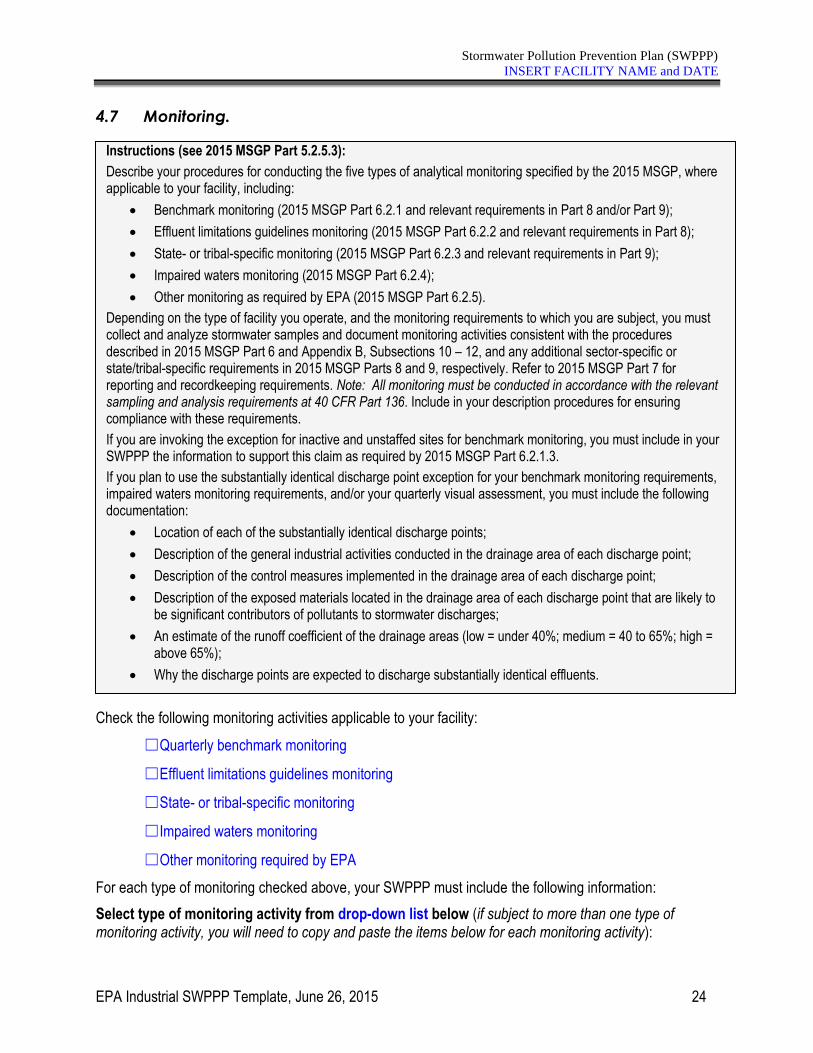
Stormwater Pollution Prevention Plan (SWPPP)
INSERT FACILITY NAME and DATE
EPA Industrial SWPPP Template, June 26, 2015 24
4.7 Monitoring.
Check the following monitoring activities applicable to your facility:
☐Quarterly benchmark monitoring
☐Effluent limitations guidelines monitoring
☐State- or tribal-specific monitoring
☐Impaired waters monitoring
☐Other monitoring required by EPA
For each type of monitoring checked above, your SWPPP must include the following information:
Select type of monitoring activity from drop-down list below (if subject to more than one type of monitoring activity, you will need to copy and paste the items below for each monitoring activity):
Instructions (see 2015 MSGP Part 5.2.5.3):
Describe your procedures for conducting the five types of analytical monitoring specified by the 2015 MSGP, where applicable to your facility, including:
• Benchmark monitoring (2015 MSGP Part 6.2.1 and relevant requirements in Part 8 and/or Part 9);
• Effluent limitations guidelines monitoring (2015 MSGP Part 6.2.2 and relevant requirements in Part 8);
• State- or tribal-specific monitoring (2015 MSGP Part 6.2.3 and relevant requirements in Part 9);
• Impaired waters monitoring (2015 MSGP Part 6.2.4);
• Other monitoring as required by EPA (2015 MSGP Part 6.2.5).
Depending on the type of facility you operate, and the monitoring requirements to which you are subject, you must collect and analyze stormwater samples and document monitoring activities consistent with the procedures described in 2015 MSGP Part 6 and Appendix B, Subsections 10 – 12, and any additional sector-specific or state/tribal-specific requirements in 2015 MSGP Parts 8 and 9, respectively. Refer to 2015 MSGP Part 7 for reporting and recordkeeping requirements. Note: All monitoring must be conducted in accordance with the relevant sampling and analysis requirements at 40 CFR Part 136. Include in your description procedures for ensuring compliance with these requirements.
If you are invoking the exception for inactive and unstaffed sites for benchmark monitoring, you must include in your SWPPP the information to support this claim as required by 2015 MSGP Part 6.2.1.3.
If you plan to use the substantially identical discharge point exception for your benchmark monitoring requirements, impaired waters monitoring requirements, and/or your quarterly visual assessment, you must include the following documentation:
• Location of each of the substantially identical discharge points;
• Description of the general industrial activities conducted in the drainage area of each discharge point;
• Description of the control measures implemented in the drainage area of each discharge point;
• Description of the exposed materials located in the drainage area of each discharge point that are likely to be significant contributors of pollutants to stormwater discharges;
• An estimate of the runoff coefficient of the drainage areas (low = under 40%; medium = 40 to 65%; high = above 65%);
• Why the discharge points are expected to discharge substantially identical effluents.
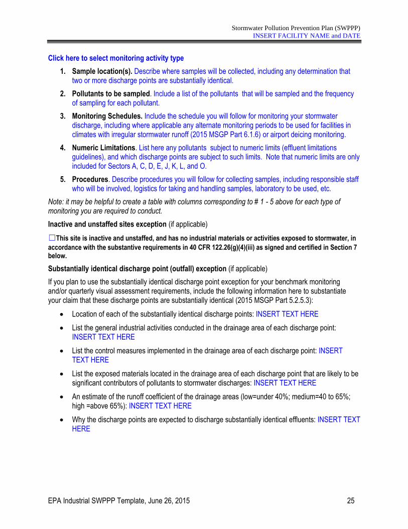
Stormwater Pollution Prevention Plan (SWPPP)
INSERT FACILITY NAME and DATE
EPA Industrial SWPPP Template, June 26, 2015 25
Click here to select monitoring activity type
1. Sample location(s). Describe where samples will be collected, including any determination that two or more discharge points are substantially identical.
2. Pollutants to be sampled. Include a list of the pollutants that will be sampled and the frequency of sampling for each pollutant.
3. Monitoring Schedules. Include the schedule you will follow for monitoring your stormwater discharge, including where applicable any alternate monitoring periods to be used for facilities in climates with irregular stormwater runoff (2015 MSGP Part 6.1.6) or airport deicing monitoring.
4. Numeric Limitations. List here any pollutants subject to numeric limits (effluent limitations guidelines), and which discharge points are subject to such limits. Note that numeric limits are only included for Sectors A, C, D, E, J, K, L, and O.
5. Procedures. Describe procedures you will follow for collecting samples, including responsible staff who will be involved, logistics for taking and handling samples, laboratory to be used, etc.
Note: it may be helpful to create a table with columns corresponding to # 1 - 5 above for each type of monitoring you are required to conduct.
Inactive and unstaffed sites exception (if applicable)
☐This site is inactive and unstaffed, and has no industrial materials or activities exposed to stormwater, in
accordance with the substantive requirements in 40 CFR 122.26(g)(4)(iii) as signed and certified in Section 7 below.
Substantially identical discharge point (outfall) exception (if applicable)
If you plan to use the substantially identical discharge point exception for your benchmark monitoring and/or quarterly visual assessment requirements, include the following information here to substantiate your claim that these discharge points are substantially identical (2015 MSGP Part 5.2.5.3):
• Location of each of the substantially identical discharge points: INSERT TEXT HERE
• List the general industrial activities conducted in the drainage area of each discharge point: INSERT TEXT HERE
• List the control measures implemented in the drainage area of each discharge point: INSERT TEXT HERE
• List the exposed materials located in the drainage area of each discharge point that are likely to be significant contributors of pollutants to stormwater discharges: INSERT TEXT HERE
• An estimate of the runoff coefficient of the drainage areas (low=under 40%; medium=40 to 65%; high =above 65%): INSERT TEXT HERE
• Why the discharge points are expected to discharge substantially identical effluents: INSERT TEXT HERE
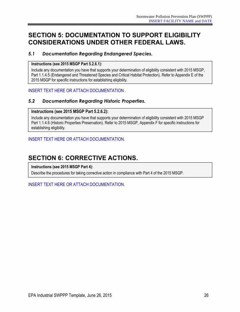
Stormwater Pollution Prevention Plan (SWPPP)
INSERT FACILITY NAME and DATE
EPA Industrial SWPPP Template, June 26, 2015 26
SECTION 5: DOCUMENTATION TO SUPPORT ELIGIBILITY CONSIDERATIONS UNDER OTHER FEDERAL LAWS.
5.1 Documentation Regarding Endangered Species.
INSERT TEXT HERE OR ATTACH DOCUMENTATION .
5.2 Documentation Regarding Historic Properties.
INSERT TEXT HERE OR ATTACH DOCUMENTATION.
SECTION 6: CORRECTIVE ACTIONS.
INSERT TEXT HERE OR ATTACH DOCUMENTATION.
Instructions (see 2015 MSGP Part 5.2.6.1):
Include any documentation you have that supports your determination of eligibility consistent with 2015 MSGP, Part 1.1.4.5 (Endangered and Threatened Species and Critical Habitat Protection). Refer to Appendix E of the 2015 MSGP for specific instructions for establishing eligibility.
Instructions (see 2015 MSGP Part 5.2.6.2):
Include any documentation you have that supports your determination of eligibility consistent with 2015 MSGP Part 1.1.4.6 (Historic Properties Preservation). Refer to 2015 MSGP, Appendix F for specific instructions for establishing eligibility.
Instructions (see 2015 MSGP Part 4):
Describe the procedures for taking corrective action in compliance with Part 4 of the 2015 MSGP.
Stormwater Pollution Prevention Plan (SWPPP)
INSERT FACILITY NAME and DATE
EPA Industrial SWPPP Template, June 26, 2015 27
SECTION 7: SWPPP CERTIFICATION.
I certify under penalty of law that this document and all attachments were prepared under my direction or supervision in accordance with a system designed to assure that qualified personnel properly gathered and evaluated the information submitted. Based on my inquiry of the person or persons who manage the system, or those persons directly responsible for gathering the information, the information submitted is, to the best of my knowledge and belief, true, accurate and complete. I am aware that there are significant penalties for submitting false information, including the possibility of fine and imprisonment for knowing violations.
Name: Title:
Signature: Date:
Instructions (see 2015 MSGP Part 5.2.7):
The following certification statement must be signed and dated by a person who meets the requirements of Appendix B, Subsection 11.A, of the 2015 MSGP.
Note: this certification must be re-signed in the event of a SWPPP modification in response to a Part 4.1 trigger for corrective action.
Stormwater Pollution Prevention Plan (SWPPP)
INSERT FACILITY NAME and DATE
EPA Industrial SWPPP Template, June 26, 2015 28
SECTION 8: SWPPP MODIFICATIONS.
SWPPP ATTACHMENTS
Attach the following documentation to the SWPPP:
Attachment A – General Location Map
Include a copy of your general location map in Attachment A.
Attachment B – Site Map
Include a copy of your site map(s) in Attachment B.
Attachment C –2015 MSGP
Note: it is helpful to keep a printed-out copy of the 2015 MSGP so that it is accessible to you for easy reference. However, you do not need to formally incorporate the entire 2015 MSGP into your SWPPP. As an alternative, you can include a reference to the permit and where it is kept at the site.
Instructions (see 2015 MSGP Part 5.3):
Your SWPPP is a “living” document and is required to be modified and updated, as necessary, in response to corrective actions. See Part 4 of the 2015 MSGP.
• If you need to modify the SWPPP in response to a corrective action required by Part 4.1 or 4.2 of the 2015 MSGP, then the certification statement in section 7 of this SWPPP template must be re-signed in accordance with 2015 MSGP Appendix B, Subsection 11.A.
• For any other SWPPP modification, you should keep a log with a description of the modification, the name of the person making it, and the date and signature of that person. See 2015 MSGP Appendix B, Subsection 11.C.
Additional MSGP Documentation
INSERT FACILITY NAME INSERT FACILITY PERMIT TRACKING NUMBER
EPA Additional MSGP Documentation Template, June 4, 2015 i
Additional 2015 MSGP Documentation Template
Introduction
After you become permitted under the 2015 MSGP, you are required to keep certain minimum records (or documentation) as part of the implementation of your permit responsibilities. As required in Part 5.5 of the 2015 MSGP, these records must be kept in the same place your SWPPP (which you completed prior to submitting your NOI to be covered) is kept. This “Additional MSGP Documentation Template” (or “Template”) will assist you in complying with this requirement.
Using the Additional MSGP Documentation Template Tips for using the Template:
• This Template is designed for use by all facilities permitted under the 2015 MSGP. The Template is NOT tailored to your individual industrial sector. Depending on which industrial sector(s) you fall under (see Appendix D of the 2015 MSGP) and where your facility is located (see Appendix C of the 2015 MSGP), you will need to address any additional documentation requirements outlined in Part 8 and/or Part 9 of the permit, respectively.
• Each section of the template includes “instructions” and space for your facility’s specific information. You should read the instructions before you complete each section. The text you will need to complete is generally indicated through the use of blue form fields (e.g., “Insert Facility Name”). Click on the form field and your text will replace the instructional text.
• The Template was developed in Microsoft Word so that you can easily add tables and additional text.
• Because many of the activities you are required to document occur throughout the permit term, you will need to continually modify and add records to this Template. You may wish to create separate electronic files for each category of documentation (e.g., files for monitoring, employee training, etc.) so that they can be easily modified.
• The records you create using this Template must be kept in the same location as your SWPPP (2015 MSGP Part 5.5).
EPA notes that while the Agency has made every effort to ensure the accuracy of all instructions and guidance contained in the Template, the actual obligations of regulated industrial facilities are determined by the relevant provisions of the 2015 MSGP, not by the Template. In the event of a conflict between the Template and any corresponding provision of the MSGP, the permit provisions establish your actual requirements. EPA welcomes comments on the Template at any time and will consider those comments in any future revision of this document.
Additional MSGP Documentation
INSERT FACILITY NAME INSERT FACILITY PERMIT TRACKING NUMBER
EPA Additional MSGP Documentation Template, June 4, 2015 ii
Additional MSGP Documentation
For:
Insert Facility Name
Insert Facility Address
Insert City, State, Zip Code
Insert Facility Telephone Number (if applicable)
Insert Facility Permit Tracking Number
Additional MSGP Documentation
INSERT FACILITY NAME INSERT FACILITY PERMIT TRACKING NUMBER
EPA Additional MSGP Documentation Template, June 4, 2015 iii
Instructions:
― Keep the following inspection, corrective action, monitoring, and certification records in the same location that you keep your SWPPP:
A copy of the NOI submitted to EPA along with any correspondence exchanged between you and EPA specific to coverage under this permit (you should already have this);
A copy of the acknowledgment you receive from the EPA assigning your NPDES ID (you should already have this);
A copy of 2015 MSGP (you can provide an electronic copy);
Documentation of maintenance and repairs of control measures, including the date(s) of regular maintenance, date(s) of discovery of areas in need of repair/replacement, and for repairs, date(s) that the control measure(s) returned to full function, and the justification for any extended maintenance/repair schedules (see Part 2.1.2.3);
All inspection reports, including the Routine Facility Inspection Reports (see Part 3.1) and Quarterly Visual Assessment Reports (see Part 3.2.2);
Description of any deviations from the schedule for visual assessments and/or monitoring, and the reason for the deviations (e.g., adverse weather or it was impracticable to collect samples within the first 30 minutes of a measurable storm event) (see Parts 3.2.3 and 6.1.5);
Corrective action documentation required per Part 4.4;
Documentation of any benchmark exceedances and the type of response to the exceedance you employed, including:
• the corrective action taken;
• a finding that the exceedance was due to natural background pollutant levels;
• a determination from EPA that benchmark monitoring can be discontinued because the exceedance was due to run-on; or
• a finding that no further pollutant reductions were technologically available and economically practicable and achievable in light of best industry practice consistent with Part 6.2.1.2.
Documentation to support any determination that pollutants of concern are not expected to be present above natural background levels if you discharge directly to impaired waters, and that such pollutants were not detected in your discharge or were solely attributable to natural background sources (see Part 6.2.4.1);
Documentation to support your claim that your facility has changed its status from active to inactive and unstaffed with respect to the requirements to conduct routine facility inspections (see Part 3.1.1), quarterly visual assessments (see Part 3.2.3), benchmark monitoring (see Part 6.2.1.3), and/or impaired waters monitoring (see Part 6.2.4.3).
― With the exception of the first 3 items, these are records that you will be updating throughout the permit term. Follow the instructions in Sections A through L of this template to keep your records complete.

Additional MSGP Documentation
INSERT FACILITY NAME INSERT FACILITY PERMIT TRACKING NUMBER
EPA Additional MSGP Documentation Template, June 4, 2015 iv
Contents
A. Employee training .............................................................................................................. 1 B. Maintenance ...................................................................................................................... 2 C. Routine Facility Inspection Reports ...................................................................................... 4
D. Quarterly Visual Assessment Reports ................................................................................ 10 E. Monitoring results ............................................................................................................. 12
F. Deviations from assessment or monitoring schedule ........................................................... 13
G. Corrective Action Documentation ...................................................................................... 14 H. Benchmark Exceedances ................................................................................................. 15 I. Impaired Waters Monitoring: Documentation of Natural Background Sources or Non-Presence of Impairment Pollutant ............................................................................................................ 16
J. Active/Inactive status change ............................................................................................. 17 K. SWPPP Amendment Log .................................................................................................. 18
L. Miscellaneous Documentation ........................................................................................... 19
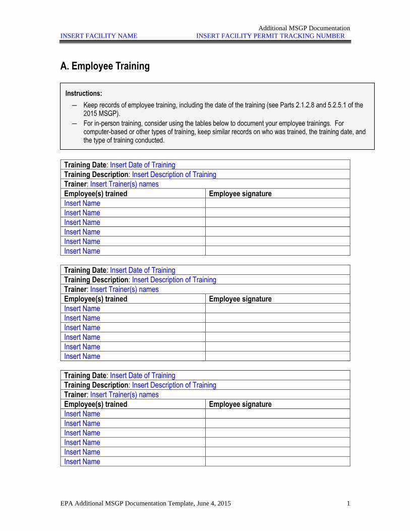
Additional MSGP Documentation
INSERT FACILITY NAME INSERT FACILITY PERMIT TRACKING NUMBER
EPA Additional MSGP Documentation Template, June 4, 2015 1
A. Employee Training
Training Date: Insert Date of Training
Training Description: Insert Description of Training
Trainer: Insert Trainer(s) names
Employee(s) trained Employee signature
Insert Name
Insert Name
Insert Name
Insert Name
Insert Name
Insert Name
Training Date: Insert Date of Training
Training Description: Insert Description of Training
Trainer: Insert Trainer(s) names
Employee(s) trained Employee signature
Insert Name
Insert Name
Insert Name
Insert Name
Insert Name
Insert Name
Training Date: Insert Date of Training
Training Description: Insert Description of Training
Trainer: Insert Trainer(s) names
Employee(s) trained Employee signature
Insert Name
Insert Name
Insert Name
Insert Name
Insert Name
Insert Name
Instructions:
― Keep records of employee training, including the date of the training (see Parts 2.1.2.8 and 5.2.5.1 of the 2015 MSGP).
― For in-person training, consider using the tables below to document your employee trainings. For computer-based or other types of training, keep similar records on who was trained, the training date, and the type of training conducted.
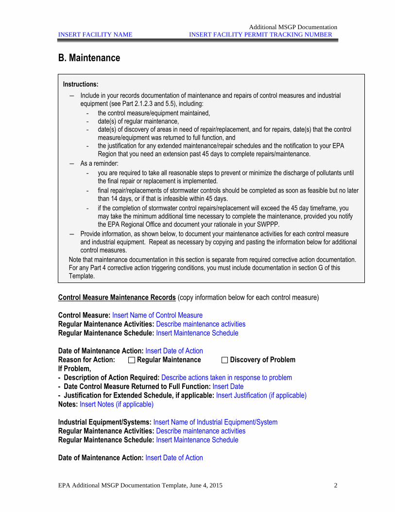
Additional MSGP Documentation
INSERT FACILITY NAME INSERT FACILITY PERMIT TRACKING NUMBER
EPA Additional MSGP Documentation Template, June 4, 2015 2
B. Maintenance
Control Measure Maintenance Records (copy information below for each control measure) Control Measure: Insert Name of Control Measure Regular Maintenance Activities: Describe maintenance activities Regular Maintenance Schedule: Insert Maintenance Schedule Date of Maintenance Action: Insert Date of Action Reason for Action: Regular Maintenance Discovery of Problem If Problem, - Description of Action Required: Describe actions taken in response to problem - Date Control Measure Returned to Full Function: Insert Date - Justification for Extended Schedule, if applicable: Insert Justification (if applicable) Notes: Insert Notes (if applicable) Industrial Equipment/Systems: Insert Name of Industrial Equipment/System Regular Maintenance Activities: Describe maintenance activities Regular Maintenance Schedule: Insert Maintenance Schedule Date of Maintenance Action: Insert Date of Action
Instructions:
― Include in your records documentation of maintenance and repairs of control measures and industrial equipment (see Part 2.1.2.3 and 5.5), including:
- the control measure/equipment maintained, - date(s) of regular maintenance, - date(s) of discovery of areas in need of repair/replacement, and for repairs, date(s) that the control
measure/equipment was returned to full function, and - the justification for any extended maintenance/repair schedules and the notification to your EPA
Region that you need an extension past 45 days to complete repairs/maintenance.
― As a reminder:
- you are required to take all reasonable steps to prevent or minimize the discharge of pollutants until the final repair or replacement is implemented.
- final repair/replacements of stormwater controls should be completed as soon as feasible but no later than 14 days, or if that is infeasible within 45 days.
- if the completion of stormwater control repairs/replacement will exceed the 45 day timeframe, you may take the minimum additional time necessary to complete the maintenance, provided you notify the EPA Regional Office and document your rationale in your SWPPP.
― Provide information, as shown below, to document your maintenance activities for each control measure and industrial equipment. Repeat as necessary by copying and pasting the information below for additional control measures.
Note that maintenance documentation in this section is separate from required corrective action documentation. For any Part 4 corrective action triggering conditions, you must include documentation in section G of this Template.
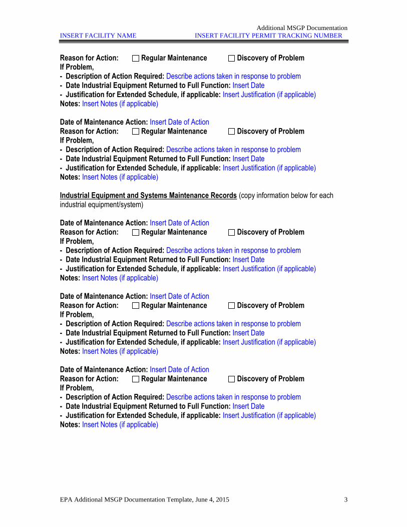
Additional MSGP Documentation
INSERT FACILITY NAME INSERT FACILITY PERMIT TRACKING NUMBER
EPA Additional MSGP Documentation Template, June 4, 2015 3
Reason for Action: Regular Maintenance Discovery of Problem If Problem, - Description of Action Required: Describe actions taken in response to problem - Date Industrial Equipment Returned to Full Function: Insert Date - Justification for Extended Schedule, if applicable: Insert Justification (if applicable) Notes: Insert Notes (if applicable) Date of Maintenance Action: Insert Date of Action Reason for Action: Regular Maintenance Discovery of Problem If Problem, - Description of Action Required: Describe actions taken in response to problem - Date Industrial Equipment Returned to Full Function: Insert Date - Justification for Extended Schedule, if applicable: Insert Justification (if applicable) Notes: Insert Notes (if applicable) Industrial Equipment and Systems Maintenance Records (copy information below for each industrial equipment/system) Date of Maintenance Action: Insert Date of Action Reason for Action: Regular Maintenance Discovery of Problem If Problem, - Description of Action Required: Describe actions taken in response to problem - Date Industrial Equipment Returned to Full Function: Insert Date - Justification for Extended Schedule, if applicable: Insert Justification (if applicable) Notes: Insert Notes (if applicable) Date of Maintenance Action: Insert Date of Action Reason for Action: Regular Maintenance Discovery of Problem If Problem, - Description of Action Required: Describe actions taken in response to problem - Date Industrial Equipment Returned to Full Function: Insert Date - Justification for Extended Schedule, if applicable: Insert Justification (if applicable) Notes: Insert Notes (if applicable) Date of Maintenance Action: Insert Date of Action Reason for Action: Regular Maintenance Discovery of Problem If Problem, - Description of Action Required: Describe actions taken in response to problem - Date Industrial Equipment Returned to Full Function: Insert Date - Justification for Extended Schedule, if applicable: Insert Justification (if applicable) Notes: Insert Notes (if applicable)
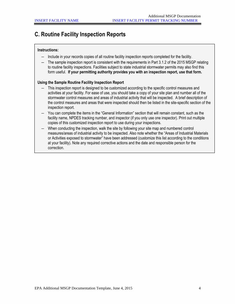
Additional MSGP Documentation
INSERT FACILITY NAME INSERT FACILITY PERMIT TRACKING NUMBER
EPA Additional MSGP Documentation Template, June 4, 2015 4
C. Routine Facility Inspection Reports
Instructions:
― Include in your records copies of all routine facility inspection reports completed for the facility.
― The sample inspection report is consistent with the requirements in Part 3.1.2 of the 2015 MSGP relating to routine facility inspections. Facilities subject to state industrial stormwater permits may also find this form useful. If your permitting authority provides you with an inspection report, use that form.
Using the Sample Routine Facility Inspection Report
― This inspection report is designed to be customized according to the specific control measures and activities at your facility. For ease of use, you should take a copy of your site plan and number all of the stormwater control measures and areas of industrial activity that will be inspected. A brief description of the control measures and areas that were inspected should then be listed in the site-specific section of the inspection report.
― You can complete the items in the “General Information” section that will remain constant, such as the facility name, NPDES tracking number, and inspector (if you only use one inspector). Print out multiple copies of this customized inspection report to use during your inspections.
― When conducting the inspection, walk the site by following your site map and numbered control measures/areas of industrial activity to be inspected. Also note whether the “Areas of Industrial Materials or Activities exposed to stormwater” have been addressed (customize this list according to the conditions at your facility). Note any required corrective actions and the date and responsible person for the correction.
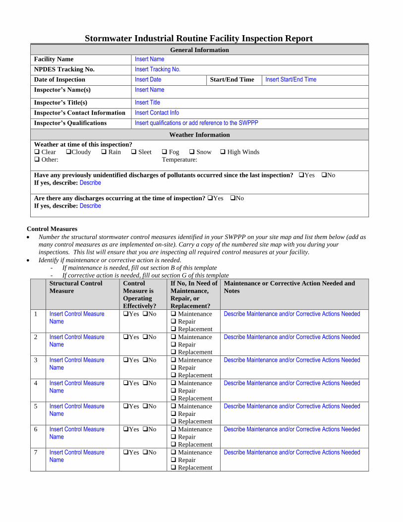
Stormwater Industrial Routine Facility Inspection Report
General Information
Facility Name Insert Name
NPDES Tracking No. Insert Tracking No.
Date of Inspection Insert Date Start/End Time Insert Start/End Time
Inspector’s Name(s) Insert Name
Inspector’s Title(s) Insert Title
Inspector’s Contact Information Insert Contact Info
Inspector’s Qualifications Insert qualifications or add reference to the SWPPP
Weather Information
Weather at time of this inspection?
❑ Clear ❑Cloudy ❑ Rain ❑ Sleet ❑ Fog ❑ Snow ❑ High Winds
❑ Other: Temperature:
Have any previously unidentified discharges of pollutants occurred since the last inspection? ❑Yes ❑No
If yes, describe: Describe
Are there any discharges occurring at the time of inspection? ❑Yes ❑No
If yes, describe: Describe
Control Measures
• Number the structural stormwater control measures identified in your SWPPP on your site map and list them below (add as
many control measures as are implemented on-site). Carry a copy of the numbered site map with you during your
inspections. This list will ensure that you are inspecting all required control measures at your facility.
• Identify if maintenance or corrective action is needed.
- If maintenance is needed, fill out section B of this template
- If corrective action is needed, fill out section G of this template
Structural Control
Measure
Control
Measure is
Operating
Effectively?
If No, In Need of
Maintenance,
Repair, or
Replacement?
Maintenance or Corrective Action Needed and
Notes
1 Insert Control Measure Name
❑Yes ❑No ❑ Maintenance
❑ Repair
❑ Replacement
Describe Maintenance and/or Corrective Actions Needed
2 Insert Control Measure Name
❑Yes ❑No ❑ Maintenance
❑ Repair
❑ Replacement
Describe Maintenance and/or Corrective Actions Needed
3 Insert Control Measure Name
❑Yes ❑No ❑ Maintenance
❑ Repair
❑ Replacement
Describe Maintenance and/or Corrective Actions Needed
4 Insert Control Measure Name
❑Yes ❑No ❑ Maintenance
❑ Repair
❑ Replacement
Describe Maintenance and/or Corrective Actions Needed
5 Insert Control Measure Name
❑Yes ❑No ❑ Maintenance
❑ Repair
❑ Replacement
Describe Maintenance and/or Corrective Actions Needed
6 Insert Control Measure Name
❑Yes ❑No ❑ Maintenance
❑ Repair
❑ Replacement
Describe Maintenance and/or Corrective Actions Needed
7 Insert Control Measure Name
❑Yes ❑No ❑ Maintenance
❑ Repair
❑ Replacement
Describe Maintenance and/or Corrective Actions Needed
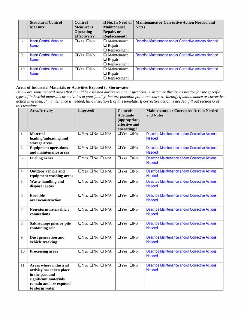
Structural Control
Measure
Control
Measure is
Operating
Effectively?
If No, In Need of
Maintenance,
Repair, or
Replacement?
Maintenance or Corrective Action Needed and
Notes
8 Insert Control Measure Name
❑Yes ❑No ❑ Maintenance
❑ Repair
❑ Replacement
Describe Maintenance and/or Corrective Actions Needed
9 Insert Control Measure Name
❑Yes ❑No ❑ Maintenance
❑ Repair
❑ Replacement
Describe Maintenance and/or Corrective Actions Needed
10 Insert Control Measure Name
❑Yes ❑No ❑ Maintenance
❑ Repair
❑ Replacement
Describe Maintenance and/or Corrective Actions Needed
Areas of Industrial Materials or Activities Exposed to Stormwater
Below are some general areas that should be assessed during routine inspections. Customize this list as needed for the specific
types of industrial materials or activities at your facility that are potential pollutant sources. Identify if maintenance or corrective
action is needed. If maintenance is needed, fill out section B of this template. If corrective action is needed, fill out section G of
this template.
Area/Activity Inspected? Controls
Adequate
(appropriate,
effective and
operating)?
Maintenance or Corrective Action Needed
and Notes
-
1 Material
loading/unloading and
storage areas
❑Yes ❑No ❑ N/A
❑Yes ❑No Describe Maintenance and/or Corrective Actions
Needed
2 Equipment operations
and maintenance areas
❑Yes ❑No ❑ N/A
❑Yes ❑No Describe Maintenance and/or Corrective Actions
Needed
3 Fueling areas ❑Yes ❑No ❑ N/A
❑Yes ❑No Describe Maintenance and/or Corrective Actions
Needed
4 Outdoor vehicle and
equipment washing areas
❑Yes ❑No ❑ N/A
❑Yes ❑No Describe Maintenance and/or Corrective Actions
Needed
5 Waste handling and
disposal areas
❑Yes ❑No ❑ N/A
❑Yes ❑No Describe Maintenance and/or Corrective Actions
Needed
6 Erodible
areas/construction
❑Yes ❑No ❑ N/A
❑Yes ❑No Describe Maintenance and/or Corrective Actions
Needed
7 Non-stormwater/ illicit
connections
❑Yes ❑No ❑ N/A
❑Yes ❑No Describe Maintenance and/or Corrective Actions
Needed
8 Salt storage piles or pile
containing salt
❑Yes ❑No ❑ N/A
❑Yes ❑No Describe Maintenance and/or Corrective Actions
Needed
9 Dust generation and
vehicle tracking
❑Yes ❑No ❑ N/A
❑Yes ❑No Describe Maintenance and/or Corrective Actions
Needed
10 Processing areas
❑Yes ❑No ❑ N/A
❑Yes ❑No Describe Maintenance and/or Corrective Actions
Needed
11 Areas where industrial
activity has taken place
in the past and
significant materials
remain and are exposed
to storm water
❑Yes ❑No ❑ N/A
❑Yes ❑No Describe Maintenance and/or Corrective Actions Needed
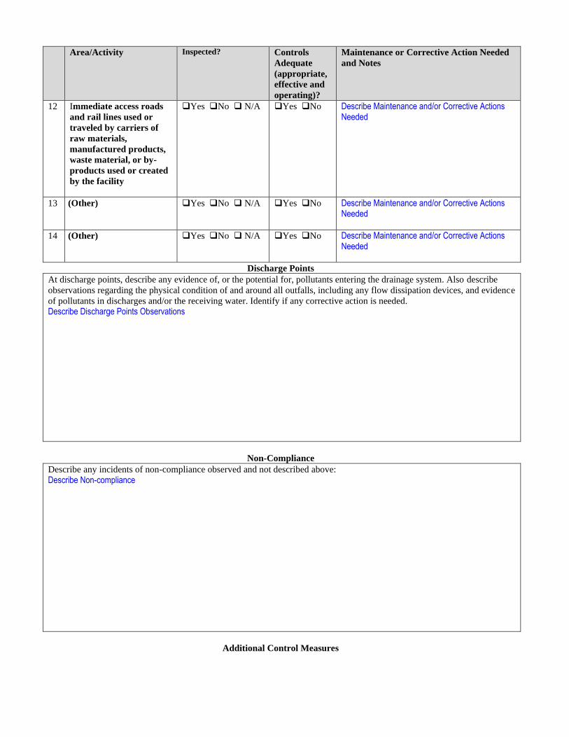
Area/Activity Inspected? Controls
Adequate
(appropriate,
effective and
operating)?
Maintenance or Corrective Action Needed
and Notes
-
12 Immediate access roads
and rail lines used or
traveled by carriers of
raw materials,
manufactured products,
waste material, or by-
products used or created
by the facility
❑Yes ❑No ❑ N/A
❑Yes ❑No Describe Maintenance and/or Corrective Actions
Needed
13 (Other)
❑Yes ❑No ❑ N/A
❑Yes ❑No Describe Maintenance and/or Corrective Actions Needed
14 (Other)
❑Yes ❑No ❑ N/A
❑Yes ❑No Describe Maintenance and/or Corrective Actions
Needed
Discharge Points
At discharge points, describe any evidence of, or the potential for, pollutants entering the drainage system. Also describe
observations regarding the physical condition of and around all outfalls, including any flow dissipation devices, and evidence
of pollutants in discharges and/or the receiving water. Identify if any corrective action is needed.
Describe Discharge Points Observations
Non-Compliance
Describe any incidents of non-compliance observed and not described above:
Describe Non-compliance
Additional Control Measures
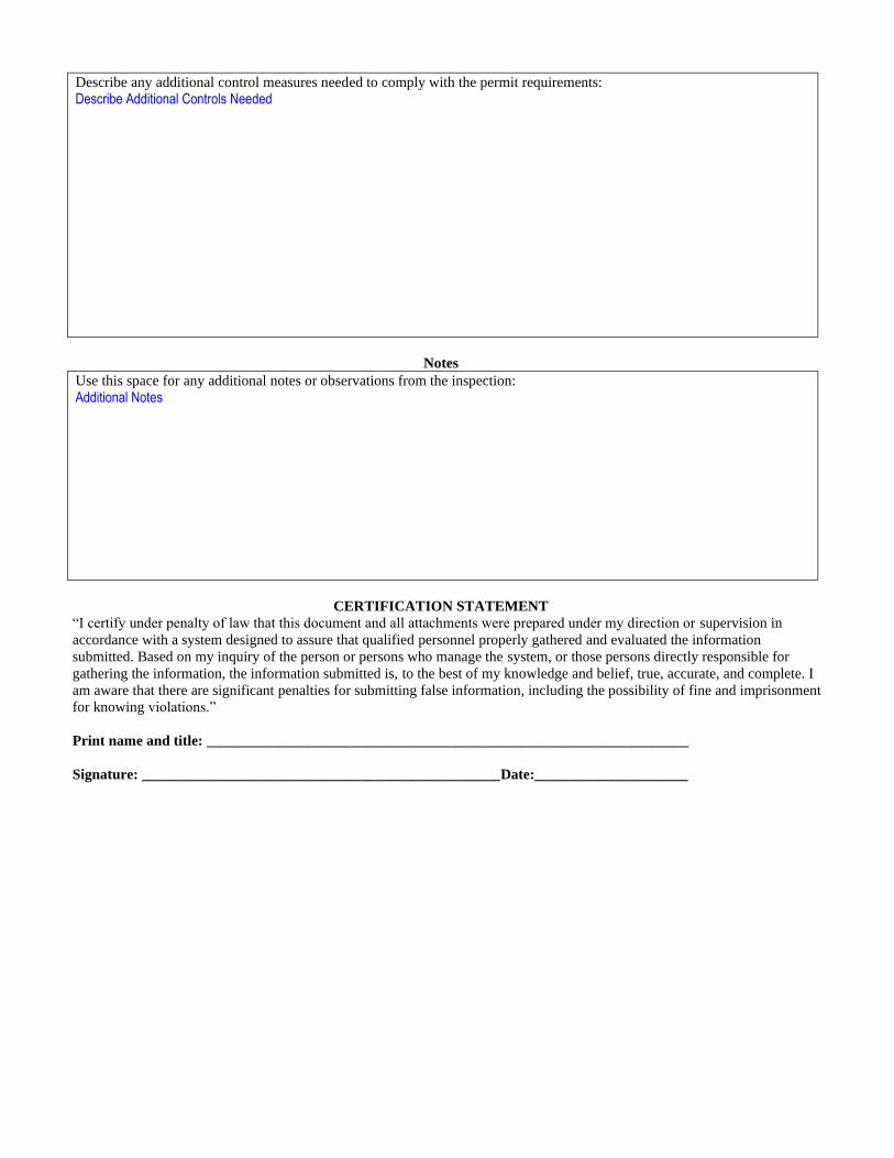
Describe any additional control measures needed to comply with the permit requirements:
Describe Additional Controls Needed
Notes
Use this space for any additional notes or observations from the inspection:
Additional Notes
CERTIFICATION STATEMENT
“I certify under penalty of law that this document and all attachments were prepared under my direction or supervision in
accordance with a system designed to assure that qualified personnel properly gathered and evaluated the information
submitted. Based on my inquiry of the person or persons who manage the system, or those persons directly responsible for
gathering the information, the information submitted is, to the best of my knowledge and belief, true, accurate, and complete. I
am aware that there are significant penalties for submitting false information, including the possibility of fine and imprisonment
for knowing violations.”
Print name and title: __________________________________________________________________
Signature: _________________________________________________Date:_____________________
Additional MSGP Documentation
INSERT FACILITY NAME INSERT FACILITY PERMIT TRACKING NUMBER
EPA Additional MSGP Documentation Template, June 4, 2015 10
D. Quarterly Visual Assessment Reports
Instructions:
― Include in your records copies of all quarterly visual assessment reports completed for the facility (Part 3.2.2). An example quarterly visual assessment report can be found on the following page.
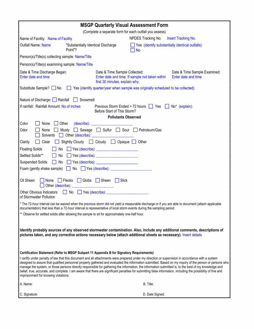
MSGP Quarterly Visual Assessment Form (Complete a separate form for each outfall you assess)
Name of Facility: Name of Facility NPDES Tracking No. Insert Tracking No.
Outfall Name: Name "Substantially Identical Discharge Point"?
Yes (identify substantially identical outfalls):
No
Person(s)/Title(s) collecting sample: Name/Title
Person(s)/Title(s) examining sample: Name/Title
Date & Time Discharge Began: Enter date and time
Date & Time Sample Collected: Enter date and time. If sample not taken within first 30 minutes, explain why.
Date & Time Sample Examined: Enter date and time
Substitute Sample? No Yes (identify quarter/year when sample was originally scheduled to be collected):
Nature of Discharge: Rainfall Snowmelt
If rainfall: Rainfall Amount: No of inches_ Previous Storm Ended > 72 hours Before Start of This Storm?
Yes No* (explain):
Pollutants Observed
Color None Other (describe): ______________________
Odor None Musty Sewage Sulfur Sour Petroleum/Gas
Solvents Other (describe): ______________________
Clarity Clear Slightly Cloudy Cloudy Opaque Other
Floating Solids No Yes (describe): ______________________
Settled Solids** No Yes (describe): ______________________
Suspended Solids No Yes (describe): ______________________
Foam (gently shake sample) No Yes (describe): ______________________
Oil Sheen None Flecks Globs Sheen Slick
Other (describe): ______________________
Other Obvious Indicators of Stormwater Pollution
No Yes (describe): ______________________
* The 72-hour interval can be waived when the previous storm did not yield a measurable discharge or if you are able to document (attach applicable documentation) that less than a 72-hour interval is representative of local storm events during the sampling period.
** Observe for settled solids after allowing the sample to sit for approximately one-half hour.
Identify probably sources of any observed stormwater contamination. Also, include any additional comments, descriptions of pictures taken, and any corrective actions necessary below (attach additional sheets as necessary). Insert details
Certification Statement (Refer to MSGP Subpart 11 Appendix B for Signatory Requirements)
I certify under penalty of law that this document and all attachments were prepared under my direction or supervision in accordance with a system designed to assure that qualified personnel properly gathered and evaluated the information submitted. Based on my inquiry of the person or persons who manage the system, or those persons directly responsible for gathering the information, the information submitted is, to the best of my knowledge and belief, true, accurate, and complete. I am aware that there are significant penalties for submitting false information, including the possibility of fine and imprisonment for knowing violations.
A. Name: B. Title:
C. Signature: D. Date Signed:
Additional MSGP Documentation
INSERT FACILITY NAME INSERT FACILITY PERMIT TRACKING NUMBER
EPA Additional MSGP Documentation Template, June 4, 2015 12
E. Monitoring results
Instructions:
― Include in your records copies of all monitoring results (including analytical laboratory data, benchmarks, effluent limits, and other monitoring conducted) for the facility. Also include copies of monitoring data submitted to EPA’s NetDMR reporting system or paper Industrial Discharge Monitoring Reports (DMRs) if EPA has issued your facility a waiver from electronic reporting (Part 6.1.9).
Additional MSGP Documentation
INSERT FACILITY NAME INSERT FACILITY PERMIT TRACKING NUMBER
EPA Additional MSGP Documentation Template, June 4, 2015 13
F. Deviations from assessment or monitoring schedule
Date: Insert Date
Visual assessments Monitoring Describe deviation from schedule: Describe deviation Reason for deviation: Describe reason Date: Insert Date
Visual assessments Monitoring Describe deviation from schedule: Describe deviation Reason for deviation: Describe reason Date: Insert Date
Visual assessments Monitoring Describe deviation from schedule: Describe deviation Reason for deviation: Describe reason Date: Insert Date
Visual assessments Monitoring Describe deviation from schedule: Describe deviation Reason for deviation: Describe reason
Instructions:
Include in your records:
― A description of any deviations from the schedule you provided in your SWPPP for visual assessments and/or monitoring (Part 5.5), and
― The reason for the deviations (e.g., adverse weather or it was impracticable to collect samples within the first 30 minutes of a measurable storm event) (Parts 3.2.3 and 6.1.5 of the 2015 MSGP).
Use the fields below to document the deviations. Repeat as necessary for any deviations.
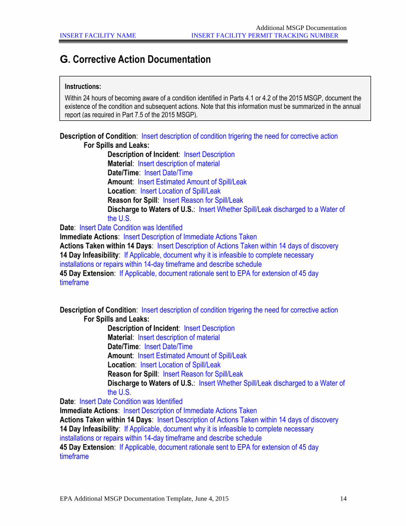
Additional MSGP Documentation
INSERT FACILITY NAME INSERT FACILITY PERMIT TRACKING NUMBER
EPA Additional MSGP Documentation Template, June 4, 2015 14
G. Corrective Action Documentation
Description of Condition: Insert description of condition trigering the need for corrective action For Spills and Leaks:
Description of Incident: Insert Description Material: Insert description of material Date/Time: Insert Date/Time Amount: Insert Estimated Amount of Spill/Leak Location: Insert Location of Spill/Leak Reason for Spill: Insert Reason for Spill/Leak Discharge to Waters of U.S.: Insert Whether Spill/Leak discharged to a Water of the U.S.
Date: Insert Date Condition was Identified Immediate Actions: Insert Description of Immediate Actions Taken Actions Taken within 14 Days: Insert Description of Actions Taken within 14 days of discovery 14 Day Infeasibility: If Applicable, document why it is infeasible to complete necessary installations or repairs within 14-day timeframe and describe schedule 45 Day Extension: If Applicable, document rationale sent to EPA for extension of 45 day timeframe Description of Condition: Insert description of condition trigering the need for corrective action For Spills and Leaks:
Description of Incident: Insert Description Material: Insert description of material Date/Time: Insert Date/Time Amount: Insert Estimated Amount of Spill/Leak Location: Insert Location of Spill/Leak Reason for Spill: Insert Reason for Spill/Leak Discharge to Waters of U.S.: Insert Whether Spill/Leak discharged to a Water of the U.S.
Date: Insert Date Condition was Identified Immediate Actions: Insert Description of Immediate Actions Taken Actions Taken within 14 Days: Insert Description of Actions Taken within 14 days of discovery 14 Day Infeasibility: If Applicable, document why it is infeasible to complete necessary installations or repairs within 14-day timeframe and describe schedule 45 Day Extension: If Applicable, document rationale sent to EPA for extension of 45 day timeframe
Instructions:
Within 24 hours of becoming aware of a condition identified in Parts 4.1 or 4.2 of the 2015 MSGP, document the existence of the condition and subsequent actions. Note that this information must be summarized in the annual report (as required in Part 7.5 of the 2015 MSGP).

Additional MSGP Documentation
INSERT FACILITY NAME INSERT FACILITY PERMIT TRACKING NUMBER
EPA Additional MSGP Documentation Template, June 4, 2015 15
H. Benchmark Exceedances
Date: Insert Date Pollutant Exceeded and Results: Insert Pollutant Name Quarter 1 (Sample date: Insert Sample Date) Result: Insert Sample Result Quarter 2 (Sample date: Insert Sample Date) Result: Insert Sample Result Quarter 3 (Sample date: Insert Sample Date) Result: Insert Sample Result Quarter 4 (Sample date: Insert Sample Date) Result: Insert Sample Result Average Result: Insert Value Benchmark Value: Insert Benchmark Value from 2015 MSGP Document how benchmark exceedance(s) responded to:
Corrective action review completed (ensure documentation is included in section G of this Template)
Finding that the exceedance was due to natural background pollutant levels
Pollutant(s): Insert Pollutant Attach data and/or studies that tie the presence of the pollutant causing the exceedance in your discharge to natural background sources in the watershed.
Determination from EPA Regional Office that benchmark monitoring can be
discontinued because the exceedance was due to run-on Pollutant(s): Insert Pollutant
Attach documentation from EPA Regional Office.
Finding that no further pollutant reductions are technologically available and economically practicable and achievable in light of best industry practice consistent with Part 6.2.1.2. Pollutant(s): Insert Pollutant
Attach documentation supporting this finding.
Instructions:
Include in your records documentation of any four quarter average benchmark exceedances and how they were responded to, including either:
― (1) corrective action taken (Parts 4.2 and 6.2.1.2),
― (2) a finding that the exceedance was due to natural background pollutant levels (Part 6.2.1.2),
― (3) a determination from the EPA Regional Office that benchmark monitoring can be discontinued because the exceedance was due to run-on, or
― (4) a finding that no further pollutant reductions were technologically available and economically practicable and achievable in light of best industry practice consistent with Part 6.2.1.2 of the 2015 MSGP.
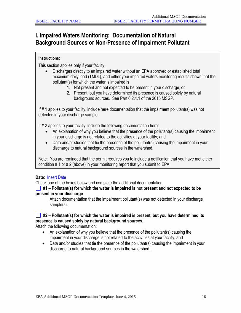
Additional MSGP Documentation
INSERT FACILITY NAME INSERT FACILITY PERMIT TRACKING NUMBER
EPA Additional MSGP Documentation Template, June 4, 2015 16
I. Impaired Waters Monitoring: Documentation of Natural Background Sources or Non-Presence of Impairment Pollutant
Date: Insert Date Check one of the boxes below and complete the additional documentation:
#1 – Pollutant(s) for which the water is impaired is not present and not expected to be present in your discharge
Attach documentation that the impairment pollutant(s) was not detected in your discharge sample(s).
#2 – Pollutant(s) for which the water is impaired is present, but you have determined its
presence is caused solely by natural background sources. Attach the following documentation:
• An explanation of why you believe that the presence of the pollutant(s) causing the impairment in your discharge is not related to the activities at your facility; and
• Data and/or studies that tie the presence of the pollutant(s) causing the impairment in your discharge to natural background sources in the watershed.
Instructions:
This section applies only if your facility:
• Discharges directly to an impaired water without an EPA approved or established total maximum daily load (TMDL), and either your impaired waters monitoring results shows that the pollutant(s) for which the water is impaired is
1. Not present and not expected to be present in your discharge, or 2. Present, but you have determined its presence is caused solely by natural
background sources. See Part 6.2.4.1 of the 2015 MSGP. If # 1 applies to your facility, include here documentation that the impairment pollutant(s) was not detected in your discharge sample. If # 2 applies to your facility, include the following documentation here:
• An explanation of why you believe that the presence of the pollutant(s) causing the impairment in your discharge is not related to the activities at your facility; and
• Data and/or studies that tie the presence of the pollutant(s) causing the impairment in your discharge to natural background sources in the watershed.
Note: You are reminded that the permit requires you to include a notification that you have met either condition # 1 or # 2 (above) in your monitoring report that you submit to EPA.
Additional MSGP Documentation
INSERT FACILITY NAME INSERT FACILITY PERMIT TRACKING NUMBER
EPA Additional MSGP Documentation Template, June 4, 2015 17
J. Active/Inactive status change
Date: Insert Date of Change in Status New Facility Status: Inactive and Unstaffed Active Reason for change in status: Describe reason
Instructions:
If your facility changes it status from active to inactive and unstaffed (or from inactive/unstaffed to active), include documentation in this section to support your claim.
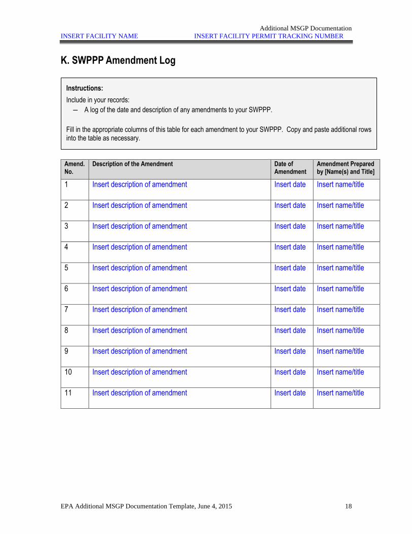
Additional MSGP Documentation
INSERT FACILITY NAME INSERT FACILITY PERMIT TRACKING NUMBER
EPA Additional MSGP Documentation Template, June 4, 2015 18
K. SWPPP Amendment Log
Amend. No.
Description of the Amendment Date of Amendment
Amendment Prepared by [Name(s) and Title]
1 Insert description of amendment Insert date Insert name/title
2 Insert description of amendment Insert date Insert name/title
3 Insert description of amendment Insert date Insert name/title
4 Insert description of amendment Insert date Insert name/title
5 Insert description of amendment Insert date Insert name/title
6 Insert description of amendment Insert date Insert name/title
7 Insert description of amendment Insert date Insert name/title
8 Insert description of amendment Insert date Insert name/title
9 Insert description of amendment Insert date Insert name/title
10 Insert description of amendment Insert date Insert name/title
11 Insert description of amendment Insert date Insert name/title
Instructions:
Include in your records:
― A log of the date and description of any amendments to your SWPPP.
Fill in the appropriate columns of this table for each amendment to your SWPPP. Copy and paste additional rows into the table as necessary.
Additional MSGP Documentation
INSERT FACILITY NAME INSERT FACILITY PERMIT TRACKING NUMBER
EPA Additional MSGP Documentation Template, June 4, 2015 19
L. Miscellaneous Documentation
Instructions:
Use this section to keep records of any additional documentation that relates to your compliance with the permit.
APPENDIX B3
Supporting Materials for MS4 Permit Activities
• EPA MS4 Annual Report Form • Pages from Appendix D of the MRG Watershed
Based MS4 Permit and the 2015 Draft Small MS4 Permit – Images of Suggested Sampling Locations for Individual and Cooperative Monitoring Programs
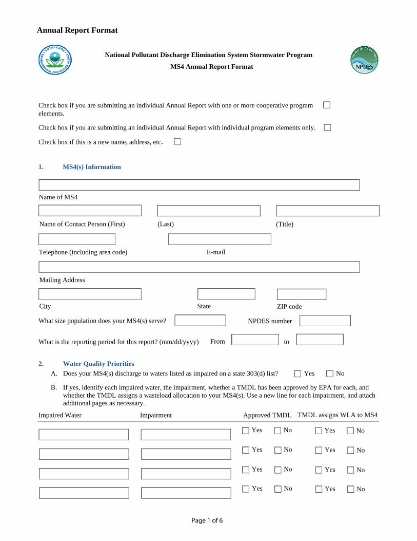
Page 1 of 6
Annual Report Format
National Pollutant Discharge Elimination System Stormwater Program
MS4 Annual Report Format
Check box if you are submitting an individual Annual Report with one or more cooperative program
elements.
Check box if you are submitting an individual Annual Report with individual program elements only.
Check box if this is a new name, address, etc.
1.
What size population does your MS4(s) serve?
What is the reporting period for this report? (mm/dd/yyyy)
2. Water Quality Priorities
A. Does your MS4(s) discharge to waters listed as impaired on a state 303(d) list? Yes No
B. If yes, identify each impaired water, the impairment, whether a TMDL has been approved by EPA for each, and
whether the TMDL assigns a wasteload allocation to your MS4(s). Use a new line for each impairment, and attach
additional pages as necessary.
Impaired Water Impairment Approved TMDL TMDL assigns WLA to MS4
Yes No NoYes
Name of MS4
Name of Contact Person (First) (Last) (Title)
Telephone (including area code) E-mail
Mailing Address
MS4(s) Information
City State ZIP code
to From
NPDES number
Yes No NoYes
Yes No NoYes
Yes No NoYes
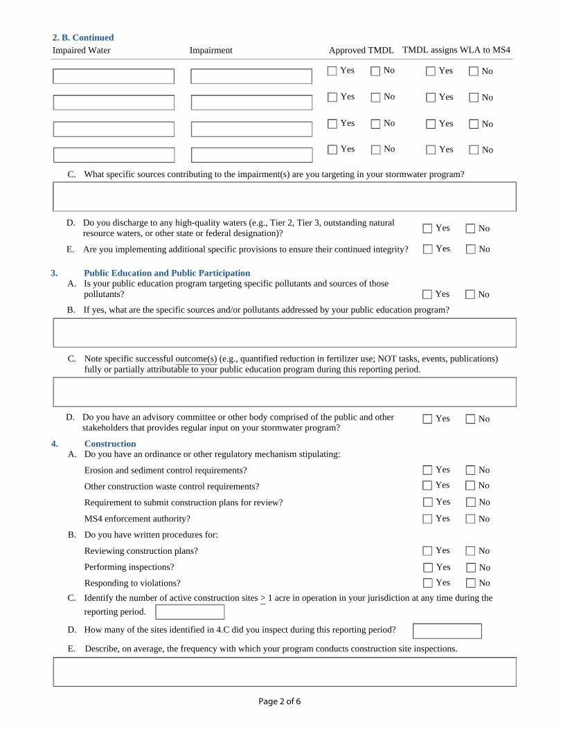
Page 2 of 6
C. What specific sources contributing to the impairment(s) are you targeting in your stormwater program?
D. Do you discharge to any high-quality waters (e.g., Tier 2, Tier 3, outstanding natural
resource waters, or other state or federal designation)?
E. Are you implementing additional specific provisions to ensure their continued integrity?
3. Public Education and Public Participation
A. Is your public education program targeting specific pollutants and sources of those
pollutants?
B. If yes, what are the specific sources and/or pollutants addressed by your public education program?
C. Note specific successful outcome(s) (e.g., quantified reduction in fertilizer use; NOT tasks, events, publications)
fully or partially attributable to your public education program during this reporting period.
D. Do you have an advisory committee or other body comprised of the public and other
stakeholders that provides regular input on your stormwater program?
4. Construction
A. Do you have an ordinance or other regulatory mechanism stipulating:
Erosion and sediment control requirements?
Other construction waste control requirements?
Requirement to submit construction plans for review?
MS4 enforcement authority?
B. Do you have written procedures for:
Reviewing construction plans?
Performing inspections?
Responding to violations?
Impaired Water Impairment Approved TMDL TMDL assigns WLA to MS4
Yes No NoYes
Yes No NoYes
Yes No NoYes
Yes No NoYes
2. B. Continued
NoYes
NoYes
NoYes
NoYes
NoYes
NoYes
NoYes
NoYes
NoYes
NoYes
NoYes
C. Identify the number of active construction sites > 1 acre in operation in your jurisdiction at any time during the
reporting period.
D. How many of the sites identified in 4.C did you inspect during this reporting period?
E. Describe, on average, the frequency with which your program conducts construction site inspections.
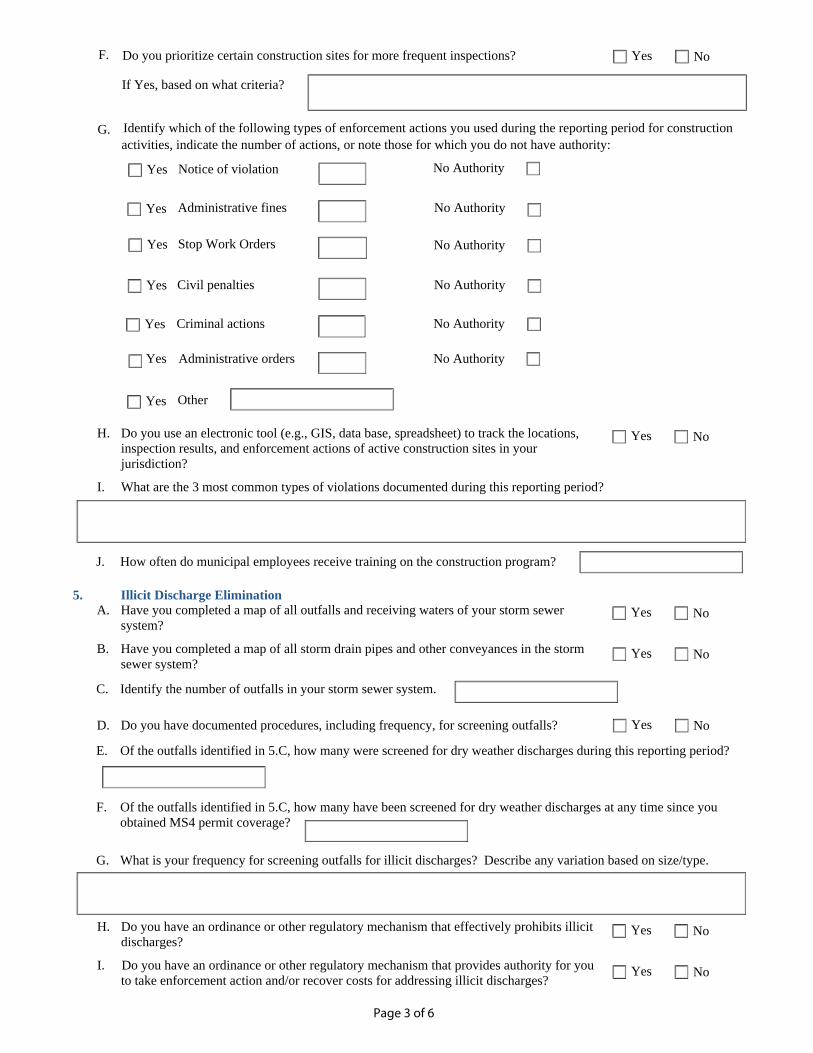
Page 3 of 6
H. Do you use an electronic tool (e.g., GIS, data base, spreadsheet) to track the locations,
inspection results, and enforcement actions of active construction sites in your
jurisdiction?
I. What are the 3 most common types of violations documented during this reporting period?
F. Do you prioritize certain construction sites for more frequent inspections?
If Yes, based on what criteria?
NoYes
Notice of violationYes
Administrative fines No Authority
Stop Work OrdersYes No Authority
Yes
No Authority
G.
activities, indicate the number of actions, or note those for which you do not have authority:
Identify which of the following types of enforcement actions you used during the reporting period for construction
Yes Administrative orders
Civil penaltiesYes No Authority
Criminal actionsYes No Authority
No Authority
J. How often do municipal employees receive training on the construction program?
5. Illicit Discharge Elimination
A. Have you completed a map of all outfalls and receiving waters of your storm sewer
system?
B. Have you completed a map of all storm drain pipes and other conveyances in the storm
sewer system?
D. Do you have documented procedures, including frequency, for screening outfalls?
NoYes
NoYes
NoYes
C. Identify the number of outfalls in your storm sewer system.
NoYes
E. Of the outfalls identified in 5.C, how many were screened for dry weather discharges during this reporting period?
F. Of the outfalls identified in 5.C, how many have been screened for dry weather discharges at any time since you
obtained MS4 permit coverage?
G. What is your frequency for screening outfalls for illicit discharges? Describe any variation based on size/type.
H. Do you have an ordinance or other regulatory mechanism that effectively prohibits illicit
discharges?
I. Do you have an ordinance or other regulatory mechanism that provides authority for you
to take enforcement action and/or recover costs for addressing illicit discharges?
NoYes
NoYes
Other Yes
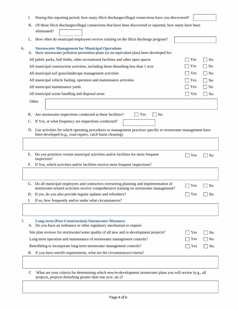
Page 4 of 6
E. Do you prioritize certain municipal activities and/or facilities for more frequent
inspection?
G. Do all municipal employees and contractors overseeing planning and implementation of
stormwater-related activities receive comprehensive training on stormwater management?
H. If yes, do you also provide regular updates and refreshers?
6. Stormwater Management for Municipal Operations A. Have stormwater pollution prevention plans (or an equivalent plan) been developed for:
All public parks, ball fields, other recreational facilities and other open spaces
All municipal construction activities, including those disturbing less than 1 acre
All municipal turf grass/landscape management activities
All municipal vehicle fueling, operation and maintenance activities
All municipal maintenance yards
All municipal waste handling and disposal areas
B. Are stormwater inspections conducted at these facilities?
C. If Yes, at what frequency are inspections conducted?
J. During this reporting period, how many illicit discharges/illegal connections have you discovered?
L. How often do municipal employees receive training on the illicit discharge program?
Of those illicit discharges/illegal connections that have been discovered or reported, how many have been K.
eliminated?
NoYes
NoYes
NoYes
NoYes
NoYes
NoYes
Other
NoYes
been developed (e.g., road repairs, catch basin cleaning).
D. List activities for which operating procedures or management practices specific to stormwater management have
If Yes, which activities and/or facilities receive most frequent inspections? F.
NoYes
NoYes
If so, how frequently and/or under what circumstances? I.
7. Long-term (Post-Construction) Stormwater Measures
A. Do you have an ordinance or other regulatory mechanism to require:
Site plan reviews for stormwater/water quality of all new and re-development projects?
Long-term operation and maintenance of stormwater management controls?
Retrofitting to incorporate long-term stormwater management controls?
B. If you have retrofit requirements, what are the circumstances/criteria?
NoYes
NoYes
NoYes
C What are your criteria for determining which new/re-development stormwater plans you will review (e.g., all
projects, projects disturbing greater than one acre, etc.)?
NoYes
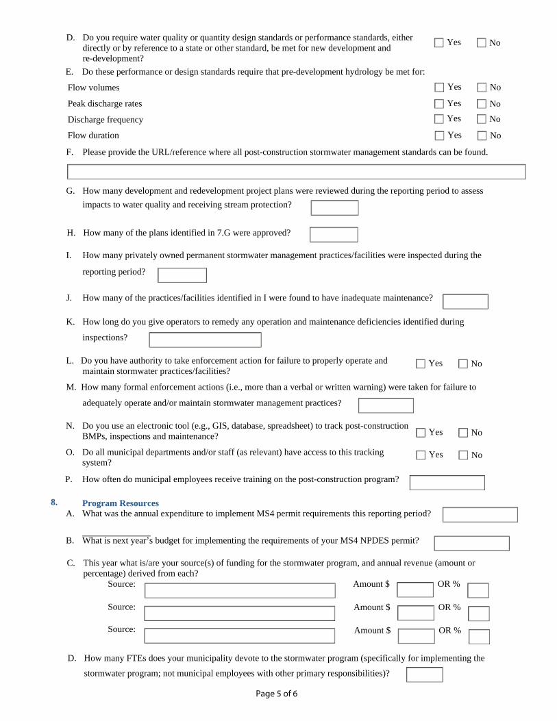
Page 5 of 6
N. Do you use an electronic tool (e.g., GIS, database, spreadsheet) to track post-construction
BMPs, inspections and maintenance?
O. Do all municipal departments and/or staff (as relevant) have access to this tracking
system?
P. How often do municipal employees receive training on the post-construction program?
A. What was the annual expenditure to implement MS4 permit requirements this reporting period?
B. What is next year’s budget for implementing the requirements of your MS4 NPDES permit?
E. Do these performance or design standards require that pre-development hydrology be met for:
Flow volumes
Peak discharge rates
Discharge frequency
Flow duration
F. Please provide the URL/reference where all post-construction stormwater management standards can be found.
G. How many development and redevelopment project plans were reviewed during the reporting period to assess
impacts to water quality and receiving stream protection?
H. How many of the plans identified in 7.G were approved?
I. How many privately owned permanent stormwater management practices/facilities were inspected during the
reporting period?
J. How many of the practices/facilities identified in I were found to have inadequate maintenance?
K. How long do you give operators to remedy any operation and maintenance deficiencies identified during
inspections?
L. Do you have authority to take enforcement action for failure to properly operate and
maintain stormwater practices/facilities?
M. How many formal enforcement actions (i.e., more than a verbal or written warning) were taken for failure to
adequately operate and/or maintain stormwater management practices?
D. Do you require water quality or quantity design standards or performance standards, either
directly or by reference to a state or other standard, be met for new development and
re-development?
NoYes
NoYes
NoYes
NoYes
NoYes
Program Resources 8.
NoYes
NoYes
NoYes
Amount $ OR %
C. This year what is/are your source(s) of funding for the stormwater program, and annual revenue (amount or
percentage) derived from each?
Source:
Source:
Source:
Amount $ OR %
Amount $ OR %
D. How many FTEs does your municipality devote to the stormwater program (specifically for implementing the
stormwater program; not municipal employees with other primary responsibilities)?
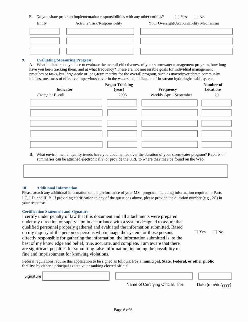
Page 6 of 6
Certification Statement and Signature
I certify under penalty of law that this document and all attachments were prepared
under my direction or supervision in accordance with a system designed to assure that
qualified personnel properly gathered and evaluated the information submitted. Based
on my inquiry of the person or persons who manage the system, or those persons
directly responsible for gathering the information, the information submitted is, to the
best of my knowledge and belief, true, accurate, and complete. I am aware that there
are significant penalties for submitting false information, including the possibility of
fine and imprisonment for knowing violations.
Federal regulations require this application to be signed as follows: For a municipal, State, Federal, or other public
facility: by either a principal executive or ranking elected official.
Name of Certifying Official, Title Date (mm/dd/yyyy)
9. Evaluating/Measuring Progress
A. What indicators do you use to evaluate the overall effectiveness of your stormwater management program, how long
have you been tracking them, and at what frequency? These are not measurable goals for individual management
practices or tasks, but large-scale or long-term metrics for the overall program, such as macroinvertebrate community
indices, measures of effective impervious cover in the watershed, indicators of in-stream hydrologic stability, etc.
Indicator
Began Tracking
(year) Frequency
Number of
Locations
Example: E. coli 2003 Weekly April–September 20
B. What environmental quality trends have you documented over the duration of your stormwater program? Reports or
summaries can be attached electronically, or provide the URL to where they may be found on the Web.
10. Additional Information
Please attach any additional information on the performance of your MS4 program, including information required in Parts
I.C, I.D, and III.B. If providing clarification to any of the questions above, please provide the question number (e.g., 2C) in
your response.
E. Do you share program implementation responsibilities with any other entities?
Entity Activity/Task/Responsibility Your Oversight/Accountability Mechanism
NoYes
NoYes
Signature
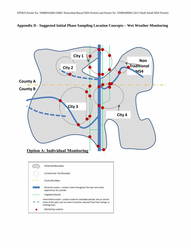
NPDES Permit No. NMR04A000 (MRG Watershed Based MS4 Permit) and Permit No. NMR040000 (2015 Draft Small MS4 Permit)
Appendix D - Suggested Initial Phase Sampling Location Concepts – Wet Weather Monitoring
Non Traditional
MS4 City 2
City 3
City 1
City 4
County A
County B
Option A: Individual Monitoring
11
1 1
9
2
2
6
8
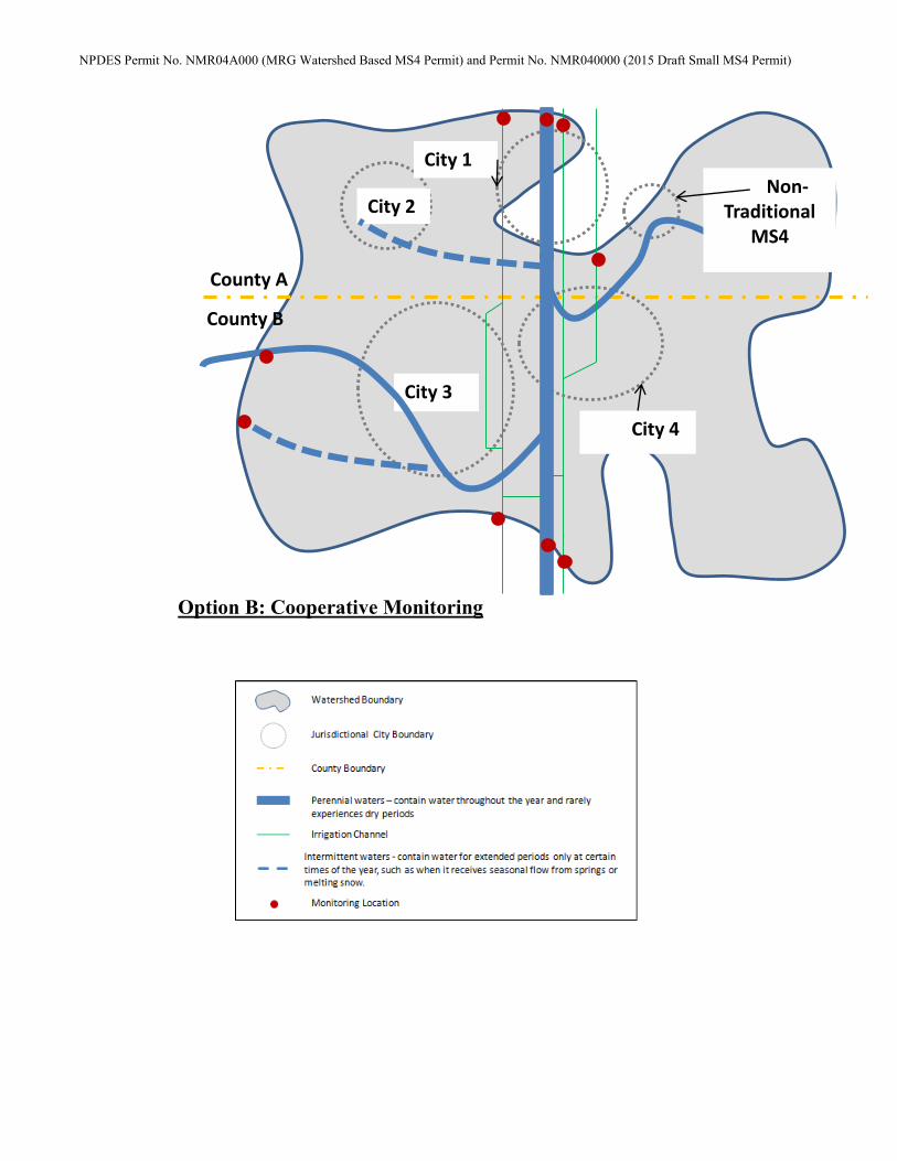
NPDES Permit No. NMR04A000 (MRG Watershed Based MS4 Permit) and Permit No. NMR040000 (2015 Draft Small MS4 Permit)
City 2
City 3
City 1
City 4
County A
County B
Option B: Cooperative Monitoring
Non-Traditional
MS4
1
APPENDIX C – BOUNDARIES FOR CURRENTLY
PERMITTED AND LOS LUNAS PROPOSED MS4
AREAS WITHIN NEW MEXICO
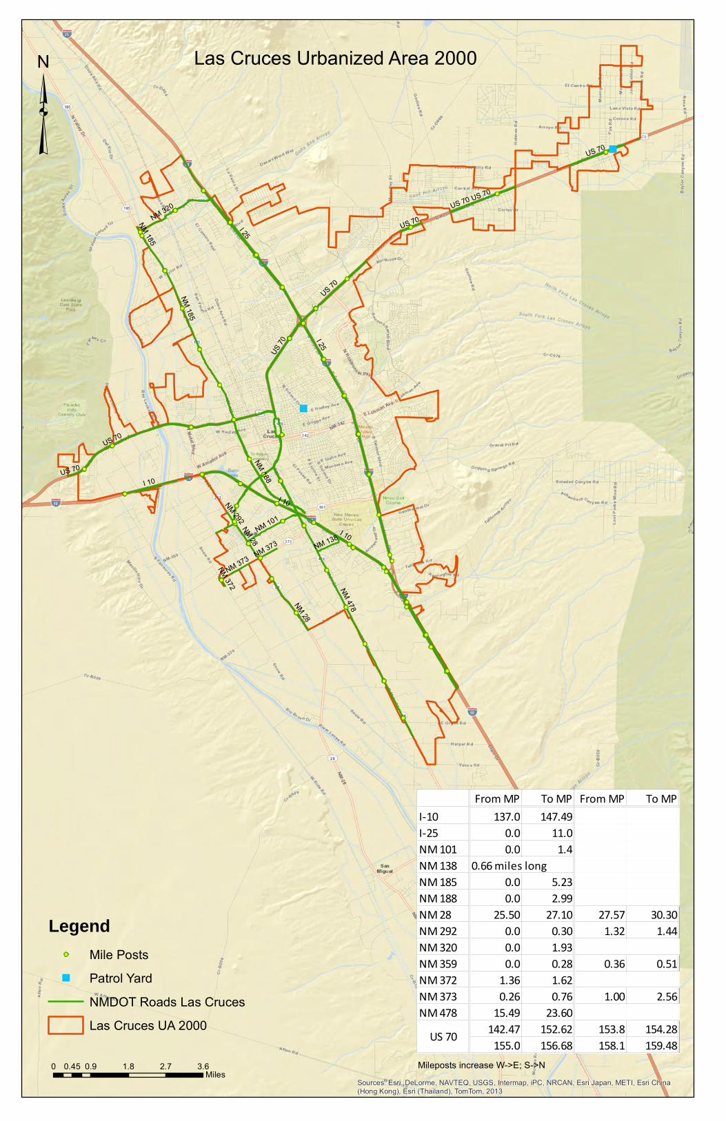
"
"
!
!
!
!
!
!
!
!
!
!
!
!
!
!
!
!
!
!
!
!
!
!
!
!
!
!
!
!
!
!
!
!
!
!
!
!
!
!
!
!
!
!
!
!
!
!
!
!
!
!
!
!
!
!!
!
!
!
!
!
!
!
!
!
!
!
!
!
!
!
!
!
!
!
!!
!
!
I 10
I 25
US 70
NM 478
NM 188
NM 185
NM 320
NM 101
NM 28
NM 138
NM 373
NM 292
NM 372
I 10
I 10US 70
US 70
US 70
I 25
US 70
NM 28
US 70
US 70
NM 185
US 70
NM 373
Sources: Esri, DeLorme, NAVTEQ, USGS, Intermap, iPC, NRCAN, Esri Japan, METI, Esri China(Hong Kong), Esri (Thailand), TomTom, 2013
³
Legend! Mile Posts
" Patrol Yard
NMDOT Roads Las Cruces
Las Cruces UA 2000
0 0.9 1.8 2.7 3.60.45Miles
Las Cruces Urbanized Area 2000
Mileposts increase W->E; S->N
From MP To MP From MP To MPI-10 137.0 147.49I-25 0.0 11.0NM 101 0.0 1.4NM 138 0.66 miles longNM 185 0.0 5.23NM 188 0.0 2.99NM 28 25.50 27.10 27.57 30.30NM 292 0.0 0.30 1.32 1.44NM 320 0.0 1.93NM 359 0.0 0.28 0.36 0.51NM 372 1.36 1.62NM 373 0.26 0.76 1.00 2.56NM 478 15.49 23.60
142.47 152.62 153.8 154.28155.0 156.68 158.1 159.48US 70
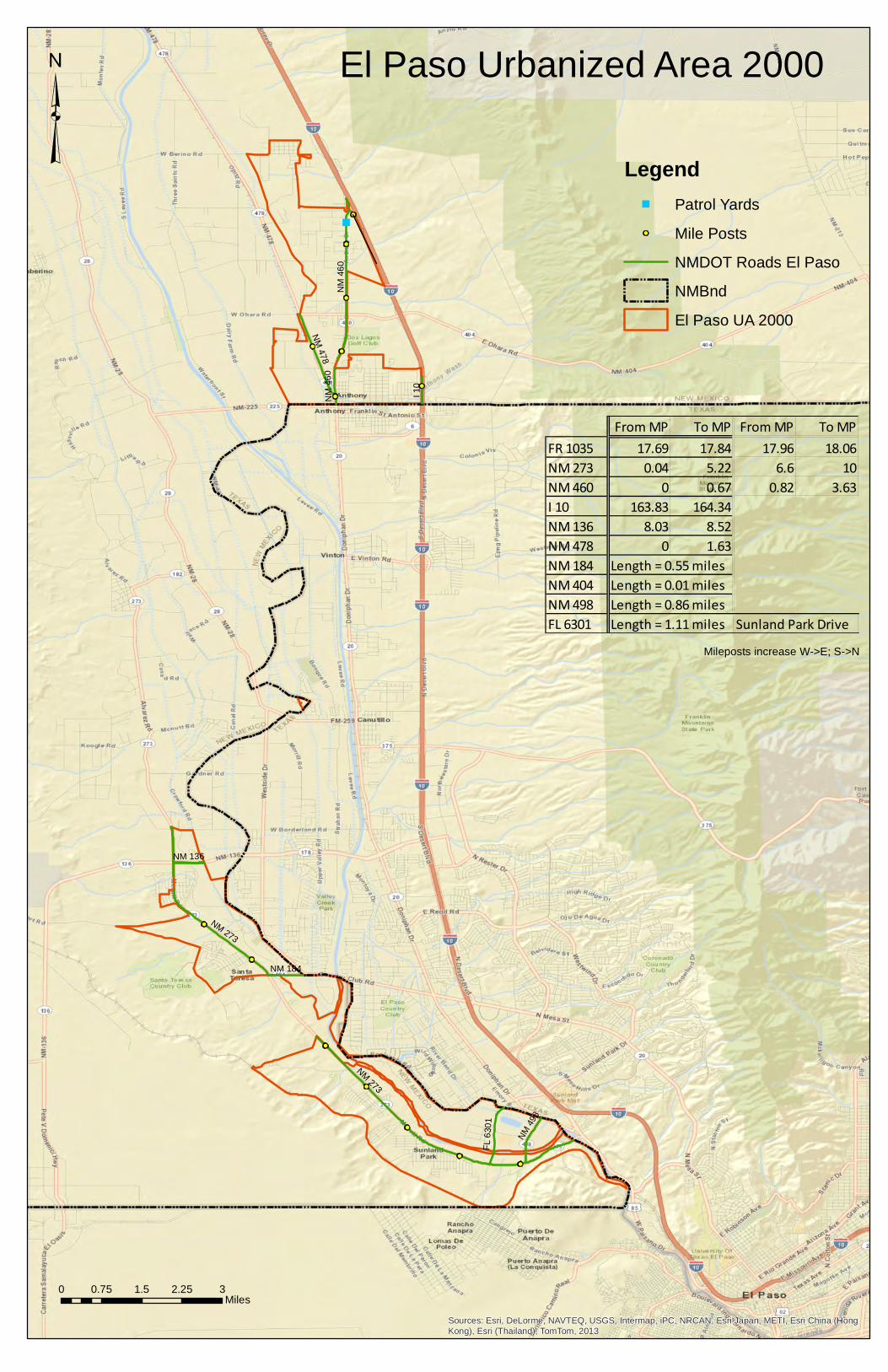
!
!
!
!
!
!
!
!
!
!!
!
!
!
"
NM
273
NM
46
0
NM
478
I 10
FL 6
30
1
NM
498
NM 184
NM 136
NM
46
0
NM 273
Sources: Esri, DeLorme, NAVTEQ, USGS, Intermap, iPC, NRCAN, Esri Japan, METI, Esri China (Hong
Kong), Esri (Thailand), TomTom, 2013
Legend" Patrol Yards
! Mile Posts
NMDOT Roads El Paso
NMBnd
El Paso UA 2000
El Paso Urbanized Area 2000
³
Mileposts increase W->E; S->N
0 0.75 1.5 2.25 3Miles
From MP To MP From MP To MPFR 1035 17.69 17.84 17.96 18.06NM 273 0.04 5.22 6.6 10NM 460 0 0.67 0.82 3.63I 10 163.83 164.34NM 136 8.03 8.52NM 478 0 1.63NM 184 Length = 0.55 milesNM 404 Length = 0.01 milesNM 498 Length = 0.86 milesFL 6301 Length = 1.11 miles Sunland Park Drive
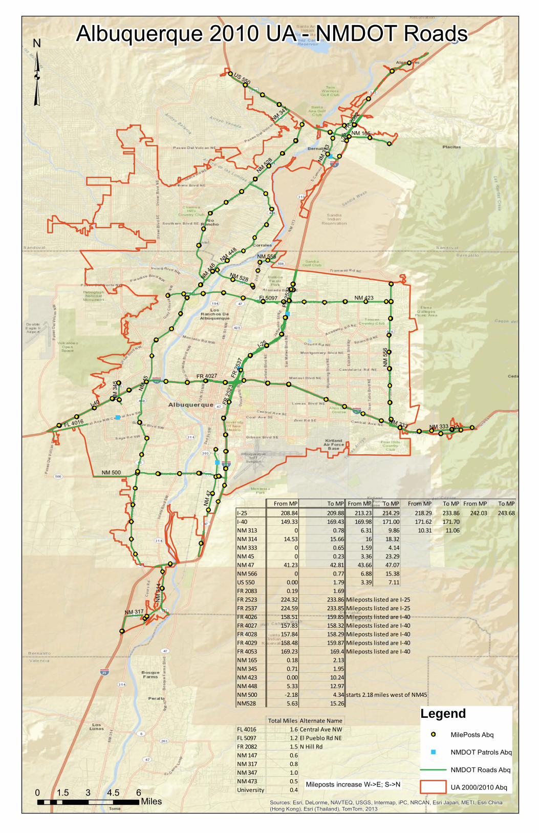
"
"
"
"
"
I-40
I-25
NM 4
5
NM 423
NM 528
NM
556
FR 2
537
NM 500
FR 2
523
NM 448
NM
47
NM 3
13
NM 333
NM 165
FL 4016
FR 20
82
NM
314
FL5097
US 550
NM
345
NM 347
NM 317
FR 4027
I-40
FR 2
523
NM 528
NM 556
NM 448
I-25
NM 333
Sources: Esri, DeLorme, NAVTEQ, USGS, Intermap, iPC, NRCAN, Esri Japan, METI, Esri China(Hong Kong), Esri (Thailand), TomTom, 2013
Albuquerque 2010 UA - NMDOT Roads
³
0 1.5 3 4.5 6Miles
From MP To MP From MP To MP From MP To MP From MP To MPI-25 208.84 209.88 213.23 214.29 218.29 233.86 242.03 243.68I-40 149.33 169.43 169.98 171.00 171.62 171.70NM 313 0 0.78 6.31 9.86 10.31 11.06NM 314 14.53 15.66 16 18.32NM 333 0 0.65 1.59 4.14NM 45 0 0.23 3.36 23.29NM 47 41.23 42.81 43.66 47.07NM 566 0 0.77 6.88 15.38US 550 0.00 1.79 3.39 7.11FR 2083 0.19 1.69FR 2523 224.32 233.86 Mileposts listed are I-25FR 2537 224.59 233.85 Mileposts listed are I-25FR 4026 158.51 159.85 Mileposts listed are I-40FR 4027 157.83 158.32 Mileposts listed are I-40FR 4028 157.84 158.29 Mileposts listed are I-40FR 4029 158.48 159.87 Mileposts listed are I-40FR 4053 169.23 169.4 Mileposts listed are I-40NM 165 0.18 2.13NM 345 0.71 1.95NM 423 0.00 10.24NM 448 5.33 12.97NM 500 -2.18 4.34 starts 2.18 miles west of NM45NM528 5.63 15.26
Total Miles Alternate NameFL 4016 1.6 Central Ave NWFL 5097 1.2 El Pueblo Rd NEFR 2082 1.5 N Hill RdNM 147 0.6NM 317 0.8NM 347 1.0NM 473 0.5University 0.4
Legend
MilePosts Abq
" NMDOT Patrols Abq
NMDOT Roads Abq
UA 2000/2010 AbqMileposts increase W->E; S->N

"
")
I 25
FR 2097
NM
59
9
NM
466
NM 475
NM
14
US
84
FR 599A
FL 4
77
7
IX 2
276
FR 2098
IX 2
282
FR
599C
IX 2
271
IX 2
282
NM
14
NM
14
NM 1
4
US 8
4
NM
59
9
US
84
NM 466
US
84
NM 1
4
Sources: Esri, DeLorme, NAVTEQ, USGS, Intermap, iPC, NRCAN, Esri Japan, METI, Esri China (Hong Kong), Esri (Thailand), TomTom, 2013
³
LegendMile Posts
" Patrol Yard
") General Office
RoadsSF2000
Santa Fe UA 2000
0 0.7 1.4 2.1 2.8Miles
Santa Fe Urbanized Areas 2000
Mileposts increase W->E; S->N
From MP To MP From MP To MPNM 599 0 4.03 5.44 6.68I-25 271.55 275.86 282.12 282.93
43.12 44.83 47.20 53.74
FL 4777 0 0.7 = GuadalupeFR 2097 271.69 NM 599 Mileposts listed are I-25NM 300 0 0.1 =west end of Old Las Vegas HwyNM 466 0 3.71 =St. Michael's, Old Pecos trailNM 475 0 2.65 toward Hyde Park & Ski BasinUS 84/US 285 160.89 167.4 = St. FrancisFR 2090 0.12 miles = Entrada La Cienega over I-25
FR 2098 adjacent to NM 599 and I-25FR 599A Frontage road near NM 599 and MeadowsFR 599C Frontage road near NM 599 and MeadowsFR 599E Frontage road near NM 599 and MeadowsIX 2271 Eastbound on-ramp at La CienegaIX 2276 On/Off ramps at I-25/NM 599IX 2282 On/Off ramps at I-25/US 84, only the north side of I-25IX 2284 On/Off ramps at I-25/NM 466, only the north side of I-25
NM 14 = Cerrillos: St. Francis to near I-25; from 599 and south
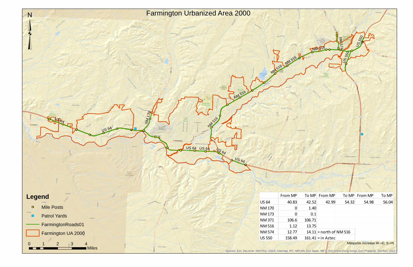
")
")
US 64
NM 516
US
550
NM
170
NM
574 U
S 5
50
NM 516
US 64
US 64
US 64
US 64
NM 5
16
NM 516
US 64
NM
516
Sources: Esri, DeLorme, NAVTEQ, USGS, Intermap, iPC, NRCAN, Esri Japan, METI, Esri China (Hong Kong), Esri (Thailand), TomTom, 2013
LegendMile Posts
") Patrol Yards
FarmingtonRoads01
Farmington UA 2000
³Farmington Urbanized Area 2000
0 1 2 3 4Miles
Mileposts increase W->E; S->N
From MP To MP From MP To MP From MP To MPUS 64 40.83 42.52 42.99 54.32 54.98 56.04NM 170 0 1.40NM 173 0 0.1NM 371 106.6 106.71NM 516 1.12 13.75NM 574 12.77 14.11 = north of NM 516US 550 158.49 161.41 = in Aztec
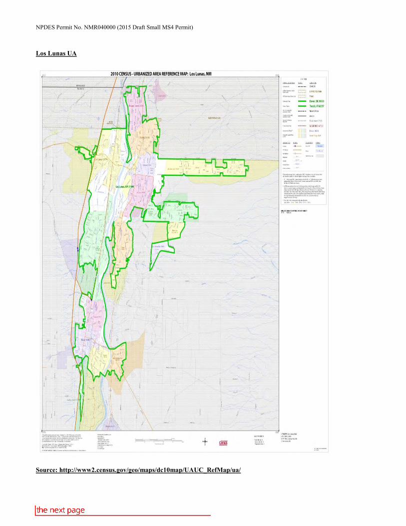
NPDES Permit No. NMR040000 (2015 Draft Small MS4 Permit)
Los Lunas UA
Source: http://www2.census.gov/geo/maps/dc10map/UAUC_RefMap/ua/
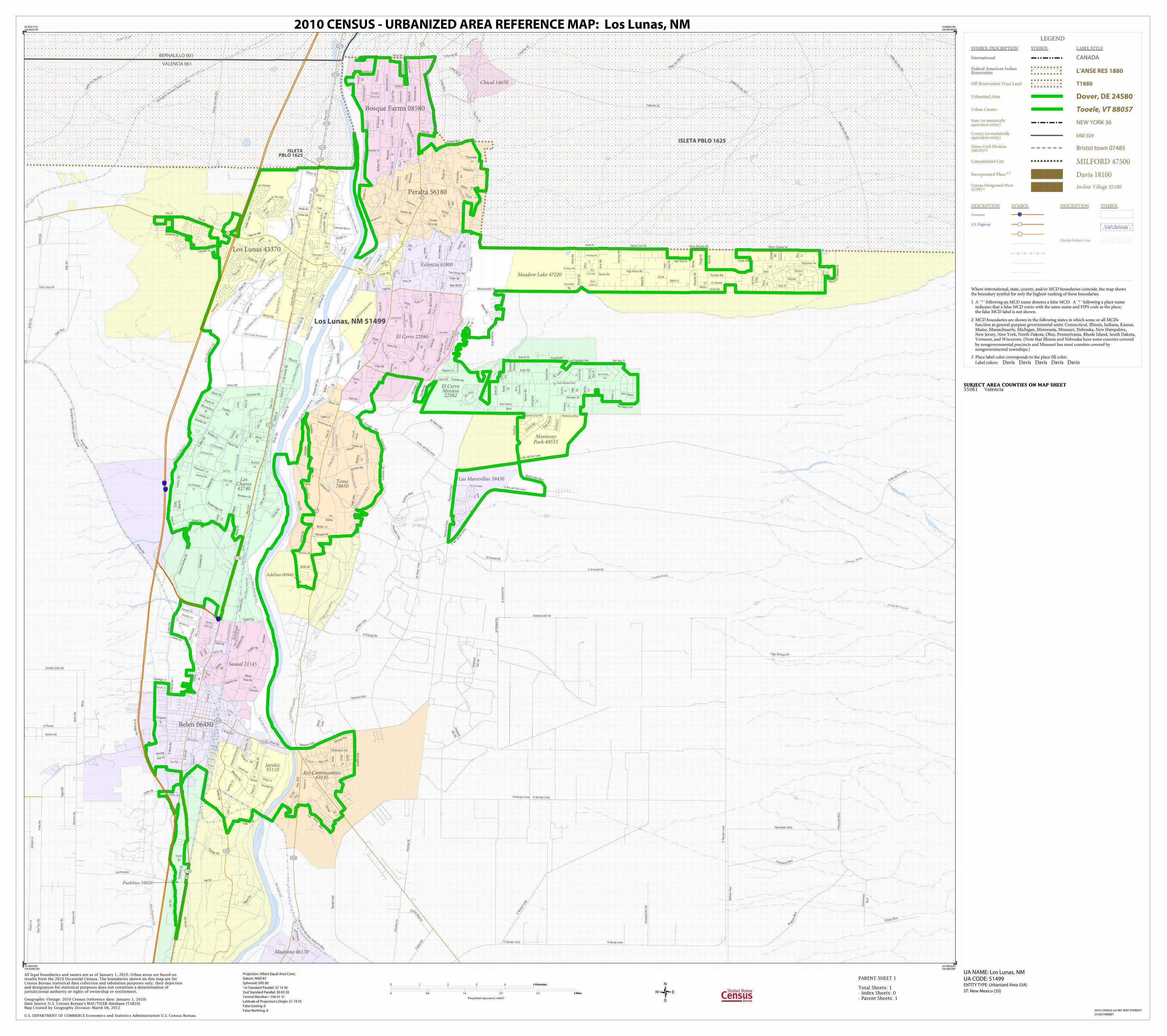
Ce dar W ash
Canada Ancha
Arroyo del Cu ervo
Canada Ancha
Belen Highline Cnl
l a C
onsta
ncia
Late
ral
Chica
l Ditch
San Juan Cnl
la Cons tan
cia L
ater
al
Tome D
rn
el Ce
rro
Ditc
h
Witt
wer L
ater
al
Belen Ditch
Peralta Ditch
San Fernandez
Drn
Valencia Drn
Costancia Ditch
Tom
e Drn
Los Chav
es Drn
Harlan
Ditc
h
Tom
e Drn
Tome D
rn
Lower
Pera
lta R
iversi
de D
rn
Los C
have
z D
itch
Valencia D
i tch
New Ja
ral D
itch
Hell
Can
yon
Was
tewa
y
Old
Belen
Ditc
h
Los
Luna
s Dit ch
Los Lunas Wasteway
Tafo
ya L
ater
al
Hell Canyon D
rn
Ote
ro L
ater
al
Lower Belen Riverside Drn
Los L
unas
Ditc
h
Tome D
itch
Upper Belen Riverside Drn
Las Cer c as Ditch
Tome Drn
Belen D
itch
Cerro D
r n
Los C
have
z Drn
Belen
High
line C
nl
Belen H
ighlin
e Cnl
Los C
have
z Ditc
h
Los C
haves Drn
el Ce
rro D
rn
Leve
e Sau
sal D
rn
Jaral Lateral No 1
New
Tom
e Ditc
h
Los C
have
s Drn
Lo
s Cha
vez L
ater
al
el Cerro Drn
Los C
havez
Drn
Otero D
rn
Har
lan
Late
ral
Fern
ande
z Lat
eral
Los L
ente
s Drn
Burling
ton Nort
hern S
anta Fe R
lwy
Burlington Northern Santa Fe Rlwy
Burlington Nor thern Santa Fe Rlwy
25
25
25
Oak
Tree R
d
Arm
ijo R
d
Jim
Rd
And
res
San
chez
Rd
Turb
ine
Rd
Trigo Springs Rd
Cielo
Azul
Silva
Rd
Mili
tary
Hw
y
Rom
ero
Rd
Esc
obar
Dr
Indi
an
Svc Rte
610
Locked Gate Rd
Nav
ajo
Loop
Triba
l R
d
16
Indian Sv
c Rt
e 62
5
Indian Svc Rte 603
Hin
son R
d
Arroyo Rd
Villa Linda Dr
Mill Rd
Indian Svc Rte 591
Sonnenberg
Loop
Triba
l Rd 10
C
astillo Rd
James St
de Haan Loop
Hw
y 3
14
India
n S
vc R
te 6
21
De
haan Loop
N Rio del Oro Loop
Tribal R
d 2
Tribal Rd 22
N Navajo Loop
Tribal Rd 1
Jense
n L
n
Fritts
Rd
W F
rontage R
d Barela Rd
S N
avaj
o Lo
op
Gallo
Rd
Rom
ero
Rd
S N
ava
jo L
oop
Tribal Rd 20
la Entrada Rd
Oga
z R
d
Pro
monto
Blv
d
Unn
a med
Dirt
Rd
Gre
er
Rd
Edm
undo
Rd
Commerce Blvd
el Paseo
Arroyo Rd
Unn
amed
Dirt
Rd
N Navajo Loop
Newcastle Blvd
de H
aan L
oop
Tribal Rd 18
At&
t R
d
Gallo
Rd
Sherrod Blvd
de H
aan L
oop
Ala
me
Loop
S Navajo Loop
la Entrada Rd
Unnamed Dirt Rd
Celaya Blvd
Com
merc
e
Blv
d
Prog
ress
Blvd
N Rio del O
ro Loop
Cha
co
n Blvd
Unnam
ed
Dirt Rd
la E
ntr
ada R
d
Prairie Wind Ln
Indian Svc Rte 627
la Estrada Rd
Esc
obar
St
N Navajo Loop
Charin L
n
Las Piedras
la E
ntra
da R
d
Olgu
in R
d
Mesa
Curfman Rd
Hig
h
Deal R
d
Elias Rd
Valle Dr
Sand
i a D
r
Val
lejo
s
Wes
tern
Dr
Ad
o be Ln
Sacra
mento
Pl
Par
k La
ne C
ir
Square Deal Rd
Winchester D
r
Maestas Rd
Apac
he L
n
MichaelannDr
Cll
del B
osqu
e
Hw
y 3
14
Cll
Medio
Abril
St
Peyton Rd
Wilson Rd
Blue Hill Rd
Ave
Val
enci
a
RiveraRd
Padil
la Rd
Cotto
nw
ood
Ln
Las
Ros
as D
r
Valle
Lindo Ct
l a Luna Pl
Hillandale Ave
Joleen Dr
la Luz
Tava
lopa
Vis
del
Rio
N Dairy Rd
N5
thS
t
Rosa
Ave
Impala
Dr
Bryan Dr
Cut Tree
Ln
Bendito Ln
elCerro Mission Blvd
Hw
y 3
14
Win
ston
Ln
Delgado
St
E River Rd
Charity Ln
Menard Rd
E RossAve
Ave Aleg
re
Parker Ct
San L
uis
Ray
Pl
Sich
ler R
d
San
dhill
Rd
Ber
ry H
ill Fa
rms
Rd
Osa
ge D
r
Palo
Duro
Dr
Willo
w R
d
Sunflower Ave
Jardin Rd
Hon
eyf ie
ld L
n
RufinaDr
Val
le L
obo
Knockal
Farms Rd
Vanderp
loeg
Ct
TomatoFarm Rd
la E
scon
dida
Rd
Carm
el
Rd
Cam la Canada
RossLn
Was
mer
Cir
Burg
e D
r
Sh a
r on
Ln
Mario Dr
Cll Encantada
Primero Rd
S
an Diego Loop
Osha Pl
Baca
Gr a
nde
Rd
Ken
nedy
Dr
Ad
ela Ln
Cam
Manza
na
Molina Dr
Lujan Rd
Ranch
ero
Rd
Ave
Jardin
el C
erroRd
Los Cerritos
Dr
Bett
sLn
W B
osq
ue
Loop
Carmel
Rd
Hw
y 314
SW
Sic
hle
rRd
Hwy
6
Lee Trevino
B
lvd
Cll Media
Hwy 6
Hwy 6
Hill S
t
Pheasant Ln
Warn
er
Rd
Van Camp
Blvd
Hig
h
Rd
Mangham Ct
Ladera
Rd
Car
son
Dr
Ora
nge
Blo
ssom
St
Chaparral Ln
Barns Rd
Cam
illo
Rd
Cam
elot
Blvd
Mesa
Vista
Rd
Terr
yD
r
SRio
del O
roLo
op
Los Cerritos
Cam
de L
os C
have
z
Cam
pbell
Ln
Gorman Ave
Talbot Ln
Euse
bio
Rd
Schlutz Ln
Winston Dr
Murra y Loo
p
Drake Rd High Deal Dr Journ
ey
Rd
Yucc
aD
r
Mar
gar
e t
Dr
Valentin Rd
Taylor Rd
Main
St
Monterey Blvd
Abo Rd
el C
erro
Loop
LosChapulines
Monica
Rd
Pauls
Pl
SerafinRd
Priscilla Dr
Riven
dell Ln
Otero Rd
WolfeRd
Blo
om
N S
hine
Rd
Los
Lent
es R
d SE
Whitehouse Rd
Puest
a d
el Sol
Alta
V ista Way
Garc
ia L
n
Sel
leck
Rd
Main
St NE
Der
echo
Rd
Hea
ton L
oop
Par k v iew
Dr
Mel
anie
Ln
Casa del Sol Ln
McN
ew
Rd
Cll
del O
ro
Lake
Vw
VisaRd
Lopez
Loop
Caballo Ln
N Rio del Oro Loop
Turbo Rd
Sausal Rd
Wood Dr
Santa Cruz Rd
Vis Cedr
o
Mounta
in S
h ado
w D
r
Fence Line Rd
laEnt
rada
Rd
NM
esa
Rd
N M
esa
Rd
Est
ado
Rd
Sutt
on L
n
Diebold Rd
Sost
eno
Chave
z
East
side
Sch
ool R
d
Morning
Star Dr
Manza
no E
xpy
Manza
no E
xpy
Don F
elip
eRd
Amy Dr
Pue
blito
s Rd
Luce
ro R
d
Main St NW
Ryd
er
Ct
Hillm
an
St
Bombero Cir
S
Haz
el
Jamerson Rd
Luz Ln
Ter
reno
Gra
nd
e
Manza
nito
Dr
Riley Ave
Sha
wn
Dr
Manzano
Ln
Countr
yLn
Cin der Ln
S3
rdS
t
Davila Rd
Llano Dr
Bunton
Ln
Juan P
ere
a R
d
MimsDr
Carn
ival Ave N W
Tres Ninas Rd
San Thomas
Ave
Jaso
n R
d
Salas Rd
Brandon Dr
Katie Ln
Luna
Rom
ero
Ln
FranklinRd
Jayb
irdLo
op
Kiv
a T
rl
Los
Lent
esRd
NE
Manzano Vw
Sunflower
Ln
Cll
de O
ro
Anay
a Rd
Can
al B
lvd
Musica Ln
la
Mirada
Entrada
Aragon Rd
Corra
l Ln
Cie
lo
Vis
ta R
d
Hob Rd
Sunset Dr
Miller Rd
S M
iller Rd
High Mesa Rd
Seab
ell R
d
Cer
ritos
Ave
Bonita Vista Blvd
River Rd
Romero Rd
Miguel Ln
Rector
Rd
Edeal R
d
Gre
en
Acr
es
Ln
MarthaJean Dr
Leibel
Ct
Chantelly
Ln
Jara
millo
Rd
Hen
dri x L
n
Elai
ne D
r
Win
ston
Ct
Ela
ine
Dr
Blythe Rd
Don P
asqu
al R
d
Diaz
Ave
Guru
leR
d
Saxo
n R
d
Rho
di R
d
Airport
Rd
Orona Rd
Pla ta Dr
Par
k La
ne D
r
Coronado
St
Flora
Ln
Gre
en Rd
Bosque
Pl
S L
os L
ente
s Rd
Bernard Ave
PatricioDr
Mesi
taLn
Orilla Rd
Bra
ugh
t
Rd
S M
esa
Rd
Blu
eb
erry
Ln
Emilio
Lop
ez R
d
Sierra
Linda Ct
Cole
Rd
Palo
mas
Rd
K e lly L
n
Bonita Dr
la L
ader
a Rd
Sands
Loop
Trujillo
Rd
Hac
iend
a
C tB
rian
Ln
Peralta Blvd
Benito Ln
Vegas Rd
Horne
rSt
Armonica Rd
Morris Rd
Vigil Rd
MonteVista Rd
Trujillo
Rd Wesley Rd
Ace
quia
Flamingo Ln
Cannon Rd
Avi
la D
r
Zent
ner
Rd
Moli
naRd
Gra
vel
Pit
Rd
Hunnick
Rd
Cll
deW
ence
s
Oney Ln
US ThresherLn
Sie
sta
Manzano Expy
Sundance St
Tavalopa
SM
ain
St
Sun
dial
Loo
p
Tome
Ln
S Rio del Oro Loop
la
En trada
Rd
San Mateo
Rita
Ln
San Jose Pl
Hw
y 3
04
Paci
fica
Meadowlake Rd
Care
joLn
Mesa Estates Rd
Frances Rd
Em
elia
Ln
Jarales Rd
Ranch
itos
Rd
Orchar d Rd
Gon
zale
sR
d
Airport Dr
Hw
y 47
Lonestar St
Sedillo Rd
Marquez Rd
Cyp
ress B
lvd
Yucca
Dr
Lopez Rd
la Entrada Rd
Lawre
nce
Dr
Court St
Lazy
Ln
Mesa Estates Rd
Garc
ia
Ln
Bue
na
Vis
Vis
Solano
Mesa
Loo
p
Am
y R
d
Dairy
Rd
Dama Rd
Dean Ln
Escondida
Ln
Rivas
Rd
Elcampo Rd
De
lla R
d
Polka Rd
San Francisco Ave
Gar
cia
Dr
Hool D
r
Case
y
Ln
Luna S
t
Tondre Rd
Gab
aldo
n Rd
314
47
116
47
304
109
314
6
314
47
314
314
314
309
314
6
309
263
314
85
BERNALILLO 001
VALENCIA 061
ISLETA PBLO 1625
ISLETAPBLO 1625
Madrone 46170
Chical 14670
Rio Communities63145
Meadow Lake 47220
Las Maravillas 39430
El Cerro 22580
Sausal 71145
Valencia 81800
Adelino 00940
Tome78650
El CerroMission22582
MontereyPark 49515
Pueblitos 59820
LosChaves42740
Jarales35110
Belen 06480
Peralta 56180
Los Lunas 43370
Bosque Farms 08580
Los Lunas, NM 51499
LEGEND
SYMBOL DESCRIPTION SYMBOL LABEL STYLE
International CANADA
Federal American IndianReservation L'ANSE RES 1880
Off-Reservation Trust Land T1880
Urbanized Area Dover, DE 24580
Urban Cluster Tooele, VT 88057
State (or statisticallyequivalent entity) NEW YORK 36
County (or statisticallyequivalent entity) ERIE 029
Minor Civil Division(MCD)1,2 Bristol town 07485
Consolidated City MILFORD 47500
Incorporated Place 1,3 Davis 18100
Census Designated Place(CDP) 3 Incline Village 35100
DESCRIPTION SYMBOL DESCRIPTION SYMBOL
Interstate 3
U.S. Highway 2
State Highway 4
Other RoadMarsh Ln
RailroadSouthern RR
Perennial StreamTumbling Cr
Intermittent StreamPiney Cr
Water Body Pleasant Lake
Military Fort Belvoir
Outside Subject Area
Where international, state, county, and/or MCD boundaries coincide, the map showsthe boundary symbol for only the highest-ranking of these boundaries.
1 A ' ° ' following an MCD name denotes a false MCD. A ' ° ' following a place name indicates that a false MCD exists with the same name and FIPS code as the place; the false MCD label is not shown.
2 MCD boundaries are shown in the following states in which some or all MCDs function as general-purpose governmental units: Connecticut, Illinois, Indiana, Kansas, Maine, Massachusetts, Michigan, Minnesota, Missouri, Nebraska, New Hampshire, New Jersey, New York, North Dakota, Ohio, Pennsylvania, Rhode Island, South Dakota, Vermont, and Wisconsin. (Note that Illinois and Nebraska have some counties covered by nongovernmental precincts and Missouri has most counties covered by nongovernmental townships.)
3 Place label color corresponds to the place fill color.
Label colors: Davis Davis Davis Davis Davis
SUBJECT AREA COUNTIES ON MAP SHEET 35061 Valencia
34.878171N106.84267W
34.880010N106.485885W
34.586263N106.48428W
34.584430N106.839823W
All legal boundaries and names are as of January 1, 2010. Urban areas are based onresults from the 2010 Decennial Census. The boundaries shown on this map are forCensus Bureau statistical data collection and tabulation purposes only; their depictionand designation for statistical purposes does not constitute a determination ofjurisdictional authority or rights of ownership or entitlement.
U.S. DEPARTMENT OF COMMERCE Economics and Statistics Administration U.S. Census Bureau
Geographic Vintage: 2010 Census (reference date: January 1, 2010)Data Source: U.S. Census Bureau's MAF/TIGER database (TAB10)Map Created by Geography Division: March 08, 2012
ENTITY TYPE: Urbanized Area (UA)
UA NAME: Los Lunas, NMUA CODE: 51499
Projection: Albers Equal Area Conic
Datum: NAD 83
Spheroid: GRS 80
1st Standard Parallel: 32 16 36
2nd Standard Parallel: 36 03 20
Central Meridian: -106 01 31
Latitude of Projection's Origin: 31 19 55
False Easting: 0
False Northing: 0
Total Sheets: 1- Index Sheets: 0- Parent Sheets: 1
ST: New Mexico (35)
0 1 2 3 4 5 Kilometers5 Kilometers
0 0.8 1.6 2.4 3.2 4 Miles4 Miles
The plotted map scale is 1:44647
2010 CENSUS - URBANIZED AREA REFERENCE MAP: Los Lunas, NM
2010 CENSUS UA REF MAP (PARENT)
231051499001
PARENT SHEET 1


