Embed Size (px)
Citation preview

Part No. OS3-135
R
MX-80PROFESSIONAL RECORDER
OPERATION AND MAINTENANCE MANUALNINTH EDITION
Printed: February 1992Ed 9 (GK)

Copyright © 1987, 1988, 1989, 1992 by Otari, Inc.
Printed in Japan
This manual may not be reproduced by any means without written permission.

WARNING
This equipment generates, uses and can radiate radio frequency energy
and if not installed and used in accordance with the instructions
manual, may cause interference to radio communications.
It has been tested and found to comply with the limits for a Class A
computing device pursuant to Subpart J of Part 15 of FCC Rules, which
are designed to provide reasonable protection against such interference
when operated in a commercial environment. Operation of this
equipment in a residential area is likely to cause interference in which
case the user at this own expense will be required to take whatever
measures may be required to correct the interference.


CAUTION
To prevent fire or shock hazard:
Do not expose this unit to rain or moisture.
Do not remove panels (unless instructed to do so).
There are no user-serviceable parts inside.
Refer servicing to qualified service personnel.
PLEASE READ THROUGH THE SAFETY INSTRUCTIONS ON THE NEXT PAGE.

SAFETY INSTRUCTIONS
1. Read Instructions All safety and operating instructions should be read before the device isoperated.
2. Retain Instructions The safety and operating instructions should be retained for future reference.
3. Heed Warnings All warnings on the device and in the operating instructions should becomplied with.
4. Follow Instructions All operating and use instructions should be followed.
5. Water and Moisture The device should not be used near water — for example, near a bathtub,wash bowl, sink, laundry tub, in a wet basement, near a swimming pool, etc.
6. Carts and Stands The device should be used only with a cart or stand that is recommended bythe manufacturer.
7. Ventilation The device should be situated so that its location or position does not interferewith its proper ventilation. For example, the device should not be situated on abed, sofa, rug, or similar surface that may block the ventilation openings; or,placed in a built-in installation, such as a bookcase or cabinet that may impedethe flow of air through the ventilation openings.
8. Heat The device should be situated away from heat sources such as a radiator,heat register, stove or other appliances (including amplifiers) that produceheat.
9. Power Sources The device should be connected to a power supply only of the type describedin the operating instructions or as marked on the device.
10. Grounding or Polarization Precautions should be taken so that the grounding or polarization means ofthe device is not defeated.
11. Power Cord Protection Power supply cords should be routed so that they are not likely to be walkedon or pinched by items placed upon or against them, paying particularattention to cords at plugs, convenience receptacles, and the point wherethey exit from the device.
12. Cleaning The device should be cleaned only as recommended by the manufacturer.
13. Non-Use Periods The power cord of the device should be unplugged from the outlet when leftunused for a long period of time.
14 Object and Liquid Entry Care should be taken that objects do not enter and that liquids are not spilledinto the enclosure through any openings.
15. Damage Requiring Service The device should be serviced by qualified service personnel when:A. The power supply cord or the plug has been damaged; orB. Objects have entered, or liquid has been spilled into the appliance; orC. The appliance has been exposed to rain; orD. The appliance does not appear to operate normally or exhibits a marked
change in performance; orE. The appliance has been dropped, or the enclosure damaged.
16. Servicing The user should not attempt to service the device beyond what is describedin the operating instructions. All other service should be referred to qualifiedpersonnel.

COMMUNICATION WITH OTARI
FOR SERVICE INFORMATION AND PARTS
All Otari products are manufactured under strict quality control. Each unit is carefully inspected and tested prior toshipment.
If, however, some adjustment or technical support becomes necessary, replacement parts are required, or technicalquestions arise, please contact your Otari dealer or contact Otari at:
Otari, Inc. Otari Corporation4-33-3 Kokuryo-cho 378 Vintage Park DriveChofu-shi, Tokyo182 Foster CityJapan California 94404
U.S.A.Phone : (0424) 81-8626 Phone : (415) 341-5900Telex : J26604 OTRDENKI Telex : 650 302 8432 MCI UWFax : (0424) 81-8633 Fax : (415) 341-7200Cable : OTARIDENKI TOKYO
Otari Deutschland GmbH. Otari Singapore Pte., LtdRudolf-Diesel-Str.12 625 Aljunied RoadD-4005 Meerbusch 2 (Osterath) #07-05 Aljunied Industrial ComplexF.R.Germany Singapore 1438
Phone : (02159) 50861 Phone : (743)7711Telex : 8531638 OTEL D Telex : RS 36935 OTARIFax : (02159) 1778 Fax : (743) 6430
Otari (U.K.) LimitedUnit 13, Elder Way, Waterside Drive, Langley,Slough, Berkshire SL3 6EPUnited Kingdom
Phone : (0753) 580777Telex : 849453 OTARI GFax : (0753) 542600
Another part of Otari's continuing technical support program for our products is the continuous revision of manuals as theequipment is improved or modified. In order for you to receive the information and support which is applicable to yourequipment, and for the technical support program to function properly, please include the following information, most ofwhich can be obtained from the Serial number label on the machine, in all correspondence with Otari:
• Model Number:• Serial Number:• Date of Purchase:• Name and address of the dealer where the machine was purchased and the power requirements (voltage and
frequency) of the machine.


February 1992 ix
Table of Contents
Safety Instructions . . . . . . . . . . . . . . . . . . . . . . . . . . . . . . . . . . . . . . . . . . . . . . . . . . . . . . . . . . . . . viCommunications with Otari . . . . . . . . . . . . . . . . . . . . . . . . . . . . . . . . . . . . . . . . . . . . . . . . . . . . vii
Section 1 Introduction
1.1 Otari MX-80 Series Tape Recorder . . . . . . . . . . . . . . . . . . . . . . . . . . . . . . . . . 1-2
1.2 Using this Manual . . . . . . . . . . . . . . . . . . . . . . . . . . . . . . . . . . . . . . . . . . . . . . . . . . . . 1-41.2.1 Organization . . . . . . . . . . . . . . . . . . . . . . . . . . . . . . . . . . . . . . . . . . . . . . . . . . . . . . . 1-41.2.2 Conventions within this Manual . . . . . . . . . . . . . . . . . . . . . . . . . . . . . . . . . . . . . 1-5
1.3 Specifications . . . . . . . . . . . . . . . . . . . . . . . . . . . . . . . . . . . . . . . . . . . . . . . . . . . . . . . . 1-61.3.1 Transport . . . . . . . . . . . . . . . . . . . . . . . . . . . . . . . . . . . . . . . . . . . . . . . . . . . . . . . . . . 1-61.3.2 Electronics . . . . . . . . . . . . . . . . . . . . . . . . . . . . . . . . . . . . . . . . . . . . . . . . . . . . . . . . . 1-71.3.3 Physical . . . . . . . . . . . . . . . . . . . . . . . . . . . . . . . . . . . . . . . . . . . . . . . . . . . . . . . . . . . 1-81.3.4 Accessories . . . . . . . . . . . . . . . . . . . . . . . . . . . . . . . . . . . . . . . . . . . . . . . . . . . . . . . . 1-9
Section 2 Installation
2.1 Unpacking the Machine . . . . . . . . . . . . . . . . . . . . . . . . . . . . . . . . . . . . . . . . . . . . . 2-2
2.2 Inspection . . . . . . . . . . . . . . . . . . . . . . . . . . . . . . . . . . . . . . . . . . . . . . . . . . . . . . . . . . . . . 2-22.2.1 Audio Control PCB . . . . . . . . . . . . . . . . . . . . . . . . . . . . . . . . . . . . . . . . . . . . . . . . . 2-22.2.2 Audio Amplifier PCB . . . . . . . . . . . . . . . . . . . . . . . . . . . . . . . . . . . . . . . . . . . . . . . . 2-32.2.3 Serial Remote Control PCB . . . . . . . . . . . . . . . . . . . . . . . . . . . . . . . . . . . . . . . . . 2-42.2.4 Transport Control PCB . . . . . . . . . . . . . . . . . . . . . . . . . . . . . . . . . . . . . . . . . . . . . . 2-52.2.5 Power Supply Panel . . . . . . . . . . . . . . . . . . . . . . . . . . . . . . . . . . . . . . . . . . . . . . . . 2-82.2.6 Transport Assemblies . . . . . . . . . . . . . . . . . . . . . . . . . . . . . . . . . . . . . . . . . . . . . . 2-82.2.7 Remote Control Unit . . . . . . . . . . . . . . . . . . . . . . . . . . . . . . . . . . . . . . . . . . . . . . . 2-9
2.3 Hooking up the MX-80 . . . . . . . . . . . . . . . . . . . . . . . . . . . . . . . . . . . . . . . . . . . . . 2-102.3.1 Hooking up the AC Power . . . . . . . . . . . . . . . . . . . . . . . . . . . . . . . . . . . . . . . . . 2-102.3.2 Hooking up the Audio Inputs and Outputs . . . . . . . . . . . . . . . . . . . . . . . . . . 2-102.3.3 Hooking up the Remote Control Unit . . . . . . . . . . . . . . . . . . . . . . . . . . . . . . . 2-112.3.4 Using the Parallel I/O Connector . . . . . . . . . . . . . . . . . . . . . . . . . . . . . . . . . . . 2-12
2.3.4.1 Rehearse Mode on the MX-80 . . . . . . . . . . . . . . . . . . . . . . . . . . . . . . 2-132.3.4.2 Enabling “Time Code Cue” . . . . . . . . . . . . . . . . . . . . . . . . . . . . . . . . . . 2-132.3.4.3 Speed Mode Selection with no Remote Control Unit . . . . . . . . . 2-13
2.3.5 Noise Reduction System Control . . . . . . . . . . . . . . . . . . . . . . . . . . . . . . . . . . 2-142.3.6 Serial I/O (Optional) . . . . . . . . . . . . . . . . . . . . . . . . . . . . . . . . . . . . . . . . . . . . . . . 2-15
2.4 Level Matching . . . . . . . . . . . . . . . . . . . . . . . . . . . . . . . . . . . . . . . . . . . . . . . . . . . . . . 2-16
Section 3 Controls and Indicators
3.1 Transport Controls and Indicators . . . . . . . . . . . . . . . . . . . . . . . . . . . . . . . . . 3-2
3.2 VU Meters (Upper Front Panel) . . . . . . . . . . . . . . . . . . . . . . . . . . . . . . . . . . . . 3-5
3.3 Amplifier Controls (Lower Front Panel) . . . . . . . . . . . . . . . . . . . . . . . . . . . 3-63.3.1 Audio Control PCB . . . . . . . . . . . . . . . . . . . . . . . . . . . . . . . . . . . . . . . . . . . . . . . . . 3-63.3.2 Serial Remote PCB . . . . . . . . . . . . . . . . . . . . . . . . . . . . . . . . . . . . . . . . . . . . . . . . . 3-73.3.3 Audio Amplifier PCB . . . . . . . . . . . . . . . . . . . . . . . . . . . . . . . . . . . . . . . . . . . . . . . . 3-8
3.4 Power Supply Panel . . . . . . . . . . . . . . . . . . . . . . . . . . . . . . . . . . . . . . . . . . . . . . . . . 3-9

3.5 Input and Output Connectors . . . . . . . . . . . . . . . . . . . . . . . . . . . . . . . . . . . . . 3-10
3.6 Remote Control Unit . . . . . . . . . . . . . . . . . . . . . . . . . . . . . . . . . . . . . . . . . . . . . . . . 3-113.6.1 Controls, Indicators, and Connectors . . . . . . . . . . . . . . . . . . . . . . . . . . . . . . 3-113.6.2 Controls on the CB-140 CPU PCB Assembly . . . . . . . . . . . . . . . . . . . . . . . 3-15
Section 4 Operation
4.1 Modes of Operation . . . . . . . . . . . . . . . . . . . . . . . . . . . . . . . . . . . . . . . . . . . . . . . . . . 4-2
4.2 Recording with the MX-80 — A Tutorial . . . . . . . . . . . . . . . . . . . . . . . . . . 4-34.2.1 Threading the Tape on the Machine . . . . . . . . . . . . . . . . . . . . . . . . . . . . . . . . . 4-34.2.2 Recording the Basic Tracks . . . . . . . . . . . . . . . . . . . . . . . . . . . . . . . . . . . . . . . . . 4-44.2.3 Playing Back the Basic Tracks . . . . . . . . . . . . . . . . . . . . . . . . . . . . . . . . . . . . . . . 4-54.2.4 Recording Overdubs Using Sel·Rep Playback . . . . . . . . . . . . . . . . . . . . . . . . 4-54.2.5 Recording Punch-In Overdubs . . . . . . . . . . . . . . . . . . . . . . . . . . . . . . . . . . . . . . 4-64.2.6 Rehearsing the Punch-In . . . . . . . . . . . . . . . . . . . . . . . . . . . . . . . . . . . . . . . . . . . 4-74.2.7 Bouncing or “Ping-Ponging” Tracks . . . . . . . . . . . . . . . . . . . . . . . . . . . . . . . . . 4-84.2.8 Using the Spot Erase Feature . . . . . . . . . . . . . . . . . . . . . . . . . . . . . . . . . . . . . . . 4-94.2.9 Playing Back the Track for Mixdown . . . . . . . . . . . . . . . . . . . . . . . . . . . . . . . . 4-94.2.10 Library Winding the Tape . . . . . . . . . . . . . . . . . . . . . . . . . . . . . . . . . . . . . . . . 4-104.2.11 Moving the Tape by Hand for Editing . . . . . . . . . . . . . . . . . . . . . . . . . . . . . 4-104.2.12 Editing the Tape . . . . . . . . . . . . . . . . . . . . . . . . . . . . . . . . . . . . . . . . . . . . . . . . . 4-114.2.13 Using the Variable Speed Feature . . . . . . . . . . . . . . . . . . . . . . . . . . . . . . . . . 4-124.2.14 Controlling the Capstan Speed with an External Device . . . . . . . . . . . . 4-12
Section 5 Alignment and Calibration
5.1 Transport Alignment . . . . . . . . . . . . . . . . . . . . . . . . . . . . . . . . . . . . . . . . . . . . . . . . . 5-25.1.1 Tools and Equipment Required . . . . . . . . . . . . . . . . . . . . . . . . . . . . . . . . . . . . . 5-25.1.2 Opening the Transport and Removing the Deck Skin Panels . . . . . . . . . . 5-25.1.3 Reel Tension Servo Adjustment . . . . . . . . . . . . . . . . . . . . . . . . . . . . . . . . . . . . . 5-4
5.1.3.1 Tension Arm Spring Tension Adjustment . . . . . . . . . . . . . . . . . . . . . 5-45.1.3.2 Tachometer Quadrature/Phase Adjustment . . . . . . . . . . . . . . . . . . . 5-55.1.3.3 Fast Wind Speed Reference Voltage Adjustment . . . . . . . . . . . . . . 5-65.1.3.4 Tension Sensor Position . . . . . . . . . . . . . . . . . . . . . . . . . . . . . . . . . . . . . 5-65.1.3.5 Tension Arm Sensor Gain Adjustment . . . . . . . . . . . . . . . . . . . . . . . . 5-75.1.3.6 Play Acceleration Preliminary Adjustment . . . . . . . . . . . . . . . . . . . . 5-75.1.3.7 Fast Forward and Rewind Torque Adjustment . . . . . . . . . . . . . . . . . 5-75.1.3.8 Reel Motor Torque Adjustment . . . . . . . . . . . . . . . . . . . . . . . . . . . . . . . 5-75.1.3.9 Tension Arm Position Adjustment . . . . . . . . . . . . . . . . . . . . . . . . . . . . 5-85.1.3.10 Fast Wind and Spooling Wind Speed Adjustment . . . . . . . . . . . . 5-85.1.3.11 Tape Tension Check . . . . . . . . . . . . . . . . . . . . . . . . . . . . . . . . . . . . . . . . 5-8
5.1.4 Capstan Servo Adjustment . . . . . . . . . . . . . . . . . . . . . . . . . . . . . . . . . . . . . . . . . 5-95.1.4.1 Preliminary Adjustment . . . . . . . . . . . . . . . . . . . . . . . . . . . . . . . . . . . . . . 5-95.1.4.2 Phase Locked Loop Duty Cycle Adjustment . . . . . . . . . . . . . . . . . . 5-95.1.4.3 Gain Adjustment . . . . . . . . . . . . . . . . . . . . . . . . . . . . . . . . . . . . . . . . . . . . 5-95.1.4.4 Capstan Servo Damping Adjustment . . . . . . . . . . . . . . . . . . . . . . . . 5-10
5.1.5 Tape Lifter Adjustment . . . . . . . . . . . . . . . . . . . . . . . . . . . . . . . . . . . . . . . . . . . . 5-105.1.6 Pinch Roller Position and Pressure Adjustment . . . . . . . . . . . . . . . . . . . . 5-125.1.7 Brake Adjustment . . . . . . . . . . . . . . . . . . . . . . . . . . . . . . . . . . . . . . . . . . . . . . . . . 5-125.1.8 Variable Speed Range Criterion Setting . . . . . . . . . . . . . . . . . . . . . . . . . . . . 5-13
5.2 Routine Audio Alignment . . . . . . . . . . . . . . . . . . . . . . . . . . . . . . . . . . . . . . . . . . 5-145.2.1 Tools, Materials, and Test Equipment Required . . . . . . . . . . . . . . . . . . . . . 5-145.2.2 Demagnetizing the Heads and Tape Path . . . . . . . . . . . . . . . . . . . . . . . . . . . 5-155.2.3 Cleaning the Tape Path and Lubrication . . . . . . . . . . . . . . . . . . . . . . . . . . . . 5-165.2.4 Input Level, Output Level, and Peak Indicator Adjustment . . . . . . . . . . 5-175.2.5 Reproduce Head Azimuth Adjustment . . . . . . . . . . . . . . . . . . . . . . . . . . . . . . 5-18
Table of Contents
x February 1992
MX-80 Operation and Maintenance Manual

5.2.6 Record Head Azimuth Adjustment . . . . . . . . . . . . . . . . . . . . . . . . . . . . . . . . . 5-195.2.7 Reproduce Level Adjustment . . . . . . . . . . . . . . . . . . . . . . . . . . . . . . . . . . . . . . 5-205.2.8 Low Speed Reproduce Equalization Alignment . . . . . . . . . . . . . . . . . . . . . 5-205.2.9 High Speed Reproduce Equalization Alignment . . . . . . . . . . . . . . . . . . . . . 5-205.2.10 Sel·Rep Level Adjustment . . . . . . . . . . . . . . . . . . . . . . . . . . . . . . . . . . . . . . . . 5-215.2.11 Low Speed Sel·Rep Equalization Alignment . . . . . . . . . . . . . . . . . . . . . . . 5-215.2.12 High Speed Sel·Rep Equalization Alignment . . . . . . . . . . . . . . . . . . . . . . . 5-215.2.13 Low Speed Record Bias, Equalization, and Level Adjustment . . . . . . 5-225.2.14 High Speed Record Bias, Equalization, and Level Adjustment . . . . . . 5-235.2.15 Low Frequency Compensation Adjustment . . . . . . . . . . . . . . . . . . . . . . . . 5-235.2.16 Record Phase Compensation Adjustment . . . . . . . . . . . . . . . . . . . . . . . . . 5-245.2.17 Erase and Record Bias Symmetry Adjustment . . . . . . . . . . . . . . . . . . . . 5-255.2.18 Gapless Punch-In/Out Test and Adjustment . . . . . . . . . . . . . . . . . . . . . . . 5-27
Section 6 Printed Circuit Board Layouts and Parts Lists
6.1 Capstan Control PCB Assembly (PB-4FAA) . . . . . . . . . . . . . . . . . . . . . . . 6-2
6.2 Reel Control PCB Assembly (PB-4FBA) . . . . . . . . . . . . . . . . . . . . . . . . . . . 6-5
6.3 Reel Drive PCB Assembly (PB-4FCA) . . . . . . . . . . . . . . . . . . . . . . . . . . . . . 6-6
6.4 Transport Control PCB Assembly (PB-4FDA) . . . . . . . . . . . . . . . . . . . . 6-9
6.5 Serial Remote Control PCB Assembly (PB-4FEA) . . . . . . . . . . . . . . 6-10
6.6 Audio Control PCB Assembly (PB-4FFA) . . . . . . . . . . . . . . . . . . . . . . . . 6-13
6.7 Audio Amplifier PCB Assembly (PB-19JA) . . . . . . . . . . . . . . . . . . . . . . 6-14
6.8 Power Supply PCB Assembly (PB-62ZA) . . . . . . . . . . . . . . . . . . . . . . . 6-17
6.9 CB-140 Display PCB Assembly (PB-7JAB) . . . . . . . . . . . . . . . . . . . . . . 6-18
6.10 CB-140 CPU PCB Assembly (PB-4FGA) . . . . . . . . . . . . . . . . . . . . . . . 6-21
Section 7 Exploded View Drawings and Parts Lists
7.1 Reel Assembly . . . . . . . . . . . . . . . . . . . . . . . . . . . . . . . . . . . . . . . . . . . . . . . . . . . . . . . . 7-2
7.2 Capstan and Pinch Roller Assemblies . . . . . . . . . . . . . . . . . . . . . . . . . . . . . 7-4
7.3 Tachometer Roller, Impedance Roller, and Tension ArmAssemblies . . . . . . . . . . . . . . . . . . . . . . . . . . . . . . . . . . . . . . . . . . . . . . . . . . . . . . . . . . . . 7-6
7.4 Head Shield and Tape Lifter Assemblies . . . . . . . . . . . . . . . . . . . . . . . . . . 7-8
7.5 Head Assembly . . . . . . . . . . . . . . . . . . . . . . . . . . . . . . . . . . . . . . . . . . . . . . . . . . . . . . 7-10
7.6 Control Panel Assembly . . . . . . . . . . . . . . . . . . . . . . . . . . . . . . . . . . . . . . . . . . . . 7-12
7.7 VU Meter Panel Assembly . . . . . . . . . . . . . . . . . . . . . . . . . . . . . . . . . . . . . . . . . 7-14
7.8 Amplifier Assembly . . . . . . . . . . . . . . . . . . . . . . . . . . . . . . . . . . . . . . . . . . . . . . . . . 7-16
7.9 Power Supply Assembly . . . . . . . . . . . . . . . . . . . . . . . . . . . . . . . . . . . . . . . . . . . 7-18
7.10 Rear Panel Assemblies . . . . . . . . . . . . . . . . . . . . . . . . . . . . . . . . . . . . . . . . . . . 7-20
7.11 Audio I/O Panel Assembly . . . . . . . . . . . . . . . . . . . . . . . . . . . . . . . . . . . . . . . . 7-22
7.12 Remote Control Assembly CB-140 . . . . . . . . . . . . . . . . . . . . . . . . . . . . . . 7-24
7.13 Remote Control Assembly CB-151 . . . . . . . . . . . . . . . . . . . . . . . . . . . . . . 7-26
Table of ContentsMX-80 Operation and Maintenance Manual
xiFebruary 1992

Appendix Modification and Field Upgrades
A.1 Wide Band Modification . . . . . . . . . . . . . . . . . . . . . . . . . . . . . . . . . . . . . . . . . . . . . A-2
A.2 Changing Machine Speed Pairs . . . . . . . . . . . . . . . . . . . . . . . . . . . . . . . . . . . . A-3
A.3 Installation of Overbridge Case for Noise Reduction System . . . . . A-4
Schematic Diagrams
xii February 1992
Table of Contents MX-80 Operation and Maintenance Manual

February 1992 1 - 1
Section 1 Introduction
This section contains general information about the MX-80 SeriesMultichannel Tape Recorder and about this manual.
1.1 Otari MX-80 Series Tape Recorder . . . . . . . . . . . . . . . . . . . . . . . . . . . . . . . . . 1-2
1.2 Using this Manual . . . . . . . . . . . . . . . . . . . . . . . . . . . . . . . . . . . . . . . . . . . . . . . . . . . . 1-41.2.1 Organization . . . . . . . . . . . . . . . . . . . . . . . . . . . . . . . . . . . . . . . . . . . . . . . . . . . . . . . 1-41.2.2 Conventions within this Manual . . . . . . . . . . . . . . . . . . . . . . . . . . . . . . . . . . . . . 1-5
1.3 Specifications . . . . . . . . . . . . . . . . . . . . . . . . . . . . . . . . . . . . . . . . . . . . . . . . . . . . . . . . 1-61.3.1 Transport . . . . . . . . . . . . . . . . . . . . . . . . . . . . . . . . . . . . . . . . . . . . . . . . . . . . . . . . . . 1-61.3.2 Electronics . . . . . . . . . . . . . . . . . . . . . . . . . . . . . . . . . . . . . . . . . . . . . . . . . . . . . . . . . 1-71.3.3 Physical . . . . . . . . . . . . . . . . . . . . . . . . . . . . . . . . . . . . . . . . . . . . . . . . . . . . . . . . . . . 1-81.3.4 Accessories . . . . . . . . . . . . . . . . . . . . . . . . . . . . . . . . . . . . . . . . . . . . . . . . . . . . . . . . 1-9

1.1 Otari MX-80 Series Tape RecordersThe Otari MX-80 series machines are extremely versatile, high performance8, 16, or 24 track recorder/reproducers using 1" or 2" wide tape and 10-1/2”NAB reels. The MX-80 series consists of eight machines, each having adifferent combination of tape speed pairs (7.5 and 15 ips or 15 and 30 ips)and track configurations (8 tracks, 16 tracks, or 24 tracks). Table 1-1describes the various configurations and model numbers.
Table 1-1MX-80 Series Configurations
Tape Width Tape Speed Track Configuration Model Number
1" 30 & 15 ips 8 tracks MX-80-8-H16 tracks MX-80-1-16H
15 & 7.5 ips 8 tracks MX-80-8-L16 tracks MX-80-1-16L
2" 30 & 15 ips 16 tracks MX-80-16-H24 tracks MX-80-24-H
15 & 7.5 ips 16 tracks MX-80-16-L24 tracks MX-80-24-L
The MX-80 series tape transport is fully microprocessor controlled to provideprecision tape handling characteristics while maintaining the high degree ofreliability long associated with the Otari line of professional tape recorders.The transport controls (PLAY, F.FWD, REWIND, STOP, CUE, EDIT/UNLOAD, etc.) directcommands to the microprocessor which, in turn, controls the activities of thecapstan and reel servo circuits to provide the desired operating mode orfunction. The microprocessor provides two-level illumination for thetransport control buttons, dim when “off”, flashing when “ready” to performa function, and bright when “active” after a function has been selected, givingconfirmation of the operating mode to the operator.
The plug-in multi-track head assembly allows replacement of a headassembly without having to perform time-consuming height, wrap, andzenith adjustments. Only the azimuth adjustment need be verified wheneverchanging heads, or optimizing the alignment for a tape recorded on anothertape recorder. The head assembly is equipped with a scrape flutter rollerlocated between the record and reproduce head stacks. A head shield, whichis manually moved up and down, is provided in front of the head stacks. Thehead shield rises automatically in PLAY and RECORD modes.
The capstan shaft is driven directly by a DC servo motor which is controlledby a quartz crystal-based phase-locked-loop servo system. A switch on thetransport selects between the two operating speeds (7.5, 15 ips or 15, 30ips). The speed mode switch on the Remote Control Unit (CB-140 or CB-151)selects between the three available speed modes; FIX — crystal controlledspeed selected by the speed switch on the transport, VARI — variable speed+50%, and EXT — variable speed controlled by an external speed referencesignal (9,600 Hz nominal).
Constant tape tension is provided by the reel motor servo circuit. The tapetension arms utilize non-contact photo-optical sensors to generate feedbacksignals for the Reel Control Printed Circuit Board (PCB). Constant tension isapplied to the tape in all but Edit/Unload mode to insure fast, accurate, stressfree tape handling. Motion sensing and accurate tape speed information areprovided by the tachometer roller to the transport control circuits in the formof tach pulses. These tach pulses are also used to control the fast forwardand rewind speeds, and to provide tape length information to the direct-reading Tape Timer.
Section 1 Introduction
1 - 2 February 1992
MX-80 Operation and Maintenance Manual

Located in the pedestal portion of the MX-80, the audio section contains theAudio Control PCB, the Serial Remote Control PCB, the Audio Amplifier PCBs(8, 16, or 24), and the power supplies for; the various sections of the taperecorder. The Audio Control PCB contains the test signal jack (for applicationof a test signal to all channels simultaneously), a selector switch for high orlow reference flux density and indicators showing the level selected, the biasswitch which allows bias setting for two different tape formulations, EQswitch for selecting IEC or NAB equalizer, high/low select switch for outputand input level, gapless function on/off switch, Dolby HX Pro* on/off switchand VU meter sensitivity selector switch.
The Serial Remote Control PCB contains two on/off switches for the selectionof Stop Standby and Fast Standby modes (Refer to §2.2.3).
The Audio Amplifier PCBs each contain the record, reproduce, sel·rep, andbias electronics for one audio channel. Front panel adjustments are providedfor record and reproduce equalization at both currently selected speeds,record, reproduce and sel·rep gain, record phase compensation andreproduce low frequency compensation for each speed of the current speedpair, and individual channel bias adjustment. Each channel is provided withan individual LINE OUTPUT Jack on the front panel, for test purposes, in additionto the XL type OUTPUT connector provided on the rear of the machine.
A VU meter is provided for each channel. In each VU meter are two LEDindicators, one to indicate signal level peaks that are too short to cause theVU meter to indicate accurately, and another to indicate the channel’s Recordstatus.
Each MX-80 series tape recorder includes either the CB-140 (16 or 24 tracks)or the CB-151 (8 tracks) full function Remote Control Unit.
The Remote Control Unit provides control of monitor (Input/Sel·Rep/Repro)and Record Ready switching and indication; transport mode, Search-to-Cue,Search-to-Zero, Repeat, and Speed Control functions.
The CB-140 Remote Control Unit also features four Channel Status memoriesto store and recall the mode status (Ready/Safe, Mute/Input/Sel·Rep/Repro)of all the channels simultaneously.
* HX Pro headroom extension originated by Bang and Olufsen and manufacturedunder license from Dolby Laboratories Licensing Corporation. “Dolby”, the Double-Dsymbol and HX Pro are trademarks of Dolby Laboratories Licensing Corporation.
MX-80 Operation and Maintenance Manual
February 1992
Section 1 Introduction
1 - 3

1.2 Using this ManualThis manual is intended for use with any of the models and configurationslisted above. The descriptions and references refer to the MX-80-24-H model(the 24 track, high speed-pair version). If any differences exist between thereferenced machine and another model, those differences will be explainedfully.
1.2.1 Organization
This manual is divided into eight sections beginning with this Introductionwhich contains general information about the machine and about the manual.
Section two, Installation, contains the information required when uncratingand installing the MX-80 for the first time, or when interfacing the machine toa recording mixer or other equipment.
The third section, Controls and Indicators, contains a keyed guide to thecontrols and indicators. This reference guide provides detailed informationabout each control and its functions. You should use this section of themanual when you have a question about the function of a particular controlor indicator.
Fourth is the Operation section which describes the operation of themachine. This section is divided into two parts, first, a list of all the operatingmodes of the machine, and second, “Recording with the MX-80”, a tutorialorganized by task, starting with threading tape on the machine and recordingbasic tracks, and continuing through overdubs, punch-ins, etc. You shoulduse this section when you wish to learn “how to” perform a task or operation(like spot erase or spooling).
The fifth section of this manual covers Alignment and Calibration includingthe information needed to perform the routine alignments and calibrationsassociated with normal operation of the machine (like head azimuth, biasadjustment, or output level adjustment). You should refer to this section ofthe manual when you are performing the normal maintenance and calibrationroutines that must be done to keep the recorder operating at peakperformance.
Section six contains Printed Circuit Board Layouts, with two-color “x-ray”views of each printed circuit board showing the component locations and foiltraces.
Section seven, Exploded Views and Parts Lists, contains assembly drawingsof the machine “exploded” to show internal parts and hardware, and theorder of assembly. Each exploded view is keyed to an accompanying partslist showing Otari part numbers for all mechanical components.
The final section of the manual contains the Schematics for all electronicsand printed circuit boards.
Section 1 Introduction
1 - 4 February 1992
MX-80 Operation and Maintenance Manual

1.2.2 Conventions within this Manual
The use of terms channel and track may require some clarification. Thismanual refers to the signal, or the path of the signal, recorded on the tape asa TRACK, and the electronics or controls for that path are referred to as aCHANNEL.
Generally, this manual uses all upper case type to describe a switch orcontrol when that item is similarly labeled on the machine (e.g., the PLAYbutton). Where a switch or button is not labeled, or the reference is lessclear, only the first letter of the item is capitalized (e.g., the Cue lever near theCUE button). Machine status or operating modes are described with an uppercase first letter (e.g., you press the PLAY button to place the machine in PLAY
mode). Normal parentheses ( ) are used for examples and parentheticcomments. Square brackets [ ] are used for reference to callouts in certainillustrations. The square brackets in a particular sub-section are either allreferenced to the same figure, as noted in that sub-section, or are individuallyreferenced (e.g., [Fig. 2-1,3], meaning callout “3” in Figure 2-1).
The information and procedure in Section 2, Installation should be followedvery carefully when the machine is first uncrated and installed. Performingthe inspection steps will familiarize you with the machine and its componentparts if this is your first contact with the MX-80 series of tape recorders.
Please read Sections 3 and 4 carefully before using the machine. In thefuture, after you are more familiar with the machine, if you need informationabout a specific operation, or instructions on how to perform a particularfunction, refer to the tutorial instructions in Section 4.
MX-80 Operation and Maintenance Manual
February 1992
Section 1 Introduction
1 - 5

1.3 Specifications
1.3.1 Tape Transport
Track Configuration MX-80-24-H, -24-L2" (50.8 mm) wide tape 24 channelMX-80-16-H, -16-L2" (50.8 mm) wide tape 16 channelMX-80-1-16H, 16-L1" (25.4 mm) wide tape 16 channelMX-80-8-H, -8-L1" (25.4 mm) wide tape 8 channel
Tape Speeds Switchable for speed version change.High speed version: 30 ips (76.2 cm/s)
15 ips (38.1 cm/s)Low speed version: 15 ips (38.1 cm/s)
7.5ips (19.05 cm/s)
Fast Wind Time 80 s for 2,500 ft
Reel Size 10.5” diameter (26.8 cm)
Heads Plug-in head blocks with full access toindependent head azimuth adjustment.
Motors Capstan Motor: Servo controlled Quartz PLLDirect drive DC motorReel Motor: CPU controlled Tension servo DCmotor
Library Wind Speed 120 ips
Fast Wind Speed 450 ips
Pitch Control ±50% continuously variable control.
External Speed Control Range 30 ips = +50% to -50%15 ips = +100% to -50%7.5ips = +100% to -50%
Start Time Play30 ips max. 0.8 s15 ips max. 0.6 s7.5 ips max. 0.5 sFast Windmax. 8 s
Stop Time Play30 ips max. 0.7 s15 ips max. 0.6 s7.5 ips max. 0.5 sFast Windmax. 5 s
Tape Speed Accuracy ±0.1%
Tape Speed Deviation Within 0.07%
Wow & Flutter (CCIR (DIN) WTD.) 30 ips max. ±0.04%15 ips max. ±0.06%7.5 ips max. ±0.08%
Tape Time Counter Five digit LED readout from tachometer/logicmeasurement circuit; indicates tape time inhours, minutes, and seconds.
Section 1 Introduction
1 - 6 February 1992
MX-80 Operation and Maintenance Manual

1.3.2 Electronics
NOTE: All specifications are measured with AMPEX 456 (0 dBu = 0.775 V).
Line Input Active balanced (transformerless), 10kΩimpedance, Input level +4/-8 dBu switchable,maximum +30 dBu
Line Output Active balanced, BAL/UNBAL switchable,Less than 5 Ω source impedance, +4 dBuoutput for 0 VU, maximum +28 dBu
Line Output (though front panel Jack) BAL/UNBAL switchable 1 kΩ sourceimpedance
Equalization 30 ips AES15 ips IEC or NAB switchable7.5 ips IEC or NAB switchable
Bias & Erase Frequency 192 kHz
Calibration Levels Switchable, 320 nWb/m or 250 nWb/m
Peak Indicator Level 1040 nWb/m adjustable
Frequency Response Overall (2")30 ips 50 Hz to 22 kHz ±2 dB15 ips 30 Hz to 20 kHz ±2 dB7.5 ips 20 Hz to 18 kHz ±2 dBOverall (1")30 ips 50 Hz to 22 kHz +2, -3 dB15 ips 30 Hz to 20 kHz +2, -3 dB7.5 ips 20 Hz to 18 kHz +2, -3 dBRec/Sel·Rep (2")30 ips 60 Hz to 22 kHz ±2 dB15 ips 35 Hz to 20 kHz ±2 dB7.5 ips 25 Hz to 18 kHz ±2 dBRec/Sel·Rep (1")30 ips 60 Hz to 16 kHz ±3 dB15 ips 30 Hz to 16 kHz ±3 dB7.5 ips 30 Hz to 16 kHz ±3 dB
Distortion (THD) max. 0.5% at 1 kHz 320 nWb/m
Crosstalk min. 55 dB at 1 kHz (24ch)min. 48 dB at 1 kHz (16ch)min. 55 dB at 1 kHz (8ch)
Depth of Erasure min. 75 dB (24ch)min. 72 dB (8 & 16ch)
Signal-to-Noise Ratio Unweighted with audio filter (30 Hz – 18 kHz)at 320 nWb/m
24ch IEC NAB AES30 ips — — 57 dB15 ips 57 dB 55 dB —7.5 ips 55 dB 57 dB —
16ch IEC NAB AES30 ips — — 56 dB15 ips 56 dB 54 dB —7.5 ips 53 dB 55 dB —
8ch IEC NAB AES30 ips — — 59 dB15 ips 59 dB 57 dB —7.5 ips 56 dB 58 dB —
MX-80 Operation and Maintenance Manual
February 1992
Section 1 Introduction
1 - 7

1.3.3 Physical
Power Requirements 100, 117, 200 or 240 volts, Single phase AC,50 or 60 Hz
Power Consumption 550 VA (24 ch)
Operating Environment 40˚ to 104˚F (5˚ to 40˚C), 20–80% RH
Storage Environment -5˚ to 113˚F (-20˚ to 45˚C), 20–80% RH
Mounting All models are in floor console.
Weight approx. 130 kg
Dimensions (W x D x H) 640 x 729 x 1080 mm
Section 1 Introduction
1 - 8 February 1992
MX-80 Operation and Maintenance Manual
640 mm
729 mm
1080
mm
1152
mm
97 m
m
35°95
9 m
m

1.3.4 Accessories
Standard Accessories Remote Control Unit with cable ass’y (CB-140 or CB-151)Operation ManualFusesPower CableLamps
Optional Accessories Extension PCB Assembly (PB-7JEA)CB-120 Series Auto Locators
Otari reserves the right to change these specifications without notice orobligation.
MX-80 Operation and Maintenance Manual
February 1992
Section 1 Introduction
1 - 9


February 1992 2 - 1
Section 2 Installation
This section contains the necessary information for unpacking, inspecting,and installing the MX-80, and includes procedures for customizing the MX-80.
2.1 Uncrating the Machine . . . . . . . . . . . . . . . . . . . . . . . . . . . . . . . . . . . . . . . . . . . . . . 2-2
2.2 Inspection . . . . . . . . . . . . . . . . . . . . . . . . . . . . . . . . . . . . . . . . . . . . . . . . . . . . . . . . . . . . . 2-22.2.1 Audio Control PCB . . . . . . . . . . . . . . . . . . . . . . . . . . . . . . . . . . . . . . . . . . . . . . . . . 2-22.2.2 Audio Amplifier PCB . . . . . . . . . . . . . . . . . . . . . . . . . . . . . . . . . . . . . . . . . . . . . . . . 2-32.2.3 Serial Remote Control PCB . . . . . . . . . . . . . . . . . . . . . . . . . . . . . . . . . . . . . . . . . 2-42.2.4 Transport Control PCB . . . . . . . . . . . . . . . . . . . . . . . . . . . . . . . . . . . . . . . . . . . . . . 2-52.2.5 Power Supply Panel . . . . . . . . . . . . . . . . . . . . . . . . . . . . . . . . . . . . . . . . . . . . . . . . 2-82.2.6 Transport Assemblies . . . . . . . . . . . . . . . . . . . . . . . . . . . . . . . . . . . . . . . . . . . . . . 2-82.2.7 Remote Control Unit . . . . . . . . . . . . . . . . . . . . . . . . . . . . . . . . . . . . . . . . . . . . . . . 2-9
2.3 Hooking up the MX-80 . . . . . . . . . . . . . . . . . . . . . . . . . . . . . . . . . . . . . . . . . . . . . 2-102.3.1 Hooking up the AC Power . . . . . . . . . . . . . . . . . . . . . . . . . . . . . . . . . . . . . . . . . 2-102.3.2 Hooking up the Audio Inputs and Outputs . . . . . . . . . . . . . . . . . . . . . . . . . . 2-202.3.3 Hooking up the Remote Control Unit . . . . . . . . . . . . . . . . . . . . . . . . . . . . . . . 2-112.3.4 Using the Parallel I/O Connector . . . . . . . . . . . . . . . . . . . . . . . . . . . . . . . . . . . 2-12
2.3.4.1 Rehearse Mode on the MX-80 . . . . . . . . . . . . . . . . . . . . . . . . . . . . . . 2-132.3.4.2 Enabling “Time Code Cue” . . . . . . . . . . . . . . . . . . . . . . . . . . . . . . . . . . 2-132.3.4.3 Speed Mode Selection with no Remote Control Unit . . . . . . . . . 2-13
2.3.5 Noise Reduction System Control . . . . . . . . . . . . . . . . . . . . . . . . . . . . . . . . . . 2-142.3.6 Serial I/O (Optional) . . . . . . . . . . . . . . . . . . . . . . . . . . . . . . . . . . . . . . . . . . . . . . . 2-15
2.4 Level Matching . . . . . . . . . . . . . . . . . . . . . . . . . . . . . . . . . . . . . . . . . . . . . . . . . . . . . . 2-16

2.1 Uncrating the MachineMX-80 series recorders are shipped fully assembled (including casters) on awood pallet, with a heavy cardboard carton containing a form-fitting foampacking insert surrounding the machine, strapped to the pallet. A separatebox, under the machine, contains an AC power cord, spare lamp assembliesfor control buttons, and a spare fuse. We recommend that you open thecarton carefully and retain the packing materials at least until properoperation of the machine has been established.
NOTE: MX-80 machines delivered in the United States have been uncratedand checked by Otari Corporation and the dealer, making these stepsnecessary only if the machine has been recrated for delivery to your facility.Even so, you may wish to perform the checks and inspections in this sectionto become familiar with the machine.
2.2 InspectionBefore you make any electrical connections, the MX-80 should be inspectedvisually. If there is any evidence of damage due to rough handling inshipping, you must notify the transportation carrier and submit a claim. Donot connect or use the MX-80 until you have successfully completed thisinspection.
2.2.1 Audio Control PCB
Release the six nylon latches that hold the amplifier panel in place on thefront of the machine by pulling out on the buttons. The buttons will “pop” outabout 3 mm (1/8"), releasing their hold on the chassis behind the panel. Thepanel will then remove to reveal the AUDIO CONTROL and AUDIO AMPLIFIER PCBs.
Grasp the edges of the PCB front panel at the top of and bottom of the AUDIOCONTROL PCB (the leftmost PCB), and pull straight out to extract the board.
SW3 EQ IEC/NAB SWITCH: It should be set to the EQ position required for the type ofmachine you ordered.
SW4 OUTPUT LEVEL +4/-8 dBu SWITCH: It is set to +4 dBu at the time of shipment fromthe factory.
SW5 INPUT LEVEL +4/-8 dBu SWITCH: It is set to +4 dBu at the time of shipment from thefactory.
SW6 GAPLESS RECORD ON/OFF SWITCH: It is set to the “ON” position at the time ofshipment from the factory.
SW7 DOLBY HX PRO ON/OFF SWITCH: It is set to the “ON” position at the time ofshipment from the factory.
SW8 VU +10 DB ON/OFF SWITCH: It is set to the “OFF” position at the time of shipmentfrom the factory.
Section 2 Installation
2 - 2 February 1992
MX-80 Operation and Maintenance Manual

2.2.2 Audio Amplifier PCBs
Grasp the intermost edge of the white extractor tab at the top of the channel1 AUDIO AMPLIFIER PCB and pull outward to extract the board. Refer to Figure 2-2 for the location of the various controls on the AUDIO AMPLIFIER PCB. Check thefollowing switches on the PCB:
SW1 BAL/UNBAL SWITCH: Set to “BAL” at the factory.
SW2 GAPLESS PUNCH-IN SWITCH: a. Erase/Record Head Distance Compensation; SW2-1 ON, SW2-2 ON
b. Punch-Out Timing; SW2-3 ON, SW2-4 ON, SW2-5 OFF
c. Punch-In Timing; SW2-6 ON, SW2-7 ON, SW2-8 OFF
Figure 2-2Audio Amplifier PCB
MX-80 Operation and Maintenance Manual
February 1992
Section 2 Installation
2 - 3
PB-4FFA
SW3IEC NAB EQ
SW4HI LOW OUT
SW5HI LOW IN
SW6ON OFF GLON OFF HXON OFF VUSW8
SW7
Figure 2-1Location of Switches on Audio Control PCB
PB-19JA
VR5VR1VR2VR3VR4
VR10VR6VR7VR8VR9
VR15VR16VR17VR18VR19VR20
VR21PH1
VR11
VR2
SW1
SW2
VR13 VR14
VR23
VR22
R503
Q503
R505C501
Q502
Q504
Q501
R501
R502
R506
J2
R505

2.2.3 Serial Remote Control PCB
This PCB is located at the right-hand end of the lower card cage. Thefollowing controls are located on this PCB. Contact Otari for detailedinformation regarding external control of the recorder with RS-232C or RS-422A.
Table 2-1Switches on the Serial Remote Control PCB
SW No. Function Initial position
SW1 CPU Reset switch. —SW2 Test switch which should be normally on. ONSW3 MX-80 becomes the system’s terminal (S) or the host (M) (RS-232C). SSW4 MX-80 becomes the system’s terminal (S) or the host (M) (RS-422A). SSWs5-1–3 Baud Rate Selection. All ON
SW5-1 SW5-2 SW5-3 Baud Rate Frequency at TP2OFF OFF OFF 110 1.76 kHzON OFF OFF 300 4.8 kHzOFF ON OFF 1200 19.2 kHzON ON OFF 2400 38.4 kHzOFF OFF ON 4800 76.8 kHzON OFF ON 9600 153.6 kHzOFF ON ON 19200 307.2 kHzON ON ON 38400 614.4 kHz
SW5-4 2 bit (ON), 1 bit (OFF) Stop Bit. OFFSW5-5 8 char (ON), 7 char (OFF) length. ONSW5-6 Parity Enable (ON), disable (OFF) ONSW5-7 Even (ON), odd (OFF) Parity. ONSW5-8 Multipoint or RS-422-A (ON), point-to-point or RS-232-C (OFF). OFFSW6 RS-422-A Machine Address Selection (two-digit). 0SW7 RS-422-A Machine Address Selection (one-digit). 0
Maximum value: 32.SW8 Input Data Selection. RS-422-A (ON), RS-232-C (OFF). ONSW9 All Channels' Ready/Safe Switch (for test). —SW10 All Channels' Monitor Mode Switch (for test). —SW11 ON/OFF switch for Stop Standby. OFFSW12 ON/OFF switch for Fast Standby. OFFCN3 Tachometer pulses output in the Serial I/O connector Jumper 1-2
Jumper 1-2: No Tachometer pulse, Jumper 2-3: Tachometer pulse.J1/J2 ROM Size (256 kB = J1, 128 kB = J2). J1 JumperedSW1* With (ON) or without (OFF) termination resistor. OFF
*On Piggy Back PCB assembly (PB-4EZA) on this PCB assembly.
Section 2 Installation
2 - 4 February 1992
MX-80 Operation and Maintenance Manual
PB-4FEA
SW2
SW1
STOP STANDBY
FAST STANDBY
SW11
SW12
ALLREADY
SW9
SW10
ALLMONITOR SW8
SW5SW7
SW6
SW3
SW4
CN3
12
3
Figure 2-3Serial Remote Control PCB

2.2.4 Transport Control PCB
Open the upper rear panel of the MX-80 by removing two philips headscrews on each side of the panel and hinging it down to a horizontal position.Check the following PCB assemblies for loose or damaged connectors orcomponents:
a. TRANSPORT CONTROL PCB
b. REEL CONTROL PCB
c. CAPSTAN CONTROL PCB
d. REEL MOTOR DRIVE AMPLIFIER PCBs
There are many function selection switches on the TRANSPORT CONTROL PCBassembly as described in Table 2-2. Check each switch’s allocation or resetthem as you like. Close the rear panel and secure it with the four screwsremoved earlier.
MX-80 Operation and Maintenance Manual
February 1992
Section 2 Installation
2 - 5
PARALLEL I/O
CAPSTAN DRIVE ASS'Y
REEL CONTROL PCB CAPSTAN CONTROL PCB
REEL MOTORDRIVE AMPPCB ASS'Y
REEL MOTORDRIVE AMPPCB ASS'Y
TRANSPORTCONTROL PCB ASS'Y
Figure 2-5Inside View of Rear MX-80
SW2
SW4 SW3
SW6
CP6
CP2
CP13
SW5
CP3
VR3
CP1
VR2VR1
SW1
CP5
CP12
CP11
PB-4JSA
CP4
Figure 2-6Transport Control PCB
Figure 2-4Screws to Remove for Access to TransportControl PCB

NOTE: Some of the function selection switches on the TRANSPORT CONTROL PCBassembly are also provided on the Remote Control Unit PCB assembly, sosome functions can be selected differently at each location.
Table 2-2Switches on the Transport Control PCB
SW No. Function Initial position
SW1 CPU Reset —
SW2 Speed Pair Selection H or L
SW3-1 Record Punch-In. OFFOFF Pressing the RECORD button, when in Play mode, causes the MX-80 to enter Record.ON Pressing the RECORD and PLAY buttons simultaneously, when in Play mode, causes the MX-80
to enter Record.
SW3-2 Record Punch-Out. OFFOFF Pressing the PLAY button, when in Record mode causes the MX-80 to leave Record.ON Holding the RECORD button pressed and pressing the STOP button causes the MX-80 to leave
Record.
SW3-3 Lifter Defeat. OFFOFF The tape lifters do not retract when the CUE button is pressed.ON The tape lifters retract when the CUE button is pressed.
SW3-4 Tach Pulse Rate Switch. OFFOFF The Tach Pulse rate at the Parallel I/O connector is 240 pulses per second at 30 ips (SMPTE
rate).ON 200 pulses per second at 30 ips (EBU rate).
SW3-5 Play-to-Stop Audio Mute OFFOFF The audio output is briefly muted when the tape is stopped from Play mode.ON The audio output is not muted when the tape is stopped from Play mode.
SW3-6 Stop-to-Play Audio Mute OFFOFF The audio output is muted until the tape reaches play speed when entering Play from Stop
mode.ON The audio output is not muted when entering Play from Stop mode.
SW3-7 Auto Memory for Play Start OFFON The location at the transport was last placed in Play is automatically stored in Cue point 3.OFF The location is not stored.
SW3-8 Add Channel into Record OFFOFF You can add channels into Record by setting the channel’s Ready/Safe switch to the Ready
Position, when in Record mode.ON You must press RECORD (or RECORD and PLAY depending on the position of SW3-1) to add
channels into Record.
SW4-1 Parallel I/O Rehearsal Enable OFFOFF Command Type. While Rehearse Rec on the Parallel I/O is on, the MX-80 enters Rehearse
REC. This is setting for CB-120.ON Mode Type. While Rehearse Rec on the Parallel I/O is on, the MX-80 is in Rehearse mode.
Actual Rehearse Rec starts when the MX-80 receives the Record command.
SW4-2 Automatic Memory Back-up OFFOFF The Cue Locations stored will be lost whenever the Power to the MX-80 is turned Off or
disconnected.ON The Cue Locations stored will remain in memory even when the Power to the MX-80 is turned
off or disconnected.
Section 2 Installation
2 - 6 February 1992
MX-80 Operation and Maintenance Manual

SW No. Function Initial position
SW4-3 Head Shield OFFOFF The Head Shield plate is manually operated.ON The Head Shield Plate will “pop up” automatically each time the MX-80 enters Play or Record
mode, if it was retracted.
SW4-4 Monitor Mute OFFOFF The Monitor Mute function is defeated.ON The Monitor Mute function is activated and in Stop mode, tape monitor signal (Repro or
Sel·Rep) is muted.
SW4-5 All Channels' Sync/Replay (function selection OFFof Pin 29 in the Parallel I/O connector. For optional console interface)OFF Sync/Replay (Make = Replay).ON Tape/Input (Make = Input).
SW4-6 Record Tally ONOFF The Record tally on the Parallel I/O connector is disabled when in Rehearse mode.ON The Record tally on the Parallel I/O connector is not disabled when in Rehearse mode.
SW4-7 Time Display Mode OFFOFF The Tape Timer display figure on the CB-140 is HH:MM:SS.S.ON The Tape Timer display figure on the CB-140 is HH:MM:SS:FF.
SW4-8 Not Used OFF
SW5 Watch Dog Timer always ON
SW6 Pinch Roller Timing setting all ON
MX-80 Operation and Maintenance Manual
February 1992
Section 2 Installation
2 - 7
2.2.5 Power Supply Panel
Open the lower rear power supply panel (containing the regulator heat sinks)by removing two philips head screws on each side of the panel and hinging itdown to a horizontal position.
Check the connectors and wiring leading to the power supply PCB located onthe panel. Also check the connectors on the Voltage Select PCB.
Close the lower rear power supply panel and secure it with the four screwsremoved earlier.
2.2.6 Transport Assemblies
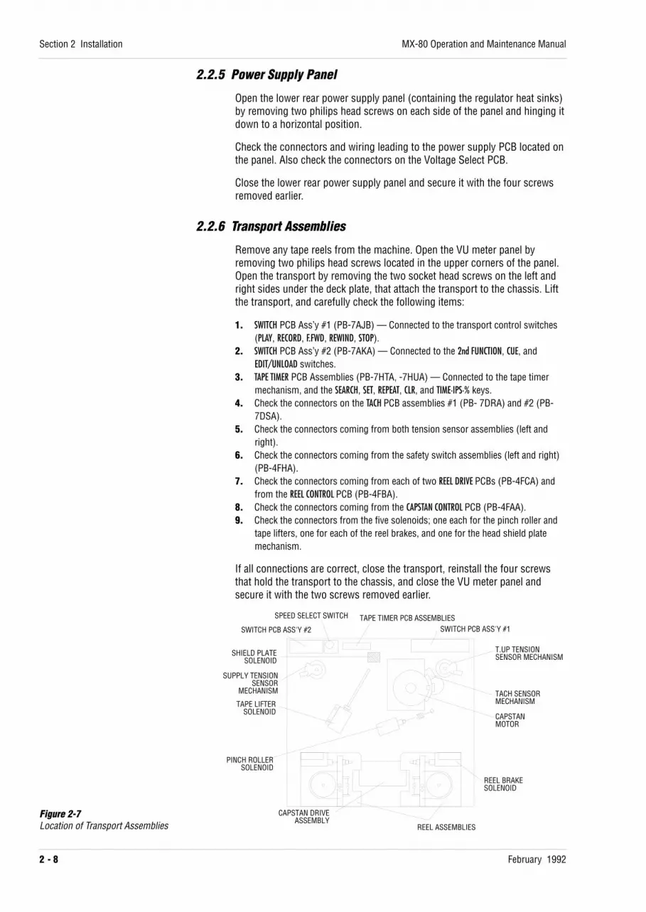
Remove any tape reels from the machine. Open the VU meter panel byremoving two philips head screws located in the upper corners of the panel.Open the transport by removing the two socket head screws on the left andright sides under the deck plate, that attach the transport to the chassis. Liftthe transport, and carefully check the following items:
1. SWITCH PCB Ass’y #1 (PB-7AJB) — Connected to the transport control switches(PLAY, RECORD, F.FWD, REWIND, STOP).
2. SWITCH PCB Ass’y #2 (PB-7AKA) — Connected to the 2nd FUNCTION, CUE, andEDIT/UNLOAD switches.
3. TAPE TIMER PCB Assemblies (PB-7HTA, -7HUA) — Connected to the tape timermechanism, and the SEARCH, SET, REPEAT, CLR, and TIME·IPS·% keys.
4. Check the connectors on the TACH PCB assemblies #1 (PB- 7DRA) and #2 (PB-7DSA).
5. Check the connectors coming from both tension sensor assemblies (left andright).
6. Check the connectors coming from the safety switch assemblies (left and right)(PB-4FHA).
7. Check the connectors coming from each of two REEL DRIVE PCBs (PB-4FCA) andfrom the REEL CONTROL PCB (PB-4FBA).
8. Check the connectors coming from the CAPSTAN CONTROL PCB (PB-4FAA).9. Check the connectors from the five solenoids; one each for the pinch roller and
tape lifters, one for each of the reel brakes, and one for the head shield platemechanism.
If all connections are correct, close the transport, reinstall the four screwsthat hold the transport to the chassis, and close the VU meter panel andsecure it with the two screws removed earlier.
Section 2 Installation
2 - 8 February 1992
MX-80 Operation and Maintenance Manual
SWITCH PCB ASS'Y #1
T.UP TENSIONSENSOR MECHANISM
TACH SENSORMECHANISM
CAPSTANMOTOR
REEL BRAKESOLENOID
REEL ASSEMBLIES
SWITCH PCB ASS'Y #2
SPEED SELECT SWITCH TAPE TIMER PCB ASSEMBLIES
SUPPLY TENSIONSENSOR
MECHANISM
SHIELD PLATESOLENOID
TAPE LIFTERSOLENOID
PINCH ROLLERSOLENOID
CAPSTAN DRIVEASSEMBLY
Figure 2-7Location of Transport Assemblies

2.2.7 Remote Control Unit
There are several function selection switches and jumpers on the CPU PCA inthe CB-140 (PB-4FGA) as described in Table 2-3. Check each switch’sallocation or reset them as you like.
Table 2-3Switches and Jumpers on the CPU PCA (PB-4FGA)
SW No. Function Initial position
SW1-1 Record Punch-In Mode Selection OFFSame as SW3-1 on Transport Control PCB. Refer to page 2-10.
SW1-2 Record Punch Out Mode Selection OFFSame as SW3-2 on Transport Control PCB. Refer to page 2-12.
SW1-3 Monitor SW Mode Selection OFFOFF Amplifier Monitor mode can be changed directly when you press the button.ON Monitor mode can be only changed by pressing the button twice within one second.
SW1-4 Auto set-up Selection ONOFF Channel set-up for the Audio channels is automatically stored when selection keys are
controlled.ON Channel set-up is not stored automatically.
SW1-5 Error Message Display ONOFF Error Message is not displayed on malfunction.ON Error Message will be displayed when malfunction has occurred (Refer to Table 2-4).
SW1-6 Not used. OFFSW1-7 Not used. OFFSW1-8 Not used. OFF
SW2 CPU reset. —
Table 2-4AMP Remote Control Unit Error Code
Code Meaning
00 ROM Check SUM Error01 RAM READ/WRITE Error04 Back Up Error90 Initial Communication Error91 Time-out Error in Communication with Transport92 Undefined Error93 Check SUM Error on Receiving Command94 No Acknowledge Signal was received95 Parity Error96 Double Data Error97 Framing Error98 Buffer Error99 STX Signal is not found
MX-80 Operation and Maintenance Manual
February 1992
Section 2 Installation
2 - 9

2.3 Hooking up the MX-80
2.3.1 Hooking up the AC Power
The AC power is supplied to the MX-80 via a three-conductor IEC standardconnector. Insure that voltage and frequency supplied to the MX-80 agreewith the machine’s power requirements printed on the serial number label onthe rear panel of the machine, before applying power. Use the power cordsupplied with the machine. Figure 2-8 describes the wiring of the AC inputconnector.
Figure 2-8AC Power Connector
2.3.2 Hooking up the Audio Inputs and Outputs
Connect the bus or track outputs from the mixing console to the Inputs of theMX-80. Connect the Outputs from the MX-80 to the monitor or tape inputs ofthe mixing console.
The Input to each channel of the MX-80 is transformerless balanced and hasan input impedance of 10 kΩ. Pin 1 of the connector is connected to theshield or drain, Pin 2 is connected to the “cold” side of the signal, and Pin 3is connected to the “hot” side of the signal. If unbalanced input wiring isdesired, connect to Pin 1 (shield) and Pin 3 (hot). And connect Pin 2 to Pin 1.See Figure 2-9 and 2-10 for details of input connector wiring.
The output from each channel is transformerless, balanced or unbalanced,and has an output impedance of less than 5 Ω. Pin 1 of the connector isconnected to the shield or drain, Pin 2 is connected to the signal “cold” or“low” conductor, and Pin 3 is connected to the signal “hot” or “high”conductor. When the unbalanced operation is required, set the BAL/UNBALswitch (SW1) on the AUDIO AMPLIFIER PCB to the “UNBAL” position. The OUTPUTconnector for unbalanced operation is wired with Pin 1 connected to theshield, and Pin 3 connected to the signal “hot” or high side (centerconductor). Do not connect Pin 2 to either Pin 1 or Pin 3. The level of theoutput signal will be approximately 6 dB lower than normal if the BAL/UNBALswitch is incorrectly set to the “BAL” position.
NOTE: To avoid ground loop induced hum, it is a good practice to follow asingle point grounding plan, in which the cable shields are connected only atone end (usually at the console) and a single ground or drain wire connectsthe tape machine to the mixing console.
Section 2 Installation
2 - 10 February 1992
MX-80 Operation and Maintenance Manual
ACHOT
ACNEUTRALGND
BALANCED INPUT BALANCED OUTPUT
2 1 GND
3HOT
COLD
2 1 GND
3HOT
(SHIELD)COLD
2
3
1
1
23
HOT
2 1 GND
3
UNBALANCED INPUT UNBALANCED OUTPUT
21
3HOT
GND2
13 3
1
2
Figure 2-9Balanced Input and Output Connector Wiring
Figure 2-10Unbalanced Input and Output Connector Wiring

2.3.3 Hooking up the Remote Control Unit (CB-140 or CB-151)
Connect the MX-80 and the Remote Control Unit together using the cablesupplied with the machine.
NOTE: Make sure the Power to the machine is turned off before connectingthe Remote Control Unit to the MX-80. Table 2-5 describes the pinassignments for the REMOTE CONTROL connector on the MX-80 and TOTAPE RECORDER connector on the CB-140.
Table 2-5aREMOTE CONTROL Connector Pin Assignments
Pin No. Description Pin No. Description
1. FRAME GROUND 14. FRAME GROUND8, 9. GROUND 16, 17. +24 V UNREG.10. TRANSMIT COMMON 19. TACH PULSE11. TRANSMIT A 21. FWD/REV (Fwd = Low)12. RECEIVE B 24. TRANSMIT B13. RECEIVE COMMON 25. RECEIVE A
Table 2-5bTO TAPE RECORDER Connector Pin Assignments
Pin No. Description Pin No. Description
1. FRAME GROUND 14. FRAME GROUND8, 9. GROUND 16, 17. +24 V UNREG.10. TRANSMIT COMMON 19. TACH PULSE11. RECEIVE A 21. FWD/REV (Fwd = Low)12. TRANSMIT B 24. RECEIVE B13. RECEIVE COMMON 25. TRANSMIT A
MX-80 Operation and Maintenance Manual
February 1992
Section 2 Installation
2 - 11

2.3.4 Using the Parallel I/O Connector
This 37-pin D-sub type connector is used to interface the optional CB-120series Auto Locator or another synchronizer/controller to MX-80. Theconnector contains “tally” signals, indicating machine status, in addition totransport control, tachometer pulses, and capstan speed reference signals.Refer to Table 2-6 for a complete description of the signals and controlsavailable at this connector.
Table 2-6Parallel I/O Connector Pin Assignments
No. Functions Level I/O No. Functions Level I/O
1. Record Switch Low In 20. Capstan Clock 9.6 kHz (Nom) — In2. Play Switch Low In 21. Tape Speed A (Note 2) H/L Out3. Stop Switch Low In 22. Tape Speed B (Note 2) H/L Out4. F.Fwd Switch Low In 23. Ext. Pitch Control Enable Low In5. Rewind Switch Low In 24. Ext. Pitch Control Tally Low Out6. Lifter Defeat Command Low In 25. Amp Rec Ready Tally Low Out7. 2nd Func Switch Low In 26. NC — —8. NC — — — 27. NC — —9. Shut Off Switch Low Out 28. NC — —10. Record Tally Low Out 29. NC — —11. Play Tally Low Out 30. Time Code Cue Low In12. Stop Tally Low Out 31. NC — —13. F.Fwd Tally Low Out 32. Rec Rehearsal Command Low In14. Rewind Tally Low Out 33. +5V +10% Reg. (max 150 mA) —15. 2nd Func Tally Low Out 34. +24V Unreg. (max 500 mA) —16. Signal Ground — — 35. +24V Unreg. (max 500 mA) —17. Tach Pulse (Note 1) — Out 36. Power Ground — —18. Tape Direction (Fwd = L) H/L Out 37. Power Ground — —19. Capstan Clock — Out
NOTE:1. Output Tach Pulse Rate (pulse/s) SMPTE EBU
7.5 ips 60 5015 ips 120 10030 ips 240 200
2. TAPE SPEED → SPEED A/SPEED B: 7.5 ips → Low/High. 15 ips → High/Low. 30 ips → High/High
3. Type of Connector: D-sub 37-pin Female
4. Output Signal Output Type = Open CollectorVOL = 0–0.5 VIOL = 20 mA (max)VIL = TTL LevelLeakage Current = 20 µ A (max)Pull Up = 10 kΩ (Terminated to +5 V)VOH (High Level) = +30 V (max)
5. Input Signal Fan-in = 1.5VIL = 0–0.5 V (-2.4 mA)VIH = 2.5–5.25 V (60 µ A)
6. Cable Length : 10 m (32 ft)
7. Input Command Pulse Width: 10 ms (min)
8. Duty Cycle of Tach Pulse : 20–80%
Section 2 Installation
2 - 12 February 1992
MX-80 Operation and Maintenance Manual

2.3.4.1 Rehearse Mode on the MX-80
The following items relate to the CB-140 Remote Control Unit.
When REHEARSE mode is enabled at the MX-80, the standard parallel I/O, orthe optional console interface, REHEARSE mode cannot be disabled from theCB-140 Remote Control Unit. In other words, Rehearse command on the MX-80, standard parallel I/O, or console interface has priority over commandsfrom the CB-140 or other remote controllers.
The MX-80 parallel I/O has two types of Rehearse function, i/e/, “Mode” and“Command”, both being selectable using SW4-1 on the TRANSPORT CONTROL PCB.The switch setting must be same on both MX-80 and CB-120 Auto Locator(parallel interface version).
NOTE: If interfacing the MX-80 to a version of the CB-120 which has no“Mode”/“Command” selection switch, set SW4-1 on the MX-80 to“Command”.
2.3.4.2 Enabling “Time Code Cue”
Also see Appendix for wide band modification on time code channel.
CAUTION! These modifications and changes in set up require proficiency inelectronics adjustment. If required, please contact your local Otari dealer orqualified service personnel.
NOTE: “Time Code Cue” can only be enabled on machines with parallel I/OROM number versions PG08211G, I, J, K to PG16611.
Since a time code signal is recorder on the tape, “Time Code Cue” enablesthe MX-80 to stay in Input Monitor mode (while reading TC) and mutes allthe outputs other than the time code channel.
Two foil traces on the back (dip side) of the AUDIO AMPLIFIER PCB which areused for the time code channel must be cut. This modification changes thefunction of Pin 30 on the parallel I/O connector. See the attached figure.
1. Cut the foil trace between pin 2 of RA4 and pin 32A of the PCB edgeconnector.
2. Cut the foil trace between pin 3 of RA4 and pin 32B of the PCB edgeconnector.
2.3.4.3 Speed Mode Selection with no Remote Control
The MX-80 was originally designed to select its speed mode (INT/EXT/VARI)from the CB-140 or CB-151 Remote Control Unit. If the CB-140 or CB-151 isdisconnected or is not used, the speed mode on the MX-80 is automaticallyset to “EXT” mode. Thus, after “Enable” is set on the parallel I/O Pin 23 (PitchControl Enable) MX-80 Capstan speed can be externally controlled thoughpin 20, the external capstan clock.
MX-80 Operation and Maintenance Manual
February 1992
Section 2 Installation
2 - 13
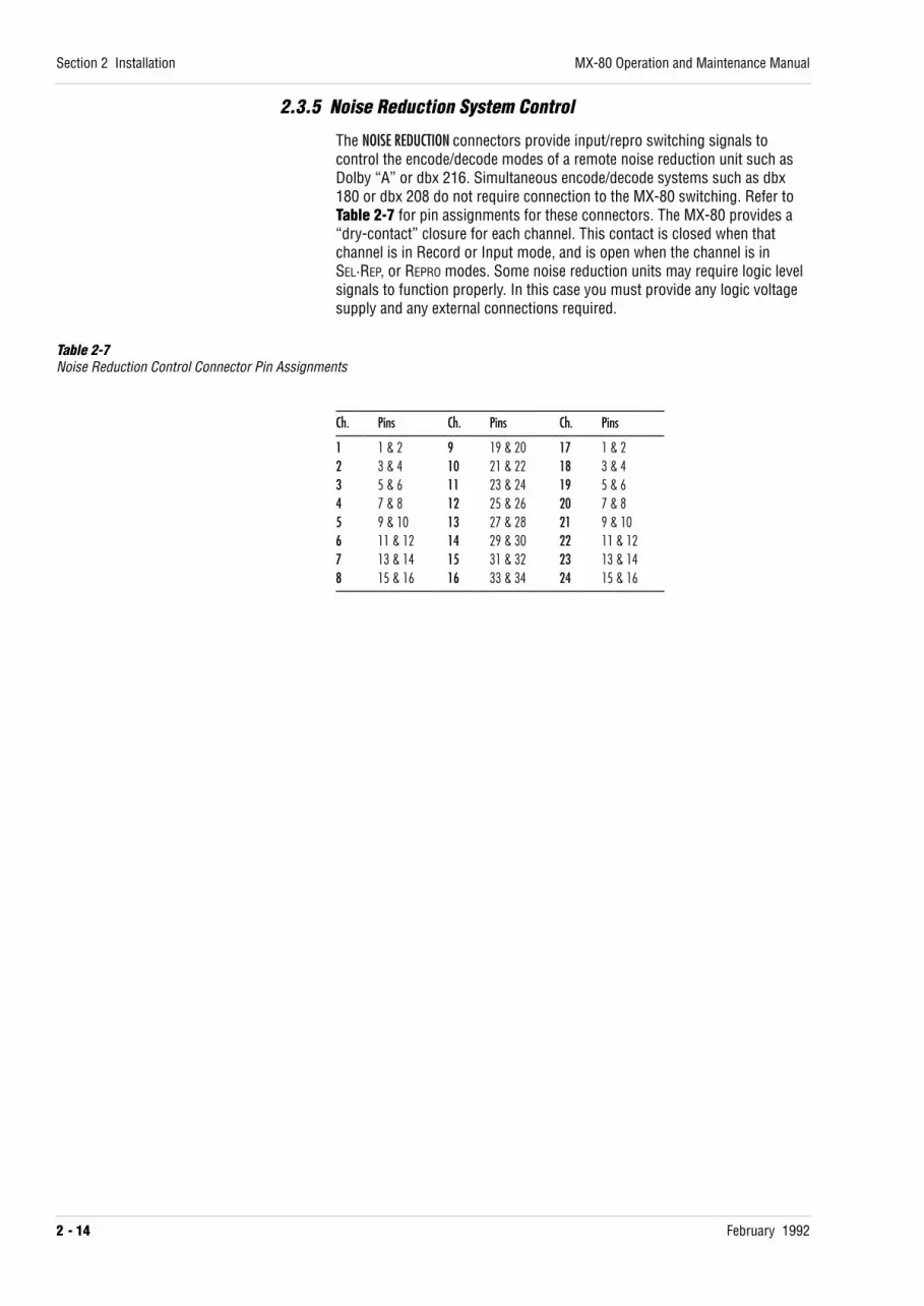
2.3.5 Noise Reduction System Control
The NOISE REDUCTION connectors provide input/repro switching signals tocontrol the encode/decode modes of a remote noise reduction unit such asDolby “A” or dbx 216. Simultaneous encode/decode systems such as dbx180 or dbx 208 do not require connection to the MX-80 switching. Refer toTable 2-7 for pin assignments for these connectors. The MX-80 provides a“dry-contact” closure for each channel. This contact is closed when thatchannel is in Record or Input mode, and is open when the channel is inSEL·REP, or REPRO modes. Some noise reduction units may require logic levelsignals to function properly. In this case you must provide any logic voltagesupply and any external connections required.
Table 2-7Noise Reduction Control Connector Pin Assignments
_______________________________________________Ch. Pins Ch. Pins Ch. Pins_______________________________________________1 1 & 2 9 19 & 20 17 1 & 22 3 & 4 10 21 & 22 18 3 & 43 5 & 6 11 23 & 24 19 5 & 64 7 & 8 12 25 & 26 20 7 & 85 9 & 10 13 27 & 28 21 9 & 106 11 & 12 14 29 & 30 22 11 & 127 13 & 14 15 31 & 32 23 13 & 148 15 & 16 16 33 & 34 24 15 & 16_______________________________________________
Section 2 Installation
2 - 14 February 1992
MX-80 Operation and Maintenance Manual
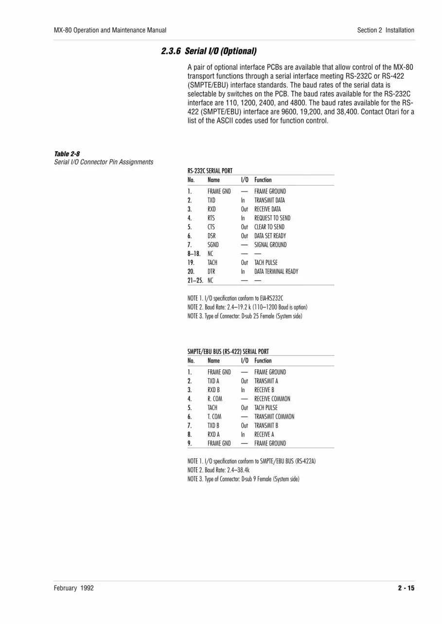
2.3.6 Serial I/O (Optional)
A pair of optional interface PCBs are available that allow control of the MX-80transport functions through a serial interface meeting RS-232C or RS-422(SMPTE/EBU) interface standards. The baud rates of the serial data isselectable by switches on the PCB. The baud rates available for the RS-232Cinterface are 110, 1200, 2400, and 4800. The baud rates available for the RS-422 (SMPTE/EBU) interface are 9600, 19,200, and 38,400. Contact Otari for alist of the ASCII codes used for function control.
Table 2-8Serial I/O Connector Pin Assignments
RS-232C SERIAL PORTNo. Name I/O Function
1. FRAME GND — FRAME GROUND2. TXD In TRANSMIT DATA3. RXD Out RECEIVE DATA4. RTS In REQUEST TO SEND5. CTS Out CLEAR TO SEND6. DSR Out DATA SET READY7. SGND — SIGNAL GROUND8–18. NC — —19. TACH Out TACH PULSE20. DTR In DATA TERMINAL READY21–25. NC — —
NOTE 1. I/O specification conform to EIA-RS232CNOTE 2. Baud Rate: 2.4–19.2 k (110–1200 Baud is option)NOTE 3. Type of Connector: D-sub 25 Female (System side)
SMPTE/EBU BUS (RS-422) SERIAL PORTNo. Name I/O Function
1. FRAME GND — FRAME GROUND2. TXD A Out TRANSMIT A3. RXD B In RECEIVE B4. R. COM — RECEIVE COMMON5. TACH Out TACH PULSE6. T. COM — TRANSMIT COMMON7. TXD B Out TRANSMIT B8. RXD A In RECEIVE A9. FRAME GND — FRAME GROUND
NOTE 1. I/O specification conform to SMPTE/EBU BUS (RS-422A)NOTE 2. Baud Rate: 2.4–38.4kNOTE 3. Type of Connector: D-sub 9 Female (System side)
MX-80 Operation and Maintenance Manual
February 1992
Section 2 Installation
2 - 15

2.4 Level MatchingIt is important that the input and output level of the mixing console matchthose of the tape recorder, to insure the best balance of headroom andsignal-to-noise ratio. The input and output levels of the MX-80 are switchselectable to match systems using either +4 dBu or -10 dBV signal levels.
NOTE: The MX-80 reference level and VU meter calibration must be adjustedproperly in accordance with the instructions in section 5 before proceedingwith level matching.
Thread the machine with a reel of the tape normally used for sessions.
1. Determine the nominal input and output levels of your mixing console.This can usually be found in the specifications section of the mixingconsole instruction manual.
2. Set the input and output level switches (SW5 and SW4 respectively) on theAUDIO CONTROL PCB to match the mixing console input and output levels.
3. Using the mixing console’s test oscillator, or an external test oscillatorconnected to one of the mixing console’s inputs, adjust the mixingconsole controls so that the console’s output VU meter reads 0 VU.
4. Extend the MX-80’s channel 1 AUDIO AMPLIFIER PCB.
5. Patch or route the test signal to the MX-80’s channel 1 INPUT connector.
6. Press the ALL INPUT button on the Remote Control Unit, and adjust theINPUT trimmer (VR14) on the channel 1 AUDIO AMPLIFIER PCB until thechannel 1 VU meter indicates 0 VU.
7. Connect the oscillator to the TEST SIGNAL input on the AUDIO CONTROL PCB,press the ALL INPUT button on the Remote Control Unit, and adjust the TESTSIGNAL trimmer (VR13) on the AUDIO AMPLIFIER PCB until the channel 1 VUmeter reads 0 VU.
8. Repeat steps 4 through 7 for all remaining channels.
9. Press the PLAY and RECORD buttons to place the transport in RECORD mode.
10. Record several minutes of signal.
11. Rewind the tape, and press the ALL REPRO button.
12. Press the PLAY button.
13. Put the mixing console into “mix-down” mode or connect the channel 1OUTPUT connector to a mixing console line input.
14. Adjust the mixing console input trim control so that the channel faderreaches the desired position when the mixing console VU meterindicates 0 VU.
Section 2 Installation
2 - 16 February 1992
MX-80 Operation and Maintenance Manual

February 1992 3 - 1
Section 3 Controls and Indicators
This section contains general information about the MX-80 SeriesMultichannel Tape Recorder and about this manual.
NOTE: Numbers in brackets refer to the callouts in each figure of this section.
3.1 Transport Controls and Indicators . . . . . . . . . . . . . . . . . . . . . . . . . . . . . . . . . 3-2
3.2 VU Meters (Upper Front Panel) . . . . . . . . . . . . . . . . . . . . . . . . . . . . . . . . . . . . 3-5
3.3 Amplifier Controls (Lower Front Panel) . . . . . . . . . . . . . . . . . . . . . . . . . . . 3-63.3.1 Audio Control PCB . . . . . . . . . . . . . . . . . . . . . . . . . . . . . . . . . . . . . . . . . . . . . . . . . 3-63.3.2 Serial Remote PCB . . . . . . . . . . . . . . . . . . . . . . . . . . . . . . . . . . . . . . . . . . . . . . . . . 3-73.3.3 Audio Amplifier PCB . . . . . . . . . . . . . . . . . . . . . . . . . . . . . . . . . . . . . . . . . . . . . . . . 3-8
3.4 Power Supply Panel . . . . . . . . . . . . . . . . . . . . . . . . . . . . . . . . . . . . . . . . . . . . . . . . . 3-9
3.5 Input and Output Connectors . . . . . . . . . . . . . . . . . . . . . . . . . . . . . . . . . . . . . 3-10
3.6 Remote Control Unit . . . . . . . . . . . . . . . . . . . . . . . . . . . . . . . . . . . . . . . . . . . . . . . . 3-113.6.1 Controls, Indicators, and Connectors . . . . . . . . . . . . . . . . . . . . . . . . . . . . . . 3-113.6.2 Controls on the CB-140 CPU PCB Assembly . . . . . . . . . . . . . . . . . . . . . . . 3-15

3.1 Transport Controls and Indicators
Figure 3-1Transport Control Panel
[1] F.FWD BUTTON Pressing this button places the transport in FAST FORWARD mode. Holding theF.FWD button pressed, and then pressing the 2nd FUNCTION button places thetransport in FORWARD SPOOL mode for winding tape onto the take-up reel witha smoother tape pack than is achieved at full wind speed.
[2] REWIND BUTTON Pressing this button places the transport in REWIND mode. Holding the REWINDbutton pressed, and then pressing the 2nd FUNCTION button places thetransport in REVERSE SPOOL mode for winding tape onto the supply reel with asmoother tape pack than is achieved at full wind speed.
[3] STOP BUTTON Pressing the STOP button causes the tape motion to stop. Pressing this buttonwhen the transport is in UNLOAD mode and the STOP button is flashing, (suchas when tape has just been threaded, and the slack has been removed byturning the reels by hand) causes the transport to apply tension to the tape inpreparation for other transport modes. The button will become brightlyilluminated. Pressing the 2nd FUNCTION button simultaneously with the STOPbutton causes the capstan motor to reverse direction in preparation forREVERSE PLAY mode (there is a slight delay while the capstan motor achievescrystal-locked speed, when reversing).
Section 3 Controls and Indicators
3 - 2 February 1992
MX-80 Operation and Maintenance Manual
2nd FUNCTION CUE EDIT/UNLOADSPEED SELECT
L H RECORD PLAY STOP REWIND F.FWDSET
ZERO 1 2 3 REPEAT CLR
TIME·IPS·%
SEARCHH M S
HL
TAPE SPEED
12345789 6
10 1115
1213
14 16
17
18
25
21
24
20
24
2223
19 19

[4] PLAY BUTTON Pressing this button places the transport in PLAY mode. Pressing this buttonwhile the transport is in EDIT READY mode (with the EDIT/UNLOAD buttonflashing) causes the transport to enter DUMP EDIT mode. Pressing this buttonwhile the transport is in SEARCH CUE or SEARCH TO ZERO mode causes PLAYbutton to flash and the transport to enter PLAY mode upon reaching the endof the search. Pressing the PLAY and 2nd FUNCTION buttons simultaneouslycauses the machine to enter REVERSE PLAY mode.
[5] RECORD BUTTON When a channel is in RECORD READY mode the RECORD button will flash. Youmay select one of two methods of entering RECORD mode: a) pressing thisbutton simultaneously with the PLAY button; b) pressing the RECORD buttonwhile the transport is in PLAY mode. The MX-80 is factory preset for methodb. Similarly, you may select between two methods of exiting from RECORD
mode: a) holding the RECORD button pressed and pressing the STOP button; b)pressing the PLAY button while in RECORD mode. The MX-80 is factory presetfor method b. The selection of Punch-In and Punch-Out methods is made viaswitches SW3-1 and SW3-2 on the TRANSPORT CONTROL PCB.Pressing this button simultaneously with 2nd FUNCTION button causes thetransport to enter SPOT ERASE mode. Pressing the RECORD button again, andholding it, while slowly moving the tape by hand, causes the erase circuitry tobe activated to erase the tape at the erase head. Releasing the RECORD buttonwill deactivate the erase signal. Pressing this button while the transport is inREVERSE PLAY mode causes the MX-80 to enter REVERSE ERASE mode.
[6] SPEED SELECT SWITCH Selects between the high or low speed of the speed pair selected internally.On high speed-pair machines the H setting is 30 ips and the L setting is 15ips. On low speed-pair machines the H setting is 15 ips and the L setting is7.5 ips.
[7] EDIT/UNLOAD BUTTON Pressing this button while the transport is in STOP mode causes the transportto enter EDIT READY mode and the button will flash. Pressing the EDIT/UNLOADbutton again causes the transport to enter UNLOAD mode and remove thetension from the tape. Pressing this button when the transport is in PLAY
mode causes the machine to enter DUMP EDIT mode in which the take-up reelmotor stops, allowing tape to “dump” over the side of the machine. In EDIT
PLAY mode the button will be brightly illuminated.
[8] CUE BUTTON Holding the CUE button pressed causes the tape lifters to remain retractedonly as long as the button is held pressed. Tapping the CUE button causes thetape lifters to remain retracted until the next time the CUE button is pressed.When the lifters are retracted, the audio output is attenuated and the highfrequencies rolled-off to prevent damage to the monitor speakers. Press theCUE, STOP, or PLAY button to leave CUE mode. Depending upon the setting ofSW3-3 on the TRANSPORT CONTROL PCB, the lifters will remain retracted, and theaudio attenuated, as described above, or the lifters will not retract, and theaudio is unmuted and not attenuated.
[9] 2ND FUNCTION BUTTON Pressing the 2nd FUNCTION button with other buttons provides access toadditional functions, such as REVERSE PLAY, which are not labeled on themachine. Each function is described with the appropriate button.
[10] TAPE TIMER Displays the current tape time. If the tape is located behind the 0.00.00position the Tape Timer will display the time as negative (or -) time, relativeto 0.00.00.
MX-80 Operation and Maintenance Manual
February 1992
Section 3 Controls and Indicators
3 - 3

[11] TIME·IPS·% KEY Pressing this key causes the Tape Timer to show the tape time, the selectedplay speed in ips, or the percentage of play speed, in turn.
[12] CLR KEY Pressing this key simultaneously with another key clears the selectedfunction as follows:
CLR + SET SET mode is canceled.CLR + TIME·IPS·% The Tape Timer is cleared to 0.00.00.CLR + SEARCH 1–3 The stored cue point is cleared.
[13] REPEAT KEY Pressing the REPEAT key, and then pressing any two illuminated cue keys (ZERO,1, 2, 3), places the machine in REPEAT mode. Then pressing the PLAY button,causes the machine to play from the first location to the second, rewind tothe first location and play again, repeating until REPEAT mode is deactivated.
[14] SEARCH ZERO KEY Pressing this key causes the transport to wind the tape, stopping when thetape timer reads 0.00.00. Pressing the PLAY button while in SEARCH TO ZERO
mode causes the PLAY button to flash and when the tape reaches 0.00.00, thetransport enters PLAY mode. Pressing the STOP, F.FWD, or REWIND button while inSEARCH TO ZERO mode causes the machine to leave SEARCH TO ZERO mode andtake the action directed by the button.
[15] SET KEY Pressing this key causes the MX-80 to enter SET mode, which is indicated bythe flashing of the display’s decimal points. SET mode allows the tape timesfor three cue points to be entered in the following manner:
SEARCH ZERO key + or - signSEARCH CUE 1 key Hours digitSEARCH CUE 2 key Tens of minutes digitSEARCH CUE 3 key Units of minutes digitREPEAT key Tens of seconds digitCLR key Units of seconds digit
The selected digit will increment each time the corresponding button ispressed. To store the entered time as a cue point, press and hold the SET key,and then press the desired SEARCH CUE key. Simultaneously press the CLR andSET keys for clearing the SET mode.After entering a tape time in SET mode, that tape time can be used as anoffset, being automatically subtracted from or added to all cue locations, byholding the SET key pressed and pressing the TIME·IPS·% key.
[16] SEARCH 1, 2, 3 KEYS If a key is not illuminated, no tape location is stored for that cue point.Pressing an unlit SEARCH 1–3 key causes the current time shown on the TapeTimer to be stored as that cue point, and that key to become illuminated. If aSEARCH 1–3 key is illuminated, a tape location has been stored for that cuepoint. Pressing that key causes the transport to search to the location storedas that cue point. The location will be displayed for approximately 2 secondsat the beginning of the search. Pressing the PLAY button while in SEARCH modecauses the PLAY button to flash, and when the tape reaches the location beingsearched to, the transport will enter PLAY mode. Pressing the STOP buttontogether with any SEARCH 1–3 key causes the Tape Timer to show the locationstored for that key. Pressing the CLR key simultaneously with any SEARCH 1–3key clears the location stored for that cue point.NOTE: There are different SEARCH 1–3 keys on the Remote Control Unit whichstore the different cue points from those on transport control panel. In otherwords, all together 6 cue points can be stored.
[17] TAPE SPEED INDICATOR This LED indicates the position of the SPEED SELECT switch.
Section 3 Controls and Indicators
3 - 4 February 1992
MX-80 Operation and Maintenance Manual

[18] TAPE SPLICING BLOCK This conveniently located splicing block has been provided to make tapeediting easier. Lay the magnetic tape in the slot and cut it using the groove toguide your blade.
[19] TAPE TENSION ARMS These swing arms are connected to the sensor mechanisms that providetension feedback information to the capstan and reel control circuits. Thearms also activate the safety switches which stop all transport functions iftoo much slack develops in the tape path or if the tape becomes unthreadedfrom the reel. After threading the tape, the take-up and supply reels shouldbe turned by hand to remove the slack in the tape path, and to move the tapetension arms away from the bottom of their travel.
[20] GUIDE ROLLER This rotating tape guide provides tape guidance and acts as an impedanceroller to help damp out any fluctuations in tape speed caused by irregularitiesin the supply reel tape pack.
[21] CAPSTAN SHAFT The capstan shaft is driven by a DC servo motor which is controlled by aquartz crystal reference in a phase-locked-loop circuit located on the CAPSTANCONTROL PCB.
[22] TACHOMETER ROLLER Tape motion across this roller causes it to rotate, generating tach pulses foraccurate measurement of the tape length and speed by the microprocessorand tape timer circuits. In STOP mode you can move the tape by turning thetop of the tachometer roller by hand. The tape will follow the motion of theroller. Do not “jerk” the tachometer roller when moving tape by hand or thetape may slip against the roller.
[23] PINCH ROLLER The tape is driven by the rotation of the capstan shaft against the pinch roller.
[24] REEL TABLES Reel tables with quick-release levers and locating pins.
[25] HEAD SHIELD The head shield is manually retracted by pushing it down until it latches.When in the retracted position, pressing it down causes the latch to bereleased and the shield will rise into position. The head shield willautomatically rise, if retracted, whenever the MX-80 enters RECORD or PLAY
mode if SW4-3 on the TRANSPORT CONTROL PCB is in the On position.
3.2 VU Meters (Upper Front Panel)Each VU meter is calibrated to indicate 0 VU at the selected reference level(250 or 320 nWb/m). Each meter incorporates two LED indicators, the PEAKindicator, which is set to illuminate if a signal peak reaches a level equivalentto 1040 nWb/m (approximately 3% THD), and the RECORD indicator, whichflashes when the channel is in RECORD READY mode, and is steadilyilluminated when the channel is in RECORD or SPOT ERASE modes.
MX-80 Operation and Maintenance Manual
February 1992
Section 3 Controls and Indicators
3 - 5
1 2 3 4 5 6 7 8
9 10 11 12 13 14 15 16
17 18 19 20 21 22 23 24
Figure 3-2VU Meter Panel

3.3 Amplifier Controls (Lower Front Panel)
3.3.1 Audio Control PCB
[1] MASTER BIAS SELECT SWITCH (SW1) AND TRIMMERS
This switch selects between two preset bias levels to facilitate changing thebias level for two different tape formulations. The associated trimmers adjustthe bias level for each switch position.
TYPE HI SPEED LOW SPEEDTAPE A VR 1 fixedTAPE B VR 2 VR 3
The A HI SPD trimmer (VR1) adjusts the bias for the A position of the BIAS SELECTswitch at high tape speed. The bias level for the A position at the Low tapespeed is fixed for AMPEX 456 tape.The B HI SPD trimmer (VR2) adjusts the bias for the B position of the BIAS SELECTswitch at high tape speed. The B LOW SPD trimmer (VR3) adjusts the bias for theB position of the BIAS SELECT switch at high tape speed.
[2] REFERENCE FLUX LEVEL INDICATORS These LEDs indicate the position of the REF FLUX switch. The HI LED isilluminated when the selected reference level is 320 nWb/m*. The LOW LEDindicates that the selected reference level is 250 nWb/m*.
[3] REF FLUX SWITCH (SW2) This switch selects either HI (320 nWb/m*) or LOW (250 nWb/m*) referenceflux level (the magnetic flux density applied to, or playing from the tape whenoperating at 0 VU). Selection of reference level does not affect the input oroutput signal level.* These values are default values at the time of shipment from the factory.They may be changed as required.
[4] EQUALIZATION INDICATORS (SELECT SWITCH: SW3) Selection of IEC or NAB equalization is made with SW3 on the AUDIO CONTROLPCB. The indicator corresponding to the selected switch position will beilluminated.
Section 3 Controls and Indicators
3 - 6 February 1992
MX-80 Operation and Maintenance Manual
HI SPDLOW SPD
GAIN
LF COMP
GAIN
LF COMP
REPRO
SEL·REP
RECORD
EQ
BIAS
HI SPD
LOW SPD
HI SPD
HI SPD
LOW SPD
HI SPD
LOW SPD
HI SPD
LOW SPD
HI SPD
LOW SPD
HI SPD
LOW SPD
LINE OUTPUT
EQ
EQ
GAIN
PHASE
HI SPD
ABIAS SELECT
B
LOW SPD
HI
LOW
HIREF FLUX
LOW
IEC
NAB
HI
LOW
HI
LOW
GAPLESSRECORDDOLBY HX PROVU +10dB
TEST SIGNAL
16
EQ
OUTPUT
INPUT
1
2
3
4
5
6
78
9
10
Figure 3-3Audio Control PCB

[5] OUTPUT LEVEL INDICATORS (SELECT SWITCH: SW4) Selection of the output level is made by SW4 located on the AUDIO CONTROL PCB.At the time of shipment from the factory, the “HI” position corresponds to +4dBu and the “LOW” position corresponds to -8 dBu. These values can bechanged as required. The indicator corresponding to the selected switchposition will be illuminated.
[6] INPUT LEVEL INDICATORS (SELECT SWITCH: SW5) Selection of the input level is made by SW5 located on the AUDIO CONTROL PCB.At the time of shipment from the factory, the “HI” position corresponds to +4dBu and the “LOW” position corresponds to -8 dBu, but these values can bechanged as required. The indicator corresponding to the selected switchposition will be illuminated.
[7] GAPLESS RECORD INDICATOR (SELECT SWITCH: SW6)This switch controls the gapless record function. At the time of shipmentfrom the factory, the switch is set to the “ON” position. The indicatorcorresponding to the selected switch position will be illuminated.
[8] DOLBY HX PRO INDICATOR (SELECT SWITCH: SW7)This switch controls the Dolby HX Pro head room expansion function. At thetime of shipment from the factory, the switch is set to the “ON” position. Theindicator corresponding to the selected switch position will be illuminated.
[9] +10 DB VU INDICATOR (SELECT SWITCH: SW8) When this switch is ON, the sensitivity of the VU meters is increased by +10dB. At the time of shipment from the factory, the switch is set to the “OFF”position. The indicator corresponding to the selected switch position will beilluminated.
[10] TEST SIGNAL JACK (PH1) Any signal applied to this connector (1/4” phone jack) will appear at a testsignal input to each audio channel. This connector is used to apply a testsignal to all channels simultaneously for adjustment of gain, EQ, etc. Thelevel of the signal applied to the TEST SIGNAL input should be the same as thatapplied to the rear panel input connectors (e.g., if the input level select switchis set to “LOW”, an input signal of -8 dBu* will cause the VU meter to indicate0 VU, if the switch is set to “HI”, the test signal input must be +4 dBu* for theVU meters to indicate 0 VU. (*Or a value set elsewhere)
3.3.2 Serial Remote Control PCB
[11] STOP STANDBY SWITCH AND INDICATOR Setting this switch to the “ON” position causes the output of any channel thatis in RECORD READY mode to be fed from the input whenever the tape stops,regardless of the position of the monitor switches. The indicator isilluminated when STOP STANDBY mode is selected.
[12] FAST STANDBY SWITCH AND INDICATOR Setting this switch to the “ON” position causes the output of any channel thatis in RECORD READY mode to be fed from the Input whenever the machine is inF.FWD, REWIND, or SPOOL mode, regardless of the position of the monitorswitches.Pressing the CUE button during wind temporarily overrides the STANDBY
function. The indicator is illuminated when FAST STANDBY mode is selected.
MX-80 Operation and Maintenance Manual
February 1992
Section 3 Controls and Indicators
3 - 7
STOP STANDBY
ON
OFF
FAST STANDBY
ON
OFF
11
12
Figure 3-4Serial Remote Control PCB
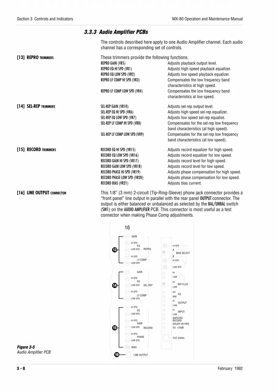
3.3.3 Audio Amplifier PCBs
The controls described here apply to one Audio Amplifier channel. Each audiochannel has a corresponding set of controls.
[13] REPRO TRIMMERS These trimmers provide the following functions.REPRO GAIN (VR5) Adjusts playback output level.REPRO EQ HI SPD (VR1) Adjusts high speed playback equalizer.REPRO EQ LOW SPD (VR2) Adjusts low speed playback equalizer.REPRO LF COMP HI SPD (VR3) Compensates the low frequency band
characteristics at high speed.REPRO LF COMP LOW SPD (VR4) Compensates the low frequency band
characteristics at low speed.
[14] SEL·REP TRIMMERS SEL·REP GAIN (VR10) Adjusts sel·rep output level.SEL·REP EQ HI SPD (VR6) Adjusts high speed sel·rep equalizer.SEL·REP EQ LOW SPD (VR7) Adjusts low speed sel·rep equalize.SEL·REP LF COMP HI SPD (VR8) Compensates for the sel·rep low frequency
band characteristics (at high speed).SEL·REP LF COMP LOW SPD (VR9) Compensates for the sel·rep low frequency
band characteristics (at low speed).
[15] RECORD TRIMMERS RECORD EQ HI SPD (VR15) Adjusts record equalizer for high speed.RECORD EQ LOW SPD (VR16) Adjusts record equalizer for low speed.RECORD GAIN HI SPD (VR17) Adjusts record level for high speed.RECORD GAIN LOW SPD (VR18) Adjusts record level for low speed.RECORD PHASE HI SPD (VR19) Adjusts phase compensation for high speed.RECORD PHASE LOW SPD (VR20) Adjusts phase compensation for low speed.RECORD BIAS (VR21) Adjusts bias current.
[16] LINE OUTPUT CONNECTOR This 1/8” (3 mm) 2-circuit (Tip-Ring-Sleeve) phone jack connector provides a“front panel” line output in parallel with the rear panel OUTPUT connector. Theoutput is either balanced or unbalanced as selected by the BAL/UNBAL switch(SW1) on the AUDIO AMPLIFIER PCB. This connector is most useful as a testconnector when making Phase Comp adjustments.
Section 3 Controls and Indicators
3 - 8 February 1992
MX-80 Operation and Maintenance Manual
HI SPDLOW SPD
GAIN
LF COMP
GAIN
LF COMP
REPRO
SEL·REP
RECORD
EQ
BIAS
HI SPD
LOW SPD
HI SPD
HI SPD
LOW SPD
HI SPD
LOW SPD
HI SPD
LOW SPD
HI SPD
LOW SPD
HI SPD
LOW SPD
LINE OUTPUT
EQ
EQ
GAIN
PHASE
HI SPD
ABIAS SELECT
B
LOW SPD
HI
LOW
HIREF FLUX
LOW
IEC
NAB
HI
LOW
HI
LOW
GAPLESSRECORDDOLBY HX PROVU +10dB
TEST SIGNAL
16
EQ
OUTPUT
INPUT
13
14
15
16
Figure 3-5Audio Amplifier PCB

3.4 Power Supply PanelThis panel contains the POWER switch, the Power Indicator, and the powersupply circuit breakers. There is one circuit breaker for each of the supplyvoltages. When power is applied to the machine, and the POWER switch is inthe On position, the VU Meters are illuminated. The Power Indicator changescolor from Red to Green shortly after the Power is turned On, indicating thatthe power supply circuits are functioning normally.
The circuit breakers have been provided to protect the circuitry in casetrouble should develop. If a circuit breaker should trip, turn off the machine,wait 30 seconds, press the circuit breaker to reset it, and turn the machineback on. If the problem reoccurs or continues, contact your Otari dealer orOtari. See page vii for Otari’s location nearest you.
Figure 3-6Power Supply Panel
MX-80 Operation and Maintenance Manual
February 1992
Section 3 Controls and Indicators
3 - 9
AC6V +5V -20V +20V +24V +5V -15V +15V +24V +40V
ON
OFF
AUDIO CONTROL

3.5 Input and Output Connectors
NOTE: Refer to §2.3 for further information about I/O connectors and pinassignments.
[1] INPUT CONNECTORS These 3-pin XL type connectors are the audio signal inputs to each channelof the recorder. Connect the bus or track outputs of the mixing console tothese INPUT connectors. The MX-80 inputs are designed for use with “linelevel” signals at either -8 dBu (-10 dBV) or +4 dBu (selectable via a switch onthe AUDIO CONTROL PCB).
Section 3 Controls and Indicators
3 - 10 February 1992
MX-80 Operation and Maintenance Manual
DOLBY HX PROHX PRO HEADROOM EXTENSION ORIGINATED BY BANG&OLUFSEN AND MANUFACTURED UNDER LICENSE FROM DOLBYLABORATORIES LICENSING CORPORATION. "DOLBY" ANDTHE DOUBLED SYNBOL ARE TRADEMARKS OF DOLBYLABORATORIES LICENSING CORPORATION.
CAUTIONTO PREVENT FIRE OR SHOCK HAZARD:DO NOT EXPOSE THIS APPLIANCE TORAIN OR MOISTURE.DO NOT REMOVE COVER.NO USER-SERVICEABLE PARTS INSIDE.REFER SERVICING TO QUALIFIEDSERVICE PERSONNEL.
NOISE REDUCTION
CH1-CH16
NOISE REDUCTION
CH17-CH24
RERMOTE CONTROL
PARALLEL I/O
CH16 CH15 CH14 CH13 CH12 CH11 CH10 CH9 CH8 CH7 CH6 CH5 CH4 CH3 CH2 CH1
CH17CH18CH19CH20CH21CH22CH23CH24
GND
FUSE
MX-80-32 SLOW BLOW(T) 15A
MX-80-24 SLOW BLOW(T) 10A
AC IN
INPUT
OUTPUT
INPUT
OUTPUT
REEL MDA PANELTRANSPORT CONTROL PCB
CONTROLCONNECTOR
PANEL
AUDIOCONNECTOR
PANEL
POWER SUPPLYPANEL WITHHEAT SINK
1
2
1
23
4
6 5 6
7
Figure 3-7Rear Panel I/O connectors

[2] OUTPUT CONNECTORS These 3-pin XL type connectors are the audio signal outputs from eachchannel of the recorder. Connect the track or monitor inputs of the mixingconsole to these OUTPUT connectors. The output from these connectors is at“line level”, either -8 dBu (-10 dBV) or +4 dBu.
[3] REMOTE CONTROL CONNECTOR Used to connect the CB-140/CB-151 Remote Control Unit to the MX-80.
[4] NOISE REDUCTION CONNECTOR These 34-pin connectors are used to provide mode control of any non-simultaneous external noise reduction system which requires machinecontrol of encode/decode modes. These connectors provide a “dry-contact”relay closure when the channel is in INPUT MONITOR or RECORD mode.
[5] PARALLEL I/O CONNECTOR This 37-pin connector is used to provide interface signals to the optional CB-119 Auto Locator or machine controller (e.g., synchronizer or resolver).
[6] SERIAL I/O INTERFACE PANEL (Optional) This optional Interface panel is used to connect the transport to controlsignals meeting RS-232C or RS-422A (SMPTE/EBU BUS) standards.
[7] (OPTIONAL I/O PANEL)
MX-80 Operation and Maintenance Manual
February 1992
Section 3 Controls and Indicators
3 - 11

3.6 Remote Control Unit
3.6.1 Controls, Indicators, and Connectors
Figure 3-8Remote Control Unit Front Panel
[1] F.FWD BUTTON, [2] REWIND BUTTON, [3] STOP BUTTON, [4] PLAY BUTTON, [5] RECORD BUTTON, [6] 2ND FUNC BUTTON, [7] CUE BUTTON*,[8] TAPE TIME DISPLAY, [9] TIME·IPS·% KEY, [10] CLR KEY, [11] REPEAT KEY, [12] SEARCH ZERO KEY, [13] SET KEY, [14] SEARCH 1–3 KEYS*
The functions of the above controls and indicators are duplicates of thesimilarly labeled controls and indicators on the MX-80 transport with thefollowing exceptions. Refer to Section 3.1 for information about thesecontrols and indicators.*Fast Wind Cue mode only, **SEARCH 3 key: No Search Play mode. These cuepoints are separate from those on the MX-80 transport control panel.
[15] TC AND DF INDICATORS These indications are invalid when connected to the MX-80.
Section 3 Controls and Indicators
3 - 12 February 1992
MX-80 Operation and Maintenance Manual
1 2 3 4 5 6 7 8 9 10 11 12 13 14 15 16 17 18 19 20 21 22 23 24
1 2 3 4 5 6 7 8 9 10 11 12 13 14 15 16 17 18 19 20 21 22 23 24
READY
SAFE
INPUT
SEL·REP
REPRO
INPUT
SEL·REP
REPRO
CB-140
REMOTE CONTROL UNIT
ALL INPUT
ALL SEL·REP
ALL REPRO
INDIVIDUAL
ALL SAFE
PITCH CONTROL
UPDOWNEXT VARIFIX
RECALL 1 2 3 4 CLEARAUTO
ALIGNMENT
NRSELECTMODE
CHANNEL SETUP
CUE REHEARSE 2nd FUNC
A
SR
OFF
SET
ZERO 1 2 3 REPEAT CLR
TIME·IPS·%
SEARCH
H M STC
DF
RECORD PLAY STOP REWIND F.FWD
EXT FIX VARI
SPEEDMODE
PITCHCONTROL
DOWN UP
INPUT
SEL·REP
REPRO
ALL INPUT
ALL SEL·REP
ALL REPRO
INPUT
SEL-REP
REPRO
INDIVIDUAL
SET TIME·IPS·%
ZERO 1 2 3 REPEAT CLRSEARCH
HL
H M S
REHEARSE
TAPE SPEED
CB-151REMOTE CONTROLUNIT ALL SAFE
READY
SAFE
1 2 3 4 5 6 7 8
1234561679101114121718 13
19
21 22
20
2524
23
8 15
26 27
1234571610111412 913
20
22
2119
17
18
828

[16] REHEARSE BUTTON Pressing this button places the MX-80 in REHEARSE mode. When a punch-in isperformed in REHEARSE mode, the monitor circuit of any channel which is inRECORD READY will be switched to Input monitor at the moment that the RECORDbutton is pressed, even though actual recording does not take place. InREHEARSE mode, the REC and READY indicators remain flashing. To leaveREHEARSE mode press the REHEARSE button again.
[17] PITCH CONTROL KNOB Adjusts the tape speed from -50% to +50% when the Speed Mode selector isset to the Vari position. The pitch control is velocity sensitive, so that turningthe knob quickly produces a large pitch change and turning it slowlyproduces a small pitch change. By turning the knob slowly, the pitch can bechanged in increments of 0.01%.The amount of pitch change can be viewed directly by pressing the TIME·IPS·%button until “PC” is displayed, indicating that the display is showing thePercent of speed change from the currently selected speed.
[18] SPEED MODE SELECTOR SWITCH Selects the speed reference for the capstan motor from three options.FIX: The tape speed is fixed at the speed selected by the SPEED SELECT button onthe MX-80 transport. The speed is locked to the MX-80’s internal crystalcontrolled speed reference.EXT: The tape speed is determined by the frequency of an EXTernal speedreference signal applied to pin 20 of the PARALLEL I/O connector on the rearpanel. External control is used whenever the tape speed is to be controlled bya synchronizer, resolver or other similar device. The signal should be 9,600kHz for nominal tape speed. If the speed mode selector is set to Ext, and thePITCH ENABLE line (pin 23) of the PARALLEL I/O connector is set to low logiclevel, the speed of the capstan motor will be controlled by the external speedreference signal. Refer to §2.3.4 for more information about controlling theMX-80 from an external device.VARI: The tape speed is determined by the setting of the PITCH CONTROL.
[19] INDIVIDUAL/ALL INPUT/ALL SEL·REP/ALL REPRO BUTTONS
When the INDIVIDUAL button is pressed, the monitor mode (INPUT, SEL·REP, orREPRO) of each channel can be selected individually with the output selectorswitches.Pressing the ALL INPUT (ALL SEL·REP, or ALL REPRO) button changes all channels toINPUT (SEL·REP, or REPRO) MONITOR mode regardless of the position of theoutput selector switches. SW2-3 on the CPU PCB in the CB-140 selects themethod of simultaneously changing all channels’ monitor mode: a) press theselected ALL button = SW2-3 OFF; b) press the selected ALL button twice quickly= SW2-3 ON.
[20] OUTPUT SELECTOR SWITCHES (INPUT/SEL·REP/REPRO)When the INDIVIDUAL button has been pressed, setting one of these switches tothe INPUT position causes the corresponding channel’s output to be the signalpresent at that channel’s input (INPUT MONITOR mode).When the INDIVIDUAL button has been pressed, setting one of these switchesto the SEL·REP position causes the corresponding channel’s output to be thesignal present on tape played back by the record head (SEL·REP MONITOR
mode) if the channel is in RECORD SAFE.When the INDIVIDUAL button has been pressed, setting one of these switchesto the REPRO position causes the corresponding channel’s output to be thesignal present on tape played back by the reproduce head (REPRO MONITOR
mode) if the channel is in RECORD SAFE.The mode indicators show each channel’s output monitor status. Table 3-1shows the relationship between RECORD mode, switch position, and indicatorcondition.
MX-80 Operation and Maintenance Manual
February 1992
Section 3 Controls and Indicators
3 - 13
Table 3-1Monitor Mode Indicators
Switch Position Mode IndicatorINPUT Record INPUT (Yellow)SEL·REP Record INPUT (Yellow)
Safe SEL·REP (Green)REPRO —— REPRODUCE (Orange)

[21] ALL SAFE SWITCH AND INDICATOR Setting this switch to the All Safe position puts all channels into Record Safemode, and illuminates the green ALL SAFE indicator. In All Safe mode, thechannel READY/SAFE switches have no effect. When All Safe is not selected, theRecord Ready status of each channel is determined by that channel’sREADY/SAFE switch.
[22] READY/SAFE SWITCHES AND MODE INDICATORS When the ALL SAFE switch is not engaged, these switches determine theRecord Ready status of each channel. If a channel’s READY/SAFE switch is inthe Ready position, the associated indicator will flash, the RECORD button willflash, and that channel will enter Record when the RECORD (or RECORD and PLAY)button on the transport or Remote Control Unit is pressed. When a channel isin Record mode, its indicator will be steadily illuminated. Table 3-2 describesthe condition of the channel indicator and RECORD button for variouscombinations of switch position and transport mode.
Table 3-2Record Indicator and Modes
Switch Position Transport mode Indicator (red) RECORD button Lamp (red)SAFE Not Recording Off Off
Recording Off OnREADY Not Recording Flashing Flashing
Recording On On
[23] CHANNEL SET UP BUTTONS Pressing one of these buttons, when it is not illuminated, causes the currentREADY/SAFE and INPUT/SEL·REPRO/REPRO status of all the channels to be storedthat memory and that button to become illuminated.Pressing one of these buttons, when it is illuminated, causes the channelstatus stored in that memory to be displayed, but the channels will notassume the stored status.Holding the RECALL button pressed while pressing one of these buttons causesall the channels to be set to the READY/SAFE and INPUT/SEL·REP/REPRO statuswhich was stored in that memory, and that button to flash.Holding the CLEAR button pressed and then pressing any of the illuminatedCHANNEL SET UP buttons causes the channel status stored in that memory to becleared.SW2-4 on the CB-140 CPU PCB Assembly selects NORMAL or PROTECTED mode forchannel setup memories.SW2-4 ON: Protected mode - channel setup memory contents cannot bechanged.SW2-4 OFF: Normal mode - channel setup memory contents are changedwhenever the contents are recalled and a switch position is changed.
[24] AUTO ALIGNMENT BUTTON AND INDICATOR These controls are not used on MX-80.[25] NR SELECT MODE BUTTON
[26] TO TAPE RECORDER CONNECTOR This multiconductor connector provides the serial interface between the CB-140 and the MX-80. Refer to §2.3.3.
[27] AUX POWER CONNECTOR This connector can be used to provide DC power to an external deviceconnected to the CB-140.Pin Assignment (Connector Type: HONDA MR-8S (Female))No. Description1–4. Not Used5, 6. +24V Unregulated (max. 500mA)7, 8. Power Ground
[28] TAPE SPEED H/L INDICATOR Shows the current position of the SPEED SELECT switch.
Section 3 Controls and Indicators
3 - 14 February 1992
MX-80 Operation and Maintenance Manual
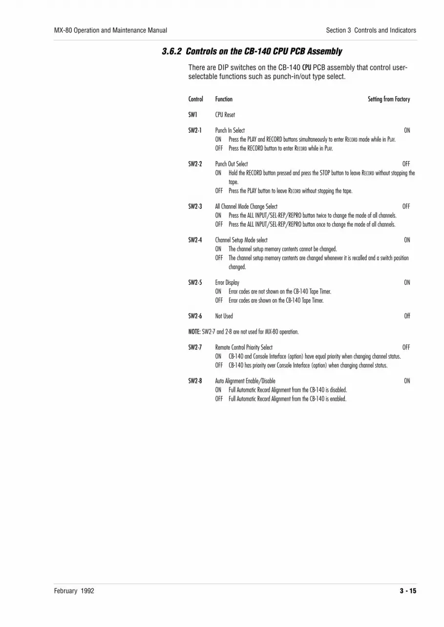
3.6.2 Controls on the CB-140 CPU PCB Assembly
There are DIP switches on the CB-140 CPU PCB assembly that control user-selectable functions such as punch-in/out type select.
Control Function Setting from Factory
SW1 CPU Reset
SW2-1 Punch In Select ONON Press the PLAY and RECORD buttons simultaneously to enter RECORD mode while in PLAY.OFF Press the RECORD button to enter RECORD while in PLAY.
SW2-2 Punch Out Select OFFON Hold the RECORD button pressed and press the STOP button to leave RECORD without stopping the
tape.OFF Press the PLAY button to leave RECORD without stopping the tape.
SW2-3 All Channel Mode Change Select OFFON Press the ALL INPUT/SEL·REP/REPRO button twice to change the mode of all channels.OFF Press the ALL INPUT/SEL·REP/REPRO button once to change the mode of all channels.
SW2-4 Channel Setup Mode select ONON The channel setup memory contents cannot be changed.OFF The channel setup memory contents are changed whenever it is recalled and a switch position
changed.
SW2-5 Error Display ONON Error codes are not shown on the CB-140 Tape Timer.OFF Error codes are shown on the CB-140 Tape Timer.
SW2-6 Not Used Off
NOTE: SW2-7 and 2-8 are not used for MX-80 operation.
SW2-7 Remote Control Priority Select OFFON CB-140 and Console Interface (option) have equal priority when changing channel status.OFF CB-140 has priority over Console Interface (option) when changing channel status.
SW2-8 Auto Alignment Enable/Disable ONON Full Automatic Record Alignment from the CB-140 is disabled.OFF Full Automatic Record Alignment from the CB-140 is enabled.
MX-80 Operation and Maintenance Manual
February 1992
Section 3 Controls and Indicators
3 - 15


February 1992 4 - 1
Section 4 Operation
This section contains, first, a list and an accompanying explanation of each ofthe many operating conditions (or modes) of the MX-80, and second, atutorial covering the tape recorder-related tasks involved in makingrecordings. You should read both parts of this section when first becomingfamiliar with the machine, and again as a guide while you are learning tooperate the machine. The portion describing the Operating Modes provides aquick reference, while the Tutorial portion provides hands-on instructionsabout how to operate the machine. Information regarding Installation andhooking up of the machine is contained in Section 2 of this manual. If you areuncrating and hooking up the machine for the first time, please refer to theinformation in Section 2 before continuing with this section.
4.1 Modes of Operation . . . . . . . . . . . . . . . . . . . . . . . . . . . . . . . . . . . . . . . . . . . . . . . . . . 4-2
4.2 Recording with the MX-80 — A Tutorial . . . . . . . . . . . . . . . . . . . . . . . . . . 4-34.2.1 Threading the Tape on the Machine . . . . . . . . . . . . . . . . . . . . . . . . . . . . . . . . . 4-34.2.2 Recording the Basic Tracks . . . . . . . . . . . . . . . . . . . . . . . . . . . . . . . . . . . . . . . . . 4-44.2.3 Playing Back the Basic Tracks . . . . . . . . . . . . . . . . . . . . . . . . . . . . . . . . . . . . . . . 4-54.2.4 Recording Overdubs Using Sel·Rep Playback . . . . . . . . . . . . . . . . . . . . . . . . 4-54.2.5 Recording Punch-In Overdubs . . . . . . . . . . . . . . . . . . . . . . . . . . . . . . . . . . . . . . 4-64.2.6 Rehearsing the Punch-In . . . . . . . . . . . . . . . . . . . . . . . . . . . . . . . . . . . . . . . . . . . 4-74.2.7 Bouncing or “Ping-Ponging” Tracks . . . . . . . . . . . . . . . . . . . . . . . . . . . . . . . . . 4-84.2.8 Using the Spot Erase Feature . . . . . . . . . . . . . . . . . . . . . . . . . . . . . . . . . . . . . . . 4-94.2.9 Playing Back the Track for Mixdown . . . . . . . . . . . . . . . . . . . . . . . . . . . . . . . . 4-94.2.10 Library Winding the Tape . . . . . . . . . . . . . . . . . . . . . . . . . . . . . . . . . . . . . . . . 4-104.2.11 Moving the Tape by Hand for Editing . . . . . . . . . . . . . . . . . . . . . . . . . . . . . 4-104.2.12 Editing the Tape . . . . . . . . . . . . . . . . . . . . . . . . . . . . . . . . . . . . . . . . . . . . . . . . . 4-114.2.13 Using the Variable Speed Feature . . . . . . . . . . . . . . . . . . . . . . . . . . . . . . . . . 4-124.2.14 Controlling the Capstan Speed with an External Device . . . . . . . . . . . . 4-12

4.1 Modes of Operation
Mode Control Operation
Play PLAY Tape moves from Supply to Take-up at the currently selected speed.
Reverse Play PLAY + 2nd FUNC Tape moves from Take-up to Supply at the currently selected speed.
Record RECORD (or REC & PLAY) Any channel in Record Ready begins to record.
Ready READY/SAFE The selected channel will enter Record when the RECORD button is pressed.
Safe READY/SAFE The selected channel will not enter Record.
Stop STOP Tape motion stops.
Reverse Stop STOP + 2nd FUNC Tape motion stops and the Capstan reverses its rotation.
F.Fwd F.FWD Tape moves from Supply reel to Take-up at wind speed.
Rewind REWIND Tape moves from Take-up reel to Supply reel at wind speed.
Edit Ready EDIT + STOP Transport is prepared for next Edit mode.
Dump Edit EDIT + PLAY Tape moves toward the Take-up reel but the Take-up motor does not turn.
Unload EDIT/UNLOAD Twice The tension on the tape is released.
Stop Cue STOP + CUE The lifters move out in preparation for another Cue mode.
Spooling Cue Stop Cue + F.FWD or REW Tape moves at 120 ips and audio can be monitored.
Fast Winding Cue F.Fwd or Rew + CUE The lifters retract and the tape contacts the heads for monitoring audio.
Spooling Wind 2nd FUNC + F.FWD or REW Tape is wound in the direction selected at approximately 120 ips for library winding for storage. Audio ismuted.
Input Monitor ALL INPUT or The signal at the MX-80 Output is the signal at the Input.INDIVIDUAL + INPUT
Sel·Rep Monitor ALL SEL·REP The signal at the MX-80 Output is the signal on tape reproduced by the Record Head.or INDIVIDUAL + SEL·REP
Repro Monitor ALL REPRO or The signal at the MX-80 Output is the signal on tape reproduced by the Repro Head.INDIVIDUAL + REPRO
Search to Zero SEARCH ZERO Tape is moved at wind speed to the location corresponding to 0.00.00 on the Tape Timer.
Search Cue SEARCH 1–3 Tape is moved at wind speed to the location corresponding to the Tape Timer reading stored with theSEARCH 1–3 key.
Search Play SEARCH CUE + PLAY Tape is moved at wind speed to the stored location, where the tape enters Play.
Spot Erase 2nd FUNC + RECORD Twice The Erase head for the channel in Record Ready will be activated and move the tape by hand for erasing.
Reverse Erase 2nd FUNC + PLAY + REC The erase head for the channel in Record Ready will be activated and the tape will move from take-up tosupply.
Stop Standby STOP STANDBY On All channels in Record Ready will be set to Input Monitor whenever tape stops.
Fast Standby FAST STANDBY On All channels in Record Ready will be set to Input Monitor whenever tape is in F.Fwd or Rewind.
Section 4 Operation
4 - 2 February 1992
MX-80 Operation and Maintenance Manual

4.2 Recording with the MX-80 — A Tutorial
4.2.1 Threading the Tape on the Machine
1. Set the POWER switch [Figure 3-6] to the “ON” position. It is located onthe power supply panel at the bottom of the machine pedestal. The VUmeter lamps will become illuminated.
2. Lift up the clamp levers on the top surface of the reel turntables tounlock them so they will accommodate the reels. Place an empty reel onthe machine. If the tape is “heads” out, place the empty reel on the take-up reel turntable. If the tape is “tails” out, place the empty reel on thesupply reel turntable.NOTE: There is a locating pin near the bottom of each reel turntable. Inorder for the reel to be seated firmly against the reel turntable, be sureone of the slots in the reel hub is aligned with the locating pin. When thereel is seated, push down on the clamp lever causing the clamp ring toexpand and firmly grip the reel hub. Check to be sure the reel is seatedfirmly against the reel turntable.
3. Pull about 4 feet of tape from the reel, and thread it around the lefttension arm and guide roller, across the head assembly, between thecapstan and pinch roller, around the tachometer roller and the righttension arm, and onto the take-up reel, exactly as shown in Figure 4-1and on the transport of the MX-80.
4. Rotate the take-up reel counterclockwise, and the supply reel clockwise,by hand, to take up any slack in the tape and to lift the tension arms uptoward the center of the transport. The STOP button will begin to flash.
5. Press the STOP button [Figure 3-1, 3] to apply tension to the tape andprepare the transport for further functions. The STOP button will becomebrightly illuminated. It is not necessary to perform this step, (you can godirectly from UNLOAD to PLAY or WIND), but we recommend that youdevelop the habit of pressing the STOP button to insure there is no slackin the tape before proceeding to other operations to prevent any possibledamage to the tape or machine caused by sudden movement of the tape.
MX-80 Operation and Maintenance Manual
February 1992
Section 4 Operation
4 - 3
2nd FUNCTION CUE EDIT/UNLOADSPEED SELECT
L H RECORD PLAY STOP REWIND F.FWDSET
ZERO 1 2 3 REPEAT CLR
TIME·IPS·%
SEARCHH M S
HL
TAPE SPEED
Figure 4-1Tape Threading

4.2.2 Recording the Basic Tracks
1. Thread the tape on the transport as described in §4.2.1.
2. Set the SPEED SELECT switch [Figure 2-1, 6] to the desired tape speed. Onhigh speed-pair machines L is 15 ips and H is 30 ips. On low speed-pairmachines, L is 7.5 ips and H is 15 ips. Set the Speed Mode Selectorswitch [Figure 2-9, 18] to the “FIX” position.
3. Press the CLR and TIME·IPS·% keys simultaneously to reset the Tape Timerto 0.00.00.
4. Set the ALL SAFE switch on the Remote Control Unit to the “READY”position.
5. Set the READY/SAFE switch(es) for the track(s) on which you wish torecord to the “READY” position. The READY LED above that switch will beilluminated, and the RECORD button will flash indicating that the channel isin RECORD READY mode.
6. Set the Output Selector switches [Figure 2-9, 20] for the selectedchannel(s) to the “INPUT” position, or press the ALL INPUT button. Thecorresponding INPUT indicator(s) will become illuminated.
7. Adjust the signal level at the mixing console or signal source. The outputof the console should be set for the same level range as the input of theMX-80. Refer to §2.4 for more information about setting console andMX-80 levels.
8. It is good practice to record reference tones at the head of every sessiontape for later level matching. If you use reference tones, adjust the levelat the console for a meter indication of 0 VU.
9. Press the PLAY and RECORD buttons simultaneously to cause the MX-80 tobegin recording on the selected tracks. See §3.1 for more informationabout selecting the method of entering and leaving Record mode.
10. There are several ways to end recording. To end the recording and stopthe tape, press the STOP button. To end the recording on all tracks andhave the tape continue in PLAY (punch-out), press the PLAY or PLAY andRECORD buttons (depending upon the setting of SW1 on the TRANSPORTCONTROL PCB, see §3.1), or set the ALL SAFE switch to the “ALL SAFE”position. To end the recording on one or more tracks, while other trackscontinue to record, move the READY/SAFE switches for those tracks to the“SAFE” position.
Section 4 Operation
4 - 4 February 1992
MX-80 Operation and Maintenance Manual

4.2.3 Playing Back the Basic Tracks
1. Rewind the tape to the beginning of the recording by pressing SEARCHZERO (if the Tape Timer was reset at the beginning), or by pressing theREWIND button.
2. Set the ALL SAFE switch to the “ALL SAFE” position to avoid accidentallyerasing recorded tracks. The ALL SAFE LED will become illuminated.
3. Set the Output Selector switches [Figure 3-9, 20] for the selectedchannel(s) to the “REPRO” position, or press the ALL REPRO button. Thecorresponding REPRO indicator(s) will become illuminated.
4. Press the PLAY button. The signal on the tape will be reproduced by thereproduce head and fed to the OUTPUT connectors.
5. Adjust the monitor level at the mixing console.
4.2.4 Recording Overdubs Using Sel·Rep Playback
Overdubs are performed when it is necessary to add additional tracks in syncwith material already recorded on some of the tracks. During SEL·REP
playback the previously recorded material is reproduced by the record headmaking it possible to add (overdub) tracks without the delay caused, duringnormal playback, by the space between the record and reproduce heads.When overdubs are recorded, the previously recorded tracks are played inSel·Rep and monitored by the performer through the mixing console. Thenew material is then recorded in sync with the existing tracks.
1. Rewind the tape to the beginning of the section to be overdubbed.
2. Set the ALL SAFE switch to the “READY” position, and set the READY/SAFEswitches to “SAFE” for the all the tracks on which no new material will berecorded.
3. Set the READY/SAFE switches to “READY” for the tracks on which newmaterial is going to be recorded. The READY LEDs for those tracks willflash.
4. Set the Output Selector switches [Figure 3-9, 20] to the “SEL·REP”position for all the channels, or press the ALL SEL·REP button. The INPUTindicator(s) will be illuminated for the channels which are in RECORD
READY mode, if the STOP STANDBY switch [Figure 3-5, 11] is On.
5. Press the PLAY and RECORD buttons simultaneously to begin overdubbing.Adjust the recording and monitor levels at the mixing console.
MX-80 Operation and Maintenance Manual
February 1992
Section 4 Operation
4 - 5

4.2.5 Recording Punch-In Overdubs
Punch-in overdubs are performed when it is necessary to insert new materialinto a track that has already been recorded, without re-recording the entiretrack. Punch-in overdubbing allows you to monitor the previously recordedmaterial on the tracks selected for recording, right up to the instant the trackis put into Record. At the moment that the track(s) enter Record mode, theMX-80 switches the outputs of the tracks being recorded to Input monitor toallow you to listen to the new material as it is being recorded in sync with thematerial recorded earlier.
1. Rewind the tape to the beginning of the section to be overdubbed.
2. Set the ALL SAFE switch to the “READY” position, and set the READY/SAFEswitches for all the tracks that are not going to be recorded to “SAFE”.
3. Set the READY/SAFE switches for the tracks that are going to beoverdubbed to “READY”. The READY LEDs for those tracks will beilluminated.
4. Press the ALL SEL·REP button. The SEL·REP LEDs for the tracks that are notbeing recorded will be illuminated. The INPUT LEDs for the tracks to berecorded will be illuminated if the STOP STANDBY switch is On.
5. Press the PLAY button to listen to the existing tracks. At the moment thatthe new material is to be inserted, press the RECORD button (or the PLAYand RECORD buttons, depending upon the setting of SW1 on the TRANSPORTCONTROL PCB) to begin the punch-in. Adjust the recording and monitorlevels at the mixing console.
6. Press the PLAY button (or RECORD and STOP buttons, depending on thesetting of SW1 on the TRANSPORT CONTROL PCB) to punch-out (end thepunch-in). The output signal for the tracks being overdubbed will returnto SEL·REP mode (e.g., being played back by the record head), and theMX-80 will continue in PLAY.
7. To hear the results of the punch-in, rewind the tape to the beginning ofthe section, set the ALL SAFE switch to the “ALL SAFE” position. Press thePLAY button and adjust the monitor level at the console.
Repeat the punch-in until you are happy with the results. Otari’s gaplesspunch-in provides the capability to insert new material onto a previouslyrecorded track without a gap or overlap being recorded on the tape. Actuallyproducing perfect punch-ins requires patience and practice to achieveaccurate results.
Section 4 Operation
4 - 6 February 1992
MX-80 Operation and Maintenance Manual

4.2.6 Rehearsing the Punch-In
To rehearse a punch-in without actually recording anything on the tape:
1. Rewind the tape to the beginning of the section to be overdubbed.
2. Press the REHEARSE button.
3. Set the ALL SAFE switch to the “READY” position, and set the READY/SAFEswitches for all channels which are not going to be recorded to “SAFE”.
4. Set the READY/SAFE switches for the channels that are going to beoverdubbed to the “READY” position. The READY LEDs for those channelswill flash.
5. Press the ALL SEL·REP button. The SEL·REP LEDs for the tracks which are notbeing overdubbed will be illuminated. The INPUT LEDs for the channelswhich are being overdubbed will be illuminated if the STOP STANDBY switchis On.
6. Press the PLAY button to listen to the existing tracks. At the moment thatthe new recording is to begin, press the RECORD button (or the PLAY andRECORD buttons, depending upon the setting of SW3 on the TRANSPORTCONTROL PCB) to begin the punch-in rehearsal.
MX-80 Operation and Maintenance Manual
February 1992
Section 4 Operation
4 - 7

4.2.7 Bouncing or “Ping-Ponging” Tracks
Bouncing or “ping-ponging” tracks involves recording several original tracks,mixing those tracks and recording them back on to other tracks of the sametape, and then, adding more tracks to the mixed tracks. In order to maintainthe highest signal quality during “ping-ponging”, the recorded materialshould be played back from the reproduce head. This means that the mixedtracks will not be in sync with the rest of the tracks. It is possible to bouncetracks using SEL·REP playback from the record head, but the quality will notbe as good as it will be when using the reproduce head. However, usingSEL·REP to bounce tracks leaves the resulting mixed track(s) in sync with therest of the tracks. When bouncing tracks using SEL·REP we recommend thatyou leave a blank (empty) track between the tracks being recorded and thetracks being mixed. For example, if you have already recorded on tracks 1through 12, and wish to mix and bounce them to another track, it is advisableto record the mixed tracks on tracks 14 and 15, leaving track 13 empty as aguard track. You can then come back and record additional tracks in syncwith the mixed material on tracks 14 and 15.
To “ping-pong” or bounce tracks:
1. Rewind the tape to the beginning of the section of tape to be mixed, anddetermine which tracks will be mixed and which tracks will be recordedonto.
2. Set the ALL SAFE switch to the “READY” position.
3. Press the INDIVIDUAL button.
4. Set the individual INPUT/SEL·REP/REPRO switches to “REPRO” for those tracksto be mixed, and to “INPUT” for those tracks to be recorded onto. Themixing console controls should be set to mix the tracks that are in REPRO
and send the resulting mix to the tracks that are in RECORD READY.
5. Reset the Tape Timer so that Search to Zero can be used to quicklyreturn the tape to the beginning of the section.
6. Press the PLAY button, and adjust the mixing console for the desired mixof tracks and for a suitable recording level.
7. Press the SEARCH ZERO key to return the tape to the beginning.
8. When the desired mix has been achieved, begin recording by pressingthe PLAY and RECORD buttons simultaneously.
The previously recorded tracks will be played by the reproduce head, mixedtogether, and recorded on the tape at the record head. You may now go backand record over (thereby erasing) the original tracks with new material insync with the “ping-ponged” tracks, giving you the ability to record manymore channels of material than the tape recorder has tracks.
Section 4 Operation
4 - 8 February 1992
MX-80 Operation and Maintenance Manual

4.2.8 Using the Spot Erase Feature
The spot erase feature utilizes time-ramp bias switching to enable you toerase small areas of the tape without leaving the usual assortment of clicks,pops, and chirps that are caused by short bias turn-on and turn-off times. Tospot erase a small section of one track:
1. Mark the head (or beginning) and tail (or end) of the area to be erasedusing grease pencil or china marker. Position the tape so that the headmark is several inches to the left of the erase head.
2. Set the ALL SAFE switch to the “READY” position.
3. Set the READY/SAFE switches for the tracks to be erased to the “READY”position.
4. Press the 2nd FUNCTION button and begin to move the tape toward themarked points, then press the RECORD button to enter SPOT ERASE modewithout leaving a pop or thump recorded on the tape.
5. Move the tape by hand from the head mark to the tail mark. When thetail mark reaches the erase head, release the RECORD button to terminatethe function.
NOTE: The spot erase feature cannot be used through the Remote ControlUnit CB-140 or CB-151.
4.2.9 Playing Back the Tracks for Mixdown
The basic tracks, overdubs, and punch-ins must all be played back into themixing console to be combined and balanced for the final master tape. Toplay the tracks that have been recorded:
1. Rewind the tape to the beginning of the section of tape to be mixed.
2. Reset the Tape Timer to 0.00.00.
3. Set the ALL SAFE switch to the “ALL SAFE” position.
4. Press the ALL REPRO button.
5. Press the PLAY button to begin playback.
6. Adjust the level and balance of the individual tracks at the mixingconsole.
7. To return to the beginning of the tape for another pass, press the SEARCHZERO key.
MX-80 Operation and Maintenance Manual
February 1992
Section 4 Operation
4 - 9

4.2.10 Library Winding the Tape
At the completion of a session the tape is generally stored “tails” out, for twogood reasons, 1) to avoid audible “pre-echoes” resulting from tape print-through, and 2) to lessen the possibility of edge damage because the justplayed tape is wound much smoother than would result from fast windingthe tape. The MX-80 includes a SPOOL mode which provides a smooth librarywind in only 1/4 the time required to play the tape onto the reel.
1. To spool the tape onto the take-up reel, press the F.FWD button, and then,keeping the F.FWD button pressed, press the 2nd FUNCTION button.
2. To spool the tape onto the supply reel, press the REWIND button, and then,keeping the REWIND button pressed, press the 2nd FUNCTION button.
3. To end the spool operation, press the STOP button.
4.2.11 Moving the Tape by Hand for Editing
The constant tape tension system used in the MX-80 allows the tape to bemoved from one reel to the other by hand very easily. When the transport isin Stop mode, the tape lifters are retracted and the audio is not muted,making it possible to simply move the tachometer roller manually to locatethe correct place on the tape.
To monitor the tape at the reproduce head, press the ALL REPRO button, tomonitor the tape at the record head press the ALL SEL·REP button.
Section 4 Operation
4 - 10 February 1992
MX-80 Operation and Maintenance Manual

4.2.12 Editing the Tape
Often it is necessary to cut the tape to remove unwanted material. Thisinvolves selecting two points on the tape, separated by the segment to beremoved, cutting the tape at those “edit points”, removing the unwantedpiece of tape, and rejoining the cut ends of the tape with adhesive splicingtape. The MX-80 constant tension system does not allow you to pull the tapeaway from the head assembly and cut it, as on some older machines, so theMX-80 features an edit mode for releasing the reel brakes and dumpingunwanted tape.
1. Press the ALL REPRO button, and wind the tape to the beginning of thesection to be edited.
2. Press the STOP button, and move the tape by hand to locate the exact editpoint at the head of the segment.
3. Mark the head edit point with grease pencil or china marker. Press oneof the SEARCH 1–3 keys to store this location.
4. Move the tape to the tail edit point, and carefully locate and mark thepoint.
5. Rewind the tape to the head edit point. If you stored the location usingthe SEARCH 1–3 key, press the SEARCH 1–3 key to quickly go to that point onthe tape. Move the tape to place the head edit point between theTachometer roller and the take-up reel.
6. Press the EDIT/UNLOAD button and the PLAY button.
7. Allow the tape to “dump” to the tail edit point. When the tail edit pointreaches the heads, stop the tape.
8. Pull the tape out away from the head assembly, and fit it into the splicingblock. Position the tail edit point over the groove in the splicing block,and carefully cut the tape with a sharp blade.
9. Pull the head edit point from the take-up reel to the splicing block,position it over the groove in the splicing block, and carefully cut thetape and join the ends with splicing tape.
CAUTION: When in the DUMP EDIT mode, direct the tape off the side of thetransport with your hand to prevent the tape from being caught in the pinchroller.
MX-80 Operation and Maintenance Manual
February 1992
Section 4 Operation
4 - 11

4.2.13 Using the Variable Speed Feature
The MX-80 allows you to change the speed of the tape, as it is beingRecorded or Played, by ±50% (about ± two whole tones). This feature makesit possible to compress or extend material to fit it into a time slot, or tochange the pitch for special effects, etc.
To manually adjust the speed of the MX-80:
1. Set the Speed Mode selector switch on the Remote Control Unit to the“VARI” position.
2. Use the PITCH CONTROL knob on the Remote Control Unit to vary thecapstan speed as desired. Turning the PITCH CONTROL knobcounterclockwise causes the speed to decrease, turning it clockwisecauses the speed to increase.
Also using the SET key on the tape time display, Varispeed amount ispresettable.
4.2.14 Controlling the Capstan Speed with an External Device
The capstan speed of the MX-80 can be controlled by an external device suchas a resolver or synchronizer. The PARALLEL I/O connector on the rear panelprovides an input for an external speed reference signal. This signal shouldbe a square wave, TTL level (+5 V when on, 0 V when off), or a sine wave of10 V peak to peak from a generator having a source impedance of less than50 Ω at 9600 Hz for nominal speed. Refer to Table 2-4 for the PARALLEL I/Oconnector pin assignments and signal descriptions.
To use an external speed reference signal connected to the PARALLEL I/Oconnector, set the Speed Mode Selector switch on the Remote Control Unit tothe “EXT” position. If the external reference signal is lost, or falls below 6 V(sine wave signal) the machine will revert to its Fix speed mode. The range ofspeed control possible from the PARALLEL I/O connector is -50%, +100% at 15ips and +40, -50% at 30 ips.
NOTE: The capstan motor will stop when the external control signal (9600Hz) is lost, unless the pitch enable line (pin 23 of the PARALLEL I/O connector)returns to the logic high state.
Section 4 Operation
4 - 12 February 1992
MX-80 Operation and Maintenance Manual

February 1992 5 - 1
Section 5 Alignment and Calibration
This section contains the instructions and information required to performthe routine reel control, tape tension, head alignment, audio channelcalibration, bias and erase adjustments associated with normal maintenanceof the MX-80.
When you are performing these procedures for the first few times, proceedslowly and carefully. Soon you will be familiar with them, but initially it isbetter to be cautious and avoid accidents.
5.1 Transport Alignment . . . . . . . . . . . . . . . . . . . . . . . . . . . . . . . . . . . . . . . . . . . . . . . . . 5-25.1.1 Tools and Equipment Required . . . . . . . . . . . . . . . . . . . . . . . . . . . . . . . . . . . . . 5-25.1.2 Opening the Transport and Removing the Deck Skin Panels . . . . . . . . . . 5-25.1.3 Reel Tension Servo Adjustment . . . . . . . . . . . . . . . . . . . . . . . . . . . . . . . . . . . . . 5-4
5.1.3.1 Tension Arm Spring Tension Adjustment . . . . . . . . . . . . . . . . . . . . . 5-45.1.3.2 Tachometer Quadrature/Phase Adjustment . . . . . . . . . . . . . . . . . . . 5-55.1.3.3 Fast Wind Speed Reference Voltage Adjustment . . . . . . . . . . . . . . 5-65.1.3.4 Tension Sensor Position . . . . . . . . . . . . . . . . . . . . . . . . . . . . . . . . . . . . . 5-65.1.3.5 Tension Arm Sensor Gain Adjustment . . . . . . . . . . . . . . . . . . . . . . . . 5-75.1.3.6 Play Acceleration Preliminary Adjustment . . . . . . . . . . . . . . . . . . . . 5-75.1.3.7 Fast Forward and Rewind Torque Adjustment . . . . . . . . . . . . . . . . . 5-75.1.3.8 Reel Motor Torque Adjustment . . . . . . . . . . . . . . . . . . . . . . . . . . . . . . . 5-75.1.3.9 Tension Arm Position Adjustment . . . . . . . . . . . . . . . . . . . . . . . . . . . . 5-85.1.3.10 Fast Wind and Spooling Wind Speed Adjustment . . . . . . . . . . . . 5-85.1.3.11 Tape Tension Check . . . . . . . . . . . . . . . . . . . . . . . . . . . . . . . . . . . . . . . . 5-8
5.1.4 Capstan Servo Adjustment . . . . . . . . . . . . . . . . . . . . . . . . . . . . . . . . . . . . . . . . . 5-95.1.4.1 Preliminary Adjustment . . . . . . . . . . . . . . . . . . . . . . . . . . . . . . . . . . . . . . 5-95.1.4.2 Phase Locked Loop Duty Cycle Adjustment . . . . . . . . . . . . . . . . . . 5-95.1.4.3 Gain Adjustment . . . . . . . . . . . . . . . . . . . . . . . . . . . . . . . . . . . . . . . . . . . . 5-95.1.4.4 Capstan Servo Damping Adjustment . . . . . . . . . . . . . . . . . . . . . . . . 5-10
5.1.5 Tape Lifter Adjustment . . . . . . . . . . . . . . . . . . . . . . . . . . . . . . . . . . . . . . . . . . . . 5-105.1.6 Pinch Roller Position and Pressure Adjustment . . . . . . . . . . . . . . . . . . . . 5-125.1.7 Brake Adjustment . . . . . . . . . . . . . . . . . . . . . . . . . . . . . . . . . . . . . . . . . . . . . . . . . 5-125.1.8 Variable Speed Range Criterion Setting . . . . . . . . . . . . . . . . . . . . . . . . . . . . 5-13
5.2 Routine Audio Alignment . . . . . . . . . . . . . . . . . . . . . . . . . . . . . . . . . . . . . . . . . . 5-145.2.1 Tools, Materials, and Test Equipment Required . . . . . . . . . . . . . . . . . . . . . 5-145.2.2 Demagnetizing the Heads and Tape Path . . . . . . . . . . . . . . . . . . . . . . . . . . . 5-155.2.3 Cleaning the Tape Path and Lubrication . . . . . . . . . . . . . . . . . . . . . . . . . . . . 5-165.2.4 Input Level, Output Level, and Peak Indicator Adjustment . . . . . . . . . . 5-175.2.5 Reproduce Head Azimuth Adjustment . . . . . . . . . . . . . . . . . . . . . . . . . . . . . . 5-185.2.6 Record Head Azimuth Adjustment . . . . . . . . . . . . . . . . . . . . . . . . . . . . . . . . . 5-195.2.7 Reproduce Level Adjustment . . . . . . . . . . . . . . . . . . . . . . . . . . . . . . . . . . . . . . 5-205.2.8 Low Speed Reproduce Equalization Alignment . . . . . . . . . . . . . . . . . . . . . 5-205.2.9 High Speed Reproduce Equalization Alignment . . . . . . . . . . . . . . . . . . . . . 5-205.2.10 Sel·Rep Level Adjustment . . . . . . . . . . . . . . . . . . . . . . . . . . . . . . . . . . . . . . . . 5-215.2.11 Low Speed Sel·Rep Equalization Alignment . . . . . . . . . . . . . . . . . . . . . . . 5-215.2.12 High Speed Sel·Rep Equalization Alignment . . . . . . . . . . . . . . . . . . . . . . . 5-215.2.13 Low Speed Record Bias, Equalization, and Level Adjustment . . . . . . 5-225.2.14 High Speed Record Bias, Equalization, and Level Adjustment . . . . . . 5-235.2.15 Low Frequency Compensation Adjustment . . . . . . . . . . . . . . . . . . . . . . . . 5-235.2.16 Record Phase Compensation Adjustment . . . . . . . . . . . . . . . . . . . . . . . . . 5-245.2.17 Erase and Record Bias Symmetry Adjustment . . . . . . . . . . . . . . . . . . . . 5-255.2.18 Gapless Punch-In/Out Test and Adjustment . . . . . . . . . . . . . . . . . . . . . . . 5-27

5.1 Transport AlignmentThe MX-80 transport should not require frequent adjustment of tape tensionand wind speeds, but these procedures should be performed whenever trackformat or tape width is changed, or if any mechanical component in the tapepath has been replaced.
5.1.1 Tools and Equipment Required
a. DC voltmeter capable of 0.05 V resolution while measuring +5 V.
b. Frequency counter capable of 50 Hz resolution while measuring 9.6 kHz.
c. A general purpose dual-trace oscilloscope such as those made byTektronics, Leader, Hitachi, Hewlett-Packard, etc. The oscilloscope isnecessary for tachometer pulse quadrature, and capstan duty cycleadjustments.
d. A wow and flutter meter capable of 0.01% resolution, DIN 45504weighted.
e. A reel of tape of the type normally used for sessions.
f. A small non-magnetic alignment screwdriver with a blade small enoughto fit the trimmers on the REEL CONTROL and TRANSPORT CONTROL PCBs.
g. 1.5 mm, 2 mm, 2.5 mm, and 4 mm hex keys (allen wrenches).
h. A calibrated, direct reading tape tension meter such as TentelometerModel T2-H2O-2.
5.1.2 Opening the Transport and Removing the Deck Skin Panels
1. Turn off the power to the machine and wait 30 seconds to allow thepower supply capacitors to discharge, Remove any tape and/or emptyreels from the transport.
2. Open the upper rear panel to gain access to the REEL CONTROL PCB byremoving the uppermost two screws on each side of the panel, andfolding it down to a horizontal position.
3. Open the VU meter panel by removing the outer two screws from the topof the panel, and folding it down to a horizontal position.
4. Remove the splicing block by removing the four socket head screwswhich attach it to the transport deck top.
5. Loosen the capstan shaft dust cap by turning it counterclockwise.
6. Remove the four socket head screws which attach the front deck skinpanel, and while holding the tension arm rollers at their uppermostposition, carefully remove the panel.
7. Remove the pinch roller assembly from its shaft by removing the sockethead screw in the center of the top of the roller assembly and lifting thepinch roller assembly off its shaft.
8. Remove the head assembly cover by removing the two socket head capscrews which attach it to the transport deck, and lifting the headassembly cover off the machine.
Section 5 Alignment and Calibration
5 - 2 February 1992
MX-80 Operation and Maintenance Manual

9. Remove the rear deck skin panel by first removing the five socket headscrews from the perimeter of the rear deck skin. Then lift the rear of thepanel and carefully slide it toward the rear of the machine until it can belifted off the machine.
Figure 5-1Location of Transport, Capstan, and Reel Control PCBs
Figure 5-2Deck Skin Panel removal
MX-80 Operation and Maintenance Manual
February 1992
Section 5 Alignment and Calibration
5 - 3
CAPSTAN DRIVE ASS'Y
REEL CONTROL PCB CAPSTAN CONTROL PCB
REEL MOTORDRIVE AMPPCB ASS'Y
REEL MOTORDRIVE AMPPCB ASS'Y
TRANSPORTCONTROL PCB ASS'Y
2nd FUNCTION CUE EDIT/UNLOADSPEED SELECT
L H RECORD PLAY STOP REWIND F.FWDSET
ZERO 1 2 3 REPEAT CLR
TIME·IPS·%
SEARCHH M S
HL
TAPE SPEED
LIFT AND SLIDE
HEAD COVER SCREWS
LOOSEN CAPSTAN MOTOR DUST CAP
REMOVE SCREWS MARKED
LIFT AND SLIDE

5.1.3 Reel Tension Servo Adjustment
The constant tape tension system employed on the MX-80 utilizes tensionarms in the tape path to provide feedback information to the REEL CONTROL PCB.These circuits adjust the torque and speed of the take-up and supply reelmotors to keep the tension on the tape constant regardless of operatingmode, tape speed, and amount of tape on the reels.
5.1.3.1 Tension Arm Spring Tension Adjustment
The running tape tension is set by the balance of reel motor torque againstthe tension of the tension arm springs. Therefore it is important that thetension arm spring tension be set accurately.
1. Attach the 0–2000 gram spring scale to the tension arm roller with aloop of string.
2. Pull the spring scale toward the rear of the machine until the tension armis in the middle of its travel, and measure the spring tension. Refer toFigure 5-3.
3. If the spring tension is not 500 (for 1" tape width, 320 grams) grams±10%, then loosen the lock nut on the spring adjusting screw by holdingthe portion closest to the anchor bracket and unscrewing the outerportion. Adjust the inner nut as necessary to obtain 500 (or 320 for 1"tape width) grams ±10% tension reading on the spring scale. It is goodpractice to adjust both supply and take-up tension arms to the sametension within ±10 grams.
4. Tighten the outer portion of the double nut to lock the adjusting screw inplace.
Figure 5-3Tension Arm Spring Tension Measurement
Section 5 Alignment and Calibration
5 - 4 February 1992
MX-80 Operation and Maintenance Manual
LOOP OF STRING
ADJUST HERE
500 GRAMS (TAPE WIDTH = 2")
320 GRAMS (TAPE WIDTH = 1")

5.1.3.2 Tachometer Quadrature/Phase Adjustment
1. Connect channel 1 of the dual channel oscilloscope to TP2 on theTRANSPORT CONTROL PCB.
2. Connect channel 2 of the oscilloscope to TP3. Use TP1 for ground for theoscilloscope.
3. Connect the tachometer roller to the capstan shaft with a rubber band,so that the tachometer roller turns when the capstan shaft turns.
4. Secure both tension arms at the top of their travel.
5. Adjust the position of the TACHO I PCB (the PCB with two sensors) so thatthe waveform at TP3 leads the waveform at TP2 by 90 degrees.
NOTE: The waveforms do not have a 50% duty cycle. Refer to Figure 5-5.Remove the rubber band when adjustment is completed.
Figure 5-4Location of Trimmers and Check Points on Transport Control PCB
MX-80 Operation and Maintenance Manual
February 1992
Section 5 Alignment and Calibration
5 - 5
SW2
SW4 SW3
SW6
CP6
CP2
CP13
SW5
CP3
VR3
CP1
VR2VR1
SW1
CP5
CP12
CP11
PB-4JSA
CP4
TP3 TACHO B
TP2 TACHO A90˚
5V
0V
5V
0V
CN1-4TACHO B
CN1-5TACHO A
CN1-1TACHO B
TACHO (II) PCB
TACHO (I) PCB
INSIDE = SMPTE RATE (TACHO A, B)OUTSIDE = EBU (TACHO C)
VIEW FROM ABOVE
Figure 5-6Location of Tacho I and Tacho II PCBs
Figure 5-5Tach Waveforms

5.1.3.3 Fast Wind Speed Reference Voltage Adjustment
1. Adjust VR2 for 0.0 V at TP5 on the TRANSPORT CONTROL PCB in UNLOAD mode.
2. Secure both tension arms at the top of their travel.
3. Adjust VR1 for 7.0 V at TP5 on the TRANSPORT CONTROL PCB in FAST FORWARD
mode.
5.1.3.4 Tension Sensor Position
1. Remove tape and reels from the transport, and raise the transport to itsopen position. Turn on the power to the machine.
2. With the supply tension arm at the bottom of its travel, adjust theposition of the safety sensor so that its centerline is aligned with thecenter of the tension arm shaft.
3. With the supply tension arm at the bottom of its travel, adjust theposition of the sensor vane, by loosening the two screws which attachthe vane to the mounting collar, so that the edge of the vane lines upwith the edge of the safety sensor. Tighten the vane mounting screws.
4. Adjust the position of the supply tension sensor so that its centerline isaligned with the center of the “C” screw. Tighten its mounting screwsecurely.
5. Connect the DC voltmeter to CP1 (SUPPLY) and CP11 (GROUND) on the REELCONTROL PCB.
6. Slowly move the supply tension arm from the bottom to the top of itstravel while observing the voltage on the DC voltmeter. The voltage willdecrease as the tension arm is raised. If the voltage reaches itsminimum before the tension arm reaches its upper limit, then thetension sensor position must be adjusted. Repeat the observation andadjustment until the sensor voltage is linear with tension arm travel.Refer to Figure 5-9.
7. Repeat steps 1 through 6 for the take-up tension arm sensor assemblyusing CP5 on the REEL CONTROL PCB.
Section 5 Alignment and Calibration
5 - 6 February 1992
MX-80 Operation and Maintenance Manual
ARMSHAFT
SAFETYSENSOR
TENSIONSENSOR
AB
C
VR8 VR9
VR1 VR4VR2 VR5
CP2CP6
VR10
CP1 CP5
CP11
CP4
VR3CP3
CP8
VR6
CP10
CP13
VR11
VR7CP12CP7
CP9
VOLTAGE
CORRECT
TENSION ARMMOTION
UP
VOLTAGE
INCORRECT
TENSION ARMMOTION
UP
Figure 5-7Location of Tension Sensor Adjustments
Figure 5-8Location of Trimmers and Check Points on ReelControl PCB
Figure 5-9Tension Sensor Voltage Adjustment

5.1.3.5 Tension Arm Sensor Gain Adjustment
1. Hold the take-up tension arm at the top of its travel and adjust VR4 on theREEL CONTROL PCB for 0.0 V at CP6. Let the take-up tension arm return tothe bottom of its travel and adjust VR5 for 10.0 V at CP6.
2. Hold the supply tension arm at the top of its travel and adjust VR1 for 0.0V at CP2. Let the supply tension arm return to the bottom of its travel andadjust VR2 for 10.0 V at CP2.
5.1.3.6 Play Acceleration Preliminary Adjustment
1. Hold both tension arms at the top of their travel.
2. Adjust VR11 of the REEL CONTROL PCB for 7.0 V at CP10 in PLAY mode.
NOTE: Adjust VR11 within the first two seconds after pressing the PLAY buttonbecause the voltage will decrease rapidly after a short time.
5.1.3.7 Fast Forward and Rewind Torque Adjustment
1. Remove tape and reels from the transport and secure both tension armsat the top of their travel.
2. Connect the DC voltmeter to the top of R27 (or IC4 pin 1) on the REELCONTROL PCB, and place the MX-80 in REWIND mode.
3. After about 10 seconds (after the voltage has stabilized), adjust VR8 toobtain a reading of -8.0 V +0.5/-0.25 V on the DC voltmeter. Press theSTOP button.
4. Connect the DC voltmeter to the top of R71 (or IC10 pin 1), and place theMX-80 in FAST FORWARD mode.
5. After about 10 seconds (after the voltage has stabilized), adjust VR9 toobtain a reading of -8.0 V +0.5/-0.25 V on the DC voltmeter. Press theSTOP button.
5.1.3.8 Reel Motor Torque Adjustment
1. Secure both tension arms at the top of their travel. Connect the DCvoltmeter to CP4 on the REEL CONTROL PCB.
2. Hold the supply reel firmly by hand to prevent it from turning, and placethe MX-80 in REWIND.
3. After about 10 seconds (after the voltage has stabilized), adjust VR3 toobtain a reading of +7.5 (for 1" tape width, +9 V) ±0.5 V on the voltmeter.Press the STOP button.
4. Connect the DC voltmeter to CP8.
5. Hold the take-up reel firmly by hand to prevent it from turning, and placethe MX-80 in Fast Forward.
6. After about 10 seconds (after the voltage has stabilized), adjust VR6 toobtain a reading of +7.5 (or +9 V for 1" tape width) ±0.5 V on thevoltmeter. Press the STOP button.
MX-80 Operation and Maintenance Manual
February 1992
Section 5 Alignment and Calibration
5 - 7

5.1.3.9 Tension Arm Position Adjustment
1. Thread the machine with tape and wind until there is an equal amount oftape on each reel.
2. Adjust VR4 on the REEL CONTROL PCB until the front edge of the take-uptension arm is even with the drill mark in the deck plate, while in LOAD
mode. Refer to Figure 5-10.
3. Place the machine in PLAY briefly to confirm the position of the tensionarm.
4. Adjust VR1 until the front edge of the supply tension arm is even with thedrill mark in the deck plate, while in LOAD mode.
5. Place the machine in PLAY briefly to confirm the position of the tensionarm.
Figure 5-10Tension Arm Position Adjustment
5.1.3.10 Fast Wind and Spooling Wind Speed Adjustment
1. Connect the frequency counter to CP13 on the REEL CONTROL PCB.
2. Thread the machine with tape and wind until there is an equal amount oftape on each reel.
3. Place the machine in FAST FORWARD mode.
4. After the frequency has reached its maximum (about 10 seconds), adjustVR10 to obtain a frequency reading of 3000 ±30 Hz.
5. Rewind the tape until there is an equal amount on each reel.
6. Place the machine in FORWARD SPOOL mode (by pressing the 2nd FUNCTIONand F.FWD buttons).
7. Readjust VR7 to obtain a frequency reading of 1000 ±10 Hz.
8. Place the machine in FAST FORWARD mode and note the frequencyreading.
9. Place the machine in REWIND and note the frequency reading. If the FAST
FORWARD and REWIND readings are not within 60 Hz of each other adjustVR3 and VR6 until they are.
5.1.3.11 Tape Tension Check
Thread the machine with tape and wind until there is an equal amount of tapeon each reel. With the MX-80 in STOP mode, measure the tape tensionbetween the take-up tension arm roller and the take-up reel, using acalibrated Tentelometer (or equivalent). The tape tension should be 320 (for1" tape width, 210) ±20 grams. If the tape tension is not correct, check thetension of the tension arm springs (§5.1.3.1), and check the setting of thetension arm position trimmers VR1 (SUPPLY) and VR4 (TAKE-UP). Refer to§5.1.3.9.
Section 5 Alignment and Calibration
5 - 8 February 1992
MX-80 Operation and Maintenance Manual
EDGE OF TENSION ARMLINES UP WITH DRILL HOLEIN DECK PLATE

5.1.4 Capstan Servo Adjustment
Refer to Figure 5-1 for the location of the CAPSTAN CONTROL PCB. If you havejust completed adjustments to the REEL CONTROL PCB, the necessary panels willalready be open, and you may disregard any instructions relating to openingthe panels to gain access to the PCBs. These procedures should beperformed in the order presented here because the correct adjustment of oneparameter may depend upon the previous correct adjustment of anotherparameter.
5.1.4.1 Preliminary Adjustment
1. Turn off the power to the machine and wait 30 seconds to allow thepower supply capacitors to discharge. Remove any tape and/or emptyreels from the transport.
2. Open the upper rear panel to gain access to the CAPSTAN CONTROL PCB byremoving the uppermost two screws on each side of the panel, andfolding it down to a horizontal position.
3. On the CAPSTAN CONTROL PCB, turn VR1, VR2, VR3, VR4, VR5, and VR6 fullycounterclockwise until the trimpot clicks on each revolution (NOTE:These are 30-turn trimpots), then turn each trimmer clockwise 15 fullrevolutions.
4. Set VR7 on the CAPSTAN CONTROL PCB to the center of its rotation.
5.1.4.2 Phase Locked Loop Duty Cycle Adjustment
1. Connect an oscilloscope to CP3 and GND on the CAPSTAN CONTROL PCB.
2. Set the SPEED switch on the transport control panel to the “H” position.Set SW2 (H/L SPEED PAIR) on the TRANSPORT CONTROL PCB to the “H” position.Set the SPEED MODE switch on the Remote Control Unit to the “FIX”position.
3. Secure both tension arms at the top of their travel.
4. Turn on the power to the MX-80.
5. Adjust VR7 so that the waveform displayed on the oscilloscope has a dutycycle of approximately 50%.
5.1.4.3 Gain Adjustment
1. With the oscilloscope still connected to CP3 on the CAPSTAN CONTROL PCBand the SPEED switch still set for 30 ips, adjust VR4 (30 IPS GAIN) so that thewaveform displayed on the oscilloscope has a duty cycle of exactly 50%.
2. Set the SPEED switch on the transport control panel to the “L” position (15ips).
3. Adjust VR5 (15 IPS GAIN) so that the waveform displayed on theoscilloscope has a duty cycle of exactly 50%.
4. Set SW2 (H/L SPEED PAIR) on the TRANSPORT CONTROL PCB to the “L” position.
5. Adjust VR6 (7.5 IPS GAIN) so that the waveform displayed on theoscilloscope has a duty cycle of exactly 50%.
MX-80 Operation and Maintenance Manual
February 1992
Section 5 Alignment and Calibration
5 - 9
VR7
CP5
CP4
CP6
CP2CP3CP1
VR6
VR3
VR5
VR2
VR4
VR1
CN6 1
3
0 V50% 50%
+15 V
Figure 5-12Capstan Waveforms
Figure 5-11Location of Trimmers and Test Pointson Capstan Control PCB

5.1.4.4 Capstan Servo Damping Adjustment
NOTE: If a wow and flutter meter is not available, do not change the setting ofVR1, VR2, or VR3 (CAPSTAN DAMPING trimmers).
1. Thread the MX-80 with tape and wind until there is less than 1/2” (1.25cm) of tape pack remaining on the supply reel.
2. Connect the 3150 Hz output of the wow and flutter meter to the TESTSIGNAL input on the AUDIO CONTROL PCB. Connect the input of the wow andflutter meter to the channel 8 rear panel OUTPUT connector.
3. Set SW2 (H/L SPEED PAIR) on the TRANSPORT CONTROL PCB to the “H” position.Set the SPEED switch on the transport control panel to the “H” position (30ips).
4. Set the channel 8 READY/SAFE switch on the Remote Control Unit to the“READY” position. Set the ALL SAFE switch to the “READY” position and pressthe ALL REPRO button.
5. Place the machine in RECORD mode. Adjust VR1 a small amount (one ortwo revolutions) and observe the wow and flutter meter. If a change inwow and flutter performance is observed, continue adjusting VR1 untilthe best performance is observed. If no change is observed in the firstone or two revolutions of the trimmer, return the trimmer to its initialposition and continue with the next step.
6. Set the SPEED switch to the “L” position (15 ips). Repeat step 5 using VR2for adjustment.
7. Set SW2 (H/L SPEED PAIR) on the TRANSPORT CONTROL PCB to the “L” position.Repeat step 5 using VR3 for adjustment.
The capstan motor should lock (as indicated by the bi-color LED on theCAPSTAN CONTROL PCB changing from red to green) quickly and smoothly whenthe capstan motor speed or direction is changed.
5.1.5 Tape Lifter Adjustment
Adjustment of the tape lifter position should not be necessary unless a tapelifter is changed or a head is replaced.
1. Turn off the power to the machine and wait 30 seconds to allow thepower supply capacitors to discharge. Open the VU meter panel byremoving the outer two screws from the top of the panel, and folding itdown to a horizontal position.
2. Thread a reel of the tape on the machine.
3. Remove the 4.5 mm socket head cap screw from the underside of eachside of the deck plate, and carefully lift the deck plate until it latches inthe open position.
4. Loosen the four screws which attach the lifter solenoid to the deck plate,and move the solenoid as far toward the left side of the machine as it willgo. Refer to Figure 5-14.
Section 5 Alignment and Calibration
5 - 10 February 1992
MX-80 Operation and Maintenance Manual
1 2 3 4 5 6 7 8
9 10 11 12 13 14 15 16
17 18 19 20 21 22 23 24
UP
DOWNVU METER PANEL
TOP PANEL
REMOVETHIS SCREW
REMOVETHIS SCREW
Figure 5-13Opening the Transport

5. Push the right tape lifter toward the front of the machine, and adjuststopper “A” so that the right tape lifter (between the reproduce head andthe flutter filter roller) moves the tape 0.5 mm (0.02 in) away from thereproduce head. Be sure that the tape lifter arm does not hit the headshield plate, when the shield plate is in its retracted position.
6. Hold the right tape lifter so that it is extended fully (against stopper “A”),and adjust the length of the connecting arm so the left tape lifter(between the left tape guide and the impedance roller) holds the tape 0.5mm (0.02 in) away from the record head.
Figure 5-14Tape Lifter Adjustments
7. Push the solenoid plunger into the solenoid body, and adjust the positionof the solenoid until the left tape lifter holds the tape 0.5 mm from therecord head when it is extended. Tighten the screws to hold the solenoidin position.
8. Secure both tension arms at the top of their travel.
9. Set SW3-3 on the TRANSPORT CONTROL PCB to the “ON” position.
10. Apply power to the MX-80. Press the STOP button to place the transport inLOAD mode. Press the CUE button to cause the tape lifters to be extended.
11. Carefully check the position of the tape lifters. If the tape is not 0.5 mmfrom the repro and record heads, repeat the adjustment procedure.
12. Press the CUE button to retract the tape lifters, and check to see that theleft tape lifter is approximately 1 mm behind the tape. If it is not, adjustthe position of stopper “B” until the retracted position is correct.
13. Adjust the position of the plunger stopper so that the solenoid plungercontacts it at the same time that the left tape lifter arm contacts stopper“B”.
MX-80 Operation and Maintenance Manual
February 1992
Section 5 Alignment and Calibration
5 - 11
SOLENOID
PLUNGERSTOPPER CONNECTING ARM
STOPPER“B”
STOPPER“A”
LIFTER ARM(RIGHT)
LIFTER ARM(LEFT)

5.1.6 Pinch Roller Position and Pressure Adjustment
1. Adjust the position (from beneath the transport deck plate) of thesolenoid stopper so the pinch roller is 4–5 mm from the capstan shaftwhen it is in its disengaged position.
2. Secure both tension arms at the top of their travel.
3. Attach the 0–4000 gram spring scale to the pinch roller with a loop ofstring.
4. Place the MX-80 in PLAY mode.
5. Pull the spring scale toward the rear of the machine until the pinch rollerjust loses contact with the capstan shaft (and stops turning), andmeasure the pinch roller pressure.
6. If the pinch roller pressure is not 2500 grams ±300 grams, adjust theposition of the pinch roller solenoid slightly and repeat themeasurement.
Figure 5-15Pinch Roller Pressure Measurement
Pinch Roller Timing: Switch SW6 on the TRANSPORT CONTROL PCB adjusts thedelay time between pressing the PLAY button and the pinch roller pulling inagainst the capstan shaft. These switches have been preset at the Otarifactory and do not require adjustment.
5.1.7 Brake Adjustment
Some of these adjustments can be performed with the reel motor assemblyinstalled in the MX-80, or with the reel motor assembly on the work bench. Ifthe adjustments are performed at the bench, the final adjustments for tensionmust be made after the assembly is re-installed in the MX-80.
1. Loosen the screws marked “B” in Figure 5-16 and adjust the brakeassembly on the motor so that there is 0.5 mm clearance between arm“D” and stopper “E”. Securely tighten the screws.
2. Adjust the double-nut “F” so that 5–6 mm of plunger body protrudesfrom the solenoid body, while pushing in on “G” to remove any slack inthe linkage.
3. Adjust bracket “C” for 1 mm clearance between the fiber washer “F” andthe arm “D” while pulling out on “G” to remove any slack in the linkage.
4. Loosen the screws marked “H” and adjust the guide so that the banddoes not rub on the brake drum when the solenoid is energized (push“G” all the way in to check).
5. Check the holdback tension by winding the free end of a piece of stringor twine around an NAB reel hub (clockwise for the supply reel,counterclockwise for the take-up reel), and pulling on the string with aspring scale to unwind the string. Since the reading on the spring scaleis dependent on the speed at which the string is pulled, it isrecommended that two or three readings be made and the resultsaveraged.
Section 5 Alignment and Calibration
5 - 12 February 1992
MX-80 Operation and Maintenance Manual
PINCHROLLER
CAPSTANSHAFT
4 - 5 mm

6. If the tension is not approximately 1200–1500 grams, loosen the tensionbracket locking screw and adjust the screw marked “A” so that thetension in the “holdback” direction is within that range.NOTE: Adjust the brake tension so that both take-up and supply sidesshow the same tension +100 grams in the “holdback” direction.
7. Check the feed tension by repeating the above procedure with the stringwound on the hub in the opposite direction.
The brake tension in the feed direction is not separately adjustable, andshould be approximately one-half of the value measured in the “holdback”direction (i.e., 600–750 grams).
If correct holdback tension cannot be obtained after replacing brake bands, itmay be necessary to rotate the drum against the brake band to “wear in” thebrake bands.
Figure 5-16Brake Adjustments
5.1.8 Variable Speed Range Criterion Setting
Variable speed range in the EXT and VARI mode has been set at the factoryso that the FIX speed is set at the middle of the variable range. If this settingshifts, adjust VR3 on the TRANSPORT CONTROL PCB as follows.
1. After extending the TRANSPORT CONTROL PCB, connect the voltmeter at pin11 of IC40.
2. If the Remote Control Unit has been connected, set the Speed ModeSelector to the “FIX” position.
3. Adjust VR3 on the TRANSPORT CONTROL PCB so that the voltmeter indicates+2.5 V.
MX-80 Operation and Maintenance Manual
February 1992
Section 5 Alignment and Calibration
5 - 13
2 mm
0.5 mm
5–6 mm F GDC
B
B
H
H
A
I
J
E
B

5.2 Routine Audio Alignment
5.2.1 Tools, Materials, and Test Equipment Required
a. 2" Calibration TapeSpeed EQ Ref. Flux MRL Cat. No.30 ips AES 250 nWb/m 51L21415 ips NAB 250 nWb/m 51J2137.5 ips NAB 250 nWb/m 51T21215 ips IEC 320 nWb/m 51J32315 ips IEC 250 nWb/m 51J2237.5 ips IEC 320 nWb/m 51T3227.5 ips IEC 250 nWb/m 51T222
b. 1" Calibration TapeSpeed EQ Ref. Flux MRL Cat. No.30 ips AES 250 nWb/m 41L21715 ips NAB 250 nWb/m 41J2167.5 ips NAB 250 nWb/m 41T21515 ips IEC 320 nWb/m 41J32615 ips IEC 250 nWb/m 41J2267.5 ips IEC 320 nWb/m 41T3257.5 ips IEC 250 nWb/m 41T225
NOTE: Standard equalization at 15 and 7.5 ips is NAB. Standardequalization at 30 ips is AES for all track formats.
c. Audio signal generator (test oscillator).
d. AC voltmeter.
e. A general purpose dual-trace oscilloscope such as those made byTektronics, Leader, Hitachi, Hewlett-Packard, etc. The oscilloscope isnecessary for tachometer pulse quadrature, and capstan duty cycleadjustments.
f. A reel of tape of the type normally used for sessions.
g. A small non-magnetic alignment screwdriver with a blade small enoughto fit the trimmers.
h. 1.5 mm, 2 mm, 2.5 mm, and 4 mm hex keys (allen wrenches).
Section 5 Alignment and Calibration
5 - 14 February 1992
MX-80 Operation and Maintenance Manual

5.2.2 Demagnetizing the Heads and Tape Path
Demagnetizing (sometimes called degaussing, although that term is moreoften applied to bulk tape erasure) is a necessary procedure, and should beperformed prior to every alignment and before every recording session.Demagnetizing should always be done with extreme caution:
DEMAGNETIZING CAUTION: To avoid damage to the MX-80, always make surethe power switch is Off before proceeding. Make sure that all recordingtapes, especially alignment tapes, are removed from the vicinity of the MX-80. The AC field created by the demagnetizer is extremely powerful and couldseriously damage the electronics if they are On.
Never turn On or Off the power to the demagnetizer unless it is at least 3 feet(1 meter) away from the MX-80. This would cause an extremely strongmoving magnetic field which could possibly place a permanent magneticcharge on parts of the machine. The demagnetizer would not be powerfulenough to remove these charges under normal circumstances, and the partsmight have to be removed and discarded.
USE ONLY A DEMAGNETIZER WITH HIGH FLUX DENSITY, INEXPENSIVE “HI-FI” TYPE DEMAGNETIZERS CAN LEAVE RESIDUAL FIELDS THAT WILLCAUSE MORE HARM THAN BENEFIT.
1. Turn off the MX-80 POWER switch.
2. With the demagnetizer at least 3 feet (1 meter) from the MX-80, plug thedemagnetizer into the AC mains and turn it on.
3. Slowly move the demagnetizer toward the supply swing arm roller untilthe tip is approximately 1/8” (3 mm) away from the roller.
4. Slowly move the tip of the demagnetizer up and down along the roller sothat the entire roller surface is exposed to the demagnetizing field. DONOT TOUCH ANY PART OF THE MX-80 WITH THE DEMAGNETIZER.
5. Slowly move the demagnetizer at least 3 feet (1 meter) away from theMX-80.
6. Working from left to right repeat steps 3, 4, and 5 for each of thefollowing metal parts in the tape path:A. Tension Arm Guide Roller (left)B. Guide Roller (Impedance Roller)C. Tape Lifter (left)D. Fixed Tape Guide (left)E. Erase HeadF. Record HeadG. Flutter Filter RollerH. Tape Lifter (right)I. Reproduce HeadJ. Fixed Tape Guide (right)K. Capstan ShaftL. Tension Arm Guide Roller (right)
7. When all the above parts have been demagnetized, slowly move thedemagnetizer at least 3 feet (1 meter) away from the MX-80 and turn itoff or unplug it.
MX-80 Operation and Maintenance Manual
February 1992
Section 5 Alignment and Calibration
5 - 15

5.2.3 Cleaning the Tape Path and Lubrication
It is extremely important to clean the entire tape path regularly. Oxide and dirtwill be shed from the tape and accumulate on these parts, causing a build-upthat can degrade audio performance, cause slipping, and cause undue wearon the tape.
CAUTION: Never use any metallic item or abrasive to clean the heads or anyother tape guidance parts. Never use spirits, lacquer thinner, acetone or othersolvents on the tape heads. Rubbing alcohol should be avoided since itcontains oil that will leave a residue.
You should clean and demagnetize the entire tape path before performing anyadjustments in this section.
1. Moisten a cotton swab in pure isopropyl alcohol, and wipe the entiresurface of the supply tension arm roller. Allow the roller to dry byevaporation.
2. Moisten additional swabs and clean the following parts:A. Tension Arm Guide Roller (left)B. Guide Roller (Impedance Roller)C. Tape Lifter (left)D. Fixed Tape Guide (left)E. Erase HeadF. Record HeadG. Flutter Filter RollerH. Tape Lifter (right)I. Reproduce HeadJ. Fixed Tape Guide (right)K. Capstan ShaftL. Tension Arm Guide Roller (right)
CAUTION: Don’t use alcohol moistened swabs to clean the tachometer rolleror the pinch roller. To avoid embedding dust and lint particles in the surfaceof these rollers, use only an alcohol moistened Lint-Free cloth to gently cleanthe rollers.
LUBRICATION: The only component requiring lubrication is the capstanmotor. Lubricate the capstan every four months, or after each 1000 hours ofoperation (whichever occurs first), or as required using the lubricating oil(use only Otari oil PZ9E003). For lubrication, proceed as follows, referring to§7.2, pinch roller assembly.
1. Remove the pinch roller cap by turning, the hex socket head screwcounterclockwise.
2. Remove the pinch roller from the pinch roller shaft.
3. Remove the metal dust cap from the capstan shaft by turning itcounterclockwise.
4. The foam ring surrounding the oilite bearing should now be visible.Apply 3 drops of oil to the foam ring. Do not over lubricate, and becareful not to apply oil to the portion of the capstan shaft which contactsthe tape.
5. Reinstall the dust cap, pinch roller and pinch roller cap.
Section 5 Alignment and Calibration
5 - 16 February 1992
MX-80 Operation and Maintenance Manual
5.2.4 Input Level, Output Level and Peak Indicator Adjustment
NOTE: The MX-80 outputs are set at the factory for balanced operation. Ifunbalanced operation is desired, set the BAL/UNBAL switch (SW1) on each AUDIOAMPLIFIER PCB to the “UNBAL” position.
1. Set the test oscillator to produce a 1 kHz sine wave at +4 dBu, using theAC voltmeter.
2. Connect the oscillator to the channel 1 INPUT connector on the rear panel.Connect the AC voltmeter to the channel 1 OUTPUT connector.
3. Extend the channel 1 AUDIO AMPLIFIER PCB using the EXTENDER PCB (PB-7JEA). Turn on the power to the MX-80.
4. Adjust VR14 (INPUT LEVEL) on the AUDIO AMPLIFIER PCB until the channel 1 VUmeter indicates 0 VU.
5. Adjust VR12 (OUTPUT LEVEL) until the AC voltmeter indicates +4 dBu at theOUTPUT connector.
6. Connect the oscillator to the TEST SIGNAL input on the AUDIO CONTROL PCB,and adjust VR13 (TEST SIGNAL LEVEL) until the channel 1 VU meter indicates 0VU.
7. Adjust the test oscillator to produce 1 kHz at +12 dBu.NOTE: This level causes the PEAK indicator to become illuminated at alevel corresponding to 1040 nWb/m.
8. Adjust VR11 (PEAK INDICATOR LEVEL) on the AUDIO AMPLIFIER PCB until the PEAKindicator in the channel 1 VU meter is steadily illuminated.
9. Repeat steps 2 through 8 for each remaining channel.
Preliminary Record and Erase Transformer Peaking Adjustment: Thisprocedure is necessary only when a semi-permanent head format conversionis made, or if the record or erase head are changed. It is not necessary toperform this procedure as part of the routine maintenance procedures.
10. Disconnect the test oscillator, and thread the machine with tape.
11. Connect the AC voltmeter to CP1 and CP2 (GND), and place the channelunder alignment into RECORD mode.
12. Adjust TF1 (RECORD BIAS TRANSFORMER) on the AUDIO AMPLIFIER PCB for a peakreading on the AC voltmeter.NOTE: Use a non-metallic alignment tool for these adjustments.
13. With the machine still in RECORD mode, connect the AC voltmeter to CP3and CP4 (GND), and adjust TF2 (ERASE BIAS TRANSFORMER) for a peak readingon the AC voltmeter. For 24 channel machine the voltage at the peakshould be 100–130 mV.
14. Repeat steps 11 through 13 for all remaining AUDIO AMPLIFIER PCBs.Reinstall PCBs when completed.
MX-80 Operation and Maintenance Manual
February 1992
Section 5 Alignment and Calibration
5 - 17

5.2.5 Reproduce Head Azimuth Alignment
Refer to Figure 5-17 for the location and reproduce azimuth adjustmentscrews.
Figure 5-17Record and Reproduce Azimuth Adjustment Screws
1. Set the Speed Mode Selector on the Remote Control Unit to the “FIX”position, and set the SPEED selector on the MX-80 transport to the “L”position. Set the ALL SAFE switch to the “ALL SAFE” position. Press the ALLREPRO button on the Remote Control Unit.
2. Thread the MX-80 with an appropriate reproducer calibration tape for the“L” speed setting. Refer to §5.2.1 for suggestions.
3. Connect one vertical input of the oscilloscope to the channel 2 OUTPUTconnector. Connect the other vertical input of the oscilloscope to thechannel 23 OUTPUT connector. Adjust the oscilloscope vertical sensitivityso that the output signal from the MX-80 produces a usable display onthe oscilloscope.
4. Insert the 2.5 mm hex key through the right hand hole in the head coverto the azimuth adjustment screw below. Locate and play the 1 kHzportion of the reproducer calibration tape. Adjust the oscilloscopecontrols until at least two complete cycles are displayed for eachchannel.
5. Adjust the reproduce head azimuth adjustment screw (Figure 5-17) untilthe two signals displayed on the oscilloscope are in phase.NOTE: The azimuth adjustment screw is on the right side of the head,and has a hex socket head. The slotted screw should not be adjusted.
6. Locate and play the 2 kHz portion of the calibration tape. Adjust thereproduce head azimuth adjustment screw until the two signals on thescope are in phase.
7. Repeat step 5 for each frequency on the calibration tape up to 16 kHz.The adjustment of the screw becomes more critical as the frequencyincreases.
Section 5 Alignment and Calibration
5 - 18 February 1992
MX-80 Operation and Maintenance Manual
REC HEADAZIMUTH
REP HEADAZIMUTH

5.2.6 Record Head Azimuth Adjustment
It is not possible to establish proper record head azimuth as a function ofrecord/playback phase response due to the record phase compensationcircuits in the MX-80. The procedure given here adjusts the azimuth of therecord head in SEL·REP mode, thus ensuring that the azimuth of the recordhead is exactly matched to that of the reproduce head.
1. Press the ALL SEL·REP button on the Remote Control Unit.
2. Locate and play the 1 kHz portion of the reproducer calibration tape.
3. Adjust the record head azimuth adjustment screw (the left hand hole inthe head cover) until the two signals displayed on the oscilloscope are inphase.
4. Repeat step 3 for each frequency on the calibration tape up to 16 kHz.The adjustment of the screw becomes more critical as the frequencyincreases.
MX-80 Operation and Maintenance Manual
February 1992
Section 5 Alignment and Calibration
5 - 19

5.2.7 Reproduce Level Adjustment
NOTE: The MX-80 does not provide separate REPRO GAIN controls for eachspeed, therefore perform the reproduce level adjustment at the speed (H orL) which you will use most often. After performing the adjustments in§§5.2.7–5.2.15, when the tape speed is changed only the reproduce leveladjustment needs to be re-adjusted. The reproduce equalization adjustmentswill track the level adjustments.
1. Press the ALL REPRO button on the Remote Control Unit.
2. Make sure the REF FLUX switch on the AUDIO CONTROL PCB is set tocorrespond to the reference level of the reproducer calibration tape youare using. The “H” setting corresponds to 320 nWb/m, the “L” settingcorresponds to 250 nWb/m.
3. Locate and play the portion of the calibration tape containing the 1 kHztone at reference level. Adjust the REPRO GAIN trimmer on the front of thechannel 1 AUDIO AMPLIFIER PCB until the channel 1 VU meter indicates 0VU.
4. Repeat step 3 for each remaining AUDIO AMPLIFIER PCB.
5.2.8 Low Speed Reproduce Equalization Alignment
1. Set the SPEED selector on the MX-80 Transport to the “L” position. Pressthe ALL REPRO button on the Remote Control Unit.
2. Thread the MX-80 with an appropriate reproducer calibration tape for thereference flux level and equalization you are using.
3. Locate and play the 1 kHz portion of the calibration tape. If the VU meterdoes not indicate 0 VU (it might not if reproduce gain was set at highspeed), note the level which is indicated.
4. Play the equalization adjustment tones and adjust the REPRO EQ LOW SPDtrimmer at 10 kHz for the same level as the 1 kHz tone in step 3. Youshould adjust all the channels at the same time (writing down theresults) to save wear on the reproducer calibration tape.
5.2.9 High Speed Reproduce Equalization Alignment
1. Set the SPEED selector on the MX-80 Transport to the “H” position. Pressthe ALL REPRO button on the Remote Control Unit.
2. Thread the MX-80 with an appropriate reproducer calibration tape for thereference flux level and equalization you are using.
3. Locate and play the 1 kHz portion of the alignment tape. If the VU meterdoes not indicate 0 VU (it might not if reproduce gain was set at lowspeed), note the level which is indicated.
4. Play the equalization adjustment tones and adjust the REPRO EQ HIGH SPDtrimmer at 10 kHz for the same level as the 1 kHz tone in step 3. Youshould adjust all the channels at the same time (writing down theresults) to save wear on the reproducer calibration tape.
Section 5 Alignment and Calibration
5 - 20 February 1992
MX-80 Operation and Maintenance Manual

5.2.10 Sel·Rep Level Adjustment
NOTE: The MX-80 does not provide separate SEL·REP GAIN controls for eachspeed, therefore perform the sel·rep level adjustment at the speed (H or L)which you will use most often.
1. Press the ALL SEL·REP button on the Remote Control Unit.
2. Make sure the REF FLUX switch on the AUDIO CONTROL PCB is set tocorrespond to the reference level of the reproducer calibration tape youare using. The “H” setting corresponds to 320 nWb/m, the “L” settingcorresponds to 250 nWb/m.
3. Locate and play the portion of the calibration tape containing the 1 kHztone at reference level. Adjust the SEL·REP GAIN trimmer on the front of thechannel 1 AUDIO AMPLIFIER PCB until the channel 1 VU meter indicates 0VU.
4. Repeat step 3 for each remaining AUDIO AMPLIFIER PCB.
5.2.11 Low Speed Sel·Rep Equalization Adjustment
1. Set the SPEED selector on the MX-80 Transport to the “L” position. Pressthe ALL SEL·REP button on the Remote Control Unit.
2. Thread the MX-80 with an appropriate reproducer calibration tape for thereference flux level and equalization you are using.
3. Locate and play the 1 kHz portion of the calibration tape. If the VU meterdoes not indicate 0 VU (it might not if sel·rep gain was set at highspeed), note the level which is indicated.
4. Play the equalization adjustment tones and adjust the SEL·REP EQ LOW SPDtrimmer at 10 kHz for the same level as the 1 kHz tone in step 3. Youshould adjust all the channels at the same time (writing down theresults) to save wear on the reproducer calibration tape.
5.2.12 High Speed Sel·Rep Equalization Alignment
1. Set the SPEED selector on the MX-80 transport to the “H” position. Pressthe ALL SEL·REP button on the Remote Control Unit.
2. Thread the MX-80 with an appropriate reproducer calibration tape for thereference flux level and equalization you are using.
3. Locate and play the 1 kHz portion of the alignment tape. If the VU meterdoes not indicate 0 VU (it might not if sel·rep gain was set at low speed),note the level which is indicated.
4. Play the equalization adjustment tones and adjust the SEL·REP EQ HIGH SPDtrimmer at 10 kHz for the same level as the 1 kHz tone in step 3. Youshould adjust all the channels at the same time (writing down theresults) to save wear on the reproducer calibration tape.
MX-80 Operation and Maintenance Manual
February 1992
Section 5 Alignment and Calibration
5 - 21

5.2.13 Low Speed Record Bias, Equalization, and Level Adjustment
The MX-80 provides switch selectable bias settings for two different tapeformulations. At the low tape speed, the bias level for switch position “A” isfixed for AMPEX 456 tape. The bias level for switch position “B” is adjustablefor both speeds. Once the BIAS control on each AUDIO AMPLIFIER PCB has beenproperly adjusted, a single control can reset the bias for all channelssimultaneously.
NOTE: If the low speed is 7.5 ips, set the oscillator level for -6 dBu and use 5kHz for adjustment instead of 10 kHz.
1. Thread the MX-80 with the tape; you will use for sessions. Set the BIASSELECT switch on the AUDIO CONTROL PCB to the “A” position.
2. Set the test oscillator to produce a 10 kHz sine wave at +4 dBu, orwhatever standard operating level you have chosen for your system,e.g., -10 dBv (-8 dBu). Connect the oscillator to the TEST SIGNAL input onthe AUDIO CONTROL PCB. Connect the AC voltmeter to the channel 1 OUTPUTconnector.
3. Press the ALL INPUT button on the Remote Control Unit. Set the ALL SAFEswitch to the “READY” position. Set the READY/SAFE switch to the “READY”position for all channels. Set the SPEED SELECT switch on the Transport tothe “L” position, and set the Speed Mode Selector switch on the RemoteControl Unit to the “FIX” position.
4. Press the RECORD and PLAY buttons simultaneously to begin recording.Press the ALL REPRO button on the Remote Control Unit.
5. Turn the RECORD BIAS trimmer on the channel 1 AUDIO AMPLIFIER PCBcounterclockwise until the level on the AC voltmeter begins to decrease.
6. Turn the RECORD BIAS trimmer clockwise until the indication on the ACvoltmeter peaks; then continue clockwise rotation until the voltmeterreading decreases (overbias). Refer to Table 5-1 the amount of overbiasthat is appropriate for the tape type and speed.
7. Set the oscillator to 1 kHz and adjust the RECORD GAIN LOW SPD trimmer for0 VU (-10 VU for 7.5 ips). Set the oscillator to 10 kHz and adjust theRECORD EQ LOW SPD trimmer for 0 VU (-10 VU for 7.5 ips).
8. Repeat steps 5 through 7 for all remaining channels.
NOTE: If you wish to use a different tape formulation at low speed, set theBIAS SELECT switch on the AUDIO CONTROL PCB to the “B” position, thread themachine with the desired tape, and adjust the LOW SPD B trimmer for thedesired bias level. This trimmer will adjust the bias for all channelssimultaneously.
Table 5-1Recommended Record Bias Setting (Unit: dB)
Speed (ips) 3.75 7.5 15 30Frequency (Hz) 10k 10k 10k 10kAGFA PEM468 — — — —AGFA PEM169 — — — —AMPEX 406/407 — — — —AMPEX 456 — 7.0 3.5 1.7BASF LGR50P — — — —BASF SPR50LH/50LHL — — — —SCOTCH (3M) 206/207 — — — —SCOTCH (3M) 226/227 7.0 3.5 1.7SCOTCH (3M) 250 — — — —
Section 5 Alignment and Calibration
5 - 22 February 1992
MX-80 Operation and Maintenance Manual
∆ dB
10 kHz
Peak Bias Point
Recomended Bias Point
Bp Br

5.2.14 High Speed Record Bias, Equalization, and Level Adjustment
1. Reset the BIAS SELECT switch on the AUDIO CONTROL PCB to the “A” position,set the SPEED SELECT switch on the transport to the “H” position, thread themachine with a reel of the desired tape, and repeat steps 3 through 8 of§5.2.13 (low speed record bias adjustment) using the HIGH SPD A trimmeron the AUDIO CONTROL PCB for the desired amount of overbias.
2. Repeat steps 3 through 8 of §5.2.13 using the RECORD GAIN HIGH SPD andRECORD EQ HIGH SPD trimmers.
To set the machine for an alternate tape type, having different biasrequirements, at high speed, set the BIAS SELECT switch on the AUDIO CONTROLPCB to the “B” position and repeat step 2 above for all channels. Thereafter,whenever that tape type is to be used, set the BIAS SELECT switch to the “B”position, and the bias level for all channels is automatically adjusted for thattape type.
5.2.15 Low Frequency Compensation Adjustment
1. Connect the test oscillator to the TEST SIGNAL input on the AUDIO CONTROLPCB. Set the oscillator to produce 100 Hz at +4 dBu.
2. Set the SPEED SELECT switch on the transport to the “H” position.
3. Press the ALL REPRO button on the Remote Control Unit. Set the ALL SAFEswitch to the “READY” position.
4. Set the READY/SAFE switches for all channels to the “READY” position.
5. Press the RECORD and PLAY buttons simultaneously to begin recording.
6. Adjust the REPRO LF COMP HI SPD trimmer for 0 VU on the MX-80 VU meter.Repeat for each channel.
7. Rewind the tape to the beginning of the recorded section.
8. Press the ALL SEL·REP button on the Remote Control Unit.
9. Play the tape and adjust the SEL·REP LF COMP HI SPD trimmer for 0 VU on theMX-80 VU meter. Repeat for each channel.
10. Set the SPEED SELECT switch on the transport to the “L” position.
11. Repeat steps 3 through 9 using the REPRO and SEL·REP LF COMP LOW SPDtrimmers.
MX-80 Operation and Maintenance Manual
February 1992
Section 5 Alignment and Calibration
5 - 23

5.2.16 Record Phase Compensation Adjustment
1. Set the SPEED SELECT switch on the transport to the “H” position. Press theALL REPRO button on the Remote Control Unit.
2. Set the test oscillator to produce a 10 kHz square wave, and connect it tothe TEST SIGNAL input on the AUDIO CONTROL PCB.
3. Connect the oscilloscope to either the channel 1 OUTPUT connector on therear panel, or to the 1/8” mini-jack LINE OUTPUT connector on the front ofthe channel 1 AUDIO AMPLIFIER PCB.
4. Press the RECORD and PLAY buttons to begin recording.
5. While recording the square wave, adjust the RECORD PHASE HI SPD trimmerfor the best square wave response shown on the oscilloscope. (Refer toFigure 5-18).
6. Repeat for all remaining channels.
7. Set the SPEED SELECT switch on the transport to the “L” position and repeatsteps 3 through 6 using the RECORD PHASE LOW SPD trimmers. NOTE: Use 5kHz for 7.5 ips adjustment.
Figure 5-18Record Phase Compensation Waveform
Section 5 Alignment and Calibration
5 - 24 February 1992
MX-80 Operation and Maintenance Manual
GOOD
WRONG(UNDER COMP.)
WRONG(OVER COMP.)
MUST BE FLAT

5.2.17 Erase and Record Bias Symmetry Adjustment
Erase Bias Symmetry Adjustment: This adjustment is necessary only tominimize Punch-In/Punch-Out noise. It is not necessary to perform thisprocedure as part of normal maintenance procedures.
1. Clean and demagnetize the heads and tape path.
2. Turn off the power to the MX-80 and wait 30 seconds for the powersupply capacitors to discharge.
3. Remove the head assembly cover.
4. Unplug the record head connectors. The left-hand connector is for theupper tracks.
5. Thread the machine with a reel of the tape which is usually used forsessions. Set the SPEED SELECT switch on the transport for 15 ips operation.
6. Extend the channel 1 AUDIO AMPLIFIER PCB with the EXTENDER PCB (PB-7JEA). Turn on the power to the machine.
7. Press the ALL REPRO button on the Remote Control Unit, set the ALL SAFEswitch to the “READY” position, and set the channel 1 READY/SAFE switch tothe “READY” position.
8. Connect an amplifier and monitor speaker to the channel 1 OUTPUTconnector on the rear panel.
9. Press the PLAY and RECORD buttons to begin recording.
10. While listening to the monitor speaker, repeatedly punch-in and punch-out of Record. If any click or thump noise is heard, adjust VR23 (ERASESYMMETRY) on the AUDIO AMPLIFIER PCB to minimize the noise.
11. Repeat steps 6 through 10 for each remaining channel.
12. Reconnect the record head connectors and replace the head assemblycover when the procedure is completed.
ERASE CURRENT ADJUSTMENT: Erase current should be set to the value asexplained in the table below for the serial number suffix B and after.
Parts No. of Erase Head Erase Current Setting for suffix B and after.1" 8CH GH1E020A 100 +5/-0 mA1" 16CH GH1E021A 80 +5/-0 mA2" 16CH GH6E020A 100 +5/-0 mA2" 24CH GH6E021A 90 +5/-0 mA
NOTE: VR24 on the AUDIO AMPLIFIER PCB assembly is assigned for erase currentsetting. When this PCB assembly is used for an “A” lot machine, turn VR24 allthe way clockwise.
MX-80 Operation and Maintenance Manual
February 1992
Section 5 Alignment and Calibration
5 - 25

Record Bias Symmetry Adjustment: This adjustment is necessary only tominimize Punch-In/Punch-Out noise. It is not necessary to perform thisprocedure as part of normal maintenance procedures.
1. Clean and demagnetize the heads and tape path.
2. Turn off the power to the MX-80 and wait 30 seconds for the powersupply capacitors to discharge.
3. Remove the head assembly cover.
4. Unplug the erase head connectors. The left-hand connector is for theupper tracks.
5. Thread the machine with a reel of the tape which is usually used forsessions. Set the SPEED SELECT switch on the transport for 15 ipsoperation.
6. Extend the channel 1 AUDIO AMPLIFIER PCB with the EXTENDER PCB (PB-7JEA). Turn on the power to the machine.
7. Press the ALL REPRO button on the Remote Control Unit, set the ALL SAFEswitch to the “READY” position, and set the channel 1 READY/SAFE switch tothe “READY” position.
8. Connect an amplifier and monitor speaker to the channel 1 OUTPUTconnector on the rear panel.
9. Press the PLAY and RECORD buttons to begin recording.
10. While listening to the monitor speaker, repeatedly punch-in and punch-out of Record. If any click or thump noise is heard, adjust VR22 (RECORDSYMMETRY) on the AUDIO AMPLIFIER PCB to minimize the noise.
11. Repeat steps 6 through 10 for each remaining channel.
12. Reconnect the erase head connectors and reinstall the head assemblycover when the procedure is completed.
NOTE: If it is not possible to totally eliminate the thump or click noise,additional demagnetization might be necessary. Use a demagnetizer rated at40–60 watts minimum.
Section 5 Alignment and Calibration
5 - 26 February 1992
MX-80 Operation and Maintenance Manual

5.2.18 Gapless Punch-In/Out Test and Adjustment
NOTE: It is very important that the erase current and record bias adjustmentsbe correctly performed prior to adjusting the gapless timing.
1. Record a 1 kHz tone at 0 VU at 15 ips on all channels for 10 minutes,and Rewind to the beginning of the recorded section.
2. Set the GAPLESS RECORD switch (SW6) on the AUDIO CONTROL PCB to the “OFF”position.
3. Connect the channel 8 OUTPUT connector to the channel 1 INPUTconnector. Press the INDIVIDUAL button on the Remote Control Unit. Setchannel 8 to Sel·Rep mode. Set channel 1 to Reproduce mode. Set thechannel 1 READY/SAFE switch to the “READY” position, and set the ALL SAFEswitch to the “READY” position.
4. Connect the oscilloscope to the channel 1 OUTPUT connector on the rearpanel. Adjust the oscilloscope for a usable display (either 0.5 or 1.0s/div).
5. Repeatedly punch in and out of Record on channel 1 while observing theoscilloscope. The oscilloscope should display a 100–200 ms overlapwhen punching in, and a 100–200 ms gap when punching out.
6. Repeat steps 3 through 5 for all remaining channels. The results shouldbe the same on all channels ±20 ms.
7. Set the GAPLESS RECORD switch (SW6) on the AUDIO CONTROL PCB to the “ON”position, and repeat steps 3 through 5. Set the oscilloscope timebase for5 or 10 ms/div. The oscilloscope should display a maximum overlap of15 ms on punching in, and a maximum gap of 15 ms on punching out. Ifcorrect results are not obtained, adjust the position of SW2-3, SW2-4, andSW2-5 on each AUDIO AMPLIFIER PCB, to adjust the punch out gap, andadjust SW2-6, SW2-7 and SW2-8 to adjust the punch in overlap. The factorysettings of SW2 are shown in §2.2.2.
MX-80 Operation and Maintenance Manual
February 1992
Section 5 Alignment and Calibration
5 - 27


February 1992 6 - 1
Section 6 Printed Circuit Board Layouts and Parts Lists
The following P.C.B. pattern layout drawings and parts lists are provided forservice reference. Parts list includes only main parts or the parts difficult toobtain in the field. Also the lists include the parts which should be replacedwith the exact same parts supplied by Otari to maintain the performance.Many diodes, transistors, and ICs are well described in the schematicsattached to the machine, so to find out the correct parts number of thoseparts you need, refer to the schematics.
NOTE: Reference number for the parts which are many used on a PCBassembly such as capacitor diode, transistor and IC are only few given in thelists instead of being described all.
6.1 Capstan Control PCB Assembly (PB-4FAA) . . . . . . . . . . . . . . . . . . . . . . . 6-2
6.2 Reel Control PCB Assembly (PB-4FBA) . . . . . . . . . . . . . . . . . . . . . . . . . . . 6-5
6.3 Reel Drive PCB Assembly (PB-4FCA) . . . . . . . . . . . . . . . . . . . . . . . . . . . . . 6-6
6.4 Transport Control PCB Assembly (PB-4FDA) . . . . . . . . . . . . . . . . . . . . 6-9
6.5 Serial Remote Control PCB Assembly (PB-4FEA) . . . . . . . . . . . . . . 6-10
6.6 Audio Control PCB Assembly (PB-4FFA) . . . . . . . . . . . . . . . . . . . . . . . . 6-13
6.7 Audio Amplifier PCB Assembly (PB-19JA) . . . . . . . . . . . . . . . . . . . . . . 6-14
6.8 Power Supply PCB Assembly (PB-62ZA) . . . . . . . . . . . . . . . . . . . . . . . 6-17
6.9 CB-140 Display PCB Assembly (PB-7JAB) . . . . . . . . . . . . . . . . . . . . . . 6-18
6.10 CB-140 CPU PCB Assembly (PB-4FGA) . . . . . . . . . . . . . . . . . . . . . . . 6-21
NOTE: In the parts lists, descriptions for capacitors have following meanings.F-capacitor Maylar film type capacitorB-capacitor Bipolar chemical capacitorP-capacitor Polypropylen film capacitorM-capacitor Mica capacitorL-capacitor Low leakage current chemical capacitorT-capacitor Tantalum electrolytic capacitor

6.1 Capstan Control PCB Assembly
Ref. No. Description Parts No. NotesIC10, 15–17 IC I-0067D1 LED PNSLP520 Red/BlueD3, 5, 7, 13, 14 Diode PN-0230D4, 6 Diode PN-0038 12 VD9 Diode PNVD1222D10 Diode PN-0026 8.2 VQ1–14 Transistor Q-0008L1, 2 Inductor IN19073 470 µHVR1–6 Potentiometer RV414312 10 kVR7 Potentiometer RV453206 5 kR80 Resistor R8CJ621M 620 Ω 2 WR92 Resistor R8CJ101M 100 Ω 2 WC1 F-Capacitor CFF3103 50 V/0.1uFC3 B-Capacitor C11R067M 50 V/1C4, 15, 19 B-Capacitor C110062M 25 V/10 µC6 F-Capacitor CFF3471 50 V/470 pFC7, 9 F-Capacitor CFF3563 50 V/0.056 µFC12 B-Capacitor C133053M 10 V/33 µC16, 17 ,21, 22 F-Capacitor CFF3333 50 V/0.33 µFRL1 Relay RY2DC090 24 VRL2 Relay RY1DC051 DC 24 VCP1–4 Check Pin CN901149 RedCP5, 6 Check Pin CN901157 BlackCN1 Connector CN408356 8PCN2 Connector CN402350 2PCN3 Connector CN411379 11PCN4 Connector CN410358 10PCN5 Connector CN409357 9PCN6 Connector CN402306
Section 6 Printed Circuit Board Layouts and Parts Lists
6 - 2 February 1992
MX-80 Operation and Maintenance Manual

Capstan Control PCB Assembly
MX-80 Operation and Maintenance Manual
February 1992
Section 6 Printed Circuit Board Layouts and Parts Lists
6 - 3

Reel Control PCB Assembly
Section 6 Printed Circuit Board Layouts and Parts Lists
6 - 4 February 1992
MX-80 Operation and Maintenance Manual

6.2 Reel Control PCB AssemblyRef. No. Description Parts No. NotesIC14, 23 IC I-0053D2, 7 Diode PN-0230D5, 10 Diode PN-0035D13, 15 LED PNTLR124 RedQ1–5, 7–9 Transistor Q-0008Q6, 17 Transistor Q-0004L1, 2 Inductor IN19073 470 µHVR1, 2, 4, 5, 7, 10 Potentiometer RV414207 10 kVR3, 6 Potentiometer RV453206 5 kVR8, 9 Potentiometer RV454210 50 kVR11 Potentiometer RV415257 100 kC1, 2, 7, 8 F-Capacitor CFF3102 50 V/0.001 µFC3, 9 B-Capacitor C110052M 16 V/10 µFC4, 10, 11 F-Capacitor CFF3103 50 V/0.01 µFC5 P-Capacitor CGI3151 100 V/150 pFC15 F-Capacitor CFF3472 50 V/0.0047 µFCP1–10, 13 Check Pin CN901149 RedCP11, 12 Check Pin CN901157 BlackCN1 Connector CN326220 26PCN2 Connector CN410358 10PCN3 Connector CN408356 8PCN4 Connector CN405353 5PCN5 Connector CN406354 6PCN6 Connector CN407355 7P
MX-80 Operation and Maintenance Manual
February 1992
Section 6 Printed Circuit Board Layouts and Parts Lists
6 - 5

6.3 Reel Drive PCB AssemblyRef. No. Description Parts No. NotesD3, 4 Diode, Zener PN1Z18D5 Diode PNMA650Q3, 4 Insulator PZ4B068Q7 Insulator PZ4B055L1, 2 Ferrite Core PZ4Z003L3, 4 Inductor IN19080 140 µHR12, 13 Resistor R4DKR22M 0.22 Ω 7WC2 F-Capacitor CFF3102 50 V/0.001 µFCN1 Connector CN405353 5PCN2 Connector, Header CN402081 2PCN3 Connector, S Header CN404083 4P
Heat Sink CB73802
Section 6 Printed Circuit Board Layouts and Parts Lists
6 - 6 February 1992
MX-80 Operation and Maintenance Manual

Reel Drive PCB Assembly
MX-80 Operation and Maintenance Manual
February 1992
Section 6 Printed Circuit Board Layouts and Parts Lists
6 - 7

Transport Control PCB Assembly
Section 6 Printed Circuit Board Layouts and Parts Lists
6 - 8 February 1992
MX-80 Operation and Maintenance Manual

6.4 Transport Control PCB AssemblyRef. No. Description Parts No. NotesIC15 IC I-0002IC18 IC I-0112IC23 IC I-0075IC38 IC I-0145DA1, 2 Diode Array PNNAL8CSQ1, 10, 11, 14–37, Transistor Q-000840-47, 54-56Q2–9 Transistor Q-0011L1 Inductor IN19069 47 µHVR1 Potentiometer RV424208 20 kVR2 Potentiometer RV414207 10 kVR3 Potentiometer RV453206 5 kRA1, 3 Resistor Array R94-132 4.7 k x 8RA2 Resistor Array R94-079 10 k x 4RA4–13 Resistor Array R94-136 10 k x 8C12 Capacitor C1105184 5 V/1 FC13, 15, 22, 24, 42 F-Capacitor CFF3103 50 V/0.01 µFC18, 27, 33, 901–904, T-Capacitor C622307M 50 V/0.022 µF949, 950CN1 Connector CN326220 26PCN2 Connector CN412380 12PCN3 Connector CN334222 34PCN4 Connector CN404352 4PCN5 Connector CN410358 10PCN6 Connector CN409357 9PCN7 Connector CN406354 6PCN8 Connector CN320219 20PCN9 Connector CN407355 7PCN10 Connector CN316218 16PCN11 Connector CN408356 8PCN12 Connector CN405353 5PCN13 Connector CN340223 40PLED1 LED PNTLG124 GreenLED2 LED PNTLG124 RedSW1 Switch WH0B104R RedSW1 Switch WH11181 ResetSW2 Switch WH31031SW3, 4 Switch WH98012SW5 Switch WH91023SW6 Switch WH94008X1 Crystal PZ4C021 6.144MHz
MX-80 Operation and Maintenance Manual
February 1992
Section 6 Printed Circuit Board Layouts and Parts Lists
6 - 9

6.5 Serial Remote Control PCB AssemblyRef. No. Description Parts No. NotesIC19 IC I-0021Q1–15, 20–25 Transistor Q-0008Q16–19 Transistor Q-0004L1 Inductor IN19069 470 µHRA1–6 Resistor Array R94-136 10 k x8RA7 Resistor Array R94-079 10 k x4C9, 34 F-Capacitor CFF3103 50 V/0.01 µFCP0, 1 Connector CN901157 BlackCP2–4 Connector CN901150 Orange
Connector CN402328 2P for LEDCN1 Connector CN3A0305CN2 Connector CN412349 12PCN3 Connector CN402306 2PCN3 Connector CN403310 3PCN16 Connector CN628152 28PCN27 Connector CN640153 40PLED1, 10–19 LED PNTLR124 RedLED2–7, 9 LED PNLN2GLED8 LED PNTLG124 GreenLED LED PNTL1024 OrangeSW1 Switch WH0B104R RedSW1 Switch WH11181SW2, 8 Switch WH91023SW3, 4 Switch WH360441SW5 Switch WH98012SW6 Switch WH91059SW7 Switch, Dip WH91058SW9, 10 Switch WH11253SW11, 12 Switch, Slide WH31032X1 Crystal PZ4C033X2 Crystal PZ4C017
Card Puller PZ4E068Front Panel PB4FE01
Section 6 Printed Circuit Board Layouts and Parts Lists
6 - 10 February 1992
MX-80 Operation and Maintenance Manual

Serial Remote Control PCB Assembly
MX-80 Operation and Maintenance Manual
February 1992
Section 6 Printed Circuit Board Layouts and Parts Lists
6 - 11

Audio Control PCB Assembly
Section 6 Printed Circuit Board Layouts and Parts Lists
6 - 12 February 1992
MX-80 Operation and Maintenance Manual

6.6 Audio Control PCB AssemblyRef. No. Description Parts No. NotesIC1–3 IC I-0067IC4, 5 IC I-0053D1 Diode PN-0011Q1–3, 5, 24 Transistor Q-0004Q6–23 Transistor Q-0008L1–3 Inductor IN19078 470 µHVR1–3 Potentiometer RV454174 50 kC1, 3, 8, 10 B-Capacitor C14R761M 25 V/4.7C5 B-Capacitor C110165M 25 V/100C13, 17, 18 F-Capacitor CFF3222 50 V/0.0022 µFC14, 20, 26 F-Capacitor CFF3822 50 V/0.0082 µFRL1 Relay RY2DC089SW1, 2 Switch, Slide WH31032SW3–8 Switch WH31022LD1–11 LED PNTL0124 OrangeCN1–11 Connector CN402328PH1 Connector CN601174
Front Panel PB4FF01Card Puller PZ4E068
MX-80 Operation and Maintenance Manual
February 1992
Section 6 Printed Circuit Board Layouts and Parts Lists
6 - 13

6.7 Audio Amplifier PCB AssemblyRef. No. Description Parts No. Notes Ref. No. Description Parts No. NotesIC1–6, 15–19 IC I-0067 C137 P-Capacitor (100 V) CGI3821 820 pFIC7 IC, Line Out Amp. I-0125 C138 P-Capacitor (630 V) CGP3681S 680 pFIC8 IC ITC9164N C169 P-Capacitor (630 V) CGP3332S 3300 pFIC9, 10, 12, 13 IC I-0133 C174, 175 T-Capacitor (35 V) C71R012M 1IC11, 20, 23 IC, Analog Switch I-0053 RL1, 3 Relay RY1DC051 DC 24 VIC21, 29 IC, Analog Switch I-0051 RL2 Relay RY2DC089IC22 IC ITC9163N SW1 Switch, Bal/Unbal WH31022IC24 IC I-0126 SW2 Switch WH98095IC33 IC, Mode Controller I-0056 CP1, 3, 5, 6 Check Pin, Orange CN901150D6–9, 19, 22 Diode PN-0011 CP2, 4, 7, 8 Check Pin Black CN901157D14 Diode PN-0044 CN Connector CN3A0305 50P DINQ3, 14, 25–30 Transistor Q-0008 LD1 LED PNTLY124 YellowQ6, 15, 31–38 Transistor Q-0004 LD2 LED PNTLG124 GreenL1, 4 Inductor IN19085 1.8 MH LD3 LED PNTLO124 OrangeL2, 3 Inductor IN19112 TF1, 2 Transformer TF31022 BiasL5 Inductor IN19123 1 MH J1 Register PZ4E001 0 ΩVR1, 2, 6, 7, 15 Potentiometer RV454285 50 k Stud KZ71A101 for LEDVR3–5, 8–10 Potentiometer RV424284 20 kVR11–14, 24 Potentiometer RV424297 20 kVR21 Potentiometer RV454174 50 kVR22, 23 Potentiometer RV413293 1 kRA1, 5, 6 Resistor Array R94-091 100 k x4RA2, 7 Resistor Array R94-095 220 k x4RA3 Resistor Array R94-079RA4 Resistor Array R94-144 47 k x8R29, 45 1/4 W 1% Resistor R7HF1742 17.4 k R30, 46 1/4 W 1% Resistor R7HF3743 374 k R31, 47 1/4 W 1% Resistor R7HF2671 2.67 k R32, 48 1/4 W 1% Resistor R7HF6981 6.98 k R33, 49 1/4 W 1% Resistor R7HF1182 11.8 k R69, 70 Resistor R7HF472MR72 Resistor R7HF362MR84, 94 1/4 W 1% Resistor R7HF7680 768 ΩR85 1/4 W 1% Resistor R7HF752M 7.5 k R86, 290 1/4 W 1% Resistor R7HF912M 9.1 k R87 1/4 W 1% Resistor R7HF203M 20 k R91, 92, 98 1/4 W 1% Resistor R7HF273M 27 k R93 1/4 W 1% Resistor R7HF182M 1.8 k R97 1/4 W 1% Resistor R7HF392M 3.9 k R120, 121 1/4 W 1% Resistor R7HF103M 10 k R122–125 1/4 W 1% Resistor R7HF332M 3.3 k R143 1/4 W 1% Resistor R7HF104M 100 k R249 1/2 W 1% Resistor R7AJ1ROM 1 ΩC3,15 L-Capacitor (25 V) C110019M 10 µFC11, 28, 72 B-Capacitor (25 V) C110062M 10 µFC23, 62, 85 B-Capacitor (25 V) C14R761M 4.7 µFC26, 37, 59 P-Capacitor (100 V) CGI3271 270 pFC27, 38 F-Capacitor (50V) C3103168 0.01 µF 2%C33, 44 B-Capacitor (50V) C11R067M 1 µFC50 B-Capacitor (25 V) C110165M 100 µFC65, 70, 134 B-Capacitor (25 V) C122077M 22 µFC66 P-Capacitor (100 V) CGI3391 390 pFC104, 105 P-Capacitor (100 V) CGI3621 620 pFC106 F-Capacitor (50V) C3334169 0.33µF 2%C115 P-Capacitor (100 V) CGI3471 470 pFC123 P-Capacitor (100 V) CGI3182 1800 pF
Section 6 Printed Circuit Board Layouts and Parts Lists
6 - 14 February 1992
MX-80 Operation and Maintenance Manual

Audio Amplifier PCB Assembly
MX-80 Operation and Maintenance Manual
February 1992
Section 6 Printed Circuit Board Layouts and Parts Lists
6 - 15

Power Supply PCB Assembly
Section 6 Printed Circuit Board Layouts and Parts Lists
6 - 16 February 1992
MX-80 Operation and Maintenance Manual

6.8 Power Supply PCB AssemblyRef. No. Description Parts No. NotesIC1, 8 IC I-0062IC2, 6 IC I-0063D2 Diode PN-0044D3, 5, 6, 9, 11 LED PNTLG124 GreenD4, 15, 17 Diode, Bridge PND5FB20D8 Diode PNU05CD12–14 Diode PN-0264R1 Resistor R8CJ242M 2.4 kR2 Resistor R8BJ512M 5.1 kR3, 4 Resistor R8BJ122M 1.2 kR5, 10 Resistor R7CJR33M 0.33 ΩR14 Resistor R7HF243M 24 kR15, 25, 41 Resistor R7HF332M 1/4 W 3.3 kR16, 17, 67 Resistor R7HF153M 15 kR20, 35 Resistor R8BJ202M 2 kR21 Resistor R7CJR39M 0.39 ΩR24, 40 Resistor R7HF393M 1/4 W 39 kR36, 48, 49 Resistor R7DJR22M 0.22 ΩR46, 47 Resistor R8BJ152M 1.5 kR65 Resistor R7HF3402 34 kC8, 21, 37 F-Capacitor CFF3103 50 V/0.01 µFCN1, 18 Connector CN402350 2PCN2 Connector, Header CN409085CN3 Connector, S Header CN404083CN4 Connector, Header CN403082CN5 Connector, Header CN402081CN6 Connector, Plug CN409078CN7 Connector CN405295CN8, 16, 17 Connector CN406354 6PCN9, 21 Connector CN403351 3PCN10, 13 Connector CN410358 10PCN11 Connector CN407355 7PCN12 Connector CN409357 9PCN14 Connector CN412380 12PCN15 Connector CN408356 8PCN19 Connector CN404352 4PCN20 Connector CN405353 5PCN22, 23 Connector CN405296CN24, 25 Connector, Header CN406084CN26, 27 Connector CN402074
MX-80 Operation and Maintenance Manual
February 1992
Section 6 Printed Circuit Board Layouts and Parts Lists
6 - 17

6.9 CB-140 Display PCB AssemblyRef. No. Description Parts No. Notes
P.C.B., LED PB9A932ALED3–10, 12–19 LED PNTLR124 RedLED35–42, 44–51 LED PNTLY124 YellowLED67–74, 76–83 LED PNTLG124 GreenLED99–106, 108–115 LED PNTLO124 OrangeSW3–10 Lever, Switch KN3002 VermilionSW3–10 Switch WH42057SW35–42 Lever, Switch KN3004 Light GraySW65 Switch WH340463SW66 Switch WH340433SW67 Stopper, Switch PB7JA02CN3 Connector CN403351 3PRE1 Encoder SR3Z030 50 Pulse
Spacer KZ71A110Angle PB7JA01Plate, Shield PB7JA03
Section 6 Printed Circuit Board Layouts and Parts Lists
6 - 18 February 1992
MX-80 Operation and Maintenance Manual

CB-140 Display PCB Assembly
MX-80 Operation and Maintenance Manual
February 1992
Section 6 Printed Circuit Board Layouts and Parts Lists
6 - 19

CB-140 CPU PCB Assembly
Section 6 Printed Circuit Board Layouts and Parts Lists
6 - 20 February 1992
MX-80 Operation and Maintenance Manual

6.10 CB-140 CPU PCB AssemblyRef. No. Description Parts No. Notes
P.C.B., CPU PB9A931AIC10 IC IC-0075IC14 ROM Assembly PG-0841Q1–8 Transistor Q-0004Q9–16 Transistor Q-0011Q17 Transistor Q-0008RA1 Resistor R94-136 10 kRA2, 3 Resistor Array R94-132C1, 19–43 Capacitor C622307M 50 V/0.022 µFC3, 4, 6 F-Capacitor CFF3103 50 V/0.01 µFC5 Capacitor C1105184 5 V/1 FC10, 11 Capacitor C656142M 50 V/560 pFC12, 13 Capacitor C622134M 50 V/220 pFSW1 Switch, Dip WH98137SW2 Switch WH11181TP0 Connector CN901157 BlackTP1, 2, 3 Connector CN901149 RedCN1 Connector CN326211 26PCN2 Connector CN330212CN3, 4 Connector CN412368 12PCN5, 9 Connector CN320210 20PCN6 Connector CN403360 3PCN7 Connector CN404361 4PCN8 Connector CN406363X1 Crystal PZ4C033X2 Crystal PZ4C017
MX-80 Operation and Maintenance Manual
February 1992
Section 6 Printed Circuit Board Layouts and Parts Lists
6 - 21


February 1992 7 - 1
Section 7 Exploded View Drawings and Parts Lists
The following exploded view drawings and parts lists are provided for servicereference. Each drawing has its own parts list followed by a key number andtitle.
When ordering parts, give a full description, using both the part number andthe name of the part. If there seems to be a discrepancy between thedrawings herein and your MX-80, contact Otari; we assume no liability forimproper servicing due to changes and improvements which we make thatsubsequently render certain of those documents obsolete. New explodedview drawings were not prepared for parts which differ from those for theMX-80, please refer to the parts list in which you will find the properinformation. Following are the lists of the edited exploded view drawingsattached hereto.
7.1 Reel Assembly . . . . . . . . . . . . . . . . . . . . . . . . . . . . . . . . . . . . . . . . . . . . . . . . . . . . . . . . 7-2
7.2 Capstan and Pinch Roller Assemblies . . . . . . . . . . . . . . . . . . . . . . . . . . . . . 7-4
7.3 Tachometer Roller, Impedance Roller, and Tension ArmAssemblies . . . . . . . . . . . . . . . . . . . . . . . . . . . . . . . . . . . . . . . . . . . . . . . . . . . . . . . . . . . . 7-6
7.4 Head Shield and Tape Lifter Assemblies . . . . . . . . . . . . . . . . . . . . . . . . . . 7-8
7.5 Head Assembly . . . . . . . . . . . . . . . . . . . . . . . . . . . . . . . . . . . . . . . . . . . . . . . . . . . . . . 7-10
7.6 Control Panel Assembly . . . . . . . . . . . . . . . . . . . . . . . . . . . . . . . . . . . . . . . . . . . . 7-12
7.7 VU Meter Panel Assembly . . . . . . . . . . . . . . . . . . . . . . . . . . . . . . . . . . . . . . . . . 7-14
7.8 Amplifier Assembly . . . . . . . . . . . . . . . . . . . . . . . . . . . . . . . . . . . . . . . . . . . . . . . . . 7-16
7.9 Power Supply Assembly . . . . . . . . . . . . . . . . . . . . . . . . . . . . . . . . . . . . . . . . . . . 7-18
7.10 Rear Panel Assemblies . . . . . . . . . . . . . . . . . . . . . . . . . . . . . . . . . . . . . . . . . . . 7-20
7.11 Audio I/O Panel Assembly . . . . . . . . . . . . . . . . . . . . . . . . . . . . . . . . . . . . . . . . 7-22
7.12 Remote Control Assembly CB-140 . . . . . . . . . . . . . . . . . . . . . . . . . . . . . . 7-24
7.13 Remote Control Assembly CB-151 . . . . . . . . . . . . . . . . . . . . . . . . . . . . . . 7-26

7.1 Reel AssemblyKW-6E (2"), KW-1K (1")
No. Description Parts No. Notes1. Reel Table Assembly KW0HG 2"
KWAHG 1"2 Screw, Reel Location KW0E0423 Motor, DC Reel MR5A0404 Base, Brake Assembly KW-6E-B5 Brake Drum KW0A0566 Brake Band KW-6B-A7 (not assigned) ————8 Guide, Brake Band KW-1G-A9 Tach Disk SR3Z024B 10 Bracket, Tach Sensor PCB KZ3A14311 PCB Assembly, TACH SENSOR PB-7BTD12 Solenoid, Brake GP1B0213 Stopper, Solenoid Plunger KZ2A01514 Link, Brake Adjustment KZ6A06315 Pin, Solenoid Plunger KZ5A00316 (not assigned) ————17 Lever, Brake KW6B01418 (not assigned) ————19 (not assigned) ————20 Post, Spring Anchor KZ5B01021 Spring GS108822 Spring GS108923 (not assigned) ————24 Link, Adjustment KW6B00625 Retaining Ring, E-Type F7502.026 Retaining Ring, E-Type F74TE1827 Nut, Adjustment F517-428 Connector, Plug Housing CN40203029 Connector, Plug Contact CN7B-04130 Solenoid Cable Assembly ZA-6JN31 Cover, Slit KW1G00232 Adjustment Screw KZ6A09933 Cushion PZ1C089
Section 7 Exploded View Drawings and Parts Lists
7 - 2 February 1992
MX-80 Operation and Maintenance Manual

Reel Assembly
MX-80 Operation and Maintenance Manual
February 1992
Section 7 Exploded View Drawings and Parts Lists
7 - 3

7.2 Capstan and Pinch Roller AssembliesCapstan Assembly KC-6C (2"), KC-1L (1")
Pinch Roller Assembly KP-6A (2"), KP-1E (1")
No. Description Parts No. Notes1 Cap, Capstan Dust KC6C0012 Motor, DC Capstan MR-1H 2"
MR-11E 1"3 Bracket, Heat Sink ZA93G014 Heat Sink KZ1A0715 PCB, Transistor PB9A9066 Insulator, Transistor PZ4B0687 Transistor QD1436K8 Transistor QB1032K9 Capacitor CFF310210 Cap, Pinch Roller KP0C02311 Spacer KP6A008 2"
KZ7C119 1"12 Retaining Ring, C-Type F71220713 Bearing BA1Z02814 Roller Assembly, Pinch KP0A037 2"
KP0A044 1"15 Shaft, Pinch Roller KP0B050 2"
KP0B065 1"16 Arm, Pinch Roller KP6A00517 Boss KP6A00618 Bearing BA2-608A19 Shaft, Pinch Roller Arm KP6A01220 Base, Solenoid KP6A01021 Bracket, Damper KP6A00122 Stopper, Solenoid Plunger KP6A00223 Tube, Rubber KR6B01124 Damper, Pinch Roller AS509625 Solenoid GP1B1226 Link, Solenoid KP1D00727 Spring GS114128 Post, Spring Anchor KP6A00729 Pin, Solenoid Plunger KZ5A00330 Retaining Ring, E-Type F7502.031 Bracket, Solenoid KP6A00932 Base KP6A013
Section 7 Exploded View Drawings and Parts Lists
7 - 4 February 1992
MX-80 Operation and Maintenance Manual

Capstan and Pinch Roller Assemblies
MX-80 Operation and Maintenance Manual
February 1992
Section 7 Exploded View Drawings and Parts Lists
7 - 5

7.3 Tachometer Roller, Impedance Roller, and Tension Arm AssembliesTachometer Roller Assembly KI-6B (2"), KI-1K (1")Impedance Roller Assembly KI-6C (2"), KI-1L (1")
Tension Arm Assembly KA-6D (2"), KA-1N (1")
No. Description Parts No. Notes1 Cap, Roller KP0C0232 Retaining Ring, C-Type F7208.03 Bearing BA1Z0284 Washer, Cup Type F953A0015 Retaining Ring, C-Type F7022.06 Roller Assembly, Counter KI0A059 2"
KI0A071 1"7 Tachometer Disk SR3Z024B8 Shaft, Counter Roller KI0A060 2"
KI0A072 1"9 Bracket, Tach Sensor PCB KI6B00210 PCB Assembly, TACH SENSOR PB-7DSA11 PCB Assembly, TACH SENSOR PB-7LAA12 Retaining Ring, C-Type F7212.013 Bearing BA1Z011W14 Washer, Cup Type F953A00515 Retaining Ring, C-Type F7028.016 Roller, Impedance KI0A061 2"
KI0A073 1"17 Shaft, Impedance Roller KI0A062 2"
KI0A074 1"18 Roller Assembly, Tension GR-6R 2"
GR-1P 1"Roller, Tension GR6R002 2"
GR01008 1"Cap, Roller KP0C023Shaft, Tension Roller GR6R001 2"
GR1P001 1"Spring GS2115 2"
GS2087 1"Bearing BA1Z028Washer KZ6C055Retaining Ring F7022.0Retaining Ring C-Type F7208.0
19 Shield, Tension Arm KA6D00620 Arm, Tension Roller KA6D00121 Shaft, Tension Arm KA6D00222 Bearing BA2-608A23 Housing, Tension Arm KA1E00324 Collar, Tension Vane KA1E00425 Vane, Tension SR3Z028A26 Post, Spring Anchor KA6D00427 Spring GS113328 Screw, Tension Adjusting KZ6A00329 Bracket, Spring KA6D00530 Post, Cushion KA6D00331 Cushion CY500632 Bracket, Damper KP6A00133 Damper, Tension Arm AS509634 Holder, Tension Sensor SR1W00135 PCB Assembly, TENSION SENSOR PB-7AVA36 PCB Assembly, SAFETY SWITCH PB-4FHA
Section 7 Exploded View Drawings and Parts Lists
7 - 6 February 1992
MX-80 Operation and Maintenance Manual

Tachometer Roller, Impedance Roller, and Tension Arm Assemblies
MX-80 Operation and Maintenance Manual
February 1992
Section 7 Exploded View Drawings and Parts Lists
7 - 7

7.4 Head Shield and Tape Lifter AssembliesHead Shield Assembly ZA-73Z (2"), ZA-75P (1")
Tape Lifter Assembly KR-6C (2"), KR-1G (1")
No. Description Parts No. Notes1 Base, Shield Plate Assembly ZA73Z182 Shaft ZA73Z023 Bracket, Shield Plate ZA73Z194 Spring GS21165 Damper, Shield Plate PZ1Z0116 Bracket, Damper ZA73Z177 Hook ZA73Z078 Cover, Shield ZA73Z019 Plate, Shield ZA73Z1010 Arm Assembly, Lock ZA-73ZA11 Washer ZA73Z0612 Collar ZA73Z0513 Spring GS211714 Nut, Adjustment F517-315 Stopper, Solenoid Plunger ZA73Z0316 Solenoid GP1M0417 Bracket, Solenoid ZA73Z0818 Link, Solenoid ZA73Z0419 Pin, Solenoid Plunger F6220820 Tapping Screw F31206SB21 Lifter KR6C002 2"
KR0A020 1"22 Arm, Lifter KR6C00123 Stopper, Bearing KR6C00424 Bearing BA11260L25 (not assigned) ————26 Screw KR6C00527 Link, Solenoid KR6C00828 Solenoid, Shifter GP1B1229 Pin, Solenoid Plunger KZ5A00330 Bracket, Solenoid KR6C02131 Stopper, Solenoid Plunger KP6A00232 Tube, Rubber KR6B01133 Stopper KR-6C-A34 Arm, Connector B KZ3A15635 Collar KR6C00636 (not assigned) ————37 Arm, Connector A KZ3A15538 Spring GS114439 Bracket, Spring CN7D-00340 Retaining Ring, E-Type F7502041 Switch WH5100242 Stopper KR-6C-C43 Spark Arrester CZ20001W44 Shaft, Shifter KR6C01945 Base Plate KR6C02046 Spacer ZA75P0147 Dumper A ZA73Z2048 Cushion PZ1C117
Section 7 Exploded View Drawings and Parts Lists
7 - 8 February 1992
MX-80 Operation and Maintenance Manual

Head Shield and Tape Lifter Assemblies
MX-80 Operation and Maintenance Manual
February 1992
Section 7 Exploded View Drawings and Parts Lists
7 - 9

7.5 Head AssemblyKH-6D (24ch)KH-1N (16ch)KH-1M (8ch)
No. Description Parts No. Notes1 Cover, Head T003702 2"
T008001 1"2 Guide, Tape KG6A001 2"
KG1A002 1"3 (not assigned) ————4 Head, 2” 24ch Erase GH6E021A
Head, 1” 16ch Erase GH1E021AHead, 1” 8ch Erase GH1E020B
5 (not assigned) ————6 Head, 2” 24ch Record GH6R017A
Head, 1” 16ch Record GH1R017AHead, 1” 8ch Record GH1R015A
7 (not assigned) ————8 Head, 2” 24ch Reproduce GH6P009B
Head, 1” 16ch Reproduce GH1P018AHead, 1” 8ch Reproduce GH1P023A
9 Roller Assembly, Flutter Filter GR-6J 2"GR-1E 1"
10 Base, Head Assembly KH0C06611 Shield, Head Base T00370912 Bracket, Head Connector KH6C00113 Cable Ties PZ1G16714 Cable Ties PZ1G16615 (not assigned) ————16 (not assigned) ————17 Connector, MR-Type CN23413018 Connector, MR-Type CN23412919 Pin, Head Base Location KZ5G030
Section 7 Exploded View Drawings and Parts Lists
7 - 10 February 1992
MX-80 Operation and Maintenance Manual

Head Assembly
MX-80 Operation and Maintenance Manual
February 1992
Section 7 Exploded View Drawings and Parts Lists
7 - 11

7.6 Control Panel AssemblyNo. Description Parts No. Notes1 Deck Skin T0080-A2 Deck Skin, Front T0037103 (not assigned) ————4 Deck Plate T0037015 Panel, Transport Control CB20W016 Splicing Block T003707 2"
T008003 1"7 Bracket, Splicing Block CB20W068 Escutcheon, Switch PZ4A0149 PCB Assembly, Switch PB-7AKA10 Bracket, Control Panel CB20W0211 Bracket, Control Panel CB20W0312 Cap, Knob KN105813 Knob KN1059B14 Bracket, Switch CB20W0415 Switch, Rotary WH6606716 Lens, Tape Timer KN501117 PCB Assembly, SWITCH/TIMER PB-7HTA18 PCB Assembly, TIMER DRIVE PB-7HUA19 Spacer KZ71A10920 Escutcheon, Switch PZ4A01321 PCB Assembly, SWITCH PB-7AJB22 Stopper, Blade T003708 2"
T70006 1"23 Cushion CY4130
Section 7 Exploded View Drawings and Parts Lists
7 - 12 February 1992
MX-80 Operation and Maintenance Manual

Control Panel Assembly
MX-80 Operation and Maintenance Manual
February 1992
Section 7 Exploded View Drawings and Parts Lists
7 - 13
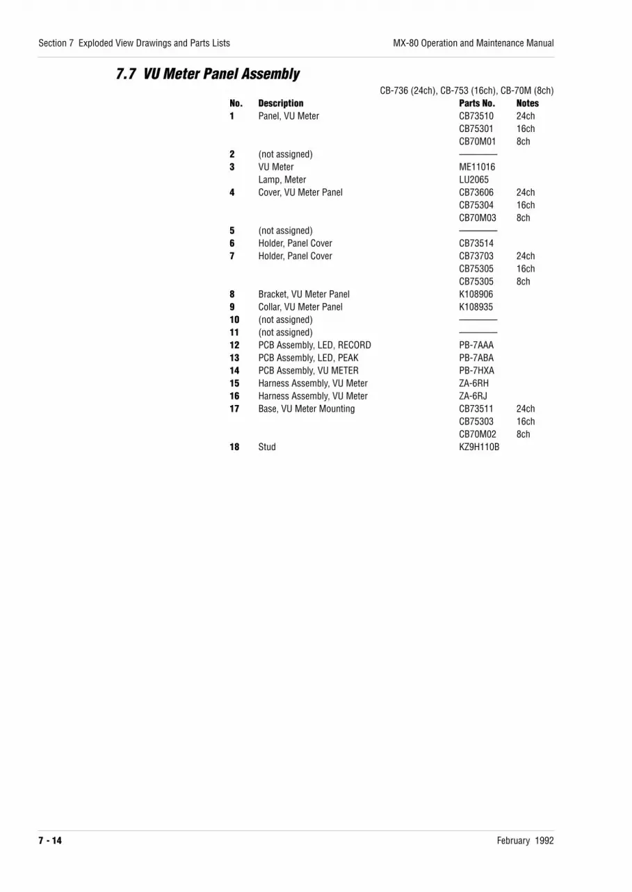
7.7 VU Meter Panel AssemblyCB-736 (24ch), CB-753 (16ch), CB-70M (8ch)
No. Description Parts No. Notes1 Panel, VU Meter CB73510 24ch
CB75301 16chCB70M01 8ch
2 (not assigned) ————3 VU Meter ME11016
Lamp, Meter LU20654 Cover, VU Meter Panel CB73606 24ch
CB75304 16chCB70M03 8ch
5 (not assigned) ————6 Holder, Panel Cover CB735147 Holder, Panel Cover CB73703 24ch
CB75305 16chCB75305 8ch
8 Bracket, VU Meter Panel K1089069 Collar, VU Meter Panel K10893510 (not assigned) ————11 (not assigned) ————12 PCB Assembly, LED, RECORD PB-7AAA13 PCB Assembly, LED, PEAK PB-7ABA14 PCB Assembly, VU METER PB-7HXA15 Harness Assembly, VU Meter ZA-6RH16 Harness Assembly, VU Meter ZA-6RJ17 Base, VU Meter Mounting CB73511 24ch
CB75303 16chCB70M02 8ch
18 Stud KZ9H110B
Section 7 Exploded View Drawings and Parts Lists
7 - 14 February 1992
MX-80 Operation and Maintenance Manual

VU Meter Panel Assembly
MX-80 Operation and Maintenance Manual
February 1992
Section 7 Exploded View Drawings and Parts Lists
7 - 15
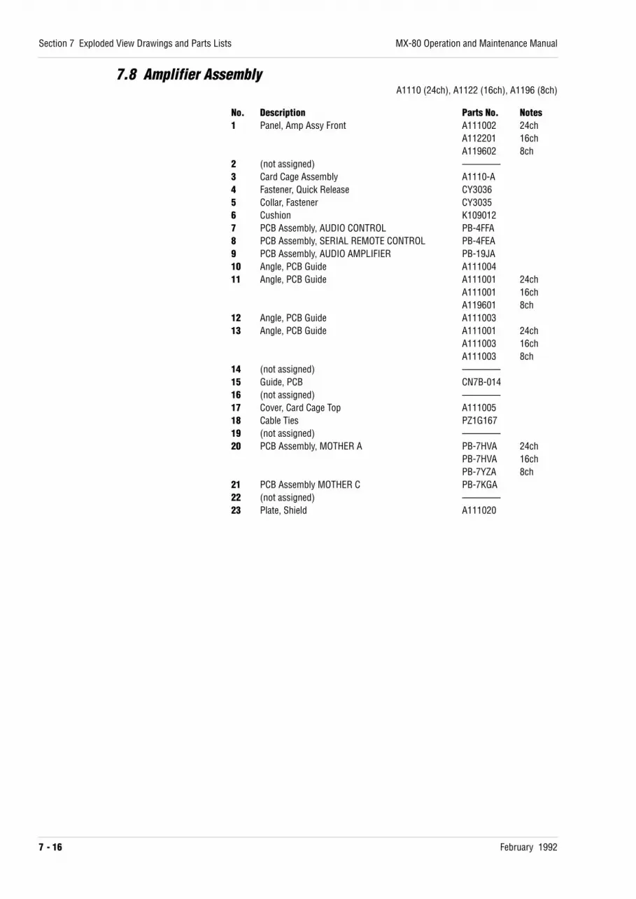
7.8 Amplifier AssemblyA1110 (24ch), A1122 (16ch), A1196 (8ch)
No. Description Parts No. Notes1 Panel, Amp Assy Front A111002 24ch
A112201 16chA119602 8ch
2 (not assigned) ————3 Card Cage Assembly A1110-A4 Fastener, Quick Release CY30365 Collar, Fastener CY30356 Cushion K1090127 PCB Assembly, AUDIO CONTROL PB-4FFA8 PCB Assembly, SERIAL REMOTE CONTROL PB-4FEA9 PCB Assembly, AUDIO AMPLIFIER PB-19JA10 Angle, PCB Guide A11100411 Angle, PCB Guide A111001 24ch
A111001 16chA119601 8ch
12 Angle, PCB Guide A11100313 Angle, PCB Guide A111001 24ch
A111003 16chA111003 8ch
14 (not assigned) ————15 Guide, PCB CN7B-01416 (not assigned) ————17 Cover, Card Cage Top A11100518 Cable Ties PZ1G16719 (not assigned) ————20 PCB Assembly, MOTHER A PB-7HVA 24ch
PB-7HVA 16chPB-7YZA 8ch
21 PCB Assembly MOTHER C PB-7KGA22 (not assigned) ————23 Plate, Shield A111020
Section 7 Exploded View Drawings and Parts Lists
7 - 16 February 1992
MX-80 Operation and Maintenance Manual

Amplifier Assembly
MX-80 Operation and Maintenance Manual
February 1992
Section 7 Exploded View Drawings and Parts Lists
7 - 17

7.9 Power Supply AssemblyNo. Description Parts No. Notes1 Heat Sink KZ1A0702 Diode, Bridge PN-01903 IC ISTR90054 PCB, Transistor PB9A622A5 Transistor QB863O6 Transistor QD1148O7 IC IHC7805H8 PCB, Transistor (L) PB9A393A9 PCB, Transistor (S) PB9A385A10 Collar, Transistor PZ4B03611 Insulator, Transistor PZ4B06812 Insulator, Transistor PZ4B05513 Insulator, Transistor PZ4B05414 Diode, Bridge PN000515 IC ISTR900516 Transistor QB863O17 AC Inlet CN60322118 Fuse Holder FH1-03419 Fuse 10A FH9-01120 (not assigned) ————21 Terminal, Ground CN90104022 Panel, Power Supply, Rear DS3J00323 Stand off KZ9L200A24 PCB Assembly, POWER SUPPLY PB-62ZA25 Hinge, Front Panel (L) CY201526 Hinge, Front Panel (R) CY201627 Noise Filter SF500928 Transformer, Power TF1110729 Transformer, Power TF1110930 (not assigned)31 Capacitor C122318032 PCB Assembly, VOLTAGE SELECT PB-7HYA33 Stand Off KZ9L100A34 Cap, Leg CY500735 Panel, Power Supply, Front DS3J00136 Spacer DS3J00537 Escutcheon KN500738 Switch, Power WH9210139 Capacitor, Spark Arrester CZ20001W40 PCB Assembly, LED, POWER PB-7HZA41 Spacer KZ7A18342 Spacer KZ9A075B43 Circuit Breaker 10A WH9109244 Circuit Breaker 8A WH9109145 Circuit Breaker 2.5A WH9108646 Circuit Breaker 6.3A WH9109047 (not assigned) ————50 Circuit Breaker 3.15A WH9108751 Circuit Breaker 4A WH9108852 Caster, with Brake CY408253 Caster, without Brake CY408154 Collar K10890455–58 (not assigned) ————59 Circuit Breaker 10A WH91092
Section 7 Exploded View Drawings and Parts Lists
7 - 18 February 1992
MX-80 Operation and Maintenance Manual

Power Supply Assembly
MX-80 Operation and Maintenance Manual
February 1992
Section 7 Exploded View Drawings and Parts Lists
7 - 19

7.10 Rear Panel AssembliesRear Panel Assembly (CB-738), External I/O Panel Assembly (CB-749)
No. Description Parts No. Notes1 Panel, I/O CB784012 Panel, Blank CB749033 Lock, Connector CN7B-2124 Connector Assembly, Parallel I/O PZ9D1645 Panel, Rear CB738016 Resistor 150 Ω R97-0027 PCB Assembly, REEL DRIVE PB-4FCA8 PCB Assembly, TRANSPORT CONTROL PB-4JSA9 Stud KZ9H100A10 Plate, Nut A10441211 PCB Assembly, CAPSTAN CONTROL PB-4FAA12 PCB Assembly, REEL CONTROL PB-4FBA13 Hinge R CY201614 Hinge L CY201515 Fan AS1Z02216 Cover K11312617 Washer, Nylon KZ6C04318 Stud KZ7A23619 Heat Transfer Sheet PZ4B08820 7K Bushing PZ4B03521 Mini Clamp PZ1G082
Section 7 Exploded View Drawings and Parts Lists
7 - 20 February 1992
MX-80 Operation and Maintenance Manual

Rear Panel Assemblies
MX-80 Operation and Maintenance Manual
February 1992
Section 7 Exploded View Drawings and Parts Lists
7 - 21

7.11 Audio I/O Panel AssemblyCB-733 (24ch), CB-752 (16ch), CB-70L (8ch)
No. Description Parts No. Notes1 Panel, Audio I/O CB73301 24ch
CB75201 16chCB70L01 8ch
2 (not assigned) ————3 Connector, XL-Type Receptacle CN1031944 Connector, XL-Type Plug CN1031955 (not assigned) ————6 Cable Assembly, NR ZA-6EF7 Cable Assembly ZA-6EG 24ch8 Lock, Connector CN7B-0619 Hinge R CY201610 Hinge L CY201511 Collar K10890412 Blank Panel CB7320413 Edging PZ1G12214 Lock, Connector CN7B-21215 Cable Assembly, Amplifier ZA-6KF
Section 7 Exploded View Drawings and Parts Lists
7 - 22 February 1992
MX-80 Operation and Maintenance Manual

Audio I/O Panel Assembly
MX-80 Operation and Maintenance Manual
February 1992
Section 7 Exploded View Drawings and Parts Lists
7 - 23

7.12 Remote Control Assembly CB-140No. Description Parts No. Notes1 Panel CB140012 (not assigned) ————3 Panel R, Side CB139024 Panel L, Side CB139035 Protector Assembly CB-139C6 Cover, Under CB123047 Bottom Panel Assembly CB-123C8 Hinge CY20239 Escutcheon, Timer KN501210 Protector B PZ4A01411 Protector A PZ4A01312 PCB Assembly, MASTER SWITCH PB-7QBA13 PCB Assembly, TIMER INDICATOR PB-7HTC14 PCB Assembly, CHANNEL SET-UP PB-7QCA15 PCB Assembly, DISPLAY PB-7PUB16 (not assigned) ————17 Cap KN104818 Knob B KN104619 PCB Assembly, TRANSPORT SWITCH PB-7QDA20 PCB Assembly, CPU PB-4KWA21 PCB Assembly, POWER SUPPLY PB-63AA22 Heatsink CB1230523 Bracket, Connector CB1231324 Screw, Lock CN7B-21225 Bracket CN7B-06l26 Cable Assembly A ZA-6EL27 Cable Assembly B ZA-6EM28 Foot CY406329 Insulation Sheet CB1390730 Number Seal PT5064
Section 7 Exploded View Drawings and Parts Lists
7 - 24 February 1992
MX-80 Operation and Maintenance Manual

Remote Control Assembly CB-140
MX-80 Operation and Maintenance Manual
February 1992
Section 7 Exploded View Drawings and Parts Lists
7 - 25

7.13 Remote Control Assembly CB-151No. Description Parts No. Notes1 Escutcheon, Timer KN50202 Escutcheon, Switch PZ4A0263 Escutcheon, Switch PZ4A0274 CAUTION Label, UL PT41175 CAUTION Label PT42316 Panel CB151017 Stud KZ9H220A8 PCB Assembly, TRANSPORT SWITCH PB-4SZA
A REHEARSE Button KN2240B CUE Button KN2145C RECORD button KN2144D PLAY Button KN2142E STOP Button KN2141F F.FWD/RWD Button KN2143G Button KN2184
9 PCB Assembly, TIMER INDICATOR PB-7HTD10 Stud KZ9H140A11 Cap, Knob KN109912 Knob KN110313 Blind PZ1B04814 PCB Assembly, DISPLAY PB-7VXA15 Shield PZ1G18616 PCB Assembly, CPU PB-4SYA17 Plate, Heatsink CB1230518 Sub Assembly, Bottom CB-151B19 Bushing PZ1G070A20 Cable Assembly, Remote ZA-6VD21 Stud KZ9H070A22 Foot CY4137
Section 7 Exploded View Drawings and Parts Lists
7 - 26 February 1992
MX-80 Operation and Maintenance Manual

Remote Control Assembly CB-151
MX-80 Operation and Maintenance Manual
February 1992
Section 7 Exploded View Drawings and Parts Lists
7 - 27
SET
ZERO
1
2
3
REPEATCLR
TIME-IPS-%
SEARCH
H
M
S
HL
TAPE SPEED
CB-144 REMOTE CONTROL UNIT
REHARSE
AB
CD
EF
2
3
1
B3x6
TP3x6
TS3x6
5
7
8
9
10
8
5
6
8
11
12
TS3x6
TS3x4
TS3x6
TS3x6
20
14
15
19
16
8
TS3x10
4
13
1718
G


February 1992 A - 1
Appendix Modification and Field Upgrades
This section contains general information about the wide band modificationfor reproducing time code signals and about changing the tape speed pairs.This section also contains installation instructions for the optional overbridgecase for a noise reduction system.
A.1 Wide Band Modification . . . . . . . . . . . . . . . . . . . . . . . . . . . . . . . . . . . . . . . . . . . . . A-2
A.2 Changing Machine Speed Pairs . . . . . . . . . . . . . . . . . . . . . . . . . . . . . . . . . . . . A-3
A.3 Installation of Overbridge Case for Noise Reduction System . . . . . A-4

A.1 Wide Band ModificationThe following modification to the AUDIO AMPLIFIER PCB assembly is required forreproducing SMPTE/EBU time code in FAST WIND and SPOOL modes.
1. Remove J1 (located between IC3 and IC4).
2. Solder a jumper wire to J2 (in the vicinity of IC1).
3. Check the following parts and solder them to the specified positions.
R501: 1/4W, 5%, 8.2 kΩ carbon resistorR503: 1/4W, 5%, 470 Ω carbon resistorR505: 1/4W, 5%, 1 MΩ carbon resistorR506: 1/4W, 5%, 1 MΩ carbon resistorR507: 1/4W, 5%, 1 MΩ carbon resistorQ501: 2SK336 (FET switch)Q503: 2SK336 (FET switch)C5: 0.001 µF, mylar film capacitor (±5%, 50 V)C17: 0.001 µF, mylar film capacitor (±5%, 50 V)C26: 47 pF, polypropylene film capacitor (±5%, 50 V)C37: 47 pF, polypropylene film capacitor (±5%, 50 V)C501: 0.1 µF, mylar film capacitor (±5%, 50 V)
R502, R504, Q502, Q504 must be removed.
4. Cut the printed wiring on the PCB as follows.
NOTE: When this modification has been carried out, MX-80 can read timecode up to 25 times written speed. Time code written at 30 or 15 ips can beread at maximum speed. Since time code written at 7.5 ips cannot be read atmaximum speed, the maximum speed should be reduced (i.e., to use SPOOL
mode or reduce speed by changing R125 on REEL CONTROL PCA to 30 kΩ andreadjusting VR10 on REEL CONTROL PCA).
Appendix Modification and Field Upgrades
A - 2 February 1992
MX-80 Operation and Maintenance Manual
35 V.CLOCKR25822K
C180IC30
9 87
36 C.CLOCKR25147K
C1818
34 LED.CLOCKR25247K
C182IC30
13 126
32A ST.BYR25347K
C1832
32B T.MUTER25447K
C1843
37 R.ONR25547K
C185IC30
1 29
IC3011 10
IC303 4
RA4 47K
+5V
CUT
1

A.2 Changing Machine Speed PairsThe MX-80 is a three speed machine with two of the speeds available forselection by the SPEED switch on the transport. Changing the speed pairinvolves changing one switch (SW1-1) on the TRANSPORT CONTROL PCB and re-aligning the audio channels.
1. Open the upper rear panel by removing the 2 upper screws on each sideof the panel, and allowing it to fold down to a horizontal position.
2. On the TRANSPORT CONTROL PCB, change the setting of SW2. If your machinewas initially configured for 15 & 30 ips, the switch will be in the “H”position, if initially configured for 7.5 & 15 ips, the switch will be in the“L” position. Set the switch to correspond to the desired speed pair (H orL).
3. Perform the routine audio alignment procedures described in §5.2.
4. Perform the routine transport alignment procedures described in §5.1.
5. Close the upper rear panel and replace the four screws removed in step1.
MX-80 Operation and Maintenance Manual
February 1992
Appendix Modification and Field Upgrades
A - 3

A.3 Installation of Overbridge Case for Noise Reduction System1. Install the Foot [12] with the plate [11] (This step is required for any MX-
80 having a serial number suffix of C or later, and for the some B suffixmachines).
2. Mount trim plates A [4] to the top and bottom of both side trims [2] and[3]. Secure each with two M3x10 hex socket head screws.
3. Mount the parts assembled in step 2 into the overbridge case [1].Secure with four M4x10 hex socket head screws on each side.
4. Insert two spacers [9] and two casters [10] into the bottom support [8].Secure side panel L [5] and side panel R [6] to the bottom support [8]with two M4x10 hex socket head screws on each side.
5. Mount the parts assembled in step 4 to the MX-80 case frame from therear. Secure with five M8x12 hex socket head screws. These screwsshould not be tightened completely at this time.
6. Mount the cover [7] between side panel L [5] and side panel R [6].Secure with M3x6 hex socket head screws from the inside of the cover.Completely tighten the M4x10 and M8x12 hex socket head screws formsteps 4 and 5.
7. Mount the overbridge case [1] onto side panel L [5] and side panel R[6]. Secure with two M5x8 binding head screws on each side.
8. Attach the floating nuts to the trim plate L [2] and trim plate R [3] asillustrated.
9. Mount the blank panel A [13] and the blank panel B [14] from the front.Secure with eight M5x20 binding head screws.
10. Mount the noise reduction system and power supply unit from the front.Secure with four M5x20 binding head screws.
11. Verify that all screws have been completely tightened.
NOTE: Due to weight of this assembly, we suggest that this installation bedone with the help of another person.
PARTS LISTNo. Description Parts No. Qty No. Description Parts No. Qty1 Overbridge Case K1134-B 1 8 Bottom Support K113425 12 Side Trim L K113427 1 9 Spacer KZ6C120 23 Side Trim R K113428 1 10 Caster CY4081 24 Trim Plate A K113413 2 11 Plate Adjust K113430 25 Side Panel L K1134-C 1 12 Foot CY4129 26 Side Panel R K1134-D 1 13 Blank Panel A K113416 17 Cover K113424 1 14 Blank Panel B K113429 1
LIST OF SCREWSType Quantity CodeM3x 6 Hex Socket Head Screw 6 C3x 6BM3x10 Hex Socket Head Screw 4 C3x10BM4x10 Hex Socket Head Screw 20 C4x10BM5x 8 Binding Head Screw 4 B5x 8NM5x20 Binding Head Screw 20 B5x20NFloating Nut 20 F951Z004M8x12 Hex Socket Head Screw 10 C8x12B
Appendix A Modification and Field Upgrades
A - 4 February 1992
MX-80 Operation and Maintenance Manual

Overbridge Case Assembling
MX-80 Operation and Maintenance Manual
February 1992
Appendix Modification and Field Upgrades
A - 5
Floating Nut Mounting
C3x10B
1
4
13
14 2
B5x20N
B5x20N
3
4
C3x10B
5
C3x6B
C8x10B
7
B5x8N
8
9
10
C4x10B
C4x12B
9
1011
12C4x10B
6
C4x10B
1112


February 1992 1
Schematic Diagrams
TYPE R and later
Part No. Description DWG. No.T00370C Wiring Diagram (24 ch) 3-15107T00370D Wiring Diagram (16 ch) 3-15106KH6D00B Head Wiring Diagram (24 ch) 3-12542KH6E00B Head Wiring Diagram (16 ch) 3-12543T00370E Transport Wiring Diagram 3-12544CB20W0B Control Panel Assembly 3-12635CB20W0C Control Panel Assembly 3-12637PB7AJ0A Switch PCB Assembly (I) 3-12641PB7AK0A Switch PCB Assembly (II) 4-37429ZA93E0A Timer Display Assembly 3-12645PB7HT0A Timer Indicator PCB Assembly 3-14224PB7HU0A Timer Drive PCB Assembly 3-14220SR1W00A Tension Detect Assembly 4-44454PB7LA0A Tach (I) PCB Assembly 4-42942PB7DS0A Tach (II) PCB Assembly 4-42330PB4FH0A Safety PCB Assembly 4-42934PB7MV0A Reel Tach PCB Assembly 4-43028PB4FD0B Transport Control Block Diagram 3-12633PB4JS0A Transport Control PCB Assembly (1/2) 3-13894PB4JS0A Transport Control PCB Assembly (2/2) 3-13895PB4FC0A Reel Drive PCB Assembly 3-12617PB4FB0A Reel Control PCB Assembly 3-17177ZA93G0A Capstan Drive Assembly 4-42937PB4FA0A Capstan Control PCB Assembly 3-12607PB4FE0A Serial Remote Control PCB Assembly (1/2) 3-14218PB4FE0A Serial Remote Control PCB Assembly (2/2) 3-14219PB4LR0A 422 TRNCV PCB Assembly 4-44612PB7HX0A VU Meter PCB Assembly 3-12519PB7AA0A Record Indicator PCB Assembly 4-36987PB7AB0A Peak Indicator PCB Assembly 4-36989A11110B Audio Wiring Diagram (24 ch) 3-12546A11220B Audio Wiring Diagram (16 ch) 3-12547PB4FF0A Audio Control PCB Assembly (Command) 3-12548PB4FF0A Audio Control PCB Assembly (Clock) 3-12549PB19J0A Audio Amplifier PCB Assembly (Playback) 3-15518PB19J0A Audio Amplifier PCB Assembly (Record) 3-15519PB19J0A Audio Amplifier PCB Assembly (Bias) 3-15520PB19J0A Audio Amplifier PCB Assembly (Control) 3-15521PB7HV0A Mother A PCB Assembly 3-13255PB7HW0A Mother B PCB Assembly 3-13256PB7KG0A Mother C PCB Assembly 3-12556DS3J00B Power Supply Assembly Wiring 3-15108DS3J00A Power Supply Assembly 3-13266DS3J00C Circuit Protector Assembly 4-42936PB7HY0A Voltage Select PCB Assembly 3-15104PB7HZ0A Power Indicator PCB Assembly 4-42935CB1390B Remote Controller Wiring Diagram 3-14020PB4KW0A CPU PCB Assembly (1/4) 3-14016PB4KW0A CPU PCB Assembly (2/4) 3-14017PB4KW0A CPU PCB Assembly (3/4) 3-14018PB4KW0A CPU PCB Assembly (4/4) 3-14019PB7QB0A Master Switch PCB Assembly 4-44631PB7QD0A Transport Switch PCB Assembly 3-14009PB7QC0A Channel Setup PCB Assembly 4-44633PB7PU0A Display PCB Assembly (1/2) 3-14010PB7PU0A Display PCB Assembly (2/2) 3-14011PB63A0A Power PCB Assembly 3-14223


