Embed Size (px)
Citation preview
MPI as an Abstraction for Software-HardwareInteraction for HPRCs
Manuel Saldana∗, Arun Patel∗, Christopher Madill§, Daniel Nunes†, Danyao Wang†,Henry Styles‡, Andrew Putnam‡, Ralph Wittig‡, Paul Chow†
∗Arches Computing Systems, Ontario, Canada
Email:{ms,ap}@archescomputing.com†University of Toronto, Department of Electrical and Computer Engineering, Ontario, Canada
Email:{cmadill,dnunes,wangda,pc}@eecg.toronto.edu§University of Toronto, Department of Biochemistry, Ontario, Canada
Email:{chris.madill}@utoronto.ca‡Xilinx, San Jose, California, USA
Email:{ralph.wittig, henry.styles, andrew.putnam}@xilinx.com
Abstract—High Performance Reconfigurable Computers(HPRCs) consist of one or more standard microprocessorstightly coupled with one or more reconfigurable FPGAs.HPRCs have been shown to provide good speedups and goodcost/performance ratios, but not necessarily ease of use, leadingto a slow acceptance of this technology. HPRCs introducenew design challenges, such as the lack of portability acrossplatforms, incompatibilities with legacy code, users reluctant tochange their code base, a prolonged learning curve, and the needfor a system-level Hardware/Software co-design developmentflow. This paper presents the evolution and current work onTMD-MPI, which started as an MPI-based programming modelfor Multiprocessor Systems-on-Chip implemented in FPGAs,and has now evolved to include multiple X86 processors.TMD-MPI is shown to address current design challenges inHPRC usage, suggesting that the MPI standard has enoughsyntax and semantics to program these new types of parallelarchitectures. Also presented is the TMD-MPI Ecosystem, whichconsists of research projects and tools that are developed aroundTMD-MPI to further improve HPRC usability.
I. INTRODUCTION
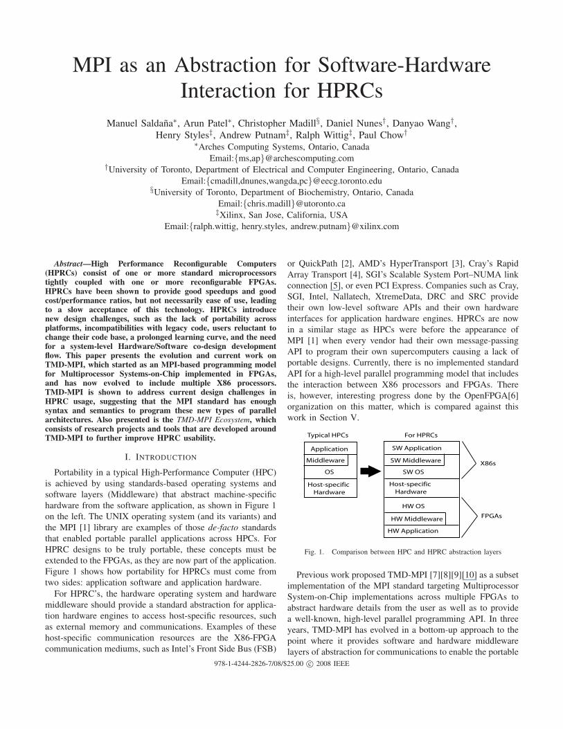
Portability in a typical High-Performance Computer (HPC)
is achieved by using standards-based operating systems and
software layers (Middleware) that abstract machine-specific
hardware from the software application, as shown in Figure 1
on the left. The UNIX operating system (and its variants) and
the MPI [1] library are examples of those de-facto standards
that enabled portable parallel applications across HPCs. For
HPRC designs to be truly portable, these concepts must be
extended to the FPGAs, as they are now part of the application.
Figure 1 shows how portability for HPRCs must come from
two sides: application software and application hardware.
For HPRC’s, the hardware operating system and hardware
middleware should provide a standard abstraction for applica-
tion hardware engines to access host-specific resources, such
as external memory and communications. Examples of these
host-specific communication resources are the X86-FPGA
communication mediums, such as Intel’s Front Side Bus (FSB)
or QuickPath [2], AMD’s HyperTransport [3], Cray’s Rapid
Array Transport [4], SGI’s Scalable System Port–NUMA link
connection [5], or even PCI Express. Companies such as Cray,
SGI, Intel, Nallatech, XtremeData, DRC and SRC provide
their own low-level software APIs and their own hardware
interfaces for application hardware engines. HPRCs are now
in a similar stage as HPCs were before the appearance of
MPI [1] when every vendor had their own message-passing
API to program their own supercomputers causing a lack of
portable designs. Currently, there is no implemented standard
API for a high-level parallel programming model that includes
the interaction between X86 processors and FPGAs. There
is, however, interesting progress done by the OpenFPGA[6]
organization on this matter, which is compared against this
work in Section V.
SW Application
SW Middleware
SW OS
HW Application
HW Middleware
HW OS
OS
Application
Middleware
Host-specific
Hardware
Host-specific
Hardware
X86s
FPGAs
Typical HPCs For HPRCs
Fig. 1. Comparison between HPC and HPRC abstraction layers
Previous work proposed TMD-MPI [7][8][9][10] as a subset
implementation of the MPI standard targeting Multiprocessor
System-on-Chip implementations across multiple FPGAs to
abstract hardware details from the user as well as to provide
a well-known, high-level parallel programming API. In three
years, TMD-MPI has evolved in a bottom-up approach to the
point where it provides software and hardware middleware
layers of abstraction for communications to enable the portable
978-1-4244-2826-7/08/$25.00 c© 2008 IEEE
interaction between embedded processors, specialized hard-
ware computing engines and now X86 processors; all pro-
grammed under the same message passing paradigm making
it a unified programming model for HPRCs.
This paper provides a summary of TMD-MPI’s philosophy
and evolution, followed by a discussion of the new additions,
current work and supporting tools and research projects called
the “TMD-MPI Ecosystem”. It is hoped that these research ef-
forts generate discussion in the community regarding whether
MPI is a good model for HPRCs or not, influencing perhaps
existing MPI implementations to include FPGA support. It is
time to consider how to include acceleration technologies, such
as FPGAs, GPUs and CELL processors into a potential MPI-
3 accelerator-aware standard because accelerator technologies
also have data movement and synchronization requirements.
The rest of the paper is organized as follows. Section II
explains the motivations that led to the development and use of
TMD-MPI. In Section III an updated version of the design flow
based on recent work is presented. Section IV provides a real
example of portability based on experiences using TMD-MPI.
Section V contrasts TMD-MPI with related work regarding
X86-FPGA communication. Section VI describes TMD-MPI’s
architecture and HPRC reference platform. In Section VII, the
current functionality of TMD-MPI is described. Section VIII
presents a synopsis of the projects that constitute the TMD-
MPI Ecosystem. Finally, some concluding remarks are given
in Section IX.
II. MOTIVATION
TMD-MPI was initially developed to address the need
for a programming model for the TMD (Toronto Molecu-
lar Dynamics) machine being developed at the University
of Toronto [10]. The TMD machine is a scalable Multi-
FPGA configurable system designed to accelerate computing
intensive applications. The basic assumption is that FPGAs
have enough resources to implement entire applications, as
opposed to only parts of computations, such as small comput-
ing kernels. The objective is to have a tightly coupled mix
of embedded processors (for control intensive parts of the
application) and specialized hardware engines (to accelerate
the compute-intensive parts of the application) all within the
same FPGA or distributed among many FPGAs.
With multiple embedded processors and hardware engines
(collectively referred to in this paper as computing elements,
or CEs) interacting across multiple FPGAs, there is a need
for a networking infrastructure and a distributed programming
model. Most multi-FPGA systems have distributed memory
(usually, each FPGA has its own external memory), and inside
each FPGA there might be multiple CEs, each with their
own local memory; hence, a programming model such as
MPI seems adequate. With the appearance of tightly-coupled
FPGAs and X86 processors sharing the main system mem-
ory [11], [12], [13], [14], [15], TMD-MPI has been extended to
include communication with X86 processors, marking TMD-
MPI’s entrance to the HPRC world.
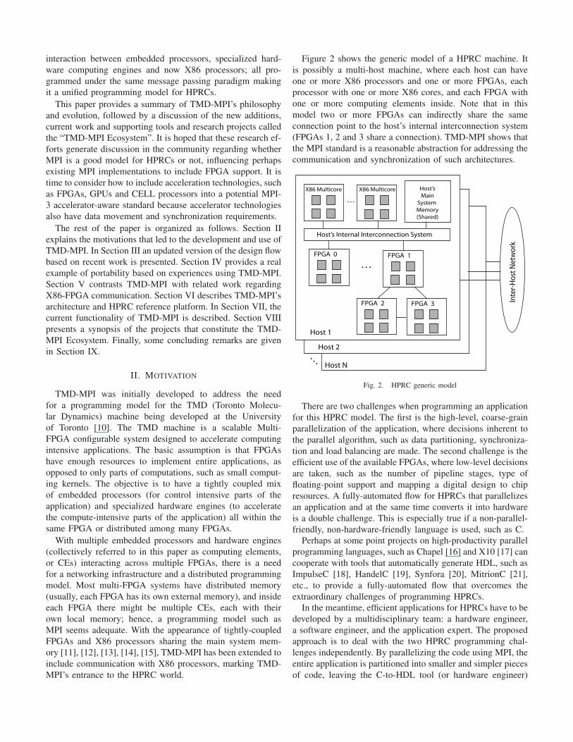
Figure 2 shows the generic model of a HPRC machine. It
is possibly a multi-host machine, where each host can have
one or more X86 processors and one or more FPGAs, each
processor with one or more X86 cores, and each FPGA with
one or more computing elements inside. Note that in this
model two or more FPGAs can indirectly share the same
connection point to the host’s internal interconnection system
(FPGAs 1, 2 and 3 share a connection). TMD-MPI shows that
the MPI standard is a reasonable abstraction for addressing the
communication and synchronization of such architectures.
X86 Multicore Host’s
Main
System
Memory
(Shared)
. . .
FPGA 1
FPGA 3FPGA 2
FPGA 0
X86 Multicore
Host’s Internal Interconnection System
Host 1
Host 2
Host N
. . .
. . .
Inte
r-H
ost
Net
wo
rk
Fig. 2. HPRC generic model
There are two challenges when programming an application
for this HPRC model. The first is the high-level, coarse-grain
parallelization of the application, where decisions inherent to
the parallel algorithm, such as data partitioning, synchroniza-
tion and load balancing are made. The second challenge is the
efficient use of the available FPGAs, where low-level decisions
are taken, such as the number of pipeline stages, type of
floating-point support and mapping a digital design to chip
resources. A fully-automated flow for HPRCs that parallelizes
an application and at the same time converts it into hardware
is a double challenge. This is especially true if a non-parallel-
friendly, non-hardware-friendly language is used, such as C.
Perhaps at some point projects on high-productivity parallel
programming languages, such as Chapel [16] and X10 [17] can
cooperate with tools that automatically generate HDL, such as
ImpulseC [18], HandelC [19], Synfora [20], MitrionC [21],
etc., to provide a fully-automated flow that overcomes the
extraordinary challenges of programming HPRCs.
In the meantime, efficient applications for HPRCs have to be
developed by a multidisciplinary team: a hardware engineer,
a software engineer, and the application expert. The proposed
approach is to deal with the two HPRC programming chal-
lenges independently. By parallelizing the code using MPI, the
entire application is partitioned into smaller and simpler pieces
of code, leaving the C-to-HDL tool (or hardware engineer)
the easier task of turning into hardware more confined pieces
of code. Writing high-level parallel code is still easier than
writing low-level HDL code, so this approach is of great help
to the non-hardware knowledgeable user. The experience of
using TMD-MPI shows that MPI applied to FPGAs offers
a convenient and clean interface between hardware designers
and software developers that allows independent progress of
both due to the standard interface and well-defined semantics.
Pragmatically, HPRCs exist now and the user community
cannot wait for fully automated tools to magically appear
and make them trivial to use. TMD-MPI and its surrounding
Ecosystem are examples of tools that exist today.
III. DESIGN FLOW
As previously discussed, the two major challenges to im-
plementing an application on HPRCs are coarse-grain paral-
lelization and HDL coding. To address these challenges, a top-
down, step-by-step design flow was developed to implement
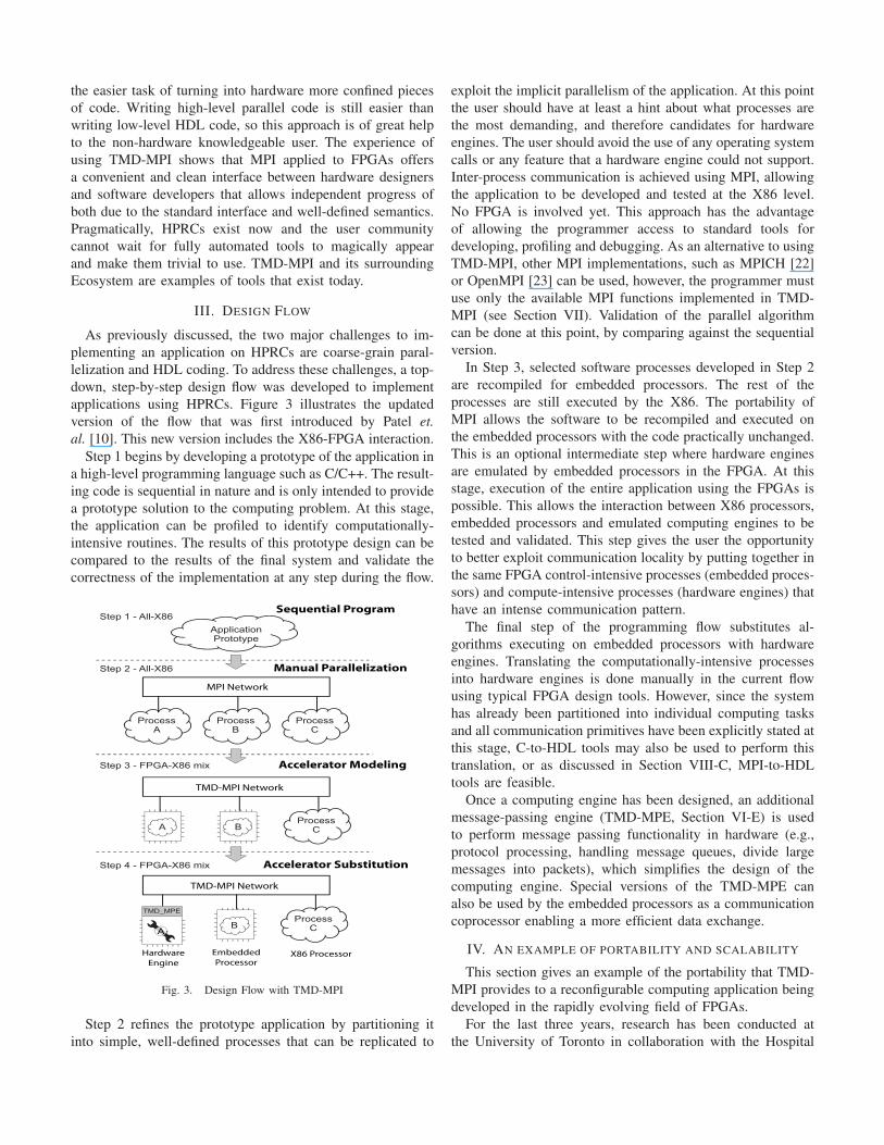
applications using HPRCs. Figure 3 illustrates the updated
version of the flow that was first introduced by Patel et.
al. [10]. This new version includes the X86-FPGA interaction.
Step 1 begins by developing a prototype of the application in
a high-level programming language such as C/C++. The result-
ing code is sequential in nature and is only intended to provide
a prototype solution to the computing problem. At this stage,
the application can be profiled to identify computationally-
intensive routines. The results of this prototype design can be
compared to the results of the final system and validate the
correctness of the implementation at any step during the flow.
MPI Network
ApplicationPrototype
ProcessA
ProcessB
ProcessC
Step 1 - All-X86
Step 2 - All-X86
Step 3 - FPGA-X86 mix
Step 4 - FPGA-X86 mix
ProcessC
TMD_MPE
BA
ProcessCB
Hardware
Engine
Embedded
ProcessorX86 Processor
TMD-MPI Network
TMD-MPI Network
A
Sequential Program
Manual Parallelization
Accelerator Modeling
Accelerator Substitution
Fig. 3. Design Flow with TMD-MPI
Step 2 refines the prototype application by partitioning it
into simple, well-defined processes that can be replicated to
exploit the implicit parallelism of the application. At this point
the user should have at least a hint about what processes are
the most demanding, and therefore candidates for hardware
engines. The user should avoid the use of any operating system
calls or any feature that a hardware engine could not support.
Inter-process communication is achieved using MPI, allowing
the application to be developed and tested at the X86 level.
No FPGA is involved yet. This approach has the advantage
of allowing the programmer access to standard tools for
developing, profiling and debugging. As an alternative to using
TMD-MPI, other MPI implementations, such as MPICH [22]
or OpenMPI [23] can be used, however, the programmer must
use only the available MPI functions implemented in TMD-
MPI (see Section VII). Validation of the parallel algorithm
can be done at this point, by comparing against the sequential
version.
In Step 3, selected software processes developed in Step 2
are recompiled for embedded processors. The rest of the
processes are still executed by the X86. The portability of
MPI allows the software to be recompiled and executed on
the embedded processors with the code practically unchanged.
This is an optional intermediate step where hardware engines
are emulated by embedded processors in the FPGA. At this
stage, execution of the entire application using the FPGAs is
possible. This allows the interaction between X86 processors,
embedded processors and emulated computing engines to be
tested and validated. This step gives the user the opportunity
to better exploit communication locality by putting together in
the same FPGA control-intensive processes (embedded proces-
sors) and compute-intensive processes (hardware engines) that
have an intense communication pattern.
The final step of the programming flow substitutes al-
gorithms executing on embedded processors with hardware
engines. Translating the computationally-intensive processes
into hardware engines is done manually in the current flow
using typical FPGA design tools. However, since the system
has already been partitioned into individual computing tasks
and all communication primitives have been explicitly stated at
this stage, C-to-HDL tools may also be used to perform this
translation, or as discussed in Section VIII-C, MPI-to-HDL
tools are feasible.
Once a computing engine has been designed, an additional
message-passing engine (TMD-MPE, Section VI-E) is used
to perform message passing functionality in hardware (e.g.,
protocol processing, handling message queues, divide large
messages into packets), which simplifies the design of the
computing engine. Special versions of the TMD-MPE can
also be used by the embedded processors as a communication
coprocessor enabling a more efficient data exchange.
IV. AN EXAMPLE OF PORTABILITY AND SCALABILITY
This section gives an example of the portability that TMD-
MPI provides to a reconfigurable computing application being
developed in the rapidly evolving field of FPGAs.
For the last three years, research has been conducted at
the University of Toronto in collaboration with the Hospital
for Sick Children to develop an FPGA-based machine to
accelerate Molecular Dynamics (MD) simulations. These are
atomic-level simulations of biomolecular systems used in
biomedical research to design more effective drugs. The devel-
opment of this machine began using the Amirix AP1000 PCI
development boards [24]. Each board contains one XC2VP100
FPGA, 64 MB of external memory and four high-speed serial
I/O links, which allowed five of these boards to be fully
interconnected. The MD application coding was in progress
when the new BEE2 platform [25] arrived with five XC2VP70
FPGAs per board, 4 GB of external memory per FPGA,
using parallel LVDS lines and 18 high-speed serial links. This
platform is obviously more integrated, provides more resources
and potential for acceleration. Consequently, the development
of the MD application continued on the BEE2 platform. The
MD code was still in progress when the even newer Xilinx
Accelerated Computing Platform (Xilinx ACP) arrived. This
platform (further described in Section VI-A) has Virtex 5
FPGAs that can be connected directly to the Intel FSB by
inserting them into one of the CPU sockets in the motherboard.
The FPGAs are tightly coupled to X86 processors sharing
8 GB of memory, opening up more opportunities for acceler-
ation. Currently, the development continues for this platform.
The question is how can one develop an application if
the hardware keeps changing. Furthermore, how can existing
code be isolated from future hardware changes. The impact
of these hardware changes on the MD application has been
minimized by using TMD-MPI. Indeed, there were changes,
but all of them in the system infrastructure (what is described
as SW/HW OS and SW/HW Middleware in Figure 1), not
at the SW/HW application levels. The MD software code
(written in C++) and the MD hardware engines (HDL) have
been mostly the same, changing only in their natural evolution
towards a more complete MD simulator.
One of the necessary changes was to regenerate some
of the core netlists to take advantage of the newer Vir-
tex 5 architecture. Another change was computing element
reallocations. The bonded and non-bonded force calculations
(particular types of forces in MD) were performed by two
different computing elements that were located in the same
FPGA, but when switching from the AP1000 boards to the
BEE2 boards the bonded forces compute engine had to be
reallocated to another FPGA because the BEE2 board has
smaller FPGAs than the AP1000 board. Moreover, the bonded
force computing element was originally a PowerPC processor,
then it became a MicroBlaze soft-processor, but most likely it
will end up being an X86 processor. Through all these changes,
TMD-MPI provided tolerance to hardware changes and made
it possible to perform architectural explorations and propose
changes to achieve better performance without impacting the
MD application code-base.
Another advantage of using TMD-MPI was the abstraction
of the FPGA configuration process, which is usually not as
easy to run as a typical program, and it is also a completely
different procedure between the AP1000 boards, the BEE2
boards and the Xilinx ACP. Furthermore, in a HPRC, starting
the execution of a large number of X86 software processes
and configuring a large number of FPGAs must be automated.
By using mpirun/mpiexec scripts, a difference like this can be
minimized and hidden from the user perspective.
V. RELATED WORK
TMD-MPI was created with the influence of the Multipro-
cessor System-on-Chip [26] and Network-on-Chip research
fields. Related work of those areas to TMD-MPI is discussed
in previous work [8][9] and briefly mentioned in Section VI-B.
In this Section, current APIs for X86-FPGA communication
are compared with TMD-MPI.
Currently, the most common usage of MPI on HPRCs is at
the host level [27], where X86 processors exchange messages
using MPI and then forward the received data to the FPGAs,
which is a mere slave to the X86 processor. This uses the
X86 as a message relay introducing latencies and complicating
the programming model because the user has to be aware of
two different APIs: one for message-passing and another for
interacting with the FPGA. This section shows how MPI’s
high-level API can be used instead of low-level API calls to
perform X86-FPGA communications, with the added benefit
of a broader communication context, more abstraction and a
familiar API, providing a unified programming model. Note
that many features that are available in the MPI standard are
not implemented in TMD-MPI yet, and that certain features
are not defined in the MPI standard but left open to the imple-
mentation. Here references to MPI mean the API itself, and
references to TMD-MPI means our particular implementation
of MPI.
At the time of writing this paper, OpenFPGA has released
its first General API Specification 0.4 (GenAPI) draft [28].
Its objective is to propose an industry standard API for high-
level language access to reconfigurable computing resources
in a portable manner. The draft is an excellent compilation of
common X86-FPGA communication requirements for HPRCs.
GenAPI shares practically all the same design goals as TMD-
MPI, however, there is a fundamental difference: the scope
of the standard. GenAPI only focuses on the low-level X86-
FPGA interaction, not making any assumptions on higher level
forms of communication, such as FPGA-initiated transfers,
inter-host communications, inter-FPGA communications and
intra-FPGA communications. In contrast, the MPI standard is
agnostic of the communication media and requires that every
rank (a task in the MPI jargon) be able to initiate transfers
(Master) at any time regardless of its physical location. In this
sense, the FPGA is no longer a passive slave in the system.
Similar to GenAPI, HPRC vendors provide their own APIs,
but with the same limited scope: X86-FPGA communication,
which is a subset of the communications that TMD-MPI is
able to provide. Table I summarizes these communication ca-
pabilities. TMD-MPI will be able to provide communications
at the host-to-host level, X86-to-X86 level, FPGA-to-FPGA
level and intra-FPGA level (CE to CE); and in between these
categories as well. That is, a hardware engine inside an FPGA
in one host can exchange data with another hardware engine
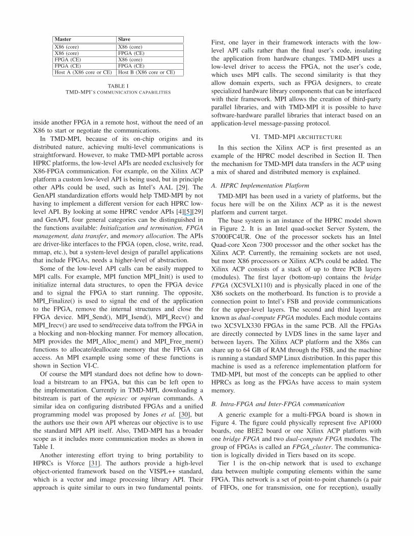
Master Slave
X86 (core) X86 (core)X86 (core) FPGA (CE)FPGA (CE) X86 (core)FPGA (CE) FPGA (CE)Host A (X86 core or CE) Host B (X86 core or CE)
TABLE ITMD-MPI’S COMMUNICATION CAPABILITIES
inside another FPGA in a remote host, without the need of an
X86 to start or negotiate the communications.
In TMD-MPI, because of its on-chip origins and its
distributed nature, achieving multi-level communications is
straightforward. However, to make TMD-MPI portable across
HPRC platforms, the low-level APIs are needed exclusively for
X86-FPGA communication. For example, on the Xilinx ACP
platform a custom low-level API is being used, but in principle
other APIs could be used, such as Intel’s AAL [29]. The
GenAPI standardization efforts would help TMD-MPI by not
having to implement a different version for each HPRC low-
level API. By looking at some HPRC vendor APIs [4][5][29]
and GenAPI, four general categories can be distinguished in
the functions available: Initialization and termination, FPGA
management, data transfer, and memory allocation. The APIs
are driver-like interfaces to the FPGA (open, close, write, read,
mmap, etc.), but a system-level design of parallel applications
that include FPGAs, needs a higher-level of abstraction.
Some of the low-level API calls can be easily mapped to
MPI calls. For example, MPI function MPI Init() is used to
initialize internal data structures, to open the FPGA device
and to signal the FPGA to start running. The opposite,
MPI Finalize() is used to signal the end of the application
to the FPGA, remove the internal structures and close the
FPGA device. MPI Send(), MPI Isend(), MPI Recv() and
MPI Irecv() are used to send/receive data to/from the FPGA in
a blocking and non-blocking manner. For memory allocation,
MPI provides the MPI Alloc mem() and MPI Free mem()
functions to allocate/deallocate memory that the FPGA can
access. An MPI example using some of these functions is
shown in Section VI-C.
Of course the MPI standard does not define how to down-
load a bitstream to an FPGA, but this can be left open to
the implementation. Currently in TMD-MPI, downloading a
bitstream is part of the mpiexec or mpirun commands. A
similar idea on configuring distributed FPGAs and a unified
programming model was proposed by Jones et al. [30], but
the authors use their own API whereas our objective is to use
the standard MPI API itself. Also, TMD-MPI has a broader
scope as it includes more communication modes as shown in
Table I.
Another interesting effort trying to bring portability to
HPRCs is Vforce [31]. The authors provide a high-level
object-oriented framework based on the VISPL++ standard,
which is a vector and image processing library API. Their
approach is quite similar to ours in two fundamental points.
First, one layer in their framework interacts with the low-
level API calls rather than the final user’s code, insulating
the application from hardware changes. TMD-MPI uses a
low-level driver to access the FPGA, not the user’s code,
which uses MPI calls. The second similarity is that they
allow domain experts, such as FPGA designers, to create
specialized hardware library components that can be interfaced
with their framework. MPI allows the creation of third-party
parallel libraries, and with TMD-MPI it is possible to have
software-hardware parallel libraries that interact based on an
application-level message-passing protocol.
VI. TMD-MPI ARCHITECTURE
In this section the Xilinx ACP is first presented as an
example of the HPRC model described in Section II. Then
the mechanism for TMD-MPI data transfers in the ACP using
a mix of shared and distributed memory is explained.
A. HPRC Implementation Platform
TMD-MPI has been used in a variety of platforms, but the
focus here will be on the Xilinx ACP as it is the newest
platform and current target.
The base system is an instance of the HPRC model shown
in Figure 2. It is an Intel quad-socket Server System, the
S7000FC4UR. One of the processor sockets has an Intel
Quad-core Xeon 7300 processor and the other socket has the
Xilinx ACP. Currently, the remaining sockets are not used,
but more X86 processors or Xilinx ACPs could be added. The
Xilinx ACP consists of a stack of up to three PCB layers
(modules). The first layer (bottom-up) contains the bridge
FPGA (XC5VLX110) and is physically placed in one of the
X86 sockets on the motherboard. Its function is to provide a
connection point to Intel’s FSB and provide communications
for the upper-level layers. The second and third layers are
known as dual-compute FPGA modules. Each module contains
two XC5VLX330 FPGAs in the same PCB. All the FPGAs
are directly connected by LVDS lines in the same layer and
between layers. The Xilinx ACP platform and the X86s can
share up to 64 GB of RAM through the FSB, and the machine
is running a standard SMP Linux distribution. In this paper this
machine is used as a reference implementation platform for
TMD-MPI, but most of the concepts can be applied to other
HPRCs as long as the FPGAs have access to main system
memory.
B. Intra-FPGA and Inter-FPGA communication
A generic example for a multi-FPGA board is shown in
Figure 4. The figure could physically represent five AP1000
boards, one BEE2 board or one Xilinx ACP platform with
one bridge FPGA and two dual-compute FPGA modules. The
group of FPGAs is called an FPGA cluster. The communica-
tion is logically divided in Tiers based on its scope.
Tier 1 is the on-chip network that is used to exchange
data between multiple computing elements within the same
FPGA. This network is a set of point-to-point channels (a pair
of FIFOs, one for transmission, one for reception), usually
in a fully-connected topology, but other topologies can be
used as well, depending on the communication needs. The
network latency is usually a few clock cycles depending on
the topology. The bandwidth is limited by the FPGA frequency
and the width of the point-to-point channels.
The Tier 2 network is used for inter-FPGA communication
within the same FPGA cluster. The gateways are connection
points (bridges) between Tier 1 and Tier 2. Usually this
network uses high-speed serial links or parallel LVDS lines.
An important requirement is that this network has CRC and
packet retransmission that guarantees error free transfers. One
of the FPGAs, has a special gateway that connects Tier 2 to
Tier 3 and Tier 4.
Tier 3, not shown in the picture, would be all the com-
munications within the same host: FPGA cluster-X86, X86-
X86, and FPGA cluster-FPGA cluster. Finally, Tier 4, also
not shown in the figure would be the host-host communication.
FPGA
FPGA FPGA
FPGA FPGA
PPC
µB
Tier 1
Network
To Tier 3 and Tier 4
Network
Tier 2
Network
(MGT/LVDS Links)Gateway node
TMD
MPE
Fig. 4. Inter-FPGA and Intra-FPGA communication
The Tier 1 network uses small distributed on-chip network
interfaces (NetIfs), that forward packets to the right channels
based on a routing table. The NetIfs use a buffer-less cut-
through routing approach to reduce latency and to save on-chip
resources. Some degree of buffering is implicit by using FIFOs
as channels. Since all communication is FIFO-based, full and
exists signals are used for flow control back-propagating the
full condition to the sender.
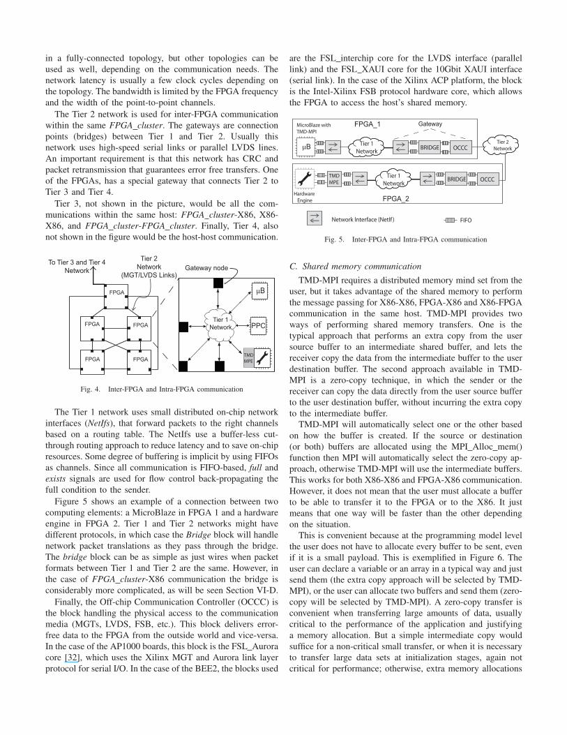
Figure 5 shows an example of a connection between two
computing elements: a MicroBlaze in FPGA 1 and a hardware
engine in FPGA 2. Tier 1 and Tier 2 networks might have
different protocols, in which case the Bridge block will handle
network packet translations as they pass through the bridge.
The bridge block can be as simple as just wires when packet
formats between Tier 1 and Tier 2 are the same. However, in
the case of FPGA cluster-X86 communication the bridge is
considerably more complicated, as will be seen Section VI-D.
Finally, the Off-chip Communication Controller (OCCC) is
the block handling the physical access to the communication
media (MGTs, LVDS, FSB, etc.). This block delivers error-
free data to the FPGA from the outside world and vice-versa.
In the case of the AP1000 boards, this block is the FSL Aurora
core [32], which uses the Xilinx MGT and Aurora link layer
protocol for serial I/O. In the case of the BEE2, the blocks used
are the FSL interchip core for the LVDS interface (parallel
link) and the FSL XAUI core for the 10Gbit XAUI interface
(serial link). In the case of the Xilinx ACP platform, the block
is the Intel-Xilinx FSB protocol hardware core, which allows
the FPGA to access the host’s shared memory.
BRIDGE OCCC
Network Interface (NetIf ) FIFO
Tier 1
Network
BRIDGE OCCCTier 1
Network
TMD
MPE
Tier 2
Network
Hardware
Engine
µB
FPGA_1 Gateway
FPGA_2
MicroBlaze with
TMD-MPI
Fig. 5. Inter-FPGA and Intra-FPGA communication
C. Shared memory communication
TMD-MPI requires a distributed memory mind set from the
user, but it takes advantage of the shared memory to perform
the message passing for X86-X86, FPGA-X86 and X86-FPGA
communication in the same host. TMD-MPI provides two
ways of performing shared memory transfers. One is the
typical approach that performs an extra copy from the user
source buffer to an intermediate shared buffer, and lets the
receiver copy the data from the intermediate buffer to the user
destination buffer. The second approach available in TMD-
MPI is a zero-copy technique, in which the sender or the
receiver can copy the data directly from the user source buffer
to the user destination buffer, without incurring the extra copy
to the intermediate buffer.
TMD-MPI will automatically select one or the other based
on how the buffer is created. If the source or destination
(or both) buffers are allocated using the MPI Alloc mem()
function then MPI will automatically select the zero-copy ap-
proach, otherwise TMD-MPI will use the intermediate buffers.
This works for both X86-X86 and FPGA-X86 communication.
However, it does not mean that the user must allocate a buffer
to be able to transfer it to the FPGA or to the X86. It just
means that one way will be faster than the other depending
on the situation.
This is convenient because at the programming model level
the user does not have to allocate every buffer to be sent, even
if it is a small payload. This is exemplified in Figure 6. The
user can declare a variable or an array in a typical way and just
send them (the extra copy approach will be selected by TMD-
MPI), or the user can allocate two buffers and send them (zero-
copy will be selected by TMD-MPI). A zero-copy transfer is
convenient when transferring large amounts of data, usually
critical to the performance of the application and justifying
a memory allocation. But a simple intermediate copy would
suffice for a non-critical small transfer, or when it is necessary
to transfer large data sets at initialization stages, again not
critical for performance; otherwise, extra memory allocations
might be tedious for the programmer. In Figure 6, the variable
dest can be the rank of an X86 processor, a MicroBlaze, a
PowerPC or a hardware engine. The same API is used.
main() {
int x, ax[1000];
int * px, * pax;
...
MPI_Init();
...
// ----- Send with implicit extra copy -----
x = 23;
init_with_data(ax);
MPI_Send (&x,1,MPI_INT,dest,tag,comm);
MPI_Send (ax,1000,MPI_INT,dest,tag,comm);
// ----- Send with zero-copy -----
MPI_Alloc_mem (1*sizeof(int),MPI_INFO_NULL,&px);
MPI_Alloc_mem(1000*sizeof(int),MPI_INFO_NULL,&pax);
*px = 23;
init_with_data(pax);
MPI_Send (px,1,MPI_INT,dest,tag,comm);
MPI_Send (pax,1000,MPI_INT,dest,tag,comm);
MPI_Free_mem(pax);
MPI_Free_mem(px);
...
MPI_Finalize();
}
Fig. 6. Transfers with implicit extra copy and zero-copy
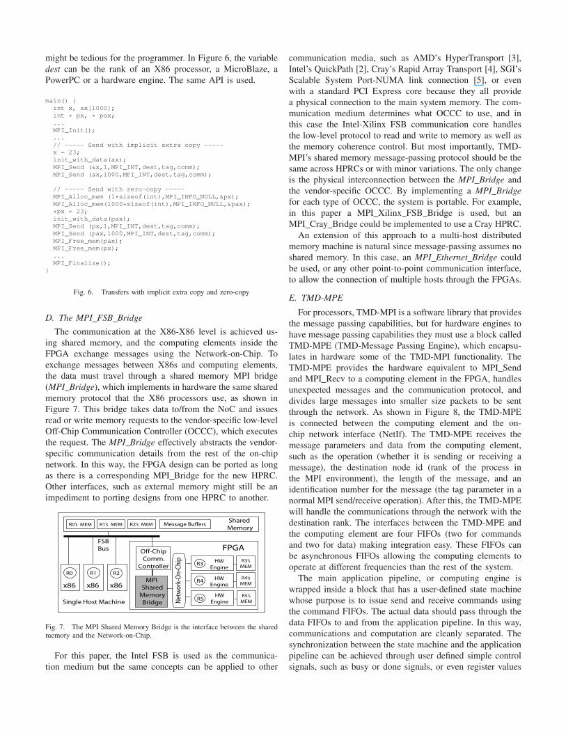
D. The MPI FSB Bridge
The communication at the X86-X86 level is achieved us-
ing shared memory, and the computing elements inside the
FPGA exchange messages using the Network-on-Chip. To
exchange messages between X86s and computing elements,
the data must travel through a shared memory MPI bridge
(MPI Bridge), which implements in hardware the same shared
memory protocol that the X86 processors use, as shown in
Figure 7. This bridge takes data to/from the NoC and issues
read or write memory requests to the vendor-specific low-level
Off-Chip Communication Controller (OCCC), which executes
the request. The MPI Bridge effectively abstracts the vendor-
specific communication details from the rest of the on-chip
network. In this way, the FPGA design can be ported as long
as there is a corresponding MPI Bridge for the new HPRC.
Other interfaces, such as external memory might still be an
impediment to porting designs from one HPRC to another.
R1
x86
FPGA Off-Chip
Comm.
Controller
MPI
Shared
Memory
Bridge Net
wor
k-O
n-C
hip
Single Host Machine
FSB
Bus
R5HW
EngineR5’s
MEM
R4HW
Engine
R4’s
MEM
R3HW
Engine
R3’s
MEM
R2
x86
R0
x86
Shared
MemoryR0’s MEM R1’s MEM R2’s MEM Message Buffers
Fig. 7. The MPI Shared Memory Bridge is the interface between the sharedmemory and the Network-on-Chip.
For this paper, the Intel FSB is used as the communica-
tion medium but the same concepts can be applied to other
communication media, such as AMD’s HyperTransport [3],
Intel’s QuickPath [2], Cray’s Rapid Array Transport [4], SGI’s
Scalable System Port-NUMA link connection [5], or even
with a standard PCI Express core because they all provide
a physical connection to the main system memory. The com-
munication medium determines what OCCC to use, and in
this case the Intel-Xilinx FSB communication core handles
the low-level protocol to read and write to memory as well as
the memory coherence control. But most importantly, TMD-
MPI’s shared memory message-passing protocol should be the
same across HPRCs or with minor variations. The only change
is the physical interconnection between the MPI Bridge and
the vendor-specific OCCC. By implementing a MPI Bridge
for each type of OCCC, the system is portable. For example,
in this paper a MPI Xilinx FSB Bridge is used, but an
MPI Cray Bridge could be implemented to use a Cray HPRC.
An extension of this approach to a multi-host distributed
memory machine is natural since message-passing assumes no
shared memory. In this case, an MPI Ethernet Bridge could
be used, or any other point-to-point communication interface,
to allow the connection of multiple hosts through the FPGAs.
E. TMD-MPE
For processors, TMD-MPI is a software library that provides
the message passing capabilities, but for hardware engines to
have message passing capabilities they must use a block called
TMD-MPE (TMD-Message Passing Engine), which encapsu-
lates in hardware some of the TMD-MPI functionality. The
TMD-MPE provides the hardware equivalent to MPI Send
and MPI Recv to a computing element in the FPGA, handles
unexpected messages and the communication protocol, and
divides large messages into smaller size packets to be sent
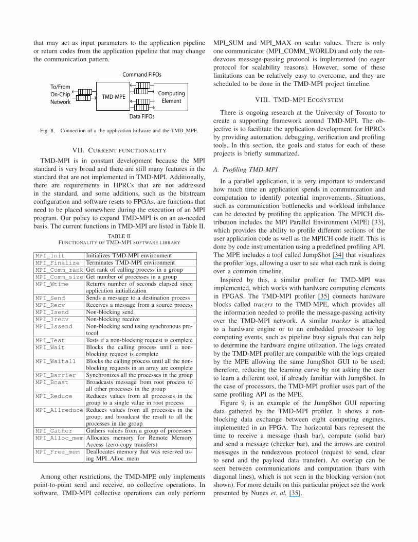
through the network. As shown in Figure 8, the TMD-MPE
is connected between the computing element and the on-
chip network interface (NetIf). The TMD-MPE receives the
message parameters and data from the computing element,
such as the operation (whether it is sending or receiving a
message), the destination node id (rank of the process in
the MPI environment), the length of the message, and an
identification number for the message (the tag parameter in a
normal MPI send/receive operation). After this, the TMD-MPE
will handle the communications through the network with the
destination rank. The interfaces between the TMD-MPE and
the computing element are four FIFOs (two for commands
and two for data) making integration easy. These FIFOs can
be asynchronous FIFOs allowing the computing elements to
operate at different frequencies than the rest of the system.
The main application pipeline, or computing engine is
wrapped inside a block that has a user-defined state machine
whose purpose is to issue send and receive commands using
the command FIFOs. The actual data should pass through the
data FIFOs to and from the application pipeline. In this way,
communications and computation are cleanly separated. The
synchronization between the state machine and the application
pipeline can be achieved through user defined simple control
signals, such as busy or done signals, or even register values
that may act as input parameters to the application pipeline
or return codes from the application pipeline that may change
the communication pattern.
Computing
ElementTMD-MPE
Command FIFOs
Data FIFOs
To/From
On-Chip
Network
Fig. 8. Connection of a the application hrdware and the TMD MPE.
VII. CURRENT FUNCTIONALITY
TMD-MPI is in constant development because the MPI
standard is very broad and there are still many features in the
standard that are not implemented in TMD-MPI. Additionally,
there are requirements in HPRCs that are not addressed
in the standard, and some additions, such as the bitstream
configuration and software resets to FPGAs, are functions that
need to be placed somewhere during the execution of an MPI
program. Our policy to expand TMD-MPI is on an as-needed
basis. The current functions in TMD-MPI are listed in Table II.
TABLE IIFUNCTIONALITY OF TMD-MPI SOFTWARE LIBRARY
MPI_Init Initializes TMD-MPI environmentMPI_Finalize Terminates TMD-MPI environmentMPI_Comm_rank Get rank of calling process in a groupMPI_Comm_size Get number of processes in a groupMPI_Wtime Returns number of seconds elapsed since
application initializationMPI_Send Sends a message to a destination processMPI_Recv Receives a message from a source processMPI_Isend Non-blocking sendMPI_Irecv Non-blocking receiveMPI_Issend Non-blocking send using synchronous pro-
tocolMPI_Test Tests if a non-blocking request is completeMPI_Wait Blocks the calling process until a non-
blocking request is completeMPI_Waitall Blocks the calling process until all the non-
blocking requests in an array are completeMPI_Barrier Synchronizes all the processes in the groupMPI_Bcast Broadcasts message from root process to
all other processes in the groupMPI_Reduce Reduces values from all processes in the
group to a single value in root processMPI_Allreduce Reduces values from all processes in the
group, and broadcast the result to all theprocesses in the group
MPI_Gather Gathers values from a group of processesMPI_Alloc_mem Allocates memory for Remote Memory
Access (zero-copy transfers)MPI_Free_mem Deallocates memory that was reserved us-
ing MPI Alloc mem
Among other restrictions, the TMD-MPE only implements
point-to-point send and receive, no collective operations. In
software, TMD-MPI collective operations can only perform
MPI SUM and MPI MAX on scalar values. There is only
one communicator (MPI COMM WORLD) and only the ren-
dezvous message-passing protocol is implemented (no eager
protocol for scalability reasons). However, some of these
limitations can be relatively easy to overcome, and they are
scheduled to be done in the TMD-MPI project timeline.
VIII. TMD-MPI ECOSYSTEM
There is ongoing research at the University of Toronto to
create a supporting framework around TMD-MPI. The ob-
jective is to facilitate the application development for HPRCs
by providing automation, debugging, verification and profiling
tools. In this section, the goals and status for each of these
projects is briefly summarized.
A. Profiling TMD-MPI
In a parallel application, it is very important to understand
how much time an application spends in communication and
computation to identify potential improvements. Situations,
such as communication bottlenecks and workload imbalance
can be detected by profiling the application. The MPICH dis-
tribution includes the MPI Parallel Environment (MPE) [33],
which provides the ability to profile different sections of the
user application code as well as the MPICH code itself. This is
done by code instrumentation using a predefined profiling API.
The MPE includes a tool called JumpShot [34] that visualizes
the profiler logs, allowing a user to see what each rank is doing
over a common timeline.
Inspired by this, a similar profiler for TMD-MPI was
implemented, which works with hardware computing elements
in FPGAS. The TMD-MPI profiler [35] connects hardware
blocks called tracers to the TMD-MPE, which provides all
the information needed to profile the message-passing activity
over the TMD-MPI network. A similar tracker is attached
to a hardware engine or to an embedded processor to log
computing events, such as pipeline busy signals that can help
to determine the hardware engine utilization. The logs created
by the TMD-MPI profiler are compatible with the logs created
by the MPE allowing the same JumpShot GUI to be used;
therefore, reducing the learning curve by not asking the user
to learn a different tool, if already familiar with JumpShot. In
the case of processors, the TMD-MPI profiler uses part of the
same profiling API as the MPE.
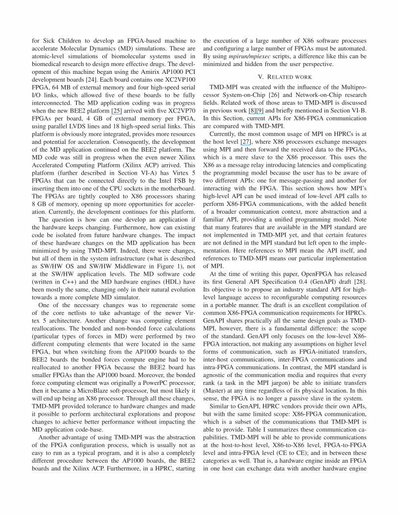
Figure 9, is an example of the JumpShot GUI reporting
data gathered by the TMD-MPI profiler. It shows a non-
blocking data exchange between eight computing engines,
implemented in an FPGA. The horizontal bars represent the
time to receive a message (hash bar), compute (solid bar)
and send a message (checker bar), and the arrows are control
messages in the rendezvous protocol (request to send, clear
to send and the payload data transfer). An overlap can be
seen between communications and computation (bars with
diagonal lines), which is not seen in the blocking version (not
shown). For more details on this particular project see the work
presented by Nunes et. al. [35].
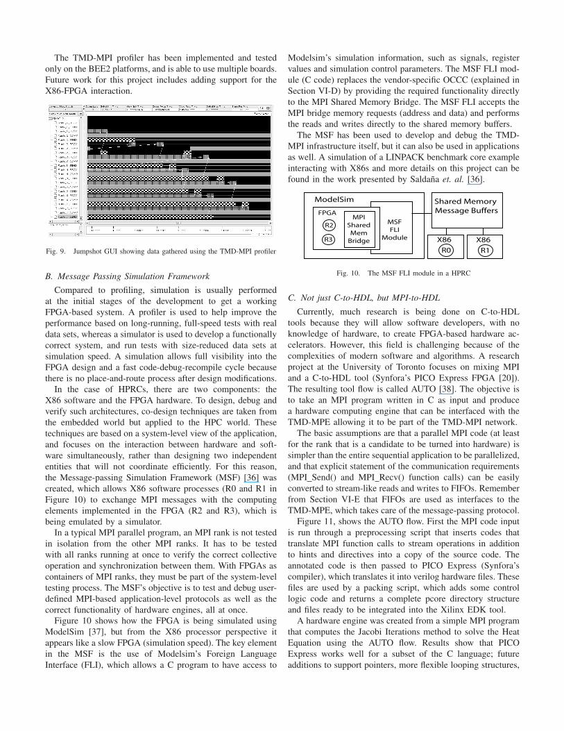
The TMD-MPI profiler has been implemented and tested
only on the BEE2 platforms, and is able to use multiple boards.
Future work for this project includes adding support for the
X86-FPGA interaction.
Fig. 9. Jumpshot GUI showing data gathered using the TMD-MPI profiler
B. Message Passing Simulation Framework
Compared to profiling, simulation is usually performed
at the initial stages of the development to get a working
FPGA-based system. A profiler is used to help improve the
performance based on long-running, full-speed tests with real
data sets, whereas a simulator is used to develop a functionally
correct system, and run tests with size-reduced data sets at
simulation speed. A simulation allows full visibility into the
FPGA design and a fast code-debug-recompile cycle because
there is no place-and-route process after design modifications.
In the case of HPRCs, there are two components: the
X86 software and the FPGA hardware. To design, debug and
verify such architectures, co-design techniques are taken from
the embedded world but applied to the HPC world. These
techniques are based on a system-level view of the application,
and focuses on the interaction between hardware and soft-
ware simultaneously, rather than designing two independent
entities that will not coordinate efficiently. For this reason,
the Message-passing Simulation Framework (MSF) [36] was
created, which allows X86 software processes (R0 and R1 in
Figure 10) to exchange MPI messages with the computing
elements implemented in the FPGA (R2 and R3), which is
being emulated by a simulator.
In a typical MPI parallel program, an MPI rank is not tested
in isolation from the other MPI ranks. It has to be tested
with all ranks running at once to verify the correct collective
operation and synchronization between them. With FPGAs as
containers of MPI ranks, they must be part of the system-level
testing process. The MSF’s objective is to test and debug user-
defined MPI-based application-level protocols as well as the
correct functionality of hardware engines, all at once.
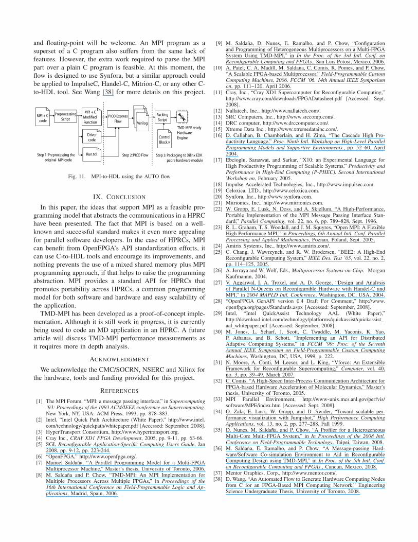
Figure 10 shows how the FPGA is being simulated using
ModelSim [37], but from the X86 processor perspective it
appears like a slow FPGA (simulation speed). The key element
in the MSF is the use of Modelsim’s Foreign Language
Interface (FLI), which allows a C program to have access to
Modelsim’s simulation information, such as signals, register
values and simulation control parameters. The MSF FLI mod-
ule (C code) replaces the vendor-specific OCCC (explained in
Section VI-D) by providing the required functionality directly
to the MPI Shared Memory Bridge. The MSF FLI accepts the
MPI bridge memory requests (address and data) and performs
the reads and writes directly to the shared memory buffers.
The MSF has been used to develop and debug the TMD-
MPI infrastructure itself, but it can also be used in applications
as well. A simulation of a LINPACK benchmark core example
interacting with X86s and more details on this project can be
found in the work presented by Saldana et. al. [36].
X86
R0
X86
R1
ModelSim
MSF
FLI
Module
FPGA
R2
R3
MPI
Shared
Mem
Bridge
Shared Memory
Message Buffers
Fig. 10. The MSF FLI module in a HPRC
C. Not just C-to-HDL, but MPI-to-HDL
Currently, much research is being done on C-to-HDL
tools because they will allow software developers, with no
knowledge of hardware, to create FPGA-based hardware ac-
celerators. However, this field is challenging because of the
complexities of modern software and algorithms. A research
project at the University of Toronto focuses on mixing MPI
and a C-to-HDL tool (Synfora’s PICO Express FPGA [20]).
The resulting tool flow is called AUTO [38]. The objective is
to take an MPI program written in C as input and produce
a hardware computing engine that can be interfaced with the
TMD-MPE allowing it to be part of the TMD-MPI network.
The basic assumptions are that a parallel MPI code (at least
for the rank that is a candidate to be turned into hardware) is
simpler than the entire sequential application to be parallelized,
and that explicit statement of the communication requirements
(MPI Send() and MPI Recv() function calls) can be easily
converted to stream-like reads and writes to FIFOs. Remember
from Section VI-E that FIFOs are used as interfaces to the
TMD-MPE, which takes care of the message-passing protocol.
Figure 11, shows the AUTO flow. First the MPI code input
is run through a preprocessing script that inserts codes that
translate MPI function calls to stream operations in addition
to hints and directives into a copy of the source code. The
annotated code is then passed to PICO Express (Synfora’s
compiler), which translates it into verilog hardware files. These
files are used by a packing script, which adds some control
logic code and returns a complete pcore directory structure
and files ready to be integrated into the Xilinx EDK tool.
A hardware engine was created from a simple MPI program
that computes the Jacobi Iterations method to solve the Heat
Equation using the AUTO flow. Results show that PICO
Express works well for a subset of the C language; future
additions to support pointers, more flexible looping structures,
and floating-point will be welcome. An MPI program as a
superset of a C program also suffers from the same lack of
features. However, the extra work required to parse the MPI
part over a plain C program is feasible. At this moment, the
flow is designed to use Synfora, but a similar approach could
be applied to ImpulseC, Handel-C, Mitrion-C, or any other C-
to-HDL tool. See Wang [38] for more details on this project.
MPI + C
code
Preprocessing
Script
MPI + C
Modified
Function Verilog
Driver
code
PICO Express
Flow
Run.tcl
Packing
Script
Control
Block.v
A
Step 1: Preprocessing the
original MPI codeStep 2: PICO Flow
Step 3: Packaging to Xilinx EDK
pcore hardware module
TMD-MPE ready
Hardware
Engine
Fig. 11. MPI-to-HDL using the AUTO flow
IX. CONCLUSION
In this paper, the ideas that support MPI as a feasible pro-
gramming model that abstracts the communications in a HPRC
have been presented. The fact that MPI is based on a well-
known and successful standard makes it even more appealing
for parallel software developers. In the case of HPRCs, MPI
can benefit from OpenFPGA’s API standardization efforts, it
can use C-to-HDL tools and encourage its improvements, and
nothing prevents the use of a mixed shared memory plus MPI
programming approach, if that helps to raise the programming
abstraction. MPI provides a standard API for HPRCs that
promotes portability across HPRCs, a common programming
model for both software and hardware and easy scalability of
the application.
TMD-MPI has been developed as a proof-of-concept imple-
mentation. Although it is still work in progress, it is currently
being used to code an MD application in an HPRC. A future
article will discuss TMD-MPI performance measurements as
it requires more in depth analysis.
ACKNOWLEDGMENT
We acknowledge the CMC/SOCRN, NSERC and Xilinx for
the hardware, tools and funding provided for this project.
REFERENCES
[1] The MPI Forum, “MPI: a message passing interface,” in Supercomputing’93: Proceedings of the 1993 ACM/IEEE conference on Supercomputing.New York, NY, USA: ACM Press, 1993, pp. 878–883.
[2] Intel, “Intel Quick Path Architecture (White Paper),” http://www.intel.com/technology/quickpath/whitepaper.pdf [Accessed: September, 2008].
[3] HyperTransport Consortium, http://www.hypertransport.org.[4] Cray Inc., CRAY XD1 FPGA Development, 2005, pp. 9-11, pp. 63-66.[5] SGI, Reconfigurable Application-Specific Computing Users Guide, Jan
2008, pp. 9-12, pp. 223-244.[6] “OpenFPGA,” http://www.openfpga.org/.[7] Manuel Saldana, “A Parallel Programming Model for a Multi-FPGA
Multiprocessor Machine,” Master’s thesis, University of Toronto, 2006.[8] M. Saldana and P. Chow, “TMD-MPI: An MPI Implementation for
Multiple Processors Across Multiple FPGAs,” in Proceedings of the
16th International Conference on Field-Programmable Logic and Ap-
plications, Madrid, Spain, 2006.
[9] M. Saldana, D. Nunes, E. Ramalho, and P. Chow, “Configurationand Programming of Heterogeneous Multiprocessors on a Multi-FPGASystem Using TMD-MPI,” in In the Proc. of the 3rd Intl. Conf. on
Reconfigurable Computing and FPGAs., San Luis Potosi, Mexico, 2006.[10] A. Patel, C. A. Madill, M. Saldana, C. Comis, R. Pomes, and P. Chow,
“A Scalable FPGA-based Multiprocessor,” Field-Programmable CustomComputing Machines, 2006. FCCM ’06. 14th Annual IEEE Symposium
on, pp. 111–120, April 2006.[11] Cray, Inc., “Cray XD1 Supercomputer for Reconfigurable Computing,”
http://www.cray.com/downloads/FPGADatasheet.pdf [Accessed: Sept.2008].
[12] Nallatech, Inc., http://www.nallatech.com/.[13] SRC Computers, Inc., http://www.srccomp.com/.[14] DRC computer, http://www.drccomputer.com/.[15] Xtreme Data Inc., http://www.xtremedatainc.com/.[16] D. Callahan, B. Chamberlain, and H. Zima, “The Cascade High Pro-
ductivity Language,” Proc. Ninth Intl. Workshop on High-Level Parallel
Programming Models and Supportive Environments., pp. 52–60, April2004.
[17] Ebcioglu, Saraswat, and Sarkar, “X10: an Experimental Language forHigh Productivity Programming of Scalable Systems,” Productivity and
Performance in High-End Computing (P-PHEC). Second International
Workshop on, February 2005.[18] Impulse Accelerated Technologies, Inc., http://www.impulsec.com.[19] Celoxica, LTD., http://www.celoxica.com.[20] Synfora, Inc., http://www.synfora.com.[21] Mitrionics, Inc., http://www.mitrionics.com.[22] W. Gropp, E. Lusk, N. Doss, and A. Skjellum, “A High-Performance,
Portable Implementation of the MPI Message Passing Interface Stan-dard,” Parallel Computing, vol. 22, no. 6, pp. 789–828, Sept. 1996.
[23] R. L. Graham, T. S. Woodall, and J. M. Squyres, “Open MPI: A FlexibleHigh Performance MPI,” in Proceedings, 6th Annual Intl. Conf. Parallel
Processing and Applied Mathematics, Poznan, Poland, Sept. 2005.[24] Amirix Systems, Inc., http://www.amirix.com/.[25] C. Chang, J. Wawrzynek, and R. W. Brodersen, “BEE2: A High-End
Reconfigurable Computing System,” IEEE Des. Test ’05, vol. 22, no. 2,pp. 114–125, 2005.
[26] A. Jerraya and W. Wolf, Eds.,Multiprocessor Systems-on-Chip. MorganKaufmannn, 2004.
[27] V. Aggarwal, I. A. Troxel, and A. D. George, “Design and Analysisof Parallel N-Queens on Reconfigurable Hardware with Handel-C andMPI,” in 2004 MAPLD Intl. Conference, Washington, DC, USA, 2004.
[28] “OpenFPGA GenAPI version 0.4 Draft For Comment,” http://www.openfpga.org/pages/Standards.aspx [Accessed: September, 2008].
[29] Intel, “Intel QuickAssist Technology AAL (White Paper),”http://download.intel.com/technology/platforms/quickassist/quickassistaal whitepaper.pdf [Accessed: September, 2008].
[30] M. Jones, L. Scharf, J. Scott, C. Twaddle, M. Yaconis, K. Yao,P. Athanas, and B. Schott, “Implementing an API for DistributedAdaptive Computing Systems,” in FCCM ’99: Proc. of the Seventh
Annual IEEE Symposium on Field-Programmable Custom Computing
Machines, Washington, DC, USA, 1999, p. 222.[31] N. Moore, A. Conti, M. Leeser, and L. King, “Vforce: An Extensible
Framework for Reconfigurable Supercomputing,” Computer, vol. 40,no. 3, pp. 39–49, March 2007.
[32] C. Comis, “A High-Speed Inter-Process Communication Architecture forFPGA-based Hardware Acceleration of Molecular Dynamics,” Master’sthesis, University of Toronto, 2005.
[33] MPI Parallel Environment, http://www-unix.mcs.anl.gov/perfvis/software/MPE/index.htm [Accessed: Sept. 2008].
[34] O. Zaki, E. Lusk, W. Gropp, and D. Swider, “Toward scalable per-formance visualization with Jumpshot,” High Performance Computing
Applications, vol. 13, no. 2, pp. 277–288, Fall 1999.[35] D. Nunes, M. Saldana, and P. Chow, “A Profiler for a Heterogeneous
Multi-Core Multi-FPGA System,” in In Proceedings of the 2008 Intl.
Conference on Field-Programmable Technology, Taipei, Taiwan, 2008.[36] M. Saldana, E. Ramalho, and P. Chow, “A Message-passing Hard-
ware/Software Co-simulation Environment to Aid in ReconfigurableComputing Design using TMD-MPI,” in In Proc. of the 5th Intl. Conf.
on Reconfigurable Computing and FPGAs., Cancun, Mexico, 2008.[37] Mentor Graphics, Corp., http://www.mentor.com/.[38] D. Wang, “An Automated Flow to Generate Hardware Computing Nodes
from C for an FPGA-Based MPI Computing Network,” EngineeringScience Undergraduate Thesis, University of Toronto, 2008.