Embed Size (px)
Citation preview

��������� ���������� Gasoline Engines - Sterndrive MPI Models ���������������
0001.06
Identification Record
PLEASE RECORD THE FOLLOWING INFORMATION:
1.
Engine Model and Horsepower Engine Serial Number
2.
Transom Assembly Serial Number(Sterndrive)
Gear Ratio Sterndrive Unit SerialNumber
3.
Transmission Model (Inboard) Gear Ratio Transmission SerialNumber
4.
Propeller Number Pitch Diameter
5.
Hull Identification Number (HIN) Purchase Date
6.
Boat Manufacturer Boat Model Length
7.
Exhaust Gas Emissions Certificate Number
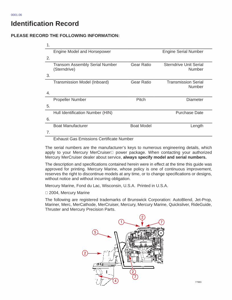
The serial numbers are the manufacturer’s keys to numerous engineering details, whichapply to your Mercury MerCruiser power package. When contacting your authorizedMercury MerCruiser dealer about service, always specify model and serial numbers.
The description and specifications contained herein were in effect at the time this guide wasapproved for printing. Mercury Marine, whose policy is one of continuous improvement,reserves the right to discontinue models at any time, or to change specifications or designs,without notice and without incurring obligation.
Mercury Marine, Fond du Lac, Wisconsin, U.S.A. Printed in U.S.A.
2004, Mercury Marine
The following are registered trademarks of Brunswick Corporation: AutoBlend, Jet-Prop,Mariner, Merc, MerCathode, MerCruiser, Mercury, Mercury Marine, Quicksilver, RideGuide,Thruster and Mercury Precision Parts.
77983
�
�
�
��
��
�
0002.1
Welcome!
You have selected one of the finest marine power packages available. It incorporatesnumerous design features to assure operating ease and durability.
With proper care and maintenance, you will thoroughly enjoy using this product for manyboating seasons. To ensure maximum performance and carefree use, we ask that youthoroughly read this manual.
The Operation, Maintenance and Warranty Manual contains specific instructions for usingand maintaining your product. We suggest that this manual remain with the product for readyreference whenever you are on the water.
Thank you for purchasing one of our Mercury MerCruiser products. We sincerely hope yourboating will be pleasant!
Mercury MerCruiser0003
Warranty MessageThe product you have purchased comes with a limited warranty from Mercury Marine; theterms of the warranty are set forth in the Warranty Sections of this manual. The warrantystatement contains a description of what is covered, what is not covered, the duration ofcoverage, how to best obtain warranty coverage, important disclaimers and limitations ofdamages and other related information. Please review this important information.
0217
Mercury Marine products are designed and manufactured to comply with our own high qualitystandards, applicable industry standards and regulations, as well as certain emissionsregulations. At Mercury Marine every engine is operated and tested before it is boxed forshipment to make sure that the product is ready for use. In addition, certain Mercury Marineproducts are tested in a controlled and monitored environment, for up to 10 hours of enginerun time, in order to verify and make a record of compliance with applicable standards andregulations. All Mercury Marine product, sold as new, receives the applicable limited warrantycoverage, whether the engine participated in one of the test programs described above or not.
0004
Read This Manual ThoroughlyIF YOU DON’T UNDERSTAND ANY PORTION, CONTACT YOUR DEALER FOR ADEMONSTRATION OF ACTUAL STARTING AND OPERATING PROCEDURES.
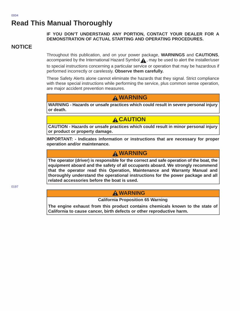
NOTICEThroughout this publication, and on your power package, WARNINGS and CAUTIONS,accompanied by the International Hazard Symbol ! , may be used to alert the installer/userto special instructions concerning a particular service or operation that may be hazardous ifperformed incorrectly or carelessly. Observe them carefully.
These Safety Alerts alone cannot eliminate the hazards that they signal. Strict compliancewith these special instructions while performing the service, plus common sense operation,are major accident prevention measures.
WARNINGWARNING - Hazards or unsafe practices which could result in severe personal injuryor death.
CAUTIONCAUTION - Hazards or unsafe practices which could result in minor personal injuryor product or property damage.
IMPORTANT: - Indicates information or instructions that are necessary for properoperation and/or maintenance.
WARNINGThe operator (driver) is responsible for the correct and safe operation of the boat, theequipment aboard and the safety of all occupants aboard. We strongly recommendthat the operator read this Operation, Maintenance and Warranty Manual andthoroughly understand the operational instructions for the power package and allrelated accessories before the boat is used.
0197
WARNINGCalifornia Proposition 65 Warning
The engine exhaust from this product contains chemicals known to the state ofCalifornia to cause cancer, birth defects or other reproductive harm.
90-864195040 JANUARY 2004 Page i
WARRANTYWarranty Information 2. . . . . . . . . . . . . . . . .
Owner Warranty Registration 2. . . . . . . . . . . . International Owner Registration 3. . . . . . . . .
Warranty Policies 4. . . . . . . . . . . . . . . . . . . . Mercury MerCruiser One Year LimitedWarranty (Gasoline Fueled Products Only) 4. . . . . . . . California Emissions Limited Warranty 6. . . . California Emission Control Warranty Statement 9. . . . . . . . . . . . . . . . . . .
3 Year Limited Warranty Against Corrosion (Worldwide) 10. . . . . . . . .
Transferable Warranty 12. . . . . . . . . . . . . . . Direct Sale By Owner 12. . . . . . . . . . . . . . . . .
Mercury Product Protection Plan 12. . . . . United States And Canada Only 12. . . . . . . .
California Emission Certification Label 13. . . . . . . . . . . . . . . . . .
Star Label 13. . . . . . . . . . . . . . . . . . . . . . . . . . .
GETTING TO KNOW YOUR POWER PACKAGEFeatures And Controls 16. . . . . . . . . . . . . .
Lanyard Stop Switch 16. . . . . . . . . . . . . . . . . . Instrumentation 18. . . . . . . . . . . . . . . . . . . . . . . Remote Controls 19. . . . . . . . . . . . . . . . . . . . . Power Trim 21. . . . . . . . . . . . . . . . . . . . . . . . . . Electrical System Overload Protection 23. . .
Audio Warning System 25. . . . . . . . . . . . . . . . Engine Guardian Strategy 26. . . . . . . . . . . . .
Emissions Information 27. . . . . . . . . . . . . . Emission Control Information Label 27. . . . . Owner Responsibility 27. . . . . . . . . . . . . . . . . . Star Label 28. . . . . . . . . . . . . . . . . . . . . . .
ON THE WATERSafe Boating Suggestions 30. . . . . . . . . . . . . .
Be Alert To Carbon Monoxide Poisoning 32. . . . . . . . . . .
Basic Boat Operation 34. . . . . . . . . . . . . . . . . . . Launching And Boat Operation Care 34. . . . Starting And Stopping The Engine 36. . . . . . Starting Engine After Stopped While In Gear 37. . . . . . . . . . . . . . . . . . . . . . . . Trailering The Boat 37. . . . . . . . . . . . . . . . . . . Freezing Temperature Operation 37. . . . . . . Drain Plug and Bilge Pump 37. . . . . . . . . . . .
Protecting People In The Water 38. . . . . . . . . While You Are Cruising 38. . . . . . . . . . . . . . . . While Boat Is Stationary 38. . . . . . . . . . . . . . .
High-Speed And High-Performance Boat Operation 38. . . . . . . . . . . . . . . . . . . . . . . . Passenger Safety Message - Pontoon And Deck Boats 39. . . . . . . . . . . . . .
Wave And Wake Jumping 40. . . . . . . . . . . . . . . Impact With Underwater Hazards 41. . . . . . . .
Drive Unit Impact Protection 42. . . . . . . . . . . Operating With Low Water Inlets In Shallow Water 42. . . . . . . . . . . . . . . . . . . . . . Conditions Affecting Operation 43. . . . . . . . .
Weight Distribution (Passengers And Gear) Inside The Boat 43. . . . . . . . . . . . . . . . . . . . . . Bottom Of Boat 43. . . . . . . . . . . . . . . . . . . . . . . Cavitation 43. . . . . . . . . . . . . . . . . . . . . . . . . . . Ventilation 44. . . . . . . . . . . . . . . . . . . . . . . . . . . Elevation And Climate 44. . . . . . . . . . . . . . . . . Propeller Selection 45. . . . . . . . . . . . . . . . . . . .
Getting Started 46. . . . . . . . . . . . . . . . . . . . . . . . . 20-Hour Break-In Period 46. . . . . . . . . . . . . . . After Break-In Period 46. . . . . . . . . . . . . . . . . . End of First Season Checkup 46. . . . . . . . . .

Page ii 90-864195040 JANUARY 2004
SPECIFICATIONSSpecifications 48. . . . . . . . . . . . . . . . . . . . . . . . .
Fuel Recommendations 48. . . . . . . . . . . . . . . Engine Oil 50. . . . . . . . . . . . . . . . . . . . . . . . . . . Engine Specifications 51. . . . . . . . . . . . . . . . . Fluid Specifications 52. . . . . . . . . . . . . . . . . . .
Engine 52. . . . . . . . . . . . . . . . . . . . . . . . . . . . Sterndrives 52. . . . . . . . . . . . . . . . . . . . . . . .
MAINTENANCEOwner/Operator Responsibilities 54. . . . . . . . Dealer Responsibilities 54. . . . . . . . . . . . . . . . . Maintenance 55. . . . . . . . . . . . . . . . . . . . . . . . . . .
Do-It-Yourself Maintenance Suggestions 56. . . . . . . . . . . . . . . . . . . . . . . . . Inspection 57. . . . . . . . . . . . . . . . . . . . . . . . . . . Sterndrive Maintenance Chart 57. . . . . . . . . . Maintenance Record 60. . . . . . . . . . . . . . . . . .
Engine Oil 61. . . . . . . . . . . . . . . . . . . . . . . . . . . . . Checking 61. . . . . . . . . . . . . . . . . . . . . . . . . . . . Filling 62. . . . . . . . . . . . . . . . . . . . . . . . . . . . . . . Changing Oil and Filter 63. . . . . . . . . . . . . . . .
Quick Drain Oil 63. . . . . . . . . . . . . . . . . . . . Engine Oil Pump 63. . . . . . . . . . . . . . . . . . . All Models 64. . . . . . . . . . . . . . . . . . . . . . . . .
Power Steering Pump Fluid 65. . . . . . . . . . . . . Checking 65. . . . . . . . . . . . . . . . . . . . . . . . . . . . Filling 65. . . . . . . . . . . . . . . . . . . . . . . . . . . . . . . Changing 65. . . . . . . . . . . . . . . . . . . . . . . . . . . .
Engine Coolant - Closed Cooled Models Only 66. . . . . . . . . . . . . . . . . . . . . . . . . . .
Checking 66. . . . . . . . . . . . . . . . . . . . . . . . . . . . Filling 67. . . . . . . . . . . . . . . . . . . . . . . . . . . . . . . Changing 67. . . . . . . . . . . . . . . . . . . . . . . . . . . .
Drive Unit Oil 68. . . . . . . . . . . . . . . . . . . . . . . . . . Checking 68. . . . . . . . . . . . . . . . . . . . . . . . . . . . Filling 69. . . . . . . . . . . . . . . . . . . . . . . . . . . . . . . Changing 70. . . . . . . . . . . . . . . . . . . . . . . . . . . .
Power Trim Pump Fluid 72. . . . . . . . . . . . . . . . . Checking 72. . . . . . . . . . . . . . . . . . . . . . . . . . . . Filling 72. . . . . . . . . . . . . . . . . . . . . . . . . . . . . . . Changing 72. . . . . . . . . . . . . . . . . . . . . . . . . . . .
Battery 73. . . . . . . . . . . . . . . . . . . . . . . . . . . . . . . . Multiple EFI Engine Battery Precautions 73. . . . . . . . . . . . . . . . . . . . . . . . .
Flame Arrestor and Related Components 74. . . . . . . . . . . . . . . . . .
Cleaning 74. . . . . . . . . . . . . . . . . . . . . . . . . . . . Positive Crankcase Ventilation Valve (PCV) 75. . . . . . . . . . . . . . .
Changing 75. . . . . . . . . . . . . . . . . . . . . . . . .
Water Separating Fuel Filter 76. . . . . . . . . . . . Changing 76. . . . . . . . . . . . . . . . . . . . . . . . . . . .
Lubrication 78. . . . . . . . . . . . . . . . . . . . . . . . . . . . Steering System 78. . . . . . . . . . . . . . . . . . . . . . Throttle Cable 79. . . . . . . . . . . . . . . . . . . . . . . . Shift Cable - Typical 80. . . . . . . . . . . . . . . . . . . Sterndrive Unit and Transom Assembly 81. . . . . . . . . . . . . . . . . . . . . . . . . . . Engine Coupler 82. . . . . . . . . . . . . . . . . . . . . . . Drive Shaft Extension Models 83. . . . . . . . . .
Propellers 84. . . . . . . . . . . . . . . . . . . . . . . . . . . . . Alpha 84. . . . . . . . . . . . . . . . . . . . . . . . . . . . . . .
Removal 84. . . . . . . . . . . . . . . . . . . . . . . . . . Repair 84. . . . . . . . . . . . . . . . . . . . . . . . . . . . Installation 85. . . . . . . . . . . . . . . . . . . . . . . .
Bravo One and Two 86. . . . . . . . . . . . . . . . . . . Removal 86. . . . . . . . . . . . . . . . . . . . . . . . . . Repair 86. . . . . . . . . . . . . . . . . . . . . . . . . . . . Installation 86. . . . . . . . . . . . . . . . . . . . . . . .
Bravo Three 88. . . . . . . . . . . . . . . . . . . . . . . . . Removal 88. . . . . . . . . . . . . . . . . . . . . . . . . . Repair 88. . . . . . . . . . . . . . . . . . . . . . . . . . . . Installation 89. . . . . . . . . . . . . . . . . . . . . . . .
Serpentine Drive Belt 91. . . . . . . . . . . . . . . . . . . Checking 92. . . . . . . . . . . . . . . . . . . . . . . . . . . . Replacing and / or Adjusting Tension 92. . . .
Corrosion Protection 94. . . . . . . . . . . . . . . . . . . Painting Your Power Package 98. . . . . . . . . .
Emissions (Europe Only) 99. . . . . . . . . . . . . . . Emissions Testing 99. . . . . . . . . . . . . . . . . . . . Installing Test Probes 99. . . . . . . . . . . . . . . . .
90-864195040 JANUARY 2004 Page iii
STORAGECold Weather Or Extended Storage 102. . . . .
Preparing Your Power Package For Storage 102. . . . . . . . . . . . . . . .
Fuel System 104. . . . . . . . . . . . . . . . . . . . . . Battery 105. . . . . . . . . . . . . . . . . . . . . . . . . .
Draining Instructions 105. . . . . . . . . . . . . . . . . . Identification 106. . . . . . . . . . . . . . . . . . . . . . . .
Air Actuated Single Point Drain System 106. . . . . . . . . . . . . . . . . . . . Manual Single Point Drain System 106. . . . . . . . . . . . . . . . . . . . 3 Point Manual Drain System 106. . . . . . . Multi-Point Drain (MPD) System 107. . . .
Boat In Water 108. . . . . . . . . . . . . . . . . . . . . . . Air Actuated Single Point Drain System 108. . . . . . . . . . . . . . . . . . . . Manual Single Point Drain System 110. . . . . . . . . . . . . . . . . . . . 3 Point Manual Drain System 112. . . . . . .
Boat Out Of The Water 114. . . . . . . . . . . . . . . Air Actuated Single Point Drain System 114. . . . . . . . . . . . . . . . . . . . Manual Single Point Drain System 116. . . . . . . . . . . . . . . . . . . . 3 Point Manual Drain System 117. . . . . . . Multi-Point Drain (MPD) System 118. . . .
All Models 120. . . . . . . . . . . . . . . . . . . . . . . . . . Flushing The Power Package 121. . . . . . . . . .
Sterndrive Water Pickups 121. . . . . . . . . . . . . Flushing Attachments 122. . . . . . . . . . . . . .
Alternative Water Pickups 125. . . . . . . . . . . . . Power Package Recommissioning 127. . . . .
TROUBLESHOOTINGDiagnosing EFI Problems 130. . . . . . . . . . . . . . Troubleshooting Charts 130. . . . . . . . . . . . . . .
Starter Motor Will Not Crank Engine, Or Cranks Slow 130. . . . . . . . . . . . . . . . . . . . . Engine Will Not Start, Or Is Hard To Start 130. . . . . . . . . . . . . . . . . . . . . . . . . . . . . . . Engine Runs Rough, Misses And/Or Backfires 131. . . . . . . . . . . . . . . . . . . . . . . . . . . Poor Performance 131. . . . . . . . . . . . . . . . . . . Excessive Engine Temperature 132. . . . . . . . Insufficient Engine Temperature 132. . . . . . .
Low Engine Oil Pressure 132. . . . . . . . . . . . . Battery Will Not Come Up On Charge 133. . Remote Control Operates Hard, Binds, Has Excessive Free-play Or Makes Unusual Sounds 133. . . . . . . . . . . . . . . . . . . . Steering Wheel Turns Hard Or Jerky 134. . . Power Trim Does Not Operate (Motor Doesn’t Operate) 134. . . . . . . . . . . . . . . . . . . . Power Trim Does Not Operate (Motor Operates But Sterndrive Unit Does Not Move) 134. . . . . . . . . . . . . . . . . . . . . . . . . . . . .
CUSTOMER ASSISTANCE INFORMATIONOwner Service Assistance 136. . . . . . . . . . . . .
Local Repair Service 136. . . . . . . . . . . . . . . . . Service Away From Home 136. . . . . . . . . . . . Stolen Power Package 136. . . . . . . . . . . . . . . Attention Required After Submersion 136. . . Replacement Service Parts 137. . . . . . . . . . .
Parts And Accessories Inquiries 137. . . . Resolving A Problem 138. . . . . . . . . . . . . . . . . Mercury Marine Service Offices 139. . . . . . .
Customer Service Literature 140. . . . . . . . . . . English Language 140. . . . . . . . . . . . . . . . . . . Other Languages 140. . . . . . . . . . . . . . . . . . . . Andre sprog 140. . . . . . . . . . . . . . . . . . . . . . . . Andere talen 140. . . . . . . . . . . . . . . . . . . . . . . .
Muut kielet 140. . . . . . . . . . . . . . . . . . . . . . . . . . Autres langues 140. . . . . . . . . . . . . . . . . . . . . . Andere Sprachen 141. . . . . . . . . . . . . . . . . . . . Altre lingue 141. . . . . . . . . . . . . . . . . . . . . . . . . Andre språk 141. . . . . . . . . . . . . . . . . . . . . . . . . Outros Idiomas 141. . . . . . . . . . . . . . . . . . . . . . Otros idiomas 141. . . . . . . . . . . . . . . . . . . . . . . Andra språk 141. . . . . . . . . . . . . . . . . . . . . . . . . ��� ���� ���� � � � � � � � � � � � � � � � � � � � � � �
Ordering Literature 142. . . . . . . . . . . . . . . . . . . . United States and Canada 142. . . . . . . . . . . . Outside The United States and Canada 142. . . . . . . . . . . . . . . . . . . . . . . .
Page iv 90-864195040 JANUARY 2004
NOTES:

1
WARRANTY
90-864195040 JANUARY 2004 Page 1
WARRANTY
Table of Contents
Warranty Information 2. . . . . . . . . . . . . . . . . Owner Warranty Registration 2. . . . . . . . . . . . International Owner Registration 3. . . . . . . . .
Warranty Policies 4. . . . . . . . . . . . . . . . . . . . Mercury MerCruiser One Year LimitedWarranty (Gasoline Fueled Products Only) 4. . . . . . . . California Emissions Limited Warranty 6. . . . California Emission Control Warranty Statement 9. . . . . . . . . . . . . . . . . . .
3 Year Limited Warranty Against Corrosion (Worldwide) 10. . . . . . . . .
Transferable Warranty 12. . . . . . . . . . . . . . . Direct Sale By Owner 12. . . . . . . . . . . . . . . . .
Mercury Product Protection Plan 12. . . . . United States And Canada Only 12. . . . . . . .
California Emission Certification Label 13. . . . . . . . . . . . . . . . . .
Star Label 13. . . . . . . . . . . . . . . . . . . . . . . . . . .
WARRANTY
Page 2 90-864195040 JANUARY 2004
0005
Warranty Information
Owner Warranty RegistrationUNITED STATES AND CANADA ONLY
• It is important that your selling dealer fills out the Warranty Registration Cardcompletely and mails it to the factory immediately upon sale of the new product.
• It identifies name and address of the original purchaser, product model and serialnumber(s), date of sale, type of use and selling dealer’s code, name and address.The dealer also certifies that you are the original purchaser and user of the product.
• Upon receipt of the Warranty Registration Card at the factory, you will be issued aplastic Owner Warranty Registration Card which is your only valid registrationidentification. It must be presented to the servicing dealer should warranty service berequired. Warranty claims will not be accepted without presentation of this card.
• A temporary Owner Warranty Registration Card will be presented to you when youpurchase the product. It is valid only for 30 days from date of sale while your plasticOwner Warranty Registration Card is being processed. Should your product needservice during this period, present the temporary registration card to the dealer. Hewill attach it to your warranty claim form.
• Because of your selling dealer’s continuing personal interest in your satisfaction, theproduct should be returned to him for warranty service.
• If your plastic card is not received within 30 days from date of new product sale,please contact your selling dealer.
• The product warranty is not effective until the product is registered at the factory.
• NOTICE: Registration lists must be maintained by factory and dealer on marineproducts sold in the United States, should notification under the Federal Boat SafetyAct be required.
• You may change your address at any time, including at time of warranty claim, bycalling Mercury MerCruiser or sending a letter or fax with you name, old address,new address, and engine serial number to Mercury MerCruiser’s warrantyregistration department. Your dealer can also process this change of information.
Mercury MarineAttn: Warranty Registration Department
W6250 Pioneer RoadP.O. Box 1939
Fond du Lac, WI 54935-1939Phone: 920-929-5054
Fax: 920-929-5893
WARRANTY
90-864195040 JANUARY 2004 Page 3
International Owner RegistrationOUTSIDE THE UNITED STATES AND CANADA
• It is important that your selling dealer fills out the Warranty Registration Cardcompletely and mails it to the distributor or Marine Power Service Center responsiblefor administering the warranty registration/claim program for your area.
• The Warranty Registration Card identifies your name and address, product modeland serial number(s), date of sale, type of use and the selling distributor’s/dealer’scode number, name and address. The distributor/dealer also certifies that you arethe original purchaser and user of the product.
• A copy of the Warranty Registration Card, designated as the “Purchaser’s Copy”,MUST be given to you immediately after the card has been completely filled out bythe selling distributor/dealer. This card represents your factory registrationidentification, and should be retained by you for future use when required. Shouldyou ever require warranty service on this product, your dealer may ask you for theWarranty Registration Card to verify date of purchase and to use the information onthe card to prepare the warranty claim form(s).
• In some countries, the Marine Power Service Center will issue you a permanent(plastic) Warranty Registration Card within 30 days after receiving the “Factory Copy”of the Warranty Registration Card from your distributor/dealer. If you receive a plasticWarranty Registration Card, you may discard the “Purchaser’s Copy” that youreceived from the distributor/dealer when you purchased the product. Ask yourdistributor/dealer if this plastic card program applies to you.
• For further information concerning the Warranty Registration Card and itsrelationship to Warranty Claim processing, refer to the “International Warranty.” Referto “Table of Contents.”
IMPORTANT: Registration lists must be maintained by the factory and dealer in somecountries by law. It is our desire to have ALL products registered at the factory shouldit ever be necessary to contact you. Make sure your dealer/distributor fills out thewarranty registration card immediately and sends the factory copy to the MarinePower International Service Center for your area.
WARRANTY
Page 4 90-864195040 JANUARY 2004
0006
Warranty Policies
Mercury MerCruiser One Year Limited Warranty (Gasoline Fueled ProductsOnly)WHAT IS COVERED
Mercury Marine warrants its new products to be free of defects in material and workmanshipduring the period described below.
DURATION OF COVERAGE
This Limited Warranty provides coverage for either one (1) year from the date the productis first sold to a recreational use retail purchaser, or the date on which the product is first putinto service, whichever occurs first. Commercial users of these products receive warrantycoverage of either one (1) year from the date of first retail sale, or the accumulation of 500hours of operation, whichever occurs first. Commercial use is defined as any work oremployment related use of the product, or any use of the product which generates income,for any part of the warranty period, even if the product is only occasionally used for suchpurposes. The repair or replacement of parts, or the performance of service under thiswarranty, does not extend the life of this warranty beyond its original expiration date.Unexpired warranty coverage can be transferred from one recreational use customer to asubsequent recreational use customer upon proper re-registration of the product.Unexpired warranty coverage cannot be transferred either to or from a commercial usecustomer.
CONDITIONS THAT MUST BE MET IN ORDER TO OBTAIN WARRANTY COVERAGE
Warranty coverage is available only to retail customers that purchase from a Dealerauthorized by Mercury Marine to distribute the product in the country in which the saleoccurred, and then only after the Mercury Marine specified pre-delivery inspection processis completed and documented. Warranty coverage becomes available upon properregistration of the product by the authorized dealer. Inaccurate warranty registrationinformation regarding recreational use, or subsequent change of use from recreational tocommercial (unless properly re-registered) may void the warranty at the sole discretion ofMercury Marine. Routine maintenance outlined in the Operation and Maintenance Manualmust be timely performed in order to obtain warranty coverage. Mercury Marine reservesthe right to make any warranty coverage contingent upon proof of proper maintenance.
WHAT MERCURY WILL DO
Mercury’s sole and exclusive obligation under this warranty is limited to, at our option,repairing a defective part, replacing such part or parts with new or Mercury Marine certifiedre-manufactured parts, or refunding the purchase price of the Mercury product. Mercuryreserves the right to improve or modify products from time to time without assuming anobligation to modify products previously manufactured.
WARRANTY
90-864195040 JANUARY 2004 Page 5
HOW TO OBTAIN WARRANTY COVERAGE
The customer must provide Mercury with a reasonable opportunity to repair, andreasonable access to the product for warranty service. Warranty claims shall be made bydelivering the product for inspection to a Mercury dealer authorized to service the product.If purchaser cannot deliver the product to such a dealer, written notice must be given toMercury. We will then arrange for the inspection and any covered repair. Purchaser in thatcase shall pay for all related transportation charges and/or travel time. If the serviceprovided is not covered by this warranty, purchaser shall pay for all related labor andmaterial, and any other expenses associated with that service. Purchaser shall not, unlessrequested by Mercury, ship the product or parts of the product directly to Mercury. Thewarranty registration card is the only valid registration identification and must be presentedto the dealer at the time warranty service is requested in order to obtain coverage.
WHAT IS NOT COVERED
This limited warranty does not cover routine maintenance items, tune ups, adjustments,normal wear and tear, damage caused by abuse, abnormal use, use of a propeller or gearratio that does not allow the engine to run in its recommended RPM range (see theOperation and Maintenance Manual), operation of the product in a manner inconsistent withthe recommended operation/duty cycle section of the Operation and Maintenance Manual,neglect, accident, submersion, improper installation (proper installation specifications andtechniques are set forth in the installation instructions for the product), improper service, useof an accessory or part which damages the Mercury product and was not manufactured orsold by us, jet pump impellers and liners, operation with fuels, oils or lubricants which arenot suitable for use with the product (see the Operation and Maintenance Manual),alteration or removal of parts, water entering the engine through the fuel intake, air intakeor exhaust system or damage to the product from insufficient cooling water caused byblockage of the cooling system by a foreign body, running the engine out of water, mountingthe engine too high on the transom, or running the boat with the engine trimmed out too far.Use of the product for racing or other competitive activity, or operating with a racing typelower unit, at any point, even by a prior owner of the product, voids the warranty.
Expenses related to haul-out, launch, towing, storage, telephone, rental, inconvenience,slip fees, insurance coverage, loan payments, loss of time, loss of income, or any other typeof incidental or consequential damages are not covered by this warranty. Also, expensesassociated with the removal and/or replacement of boat partitions or material caused byboat design for access to the product are not covered by this warranty.
No individual or entity, including Mercury Marine authorized dealers, has been givenauthority by Mercury Marine to make any affirmation, representation or warranty regardingthe product, other than those contained in this limited warranty, and if made, shall not beenforceable against Mercury Marine.
DISCLAIMERS AND LIMITATIONS
THE IMPLIED WARRANTIES OF MERCHANTABILITY AND FITNESS FOR APARTICULAR PURPOSE ARE EXPRESSLY DISCLAIMED. TO THE EXTENT THATTHEY CANNOT BE DISCLAIMED, THE IMPLIED WARRANTIES ARE LIMITED INDURATION TO THE LIFE OF THE EXPRESS WARRANTY. INCIDENTAL ANDCONSEQUENTIAL DAMAGES ARE EXCLUDED FROM COVERAGE UNDER THISWARRANTY. SOME STATES/COUNTRIES DO NOT ALLOW FOR THEDISCLAIMERS, LIMITATIONS AND EXCLUSIONS IDENTIFIED ABOVE. AS ARESULT, THEY MAY NOT APPLY TO YOU. THIS WARRANTY GIVES YOU SPECIFICLEGAL RIGHTS, AND YOU MAY ALSO HAVE OTHER LEGAL RIGHTS WHICH VARYFROM STATE TO STATE AND COUNTRY TO COUNTRY.
WARRANTY
Page 6 90-864195040 JANUARY 2004
0218.0
California Emissions Limited Warranty
The California Air Resources Board has promulgated air emissions regulations for inboardand sterndrive engines. The regulations apply to all inboard and sterndrive engines thatwere manufactured for the 2003 model year1 and later. Mercury Marine, in compliance withthose regulations, provides this limited warranty for the emission control systems (see thecomponents of the emission control system listed following), and further warrants that theinboard or sterndrive engine was designed, built and equipped to conform with all applicableregulations adopted by the California Air Resources Board pursuant to its authority inChapters 1 and 2, Part 5, Division 26 of the Health and Safety Code. For informationregarding the limited warranty for the non-emissions related components of the inboard orsterndrive engine, please see the limited warranty statement for your engine.
WHAT IS COVERED
Mercury Marine warrants the components of the emissions control systems (see thecomponents of the emission control system listed following) of its new, 2003 model year1
and later California certified inboard and sterndrive engines, registered2 to a Californiaresident, to be free from defects in material or workmanship that cause the failure of awarranted part to be identical in all material respects to that part as described in theapplication of Mercury Marine for certification from the California Air Resources Board, forthe period of time, and under the conditions identified below. The cost to diagnose awarranty failure is covered under the warranty (if the warranty claim is approved). Damageto other engine components caused by the failure of a warranted part will also be repairedunder warranty.
DURATION OF COVERAGE
This limited warranty provides coverage for the components of the emissions controlsystems of new 2003-2008 model year1 inboard and sterndrive engines for 2 years fromeither the date the product is first sold, or first put into service, whichever occurs first.Emission related normal maintenance items such as spark plugs and filters, that are on thewarranted parts list (see following) are warranted up to their first required replacementinterval only. (See Maintenance Schedule). The repair or replacement of parts, or theperformance of service under this warranty, does not extend the life of this warranty beyondits original expiration date. Unexpired warranty coverage can be transferred to asubsequent purchaser. (See instructions on transfer of warranty).
HOW TO OBTAIN WARRANTY COVERAGE
The customer must provide Mercury with a reasonable opportunity to repair and reasonableaccess to the product for warranty service. Warranty claims shall be made by delivering theproduct for inspection to a Mercury dealer authorized to service the product. If purchasercannot deliver the product to such a dealer, please notify Mercury Marine and Mercury willthen arrange for the inspection and any covered repair. Purchaser in that case shall pay forall related transportation charges and/or travel time. If the service provided is not coveredby this warranty, purchaser shall pay for all related labor and material, and any otherexpenses associated with that service. Purchaser shall not, unless requested by Mercury,ship the product or parts of the product directly to Mercury.
WARRANTY
90-864195040 JANUARY 2004 Page 7
WHAT MERCURY WILL DO
Mercury Marine’s sole and exclusive obligation under this warranty is limited to, at ourexpense and at our option, repairing or replacing defective parts with new or Mercury Marinecertified re-manufactured parts, or refunding the purchase price of the Mercury product.Mercury reserves the right to improve or modify products from time to time without assumingan obligation to modify products previously manufactured.
WHAT IS NOT COVERED
This limited warranty does not cover routine maintenance items, tune ups, adjustments,normal wear and tear, damage caused by abuse, abnormal use, use of a propeller or gearratio that does not allow the engine to run in its recommended wide-open-throttle RPMrange (see Specifications), operation of the product in a manner inconsistent with therecommended operation procedures, neglect, accident, submersion, improper installation(proper installation specifications and techniques are set forth in the installation instructionsfor the product), improper service, use of an accessory or part not manufactured or sold byus, jet pump impellers and liners, operation with fuels, oils or lubricants which are notsuitable for use with the product (see Specifications section), alteration or removal of parts,or water entering the engine through the fuel intake, air intake or exhaust system. Use ofthe product for racing or other competitive activity, or operating with a racing type lower unit,at any point, even by a prior owner of the product, voids the warranty.
Expenses related to haul-out, launch, towing, storage, telephone, rental, inconvenience,slip fees, insurance coverage, loan payments, loss of time, loss of income, or any other typeof incidental or consequential damages are not covered by this warranty. Also, expensesassociated with the removal and/or replacement of boat partitions or material caused byboat design for access to the product are not covered by this warranty.
Non-warranty maintenance, replacement, or repair of emission control devices andsystems may be performed by any marine engine repair establishment or individual. Theuse of non-Mercury parts for non-warranty maintenance or repairs will not be grounds fordisallowing other warranty work. The use of add-on (as defined at section 1900 (b)(1) and(b)(10) of Title 13 of the California Code of Regulations) or modified parts not exempted bythe California Air Resources Board may be grounds for disallowing a warranty claim, at thediscretion of Mercury Marine. Failures of warranted parts caused by the use of anon-exempted add-on or modified part will not be covered.
1 Mercury Marine does not establish model years for the Mercury MerCruiser product line. In order to complywith CARB warranty regulations, and for that limited purpose only, model year shall have the same meaningas calendar year. As an example, 2003 model year products refers to products manufactured duringcalendar year 2003.
2 Your dealer will register your engine for warranty coverage for you. The warranty registration process is notrelated in any way to the process of obtaining a license, title or registration from state boating authorities.You should ask your dealer to update your warranty registration information to reflect a change of addressor a transfer of ownership. (This change may be made at any time.) See the Warranty Registration sectionof your manual or your dealer for more information.
WARRANTY
Page 8 90-864195040 JANUARY 2004
COMPONENTS OF THE EMISSIONS CONTROL SYSTEM
1. Fuel Metering System
a. Carburetor and internal parts (and/or pressure regulator or fuel injection system)
b. Intake valve(s)
2. Air Induction System
a. Intake manifold
3. Ignition System
a. Spark plugs
b. Electronic ignition system
c. Ignition coil and/or control module
d. Ignition wires
4. Positive Crankcase Ventilation (PCV) System
a. PCV Valve
b. Oil filler cap
5. Exhaust System
a. Exhaust manifold
b. Exhaust elbow
c. Intermediate exhaust elbow
d. Lower exhaust pipe
e. Tailpipe
f. Exhaust valve
6. Miscellaneous Items Used in Above Systems
a. Hoses, clamps, fittings, tubing, sealing gaskets or devices, and mounting hardware.
b. Pulleys, belts, and idlers.
c. Vacuum, temperature, check and time sensitive valves and switches
d. Electronic controls.
DISCLAIMERS AND LIMITATIONS
DISCLAIMERS AND LIMITATIONS
THE IMPLIED WARRANTIES OF MERCHANTABILITY AND FITNESS FOR APARTICULAR PURPOSE ARE EXPRESSLY DISCLAIMED. TO THE EXTENT THATTHEY CANNOT BE DISCLAIMED, THE IMPLIED WARRANTIES ARE LIMITED INDURATION TO THE LIFE OF THE EXPRESS WARRANTY. INCIDENTAL ANDCONSEQUENTIAL DAMAGES ARE EXCLUDED FROM COVERAGE UNDER THISWARRANTY. SOME STATES/COUNTRIES DO NOT ALLOW FOR THEDISCLAIMERS, LIMITATIONS AND EXCLUSIONS IDENTIFIED ABOVE. AS ARESULT, THEY MAY NOT APPLY TO YOU. THIS WARRANTY GIVES YOU SPECIFICLEGAL RIGHTS, AND YOU MAY ALSO HAVE OTHER LEGAL RIGHTS WHICH VARYFROM STATE TO STATE AND COUNTRY TO COUNTRY.
If you have any questions regarding your warranty rights and responsibilities, refer to OwnerService Assistance for contact information.
WARRANTY
90-864195040 JANUARY 2004 Page 9
California Emission Control Warranty Statement
YOUR WARRANTY RIGHTS AND OBLIGATIONS
The California Air Resources Board is pleased to explain the emission control systemwarranty on your 2003 model year1 and later inboard or sterndrive engine. In California, newinboard and sterndrive engines must be designed, built and equipped to meet the State’sstringent anti-smog standards. Mercury Marine must warrant the emission control systemon your inboard or sterndrive engine for the periods of time listed below provided there hasbeen no abuse, neglect or improper maintenance of your inboard or sterndrive engine.
Your emission control system may include parts such as the carburetor or fuel injectionsystem, the ignition system, and catalytic converter. Also included may be hoses, belts,connectors and other emission-related assemblies.
Where a warrantable condition exists, Mercury Marine will repair your inboard or sterndriveengine at no cost to you; including diagnosis, parts and labor.
MANUFACTURER’S WARRANTY COVERAGE
For 2003-2008 spark-ignition inboard and sterndrive marine engines: Select emissioncontrol parts from model year1 2003-2008 inboard and sterndrive engines are warrantedfor 2 years. If any emission-related part on your engine is defective under warranty, the partwill be repaired or replaced by Mercury Marine.
OWNER’S WARRANTY RESPONSIBILITIES
As the inboard or sterndrive engine owner, you are responsible for the performance of therequired maintenance listed in your owner’s manual. Mercury Marine recommends that youretain all receipts covering maintenance on your inboard or sterndrive engine, but MercuryMarine cannot deny warranty solely for the lack of receipts or your failure to ensure theperformance of all scheduled maintenance.
As the inboard or sterndrive engine owner, you should however be aware that MercuryMarine may deny you warranty coverage if your inboard or sterndrive engine or a part hasfailed due to abuse, neglect, improper maintenance or unapproved modifications.
You are responsible for presenting your inboard or sterndrive engine to a Mercury Marinedealer authorized to service the product as soon as a problem exists. The warranty repairswill be completed in a reasonable amount of time, not to exceed 30 days.
If you have any questions regarding your warranty rights and responsibilities, refer to OwnerService Assistance for contact information.
1 Mercury Marine does not establish model years for the Mercury MerCruiser product line. In order to complywith CARB warranty regulations, and for that limited purpose only, model year shall have the same meaningas calendar year. As an example, 2003 model year products refers to products manufactured duringcalendar year 2003.
WARRANTY
Page 10 90-864195040 JANUARY 2004
0007
3 Year Limited Warranty Against Corrosion (Worldwide)WHAT IS COVERED
Mercury Marine warrants that each new Mercury, Mariner, Mercury Racing, Sport Jet, M2
Jet Drive, Tracker by Mercury Marine Outboard, MerCruiser Inboard or Sterndrive engine(Product) will not be rendered inoperative as a direct result of corrosion for the period of timedescribed below.
DURATION OF COVERAGE
This limited corrosion warranty provides coverage for three (3) years from either the datethe product is first sold, or the date on which the product is first put into service, whicheveroccurs first. The repair and replacement of parts, or the performance of service under thiswarranty does not extend the life of this warranty beyond its original expiration date.Unexpired warranty coverage can be transferred to subsequent (noncommercial use)purchaser upon proper re-registration of the product.
CONDITIONS THAT MUST BE MET IN ORDER TO OBTAIN WARRANTY COVERAGE
Warranty coverage is available only to retail customers that purchase from a Dealerauthorized by Mercury Marine to distribute the product in the country in which the saleoccurred, and then only after the Mercury Marine specified pre-delivery inspection processis completed and documented. Warranty coverage becomes available upon properregistration of the product by the authorized dealer. Corrosion prevention devices specifiedin the Operation and Maintenance Manual must be in use on the boat, and routinemaintenance outlined in the Operation and Maintenance Manual must be timely performed(including without limitation the replacement of sacrificial anodes, use of specifiedlubricants, and touch-up of nicks and scratches) in order to maintain warranty coverage.Mercury Marine reserves the right to make warranty coverage contingent upon proof ofproper maintenance.
WHAT MERCURY WILL DO
Mercury’s sole and exclusive obligation under this warranty is limited to, at our option,repairing a corroded part, replacing such part or parts with new or Mercury Marine certifiedre-manufactured parts, or refunding the purchase price of the Mercury product. Mercuryreserves the right to improve or modify products from time to time without assuming anobligation to modify products previously manufactured.
WARRANTY
90-864195040 JANUARY 2004 Page 11
HOW TO OBTAIN WARRANTY COVERAGE
The customer must provide Mercury with a reasonable opportunity to repair, andreasonable access to the product for warranty service. Warranty claims shall be made bydelivering the product for inspection to a Mercury dealer authorized to service the product.If purchaser cannot deliver the product to such a dealer, written notice must be given toMercury. We will then arrange for the inspection and any covered repair. Purchaser in thatcase shall pay for all related transportation charges and/or travel time. If the serviceprovided is not covered by this warranty, purchaser shall pay for all related labor andmaterial, and any other expenses associated with that service. Purchaser shall not, unlessrequested by Mercury, ship the product or parts of the product directly to Mercury. Thewarranty registration card is the only valid registration identification and must be presentedto the dealer at the time warranty service is requested in order to obtain coverage.
WHAT IS NOT COVERED
This limited warranty does not cover electrical system corrosion; corrosion resulting fromdamage, corrosion which causes purely cosmetic damage, abuse or improper service;corrosion to accessories, instruments, steering systems; corrosion to factory installed jetdrive unit; damage due to marine growth; product sold with less than a one year limitedProduct warranty; replacement parts (parts purchased by the Customer); products used ina commercial application. Commercial use is defined as any work or employment relateduse of the product, or any use of the product which generates income, for any part ofwarranty period, even if the product is only occasionally used for such purposes.
WARRANTY
Page 12 90-864195040 JANUARY 2004
0008
Transferable Warranty
The product warranty is transferable to a subsequent purchaser, but only for the remainderof the unused portion of the limited warranty. This will not apply to products used forcommercial applications.
Direct Sale By Owner• The second owner can be registered as the new owner and retain the unused
portion of the limited warranty by sending the former owner’s plastic Owner WarrantyRegistration Card and a copy of the bill of sale to show proof of ownership. In theUnited States and Canada, mail to:
Mercury MarineAttn: Warranty Registration Department
W6250 Pioneer RoadP.O. Box 1939
Fond du Lac, WI 54935-1939
• A new Owner Warranty Registration Card will be issued with the new owner’s nameand address. Registration records will be changed on the factory computerregistration file.
• There is no charge for this service.
Outside the United States and Canada, please contact the distributor in your country, or theMarine Power International Service Center closest to you, for the transferable warrantyprocedure that would apply to you.
0009
Mercury Product Protection Plan
United States And Canada Only(Certain performance products, triple engine installations, and commercial applications areexcluded.)
The Mercury Product Protection Plan provides coverage against unexpected mechanicaland electrical breakdowns that may occur beyond the standard limited warranty.
The optional Mercury Product Protection Plan is the only Factory Plan available for yourengine.
Two, three or four - year term plans can be purchased up to 12 months after the originalengine registration date.
See your participating Mercury MerCruiser dealer for complete program details.
WARRANTY
90-864195040 JANUARY 2004 Page 13
0219.0
California Emission Certification Label
Star Label
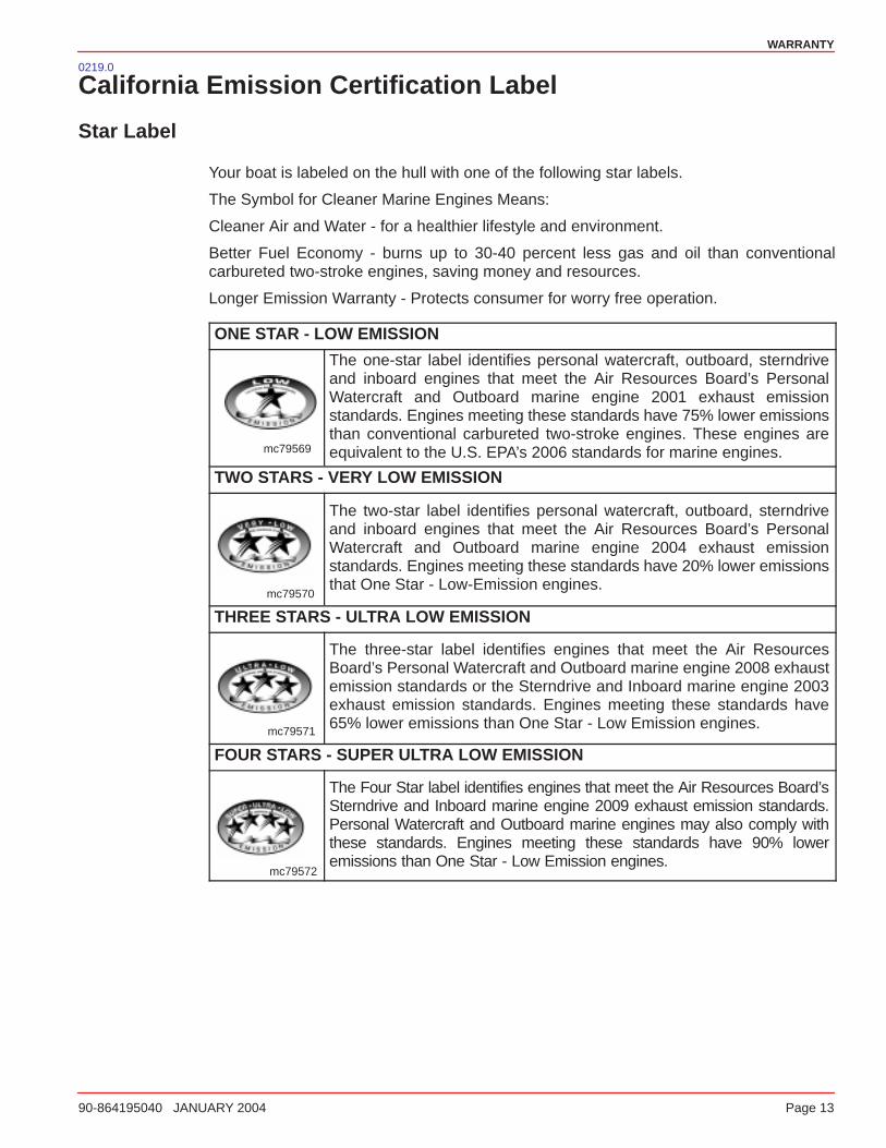
Your boat is labeled on the hull with one of the following star labels.
The Symbol for Cleaner Marine Engines Means:
Cleaner Air and Water - for a healthier lifestyle and environment.
Better Fuel Economy - burns up to 30-40 percent less gas and oil than conventionalcarbureted two-stroke engines, saving money and resources.
Longer Emission Warranty - Protects consumer for worry free operation.
ONE STAR - LOW EMISSION
mc79569
The one-star label identifies personal watercraft, outboard, sterndriveand inboard engines that meet the Air Resources Board’s PersonalWatercraft and Outboard marine engine 2001 exhaust emissionstandards. Engines meeting these standards have 75% lower emissionsthan conventional carbureted two-stroke engines. These engines areequivalent to the U.S. EPA’s 2006 standards for marine engines.
TWO STARS - VERY LOW EMISSION
mc79570
The two-star label identifies personal watercraft, outboard, sterndriveand inboard engines that meet the Air Resources Board’s PersonalWatercraft and Outboard marine engine 2004 exhaust emissionstandards. Engines meeting these standards have 20% lower emissionsthat One Star - Low-Emission engines.
THREE STARS - ULTRA LOW EMISSION
mc79571
The three-star label identifies engines that meet the Air ResourcesBoard’s Personal Watercraft and Outboard marine engine 2008 exhaustemission standards or the Sterndrive and Inboard marine engine 2003exhaust emission standards. Engines meeting these standards have65% lower emissions than One Star - Low Emission engines.
FOUR STARS - SUPER ULTRA LOW EMISSION
mc79572
The Four Star label identifies engines that meet the Air Resources Board’sSterndrive and Inboard marine engine 2009 exhaust emission standards.Personal Watercraft and Outboard marine engines may also comply withthese standards. Engines meeting these standards have 90% loweremissions than One Star - Low Emission engines.
WARRANTY
Page 14 90-864195040 JANUARY 2004
NOTES:

2
GETTING TO KNOW YOUR POWER PACKAGE
90-864195040 JANUARY 2004 Page 15
GETTING TO KNOW YOUR POWER PACKAGE
Table of Contents
Features And Controls 16. . . . . . . . . . . . . . Lanyard Stop Switch 16. . . . . . . . . . . . . . . . . . Instrumentation 18. . . . . . . . . . . . . . . . . . . . . . . Remote Controls 19. . . . . . . . . . . . . . . . . . . . . Power Trim 21. . . . . . . . . . . . . . . . . . . . . . . . . . Electrical System Overload Protection 23. . .
Audio Warning System 25. . . . . . . . . . . . . . . . Engine Guardian Strategy 26. . . . . . . . . . . . .
Emissions Information 27. . . . . . . . . . . . . . Emission Control Information Label 27. . . . . Owner Responsibility 27. . . . . . . . . . . . . . . . . . Star Label 28. . . . . . . . . . . . . . . . . . . . . . .
GETTING TO KNOW YOUR POWER PACKAGE
Page 16 90-864195040 JANUARY 2004
0010
Features And Controls0011
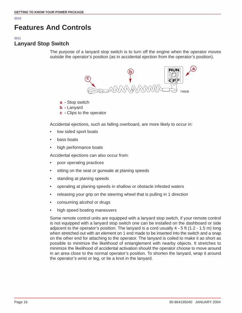
Lanyard Stop SwitchThe purpose of a lanyard stop switch is to turn off the engine when the operator movesoutside the operator’s position (as in accidental ejection from the operator’s position).
74608
ab
c
a - Stop switchb - Lanyardc - Clips to the operator
Accidental ejections, such as falling overboard, are more likely to occur in:
• low sided sport boats
• bass boats
• high performance boats
Accidental ejections can also occur from:
• poor operating practices
• sitting on the seat or gunwale at planing speeds
• standing at planing speeds
• operating at planing speeds in shallow or obstacle infested waters
• releasing your grip on the steering wheel that is pulling in 1 direction
• consuming alcohol or drugs
• high speed boating maneuvers
Some remote control units are equipped with a lanyard stop switch, if your remote controlis not equipped with a lanyard stop switch one can be installed on the dashboard or sideadjacent to the operator’s position. The lanyard is a cord usually 4 - 5 ft (1.2 - 1.5 m) longwhen stretched out with an element on 1 end made to be inserted into the switch and a snapon the other end for attaching to the operator. The lanyard is coiled to make it as short aspossible to minimize the likelihood of entanglement with nearby objects. It stretches tominimize the likelihood of accidental activation should the operator choose to move aroundin an area close to the normal operator’s position. To shorten the lanyard, wrap it aroundthe operator’s wrist or leg, or tie a knot in the lanyard.

GETTING TO KNOW YOUR POWER PACKAGE
90-864195040 JANUARY 2004 Page 17
Activation of the lanyard stop switch will stop the engine immediately, but the boat willcontinue to coast for some distance depending upon the velocity and degree of any turn atshut down. However, the boat will not complete a full circle. While the boat is coasting, it cancause injury to anyone in the boat’s path as seriously as the boat would when under power.
We strongly recommend that other occupants be instructed on proper starting and operatingprocedures should they be required to operate the engine in an emergency (e.g. if theoperator is accidentally ejected).
WARNINGAvoid contact with the boat hull and propeller from accidental ejection. Personalinjury or death could occur. Always properly connect both ends of the lanyard stopswitch.
Accidental or unintended activation of the switch during normal operation is also apossibility. This could cause any, or all, of the following potentially hazardous situations:
• Occupants could be thrown forward due to unexpected loss of forward motion, aparticular concern for passengers in the front of the boat who could be ejected overthe bow and possibly struck by the gear case or propeller.
• Loss of power and directional control in heavy seas, strong current or high winds.
• Loss of control when docking.
WARNINGAvoid abrupt deceleration of the boat from lanyard stop switch activation. Boatdamage and personal injury or death could occur. NEVER leave the operator’sstation with the engine operating and in gear .
GETTING TO KNOW YOUR POWER PACKAGE
Page 18 90-864195040 JANUARY 2004
0012.2
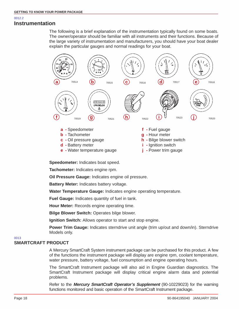
InstrumentationThe following is a brief explanation of the instrumentation typically found on some boats.The owner/operator should be familiar with all instruments and their functions. Because ofthe large variety of instrumentation and manufacturers, you should have your boat dealerexplain the particular gauges and normal readings for your boat.
70514 70515 70516
70523
70517
70522
70518
7052170519 70520
a b c d e
f g h i j
a - Speedometerb - Tachometerc - Oil pressure gauged - Battery metere - Water temperature gauge
f - Fuel gaugeg - Hour meterh - Bilge blower switchi - Ignition switchj - Power trim gauge
Speedometer: Indicates boat speed.
Tachometer: Indicates engine rpm.
Oil Pressure Gauge: Indicates engine oil pressure.
Battery Meter: Indicates battery voltage.
Water Temperature Gauge: Indicates engine operating temperature.
Fuel Gauge: Indicates quantity of fuel in tank.
Hour Meter: Records engine operating time.
Bilge Blower Switch: Operates bilge blower.
Ignition Switch: Allows operator to start and stop engine.
Power Trim Gauge: Indicates sterndrive unit angle (trim up/out and down/in). SterndriveModels only.
0013
SMARTCRAFT PRODUCT
A Mercury SmartCraft System instrument package can be purchased for this product. A fewof the functions the instrument package will display are engine rpm, coolant temperature,water pressure, battery voltage, fuel consumption and engine operating hours.
The SmartCraft Instrument package will also aid in Engine Guardian diagnostics. TheSmartCraft Instrument package will display critical engine alarm data and potentialproblems.
Refer to the Mercury SmartCraft Operator’s Supplement (90-10229023) for the warningfunctions monitored and basic operation of the SmartCraft Instrument package.
GETTING TO KNOW YOUR POWER PACKAGE
90-864195040 JANUARY 2004 Page 19
0014
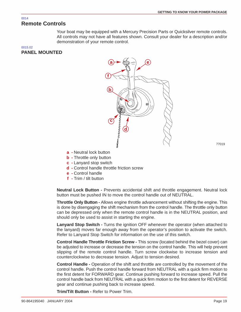
Remote ControlsYour boat may be equipped with a Mercury Precision Parts or Quicksilver remote controls.All controls may not have all features shown. Consult your dealer for a description and/ordemonstration of your remote control.
0015.02
PANEL MOUNTED
77019
a
b
c
d
e
f
a - Neutral lock buttonb - Throttle only buttonc - Lanyard stop switchd - Control handle throttle friction screwe - Control handlef - Trim / tilt button
Neutral Lock Button - Prevents accidental shift and throttle engagement. Neutral lockbutton must be pushed IN to move the control handle out of NEUTRAL.
Throttle Only Button - Allows engine throttle advancement without shifting the engine. Thisis done by disengaging the shift mechanism from the control handle. The throttle only buttoncan be depressed only when the remote control handle is in the NEUTRAL position, andshould only be used to assist in starting the engine.
Lanyard Stop Switch - Turns the ignition OFF whenever the operator (when attached tothe lanyard) moves far enough away from the operator’s position to activate the switch.Refer to Lanyard Stop Switch for information on the use of this switch.
Control Handle Throttle Friction Screw - This screw (located behind the bezel cover) canbe adjusted to increase or decrease the tension on the control handle. This will help preventslipping of the remote control handle. Turn screw clockwise to increase tension andcounterclockwise to decrease tension. Adjust to tension desired.
Control Handle - Operation of the shift and throttle are controlled by the movement of thecontrol handle. Push the control handle forward from NEUTRAL with a quick firm motion tothe first detent for FORWARD gear. Continue pushing forward to increase speed. Pull thecontrol handle back from NEUTRAL with a quick firm motion to the first detent for REVERSEgear and continue pushing back to increase speed.
Trim/Tilt Button - Refer to Power Trim.

GETTING TO KNOW YOUR POWER PACKAGE
Page 20 90-864195040 JANUARY 2004
0242.00
CONSOLE MOUNTED
mc79503
a
bcd
a
b
79690c d
a - Throttle only buttonb - Control handlesc - Power Trim switchd - Trailer switch
Throttle Only Button - Allows engine throttle advancement without shifting the engine. Thisis done by disengaging the shift mechanism from the control handle. The throttle only buttoncan be depressed only when the remote control handle is in the NEUTRAL position, andshould only be used to assist in starting the engine.
Control Handle Tension Adjustment Screw - This screw can be adjusted to increase ordecrease the tension on the control handle (cover must be removed to adjust). This will helpprevent slipping of the remote control handle. Turn screw clockwise to increase tension andcounterclockwise to decrease tension. Adjust to tension desired.
Control Handles - Operation of the the shift and throttle are controlled by the movementof the control handle. Push the control handle forward from NEUTRAL with a quick firmmotion to the first detent for FORWARD gear and continue pushing forward to increasespeed. Pull the control handle back from NEUTRAL with a quick firm motion to the firstdetent for REVERSE gear and continue pushing back to increase speed.
Power Trim Switch - See Power Trim section for detailed power trim operating procedures.
Trailer Sw itch - Used to raise drive unit for trailering, launching, beaching or shallow wateroperation. On the single remote control handle units, the trailering mode begins with thesecond click or when the Power Trim/ Trailer Switch is pressed all the way UP. See PowerTrim for detailed trailer switch operation.
GETTING TO KNOW YOUR POWER PACKAGE
90-864195040 JANUARY 2004 Page 21
0169.02
Power Trim
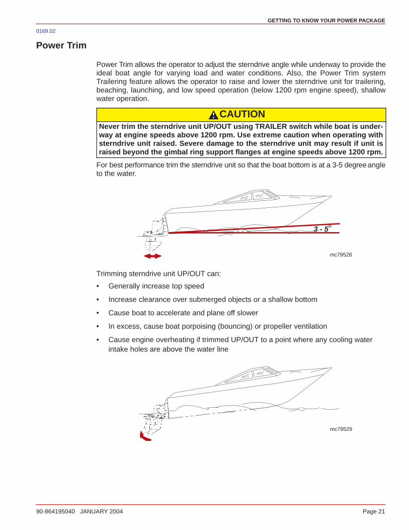
Power Trim allows the operator to adjust the sterndrive angle while underway to provide theideal boat angle for varying load and water conditions. Also, the Power Trim systemTrailering feature allows the operator to raise and lower the sterndrive unit for trailering,beaching, launching, and low speed operation (below 1200 rpm engine speed), shallowwater operation.
CAUTIONNever trim the sterndrive unit UP/OUT using TRAILER switch while boat is under-way at engine speeds above 1200 rpm. Use extreme caution when operating withsterndrive unit raised. Severe damage to the sterndrive unit may result if unit israised beyond the gimbal ring support flanges at engine speeds above 1200 rpm.
For best performance trim the sterndrive unit so that the boat bottom is at a 3-5 degreeangleto the water.
°3 - 5
mc79528
Trimming sterndrive unit UP/OUT can:
• Generally increase top speed
• Increase clearance over submerged objects or a shallow bottom
• Cause boat to accelerate and plane off slower
• In excess, cause boat porpoising (bouncing) or propeller ventilation
• Cause engine overheating if trimmed UP/OUT to a point where any cooling waterintake holes are above the water line
mc79529
GETTING TO KNOW YOUR POWER PACKAGE
Page 22 90-864195040 JANUARY 2004
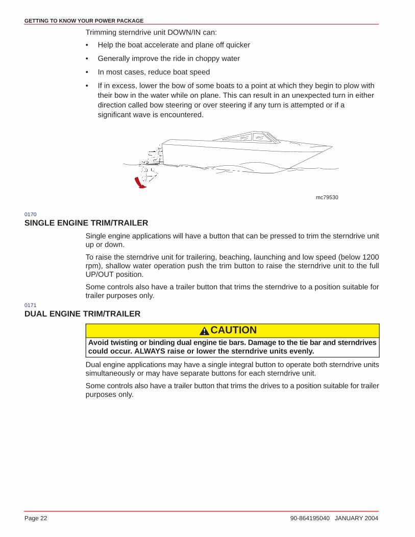
Trimming sterndrive unit DOWN/IN can:
• Help the boat accelerate and plane off quicker
• Generally improve the ride in choppy water
• In most cases, reduce boat speed
• If in excess, lower the bow of some boats to a point at which they begin to plow withtheir bow in the water while on plane. This can result in an unexpected turn in eitherdirection called bow steering or over steering if any turn is attempted or if asignificant wave is encountered.
mc79530
0170
SINGLE ENGINE TRIM/TRAILER
Single engine applications will have a button that can be pressed to trim the sterndrive unitup or down.
To raise the sterndrive unit for trailering, beaching, launching and low speed (below 1200rpm), shallow water operation push the trim button to raise the sterndrive unit to the fullUP/OUT position.
Some controls also have a trailer button that trims the sterndrive to a position suitable fortrailer purposes only.
0171
DUAL ENGINE TRIM/TRAILER
CAUTIONAvoid twisting or binding dual engine tie bars. Damage to the tie bar and sterndrivescould occur. ALWAYS raise or lower the sterndrive units evenly.
Dual engine applications may have a single integral button to operate both sterndrive unitssimultaneously or may have separate buttons for each sterndrive unit.
Some controls also have a trailer button that trims the drives to a position suitable for trailerpurposes only.
GETTING TO KNOW YOUR POWER PACKAGE
90-864195040 JANUARY 2004 Page 23
0018.01
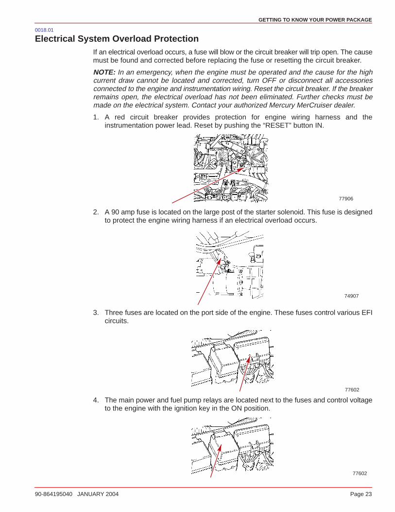
Electrical System Overload ProtectionIf an electrical overload occurs, a fuse will blow or the circuit breaker will trip open. The causemust be found and corrected before replacing the fuse or resetting the circuit breaker.
NOTE: In an emergency, when the engine must be operated and the cause for the highcurrent draw cannot be located and corrected, turn OFF or disconnect all accessoriesconnected to the engine and instrumentation wiring. Reset the circuit breaker. If the breakerremains open, the electrical overload has not been eliminated. Further checks must bemade on the electrical system. Contact your authorized Mercury MerCruiser dealer.
1. A red circuit breaker provides protection for engine wiring harness and theinstrumentation power lead. Reset by pushing the “RESET” button IN.
77906
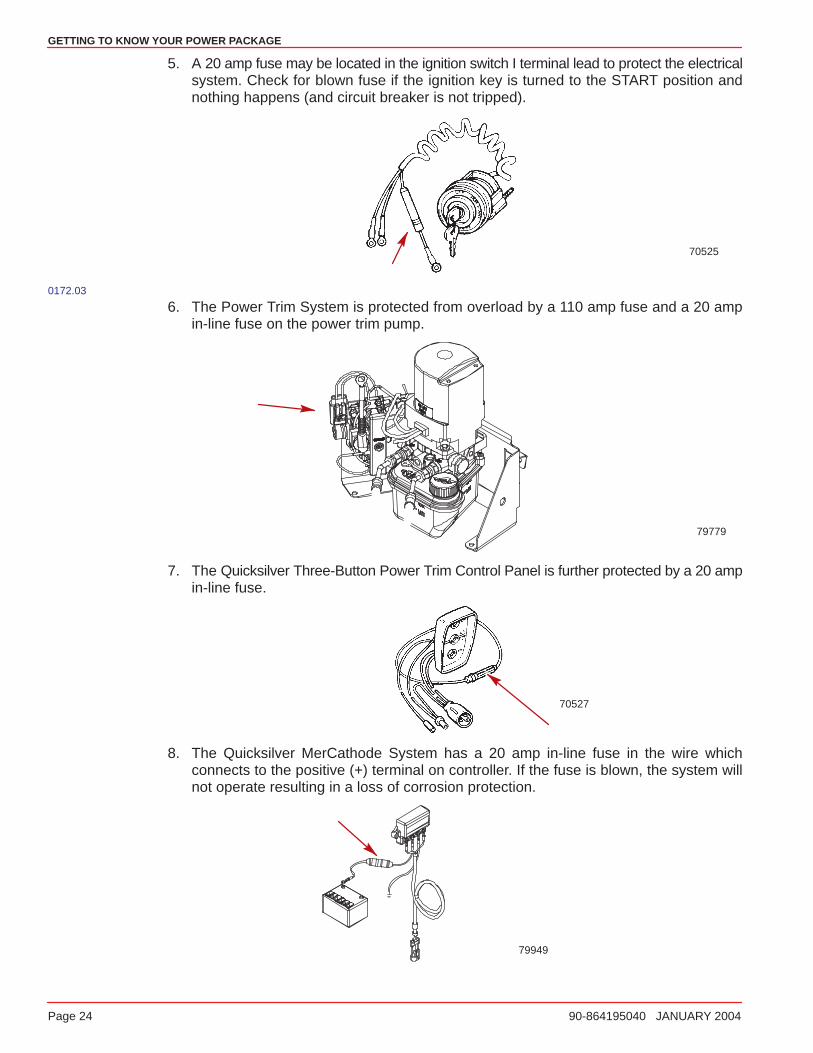
2. A 90 amp fuse is located on the large post of the starter solenoid. This fuse is designedto protect the engine wiring harness if an electrical overload occurs.
74907
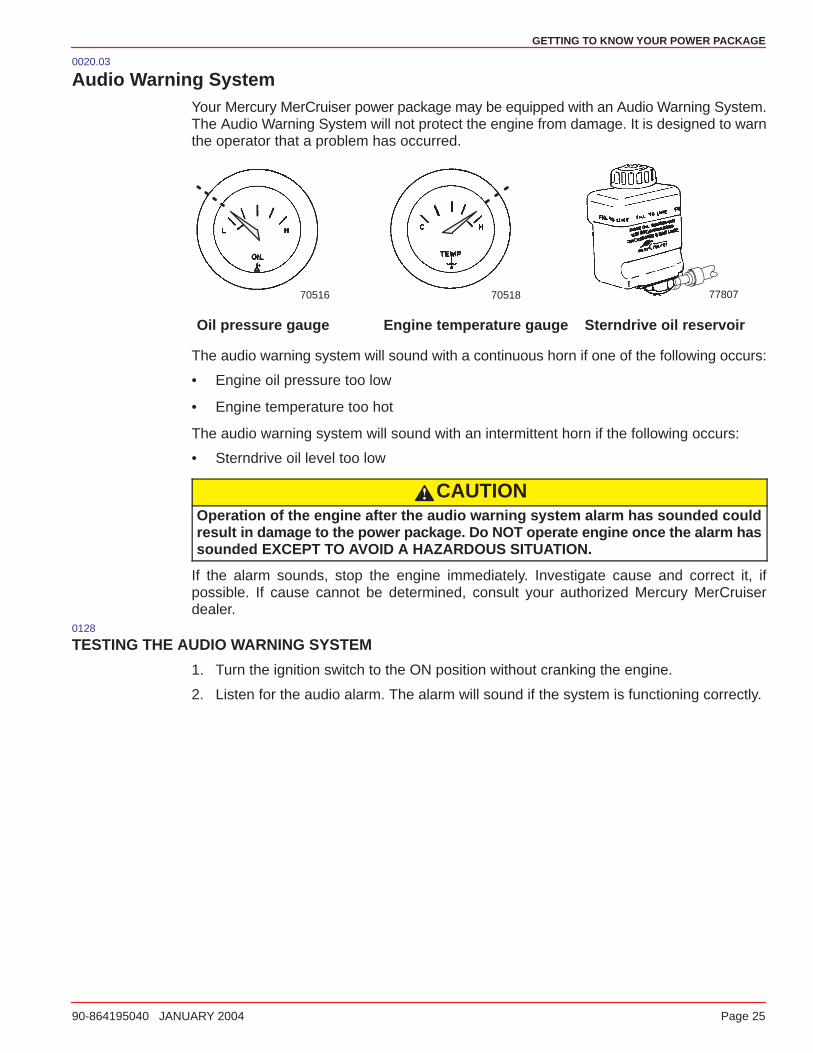
3. Three fuses are located on the port side of the engine. These fuses control various EFIcircuits.
77602
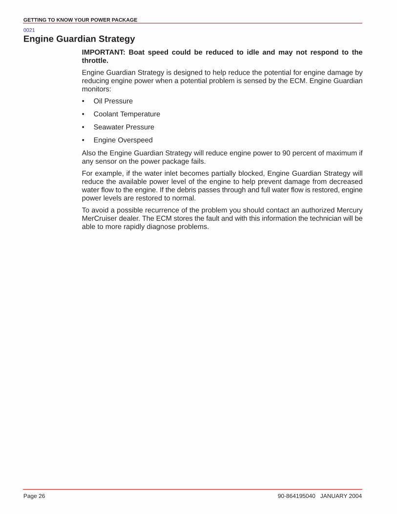
4. The main power and fuel pump relays are located next to the fuses and control voltageto the engine with the ignition key in the ON position.
77602
GETTING TO KNOW YOUR POWER PACKAGE
Page 24 90-864195040 JANUARY 2004
5. A 20 amp fuse may be located in the ignition switch I terminal lead to protect the electricalsystem. Check for blown fuse if the ignition key is turned to the START position andnothing happens (and circuit breaker is not tripped).
70525
0172.03
6. The Power Trim System is protected from overload by a 110 amp fuse and a 20 ampin-line fuse on the power trim pump.
79779
7. The Quicksilver Three-Button Power Trim Control Panel is further protected by a 20 ampin-line fuse.
70527
8. The Quicksilver MerCathode System has a 20 amp in-line fuse in the wire whichconnects to the positive (+) terminal on controller. If the fuse is blown, the system willnot operate resulting in a loss of corrosion protection.
79949
GETTING TO KNOW YOUR POWER PACKAGE
90-864195040 JANUARY 2004 Page 25
0020.03
Audio Warning SystemYour Mercury MerCruiser power package may be equipped with an Audio Warning System.The Audio Warning System will not protect the engine from damage. It is designed to warnthe operator that a problem has occurred.
70516 70518 77807
Oil pressure gauge Engine temperature gauge Sterndrive oil reservoir
The audio warning system will sound with a continuous horn if one of the following occurs:
• Engine oil pressure too low
• Engine temperature too hot
The audio warning system will sound with an intermittent horn if the following occurs:
• Sterndrive oil level too low
CAUTIONOperation of the engine after the audio warning system alarm has sounded couldresult in damage to the power package. Do NOT operate engine once the alarm hassounded EXCEPT TO AVOID A HAZARDOUS SITUATION.
If the alarm sounds, stop the engine immediately. Investigate cause and correct it, ifpossible. If cause cannot be determined, consult your authorized Mercury MerCruiserdealer.
0128
TESTING THE AUDIO WARNING SYSTEM
1. Turn the ignition switch to the ON position without cranking the engine.
2. Listen for the audio alarm. The alarm will sound if the system is functioning correctly.
GETTING TO KNOW YOUR POWER PACKAGE
Page 26 90-864195040 JANUARY 2004
0021
Engine Guardian StrategyIMPORTANT: Boat speed could be reduced to idle and may not respond to thethrottle.
Engine Guardian Strategy is designed to help reduce the potential for engine damage byreducing engine power when a potential problem is sensed by the ECM. Engine Guardianmonitors:
• Oil Pressure
• Coolant Temperature
• Seawater Pressure
• Engine Overspeed
Also the Engine Guardian Strategy will reduce engine power to 90 percent of maximum ifany sensor on the power package fails.
For example, if the water inlet becomes partially blocked, Engine Guardian Strategy willreduce the available power level of the engine to help prevent damage from decreasedwater flow to the engine. If the debris passes through and full water flow is restored, enginepower levels are restored to normal.
To avoid a possible recurrence of the problem you should contact an authorized MercuryMerCruiser dealer. The ECM stores the fault and with this information the technician will beable to more rapidly diagnose problems.
GETTING TO KNOW YOUR POWER PACKAGE
90-864195040 JANUARY 2004 Page 27
0220.01
Emissions Information
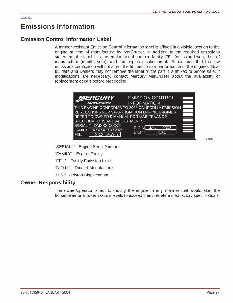
Emission Control Information LabelA tamper-resistant Emission Control Information label is affixed in a visible location to theengine at time of manufacture by MerCruiser. In addition to the required emissionsstatement, the label lists the engine serial number, family, FEL (emission level), date ofmanufacture (month, year), and the engine displacement. Please note that the lowemissions certification will not affect the fit, function, or performance of the engines. Boatbuilders and Dealers may not remove the label or the part it is affixed to before sale. Ifmodifications are necessary, contact Mercury MerCruiser about the availability ofreplacement decals before proceeding.
79706
EMISSION CONTROLINFORMATION
THIS ENGINE CONFORMS TO 2003 CALIFORNIA EMISSIONREGULATIONS FOR SPARK IGNITION MARINE ENGINESREFER TO OWNER’S MANUAL FOR MAINTENANCESPECIFICATIONS AND ADJUSTMENTSSERIAL # OMXXXXXXXXFAMILY XXXXX_XXXXXXFEL. XX.X g/kW-hr
D.O.M. JAN. 2003DISP X.XL
“SERIAL#” - Engine Serial Number
“FAMILY” - Engine Family
“FEL.” - Family Emission Limit
“D.O.M.” - Date of Manufacture
“DISP” - Piston Displacement
Owner ResponsibilityThe owner/operator is not to modify the engine in any manner that would alter thehorsepower or allow emissions levels to exceed their predetermined factory specifications.

GETTING TO KNOW YOUR POWER PACKAGE
Page 28 90-864195040 JANUARY 2004
0221.01
Star LabelBeginning January 1, 2003, one 3-Star label will be included with each factory-certifiedMerCruiser engine.
All Mercury MerCruiser engines (500 hp and below) will have a 3-Star Ultra Low Emissionrating. The 3-Star label identifies that these engines meet the California Air ResourcesBoard’s Sterndrive and Inboard marine engine 2003 exhaust emission standards. Enginesmeeting these standards have 65% lower emissions that One Star - Low Emission engines.
The 3-Star label will be affixed on the left side of the hull as shown.
ba
mc79531
a - Recommended decal locationb - Secondary decal location
ONE STAR - LOW EMISSION
mc79569
The one-star label identifies personal watercraft, outboard, sterndriveand inboard engines that meet the Air Resources Board’s PersonalWatercraft and Outboard marine engine 2001 exhaust emissionstandards. Engines meeting these standards have 75% lower emissionsthan conventional carbureted two-stroke engines. These engines areequivalent to the U.S. EPA’s 2006 standards for marine engines.
TWO STARS - VERY LOW EMISSION
mc79570
The two-star label identifies personal watercraft, outboard, sterndriveand inboard engines that meet the Air Resources Board’s PersonalWatercraft and Outboard marine engine 2004 exhaust emissionstandards. Engines meeting these standards have 20% lower emissionsthat One Star - Low-Emission engines.
THREE STARS - ULTRA LOW EMISSION
mc79571
The three-star label identifies engines that meet the Air ResourcesBoard’s Personal Watercraft and Outboard marine engine 2008 exhaustemission standards or the Sterndrive and Inboard marine engine 2003exhaust emission standards. Engines meeting these standards have65% lower emissions than One Star - Low Emission engines.
FOUR STARS - SUPER ULTRA LOW EMISSION
mc79572
The Four Star label identifies engines that meet the Air Resources Board’sSterndrive and Inboard marine engine 2009 exhaust emission standards.Personal Watercraft and Outboard marine engines may also comply withthese standards. Engines meeting these standards have 90% loweremissions than One Star - Low Emission engines.
3
ON THE WATER
90-864195040 JANUARY 2004 Page 29
ON THE WATER
Table of Contents
Safe Boating Suggestions 30. . . . . . . . . . . . . . Be Alert To Carbon Monoxide Poisoning 32. . . . . . . . . . .
Basic Boat Operation 34. . . . . . . . . . . . . . . . . . . Launching And Boat Operation Care 34. . . . Starting And Stopping The Engine 36. . . . . . Starting Engine After Stopped While In Gear 37. . . . . . . . . . . . . . . . . . . . . . . . Trailering The Boat 37. . . . . . . . . . . . . . . . . . . Freezing Temperature Operation 37. . . . . . . Drain Plug and Bilge Pump 37. . . . . . . . . . . .
Protecting People In The Water 38. . . . . . . . . While You Are Cruising 38. . . . . . . . . . . . . . . . While Boat Is Stationary 38. . . . . . . . . . . . . . .
High-Speed And High-Performance Boat Operation 38. . . . . . . . . . . . . . . . . . . . . . . . Passenger Safety Message - Pontoon And Deck Boats 39. . . . . . . . . . . . . .
Wave And Wake Jumping 40. . . . . . . . . . . . . . . Impact With Underwater Hazards 41. . . . . . . .
Drive Unit Impact Protection 42. . . . . . . . . . . Operating With Low Water Inlets In Shallow Water 42. . . . . . . . . . . . . . . . . . . . . . Conditions Affecting Operation 43. . . . . . . . .
Weight Distribution (Passengers And Gear) Inside The Boat 43. . . . . . . . . . . . . . . . . . . . . . Bottom Of Boat 43. . . . . . . . . . . . . . . . . . . . . . . Cavitation 43. . . . . . . . . . . . . . . . . . . . . . . . . . . Ventilation 44. . . . . . . . . . . . . . . . . . . . . . . . . . . Elevation And Climate 44. . . . . . . . . . . . . . . . . Propeller Selection 45. . . . . . . . . . . . . . . . . . . .
Getting Started 46. . . . . . . . . . . . . . . . . . . . . . . . . 20-Hour Break-In Period 46. . . . . . . . . . . . . . . After Break-In Period 46. . . . . . . . . . . . . . . . . . End of First Season Checkup 46. . . . . . . . . .
ON THE WATER
Page 30 90-864195040 JANUARY 2004
0022
Safe Boating Suggestions
In order to safely enjoy the waterways, familiarize yourself with local and all othergovernmental boating regulations and restrictions and also consider the followingsuggestions.
• Know and obey all nautical rules and laws of the waterways.
Mercury MerCruiser strongly recommends that all powerboat operators complete a boatingsafety course. Courses are offered in the U.S.A. by: The U.S. Coast Guard Auxiliary, ThePower Squadron, The Red Cross and your state or provincial boating law enforcementagency. Inquiries may be made to the Boating Hotline at 1-800-368-5647 or the Boat U.S.Foundation at 1-800-336-BOAT.
You should also review the NMMA Sources of Waterway Information booklet. It lists regionalsources of safety, cruising and local navigation and is available at no charge by writing to:
Sources of Waterway Information
National Marine Manufacturers Association
410 N. Michigan Avenue
Chicago, IL 60611 U.S.A.
• Perform safety checks and required maintenance. Follow a regular schedule andensure that all repairs are properly made.
• Check safety equipment on board. Here are some suggestions of the types ofsafety equipment to carry when boating:
Approved fire extinguishers Paddle or oar
Signal devices: flashlight, rockets orflares, flag and whistle or horn
Spare propeller, thrust hubs, and anappropriate wrench
Tools necessary for minor repairs First aid kit and instructions
Anchor and extra anchor line Water-proof storage containers
Manual bilge pump and extra drainplugs
Spare operating equipment, batteries,bulbs and fuses
Drinking water Compass and map or chart of the area
Transistor radio
ON THE WATER
90-864195040 JANUARY 2004 Page 31
• Watch for signs of weather change and avoid foul weather and rough-seaboating.
• Tell someone where you are going and when you expect to return.
• Passenger boarding. Stop the engine whenever passengers are boarding,unloading or are near the back (stern) of the boat. Shifting the drive unit into neutralis not sufficient.
• Use personal flotation devices. Federal Law requires that there be a U. S. CoastGuard approved, wearable-type life jacket (personal flotation device), correctly sizedand readily accessible for every person on board, plus a throwable cushion or ring.We strongly advise that everyone wear a life jacket at all times while in the boat.
• Prepare other boat operators. Instruct at least 1 person on board in the basics ofstarting and operating the engine and boat handling in case the driver becomesdisabled or falls overboard.
• Do NOT overload your boat. Most boats are rated and certified for maximum load(weight) capacities (refer to your boat capacity plate). Know your boat’s operatingand loading limitations. Know if your boat will float if full of water. When in doubt,contact your authorized Mercury MerCruiser dealer or the boat manufacturer.
• Ensure that everyone in the boat is properly seated. Do NOT allow anyone to sitor ride on any part of the boat that was not intended for such use. This includes thebacks of seats, gunwales, transom, bow, decks, raised fishing seats and any rotatingfishing seat; anywhere that sudden unexpected acceleration, sudden stopping,unexpected loss of boat control or sudden boat movement could cause a person tobe thrown overboard or into the boat. Ensure that all passengers have a proper seatand are in it before any boat movement.
• Never be under the influence of alcohol or drugs while boating (it is the law).They impair your judgment and greatly reduce your ability to react quickly.
ON THE WATER
Page 32 90-864195040 JANUARY 2004
• Know your boating area and avoid hazardous locations.
• Be alert. The operator of the boat is responsible by law to “maintain a proper lookoutby sight and hearing.” The operator must have an unobstructed view particularly tothe front. No passengers, load or fishing seats should block the operators view whenoperating the boat above idle or planing transition speed. Watch out for others, thewater and your wake.
• Never drive your boat directly behind a water skier in case the skier falls. As anexample, your boat traveling at 25 MPH (40 km/h) will overtake a fallen skier whowas 61 m (200 ft) in front of you in 5 seconds.
• Watch fallen skiers. When using your boat for water skiing or similar activities,always keep a fallen or down skier on the operator’s side of the boat while returningto attend to the skier. The operator should always have the down skier in sight andnever back up to the skier or anyone in the water.
• Report accidents. Boat operators are required by law to file a Boating AccidentReport with their state boating law enforcement agency when their boat is involved incertain boating accidents. A boating accident must be reported if (1) there is loss oflife or probable loss of life, (2) there is personal injury requiring medical treatmentbeyond first aid, (3) there is damage to boats or other property where the damagevalue exceeds $500.00 or (4) there is complete loss of the boat. Seek furtherassistance from local law enforcement.
0023
Be Alert To Carbon Monoxide PoisoningCarbon monoxide is present in the exhaust fumes of all internal combustion enginesincluding the outboards, sterndrives and inboard engines that propel boats, as well as thegenerators that power various boat accessories. Carbon monoxide is a deadly gas that isodorless, colorless and tasteless.
Early symptoms of carbon monoxide poisoning, which should not be confused withseasickness or intoxication, include headache, dizziness, drowsiness and nausea.
WARNINGAvoid prolonged exposure to carbon monoxide. Carbon monoxide poisoning canlead to unconsciousness, brain damage or death. Ensure that the boat, while at restor underway, is well ventilated.
ON THE WATER
90-864195040 JANUARY 2004 Page 33
0024.01
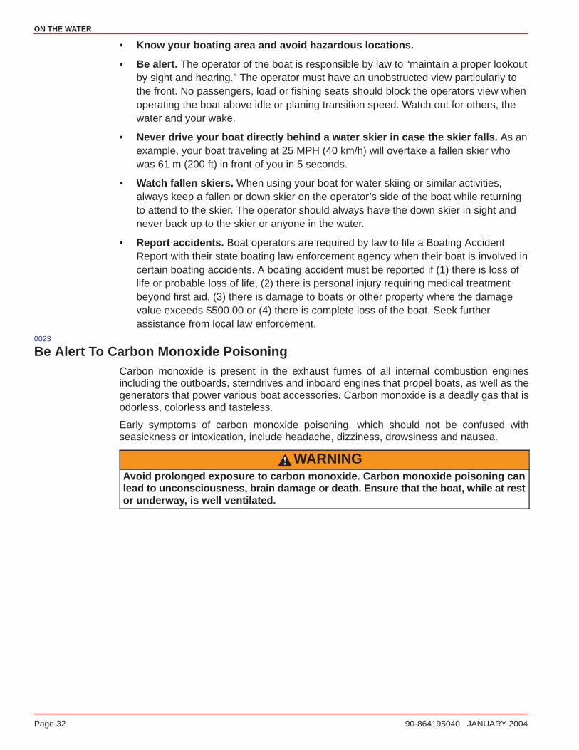
GOOD VENTILATION
Ventilate the passenger area by opening the side curtains or forward hatches to removefumes.
Courtesy of ABYCmc79553
Example of desired air flow through the boat0025.01
POOR VENTILATION
Under certain conditions, permanently enclosed or canvas enclosed cabins or cockpits withinsufficient ventilation may draw in carbon monoxide. Install one or more carbon monoxidedetectors in your boat.
Although the occurrence is rare, on a very calm day, swimmers and passengers in an openarea of a stationary boat that contains or is near an operating engine may be exposed toa hazardous level of carbon monoxide.
Courtesy of ABYC
a bmc79554
Example of poor ventilation while a boat is stationary:a - Operating the engine when the boat is moored in a confined space.b - Mooring close to another boat with its engine operating.
Courtesy of ABYCa bmc79556
Example of poor ventilation while a boat is moving:a - Operating the boat with the trim angle of the bow too high.b - Operating the boat with no forward hatches open (station wagon effect).
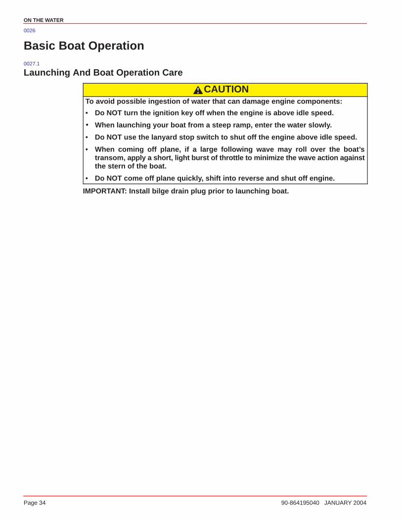
ON THE WATER
Page 34 90-864195040 JANUARY 2004
0026
Basic Boat Operation0027.1
Launching And Boat Operation Care
CAUTIONTo avoid possible ingestion of water that can damage engine components:
• Do NOT turn the ignition key off when the engine is above idle speed.
� When launching your boat from a steep ramp, enter the water slowly.
• Do NOT use the lanyard stop switch to shut off the engine above idle speed.
• When coming off plane, if a large following wave may roll over the boat’stransom, apply a short, light burst of throttle to minimize the wave action againstthe stern of the boat.
• Do NOT come off plane quickly, shift into reverse and shut off engine.
IMPORTANT: Install bilge drain plug prior to launching boat.
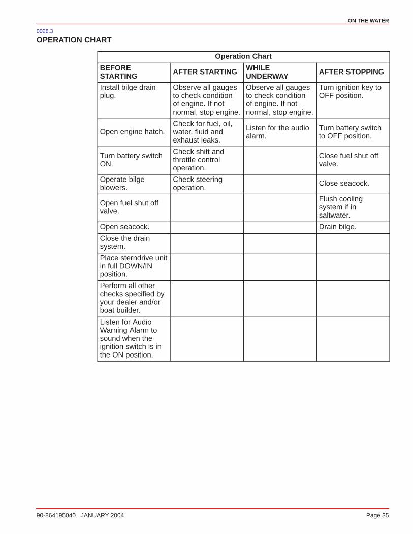
ON THE WATER
90-864195040 JANUARY 2004 Page 35
0028.3
OPERATION CHART
Operation Chart
BEFORESTARTING AFTER STARTING WHILE
UNDERWAY AFTER STOPPING
Install bilge drainplug.
Observe all gaugesto check conditionof engine. If notnormal, stop engine.
Observe all gaugesto check conditionof engine. If notnormal, stop engine.
Turn ignition key toOFF position.
Open engine hatch.Check for fuel, oil,water, fluid andexhaust leaks.
Listen for the audioalarm.
Turn battery switchto OFF position.
Turn battery switchON.
Check shift andthrottle controloperation.
Close fuel shut offvalve.
Operate bilgeblowers.
Check steeringoperation.
Close seacock.
Open fuel shut offvalve.
Flush coolingsystem if insaltwater.
Open seacock. Drain bilge.
Close the drainsystem.
Place sterndrive unitin full DOWN/INposition.
Perform all otherchecks specified byyour dealer and/orboat builder.
Listen for AudioWarning Alarm tosound when theignition switch is inthe ON position.

ON THE WATER
Page 36 90-864195040 JANUARY 2004
0029
Starting And Stopping The EngineNOTE: Only perform those functions applicable to your power package.
1. Check all items listed in Operation Chart.
2. Place the remote control handle in NEUTRAL.
CAUTIONOverheating from insufficient cooling water will cause engine and drive systemdamage. Ensure that there is sufficient water always available at water inlet holesduring operation.
WARNINGExplosive gasoline fumes collect in the engine compartment. Avoid injury orproperty damage, operate the bilge blower for at least 5 minutes prior to starting theengine. If the boat is not equipped with a bilge blower, open the engine hatch andleave it open while starting the engine.
3. Position throttle setting as follows:
a. COLD AND WARM ENGINE - Leave in the NEUTRAL/IDLE speed position.
b. FLOODED ENGINE - Turn ignition switch to the ON position. Push the THROTTLEONLY button and place the throttle lever at 50 percent position. Attempt to startengine. As soon as engine starts, return the throttle to the IDLE position.
IMPORTANT: Do NOT operate starter motor continuously for more than 30 seconds.
4. Turn ignition key to START. Release key when engine starts and allow switch to returnto ON position.
5. If engine is cold, operate engine for 1 or 2 minutes at fast IDLE (1000 - 1500 rpm) or untilengine temperature reaches 140 - 160 degrees F (60 - 71 degrees C).
6. Inspect the power package for fuel, oil, water and exhaust leaks.
7. To shift into gear, move control handle with a firm, quick motion forward to shift toFORWARD gear, or backward to shift to REVERSE. After shifting drive unit, advancethrottle to desired setting.
8. Move the remote control handle to NEUTRAL/IDLE and allow the engine to slow to IDLEspeed. If engine has been operated at high speed for a long period of time, allow theengine to cool at IDLE speed for 3 to 5 minutes.
9. Turn ignition key to the OFF position.
ON THE WATER
90-864195040 JANUARY 2004 Page 37
0173
Starting Engine After Stopped While In GearIMPORTANT: Avoid stopping the engine if the sterndrive unit is in gear. If the enginedoes stop, refer to the following procedure:
1. Push and pull repeatedly on the remote control handle until handle returns to theNEUTRAL/IDLE position. This may take several tries if the power package wasoperating above idle rpm when the engine stopped.
2. After the handle returns to the NEUTRAL/IDLE position, resume normal startingprocedures.
0174
Trailering The BoatYour boat can be trailered with the sterndrive unit in the UP or DOWN position. Adequateclearance is required between the road and sterndrive when transporting.
If adequate road clearance is a problem, place the sterndrive unit in full trailer position andsupport it with an optional trailer kit which is available from your authorized MercuryMerCruiser dealer.
0030
Freezing Temperature OperationIMPORTANT: If the boat is operated during periods of freezing temperature,precautions must be taken to prevent freeze damage to the power package. Damagecaused by freezing IS NOT covered by Mercury MerCruiser Limited Warranty.
0031
Drain Plug and Bilge PumpThe engine compartment in your boat is a natural place for water to collect. For this reason,boats are normally equipped with a drain plug and/or a bilge pump. It is very important tocheck these items on a regular basis to ensure that the water level does not come intocontact with your power package. Components on your engine will be damaged ifsubmerged. Damage caused by submersion is not covered by the Mercury MerCruiserLimited Warranty.
ON THE WATER
Page 38 90-864195040 JANUARY 2004
0032
Protecting People In The Water
While You Are CruisingIt is very difficult for a person standing or floating in the water to take quick action to avoida boat heading in his/her direction even at slow speed.
Always slow down and exercise extreme caution any time you are boating in an area wherethere might be people in the water.
Whenever a boat is moving (coasting) in NEUTRAL/IDLE, there is sufficient force by thewater on the propeller to cause the propeller to rotate. This neutral propeller rotation cancause serious injury.
While Boat Is Stationary
WARNINGStop your engine immediately whenever anyone in the water is near your boat.Serious injury to the person in the water is likely if contacted by a rotating propeller,a moving boat, a gear case or any solid device rigidly attached to a moving boat orgear case.
Shift into the NEUTRAL/IDLE position and shut off the engine before allowing people toswim or be in the water near your boat.
0033
High-Speed And High-Performance Boat Operation
If your boat is considered a high-speed or high-performance boat with which you areunfamiliar, we recommend that you never operate it at its high speed capability without firstrequesting an initial orientation and demonstration ride with your dealer or an operatorexperienced with your boat. For additional information, refer to Hi-Performance BoatOperation booklet (90-849250-R2) from your dealer, distributor or Mercury Marine.

ON THE WATER
90-864195040 JANUARY 2004 Page 39
0131.02
Passenger Safety Message - Pontoon And Deck Boats
WARNINGAvoid serious injury or death from falling over the front end of a pontoon or deckboat and coming in contact with the boat hull or propeller. Stay back from the frontend of the deck and remain seated while the boat is in motion.
Whenever the boat is in motion, observe the location of all the passengers. Do not allow anypassengers to stand or use seats other than those designated for traveling faster than idlespeed. A sudden reduction in boat speed, such as the result of plunging into a large waveor wake, a sudden throttle reduction or a sharp change of boat direction, could throw themover the front of boat. Falling over the front of the boat between the two pontoons will positionthem to come into contact with the drive unit.
1. Boats having an open front deck:
a. No one should ever be on the deck in front of the fence while the boat is in motion. Keepall passengers behind the front fence or enclosure.
b. Persons on the front deck could easily be thrown overboard or persons danglingtheir feet over the front edge could get their legs caught by a wave and pulled intothe water.
mc79555
Incorrect Correct
2. Boats with front-mounted, raised pedestal fishing seats:
a. These elevated fishing seats are not intended for use when the boat is travelingfaster than idle or trolling speed. Sit only in seats designated for traveling at fasterspeeds.
b. Any unexpected sudden reduction in boat speed could result in the elevatedpassenger falling over the front of the boat.
mc79557
Incorrect Correct
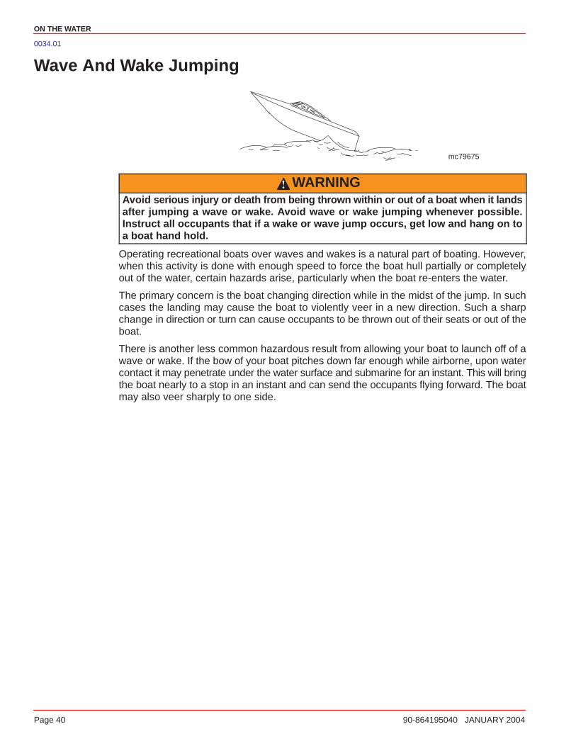
ON THE WATER
Page 40 90-864195040 JANUARY 2004
0034.01
Wave And Wake Jumping
mc79675
WARNINGAvoid serious injury or death from being thrown within or out of a boat when it landsafter jumping a wave or wake. Avoid wave or wake jumping whenever possible.Instruct all occupants that if a wake or wave jump occurs, get low and hang on toa boat hand hold.
Operating recreational boats over waves and wakes is a natural part of boating. However,when this activity is done with enough speed to force the boat hull partially or completelyout of the water, certain hazards arise, particularly when the boat re-enters the water.
The primary concern is the boat changing direction while in the midst of the jump. In suchcases the landing may cause the boat to violently veer in a new direction. Such a sharpchange in direction or turn can cause occupants to be thrown out of their seats or out of theboat.
There is another less common hazardous result from allowing your boat to launch off of awave or wake. If the bow of your boat pitches down far enough while airborne, upon watercontact it may penetrate under the water surface and submarine for an instant. This will bringthe boat nearly to a stop in an instant and can send the occupants flying forward. The boatmay also veer sharply to one side.
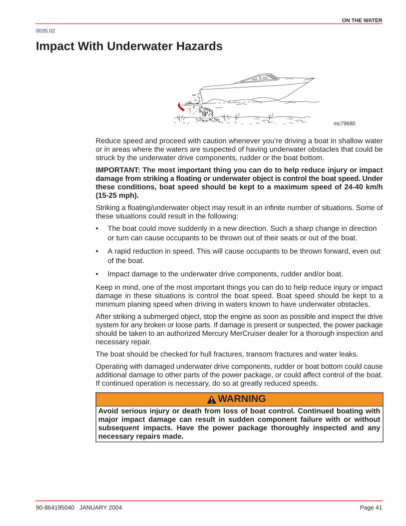
ON THE WATER
90-864195040 JANUARY 2004 Page 41
0035.02
Impact With Underwater Hazards
mc79680
Reduce speed and proceed with caution whenever you’re driving a boat in shallow wateror in areas where the waters are suspected of having underwater obstacles that could bestruck by the underwater drive components, rudder or the boat bottom.
IMPORTANT: The most important thing you can do to help reduce injury or impactdamage from striking a floating or underwater object is control the boat speed. Underthese conditions, boat speed should be kept to a maximum speed of 24-40 km/h(15-25 mph).
Striking a floating/underwater object may result in an infinite number of situations. Some ofthese situations could result in the following:
• The boat could move suddenly in a new direction. Such a sharp change in directionor turn can cause occupants to be thrown out of their seats or out of the boat.
• A rapid reduction in speed. This will cause occupants to be thrown forward, even outof the boat.
• Impact damage to the underwater drive components, rudder and/or boat.
Keep in mind, one of the most important things you can do to help reduce injury or impactdamage in these situations is control the boat speed. Boat speed should be kept to aminimum planing speed when driving in waters known to have underwater obstacles.
After striking a submerged object, stop the engine as soon as possible and inspect the drivesystem for any broken or loose parts. If damage is present or suspected, the power packageshould be taken to an authorized Mercury MerCruiser dealer for a thorough inspection andnecessary repair.
The boat should be checked for hull fractures, transom fractures and water leaks.
Operating with damaged underwater drive components, rudder or boat bottom could causeadditional damage to other parts of the power package, or could affect control of the boat.If continued operation is necessary, do so at greatly reduced speeds.
WARNINGAvoid serious injury or death from loss of boat control. Continued boating withmajor impact damage can result in sudden component failure with or withoutsubsequent impacts. Have the power package thoroughly inspected and anynecessary repairs made.
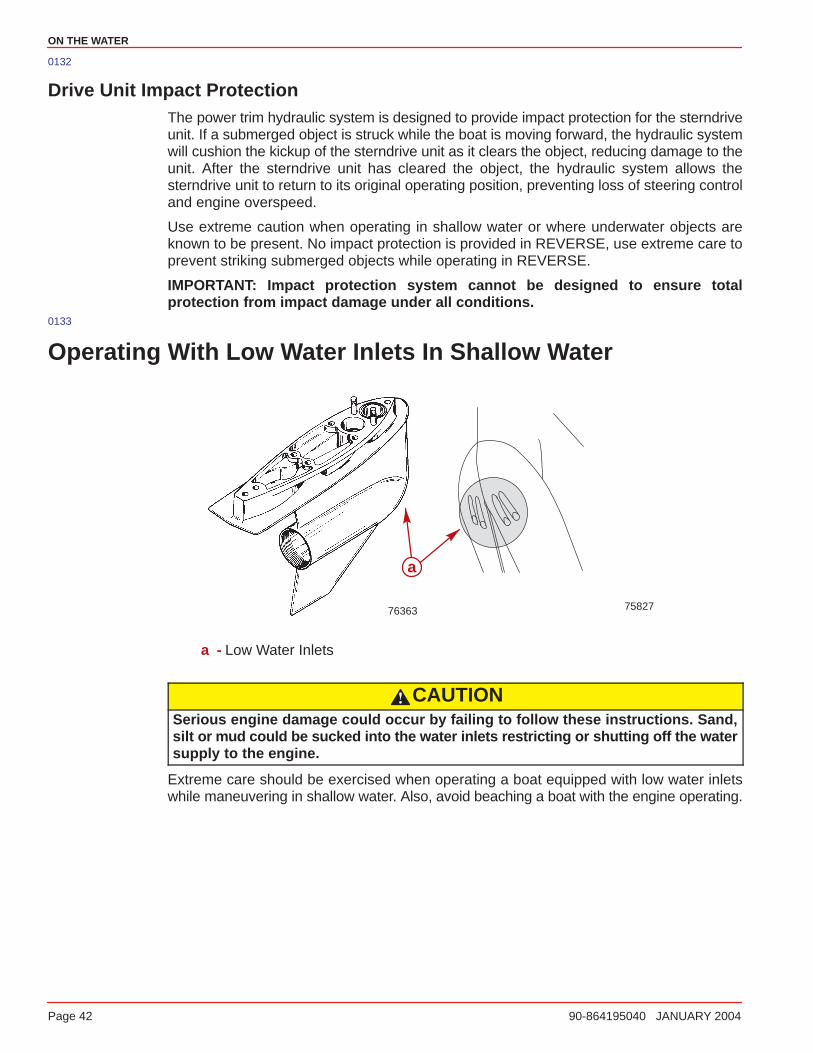
ON THE WATER
Page 42 90-864195040 JANUARY 2004
0132
Drive Unit Impact ProtectionThe power trim hydraulic system is designed to provide impact protection for the sterndriveunit. If a submerged object is struck while the boat is moving forward, the hydraulic systemwill cushion the kickup of the sterndrive unit as it clears the object, reducing damage to theunit. After the sterndrive unit has cleared the object, the hydraulic system allows thesterndrive unit to return to its original operating position, preventing loss of steering controland engine overspeed.
Use extreme caution when operating in shallow water or where underwater objects areknown to be present. No impact protection is provided in REVERSE, use extreme care toprevent striking submerged objects while operating in REVERSE.
IMPORTANT: Impact protection system cannot be designed to ensure totalprotection from impact damage under all conditions.
0133
Operating With Low Water Inlets In Shallow Water
7582776363
a
a - Low Water Inlets
CAUTIONSerious engine damage could occur by failing to follow these instructions. Sand,silt or mud could be sucked into the water inlets restricting or shutting off the watersupply to the engine.
Extreme care should be exercised when operating a boat equipped with low water inletswhile maneuvering in shallow water. Also, avoid beaching a boat with the engine operating.
ON THE WATER
90-864195040 JANUARY 2004 Page 43
0036
Conditions Affecting Operation
Weight Distribution (Passengers And Gear) Inside The BoatShifting weight to rear (stern):
• Generally increases speed and engine rpm
• Causes bow to bounce in choppy water
• Increases danger of following wave splashing into the boat when coming off plane
• At extremes, can cause the boat to porpoise
Shifting weight to front (bow):
• Improves ease of planing
• Improves rough water ride
• At extremes, can cause the boat to veer back and forth (bow steer)0037
Bottom Of BoatTo maintain maximum speed, the boat bottom should be:
• Clean, free of barnacles and marine growth
• Free of distortion; nearly flat where it contacts the water
• Straight and smooth, fore and aft
Marine vegetation may accumulate when the boat is docked. This growth must be removedbefore operation; it may clog the water inlets and cause the engine to overheat.
0038
CavitationCavitation occurs when water flow cannot follow the contour of a fast-moving underwaterobject, such as a gear housing or a propeller. Cavitation permits the propeller to speed up,but the boat speed to reduce. Cavitation can seriously erode the surface of the gear housingor the propeller. Common causes of cavitation are:
• Weeds or other debris snagged on the propeller
• Bent propeller blade
• Raised burrs or sharp edges on the propeller
ON THE WATER
Page 44 90-864195040 JANUARY 2004
0134
VentilationVentilation is caused by surface air or exhaust gases that are introduced around thepropeller resulting in propeller speedup and a reduction in boat speed. Excessive ventilationis annoying and usually caused by:
• Drive unit trimmed out too far
• A missing propeller diffuser ring
• A damaged propeller or gear housing, which allows exhaust gases to escapebetween propeller and gear housing
• Drive unit installed too high on transom0039
Elevation And ClimateElevation and climate changes will affect the performance of your power package. Loss ofperformance can be caused by:
• Higher elevations
• Higher temperatures
• Low barometric pressures
• High humidity
For you to have optimum engine performance under changing weather conditions, it isessential that the engine be propped to allow the engine to operate at or near the top endof the specified maximum rpm range with a normal boat load during your normal boatingweather conditions.
In most cases, performance can be regained by changing to a lower pitch propeller.

ON THE WATER
90-864195040 JANUARY 2004 Page 45
0040
Propeller SelectionIMPORTANT: The engines covered in this manual are equipped with an rpmrev-limiter that is set to an upper (or limited) rpm amount. This limit is slightly abovethe normal operating range of the engine and is designed to help prevent damagefrom excessive engine rpm. Once the rpm drop into the recommended operating rpmrange, normal engine operation resumes.
It is the responsibility of the boat manufacturer and/or the selling dealer to equip the powerpackage with the correct propeller. Refer to Everything You Need To Know AboutPropellers (90-8614492).
Select a propeller that will allow the engine power package to operate at or near the top endof the recommended WOT operating rpm range with a normal load.
If full throttle operation is below the recommended range, the propeller must be changedto prevent loss of performance and possible engine damage. On the other hand, operatingan engine above the recommended operating rpm range will cause higher than normal wearand/or damage.
After initial propeller selection, the following common problems may require that thepropeller be changed to a lower pitch.
• Warmer weather and greater humidity cause a loss of rpm.
• Operating in a higher elevation causes a loss of rpm.
• Operating with a dirty boat bottom causes a loss of rpm.
• Operating with increased load (additional passengers, pulling skiers) causes a lossof rpm.
For better acceleration, such as is needed for water skiing, use the next lower pitchpropeller. Do NOT operate at full throttle when using the lower pitch propeller, but not pullingskiers.

ON THE WATER
Page 46 90-864195040 JANUARY 2004
0042
Getting Started0041
20-Hour Break-In PeriodIMPORTANT: The first 20 hours of operation is the engine break-in period. Correctbreak-in is essential to obtain minimum oil consumption and maximum engineperformance. During this break-in period, the following rules must be observed:
• Do NOT operate below 1500 rpm for extended periods of time for the first 10 hours.Shift into gear as soon as possible after starting and advance the throttle above 1500rpm if conditions permit safe operation.
• Do NOT operate at one speed consistently for extended periods.
• Do not exceed 3/4 throttle during the first 10 hours. During the next 10 hours,occasional operation at full throttle is permissible (5 minutes at a time maximum).
• Avoid full throttle acceleration from IDLE speed.
• Do NOT operate at full throttle until the engine reaches normal operatingtemperature.
• Frequently check engine oil level. Add oil as needed. It is normal for oil consumptionto be high during the break-in period.
0043
After Break-In PeriodTo help extend the life of your Mercury MerCruiser power package, the followingrecommendations should be considered;
• Ensure that propeller allows the engine to operate at or near the top of the specifiedWOT rpm range (Refer to Specifications and Maintenance) when at full throttle witha normal boat load.
• Operation at 3/4 throttle setting or lower is recommended. Refrain from prolongedoperation at WOT rpm.
• Change the oil and oil filter. Refer to Specifications and Maintenance.0044
End of First Season CheckupAt the end of the first season of operation, contact an authorized Mercury MerCruiser dealerto discuss and/or perform scheduled maintenance items. If you are in an area where theproduct is operated continuously, year-round, you should contact your dealer at the end ofthe first 100 hours of operation or once yearly, whichever occurs first.
4
SPECIFICATIONS
90-864195032 SEPTEMBER 2003 Page 47
SPECIFICATIONS
Table of Contents
Specifications 48. . . . . . . . . . . . . . . . . . . . . . . . . Fuel Recommendations 48. . . . . . . . . . . . . . . Engine Oil 50. . . . . . . . . . . . . . . . . . . . . . . . . . . Engine Specifications 51. . . . . . . . . . . . . . . . .
Fluid Specifications 52. . . . . . . . . . . . . . . . . . . Engine 52. . . . . . . . . . . . . . . . . . . . . . . . . . . . Sterndrives 52. . . . . . . . . . . . . . . . . . . . . . . .
SPECIFICATIONS
Page 48 90-864195032 SEPTEMBER 2003
0045
Specifications
Fuel RecommendationsIMPORTANT: Use of improper gasoline can damage your engine. Engine damageresulting from the use of improper gasoline is considered misuse of the engine, anddamage caused thereby will not be covered under the limited warranty.
FUEL RATINGS
Mercury MerCruiser engines will operate satisfactorily when using a major brand ofunleaded gasoline meeting the following specifications:
USA and Canada - having a posted pump Octane Rating of 87 (R+M)/2 minimum. Premiumgasoline [92 (R+M)/2 Octane] is also acceptable. Do NOT use leaded gasoline.
Outside USA and Canada - having a posted pump Octane Rating of 90 RON minimum.Premium gasoline (98 RON) is also acceptable. If unleaded gasoline is not available, usea major brand of leaded gasoline.
0046
USING REFORMULATED (OXYGENATED) GASOLINES (USA ONLY)
This type of gasoline is required in certain areas of the USA. The 2 types of oxygenates usedin these fuels is Alcohol (Ethanol) or Ether (MTBE or ETBE). If Ethanol is the oxygenate thatis used in the gasoline in your area, refer to Gasolines Containing Alcohol.
These Reformulated Gasolines are acceptable for use in your Mercury MerCruiser engine.
SPECIFICATIONS
90-864195032 SEPTEMBER 2003 Page 49
0047
GASOLINES CONTAINING ALCOHOL
If the gasoline in your area contains either methanol (methyl alcohol) or ethanol (ethylalcohol), you should be aware of certain adverse effects that can occur. These adverseeffects are more severe with methanol. Increasing the percentage of alcohol in the fuel canalso worsen these adverse effects.
Some of these adverse effects are caused because the alcohol in the gasoline can absorbmoisture from the air, resulting in a separation of the water/alcohol from the gasoline in thefuel tank.
The fuel system components on your Mercury MerCruiser engine will withstand up to 10%alcohol content in the gasoline. We do not know what percentage your boat’s fuel systemwill withstand. Contact your boat manufacturer for specific recommendations on the boat’sfuel system components (fuel tanks, fuel lines, and fittings). Be aware that gasolinescontaining alcohol may cause increased:
• Corrosion of metal parts
• Deterioration of rubber or plastic parts
• Fuel permeation through rubber fuel lines
• Starting and operating difficulties
WARNINGFIRE AND EXPLOSION HAZARD: Fuel leakage from any part of the fuel system canbe a fire and explosion hazard which can cause serious bodily injury or death.Careful periodic inspection of entire fuel system is mandatory, particularly afterstorage. All fuel components should be inspected for leakage, softening,hardening, swelling or corrosion. Any sign of leakage or deterioration requiresreplacement before further engine operation.
Because of possible adverse effects of alcohol in gasoline, it is recommended that onlyalcohol-free gasoline be used where possible. If only fuel containing alcohol is available, orif the presence of alcohol is unknown, increased inspection frequency for leaks andabnormalities is required.
IMPORTANT: When operating a Mercury MerCruiser engine on gasoline containingalcohol, storage of gasoline in the fuel tank for long periods should be avoided. Longperiods of storage, common to boats, create unique problems. In cars alcohol-blendfuels normally are consumed before they can absorb enough moisture to causetrouble, but boats often sit idle long enough for phase separation to take place. Inaddition, internal corrosion may take place during storage if alcohol has washedprotective oil films from internal components.
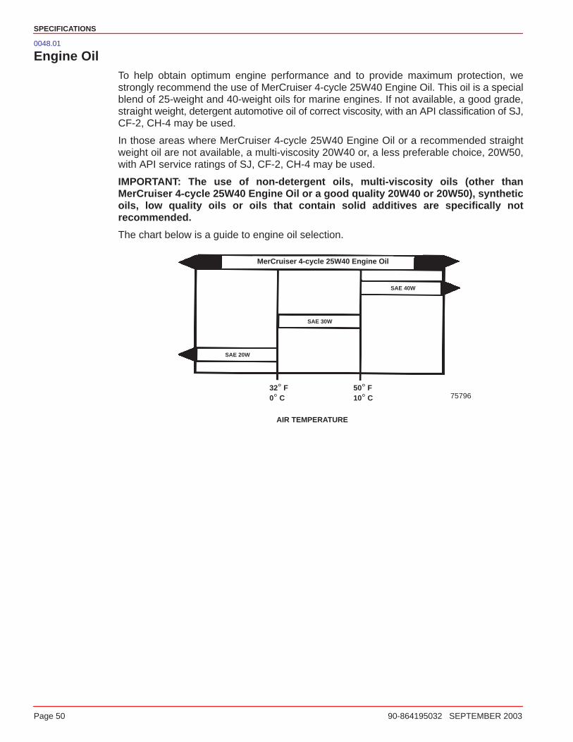
SPECIFICATIONS
Page 50 90-864195032 SEPTEMBER 2003
0048.01
Engine OilTo help obtain optimum engine performance and to provide maximum protection, westrongly recommend the use of MerCruiser 4-cycle 25W40 Engine Oil. This oil is a specialblend of 25-weight and 40-weight oils for marine engines. If not available, a good grade,straight weight, detergent automotive oil of correct viscosity, with an API classification of SJ,CF-2, CH-4 may be used.
In those areas where MerCruiser 4-cycle 25W40 Engine Oil or a recommended straightweight oil are not available, a multi-viscosity 20W40 or, a less preferable choice, 20W50,with API service ratings of SJ, CF-2, CH-4 may be used.
IMPORTANT: The use of non-detergent oils, multi-viscosity oils (other thanMerCruiser 4-cycle 25W40 Engine Oil or a good quality 20W40 or 20W50), syntheticoils, low quality oils or oils that contain solid additives are specifically notrecommended.
The chart below is a guide to engine oil selection.
75796
MerCruiser 4-cycle 25W40 Engine Oil
SAE 20W
SAE 30W
SAE 40W
32° F0° C
50° F10° C
AIR TEMPERATURE
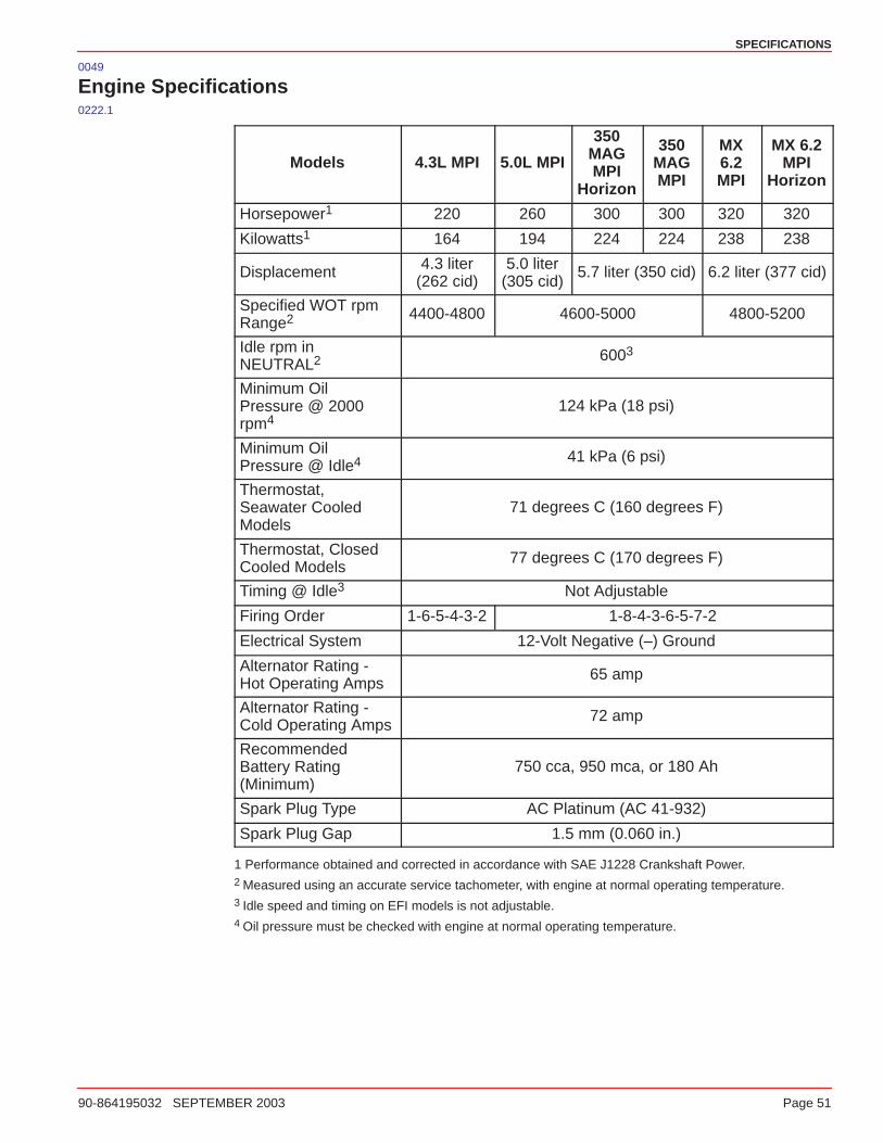
SPECIFICATIONS
90-864195032 SEPTEMBER 2003 Page 51
0049
Engine Specifications0222.1
Models 4.3L MPI 5.0L MPI
350MAGMPI
Horizon
350MAGMPI
MX6.2MPI
MX 6.2MPI
Horizon
Horsepower1 220 260 300 300 320 320
Kilowatts1 164 194 224 224 238 238
Displacement 4.3 liter(262 cid)
5.0 liter(305 cid)
5.7 liter (350 cid) 6.2 liter (377 cid)
Specified WOT rpmRange2 4400-4800 4600-5000 4800-5200
Idle rpm inNEUTRAL2 6003
Minimum OilPressure @ 2000rpm4
124 kPa (18 psi)
Minimum OilPressure @ Idle4 41 kPa (6 psi)
Thermostat,Seawater CooledModels
71 degrees C (160 degrees F)
Thermostat, ClosedCooled Models
77 degrees C (170 degrees F)
Timing @ Idle3 Not Adjustable
Firing Order 1-6-5-4-3-2 1-8-4-3-6-5-7-2
Electrical System 12-Volt Negative (–) Ground
Alternator Rating -Hot Operating Amps
65 amp
Alternator Rating -Cold Operating Amps
72 amp
RecommendedBattery Rating(Minimum)
750 cca, 950 mca, or 180 Ah
Spark Plug Type AC Platinum (AC 41-932)
Spark Plug Gap 1.5 mm (0.060 in.)
1 Performance obtained and corrected in accordance with SAE J1228 Crankshaft Power.2 Measured using an accurate service tachometer, with engine at normal operating temperature.3 Idle speed and timing on EFI models is not adjustable.4 Oil pressure must be checked with engine at normal operating temperature.
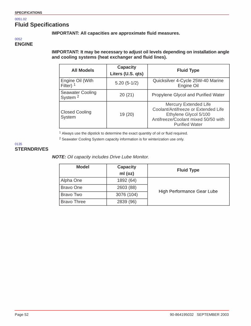
SPECIFICATIONS
Page 52 90-864195032 SEPTEMBER 2003
0051.02
Fluid SpecificationsIMPORTANT: All capacities are approximate fluid measures.
0052
ENGINE
IMPORTANT: It may be necessary to adjust oil levels depending on installation angleand cooling systems (heat exchanger and fluid lines).
All ModelsCapacity
Liters (U.S. qts)Fluid Type
Engine Oil (WithFilter) 1
5.20 (5-1/2) Quicksilver 4-Cycle 25W-40 MarineEngine Oil
Seawater CoolingSystem 2
20 (21) Propylene Glycol and Purified Water
Closed CoolingSystem
19 (20)
Mercury Extended LifeCoolant/Antifreeze or Extended Life
Ethylene Glycol 5/100Antifreeze/Coolant mixed 50/50 with
Purified Water
1 Always use the dipstick to determine the exact quantity of oil or fluid required.2 Seawater Cooling System capacity information is for winterization use only.
0135
STERNDRIVES
NOTE: Oil capacity includes Drive Lube Monitor.
Model Capacityml (oz)
Fluid Type
Alpha One 1892 (64)
Bravo One 2603 (88)High Performance Gear Lube
Bravo Two 3076 (104)High Performance Gear Lube
Bravo Three 2839 (96)
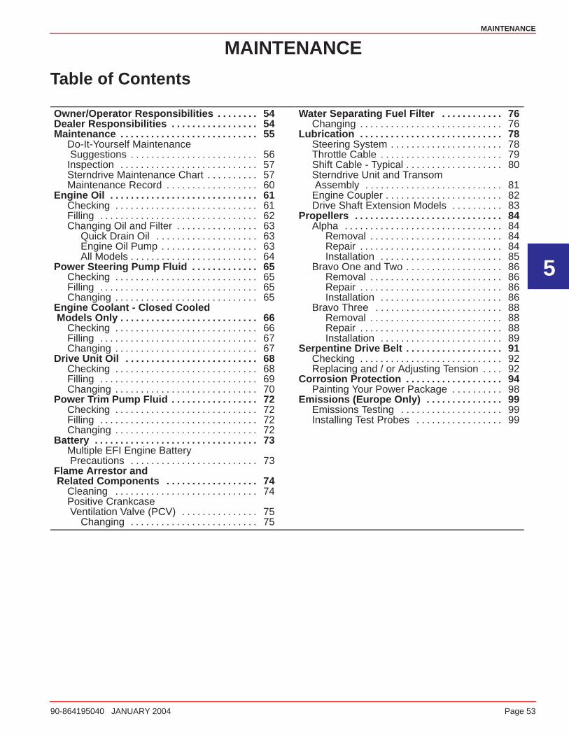
5
MAINTENANCE
90-864195040 JANUARY 2004 Page 53
MAINTENANCE
Table of Contents
Owner/Operator Responsibilities 54. . . . . . . . Dealer Responsibilities 54. . . . . . . . . . . . . . . . . Maintenance 55. . . . . . . . . . . . . . . . . . . . . . . . . . .
Do-It-Yourself Maintenance Suggestions 56. . . . . . . . . . . . . . . . . . . . . . . . . Inspection 57. . . . . . . . . . . . . . . . . . . . . . . . . . . Sterndrive Maintenance Chart 57. . . . . . . . . . Maintenance Record 60. . . . . . . . . . . . . . . . . .
Engine Oil 61. . . . . . . . . . . . . . . . . . . . . . . . . . . . . Checking 61. . . . . . . . . . . . . . . . . . . . . . . . . . . . Filling 62. . . . . . . . . . . . . . . . . . . . . . . . . . . . . . . Changing Oil and Filter 63. . . . . . . . . . . . . . . .
Quick Drain Oil 63. . . . . . . . . . . . . . . . . . . . Engine Oil Pump 63. . . . . . . . . . . . . . . . . . . All Models 64. . . . . . . . . . . . . . . . . . . . . . . . .
Power Steering Pump Fluid 65. . . . . . . . . . . . . Checking 65. . . . . . . . . . . . . . . . . . . . . . . . . . . . Filling 65. . . . . . . . . . . . . . . . . . . . . . . . . . . . . . . Changing 65. . . . . . . . . . . . . . . . . . . . . . . . . . . .
Engine Coolant - Closed Cooled Models Only 66. . . . . . . . . . . . . . . . . . . . . . . . . . .
Checking 66. . . . . . . . . . . . . . . . . . . . . . . . . . . . Filling 67. . . . . . . . . . . . . . . . . . . . . . . . . . . . . . . Changing 67. . . . . . . . . . . . . . . . . . . . . . . . . . . .
Drive Unit Oil 68. . . . . . . . . . . . . . . . . . . . . . . . . . Checking 68. . . . . . . . . . . . . . . . . . . . . . . . . . . . Filling 69. . . . . . . . . . . . . . . . . . . . . . . . . . . . . . . Changing 70. . . . . . . . . . . . . . . . . . . . . . . . . . . .
Power Trim Pump Fluid 72. . . . . . . . . . . . . . . . . Checking 72. . . . . . . . . . . . . . . . . . . . . . . . . . . . Filling 72. . . . . . . . . . . . . . . . . . . . . . . . . . . . . . . Changing 72. . . . . . . . . . . . . . . . . . . . . . . . . . . .
Battery 73. . . . . . . . . . . . . . . . . . . . . . . . . . . . . . . . Multiple EFI Engine Battery Precautions 73. . . . . . . . . . . . . . . . . . . . . . . . .
Flame Arrestor and Related Components 74. . . . . . . . . . . . . . . . . .
Cleaning 74. . . . . . . . . . . . . . . . . . . . . . . . . . . . Positive Crankcase Ventilation Valve (PCV) 75. . . . . . . . . . . . . . .
Changing 75. . . . . . . . . . . . . . . . . . . . . . . . .
Water Separating Fuel Filter 76. . . . . . . . . . . . Changing 76. . . . . . . . . . . . . . . . . . . . . . . . . . . .
Lubrication 78. . . . . . . . . . . . . . . . . . . . . . . . . . . . Steering System 78. . . . . . . . . . . . . . . . . . . . . . Throttle Cable 79. . . . . . . . . . . . . . . . . . . . . . . . Shift Cable - Typical 80. . . . . . . . . . . . . . . . . . . Sterndrive Unit and Transom Assembly 81. . . . . . . . . . . . . . . . . . . . . . . . . . . Engine Coupler 82. . . . . . . . . . . . . . . . . . . . . . . Drive Shaft Extension Models 83. . . . . . . . . .
Propellers 84. . . . . . . . . . . . . . . . . . . . . . . . . . . . . Alpha 84. . . . . . . . . . . . . . . . . . . . . . . . . . . . . . .
Removal 84. . . . . . . . . . . . . . . . . . . . . . . . . . Repair 84. . . . . . . . . . . . . . . . . . . . . . . . . . . . Installation 85. . . . . . . . . . . . . . . . . . . . . . . .
Bravo One and Two 86. . . . . . . . . . . . . . . . . . . Removal 86. . . . . . . . . . . . . . . . . . . . . . . . . . Repair 86. . . . . . . . . . . . . . . . . . . . . . . . . . . . Installation 86. . . . . . . . . . . . . . . . . . . . . . . .
Bravo Three 88. . . . . . . . . . . . . . . . . . . . . . . . . Removal 88. . . . . . . . . . . . . . . . . . . . . . . . . . Repair 88. . . . . . . . . . . . . . . . . . . . . . . . . . . . Installation 89. . . . . . . . . . . . . . . . . . . . . . . .
Serpentine Drive Belt 91. . . . . . . . . . . . . . . . . . . Checking 92. . . . . . . . . . . . . . . . . . . . . . . . . . . . Replacing and / or Adjusting Tension 92. . . .
Corrosion Protection 94. . . . . . . . . . . . . . . . . . . Painting Your Power Package 98. . . . . . . . . .
Emissions (Europe Only) 99. . . . . . . . . . . . . . . Emissions Testing 99. . . . . . . . . . . . . . . . . . . . Installing Test Probes 99. . . . . . . . . . . . . . . . .

MAINTENANCE
Page 54 90-864195040 JANUARY 2004
0054
Owner/Operator Responsibilities
It is the operator’s responsibility to perform all safety checks, to ensure that all lubricationand maintenance instructions are complied with for safe operation and to return the unit toan authorized Mercury MerCruiser dealer for a periodic checkup.
Normal maintenance service and replacement parts are the responsibility of theowner/operator and as such, are not considered defects in workmanship or material withinthe terms of the warranty. Individual operating habits and usage contribute to the need formaintenance service.
Proper maintenance and care of your power package will ensure optimum performance anddependability and will keep your overall operating expenses at a minimum. See yourauthorized Mercury MerCruiser dealer for service aids.
0055
Dealer Responsibilities
In general, a dealer’s responsibilities to the customer include predelivery inspection andpreparation such as:
• Ensure that the boat is properly equipped.
• Prior to delivery, make certain that the Mercury MerCruiser power package and otherequipment are in proper operating condition.
• Make all necessary adjustments for maximum efficiency.
• Familiarize the customer with the on-board equipment.
• Explain and demonstrate the operation of the power package and boat.
• Provide you with a copy of a Predelivery Inspection Checklist.
• Your selling dealer should fill out the Warranty Registration Card completely and mailit to the factory immediately upon sale of the new product.
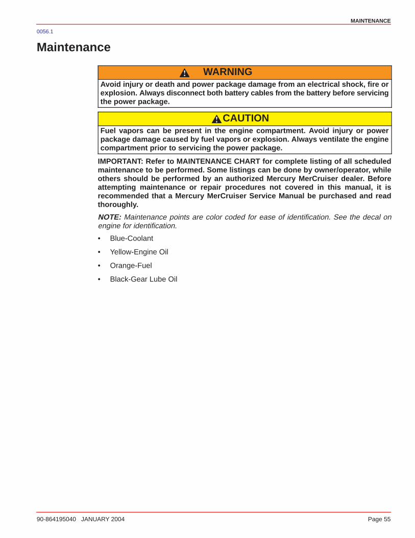
MAINTENANCE
90-864195040 JANUARY 2004 Page 55
0056.1
Maintenance
WARNINGAvoid injury or death and power package damage from an electrical shock, fire orexplosion. Al ways disconnect both battery cables from the battery before servicingthe power package.
CAUTIONFuel vapors can be present in the engine compartment. Avoid injury or powerpackage damage caused by fuel vapors or explosion. Always ventilate the enginecompartment prior to servicing the power package.
IMPORTANT: Refer to MAINTENANCE CHART for complete listing of all scheduledmaintenance to be performed. Some listings can be done by owner/operator, whileothers should be performed by an authorized Mercury MerCruiser dealer. Beforeattempting maintenance or repair procedures not covered in this manual, it isrecommended that a Mercury MerCruiser Service Manual be purchased and readthoroughly.
NOTE: Maintenance points are color coded for ease of identification. See the decal onengine for identification.
• Blue-Coolant
• Yellow-Engine Oil
• Orange-Fuel
• Black-Gear Lube Oil
MAINTENANCE
Page 56 90-864195040 JANUARY 2004
0057
Do-It-Yourself Maintenance SuggestionsPresent-day marine equipment, such as your Mercury MerCruiser power package, arehighly technical pieces of machinery. Electronic ignition and special fuel delivery systemsprovide greater fuel economies, but also are more complex for the untrained mechanic.
If you are one of those persons who likes to do-it-yourself, here are some suggestions foryou.
• Do NOT attempt any repairs unless you are aware of the Cautions, Warnings and proce-dures required. Your safety is our concern.
• If you attempt to service the product yourself, we suggest you order the service manualfor that model. The service manual outlines the correct procedures to follow. It is writtenfor the trained mechanic, so there may be procedures you don’t understand. Do NOTattempt repairs if you do not understand the procedures.
• There are special tools and equipment that are required to perform some repairs. DoNOT attempt these repairs unless you have these special tools and/or equipment. Youcan cause damage to the product in excess of the cost a dealer would charge you.
• Also, if you partially disassemble an engine or drive assembly and are unable to repair it,the dealer’s mechanic must reassemble the components and test to determine theproblem. This will cost you more than taking it to the dealer immediately upon having aproblem. It may be a very simple adjustment to correct the problem.
• Do NOT telephone the dealer, service office or the factory to attempt for them todiagnose a problem or to request the repair procedure. It is difficult for them to diagnosea problem over the telephone.
Your authorized dealer is there to service your power package. They have qualifiedfactory-trained mechanics.
It is recommended you have the dealer do periodic maintenance checks on your powerpackage. Have them winterize it in the fall and service it before the boating season. This willreduce the possibility of any problems occurring during your boating season when you wanttrouble-free boating pleasure.
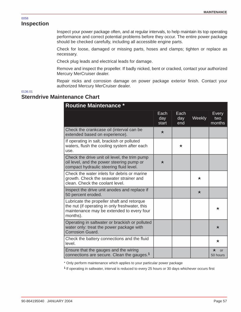
MAINTENANCE
90-864195040 JANUARY 2004 Page 57
0058
InspectionInspect your power package often, and at regular intervals, to help maintain its top operatingperformance and correct potential problems before they occur. The entire power packageshould be checked carefully, including all accessible engine parts.
Check for loose, damaged or missing parts, hoses and clamps; tighten or replace asnecessary.
Check plug leads and electrical leads for damage.
Remove and inspect the propeller. If badly nicked, bent or cracked, contact your authorizedMercury MerCruiser dealer.
Repair nicks and corrosion damage on power package exterior finish. Contact yourauthorized Mercury MerCruiser dealer.
0136.01
Sterndrive Maintenance Chart
Routine Maintenance *Eachdaystart
Eachdayend
WeeklyEverytwo
months
Check the crankcase oil (interval can beextended based on experience).
�
If operating in salt, brackish or pollutedwaters, flush the cooling system after eachuse.
�
Check the drive unit oil level, the trim pumpoil level, and the power steering pump orcompact hydraulic steering fluid level.
�
Check the water inlets for debris or marinegrowth. Check the seawater strainer andclean. Check the coolant level.
�
Inspect the drive unit anodes and replace if50 percent eroded.
�
Lubricate the propeller shaft and retorquethe nut (if operating in only freshwater, thismaintenance may be extended to every fourmonths).
�
Operating in saltwater or brackish or pollutedwater only: treat the power package withCorrosion Guard.
�
Check the battery connections and the fluidlevel.
�
Ensure that the gauges and the wiringconnections are secure. Clean the gauges.1
� or50 hours
* Only perform maintenance which applies to your particular power package1 If operating in saltwater, interval is reduced to every 25 hours or 30 days whichever occurs first
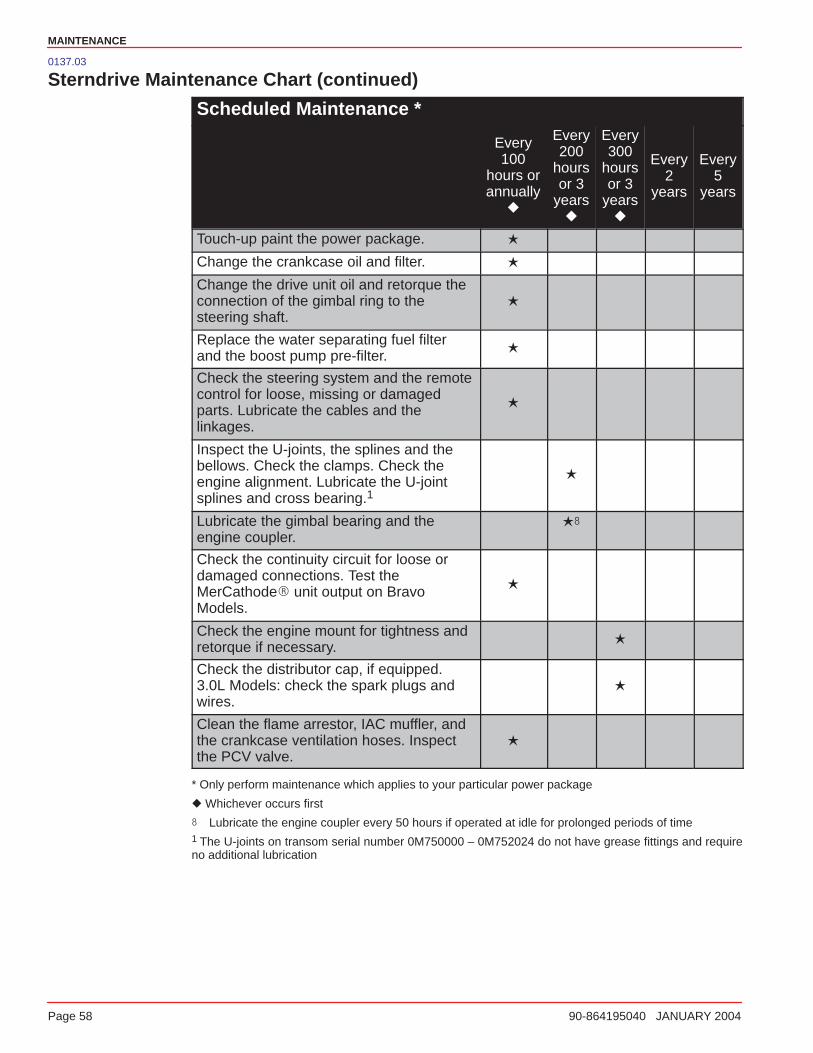
MAINTENANCE
Page 58 90-864195040 JANUARY 2004
0137.03
Sterndrive Maintenance Chart (continued)
Scheduled Maintenance *
Every100
hours orannually
�
Every200
hoursor 3
years�
Every300
hoursor 3
years�
Every2
years
Every5
years
Touch-up paint the power package. �
Change the crankcase oil and filter. �
Change the drive unit oil and retorque theconnection of the gimbal ring to thesteering shaft.
�
Replace the water separating fuel filterand the boost pump pre-filter.
�
Check the steering system and the remotecontrol for loose, missing or damagedparts. Lubricate the cables and thelinkages.
�
Inspect the U-joints, the splines and thebellows. Check the clamps. Check theengine alignment. Lubricate the U-jointsplines and cross bearing.1
�
Lubricate the gimbal bearing and theengine coupler.
��
Check the continuity circuit for loose ordamaged connections. Test theMerCathode� unit output on BravoModels.
�
Check the engine mount for tightness andretorque if necessary.
�
Check the distributor cap, if equipped.3.0L Models: check the spark plugs andwires.
�
Clean the flame arrestor, IAC muffler, andthe crankcase ventilation hoses. Inspectthe PCV valve.
�
* Only perform maintenance which applies to your particular power package
� Whichever occurs first
� Lubricate the engine coupler every 50 hours if operated at idle for prolonged periods of time1 The U-joints on transom serial number 0M750000 – 0M752024 do not have grease fittings and requireno additional lubrication
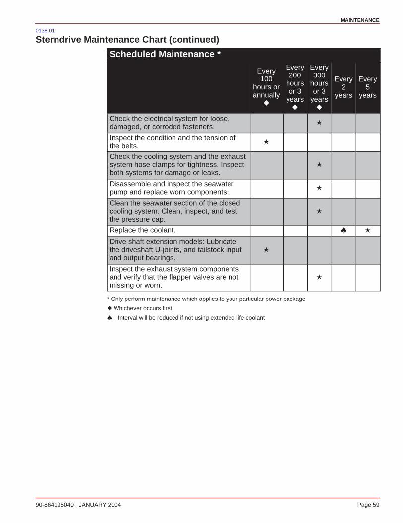
MAINTENANCE
90-864195040 JANUARY 2004 Page 59
0138.01
Sterndrive Maintenance Chart (continued)
Scheduled Maintenance *
Every100
hours orannually
�
Every200
hoursor 3
years�
Every300
hoursor 3
years�
Every2
years
Every5
years
Check the electrical system for loose,damaged, or corroded fasteners.
�
Inspect the condition and the tension ofthe belts.
�
Check the cooling system and the exhaustsystem hose clamps for tightness. Inspectboth systems for damage or leaks.
�
Disassemble and inspect the seawaterpump and replace worn components.
�
Clean the seawater section of the closedcooling system. Clean, inspect, and testthe pressure cap.
�
Replace the coolant. � �
Drive shaft extension models: Lubricatethe driveshaft U-joints, and tailstock inputand output bearings.
�
Inspect the exhaust system componentsand verify that the flapper valves are notmissing or worn.
�
* Only perform maintenance which applies to your particular power package
� Whichever occurs first
� Interval will be reduced if not using extended life coolant
MAINTENANCE
Page 60 90-864195040 JANUARY 2004
0166
Maintenance Record
Date Hour MeterReading Serviced By Maintenance
Performed
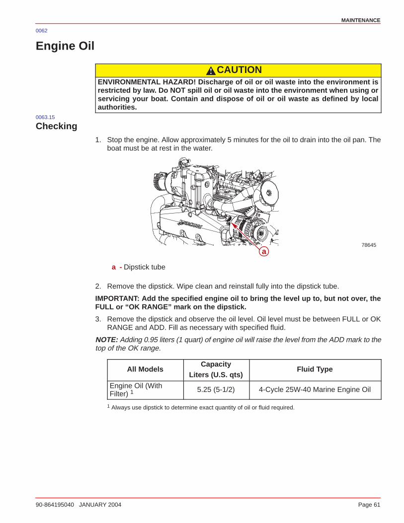
MAINTENANCE
90-864195040 JANUARY 2004 Page 61
0062
Engine Oil
CAUTIONENVIRONMENTAL HAZARD! Discharge of oil or oil waste into the environment isrestricted by law. Do NOT spill oil or oil waste into the environment when using orservicing your boat. Contain and dispose of oil or oil waste as defined by localauthorities.
0063.15
Checking1. Stop the engine. Allow approximately 5 minutes for the oil to drain into the oil pan. The
boat must be at rest in the water.
78645a
a - Dipstick tube
2. Remove the dipstick. Wipe clean and reinstall fully into the dipstick tube.
IMPORTANT: Add the specified engine oil to bring the level up to, but not over, theFULL or “OK RANGE” mark on the dipstick.
3. Remove the dipstick and observe the oil level. Oil level must be between FULL or OKRANGE and ADD. Fill as necessary with specified fluid.
NOTE: Adding 0.95 liters (1 quart) of engine oil will raise the level from the ADD mark to thetop of the OK range.
All ModelsCapacity
Liters (U.S. qts)Fluid Type
Engine Oil (WithFilter) 1
5.25 (5-1/2) 4-Cycle 25W-40 Marine Engine Oil
1 Always use dipstick to determine exact quantity of oil or fluid required.
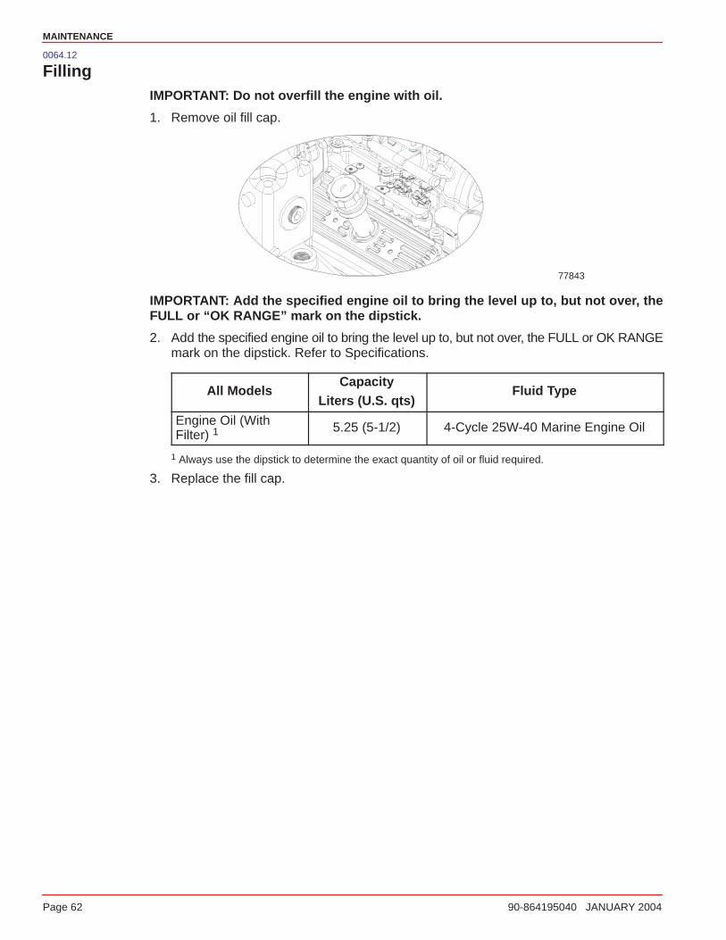
MAINTENANCE
Page 62 90-864195040 JANUARY 2004
0064.12
FillingIMPORTANT: Do not overfill the engine with oil.
1. Remove oil fill cap.
77843
IMPORTANT: Add the specified engine oil to bring the level up to, but not over, theFULL or “OK RANGE” mark on the dipstick.
2. Add the specified engine oil to bring the level up to, but not over, the FULL or OK RANGEmark on the dipstick. Refer to Specifications.
All ModelsCapacity
Liters (U.S. qts)Fluid Type
Engine Oil (WithFilter) 1
5.25 (5-1/2) 4-Cycle 25W-40 Marine Engine Oil
1 Always use the dipstick to determine the exact quantity of oil or fluid required.
3. Replace the fill cap.
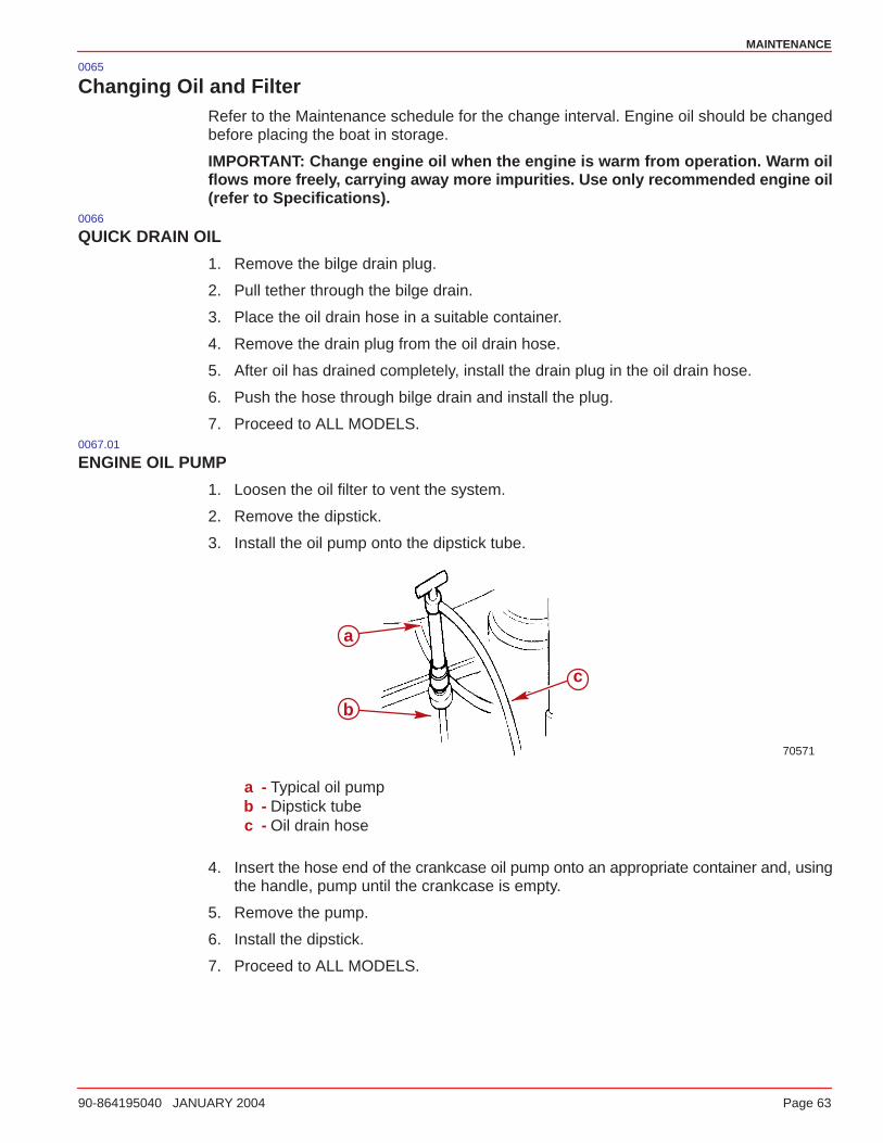
MAINTENANCE
90-864195040 JANUARY 2004 Page 63
0065
Changing Oil and FilterRefer to the Maintenance schedule for the change interval. Engine oil should be changedbefore placing the boat in storage.
IMPORTANT: Change engine oil when the engine is warm from operation. Warm oilflows more freely, carrying away more impurities. Use only recommended engine oil(refer to Specifications).
0066
QUICK DRAIN OIL
1. Remove the bilge drain plug.
2. Pull tether through the bilge drain.
3. Place the oil drain hose in a suitable container.
4. Remove the drain plug from the oil drain hose.
5. After oil has drained completely, install the drain plug in the oil drain hose.
6. Push the hose through bilge drain and install the plug.
7. Proceed to ALL MODELS.0067.01
ENGINE OIL PUMP
1. Loosen the oil filter to vent the system.
2. Remove the dipstick.
3. Install the oil pump onto the dipstick tube.
70571
a
b
c
a - Typical oil pumpb - Dipstick tubec - Oil drain hose
4. Insert the hose end of the crankcase oil pump onto an appropriate container and, usingthe handle, pump until the crankcase is empty.
5. Remove the pump.
6. Install the dipstick.
7. Proceed to ALL MODELS.
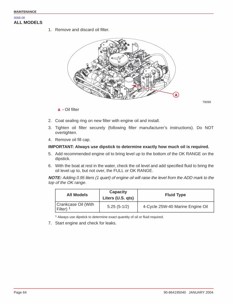
MAINTENANCE
Page 64 90-864195040 JANUARY 2004
0068.08
ALL MODELS
1. Remove and discard oil filter.
79099
a
a - Oil filter
2. Coat sealing ring on new filter with engine oil and install.
3. Tighten oil filter securely (following filter manufacturer’s instructions). Do NOTovertighten.
4. Remove oil fill cap.
IMPORTANT: Always use dipstick to determine exactly how much oil is required.
5. Add recommended engine oil to bring level up to the bottom of the OK RANGE on thedipstick.
6. With the boat at rest in the water, check the oil level and add specified fluid to bring theoil level up to, but not over, the FULL or OK RANGE.
NOTE: Adding 0.95 liters (1 quart) of engine oil will raise the level from the ADD mark to thetop of the OK range.
All ModelsCapacity
Liters (U.S. qts)Fluid Type
Crankcase Oil (WithFilter) 1
5.25 (5-1/2) 4-Cycle 25W-40 Marine Engine Oil
1 Always use dipstick to determine exact quantity of oil or fluid required.
7. Start engine and check for leaks.

MAINTENANCE
90-864195040 JANUARY 2004 Page 65
0139.2
Power Steering Pump Fluid
Checking1. Stop the engine and center the sterndrive unit.
2. Remove the fillcap/dipstick and observe the level.
a. Proper fluid level with engine at normal operating temperature should be betweenthe full HOT and ADD marks.
b. Proper fluid level with engine cold should be between the full COLD mark and theend of the dipstick.
a
70546
b
c
78642
a - Power steering pumpb - Cold rangec - Warm range
3. Fill to FULL line with specified fluid.
IMPORTANT: If fluid is not visible in pump, contact your authorized MercuryMerCruiser dealer.
0140
Filling1. Remove the fill cap/dipstick and observe the level.
2. Add Quicksilver Power Trim and Steering Fluid or Dexron III Automatic TransmissionFluid (ATF) to bring the fluid level up to the proper level.
3. Reinstall the fill cap/dipstick.0141
ChangingPower Steering fluid does not require changing.
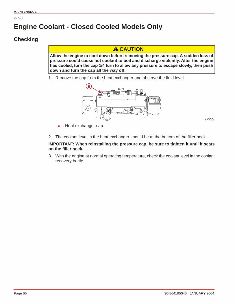
MAINTENANCE
Page 66 90-864195040 JANUARY 2004
0071.2
Engine Coolant - Closed Cooled Models Only
Checking
CAUTIONAllow the engine to cool down before removing the pressure cap. A sudden loss ofpressure could cause hot coolant to boil and discharge violently. After the enginehas cooled, turn the cap 1/4 turn to allow any pressure to escape slowly, then pushdown and turn the cap all the way off.
1. Remove the cap from the heat exchanger and observe the fluid level.
a
77955
a - Heat exchanger cap
2. The coolant level in the heat exchanger should be at the bottom of the filler neck.
IMPORTANT: When reinstalling the pressure cap, be sure to tighten it until it seatson the filler neck.
3. With the engine at normal operating temperature, check the coolant level in the coolantrecovery bottle.
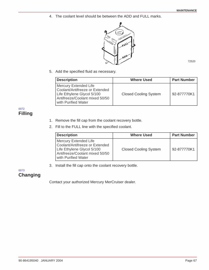
MAINTENANCE
90-864195040 JANUARY 2004 Page 67
4. The coolant level should be between the ADD and FULL marks.
72520
5. Add the specified fluid as necessary.
Description Where Used Part Number
Mercury Extended LifeCoolant/Antifreeze or ExtendedLife Ethylene Glycol 5/100Antifreeze/Coolant mixed 50/50with Purified Water
Closed Cooling System 92-877770K1
0072
Filling1. Remove the fill cap from the coolant recovery bottle.
2. Fill to the FULL line with the specified coolant.
Description Where Used Part Number
Mercury Extended LifeCoolant/Antifreeze or ExtendedLife Ethylene Glycol 5/100Antifreeze/Coolant mixed 50/50with Purified Water
Closed Cooling System 92-877770K1
3. Install the fill cap onto the coolant recovery bottle.0073
ChangingContact your authorized Mercury MerCruiser dealer.
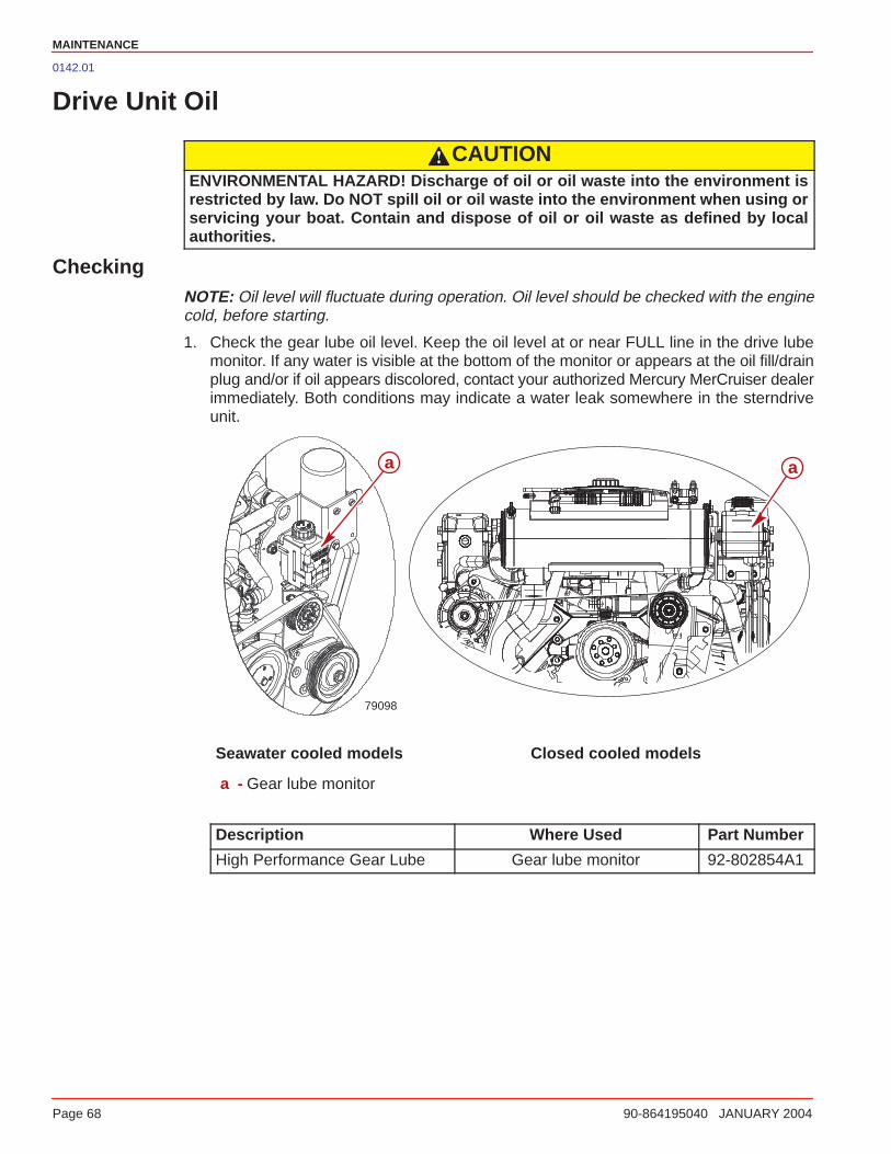
MAINTENANCE
Page 68 90-864195040 JANUARY 2004
0142.01
Drive Unit Oil
CAUTIONENVIRONMENTAL HAZARD! Discharge of oil or oil waste into the environment isrestricted by law. Do NOT spill oil or oil waste into the environment when using orservicing your boat. Contain and dispose of oil or oil waste as defined by localauthorities.
CheckingNOTE: Oil level will fluctuate during operation. Oil level should be checked with the enginecold, before starting.
1. Check the gear lube oil level. Keep the oil level at or near FULL line in the drive lubemonitor. If any water is visible at the bottom of the monitor or appears at the oil fill/drainplug and/or if oil appears discolored, contact your authorized Mercury MerCruiser dealerimmediately. Both conditions may indicate a water leak somewhere in the sterndriveunit.
79098
a a
Seawater cooled models Closed cooled models
a - Gear lube monitor
Description Where Used Part Number
High Performance Gear Lube Gear lube monitor 92-802854A1
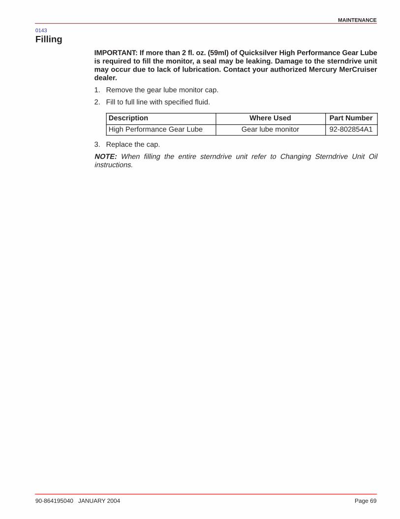
MAINTENANCE
90-864195040 JANUARY 2004 Page 69
0143
FillingIMPORTANT: If more than 2 fl. oz. (59ml) of Quicksilver High Performance Gear Lubeis required to fill the monitor, a seal may be leaking. Damage to the sterndrive unitmay occur due to lack of lubrication. Contact your authorized Mercury MerCruiserdealer.
1. Remove the gear lube monitor cap.
2. Fill to full line with specified fluid.
Description Where Used Part Number
High Performance Gear Lube Gear lube monitor 92-802854A1
3. Replace the cap.
NOTE: When filling the entire sterndrive unit refer to Changing Sterndrive Unit Oilinstructions.
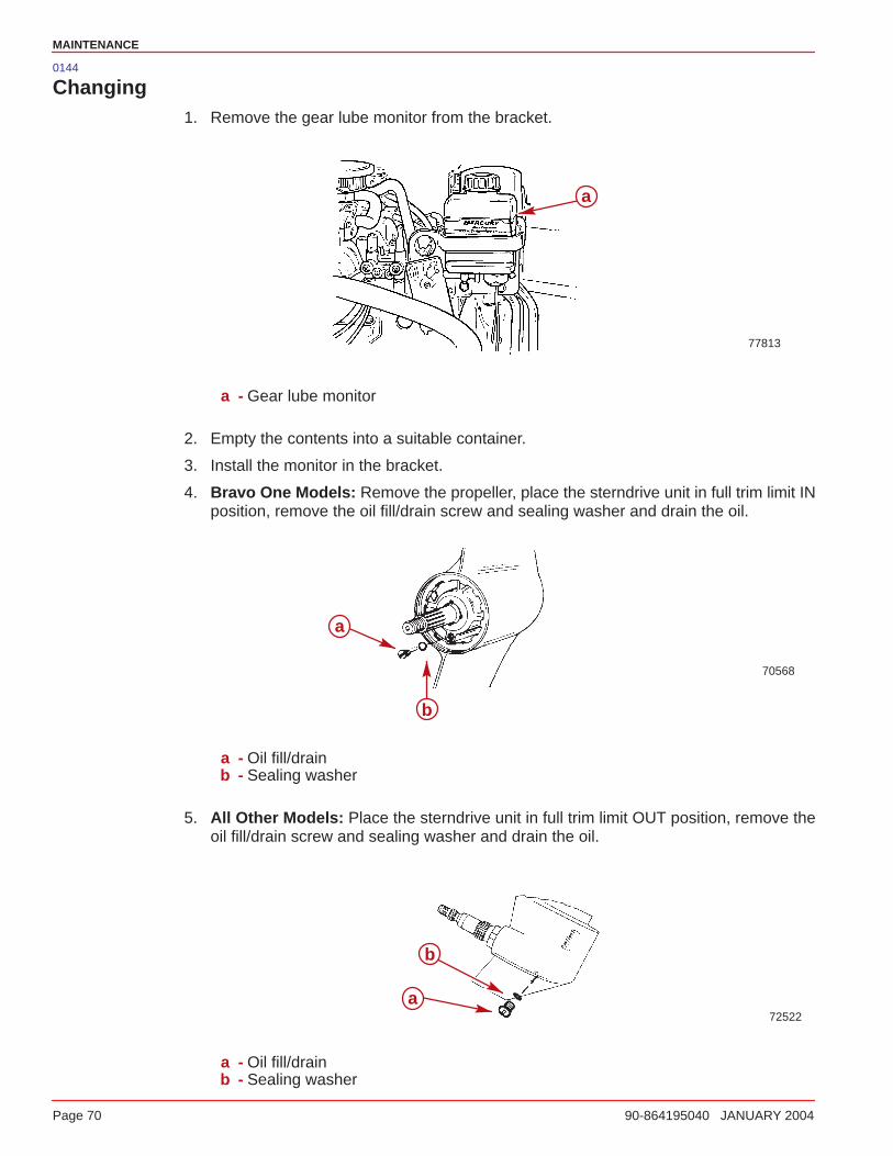
MAINTENANCE
Page 70 90-864195040 JANUARY 2004
0144
Changing1. Remove the gear lube monitor from the bracket.
a
77813
a - Gear lube monitor
2. Empty the contents into a suitable container.
3. Install the monitor in the bracket.
4. Bravo One Models: Remove the propeller, place the sterndrive unit in full trim limit INposition, remove the oil fill/drain screw and sealing washer and drain the oil.
70568
a
b
a - Oil fill/drainb - Sealing washer
5. All Other Models: Place the sterndrive unit in full trim limit OUT position, remove theoil fill/drain screw and sealing washer and drain the oil.
72522a
b
a - Oil fill/drainb - Sealing washer
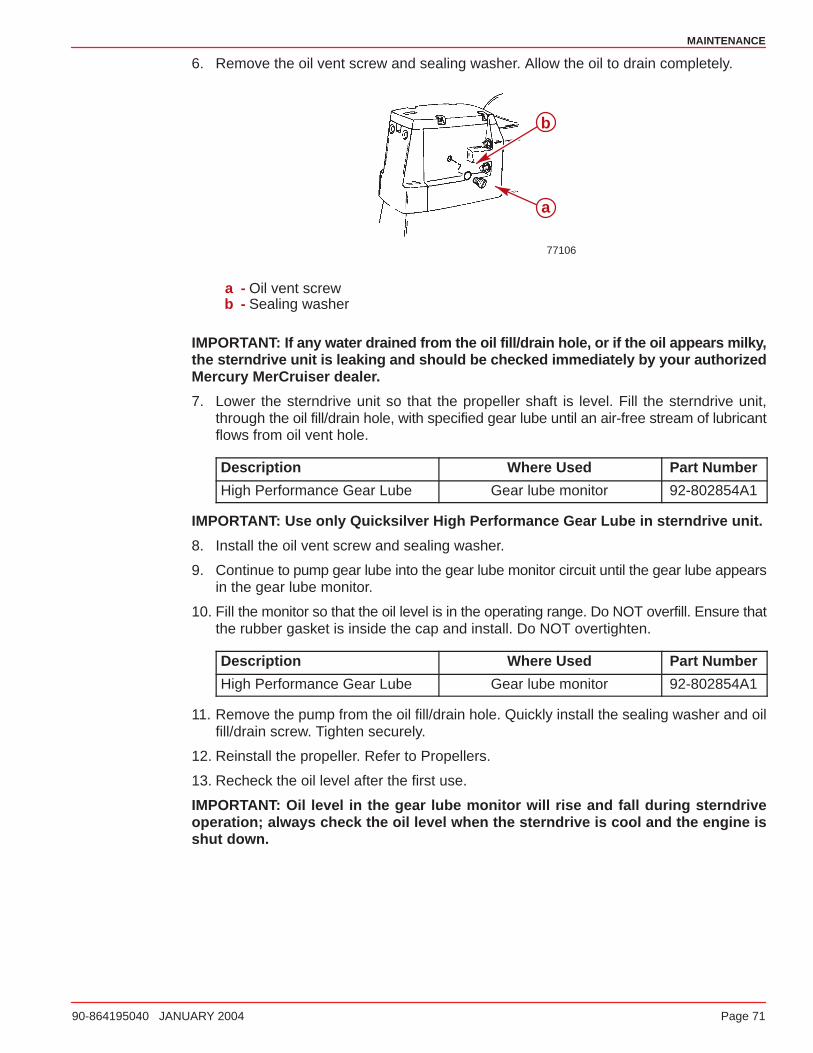
MAINTENANCE
90-864195040 JANUARY 2004 Page 71
6. Remove the oil vent screw and sealing washer. Allow the oil to drain completely.
77106
a
b
a - Oil vent screwb - Sealing washer
IMPORTANT: If any water drained from the oil fill/drain hole, or if the oil appears milky,the sterndrive unit is leaking and should be checked immediately by your authorizedMercury MerCruiser dealer.
7. Lower the sterndrive unit so that the propeller shaft is level. Fill the sterndrive unit,through the oil fill/drain hole, with specified gear lube until an air-free stream of lubricantflows from oil vent hole.
Description Where Used Part Number
High Performance Gear Lube Gear lube monitor 92-802854A1
IMPORTANT: Use only Quicksilver High Performance Gear Lube in sterndrive unit.
8. Install the oil vent screw and sealing washer.
9. Continue to pump gear lube into the gear lube monitor circuit until the gear lube appearsin the gear lube monitor.
10. Fill the monitor so that the oil level is in the operating range. Do NOT overfill. Ensure thatthe rubber gasket is inside the cap and install. Do NOT overtighten.
Description Where Used Part Number
High Performance Gear Lube Gear lube monitor 92-802854A1
11. Remove the pump from the oil fill/drain hole. Quickly install the sealing washer and oilfill/drain screw. Tighten securely.
12. Reinstall the propeller. Refer to Propellers.
13. Recheck the oil level after the first use.
IMPORTANT: Oil level in the gear lube monitor will rise and fall during sterndriveoperation; always check the oil level when the sterndrive is cool and the engine isshut down.
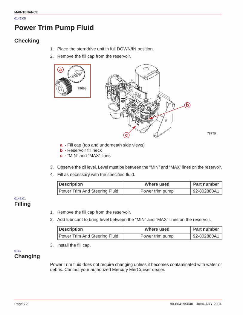
MAINTENANCE
Page 72 90-864195040 JANUARY 2004
0145.05
Power Trim Pump Fluid
Checking1. Place the sterndrive unit in full DOWN/IN position.
2. Remove the fill cap from the reservoir.
79779
a
79699
c
b
a - Fill cap (top and underneath side views)b - Reservoir fill neckc - “MIN” and “MAX” lines
3. Observe the oil level. Level must be between the “MIN” and “MAX” lines on the reservoir.
4. Fill as necessary with the specified fluid.
Description Where used Part number
Power Trim And Steering Fluid Power trim pump 92-802880A1
0146.01
Filling1. Remove the fill cap from the reservoir.
2. Add lubricant to bring level between the “MIN” and “MAX” lines on the reservoir.
Description Where used Part number
Power Trim And Steering Fluid Power trim pump 92-802880A1
3. Install the fill cap.0147
ChangingPower Trim fluid does not require changing unless it becomes contaminated with water ordebris. Contact your authorized Mercury MerCruiser dealer.
MAINTENANCE
90-864195040 JANUARY 2004 Page 73
0076
Battery
Refer to specific instructions and warnings accompanying your battery. If this informationis not available, observe the following precautions when handling a battery.
WARNINGAvoid serious injury from fire or explosion. Do NOT use jumper cables and abooster battery to start engine. Do NOT recharge a weak battery in the boat. Removebattery and recharge in a ventilated area away from fuel vapors, sparks or flames.
WARNINGBatteries contain acid which can cause severe burns. Avoid contact with skin, eyesand clothing. If electrolyte is spilled or splashed on any part of the body,immediately flush the exposed area with liberal amounts of water and obtainmedical aid as soon as possible.
Safety glasses and rubber gloves are recommended when handling batteries orfilling with electrolyte.
0077
Multiple EFI Engine Battery PrecautionsAlternators: Alternators are designed to charge the battery that supplies electrical powerto the engine that the alternator is mounted on. When batteries for 2 different engines areconnected, 1 alternator will supply all of the charging current for both batteries. Normally,the other engine’s alternator will not be required to supply any charging current.
EFI Electronic Control Module (ECM): The ECM requires a stable voltage source. Duringmultiple engine operation, an onboard electrical device may cause a sudden drain of voltageat the engine’s battery. The voltage may go below the ECM’s minimum required voltage.Also, the alternator on the other engine may now start charging. This could cause a voltagespike in the engine’s electrical system.
In either case, the ECM could shut off. When the voltage returns to the range that the ECMrequires, the ECM will reset itself. The engine will now operate normally. This ECM shutdown usually happens so fast that the engine just appears to have an ignition miss.
Batteries: Boats with multi-engine EFI power packages require each engine be connectedto its own battery. This ensures that the engine’s Electronic Control Module (ECM) has astable voltage source.
Battery Switches: Battery switches should always be positioned so each engine isoperating off of its own battery. Do NOT operate engines with switches in BOTH or ALLposition. In an emergency, another engine’s battery can be used to start an engine with adead battery.
Battery Isolators: Isolators can be used to charge an auxiliary battery used for poweringaccessories in the boat. They should not be used to charge the battery of another enginein the boat unless the type of isolator is specifically designed for this purpose.
Generators: The generator’s battery should be considered another engine’s battery.
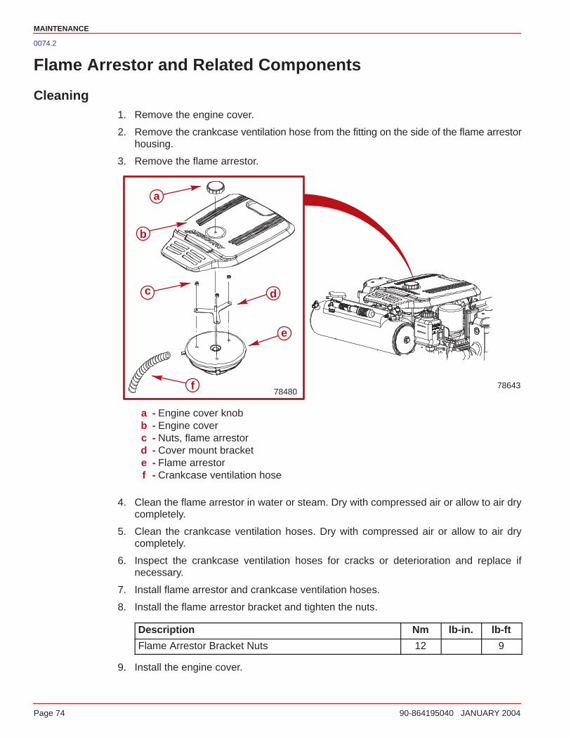
MAINTENANCE
Page 74 90-864195040 JANUARY 2004
0074.2
Flame Arrestor and Related Components
Cleaning1. Remove the engine cover.
2. Remove the crankcase ventilation hose from the fitting on the side of the flame arrestorhousing.
3. Remove the flame arrestor.
78643
a
b
c d
e
f78480
a - Engine cover knobb - Engine coverc - Nuts, flame arrestord - Cover mount brackete - Flame arrestorf - Crankcase ventilation hose
4. Clean the flame arrestor in water or steam. Dry with compressed air or allow to air drycompletely.
5. Clean the crankcase ventilation hoses. Dry with compressed air or allow to air drycompletely.
6. Inspect the crankcase ventilation hoses for cracks or deterioration and replace ifnecessary.
7. Install flame arrestor and crankcase ventilation hoses.
8. Install the flame arrestor bracket and tighten the nuts.
Description Nm lb-in. lb-ft
Flame Arrestor Bracket Nuts 12 9
9. Install the engine cover.
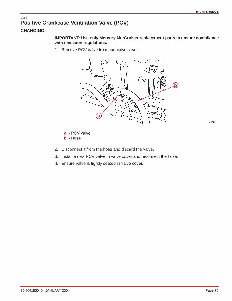
MAINTENANCE
90-864195040 JANUARY 2004 Page 75
0167
Positive Crankcase Ventilation Valve (PCV)CHANGING
IMPORTANT: Use only Mercury MerCruiser replacement parts to ensure compliancewith emission regulations.
1. Remove PCV valve from port valve cover.
71925
a
b
a - PCV valveb - Hose
2. Disconnect it from the hose and discard the valve.
3. Install a new PCV valve in valve cover and reconnect the hose.
4. Ensure valve is tightly seated in valve cover.

MAINTENANCE
Page 76 90-864195040 JANUARY 2004
0075.2
Water Separating Fuel Filter
Changing
WARNINGAvoid Fire or Explosion: The fuel injection system is pressurized during operation.Use care when removing the water separating fuel filter. Fuel could spray on the hotengine causing fire or explosion. Allow the engine to cool down before attemptingto remove the water separating fuel filter in the following procedure. Also, hold aclean shop towel over the water separating fuel filter when removing it, to help avoidfuel spraying on the engine.
WARNINGBe careful when changing the water separating fuel filter. Gasoline is extremelyflammable and highly explosive under certain conditions. Ensure the ignition keyis OFF. Do NOT smoke or allow spark or open flame in the area when changing thefuel filter. Wipe up any spilled fuel immediately.
WARNINGEnsure that no fuel leaks exist before closing the engine hatch.
1. Allow the engine to cool down.
NOTE: Mercury MerCruiser recommends that the engine be shut off for 12 hours prior tofilter removal.
2. Wrap the water separating fuel filter with a cloth to help catch any fuel spills or spray.
3. Remove and discard the water separating fuel filter and sealing ring from the mountingbracket.
4. Coat the sealing ring on the new filter with engine oil.
Description Where Used Part Number
Engine Oil Filter sealing ring Obtain Locally
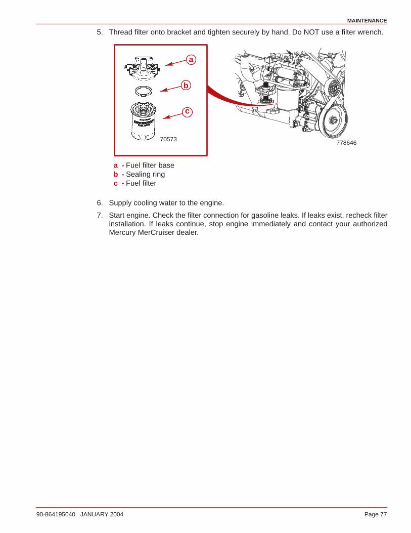
MAINTENANCE
90-864195040 JANUARY 2004 Page 77
5. Thread filter onto bracket and tighten securely by hand. Do NOT use a filter wrench.
77864670573
a
b
c
a - Fuel filter baseb - Sealing ringc - Fuel filter
6. Supply cooling water to the engine.
7. Start engine. Check the filter connection for gasoline leaks. If leaks exist, recheck filterinstallation. If leaks continue, stop engine immediately and contact your authorizedMercury MerCruiser dealer.
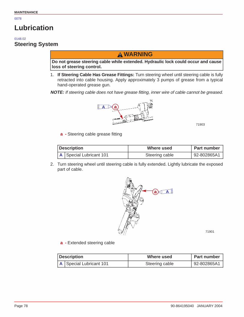
MAINTENANCE
Page 78 90-864195040 JANUARY 2004
0078
Lubrication0148.02
Steering System
WARNINGDo not grease steering cable while extended. Hydraulic lock could occur and causeloss of steering control.
1. If Steering Cable Has Grease Fittings: Turn steering wheel until steering cable is fullyretracted into cable housing. Apply approximately 3 pumps of grease from a typicalhand-operated grease gun.
NOTE: If steering cable does not have grease fitting, inner wire of cable cannot be greased.
71903
aA
a - Steering cable grease fitting
Description Where used Part number
A Special Lubricant 101 Steering cable 92-802865A1
2. Turn steering wheel until steering cable is fully extended. Lightly lubricate the exposedpart of cable.
71901
a A
a - Extended steering cable
Description Where used Part number
A Special Lubricant 101 Steering cable 92-802865A1
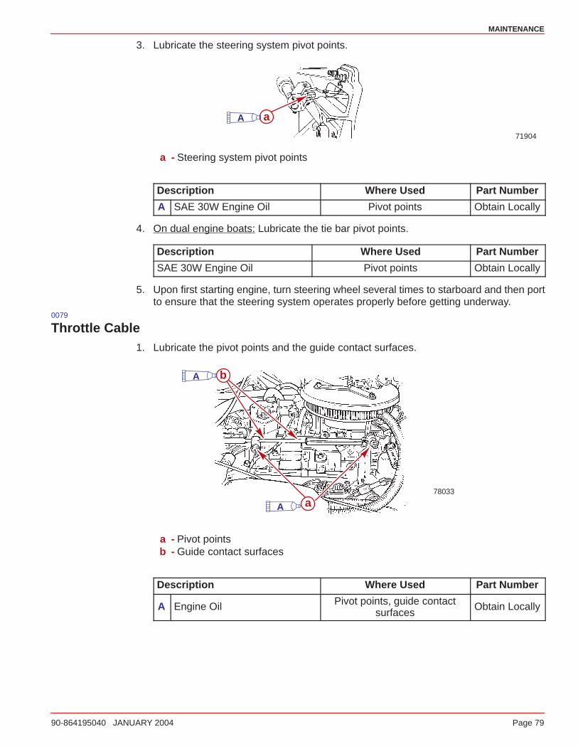
MAINTENANCE
90-864195040 JANUARY 2004 Page 79
3. Lubricate the steering system pivot points.
71904
aA
a - Steering system pivot points
Description Where Used Part Number
A SAE 30W Engine Oil Pivot points Obtain Locally
4. On dual engine boats: Lubricate the tie bar pivot points.
Description Where Used Part Number
SAE 30W Engine Oil Pivot points Obtain Locally
5. Upon first starting engine, turn steering wheel several times to starboard and then portto ensure that the steering system operates properly before getting underway.
0079
Throttle Cable1. Lubricate the pivot points and the guide contact surfaces.
a
b
78033
A
A
a - Pivot pointsb - Guide contact surfaces
Description Where Used Part Number
A Engine Oil Pivot points, guide contactsurfaces
Obtain Locally
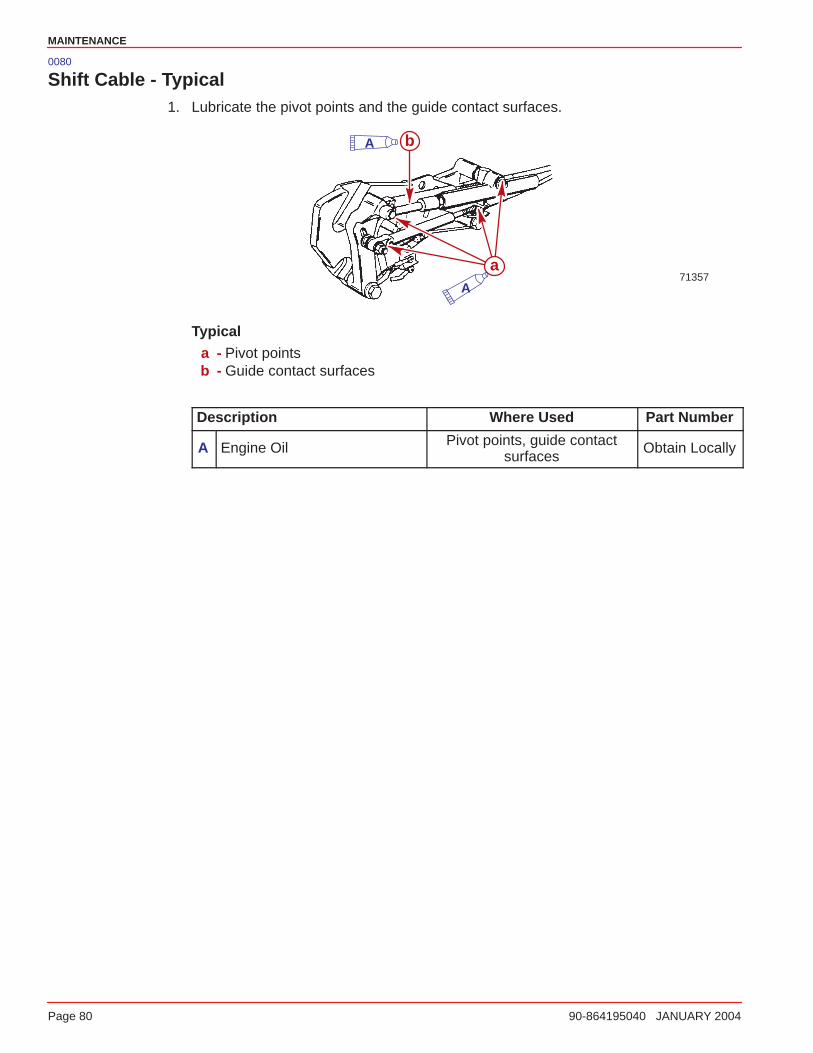
MAINTENANCE
Page 80 90-864195040 JANUARY 2004
0080
Shift Cable - Typical1. Lubricate the pivot points and the guide contact surfaces.
b
71357a
A
A
Typicala - Pivot pointsb - Guide contact surfaces
Description Where Used Part Number
A Engine Oil Pivot points, guide contactsurfaces
Obtain Locally
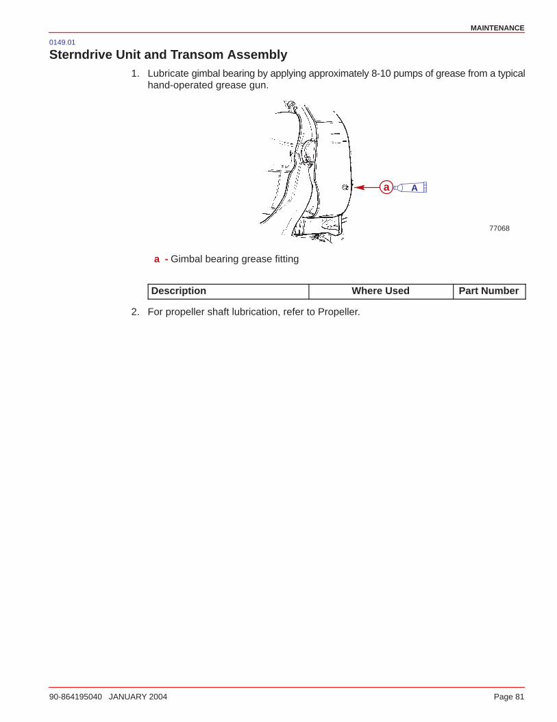
MAINTENANCE
90-864195040 JANUARY 2004 Page 81
0149.01
Sterndrive Unit and Transom Assembly1. Lubricate gimbal bearing by applying approximately 8-10 pumps of grease from a typical
hand-operated grease gun.
77068
a A
a - Gimbal bearing grease fitting
Description Where Used Part Number
2. For propeller shaft lubrication, refer to Propeller.
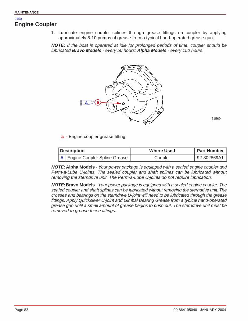
MAINTENANCE
Page 82 90-864195040 JANUARY 2004
0150
Engine Coupler1. Lubricate engine coupler splines through grease fittings on coupler by applying
approximately 8-10 pumps of grease from a typical hand-operated grease gun.
NOTE: If the boat is operated at idle for prolonged periods of time, coupler should belubricated Bravo Models - every 50 hours; Alpha Models - every 150 hours.
71569
aA
a - Engine coupler grease fitting
Description Where Used Part Number
A Engine Coupler Spline Grease Coupler 92-802869A1
NOTE: Alpha Models - Your power package is equipped with a sealed engine coupler andPerm-a-Lube U-joints. The sealed coupler and shaft splines can be lubricated withoutremoving the sterndrive unit. The Perm-a-Lube U-joints do not require lubrication.
NOTE: Bravo Models - Your power package is equipped with a sealed engine coupler. Thesealed coupler and shaft splines can be lubricated without removing the sterndrive unit. Thecrosses and bearings on the sterndrive U-joint will need to be lubricated through the greasefittings. Apply Quicksilver U-joint and Gimbal Bearing Grease from a typical hand-operatedgrease gun until a small amount of grease begins to push out. The sterndrive unit must beremoved to grease these fittings.
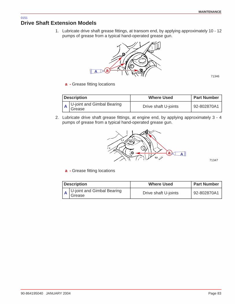
MAINTENANCE
90-864195040 JANUARY 2004 Page 83
0151
Drive Shaft Extension Models1. Lubricate drive shaft grease fittings, at transom end, by applying approximately 10 - 12
pumps of grease from a typical hand-operated grease gun.
71346
aA
a - Grease fitting locations
Description Where Used Part Number
A U-joint and Gimbal BearingGrease
Drive shaft U-joints 92-802870A1
2. Lubricate drive shaft grease fittings, at engine end, by applying approximately 3 - 4pumps of grease from a typical hand-operated grease gun.
71347
a A
a - Grease fitting locations
Description Where Used Part Number
A U-joint and Gimbal BearingGrease
Drive shaft U-joints 92-802870A1
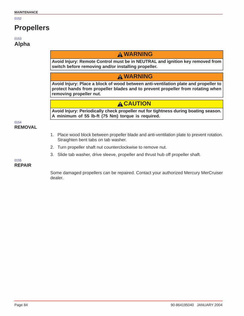
MAINTENANCE
Page 84 90-864195040 JANUARY 2004
0152
Propellers0153
Alpha
WARNINGAvoid Injury: Remote Control must be in NEUTRAL and ignition key removed fromswitch before removing and/or installing propeller.
WARNINGAvoid Injury: Place a block of wood between anti-ventilation plate and propeller toprotect hands from propeller blades and to prevent propeller from rotating whenremoving propeller nut.
CAUTIONAvoid Injury: Periodically check propeller nut for tightness during boating season.A minimum of 55 lb-ft (75 Nm) torque is required.
0154
REMOVAL
1. Place wood block between propeller blade and anti-ventilation plate to prevent rotation.Straighten bent tabs on tab washer.
2. Turn propeller shaft nut counterclockwise to remove nut.
3. Slide tab washer, drive sleeve, propeller and thrust hub off propeller shaft.0155
REPAIR
Some damaged propellers can be repaired. Contact your authorized Mercury MerCruiserdealer.
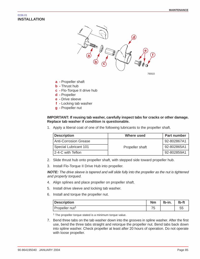
MAINTENANCE
90-864195040 JANUARY 2004 Page 85
0156.01
INSTALLATION
76910
a f
b c
d
e
a - Propeller shaftb - Thrust hubc - Flo-Torque II drive hubd - Propellere - Drive sleevef - Locking tab washerg - Propeller nut
IMPORTANT: If reusing tab washer, carefully inspect tabs for cracks or other damage.Replace tab washer if condition is questionable.
1. Apply a liberal coat of one of the following lubricants to the propeller shaft.
Description Where used Part number
Anti-Corrosion Grease 92-802867A1
Special Lubricant 101 Propeller shaft 92-802865A1
2-4-C with Teflon 92-802859A1
2. Slide thrust hub onto propeller shaft, with stepped side toward propeller hub.
3. Install Flo-Torque II Drive Hub into propeller.
NOTE: The drive sleeve is tapered and will slide fully into the propeller as the nut is tightenedand properly torqued.
4. Align splines and place propeller on propeller shaft.
5. Install drive sleeve and locking tab washer.
6. Install and torque the propeller nut.
Description Nm lb-in. lb-ft
Propeller nut1 75 55
1 The propeller torque stated is a minimum torque value.
7. Bend three tabs on the tab washer down into the grooves in spline washer. After the firstuse, bend the three tabs straight and retorque the propeller nut. Bend tabs back downinto spline washer. Check propeller at least after 20 hours of operation. Do not operatewith loose propeller.
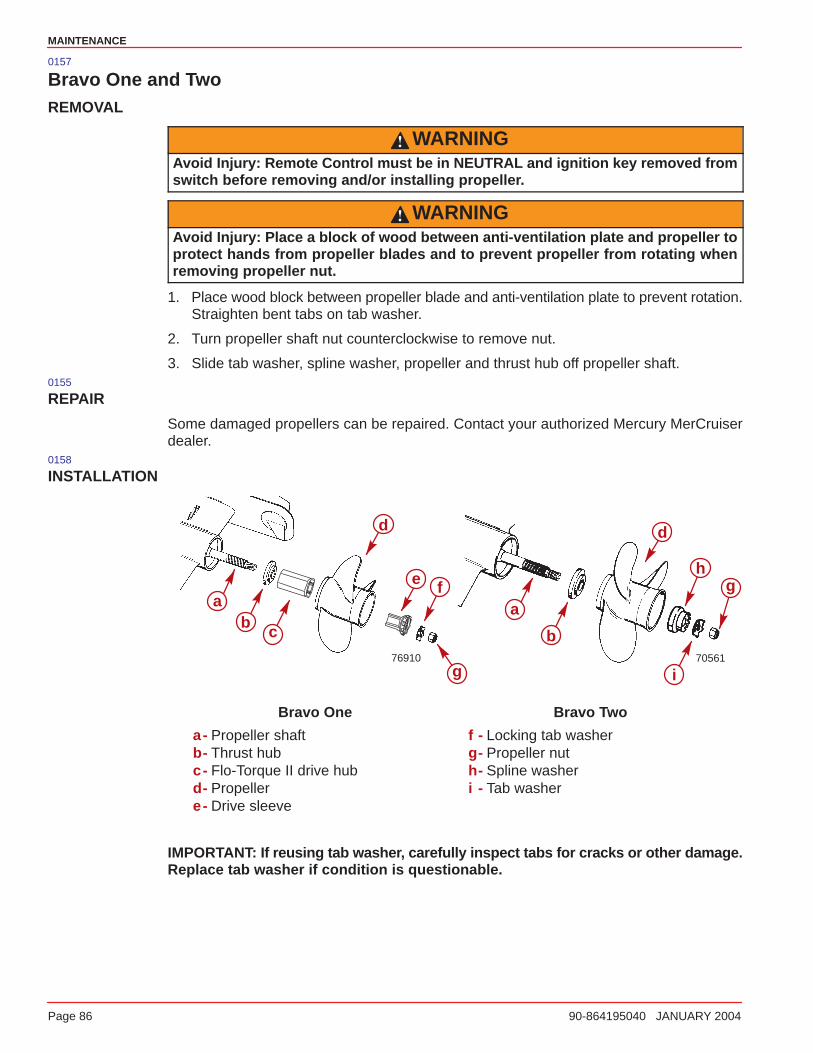
MAINTENANCE
Page 86 90-864195040 JANUARY 2004
0157
Bravo One and TwoREMOVAL
WARNINGAvoid Injury: Remote Control must be in NEUTRAL and ignition key removed fromswitch before removing and/or installing propeller.
WARNINGAvoid Injury: Place a block of wood between anti-ventilation plate and propeller toprotect hands from propeller blades and to prevent propeller from rotating whenremoving propeller nut.
1. Place wood block between propeller blade and anti-ventilation plate to prevent rotation.Straighten bent tabs on tab washer.
2. Turn propeller shaft nut counterclockwise to remove nut.
3. Slide tab washer, spline washer, propeller and thrust hub off propeller shaft.0155
REPAIR
Some damaged propellers can be repaired. Contact your authorized Mercury MerCruiserdealer.
0158
INSTALLATION
7056176910
a
d
bc
f
g
a
b
d
gh
i
e
Bravo One Bravo Two
a- Propeller shaftb- Thrust hubc- Flo-Torque II drive hubd- Propellere- Drive sleeve
f - Locking tab washerg- Propeller nuth- Spline washeri - Tab washer
IMPORTANT: If reusing tab washer, carefully inspect tabs for cracks or other damage.Replace tab washer if condition is questionable.
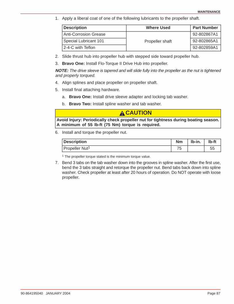
MAINTENANCE
90-864195040 JANUARY 2004 Page 87
1. Apply a liberal coat of one of the following lubricants to the propeller shaft.
Description Where Used Part Number
Anti-Corrosion Grease 92-802867A1
Special Lubricant 101 Propeller shaft 92-802865A1
2-4-C with Teflon 92-802859A1
2. Slide thrust hub into propeller hub with stepped side toward propeller hub.
3. Bravo One: Install Flo-Torque II Drive Hub into propeller.
NOTE: The drive sleeve is tapered and will slide fully into the propeller as the nut is tightenedand properly torqued.
4. Align splines and place propeller on propeller shaft.
5. Install final attaching hardware.
a. Bravo One: Install drive sleeve adapter and locking tab washer.
b. Bravo Two: Install spline washer and tab washer.
CAUTIONAvoid Injury: Periodically check propeller nut for tightness during boating season.A minimum of 55 lb-ft (75 Nm) torque is required.
6. Install and torque the propeller nut.
Description Nm lb-in. lb-ft
Propeller Nut1 75 55
1 The propeller torque stated is the minimum torque value.
7. Bend 3 tabs on the tab washer down into the grooves in spline washer. After the first use,bend the 3 tabs straight and retorque the propeller nut. Bend tabs back down into splinewasher. Check propeller at least after 20 hours of operation. Do NOT operate with loosepropeller.
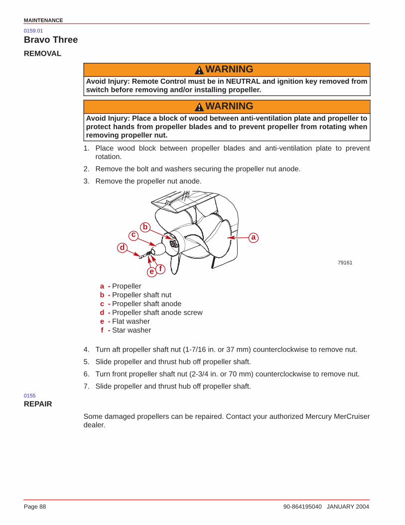
MAINTENANCE
Page 88 90-864195040 JANUARY 2004
0159.01
Bravo ThreeREMOVAL
WARNINGAvoid Injury: Remote Control must be in NEUTRAL and ignition key removed fromswitch before removing and/or installing propeller.
WARNINGAvoid Injury: Place a block of wood between anti-ventilation plate and propeller toprotect hands from propeller blades and to prevent propeller from rotating whenremoving propeller nut.
1. Place wood block between propeller blades and anti-ventilation plate to preventrotation.
2. Remove the bolt and washers securing the propeller nut anode.
3. Remove the propeller nut anode.
79161
ab
c
d
e f
a - Propellerb - Propeller shaft nutc - Propeller shaft anoded - Propeller shaft anode screwe - Flat washerf - Star washer
4. Turn aft propeller shaft nut (1-7/16 in. or 37 mm) counterclockwise to remove nut.
5. Slide propeller and thrust hub off propeller shaft.
6. Turn front propeller shaft nut (2-3/4 in. or 70 mm) counterclockwise to remove nut.
7. Slide propeller and thrust hub off propeller shaft.0155
REPAIR
Some damaged propellers can be repaired. Contact your authorized Mercury MerCruiserdealer.
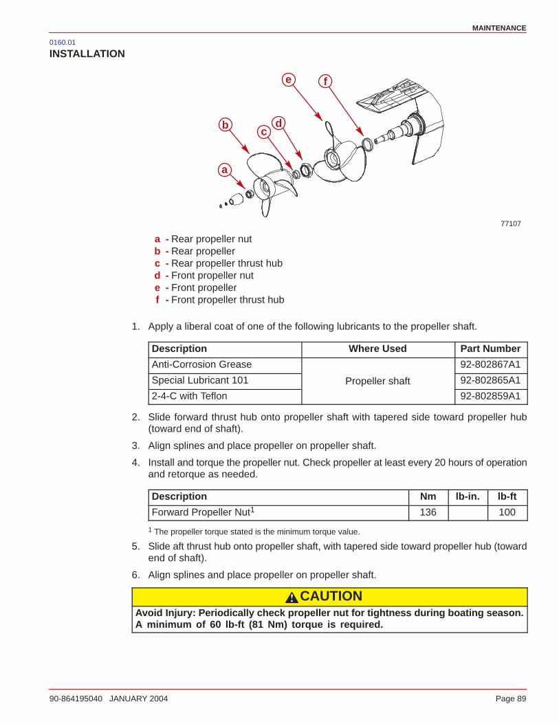
MAINTENANCE
90-864195040 JANUARY 2004 Page 89
0160.01
INSTALLATION
77107
fe
dc
b
a
a - Rear propeller nutb - Rear propellerc - Rear propeller thrust hubd - Front propeller nute - Front propellerf - Front propeller thrust hub
1. Apply a liberal coat of one of the following lubricants to the propeller shaft.
Description Where Used Part Number
Anti-Corrosion Grease 92-802867A1
Special Lubricant 101 Propeller shaft 92-802865A1
2-4-C with Teflon 92-802859A1
2. Slide forward thrust hub onto propeller shaft with tapered side toward propeller hub(toward end of shaft).
3. Align splines and place propeller on propeller shaft.
4. Install and torque the propeller nut. Check propeller at least every 20 hours of operationand retorque as needed.
Description Nm lb-in. lb-ft
Forward Propeller Nut1 136 100
1 The propeller torque stated is the minimum torque value.
5. Slide aft thrust hub onto propeller shaft, with tapered side toward propeller hub (towardend of shaft).
6. Align splines and place propeller on propeller shaft.
CAUTIONAvoid Injury: Periodically check propeller nut for tightness during boating season.A minimum of 60 lb-ft (81 Nm) torque is required.

MAINTENANCE
Page 90 90-864195040 JANUARY 2004
7. Install and torque the propeller nut. Check propeller at least every 20 hours of operationand retorque as needed.
Description Nm lb-in. lb-ft
Aft Propeller Nut1 81 60
1 The propeller torque stated is the minimum torque value.
8. Install the propeller shaft anode over the propeller shaft nut.
9. Place the flat washer onto the propeller shaft anode screw.
10. Place the star washer onto the propeller shaft anode screw.
NOTE: If the propeller shaft anode is removed after initial installation and is to be reinstalled,it will be necessary to apply Loctite Thread Locker 271 to the threads of the propeller shaftanode screw.
11. Secure the propeller shaft anode to the propeller shaft using the propeller shaft anodescrew and washers. Torque the screw.
Description Nm lb-in. lb-ft
Propeller shaft anode screw 0.3125-18 x 1.5 in. (38 mm)long
27 20
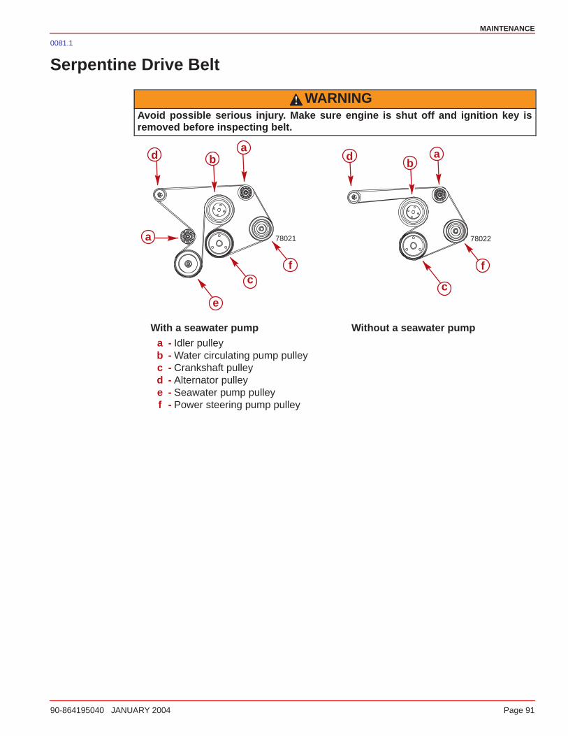
MAINTENANCE
90-864195040 JANUARY 2004 Page 91
0081.1
Serpentine Drive Belt
WARNINGAvoid possible serious injury. Make sure engine is shut off and ignition key isremoved before inspecting belt.
78021 78022
ab
cc
d
e
f
d
f
b
a
a
With a seawater pump Without a seawater pumpa - Idler pulleyb - Water circulating pump pulleyc - Crankshaft pulleyd - Alternator pulleye - Seawater pump pulleyf - Power steering pump pulley
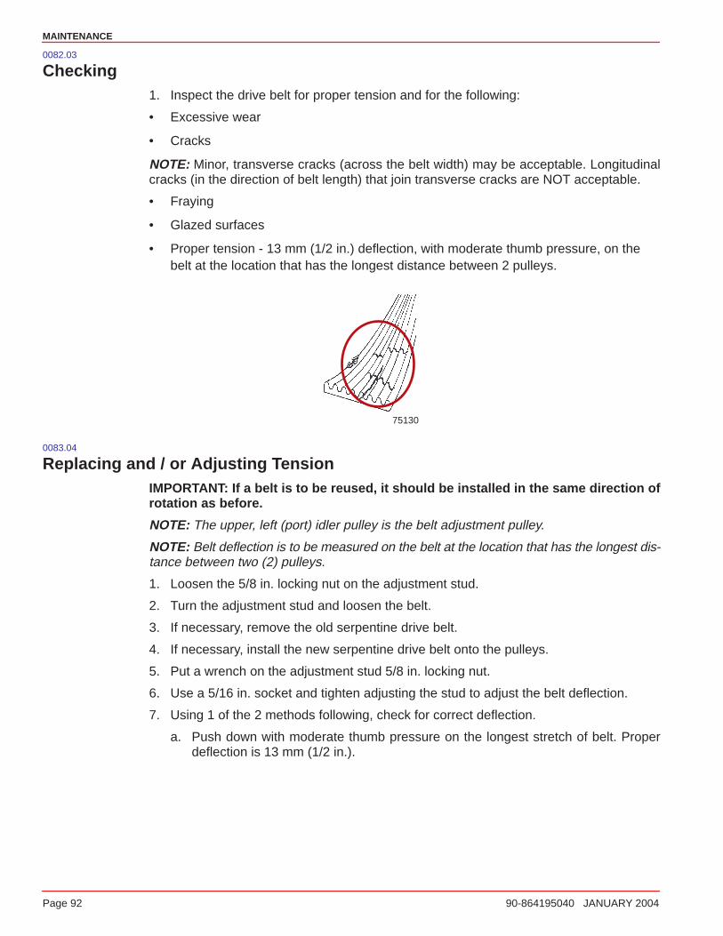
MAINTENANCE
Page 92 90-864195040 JANUARY 2004
0082.03
Checking1. Inspect the drive belt for proper tension and for the following:
• Excessive wear
• Cracks
NOTE: Minor, transverse cracks (across the belt width) may be acceptable. Longitudinalcracks (in the direction of belt length) that join transverse cracks are NOT acceptable.
• Fraying
• Glazed surfaces
• Proper tension - 13 mm (1/2 in.) deflection, with moderate thumb pressure, on thebelt at the location that has the longest distance between 2 pulleys.
75130
0083.04
Replacing and / or Adjusting TensionIMPORTANT: If a belt is to be reused, it should be installed in the same direction ofrotation as before.
NOTE: The upper, left (port) idler pulley is the belt adjustment pulley.
NOTE: Belt deflection is to be measured on the belt at the location that has the longest dis-tance between two (2) pulleys.
1. Loosen the 5/8 in. locking nut on the adjustment stud.
2. Turn the adjustment stud and loosen the belt.
3. If necessary, remove the old serpentine drive belt.
4. If necessary, install the new serpentine drive belt onto the pulleys.
5. Put a wrench on the adjustment stud 5/8 in. locking nut.
6. Use a 5/16 in. socket and tighten adjusting the stud to adjust the belt deflection.
7. Using 1 of the 2 methods following, check for correct deflection.
a. Push down with moderate thumb pressure on the longest stretch of belt. Properdeflection is 13 mm (1/2 in.).
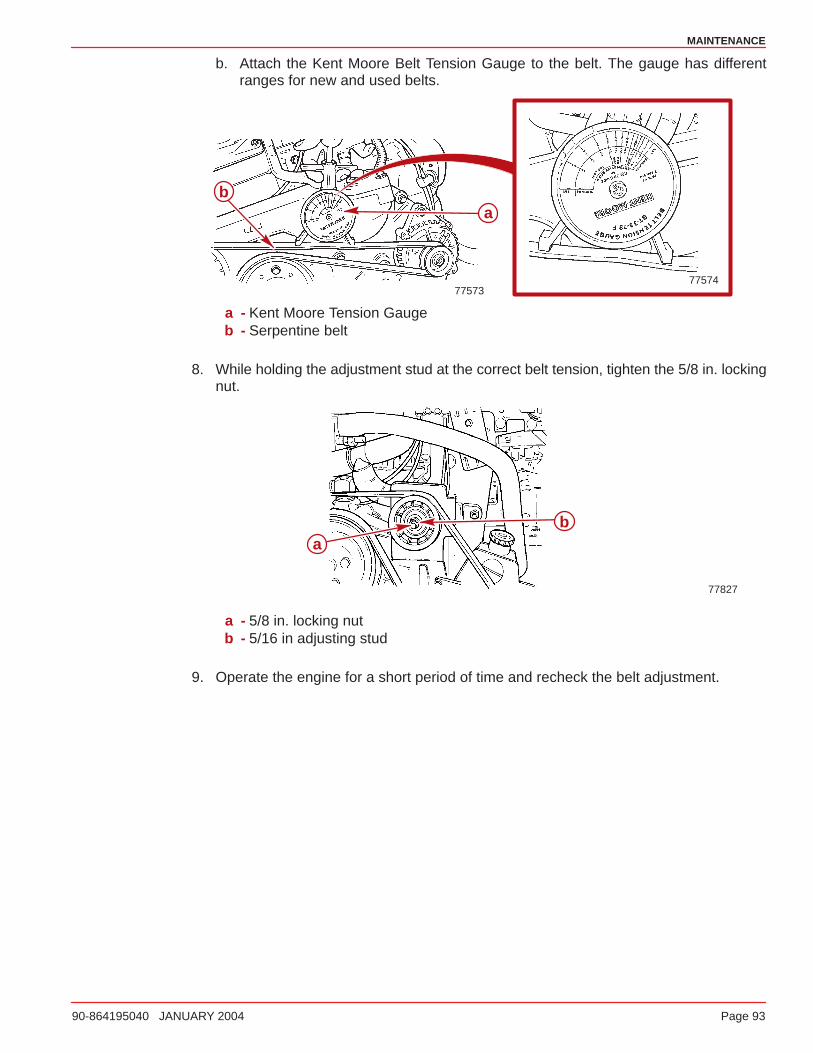
MAINTENANCE
90-864195040 JANUARY 2004 Page 93
b. Attach the Kent Moore Belt Tension Gauge to the belt. The gauge has differentranges for new and used belts.
77573
ab
77574
a - Kent Moore Tension Gaugeb - Serpentine belt
8. While holding the adjustment stud at the correct belt tension, tighten the 5/8 in. lockingnut.
77827
ab
a - 5/8 in. locking nutb - 5/16 in adjusting stud
9. Operate the engine for a short period of time and recheck the belt adjustment.
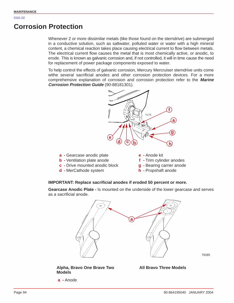
MAINTENANCE
Page 94 90-864195040 JANUARY 2004
0161.02
Corrosion Protection
Whenever 2 or more dissimilar metals (like those found on the sterndrive) are submergedin a conductive solution, such as saltwater, polluted water or water with a high mineralcontent, a chemical reaction takes place causing electrical current to flow between metals.The electrical current flow causes the metal that is most chemically active, or anodic, toerode. This is known as galvanic corrosion and, if not controlled, it will in time cause the needfor replacement of power package components exposed to water.
To help control the effects of galvanic corrosion, Mercury Mercruiser sterndrive units comewithe several sacrificial anodes and other corrosion protection devices. For a morecomprehensive explanation of corrosion and corrosion protection refer to the MarineCorrosion Protection Guide (90-88181301).
71176
a
bcde
f
g
h
a - Gearcase anodic plateb - Ventilation plate anodec - Drive mounted anodic blockd - MerCathode system
e - Anode kitf - Trim cylinder anodesg - Bearing carrier anodeh - Propshaft anode
IMPORTANT: Replace sacrificial anodes if eroded 50 percent or more.
Gearcase Anodic Plate - Is mounted on the underside of the lower gearcase and servesas a sacrificial anode.
79285
a
Alpha, Bravo One Brave TwoModels
All Bravo Three Models
a - Anode
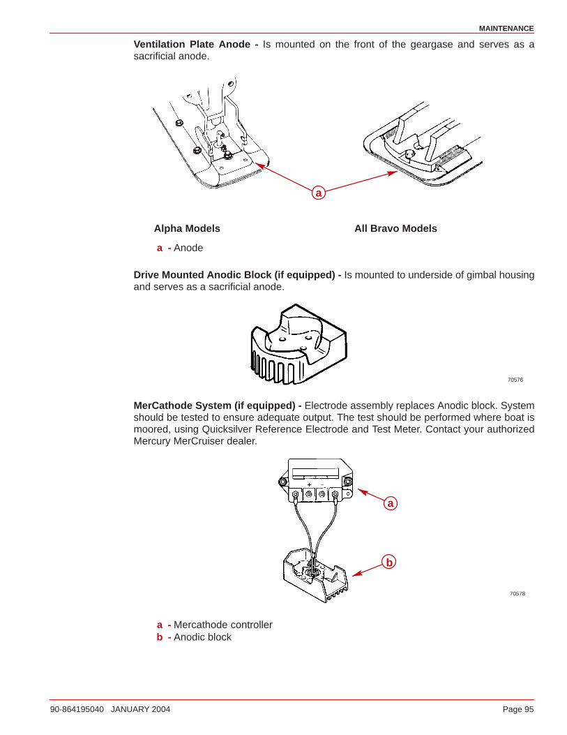
MAINTENANCE
90-864195040 JANUARY 2004 Page 95
Ventilation Plate Anode - Is mounted on the front of the geargase and serves as asacrificial anode.
a
Alpha Models All Bravo Models
a - Anode
Drive Mounted Anodic Block (if equipped) - Is mounted to underside of gimbal housingand serves as a sacrificial anode.
70576
MerCathode System (if equipped) - Electrode assembly replaces Anodic block. Systemshould be tested to ensure adequate output. The test should be performed where boat ismoored, using Quicksilver Reference Electrode and Test Meter. Contact your authorizedMercury MerCruiser dealer.
70578
a
b
a - Mercathode controllerb - Anodic block
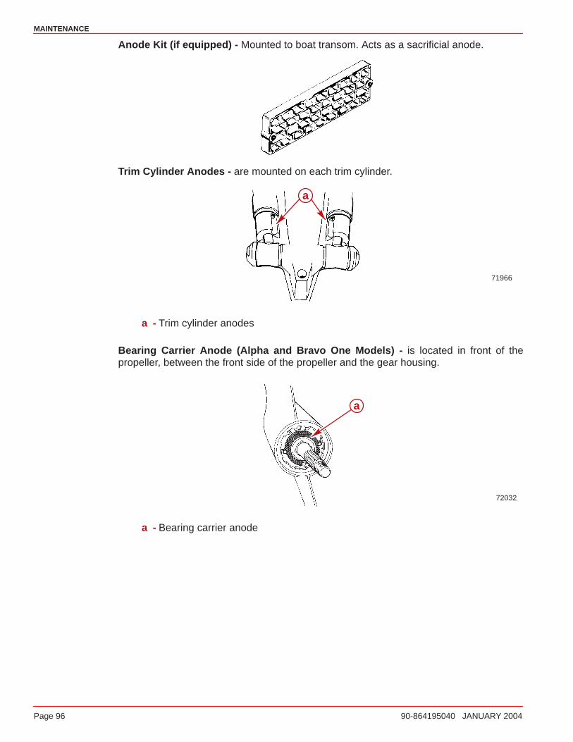
MAINTENANCE
Page 96 90-864195040 JANUARY 2004
Anode Kit (if equipped) - Mounted to boat transom. Acts as a sacrificial anode.
Trim Cylinder Anodes - are mounted on each trim cylinder.
71966
a
a - Trim cylinder anodes
Bearing Carrier Anode (Alpha and Bravo One Models) - is located in front of thepropeller, between the front side of the propeller and the gear housing.
72032
a
a - Bearing carrier anode
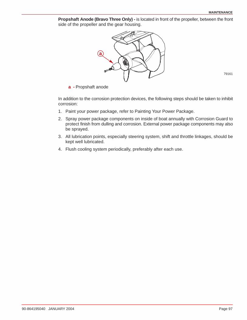
MAINTENANCE
90-864195040 JANUARY 2004 Page 97
Propshaft Anode (Bravo Three Only) - is located in front of the propeller, between the frontside of the propeller and the gear housing.
79161
a
a - Propshaft anode
In addition to the corrosion protection devices, the following steps should be taken to inhibitcorrosion:
1. Paint your power package, refer to Painting Your Power Package.
2. Spray power package components on inside of boat annually with Corrosion Guard toprotect finish from dulling and corrosion. External power package components may alsobe sprayed.
3. All lubrication points, especially steering system, shift and throttle linkages, should bekept well lubricated.
4. Flush cooling system periodically, preferably after each use.
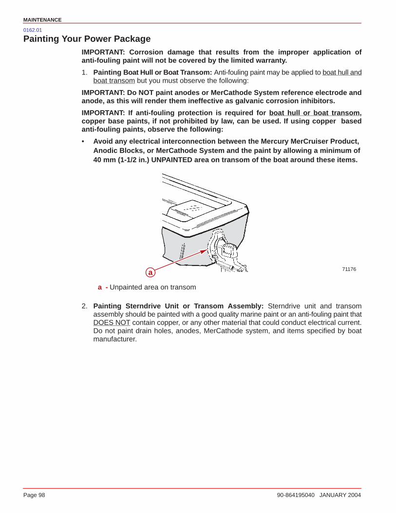
MAINTENANCE
Page 98 90-864195040 JANUARY 2004
0162.01
Painting Your Power PackageIMPORTANT: Corrosion damage that results from the improper application ofanti-fouling paint will not be covered by the limited warranty.
1. Painting Boat Hull or Boat T ransom: Anti-fouling paint may be applied to boat hull andboat transom but you must observe the following:
IMPORTANT: Do NOT paint anodes or MerCathode System reference electrode andanode, as this will render them ineffective as galvanic corrosion inhibitors.
IMPORTANT: If anti-fouling protection is required for boat hull or boat transom ,copper base paints, if not prohibited by law, can be used. If using copper basedanti-fouling paints, observe the following:
• Avoid any electrical interconnection between the Mercury MerCruiser Product,Anodic Blocks, or MerCathode System and the paint by allowing a minimum of40 mm (1-1/2 in.) UNPAINTED area on transom of the boat around these items.
71176a
a - Unpainted area on transom
2. Painting Sterndrive Unit or Transom Assembly: Sterndrive unit and transomassembly should be painted with a good quality marine paint or an anti-fouling paint thatDOES NOT contain copper, or any other material that could conduct electrical current.Do not paint drain holes, anodes, MerCathode system, and items specified by boatmanufacturer.
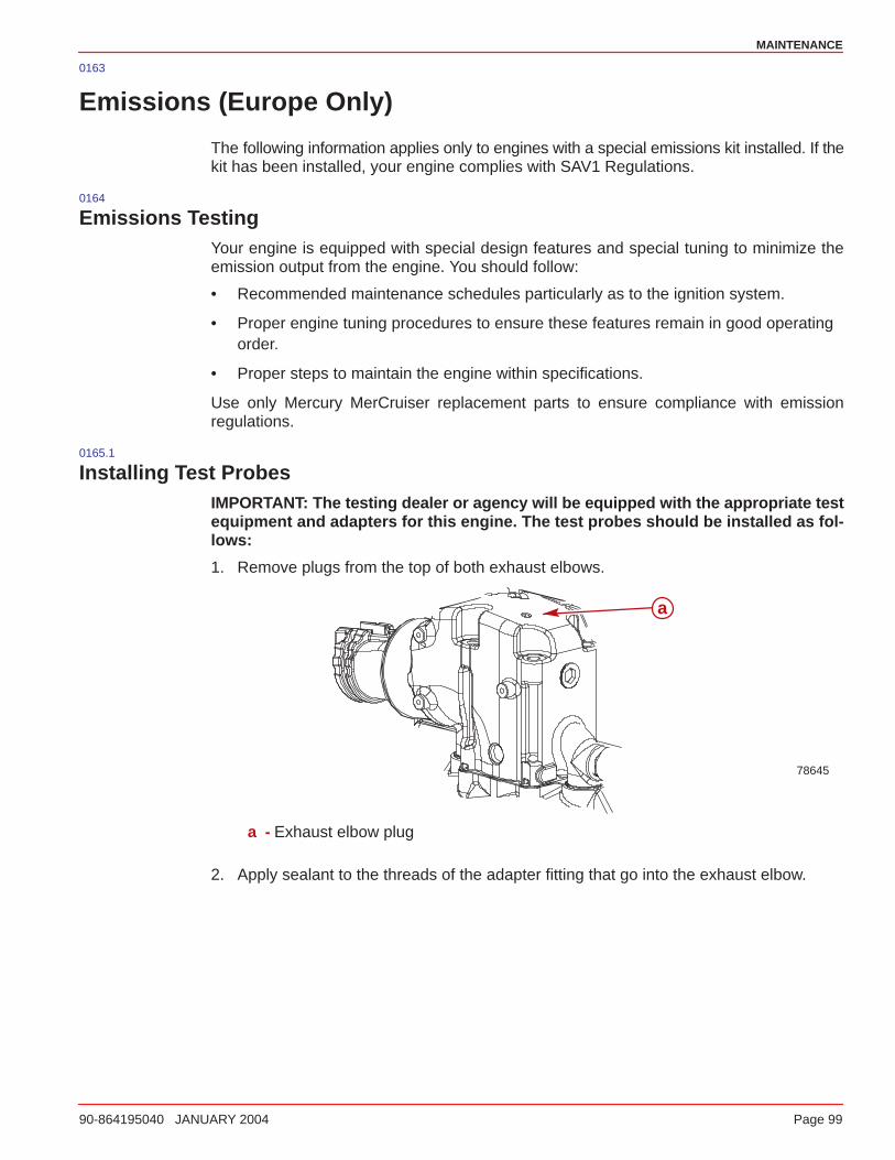
MAINTENANCE
90-864195040 JANUARY 2004 Page 99
0163
Emissions (Europe Only)
The following information applies only to engines with a special emissions kit installed. If thekit has been installed, your engine complies with SAV1 Regulations.
0164
Emissions TestingYour engine is equipped with special design features and special tuning to minimize theemission output from the engine. You should follow:
• Recommended maintenance schedules particularly as to the ignition system.
• Proper engine tuning procedures to ensure these features remain in good operatingorder.
• Proper steps to maintain the engine within specifications.
Use only Mercury MerCruiser replacement parts to ensure compliance with emissionregulations.
0165.1
Installing Test ProbesIMPORTANT: The testing dealer or agency will be equipped with the appropriate testequipment and adapters for this engine. The test probes should be installed as fol-lows:
1. Remove plugs from the top of both exhaust elbows.
78645
a
a - Exhaust elbow plug
2. Apply sealant to the threads of the adapter fitting that go into the exhaust elbow.
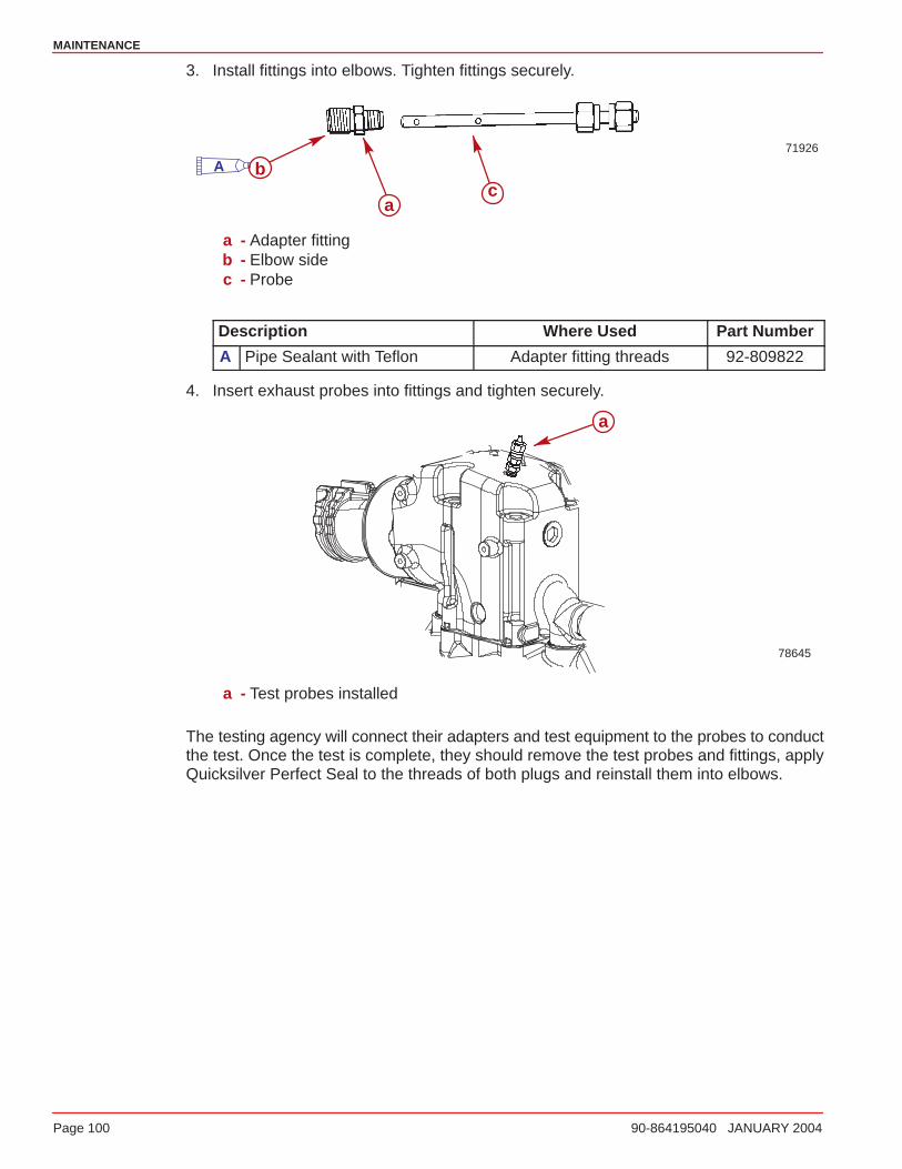
MAINTENANCE
Page 100 90-864195040 JANUARY 2004
3. Install fittings into elbows. Tighten fittings securely.
71926
a
bc
A
a - Adapter fittingb - Elbow sidec - Probe
Description Where Used Part Number
A Pipe Sealant with Teflon Adapter fitting threads 92-809822
4. Insert exhaust probes into fittings and tighten securely.
78645
a
a - Test probes installed
The testing agency will connect their adapters and test equipment to the probes to conductthe test. Once the test is complete, they should remove the test probes and fittings, applyQuicksilver Perfect Seal to the threads of both plugs and reinstall them into elbows.
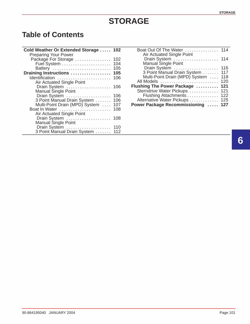
6
STORAGE
90-864195040 JANUARY 2004 Page 101
STORAGE
Table of Contents
Cold Weather Or Extended Storage 102. . . . . Preparing Your Power Package For Storage 102. . . . . . . . . . . . . . . .
Fuel System 104. . . . . . . . . . . . . . . . . . . . . . Battery 105. . . . . . . . . . . . . . . . . . . . . . . . . .
Draining Instructions 105. . . . . . . . . . . . . . . . . . Identification 106. . . . . . . . . . . . . . . . . . . . . . . .
Air Actuated Single Point Drain System 106. . . . . . . . . . . . . . . . . . . . Manual Single Point Drain System 106. . . . . . . . . . . . . . . . . . . . 3 Point Manual Drain System 106. . . . . . . Multi-Point Drain (MPD) System 107. . . .
Boat In Water 108. . . . . . . . . . . . . . . . . . . . . . . Air Actuated Single Point Drain System 108. . . . . . . . . . . . . . . . . . . . Manual Single Point Drain System 110. . . . . . . . . . . . . . . . . . . . 3 Point Manual Drain System 112. . . . . . .
Boat Out Of The Water 114. . . . . . . . . . . . . . . Air Actuated Single Point Drain System 114. . . . . . . . . . . . . . . . . . . . Manual Single Point Drain System 116. . . . . . . . . . . . . . . . . . . . 3 Point Manual Drain System 117. . . . . . . Multi-Point Drain (MPD) System 118. . . .
All Models 120. . . . . . . . . . . . . . . . . . . . . . . . . . Flushing The Power Package 121. . . . . . . . . .
Sterndrive Water Pickups 121. . . . . . . . . . . . . Flushing Attachments 122. . . . . . . . . . . . . .
Alternative Water Pickups 125. . . . . . . . . . . . . Power Package Recommissioning 127. . . . .
STORAGE
Page 102 90-864195040 JANUARY 2004
0084
Cold Weather Or Extended Storage
IMPORTANT: Mercury MerCruiser strongly recommends that this service should beperformed by an authorized Mercury MerCruiser dealer. Damage caused by freezingIS NOT covered by the Mercury MerCruiser Limited Warranty.
CAUTIONSeawater section of cooling system MUST BE COMPLETELY drained for winterstorage, or immediately after cold weather use, if the possibility of freezing temper-atures exist. Failure to comply may result in trapped water causing freeze and/orcorrosion damage to engine. Damage caused by freezing is NOT covered by theMercury MerCruiser Limited Warranty.
IMPORTANT: Mercury MerCruiser recommends that propylene glycol antifreeze (anontoxic and environmentally safe) antifreeze be used in the seawater section of thecooling system for cold weather or extended storage. Make sure that the propyleneglycol antifreeze contains a rust inhibitor and is recommended for use in marine en-gines. Be certain to follow the propylene glycol manufacturer’s recommendations.
0085.01
Preparing Your Power Package For Storage1. Fill the fuel tanks with fresh gasoline (that does not contain alcohol) and a sufficient
amount of Quicksilver Gasoline Stabilizer for Marine Engines to treat the gasoline.Follow instructions on the container.
2. If the boat is to be placed in storage with fuel containing alcohol in fuel tanks (iffuel wit hout alcohol is not available): Fuel tanks should be drained as low as possibleand Quicksilver Gasoline Stabilizer for Marine Engines added to any fuel remaining inthe tank. Refer to Fuel Requirements for additional information.
NOTE: If desired, a portable fuel tank can be used to perform the remainder of the powerpackage lay up procedures. Add an appropriate amount of Gasoline Stabilizer to theportable tank.
3. Flush the cooling system.

STORAGE
90-864195040 JANUARY 2004 Page 103
4. Operate the engine sufficiently to bring it up to normal operating temperature and allowfuel with Quicksilver Gasoline Stabilizer to circulate through the fuel system. Shut offengine.
5. Drain the engine.
6. Ensure that the sterndrive vent holes and water drain holes and passages areunobstructed and open (refer to Draining - Sterndrive).
7. For additional assurance against freezing and rust, after draining fill the cooling systemwith a mixture of propylene glycol and tap water mixed to manufacturer’srecommendation to protect engine to the lowest temperature to which it will be exposedduring cold weather or extended storage.
CAUTIONSterndrive should be stored in full DOWN position. Universal Joint bellows maydevelop a set if unit is stored in raised position and may fail when unit is returnedto service.
8. Store boat with drive unit in full DOWN/IN position.
STORAGE
Page 104 90-864195040 JANUARY 2004
0086
FUEL SYSTEM
WARNINGThe fuel injection system is pressurized. Avoid serious injury from an explosion.Use care when removing water separating fuel filter. Allow engine to cool downbefore removing the water separating fuel filter. Also, hold a clean shop towel overthe water separating fuel filter when removing it, to help avoid fuel spraying on theengine.
WARNINGFuel vapors can be present in the engine compartment. Avoid injury or powerpackage damage caused by fuel vapors or explosion. Always ventilate the enginecompartment prior to servicing the power package.
1. In a 23 liter (6 U.S. gal.) remote fuel tank mix:
a. 19 liter (5 U.S. gal) regular unleaded 87 octane (90 RON) gasoline
b. 1.89 liter (2 U.S. qts.) Premium Plus 2-Cycle TC-W3 Outboard Oil
c. 150ml (5 ounces) Fuel System Treatment and Stabilizer or 30 ml (1 ounce) Fuel Sys-tem Treatment and Stabilizer Concentrate.
Description Where Used Part Number
Mercury Fuel System Treatmentand Stabilizer
Fuel system 92-802875A1
Mercury Fuel System Treatmentand Stabilizer Concentrate
Fuel system 92-802876A1
Premium Plus 2-Cycle TC-W3Outboard Oil
Fuel system 92-802824A1
2. Allow the engine to cool down.
IMPORTANT: Immediately wipe up any fuel spills or sprays.
3. Close the fuel shut off valve, if equipped. Disconnect and plug the fuel inlet fitting if notequipped with a fuel shut off valve.
4. Connect the remote fuel tank (with the fogging mixture) to the fuel inlet fitting.
STORAGE
90-864195040 JANUARY 2004 Page 105
IMPORTANT: Supply cooling water to the engine.
5. Start and operate the engine at 1300 rpm for 5 minutes.
6. After specified operating time is complete, slowly return throttle to idle rpm and shutengine off.
IMPORTANT: Ensure that some fogging mixture remains in the engine. Do NOT allowthe engine’s fuel system to become completely dry.
7. Remove and discard the water separating fuel filter.
8. Install a new filter.0087
BATTERY
Follow the battery manufacturer’s instructions for storage.0088
Draining Instructions
CAUTIONEnsure that boat is out of the water or seacock is closed and bilge pump is operatingbefore beginning procedure. Excess water in bilge can damage engine or causeboat to sink.
CAUTIONDo NOT operate engine with drain system open. Excess water in bilge can damageengine or cause boat to sink.
IMPORTANT: Boat must be as level as possible to ensure complete draining ofcooling system.
Your power package is equipped with a drain system. Refer to Identification on the followingpage to determine which instructions apply to your power package.
The power package should be drained before flushing or prior to extended or cold weatherstorage.
IMPORTANT: The engine must not be operating at any point during this procedure.
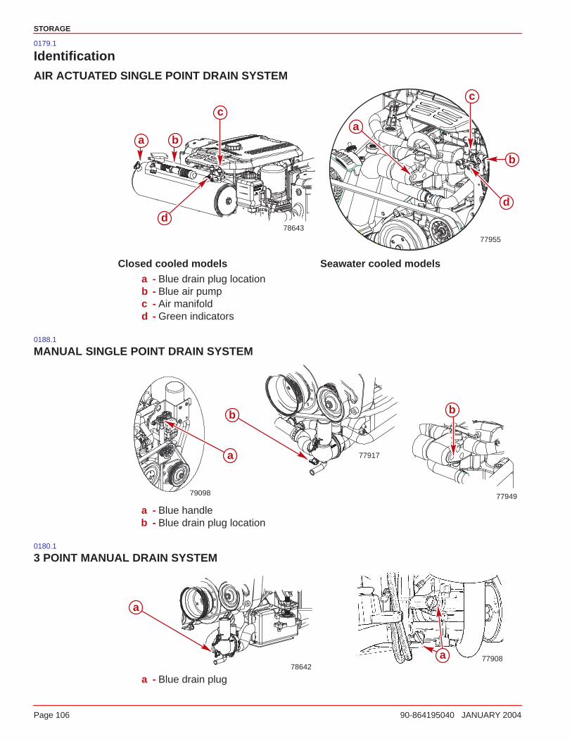
STORAGE
Page 106 90-864195040 JANUARY 2004
0179.1
IdentificationAIR ACTUATED SINGLE POINT DRAIN SYSTEM
78643
77955
a
b
c
d
ba
c
d
Closed cooled models Seawater cooled modelsa - Blue drain plug locationb - Blue air pumpc - Air manifoldd - Green indicators
0188.1
MANUAL SINGLE POINT DRAIN SYSTEM
77949
b
77917
b
79098
a
a - Blue handleb - Blue drain plug location
0180.1
3 POINT MANUAL DRAIN SYSTEM
7790878642
a
a
a - Blue drain plug

STORAGE
90-864195040 JANUARY 2004 Page 107
0181.1
MULTI-POINT DRAIN (MPD) SYSTEM
78181 78178
a
b
a
b
a - Side of cylinder blockb - Bottom of exhaust manifolds
78182
a
78179
b
a - Water circulating pump hoseb - Fuel cooler to thermostat housing
78180
a
a - Check valve
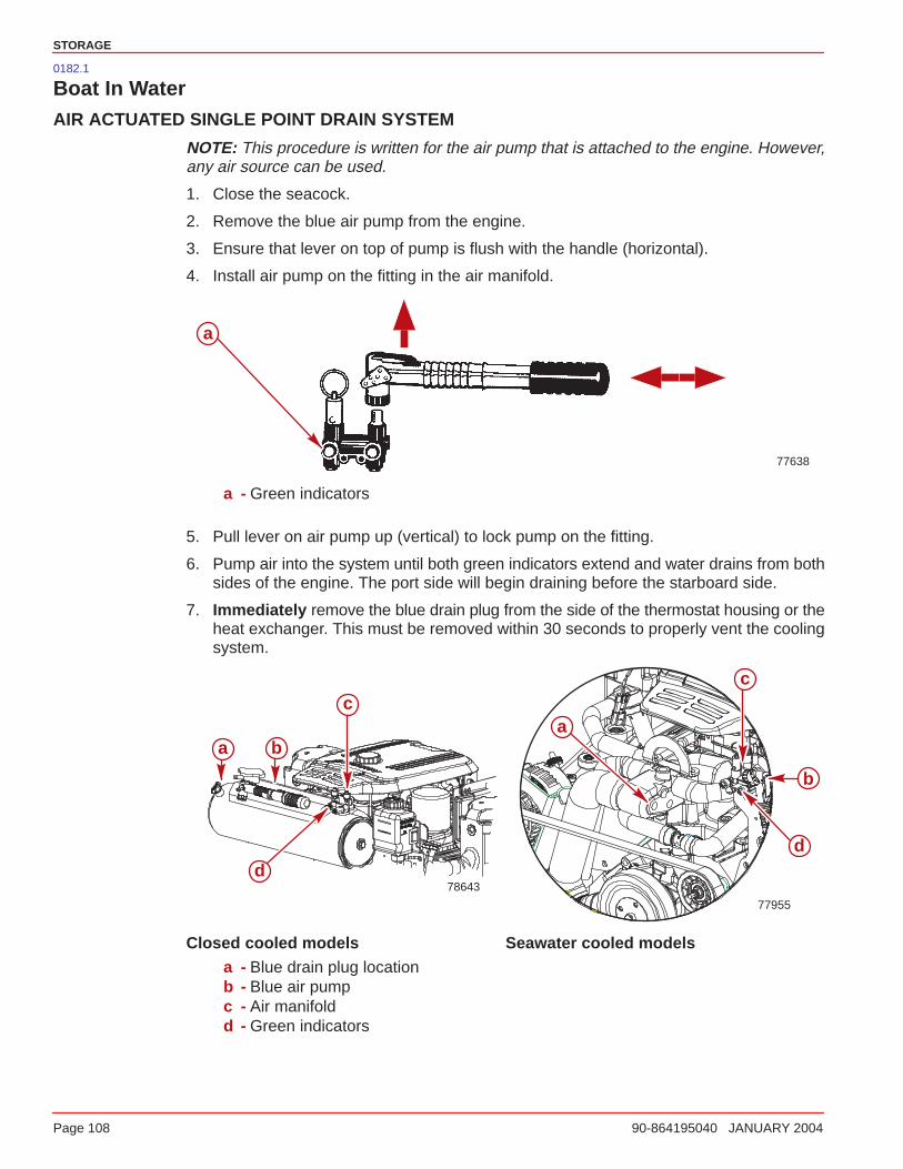
STORAGE
Page 108 90-864195040 JANUARY 2004
0182.1
Boat In WaterAIR ACTUATED SINGLE POINT DRAIN SYSTEM
NOTE: This procedure is written for the air pump that is attached to the engine. However,any air source can be used.
1. Close the seacock.
2. Remove the blue air pump from the engine.
3. Ensure that lever on top of pump is flush with the handle (horizontal).
4. Install air pump on the fitting in the air manifold.
77638
a
a - Green indicators
5. Pull lever on air pump up (vertical) to lock pump on the fitting.
6. Pump air into the system until both green indicators extend and water drains from bothsides of the engine. The port side will begin draining before the starboard side.
7. Immediately remove the blue drain plug from the side of the thermostat housing or theheat exchanger. This must be removed within 30 seconds to properly vent the coolingsystem.
78643
77955
a
b
c
d
ba
c
d
Closed cooled models Seawater cooled modelsa - Blue drain plug locationb - Blue air pumpc - Air manifoldd - Green indicators
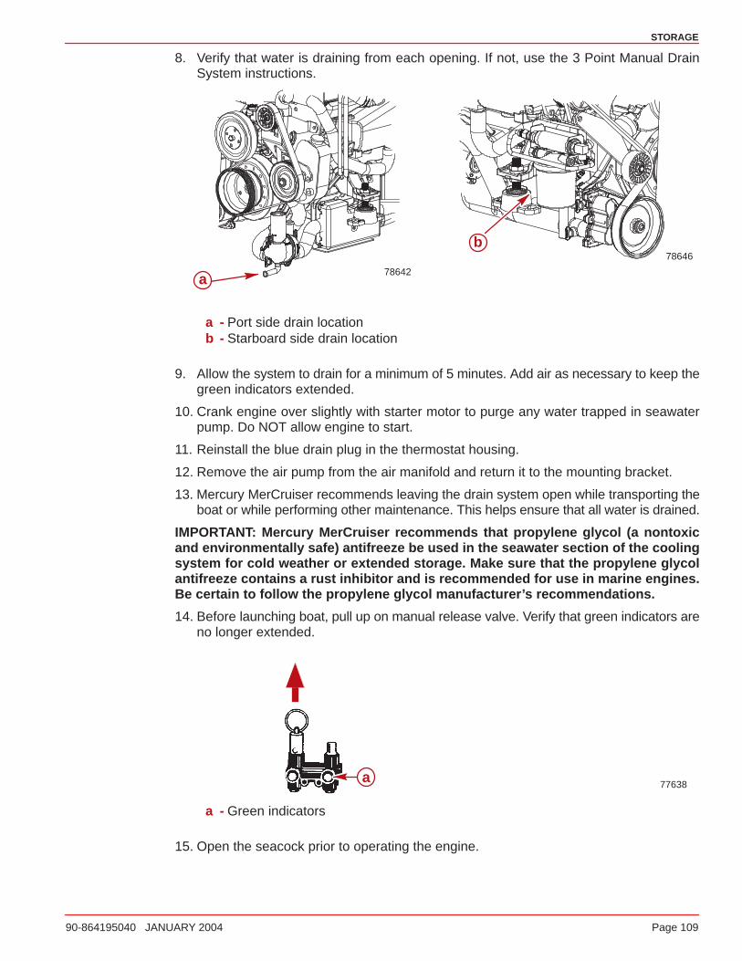
STORAGE
90-864195040 JANUARY 2004 Page 109
8. Verify that water is draining from each opening. If not, use the 3 Point Manual DrainSystem instructions.
78646
78642
b
a
a - Port side drain locationb - Starboard side drain location
9. Allow the system to drain for a minimum of 5 minutes. Add air as necessary to keep thegreen indicators extended.
10. Crank engine over slightly with starter motor to purge any water trapped in seawaterpump. Do NOT allow engine to start.
11. Reinstall the blue drain plug in the thermostat housing.
12. Remove the air pump from the air manifold and return it to the mounting bracket.
13. Mercury MerCruiser recommends leaving the drain system open while transporting theboat or while performing other maintenance. This helps ensure that all water is drained.
IMPORTANT: Mercury MerCruiser recommends that propylene glycol (a nontoxicand environmentally safe) antifreeze be used in the seawater section of the coolingsystem for cold weather or extended storage. Make sure that the propylene glycolantifreeze contains a rust inhibitor and is recommended for use in marine engines.Be certain to follow the propylene glycol manufacturer’s recommendations.
14. Before launching boat, pull up on manual release valve. Verify that green indicators areno longer extended.
77638a
a - Green indicators
15. Open the seacock prior to operating the engine.
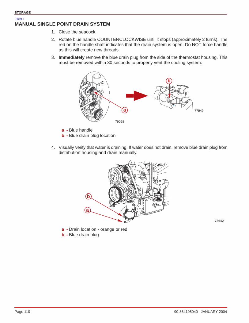
STORAGE
Page 110 90-864195040 JANUARY 2004
0189.1
MANUAL SINGLE POINT DRAIN SYSTEM
1. Close the seacock.
2. Rotate blue handle COUNTERCLOCKWISE until it stops (approximately 2 turns). Thered on the handle shaft indicates that the drain system is open. Do NOT force handleas this will create new threads.
3. Immediately remove the blue drain plug from the side of the thermostat housing. Thismust be removed within 30 seconds to properly vent the cooling system.
79098
77949
b
a
a - Blue handleb - Blue drain plug location
4. Visually verify that water is draining. If water does not drain, remove blue drain plug fromdistribution housing and drain manually.
78642
a
b
a - Drain location - orange or redb - Blue drain plug
STORAGE
90-864195040 JANUARY 2004 Page 111
5. Allow the system to drain for a minimum of 5 minutes. Mercury MerCruiser recommendsleaving the drain system open while transporting the boat or while performing othermaintenance.
6. Reinstall the blue drain plug in the thermostat housing.
7. Close the drain system by rotating the blue handle CLOCKWISE until it stops and installthe blue drain plug, if removed. The handle is fully seated when no red is visible. Do NOTovertighten the handle as this will create new threads.
IMPORTANT: Mercury MerCruiser recommends that propylene glycol (a nontoxicand environmentally safe) antifreeze be used in the seawater section of the coolingsystem for cold weather or extended storage. Make sure that the propylene glycolantifreeze contains a rust inhibitor and is recommended for use in marine engines.Be certain to follow the propylene glycol manufacturer’s recommendations.
8. Open the seacock prior to operating the engine.

STORAGE
Page 112 90-864195040 JANUARY 2004
0183
3 POINT MANUAL DRAIN SYSTEM
NOTE: Use this procedure if your engine is not equipped with an air actuated single pointdrain system or if the single point drain system fails.
1. Close the seacock.
2. Remove the blue drain plug from the distribution housing (lower front, port side).
77917
a
a - Blue drain plug
3. Immediately remove the blue drain plug from the side of the thermostat housing. Thismust be removed within 30 seconds to properly vent the cooling system.
77949
a
a - Blue drain plug location
4. Remove the 2 blue drain plugs from the seawater pickup pump (front, starboard side).
77908a
a - Blue drain plugs
STORAGE
90-864195040 JANUARY 2004 Page 113
5. Verify that water is draining from each opening.
6. Allow the system to drain for a minimum of 5 minutes. Mercury MerCruiser recommendsleaving the drain system open while transporting the boat or while performing othermaintenance.
7. Crank engine over slightly with starter motor to purge any water trapped in seawaterpickup pump. Do NOT allow engine to start.
8. Prior to launching boat or starting the engine, close the drain system by installing the4 blue drain plugs.
IMPORTANT: Mercury MerCruiser recommends that propylene glycol (a nontoxicand environmentally safe) antifreeze be used in the seawater section of the coolingsystem for cold weather or extended storage. Make sure that the propylene glycolantifreeze contains a rust inhibitor and is recommended for use in marine engines.Be certain to follow the propylene glycol manufacturer’s recommendations.
9. Open the seacock prior to operating the engine.

STORAGE
Page 114 90-864195040 JANUARY 2004
0184.1
Boat Out Of The WaterAIR ACTUATED SINGLE POINT DRAIN SYSTEM
NOTE: This procedure is written for the air pump that is attached to the engine. However,any air source can be used.
1. Place the boat on a level surface to ensure complete draining of system.
2. Remove the blue air pump from the engine.
3. Ensure that lever on top of pump is flush with the handle (horizontal).
4. Install air pump on the fitting in the air manifold.
77638
a
a - Green indicators
5. Pull lever on air pump up (vertical) to lock pump on the fitting.
6. Pump air into the system until both green indicators extend and water drains from bothsides of the engine. The port side will begin draining before the starboard side.
78643
77955
a
b
c
d
ba
c
d
Closed cooled models Seawater cooled modelsa - Blue drain plug locationb - Blue air pumpc - Air manifoldd - Green indicators
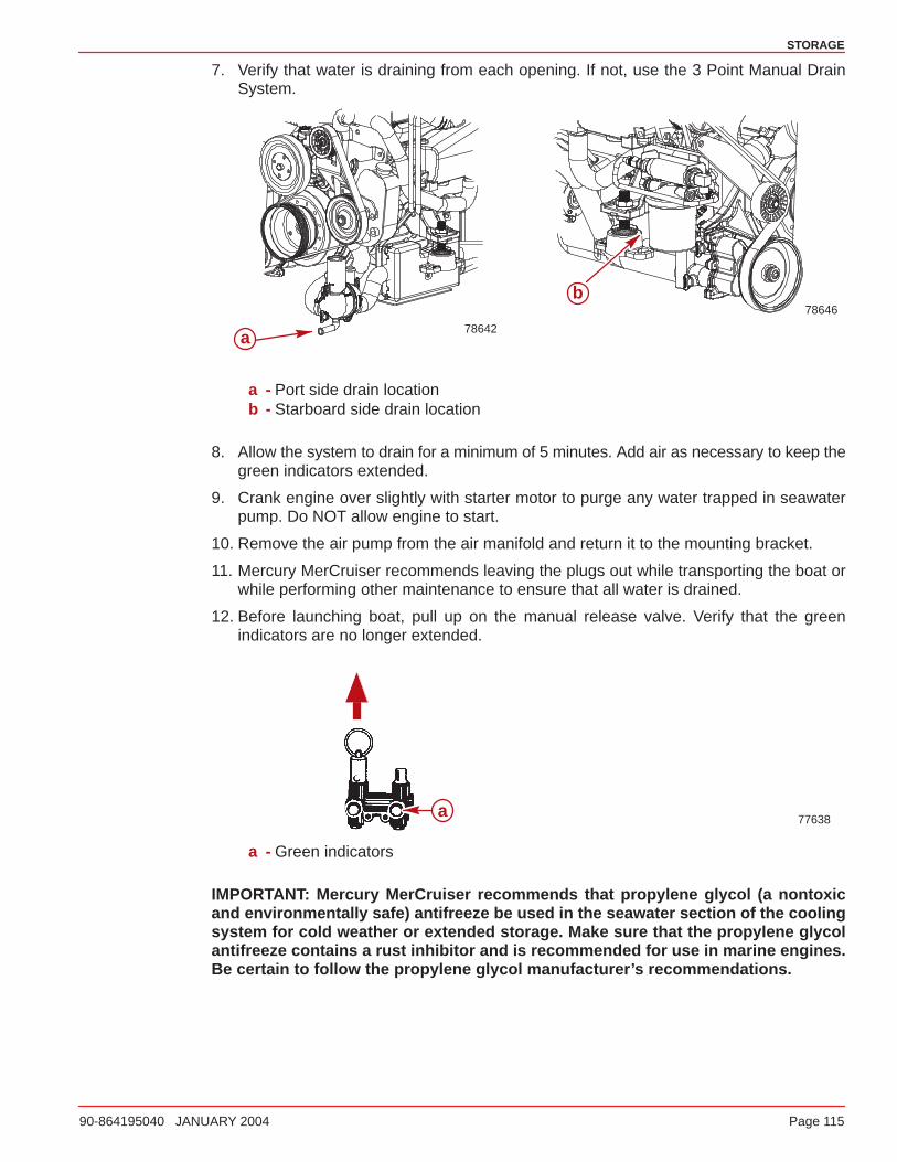
STORAGE
90-864195040 JANUARY 2004 Page 115
7. Verify that water is draining from each opening. If not, use the 3 Point Manual DrainSystem.
78646
78642
b
a
a - Port side drain locationb - Starboard side drain location
8. Allow the system to drain for a minimum of 5 minutes. Add air as necessary to keep thegreen indicators extended.
9. Crank engine over slightly with starter motor to purge any water trapped in seawaterpump. Do NOT allow engine to start.
10. Remove the air pump from the air manifold and return it to the mounting bracket.
11. Mercury MerCruiser recommends leaving the plugs out while transporting the boat orwhile performing other maintenance to ensure that all water is drained.
12. Before launching boat, pull up on the manual release valve. Verify that the greenindicators are no longer extended.
77638a
a - Green indicators
IMPORTANT: Mercury MerCruiser recommends that propylene glycol (a nontoxicand environmentally safe) antifreeze be used in the seawater section of the coolingsystem for cold weather or extended storage. Make sure that the propylene glycolantifreeze contains a rust inhibitor and is recommended for use in marine engines.Be certain to follow the propylene glycol manufacturer’s recommendations.
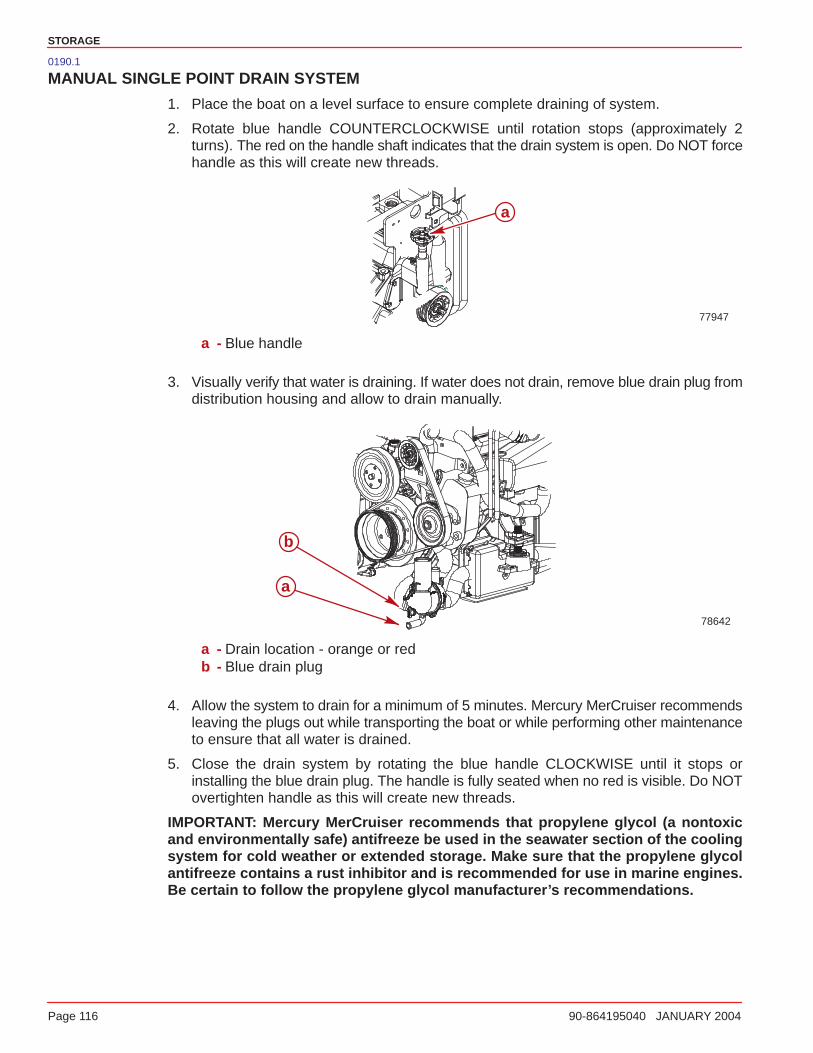
STORAGE
Page 116 90-864195040 JANUARY 2004
0190.1
MANUAL SINGLE POINT DRAIN SYSTEM
1. Place the boat on a level surface to ensure complete draining of system.
2. Rotate blue handle COUNTERCLOCKWISE until rotation stops (approximately 2turns). The red on the handle shaft indicates that the drain system is open. Do NOT forcehandle as this will create new threads.
77947
a
a - Blue handle
3. Visually verify that water is draining. If water does not drain, remove blue drain plug fromdistribution housing and allow to drain manually.
78642
a
b
a - Drain location - orange or redb - Blue drain plug
4. Allow the system to drain for a minimum of 5 minutes. Mercury MerCruiser recommendsleaving the plugs out while transporting the boat or while performing other maintenanceto ensure that all water is drained.
5. Close the drain system by rotating the blue handle CLOCKWISE until it stops orinstalling the blue drain plug. The handle is fully seated when no red is visible. Do NOTovertighten handle as this will create new threads.
IMPORTANT: Mercury MerCruiser recommends that propylene glycol (a nontoxicand environmentally safe) antifreeze be used in the seawater section of the coolingsystem for cold weather or extended storage. Make sure that the propylene glycolantifreeze contains a rust inhibitor and is recommended for use in marine engines.Be certain to follow the propylene glycol manufacturer’s recommendations.

STORAGE
90-864195040 JANUARY 2004 Page 117
0185
3 POINT MANUAL DRAIN SYSTEM
NOTE: Use this procedure if your engine is not equipped with an air actuated single pointdrain system or if the single point drain system fails.
1. Place the boat on a level surface to ensure complete draining of system.
2. Remove 3 blue drain plugs: 1 from the distribution housing (lower front, port side) and2 from the seawater pickup pump (front, starboard side).
7790877917
aa
a - Blue drain plug
3. Verify that water is draining from each opening.
4. Allow the system to drain for a minimum of 5 minutes. Mercury MerCruiser recommendsleaving the plugs out while transporting the boat or while performing other maintenanceto ensure that all water is drained.
5. Crank engine over slightly with starter motor to purge any water trapped in seawaterpickup pump. Do NOT allow engine to start.
IMPORTANT: Mercury MerCruiser recommends that propylene glycol (a nontoxicand environmentally safe) antifreeze be used in the seawater section of the coolingsystem for cold weather or extended storage. Make sure that the propylene glycolantifreeze contains a rust inhibitor and is recommended for use in marine engines.Be certain to follow the propylene glycol manufacturer’s recommendations.
6. Prior to launching boat or starting the engine, close the drain system by re-installing the3 blue drain plugs.

STORAGE
Page 118 90-864195040 JANUARY 2004
0186.1
MULTI-POINT DRAIN (MPD) SYSTEM
1. Place the boat on a level surface to ensure complete draining of system.
2. Remove blue drain plugs from the following locations. It may be necessary to clean outdrain holes using a stiff piece of wire. Do so until the entire system is drained.
a. Port and starboard side of cylinder block.
b. Bottom of exhaust manifolds.
78181 78178
a
b
a
b
a - Side of cylinder blockb - Bottom of exhaust manifolds
c. Water circulating pump hose.
78182
a
a - Water circulating pump drain plug
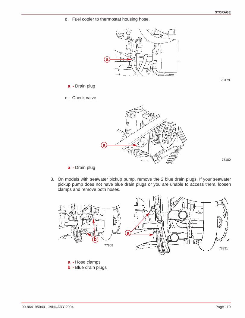
STORAGE
90-864195040 JANUARY 2004 Page 119
d. Fuel cooler to thermostat housing hose.
78179
a
a - Drain plug
e. Check valve.
78180
a
a - Drain plug
3. On models with seawater pickup pump, remove the 2 blue drain plugs. If your seawaterpickup pump does not have blue drain plugs or you are unable to access them, loosenclamps and remove both hoses.
78331
a
77908
b
a - Hose clampsb - Blue drain plugs
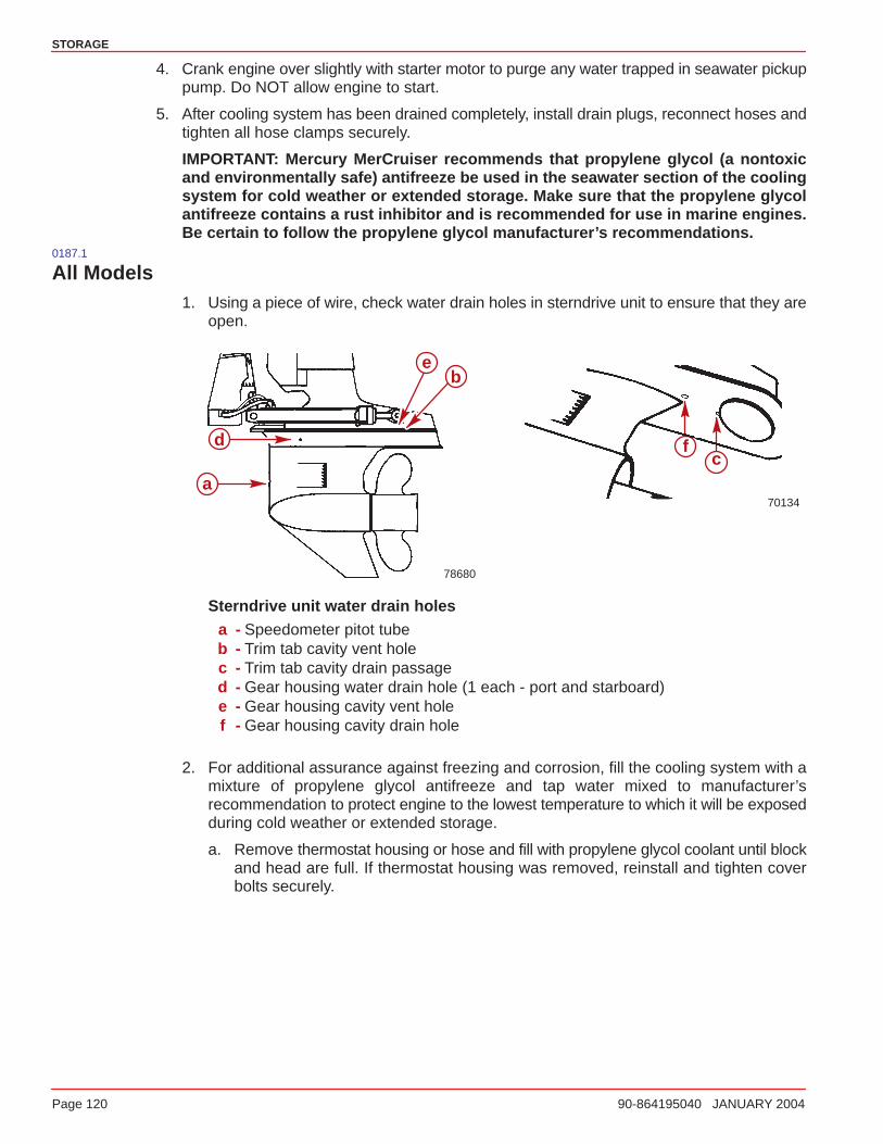
STORAGE
Page 120 90-864195040 JANUARY 2004
4. Crank engine over slightly with starter motor to purge any water trapped in seawater pickuppump. Do NOT allow engine to start.
5. After cooling system has been drained completely, install drain plugs, reconnect hoses andtighten all hose clamps securely.
IMPORTANT: Mercury MerCruiser recommends that propylene glycol (a nontoxicand environmentally safe) antifreeze be used in the seawater section of the coolingsystem for cold weather or extended storage. Make sure that the propylene glycolantifreeze contains a rust inhibitor and is recommended for use in marine engines.Be certain to follow the propylene glycol manufacturer’s recommendations.
0187.1
All Models1. Using a piece of wire, check water drain holes in sterndrive unit to ensure that they are
open.
70134
78680
a
be
d fc
Sterndrive unit water drain holesa - Speedometer pitot tubeb - Trim tab cavity vent holec - Trim tab cavity drain passaged - Gear housing water drain hole (1 each - port and starboard)e - Gear housing cavity vent holef - Gear housing cavity drain hole
2. For additional assurance against freezing and corrosion, fill the cooling system with amixture of propylene glycol antifreeze and tap water mixed to manufacturer’srecommendation to protect engine to the lowest temperature to which it will be exposedduring cold weather or extended storage.
a. Remove thermostat housing or hose and fill with propylene glycol coolant until blockand head are full. If thermostat housing was removed, reinstall and tighten coverbolts securely.
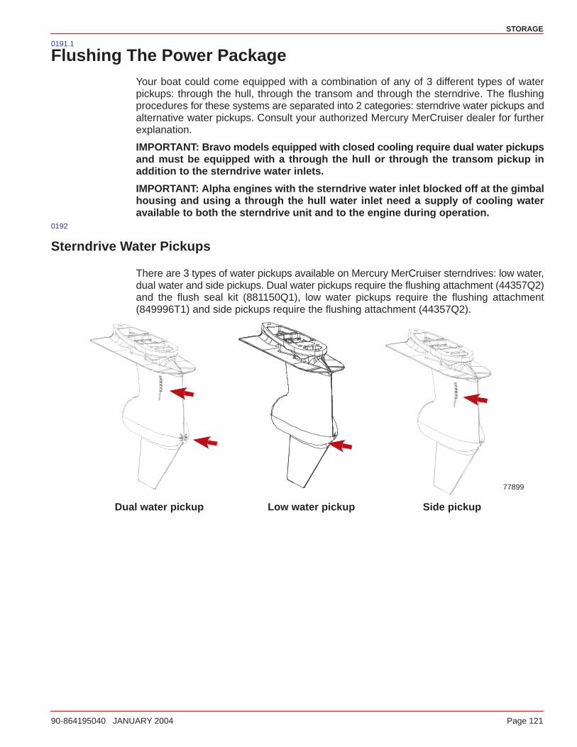
STORAGE
90-864195040 JANUARY 2004 Page 121
0191.1
Flushing The Power PackageYour boat could come equipped with a combination of any of 3 different types of waterpickups: through the hull, through the transom and through the sterndrive. The flushingprocedures for these systems are separated into 2 categories: sterndrive water pickups andalternative water pickups. Consult your authorized Mercury MerCruiser dealer for furtherexplanation.
IMPORTANT: Bravo models equipped with closed cooling require dual water pickupsand must be equipped with a through the hull or through the transom pickup inaddition to the sterndrive water inlets.
IMPORTANT: Alpha engines with the sterndrive water inlet blocked off at the gimbalhousing and using a through the hull water inlet need a supply of cooling wateravailable to both the sterndrive unit and to the engine during operation.
0192
Sterndrive Water Pickups
There are 3 types of water pickups available on Mercury MerCruiser sterndrives: low water,dual water and side pickups. Dual water pickups require the flushing attachment (44357Q2)and the flush seal kit (881150Q1), low water pickups require the flushing attachment(849996T1) and side pickups require the flushing attachment (44357Q2).
77899
Dual water pickup Low water pickup Side pickup
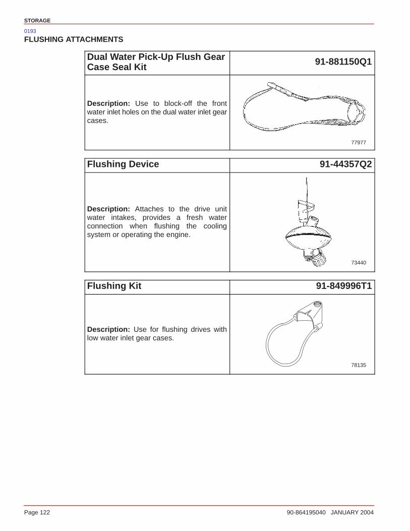
STORAGE
Page 122 90-864195040 JANUARY 2004
0193
FLUSHING ATTACHMENTS
Dual Water Pick-Up Flush GearCase Seal Kit 91-881150Q1
Description: Use to block-off the frontwater inlet holes on the dual water inlet gearcases.
77977
Flushing Device 91-44357Q2
Description: Attaches to the drive unitwater intakes, provides a fresh waterconnection when flushing the coolingsystem or operating the engine.
73440
Flushing Kit 91-849996T1
Description: Use for flushing drives withlow water inlet gear cases.
78135
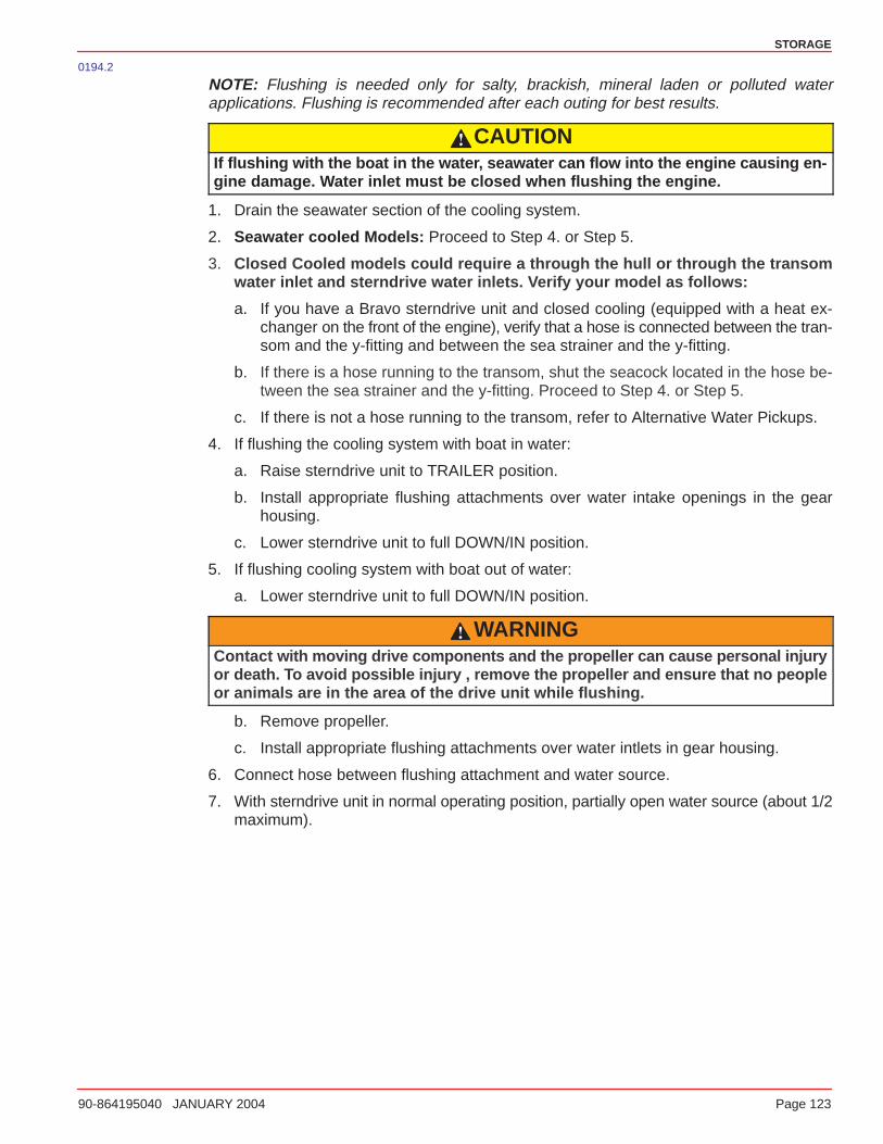
STORAGE
90-864195040 JANUARY 2004 Page 123
0194.2
NOTE: Flushing is needed only for salty, brackish, mineral laden or polluted waterapplications. Flushing is recommended after each outing for best results.
CAUTIONIf flushing with the boat in the water, seawater can flow into the engine causing en-gine damage. Water inlet must be closed when flushing the engine.
1. Drain the seawater section of the cooling system.
2. Seawater cooled Models: Proceed to Step 4. or Step 5.
3. Closed Cooled models could require a through the hull or through the transomwater inlet and sterndrive water inlets. Verify your model as follows:
a. If you have a Bravo sterndrive unit and closed cooling (equipped with a heat ex-changer on the front of the engine), verify that a hose is connected between the tran-som and the y-fitting and between the sea strainer and the y-fitting.
b. If there is a hose running to the transom, shut the seacock located in the hose be-tween the sea strainer and the y-fitting. Proceed to Step 4. or Step 5.
c. If there is not a hose running to the transom, refer to Alternative Water Pickups.
4. If flushing the cooling system with boat in water:
a. Raise sterndrive unit to TRAILER position.
b. Install appropriate flushing attachments over water intake openings in the gearhousing.
c. Lower sterndrive unit to full DOWN/IN position.
5. If flushing cooling system with boat out of water:
a. Lower sterndrive unit to full DOWN/IN position.
WARNINGContact with moving drive components and the propeller can cause personal injuryor death. To avoid possible injury , remove the propeller and ensure that no peopleor animals are in the area of the drive unit while flushing.
b. Remove propeller.
c. Install appropriate flushing attachments over water intlets in gear housing.
6. Connect hose between flushing attachment and water source.
7. With sterndrive unit in normal operating position, partially open water source (about 1/2maximum).

STORAGE
Page 124 90-864195040 JANUARY 2004
8. Place sterndrive in NEUTRAL, idle speed position and start engine.
CAUTIONSuction created by the seawater pickup pump may collapse the flushing water hosecausing the engine to overheat. Avoid engine damage from overheating, Do NOToperate the engine above 1500 rpm.
9. Slowly advance throttle until engine reaches 1300 rpm (+/–100 rpm).
CAUTIONEngine overheating can cause engine damage. To avoid, observe the water temper-ature gauge and ensure that the engine is operating in the normal range.
10. Observe the water temperature gauge to ensure that the engine is operating in thenormal range.
11. Operate engine with sterndrive in NEUTRAL for about 10 minutes or until dischargewater is clear.
12. Slowly return throttle to idle speed position.
13. Stop engine.
14. Shut off water and remove flushing attachment.
15. Remove the seawater inlet hose from the seawater pump and plug the hose to preventwater from siphoning into the engine.
16. Tag the ignition switch with an appropriate tag requiring the seawater inlet hose to bereconnected prior to operating engine.
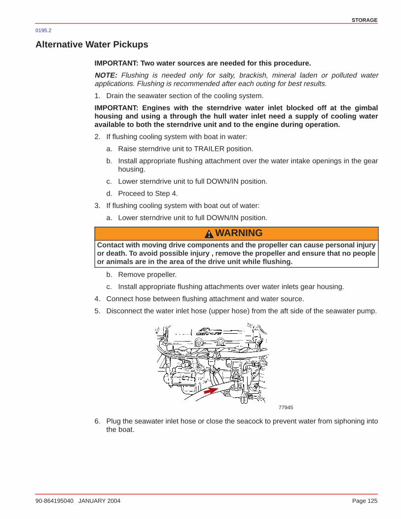
STORAGE
90-864195040 JANUARY 2004 Page 125
0195.2
Alternative Water Pickups
IMPORTANT: Two water sources are needed for this procedure.
NOTE: Flushing is needed only for salty, brackish, mineral laden or polluted waterapplications. Flushing is recommended after each outing for best results.
1. Drain the seawater section of the cooling system.
IMPORTANT: Engines with the sterndrive water inlet blocked off at the gimbalhousing and using a through the hull water inlet need a supply of cooling wateravailable to both the sterndrive unit and to the engine during operation.
2. If flushing cooling system with boat in water:
a. Raise sterndrive unit to TRAILER position.
b. Install appropriate flushing attachment over the water intake openings in the gearhousing.
c. Lower sterndrive unit to full DOWN/IN position.
d. Proceed to Step 4.
3. If flushing cooling system with boat out of water:
a. Lower sterndrive unit to full DOWN/IN position.
WARNINGContact with moving drive components and the propeller can cause personal injuryor death. To avoid possible injury , remove the propeller and ensure that no peopleor animals are in the area of the drive unit while flushing.
b. Remove propeller.
c. Install appropriate flushing attachments over water inlets gear housing.
4. Connect hose between flushing attachment and water source.
5. Disconnect the water inlet hose (upper hose) from the aft side of the seawater pump.
77945
6. Plug the seawater inlet hose or close the seacock to prevent water from siphoning intothe boat.
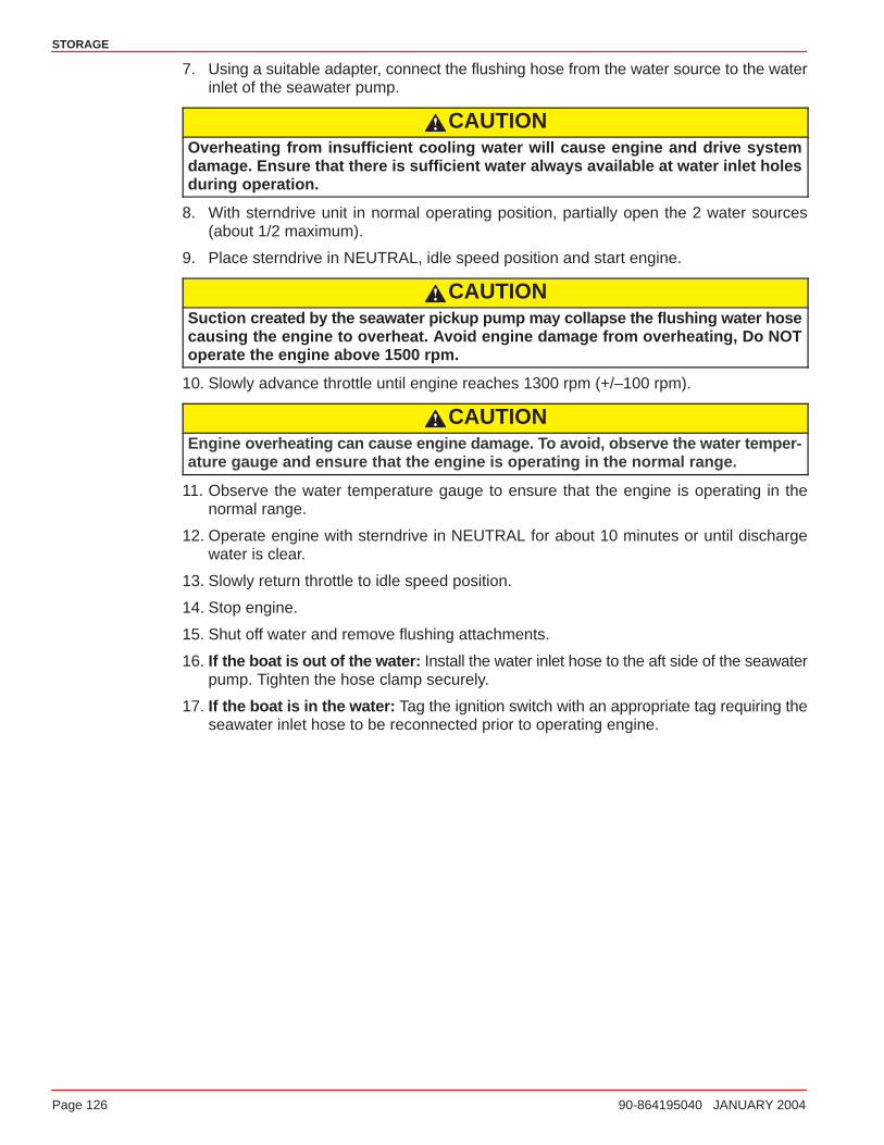
STORAGE
Page 126 90-864195040 JANUARY 2004
7. Using a suitable adapter, connect the flushing hose from the water source to the waterinlet of the seawater pump.
CAUTIONOverheating from insufficient cooling water will cause engine and drive systemdamage. Ensure that there is sufficient water always available at water inlet holesduring operation.
8. With sterndrive unit in normal operating position, partially open the 2 water sources(about 1/2 maximum).
9. Place sterndrive in NEUTRAL, idle speed position and start engine.
CAUTIONSuction created by the seawater pickup pump may collapse the flushing water hosecausing the engine to overheat. Avoid engine damage from overheating, Do NOToperate the engine above 1500 rpm.
10. Slowly advance throttle until engine reaches 1300 rpm (+/–100 rpm).
CAUTIONEngine overheating can cause engine damage. To avoid, observe the water temper-ature gauge and ensure that the engine is operating in the normal range.
11. Observe the water temperature gauge to ensure that the engine is operating in thenormal range.
12. Operate engine with sterndrive in NEUTRAL for about 10 minutes or until dischargewater is clear.
13. Slowly return throttle to idle speed position.
14. Stop engine.
15. Shut off water and remove flushing attachments.
16. If the boat is out of the water: Install the water inlet hose to the aft side of the seawaterpump. Tighten the hose clamp securely.
17. If the boat is in the water: Tag the ignition switch with an appropriate tag requiring theseawater inlet hose to be reconnected prior to operating engine.
STORAGE
90-864195040 JANUARY 2004 Page 127
0101
Power Package Recommissioning
1. Ensure that all cooling system hoses are connected properly and hose clamps are tight.
CAUTIONWhen installing the battery, be sure to connect the NEGATIVE (–) battery cable tothe NEGATIVE (–) battery terminal and the POSITIVE (+) battery cable to thePOSITIVE (+) battery terminal. If the battery cables are reversed, electrical systemdamage will result.
2. Install a fully-charged battery. Clean the battery cable clamps and terminals andreconnect cables (see CAUTION listed above). Tighten each cable clamp securelywhen connecting.
3. Coat the terminal connections with a battery terminal anti-corrosion agent.
4. Perform all the checks in the BEFORE STARTING column of the Operations Chart.
CAUTIONOverheating from insufficient cooling water will cause engine and drive systemdamage. Ensure that there is sufficient water always available at water inlet holesduring operation.
5. Start the engine and closely observe instrumentation to ensure that all systems arefunctioning correctly.
6. Carefully inspect the engine for fuel, oil, fluid, water and exhaust leaks.
7. Inspect the steering system, shift and throttle control for proper operation.

STORAGE
Page 128 90-864195040 JANUARY 2004
NOTES:

7
TROUBLESHOOTING
90-864195040 JANUARY 2004 Page 129
TROUBLESHOOTING
Table of Contents
Diagnosing EFI Problems 130. . . . . . . . . . . . . . Troubleshooting Charts 130. . . . . . . . . . . . . . .
Starter Motor Will Not Crank Engine, Or Cranks Slow 130. . . . . . . . . . . . . . . . . . . . . Engine Will Not Start, Or Is Hard To Start 130. . . . . . . . . . . . . . . . . . . . . . . . . . . . . . . Engine Runs Rough, Misses And/Or Backfires 131. . . . . . . . . . . . . . . . . . . . . . . . . . . Poor Performance 131. . . . . . . . . . . . . . . . . . . Excessive Engine Temperature 132. . . . . . . . Insufficient Engine Temperature 132. . . . . . .
Low Engine Oil Pressure 132. . . . . . . . . . . . . Battery Will Not Come Up On Charge 133. . Remote Control Operates Hard, Binds, Has Excessive Free-play Or Makes Unusual Sounds 133. . . . . . . . . . . . . . . . . . . . Steering Wheel Turns Hard Or Jerky 134. . . Power Trim Does Not Operate (Motor Doesn’t Operate) 134. . . . . . . . . . . . . . . . . . . . Power Trim Does Not Operate (Motor Operates But Sterndrive Unit Does Not Move) 134. . . . . . . . . . . . . . . . . . . . . . . . . . . . .
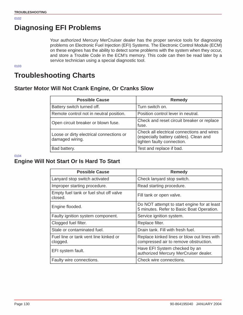
TROUBLESHOOTING
Page 130 90-864195040 JANUARY 2004
0102
Diagnosing EFI Problems
Your authorized Mercury MerCruiser dealer has the proper service tools for diagnosingproblems on Electronic Fuel Injection (EFI) Systems. The Electronic Control Module (ECM)on these engines has the ability to detect some problems with the system when they occur,and store a Trouble Code in the ECM’s memory. This code can then be read later by aservice technician using a special diagnostic tool.
0103
Troubleshooting Charts
Starter Motor Will Not Crank Engine, Or Cranks Slow
Possible Cause Remedy
Battery switch turned off. Turn switch on.
Remote control not in neutral position. Position control lever in neutral.
Open circuit breaker or blown fuse. Check and reset circuit breaker or replacefuse.
Loose or dirty electrical connections ordamaged wiring.
Check all electrical connections and wires(especially battery cables). Clean andtighten faulty connection.
Bad battery. Test and replace if bad.
0104
Engine Will Not Start Or Is Hard To Start
Possible Cause Remedy
Lanyard stop switch activated Check lanyard stop switch.
Improper starting procedure. Read starting procedure.
Empty fuel tank or fuel shut off valveclosed.
Fill tank or open valve.
Engine flooded. Do NOT attempt to start engine for at least5 minutes. Refer to Basic Boat Operation.
Faulty ignition system component. Service ignition system.
Clogged fuel filter. Replace filter.
Stale or contaminated fuel. Drain tank. Fill with fresh fuel.
Fuel line or tank vent line kinked orclogged.
Replace kinked lines or blow out lines withcompressed air to remove obstruction.
EFI system fault. Have EFI System checked by anauthorized Mercury MerCruiser dealer.
Faulty wire connections. Check wire connections.
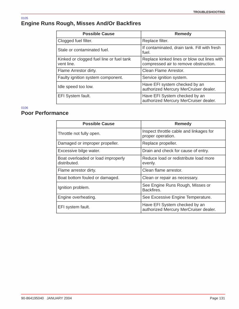
TROUBLESHOOTING
90-864195040 JANUARY 2004 Page 131
0105
Engine Runs Rough, Misses And/Or Backfires
Possible Cause Remedy
Clogged fuel filter. Replace filter.
Stale or contaminated fuel. If contaminated, drain tank. Fill with freshfuel.
Kinked or clogged fuel line or fuel tankvent line.
Replace kinked lines or blow out lines withcompressed air to remove obstruction.
Flame Arrestor dirty. Clean Flame Arrestor.
Faulty ignition system component. Service ignition system.
Idle speed too low. Have EFI system checked by anauthorized Mercury MerCruiser dealer.
EFI System fault. Have EFI System checked by anauthorized Mercury MerCruiser dealer.
0106
Poor Performance
Possible Cause Remedy
Throttle not fully open. Inspect throttle cable and linkages forproper operation.
Damaged or improper propeller. Replace propeller.
Excessive bilge water. Drain and check for cause of entry.
Boat overloaded or load improperlydistributed.
Reduce load or redistribute load moreevenly.
Flame arrestor dirty. Clean flame arrestor.
Boat bottom fouled or damaged. Clean or repair as necessary.
Ignition problem. See Engine Runs Rough, Misses orBackfires.
Engine overheating. See Excessive Engine Temperature.
EFI system fault. Have EFI System checked by anauthorized Mercury MerCruiser dealer.
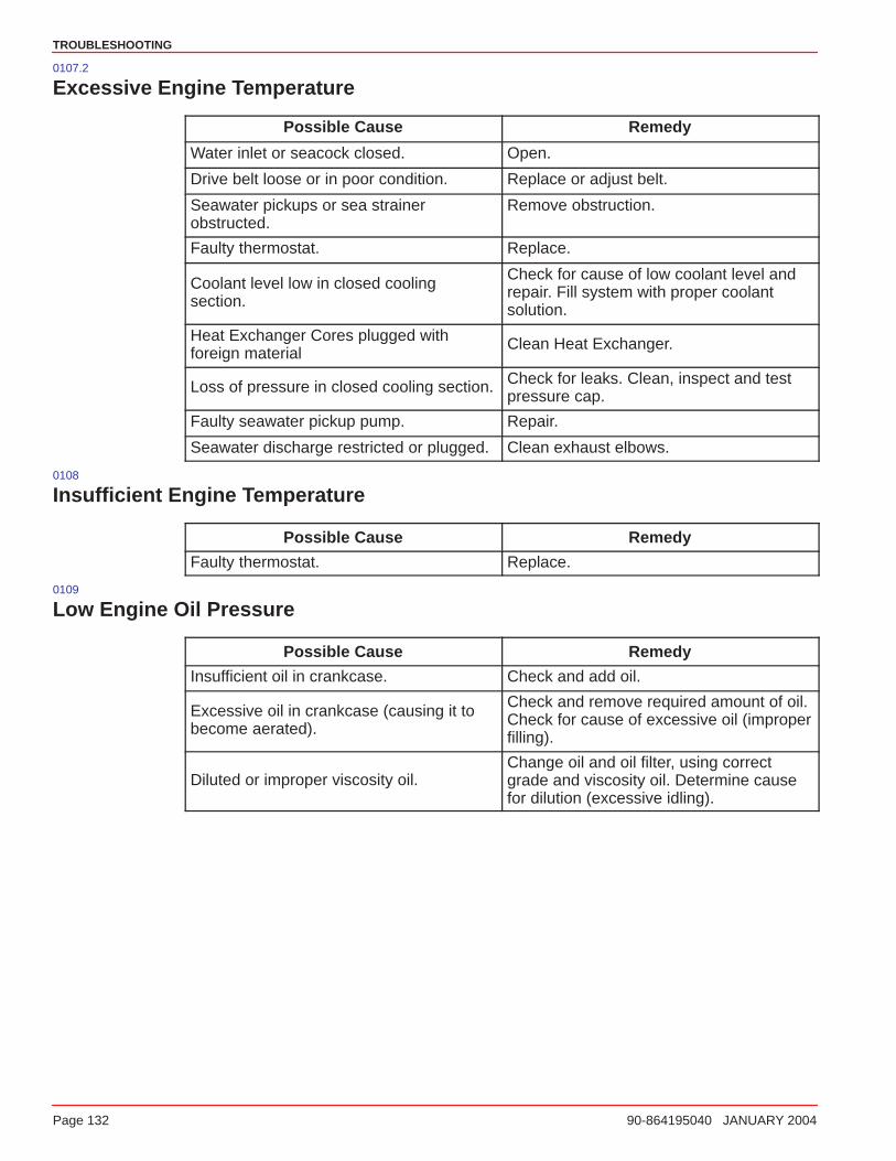
TROUBLESHOOTING
Page 132 90-864195040 JANUARY 2004
0107.2
Excessive Engine Temperature
Possible Cause Remedy
Water inlet or seacock closed. Open.
Drive belt loose or in poor condition. Replace or adjust belt.
Seawater pickups or sea strainerobstructed.
Remove obstruction.
Faulty thermostat. Replace.
Coolant level low in closed coolingsection.
Check for cause of low coolant level andrepair. Fill system with proper coolantsolution.
Heat Exchanger Cores plugged withforeign material
Clean Heat Exchanger.
Loss of pressure in closed cooling section. Check for leaks. Clean, inspect and testpressure cap.
Faulty seawater pickup pump. Repair.
Seawater discharge restricted or plugged. Clean exhaust elbows.
0108
Insufficient Engine Temperature
Possible Cause Remedy
Faulty thermostat. Replace.
0109
Low Engine Oil Pressure
Possible Cause Remedy
Insufficient oil in crankcase. Check and add oil.
Excessive oil in crankcase (causing it tobecome aerated).
Check and remove required amount of oil.Check for cause of excessive oil (improperfilling).
Diluted or improper viscosity oil.Change oil and oil filter, using correctgrade and viscosity oil. Determine causefor dilution (excessive idling).
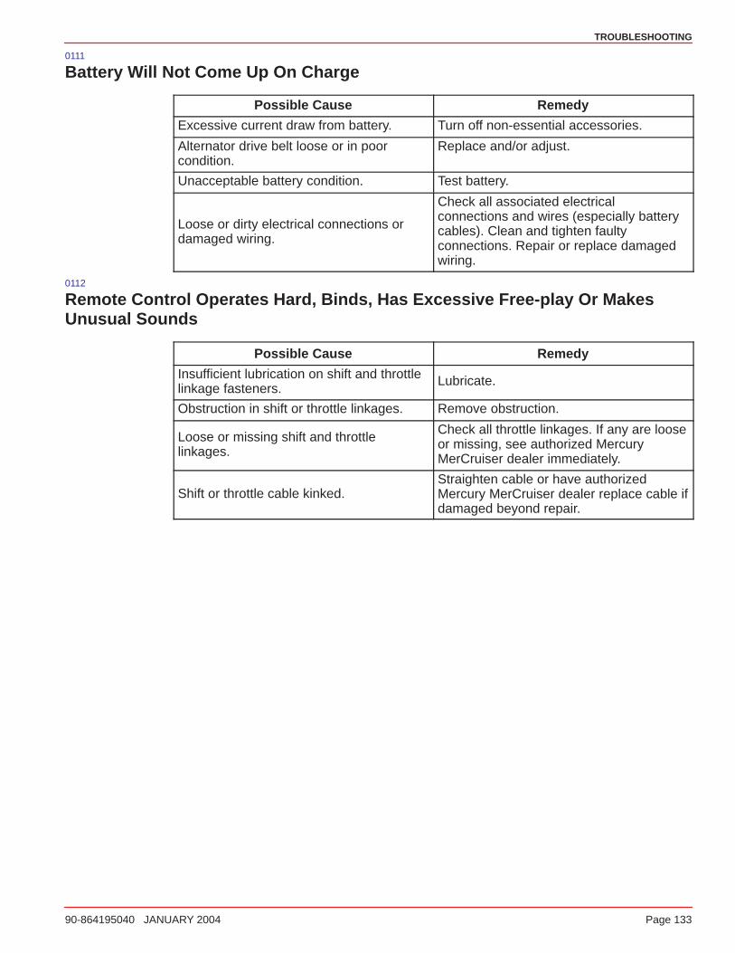
TROUBLESHOOTING
90-864195040 JANUARY 2004 Page 133
0111
Battery Will Not Come Up On Charge
Possible Cause Remedy
Excessive current draw from battery. Turn off non-essential accessories.
Alternator drive belt loose or in poorcondition.
Replace and/or adjust.
Unacceptable battery condition. Test battery.
Loose or dirty electrical connections ordamaged wiring.
Check all associated electricalconnections and wires (especially batterycables). Clean and tighten faultyconnections. Repair or replace damagedwiring.
0112
Remote Control Operates Hard, Binds, Has Excessive Free-play Or MakesUnusual Sounds
Possible Cause Remedy
Insufficient lubrication on shift and throttlelinkage fasteners.
Lubricate.
Obstruction in shift or throttle linkages. Remove obstruction.
Loose or missing shift and throttlelinkages.
Check all throttle linkages. If any are looseor missing, see authorized MercuryMerCruiser dealer immediately.
Shift or throttle cable kinked.Straighten cable or have authorizedMercury MerCruiser dealer replace cable ifdamaged beyond repair.
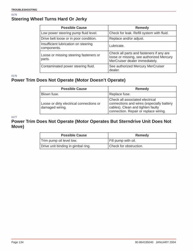
TROUBLESHOOTING
Page 134 90-864195040 JANUARY 2004
0175
Steering Wheel Turns Hard Or Jerky
Possible Cause Remedy
Low power steering pump fluid level. Check for leak. Refill system with fluid.
Drive belt loose or in poor condition. Replace and/or adjust.
Insufficient lubrication on steeringcomponents.
Lubricate.
Loose or missing steering fasteners orparts.
Check all parts and fasteners if any areloose or missing, see authorized MercuryMerCruiser dealer immediately.
Contaminated power steering fluid. See authorized Mercury MerCruiserdealer.
0176
Power Trim Does Not Operate (Motor Doesn’t Operate)
Possible Cause Remedy
Blown fuse. Replace fuse.
Loose or dirty electrical connections ordamaged wiring.
Check all associated electricalconnections and wires (especially batterycables). Clean and tighten faultyconnection. Repair or replace wiring.
0177
Power Trim Does Not Operate (Motor Operates But Sterndrive Unit Does NotMove)
Possible Cause Remedy
Trim pump oil level low. Fill pump with oil.
Drive unit binding in gimbal ring. Check for obstruction.
8
CUSTOMER ASSISTANCE INFORMATION
90-864195040 JANUARY 2004 Page 135
CUSTOMER ASSISTANCE INFORMATION
Table of Contents
Owner Service Assistance 136. . . . . . . . . . . . . Local Repair Service 136. . . . . . . . . . . . . . . . . Service Away From Home 136. . . . . . . . . . . . Stolen Power Package 136. . . . . . . . . . . . . . . Attention Required After Submersion 136. . . Replacement Service Parts 137. . . . . . . . . . .
Parts And Accessories Inquiries 137. . . . Resolving A Problem 138. . . . . . . . . . . . . . . . . Mercury Marine Service Offices 139. . . . . . .
Customer Service Literature 140. . . . . . . . . . . English Language 140. . . . . . . . . . . . . . . . . . . Other Languages 140. . . . . . . . . . . . . . . . . . . . Andre sprog 140. . . . . . . . . . . . . . . . . . . . . . . . Andere talen 140. . . . . . . . . . . . . . . . . . . . . . . .
Muut kielet 140. . . . . . . . . . . . . . . . . . . . . . . . . . Autres langues 140. . . . . . . . . . . . . . . . . . . . . . Andere Sprachen 141. . . . . . . . . . . . . . . . . . . . Altre lingue 141. . . . . . . . . . . . . . . . . . . . . . . . . Andre språk 141. . . . . . . . . . . . . . . . . . . . . . . . . Outros Idiomas 141. . . . . . . . . . . . . . . . . . . . . . Otros idiomas 141. . . . . . . . . . . . . . . . . . . . . . . Andra språk 141. . . . . . . . . . . . . . . . . . . . . . . . . ��� ���� ���� � � � � � � � � � � � � � � � � � � � � � �
Ordering Literature 142. . . . . . . . . . . . . . . . . . . . United States and Canada 142. . . . . . . . . . . . Outside The United States and Canada 142. . . . . . . . . . . . . . . . . . . . . . . .
CUSTOMER ASSISTANCE INFORMATION
Page 136 90-864195040 JANUARY 2004
0113
Owner Service Assistance
Local Repair ServiceAlways return your Mercury MerCruiser powered boat to your authorized dealer should theneed for service arise. Only he has the factory trained mechanics, knowledge, special toolsand equipment and the genuine Quicksilver parts and accessories* to properly service yourengine should the need occur. He knows your engine best.
* Quicksilver parts and accessories are engineered and built by Mercury Marine, specifically for MercuryMerCruiser sterndrives and inboards.
0114
Service Away From HomeIf you are away from your local dealer and the need arises for service, contact the nearestauthorized dealer. Refer to the Yellow Pages of the telephone directory. If, for any reason,you cannot obtain service, contact the nearest Regional Service Center. Outside the UnitedStates and Canada, contact the nearest Marine Power International Service Center.
0115
Stolen Power PackageIf your power package is stolen, immediately advise the local authorities and MercuryMarine of the model and serial numbers and to whom the recovery is to be reported. Thisinformation is placed into a file at Mercury Marine to aid authorities and dealers in recoveryof stolen power packages.
0116
Attention Required After Submersion1. Before recovery, contact an authorized Mercury MerCruiser dealer.
2. After recovery, immediate service by an authorized Mercury MerCruiser dealer isrequired to prevent serious damage to power package.
CUSTOMER ASSISTANCE INFORMATION
90-864195040 JANUARY 2004 Page 137
0117
Replacement Service Parts
WARNINGElectrical, ignition and fuel system components on Mercury MerCruiser Enginesand Sterndrives are designed and manufactured to comply with U.S. Coast GuardRules and Regulations to minimize risks of fire or explosion.
Use of replacement electrical, ignition or fuel system components, which do notcomply to these rules and regulations, could result in a fire or explosion hazard andshould be avoided.
When servicing the electrical, ignition and fuel systems, it is extremely importantthat all components are properly installed and tightened. If not, any electrical orignition component opening would permit sparks to ignite fuel vapors from fuelsystem leaks, if they existed.
Marine engines are expected to operate at or near full throttle for most of their life. They arealso expected to operate in both fresh and saltwater environments. These conditionsrequire numerous special parts. Care should be exercised when replacing marine engineparts as specifications are quite different from those of the standard automotive engine.
For example, one of the most important, and probably the least suspected specialreplacement part, is the cylinder head gasket. Since saltwater is highly corrosive, thesteel-type automotive head gasket cannot be used. A marine engine head gasket usesspecial materials to resist corrosive action.
Since marine engines must be capable of running at or near maximum rpm much of the time,special valve springs, valve lifters, pistons, bearings, camshafts and other heavy-dutymoving parts are required for long life and peak performance.
These are but a few of the many special modifications that are required in MercuryMerCruiser marine engines to provide long life and dependable performance.
0118
PARTS AND ACCESSORIES INQUIRIES
All inquiries concerning Quicksilver replacement parts and accessories should be directedto your local authorized dealer. The dealer has the necessary information to order parts andaccessories for you should he not have them in stock. Only authorized dealers can purchasegenuine Quicksilver parts and accessories from the factory. Mercury Marine does not sellto unauthorized dealers or retail customers. When inquiring on parts and accessories, thedealer requires the engine model and serial numbers to order the correct parts.
CUSTOMER ASSISTANCE INFORMATION
Page 138 90-864195040 JANUARY 2004
0119
Resolving A ProblemSatisfaction with your Mercury MerCruiser product is very important to your dealer and tous. If you ever have a problem, question or concern about your power package, contact yourdealer or any authorized Mercury MerCruiser dealership. If additional assistance isrequired, take these steps:
1. Talk with the dealership’s sales manager or service manager. If thishas already been done, then contact the owner of the dealership.
2. Should you have a question, concern or problem that cannot beresolved by your dealership, please contact Mercury Marine ServiceOffice for assistance. Mercury Marine will work with you and yourdealership to resolve all problems.
EXTRA HELP
The following information will be needed by the service office:
• Your name and address
• Daytime telephone number
• Model and serial numbers for your power package
• The name and address of your dealership
• Nature of problem
Mercury Marine Service Offices are listed on the next page.
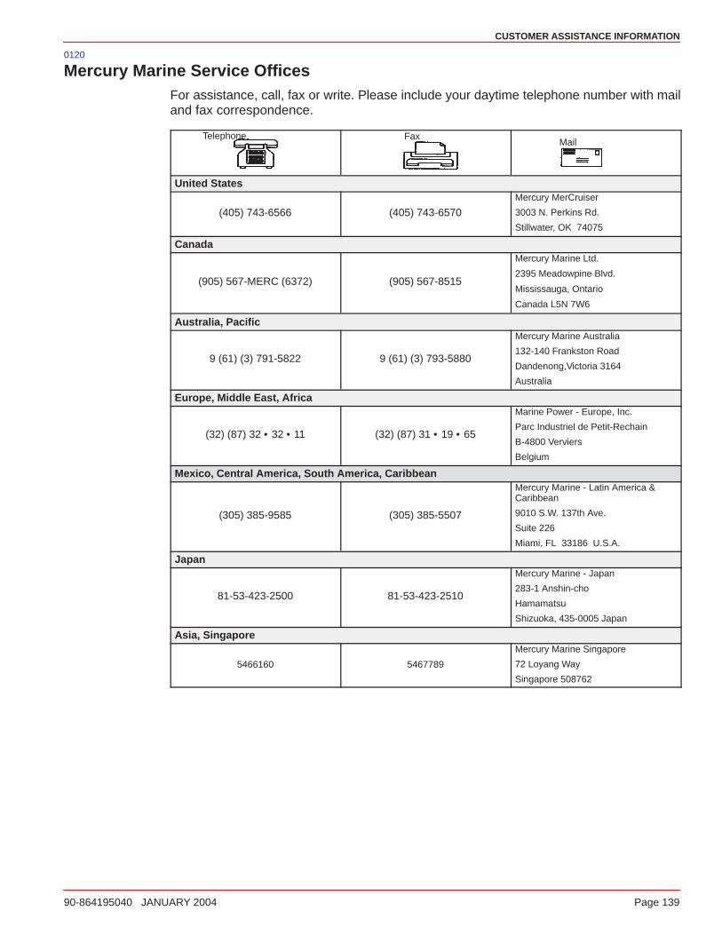
CUSTOMER ASSISTANCE INFORMATION
90-864195040 JANUARY 2004 Page 139
0120
Mercury Marine Service OfficesFor assistance, call, fax or write. Please include your daytime telephone number with mailand fax correspondence.
Telephone FaxMail
United States
(405) 743-6566 (405) 743-6570
Mercury MerCruiser
3003 N. Perkins Rd.
Stillwater, OK 74075
Canada
(905) 567-MERC (6372) (905) 567-8515
Mercury Marine Ltd.
2395 Meadowpine Blvd.
Mississauga, Ontario
Canada L5N 7W6
Australia, Pacific
9 (61) (3) 791-5822 9 (61) (3) 793-5880
Mercury Marine Australia
132-140 Frankston Road
Dandenong,Victoria 3164
Australia
Europe, Middle East, Africa
(32) (87) 32 • 32 • 11 (32) (87) 31 • 19 • 65
Marine Power - Europe, Inc.
Parc Industriel de Petit-Rechain
B-4800 Verviers
Belgium
Mexico, Central America, South America, Caribbean
(305) 385-9585 (305) 385-5507
Mercury Marine - Latin America &Caribbean
9010 S.W. 137th Ave.
Suite 226
Miami, FL 33186 U.S.A.
Japan
81-53-423-2500 81-53-423-2510
Mercury Marine - Japan
283-1 Anshin-cho
Hamamatsu
Shizuoka, 435-0005 Japan
Asia, Singapore
5466160 5467789
Mercury Marine Singapore
72 Loyang Way
Singapore 508762
CUSTOMER ASSISTANCE INFORMATION
Page 140 90-864195040 JANUARY 2004
0121
Customer Service Literature
English LanguageEnglish language publications are available from:
Mercury MarineAttn: Publications DepartmentW6250 West Pioneer RoadP.O. Box 1939Fond du Lac, WI 54935-1939
Outside the United States and Canada, contact the nearest Mercury Marine or MarinePower International Service Center for further information.
When ordering be sure to:
• List your product, model, year and serial numbers.
• Check the literature and quantities you want.
• Enclose full remittance in check or money order (NO COD).0178
Other LanguagesTo obtain an Operation, Maintenance and Warranty Manual in another language, contactthe nearest Mercury Marine or Marine Power International Service Center for information.A list of part numbers for other languages is provided with your power package.
Andre sprogKontakt det nærmeste Mercury Marine eller Marine Power International servicecenter foroplysninger om hvordan du kan anskaffe en Betjenings– og vedligeholdelsesmanual på etandet sprog. En liste med reservedelsnumre for andre sprog leveres sammen med dinpower–pakke.
Andere talenVoor het verkrijgen van een Handleiding voor gebruik en onderhoud in andere talen dientu contact op te nemen met het dichtstbijzijnde internationale servicecentrum van MercuryMarine of Marine Power voor informatie hierover. Een lijst met onderdeelnummers voorandere talen wordt bij uw motorinstallatie geleverd.
Muut kieletSaadaksesi Käyttö– ja huolto–ohjekirjoja muilla kielillä, ota yhteys lähimpään MercuryMarine tai Marine Power International huoltokeskukseen, josta saat lähempiä tietoja.Moottorisi mukana seuraa monikielinen varaosanumeroluettelo.
Autres languesPour obtenir un Manuel d’utilisation et d’entretien dans une autre langue, contactez lecentre de service après–vente international Mercury Marine ou Marine Power le plus prochepour toute information. Une liste des numéros de pièces en d’autres langues accompagnevotre bloc–moteur.
CUSTOMER ASSISTANCE INFORMATION
90-864195040 JANUARY 2004 Page 141
Andere SprachenUm eine Betriebs– und Wartungsanleitung in einer anderen Sprache zu erhalten, wendenSie sich an das nächste Mercury Marine oder Marine Power International Service Center.Eine Liste mit Teilenummern für Fremdsprachen ist im Lieferumfang Ihres Motors enthalten.
Altre linguePer ottenere il manuale di funzionamento e manutenzione in altra lingua, contattate il centroassistenza internazionale Mercury Marine o Marine Power più vicino. In dotazione con ilgruppo motore, viene fornito l’elenco dei codici prodotto dei componenti venduti all’estero.
Andre språkYtterligere informasjon om bruks– og vedlikeholdshåndbok på andre språk kan fås vedhenvendelse til nærmeste internasjonale servicecenter for Mercury Marine eller MarinePower. En liste over delenumre for andre språk følger med aggregatet.
Outros IdiomasPara obter um Manual de Operação e Manutenção em outro idioma, contate o Centro deServiço Internacional de “Marine Power” (Potência Marinha) ou a Mercury Marine maispróxima para obter informações. Uma lista de números de referência para outros idiomasé fornecida com o seu pacote de propulsão.
Otros idiomasPara obtener un Manual de operación y mantenimiento en otro idioma, póngase encontacto con el centro de servicio más cercano de Mercury Marine o Marine PowerInternational para recibir información. Con su conjunto motriz se entrega una lista de losnúmeros de pieza para los otros idiomas.
Andra språkFör att få Instruktions– och underhållsböcker på andra språk, kontakta närmaste MercuryMarine eller Marine Power International servicecenter, som kan ge ytterligare information.En förteckning över artikelnummer på andra språk medföljer ditt kraftpaket.
����� ���������� �� ���������� ��� � ���ρ �� ������ρ �� ��� �����ρ���� �� ���� �#���,������������� �� �� ���������ρ� ������� ����ρ� ��ρ�� ��� Mercury Marine � ��� MarinePower �� ���ρ���ρ ��. �� ������ ���"�� ��� �����"���� ��! ���� ������ � �ρ���#���ρ� �� �� �� ����� �#����.
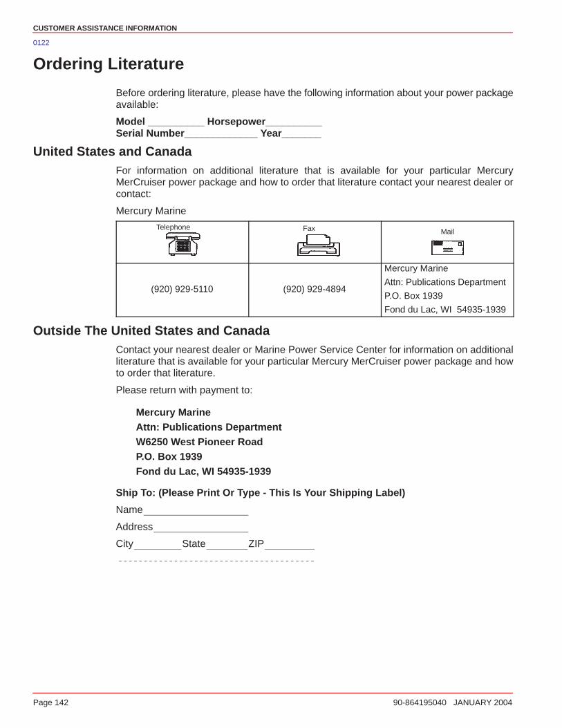
CUSTOMER ASSISTANCE INFORMATION
Page 142 90-864195040 JANUARY 2004
0122
Ordering Literature
Before ordering literature, please have the following information about your power packageavailable:
Model __________ Horsepower__________Serial Number_____________ Year_______
United States and CanadaFor information on additional literature that is available for your particular MercuryMerCruiser power package and how to order that literature contact your nearest dealer orcontact:
Mercury Marine
Telephone Fax Mail
(920) 929-5110 (920) 929-4894
Mercury Marine
Attn: Publications Department
P.O. Box 1939
Fond du Lac, WI 54935-1939
Outside The United States and CanadaContact your nearest dealer or Marine Power Service Center for information on additionalliterature that is available for your particular Mercury MerCruiser power package and howto order that literature.
Please return with payment to:
Mercury MarineAttn: Publications DepartmentW6250 West Pioneer RoadP.O. Box 1939Fond du Lac, WI 54935-1939
Ship To: (Please Print Or Type - This Is Your Shipping Label)
Name
Address
City State ZIP


