Embed Size (px)
Citation preview
Modelling of Automotive Systems 1
Objectives To introduce mathematical models and optimization methods that allow a
systematic minimization of the energy consumption of vehicle systems.
VehicleA vehicle is a means of transport, such as bicycles, cars, motorcycles, trains, ships, and
aircraft. Vehicles that do not travel on land are often called crafts, such as watercraft, sailcraft, aircraft, hovercraft and spacecraft. Most land vehicles have wheels.
Scope of the vehicle: Passenger cars1. Autonomous2. Refuelling time short3. Transport 2-6 people4. Acceleration 10-15 seconds to 100km/h, and 5%ramp at legal top speed
Vehicle Propulsion Systems
Modelling of Automotive Systems 2
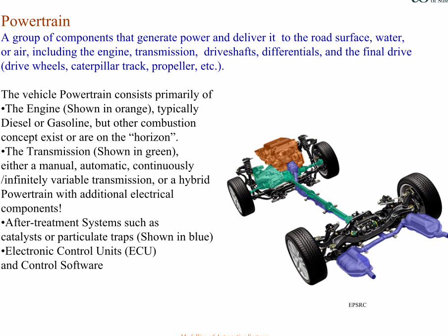
PowertrainA group of components that generate power and deliver it to the road surface, water, or air, including the engine, transmission, driveshafts, differentials, and the final drive (drive wheels, caterpillar track, propeller, etc.).
The vehicle Powertrain consists primarily of •The Engine (Shown in orange), typically Diesel or Gasoline, but other combustionconcept exist or are on the “horizon”.•The Transmission (Shown in green), either a manual, automatic, continuously/infinitely variable transmission, or a hybrid Powertrain with additional electrical components!•After-treatment Systems such as catalysts or particulate traps (Shown in blue)•Electronic Control Units (ECU) and Control Software
EPSRC
Modelling of Automotive Systems 3
Energy sourcesHydrocarbons: petroleum (Fossil/mineral or biofuel) , coal, and natural gasHydrogen – fuel cellBatteries
Biofuel (agrofuel) can be broadly defined as solid, liquid, or gas fuelconsisting of, or derived from biomass.
Biomass is grown from plants, including miscanthus, switchgrass, hemp, corn, poplar, willow and sugarcane
On-board energy carrier requirementsHigh energy densitySafe and no environmental hazards in production or operation.
Modelling of Automotive Systems 4
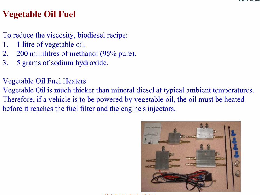
Vegetable Oil Fuel
To reduce the viscosity, biodiesel recipe:1. 1 litre of vegetable oil.2. 200 millilitres of methanol (95% pure).3. 5 grams of sodium hydroxide.
Vegetable Oil Fuel HeatersVegetable Oil is much thicker than mineral diesel at typical ambient temperatures. Therefore, if a vehicle is to be powered by vegetable oil, the oil must be heated before it reaches the fuel filter and the engine's injectors,
Modelling of Automotive Systems 5
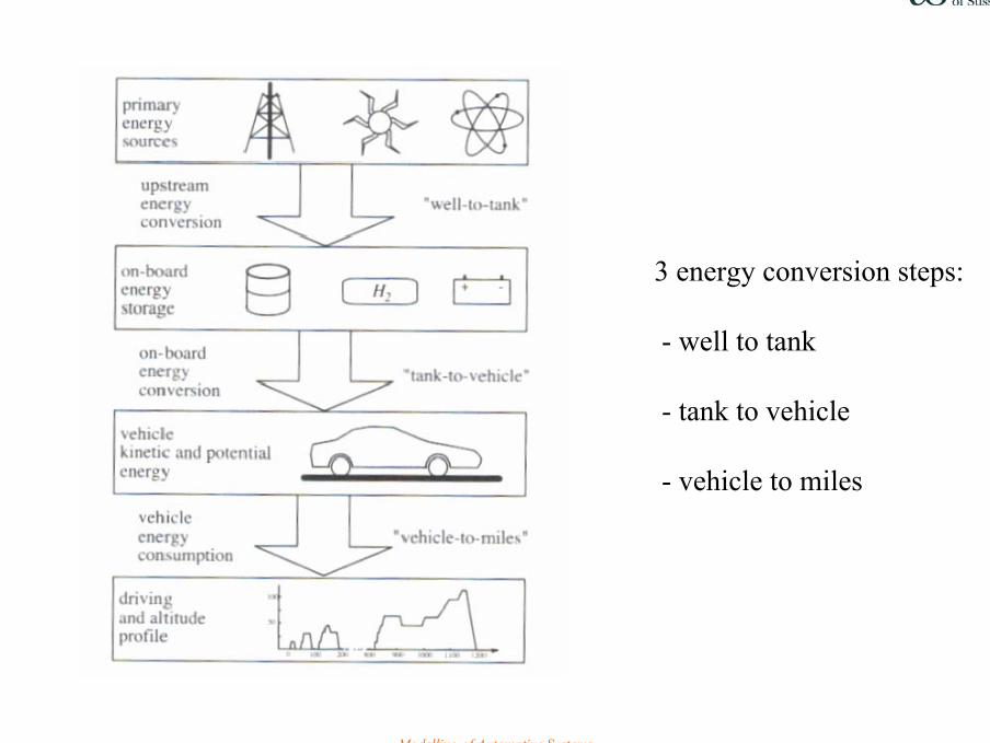
3 energy conversion steps:
- well to tank
- tank to vehicle
- vehicle to miles
Modelling of Automotive Systems 6
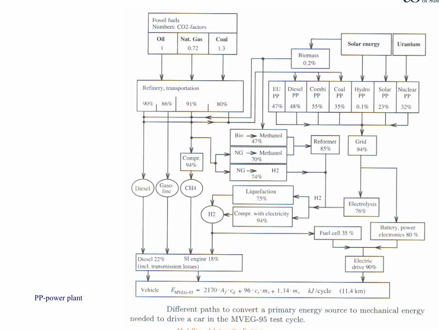
PP-power plant
Modelling of Automotive Systems 7
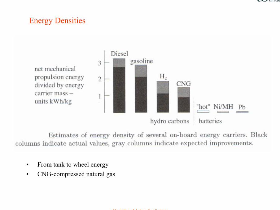
Energy Densities
• From tank to wheel energy• CNG-compressed natural gas
Modelling of Automotive Systems 8
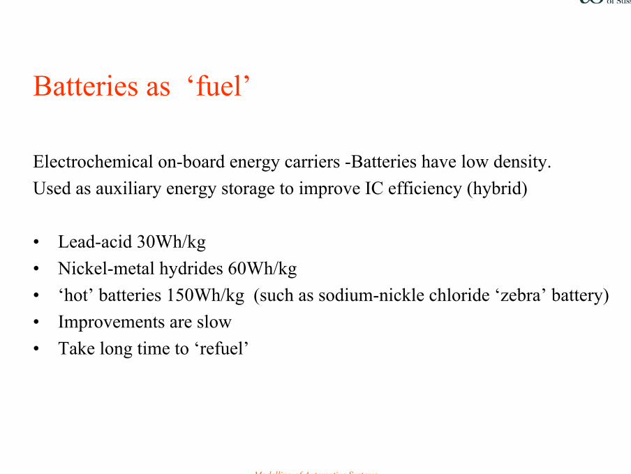
Batteries as ‘fuel’
Electrochemical on-board energy carriers -Batteries have low density.Used as auxiliary energy storage to improve IC efficiency (hybrid)
• Lead-acid 30Wh/kg• Nickel-metal hydrides 60Wh/kg• ‘hot’ batteries 150Wh/kg (such as sodium-nickle chloride ‘zebra’ battery)• Improvements are slow• Take long time to ‘refuel’
Modelling of Automotive Systems 9
Pathway to better fuel economy
• Improve well to tank efficiencyby optimizing upstream processes
• Improve tank to wheel efficiency by 1. improve the peak efficiency of components
2. improve the part load efficiency3. recuperate kinetic and potential energy in the vehicle4. control propulsion system configuration
• Improve wheel to mile efficiency by reducing the vehicle mass and aerodynamic and rolling losses
Modelling of Automotive Systems 10
Vehicle Energy
• Kinetic energy when have speed
• Potential energy when have altitudes
Vehicle Energy Losses (after engine)
• Aerodynamic drag • Rolling friction• Brake dissipation
Modelling of Automotive Systems 11
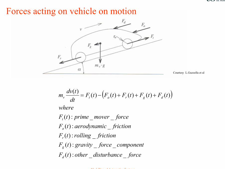
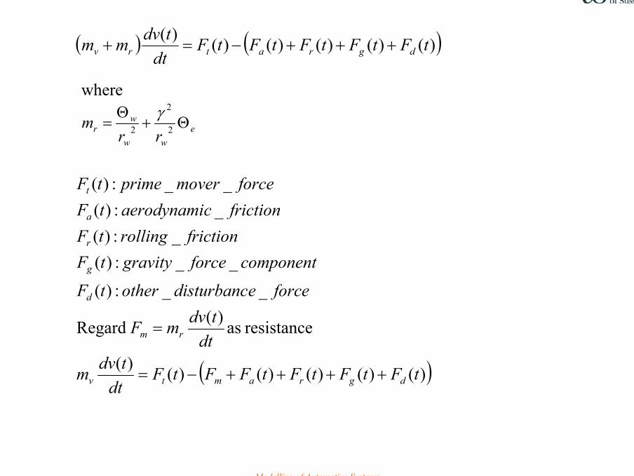
Forces acting on vehicle on motion
( )
forceedisturbancothertF
componentforcegravitytFfrictionrollingtF
frictioncaerodynamitFforcemoverprimetF
where
tFtFtFtFtFdt
tdvm
d
g
r
a
t
dgratv
__:)(
__:)(_:)(
_:)(__:)(
)()()()()()(+++−=
Courtesy L.Guzzella et al
Modelling of Automotive Systems 12
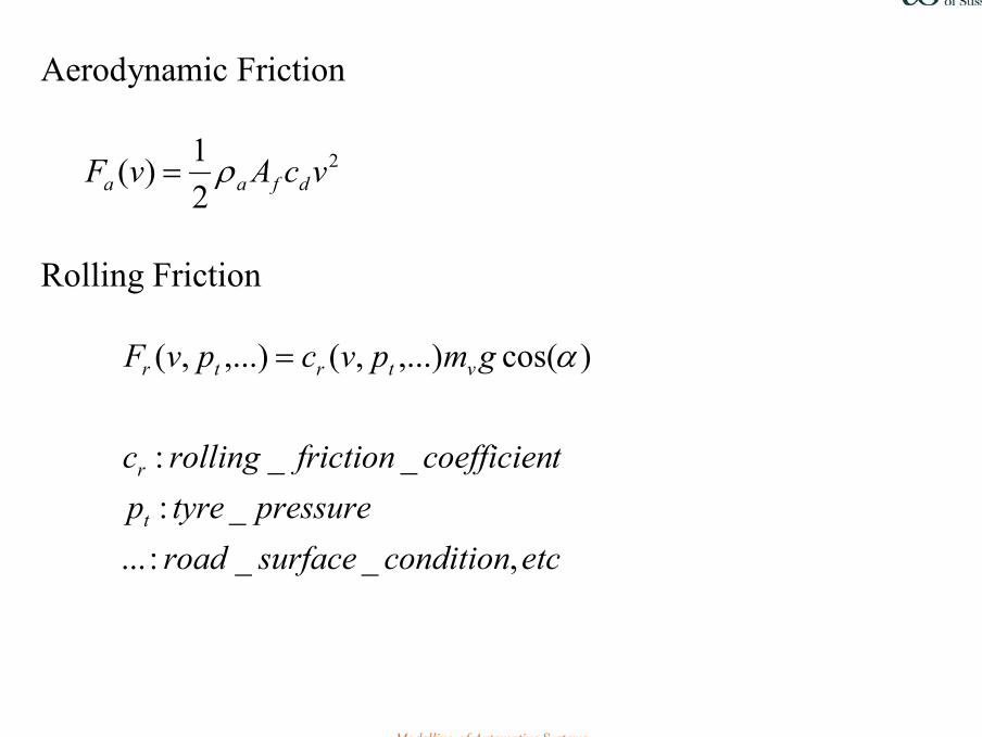
Aerodynamic Friction
2
21)( vcAvF dfaa ρ=
Rolling Friction
etcconditionsurfaceroad
pressuretyreptcoefficienfrictionrollingc
gmpvcpvF
t
r
vtrtr
,__:..._:
__:
)cos(,...),(,...),( α=
Modelling of Automotive Systems 13
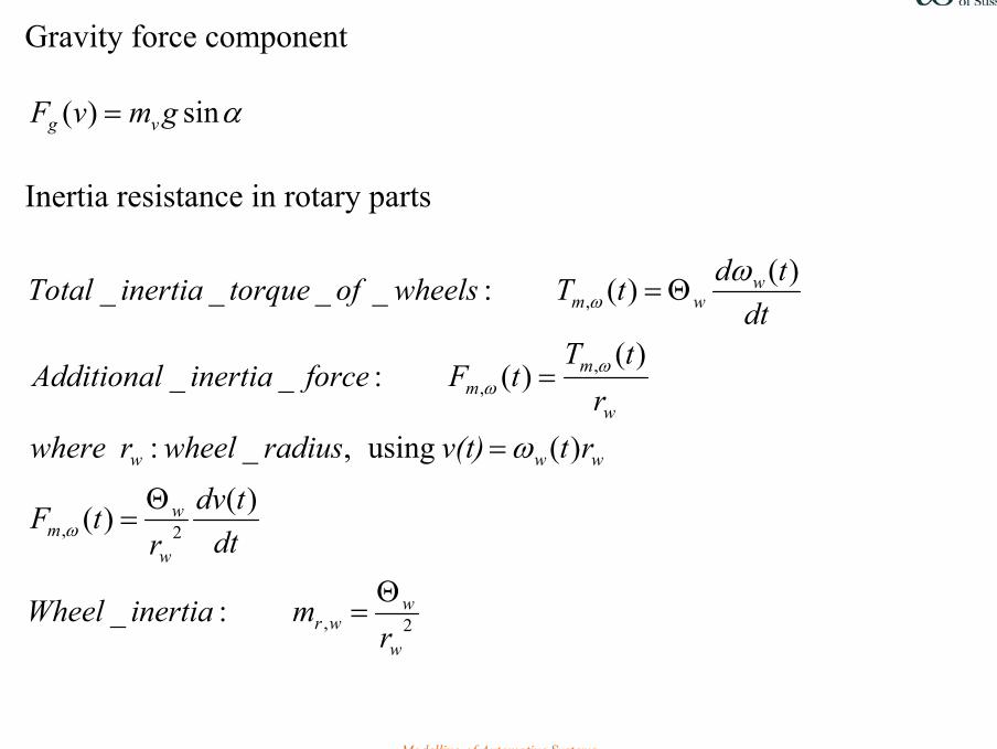
Gravity force component
αsin)( gmvF vg = Inertia resistance in rotary parts
2,
2,
,,
,
:_
)()(
)( using,_:
)()(:__
)()(:____
w
wwr
w
wm
www
w
mm
wwm
rminertiaWheel
dttdv
rtF
rtv(t)radiuswheelrwherer
tTtFforceinertiaAdditional
dttdtTwheelsoftorqueinertiaTotal
Θ=
Θ=
=
=
Θ=
ω
ωω
ω
ω
ω
Modelling of Automotive Systems 14
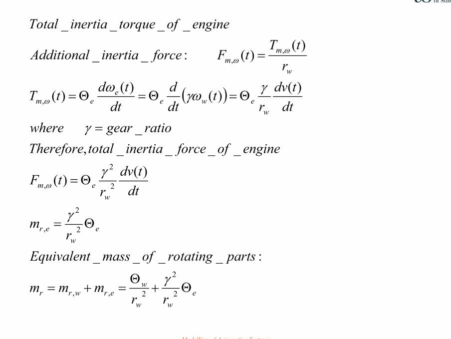
( )
eww
werwrr
ew
er
wem
wewe
eem
w
mm
rrmmm
partsrotatingofmassEquivalentr
m
dttdv
rtF
engineofforceinertiatotalThereforeratiogearwhere
dttdv
rt
dtd
dttdtT
rtT
tFforceinertiaAdditional
engineoftorqueinertiaTotal
Θ+Θ
=+=
Θ=
Θ=
=
Θ=Θ=Θ=
=
2
2
2,,
2
2
,
2
2
,
,
,,
:____
)()(
____,_
)()()()(
)()(:__
____
γ
γ
γ
γ
γγωω
ω
ω
ωω
Modelling of Automotive Systems 15
( ) ( )
( ))()()()()()(
resistance as)( Regard
__:)(
__:)(_:)(
_:)(__:)(
)()()()()()(
tFtFtFtFFtFdt
tdvm
dttdvmF
forceedisturbancothertF
componentforcegravitytFfrictionrollingtF
frictioncaerodynamitFforcemoverprimetF
tFtFtFtFtFdt
tdvmm
dgramtv
rm
d
g
r
a
t
dgratrv
++++−=
=
+++−=+
where
eww
wr rr
m Θ+Θ
= 2
2
2γ
Modelling of Automotive Systems 16
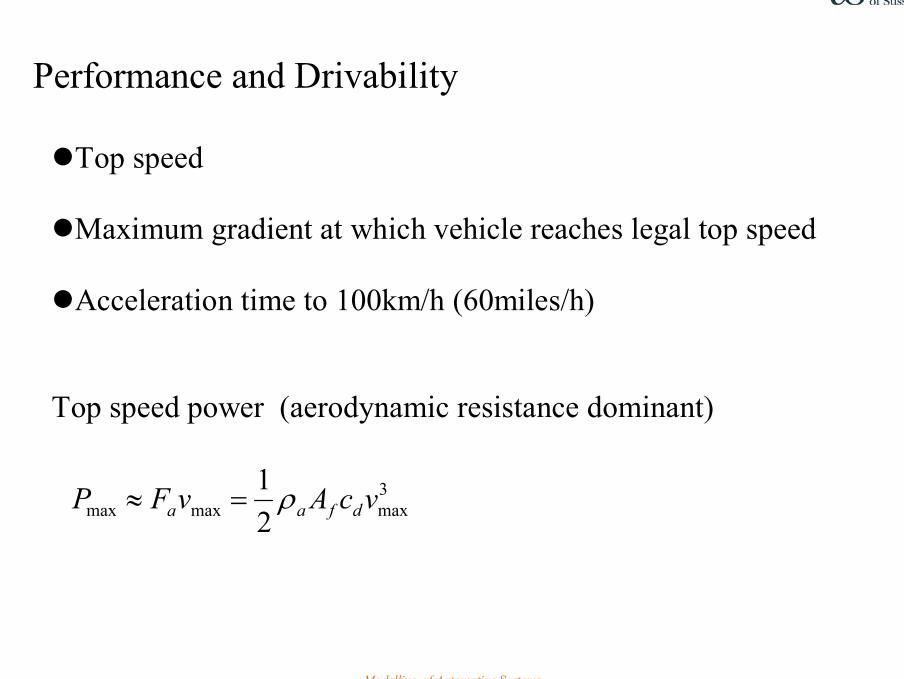
Performance and Drivability
Top speed
Maximum gradient at which vehicle reaches legal top speed
Acceleration time to 100km/h (60miles/h)
Top speed power (aerodynamic resistance dominant)
3maxmaxmax 2
1 vcAvFP dfaa ρ=≈
Modelling of Automotive Systems 17
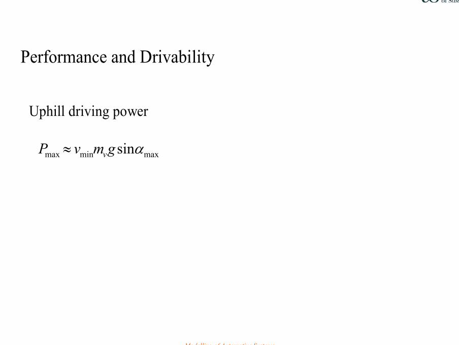
Performance and Drivability Uphill driving power maxminmax sinαgmvP v≈
Modelling of Automotive Systems 18
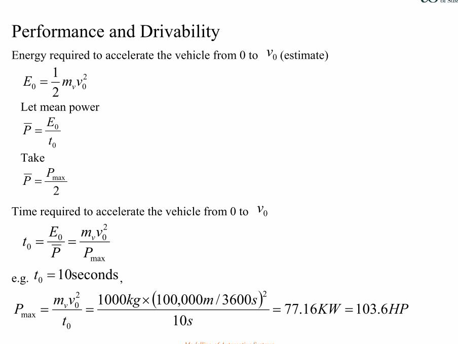
Performance and Drivability Energy required to accelerate the vehicle from 0 to 0v (estimate)
200 2
1 vmE v=
Let mean power
0
0
tEP =
Take
2maxPP =
Time required to accelerate the vehicle from 0 to 0v
max
200
0 Pvm
PEt v==
e.g. seconds100 =t ,
( ) HPKWs
smkgtvmP v 6.10316.77
103600/000,1001000 2
0
20
max ==×
==
Modelling of Automotive Systems 19
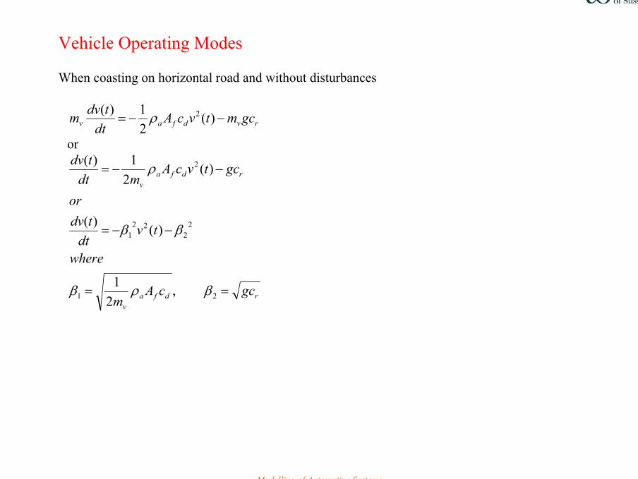
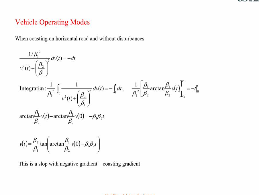
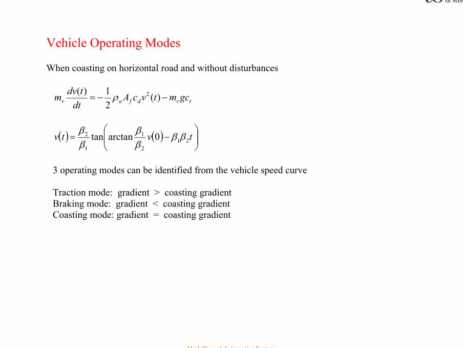
Vehicle Operating Modes When coasting on horizontal road and without disturbances
rvdfav gcmtvcAdt
tdvm −−= )(21)( 2ρ
or
rdfav
rdfav
gccAm
where
tvdt
tdvor
gctvcAmdt
tdv
==
−−=
−−=
21
22
221
2
,2
1
)()(
)(2
1)(
βρβ
ββ
ρ
Modelling of Automotive Systems 20
Vehicle Operating Modes When coasting on horizontal road and without disturbances
( )
( ) ( )
( ) ( )
−=
−=−
−=
−=
+
−=
+
∫∫
tvtv
tvtv
ttvdttdv
tv
dttdv
tv
tv
v
tv
v
212
1
1
2
212
1
2
1
02
1
2
12
102
1
222
1
2
1
22
21
0arctantan
0arctanarctan
arctan1,)(
)(
11:nIntegratio
)(
)(
/1
00
ββββ
ββ
ββββ
ββ
ββ
ββ
ββββ
ββ
β
This is a slop with negative gradient – coasting gradient
Modelling of Automotive Systems 21
Vehicle Operating Modes When coasting on horizontal road and without disturbances
rvdfav gcmtvcAdt
tdvm −−= )(21)( 2ρ
( ) ( )
−= tvtv 21
2
1
1
2 0arctantan ββββ
ββ
3 operating modes can be identified from the vehicle speed curve Traction mode: gradient > coasting gradient Braking mode: gradient < coasting gradient Coasting mode: gradient = coasting gradient
Modelling of Automotive Systems 22
0 20 40 60 80 100 120 140 160-5
0
5
10
15
20
25
30Coasting velocity
t (s)
v (m
/s)
( )( )
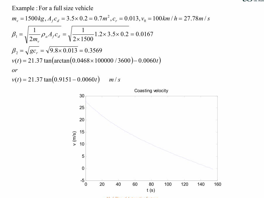
( ) smttvor
ttvgc
cAm
smhkmvcmcAkgm
r
dfav
rdfv
/0060.09151.0tan37.21)(
0060.03600/1000000468.0arctantan37.21)(3569.0013.08.9
0167.02.05.32.1150021
21
/78.27/100,013.0,7.02.05.3,1500vehiclesize full aFor :Example
2
1
02
−=
−×=
=×==
=×××
==
====×==
β
ρβ
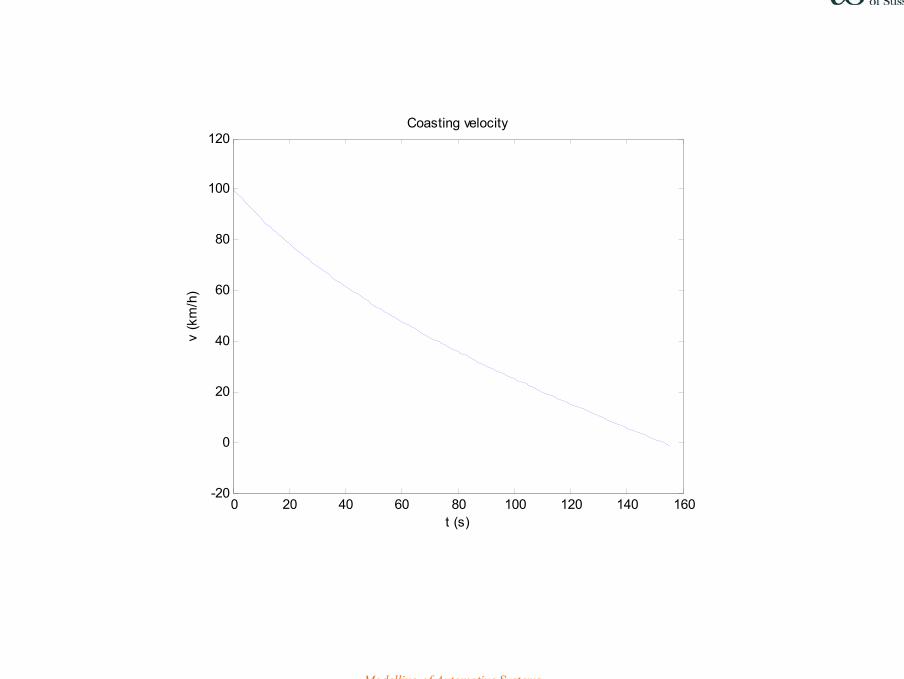
Modelling of Automotive Systems 23
0 20 40 60 80 100 120 140 160-20
0
20
40
60
80
100
120
v (k
m/h
)
t (s)
Coasting velocity

Modelling of Automotive Systems 24
Vehicle Operating Modes
Traction
0>tF
Braking
0<tF
Coasting
0=tF
L.Guzzella et al


