Embed Size (px)
Citation preview

MOVING THE SHARED MEMORYCLOSER TO THE PROCESSORS {DDMErik Hagersten, Anders Landin and Seif HaridiSICS Research Report R90:17B May 1991.�AbstractMultiprocessors with shared memory are considered more general and easierto program than message-passing machines. The scalability is, however, in favorof the latter. There are a number of proposals showing how the poor scalabilityof shared memory multiprocessors can be improved by the introduction of privatecaches attached to the processors. These caches are kept consistent with eachother by cache-coherence protocols.In this paper we introduce a new class of architectures called Cache OnlyMemory Architectures (COMA). These architectures provide the programmingparadigm of the shared-memory architectures, but are believed to be more scal-able. COMAs have no physically shared memory; instead, the caches attached tothe processors contain all the memory in the system, and their size is thereforelarge. A datum is allowed to be in any or many of the caches, and will automat-ically be moved to where it is needed by a cache-coherence protocol, which alsoensures that the last copy of a datum is never lost. The location of a datum inthe machine is completely decoupled from its address.We also introduce one example of COMA: the Data Di�usion Machine (DDM).The DDM is based on a hierarchical network structure, with processor/memorypairs at its tips. Remote accesses generally cause only a limited amount of tra�cover a limited part of the machine.The architecture is scalable in that there can be any number of levels in thehierarchy, and that the root bus of the hierarchy can be implemented by severalbuses, increasing the bandwidth.Keywords: Multiprocessor, hierarchical architecture, hierarchical buses, mul-tilevel cache, shared memory, split-transaction bus, cache coherence.�Swedish Institute of Computer Science; Box 1263 ; 164 28 KISTA ; SWEDEN.Email: fhag,landin,[email protected] 1

1 CACHE-ONLY MEMORY ARCHITECTURESMultiprocessor architectures are divided into two classes: shared-memory architecturesand message-passing architectures.Existing architectures with shared memory are typically computers with one com-mon shared memory, such as computers manufactured by Sequent and Encore, or withdistributed shared memory, such as the BBN Butter y and the IBM RP3. In the latter,known as non-uniform memory architectures (NUMA), each processor node containsa portion of the shared memory; consequently access times to di�erent parts of theshared address space can vary. Communication and synchronization in architectureswith shared memory are done implicitly through the common shared address space andby the use of synchronization primitives.Machines with shared memory typically have only a limited number of processors.Especially systems based on a single bus su�er from bus saturation. Their poor scala-bility can bene�t from large caches local to the processors. The contents of the cachesare kept coherent by a cache-coherence protocol. Each cache snoops the tra�c on thecommon bus and prevents any inconsistencies from occurring [Ste90].Message-passing architectures also have distributed memory, but lack the commonshared address space. Instead, each processor has its own address space. Examples ofsuch architectures are the Hypercube architectures by Intel and architectures based onthe Transputer by Inmos. Communication and synchronization among the processorsis handled by explicit messages. So, memory access and communication with otherprocessors are viewed as completely separate functions.Message-passing machines are said to scale better and consequently might have moreprocessors. Message-passing architectures, however, burden the software to a muchgreater extent in that it has to statically distribute the execution and memory usageamong the processors. Task migration and dynamic job allocation are very costly. Thus,the hardware scalability of a message-passing architecture is only useful to the extentthat the software can keep communication to a minimum.This is one of the reasons why shared-memory architectures are considered more gen-eral and easier to program. E�cient programs for NUMA architectures su�er softwarelimitations similar to those of message-passing architectures, in that processors need towork as much as possible in \their" portion of the shared memory in order to get theshortest access time and to keep communication to a minimum.In cache-only memory architectures (COMA), the memory organization is similar tothat of NUMA in that each processor holds a portion of the address space. However, allmemory in the COMA, called attraction memory (AM), is organized like large (second-level) caches. While each NUMA memory holds a static portion of the address space,the content of each AM changes dynamically throughout the computation. A cache-coherence protocol allows copies of a datum to exist in multiple AMs and maintainsthe coherence among the di�erent copies. When replacing one datum in an AM with amore recently accessed one, the protocol makes sure that the last copy of the datum inthe system is not lost.COMA provides a programming model identical to that of shared-memory architec-tures, but does not require static distribution of execution and memory usage in order2

to run e�ciently. COMA has advantages for moderately sized machines, as well as forlarge machines, in that it provides the largest possible (second-level) caches for a giventotal amount of memory, since all the memory is used in the AMs. The attraction mem-ories not only dynamically distribute the address space over the machine, but also cutdown the need for communication among processors, since most accesses are local to theattraction memory of the processor. The overhead required for accessing a large cachecompared to a large memory and the increased amount of memory for implementationare surprisingly small. Figure 1 compares COMA to other shared-memory architectures.Memory
Network
Shared Memory (UMA) Shared Memory (NUMA)
Mem Mem
Cache Only Memory (COMA)
AM AM
...
Network Network
... ...CacheProc
CacheProc
CacheProc
CacheProc
CacheProc
CacheProcFigure 1: Shared-memory architectures compared to the COMA.This paper describes the basic ideas behind a new architecture of the COMA class.The architecture, called the Data Di�usion Machine (DDM), relies on a hierarchical net-work structure. The paper �rst introduces the key ideas behind the DDM by describinga small machine and its protocol. It continues with a description of a large machine withhundreds of processors, followed by a more detailed study of some issues essential tomachines of this class, how to increase the network bandwidth, and how to implementvirtual memory and secondary storage. The paper ends with a brief introduction to theongoing prototype project and the simulated performance �gures.2 CACHE-COHERENCE STRATEGIESThe problem of maintaining coherence among read-write data shared by di�erent cacheshas been studied extensively over the last years. Coherence can either be kept bysoftware or hardware. It is our belief that the cache line of a COMA must be smallin order to prevent performance degradation by false sharing. Using a software-basedprotocol therefore introduces extensive overhead. Hardware-based schemes maintaincoherence without involving software and can therefore be implementedmore e�ciently.Examples of hardware-based protocols are snooping-cache protocols and directory-basedprotocols.Snooping-cache protocols have a distributed implementation. Each cache is respon-sible for snooping tra�c on the bus and taking necessary actions if an incoherence isabout to occur. 3

An example of such a protocol is the write-once protocol introduced by Goodman andreviewed by Stenstr�om [Ste90]. In that protocol, shown in Figure 2, each cache line canbe in one of the four states INVALID, VALID, RESERVED, or DIRTY. Many cachesmight have the same cache line in the state VALID at the same time, and may read itlocally. When writing to a cache line in VALID, the line changes state to RESERVED,and a write is sent on the common bus to the common memory. All other caches withlines in VALID snoop the write and invalidate their copies. At this point there is only onecached copy of the cache line containing the newly written value. The common memorynow also contains the new value. If a cache already has the cache line in RESERVED, itcan perform a write locally without any transactions on the common bus. Its value willnow di�er from that in the memory, and its state is therefore changed to DIRTY. Anyread requests from other caches to that cache line must now be intercepted, in order toprovide the new value, marked by \intercept" in the �gure. The �gure also shows theoptimization \Nread.inv", which allows a cache to read a private copy of a cache linewhen in state INVALID.Pread/Nread
Pread
Nread
Pwrite
Inv. Val.
Dirty Res.
Pwrite,Pread
Nwrite, Nread.inv
Nread/intercept
Pwrite/Nwrite
Pread
Pwrite/Nread.inv
Nread.inv
Nread.inv/intercept
NOTATION:
in−trans./out−trans.
P= processor trans.N= network trans.Figure 2: The write-once protocol.Snooping caches, as described above, rely on broadcasting and are not suited forgeneral interconnection networks: broadcasting would reduce the bandwidth availableto that of a single bus. Instead, directory-based schemes send messages directly betweennodes [Ste90]. A read request is sent to main memory, without any snooping. The mainmemory knows if the cache line is cached, in which cache or caches, and whether or notit has been modi�ed. If the line has been modi�ed, the read request is passed on to thecache with a copy, which provides a copy for the requesting cache. The caches mightalso keep information about what other caches have copies of the cache lines. Writingcan now be performed with direct messages between all caches with copies.Neither of the above schemes looks attractive for the implementation of a COMA.The snooping-cache implementation has poor scalability caused by its broadcast nature,and the directory-based scheme initially presents a read request to a shared \directory"location. This does not conform to the COMA idea, which has nothing but caches.Instead, we developed a new protocol, similar in many ways to the snooping-cache4

protocol, limiting broadcast requirements to a smaller subsystem and adding supportfor replacement.3 A MINIMAL COMAWe will introduce the COMA architecture by looking at the smallest instance of ourarchitecture, the Data Di�usion Machine (DDM). The minimal DDM, as presented, canbe a COMA on its own or a subsystem of a larger COMA.The attraction memories of the minimal DDM are connected by a single bus. Thedistribution and coherence of data among the attraction memories is controlled by thesnooping protocol memory above, and the interface between the processor and the at-traction memory is de�ned by the protocol memory below. A cache line of an attractionmemory, here called an item, is viewed by the protocol as one unit. The attractionmemory stores one small state �eld per item.CONTROLLER
STATE + DATA MEMORY
Above Protocol
Below Protocol
DDM bus
Arbitration,Selection Top Protocol
OAATTRACTION MEMORY
PROCESSOR PROCESSOR
ATTRACTION MEMORY
...
Figure 3: The architecture of a single-bus DDM. Below the attraction memories are theprocessors. Located on top of the bus are the top protocol, arbitration, and selection.The architecture of the nodes in the single-bus DDM is shown in �gure 3. Theattraction memory has a small output bu�er, output bu�er above (OA), for transactionswaiting to be sent on the bus above. The OA can be limited to a depth of three, anddeadlock can still be avoided by the use of a special arbitration algorithm.5

3.1 The Behavior of the BusThe DDM uses an asynchronous split-transaction bus, where the bus is released betweena requesting transaction and its reply, e.g., between a read request and its data reply.The delay between the request and its reply can be of arbitrary length, and there mightbe a large number of outstanding requests. The reply transaction will eventually appearon the bus as a di�erent transaction.Unlike other buses, the DDM bus has a selection mechanism, where many nodes canexpress interest in a transaction on the bus, but only one is selected to service it. Thereare selections of di�erent priorities, used to make sure that each transaction on the busdoes not produce more than one new transaction for the bus, a requirement necessaryfor deadlock avoidance.3.2 The Protocol of the Single-Bus DDMThe DDM coherence protocol is a write-invalidate protocol; i.e., in order to keep dataconsistent, all copies of the item but the one to be updated are erased on a write. Thesmall item size in combination with the large \cache" size gives it an advantage over thewrite-broadcast approach, where, on a write, the new value is broadcast to all \caches"with a shared copy of the item [EK89]. The protocol also handles the attraction of data(read) and replacement when a set in an attraction memory gets full. The snoopingprotocol de�nes a new state, a new transaction to send, and a selection priority as afunction of the transaction appearing on the bus and the present state of the item inthe attraction memory.PROTOCOL: old state � transaction !new state � new transaction � sel. prio.An item can be in one of the following states, where subsystem refers to the attrac-tion memory:I Invalid. This subsystem does not contain the item.E Exclusive. This subsystem and no other contains the item.S Shared. This subsystem and possibly other subsystems contain the item.R Reading. This subsystem is waiting for a data value after having issued a read.WWaiting. This subsystem is waiting to become exclusive after having issued an erase.RW Reading and Waiting. This subsystem is waiting for a data value, later to becomeexclusive. A combination of states R and W.The �rst three states, I, E, and S, correspond to the states INVALID, RESERVED,and VALID in Goodman's write-once protocol. The state DIRTY in that protocol, withthe meaning: this is the only cached copy and its value di�ers from that in the memory,has no correspondence in a COMA with no shared memory. New states in the protocolare the transient states R, W, and RW. The need for the transient states is created bythe nature of the split-transaction bus and the need to remember outstanding requests.The bus carries the following transactions:6

e, erase. Erase all your copies of this item.x, exclusive. Now there is only one copy of the item in the system.r, read. Request to read a copy of the item.d, data. Carries the data in reply to an earlier read.i, inject. Carries the only copy of an item and is looking for a subsystem to move into,caused by a replacement.o, out. Carries the data on its way out of the subsystem, caused by a replacement. Itwill terminate when another copy of the item is found.Pread/Nread Ndata
Nerase/Nread
Pread
Nread/Ndata
Nerase
Nread/Ndata
Ndata/Nerase
Nerase/Nread
Pwrite/Nerase
Pwrite/Nread
I R S
RW W E
Nerase/Nread
Nack/Nread
NOTATION:
in−trans./out−trans.
P= from processorN= from network
Nexclusive
Pread
PwriteFigure 4: A simpli�ed representation of the attraction memory protocol.A processor writing an item in state E or reading an item in state E or S will proceedwithout interruption. A read attempt of an item in state I will result in a read requestand a new state R as shown in �gure 4. The selection mechanism of the bus will selectone attraction memory to service the request, eventually putting data on the bus. Therequesting attraction memory, now in state R, will grab the data transaction, changestate to S, and continue.Processors are only allowed to write to items in state E. If the item is in S, all othercopies have to be erased, and an acknowledge received, before the writing is allowed.The AM sends an erase transaction and waits for the acknowledge transaction exclusivein the new state, W. Many simultaneous attempts to write the same item will resultin many attraction memories in state W, all with an outstanding erase transaction intheir output bu�ers. The �rst erase to reach the bus1 is the winner of the write race.All other transactions bound for the same item are removed from the small OA bu�ers.Therefore, the bu�ers also have to snoop transactions. The losing attraction memoriesin state W change state to RW while sending a read request on the bus. Eventually thetop protocol sitting on top of the bus replies with an exclusive acknowledge, telling theonly attraction memory left in state W that it may now proceed.Writing to an item in state I results in a read request and a new state RW. Uponthe data reply, the state changes to W and an erase request is sent.1The attraction memories send transactions one at a time7
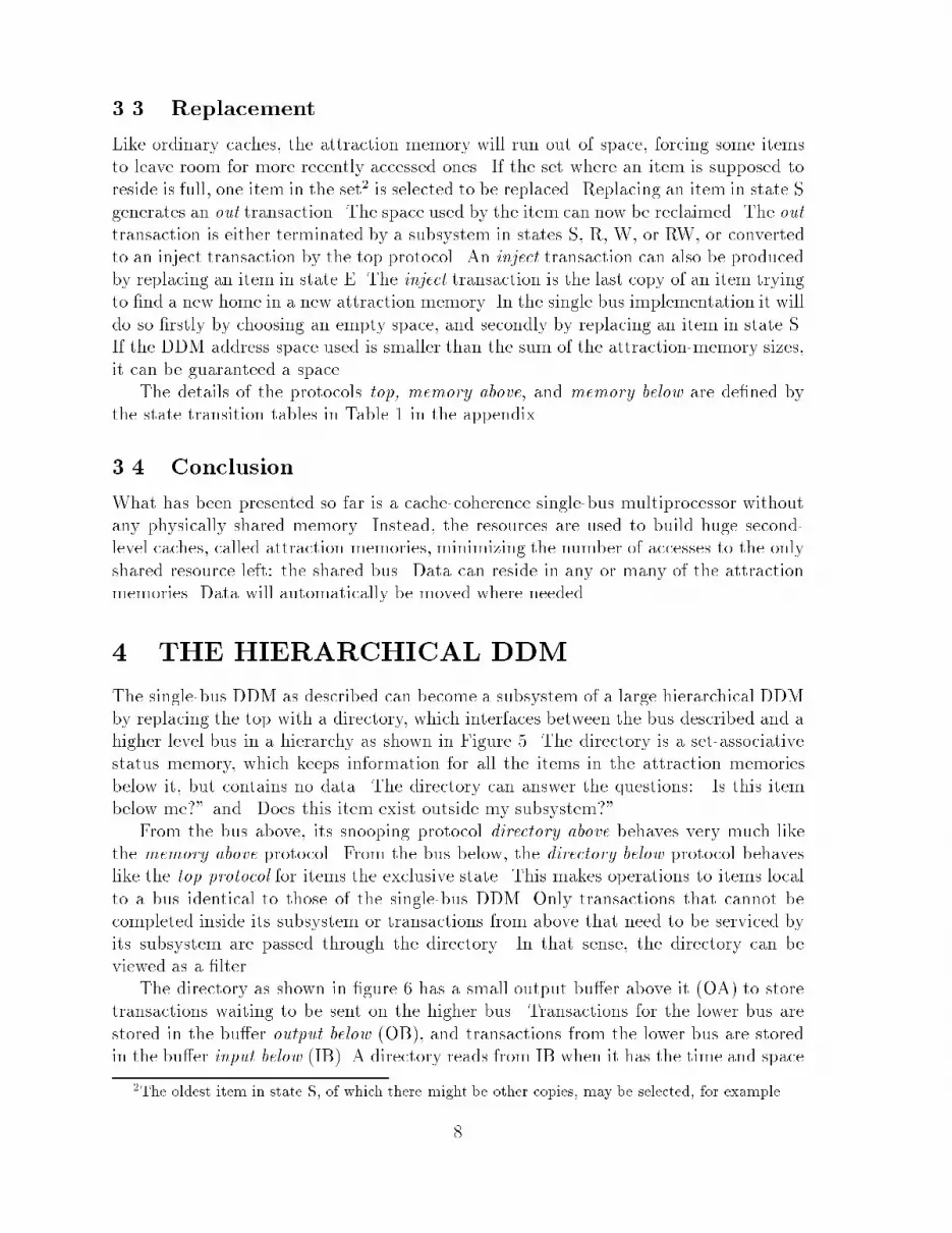
3.3 ReplacementLike ordinary caches, the attraction memory will run out of space, forcing some itemsto leave room for more recently accessed ones. If the set where an item is supposed toreside is full, one item in the set2 is selected to be replaced. Replacing an item in state Sgenerates an out transaction. The space used by the item can now be reclaimed. The outtransaction is either terminated by a subsystem in states S, R, W, or RW, or convertedto an inject transaction by the top protocol. An inject transaction can also be producedby replacing an item in state E. The inject transaction is the last copy of an item tryingto �nd a new home in a new attraction memory. In the single bus implementation it willdo so �rstly by choosing an empty space, and secondly by replacing an item in state S.If the DDM address space used is smaller than the sum of the attraction-memory sizes,it can be guaranteed a space.The details of the protocols top, memory above, and memory below are de�ned bythe state transition tables in Table 1 in the appendix.3.4 ConclusionWhat has been presented so far is a cache-coherence single-bus multiprocessor withoutany physically shared memory. Instead, the resources are used to build huge second-level caches, called attraction memories, minimizing the number of accesses to the onlyshared resource left: the shared bus. Data can reside in any or many of the attractionmemories. Data will automatically be moved where needed.4 THE HIERARCHICAL DDMThe single-bus DDM as described can become a subsystem of a large hierarchical DDMby replacing the top with a directory, which interfaces between the bus described and ahigher level bus in a hierarchy as shown in Figure 5. The directory is a set-associativestatus memory, which keeps information for all the items in the attraction memoriesbelow it, but contains no data. The directory can answer the questions: \Is this itembelow me?" and \Does this item exist outside my subsystem?"From the bus above, its snooping protocol directory above behaves very much likethe memory above protocol. From the bus below, the directory below protocol behaveslike the top protocol for items the exclusive state. This makes operations to items localto a bus identical to those of the single-bus DDM. Only transactions that cannot becompleted inside its subsystem or transactions from above that need to be serviced byits subsystem are passed through the directory. In that sense, the directory can beviewed as a �lter.The directory as shown in �gure 6 has a small output bu�er above it (OA) to storetransactions waiting to be sent on the higher bus. Transactions for the lower bus arestored in the bu�er output below (OB), and transactions from the lower bus are storedin the bu�er input below (IB). A directory reads from IB when it has the time and space2The oldest item in state S, of which there might be other copies, may be selected, for example.8

Figure 5: The hierarchical DDM, here with three levels.CONTROLLER STATE MEMORY
Above Protocol
Below Protocol
DDM bus
DDM bus
OA
OBIB
DIRECTORY
Figure 6: The architecture of a directory.to do a lookup in its status memory. This is not part of the atomic snooping action ofthe bus.4.1 Multilevel ReadIf a read request cannot be satis�ed by the subsystems connected to the bus, the nexthigher directory retransmits the read request on the next higher bus. The directory alsochanges the item's state to reading (R), marking the outstanding request. Eventually,the request reaches a level in the hierarchy where a directory, containing a copy ofthe item, is selected to answer the request. The selected directory changes its state toanswering (A), marking an outstanding request from above, and retransmits the readrequest on its lower bus. The new states, R and A in the directories, mark the request'spath through the hierarchy, shown in Figure 7, like rolling out a red thread when walking9
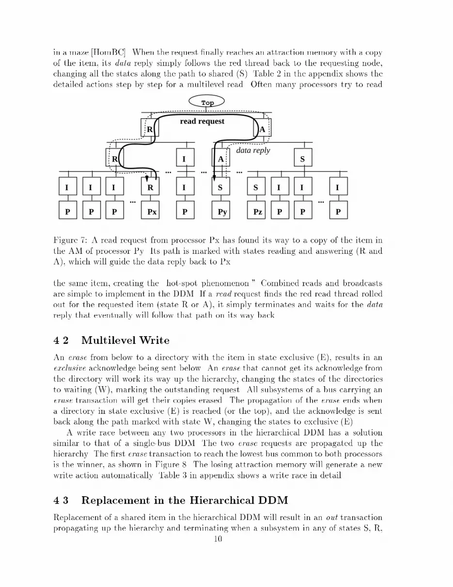
in a maze [HomBC]. When the request �nally reaches an attraction memory with a copyof the item, its data reply simply follows the red thread back to the requesting node,changing all the states along the path to shared (S). Table 2 in the appendix shows thedetailed actions step by step for a multilevel read. Often many processors try to readP
I
P
I
P
I
R
...Px
R
P
I
I...
Pz
S
P
I
P
I
S
...P
I
Py
S
A...
R A
...
Top
data reply
read request
Figure 7: A read request from processor Px has found its way to a copy of the item inthe AM of processor Py. Its path is marked with states reading and answering (R andA), which will guide the data reply back to Px.the same item, creating the \hot-spot phenomenon." Combined reads and broadcastsare simple to implement in the DDM. If a read request �nds the red read thread rolledout for the requested item (state R or A), it simply terminates and waits for the datareply that eventually will follow that path on its way back.4.2 Multilevel WriteAn erase from below to a directory with the item in state exclusive (E), results in anexclusive acknowledge being sent below. An erase that cannot get its acknowledge fromthe directory will work its way up the hierarchy, changing the states of the directoriesto waiting (W), marking the outstanding request. All subsystems of a bus carrying anerase transaction will get their copies erased. The propagation of the erase ends whena directory in state exclusive (E) is reached (or the top), and the acknowledge is sentback along the path marked with state W, changing the states to exclusive (E).A write race between any two processors in the hierarchical DDM has a solutionsimilar to that of a single-bus DDM. The two erase requests are propagated up thehierarchy. The �rst erase transaction to reach the lowest bus common to both processorsis the winner, as shown in Figure 8. The losing attraction memory will generate a newwrite action automatically. Table 3 in appendix shows a write race in detail.4.3 Replacement in the Hierarchical DDMReplacement of a shared item in the hierarchical DDM will result in an out transactionpropagating up the hierarchy and terminating when a subsystem in any of states S, R,10

P
I
P
I
P
I
W
...Px
W
P
I
I...
Pz
S
P
I
P
I
S
...P
I
Py
W
W...
W W
...
Top exclusive acknowledge
erase request (winner)
erase request (loser)Figure 8: A write race between two processors, Px and Py, is resolved when the requestoriginating from Py reaches the top bus (the lowest bus common to both processors.)The top can now send the acknowledge, exclusive, which follows the path marked withWs back to the winning processor Py. The states W will be changed to E by the exclusiveacknowledge.W, or A is found. If the last copy of an item marked with state S is replaced, an outthat fails to terminate will reach a directory in state E.Replacing an item in state E generates an inject transaction, trying to �nd an emptyspace in a neighboring AM. Nonterminated out transactions and inject transactionsfailing to �nd empty spaces will force themselves into an AM by replacing an item instate S as described for the single-bus DDM. A replacement might take place in orderto give space to the homeless item. In order to avoid chain reactions and livelocks, allitems have a preferred bus to which they turn whenever they are refused space elsewhere,called go home.The item space is equally divided among all directories at the same level, so that eachitem has one preferred subsystem. A directory can detect if a transaction is within theirportion of the item space and can guide the go home to its home bus. The home itemspace of a bus is slightly smaller than the sum of the sizes of the attraction memoriesconnected to that bus, guaranteeing each go home a space, if necessary by throwingshared and/or foreign items out.The preferred location, as described, is di�erent from the memory location of NUMAsin that the notion of a home is only used after failing to �nd space elsewhere. Whenthe item is not there, its place can be used by other items.The details of the directory protocols are de�ned by the state transition diagram inTable 4 in the appendix.4.4 Replacement in a DirectoryOther hierarchical bus projects have identi�ed a problem called the full-inclusion prop-erty, making such architectures impractical.11

The memory size (size here meaning number of items) of the directories increaseshigher up in the hierarchy. However, in order to guarantee space in a directory for allitems in its subsystem, it is not enough to just make the size of the directory equal to thenumber of items in the attraction memories below. The degree of associativity (numberof ways) in a directory should also be equal to the product of the number of attractionmemories in its subsystem and their degree of associativity. In the higher directoriesof big systems, the associativity would range in the hundreds. Even if implementable,such memories would be expensive and slow.The DDM uses directories with smaller sets, called imperfect directories, and endowsthe directory with the ability to perform replacement. The probability of replacementcan be kept at a reasonable level by increasing the associativity moderately higher upin the hierarchy. A higher degree of sharing will also help to keep that probability low.A shared item occupies space in many attraction memories, but only one space in thedirectories above them.Directory replacement is implemented by an extension to the existing protocol, whichrequires one extra state and two extra transactions [HHW90].4.5 Other ProtocolsThe described protocol provides a sequentially consistent [LHH91] system to the pro-grammer. While ful�lling the strongest programming model, performance is degradedby waiting for the acknowledge before the write can be performed. Note though thatthe acknowledge is sent by the topmost node of the subsystem in which all the copiesof the item reside, instead of by each individual AM. This not only reduces the remotedelay, but also cuts down the number of transactions in the system.A more e�cient protocol has been proposed that performs the write without waitingfor an acknowledge, allowing for many outstanding writes at the same time. A newlywritten, but not yet acknowledged, item is marked \write pending", while the processorcontinues its execution. Its new value will not be revealed before the acknowledgeis received. This protocol, called fast write [HLH91], results in a better performance,while supporting the looser programmingmodel processor consistency.3 Other proposalsfor architectures allowing multiple outstanding writes can only support models of evenlooser consistency.5 INCREASING THE BANDWIDTHThe system described so far has two apparent bottlenecks:� The size of the directories grows the higher up one gets in the hierarchy. Thebiggest directories are found right underneath the top bus. A practical limit tohow big these directories can be made limits the size of the system.� Although most memory accesses tend to be localized in the machine, the higherlevel buses may nevertheless demand a higher bandwidth than the bus can provide,3It also provides causal correctness. 12

which creates a bottleneck. Snooping in the big directories makes the top busslower rather than faster.A way of taking the load o� the higher buses is to have a smaller branch factor atthe top of the hierarchy than lower down [VJS88]. This solution, however, makes thehigher directories bigger rather than smaller.Dir Dir Dir Dir...
Even
Odd
Figure 9: Increasing the bandwidth of a bus by splitting buses.Instead, both problems are solved with the same solution: splitting the higher busesas shown in Figure 9. The directory is split into two directories half the size. Thedirectories deal with di�erent address domains (even and odd). The number of busesabove is also doubled, each bus dealing with its own address domain. Repeated splits willmake a bus as wide as possible, and directories as small as needed. Splitting is possibleat any level. Regardless of the number of splits, the architecture is still hierarchicalto each speci�c address. Transactions on the respective buses can be prevented fromovertaking each other, which leaves us with a network that is said to be race-free. Thiscan be achieved by selectively restricting the transactions allowed to be transferred inparallel [LHH91]. One example of where the splitting can be used is a ring-based bustime-slotted into di�erent address domains.Nonrace-free networks would require the write acknowledges to be produced by eachindividual AM, rather that by the topmost node of the subsystem in which all the copiesof the item reside. It would also prevent the implementation of the fast write protocol.6 THE MEMORY SYSTEMAn architecture containing only caches has an interesting property in that it can havea larger address space than there is physical memory in the system, given that thewhole address space is never used at the same time. Applications with sparse addressesand garbage-collecting applications could bene�t from such a behavior. However, it13

also requires a replacement strategy di�erent from the one described, and introducesthe need for some kind of secondary storage (called item reservoir) for situations whenreplaced items fail to �nd an empty space.Described below is a more conventional way of handling the memory system, bettersuited for general-purpose programs and operating systems.6.1 Virtual and Physical MemoryVirtual memory is traditionally used to allow for multiple address spaces. Two di�erentprocesses, possibly located in the same processor, may use the same virtual address foraccessing their own private address spaces. They must therefore access di�erent partsof the physical memory. The processes might also access di�erent virtual addresseswhen referring to the same physical address. This behavior of virtual addresses makesthem hard to use in snooping caches. Instead, the translation from virtual to physicaladdresses is often performed by a memory management unit (MMU), located betweenthe processor and the cache. The MMU maps pages of virtual memory to pages ofphysical memory. The mapping is done by the operating system when the page is �rsttouched. During execution, the page might get unmapped (paged out) and remapped(paged in) to a new physical page. The operating system keeps a free list of physicalpages not in use.The DDM handles the virtual memory in exactly the same way, allowing for multipleaddress spaces. An MMU identical to the one above is located between the processorand the attraction memory. The MMU maps pages of virtual addresses to pages ofitem identi�ers, which are the addresses of the items described in earlier examples. Theoperating system maps, unmaps, and remaps pages using a free list of item pages notin use. A page of item identi�ers di�ers from a physical page in that it does not occupyconsecutive physical space in a shared memory. Item identi�ers have unique names andmight reside anywhere in the machine. An item page on the free list will not occupy anymemory in the machine. When allocating a new item page, none of the items on thatpage will occupy any space before they are used. They will get \born" when �rst used(written to). The latency of the birth can be hidden if a protocol allowing for multipleoutstanding writes is used.6.2 Connecting DisksMany existing I/O devices, like disks, expect a memory with a contiguous address space.Each AM can host a number of those devices, such as one disk for each AM.When the operating system decides to send a page to secondary storage, it �rstinvalidates its entries in the MMUs, and then gives an order to a selected node to sendthe page to its secondary storage. The selected node �rst gets all the items into the newstate \exclusive-immune" to make them immune to replacement. Secondly, it starts theDMA to disk. Each item read by DMA will automatically be invalidated.Trying to access a page that has been paged out reverses the process. The operatingsystem orders the node holding the page on its disk to write the page to a selected itempage. The node �rst allocates space in its AM by putting the items of the selected item14

page in the state \exclusive-immune". Then it starts the DMA transfer from the disk,changing states to exclusive. Finally, the virtual page is mapped to the item page bythe operating system.7 THE DDM PROTOTYPE PROJECTMEMORY(AM Data) I/F
DNC
DDM bus
M bus
88k
Cache MMU
88k
Cache MMU
88k
Cache MMU
88k
Cache MMU
SCSIttyEthernet
AM State
TP881
Figure 10: The implementation of a DDM node consisting of four processors sharingone attraction memory.A prototype design of the DDM is near completion at SICS. To minimize the work,the hardware implementation of the processor/attraction memory is based on the sys-tem TP881V by Tadpole Technology, U.K. Each such system has four Motorola 8810020 MHz processors, eight 88200 processor caches, between 8 and 32 Mbyte DRAM, andinterfaces for the SCSI-bus, Ethernet, and terminals, all connected by the MotorolaMbus.A DDM Node Controller (DNC) board, hosting a four-way set-associative statememory, is being developed, interfacing the TP881 node and the �rst level DDM busas shown in Figure 10. The DNC snoops accesses between the processor caches and thememory of the TP881 according to the protocol memory below,4 and also snoops theDDM bus according to the protocol memory above. The DNC thus changes the behaviorof the memory into a four-way set-associative attraction memory. Read accesses tothe attraction memory take seven cycles per cache line, which is identical to the readaccesses of the original TP881 system. Write accesses to the attraction memory taketwelve cycles compared to ten cycles for the original system. A read/write mix of 3/1to the attraction memory results in the access time to the attraction memory being onthe average 6 percent slower than that to the original TP881 memory.A remote read to a node on the same DDM-bus takes 65 cycles at best, most ofwhich are spent making Mbus transactions (a total of four accesses). Read accessesclimbing one step up and down the hierarchy add about 20 extra cycles.The DDM bus is pipelined in three phases: transaction code, selection, and data. Wehave decided to make an initial conservative bus design, since pushing the bus speed is4Extended to handle multiple 88200 caches 15

not a primary goal of this research. The DDM bus of the prototype operates at 20 MHz,with a 32-bit data bus and a 32-bit address bus. It provides a moderate bandwidth ofabout 80 Mbyte/s which is enough for connecting up to eight nodes, i.e., 32 processors.A new, ring-based, bus is also being designed. It explores the splitting of buses anddirectories into di�erent address domains by time-slotting. It is targeted for a bandwidthof 0.5 Gbyte/s using o�-the-shelf components.We expect to have a small DDM prototype of 16{32 processors running in 1991. Theprototype should gradually be increased to include hundreds of processors.8 MEMORY OVERHEADAt �rst sight, it might be tempting to believe that an implementation of the DDM wouldrequire far more memory than alternative architectures. Extra memory will be requiredfor storing state bits and address keys for the set-associative attraction memories, aswell as for the directories. We have calculated the extra bits needed if all items resideonly in one copy (worst case). An item size of 128 bits is assumed.5A 32-processor DDM, i.e., a one-level DDM with a maximum of eight four-way set-associative attraction memories, needs �ve bits of address tag per item, regardless ofthe attraction memory size. As stated before, the item space is slightly smaller thanthe sum of the sizes of the attraction memories, i.e., the size of each attraction memoryis 1/8 of the item space. Each set in the attraction memory is divided four ways, i.e.,there are 32 items that could reside in the same set. The �ve bits are needed to tellthem apart. Each item also needs four bits of state. An item size of 128 bits gives anoverhead of (5+4)/128 = 7 percent.By adding another layer with eight 8-way set-associative directories, the maximumnumber of processors comes to 256. The size of the directories is the sum of the sizes ofthe attraction memories in their subsystems. A directory entry consists of six bits forthe address tag and four bits of state per item, using a similar calculation as above. Theoverhead in the attraction memories is larger than in the previous example, because ofthe larger item space: eight bits of address tag and four bits of state. The total overheadper item is (6+4+8+4)/128 = 17 percent. A larger item sized would, of course, decreasethese overheads.The fact that the item space is slightly smaller than the sum of the attractionmemories will also introduce a memory overhead, which has not been taken into accountin the above calculations.The absence of any entry in a directory has previously been interpreted as stateinvalid, since this is the state in which most of the items in the item space will reside.The replacement algorithm introduced a notion of a home bus for an item. If an itemis most often found in its home bus and nowhere else, the absence of any entry in adirectory could instead be interpreted as state exclusive, for items in its home subsystem,and as state invalid for items from outside. This would drastically cut down the sizeof a directory. The technique is only practical to a limited extent, however, since too5This is the cache line size of the Motorola 88200.16

small directories prevent items from moving out of their subsystems, and thus preventsharing and migration, with drawbacks similar to those of NUMAs as a result.Note that in a COMA, a \cached" item occupies only one space, while other shared-memory architectures require two spaces, one in the cache and one in the shared memory.9 SIMULATED PERFORMANCEThe DDM is a general-purpose multiprocessor with a shared-memory view. As such,the architecture can be used for most of today's shared-memory applications. SICS hasa tradition of implementing parallel Prolog systems for shared-memory multiprocessors.Since we have the insight in these systems, they have been part of our �rst evalua-tions. We can see no reason why the DDM could not perform well for other parallelapplications, and are in the process of evaluating more commonly used benchmarks.The DDM simulator models the architecture of the prototype and has a protocolsimilar to the one described in this paper. Four DDM nodes are connected by a DDMbus. Each node contains 8 Mbyte of four-way attraction memory and eight four-way,16 kbyte processor caches for instruction and data. The item size is 16 bytes. The pro-cessor caches are fed with references generated by execution taking place in applicationprocesses running in parallel with the simulator process. All virtual addresses touchedby an application process, both data and instructions, are detected. The translation toitem identi�ers (physical addresses) takes place in the modeled MMUs, performing alltheir necessary memory operations in the DDM. The execution-driven simulator runsat about 50 000 CPU-cycles per second on a SUN SPARC station.In this study, we have used the OR-parallel Prolog system MUSE [AK90] optimizedfor Sequent Symmetry. It can be viewed as a large parallel application written in C,taking Prolog programs as inputs. The execution of parallel Prolog tends to be veryirregular compared to traditional computing, having replaced regular structures likearrays with irregular structures like stacks. Load balancing is done dynamically and theparallelism is often �ne-grained. The MUSE required no modi�cations in order to runin our simulator.We have run benchmarks commonly used for evaluating parallel Prolog systems.The DDM showed a high processor utilization due to the high hit-rates in the attractionmemories. The highest hit-rates is recorded for the coarse-grained queens(40) that took70 Mcycles to run on a 16 processors machine. The 300 kitems, i.e., 5 Mbytes, touchedduring the execution were accessed with a average hit-rate of 96 percent in the attractionmemories.A more realistic benchmark was a natural language system from Unisys Paoli Re-search Center called Pundit. Pundit is interesting in that it is one of the largest Prologapplications and has a lot of OR-parallelism. We ran the benchmark phrase \startingair regulating valve failed." About 125 kitems, i.e., 2 Mbyte, were touched during theexecution, resulting in an average hit rate of 91 percent in the attraction memories, and98.5 percent in the processor caches. Each reference by the processor took on the aver-age less than 1.3 cycles. The high hit-rate also resulted in a low DDM-bus utilizationthat ranged between 15{30 percent. The hit rate of one attraction memory and one17

processor over time is shown in Figure 11.10%20%30%40%50%60%70%80%90%100%
0 20 40 60 80 M cycles'processor cache''attraction memory'Figure 11: Simulated hit rate for an attraction memory and a processor cache runningPundit. The program is run a second time starting after 63 Mcycles.10 RELATED ACTIVITIESAn operating system targeted for the DDM prototype is under development at SICS.This work is based on the Mach operating system from CMU that is modi�ed to e�-ciently support the DDM. Other related activities at SICS involve a hardware prefetchingscheme that dynamically prefetches items to the attraction memory, especially usefulwhen a process is started or migrated. We are also experimenting with alternativeprotocols.An emulator of the DDM is currently under development at the University of Bristol.The emulator runs on the Meiko Transputer platform. The modeled architecture hasa tree-shaped link-based structure with Transputers as directories. Their four linksallow for a branch factor of three at each level. The Transputers at the leaves executethe application. All references to global data are intercepted and handled in a DDMmanner by software. The access to large Transputer facilities in the U.K. will allow forstudying real-size problems running on hundreds of Transputers. The DDM protocol inthe emulator has a di�erent representation, which is suited for a link-based architecturestructured like a tree, rather than a bus-based one. The implementation has certainsimilarities to directory-based systems.11 CONCLUSIONWe have introduced a new class of architectures, cache-only memory architectures, thatallows for private caches of the largest size possible, since all data memory is used to18

implement the caches. The caches, which are kept coherent by a hardware protocol andhave an extended functionality that handles replacement, are called attraction memories.A hierarchical bus structure has been described that ties a large number of attractionmemories together and isolates the tra�c generated by the hardware protocol to assmall part of the machine as possible. The higher levels of the hierarchy can be split toovercome bandwidth bottlenecks, while still providing a race-free network.The overhead of COMA explored in our hardware prototype is limited to 6 percent inthe access time between the processor caches and the attraction memory, and a memoryoverhead of 7{17 percent for 32{256 processors.12 RELATED WORKThe DDM has many similarities to Wilson's proposal [Wil86] for a hierarchical shared-memory architecture and certain similarities to the Wisconsin Multicube [GW88] andthe TREEB architecture [VJS88]. However, all of these machines, unlike the DDM,depend on physically shared memory providing a \home" location for data. The Wis-consin Multicube can also be contrasted with the DDM in that certain requests need tobe broadcast throughout the entire machine. Data moving closer to the processor ac-cessing it can be found in the architecture of Mizrahi [MBLZ89]. The memory overheadof that architecture is much bigger than in the DDM, due to a low branch factor andfull inclusion. It is also provided with a common shared memory and restricts writableobjects to be cached to only one copy.13 ACKNOWLEDGMENTSSICS is a nonpro�t research foundation sponsored by the Swedish National Board for TechnicalDevelopment (STU), Swedish Telecom, LM Ericsson, ASEA Brown Boveri, IBM Sweden,Bofors Electronics, and, the Swedish Defence Material Administration (FMV). Work on theDDM is being carried out as part of the Esprit project 2741 PEPMA. We thank our manycolleagues involved in or associated with the project. Especially we thank David H.D. Warren,University of Bristol, who is a coinventor of the DDM. Mikael L�ofgren, SICS, wrote the DDMsimulator and performed the simulations, basing his work on \Abstract Execution", (AE),which was provided to us by James Larus, University of Wisconsin. We are also grateful forthe constructive criticism of the reviewers.References[AK90] K. A. M. Ali and R. Karlsson. The MUSE OR-parallel Prolog model and itsperformance. In North American Conference on Logic Programming. MITPress, October 1990.[EK89] S.J. Eggers and R.H. Katz. Evaluating the performance of four snoopingcache coherency protocols. In Proceedings of the 16th Annual InternationalSymposium on Computer Architecture, pages 2{15, 1989.19
[GW88] J.R. Goodman and P.J. Woest. The Wisconsin Multicube: a new large-scale cache-coherent multiprocessor. In Proceedings of the 15th Annual In-ternational Symposium on Computer Architecture, Honolulu, Hawaii, pages442{431, 1988.[HHW90] E. Hagersten, S. Haridi, and D.H.D.Warren. The cache-coherence protocol ofthe data di�usion machine. In M. Dubois and S. Thakkar, editors, Cache andInterconnect Architectures in Multiprocessors. Kluwer Academic Publisher,Norwell, Mass, 1990.[HLH91] E. Hagersten, A. Landin, and S. Haridi. Multiprocessor consistency and syn-chronization through transient cache states. In M. Dubois and S. Thakkar,editors, Scalable Shared-Memory Multiprocessors. Kluwer Academic Pub-lisher, Norwell, Mass, 1991.[HomBC] Homer. Odyssey. 800 BC.[LHH91] A. Landin, E. Hagersten, and S. Haridi. Race-free interconnection networksand multiprocessor consistency. In To appear in Proceedings of the 18thAnnual International Symposium on Computer Architecture, 1991.[MBLZ89] H. E. Mizrahi, J-L Baer, D.E. Lazowska, and J. Zahorjan. Introducing mem-ory into the switch elements of multiprocessor interconnection networks. InProceedings of the 16th Annual International Symposium on Computer Ar-chitecture, pages 158{176, 1989.[Ste90] P. Stenstr�om. A survey of cache coherence for multiprocessors. IEEE Com-puter, 23(6), June 1990.[VJS88] M.K. Vernon, R Jog, and G.S. Sohi. Performance analysis of hierarchicalcache-consistent multiprocessors. In Conference Proceedings of InternationalSeminar on Performance of Distributed and Parallel Systems, pages 111 {126, 1988.[WH88] D. H. D. Warren and S. Haridi. Data Di�usion Machine{a scalable sharedvirtual memory multiprocessor. In International Conference on Fifth Gen-eration Computer Systems 1988. ICOT, 1988.[Wil86] A. Wilson. Hierarchical cache/bus architecture for shared memory multipro-cessor. Technical report ETR 86-006, Encore Computer Corporation, 1986.20

AppendixATTRACTION MEMORY BELOWTrans- Stateaction I E S R W RWread R:rA12 ? ? ; ; ;write 3 RW:rA12 ? W:eA2 ; ; ;replace I:iA I:oA ; ; ; TOPTrans- a = 0! a � 1!actionr create item4e xB xBdxo iBi go home4ATTRACTION MEMORY ABOVETrans- Stateaction I E S R W RWr sel1!S:dA sel1!S:dA sel2!:sel!; :sel!S:dA :sel!e ; I:- sel1!R:rA sel1!RW:rA sel1!RW:rA:sel! :sel!RW:- :sel!d ; S:? sel1!W:eA:sel!x ; ; sel1!R:rA E:? sel1!RW:rA:sel! :sel!o ; sel0! sel1!S:? sel0! sel2!W:eA:sel! :sel!S:- :sel!i seln!4 E:- ; ; sel1!S:? ; sel2!W:eA:sel! :sel! :sel!a = 0! No client tried to be selected.a � 1! At least one client tried to be selected.; This situation is impossible.? The processor may continue with its operation.seln! Selection of the nth priority succeeded. The priority increases with the number.:sel! The attempt to become selected failed.1 Preceded by a replace of the old item.2 The processor is suspended. The processor will be awakened by a ? for this very item.3 Read with intent to modify is treated like a write.4 Discussed further in Section 4.3.Table 1: The protocol of the single-bus DDM. Each state has its own column and eachtransaction its own row. Actions have the format: guard!NEWSTATE:transaction-to-sendIndex, where index A means to the bus above and index B means to the bus below.An empty square means no action; the rest of the symbols are explained in the table.21

Er2 d5E 3!A 5!S I 2!R 6!S Ir3 d4 r1 d6I S 4!S I S I I 1!R 7!S I I I I I IP1 P2 P3 P4 P5 P6 P7 P8 P9 P10 P11 P12r1 Indicates a read transaction on the bus at phase 1.I 1!R Indicates a state transition from state invalid to reading at phase 1.The actions at the di�erent phases are explained below.1 A read by P6 to an I item generates a read and changes the state to R.2 The directory detects a nonlocal action and repeats the read upward, changing its state to R.3 A directory in state E answers the request by changing its state to A, sending read below.4 One of the memories, P2, is selected to service the read. It stays in S and sends data.5 The directory in state A has promised to answer. It send data above and changes its state to S.6 The directory in state R is waiting for the data. It changes state to S and sends the data below.7 The attraction memory in state R is waiting for the data. It receives the data and changes state to S.NOTE 1: Many subsystems on a bus may have an item in state S. Letting all of them reply with thedata would produce unnecessary bus transactions; instead, one is selected in phase 4.NOTE 2: After phase 3, the return path for data is marked with As and Rs.Table 2: Multilevel read on a DDM with twelve processors (P1-P12). The table showsthe states for one item, originally residing in state shared (S) in the attraction memoriesof processors P2 and P4. Their parent directories start with the item in state exclu-sive (E). The state transitions and transactions generated are indexed chronologically,showing a read attempt by processor P6.22

E 3!Ee2x3r5d8S 3!I S 2!W 4!E 6!A 8!S S 2!W 3!I 5!R 9!Se3 e1x4r6d7 e1e3r4d9e10I S 4!I I I I S 1!W 5!E 7!S I I I S 1!W 4!RW10!W I IP1 P2 P3 P4 P5 P6 P7 P8 P9 P10 P11 P120 Originally the item resides in state S in the AMs of P2, P6, and, P10.1 P6 and P10 try to write to the shared item, generate erase (e) transactions, and change states to W.2 The directories detect nonlocal erases, change their states to W, and retransmit erases above.3 The erase originating in P6 is the winner and is carried on the top bus. All other directories changetheir states to I and retransmit the erase below.4 P10 receives the bad news (erase). Instead of just invalidating it starts a read transaction.5 P6 becomes the exclusive owner of the item and carries out the write.6�9 The read from P10 reaches P6, which changes state to S and sends data containing the new value.The data follows the path back to P1010 The data reach P10, which changes state to W and once more sends an erase.Table 3: Write race between processors P6 and P10. The erase request origin fromprocessor P6 is the winner.23

DIRECTORY BELOWTrans- Statesaction I E S R W Ar R:rA1e E:xB W:eA ; ; W:eAd ; ; S:dAo a = 0!E:iB a = 0!I:oA ; ; a = 0!I:oAa � 1!S:dAi2 ; a = 0!I:iA ; ; ; a = 0!I:oAa � 1!A:rBDIRECTORY ABOVETrans- Statesaction I E S R W Ar sel1!A:rB sel1!A:rB sel2! sel2!:sel!; :sel! :sel! :sel!e ; I:eB sel1!R:rA I:eB I:eB:sel!d ; S:dB S:-x ; ; sel1!R:rA E:xB ;:sel!o ; sel0! sel1!S:dB sel0! sel1!S:-:sel!S:dB :sel!S:-i seln!3 E:iB ; ; sel1!S:dB ; ;:sel!S:dBa = 0! No client tried to be selected.a � 1! At least one client tried to be selected.1 If the corresponding set is full, an item x is chosen to be replaced.2 The transaction might be sent by the directory itself.3 Discussed further in Section 4.3.Table 4: The protocol of directories of a hierarchical DDM.24


