Embed Size (px)
Citation preview
*23031719_0317*Drive Technology \ Drive Automation \ System Integration \ Services
Operating Instructions
Application InverterMOVIDRIVE® system
Edition 03/2017 23031719/EN

SEW-EURODRIVE—Driving the world

Table of contents
Operating Instructions – MOVIDRIVE® system 3
Table of contents1 General information.................................................................................................................. 8
1.1 About this documentation ............................................................................................... 81.2 Structure of the safety notes ........................................................................................... 8
1.2.1 Meaning of signal words ................................................................................ 81.2.2 Structure of section-related safety notes........................................................ 81.2.3 Structure of embedded safety notes .............................................................. 9
1.3 Rights to claim under limited warranty ............................................................................ 91.4 Content of the documentation....................................................................................... 101.5 Exclusion of liability....................................................................................................... 101.6 Other applicable documentation ................................................................................... 101.7 Product names and trademarks.................................................................................... 101.8 Copyright notice ............................................................................................................ 101.9 Device availability ......................................................................................................... 10
2 Safety notes ............................................................................................................................ 122.1 Preliminary information ................................................................................................. 122.2 Operator's duties........................................................................................................... 122.3 Target group ................................................................................................................. 122.4 Designated use ............................................................................................................. 13
2.4.1 Hoist applications ......................................................................................... 132.5 Functional safety technology ........................................................................................ 142.6 Transport....................................................................................................................... 142.7 Installation/assembly..................................................................................................... 15
2.7.1 Restrictions of use........................................................................................ 152.8 Electrical connection ..................................................................................................... 16
2.8.1 Required preventive measure ...................................................................... 162.8.2 Stationary application................................................................................... 162.8.3 Regenerative operation................................................................................ 16
2.9 Protective separation .................................................................................................... 162.10 Startup/operation .......................................................................................................... 17
2.10.1 Energy storage unit ...................................................................................... 17
3 Device structure ..................................................................................................................... 183.1 Connection variants ...................................................................................................... 183.2 Nameplates................................................................................................................... 20
3.2.1 System nameplate ....................................................................................... 203.2.2 Performance data nameplate....................................................................... 20
3.3 Type code ..................................................................................................................... 213.4 Device structure of the application inverter................................................................... 22
3.4.1 MDX90A-0020 – 0040-5_3-.. ....................................................................... 223.4.2 MDX90A-0055 – 0095-5_3-.. , MDX90A-0070 – 0093-2_3-.. ...................... 233.4.3 MDX90A-0125 – 0160-5_3-.. , MDX90A-0140-2_3-.. .................................. 243.4.4 MDX90A-0240 – 0320-5_3-.. , MDX90A-0210 – 0290-2_3-.. ...................... 25
3.5 Use of option cards ....................................................................................................... 26
4 Installation............................................................................................................................... 272303
1719
/EN
– 0
3/20
17
Table of contents
Operating Instructions – MOVIDRIVE® system4
4.1 Installation accessories................................................................................................. 274.1.1 Standard accessories................................................................................... 27
4.2 Permitted tightening torques ......................................................................................... 284.3 Mechanical installation.................................................................................................. 29
4.3.1 Bore patterns................................................................................................ 304.3.2 Minimum clearance and mounting position.................................................. 31
4.4 Covers........................................................................................................................... 324.5 Control cabinet installation............................................................................................ 334.6 Electrical installation ..................................................................................................... 34
4.6.1 General information...................................................................................... 354.6.2 Permitted voltage systems ........................................................................... 354.6.3 Use in IT systems......................................................................................... 354.6.4 Line fuses, fuse types .................................................................................. 374.6.5 Line connection ............................................................................................ 374.6.6 Line contactor............................................................................................... 384.6.7 24 V supply voltage...................................................................................... 394.6.8 Motor output ................................................................................................. 404.6.9 Output brake chopper .................................................................................. 404.6.10 Temperature evaluation of the motor ........................................................... 404.6.11 Brake output................................................................................................. 414.6.12 Digital inputs, digital outputs ........................................................................ 414.6.13 System bus EtherCAT®/SBusPLUS ................................................................. 424.6.14 Encoders ...................................................................................................... 43
4.7 Installing options and accessories ................................................................................ 454.7.1 Installing an option card ............................................................................... 454.7.2 CIO21A and CID21A input/output card ........................................................ 484.7.3 CES11A multi-encoder card......................................................................... 51
4.8 Braking resistors ........................................................................................................... 554.8.1 Permitted installation of braking resistors .................................................... 564.8.2 Protection against thermal overload of the braking resistor ......................... 58
4.9 Line filter ....................................................................................................................... 684.10 EMC-compliant installation ........................................................................................... 69
4.10.1 Control cabinet ............................................................................................. 704.10.2 HF equipotential bonding in the system ....................................................... 704.10.3 Cable installation.......................................................................................... 704.10.4 Supply system cable connection.................................................................. 704.10.5 Line filter connection .................................................................................... 704.10.6 Braking resistor connection.......................................................................... 714.10.7 Motor and brake connection......................................................................... 714.10.8 Control cable connection.............................................................................. 724.10.9 Encoder connection ..................................................................................... 724.10.10 Shielding connection .................................................................................... 72
4.11 Terminal assignment..................................................................................................... 734.12 Wiring diagrams ............................................................................................................ 77
4.12.1 General information on the wiring diagrams ................................................ 774.12.2 Power connection......................................................................................... 77
2303
1719
/EN
– 0
3/20
17
Table of contents
Operating Instructions – MOVIDRIVE® system 5
4.12.3 Brake control ................................................................................................ 804.12.4 Electronics connection ................................................................................. 854.12.5 Connection diagram CIO21A and CID21A input/output card....................... 86
4.13 UL-compliant installation............................................................................................... 89
5 Startup ..................................................................................................................................... 905.1 General ......................................................................................................................... 90
5.1.1 Lifting applications........................................................................................ 905.1.2 Connecting power ........................................................................................ 905.1.3 Connecting cables........................................................................................ 90
5.2 Setting the EtherCAT®/SBusPLUS ID .............................................................................. 915.3 Startup requirements .................................................................................................... 915.4 Startup procedure ......................................................................................................... 92
5.4.1 Check list for startup .................................................................................... 935.5 Connection to the engineering software ....................................................................... 955.6 Setting the module bus operating mode ....................................................................... 96
5.6.1 Connection types ......................................................................................... 975.6.2 Setting options ............................................................................................. 97
6 Operation................................................................................................................................. 986.1 General information ...................................................................................................... 986.2 7-segment display......................................................................................................... 99
6.2.1 Operating displays ....................................................................................... 996.2.2 Fault display ................................................................................................. 99
6.3 Operating displays ...................................................................................................... 1006.4 Fault description.......................................................................................................... 102
6.4.1 Fault 1 Output stage monitoring................................................................. 1026.4.2 Fault 3 Ground fault ................................................................................... 1026.4.3 Fault 4 Brake chopper................................................................................ 1026.4.4 Fault 6 Line fault......................................................................................... 1026.4.5 Fault 7 DC link fault .................................................................................... 1036.4.6 Fault 8 Speed monitoring fault ................................................................... 1036.4.7 Fault 9 control mode .................................................................................. 1036.4.8 Fault 10 Data flexibilization layer ............................................................... 1046.4.9 Fault 11 Temperature monitoring............................................................... 1066.4.10 Fault 12 Brake............................................................................................ 1076.4.11 Error 13 Encoder 1..................................................................................... 1076.4.12 Fault 14 Encoder 2..................................................................................... 1116.4.13 Error 16 Startup.......................................................................................... 1156.4.14 Error 17 Internal processor error ................................................................ 1176.4.15 Error 18 Software error .............................................................................. 1176.4.16 Error 19 Process data ................................................................................ 1186.4.17 Fault 20 Device monitoring ........................................................................ 1196.4.18 Fault 23 Power section............................................................................... 1206.4.19 Error 24 Cam switch................................................................................... 1216.4.20 Error 25 Parameter memory monitoring..................................................... 1216.4.21 Fault 26 External fault ................................................................................ 124
2303
1719
/EN
– 0
3/20
17
Table of contents
Operating Instructions – MOVIDRIVE® system6
6.4.22 Error 28 FCB drive functions...................................................................... 1246.4.23 Error 29 Hardware limit switch ................................................................... 1266.4.24 Error 30 Software limit switch..................................................................... 1276.4.25 Error 31 Thermal motor protection ............................................................. 1276.4.26 Error 32 Communication ............................................................................ 1296.4.27 Error 33 System initialization...................................................................... 1306.4.28 Error 34 Process data configuration........................................................... 1316.4.29 Error 35 Function activation ....................................................................... 1316.4.30 Error 42 Lag error....................................................................................... 1326.4.31 Fault 45 Fieldbus option............................................................................. 1336.4.32 Error 46 Safety option ................................................................................ 1336.4.33 Fault 47 Supply unit ................................................................................... 1346.4.34 Error 48 Module bus................................................................................... 1346.4.35 Error 50 I/O option...................................................................................... 1346.4.36 Error 51 Analog processing........................................................................ 1356.4.37 Error 52 Explosion protection category 2 function ..................................... 135
6.5 Responses to error acknowledgement ....................................................................... 1376.5.1 Error acknowledgement ............................................................................. 137
6.6 Fault responses .......................................................................................................... 1396.6.1 Default – fault response ............................................................................. 1396.6.2 Parameterizable faults ............................................................................... 139
7 Service................................................................................................................................... 1427.1 Electronics Service by SEW‑EURODRIVE................................................................. 1427.2 Extended storage........................................................................................................ 142
7.2.1 Procedure in case maintenance has been neglected ................................ 1437.3 Shutdown.................................................................................................................... 1437.4 Waste disposal............................................................................................................ 143
8 Technical data....................................................................................................................... 1448.1 Markings ..................................................................................................................... 1448.2 General technical data ................................................................................................ 1458.3 Technical data of basic device.................................................................................... 146
8.3.1 Performance data 3 × AC 400 V ................................................................ 1468.3.2 Performance data 3 × AC 230 V ................................................................ 149
8.4 Electronics data – signal terminals ............................................................................. 1518.5 Electronics data – safety functions ............................................................................. 1528.6 Dimension drawings.................................................................................................... 153
8.6.1 MDX90A-0020 – 0040-5_3-.. ..................................................................... 1538.6.2 MDX90A-0055 – 0095-5_3-.. , MDX90A-0070 – 0093-2_3-.. .................... 1548.6.3 MDX90A-0020 – 0040-5_3-.. , MDX90A-0070 – 0093-2_3-.. with braking
resistor ....................................................................................................... 1558.6.4 MDX90A-0125 – 0160-5_3-.. , MDX90A-0140-2_3-.. ................................ 1568.6.5 MDX90A-0240 – 0320-5_3-.. , MDX90A-0213 – 0290-2_3-.. .................... 157
8.7 Technical data of the option cards .............................................................................. 1588.7.1 CIO21A and CID21A input/output cards .................................................... 1588.7.2 CES11A multi-encoder card....................................................................... 160 23
0317
19/E
N –
03/
2017
Table of contents
Operating Instructions – MOVIDRIVE® system 7
8.8 Technical data of encoder interfaces .......................................................................... 1618.8.1 Basic device ............................................................................................... 1618.8.2 CES11A multi-encoder card....................................................................... 161
8.9 Technical data of braking resistors, filters and chokes ............................................... 1628.9.1 Braking resistors type BW.../BW...-T.......................................................... 1628.9.2 TCB thermal circuit breaker option............................................................. 1728.9.3 Line filter..................................................................................................... 1748.9.4 Line choke.................................................................................................. 1768.9.5 Output filter................................................................................................. 1788.9.6 Output choke.............................................................................................. 180
9 Functional safety .................................................................................................................. 1819.1 General information .................................................................................................... 181
9.1.1 Underlying standards ................................................................................. 1819.2 Integrated safety technology....................................................................................... 181
9.2.1 Safe condition ............................................................................................ 1819.2.2 Safety concept ........................................................................................... 1819.2.3 Schematic representation of the safety concept ........................................ 1829.2.4 Safety functions.......................................................................................... 1839.2.5 Restrictions ................................................................................................ 185
9.3 Safety conditions......................................................................................................... 1869.3.1 Approved devices....................................................................................... 1869.3.2 Requirements on the installation................................................................ 1879.3.3 Requirements on the external safety controller.......................................... 1889.3.4 Requirements on startup............................................................................ 1909.3.5 Requirements on operation........................................................................ 190
9.4 Connection variants .................................................................................................... 1919.4.1 General information.................................................................................... 1919.4.2 Requirements............................................................................................. 1929.4.3 STO signal for group disconnection ........................................................... 196
9.5 Safety characteristics.................................................................................................. 197
10 Appendix ............................................................................................................................... 19810.1 Abbreviation key ......................................................................................................... 19810.2 Declaration of conformity ............................................................................................ 200
Index ...................................................................................................................................... 201
11 Address list ........................................................................................................................... 204
2303
1719
/EN
– 0
3/20
17
1 General informationAbout this documentation
Operating Instructions – MOVIDRIVE® system8
1 General information1.1 About this documentation
This documentation is an integral part of the product. The documentation is written forall employees who assemble, install, start up, and service this product.Make sure this documentation is accessible and legible. Ensure that persons respons-ible for the machinery and its operation as well as persons who work on the productindependently have read through the documentation carefully and understood it. If youare unclear about any of the information in this documentation or require further in-formation, contact SEW‑EURODRIVE.
1.2 Structure of the safety notes1.2.1 Meaning of signal words
The following table shows the grading and meaning of the signal words for safetynotes.
Signal word Meaning Consequences if disregarded DANGER Imminent hazard Severe or fatal injuries
WARNING Possible dangerous situation Severe or fatal injuries
CAUTION Possible dangerous situation Minor injuries
NOTICE Possible damage to property Damage to the product or its envir-onment
INFORMATION Useful information or tip: Simplifieshandling of the product.
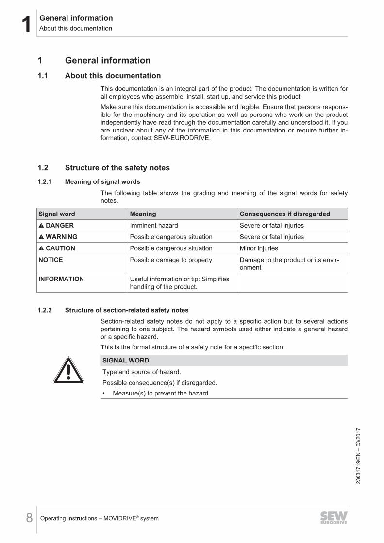
1.2.2 Structure of section-related safety notesSection-related safety notes do not apply to a specific action but to several actionspertaining to one subject. The hazard symbols used either indicate a general hazardor a specific hazard.This is the formal structure of a safety note for a specific section:
SIGNAL WORDType and source of hazard.Possible consequence(s) if disregarded.• Measure(s) to prevent the hazard.
2303
1719
/EN
– 0
3/20
17
1General informationRights to claim under limited warranty
Operating Instructions – MOVIDRIVE® system 9
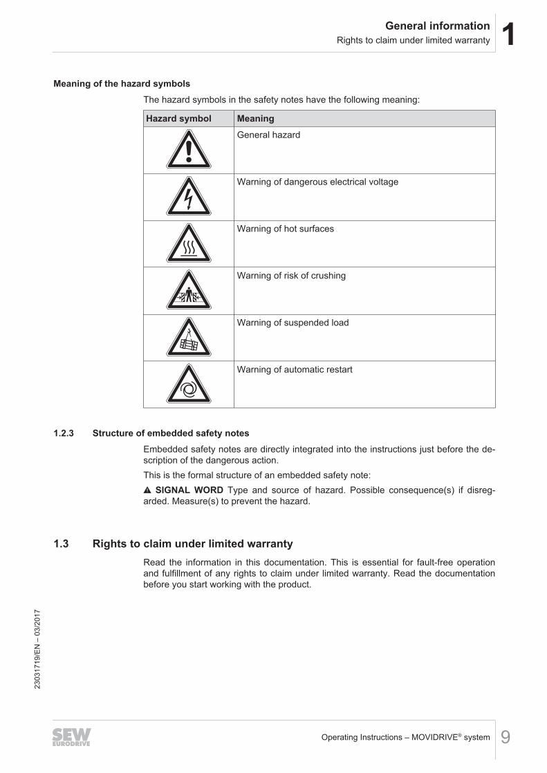
Meaning of the hazard symbolsThe hazard symbols in the safety notes have the following meaning:
Hazard symbol MeaningGeneral hazard
Warning of dangerous electrical voltage
Warning of hot surfaces
Warning of risk of crushing
Warning of suspended load
Warning of automatic restart
1.2.3 Structure of embedded safety notesEmbedded safety notes are directly integrated into the instructions just before the de-scription of the dangerous action.This is the formal structure of an embedded safety note:
SIGNAL WORD Type and source of hazard. Possible consequence(s) if disreg-arded. Measure(s) to prevent the hazard.
1.3 Rights to claim under limited warrantyRead the information in this documentation. This is essential for fault-free operationand fulfillment of any rights to claim under limited warranty. Read the documentationbefore you start working with the product.
2303
1719
/EN
– 0
3/20
17
1 General informationContent of the documentation
Operating Instructions – MOVIDRIVE® system10
1.4 Content of the documentationThe current version of the documentation is the original.This document contains additional safety-relevant information and conditions for usein safety-related applications.
1.5 Exclusion of liabilityRead the information in this documentation, otherwise safe operation is impossible.You must comply with the information contained in this documentation to achieve thespecified product characteristics and performance features. SEW‑EURODRIVE as-sumes no liability for injury to persons or damage to equipment or property resultingfrom non-observance of these operating instructions. In such cases,SEW‑EURODRIVE assumes no liability for defects.
1.6 Other applicable documentationObserve the corresponding documentation for all further components.
1.7 Product names and trademarks
The brands and product names in this documentation are trademarks or registeredtrademarks of their respective titleholders.
1.8 Copyright notice
© 2017 SEW‑EURODRIVE. All rights reserved. Unauthorized reproduction, modifica-tion, distribution or any other use of the whole or any part of this documentation isstrictly prohibited.
1.9 Device availabilityThis documentation lists modules of the application inverter and accessories that arenot yet available at the time of the publication of this document.The following table lists the available application inverters. Accessories required forthe inverter operation such as braking resistors, chokes, and filters are available.
Type designationMDX90A-0020-5E3-4-S00MDX90A-0025-5E3-4-S00MDX90A-0032-5E3-4-S00MDX90A-0040-5E3-4-S00MDX90A-0055-5E3-4-S00MDX90A-0070-5E3-4-S00MDX90A-0950-5E3-4-S00MDX90A-0125-5E3-4-S00MDX90A-0160-5E3-4-S00MDX90A-0240-503-4-S00
2303
1719
/EN
– 0
3/20
17

1General informationDevice availability
Operating Instructions – MOVIDRIVE® system 11
Type designationMDX90A-0320-503-4-S00
MDX90A-0070-2E3-4-S00MDX90A-0093-2E3-4-S00MDX90A-0140-2E3-4-S00MDX90A-0213-2E3-4-S00MDX90A-0290-2E3-4-S00
2303
1719
/EN
– 0
3/20
17
2 Safety notesPreliminary information
Operating Instructions – MOVIDRIVE® system12
2 Safety notes2.1 Preliminary information
The following general safety notes have the purpose to avoid injury and damage toproperty. They primarily apply to the use of products described in this documentation.If you use additional components also observe the relevant warning and safety notes.
2.2 Operator's dutiesMake sure that the basic safety notes are read and observed. Make sure that personsresponsible for the machinery and its operation as well as persons who work on thedevice independently have read through the documentation carefully and understoodit. If you are unclear about any of the information in this documentation, or if you re-quire further information, contact SEW‑EURODRIVE.The operator must ensure that the following works are only performed by qualified per-sonnel:• Transport• Storage• Setup and assembly• Installation and connection• Startup• Maintenance and repair• Shutdown• Disassembly• Waste disposalMake sure persons working on the product adhere to the following regulations, re-quirements, documents and information:• National and regional safety and accident prevention regulations• Warning and safety signs on the product• All other relevant project planning documents, installation and startup instructions,
wiring diagrams and schematics• Do not assemble, install or operate damaged products• All specific specifications and requirements for the systemMake sure that systems with the product installed are equipped with additional monit-oring and protection devices. Observe the applicable safety regulations and legislationgoverning technical equipment and accident prevention regulations.
2.3 Target group
Specialist formechanical work
Any mechanical work may only be performed by adequately qualified personnel. Qual-ified personnel in the context of this documentation are persons familiar with thedesign, mechanical installation, troubleshooting and maintenance of the product, whopossess the following qualifications:• Qualification in the field of mechanics according to applicable national regulation.• They are familiar with this documentation 23
0317
19/E
N –
03/
2017
2Safety notesDesignated use
Operating Instructions – MOVIDRIVE® system 13
Specialist for elec-trotechnical work
Any electronic work may only be performed by adequately skilled persons (electric-ally). Qualified electricians in the context of this documentation are persons familiarwith electrical installation, startup, troubleshooting and servicing of the product whopossess the following qualifications:• Qualification in the field of electrical engineering according to applicable national
regulation.• They are familiar with this documentationIn addition to that, these persons must be familiar with the valid safety regulations andlaws, as well as with the requirements of the standards, directives and laws specifiedin this documentation. The above mentioned persons must have the authorization ex-pressly issued by the company to operate, program, configure, label and grounddevices, systems and circuits in accordance with the standards of safety technology.
Instructed persons All work in the areas of transportation, storage, operation and waste disposal must becarried out by persons who are trained appropriately. The purpose of the instruction isthat the persons are capable of performing the required tasks and work steps in a safeand correct manner.
2.4 Designated use
The product is intended for control cabinet installation in electrical plants or machines.In case of installation in electrical systems or machines, startup of the product is pro-hibited until it is determined that the machine meets the requirements stipulated in thelocal laws and directives. For Europe, Machinery Directive 2006/42/EC as well as theEMC Directive 2014/30/EU apply. Observe EN 60204-1 (Safety of machinery - elec-trical equipment of machines). The product meets the requirements stipulated in theLow Voltage Directive 2014/35/EU.The standards given in the declaration of conformity apply to the product.The systems can be mobile or stationary. The motors must be suitable for operationwith inverters. Do not connect any other loads to the product. Never connect capacit-ive loads to the product.The product can be used to operate the following motors in industrial and commercialsystems:• AC asynchronous motors with squirrel-cage rotor• Permanent-field AC synchronous motorsTechnical data and information on the connection conditions are provided on thenameplate and in chapter "Technical data" in the documentation. Always comply withthe data and conditions.Unintended or improper use of the product may result in severe injury to persons anddamage to property.
2.4.1 Hoist applicationsTo avoid danger of fatal injury by falling hoists, observe the following points when us-ing the product in lifting applications:• Use mechanical protection devices.• Perform a hoist startup.
2303
1719
/EN
– 0
3/20
17
2 Safety notesFunctional safety technology
Operating Instructions – MOVIDRIVE® system14
Application in ELSM® control modeWhen the inverter is operated in ELSM® control mode, using it in lifting applications isnot permitted. In this control mode only applications of horizontal materials handlingare permitted.
2.5 Functional safety technologyThe product must not perform any safety functions without a higher-level safety sys-tem, unless explicitly allowed by the documentation.
2.6 Transport
Inspect the shipment for damage as soon as you receive the delivery. Inform the ship-ping company immediately about any damage. If the product is damaged, it must notbe assembled, installed or started up.Observe the following notes when transporting the device:• Ensure that the product is not subject to mechanical impact during transportation.• Before transportation, cover the connections with the supplied protection caps.• Only place the product on the cooling fins or on the side without connectors during
transportation.• Always use lifting eyes if available.If necessary, use suitable, sufficiently dimensioned handling equipment.Observe the information on climatic conditions in chapter "Technical data" of the docu-mentation.
2303
1719
/EN
– 0
3/20
17
2Safety notesInstallation/assembly
Operating Instructions – MOVIDRIVE® system 15
2.7 Installation/assemblyEnsure that the product is installed and cooled according to the regulations in this doc-umentation.Protect the product from excessive mechanical strain. Ensure that elements are notdeformed or insulation spaces are maintained, particularly during transportation. Elec-tric components must not be mechanically damaged or destroyed.Observe the notes in the chapter "Mechanical installation".
2.7.1 Restrictions of useThe following applications are prohibited unless explicitly permitted:• Use in potentially explosive atmospheres• Use in areas exposed to harmful oils, acids, gases, vapors, dust, and radiation• Operation in applications with impermissibly high mechanical vibration and shock
loads in excess of the regulations stipulated in EN 61800-5-1• Operation at installation altitudes above 3800 m above sea levelThe product can be used at altitudes above 1000 m asl up to 3800 m asl under the fol-lowing conditions:• Taking the reduced continuous rated current into consideration, see chapter
"Technical data" of the documentation.• Above 2000 m asl, the air and creeping distances are only sufficient for over-
voltage class II according to EN 60664. If the installation requires overvoltage cat-egory III according to EN 60664 you have to reduce the overvoltages on the sys-tem side from category III to II using additional external overvoltage protection.
• If a protective electrical separation is required, then implement this outside theproduct at altitudes of more than 2000 m above sea level (protective separation inaccordance with EN 61800‑5‑1 and EN 60204‑1)
2303
1719
/EN
– 0
3/20
17
2 Safety notesElectrical connection
Operating Instructions – MOVIDRIVE® system16
2.8 Electrical connection
Make yourself familiar with the applicable national accident prevention guidelines be-fore you work on the product.Perform electrical installation according to the pertinent regulations (e.g. cable crosssections, fusing, protective conductor connection). The documentation at hand con-tains additional information.Make sure that all required covers are installed correctly after electrical installation.Make sure that preventive measures and protection devices comply with the applic-able regulations (e.g. EN 60204-1 or EN 61800-5-1).
2.8.1 Required preventive measureMake sure that the product is correctly attached to the ground connection.
2.8.2 Stationary applicationNecessary preventive measure for the product is:
Type of energy transfer Preventive measureDirect power supply • Ground connection
2.8.3 Regenerative operationThe drive is operated as a generator due to the kinetic energy of the system/machine.Before opening the connection box, secure the output shaft against rotation.
2.9 Protective separationThe product meets all requirements for protective separation of power and electronicsconnections in accordance with EN 61800-5-1. To ensure protective separation, allconnected circuits must also meet the requirements for protective separation.
2303
1719
/EN
– 0
3/20
17
2Safety notesStartup/operation
Operating Instructions – MOVIDRIVE® system 17
2.10 Startup/operation
Observe the safety notes in the chapters "Startup" and "Operation" in the documenta-tion.Make sure that the present transport protection is removed.Do not deactivate monitoring and protection devices of the machine or system evenfor a test run.Make sure the connection boxes are closed and screwed before connecting the sup-ply voltage.Depending on the degree of protection, products may have live, uninsulated, andsometimes moving or rotating parts, as well as hot surfaces during operation.Additional preventive measures may be required for applications with increased haz-ard potential. You have to check the protection devices after each modification.When in doubt, switch off the product whenever changes occur in relation to normaloperation. Possible changes are e.g. increased temperatures, noise, or oscillation. De-termine the cause. Contact SEW‑EURODRIVE if necessary.When the device is switched on, dangerous voltages are present at all power connec-tions as well as at any connected cables and terminals. This also applies even whenthe product is inhibited and the motor is at standstill.Do not separate the connection to the product during operation.This may result in dangerous electric arcs damaging the product.If you disconnect the product from the voltage supply, do not touch any live compon-ents or power connections because capacitors might still be charged. Observe the fol-lowing minimum switch-off time:10 minutes.Observe the corresponding information signs on the product.The fact that the operation LED and other display elements are no longer illuminateddoes not indicate that the product has been disconnected from the supply system andno longer carries any voltage.Mechanical blocking or internal safety functions of the product can cause a motorstandstill. Eliminating the cause of the problem or performing a reset may result in thedrive re-starting automatically. If, for safety reasons, this is not permitted for the drive-controlled machine, first disconnect the product from the supply system and then starttroubleshooting.Risk of burns: The surface temperature of the product can exceed 60 °C during opera-tion.Do not touch the product during operation.Let the product cool down before touching it.
2.10.1 Energy storage unitProducts with a connected energy storage unit are not necessarily de-energized whenthey have been disconnected from the supply system. Usually, the energy storage unitstores sufficient energy to continue operation of the connected motors for a limitedperiod of time. It is not sufficient to observe a minimum switch-off time.Perform a shutdown as described in the documentation in chapter "Service" > "Shut-down".
2303
1719
/EN
– 0
3/20
17
3 Device structureConnection variants
Operating Instructions – MOVIDRIVE® system18
3 Device structure3.1 Connection variants
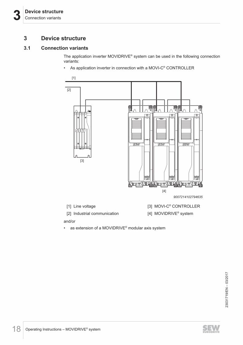
The application inverter MOVIDRIVE® system can be used in the following connectionvariants:• As application inverter in connection with a MOVI-C® CONTROLLER
[1]
[2]
[3]
[4]
9007214102794635
[1] Line voltage [3] MOVI-C® CONTROLLER
[2] Industrial communication [4] MOVIDRIVE® system
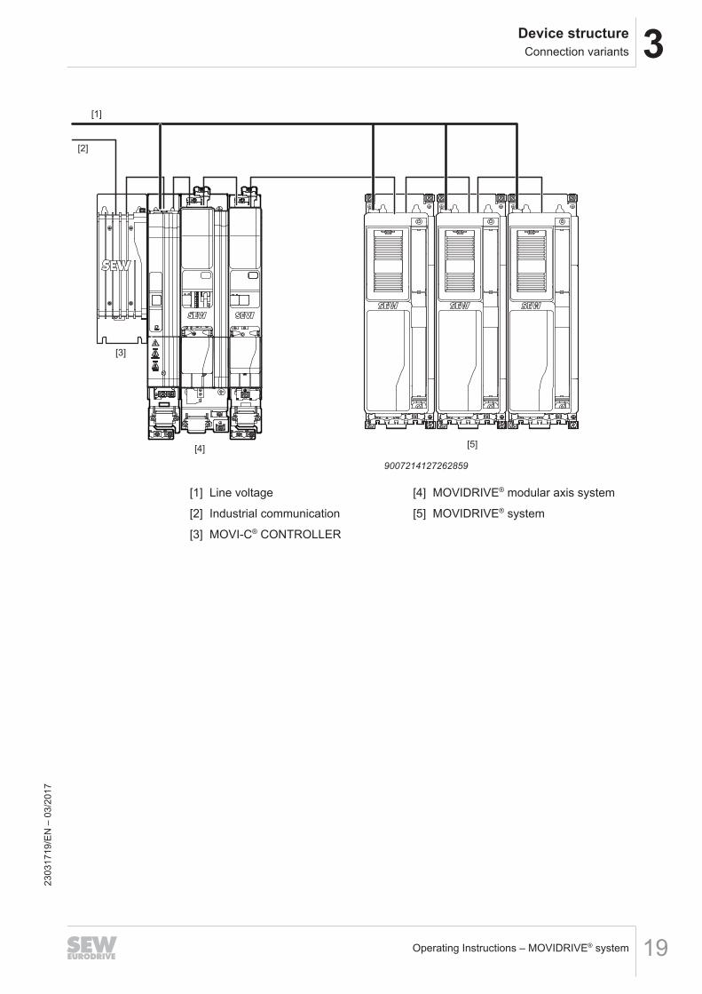
and/or• as extension of a MOVIDRIVE® modular axis system
2303
1719
/EN
– 0
3/20
17
3Device structureConnection variants
Operating Instructions – MOVIDRIVE® system 19
[1]
[2]
[3]
[4]
RUN ERR
X15
X21
X20
X31
S1
S2
+UZ
-UZ
X4
+U
Z-U
Z
24V
X5
+UZ
X4
-UZ -UZ
+U
Z
GND
X3
1X
20
_1
X2
1_
1
X2
0_
2X
21
_2
X1
5_
1
X1
5_
2
S1
S2
RUN ERR
+UZ
X4
X5
24V
GND
-UZ
+ U
Z-
UZ
[5]
9007214127262859
[1] Line voltage [4] MOVIDRIVE® modular axis system
[2] Industrial communication [5] MOVIDRIVE® system
[3] MOVI-C® CONTROLLER
2303
1719
/EN
– 0
3/20
17
3 Device structureNameplates
Operating Instructions – MOVIDRIVE® system20
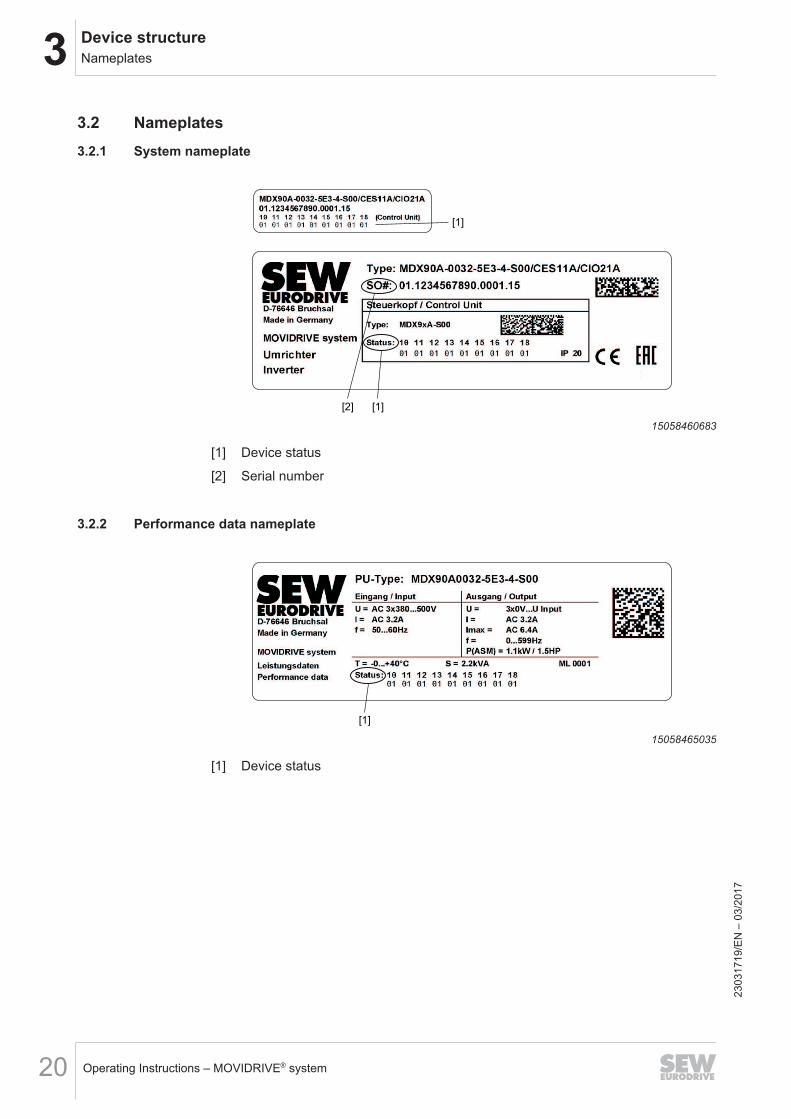
3.2 Nameplates3.2.1 System nameplate
[1]
[2] [1]
15058460683
[1] Device status
[2] Serial number
3.2.2 Performance data nameplate
[1]
15058465035
[1] Device status
2303
1719
/EN
– 0
3/20
17
3Device structureType code
Operating Instructions – MOVIDRIVE® system 21
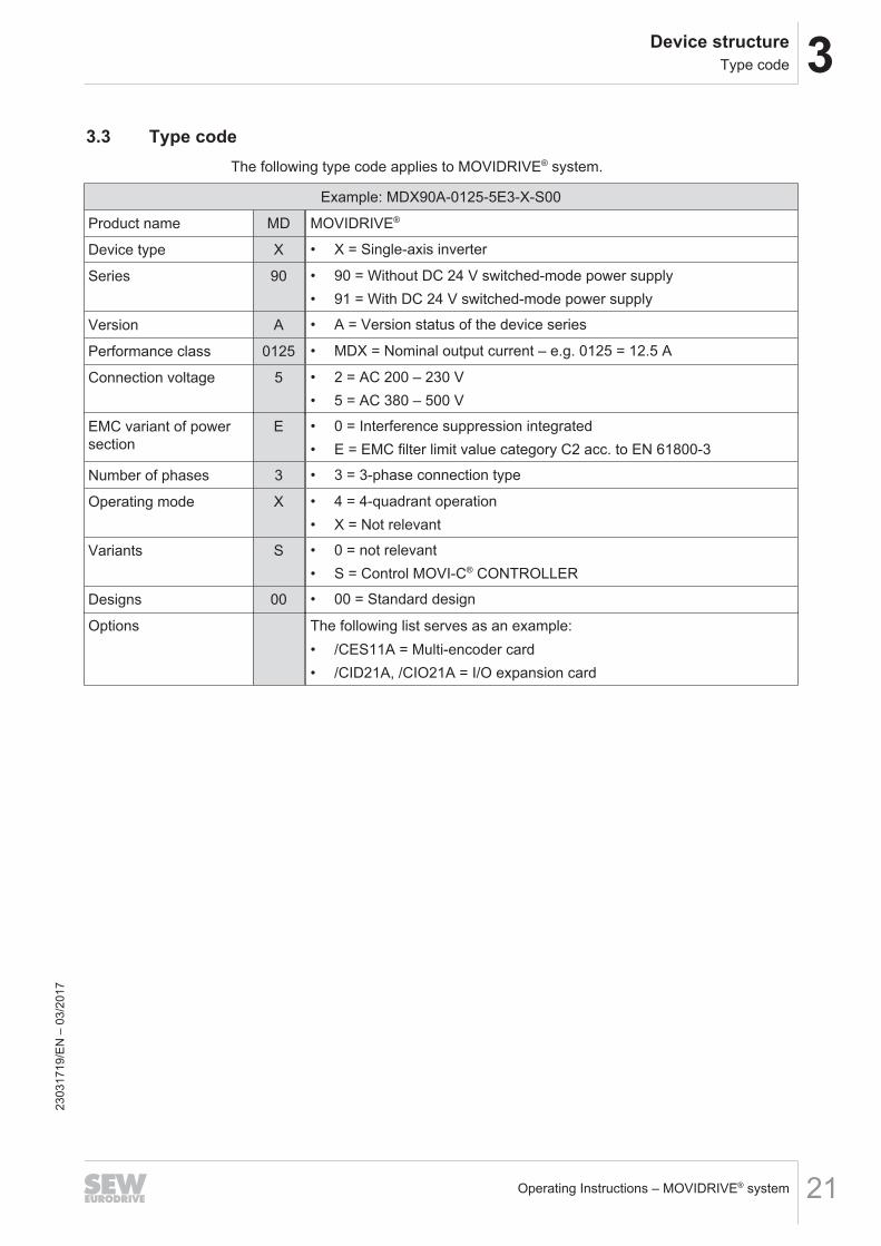
3.3 Type codeThe following type code applies to MOVIDRIVE® system.
Example: MDX90A-0125-5E3-X-S00
Product name MD MOVIDRIVE®
Device type X • X = Single-axis inverter
Series 90 • 90 = Without DC 24 V switched-mode power supply• 91 = With DC 24 V switched-mode power supply
Version A • A = Version status of the device series
Performance class 0125 • MDX = Nominal output current – e.g. 0125 = 12.5 A
Connection voltage 5 • 2 = AC 200 – 230 V• 5 = AC 380 – 500 V
EMC variant of powersection
E • 0 = Interference suppression integrated• E = EMC filter limit value category C2 acc. to EN 61800-3
Number of phases 3 • 3 = 3-phase connection type
Operating mode X • 4 = 4-quadrant operation• X = Not relevant
Variants S • 0 = not relevant• S = Control MOVI-C® CONTROLLER
Designs 00 • 00 = Standard design
Options The following list serves as an example:• /CES11A = Multi-encoder card• /CID21A, /CIO21A = I/O expansion card
2303
1719
/EN
– 0
3/20
17
3 Device structureDevice structure of the application inverter
Operating Instructions – MOVIDRIVE® system22
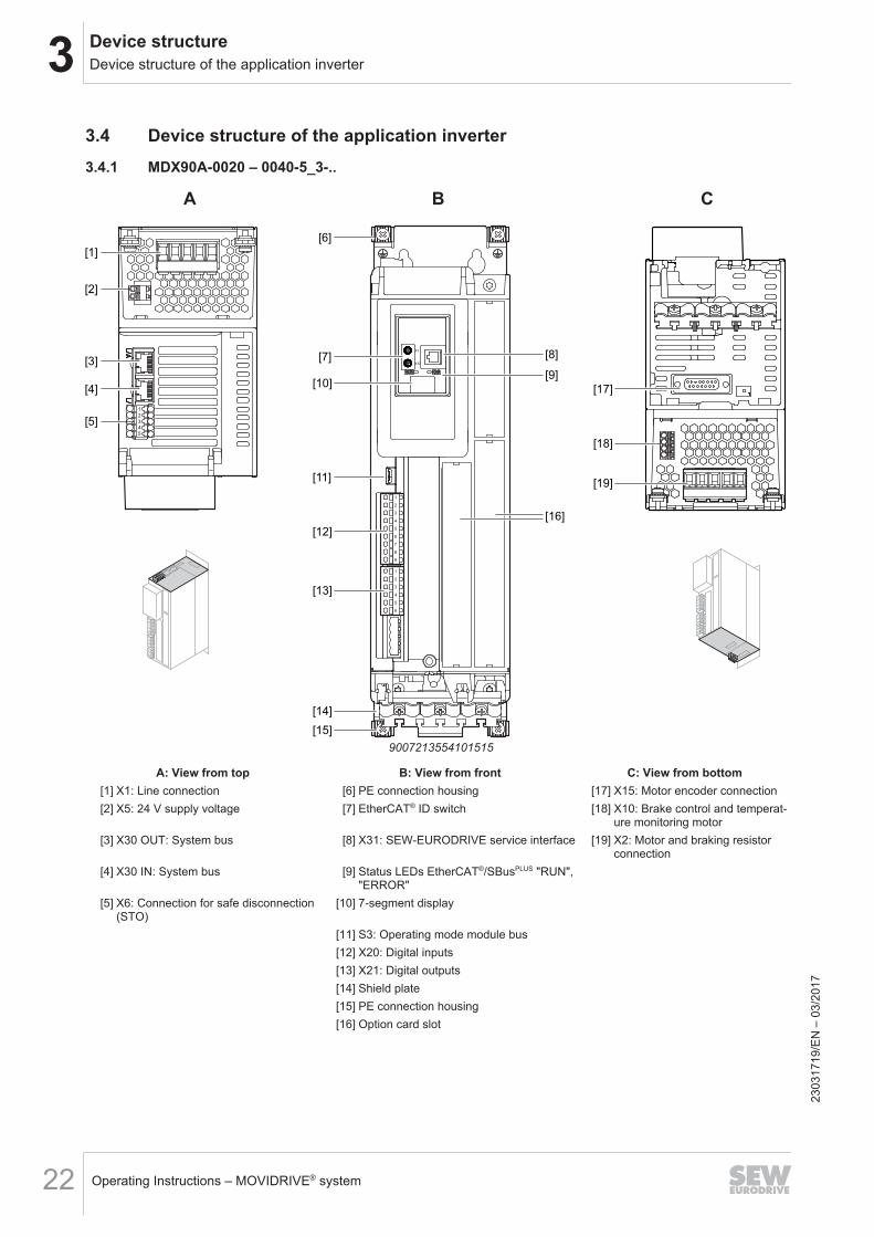
3.4 Device structure of the application inverter3.4.1 MDX90A-0020 – 0040-5_3-..
[14]
[11]
[9]
[7] [8]
[6]
[15]
[16]
[3]
[4]
[2]
[1]
[5]
[17]
[18]
[19]
A B C
[10]
X1
X10
[13]
[12]
1
2
3
4
5
9007213554101515
A: View from top B: View from front C: View from bottom[1] X1: Line connection [6] PE connection housing [17] X15: Motor encoder connection[2] X5: 24 V supply voltage [7] EtherCAT® ID switch [18] X10: Brake control and temperat-
ure monitoring motor[3] X30 OUT: System bus [8] X31: SEW‑EURODRIVE service interface [19] X2: Motor and braking resistor
connection[4] X30 IN: System bus [9] Status LEDs EtherCAT®/SBusPLUS "RUN",
"ERROR"[5] X6: Connection for safe disconnection
(STO)[10] 7-segment display
[11] S3: Operating mode module bus[12] X20: Digital inputs[13] X21: Digital outputs[14] Shield plate[15] PE connection housing[16] Option card slot
2303
1719
/EN
– 0
3/20
17
3Device structureDevice structure of the application inverter
Operating Instructions – MOVIDRIVE® system 23
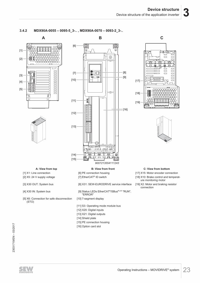
3.4.2 MDX90A-0055 – 0095-5_3-.. , MDX90A-0070 – 0093-2_3-..
A B C
[14]
[11]
[9]
[7] [8]
[6]
[15]
[16]
[3]
[4]
[2]
[1]
[5]
[17]
[18]
[19]
[10]
X1
X10
[13]
[12]
1
2
3
4
5
9007213554111243
A: View from top B: View from front C: View from bottom[1] X1: Line connection [6] PE connection housing [17] X15: Motor encoder connection[2] X5: 24 V supply voltage [7] EtherCAT® ID switch [18] X10: Brake control and temperat-
ure monitoring motor[3] X30 OUT: System bus [8] X31: SEW‑EURODRIVE service interface [19] X2: Motor and braking resistor
connection[4] X30 IN: System bus [9] Status LEDs EtherCAT®/SBusPLUS "RUN",
"ERROR"[5] X6: Connection for safe disconnection
(STO)[10] 7-segment display
[11] S3: Operating mode module bus[12] X20: Digital inputs[13] X21: Digital outputs[14] Shield plate[15] PE connection housing[16] Option card slot
2303
1719
/EN
– 0
3/20
17
3 Device structureDevice structure of the application inverter
Operating Instructions – MOVIDRIVE® system24
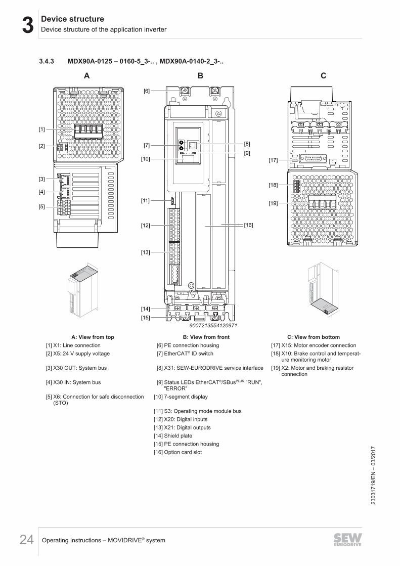
3.4.3 MDX90A-0125 – 0160-5_3-.. , MDX90A-0140-2_3-..
A B C
[14]
[11]
[9]
[7] [8]
[6]
[15]
[16]
[3]
[4]
[2]
[1]
[5]
[17]
[18]
[19]
[10]
X1
X10
[13]
[12]
1
2
3
4
5
9007213554120971
A: View from top B: View from front C: View from bottom[1] X1: Line connection [6] PE connection housing [17] X15: Motor encoder connection[2] X5: 24 V supply voltage [7] EtherCAT® ID switch [18] X10: Brake control and temperat-
ure monitoring motor[3] X30 OUT: System bus [8] X31: SEW‑EURODRIVE service interface [19] X2: Motor and braking resistor
connection[4] X30 IN: System bus [9] Status LEDs EtherCAT®/SBusPLUS "RUN",
"ERROR"[5] X6: Connection for safe disconnection
(STO)[10] 7-segment display
[11] S3: Operating mode module bus[12] X20: Digital inputs[13] X21: Digital outputs[14] Shield plate[15] PE connection housing[16] Option card slot
2303
1719
/EN
– 0
3/20
17
3Device structureDevice structure of the application inverter
Operating Instructions – MOVIDRIVE® system 25
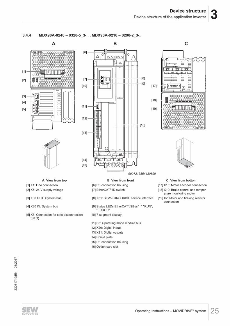
3.4.4 MDX90A-0240 – 0320-5_3-.. , MDX90A-0210 – 0290-2_3-..
A B C
[14]
[11]
[9]
[7] [8]
[6]
[15]
[16]
[3]
[4]
[2]
[1]
[5]
[17]
[18]
[19]
[10]
X1
X10
[13]
[12]
1
2
3
4
5
9007213554130699
A: View from top B: View from front C: View from bottom[1] X1: Line connection [6] PE connection housing [17] X15: Motor encoder connection[2] X5: 24 V supply voltage [7] EtherCAT® ID switch [18] X10: Brake control and temper-
ature monitoring motor[3] X30 OUT: System bus [8] X31: SEW‑EURODRIVE service interface [19] X2: Motor and braking resistor
connection[4] X30 IN: System bus [9] Status LEDs EtherCAT®/SBusPLUS "RUN",
"ERROR"[5] X6: Connection for safe disconnection
(STO)[10] 7-segment display
[11] S3: Operating mode module bus[12] X20: Digital inputs[13] X21: Digital outputs[14] Shield plate[15] PE connection housing[16] Option card slot
2303
1719
/EN
– 0
3/20
17
3 Device structureUse of option cards
Operating Instructions – MOVIDRIVE® system26
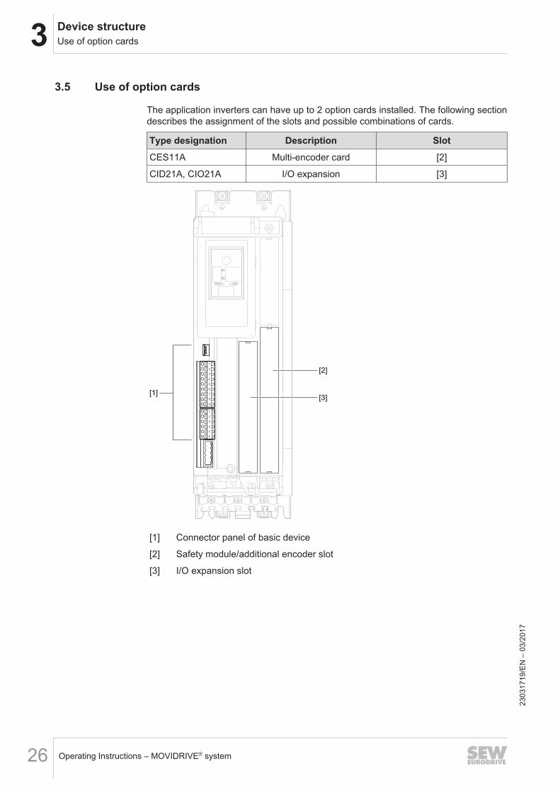
3.5 Use of option cards
The application inverters can have up to 2 option cards installed. The following sectiondescribes the assignment of the slots and possible combinations of cards.
Type designation Description SlotCES11A Multi-encoder card [2]
CID21A, CIO21A I/O expansion [3]
[1]
[2]
[3]
[1] Connector panel of basic device
[2] Safety module/additional encoder slot
[3] I/O expansion slot
2303
1719
/EN
– 0
3/20
17
4InstallationInstallation accessories
Operating Instructions – MOVIDRIVE® system 27
4 InstallationMOVIDRIVE® system application inverters are exclusively suitable for control cabinetinstallation according to the degree of protection.
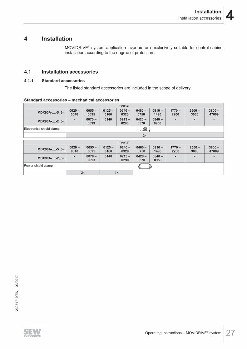
4.1 Installation accessories4.1.1 Standard accessories
The listed standard accessories are included in the scope of delivery.
Standard accessories – mechanical accessoriesInverter
MDX90A-....-5_3-.. 0020 –0040
0055 –0095
0125 –0160
0240 –0320
0460 –0750
0910 –1490
1770 –2200
2500 –3000
3800 –47009
MDX90A-....-2_3-.. - 0070 –0093
0140 0213 –0290
0420 –0570
0840 –0950
- - -
Electronics shield clamp
3×
Inverter
MDX90A-....-5_3-.. 0020 –0040
0055 –0095
0125 –0160
0240 –0320
0460 –0750
0910 –1490
1770 –2200
2500 –3000
3800 –47009
MDX90A-....-2_3-.. - 0070 –0093
0140 0213 –0290
0420 –0570
0840 –0950
- - -
Power shield clamp
2× 1×
2303
1719
/EN
– 0
3/20
17
4 InstallationPermitted tightening torques
Operating Instructions – MOVIDRIVE® system28
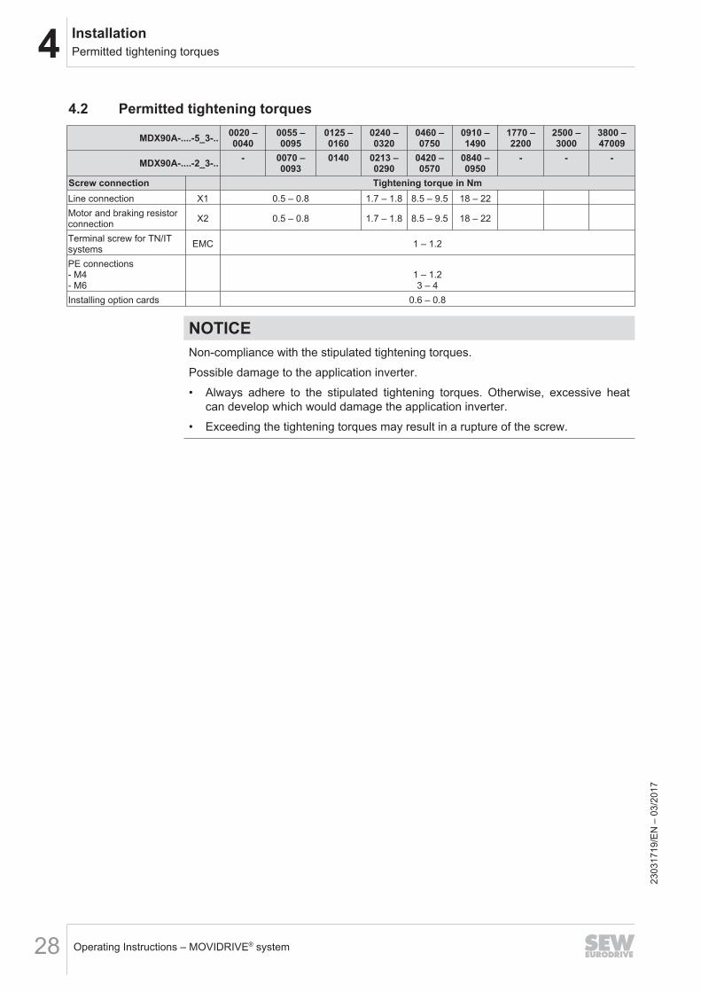
4.2 Permitted tightening torques
MDX90A-....-5_3-.. 0020 –0040
0055 –0095
0125 –0160
0240 –0320
0460 –0750
0910 –1490
1770 –2200
2500 –3000
3800 –47009
MDX90A-....-2_3-.. - 0070 –0093
0140 0213 –0290
0420 –0570
0840 –0950
- - -
Screw connection Tightening torque in NmLine connection X1 0.5 – 0.8 1.7 – 1.8 8.5 – 9.5 18 – 22Motor and braking resistorconnection X2 0.5 – 0.8 1.7 – 1.8 8.5 – 9.5 18 – 22
Terminal screw for TN/ITsystems EMC 1 – 1.2
PE connections- M4- M6
1 – 1.23 – 4
Installing option cards 0.6 – 0.8
NOTICENon-compliance with the stipulated tightening torques.Possible damage to the application inverter.• Always adhere to the stipulated tightening torques. Otherwise, excessive heat
can develop which would damage the application inverter.• Exceeding the tightening torques may result in a rupture of the screw.
2303
1719
/EN
– 0
3/20
17
4InstallationMechanical installation
Operating Instructions – MOVIDRIVE® system 29
4.3 Mechanical installation
CAUTIONRisk of injury to persons and damage to property.Never install defective or damaged application inverters.• Before installing modules, check them for external damage. Replace any dam-
aged modules.
NOTICERisk of damage to property due to mounting surface with poor conductivity.Damage to the application inverter.• The mounting plate in the control cabinet must be conductive over a large area
for the mounting surface of the application inverter (metallically pure, good con-ductivity). EMC‑compliant installation of the application inverter can only be ac-complished with a mounting plate that is conductive over a large area.
2303
1719
/EN
– 0
3/20
17
4 InstallationMechanical installation
Operating Instructions – MOVIDRIVE® system30
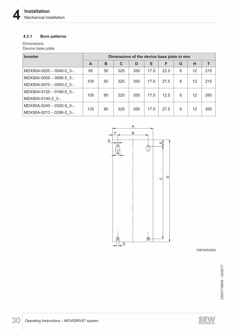
4.3.1 Bore patterns
Dimensions Device base plate
Inverter Dimensions of the device base plate in mmA B C D E F G H T
MDX90A-0020 – 0040-5_3-.. 95 50 325 350 17.5 22.5 6 12 215
MDX90A-0055 – 0095-5_3-..MDX90A-0070 – 0093-2_3-..
105 50 325 350 17.5 27.5 6 12 215
MDX90A-0125 – 0160-5_3-..MDX90A-0140-2_3-..
105 80 325 350 17.5 12.5 6 12 260
MDX90A-0240 – 0320-5_3-..MDX90A-0213 – 0290-2_3-..
135 80 325 350 17.5 27.5 6 12 260
D
A
E
BF
G
H
G
C
15874454283
2303
1719
/EN
– 0
3/20
17
4InstallationMechanical installation
Operating Instructions – MOVIDRIVE® system 31
4.3.2 Minimum clearance and mounting positionWhen installing the application inverters in the control cabinet, observe the following:• To ensure unobstructed cooling, leave a minimum clearance of 100 mm above
and below the application inverter housings. Make sure air circulation in the clear-ance is not impaired by cables or other installation equipment.
• Make sure that the application inverters are not subjected to heated exhaust airfrom nearby components.
• Install the application inverters only vertically. You must not install them horizont-ally, tilted or upside down.
INFORMATION
Special bending spaces are required according to EN 61800‑5‑1 for cables with across section of 10 mm2 and larger. This means the clearance must be increased ifrequired.
2303
1719
/EN
– 0
3/20
17
4 InstallationCovers
Operating Instructions – MOVIDRIVE® system32
4.4 Covers
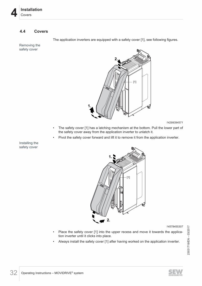
The application inverters are equipped with a safety cover [1], see following figures.Removing thesafety cover
1.
2.
[1]5
4
321
14299394571
• The safety cover [1] has a latching mechanism at the bottom. Pull the lower part ofthe safety cover away from the application inverter to unlatch it.
• Pivot the safety cover forward and lift it to remove it from the application inverter.Installing thesafety cover
[1]
5
4
321
2.
1.
14578455307
• Place the safety cover [1] into the upper recess and move it towards the applica-tion inverter until it clicks into place.
• Always install the safety cover [1] after having worked on the application inverter.
2303
1719
/EN
– 0
3/20
17
4InstallationControl cabinet installation
Operating Instructions – MOVIDRIVE® system 33
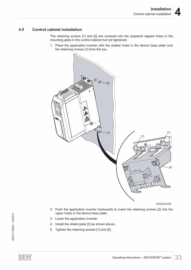
4.5 Control cabinet installationThe retaining screws [1] and [2] are screwed into the prepared tapped holes in themounting plate in the control cabinet but not tightened.1. Place the application inverter with the slotted holes in the device base plate onto
the retaining screws [1] from the top.
[2]
[1]
[1]
[1]
[3]
54321
15026233355
2. Push the application inverter backwards to insert the retaining screws [2] into theupper holes in the device base plate.
3. Lower the application inverter.4. Install the shield plate [3] as shown above.5. Tighten the retaining screws [1] and [2].
2303
1719
/EN
– 0
3/20
17
4 InstallationElectrical installation
Operating Instructions – MOVIDRIVE® system34
4.6 Electrical installation
DANGERDangerous voltage levels may still be present inside the device and at the terminalstrips up to 10 minutes after the application inverter has been disconnected from thesupply system.Severe or fatal injuries from electric shock.To prevent electric shocks:• Disconnect the application inverter from the supply system and wait 10 minutes
before removing the protective covers.
DANGERA leakage current > 3.5 mA can occur during operation of the application inverter.Severe or fatal injuries from electric shock.To avoid shock currents according to EN 61800-5-1, strictly observe the following:• Supply system lead < 10 mm2:
– Route a second PE conductor with the cable cross section of the supply sys-tem lead in parallel to the protective earth via separate terminals or use a cop-per PE conductor with a cable cross section of 10 mm2.
• Supply system cable 10 mm2 – 16 mm2:– Route a copper protective earth conductor with the cable cross section of the
supply system lead.• Supply system cable 16 mm2 – 35 mm2:
– Route a copper protective earth conductor with a cable cross section of16 mm2.
• Supply system cable > 35 mm2:– Route a copper protective earth conductor with half the cable cross section of
the supply cable.• If an earth leakage circuit breaker is used for protection against direct and indir-
ect contact, it must be universal current sensitive (RCD type B).
INFORMATIONInstallation with protective separation.The application inverter meets all requirements for protective separation of powerand electronics connections in accordance with EN 61800-5-1. The connected signalcircuits have to meet the requirements according to SELV (Safety Extra Low Voltage)or PELV (Protective Extra Low Voltage) to ensure protective separation. The installa-tion must meet the requirements for protective separation.
2303
1719
/EN
– 0
3/20
17
4InstallationElectrical installation
Operating Instructions – MOVIDRIVE® system 35
4.6.1 General information• Take suitable measures to prevent the motor starting up inadvertently, for example
by removing the electronics terminal block X20. Take additional safety measuresdepending on the application to prevent possible injuries to people and damage tomachinery.
• Only use closed cable lugs for connection to the screws in order to prevent litzstrands from escaping.
4.6.2 Permitted voltage systems
Information on the voltage systems Information on permissibilityTN and TT systems – voltage systems withdirectly grounded star point.
Use is possible without restrictions.
IT systems – voltage systems with non-groun-ded star point.
Use is only permitted adhering tospecific measures. The measuresare described in chapter "Use in ITsystems" (→ 2 35):
Voltage systems with grounded outer con-ductor.
Use only for line voltages up to max.240 V.
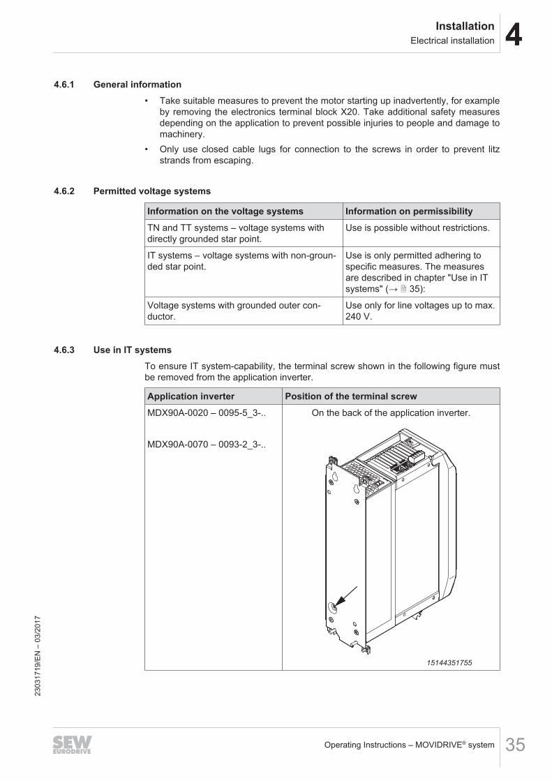
4.6.3 Use in IT systemsTo ensure IT system-capability, the terminal screw shown in the following figure mustbe removed from the application inverter.
Application inverter Position of the terminal screwMDX90A-0020 – 0095-5_3-..
MDX90A-0070 – 0093-2_3-..
On the back of the application inverter.
15144351755
2303
1719
/EN
– 0
3/20
17
4 InstallationElectrical installation
Operating Instructions – MOVIDRIVE® system36
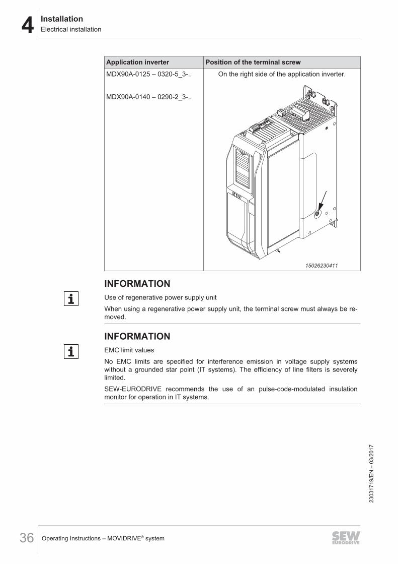
Application inverter Position of the terminal screwMDX90A-0125 – 0320-5_3-..
MDX90A-0140 – 0290-2_3-..
On the right side of the application inverter.
5
43
21
15026230411
INFORMATIONUse of regenerative power supply unitWhen using a regenerative power supply unit, the terminal screw must always be re-moved.
INFORMATIONEMC limit valuesNo EMC limits are specified for interference emission in voltage supply systemswithout a grounded star point (IT systems). The efficiency of line filters is severelylimited.SEW‑EURODRIVE recommends the use of an pulse-code-modulated insulationmonitor for operation in IT systems.
2303
1719
/EN
– 0
3/20
17
4InstallationElectrical installation
Operating Instructions – MOVIDRIVE® system 37
4.6.4 Line fuses, fuse types
Type class RequirementFuses in utilization categor-ies gL, gG
Fusing voltage ≥ rated line voltage
Miniature circuit breaker ofcharacteristics D
Nominal miniature circuit breaker voltage ≥ nominalline voltage
Nominal currents of the miniature circuit breaker mustbe 10% higher than the nominal line current of the ap-plication inverter
4.6.5 Line connectionThe operation of the application inverter with connected braking resistor is possiblewith and without line contactor.
NOTICEFrequent switch-on may destroy the application inverter or lead to unexpected mal-functions.The specified times and intervals must be observed.• Observe the minimum switch-off time of 10 s before switching the power back on.• Do not turn the power of the supply system on or off more than once per minute.
• The line contactor must always be located before the line filter.• Use only line contactors in utilization category AC-3 (EN 60947-4-1) or higher.• Do not use the line contactor for jog mode, but only for switching the application in-
verter on and off. For jog mode, the FCB 20 "Jog" must be used.• Observe the required dimensioning of the cable cross section for UL-compliant in-
stalling.
2303
1719
/EN
– 0
3/20
17
4 InstallationElectrical installation
Operating Instructions – MOVIDRIVE® system38
4.6.6 Line contactorThe following table provides an overview of when a line contactor is required and whatkind of preventive measures must be taken for the used braking resistor, see alsochapter "Protection against thermal overload of the braking resistor" (→ 2 58).
Inverter type Braking resistor type Protective element/pre-ventive measure
Line con-tactor re-quired?
MDX90A-0020 – 0160-5_3-..
MDX90A-0070 – 0140-2_3-..
No BR - No
BR... flat design - No
BR... as PTC - No
BW...External bimetallic relay Yes
TBC circuit breaker No
BR...-TExternal bimetallic relay Yes
TBC circuit breaker No
MDX90A-0240-5_3-.. and higher
MDX90A-0213-2_3-.. and higher
No BR - No
BR... flat design - No
BR... as PTC - No
BW...External bimetallic relay No
TBC circuit breaker No
BR...-T
Temperature contact evalu-ation No
External bimetallic relay No
TBC circuit breaker No
INFORMATIONWhen connecting a braking resistor without using a line contactor or a TCB circuitbreaker, it is mandatory to connect an external DC 24 V voltage supply to the applic-ation inverter.
2303
1719
/EN
– 0
3/20
17
4InstallationElectrical installation
Operating Instructions – MOVIDRIVE® system 39
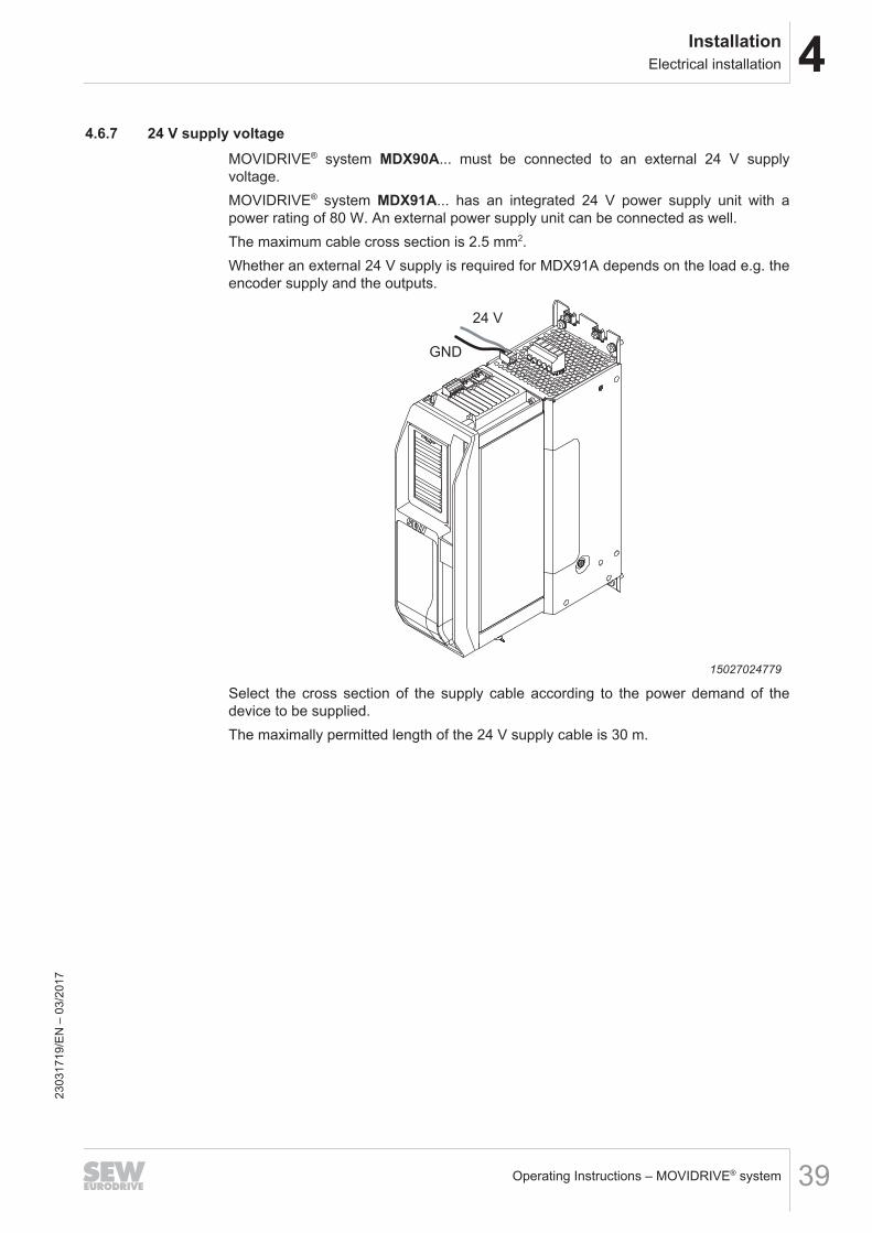
4.6.7 24 V supply voltageMOVIDRIVE® system MDX90A... must be connected to an external 24 V supplyvoltage.MOVIDRIVE® system MDX91A... has an integrated 24 V power supply unit with apower rating of 80 W. An external power supply unit can be connected as well.The maximum cable cross section is 2.5 mm2.Whether an external 24 V supply is required for MDX91A depends on the load e.g. theencoder supply and the outputs.
24 V
GND
5
43
21
15027024779
Select the cross section of the supply cable according to the power demand of thedevice to be supplied.The maximally permitted length of the 24 V supply cable is 30 m.
2303
1719
/EN
– 0
3/20
17
4 InstallationElectrical installation
Operating Instructions – MOVIDRIVE® system40
4.6.8 Motor output
NOTICEConnecting capacitive loads to the application inverter.Destruction of the application inverter.• Only connect ohmic/inductive loads (motors).• Never connect capacitive loads.
4.6.9 Output brake chopper
NOTICEConnecting capacitive loads to the application inverter.Connecting inductive loads to the application inverter.Destruction of the application inverter.• Only connect ohmic loads (braking resistors).• Never connect capacitive or inductive loads.
4.6.10 Temperature evaluation of the motorThe temperature evaluation can be connected in 2 ways:• The encoder cable includes the cables of the temperature evaluation.• The temperature evaluation is connected separately.
WARNINGDangerous contact voltages at the terminals of the application inverter when con-necting the wrong temperature sensors.Severe or fatal injuries from electric shock.• Connect only temperature sensors with protective separation from the motor
winding to the temperature evaluation. Otherwise, the requirements for protectiveseparation are not met. Dangerous contact voltages may occur at the terminalsof the application inverter via the signal electronics in case of an error.
2303
1719
/EN
– 0
3/20
17
4InstallationElectrical installation
Operating Instructions – MOVIDRIVE® system 41
4.6.11 Brake output
INFORMATION• If the brake connection and the motor connection are combined in one power
cable, the brake cable must be shielded separately. The shielding of the powercable and the brake cable must be connected to the motor and application inverterover a large area.
• SEW‑EURODRIVE recommends to also use a shielded brake cable for separatebrake cable routing.
• Note the different project planning criteria to determine the length of brake cableand motor cable.
4.6.12 Digital inputs, digital outputs
NOTICEDestruction of digital inputs and digital outputs.The digital inputs are not electrically isolated. Incorrectly applied voltages can dam-age the digital inputs.• Do not apply external voltages to the digital outputs.• The digital inputs and outputs are dimensioned according to IEC 61131‑2.
If you route the cables outside the control cabinet, you have to shield them irrespect-ive of the length.When connecting the shielding, ensure equipotential bonding.
2303
1719
/EN
– 0
3/20
17
4 InstallationElectrical installation
Operating Instructions – MOVIDRIVE® system42
4.6.13 System bus EtherCAT®/SBusPLUS
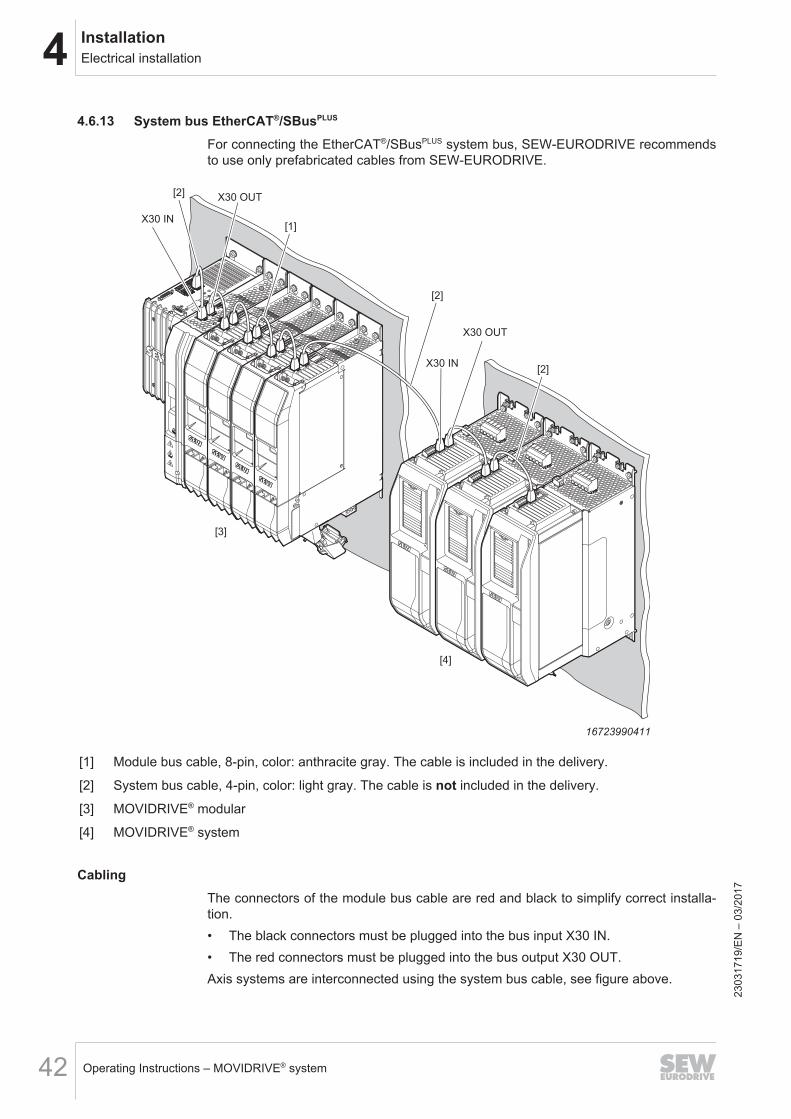
For connecting the EtherCAT®/SBusPLUS system bus, SEW‑EURODRIVE recommendsto use only prefabricated cables from SEW‑EURODRIVE.
5
4
32
1
5
4
32
1
5
4
32
1
X30 IN
X30 OUT
X30 OUT
X30 IN
[2]
[1]
[2]
[3]
[4]
[2]
16723990411
[1] Module bus cable, 8-pin, color: anthracite gray. The cable is included in the delivery.
[2] System bus cable, 4-pin, color: light gray. The cable is not included in the delivery.
[3] MOVIDRIVE® modular
[4] MOVIDRIVE® system
CablingThe connectors of the module bus cable are red and black to simplify correct installa-tion.• The black connectors must be plugged into the bus input X30 IN.• The red connectors must be plugged into the bus output X30 OUT.Axis systems are interconnected using the system bus cable, see figure above.
2303
1719
/EN
– 0
3/20
17
4InstallationElectrical installation
Operating Instructions – MOVIDRIVE® system 43
4.6.14 EncodersThe encoder cable may include the cables of the temperature evaluation.For information on the pin assignment, refer to chapter "Terminalassignment" (→ 2 73).
WARNINGDangerous contact voltages at the terminals of the application inverter when con-necting the wrong temperature sensors.Severe or fatal injuries from electric shock.• Connect only temperature sensors with protective separation from the motor
winding to the temperature evaluation. Otherwise, the requirements for protectiveseparation are not met. Dangerous contact voltages may occur at the terminalsof the application inverter via the signal electronics in case of an error.
Installation notes for encoder connection
Encoder cables
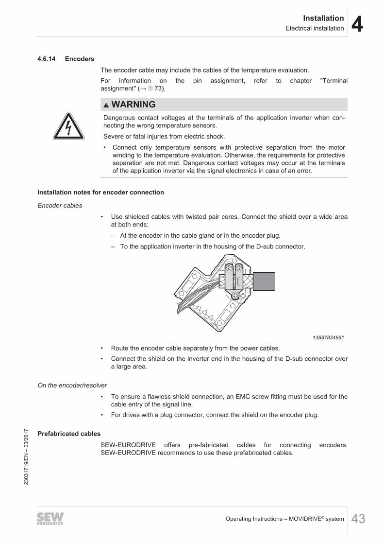
• Use shielded cables with twisted pair cores. Connect the shield over a wide areaat both ends:– At the encoder in the cable gland or in the encoder plug,– To the application inverter in the housing of the D-sub connector.
13887834891
• Route the encoder cable separately from the power cables.• Connect the shield on the inverter end in the housing of the D-sub connector over
a large area.
On the encoder/resolver
• To ensure a flawless shield connection, an EMC screw fitting must be used for thecable entry of the signal line.
• For drives with a plug connector, connect the shield on the encoder plug.
Prefabricated cablesSEW‑EURODRIVE offers pre-fabricated cables for connecting encoders.SEW‑EURODRIVE recommends to use these prefabricated cables.
2303
1719
/EN
– 0
3/20
17
4 InstallationElectrical installation
Operating Instructions – MOVIDRIVE® system44
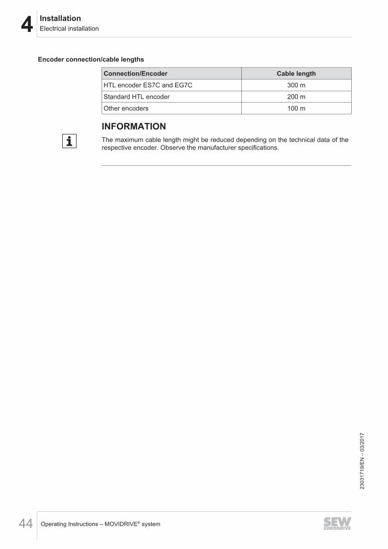
Encoder connection/cable lengths
Connection/Encoder Cable lengthHTL encoder ES7C and EG7C 300 m
Standard HTL encoder 200 m
Other encoders 100 m
INFORMATIONThe maximum cable length might be reduced depending on the technical data of therespective encoder. Observe the manufacturer specifications.
2303
1719
/EN
– 0
3/20
17
4InstallationInstalling options and accessories
Operating Instructions – MOVIDRIVE® system 45
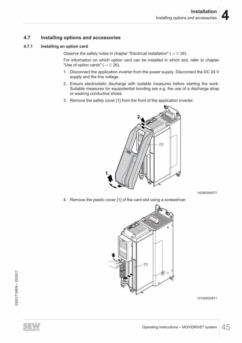
4.7 Installing options and accessories4.7.1 Installing an option card
Observe the safety notes in chapter "Electrical installation" (→ 2 34).For information on which option card can be installed in which slot, refer to chapter"Use of option cards" (→ 2 26).1. Disconnect the application inverter from the power supply. Disconnect the DC 24 V
supply and the line voltage.2. Ensure electrostatic discharge with suitable measures before starting the work.
Suitable measures for equipotential bonding are e.g. the use of a discharge strapor wearing conductive shoes.
3. Remove the safety cover [1] from the front of the application inverter.
1.
2.
[1]
5
4
321
14299394571
4. Remove the plastic cover [1] of the card slot using a screwdriver.
[1]
15160620811
2303
1719
/EN
– 0
3/20
17
4 InstallationInstalling options and accessories
Operating Instructions – MOVIDRIVE® system46
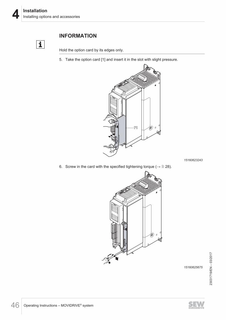
INFORMATION
Hold the option card by its edges only.
5. Take the option card [1] and insert it in the slot with slight pressure.
[1]
15160623243
6. Screw in the card with the specified tightening torque (→ 2 28).
15160625675
2303
1719
/EN
– 0
3/20
17
4InstallationInstalling options and accessories
Operating Instructions – MOVIDRIVE® system 47
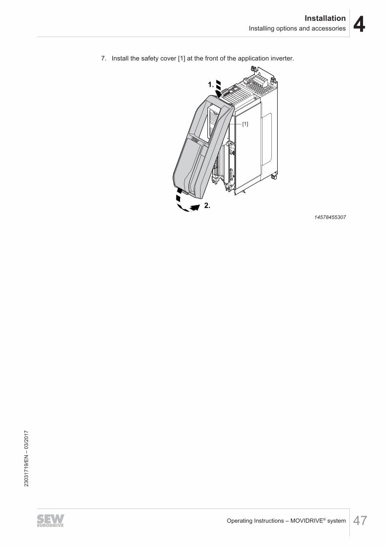
7. Install the safety cover [1] at the front of the application inverter.
[1]
5
4
321
2.
1.
14578455307
2303
1719
/EN
– 0
3/20
17
4 InstallationInstalling options and accessories
Operating Instructions – MOVIDRIVE® system48
4.7.2 CIO21A and CID21A input/output card
INFORMATIONTechnical data of the option cardsFor technical data and a detailed description of the encoder interface, refer to chapter"Technical data of the option cards".
Voltage supplyThe I/O cards are supplied by the basic unit via the 24 V voltage supply.
Short-circuit behavior of digital outputsThe digital outputs are short-circuit-proof.As soon as the short circuit is remedied, the target output voltage is output, meaningthe output does not switch off.
Short circuit behavior of analog outputsThe analog outputs are short-circuit-proof.In the event of a short circuit, the output current is limited to a maximum value of30 mA. The short circuit current is not pulsating.As soon as the short circuit is remedied, the target output voltage is output, meaningthe output does not switch off.
Connecting inductive loads at digital outputsFor inductive loads an external protective element (e.g. freewheeling diode) is re-quired.
Connecting digital outputs in parallelConnecting digital outputs in parallel is possible. The possible output current isdoubled. Ensure identical parameterization of the digital outputs.
Cable lengths and shieldingCable length The maximum cable length of connections on the inputs and outputs is 30 m.Shielding of signallines
Cables outside the control cabinet must be shielded.
2303
1719
/EN
– 0
3/20
17
4InstallationInstalling options and accessories
Operating Instructions – MOVIDRIVE® system 49
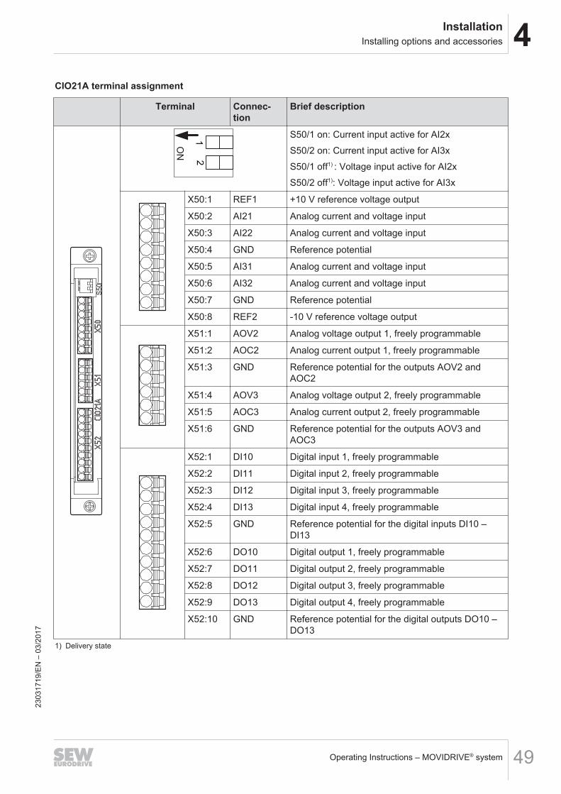
CIO21A terminal assignment
Terminal Connec-tion
Brief descriptionS50
ON
12
S50/1 on: Current input active for AI2xS50/2 on: Current input active for AI3xS50/1 off1) : Voltage input active for AI2xS50/2 off1): Voltage input active for AI3x
X50:1 REF1 +10 V reference voltage output
X50:2 AI21 Analog current and voltage input
X50:3 AI22 Analog current and voltage input
X50:4 GND Reference potential
X50:5 AI31 Analog current and voltage input
X50:6 AI32 Analog current and voltage input
X50:7 GND Reference potential
X50:8 REF2 -10 V reference voltage output
X51:1 AOV2 Analog voltage output 1, freely programmable
X51:2 AOC2 Analog current output 1, freely programmable
X51:3 GND Reference potential for the outputs AOV2 andAOC2
X51:4 AOV3 Analog voltage output 2, freely programmable
X51:5 AOC3 Analog current output 2, freely programmable
X51:6 GND Reference potential for the outputs AOV3 andAOC3
X52:1 DI10 Digital input 1, freely programmable
X52:2 DI11 Digital input 2, freely programmable
X52:3 DI12 Digital input 3, freely programmable
X52:4 DI13 Digital input 4, freely programmable
X52:5 GND Reference potential for the digital inputs DI10 –DI13
X52:6 DO10 Digital output 1, freely programmable
X52:7 DO11 Digital output 2, freely programmable
X52:8 DO12 Digital output 3, freely programmable
X52:9 DO13 Digital output 4, freely programmable
X52:10 GND Reference potential for the digital outputs DO10 –DO13
1) Delivery state
2303
1719
/EN
– 0
3/20
17
4 InstallationInstalling options and accessories
Operating Instructions – MOVIDRIVE® system50
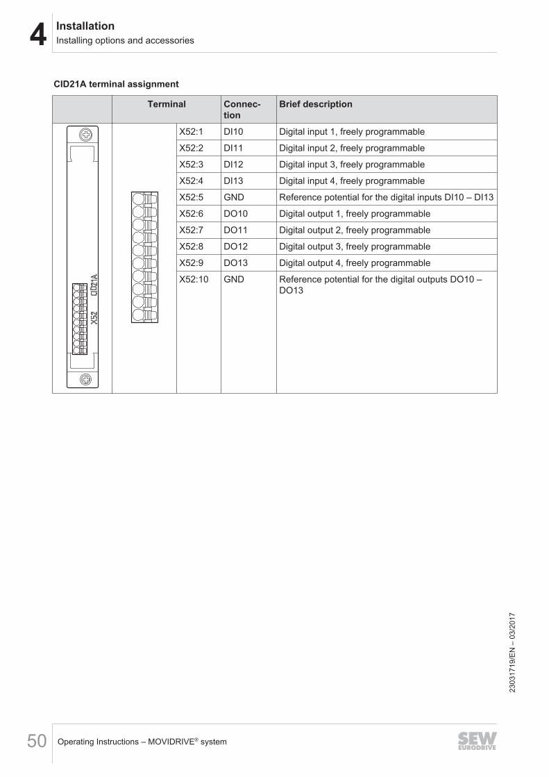
CID21A terminal assignment
Terminal Connec-tion
Brief description
X52:1 DI10 Digital input 1, freely programmable
X52:2 DI11 Digital input 2, freely programmable
X52:3 DI12 Digital input 3, freely programmable
X52:4 DI13 Digital input 4, freely programmable
X52:5 GND Reference potential for the digital inputs DI10 – DI13
X52:6 DO10 Digital output 1, freely programmable
X52:7 DO11 Digital output 2, freely programmable
X52:8 DO12 Digital output 3, freely programmable
X52:9 DO13 Digital output 4, freely programmable
X52:10 GND Reference potential for the digital outputs DO10 –DO13
2303
1719
/EN
– 0
3/20
17
4InstallationInstalling options and accessories
Operating Instructions – MOVIDRIVE® system 51
4.7.3 CES11A multi-encoder card
INFORMATIONTechnical data of the option cardsFor technical data and a detailed description of the encoder interface, refer to chapter"Technical data of the option cards".
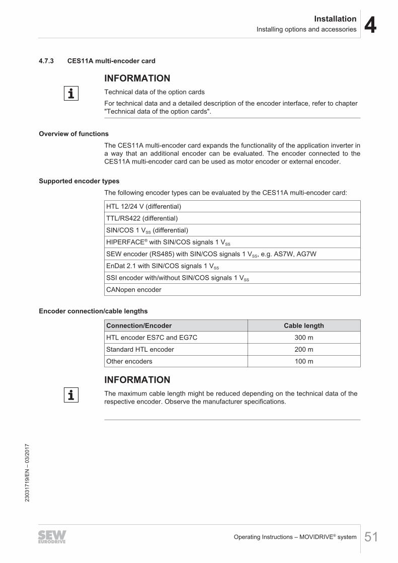
Overview of functionsThe CES11A multi-encoder card expands the functionality of the application inverter ina way that an additional encoder can be evaluated. The encoder connected to theCES11A multi-encoder card can be used as motor encoder or external encoder.
Supported encoder typesThe following encoder types can be evaluated by the CES11A multi-encoder card:
HTL 12/24 V (differential)
TTL/RS422 (differential)
SIN/COS 1 VSS (differential)
HIPERFACE® with SIN/COS signals 1 VSS
SEW encoder (RS485) with SIN/COS signals 1 VSS, e.g. AS7W, AG7W
EnDat 2.1 with SIN/COS signals 1 VSS
SSI encoder with/without SIN/COS signals 1 VSS
CANopen encoder
Encoder connection/cable lengths
Connection/Encoder Cable lengthHTL encoder ES7C and EG7C 300 m
Standard HTL encoder 200 m
Other encoders 100 m
INFORMATIONThe maximum cable length might be reduced depending on the technical data of therespective encoder. Observe the manufacturer specifications.
2303
1719
/EN
– 0
3/20
17
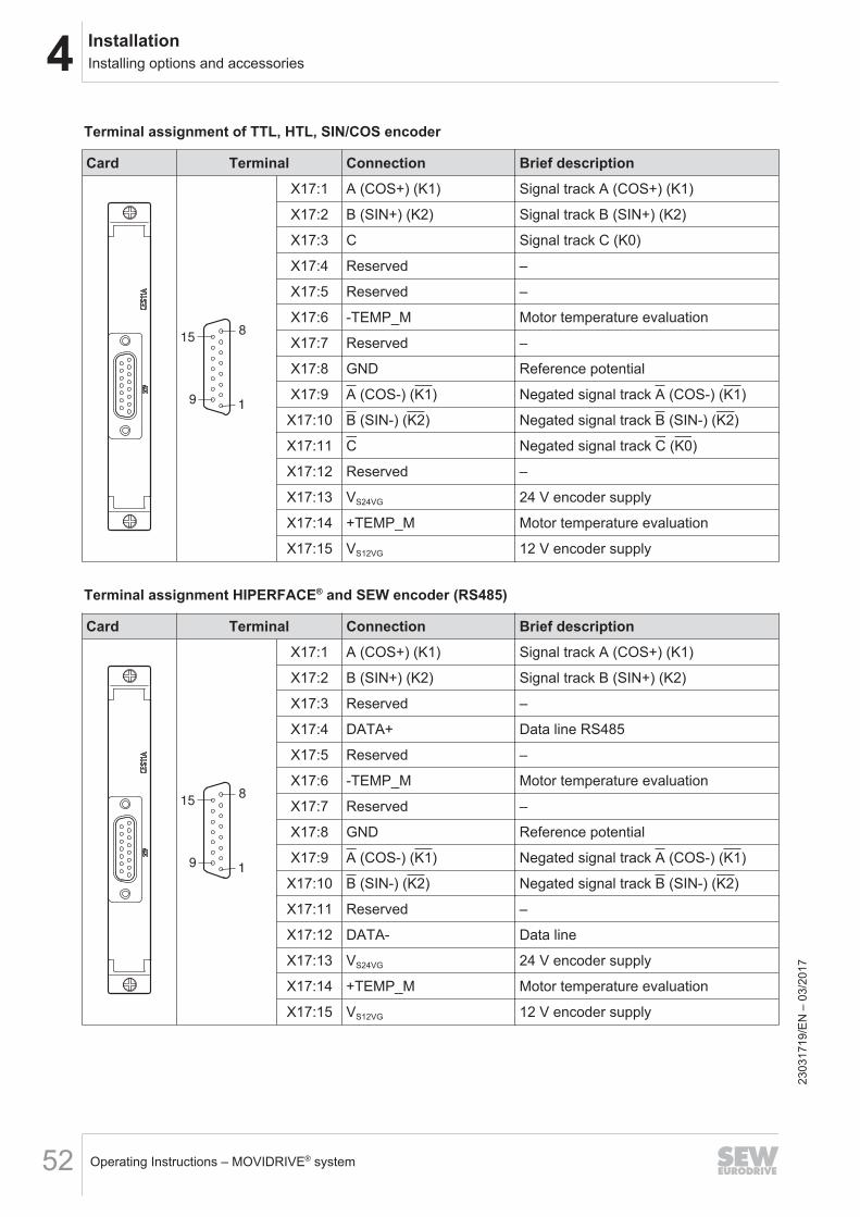
4 InstallationInstalling options and accessories
Operating Instructions – MOVIDRIVE® system52
Terminal assignment of TTL, HTL, SIN/COS encoder
Card Terminal Connection Brief description
15
91
8
X17:1 A (COS+) (K1) Signal track A (COS+) (K1)
X17:2 B (SIN+) (K2) Signal track B (SIN+) (K2)
X17:3 C Signal track C (K0)
X17:4 Reserved –
X17:5 Reserved –
X17:6 -TEMP_M Motor temperature evaluation
X17:7 Reserved –
X17:8 GND Reference potential
X17:9 A (COS-) (K1) Negated signal track A (COS-) (K1)
X17:10 B (SIN-) (K2) Negated signal track B (SIN-) (K2)
X17:11 C Negated signal track C (K0)
X17:12 Reserved –
X17:13 VS24VG 24 V encoder supply
X17:14 +TEMP_M Motor temperature evaluation
X17:15 VS12VG 12 V encoder supply
Terminal assignment HIPERFACE® and SEW encoder (RS485)
Card Terminal Connection Brief description
15
91
8
X17:1 A (COS+) (K1) Signal track A (COS+) (K1)
X17:2 B (SIN+) (K2) Signal track B (SIN+) (K2)
X17:3 Reserved –
X17:4 DATA+ Data line RS485
X17:5 Reserved –
X17:6 -TEMP_M Motor temperature evaluation
X17:7 Reserved –
X17:8 GND Reference potential
X17:9 A (COS-) (K1) Negated signal track A (COS-) (K1)
X17:10 B (SIN-) (K2) Negated signal track B (SIN-) (K2)
X17:11 Reserved –
X17:12 DATA- Data line
X17:13 VS24VG 24 V encoder supply
X17:14 +TEMP_M Motor temperature evaluation
X17:15 VS12VG 12 V encoder supply
2303
1719
/EN
– 0
3/20
17
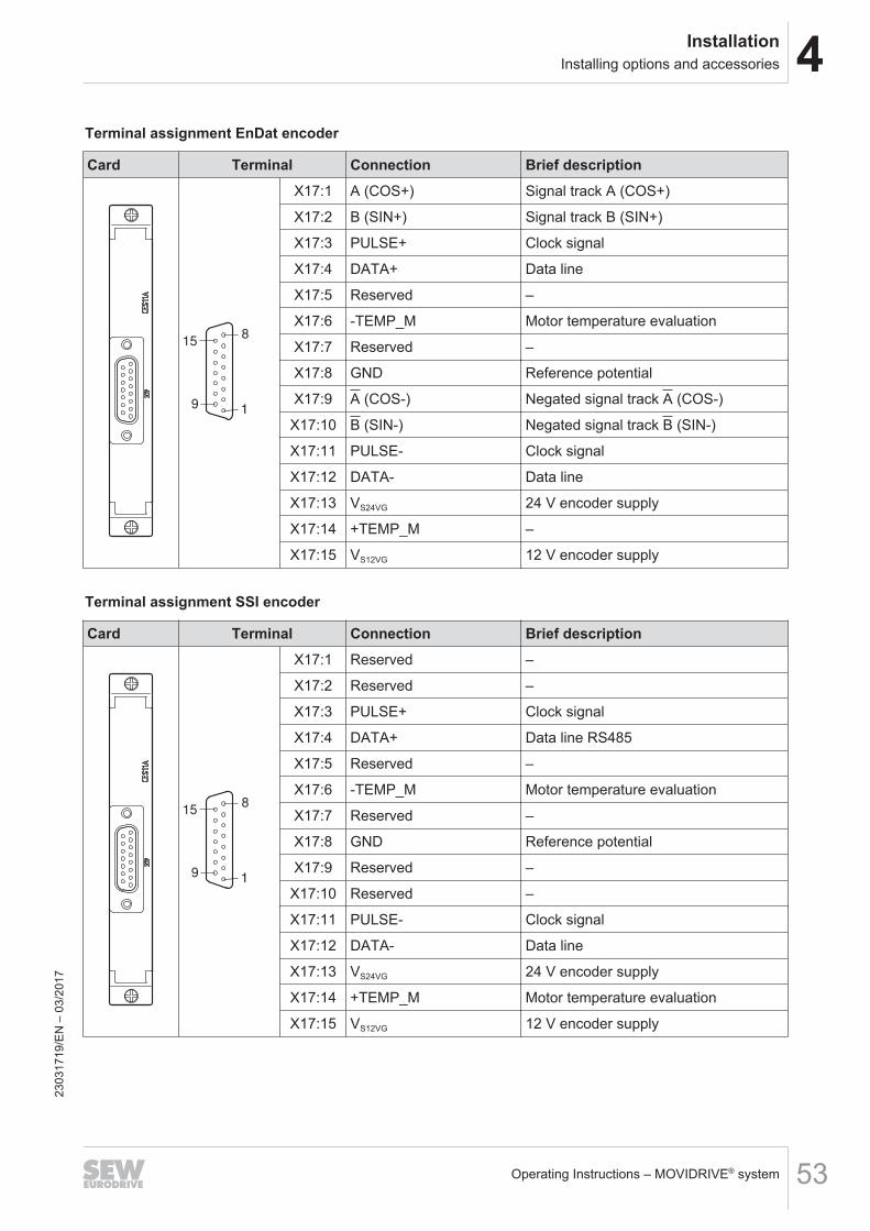
4InstallationInstalling options and accessories
Operating Instructions – MOVIDRIVE® system 53
Terminal assignment EnDat encoder
Card Terminal Connection Brief description
15
91
8
X17:1 A (COS+) Signal track A (COS+)
X17:2 B (SIN+) Signal track B (SIN+)
X17:3 PULSE+ Clock signal
X17:4 DATA+ Data line
X17:5 Reserved –
X17:6 -TEMP_M Motor temperature evaluation
X17:7 Reserved –
X17:8 GND Reference potential
X17:9 A (COS-) Negated signal track A (COS-)
X17:10 B (SIN-) Negated signal track B (SIN-)
X17:11 PULSE- Clock signal
X17:12 DATA- Data line
X17:13 VS24VG 24 V encoder supply
X17:14 +TEMP_M –
X17:15 VS12VG 12 V encoder supply
Terminal assignment SSI encoder
Card Terminal Connection Brief description
15
91
8
X17:1 Reserved –
X17:2 Reserved –
X17:3 PULSE+ Clock signal
X17:4 DATA+ Data line RS485
X17:5 Reserved –
X17:6 -TEMP_M Motor temperature evaluation
X17:7 Reserved –
X17:8 GND Reference potential
X17:9 Reserved –
X17:10 Reserved –
X17:11 PULSE- Clock signal
X17:12 DATA- Data line
X17:13 VS24VG 24 V encoder supply
X17:14 +TEMP_M Motor temperature evaluation
X17:15 VS12VG 12 V encoder supply
2303
1719
/EN
– 0
3/20
17
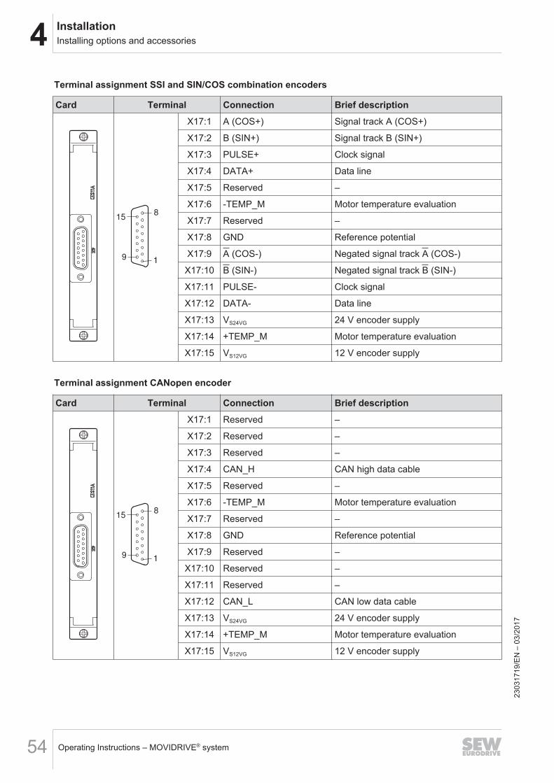
4 InstallationInstalling options and accessories
Operating Instructions – MOVIDRIVE® system54
Terminal assignment SSI and SIN/COS combination encoders
Card Terminal Connection Brief description
15
91
8
X17:1 A (COS+) Signal track A (COS+)
X17:2 B (SIN+) Signal track B (SIN+)
X17:3 PULSE+ Clock signal
X17:4 DATA+ Data line
X17:5 Reserved –
X17:6 -TEMP_M Motor temperature evaluation
X17:7 Reserved –
X17:8 GND Reference potential
X17:9 A (COS-) Negated signal track A (COS-)
X17:10 B (SIN-) Negated signal track B (SIN-)
X17:11 PULSE- Clock signal
X17:12 DATA- Data line
X17:13 VS24VG 24 V encoder supply
X17:14 +TEMP_M Motor temperature evaluation
X17:15 VS12VG 12 V encoder supply
Terminal assignment CANopen encoder
Card Terminal Connection Brief description
15
91
8
X17:1 Reserved –
X17:2 Reserved –
X17:3 Reserved –
X17:4 CAN_H CAN high data cable
X17:5 Reserved –
X17:6 -TEMP_M Motor temperature evaluation
X17:7 Reserved –
X17:8 GND Reference potential
X17:9 Reserved –
X17:10 Reserved –
X17:11 Reserved –
X17:12 CAN_L CAN low data cable
X17:13 VS24VG 24 V encoder supply
X17:14 +TEMP_M Motor temperature evaluation
X17:15 VS12VG 12 V encoder supply
2303
1719
/EN
– 0
3/20
17
4InstallationBraking resistors
Operating Instructions – MOVIDRIVE® system 55
4.8 Braking resistorsObserve the following points if braking resistors are installed:• The supply cables to the braking resistors carry a high pulsed DC voltage during
nominal operation.
DANGERDangerous clocked DC voltage of up to 970 V.Severe or fatal injuries from electric shock.To prevent electric shocks:• Disconnect the application inverter from the supply system and wait 10 minutes
before working on a braking resistor or its supply cables.• Never operate the application inverter without touch guards and installed closing
covers.
• Braking resistors get very hot during operation.
WARNINGThe surfaces of the braking resistors will reach temperatures of up to 250 °C whenthe braking resistors are loaded with the nominal power.Severe burns.To prevent burns:• Do not touch any braking resistor.• Select a suitable installation location for the braking resistors such as the control
cabinet roof.
2303
1719
/EN
– 0
3/20
17
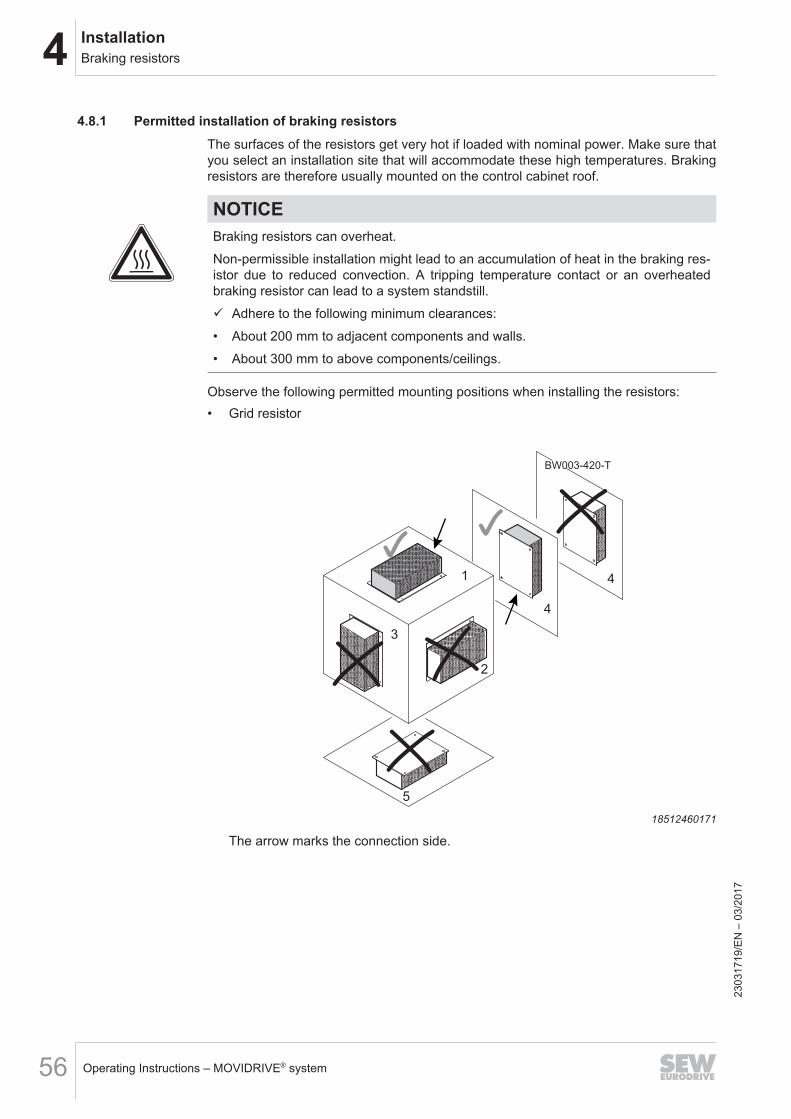
4 InstallationBraking resistors
Operating Instructions – MOVIDRIVE® system56
4.8.1 Permitted installation of braking resistorsThe surfaces of the resistors get very hot if loaded with nominal power. Make sure thatyou select an installation site that will accommodate these high temperatures. Brakingresistors are therefore usually mounted on the control cabinet roof.
NOTICEBraking resistors can overheat.Non-permissible installation might lead to an accumulation of heat in the braking res-istor due to reduced convection. A tripping temperature contact or an overheatedbraking resistor can lead to a system standstill.ü Adhere to the following minimum clearances:• About 200 mm to adjacent components and walls.• About 300 mm to above components/ceilings.
Observe the following permitted mounting positions when installing the resistors:• Grid resistor
BW003-420-T
1
2
3
4
4
5
18512460171
The arrow marks the connection side.
2303
1719
/EN
– 0
3/20
17
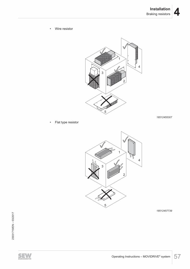
4InstallationBraking resistors
Operating Instructions – MOVIDRIVE® system 57
• Wire resistor
1
2
3
4
5
18512455307
• Flat type resistor
1
2
3
4
5
18512457739
2303
1719
/EN
– 0
3/20
17
4 InstallationBraking resistors
Operating Instructions – MOVIDRIVE® system58
4.8.2 Protection against thermal overload of the braking resistor
INFORMATIONPTC braking resistorA PTC braking resistor goes to high resistance in case of overload.
INFORMATIONFlat-type resistorFlat-design resistors have an internal thermal protection (non-replaceable fuse) thatinterrupts the current circuit in the event of overload. The project planning guidelinesand the documented assignments of drive inverter and braking resistor must be ad-hered to.
Parallel connection of braking resistorsIt is permitted to connect several identical braking resistors in parallel. The followingapplies:• The power connections of the braking resistors must be connected to +R and –R
in parallel.• Each braking resistor requires a separate protection against thermal overload.• The signal contacts (NC contacts) of the protection devices must be connected in
series.
2303
1719
/EN
– 0
3/20
17
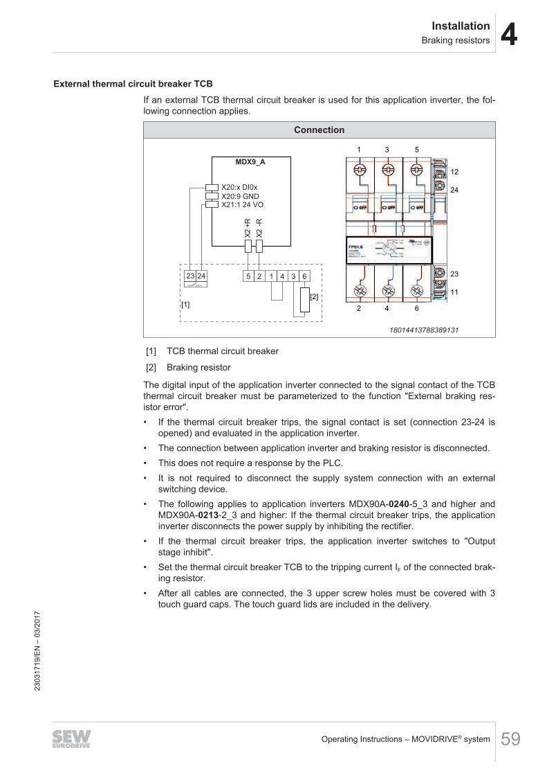
4InstallationBraking resistors
Operating Instructions – MOVIDRIVE® system 59
External thermal circuit breaker TCBIf an external TCB thermal circuit breaker is used for this application inverter, the fol-lowing connection applies.
Connection
MDX9_A
X20:x DI0x
X20:9 GND
X2 -
R
X2 +
R
X21:1 24 VO
23 24 5 2 1 4 3 6
[1][2]
1 3 5
2 4 6
12
24
23
11
18014413788389131
[1] TCB thermal circuit breaker
[2] Braking resistor
The digital input of the application inverter connected to the signal contact of the TCBthermal circuit breaker must be parameterized to the function "External braking res-istor error".• If the thermal circuit breaker trips, the signal contact is set (connection 23-24 is
opened) and evaluated in the application inverter.• The connection between application inverter and braking resistor is disconnected.• This does not require a response by the PLC.• It is not required to disconnect the supply system connection with an external
switching device.• The following applies to application inverters MDX90A-0240-5_3 and higher and
MDX90A-0213-2_3 and higher: If the thermal circuit breaker trips, the applicationinverter disconnects the power supply by inhibiting the rectifier.
• If the thermal circuit breaker trips, the application inverter switches to "Outputstage inhibit".
• Set the thermal circuit breaker TCB to the tripping current IF of the connected brak-ing resistor.
• After all cables are connected, the 3 upper screw holes must be covered with 3touch guard caps. The touch guard lids are included in the delivery.
2303
1719
/EN
– 0
3/20
17
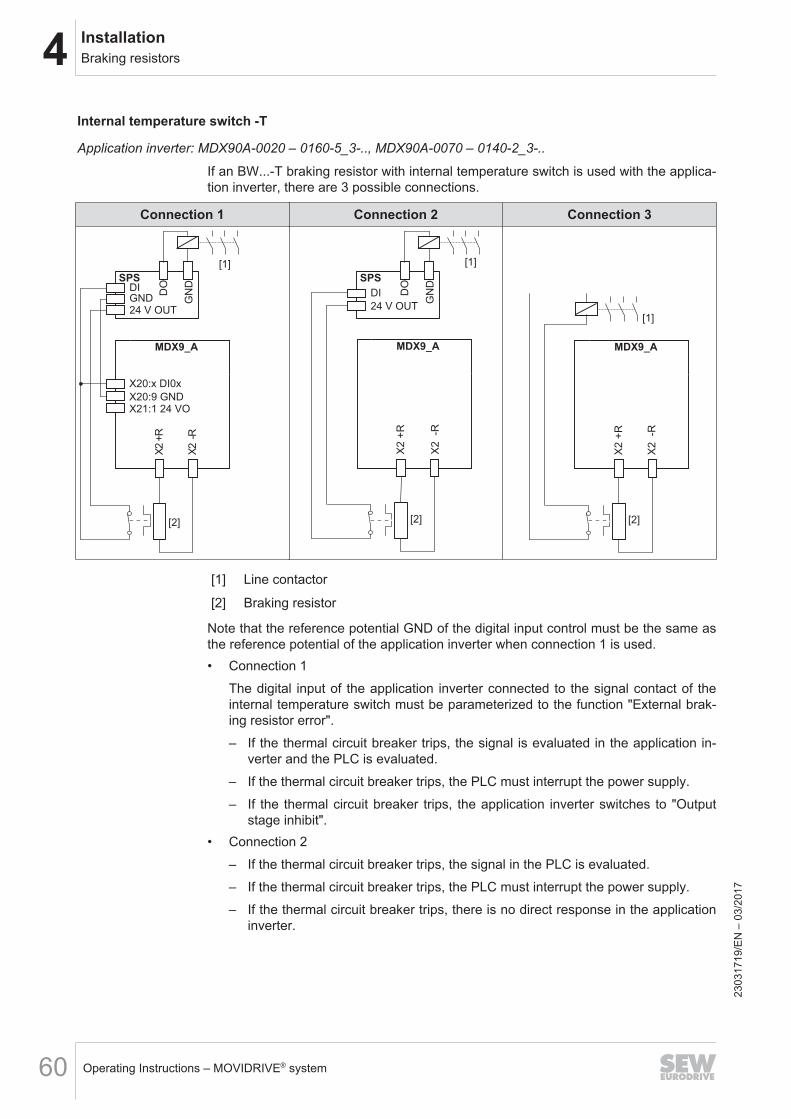
4 InstallationBraking resistors
Operating Instructions – MOVIDRIVE® system60
Internal temperature switch -T
Application inverter: MDX90A-0020 – 0160-5_3-.., MDX90A-0070 – 0140-2_3-..
If an BW...-T braking resistor with internal temperature switch is used with the applica-tion inverter, there are 3 possible connections.
Connection 1 Connection 2 Connection 3
SPS
MDX9_A
X20:x DI0x
X20:9 GND
DI
24 V OUT
[1]
X2 -
R
X2 +
RD
O
GN
D
[2]
X21:1 24 VO
GND
MDX9_A
[2]
X2
-R
X2
+R
SPS
DI
24 V OUT
DO
GN
D
[1]
MDX9_A
[2]
X2
-R
X2
+R
[1]
[1] Line contactor
[2] Braking resistor
Note that the reference potential GND of the digital input control must be the same asthe reference potential of the application inverter when connection 1 is used.• Connection 1
The digital input of the application inverter connected to the signal contact of theinternal temperature switch must be parameterized to the function "External brak-ing resistor error".– If the thermal circuit breaker trips, the signal is evaluated in the application in-
verter and the PLC is evaluated.– If the thermal circuit breaker trips, the PLC must interrupt the power supply.– If the thermal circuit breaker trips, the application inverter switches to "Output
stage inhibit".• Connection 2
– If the thermal circuit breaker trips, the signal in the PLC is evaluated.– If the thermal circuit breaker trips, the PLC must interrupt the power supply.– If the thermal circuit breaker trips, there is no direct response in the application
inverter.
2303
1719
/EN
– 0
3/20
17
4InstallationBraking resistors
Operating Instructions – MOVIDRIVE® system 61
– With connection 2, it is possible that the PLC finishes the current travel cycle al-though the thermal circuit breaker has tripped. Only then, the power supply isdisconnected. In this case, the residual braking energy WRest = RBRnom × 20 smust not be exceeded.
• Connection 3– If the thermal circuit breaker trips, the signal directly affects the line contactor.– This does not require a response by the PLC.– If the thermal circuit breaker trips, there is no direct response in the application
inverter.
2303
1719
/EN
– 0
3/20
17
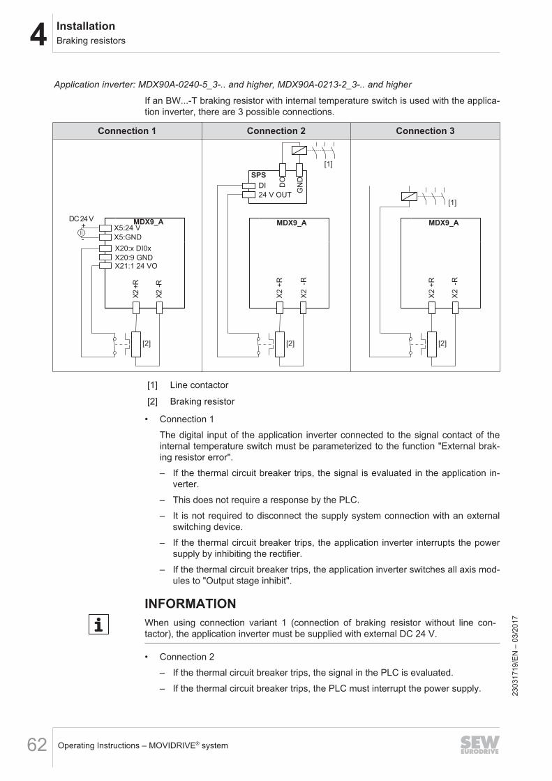
4 InstallationBraking resistors
Operating Instructions – MOVIDRIVE® system62
Application inverter: MDX90A-0240-5_3-.. and higher, MDX90A-0213-2_3-.. and higher
If an BW...-T braking resistor with internal temperature switch is used with the applica-tion inverter, there are 3 possible connections.
Connection 1 Connection 2 Connection 3
MDX9_A
X20:x DI0x
X20:9 GND
[2]
X2 -
R
X2 +
R
X21:1 24 VO
X5:GND
X5:24 V+
-
DC 24 VMDX9_A
[2]
X2
-R
X2
+R
SPS
DI
24 V OUT
DO
GN
D
[1]
MDX9_A
[2]
X2
-R
X2
+R
[1]
[1] Line contactor
[2] Braking resistor
• Connection 1The digital input of the application inverter connected to the signal contact of theinternal temperature switch must be parameterized to the function "External brak-ing resistor error".– If the thermal circuit breaker trips, the signal is evaluated in the application in-
verter.– This does not require a response by the PLC.– It is not required to disconnect the supply system connection with an external
switching device.– If the thermal circuit breaker trips, the application inverter interrupts the power
supply by inhibiting the rectifier.– If the thermal circuit breaker trips, the application inverter switches all axis mod-
ules to "Output stage inhibit".
INFORMATIONWhen using connection variant 1 (connection of braking resistor without line con-tactor), the application inverter must be supplied with external DC 24 V.
• Connection 2– If the thermal circuit breaker trips, the signal in the PLC is evaluated.– If the thermal circuit breaker trips, the PLC must interrupt the power supply. 23
0317
19/E
N –
03/
2017
4InstallationBraking resistors
Operating Instructions – MOVIDRIVE® system 63
– If the thermal circuit breaker trips, there is no direct response in the applicationinverter.
– With connection 2, it is possible that the PLC finishes the current travel cycle al-though the thermal circuit breaker has tripped. Only then, the power supply isdisconnected. In this case, the residual braking energy WRest = RBRnom × 20 smust not be exceeded.
• Connection 3– If the thermal circuit breaker trips, the signal directly affects the line contactor.– This does not require a response by the PLC.– If the thermal circuit breaker trips, there is no direct response in the application
inverter.
2303
1719
/EN
– 0
3/20
17
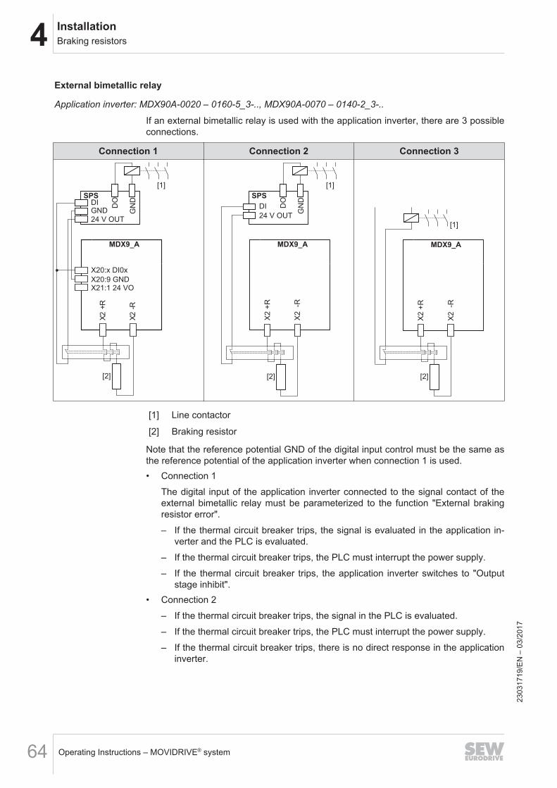
4 InstallationBraking resistors
Operating Instructions – MOVIDRIVE® system64
External bimetallic relay
Application inverter: MDX90A-0020 – 0160-5_3-.., MDX90A-0070 – 0140-2_3-..
If an external bimetallic relay is used with the application inverter, there are 3 possibleconnections.
Connection 1 Connection 2 Connection 3
MDX9_A
X20:x DI0x
X20:9 GND
[2]
X2 -
R
X2 +
R
SPSDI
24 V OUT
DO
GN
D
[1]
GND
X21:1 24 VO
MDX9_A
X2
-R
X2
+R
[2]
SPS
DI
24 V OUT
DO
GN
D
[1]
MDX9_A
X2
-R
X2
+R
[2]
[1]
[1] Line contactor
[2] Braking resistor
Note that the reference potential GND of the digital input control must be the same asthe reference potential of the application inverter when connection 1 is used.• Connection 1
The digital input of the application inverter connected to the signal contact of theexternal bimetallic relay must be parameterized to the function "External brakingresistor error".– If the thermal circuit breaker trips, the signal is evaluated in the application in-
verter and the PLC is evaluated.– If the thermal circuit breaker trips, the PLC must interrupt the power supply.– If the thermal circuit breaker trips, the application inverter switches to "Output
stage inhibit".• Connection 2
– If the thermal circuit breaker trips, the signal in the PLC is evaluated.– If the thermal circuit breaker trips, the PLC must interrupt the power supply.– If the thermal circuit breaker trips, there is no direct response in the application
inverter.
2303
1719
/EN
– 0
3/20
17
4InstallationBraking resistors
Operating Instructions – MOVIDRIVE® system 65
– With connection 2, it is possible that the PLC finishes the current travel cycle al-though the thermal circuit breaker has tripped. Only then, the power supply isdisconnected. In this case, the residual braking energy WRest = RBRnom × 20 smust not be exceeded.
• Connection 3– If the thermal circuit breaker trips, the signal directly affects the line contactor.– This does not require a response by the PLC.– If the thermal circuit breaker trips, there is no direct response in the application
inverter.
2303
1719
/EN
– 0
3/20
17
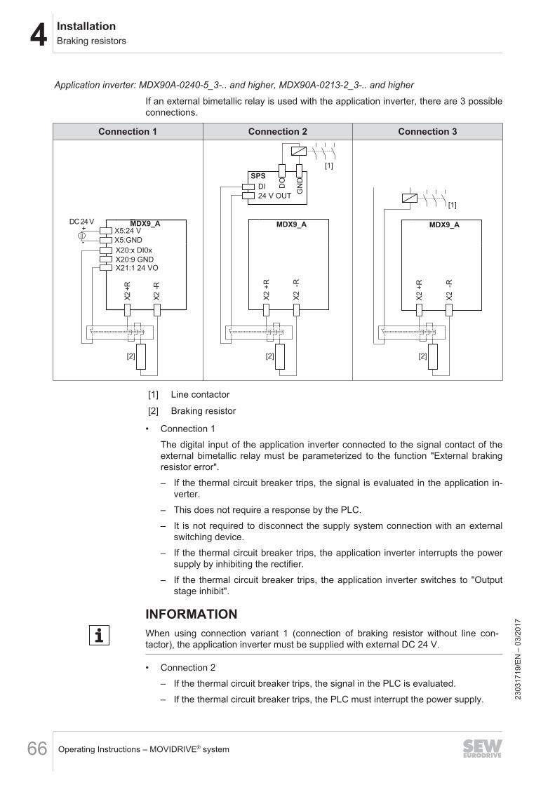
4 InstallationBraking resistors
Operating Instructions – MOVIDRIVE® system66
Application inverter: MDX90A-0240-5_3-.. and higher, MDX90A-0213-2_3-.. and higher
If an external bimetallic relay is used with the application inverter, there are 3 possibleconnections.
Connection 1 Connection 2 Connection 3
MDX9_A
X20:x DI0x
X20:9 GND
X2 -
R
X2 +
R
[2]
X21:1 24 VO
X5:GND
X5:24 V+
-
DC 24 VMDX9_A
X2
-R
X2
+R
[2]
SPS
DI
24 V OUT
DO
GN
D
[1]
MDX9_A
X2
-R
X2
+R
[2]
[1]
[1] Line contactor
[2] Braking resistor
• Connection 1The digital input of the application inverter connected to the signal contact of theexternal bimetallic relay must be parameterized to the function "External brakingresistor error".– If the thermal circuit breaker trips, the signal is evaluated in the application in-
verter.– This does not require a response by the PLC.– It is not required to disconnect the supply system connection with an external
switching device.– If the thermal circuit breaker trips, the application inverter interrupts the power
supply by inhibiting the rectifier.– If the thermal circuit breaker trips, the application inverter switches to "Output
stage inhibit".
INFORMATIONWhen using connection variant 1 (connection of braking resistor without line con-tactor), the application inverter must be supplied with external DC 24 V.
• Connection 2– If the thermal circuit breaker trips, the signal in the PLC is evaluated.– If the thermal circuit breaker trips, the PLC must interrupt the power supply. 23
0317
19/E
N –
03/
2017

4InstallationBraking resistors
Operating Instructions – MOVIDRIVE® system 67
– If the thermal circuit breaker trips, there is no direct response in the applicationinverter.
– With connection 2, it is possible that the PLC finishes the current travel cycle al-though the thermal circuit breaker has tripped. Only then, the power supply isdisconnected. In this case, the residual braking energy WRest = RBRnom × 20 smust not be exceeded.
• Connection 3– If the thermal circuit breaker trips, the signal directly affects the line contactor.– This does not require a response by the PLC.– If the thermal circuit breaker trips, there is no direct response in the application
inverter.
2303
1719
/EN
– 0
3/20
17
4 InstallationLine filter
Operating Instructions – MOVIDRIVE® system68
4.9 Line filter
• Install the line filter close to the application inverter but outside the minimum clear-ance for cooling. The line filter must not be heated by the exhaust air of the applic-ation inverter.
• Do not wire any other consumers between the line filter and the application in-verter.
• The connection cable between line filter and application inverter does not have tobe shielded.
• Limit the length of the cable between the line filter and the application inverter tothe absolute minimum needed.
• Do not switch between the NF... line filter and inverter.
2303
1719
/EN
– 0
3/20
17
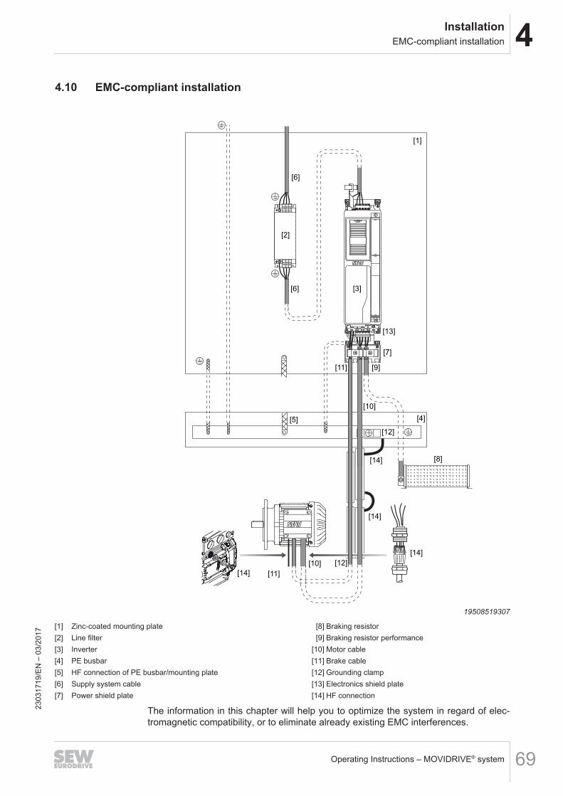
4InstallationEMC-compliant installation
Operating Instructions – MOVIDRIVE® system 69
4.10 EMC-compliant installation
[6]
[6]
[3]
[1]
[2]
[7]
[11]
[11]
[9]
[5]
[12]
[14]
[14]
[14]
[14]
[12][10]
[8]
[4]
[13]
[10]
19508519307
[1] Zinc-coated mounting plate [8] Braking resistor[2] Line filter [9] Braking resistor performance[3] Inverter [10] Motor cable[4] PE busbar [11] Brake cable[5] HF connection of PE busbar/mounting plate [12] Grounding clamp[6] Supply system cable [13] Electronics shield plate[7] Power shield plate [14] HF connection
The information in this chapter will help you to optimize the system in regard of elec-tromagnetic compatibility, or to eliminate already existing EMC interferences.
2303
1719
/EN
– 0
3/20
17
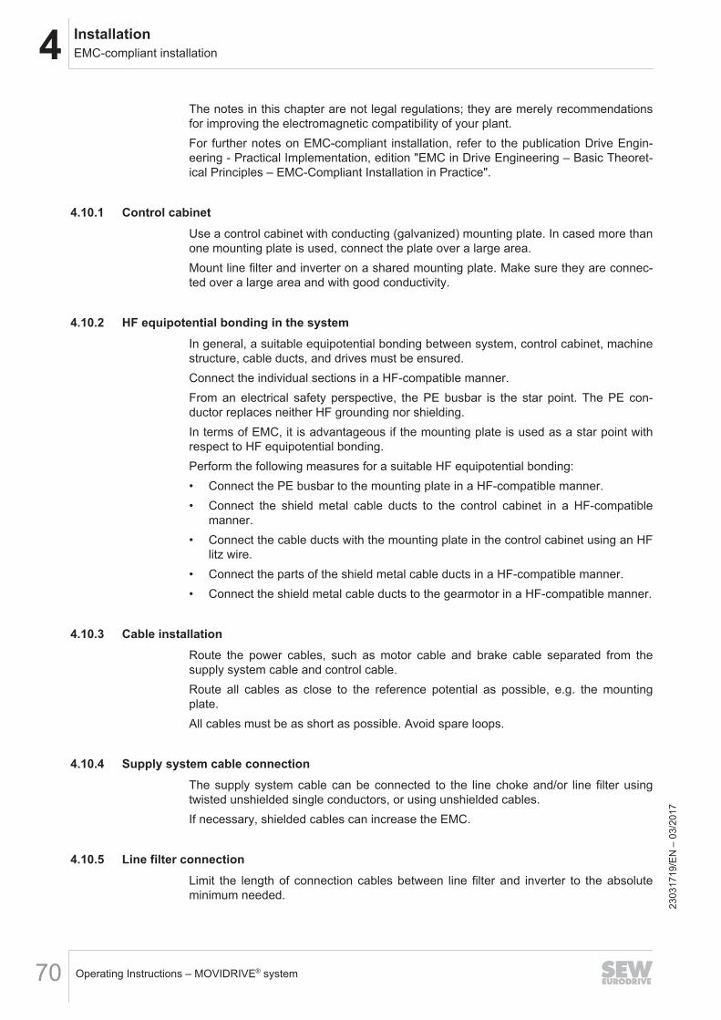
4 InstallationEMC-compliant installation
Operating Instructions – MOVIDRIVE® system70
The notes in this chapter are not legal regulations; they are merely recommendationsfor improving the electromagnetic compatibility of your plant.For further notes on EMC-compliant installation, refer to the publication Drive Engin-eering - Practical Implementation, edition "EMC in Drive Engineering – Basic Theoret-ical Principles – EMC-Compliant Installation in Practice".
4.10.1 Control cabinetUse a control cabinet with conducting (galvanized) mounting plate. In cased more thanone mounting plate is used, connect the plate over a large area.Mount line filter and inverter on a shared mounting plate. Make sure they are connec-ted over a large area and with good conductivity.
4.10.2 HF equipotential bonding in the systemIn general, a suitable equipotential bonding between system, control cabinet, machinestructure, cable ducts, and drives must be ensured.Connect the individual sections in a HF-compatible manner.From an electrical safety perspective, the PE busbar is the star point. The PE con-ductor replaces neither HF grounding nor shielding.In terms of EMC, it is advantageous if the mounting plate is used as a star point withrespect to HF equipotential bonding.Perform the following measures for a suitable HF equipotential bonding:• Connect the PE busbar to the mounting plate in a HF-compatible manner.• Connect the shield metal cable ducts to the control cabinet in a HF-compatible
manner.• Connect the cable ducts with the mounting plate in the control cabinet using an HF
litz wire.• Connect the parts of the shield metal cable ducts in a HF-compatible manner.• Connect the shield metal cable ducts to the gearmotor in a HF-compatible manner.
4.10.3 Cable installationRoute the power cables, such as motor cable and brake cable separated from thesupply system cable and control cable.Route all cables as close to the reference potential as possible, e.g. the mountingplate.All cables must be as short as possible. Avoid spare loops.
4.10.4 Supply system cable connectionThe supply system cable can be connected to the line choke and/or line filter usingtwisted unshielded single conductors, or using unshielded cables.If necessary, shielded cables can increase the EMC.
4.10.5 Line filter connectionLimit the length of connection cables between line filter and inverter to the absoluteminimum needed.
2303
1719
/EN
– 0
3/20
17
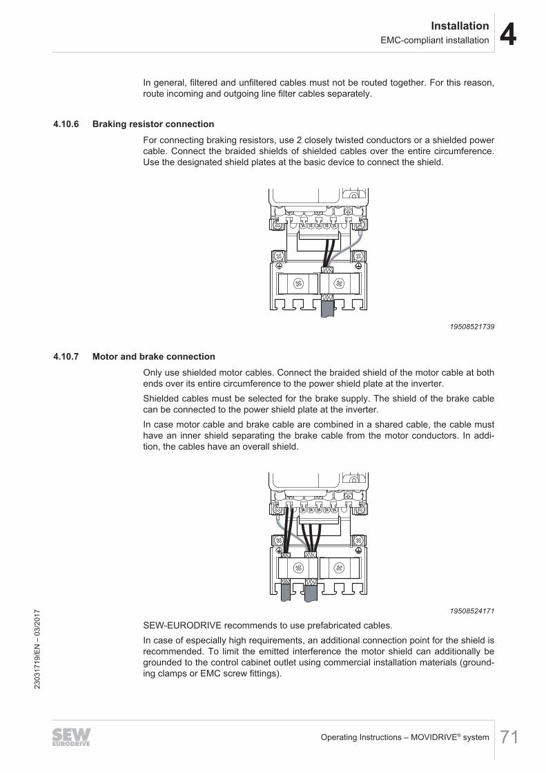
4InstallationEMC-compliant installation
Operating Instructions – MOVIDRIVE® system 71
In general, filtered and unfiltered cables must not be routed together. For this reason,route incoming and outgoing line filter cables separately.
4.10.6 Braking resistor connectionFor connecting braking resistors, use 2 closely twisted conductors or a shielded powercable. Connect the braided shields of shielded cables over the entire circumference.Use the designated shield plates at the basic device to connect the shield.
19508521739
4.10.7 Motor and brake connectionOnly use shielded motor cables. Connect the braided shield of the motor cable at bothends over its entire circumference to the power shield plate at the inverter.Shielded cables must be selected for the brake supply. The shield of the brake cablecan be connected to the power shield plate at the inverter.In case motor cable and brake cable are combined in a shared cable, the cable musthave an inner shield separating the brake cable from the motor conductors. In addi-tion, the cables have an overall shield.
19508524171
SEW‑EURODRIVE recommends to use prefabricated cables.In case of especially high requirements, an additional connection point for the shield isrecommended. To limit the emitted interference the motor shield can additionally begrounded to the control cabinet outlet using commercial installation materials (ground-ing clamps or EMC screw fittings).
2303
1719
/EN
– 0
3/20
17
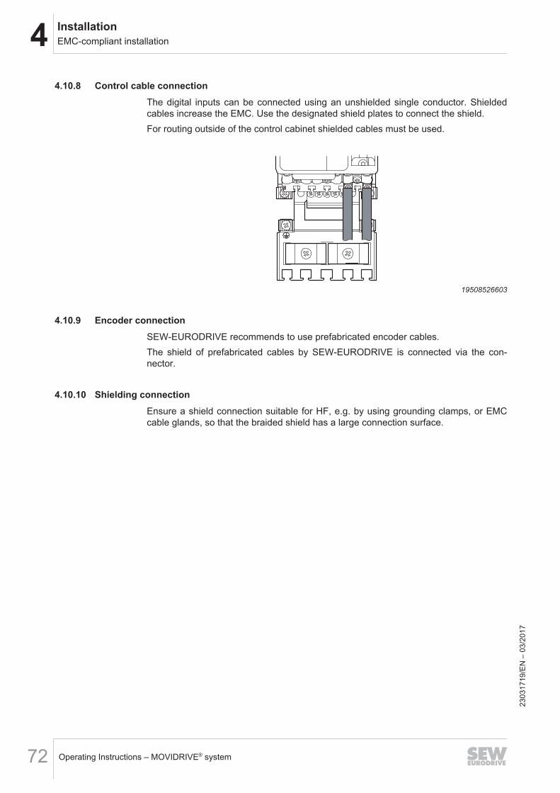
4 InstallationEMC-compliant installation
Operating Instructions – MOVIDRIVE® system72
4.10.8 Control cable connectionThe digital inputs can be connected using an unshielded single conductor. Shieldedcables increase the EMC. Use the designated shield plates to connect the shield.For routing outside of the control cabinet shielded cables must be used.
19508526603
4.10.9 Encoder connectionSEW‑EURODRIVE recommends to use prefabricated encoder cables.The shield of prefabricated cables by SEW‑EURODRIVE is connected via the con-nector.
4.10.10 Shielding connectionEnsure a shield connection suitable for HF, e.g. by using grounding clamps, or EMCcable glands, so that the braided shield has a large connection surface.
2303
1719
/EN
– 0
3/20
17
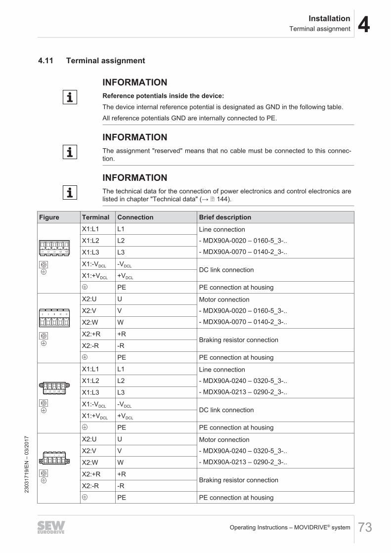
4InstallationTerminal assignment
Operating Instructions – MOVIDRIVE® system 73
4.11 Terminal assignment
INFORMATIONReference potentials inside the device:The device internal reference potential is designated as GND in the following table.All reference potentials GND are internally connected to PE.
INFORMATIONThe assignment "reserved" means that no cable must be connected to this connec-tion.
INFORMATIONThe technical data for the connection of power electronics and control electronics arelisted in chapter "Technical data" (→ 2 144).
Figure Terminal Connection Brief descriptionX1:L1 L1 Line connection
- MDX90A-0020 – 0160-5_3-..- MDX90A-0070 – 0140-2_3-..
X1:L2 L2
X1:L3 L3
X1:-VDCL -VDCLDC link connection
X1:+VDCL +VDCL
PE PE connection at housing
X2:U U Motor connection- MDX90A-0020 – 0160-5_3-..- MDX90A-0070 – 0140-2_3-..
X2:V V
X2:W W
X2:+R +RBraking resistor connection
X2:-R -R
PE PE connection at housing
X1:L1 L1 Line connection- MDX90A-0240 – 0320-5_3-..- MDX90A-0213 – 0290-2_3-..
X1:L2 L2
X1:L3 L3
X1:-VDCL -VDCLDC link connection
X1:+VDCL +VDCL
PE PE connection at housing
X2:U U Motor connection- MDX90A-0240 – 0320-5_3-..- MDX90A-0213 – 0290-2_3-..
X2:V V
X2:W W
X2:+R +RBraking resistor connection
X2:-R -R
PE PE connection at housing
2303
1719
/EN
– 0
3/20
17
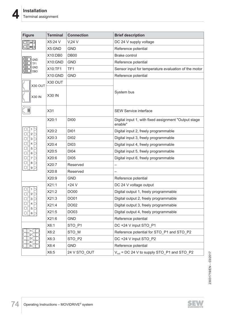
4 InstallationTerminal assignment
Operating Instructions – MOVIDRIVE® system74
Figure Terminal Connection Brief descriptionX5:24 V VI24 V DC 24 V supply voltage
X5:GND GND Reference potential
DBO
GND
TF1
GND
X10:DB0 DB00 Brake control
X10:GND GND Reference potential
X10:TF1 TF1 Sensor input for temperature evaluation of the motor
X10:GND GND Reference potential
X30 OUT
X30 IN
X30 OUT
System busX30 IN
X31 SEW Service interface
1
2
3
4
5
6
7
8
9
X20:1 DI00 Digital input 1, with fixed assignment "Output stageenable"
X20:2 DI01 Digital input 2, freely programmable
X20:3 DI02 Digital input 3, freely programmable
X20:4 DI03 Digital input 4, freely programmable
X20:5 DI04 Digital input 5, freely programmable
X20:6 DI05 Digital input 6, freely programmable
X20:7 Reserved –
X20:8 Reserved –
X20:9 GND Reference potential
1
2
3
4
5
6
X21:1 +24 V DC 24 V voltage output
X21:2 DO00 Digital output 1, freely programmable
X21:3 DO01 Digital output 2, freely programmable
X21:4 DO02 Digital output 3, freely programmable
X21:5 DO03 Digital output 4, freely programmable
X21:6 GND Reference potential
1
2
3
4
5
X6:1 STO_P1 DC +24 V input STO_P1
X6:2 STO_M Reference potential for STO_P1 and STO_P2
X6:3 STO_P2 DC +24 V input STO_P2
X6:4 GND Reference potential
X6:5 24 V STO_OUT Vout = DC 24 V to supply STO_P1 and STO_P2
2303
1719
/EN
– 0
3/20
17
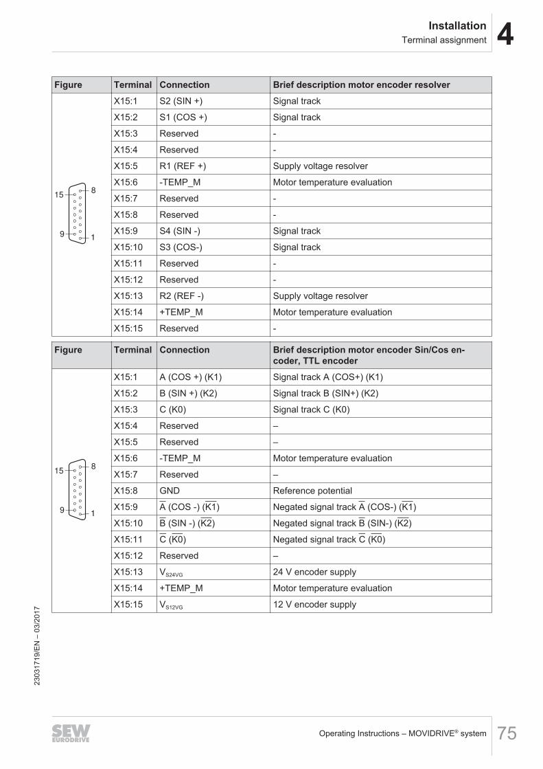
4InstallationTerminal assignment
Operating Instructions – MOVIDRIVE® system 75
Figure Terminal Connection Brief description motor encoder resolver
15
91
8
X15:1 S2 (SIN +) Signal track
X15:2 S1 (COS +) Signal track
X15:3 Reserved -
X15:4 Reserved -
X15:5 R1 (REF +) Supply voltage resolver
X15:6 -TEMP_M Motor temperature evaluation
X15:7 Reserved -
X15:8 Reserved -
X15:9 S4 (SIN -) Signal track
X15:10 S3 (COS-) Signal track
X15:11 Reserved -
X15:12 Reserved -
X15:13 R2 (REF -) Supply voltage resolver
X15:14 +TEMP_M Motor temperature evaluation
X15:15 Reserved -
Figure Terminal Connection Brief description motor encoder Sin/Cos en-coder, TTL encoder
15
91
8
X15:1 A (COS +) (K1) Signal track A (COS+) (K1)
X15:2 B (SIN +) (K2) Signal track B (SIN+) (K2)
X15:3 C (K0) Signal track C (K0)
X15:4 Reserved –
X15:5 Reserved –
X15:6 -TEMP_M Motor temperature evaluation
X15:7 Reserved –
X15:8 GND Reference potential
X15:9 A (COS -) (K1) Negated signal track A (COS-) (K1)
X15:10 B (SIN -) (K2) Negated signal track B (SIN-) (K2)
X15:11 C (K0) Negated signal track C (K0)
X15:12 Reserved –
X15:13 VS24VG 24 V encoder supply
X15:14 +TEMP_M Motor temperature evaluation
X15:15 VS12VG 12 V encoder supply
2303
1719
/EN
– 0
3/20
17
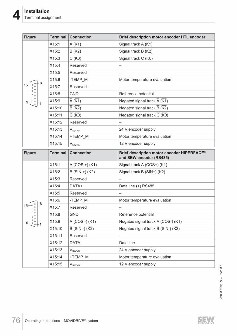
4 InstallationTerminal assignment
Operating Instructions – MOVIDRIVE® system76
Figure Terminal Connection Brief description motor encoder HTL encoder
15
91
8
X15:1 A (K1) Signal track A (K1)
X15:2 B (K2) Signal track B (K2)
X15:3 C (K0) Signal track C (K0)
X15:4 Reserved –
X15:5 Reserved –
X15:6 -TEMP_M Motor temperature evaluation
X15:7 Reserved –
X15:8 GND Reference potential
X15:9 A (K1) Negated signal track A (K1)
X15:10 B (K2) Negated signal track B (K2)
X15:11 C (K0) Negated signal track C (K0)
X15:12 Reserved –
X15:13 VS24VG 24 V encoder supply
X15:14 +TEMP_M Motor temperature evaluation
X15:15 VS12VG 12 V encoder supply
Figure Terminal Connection Brief description motor encoder HIPERFACE®
and SEW encoder (RS485)
15
91
8
X15:1 A (COS +) (K1) Signal track A (COS+) (K1)
X15:2 B (SIN +) (K2) Signal track B (SIN+) (K2)
X15:3 Reserved –
X15:4 DATA+ Data line (+) RS485
X15:5 Reserved –
X15:6 -TEMP_M Motor temperature evaluation
X15:7 Reserved –
X15:8 GND Reference potential
X15:9 A (COS -) (K1) Negated signal track A (COS-) (K1)
X15:10 B (SIN -) (K2) Negated signal track B (SIN-) (K2)
X15:11 Reserved –
X15:12 DATA- Data line
X15:13 VS24VG 24 V encoder supply
X15:14 +TEMP_M Motor temperature evaluation
X15:15 VS12VG 12 V encoder supply
2303
1719
/EN
– 0
3/20
17
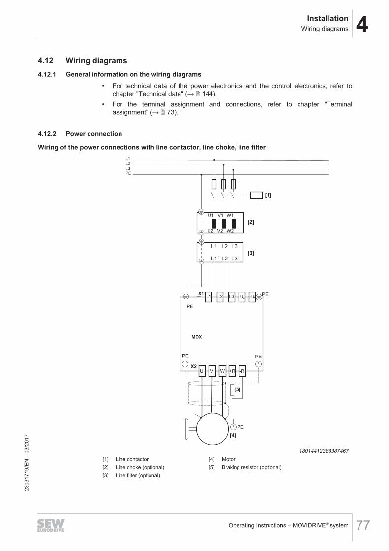
4InstallationWiring diagrams
Operating Instructions – MOVIDRIVE® system 77
4.12 Wiring diagrams4.12.1 General information on the wiring diagrams
• For technical data of the power electronics and the control electronics, refer tochapter "Technical data" (→ 2 144).
• For the terminal assignment and connections, refer to chapter "Terminalassignment" (→ 2 73).
4.12.2 Power connection
Wiring of the power connections with line contactor, line choke, line filter
L1 L2 L3
L1´ L2´ L3´
L1
L2
L3PE
U1 V1 W1
U2 V2 W2
X1L1 L2 L3
PE
X2
PE
MDX
[4]
[3]
[2]
PE
PE
[1]
-Uz z+U
[5]
U V W -R+R
PE
18014412388387467[1] Line contactor [4] Motor[2] Line choke (optional) [5] Braking resistor (optional)[3] Line filter (optional)
2303
1719
/EN
– 0
3/20
17
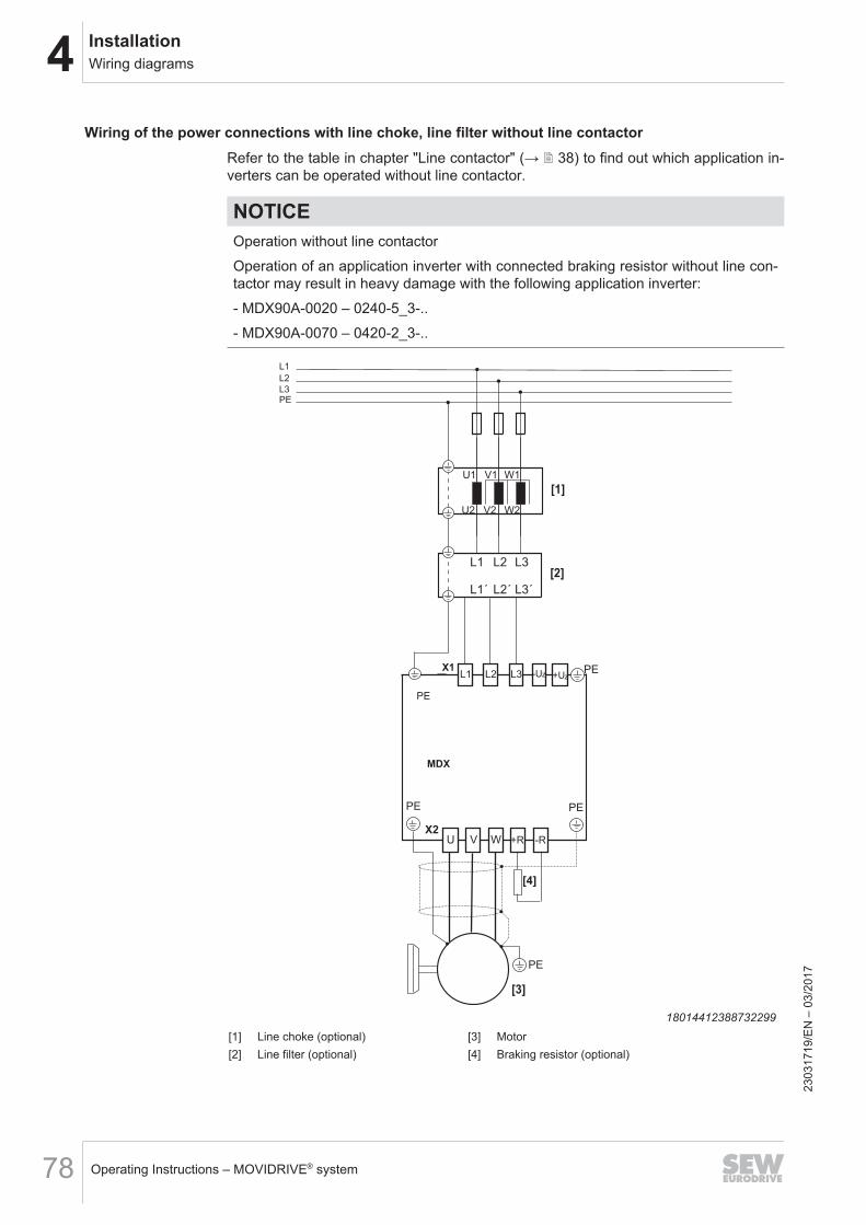
4 InstallationWiring diagrams
Operating Instructions – MOVIDRIVE® system78
Wiring of the power connections with line choke, line filter without line contactorRefer to the table in chapter "Line contactor" (→ 2 38) to find out which application in-verters can be operated without line contactor.
NOTICEOperation without line contactorOperation of an application inverter with connected braking resistor without line con-tactor may result in heavy damage with the following application inverter:- MDX90A-0020 – 0240-5_3-..- MDX90A-0070 – 0420-2_3-..
L1 L2 L3
L1´ L2´ L3´
L1
L2
L3PE
U1 V1 W1
U2 V2 W2
[1]
X1L1 L2 L3
PE
X2
PE
U V W
MDX
PE
PE
-Uz z
+R
+U
[2]
[3]
[4]
PE
-R
18014412388732299[1] Line choke (optional) [3] Motor[2] Line filter (optional) [4] Braking resistor (optional)
2303
1719
/EN
– 0
3/20
17
4InstallationWiring diagrams
Operating Instructions – MOVIDRIVE® system 79
INFORMATIONIn case of a line connection without line contactor, the temperature evaluation of thebraking resistor via a digital input of the application inverter must be ensured. Theconnected digital input must be parameterized for monitoring the braking resistortemperature evaluation.
2303
1719
/EN
– 0
3/20
17
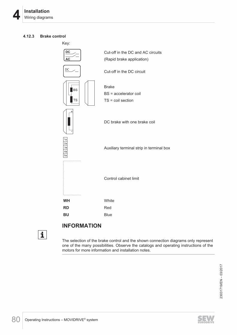
4 InstallationWiring diagrams
Operating Instructions – MOVIDRIVE® system80
4.12.3 Brake controlKey:
AC
DC Cut-off in the DC and AC circuits(Rapid brake application)
DC Cut-off in the DC circuit
BS
TS
BrakeBS = accelerator coilTS = coil section
+
-
DC brake with one brake coil
1a
2a
5a
4a
3a Auxiliary terminal strip in terminal box
Control cabinet limit
WH White
RD Red
BU Blue
INFORMATION
The selection of the brake control and the shown connection diagrams only representone of the many possibilities. Observe the catalogs and operating instructions of themotors for more information and installation notes.
2303
1719
/EN
– 0
3/20
17
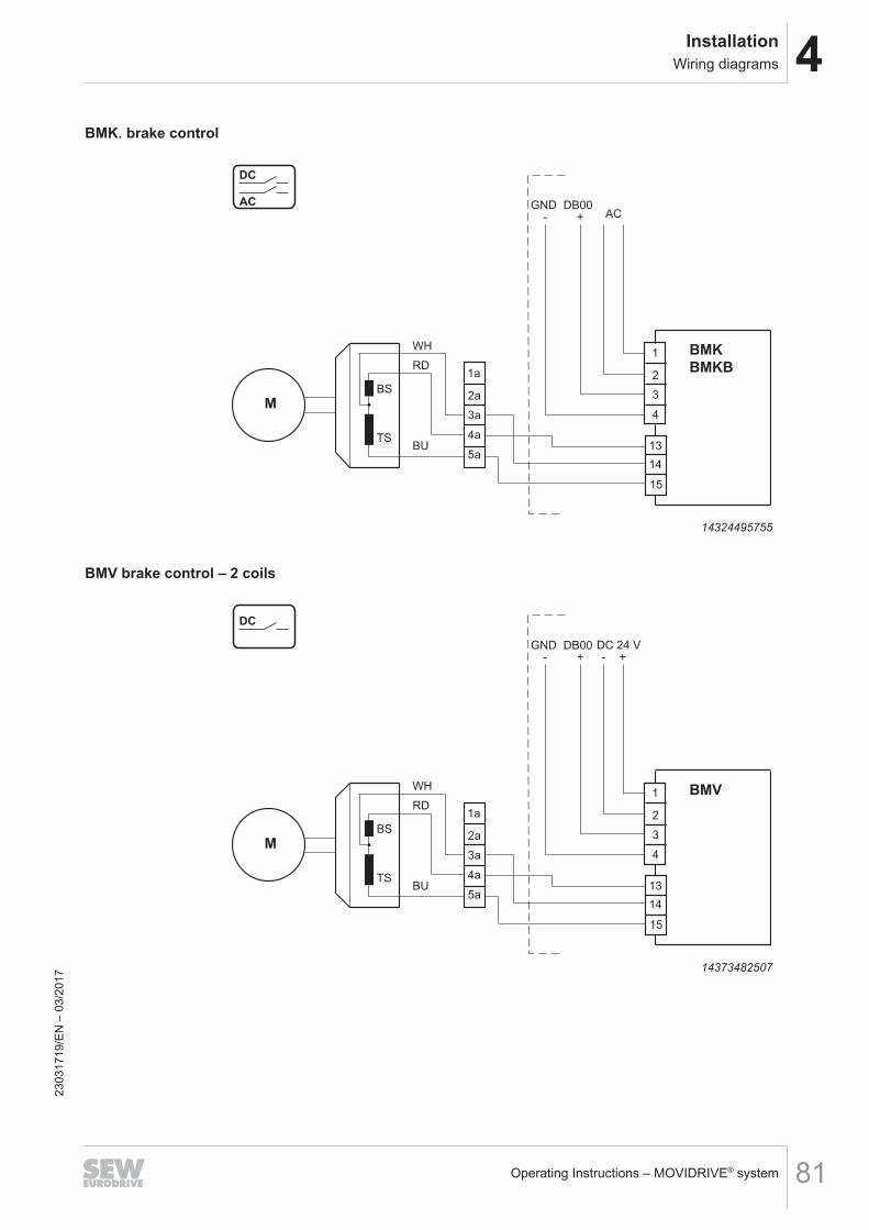
4InstallationWiring diagrams
Operating Instructions – MOVIDRIVE® system 81
BMK. brake control
BU
+- AC
WH
RD1a
2a
5a
4a
3aM
TS
BS
1
2
13
14
15
4
3
BMK
BMKB
DB00GNDAC
DC
14324495755
BMV brake control – 2 coils
BU
+-DC 24 V
WH
RD1a
2a
5a
4a
3aM
TS
BS
1
2
13
14
15
4
3
BMV
DB00GND
DC
+-
14373482507
2303
1719
/EN
– 0
3/20
17
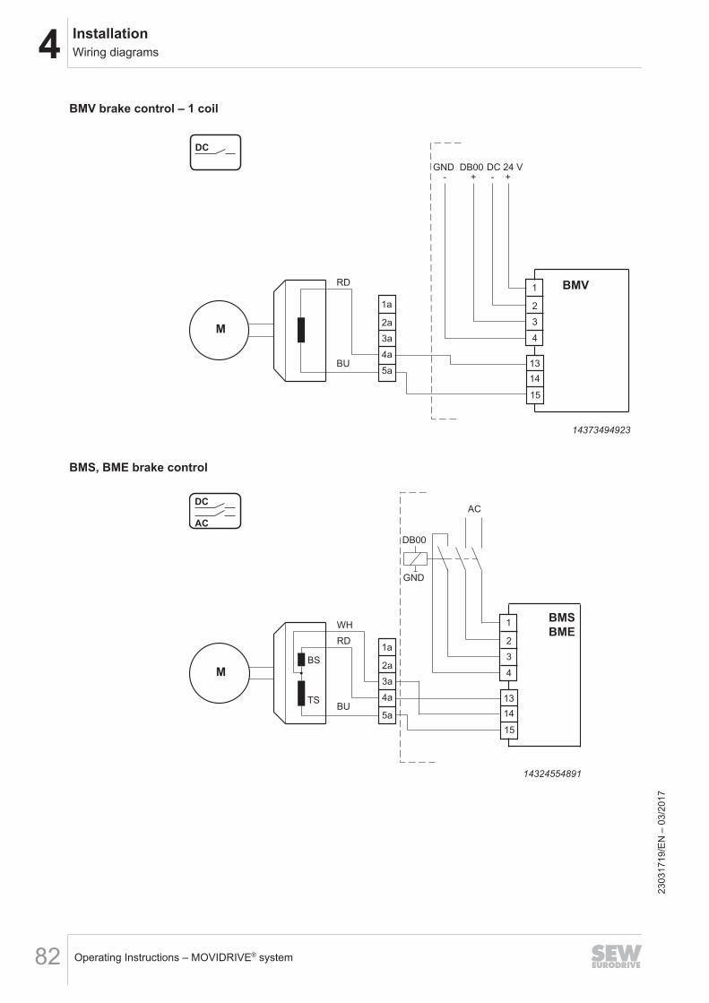
4 InstallationWiring diagrams
Operating Instructions – MOVIDRIVE® system82
BMV brake control – 1 coil
BU
+-DC 24 V
RD
1a
2a
5a
4a
3aM
1
2
13
14
15
4
3
BMV
DB00GND
DC
+-
14373494923
BMS, BME brake control
BU
AC
WH
RD1a
2a
5a
4a
3aM
TS
BS
BMS
BME1
2
13
14
15
4
3
AC
DC
DB00
GND
14324554891
2303
1719
/EN
– 0
3/20
17
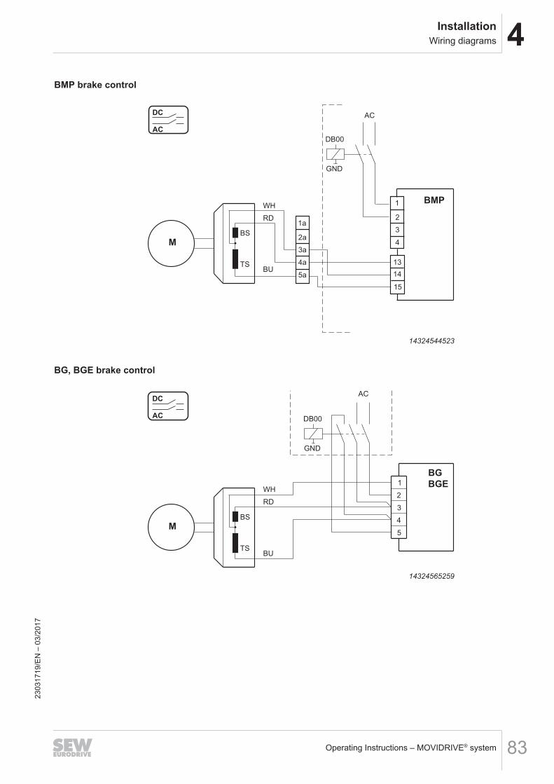
4InstallationWiring diagrams
Operating Instructions – MOVIDRIVE® system 83
BMP brake control
BU
AC
WH
RD1a
2a
5a
4a
3aM
TS
BS
1
2
13
14
15
4
3
BMP
DB00
GND
AC
DC
14324544523
BG, BGE brake control
AC
BG
BGE
RD
WH
5
4
1
3
2
BU
M
TS
BS
AC
DC
DB00
GND
14324565259
2303
1719
/EN
– 0
3/20
17
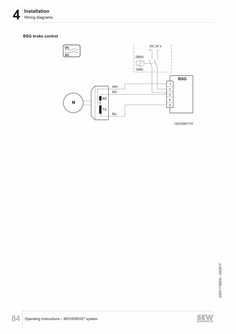
4 InstallationWiring diagrams
Operating Instructions – MOVIDRIVE® system84
BSG brake control
M4
1
3
2
TS
BS
BU
BSG
RD
WH
DC 24 V
+ -
5
DB00
GND
AC
DC
14324597131
2303
1719
/EN
– 0
3/20
17
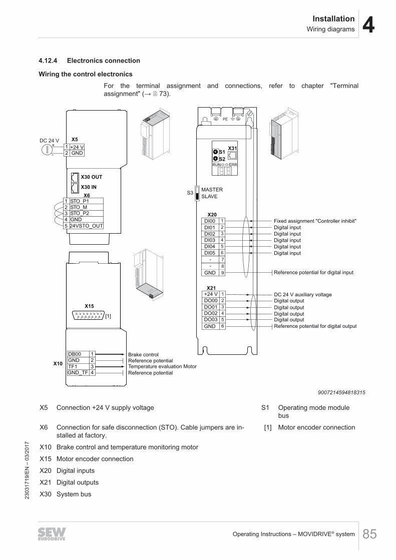
4InstallationWiring diagrams
Operating Instructions – MOVIDRIVE® system 85
4.12.4 Electronics connection
Wiring the control electronicsFor the terminal assignment and connections, refer to chapter "Terminalassignment" (→ 2 73).
X15
15
14
13
12 11
10 9
4567 1238
X30 OUT
X30 IN
2
1
3
4
5
STO_P1
STO_MSTO_P2
GND
X6
24VSTO_OUT
X5
[1]
MASTER
SLAVES3
X31S1
S2
RUN ERR
+24 VGND2
1
2
1
34
DB00
GND
TF1GND_TF
X10
Brake controlReference potential
Reference potential
Temperature evaluation Motor
PE
Fixed assignment "Controller inhibit"
Digital input
Reference potential for digital input
DC 24 V auxiliary voltage
Reference potential for digital output
Digital input
Digital input
Digital input
Digital input
Digital output
Digital output
Digital outputDigital output
DC 24 V+
-
2
X20
1
3
4
5
6
8
7
DI00
DI01
DI02
DI03
DI04
DI05
2
X21
1
3
4
5
DO00
DO01
DO02
DO03
9GND
-
-
GND 6
+24 V
9007214594818315
X5 Connection +24 V supply voltage S1 Operating mode modulebus
X6 Connection for safe disconnection (STO). Cable jumpers are in-stalled at factory.
[1] Motor encoder connection
X10 Brake control and temperature monitoring motor
X15 Motor encoder connection
X20 Digital inputs
X21 Digital outputs
X30 System bus2303
1719
/EN
– 0
3/20
17
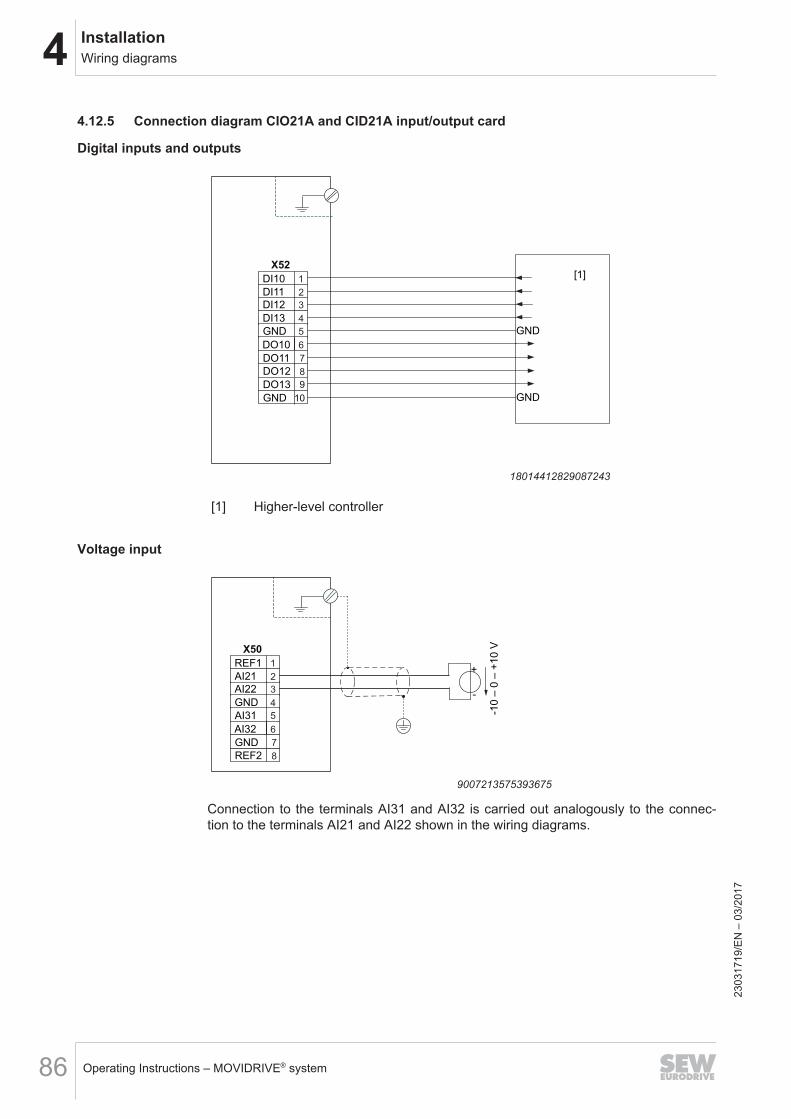
4 InstallationWiring diagrams
Operating Instructions – MOVIDRIVE® system86
4.12.5 Connection diagram CIO21A and CID21A input/output card
Digital inputs and outputs
GND
GND
[1]
2
X52
1
3
4
5
6
8
7
9
10
DI10
DI11
DI12
DI13
GND
DO10
DO11
DO12
DO13
GND
18014412829087243
[1] Higher-level controller
Voltage input
-10
– 0
– +
10
V
+
-
2
X50
1
3
4
5
6
8
7
REF1
AI21
AI22
GND
AI31
AI32
GND
REF2
9007213575393675
Connection to the terminals AI31 and AI32 is carried out analogously to the connec-tion to the terminals AI21 and AI22 shown in the wiring diagrams.
2303
1719
/EN
– 0
3/20
17
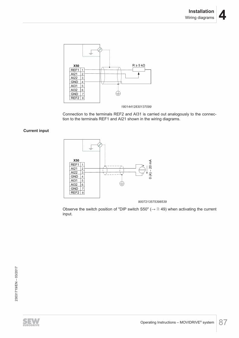
4InstallationWiring diagrams
Operating Instructions – MOVIDRIVE® system 87
2
X50
1
3
4
5
6
8
7
REF1
AI21
AI22
GND
AI31
AI32
GND
REF2
R > 5 kΩ
18014412830137099
Connection to the terminals REF2 and AI31 is carried out analogously to the connec-tion to the terminals REF1 and AI21 shown in the wiring diagrams.
Current input
0 (
4)
– 2
0 m
A
+
-
2
X50
1
3
4
5
6
8
7
REF1
AI21
AI22
GND
AI31
AI32
GND
REF2
9007213575398539
Observe the switch position of "DIP switch S50" (→ 2 49) when activating the currentinput.
2303
1719
/EN
– 0
3/20
17
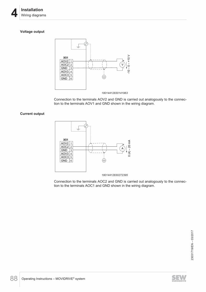
4 InstallationWiring diagrams
Operating Instructions – MOVIDRIVE® system88
Voltage output
-10
– 0
– +
10
V
+
-2
X51
1
3
4
5
6
AOV2
AOC2
GND
AOV3
AOC3
GND
V
18014412830141963
Connection to the terminals AOV2 and GND is carried out analogously to the connec-tion to the terminals AOV1 and GND shown in the wiring diagram.
Current output
0 (
4)
– 2
0 m
A
+
-
2
X51
1
3
4
5
6
AOV2
AOC2
GND
AOV3
AOC3
GND
A
18014412830272395
Connection to the terminals AOC2 and GND is carried out analogously to the connec-tion to the terminals AOC1 and GND shown in the wiring diagram.
2303
1719
/EN
– 0
3/20
17
4InstallationUL-compliant installation
Operating Instructions – MOVIDRIVE® system 89
4.13 UL-compliant installationUL approval of the application inverter is in preparation.
2303
1719
/EN
– 0
3/20
17
5 StartupGeneral
Operating Instructions – MOVIDRIVE® system90
5 Startup5.1 General5.1.1 Lifting applications
WARNINGDanger of fatal injury if the hoist falls.Severe or fatal injuries.• The application inverter is not designed for use as a safety device in lifting applic-
ations. Use monitoring systems or mechanical protection devices to ensuresafety.
5.1.2 Connecting power
NOTICEUndercutting the minimum switch-off time of the line contactor.Irreparable damage to the application inverter or unforeseeable malfunctions.The specified times and intervals must be observed.• After disconnection from the supply system, observe a minimum switch-off time
of 10 s.• Do not turn the power of the supply system on or off more than once per
minute.
5.1.3 Connecting cables
NOTICECables may only be connected and plugged in a de-energized state.Irreparable damage to the application inverter or unforeseeable malfunctions.• De-energize the application inverter.
2303
1719
/EN
– 0
3/20
17
5StartupSetting the EtherCAT®/SBusPLUS ID
Operating Instructions – MOVIDRIVE® system 91
5.2 Setting the EtherCAT®/SBusPLUS IDSetting theEtherCAT®/SBusPLUSID
The hexadecimal switches S1 and S2 must be set to "0".
5.3 Startup requirementsThe following conditions apply to startup:• You installed the application inverter correctly both mechanically and electrically.• You configured the application inverter and connected drives correctly.• Safety measures prevent accidental drive startup.• Safety measures prevent danger to persons or machines.Required hardware components:• PC or laptop with Ethernet interface.• Standard Ethernet cables for connection between PC and MOVI‑C®
CONTROLLER.• MOVI‑C® CONTROLLER with completed startup.Required software:• Engineering software MOVISUITE® standard from SEW‑EURODRIVE.
2303
1719
/EN
– 0
3/20
17
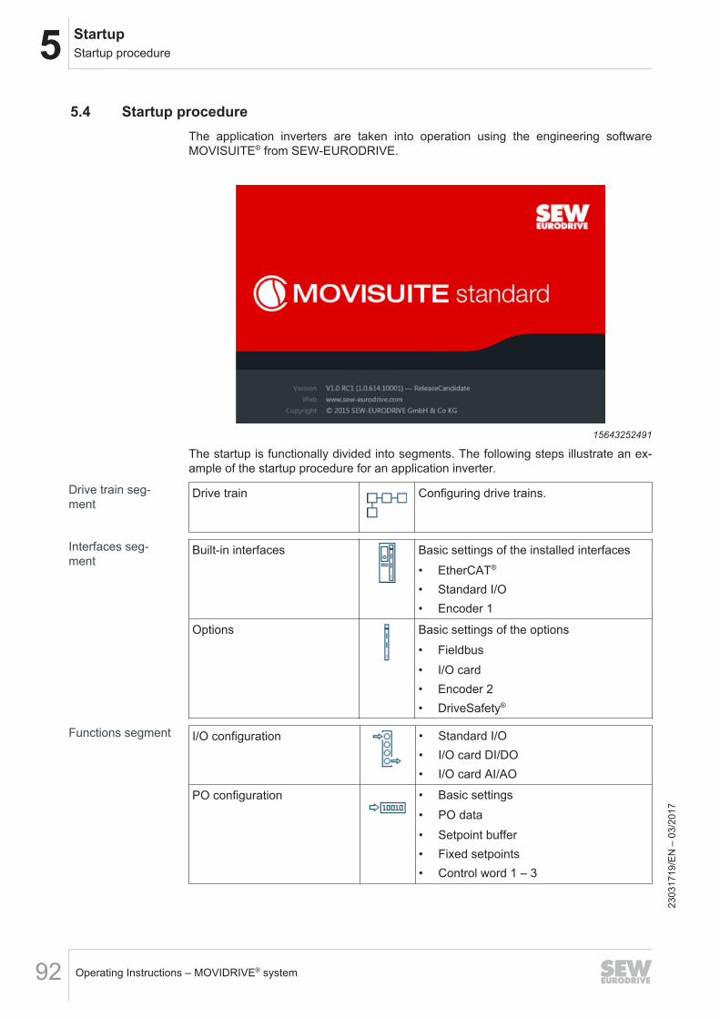
5 StartupStartup procedure
Operating Instructions – MOVIDRIVE® system92
5.4 Startup procedureThe application inverters are taken into operation using the engineering softwareMOVISUITE® from SEW‑EURODRIVE.
15643252491
The startup is functionally divided into segments. The following steps illustrate an ex-ample of the startup procedure for an application inverter.
Drive train seg-ment
Drive train Configuring drive trains.
Interfaces seg-ment
Built-in interfaces Basic settings of the installed interfaces• EtherCAT®
• Standard I/O• Encoder 1
Options Basic settings of the options• Fieldbus• I/O card• Encoder 2• DriveSafety®
Functions segment I/O configuration • Standard I/O• I/O card DI/DO• I/O card AI/AO
PO configuration • Basic settings• PO data• Setpoint buffer• Fixed setpoints• Control word 1 – 3
2303
1719
/EN
– 0
3/20
17
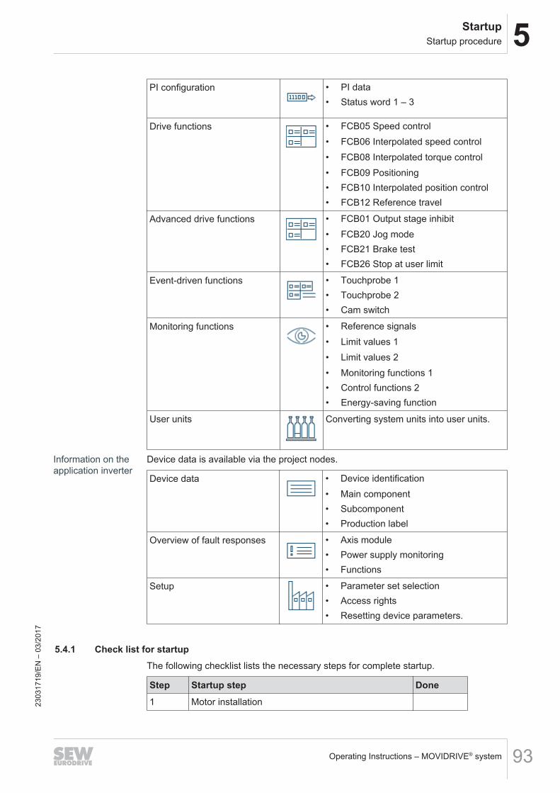
5StartupStartup procedure
Operating Instructions – MOVIDRIVE® system 93
PI configuration • PI data• Status word 1 – 3
Drive functions • FCB05 Speed control• FCB06 Interpolated speed control• FCB08 Interpolated torque control• FCB09 Positioning• FCB10 Interpolated position control• FCB12 Reference travel
Advanced drive functions • FCB01 Output stage inhibit• FCB20 Jog mode• FCB21 Brake test• FCB26 Stop at user limit
Event-driven functions • Touchprobe 1• Touchprobe 2• Cam switch
Monitoring functions • Reference signals• Limit values 1• Limit values 2• Monitoring functions 1• Control functions 2• Energy-saving function
User units Converting system units into user units.
Information on theapplication inverter
Device data is available via the project nodes.
Device data • Device identification• Main component• Subcomponent• Production label
Overview of fault responses • Axis module• Power supply monitoring• Functions
Setup • Parameter set selection• Access rights• Resetting device parameters.
5.4.1 Check list for startupThe following checklist lists the necessary steps for complete startup.
Step Startup step Done1 Motor installation23
0317
19/E
N –
03/
2017
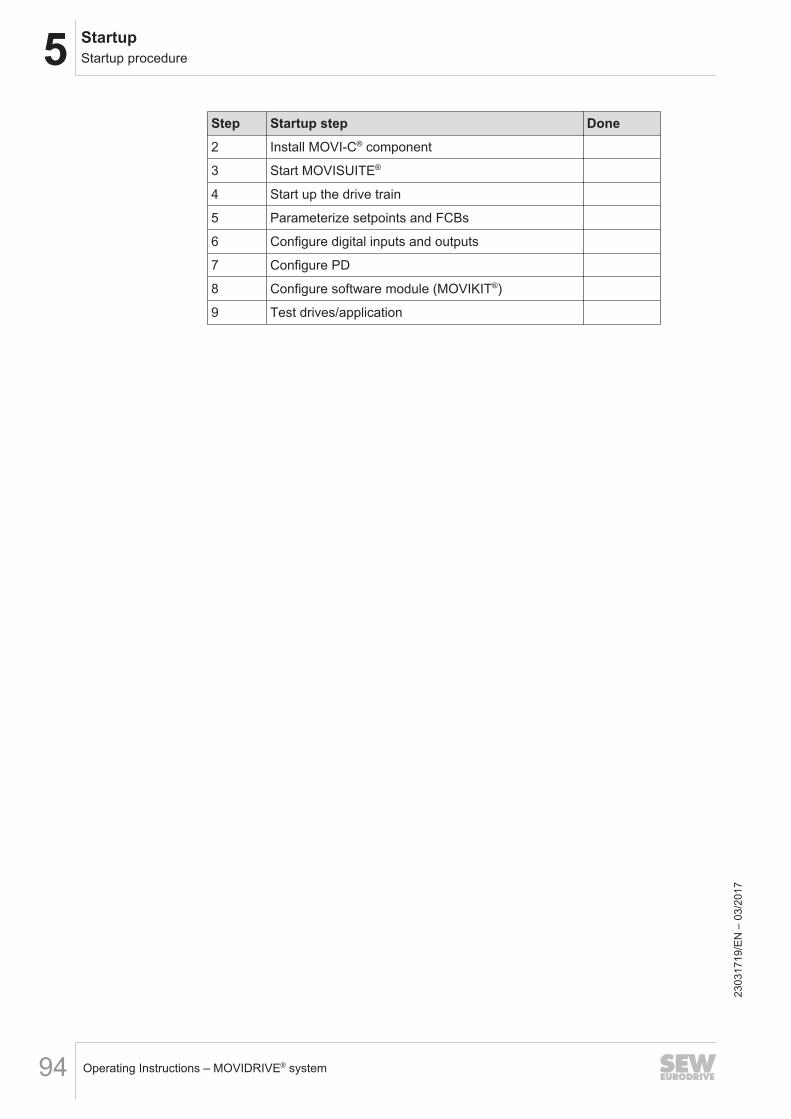
5 StartupStartup procedure
Operating Instructions – MOVIDRIVE® system94
Step Startup step Done2 Install MOVI‑C® component
3 Start MOVISUITE®
4 Start up the drive train
5 Parameterize setpoints and FCBs
6 Configure digital inputs and outputs
7 Configure PD
8 Configure software module (MOVIKIT®)
9 Test drives/application
2303
1719
/EN
– 0
3/20
17
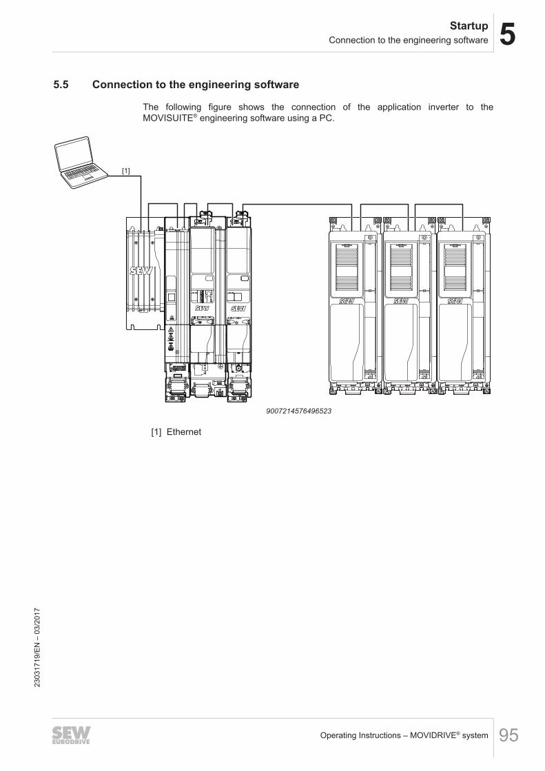
5StartupConnection to the engineering software
Operating Instructions – MOVIDRIVE® system 95
5.5 Connection to the engineering software
The following figure shows the connection of the application inverter to theMOVISUITE® engineering software using a PC.
[1]
RUN ERR
X15
X21
X20
X31
S1
S2
+UZ
-UZ
X4
+U
Z-U
Z
24V
X5
+UZ
X4
-UZ -UZ
+U
Z
GND
X3
1X
20
_1
X2
1_
1
X2
0_
2X
21
_2
X1
5_
1
X1
5_
2
S1
S2
RUN ERR
+UZ
X4
X5
24V
GND
-UZ
+ U
Z-
UZ
9007214576496523
[1] Ethernet
2303
1719
/EN
– 0
3/20
17
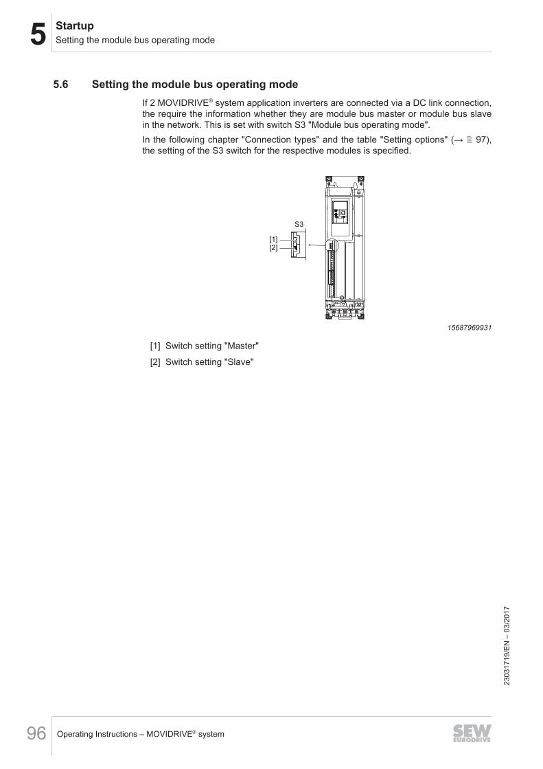
5 StartupSetting the module bus operating mode
Operating Instructions – MOVIDRIVE® system96
5.6 Setting the module bus operating modeIf 2 MOVIDRIVE® system application inverters are connected via a DC link connection,the require the information whether they are module bus master or module bus slavein the network. This is set with switch S3 "Module bus operating mode".In the following chapter "Connection types" and the table "Setting options" (→ 2 97),the setting of the S3 switch for the respective modules is specified.
[1]
X1
X10
[2]
1
2
3
4
5
6
1
2
3
4
5
6
7
8
9
S3
15687969931
[1] Switch setting "Master"
[2] Switch setting "Slave"
2303
1719
/EN
– 0
3/20
17
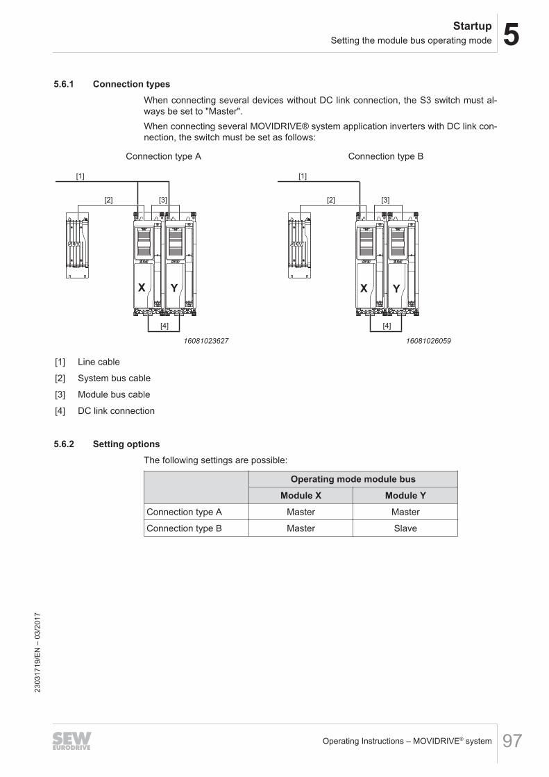
5StartupSetting the module bus operating mode
Operating Instructions – MOVIDRIVE® system 97
5.6.1 Connection typesWhen connecting several devices without DC link connection, the S3 switch must al-ways be set to "Master".When connecting several MOVIDRIVE® system application inverters with DC link con-nection, the switch must be set as follows:
Connection type A Connection type B
[1]
[3][2]
[4]
X Y
16081023627
[1]
[3][2]
[4]
X Y
16081026059
[1] Line cable
[2] System bus cable
[3] Module bus cable
[4] DC link connection
5.6.2 Setting optionsThe following settings are possible:
Operating mode module busModule X Module Y
Connection type A Master Master
Connection type B Master Slave
2303
1719
/EN
– 0
3/20
17
6 OperationGeneral information
Operating Instructions – MOVIDRIVE® system98
6 Operation6.1 General information
DANGERDangerous voltages present at cables and motor terminals.Severe or fatal injuries from electric shock.• Dangerous voltages are present at the output terminals and the cables and motor
terminals connected to them when the device is switched on. This also applieseven when the device is inhibited and the motor is at standstill.
• The fact that the operation LED is no longer illuminated does not indicate that theapplication inverter has been disconnected from the power supply and no longercarries any voltage.
• Before you touch the power terminals, check to see that the application inverterhas been disconnected from the supply system.
• Observe the general safety notes in chapter "Safety notes" (→ 2 12) and thenotes in chapter "Electrical installation" (→ 2 34).
DANGERRisk of crushing if the motor starts up unintentionally.Severe or fatal injuries.• Ensure that the motor cannot start inadvertently, for example, by removing the
electronics terminal block X20.• Additional safety precautions must be taken depending on the application to
avoid injury to people and damage to machinery.
NOTICESwitching the motor output at the application inverter with enabled output stage.Damage to the application inverter.• The motor output of the application inverter may only be switched or disconnec-
ted when the output stage is inhibited.23
0317
19/E
N –
03/
2017
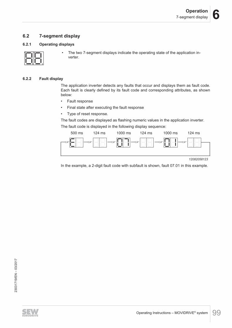
6Operation7-segment display
Operating Instructions – MOVIDRIVE® system 99
6.2 7-segment display6.2.1 Operating displays
• The two 7-segment displays indicate the operating state of the application in-verter.
6.2.2 Fault displayThe application inverter detects any faults that occur and displays them as fault code.Each fault is clearly defined by its fault code and corresponding attributes, as shownbelow:• Fault response• Final state after executing the fault response• Type of reset response.The fault codes are displayed as flashing numeric values in the application inverter.The fault code is displayed in the following display sequence:
500 ms 124 ms 1000 ms 124 ms
1000 ms 124 ms
12082058123
In the example, a 2-digit fault code with subfault is shown, fault 07.01 in this example.
2303
1719
/EN
– 0
3/20
17
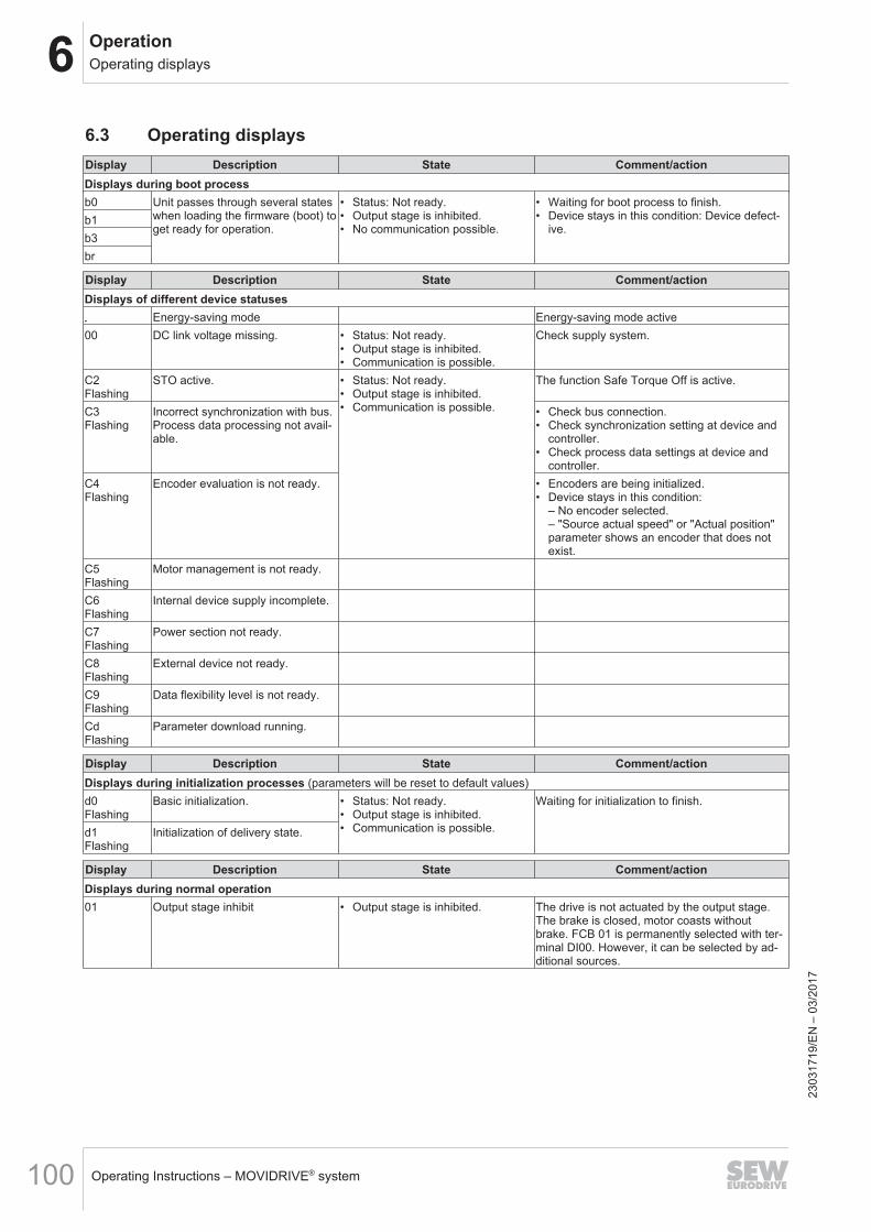
6 OperationOperating displays
Operating Instructions – MOVIDRIVE® system100
6.3 Operating displaysDisplay Description State Comment/actionDisplays during boot processb0 Unit passes through several states
when loading the firmware (boot) toget ready for operation.
• Status: Not ready.• Output stage is inhibited.• No communication possible.
• Waiting for boot process to finish.• Device stays in this condition: Device defect-
ive.b1b3br
Display Description State Comment/actionDisplays of different device statuses• Energy-saving mode Energy-saving mode active00 DC link voltage missing. • Status: Not ready.
• Output stage is inhibited.• Communication is possible.
Check supply system.
C2Flashing
STO active. • Status: Not ready.• Output stage is inhibited.• Communication is possible.
The function Safe Torque Off is active.
C3Flashing
Incorrect synchronization with bus.Process data processing not avail-able.
• Check bus connection.• Check synchronization setting at device and
controller.• Check process data settings at device and
controller.C4Flashing
Encoder evaluation is not ready. • Encoders are being initialized.• Device stays in this condition:
– No encoder selected.– "Source actual speed" or "Actual position"parameter shows an encoder that does notexist.
C5Flashing
Motor management is not ready.
C6Flashing
Internal device supply incomplete.
C7Flashing
Power section not ready.
C8Flashing
External device not ready.
C9Flashing
Data flexibility level is not ready.
CdFlashing
Parameter download running.
Display Description State Comment/actionDisplays during initialization processes (parameters will be reset to default values)d0Flashing
Basic initialization. • Status: Not ready.• Output stage is inhibited.• Communication is possible.
Waiting for initialization to finish.
d1Flashing
Initialization of delivery state.
Display Description State Comment/actionDisplays during normal operation01 Output stage inhibit • Output stage is inhibited. The drive is not actuated by the output stage.
The brake is closed, motor coasts withoutbrake. FCB 01 is permanently selected with ter-minal DI00. However, it can be selected by ad-ditional sources.
2303
1719
/EN
– 0
3/20
17
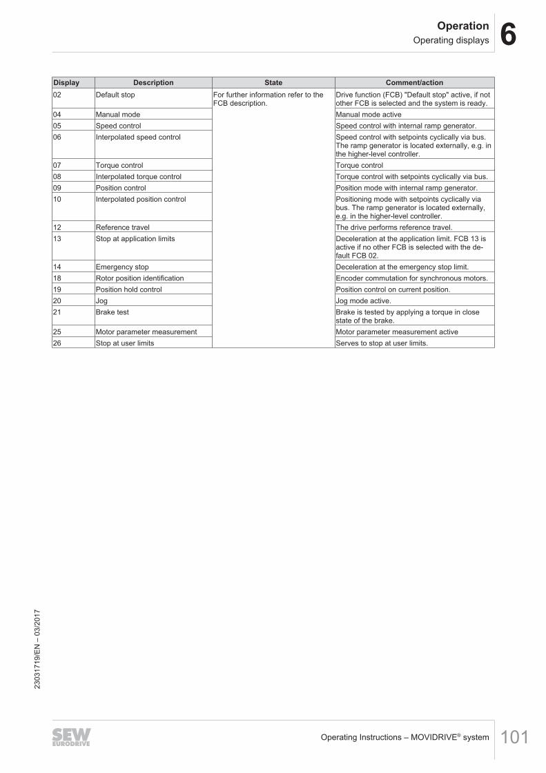
6OperationOperating displays
Operating Instructions – MOVIDRIVE® system 101
Display Description State Comment/action02 Default stop For further information refer to the
FCB description.Drive function (FCB) "Default stop" active, if notother FCB is selected and the system is ready.
04 Manual mode Manual mode active05 Speed control Speed control with internal ramp generator.06 Interpolated speed control Speed control with setpoints cyclically via bus.
The ramp generator is located externally, e.g. inthe higher-level controller.
07 Torque control Torque control08 Interpolated torque control Torque control with setpoints cyclically via bus.09 Position control Position mode with internal ramp generator.10 Interpolated position control Positioning mode with setpoints cyclically via
bus. The ramp generator is located externally,e.g. in the higher-level controller.
12 Reference travel The drive performs reference travel.13 Stop at application limits Deceleration at the application limit. FCB 13 is
active if no other FCB is selected with the de-fault FCB 02.
14 Emergency stop Deceleration at the emergency stop limit.18 Rotor position identification Encoder commutation for synchronous motors.19 Position hold control Position control on current position.20 Jog Jog mode active.21 Brake test Brake is tested by applying a torque in close
state of the brake.25 Motor parameter measurement Motor parameter measurement active26 Stop at user limits Serves to stop at user limits.
2303
1719
/EN
– 0
3/20
17
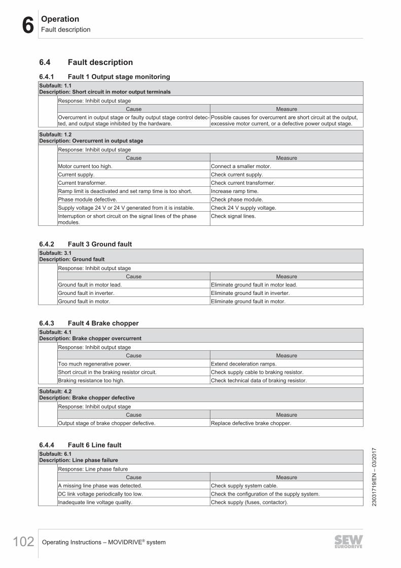
6 OperationFault description
Operating Instructions – MOVIDRIVE® system102
6.4 Fault description6.4.1 Fault 1 Output stage monitoringSubfault: 1.1Description: Short circuit in motor output terminals
Response: Inhibit output stageCause Measure
Overcurrent in output stage or faulty output stage control detec-ted, and output stage inhibited by the hardware.
Possible causes for overcurrent are short circuit at the output,excessive motor current, or a defective power output stage.
Subfault: 1.2Description: Overcurrent in output stage
Response: Inhibit output stageCause Measure
Motor current too high. Connect a smaller motor.Current supply. Check current supply.Current transformer. Check current transformer.Ramp limit is deactivated and set ramp time is too short. Increase ramp time.Phase module defective. Check phase module.Supply voltage 24 V or 24 V generated from it is instable. Check 24 V supply voltage.Interruption or short circuit on the signal lines of the phasemodules.
Check signal lines.
6.4.2 Fault 3 Ground faultSubfault: 3.1Description: Ground fault
Response: Inhibit output stageCause Measure
Ground fault in motor lead. Eliminate ground fault in motor lead.Ground fault in inverter. Eliminate ground fault in inverter.Ground fault in motor. Eliminate ground fault in motor.
6.4.3 Fault 4 Brake chopperSubfault: 4.1Description: Brake chopper overcurrent
Response: Inhibit output stageCause Measure
Too much regenerative power. Extend deceleration ramps.Short circuit in the braking resistor circuit. Check supply cable to braking resistor.Braking resistance too high. Check technical data of braking resistor.
Subfault: 4.2Description: Brake chopper defective
Response: Inhibit output stageCause Measure
Output stage of brake chopper defective. Replace defective brake chopper.
6.4.4 Fault 6 Line faultSubfault: 6.1Description: Line phase failure
Response: Line phase failureCause Measure
A missing line phase was detected. Check supply system cable.DC link voltage periodically too low. Check the configuration of the supply system.Inadequate line voltage quality. Check supply (fuses, contactor). 23
0317
19/E
N –
03/
2017
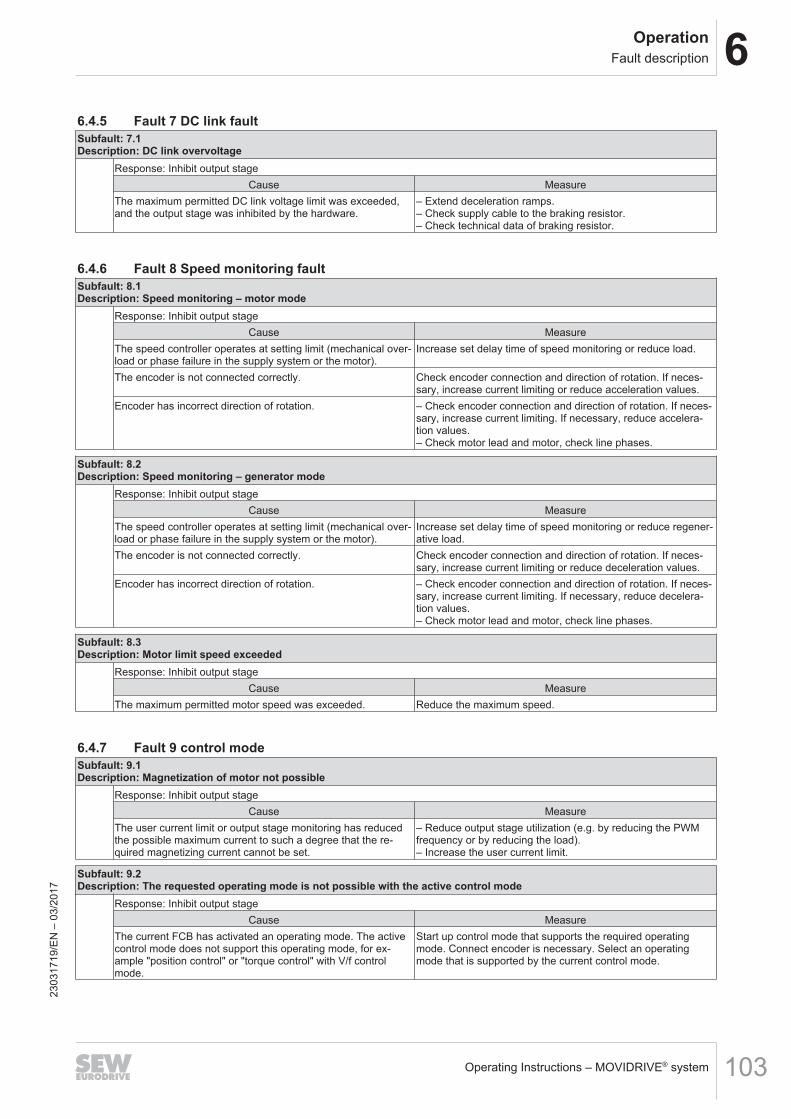
6OperationFault description
Operating Instructions – MOVIDRIVE® system 103
6.4.5 Fault 7 DC link faultSubfault: 7.1Description: DC link overvoltage
Response: Inhibit output stageCause Measure
The maximum permitted DC link voltage limit was exceeded,and the output stage was inhibited by the hardware.
– Extend deceleration ramps.– Check supply cable to the braking resistor.– Check technical data of braking resistor.
6.4.6 Fault 8 Speed monitoring faultSubfault: 8.1Description: Speed monitoring – motor mode
Response: Inhibit output stageCause Measure
The speed controller operates at setting limit (mechanical over-load or phase failure in the supply system or the motor).
Increase set delay time of speed monitoring or reduce load.
The encoder is not connected correctly. Check encoder connection and direction of rotation. If neces-sary, increase current limiting or reduce acceleration values.
Encoder has incorrect direction of rotation. – Check encoder connection and direction of rotation. If neces-sary, increase current limiting. If necessary, reduce accelera-tion values.– Check motor lead and motor, check line phases.
Subfault: 8.2Description: Speed monitoring – generator mode
Response: Inhibit output stageCause Measure
The speed controller operates at setting limit (mechanical over-load or phase failure in the supply system or the motor).
Increase set delay time of speed monitoring or reduce regener-ative load.
The encoder is not connected correctly. Check encoder connection and direction of rotation. If neces-sary, increase current limiting or reduce deceleration values.
Encoder has incorrect direction of rotation. – Check encoder connection and direction of rotation. If neces-sary, increase current limiting. If necessary, reduce decelera-tion values.– Check motor lead and motor, check line phases.
Subfault: 8.3Description: Motor limit speed exceeded
Response: Inhibit output stageCause Measure
The maximum permitted motor speed was exceeded. Reduce the maximum speed.
6.4.7 Fault 9 control modeSubfault: 9.1Description: Magnetization of motor not possible
Response: Inhibit output stageCause Measure
The user current limit or output stage monitoring has reducedthe possible maximum current to such a degree that the re-quired magnetizing current cannot be set.
– Reduce output stage utilization (e.g. by reducing the PWMfrequency or by reducing the load).– Increase the user current limit.
Subfault: 9.2Description: The requested operating mode is not possible with the active control mode
Response: Inhibit output stageCause Measure
The current FCB has activated an operating mode. The activecontrol mode does not support this operating mode, for ex-ample "position control" or "torque control" with V/f controlmode.
Start up control mode that supports the required operatingmode. Connect encoder is necessary. Select an operatingmode that is supported by the current control mode.
2303
1719
/EN
– 0
3/20
17
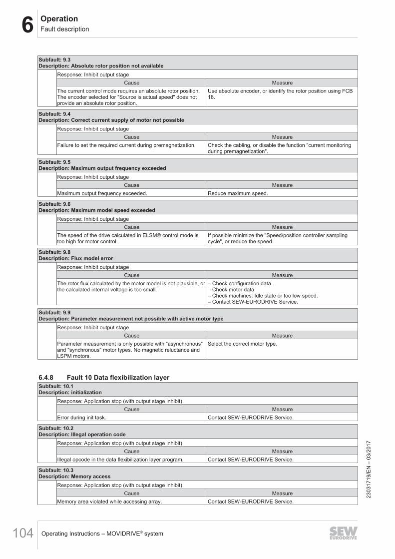
6 OperationFault description
Operating Instructions – MOVIDRIVE® system104
Subfault: 9.3Description: Absolute rotor position not available
Response: Inhibit output stageCause Measure
The current control mode requires an absolute rotor position.The encoder selected for "Source is actual speed" does notprovide an absolute rotor position.
Use absolute encoder, or identify the rotor position using FCB18.
Subfault: 9.4Description: Correct current supply of motor not possible
Response: Inhibit output stageCause Measure
Failure to set the required current during premagnetization. Check the cabling, or disable the function "current monitoringduring premagnetization".
Subfault: 9.5Description: Maximum output frequency exceeded
Response: Inhibit output stageCause Measure
Maximum output frequency exceeded. Reduce maximum speed.
Subfault: 9.6Description: Maximum model speed exceeded
Response: Inhibit output stageCause Measure
The speed of the drive calculated in ELSM® control mode istoo high for motor control.
If possible minimize the "Speed/position controller samplingcycle", or reduce the speed.
Subfault: 9.8Description: Flux model error
Response: Inhibit output stageCause Measure
The rotor flux calculated by the motor model is not plausible, orthe calculated internal voltage is too small.
– Check configuration data.– Check motor data.– Check machines: Idle state or too low speed.– Contact SEW‑EURODRIVE Service.
Subfault: 9.9Description: Parameter measurement not possible with active motor type
Response: Inhibit output stageCause Measure
Parameter measurement is only possible with "asynchronous"and "synchronous" motor types. No magnetic reluctance andLSPM motors.
Select the correct motor type.
6.4.8 Fault 10 Data flexibilization layerSubfault: 10.1Description: initialization
Response: Application stop (with output stage inhibit)Cause Measure
Error during init task. Contact SEW-EURODRIVE Service.
Subfault: 10.2Description: Illegal operation code
Response: Application stop (with output stage inhibit)Cause Measure
Illegal opcode in the data flexibilization layer program. Contact SEW-EURODRIVE Service.
Subfault: 10.3Description: Memory access
Response: Application stop (with output stage inhibit)Cause Measure
Memory area violated while accessing array. Contact SEW-EURODRIVE Service.
2303
1719
/EN
– 0
3/20
17
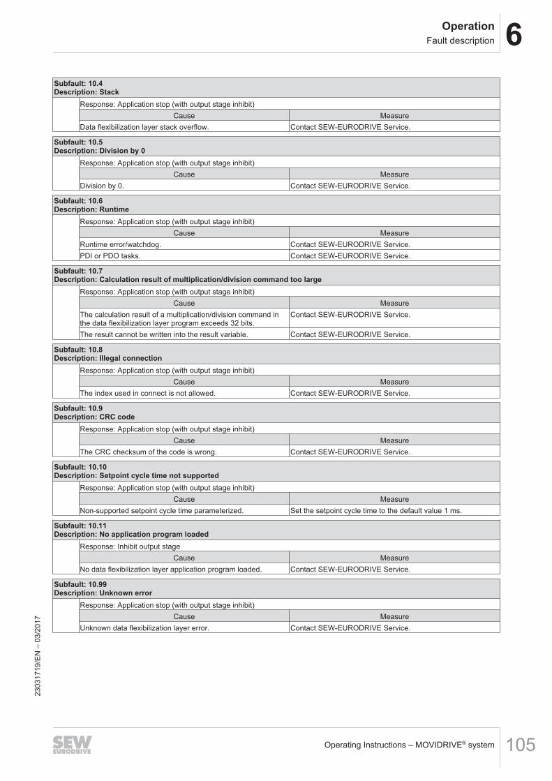
6OperationFault description
Operating Instructions – MOVIDRIVE® system 105
Subfault: 10.4Description: Stack
Response: Application stop (with output stage inhibit)Cause Measure
Data flexibilization layer stack overflow. Contact SEW-EURODRIVE Service.
Subfault: 10.5Description: Division by 0
Response: Application stop (with output stage inhibit)Cause Measure
Division by 0. Contact SEW-EURODRIVE Service.
Subfault: 10.6Description: Runtime
Response: Application stop (with output stage inhibit)Cause Measure
Runtime error/watchdog. Contact SEW-EURODRIVE Service.PDI or PDO tasks. Contact SEW-EURODRIVE Service.
Subfault: 10.7Description: Calculation result of multiplication/division command too large
Response: Application stop (with output stage inhibit)Cause Measure
The calculation result of a multiplication/division command inthe data flexibilization layer program exceeds 32 bits.
Contact SEW-EURODRIVE Service.
The result cannot be written into the result variable. Contact SEW-EURODRIVE Service.
Subfault: 10.8Description: Illegal connection
Response: Application stop (with output stage inhibit)Cause Measure
The index used in connect is not allowed. Contact SEW-EURODRIVE Service.
Subfault: 10.9Description: CRC code
Response: Application stop (with output stage inhibit)Cause Measure
The CRC checksum of the code is wrong. Contact SEW-EURODRIVE Service.
Subfault: 10.10Description: Setpoint cycle time not supported
Response: Application stop (with output stage inhibit)Cause Measure
Non-supported setpoint cycle time parameterized. Set the setpoint cycle time to the default value 1 ms.
Subfault: 10.11Description: No application program loaded
Response: Inhibit output stageCause Measure
No data flexibilization layer application program loaded. Contact SEW-EURODRIVE Service.
Subfault: 10.99Description: Unknown error
Response: Application stop (with output stage inhibit)Cause Measure
Unknown data flexibilization layer error. Contact SEW-EURODRIVE Service.
2303
1719
/EN
– 0
3/20
17
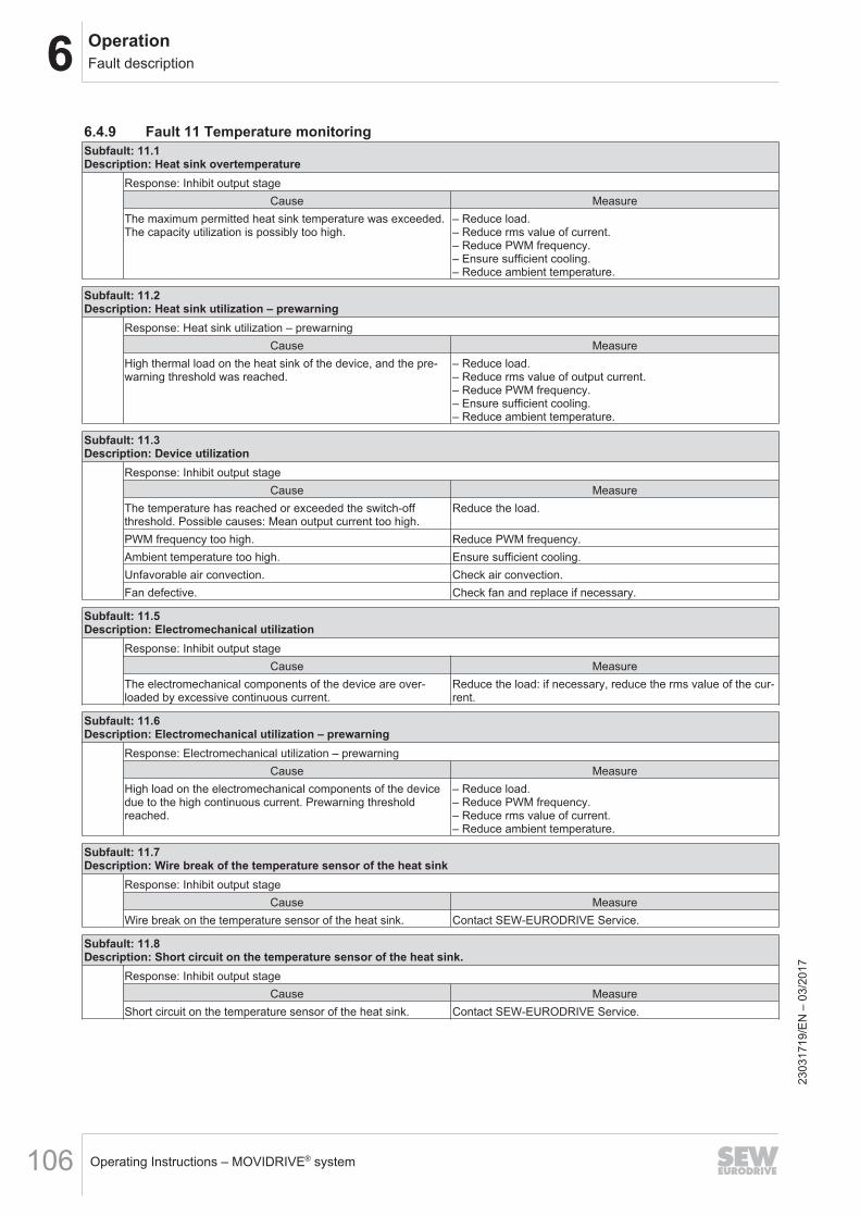
6 OperationFault description
Operating Instructions – MOVIDRIVE® system106
6.4.9 Fault 11 Temperature monitoringSubfault: 11.1Description: Heat sink overtemperature
Response: Inhibit output stageCause Measure
The maximum permitted heat sink temperature was exceeded.The capacity utilization is possibly too high.
– Reduce load.– Reduce rms value of current.– Reduce PWM frequency.– Ensure sufficient cooling.– Reduce ambient temperature.
Subfault: 11.2Description: Heat sink utilization – prewarning
Response: Heat sink utilization – prewarningCause Measure
High thermal load on the heat sink of the device, and the pre-warning threshold was reached.
– Reduce load.– Reduce rms value of output current.– Reduce PWM frequency.– Ensure sufficient cooling.– Reduce ambient temperature.
Subfault: 11.3Description: Device utilization
Response: Inhibit output stageCause Measure
The temperature has reached or exceeded the switch-offthreshold. Possible causes: Mean output current too high.
Reduce the load.
PWM frequency too high. Reduce PWM frequency.Ambient temperature too high. Ensure sufficient cooling.Unfavorable air convection. Check air convection.Fan defective. Check fan and replace if necessary.
Subfault: 11.5Description: Electromechanical utilization
Response: Inhibit output stageCause Measure
The electromechanical components of the device are over-loaded by excessive continuous current.
Reduce the load: if necessary, reduce the rms value of the cur-rent.
Subfault: 11.6Description: Electromechanical utilization – prewarning
Response: Electromechanical utilization – prewarningCause Measure
High load on the electromechanical components of the devicedue to the high continuous current. Prewarning thresholdreached.
– Reduce load.– Reduce PWM frequency.– Reduce rms value of current.– Reduce ambient temperature.
Subfault: 11.7Description: Wire break of the temperature sensor of the heat sink
Response: Inhibit output stageCause Measure
Wire break on the temperature sensor of the heat sink. Contact SEW-EURODRIVE Service.
Subfault: 11.8Description: Short circuit on the temperature sensor of the heat sink.
Response: Inhibit output stageCause Measure
Short circuit on the temperature sensor of the heat sink. Contact SEW-EURODRIVE Service.
2303
1719
/EN
– 0
3/20
17
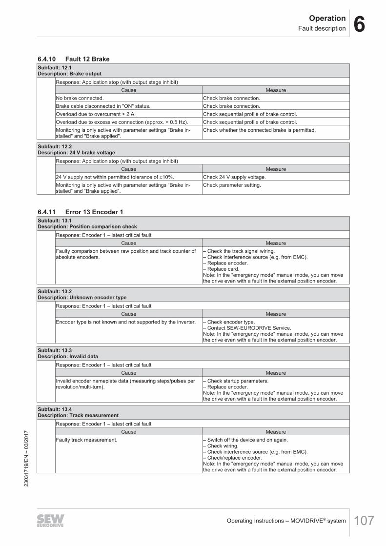
6OperationFault description
Operating Instructions – MOVIDRIVE® system 107
6.4.10 Fault 12 BrakeSubfault: 12.1Description: Brake output
Response: Application stop (with output stage inhibit)Cause Measure
No brake connected. Check brake connection.Brake cable disconnected in "ON" status. Check brake connection.Overload due to overcurrent > 2 A. Check sequential profile of brake control.Overload due to excessive connection (approx. > 0.5 Hz). Check sequential profile of brake control.Monitoring is only active with parameter settings "Brake in-stalled" and "Brake applied".
Check whether the connected brake is permitted.
Subfault: 12.2Description: 24 V brake voltage
Response: Application stop (with output stage inhibit)Cause Measure
24 V supply not within permitted tolerance of ±10%. Check 24 V supply voltage.Monitoring is only active with parameter settings “Brake in-stalled” and “Brake applied”.
Check parameter setting.
6.4.11 Error 13 Encoder 1Subfault: 13.1Description: Position comparison check
Response: Encoder 1 – latest critical faultCause Measure
Faulty comparison between raw position and track counter ofabsolute encoders.
– Check the track signal wiring.– Check interference source (e.g. from EMC).– Replace encoder.– Replace card.Note: In the "emergency mode" manual mode, you can movethe drive even with a fault in the external position encoder.
Subfault: 13.2Description: Unknown encoder type
Response: Encoder 1 – latest critical faultCause Measure
Encoder type is not known and not supported by the inverter. – Check encoder type.– Contact SEW‑EURODRIVE Service.Note: In the "emergency mode" manual mode, you can movethe drive even with a fault in the external position encoder.
Subfault: 13.3Description: Invalid data
Response: Encoder 1 – latest critical faultCause Measure
Invalid encoder nameplate data (measuring steps/pulses perrevolution/multi-turn).
– Check startup parameters.– Replace encoder.Note: In the "emergency mode" manual mode, you can movethe drive even with a fault in the external position encoder.
Subfault: 13.4Description: Track measurement
Response: Encoder 1 – latest critical faultCause Measure
Faulty track measurement. – Switch off the device and on again.– Check wiring.– Check interference source (e.g. from EMC).– Check/replace encoder.Note: In the "emergency mode" manual mode, you can movethe drive even with a fault in the external position encoder.
2303
1719
/EN
– 0
3/20
17
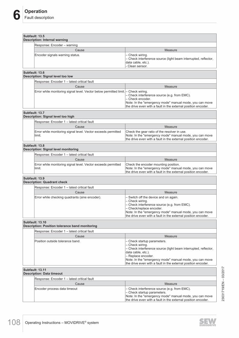
6 OperationFault description
Operating Instructions – MOVIDRIVE® system108
Subfault: 13.5Description: Internal warning
Response: Encoder – warningCause Measure
Encoder signals warning status. – Check wiring.– Check interference source (light beam interrupted, reflector,data cable, etc.).- Clean sensor.
Subfault: 13.6Description: Signal level too low
Response: Encoder 1 – latest critical faultCause Measure
Error while monitoring signal level. Vector below permitted limit. – Check wiring.– Check interference source (e.g. from EMC).– Check encoder.Note: In the "emergency mode" manual mode, you can movethe drive even with a fault in the external position encoder.
Subfault: 13.7Description: Signal level too high
Response: Encoder 1 – latest critical faultCause Measure
Error while monitoring signal level. Vector exceeds permittedlimit.
Check the gear ratio of the resolver in use.Note: In the "emergency mode" manual mode, you can movethe drive even with a fault in the external position encoder.
Subfault: 13.8Description: Signal level monitoring
Response: Encoder 1 – latest critical faultCause Measure
Error while monitoring signal level. Vector exceeds permittedlimit.
Check the encoder mounting position.Note: In the "emergency mode" manual mode, you can movethe drive even with a fault in the external position encoder.
Subfault: 13.9Description: Quadrant check
Response: Encoder 1 – latest critical faultCause Measure
Error while checking quadrants (sine encoder). – Switch off the device and on again.– Check wiring.– Check interference source (e.g. from EMC).– Check/replace encoder.Note: In the "emergency mode" manual mode, you can movethe drive even with a fault in the external position encoder.
Subfault: 13.10Description: Position tolerance band monitoring
Response: Encoder 1 – latest critical faultCause Measure
Position outside tolerance band. – Check startup parameters.– Check wiring.– Check interference source (light beam interrupted, reflector,data cable, etc.).– Replace encoder.Note: In the "emergency mode" manual mode, you can movethe drive even with a fault in the external position encoder.
Subfault: 13.11Description: Data timeout
Response: Encoder 1 – latest critical faultCause Measure
Encoder process data timeout – Check interference source (e.g. from EMC).– Check startup parameters.Note: In the "emergency mode" manual mode, you can movethe drive even with a fault in the external position encoder. 23
0317
19/E
N –
03/
2017
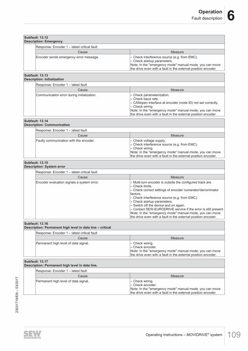
6OperationFault description
Operating Instructions – MOVIDRIVE® system 109
Subfault: 13.12Description: Emergency
Response: Encoder 1 – latest critical faultCause Measure
Encoder sends emergency error message. – Check interference source (e.g. from EMC).– Check startup parameters.Note: In the "emergency mode" manual mode, you can movethe drive even with a fault in the external position encoder.
Subfault: 13.13Description: Initialization
Response: Encoder 1 – latest faultCause Measure
Communication error during initialization. – Check parameterization.– Check baud rate.– CANopen interface at encoder (node ID) not set correctly.– Check wiring.Note: In the "emergency mode" manual mode, you can movethe drive even with a fault in the external position encoder.
Subfault: 13.14Description: Communication
Response: Encoder 1 – latest faultCause Measure
Faulty communication with the encoder. – Check voltage supply.– Check interference source (e.g. from EMC).– Check wiring.Note: In the "emergency mode" manual mode, you can movethe drive even with a fault in the external position encoder.
Subfault: 13.15Description: System error
Response: Encoder 1 – latest critical faultCause Measure
Encoder evaluation signals a system error. – Multi-turn encoder is outside the configured track are.– Check limits.– Check correct settings of encoder numerator/denominatorfactors.– Check interference source (e.g. from EMC).– Check startup parameters.– Switch off the device and on again.– Contact SEW‑EURODRIVE service if the error is still present.Note: In the "emergency mode" manual mode, you can movethe drive even with a fault in the external position encoder.
Subfault: 13.16Description: Permanent high level in data line – critical
Response: Encoder 1 – latest critical faultCause Measure
Permanent high level of data signal. – Check wiring.– Check encoder.Note: In the "emergency mode" manual mode, you can movethe drive even with a fault in the external position encoder.
Subfault: 13.17Description: Permanent high level in data line.
Response: Encoder 1 – latest faultCause Measure
Permanent high level of data signal. – Check wiring.– Check encoder.Note: In the "emergency mode" manual mode, you can movethe drive even with a fault in the external position encoder.
2303
1719
/EN
– 0
3/20
17
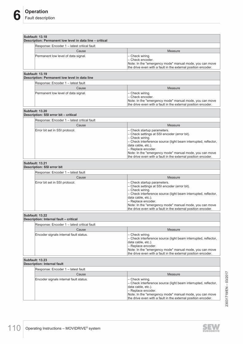
6 OperationFault description
Operating Instructions – MOVIDRIVE® system110
Subfault: 13.18Description: Permanent low level in data line – critical
Response: Encoder 1 – latest critical faultCause Measure
Permanent low level of data signal. – Check wiring.– Check encoder.Note: In the "emergency mode" manual mode, you can movethe drive even with a fault in the external position encoder.
Subfault: 13.19Description: Permanent low level in data line
Response: Encoder 1 – latest faultCause Measure
Permanent low level of data signal. – Check wiring.– Check encoder.Note: In the "emergency mode" manual mode, you can movethe drive even with a fault in the external position encoder.
Subfault: 13.20Description: SSI error bit – critical
Response: Encoder 1 – latest critical faultCause Measure
Error bit set in SSI protocol. – Check startup parameters.– Check settings at SSI encoder (error bit).– Check wiring.– Check interference source (light beam interrupted, reflector,data cable, etc.).– Replace encoder.Note: In the "emergency mode" manual mode, you can movethe drive even with a fault in the external position encoder.
Subfault: 13.21Description: SSI error bit
Response: Encoder 1 – latest faultCause Measure
Error bit set in SSI protocol. – Check startup parameters.– Check settings at SSI encoder (error bit).– Check wiring.– Check interference source (light beam interrupted, reflector,data cable, etc.).– Replace encoder.Note: In the "emergency mode" manual mode, you can movethe drive even with a fault in the external position encoder.
Subfault: 13.22Description: Internal fault – critical
Response: Encoder 1 – latest critical faultCause Measure
Encoder signals internal fault status. – Check wiring.– Check interference source (light beam interrupted, reflector,data cable, etc.).– Replace encoder.Note: In the "emergency mode" manual mode, you can movethe drive even with a fault in the external position encoder.
Subfault: 13.23Description: Internal fault
Response: Encoder 1 – latest faultCause Measure
Encoder signals internal fault status. – Check wiring.– Check interference source (light beam interrupted, reflector,data cable, etc.).– Replace encoder.Note: In the "emergency mode" manual mode, you can movethe drive even with a fault in the external position encoder.
2303
1719
/EN
– 0
3/20
17
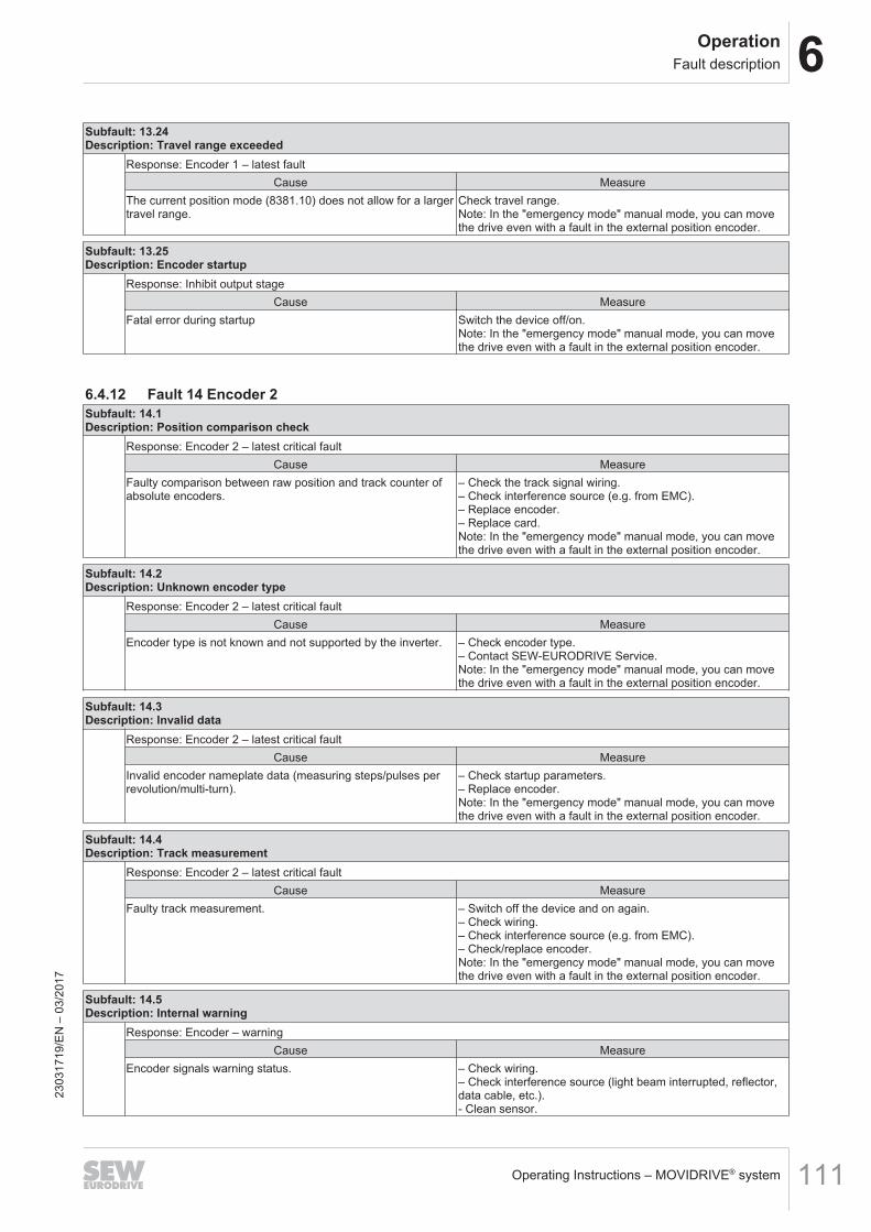
6OperationFault description
Operating Instructions – MOVIDRIVE® system 111
Subfault: 13.24Description: Travel range exceeded
Response: Encoder 1 – latest faultCause Measure
The current position mode (8381.10) does not allow for a largertravel range.
Check travel range.Note: In the "emergency mode" manual mode, you can movethe drive even with a fault in the external position encoder.
Subfault: 13.25Description: Encoder startup
Response: Inhibit output stageCause Measure
Fatal error during startup Switch the device off/on.Note: In the "emergency mode" manual mode, you can movethe drive even with a fault in the external position encoder.
6.4.12 Fault 14 Encoder 2Subfault: 14.1Description: Position comparison check
Response: Encoder 2 – latest critical faultCause Measure
Faulty comparison between raw position and track counter ofabsolute encoders.
– Check the track signal wiring.– Check interference source (e.g. from EMC).– Replace encoder.– Replace card.Note: In the "emergency mode" manual mode, you can movethe drive even with a fault in the external position encoder.
Subfault: 14.2Description: Unknown encoder type
Response: Encoder 2 – latest critical faultCause Measure
Encoder type is not known and not supported by the inverter. – Check encoder type.– Contact SEW‑EURODRIVE Service.Note: In the "emergency mode" manual mode, you can movethe drive even with a fault in the external position encoder.
Subfault: 14.3Description: Invalid data
Response: Encoder 2 – latest critical faultCause Measure
Invalid encoder nameplate data (measuring steps/pulses perrevolution/multi-turn).
– Check startup parameters.– Replace encoder.Note: In the "emergency mode" manual mode, you can movethe drive even with a fault in the external position encoder.
Subfault: 14.4Description: Track measurement
Response: Encoder 2 – latest critical faultCause Measure
Faulty track measurement. – Switch off the device and on again.– Check wiring.– Check interference source (e.g. from EMC).– Check/replace encoder.Note: In the "emergency mode" manual mode, you can movethe drive even with a fault in the external position encoder.
Subfault: 14.5Description: Internal warning
Response: Encoder – warningCause Measure
Encoder signals warning status. – Check wiring.– Check interference source (light beam interrupted, reflector,data cable, etc.).- Clean sensor.
2303
1719
/EN
– 0
3/20
17
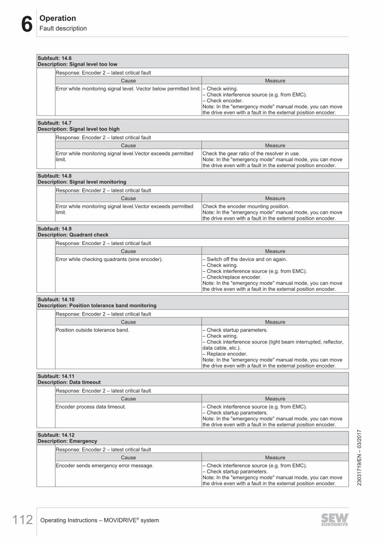
6 OperationFault description
Operating Instructions – MOVIDRIVE® system112
Subfault: 14.6Description: Signal level too low
Response: Encoder 2 – latest critical faultCause Measure
Error while monitoring signal level. Vector below permitted limit. – Check wiring.– Check interference source (e.g. from EMC).– Check encoder.Note: In the "emergency mode" manual mode, you can movethe drive even with a fault in the external position encoder.
Subfault: 14.7Description: Signal level too high
Response: Encoder 2 – latest critical faultCause Measure
Error while monitoring signal level.Vector exceeds permittedlimit.
Check the gear ratio of the resolver in use.Note: In the "emergency mode" manual mode, you can movethe drive even with a fault in the external position encoder.
Subfault: 14.8Description: Signal level monitoring
Response: Encoder 2 – latest critical faultCause Measure
Error while monitoring signal level.Vector exceeds permittedlimit.
Check the encoder mounting position.Note: In the "emergency mode" manual mode, you can movethe drive even with a fault in the external position encoder.
Subfault: 14.9Description: Quadrant check
Response: Encoder 2 – latest critical faultCause Measure
Error while checking quadrants (sine encoder). – Switch off the device and on again.– Check wiring.– Check interference source (e.g. from EMC).– Check/replace encoder.Note: In the "emergency mode" manual mode, you can movethe drive even with a fault in the external position encoder.
Subfault: 14.10Description: Position tolerance band monitoring
Response: Encoder 2 – latest critical faultCause Measure
Position outside tolerance band. – Check startup parameters.– Check wiring.– Check interference source (light beam interrupted, reflector,data cable, etc.).– Replace encoder.Note: In the "emergency mode" manual mode, you can movethe drive even with a fault in the external position encoder.
Subfault: 14.11Description: Data timeout
Response: Encoder 2 – latest critical faultCause Measure
Encoder process data timeout. – Check interference source (e.g. from EMC).– Check startup parameters.Note: In the "emergency mode" manual mode, you can movethe drive even with a fault in the external position encoder.
Subfault: 14.12Description: Emergency
Response: Encoder 2 – latest critical faultCause Measure
Encoder sends emergency error message. – Check interference source (e.g. from EMC).– Check startup parameters.Note: In the "emergency mode" manual mode, you can movethe drive even with a fault in the external position encoder. 23
0317
19/E
N –
03/
2017
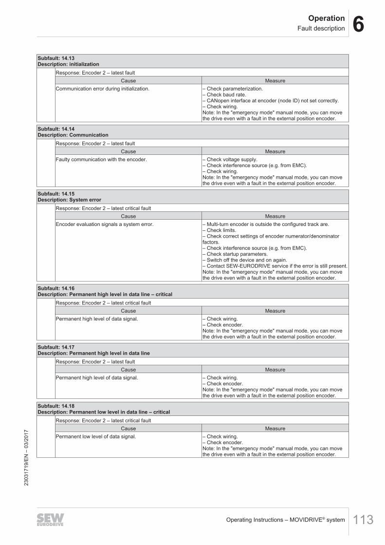
6OperationFault description
Operating Instructions – MOVIDRIVE® system 113
Subfault: 14.13Description: initialization
Response: Encoder 2 – latest faultCause Measure
Communication error during initialization. – Check parameterization.– Check baud rate.– CANopen interface at encoder (node ID) not set correctly.– Check wiring.Note: In the "emergency mode" manual mode, you can movethe drive even with a fault in the external position encoder.
Subfault: 14.14Description: Communication
Response: Encoder 2 – latest faultCause Measure
Faulty communication with the encoder. – Check voltage supply.– Check interference source (e.g. from EMC).– Check wiring.Note: In the "emergency mode" manual mode, you can movethe drive even with a fault in the external position encoder.
Subfault: 14.15Description: System error
Response: Encoder 2 – latest critical faultCause Measure
Encoder evaluation signals a system error. – Multi-turn encoder is outside the configured track are.– Check limits.– Check correct settings of encoder numerator/denominatorfactors.– Check interference source (e.g. from EMC).– Check startup parameters.– Switch off the device and on again.– Contact SEW‑EURODRIVE service if the error is still present.Note: In the "emergency mode" manual mode, you can movethe drive even with a fault in the external position encoder.
Subfault: 14.16Description: Permanent high level in data line – critical
Response: Encoder 2 – latest critical faultCause Measure
Permanent high level of data signal. – Check wiring.– Check encoder.Note: In the "emergency mode" manual mode, you can movethe drive even with a fault in the external position encoder.
Subfault: 14.17Description: Permanent high level in data line
Response: Encoder 2 – latest faultCause Measure
Permanent high level of data signal. – Check wiring.– Check encoder.Note: In the "emergency mode" manual mode, you can movethe drive even with a fault in the external position encoder.
Subfault: 14.18Description: Permanent low level in data line – critical
Response: Encoder 2 – latest critical faultCause Measure
Permanent low level of data signal. – Check wiring.– Check encoder.Note: In the "emergency mode" manual mode, you can movethe drive even with a fault in the external position encoder.
2303
1719
/EN
– 0
3/20
17
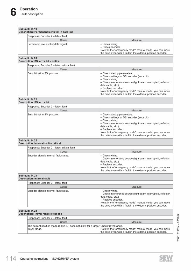
6 OperationFault description
Operating Instructions – MOVIDRIVE® system114
Subfault: 14.19Description: Permanent low level in data line
Response: Encoder 2 – latest faultCause Measure
Permanent low level of data signal. – Check wiring.– Check encoder.Note: In the "emergency mode" manual mode, you can movethe drive even with a fault in the external position encoder.
Subfault: 14.20Description: SSI error bit – critical
Response: Encoder 2 – latest critical faultCause Measure
Error bit set in SSI protocol. – Check startup parameters.– Check settings at SSI encoder (error bit).– Check wiring.– Check interference source (light beam interrupted, reflector,data cable, etc.).– Replace encoder.Note: In the "emergency mode" manual mode, you can movethe drive even with a fault in the external position encoder.
Subfault: 14.21Description: SSI error bit
Response: Encoder 2 – latest faultCause Measure
Error bit set in SSI protocol. – Check startup parameters.– Check settings at SSI encoder (error bit).– Check wiring.– Check interference source (light beam interrupted, reflector,data cable, etc.).– Replace encoder.Note: In the "emergency mode" manual mode, you can movethe drive even with a fault in the external position encoder.
Subfault: 14.22Description: Internal fault – critical
Response: Encoder 2 – latest critical faultCause Measure
Encoder signals internal fault status. – Check wiring.– Check interference source (light beam interrupted, reflector,data cable, etc.).– Replace encoder.Note: In the "emergency mode" manual mode, you can movethe drive even with a fault in the external position encoder.
Subfault: 14.23Description: Internal fault
Response: Encoder 2 – latest faultCause Measure
Encoder signals internal fault status. – Check wiring.– Check interference source (light beam interrupted, reflector,data cable, etc.).– Replace encoder.Note: In the "emergency mode" manual mode, you can movethe drive even with a fault in the external position encoder.
Subfault: 14.24Description: Travel range exceeded
Response: Encoder 2 – latest faultCause Measure
The current position mode (8382.10) does not allow for a largertravel range.
Check travel range.Note: In the "emergency mode" manual mode, you can movethe drive even with a fault in the external position encoder.
2303
1719
/EN
– 0
3/20
17
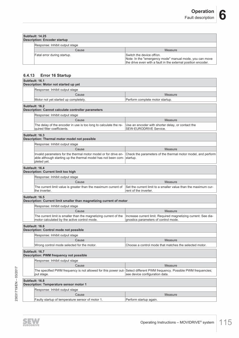
6OperationFault description
Operating Instructions – MOVIDRIVE® system 115
Subfault: 14.25Description: Encoder startup
Response: Inhibit output stageCause Measure
Fatal error during startup. Switch the device off/on.Note: In the "emergency mode" manual mode, you can movethe drive even with a fault in the external position encoder.
6.4.13 Error 16 StartupSubfault: 16.1Description: Motor not started up yet
Response: Inhibit output stageCause Measure
Motor not yet started up completely. Perform complete motor startup.
Subfault: 16.2Description: Cannot calculate controller parameters
Response: Inhibit output stageCause Measure
The delay of the encoder in use is too long to calculate the re-quired filter coefficients.
Use an encoder with shorter delay, or contact theSEW‑EURODRIVE Service.
Subfault: 16.3Description: Thermal motor model not possible
Response: Inhibit output stageCause Measure
Invalid parameters for the thermal motor model or for drive en-able although starting up the thermal model has not been com-pleted yet.
Check the parameters of the thermal motor model, and performstartup.
Subfault: 16.4Description: Current limit too high
Response: Inhibit output stageCause Measure
The current limit value is greater than the maximum current ofthe inverter.
Set the current limit to a smaller value than the maximum cur-rent of the inverter.
Subfault: 16.5Description: Current limit smaller than magnetizing current of motor
Response: Inhibit output stageCause Measure
The current limit is smaller than the magnetizing current of themotor calculated by the active control mode.
Increase current limit. Required magnetizing current: See dia-gnostics parameters of control mode.
Subfault: 16.6Description: Control mode not possible
Response: Inhibit output stageCause Measure
Wrong control mode selected for the motor. Choose a control mode that matches the selected motor.
Subfault: 16.7Description: PWM frequency not possible
Response: Inhibit output stageCause Measure
The specified PWM frequency is not allowed for this power out-put stage.
Select different PWM frequency. Possible PWM frequencies;see device configuration data.
Subfault: 16.8Description: Temperature sensor motor 1
Response: Inhibit output stageCause Measure
Faulty startup of temperature sensor of motor 1. Perform startup again.2303
1719
/EN
– 0
3/20
17
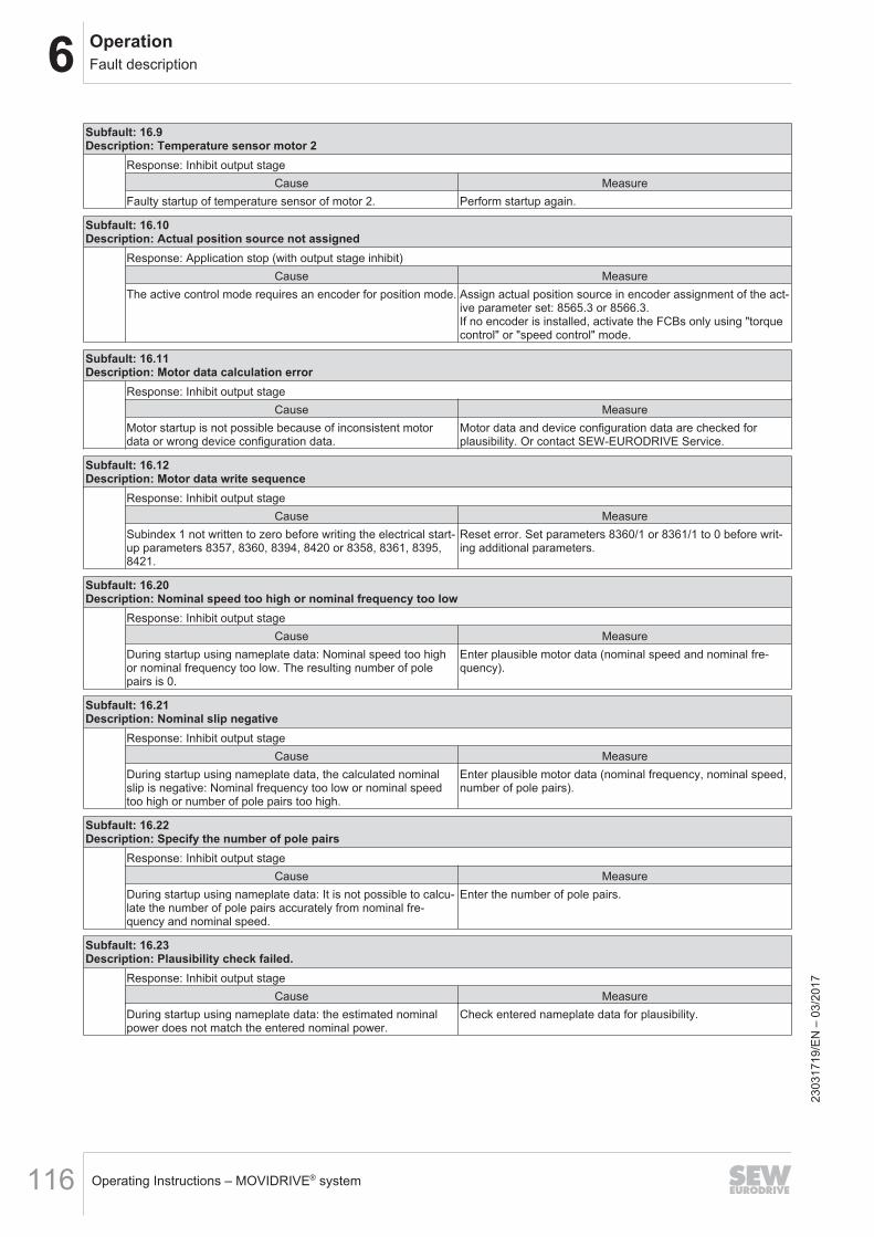
6 OperationFault description
Operating Instructions – MOVIDRIVE® system116
Subfault: 16.9Description: Temperature sensor motor 2
Response: Inhibit output stageCause Measure
Faulty startup of temperature sensor of motor 2. Perform startup again.
Subfault: 16.10Description: Actual position source not assigned
Response: Application stop (with output stage inhibit)Cause Measure
The active control mode requires an encoder for position mode. Assign actual position source in encoder assignment of the act-ive parameter set: 8565.3 or 8566.3.If no encoder is installed, activate the FCBs only using "torquecontrol" or "speed control" mode.
Subfault: 16.11Description: Motor data calculation error
Response: Inhibit output stageCause Measure
Motor startup is not possible because of inconsistent motordata or wrong device configuration data.
Motor data and device configuration data are checked forplausibility. Or contact SEW‑EURODRIVE Service.
Subfault: 16.12Description: Motor data write sequence
Response: Inhibit output stageCause Measure
Subindex 1 not written to zero before writing the electrical start-up parameters 8357, 8360, 8394, 8420 or 8358, 8361, 8395,8421.
Reset error. Set parameters 8360/1 or 8361/1 to 0 before writ-ing additional parameters.
Subfault: 16.20Description: Nominal speed too high or nominal frequency too low
Response: Inhibit output stageCause Measure
During startup using nameplate data: Nominal speed too highor nominal frequency too low. The resulting number of polepairs is 0.
Enter plausible motor data (nominal speed and nominal fre-quency).
Subfault: 16.21Description: Nominal slip negative
Response: Inhibit output stageCause Measure
During startup using nameplate data, the calculated nominalslip is negative: Nominal frequency too low or nominal speedtoo high or number of pole pairs too high.
Enter plausible motor data (nominal frequency, nominal speed,number of pole pairs).
Subfault: 16.22Description: Specify the number of pole pairs
Response: Inhibit output stageCause Measure
During startup using nameplate data: It is not possible to calcu-late the number of pole pairs accurately from nominal fre-quency and nominal speed.
Enter the number of pole pairs.
Subfault: 16.23Description: Plausibility check failed.
Response: Inhibit output stageCause Measure
During startup using nameplate data: the estimated nominalpower does not match the entered nominal power.
Check entered nameplate data for plausibility.
2303
1719
/EN
– 0
3/20
17
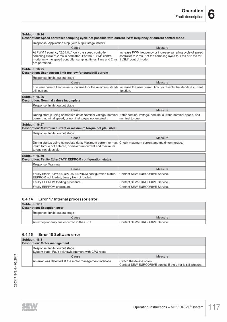
6OperationFault description
Operating Instructions – MOVIDRIVE® system 117
Subfault: 16.24Description: Speed controller sampling cycle not possible with current PWM frequency or current control mode
Response: Application stop (with output stage inhibit)Cause Measure
At PWM frequency "2.5 kHz", only the speed controllersampling cycle of 2 ms is permitted. For the ELSM® controlmode, only the speed controller sampling times 1 ms and 2 msare permitted.
Increase PWM frequency or increase sampling cycle of speedcontroller to 2 ms. Set the sampling cycle to 1 ms or 2 ms forELSM® control mode.
Subfault: 16.25Description: User current limit too low for standstill current
Response: Inhibit output stageCause Measure
The user current limit value is too small for the minimum stand-still current.
Increase the user current limit, or disable the standstill currentfunction.
Subfault: 16.26Description: Nominal values incomplete
Response: Inhibit output stageCause Measure
During startup using nameplate data: Nominal voltage, nominalcurrent, nominal speed, or nominal torque not entered.
Enter nominal voltage, nominal current, nominal speed, andnominal torque.
Subfault: 16.27Description: Maximum current or maximum torque not plausible
Response: Inhibit output stageCause Measure
During startup using nameplate data: Maximum current or max-imum torque not entered, or maximum current and maximumtorque not plausible.
Check maximum current and maximum torque.
Subfault: 16.30Description: Faulty EtherCAT® EEPROM configuration status.
Response: WarningCause Measure
Faulty EtherCAT®/SBusPLUS EEPROM configuration status.EEPROM not loaded, binary file not loaded.
Contact SEW‑EURODRIVE Service.
Faulty EEPROM loading procedure. Contact SEW‑EURODRIVE Service.Faulty EEPROM checksum. Contact SEW‑EURODRIVE Service.
6.4.14 Error 17 Internal processor errorSubfault: 17.7Description: Exception error
Response: Inhibit output stageCause Measure
An exception trap has occurred in the CPU. Contact SEW‑EURODRIVE Service.
6.4.15 Error 18 Software errorSubfault: 18.1Description: Motor management
Response: Inhibit output stageSystem state: Fault acknowledgement with CPU reset
Cause MeasureAn error was detected at the motor management interface. Switch the device off/on.
Contact SEW‑EURODRIVE service if the error is still present.
2303
1719
/EN
– 0
3/20
17
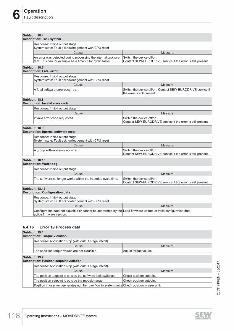
6 OperationFault description
Operating Instructions – MOVIDRIVE® system118
Subfault: 18.4Description: Task system
Response: Inhibit output stageSystem state: Fault acknowledgement with CPU reset
Cause MeasureAn error was detected during processing the internal task sys-tem. This can for example be a timeout for cyclic tasks.
Switch the device off/on.Contact SEW‑EURODRIVE service if the error is still present.
Subfault: 18.7Description: Fatal error
Response: Inhibit output stageSystem state: Fault acknowledgement with CPU reset
Cause MeasureA fatal software error occurred. Switch the device off/on. Contact SEW‑EURODRIVE service if
the error is still present.
Subfault: 18.8Description: Invalid error code
Response: Inhibit output stageCause Measure
Invalid error code requested. Switch the device off/on.Contact SEW‑EURODRIVE service if the error is still present.
Subfault: 18.9Description: Internal software error
Response: Inhibit output stageSystem state: Fault acknowledgement with CPU reset
Cause MeasureA group software error occurred. Switch the device off/on.
Contact SEW‑EURODRIVE service if the error is still present.
Subfault: 18.10Description: Watchdog
Response: Inhibit output stageCause Measure
The software no longer works within the intended cycle time. Switch the device off/on.Contact SEW‑EURODRIVE service if the error is still present.
Subfault: 18.12Description: Configuration data
Response: Inhibit output stageSystem state: Fault acknowledgement with CPU reset
Cause MeasureConfiguration data not plausible or cannot be interpreted by theactive firmware version.
Load firmware update or valid configuration data.
6.4.16 Error 19 Process dataSubfault: 19.1Description: Torque violation
Response: Application stop (with output stage inhibit)Cause Measure
The specified torque values are not plausible. Adjust torque values.
Subfault: 19.2Description: Position setpoint violation
Response: Application stop (with output stage inhibit)Cause Measure
The position setpoint is outside the software limit switches. Check position setpoint.The position setpoint is outside the modulo range. Check position setpoint.Position in user unit generates number overflow in system units Check position in user unit.
2303
1719
/EN
– 0
3/20
17
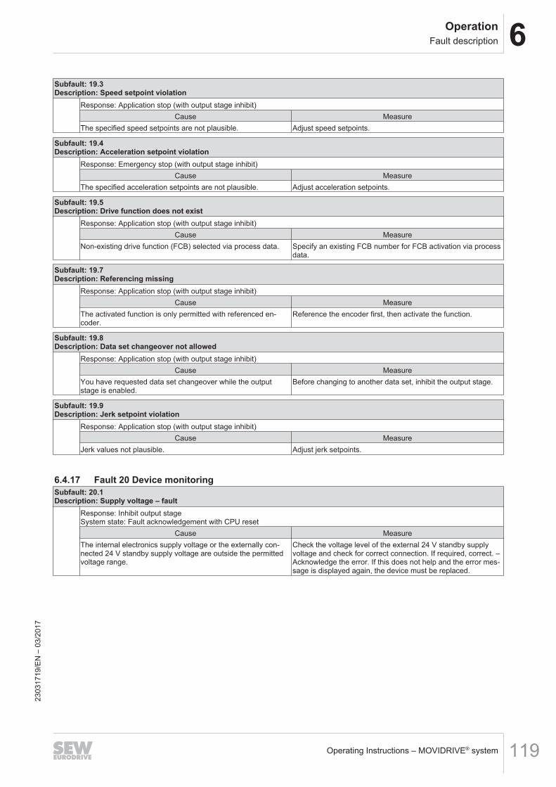
6OperationFault description
Operating Instructions – MOVIDRIVE® system 119
Subfault: 19.3Description: Speed setpoint violation
Response: Application stop (with output stage inhibit)Cause Measure
The specified speed setpoints are not plausible. Adjust speed setpoints.
Subfault: 19.4Description: Acceleration setpoint violation
Response: Emergency stop (with output stage inhibit)Cause Measure
The specified acceleration setpoints are not plausible. Adjust acceleration setpoints.
Subfault: 19.5Description: Drive function does not exist
Response: Application stop (with output stage inhibit)Cause Measure
Non-existing drive function (FCB) selected via process data. Specify an existing FCB number for FCB activation via processdata.
Subfault: 19.7Description: Referencing missing
Response: Application stop (with output stage inhibit)Cause Measure
The activated function is only permitted with referenced en-coder.
Reference the encoder first, then activate the function.
Subfault: 19.8Description: Data set changeover not allowed
Response: Application stop (with output stage inhibit)Cause Measure
You have requested data set changeover while the outputstage is enabled.
Before changing to another data set, inhibit the output stage.
Subfault: 19.9Description: Jerk setpoint violation
Response: Application stop (with output stage inhibit)Cause Measure
Jerk values not plausible. Adjust jerk setpoints.
6.4.17 Fault 20 Device monitoringSubfault: 20.1Description: Supply voltage – fault
Response: Inhibit output stageSystem state: Fault acknowledgement with CPU reset
Cause MeasureThe internal electronics supply voltage or the externally con-nected 24 V standby supply voltage are outside the permittedvoltage range.
Check the voltage level of the external 24 V standby supplyvoltage and check for correct connection. If required, correct. –Acknowledge the error. If this does not help and the error mes-sage is displayed again, the device must be replaced.
2303
1719
/EN
– 0
3/20
17
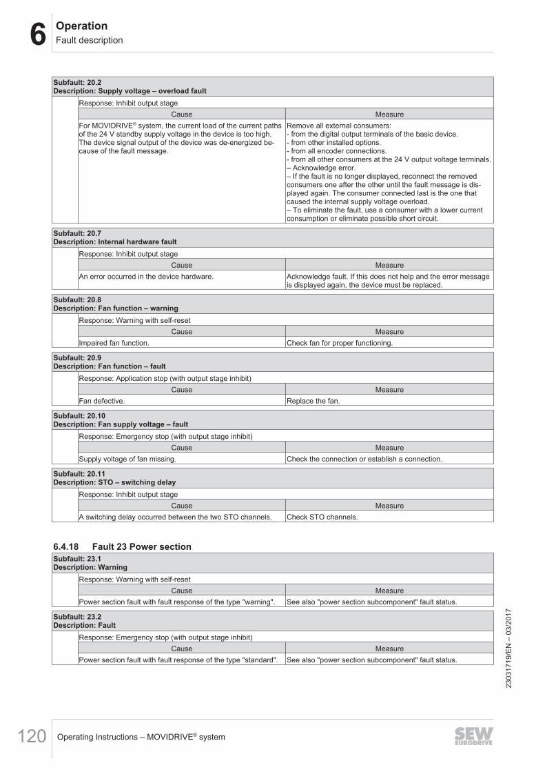
6 OperationFault description
Operating Instructions – MOVIDRIVE® system120
Subfault: 20.2Description: Supply voltage – overload fault
Response: Inhibit output stageCause Measure
For MOVIDRIVE® system, the current load of the current pathsof the 24 V standby supply voltage in the device is too high.The device signal output of the device was de-energized be-cause of the fault message.
Remove all external consumers:- from the digital output terminals of the basic device.- from other installed options.- from all encoder connections.- from all other consumers at the 24 V output voltage terminals.– Acknowledge error.– If the fault is no longer displayed, reconnect the removedconsumers one after the other until the fault message is dis-played again. The consumer connected last is the one thatcaused the internal supply voltage overload.– To eliminate the fault, use a consumer with a lower currentconsumption or eliminate possible short circuit.
Subfault: 20.7Description: Internal hardware fault
Response: Inhibit output stageCause Measure
An error occurred in the device hardware. Acknowledge fault. If this does not help and the error messageis displayed again, the device must be replaced.
Subfault: 20.8Description: Fan function – warning
Response: Warning with self-resetCause Measure
Impaired fan function. Check fan for proper functioning.
Subfault: 20.9Description: Fan function – fault
Response: Application stop (with output stage inhibit)Cause Measure
Fan defective. Replace the fan.
Subfault: 20.10Description: Fan supply voltage – fault
Response: Emergency stop (with output stage inhibit)Cause Measure
Supply voltage of fan missing. Check the connection or establish a connection.
Subfault: 20.11Description: STO – switching delay
Response: Inhibit output stageCause Measure
A switching delay occurred between the two STO channels. Check STO channels.
6.4.18 Fault 23 Power sectionSubfault: 23.1Description: Warning
Response: Warning with self-resetCause Measure
Power section fault with fault response of the type "warning". See also "power section subcomponent" fault status.
Subfault: 23.2Description: Fault
Response: Emergency stop (with output stage inhibit)Cause Measure
Power section fault with fault response of the type "standard". See also "power section subcomponent" fault status.
2303
1719
/EN
– 0
3/20
17
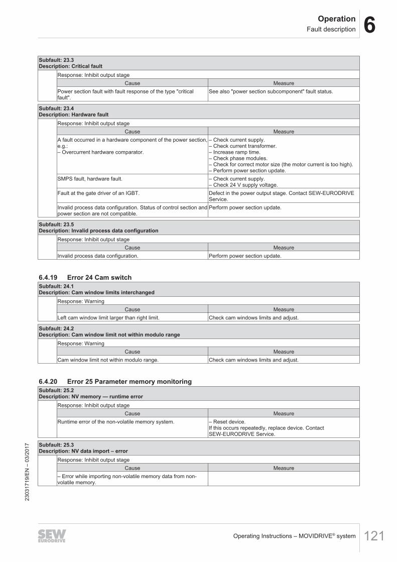
6OperationFault description
Operating Instructions – MOVIDRIVE® system 121
Subfault: 23.3Description: Critical fault
Response: Inhibit output stageCause Measure
Power section fault with fault response of the type "criticalfault".
See also "power section subcomponent" fault status.
Subfault: 23.4Description: Hardware fault
Response: Inhibit output stageCause Measure
A fault occurred in a hardware component of the power section,e.g.:– Overcurrent hardware comparator.
– Check current supply.– Check current transformer.– Increase ramp time.– Check phase modules.– Check for correct motor size (the motor current is too high).– Perform power section update.
SMPS fault, hardware fault. – Check current supply.– Check 24 V supply voltage.
Fault at the gate driver of an IGBT. Defect in the power output stage. Contact SEW‑EURODRIVEService.
Invalid process data configuration. Status of control section andpower section are not compatible.
Perform power section update.
Subfault: 23.5Description: Invalid process data configuration
Response: Inhibit output stageCause Measure
Invalid process data configuration. Perform power section update.
6.4.19 Error 24 Cam switchSubfault: 24.1Description: Cam window limits interchanged
Response: WarningCause Measure
Left cam window limit larger than right limit. Check cam windows limits and adjust.
Subfault: 24.2Description: Cam window limit not within modulo range
Response: WarningCause Measure
Cam window limit not within modulo range. Check cam windows limits and adjust.
6.4.20 Error 25 Parameter memory monitoringSubfault: 25.2Description: NV memory — runtime error
Response: Inhibit output stageCause Measure
Runtime error of the non-volatile memory system. – Reset device.If this occurs repeatedly, replace device. ContactSEW‑EURODRIVE Service.
Subfault: 25.3Description: NV data import – error
Response: Inhibit output stageCause Measure
– Error while importing non-volatile memory data from non-volatile memory.
2303
1719
/EN
– 0
3/20
17
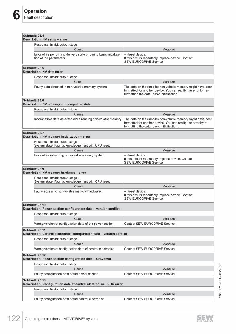
6 OperationFault description
Operating Instructions – MOVIDRIVE® system122
Subfault: 25.4Description: NV setup – error
Response: Inhibit output stageCause Measure
Error while performing delivery state or during basic initializa-tion of the parameters.
– Reset device.If this occurs repeatedly, replace device. ContactSEW‑EURODRIVE Service.
Subfault: 25.5Description: NV data error
Response: Inhibit output stageCause Measure
Faulty data detected in non-volatile memory system. The data on the (mobile) non-volatile memory might have beenformatted for another device. You can rectify the error by re-formatting the data (basic initialization).
Subfault: 25.6Description: NV memory – incompatible data
Response: Inhibit output stageCause Measure
Incompatible data detected while reading non-volatile memory. The data on the (mobile) non-volatile memory might have beenformatted for another device. You can rectify the error by re-formatting the data (basic initialization).
Subfault: 25.7Description: NV memory initialization – error
Response: Inhibit output stageSystem state: Fault acknowledgement with CPU reset
Cause MeasureError while initializing non-volatile memory system. – Reset device.
If this occurs repeatedly, replace device. ContactSEW‑EURODRIVE Service.
Subfault: 25.9Description: NV memory hardware – error
Response: Inhibit output stageSystem state: Fault acknowledgement with CPU reset
Cause MeasureFaulty access to non-volatile memory hardware. – Reset device.
If this occurs repeatedly, replace device. ContactSEW‑EURODRIVE Service.
Subfault: 25.10Description: Power section configuration data – version conflict
Response: Inhibit output stageCause Measure
Wrong version of configuration data of the power section. Contact SEW‑EURODRIVE Service.
Subfault: 25.11Description: Control electronics configuration data – version conflict
Response: Inhibit output stageCause Measure
Wrong version of configuration data of control electronics. Contact SEW‑EURODRIVE Service.
Subfault: 25.12Description: Power section configuration data – CRC error
Response: Inhibit output stageCause Measure
Faulty configuration data of the power section. Contact SEW‑EURODRIVE Service.
Subfault: 25.13Description: Configuration data of control electronics – CRC error
Response: Inhibit output stageCause Measure
Faulty configuration data of the control electronics. Contact SEW‑EURODRIVE Service.
2303
1719
/EN
– 0
3/20
17
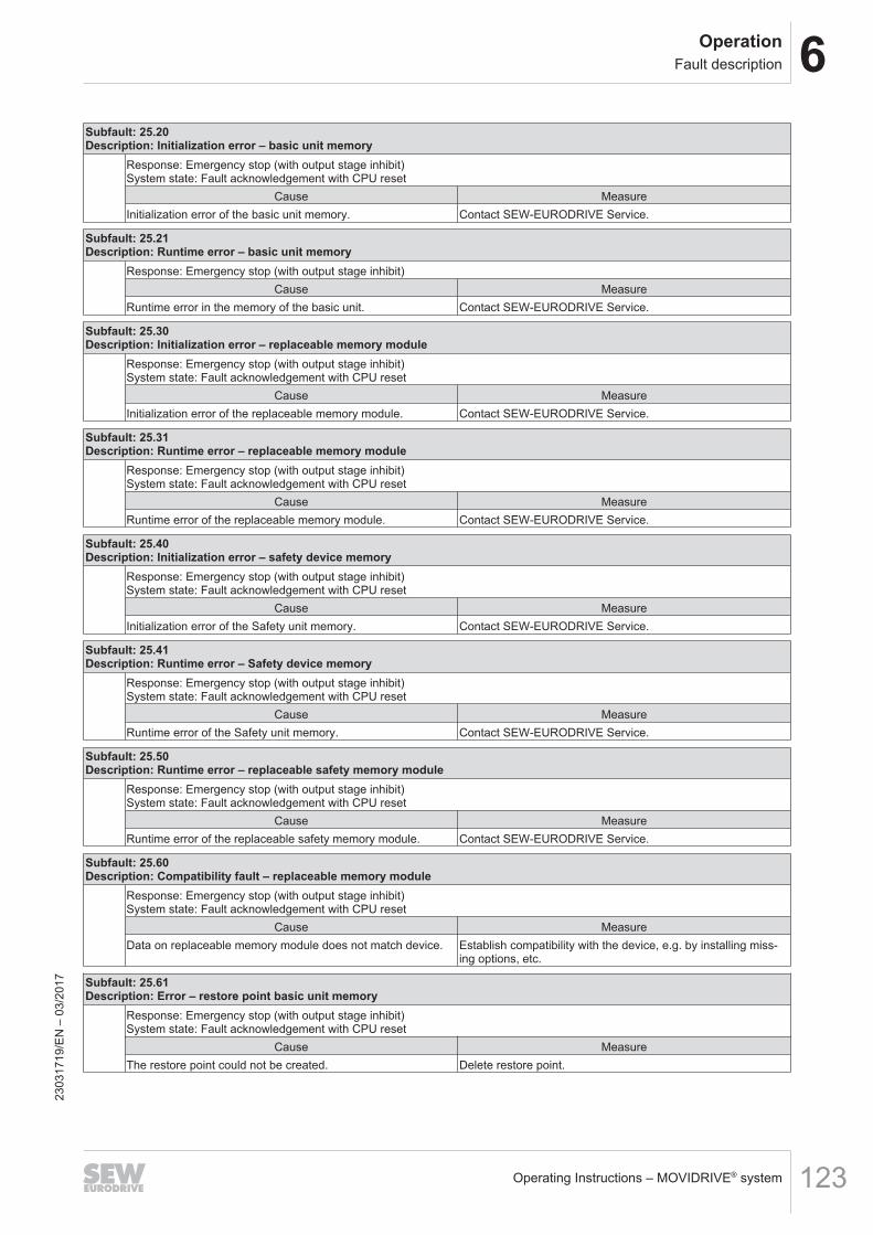
6OperationFault description
Operating Instructions – MOVIDRIVE® system 123
Subfault: 25.20Description: Initialization error – basic unit memory
Response: Emergency stop (with output stage inhibit)System state: Fault acknowledgement with CPU reset
Cause MeasureInitialization error of the basic unit memory. Contact SEW‑EURODRIVE Service.
Subfault: 25.21Description: Runtime error – basic unit memory
Response: Emergency stop (with output stage inhibit)Cause Measure
Runtime error in the memory of the basic unit. Contact SEW‑EURODRIVE Service.
Subfault: 25.30Description: Initialization error – replaceable memory module
Response: Emergency stop (with output stage inhibit)System state: Fault acknowledgement with CPU reset
Cause MeasureInitialization error of the replaceable memory module. Contact SEW‑EURODRIVE Service.
Subfault: 25.31Description: Runtime error – replaceable memory module
Response: Emergency stop (with output stage inhibit)System state: Fault acknowledgement with CPU reset
Cause MeasureRuntime error of the replaceable memory module. Contact SEW‑EURODRIVE Service.
Subfault: 25.40Description: Initialization error – safety device memory
Response: Emergency stop (with output stage inhibit)System state: Fault acknowledgement with CPU reset
Cause MeasureInitialization error of the Safety unit memory. Contact SEW‑EURODRIVE Service.
Subfault: 25.41Description: Runtime error – Safety device memory
Response: Emergency stop (with output stage inhibit)System state: Fault acknowledgement with CPU reset
Cause MeasureRuntime error of the Safety unit memory. Contact SEW‑EURODRIVE Service.
Subfault: 25.50Description: Runtime error – replaceable safety memory module
Response: Emergency stop (with output stage inhibit)System state: Fault acknowledgement with CPU reset
Cause MeasureRuntime error of the replaceable safety memory module. Contact SEW‑EURODRIVE Service.
Subfault: 25.60Description: Compatibility fault – replaceable memory module
Response: Emergency stop (with output stage inhibit)System state: Fault acknowledgement with CPU reset
Cause MeasureData on replaceable memory module does not match device. Establish compatibility with the device, e.g. by installing miss-
ing options, etc.
Subfault: 25.61Description: Error – restore point basic unit memory
Response: Emergency stop (with output stage inhibit)System state: Fault acknowledgement with CPU reset
Cause MeasureThe restore point could not be created. Delete restore point.
2303
1719
/EN
– 0
3/20
17
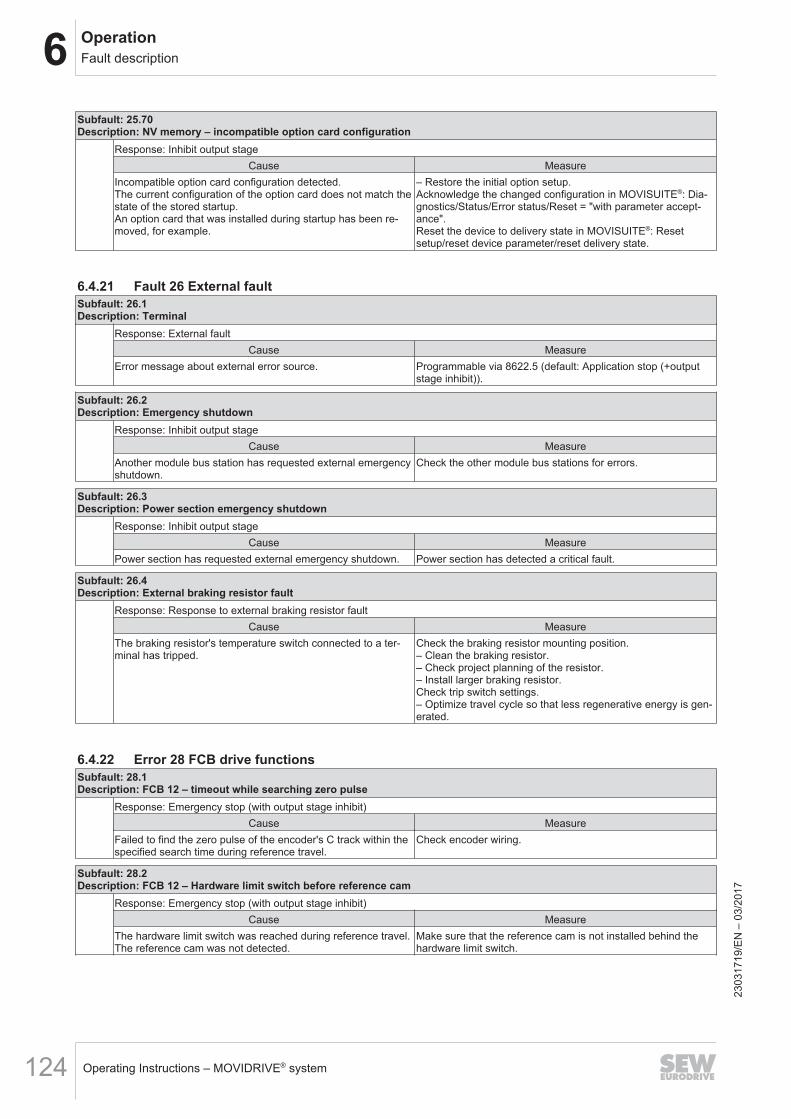
6 OperationFault description
Operating Instructions – MOVIDRIVE® system124
Subfault: 25.70Description: NV memory – incompatible option card configuration
Response: Inhibit output stageCause Measure
Incompatible option card configuration detected.The current configuration of the option card does not match thestate of the stored startup.An option card that was installed during startup has been re-moved, for example.
– Restore the initial option setup.Acknowledge the changed configuration in MOVISUITE®: Dia-gnostics/Status/Error status/Reset = "with parameter accept-ance".Reset the device to delivery state in MOVISUITE®: Resetsetup/reset device parameter/reset delivery state.
6.4.21 Fault 26 External faultSubfault: 26.1Description: Terminal
Response: External faultCause Measure
Error message about external error source. Programmable via 8622.5 (default: Application stop (+outputstage inhibit)).
Subfault: 26.2Description: Emergency shutdown
Response: Inhibit output stageCause Measure
Another module bus station has requested external emergencyshutdown.
Check the other module bus stations for errors.
Subfault: 26.3Description: Power section emergency shutdown
Response: Inhibit output stageCause Measure
Power section has requested external emergency shutdown. Power section has detected a critical fault.
Subfault: 26.4Description: External braking resistor fault
Response: Response to external braking resistor faultCause Measure
The braking resistor's temperature switch connected to a ter-minal has tripped.
Check the braking resistor mounting position.– Clean the braking resistor.– Check project planning of the resistor.– Install larger braking resistor.Check trip switch settings.– Optimize travel cycle so that less regenerative energy is gen-erated.
6.4.22 Error 28 FCB drive functionsSubfault: 28.1Description: FCB 12 – timeout while searching zero pulse
Response: Emergency stop (with output stage inhibit)Cause Measure
Failed to find the zero pulse of the encoder's C track within thespecified search time during reference travel.
Check encoder wiring.
Subfault: 28.2Description: FCB 12 – Hardware limit switch before reference cam
Response: Emergency stop (with output stage inhibit)Cause Measure
The hardware limit switch was reached during reference travel.The reference cam was not detected.
Make sure that the reference cam is not installed behind thehardware limit switch.
2303
1719
/EN
– 0
3/20
17
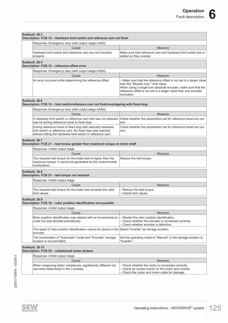
6OperationFault description
Operating Instructions – MOVIDRIVE® system 125
Subfault: 28.3Description: FCB 12 – Hardware limit switch and reference cam not flush
Response: Emergency stop (with output stage inhibit)Cause Measure
Hardware limit switch and reference cam are not mountedproperly.
Make sure that reference cam and hardware limit switch are in-stalled so they overlap.
Subfault: 28.4Description: FCB 12 – reference offset error
Response: Emergency stop (with output stage inhibit)Cause Measure
An error occurred while determining the reference offset. – Make sure that the reference offset is not set to a larger valuethan the "Modulo max." limit value.When using a single-turn absolute encoder, make sure that thereference offset is not set to a larger value than one encoderrevolution.
Subfault: 28.6Description: FCB 12 – limit switch/reference cam not flush/overlapping with fixed stop
Response: Emergency stop (with output stage inhibit)Cause Measure
A hardware limit switch or reference cam that was not selectedwas hit during reference travel to fixed stop.
Check whether the parameters set for reference travel are cor-rect.
During reference travel to fixed stop with selected hardwarelimit switch or reference cam, the fixed stop was reachedwithout hitting the hardware limit switch or reference cam.
Check whether the parameters set for reference travel are cor-rect.
Subfault: 28.7Description: FCB 21 – test torque greater than maximum torque at motor shaft
Response: Inhibit output stageCause Measure
The required test torque for the brake test is higher than themaximum torque. It cannot be generated by the motor/invertercombination.
Reduce the test torque.
Subfault: 28.8Description: FCB 21 – test torque not reached
Response: Inhibit output stageCause Measure
The required test torque for the brake test exceeds the validlimit values.
– Reduce the test torque.– Check limit values.
Subfault: 28.9Description: FCB 18 – rotor position identification not possible
Response: Inhibit output stageCause Measure
Rotor position identification was started with an incremental en-coder but was aborted prematurely.
– Restart the rotor position identification.– Check whether the encoder is connected correctly.– Check whether encoder is defective.
The result of rotor position identification cannot be stored in theencoder.
Select "inverter" as storage location.
The combination of "Automatic" mode and "Encoder" storagelocation is not permitted.
Set the operating mode to "Manual" or the storage location to"Inverter".
Subfault: 28.10Description: FCB 25 – unbalanced motor phases
Response: Inhibit output stageCause Measure
When measuring stator resistances, significantly different val-ues were determined in the 3 phases.
– Check whether the motor is connected correctly.– Check all contact points on the motor and inverter.– Check the motor and motor cable for damage.
2303
1719
/EN
– 0
3/20
17
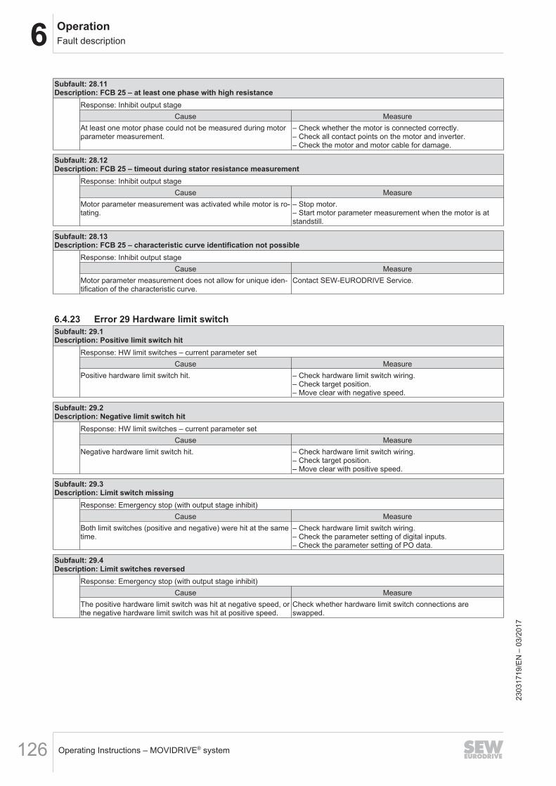
6 OperationFault description
Operating Instructions – MOVIDRIVE® system126
Subfault: 28.11Description: FCB 25 – at least one phase with high resistance
Response: Inhibit output stageCause Measure
At least one motor phase could not be measured during motorparameter measurement.
– Check whether the motor is connected correctly.– Check all contact points on the motor and inverter.– Check the motor and motor cable for damage.
Subfault: 28.12Description: FCB 25 – timeout during stator resistance measurement
Response: Inhibit output stageCause Measure
Motor parameter measurement was activated while motor is ro-tating.
– Stop motor.– Start motor parameter measurement when the motor is atstandstill.
Subfault: 28.13Description: FCB 25 – characteristic curve identification not possible
Response: Inhibit output stageCause Measure
Motor parameter measurement does not allow for unique iden-tification of the characteristic curve.
Contact SEW‑EURODRIVE Service.
6.4.23 Error 29 Hardware limit switchSubfault: 29.1Description: Positive limit switch hit
Response: HW limit switches – current parameter setCause Measure
Positive hardware limit switch hit. – Check hardware limit switch wiring.– Check target position.– Move clear with negative speed.
Subfault: 29.2Description: Negative limit switch hit
Response: HW limit switches – current parameter setCause Measure
Negative hardware limit switch hit. – Check hardware limit switch wiring.– Check target position.– Move clear with positive speed.
Subfault: 29.3Description: Limit switch missing
Response: Emergency stop (with output stage inhibit)Cause Measure
Both limit switches (positive and negative) were hit at the sametime.
– Check hardware limit switch wiring.– Check the parameter setting of digital inputs.– Check the parameter setting of PO data.
Subfault: 29.4Description: Limit switches reversed
Response: Emergency stop (with output stage inhibit)Cause Measure
The positive hardware limit switch was hit at negative speed, orthe negative hardware limit switch was hit at positive speed.
Check whether hardware limit switch connections areswapped.
2303
1719
/EN
– 0
3/20
17
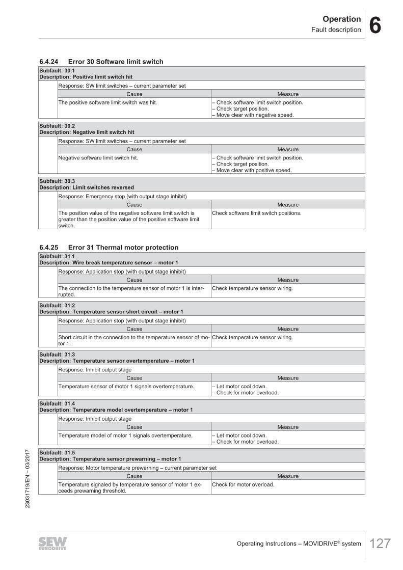
6OperationFault description
Operating Instructions – MOVIDRIVE® system 127
6.4.24 Error 30 Software limit switchSubfault: 30.1Description: Positive limit switch hit
Response: SW limit switches – current parameter setCause Measure
The positive software limit switch was hit. – Check software limit switch position.– Check target position.– Move clear with negative speed.
Subfault: 30.2Description: Negative limit switch hit
Response: SW limit switches – current parameter setCause Measure
Negative software limit switch hit. – Check software limit switch position.– Check target position.– Move clear with positive speed.
Subfault: 30.3Description: Limit switches reversed
Response: Emergency stop (with output stage inhibit)Cause Measure
The position value of the negative software limit switch isgreater than the position value of the positive software limitswitch.
Check software limit switch positions.
6.4.25 Error 31 Thermal motor protectionSubfault: 31.1Description: Wire break temperature sensor – motor 1
Response: Application stop (with output stage inhibit)Cause Measure
The connection to the temperature sensor of motor 1 is inter-rupted.
Check temperature sensor wiring.
Subfault: 31.2Description: Temperature sensor short circuit – motor 1
Response: Application stop (with output stage inhibit)Cause Measure
Short circuit in the connection to the temperature sensor of mo-tor 1.
Check temperature sensor wiring.
Subfault: 31.3Description: Temperature sensor overtemperature – motor 1
Response: Inhibit output stageCause Measure
Temperature sensor of motor 1 signals overtemperature. – Let motor cool down.– Check for motor overload.
Subfault: 31.4Description: Temperature model overtemperature – motor 1
Response: Inhibit output stageCause Measure
Temperature model of motor 1 signals overtemperature. – Let motor cool down.– Check for motor overload.
Subfault: 31.5Description: Temperature sensor prewarning – motor 1
Response: Motor temperature prewarning – current parameter setCause Measure
Temperature signaled by temperature sensor of motor 1 ex-ceeds prewarning threshold.
Check for motor overload.
2303
1719
/EN
– 0
3/20
17
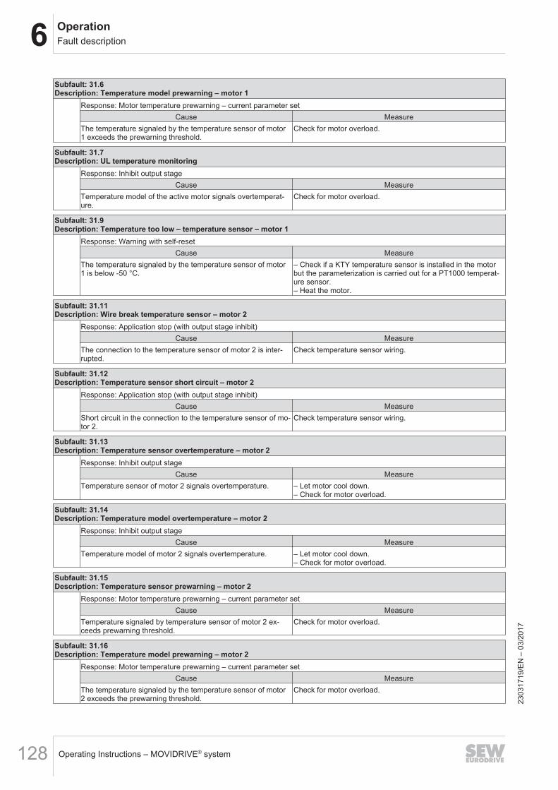
6 OperationFault description
Operating Instructions – MOVIDRIVE® system128
Subfault: 31.6Description: Temperature model prewarning – motor 1
Response: Motor temperature prewarning – current parameter setCause Measure
The temperature signaled by the temperature sensor of motor1 exceeds the prewarning threshold.
Check for motor overload.
Subfault: 31.7Description: UL temperature monitoring
Response: Inhibit output stageCause Measure
Temperature model of the active motor signals overtemperat-ure.
Check for motor overload.
Subfault: 31.9Description: Temperature too low – temperature sensor – motor 1
Response: Warning with self-resetCause Measure
The temperature signaled by the temperature sensor of motor1 is below -50 °C.
– Check if a KTY temperature sensor is installed in the motorbut the parameterization is carried out for a PT1000 temperat-ure sensor.– Heat the motor.
Subfault: 31.11Description: Wire break temperature sensor – motor 2
Response: Application stop (with output stage inhibit)Cause Measure
The connection to the temperature sensor of motor 2 is inter-rupted.
Check temperature sensor wiring.
Subfault: 31.12Description: Temperature sensor short circuit – motor 2
Response: Application stop (with output stage inhibit)Cause Measure
Short circuit in the connection to the temperature sensor of mo-tor 2.
Check temperature sensor wiring.
Subfault: 31.13Description: Temperature sensor overtemperature – motor 2
Response: Inhibit output stageCause Measure
Temperature sensor of motor 2 signals overtemperature. – Let motor cool down.– Check for motor overload.
Subfault: 31.14Description: Temperature model overtemperature – motor 2
Response: Inhibit output stageCause Measure
Temperature model of motor 2 signals overtemperature. – Let motor cool down.– Check for motor overload.
Subfault: 31.15Description: Temperature sensor prewarning – motor 2
Response: Motor temperature prewarning – current parameter setCause Measure
Temperature signaled by temperature sensor of motor 2 ex-ceeds prewarning threshold.
Check for motor overload.
Subfault: 31.16Description: Temperature model prewarning – motor 2
Response: Motor temperature prewarning – current parameter setCause Measure
The temperature signaled by the temperature sensor of motor2 exceeds the prewarning threshold.
Check for motor overload.
2303
1719
/EN
– 0
3/20
17
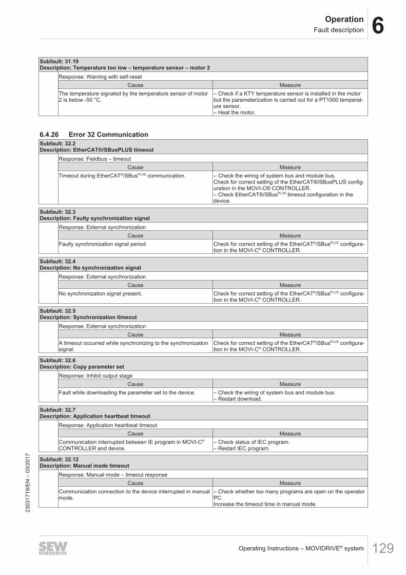
6OperationFault description
Operating Instructions – MOVIDRIVE® system 129
Subfault: 31.19Description: Temperature too low – temperature sensor – motor 2
Response: Warning with self-resetCause Measure
The temperature signaled by the temperature sensor of motor2 is below -50 °C.
– Check if a KTY temperature sensor is installed in the motorbut the parameterization is carried out for a PT1000 temperat-ure sensor.– Heat the motor.
6.4.26 Error 32 CommunicationSubfault: 32.2Description: EtherCAT®/SBusPLUS timeout
Response: Fieldbus – timeoutCause Measure
Timeout during EtherCAT®/SBusPLUS communication. – Check the wiring of system bus and module bus.Check for correct setting of the EtherCAT®/SBusPLUS config-uration in the MOVI-C® CONTROLLER.– Check EtherCAT®/SBusPLUS timeout configuration in thedevice.
Subfault: 32.3Description: Faulty synchronization signal
Response: External synchronizationCause Measure
Faulty synchronization signal period. Check for correct setting of the EtherCAT®/SBusPLUS configura-tion in the MOVI-C® CONTROLLER.
Subfault: 32.4Description: No synchronization signal
Response: External synchronizationCause Measure
No synchronization signal present. Check for correct setting of the EtherCAT®/SBusPLUS configura-tion in the MOVI-C® CONTROLLER.
Subfault: 32.5Description: Synchronization timeout
Response: External synchronizationCause Measure
A timeout occurred while synchronizing to the synchronizationsignal.
Check for correct setting of the EtherCAT®/SBusPLUS configura-tion in the MOVI-C® CONTROLLER.
Subfault: 32.6Description: Copy parameter set
Response: Inhibit output stageCause Measure
Fault while downloading the parameter set to the device. – Check the wiring of system bus and module bus.– Restart download.
Subfault: 32.7Description: Application heartbeat timeout
Response: Application heartbeat timeoutCause Measure
Communication interrupted between IE program in MOVI-C®
CONTROLLER and device.– Check status of IEC program.– Restart IEC program.
Subfault: 32.12Description: Manual mode timeout
Response: Manual mode – timeout responseCause Measure
Communication connection to the device interrupted in manualmode.
– Check whether too many programs are open on the operatorPC.Increase the timeout time in manual mode.
2303
1719
/EN
– 0
3/20
17
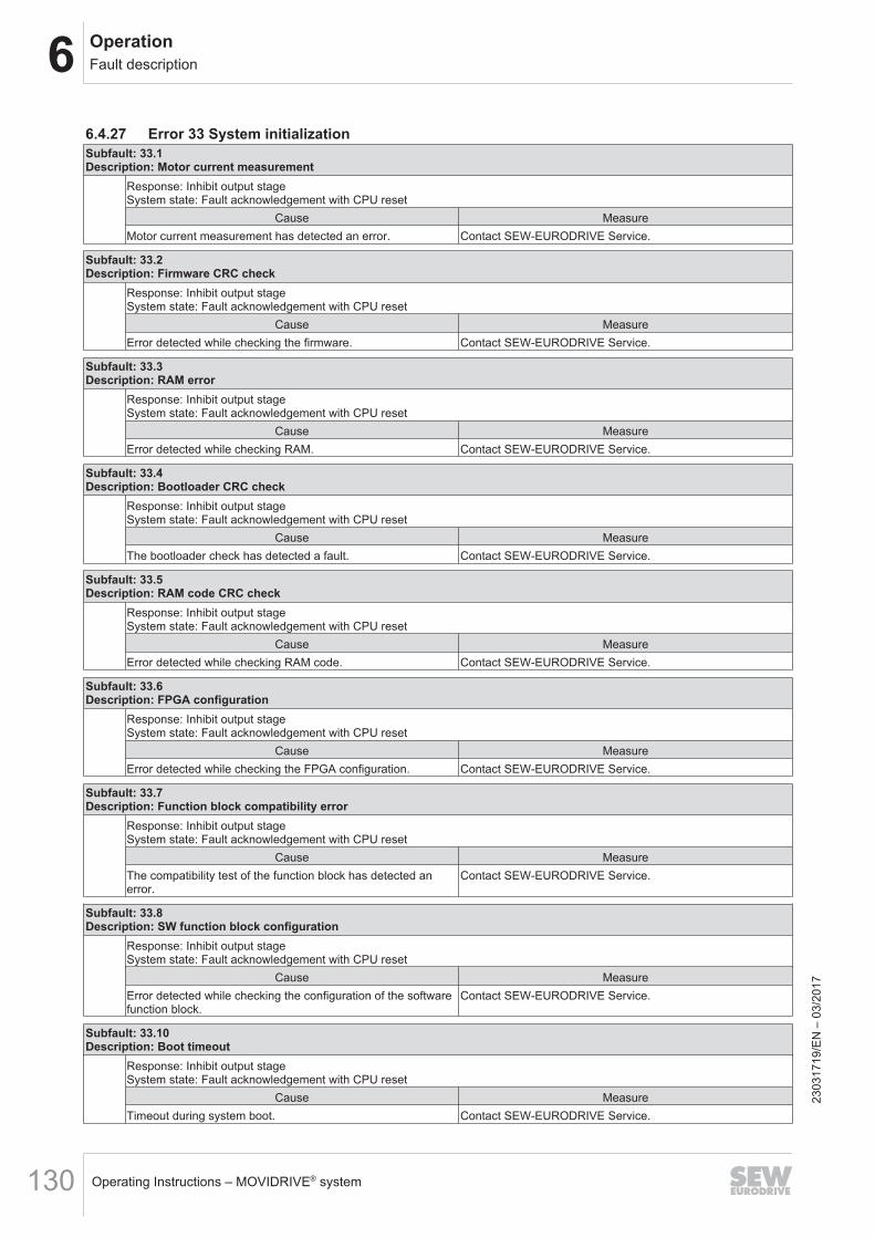
6 OperationFault description
Operating Instructions – MOVIDRIVE® system130
6.4.27 Error 33 System initializationSubfault: 33.1Description: Motor current measurement
Response: Inhibit output stageSystem state: Fault acknowledgement with CPU reset
Cause MeasureMotor current measurement has detected an error. Contact SEW‑EURODRIVE Service.
Subfault: 33.2Description: Firmware CRC check
Response: Inhibit output stageSystem state: Fault acknowledgement with CPU reset
Cause MeasureError detected while checking the firmware. Contact SEW‑EURODRIVE Service.
Subfault: 33.3Description: RAM error
Response: Inhibit output stageSystem state: Fault acknowledgement with CPU reset
Cause MeasureError detected while checking RAM. Contact SEW‑EURODRIVE Service.
Subfault: 33.4Description: Bootloader CRC check
Response: Inhibit output stageSystem state: Fault acknowledgement with CPU reset
Cause MeasureThe bootloader check has detected a fault. Contact SEW‑EURODRIVE Service.
Subfault: 33.5Description: RAM code CRC check
Response: Inhibit output stageSystem state: Fault acknowledgement with CPU reset
Cause MeasureError detected while checking RAM code. Contact SEW‑EURODRIVE Service.
Subfault: 33.6Description: FPGA configuration
Response: Inhibit output stageSystem state: Fault acknowledgement with CPU reset
Cause MeasureError detected while checking the FPGA configuration. Contact SEW‑EURODRIVE Service.
Subfault: 33.7Description: Function block compatibility error
Response: Inhibit output stageSystem state: Fault acknowledgement with CPU reset
Cause MeasureThe compatibility test of the function block has detected anerror.
Contact SEW‑EURODRIVE Service.
Subfault: 33.8Description: SW function block configuration
Response: Inhibit output stageSystem state: Fault acknowledgement with CPU reset
Cause MeasureError detected while checking the configuration of the softwarefunction block.
Contact SEW‑EURODRIVE Service.
Subfault: 33.10Description: Boot timeout
Response: Inhibit output stageSystem state: Fault acknowledgement with CPU reset
Cause MeasureTimeout during system boot. Contact SEW‑EURODRIVE Service.
2303
1719
/EN
– 0
3/20
17
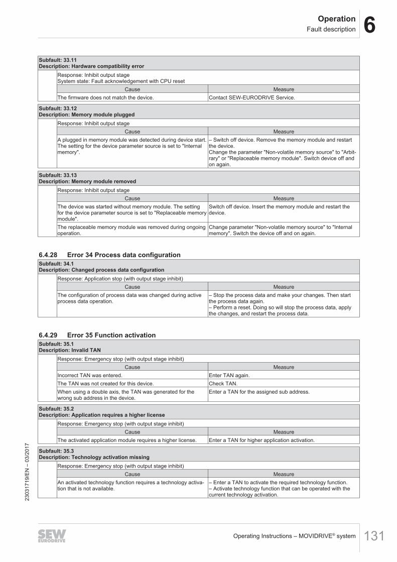
6OperationFault description
Operating Instructions – MOVIDRIVE® system 131
Subfault: 33.11Description: Hardware compatibility error
Response: Inhibit output stageSystem state: Fault acknowledgement with CPU reset
Cause MeasureThe firmware does not match the device. Contact SEW‑EURODRIVE Service.
Subfault: 33.12Description: Memory module plugged
Response: Inhibit output stageCause Measure
A plugged in memory module was detected during device start.The setting for the device parameter source is set to "Internalmemory".
– Switch off device. Remove the memory module and restartthe device.Change the parameter "Non-volatile memory source" to "Arbit-rary" or "Replaceable memory module". Switch device off andon again.
Subfault: 33.13Description: Memory module removed
Response: Inhibit output stageCause Measure
The device was started without memory module. The settingfor the device parameter source is set to "Replaceable memorymodule".
Switch off device. Insert the memory module and restart thedevice.
The replaceable memory module was removed during ongoingoperation.
Change parameter "Non-volatile memory source" to "Internalmemory". Switch the device off and on again.
6.4.28 Error 34 Process data configurationSubfault: 34.1Description: Changed process data configuration
Response: Application stop (with output stage inhibit)Cause Measure
The configuration of process data was changed during activeprocess data operation.
– Stop the process data and make your changes. Then startthe process data again.– Perform a reset. Doing so will stop the process data, applythe changes, and restart the process data.
6.4.29 Error 35 Function activationSubfault: 35.1Description: Invalid TAN
Response: Emergency stop (with output stage inhibit)Cause Measure
Incorrect TAN was entered. Enter TAN again.The TAN was not created for this device. Check TAN.When using a double axis, the TAN was generated for thewrong sub address in the device.
Enter a TAN for the assigned sub address.
Subfault: 35.2Description: Application requires a higher license
Response: Emergency stop (with output stage inhibit)Cause Measure
The activated application module requires a higher license. Enter a TAN for higher application activation.
Subfault: 35.3Description: Technology activation missing
Response: Emergency stop (with output stage inhibit)Cause Measure
An activated technology function requires a technology activa-tion that is not available.
– Enter a TAN to activate the required technology function.– Activate technology function that can be operated with thecurrent technology activation.
2303
1719
/EN
– 0
3/20
17
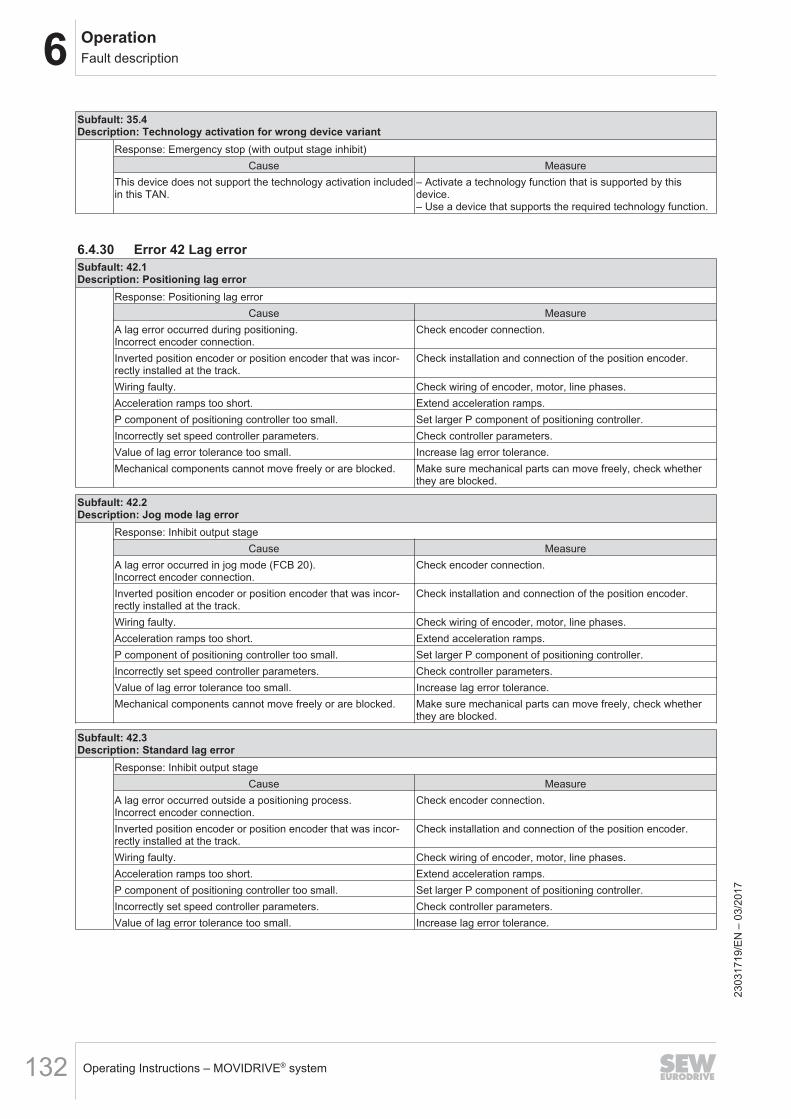
6 OperationFault description
Operating Instructions – MOVIDRIVE® system132
Subfault: 35.4Description: Technology activation for wrong device variant
Response: Emergency stop (with output stage inhibit)Cause Measure
This device does not support the technology activation includedin this TAN.
– Activate a technology function that is supported by thisdevice.– Use a device that supports the required technology function.
6.4.30 Error 42 Lag errorSubfault: 42.1Description: Positioning lag error
Response: Positioning lag errorCause Measure
A lag error occurred during positioning.Incorrect encoder connection.
Check encoder connection.
Inverted position encoder or position encoder that was incor-rectly installed at the track.
Check installation and connection of the position encoder.
Wiring faulty. Check wiring of encoder, motor, line phases.Acceleration ramps too short. Extend acceleration ramps.P component of positioning controller too small. Set larger P component of positioning controller.Incorrectly set speed controller parameters. Check controller parameters.Value of lag error tolerance too small. Increase lag error tolerance.Mechanical components cannot move freely or are blocked. Make sure mechanical parts can move freely, check whether
they are blocked.
Subfault: 42.2Description: Jog mode lag error
Response: Inhibit output stageCause Measure
A lag error occurred in jog mode (FCB 20).Incorrect encoder connection.
Check encoder connection.
Inverted position encoder or position encoder that was incor-rectly installed at the track.
Check installation and connection of the position encoder.
Wiring faulty. Check wiring of encoder, motor, line phases.Acceleration ramps too short. Extend acceleration ramps.P component of positioning controller too small. Set larger P component of positioning controller.Incorrectly set speed controller parameters. Check controller parameters.Value of lag error tolerance too small. Increase lag error tolerance.Mechanical components cannot move freely or are blocked. Make sure mechanical parts can move freely, check whether
they are blocked.
Subfault: 42.3Description: Standard lag error
Response: Inhibit output stageCause Measure
A lag error occurred outside a positioning process.Incorrect encoder connection.
Check encoder connection.
Inverted position encoder or position encoder that was incor-rectly installed at the track.
Check installation and connection of the position encoder.
Wiring faulty. Check wiring of encoder, motor, line phases.Acceleration ramps too short. Extend acceleration ramps.P component of positioning controller too small. Set larger P component of positioning controller.Incorrectly set speed controller parameters. Check controller parameters.Value of lag error tolerance too small. Increase lag error tolerance.
2303
1719
/EN
– 0
3/20
17
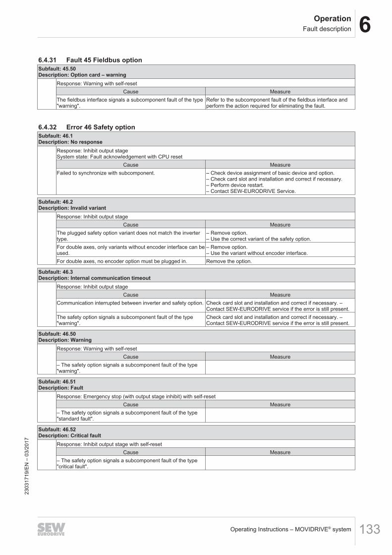
6OperationFault description
Operating Instructions – MOVIDRIVE® system 133
6.4.31 Fault 45 Fieldbus optionSubfault: 45.50Description: Option card – warning
Response: Warning with self-resetCause Measure
The fieldbus interface signals a subcomponent fault of the type"warning".
Refer to the subcomponent fault of the fieldbus interface andperform the action required for eliminating the fault.
6.4.32 Error 46 Safety optionSubfault: 46.1Description: No response
Response: Inhibit output stageSystem state: Fault acknowledgement with CPU reset
Cause MeasureFailed to synchronize with subcomponent. – Check device assignment of basic device and option.
– Check card slot and installation and correct if necessary.– Perform device restart.– Contact SEW‑EURODRIVE Service.
Subfault: 46.2Description: Invalid variant
Response: Inhibit output stageCause Measure
The plugged safety option variant does not match the invertertype.
– Remove option.– Use the correct variant of the safety option.
For double axes, only variants without encoder interface can beused.
– Remove option.– Use the variant without encoder interface.
For double axes, no encoder option must be plugged in. Remove the option.
Subfault: 46.3Description: Internal communication timeout
Response: Inhibit output stageCause Measure
Communication interrupted between inverter and safety option. Check card slot and installation and correct if necessary. –Contact SEW‑EURODRIVE service if the error is still present.
The safety option signals a subcomponent fault of the type"warning".
Check card slot and installation and correct if necessary. –Contact SEW‑EURODRIVE service if the error is still present.
Subfault: 46.50Description: Warning
Response: Warning with self-resetCause Measure
– The safety option signals a subcomponent fault of the type"warning".
Subfault: 46.51Description: Fault
Response: Emergency stop (with output stage inhibit) with self-resetCause Measure
– The safety option signals a subcomponent fault of the type"standard fault".
Subfault: 46.52Description: Critical fault
Response: Inhibit output stage with self-resetCause Measure
– The safety option signals a subcomponent fault of the type"critical fault".
2303
1719
/EN
– 0
3/20
17
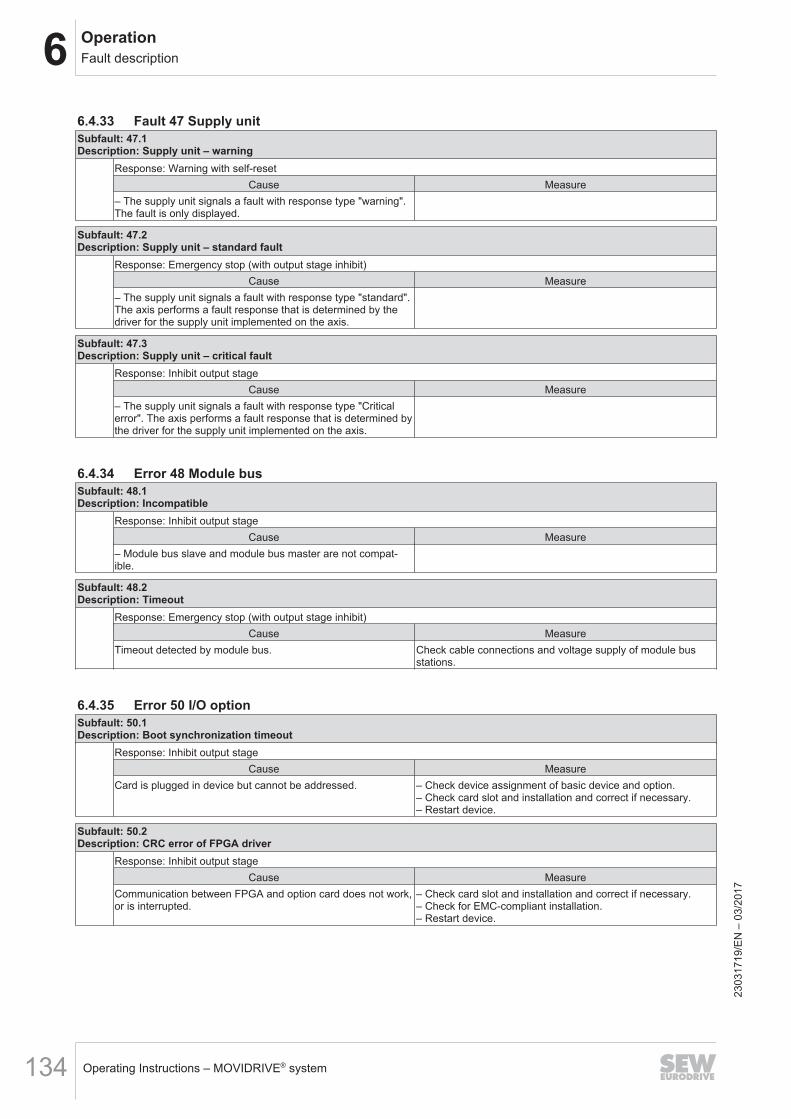
6 OperationFault description
Operating Instructions – MOVIDRIVE® system134
6.4.33 Fault 47 Supply unitSubfault: 47.1Description: Supply unit – warning
Response: Warning with self-resetCause Measure
– The supply unit signals a fault with response type "warning".The fault is only displayed.
Subfault: 47.2Description: Supply unit – standard fault
Response: Emergency stop (with output stage inhibit)Cause Measure
– The supply unit signals a fault with response type "standard".The axis performs a fault response that is determined by thedriver for the supply unit implemented on the axis.
Subfault: 47.3Description: Supply unit – critical fault
Response: Inhibit output stageCause Measure
– The supply unit signals a fault with response type "Criticalerror". The axis performs a fault response that is determined bythe driver for the supply unit implemented on the axis.
6.4.34 Error 48 Module busSubfault: 48.1Description: Incompatible
Response: Inhibit output stageCause Measure
– Module bus slave and module bus master are not compat-ible.
Subfault: 48.2Description: Timeout
Response: Emergency stop (with output stage inhibit)Cause Measure
Timeout detected by module bus. Check cable connections and voltage supply of module busstations.
6.4.35 Error 50 I/O optionSubfault: 50.1Description: Boot synchronization timeout
Response: Inhibit output stageCause Measure
Card is plugged in device but cannot be addressed. – Check device assignment of basic device and option.– Check card slot and installation and correct if necessary.– Restart device.
Subfault: 50.2Description: CRC error of FPGA driver
Response: Inhibit output stageCause Measure
Communication between FPGA and option card does not work,or is interrupted.
– Check card slot and installation and correct if necessary.– Check for EMC-compliant installation.– Restart device.
2303
1719
/EN
– 0
3/20
17
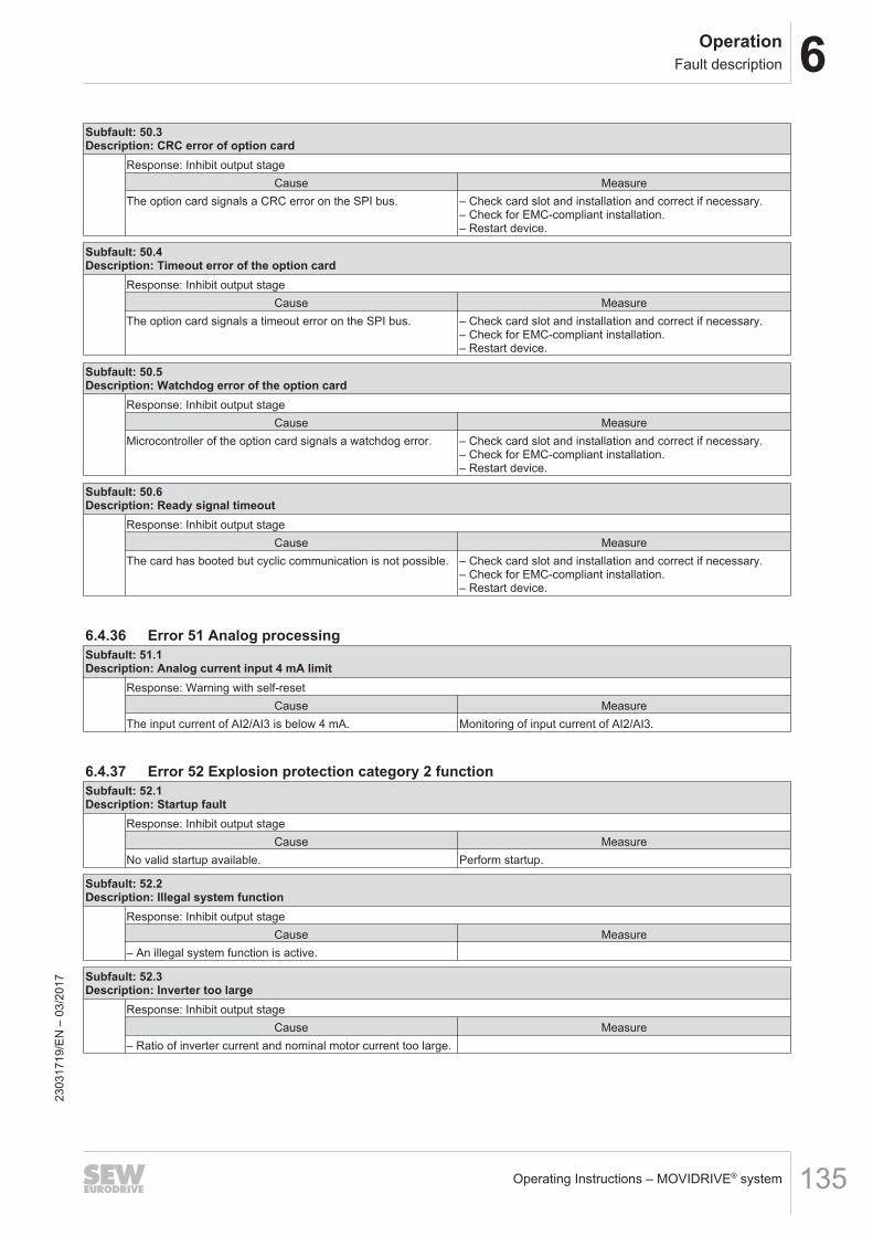
6OperationFault description
Operating Instructions – MOVIDRIVE® system 135
Subfault: 50.3Description: CRC error of option card
Response: Inhibit output stageCause Measure
The option card signals a CRC error on the SPI bus. – Check card slot and installation and correct if necessary.– Check for EMC-compliant installation.– Restart device.
Subfault: 50.4Description: Timeout error of the option card
Response: Inhibit output stageCause Measure
The option card signals a timeout error on the SPI bus. – Check card slot and installation and correct if necessary.– Check for EMC-compliant installation.– Restart device.
Subfault: 50.5Description: Watchdog error of the option card
Response: Inhibit output stageCause Measure
Microcontroller of the option card signals a watchdog error. – Check card slot and installation and correct if necessary.– Check for EMC-compliant installation.– Restart device.
Subfault: 50.6Description: Ready signal timeout
Response: Inhibit output stageCause Measure
The card has booted but cyclic communication is not possible. – Check card slot and installation and correct if necessary.– Check for EMC-compliant installation.– Restart device.
6.4.36 Error 51 Analog processingSubfault: 51.1Description: Analog current input 4 mA limit
Response: Warning with self-resetCause Measure
The input current of AI2/AI3 is below 4 mA. Monitoring of input current of AI2/AI3.
6.4.37 Error 52 Explosion protection category 2 functionSubfault: 52.1Description: Startup fault
Response: Inhibit output stageCause Measure
No valid startup available. Perform startup.
Subfault: 52.2Description: Illegal system function
Response: Inhibit output stageCause Measure
– An illegal system function is active.
Subfault: 52.3Description: Inverter too large
Response: Inhibit output stageCause Measure
– Ratio of inverter current and nominal motor current too large.
2303
1719
/EN
– 0
3/20
17
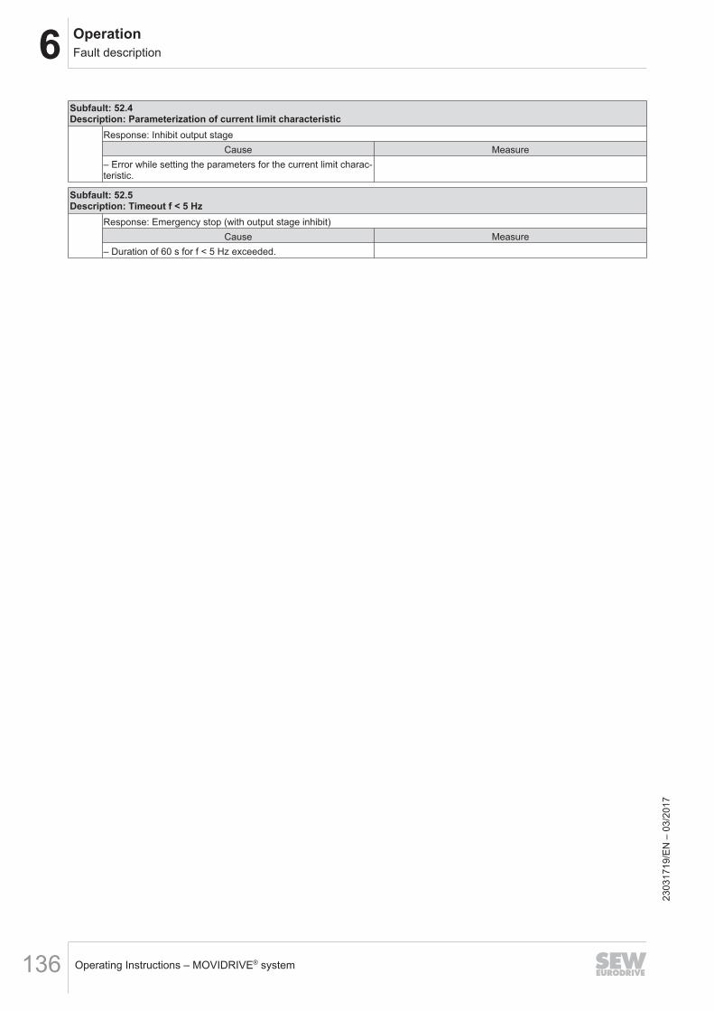
6 OperationFault description
Operating Instructions – MOVIDRIVE® system136
Subfault: 52.4Description: Parameterization of current limit characteristic
Response: Inhibit output stageCause Measure
– Error while setting the parameters for the current limit charac-teristic.
Subfault: 52.5Description: Timeout f < 5 Hz
Response: Emergency stop (with output stage inhibit)Cause Measure
– Duration of 60 s for f < 5 Hz exceeded.
2303
1719
/EN
– 0
3/20
17
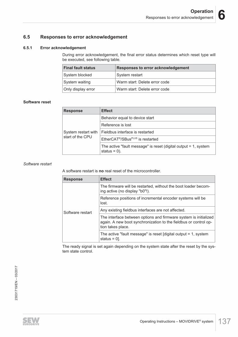
6OperationResponses to error acknowledgement
Operating Instructions – MOVIDRIVE® system 137
6.5 Responses to error acknowledgement
6.5.1 Error acknowledgementDuring error acknowledgement, the final error status determines which reset type willbe executed, see following table.
Final fault status Responses to error acknowledgementSystem blocked System restart
System waiting Warm start: Delete error code
Only display error Warm start: Delete error code
Software reset
Response Effect
System restart withstart of the CPU
Behavior equal to device start
Reference is lost
Fieldbus interface is restarted
EtherCAT®/SBusPLUS is restarted
The active "fault message" is reset (digital output = 1, systemstatus = 0).
Software restart
A software restart is no real reset of the microcontroller.
Response Effect
Software restart
The firmware will be restarted, without the boot loader becom-ing active (no display "b0"!).
Reference positions of incremental encoder systems will belost.
Any existing fieldbus interfaces are not affected.
The interface between options and firmware system is initializedagain. A new boot synchronization to the fieldbus or control op-tion takes place.
The active "fault message" is reset [digital output = 1, systemstatus = 0].
The ready signal is set again depending on the system state after the reset by the sys-tem state control.
2303
1719
/EN
– 0
3/20
17
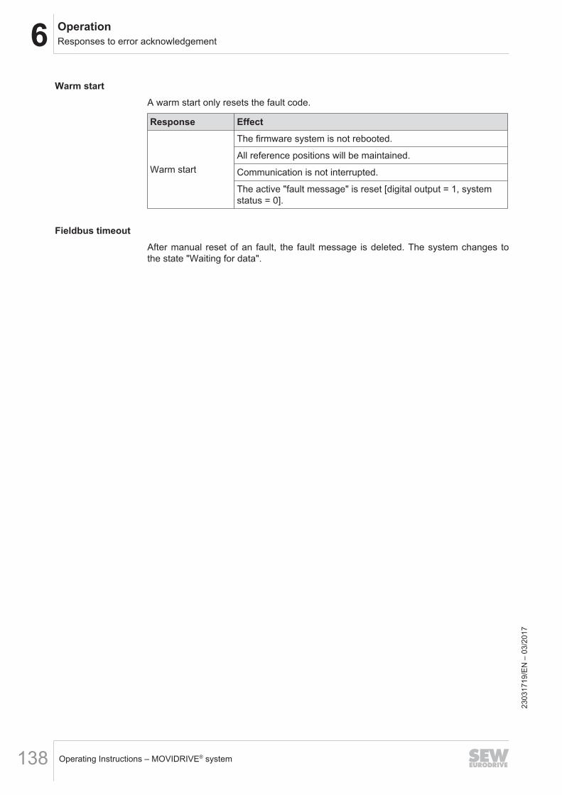
6 OperationResponses to error acknowledgement
Operating Instructions – MOVIDRIVE® system138
Warm startA warm start only resets the fault code.
Response Effect
Warm start
The firmware system is not rebooted.
All reference positions will be maintained.
Communication is not interrupted.
The active "fault message" is reset [digital output = 1, systemstatus = 0].
Fieldbus timeoutAfter manual reset of an fault, the fault message is deleted. The system changes tothe state "Waiting for data".
2303
1719
/EN
– 0
3/20
17
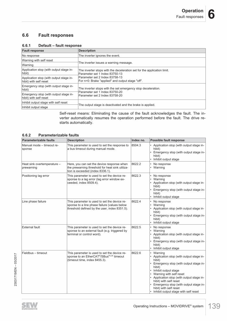
6OperationFault responses
Operating Instructions – MOVIDRIVE® system 139
6.6 Fault responses
6.6.1 Default – fault responseFault response DescriptionNo response The inverter ignores the event.Warning with self reset
The inverter issues a warning message.WarningApplication stop (with output stage in-hibit)
The inverter stops with the deceleration set for the application limit.Parameter set 1 Index 83750-13Parameter set 2 Index 83758-13For n=0: Brake "applied" and output stage "off".
Application stop (with output stage in-hibit) with self resetEmergency stop (with output stage in-hibit) The inverter stops with the set emergency stop deceleration.
Parameter set 1 Index 83750-20Parameter set 2 Index 83758-20Emergency stop (with output stage in-
hibit) with self resetInhibit output stage with self reset
The output stage is deactivated and the brake is applied.Inhibit output stage
Self-reset means: Eliminating the cause of the fault acknowledges the fault. The in-verter automatically resumes the operation performed before the fault. The drive re-starts automatically.
6.6.2 Parameterizable faultsParameterizable faults Description Index no. Possible fault responseManual mode – timeout re-sponse
This parameter is used to set the response toa bus timeout during manual mode.
8504.3 • Application stop (with output stage in-hibit)
• Emergency stop (with output stage in-hibit)
• Inhibit output stageHeat sink overtemperature –prewarning
Here, you can set the device response whenthe prewarning threshold for heat sink utiliza-tion is exceeded (index 8336.1).
8622.2 • No response• Warning
Positioning lag error This parameter is used to set the device re-sponse to a lag error (lag error window ex-ceeded, index 8509.4).
8622.3 • No response• Warning• Application stop (with output stage in-
hibit)• Emergency stop (with output stage in-
hibit)• Inhibit output stage
Line phase failure This parameter is used to set the device re-sponse to a line phase failure (values belowthreshold defined by the user, index 8351.5).
8622.4 • No response• Warning• Application stop (with output stage in-
hibit)• Emergency stop (with output stage in-
hibit)• Inhibit output stage
External fault This parameter is used to set the device re-sponse to an external fault (e.g. triggered byterminal or control word).
8622.5 • No response• Warning• Application stop (with output stage in-
hibit)• Emergency stop (with output stage in-
hibit)• Inhibit output stage
Fieldbus – timeout This parameter is used to set the device re-sponse to an EtherCAT®/SBusPLUS timeout(timeout time, index 8455.3).
8622.6 • Warning• Application stop (with output stage in-
hibit)• Emergency stop (with output stage in-
hibit)• Inhibit output stage• Warning with self reset• Application stop (with output stage in-
hibit) with self reset• Emergency stop (with output stage in-
hibit) with self reset• Inhibit output stage with self reset
2303
1719
/EN
– 0
3/20
17
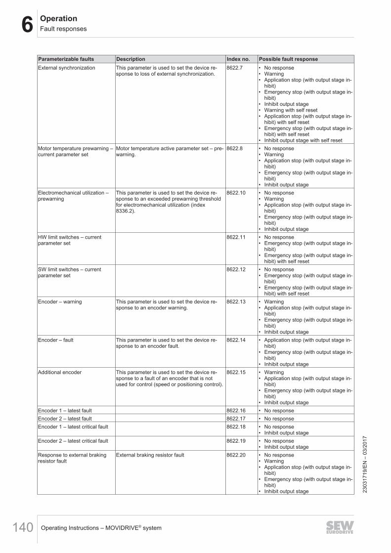
6 OperationFault responses
Operating Instructions – MOVIDRIVE® system140
Parameterizable faults Description Index no. Possible fault responseExternal synchronization This parameter is used to set the device re-
sponse to loss of external synchronization.8622.7 • No response
• Warning• Application stop (with output stage in-
hibit)• Emergency stop (with output stage in-
hibit)• Inhibit output stage• Warning with self reset• Application stop (with output stage in-
hibit) with self reset• Emergency stop (with output stage in-
hibit) with self reset• Inhibit output stage with self reset
Motor temperature prewarning –current parameter set
Motor temperature active parameter set – pre-warning.
8622.8 • No response• Warning• Application stop (with output stage in-
hibit)• Emergency stop (with output stage in-
hibit)• Inhibit output stage
Electromechanical utilization –prewarning
This parameter is used to set the device re-sponse to an exceeded prewarning thresholdfor electromechanical utilization (index8336.2).
8622.10 • No response• Warning• Application stop (with output stage in-
hibit)• Emergency stop (with output stage in-
hibit)• Inhibit output stage
HW limit switches – currentparameter set
8622.11 • No response• Emergency stop (with output stage in-
hibit)• Emergency stop (with output stage in-
hibit) with self resetSW limit switches – currentparameter set
8622.12 • No response• Emergency stop (with output stage in-
hibit)• Emergency stop (with output stage in-
hibit) with self resetEncoder – warning This parameter is used to set the device re-
sponse to an encoder warning.8622.13 • Warning
• Application stop (with output stage in-hibit)
• Emergency stop (with output stage in-hibit)
• Inhibit output stageEncoder – fault This parameter is used to set the device re-
sponse to an encoder fault.8622.14 • Application stop (with output stage in-
hibit)• Emergency stop (with output stage in-
hibit)• Inhibit output stage
Additional encoder This parameter is used to set the device re-sponse to a fault of an encoder that is notused for control (speed or positioning control).
8622.15 • Warning• Application stop (with output stage in-
hibit)• Emergency stop (with output stage in-
hibit)• Inhibit output stage
Encoder 1 – latest fault 8622.16 • No responseEncoder 2 – latest fault 8622.17 • No responseEncoder 1 – latest critical fault 8622.18 • No response
• Inhibit output stageEncoder 2 – latest critical fault 8622.19 • No response
• Inhibit output stageResponse to external brakingresistor fault
External braking resistor fault 8622.20 • No response• Warning• Application stop (with output stage in-
hibit)• Emergency stop (with output stage in-
hibit)• Inhibit output stage 23
0317
19/E
N –
03/
2017

6OperationFault responses
Operating Instructions – MOVIDRIVE® system 141
Parameterizable faults Description Index no. Possible fault responseApplication heartbeat timeout This parameter is used to set the device re-
sponse to a timeout of the application heart-beat.
8622.21 • Warning• Application stop (with output stage in-
hibit)• Emergency stop (with output stage in-
hibit)• Inhibit output stage
2303
1719
/EN
– 0
3/20
17
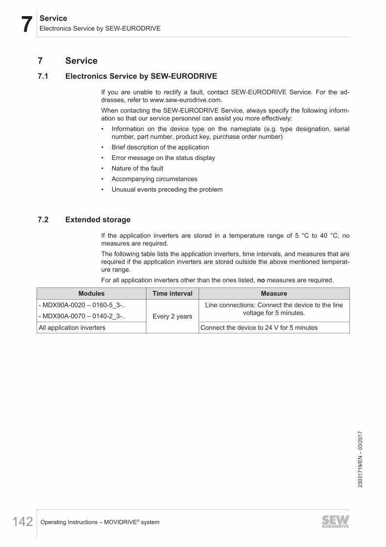
7 ServiceElectronics Service by SEW‑EURODRIVE
Operating Instructions – MOVIDRIVE® system142
7 Service7.1 Electronics Service by SEW‑EURODRIVE
If you are unable to rectify a fault, contact SEW‑EURODRIVE Service. For the ad-dresses, refer to www.sew‑eurodrive.com.When contacting the SEW‑EURODRIVE Service, always specify the following inform-ation so that our service personnel can assist you more effectively:• Information on the device type on the nameplate (e.g. type designation, serial
number, part number, product key, purchase order number)• Brief description of the application• Error message on the status display• Nature of the fault• Accompanying circumstances• Unusual events preceding the problem
7.2 Extended storage
If the application inverters are stored in a temperature range of 5 °C to 40 °C, nomeasures are required.The following table lists the application inverters, time intervals, and measures that arerequired if the application inverters are stored outside the above mentioned temperat-ure range.For all application inverters other than the ones listed, no measures are required.
Modules Time interval Measure- MDX90A-0020 – 0160-5_3-..- MDX90A-0070 – 0140-2_3-.. Every 2 years
Line connections: Connect the device to the linevoltage for 5 minutes.
All application inverters Connect the device to 24 V for 5 minutes
2303
1719
/EN
– 0
3/20
17
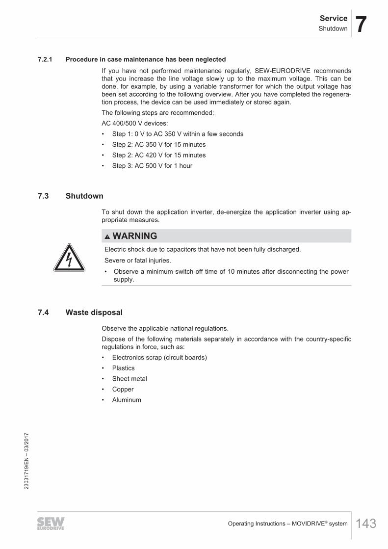
7ServiceShutdown
Operating Instructions – MOVIDRIVE® system 143
7.2.1 Procedure in case maintenance has been neglectedIf you have not performed maintenance regularly, SEW‑EURODRIVE recommendsthat you increase the line voltage slowly up to the maximum voltage. This can bedone, for example, by using a variable transformer for which the output voltage hasbeen set according to the following overview. After you have completed the regenera-tion process, the device can be used immediately or stored again.The following steps are recommended:AC 400/500 V devices:• Step 1: 0 V to AC 350 V within a few seconds• Step 2: AC 350 V for 15 minutes• Step 2: AC 420 V for 15 minutes• Step 3: AC 500 V for 1 hour
7.3 Shutdown
To shut down the application inverter, de-energize the application inverter using ap-propriate measures.
WARNINGElectric shock due to capacitors that have not been fully discharged.Severe or fatal injuries.• Observe a minimum switch-off time of 10 minutes after disconnecting the power
supply.
7.4 Waste disposal
Observe the applicable national regulations.Dispose of the following materials separately in accordance with the country-specificregulations in force, such as:• Electronics scrap (circuit boards)• Plastics• Sheet metal• Copper• Aluminum
2303
1719
/EN
– 0
3/20
17
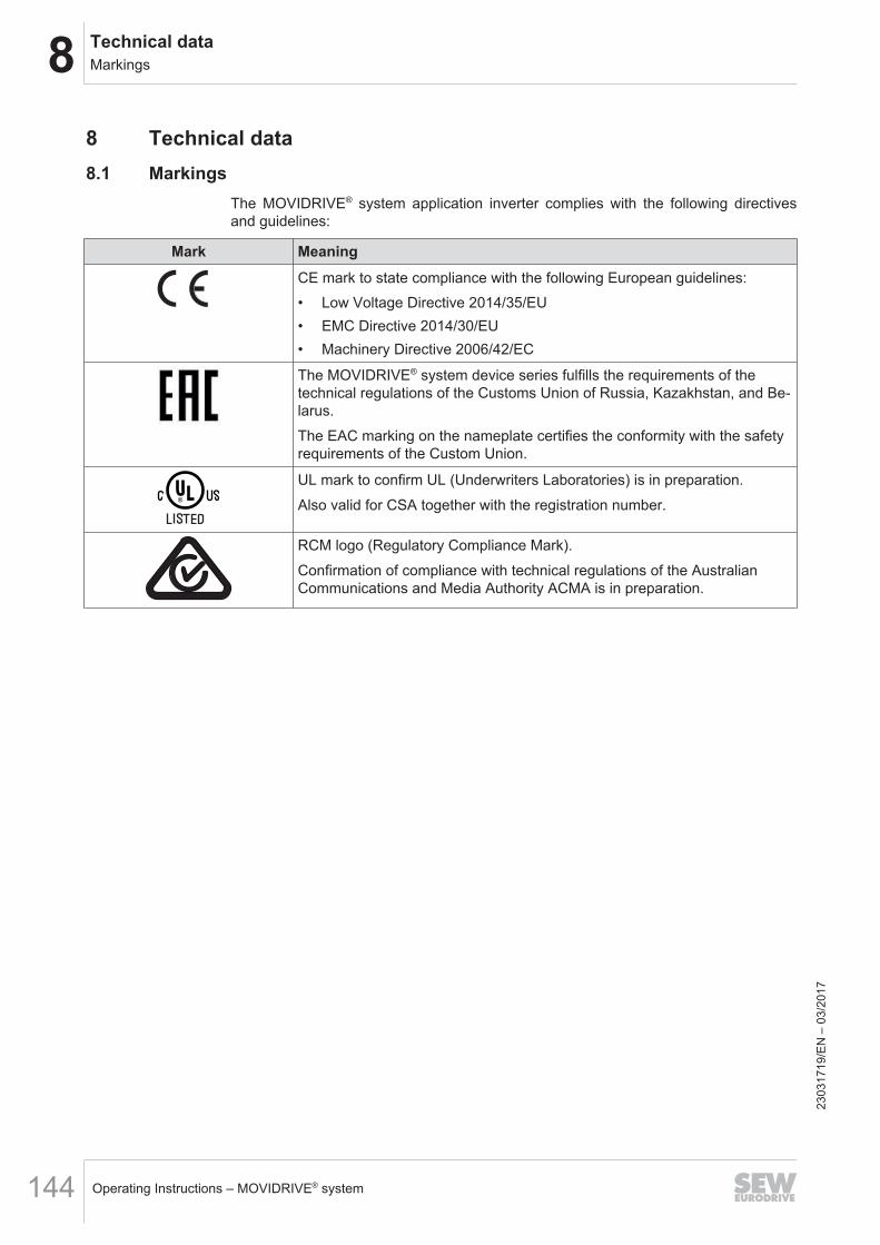
8 Technical dataMarkings
Operating Instructions – MOVIDRIVE® system144
8 Technical data8.1 Markings
The MOVIDRIVE® system application inverter complies with the following directivesand guidelines:
Mark MeaningCE mark to state compliance with the following European guidelines:• Low Voltage Directive 2014/35/EU• EMC Directive 2014/30/EU• Machinery Directive 2006/42/EC
The MOVIDRIVE® system device series fulfills the requirements of thetechnical regulations of the Customs Union of Russia, Kazakhstan, and Be-larus.The EAC marking on the nameplate certifies the conformity with the safetyrequirements of the Custom Union.
UL mark to confirm UL (Underwriters Laboratories) is in preparation.Also valid for CSA together with the registration number.
RCM logo (Regulatory Compliance Mark).Confirmation of compliance with technical regulations of the AustralianCommunications and Media Authority ACMA is in preparation.
2303
1719
/EN
– 0
3/20
17
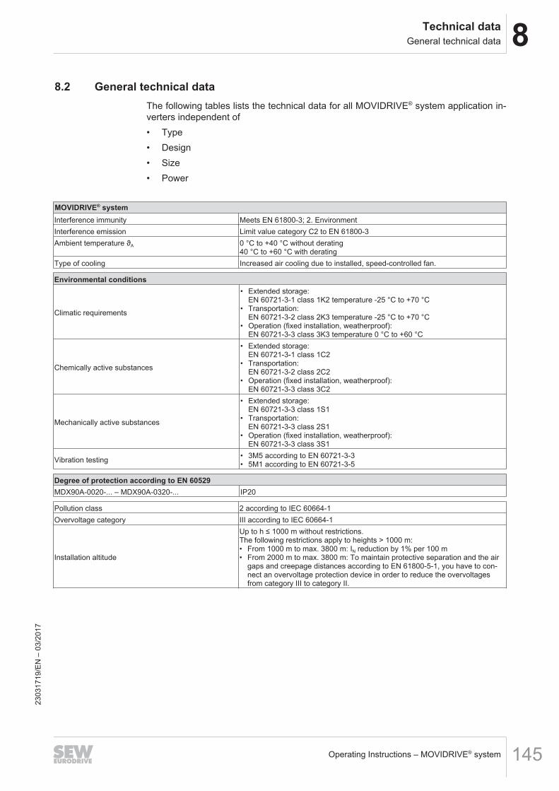
8Technical dataGeneral technical data
Operating Instructions – MOVIDRIVE® system 145
8.2 General technical dataThe following tables lists the technical data for all MOVIDRIVE® system application in-verters independent of• Type• Design• Size• Power
MOVIDRIVE® systemInterference immunity Meets EN 61800-3; 2. EnvironmentInterference emission Limit value category C2 to EN 61800‑3Ambient temperature ϑA 0 °C to +40 °C without derating
40 °C to +60 °C with deratingType of cooling Increased air cooling due to installed, speed-controlled fan.
Environmental conditions
Climatic requirements
• Extended storage:EN 60721-3-1 class 1K2 temperature -25 °C to +70 °C
• Transportation:EN 60721-3-2 class 2K3 temperature -25 °C to +70 °C
• Operation (fixed installation, weatherproof):EN 60721-3-3 class 3K3 temperature 0 °C to +60 °C
Chemically active substances
• Extended storage:EN 60721-3-1 class 1C2
• Transportation:EN 60721-3-2 class 2C2
• Operation (fixed installation, weatherproof):EN 60721-3-3 class 3C2
Mechanically active substances
• Extended storage:EN 60721-3-3 class 1S1
• Transportation:EN 60721-3-3 class 2S1
• Operation (fixed installation, weatherproof):EN 60721-3-3 class 3S1
Vibration testing • 3M5 according to EN 60721-3-3• 5M1 according to EN 60721-3-5
Degree of protection according to EN 60529MDX90A-0020-... – MDX90A-0320-... IP20
Pollution class 2 according to IEC 60664-1Overvoltage category III according to IEC 60664-1
Installation altitude
Up to h ≤ 1000 m without restrictions.The following restrictions apply to heights > 1000 m:• From 1000 m to max. 3800 m: IN reduction by 1% per 100 m• From 2000 m to max. 3800 m: To maintain protective separation and the air
gaps and creepage distances according to EN 61800‑5‑1, you have to con-nect an overvoltage protection device in order to reduce the overvoltagesfrom category III to category II.
2303
1719
/EN
– 0
3/20
17
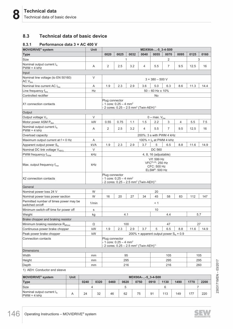
8 Technical dataTechnical data of basic device
Operating Instructions – MOVIDRIVE® system146
8.3 Technical data of basic device8.3.1 Performance data 3 × AC 400 VMOVIDRIVE® system Unit MDX90A-...-5_3-4-S00Type 0020 0025 0032 0040 0055 0070 0095 0125 0160Size 1 2 3Nominal output current INPWM = 4 kHz A 2 2.5 3.2 4 5.5 7 9.5 12.5 16
InputNominal line voltage (to EN 50160) AC Vline
V 3 × 380 – 500 V
Nominal line current AC Iline A 1.9 2.3 2.9 3.6 5.0 6.3 8.6 11.3 14.4Line frequency fline Hz 50 – 60 Hz ± 10%Controlled rectifier No
X1 connection contactsPlug connector- 1 core: 0.25 – 4 mm2
- 2 cores: 0.25 – 2.5 mm2 (Twin-AEH)1)
OutputOutput voltage VO V 0 – max. Vline
Motor power ASM PMot kW 0.55 0.75 1.1 1.5 2.2 3 4 5.5 7.5Nominal output current INPWM = 4 kHz A 2 2.5 3.2 4 5.5 7 9.5 12.5 16
Overload capacity 200%: 3 s with PWM 4 kHzMaximum output current at f = 0 Hz A 100% × IN at PWM 4 kHzApparent output power SN kVA 1.9 2.3 2.9 3.7 5 6.5 8.8 11.6 14.9Nominal DC link voltage VNDCL V DC 560PWM frequency fPWM kHz 4, 8, 16 (adjustable)
Max. output frequency fmax kHz
V/f: 599 HzVFCPLUS: 250 Hz
CFC: 500 HzELSM®: 500 Hz
X2 connection contactsPlug connector- 1 core: 0.25 – 4 mm2
- 2 cores: 0.25 – 2.5 mm2 (Twin-AEH)1)
GeneralNominal power loss 24 V W 20Nominal power loss power section W 16 20 27 34 45 58 83 112 147Permitted number of times power may beswitched on/off 1/min < 1
Minimum switch-off time for power off s 10Weight kg 4.1 4.4 5.7Brake chopper and braking resistorMinimum braking resistance RBRmin Ω 100 47 27Continuous power brake chopper kW 1.9 2.3 2.9 3.7 5 6.5 8.8 11.6 14.9Peak power brake chopper kW 200% × apparent output power SN × 0.9Connection contacts Plug connector
- 1 core: 0.25 – 4 mm2
- 2 cores: 0.25 – 2.5 mm2 (Twin-AEH)1)
DimensionsWidth mm 95 105 105Height mm 295 295 295Depth mm 216 216 2601) AEH: Conductor end sleeve
MOVIDRIVE® system Unit MDX90A-...-5_3-4-S00Type 0240 0320 0460 0620 0750 0910 1130 1490 1770 2200Size 4 5 6 7Nominal output current INPWM = 4 kHz A 24 32 46 62 75 91 113 149 177 220 23
0317
19/E
N –
03/
2017
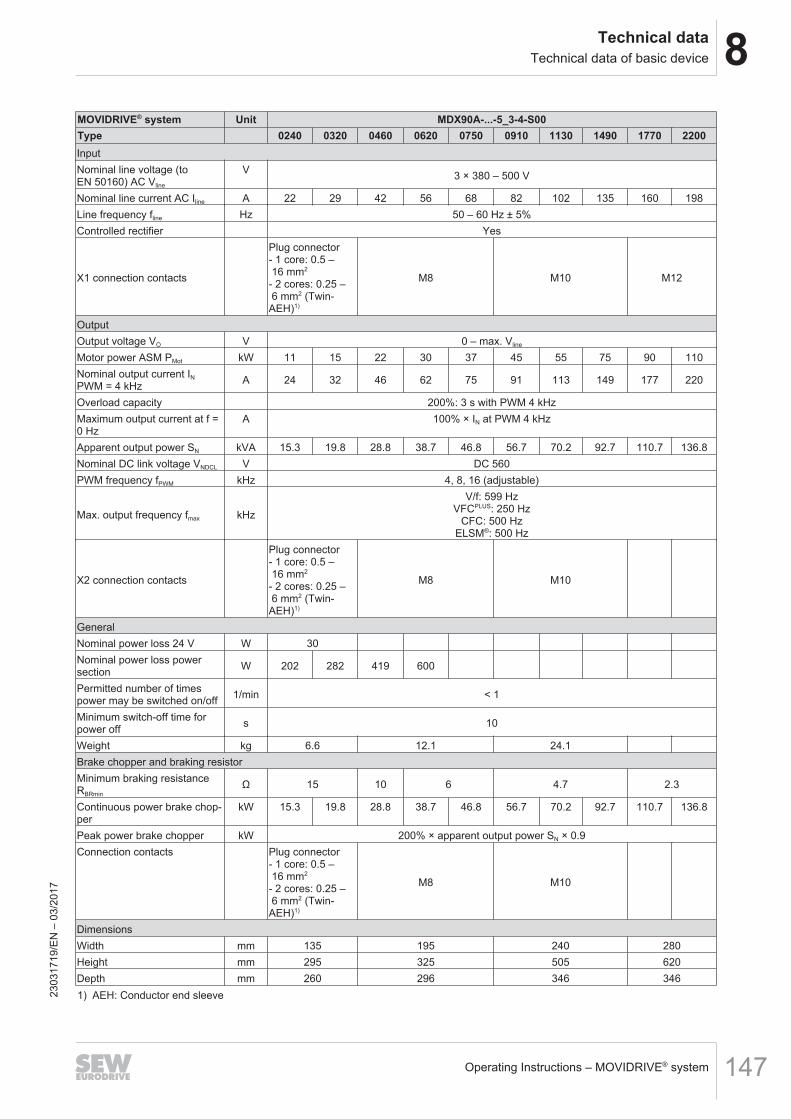
8Technical dataTechnical data of basic device
Operating Instructions – MOVIDRIVE® system 147
MOVIDRIVE® system Unit MDX90A-...-5_3-4-S00Type 0240 0320 0460 0620 0750 0910 1130 1490 1770 2200InputNominal line voltage (toEN 50160) AC Vline
V 3 × 380 – 500 V
Nominal line current AC Iline A 22 29 42 56 68 82 102 135 160 198Line frequency fline Hz 50 – 60 Hz ± 5%Controlled rectifier Yes
X1 connection contacts
Plug connector- 1 core: 0.5 – 16 mm2
- 2 cores: 0.25 – 6 mm2 (Twin-AEH)1)
M8 M10 M12
OutputOutput voltage VO V 0 – max. Vline
Motor power ASM PMot kW 11 15 22 30 37 45 55 75 90 110Nominal output current INPWM = 4 kHz A 24 32 46 62 75 91 113 149 177 220
Overload capacity 200%: 3 s with PWM 4 kHzMaximum output current at f =0 Hz
A 100% × IN at PWM 4 kHz
Apparent output power SN kVA 15.3 19.8 28.8 38.7 46.8 56.7 70.2 92.7 110.7 136.8Nominal DC link voltage VNDCL V DC 560PWM frequency fPWM kHz 4, 8, 16 (adjustable)
Max. output frequency fmax kHz
V/f: 599 HzVFCPLUS: 250 Hz
CFC: 500 HzELSM®: 500 Hz
X2 connection contacts
Plug connector- 1 core: 0.5 – 16 mm2
- 2 cores: 0.25 – 6 mm2 (Twin-AEH)1)
M8 M10
GeneralNominal power loss 24 V W 30Nominal power loss powersection W 202 282 419 600
Permitted number of timespower may be switched on/off 1/min < 1
Minimum switch-off time forpower off s 10
Weight kg 6.6 12.1 24.1Brake chopper and braking resistorMinimum braking resistanceRBRmin
Ω 15 10 6 4.7 2.3
Continuous power brake chop-per
kW 15.3 19.8 28.8 38.7 46.8 56.7 70.2 92.7 110.7 136.8
Peak power brake chopper kW 200% × apparent output power SN × 0.9Connection contacts Plug connector
- 1 core: 0.5 – 16 mm2
- 2 cores: 0.25 – 6 mm2 (Twin-AEH)1)
M8 M10
DimensionsWidth mm 135 195 240 280Height mm 295 325 505 620Depth mm 260 296 346 3461) AEH: Conductor end sleeve23
0317
19/E
N –
03/
2017
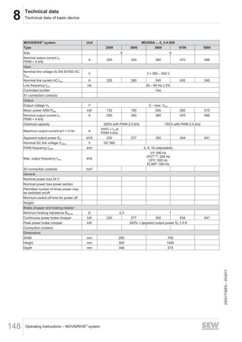
8 Technical dataTechnical data of basic device
Operating Instructions – MOVIDRIVE® system148
MOVIDRIVE® system Unit MDX90A-...-5_3-4-S00Type 2500 3000 3800 4700 5880Size 8 9Nominal output current INPWM = 4 kHz A 250 300 380 470 588
InputNominal line voltage (to EN 50160) ACVline
V 3 × 380 – 500 V
Nominal line current AC Iline A 225 280 340 435 545Line frequency fline Hz 50 – 60 Hz ± 5%Controlled rectifier YesX1 connection contactsOutputOutput voltage VO V 0 – max. Vline
Motor power ASM PMot kW 132 160 200 250 315Nominal output current INPWM = 4 kHz
A 250 300 380 470 588
Overload capacity 200% with PWM 2.5 kHz 150% with PWM 2.5 kHz
Maximum output current at f = 0 Hz A 100% × IN atPWM 4 kHz
Apparent output power SN kVA 230 277 350 434 541Nominal DC link voltage VNDCL V DC 560PWM frequency fPWM kHz 4, 8, 16 (adjustable)
Max. output frequency fmax kHz
V/f: 599 HzVFCPLUS: 250 Hz
CFC: 500 HzELSM®: 500 Hz
X2 connection contacts mm2
GeneralNominal power loss 24 VNominal power loss power sectionPermitted number of times power maybe switched on/offMinimum switch-off time for power offWeightBrake chopper and braking resistorMinimum braking resistance RBRmin Ω 2.3 1Continuous power brake chopper kW 230 277 350 434 541Peak power brake chopper kW 200% × apparent output power SN × 0.9Connection contactsDimensionsWidth mm 285 700Height mm 950 1490Depth mm 346 473
2303
1719
/EN
– 0
3/20
17
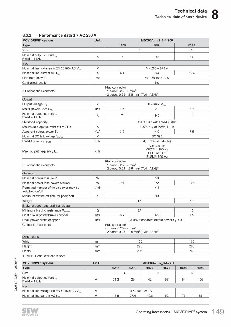
8Technical dataTechnical data of basic device
Operating Instructions – MOVIDRIVE® system 149
8.3.2 Performance data 3 × AC 230 VMOVIDRIVE® system Unit MDX90A-...-2_3-4-S00Type 0070 0093 0140Size 2 3Nominal output current INPWM = 4 kHz A 7 9.3 14
InputNominal line voltage (to EN 50160) AC Vline V 3 × 200 – 240 VNominal line current AC Iline A 6.4 8.4 12.4Line frequency fline Hz 50 – 60 Hz ± 10%Controlled rectifier No
X1 connection contactsPlug connector- 1 core: 0.25 – 4 mm2
- 2 cores: 0.25 – 2.5 mm2 (Twin-AEH)1)
OutputOutput voltage VO V 0 – max. Vline
Motor power ASM PMot kW 1.5 2.2 3.7Nominal output current INPWM = 4 kHz A 7 9.3 14
Overload capacity 200%: 3 s with PWM 4 kHzMaximum output current at f = 0 Hz A 100% × IN at PWM 4 kHzApparent output power SN kVA 3.7 4.9 7.5Nominal DC link voltage VNDCL V DC 325PWM frequency fPWM kHz 4, 8, 16 (adjustable)
Max. output frequency fmax kHz
V/f: 599 HzVFCPLUS: 250 Hz
CFC: 500 HzELSM®: 500 Hz
X2 connection contactsPlug connector- 1 core: 0.25 – 4 mm2
- 2 cores: 0.25 – 2.5 mm2 (Twin-AEH)1)
GeneralNominal power loss 24 V W 20Nominal power loss power section W 51 72 105Permitted number of times power may beswitched on/off
1/min < 1
Minimum switch-off time for power off s 10Weight 4.4 5.7Brake chopper and braking resistorMinimum braking resistance RBRmin Ω 27 15Continuous power brake chopper kW 3.7 4.9 7.5Peak power brake chopper kW 200% × apparent output power SN × 0.9Connection contacts Plug connector
- 1 core: 0.25 – 4 mm2
- 2 cores: 0.25 – 2.5 mm2 (Twin-AEH)1)
DimensionsWidth mm 105 105Height mm 295 295Depth mm 216 2601) AEH: Conductor end sleeve
MOVIDRIVE® system Unit MDX90A-...-2_3-4-S00Type 0213 0290 0420 0570 0840 1080Size 4 5 6Nominal output current INPWM = 4 kHz A 21.3 29 42 57 84 108
InputNominal line voltage (to EN 50160) AC Vline V 3 × 200 – 240 VNominal line current AC Iline A 18.9 27.4 40.8 52 76 86
2303
1719
/EN
– 0
3/20
17
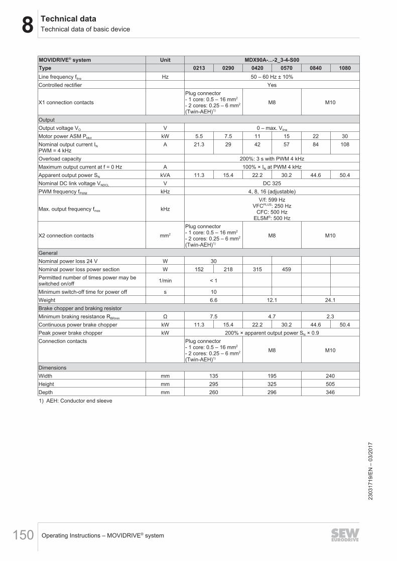
8 Technical dataTechnical data of basic device
Operating Instructions – MOVIDRIVE® system150
MOVIDRIVE® system Unit MDX90A-...-2_3-4-S00Type 0213 0290 0420 0570 0840 1080Line frequency fline Hz 50 – 60 Hz ± 10%Controlled rectifier Yes
X1 connection contacts
Plug connector- 1 core: 0.5 – 16 mm2
- 2 cores: 0.25 – 6 mm2
(Twin-AEH)1)
M8 M10
OutputOutput voltage VO V 0 – max. Vline
Motor power ASM PMot kW 5.5 7.5 11 15 22 30Nominal output current INPWM = 4 kHz
A 21.3 29 42 57 84 108
Overload capacity 200%: 3 s with PWM 4 kHzMaximum output current at f = 0 Hz A 100% × IN at PWM 4 kHzApparent output power SN kVA 11.3 15.4 22.2 30.2 44.6 50.4Nominal DC link voltage VNDCL V DC 325PWM frequency fPWM kHz 4, 8, 16 (adjustable)
Max. output frequency fmax kHz
V/f: 599 HzVFCPLUS: 250 Hz
CFC: 500 HzELSM®: 500 Hz
X2 connection contacts mm2
Plug connector- 1 core: 0.5 – 16 mm2
- 2 cores: 0.25 – 6 mm2
(Twin-AEH)1)
M8 M10
GeneralNominal power loss 24 V W 30Nominal power loss power section W 152 218 315 459Permitted number of times power may beswitched on/off 1/min < 1
Minimum switch-off time for power off s 10Weight 6.6 12.1 24.1Brake chopper and braking resistorMinimum braking resistance RBRmin Ω 7.5 4.7 2.3Continuous power brake chopper kW 11.3 15.4 22.2 30.2 44.6 50.4Peak power brake chopper kW 200% × apparent output power SN × 0.9Connection contacts Plug connector
- 1 core: 0.5 – 16 mm2
- 2 cores: 0.25 – 6 mm2
(Twin-AEH)1)
M8 M10
DimensionsWidth mm 135 195 240Height mm 295 325 505Depth mm 260 296 3461) AEH: Conductor end sleeve
2303
1719
/EN
– 0
3/20
17
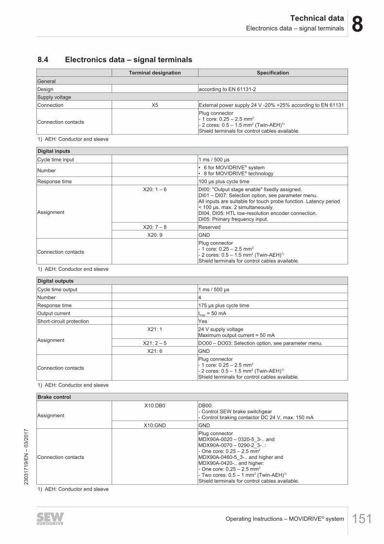
8Technical dataElectronics data – signal terminals
Operating Instructions – MOVIDRIVE® system 151
8.4 Electronics data – signal terminalsTerminal designation Specification
GeneralDesign according to EN 61131-2Supply voltageConnection X5 External power supply 24 V -20% +25% according to EN 61131
Connection contacts
Plug connector- 1 core: 0.25 – 2.5 mm2
- 2 cores: 0.5 – 1.5 mm2 (Twin-AEH)1)
Shield terminals for control cables available.1) AEH: Conductor end sleeve
Digital inputsCycle time input 1 ms / 500 μs
Number • 6 for MOVIDRIVE® system• 8 for MOVIDRIVE® technology
Response time 100 μs plus cycle time
Assignment
X20: 1 – 6 DI00: "Output stage enable" fixedly assigned.DI01 – DI07: Selection option, see parameter menu.All inputs are suitable for touch probe function. Latency period< 100 µs, max. 2 simultaneously.DI04, DI05: HTL low-resolution encoder connection.DI05: Primary frequency input.
X20: 7 – 8 ReservedX20: 9 GND
Connection contacts
Plug connector- 1 core: 0.25 – 2.5 mm2
- 2 cores: 0.5 – 1.5 mm2 (Twin-AEH)1)
Shield terminals for control cables available.1) AEH: Conductor end sleeve
Digital outputsCycle time output 1 ms / 500 μsNumber 4Response time 175 μs plus cycle timeOutput current Imax = 50 mAShort-circuit protection Yes
Assignment
X21: 1 24 V supply voltageMaximum output current = 50 mA
X21: 2 – 5 DO00 – DO03: Selection option, see parameter menu.X21: 6 GND
Connection contacts
Plug connector- 1 core: 0.25 – 2.5 mm2
- 2 cores: 0.5 – 1.5 mm2 (Twin-AEH)1)
Shield terminals for control cables available.1) AEH: Conductor end sleeve
Brake control
Assignment
X10:DB0 DB00:- Control SEW brake switchgear- Control braking contactor DC 24 V, max. 150 mA
X10:GND GND
Connection contacts
Plug connectorMDX90A-0020 – 0320-5_3-.. andMDX90A-0070 – 0290-2_3-..:- One core: 0.25 – 2.5 mm2
MDX90A-0460-5_3-.. and higher andMDX90A-0420-.. and higher:- One core: 0.25 – 2.5 mm2
- Two cores: 0.5 – 1 mm2 (Twin-AEH)1)
Shield terminals for control cables available.1) AEH: Conductor end sleeve
2303
1719
/EN
– 0
3/20
17
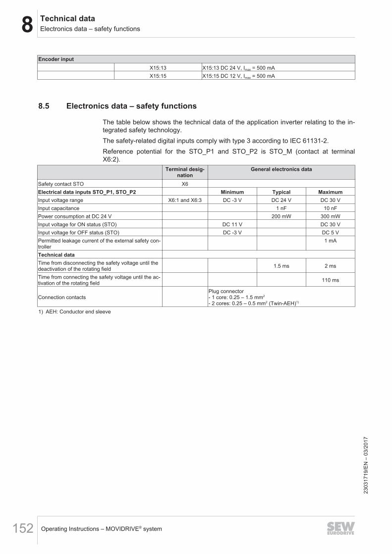
8 Technical dataElectronics data – safety functions
Operating Instructions – MOVIDRIVE® system152
Encoder inputX15:13 X15:13 DC 24 V, Imax = 500 mAX15:15 X15:15 DC 12 V, Imax = 500 mA
8.5 Electronics data – safety functions
The table below shows the technical data of the application inverter relating to the in-tegrated safety technology.The safety-related digital inputs comply with type 3 according to IEC 61131‑2.Reference potential for the STO_P1 and STO_P2 is STO_M (contact at terminalX6:2).
Terminal desig-nation
General electronics data
Safety contact STO X6Electrical data inputs STO_P1, STO_P2 Minimum Typical MaximumInput voltage range X6:1 and X6:3 DC -3 V DC 24 V DC 30 VInput capacitance 1 nF 10 nFPower consumption at DC 24 V 200 mW 300 mWInput voltage for ON status (STO) DC 11 V DC 30 VInput voltage for OFF status (STO) DC -3 V DC 5 VPermitted leakage current of the external safety con-troller
1 mA
Technical dataTime from disconnecting the safety voltage until thedeactivation of the rotating field 1.5 ms 2 ms
Time from connecting the safety voltage until the ac-tivation of the rotating field 110 ms
Connection contactsPlug connector- 1 core: 0.25 – 1.5 mm2
- 2 cores: 0.25 – 0.5 mm2 (Twin-AEH)1)
1) AEH: Conductor end sleeve
2303
1719
/EN
– 0
3/20
17
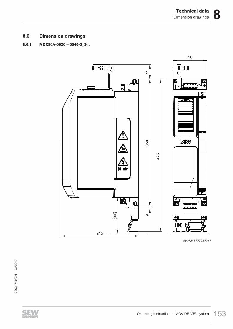
8Technical dataDimension drawings
Operating Instructions – MOVIDRIVE® system 153
8.6 Dimension drawings8.6.1 MDX90A-0020 – 0040-5_3-..
350
9
425
41
215
100
95
9007215177854347
2303
1719
/EN
– 0
3/20
17
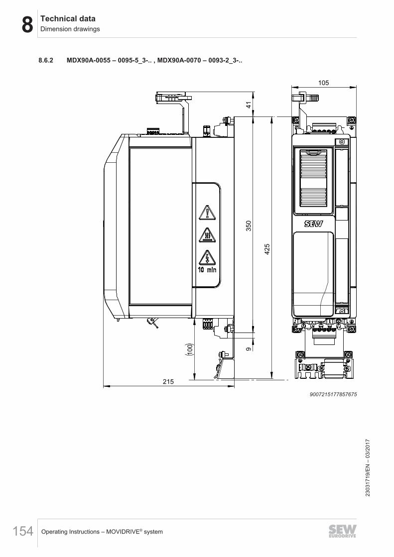
8 Technical dataDimension drawings
Operating Instructions – MOVIDRIVE® system154
8.6.2 MDX90A-0055 – 0095-5_3-.. , MDX90A-0070 – 0093-2_3-..
350
9
215
425
41
100
105
9007215177857675
2303
1719
/EN
– 0
3/20
17
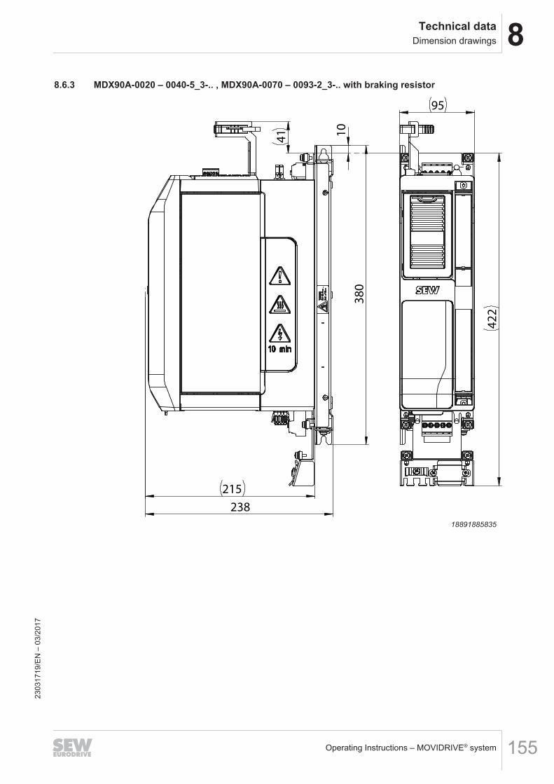
8Technical dataDimension drawings
Operating Instructions – MOVIDRIVE® system 155
8.6.3 MDX90A-0020 – 0040-5_3-.. , MDX90A-0070 – 0093-2_3-.. with braking resistor
41
380
10
215
238
95
422
18891885835
2303
1719
/EN
– 0
3/20
17
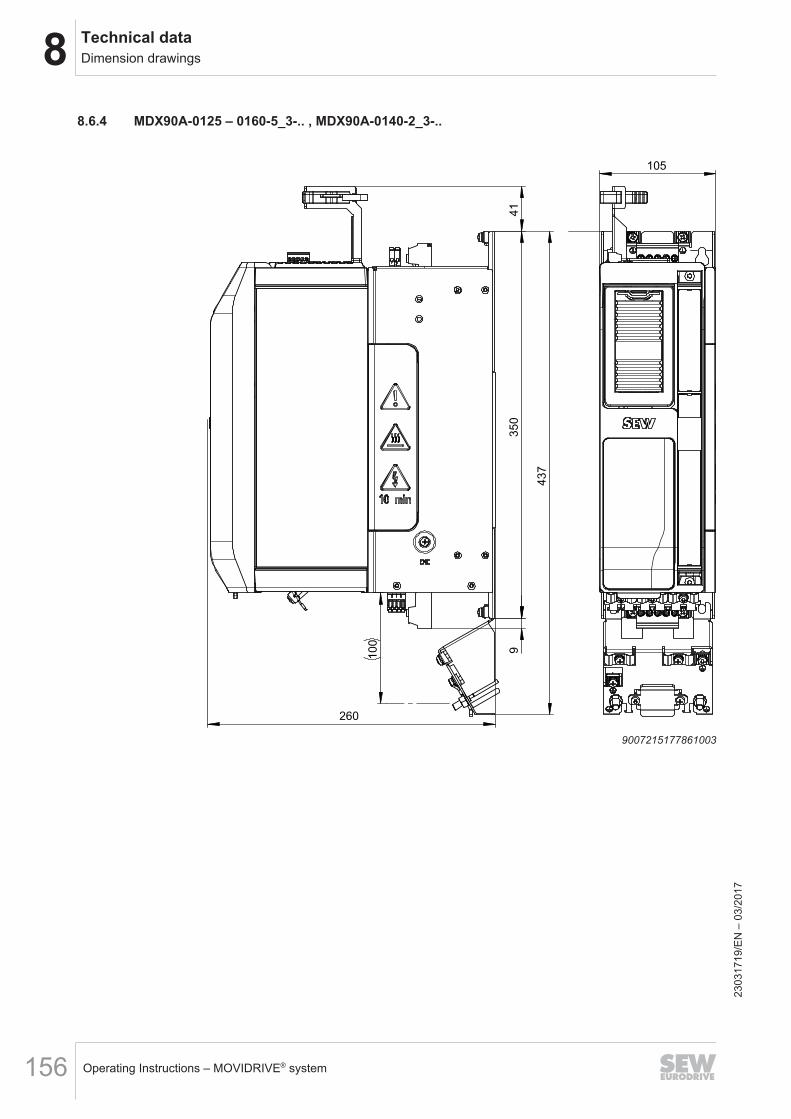
8 Technical dataDimension drawings
Operating Instructions – MOVIDRIVE® system156
8.6.4 MDX90A-0125 – 0160-5_3-.. , MDX90A-0140-2_3-..
105
350
9
437
41
260
100
900721517786100323
0317
19/E
N –
03/
2017
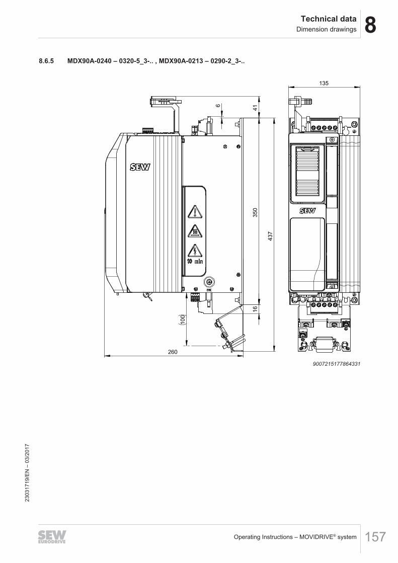
8Technical dataDimension drawings
Operating Instructions – MOVIDRIVE® system 157
8.6.5 MDX90A-0240 – 0320-5_3-.. , MDX90A-0213 – 0290-2_3-..
135
350
16
6
437
41
260
100
9007215177864331
2303
1719
/EN
– 0
3/20
17
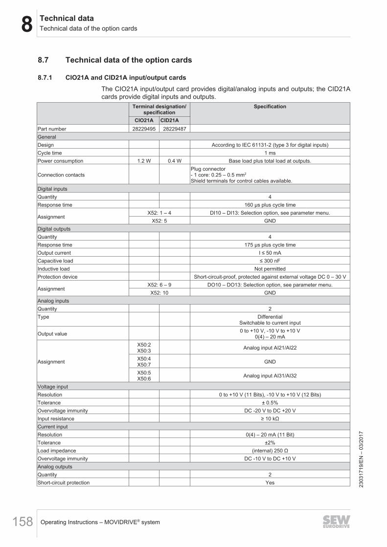
8 Technical dataTechnical data of the option cards
Operating Instructions – MOVIDRIVE® system158
8.7 Technical data of the option cards
8.7.1 CIO21A and CID21A input/output cardsThe CIO21A input/output card provides digital/analog inputs and outputs; the CID21Acards provide digital inputs and outputs.
Terminal designation/specification
Specification
CIO21A CID21APart number 28229495 28229487GeneralDesign According to IEC 61131‑2 (type 3 for digital inputs)Cycle time 1 msPower consumption 1.2 W 0.4 W Base load plus total load at outputs.
Connection contactsPlug connector- 1 core: 0.25 – 0.5 mm2
Shield terminals for control cables available.Digital inputsQuantity 4Response time 160 μs plus cycle time
AssignmentX52: 1 – 4 DI10 – DI13: Selection option, see parameter menu.
X52: 5 GNDDigital outputsQuantity 4Response time 175 μs plus cycle timeOutput current I ≤ 50 mACapacitive load ≤ 300 nFInductive load Not permittedProtection device Short-circuit-proof, protected against external voltage DC 0 – 30 V
AssignmentX52: 6 – 9 DO10 – DO13: Selection option, see parameter menu.X52: 10 GND
Analog inputsQuantity 2Type Differential
Switchable to current input
Output value 0 to +10 V, -10 V to +10 V0(4) – 20 mA
Assignment
X50:2X50:3 Analog input AI21/AI22
X50:4X50:7 GND
X50:5X50:6 Analog input AI31/AI32
Voltage inputResolution 0 to +10 V (11 Bits), -10 V to +10 V (12 Bits)Tolerance ± 0.5%Overvoltage immunity DC -20 V to DC +20 VInput resistance ≥ 10 kΩCurrent inputResolution 0(4) – 20 mA (11 Bit)Tolerance ±2%Load impedance (internal) 250 ΩOvervoltage immunity DC -10 V to DC +10 VAnalog outputsQuantity 2Short-circuit protection Yes 23
0317
19/E
N –
03/
2017
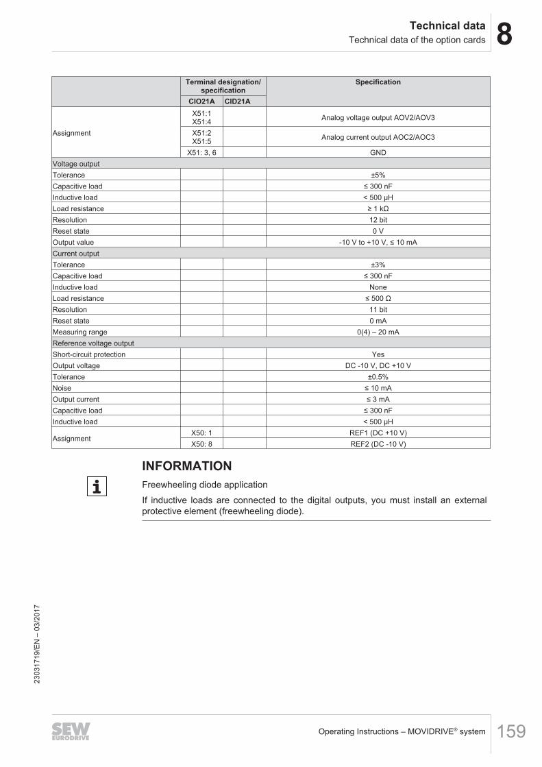
8Technical dataTechnical data of the option cards
Operating Instructions – MOVIDRIVE® system 159
Terminal designation/specification
Specification
CIO21A CID21A
Assignment
X51:1X51:4 Analog voltage output AOV2/AOV3
X51:2X51:5 Analog current output AOC2/AOC3
X51: 3, 6 GNDVoltage outputTolerance ±5%Capacitive load ≤ 300 nFInductive load < 500 μHLoad resistance ≥ 1 kΩResolution 12 bitReset state 0 VOutput value -10 V to +10 V, ≤ 10 mACurrent outputTolerance ±3%Capacitive load ≤ 300 nFInductive load NoneLoad resistance ≤ 500 ΩResolution 11 bitReset state 0 mAMeasuring range 0(4) – 20 mAReference voltage outputShort-circuit protection YesOutput voltage DC -10 V, DC +10 VTolerance ±0.5%Noise ≤ 10 mAOutput current ≤ 3 mACapacitive load ≤ 300 nFInductive load < 500 μH
AssignmentX50: 1 REF1 (DC +10 V)X50: 8 REF2 (DC -10 V)
INFORMATIONFreewheeling diode applicationIf inductive loads are connected to the digital outputs, you must install an externalprotective element (freewheeling diode).
2303
1719
/EN
– 0
3/20
17
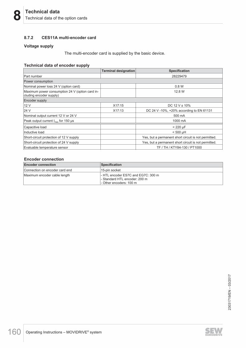
8 Technical dataTechnical data of the option cards
Operating Instructions – MOVIDRIVE® system160
8.7.2 CES11A multi-encoder card
Voltage supplyThe multi-encoder card is supplied by the basic device.
Technical data of encoder supplyTerminal designation Specification
Part number 28229479Power consumptionNominal power loss 24 V (option card) 0.8 WMaximum power consumption 24 V (option card in-cluding encoder supply)
12.8 W
Encoder supply12 V X17:15 DC 12 V ± 10%24 V X17:13 DC 24 V -10%, +20% according to EN 61131Nominal output current 12 V or 24 V 500 mAPeak output current Imax for 150 μs 1000 mA
Capacitive load < 220 μFInductive load < 500 μHShort-circuit protection of 12 V supply Yes, but a permanent short circuit is not permitted.Short-circuit protection of 24 V supply Yes, but a permanent short circuit is not permitted.Evaluable temperature sensor TF / TH / KTY84-130 / PT1000
Encoder connectionEncoder connection SpecificationConnection on encoder card end 15-pin socketMaximum encoder cable length - HTL encoder ES7C and EG7C: 300 m
- Standard HTL encoder: 200 m- Other encoders: 100 m
2303
1719
/EN
– 0
3/20
17
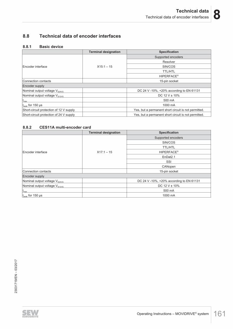
8Technical dataTechnical data of encoder interfaces
Operating Instructions – MOVIDRIVE® system 161
8.8 Technical data of encoder interfaces
8.8.1 Basic deviceTerminal designation Specification
Encoder interface X15:1 – 15
Supported encodersResolverSIN/COSTTL/HTL
HIPERFACE®
Connection contacts 15-pin socketEncoder supplyNominal output voltage VS24VG DC 24 V -10%, +20% according to EN 61131Nominal output voltage VS12VG DC 12 V ± 10%Imax 500 mAIpeak for 150 μs 1000 mAShort-circuit protection of 12 V supply Yes, but a permanent short circuit is not permitted.Short-circuit protection of 24 V supply Yes, but a permanent short circuit is not permitted.
8.8.2 CES11A multi-encoder cardTerminal designation Specification
Encoder interface X17:1 – 15
Supported encodersSIN/COSTTL/HTL
HIPERFACE®
EnDat2.1SSI
CANopenConnection contacts 15-pin socketEncoder supplyNominal output voltage VS24VG DC 24 V -10%, +20% according to EN 61131Nominal output voltage VS12VG DC 12 V ± 10%Imax 500 mAIpeak for 150 μs 1000 mA
2303
1719
/EN
– 0
3/20
17
8 Technical dataTechnical data of braking resistors, filters and chokes
Operating Instructions – MOVIDRIVE® system162
8.9 Technical data of braking resistors, filters and chokes8.9.1 Braking resistors type BW.../BW...-T
GeneralThe BW... / BW...-T braking resistors are adapted to the technical characteristics ofthe application inverter.There are braking resistors with different continuous and peak braking power avail-able.The braking resistors can be protected against overload and overtemperature by thecustomer by using a thermal overload relay. The tripping current is set to the value IF,see the following tables.The braking resistors of the series BW...-T are equipped with an integrated temperat-ure switch that monitors the temperature. If the nominal operating temperature is ex-ceeded, the temperature switch triggers a signal contact. The temperature switch doesnot switch off the braking resistor. This is why the temperature switch must be evalu-ated to avoid thermal overload of the braking resistor.Another possibility to protect the braking resistor is the TCB thermal circuit breaker.The TCB thermal circuit breaker protects the braking resistor against continuous over-load and against power peaks over short periods.A PTC resistor protects itself (reversible) against regenerative overload by changingabruptly to high resistance and no longer consuming any more energy. The inverterthen switches off and signals a "brake chopper" fault.In the documented assignments of drive inverters and flat-design resistors, flat-designresistors have an internal thermal protection (non-replaceable fuse) that interrupts thecurrent circuit in the event of overload. The project planning guidelines and the docu-mented assignments of drive inverter and braking resistor must be adhered to.
INFORMATIONUse of protection devicesOnly use the protection devices listed in the following section:• TCB thermal circuit breaker• Internal temperature switch T• External bimetallic relay
→ See also chapter Protection against thermal overload of the braking resistor.23
0317
19/E
N –
03/
2017
8Technical dataTechnical data of braking resistors, filters and chokes
Operating Instructions – MOVIDRIVE® system 163
UL and cUL approvalThe listed braking resistors have cRUus approvals independent of the application in-verter.
Parallel connection of braking resistorsIdentical braking resistors must be connected in parallel for some inverter/resistorcombinations.In this case, protect each braking resistor against overload and overtemperature usinga thermal overload relay.The temperature switches must be connected in series for braking resistors of theBW...-T series.
2303
1719
/EN
– 0
3/20
17
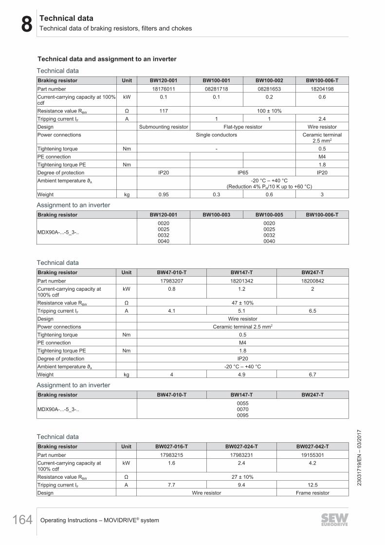
8 Technical dataTechnical data of braking resistors, filters and chokes
Operating Instructions – MOVIDRIVE® system164
Technical data and assignment to an inverter
Technical dataBraking resistor Unit BW120-001 BW100-001 BW100-002 BW100-006-TPart number 18176011 08281718 08281653 18204198Current-carrying capacity at 100%cdf
kW 0.1 0.1 0.2 0.6
Resistance value RBW Ω 117 100 ± 10%Tripping current IF A 1 1 2.4Design Submounting resistor Flat-type resistor Wire resistorPower connections Single conductors Ceramic terminal
2.5 mm2
Tightening torque Nm - 0.5PE connection M4Tightening torque PE Nm 1.8Degree of protection IP20 IP65 IP20Ambient temperature ϑA -20 °C – +40 °C
(Reduction 4% PN/10 K up to +60 °C)Weight kg 0.95 0.3 0.6 3
Assignment to an inverterBraking resistor BW120-001 BW100-003 BW100-005 BW100-006-T
MDX90A-...-5_3-..
0020002500320040
0020002500320040
Technical dataBraking resistor Unit BW47-010-T BW147-T BW247-TPart number 17983207 18201342 18200842Current-carrying capacity at100% cdf
kW 0.8 1.2 2
Resistance value RBW Ω 47 ± 10%Tripping current IF A 4.1 5.1 6.5Design Wire resistorPower connections Ceramic terminal 2.5 mm2
Tightening torque Nm 0.5PE connection M4Tightening torque PE Nm 1.8Degree of protection IP20Ambient temperature ϑA -20 °C – +40 °CWeight kg 4 4.9 6.7
Assignment to an inverterBraking resistor BW47-010-T BW147-T BW247-T
MDX90A-...-5_3-..005500700095
Technical dataBraking resistor Unit BW027-016-T BW027-024-T BW027-042-TPart number 17983215 17983231 19155301Current-carrying capacity at100% cdf
kW 1.6 2.4 4.2
Resistance value RBW Ω 27 ± 10%Tripping current IF A 7.7 9.4 12.5Design Wire resistor Frame resistor
2303
1719
/EN
– 0
3/20
17
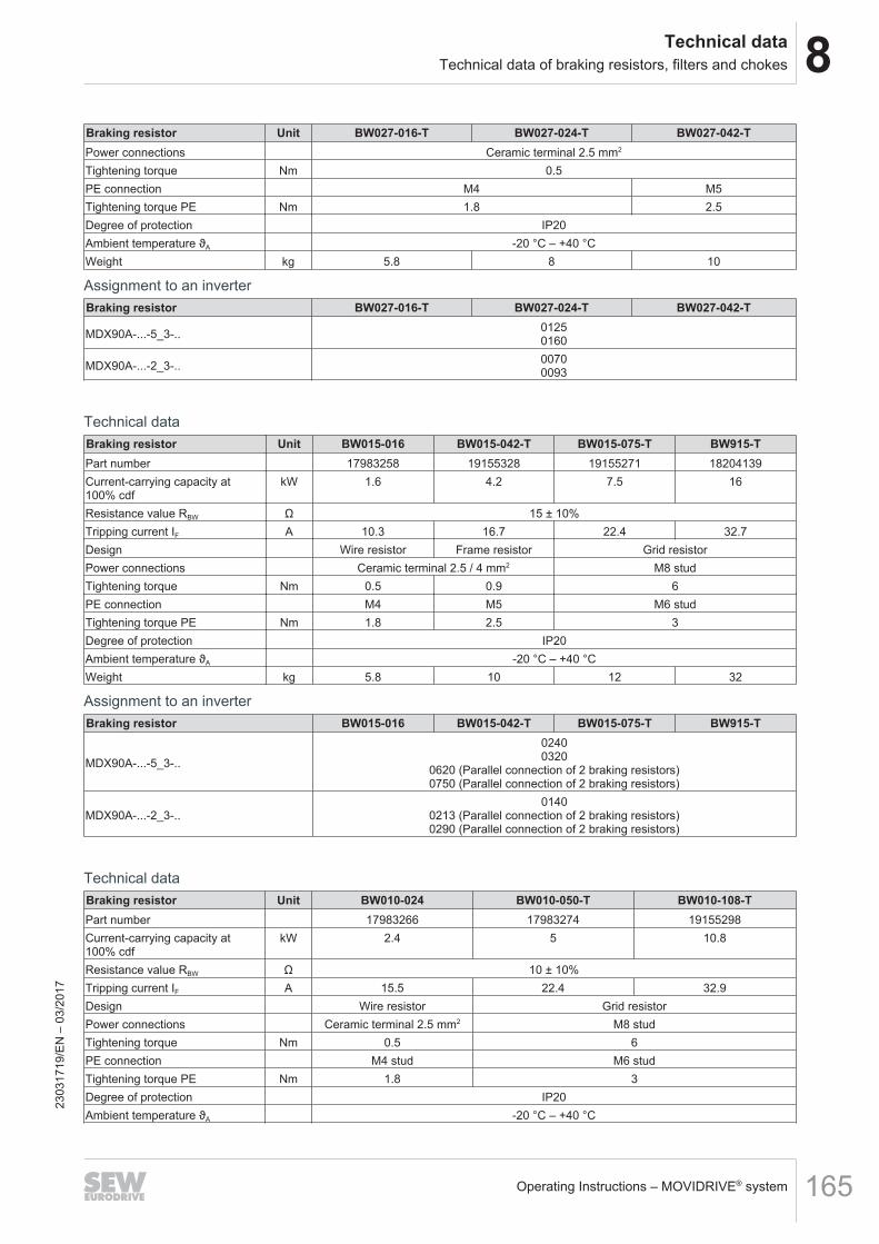
8Technical dataTechnical data of braking resistors, filters and chokes
Operating Instructions – MOVIDRIVE® system 165
Braking resistor Unit BW027-016-T BW027-024-T BW027-042-TPower connections Ceramic terminal 2.5 mm2
Tightening torque Nm 0.5PE connection M4 M5Tightening torque PE Nm 1.8 2.5Degree of protection IP20Ambient temperature ϑA -20 °C – +40 °CWeight kg 5.8 8 10
Assignment to an inverterBraking resistor BW027-016-T BW027-024-T BW027-042-T
MDX90A-...-5_3-.. 01250160
MDX90A-...-2_3-.. 00700093
Technical dataBraking resistor Unit BW015-016 BW015-042-T BW015-075-T BW915-TPart number 17983258 19155328 19155271 18204139Current-carrying capacity at100% cdf
kW 1.6 4.2 7.5 16
Resistance value RBW Ω 15 ± 10%Tripping current IF A 10.3 16.7 22.4 32.7Design Wire resistor Frame resistor Grid resistorPower connections Ceramic terminal 2.5 / 4 mm2 M8 studTightening torque Nm 0.5 0.9 6PE connection M4 M5 M6 studTightening torque PE Nm 1.8 2.5 3Degree of protection IP20Ambient temperature ϑA -20 °C – +40 °CWeight kg 5.8 10 12 32
Assignment to an inverterBraking resistor BW015-016 BW015-042-T BW015-075-T BW915-T
MDX90A-...-5_3-..
02400320
0620 (Parallel connection of 2 braking resistors)0750 (Parallel connection of 2 braking resistors)
MDX90A-...-2_3-..0140
0213 (Parallel connection of 2 braking resistors)0290 (Parallel connection of 2 braking resistors)
Technical dataBraking resistor Unit BW010-024 BW010-050-T BW010-108-TPart number 17983266 17983274 19155298Current-carrying capacity at100% cdf
kW 2.4 5 10.8
Resistance value RBW Ω 10 ± 10%Tripping current IF A 15.5 22.4 32.9Design Wire resistor Grid resistorPower connections Ceramic terminal 2.5 mm2 M8 studTightening torque Nm 0.5 6PE connection M4 stud M6 studTightening torque PE Nm 1.8 3Degree of protection IP20Ambient temperature ϑA -20 °C – +40 °C
2303
1719
/EN
– 0
3/20
17
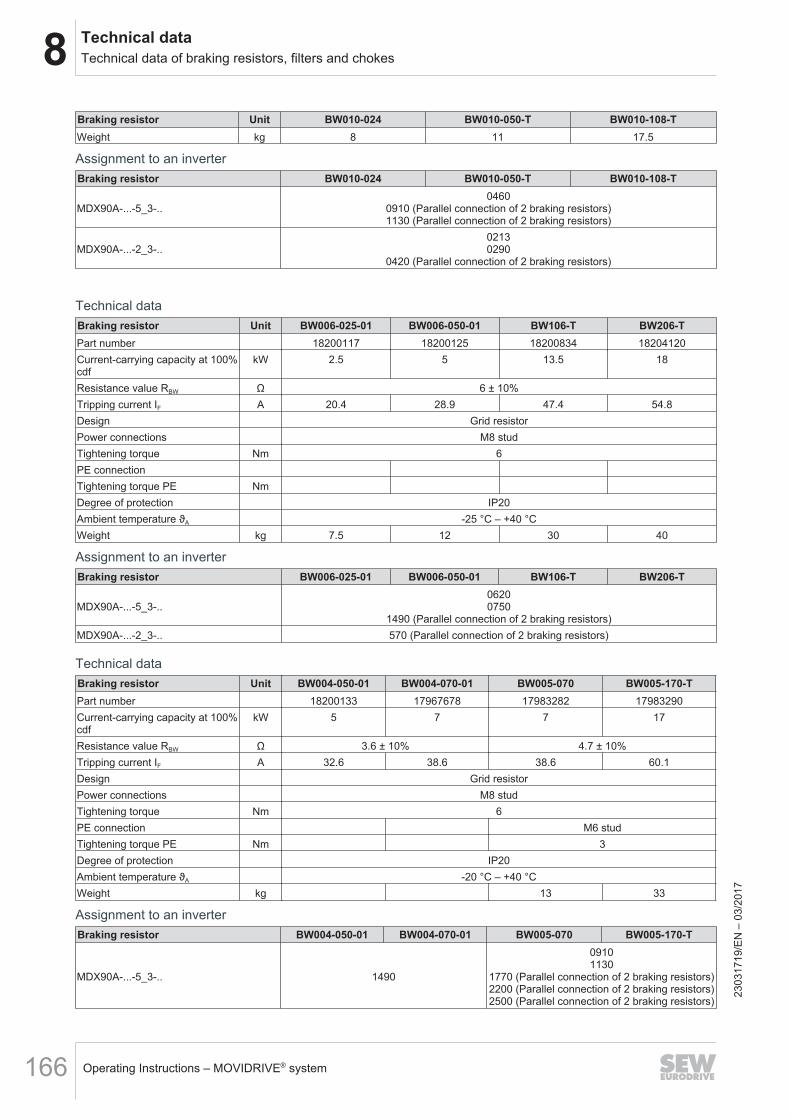
8 Technical dataTechnical data of braking resistors, filters and chokes
Operating Instructions – MOVIDRIVE® system166
Braking resistor Unit BW010-024 BW010-050-T BW010-108-TWeight kg 8 11 17.5
Assignment to an inverterBraking resistor BW010-024 BW010-050-T BW010-108-T
MDX90A-...-5_3-..0460
0910 (Parallel connection of 2 braking resistors)1130 (Parallel connection of 2 braking resistors)
MDX90A-...-2_3-..02130290
0420 (Parallel connection of 2 braking resistors)
Technical dataBraking resistor Unit BW006-025-01 BW006-050-01 BW106-T BW206-TPart number 18200117 18200125 18200834 18204120Current-carrying capacity at 100%cdf
kW 2.5 5 13.5 18
Resistance value RBW Ω 6 ± 10%Tripping current IF A 20.4 28.9 47.4 54.8Design Grid resistorPower connections M8 studTightening torque Nm 6PE connectionTightening torque PE NmDegree of protection IP20Ambient temperature ϑA -25 °C – +40 °CWeight kg 7.5 12 30 40
Assignment to an inverterBraking resistor BW006-025-01 BW006-050-01 BW106-T BW206-T
MDX90A-...-5_3-..06200750
1490 (Parallel connection of 2 braking resistors)MDX90A-...-2_3-.. 570 (Parallel connection of 2 braking resistors)
Technical dataBraking resistor Unit BW004-050-01 BW004-070-01 BW005-070 BW005-170-TPart number 18200133 17967678 17983282 17983290Current-carrying capacity at 100%cdf
kW 5 7 7 17
Resistance value RBW Ω 3.6 ± 10% 4.7 ± 10%Tripping current IF A 32.6 38.6 38.6 60.1Design Grid resistorPower connections M8 studTightening torque Nm 6PE connection M6 studTightening torque PE Nm 3Degree of protection IP20Ambient temperature ϑA -20 °C – +40 °CWeight kg 13 33
Assignment to an inverterBraking resistor BW004-050-01 BW004-070-01 BW005-070 BW005-170-T
MDX90A-...-5_3-.. 1490
09101130
1770 (Parallel connection of 2 braking resistors)2200 (Parallel connection of 2 braking resistors)2500 (Parallel connection of 2 braking resistors)
2303
1719
/EN
– 0
3/20
17
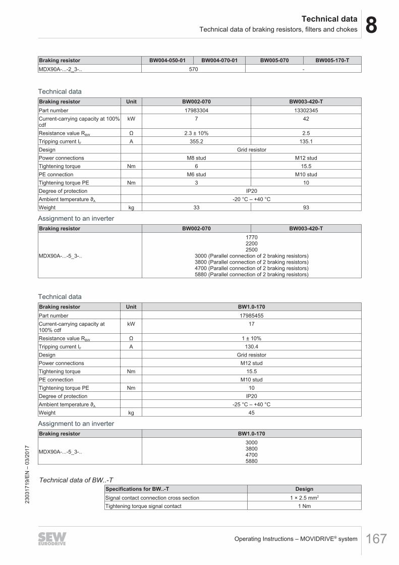
8Technical dataTechnical data of braking resistors, filters and chokes
Operating Instructions – MOVIDRIVE® system 167
Braking resistor BW004-050-01 BW004-070-01 BW005-070 BW005-170-TMDX90A-...-2_3-.. 570 -
Technical dataBraking resistor Unit BW002-070 BW003-420-TPart number 17983304 13302345Current-carrying capacity at 100%cdf
kW 7 42
Resistance value RBW Ω 2.3 ± 10% 2.5Tripping current IF A 355.2 135.1Design Grid resistorPower connections M8 stud M12 studTightening torque Nm 6 15.5PE connection M6 stud M10 studTightening torque PE Nm 3 10Degree of protection IP20Ambient temperature ϑA -20 °C – +40 °CWeight kg 33 93
Assignment to an inverterBraking resistor BW002-070 BW003-420-T
MDX90A-...-5_3-..
177022002500
3000 (Parallel connection of 2 braking resistors)3800 (Parallel connection of 2 braking resistors)4700 (Parallel connection of 2 braking resistors)5880 (Parallel connection of 2 braking resistors)
Technical dataBraking resistor Unit BW1.0-170Part number 17985455Current-carrying capacity at100% cdf
kW 17
Resistance value RBW Ω 1 ± 10%Tripping current IF A 130.4Design Grid resistorPower connections M12 studTightening torque Nm 15.5PE connection M10 studTightening torque PE Nm 10Degree of protection IP20Ambient temperature ϑA -25 °C – +40 °CWeight kg 45
Assignment to an inverterBraking resistor BW1.0-170
MDX90A-...-5_3-..
3000380047005880
Technical data of BW..-TSpecifications for BW..-T DesignSignal contact connection cross section 1 × 2.5 mm2
Tightening torque signal contact 1 Nm
2303
1719
/EN
– 0
3/20
17
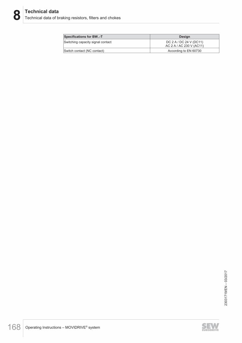
8 Technical dataTechnical data of braking resistors, filters and chokes
Operating Instructions – MOVIDRIVE® system168
Specifications for BW..-T DesignSwitching capacity signal contact DC 2 A / DC 24 V (DC11)
AC 2 A / AC 230 V (AC11)Switch contact (NC contact) According to EN 60730
2303
1719
/EN
– 0
3/20
17
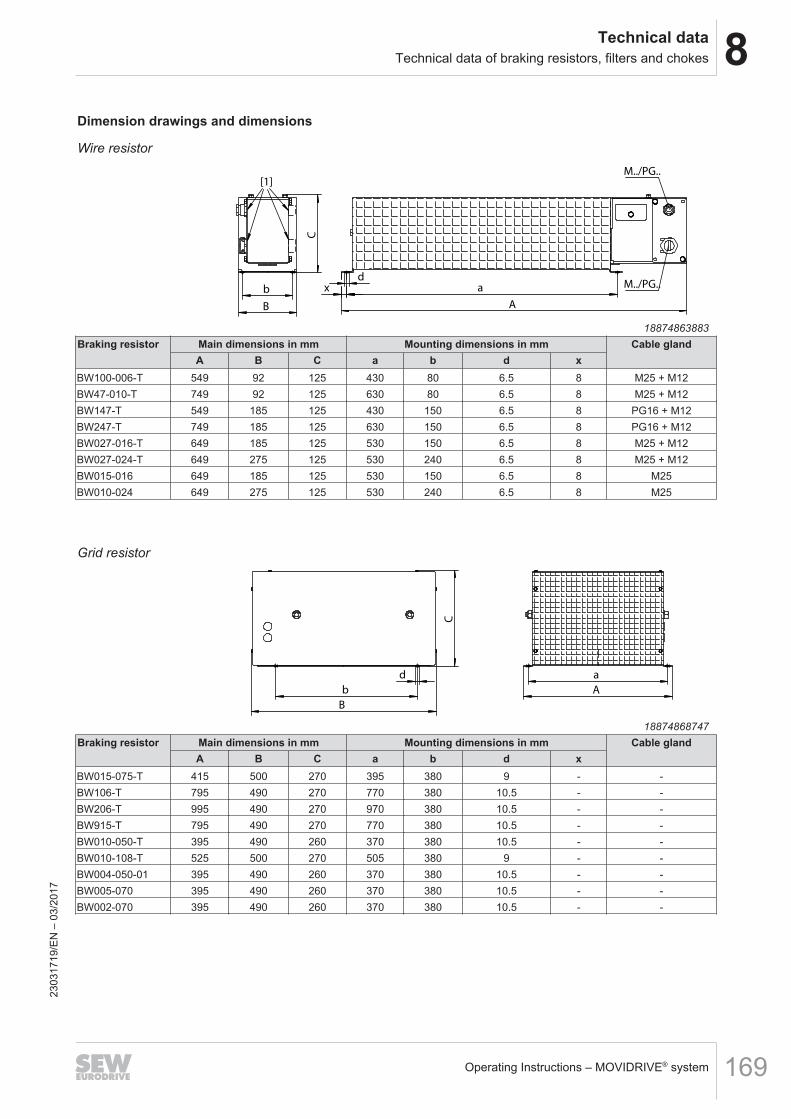
8Technical dataTechnical data of braking resistors, filters and chokes
Operating Instructions – MOVIDRIVE® system 169
Dimension drawings and dimensions
Wire resistor
A
d x a
M../PG..
M../PG..
C
B
b
[1]
18874863883Braking resistor Main dimensions in mm Mounting dimensions in mm Cable gland
A B C a b d xBW100-006-T 549 92 125 430 80 6.5 8 M25 + M12BW47-010-T 749 92 125 630 80 6.5 8 M25 + M12BW147-T 549 185 125 430 150 6.5 8 PG16 + M12BW247-T 749 185 125 630 150 6.5 8 PG16 + M12BW027-016-T 649 185 125 530 150 6.5 8 M25 + M12BW027-024-T 649 275 125 530 240 6.5 8 M25 + M12BW015-016 649 185 125 530 150 6.5 8 M25BW010-024 649 275 125 530 240 6.5 8 M25
Grid resistor
C
B
b
d
A
a
18874868747Braking resistor Main dimensions in mm Mounting dimensions in mm Cable gland
A B C a b d xBW015-075-T 415 500 270 395 380 9 - -BW106-T 795 490 270 770 380 10.5 - -BW206-T 995 490 270 970 380 10.5 - -BW915-T 795 490 270 770 380 10.5 - -BW010-050-T 395 490 260 370 380 10.5 - -BW010-108-T 525 500 270 505 380 9 - -BW004-050-01 395 490 260 370 380 10.5 - -BW005-070 395 490 260 370 380 10.5 - -BW002-070 395 490 260 370 380 10.5 - -
2303
1719
/EN
– 0
3/20
17
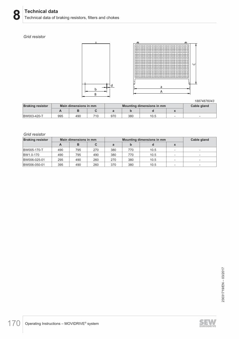
8 Technical dataTechnical data of braking resistors, filters and chokes
Operating Instructions – MOVIDRIVE® system170
Grid resistor
A
C
a
B
d
b
18874876043Braking resistor Main dimensions in mm Mounting dimensions in mm Cable gland
A B C a b d xBW003-420-T 995 490 710 970 380 10.5 - -
Grid resistorBraking resistor Main dimensions in mm Mounting dimensions in mm Cable gland
A B C a b d xBW005-170-T 490 795 270 380 770 10.5 - -BW1.0-170 490 795 490 380 770 10.5 - -BW006-025-01 295 490 260 270 380 10.5 - -BW006-050-01 395 490 260 370 380 10.5 - -
2303
1719
/EN
– 0
3/20
17
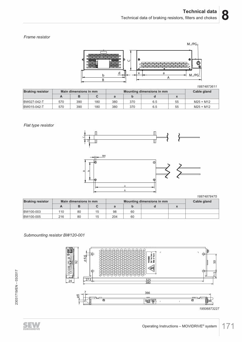
8Technical dataTechnical data of braking resistors, filters and chokes
Operating Instructions – MOVIDRIVE® system 171
Frame resistor
A
C
x a
M../PG..
M../PG..
B
d b
18874873611Braking resistor Main dimensions in mm Mounting dimensions in mm Cable gland
A B C a b d xBW027-042-T 570 390 180 380 370 6.5 55 M25 + M12BW015-042-T 570 390 180 380 370 6.5 55 M25 + M12
Flat type resistor
A
a
B b
M4
C
12
18874878475Braking resistor Main dimensions in mm Mounting dimensions in mm Cable gland
A B C a b d xBW100-003 110 80 15 98 60BW100-005 216 80 15 204 60
Submounting resistor BW120-001
6
50
6
.6
21
.5
92
27.5 325380
3667
24
19506873227
2303
1719
/EN
– 0
3/20
17
8 Technical dataTechnical data of braking resistors, filters and chokes
Operating Instructions – MOVIDRIVE® system172
8.9.2 TCB thermal circuit breaker option
GeneralThe TCB thermal circuit breaker protects the braking resistor from constant overloadand protects it in case of a short circuit in the cable or the braking resistor.In the event of a fault, the thermal circuit breaker disconnects the braking resistor andsignals this fault via isolated NO and NC contacts.After fault elimination, the thermal circuit breaker can be reset manually. For this pur-pose, there is a lever at the front, similar to the design of a miniature circuit breaker.The setting range of the thermal circuit breaker has to be selected in such a way that itcorresponds to the tripping current IF of the braking resistor.The switch reacts to the following events:• Thermal overload.• Short circuit.• Exceeded nominal current.In the event of a fault, the thermal circuit breaker switches off the braking resistor. Thepresent fault is signaled via isolated NO and NC contacts.After fault elimination, the thermal circuit breaker can be reconnected like a normalminiature circuit breaker.
Technical dataCircuit breaker type Unit TCB0040 TCB0063 TCB0100Part number 19170424 19170432 19170440Setting range A 2.5 – 4 4 – 6.3 6.3 – 10Connection cross section main contact mm2 1.5 – 16Tightening torque Nm 2.5Signal contact connection cross section mm2 0.5 – 1.5Tightening torque Nm 0.8Mechanical service life 20000 switching cycles
Circuit breaker type Unit TCB0160 TCB0200 TCB0250 TCB0320 TCB0400Part number 19170459 19148658 19170467 19170475 19170483Setting range A 10 – 16 16 – 20 20 – 25 25 – 32 32 – 40Connection cross section main contact mm2 2.5 – 16 4 – 16 6 – 16 10 – 16Tightening torque Nm 2.5Signal contact connection cross section mm2 0.5 – 1.5Tightening torque Nm 0.8Mechanical service life 20000 switching cycles
2303
1719
/EN
– 0
3/20
17
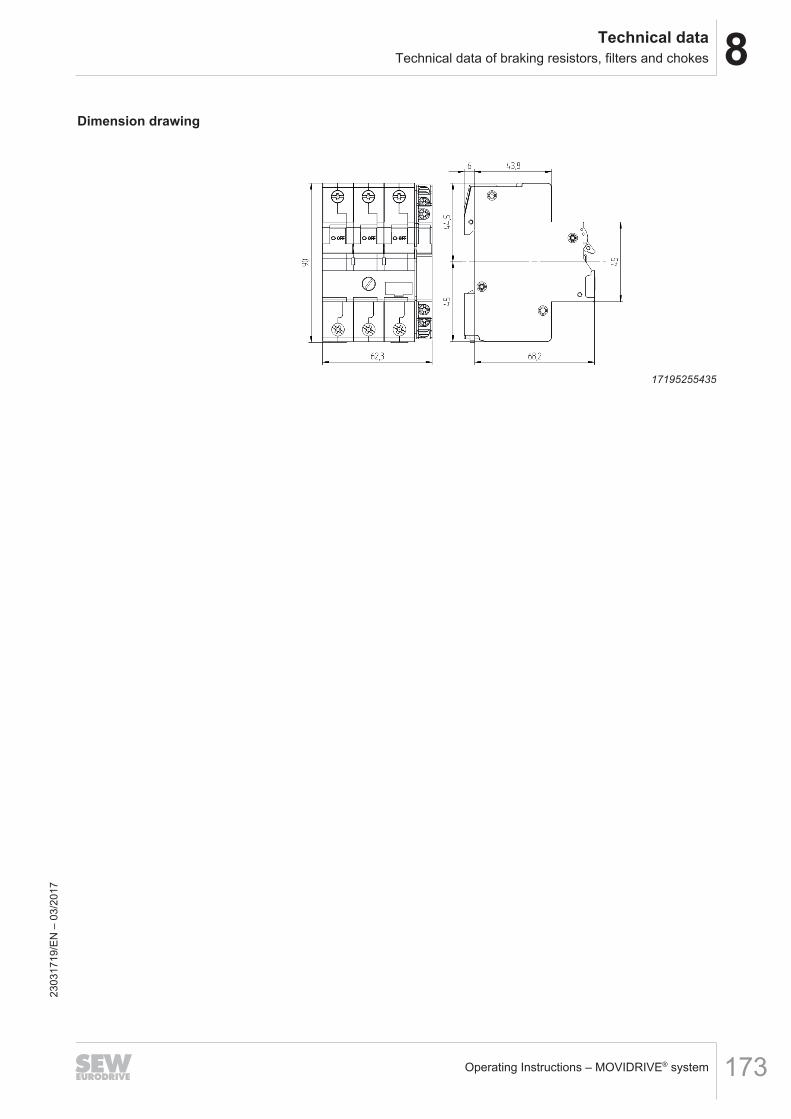
8Technical dataTechnical data of braking resistors, filters and chokes
Operating Instructions – MOVIDRIVE® system 173
Dimension drawing
17195255435
2303
1719
/EN
– 0
3/20
17
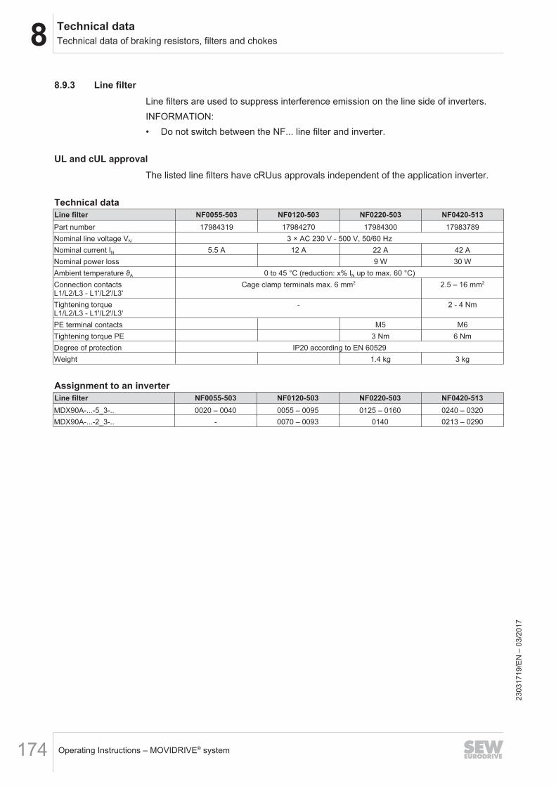
8 Technical dataTechnical data of braking resistors, filters and chokes
Operating Instructions – MOVIDRIVE® system174
8.9.3 Line filterLine filters are used to suppress interference emission on the line side of inverters.INFORMATION:• Do not switch between the NF... line filter and inverter.
UL and cUL approvalThe listed line filters have cRUus approvals independent of the application inverter.
Technical dataLine filter NF0055-503 NF0120-503 NF0220-503 NF0420-513Part number 17984319 17984270 17984300 17983789Nominal line voltage VN 3 × AC 230 V - 500 V, 50/60 HzNominal current IN 5.5 A 12 A 22 A 42 ANominal power loss 9 W 30 WAmbient temperature ϑA 0 to 45 °C (reduction: x% IN up to max. 60 °C)Connection contactsL1/L2/L3 - L1'/L2'/L3'
Cage clamp terminals max. 6 mm2 2.5 – 16 mm2
Tightening torqueL1/L2/L3 - L1'/L2'/L3'
- 2 - 4 Nm
PE terminal contacts M5 M6Tightening torque PE 3 Nm 6 NmDegree of protection IP20 according to EN 60529Weight 1.4 kg 3 kg
Assignment to an inverterLine filter NF0055-503 NF0120-503 NF0220-503 NF0420-513MDX90A-...-5_3-.. 0020 – 0040 0055 – 0095 0125 – 0160 0240 – 0320MDX90A-...-2_3-.. - 0070 – 0093 0140 0213 – 0290
2303
1719
/EN
– 0
3/20
17
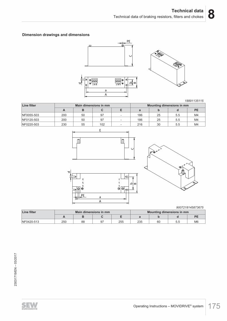
8Technical dataTechnical data of braking resistors, filters and chokes
Operating Instructions – MOVIDRIVE® system 175
Dimension drawings and dimensions
C
PE
A
a
B
b
d
18891135115Line filter Main dimensions in mm Mounting dimensions in mm
A B C E a b d PENF0055-503 200 50 97 - 186 25 5.5 M4NF0120-503 200 50 97 - 186 25 5.5 M4NF0220-503 230 55 102 - 216 30 5.5 M4
C
E
B
a
b
d
PE
A
9007218145873675Line filter Main dimensions in mm Mounting dimensions in mm
A B C E a b d PENF0420-513 250 88 97 255 235 60 5.5 M6
2303
1719
/EN
– 0
3/20
17
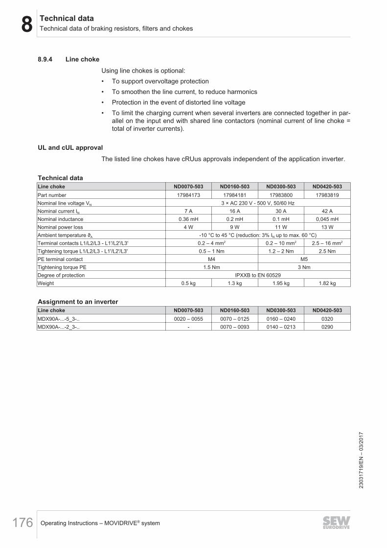
8 Technical dataTechnical data of braking resistors, filters and chokes
Operating Instructions – MOVIDRIVE® system176
8.9.4 Line chokeUsing line chokes is optional:• To support overvoltage protection• To smoothen the line current, to reduce harmonics• Protection in the event of distorted line voltage• To limit the charging current when several inverters are connected together in par-
allel on the input end with shared line contactors (nominal current of line choke =total of inverter currents).
UL and cUL approvalThe listed line chokes have cRUus approvals independent of the application inverter.
Technical dataLine choke ND0070-503 ND0160-503 ND0300-503 ND0420-503Part number 17984173 17984181 17983800 17983819Nominal line voltage VN 3 × AC 230 V - 500 V, 50/60 HzNominal current IN 7 A 16 A 30 A 42 ANominal inductance 0.36 mH 0.2 mH 0.1 mH 0,045 mHNominal power loss 4 W 9 W 11 W 13 WAmbient temperature ϑA -10 °C to 45 °C (reduction: 3% IN up to max. 60 °C)Terminal contacts L1/L2/L3 - L1'/L2'/L3' 0.2 – 4 mm2 0.2 – 10 mm2 2.5 – 16 mm2
Tightening torque L1/L2/L3 - L1'/L2'/L3' 0.5 – 1 Nm 1.2 – 2 Nm 2.5 NmPE terminal contact M4 M5Tightening torque PE 1.5 Nm 3 NmDegree of protection IPXXB to EN 60529Weight 0.5 kg 1.3 kg 1.95 kg 1.82 kg
Assignment to an inverterLine choke ND0070-503 ND0160-503 ND0300-503 ND0420-503MDX90A-...-5_3-.. 0020 – 0055 0070 – 0125 0160 – 0240 0320MDX90A-...-2_3-.. - 0070 – 0093 0140 – 0213 0290
2303
1719
/EN
– 0
3/20
17
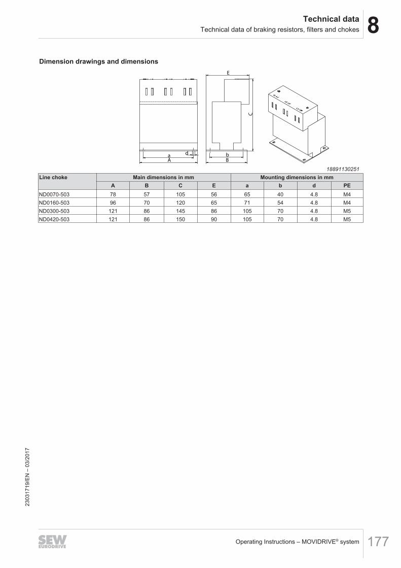
8Technical dataTechnical data of braking resistors, filters and chokes
Operating Instructions – MOVIDRIVE® system 177
Dimension drawings and dimensions
A a
d
B
C
E
b
18891130251Line choke Main dimensions in mm Mounting dimensions in mm
A B C E a b d PEND0070-503 78 57 105 56 65 40 4.8 M4ND0160-503 96 70 120 65 71 54 4.8 M4ND0300-503 121 86 145 86 105 70 4.8 M5ND0420-503 121 86 150 90 105 70 4.8 M5
2303
1719
/EN
– 0
3/20
17
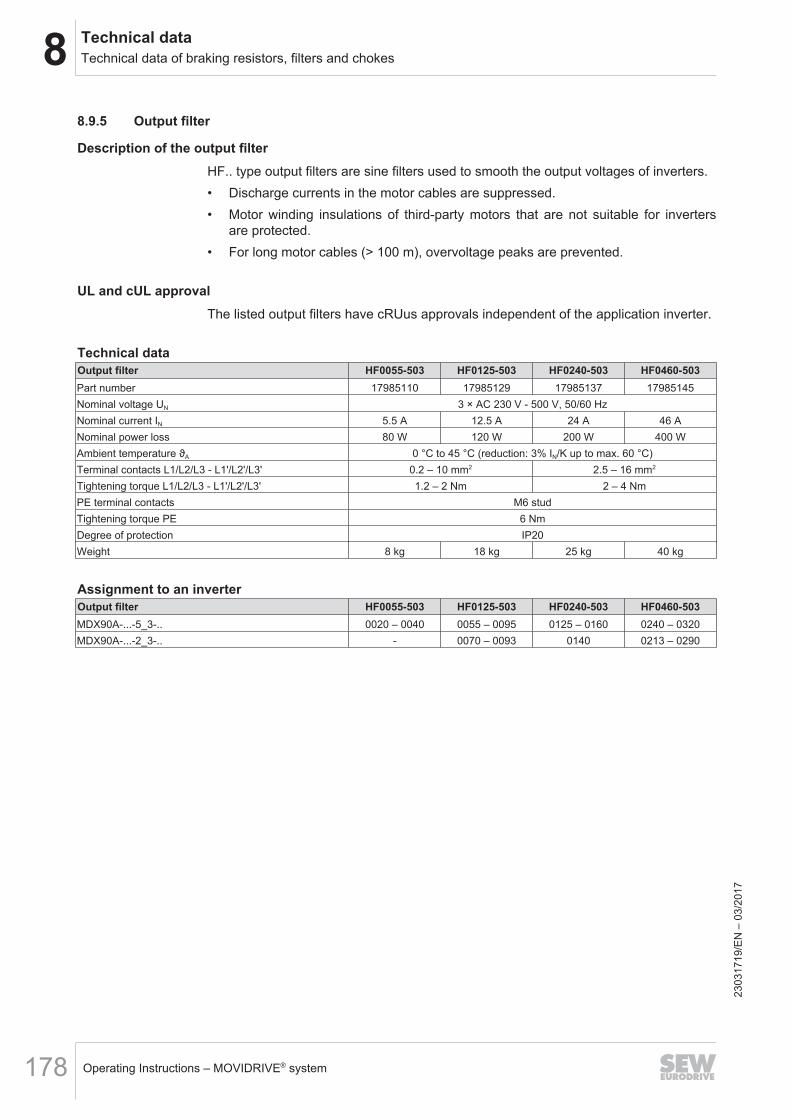
8 Technical dataTechnical data of braking resistors, filters and chokes
Operating Instructions – MOVIDRIVE® system178
8.9.5 Output filter
Description of the output filterHF.. type output filters are sine filters used to smooth the output voltages of inverters.• Discharge currents in the motor cables are suppressed.• Motor winding insulations of third-party motors that are not suitable for inverters
are protected.• For long motor cables (> 100 m), overvoltage peaks are prevented.
UL and cUL approvalThe listed output filters have cRUus approvals independent of the application inverter.
Technical dataOutput filter HF0055-503 HF0125-503 HF0240-503 HF0460-503Part number 17985110 17985129 17985137 17985145Nominal voltage UN 3 × AC 230 V - 500 V, 50/60 HzNominal current IN 5.5 A 12.5 A 24 A 46 ANominal power loss 80 W 120 W 200 W 400 WAmbient temperature ϑA 0 °C to 45 °C (reduction: 3% IN/K up to max. 60 °C)Terminal contacts L1/L2/L3 - L1'/L2'/L3' 0.2 – 10 mm2 2.5 – 16 mm2
Tightening torque L1/L2/L3 - L1'/L2'/L3' 1.2 – 2 Nm 2 – 4 NmPE terminal contacts M6 studTightening torque PE 6 NmDegree of protection IP20Weight 8 kg 18 kg 25 kg 40 kg
Assignment to an inverterOutput filter HF0055-503 HF0125-503 HF0240-503 HF0460-503MDX90A-...-5_3-.. 0020 – 0040 0055 – 0095 0125 – 0160 0240 – 0320MDX90A-...-2_3-.. - 0070 – 0093 0140 0213 – 0290
2303
1719
/EN
– 0
3/20
17
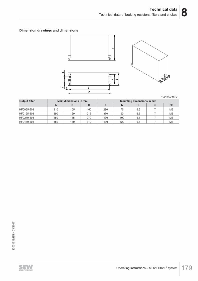
8Technical dataTechnical data of braking resistors, filters and chokes
Operating Instructions – MOVIDRIVE® system 179
Dimension drawings and dimensions
C
A
a
b
B
PE
d
x
19269071627Output filter Main dimensions in mm Mounting dimensions in mm
A B C a b d x PEHF0055-503 310 105 160 290 75 6.5 7 M6HF0125-503 390 120 215 370 90 6.5 7 M6HF0240-503 450 135 270 430 100 6.5 7 M6HF0460-503 450 160 310 430 120 6.5 7 M6
2303
1719
/EN
– 0
3/20
17
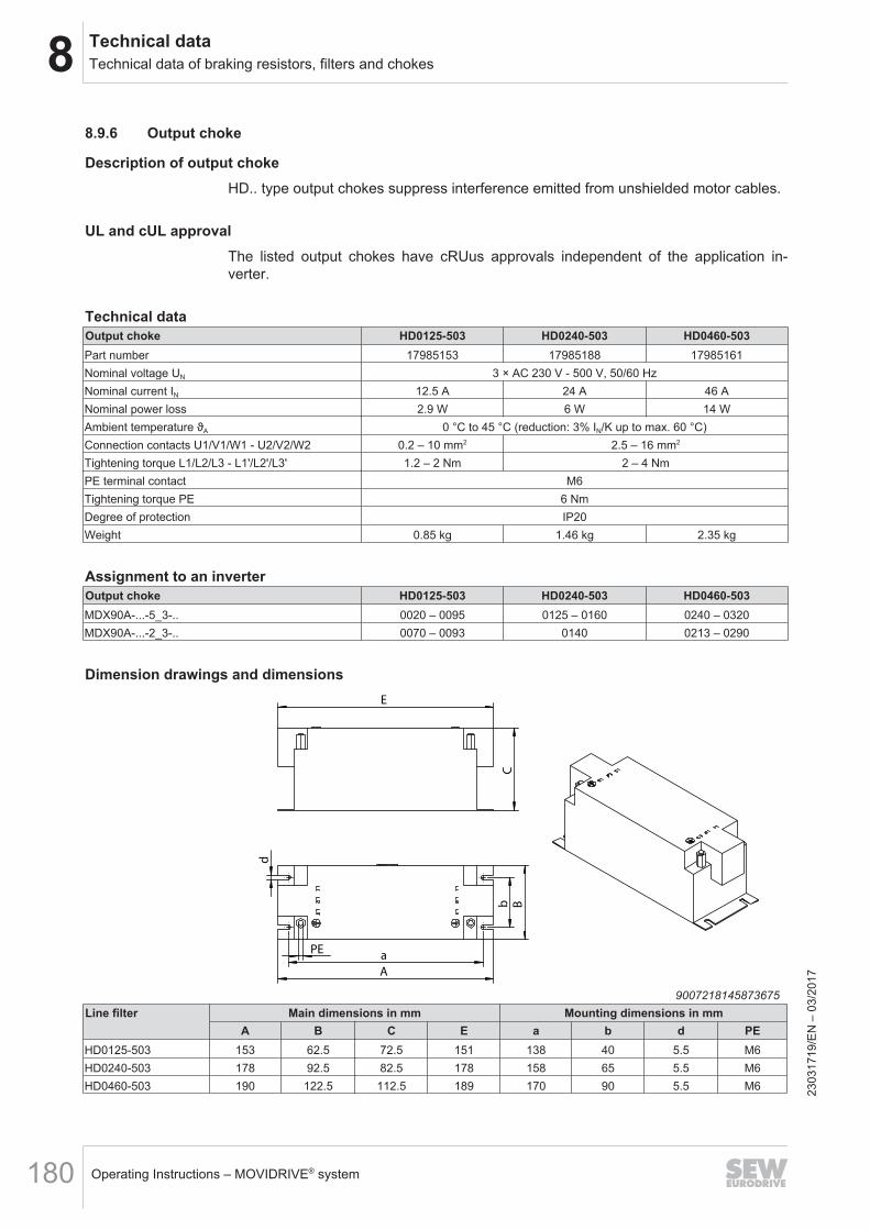
8 Technical dataTechnical data of braking resistors, filters and chokes
Operating Instructions – MOVIDRIVE® system180
8.9.6 Output choke
Description of output chokeHD.. type output chokes suppress interference emitted from unshielded motor cables.
UL and cUL approvalThe listed output chokes have cRUus approvals independent of the application in-verter.
Technical dataOutput choke HD0125-503 HD0240-503 HD0460-503Part number 17985153 17985188 17985161Nominal voltage UN 3 × AC 230 V - 500 V, 50/60 HzNominal current IN 12.5 A 24 A 46 ANominal power loss 2.9 W 6 W 14 WAmbient temperature ϑA 0 °C to 45 °C (reduction: 3% IN/K up to max. 60 °C)Connection contacts U1/V1/W1 - U2/V2/W2 0.2 – 10 mm2 2.5 – 16 mm2
Tightening torque L1/L2/L3 - L1'/L2'/L3' 1.2 – 2 Nm 2 – 4 NmPE terminal contact M6Tightening torque PE 6 NmDegree of protection IP20Weight 0.85 kg 1.46 kg 2.35 kg
Assignment to an inverterOutput choke HD0125-503 HD0240-503 HD0460-503MDX90A-...-5_3-.. 0020 – 0095 0125 – 0160 0240 – 0320MDX90A-...-2_3-.. 0070 – 0093 0140 0213 – 0290
Dimension drawings and dimensions
C
E
B
a
b
d
PE
A
9007218145873675Line filter Main dimensions in mm Mounting dimensions in mm
A B C E a b d PEHD0125-503 153 62.5 72.5 151 138 40 5.5 M6HD0240-503 178 92.5 82.5 178 158 65 5.5 M6HD0460-503 190 122.5 112.5 189 170 90 5.5 M6 23
0317
19/E
N –
03/
2017
9Functional safetyGeneral information
Operating Instructions – MOVIDRIVE® system 181
9 Functional safety9.1 General information9.1.1 Underlying standards
The safety assessment of the application inverter is based on the following standardsand safety classes:
Underlying standardsSafety class/underlying standard • Performance level (PL) according to
EN ISO 13849‑1:2008• Safety Integrity Level (SIL) according to
EN 61800‑5‑2:2007• Safety Integrity Level Claim Limit (SILCL) ac-
cording to EN 62061:2005/A1:2013
9.2 Integrated safety technologyThe safety technology of the application inverter described below has been developedand tested in accordance with the following safety requirements:• Safety Integrity Level 3 according to EN 61800-5-2:2007, EN 61508:2010.• PL e according to EN ISO 13849-1: 2008.This was certified by TÜV Rheinland. Copies of the TÜV certificate and the corres-ponding report are available from SEW‑EURODRIVE on request.
9.2.1 Safe conditionFor safety-related operation of the application inverter, safe torque off is defined assafe condition (see STO safety function). The safety concept is based on this.
9.2.2 Safety conceptThe application inverter is supposed to be able to perform the safety function "SafeTorque Off" according to EN 61800‑5‑2:• The application inverter is characterized by the optional connection of a safety re-
lay/external safety controller. This external safety controller/safety relay discon-nects the safety-related STO input via a 2-pole 24 V switching signal (sourcing/sinking) when a connected control device (e.g. emergency stop button with latch-ing function) is activated. This activates the STO function of the application in-verter.
• An internal, dual-channel structure with diagnostics prevents the generation ofpulse trains at the power output stage (IGBT).
• Instead of galvanic separation of the drive from the supply system by means ofcontactors or switches, the disconnection of the STO input described here safelyprevents the control of the power semiconductors in the output stage. The rotary-field generation for the respective motor is deactivated even though the linevoltage is still present.
• When the STO safety function is activated, the PWM signals generated by the ap-plication inverter are interrupted and not transmitted to the IGBTs.
2303
1719
/EN
– 0
3/20
17
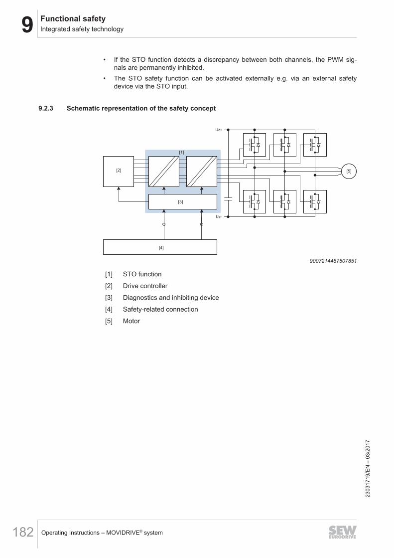
9 Functional safetyIntegrated safety technology
Operating Instructions – MOVIDRIVE® system182
• If the STO function detects a discrepancy between both channels, the PWM sig-nals are permanently inhibited.
• The STO safety function can be activated externally e.g. via an external safetydevice via the STO input.
9.2.3 Schematic representation of the safety concept
Uz+
Uz-
[2]
[3]
[4]
[5]
[1]
9007214467507851
[1] STO function
[2] Drive controller
[3] Diagnostics and inhibiting device
[4] Safety-related connection
[5] Motor
2303
1719
/EN
– 0
3/20
17
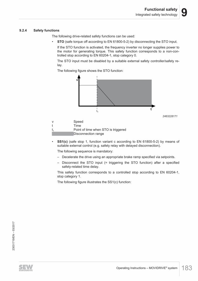
9Functional safetyIntegrated safety technology
Operating Instructions – MOVIDRIVE® system 183
9.2.4 Safety functionsThe following drive-related safety functions can be used:• STO (safe torque off according to EN 61800-5-2) by disconnecting the STO input.
If the STO function is activated, the frequency inverter no longer supplies power tothe motor for generating torque. This safety function corresponds to a non-con-trolled stop according to EN 60204-1, stop category 0.The STO input must be disabled by a suitable external safety controller/safety re-lay.The following figure shows the STO function:
v
tt1
2463228171
v Speedt Timet1 Point of time when STO is triggered
Disconnection range
• SS1(c) (safe stop 1, function variant c according to EN 61800-5-2) by means ofsuitable external control (e.g. safety relay with delayed disconnection).The following sequence is mandatory:– Decelerate the drive using an appropriate brake ramp specified via setpoints.– Disconnect the STO input (= triggering the STO function) after a specified
safety-related time delay.This safety function corresponds to a controlled stop according to EN 60204‑1,stop category 1.The following figure illustrates the SS1(c) function:
2303
1719
/EN
– 0
3/20
17
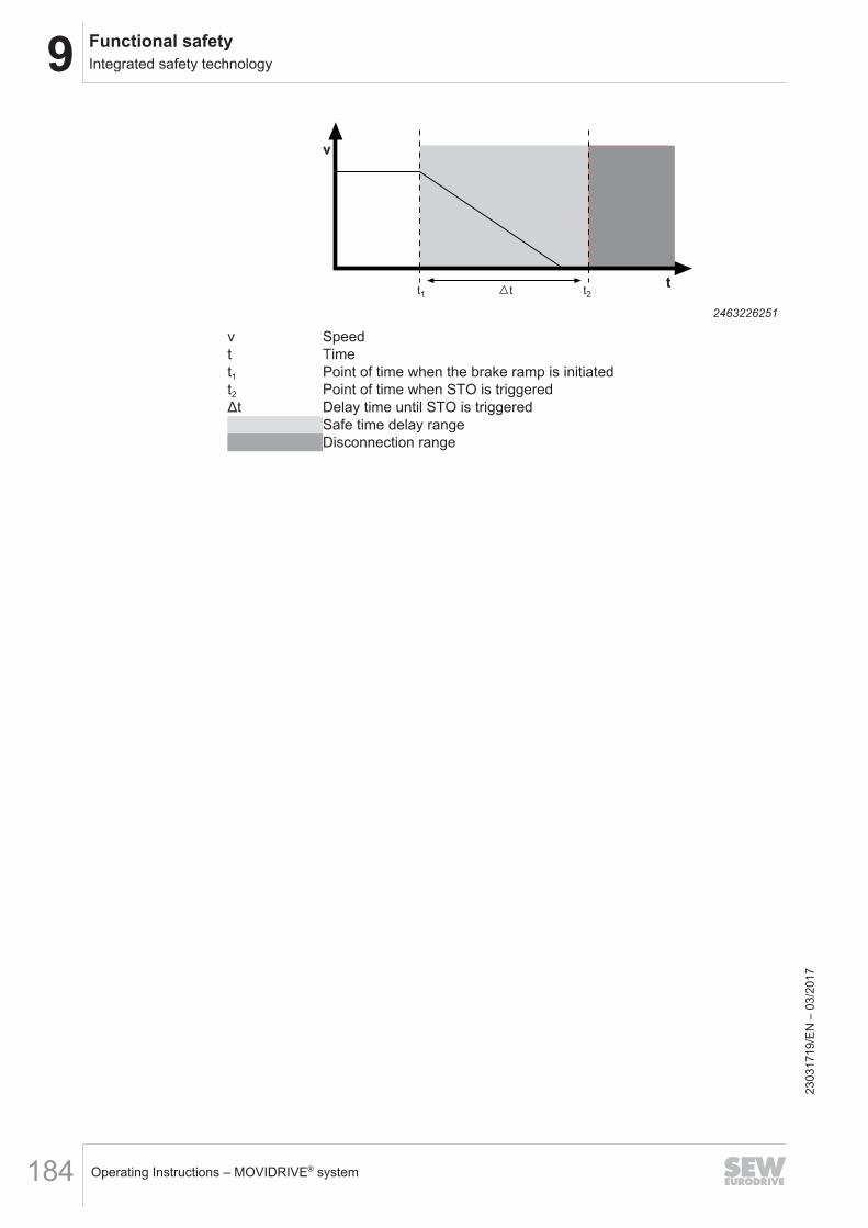
9 Functional safetyIntegrated safety technology
Operating Instructions – MOVIDRIVE® system184
v
tt1 t t2
2463226251
v Speedt Timet1 Point of time when the brake ramp is initiatedt2 Point of time when STO is triggeredΔt Delay time until STO is triggered
Safe time delay rangeDisconnection range
2303
1719
/EN
– 0
3/20
17
9Functional safetyIntegrated safety technology
Operating Instructions – MOVIDRIVE® system 185
9.2.5 Restrictions• Note that if the drive does not have a mechanical brake, or if the brake is defect-
ive, the drive may coast to a halt (depending on the friction and mass moment ofinertia of the system). In case of regenerative loads, or with axes that are loadedwith gravitational forces or driven externally, the drive can even accelerate. Thismust be taken into account in a risk assessment of the system/machine. Additionalsafety measures might have to be implemented (e.g. safety brake system).The application inverter cannot be used without an additional brake system for ap-plication-specific safety functions that require active deceleration (braking) of thedangerous movement.
• When using the SS1(c) function as described in chapter "Safetyfunctions" (→ 2 183), the brake ramp of the drive is not monitored with respect tosafety. In case of a fault, the drive might not be decelerated after the delay time, orit might be accelerated in the worst case. In this case, the safety-related discon-nection via the STO function is only activated after the set time delay has passed,see chapter "Safety functions" (→ 2 183). The resulting danger must be taken intoaccount in the risk assessment of the system/machine. Additional safety measuresmight have to be implemented.
• The STO function cannot prevent a possible jerk or DC braking.
WARNINGThe safety concept is only suitable for performing mechanical work on driven sys-tem/machine components.
When the STO signal is disconnected, the line voltage is still present at the DC linkof the application inverter.• Before working on the electric part of the drive system, disconnect it from the
supply voltage using an appropriate external disconnecting device and secure itagainst unintentional reconnection to the voltage supply.
WARNINGElectric shock due to charged capacitors.Severe or fatal injuries.• Observe a minimum switch-off time of 10 minutes after disconnecting the power
supply.
INFORMATIONIn case of safety-related disconnection of the DC 24 V supply voltage at X16 (STOactivated), the brake is always applied. The brake control in the application inverteris not safety-related.
2303
1719
/EN
– 0
3/20
17
9 Functional safetySafety conditions
Operating Instructions – MOVIDRIVE® system186
9.3 Safety conditions
The requirement for safe operation is that the safety functions of the application in-verter are properly integrated into an application-specific higher-level safety function.A system/machine-specific risk assessment must be carried out through the system/machine manufacturer and taken into account for the use of the drive system with theapplication inverter.The system/machine manufacturer and the operator are responsible for compliance ofthe system/machine with applicable safety regulations.The following requirements are mandatory when installing and operating the applica-tion inverter in safety-related applications:• Approved units.• Installation requirements.• Requirements on external safety controllers and safety relays.• Startup requirements.• Operation requirements.
9.3.1 Approved devicesThe following device types of MOVIDRIVE® system are permitted for safety-relatedapplications:
Application inverter Nominal output currentMOVIDRIVE® system 2 – 588 A
2303
1719
/EN
– 0
3/20
17
9Functional safetySafety conditions
Operating Instructions – MOVIDRIVE® system 187
9.3.2 Requirements on the installation• The components must be protected against conductive dirt, e.g. by installing them
in a control cabinet with degree of protection IP54 according to IEC 60529.If conductive dirt can be excluded at the installation site, a control cabinet withlower degree of protection is permitted under observance of the applicable stand-ards, e.g. EN 60204‑1.The same applies to temporary condensation, e.g. due to rapid changes of the am-bient temperature.
• The wiring technology used must comply with the standard EN 60204-1.• The STO control lines must be routed according to EMC guidelines and as follows:
– Inside an electrical installation space: Individual conductors can be routed.– Adhere to the relevant regulations in force for the application.– The sinking and sourcing cables from the external safety device to the axis
must be routed right next to each other with a cable length of ≤ 30 m.– The sinking and sourcing cables from the external safety device to the axis
must have the same cable length. A difference in length ≤ 3% of the two cablesis not permitted.
– The STO control cable must be routed separately to the power lines of thedrive.
• The STO function does not detect short circuits or interference voltage in the sup-ply line. This is why you must make sure that:– No parasitic voltages can occur in the STO control lines
or– The external safety controller can detect a crossfault from an external potential
to the STO control lines.• Observe the values specified for safety components when designing the safety cir-
cuits.• The STO signal (STO_P1, STO_P2, and STO_M) may not be used for feedback.• For safety controller/safety relays, you must only use grounded voltage sources
with protective electrical separation (PELV) according to EN 61131-2 andEN 60204-1.
• If several voltage sources are used, each voltage source must be connected to aPE system.
• When planning the installation, observe the technical data of the application in-verter.
• Do not use the 24-V-STO_Out of the application inverter for safety-related applica-tions. Voltage is only permitted to supply the connection for safe disconnection X6with plugged jumper plug.
• For safety-related applications with the application inverter, the jumper plug at theSTO input X6 must be removed.
2303
1719
/EN
– 0
3/20
17
9 Functional safetySafety conditions
Operating Instructions – MOVIDRIVE® system188
9.3.3 Requirements on the external safety controllerA safety relay can be used as an alternative to a safety controller. The following re-quirements apply analogously.• The safety controller and all other safety-related subsystems must be approved for
at least that safety class which is required in the overall system for the respective,application-related safety function.The following table shows an example of the required safety class of the safetycontroller:
Application Safety controller requirementsPerformance level d according to
EN ISO 13849-1, SIL 2 according toEN 62062
Performance level d according toEN ISO 13849‑1
SIL 2 according to EN 61508
Performance level e according toEN ISO 13849-1, SIL 3 according to
EN 62061
Performance level e according toEN ISO 13849-1, SIL 3 according to
EN 61508
• The wiring of the safety controller must be suitable for the required safety class,(see manufacturer documentation). The STO input of the application inverter canbe switched with 2 poles (sourcing, sourcing/sinking, or serial sourcing) or with 1pole (sourcing).
• The values specified for the safety controller must be strictly adhered to whendesigning the circuit.
• Electro-sensitive protective equipment (such as light grid or scanner) according toEN 61496‑1 and emergency stop buttons must not be directly connected to theSTO input. The connection must be realized using safety relays, safety controllersetc.
• To ensure protection against unintended restart in accordance with EN 1037, thesafe control system must be designed and connected in such a way that resettingthe control device alone does not lead to a restart. A restart may only be carriedout after a manual reset of the safety circuit.
• If no fault exclusion is used for the STO wiring according to EN ISO 13849‑2 orDIN EN 61800‑5‑2, the external safety device must detect the following faults inthe STO wiring within 20 s depending on the connection type:– 2-pole sourcing:
Short circuit of 24 V at STO_P1 or STO_P2 (Stuck-at 1)Crossfault between STO_P1 and STO_P2
– 2-pole sourcing/sinking:Short circuit of 24 V at STO_P1 (Stuck-at 1)Short circuit of 0 V at STO_M (Stuck-at 0)
– 2-pole serial sourcing:Fault exclusion is mandatory
– 1-pole sourcing:Short circuit of 24 V at STO_P (Stuck-at 1)
2-pole sourcing:• In disconnected state, no switch-on test pulses must occur in the sourcing cables.• In connected state: 23
0317
19/E
N –
03/
2017
9Functional safetySafety conditions
Operating Instructions – MOVIDRIVE® system 189
– The switch-off test pulses on both sourcing channels must be switched with atime delay. However, additional switch-off test pulses may occur simultan-eously.
– The switch-off test pulses in both sourcing channels must not exceed 1 ms.– The next switch-off test pulse in one sourcing channel must only occur after a
2 ms time period.– The signal levels must be played back by the safety controller and compared to
the expected value.2-pole sourcing/sinking:• In disconnected state, no switch-on test pulses must occur in the sourcing cable.• In connected state:
– The switch-off test pulses in the sourcing and sinking channel must not exceed1 ms.
– The next switch-off test pulse in the sourcing or sinking channel must only oc-cur after a 2 ms time period.
– The signal levels must be played back by the safety controller and compared tothe expected value.
2-pole serial sourcing:• Fault exclusion in the connection lead is mandatory if no external test pulses are
possible.1-pole sourcing:• In disconnected state, no switch-on test pulses must occur in the sourcing cable.• In connected state:
– The switch-off test pulse in the sourcing channel must not exceed 1 ms.– The next switch-off test pulse must only occur after a 2 ms time period.– The signal levels must be played back by the safety controller and compared to
the expected value.
2303
1719
/EN
– 0
3/20
17
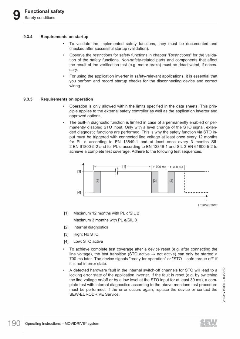
9 Functional safetySafety conditions
Operating Instructions – MOVIDRIVE® system190
9.3.4 Requirements on startup• To validate the implemented safety functions, they must be documented and
checked after successful startup (validation).• Observe the restrictions for safety functions in chapter "Restrictions" for the valida-
tion of the safety functions. Non-safety-related parts and components that affectthe result of the verification test (e.g. motor brake) must be deactivated, if neces-sary.
• For using the application inverter in safety-relevant applications, it is essential thatyou perform and record startup checks for the disconnecting device and correctwiring.
9.3.5 Requirements on operation• Operation is only allowed within the limits specified in the data sheets. This prin-
ciple applies to the external safety controller as well as the application inverter andapproved options.
• The built-in diagnostic function is limited in case of a permanently enabled or per-manently disabled STO input. Only with a level change of the STO signal, exten-ded diagnostic functions are performed. This is why the safety function via STO in-put must be triggered with connected line voltage at least once every 12 monthsfor PL d according to EN 13849‑1 and at least once every 3 months SIL2 EN 61800‑5‑2 and for PL e according to EN 13849‑1 and SIL 3 EN 61800‑5‑2 toachieve a complete test coverage. Adhere to the following test sequences.
[1] > 700 ms > 700 ms
[3]
t
[2] [2] [2]
[4]
15205932683
[1] Maximum 12 months with PL d/SIL 2Maximum 3 months with PL e/SIL 3
[2] Internal diagnostics
[3] High: No STO
[4] Low: STO active
• To achieve complete test coverage after a device reset (e.g. after connecting theline voltage), the test transition (STO active → not active) can only be started >700 ms later. The device signals "ready for operation" or "STO – safe torque off" ifit is not in error state.
• A detected hardware fault in the internal switch-off channels for STO will lead to alocking error state of the application inverter. If the fault is reset (e.g. by switchingthe line voltage on/off or by a low level at the STO input for at least 30 ms), a com-plete test with internal diagnostics according to the above mentions test proceduremust be performed. If the error occurs again, replace the device or contact theSEW‑EURODRIVE Service.
2303
1719
/EN
– 0
3/20
17
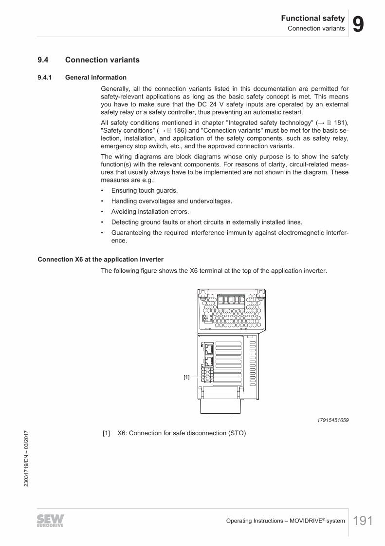
9Functional safetyConnection variants
Operating Instructions – MOVIDRIVE® system 191
9.4 Connection variants
9.4.1 General informationGenerally, all the connection variants listed in this documentation are permitted forsafety-relevant applications as long as the basic safety concept is met. This meansyou have to make sure that the DC 24 V safety inputs are operated by an externalsafety relay or a safety controller, thus preventing an automatic restart.All safety conditions mentioned in chapter "Integrated safety technology" (→ 2 181),"Safety conditions" (→ 2 186) and "Connection variants" must be met for the basic se-lection, installation, and application of the safety components, such as safety relay,emergency stop switch, etc., and the approved connection variants.The wiring diagrams are block diagrams whose only purpose is to show the safetyfunction(s) with the relevant components. For reasons of clarity, circuit-related meas-ures that usually always have to be implemented are not shown in the diagram. Thesemeasures are e.g.:• Ensuring touch guards.• Handling overvoltages and undervoltages.• Avoiding installation errors.• Detecting ground faults or short circuits in externally installed lines.• Guaranteeing the required interference immunity against electromagnetic interfer-
ence.
Connection X6 at the application inverterThe following figure shows the X6 terminal at the top of the application inverter.
[1]
1
2
3
4
5
17915451659
[1] X6: Connection for safe disconnection (STO)
2303
1719
/EN
– 0
3/20
17
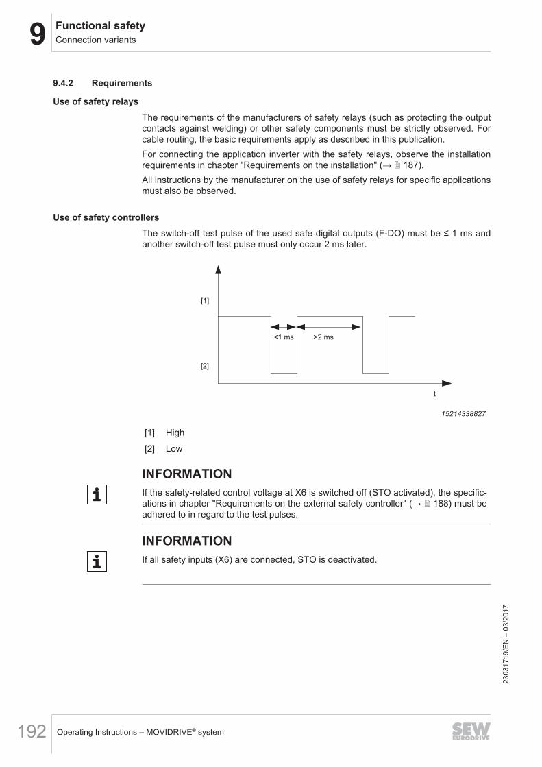
9 Functional safetyConnection variants
Operating Instructions – MOVIDRIVE® system192
9.4.2 Requirements
Use of safety relaysThe requirements of the manufacturers of safety relays (such as protecting the outputcontacts against welding) or other safety components must be strictly observed. Forcable routing, the basic requirements apply as described in this publication.For connecting the application inverter with the safety relays, observe the installationrequirements in chapter "Requirements on the installation" (→ 2 187).All instructions by the manufacturer on the use of safety relays for specific applicationsmust also be observed.
Use of safety controllersThe switch-off test pulse of the used safe digital outputs (F-DO) must be ≤ 1 ms andanother switch-off test pulse must only occur 2 ms later.
<1 ms >2 ms
t
[1]
[2]
15214338827
[1] High
[2] Low
INFORMATIONIf the safety-related control voltage at X6 is switched off (STO activated), the specific-ations in chapter "Requirements on the external safety controller" (→ 2 188) must beadhered to in regard to the test pulses.
INFORMATIONIf all safety inputs (X6) are connected, STO is deactivated.
2303
1719
/EN
– 0
3/20
17
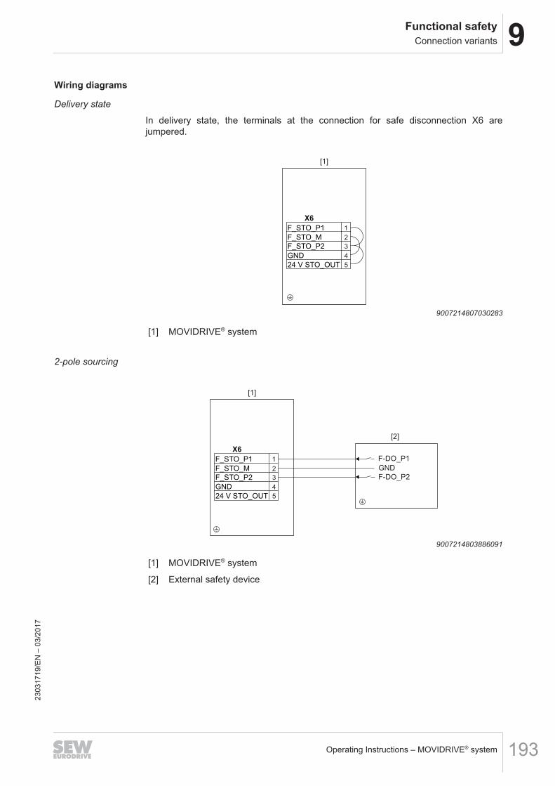
9Functional safetyConnection variants
Operating Instructions – MOVIDRIVE® system 193
Wiring diagrams
Delivery state
In delivery state, the terminals at the connection for safe disconnection X6 arejumpered.
2
X6
1
3
4
5
F_STO_P1
F_STO_M
F_STO_P2
GND
24 V STO_OUT
[1]
9007214807030283
[1] MOVIDRIVE® system
2-pole sourcing
[2]
2
X6
1
3
4
5
F_STO_P1
F_STO_M
F_STO_P2
GND
24 V STO_OUT
F-DO_P1
F-DO_P2
GND
[1]
9007214803886091
[1] MOVIDRIVE® system
[2] External safety device
2303
1719
/EN
– 0
3/20
17
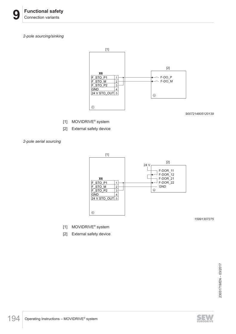
9 Functional safetyConnection variants
Operating Instructions – MOVIDRIVE® system194
2-pole sourcing/sinking
[2]
2
X6
1
3
4
5
F_STO_P1
F_STO_M
F_STO_P2
GND
24 V STO_OUT
F-DO_P
F-DO_M
[1]
9007214805120139
[1] MOVIDRIVE® system
[2] External safety device
2-pole serial sourcing
[2]
2
X6
1
3
4
5
F_STO_P1
F_STO_M
F_STO_P2
GND
24 V STO_OUT
F-DOR_22
GND
[1]
F-DOR_21
F-DOR_12
F-DOR_11
24 V
15991307275
[1] MOVIDRIVE® system
[2] External safety device
2303
1719
/EN
– 0
3/20
17
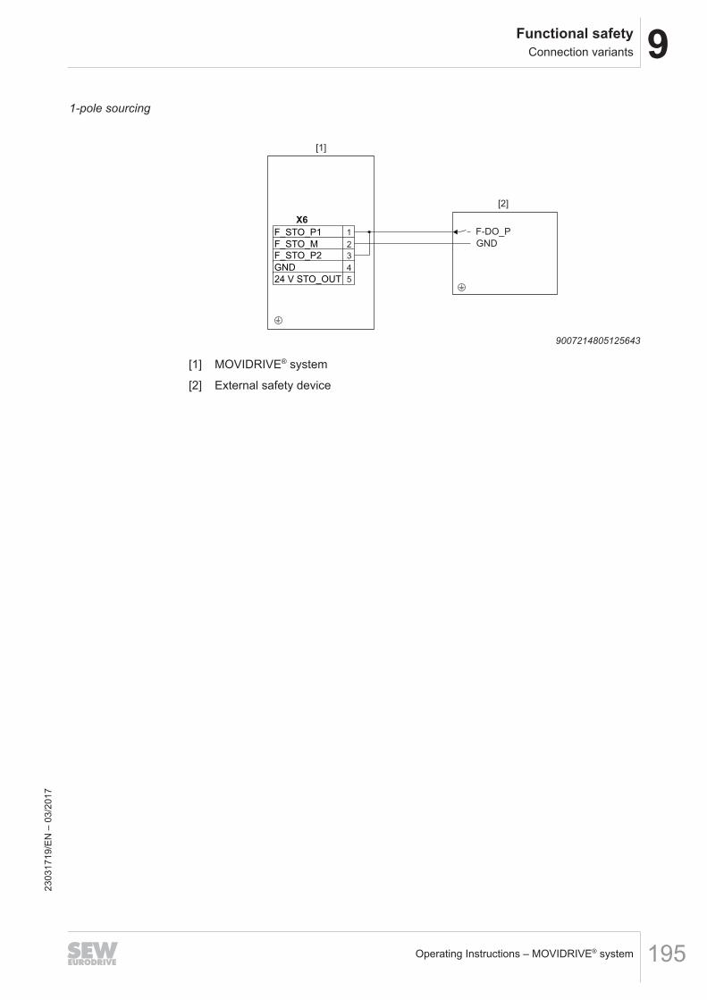
9Functional safetyConnection variants
Operating Instructions – MOVIDRIVE® system 195
1-pole sourcing
[2]
2
X6
1
3
4
5
F_STO_P1
F_STO_M
F_STO_P2
GND
24 V STO_OUT
F-DO_P
GND
[1]
9007214805125643
[1] MOVIDRIVE® system
[2] External safety device
2303
1719
/EN
– 0
3/20
17
9 Functional safetyConnection variants
Operating Instructions – MOVIDRIVE® system196
9.4.3 STO signal for group disconnectionFor group drives, the STO signal for several application inverters can be provided by asingle safety relay. The following requirements must be met:• The cable length is limited to 30 m. Other instructions published by the manufac-
turer on the use of the safety device (for the respective application) must also beobserved.
• The maximum output current and the maximally permitted contact load of thesafety device must be observed.
• You must comply with the permitted signal levels at the STO input and all othertechnical data of the application inverter. The routing of the STO control cablesand the voltage drop must be considered.
• Other requirements of the safety manufacturer (such as protecting the output con-tacts against welding) must be strictly observed. The basic cable routing require-ments apply.
• A calculation based on the technical data of the application inverter must be per-formed separately for each case of group drive disconnection.
• A maximum of 20 axes of the application inverter must be used in a group discon-nection.
2303
1719
/EN
– 0
3/20
17
9Functional safetySafety characteristics
Operating Instructions – MOVIDRIVE® system 197
9.5 Safety characteristics
Characteristic values according toEN 61800-5-2 EN ISO 13849-1
Tested safety class/underlying stand-ards
Safety integrity level 3 Performance level e
Probability of dangerous failure perhour (PFH value)
2.5 × 10⁻⁹ 1/h
Service life 20 years, after which the component must be replaced with a newone.
Proof test interval > 20 years -
Safe state Safe torque off (STO)
Safety function STO, SS11) according to EN 61800-5-21) With suitable external control
INFORMATIONWith 1-pole wiring, the realizable performance level according to EN ISO 13849 is re-duced to PL d. For the wiring between safety relay and STO input, an fault exclusionis necessary.
2303
1719
/EN
– 0
3/20
17
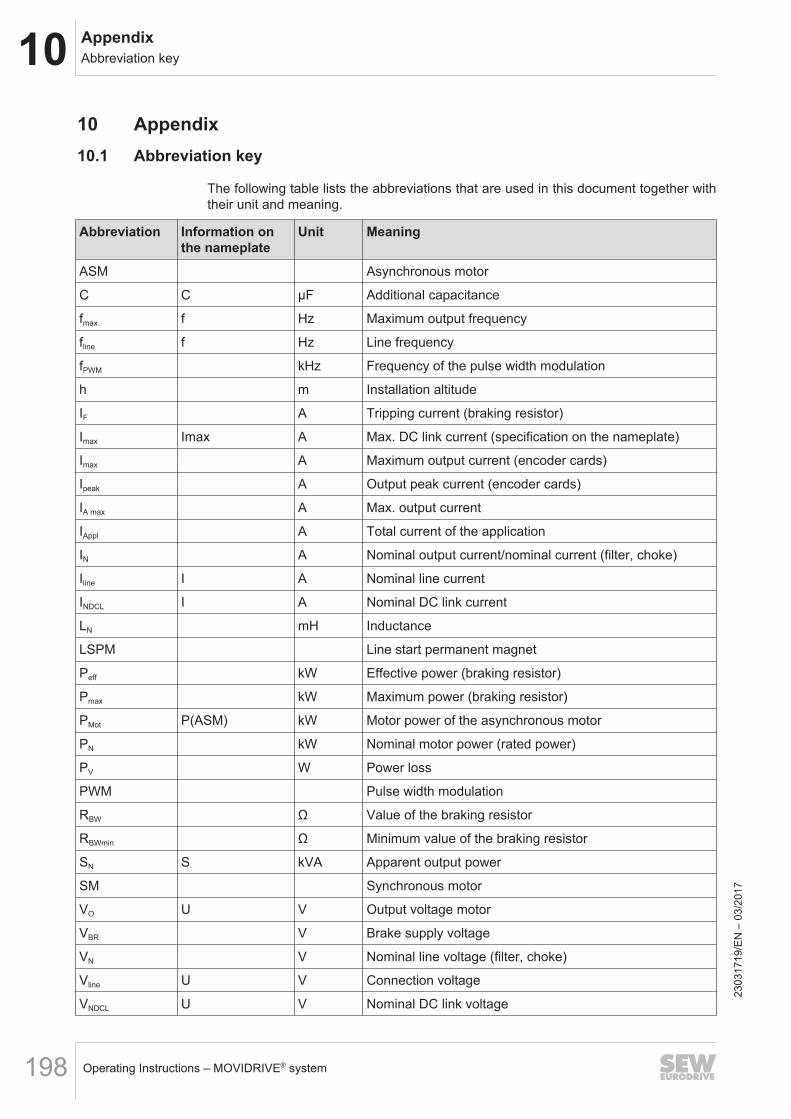
10 AppendixAbbreviation key
Operating Instructions – MOVIDRIVE® system198
10 Appendix10.1 Abbreviation key
The following table lists the abbreviations that are used in this document together withtheir unit and meaning.
Abbreviation Information onthe nameplate
Unit Meaning
ASM Asynchronous motor
C C μF Additional capacitance
fmax f Hz Maximum output frequency
fline f Hz Line frequency
fPWM kHz Frequency of the pulse width modulation
h m Installation altitude
IF A Tripping current (braking resistor)
Imax Imax A Max. DC link current (specification on the nameplate)
Imax A Maximum output current (encoder cards)
Ipeak A Output peak current (encoder cards)
IA max A Max. output current
IAppl A Total current of the application
IN A Nominal output current/nominal current (filter, choke)
Iline I A Nominal line current
INDCL I A Nominal DC link current
LN mH Inductance
LSPM Line start permanent magnet
Peff kW Effective power (braking resistor)
Pmax kW Maximum power (braking resistor)
PMot P(ASM) kW Motor power of the asynchronous motor
PN kW Nominal motor power (rated power)
PV W Power loss
PWM Pulse width modulation
RBW Ω Value of the braking resistor
RBWmin Ω Minimum value of the braking resistor
SN S kVA Apparent output power
SM Synchronous motor
VO U V Output voltage motor
VBR V Brake supply voltage
VN V Nominal line voltage (filter, choke)
Vline U V Connection voltage
VNDCL U V Nominal DC link voltage
2303
1719
/EN
– 0
3/20
17
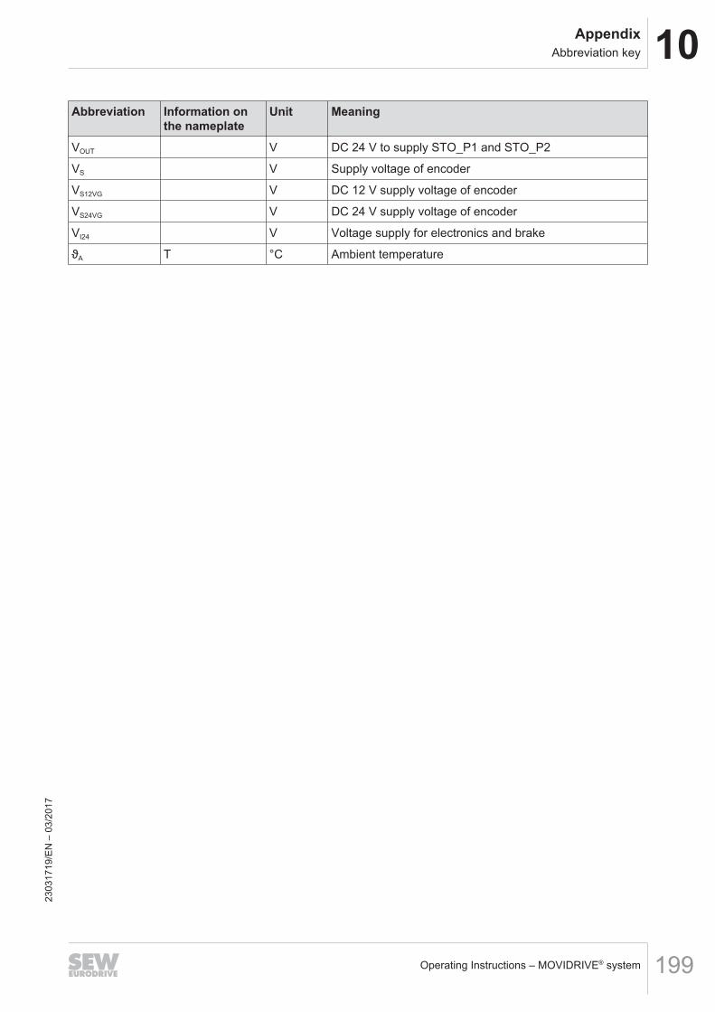
10AppendixAbbreviation key
Operating Instructions – MOVIDRIVE® system 199
Abbreviation Information onthe nameplate
Unit Meaning
VOUT V DC 24 V to supply STO_P1 and STO_P2
VS V Supply voltage of encoder
VS12VG V DC 12 V supply voltage of encoder
VS24VG V DC 24 V supply voltage of encoder
VI24 V Voltage supply for electronics and brake
ϑA T °C Ambient temperature
2303
1719
/EN
– 0
3/20
17
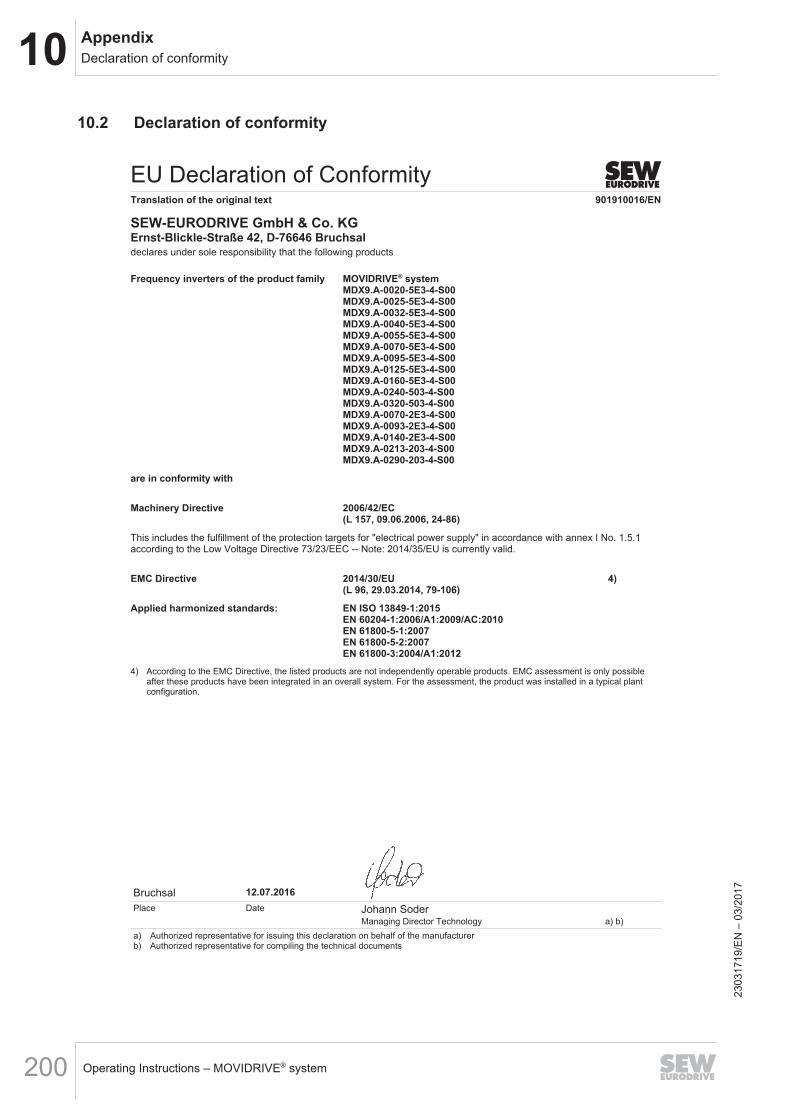
10 AppendixDeclaration of conformity
Operating Instructions – MOVIDRIVE® system200
10.2 Declaration of conformity
EU Declaration of ConformityTranslation of the original text 901910016/EN
SEW-EURODRIVE GmbH & Co. KGErnst-Blickle-Straße 42, D-76646 Bruchsaldeclares under sole responsibility that the following products
Bruchsal
a) Authorized representative for issuing this declaration on behalf of the manufacturerb) Authorized representative for compiling the technical documents
Place Date
12.07.2016
Managing Director TechnologyJohann Soder
a) b)
Frequency inverters of the product family MOVIDRIVE® systemMDX9.A-0020-5E3-4-S00MDX9.A-0025-5E3-4-S00MDX9.A-0032-5E3-4-S00MDX9.A-0040-5E3-4-S00MDX9.A-0055-5E3-4-S00MDX9.A-0070-5E3-4-S00MDX9.A-0095-5E3-4-S00MDX9.A-0125-5E3-4-S00MDX9.A-0160-5E3-4-S00MDX9.A-0240-503-4-S00MDX9.A-0320-503-4-S00MDX9.A-0070-2E3-4-S00MDX9.A-0093-2E3-4-S00MDX9.A-0140-2E3-4-S00MDX9.A-0213-203-4-S00MDX9.A-0290-203-4-S00
are in conformity with
Machinery Directive 2006/42/EC(L 157, 09.06.2006, 24-86)
This includes the fulfillment of the protection targets for "electrical power supply" in accordance with annex I No. 1.5.1according to the Low Voltage Directive 73/23/EEC -- Note: 2014/35/EU is currently valid.
EMC Directive 2014/30/EU 4)(L 96, 29.03.2014, 79-106)
Applied harmonized standards: EN ISO 13849-1:2015EN 60204-1:2006/A1:2009/AC:2010EN 61800-5-1:2007EN 61800-5-2:2007EN 61800-3:2004/A1:2012
4) According to the EMC Directive, the listed products are not independently operable products. EMC assessment is only possibleafter these products have been integrated in an overall system. For the assessment, the product was installed in a typical plantconfiguration.
2303
1719
/EN
– 0
3/20
17
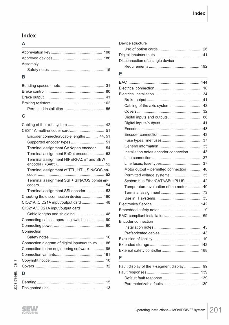
Index
IndexA
Abbreviation key................................................ 198Approved devices.............................................. 186Assembly
Safety notes ................................................... 15
B
Bending spaces - note......................................... 31Brake control ....................................................... 80Brake output ........................................................ 41Braking resistors................................................ 162
Permitted installation ...................................... 56
C
Cabling of the axis system .................................. 42CES11A multi-encoder card................................ 51
Encoder connection/cable lengths ........... 44, 51Supported encoder types ............................... 51Terminal assignment CANopen encoder ....... 54Terminal assignment EnDat encoder ............. 53Terminal assignment HIPERFACE® and SEWencoder (RS485) ............................................ 52Terminal assignment of TTL, HTL, SIN/COS en-coder .............................................................. 52Terminal assignment SSI + SIN/COS combi en-coders............................................................. 54Terminal assignment SSI encoder ................. 53
Checking the disconnection device ................... 190CIO21A, CID21A input/output card ..................... 48CIO21A/CID21A input/output card
Cable lengths and shielding ........................... 48Connecting cables, operating switches. .............. 90Connecting power ............................................... 90Connection
Safety notes ................................................... 16Connection diagram of digital inputs/outputs ...... 86Connection to the engineering software.............. 95Connection variants........................................... 191Copyright notice .................................................. 10Covers ................................................................. 32
D
Derating............................................................... 15Designated use ................................................... 13
Device structureUse of option cards ........................................ 26
Digital inputs/outputs ........................................... 41Disconnection of a single device
Requirements ............................................... 192
E
EAC ................................................................... 144Electrical connection ........................................... 16Electrical installation............................................ 34
Brake output ................................................... 41Cabling of the axis system ............................. 42Covers ............................................................ 32Digital inputs and outputs ............................... 86Digital inputs/outputs ...................................... 41Encoder .......................................................... 43Encoder connection........................................ 43Fuse types, line fuses..................................... 37General information........................................ 35Installation notes encoder connection ............ 43Line connection .............................................. 37Line fuses, fuse types..................................... 37Motor output – permitted connection.............. 40Permitted voltage systems ............................. 35System bus EtherCAT®/SBusPLUS ............... 42Temperature evaluation of the motor ............. 40Terminal assignment ...................................... 73Use in IT systems........................................... 35
Electronics Service............................................ 142Embedded safety notes......................................... 9EMC-compliant installation.................................. 69Encoder connection
Installation notes ............................................ 43Prefabricated cables....................................... 43
Exclusion of liability ............................................. 10Extended storage .............................................. 142External safety controller ................................... 188
F
Fault display of the 7-segment display ................ 99Fault responses................................................. 139
Default fault response .................................. 139Parameterizable faults.................................. 139
2303
1719
/EN
– 0
3/17
Operating Instructions – MOVIDRIVE® system 201
Index
Functional safety technologySafety note ..................................................... 14
Fuse types, line fuses.......................................... 37
H
Hazard symbolsMeaning............................................................ 9
I
InstallationElectrical installation....................................... 34EMC-compliant installation............................. 69Line filter......................................................... 68Permitted installation of braking resistors....... 56Permitted tightening torques .......................... 28Requirements ............................................... 187
Installation instructionsDerating.......................................................... 15Installation altitudes........................................ 15
Installing options and accessoriesCES11A multi-encoder card........................... 51CID21A terminal assignment.......................... 50CIO21A terminal assignment ......................... 49CIO21A, CID21A input/output card ................ 48
IT systems ........................................................... 35
L
Lifting applications......................................... 13, 90Line choke for power supply module......... 174, 176Line connection ................................................... 37Line fuses, fuse types.......................................... 37
M
Mechanical accessories ...................................... 27Minimum clearance and mounting position ......... 31Motor output – permitted connection................... 40
N
NotesDesignation in the documentation .................... 8Meaning of the hazard symbols ....................... 9
O
Operating displays and faultsTable of displays .......................................... 100
Operating states of the 7-segment display.......... 99
operationFault display of the 7-segment display ........... 99Fault responses............................................ 139Fieldbus timeout ........................................... 138Operating states of the 7-segment display..... 99Responses to error reset.............................. 137Safety notes ................................................... 17Software reset .............................................. 137Software restart ............................................ 137Table of displays .......................................... 100Warm start.................................................... 138
Operation, requirements.................................... 190Option cards, possible combinations................... 26
P
Permitted tightening torques ............................... 28Permitted voltage systems .................................. 35Product names .................................................... 10Protective separation........................................... 16
R
Repair ................................................................ 142Requirements
External safety controller.............................. 188Installation .................................................... 187Operation...................................................... 190Startup.......................................................... 190
Responses to error acknowledgementFieldbus timeout ........................................... 138Software reset .............................................. 137Software restart ............................................ 137Warm start.................................................... 138
Responses to error reset ................................... 137Restrictions to application ................................... 15Rights to claim under limited warranty .................. 9
S
Safe condition.................................................... 181Safe torque off (STO) ........................................ 183Safety concept................................................... 181
Restrictions................................................... 185Safety controller, external.................................. 188
Requirements ............................................... 188Safety controllers, requirements........................ 192Safety functions................................................... 14Safety functions - electronics data .................... 152
2303
1719
/EN
– 0
3/17
Operating Instructions – MOVIDRIVE® system202
Index
Safety notesAssembly........................................................ 15Designation in the documentation .................... 8Installation ...................................................... 15Meaning of the hazard symbols ....................... 9Preliminary information................................... 12Regenerative operation .................................. 16Structure of embedded..................................... 9Structure of the section-related ........................ 8
Safety relays, requirements............................... 192Safety technology
Safe condition............................................... 181Safety-relevant conditions ................................. 186Section-related safety notes.................................. 8Separation, protective ......................................... 16Service
Extended storage ......................................... 142Shutdown ..................................................... 143
Setting the EtherCAT®/SBusPLUS ID ................. 91Shutdown .......................................................... 143Signal terminals - electronics data .................... 151Signal words in safety notes.................................. 8Standard accessories
Mechanical accessories ................................. 27Standards .......................................................... 181Startup
Connecting cables, operating switches .......... 90Connecting power .......................................... 90Connection to the engineering software......... 95Lifting applications.......................................... 90Safety notes ................................................... 17Setting the EtherCAT®/SBusPLUS ID ............ 91
Startup, requirements........................................ 190STO (safe torque off)......................................... 183System bus EtherCAT®/SBusPLUS .................... 42
T
Target group........................................................ 12Technical data
CES11A multi-encoder card......................... 160CIO21A and CID21A input/output cards ...... 158Line choke for power supply module............ 176Line components for power supply module.. 174TCB thermal circuit breaker.......................... 172Technical data of encoder interfaces ........... 161Technical data of the option cards ............... 158
Technical data of encoder interfaces ................ 161Temperature evaluation of the motor .................. 40Terminal assignment ........................................... 73
CID21A........................................................... 50CIO21A........................................................... 49
Tightening torques............................................... 28Trademarks ......................................................... 10Transport ............................................................. 14
U
Use in IT systems................................................ 35Use of option cards ............................................. 26
V
Validating the safety functions........................... 190Validation........................................................... 190Validity ............................................................... 181
W
Waste disposal .................................................. 143Wiring diagrams
Brake control .................................................. 80Connection diagram of digital inputs .............. 86General information........................................ 77Power connection........................................... 77
2303
1719
/EN
– 0
3/17
Operating Instructions – MOVIDRIVE® system 203
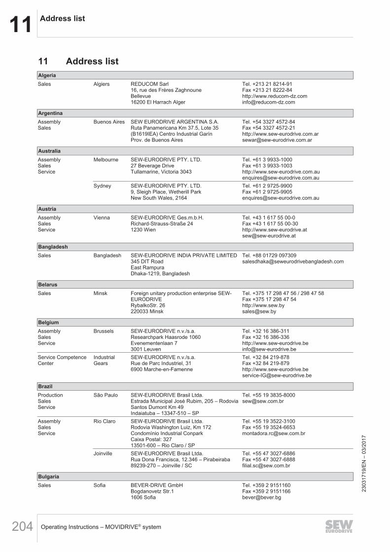
11 Address list
Operating Instructions – MOVIDRIVE® system204
11 Address listAlgeriaSales Algiers REDUCOM Sarl
16, rue des Frères ZaghnouneBellevue16200 El Harrach Alger
Tel. +213 21 8214-91Fax +213 21 8222-84http://[email protected]
ArgentinaAssemblySales
Buenos Aires SEW EURODRIVE ARGENTINA S.A.Ruta Panamericana Km 37.5, Lote 35(B1619IEA) Centro Industrial GarínProv. de Buenos Aires
Tel. +54 3327 4572-84Fax +54 3327 4572-21http://[email protected]
AustraliaAssemblySalesService
Melbourne SEW-EURODRIVE PTY. LTD.27 Beverage DriveTullamarine, Victoria 3043
Tel. +61 3 9933-1000Fax +61 3 9933-1003http://[email protected]
Sydney SEW-EURODRIVE PTY. LTD.9, Sleigh Place, Wetherill ParkNew South Wales, 2164
Tel. +61 2 9725-9900Fax +61 2 [email protected]
AustriaAssemblySalesService
Vienna SEW-EURODRIVE Ges.m.b.H.Richard-Strauss-Straße 241230 Wien
Tel. +43 1 617 55 00-0Fax +43 1 617 55 00-30http://[email protected]
BangladeshSales Bangladesh SEW-EURODRIVE INDIA PRIVATE LIMITED
345 DIT RoadEast RampuraDhaka-1219, Bangladesh
Tel. +88 01729 [email protected]
BelarusSales Minsk Foreign unitary production enterprise SEW-
EURODRIVERybalkoStr. 26220033 Minsk
Tel. +375 17 298 47 56 / 298 47 58Fax +375 17 298 47 54http://[email protected]
BelgiumAssemblySalesService
Brussels SEW-EURODRIVE n.v./s.a.Researchpark Haasrode 1060Evenementenlaan 73001 Leuven
Tel. +32 16 386-311Fax +32 16 386-336http://[email protected]
Service CompetenceCenter
IndustrialGears
SEW-EURODRIVE n.v./s.a.Rue de Parc Industriel, 316900 Marche-en-Famenne
Tel. +32 84 219-878Fax +32 84 219-879http://[email protected]
BrazilProductionSalesService
São Paulo SEW-EURODRIVE Brasil Ltda.Estrada Municipal José Rubim, 205 – RodoviaSantos Dumont Km 49Indaiatuba – 13347-510 – SP
Tel. +55 19 [email protected]
AssemblySalesService
Rio Claro SEW-EURODRIVE Brasil Ltda.Rodovia Washington Luiz, Km 172Condomínio Industrial ConparkCaixa Postal: 32713501-600 – Rio Claro / SP
Tel. +55 19 3522-3100Fax +55 19 [email protected]
Joinville SEW-EURODRIVE Brasil Ltda.Rua Dona Francisca, 12.346 – Pirabeiraba89239-270 – Joinville / SC
Tel. +55 47 3027-6886Fax +55 47 [email protected]
BulgariaSales Sofia BEVER-DRIVE GmbH
Bogdanovetz Str.11606 Sofia
Tel. +359 2 9151160Fax +359 2 [email protected]
2303
1719
/EN
– 0
3/20
17
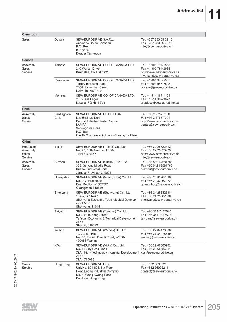
11Address list
Operating Instructions – MOVIDRIVE® system 205
CameroonSales Douala SEW-EURODRIVE S.A.R.L.
Ancienne Route BonabériP.O. BoxB.P 8674Douala-Cameroun
Tel. +237 233 39 02 10Fax +237 233 39 02 10info@sew-eurodrive-cm
CanadaAssemblySalesService
Toronto SEW-EURODRIVE CO. OF CANADA LTD.210 Walker DriveBramalea, ON L6T 3W1
Tel. +1 905 791-1553Fax +1 905 791-2999http://[email protected]
Vancouver SEW-EURODRIVE CO. OF CANADA LTD.Tilbury Industrial Park7188 Honeyman StreetDelta, BC V4G 1G1
Tel. +1 604 946-5535Fax +1 604 [email protected]
Montreal SEW-EURODRIVE CO. OF CANADA LTD.2555 Rue LegerLasalle, PQ H8N 2V9
Tel. +1 514 367-1124Fax +1 514 [email protected]
ChileAssemblySalesService
Santiago deChile
SEW-EURODRIVE CHILE LTDALas Encinas 1295Parque Industrial Valle GrandeLAMPASantiago de ChileP.O. BoxCasilla 23 Correo Quilicura - Santiago - Chile
Tel. +56 2 2757 7000Fax +56 2 2757 7001http://[email protected]
ChinaProductionAssemblySalesService
Tianjin SEW-EURODRIVE (Tianjin) Co., Ltd.No. 78, 13th Avenue, TEDATianjin 300457
Tel. +86 22 25322612Fax +86 22 25323273http://[email protected]
AssemblySalesService
Suzhou SEW-EURODRIVE (Suzhou) Co., Ltd.333, Suhong Middle RoadSuzhou Industrial ParkJiangsu Province, 215021
Tel. +86 512 62581781Fax +86 512 [email protected]
Guangzhou SEW-EURODRIVE (Guangzhou) Co., Ltd.No. 9, JunDa RoadEast Section of GETDDGuangzhou 510530
Tel. +86 20 82267890Fax +86 20 [email protected]
Shenyang SEW-EURODRIVE (Shenyang) Co., Ltd.10A-2, 6th RoadShenyang Economic Technological Develop-ment AreaShenyang, 110141
Tel. +86 24 25382538Fax +86 24 [email protected]
Taiyuan SEW-EURODRIVE (Taiyuan) Co,. Ltd.No.3, HuaZhang Street,TaiYuan Economic & Technical DevelopmentZoneShanXi, 030032
Tel. +86-351-7117520Fax [email protected]
Wuhan SEW-EURODRIVE (Wuhan) Co., Ltd.10A-2, 6th RoadNo. 59, the 4th Quanli Road, WEDA430056 Wuhan
Tel. +86 27 84478388Fax +86 27 [email protected]
Xi'An SEW-EURODRIVE (Xi'An) Co., Ltd.No. 12 Jinye 2nd RoadXi'An High-Technology Industrial DevelopmentZoneXi'An 710065
Tel. +86 29 68686262Fax +86 29 [email protected]
SalesService
Hong Kong SEW-EURODRIVE LTD.Unit No. 801-806, 8th FloorHong Leong Industrial ComplexNo. 4, Wang Kwong RoadKowloon, Hong Kong
Tel. +852 36902200Fax +852 [email protected]
2303
1719
/EN
– 0
3/20
17
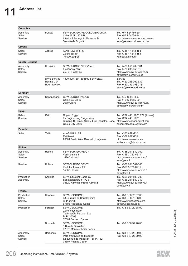
11 Address list
Operating Instructions – MOVIDRIVE® system206
ColombiaAssemblySalesService
Bogota SEW-EURODRIVE COLOMBIA LTDA.Calle 17 No. 132-18Interior 2 Bodega 6, Manzana BSantafé de Bogotá
Tel. +57 1 54750-50Fax +57 1 54750-44http://[email protected]
CroatiaSalesService
Zagreb KOMPEKS d. o. o.Zeleni dol 1010 000 Zagreb
Tel. +385 1 4613-158Fax +385 1 [email protected]
Czech RepublicAssemblySalesService
Hostivice SEW-EURODRIVE CZ s.r.o.Floriánova 2459253 01 Hostivice
Tel. +420 255 709 601Fax +420 235 350 613http://[email protected]
Drive ServiceHotline / 24Hour Service
+420 800 739 739 (800 SEW SEW) ServiceTel. +420 255 709 632Fax +420 235 358 [email protected]
DenmarkAssemblySalesService
Copenhagen SEW-EURODRIVEA/SGeminivej 28-302670 Greve
Tel. +45 43 95 8500Fax +45 43 9585-09http://[email protected]
EgyptSalesService
Cairo Copam Egyptfor Engineering & AgenciesBuilding 10, Block 13005, First Industrial Zone,Obour City Cairo
Tel. +202 44812673 / 79 (7 lines)Fax +202 44812685http://[email protected]
EstoniaSales Tallin ALAS-KUUL AS
Reti tee 475301 Peetri küla, Rae vald, Harjumaa
Tel. +372 6593230Fax +372 6593231http://[email protected]
FinlandAssemblySalesService
Hollola SEW-EURODRIVE OYVesimäentie 415860 Hollola
Tel. +358 201 589-300Fax +358 3 780-6211http://[email protected]
Service Hollola SEW-EURODRIVE OYKeskikankaantie 2115860 Hollola
Tel. +358 201 589-300Fax +358 3 780-6211http://[email protected]
ProductionAssembly
Karkkila SEW Industrial Gears OySantasalonkatu 6, PL 803620 Karkkila, 03601 Karkkila
Tel. +358 201 589-300Fax +358 201 589-310http://[email protected]
FranceProductionSalesService
Hagenau SEW-USOCOME48-54 route de SoufflenheimB. P. 2018567506 Haguenau Cedex
Tel. +33 3 88 73 67 00Fax +33 3 88 73 66 00http://[email protected]
Production Forbach SEW-USOCOMEZone industrielleTechnopôle Forbach SudB. P. 3026957604 Forbach Cedex
Tel. +33 3 87 29 38 00
Brumath SEW-USOCOME1 Rue de Bruxelles67670 Mommenheim Cedex
Tel. +33 3 88 37 48 00
AssemblySalesService
Bordeaux SEW-USOCOMEParc d'activités de Magellan62 avenue de Magellan – B. P. 18233607 Pessac Cedex
Tel. +33 5 57 26 39 00Fax +33 5 57 26 39 09 23
0317
19/E
N –
03/
2017
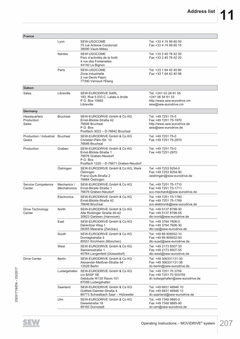
11Address list
Operating Instructions – MOVIDRIVE® system 207
FranceLyon SEW-USOCOME
75 rue Antoine Condorcet38090 Vaulx-Milieu
Tel. +33 4 74 99 60 00Fax +33 4 74 99 60 15
Nantes SEW-USOCOMEParc d’activités de la forêt4 rue des Fontenelles44140 Le Bignon
Tel. +33 2 40 78 42 00Fax +33 2 40 78 42 20
Paris SEW-USOCOMEZone industrielle2 rue Denis Papin77390 Verneuil I'Étang
Tel. +33 1 64 42 40 80Fax +33 1 64 42 40 88
GabonSales Libreville SEW-EURODRIVE SARL
183, Rue 5.033.C, Lalala à droiteP.O. Box 15682Libreville
Tel. +241 03 28 81 55+241 06 54 81 33http://[email protected]
GermanyHeadquartersProductionSales
Bruchsal SEW-EURODRIVE GmbH & Co KGErnst-Blickle-Straße 4276646 BruchsalP.O. BoxPostfach 3023 – D-76642 Bruchsal
Tel. +49 7251 75-0Fax +49 7251 75-1970http://[email protected]
Production / IndustrialGears
Bruchsal SEW-EURODRIVE GmbH & Co KGChristian-Pähr-Str. 1076646 Bruchsal
Tel. +49 7251 75-0Fax +49 7251 75-2970
Production Graben SEW-EURODRIVE GmbH & Co KGErnst-Blickle-Straße 176676 Graben-NeudorfP.O. BoxPostfach 1220 – D-76671 Graben-Neudorf
Tel. +49 7251 75-0Fax +49 7251-2970
Östringen SEW-EURODRIVE GmbH & Co KG, WerkÖstringenFranz-Gurk-Straße 276684 Östringen
Tel. +49 7253 9254-0Fax +49 7253 [email protected]
Service CompetenceCenter
Mechanics /Mechatronics
SEW-EURODRIVE GmbH & Co KGErnst-Blickle-Straße 176676 Graben-Neudorf
Tel. +49 7251 75-1710Fax +49 7251 [email protected]
Electronics SEW-EURODRIVE GmbH & Co KGErnst-Blickle-Straße 4276646 Bruchsal
Tel. +49 7251 75-1780Fax +49 7251 [email protected]
Drive TechnologyCenter
North SEW-EURODRIVE GmbH & Co KGAlte Ricklinger Straße 40-4230823 Garbsen (Hannover)
Tel. +49 5137 8798-30Fax +49 5137 [email protected]
East SEW-EURODRIVE GmbH & Co KGDänkritzer Weg 108393 Meerane (Zwickau)
Tel. +49 3764 7606-0Fax +49 3764 [email protected]
South SEW-EURODRIVE GmbH & Co KGDomagkstraße 585551 Kirchheim (München)
Tel. +49 89 909552-10Fax +49 89 [email protected]
West SEW-EURODRIVE GmbH & Co KGSiemensstraße 140764 Langenfeld (Düsseldorf)
Tel. +49 2173 8507-30Fax +49 2173 [email protected]
Drive Center Berlin SEW-EURODRIVE GmbH & Co KGAlexander-Meißner-Straße 4412526 Berlin
Tel. +49 306331131-30Fax +49 [email protected]
Ludwigshafen SEW-EURODRIVE GmbH & Co KGc/o BASF SEGebäude W130 Raum 10167056 Ludwigshafen
Tel. +49 7251 75 3759Fax +49 7251 75 [email protected]
Saarland SEW-EURODRIVE GmbH & Co KGGottlieb-Daimler-Straße 466773 Schwalbach Saar – Hülzweiler
Tel. +49 6831 48946 10Fax +49 6831 48946 [email protected]
Ulm SEW-EURODRIVE GmbH & Co KGDieselstraße 1889160 Dornstadt
Tel. +49 7348 9885-0Fax +49 7348 [email protected]
2303
1719
/EN
– 0
3/20
17
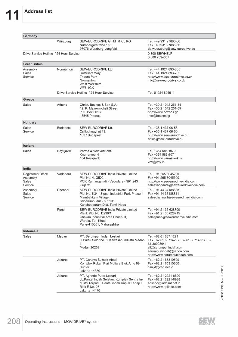
11 Address list
Operating Instructions – MOVIDRIVE® system208
GermanyWürzburg SEW-EURODRIVE GmbH & Co KG
Nürnbergerstraße 11897076 Würzburg-Lengfeld
Tel. +49 931 27886-60Fax +49 931 [email protected]
Drive Service Hotline / 24 Hour Service 0 800 SEWHELP0 800 7394357
Great BritainAssemblySalesService
Normanton SEW-EURODRIVE Ltd.DeVilliers WayTrident ParkNormantonWest YorkshireWF6 1GX
Tel. +44 1924 893-855Fax +44 1924 893-702http://[email protected]
Drive Service Hotline / 24 Hour Service Tel. 01924 896911
GreeceSales Athens Christ. Boznos & Son S.A.
12, K. Mavromichali StreetP.O. Box 8013618545 Piraeus
Tel. +30 2 1042 251-34Fax +30 2 1042 251-59http://[email protected]
HungarySalesService
Budapest SEW-EURODRIVE Kft.Csillaghegyí út 13.1037 Budapest
Tel. +36 1 437 06-58Fax +36 1 437 06-50http://[email protected]
IcelandSales Reykjavik Varma & Vélaverk ehf.
Knarrarvogi 4104 Reykjavík
Tel. +354 585 1070Fax +354 585)1071http://[email protected]
IndiaRegistered OfficeAssemblySalesService
Vadodara SEW-EURODRIVE India Private LimitedPlot No. 4, GIDCPOR Ramangamdi • Vadodara - 391 243Gujarat
Tel. +91 265 3045200Fax +91 265 3045300http://[email protected]
AssemblySalesService
Chennai SEW-EURODRIVE India Private LimitedPlot No. K3/1, Sipcot Industrial Park Phase IIMambakkam VillageSriperumbudur - 602105Kancheepuram Dist, Tamil Nadu
Tel. +91 44 37188888Fax +91 44 [email protected]
Pune SEW-EURODRIVE India Private LimitedPlant: Plot No. D236/1,Chakan Industrial Area Phase- II,Warale, Tal- Khed,Pune-410501, Maharashtra
Tel. +91 21 35 628700Fax +91 21 35 [email protected]
IndonesiaSales Medan PT. Serumpun Indah Lestari
Jl.Pulau Solor no. 8, Kawasan Industri MedanIIMedan 20252
Tel. +62 61 687 1221Fax +62 61 6871429 / +62 61 6871458 / +6261 [email protected]@yahoo.comhttp://www.serumpunindah.com
Jakarta PT. Cahaya Sukses AbadiKomplek Rukan Puri Mutiara Blok A no 99,SunterJakarta 14350
Tel. +62 21 65310599Fax +62 21 [email protected]
Jakarta PT. Agrindo Putra LestariJL.Pantai Indah Selatan, Komplek Sentra In-dustri Terpadu, Pantai indah Kapuk Tahap III,Blok E No. 27Jakarta 14470
Tel. +62 21 2921-8899Fax +62 21 [email protected]://www.aplindo.com
2303
1719
/EN
– 0
3/20
17
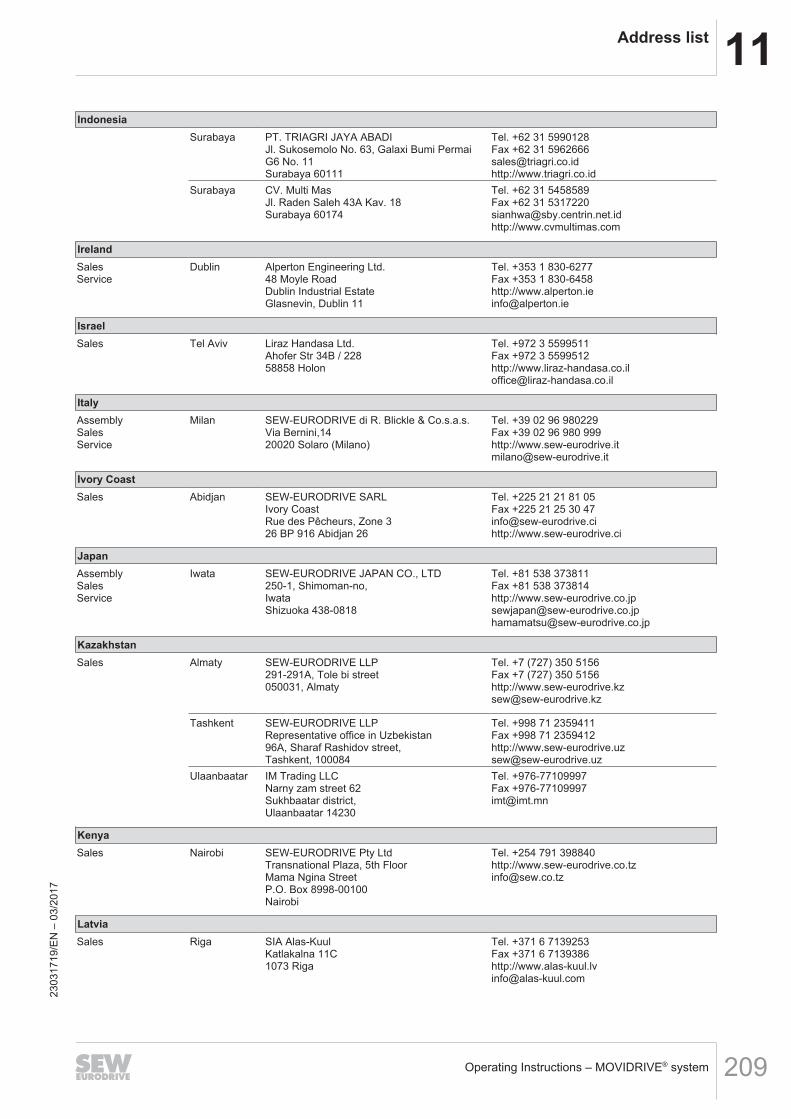
11Address list
Operating Instructions – MOVIDRIVE® system 209
IndonesiaSurabaya PT. TRIAGRI JAYA ABADI
Jl. Sukosemolo No. 63, Galaxi Bumi PermaiG6 No. 11Surabaya 60111
Tel. +62 31 5990128Fax +62 31 [email protected]://www.triagri.co.id
Surabaya CV. Multi MasJl. Raden Saleh 43A Kav. 18Surabaya 60174
Tel. +62 31 5458589Fax +62 31 [email protected]://www.cvmultimas.com
IrelandSalesService
Dublin Alperton Engineering Ltd.48 Moyle RoadDublin Industrial EstateGlasnevin, Dublin 11
Tel. +353 1 830-6277Fax +353 1 830-6458http://[email protected]
IsraelSales Tel Aviv Liraz Handasa Ltd.
Ahofer Str 34B / 22858858 Holon
Tel. +972 3 5599511Fax +972 3 5599512http://[email protected]
ItalyAssemblySalesService
Milan SEW-EURODRIVE di R. Blickle & Co.s.a.s.Via Bernini,1420020 Solaro (Milano)
Tel. +39 02 96 980229Fax +39 02 96 980 999http://[email protected]
Ivory CoastSales Abidjan SEW-EURODRIVE SARL
Ivory CoastRue des Pêcheurs, Zone 326 BP 916 Abidjan 26
Tel. +225 21 21 81 05Fax +225 21 25 30 [email protected]://www.sew-eurodrive.ci
JapanAssemblySalesService
Iwata SEW-EURODRIVE JAPAN CO., LTD250-1, Shimoman-no,IwataShizuoka 438-0818
Tel. +81 538 373811Fax +81 538 373814http://[email protected]@sew-eurodrive.co.jp
KazakhstanSales Almaty SEW-EURODRIVE LLP
291-291A, Tole bi street050031, Almaty
Tel. +7 (727) 350 5156Fax +7 (727) 350 5156http://[email protected]
Tashkent SEW-EURODRIVE LLPRepresentative office in Uzbekistan96A, Sharaf Rashidov street,Tashkent, 100084
Tel. +998 71 2359411Fax +998 71 2359412http://[email protected]
Ulaanbaatar IM Trading LLCNarny zam street 62Sukhbaatar district,Ulaanbaatar 14230
Tel. +976-77109997Fax [email protected]
KenyaSales Nairobi SEW-EURODRIVE Pty Ltd
Transnational Plaza, 5th FloorMama Ngina StreetP.O. Box 8998-00100Nairobi
Tel. +254 791 398840http://[email protected]
LatviaSales Riga SIA Alas-Kuul
Katlakalna 11C1073 Riga
Tel. +371 6 7139253Fax +371 6 7139386http://[email protected]
2303
1719
/EN
– 0
3/20
17
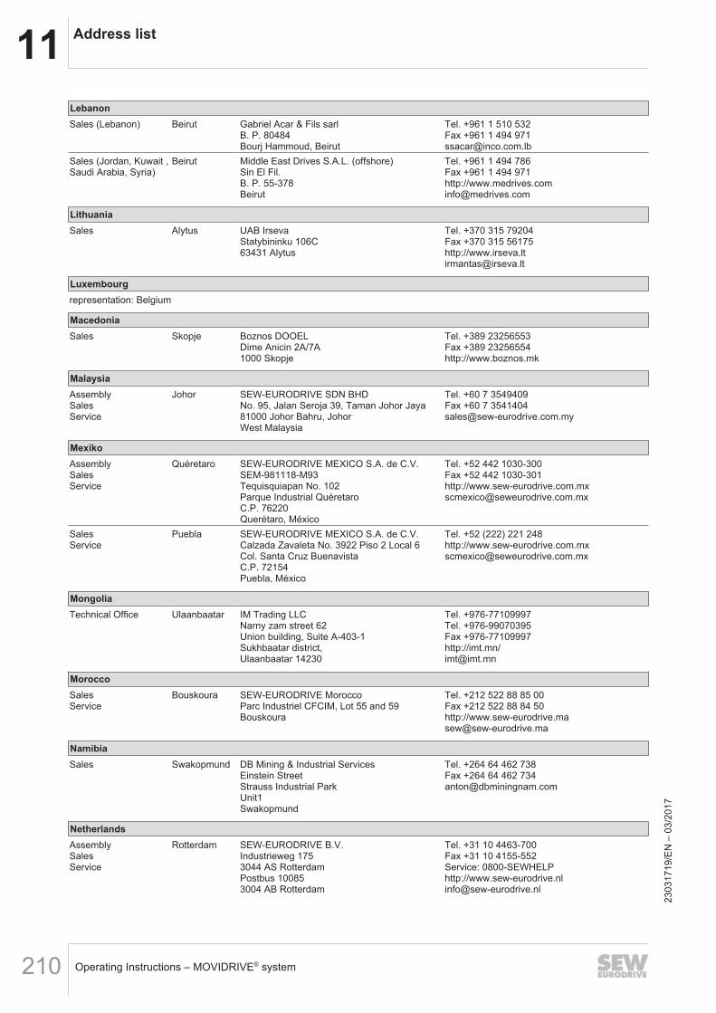
11 Address list
Operating Instructions – MOVIDRIVE® system210
LebanonSales (Lebanon) Beirut Gabriel Acar & Fils sarl
B. P. 80484Bourj Hammoud, Beirut
Tel. +961 1 510 532Fax +961 1 494 [email protected]
Sales (Jordan, Kuwait ,Saudi Arabia, Syria)
Beirut Middle East Drives S.A.L. (offshore)Sin El Fil.B. P. 55-378Beirut
Tel. +961 1 494 786Fax +961 1 494 971http://[email protected]
LithuaniaSales Alytus UAB Irseva
Statybininku 106C63431 Alytus
Tel. +370 315 79204Fax +370 315 56175http://[email protected]
Luxembourgrepresentation: Belgium
MacedoniaSales Skopje Boznos DOOEL
Dime Anicin 2A/7A1000 Skopje
Tel. +389 23256553Fax +389 23256554http://www.boznos.mk
MalaysiaAssemblySalesService
Johor SEW-EURODRIVE SDN BHDNo. 95, Jalan Seroja 39, Taman Johor Jaya81000 Johor Bahru, JohorWest Malaysia
Tel. +60 7 3549409Fax +60 7 [email protected]
MexikoAssemblySalesService
Quéretaro SEW-EURODRIVE MEXICO S.A. de C.V.SEM-981118-M93Tequisquiapan No. 102Parque Industrial QuéretaroC.P. 76220Querétaro, México
Tel. +52 442 1030-300Fax +52 442 1030-301http://[email protected]
SalesService
Puebla SEW-EURODRIVE MEXICO S.A. de C.V.Calzada Zavaleta No. 3922 Piso 2 Local 6Col. Santa Cruz BuenavistaC.P. 72154Puebla, México
Tel. +52 (222) 221 248http://[email protected]
MongoliaTechnical Office Ulaanbaatar IM Trading LLC
Narny zam street 62Union building, Suite A-403-1Sukhbaatar district,Ulaanbaatar 14230
Tel. +976-77109997Tel. +976-99070395Fax +976-77109997http://imt.mn/[email protected]
MoroccoSalesService
Bouskoura SEW-EURODRIVE MoroccoParc Industriel CFCIM, Lot 55 and 59Bouskoura
Tel. +212 522 88 85 00Fax +212 522 88 84 50http://[email protected]
NamibiaSales Swakopmund DB Mining & Industrial Services
Einstein StreetStrauss Industrial ParkUnit1Swakopmund
Tel. +264 64 462 738Fax +264 64 462 [email protected]
NetherlandsAssemblySalesService
Rotterdam SEW-EURODRIVE B.V.Industrieweg 1753044 AS RotterdamPostbus 100853004 AB Rotterdam
Tel. +31 10 4463-700Fax +31 10 4155-552Service: 0800-SEWHELPhttp://[email protected]
2303
1719
/EN
– 0
3/20
17
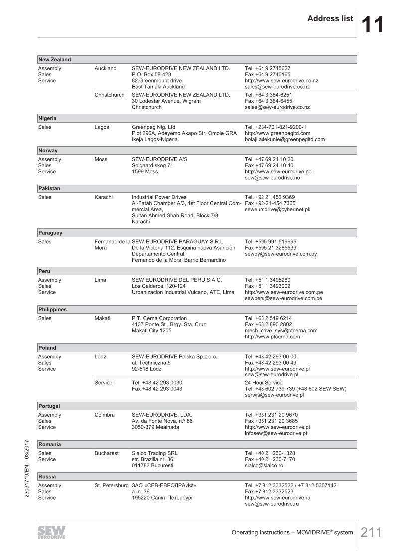
11Address list
Operating Instructions – MOVIDRIVE® system 211
New ZealandAssemblySalesService
Auckland SEW-EURODRIVE NEW ZEALAND LTD.P.O. Box 58-42882 Greenmount driveEast Tamaki Auckland
Tel. +64 9 2745627Fax +64 9 2740165http://[email protected]
Christchurch SEW-EURODRIVE NEW ZEALAND LTD.30 Lodestar Avenue, WigramChristchurch
Tel. +64 3 384-6251Fax +64 3 [email protected]
NigeriaSales Lagos Greenpeg Nig. Ltd
Plot 296A, Adeyemo Akapo Str. Omole GRAIkeja Lagos-Nigeria
Tel. +234-701-821-9200-1http://[email protected]
NorwayAssemblySalesService
Moss SEW-EURODRIVE A/SSolgaard skog 711599 Moss
Tel. +47 69 24 10 20Fax +47 69 24 10 40http://[email protected]
PakistanSales Karachi Industrial Power Drives
Al-Fatah Chamber A/3, 1st Floor Central Com-mercial Area,Sultan Ahmed Shah Road, Block 7/8,Karachi
Tel. +92 21 452 9369Fax +92-21-454 [email protected]
ParaguaySales Fernando de la
MoraSEW-EURODRIVE PARAGUAY S.R.LDe la Victoria 112, Esquina nueva AsunciónDepartamento CentralFernando de la Mora, Barrio Bernardino
Tel. +595 991 519695Fax +595 21 [email protected]
PeruAssemblySalesService
Lima SEW EURODRIVE DEL PERU S.A.C.Los Calderos, 120-124Urbanizacion Industrial Vulcano, ATE, Lima
Tel. +51 1 3495280Fax +51 1 3493002http://[email protected]
PhilippinesSales Makati P.T. Cerna Corporation
4137 Ponte St., Brgy. Sta. CruzMakati City 1205
Tel. +63 2 519 6214Fax +63 2 890 [email protected]://www.ptcerna.com
PolandAssemblySalesService
Łódź SEW-EURODRIVE Polska Sp.z.o.o.ul. Techniczna 592-518 Łódź
Tel. +48 42 293 00 00Fax +48 42 293 00 49http://[email protected]
Service Tel. +48 42 293 0030Fax +48 42 293 0043
24 Hour ServiceTel. +48 602 739 739 (+48 602 SEW SEW)[email protected]
PortugalAssemblySalesService
Coimbra SEW-EURODRIVE, LDA.Av. da Fonte Nova, n.º 863050-379 Mealhada
Tel. +351 231 20 9670Fax +351 231 20 3685http://[email protected]
RomaniaSalesService
Bucharest Sialco Trading SRLstr. Brazilia nr. 36011783 Bucuresti
Tel. +40 21 230-1328Fax +40 21 [email protected]
RussiaAssemblySalesService
St. Petersburg ЗАО «СЕВ-ЕВРОДРАЙФ»а. я. 36195220 Санкт-Петербург
Tel. +7 812 3332522 / +7 812 5357142Fax +7 812 3332523http://[email protected]
2303
1719
/EN
– 0
3/20
17
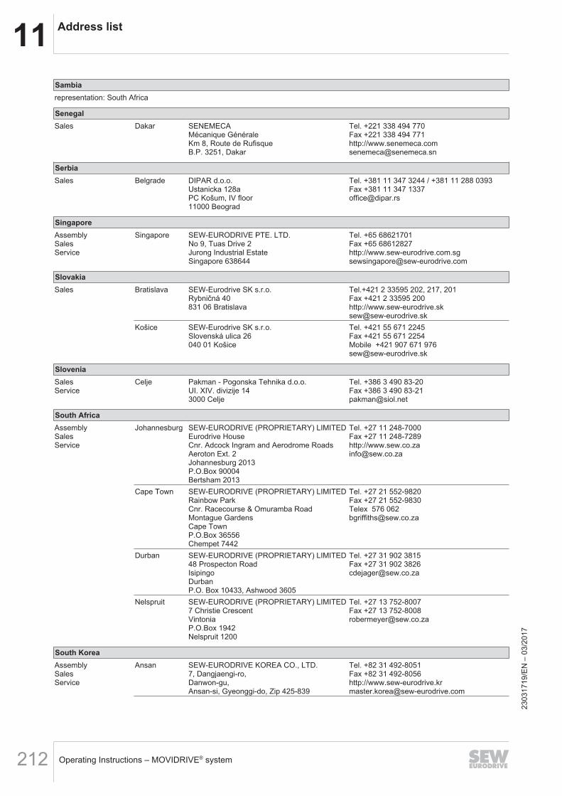
11 Address list
Operating Instructions – MOVIDRIVE® system212
Sambiarepresentation: South Africa
SenegalSales Dakar SENEMECA
Mécanique GénéraleKm 8, Route de RufisqueB.P. 3251, Dakar
Tel. +221 338 494 770Fax +221 338 494 771http://[email protected]
SerbiaSales Belgrade DIPAR d.o.o.
Ustanicka 128aPC Košum, IV floor11000 Beograd
Tel. +381 11 347 3244 / +381 11 288 0393Fax +381 11 347 [email protected]
SingaporeAssemblySalesService
Singapore SEW-EURODRIVE PTE. LTD.No 9, Tuas Drive 2Jurong Industrial EstateSingapore 638644
Tel. +65 68621701Fax +65 68612827http://[email protected]
SlovakiaSales Bratislava SEW-Eurodrive SK s.r.o.
Rybničná 40831 06 Bratislava
Tel.+421 2 33595 202, 217, 201Fax +421 2 33595 200http://[email protected]
Košice SEW-Eurodrive SK s.r.o.Slovenská ulica 26040 01 Košice
Tel. +421 55 671 2245Fax +421 55 671 2254Mobile +421 907 671 [email protected]
SloveniaSalesService
Celje Pakman - Pogonska Tehnika d.o.o.UI. XIV. divizije 143000 Celje
Tel. +386 3 490 83-20Fax +386 3 490 [email protected]
South AfricaAssemblySalesService
Johannesburg SEW-EURODRIVE (PROPRIETARY) LIMITEDEurodrive HouseCnr. Adcock Ingram and Aerodrome RoadsAeroton Ext. 2Johannesburg 2013P.O.Box 90004Bertsham 2013
Tel. +27 11 248-7000Fax +27 11 248-7289http://[email protected]
Cape Town SEW-EURODRIVE (PROPRIETARY) LIMITEDRainbow ParkCnr. Racecourse & Omuramba RoadMontague GardensCape TownP.O.Box 36556Chempet 7442
Tel. +27 21 552-9820Fax +27 21 552-9830Telex 576 [email protected]
Durban SEW-EURODRIVE (PROPRIETARY) LIMITED48 Prospecton RoadIsipingoDurbanP.O. Box 10433, Ashwood 3605
Tel. +27 31 902 3815Fax +27 31 902 [email protected]
Nelspruit SEW-EURODRIVE (PROPRIETARY) LIMITED7 Christie CrescentVintoniaP.O.Box 1942Nelspruit 1200
Tel. +27 13 752-8007Fax +27 13 [email protected]
South KoreaAssemblySalesService
Ansan SEW-EURODRIVE KOREA CO., LTD.7, Dangjaengi-ro,Danwon-gu,Ansan-si, Gyeonggi-do, Zip 425-839
Tel. +82 31 492-8051Fax +82 31 492-8056http://[email protected]
2303
1719
/EN
– 0
3/20
17
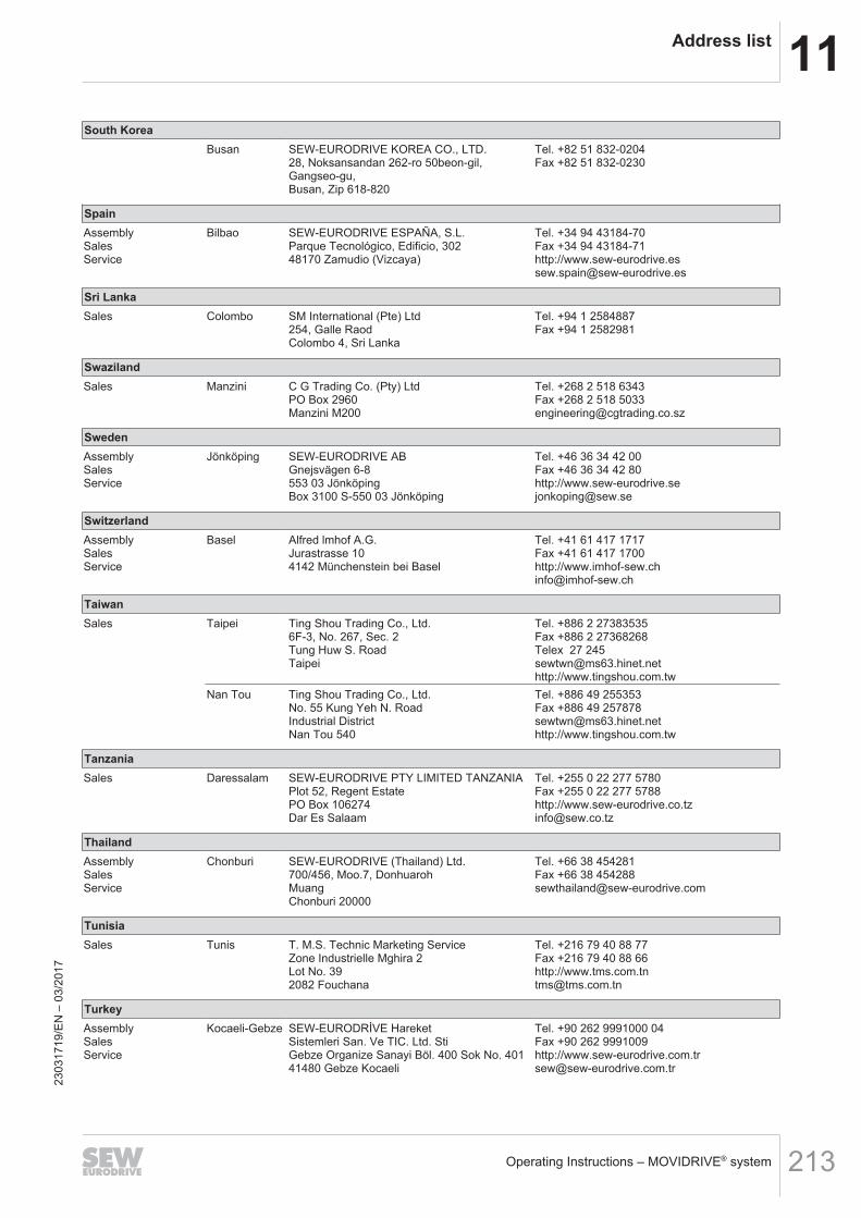
11Address list
Operating Instructions – MOVIDRIVE® system 213
South KoreaBusan SEW-EURODRIVE KOREA CO., LTD.
28, Noksansandan 262-ro 50beon-gil,Gangseo-gu,Busan, Zip 618-820
Tel. +82 51 832-0204Fax +82 51 832-0230
SpainAssemblySalesService
Bilbao SEW-EURODRIVE ESPAÑA, S.L.Parque Tecnológico, Edificio, 30248170 Zamudio (Vizcaya)
Tel. +34 94 43184-70Fax +34 94 43184-71http://[email protected]
Sri LankaSales Colombo SM International (Pte) Ltd
254, Galle RaodColombo 4, Sri Lanka
Tel. +94 1 2584887Fax +94 1 2582981
SwazilandSales Manzini C G Trading Co. (Pty) Ltd
PO Box 2960Manzini M200
Tel. +268 2 518 6343Fax +268 2 518 [email protected]
SwedenAssemblySalesService
Jönköping SEW-EURODRIVE ABGnejsvägen 6-8553 03 JönköpingBox 3100 S-550 03 Jönköping
Tel. +46 36 34 42 00Fax +46 36 34 42 80http://[email protected]
SwitzerlandAssemblySalesService
Basel Alfred lmhof A.G.Jurastrasse 104142 Münchenstein bei Basel
Tel. +41 61 417 1717Fax +41 61 417 1700http://[email protected]
TaiwanSales Taipei Ting Shou Trading Co., Ltd.
6F-3, No. 267, Sec. 2Tung Huw S. RoadTaipei
Tel. +886 2 27383535Fax +886 2 27368268Telex 27 [email protected]://www.tingshou.com.tw
Nan Tou Ting Shou Trading Co., Ltd.No. 55 Kung Yeh N. RoadIndustrial DistrictNan Tou 540
Tel. +886 49 255353Fax +886 49 [email protected]://www.tingshou.com.tw
TanzaniaSales Daressalam SEW-EURODRIVE PTY LIMITED TANZANIA
Plot 52, Regent EstatePO Box 106274Dar Es Salaam
Tel. +255 0 22 277 5780Fax +255 0 22 277 5788http://[email protected]
ThailandAssemblySalesService
Chonburi SEW-EURODRIVE (Thailand) Ltd.700/456, Moo.7, DonhuarohMuangChonburi 20000
Tel. +66 38 454281Fax +66 38 [email protected]
TunisiaSales Tunis T. M.S. Technic Marketing Service
Zone Industrielle Mghira 2Lot No. 392082 Fouchana
Tel. +216 79 40 88 77Fax +216 79 40 88 66http://[email protected]
TurkeyAssemblySalesService
Kocaeli-Gebze SEW-EURODRİVE HareketSistemleri San. Ve TIC. Ltd. StiGebze Organize Sanayi Böl. 400 Sok No. 40141480 Gebze Kocaeli
Tel. +90 262 9991000 04Fax +90 262 9991009http://[email protected]
2303
1719
/EN
– 0
3/20
17

11 Address list
Operating Instructions – MOVIDRIVE® system214
UkraineAssemblySalesService
Dnipropetrovsk ООО «СЕВ-Евродрайв»ул. Рабочая, 23-B, офис 40949008 Днепропетровск
Tel. +380 56 370 3211Fax +380 56 372 2078http://[email protected]
UruguayAssemblySales
Montevideo SEW-EURODRIVE Uruguay, S. A.Jose Serrato 3569 Esqina CorumbeCP 12000 Montevideo
Tel. +598 2 21181-89Fax +598 2 [email protected]
USAProductionAssemblySalesService
SoutheastRegion
SEW-EURODRIVE INC.1295 Old Spartanburg HighwayP.O. Box 518Lyman, S.C. 29365
Tel. +1 864 439-7537Fax Sales +1 864 439-7830Fax Production +1 864 439-9948Fax Assembly +1 864 439-0566Fax Confidential/HR +1 864 949-5557http://[email protected]
AssemblySalesService
NortheastRegion
SEW-EURODRIVE INC.Pureland Ind. Complex2107 High Hill Road, P.O. Box 481Bridgeport, New Jersey 08014
Tel. +1 856 467-2277Fax +1 856 [email protected]
MidwestRegion
SEW-EURODRIVE INC.2001 West Main StreetTroy, Ohio 45373
Tel. +1 937 335-0036Fax +1 937 [email protected]
SouthwestRegion
SEW-EURODRIVE INC.3950 Platinum WayDallas, Texas 75237
Tel. +1 214 330-4824Fax +1 214 [email protected]
WesternRegion
SEW-EURODRIVE INC.30599 San Antonio St.Hayward, CA 94544
Tel. +1 510 487-3560Fax +1 510 [email protected]
Wellford SEW-EURODRIVE INC.148/150 Finch Rd.Wellford, S.C. 29385
Additional addresses for service provided on request!
UzbekistanTechnical Office Tashkent SEW-EURODRIVE LLP
Representative office in Uzbekistan96A, Sharaf Rashidov street,Tashkent, 100084
Tel. +998 71 2359411Fax +998 71 2359412http://[email protected]
VietnamSales Ho Chi Minh
CityNam Trung Co., LtdHuế - South Vietnam / Construction Materials250 Binh Duong Avenue, Thu Dau Mot Town,Binh Duong ProvinceHCM office: 91 Tran Minh Quyen StreetDistrict 10, Ho Chi Minh City
Tel. +84 8 8301026Fax +84 8 [email protected]://www.namtrung.com.vn
Hanoi MICO LTDQuảng Trị - North Vietnam / All sectors except Construction Materials8th Floor, Ocean Park Building, 01 Dao DuyAnh St, Ha Noi, Viet Nam
Tel. +84 4 39386666Fax +84 4 3938 [email protected]://www.micogroup.com.vn
2303
1719
/EN
– 0
3/20
17


SEW-EURODRIVE—Driving the world
SEW-EURODRIVE GmbH & Co KGP.O. Box 302376642 BRUCHSALGERMANYPhone +49 7251 75-0Fax +49 7251 [email protected]


