Embed Size (px)
Citation preview

www.lg.com
OWNER’S MANUAL
MONITOR TV
MONITOR TV MODELSM197WAP M227WAPM237WAP
M2062AM2262AM2362AM2762A
Please read this manual carefully before operatingyour set and retain it for future reference.
ENGLIS
H

CONTENTS
CO
NTEN
TS
2
PREPARATION
SIDE PANEL CONTROLS <M197WAP/M227WAP/M237WAP> ............4FRONT PANEL CONTROLS <M2062A/M2262A/M2362A/M2762A>.........5BACK PANEL INFORMATION <M197WAP/M227WAP/M237WAP> ............6 <M2062A/M2262A/M2362A/M2762A>.........7STAND INSTALLATION <M197WAP/M227WAP> ..............................8 <M237WAP> ................................................9 <M2062A/M2262A/M2362A> .....................10 <M2762A> ..................................................11DETACHING STAND <M197WAP/M227WAP> ............................12 <M237WAP> ..............................................13 <M2062A/M2262A/M2362A> .....................14 <M2762A> ..................................................15DETACHING STAND BODY (M2062A/M2262A/M2362A/M2762A) ...............16WALL MOUNT: HORIZONTAL INSTALLATION ..17DESKTOP PEDESTAL INSTALLATION ...........18SWIVEL STAND(Only M2762DP) .....................19POSITIONING YOUR DISPLAY .......................19LOCATION ........................................................20SECURING THE SET TO THE WALL TO PREVENT FALLING WHEN THE SET IS USED ON A STAND (Only M2762A) ............................21ATTACHING THE TV TO A DESK (Only M2762A) ..................................................22KENSINGTON SECURITY SYSTEM ...............23
EXTERNAL EQUIPMENT SETUP
ANTENNA CONNECTION ................................24HD RECEIVER SETUP When connecting with a component cable ...25 Connecting a set-top box with a HDMI cable ..26DVD SETUP Connecting with a component cable ..........27 Connecting with a HDMI cable ...................28
VCR SETUP Connecting with a RF cable .......................29 Connecting with a RCA cable .....................29OTHER A/V SOURCE SETUP .........................30PC SETUP When connecting with a D-sub 15 pin cable ...31BACK COVER FOR WIRE ARRANGEMENT ..32SUPPORTED DISPALY RESOLUTION ...........33
WATCHING TV / PROGRAMME CONTROL
REMOTE CONTROL KEY FUNCTIONS ..........34TURNING ON THE SET ...................................36INSTALLATION GUIDE .....................................36PROGRAMME SELECTION .............................36VOLUME ADJUSTMENT ..................................36ON SCREEN MENUS SELECTION AND ADJUSTMENT ..................................................37AUTO PROGRAMME TUNING ........................38MANUAL PROGRAMME TUNING ...................39FINE TUNING ...................................................40ASSIGNING A STATION NAME .......................41PROGRAMME EDIT .........................................42FAVOURITE PROGRAMME .............................43SELECTING THE PROGRAMME LIST ............44
PICTURE CONTROL
PICTURE SIZE (ASPECT RATIO) CONTROL ...45PRESET PICTURE SETTINGS ........................46MANUAL PICTURE ADJUSTMENT .................47PICTURE IMPROVEMENT TECHNOLOGY ....48PICTURE RESET .............................................50SCREEN SETUP AUTO CONFIGURE (RGB [PC] mode only)................................51 MANUAL CONFIGURE (Adjustment for screen Position) ................52

CO
NTEN
TS
3
INITIALIZING (Reset to original factory settings) ..............53 SELECTING RESOLUTION .......................54
SOUND CONTROL
PRESET SOUND SETTINGS - SOUND MODE ........................................55SOUND SETTING ADJUSTMENT - USER MODE ...........................................56AUTO VOLUME LEVELER ...............................57BALANCE ..........................................................58AUDIO RESET ..................................................59I/IISTEREO / DUAL RECEPTION ........................60NICAM RECEPTION ........................................61SPEAKER SOUND OUTPUT SELECTION .....61
TIME SETTING
CLOCK SETUP .................................................62AUTO ON/OFF TIMER SETTING ....................63SLEEP TIMER SETTING ..................................64AUTO SLEEP ....................................................65
OPTION SETTING
ON-SCREEN MENU LANGUAGE SELECTION ...66KEY LOCK ........................................................67DDC-CI(Only RGB) ...........................................68POWER INDICATOR ........................................69MODE SETTING ...............................................70FACTORY RESET ............................................71
TELETEXT
SWITCH ON/OFF .............................................72SIMPLE TEXT ...................................................72SWITCH ON/OFF .............................................73FASTEXT ..........................................................73SPECIAL TELETEXT FUNCTIONS ..................74
APPENDIX
TROUBLESHOOTING ......................................75MAINTENANCE ................................................77PRODUCT SPECIFICATIONS M197WAP ...................................................78 M227WAP ...................................................79 M237WAP ...................................................80 M2062A .......................................................81 M2262A .......................................................82 M2362A .......................................................83 M2762A .......................................................84

4
PREPA
RATIO
N
PREPARATION
SIDE PANEL CONTROLS This is a simplified representation of the side panel. The image shown may be somewhat different from your set.
INPUT
MENU
VOL
PROK
INPUT Button
MENU Button
OK Button
VOLUME Buttons
PROGRAMME Buttons
Power Button
Headphone Jack
<M197WAP/M227WAP/M237WAP>

5
PREPA
RATIO
N
FRONT PANEL CONTROLS This is a simplified representation of the front panel. The image shown may be somewhat different from your set.
INPUT MENUPRVOLOK
INPUT MENUPRVOLOK
Power Indicatorilluminates blue when the set is switched on.
HeadphoneJack
IR receiver(Remote controller
receiver)
<M2062A/M2262A/M2362A/M2762A>
INPUT MENUPRVOLOK
INPUT ButtonMENU Button
OK Button VOLUME ButtonPROGRAMME Button
POWER Button

6
PREPARATION
PREPA
RATIO
N
BACK PANEL INFORMATION This is a simplified representation of the back panel. The image shown may be somewhat different from your set.
AUDIO IN(RGB)
VIDEO
VIDEO AUDIO(MONO)
AUDIOY PB PR L R
HDMI IN
AC IN
ANTENNA/CABLE IN
L R
RGB IN (PC) COMPONENT IN
AV IN
AUDIO IN(RGB)
VIDEO
VIDEO AUDIO(MONO)
AUDIOY PB PR L R
HDMI IN
AC IN
ANTENNA/CABLE IN
L R
RGB IN (PC) COMPONENT IN
AV IN
AUDIO IN(RGB)
VIDEO
VIDEO AUDIO(MONO)
AUDIOY PB PR L R
HDMI IN
AC IN
ANTENNA/CABLE IN
L R
RGB IN (PC) COMPONENT IN
AV IN
POWER CORD SOCKETThis set operates on AC power. The voltage is indicated on the Specifications page. Never attempt to operate the set on DC power.
HEADPHONE AUDIO OUTPUTConnect the audio from a Headphone Jack.
HDMI INPUTConnect a HDMI signal to HDMI IN.Or DVI (VIDEO) signal to HDMI IN with DVI to HDMI cable.
RGB AUDIO INPUTConnect the audio from a PC.
RGB INPUT (PC)Connect the output from a PC.
COMPONENT INPUTConnect a component video/audio device to these jacks.
AV(AUDIO/VIDEO) INPUTConnect audio/video output from an external device to these jacks.
ANTENNA / CABLE INPUTConnect over-the-air signals to this jack.
1
1 1
2 2
5
6
7
8
2
3
4
3 4 7 8
5 6
<M197WAP/M227WAP> <M237WAP>
<M197WAP/M227WAP/M237WAP>

7
PREPA
RATIO
N
BACK PANEL INFORMATION This is a simplified representation of the back panel. The image shown may be somewhat different from your set.
AC IN
AUDIO IN(RGB)
VIDEO
VIDEO AUDIO(MONO)
AUDIOY PB PR L R
HDMI IN
AC IN
ANTENNA/CABLE IN
L R
RGB IN (PC) COMPONENT IN
AV IN
POWER CORD SOCKETThis set operates on AC power. The voltage is indicated on the Specifications page. Never attempt to operate the set on DC power.
HEADPHONE AUDIO OUTPUTConnect the audio from a Headphone Jack.
HDMI INPUTConnect a HDMI signal to HDMI IN.Or DVI (VIDEO) signal to HDMI IN with DVI to HDMI cable.
RGB AUDIO INPUTConnect the audio from a PC.
RGB INPUT (PC)Connect the output from a PC.
COMPONENT INPUTConnect a component video/audio device to these jacks.
AV(AUDIO/VIDEO) INPUTConnect audio/video output from an external device to these jacks.
ANTENNA / CABLE INPUTConnect over-the-air signals to this jack.
1
1
2
5
6
7
8
2
3
4
3 4 7 8
5 6
<M2062A/M2262A/M2362A/M2762A>

8
PREPARATION
PREPA
RATIO
N
<M197WAP/M227WAP>STAND INSTALLATION
The image shown may be somewhat different from your set.
Carefully place the product screen side down on a cushioned surface that will protect product and screen from damage.
Insert the Stand Base into the product.
Use a Coin on the bottom of the stand base and turn the screw clockwise to tighten.
1
2
3
Stand Base
Coin
INPUT
MENU
VOL
CH
ENTER

9
PREPA
RATIO
N
STAND INSTALLATION The image shown may be somewhat different from your set.
Carefully place the product screen side down on a cushioned surface that will protect product and screen from damage.
1
Insert the Stand Base into the product.2
Use a Coin on the bottom of the stand base and turn the screw clockwise to tighten.
3
<M237WAP>
Stand Base
Coin
INPUT
MENU
VOL
CH
ENTER

10
PREPARATION
PREPA
RATIO
NOPEN
OPEN
OPEN
OPEN
OPEN
OPEN
OPEN
OPEN
OPEN
OPEN
STAND INSTALLATION The image shown may be somewhat different from your set.
1
3
4
Carefully place the product screen side down on a cushioned surface that will protect product and screen from damage.
Turn the Stand Base Lock through 90° to fix the stand base to the stand body.
Stand Base Lock
2 Insert the Stand Base into the product.
<M2062A/M2262A/M2362A>
OPEN
OPEN
OPEN
OPEN
OPEN
OPEN
OPEN
OPEN
OPEN
OPEN
Stand Base
INPUT MENUPRVOLOK

11
PREPA
RATIO
N
STAND INSTALLATION The image shown may be somewhat different from your set.
1
3
2
Carefully place the product screen side down on a cush-ioned surface that will protect product and screen from damage.
Use a Coin on the bottom of the stand base and turn the screw clockwise to tighten.
Insert the Stand Base into the product.
<M2762A>
Stand Base
Coin
INPUT MENUPRVOLOK

12
PREPARATION
PREPA
RATIO
N
DETACHING STAND The image shown may be somewhat different from your set.
1
2
3
Place the set screen side down on a cushion or soft cloth.
Detach the stand base from the set by turning the screw to the left with a Coin.
Pull the Stand base.
<M197WAP/M227WAP>
Coin
Stand Base

13
PREPA
RATIO
N
DETACHING STAND The image shown may be somewhat different from your set.
<M237WAP>
1 Place the set screen side down on a cushion or soft cloth.
2 Detach the stand base from the set by turning the screw to the left with a Coin.
3 Pull the Stand base.
Coin
Stand Base

14
PREPARATION
PREPA
RATIO
N
3
4
DETACHING STAND The image shown may be somewhat different from your set.
<M2062A/M2262A/M2362A>
1 Place the set screen side down on a cushion or soft cloth.
2 Detach the monitor to the Stand Base by turn-ing the screw to the left.
Turn the stand base lock through 90° to separate the stand base from the stand body.
Pushing Latch inside, Take the stand base from stand body.
Latch
OPEN
OPEN
OPEN
OPEN
OPEN
OPEN
OPEN
OPEN
OPEN
OPEN
OPEN
OPEN
OPEN
OPEN
OPEN
OPEN
OPEN
OPEN
OPEN
OPEN
OPEN
OPEN
OPEN
OPEN
OPEN
OPEN
OPEN
OPEN
OPEN
OPEN
Stand Base

15
PREPA
RATIO
N
DETACHING STAND The image shown may be somewhat different from your set.
<M2762A>
1
2
3
Place the set screen side down on a cushion or soft cloth.
Detach the stand base from the set by turning the screw to the left with a Coin.
Pull the Stand base.
Coin
Stand Base

16
PREPARATION
PREPA
RATIO
N
DETACHING STAND BODY (M2062A/M2262A/M2362A/M2762A)
The image shown may be somewhat different from your set. Remove the Stand Body in the same way as the following when using it as a Wall Hook.
1. Remove the screw 4 point.
2. Pull the stand body.
<M2062A/M2262A/M2362A>
<M2762A>
1. Remove the screw 2 point.
2. Pull the stand body.

17
PREPA
RATIO
N
WALL MOUNT: HORIZONTAL INSTALLATION
For proper ventilation, allow a clearance of 10 cm on each side and from the wall. Detailed installationinstructions are available from your dealer, see the optional Tilt Wall Mounting Bracket Installation andSetup Guide.
10 cm
10 cm
10 cm
10 cm
10 cm
If you intend to mount the set to a wall, attach Wall mounting interface (optional parts) to the back of the set.When you install the set using the wall mounting interface (optional parts), attach it carefully so it will not drop.
1. Be sure to use screws and a wall mount that meet VESA standards.2. Using screws longer than those recommended might damage the product.3. Using screws that do not meet VESA standards might either damage the product or result in it coming
away from the wall. We will not be held responsible for any damage resulting from failure to follow these instructions.
4. VESA compatible only with respect to screw mounting interface dimensions and mounting screw speci-fications
5. Please use VESA standard as below. 5-1) 784.8 mm (30.9 inch) and under * Wall Mount Pad Thickness : 2.6 mm * Screw : Φ 4.0 mm x Pitch 0.7 mm x Length 10 mm 5-2) 787.4 mm (31.0 inch) and above * Please use VESA standard wall mount pad and screws.
< Screw Mounting Interface Dimension >M197WAP/M227WAP: 100 mm x 100 mm hole spacingM237WAP: 75 mm x 75 mm hole spacingM2062A/M2262A/M2362A: 100 mm x 100 mm hole spacingM2762A: 200 mm x 100 mm hole spacing
Wall Mount Pad
The image shown may be somewhat different from your set.

18
PREPARATION
PREPA
RATIO
N
DESKTOP PEDESTAL INSTALLATIONFor proper ventilation, allow a clearance of 10 cm on each side and from the wall.
The image shown may be somewhat different from your set.
INPUT
MENU
VOL
CH
ENTER
10 cm
10 cm
10 cm
10 cm
10 cm
10 cm
10 cm
10 cm
<M2062A/M2262A/M2362A/M2762A>
<M197WAP/M227WAP/M237WAP>
INPUT MENUPRVOLOK

19
PREPA
RATIO
N
INPUT MENUPRVOLOK
SWIVEL STAND(Only M2762A) The image shown may be somewhat different from your set.
After installing the set, you can adjust the set manually to the left or right direction by 179 degrees to suit your viewing position.
179° 179°
<M2062A/M2262A/M2362A/M2762A><M197WAP/M227WAP/M237WAP>
POSITIONING YOUR DISPLAY
-5°-5° 15°15°
The image shown may be somewhat different from your set.Adjust the position of the panel in various ways for maximum comfort.
* Tilt range

20
PREPARATION
PREPA
RATIO
N
LOCATIONPosition your set so that no bright light or sunlight falls directly onto the screen. Care should be taken not to expose the set to any unnecessary vibration, moisture, dust or heat. Also, ensure that the set is placed in a position to allow a free flow of air. Do not cover the ventilation openings on the back cover.
When adjusting the angle of the screen, do not put your finger(s) in between the head of the monitor and the stand body. You can hurt your finger(s).
WARNING!
?
!
?<M2062A/M2262A/M2362A/M2762A><M197WAP/M227WAP/M237WAP>

21
PREPA
RATIO
N
We recommend that you set up the set close to a wall so it cannot fall over if pushed backwards.Additionally, we recommend that the set be attached to a wall so it cannot be pulled in a forward direc-tion, potentially causing injury or damaging the product.Caution: Please make sure that children don’t climb on or hang from the set.
Insert the eye-bolts (or set brackets and bolts) to tighten the product to the wall as shown in the pic-ture.* If your product has the bolts in the eye-bolts position before inserting the eye-bolts, loosen the bolts.* Insert the eye-bolts or set brackets/bolts and tighten them securely in the upper holes.Secure the wall brackets with the bolts (sold separately) to the wall. Match the height of the bracket that is mounted on the wall to the holes in the product.Ensure the eye-bolts or brackets are tightened securely.
Use a sturdy rope or cord (sold separately) to tie the product. It is safer to tie the rope so it becomes horizon-tal between the wall and the product.
SECURING THE SET TO THE WALL TO PREVENT FALLING WHEN THE SET IS USED ON A STAND (Only M2762A)
Image shown may differ from your set.
NOTE!
?
!
?
When moving the set, undo the cords first. Use a platform or cabinet strong enough and large enough to support the size and weight of the set. To use the set safely make sure that the height of the bracket on the wall and the one on the set are the same.

22
PREPARATION
PREPA
RATIO
N
The TV must be attached to desk so it cannot be pulled in a forward/backward direction,potentially caus-ing injury or damaging the product.Use only an attached screw.
1-Screw(provided as parts of the product)
Stand
Desk
ATTACHING THE TV TO A DESK (Only M2762A)
Image shown may differ from your set.
WARNING!
?
!
?
To prevent TV from falling over,the TV should be securely attached to the floor/wall per installation instructions. Tipping,shaking, or rocking the machine may cause injury.

23
PREPA
RATIO
N
KENSINGTON SECURITY SYSTEM- The product is equipped with a Kensington Security System connector on the back panel. Connect the
Kensington Security System cable as shown below.- For detailed installation and use of the Kensington Security System, refer to the user’s guide provided
with the Kensington Security System.For further information, contact http://www.kensington.com, the internet homepage of the Kensington company. Kensington sells security systems for expensive electronic equipment such as notebook PCs and LCD projectors.
NOTE- The Kensington Security System is an optional accessory.
NOTESa. If the product feels cold to the touch, there may be a small “flicker” when it is turned on.
This is normal, there is nothing wrong with product.b. Some minute dot defects may be visible on the screen, appearing as tiny red, green, or blue spots.
However, they have no adverse effect on the monitor’s performance.c. Avoid touching the LCD screen or holding your finger(s) against it for long periods of time.
Doing so may produce some temporary distortion effects on the screen.
<M237WAP>
<M2062A/M2262A/M2362A/M2762A>
<M197WAP/ M227WAP >

24
EXTERN
AL EQ
UIPM
ENT SETU
P
AUDIO IN(RGB)
VIDEO
VIDEO AUDIO(MONO)
AUDIOY PB PR L R
HDMI IN
AC IN
ANTENNA/CABLE IN
L R
RGB IN (PC) COMPONENT IN
AV IN
AUDIO IN(RGB)
VIDEO
VIDEO AUDIO(MONO)
AUDIOY PB PR L R
HDMI IN
AC IN
ANTENNA/CABLE IN
L R
RGB IN (PC) COMPONENT IN
AV IN
ANTENNA CONNECTION To prevent damage do not connect to the mains outlet until all connections are made between the devices.
For optimum picture quality, adjust antenna direction. An antenna cable and converter are not supplied.
AUDIO IN(RGB)
VIDEO
VIDEO AUDIO(MONO)
AUDIOY PB PR L R
HDMI IN
AC IN
ANTENNA/CABLE IN
L R
RGB IN (PC) COMPONENT IN
AV IN
AUDIO IN(RGB)
VIDEO
VIDEO AUDIO(MONO)
AUDIOY PB PR L R
HDMI IN
AC IN
ANTENNA/CABLE IN
L R
RGB IN (PC) COMPONENT IN
AV IN
Multi-family Dwellings / Apartments(Connect to wall antenna socket)Wall
AntennaSocket
OutdoorAntenna
Antenna SignalAmplifier
UHF
VHF
Single-family Dwellings / Houses(Connect to wall jack for outdoor antenna)
RF Coaxial Wire (75 Ω)
In poor signal areas, to get better picture quality, install a signal amplifier to the antenna as shown above. If signal needs to be split for two sets, use an antenna signal splitter for connection.
<M237WAP><M197WAP/ M227WAP >
AC IN
<M2062A/M2262A/M2362A/M2762A>
EXTERNAL EQUIPMENT SETUP

25
EXTERN
AL EQ
UIPM
ENT SETU
P
HD RECEIVER SETUP
When connecting with a component cable
To avoid damaging any equipment, never plug in any power cords until you have finished connecting all equipment. The image shown may be somewhat different from your set.
Connect the video outputs (Y, PB, PR) of the digital set-top box to the COMPONENT IN VIDEO jacks on the SET.
Connect the audio output of the digital set-top box to the COMPONENT IN AUDIO jacks on the SET.
Turn on the digital set-top box. (Refer to the owner’s manual for the digital set-top box.)
Select COMPONENT input source using the INPUT button on the remote control.
1
2
3
4
AUDIO IN(RGB)
VIDEO
VIDEO AUDIO(MONO)
AUDIOY PB PR L R
HDMI IN
ANTENNA/CABLE IN
L R
RGB IN (PC) COMPONENT IN
AV IN
AUDIO IN(RGB) VIDEO AUDIO(MONO) L R
AV IN
VIDEO AUDIOY PB PR L R
HDMI IN
ANTENNA/CABLE IN
COMPONENT INRGB IN (PC)
Signal Component
480i / 576i O
480p / 576p O
720p O
1080i / 1080p O
EXTERNAL EQUIPMENT SETUP

26
EXTERNAL EQUIPMENT SETUP
EXTERN
AL EQ
UIPM
ENT SETU
P
Connecting a set-top box with a HDMI cable
Connect the HDMI output of the digital set-top box tothe HDMI IN jack on the SET.
Select HDMI input source using the INPUT button onthe remote control.
Turn on the digital set-top box. (Refer to the owner’s manual for the digital set-top box.)
1
2
3
AUDIO IN(RGB)
VIDEO
VIDEO AUDIO(MONO)
AUDIOY PB PR L R
HDMI IN
ANTENNA/CABLE IN
L R
RGB IN (PC) COMPONENT IN
AV IN
AUDIO IN(RGB) VIDEO AUDIO(MONO) L R
AV IN
VIDEO AUDIOY PB PR L R
HDMI IN
ANTENNA/CABLE IN
COMPONENT INRGB IN (PC)
Signal HDMI
480p / 576p O
720p O
1080i / 1080p O
NOTE!
?
!
?
SET can receive the video and audio signal simultane-ously with using a HDMI cable. If the digital set-top box supports Auto HDMI function, the output resolution of the source device will be automatically SET to 1920 x 1080p. If the digital set-top box player does not support Auto HDMI, you need to SET the output resolution appropriately.To get the best picture quality, adjust the output reso-lution of the source device to 1920 x 1080p .
We recommend less than 10 m for HDMI cable.
27
EXTERN
AL EQ
UIPM
ENT SETU
P
1
2
3
4
5
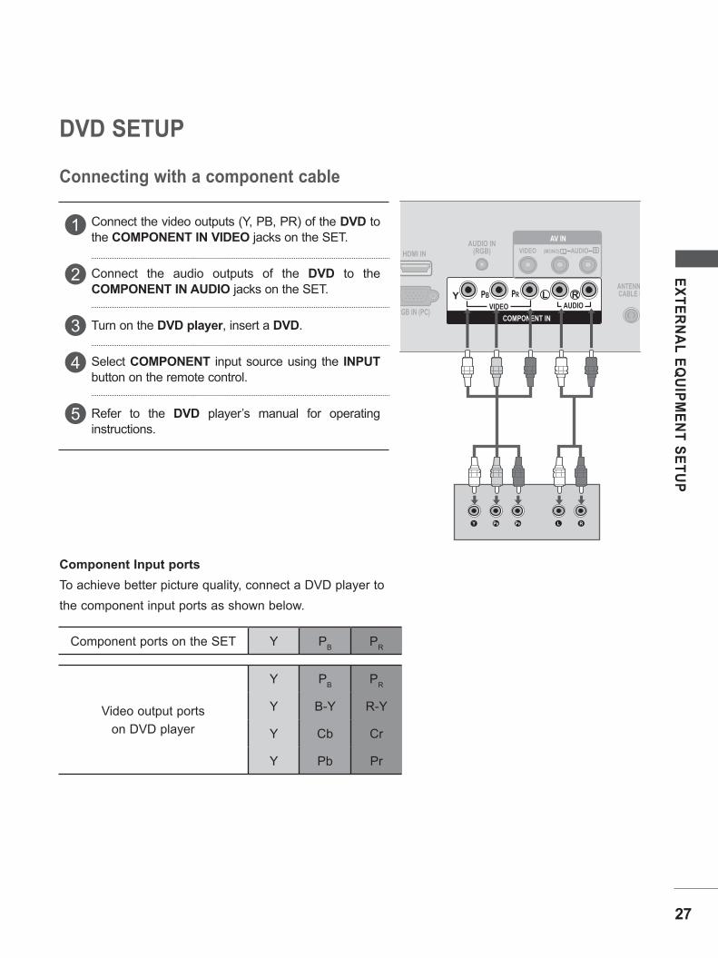
DVD SETUP
Connecting with a component cable
Connect the video outputs (Y, PB, PR) of the DVD to the COMPONENT IN VIDEO jacks on the SET.
Connect the audio outputs of the DVD to the COMPONENT IN AUDIO jacks on the SET.
Turn on the DVD player, insert a DVD.
Select COMPONENT input source using the INPUT button on the remote control.
Refer to the DVD player’s manual for operating instructions.
AUDIO IN(RGB)
VIDEO
VIDEO AUDIO(MONO)
AUDIOY PB PR L R
HDMI IN
ANTENNA/CABLE IN
L R
RGB IN (PC) COMPONENT IN
AV IN
AUDIO IN(RGB) VIDEO AUDIO(MONO) L R
AV IN
VIDEO AUDIOY PB PR L R
HDMI IN
ANTENNA/CABLE IN
COMPONENT INRGB IN (PC)
Component Input portsTo achieve better picture quality, connect a DVD player tothe component input ports as shown below.
Component ports on the SET Y PB PR
Video output portson DVD player
Y PB PR
Y B-Y R-Y
Y Cb Cr
Y Pb Pr

28
EXTERNAL EQUIPMENT SETUP
EXTERN
AL EQ
UIPM
ENT SETU
P
Connecting with a HDMI cable
Connect the HDMI output of the DVD to the HDMI IN jack on the SET.
Select HDMI input source using the INPUT button on the remote control.
Refer to the DVD player’s manual for operating instructions.
1
2
3
AUDIO IN(RGB)
VIDEO
VIDEO AUDIO(MONO)
AUDIOY PB PR L R
HDMI IN
ANTENNA/CABLE IN
L R
RGB IN (PC) COMPONENT IN
AV IN
AUDIO IN(RGB) VIDEO AUDIO(MONO) L R
AV IN
VIDEO AUDIOY PB PR L R
HDMI IN
ANTENNA/CABLE IN
COMPONENT INRGB IN (PC)
NOTE!
?
!
?
SET can receive the video and audio signal simultane-ously with using a HDMI cable. If the digital set-top box supports Auto HDMI function, the output resolution of the source device will be automatically SET to 1920 x 1080p. If the digital set-top box player does not support Auto HDMI, you need to SET the output resolution appropriately. To get the best picture quality, adjust the output resolu-tion of the source device to 1920 x 1080p. We recommend less than 10 m for HDMI cable.

29
EXTERN
AL EQ
UIPM
ENT SETU
P
HDMI INAUDIO IN
(RGB)
Y PB PR L R
COMPONENT INRGB IN (PC)
ANTENNA/CABLE IN
OUTPUTSWITCHANT IN
RS-VIDEO VIDEOANT OUT L
L RS-VIDEO VIDEO
OUTPUTSWITCH
ANT IN
ANT OUT
HDMI INAUDIO IN
(RGB) VIDEO AUDIO(MONO) L R
AV IN
VIDEO AUDIOY PB PR VIDEO AUDIOL R
ANTENNA/CABLE IN
COMPONENT INRGB IN (PC)
VIDEO AUDIO(MONO) L R
AV IN
Connecting with a RCA cable
Connect the AUDIO / VIDEO jacks between SET and VCR. Match the jack colours (Video = yellow, Audio Left = white, and Audio Right = red)
Insert a video tape into the VCR and press PLAY on the VCR. (Refer to the VCR owner’s manual.)
Select AV input source using the INPUT button on theremote control.
Connect the ANT OUT socket of the VCR to the ANTENNA IN socket on the SET.
Connect the antenna cable to the ANT INsocket of the VCR.
Press the PLAY button on the VCR and match the appropriate programme between the SET and VCR for viewing.
1
1
2
2
3
3
VCR SETUP
Connecting with a RF cable
To avoid picture noise (interference), allow adequate distance between the VCR and SET.
HDMI INAUDIO IN
(RGB)
Y PB PR L R
COMPONENT INRGB IN (PC)
ANTENNA/CABLE IN
OUTPUTSWITCHANT IN
RS-VIDEO VIDEOANT OUT L
L RS-VIDEO VIDEO
OUTPUTSWITCH
ANT IN
ANT OUT
HDMI INAUDIO IN
(RGB) VIDEO AUDIO(MONO) L R
AV IN
VIDEO AUDIOY PB PR VIDEO AUDIOL R
ANTENNA/CABLE IN
COMPONENT INRGB IN (PC)
VIDEO AUDIO(MONO) L R
AV IN
Wall Jack
Antenna

30
EXTERNAL EQUIPMENT SETUP
EXTERN
AL EQ
UIPM
ENT SETU
P
Connect the AUDIO / VIDEO jacks between SET and external equipment. Match the jack colours.(Video = yellow, Audio Left = white, and Audio Right = red)
Select AV input source using the INPUT button on the remote control.If connected to AV IN, select AV input source.
Operate the corresponding external equipment. Refer to external equipment operating guide.
1
2
3
OTHER A/V SOURCE SETUP
HDMI INAUDIO IN
(RGB)
VIDEO AUDIOY PB PR L R
COMPONENT INRGB IN (PC)
ANTENNA/CABLE IN
VIDEO AUDIO(MONO) L R
AV IN
L RVIDEO
Camcorder
Video Game Set

31
EXTERN
AL EQ
UIPM
ENT SETU
P
PC SETUPWhen using the remote control, aim it at the remote control sensor on the SET.
When connecting with a D-sub 15 pin cable
Connect the signal cable from the monitor output socket of the PERSONAL COMPUTER to the PC input socket of the set.
Connect the audio cable from the PC to the AUDIO IN(RGB) sockets of the set.
Press the INPUT button to select RGB PC.
Switch on the PC, and the PC screen appears on the set.The set can be operated as a PC monitor.
1
2
3
4
HDMI IN VIDEO AUDIO(MONO) L R
AV IN
VIDEO AUDIOY PB PR L R
COMPONENT IN
ANTENNA/CABLE IN
RGB IN (PC)
AUDIO IN(RGB)
RGB OUTPUT AUDIO
Connect the signal input cable and tighten the screws by turn-ing them clockwise.
NOTE!
?
!
? User must use shielded signal interface cables (D-sub 15 pin cable) with ferrite cores to maintain standard compliance for the product.

32
EXTERNAL EQUIPMENT SETUP
EXTERN
AL EQ
UIPM
ENT SETU
P
BACK COVER FOR WIRE ARRANGEMENTTie cables together with a cable management as shown in the illustration.
<M237WAP>
<M2062A/M2262A/M2362A/M2762A>
<M197WAP/ M227WAP >

33
EXTERN
AL EQ
UIPM
ENT SETU
P
SUPPORTED DISPALY RESOLUTION
Resolution HorizontalFrequency(kHz)
VerticalFrequency(Hz)
640 x 480 31.469 59.94800 x 600 37.879 60.317
1024 x 768 48.363 60.01280 x 720 47.77 59.851360 x 768 47.71 60.02
Resolution HorizontalFrequency(kHz)
VerticalFrequency(Hz)
640 x 480 31.469 59.94800 x 600 37.879 60.317
1024 x 768 48.363 60.01280 x 720 47.77 59.85
1280 x 1024 63.981 60.021600 x 900 60 60
Resolution HorizontalFrequency(kHz)
VerticalFrequency(Hz)
640 x 480 31.469 59.94800 x 600 37.879 60.317
1024 x 768 48.363 60.01152 x 864 54.34 60.051280 x 960 60 60
1280 x 1024 63.981 60.021680 x 1050 64.674 59.8831680 x 1050 65.290 59.9541920 x 1080 67.5 60
Resolution HorizontalFrequency(kHz)
VerticalFrequency(Hz)
720 x 480 31.47 59.94720 x 480 31.50 60.00720 x 576 31.25 50.00
1280 x 720 44.96 59.941280 x 720 45.00 60.001280 x 720 37.50 50.00
1920 x 1080 33.72 59.941920 x 1080 33.75 60.001920 x 1080 28.125 50.001920 x 1080 67.432 59.941920 x 1080 67.5 601920 x 1080 56.250 50
RGB[PC] mode
HDMI[DTV] mode
M197WAP
M2062A
M227WAP / M237WAP / M2262A / M2362A / M2762A

WATCHING TV / PROGRAMME CONTROL
When using the remote control, aim it at the remote control sensor on the SET.
A TYPE
B TYPE
OK
1 2 3
4 5 6
7 8 9
0Q.VIEWLIST
PR
VOL VOL
PR
TV/PC
MUTE PSM SSM I/II
INPUTPOWER
? i
MENU
HOLD
REVEAL
SIZE
INDEX MODE UPDATE
MIX TIME
SLEEP *ARC/ TEXT
OK
1 2 3
4 5 6
7 8 9
0Q.VIEWLIST
PR
VOL VOL
PR
TV/PC
MUTE PSM SSM I/II
INPUTPOWER
? i
MENU
HOLD
REVEAL
SIZE
INDEX MODE UPDATE
MIX TIME
SLEEP *ARC/ TEXT
POWER
TV/PC
INPUT
Switches the set on from standby or off to standby.
Selects TV or PC mode.
If you press the button once, the input source OSD will appear on screen as shown. Press the /button and then OK button to select the desired input source.
MUTE
PSM
SSM
I/II
Switches the sound on or off.
Recalls your preferred picture setting.
Recalls your preferred sound setting.
Selects the sound output. (p.60)
0~9 number button
LIST
Q.VIEW
Selects a programme.Selects numbered items in a menu.
Displays the programme table.
Returns to the previously viewed programme.
REMOTE CONTROL KEY FUNCTIONS
THUMBSTICK(Up/Down/Left/Right)
-Up/Down
-Left/Right
OK
Allows you to navigate the on-screen menus and adjust the system settings to your preference.Selects a programme.Adjusts the volume.
Accepts your selection or displays the current mode.
1
1
2
3
4
1
2
2
3
3
4
4
34
WATC
HIN
G TV / PR
OG
RA
MM
E CO
NTR
OL

35
WATC
HIN
G TV / PR
OG
RA
MM
E CO
NTR
OL
OK
1 2 3
4 5 6
7 8 9
0Q.VIEWLIST
PR
VOL VOL
PR
TV/PC
MUTE PSM SSM I/II
INPUTPOWER
? i
MENU
HOLD
REVEAL
SIZE
INDEX MODE UPDATE
MIX TIME
SLEEP *ARC/ TEXT
OK
1 2 3
4 5 6
7 8 9
0Q.VIEWLIST
PR
VOL VOL
PR
TV/PC
MUTE PSM SSM I/II
INPUTPOWER
MENU SLEEP *ARC/ TEXT
MENU
SLEEP
ARC/*
Selects a menu.( p.37)
Sets the sleep timer.
Selects your desired picture format.( p.45)
Coloured buttons
TELETEXT BUTTONS
These buttons are used for teletext (on TELETEXT models only) or Programme edit.
These buttons are used for teletext. For further details, see the ‘Teletext’ section. (p.72)
Installing Batteries
Open the battery compartment cover on the back side and install the batteries matching correct polarity (+with +,-with -)
Install two 1.5 V AAA batteries. Don’t mix old or used batteries with new ones.
Close cover. To remove the batteries, perform the installation actions in reverse.
5
6
A TYPE
B TYPE
5
5
6
6
REMOTE CONTROL KEY FUNCTIONS

36
WATCHING TV / PROGRAMME CONTROL
WATC
HIN
G TV / PR
OG
RA
MM
E CO
NTR
OL
TURNING ON THE SET
INSTALLATION GUIDE
PROGRAMME SELECTION
VOLUME ADJUSTMENT
When using the remote control, aim it at the remote control sensor on the SET.
Firstly, connect the power cord correctly.At this stage, the SET switches to standby mode.
In standby mode to turn SET on, press the button on the SET or press the POWER buttons on the remote control and the SET will switch on.
If the OSD (On Screen Display) is displayed on the screen after turning on the SET, you can adjust the Language, Auto Tuning.
Note:a. It will automatically disappear after approx. 40 seconds unless a button is pressed.b. If you close without completing the initial setting, the Instal lation Guide menu can be displayed
again.
Press the / or NUMBER buttons to select a programme number.
Press the / button to adjust the volume.
If you wish to switch the sound off, press the MUTE button.
You can cancel the Mute function by pressing the MUTE, / , SSM or I/II button.
1
1
1
1
2
3

37
WATC
HIN
G TV / PR
OG
RA
MM
E CO
NTR
OL
ON SCREEN MENUS SELECTION AND ADJUSTMENTYour TV's OSD (On Screen Display) may differ slightly from that shown in this manual.
Press the MENU button and then / button to display each menu.
Press the button and then / button to select a menu item.
Change the setting of an item in the sub or pull-down menu with / button. You can move to a higher level menu by pressing the OK button.
1
2
3
Setup
Setup MENU
Option MENU
Picture MENU Audio MENU
Time MENU
OK MENU
OK MENU
OK MENU OK MENU
OK MENU
Auto TuningManual TuningProgramme EditFavourite Programme
Sound Mode • Treble 50 • Bass 50 • ResetAuto VolumeBalance 0
Aspect RatioPicture Mode
• Backlight 100
• Contrast 100
• Brightness 50
• Sharpness 70
• Colour 70
• Tint 0
LanguageKey LockDDC-CIPower IndicatorMode SettingFactory Reset
ClockOff TimeOn TimeSleep TimerAuto Sleep
Option
Picture
Audio
Time
NOTE!
?
!
?
The OSD (On Screen Display) function enables you to adjust the screen status conveniently since it provides graphical presentation. In this manual, the OSD (On Screen Display) may be different from your TV’s because it is just example to help the TV operation. In the teletext mode, menus are not displayed.

38
WATCHING TV / PROGRAMME CONTROL
WATC
HIN
G TV / PR
OG
RA
MM
E CO
NTR
OL
AUTO PROGRAMME TUNINGUp to 200 TV stations can be stored by programme numbers (0 to 199). Once you have preset the stations, you will be able to use the / or NUMBER buttons to scan the stations you have programmed.Stations can be tuned using automatic or manual modes.
All stations which can be received are stored by this method. It isrecommended that you use Auto tuning during installation of this SET.
Press the MENU button and then / button to select the Setup menu.
Press the button and then / button to select Auto Tuning.
Press the button and then / button to select System
Press the button and then / button to select a TV system menu;BG: PAL B / G, SECAM B / G (Asia / NewZealand / M.East / Africa)I: PAL I (South Africa / Hong Kong)DK: PAL D / K, SECAM D / K (China / Africa / CIS)M: (Philippines)
Press the / button to select Storage From.
Press the / button or NUMBER buttons to select the initial programme number.
Press the / button to select Search.
Press the button to begin auto tuning.All receivable stations are stored.
To stop auto tuning, press the MENU button.When auto tuning is complete, the Programme Edit menu appears on the screen. See the Programme Edit section to edit the stored programme.
Press the MENU button to move to the previous menuscreen.
1
1
2
8
75 643
2
3
4
5
6
7
8
9
Setup
Setup
Auto Tuning
Auto Tuning
Menu Stop
OK MENU
OK MENU
OK MENU
Auto TuningManual TuningProgramme EditFavourite Programme
Auto TuningManual TuningProgramme EditFavourite Programme
SystemStorage FromSearch
C 05 BG5 35%
To Set
BGIDKM
Auto Tuning
System

39
WATC
HIN
G TV / PR
OG
RA
MM
E CO
NTR
OL
MANUAL PROGRAMME TUNINGManual Turning lets you manually tune and arrange the stations in whatever order you desire.
Press the MENU button and then / button to select the Setup menu.
Press the button and then / button to select Manual Tuning.
Press the button and then / button to select Storage.
Press the / button or NUMBER buttons to select the desired programme number (0 to 199).
Press the / button to select System.
Press the button and then / button to select a TV system menu;BG: PAL B / G, SECAM B / G (Asia / NewZealand / M.East / Africa)I: PAL I (South Africa / Hong Kong)DK: PAL D / K, SECAM D / K (China / Africa / CIS) M: (Philippines)
Press the / button to select Band.
Press the button and then / button to select V/UHF or Cable.
Press the / button to select Channel.
Press the button and then You can select the desired programme number with the / button or NUMBER buttons.If possible, select the programme number directly with the number buttons.
Press the / button to select Search.
Press the / button to commence searching. If a station is found the search will stop.
Press the OK button to store it.
To store another station, repeat steps 3 to 13.
Press the MENU button to move to the previous menuscreen.
1
1
2
2
3
4
5
6
7
8
9
10
11
12
13
14
15
Setup
Setup
OK MENU
Auto TuningManual TuningProgramme EditFavourite Programme
Auto TuningManual TuningProgramme EditFavourite Programme
To Set Manual Tuning
712
510
611
49
38
Manual Tuning
OK MENU
StorageSystemBandChannelFineSearchName
1Storage
OK MENU

40
WATCHING TV / PROGRAMME CONTROL
WATC
HIN
G TV / PR
OG
RA
MM
E CO
NTR
OL
FINE TUNINGNormally fine tuning is only necessary if reception is poor.
Press the MENU button and then / button to select the Setup menu.
Press the button and then / button to select Manual Tuning.
Press the button and then / button to select Fine.
Press the button and then / button to fine tune for the best picture and sound.
Press the OK button to store it.
Press the MENU button to move to the previous menu screen.
1
2
3
4
5
6
1
Setup
OK MENU
Auto TuningManual TuningProgramme EditFavourite Programme
2
Setup
OK MENU
Auto TuningManual TuningProgramme EditFavourite Programme
To Set Manual Tuning
543
Manual Tuning
OK MENU
StorageSystemBandChannelFineSearchName
/ Fine

41
WATC
HIN
G TV / PR
OG
RA
MM
E CO
NTR
OL
ASSIGNING A STATION NAMEYou can assign a station name up to five characters to each programme number.
Press the MENU button and then / button to select the Setup menu.
Press the button and then / button to select Manual Tuning.
Press the button and then / button to select Name.
Press the button and then / button. You can use a blank, +, -, the number 0 to 9 and the alphabet A to Z.
Press the / button to select the position and make your choice of the second character, and so on.
Press the OK button to store it.
Press the MENU button to move to the previous menu screen.
1
2
3
4
5
7
6
1
Setup
OK MENU
Auto TuningManual TuningProgramme EditFavourite Programme
2
Setup
OK MENU
Auto TuningManual TuningProgramme EditFavourite Programme
To Set Manual Tuning
5 643
Manual Tuning
OK MENU
StorageSystemBandChannelFineSearchName _ _ _ _ Name

42
WATCHING TV / PROGRAMME CONTROL
WATC
HIN
G TV / PR
OG
RA
MM
E CO
NTR
OL
PROGRAMME EDITThis function enables you to delete or skip stored programmes.Also you can move some stations to other programme numbers.
Press the MENU button and then / button to select the Setup menu.
Press the button and then / button to select Programme Edit.
Press the button to display the Programme Edit menu.
Deleting a programme1. Select a programme to be deleted with the / / / button.
2. Press the RED button twice.The selected programme is deleted, all the follow-ing programmes are shifted up one position.
Moving a programme1. Select a programme to be moved with the / / / button.
2. Press the Green button.3. Move the programme to the desired programme number with the / / / button.
4. Press the Green button again to release this function.
Skipping a programme number1. Select a programme number to be skipped with the / / / button.
2. Press the BLUE button. The skipped programme turns to blue.
3. Press the BLUE button again to release the skipped programme.
When a programme number is skipped it means that you will be unable to select it using the / button during normal TV viewing. If you wish to select the skipped programme, directly enter the programme number with the NUMBER buttons
or select it in the Programme Edit or table menu.
Press the MENU button to move to the previous menu screen.
1
2
3
4
1
Setup
OK MENU
Auto TuningManual TuningProgramme EditFavourite Programme
2
Setup
OK MENU
Auto TuningManual TuningProgramme EditFavourite Programme
To Set Programme Edit
3
Programme Edit
0 C 031 BLN 032 C 123 S 664 S 67
DeleteMove Skip
0 C 031 BLN 032 C 123 S 664 S 67
OK MENU

43
WATC
HIN
G TV / PR
OG
RA
MM
E CO
NTR
OL
FAVOURITE PROGRAMMEThis function lets you select your favourite programmes directly.
Repeatedly press the YELLOW button to select stored favourite programmes.
Press the MENU button and then / button to select the Setup menu.
Press the button and then / button to select Favourite Programme.
Press the button.
Press the / button to select - - - - - - - -.
Select a desired programme with the / button or NUMBER buttons.
To store another programme, repeat steps 4 to 5.
You can store up to 8 programmes.
Press the MENU button to move to the previous menu screen.
1
2
3
4
5
7
6
1
Setup
OK MENU
Auto TuningManual TuningProgramme EditFavourite Programme
53 42
Setup
OK MENU
Auto TuningManual TuningProgramme EditFavourite Programme
_ _ _ _ _ _ _ __ _ _ _ _ _ _ __ _ _ _ _ _ _ __ _ _ _ _ _ _ __ _ _ _ _ _ _ __ _ _ _ _ _ _ __ _ _ _ _ _ _ _
Favourite Programme

44
WATCHING TV / PROGRAMME CONTROL
WATC
HIN
G TV / PR
OG
RA
MM
E CO
NTR
OL
SELECTING THE PROGRAMME LISTYou can check which programmes are stored in the memory by displaying the programme list.
Displaying programme listPress the LIST button to display the Programme List menu.The programme list appears on the screen.One programme list contains ten programmes as shown.
Selecting a programme in the Programme ListSelect a programme with the / / / button.Then press the OK button. The TV switches to the chosen programme number.
Paging through a Programme ListThere are 20 programme table pages in which contain 200 pro grammes. Pressing the / / / button repeatedly turns the pages.
Press the LIST button to return to normal TV viewing.
NOTE!
?
!
?
a. You may find some blue programmes. They have been set up to be skipped by auto programming or in the pro-gramme edit mode.
b. Some programmes with the channel number shown in the programme list indicate there is no station name assigned.
Programme List
0 C 03
1 BLN 03
2 C 12
3 S 66
4 S 67
0 C 03
1 BLN 03
2 C 12
3 S 66
4 S 67
OK MENU

45
SOU
ND
CO
NTR
OL
PICTURE SIZE (ASPECT RATIO) CONTROLYou can watch the screen in various picture formats; 16:9, Original, 4:3, 14:9, Zoom1, Zoom2 and Just Scan.If a fixed image is displayed on the screen for a long time, that fixed image may become imprinted on the screen and remain visible.You can adjust the enlarge proportion using / button.This function works in the following signal.
You can adjust Aspect Ratio in the Picture menu.1
PICTURE CONTROL
• 16:9The following selection will allow you to adjust thepicture horizontally, in linear pro-portion, to fill the entire screen(useful for viewing 4:3 formatted DVDs).
• OriginalWhen your TV receives a wide screen sig-nal it will automatically change to the pic-ture format to be broadcast.
• 4:3The following selection will allow you to view a picture with an original 4:3 aspect ration, black bars will appear on both the left and right of the screen.
• 14:9You can view a picture format of 14:9 or a general TV programme in the 14:9 mode. The 14:9 screen is viewed in the same way as in 4:3, but is magnified to the left and right.
• Zoom 1The following selection will allow you to view the picture without any alteration, while filling the entire screen. However, the top and bot tom of the picture will be cropped.
• Zoom 2Choose Zoom 2 when you wish the picture to be altered, both horizontally extended and vertically cropped. The picture adopting a compromise between alteration and screen converage.
• Just ScanFollowing Selection will lead to you view the picture of best quality without loss of origi-nal picture in high resolution image.
16:9Zoom 1
Zoom 2
Just Scan
Original
4 : 3
14 : 9
NOTE!
?
!
?
You can only select 4:3,16:9 (Wide) in Component, RGB-PC, HDMI mode. In HDMI/Component (over 720p) mode, Just Scan is available.

46
PICTURE CONTROL
PICTU
RE C
ON
TRO
L
PRESET PICTURE SETTINGS
Picture Mode adjusts the SET for the best picture appearance. Select the preset value in the Picture Mode menu based on the programmecategory.
Vivid, Standard, Cinema and sRGB are programmed for optimum picture reproduction at the factory.
Picture Mode-Preset
OK MENU
OK MENU
Aspect RatioPicture Mode
• Backlight 100
• Contrast 100
• Brightness 50
• Sharpness 70
• Colour 70
• Tint 0
Aspect RatioPicture Mode
• Backlight 100
• Contrast 100
• Brightness 50
• Sharpness 70
• Colour 70
• Tint 0
Picture
Picture
Press the MENU button and then / button to select the Picture menu.
Press the button and then / button to select Picture Mode.
Press the button and then / button to select Vivid, Standard ,Cinema or sRGB.
Press the MENU button to move to the previous menu screen.
1
2
3
4
VividStandardCinemasRGB
Picture Mode
1
32
NOTE!
?
!
?
In RGB PC mode, sRGB is available.

47
PICTU
RE C
ON
TRO
L
MANUAL PICTURE ADJUSTMENT
Backlight To control the brightness of the screen, adjust the brightness of LCD panel.Contrast Adjusts the difference between light and dark levels in the picture.Brightness Increases or decreases the amount of white in the picture.Sharpness Adjusts the level of crispness in the edges between the light and dark areas of the picture. The lower the level, the softer the image.Colour Adjusts intensity of all colours.Tint Adjusts the balance between red and green levels.
Picture Mode-User Option
OK MENU
Aspect RatioPicture Mode
• Backlight 100
• Contrast 100
• Brightness 50
• Sharpness 70
• Colour 70
• Tint 0
Picture
Press the MENU button and then / button to select the Picture menu.
Press the button and then / button to select Picture Mode.
Press the button and then / button to select Vivid, Standard, Cinema or sRGB.
Press the OK button and then / button to select the desired picture option (Backlight, Contrast, Brightness, Sharpness, Colour and Tint).
Press the / button to make appropriate adjust-ments.
Press the MENU button to move to the previous menu screen.
1
2
3
4
5
6
OK MENU
OK MENU
Aspect RatioPicture Mode
• Backlight 100
• Contrast 100
• Brightness 50
• Sharpness 70
• Colour 70
• Tint 0
Aspect RatioPicture Mode
• Backlight 100
• Contrast 100
• Brightness 50
• Sharpness 70
• Colour 70
• Tint 0
Picture
Picture
VividStandardCinemasRGB
Vivid
Picture Mode
• Backlight 100
• Backlight 100
1
3
5
2
4
NOTE!
?
!
?
In RGB PC mode, sRGB is available.

48
PICTURE CONTROL
PICTU
RE C
ON
TRO
L
PICTURE IMPROVEMENT TECHNOLOGYYou can calibrate the screen for each Picture Mode or set the video value according to the special video screen.You can set the video value differently for each input.To reset to the factory default screen after making adjustments to each video mode, execute the “Picture Reset” function for each Picture Mode.
Press the MENU button and then / button to select the Picture menu.
Press the button and then / button to select Advanced.
Press the button and then / button to select Dynamic Contrast, Dynamic Colour, Noise Reduction, Black Level, Film Mode or Colour Temperature.
Press the MENU button to move to the previous menu screen.
1
2
3
4
OK MENU
Picture Mode• Backlight 100• Contrast 100• Brightness 50• Sharpness 70• Colour 70• Tint 0• Advanced
Picture
1
OK MENU
OK MENU
Picture Mode• Backlight 100• Contrast 100• Brightness 50• Sharpness 70• Colour 70• Tint 0• Advanced
Dynamic ContrastDynamic ColourNoise ReductionBlack LevelFilm ModeColour Temperature• Red 0• Green 0
Picture
Advanced
OffLowHigh
• Advanced
Dynamic Contrast
3
2
To Set
NOTE!
?
!
?
At 1080i / p Dynamic Contrast, Dynamic Colour, Noise Reduction is not enable.
49
PICTU
RE C
ON
TRO
L
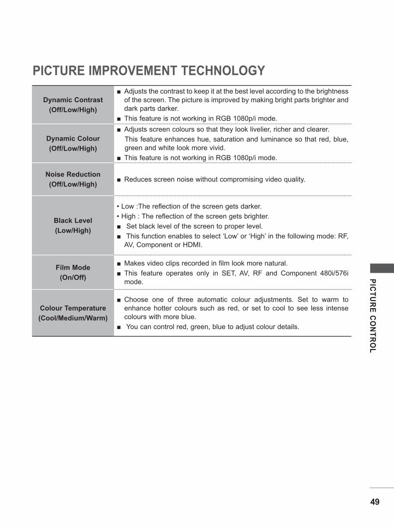
Dynamic Contrast(Off/Low/High)
Adjusts the contrast to keep it at the best level according to the brightness of the screen. The picture is improved by making bright parts brighter and dark parts darker.
This feature is not working in RGB 1080p/i mode.
Dynamic Colour(Off/Low/High)
Adjusts screen colours so that they look livelier, richer and clearer. This feature enhances hue, saturation and luminance so that red, blue, green and white look more vivid.
This feature is not working in RGB 1080p/i mode.
Noise Reduction(Off/Low/High)
Reduces screen noise without compromising video quality.
Black Level(Low/High)
• Low :The reflection of the screen gets darker.• High : The reflection of the screen gets brighter.
Set black level of the screen to proper level. This function enables to select ‘Low’ or ‘High’ in the following mode: RF, AV, Component or HDMI.
Film Mode(On/Off)
Makes video clips recorded in film look more natural. This feature operates only in SET, AV, RF and Component 480i/576i mode.
Colour Temperature(Cool/Medium/Warm)
Choose one of three automatic colour adjustments. Set to warm to enhance hotter colours such as red, or set to cool to see less intense colours with more blue.
You can control red, green, blue to adjust colour details.
PICTURE IMPROVEMENT TECHNOLOGY

50
PICTURE CONTROL
PICTU
RE C
ON
TRO
L
PICTURE RESETSettings of the selected picture modes return to the default factory settings.
Press the MENU button and then / button to select the Picture menu.
Press the button and then / button to select Picture Reset.
Press the button to initialize the adjusted value.
Press the MENU button to move to the previous menu screen.
1
2
3
4
OK MENU
• Backlight 100• Contrast 100• Brightness 50• Sharpness 70• Colour 70• Tint 0• Advanced• Picture Reset
Picture
1
32 OK MENU
• Backlight 100• Contrast 100• Brightness 50• Sharpness 70• Colour 70• Tint 0• Advanced• Picture Reset
Picture
• Picture Reset OK

51
PICTU
RE C
ON
TRO
L
SCREEN SETUP
Automatically adjusts picture position and minimizes image instability. After adjustment, if the image is still not correct, your set is functioning properly but needs further adjustment.
Auto configureThis function is for automatic adjustment of the screen position, clock, and phase The displayed image will be unstable for a few seconds while the auto configuration is in progress.
AUTO CONFIGURE (RGB [PC] mode only)
Press the MENU button and then use / button to select the Picture menu.
Press the button and then use / button to select Screen.
Press the button and then use / button to select Auto Config.
Press the OK button
Press the MENU button to move to the previous menu screen
1
2
3
4
5
OK MENU
Aspect RatioPicture Mode
• Backlight 100• Contrast 100• Brightness 50• Sharpness 70• Colour 70• Tint 0
Picture
1
4
2
3
OK MENU
OK MENU
• Contrast 100• Brightness 50• Sharpness 70• Colour 70• Tint 0• Advanced• Picture ResetScreen
Auto configManual Config. Reset
Picture
Screen
Screen
Auto Config.
To set
To Set

52
PICTURE CONTROL
PICTU
RE C
ON
TRO
L
If the picture is not clear and especially if characters are still trembling, adjust the picture phase manually.
This function works in the following mode when the signal exist : RGB PC
MANUAL CONFIGURE(Adjustment for screen Position)
Press the MENU button and then use / button to select the Picture menu.
Press the button and then use / button to select Screen.
Press the button and then use / button to select Manual Config.
Press the button and then use / button to select Phase, Clock, H-Position or V-Position.(When the H-Position and V-Position be changed, Value may differ from the aspect ratio.)
Press the / button to make appropriate adjust-ments.
Press the MENU button to move to the previous menuscreen.
1
2
3
4
5
6
OK MENU
Aspect RatioPicture Mode
• Backlight 100• Contrast 100• Brightness 50• Sharpness 70• Colour 70• Tint 0
Picture
1
4 5
2
3
OK MENU
OK MENU
• Contrast 100• Brightness 50• Sharpness 70• Colour 70• Tint 0• Advanced• Picture ResetScreen
Auto configManual Config. Reset
Picture
Screen
Screen
Manual Config.
To set
Phase 8Clock 50H-Position 50V-Position 50

53
PICTU
RE C
ON
TRO
L
This function operates in current mode.To initialize the adjusted valueThis function works in the following mode when the signal exist : RGB PC
INITIALIZING (Reset to original factory settings)
Press the MENU button and then use / button to
select the Picture menu.
Press the button and then use / button to select
Screen.
Press the button and then use / button to select
Reset.
Press the button.
Press the MENU button to move to the previous menu
screen.
1
2
3
4
5
OK MENU
Aspect RatioPicture Mode
• Backlight 100• Contrast 100• Brightness 50• Sharpness 70• Colour 70• Tint 0
Picture
1
4
2
3
OK MENU
OK MENU
• Contrast 100• Brightness 50• Sharpness 70• Colour 70• Tint 0• Advanced• Picture ResetScreen
Auto Config.Manual Config. Reset
Picture
Screen
Screen
Reset
To set
To Set

54
PICTURE CONTROL
PICTU
RE C
ON
TRO
L
To view a normal picture, match the resolution of RGB mode and selection of PC mode.
This function works in the following mode: RGB[PC] mode.
SELECTING RESOLUTION
Press the MENU button and then use / button to select the Picture menu.
Press the button and then use / button to select Screen.
Press the button and then use / button to select Resolution.
Press the MENU button to move to the previous menuscreen.
1
2
3
4
OK MENU
Aspect RatioPicture Mode
• Backlight 100• Contrast 100• Brightness 50• Sharpness 70• Colour 70• Tint 0
Picture
1
2
3
OK MENU
OK MENU OK MENU
• Contrast 100• Brightness 50• Sharpness 70• Colour 70• Tint 0• Advanced• Picture ResetScreen
Auto configManual Config. ResolutionReset
Auto configManual Config. ResolutionReset
Picture
Screen Screen
Screen
Resolution Resolution
To set
1024 x 7681280 x 7681360 x 7681366 x 768
1400 x 10501680 x 1050
<Vertical resolution : 768> <Vertical resolution : 1050(Except M2062A)>

55
SOU
ND
CO
NTR
OL
SOUND CONTROL
PRESET SOUND SETTINGS - SOUND MODEYou can select your preferred sound setting; Standard, Music or Cinema.
Sound Mode lets you enjoy the best sound without any Special adjustment as the TV sets the appropriate sound options based on the programme content.
Standard, Music and Cinema are preset for optimum sound quality at the factory.
Press the MENU button and then / button to select the Audio menu.
Press the button and then / button to select Sound Mode.
Press the button and then / button to select Standard, Music or Cinema.
Press the MENU button to move to the previous menu screen.
1
2
3
4
OK MENU
OK MENU
Sound Mode • Treble 50 • Bass 50 • ResetAuto VolumeBalance 0
Sound Mode • Treble 50 • Bass 50 • ResetAuto VolumeBalance 0
Audio
Audio
Sound Mode StandardMusicCinema
1
32

56
SOUND CONTROL
SOU
ND
CO
NTR
OL
SOUND SETTING ADJUSTMENT - USER MODE
Press the MENU button and then / button to select the Audio menu.
Press the button and then / button to select Sound Mode.
Press the button and then / button to select Standard, Music or Cinema.
Press the OK button and then / button to select Treble or Bass.
Press the / button to make appropriate adjustments.
Press the MENU button to move to the previous menu screen.
1
2
3
4
5
6
OK MENU
OK MENU
Sound Mode • Treble 50 • Bass 50 • ResetAuto VolumeBalance 0
Sound Mode • Treble 50 • Bass 50 • ResetAuto VolumeBalance 0
Audio
Audio
• Treble Standard
To set
1
53 42

57
SOU
ND
CO
NTR
OL
AUTO VOLUME LEVELERAuto Volume automatically remains on the same level of volume if you change programmes.
Press the MENU button and then / button to select the Audio menu.
Press the button and then / button to select Auto Volume.
Press the button and then / button to select On
or Off.
Press the MENU button to move to the previous menu screen.
1
2
3
4
OK MENU
OK MENU
Sound Mode • Treble 50 • Bass 50 • ResetAuto VolumeBalance 0
Sound Mode • Treble 50 • Bass 50 • ResetAuto VolumeBalance 0
Audio
Audio
Auto Volume OffOn
1
32

58
SOUND CONTROL
SOU
ND
CO
NTR
OL
BALANCEYou can adjust the sound balance of the speakers to the preferred levels.
Press the MENU button and then / button to select the Audio menu.
Press the button and then / button to select Auto Balance.
Press the button and then / button to make desired adjustment.
Press the MENU button to move to the previous menu screen.
1
2
3
4
OK MENU
OK MENU
Sound Mode • Treble 50 • Bass 50 • ResetAuto VolumeBalance 0
Sound Mode • Treble 50 • Bass 50 • ResetAuto VolumeBalance 0
Audio
Audio
Balance 0
1
32

59
SOU
ND
CO
NTR
OL
AUDIO RESETSettings of the selected Sound Mode return to the default factory settings.
Press the MENU button and then / button to select the Audio menu.
Press the button and then / button to select Reset.
Press the button or OK button.
Press the MENU button to move to the previous menu screen.
1
2
3
4
OK MENU
OK MENU
Sound Mode • Treble 50 • Bass 50 • ResetAuto VolumeBalance 0
Sound Mode • Treble 50 • Bass 50 • ResetAuto VolumeBalance 0
Audio
Audio
• Reset
1
32
Standard
To set
60
SOUND CONTROL
SOU
ND
CO
NTR
OL
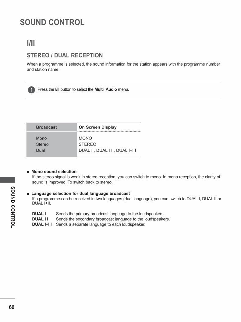
I/II
When a programme is selected, the sound information for the station appears with the programme numberand station name.
Mono sound selectionIf the stereo signal is weak in stereo reception, you can switch to mono. In mono reception, the clarity ofsound is improved. To switch back to stereo.
Language selection for dual language broadcastIf a programme can be received in two languages (dual language), you can switch to DUAL I, DUAL II or DUAL I+II.
DUAL I Sends the primary broadcast language to the loudspeakers.DUAL I I Sends the secondary broadcast language to the loudspeakers.DUAL I+I I Sends a separate language to each loudspeaker.
Press the I/II button to select the Multi Audio menu.1
STEREO / DUAL RECEPTION
Broadcast On Screen Display
MonoStereoDual
MONOSTEREODUAL I , DUAL I I , DUAL I+I I

61
SOU
ND
CO
NTR
OL
If the SET is equipped with a receiver for NICAM reception, high quality NICAM (Near Instantaneous Companding Audio Multiplex) digital sound can be received.
Sound output can be selected according to the type of broadcast received.
In AV, Component, RGB PC and HDMI mode, you can select output sound for the left and right loudspeak-ers.
Select the sound output.
L+R : Audio signal from audio L input is sent to the left loudspeaker and audio signal from audio R input is sent to the right loudspeaker.
L+L : Audio signal from audio L input is sent to left and right loudspeakers.R+R : Audio signal from audio R input is sent to left and right loudspeakers.
When NICAM MONO is received, you can select NICAM MONO or MONO.
When NICAM STEREO is received, you can select NICAM STEREO or MONO.
If the stereo signal is weak, switch to MONO.
When NICAM DUAL is received, you can select NICAM DUAL I, NICAM DUAL II or NICAM DUAL I+II or MONO.
1
2
3
NICAM RECEPTION
SPEAKER SOUND OUTPUT SELECTION

TIME SETTING
CLOCK SETUPYou must set the time correctly before using on/off time function.
If current time setting is erased by a power failure or the SET is unplugged, reset the clock.
Press the MENU button and then / button to select the Time menu.
Press the button and then / button to select Clock.
Press the button and then / button to set the hour.
Press the button and then / button to set the min-ute.
Press the MENU button to move to the previous menu screen.
1
2
3
4
5
OK MENU
OK MENU
ClockOff TimeOn TimeSleep TimerAuto Sleep
ClockOff TimeOn TimeSleep TimerAuto Sleep
Time
Time
Clock – – : – –
1
3 32
1
3 42
62
TIME SETTIN
G

63
TIME SETTIN
G
AUTO ON/OFF TIMER SETTINGThe Off time function automatically switches the SET to standby at a preset time.
The SET is switched on by the on time function it will automatically switch back to standby mode unless a button has been pressed for Two hours after.
Once the on time/off time is set, these functions operate daily at the preset time.
The Off time function overrides the On time function if both are set to the same time.
The SET must be in standby mode for the On time to work.
Press the MENU button and then / button to select the Time menu.
Press the button and then / button to select On/Off Time.
• To cancel On / Off Time function, select Off.
Press the button and then / button to set the hour.
Press the button and then / button to set the minutes.
For On Time function only
• PR : Press the button and then / button to select the programme.
• Vol : Press the button and then / button to adjust volume level at switch-on.
Press the MENU button to move to the previous menu screen.
1
2
3
4
5
6
OK MENU
OK MENU
OK MENU
ClockOff TimeOn TimeSleep TimerAuto Sleep
ClockOff TimeOn TimeSleep TimerAuto Sleep
ClockOff TimeOn TimeSleep TimerAuto Sleep
Time
Time
Time
Off Time
On Time
– – : – –Off
– – : – –PR 1VOL 30ON
1
3
3
3
3
2
2
1
3
3
4
4 5
2
2

64
TIME SETTING
TIME SETTIN
G
SLEEP TIMER SETTINGYou do not have to remember to switch the SET off before you go to sleep. The sleep timer automatically switches the SET to standby after the preset time has elapsed.
Press the MENU button and then / but ton to select the Time menu.
Press the button and then / button to select Sleep Timer.
Press the button and then / button to set the minute (Off, 10, 20, 30, 60, 90, 120, 180 or 240).
Press the MENU button to move to the previous menu
screen.
1
2
3
4
OK MENU
OK MENU
ClockOff TimeOn TimeSleep TimerAuto Sleep
ClockOff TimeOn TimeSleep TimerAuto Sleep
Time
Time
Sleep Timer Off
1
3 32
1
3 42

65
TIME SETTIN
G
AUTO SLEEPIf the set is switched on and there is no input signal, it will switch off automatically after 15 minutes.
Press the MENU button and then / but ton to select the Time menu.
Press the button and then / button to select Auto Sleep.
Press the button and then / button to select On or Off.
1
2
3
OK MENU
OK MENU
ClockOff TimeOn TimeSleep TimerAuto Sleep
ClockOff TimeOn TimeSleep TimerAuto Sleep
Time
Time
Auto Sleep OffOn
1
32
1
32

OPTION SETTING
LanguageKey LockDDC-CIPower IndicatorMode SettingFactory Reset
LanguageKey LockDDC-CIPower IndicatorMode SettingFactory Reset
Option
Option
OK MENU
OK MENU
To set Language
Press the MENU button and then use / button
to select the Option menu.
Press the button and then use / button to
select Language.
Press the button and then use / / /
button to select your desired language.
Press the OK button
Press the MENU button to move to the previous
menu screen.
1
2
3
4
5
ON-SCREEN MENU LANGUAGE SELECTIONThe menus can be shown on the screen in the selected language.
1
2
66
OPTIO
N SETTIN
G

67
OPTIO
N SETTIN
G
KEY LOCKThe SET can be set so that the remote control is needed to control it.This feature can be used to prevent unauthorized viewing.
This SET is programmed to remember which option it was last set to even if you turn the SET off.
Press the MENU button and then / button to select the Option menu.
Press the button and then / button to select Key Lock.
Press the button and then / button to select On or Off.
Press the MENU button to move to the previous menu screen.
1
2
3
4
LanguageKey LockDDC-CIPower IndicatorMode SettingFactory Reset
LanguageKey LockDDC-CIPower IndicatorMode SettingFactory Reset
Option
Option
OK MENU
OK MENU
OffOn
Key Lock
NOTE!
?
!
?
In Key Lock ‘On’, if the TV is turned off, press the ꔰ / I button on the SET or POWER buttons on the remote control. With the Key Lock On, the display ‘Key Lock On’ appears on the screen if any button on the side panel is pressed while viewing the SET.
1
32

68
OPTION SETTING
OPTIO
N SETTIN
G
DDC-CI(Only RGB)DDC-CI (Display Data Channel Command Interface) is a communication protocol for communications between PC and set.
DDC-CI makes it possible to adjust and setup detailed functions on PC instead of the set OSD.
Set can be adjusted with PC by connecting communication between PC and set when DDC-CI is ON, and when DDC-CI is OFF set cannot be adjusted with PC because communication between PC and set is discon-nected.
Press the MENU button and then / button to select the Option menu.
Press the button and then / button to select DDC-CI.
Press the button and then / button to select On or Off.
Press the MENU button to move to the previous menu screen.
1
2
3
4
LanguageKey LockDDC-CIPower IndicatorMode SettingFactory Reset
LanguageKey LockDDC-CIPower IndicatorMode SettingFactory Reset
Option
Option
OK MENU
OffOn
DDC - CI
1
32 OK MENU

69
OPTIO
N SETTIN
G
POWER INDICATOR
Press the MENU button and then / button to select the Option menu.
Press the button and then / button to select Power Indicator.
Press the button and then / button to select On or Off .
Press the MENU button to move to the previous menu screen.
1
2
3
4
1
2
OK MENU
OK MENU
LanguageKey LockDDC-CIPower IndicatorMode SettingFactory Reset
LanguageKey LockDDC-CIPower IndicatorMode SettingFactory Reset
Option
Option
Power Indicator
It is function to control of LED(turn on/off).
1
2
3
4
Option
OffOn

70
OPTION SETTING
OPTIO
N SETTIN
G
MODE SETTINGWe recommend setting the set to “Home Use” mode for the best picture in your home environment.“Store Demo” mode is an optimal setting for displaying at stores.
Press the MENU button and then / button to select the Option menu.
Press the button and then / button to select Mode Setting.
Press the button and then / button to select Store Demo or Home Use.
Press the MENU button to move to the previous menu screen.
1
2
3
4
LanguageKey LockDDC-CIPower IndicatorMode SettingFactory Reset
LanguageKey LockDDC-CIPower IndicatorMode SettingFactory Reset
Option
Option
OK MENU
To set Mode Stting
1
2
3
Mode Setting
Choose the setting mode you want
Select (Home Use) to use this TV at home
To use this TV at storeselect (Store Demo)
Store Demo Home Use
OK MENU
OK MENU

71
OPTIO
N SETTIN
G
FACTORY RESETUse to quickly reset all the menu options to their original factory preset values.This function deletes all SET programmes.When the Factory Reset is completed, you must restart the Installation Guide.
Press the MENU button and then / button to select the Option menu.
Press the button and then / button to select Factory Reset.
Press the button and then / button to select Yes or No.
Press the MENU button to move to the previous menu screen.
1
2
3
4
LanguageKey LockDDC-CIPower IndicatorMode SettingFactory Reset
LanguageKey LockDDC-CIPower IndicatorMode SettingFactory Reset
Option
Option
OK MENU
To set Factory Reset
1
2
3
Factory Reset
OK MENU
Yes No
OK MENU

TELETEXTThis feature is not avai lable in al l countries.
Teletext is a free service broadcast by most SET stations which gives up-to-the-minute information on news, weather, television programmes, share prices and many other topics.
The teletext decoder of this SET can support the SIMPLE, TOP and FASTEXT systems. SIMPLE (standard teletext) consists of a number of pages which are selected by directly entering the cor-responding page number. TOP and FASTEXT are more modern methods allowing quick and easy selection of teletext information.
1
1
3
2
2
4
Press the TEXT button to switch to teletext. The initial page or last page viewed appears on the screen.Two page numbers, SET station name, date and time are dis-played on the screen headline. The first page number indicates your selection, while the second shows the current page displayed.Press the TEXT button to switch off teletext. The previous mode reappears.
Page selection
Enter the desired page number as a three digit number with the NUMBER buttons. If during selection you press a wrong number, you must complete the three digit number and then re-enter the correct page number.The / button can be used to select the preceding or following page.
Programming a colour button in LIST mode
If the SET is in SIMPLE text, TOP text or FASTEXT mode, press the M button to switch to LIST mode.
Four teletext page numbers of your choice can be colour coded and easily selected by pressing the corre-sponding coloured button on the remote control handset.
Press a coloured button.Using the NUMBER buttons, select the page you wish to programme.Press the OK button. The selected page is stored as the selected page number, blinking once to confirm this.From now on, you can select this page with the same coloured button.The three other coloured buttons are programmed in this way.
SWITCH ON/OFF
SIMPLE TEXT
OK
1 2 3
4 5 6
7 8 9
0Q.VIEWLIST
PR
VOL VOL
PR
TV/PC
MUTE PSM SSM I/II
INPUTPOWER
? i
MENU
HOLD
REVEAL
SIZE
INDEX MODE UPDATE
MIX TIME
SLEEP *ARC/ TEXT
72
TELETEXT

73
TELETEXT
The user guide displays four fields-red, green, yellow and blue at the bottom of the screen. The yellow fielddenotes the next group and the blue field indicates the next block.
Block / group / page selection
With the blue button you can progress from block to block.Use the yellow button to proceed to the next group with automatic overflow to the next block.With the green button you can proceed to the next existing page with automatic overflow to the next group.Alternatively the button can be used.The red button return to the previous selection. Alternatively the button can be used.
Direct page selection
As with SIMPLE teletext mode, you can select a page by entering it as a three digit number using the NUMBER buttons in TOP mode.
The teletext pages are colour coded along the bottom of the screen and are selected by pressing the cor-responding coloured button.
Page selection
Press the i button to select the index page.You can select the pages which are colour coded along the bottom line with corresponding coloured buttons.As with SIMPLE teletext mode, you can select a page by entering its three digit page number with the NUMBERbuttons in FASTEXT mode.The / button can be used to select the preceding or following page.
SWITCH ON/OFF
FASTEXT
1
1
3
3
2
2
4
4

74
TELETEXT
TELETEXT
SPECIAL TELETEXT FUNCTIONS
ꕎTIMEWhen viewing a SET programme, press this button to display the time at the topright hand corner of the screen. Press this button again to remove the display.In the teletext mode, press this button to select a sub page number. The sub page number is displayed at the bottom of the screen. To hold or change the sub page, press the RED / GREEN, / or NUMBER buttons.Press again to exit this function.
ꕍSIZESelects double height text.Press this button to enlarge the top half of the page.Press this button again to enlarge the bottom half of the page.Press this button again to return to the normal display.
ꕋUPDATEDisplays the SET picture on the screen while waiting for a new teletext page. The display will appear at the top left hand corner of the screen. When the updated page is available then display will change to the page number. Press this button again to view the updated teletext page.
ꕌREVEALPress this button to display concealed information, such as solutions to riddles or puzzles.Press this button again to remove the information from the display.
ꕉINDEXSelect the each index page.
ꕘHOLDStops the automatic page change which will occur if a teletext page consists of 2 or more sub pages. The number of sub pages and the sub page displayed is, usually, shown on the screen below the time. When this button is pressed the stop symbol is displayed at the top left-hand corner of the screen and the automatic page change is inactive. To continue press this button again.
ꕊMIXDisplays the teletext pages superimposed on the SET picture.To switch the SET picture off press this button again.

75
APPEN
DIX
APPENDIX
TROUBLESHOOTINGThe SET does not operate properly
The remote controldoes not work
Check to see if there is any object between the SET and the remote control causing an obstruction.
Are batteries installed with correct polarity (+ to +, - to -)? Install new batteries.
Power is suddenlyturned Off
Is the sleep timer set? Check the power control settings. Has the Power supply been inter-rupted.
The SET goes into Standby mode automatically if no signal is received and no operation is performed for 15 minutes.
The Video function is not working
No picture &No sound
Check whether the SET is switched on. Try another channel. The problem may be with the broadcast. Is the power cord inserted correctly into the mains? Check your antenna direction and/or location. Test the mains outlet by plugging another SET into the same outlet.
Picture appears slowlyafter switching on
This is normal, the image is muted during the SET startup process. Please contact your service center, if the picture has not appeared after five minutes.
No or poor colouror poor picture
Adjust Colour in menu option. Allow a sufficient distance between the SET and the VCR. Try another channel. The problem may be with the broadcast. Are the video cables installed properly? Activate any function to restore the brightness of the picture.
Horizontal/verticalbars or picture shaking
Check for local interference such as an electrical appliance or power tool.
Poor reception onsome channels
Station or cable channel experiencing problems, tune to another station. Station signal is weak, reposition the antenna to receive weaker stations. Check for sources of possible interference.
Lines or streaks inpictures Check antenna (Change the position of the antenna).

76
APPENDIX
APPEN
DIX
TROUBLESHOOTINGThe Audio function is not working
Picture OK &No sound
Press the VOL or (or - +) button. Sound muted? Press MUTE button. Try another channel. The problem may be with the broadcast. Are the audio cables installed properly?
No output from oneof the speakers Adjust Balance in menu option.
Unusual sound frominside the TV
A change in ambient humidity or temperature may result in an unusu-al noise when the TV is switched on or off and does not indicate a fault with the TV.
Picture ok & No sound
Check whether volume is “0”. Check sound muted. HDMI cable installed properly. Head phone cable installed properly. Check sound format. Not supply to bitstream and compressed sound format.
NO image appear.
Do you see an “OUT OF RANGE” message
on the screen?
This message appears when the signal from the PC(video card) is out off horizontal or vertical frequency range of the display. See the ‘ Product Specifications’ section of this manual and configure you dis-play again.
77
APPEN
DIX
MAINTENANCEEarly malfunctions can be prevented. Careful and regular cleaning can prolong the life of your new SET.Caution : Be sure to swith the power off and unplug the power cord before you begin any cleaning.
Cleaning the Screen
A good way to keep the dust off your screen for a while is to wet a soft cloth in a mixture of lukewarm water and a little fabric softener or dish washing detergent. Wring the cloth until it’s almost dry, and then use it to wipe the screen.
Ensure there is no excess water on the screen. Allow any water or dampness to evaporate before switching on.
Cleaning the Cabinet
To remove dirt or dust, wipe the cabinet with a soft, dry, lint-free cloth. Do not to use a wet cloth.
Extended Absence
1
2
CAUTION
!
?
!
?
If you expect to leave your SET dormant for prolonged periods (such as a holiday), unplug the power cord to protect against possible damage from lightning or power surges.

78
APPENDIX
APPEN
DIX
PRODUCT SPECIFICATIONS
The specifications shown above may be changed without prior notice for quality improvement.
LCD PanelScreen Type
470.1 mm Wide (18.51 inch) TFT (Thin Film Transistor)
LCD (Liquid Crystal Display) Panel
Visible diagonal size: 470.1 mm
Pixel Pitch 0.30 mm (H) x 0.30 mm (V)
Video Signal
Max. Resolution 1360 x 768 @ 60 Hz
Recommended Resolution 1360 x 768 @ 60 Hz
Horizontal Frequency 30 kHz to 61 kHz
Vertical Frequency 56 Hz to 61 Hz
Synchronization Type Separate Sync
Input Connector CVBS, TV, D-Sub Analog, HDMI, PC Audio In, component
Power
Rated Voltage AC 100-240 V~ 50 / 60 Hz 0.6 A
Power ConsumptionOn Mode : 25 W (typ.)
Sleep Mode 1 W (RGB)
Off Mode 0.5 W
Tilt Tilt Range -5° to 15°
Dimensions (Width x Height x Depth)Weight
454.7 mm x 362.8 mm x 193.2 mm
(17.90 inch x 14.28 inch x 7.61 inch)
3.5 kg (7.72 lb)
Environmentalconditions
Operating TemperatureOperating Humidity
10 °C to 35 °C
20 % to 80 %
-10 °C to 60 °C
5 % to 90 %Storage TemperatureStorage Humidity
M197WAP

79
APPEN
DIX
The specifications shown above may be changed without prior notice for quality improvement.
LCD PanelScreen Type
546.86 mm Wide (21.53 inch) TFT (Thin Film Transistor)
LCD (Liquid Crystal Display) Panel
Visible diagonal size: 546.86 mm
Pixel Pitch 0.248 mm (H) x 0.248 mm (V)
Video Signal
Max. Resolution 1920 x 1080 @ 60 Hz
Recommended Resolution 1920 x 1080 @ 60 Hz
Horizontal Frequency 30 kHz to 69 kHz
Vertical Frequency 56 Hz to 61 Hz
Synchronization Type Separate Sync
Input Connector CVBS, TV, D-Sub Analog, HDMI, PC Audio In, component
Power
Rated Voltage AC 100-240 V~ 50 / 60 Hz 0.9 A
Power ConsumptionOn Mode : 45 W (typ.)
Sleep Mode 1 W (RGB)
Off Mode 0.5 W
Tilt Tilt Range -5° to 15°
Dimensions (Width x Height x Depth)Weight
519.8 mm x 400.5 mm x 193.2 mm
(20.46 inch x 15.77 inch x 7.61 inch)
4.5 kg (9.92 lb)
Environmentalconditions
Operating TemperatureOperating Humidity
10 °C to 35 °C
20 % to 80 %
-10 °C to 60 °C
5 % to 90 %Storage TemperatureStorage Humidity
M227WAP
PRODUCT SPECIFICATIONS

80
APPENDIX
APPEN
DIX
The specifications shown above may be changed without prior notice for quality improvement.
LCD PanelScreen Type
584.2 mm Wide (23 inch) TFT (Thin Film Transistor)
LCD (Liquid Crystal Display) Panel
Visible diagonal size: 584.2 mm
Pixel Pitch 0.265 mm (H) x 0.265 mm (V)
Video Signal
Max. Resolution 1920 x 1080 @ 60 Hz
Recommended Resolution 1920 x 1080 @ 60 Hz
Horizontal Frequency 30 kHz to 69 kHz
Vertical Frequency 56 Hz to 61 Hz
Synchronization Type Separate Sync
Input Connector CVBS, TV, D-Sub Analog, HDMI, PC Audio In, component
Power
Rated Voltage AC 100-240 V~ 50 / 60 Hz 1.0 A
Power ConsumptionOn Mode : 50 W (typ.)
Sleep Mode 1 W (RGB)
Off Mode 0.5 W
Tilt Tilt Range -5° to 15°
Dimensions (Width x Height x Depth)Weight
560.8 mm x 427 mm x 193.2 mm
(20.08 inch x 16.81 inch x 7.61 inch)
5.6 kg (12.35 lb)
Environmentalconditions
Operating TemperatureOperating Humidity
10 °C to 35 °C
20 % to 80 %
-10 °C to 60 °C
5 % to 90 %Storage TemperatureStorage Humidity
M237WAP
PRODUCT SPECIFICATIONS

81
APPEN
DIX
The specifications shown above may be changed without prior notice for quality improvement.
LCD PanelScreen Type
508.05 mm Wide (20 inch) TFT (Thin Film Transistor)
LCD (Liquid Crystal Display) Panel
Visible diagonal size: 508.05 mm
Pixel Pitch 0.2766 mm (H) x 0.2766 mm (V)
Video Signal
Max. Resolution 1600 x 900 @ 60 Hz
Recommended Resolution 1600 x 900 @ 60 Hz
Horizontal Frequency 30 kHz to 69 kHz
Vertical Frequency 56 Hz to 61 Hz
Synchronization Type Separate Sync
Input Connector CVBS, TV, D-Sub Analog, HDMI, PC Audio In, component
Power
Rated Voltage AC 100-240 V~ 50 / 60 Hz 0.9 A
Power ConsumptionOn Mode : 42W (typ.)
Sleep Mode 1 W (RGB)
Off Mode 0.5 W
Tilt Tilt Range -5° to 15°
Dimensions (Width x Height x Depth)Weight
482.3 mm x 384.2 mm x 221.6 mm
(18.98 inch x 15.12 inch x 8.72 inch)
4.6 kg (10.14 lb)
Environmentalconditions
Operating TemperatureOperating Humidity
10 °C to 35 °C
20 % to 80 %
-10 °C to 60 °C
5 % to 90 %Storage TemperatureStorage Humidity
M2062A
PRODUCT SPECIFICATIONS

82
APPENDIX
APPEN
DIX
The specifications shown above may be changed without prior notice for quality improvement.
M2262A
PRODUCT SPECIFICATIONS
LCD PanelScreen Type
546.86 mm Wide (21.53 inch) TFT (Thin Film Transistor)
LCD (Liquid Crystal Display) Panel
Visible diagonal size: 546.86 mm
Pixel Pitch 0.248 mm (H) x 0.248 mm (V)
Video Signal
Max. Resolution 1920 x 1080 @ 60 Hz
Recommended Resolution 1920 x 1080 @ 60 Hz
Horizontal Frequency 30 kHz to 69 kHz
Vertical Frequency 56 Hz to 61 Hz
Synchronization Type Separate Sync
Input Connector CVBS, TV, D-Sub Analog, HDMI, PC Audio In, component
Power
Rated Voltage AC 100-240 V~ 50 / 60 Hz 1.2 A
Power ConsumptionOn Mode : 45 W (typ.)
Sleep Mode 1 W (RGB)
Off Mode 0.5 W
Tilt Tilt Range -5° to 15°
Dimensions (Width x Height x Depth)Weight
517.2 mm x 399.8 mm x 221.6 mm
(20.36 inch x 15.74 inch x 8.72 inch)
4.7 kg (10.36 lb)
Environmentalconditions
Operating TemperatureOperating Humidity
10 °C to 35 °C
20 % to 80 %
-10 °C to 60 °C
5 % to 90 %Storage TemperatureStorage Humidity

83
APPEN
DIX
The specifications shown above may be changed without prior notice for quality improvement.
M2362A
PRODUCT SPECIFICATIONS
LCD PanelScreen Type
584.2 mm Wide (23 inch) TFT (Thin Film Transistor)
LCD (Liquid Crystal Display) Panel
Visible diagonal size: 584.2 mm
Pixel Pitch 0.265 mm (H) x 0.265 mm (V)
Video Signal
Max. Resolution 1920 x 1080 @ 60 Hz
Recommended Resolution 1920 x 1080 @ 60 Hz
Horizontal Frequency 30 kHz to 69 kHz
Vertical Frequency 56 Hz to 61 Hz
Synchronization Type Separate Sync
Input Connector CVBS, TV, D-Sub Analog, HDMI, PC Audio In, component
Power
Rated Voltage AC 100-240 V~ 50 / 60 Hz 1.2 A
Power ConsumptionOn Mode : 50 W (typ.)
Sleep Mode 1 W (RGB)
Off Mode 0.5 W
Tilt Tilt Range -5° to 15°
Dimensions (Width x Height x Depth)Weight
551.8 mm x 419.5 mm x 221.6 mm
(21.72 inch x 16.51 inch x 8.72 inch)
5.2 kg (11.46 lb)
Environmentalconditions
Operating TemperatureOperating Humidity
10 °C to 35 °C
20 % to 80 %
-10 °C to 60 °C
5 % to 90 %Storage TemperatureStorage Humidity

84
APPENDIX
APPEN
DIX
The specifications shown above may be changed without prior notice for quality improvement.
LCD PanelScreen Type
686 mm Wide (27 inch) TFT (Thin Film Transistor)
LCD (Liquid Crystal Display) Panel
Visible diagonal size: 686 mm
Pixel Pitch 0.3114 mm (H) x 0.3114 mm (V)
Video Signal
Max. Resolution 1920 x 1080 @ 60 Hz
Recommended Resolution 1920 x 1080 @ 60 Hz
Horizontal Frequency 30 kHz to 69 kHz
Vertical Frequency 56 Hz to 61 Hz
Synchronization Type Separate Sync
Input Connector CVBS, TV, D-Sub Analog, HDMI, PC Audio In, component
Power
Rated Voltage AC 100-240 V~ 50 / 60 Hz 1.2 A
Power ConsumptionOn Mode : 60 W (typ.)
Sleep Mode 1 W (RGB)
Off Mode 0.5 W
Tilt Tilt Range -5° to 15°
Swivel Swivel Range 358°
Dimensions (Width x Height x Depth)Weight
649.1 mm x 485 mm x 210 mm
(25.56 inch x 19.09 inch x 8.27 inch)
7.2 kg (15.87 lb)
Environmentalconditions
Operating TemperatureOperating Humidity
10 °C to 35 °C
20 % to 80 %
-10 °C to 60 °C
5 % to 90 %Storage TemperatureStorage Humidity
M2762A
PRODUCT SPECIFICATIONS


Make sure to read the Safety Precautions beforeusing the product.Keep the Owner's Manual (CD) in an accessible place for future reference.The model and serial number of the SET is located on the back and one side of the SET. Record it below should you ever need service.
MODEL
SERIAL


