Embed Size (px)
Citation preview
Mohawk
Remotely Operated Vehicle
User’s Guide
Undersea Vehicles Program University of North Carolina at Wilmington
5600 Marvin Moss Lane
Wilmington, NC 28409
http://www.uncw.edu/uvp
Jason White Eric Glidden
Operations Director/Pilot Pilot/Technician
910-962-2317 910-962-2443
Mohawk ROV User’s Guide
2
Table of Contents
Introduction .................................................................................................................................3
Vehicle Description .....................................................................................................................3
Basic Shipboard Requirements ...................................................................................................4
Cameras and Lights .....................................................................................................................5
HD Video ..............................................................................................................................5
Video Recording ...................................................................................................................5
Digital Still Photographs .......................................................................................................6
Dual Laser Scaling Device ....................................................................................................7
Lights .....................................................................................................................................7
Collection Skid……………………………………………………………….…………… ....7
Manipulator with Opening/Closing Bio Box……………………………….…………… .8
Suction Sampler……………………………………………………………………….…9
Collection Skid Spare Wires………………………………………………………….… .9
Navigation and Tracking .............................................................................................................9
Navigation Files and Geo-referencing ..................................................................................10
Data Acquisition and Sampling Tools ........................................................................................11
Imagenex 881 Digital Sector-Scanning Sonar ......................................................................11
SeaBird FastCAT 49 Conductivity/Temperature/Pressure ..................................................11
Tritech PA500 Altimeter .......................................................................................................12
Tether Management and Penetrations .........................................................................................12
Vessel at Anchor ...................................................................................................................12
ROV Free Swimming with Tether Marked by Surface Buoy ..............................................12
ROV Towed Using Down Weight ........................................................................................13
ROV Free Swimming Using Down Weight .........................................................................13
Typical Work Day .......................................................................................................................14
Results and Deliverables .............................................................................................................14
Day Rate Charges ........................................................................................................................15
Mohawk ROV User’s Guide
3
INTRODUCTION
This remotely operated vehicle (ROV) guide is designed to provide guidelines for the use of the
Mohawk ROV system operated by the Undersea Vehicles Program at the University of North
Carolina at Wilmington (UVP/UNCW). Following these guidelines will ensure the safe performance
of ROV research operations for the equipment and personnel involved. This guide is to be used for
mission planning and implementation in conjunction with direct consultation with the UVP/UNCW
office. Every effort shall be made to complete the scientific task proposed by the Principal
Investigator without placing the vehicle in jeopardy. In order to do this, all scientific requirements
shall be thoroughly discussed and planned with the Principal Investigator to maximize efficiency and
the successful completion of the mission objectives. Ultimate responsibility for vehicle and personnel
safety rests with the ROV supervisor/operator. Therefore, it is the supervisor/operator's responsibility
and duty to refuse to commit the ROV if conditions are unsafe, unfavorable, or they would be
violating the conditions of their training or the regulations of the UVP/UNCW ROV Operations and
Procedures Manual.
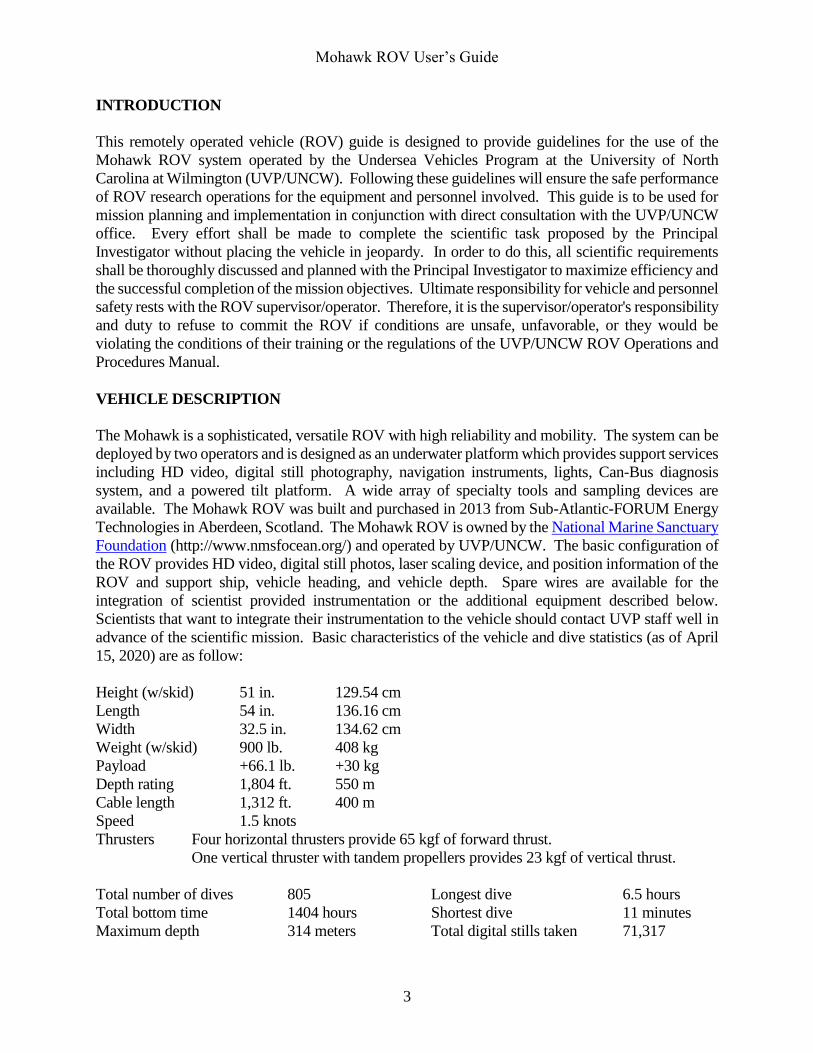
VEHICLE DESCRIPTION
The Mohawk is a sophisticated, versatile ROV with high reliability and mobility. The system can be
deployed by two operators and is designed as an underwater platform which provides support services
including HD video, digital still photography, navigation instruments, lights, Can-Bus diagnosis
system, and a powered tilt platform. A wide array of specialty tools and sampling devices are
available. The Mohawk ROV was built and purchased in 2013 from Sub-Atlantic-FORUM Energy
Technologies in Aberdeen, Scotland. The Mohawk ROV is owned by the National Marine Sanctuary
Foundation (http://www.nmsfocean.org/) and operated by UVP/UNCW. The basic configuration of
the ROV provides HD video, digital still photos, laser scaling device, and position information of the
ROV and support ship, vehicle heading, and vehicle depth. Spare wires are available for the
integration of scientist provided instrumentation or the additional equipment described below.
Scientists that want to integrate their instrumentation to the vehicle should contact UVP staff well in
advance of the scientific mission. Basic characteristics of the vehicle and dive statistics (as of April
15, 2020) are as follow:
Height (w/skid) 51 in. 129.54 cm
Length 54 in. 136.16 cm
Width 32.5 in. 134.62 cm
Weight (w/skid) 900 lb. 408 kg
Payload +66.1 lb. +30 kg
Depth rating 1,804 ft. 550 m
Cable length 1,312 ft. 400 m
Speed 1.5 knots
Thrusters Four horizontal thrusters provide 65 kgf of forward thrust.
One vertical thruster with tandem propellers provides 23 kgf of vertical thrust.
Total number of dives 805 Longest dive 6.5 hours
Total bottom time 1404 hours Shortest dive 11 minutes
Maximum depth 314 meters Total digital stills taken 71,317
Mohawk ROV User’s Guide
4
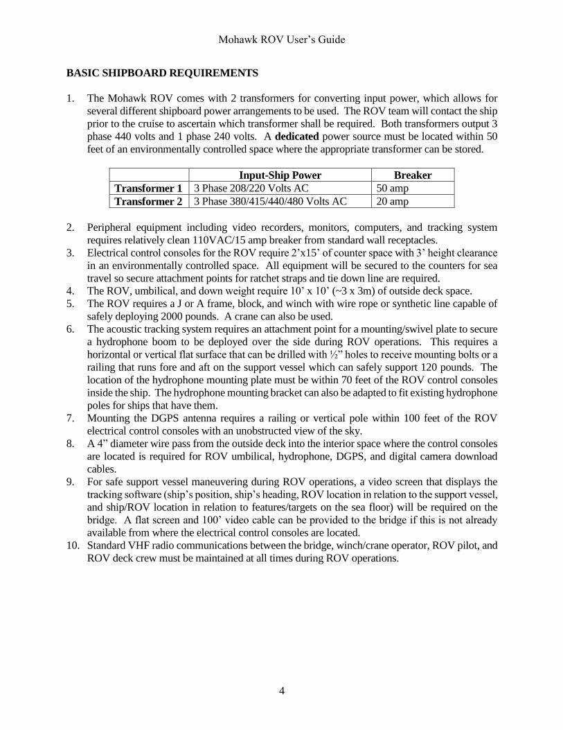
BASIC SHIPBOARD REQUIREMENTS
1. The Mohawk ROV comes with 2 transformers for converting input power, which allows for
several different shipboard power arrangements to be used. The ROV team will contact the ship
prior to the cruise to ascertain which transformer shall be required. Both transformers output 3
phase 440 volts and 1 phase 240 volts. A dedicated power source must be located within 50
feet of an environmentally controlled space where the appropriate transformer can be stored.
Input-Ship Power Breaker
Transformer 1 3 Phase 208/220 Volts AC 50 amp
Transformer 2 3 Phase 380/415/440/480 Volts AC 20 amp
2. Peripheral equipment including video recorders, monitors, computers, and tracking system
requires relatively clean 110VAC/15 amp breaker from standard wall receptacles.
3. Electrical control consoles for the ROV require 2’x15’ of counter space with 3’ height clearance
in an environmentally controlled space. All equipment will be secured to the counters for sea
travel so secure attachment points for ratchet straps and tie down line are required.
4. The ROV, umbilical, and down weight require 10’ x 10’ (~3 x 3m) of outside deck space.
5. The ROV requires a J or A frame, block, and winch with wire rope or synthetic line capable of
safely deploying 2000 pounds. A crane can also be used.
6. The acoustic tracking system requires an attachment point for a mounting/swivel plate to secure
a hydrophone boom to be deployed over the side during ROV operations. This requires a
horizontal or vertical flat surface that can be drilled with ½” holes to receive mounting bolts or a
railing that runs fore and aft on the support vessel which can safely support 120 pounds. The
location of the hydrophone mounting plate must be within 70 feet of the ROV control consoles
inside the ship. The hydrophone mounting bracket can also be adapted to fit existing hydrophone
poles for ships that have them.
7. Mounting the DGPS antenna requires a railing or vertical pole within 100 feet of the ROV
electrical control consoles with an unobstructed view of the sky.
8. A 4” diameter wire pass from the outside deck into the interior space where the control consoles
are located is required for ROV umbilical, hydrophone, DGPS, and digital camera download
cables.
9. For safe support vessel maneuvering during ROV operations, a video screen that displays the
tracking software (ship’s position, ship’s heading, ROV location in relation to the support vessel,
and ship/ROV location in relation to features/targets on the sea floor) will be required on the
bridge. A flat screen and 100’ video cable can be provided to the bridge if this is not already
available from where the electrical control consoles are located.
10. Standard VHF radio communications between the bridge, winch/crane operator, ROV pilot, and
ROV deck crew must be maintained at all times during ROV operations.
Mohawk ROV User’s Guide
5
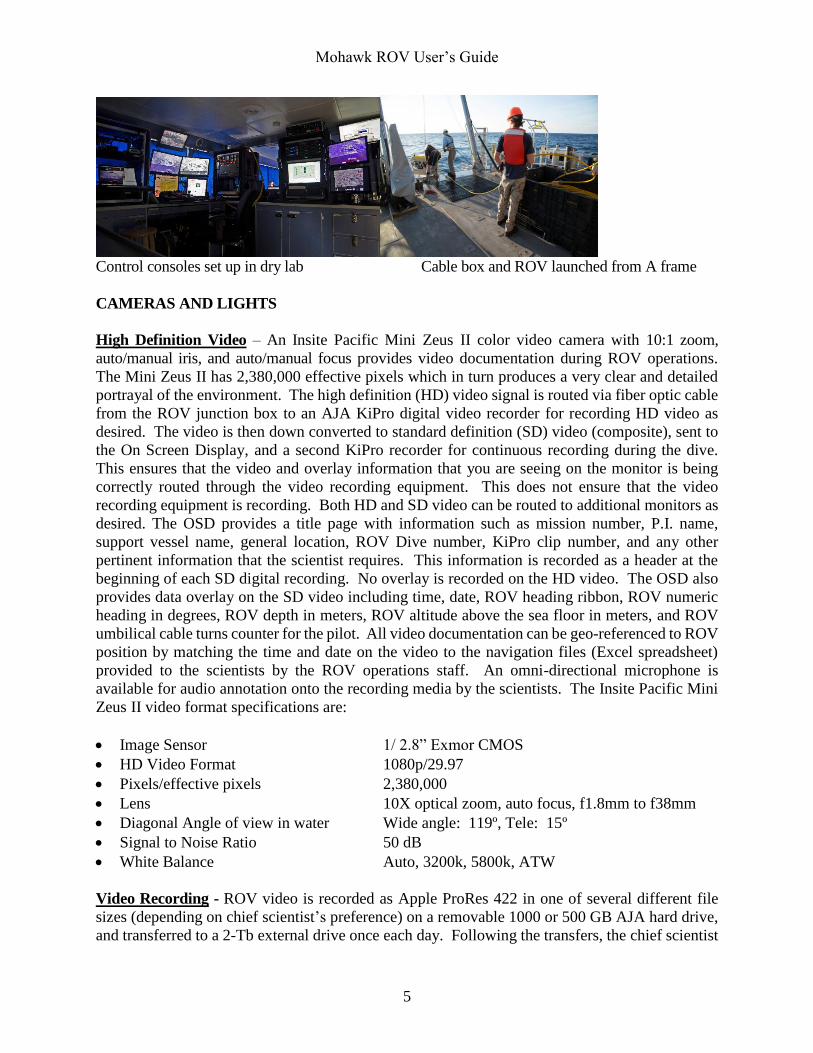
Control consoles set up in dry lab Cable box and ROV launched from A frame
CAMERAS AND LIGHTS
High Definition Video – An Insite Pacific Mini Zeus II color video camera with 10:1 zoom,
auto/manual iris, and auto/manual focus provides video documentation during ROV operations.
The Mini Zeus II has 2,380,000 effective pixels which in turn produces a very clear and detailed
portrayal of the environment. The high definition (HD) video signal is routed via fiber optic cable
from the ROV junction box to an AJA KiPro digital video recorder for recording HD video as
desired. The video is then down converted to standard definition (SD) video (composite), sent to
the On Screen Display, and a second KiPro recorder for continuous recording during the dive.
This ensures that the video and overlay information that you are seeing on the monitor is being
correctly routed through the video recording equipment. This does not ensure that the video
recording equipment is recording. Both HD and SD video can be routed to additional monitors as
desired. The OSD provides a title page with information such as mission number, P.I. name,
support vessel name, general location, ROV Dive number, KiPro clip number, and any other
pertinent information that the scientist requires. This information is recorded as a header at the
beginning of each SD digital recording. No overlay is recorded on the HD video. The OSD also
provides data overlay on the SD video including time, date, ROV heading ribbon, ROV numeric
heading in degrees, ROV depth in meters, ROV altitude above the sea floor in meters, and ROV
umbilical cable turns counter for the pilot. All video documentation can be geo-referenced to ROV
position by matching the time and date on the video to the navigation files (Excel spreadsheet)
provided to the scientists by the ROV operations staff. An omni-directional microphone is
available for audio annotation onto the recording media by the scientists. The Insite Pacific Mini
Zeus II video format specifications are:
Image Sensor 1/ 2.8” Exmor CMOS
HD Video Format 1080p/29.97
Pixels/effective pixels 2,380,000
Lens 10X optical zoom, auto focus, f1.8mm to f38mm
Diagonal Angle of view in water Wide angle: 119º, Tele: 15º
Signal to Noise Ratio 50 dB
White Balance Auto, 3200k, 5800k, ATW
Video Recording - ROV video is recorded as Apple ProRes 422 in one of several different file
sizes (depending on chief scientist’s preference) on a removable 1000 or 500 GB AJA hard drive,
and transferred to a 2-Tb external drive once each day. Following the transfers, the chief scientist
Mohawk ROV User’s Guide
6
will have access to the drive for viewing or to make additional copies. The video files can be easily
viewed using Apple Quicktime on both Mac and PC computers. Make sure your computer has the
latest version of Quicktime if you wish to use it to view the video files. Both HD and SD digital
video recordings are time synchronized to GPS satellite time and frame number (29.97FPS drop
frame) by the Horita UTG-50 Longitudinal Time Code generator (LTC/SMPTE 12M
specification), which is visible in the Quicktime playback window.
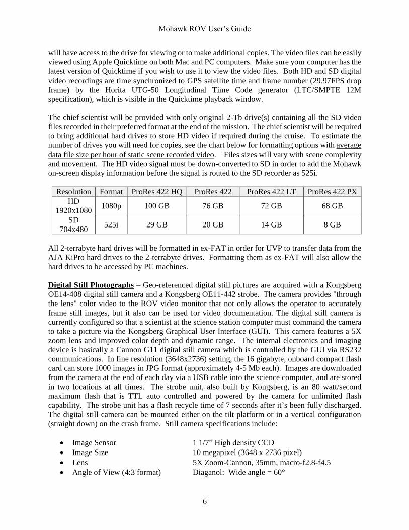
The chief scientist will be provided with only original 2-Tb drive(s) containing all the SD video
files recorded in their preferred format at the end of the mission. The chief scientist will be required
to bring additional hard drives to store HD video if required during the cruise. To estimate the
number of drives you will need for copies, see the chart below for formatting options with average
data file size per hour of static scene recorded video. Files sizes will vary with scene complexity
and movement. The HD video signal must be down-converted to SD in order to add the Mohawk
on-screen display information before the signal is routed to the SD recorder as 525i.
Resolution Format ProRes 422 HQ ProRes 422 ProRes 422 LT ProRes 422 PX
HD
1920x1080 1080p 100 GB 76 GB 72 GB 68 GB
SD
704x480 525i 29 GB 20 GB 14 GB 8 GB
All 2-terrabyte hard drives will be formatted in ex-FAT in order for UVP to transfer data from the
AJA KiPro hard drives to the 2-terrabyte drives. Formatting them as ex-FAT will also allow the
hard drives to be accessed by PC machines.
Digital Still Photographs – Geo-referenced digital still pictures are acquired with a Kongsberg
OE14-408 digital still camera and a Kongsberg OE11-442 strobe. The camera provides "through
the lens" color video to the ROV video monitor that not only allows the operator to accurately
frame still images, but it also can be used for video documentation. The digital still camera is
currently configured so that a scientist at the science station computer must command the camera
to take a picture via the Kongsberg Graphical User Interface (GUI). This camera features a 5X
zoom lens and improved color depth and dynamic range. The internal electronics and imaging
device is basically a Cannon G11 digital still camera which is controlled by the GUI via RS232
communications. In fine resolution (3648x2736) setting, the 16 gigabyte, onboard compact flash
card can store 1000 images in JPG format (approximately 4-5 Mb each). Images are downloaded
from the camera at the end of each day via a USB cable into the science computer, and are stored
in two locations at all times. The strobe unit, also built by Kongsberg, is an 80 watt/second
maximum flash that is TTL auto controlled and powered by the camera for unlimited flash
capability. The strobe unit has a flash recycle time of 7 seconds after it’s been fully discharged.
The digital still camera can be mounted either on the tilt platform or in a vertical configuration
(straight down) on the crash frame. Still camera specifications include:
Image Sensor 1 1/7” High density CCD
Image Size 10 megapixel (3648 x 2736 pixel)
Lens 5X Zoom-Cannon, 35mm, macro-f2.8-f4.5
Angle of View (4:3 format) Diaganol: Wide angle = 60°
Mohawk ROV User’s Guide
7
Focus Range 50 mm to ∞
Image Storage Capacity Up to 1,000 images during a single dive
Dual Laser Scaling Devices – A pair of 50mW red lasers (fabricated in house) are mounted on the
ROV tilt platform directly under the video camera. They are mounted in a precision machined
aluminum block to maintain the lasers in a parallel orientation at exactly 10 cm apart, and are usually
in the video unless the ROV is very close to the object or the camera is zoomed in. An additional
laser scaling device is used for scaling objects in the digital still photographs. They consist of a pair
of Sidus 50mW green lasers in a calibrated fixture, also set to 10 cm, that is mounted to the digital
still camera. They provide accurate scaling over the entire image in either axis when the digital still
camera is mounted in the vertical position on the ROV.
Lights – Two Deep Sea Power and Light (DSP&L) SeaLite Sphere 3100 LED lights are mounted on
the ROV tilt platform and provide illumination for the HD video camera. Each of the light outputs
can be controlled by dimmer switches, which is useful for viewing light colored material such as sand.
The DSP&L 3100 LED light provides a typical luminous flux of 3700 lumens at 75 degrees and
6000K color temperature.
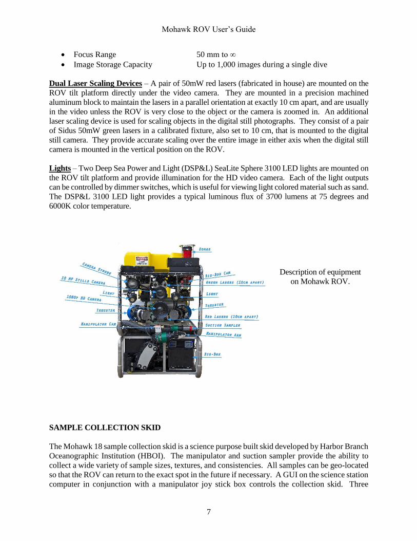
Description of equipment
on Mohawk ROV.
SAMPLE COLLECTION SKID
The Mohawk 18 sample collection skid is a science purpose built skid developed by Harbor Branch
Oceanographic Institution (HBOI). The manipulator and suction sampler provide the ability to
collect a wide variety of sample sizes, textures, and consistencies. All samples can be geo-located
so that the ROV can return to the exact spot in the future if necessary. A GUI on the science station
computer in conjunction with a manipulator joy stick box controls the collection skid. Three
Mohawk ROV User’s Guide
8
additional color, fixed focus video cameras are mounted on the skid to assist the scientist with
operations. All sample processing and storage are the responsibility of the science personnel.
Installation or removal of the sample collection skid to or from the ROV requires four hours of an
operational day, not four hours in addition to an operational day, so please plan accordingly.
Height 16 in. 40.64 cm
Length 53 in. 134.62 cm
Width 32 in. 81.28 cm
Weight 300 lb.(dry) 135 kg
Depth rating 1,804 ft. 550 m
Power requirement 220VAC @ 1amp
Capacity Approximately 15lbs of samples (in water weight)
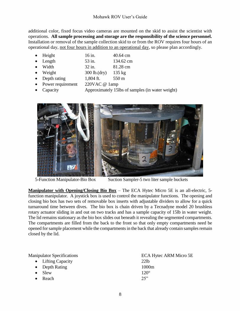
5-Function Manipulator-Bio Box Suction Sampler-5 two liter sample buckets
Manipulator with Opening/Closing Bio Box – The ECA Hytec Micro 5E is an all-electric, 5-
function manipulator. A joystick box is used to control the manipulator functions. The opening and
closing bio box has two sets of removable box inserts with adjustable dividers to allow for a quick
turnaround time between dives. The bio box is chain driven by a Tecnadyne model 20 brushless
rotary actuator sliding in and out on two tracks and has a sample capacity of 15lb in water weight.
The lid remains stationary as the bio box slides out beneath it revealing the segmented compartments.
The compartments are filled from the back to the front so that only empty compartments need be
opened for sample placement while the compartments in the back that already contain samples remain
closed by the lid.
Manipulator Specifications ECA Hytec ARM Micro 5E
Lifting Capacity 22lb
Depth Rating 1000m
Slew 120°
Reach 25”
Mohawk ROV User’s Guide
9
Jaw Opening 4.9”
Jaw Closing Force 110lb
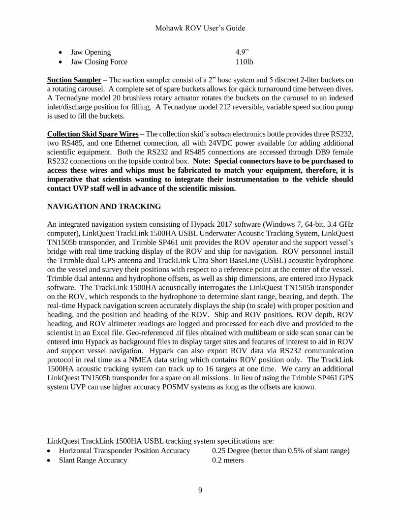
Suction Sampler – The suction sampler consist of a 2” hose system and 5 discreet 2-liter buckets on
a rotating carousel. A complete set of spare buckets allows for quick turnaround time between dives.
A Tecnadyne model 20 brushless rotary actuator rotates the buckets on the carousel to an indexed
inlet/discharge position for filling. A Tecnadyne model 212 reversible, variable speed suction pump
is used to fill the buckets.
Collection Skid Spare Wires – The collection skid’s subsea electronics bottle provides three RS232,
two RS485, and one Ethernet connection, all with 24VDC power available for adding additional
scientific equipment. Both the RS232 and RS485 connections are accessed through DB9 female
RS232 connections on the topside control box. Note: Special connectors have to be purchased to
access these wires and whips must be fabricated to match your equipment, therefore, it is
imperative that scientists wanting to integrate their instrumentation to the vehicle should
contact UVP staff well in advance of the scientific mission.
NAVIGATION AND TRACKING
An integrated navigation system consisting of Hypack 2017 software (Windows 7, 64-bit, 3.4 GHz
computer), LinkQuest TrackLink 1500HA USBL Underwater Acoustic Tracking System, LinkQuest
TN1505b transponder, and Trimble SP461 unit provides the ROV operator and the support vessel’s
bridge with real time tracking display of the ROV and ship for navigation. ROV personnel install
the Trimble dual GPS antenna and TrackLink Ultra Short BaseLine (USBL) acoustic hydrophone
on the vessel and survey their positions with respect to a reference point at the center of the vessel.
Trimble dual antenna and hydrophone offsets, as well as ship dimensions, are entered into Hypack
software. The TrackLink 1500HA acoustically interrogates the LinkQuest TN1505b transponder
on the ROV, which responds to the hydrophone to determine slant range, bearing, and depth. The
real-time Hypack navigation screen accurately displays the ship (to scale) with proper position and
heading, and the position and heading of the ROV. Ship and ROV positions, ROV depth, ROV
heading, and ROV altimeter readings are logged and processed for each dive and provided to the
scientist in an Excel file. Geo-referenced .tif files obtained with multibeam or side scan sonar can be
entered into Hypack as background files to display target sites and features of interest to aid in ROV
and support vessel navigation. Hypack can also export ROV data via RS232 communication
protocol in real time as a NMEA data string which contains ROV position only. The TrackLink
1500HA acoustic tracking system can track up to 16 targets at one time. We carry an additional
LinkQuest TN1505b transponder for a spare on all missions. In lieu of using the Trimble SP461 GPS
system UVP can use higher accuracy POSMV systems as long as the offsets are known.
LinkQuest TrackLink 1500HA USBL tracking system specifications are:
Horizontal Transponder Position Accuracy 0.25 Degree (better than 0.5% of slant range)
Slant Range Accuracy 0.2 meters
Mohawk ROV User’s Guide
10
Operating Frequency 31-43.2 kHz
Operating Beamwidth 120-150 degrees
Targets Tracked 16
Working range with ship noise 1000 meters
Sound Level 190dBs
LinkQuest TN1505b transponder specifications are:
Receive Frequency 31-43.2 kHz
Battery Operation Time 1 Year
Active Responding Time 8 x 10 hours
Transmit Power 25 Watts
Beamwidth Omni-directional
Transponder Depth Rating 500 meters
Sound Level 185dBs
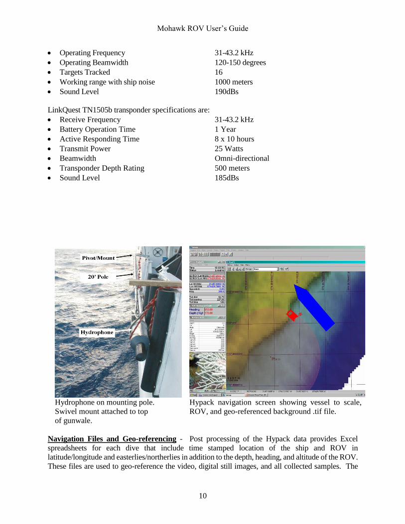
Hydrophone on mounting pole.
Swivel mount attached to top
of gunwale.
Hypack navigation screen showing vessel to scale,
ROV, and geo-referenced background .tif file.
Navigation Files and Geo-referencing - Post processing of the Hypack data provides Excel
spreadsheets for each dive that include time stamped location of the ship and ROV in
latitude/longitude and easterlies/northerlies in addition to the depth, heading, and altitude of the ROV.
These files are used to geo-reference the video, digital still images, and all collected samples. The
Mohawk ROV User’s Guide
11
navigation computer running Hypack and the KiPro digital recorders for HD and SD video are all
time synchronized to GPS satellite time by a Horita UTG-50 to the second and frame number. To
geo-reference the video, take the time stamp of the video and enter the spreadsheet for the
corresponding ROV dive. Find the ROV time that is closest to the time stamp on the video and find
the ROV location and depth at that specific time. For digital still images, each image name consist
of the dive number, image number in that dive, and time (hhmmss) in hours, minutes, and seconds
(e.g. Dive07 128 112225.jpg). Therefore, the image named “Dive07 128 112225.jpg” tells us that
the image was taken on ROV dive number 7, that it is the 128th image taken on that particular ROV
dive, and that the picture was taken at 11:22:25 (or 11:22 and 25 seconds am). To geo-reference a
digital still image, take the time stamp of the image and enter the spreadsheet for the corresponding
ROV dive. Find the ROV time that is closest to the time stamp on the image and find the ROV
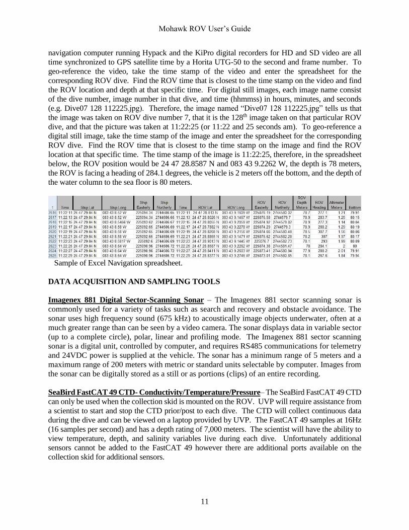
location at that specific time. The time stamp of the image is 11:22:25, therefore, in the spreadsheet
below, the ROV position would be 24 47 28.8587 N and 083 43 9.2262 W, the depth is 78 meters,
the ROV is facing a heading of 284.1 degrees, the vehicle is 2 meters off the bottom, and the depth of
the water column to the sea floor is 80 meters.
Sample of Excel Navigation spreadsheet.
DATA ACQUISITION AND SAMPLING TOOLS
Imagenex 881 Digital Sector-Scanning Sonar – The Imagenex 881 sector scanning sonar is
commonly used for a variety of tasks such as search and recovery and obstacle avoidance. The
sonar uses high frequency sound (675 kHz) to acoustically image objects underwater, often at a
much greater range than can be seen by a video camera. The sonar displays data in variable sector
(up to a complete circle), polar, linear and profiling mode. The Imagenex 881 sector scanning
sonar is a digital unit, controlled by computer, and requires RS485 communications for telemetry
and 24VDC power is supplied at the vehicle. The sonar has a minimum range of 5 meters and a
maximum range of 200 meters with metric or standard units selectable by computer. Images from
the sonar can be digitally stored as a still or as portions (clips) of an entire recording.
SeaBird FastCAT 49 CTD- Conductivity/Temperature/Pressure– The SeaBird FastCAT 49 CTD
can only be used when the collection skid is mounted on the ROV. UVP will require assistance from
a scientist to start and stop the CTD prior/post to each dive. The CTD will collect continuous data
during the dive and can be viewed on a laptop provided by UVP. The FastCAT 49 samples at 16Hz
(16 samples per second) and has a depth rating of 7,000 meters. The scientist will have the ability to
view temperature, depth, and salinity variables live during each dive. Unfortunately additional
sensors cannot be added to the FastCAT 49 however there are additional ports available on the
collection skid for additional sensors.
Mohawk ROV User’s Guide
12
Tritech PA500 Altimeter – This device is mounted on the ROV to provide the distance of the ROV
from the bottom of the sea floor. It is logged in Hypack navigation software. The altimeter is
commonly used with the digital still camera in a vertical configuration to ensure the vehicle is at a
standard height above the bottom so that the area visible in all photographs is consistent. This data
can be easily added to the ROV depth, also logged in Hypack, to provide rugosity or a profile of the
ocean floor.
TETHER MANAGEMENT AND PENETRATIONS
Different operating modes and tether management techniques are used to ensure the best possibility
of a successful ROV dive. Current strength, bottom type, and science objectives will require different
techniques of tether management. Some of the most common and successful techniques of tether
management are discussed below. The tether shall always be monitored by a tender on deck, and
communications set up between the tender, operator, support vessel’s bridge, and crane or winch
operator. Penetrations into large, natural enclosures will be considered only after a thorough external
visual inspection. As a rule, penetrations into wrecks or areas that limit maneuverability shall not be
performed. No penetrations will be permitted during live-boat operations.
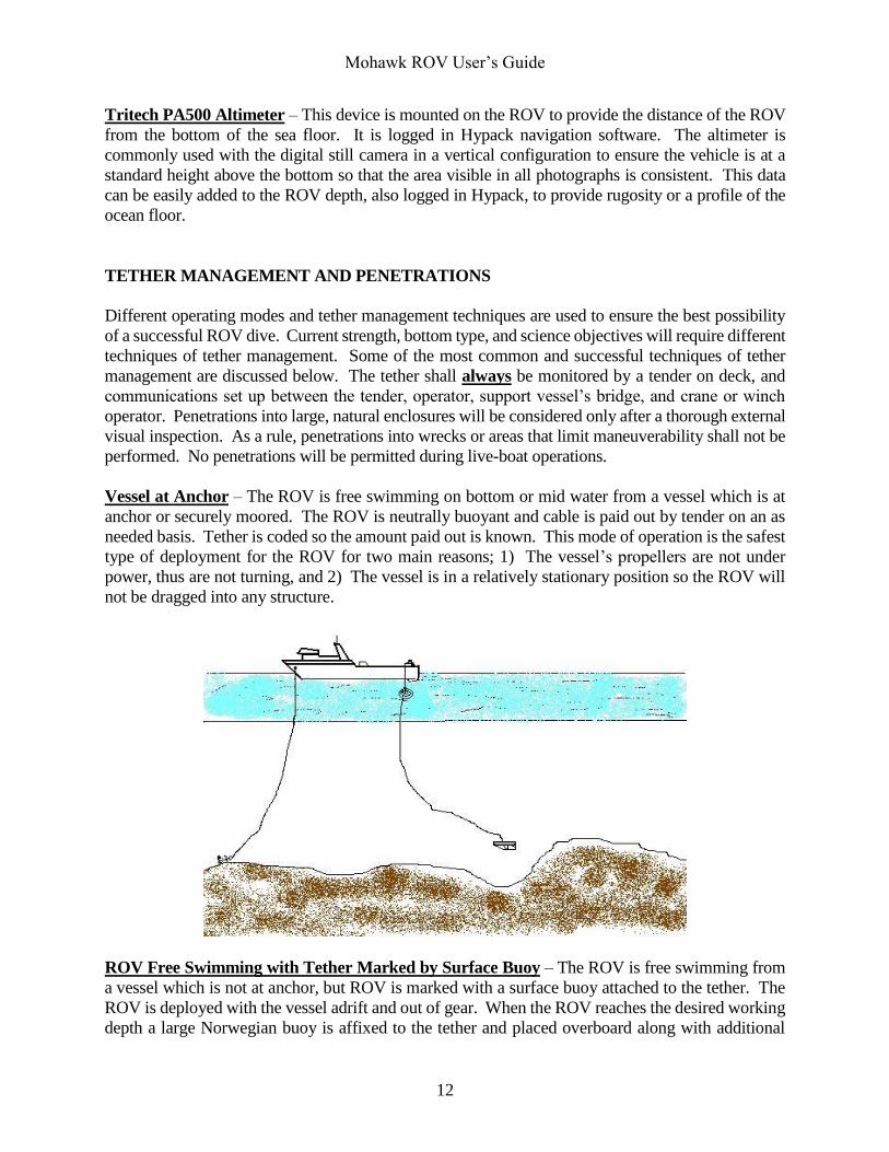
Vessel at Anchor – The ROV is free swimming on bottom or mid water from a vessel which is at
anchor or securely moored. The ROV is neutrally buoyant and cable is paid out by tender on an as
needed basis. Tether is coded so the amount paid out is known. This mode of operation is the safest
type of deployment for the ROV for two main reasons; 1) The vessel’s propellers are not under
power, thus are not turning, and 2) The vessel is in a relatively stationary position so the ROV will
not be dragged into any structure.
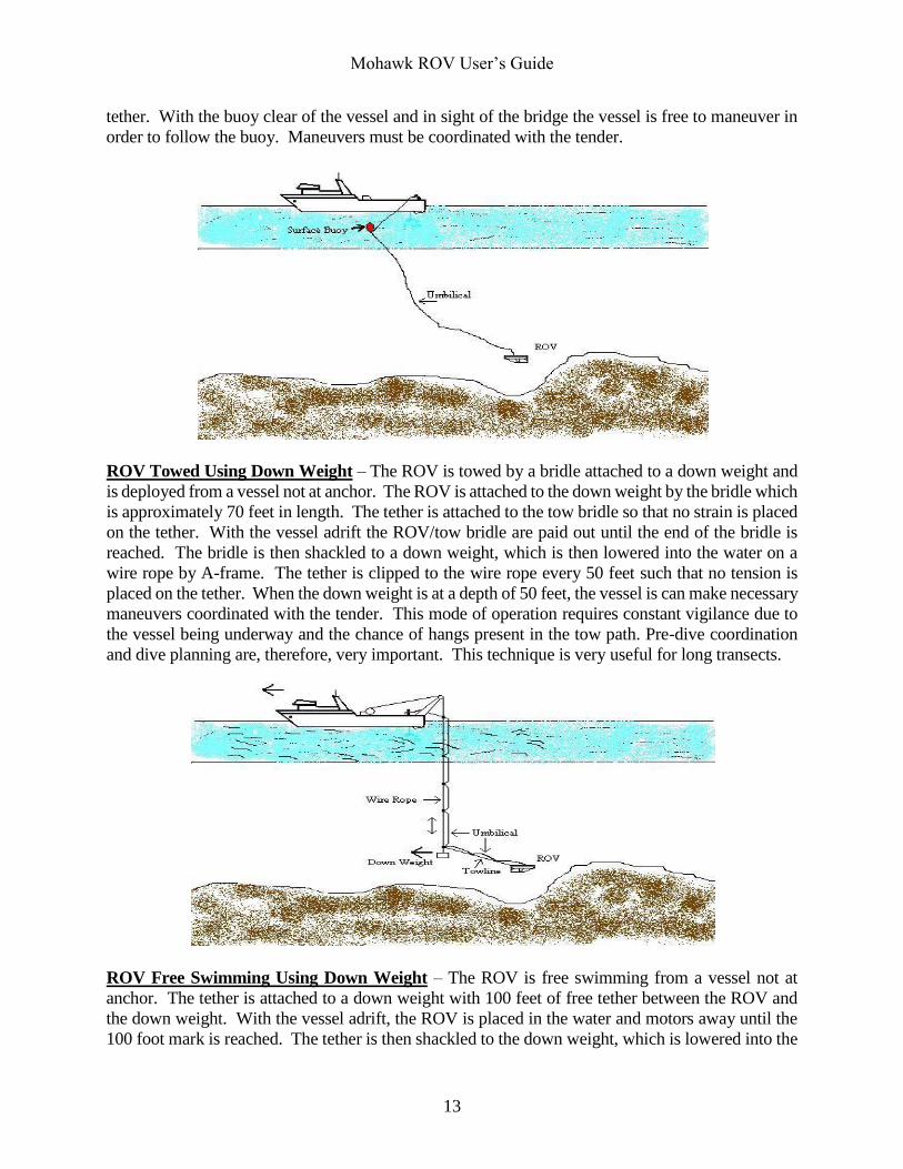
ROV Free Swimming with Tether Marked by Surface Buoy – The ROV is free swimming from
a vessel which is not at anchor, but ROV is marked with a surface buoy attached to the tether. The
ROV is deployed with the vessel adrift and out of gear. When the ROV reaches the desired working
depth a large Norwegian buoy is affixed to the tether and placed overboard along with additional
Mohawk ROV User’s Guide
13
tether. With the buoy clear of the vessel and in sight of the bridge the vessel is free to maneuver in
order to follow the buoy. Maneuvers must be coordinated with the tender.
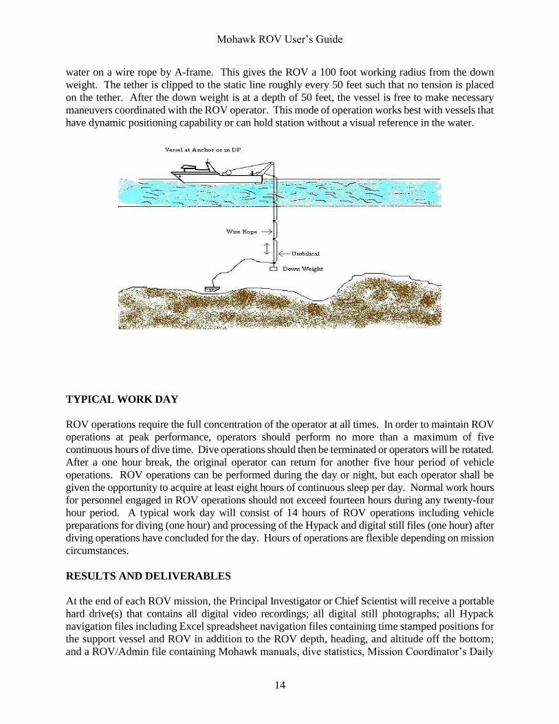
ROV Towed Using Down Weight – The ROV is towed by a bridle attached to a down weight and
is deployed from a vessel not at anchor. The ROV is attached to the down weight by the bridle which
is approximately 70 feet in length. The tether is attached to the tow bridle so that no strain is placed
on the tether. With the vessel adrift the ROV/tow bridle are paid out until the end of the bridle is
reached. The bridle is then shackled to a down weight, which is then lowered into the water on a
wire rope by A-frame. The tether is clipped to the wire rope every 50 feet such that no tension is
placed on the tether. When the down weight is at a depth of 50 feet, the vessel is can make necessary
maneuvers coordinated with the tender. This mode of operation requires constant vigilance due to
the vessel being underway and the chance of hangs present in the tow path. Pre-dive coordination
and dive planning are, therefore, very important. This technique is very useful for long transects.
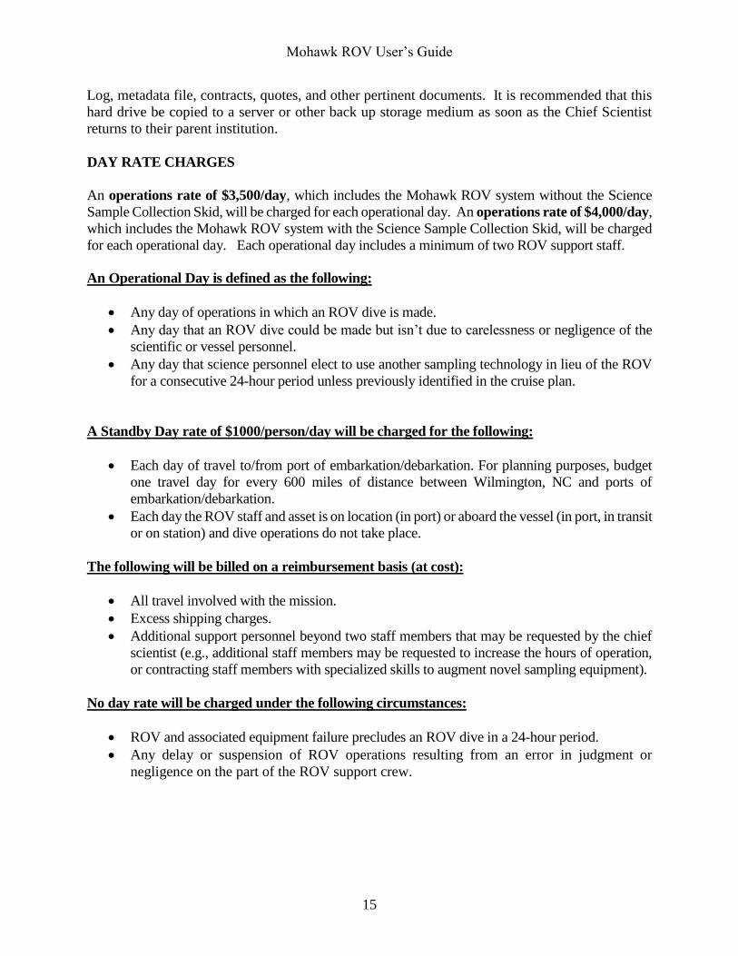
ROV Free Swimming Using Down Weight – The ROV is free swimming from a vessel not at
anchor. The tether is attached to a down weight with 100 feet of free tether between the ROV and
the down weight. With the vessel adrift, the ROV is placed in the water and motors away until the
100 foot mark is reached. The tether is then shackled to the down weight, which is lowered into the
Mohawk ROV User’s Guide
14
water on a wire rope by A-frame. This gives the ROV a 100 foot working radius from the down
weight. The tether is clipped to the static line roughly every 50 feet such that no tension is placed
on the tether. After the down weight is at a depth of 50 feet, the vessel is free to make necessary
maneuvers coordinated with the ROV operator. This mode of operation works best with vessels that
have dynamic positioning capability or can hold station without a visual reference in the water.
TYPICAL WORK DAY
ROV operations require the full concentration of the operator at all times. In order to maintain ROV
operations at peak performance, operators should perform no more than a maximum of five
continuous hours of dive time. Dive operations should then be terminated or operators will be rotated.
After a one hour break, the original operator can return for another five hour period of vehicle
operations. ROV operations can be performed during the day or night, but each operator shall be
given the opportunity to acquire at least eight hours of continuous sleep per day. Normal work hours
for personnel engaged in ROV operations should not exceed fourteen hours during any twenty-four
hour period. A typical work day will consist of 14 hours of ROV operations including vehicle
preparations for diving (one hour) and processing of the Hypack and digital still files (one hour) after
diving operations have concluded for the day. Hours of operations are flexible depending on mission
circumstances.
RESULTS AND DELIVERABLES
At the end of each ROV mission, the Principal Investigator or Chief Scientist will receive a portable
hard drive(s) that contains all digital video recordings; all digital still photographs; all Hypack
navigation files including Excel spreadsheet navigation files containing time stamped positions for
the support vessel and ROV in addition to the ROV depth, heading, and altitude off the bottom;
and a ROV/Admin file containing Mohawk manuals, dive statistics, Mission Coordinator’s Daily
Mohawk ROV User’s Guide
15
Log, metadata file, contracts, quotes, and other pertinent documents. It is recommended that this
hard drive be copied to a server or other back up storage medium as soon as the Chief Scientist
returns to their parent institution.
DAY RATE CHARGES
An operations rate of $3,500/day, which includes the Mohawk ROV system without the Science
Sample Collection Skid, will be charged for each operational day. An operations rate of $4,000/day,
which includes the Mohawk ROV system with the Science Sample Collection Skid, will be charged
for each operational day. Each operational day includes a minimum of two ROV support staff.
An Operational Day is defined as the following:
Any day of operations in which an ROV dive is made.
Any day that an ROV dive could be made but isn’t due to carelessness or negligence of the
scientific or vessel personnel.
Any day that science personnel elect to use another sampling technology in lieu of the ROV
for a consecutive 24-hour period unless previously identified in the cruise plan.
A Standby Day rate of $1000/person/day will be charged for the following:
Each day of travel to/from port of embarkation/debarkation. For planning purposes, budget
one travel day for every 600 miles of distance between Wilmington, NC and ports of
embarkation/debarkation.
Each day the ROV staff and asset is on location (in port) or aboard the vessel (in port, in transit
or on station) and dive operations do not take place.
The following will be billed on a reimbursement basis (at cost):
All travel involved with the mission.
Excess shipping charges.
Additional support personnel beyond two staff members that may be requested by the chief
scientist (e.g., additional staff members may be requested to increase the hours of operation,
or contracting staff members with specialized skills to augment novel sampling equipment).
No day rate will be charged under the following circumstances:
ROV and associated equipment failure precludes an ROV dive in a 24-hour period.
Any delay or suspension of ROV operations resulting from an error in judgment or
negligence on the part of the ROV support crew.


