Embed Size (px)
Citation preview
Modular design and implementation of a logic control system for abatch process
Luca Ferrarini *, Luigi Piroddi
Dipartimento di Elettronica e Informazione, Politecnico di Milano, Piazza Leonardo da Vinci 32, 20133 Milano, Italy
Received 23 October 2001; received in revised form 29 July 2002; accepted 30 December 2002
Abstract
This paper addresses the problems of the design and implementation of the sequential and logic control functions of a multi-recipe
chemical batch process. A hierarchical control structure is adopted, with one supervisor module co-ordinating many independent
slave controllers. Specific rules are given for the construction of the supervisor, from the definition of recipes to the implementation
of resource usage and deadlock prevention constraints. Particular care must be paid in the definition of events during the various
steps of the control system development: distinct event sets are employed for the communication between supervisor and controllers
and between these and the actual plant. As for representation models, Petri nets are used for the supervisor description, whereas the
slave controllers are represented in Grafcet/SFC. Finally, the implementation of the control structure is discussed, showing that it is
possible to write the control code in an IEC1131-compliant language for programmable controllers, like Ladder Diagrams, in an
automatic way. The results shown in the paper are to be interpreted in a design perspective aimed at real-size industrial applications.
# 2003 Elsevier Science Ltd. All rights reserved.
Keywords: Petri nets; Design tools; Modeling control and verification; Manufacturing systems; Batch processes; Process automation
1. Introduction
Beside representing a large portion of industrial
applications and playing a primary role in everyday
life, in the recent years batch processes and plants have
been attracting more and more control engineers, since
they pose a number of different, challenging and
stimulating control problems. This is becoming even
more real in view of the increasing demand for plant
flexibility, for cost reduction and safeness, and for risk
reduction.
Basically, in a typical batch process, multiple recipes
(specified sequences of operations) are carried out on
many different batches of material, present at the same
time in the system. Such recipes typically make use of
different process components, like tanks, reactors, pipes,
valves and pumps. The control of a batch plant, i.e. the
act of imposing a given behavior to the plant, is typically
made with complex hardware architecture, which im-
plements non trivial control algorithms. These relate to:
a) the low-level continuous control of the various
devices,
b) the logic control of the recipes and the co-ordina-
tion of the different physical components, and
c) the scheduling of batches.
In this paper, we specifically address the logic control
problem, whose aim is to co-ordinate and manage the
different components of a plant, aiming at the imple-
mentation of recipes and typically using only binary
(logic) signals. Basically, two distinct design approaches
can be adopted. In the direct approach, the controller is
designed by suitably composing the various specifica-
tions and constraints on the plant behavior. This can be
realized by means of different formalisms, from low-
level ones, e.g. Ladder Diagrams (LD) (International
Standard IEC 1131-3, 1993), which are widely used in
common industrial practice, to more abstract ones, e.g.
Grafcet/Sequential Function Charts (SFC), Petri Nets
* Corresponding author. Tel.: �/39-02-2399-3556; fax: �/39-02-
2399-3412.
E-mail addresses: [email protected] (L. Ferrarini),
[email protected] (L. Piroddi).
Computers and Chemical Engineering 27 (2003) 983�/996
www.elsevier.com/locate/compchemeng
0098-1354/03/$ - see front matter # 2003 Elsevier Science Ltd. All rights reserved.
doi:10.1016/S0098-1354(03)00009-7
(PNs) (Zhou, DiCesare & Desrochers, 1992aDavid &
Alla, 1992). In particular, many design approaches have
been devised using PNs, to exploit both the modeling
characteristics and the analysis tools available for thisformalism, e.g. (Valavanis, 1990; Jeng & DiCesare,
1992; Zhou et al., 1992a). In the indirect approach of
Supervisory Control Theory (Ramadge & Wonham,
1987), the controller model results from a synthesis
process, which requires the separate modeling of both
the system to be controlled and the specification for the
behavior of the controlled system. Significant applica-
tions of Supervisory Control Theory are documented inBalemi, Hoffmann, Gyugyi, Wong-Toi & Franklin
(1993) using automata, Giua & DiCesare (1991) using
PNs and Charbonnier, Alla & David (1999) using
Grafcet/SFC.
Unfortunately, neither design framework generally
provides formal rules or pragmatic guidelines to build
up the relevant models. Actually, in the current indus-
trial practice, advanced modeling and software engineer-ing techniques are seldom employed in the control
system design. This often results in huge control codes,
difficult to analyze, validate, re-use and maintain. It is
then clear that structured modeling techniques are
particularly important for complex, real-size applica-
tions. Some notable efforts in this direction are docu-
mented in the literature, especially in the field of PN
modeling (Valavanis, 1990; Zhou et al., 1992a; Jeng &DiCesare, 1992). These works provide structured means
to aid the designer in the phase of model definition, but
end up with a single comprehensive model, subject to
some restrictions, which are introduced mainly to
simplify the formal analysis. With reference to Grafcet
based modeling, the Grafchart formalism has been
developed with the aim of providing compact and
formal models to be used in complex batch applications(Johnsson & .Arzen, 1998). Grafchart is a generalization
of the Grafcet language, which allows an appropriate
and efficient software organization of the control code,
but does not provide a complete design solution, since
formal analysis is complicated by the richness of the
language. Besides structured modeling techniques, a
modular approach to the design of the control archi-
tecture is really needed to deal with the complexity ofreal-size applications, so that different modules address
different control tasks, efficiently decomposing and
simplifying the original control problem (Tittus &
Lennartson, 1999).
The logic control system design methodology intro-
duced in this work is a direct design approach based on
PNs and SFC, which guides the designer from the initial
model description to the final control code generation.Such a methodology incorporates some useful concepts
originally introduced in the framework of Supervisory
Control Theory, such as synchronous composition,
specification modularity and the use of a hierarchical
control structure (Zhong & Wonham, 1990; Balemi et
al., 1993; Charbonnier et al., 1999). A hierarchical and
modular design approach is proposed and illustrated
with reference to a multi-recipe chemical batch process.A PN supervisor is employed to regulate the process
flow, while the task of commanding the plant devices is
devoted to a modular control section, designed in
Grafcet/SFC. The overall aim of the paper is to show
that control schemes of reasonable complexity can be
adopted for real-size plants, remaining in a formal
modeling framework.
The proposed approach yields a considerably com-pact supervisor model, which can be derived following
specific formal rules and combines advantages of
different formalisms. Also, the control section can be
efficiently separated in isolated modules which exchange
information directly with the supervisor and the plant
and which can be easily reused. The automatic imple-
mentation of the overall control system in an IEC1131-
compliant language (LD) is also briefly discussed.In the following it is assumed that the reader is
familiar with the basic concepts relative to PNs, Grafcet/
SFC, LD. Good tutorials on PNs are e.g. Murata
(1989), Peterson (1981) and David and Alla (1992),
which also illustrates Grafcet/SFC. For LD, the reader
is referred to International Standard IEC 1131-3 (1993).
The paper is organized as follows. In Section 2, a
batch process is described, illustrating the modeling andcontrol problems it introduces. In Section 3, the
hierarchical control architecture is introduced and
discussed. The design methodology, stage by stage, is
discussed in Section 4. In Section 5, the application of
the design methodology to the batch process is dis-
cussed. Finally, some concluding remarks are reported
in Section 6.
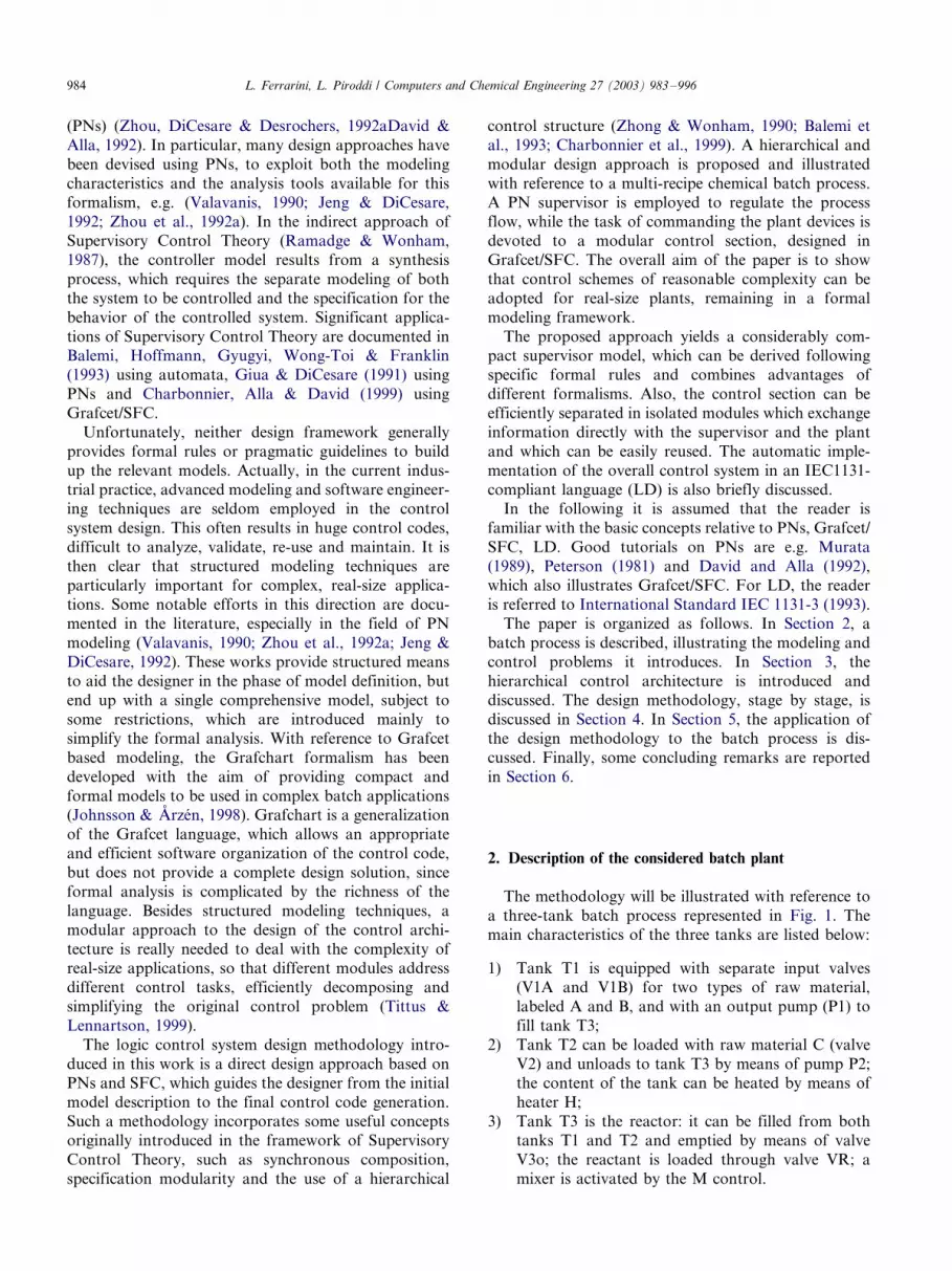
2. Description of the considered batch plant
The methodology will be illustrated with reference to
a three-tank batch process represented in Fig. 1. The
main characteristics of the three tanks are listed below:
1) Tank T1 is equipped with separate input valves(V1A and V1B) for two types of raw material,
labeled A and B, and with an output pump (P1) to
fill tank T3;
2) Tank T2 can be loaded with raw material C (valve
V2) and unloads to tank T3 by means of pump P2;
the content of the tank can be heated by means of
heater H;
3) Tank T3 is the reactor: it can be filled from bothtanks T1 and T2 and emptied by means of valve
V3o; the reactant is loaded through valve VR; a
mixer is activated by the M control.
L. Ferrarini, L. Piroddi / Computers and Chemical Engineering 27 (2003) 983�/996984
All the tanks are equipped with low- (l1, l2, l3) and
high-level (h1, h2, h3) sensors. Tank T2 also employs a
thermometer (T) to monitor the heating process.
The plant activities corresponding to different pro-
ducts are specified in terms of ‘recipes’, i.e. sequences of
tasks to be carried out on discrete amounts of raw
materials employing all or part of the plant devices.
Three recipes, R1, R2 and R3, are defined for the plant
and described informally in Table 1.
All the recipes require the use of tank T3 in the last
phase, whereas only tanks T1 and T2 are used in the first
operations. Also, recipe R3 does not require the use of
tank T2. Thus, the three tanks represent shared
resources between the different recipes and the logic
control system must correctly perform their allocation,
and in particular allow all the recipes to be completed
without reaching deadlock states. For this purpose, the
logic control system must enable or prevent resource
allocation as required, possibly without introducing
unnecessary constraints in the process flow.
Notice also that some tasks required in the recipes are
not trivial to model. For example, the unloading of
tanks T1 and T2 to tank T3 in recipes R1 and R2 is a
‘join’ operation (Tittus & Lennartson, 1999), where the
individual unloading operations from T1 and T2 can be
performed in any order and even concurrently. An
efficient modeling of the resource usage must therefore
distinguish the two individual unloading operations, so
Fig. 1. The batch process.
Table 1
Recipes
Step Recipe R1 (product 1) Recipe R2 (product 2) Recipe R3 (product 3)
1 Load tank T1 with material A and tank T2 with
material C
Load tank T1 with material B and tank T2 with
material C
Load tank T1 with materials A and B
2 Heat the content of tank T2 to 60 8C Heat the content of tank T2 to 60 8C Wait at least 30 s
3 Unload tanks T1 and T2 to tank T3 Unload tanks T1 and T2 to tank T3 Unload tank T1 to tank T3
4 Mix the content of tank T3 for at least 1 min Mix the content of tank T3 for at least 1 min Add the reactant to tank T3
5 Unload tank T3 Unload tank T3 Mix the content of tank T3 for at least
1 min
6 Unload tank T3
L. Ferrarini, L. Piroddi / Computers and Chemical Engineering 27 (2003) 983�/996 985
that the allocation of resources T1 and T2 is not
necessarily forced to last for the entire duration of the
join operation.
In view of these remarks, the following issues are
relevant in the design of the logic control system and
motivate the development of innovative control archi-
tectures and structured design methodologies:
1) the different tasks performed in the plant must be
suitably co-ordinated in terms of sequences and
concurrency as specified in the recipes;
2) mutual exclusion constraints for the usage of plant
resources by different operations must be enforced;
3) a deadlock prevention policy must be employed to
avoid incorrect allocation of the shared resources
resulting in a system blocking;4) a suitable control architecture must be employed to
decompose the modeling and control problem, in
order to deal efficiently with its complexity.
With reference to the last point, in particular, the
difficulty in the computation of a deadlock prevention
policy grows with size; therefore, since the deadlock
prevention depends mainly on the usage of the shared
resources, it is necessary to find efficient and compact
ways to model this information.
3. The control architecture
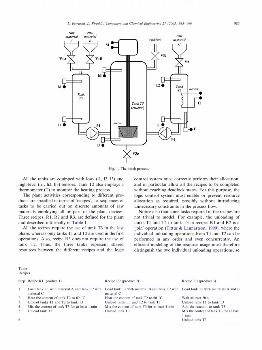
The basic control architecture adopted in this work is
characterized by a two-level functional hierarchy of
modules, as shown in Fig. 2. Such modular schemes,
comprising a controller and a supervisor, are common in
the literature, though the meaning of the two control
modules and the way they are constructed can be quite
different, depending on the design approach. In any
case, the functional architecture depicted in Fig. 2 is too
general for real practice applications and there are no
general design guidelines available in the technical
literature for the development of the control modules.
In particular, several questions remain unanswered,
such as:
�/ Should there be more than two levels in the control
hierarchy?
�/ Should each level be further decomposed in smaller
modules and with what rationale?
�/ What is the most appropriate usage of signals in the
control system: issuing or inhibiting commands?
�/ What is the most appropriate level of interactionbetween modules?
Many possible design solutions can be adopted.
Particularly worth noting is the work of Tittus &
Lennartson (1999), where a functional decomposition
of the supervisor in a multi-level hierarchy is proposed.
Here, plant components are aggregated in different
groups according to their function (transporting and
processing units) and this separation is reflected into the
control architecture.The approach pursued in this paper is based on a
different rationale: each level of the control hierarchy
deals with a different level of abstraction of the process
operations. At the uppermost level, a supervisor co-
ordinates the various tasks regulating the process flow
by issuing the appropriate commands to the controller,
Fig. 2. The basic hierarchical control architecture.
Fig. 3. The proposed control architecture.
L. Ferrarini, L. Piroddi / Computers and Chemical Engineering 27 (2003) 983�/996986
whereas the latter actually governs the plant by activat-
ing and switching off the individual devices. In other
words, the controller is in charge to force action to the
plant, driving it to assume specific behaviors, while the
supervisor co-ordinates the controller-plant system,
forcing it to execute suitable tasks and avoiding illegal
behavior. In particular, the supervisor regulates the
usage of shared resources.
In view of this, the design of the supervisor can
disregard all the issues related to the physical imple-
mentation of elementary operations on the actual
devices of the plant and represents only aggregated
tasks, denoted ‘macro-tasks’: each macro-task corre-
sponds to a sequence of actions that employ the shared
resources in the same way. For example, a chemical
reaction performed in a single tank may be represented
by a single macro-task in the supervisor, identified by a
beginReaction event and an endReaction event, while
the controller level defines the specific sequence of
mixing, heating and other actions that are needed for
the correct execution of the chemical reaction. In this
way, a very compact supervisor model is obtained,
which operates on a reduced event set, limited to ‘begin’
and ‘end’ events related to the macro-tasks. The actual
command sequences corresponding to the macro-tasks
are expanded at the controller level. Any two macro-
tasks using the same (shared) resource must be operated
in mutual exclusion, and this constraint must be
enforced at the supervisor level. Therefore, the corre-
sponding command sequences need not exchange in-
formation directly and can be implemented in
‘independent’ modules. More precisely, interaction be-
tween the two levels works as follows:
1) before activating a command sequence, the super-
visor ensures the availability of all the resources
required for the task execution which are modeledat its level, assuming that the command sequence
will always be completed after its activation;
2) when the controller receives a bTask event from the
supervisor, it proceeds to execute the corresponding
task, certain that all the necessary resource avail-
ability checks have already been performed by the
supervisor.
The validity of this decomposition model relies on the
following assumptions:
1) all mutual exclusion constraints between macro-
tasks are managed by the supervisor;
2) eTask events are generated only after the corre-
sponding bTask event, and each couple (bTask,
eTask) is associated to a single macro-task;
3) in the absence of plant malfunctions (due e.g. to
sensor or actuator faults), an active macro-task can
always terminate the execution of the corresponding
control sequence, generating an eTask event.
Notice that if a plant malfunction actually occurs, the
model evolution is stopped due to a physical system
block, which can be detected by inspection of the current
state of the supervisor.
The proposed modularization and interaction scheme
decouples the design (and the analysis) of the involved
control and supervisor modules, thus greatly simplifying
the design process. In fact, each controller module is
designed independently, disregarding the resource allo-
cation problem. The supervisor is designed with refer-
ence to an ‘extended plant’, constituted by the
uncontrolled plant and the controller modules (Con-
trol_1,..., Control_n), as shown in Fig. 3. The extended
plant represents the main tasks the process can execute,
i.e. the macro-tasks, and therefore is extremely compact.
A scheduler section has also been represented in Fig. 3,
although its design goes outside the scope of the current
work.
Such a modular control architecture is quite general:
modular plants with low mutual interaction will be
characterized by a comparably simple supervisor and
complex controller modules. On the other hand, plants
composed of many simple and interacting devices will
result in a complex supervisor with simple controllers.
The example discussed in Section 5 shows a possible
criterion for an efficient functional decomposition
compliant with the proposed architecture.
With reference to the schemes of Figs. 2 and 3, it is
important to notice that each level of the control system
hierarchy may be modeled with different representation
tools, such as automata, PNs or SFC. This design choice
is not without consequences, since it influences a
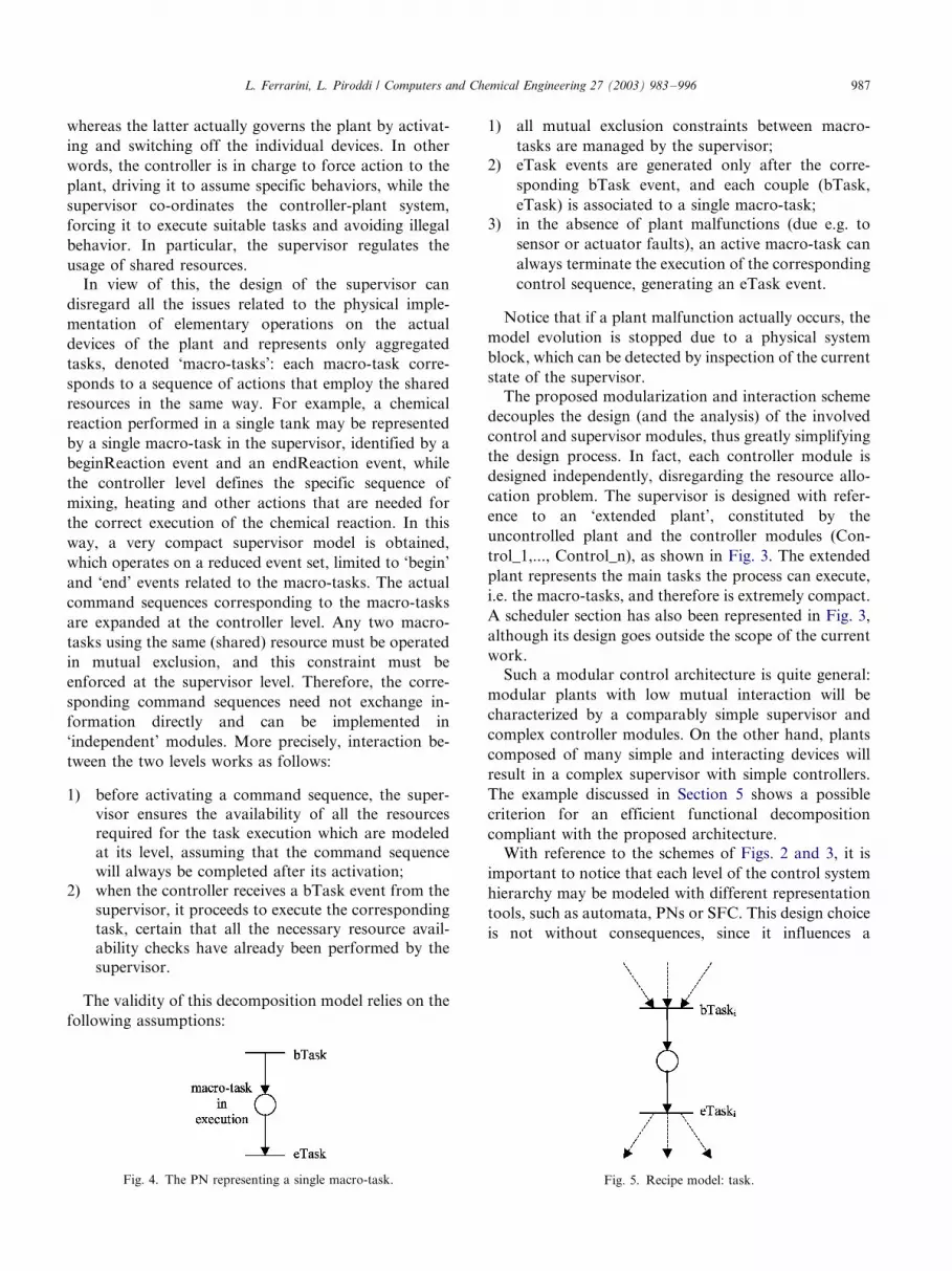
Fig. 4. The PN representing a single macro-task. Fig. 5. Recipe model: task.
L. Ferrarini, L. Piroddi / Computers and Chemical Engineering 27 (2003) 983�/996 987
number of factors, such as model dimension, ease of
supervisor analysis, etc.
4. Design methodology
According to the above control functional architec-
ture, the design methodology of the overall control
functions of a plant is based on the following steps:
design of the supervisor, design of the controllermodules and implementation. In the following subsec-
tions, the above design steps are explained and discussed
in detail.
4.1. The design of the supervisor
The design of the supervisor is the most critical part of
the control system development, since it involves the
modeling and management of shared resources. First of
all, the ‘macro-tasks’ are defined by suitably aggregating
sequences of elementary plant operations. Though thereis no general rule as to how an optimal macro-task
decomposition should be obtained and much is left to
the decision of the designer, a good rule is to associate
each macro-task with the usage of one or more
resources, so that the macro-task starts with the
acquisition of a resource and ends with the release of a
resource. Based on the identified set of macro-tasks the
following are defined in the design process:
a) the products to be obtained, characterized by rules
for the co-ordination and synchronization of
macro-tasks, collected in ‘recipes’,
b) the constraints on the plant behavior, due, forexample, to shared resources.
Both the recipes and the constraints are modeled withlabeled PN modules, i.e. PNs whose transitions are
associated to events (labels) so that the net evolution is
synchronized with the triggering of events (Peterson,
1981). The PN modules are then aggregated with the
synchronous or parallel composition operator to yield
the supervisor model. In the synchronous composition,
a common event between two PNs can only be executed
if the two PNs can execute it simultaneously, i.e. if inboth PNs a transition labeled with the common event is
enabled (Tittus & Lennartson, 1999).
Classical PN analysis tools can then be employed to
check (and, in case, enforce) the boundedness, reversi-
bility and liveness of the resulting supervisor PN. These
properties represent standard conditions for a well
defined supervisor model (Zhou et al., 1992a): this
must be bounded, since it ultimately models thebehaviour of a physical system with a limited number
of resources, reversible, to ensure repeatability of
production cycles, and live, to avoid system blocks
(deadlocks).
4.1.1. Model of the specifications: product recipes
The recipe model specifies the process flow in terms of
aggregated plant operations (macro-tasks), suitably
connected to form the desired operation sequences.
Each individual macro-task performed in the plant is
represented as a PN with one place (Task in execution)
and two transitions (associated to events bTask and
eTask, which represent the beginning and the end of the
operation, respectively) as in Fig. 4.The bTask event will be an output of the supervisor
which acts as a command to the controller (‘control-
lable’ event), whereas the eTask event will be an input to
the supervisor from the controller (‘uncontrollable’
event). When assembling macro-tasks, it is necessary
to ensure that a bTask event will be always followed by
Fig. 7. An example showing possible resource allocations Fig. 8. The standard controller module.
Fig. 6. Recipe model: connections among tasks.
L. Ferrarini, L. Piroddi / Computers and Chemical Engineering 27 (2003) 983�/996988
the corresponding eTask event, i.e. the transition
associated to a bTask event must have only one
outgoing arc connecting it to the place representing
the task in execution and the transition associated to thecorresponding eTask event must have only one incom-
ing arc connecting it to the same place. On the contrary,
no limit is imposed on the number of incoming [out-
going] arcs connected to the bTask [eTask] transition
(Fig. 5).
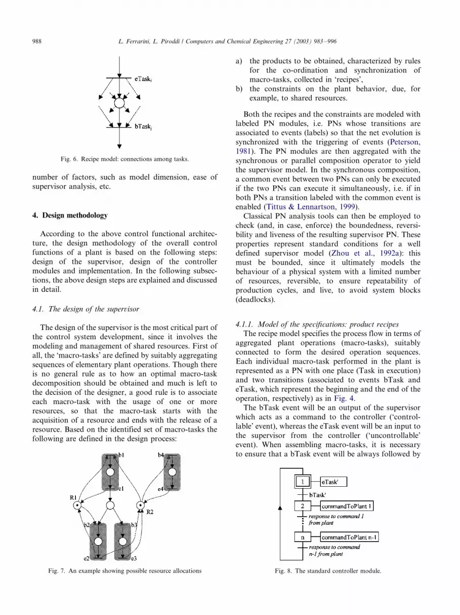
A connection between two operations is obtained by
adding an intermediate place linked to the transitions
associated to the eTask event of one operation and thebTask event of the subsequent operation, with an
incoming arc and an outgoing arc, respectively. The
intermediate place can be linked to other bTask or
eTask transitions as well (Fig. 6). The additional place is
necessary to describe the intermediate state in a
sequence of two tasks, when the preceding task has
been accomplished and the following task is waiting to
begin.The complete recipe model will be denoted SPRECIPES.
4.1.2. Modeling of the resources and physical constraints
Other specifications derive from physical constraints
on the process concerning the usage of ‘resources’. A
physical resource is any device required to perform an
operation. In a batch process, operations can be of two
types: processing operations and transporting opera-
tions. Accordingly, there are processing resources (e.g.
tanks, reactors, mixers, heaters) and transporting re-sources (pipes, valves, pumps, etc.).
A resource is modeled by one or more places (initially
marked) representing the resource availability, con-
nected with outgoing arcs to bTask transitions asso-
ciated to macro-tasks using the resource and with
incoming arcs to eTask transitions associated to the
same macro-tasks. If the resource is to be held between
subsequent macro-tasks, only the first bTask transitionand the last eTask transition of the sequence are
connected to the resource place. Notice that particular
care must be paid when a resource is required to be held
throughout a portion of a recipe containing a choice
connection (a conflict): all alternative sub-sequences
must require the resource to avoid inconsistencies.
Mutual exclusion constraints must be introduced to
avoid usage of the same resources by different recipes or
at different stages of the same recipe. On the other hand,
concurrent usage of a single resource by multipleoperations may be allowed on purpose, e.g. in opera-
tions of concurrent material transfer from one tank to
many tanks (or vice-versa).
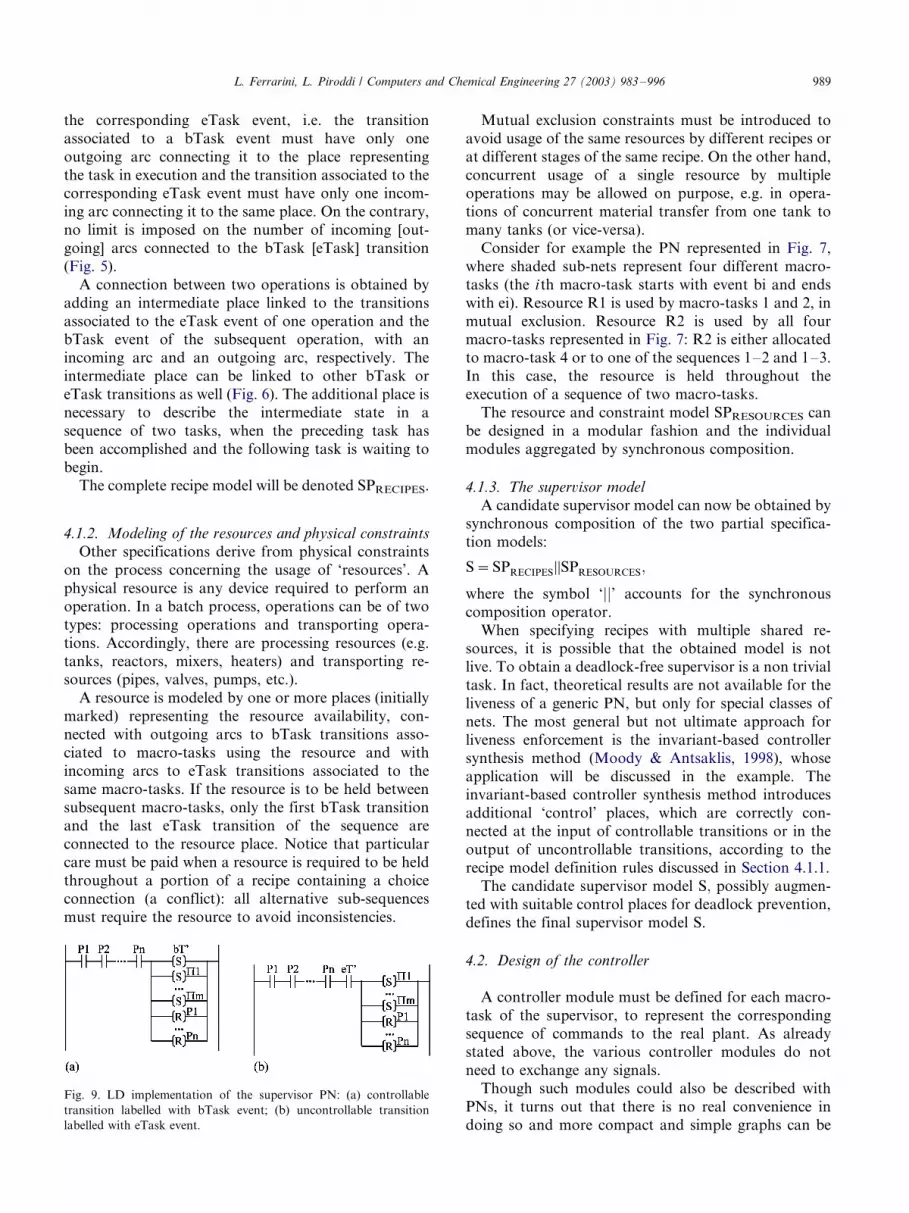
Consider for example the PN represented in Fig. 7,
where shaded sub-nets represent four different macro-
tasks (the ith macro-task starts with event bi and ends
with ei). Resource R1 is used by macro-tasks 1 and 2, in
mutual exclusion. Resource R2 is used by all fourmacro-tasks represented in Fig. 7: R2 is either allocated
to macro-task 4 or to one of the sequences 1�/2 and 1�/3.
In this case, the resource is held throughout the
execution of a sequence of two macro-tasks.
The resource and constraint model SPRESOURCES can
be designed in a modular fashion and the individual
modules aggregated by synchronous composition.
4.1.3. The supervisor model
A candidate supervisor model can now be obtained by
synchronous composition of the two partial specifica-
tion models:
S�SPRECIPES½½SPRESOURCES;
where the symbol ‘jj’ accounts for the synchronous
composition operator.
When specifying recipes with multiple shared re-sources, it is possible that the obtained model is not
live. To obtain a deadlock-free supervisor is a non trivial
task. In fact, theoretical results are not available for the
liveness of a generic PN, but only for special classes of
nets. The most general but not ultimate approach for
liveness enforcement is the invariant-based controller
synthesis method (Moody & Antsaklis, 1998), whose
application will be discussed in the example. Theinvariant-based controller synthesis method introduces
additional ‘control’ places, which are correctly con-
nected at the input of controllable transitions or in the
output of uncontrollable transitions, according to the
recipe model definition rules discussed in Section 4.1.1.
The candidate supervisor model S; possibly augmen-
ted with suitable control places for deadlock prevention,
defines the final supervisor model S.
4.2. Design of the controller
A controller module must be defined for each macro-
task of the supervisor, to represent the corresponding
sequence of commands to the real plant. As already
stated above, the various controller modules do not
need to exchange any signals.Though such modules could also be described with
PNs, it turns out that there is no real convenience in
doing so and more compact and simple graphs can be
Fig. 9. LD implementation of the supervisor PN: (a) controllable
transition labelled with bTask event; (b) uncontrollable transition
labelled with eTask event.
L. Ferrarini, L. Piroddi / Computers and Chemical Engineering 27 (2003) 983�/996 989
obtained with Grafcet/SFC, which has the additional
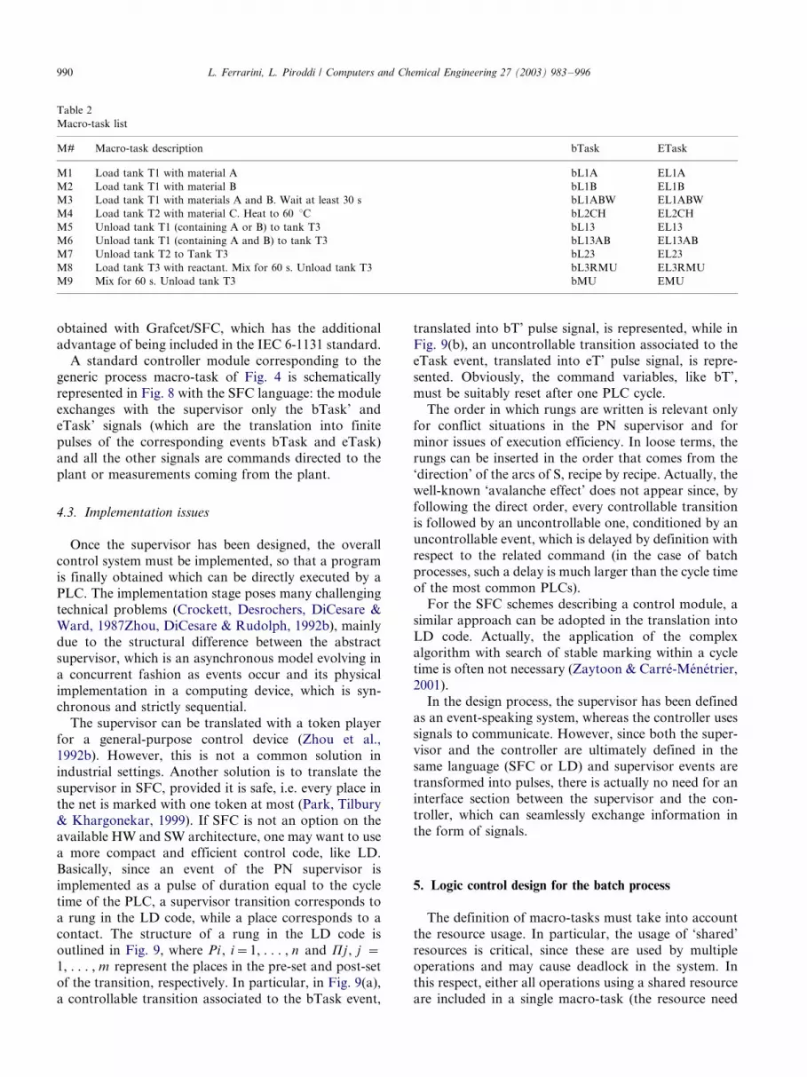
advantage of being included in the IEC 6-1131 standard.A standard controller module corresponding to the
generic process macro-task of Fig. 4 is schematically
represented in Fig. 8 with the SFC language: the module
exchanges with the supervisor only the bTask’ and
eTask’ signals (which are the translation into finite
pulses of the corresponding events bTask and eTask)
and all the other signals are commands directed to the
plant or measurements coming from the plant.
4.3. Implementation issues
Once the supervisor has been designed, the overall
control system must be implemented, so that a programis finally obtained which can be directly executed by a
PLC. The implementation stage poses many challenging
technical problems (Crockett, Desrochers, DiCesare &
Ward, 1987Zhou, DiCesare & Rudolph, 1992b), mainly
due to the structural difference between the abstract
supervisor, which is an asynchronous model evolving in
a concurrent fashion as events occur and its physical
implementation in a computing device, which is syn-chronous and strictly sequential.
The supervisor can be translated with a token player
for a general-purpose control device (Zhou et al.,
1992b). However, this is not a common solution in
industrial settings. Another solution is to translate the
supervisor in SFC, provided it is safe, i.e. every place in
the net is marked with one token at most (Park, Tilbury
& Khargonekar, 1999). If SFC is not an option on theavailable HW and SW architecture, one may want to use
a more compact and efficient control code, like LD.
Basically, since an event of the PN supervisor is
implemented as a pulse of duration equal to the cycle
time of the PLC, a supervisor transition corresponds to
a rung in the LD code, while a place corresponds to a
contact. The structure of a rung in the LD code is
outlined in Fig. 9, where Pi , i�/1, . . . , n and Pj , j �/
1, . . . , m represent the places in the pre-set and post-set
of the transition, respectively. In particular, in Fig. 9(a),
a controllable transition associated to the bTask event,
translated into bT’ pulse signal, is represented, while in
Fig. 9(b), an uncontrollable transition associated to theeTask event, translated into eT’ pulse signal, is repre-
sented. Obviously, the command variables, like bT’,
must be suitably reset after one PLC cycle.
The order in which rungs are written is relevant only
for conflict situations in the PN supervisor and for
minor issues of execution efficiency. In loose terms, the
rungs can be inserted in the order that comes from the
‘direction’ of the arcs of S, recipe by recipe. Actually, thewell-known ‘avalanche effect’ does not appear since, by
following the direct order, every controllable transition
is followed by an uncontrollable one, conditioned by an
uncontrollable event, which is delayed by definition with
respect to the related command (in the case of batch
processes, such a delay is much larger than the cycle time
of the most common PLCs).
For the SFC schemes describing a control module, asimilar approach can be adopted in the translation into
LD code. Actually, the application of the complex
algorithm with search of stable marking within a cycle
time is often not necessary (Zaytoon & Carre-Menetrier,
2001).
In the design process, the supervisor has been defined
as an event-speaking system, whereas the controller uses
signals to communicate. However, since both the super-visor and the controller are ultimately defined in the
same language (SFC or LD) and supervisor events are
transformed into pulses, there is actually no need for an
interface section between the supervisor and the con-
troller, which can seamlessly exchange information in
the form of signals.
5. Logic control design for the batch process
The definition of macro-tasks must take into account
the resource usage. In particular, the usage of ‘shared’
resources is critical, since these are used by multipleoperations and may cause deadlock in the system. In
this respect, either all operations using a shared resource
are included in a single macro-task (the resource need
Table 2
Macro-task list
M# Macro-task description bTask ETask
M1 Load tank T1 with material A bL1A EL1A
M2 Load tank T1 with material B bL1B EL1B
M3 Load tank T1 with materials A and B. Wait at least 30 s bL1ABW EL1ABW
M4 Load tank T2 with material C. Heat to 60 8C bL2CH EL2CH
M5 Unload tank T1 (containing A or B) to tank T3 bL13 EL13
M6 Unload tank T1 (containing A and B) to tank T3 bL13AB EL13AB
M7 Unload tank T2 to Tank T3 bL23 EL23
M8 Load tank T3 with reactant. Mix for 60 s. Unload tank T3 bL3RMU EL3RMU
M9 Mix for 60 s. Unload tank T3 bMU EMU
L. Ferrarini, L. Piroddi / Computers and Chemical Engineering 27 (2003) 983�/996990
not be represented at the supervisor level) or they are
distributed among different macro-tasks (in this case the
resource must be explicitly modeled in the supervisor,
which must manage the execution of the macro-tasks in
mutual exclusion).
The designer must then decide how to group physical
devices into logical resources to be modeled in the
supervisor. In the described application, a convenient set
of logical resources consists of the three tanks, each one
with the respective sensors and process and transport
equipment, as follows:
res1) T1, V1A, V1B, P1, h1, l1;
res2) T2, V2, P2, H, T, h2, l2;
res3) T3, VR, V3o, M, h3, l3.
A possible decomposition of the recipes defined in
Section 2 for the batch process, compatible with the
usage of the three logical resources defined above, as
that reported in Table 2, where nine macro-tasks are
defined together with the associated bTask and eTask
events. In particular, M1, M2 and M3 use res1, M4 uses
res2, M5 and M6 use res1 and res3, M7 uses res2 and
res3, M8 and M9 use res3.
Clearly, there is not a unique way to group sequences
of elementary operations in macro-tasks. For example,
macro-task M9 is completely contained in M8, so that a
compatible recipe model could be obtained using the
simpler macro-task M8?, performing only the loading of
tank T3 with reactant, instead of M8. However, with
this solution, the sequence M8?, M9 would appear in the
model of recipe R3 instead of a single macro-task,
thereby increasing the supervisor model dimension. On
the other hand, this modification does not help to refine
the model of the resource usage, since both M8? and M9
would be characterized by exactly the same usage of
shared resources.
The unloading operation from tank T1 to tank T3,
equally necessary in the three recipes, has been repre-
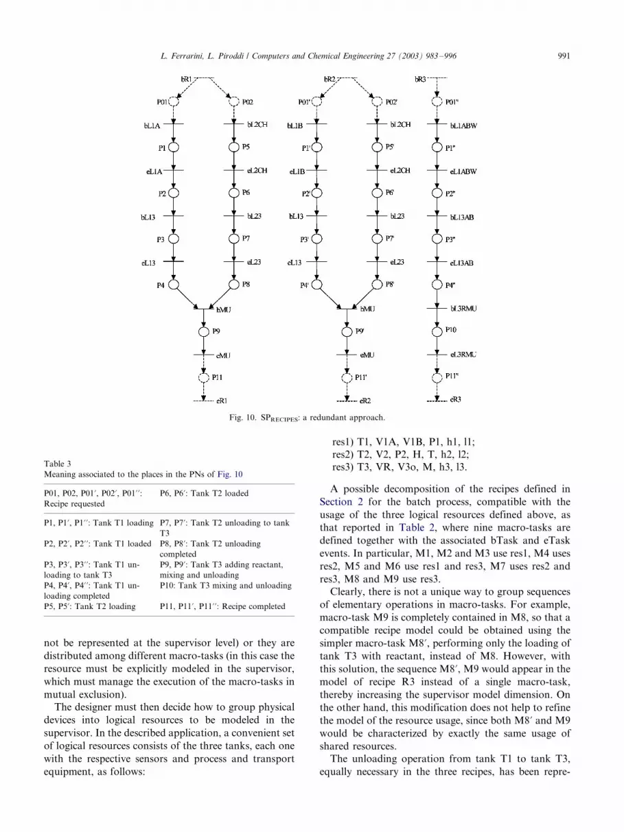
Fig. 10. SPRECIPES: a redundant approach.
Table 3
Meaning associated to the places in the PNs of Fig. 10
P01, P02, P01?, P02?, P01??:Recipe requested
P6, P6?: Tank T2 loaded
P1, P1?, P1??: Tank T1 loading P7, P7?: Tank T2 unloading to tank
T3
P2, P2?, P2??: Tank T1 loaded P8, P8?: Tank T2 unloading
completed
P3, P3?, P3??: Tank T1 un-
loading to tank T3
P9, P9?: Tank T3 adding reactant,
mixing and unloading
P4, P4?, P4??: Tank T1 un-
loading completed
P10: Tank T3 mixing and unloading
P5, P5?: Tank T2 loading P11, P11?, P11??: Recipe completed
L. Ferrarini, L. Piroddi / Computers and Chemical Engineering 27 (2003) 983�/996 991
sented with two macro-tasks, M5 relative to recipes R1
and R2 and M6 to R3. The reason for this is that the
operation executed in recipes R1 and R2 has the sameusage of resource res3, which is different from the usage
of the same resource by the corresponding operation in
recipe R3. In fact, while in recipes R1 and R2 the
unloading operation from tank T1 to tank T3 can be
performed ‘concurrently’ with the unloading of tank T2
to tank T3, represented by macro-task M7, the same
operation in recipe R3 is incompatible with M7, due to a
mutual exclusion constraint concerning the use ofresource res3.
5.1. Model of the specifications: recipes
A possible, conservative model of the recipes is
represented in Fig. 10, where the three recipes have
been realized by means of three independent sub-nets.Notice that, since some operations are carried out in
several recipes, this approach requires the duplication of
some operation places and the labeling of different
transitions with the same events. Also, suitable places
and transitions have been added to deal with the recipe
scheduling: the event list has been augmented with the
events related to the beginning (bR1, bR2 and bR3) and
ending (eR1, eR2 and eR3) of the single recipes, but thisis not essential for the comprehension of the example.
The meaning associated to the net places is presented in
Table 3.
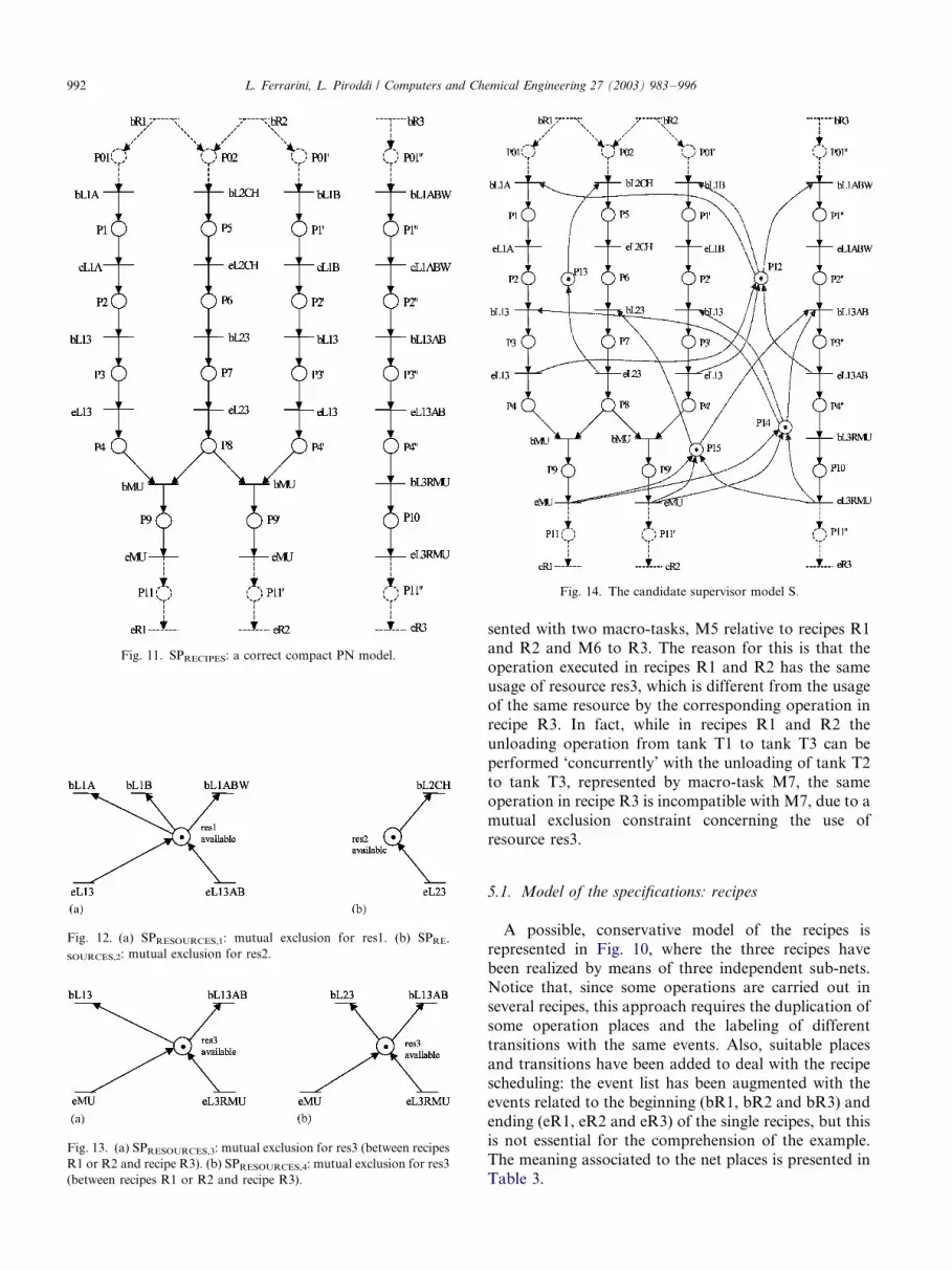
Fig. 11. SPRECIPES: a correct compact PN model.
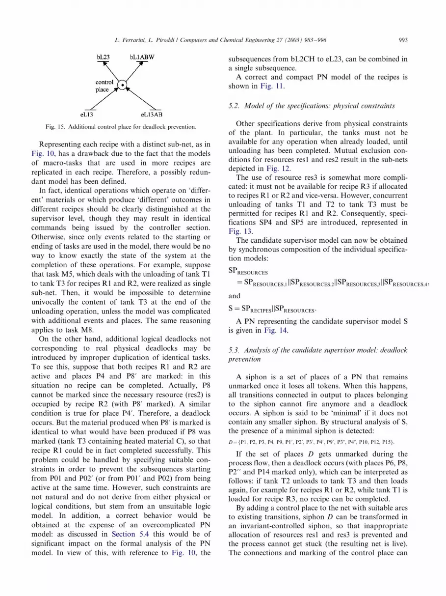
Fig. 14. The candidate supervisor model S:/
Fig. 12. (a) SPRESOURCES,1: mutual exclusion for res1. (b) SPRE-
SOURCES,2: mutual exclusion for res2.
Fig. 13. (a) SPRESOURCES,3: mutual exclusion for res3 (between recipes
R1 or R2 and recipe R3). (b) SPRESOURCES,4: mutual exclusion for res3
(between recipes R1 or R2 and recipe R3).
L. Ferrarini, L. Piroddi / Computers and Chemical Engineering 27 (2003) 983�/996992
Representing each recipe with a distinct sub-net, as in
Fig. 10, has a drawback due to the fact that the models
of macro-tasks that are used in more recipes are
replicated in each recipe. Therefore, a possibly redun-
dant model has been defined.
In fact, identical operations which operate on ‘differ-
ent’ materials or which produce ‘different’ outcomes in
different recipes should be clearly distinguished at the
supervisor level, though they may result in identical
commands being issued by the controller section.
Otherwise, since only events related to the starting or
ending of tasks are used in the model, there would be no
way to know exactly the state of the system at the
completion of these operations. For example, suppose
that task M5, which deals with the unloading of tank T1
to tank T3 for recipes R1 and R2, were realized as single
sub-net. Then, it would be impossible to determine
univocally the content of tank T3 at the end of the
unloading operation, unless the model was complicated
with additional events and places. The same reasoning
applies to task M8.
On the other hand, additional logical deadlocks not
corresponding to real physical deadlocks may be
introduced by improper duplication of identical tasks.
To see this, suppose that both recipes R1 and R2 are
active and places P4 and P8? are marked: in this
situation no recipe can be completed. Actually, P8
cannot be marked since the necessary resource (res2) is
occupied by recipe R2 (with P8? marked). A similar
condition is true for place P4?. Therefore, a deadlock
occurs. But the material produced when P8? is marked is
identical to what would have been produced if P8 was
marked (tank T3 containing heated material C), so that
recipe R1 could be in fact completed successfully. This
problem could be handled by specifying suitable con-
straints in order to prevent the subsequences starting
from P01 and P02? (or from P01? and P02) from being
active at the same time. However, such constraints are
not natural and do not derive from either physical or
logical conditions, but stem from an unsuitable logic
model. In addition, a correct behavior would be
obtained at the expense of an overcomplicated PN
model: as discussed in Section 5.4 this would be of
significant impact on the formal analysis of the PN
model. In view of this, with reference to Fig. 10, the
subsequences from bL2CH to eL23, can be combined in
a single subsequence.
A correct and compact PN model of the recipes is
shown in Fig. 11.
5.2. Model of the specifications: physical constraints
Other specifications derive from physical constraints
of the plant. In particular, the tanks must not be
available for any operation when already loaded, until
unloading has been completed. Mutual exclusion con-
ditions for resources res1 and res2 result in the sub-nets
depicted in Fig. 12.
The use of resource res3 is somewhat more compli-cated: it must not be available for recipe R3 if allocated
to recipes R1 or R2 and vice-versa. However, concurrent
unloading of tanks T1 and T2 to tank T3 must be
permitted for recipes R1 and R2. Consequently, speci-
fications SP4 and SP5 are introduced, represented in
Fig. 13.
The candidate supervisor model can now be obtained
by synchronous composition of the individual specifica-tion models:
SPRESOURCES
�SPRESOURCES;1½½SPRESOURCES;2½½SPRESOURCES;3½½SPRESOURCES;4;
and
S�SPRECIPES½½SPRESOURCES:
A PN representing the candidate supervisor model S
is given in Fig. 14.
5.3. Analysis of the candidate supervisor model: deadlock
prevention
A siphon is a set of places of a PN that remainsunmarked once it loses all tokens. When this happens,
all transitions connected in output to places belonging
to the siphon cannot fire anymore and a deadlock
occurs. A siphon is said to be ‘minimal’ if it does not
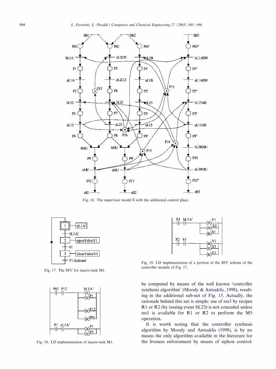
contain any smaller siphon. By structural analysis of S;the presence of a minimal siphon is detected:
D�fP1; P2; P3; P4; P9; P1?; P2?; P3?; P4?; P9?; P3ƒ; P4ƒ; P10; P12; P15g:
If the set of places D gets unmarked during theprocess flow, then a deadlock occurs (with places P6, P8,
P2?? and P14 marked only), which can be interpreted as
follows: if tank T2 unloads to tank T3 and then loads
again, for example for recipes R1 or R2, while tank T1 is
loaded for recipe R3, no recipe can be completed.
By adding a control place to the net with suitable arcs
to existing transitions, siphon D can be transformed in
an invariant-controlled siphon, so that inappropriateallocation of resources res1 and res3 is prevented and
the process cannot get stuck (the resulting net is live).
The connections and marking of the control place can
Fig. 15. Additional control place for deadlock prevention.
L. Ferrarini, L. Piroddi / Computers and Chemical Engineering 27 (2003) 983�/996 993
be computed by means of the well known ‘controller
synthesis algorithm’ (Moody & Antsaklis, 1998), result-
ing in the additional sub-net of Fig. 15. Actually, the
rationale behind this net is simple: use of res3 by recipes
R1 or R2 (by issuing event bL23) is not conceded unless
res1 is available for R1 or R2 to perform the M5
operation.
It is worth noting that the controller synthesis
algorithm by Moody and Antsaklis (1998), is by no
means the only algorithm available in the literature for
the liveness enforcement by means of siphon control:
Fig. 16. The supervisor model S with the additional control place.
Fig. 17. The SFC for macro-task M1.
Fig. 18. LD implementation of macro-task M1.
Fig. 19. LD implementation of a portion of the SFC scheme of the
controller module of Fig. 17.
L. Ferrarini, L. Piroddi / Computers and Chemical Engineering 27 (2003) 983�/996994
many other algorithms are available for special classes
of PNs. Among these are deadlock prevention algo-
rithms for the extended (Murata, 1989) and asymmetric
free-choice nets (Barkaoui & Abdallah, 1995), theproduction PNs (Banaszak & Krogh, 1990) and the
S3PR nets (Ezpeleta, Colom & Martinez, 1995). Un-
fortunately, the supervisor model developed in this
example and, in general, the supervisor designed as
shown in Section 3 and Section 4 do not belong to any
special PN class and none of these algorithms apply.
The overall supervisor model S, obtained by synchro-
nous composition of the candidate supervisor model Sand the control sub-net is shown in Fig. 16.Remark*/
Notice that if the recipe model of Fig. 10 had been
adopted instead of the more compact one of Fig. 11,
expressing the physical constraints on the use of the
tanks would have required additional arcs and places,
with five shared resource places instead of the three
represented in Fig. 14. This, in turn, badly complicates
the deadlock prevention phase, since 17 minimal siphonsare found in the net!I
5.4. Design of the controller
The SFC controller modules actually implement on
the plant the macro-tasks listed in Table 2 as explained
in Section 3. As an example, the SFC controller module
corresponding to macro-task M1 is represented in Fig.
17. The other macro-tasks are implemented with the
same criterion and are thus omitted for brevity sake.
5.5. Implementation issues
The guidelines discussed in Section 4.3 can be
employed to translate the supervisor and the controller
modules in LD. As an example, macro-task M1 can be
implemented as shown in Fig. 18.
With a similar rationale, the corresponding control
module (see Fig. 17) can be translated as shown in Fig.
19.
6. Conclusions
A methodology has been presented for the design of
logic control systems for batch processes. It is based on
a modular and hierarchical control structure. The
control architecture includes various blocks, namely a
supervisor (designed with PNs) and multiple controller
modules (designed with SFC). The combined effect of
modularity and hierarchy turns out to be extremely
successful in defining a compact supervisor model, thussimplifying analysis and deadlock prevention in real-size
cases, while remaining in a formal modeling framework.
This hopefully may encourage the use of formal models
and rigorous design methodology in the current indus-
trial practice.
A LD implementation of the whole structure has been
discussed demonstrating the feasibility of the multi-formalism hierarchical approach with the most popular
programmable control devices. The approach has been
illustrated on a multi-recipe batch process, but due to its
generality, is applicable to many other discrete manu-
facturing systems.
The work illustrated in the paper must be regarded as
a first step towards the definition of a structured
modeling methodology for logic control systems. Futuredevelopments will focus on the formalization of model-
ing rules, possibly including different types of specifica-
tions (other state and event constraints) and capable of
describing more complex processes (operations with
multiple outcomes, recirculating paths, shared pipeline
networks, etc.).
References
Balemi, S., Hoffmann, G. J., Gyugyi, P., Wong-Toi, H., & Franklin,
G. F. (1993). Supervisory control of a rapid thermal multi-
processor. IEEE Transactions on Automatic Control 38 (7),
1040�/1059.
Banaszak, Z., & Krogh, B. H. (1990). Deadlock avoidance in flexible
manufacturing systems with concurrently competing process flows.
IEEE Transactions on Robotics and Automation 6 (6), 724�/734.
Barkaoui, K., Abdallah, I.B. A deadlock prevention method for a class
of FMS. Intelligent Systems for the Twenty-first Century. IEEE
International Conference on Systems Man and Cybernetics
1995;5:4119�/4124.
Charbonnier, F., Alla, H., & David, R. (1999). The supervised control
of discrete-event dynamic systems. IEEE Transactions on Control
System Technology 7 (2), 175�/187.
Crockett, D., Desrochers, A., DiCesare, F., Ward, T. Implementation
a Petri net controller for a machining workstation. Proceedings of
the IEEE Conference on Robotics and Automation, Raleigh, NC,
1987, pp. 1861�/1867.
David, R., & Alla, H. (1992). Petri Nets and Grafcet-Tools for
Modeling Discrete Event Systems . New York: Prentice Hall.
Ezpeleta, J., Colom, J.-M., & Martinez, J. (1995). A Petri net based
deadlock prevention policy for flexible manufacturing systems.
IEEE Transactions on Robotics and Automation 11 (2), 173�/184.
Giua, A., DiCesare, F. Supervisory design using Petri nets. Proceed-
ings of the Thirtieth Conference on Decision and Control,
Brighton, UK, 1991, pp. 92�/97.
International Standard IEC 1131-3, Programmable Controllers*/Part
3, ISO/IEC, 1993.
Jeng, M.D., DiCesare, F. A synthesis method for Petri net modeling of
automated manufacturing systems with shared resources. IEEE
Thirty-first Conference on Decision and Control, Tucson, AZ,
1992, pp. 1184�/1189.
Johnsson, C., & .Arzen, K.-E. (1998). Grafchart for recipe-based batch
control. Computers in Chemical Engineering 22 (12), 1811�/1828.
Moody, J. O., & Antsaklis, P. J. (1989). Supervisory Control of Discrete
Event Systems Using Petri Nets . Dordrecht: Kluwer Academic.
Murata, T. (1989). Petri nets: properties, analysis and application.
Proceedings of the IEEE 77 (4), 541�/580.
Park, E., Tilbury, D. M., & Khargonekar, P. P. (1999). Modular logic
controllers for machining systems: formal representation and
L. Ferrarini, L. Piroddi / Computers and Chemical Engineering 27 (2003) 983�/996 995
performance analysis using Petri nets. IEEE Transactions on
Robotics and Automation 15 (6), 1046�/1061.
Peterson, J. L. (1981). Petri Net Theory and The Modeling of Systems .
New York: Prentice Hall.
Ramadge, P. J., & Wonham, W. M. (1987). Supervisory control of a
class of discrete-event systems. SIAM Journal of Control and
Optimization 25 (1), 206�/230.
Tittus, M., & Lennartson, B. (1999). Hierarchical supervisory control
for batch processes. IEEE Transactions on Control System Tech-
nology 7 (5), 542�/554.
Valavanis, K. (1990). On the hierarchical modeling, analysis and
simulation of FMS with extended Petri nets. IEEE Transactions on
Systems, Man and Cybernetics 20 (1), 94�/110.
Zaytoon, J., & Carre-Menetrier, V. (2001). Synthesis of a correct
control implementation for manufacturing systems. International
Journal of Production Research 39 , 329�/345.
Zhong, H., & Wonham, W. M. (1990). On the consistency of
hierarchical supervision in discrete-event systems. IEEE Transac-
tions on Automatic Control 35 (10), 1125�/1134.
Zhou, M. C., DiCesare, F., & Desrochers, A. (1992a). Hybrid
methodology for synthesis of Petri nets models for manufacturing
systems. IEEE Transactions on Robotics and Automation 8 (3),
350�/361.
Zhou, M. C., DiCesare, F., & Rudolph, D. L. (1992b). Design and
implementation of a Petri nets based supervisor for a flexible
manufacturing systems. Automatica 28 (6), 1199�/1208.
L. Ferrarini, L. Piroddi / Computers and Chemical Engineering 27 (2003) 983�/996996


