Embed Size (px)
Citation preview
Modicon TM5
EIO0000000590 04/2014
EIO
0000
0005
90.0
6
www.schneider-electric.com
Modicon TM5PCI Modules ConfigurationProgramming Guide
04/2014

The information provided in this documentation contains general descriptions and/or technical characteristics of the performance of the products contained herein. This documentation is not intended as a substitute for and is not to be used for determining suitability or reliability of these products for specific user applications. It is the duty of any such user or integrator to perform the appropriate and complete risk analysis, evaluation and testing of the products with respect to the relevant specific application or use thereof. Neither Schneider Electric nor any of its affiliates or subsidiaries shall be responsible or liable for misuse of the information contained herein. If you have any suggestions for improvements or amendments or have found errors in this publication, please notify us.
No part of this document may be reproduced in any form or by any means, electronic or mechanical, including photocopying, without express written permission of Schneider Electric.
All pertinent state, regional, and local safety regulations must be observed when installing and using this product. For reasons of safety and to help ensure compliance with documented system data, only the manufacturer should perform repairs to components.
When devices are used for applications with technical safety requirements, the relevant instructions must be followed.
Failure to use Schneider Electric software or approved software with our hardware products may result in injury, harm, or improper operating results.
Failure to observe this information can result in injury or equipment damage.
© 2014 Schneider Electric. All rights reserved.
2 EIO0000000590 04/2014
Table of Contents
Safety Information . . . . . . . . . . . . . . . . . . . . . . . . . . . . . 5About the Book. . . . . . . . . . . . . . . . . . . . . . . . . . . . . . . . 7
Chapter 1 General Description . . . . . . . . . . . . . . . . . . . . . . . . . . . . 9TM5 PCI Expansion Modules General Description . . . . . . . . . . . . . . . 10Add a PCI Expansion Module . . . . . . . . . . . . . . . . . . . . . . . . . . . . . . . 11
Chapter 2 Serial Line PCI Expansion Module . . . . . . . . . . . . . . . . 132.1 Serial Line PCI Expansion Module Configuration . . . . . . . . . . . . . . . . 14
Serial Line PCI Expansion Module Configuration . . . . . . . . . . . . . . . . 142.2 Devices on Serial Line PCI Expansion Modules . . . . . . . . . . . . . . . . . 16
ASCII Manager . . . . . . . . . . . . . . . . . . . . . . . . . . . . . . . . . . . . . . . . . . 17SoMachine Network Manager . . . . . . . . . . . . . . . . . . . . . . . . . . . . . . . 19Modbus IOScanner . . . . . . . . . . . . . . . . . . . . . . . . . . . . . . . . . . . . . . . 20Adding a Device on the Modbus IOScanner . . . . . . . . . . . . . . . . . . . . 21Modbus Manager. . . . . . . . . . . . . . . . . . . . . . . . . . . . . . . . . . . . . . . . . 26Adding a Modem to a Manager . . . . . . . . . . . . . . . . . . . . . . . . . . . . . . 30
2.3 SerialConf Functions . . . . . . . . . . . . . . . . . . . . . . . . . . . . . . . . . . . . . . 31GetSerialConf: Get the Serial Line Configuration . . . . . . . . . . . . . . . . 32SetSerialConf: Change the Serial Line Configuration . . . . . . . . . . . . . 33SERIAL_CONF: Structure of the Serial Line Configuration Data Type 35
Chapter 3 Profibus DP Slave PCI Expansion Module. . . . . . . . . . 373.1 Profibus DP Slave PCI Expansion Module Configuration . . . . . . . . . . 38
Add a Profibus DP Slave PCI Expansion Module . . . . . . . . . . . . . . . . 39Configure the Profibus DP Slave PCI Expansion Module . . . . . . . . . . 40Input / Output Devices Objects . . . . . . . . . . . . . . . . . . . . . . . . . . . . . . 41
3.2 Data Exchange . . . . . . . . . . . . . . . . . . . . . . . . . . . . . . . . . . . . . . . . . . 43I/O Cyclic Exchange . . . . . . . . . . . . . . . . . . . . . . . . . . . . . . . . . . . . . . 44Acyclic Exchange with Profibus DPV1 Functions . . . . . . . . . . . . . . . . 46
3.3 Diagnostic . . . . . . . . . . . . . . . . . . . . . . . . . . . . . . . . . . . . . . . . . . . . . . 48Diagnostic Information. . . . . . . . . . . . . . . . . . . . . . . . . . . . . . . . . . . . . 48
Glossary . . . . . . . . . . . . . . . . . . . . . . . . . . . . . . . . . . . . . . . . . 51Index . . . . . . . . . . . . . . . . . . . . . . . . . . . . . . . . . . . . . . . . . 55
EIO0000000590 04/2014 3

4 EIO0000000590 04/2014
Safety Information
Important Information
NOTICERead these instructions carefully, and look at the equipment to become familiar with the device before trying to install, operate, or maintain it. The following special messages may appear throughout this documentation or on the equipment to warn of potential hazards or to call attention to information that clarifies or simplifies a procedure.
EIO0000000590 04/2014 5

PLEASE NOTEElectrical equipment should be installed, operated, serviced, and maintained only by qualified personnel. No responsibility is assumed by Schneider Electric for any consequences arising out of the use of this material.
A qualified person is one who has skills and knowledge related to the construction and operation of electrical equipment and its installation, and has received safety training to recognize and avoid the hazards involved.
6 EIO0000000590 04/2014
About the Book
At a Glance
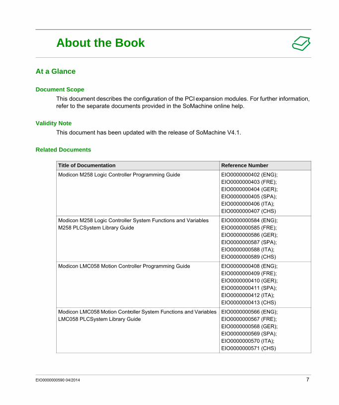
Document ScopeThis document describes the configuration of the PCI expansion modules. For further information, refer to the separate documents provided in the SoMachine online help.
Validity NoteThis document has been updated with the release of SoMachine V4.1.
Related Documents
Title of Documentation Reference Number
Modicon M258 Logic Controller Programming Guide EIO0000000402 (ENG); EIO0000000403 (FRE); EIO0000000404 (GER); EIO0000000405 (SPA); EIO0000000406 (ITA); EIO0000000407 (CHS)
Modicon M258 Logic Controller System Functions and Variables M258 PLCSystem Library Guide
EIO0000000584 (ENG); EIO0000000585 (FRE); EIO0000000586 (GER); EIO0000000587 (SPA); EIO0000000588 (ITA); EIO0000000589 (CHS)
Modicon LMC058 Motion Controller Programming Guide EIO0000000408 (ENG); EIO0000000409 (FRE); EIO0000000410 (GER); EIO0000000411 (SPA); EIO0000000412 (ITA); EIO0000000413 (CHS)
Modicon LMC058 Motion Controller System Functions and Variables LMC058 PLCSystem Library Guide
EIO0000000566 (ENG); EIO0000000567 (FRE); EIO0000000568 (GER); EIO0000000569 (SPA); EIO0000000570 (ITA); EIO0000000571 (CHS)
EIO0000000590 04/2014 7
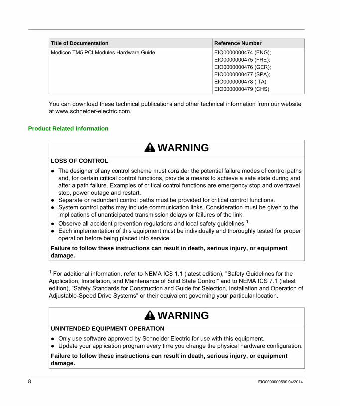
You can download these technical publications and other technical information from our website at www.schneider-electric.com.
Product Related Information
1 For additional information, refer to NEMA ICS 1.1 (latest edition), "Safety Guidelines for the Application, Installation, and Maintenance of Solid State Control" and to NEMA ICS 7.1 (latest edition), "Safety Standards for Construction and Guide for Selection, Installation and Operation of Adjustable-Speed Drive Systems" or their equivalent governing your particular location.
Modicon TM5 PCI Modules Hardware Guide EIO0000000474 (ENG); EIO0000000475 (FRE); EIO0000000476 (GER); EIO0000000477 (SPA); EIO0000000478 (ITA); EIO0000000479 (CHS)
Title of Documentation Reference Number
WARNINGLOSS OF CONTROL
The designer of any control scheme must consider the potential failure modes of control paths and, for certain critical control functions, provide a means to achieve a safe state during and after a path failure. Examples of critical control functions are emergency stop and overtravel stop, power outage and restart.Separate or redundant control paths must be provided for critical control functions.System control paths may include communication links. Consideration must be given to the implications of unanticipated transmission delays or failures of the link.Observe all accident prevention regulations and local safety guidelines.1Each implementation of this equipment must be individually and thoroughly tested for proper operation before being placed into service.
Failure to follow these instructions can result in death, serious injury, or equipment damage.
WARNINGUNINTENDED EQUIPMENT OPERATION
Only use software approved by Schneider Electric for use with this equipment.Update your application program every time you change the physical hardware configuration.
Failure to follow these instructions can result in death, serious injury, or equipment damage.
8 EIO0000000590 04/2014
Modicon TM5General DescriptionEIO0000000590 04/2014
General Description
Chapter 1General Description
IntroductionThis chapter provides the general description for configuring PCI expansion modules.
What Is in This Chapter?This chapter contains the following topics:
Topic Page
TM5 PCI Expansion Modules General Description 10
Add a PCI Expansion Module 11
EIO0000000590 04/2014 9
General Description
TM5 PCI Expansion Modules General Description
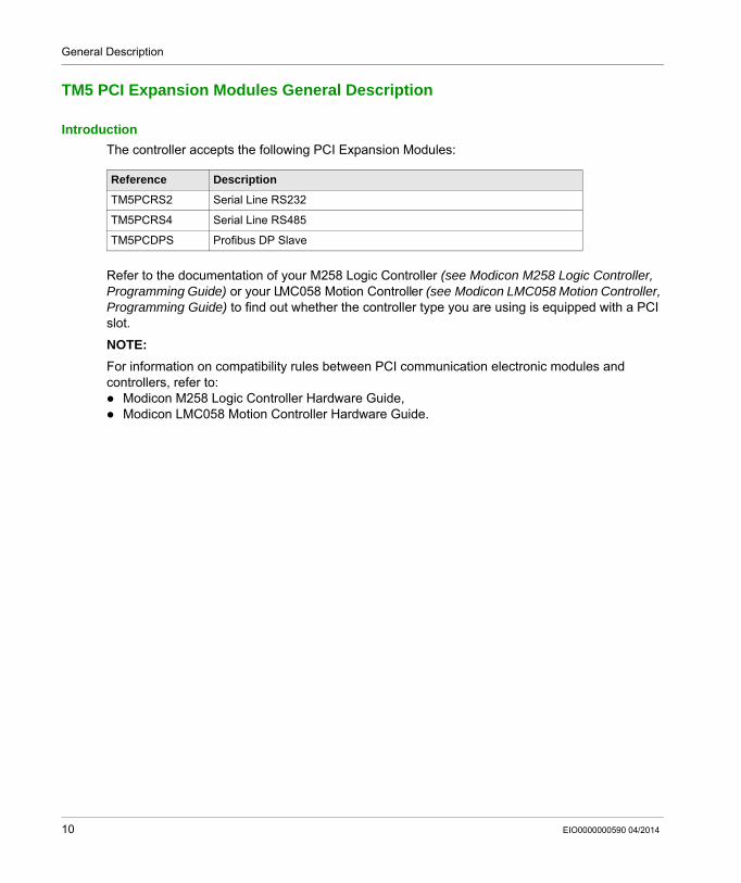
IntroductionThe controller accepts the following PCI Expansion Modules:
Refer to the documentation of your M258 Logic Controller (see Modicon M258 Logic Controller, Programming Guide) or your LMC058 Motion Controller (see Modicon LMC058 Motion Controller, Programming Guide) to find out whether the controller type you are using is equipped with a PCI slot.
NOTE: For information on compatibility rules between PCI communication electronic modules and controllers, refer to:
Modicon M258 Logic Controller Hardware Guide,Modicon LMC058 Motion Controller Hardware Guide.
Reference Description
TM5PCRS2 Serial Line RS232
TM5PCRS4 Serial Line RS485
TM5PCDPS Profibus DP Slave
10 EIO0000000590 04/2014
General Description
Add a PCI Expansion Module
Add a PCI Expansion ModuleTo add a PCI expansion module to your controller, select the expansion module in the Hardware Catalog, drag it to the Devices tree, and drop it on one of the highlighted nodes.
For more information on adding a device to your project, refer to:
• Using the Drag-and-drop Method (see SoMachine, Programming Guide)
• Using the Contextual Menu or Plus Button (see SoMachine, Programming Guide)
EIO0000000590 04/2014 11

General Description
12 EIO0000000590 04/2014
Modicon TM5Serial Line PCI Expansion ModuleEIO0000000590 04/2014
Serial Line PCI Expansion Module
Chapter 2Serial Line PCI Expansion Module
IntroductionThis chapter describes how to configure the Serial Line PCI Expansion Modules.
What Is in This Chapter?This chapter contains the following sections:
Section Topic Page
2.1 Serial Line PCI Expansion Module Configuration 14
2.2 Devices on Serial Line PCI Expansion Modules 16
2.3 SerialConf Functions 31
EIO0000000590 04/2014 13
Serial Line PCI Expansion Module
Serial Line PCI Expansion Module Configuration
Section 2.1Serial Line PCI Expansion Module Configuration
Serial Line PCI Expansion Module Configuration
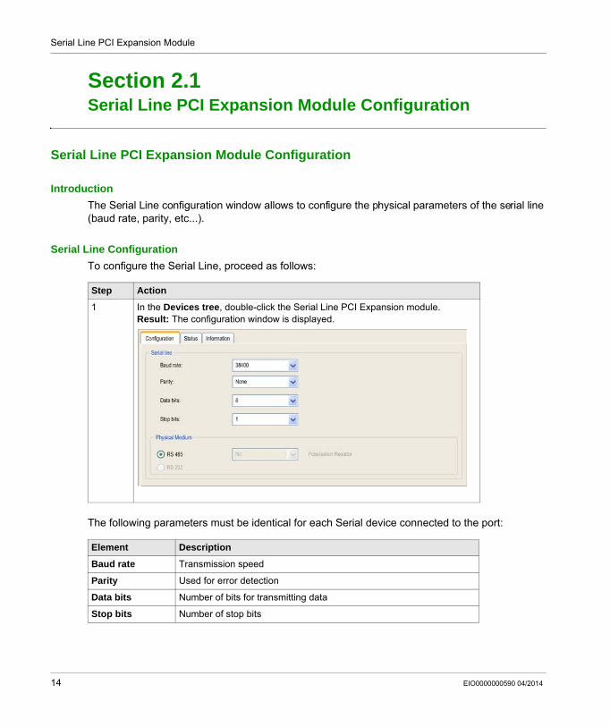
IntroductionThe Serial Line configuration window allows to configure the physical parameters of the serial line (baud rate, parity, etc...).
Serial Line ConfigurationTo configure the Serial Line, proceed as follows:
The following parameters must be identical for each Serial device connected to the port:
Step Action
1 In the Devices tree, double-click the Serial Line PCI Expansion module.Result: The configuration window is displayed.
Element Description
Baud rate Transmission speed
Parity Used for error detection
Data bits Number of bits for transmitting data
Stop bits Number of stop bits
14 EIO0000000590 04/2014
Serial Line PCI Expansion Module
The following table indicates the maximum baud rate according to the Manager:
Physical Medium Specify the medium to use (automatically selected depending on the module):
RS485 (for TM5PCRS4)RS232 (for TM5PCRS2)
Manager Maximum Baud Rate
SoMachine Network Manager 115200
ASCIIManager 38400
Modbus IOScanner
Modbus Manager
Element Description
EIO0000000590 04/2014 15
Serial Line PCI Expansion Module
Devices on Serial Line PCI Expansion Modules
Section 2.2Devices on Serial Line PCI Expansion Modules
IntroductionThis section describes the managers and devices of Serial Line PCI Expansion Modules.
What Is in This Section?This section contains the following topics:
Topic Page
ASCII Manager 17
SoMachine Network Manager 19
Modbus IOScanner 20
Adding a Device on the Modbus IOScanner 21
Modbus Manager 26
Adding a Modem to a Manager 30
16 EIO0000000590 04/2014
Serial Line PCI Expansion Module
ASCII Manager
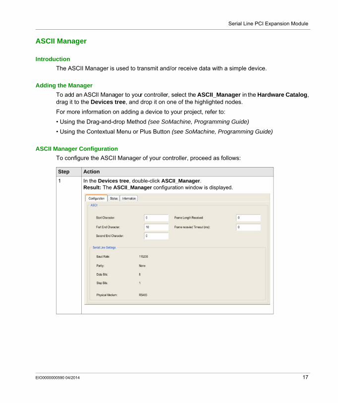
IntroductionThe ASCII Manager is used to transmit and/or receive data with a simple device.
Adding the ManagerTo add an ASCII Manager to your controller, select the ASCII_Manager in the Hardware Catalog, drag it to the Devices tree, and drop it on one of the highlighted nodes.
For more information on adding a device to your project, refer to:
• Using the Drag-and-drop Method (see SoMachine, Programming Guide)
• Using the Contextual Menu or Plus Button (see SoMachine, Programming Guide)
ASCII Manager ConfigurationTo configure the ASCII Manager of your controller, proceed as follows:
Step Action
1 In the Devices tree, double-click ASCII_Manager.Result: The ASCII_Manager configuration window is displayed.
EIO0000000590 04/2014 17
Serial Line PCI Expansion Module
Set the parameters as described in the following table:
NOTE: In the case of using First End Character and Second End Character simultanously, these 2 conditions are considered as one frame termination condition. The frame termination condition becomes TRUE when the 2 characters are recognized.
In the case of using several frame termination conditions, the first condition to be TRUE will terminate the exchange.
Adding a ModemTo add a Modem to the ASCII Manager, refer to Adding a Modem to a Manager (see page 30).
Parameter Description
Start Character If 0, no start character is used in the frame. In Receiving Mode the corresponding character in ASCII is used to detect the beginning of a frame. In Sending Mode, this character is added at the beginning of the frame.
First End Character
If 0, no first end character is used in the frame. In Receiving Mode the corresponding character in ASCII is used to detect the end of a frame. In Sending Mode, this character is added at the end of the frame.
Second End Character
If 0, no second end character is used in the frame. In Receiving Mode the corresponding character in ASCII is used to detect the end of a frame. In Sending Mode, this character is added at the end of the frame.
Frame Length Received
If 0, this parameter is not used. This parameter allows the system to conclude an end of frame at reception, when the controller receives the specified number of characters.Note: This parameter cannot be used simultaneously with Frame Received Timeout (ms).
Frame Received Timeout (ms)
If 0, this parameter is not used. This parameter allows the system to conclude the end of frame at reception after a silence of the specified number of ms.Note: This parameter cannot be used simultaneously with Frame Length Received.
Serial Line Settings
Parameters specified in the Serial Line configuration window (see page 14).
18 EIO0000000590 04/2014
Serial Line PCI Expansion Module
SoMachine Network Manager
IntroductionThe SoMachine Network Manager must be used if you want to exchange variables with HMI Terminal Range with SoMachine software protocol, or when the Serial Line is used for SoMachine programming.
Adding the ManagerTo add a SoMachine network manager to your project, select the SoMachine-Network_Manager in the Hardware Catalog, drag it to the Devices tree, and drop it on one of the highlighted nodes.
For more information on adding a device to your project, refer to:
• Using the Drag-and-drop Method (see SoMachine, Programming Guide)
• Using the Contextual Menu or Plus Button (see SoMachine, Programming Guide)
Configure the ManagerThere is no configuration for SoMachine Network Manager.
Adding a ModemTo add a Modem to the SoMachine Network Manager, refer to Adding a Modem to a Manager (see page 30).
EIO0000000590 04/2014 19
Serial Line PCI Expansion Module
Modbus IOScanner
IntroductionThe Modbus IOScanner is used to simplify exchanges with Modbus slave devices.
Add a Modbus IOScannerTo add a Modbus IOScanner on a PCI Expansion Module, select the Modbus IOScanner in the Hardware Catalog, drag it to the Devices tree, and drop it on one of the highlighted nodes.
For more information on adding a device to your project, refer to:
• Using the Drag-and-drop Method (see SoMachine, Programming Guide)
• Using the Contextual Menu or Plus Button (see SoMachine, Programming Guide)
Modbus IOScanner ConfigurationTo configure a Modbus IOScanner on a PCI Expansion Module, proceed as follows:
Set the parameters as described in the following table:
Step Action
1 In the Devices tree, double-click Modbus IOScanner.Result: The configuration window is displayed.
Element Description
Transmission Mode
The transmission mode to use is RTU. RTU uses binary coding and CRC error-checking (8 data bits).This parameter must be identical for each Modbus device on the link.
Response Timeout (ms)
Timeout used in the exchanges
Time between frames (ms)
Time to avoid bus-collisionThis parameter must be identical for each Modbus device on the link.
20 EIO0000000590 04/2014
Serial Line PCI Expansion Module
Adding a Device on the Modbus IOScanner
IntroductionThis section describes how to add a device on the Modbus IOScanner.
Add a Device on the Modbus IOScannerTo add a device on the Modbus IOScanner, select the Generic Modbus Slave in the Hardware Catalog, drag it to the Devices tree, and drop it on the Modbus_IOScanner node of the Devices tree.
For more information on adding a device to your project, refer to:
• Using the Drag-and-drop Method (see SoMachine, Programming Guide)
• Using the Contextual Menu or Plus Button (see SoMachine, Programming Guide)
NOTE: The variable for the exchange is automatically created in the %IWx and %QWx of the Modbus Serial Master I/O Mapping tab.
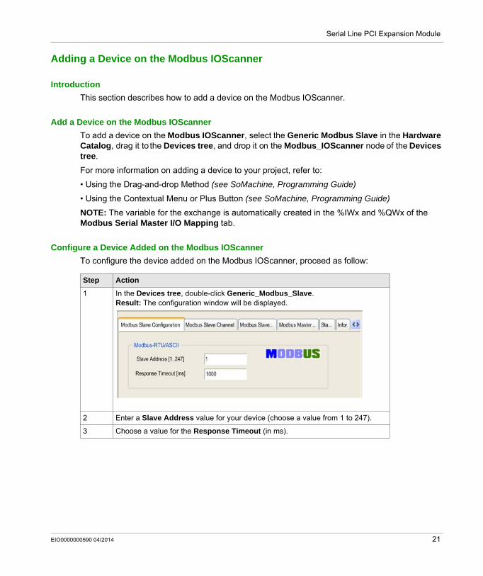
Configure a Device Added on the Modbus IOScannerTo configure the device added on the Modbus IOScanner, proceed as follow:
Step Action
1 In the Devices tree, double-click Generic_Modbus_Slave.Result: The configuration window will be displayed.
2 Enter a Slave Address value for your device (choose a value from 1 to 247).
3 Choose a value for the Response Timeout (in ms).
EIO0000000590 04/2014 21
Serial Line PCI Expansion Module
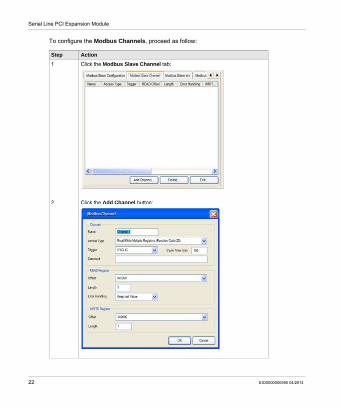
To configure the Modbus Channels, proceed as follow:
Step Action
1 Click the Modbus Slave Channel tab:
2 Click the Add Channel button:
22 EIO0000000590 04/2014
Serial Line PCI Expansion Module
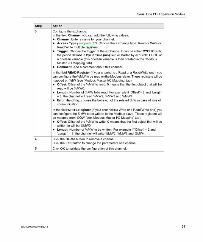
3 Configure the exchange:In the field Channel, you can add the following values:
Channel: Enter a name for your channel.Access Type (see page 27): Choose the exchange type: Read or Write or Read/Write multiple registers.Trigger: Choose the trigger of the exchange. It can be either CYCLIC with the period defined in Cycle Time (ms) field or started by a RISING EDGE on a boolean variable (this boolean variable is then created in the ’Modbus Master I/O Mapping’ tab).Comment: Add a comment about this channel.
In the field READ Register (if your channel is a Read or a Read/Write one), you can configure the %MW to be read on the Modbus slave. These registers will be mapped on %IW (see ’Modbus Master I/O Mapping’ tab):
Offset: Offset of the %MW to read. 0 means that the first object that will be read will be %MW0.Length: Number of %MW to be read. For example if ’Offset’ = 2 and ’Length’ = 3, the channel will read %MW2, %MW3 and %MW4.Error Handling: choose the behavior of the related %IW in case of loss of communication.
In the field WRITE Register (if your channel is a Write or a Read/Write one), you can configure the %MW to be written to the Modbus slave. These registers will be mapped from %QW (see ’Modbus Master I/O Mapping’ tab):
Offset: Offset of the %MW to write. 0 means that the first object that will be written to will be %MW0.Length: Number of %MW to be written. For example if ’Offset’ = 2 and ’Length’ = 3, the channel will write %MW2, %MW3 and %MW4.
4 Click the Delete button to remove a channel.Click the Edit button to change the parameters of a channel.
5 Click OK to validate the configuration of this channel.
Step Action
EIO0000000590 04/2014 23
Serial Line PCI Expansion Module
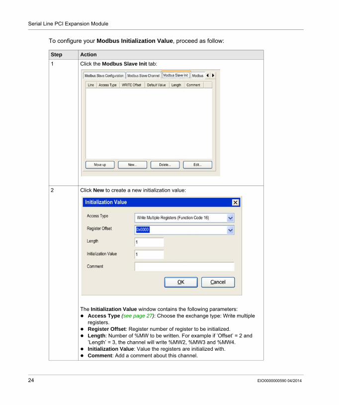
To configure your Modbus Initialization Value, proceed as follow:
Step Action
1 Click the Modbus Slave Init tab:
2 Click New to create a new initialization value:
The Initialization Value window contains the following parameters:Access Type (see page 27): Choose the exchange type: Write multiple registers.Register Offset: Register number of register to be initialized.Length: Number of %MW to be written. For example if ’Offset’ = 2 and ’Length’ = 3, the channel will write %MW2, %MW3 and %MW4.Initialization Value: Value the registers are initialized with.Comment: Add a comment about this channel.
24 EIO0000000590 04/2014
Serial Line PCI Expansion Module
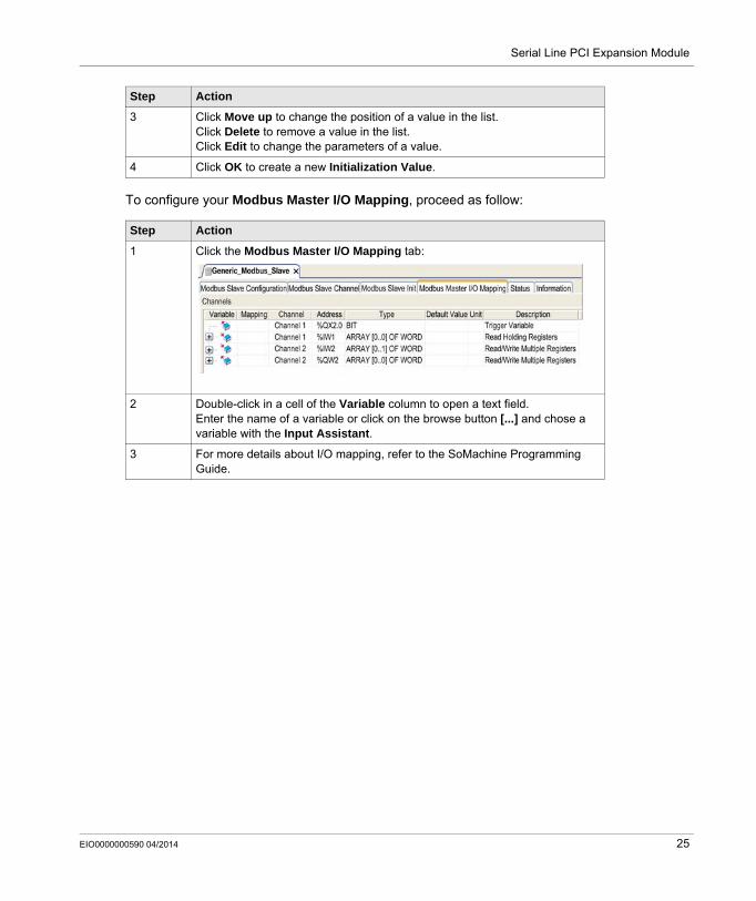
To configure your Modbus Master I/O Mapping, proceed as follow:
3 Click Move up to change the position of a value in the list.Click Delete to remove a value in the list.Click Edit to change the parameters of a value.
4 Click OK to create a new Initialization Value.
Step Action
1 Click the Modbus Master I/O Mapping tab:
2 Double-click in a cell of the Variable column to open a text field.Enter the name of a variable or click on the browse button [...] and chose a variable with the Input Assistant.
3 For more details about I/O mapping, refer to the SoMachine Programming Guide.
Step Action
EIO0000000590 04/2014 25
Serial Line PCI Expansion Module
Modbus Manager
IntroductionThe Modbus Manager is used for Modbus RTU or ASCII protocol in master or slave mode.
Adding the ManagerTo add a Modbus Manager to your controller, select Modbus_Manager in the Hardware Catalog, drag it to the Devices tree, and drop it on one of the highlighted nodes.
For more information on adding a device to your project, refer to:
• Using the Drag-and-drop Method (see SoMachine, Programming Guide)
• Using the Contextual Menu or Plus Button (see SoMachine, Programming Guide)
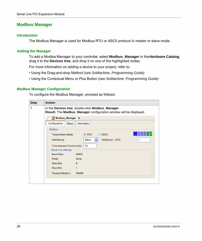
Modbus Manager Configuration To configure the Modbus Manager, proceed as follows:
Step Action
1 In the Devices tree, double-click Modbus_Manager.Result: The Modbus_Manager configuration window will be displayed.
26 EIO0000000590 04/2014
Serial Line PCI Expansion Module
Set the parameters as described in the following table:
Modbus MasterWhen the module is configured as a Modbus Master, the following Function Blocks are supported from the PLCCommunication Library:
ADDMREAD_VARSEND_RECV_MSGSINGLE_WRITEWRITE_READ_VARWRITE_VAR
For further information, see Function Block Descriptions (see SoMachine, Modbus and ASCII Read/Write Functions, PLCCommunication Library Guide) of the PLCCommunication Library.
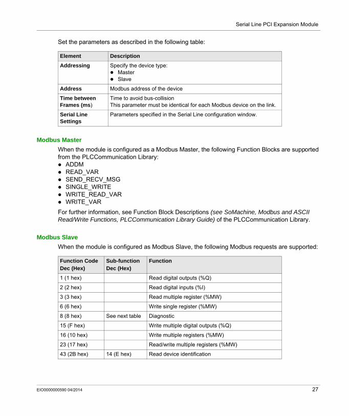
Modbus SlaveWhen the module is configured as Modbus Slave, the following Modbus requests are supported:
Element Description
Addressing Specify the device type:MasterSlave
Address Modbus address of the device
Time between Frames (ms)
Time to avoid bus-collisionThis parameter must be identical for each Modbus device on the link.
Serial Line Settings
Parameters specified in the Serial Line configuration window.
Function CodeDec (Hex)
Sub-functionDec (Hex)
Function
1 (1 hex) Read digital outputs (%Q)
2 (2 hex) Read digital inputs (%I)
3 (3 hex) Read multiple register (%MW)
6 (6 hex) Write single register (%MW)
8 (8 hex) See next table Diagnostic
15 (F hex) Write multiple digital outputs (%Q)
16 (10 hex) Write multiple registers (%MW)
23 (17 hex) Read/write multiple registers (%MW)
43 (2B hex) 14 (E hex) Read device identification
EIO0000000590 04/2014 27
Serial Line PCI Expansion Module
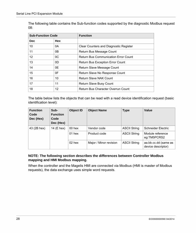
The following table contains the Sub-function codes supported by the diagnostic Modbus request 08:
The table below lists the objects that can be read with a read device identification request (basic identification level):
NOTE: The following section describes the differences between Controller Modbus mapping and HMI Modbus mapping.When the controller and the Magelis HMI are connected via Modbus (HMI is master of Modbus requests), the data exchange uses simple word requests.
Sub-Function Code Function
Dec Hex
10 0A Clear Counters and Diagnostic Register
11 0B Return Bus Message Count
12 0C Return Bus Communication Error Count
13 0D Return Bus Exception Error Count
14 0E Return Slave Message Count
15 0F Return Slave No Response Count
16 10 Return Slave NAK Count
17 11 Return Slave Busy Count
18 12 Return Bus Character Overrun Count
Function CodeDec (Hex)
Sub-Function CodeDec (Hex)
Object ID Object Name Type Value
43 (2B hex) 14 (E hex) 00 hex Vendor code ASCII String Schneider Electric
01 hex Product code ASCII String Module referenceeg:TM5PCRS2
02 hex Major / Minor revision ASCII String aa.bb.cc.dd (same as device descriptor)
28 EIO0000000590 04/2014
Serial Line PCI Expansion Module
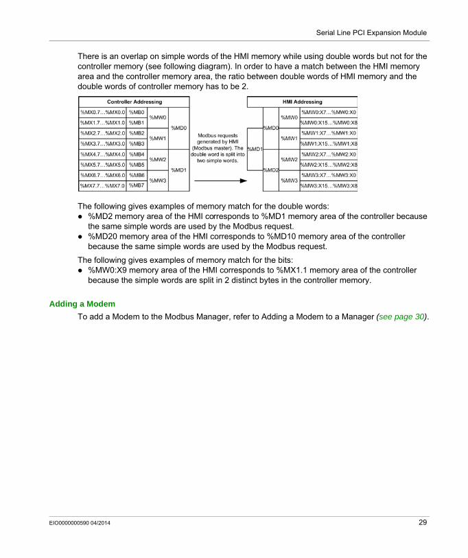
There is an overlap on simple words of the HMI memory while using double words but not for the controller memory (see following diagram). In order to have a match between the HMI memory area and the controller memory area, the ratio between double words of HMI memory and the double words of controller memory has to be 2.
The following gives examples of memory match for the double words:%MD2 memory area of the HMI corresponds to %MD1 memory area of the controller because the same simple words are used by the Modbus request.%MD20 memory area of the HMI corresponds to %MD10 memory area of the controller because the same simple words are used by the Modbus request.
The following gives examples of memory match for the bits:%MW0:X9 memory area of the HMI corresponds to %MX1.1 memory area of the controller because the simple words are split in 2 distinct bytes in the controller memory.
Adding a ModemTo add a Modem to the Modbus Manager, refer to Adding a Modem to a Manager (see page 30).
EIO0000000590 04/2014 29
Serial Line PCI Expansion Module
Adding a Modem to a Manager
IntroductionA modem can be added to the following managers:
ASCII ManagerModbus ManagerSoMachine Network Manager
Adding a Modem to the ManagerTo add a modem to your controller, select the modem you want in the Hardware Catalog, drag it to the Devices tree, and drop it on the manager node.
For more information on adding a device to your project, refer to:
• Using the Drag-and-drop Method (see SoMachine, Programming Guide)
• Using the Contextual Menu or Plus Button (see SoMachine, Programming Guide)
For further information, refer to Modem Library (see SoMachine, Modem Functions, Modem Library Guide).
30 EIO0000000590 04/2014
Serial Line PCI Expansion Module
SerialConf Functions
Section 2.3SerialConf Functions
IntroductionThis section describes the SerialConf functions. These functions can be used for Serial Line management.
To use these functions, you must add the M2xx Communication library.
For further information on adding a library, refer to the SoMachine Programming Guide.
What Is in This Section?This section contains the following topics:
Topic Page
GetSerialConf: Get the Serial Line Configuration 32
SetSerialConf: Change the Serial Line Configuration 33
SERIAL_CONF: Structure of the Serial Line Configuration Data Type 35
EIO0000000590 04/2014 31
Serial Line PCI Expansion Module
GetSerialConf: Get the Serial Line Configuration
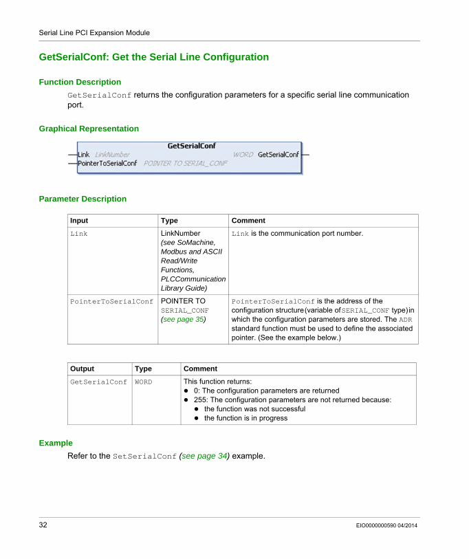
Function DescriptionGetSerialConf returns the configuration parameters for a specific serial line communication port.
Graphical Representation
Parameter Description
ExampleRefer to the SetSerialConf (see page 34) example.
Input Type Comment
Link LinkNumber (see SoMachine, Modbus and ASCII Read/Write Functions, PLCCommunication Library Guide)
Link is the communication port number.
PointerToSerialConf POINTER TO SERIAL_CONF (see page 35)
PointerToSerialConf is the address of the configuration structure (variable of SERIAL_CONF type) in which the configuration parameters are stored. The ADR standard function must be used to define the associated pointer. (See the example below.)
Output Type Comment
GetSerialConf WORD This function returns:0: The configuration parameters are returned255: The configuration parameters are not returned because:
the function was not successfulthe function is in progress
32 EIO0000000590 04/2014
Serial Line PCI Expansion Module
SetSerialConf: Change the Serial Line Configuration
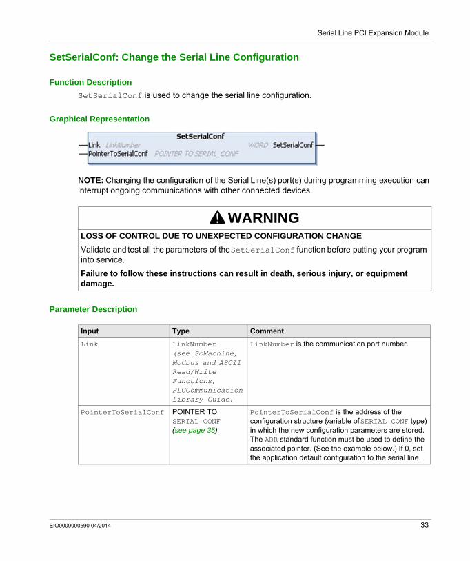
Function DescriptionSetSerialConf is used to change the serial line configuration.
Graphical Representation
NOTE: Changing the configuration of the Serial Line(s) port(s) during programming execution can interrupt ongoing communications with other connected devices.
Parameter Description
WARNINGLOSS OF CONTROL DUE TO UNEXPECTED CONFIGURATION CHANGEValidate and test all the parameters of the SetSerialConf function before putting your program into service.
Failure to follow these instructions can result in death, serious injury, or equipment damage.
Input Type Comment
Link LinkNumber (see SoMachine, Modbus and ASCII Read/Write Functions, PLCCommunication Library Guide)
LinkNumber is the communication port number.
PointerToSerialConf POINTER TO SERIAL_CONF (see page 35)
PointerToSerialConf is the address of the configuration structure (variable of SERIAL_CONF type) in which the new configuration parameters are stored. The ADR standard function must be used to define the associated pointer. (See the example below.) If 0, set the application default configuration to the serial line.
EIO0000000590 04/2014 33
Serial Line PCI Expansion Module
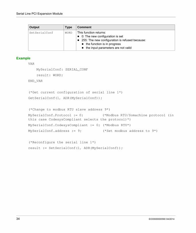
ExampleVAR
MySerialConf: SERIAL_CONF
result: WORD;
END_VAR
(*Get current configuration of serial line 1*)
GetSerialConf(1, ADR(MySerialConf));
(*Change to modbus RTU slave address 9*)
MySerialConf.Protocol := 0; (*Modbus RTU/Somachine protocol (in this case CodesysCompliant selects the protocol)*)
MySerialConf.CodesysCompliant := 0; (*Modbus RTU*)
MySerialConf.address := 9; (*Set modbus address to 9*)
(*Reconfigure the serial line 1*)
result := SetSerialConf(1, ADR(MySerialConf));
Output Type Comment
SetSerialConf WORD This function returns:0: The new configuration is set255: The new configuration is refused because:
the function is in progressthe input parameters are not valid
34 EIO0000000590 04/2014
Serial Line PCI Expansion Module
SERIAL_CONF: Structure of the Serial Line Configuration Data Type
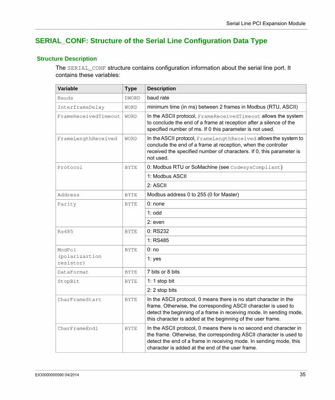
Structure DescriptionThe SERIAL_CONF structure contains configuration information about the serial line port. It contains these variables:
Variable Type Description
Bauds DWORD baud rate
InterframeDelay WORD minimum time (in ms) between 2 frames in Modbus (RTU, ASCII)
FrameReceivedTimeout WORD In the ASCII protocol, FrameReceivedTimeout allows the system to conclude the end of a frame at reception after a silence of the specified number of ms. If 0 this parameter is not used.
FrameLengthReceived WORD In the ASCII protocol, FrameLengthReceived allows the system to conclude the end of a frame at reception, when the controller received the specified number of characters. If 0, this parameter is not used.
Protocol BYTE 0: Modbus RTU or SoMachine (see CodesysCompliant)
1: Modbus ASCII
2: ASCII
Address BYTE Modbus address 0 to 255 (0 for Master)
Parity BYTE 0: none
1: odd
2: even
Rs485 BYTE 0: RS232
1: RS485
ModPol (polarizartion resistor)
BYTE 0: no
1: yes
DataFormat BYTE 7 bits or 8 bits
StopBit BYTE 1: 1 stop bit
2: 2 stop bits
CharFrameStart BYTE In the ASCII protocol, 0 means there is no start character in the frame. Otherwise, the corresponding ASCII character is used to detect the beginning of a frame in receiving mode. In sending mode, this character is added at the beginning of the user frame.
CharFrameEnd1 BYTE In the ASCII protocol, 0 means there is no second end character in the frame. Otherwise, the corresponding ASCII character is used to detect the end of a frame in receiving mode. In sending mode, this character is added at the end of the user frame.
EIO0000000590 04/2014 35
Serial Line PCI Expansion Module
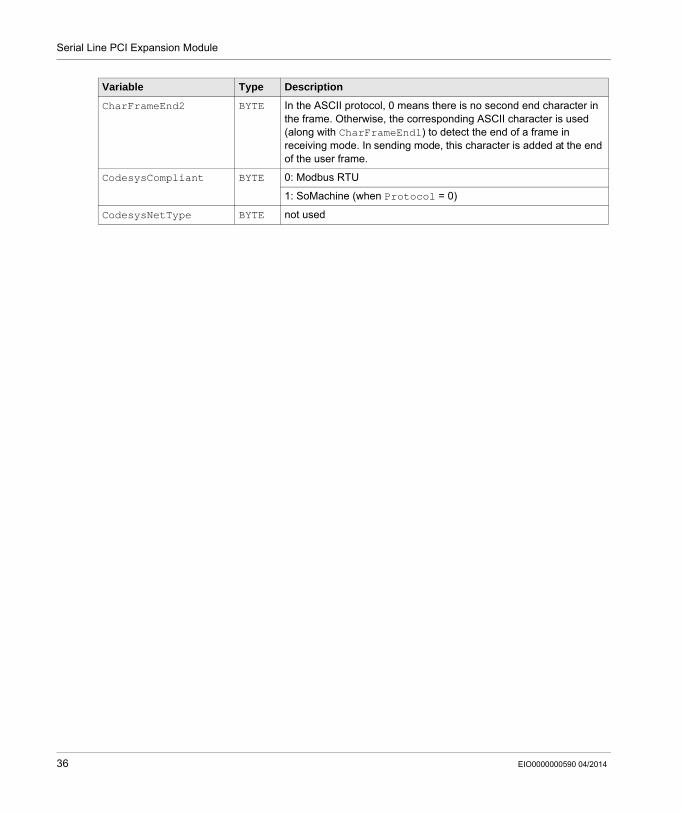
CharFrameEnd2 BYTE In the ASCII protocol, 0 means there is no second end character in the frame. Otherwise, the corresponding ASCII character is used (along with CharFrameEnd1) to detect the end of a frame in receiving mode. In sending mode, this character is added at the end of the user frame.
CodesysCompliant BYTE 0: Modbus RTU
1: SoMachine (when Protocol = 0)
CodesysNetType BYTE not used
Variable Type Description
36 EIO0000000590 04/2014
Modicon TM5Profibus DP Slave PCI Expansion ModuleEIO0000000590 04/2014
Profibus DP Slave PCI Expansion Module
Chapter 3Profibus DP Slave PCI Expansion Module
IntroductionThis chapter describes how to configure the TM5PCDPS Profibus DP Slave PCI Expansion Module.
What Is in This Chapter?This chapter contains the following sections:
Section Topic Page
3.1 Profibus DP Slave PCI Expansion Module Configuration 38
3.2 Data Exchange 43
3.3 Diagnostic 48
EIO0000000590 04/2014 37
Profibus DP Slave PCI Expansion Module
Profibus DP Slave PCI Expansion Module Configuration
Section 3.1Profibus DP Slave PCI Expansion Module Configuration
IntroductionThis section describes the configuration of Profibus DP Slave PCI expansion modules.
What Is in This Section?This section contains the following topics:
Topic Page
Add a Profibus DP Slave PCI Expansion Module 39
Configure the Profibus DP Slave PCI Expansion Module 40
Input / Output Devices Objects 41
38 EIO0000000590 04/2014
Profibus DP Slave PCI Expansion Module
Add a Profibus DP Slave PCI Expansion Module
OverviewWith the Profibus protocol the data is exchanged according to the master-slave principle. Only the master can initialize communication. The slaves respond to requests from masters. Several masters can coexist on the same bus. In this case, the slave I/O can be read by all the masters. However, a single master has write access to the outputs. The number of data items exchanged is defined during the configuration.
For the Profibus Master, the GSD file of the TM5 Profibus DP PCI module is available on www.schneider-electric.com.
There are 2 types of exchange services supported by this module:I/O cyclic frames exchanges (see page 44)acyclic data exchanges with Profibus DPV1 function (see page 46)
Add a Profibus DP Slave PCI Expansion ModuleAdd a Profibus DP slave PCI expansion module to your project, as described in the Add a PCI Expansion Module chapter (see page 11), by selecting the TM5PCDPS module.
NOTE: Adding Profibus increases the associated task cycle time by several milliseconds and the starting time by several seconds.
EIO0000000590 04/2014 39
Profibus DP Slave PCI Expansion Module
Configure the Profibus DP Slave PCI Expansion Module
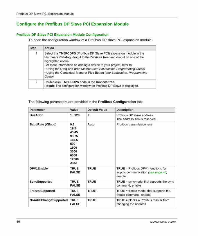
Profibus DP Slave PCI Expansion Module ConfigurationTo open the configuration window of a Profibus DP slave PCI expansion module:
The following parameters are provided in the Profibus Configuration tab:
Step Action
1 Select the TM5PCDPS (Profibus DP Slave PCI) expansion module in the Hardware Catalog, drag it to the Devices tree, and drop it on one of the highlighted nodes.For more information on adding a device to your project, refer to:• Using the Drag-and-drop Method (see SoMachine, Programming Guide)• Using the Contextual Menu or Plus Button (see SoMachine, Programming Guide)
2 Double-click TM5PCDPS node in the Devices tree.Result: The configuration window for Profibus DP Slave is displayed.
Parameter Value Default Value Description
BusAddr 1...126 2 Profibus DP slave address.The address 126 is reserved.
BaudRate (KBaud) 9.619.245.4593.75187.550015003000600012000Auto
Auto Profibus transmission rate
DPV1Enable TRUEFALSE
TRUE TRUE = Profibus DPV1 functions for acyclic communication (see page 46) enable
SyncSupported TRUEFALSE
TRUE TRUE = sync mode, that supports the sync command, enable
FreezeSupported TRUEFALSE
TRUE TRUE = freeze mode, that supports the freeze command, enable
NoAddrChangeSupported TRUEFALSE
TRUE TRUE = blocks a Profibus master from changing the address
40 EIO0000000590 04/2014
Profibus DP Slave PCI Expansion Module
Input / Output Devices Objects
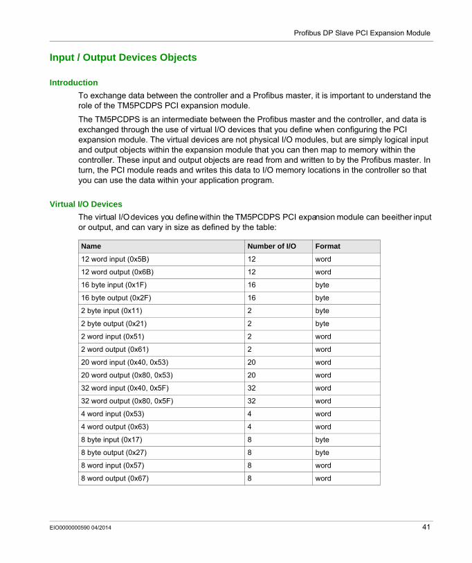
IntroductionTo exchange data between the controller and a Profibus master, it is important to understand the role of the TM5PCDPS PCI expansion module.
The TM5PCDPS is an intermediate between the Profibus master and the controller, and data is exchanged through the use of virtual I/O devices that you define when configuring the PCI expansion module. The virtual devices are not physical I/O modules, but are simply logical input and output objects within the expansion module that you can then map to memory within the controller. These input and output objects are read from and written to by the Profibus master. In turn, the PCI module reads and writes this data to I/O memory locations in the controller so that you can use the data within your application program.
Virtual I/O DevicesThe virtual I/O devices you define within the TM5PCDPS PCI expansion module can be either input or output, and can vary in size as defined by the table:
Name Number of I/O Format
12 word input (0x5B) 12 word
12 word output (0x6B) 12 word
16 byte input (0x1F) 16 byte
16 byte output (0x2F) 16 byte
2 byte input (0x11) 2 byte
2 byte output (0x21) 2 byte
2 word input (0x51) 2 word
2 word output (0x61) 2 word
20 word input (0x40, 0x53) 20 word
20 word output (0x80, 0x53) 20 word
32 word input (0x40, 0x5F) 32 word
32 word output (0x80, 0x5F) 32 word
4 word input (0x53) 4 word
4 word output (0x63) 4 word
8 byte input (0x17) 8 byte
8 byte output (0x27) 8 byte
8 word input (0x57) 8 word
8 word output (0x67) 8 word
EIO0000000590 04/2014 41

Profibus DP Slave PCI Expansion Module
Once you have defined these virtual input and/or output devices within the TM5PCDPS PCI expansion module, you can then map these devices to memory locations within the controller. The type of memory objects you map these virtual I/O devices to depends on the type of exchange you define between the master and the slave.
42 EIO0000000590 04/2014
Profibus DP Slave PCI Expansion Module
Data Exchange
Section 3.2Data Exchange
IntroductionThis section provides further information on the exchange of data between the TM5PCDPS Profibus DP Slave PCI expansion module and the Profibus master.
What Is in This Section?This section contains the following topics:
Topic Page
I/O Cyclic Exchange 44
Acyclic Exchange with Profibus DPV1 Functions 46
EIO0000000590 04/2014 43
Profibus DP Slave PCI Expansion Module
I/O Cyclic Exchange
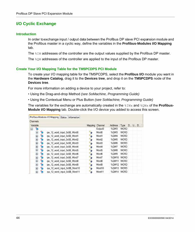
IntroductionIn order to exchange input / output data between the Profibus DP slave PCI expansion module and the Profibus master in a cyclic way, define the variables in the Profibus-Modules I/O Mapping tab.
The %IW addresses of the controller are the output values supplied by the Profibus DP master.
The %QW addresses of the controller are applied to the input of the Profibus DP master.
Create Your I/O Mapping Table for the TM5PCDPS PCI ModuleTo create your I/O mapping table for the TM5PCDPS, select the Profibus I/O module you want in the Hardware Catalog, drag it to the Devices tree, and drop it on the TM5PCDPS node of the Devices tree.
For more information on adding a device to your project, refer to:
• Using the Drag-and-drop Method (see SoMachine, Programming Guide)
• Using the Contextual Menu or Plus Button (see SoMachine, Programming Guide)
The variables for the exchange are automatically created in the %IWx and %QWx of the Profibus-Module I/O Mapping tab. Double-click the I/O device you added to access this screen.
44 EIO0000000590 04/2014
Profibus DP Slave PCI Expansion Module
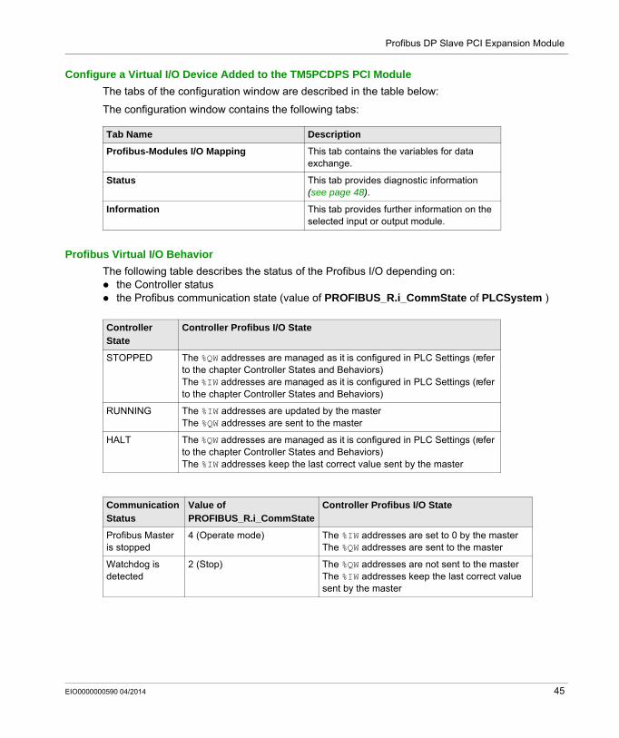
Configure a Virtual I/O Device Added to the TM5PCDPS PCI ModuleThe tabs of the configuration window are described in the table below:
The configuration window contains the following tabs:
Profibus Virtual I/O BehaviorThe following table describes the status of the Profibus I/O depending on:
the Controller statusthe Profibus communication state (value of PROFIBUS_R.i_CommState of PLCSystem )
Tab Name Description
Profibus-Modules I/O Mapping This tab contains the variables for data exchange.
Status This tab provides diagnostic information (see page 48).
Information This tab provides further information on the selected input or output module.
Controller State
Controller Profibus I/O State
STOPPED The %QW addresses are managed as it is configured in PLC Settings (refer to the chapter Controller States and Behaviors)The %IW addresses are managed as it is configured in PLC Settings (refer to the chapter Controller States and Behaviors)
RUNNING The %IW addresses are updated by the masterThe %QW addresses are sent to the master
HALT The %QW addresses are managed as it is configured in PLC Settings (refer to the chapter Controller States and Behaviors)The %IW addresses keep the last correct value sent by the master
Communication Status
Value of PROFIBUS_R.i_CommState
Controller Profibus I/O State
Profibus Master is stopped
4 (Operate mode) The %IW addresses are set to 0 by the masterThe %QW addresses are sent to the master
Watchdog is detected
2 (Stop) The %QW addresses are not sent to the masterThe %IW addresses keep the last correct value sent by the master
EIO0000000590 04/2014 45
Profibus DP Slave PCI Expansion Module
Acyclic Exchange with Profibus DPV1 Functions
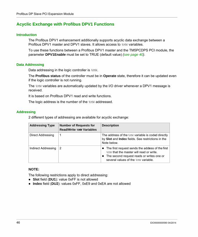
IntroductionThe Profibus DPV1 enhancement additionally supports acyclic data exchange between a Profibus DPV1 master and DPV1 slaves. It allows access to %MW variables.
To use these functions between a Profibus DPV1 master and the TM5PCDPS PCI module, the parameter DPV1Enable must be set to TRUE (default value) (see page 40).
Data AddressingData addressing in the logic controller is %MW.
The Profibus status of the controller must be in Operate state, therefore it can be updated even if the logic controller is not running.
The %MW variables are automatically updated by the I/O driver whenever a DPV1 message is received.
It is based on Profibus DPV1 read and write functions.
The logic address is the number of the %MW addressed.
Addressing2 different types of addressing are available for acyclic exchange:
NOTE: The following restrictions apply to direct addressing:
Slot field (DU1): value 0xFF is not allowedIndex field (DU2): values 0xFF, 0xE9 and 0xEA are not allowed
Addressing Type Number of Requests for Read/Write %MW Variables
Description
Direct Addressing 1 The address of the %MW variable is coded directly by Slot and Index fields. See restrictions in the Note below.
Indirect Addressing 2 The first request sends the address of the first %MW that the master will read or write.The second request reads or writes one or several values of the %MW variable.
46 EIO0000000590 04/2014
Profibus DP Slave PCI Expansion Module
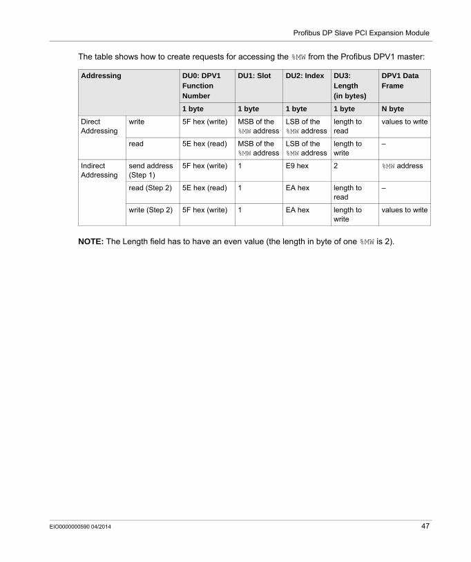
The table shows how to create requests for accessing the %MW from the Profibus DPV1 master:
NOTE: The Length field has to have an even value (the length in byte of one %MW is 2).
Addressing DU0: DPV1 Function Number
DU1: Slot DU2: Index DU3: Length (in bytes)
DPV1 Data Frame
1 byte 1 byte 1 byte 1 byte N byte
Direct Addressing
write 5F hex (write) MSB of the %MW address
LSB of the %MW address
length to read
values to write
read 5E hex (read) MSB of the %MW address
LSB of the %MW address
length to write
–
Indirect Addressing
send address (Step 1)
5F hex (write) 1 E9 hex 2 %MW address
read (Step 2) 5E hex (read) 1 EA hex length to read
–
write (Step 2) 5F hex (write) 1 EA hex length to write
values to write
EIO0000000590 04/2014 47
Profibus DP Slave PCI Expansion Module
Diagnostic
Section 3.3Diagnostic
Diagnostic Information
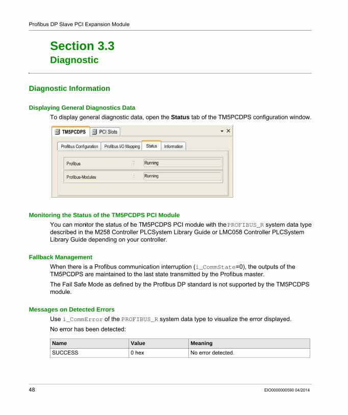
Displaying General Diagnostics DataTo display general diagnostic data, open the Status tab of the TM5PCDPS configuration window.
Monitoring the Status of the TM5PCDPS PCI ModuleYou can monitor the status of the TM5PCDPS PCI module with the PROFIBUS_R system data type described in the M258 Controller PLCSystem Library Guide or LMC058 Controller PLCSystem Library Guide depending on your controller.
Fallback ManagementWhen there is a Profibus communication interruption (i_CommState=0), the outputs of the TM5PCDPS are maintained to the last state transmitted by the Profibus master.
The Fail Safe Mode as defined by the Profibus DP standard is not supported by the TM5PCDPS module.
Messages on Detected ErrorsUse i_CommError of the PROFIBUS_R system data type to visualize the error displayed.
No error has been detected:
Name Value Meaning
SUCCESS 0 hex No error detected.
48 EIO0000000590 04/2014
Profibus DP Slave PCI Expansion Module
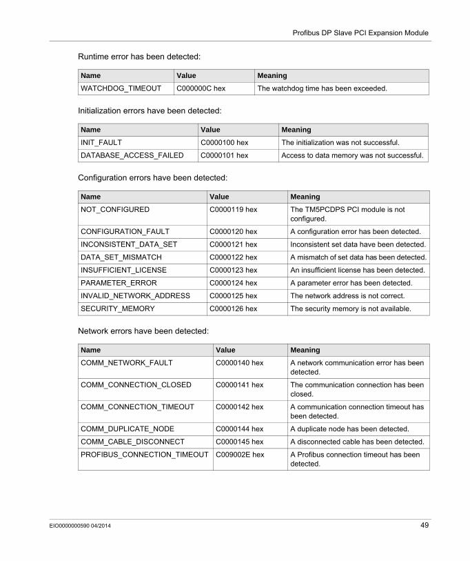
Runtime error has been detected:
Initialization errors have been detected:
Configuration errors have been detected:
Network errors have been detected:
Name Value Meaning
WATCHDOG_TIMEOUT C000000C hex The watchdog time has been exceeded.
Name Value Meaning
INIT_FAULT C0000100 hex The initialization was not successful.
DATABASE_ACCESS_FAILED C0000101 hex Access to data memory was not successful.
Name Value Meaning
NOT_CONFIGURED C0000119 hex The TM5PCDPS PCI module is not configured.
CONFIGURATION_FAULT C0000120 hex A configuration error has been detected.
INCONSISTENT_DATA_SET C0000121 hex Inconsistent set data have been detected.
DATA_SET_MISMATCH C0000122 hex A mismatch of set data has been detected.
INSUFFICIENT_LICENSE C0000123 hex An insufficient license has been detected.
PARAMETER_ERROR C0000124 hex A parameter error has been detected.
INVALID_NETWORK_ADDRESS C0000125 hex The network address is not correct.
SECURITY_MEMORY C0000126 hex The security memory is not available.
Name Value Meaning
COMM_NETWORK_FAULT C0000140 hex A network communication error has been detected.
COMM_CONNECTION_CLOSED C0000141 hex The communication connection has been closed.
COMM_CONNECTION_TIMEOUT C0000142 hex A communication connection timeout has been detected.
COMM_DUPLICATE_NODE C0000144 hex A duplicate node has been detected.
COMM_CABLE_DISCONNECT C0000145 hex A disconnected cable has been detected.
PROFIBUS_CONNECTION_TIMEOUT C009002E hex A Profibus connection timeout has been detected.
EIO0000000590 04/2014 49

Profibus DP Slave PCI Expansion Module
50 EIO0000000590 04/2014
Modicon TM5GlossaryEIO0000000590 04/2014
Glossary
AASCII
(American standard code for Information Interchange) A protocol for representing alphanumeric characters (letters, numbers, certain graphics, and control characters).
Cconfiguration
The arrangement and interconnection of hardware components within a system and the hardware and software parameters that determine the operating characteristics of the system.
controllerAutomates industrial processes (also known as programmable logic controller or programmable controller).
CRC(cyclical redundancy check) A method used to determine the validity of a communication transmission. The transmission contains a bit field that constitutes a checksum. The message is used to calculate the checksum by the transmitter according to the content of the message. Receiving nodes, then recalculate the field in the same manner. Any discrepancy in the value of the 2 CRC calculations indicates that the transmitted message and the received message are different.
Eelectronic module
In a programmable controller system, most electronic modules directly interface to the sensors, actuators, and external devices of the machine/process. This electronic module is the component that mounts in a bus base and provides electrical connections between the controller and the field devices. Electronic modules are offered in a variety of signal levels and capacities. (Some electronic modules are not I/O interfaces, including power distribution modules and transmitter/receiver modules.)
EIO0000000590 04/2014 51
Glossary
Ffunction block
A programming unit that has 1 or more inputs and returns 1 or more outputs. FBs are called through an instance (function block copy with dedicated name and variables) and each instance has a persistent state (outputs and internal variables) from 1 call to the other.
Examples: timers, counters
HHMI
(human machine interface) An operator interface (usually graphical) for human control over industrial equipment.
II/O
(input/output)
LLSB
(least significant bit/byte) The part of a number, address, or field that is written as the right-most single value in conventional hexadecimal or binary notation.
MMagelis
The commercial name for Schneider Electric’s range of HMI terminals.
ModbusThe protocol that allows communications between many devices connected to the same network.
ms(millisecond)
MSB(most significant bit/byte The part of a number, address, or field that is written as the left-most single value in conventional hexadecimal or binary notation.
52 EIO0000000590 04/2014
Glossary
NNAK
(negative acknowledge)
networkA system of interconnected devices that share a common data path and protocol for communications.
nodeAn addressable device on a communication network.
PPCI
(peripheral component interconnect) An industry-standard bus for attaching peripherals.
Profibus DP(Profibus decentralized peripheral) An open bus system uses an electrical network based on a shielded 2-wire line or an optical network based on a fiber-optic cable. DP transmission allows for high-speed, cyclic exchange of data between the controller CPU and the distributed I/O devices.
RRS-232
A standard type of serial communication bus, based on 3 wires (also known as EIA RS-232C or V.24).
RS-485A standard type of serial communication bus, based on 2 wires (also known as EIA RS-485).
Sstring
A variable that is a series of ASCII characters.
EIO0000000590 04/2014 53

Glossary
54 EIO0000000590 04/2014
Modicon TM5IndexEIO0000000590 04/2014
Index
Aacyclic exchange, 46ASCII Manager, 17
Ccyclic exchange, 44
Ddiagnostic information, 48DPV1
Profibus functions, 46
GGetSerialConf, 32
MModbus Ioscanner, 20Modbus Manager, 26
SSerial Line
ASCII Manager, 17Modbus Manager, 26
SERIAL_CONF, 35SetSerialConf, 33
TTM5 PCI, 9TM5PCDPS, 9TM5PCRS2, 9TM5PCRS4, 9
EIO0000000590 04/2014
55
Index
56 EIO0000000590 04/2014


