Embed Size (px)
Citation preview
201 (2007) 7652–7662www.elsevier.com/locate/surfcoat
Surface & Coatings Technology
Modelling, production and characterisation of duplex coatings (HVOF andPVD) on Ti–6Al–4V substrate for specific mechanical applications
E. Bemporad a,⁎, M. Sebastiani a, F. Casadei b, F. Carassiti a
a University of Rome “ROMA TRE”, Mechanical and Industrial Engineering Department, Via Vasca Navale 79, 00146 Rome, Italyb Centro Sviluppo Materiali SpA, Surface Engineering and Ceramic Unit, Via di Castel Romano 100, Rome, 00128, Italy
Received 6 November 2006; accepted in revised form 23 February 2007Available online 7 March 2007
Abstract
Titanium and its alloys are extensively used in aerospace and mechanical application because of their high specific strength and high fracturetoughness. On the other hand, titanium alloys often show low hardness, very low load bearing capacity and poor resistance to sliding wear, so thatsurface properties improvement is in many cases recommended, often by PVD processes.
Present work deals with design, production and experimental characterisation of a duplex coating for Ti–6Al–4V components, consisting of athick WC–Co interlayer deposited by High Velocity Oxygen Fuel (HVOF), followed by a Ti/TiN multilayer (two layer pairs, including the Tibond layer) deposited by Cathodic Arc Evaporation (CAE) PVD.
Before deposition, a preliminary coating design was carried out, based on finite element simulation of residual stress fields on the PVD coatingfor a range of configurations of its multilayered structure (Ti buffer layer position and thickness).
Morphological properties of the produced coatings (thickness, grain size, surface defect size distribution, roughness) were measured by meansof Digital Optical (DOM), Scanning Electron (SEM), Atomic Force (AFM) and Focused Ion Beam (FIB) microscopy techniques.
Coatings mechanical properties were investigated by micro-scratch testing, Rockwell C adhesion test, nano-indentation techniques, Vickers/Knoop micro-hardness testing and composite hardness modelling.
Results showed that the use of a CAE-PVD multilayer Ti/TiN top layer, whose thicknesses and Ti distribution were suggested by finite elementmodelling optimisation, leads to a significant increase (45%) in adhesion of PVD coating to the HVOF layer and load bearing capacity of thecoated system, compared to monolayered TiN, without reduction in superficial hardness and load bearing capacity.© 2007 Elsevier B.V. All rights reserved.
Keywords: Duplex coating; PVD-HVOF; Multilayer; Adhesion
1. Introduction
An excellent combination of high specific strength, fracturetoughness, corrosion resistance and thermal stability makesTitanium and its alloys particularly suitable candidates forbiomedical, aerospace and extreme mechanical applications [1].
Nevertheless, they also exhibit several disadvantages: lowhardness, very low load bearing capacity and poor resistance tosliding wear. Plasma nitriding and PVD coating (very oftenTitanium Nitride, TiN) are commercial methods for improving
⁎ Corresponding author. Tel.: +39 06 55173293; fax: +39 06 55173256.E-mail address: [email protected] (E. Bemporad).
0257-8972/$ - see front matter © 2007 Elsevier B.V. All rights reserved.doi:10.1016/j.surfcoat.2007.02.041
properties in those applications which involve high contactstresses and severe sliding wear [2,3].
However, a very thin, hard layer on a Titanium alloysubstrate (even if hardened by plasma nitriding) cannot lead toa mechanically improved structure: differences in bothcoating's and substrate's hardness and Young's modulus donot provide a good distribution of contact stresses; in someapplication the coated system can behave even worse than theuncoated one [2].
Moreover, Titanium alloys often show poor adhesion withrespect to PVD coatings, such that expensive surface pre-treatment before deposition is often needed [3]. Adhesion canbe enhanced by deposition of multilayered PVD metal/ceramicsystems [4–8]: as an example, several studies [9–11] showed
7653E. Bemporad et al. / Surface & Coatings Technology 201 (2007) 7652–7662
that the interposition of a Ti interlayer with a thickness of 0.5–1.5 μm accommodates the PVD TiN internal stresses and allowsthicker composite coatings to be produced, with significantimprovements in toughness, adhesion, impact resistance andcorrosion resistance; however, the presence of a relatively thickTi buffer layer often involves a significant reduction in hardnessand wear resistance of the PVD coating.
To overcome these limits (bad adhesion and differences instiffness), one possible solution is to replace plasma nitridingwith a harder and also stiffer (compared to the nitrided layer)High Velocity Oxygen Fuel (HVOF) interlayer, providing abetter distribution of contact stresses, avoiding plastic defor-mation of the substrate.
In a previous published paper [12], authors showed that aneffective configuration in terms of enhanced load bearingcapacity on Ti–6Al–4V substrates can be achieved by a duplexcoating system, consisting of an HVOF thermally sprayed WC–Co thick interlayer and a Cathodic Arc Evaporation (CAE) PVD(TiN or CrN) thin top layer: nevertheless, some problems inPVD coating toughness and adhesion still remain and a furtheroptimisation is clearly necessary.
The idea for the present work was therefore to modify thethin top layer by using a Ti–TiN multilayer coating, consistingof a Ti interlayer between two TiN layers (and a Ti bond layerbetween the HVOF and the first TiN layers), with the aim ofincreasing adhesion and toughness.
An optimisation procedure has been set up, based on finiteelement modelling of residual stress distribution, in order todetermine the optimal thickness and position of the Ti bufferlayer, allowing increased adhesion without loss of hardness andload bearing capacity.
2. Finite element modelling based design of the PVD Ti/TiNmultilayer coating
Delamination failure of PVD coatings is generally oftencaused by high interfacial residual stress fields resulting fromthe deposition process parameters and from poor adhesion.
Residual stresses in PVD coatings [13–17] occur from thecontribution and interaction of two main factors: (A) thermalstress and (B) intrinsic stress.
(A) Thermal stress [18] arises from differences in thermalexpansion coefficient between coating and substrate: during finalcooling from deposition (TD) to room temperature (Tr) a misfitstrain e arises, leading to a residual stress given by the followingequation, which refers to a state of uniform biaxial stress:
rth ¼ Ef
1� vf
� �� ec Ef
1� vf
� �� aS � afð Þ � Tr � TDð Þ ð1Þ
where Ef and νf are Young's modulus and Poisson's ratio of thefilm, respectively; αS and αf are the thermal expansion coefficientsof the substrate and film, respectively.
PVD ceramic coatings (such as Titanium Nitride) usuallyexhibit a compressive in-plane thermal stress increasing withdeposition temperature, as a consequence of their low thermalexpansion coefficient [15–18].
(B) Intrinsic stresses occur as a consequence of depositionparameters induced crystallographic growth orientation:according to models available in literature, they can beexpressed as a function of the ionic and atomic flux arrivingat the substrate during deposition, and of the energy distributionof the bombarding ionic species [13].
Usually the resulting residual stress field is approximatelycalculated by the sum of the two sources:
rtot ¼ ri þ rth ð2Þ
CAE-PVD coatings always show high in-plane compressiveintrinsic stress [14–17], which also involves high induced normalto surface tensile stress (i.e. in correspondence of sample edgeand/or internal cracks [22]), and high interfacial shear stress.
The use of ductile Titanium interlayers in multilayer Ti/TiNcoatings can be effective for the residual stresses relaxation, inorder to improve coating-substrate interfacial adhesion andimpact wear resistance, but the presence of a Ti interlayerinvolves also a reduction in mechanical properties of the coating[11], such as hardness and possibly sliding and abrasive wearresistance: an optimisation procedure is therefore necessary.
In the case of HVOF coatings, residual stresses also arisefrom two sources [19–21]: the quenching stress, due to theinstantaneous cooling of impacting droplets, and thermal stress,due to differential thermal contraction.
Quenching stresses at room temperature (Tr) can beevaluated by the following equation [19]:
rq ¼ E⁎c Trð Þ
Z bTm
TS
aC Tð ÞdT ð3Þ
E⁎C Trð Þ is the actual elastic modulus of the coating at room
temperature, as determined by experimental measurements, and ba temperature reduction coefficient (approximately equal to 0.6)adopted to take into account stress relaxation phenomena such asyielding or creep [20]. In case of ceramic-based coatings, a verymarked reduction in quenching stress has also been observed [20],produced as a consequence of extensive micro-cracking ofindividual lamellae after droplet impact. As an example, a residualtensile stress of about 10MPa can be experimentally evaluated byin situ curvature measurements for plasma-sprayed alumina [21],while quenching stresses of the order of several GPa would beobtained simply by applying Eq. (3), that is considered to be validonly for metallic sprayed materials.
Considering a duplex HVOF and PVD coating system,complex residual stress interactions are likely to coexist; byadopting realistic simplification hypotheses, a predictive modelcan be developed for qualitative stress estimation and preliminaryprocess optimisation.
The objective of this numerical study was to determine theinfluence of the Ti buffer layer position and thickness on theinterfacial residual stress field arising from the depositionprocesses.
Using a commercial finite element software, Abaqus6.5,the duplex systems under examination were modelled asexplained in Fig. 1 and Table 1: all models comprise a plane
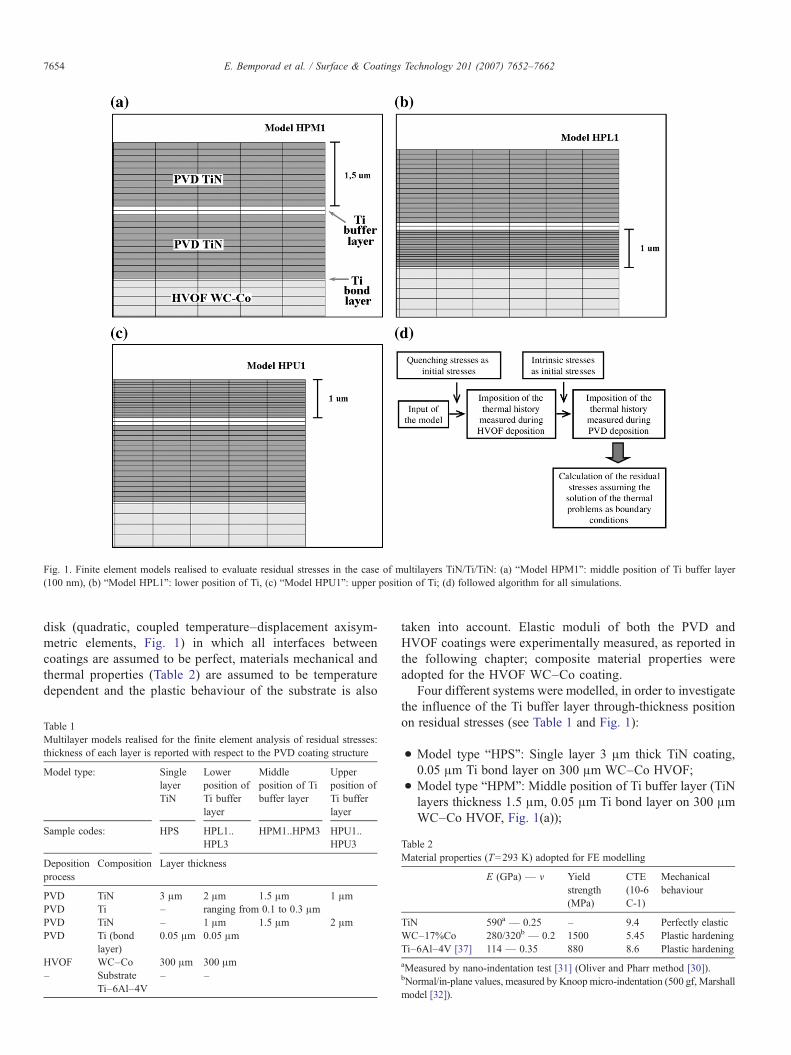
Fig. 1. Finite element models realised to evaluate residual stresses in the case of multilayers TiN/Ti/TiN: (a) “Model HPM1”: middle position of Ti buffer layer(100 nm), (b) “Model HPL1”: lower position of Ti, (c) “Model HPU1”: upper position of Ti; (d) followed algorithm for all simulations.
7654 E. Bemporad et al. / Surface & Coatings Technology 201 (2007) 7652–7662
disk (quadratic, coupled temperature–displacement axisym-metric elements, Fig. 1) in which all interfaces betweencoatings are assumed to be perfect, materials mechanical andthermal properties (Table 2) are assumed to be temperaturedependent and the plastic behaviour of the substrate is also
Table 1Multilayer models realised for the finite element analysis of residual stresses:thickness of each layer is reported with respect to the PVD coating structure
Model type: SinglelayerTiN
Lowerposition ofTi bufferlayer
Middleposition of Tibuffer layer
Upperposition ofTi bufferlayer
Sample codes: HPS HPL1..HPL3
HPM1..HPM3 HPU1..HPU3
Depositionprocess
Composition Layer thickness
PVD TiN 3 μm 2 μm 1.5 μm 1 μmPVD Ti – ranging from 0.1 to 0.3 μmPVD TiN – 1 μm 1.5 μm 2 μmPVD Ti (bond
layer)0.05 μm 0.05 μm
HVOF WC–Co 300 μm 300 μm– Substrate
Ti–6Al–4V– –
taken into account. Elastic moduli of both the PVD andHVOF coatings were experimentally measured, as reported inthe following chapter; composite material properties wereadopted for the HVOF WC–Co coating.
Four different systems were modelled, in order to investigatethe influence of the Ti buffer layer through-thickness positionon residual stresses (see Table 1 and Fig. 1):
• Model type “HPS”: Single layer 3 μm thick TiN coating,0.05 μm Ti bond layer on 300 μm WC–Co HVOF;
• Model type “HPM”: Middle position of Ti buffer layer (TiNlayers thickness 1.5 μm, 0.05 μm Ti bond layer on 300 μmWC–Co HVOF, Fig. 1(a));
Table 2Material properties (T=293 K) adopted for FE modelling
E (GPa) — ν Yieldstrength(MPa)
CTE(10-6C-1)
Mechanicalbehaviour
TiN 590a — 0.25 – 9.4 Perfectly elasticWC–17%Co 280/320b — 0.2 1500 5.45 Plastic hardeningTi–6Al–4V [37] 114 — 0.35 880 8.6 Plastic hardeningaMeasured by nano-indentation test [31] (Oliver and Pharr method [30]).bNormal/in-plane values, measured by Knoopmicro-indentation (500 gf, Marshallmodel [32]).
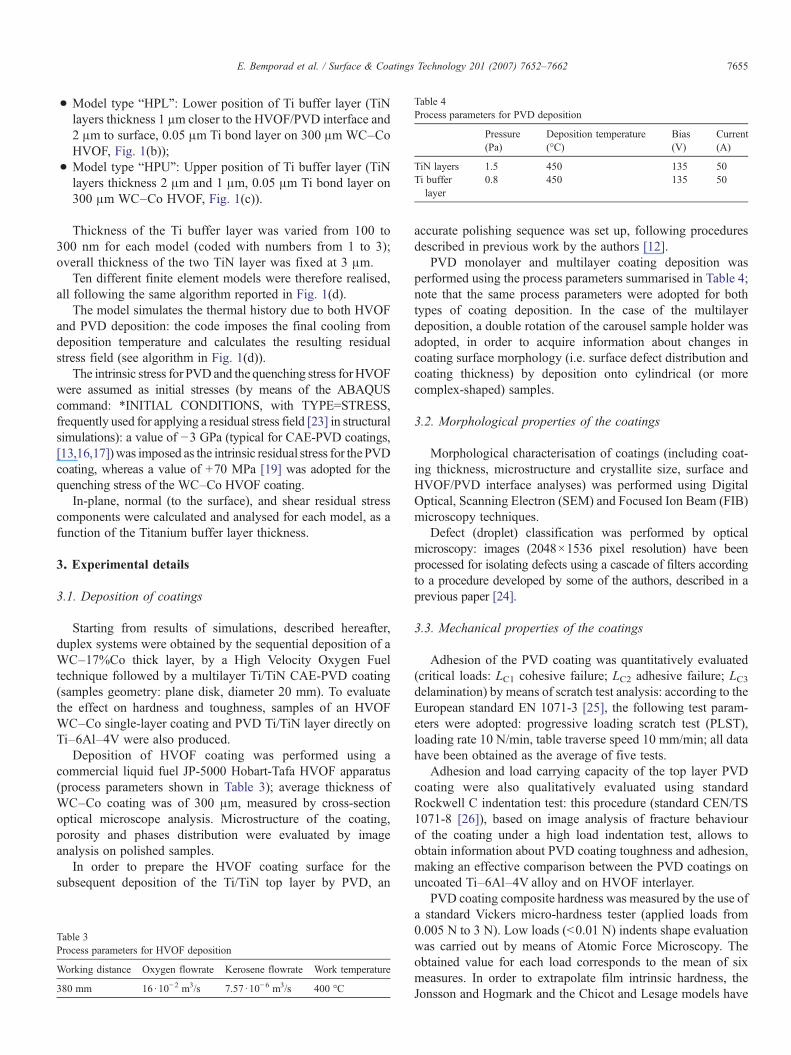
Table 4Process parameters for PVD deposition
Pressure(Pa)
Deposition temperature(°C)
Bias(V)
Current(A)
TiN layers 1.5 450 135 50Ti bufferlayer
0.8 450 135 50
7655E. Bemporad et al. / Surface & Coatings Technology 201 (2007) 7652–7662
• Model type “HPL”: Lower position of Ti buffer layer (TiNlayers thickness 1 µm closer to the HVOF/PVD interface and2 μm to surface, 0.05 μm Ti bond layer on 300 μm WC–CoHVOF, Fig. 1(b));
• Model type “HPU”: Upper position of Ti buffer layer (TiNlayers thickness 2 μm and 1 μm, 0.05 μm Ti bond layer on300 μm WC–Co HVOF, Fig. 1(c)).
Thickness of the Ti buffer layer was varied from 100 to300 nm for each model (coded with numbers from 1 to 3);overall thickness of the two TiN layer was fixed at 3 μm.
Ten different finite element models were therefore realised,all following the same algorithm reported in Fig. 1(d).
The model simulates the thermal history due to both HVOFand PVD deposition: the code imposes the final cooling fromdeposition temperature and calculates the resulting residualstress field (see algorithm in Fig. 1(d)).
The intrinsic stress for PVD and the quenching stress forHVOFwere assumed as initial stresses (by means of the ABAQUScommand: ⁎INITIAL CONDITIONS, with TYPE=STRESS,frequently used for applying a residual stress field [23] in structuralsimulations): a value of −3 GPa (typical for CAE-PVD coatings,[13,16,17])was imposed as the intrinsic residual stress for thePVDcoating, whereas a value of +70 MPa [19] was adopted for thequenching stress of the WC–Co HVOF coating.
In-plane, normal (to the surface), and shear residual stresscomponents were calculated and analysed for each model, as afunction of the Titanium buffer layer thickness.
3. Experimental details
3.1. Deposition of coatings
Starting from results of simulations, described hereafter,duplex systems were obtained by the sequential deposition of aWC–17%Co thick layer, by a High Velocity Oxygen Fueltechnique followed by a multilayer Ti/TiN CAE-PVD coating(samples geometry: plane disk, diameter 20 mm). To evaluatethe effect on hardness and toughness, samples of an HVOFWC–Co single-layer coating and PVD Ti/TiN layer directly onTi–6Al–4V were also produced.
Deposition of HVOF coating was performed using acommercial liquid fuel JP-5000 Hobart-Tafa HVOF apparatus(process parameters shown in Table 3); average thickness ofWC–Co coating was of 300 μm, measured by cross-sectionoptical microscope analysis. Microstructure of the coating,porosity and phases distribution were evaluated by imageanalysis on polished samples.
In order to prepare the HVOF coating surface for thesubsequent deposition of the Ti/TiN top layer by PVD, an
Table 3Process parameters for HVOF deposition
Working distance Oxygen flowrate Kerosene flowrate Work temperature
380 mm 16·10−2 m3/s 7.57 ·10−6 m3/s 400 °C
accurate polishing sequence was set up, following proceduresdescribed in previous work by the authors [12].
PVD monolayer and multilayer coating deposition wasperformed using the process parameters summarised in Table 4;note that the same process parameters were adopted for bothtypes of coating deposition. In the case of the multilayerdeposition, a double rotation of the carousel sample holder wasadopted, in order to acquire information about changes incoating surface morphology (i.e. surface defect distribution andcoating thickness) by deposition onto cylindrical (or morecomplex-shaped) samples.
3.2. Morphological properties of the coatings
Morphological characterisation of coatings (including coat-ing thickness, microstructure and crystallite size, surface andHVOF/PVD interface analyses) was performed using DigitalOptical, Scanning Electron (SEM) and Focused Ion Beam (FIB)microscopy techniques.
Defect (droplet) classification was performed by opticalmicroscopy: images (2048×1536 pixel resolution) have beenprocessed for isolating defects using a cascade of filters accordingto a procedure developed by some of the authors, described in aprevious paper [24].
3.3. Mechanical properties of the coatings
Adhesion of the PVD coating was quantitatively evaluated(critical loads: LC1 cohesive failure; LC2 adhesive failure; LC3delamination) by means of scratch test analysis: according to theEuropean standard EN 1071-3 [25], the following test param-eters were adopted: progressive loading scratch test (PLST),loading rate 10 N/min, table traverse speed 10 mm/min; all datahave been obtained as the average of five tests.
Adhesion and load carrying capacity of the top layer PVDcoating were also qualitatively evaluated using standardRockwell C indentation test: this procedure (standard CEN/TS1071-8 [26]), based on image analysis of fracture behaviourof the coating under a high load indentation test, allows toobtain information about PVD coating toughness and adhesion,making an effective comparison between the PVD coatings onuncoated Ti–6Al–4V alloy and on HVOF interlayer.
PVD coating composite hardness was measured by the use ofa standard Vickers micro-hardness tester (applied loads from0.005 N to 3 N). Low loads (b0.01 N) indents shape evaluationwas carried out by means of Atomic Force Microscopy. Theobtained value for each load corresponds to the mean of sixmeasures. In order to extrapolate film intrinsic hardness, theJonsson and Hogmark and the Chicot and Lesage models have
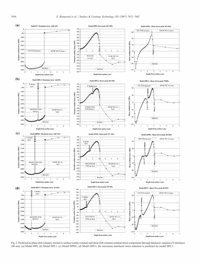
Fig. 2. Predicted in-plane (left column), normal to surface (centre column) and shear (left column) residual stress components through-thickness variation (Ti interlayer100 nm): (a) Model HPS, (b) Model HPL1, (c) Model HPM1, (d) Model HPU1; the maximum interfacial stress reduction is predicted for model HPL1.
7656 E. Bemporad et al. / Surface & Coatings Technology 201 (2007) 7652–7662
7657E. Bemporad et al. / Surface & Coatings Technology 201 (2007) 7652–7662
been used [28,29]; since the HVOF coating is much thicker thanthe PVD ones, the influence of the Ti–6Al–4V substrate wasassumed to be negligible for the in-plane micro-hardness tests.
Intrinsic hardness and reduced modulus of the PVD coatingwere measured by means of nano-indentation testing [30,31]: 50indentation tests (MTS XP-Nanoindenter) were performedadopting the following test parameters [31]: Berkovich indenter,40 mN maximum load, 0,05 1/s constant strain rate, 10 s hold atpeak load for creep, 20 s hold at 90% for thermal drift correction.Oliver and Pharr method was adopted for hardness and elasticmodulus evaluation.
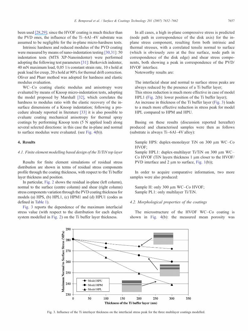
WC–Co coating elastic modulus and anisotropy wereevaluated by means of Knoop micro-indentation tests, adoptingthe model proposed by Marshall [32], which correlates thehardness to modulus ratio with the elastic recovery of the in-surface dimensions of a Knoop indentation; following a pro-cedure already reported in literature [33] it is also possible toevaluate coating mechanical anisotropy for thermal spraycoatings by performing Knoop tests (5 N applied load) alongseveral selected directions: in this case the in-plane and normalto surface modulus were evaluated. (see Fig. 4(b)).
4. Results
4.1. Finite element modelling based design of the Ti/TiN top layer
Results for finite element simulations of residual stressdistribution are shown in terms of residual stress componentsprofile through the coating thickness, with respect to the Ti bufferlayer thickness and position.
In particular, Fig. 2 shows the residual in-plane (left column),normal to the surface (centre column) and shear (right column)stress components variation through the PVD coating thickness formodels (a) HPS, (b) HPL1, (c) HPM1 and (d) HPU1 (codes asdefined in Table 1).
Fig. 3 reports the dependence of the maximum interfacialstress value (with respect to the distribution for each duplexsystem modelled in Fig. 2) on the Ti buffer layer thickness.
Fig. 3. Influence of the Ti interlayer thickness on the interfaci
In all cases, a high in-plane compressive stress is predicted(node path in correspondence of the disk axis) for the in-plane stress component, resulting form both intrinsic andthermal stresses, with a correlated tensile normal to surface(which is obviously zero at the free surface, node path incorrespondence of the disk edge) and shear stress compo-nents, both showing a peak in correspondence of the PVD/HVOF interface.
Noteworthy results are:
The interfacial shear and normal to surface stress peaks arealways reduced by the presence of a Ti buffer layer;This stress reduction is much more effective in case of modelHPL1 (Fig. 2(b): lower position of the Ti buffer layer);An increase in thickness of the Ti buffer layer (Fig. 3) leadsto a much more effective reduction in stress peak for modelHPL compared to HPM and HPU.
Basing on these results (discussion reported hereafter)produced and characterised samples were then as follows(substrate is always Ti–6Al–4V alloy):
Sample HPS: duplex-monolayer TiN on 300 μm WC–CoHVOF;Sample HPL1: duplex-multilayer Ti/TiN on 300 μm WC–Co HVOF (TiN layers thickness 1 μm closer to the HVOF/PVD interface and 2 μm to surface, Fig. 1(b));
In order to acquire comparative information, two moresamples were also produced:
Sample H: only 300 μm WC–Co HVOF;Sample PL1: only multilayer Ti/TiN.
4.2. Morphological properties of the coatings
The microstructure of the HVOF WC–Co coating isshown in Fig. 4(b): the measured mean porosity was
al stress peak for the three multilayer coatings modelled.
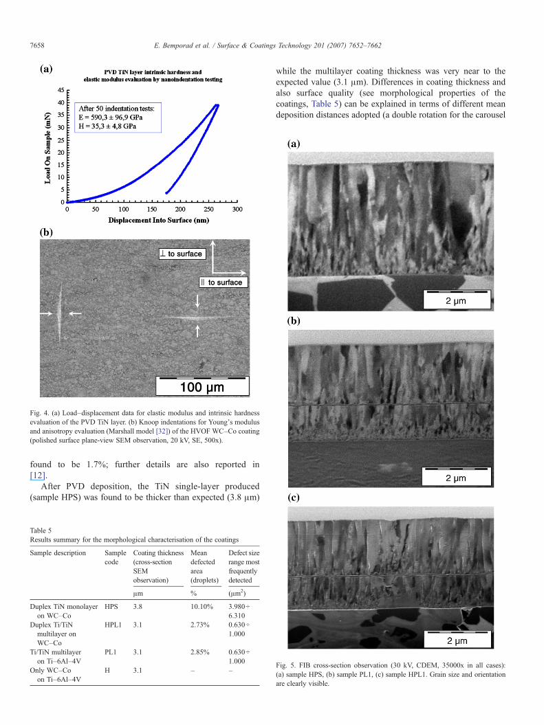
Fig. 4. (a) Load–displacement data for elastic modulus and intrinsic hardnessevaluation of the PVD TiN layer. (b) Knoop indentations for Young's modulusand anisotropy evaluation (Marshall model [32]) of the HVOF WC–Co coating(polished surface plane-view SEM observation, 20 kV, SE, 500x).
7658 E. Bemporad et al. / Surface & Coatings Technology 201 (2007) 7652–7662
found to be 1.7%; further details are also reported in[12].
After PVD deposition, the TiN single-layer produced(sample HPS) was found to be thicker than expected (3.8 μm)
Table 5Results summary for the morphological characterisation of the coatings
Sample description Samplecode
Coating thickness(cross-sectionSEMobservation)
Meandefectedarea(droplets)
Defect sizerange mostfrequentlydetected
μm % (μm2)
Duplex TiN monolayeron WC–Co
HPS 3.8 10.10% 3.980÷6.310
Duplex Ti/TiNmultilayer onWC–Co
HPL1 3.1 2.73% 0.630÷1.000
Ti/TiN multilayeron Ti–6Al–4V
PL1 3.1 2.85% 0.630÷1.000
Only WC–Coon Ti–6Al–4V
H 3.1 – –
while the multilayer coating thickness was very near to theexpected value (3.1 μm). Differences in coating thickness andalso surface quality (see morphological properties of thecoatings, Table 5) can be explained in terms of different meandeposition distances adopted (a double rotation for the carousel
Fig. 5. FIB cross-section observation (30 kV, CDEM, 35000x in all cases):(a) sample HPS, (b) sample PL1, (c) sample HPL1. Grain size and orientationare clearly visible.
7659E. Bemporad et al. / Surface & Coatings Technology 201 (2007) 7652–7662
sample holder was adopted for the multilayer coatingdeposition), so that the mean distances between cathodes andsamples were increased: indeed, it is well known from theliterature [34,35], that an increase in the deposition sourceto substrate distance always involves a reduction (with ap-proximately exponential fall-off) in the deposition efficiency(i.e. coating thickness) for arc-PVD and in droplets size andnumber.
Focused Ion Beam microstructural analysis is reported in Fig. 5for sample (a) HPS, (b) HPL1 and (c) PL1: both HVOF coatingsgrain structure and PVD coating columnar growth are clearly visible.
It can be also observed a coarser columnar microstructure ofthe TiN PVD coating for sample HPL1 (∼300 nm grain size),compared to HPL1 and PL1 (∼200 nm).
4.3. Mechanical properties of the coatings
Surface mechanical properties evaluation results for PVD TiNcoating, performed by nano-indentation (Oliver and Pharrmethod) are reported in Table 1 and Fig. 4(a): results for hardnessare in accordance with performed standard micro-Vickershardness analyses (see Table 6); also results for elastic modulus(used in FEM analyses) are in agreement with literature.
Elastic properties evaluation results for HVOF WC–Cocoating, performed by Knoop micro-indentation tests (Marshallmodel [32]) are reported in Table 1 and Fig. 4(b): different valueof elastic modulus has been measured along different directionsfor the HVOF WC–Co coating (see Fig. 4(b)), according withother results available in literature for thermal spray coatings [33].
Quantitative adhesion measurements by micro-scratch testingled to the results reported in Table 3 (critical load LC3delamination failure): a low adhesion value was recorded forsample PL1, while higher critical loads have beenmeasured in thecase of coatings on HVOF WC–Co substrate (samples HPS andHPL1). It is important to notice that critical load LC3 significantlyincreases (from 18N to 26N) passing from sampleHPS to sampleHPL1, i.e. after the interposition of a Ti buffer layer.
Qualitative HRC adhesion test (Fig. 6) is in accordance withprevious results [12]. Duplex coatings showed optimal adhesionresults (according to the standard CEN/TS 1071-8, class 1),with the presence of four long radial cracks both in the case ofsample HPS (Fig. 6(c)–(d)) and sample HPL1 (Fig. 6(a)–(b)),whereas sample PL1 showed more severe failure (Fig. 6(e)–(f)).
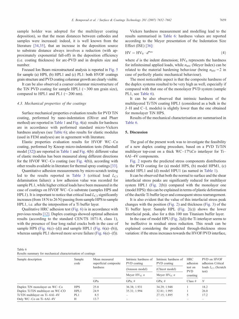
Table 6Results summary for mechanical characterisation of coatings
Sample description Samplecode
Mean measuredsuperficial compositehardness
GPa
Duplex TiN monolayer on WC–Co HPS 25.0Duplex Ti/TiN multilayer on WC-CO HPL1 24.9Ti/TiN multilayer on Ti–6Al–4V PL1 8.5Only WC–Co on Ti–6Al–4V H 13.7
Vickers hardness measurement and modelling lead to theresults summarised in Table 6: hardness values are reportedaccording to the Meyer presentation of the Indentation SizeEffect (ISE) [36]:
HV ¼ HV0 � dnHV ð4Þwhere d is the indent dimension; HV0 represents the hardnessfor infinitesimal applied loads, while nHV (Meyer Index) can berelated to the material hardening behaviour (being nHV=2 incase of perfectly plastic mechanical behaviour).
The most noticeable aspect is that the composite hardness ofthe duplex systems resulted to be very high as well, especially ifcompared with that one of the monolayer PVD system (samplePL1, see Table 6).
It can be also observed that intrinsic hardness of themultilayered Ti/TiN coating HPL1 (considered as a bulk in theJ–H and C–L models) is slightly lower than the one obtainedfor monolayer TiN HPS.
Results of the mechanical characterisation are summarised inTable 6.
5. Discussion
The goal of the present work was to investigate the feasibilityof a new duplex coating procedure, based on a PVD Ti/TiNmultilayer top-coat on a thick WC–17%Co interlayer for Ti–6Al–4V components.
Fig. 2 reports the predicted stress components distributionsin the PVD coating for (a) model HPS, (b) model HPM1, (c)model HPL1 and (d) model HPU1 (as named in Table 1).
It can be observed that both the normal to surface and the shearinterfacial stress peaks are significantly reduced for multilayersystem HPL1 (Fig. 2(b)) compared with the monolayer one(modelHPS): this can be explained in terms of plastic deformationof the ductile Ti buffer layer and consequent stress rearrangement.
It is also evident that the value of this interfacial stress peakchanges with the position (Fig. 2) and thickness (Fig. 3) of theTi buffer layer. Sample HPL (Fig. 2(c)) shows the lowerinterfacial peak, also for a thin 100 nm Titanium buffer layer.
In the case of model HPU (Fig. 2(d)) the Ti interlayer seems tobe ineffective in residual stress reduction. This result can beexplained considering the predicted through-thickness stressvariation: if the stress increases towards the HVOF/PVD interface,
Intrinsic hardness ofPVD coating
Intrinsic hardness ofPVD coating
HRCadhesiontest onPVDcoasting
PVD on HVOFadhesion Criticalloads LC3 (Scratchtest)
(Jonsson model) (Chicot model)
Meyer HV0; n Meyer HV0; n
GPa; # GPa; # Class # N
36.38; 1.931 34.29; 1.948 1 18.235.31; 1.994 32.81; 1.995 1 26.0– 27.15; 1.895 5 17.2– – – –
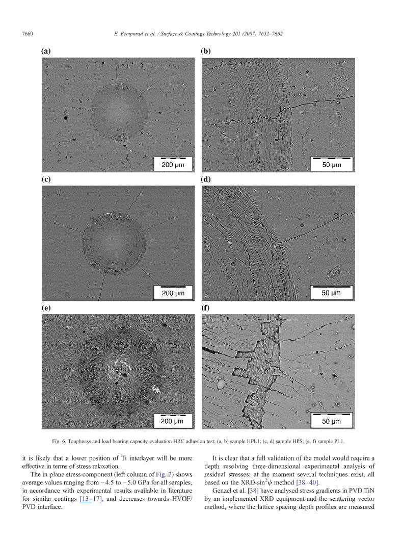
Fig. 6. Toughness and load bearing capacity evaluation HRC adhesion test: (a, b) sample HPL1; (c, d) sample HPS; (e, f) sample PL1.
7660 E. Bemporad et al. / Surface & Coatings Technology 201 (2007) 7652–7662
it is likely that a lower position of Ti interlayer will be moreeffective in terms of stress relaxation.
The in-plane stress component (left column of Fig. 2) showsaverage values ranging from −4.5 to −5.0 GPa for all samples,in accordance with experimental results available in literaturefor similar coatings [13–17], and decreases towards HVOF/PVD interface.
It is clear that a full validation of the model would require adepth resolving three-dimensional experimental analysis ofresidual stresses: at the moment several techniques exist, allbased on the XRD-sin2ψ method [38–40].
Genzel et al. [38] have analysed stress gradients in PVD TiNby an implemented XRD equipment and the scattering vectormethod, where the lattice spacing depth profiles are measured
7661E. Bemporad et al. / Surface & Coatings Technology 201 (2007) 7652–7662
after stepwise rotation of the sample around the scatteringvector, and the stress depth profile is consequently evaluated:results [38] showed an in-plane stress of (−5±0.15 GPa)decreasing towards interface, in accord with results obtained bysimulation in the present work.
Furthermore, Pantleon et al. [39] used a GDOES (GlowDischarge Optical Emission Spectroscopy) for stepwise re-moval of surface layers, followed by the application of thestandard XRD-sin2ψ method, for in-plane stress profile eval-uation in CVD TiN coatings on steel substrate: the obtainedresults (see [39] for comparison) show the same stress depthprofile predicted by FEM simulations in the present paper(Fig. 2(a)).
Anyhow, it has to be underlined that the numerical studyreported in the present paper essentially consists of a qualitativeevaluation of residual stress components distributions aimed atan effective comparison among different configurations of thesame layered structure.
FIB analyses, reported in Fig. 5, gave lot of informationabout coating microstructure and its growth mechanisms: amarked columnar structure can be observed for the PVD TiNlayers, indicating strong coating texture, also observed in X-raydiffraction patterns (not reported here); it is also clear fromFig. 5(c) that Ti interlayer promotes re-nucleation of the TiNphase: this could be one of the main reasons of reduced residualstress and improved film adhesion.
Micro-scratch testing confirmed that the optimised duplexsystem adopted (sample HPL1) involves a remarkable increasein adhesion; the critical load LC3 measured for the duplex-multilayer coating was found to be 45% higher than obtainedfor the duplex-monolayer coating.
Furthermore, the duplex coatings approach generallyprovided an equivalent load bearing capacity because of thehigh hardness and stiffness of the WC–Co thick interlayer[12]; in the case of the buffered PVD coating HPL1, loadbearing capacity is even improved after the introduction ofthe Ti interlayer: as shown in Fig. 6(c)–(d) radial cracks areless pronounced and shorter in the case of the multilayerPVD coating (sample HPL1): this could be due to theoptimisation procedure which allowed to introduce aminimum quantity of Titanium, with an increase in PVDcoating deformability without significant reductions in itsstiffness and hardness (see Table 6, hardness results); otherexperimental studies [11] adopted much thicker buffer layer(more than 500 nm) placed in middle position: in this case astronger reduction in coating hardness and impact resistancewas observed.
6. Conclusions
A duplex coating system for Ti–6Al–4V substrates,comprising a 3 μm PVD Ti/TiN multilayer (two layer pairs)on a 300 μm HVOF WC–17%Co thick interlayer has beendesigned, produced and characterised.
A finite element based design of the PVD Ti/TiN top layerpredicted a significant reduction of the PVD–HVOF interfa-cial residual stress peak and through-thickness stress gradient
for the case showed in Fig. 1(b) (Ti buffer layer in lowerposition), even when a very thin Ti interlayer (100 nm) wasused.
Scratch test adhesion measurements confirmed simulationsshowing a significantly increased adhesion of the PVD layer(45% increased critical load compared to monolayer), con-firmed by morphological analyses of HRC indents.
On the other hand, the introduction of such a thin Ti bufferlayer (100 nm) did not involve an excessive reduction insuperficial hardness, while improved toughness and load bearingcapacity were observed.
The whole coating cost will obviously be higher than for atraditional duplex process (nitriding plus PVD) and alsoapplicable for only a limited range of component geometry(due to the HVOF layer polishing requirements); nevertheless,the increase in life-time and overall performances (in terms ofload bearing capacity and durability) could overcome produc-tion costs for some specific applications.
Acknowledgments
Authors would like to acknowledge G.C. Gazzadi and C.Menozzi (S3 center, INFM-CNR, Modena, Italy) for cooper-ation in FIB analyses, Luca Lusvarghi and Fabio PighettiMartini (University of Modena and Reggio Emilia, Depart-ment of Materials and Environmental Engineering) for scratchtest analyses, and Daniele De Felicis for sample preparationand cooperation during morphological and microstructuralanalysis. All modelling and characterisation activities havebeen carried out at the “Interdepartmental Laboratory ofElectron Microscopy” (LIME), University ROMATRE (http://www.lime.uniroma3.it).
References
[1] Ch. Leyens, M. Peters, Titanium and Titanium Alloys: Fundamentals andApplications, Wiley-VCH, October 2003.
[2] T. Bell, H. Dong, Y. Sun, Tribol. Int. 31 (1998) 127.[3] G.W. Critchlow, D.M. Brewis, Int. J. Adhes. Adhes., 15 (1996) 161.[4] E. Martinez, J. Romero, A. Lousa, J. Esteve, Appl. Phys. A 77 (2003)
419.[5] J. Smolik, K. Zdunek, Vacuum 55 (1999) 147.[6] Y.L. Su, W.H. Kao, Wear 223 (1998) 119.[7] N. Dück, W. Gamer, M. Gesatzke, W. Griepentrog, M. Österle, I. Sahre,
Ž. Urban, Surf. Coat. Technol. 142–144 (2001) 579.[8] J. Smolik, K. Zdunek, B. Larisch, Vacuum 55 (1999) 45.[9] H. Holleck, H. Schulz, Surf. Coat. Technol., 36 (1988) 707.[10] A. Leyland, A. Matthews, Surf. Coat. Technol. 71 (1994) 19.[11] G.S. Kim, S.Y. Lee, J.H. Hahn, B.Y. Lee, J.G. Han, J.H. Lee, S.Y. Lee,
Surf. Coat. Technol., 171 (2003) 83.[12] E. Bemporad, M. Sebastiani, D. De Felicis, F. Carassiti, R. Valle, F. Casadei,
Thin Solid Films 515 (2006) 186.[13] Y. Pauleau, Vacuum 61 (2001) 175.[14] G. Knuyt, W. Lauwerens, L.M. Stals, Thin Solid Films 370 (2000) 232.[15] V. Teixeira, Thin Solid Films 392 (2001) 276.[16] F.R. Lamastra, F. Leonardi, R.Montanari, F. Casadei, T. Valente, G. Gusmano,
Surf. Coat. Technol. 200 (2006) 6172.[17] M. Gelfi, G.M. La Vecchia, N. Lecis, S. Troglio, Surf. Coat. Technol. 192
(2005) 263.[18] J. Haidera, M. Rahmana, B. Corcoranb, M.S.J. Hashmia, J. Mater. Process.
Technol. 168 (2005) 36.
7662 E. Bemporad et al. / Surface & Coatings Technology 201 (2007) 7652–7662
[19] J. Stokes, L. Looney, Surf. Coat. Technol. 177–178 (2004) 18.[20] S. Kuroda, T.W. Clyne, Thin Solid Films, 200 (1) (1991) 49.[21] T.W. Clyne, S.C. Gill, J. Therm. Spray Technol., 5 (4) (1996) 401.[22] U. Wiklund, J. Gunnars, S. Hogmark, Wear 232 (1999) 262.[23] Y. Telue, M. Mahendran, Eng. Struct. 26 (2004) 567.[24] E. Bemporad, C. Pecchio, S. De Rossi, F. Carassiti, Surf. Coat. Technol.
188–189 (2004) 319.[25] European standard UNI EN 1071-3, Advanced technical ceramics —
Methods of test for ceramic coatings— Part 3: Determination of adhesionand other mechanical failure modes by a scratch test, http://www.cen.eu.
[26] European standard CEN/TS 1071-8, Advanced technical ceramics.Methods of text for ceramic coatings. Rockwell indentation test forevaluation of adhesion, http://www.cen.eu.
[28] B. Jönsson, S. Hogmark, Thin Solid Films 114 (1984) 257.[29] D. Chicot, J. Lesage, Thin Solid Films 245 (1995) 123.[30] W.C. Oliver, G.M. Pharr, J. Mater. Res. 7 (6) (1992) 1564.[31] Standard ISO 14577-1, Instrumented indentation test for hardness and
materials parameters — Part 1: Test method, http://www.iso.org.
[32] D.B. Marshall, T. Noma, A.G. Evans, J. Am. Ceram. Soc. 65 (10) (1982)C175.
[33] S-H. Leigh, C-K. Lin, C.C. Berndt, J. Am. Ceram. Soc. 80 (8) (1997) 2093.[34] K.S. Fancey, Surf. Coat. Technol. 105 (1998) 76.[35] S.G. Harris, E.D. Doyle, Y.C. Wong, P.R. Munroe, J.M. Cairney, J.M. Long,
Surf. Coat. Technol. 183 (2004) 283.[36] D. Tabor, Hardness of Metals, Clarendon Press, Oxford, 1951.[37] CES. The Cambridge Engineering Selector, Granta Design, Rustat House,
62 Clifton Road, Cambridge CB1 7EG, UK. Available from: http://www.grantadesign.com.
[38] C. Genzel, W. Reimers, Surf. Coat. Technol. 116–119 (1999) 404.[39] K. Pantleon, O. Kessler, F. Hoffman, Surf. Coat. Technol. 120–121 (1999)
495.[40] G. Chen, D. Singh, O. Eryilmaz, J. Routbort, B.C. Larson, W. Liu, Appl.
Phys. Lett. 89 (2006) 172104.