Embed Size (px)
Citation preview

Materials and Design 31 (2010) 749–760
Contents lists available at ScienceDirect
Materials and Design
journal homepage: www.elsevier .com/locate /matdes
Microstructure and residual stress distribution of similar and dissimilarelectron beam welds – Maraging steel to medium alloy medium carbon steel
P. Venkata Ramana a,*, G. Madhusudhan Reddy b,1, T. Mohandas b,2, A.V.S.S.K.S. Gupta c,3
a Mahatma Gandhi Institute of Technology, Gandipet, Hyderabad 500 075, Indiab Defence Metallurgical Research Laboratory, Hyderabad 500 058, Indiac Jawaharlal Nehru Technological University, Hyderabad 500 085, India
a r t i c l e i n f o a b s t r a c t
Article history:Received 8 June 2009Accepted 2 August 2009Available online 7 August 2009
Keywords:A. Maraging steelA. Medium alloy medium carbon steelG. Residual stress
0261-3069/$ - see front matter � 2009 Elsevier Ltd. Adoi:10.1016/j.matdes.2009.08.007
* Corresponding author. Mobile: +91 98480 25631.E-mail addresses: [email protected] (P.
[email protected] (G. Madhusudhan Reddy)(A.V.S.S.K.S. Gupta).
1 Tel.: +91 040 2458 6426.2 Tel.: +91 040 2458 6424.3 Mobile: +91 98494 27331.
The influence of parent metal heat treatment condition on the residual stress distribution in dissimilarmetal welds of maraging steel to quenched and tempered medium alloy medium carbon steel has beeninvestigated. It has been observed that the residual stress distribution would be more compressive if themaraging steel is in soft condition. This is attributed to stress absorbing nature of highly yielding softmaraging steel.
� 2009 Elsevier Ltd. All rights reserved.
1. Introduction
Several high-technology applications, such as aircraft and aero-space, need to possess ultrahigh strength coupled with fracturetoughness in order to meet the requirement of minimum weightwhile ensuring high reliability [1]. In many applications, dissimilarcombinations of steels are necessary for technical and economicreasons. In such applications materials such as maraging steeland medium alloy medium carbon steel are used.
Maraging steels are a class of ultrahigh strength martensiticsteels, which develop strength due to the precipitation of interme-tallic compounds [2–9]. They exhibit a unique combination ofproperties that include ultrahigh strength and excellent fracturetoughness. Medium alloy medium carbon structural steels withultrahigh strength and reasonable ductility, considered to be inex-pensive and attractive substitute for maraging steel [1]. Anotherimportant feature of these two steels is that they exhibit good wel-dability [10,11]. These steels are therefore important candidatematerials for critical applications such as rocket motor cases, sub-marine hulls, connecting rods, landing gears and bridge layer tanks[12,13]. These materials are used extensively and individually butnot much is reported about the dissimilar combination.
ll rights reserved.
Venkata Ramana), gmred-, [email protected]
The adoption of dissimilar-metal combination provides possi-bilities for the flexible design of the component by using eachmaterial efficiently i.e., benefiting from the specific properties ofeach material to meet functional requirements. The dissimilar me-tal joints are characterized particularly by compositional gradientsand microstructural changes, which yield large variations in phys-ical and mechanical properties across the joint. These variationsmay lead to metallurgical incompatibility, e.g., the formation ofbrittle phases, the segregation of high and low melting phasesdue to chemical mismatch, and possibly large residual stressesfrom the physical mismatch. The joining of dissimilar metals is,therefore, far more complex than the joining of similar metals[14,15].
Fusion welding is one of the most widely employed fabricationprocesses for these steels. Electron beam welding (EBW) is a high-energy density fusion welding process which is extensively em-ployed in the aerospace and defence applications [16]. EBW is con-sidered advantageous over other fusion welding processes injoining dissimilar metals as it has high heating and cooling rateswhich takes care of the difference in the melting temperatures ofthe materials being welded. A low total-heat input per unit lengthof weld reduces the residual stresses substantially. The small weldbead size minimizes mixing of dissimilar metals thus limiting thebrittle zones arising from chemical mismatch, to some extent [14].
Residual stress is the stress that exists within a material with-out application of an external load [17], or it can be described asthe stress which remains in a body that is stationary and atequilibrium with its surroundings. Residual stresses can arise inmaterials in almost every step of processing. The origins of residualstresses in a component may be classified as: mechanical, thermal,

Fig. 1. Weld coupon design and test plate assembly. (a) Section of test plateassembly prior to welding and (b) test plate assembly after welding.
Table 1Welding parameters for electron beam welding.
Machine settings Parameters
Gun to work distance, mm 283Accelerating voltage, kV 55Beam current, mA 30 mA (for initial first pass for
preheating) and 65 mA (for penetration)Focus Slightly above the surfaceSpeed, m/min 1Vacuum level, mbar 10�4 mbar and lessHeat input, J/mm 214.5
750 P. Venkata Ramana et al. / Materials and Design 31 (2010) 749–760
and chemical. Mechanically generated residual stresses are often aresult of manufacturing processes that produce non-uniform plas-tic deformation. They may develop naturally during processing ortreatment, or may be introduced deliberately to develop a particu-lar stress profile in a component. Examples of operations that pro-duce undesirable surface tensile stresses or residual stressgradients are rod or wire drawing, welding, machining and grind-ing. Knowledge of residual stress field becomes essential, as itshould be used as initial state of stress of the load carrying struc-ture. Residual stresses are associated with any metal joining pro-cess in general, and with fusion welding processes in particular.It is widely recognized that residual stresses in welded joints arehighly significant in practical terms. Residual stresses are producedin the vicinity of the weld due to non-uniform expansion andshrinkage of differently heated zones during thermal transient ofa weld pass [18]. Residual stresses are not cyclic, but they may aug-ment or detract from applied stresses depending on their respec-tive sign. Tensile residual stresses may increase the rate ofdamage by fatigue or creep and reduce the load carrying capacity.Compressive stresses are generally considered beneficial, but causea decrease in the allowable buckling load [17,19–22]. The benefi-cial effects of compressive stresses have been widely recognizedin industry, as these are believed to increase fatigue strength ofthe components and reduce stress corrosion cracking and brittlefracture etc. In several practical applications these are deliberatelyintroduced through post manufacturing treatment such as shotpeening or water jet peening etc. life limiting residual stressescan be some times reduced by post-weld heat treatment, but thismay be impractical with large or inaccessible components.
The present study is on the residual stress distribution in thedissimilar metal electron beam weldments of maraging steel tomedium alloy medium carbon ultrahigh strength steels. Generallythese steels are supplied in soft condition. They attain their ultra-high strength after respective heat treatments. The aim of the pres-ent study is to investigate the influence of starting parent metalstrength on the residual stress distribution in the as-welded andsubsequent to different post-weld heat treatment conditions, asstrength levels are reported to influence the magnitude of residualstresses in similar metal welding [23].
A detailed study of microstructure and its correlation with thehardness and residual stress distribution attempted in this investi-gation assumes significance due to the availability of limited dataon the subject in this dissimilar-metal combination of welding.
Fig. 2. Schematic sketch of hardness traverse across the weldment.
2. Experimental procedures
2.1. Parent metals
The materials investigated are 18% Ni (250 grade) maraging steeland medium alloy medium carbon steels in the form of 5.2 mm thicksheets. In order to investigate the influence of pre weld heat treat-ment on microstructure, residual stress distribution and hardness,the materials were given respective heat treatments. Maraging steelwas solutionised at 815 �C for 1 h followed by air cooling and thenaged at 480 �C for 3 h followed by air cooling. Medium alloy mediumcarbon steel was austenised at 925 �C for 35 min followed by aircooling and then tempered at 295 �C for 45 min followed by air cool-ing. The as-received maraging steel is in solutionised condition. Thedetails of weld coupon preparation and test plate assembly areshown in Fig. 1. Electron beam welding was performed in butt jointconfiguration with welding parameters shown in Table 1. Similarand dissimilar-metal combinations were welded in different parentmetal heat treatment conditions as shown in Table 2. The yield stressvalues of parent material in different heat treatment conditions arepresented in Table 3 for ready reference.
2.2. Metallography
Analysed composition of the parent materials is given in Table4. The weldment microstructures of similar and dissimilar jointswere studied by metallography of various regions using Leitz opti-cal microscope. 2% Nital (2 ml HNO3 and 98 ml methanol) wasused to etch medium alloy medium carbon steel weld and modi-fied Fry’s reagent (50 ml HCl, 25 ml HNO3, 1 g CuCl2 and 150 mlwater) was used to etch maraging steel weld. The respective etch-ants were used to etch fusion zone, heat affected zone and parentmetal regions.

Table 2Details of the weldments.
S.No. Weldment with parent metal condition Post-weld condition
1 Maraging steel (solutionised and aged) to maraging steel (solutionised and aged) As-welded2 Medium alloy medium carbon steel (quenched and tempered) to medium alloy medium carbon steel (quenched and tempered) As-welded3 Maraging steel (solutionised and aged) to medium alloy medium carbon steel (quenched and tempered) As-welded4 Maraging steel (as-received) to medium alloy medium carbon steel (quenched and tempered) As-welded5 Maraging steel (as-received) to medium alloy medium carbon steel (quenched and tempered) Aged
Table 3Parent material yield stress values.
S.No. Material Condition YS (MPa) UTS (MPa) El. (%)
1 Maraging steel As received 950 1000 122 Maraging steel Solutionised and aged 1600 1750 7.53 Medium alloy medium carbon steel Quenched and tempered 1458 1815 12.014 Medium alloy medium carbon steel (quenched and tempered) Aged 1322 1675 13.17
Table 4Composition of parent materials.
Material Element (wt.%)
C Ni Co Mo Ti Al Cr Si Mn Fe
Maraging steel 0.01 18.9 8.3 4.6 0.41 0.15 – – – BalanceMedium alloy medium carbon steel 0.33 2.8 <1.0 <1.0 – – 0.85 1.8 0.35 Balance
P. Venkata Ramana et al. / Materials and Design 31 (2010) 749–760 751
2.3. Stress measurement
Residual stress measurement was carried out with AST3000 X-ray stress analyser employing CrKa radiation. X-ray techniquesmeasure stress indirectly by measuring the surface strain, whichis indicated by the position of a diffracted peak h for a crystal planeoriented at various angles to the surface of a specimen as is de-
Fig. 3. Optical microstructure of simil
scribed in the literature [17,19,24–26]. The stress is given by thegradient of a plot of diffraction angle 2h against sin2 w, where wis the angle between the diffracting planes and the specimen sur-face. The instrument uses a pair of solid-state detectors locatedon each side of the main beam. Diffraction peaks are captured bythe individual pixels in the detectors, giving rapid data capturewithout mechanical movement. Residual stresses were evaluated
ar metal weld of maraging steel.

752 P. Venkata Ramana et al. / Materials and Design 31 (2010) 749–760
in this analyser using multiple exposure sin2 w technique based onthe diffraction from (300) planes in austenitic welds and from(211) planes in ferritic/martensite welds. The residual stress mea-surement comprise of at least fourteen measurements of latticespacing over a range of w orientations (�45� to +45�) to the surfaceof the specimen. Residual stress measurements were carried outacross the weldment (i.e., perpendicular to welding direction).The accuracy of stress measurements is approximately ±20 MPa.When some anisotropy was encountered, more trials were per-formed. In weld/HAZ/parent metal where the grain size influencedthe measurements, the X-ray goniometer was oscillated by ±2�. Forcomputation of stresses from measurement of strain data, appro-priate X-ray elastic constants were used. Prior to measurement ofstress, the surfaces of the spots in each location were chemicallycleaned with acetone or carbon tetrachloride solution. Followingthis, the spots were electro polished to a depth of 0.2 mm usingelectro polishing kit with 20% perchloric acid in ethanol, cooledto 0 �C prior to measurement.
2.4. Hardness measurement
Micro-hardness survey was conducted across the weld beads ofall the welded coupons employing Knoop micro-hardness testingmachine. All of the hardness readings were obtained at a load of300 gf. The distance between two consecutive indentations is0.5 mm. But this distance varied when the hardness was taken atspecific regions such as fusion boundary. A schematic diagram ofthe hardness survey is shown in Fig. 2.
3. Results and discussion
3.1. Microstructure
Figs. 3 and 4 show the optical microstructure of similar metalwelds of age hardened maraging steel and quenched and temperedmedium alloy medium carbon steel, respectively, whereas Fig. 5
Fig. 4. Optical microstructure of similar metal w
shows the optical microstructure of dissimilar weld of age hard-ened maraging steel and quenched and tempered medium alloymedium carbon steel.
The optical microscopy revealed that the similar metal weldsexhibited symmetrical fusion zone and heat affected zones,whereas the dissimilar metal welds exhibited unsymmetrical fu-sion zone and heat affected zones. This unsymmetrical naturemay be due to the difference in the thermal conductivity of thematerials. It is evident from the Fig. 6 that the width of heat af-fected zone of medium alloy medium carbon steel is observed tobe more than that of the maraging steel because the thermal con-ductivity of medium alloy medium carbon steel is higher than thethermal conductivity of maraging steel. The heat affected zone ofquenched and tempered steel medium alloy medium carbon steelhas two regions, A – coarse-grained heat affected zone, and B –fine-grained heat affected zone, partially transformed region (softzone) and tempered region (Fig. 6).
In both similar and dissimilar welds the fusion zone exhibitedcellular/dendritic structure in the entire weld zone. The size of cellsand spacing at the top and bottom of the fusion zone are found tobe smaller. In the middle portion of the weld, a mixture of cellularand dendritic structure is predominant. This trend is also observedat the fusion boundaries of similar metal welds. In dissimilar weldsthe microstructure at the fusion boundaries is found to be depen-dant on the magnitude of thermal conductivity.
The interface microstructure of maraging steel shows cellularstructure, while the interface microstructure of quenched and tem-pered medium alloy medium carbon steel shows epitaxial grains.This is due to higher thermal conductivity of the medium alloymedium carbon steel. The rate of heat flow being more in the direc-tion perpendicular to the weld, the grains tend to grow in thatdirection resulting in columnar grains.
The microstructure of the dissimilar weld of as-received marag-ing steel and quenched and tempered medium alloy mediumcarbon steel, in the post-weld aged condition is shown in Fig. 7.The microstructure is similar to that of the dissimilar weld of
eld of medium alloy medium carbon steel.

Fig. 5. Optical microstructure of dissimilar weld of maraging steel in solutionised and aged condition and medium alloy medium carbon steel in quenched and temperedcondition.
Fig. 6. Widths of heat affected zones in dissimilar weld of aged maraging steel andquenched and tempered steel.
P. Venkata Ramana et al. / Materials and Design 31 (2010) 749–760 753
as-received maraging steel and quenched and tempered mediumalloy medium carbon steel, in the as-welded condition (Fig. 8).The only noticeable difference is that the presence of coarse mar-tensitic structure in the parent metal of medium alloy medium car-bon steel evolved due to its response to the aging treatment.
3.2. Residual stresses
Transverse residual stress distribution across the similar metalweld of age hardened maraging steel in the as-welded conditionis shown in Fig. 9. It is observed that the residual stresses are com-pressive in nature, both in the weld and parent metal. They aremore compressive (�406 MPa) in the weld than in the parent me-tal (�141 MPa).
In the similar metal weld of quenched and tempered mediumalloy medium carbon steel in the as-welded condition, the nature
of residual stresses is tensile in the weld as well as in the parentmetal (Fig. 10). The magnitude of the stresses is more in the weld(+406 MPa) compared to that in the parent metal (+108 MPa).
Fig. 11 shows the residual stress distribution across the dissim-ilar weld joint of age hardened maraging steel and quenched andtempered medium alloy medium carbon steel in the as-weldedcondition. In this joint, compressive stresses were observed inthe maraging steel and tensile stresses were observed in mediumalloy medium carbon steel. Maximum compressive residual stressis observed at the weld centre. At the fusion boundary of the mar-aging steel the residual stresses are observed to be more compres-sive compared to the adjacent heat affected zone. The reduction inthe magnitude of stress value in the heat affected zone comparedto that at the fusion boundary is explained as follows: Dissolutionof strengthening precipitates takes place at the fusion boundary ofthe age hardened maraging steel as it is subjected to high temper-atures during weld thermal cycle resulting in soft behaviour of thematerial. This soft material absorbs more stresses generated duethe hindrance of shrinkage and the magnitude of residual stresses,compressive in nature is high. In addition to this soft region closeto fusion boundary, due to dilution of medium alloy medium car-bon steel, resulted in duplex structure consisting of martensiteand austenite. Phase transformation stresses are predominant herethan the shrinkage stresses which resulted in more compressivestresses. This is mainly due to low temperature phase transforma-tion phenomenon.
The reduction in the magnitude of the residual stresses in theheat affected zone is due to the fact that this zone is close to theun-affected parent material which is hard in condition and reduces

Fig. 7. Optical microstructure of the dissimilar weld of as-received maraging steel and quenched and tempered medium alloy medium carbon steel, in the post-weld agedcondition.
754 P. Venkata Ramana et al. / Materials and Design 31 (2010) 749–760
the stress absorbing capacity of the adjacent material of heat af-fected zone.
Contrary to the high tensile residual stresses in the weld and fu-sion boundary of similar metal welds of medium alloy mediumcarbon steel, the residual stresses at the fusion boundary of dissim-ilar weld on the medium alloy medium carbon steel side are foundto be compressive. This may be due to the high compressive resid-ual stresses present in adjacent maraging steel. The residual stres-ses in the heat affected zone and parent metal of medium alloymedium carbon steel are found to be tensile in nature.
Fig. 12 shows the residual stress distribution across the post-weld aged dissimilar weld joint of maraging steel in as-receivedcondition and quenched and tempered medium alloy medium car-bon steel. The residual stresses are found to be more compressiveat the fusion boundary of maraging steel and less compressive atthe fusion boundary of medium alloy medium carbon steel, com-pared to the residual stresses at the weld centre. In the maragingsteel the stresses are more compressive in the heat affected zonecompared to the fusion boundary and parent metal. The residualstresses in the medium alloy medium carbon steel side are tensilein nature from fusion boundary to parent metal.
Residual stress in weld zone and un-affected parent material isshown in the Table 5. From the residual stress distribution in sim-ilar metal welds it is observed that maraging steel welds exhibitcompressive stresses, while quenched and tempered steel weldsexhibit tensile stresses (Figs. 9 and 10). The magnitude of the stres-ses is maximum in the weld region in that maximum compressivestresses are observed in the maraging steel weld while maximum
tensile stresses in the quenched and tempered steel weld. Thesetrends are as per the trends reported in the literature. The differ-ence is mainly attributed to BCC (Body-centered cubic) martensitein maraging steel and BCT (Body-centered tetragonal) martensite isthe quenched and tempered steel.
In the dissimilar metal welds, if the starting parent metals are intheir respective heat treatment conditions the magnitude of resid-ual stresses (either compressive or tensile) are lower (Fig. 11). Ifthe maraging steel is in soft condition and quenched and temperedsteel is in hardened condition the weld experiences higher com-pressive stress in the as-welded (Fig. 13) and aged condition(Fig. 12). However, post-weld aging results in higher compressivestresses in the maraging steel side of the weld and tensile stresseson the quenched and tempered steel side of the weld while theparent quenched and tempered steel experiences lower tensilestresses after aging (compare Figs. 12 and 13). Reduction in themagnitude of tensile stresses in quenched and tempered steel afteraging can be attributed to the coarsening of martensite duringaging as the aging temperature is higher than the tempering tem-perature of the steel. These trends are reflected in hardness reduc-tion in the quenched and tempered steel after aging. The highstresses in the dissimilar metal weld region subsequent to agingcould be attributed to inter diffusion of elements as seen fromthe EPMA elemental scan (Figs. 14 and 15) that made the weld re-spond to heat treatment similar to quenched and tempered steel.
In general the compressive nature of the residual stresses in dis-similar metal welds is due to dilution effects that lead to a composi-tion that does not result in fully BCC and BCT martensite. Reduction
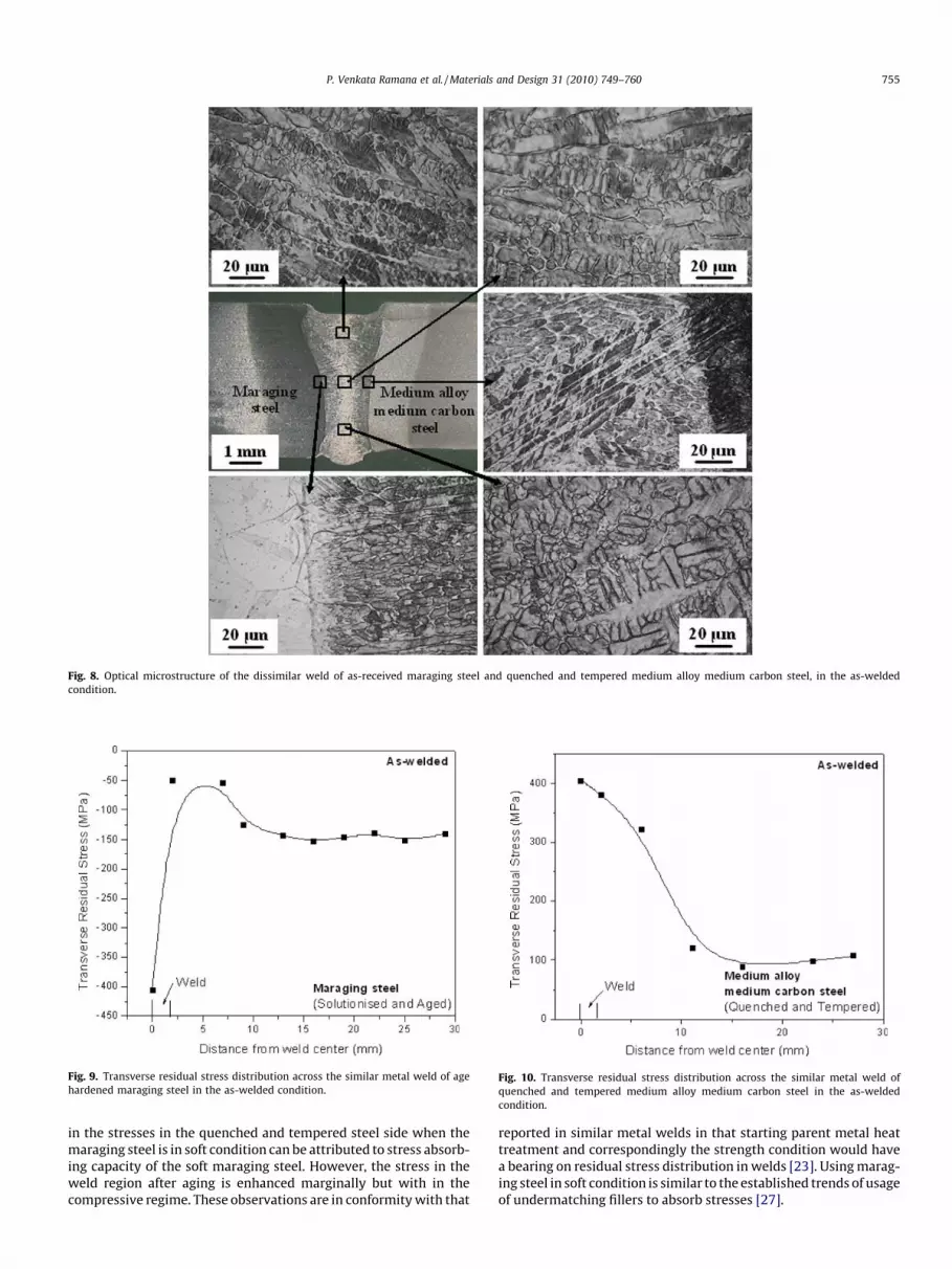
Fig. 8. Optical microstructure of the dissimilar weld of as-received maraging steel and quenched and tempered medium alloy medium carbon steel, in the as-weldedcondition.
Fig. 9. Transverse residual stress distribution across the similar metal weld of agehardened maraging steel in the as-welded condition.
Fig. 10. Transverse residual stress distribution across the similar metal weld ofquenched and tempered medium alloy medium carbon steel in the as-weldedcondition.
P. Venkata Ramana et al. / Materials and Design 31 (2010) 749–760 755
in the stresses in the quenched and tempered steel side when themaraging steel is in soft condition can be attributed to stress absorb-ing capacity of the soft maraging steel. However, the stress in theweld region after aging is enhanced marginally but with in thecompressive regime. These observations are in conformity with that
reported in similar metal welds in that starting parent metal heattreatment and correspondingly the strength condition would havea bearing on residual stress distribution in welds [23]. Using marag-ing steel in soft condition is similar to the established trends of usageof undermatching fillers to absorb stresses [27].

Fig. 11. Transverse residual stress distribution across the dissimilar weld joint ofage hardened maraging steel and quenched and tempered medium alloy mediumcarbon steel in the as-welded condition.
Fig. 12. Transverse residual stress distribution across the post-weld aged dissimilarweld of maraging steel in as-received condition and quenched and temperedmedium alloy medium carbon steel.
756 P. Venkata Ramana et al. / Materials and Design 31 (2010) 749–760
3.3. Hardness
Hardness survey across the similar metal weld in the transversesection of the aged maraging steel (Fig. 16) shows that the hard-
Table 5Residual stress in weld zone and un-affected parent material.
S.no. Weldment Conditi
1 Maraging steel (solutionised and aged) to maraging steel(solutionised and aged)
As-wel
2 Medium alloy medium carbon steel (quenched and tempered) tomedium alloy medium carbon steel (quenched and tempered)
As-wel
3 Maraging steel (solutionised and aged) to medium alloy mediumcarbon steel (quenched and tempered)
As-wel
4 Maraging steel (as-received) to medium alloy medium carbonsteel (quenched and tempered)
As-wel
5 Maraging steel (as-received) to medium alloy medium carbonsteel (quenched and tempered)
Aged
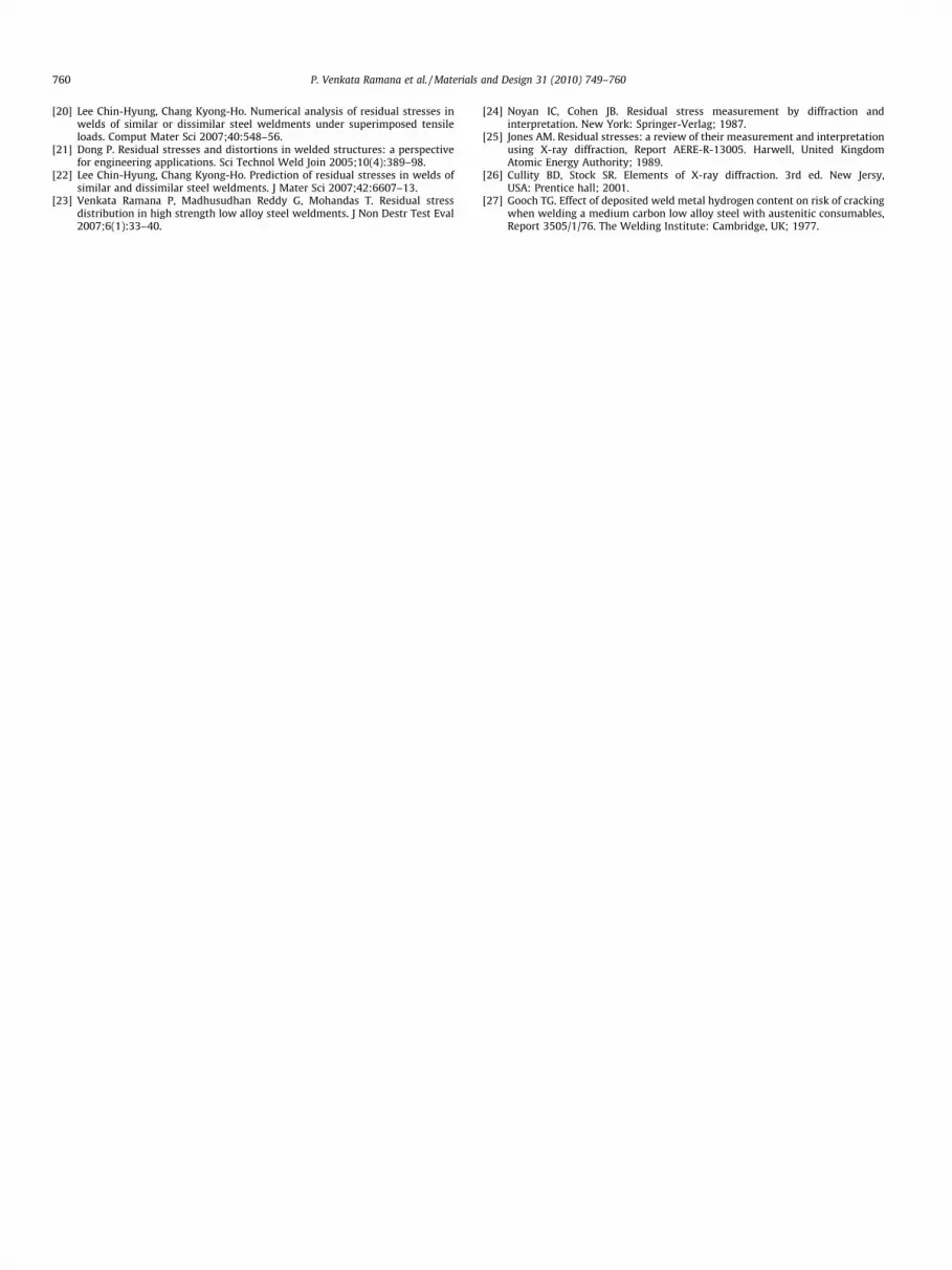
ness in the weld (Region A) is low compared to that of parent metal(Region E) because the weld is in as-welded condition whereas theparent metal is in heat treated condition (solutionised and aged).During the welding process the material adjacent to weld is sub-jected to higher peak temperature and fast cooling rates resultingin coarse-grained heat affected zone (Region B). The region awayfrom the fusion boundary and adjacent to heat affected zone is ex-posed to a lower peak temperature resulting in fine-grained struc-ture (Region C). Thus there is a gradual increase in the hardness ofheat affected zone from the fusion boundary to the fine-grained re-gion. It is observed that there is a small dip in the hardness value inthe weldment adjacent to fine-grained region. This is a very narrowdark etched soft region (Region D) that is reported to be of notmuch practical significance [10]. The average hardness of the par-ent metal is 575 HK.
Fig. 17 shows the hardness survey across the similar metal weldin the transverse section of the quenched and tempered mediumalloy medium carbon steel. It is observed that there is small differ-ence in the hardness of weld and adjoining parent metal. The weldhardness is marginally lower than that of parent metal. The aver-age hardness of the weldment is 600 HK. Near heat affected zoneexhibited marginally higher hardness than the weld and the parentmetal. The high hardness of this region is due to expected graincoarsening although not predominant in low heat input processlike electron beam welding.
The hardness distribution across the dissimilar metal weld ofage hardened maraging steel and quenched and tempered mediumalloy medium carbon steel is shown in Fig. 18. The weld exhibitedhardness gradient with a low hardness (350 HK) on the maragingsteel and high hardness (500 HK) in the quenched and temperedsteel side. The parent metal maraging steel adjacent to the weldexperienced softening as a result of exposure to temperature high-er than the solution treatment temperature for maraging steel. Thehardness gradient is opined to be due to composition gradient inthe weld region, in that the weld on maraging steel side wouldhave lower carbon than that in the quenched and tempered steel.Due to carbon dilution the quenched and tempered steel adjacentto the weld could not be hardened equal to that of parent metal, inother words, the hardenability of the weld region on the quenchedand tempered steel side is lower than the corresponding parentmetal.
The hardness traverse across the dissimilar weld of as-receivedsoft maraging steel and quenched and tempered medium alloymedium carbon steel, in the post-weld aged condition is shownin Fig. 19. It is clear from the figure that the weld hardness is al-most equal to that of maraging steel, as it is subjected post-weldaging treatment. The hardness of the medium alloy medium car-bon steel is observed to be lower than the weld and maraging steel.Far heat affected zone in the quenched and tempered steel exhib-ited lower hardness as compared to the parent metal.
on Residual Stress (MPa)
Weld Maraging steel Medium alloy medium carbon steel
ded �406 �141 –
ded +405 – +107
ded �276 to �151 �141 +93
ded �401 �286 +190
�400 to +100 �254 +26

Fig. 13. Transverse residual stress distribution across the dissimilar weld ofmaraging steel in as-received condition and quenched and tempered mediumalloy medium carbon steel, in as-welded condition.
Fig. 14. Electron probe micro analysis (EPMA) scan across the dissimilar metal weld ofcarbon steel.
P. Venkata Ramana et al. / Materials and Design 31 (2010) 749–760 757
A comparison of hardness distribution across the welds shownin Figs. 19 and 20 reveals that post-weld aging leads to eliminatesteep hardness gradients. This can be attributed to compositionalhomogenisation and correspondingly better response to age hard-ening. The lower hardness observed in the far heat affected zone ofquenched and tempered steel is due to aging at a temperaturehigher than the tempering temperature that results in coarseningof martensite laths.
4. Conclusions
The influence of parent metal strength on microstructure, resid-ual stress distribution and hardness in similar and dissimilar weldshas been investigated. Similar metal welds exhibited symmetricalfusion zone and heat affected zones, whereas the dissimilar metalwelds exhibited unsymmetrical fusion zone and heat affectedzones due to the difference in the thermal conductivity of thematerials. In the fusion zone, residual stresses are compressive insimilar welds of maraging steel and tensile in similar metal weldsof medium alloy medium carbon steel. If one of the parent metalsin the dissimilar metal welds is in soft condition the magnitude ofstresses is lowered due to stress absorbing nature of the softer par-ent metal. The benefit of soft parent metal prevailed even after
age hardened maraging steel and quenched and tempered medium alloy medium
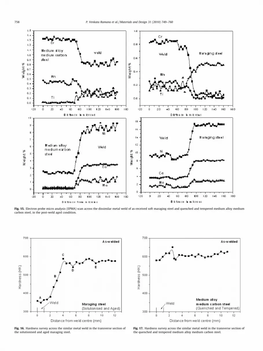
Fig. 15. Electron probe micro analysis (EPMA) scan across the dissimilar metal weld of as-received soft maraging steel and quenched and tempered medium alloy mediumcarbon steel, in the post-weld aged condition.
Fig. 16. Hardness survey across the similar metal weld in the transverse section ofthe solutionised and aged maraging steel.
Fig. 17. Hardness survey across the similar metal weld in the transverse section ofthe quenched and tempered medium alloy medium carbon steel.
758 P. Venkata Ramana et al. / Materials and Design 31 (2010) 749–760

Fig. 18. Hardness distribution across the dissimilar metal weld of age hardenedmaraging steel and quenched and tempered medium alloy medium carbon steel.
Fig. 19. Hardness traverse across the dissimilar weld of as-received soft maragingsteel and quenched and tempered medium alloy medium carbon steel, in the post-weld aged condition.
Fig. 20. Hardness traverse across the dissimilar weld of as-received soft maragingsteel and quenched and tempered medium alloy medium carbon steel, in the as-welded condition.
P. Venkata Ramana et al. / Materials and Design 31 (2010) 749–760 759
post-weld aging treatment. Coarsening of martensite plates duringaging enables to reduce the stresses in quenched and temperedsteel. In the dissimilar welds, due to the presence of BCC and BCTmartensite at the fusion boundaries of maraging steel and mediumalloy medium carbon steel, respectively, the hardness trendshowed a low to high variation from maraging steel to medium al-loy medium carbon steel. The microstructural changes are re-flected in lower hardness trends after aging.
Acknowledgements
Financial assistance from Defence Research Development Orga-nization (DRDO) is gratefully acknowledged. The authors wouldlike to thank Dr. G. Malakondaiah, Director, Defence MetallurgicalResearch Laboratory, Hyderabad for his continued encouragementand permission to publish this work. The authors also thank Struc-tural Failure Analysis Group and Metal Working Group for help inmetallography and heat treatment. One of the authors (P.Venkata
Ramana) thanks the management of Mahatma Gandhi Instituteof Technology, Hyderabad for permission and encouragement tocarryout this work.
References
[1] Malakondaiah G, Srinivas M, Rama Rao P. Basic studies leading to thedevelopment of ultrahigh strength high fracture toughness low-alloy steel.Bull Mater Sci 1995;18(4):325–41.
[2] Floreen S, Decker RF. In: Decker RF, editor. Source book on maragingsteels. Metals Park, OH: ASM; 1979. p. 20–32.
[3] Decker RF, Floreen S. In: Wilson RK, editor. Maraging steels: recentdevelopments and applications. Warrendale, PA: TMS-AIME; 1988. p. 1–38.
[4] Vasudevan VK, Kim SJ, Wayman CM. Precipitation reactions and strengtheningmechanisms in maraging steels. Metall Trans A 1990;21:2655–68.
[5] Sha W, Cerezo A, Smith GDW. Phase chemistry and precipitation reactions inmaraging steels: Part I. Introduction and study of Co-containing C-300 steel.Metall Trans A 1993;24:1221–32.
[6] Sha W, Cerezo A, Smith GDW. Phase chemistry and precipitation reactions inmaraging steels: Part II. Co-free T-300 steel. Metall Trans A 1993;24:1233–40.
[7] Sha W, Cerezo A, Smith GDW. Phase chemistry and precipitation reactions inmaraging steels: Part III. Model alloys. Metall Trans A 1993;24:1241–50.
[8] Sha W, Cerezo A, Smith GDW. Phase chemistry and precipitation reactions inmaraging steels: Part IV. Discussion and conclusions. Metall Trans A1993;24:1251–60.
[9] Guo Z, Sha W, Vaumousse D. Microstructural evolution in a PH13–8 stainlesssteel after ageing. Acta Mater 2003;51:101–16.
[10] Lang FH, Kenyon N. Bulletin 159. New York: Welding Research Council,Engineering Foundation; 1971.
[11] Adams Jr CM, Travis RE. Welding of 18% Ni–Co–Mo maraging alloys. Weld J1964;43(5):193S–7S.
[12] Garrison Jr WM. Ultrahigh-strength steels for aerospace applications. JOM1990;42(5):20–4.
[13] Tomita Y. Development of fracture toughness of ultrahigh strength low alloysteels for aircraft and aerospace applications. Mater Sci Technol 1991;7:481–9.
[14] Sun Z, Karppi R. The application of electron beam welding for the joining ofdissimilar metals: an overview. J Mater Process Technol 1996;59:257–67.
[15] Bruno Amorim Soares, Mônica Maria de Abreu Mendonça Schvartzman,Wagner Reisda Costa Campos. Characterization of the dissimilar welding –Austenitic stainless steel with filler metal of the Nickel Alloy 2007.International nuclear atlantic conference – INAC 2007, Santos, SP, Brazil,September 30–October 5, 2007. p. 1–6.
[16] Powers DE. Electron beam welding-an overview. In: Metzbower EA, Hauser D,editors. Proc. conf. power beam processing, ASM International, OH; 1988. p.25–33.
[17] Masubuchi Koichi. Analysis of welded structures. New York: Pergamon press;1980.
[18] Easterling Kenneth. Introduction to physical metallurgy ofwelding. Heinemann, London: Butterworth; 1992.
[19] Hilley ME, editor. Residual stress measurement by X-ray diffraction, SAE J784a,1971. Warrandale, PA 15096: Soc. of Auto Eng.; 1971.
760 P. Venkata Ramana et al. / Materials and Design 31 (2010) 749–760
[20] Lee Chin-Hyung, Chang Kyong-Ho. Numerical analysis of residual stresses inwelds of similar or dissimilar steel weldments under superimposed tensileloads. Comput Mater Sci 2007;40:548–56.
[21] Dong P. Residual stresses and distortions in welded structures: a perspectivefor engineering applications. Sci Technol Weld Join 2005;10(4):389–98.
[22] Lee Chin-Hyung, Chang Kyong-Ho. Prediction of residual stresses in welds ofsimilar and dissimilar steel weldments. J Mater Sci 2007;42:6607–13.
[23] Venkata Ramana P, Madhusudhan Reddy G, Mohandas T. Residual stressdistribution in high strength low alloy steel weldments. J Non Destr Test Eval2007;6(1):33–40.
[24] Noyan IC, Cohen JB. Residual stress measurement by diffraction andinterpretation. New York: Springer-Verlag; 1987.
[25] Jones AM. Residual stresses: a review of their measurement and interpretationusing X-ray diffraction, Report AERE-R-13005. Harwell, United KingdomAtomic Energy Authority; 1989.
[26] Cullity BD, Stock SR. Elements of X-ray diffraction. 3rd ed. New Jersy,USA: Prentice hall; 2001.
[27] Gooch TG. Effect of deposited weld metal hydrogen content on risk of crackingwhen welding a medium carbon low alloy steel with austenitic consumables,Report 3505/1/76. The Welding Institute: Cambridge, UK; 1977.


