Embed Size (px)
Citation preview
MICHELIN
®TR
UCK TIR
E SERVICE M
ANUAL
MICHELIN® Truck Tire Service Manual
To learn more please contact your MICHELIN Sales Representative or visit www.michelintruck.com
To order more books, please call Promotional Fulfillment Center 1-800-677-3322, Option #2Monday through Friday, 9 a.m. to 5 p.m. Eastern Time
United StatesMichelin North America, Inc.One Parkway SouthGreenville, SC • 296151-888-622-2306
CanadaMichelin North America (Canada), Inc.2500 Daniel Johnson, Suite 500Laval, Quebec H7T 2P61-888-871-4444
MexicoIndustrias Michelin, S.A. de C.V. Av. 5 de febrero No. 2113-AFracc. Industrial Benito Juarez7 6120, Querétaro, Qro. Mexico 011 52 442 296 1600
An Equal Opportunity EmployerCopyright © 2011 Michelin North America, Inc. All rights reserved. The Michelin Man is a registered trademark owned by Michelin North America, Inc.MICHELIN® tires and tubes are subject to a continuous development program. Michelin North America, Inc. reserves the right to change product specifications
at any time without notice or obligations.
MWL40732 (05/11)
MICHELIN® Truck Tire Service Manual
i
Introduction
Read this manual carefully — it is important for the SAFE operation and servicing of your tires.
Michelin is dedicated and committed to the promotion of Safe Practices in the care and handling of all tires.This manual is in full compliance with the Occupational Safety and Health Administration (OSHA) Standard1910.177 relative to the handling of single and multi-piece wheels.
The purpose of this manual is to provide the MICHELIN® Truck Tire customer with useful information to helpobtain maximum performance at minimum cost per mile. MICHELIN® radial tires are a significant investmentand should be managed properly. This manual is a collection of best practices that will assist fleets to increasetheir tire knowledge. The manual covers the full life cycle of the tire: selection, vehicle characteristics that affectperformance, maintenance, and tire life extension through repair and retreading. For complete tire specifica-tions, refer to the MICHELIN® Truck Tire Data Book, contact your local MICHELIN® Representative, or refer to theMICHELIN® website: www.michelintruck.com.
MICHELIN® tires and tubes are subject to a continuousdevelopment program. Michelin North America, Inc.reserves the right to change product specifications at
any time without notice or obligation.
Please consult wheel manufacturer’s load and inflation limits. Never exceed wheel manufacturer’s limits
without their authorization.

ii
Only MICHELIN® ONCall™ service can bring MICHELIN®
dependability to your emergency road service needs. You can count on MICHELIN® ONCall™ to find a MICHELIN® Service Provider to get you back on the road quickly and efficiently. MICHELIN® ONCall™ isavailable to Fleets large and small as well as OwnerOperators.
Delivering Value for Fleets
When you have a roadside service need for tires, make one toll-free call to 1-800-TIRE-911 (1-800-847-3911)for rapid dispatch of a service provider.
24⁄7⁄365 Nationwide Coverage
● MICHELIN® ONCall™ has expanded dealer and travel plaza coverage to meet your needs, no matter where you are.
● Our dealers stock key sizes for efficient service to get you back on the road ASAP. ● Bilingual support in English and Spanish ● Complete incident management and accountability
Free Dispatch
No dispatch fee for North American Fleet Account Customers or MICHELIN® Advantage ProgramMembers who purchase MICHELIN® tires during their service call. Nominal fee for all others.
Consistent Pricing
Whether you are a National Account Fleet customer or an Owner Operator, pricing for products and services are set at a predefined rate. No more guesswork. No more surprises.
Online Reporting and Notification
● Case-specific notification and online reporting available to registered fleets, with:– Status– Vehicle number– Service location– Full event summary and details are available by using the Event Viewer
● Monitor service work on line with instant visibility of each completed event.
Michelin reserves the right to amend or cancel this offer at any time.
MICHELIN®
ONCall™
1-800-TIRE-9111-800-847-3911
24-Hour Emergency Road Service
iii
Section One
Tire Selection ...................................................................1-14WHICH MICHELIN® TIRE? ..................................................................2
PROPER APPLICATION OF URBAN “U” TIRES .................................3
TRUCK TIRE APPLICATION ............................................................4-5
DETERMINING MICHELIN® TIRE SIZE ............................................6-7
TREAD DESIGN .................................................................................8
DEFINITIONS ................................................................................8-11
DOT Markings
Loads Per Axle and Inflation Pressures
Wheels
Maximum Speed Restrictions
Static And Low Speed Load and Pressure Coefficients
TRA (The Tire and Rim Association, Inc.) Standards
Load/Inflation Table for MICHELIN® 315/80R22.5 LRL
Technical Specifications for MICHELIN® 455/55R22.5 LRM
on 13.00x22.5 Wheels Steer Axle, First Life Only
TRUCK TYPE BY WEIGHT CLASS ..............................................12-14
Section Two
Mounting the Tire.....................................................15-34WARNINGS ................................................................................16-17
Zipper Ruptures
Tire Inspection
GENERAL INSTRUCTIONS FOR TUBELESS TIRE
MOUNTING/DEMOUNTING ......................................................18-22
Tubeless Tire Mounting/Demounting
Using a Mounting Machine
Directional Tires
Selection of Proper Components and Materials
Tire and Wheel Lubrication
Preparation of Wheels and Tires
TUBELESS TIRE MOUNTING/DEMOUNTING ............................23-29
Mounting Tubeless
19.5" Aluminum Wheels
19.5" Steel Wheels
Inflation of Tubeless Tires
Demounting of Tubeless Tires
MOUNTING THE ASSEMBLY ON THE VEHICLE........................30-34
Dual Spacing
Technical Considerations for Fitting Tires
Measuring Tires in Dual Assembly
Tire Mixing
Runout
Section Three
Extending Tire Life ...................................................35-62MAINTAINING THE TIRE............................................................36-45
Inflation Pressure- Underinflation- Overinflation- Proper Inflation- Nitrogen- Sealants- Tire Inspection- Automated Tire Inflation System (ATIS) and Tire Pressure Monitoring System (TPMS)- Drive Carefully
- Tread Depth Measurements- Wear Bars- Do Not Overload- Drive at Proper Speeds- Balance and Runout- Storage- Flood Damage- Chains- Recommendations for Use of Dynamometers- Spinning- Rotation- Siping- Branding
MAINTAINING THE VEHICLE .....................................................46-62
Major Factors That Affect Tire Life- Alignment- Steer Axle Geometry - Toe- Tandem Axle Parallelism- Thrust Angle (Tracking)- Camber - Caster- Steer Axle Setback- Toe-Out-On-Turns- TMC Recommended Alignment Targets- Periodic Alignment Checks- Alignment Equipment- Field Check Techniques- Axle Parallelism and Tracking
Tire Wear Patterns Due to Misalignment- Toe Wear- Free Rolling Wear- Camber Wear- Cupping Wear- Flat Spotting Wear- Diagonal Wear
Braking Systems and Issues
Summary of Tire Issues Due to Brakes- Brake Heat Overview
Fifth Wheel Maintenance and Placement
Wheel Bearing and Hub Inspection
Suspensions
Air Suspension Systems- Quick Checks for Trailer System Faults- Quick Checks for Front Suspension Faults - Quick Checks for Rear Suspension Faults
Section Four
MICHELIN® X One® Tires.........................................63-70MICHELIN® X One® Tire Pressure Maintenance Practices
Comparative MICHELIN® X One® Tire Sizes
Wheels
Axle Track Width
Vehicle Track
MICHELIN® X One® Tire Mounting Instructions
MICHELIN® X One® Tire Retread and Repair Recommendations
Repair Recommendations
Retread Recommendations
Chains
Gear Ratio
Footprint Comparisons to Dual Tire Fitments
Table of Contents

iv
Section Five
MICHELIN® RV Tires ...................................................71-82GENERAL INFORMATION ABOUT MICHELIN® RV TIRES ..........72-73
Service Life for RV/Motorhome Tires
The Importance of Tire Pressure
Pressure Requirement
When to Check the RV Tire Pressure
Determining the RV’s Correct Weight
HOW TO WEIGH THE RECREATIONAL VEHICLE ......................74-77
How to Weigh the RV
Weighing the Single Axle Recreational Vehicle
Weighing the Tandem Axle Recreational Vehicle
The Effect of Towed Vehicles or Trailers
How to Use the Actual RV Weight Information with the
Tire Data Load Chart
Using Blocks to Level Motorhomes and RVs Equipped with
Radial Tires
MAINTAINING MICHELIN® RV TIRES ..............................................78
Aging, Weather Checking, and Ozone Cracking
Long Term Storage and RV Tires
Proper Cleaning of the RV’s Tires
Tire Repair
Tire Inspection
COMMON TIRE DAMAGES .......................................................79-80
Underinflation
Fatigue Rupture
Dual Kissing
Tire Wear, Balance, and Wheel AlignmentToe WearCamber WearTire Rotation
VIBRATION DIAGNOSIS..................................................................81
Vibration Complaint
Vibration Diagnosis
SELECTING REPLACEMENT TIRES FOR THE RV .............................82
Section Six
Repairs and Retread ................................................83-88REPAIRS .....................................................................................84-88
Two-Piece Radial Truck Nail Hole Repair Method Instructions
MICHELIN® X One® Tires Nail Hole Repair Method Instructions
Blue Identification Triangle
RETREAD .........................................................................................88
Section Seven
Diagonal (Bias Or Cross) Plyand Tube-Type.............................................................89-100THE DIAGONAL (BIAS OR CROSS) PLY ....................................90-92
Definitions
Tube-Type Tire
Truck Tire Size Markings
Repair and Retread
Static and Low Speed Load and Pressure Coefficients
TRA (The Tire and Rim Association, Inc.) Standards
GENERAL INSTRUCTIONS FOR TUBE-TYPE TIRE
DEMOUNTING/MOUNTING ......................................................93-95
Selection of Proper Components and Materials
Tire and Wheel Lubrication
Preparation of Wheels and Tires
Storage
DEMOUNTING TUBE-TYPE TIRES .............................................96-97
MOUNTING TUBE-TYPE TIRES ................................................98-100
Mounting Tube-Type Tires Using Manual Spreaders
Mounting Tube-Type Tires Using Automatic Spreaders
Inflation of Tube-Type Tires
Section Eight
Tire Damage ...............................................................101-112EFFECT AND CAUSES ...................................................................101
RUN-FLAT ...............................................................................102-103
AIR INFILTRATION..................................................................104-105
PINCH SHOCK ...............................................................................106
MINIMUM DUAL SPACING...........................................................106
IMPACT DAMAGE.........................................................................107
FATIGUE RELATED DAMAGE .......................................................108
BEAD DAMAGE ............................................................................109
ADDITIONAL CAUSES: REPAIRS AND
RETREADING CONDITIONS ...........................................110-111
SCRAP INSPECTION FORM ...........................................................112
Section Nine
Appendix.......................................................................113-142GENERAL INFORMATION ......................................................114-117
Units of Measurement
Pressure Unit Conversion Table
Load Range/Ply Rating
Approximate Weight of Materials
Load Index
Conversion Table (Standard – Metric – Degrees)
Speed Symbol
ALIGNMENT – FIELD METHOD (ATTACC).............................118-119
RUNOUT TOLERANCES .........................................................120-121
Front End Alignment
Axle Alignment
CASING MANAGEMENT .......................................................122-123
COLD CLIMATE PRESSURE CORRECTION DATA ..........................123
COST ANALYSIS ............................................................................124
FUEL SAVINGS ..............................................................................125
WHEEL TYPE ..........................................................................126-128
TORQUE SPECIFICATIONS .....................................................128-129
MOUNTING PROCEDURES FOR 16.00R20 AND 24R21 ...............130
TIRE REVOLUTIONS PER MILE CALCULATION ............................131
OUT-OF-SERVICE CONDITIONS .............................................132-133
RUNOUT AND VIBRATION DIAGNOSIS................................134-135
SERVICING MULTI-PIECE AND SINGLE PIECE
RIM/WHEELS (OSHA 1910.177) ....................................136-138
REGROOVING ........................................................................139-140
TRANSIT APPLICATIONS IN URBAN CONDITIONS ......................141
THE CRITICAL 6 - FACTORS THAT COST FLEETS MONEY...........142
PUBLICATIONS, VIDEOS, AND WEBSITES ............................143-144
INDEX .....................................................................................145-147
1
SECTION ONE
Tire Selection
WHICH MICHELIN® TIRE? . . . . . . . . . . . . . . . . . . . . . 2
PROPER APPLICATION OF URBAN “U” TIRES . . . . . 3
TRUCK TIRE APPLICATION . . . . . . . . . . . . . . . . . . 4-5
DETERMINING MICHELIN® TIRE SIZE . . . . . . . . . . 6-7
TREAD DESIGN . . . . . . . . . . . . . . . . . . . . . . . . . . . . 8
DEFINITIONS . . . . . . . . . . . . . . . . . . . . . . . . . . . . 8-11DOT Markings
Loads Per Axle and Inflation Pressures
Wheels
Maximum Speed Restrictions
Static and Low Speed Load and Pressure Coefficients
TRA (The Tire and Rim Association, Inc.) Standards
Load/Inflation Table for MICHELIN® 315/80R22.5 LRL
Technical Specifications for MICHELIN® 455/55R22.5 LRM on 13.00x22.5 Wheels Steer Axle, First Life Only
TRUCK TYPE BY WEIGHT CLASS . . . . . . . . . . .12-14Class 1-8
Trailer
MICHELIN® X One® Fitment

2 Section One: Tire Selection
WHICH MICHELIN® TIRE?
TREAD PATTERN DESIGNATIONMichelin uses specific numbers or letters to identify different types of tread patterns or casing construction.
For example:
X = MICHELIN® RADIAL
Prefix
X One®
= Single Wide Tire Replacing 2 Traditional Duals
X COACH = Highway Coach
X MULTIWAY = Regional
X WORKS = On/Off Road
Position
D = Drive
T = Trailer
Z = All Position
F = Front (Steer)
Application
Market Segments
A = Highway Applications• Truckload Carrier
E = Regional Applications• Public Utilities• School Bus• Food Distribution• Petroleum Delivery• Manufacturing• Auto Carriers• Courier and Delivery Service
U = Urban• Urban Buses• Sanitation and Refuse
Y = 80% On-Road Use, 20% Off-Road Use• Construction and Mining• Forestry and Logging• Oil Field
L = 80% Off-Road Use, 20% On-Road Use• Construction and Mining• Forestry and Logging• Oil Field
Index
� = Anti-chip/Cut-resistant Compound
HT = High Torque
Energy = Fuel Efficient
M/S = Mud and Snow
S = Severe Service
+
+
–
–Surface Aggression
Application Stress
E Regional
U Urban
L Off Road
YOn/Off Road
A Long Haul
X O n e X Z Y 3MICHELIN®
Radial
Position
Application
Index(Used to denote productevolution or attributes)
®
Prefix
®
Section One: Tire Selection 3
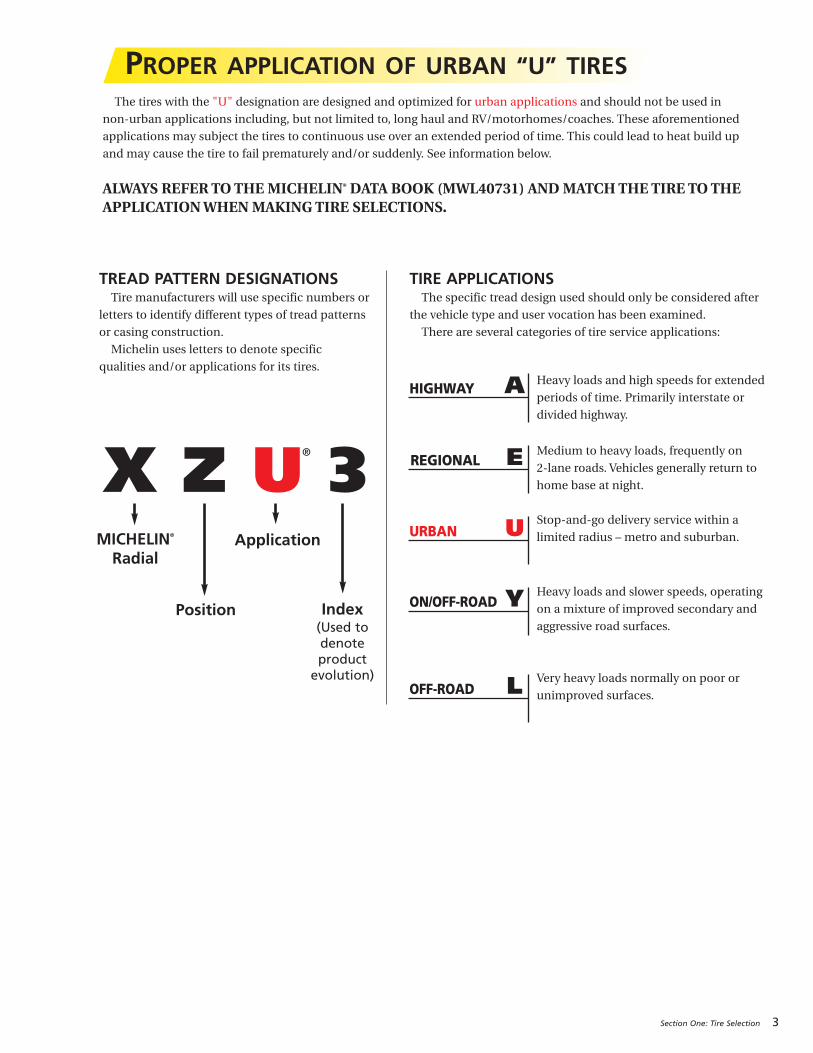
PROPER APPLICATION OF URBAN “U” TIRESThe tires with the "U" designation are designed and optimized for urban applications and should not be used in
non-urban applications including, but not limited to, long haul and RV/motorhomes/coaches. These aforementioned
applications may subject the tires to continuous use over an extended period of time. This could lead to heat build up
and may cause the tire to fail prematurely and/or suddenly. See information below.
ALWAYS REFER TO THE MICHELIN® DATA BOOK (MWL40731) AND MATCH THE TIRE TO THEAPPLICATION WHEN MAKING TIRE SELECTIONS.
X Z U 3MICHELIN®
Radial
Position
Application
Index(Used to denote product evolution)
TIRE APPLICATIONSThe specific tread design used should only be considered after
the vehicle type and user vocation has been examined.
There are several categories of tire service applications:
A
TREAD PATTERN DESIGNATIONSTire manufacturers will use specific numbers or
letters to identify different types of tread patterns
or casing construction.
Michelin uses letters to denote specific
qualities and/or applications for its tires.Heavy loads and high speeds for extended
periods of time. Primarily interstate or
divided highway.
Medium to heavy loads, frequently on
2-lane roads. Vehicles generally return to
home base at night.
Stop-and-go delivery service within a
limited radius – metro and suburban.
Heavy loads and slower speeds, operating
on a mixture of improved secondary and
aggressive road surfaces.
Very heavy loads normally on poor or
unimproved surfaces.
HIGHWAY
EREGIONAL
YON/OFF-ROAD
LOFF-ROAD
UURBAN
®

4 Section One: Tire Selection
TRUCK TIRE APPLICATIONThe choice of tire type depends upon the application
and wheel position. No matter what your application
may be, Michelin has a tire specifically designed for you.
These applications include the following:
Long Haul (A)The Long Haul application is made up of businesses
operating primarily in common carrier and lease rental
vocations. Vehicle annual mileage – 80,000 miles to
200,000 miles.
Regional (E)The Regional application is made up of businesses
such as public utilities, government – federal, state,
and local – food distribution/process, manufacturing/
process, petroleum, and schools operating within a
300-mile radius. Vehicle annual mileage – 30,000 miles
to 80,000 miles.
On/Off-Road (Y)On/Off Road tires are designed to provide the
durability and performance necessary in highly
aggressive operating conditions at limited speeds.
Vocations such as construction, mining, and refuse use
these highly specialized tires. Vehicle annual mileage –
10,000 miles to 70,000 miles.
Urban (U)Urban applications are very short mileage with
a high percentage of stop and go. Primary users are in
retail/wholesale delivery, sanitation, and bus fleets.
Vehicle annual mileage – 20,000 miles to 60,000 miles.

Section One: Tire Selection 5
Recreational Vehicle Tire Application Special Tire Applications / Off-Road (L)• Drive & Steer
• Fork Lift/Utility Vehicles
• Indoor/Outdoor Applications
Commercial Light Truck Tire Applications• Highway Tires, All-Wheel-Position
• All-Season, All-Terrain Tires
• All-Terrain Drive Axle Traction Tires
• Highway Mud & Snow Tires

6 Section One: Tire Selection
DETERMINING MICHELIN® TIRE SIZE1. Tire Size:MICHELIN® radial truck tire sizes are
designated by the nominal section width in inches or
millimeters and the wheel diameter (e.g. 11R22.5 or
275/80R22.5). The “R” indicates a radial tire. Truck tire
sizes contain dimension and load index information
and are marked in accordance with industry
standards: FMVSS (Federal Motor Vehicle Safety
Standard), TRA (The Tire and Rim Association, Inc.),
ETRTO (European Tyre and Rim Technical
Organisation), and ISO (International Standardization
Organization). This index indicates the load capacity
of the tire in single and in dual usage (e.g. 144/141K).
See Appendix under General Information (Page 116)
for complete ISO load index. Below are examples for
tubeless tires. (See Section Seven for tube-type tire
information.)
Example: 11R22.511 = nominal cross section in inches
R = radial
22.5 = wheel diameter in inches
Example: 275/80R22.5 LRG 144/141K275 = nominal cross section in mm (metric)
80 = aspect ratio
R = radial
22.5 = wheel diameter in inches
LRG = load range G
COMPARATIVE SIZES LOW-PROFILE – STANDARD PROFILEMICHELIN TRA REPLACES235/80R22.5 245/75R22.5 9R22.5
255/80R22.5 265/75R22.5 10R22.5
275/80R22.5 295/75R22.5 11R22.5
275/80R24.5 285/75R24.5 11R24.5
COMPARATIVE MICHELIN® X ONE® TIRE SIZESDUAL SIZE MICHELIN® X ONE® TIRE SIZE11R22.5, 275/80R24.5 455/55R22.5
275/80R22.5 445/50R22.5
2. Overall Width: The maximum width (cross section)
of the unloaded tires including protruding side ribs
and decorations as measured on the preferred wheel.
Overall width will change 0.1 inch (2.5 mm) for each
1⁄4 inch change in wheel width. Minimum dual
spacing should be adjusted accordingly.
3. Nominal Wheel Diameter: Diameter of wheel seat
supporting the tire bead given in nearest half-inch
numbers, e.g. 22.5".
4. Overall Diameter: The diameter of the unloaded
new tire (measured from opposite outer tread
surfaces).
5. Section Height: The distance from wheel seat to
outer tread surface of unloaded tire.
6. Aspect Ratio: A nominal number, which represents
the section height, divided by the section width and
expressed as a percentage.
Example: Tire Size Aspect Ratio11R22.5 90
275/80R22.5 80
445/50R22.5 50
7. Free Radius: One-half the overall diameter of the
unloaded new tire.
8. Loaded Radius: The distance from the wheel axle
centerline to the supporting surface under a tire
properly inflated for its load according to the load and
inflation tables found in the application specific data
books. See Appendix for listing of publications under
Publications, Videos, and Websites (Page 142).
9. Tire Deflection: Free radius minus the loaded radius.
10. Minimum Dual Spacing: The minimum allowable
lateral distance from tire tread centerline to tire tread
centerline in a dual wheel arrangement.
11. Tire Revolutions Per Mile: Revolutions per mile
for a tire size and tread is defined as the number of
revolutions that the new tire will make in one mile.
Data is normally presented for the loaded tire at its
rated load and inflation in the drive position. Rolling
circumference can be calculated from the revolutions
per mile as follows:
63,360 = Rolling circumference
Tire Revs./Mile in inches
The tire revolutions per mile can be determined by
measuring (using SAE J1025) or estimated by using
a mathematical equation. See Appendix under Tire
Revolutions Per Mile Calculation (Page 131).
The accuracy of the tire revolutions per mile number
is ±1%.
12. Wheels: The approved/preferred wheels are
designated for each tire size. MICHELIN® tires should
only be mounted on the wheels shown. The wheel
shown first is the preferred wheel. Be sure to check
wheel manufacturer’s specifications.
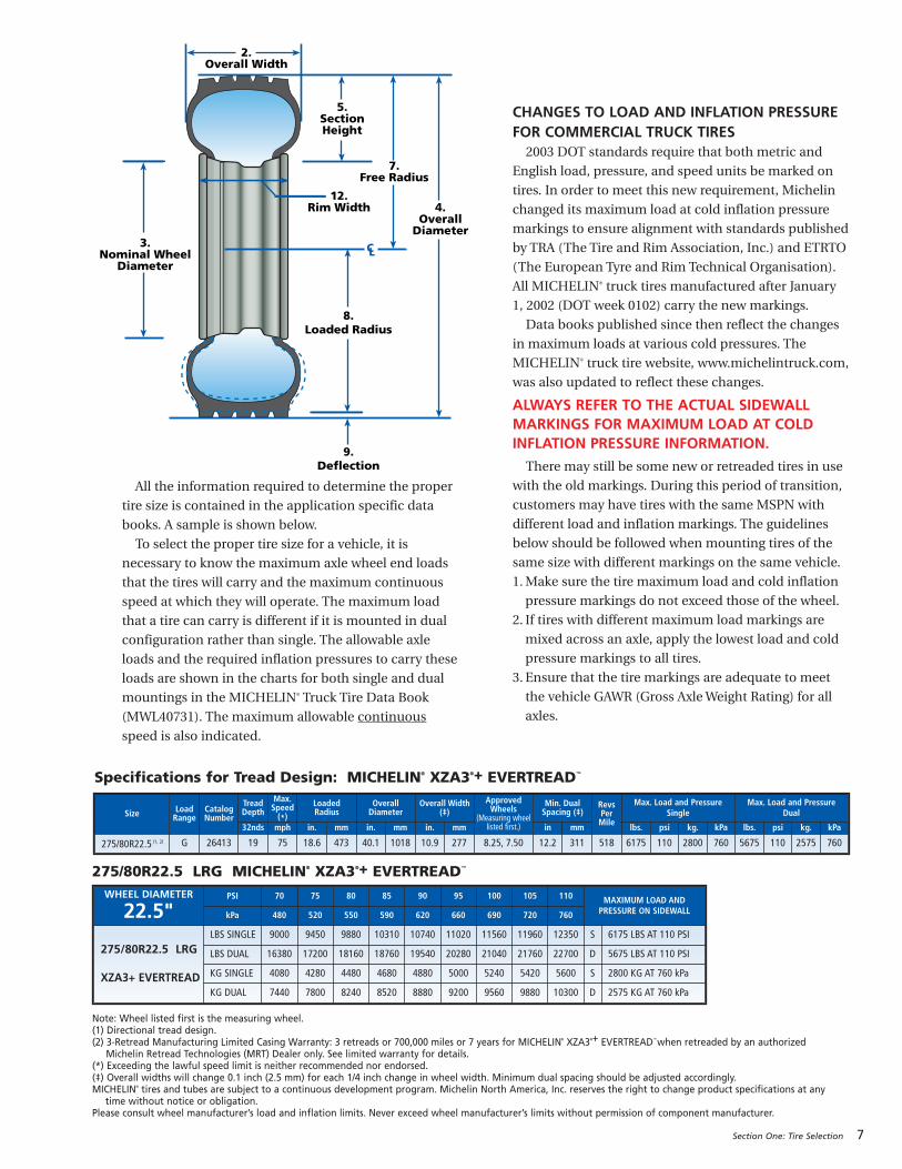
All the information required to determine the proper
tire size is contained in the application specific data
books. A sample is shown below.
To select the proper tire size for a vehicle, it is
necessary to know the maximum axle wheel end loads
that the tires will carry and the maximum continuous
speed at which they will operate. The maximum load
that a tire can carry is different if it is mounted in dual
configuration rather than single. The allowable axle
loads and the required inflation pressures to carry these
loads are shown in the charts for both single and dual
mountings in the MICHELIN® Truck Tire Data Book
(MWL40731). The maximum allowable continuous
speed is also indicated.
CHANGES TO LOAD AND INFLATION PRESSUREFOR COMMERCIAL TRUCK TIRES2003 DOT standards require that both metric and
English load, pressure, and speed units be marked on
tires. In order to meet this new requirement, Michelin
changed its maximum load at cold inflation pressure
markings to ensure alignment with standards published
by TRA (The Tire and Rim Association, Inc.) and ETRTO
(The European Tyre and Rim Technical Organisation).
All MICHELIN® truck tires manufactured after January
1, 2002 (DOT week 0102) carry the new markings.
Data books published since then reflect the changes
in maximum loads at various cold pressures. The
MICHELIN® truck tire website, www.michelintruck.com,
was also updated to reflect these changes.
ALWAYS REFER TO THE ACTUAL SIDEWALLMARKINGS FOR MAXIMUM LOAD AT COLDINFLATION PRESSURE INFORMATION.
There may still be some new or retreaded tires in use
with the old markings. During this period of transition,
customers may have tires with the same MSPN with
different load and inflation markings. The guidelines
below should be followed when mounting tires of the
same size with different markings on the same vehicle.
1.Make sure the tire maximum load and cold inflation
pressure markings do not exceed those of the wheel.
2. If tires with different maximum load markings are
mixed across an axle, apply the lowest load and cold
pressure markings to all tires.
3. Ensure that the tire markings are adequate to meet
the vehicle GAWR (Gross Axle Weight Rating) for all
axles.
Section One: Tire Selection 7
C L
9.Deflection
8. Loaded Radius
3. Nominal Wheel
Diameter
4. Overall
Diameter
7. Free Radius
5. Section Height
2.Overall Width
12. Rim Width
Note: Wheel listed first is the measuring wheel.(1) Directional tread design.(2) 3-Retread Manufacturing Limited Casing Warranty: 3 retreads or 700,000 miles or 7 years for MICHELIN® XZA3®+ EVERTREAD™ when retreaded by an authorized
Michelin Retread Technologies (MRT) Dealer only. See limited warranty for details.(*) Exceeding the lawful speed limit is neither recommended nor endorsed.(‡) Overall widths will change 0.1 inch (2.5 mm) for each 1/4 inch change in wheel width. Minimum dual spacing should be adjusted accordingly.MICHELIN® tires and tubes are subject to a continuous development program. Michelin North America, Inc. reserves the right to change product specifications at any
time without notice or obligation.Please consult wheel manufacturer’s load and inflation limits. Never exceed wheel manufacturer’s limits without permission of component manufacturer.
Specifications for Tread Design: MICHELIN® XZA3®+ EVERTREAD™
Size LoadRange
CatalogNumber
TreadDepth
Max.Speed(*)
Loaded Radius
Overall Diameter
Overall Width(‡)
Approved Wheels
(Measuring wheellisted first.)
Min. Dual Spacing (‡)
Revs Per Mile
Max. Load and PressureSingle
Max. Load and PressureDual
32nds mph in. mm in. mm in. mm in mm lbs. psi kg. kPa lbs. psi kg. kPa
275/80R22.5 (1, 2) G 26413 19 75 18.6 473 40.1 1018 10.9 277 8.25, 7.50 12.2 311 518 6175 110 2800 760 5675 110 2575 760
WHEEL DIAMETER
22.5"PSI 70 75 80 85 90 95 100 105 110 MAXIMUM LOAD AND
PRESSURE ON SIDEWALLkPa 480 520 550 590 620 660 690 720 760
275/80R22.5 LRG
XZA3+ EVERTREAD
LBS SINGLE 9000 9450 9880 10310 10740 11020 11560 11960 12350 S 6175 LBS AT 110 PSI
LBS DUAL 16380 17200 18160 18760 19540 20280 21040 21760 22700 D 5675 LBS AT 110 PSI
KG SINGLE 4080 4280 4480 4680 4880 5000 5240 5420 5600 S 2800 KG AT 760 kPa
KG DUAL 7440 7800 8240 8520 8880 9200 9560 9880 10300 D 2575 KG AT 760 kPa
275/80R22.5 LRG MICHELIN® XZA3®+ EVERTREAD™
8 Section One: Tire Selection
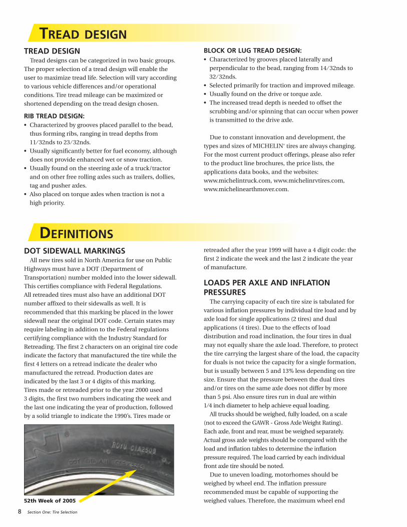
DOT SIDEWALL MARKINGSAll new tires sold in North America for use on Public
Highways must have a DOT (Department of
Transportation) number molded into the lower sidewall.
This certifies compliance with Federal Regulations.
All retreaded tires must also have an additional DOT
number affixed to their sidewalls as well. It is
recommended that this marking be placed in the lower
sidewall near the original DOT code. Certain states may
require labeling in addition to the Federal regulations
certifying compliance with the Industry Standard for
Retreading. The first 2 characters on an original tire code
indicate the factory that manufactured the tire while the
first 4 letters on a retread indicate the dealer who
manufactured the retread. Production dates are
indicated by the last 3 or 4 digits of this marking.
Tires made or retreaded prior to the year 2000 used
3 digits, the first two numbers indicating the week and
the last one indicating the year of production, followed
by a solid triangle to indicate the 1990’s. Tires made or
retreaded after the year 1999 will have a 4 digit code: the
first 2 indicate the week and the last 2 indicate the year
of manufacture.
LOADS PER AXLE AND INFLATION PRESSURES
The carrying capacity of each tire size is tabulated for
various inflation pressures by individual tire load and by
axle load for single applications (2 tires) and dual
applications (4 tires). Due to the effects of load
distribution and road inclination, the four tires in dual
may not equally share the axle load. Therefore, to protect
the tire carrying the largest share of the load, the capacity
for duals is not twice the capacity for a single formation,
but is usually between 5 and 13% less depending on tire
size. Ensure that the pressure between the dual tires
and/or tires on the same axle does not differ by more
than 5 psi. Also ensure tires run in dual are within
1 ⁄4 inch diameter to help achieve equal loading.
All trucks should be weighed, fully loaded, on a scale
(not to exceed the GAWR - Gross Axle Weight Rating).
Each axle, front and rear, must be weighed separately.
Actual gross axle weights should be compared with the
load and inflation tables to determine the inflation
pressure required. The load carried by each individual
front axle tire should be noted.
Due to uneven loading, motorhomes should be
weighed by wheel end. The inflation pressure
recommended must be capable of supporting the
weighed values. Therefore, the maximum wheel end
TREAD DESIGN
DEFINITIONS
TREAD DESIGNTread designs can be categorized in two basic groups.
The proper selection of a tread design will enable the
user to maximize tread life. Selection will vary according
to various vehicle differences and/or operational
conditions. Tire tread mileage can be maximized or
shortened depending on the tread design chosen.
RIB TREAD DESIGN:• Characterized by grooves placed parallel to the bead,
thus forming ribs, ranging in tread depths from
11⁄ 32nds to 23 ⁄ 32nds.
• Usually significantly better for fuel economy, although
does not provide enhanced wet or snow traction.
• Usually found on the steering axle of a truck/tractor
and on other free rolling axles such as trailers, dollies,
tag and pusher axles.
• Also placed on torque axles when traction is not a
high priority.
BLOCK OR LUG TREAD DESIGN:• Characterized by grooves placed laterally and
perpendicular to the bead, ranging from 14 ⁄ 32nds to
32 ⁄ 32nds.
• Selected primarily for traction and improved mileage.
• Usually found on the drive or torque axle.
• The increased tread depth is needed to offset the
scrubbing and/or spinning that can occur when power
is transmitted to the drive axle.
Due to constant innovation and development, the
types and sizes of MICHELIN® tires are always changing.
For the most current product offerings, please also refer
to the product line brochures, the price lists, the
applications data books, and the websites:
www.michelintruck.com, www.michelinrvtires.com,
www.michelinearthmover.com.
52th Week of 2005
Section One: Tire Selection 9
weight for the axle must be used. The maximum axle
weight is determined by taking the highest wheel end
value and multiplying by 2 for single applications and
4 for dual applications.
If the maximum load-carrying capacity of the tire is
below the actual scale weight, then tires with greater
carrying capacity should be used. This means either a
tire with a higher load range or ply rating, or a larger
tire size.
If the maximum load can be carried by the minimum
pressure (as listed on the Load Inflation Chart), then a
smaller size tire or a lower ply rated tire should be
considered depending on the application and operation
of the vehicle.
Never reduce pressure below minimum data book
specification without consulting Michelin.
Ambient temperature will affect the pressure within
the tire. For every 10-degree temperature change,
pressure readings will change between 1 and 2 pounds
per square inch (psi). Consider this when checking
pressures. Check all tires when cold at least 3 hours after
the vehicle has stopped. Never bleed air from hot tires.Additionally, altitude can have a slight affect on
pressure. For every 1,000 foot increase in altitude above
sea level, pressure will increase approximately 1 ⁄ 2 psi.
For example, a tire inflated to 100 psi at sea level will
read slightly over 102 psi in Denver, Colorado.
Please consult with Michelin for additional
information on cold and hot climate corrections.
WHEELSThe correct wheels for each tire size are indicated in
the specification tables. For complete tire specifications,
refer to application specific data books.
MAXIMUM SPEED RESTRICTIONS*Truck tires should normally be inflated according to
the specification tables. The carrying capacities and
inflation pressures specified in these tables are
determined with the tire’s rated maximum speed in
consideration. (See specification tables for each tire’s
rated speed in the current MICHELIN® Truck Tire Data
Book - MWL40731.) This is a maximum continuous
speed, not an absolute upper limit.
Reducing the maximum speed at which the tire will
operate and adjusting inflation pressures according to
the information contained in the following chart can
help increase the carrying capacity. To use the Low Speed
and Static Coefficient Chart (Page 10) you must know the
tire size (standard conventional size example - 11R22.5
or low profile 275/80R22.5) and the maximum speed
rating of that tire. Speed ratings can be found in the data
book. Based on the size and speed rating, select the
correct quadrant (Table A or B), find the speed value
desired, and multiply the tire load capacity by the
coefficient provided. Also, add the listed increase in
pressure (if any) to the pressure value for the selected
tire shown in the data book. Give special attention to the
wheel and vehicle axle ratings that may be exceeded by
the increases in load and pressure. Tires optimized for
highway applications have a maximum speed of 75 mph*.
For speeds less than 20 mph (32 kph), please consult
Michelin North America, Inc.
These limits apply only to Light Truck and Truck tires,
but do not include Special Application tires, tires for
high cube vans, low bed trailers, urban, on/off-road use
and 315/80R22.5 LRL mounted on 8.25x22.5" wheels on
steer axles.
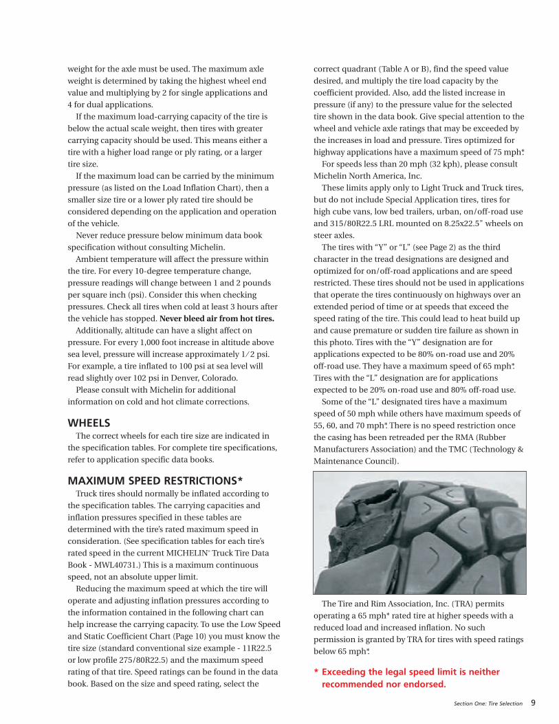
The tires with “Y” or “L” (see Page 2) as the third
character in the tread designations are designed and
optimized for on/off-road applications and are speed
restricted. These tires should not be used in applications
that operate the tires continuously on highways over an
extended period of time or at speeds that exceed the
speed rating of the tire. This could lead to heat build up
and cause premature or sudden tire failure as shown in
this photo. Tires with the “Y” designation are for
applications expected to be 80% on-road use and 20%
off-road use. They have a maximum speed of 65 mph*.
Tires with the “L” designation are for applications
expected to be 20% on-road use and 80% off-road use.
Some of the “L” designated tires have a maximum
speed of 50 mph while others have maximum speeds of
55, 60, and 70 mph*. There is no speed restriction once
the casing has been retreaded per the RMA (Rubber
Manufacturers Association) and the TMC (Technology &
Maintenance Council).
The Tire and Rim Association, Inc. (TRA) permits
operating a 65 mph* rated tire at higher speeds with a
reduced load and increased inflation. No such
permission is granted by TRA for tires with speed ratings
below 65 mph*.
* Exceeding the legal speed limit is neitherrecommended nor endorsed.

10 Section One: Tire Selection
STATIC AND LOW SPEED LOAD AND PRESSURE COEFFICIENTSDo not exceed loads or pressure limits of the wheel without permission of the componentmanufacturer. Exceeding the legal speed limit is neither recommended nor endorsed.
TRA (THE TIRE AND RIM ASSOCIATION, INC.) STANDARDS(These Tables apply to tires only. Consult wheel manufacturer for wheel load and inflation capacities.)
Load limits at various speeds for radial ply truck-bus tires used on improved surfaces. (1)
Load limits at various speeds for radial ply truck-bus tires, rated at 75 mph or above, used on improved surfaces. (1)
C. METRIC AND WIDE BASE TIRES D. CONVENTIONAL TIRES
A. METRIC AND WIDE BASE TIRESThe service load and minimum (cold) inflation must
comply with the following limitations unless a speed
restriction is indicated on the tire.*
B. CONVENTIONAL TIRESThe service load and minimum (cold) inflation must
comply with the following limitations unless a speed
restriction is indicated on the tire.*
Note: For bias ply tires please consult the TRA Year Book.
(1) These load and inflation changes are only required when exceeding the tire manufacturer’s rated speed for the tire. (2) Apply these increases to Dual Loads and Inflation Pressures.(3) Creep – Motion for not over 200 feet in a 30-minute period.Note 1: The inflation pressures shown in the referenced tables are minimum cold pressures for the various loads listed.
Higher pressures should be used as follows:A. When required by the above speed/load table.B. When higher pressures are desirable to obtain improved operating performance.For speeds above 20 mph, the combined increases of A and B should not exceed 20 psi above the inflation specified for themaximum load of the tire.
Note 2: Load limits at various speeds for:Tires used in highway service at restricted speed.Mining and logging tires used in intermittent highway service
*Exceeding the legal speed limit is neither recommended or endorsed.
Speed Range(mph) % Load Change Inflation
Pressure Change
41 thru 50 +7% No increase
31 thru 40 +9% No increase
21 thru 30 +12% +10 psi
11 thru 20 +17% +15 psi
6 thru 10 +25% +20 psi
2.6 thru 5 +45% +20 psi
Creep thru 2.5 +55% +20 psi
Creep (2) +75% +30 psi
Stationary +105% +30 psi
Speed Range(mph) % Load Change Inflation
Pressure Change
41 thru 50 +9% No increase
31 thru 40 +16% No increase
21 thru 30 +24% +10 psi
11 thru 20 +32% +15 psi
6 thru 10 (2) +60% +30 psi
2.6 thru 5 (2) +85% +30 psi
Creep thru 2.5 (2) +115% +30 psi
Creep (2) (3) +140% +40 psi
Stationary (2) +185% +40 psi
Speed Range(mph) % Load Change Inflation
Pressure Change
41 thru 50 +7% No increase
31 thru 40 +9% No increase
21 thru 30 +12% +10 psi
11 thru 20 +17% +15 psi
6 thru 10 +25% +20 psi
2.6 thru 5 +45% +20 psi
Creep thru 2.5 +55% +20 psi
Creep (2) +75% +30 psi
Stationary +105% +30 psi
Speed Range(mph) % Load Change Inflation
Pressure Change
41 thru 50 +9% No increase
31 thru 40 +16% No increase
21 thru 30 +24% +10 psi
11 thru 20 +32% +15 psi
6 thru 10 (3) +60% +30 psi
2.6 thru 5 (3) +85% +30 psi
Creep thru 2.5 (3) +115% +30 psi
Creep (2)(3) +140% +40 psi
Stationary (3) +185% +40 psi

Section One: Tire Selection 11
LOAD / INFLATION TABLE FOR MICHELIN® 315/80R22.5 LRLThe following table applies to LRL use with 8.25x22.5 Wheels.
To determine the proper load/inflation table, always comply with the markings on the tire sidewall for maximum loadat cold pressure. Load and inflation industry standards are in a constant state of change. Michelin continually updates its product information to reflect these changes.Therefore, printed material may not reflect the current load and inflation information. NOTE: Never exceed the wheel manufacturer’s maximum pressure limitation.
S = Single configuration – 2 tires per axle. D = Dual configuration – 4 tires per axle. Loads are indicated per axle.
TECHNICAL SPECIFICATIONS FOR MICHELIN® 455/55R22.5 LRM ON 13.00x22.5 WHEELS STEER AXLE, FIRST LIFE ONLY
Note: Never exceed the wheel manufacturer's maximum cold pressure limitation and/or load rating.* When used on an 8.25” wheel, the max load and pressure is lower than that indicated on the sidewall.
* Note: When used on a 13.00" wheel the max load and pressure is lower than that indicated on the sidewall.
8.25" Wheel – Michelin recommendation (loads per axle): Minimum dual spacing 13.5" (343 mm)
DimensionLoadRange
PSI 75 80 85 90 95 100 105 110 115 120*
kPa 520 550 590 620 660 690 720 760 790 830
315/80R22.58.25" Wheel
LRL
lbs. per axle
S 10990 11570 12140 12710 13280 13820 14380 14920 15460 16000
D 20900 22000 23100 24180 25260 26300 27360 28400 29440 30440
kg. per axle
S 4980 5250 5510 5770 6020 6270 6520 6770 7010 7260
D 9480 9980 10480 10970 11460 11930 12410 12880 13350 13810
DimensionLoadRange
Loaded RadiusRPM
Max. Load Single*
in. mm. lbs. psi kg. kPa
455/55R22.5 LRM 19.5 496 493 10000 120 4535 830
DimensionLoadRange
psi 75 80 85 90 95 100 105 110 115 120
kPa 520 550 590 620 660 690 720 760 790 830
455/55R22.513.00" Wheel
LRMlbs. per axle 13740 14460 15180 15880 16600 17280 17980 18660 19340 20000
kg. per axle 6240 6520 6900 7180 7560 7820 8100 8460 8720 9070
12 Section One: Tire Selection
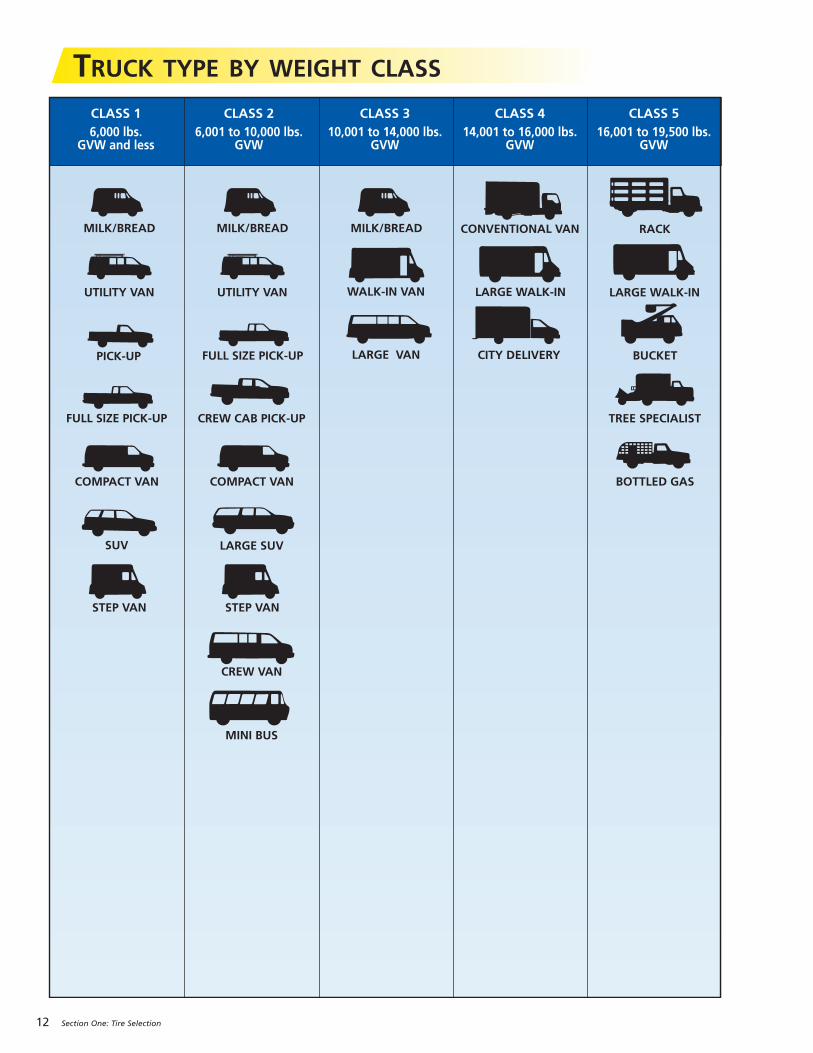
TRUCK TYPE BY WEIGHT CLASS
PICK-UP
MILK/BREAD MILK/BREADMILK/BREAD
FULL SIZE PICK-UP
FULL SIZE PICK-UP
UTILITY VANUTILITY VAN
CONVENTIONAL VAN
CITY DELIVERY
SUV
WALK-IN VAN LARGE WALK-IN
CREW CAB PICK-UP
LARGE VAN
COMPACT VAN COMPACT VAN
STEP VAN STEP VAN
RACK
LARGE WALK-IN
BUCKET
TREE SPECIALIST
BOTTLED GAS
CREW VAN
LARGE SUV
MINI BUS
CLASS 1 CLASS 2 CLASS 3 CLASS 4 CLASS 5 6,000 lbs. 6,001 to 10,000 lbs. 10,001 to 14,000 lbs. 14,001 to 16,000 lbs. 16,001 to 19,500 lbs. GVW and less GVW GVW GVW GVW
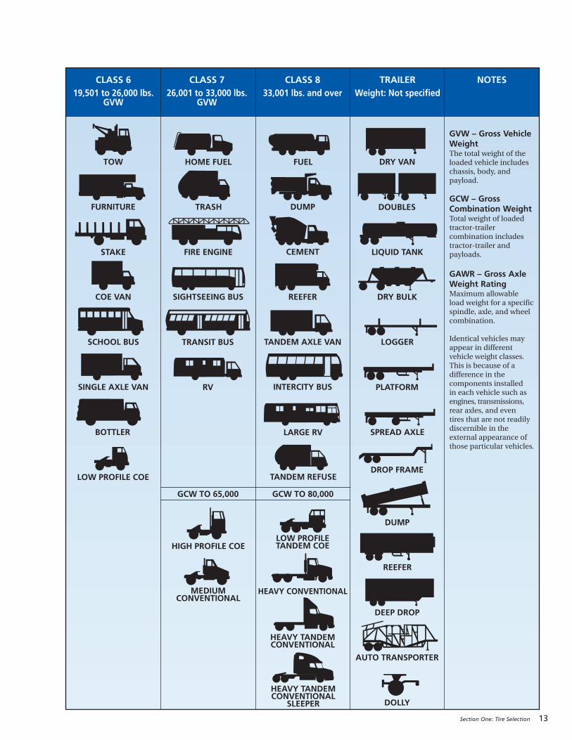
Section One: Tire Selection 13
TOW HOME FUEL FUEL DRY VAN
FURNITURE TRASH DUMP DOUBLES
STAKE FIRE ENGINE CEMENT LIQUID TANK
COE VAN SIGHTSEEING BUS REEFER DRY BULK
SCHOOL BUS TRANSIT BUS TANDEM AXLE VAN LOGGER
SINGLE AXLE VAN RV INTERCITY BUS PLATFORM
BOTTLER LARGE RV SPREAD AXLE
LOW PROFILE COE
GCW TO 65,000 GCW TO 80,000
DROP FRAME
MEDIUM CONVENTIONAL
LOW PROFILETANDEM COE
DUMP
HIGH PROFILE COE
HEAVY CONVENTIONAL
REEFER
HEAVY TANDEM CONVENTIONAL
DEEP DROP
HEAVY TANDEM CONVENTIONAL
SLEEPER
AUTO TRANSPORTER
TANDEM REFUSE
DOLLY
CLASS 6 CLASS 7 CLASS 8 TRAILER NOTES 19,501 to 26,000 lbs. 26,001 to 33,000 lbs. 33,001 lbs. and over Weight: Not specified GVW GVW
GVW – Gross VehicleWeightThe total weight of theloaded vehicle includeschassis, body, andpayload.
GCW – GrossCombination Weight Total weight of loadedtractor-trailercombination includestractor-trailer andpayloads.
GAWR – Gross AxleWeight Rating Maximum allowableload weight for a specificspindle, axle, and wheelcombination.
Identical vehicles mayappear in differentvehicle weight classes.This is because of adifference in thecomponents installed in each vehicle such asengines, transmissions,rear axles, and even tires that are not readilydiscernible in theexternal appearance ofthose particular vehicles.
14 Section One: Tire Selection
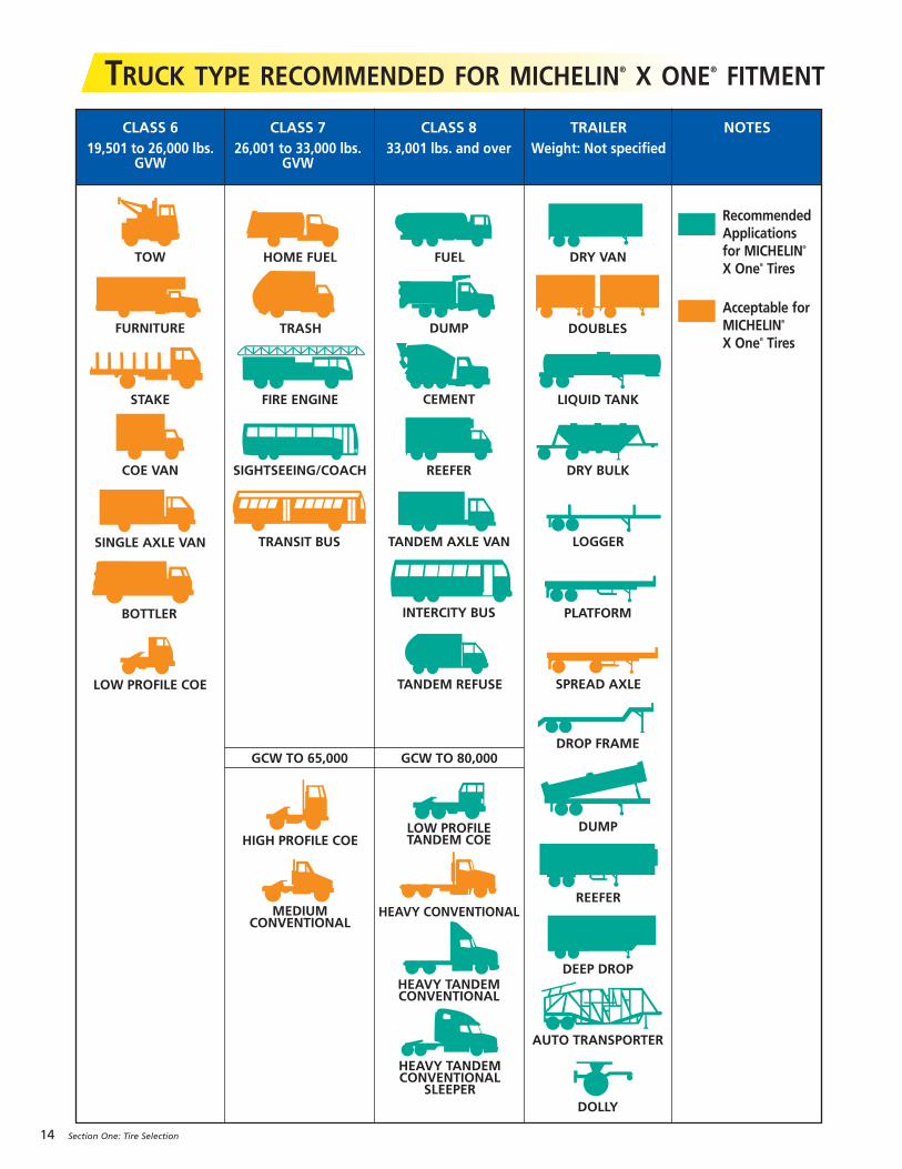
TRUCK TYPE RECOMMENDED FOR MICHELIN® X ONE® FITMENT
TOW HOME FUEL FUEL DRY VAN
FURNITURE TRASH DUMP DOUBLES
STAKE FIRE ENGINE CEMENT LIQUID TANK
COE VAN SIGHTSEEING/COACH REEFER DRY BULK
TRANSIT BUS TANDEM AXLE VAN LOGGERSINGLE AXLE VAN
INTERCITY BUS PLATFORMBOTTLER
SPREAD AXLELOW PROFILE COE
GCW TO 65,000 GCW TO 80,000DROP FRAME
MEDIUM CONVENTIONAL
LOW PROFILETANDEM COE
DUMPHIGH PROFILE COE
HEAVY CONVENTIONALREEFER
HEAVY TANDEM CONVENTIONAL
DEEP DROP
HEAVY TANDEM CONVENTIONAL
SLEEPER
AUTO TRANSPORTER
TANDEM REFUSE
DOLLY
CLASS 6 CLASS 7 CLASS 8 TRAILER NOTES 19,501 to 26,000 lbs. 26,001 to 33,000 lbs. 33,001 lbs. and over Weight: Not specified GVW GVW
RecommendedApplicationsfor MICHELIN®
X One® Tires
Acceptable forMICHELIN®
X One® Tires

15
SECTION TWO
Mounting the Tire
WARNINGS . . . . . . . . . . . . . . . . . . . . . . . . . . . . 16-17
Zipper Ruptures
Tire Inspection
GENERAL INSTRUCTIONS FOR TUBELESS TIREMOUNTING/DEMOUNTING . . . . . . . . . . . . . . . 18-22
Tubeless Tire Mounting/Demounting Using a Mounting Machine
Directional Tires
Selection of Proper Components and Materials
Tire and Wheel Lubrication
Preparation of Wheels and Tires
TUBELESS TIRE MOUNTING/DEMOUNTING . . 23-29 Mounting Tubeless
19.5" Aluminum Wheels
19.5" Steel Wheels
Inflation of Tubeless Tires
Demounting of Tubeless Tires
MOUNTING THE ASSEMBLY ON THE VEHICLE . . 30-34 Dual Spacing
Technical Considerations for Fitting Tires
Measuring Tires in Dual Assembly
Tire Mixing
Runout
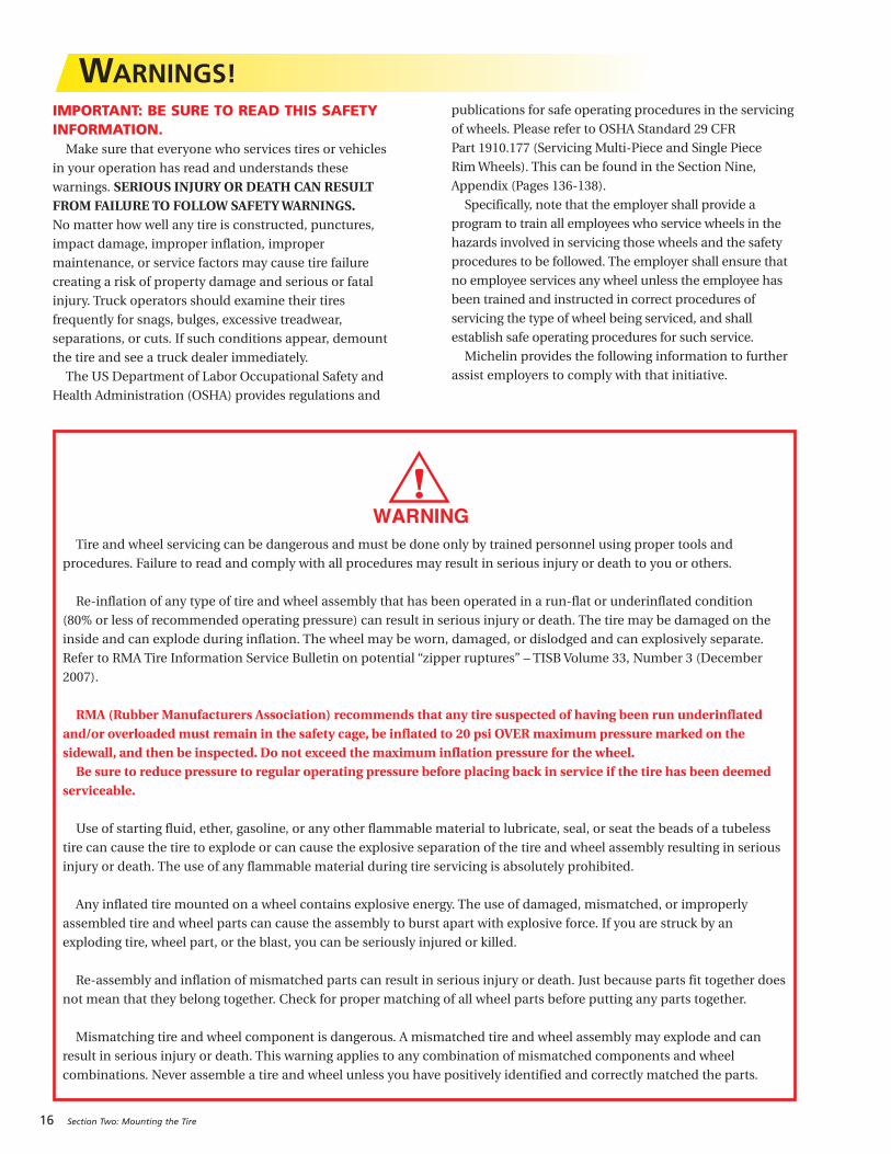
Tire and wheel servicing can be dangerous and must be done only by trained personnel using proper tools and
procedures. Failure to read and comply with all procedures may result in serious injury or death to you or others.
Re-inflation of any type of tire and wheel assembly that has been operated in a run-flat or underinflated condition
(80% or less of recommended operating pressure) can result in serious injury or death. The tire may be damaged on the
inside and can explode during inflation. The wheel may be worn, damaged, or dislodged and can explosively separate.
Refer to RMA Tire Information Service Bulletin on potential “zipper ruptures” – TISB Volume 33, Number 3 (December
2007).
RMA (Rubber Manufacturers Association) recommends that any tire suspected of having been run underinflatedand/or overloaded must remain in the safety cage, be inflated to 20 psi OVER maximum pressure marked on thesidewall, and then be inspected. Do not exceed the maximum inflation pressure for the wheel. Be sure to reduce pressure to regular operating pressure before placing back in service if the tire has been deemed
serviceable.
Use of starting fluid, ether, gasoline, or any other flammable material to lubricate, seal, or seat the beads of a tubeless
tire can cause the tire to explode or can cause the explosive separation of the tire and wheel assembly resulting in serious
injury or death. The use of any flammable material during tire servicing is absolutely prohibited.
Any inflated tire mounted on a wheel contains explosive energy. The use of damaged, mismatched, or improperly
assembled tire and wheel parts can cause the assembly to burst apart with explosive force. If you are struck by an
exploding tire, wheel part, or the blast, you can be seriously injured or killed.
Re-assembly and inflation of mismatched parts can result in serious injury or death. Just because parts fit together does
not mean that they belong together. Check for proper matching of all wheel parts before putting any parts together.
Mismatching tire and wheel component is dangerous. A mismatched tire and wheel assembly may explode and can
result in serious injury or death. This warning applies to any combination of mismatched components and wheel
combinations. Never assemble a tire and wheel unless you have positively identified and correctly matched the parts.
16 Section Two: Mounting the Tire
WARNINGS!IMPORTANT: BE SURE TO READ THIS SAFETYINFORMATION.
Make sure that everyone who services tires or vehicles
in your operation has read and understands these
warnings. SERIOUS INJURY OR DEATH CAN RESULTFROM FAILURE TO FOLLOW SAFETY WARNINGS.No matter how well any tire is constructed, punctures,
impact damage, improper inflation, improper
maintenance, or service factors may cause tire failure
creating a risk of property damage and serious or fatal
injury. Truck operators should examine their tires
frequently for snags, bulges, excessive treadwear,
separations, or cuts. If such conditions appear, demount
the tire and see a truck dealer immediately.
The US Department of Labor Occupational Safety and
Health Administration (OSHA) provides regulations and
publications for safe operating procedures in the servicing
of wheels. Please refer to OSHA Standard 29 CFR
Part 1910.177 (Servicing Multi-Piece and Single Piece
Rim Wheels). This can be found in the Section Nine,
Appendix (Pages 136-138).
Specifically, note that the employer shall provide a
program to train all employees who service wheels in the
hazards involved in servicing those wheels and the safety
procedures to be followed. The employer shall ensure that
no employee services any wheel unless the employee has
been trained and instructed in correct procedures of
servicing the type of wheel being serviced, and shall
establish safe operating procedures for such service.
Michelin provides the following information to further
assist employers to comply with that initiative.
Section Two: Mounting the Tire 17
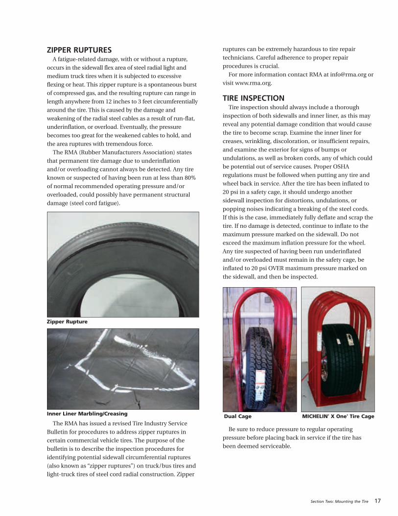
ZIPPER RUPTURESA fatigue-related damage, with or without a rupture,
occurs in the sidewall flex area of steel radial light and
medium truck tires when it is subjected to excessive
flexing or heat. This zipper rupture is a spontaneous burst
of compressed gas, and the resulting rupture can range in
length anywhere from 12 inches to 3 feet circumferentially
around the tire. This is caused by the damage and
weakening of the radial steel cables as a result of run-flat,
underinflation, or overload. Eventually, the pressure
becomes too great for the weakened cables to hold, and
the area ruptures with tremendous force.
The RMA (Rubber Manufacturers Association) states
that permanent tire damage due to underinflation
and/or overloading cannot always be detected. Any tire
known or suspected of having been run at less than 80%
of normal recommended operating pressure and/or
overloaded, could possibly have permanent structural
damage (steel cord fatigue).
The RMA has issued a revised Tire Industry Service
Bulletin for procedures to address zipper ruptures in
certain commercial vehicle tires. The purpose of the
bulletin is to describe the inspection procedures for
identifying potential sidewall circumferential ruptures
(also known as “zipper ruptures”) on truck/bus tires and
light-truck tires of steel cord radial construction. Zipper
ruptures can be extremely hazardous to tire repair
technicians. Careful adherence to proper repair
procedures is crucial.
For more information contact RMA at [email protected] or
visit www.rma.org.
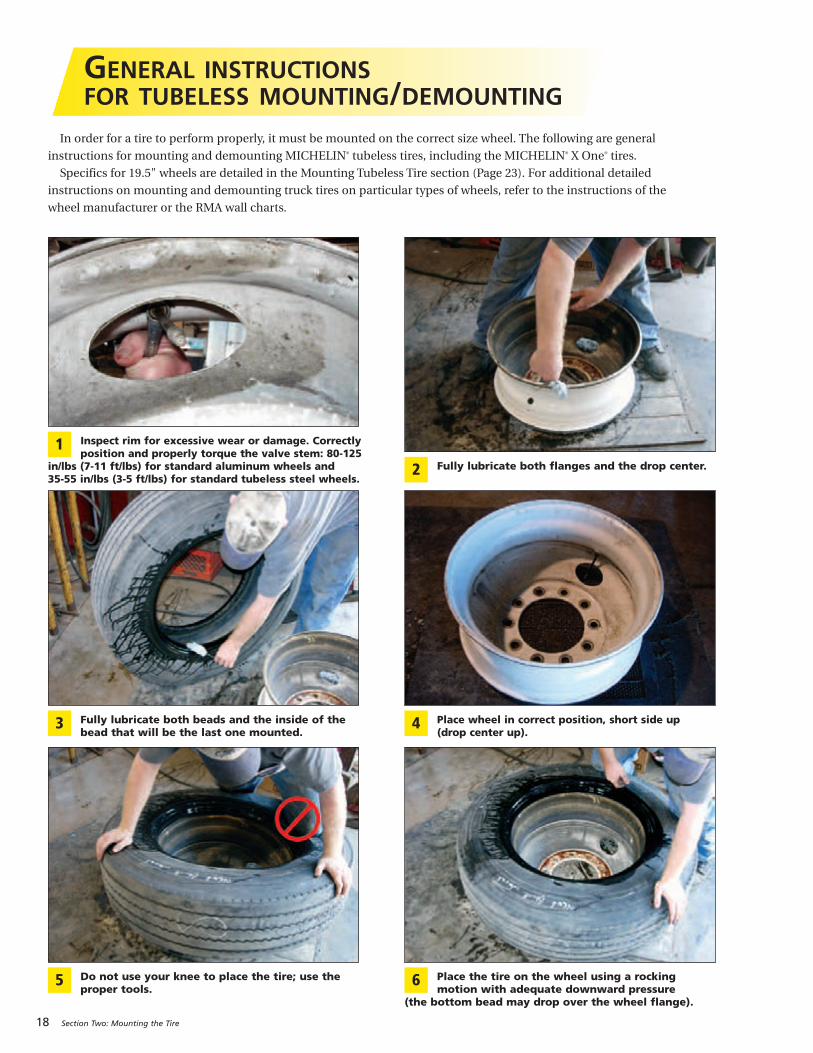
TIRE INSPECTIONTire inspection should always include a thorough
inspection of both sidewalls and inner liner, as this may
reveal any potential damage condition that would cause
the tire to become scrap. Examine the inner liner for
creases, wrinkling, discoloration, or insufficient repairs,
and examine the exterior for signs of bumps or
undulations, as well as broken cords, any of which could
be potential out of service causes. Proper OSHA
regulations must be followed when putting any tire and
wheel back in service. After the tire has been inflated to
20 psi in a safety cage, it should undergo another
sidewall inspection for distortions, undulations, or
popping noises indicating a breaking of the steel cords.
If this is the case, immediately fully deflate and scrap the
tire. If no damage is detected, continue to inflate to the
maximum pressure marked on the sidewall. Do not
exceed the maximum inflation pressure for the wheel.
Any tire suspected of having been run underinflated
and/or overloaded must remain in the safety cage, be
inflated to 20 psi OVER maximum pressure marked on
the sidewall, and then be inspected.
Be sure to reduce pressure to regular operating
pressure before placing back in service if the tire has
been deemed serviceable.
Dual Cage MICHELIN® X One® Tire Cage
Zipper Rupture
Inner Liner Marbling/Creasing
18 Section Two: Mounting the Tire
GENERAL INSTRUCTIONSFOR TUBELESS MOUNTING/DEMOUNTING
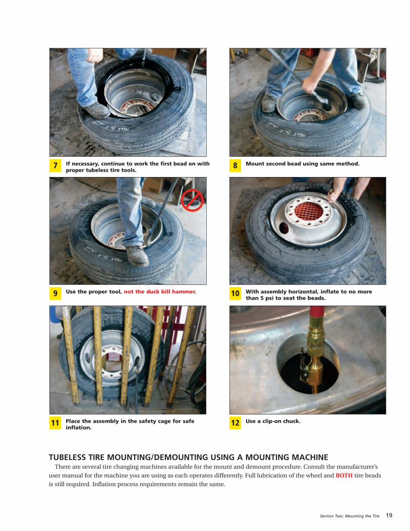
In order for a tire to perform properly, it must be mounted on the correct size wheel. The following are general
instructions for mounting and demounting MICHELIN® tubeless tires, including the MICHELIN® X One® tires.
Specifics for 19.5" wheels are detailed in the Mounting Tubeless Tire section (Page 23). For additional detailed
instructions on mounting and demounting truck tires on particular types of wheels, refer to the instructions of the
wheel manufacturer or the RMA wall charts.
Fully lubricate both flanges and the drop center.2
Fully lubricate both beads and the inside of thebead that will be the last one mounted.
3 Place wheel in correct position, short side up (drop center up).
4
Do not use your knee to place the tire; use the proper tools.
5 Place the tire on the wheel using a rockingmotion with adequate downward pressure
(the bottom bead may drop over the wheel flange).
6
Inspect rim for excessive wear or damage. Correctlyposition and properly torque the valve stem: 80-125
in/lbs (7-11 ft/lbs) for standard aluminum wheels and 35-55 in/lbs (3-5 ft/lbs) for standard tubeless steel wheels.
1
Section Two: Mounting the Tire 19
If necessary, continue to work the first bead on withproper tubeless tire tools.
7 Mount second bead using same method.8
Use the proper tool, not the duck bill hammer.9 With assembly horizontal, inflate to no more than 5 psi to seat the beads.
10
Use a clip-on chuck.12Place the assembly in the safety cage for safe inflation.
11
TUBELESS TIRE MOUNTING/DEMOUNTING USING A MOUNTING MACHINEThere are several tire changing machines available for the mount and demount procedure. Consult the manufacturer’s
user manual for the machine you are using as each operates differently. Full lubrication of the wheel and BOTH tire beads
is still required. Inflation process requirements remain the same.
20 Section Two: Mounting the Tire
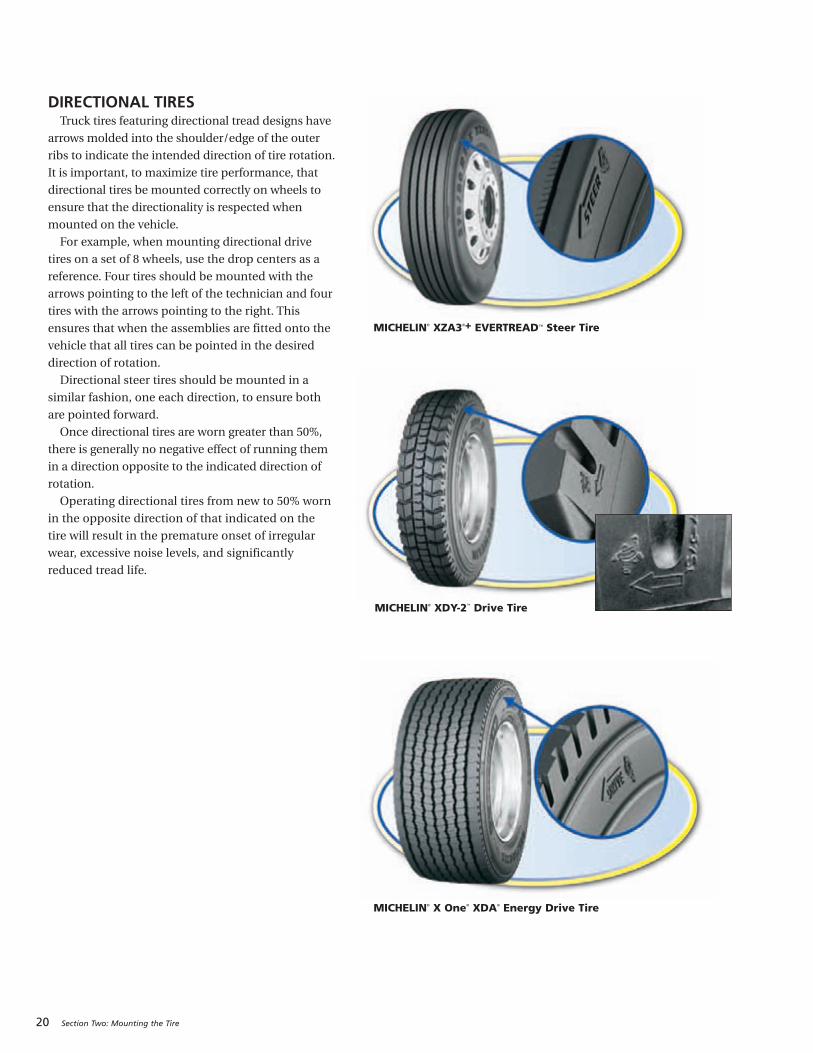
DIRECTIONAL TIRESTruck tires featuring directional tread designs have
arrows molded into the shoulder/edge of the outer
ribs to indicate the intended direction of tire rotation.
It is important, to maximize tire performance, that
directional tires be mounted correctly on wheels to
ensure that the directionality is respected when
mounted on the vehicle.
For example, when mounting directional drive
tires on a set of 8 wheels, use the drop centers as a
reference. Four tires should be mounted with the
arrows pointing to the left of the technician and four
tires with the arrows pointing to the right. This
ensures that when the assemblies are fitted onto the
vehicle that all tires can be pointed in the desired
direction of rotation.
Directional steer tires should be mounted in a
similar fashion, one each direction, to ensure both
are pointed forward.
Once directional tires are worn greater than 50%,
there is generally no negative effect of running them
in a direction opposite to the indicated direction of
rotation.
Operating directional tires from new to 50% worn
in the opposite direction of that indicated on the
tire will result in the premature onset of irregular
wear, excessive noise levels, and significantly
reduced tread life.
MICHELIN® XZA3®+ EVERTREAD™ Steer Tire
MICHELIN® XDY-2™ Drive Tire
MICHELIN® X One® XDA® Energy Drive Tire
Section Two: Mounting the Tire 21
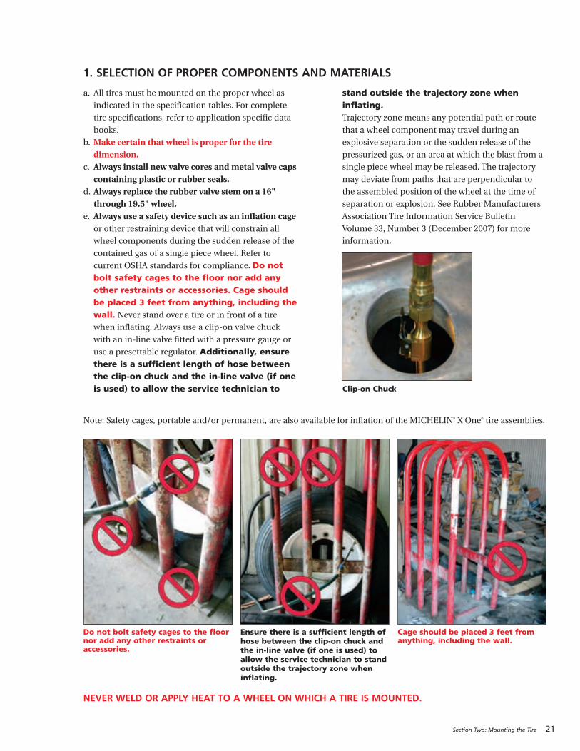
1. SELECTION OF PROPER COMPONENTS AND MATERIALS
Note: Safety cages, portable and/or permanent, are also available for inflation of the MICHELIN® X One® tire assemblies.
a. All tires must be mounted on the proper wheel as
indicated in the specification tables. For complete
tire specifications, refer to application specific data
books.
b. Make certain that wheel is proper for the tiredimension.
c. Always install new valve cores and metal valve capscontaining plastic or rubber seals.
d. Always replace the rubber valve stem on a 16"through 19.5" wheel.
e. Always use a safety device such as an inflation cageor other restraining device that will constrain all
wheel components during the sudden release of the
contained gas of a single piece wheel. Refer to
current OSHA standards for compliance. Do notbolt safety cages to the floor nor add anyother restraints or accessories. Cage shouldbe placed 3 feet from anything, including thewall. Never stand over a tire or in front of a tire
when inflating. Always use a clip-on valve chuck
with an in-line valve fitted with a pressure gauge or
use a presettable regulator. Additionally, ensurethere is a sufficient length of hose betweenthe clip-on chuck and the in-line valve (if oneis used) to allow the service technician to
stand outside the trajectory zone wheninflating.Trajectory zone means any potential path or route
that a wheel component may travel during an
explosive separation or the sudden release of the
pressurized gas, or an area at which the blast from a
single piece wheel may be released. The trajectory
may deviate from paths that are perpendicular to
the assembled position of the wheel at the time of
separation or explosion. See Rubber Manufacturers
Association Tire Information Service Bulletin
Volume 33, Number 3 (December 2007) for more
information.
NEVER WELD OR APPLY HEAT TO A WHEEL ON WHICH A TIRE IS MOUNTED.
Clip-on Chuck
Do not bolt safety cages to the floornor add any other restraints oraccessories.
Ensure there is a sufficient length ofhose between the clip-on chuck andthe in-line valve (if one is used) toallow the service technician to standoutside the trajectory zone wheninflating.
Cage should be placed 3 feet fromanything, including the wall.

22 Section Two: Mounting the Tire
2. TIRE AND WHEEL LUBRICATIONIt is essential that an approved tire mounting lubricant be
used. Preferred materials for use as bead lubricants are
vegetable based and mixed with proper water ratios per
manufacturer’s instructions. Never use antifreeze, silicones,
or petroleum-base lubricants as this will damage the rubber.
Lubricants not mixed to the manufacturer’s specifications
may have a harmful effect on the tire and wheel.
The lubricant serves the following three purposes:
• Helps minimize the possibility of damage to the tire
beads from the mounting tools.
• Helps ease the insertion of the tire onto the wheel by
lubricating all contacting surfaces.
• Assists proper bead seating (tire and wheel centering)
and helps to prevent eccentric mountings.
The MICHELIN® product, Tiger Grease 80, MSPN 25817,
is specifically formulated for commercial truck tire
mounting. It can be obtained through any authorized
MICHELIN® Truck Tire dealer or by contacting MICHELIN®
Consumer Care (1-888-622-2306).
Apply a clean lubricant to all portions of the tire bead area
and the exposed portion of the flap using sufficient but
sparing quantities of lubricant. Also, lubricate the entirerim surface of the wheel. Avoid using excessive amounts oflubricant, which can become trapped between the tire andtube and can result in tube damage and rapid gas loss.CAUTION: It is important that tire lubricant be clean and
free of dirt, sand, metal shavings, or other hard particles.
The following practice is recommended:
a. Use a fresh supply of tire lubricant each day, drawing
from a clean supply source and placing the lubricant in
a clean portable container.
b. Provide a cover for the portable container and/or other
means to prevent contamination of the lubricant when
not in use. For lubricants in solution, we suggest the
following method that has proven to be successful in
helping to minimize contamination and prevent excess
lubricant from entering the tire casing: provide a special
cover for the portable container that has a funnel-like
device attached. The small opening of the funnel should
be sized so that when a swab is inserted through the
opening into the reserve of lubricant and then
withdrawn, the swab is compressed, removing excess
lubricant. This allows the cover to be left in place
providing added protection. A mesh false bottom in the
container is a further protection against contaminants.
The tire should be mounted and inflated promptly
before lubricant dries.
3. PREPARATION OF WHEELS AND TIRESa. Always wear safety goggles or face shields when buffing
or grinding wheels.
b. Inspect wheel assemblies for cracks, distortion, and
deformation of flanges. Using a file and/or emery cloth,
smooth all burrs, welds, dents, etc. that are present on
the tire side of the wheel. Inspect the condition of bolt
holes on the wheels. Rim flange gauges and ball tapes
are available for measuring wear and circumference of
aluminum wheels.
c. Remove rust with a wire brush and apply a rust
inhibiting paint on steel wheels. The maximum paint
thickness is 0.0035" (3.5 mils) on the disc face of the
wheel.
d. Remove any accumulation of rubber or grease that
might be stuck to the tire, being careful not to damage
it. Wipe the beads down with a dry rag.
Avoid using excessive amounts of lubricants.
Avoid not using any lubricants, you must use alubricant.

MOUNTING TUBELESS1. Inspect the condition of the bolt holes on the wheels,
and look for signs of fatigue. Check flanges for
excessive wear by using the wheel manufacturer’s
flange wear indicator.
2. Replace valve core, and inspect valve stem for damage
and wear. Michelin recommends always replacing the
valve stem and using a new valve stem grommet.
Ensure valve stem is installed using the proper torque
value. 80-125 in/lbs (7-11 ft/lbs) for standard
aluminum wheels and 35-55 in/lbs (3-5 ft/lbs) for
standard tubeless steel wheels. Ensure the valve core
is installed using the proper torque value of 1.5 – 4
in/lbs. To prevent galvanic corrosion on aluminum
wheels, lubricate the threads and O-ring of the valve
stem with a non-waterbased lubricant before
installation.
3. Apply the tire and wheel lubricant to all surfaces of the
wheel and bead area of the tire. When applying lubricant
to the wheel, lubricate the entire rim surface of the
wheel from flange to flange. The tire should be mounted
and inflated before the lubricant dries.
4. With short ledge up, lay the tire over the wheel
opposite the valve side and work it on with proper
tubeless tire tools, making full use of the drop center
well. Drop center wheels are typically designed with
an off-set drop center to accommodate wheel width
and brake clearance. This creates a “short side” and a
“long side” on the wheel. (Some drop center wheels
are designed with a symmetric wheel profile
facilitating tire mounting from either side.) It is
imperative that the tire always be mounted and
dismounted only from the short side. Failure to do this
will likely result in damaged tire beads that could
eventually cause rapid gas loss due to casing rupture.
This is particularly important on 19.5 inch RW
(reduced well) aluminum wheels which, contrary to
the norm, have their drop center located close to the
disc side. Do not use 19.5 x 7.50 wheel for the
305/70R19.5 tire size.
All 19.5 inch tubeless wheels should be mounted
from the short side. Care should be taken to ensure
that any internal monitoring system molded in the
tire or on the wheel is not damaged or dislodged
during this service.
Section Two: Mounting the Tire 23
TUBELESS TIRES MOUNTING/DEMOUNTING
24 Section Two: Mounting the Tire
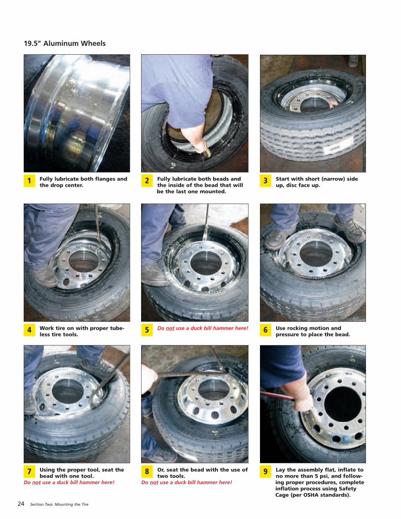
Fully lubricate both flanges andthe drop center.
1 Fully lubricate both beads andthe inside of the bead that willbe the last one mounted.
2 Start with short (narrow) sideup, disc face up.
3
Work tire on with proper tube-less tire tools.
4 Do not use a duck bill hammer here!5 Use rocking motion and pressure to place the bead.
6
Using the proper tool, seat thebead with one tool.
Do not use a duck bill hammer here!
7 Or, seat the bead with the use oftwo tools.
Do not use a duck bill hammer here!
8 Lay the assembly flat, inflate tono more than 5 psi, and follow-ing proper procedures, completeinflation process using SafetyCage (per OSHA standards).
9
19.5" Aluminum Wheels
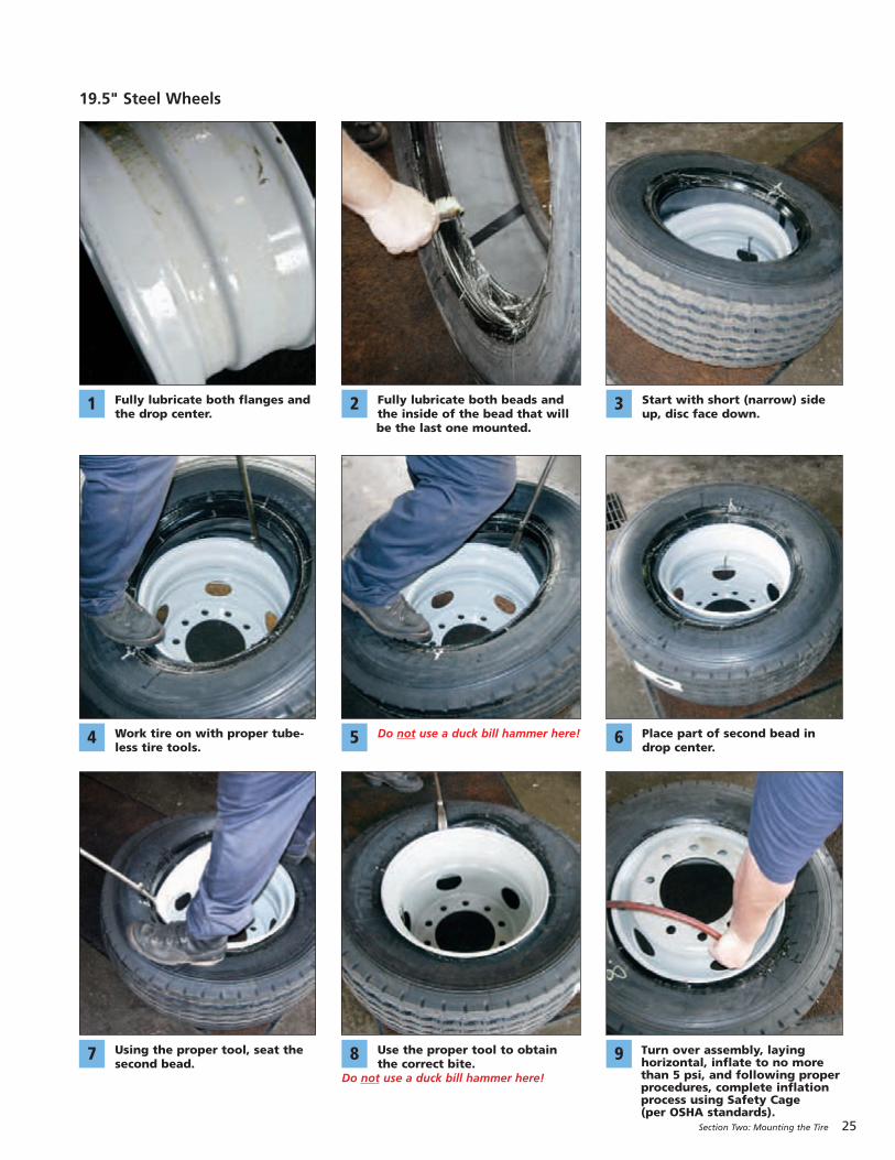
Fully lubricate both flanges andthe drop center.
1 Fully lubricate both beads andthe inside of the bead that willbe the last one mounted.
2 Start with short (narrow) sideup, disc face down.
3
Work tire on with proper tube-less tire tools.
4 Do not use a duck bill hammer here!5 Place part of second bead indrop center.
6
Using the proper tool, seat the second bead.
7 Use the proper tool to obtainthe correct bite.
Do not use a duck bill hammer here!
8 Turn over assembly, layinghorizontal, inflate to no morethan 5 psi, and following properprocedures, complete inflationprocess using Safety Cage (per OSHA standards).
9
19.5" Steel Wheels
Section Two: Mounting the Tire 25

5. Do not use any kind of hammer. Severe inner
liner damage may occur resulting in sidewall
separation and tire destruction. Use only proper
mounting levers; DO NOT USE A DUCK BILLHAMMER.
6. The MICHELIN® X One® tire is designed to replace
dual tires on the drive and trailer positions of tandem
over the road vehicles, and the tires must be mounted
on 22.5 x 14.00" size wheels. Position the tire and
wheel assembly so the valve stem is facing outward,
away from the vehicle.
26 Section Two: Mounting the Tire
Do not use a duck bill hammer to break the bead atdemount.
Do not use a duck bill hammer to seat either beadat mounting.
Only use a duck bill hammer as a wedge with arubber mallet.
Severe inner liner damage from use of hammer.
Resulting in sidewall separation and tiredestruction from air infiltration.
Section Two: Mounting the Tire 27
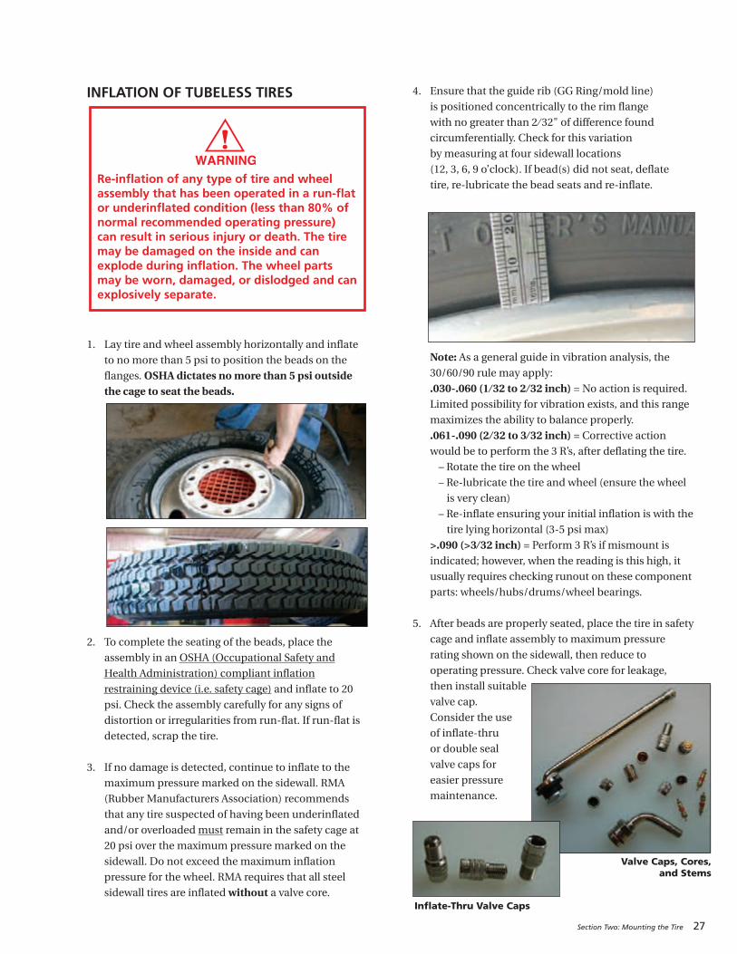
INFLATION OF TUBELESS TIRES
1. Lay tire and wheel assembly horizontally and inflate
to no more than 5 psi to position the beads on the
flanges. OSHA dictates no more than 5 psi outsidethe cage to seat the beads.
2. To complete the seating of the beads, place the
assembly in an OSHA (Occupational Safety and
Health Administration) compliant inflation
restraining device (i.e. safety cage) and inflate to 20
psi. Check the assembly carefully for any signs of
distortion or irregularities from run-flat. If run-flat is
detected, scrap the tire.
3. If no damage is detected, continue to inflate to the
maximum pressure marked on the sidewall. RMA
(Rubber Manufacturers Association) recommends
that any tire suspected of having been underinflated
and/or overloaded must remain in the safety cage at
20 psi over the maximum pressure marked on the
sidewall. Do not exceed the maximum inflation
pressure for the wheel. RMA requires that all steel
sidewall tires are inflated without a valve core.
4. Ensure that the guide rib (GG Ring/mold line)
is positioned concentrically to the rim flange
with no greater than 2 ⁄ 32" of difference found
circumferentially. Check for this variation
by measuring at four sidewall locations
(12, 3, 6, 9 o’clock). If bead(s) did not seat, deflate
tire, re-lubricate the bead seats and re-inflate.
Note: As a general guide in vibration analysis, the
30/60/90 rule may apply:
.030-.060 (1 ⁄ 32 to 2 ⁄ 32 inch) = No action is required.
Limited possibility for vibration exists, and this range
maximizes the ability to balance properly.
.061-.090 (2 ⁄ 32 to 3 ⁄ 32 inch) = Corrective action
would be to perform the 3 R’s, after deflating the tire.
– Rotate the tire on the wheel
– Re-lubricate the tire and wheel (ensure the wheel
is very clean)
– Re-inflate ensuring your initial inflation is with the
tire lying horizontal (3-5 psi max)
>.090 (>3 ⁄ 32 inch) = Perform 3 R’s if mismount is
indicated; however, when the reading is this high, it
usually requires checking runout on these component
parts: wheels/hubs/drums/wheel bearings.
5. After beads are properly seated, place the tire in safety
cage and inflate assembly to maximum pressure
rating shown on the sidewall, then reduce to
operating pressure. Check valve core for leakage,
then install suitable
valve cap.
Consider the use
of inflate-thru
or double seal
valve caps for
easier pressure
maintenance.
Re-inflation of any type of tire and wheelassembly that has been operated in a run-flator underinflated condition (less than 80% ofnormal recommended operating pressure)can result in serious injury or death. The tiremay be damaged on the inside and canexplode during inflation. The wheel partsmay be worn, damaged, or dislodged and canexplosively separate.
Inflate-Thru Valve Caps
Valve Caps, Cores,and Stems

28 Section Two: Mounting the Tire
DEMOUNTING OF TUBELESS TIRES1. If still fitted on the vehicle, completely deflate the tire
by removing the valve core. In the case of a dual
assembly, completely deflate both tires before
removing them from the vehicle (OSHA requirement).
Run a wire or a pipe cleaner through the valve stem to
ensure complete deflation.
2. With the tire assembly lying flat (after deflating the
tire), break the bead seat of both beads with a bead
breaking tool. Do not use hammers of any type to seat
the bead. Striking a wheel assembly with a hammer of
any type can damage the tire or wheel and endanger
the installer. Use a steel duck bill hammer only as awedge. Do not strike the head of a hammer with
another hard faced hammer – use a rubber mallet.
3. Apply the vegetable-based lubricant to all surfaces of
the bead area of the tire.
4. Beginning at the valve, remove the tire from the wheel.
Starting at the valve will minimize chances of
damaging the valve assembly. Make certain that the
rim flange with the tapered ledge that is closest to the
drop center is facing up. Insert the curved ends of the
tire irons between the tire and rim flange. Step forward
into the drop center and drop the bars down, lifting
the tire bead over the rim flange. Hold one tire iron in
position with your foot. Pull the second tire iron out
and reposition it about 90 degrees from the first iron.
Pull the second tire iron towards the center of the
wheel. Continue to work tools around wheel until first
bead is off the wheel.
5. Lift the assembly, place and rotate the tire iron to lock
on the back rim flange, allow the tire to drop, and with
a rocking motion remove the tire from the wheel.
Use a Slide Hammer. 1 Or a duck bill hammer as a wedge,with a rubber mallet.
2 Lubricate both beads completelyto avoid demount damage.
3
Never inflate or re-inflate any tires that have been run underinflated or flat without careful inspection
for damage, inside and out.
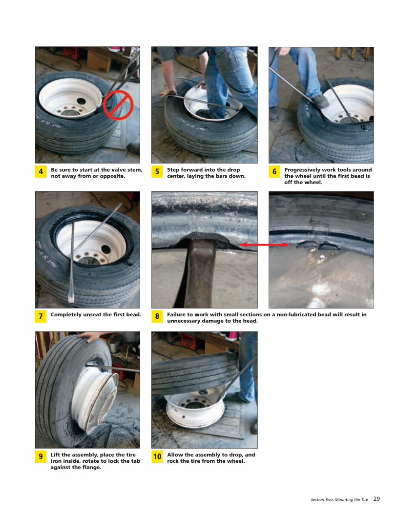
Section Two: Mounting the Tire 29
Be sure to start at the valve stem,not away from or opposite.
4 Step forward into the dropcenter, laying the bars down.
5 Progressively work tools aroundthe wheel until the first bead isoff the wheel.
6
Completely unseat the first bead.7 Failure to work with small sections on a non-lubricated bead will result inunnecessary damage to the bead.
8
Lift the assembly, place the tireiron inside, rotate to lock the tabagainst the flange.
9 Allow the assembly to drop, androck the tire from the wheel.
10
30 Section Two: Mounting the Tire
When wheel assemblies are mounted on a vehicle, be
sure that the valves do not touch the brake drums or any
mechanical part of the vehicle. When mounting the
MICHELIN® X One® tire utilizing a 2" outset wheel onto
a vehicle, position the tire so that the tire sits on the
outboard side of the wheel similar to where the outer dual
would normally be positioned. Position the tire and
wheel assembly so the valve stem is facing outward, away
from the vehicle.
Valves of dual tires should be diametrically opposite.
Ensure that the inside valve is accessible so the pressure
can be checked and maintained.
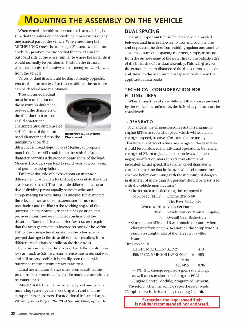
Tires mounted in dual
must be matched so that
the maximum difference
between the diameters of
the tires does not exceed
1 ⁄ 4" diameter or a
circumferential difference of
3 ⁄ 4". For tires of the same
bead diameter and size, the
maximum allowable
difference in tread depth is 4 ⁄ 32". Failure to properly
match dual tires will result in the tire with the larger
diameter carrying a disproportionate share of the load.
Mismatched duals can lead to rapid wear, uneven wear,
and possible casing failure.
Tandem drive axle vehicles without an inter-axle
differential (or when it is locked out) necessitate that tires
are closely matched. The inter-axle differential is a gear
device dividing power equally between axles and
compensating for such things as unequal tire diameters,
the effect of front and rear suspensions, torque rod
positioning and the like on the working angles of the
universal joints. Normally in the unlock position, this
provides minimized wear and tear on tires and the
drivetrain. Tandem drive rear axles (twin-screw) require
that the average tire circumference on one axle be within
1⁄ 4" of the average tire diameter on the other axle to
prevent damage to the drive differentials resulting from
different revolutions per mile on the drive axles.
Since any one tire of the size used with these axles may
lose as much as 2.5" in circumference due to normal wear
and still be serviceable, it is readily seen that a wide
difference in tire circumference may exist.
Equal tire inflation (between adjacent duals) at the
pressures recommended by the tire manufacturer should
be maintained.
IMPORTANT: Check to ensure that you know which
mounting system you are working with and that the
components are correct. For additional information, see
Wheel Type on Pages 126-129 of Section Nine, Appendix.
DUAL SPACING It is also important that sufficient space is provided
between dual tires to allow air to flow and cool the tires
and to prevent the tires from rubbing against one another.
To make sure dual spacing is correct, simply measure
from the outside edge of the outer tire to the outside edge
of the inner tire of the dual assembly. This will give you
the center to center distance of the duals across that axle
end. Refer to the minimum dual spacing column in the
application data books.
TECHNICAL CONSIDERATION FOR FITTING TIRES
When fitting tires of sizes different than those specified
by the vehicle manufacturer, the following points must be
considered:
1. GEAR RATIOA change in tire dimension will result in a change in
engine RPM at a set cruise speed, which will result in a
change in speed, tractive effort, and fuel economy.
Therefore, the effect of a tire size change on the gear ratio
should be considered in individual operations. Generally,
changes of 2% for a given diameter or less will have a
negligible effect on gear ratio, tractive effort, and
indicated/actual speed. If a smaller wheel diameter is
chosen, make sure that brake over wheel clearances are
checked before continuing with the mounting. (Changes
in diameter of more than 3% percent should be discussed
with the vehicle manufacturer.)
• The formula for calculating the top speed is:
Top Speed (MPH) = Engine RPM x 60
(Tire Revs./Mile) x R
Where MPH = Miles Per Hour
RPM = Revolution Per Minute (Engine)
R = Overall Gear Reduction
• Since engine RPM and R will remain the same when
changing from one tire to another, the comparison is
simply a straight ratio of the Tire’s Revs./Mile.
Example:
Tire Revs./Mile
11R24.5 MICHELIN® XDN2® = 473
455/55R22.5 MICHELIN® XDN2® = 495
Ratio
473/495 = 0.96
(= 4%. This change requires a gear ratio change
as well as a speedometer change or ECM
(Engine Control Module) program adjustment.)
Therefore, when the vehicle’s speedometer reads
75 mph, the vehicle is actually traveling 72 mph.
Incorrect Dual WheelPlacement
MOUNTING THE ASSEMBLY ON THE VEHICLE
Exceeding the legal speed limit is neither recommended nor endorsed.
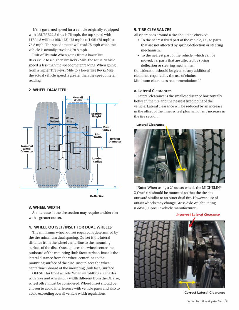
Section Two: Mounting the Tire 31
If the governed speed for a vehicle originally equipped
with 455/55R22.5 tires is 75 mph, the top speed with
11R24.5 will be (495/473) (75 mph) = (1.05) (75 mph) =
78.8 mph. The speedometer will read 75 mph when the
vehicle is actually traveling 78.8 mph.
Rule of Thumb: When going from a lower Tire
Revs./Mile to a higher Tire Revs./Mile, the actual vehicle
speed is less than the speedometer reading. When going
from a higher Tire Revs./Mile to a lower Tire Revs./Mile,
the actual vehicle speed is greater than the speedometer
reading.
2. WHEEL DIAMETER
3. WHEEL WIDTHAn increase in the tire section may require a wider rim
with a greater outset.
4. WHEEL OUTSET/INSET FOR DUAL WHEELSThe minimum wheel outset required is determined by
the tire minimum dual spacing. Outset is the lateral
distance from the wheel centerline to the mounting
surface of the disc. Outset places the wheel centerline
outboard of the mounting (hub face) surface. Inset is the
lateral distance from the wheel centerline to the
mounting surface of the disc. Inset places the wheel
centerline inboard of the mounting (hub face) surface.
OFFSET for front wheels: When retrofitting steer axles
with tires and wheels of a width different from the OE size,
wheel offset must be considered. Wheel offset should be
chosen to avoid interference with vehicle parts and also to
avoid exceeding overall vehicle width regulations.
5. TIRE CLEARANCESAll clearances around a tire should be checked:
• To the nearest fixed part of the vehicle, i.e., to parts
that are not affected by spring deflection or steering
mechanism.
• To the nearest part of the vehicle, which can be
moved, i.e. parts that are affected by spring
deflection or steering mechanism.
Consideration should be given to any additional
clearance required by the use of chains.
Minimum clearances recommendation: 1"
a. Lateral ClearancesLateral clearance is the smallest distance horizontally
between the tire and the nearest fixed point of the
vehicle. Lateral clearance will be reduced by an increase
in the offset of the inner wheel plus half of any increase in
the tire section.
Note: When using a 2" outset wheel, the MICHELIN®
X One® tire should be mounted so that the tire sits
outward similar to an outer dual tire. However, use of
outset wheels may change Gross Axle Weight Rating
(GAWR). Consult vehicle manufacturer.
C L
Deflection
LoadedRadius
NominalWheel
Diameter
Overall Diameter
RimWidth
FreeRadius
SectionHeight
OverallWidth
WheelInset
WheelOutset
Incorrect Lateral Clearance
Correct Lateral Clearance
Lateral Clearance
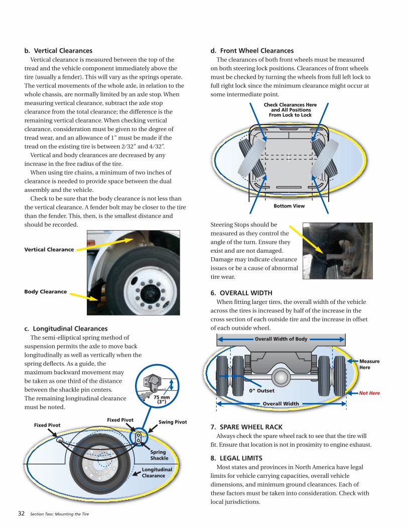
32 Section Two: Mounting the Tire
b. Vertical ClearancesVertical clearance is measured between the top of the
tread and the vehicle component immediately above the
tire (usually a fender). This will vary as the springs operate.
The vertical movements of the whole axle, in relation to the
whole chassis, are normally limited by an axle stop. When
measuring vertical clearance, subtract the axle stop
clearance from the total clearance; the difference is the
remaining vertical clearance. When checking vertical
clearance, consideration must be given to the degree of
tread wear, and an allowance of 1" must be made if the
tread on the existing tire is between 2 ⁄ 32" and 4 ⁄ 32".
Vertical and body clearances are decreased by any
increase in the free radius of the tire.
When using tire chains, a minimum of two inches of
clearance is needed to provide space between the dual
assembly and the vehicle.
Check to be sure that the body clearance is not less than
the vertical clearance. A fender bolt may be closer to the tire
than the fender. This, then, is the smallest distance and
should be recorded.
Vertical Clearance
Body Clearance
c. Longitudinal ClearancesThe semi-elliptical spring method of
suspension permits the axle to move back
longitudinally as well as vertically when the
spring deflects. As a guide, the
maximum backward movement may
be taken as one third of the distance
between the shackle pin centers.
The remaining longitudinal clearance
must be noted.
d. Front Wheel ClearancesThe clearances of both front wheels must be measured
on both steering lock positions. Clearances of front wheels
must be checked by turning the wheels from full left lock to
full right lock since the minimum clearance might occur at
some intermediate point.
Steering Stops should be
measured as they control the
angle of the turn. Ensure they
exist and are not damaged.
Damage may indicate clearance
issues or be a cause of abnormal
tire wear.
6. OVERALL WIDTHWhen fitting larger tires, the overall width of the vehicle
across the tires is increased by half of the increase in the
cross section of each outside tire and the increase in offset
of each outside wheel.
7. SPARE WHEEL RACKAlways check the spare wheel rack to see that the tire will
fit. Ensure that location is not in proximity to engine exhaust.
8. LEGAL LIMITSMost states and provinces in North America have legal
limits for vehicle carrying capacities, overall vehicle
dimensions, and minimum ground clearances. Each of
these factors must be taken into consideration. Check with
local jurisdictions.
75 mm(3”)
Fixed Pivot
SpringShackle
Swing Pivot
LongitudinalClearance
Fixed Pivot
Check Clearances Here and All Positions
From Lock to Lock
Bottom View
Overall Width
Overall Width of Body
Measure Here
Not Here0” Outset
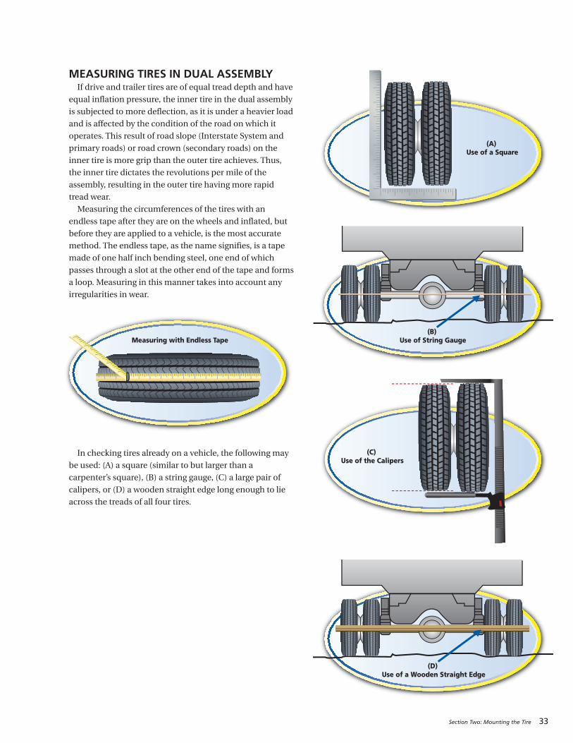
Section Two: Mounting the Tire 33
MEASURING TIRES IN DUAL ASSEMBLYIf drive and trailer tires are of equal tread depth and have
equal inflation pressure, the inner tire in the dual assembly
is subjected to more deflection, as it is under a heavier load
and is affected by the condition of the road on which it
operates. This result of road slope (Interstate System and
primary roads) or road crown (secondary roads) on the
inner tire is more grip than the outer tire achieves. Thus,
the inner tire dictates the revolutions per mile of the
assembly, resulting in the outer tire having more rapid
tread wear.
Measuring the circumferences of the tires with an
endless tape after they are on the wheels and inflated, but
before they are applied to a vehicle, is the most accurate
method. The endless tape, as the name signifies, is a tape
made of one half inch bending steel, one end of which
passes through a slot at the other end of the tape and forms
a loop. Measuring in this manner takes into account any
irregularities in wear.
In checking tires already on a vehicle, the following may
be used: (A) a square (similar to but larger than a
carpenter’s square), (B) a string gauge, (C) a large pair of
calipers, or (D) a wooden straight edge long enough to lie
across the treads of all four tires.
Measuring with Endless Tape
(A) Use of a Square
(B) Use of String Gauge
(C) Use of the Calipers
(D) Use of a Wooden Straight Edge
34 Section Two: Mounting the Tire
TIRE MIXINGIMPROPER TIRE MIXING CAN BE DANGEROUS
Four Wheel Trucks: For the best performance it is
recommended that the same size, design, and
construction of tire be used on all four wheel positions.
If only two MICHELIN® radials are mounted with two
non-radials, the radials should be mounted on the rear.
If tires of different design are mixed on a vehicle in any
configuration, they should not be used for long periods,
and speeds* should be kept to a minimum
Mixing or matching of tires on 4-wheel drive vehicles
may require special precautions. Always check vehicle
manufacturer’s Owners Manual for their
recommendations.
Trucks with more than four wheel positions:For best performance, it is recommended that radial and
non-radial tires should not be mixed in dual fitment.
It is unlawful and dangerous to mix radials and bias tires
on the same axle.
*Exceeding the safe, legal speed limit is neither recommended nor endorsed.
RUNOUTThe ideal time to verify that proper mounting
procedures have resulted in concentric bead seating is
during the installation of new steering tire/wheel
assemblies. The ‘on vehicle’ assembly radial and lateral
runout measurements should be the lowest possible to
offer the driver the smoothest ride. Both the guide rib
variance and the hub to wheel clearance on hub piloted
assemblies can be measured following the procedures
found in the Runout and Vibration Diagnosis guidelines
on Pages 134-135 of Section Nine, Appendix.
35
MAINTAINING THE TIRE . . . . . . . . . . . . . . . . . . 36-45
MAINTAINING THE VEHICLE . . . . . . . . . . . . . . 46-62
SECTION THREE
Extending Tire Life
Inflation Pressure- Underinflation- Overinflation- Proper Inflation- Nitrogen- Sealants- Tire Inspection- Inflation Systems: ATIS, TPMS- Drive Carefully- Tread Depth Measurements- Wear Bars- Do Not Overload
- Drive at Proper Speeds- Balance and Runout- Storage- Flood Damage- Chains- Recommendation for Use of Dynamometers
- Spinning- Rotation- Siping- Branding
Braking Systems and IssuesSummary of Tire Issues Due to Brakes- Brake Heat Overview
Fifth Wheel Maintenance and PlacementWheel Bearing and Hub InspectionSuspensionsAir Suspension Systems- Quick Checks for Trailer System Faults- Quick Checks for Front Suspension Faults - Quick Checks for Rear Suspension Faults
Tire Wear Patterns Due to Misalignment- Toe Wear - Cupping Wear- Free Rolling Wear - Flat Spotting Wear- Camber Wear - Diagonal Wear
Major Factors That Affect Tire Life- Alignment- Steer Axle Geometry - Toe- Tandem Axle Parallelism- Thrust Angle (Tracking)- Camber - Caster- Steer Axle Setback
- Toe-Out-On-Turns- TMC Recommended Alignment Targets
- Periodic Alignment Checks- Alignment Equipment- Field Check Techniques- Axle Parallelism and Tracking

36 Section Three: Extending Tire Life
MAINTAINING THE TIREPressures on all newly delivered equipment should be
verified for the application/operation prior to the vehicle
being placed in service. Verify that any pressure
monitoring or inflation system is correctly set for your
fleet application on the delivery of any new equipment.
Proper maintenance is important in order to obtain
maximum performance.
INFLATION PRESSUREThe most critical factor in tire maintenance is proper
inflation. No tire or tube is completely impervious to loss
of pressure. To avoid the hazards of underinflation, lost
gas must be replaced.
Driving on any tire that does not have the correct
inflation pressure is dangerous and will cause tire damage.
Any underinflated tire builds up excessive heat that
may result in sudden tire destruction. The correct
inflation pressures for your tires must incorporate many
factors including: load, speed, road surface, and handling.
Consult a MICHELIN® Truck Tire dealer or MICHELIN®
data books for the proper inflation pressures for your
application. See Section Nine, Appendix (Page 142) for
complete listings of the MICHELIN® data books.
Failure to maintain correct inflation pressure mayresult in sudden tire destruction and/or impropervehicle handling. Additionally it will result in irregularwear. Therefore, inflation pressures should be checkedweekly and always before long distance trips.Check inflation pressures on all your tires at least once a
week, including spares, before driving when tires are cold,
especially when vehicle is used by more than one driver.
The ideal time to check tire pressures is early morning.
Driving, even for a short distance, causes tires to heat up
and pressures to increase.
Generally, as a radial tire revolves during operation,
heat is generated on the inside of the tire at 4 degrees
per minute. However, the tire loses heat at the rate of
3 degrees per minute with dissipation throughout the
casing and air flow around the tire. After 40 minutes of
continuous operation, the tire temperature has increased
40 degrees Fahrenheit. As the temperature inside the tire
increases, the inflation pressure also increases. Thus, a tire
inflated to 80 psi cold would now be at 85 psi. Because the
inflation pressure has increased, the amount of tire flexing
has decreased, which decreases the amount of heat
generated per minute to 3 degrees per minute. Assuming
the heat dissipation factor is still 3 degrees Fahrenheit per
minute, the net temperature change is nil (0). This is
called thermal equilibrium.
Always inspect valve stems for proper installation and
torque, and verify there is a good tight seal by use of a leak
detector type spray such as a water/soap solution applied
from a spray bottle. It is also a good practice to
periodically check existing fitments for slow leaks with
this method.
Never bleed hot tires, as your tires will then be
underinflated. Make sure to check both tires in a dual
fitment. Pressures should be the same. Maximum
allowable difference between dual tires or between axles
should be no greater than 5 psi.
Remember, a drop in ambient temperature results
in a drop in tire pressure. More frequent checks may be
required during cold weather conditions. Avoid outdoor
pressure checks when the temperature is below freezing.
Ice can form in the valve stem, thus promoting leaks.
Check inside a heated facility if possible.
Use an accurate calibrated tire gauge to check
pressures. (Do not use “Tire Billys” to hit tires as an
inflation check. This is an unreliable method.)
Unless otherwise recommended by tire manufacturer
for optimized tire performance, use the tire inflation
pressure shown in the application data books for the
particular axle load. Exceeding this pressure could result
in reduced traction and tread life.
Never inflate to cold pressure beyond the rated capacity
of the wheel. However, for steering tires, it is common
practice to use higher inflation pressures than necessary
to carry the axle load to reduce free rolling wear.
Following are two examples of applying the previous
considerations to an operation where the user mounts
new 275/80R22.5 LRG (with a data book maximum of 110
psi tires) steer tires and desires to increase the pressure in
order to see if this will help alleviate the occurrence of free
rolling wear.
Example 1: If the axle load is 10,310 lbs., then the table inthe data book specifies a corresponding pressure of 85
psi. Then the user can increase the pressure 15-20 psi
above that to 100 or 105 psi.
Example 2: If the axle load is 12,350 lbs., then the table inthe data book recommends 110 psi. As this is the
maximum load of the tire, only a 10% pressure increase
is permitted. Thus the adjusted pressure would be
limited to 120 psi.
This procedure should not be applied “across the
board.” If satisfactory tire performance and wear are
being obtained with “table” pressures for a given load,
then leave well enough alone.
Overinflation can cause an increase in road shocks and
vibrations transmitted to the vehicle as well as an increase
in tire failures from road hazards.
NOTE: In no case should the maximum capacity of the
wheel be surpassed. Consult wheel manufacturer’s
specifications.
NOTE: The following illustration is based on therecommended inflation pressure from the data book for
the load being carried.
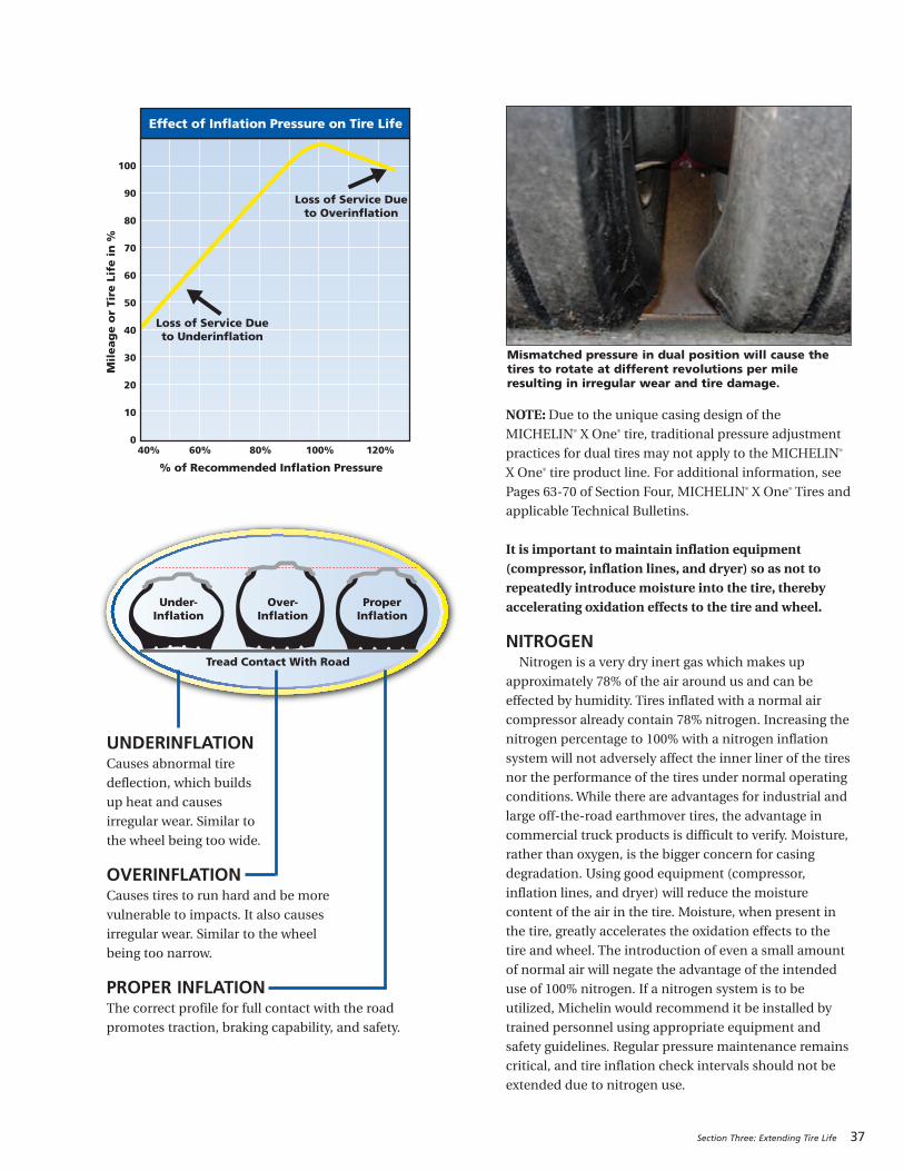
Section Three: Extending Tire Life 37
UNDERINFLATIONCauses abnormal tire
deflection, which builds
up heat and causes
irregular wear. Similar to
the wheel being too wide.
OVERINFLATIONCauses tires to run hard and be more
vulnerable to impacts. It also causes
irregular wear. Similar to the wheel
being too narrow.
PROPER INFLATIONThe correct profile for full contact with the road
promotes traction, braking capability, and safety.
NOTE: Due to the unique casing design of theMICHELIN® X One® tire, traditional pressure adjustment
practices for dual tires may not apply to the MICHELIN®
X One® tire product line. For additional information, see
Pages 63-70 of Section Four, MICHELIN® X One® Tires and
applicable Technical Bulletins.
It is important to maintain inflation equipment(compressor, inflation lines, and dryer) so as not torepeatedly introduce moisture into the tire, therebyaccelerating oxidation effects to the tire and wheel.
NITROGENNitrogen is a very dry inert gas which makes up
approximately 78% of the air around us and can be
effected by humidity. Tires inflated with a normal air
compressor already contain 78% nitrogen. Increasing the
nitrogen percentage to 100% with a nitrogen inflation
system will not adversely affect the inner liner of the tires
nor the performance of the tires under normal operating
conditions. While there are advantages for industrial and
large off-the-road earthmover tires, the advantage in
commercial truck products is difficult to verify. Moisture,
rather than oxygen, is the bigger concern for casing
degradation. Using good equipment (compressor,
inflation lines, and dryer) will reduce the moisture
content of the air in the tire. Moisture, when present in
the tire, greatly accelerates the oxidation effects to the
tire and wheel. The introduction of even a small amount
of normal air will negate the advantage of the intended
use of 100% nitrogen. If a nitrogen system is to be
utilized, Michelin would recommend it be installed by
trained personnel using appropriate equipment and
safety guidelines. Regular pressure maintenance remains
critical, and tire inflation check intervals should not be
extended due to nitrogen use.
Under-Inflation
Over-Inflation
ProperInflation
Tread Contact With Road
Mil
eag
e o
r Ti
re L
ife i
n %
% of Recommended Inflation Pressure
100
90
80
70
60
50
40
30
20
10
040% 60% 80% 100% 120%
Effect of Inflation Pressure on Tire Life
Loss of Service Dueto Overinflation
Loss of Service Dueto Underinflation
Mismatched pressure in dual position will cause thetires to rotate at different revolutions per mileresulting in irregular wear and tire damage.
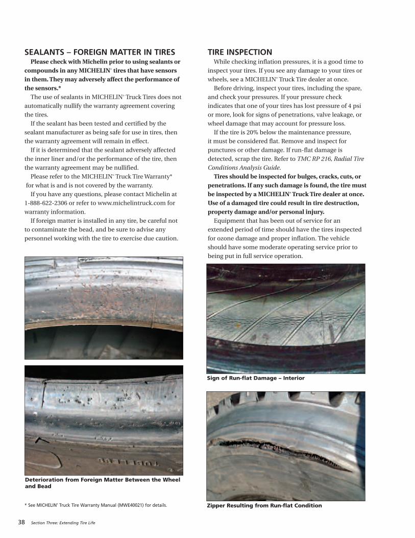
38 Section Three: Extending Tire Life
SEALANTS – FOREIGN MATTER IN TIRESPlease check with Michelin prior to using sealants or
compounds in any MICHELIN® tires that have sensorsin them. They may adversely affect the performance ofthe sensors.*The use of sealants in MICHELIN® Truck Tires does not
automatically nullify the warranty agreement covering
the tires.
If the sealant has been tested and certified by the
sealant manufacturer as being safe for use in tires, then
the warranty agreement will remain in effect.
If it is determined that the sealant adversely affected
the inner liner and/or the performance of the tire, then
the warranty agreement may be nullified.
Please refer to the MICHELIN® Truck Tire Warranty*
for what is and is not covered by the warranty.
If you have any questions, please contact Michelin at
1-888-622-2306 or refer to www.michelintruck.com for
warranty information.
If foreign matter is installed in any tire, be careful not
to contaminate the bead, and be sure to advise any
personnel working with the tire to exercise due caution.
* See MICHELIN® Truck Tire Warranty Manual (MWE40021) for details.
TIRE INSPECTIONWhile checking inflation pressures, it is a good time to
inspect your tires. If you see any damage to your tires or
wheels, see a MICHELIN® Truck Tire dealer at once.
Before driving, inspect your tires, including the spare,
and check your pressures. If your pressure check
indicates that one of your tires has lost pressure of 4 psi
or more, look for signs of penetrations, valve leakage, or
wheel damage that may account for pressure loss.
If the tire is 20% below the maintenance pressure,
it must be considered flat. Remove and inspect for
punctures or other damage. If run-flat damage is
detected, scrap the tire. Refer to TMC RP 216, Radial Tire
Conditions Analysis Guide.
Tires should be inspected for bulges, cracks, cuts, orpenetrations. If any such damage is found, the tire mustbe inspected by a MICHELIN® Truck Tire dealer at once.Use of a damaged tire could result in tire destruction,property damage and/or personal injury.Equipment that has been out of service for an
extended period of time should have the tires inspected
for ozone damage and proper inflation. The vehicle
should have some moderate operating service prior to
being put in full service operation.
Deterioration from Foreign Matter Between the Wheeland Bead
Zipper Resulting from Run-flat Condition
Sign of Run-flat Damage – Interior
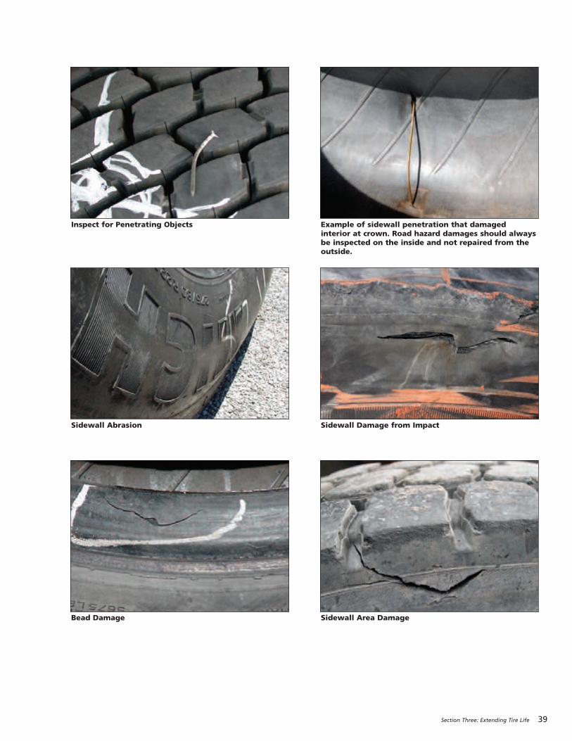
Section Three: Extending Tire Life 39
Example of sidewall penetration that damagedinterior at crown. Road hazard damages should alwaysbe inspected on the inside and not repaired from theoutside.
Inspect for Penetrating Objects
Sidewall Damage from ImpactSidewall Abrasion
Sidewall Area DamageBead Damage
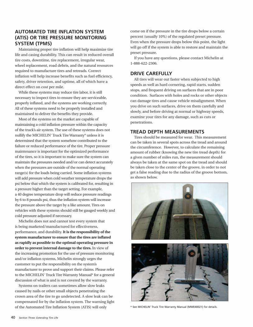
40 Section Three: Extending Tire Life
AUTOMATED TIRE INFLATION SYSTEM(ATIS) OR TIRE PRESSURE MONITORINGSYSTEM (TPMS)Maintaining proper tire inflation will help maximize tire
life and casing durability. This can result in reduced overall
tire costs, downtime, tire replacement, irregular wear,
wheel replacement, road debris, and the natural resources
required to manufacture tires and retreads. Correct
inflation will help increase benefits such as fuel efficiency,
safety, driver retention, and uptime, all of which have a
direct effect on cost per mile.
While these systems may reduce tire labor, it is still
necessary to inspect tires to ensure they are serviceable,
properly inflated, and the systems are working correctly.
All of these systems need to be properly installed and
maintained to deliver the benefits they provide.
Most of the systems on the market are capable of
maintaining a cold inflation pressure within the capacity
of the truck’s air system. The use of these systems does not
nullify the MICHELIN® Truck Tire Warranty* unless it is
determined that the system somehow contributed to the
failure or reduced performance of the tire. Proper pressure
maintenance is important for the optimized performance
of the tires, so it is important to make sure the system can
maintain the pressures needed and/or can detect accurately
when the pressures are outside of the normal operating
range(s) for the loads being carried. Some inflation systems
will add pressure when cold weather temperature drops the
psi below that which the system is calibrated for, resulting in
a pressure higher than the target setting. For example,
a 40 degree temperature drop will reduce pressure readings
by 6 to 8 pounds psi, thus the inflation system will increase
the pressure above the target by a like amount. Tires on
vehicles with these systems should still be gauged weekly and
cold pressure adjusted if necessary.
Michelin does not and cannot test every system that
is being marketed/manufactured for effectiveness,
performance, and durability. It is the responsibility of thesystem manufacturer to ensure that the tires are inflated as rapidly as possible to the optimal operating pressure inorder to prevent internal damage to the tires. In view of the increasing promotion for the use of pressure monitoring
and/or inflation systems, Michelin strongly urges the
customer to put the responsibility on the system’s
manufacturer to prove and support their claims. Please refer
to the MICHELIN® Truck Tire Warranty Manual* for a general
discussion of what is and is not covered by the warranty.
Systems on trailers can sometimes allow slow leaks
caused by nails or other small objects penetrating the
crown area of the tire to go undetected. A slow leak can be
compensated for by the inflation system. The warning light
of the Automated Tire Inflation System (ATIS) will only
come on if the pressure in the tire drops below a certain
percent (usually 10%) of the regulated preset pressure.
Even when the pressure drops below this point, the light
will go off if the system is able to restore and maintain the
preset pressure.
If you have any questions, please contact Michelin at
1-888-622-2306.
DRIVE CAREFULLYAll tires will wear out faster when subjected to high
speeds as well as hard cornering, rapid starts, sudden
stops, and frequent driving on surfaces that are in poor
condition. Surfaces with holes and rocks or other objects
can damage tires and cause vehicle misalignment. When
you drive on such surfaces, drive on them carefully and
slowly, and before driving at normal or highway speeds,
examine your tires for any damage, such as cuts or
penetrations.
TREAD DEPTH MEASUREMENTS Tires should be measured for wear. This measurement
can be taken in several spots across the tread and aroundthe circumference. However, to calculate the remainingamount of rubber (knowing the new tire tread depth) for a given number of miles run, the measurement shouldalways be taken at the same spot on the tread and shouldbe taken close to the center of the groove, in order to notget a false reading due to the radius of the groove bottom,as shown below.
* See MICHELIN® Truck Tire Warranty Manual (MWE40021) for details.
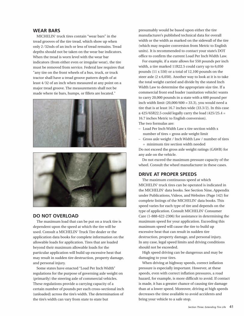
Section Three: Extending Tire Life 41
WEAR BARSMICHELIN® truck tires contain “wear bars” in the
tread grooves of the tire tread, which show up when
only 2 ⁄ 32nds of an inch or less of tread remains. Tread
depths should not be taken on the wear bar indicators.
When the tread is worn level with the wear bar
indicators (from either even or irregular wear), the tire
must be removed from service. Federal law requires that
"any tire on the front wheels of a bus, truck, or truck
tractor shall have a tread groove pattern depth of at
least 4 ⁄ 32 of an inch when measured at any point on a
major tread groove. The measurements shall not be
made where tie bars, humps, or fillets are located."
DO NOT OVERLOADThe maximum load that can be put on a truck tire is
dependent upon the speed at which the tire will be
used. Consult a MICHELIN® Truck Tire dealer or the
application data books for complete information on the
allowable loads for application. Tires that are loaded
beyond their maximum allowable loads for the
particular application will build up excessive heat that
may result in sudden tire destruction, property damage,
and personal injury.
Some states have enacted “Load Per Inch Width”
regulations for the purpose of governing axle weight on
(primarily) the steering axle of commercial vehicles.
These regulations provide a carrying capacity of a
certain number of pounds per each cross-sectional inch
(unloaded) across the tire’s width. The determination of
the tire’s width can vary from state to state but
presumably would be based upon either the tire
manufacturer’s published technical data for overall
width or the width as marked on the sidewall of the tire
(which may require conversion from Metric to English
units). It is recommended to contact your state’s DOT
office to confirm the current Load Per Inch Width Law.
For example, if a state allows for 550 pounds per inch
width, a tire marked 11R22.5 could carry up to 6,050
pounds (11 x 550) or a total of 12,100 pounds on the
steer axle (2 x 6,050). Another way to look at it is to take
the total weight carried and divide by the stated Inch
Width Law to determine the appropriate size tire. If a
commercial front end loader (sanitation vehicle) wants
to carry 20,000 pounds in a state with a 600 pound per
inch width limit (20,000/600 = 33.3), you would need a
tire that is at least 16.7 inches wide (33.3/2). In this case
a 425/65R22.5 could legally carry the load (425/25.4 =
16.7 inches Metric to English conversion).
The two formulas are:
– Load Per Inch Width Law x tire section width x
number of tires = gross axle weight limit
– Gross axle weight / Inch Width Law / number of tires
= minimum tire section width needed
Do not exceed the gross axle weight ratings (GAWR) for
any axle on the vehicle.
Do not exceed the maximum pressure capacity of the
wheel. Consult the wheel manufacturer in these cases.
DRIVE AT PROPER SPEEDSThe maximum continuous speed at which
MICHELIN® truck tires can be operated is indicated in
the MICHELIN® data books. See Section Nine, Appendix
under Publications, Videos, and Websites (Page 142) for
complete listings of the MICHELIN® data books. This
speed varies for each type of tire and depends on the
type of application. Consult MICHELIN® Consumer
Care (1-888-622-2306) for assistance in determining the
maximum speed for your application. Exceeding this
maximum speed will cause the tire to build up
excessive heat that can result in sudden tire
destruction, property damage, and personal injury.
In any case, legal speed limits and driving conditions
should not be exceeded.
High speed driving can be dangerous and may be
damaging to your tires.
When driving at highway speeds, correct inflation
pressure is especially important. However, at these
speeds, even with correct inflation pressures, a road
hazard, for example, is more difficult to avoid. If contact
is made, it has a greater chance of causing tire damage
than at a lower speed. Moreover, driving at high speeds
decreases the time available to avoid accidents and
bring your vehicle to a safe stop.
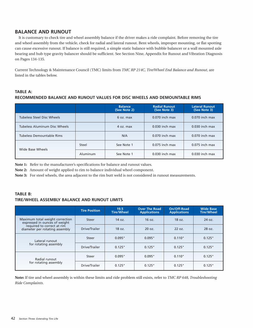
42 Section Three: Extending Tire Life
BALANCE AND RUNOUTIt is customary to check tire and wheel assembly balance if the driver makes a ride complaint. Before removing the tire
and wheel assembly from the vehicle, check for radial and lateral runout. Bent wheels, improper mounting, or flat spotting
can cause excessive runout. If balance is still required, a simple static balance with bubble balancer or a wall mounted axle
bearing and hub type gravity balancer should be sufficient. See Section Nine, Appendix for Runout and Vibration Diagnosis
on Pages 134-135.
Current Technology & Maintenance Council (TMC) limits from TMC RP 214C, Tire/Wheel End Balance and Runout, are
listed in the tables below.
TABLE A:RECOMMENDED BALANCE AND RUNOUT VALUES FOR DISC WHEELS AND DEMOUNTABLE RIMS
Note 1: Refer to the manufacturer’s specifications for balance and runout values.
Note 2: Amount of weight applied to rim to balance individual wheel component.
Note 3: For steel wheels, the area adjacent to the rim butt weld is not considered in runout measurements.
TABLE B:TIRE/WHEEL ASSEMBLY BALANCE AND RUNOUT LIMITS
Note: If tire and wheel assembly is within these limits and ride problem still exists, refer to TMC RP 648, Troubleshooting
Ride Complaints.
Tire Position 19.5 Tire/Wheel
Over The Road Applications
On/Off-RoadApplications
Wide BaseTire/Wheel
Maximum total weight correctionexpressed in ounces of weightrequired to correct at rim
diameter per rotating assembly
Steer 14 oz. 16 oz. 18 oz. 24 oz.
Drive/Trailer 18 oz. 20 oz. 22 oz. 28 oz.
Lateral runout for rotating assembly
Steer 0.095" 0.095" 0.110" 0.125"
Drive/Trailer 0.125" 0.125" 0.125" 0.125"
Radial runout for rotating assembly
Steer 0.095" 0.095" 0.110" 0.125"
Drive/Trailer 0.125" 0.125" 0.125" 0.125"
Balance (See Note 2)
Radial Runout (See Note 3)
Lateral Runout (See Note 3)
Tubeless Steel Disc Wheels 6 oz. max 0.070 inch max 0.070 inch max
Tubeless Aluminum Disc Wheels 4 oz. max 0.030 inch max 0.030 inch max
Tubeless Demountable Rims N/A 0.070 inch max 0.070 inch max
Wide Base WheelsSteel See Note 1 0.075 inch max 0.075 inch max
Aluminum See Note 1 0.030 inch max 0.030 inch max
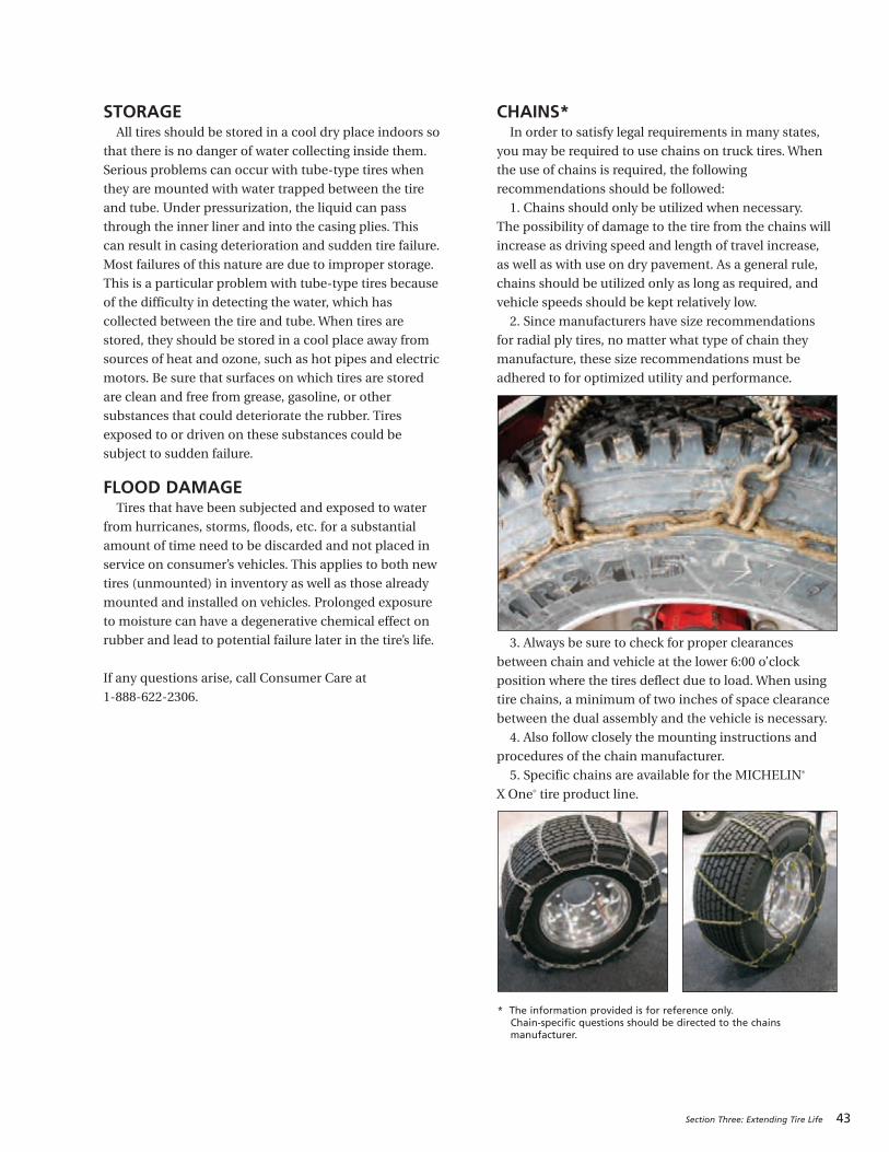
Section Three: Extending Tire Life 43
STORAGEAll tires should be stored in a cool dry place indoors so
that there is no danger of water collecting inside them.
Serious problems can occur with tube-type tires when
they are mounted with water trapped between the tire
and tube. Under pressurization, the liquid can pass
through the inner liner and into the casing plies. This
can result in casing deterioration and sudden tire failure.
Most failures of this nature are due to improper storage.
This is a particular problem with tube-type tires because
of the difficulty in detecting the water, which has
collected between the tire and tube. When tires are
stored, they should be stored in a cool place away from
sources of heat and ozone, such as hot pipes and electric
motors. Be sure that surfaces on which tires are stored
are clean and free from grease, gasoline, or other
substances that could deteriorate the rubber. Tires
exposed to or driven on these substances could be
subject to sudden failure.
FLOOD DAMAGETires that have been subjected and exposed to water
from hurricanes, storms, floods, etc. for a substantial
amount of time need to be discarded and not placed in
service on consumer’s vehicles. This applies to both new
tires (unmounted) in inventory as well as those already
mounted and installed on vehicles. Prolonged exposure
to moisture can have a degenerative chemical effect on
rubber and lead to potential failure later in the tire’s life.
If any questions arise, call Consumer Care at
1-888-622-2306.
CHAINS*In order to satisfy legal requirements in many states,
you may be required to use chains on truck tires. When
the use of chains is required, the following
recommendations should be followed:
1. Chains should only be utilized when necessary.
The possibility of damage to the tire from the chains will
increase as driving speed and length of travel increase,
as well as with use on dry pavement. As a general rule,
chains should be utilized only as long as required, and
vehicle speeds should be kept relatively low.
2. Since manufacturers have size recommendations
for radial ply tires, no matter what type of chain they
manufacture, these size recommendations must be
adhered to for optimized utility and performance.
3. Always be sure to check for proper clearances
between chain and vehicle at the lower 6:00 o’clock
position where the tires deflect due to load. When using
tire chains, a minimum of two inches of space clearance
between the dual assembly and the vehicle is necessary.
4. Also follow closely the mounting instructions and
procedures of the chain manufacturer.
5. Specific chains are available for the MICHELIN®
X One® tire product line.
* The information provided is for reference only.Chain-specific questions should be directed to the chainsmanufacturer.
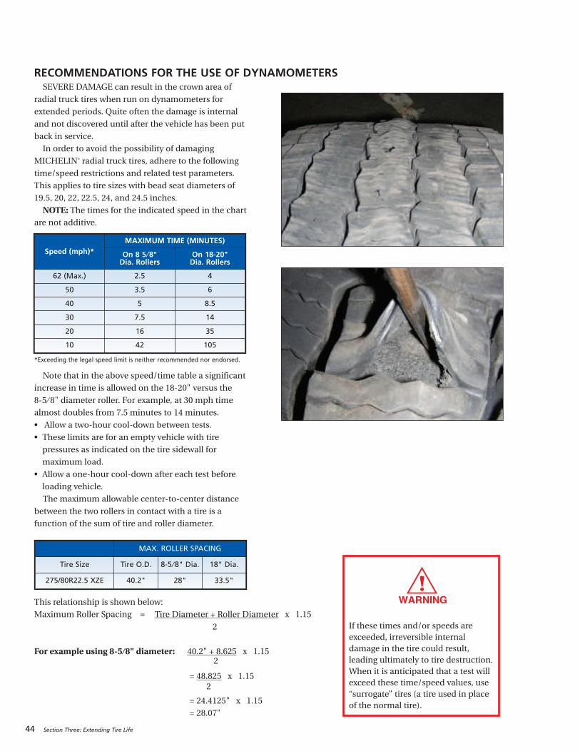
44 Section Three: Extending Tire Life
SEVERE DAMAGE can result in the crown area of
radial truck tires when run on dynamometers for
extended periods. Quite often the damage is internal
and not discovered until after the vehicle has been put
back in service.
In order to avoid the possibility of damaging
MICHELIN® radial truck tires, adhere to the following
time/speed restrictions and related test parameters.
This applies to tire sizes with bead seat diameters of
19.5, 20, 22, 22.5, 24, and 24.5 inches.
NOTE: The times for the indicated speed in the chart
are not additive.
*Exceeding the legal speed limit is neither recommended nor endorsed.
Note that in the above speed/time table a significant
increase in time is allowed on the 18-20" versus the
8-5 ⁄ 8" diameter roller. For example, at 30 mph time
almost doubles from 7.5 minutes to 14 minutes.
• Allow a two-hour cool-down between tests.
• These limits are for an empty vehicle with tire
pressures as indicated on the tire sidewall for
maximum load.
• Allow a one-hour cool-down after each test before
loading vehicle.
The maximum allowable center-to-center distance
between the two rollers in contact with a tire is a
function of the sum of tire and roller diameter.
Speed (mph)*MAXIMUM TIME (MINUTES)
On 8 5 ⁄8" Dia. Rollers
On 18-20" Dia. Rollers
62 (Max.) 2.5 4
50 3.5 6
40 5 8.5
30 7.5 14
20 16 35
10 42 105
MAX. ROLLER SPACING
Tire Size Tire O.D. 8-5 ⁄8" Dia. 18" Dia.
275/80R22.5 XZE 40.2" 28" 33.5"
If these times and/or speeds areexceeded, irreversible internaldamage in the tire could result,leading ultimately to tire destruction.When it is anticipated that a test willexceed these time/speed values, use“surrogate” tires (a tire used in placeof the normal tire).
RECOMMENDATIONS FOR THE USE OF DYNAMOMETERS
This relationship is shown below:
Maximum Roller Spacing = Tire Diameter + Roller Diameter x 1.15
2
For example using 8-5 ⁄8" diameter: 40.2" + 8.625 x 1.152
= 48.825 x 1.152
= 24.4125" x 1.15
= 28.07"
SPINNING Major tire damage can occur in a short period of time
when a tire spins on a surface at high speeds. When the
speed difference between the wheel with good traction
and the wheel without becomes too great, the tire begins
to disintegrate. This can occur on any slick surface (such
as ice, mud, and snow) or on a dry surface where there is
a variance in traction. The resulting difference in speed of
the assembly can be as high as 4 times the registered
speed indicated, resulting in tire and/or differential
damage on the vehicle.
ROTATIONMICHELIN® radial tires should be rotated when
necessary. If the tires are wearing evenly, there is no need
to rotate. If irregular wear becomes apparent or if the
wear rate on the tires is perceptively different (from axle
to axle for drive tires and side to side for steer tires),
then the tires should be rotated in such a manner as to
alleviate the condition. There is no restriction on criss-
cross rotation, including directional steer tires that have
worn 50% or more of the original tread.
When rotating tires, the following points should be
taken into consideration:
• The load carried by a particular tire in a particular
position. The inside tire of a dual mounting carries
more load than the outside tire on the same axle.
• Adjacent dual tires should not differ more than
1 ⁄ 4" inch diameter (4 ⁄ 32" inch tread wear). If there
is a difference in tread wear, fit the least worn tire in
the outside position.
• Curbing on dual applications often damages tire
sidewalls. If so, rotate the wheel and tire to the inner
wheel position.
• Often it is beneficial to rotate the tires so that irregularly
worn tires are moved to a position where they are
turning in a direction opposite the original position.
Rotation procedures such as those recommended by
vehicle manufacturers and those included in TMC RP
642A, Total Vehicle Alignment Recommendations for
Maximizing Tire and Alignment Related Component Life
may be followed.
Note Directional Tires:When mounting any new
directional tire, ensure directional arrow points toward
the direction of travel during the original 50% of tread
life. Directional casings that have been removed from
service and retreaded should be considered non-
directional tires.
SIPINGThere is no reason to ‘sipe’ new MICHELIN® tires.
Michelin incorporates siping as needed in its designs to
enhance tire performance. Experience suggests
degradation in tread wear, vehicle ride and handling, and
tire durability may be caused by poor or improper tire
tread siping. Drive tires (M/S) are optimized to provide
desirable traction in dry, wet, snow, and icy conditions.
Siping does not automatically affect the MICHELIN®
warranty* that covers workmanship and material.
However, if a tire fails or is rendered unserviceable as a
result of ‘siping,’ the tire is not warrantable.
BRANDING1. The following limits apply when branding
MICHELIN® truck tires using equipment without
accurate temperature control or which may exceed
465°F (240°C). (Hand-held equipment is typically used
for this “HOT BRANDING.”)
a. Brand Temperature/Maximum Depth
570°F (300°C) 1 ⁄64 inch (0.4 mm)
480°F (250°C) 1 ⁄32 inch (0.8 mm)
b. Only brand in the “BRAND TIRE HERE” area.
2. For equipment capable of “COLD BRANDING,” i.e.,
controlled temperatures below 465°F (240°C), the
following restrictions apply:
a. Temperature Maximum 465°F (240°C)
b. Contact pressure Maximum 100 psi
c. Time of contact Maximum 1 minute
d. Character Height Maximum 1 inch
e. Character Depth Maximum 0.040 inch (1.0 mm)
f. Location:
Circumferentially — in the “BRAND TIRE HERE”
area.
Radially — in the “BRAND TIRE HERE” area with
no portion of any character extending more than
1 inch above the outline of the area.
*See warranty for details.
Section Three: Extending Tire Life 45

46 Section Three: Extending Tire Life
MAINTAINING THE VEHICLEMany tire problems can be traced to mechanical
conditions in the vehicle. Therefore, to obtain
maximized tire performance, vehicles must be
properly maintained.
MAJOR VEHICLE FACTORS WHICHAFFECT TIRE LIFE:
ALIGNMENTAlignment refers not only to the various angles of
the steer axle geometry, but also to the tracking of all
axles on a vehicle, including the trailer. The dual
purpose of proper alignment is to minimize tire wear
and to maximize predictable vehicle handling and
driver control. Toe misalignment is the number one
cause of steer tire irregular wear, followed by rear axle
skew (parallelism or thrust). One of the challenges of
meeting this goal is that alignments are typically
performed on a static, unloaded vehicle sitting on a
level floor. The vehicle then operates over varying
contoured surfaces, under loaded conditions, with
dynamic forces acting upon it. Predicting the amount
of change between static/unloaded/level - versus –
dynamic/loaded/contoured is difficult because many
variables affect the amount of change. Variables such
as Steering System Compliance (i.e. “play”) must be
considered in making alignment setting
recommendations.
All of these misalignment conditions may exist
alone or (more likely) in combination with other
misalignment conditions. Sometimes it is these
interactions that produce the outcomes that are
especially undesirable. As an example, a tire running
at slightly negative camber may perform especially
badly if it is also subjected to tandem thrust
misalignment. The conceptual understanding for this
phenomenon is that because of the camber issue, the
wear burden imposed by the thrust misalignment is
not being shared equally by the entire tread surface.
Further, a tire that is being operated in a misaligned
condition may well transmit forces into the
suspension from its interaction with the road. Some
suspension systems manage those forces favorably.
Others react in a way that imposes motions in the tire
that are very unfavorable to the tire's ability to yield a
favorable wear outcome.
• Tires that are not operated at a normal
(perpendicular) angle to the road surface typically
produce uneven tire wear. Tires that are fighting
each other (because of conflicting alignment
operating angles) produce unfavorable and
sometimes irregular tire wear. Tires that are fighting
each other due to highly compliant suspension
components (compression/extension in the
bushings or joints, or deflection of solid parts) will
likely produce irregular wear forms.
• Alignments should be performed carefully using
best alignment practices. (For example, ensuring
that the suspension is at the correct ride height and
that the suspension has been settled out by being
moved forwards/backwards, etc.)
• Alignments should be conducted in the most
representative loading condition and ride height
for the expected usage.
We therefore recommend referring to TMC RP
642A, Total Vehicle Alignment Recommendations for
Maximizing Tire and Alignment Related Component
Life, which has established industry recommended
target values for the alignment of vehicles.
STEER AXLE GEOMETRYSince very few vehicles continue to use Center
Point Steering, the following recommendations are
based on the more common Inclined Kingpin Steer
Axle Geometry.
TOEToe is typically the most critical alignment condition
affecting steer axle tire wear. The purpose of setting toe
at a given specification is to allow the tire to run
straight during normal operating conditions. Too
much toe-in results in scrubbing from the outside
inward on both tires, and too much toe-out results in
scrubbing from the inside outward on both tires.
Total toe is the angle formed by two horizontal
lines through the planes of two wheels. Toe-in is
when the horizontal lines intersect in front of the
wheels or the wheels are closer together in front than
in back. Toe-out is when the horizontal lines intersect
behind the wheels or the wheels are closer together in
back than in front. Toe-in is commonly designated as
positive and toe-out as negative.
Inclined Kingpin
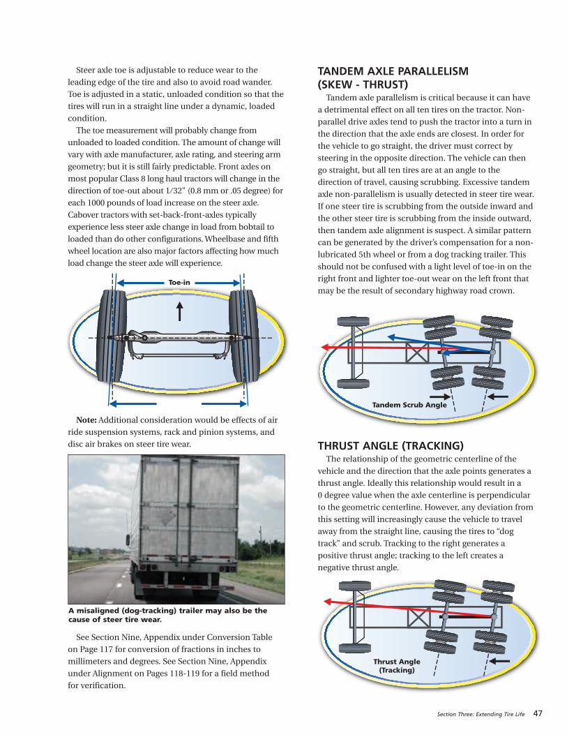
Steer axle toe is adjustable to reduce wear to the
leading edge of the tire and also to avoid road wander.
Toe is adjusted in a static, unloaded condition so that the
tires will run in a straight line under a dynamic, loaded
condition.
The toe measurement will probably change from
unloaded to loaded condition. The amount of change will
vary with axle manufacturer, axle rating, and steering arm
geometry; but it is still fairly predictable. Front axles on
most popular Class 8 long haul tractors will change in the
direction of toe-out about 1 ⁄ 32" (0.8 mm or .05 degree) for
each 1000 pounds of load increase on the steer axle.
Cabover tractors with set-back-front-axles typically
experience less steer axle change in load from bobtail to
loaded than do other configurations. Wheelbase and fifth
wheel location are also major factors affecting how much
load change the steer axle will experience.
Note: Additional consideration would be effects of airride suspension systems, rack and pinion systems, and
disc air brakes on steer tire wear.
See Section Nine, Appendix under Conversion Table
on Page 117 for conversion of fractions in inches to
millimeters and degrees. See Section Nine, Appendix
under Alignment on Pages 118-119 for a field method
for verification.
TANDEM AXLE PARALLELISM (SKEW - THRUST)Tandem axle parallelism is critical because it can have
a detrimental effect on all ten tires on the tractor. Non-
parallel drive axles tend to push the tractor into a turn in
the direction that the axle ends are closest. In order for
the vehicle to go straight, the driver must correct by
steering in the opposite direction. The vehicle can then
go straight, but all ten tires are at an angle to the
direction of travel, causing scrubbing. Excessive tandem
axle non-parallelism is usually detected in steer tire wear.
If one steer tire is scrubbing from the outside inward and
the other steer tire is scrubbing from the inside outward,
then tandem axle alignment is suspect. A similar pattern
can be generated by the driver’s compensation for a non-
lubricated 5th wheel or from a dog tracking trailer. This
should not be confused with a light level of toe-in on the
right front and lighter toe-out wear on the left front that
may be the result of secondary highway road crown.
THRUST ANGLE (TRACKING)The relationship of the geometric centerline of the
vehicle and the direction that the axle points generates a
thrust angle. Ideally this relationship would result in a
0 degree value when the axle centerline is perpendicular
to the geometric centerline. However, any deviation from
this setting will increasingly cause the vehicle to travel
away from the straight line, causing the tires to “dog
track” and scrub. Tracking to the right generates a
positive thrust angle; tracking to the left creates a
negative thrust angle.
Section Three: Extending Tire Life 47
Toe-in
Tandem Scrub Angle
Thrust Angle(Tracking)
A misaligned (dog-tracking) trailer may also be thecause of steer tire wear.
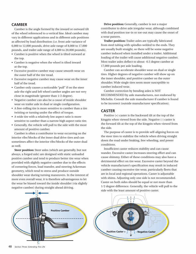
48 Section Three: Extending Tire Life
Positive Camber
Positive Caster + - Negative Caster0°
CAMBERCamber is the angle formed by the inward or outward tilt
of the wheel referenced to a vertical line. Ideal camber may
vary in different applications and in different axle positions
as affected by load distribution (i.e. front axle variance of
6,000 to 12,000 pounds, drive axle range of 8,000 to 17,000
pounds, and trailer axle range of 4,000 to 20,000 pounds).
• Camber is positive when the wheel is tilted outward at
the top.
• Camber is negative when the wheel is tilted inward
at the top.
• Excessive positive camber may cause smooth wear on
the outer half of the tire tread.
• Excessive negative camber may cause wear on the inner
half of the tread.
• Camber only causes a noticeable “pull” if on the steer
axle the right and left wheel camber angles are not very
close in magnitude (greater than 1 ⁄ 2 degree).
• Negative camber can also be a cause of inside shoulder
wear on trailer axle in dual or single configuration.
• A free-rolling tire is more sensitive to camber than a tire
twisting or turning under the effect of torque.
• A wide tire with a relatively low aspect ratio is more
sensitive to camber than a narrow high aspect ratio tire.
• Generally, the vehicle will pull to the side with the most
amount of positive camber.
Camber is often a contributor to wear occurring on the
interior ribs/blocks of the inner dual drive tires and can
sometimes affect the interior ribs/blocks of the outer dual
as well.
Steer position: Steer axles (which are generally, but notalways, a forged axle) are designed with static unloaded
positive camber and tend to produce better tire wear when
provided with slightly negative camber due to the effects
of cornering forces, load transfer, and steering Ackerman
geometry, which tend to stress and produce outside
shoulder wear during turning maneuvers. In the interest of
more even overall wear, it is therefore advantageous to let
the wear be biased toward the inside shoulder (via slightly
negative camber) during straight ahead driving.
Drive position: Generally, camber is not a major
contributor to drive axle irregular wear, although combined
with dual position toe-in or toe-out may cause the onset of
a wear pattern.
Trailer position: Trailer axles are typically fabricatedfrom steel tubing with spindles welded to the ends. They
are usually built straight, so there will be some negative
camber induced when installed under a trailer. Additional
loading of the trailer will cause additional negative camber.
Most trailer axles deflect to about -0.5 degree camber at
17,000 pounds per axle loading.
Camber can accelerate shoulder wear on dual or single
tires. Higher degrees of negative camber will show up on
the inner shoulder, and positive camber on the outer
shoulder. Wide single tires seem more susceptible to
camber induced wear.
Camber correction by bending axles is NOT
RECOMMENDED by axle manufactures, nor endorsed by
Michelin. Consult the axle manufacturer if camber is found
to be incorrect (outside manufacturer specification).
CASTER Positive (+) caster is the backward tilt at the top of the
kingpin when viewed from the side. Negative (-) caster is
the forward tilt at the top of the kingpin when viewed from
the side.
The purpose of caster is to provide self-aligning forces on
the steer tires to stabilize the vehicle when driving straight
down the road under braking, free wheeling, and power
conditions.
Insufficient caster reduces stability and can cause
wander. Excessive caster increases steering effort and can
cause shimmy. Either of these conditions may also have a
detrimental effect on tire wear. Excessive caster beyond the
vehicle manufacturer’s specification may result in induced
camber causing excessive tire wear, particularly fleets that
are in local and regional operations. Caster is adjustable
with shims. Adjusting only one side is not recommended.
Caster on both sides should be equal or not more than
1 ⁄ 2 degree difference. Generally, the vehicle will pull to the
side with the least amount of positive caster.
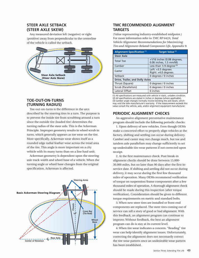
STEER AXLE SETBACK (STEER AXLE SKEW)Any measured deviation left (negative) or right
(positive) away from perpendicular to the centerline
of the vehicle is called the setback.
TOE-OUT-ON-TURNS(TURNING RADIUS) Toe-out-on-turns is the difference in the arcs
described by the steering tires in a turn. The purpose is
to prevent the inside tire from scrubbing around a turn
since the outside tire (loaded tire) determines the
turning radius of the steer axle. This is the Ackerman
Principle. Improper geometry results in wheel scrub in
turns, which generally appears as toe wear on the tire.
More specifically, Ackerman wear shows itself as a
rounded edge radial feather wear across the tread area
of the tire. This angle is more important on a city
vehicle with its many turns than on a line haul unit.
Ackerman geometry is dependent upon the steering
axle track-width and wheel base of a vehicle. When the
turning angle or wheel base changes from the original
specification, Ackerman is affected.
TMC RECOMMENDED ALIGNMENT TARGETS(Value representing industry-established midpoint.)For more information refer to TMC RP 642A, TotalVehicle Alignment: Recommendations for MaximizingTire and Alignment-Related Component Life, Appendix 9.
PERIODIC ALIGNMENT CHECKSAn aggressive alignment preventative maintenance
program should include the following periodic checks:
1. Upon delivery of new vehicles. Even though OEMs
make a concerted effort to properly align vehicles at the
factory, shifting and settling can occur during delivery.
Camber and caster may not change much, but toe and
tandem axle parallelism may change sufficiently to set
up undesirable tire wear patterns if not corrected upon
receipt.
2. At the first maintenance check. Post break-in
alignment checks should be done between 15,000-
30,000 miles, but no later than 90 days after the first in-
service date. If shifting and settling did not occur during
delivery, it may occur during the first few thousand
miles of operation. Many OEMs recommend verification
of torque on suspension/frame components after a few
thousand miles of operation. A thorough alignment check
should be made during this inspection (after torque
verification). Consideration should be given to different
torque requirements on metric and standard bolts.
3. When new steer tires are installed or front-end
components are replaced. The steer tires coming out of
service can tell a story of good or bad alignment. With
this feedback, an alignment program can continue to
improve. Without feedback, the best an alignment
program can do is stay at its current level.
4. When tire wear indicates a concern. “Reading” tire
wear can help identify alignment issues. Unfortunately,
correcting the alignment does not necessarily correct
the tire wear pattern once an undesirable wear pattern
has been established.
Section Three: Extending Tire Life 49
Steer Axle Setback(Steer Axle Skew)
WheelBase
Rear AxleCenter of Rotation
Ch
assi
s
Cross Bar(Tie Rod)
Steering Arms
Basic Ackerman Steering Diagram
Alignment Specification (1) Target Value (2)
Steer Axle
Total Toe +1⁄16 inches (0.08 degrees, 0.06 inches, 1.5 mm/M)
Camber Less than 1 ⁄ 4 degree (3)
Caster Left: +3.5 degrees Right: +4.0 degrees
Setback 0 degrees / 0 inchesDrive, Trailer, and Dolly Axles Thrust (Square) 0 degrees / 0 inchesScrub (Parallelism) 0 degrees / 0 inchesLateral Offset 0 inches
(1) All specifications are measured with vehicle in static, unladen condition.(2) All specifications are stated in inches or degrees (where applicable).(3) Camber angle changes normally involve bending the axle beam, whichmay void the axle manufacturer’s warranty. If the measurement exceeds thisvalue consult the vehicle, axle, and/or alignment equipment manufacturer.
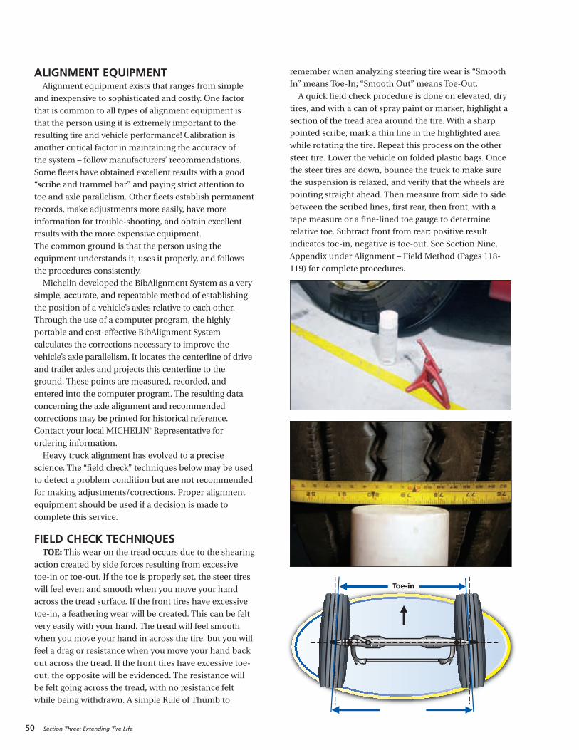
50 Section Three: Extending Tire Life
ALIGNMENT EQUIPMENTAlignment equipment exists that ranges from simple
and inexpensive to sophisticated and costly. One factor
that is common to all types of alignment equipment is
that the person using it is extremely important to the
resulting tire and vehicle performance! Calibration is
another critical factor in maintaining the accuracy of
the system – follow manufacturers’ recommendations.
Some fleets have obtained excellent results with a good
“scribe and trammel bar” and paying strict attention to
toe and axle parallelism. Other fleets establish permanent
records, make adjustments more easily, have more
information for trouble-shooting, and obtain excellent
results with the more expensive equipment.
The common ground is that the person using the
equipment understands it, uses it properly, and follows
the procedures consistently.
Michelin developed the BibAlignment System as a very
simple, accurate, and repeatable method of establishing
the position of a vehicle’s axles relative to each other.
Through the use of a computer program, the highly
portable and cost-effective BibAlignment System
calculates the corrections necessary to improve the
vehicle’s axle parallelism. It locates the centerline of drive
and trailer axles and projects this centerline to the
ground. These points are measured, recorded, and
entered into the computer program. The resulting data
concerning the axle alignment and recommended
corrections may be printed for historical reference.
Contact your local MICHELIN® Representative for
ordering information.
Heavy truck alignment has evolved to a precise
science. The “field check” techniques below may be used
to detect a problem condition but are not recommended
for making adjustments/corrections. Proper alignment
equipment should be used if a decision is made to
complete this service.
FIELD CHECK TECHNIQUESTOE: This wear on the tread occurs due to the shearing
action created by side forces resulting from excessive
toe-in or toe-out. If the toe is properly set, the steer tires
will feel even and smooth when you move your hand
across the tread surface. If the front tires have excessive
toe-in, a feathering wear will be created. This can be felt
very easily with your hand. The tread will feel smooth
when you move your hand in across the tire, but you will
feel a drag or resistance when you move your hand back
out across the tread. If the front tires have excessive toe-
out, the opposite will be evidenced. The resistance will
be felt going across the tread, with no resistance felt
while being withdrawn. A simple Rule of Thumb to
remember when analyzing steering tire wear is “Smooth
In” means Toe-In; “Smooth Out” means Toe-Out.
A quick field check procedure is done on elevated, dry
tires, and with a can of spray paint or marker, highlight a
section of the tread area around the tire. With a sharp
pointed scribe, mark a thin line in the highlighted area
while rotating the tire. Repeat this process on the other
steer tire. Lower the vehicle on folded plastic bags. Once
the steer tires are down, bounce the truck to make sure
the suspension is relaxed, and verify that the wheels are
pointing straight ahead. Then measure from side to side
between the scribed lines, first rear, then front, with a
tape measure or a fine-lined toe gauge to determine
relative toe. Subtract front from rear: positive result
indicates toe-in, negative is toe-out. See Section Nine,
Appendix under Alignment – Field Method (Pages 118-
119) for complete procedures.
Toe-in
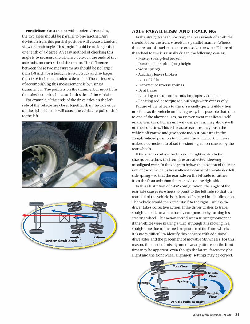
Parallelism: On a tractor with tandem drive axles,
the two axles should be parallel to one another. Any
deviation from this parallel position will create a tandem
skew or scrub angle. This angle should be no larger than
one tenth of a degree. An easy method of checking this
angle is to measure the distance between the ends of the
axle hubs on each side of the tractor. The difference
between these two measurements should be no larger
than 1 ⁄ 8 inch for a tandem tractor/truck and no larger
than 1 ⁄ 16 inch on a tandem axle trailer. The easiest way
of accomplishing this measurement is by using a
trammel bar. The pointers on the trammel bar must fit in
the axles’ centering holes on both sides of the vehicle.
For example, if the ends of the drive axles on the left
side of the vehicle are closer together than the axle ends
on the right side, this will cause the vehicle to pull or drift
to the left.
Tandem Scrub Angle
Top View
InsideWear
Vehicle Pulls to Right
SpringsSprings
OutsideWear
Section Three: Extending Tire Life 51
AXLE PARALLELISM AND TRACKINGIn the straight-ahead position, the rear wheels of a vehicle
should follow the front wheels in a parallel manner. Wheels
that are out-of-track can cause excessive tire wear. Failure of
the wheel to track is usually due to the following causes:
– Master spring-leaf broken
– Incorrect air spring (bag) height
–Worn springs
– Auxiliary leaves broken
– Loose “U” bolts
– Incorrect or reverse springs
– Bent frame
– Locating rods or torque rods improperly adjusted
– Locating rod or torque rod bushings worn excessively
Failure of the wheels to track is usually quite visible when
one follows the vehicle on the highway. It is possible that, due
to one of the above causes, no uneven wear manifests itself
on the rear tires, but an uneven wear pattern may show itself
on the front tires. This is because rear tires may push the
vehicle off course and give some toe-out-on-turns in the
straight-ahead position to the front tires. Hence, the driver
makes a correction to offset the steering action caused by the
rear wheels.
If the rear axle of a vehicle is not at right angles to the
chassis centerline, the front tires are affected, showing
misaligned wear. In the diagram below, the position of the rear
axle of the vehicle has been altered because of a weakened left
side spring – so that the rear axle on the left side is further
from the front axle than the rear axle on the right side.
In this illustration of a 4x2 configuration, the angle of the
rear axle causes its wheels to point to the left side so that the
rear end of the vehicle is, in fact, self-steered in that direction.
The vehicle would then steer itself to the right – unless the
driver takes corrective action. If the driver wishes to travel
straight ahead, he will naturally compensate by turning his
steering wheel. This action introduces a turning moment as
if the vehicle were making a turn although it is moving in a
straight line due to the toe-like posture of the front wheels.
It is more difficult to identify this concept with additional
drive axles and the placement of movable 5th wheels. For this
reason, the onset of misalignment wear patterns on the front
tires may be apparent, even though the lateral forces may be
slight and the front wheel alignment settings may be correct.
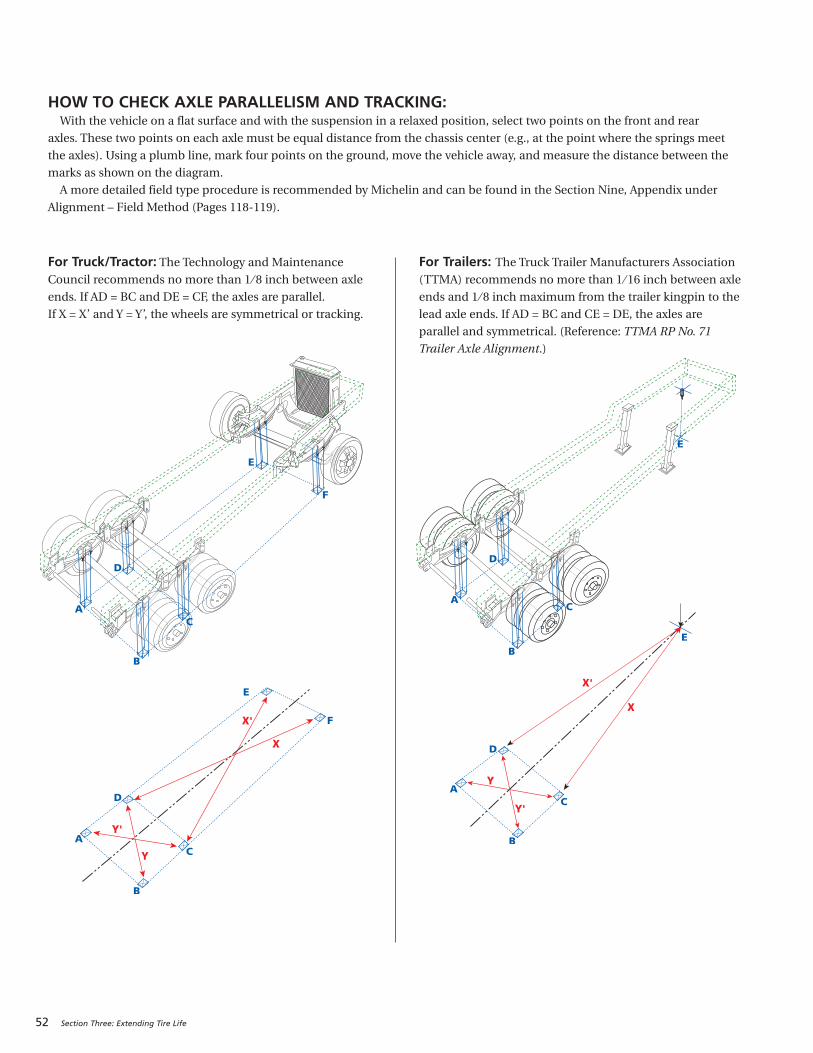
52 Section Three: Extending Tire Life
HOW TO CHECK AXLE PARALLELISM AND TRACKING: With the vehicle on a flat surface and with the suspension in a relaxed position, select two points on the front and rear
axles. These two points on each axle must be equal distance from the chassis center (e.g., at the point where the springs meet
the axles). Using a plumb line, mark four points on the ground, move the vehicle away, and measure the distance between the
marks as shown on the diagram.
A more detailed field type procedure is recommended by Michelin and can be found in the Section Nine, Appendix under
Alignment – Field Method (Pages 118-119).
Y
X'
X
Y'
Y
X'
X
Y'
For Truck/Tractor: The Technology and Maintenance
Council recommends no more than 1 ⁄ 8 inch between axle
ends. If AD = BC and DE = CF, the axles are parallel.
If X = X’ and Y = Y’, the wheels are symmetrical or tracking.
For Trailers: The Truck Trailer Manufacturers Association
(TTMA) recommends no more than 1 ⁄ 16 inch between axle
ends and 1 ⁄ 8 inch maximum from the trailer kingpin to the
lead axle ends. If AD = BC and CE = DE, the axles are
parallel and symmetrical. (Reference: TTMA RP No. 71
Trailer Axle Alignment.)
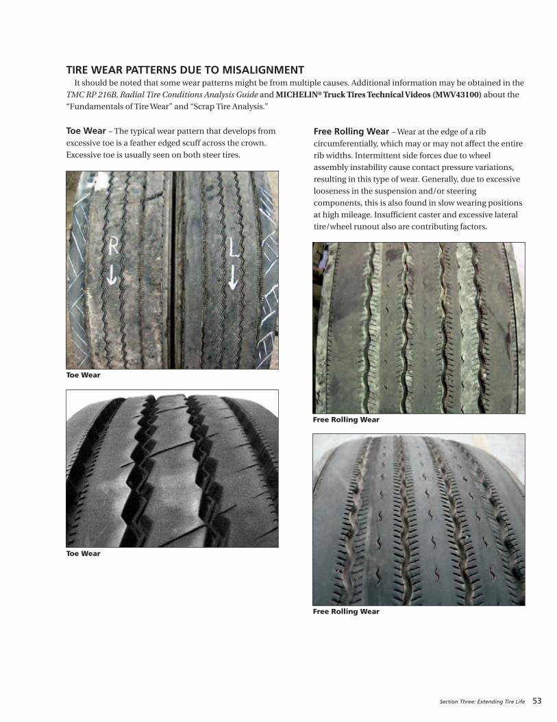
Section Three: Extending Tire Life 53
Toe Wear – The typical wear pattern that develops fromexcessive toe is a feather edged scuff across the crown.
Excessive toe is usually seen on both steer tires.
Free Rolling Wear
Free Rolling Wear
Toe Wear
Toe Wear
TIRE WEAR PATTERNS DUE TO MISALIGNMENT It should be noted that some wear patterns might be from multiple causes. Additional information may be obtained in the
TMC RP 216B, Radial Tire Conditions Analysis Guide and MICHELIN®Truck Tires Technical Videos (MWV43100) about the“Fundamentals of Tire Wear” and “Scrap Tire Analysis.”
Free Rolling Wear – Wear at the edge of a ribcircumferentially, which may or may not affect the entire
rib widths. Intermittent side forces due to wheel
assembly instability cause contact pressure variations,
resulting in this type of wear. Generally, due to excessive
looseness in the suspension and/or steering
components, this is also found in slow wearing positions
at high mileage. Insufficient caster and excessive lateral
tire/wheel runout also are contributing factors.
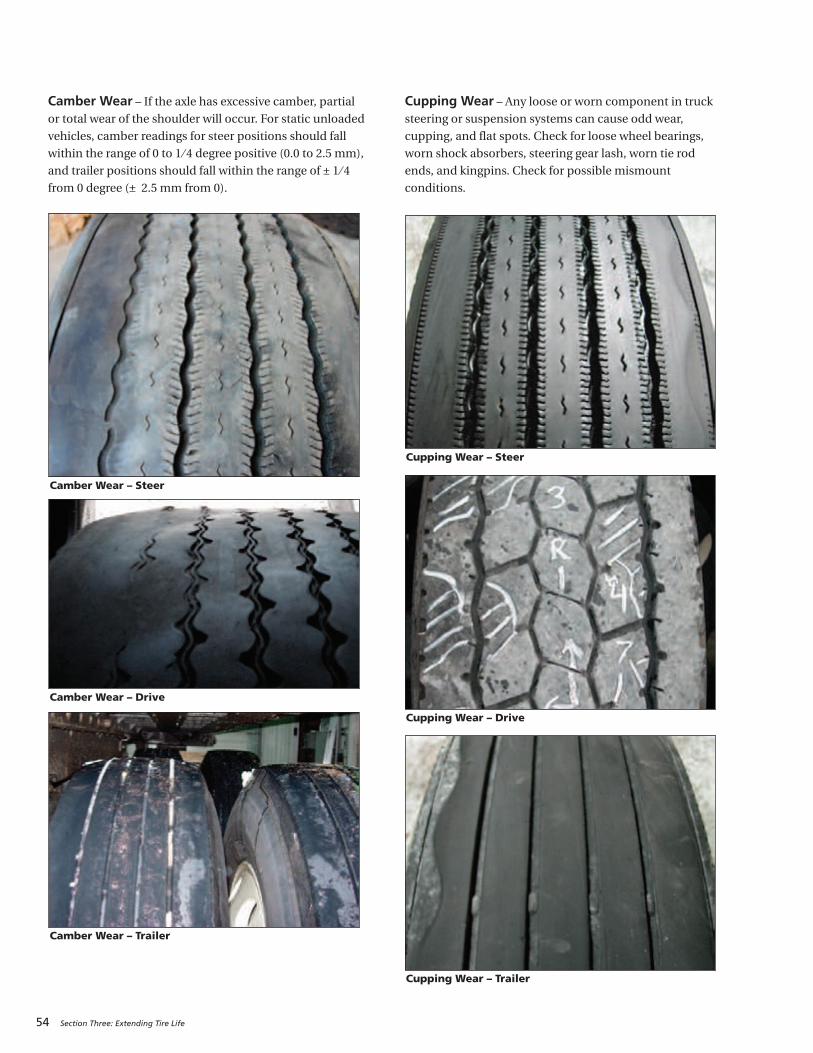
54 Section Three: Extending Tire Life
Cupping Wear – Any loose or worn component in trucksteering or suspension systems can cause odd wear,
cupping, and flat spots. Check for loose wheel bearings,
worn shock absorbers, steering gear lash, worn tie rod
ends, and kingpins. Check for possible mismount
conditions.
Cupping Wear – Steer
Cupping Wear – Drive
Cupping Wear – Trailer
Camber Wear – Steer
Camber Wear – Drive
Camber Wear – Trailer
Camber Wear – If the axle has excessive camber, partialor total wear of the shoulder will occur. For static unloaded
vehicles, camber readings for steer positions should fall
within the range of 0 to 1 ⁄ 4 degree positive (0.0 to 2.5 mm),
and trailer positions should fall within the range of ± 1 ⁄ 4
from 0 degree (± 2.5 mm from 0).
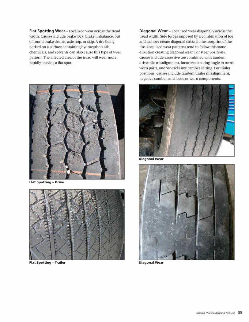
Section Three: Extending Tire Life 55
Flat Spotting Wear – Localized wear across the treadwidth. Causes include brake lock, brake imbalance, out
of round brake drums, axle hop, or skip. A tire being
parked on a surface containing hydrocarbon oils,
chemicals, and solvents can also cause this type of wear
pattern. The affected area of the tread will wear more
rapidly, leaving a flat spot.
Diagonal Wear – Localized wear diagonally across thetread width. Side forces imposed by a combination of toe
and camber create diagonal stress in the footprint of the
tire. Localized wear patterns tend to follow this same
direction creating diagonal wear. For steer positions,
causes include excessive toe combined with tandem
drive axle misalignment, incorrect steering angle in turns,
worn parts, and/or excessive camber setting. For trailer
positions, causes include tandem trailer misalignment,
negative camber, and loose or worn components.
Diagonal Wear
Diagonal Wear
Flat Spotting – Trailer
Flat Spotting – Drive
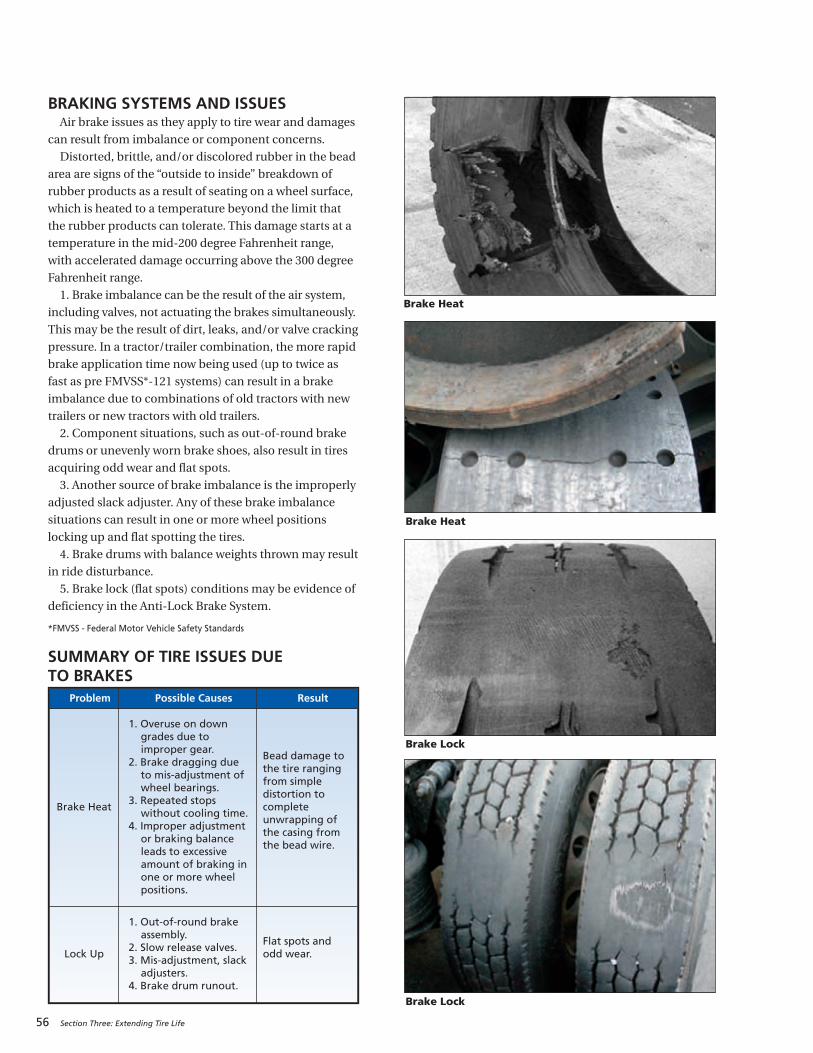
56 Section Three: Extending Tire Life
BRAKING SYSTEMS AND ISSUESAir brake issues as they apply to tire wear and damages
can result from imbalance or component concerns.
Distorted, brittle, and/or discolored rubber in the bead
area are signs of the “outside to inside” breakdown of
rubber products as a result of seating on a wheel surface,
which is heated to a temperature beyond the limit that
the rubber products can tolerate. This damage starts at a
temperature in the mid-200 degree Fahrenheit range,
with accelerated damage occurring above the 300 degree
Fahrenheit range.
1. Brake imbalance can be the result of the air system,
including valves, not actuating the brakes simultaneously.
This may be the result of dirt, leaks, and/or valve cracking
pressure. In a tractor/trailer combination, the more rapid
brake application time now being used (up to twice as
fast as pre FMVSS*-121 systems) can result in a brake
imbalance due to combinations of old tractors with new
trailers or new tractors with old trailers.
2. Component situations, such as out-of-round brake
drums or unevenly worn brake shoes, also result in tires
acquiring odd wear and flat spots.
3. Another source of brake imbalance is the improperly
adjusted slack adjuster. Any of these brake imbalance
situations can result in one or more wheel positions
locking up and flat spotting the tires.
4. Brake drums with balance weights thrown may result
in ride disturbance.
5. Brake lock (flat spots) conditions may be evidence of
deficiency in the Anti-Lock Brake System.
*FMVSS - Federal Motor Vehicle Safety Standards
SUMMARY OF TIRE ISSUES DUE TO BRAKES
Problem Possible Causes Result
Brake Heat
1. Overuse on downgrades due toimproper gear.
2. Brake dragging dueto mis-adjustment ofwheel bearings.
3. Repeated stopswithout cooling time.
4. Improper adjustmentor braking balanceleads to excessiveamount of braking inone or more wheelpositions.
Bead damage tothe tire rangingfrom simpledistortion tocompleteunwrapping ofthe casing fromthe bead wire.
Lock Up
1. Out-of-round brakeassembly.
2. Slow release valves.3. Mis-adjustment, slackadjusters.
4. Brake drum runout.
Flat spots andodd wear.
Brake Heat
Brake Lock
Brake Lock
Brake Heat
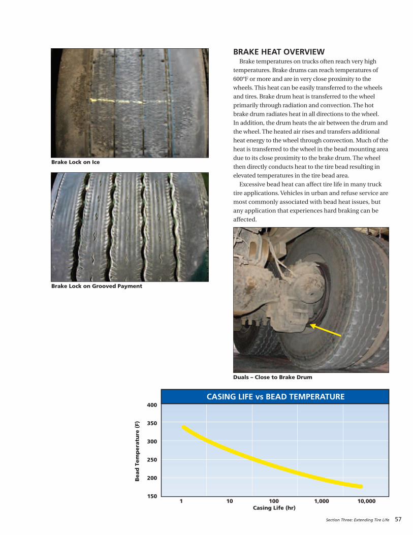
Section Three: Extending Tire Life 57
BRAKE HEAT OVERVIEWBrake temperatures on trucks often reach very high
temperatures. Brake drums can reach temperatures of
600°F or more and are in very close proximity to the
wheels. This heat can be easily transferred to the wheels
and tires. Brake drum heat is transferred to the wheel
primarily through radiation and convection. The hot
brake drum radiates heat in all directions to the wheel.
In addition, the drum heats the air between the drum and
the wheel. The heated air rises and transfers additional
heat energy to the wheel through convection. Much of the
heat is transferred to the wheel in the bead mounting area
due to its close proximity to the brake drum. The wheel
then directly conducts heat to the tire bead resulting in
elevated temperatures in the tire bead area.
Excessive bead heat can affect tire life in many truck
tire applications. Vehicles in urban and refuse service are
most commonly associated with bead heat issues, but
any application that experiences hard braking can be
affected.
Brake Lock on Grooved Payment
Brake Lock on Ice
Duals – Close to Brake Drum
1 10 100 1,000 10,000Casing Life (hr)
400
350
300
250
200
150
Bead
Tem
pera
ture
(F)
CASING LIFE vs BEAD TEMPERATURE

58 Section Three: Extending Tire Life
Results of bead heat:1. Immediate failure: In some cases, after periods ofhard braking where brake drums reach very high
temperature (in excess of 600°F), immediate
failure can occur. This normally occurs when a
truck is brought to a stop for a period of time with
very high brake temperatures. Often this occurs
when an over the road truck stops at a truck ramp
at the bottom of a long descent. As the heat rises
from the brake drum, there is excessive heat
buildup in the portion of the tire bead directly
above the brake drum (inner bead of inside dual).
The high temperature can cause a breakdown of
the rubber products in the bead area and allow
the steel body cables to unwrap from the bead.
This could result in a rapid air loss occurrence.
This phenomenon is also common in urban and
refuse fleets when the driver stops for a break after
a period of hard braking.
2. Premature aging of the casing: Heat is a tire’sworst enemy! A tire subjected to high heatconditions over an extended period of time will
experience accelerated aging of the rubber
products. The accelerated aging may result in a
blowout during operation, or it may render the
casing unsuitable for retread. The graph on the
previous page demonstrates how operating with
bead temperatures in excess of 200°F will
significantly reduce your casing life.
Bead damage as a result of brake heat is
recognizable in 3 stages of severity. In the first stage,
the bead starts to turn inward. This can be visibly
identified on the tire when it is dismounted.
A straight edge placed across the beads from one
bead to the other no longer rests on the bead point,
but now rests closer to the bead bearing area.
The second stage occurs when the rubber in the
bead area starts to split or crack, indicating that the
steel casing plies are starting to unwrap.
The third stage is when the casing ply fully
unwraps from the bead. In extreme cases the casing
ply unwraps from the bead all the way around the
tire. At this point the tire completely separates from
the bead wire. The bead wire can entangle itself
around the axle if this type of separation occurs.
1st Stage – Turning of the Bead
3rd Stage – Partial Unwrapping of the Casing Ply
3rd Stage – Complete Unwrapping of the Casing Ply
2nd Stage – Bead Splitting From Heat
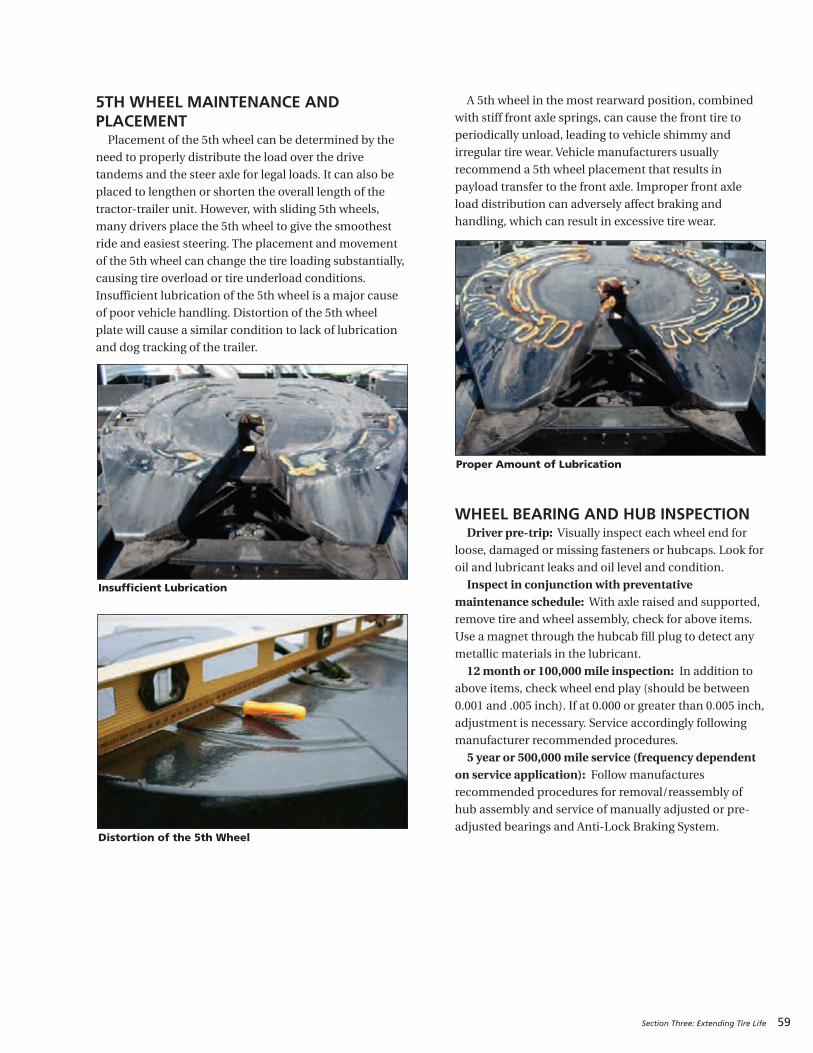
5TH WHEEL MAINTENANCE AND PLACEMENTPlacement of the 5th wheel can be determined by the
need to properly distribute the load over the drive
tandems and the steer axle for legal loads. It can also be
placed to lengthen or shorten the overall length of the
tractor-trailer unit. However, with sliding 5th wheels,
many drivers place the 5th wheel to give the smoothest
ride and easiest steering. The placement and movement
of the 5th wheel can change the tire loading substantially,
causing tire overload or tire underload conditions.
Insufficient lubrication of the 5th wheel is a major cause
of poor vehicle handling. Distortion of the 5th wheel
plate will cause a similar condition to lack of lubrication
and dog tracking of the trailer.
A 5th wheel in the most rearward position, combined
with stiff front axle springs, can cause the front tire to
periodically unload, leading to vehicle shimmy and
irregular tire wear. Vehicle manufacturers usually
recommend a 5th wheel placement that results in
payload transfer to the front axle. Improper front axle
load distribution can adversely affect braking and
handling, which can result in excessive tire wear.
WHEEL BEARING AND HUB INSPECTIONDriver pre-trip: Visually inspect each wheel end for
loose, damaged or missing fasteners or hubcaps. Look for
oil and lubricant leaks and oil level and condition.
Inspect in conjunction with preventativemaintenance schedule: With axle raised and supported,remove tire and wheel assembly, check for above items.
Use a magnet through the hubcab fill plug to detect any
metallic materials in the lubricant.
12 month or 100,000 mile inspection: In addition toabove items, check wheel end play (should be between
0.001 and .005 inch). If at 0.000 or greater than 0.005 inch,
adjustment is necessary. Service accordingly following
manufacturer recommended procedures.
5 year or 500,000 mile service (frequency dependenton service application): Follow manufacturesrecommended procedures for removal/reassembly of
hub assembly and service of manually adjusted or pre-
adjusted bearings and Anti-Lock Braking System.
Section Three: Extending Tire Life 59
Distortion of the 5th Wheel
Proper Amount of Lubrication
Insufficient Lubrication
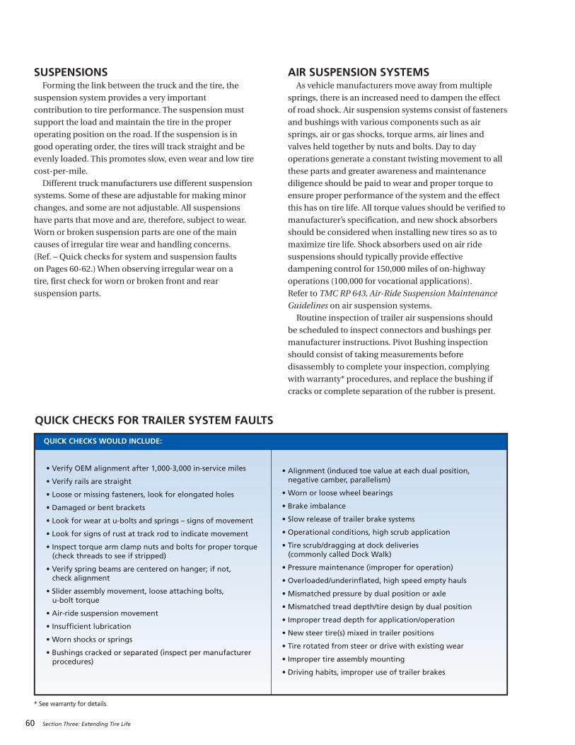
60 Section Three: Extending Tire Life
SUSPENSIONSForming the link between the truck and the tire, the
suspension system provides a very important
contribution to tire performance. The suspension must
support the load and maintain the tire in the proper
operating position on the road. If the suspension is in
good operating order, the tires will track straight and be
evenly loaded. This promotes slow, even wear and low tire
cost-per-mile.
Different truck manufacturers use different suspension
systems. Some of these are adjustable for making minor
changes, and some are not adjustable. All suspensions
have parts that move and are, therefore, subject to wear.
Worn or broken suspension parts are one of the main
causes of irregular tire wear and handling concerns.
(Ref. – Quick checks for system and suspension faults
on Pages 60-62.) When observing irregular wear on a
tire, first check for worn or broken front and rear
suspension parts.
AIR SUSPENSION SYSTEMS As vehicle manufacturers move away from multiple
springs, there is an increased need to dampen the effect
of road shock. Air suspension systems consist of fasteners
and bushings with various components such as air
springs, air or gas shocks, torque arms, air lines and
valves held together by nuts and bolts. Day to day
operations generate a constant twisting movement to all
these parts and greater awareness and maintenance
diligence should be paid to wear and proper torque to
ensure proper performance of the system and the effect
this has on tire life. All torque values should be verified to
manufacturer’s specification, and new shock absorbers
should be considered when installing new tires so as to
maximize tire life. Shock absorbers used on air ride
suspensions should typically provide effective
dampening control for 150,000 miles of on-highway
operations (100,000 for vocational applications).
Refer to TMC RP 643, Air-Ride Suspension Maintenance
Guidelines on air suspension systems.
Routine inspection of trailer air suspensions should
be scheduled to inspect connectors and bushings per
manufacturer instructions. Pivot Bushing inspection
should consist of taking measurements before
disassembly to complete your inspection, complying
with warranty* procedures, and replace the bushing if
cracks or complete separation of the rubber is present.
QUICK CHECKS FOR TRAILER SYSTEM FAULTS
QUICK CHECKS WOULD INCLUDE:
• Verify OEM alignment after 1,000-3,000 in-service miles
• Verify rails are straight
• Loose or missing fasteners, look for elongated holes
• Damaged or bent brackets
• Look for wear at u-bolts and springs – signs of movement
• Look for signs of rust at track rod to indicate movement
• Inspect torque arm clamp nuts and bolts for proper torque(check threads to see if stripped)
• Verify spring beams are centered on hanger; if not, check alignment
• Slider assembly movement, loose attaching bolts, u-bolt torque
• Air-ride suspension movement
• Insufficient lubrication
• Worn shocks or springs
• Bushings cracked or separated (inspect per manufacturerprocedures)
• Alignment (induced toe value at each dual position, negative camber, parallelism)
• Worn or loose wheel bearings
• Brake imbalance
• Slow release of trailer brake systems
• Operational conditions, high scrub application
• Tire scrub/dragging at dock deliveries (commonly called Dock Walk)
• Pressure maintenance (improper for operation)
• Overloaded/underinflated, high speed empty hauls
• Mismatched pressure by dual position or axle
• Mismatched tread depth/tire design by dual position
• Improper tread depth for application/operation
• New steer tire(s) mixed in trailer positions
• Tire rotated from steer or drive with existing wear
• Improper tire assembly mounting
• Driving habits, improper use of trailer brakes
* See warranty for details.

Section Three: Extending Tire Life 61
QUICK CHECKS FOR FRONT SUSPENSION FAULTS
ISSUE POSSIBLE CAUSE
Thumps and Knocks from Front Suspension
• Loose or worn ball joints• Loose front suspension attaching bolts• Missing adjusting shims• Loose shock absorber mountings• Check for worn or damaged spring eye bushings
Groans or Creaks from Front Suspension• Loose attaching bolts• Bent control arm or steering knuckle• Worn kingpins or kingpin bushings
Squeaks from Front Suspension • Coil spring rubbing on seat
Wander or Shimmy
• Worn tie rod ends• Worn kingpins or kingpin bushings• Loose suspension attaching bolts• Weak shock absorbers• Weak front springs• Incorrect front end alignment• Steering shaft U joint
Frequent Bottoming of Suspension on Bumps• Weak front springs• Weak shock absorbers
Front End Sag • Weak front springs
Irregular or Excessive Tire Wear
• Incorrect front wheel alignment• Worn kingpins or kingpin bushings• Loose front suspension attaching bolts• Weak shock absorbers• Weak front springs• Bent control arm or steering knuckle• Worn tie rod ends• Excessive steering system compliance• Steering shaft U joint• Loose wheel bearing
Floating, Wallowing, and Poor Recovery from Bumps • Weak shock absorbers• Weak front springs
Pulling to One Side While Braking
• Worn kingpins or kingpin bushings• Loose suspension attaching bolts• Bent control arm or steering knuckle• Weak front springs• Weak shock absorbers• Loose wheel bearing• Brake adjustment
Rough Ride and Excessive Road Shock
• Damaged shock absorbers• Weak shock absorbers• Weak springs• Control arm shaft bushings need lubrication• Worn kingpins or kingpin bushings
Excessive Steering Play
• Worn kingpins or kingpin bushings• Loose suspension attaching bolts• Worn control arm shaft bushings• Weak front springs• Worn tie rod ends• Steering shaft U joint• Loose wheel bearing
Pulls To One Side
• Worn kingpins or kingpin bushings• Loose suspension attaching bolts• Worn control arm shaft bushings• Weak front springs• Incorrect wheel or axle alignment• Bent control arm or steering knuckle
Hard Steering• Worn kingpins or kingpin bushings• Incorrect front end alignment• Bent control arm or steering knuckle
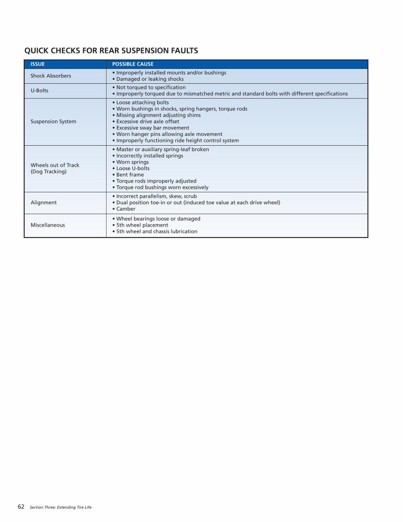
62 Section Three: Extending Tire Life
QUICK CHECKS FOR REAR SUSPENSION FAULTS
ISSUE POSSIBLE CAUSE
Shock Absorbers• Improperly installed mounts and/or bushings• Damaged or leaking shocks
U-Bolts• Not torqued to specification• Improperly torqued due to mismatched metric and standard bolts with different specifications
Suspension System
• Loose attaching bolts• Worn bushings in shocks, spring hangers, torque rods• Missing alignment adjusting shims• Excessive drive axle offset • Excessive sway bar movement• Worn hanger pins allowing axle movement• Improperly functioning ride height control system
Wheels out of Track (Dog Tracking)
• Master or auxiliary spring-leaf broken• Incorrectly installed springs• Worn springs• Loose U-bolts• Bent frame• Torque rods improperly adjusted • Torque rod bushings worn excessively
Alignment• Incorrect parallelism, skew, scrub• Dual position toe-in or out (induced toe value at each drive wheel)• Camber
Miscellaneous • Wheel bearings loose or damaged• 5th wheel placement• 5th wheel and chassis lubrication
63
SECTION FOUR
MICHELIN® X One® Tires
For additional information about MICHELIN® X One® Tires, refer to the MICHELIN® X One® Truck Tire Service Manual (MWL43101).
MICHELIN® X ONE® TIRES . . . . . . . . . . . . . . . . . 63-70
MICHELIN® X One® Tire Pressure Maintenance Practices
Comparative MICHELIN® X One® Tire Sizes
Wheels
Axle Track Width
Vehicle Track
MICHELIN® X One® Tire Mounting Instructions
MICHELIN® X One® Tire Retread and Repair Recommendations
Repair Recommendations
Retread Recommendations
Chains
Gear Ratio
Footprint Comparisons to Dual Tire Fitments
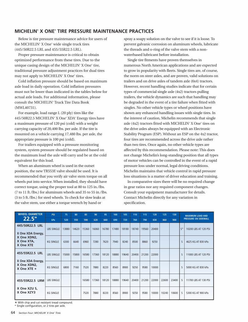
64 Section Four: MICHELIN® X One® Tires
Below is tire pressure maintenance advice for users of
the MICHELIN® X One® wide single truck tires
(445/50R22.5 LRL and 455/55R22.5 LRL).
Proper pressure maintenance is critical to obtain
optimized performance from these tires. Due to the
unique casing design of the MICHELIN® X One® tire,
traditional pressure adjustment practices for dual tires
may not apply to MICHELIN® X One® tires.
Cold inflation pressure should be based on maximum
axle load in daily operation. Cold inflation pressures
must not be lower than indicated in the tables below for
actual axle loads. For additional information, please
consult the MICHELIN® Truck Tire Data Book
(MWL40731).
For example, load range L (20 ply) tires like the
445/50R22.5 MICHELIN® X One® XDA® Energy tires have
a maximum pressure of 120 psi (cold) with a weight
carrying capacity of 20,400 lbs. per axle. If the tire is
mounted on a vehicle carrying 17,480 lbs. per axle, the
appropriate pressure is 100 psi (cold).
For trailers equipped with a pressure monitoring
system, system pressure should be regulated based on
the maximum load the axle will carry and be at the cold
equivalent for this load.
When an aluminum wheel is used in the outset
position, the new TR553E valve should be used. It is
recommended that you verify air valve stem torque on all
wheels put into service. When installed, they should have
correct torque, using the proper tool at 80 to 125 in./lbs.
(7 to 11 ft./lbs.) for aluminum wheels and 35 to 55 in./lbs.
(3 to 5 ft./lbs.) for steel wheels. To check for slow leaks at
the valve stem, use either a torque wrench by hand or
spray a soapy solution on the valve to see if it is loose. To
prevent galvanic corrosion on aluminum wheels, lubricate
the threads and o-ring of the valve stem with a non-
waterbased lubricant before installation.
Single tire fitments have proven themselves in
numerous North American applications and are expected
to grow in popularity with fleets. Single tires are, of course,
the norm on steer axles, and are proven, valid solutions on
trailers and on drive axles of tandem axle (6x4) tractors.
However, recent handling studies indicate that for certain
types of commercial single axle (4x2) tractors pulling
trailers, the vehicle dynamics are such that handling may
be degraded in the event of a tire failure when fitted with
singles. No other vehicle types or wheel positions have
shown any enhanced handling issues with single tires. In
the interest of caution, Michelin recommends that single
axle (4x2) tractors fitted with MICHELIN® X One® tires on
the drive axles always be equipped with an Electronic
Stability Program (ESP). Without an ESP on the 4x2 tractor,
four tires are recommended across the drive axle rather
than two tires. Once again, no other vehicle types are
affected by this recommendation. Please note: This does
not change Michelin’s long-standing position that all types
of motor vehicles can be controlled in the event of a rapid
pressure loss under normal, legal driving conditions.
Michelin maintains that vehicle control in rapid pressure
loss situations is a matter of driver education and training.
In comparative sizes there will be no required change
in gear ratios nor any required component changes.
Consult your equipment manufacturer for details.
Contact Michelin directly for any variation in
specification.
MICHELIN® X ONE® TIRE PRESSURE MAINTENANCE PRACTICES
WHEEL DIAMETER
22.5"PSI 75 80 85 90 95 100 105 110 115 120 125 130 MAXIMUM LOAD AND
PRESSURE ON SIDEWALLkPa 520 550 590 620 660 690 720 760 790 830 860 900
445/50R22.5 LRL
X One XDA Energy,X One XDN2,X One XTA, X One XTE
LBS SINGLE 13880 14620 15360 16060 16780 17480 18180 18740 19560 20400 S* 10200 LBS AT 120 PSI
KG SINGLE 6300 6640 6960 7280 7620 7940 8240 8500 8860 9250 S 4625 KG AT 830 kPa
455/55R22.5 LRL
X One XDA Energy,X One XDN2,X One XTE
LBS SINGLE 15000 15800 16580 17360 18120 18880 19640 20400 21200 22000 S 11000 LBS AT 120 PSI
KG SINGLE 6800 7160 7520 7880 8220 8560 8900 9250 9580 10000 S 5000 KG AT 830 kPa
455/55R22.5 LRM
X One XZU S, X One XZY3
LBS SINGLE 16580 17360 18120 18880 19640 20400 21200 22000 22600 23400 S 11700 LBS AT 130 PSI
KG SINGLE 7520 7880 8220 8560 8900 9250 9580 10000 10240 10600 S 5300 KG AT 900 kPa
With chip and cut resistant tread compound.* Single configuration, or 2 tires per axle.
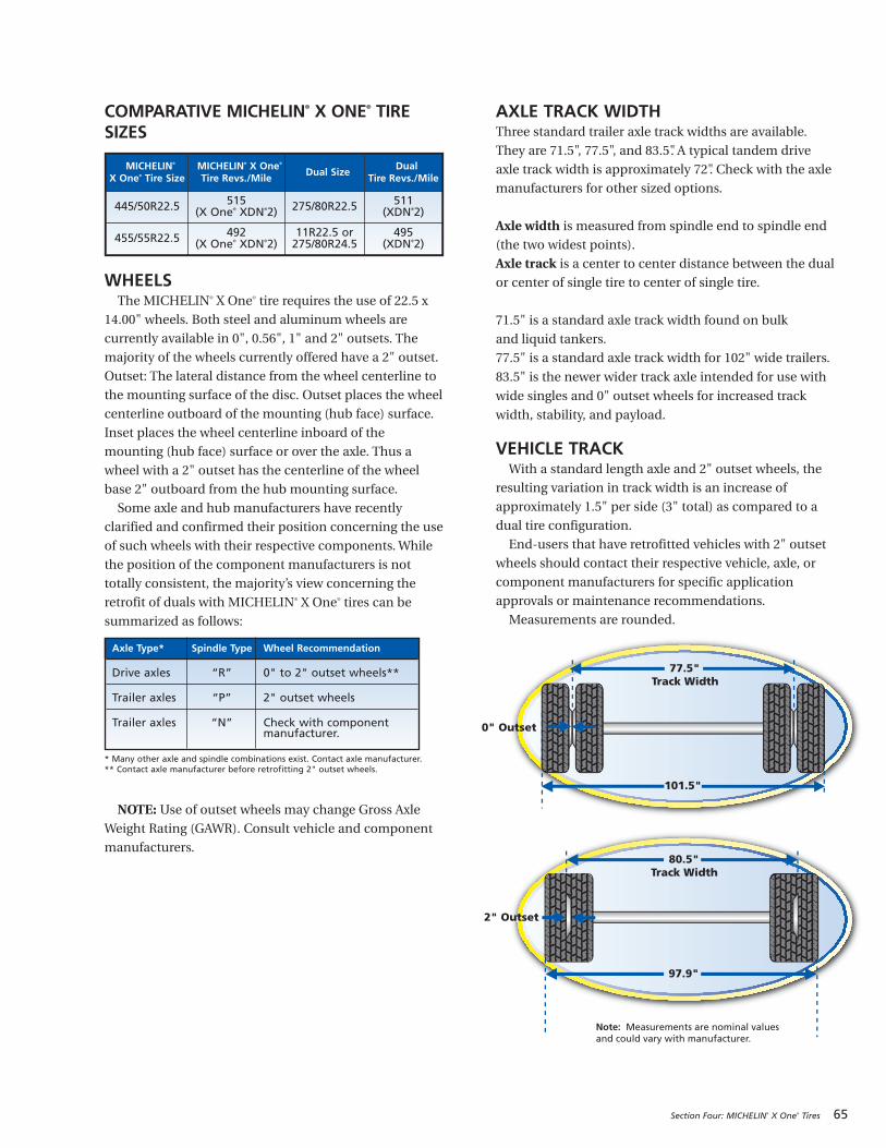
COMPARATIVE MICHELIN® X ONE® TIRESIZES
WHEELSThe MICHELIN® X One® tire requires the use of 22.5 x
14.00" wheels. Both steel and aluminum wheels are
currently available in 0", 0.56", 1" and 2" outsets. The
majority of the wheels currently offered have a 2" outset.
Outset: The lateral distance from the wheel centerline to
the mounting surface of the disc. Outset places the wheel
centerline outboard of the mounting (hub face) surface.
Inset places the wheel centerline inboard of the
mounting (hub face) surface or over the axle. Thus a
wheel with a 2" outset has the centerline of the wheel
base 2" outboard from the hub mounting surface.
Some axle and hub manufacturers have recently
clarified and confirmed their position concerning the use
of such wheels with their respective components. While
the position of the component manufacturers is not
totally consistent, the majority’s view concerning the
retrofit of duals with MICHELIN® X One® tires can be
summarized as follows:
NOTE: Use of outset wheels may change Gross Axle
Weight Rating (GAWR). Consult vehicle and component
manufacturers.
AXLE TRACK WIDTHThree standard trailer axle track widths are available.
They are 71.5", 77.5", and 83.5". A typical tandem drive
axle track width is approximately 72". Check with the axle
manufacturers for other sized options.
Axle width is measured from spindle end to spindle end
(the two widest points).
Axle track is a center to center distance between the dual
or center of single tire to center of single tire.
71.5" is a standard axle track width found on bulk
and liquid tankers.
77.5" is a standard axle track width for 102" wide trailers.
83.5" is the newer wider track axle intended for use with
wide singles and 0" outset wheels for increased track
width, stability, and payload.
VEHICLE TRACKWith a standard length axle and 2" outset wheels, the
resulting variation in track width is an increase of
approximately 1.5" per side (3" total) as compared to a
dual tire configuration.
End-users that have retrofitted vehicles with 2" outset
wheels should contact their respective vehicle, axle, or
component manufacturers for specific application
approvals or maintenance recommendations.
Measurements are rounded.
Section Four: MICHELIN® X One® Tires 65
80.5"Track Width
97.9"
77.5"Track Width
2" Outset
101.5"
0" Outset
Note: Measurements are nominal values and could vary with manufacturer.
Axle Type* Spindle Type Wheel Recommendation
Drive axles “R” 0" to 2" outset wheels**
Trailer axles “P” 2" outset wheels
Trailer axles “N” Check with componentmanufacturer.
* Many other axle and spindle combinations exist. Contact axle manufacturer.** Contact axle manufacturer before retrofitting 2" outset wheels.
MICHELIN®
X One® Tire SizeMICHELIN® X One®
Tire Revs./MileDual Size
Dual Tire Revs./Mile
445/50R22.5 515 (X One® XDN®2) 275/80R22.5 511
(XDN®2)
455/55R22.5 492 (X One® XDN®2)
11R22.5 or275/80R24.5
495 (XDN®2)
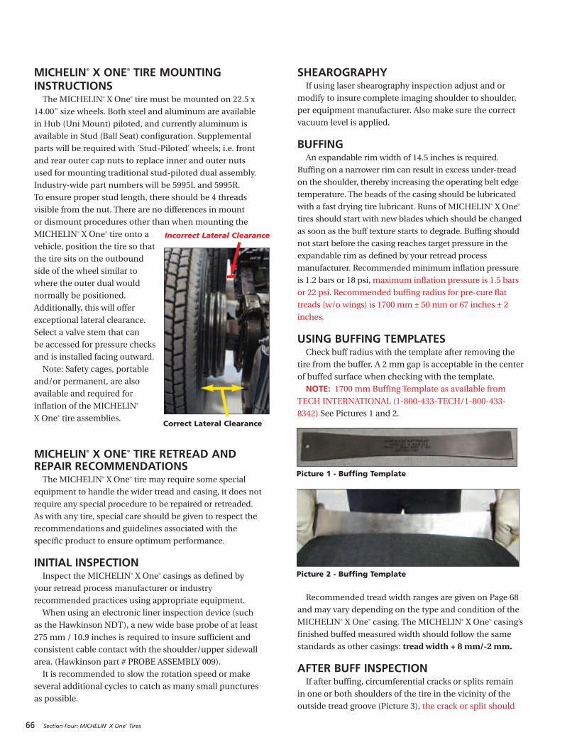
66 Section Four: MICHELIN® X One® Tires
MICHELIN® X ONE® TIRE MOUNTINGINSTRUCTIONSThe MICHELIN® X One® tire must be mounted on 22.5 x
14.00" size wheels. Both steel and aluminum are available
in Hub (Uni Mount) piloted, and currently aluminum is
available in Stud (Ball Seat) configuration. Supplemental
parts will be required with 'Stud-Piloted' wheels; i.e. front
and rear outer cap nuts to replace inner and outer nuts
used for mounting traditional stud-piloted dual assembly.
Industry-wide part numbers will be 5995L and 5995R.
To ensure proper stud length, there should be 4 threads
visible from the nut. There are no differences in mount
or dismount procedures other than when mounting the
MICHELIN® X One® tire onto a
vehicle, position the tire so that
the tire sits on the outbound
side of the wheel similar to
where the outer dual would
normally be positioned.
Additionally, this will offer
exceptional lateral clearance.
Select a valve stem that can
be accessed for pressure checks
and is installed facing outward.
Note: Safety cages, portable
and/or permanent, are also
available and required for
inflation of the MICHELIN®
X One® tire assemblies.
MICHELIN® X ONE® TIRE RETREAD ANDREPAIR RECOMMENDATIONSThe MICHELIN® X One® tire may require some special
equipment to handle the wider tread and casing, it does not
require any special procedure to be repaired or retreaded.
As with any tire, special care should be given to respect the
recommendations and guidelines associated with the
specific product to ensure optimum performance.
INITIAL INSPECTIONInspect the MICHELIN® X One® casings as defined by
your retread process manufacturer or industry
recommended practices using appropriate equipment.
When using an electronic liner inspection device (such
as the Hawkinson NDT), a new wide base probe of at least
275 mm / 10.9 inches is required to insure sufficient and
consistent cable contact with the shoulder/upper sidewall
area. (Hawkinson part # PROBE ASSEMBLY 009).
It is recommended to slow the rotation speed or make
several additional cycles to catch as many small punctures
as possible.
SHEAROGRAPHYIf using laser shearography inspection adjust and or
modify to insure complete imaging shoulder to shoulder,
per equipment manufacturer. Also make sure the correct
vacuum level is applied.
BUFFINGAn expandable rim width of 14.5 inches is required.
Buffing on a narrower rim can result in excess under-tread
on the shoulder, thereby increasing the operating belt edge
temperature. The beads of the casing should be lubricated
with a fast drying tire lubricant. Runs of MICHELIN® X One®
tires should start with new blades which should be changed
as soon as the buff texture starts to degrade. Buffing should
not start before the casing reaches target pressure in the
expandable rim as defined by your retread process
manufacturer. Recommended minimum inflation pressure
is 1.2 bars or 18 psi, maximum inflation pressure is 1.5 bars
or 22 psi. Recommended buffing radius for pre-cure flat
treads (w/o wings) is 1700 mm ± 50 mm or 67 inches ± 2
inches.
USING BUFFING TEMPLATESCheck buff radius with the template after removing the
tire from the buffer. A 2 mm gap is acceptable in the center
of buffed surface when checking with the template.
NOTE: 1700 mm Buffing Template as available from
TECH INTERNATIONAL (1-800-433-TECH/1-800-433-
8342) See Pictures 1 and 2.
Recommended tread width ranges are given on Page 68
and may vary depending on the type and condition of the
MICHELIN® X One® casing. The MICHELIN® X One® casing’s
finished buffed measured width should follow the same
standards as other casings: tread width + 8 mm/-2 mm.
AFTER BUFF INSPECTIONIf after buffing, circumferential cracks or splits remain
in one or both shoulders of the tire in the vicinity of the
outside tread groove (Picture 3), the crack or split should
Picture 2 - Buffing Template
Incorrect Lateral Clearance
Correct Lateral Clearance
Picture 1 - Buffing Template

be probed. If the probing penetrates into steel or feels
soft/loose material, the casing should be rejected. This
should not be confused with a 360 degree product interface
line that sometimes is visible after buff (Picture 4). If this
line is visible, it should be probed and if found to be
loose material, reject the casing. If it is tight, continue the
retread process.
BUILDERExpandable rim width of 14.5 inches is required.
Tread table rollers should be completely cleaned
before and/or after each build series. The base of the
wider MICHELIN® X One® tread will come in contact with
the roller’s outer edges, so care should be taken to prevent
contamination by cleaning the rollers at frequent intervals.
Tread building should not begin until tire pressure has
reached the target inflation pressures in the expandable
rim as defined by your retread process manufacturer.
For cushion to casing extruded bonding gum
application, recommended minimum inflation pressure
is 0.8 bar or 12 psi. Bonding gum thickness should not
exceed 1.5 mm (2 ⁄ 32 inch) in the crown and 2.5 mm
(3 ⁄ 32 inch) in the shoulders.
Note: For non-Michelin wing tread products, contact
MRT Duncan, SC at 1-888-678-5470, then press 3 for
Technical Support.
ENVELOPINGContact your envelope supplier for the recommended
size envelopes to be used.
CURINGCure the MICHELIN® X One® casing according to cure
law for the tread design per the retread process
manufacturer.
FINAL INSPECTIONPerform a final inspection of the MICHELIN® X One®
casing according to the retread process manufacturer
work method and specification.
Note: The retreader is still responsible for determining
if the MICHELIN® X One® casing is capable of being
retreaded; the same as would be done for any other tire
in the inspection process.
Principal Components
Section Four: MICHELIN® X One® Tires 67
Damage Guidelines
Crown
Crown Plies
Inner Liner
Body Ply
Shoulder
Sidewall
Bead B
A’
75 mm
75 mm
A
B
10 mm
C
Sidewall Damage Crown Damage
Bead Damage Interior Damage
W
W
W
W
WL
D
L
L
L
L
L
Note: For truck sizes, point B is considered the “toe” of
the bead. Point A is found 75 mm from point B towards
the interior of the casing, and point A’ is also 75 mm
from point B but is located on the exterior of the casing.
Point C is located 10 mm from point B (measured as
shown). Any repair patch material must be positioned
>10 mm from the toe of the bead (point B).
Picture 3 Picture 4
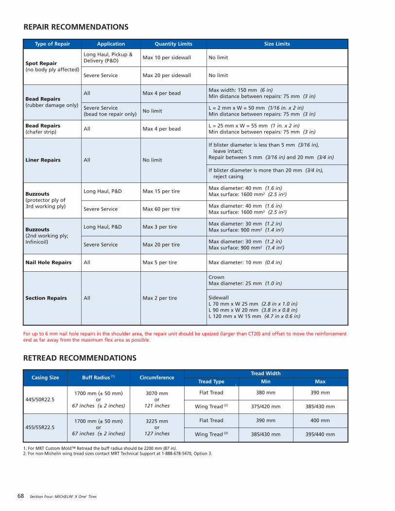
68 Section Four: MICHELIN® X One® Tires
REPAIR RECOMMENDATIONS
Type of Repair Application Quantity Limits Size Limits
Spot Repair(no body ply affected)
Long Haul, Pickup &Delivery (P&D)
Max 10 per sidewall No limit
Severe Service Max 20 per sidewall No limit
Bead Repairs(rubber damage only)
All Max 4 per beadMax width: 150 mm (6 in)Min distance between repairs: 75 mm (3 in)
Severe Service(bead toe repair only)
No limitL = 2 mm x W = 50 mm (1⁄16 in. x 2 in)Min distance between repairs: 75 mm (3 in)
Bead Repairs(chafer strip)
All Max 4 per beadL = 25 mm x W = 55 mm (1 in. x 2 in)Min distance between repairs: 75 mm (3 in)
Liner Repairs All No limit
If blister diameter is less than 5 mm (3⁄16 in),leave intact; Repair between 5 mm (3⁄16 in) and 20 mm (3⁄4 in)
If blister diameter is more than 20 mm (3⁄4 in), reject casing
Buzzouts(protector ply of3rd working ply)
Long Haul, P&D Max 15 per tireMax diameter: 40 mm (1.6 in)Max surface: 1600 mm2 (2.5 in2)
Severe Service Max 60 per tireMax diameter: 40 mm (1.6 in)Max surface: 1600 mm2 (2.5 in2)
Buzzouts(2nd working ply;Infinicoil)
Long Haul, P&D Max 3 per tireMax diameter: 30 mm (1.2 in)Max surface: 900 mm2 (1.4 in2)
Severe Service Max 20 per tireMax diameter: 30 mm (1.2 in)Max surface: 900 mm2 (1.4 in2)
Nail Hole Repairs All Max 5 per tire Max diameter: 10 mm (0.4 in)
Section Repairs All Max 2 per tire
CrownMax diameter: 25 mm (1.0 in)
SidewallL 70 mm x W 25 mm (2.8 in x 1.0 in)L 90 mm x W 20 mm (3.8 in x 0.8 in)L 120 mm x W 15 mm (4.7 in x 0.6 in)
RETREAD RECOMMENDATIONS
Casing Size Buff Radius (1) CircumferenceTread Width
Tread Type Min Max
445/50R22.51700 mm (± 50 mm)
or67 inches (± 2 inches)
3070 mmor
121 inches
Flat Tread 380 mm 390 mm
Wing Tread (2) 375/420 mm 385/430 mm
455/55R22.51700 mm (± 50 mm)
or67 inches (± 2 inches)
3225 mmor
127 inches
Flat Tread 390 mm 400 mm
Wing Tread (2) 385/430 mm 395/440 mm
1. For MRT Custom Mold™ Retread the buff radius should be 2200 mm (87 in).2. For non-Michelin wing tread sizes contact MRT Technical Support at 1-888-678-5470, Option 3.
For up to 6 mm nail hole repairs in the shoulder area, the repair unit should be upsized (larger than CT20) and offset to move the reinforcementend as far away from the maximum flex area as possible.
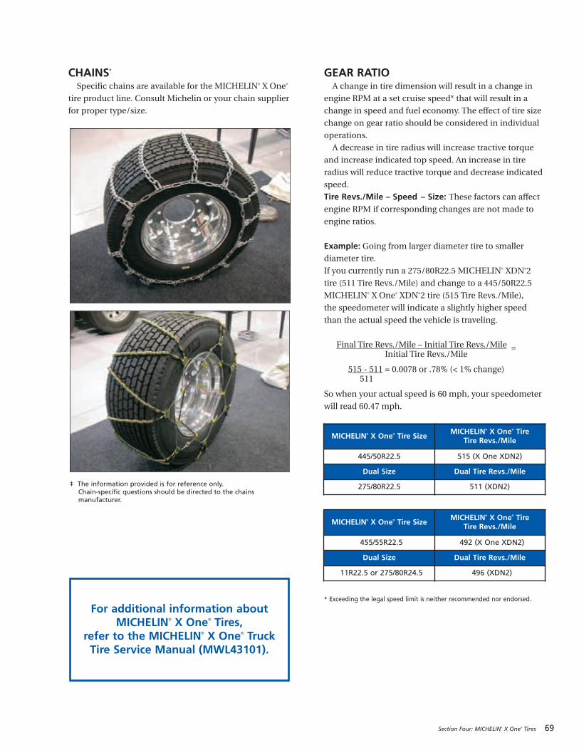
Section Four: MICHELIN® X One® Tires 69
CHAINS‡
Specific chains are available for the MICHELIN® X One®
tire product line. Consult Michelin or your chain supplier
for proper type/size.
GEAR RATIOA change in tire dimension will result in a change in
engine RPM at a set cruise speed* that will result in a
change in speed and fuel economy. The effect of tire size
change on gear ratio should be considered in individual
operations.
A decrease in tire radius will increase tractive torque
and increase indicated top speed. An increase in tire
radius will reduce tractive torque and decrease indicated
speed.
Tire Revs./Mile – Speed – Size: These factors can affectengine RPM if corresponding changes are not made to
engine ratios.
Example: Going from larger diameter tire to smaller
diameter tire.
If you currently run a 275/80R22.5 MICHELIN® XDN®2
tire (511 Tire Revs./Mile) and change to a 445/50R22.5
MICHELIN® X One® XDN®2 tire (515 Tire Revs./Mile),
the speedometer will indicate a slightly higher speed
than the actual speed the vehicle is traveling.
Final Tire Revs./Mile – Initial Tire Revs./Mile =Initial Tire Revs./Mile
515 - 511 = 0.0078 or .78% (< 1% change)511
So when your actual speed is 60 mph, your speedometer
will read 60.47 mph.
* Exceeding the legal speed limit is neither recommended nor endorsed.
For additional information aboutMICHELIN® X One® Tires,
refer to the MICHELIN® X One® TruckTire Service Manual (MWL43101).
‡ The information provided is for reference only. Chain-specific questions should be directed to the chainsmanufacturer.
MICHELIN® X One® Tire SizeMICHELIN® X One® Tire
Tire Revs./Mile
445/50R22.5 515 (X One XDN2)
Dual Size Dual Tire Revs./Mile
275/80R22.5 511 (XDN2)
MICHELIN® X One® Tire SizeMICHELIN® X One® Tire
Tire Revs./Mile
455/55R22.5 492 (X One XDN2)
Dual Size Dual Tire Revs./Mile
11R22.5 or 275/80R24.5 496 (XDN2)

70 Section Four: MICHELIN® X One® Tires
FOOTPRINT COMPARISONS TO DUAL TIRE FITMENTS
Unloaded - 8,500 lbs/axle
Loaded - 17,000 lbs/axle
Loaded - 17,000 lbs/axle
Unloaded - 8,500 lbs/axle
FOOTPRINTS: MICHELIN® X ONE® XDN®2 445/50R22.5 VERSUS MICHELIN® XDN®2 275/80R22.5
Loaded - 17,000 lbs/axle
Unloaded - 8,500 lbs/axle
71
SECTION FIVE
MICHELIN® RV Tires
GENERAL INFORMATION ABOUT MICHELIN® RV TIRES . . . . . . . . . . . . . . 72-73
Service Life for RV/Motorhome TiresThe Importance of Tire PressurePressure RequirementWhen to Check the RV Tire PressureDetermining the RV's Correct Weight
HOW TO WEIGH THE RECREATIONAL VEHICLE . . . . . . . . . . . . . . . . . 74-77
How to Weigh the RVWeighing the Single Axle Recreational VehicleWeighing the Tandem Axle Recreational VehicleThe Effect of Towed Vehicles or TrailersHow to Use the Actual RV Weight Information
with the Tire Data Load ChartUsing Blocks to Level Motorhomes and
RVs Equipped with Radial Tires
MAINTAINING MICHELIN® RV TIRES . . . . . . . . . . . 78Aging, Weather Checking, and Ozone CrackingLong Term Storage and RV TiresProper Cleaning of RV TiresTire RepairTire Inspection
COMMON TIRE DAMAGES . . . . . . . . . . . . . . . . 79-80UnderinflationFatigue RuptureDual KissingTire Wear, Balance, and Wheel Alignment —
Toe Wear, Camber Wear, Tire Rotation
VIBRATION DIAGNOSIS . . . . . . . . . . . . . . . . . . . . . 81Vibration ComplaintVibration Diagnosis
SELECTING REPLACEMENT TIRES FOR THE RV . . . 82
For additional informationabout MICHELIN® RV Tires,
refer to the MICHELIN® RV Tires Guide
(MWL43146) and MICHELIN® Truck Tire DataBook (MWL40731).
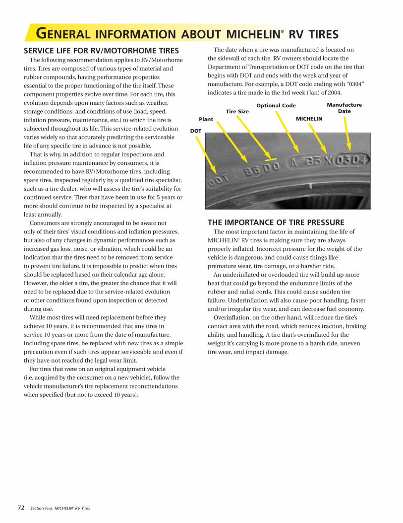
72 Section Five: MICHELIN® RV Tires
DOT
PlantTire Size
Optional Code
MICHELIN
Manufacture Date
GENERAL INFORMATION ABOUT MICHELIN® RV TIRESSERVICE LIFE FOR RV/MOTORHOME TIRES
The following recommendation applies to RV/Motorhome
tires. Tires are composed of various types of material and
rubber compounds, having performance properties
essential to the proper functioning of the tire itself. These
component properties evolve over time. For each tire, this
evolution depends upon many factors such as weather,
storage conditions, and conditions of use (load, speed,
inflation pressure, maintenance, etc.) to which the tire is
subjected throughout its life. This service-related evolution
varies widely so that accurately predicting the serviceable
life of any specific tire in advance is not possible.
That is why, in addition to regular inspections and
inflation pressure maintenance by consumers, it is
recommended to have RV/Motorhome tires, including
spare tires, inspected regularly by a qualified tire specialist,
such as a tire dealer, who will assess the tire’s suitability for
continued service. Tires that have been in use for 5 years or
more should continue to be inspected by a specialist at
least annually.
Consumers are strongly encouraged to be aware not
only of their tires’ visual conditions and inflation pressures,
but also of any changes in dynamic performances such as
increased gas loss, noise, or vibration, which could be an
indication that the tires need to be removed from service
to prevent tire failure. It is impossible to predict when tires
should be replaced based on their calendar age alone.
However, the older a tire, the greater the chance that it will
need to be replaced due to the service-related evolution
or other conditions found upon inspection or detected
during use.
While most tires will need replacement before they
achieve 10 years, it is recommended that any tires in
service 10 years or more from the date of manufacture,
including spare tires, be replaced with new tires as a simple
precaution even if such tires appear serviceable and even if
they have not reached the legal wear limit.
For tires that were on an original equipment vehicle
(i.e. acquired by the consumer on a new vehicle), follow the
vehicle manufacturer’s tire replacement recommendations
when specified (but not to exceed 10 years).
The date when a tire was manufactured is located on
the sidewall of each tire. RV owners should locate the
Department of Transportation or DOT code on the tire that
begins with DOT and ends with the week and year of
manufacture. For example, a DOT code ending with “0304”
indicates a tire made in the 3rd week (Jan) of 2004.
THE IMPORTANCE OF TIRE PRESSUREThe most important factor in maintaining the life of
MICHELIN® RV tires is making sure they are always
properly inflated. Incorrect pressure for the weight of the
vehicle is dangerous and could cause things like
premature wear, tire damage, or a harsher ride.
An underinflated or overloaded tire will build up more
heat that could go beyond the endurance limits of the
rubber and radial cords. This could cause sudden tire
failure. Underinflation will also cause poor handling, faster
and/or irregular tire wear, and can decrease fuel economy.
Overinflation, on the other hand, will reduce the tire’s
contact area with the road, which reduces traction, braking
ability, and handling. A tire that’s overinflated for the
weight it’s carrying is more prone to a harsh ride, uneven
tire wear, and impact damage.
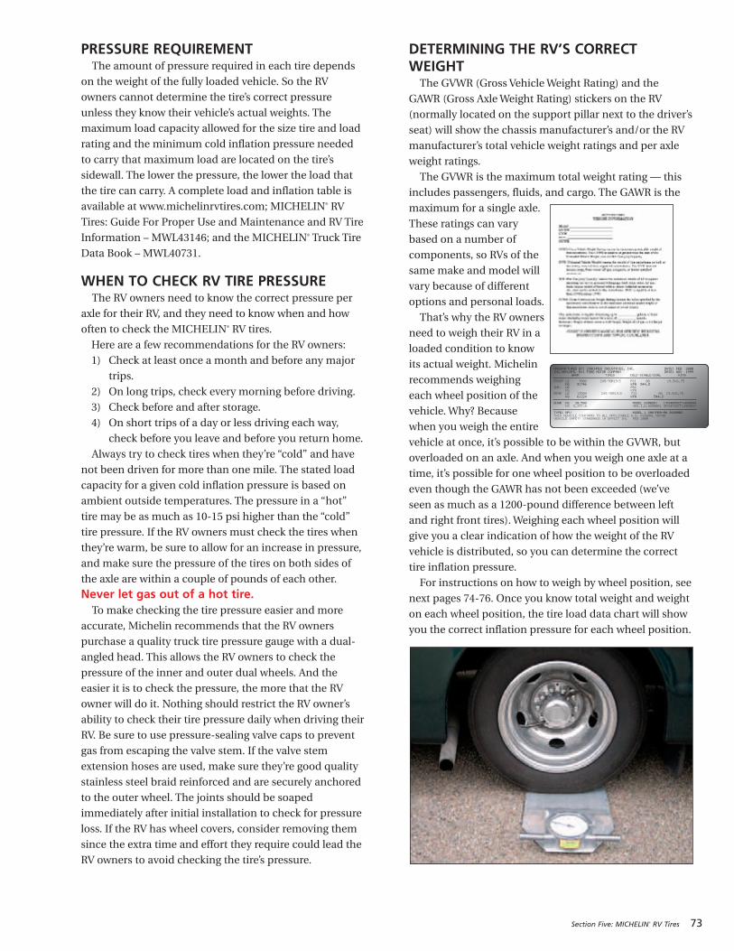
Section Five: MICHELIN® RV Tires 73
PRESSURE REQUIREMENTThe amount of pressure required in each tire depends
on the weight of the fully loaded vehicle. So the RV
owners cannot determine the tire’s correct pressure
unless they know their vehicle’s actual weights. The
maximum load capacity allowed for the size tire and load
rating and the minimum cold inflation pressure needed
to carry that maximum load are located on the tire’s
sidewall. The lower the pressure, the lower the load that
the tire can carry. A complete load and inflation table is
available at www.michelinrvtires.com; MICHELIN® RV
Tires: Guide For Proper Use and Maintenance and RV Tire
Information – MWL43146; and the MICHELIN® Truck Tire
Data Book – MWL40731.
WHEN TO CHECK RV TIRE PRESSUREThe RV owners need to know the correct pressure per
axle for their RV, and they need to know when and how
often to check the MICHELIN® RV tires.
Here are a few recommendations for the RV owners:
1) Check at least once a month and before any major
trips.
2) On long trips, check every morning before driving.
3) Check before and after storage.
4) On short trips of a day or less driving each way,
check before you leave and before you return home.
Always try to check tires when they’re “cold” and have
not been driven for more than one mile. The stated load
capacity for a given cold inflation pressure is based on
ambient outside temperatures. The pressure in a “hot”
tire may be as much as 10-15 psi higher than the “cold”
tire pressure. If the RV owners must check the tires when
they’re warm, be sure to allow for an increase in pressure,
and make sure the pressure of the tires on both sides of
the axle are within a couple of pounds of each other.
Never let gas out of a hot tire.To make checking the tire pressure easier and more
accurate, Michelin recommends that the RV owners
purchase a quality truck tire pressure gauge with a dual-
angled head. This allows the RV owners to check the
pressure of the inner and outer dual wheels. And the
easier it is to check the pressure, the more that the RV
owner will do it. Nothing should restrict the RV owner’s
ability to check their tire pressure daily when driving their
RV. Be sure to use pressure-sealing valve caps to prevent
gas from escaping the valve stem. If the valve stem
extension hoses are used, make sure they’re good quality
stainless steel braid reinforced and are securely anchored
to the outer wheel. The joints should be soaped
immediately after initial installation to check for pressure
loss. If the RV has wheel covers, consider removing them
since the extra time and effort they require could lead the
RV owners to avoid checking the tire’s pressure.
DETERMINING THE RV’S CORRECTWEIGHT
The GVWR (Gross Vehicle Weight Rating) and the
GAWR (Gross Axle Weight Rating) stickers on the RV
(normally located on the support pillar next to the driver’s
seat) will show the chassis manufacturer’s and/or the RV
manufacturer’s total vehicle weight ratings and per axle
weight ratings.
The GVWR is the maximum total weight rating — this
includes passengers, fluids, and cargo. The GAWR is the
maximum for a single axle.
These ratings can vary
based on a number of
components, so RVs of the
same make and model will
vary because of different
options and personal loads.
That’s why the RV owners
need to weigh their RV in a
loaded condition to know
its actual weight. Michelin
recommends weighing
each wheel position of the
vehicle. Why? Because
when you weigh the entire
vehicle at once, it’s possible to be within the GVWR, but
overloaded on an axle. And when you weigh one axle at a
time, it’s possible for one wheel position to be overloaded
even though the GAWR has not been exceeded (we’ve
seen as much as a 1200-pound difference between left
and right front tires). Weighing each wheel position will
give you a clear indication of how the weight of the RV
vehicle is distributed, so you can determine the correct
tire inflation pressure.
For instructions on how to weigh by wheel position, see
next pages 74-76. Once you know total weight and weight
on each wheel position, the tire load data chart will show
you the correct inflation pressure for each wheel position.
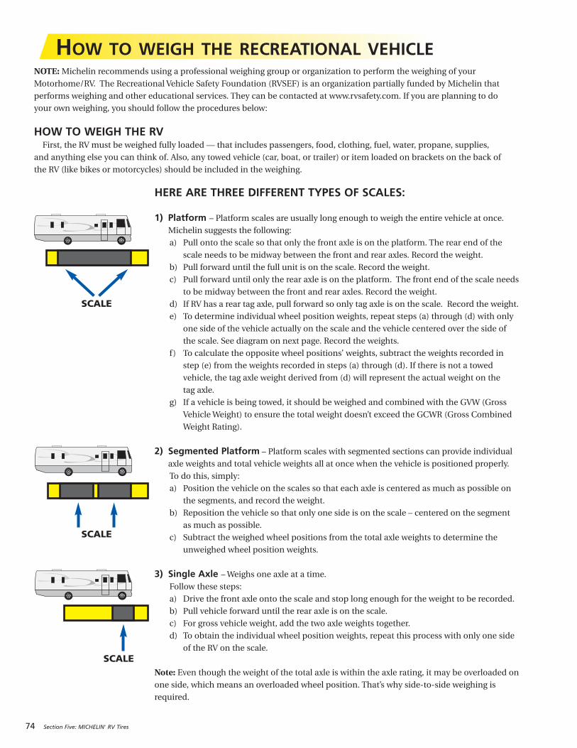
74 Section Five: MICHELIN® RV Tires
HOW TO WEIGH THE RECREATIONAL VEHICLENOTE: Michelin recommends using a professional weighing group or organization to perform the weighing of your
Motorhome/RV. The Recreational Vehicle Safety Foundation (RVSEF) is an organization partially funded by Michelin that
performs weighing and other educational services. They can be contacted at www.rvsafety.com. If you are planning to do
your own weighing, you should follow the procedures below:
HOW TO WEIGH THE RVFirst, the RV must be weighed fully loaded — that includes passengers, food, clothing, fuel, water, propane, supplies,
and anything else you can think of. Also, any towed vehicle (car, boat, or trailer) or item loaded on brackets on the back of
the RV (like bikes or motorcycles) should be included in the weighing.
HERE ARE THREE DIFFERENT TYPES OF SCALES:
1) Platform – Platform scales are usually long enough to weigh the entire vehicle at once.
Michelin suggests the following:
a) Pull onto the scale so that only the front axle is on the platform. The rear end of the
scale needs to be midway between the front and rear axles. Record the weight.
b) Pull forward until the full unit is on the scale. Record the weight.
c) Pull forward until only the rear axle is on the platform. The front end of the scale needs
to be midway between the front and rear axles. Record the weight.
d) If RV has a rear tag axle, pull forward so only tag axle is on the scale. Record the weight.
e) To determine individual wheel position weights, repeat steps (a) through (d) with only
one side of the vehicle actually on the scale and the vehicle centered over the side of
the scale. See diagram on next page. Record the weights.
f) To calculate the opposite wheel positions’ weights, subtract the weights recorded in
step (e) from the weights recorded in steps (a) through (d). If there is not a towed
vehicle, the tag axle weight derived from (d) will represent the actual weight on the
tag axle.
g) If a vehicle is being towed, it should be weighed and combined with the GVW (Gross
Vehicle Weight) to ensure the total weight doesn’t exceed the GCWR (Gross Combined
Weight Rating).
2) Segmented Platform – Platform scales with segmented sections can provide individual
axle weights and total vehicle weights all at once when the vehicle is positioned properly.
To do this, simply:
a) Position the vehicle on the scales so that each axle is centered as much as possible on
the segments, and record the weight.
b) Reposition the vehicle so that only one side is on the scale – centered on the segment
as much as possible.
c) Subtract the weighed wheel positions from the total axle weights to determine the
unweighed wheel position weights.
3) Single Axle – Weighs one axle at a time.
Follow these steps:
a) Drive the front axle onto the scale and stop long enough for the weight to be recorded.
b) Pull vehicle forward until the rear axle is on the scale.
c) For gross vehicle weight, add the two axle weights together.
d) To obtain the individual wheel position weights, repeat this process with only one side
of the RV on the scale.
Note: Even though the weight of the total axle is within the axle rating, it may be overloaded on
one side, which means an overloaded wheel position. That’s why side-to-side weighing is
required.
SCALE
SCALE
SCALE

Section Five: MICHELIN® RV Tires 75
NOTES:1. From the tire manufacturer’s load and inflation tables or the sidewall of the tires mounted on the vehicle.2. If vehicle has duals, read dual capacity from tire and multiply by 2 to obtain dual assembly load capacity.
One SideScale Weight
Calculate Other Side Weight
Tire Load (lbs.)
Inflation
__________ lbs. __________ lbs. __________ lbs.(Step 2a) (Step 2b) (Step 2c)
__________ lbs. __________ lbs. __________ lbs.(Step 1a-2a) (Step 1b-2b) (Step 1c-2c)
__________ lbs. __________ lbs. __________ lbs.(See Note #1) (See Notes #1 & #2)
__________ psi __________ psi(See Note #1) (See Note #1)
STEP 2a STEP 2b STEP 2c
__________ lbs. __________ lbs. __________ lbs. __________ lbs.(Step 1a = (Step 1b = (Step 1c = (Step 1d)Gross Axle Weight) Gross Vehicle Weight) Gross Axle Weight)
__________ lbs. __________ lbs. __________ lbs. __________ lbs.Gross Axle Gross Vehicle Gross Axle Vehicle WeightWeight Rating Weight Rating Weight Rating (Gross Combined
Weight Rating –Gross Vehicle Weight)
TO OBTAIN INDIVIDUAL AXLE AND GROSS VEHICLE WEIGHTS
STEP 1a STEP 1b STEP 1c STEP 1d
Scale Weight
From Owner’s Manual
TO OBTAIN INDIVIDUAL WHEEL POSITION WEIGHTS
The RV must remain as level as possible on the scale (even when an axle or side isn’t on the scale). Therefore, to
obtain side-to-side weights, there must be enough space on either side of the scale to accommodate the RV being
partially off the scale.
If there is a difference in the weights on one side of the vehicle as compared to the other, it is important to
redistribute the load more evenly to avoid component failure and improve handling. These weights make it possible
to compare against the GAWR (Gross Axle Weight Rating), GVWR (Gross Vehicle Weight Rating), and tire capacities.
They also help determine proper tire pressure.
WEIGHING THE SINGLE AXLE RECREATIONAL VEHICLE
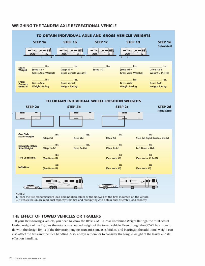
76 Section Five: MICHELIN® RV Tires
STEP 2a STEP 2b STEP 2c STEP 2d(calculated)
STEP 1a STEP 1b STEP 1c STEP 1d STEP 1e(calculated)
__________ lbs. __________ lbs. __________ lbs. __________ lbs.(Step 2a) (Step 2b) (Step 2c) Step 2d: Right Duals = (2b-2c)
__________ lbs. __________ lbs. __________ lbs. __________ lbs.(Step 1a-2a) (Step 1c-2b) (Step 1d-2c) Left Duals = (2d)
__________ lbs. __________ lbs. __________ lbs.(See Note #1) (See Note #1) (See Notes #1 & #2)
__________ psi __________ psi __________ psi(See Note #1) (See Note #1) (See Note #1)
__________ lbs. __________ lbs. __________ lbs. __________ lbs. __________ lbs.(Step 1a = (Step 1b = (Step 1c) (Step 1d = Drive Axle Gross Axle Weight) Gross Vehicle Weight) Gross Axle Weight) Weight = (1c-1d)
__________ lbs. __________ lbs. __________ lbs. __________ lbs.Gross Axle Gross Vehicle Gross Axle Gross Axle Weight Rating Weight Rating Weight Rating Weight Rating
TO OBTAIN INDIVIDUAL WHEEL POSITION WEIGHTS
Scale Weight
From Owner’s Manual
One SideScale Weight
Calculate Other Side Weight
Tire Load (lbs.)
Inflation
NOTES:1. From the tire manufacturer’s load and inflation tables or the sidewall of the tires mounted on the vehicle.2. If vehicle has duals, read dual capacity from tire and multiply by 2 to obtain dual assembly load capacity.
TO OBTAIN INDIVIDUAL AXLE AND GROSS VEHICLE WEIGHTS
WEIGHING THE TANDEM AXLE RECREATIONAL VEHICLE
THE EFFECT OF TOWED VEHICLES OR TRAILERSIf your RV is towing a vehicle, you need to know the RV’s GCWR (Gross Combined Weight Rating), the total actual
loaded weight of the RV, plus the total actual loaded weight of the towed vehicle. Even though the GCWR has more to
do with the design limits of the drivetrain (engine, transmission, axle, brakes, and bearings), the additional weight can
also affect the tires and the RV’s handling. Also, always remember to consider the tongue weight of the trailer and its
effect on handling.
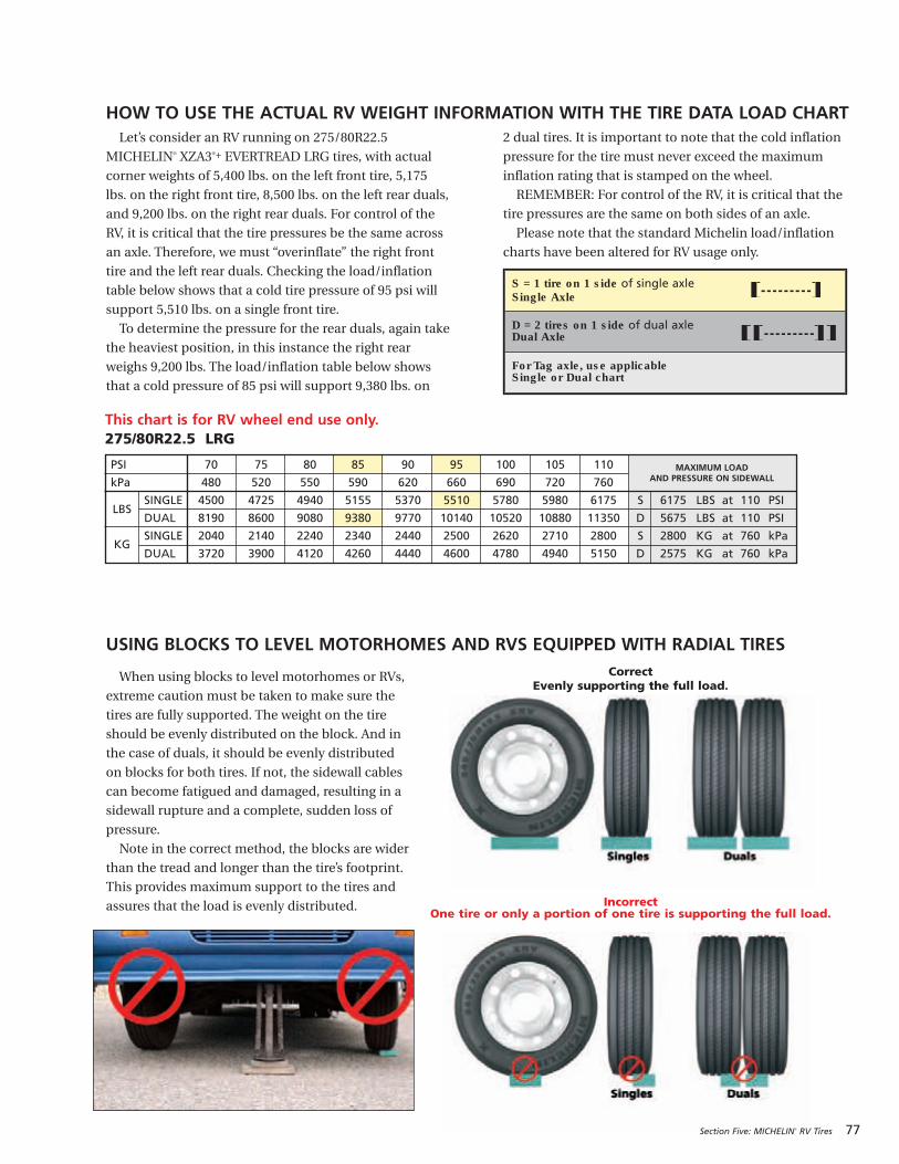
When using blocks to level motorhomes or RVs,
extreme caution must be taken to make sure the
tires are fully supported. The weight on the tire
should be evenly distributed on the block. And in
the case of duals, it should be evenly distributed
on blocks for both tires. If not, the sidewall cables
can become fatigued and damaged, resulting in a
sidewall rupture and a complete, sudden loss of
pressure.
Note in the correct method, the blocks are wider
than the tread and longer than the tire’s footprint.
This provides maximum support to the tires and
assures that the load is evenly distributed.
Section Five: MICHELIN® RV Tires 77
Let’s consider an RV running on 275/80R22.5
MICHELIN® XZA3®+ EVERTREAD LRG tires, with actual
corner weights of 5,400 lbs. on the left front tire, 5,175
lbs. on the right front tire, 8,500 lbs. on the left rear duals,
and 9,200 lbs. on the right rear duals. For control of the
RV, it is critical that the tire pressures be the same across
an axle. Therefore, we must “overinflate” the right front
tire and the left rear duals. Checking the load/inflation
table below shows that a cold tire pressure of 95 psi will
support 5,510 lbs. on a single front tire.
To determine the pressure for the rear duals, again take
the heaviest position, in this instance the right rear
weighs 9,200 lbs. The load/inflation table below shows
that a cold pressure of 85 psi will support 9,380 lbs. on
2 dual tires. It is important to note that the cold inflation
pressure for the tire must never exceed the maximum
inflation rating that is stamped on the wheel.
REMEMBER: For control of the RV, it is critical that the
tire pressures are the same on both sides of an axle.
Please note that the standard Michelin load/inflation
charts have been altered for RV usage only.
HOW TO USE THE ACTUAL RV WEIGHT INFORMATION WITH THE TIRE DATA LOAD CHART
USING BLOCKS TO LEVEL MOTORHOMES AND RVS EQUIPPED WITH RADIAL TIRES
Incorrect One tire or only a portion of one tire is supporting the full load.
MAXIMUM LOAD AND PRESSURE ON SIDEWALL
This chart is for RV wheel end use only.275/80R22.5 LRG
PSI 70 75 80 85 90 95 100 105 110
kPa 480 520 550 590 620 660 690 720 760
SINGLE 4500 4725 4940 5155 5370 5510 5780 5980 6175 S 6175 LBS at 110 PSI
DUAL 8190 8600 9080 9380 9770 10140 10520 10880 11350 D 5675 LBS at 110 PSI
SINGLE 2040 2140 2240 2340 2440 2500 2620 2710 2800 S 2800 KG at 760 kPa
DUAL 3720 3900 4120 4260 4440 4600 4780 4940 5150 D 2575 KG at 760 kPa
LBS
KG
S = 1 tire on 1 side of single axleSingle Axle
D = 2 tires on 1 side of dual axleDual Axle
For Tag axle, use applicableSingle or Dual chart
CorrectEvenly supporting the full load.

78 Section Five: MICHELIN® RV Tires
AGING, WEATHER CHECKING, ANDOZONE CRACKING
During the pre-trip inspection, be sure to check the
tires for signs of aging, weather checking, and/or ozone
cracking — these show up as tiny cracks in the rubber
surface on the sidewall of the tire. If the cracks are less
than 1 ⁄32" deep, the tire is fine to run. Between 1 ⁄32" and
2 ⁄ 32", the tire is suspect and should be examined by the
MICHELIN® dealer. If the cracks are any deeper than
2 ⁄ 32", the tire should be replaced immediately.
Here are a few tips to help you protect the tires from
these common damage conditions:
1) Keep the tires properly inflated.
2) Keep the tires clean.
3) Avoid prolonged exposure to heat, cold, or moisture.
4) Avoid prolonged exposure to ultraviolet rays.
5) Cover the tires when the vehicle is not in use.
6) Do not park near electric generators or transformers.
7) Do not store vehicle in an area where welding is being
done or in a garage that has mercury vapor lamps.
LONG TERM STORAGE AND RV TIRESUnless theRVowner is a full-timeRV-er, thevehicle
probably spendssometime in long-termstorage.Butwhat
theRVownerprobablydidn’t knowis that rubber tiresage
whennotbeingused.So, if theownermust store theRV,a
cool, dry, sealedgarage is thebestbet.Also, somestorage
surfacescancause tires toage faster.That’swhyMichelin
recommendsplacingabarrier (cardboard,plasticor
plywood)between the tireand thestoragesurface.
Here are some other steps the RV owner can take to
help reduce the aging effects from long-term storage:
1) Thoroughly clean tires with soap and water before
placing into storage.
2) Cover tires to block direct sunlight and ultraviolet rays.
3) Store out of a high ozone area.
Note: When a vehicle is stored, tires should be inflated
to the inflation pressure indicated on the sidewall.
Before removing the vehicle from long-term storage,
thoroughly inspect each tire — this includes sidewalls,
tread area, and pressure. If the tires have lost pressure, be
sure to inflate them to the correct pressure before driving.
PROPER CLEANING OF RV TIRESLike the rest of the RV, it pays to keep the MICHELIN®
tires clean. Road oil will cause deterioration of the rubber,
and dirt buildup will hold the contaminants next to the tire.
As with the cleaning of any rubber product, proper
cleaning methods must be used to obtain the maximum
years of service from the tires. A soft brush and the
normal mild soap that you would use to clean the RV
may be used. If you use a dressing product to “protect”
the tires from aging, use extra care and caution. Tire
dressings that contain petroleum products, alcohol, or
silicones will cause deterioration or cracking and
accelerate the aging process.
In many cases, it is not the dressing itself that can be
a problem, but rather the chemical reaction that the
product can have with the antioxidant in the tire. Heat
can add to the negative reaction. When these same
dressing products are used on a passenger car tire that is
replaced every three to four years, it is rare to see a major
problem. However, in most cases, RV tires may last much
longer due to limited annual mileage, and the chemical
reactions have much longer to take place.
TIRE REPAIREven the best drivers can drive over a nail, and the best
tires can pick up that nail or screw and go flat. If you pick up
an object that causes a flat with a MICHELIN® RV tire, the
repair must be made to the inside of the tire to be repaired
properly. To do this, the tire needs to be demounted and
inspected on the inside of the casing for any other damage
that the object may have caused. See the MICHELIN® truck
tire dealer for the proper repair and damage inspection.
TIRE INSPECTIONThe MICHELIN® RV tires should be inspected
thoroughly at least once a year, and any time the owner
drives in rough or rocky terrain, or when the owner is
having their RV serviced. This inspection should include
both sidewalls, the tread area, and the valves, caps, and
any valve extensions. Inspect for nails, cuts, bulges,
aging, or fatigue cracks and weathering or ozone
cracking. Also, check between the duals for objects
lodged between them. See the MICHELIN® dealer at once
if anything unusual is observed.
On a regular basis, rub the palm of your hand across the
face of the tread on your front tires to feel for any feathered
wear from “toe” alignment problems. NOTE: Be careful
since severe wear can expose steel belt edges that are very
sharp. A “toe” misalignment problem can be caused by
impact with a “chuck” hole in the road. Bad “toe” wear can
be hard to find visually, but can be felt very quickly with the
hand. This type of alignment problem can wear rubber off
the tread of the tires in just a few hundred miles.
MAINTAINING MICHELIN® RV TIRES
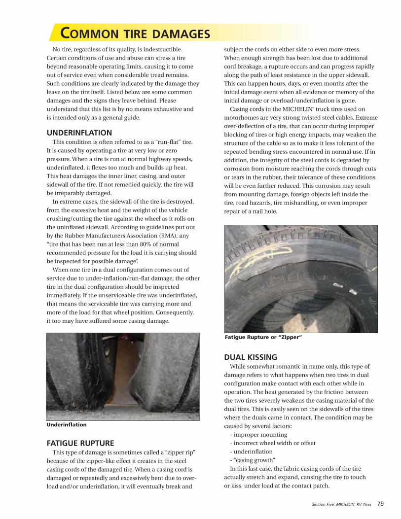
Section Five: MICHELIN® RV Tires 79
No tire, regardless of its quality, is indestructible.
Certain conditions of use and abuse can stress a tire
beyond reasonable operating limits, causing it to come
out of service even when considerable tread remains.
Such conditions are clearly indicated by the damage they
leave on the tire itself. Listed below are some common
damages and the signs they leave behind. Please
understand that this list is by no means exhaustive and
is intended only as a general guide.
UNDERINFLATIONThis condition is often referred to as a “run-flat” tire.
It is caused by operating a tire at very low or zero
pressure. When a tire is run at normal highway speeds,
underinflated, it flexes too much and builds up heat.
This heat damages the inner liner, casing, and outer
sidewall of the tire. If not remedied quickly, the tire will
be irreparably damaged.
In extreme cases, the sidewall of the tire is destroyed,
from the excessive heat and the weight of the vehicle
crushing/cutting the tire against the wheel as it rolls on
the uninflated sidewall. According to guidelines put out
by the Rubber Manufacturers Association (RMA), any
“tire that has been run at less than 80% of normal
recommended pressure for the load it is carrying should
be inspected for possible damage”.
When one tire in a dual configuration comes out of
service due to under-inflation/run-flat damage, the other
tire in the dual configuration should be inspected
immediately. If the unserviceable tire was underinflated,
that means the serviceable tire was carrying more and
more of the load for that wheel position. Consequently,
it too may have suffered some casing damage.
FATIGUE RUPTUREThis type of damage is sometimes called a “zipper rip”
because of the zipper-like effect it creates in the steel
casing cords of the damaged tire. When a casing cord is
damaged or repeatedly and excessively bent due to over-
load and/or underinflation, it will eventually break and
subject the cords on either side to even more stress.
When enough strength has been lost due to additional
cord breakage, a rupture occurs and can progress rapidly
along the path of least resistance in the upper sidewall.
This can happen hours, days, or even months after the
initial damage event when all evidence or memory of the
initial damage or overload/underinflation is gone.
Casing cords in the MICHELIN® truck tires used on
motorhomes are very strong twisted steel cables. Extreme
over-deflection of a tire, that can occur during improper
blocking of tires or high energy impacts, may weaken the
structure of the cable so as to make it less tolerant of the
repeated bending stress encountered in normal use. If in
addition, the integrity of the steel cords is degraded by
corrosion from moisture reaching the cords through cuts
or tears in the rubber, their tolerance of these conditions
will be even further reduced. This corrosion may result
from mounting damage, foreign objects left inside the
tire, road hazards, tire mishandling, or even improper
repair of a nail hole.
DUAL KISSINGWhile somewhat romantic in name only, this type of
damage refers to what happens when two tires in dual
configuration make contact with each other while in
operation. The heat generated by the friction between
the two tires severely weakens the casing material of the
dual tires. This is easily seen on the sidewalls of the tires
where the duals came in contact. The condition may be
caused by several factors:
- improper mounting
- incorrect wheel width or offset
- underinflation
- “casing growth”
In this last case, the fabric casing cords of the tire
actually stretch and expand, causing the tire to touch
or kiss, under load at the contact patch.
Underinflation
Fatigue Rupture or “Zipper”
COMMON TIRE DAMAGES
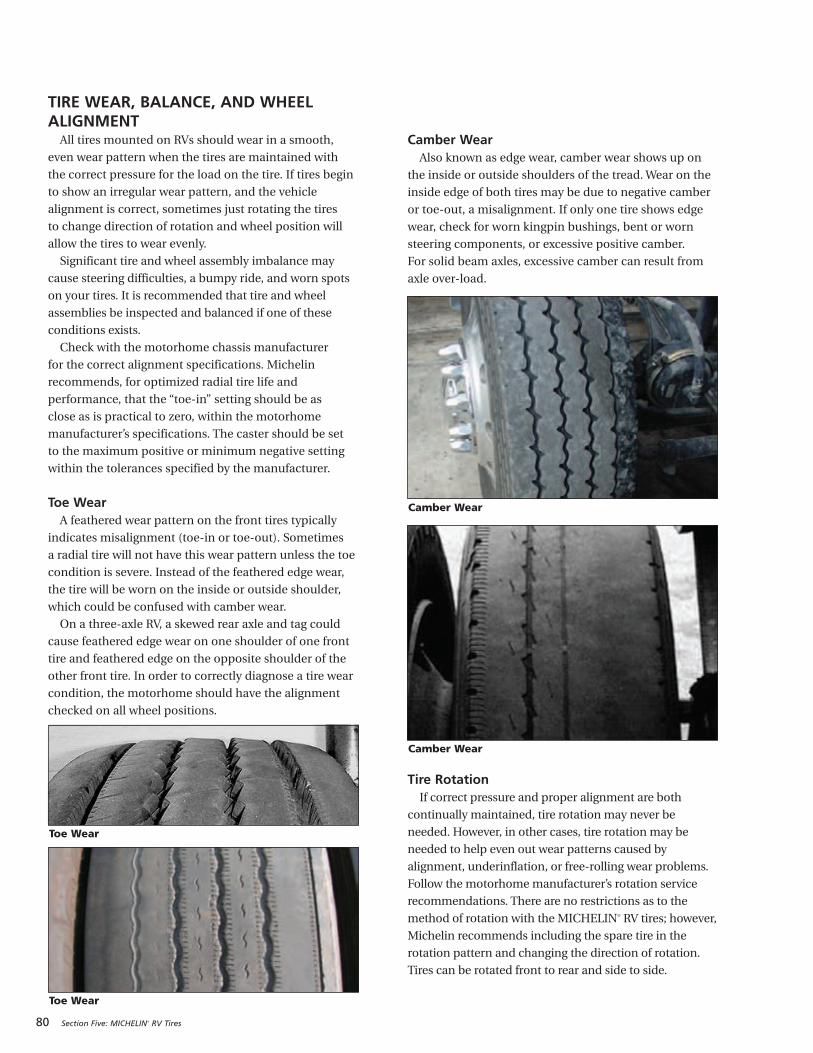
80 Section Five: MICHELIN® RV Tires
TIRE WEAR, BALANCE, AND WHEELALIGNMENT
All tires mounted on RVs should wear in a smooth,
even wear pattern when the tires are maintained with
the correct pressure for the load on the tire. If tires begin
to show an irregular wear pattern, and the vehicle
alignment is correct, sometimes just rotating the tires
to change direction of rotation and wheel position will
allow the tires to wear evenly.
Significant tire and wheel assembly imbalance may
cause steering difficulties, a bumpy ride, and worn spots
on your tires. It is recommended that tire and wheel
assemblies be inspected and balanced if one of these
conditions exists.
Check with the motorhome chassis manufacturer
for the correct alignment specifications. Michelin
recommends, for optimized radial tire life and
performance, that the “toe-in” setting should be as
close as is practical to zero, within the motorhome
manufacturer’s specifications. The caster should be set
to the maximum positive or minimum negative setting
within the tolerances specified by the manufacturer.
Toe WearA feathered wear pattern on the front tires typically
indicates misalignment (toe-in or toe-out). Sometimes
a radial tire will not have this wear pattern unless the toe
condition is severe. Instead of the feathered edge wear,
the tire will be worn on the inside or outside shoulder,
which could be confused with camber wear.
On a three-axle RV, a skewed rear axle and tag could
cause feathered edge wear on one shoulder of one front
tire and feathered edge on the opposite shoulder of the
other front tire. In order to correctly diagnose a tire wear
condition, the motorhome should have the alignment
checked on all wheel positions.
Camber WearAlso known as edge wear, camber wear shows up on
the inside or outside shoulders of the tread. Wear on the
inside edge of both tires may be due to negative camber
or toe-out, a misalignment. If only one tire shows edge
wear, check for worn kingpin bushings, bent or worn
steering components, or excessive positive camber.
For solid beam axles, excessive camber can result from
axle over-load.
Tire RotationIf correct pressure and proper alignment are both
continually maintained, tire rotation may never be
needed. However, in other cases, tire rotation may be
needed to help even out wear patterns caused by
alignment, underinflation, or free-rolling wear problems.
Follow the motorhome manufacturer’s rotation service
recommendations. There are no restrictions as to the
method of rotation with the MICHELIN® RV tires; however,
Michelin recommends including the spare tire in the
rotation pattern and changing the direction of rotation.
Tires can be rotated front to rear and side to side.
Toe Wear
Toe Wear
Camber Wear
Camber Wear
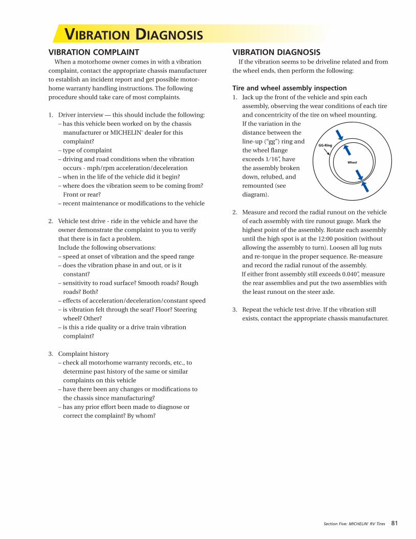
Section Five: MICHELIN® RV Tires 81
VIBRATION COMPLAINTWhen a motorhome owner comes in with a vibration
complaint, contact the appropriate chassis manufacturer
to establish an incident report and get possible motor-
home warranty handling instructions. The following
procedure should take care of most complaints.
1. Driver interview — this should include the following:
– has this vehicle been worked on by the chassis
manufacturer or MICHELIN® dealer for this
complaint?
– type of complaint
– driving and road conditions when the vibration
occurs - mph/rpm acceleration/deceleration
– when in the life of the vehicle did it begin?
– where does the vibration seem to be coming from?
Front or rear?
– recent maintenance or modifications to the vehicle
2. Vehicle test drive - ride in the vehicle and have the
owner demonstrate the complaint to you to verify
that there is in fact a problem.
Include the following observations:
– speed at onset of vibration and the speed range
– does the vibration phase in and out, or is it
constant?
– sensitivity to road surface? Smooth roads? Rough
roads? Both?
– effects of acceleration/deceleration/constant speed
– is vibration felt through the seat? Floor? Steering
wheel? Other?
– is this a ride quality or a drive train vibration
complaint?
3. Complaint history
– check all motorhome warranty records, etc., to
determine past history of the same or similar
complaints on this vehicle
– have there been any changes or modifications to
the chassis since manufacturing?
– has any prior effort been made to diagnose or
correct the complaint? By whom?
VIBRATION DIAGNOSISIf the vibration seems to be driveline related and from
the wheel ends, then perform the following:
Tire and wheel assembly inspection1. Jack up the front of the vehicle and spin each
assembly, observing the wear conditions of each tire
and concentricity of the tire on wheel mounting.
If the variation in the
distance between the
line-up (“gg”) ring and
the wheel flange
exceeds 1 ⁄ 16", have
the assembly broken
down, relubed, and
remounted (see
diagram).
2. Measure and record the radial runout on the vehicle
of each assembly with tire runout gauge. Mark the
highest point of the assembly. Rotate each assembly
until the high spot is at the 12:00 position (without
allowing the assembly to turn). Loosen all lug nuts
and re-torque in the proper sequence. Re-measure
and record the radial runout of the assembly.
If either front assembly still exceeds 0.040", measure
the rear assemblies and put the two assemblies with
the least runout on the steer axle.
3. Repeat the vehicle test drive. If the vibration still
exists, contact the appropriate chassis manufacturer.
VIBRATION DIAGNOSIS
Wheel
GG-Ring
82 Section Five: MICHELIN® RV Tires
One of the most important RV equipment purchases
that the RV owner will make will be the replacement tires.
If they obtained good service with their first set of tires,
chances are that they were matched well for the RV’s
weight needs and the RV owner type and area of driving.
Should the RV owner choose to replace their tires with
another size, be very careful with this selection. There are
some basic areas of concern, such as the load rating of
the new tire and the overall diameter of the new tire for
vehicle clearance, speedometer reading, and wheel
width.
There is also the matching of the tires to the dual
wheel offset for the dual spacing clearance and the load
rating of the wheel. For example: buying a tire with a
higher load rating that might require 105 psi would be
inappropriate if the RV wheel is limited to 80 psi. (Be sure
that the wheel width is compatible with the new tire size;
doing otherwise is dangerous.) Consult the vehicle
manufacturer for wheel specifications.
If the RV owners have already been driving on
MICHELIN® RV tires, they are aware of some of
MICHELIN® extra benefits, such as the great wet and dry
traction and outstanding handling. Most RV owners who
drive on MICHELIN® tires for the first time comment on
the smooth, quiet ride.
SELECTING REPLACEMENT TIRES FOR THE RV
For more information on MICHELIN® RV tires:
– www.michelinrvtires.com
– MICHELIN® RV Tires: Guide For Proper Use and Maintenance and RV Tire Information – MWL43146
– MICHELIN® Truck Tire Data Book – MWL40731
– MICHELIN® Recreational Vehicle Tire Reference Tool DVD – MWV43111
83
SECTION SIX
Repairs and Retread
REPAIRS . . . . . . . . . . . . . . . . . . . . . . . . . . . . . . 84-88
Two-Piece Radial Truck Tire Nail Hole Repair Method Instructions
MICHELIN® X One® Tires Nail Hole Repair Method Instructions
Blue Identification Triangle
RETREAD . . . . . . . . . . . . . . . . . . . . . . . . . . . . . . . . 88
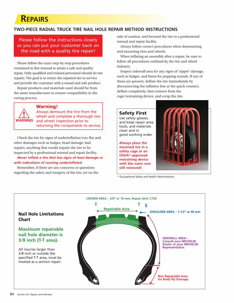
Please follow the exact step-by-step procedures
contained in this manual to attain a safe and quality
repair. Only qualified and trained personnel should do tire
repairs. The goal is to return the repaired tire to service
and provide the customer with a sound and safe product.
Repair products and materials used should be from
the same manufacturer to ensure compatibility in the
curing process.
Check the tire for signs of underinflation/run-flat and
other damages such as bulges, bead damage, bad
repairs, anything that would require the tire to be
inspected by a professional retread and repair facility.
Never inflate a tire that has signs of heat damage orwith indications of running underinflated.Remember, if there are any concerns or questions
regarding the safety and integrity of the tire, err on the
side of caution, and forward the tire to a professional
retread and repair facility.
Always follow correct procedures when demounting
and mounting tires and wheels.
When inflating an assembly after a repair, be sure to
follow all procedures outlined by the tire and wheel
industry.
Inspect sidewall area for any signs of ‘zipper’ damage,
such as bulges, and listen for popping sounds. If any of
these are present, deflate the tire immediately by
disconnecting the inflation line at the quick connect,
deflate completely, then remove from the
cage/restraining device, and scrap the tire.
Warning!Always demount the tire from thewheel and complete a thorough tireand wheel inspection prior toreturning the components to service.
84 Section Six: Repairs and Retread
REPAIRS
Safety FirstUse safety glasses,and keep repair area,tools, and materialsclean and in good working order.
Always place themounted tire in asafety cage or anOSHA*-approvedrestraining devicewith the valve corestill removed!
CROWN AREA – 3⁄8" or 10 mm, Repair Unit: CT20
S
Non Repairable Area for Body Ply Damage.
SIDEWALL AREA – Consult your MICHELINDealer or your MICHELINRepresentative.
SHOULDER AREA – 1-1⁄2" or 40 mmRepairable Area
T T
TWO-PIECE RADIAL TRUCK TIRE NAIL HOLE REPAIR METHOD INSTRUCTIONS
Nail Hole LimitationsChart
Maximum repairablenail hole diameter is3 ⁄8 inch (T-T area).
All injuries larger than 3 ⁄8 inch or outside the specified T-T area, must betreated as a section repair.
Please follow the instructions closelyso you can put your customer back onthe road with a quality tire repair!
* Occupational Safety and Health Administration
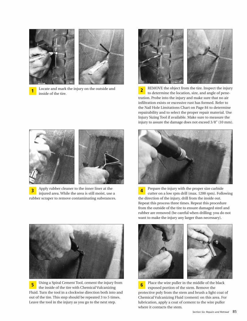
Section Six: Repairs and Retread 85
Locate and mark the injury on the outside andinside of the tire.
1REMOVE the object from the tire. Inspect the injuryto determine the location, size, and angle of pene-
tration. Probe into the injury and make sure that no airinfiltration exists or excessive rust has formed. Refer to the Nail Hole Limitations Chart on Page 84 to determinerepairability and to select the proper repair material. UseInjury Sizing Tool if available. Make sure to measure theinjury to assure the damage does not exceed 3 ⁄ 8" (10 mm).
2
Apply rubber cleaner to the inner liner at theinjured area. While the area is still moist, use a
rubber scraper to remove contaminating substances.
3 Prepare the injury with the proper size carbidecutter on a low rpm drill (max. 1200 rpm). Following
the direction of the injury, drill from the inside out.Repeat this process three times. Repeat this procedurefrom the outside of the tire to ensure damaged steel andrubber are removed (be careful when drilling; you do notwant to make the injury any larger than necessary).
4
Using a Spiral Cement Tool, cement the injury fromthe inside of the tire with Chemical Vulcanizing
Fluid. Turn the tool in a clockwise direction both into andout of the tire. This step should be repeated 3 to 5 times.Leave the tool in the injury as you go to the next step.
5 Place the wire puller in the middle of the blackexposed portion of the stem. Remove the
protective poly from the stem and brush a light coat ofChemical Vulcanizing Fluid (cement) on this area. Forlubrication, apply a coat of cement to the wire pullerwhere it contacts the stem.
6
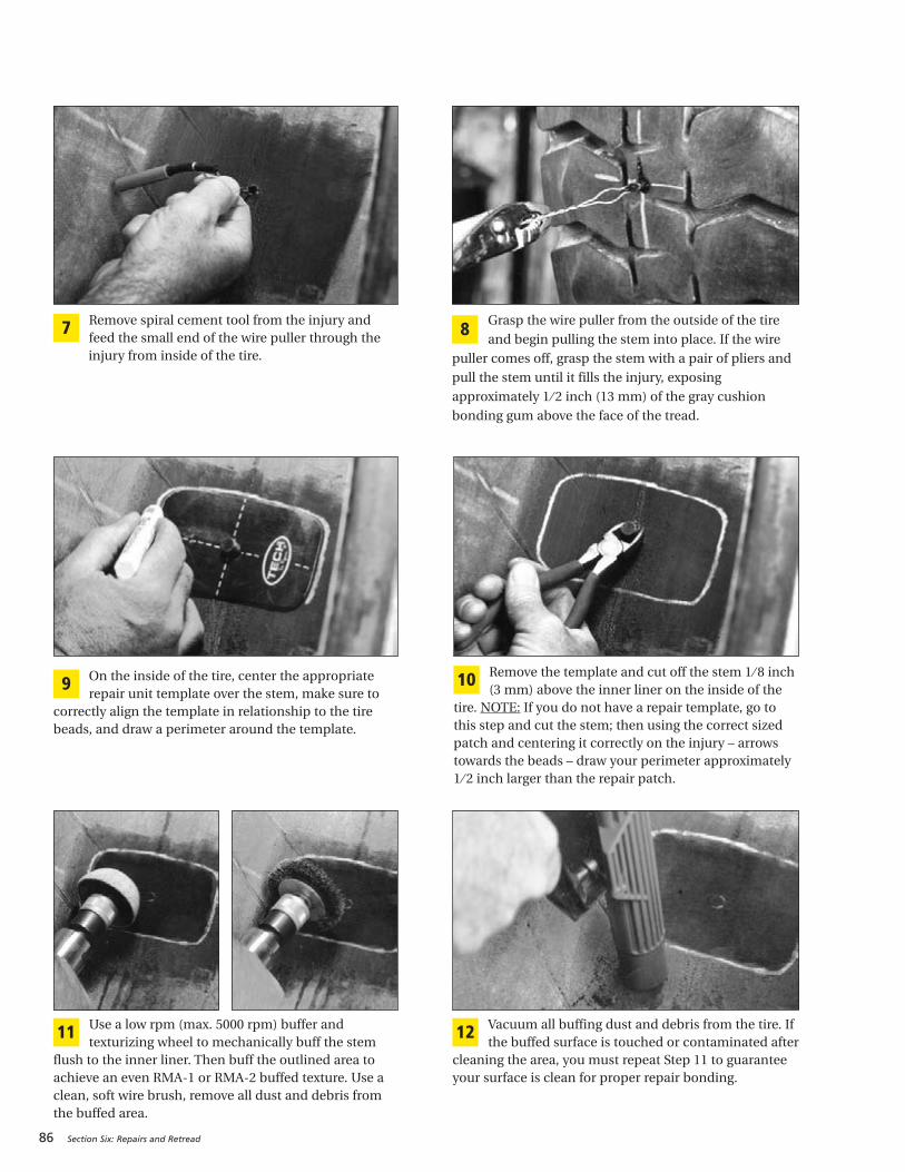
86 Section Six: Repairs and Retread
Remove spiral cement tool from the injury andfeed the small end of the wire puller through theinjury from inside of the tire.
7 Grasp the wire puller from the outside of the tire
and begin pulling the stem into place. If the wire
puller comes off, grasp the stem with a pair of pliers and
pull the stem until it fills the injury, exposing
approximately 1 ⁄ 2 inch (13 mm) of the gray cushion
bonding gum above the face of the tread.
8
On the inside of the tire, center the appropriaterepair unit template over the stem, make sure to
correctly align the template in relationship to the tirebeads, and draw a perimeter around the template.
9Remove the template and cut off the stem 1 ⁄ 8 inch(3 mm) above the inner liner on the inside of the
tire. NOTE: If you do not have a repair template, go tothis step and cut the stem; then using the correct sizedpatch and centering it correctly on the injury – arrowstowards the beads – draw your perimeter approximately1 ⁄ 2 inch larger than the repair patch.
10
Use a low rpm (max. 5000 rpm) buffer andtexturizing wheel to mechanically buff the stem
flush to the inner liner. Then buff the outlined area toachieve an even RMA-1 or RMA-2 buffed texture. Use aclean, soft wire brush, remove all dust and debris fromthe buffed area.
11 Vacuum all buffing dust and debris from the tire. Ifthe buffed surface is touched or contaminated after
cleaning the area, you must repeat Step 11 to guaranteeyour surface is clean for proper repair bonding.
12

Section Six: Repairs and Retread 87
Using Chemical Vulcanizing Fluid (cement), brusha thin, even coat into the clean textured area. Allow
3 to 5 minutes to dry; the vulcanizing cement should betacky. Areas with high humidity may require a longer drytime. Make sure the cement used is compatible with therepair units you are installing.
13 With the tire beads in a relaxed position, center therepair unit over the filled injury. Press the repair
unit down into place over the injury. Make sure thedirectional bead arrows on the repair unit are alignedwith the beads of the tire, and press into place. Roll theprotective poly back to the outer edges of the repair unit.This enables you to handle the repair unit withoutcontaminating the bonding gum layer. You are now readyto stitch the repair.
14
Stitch the repair unit, firmly pressing down fromthe center toward the outer edges. This willeliminate trapping air under the repair unit.
15 Remove the rest of the poly backing. Stitch therepair unit from the center to the outer edges.Remove the top clear protective poly.
16
To cover over-buffed areas in tubeless tires, applySecurity Sealer to the outer edge of the repair unit
and over-buffed area. If tube-type, cover the repair withTire Talc to prevent the repair from vulcanizing to thetube.
17 Cut the stem off on the outside of the tire 1 ⁄ 8 inch (3 mm) above the tire’s surface. The tire is now readyto be returned to service.
18
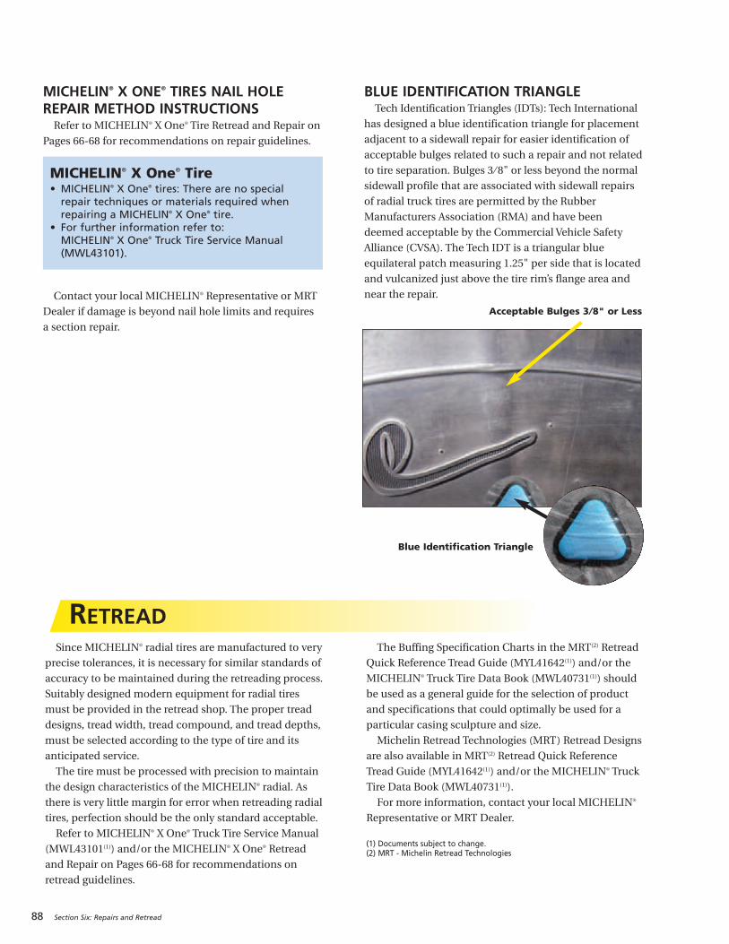
Since MICHELIN® radial tires are manufactured to very
precise tolerances, it is necessary for similar standards of
accuracy to be maintained during the retreading process.
Suitably designed modern equipment for radial tires
must be provided in the retread shop. The proper tread
designs, tread width, tread compound, and tread depths,
must be selected according to the type of tire and its
anticipated service.
The tire must be processed with precision to maintain
the design characteristics of the MICHELIN® radial. As
there is very little margin for error when retreading radial
tires, perfection should be the only standard acceptable.
Refer to MICHELIN® X One® Truck Tire Service Manual
(MWL43101(1)) and/or the MICHELIN® X One® Retread
and Repair on Pages 66-68 for recommendations on
retread guidelines.
The Buffing Specification Charts in the MRT(2) Retread
Quick Reference Tread Guide (MYL41642(1)) and/or the
MICHELIN® Truck Tire Data Book (MWL40731(1)) should
be used as a general guide for the selection of product
and specifications that could optimally be used for a
particular casing sculpture and size.
Michelin Retread Technologies (MRT) Retread Designs
are also available in MRT(2) Retread Quick Reference
Tread Guide (MYL41642(1)) and/or the MICHELIN® Truck
Tire Data Book (MWL40731(1)).
For more information, contact your local MICHELIN®
Representative or MRT Dealer.
(1) Documents subject to change.(2) MRT - Michelin Retread Technologies
88 Section Six: Repairs and Retread
MICHELIN® X ONE® TIRES NAIL HOLEREPAIR METHOD INSTRUCTIONSRefer to MICHELIN® X One® Tire Retread and Repair on
Pages 66-68 for recommendations on repair guidelines.
Contact your local MICHELIN® Representative or MRT
Dealer if damage is beyond nail hole limits and requires
a section repair.
BLUE IDENTIFICATION TRIANGLETech Identification Triangles (IDTs): Tech International
has designed a blue identification triangle for placement
adjacent to a sidewall repair for easier identification of
acceptable bulges related to such a repair and not related
to tire separation. Bulges 3 ⁄ 8" or less beyond the normal
sidewall profile that are associated with sidewall repairs
of radial truck tires are permitted by the Rubber
Manufacturers Association (RMA) and have been
deemed acceptable by the Commercial Vehicle Safety
Alliance (CVSA). The Tech IDT is a triangular blue
equilateral patch measuring 1.25" per side that is located
and vulcanized just above the tire rim’s flange area and
near the repair.
RETREAD
MICHELIN® X One® Tire• MICHELIN® X One® tires: There are no special
repair techniques or materials required whenrepairing a MICHELIN® X One® tire.
• For further information refer to: MICHELIN® X One® Truck Tire Service Manual(MWL43101).
Acceptable Bulges 3 ⁄8" or Less
Blue Identification Triangle
89
SECTION SEVENDiagonal (Bias or Cross)
Ply and Tube-TypeTHE DIAGONAL (BIAS OR CROSS) PLY. . . . . . . 90-92
Definitions
Tube-Type Tire
Truck Tire Size Markings
Repair and Retread
Static and Low Speed Load and Pressure Coefficients
TRA (The Tire and Rim Association, Inc.) Standards
GENERAL INSTRUCTIONS FOR TUBE-TYPE TIREDEMOUNTING/MOUNTING. . . . . . . . . . . . . . . . 93-95
Selection of Proper Components and Materials
Tire and Wheel Lubrication
Preparation of Wheels and Tires
DEMOUNTING TUBE-TYPE TIRES . . . . . . . . . . . 96-97
MOUNTING TUBE-TYPE TIRES . . . . . . . . . . . . 98-100
Mounting Tube-Type Tires Using Manual Spreaders
Mounting Tube-Type Tires Using Automatic Spreaders
Inflation of Tube-Type Tires
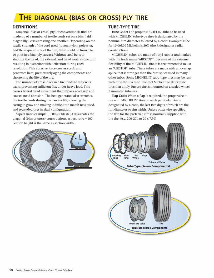
90 Section Seven: Diagonal (Bias or Cross) Ply and Tube-Type
THE DIAGONAL (BIAS OR CROSS) PLY TIREDEFINITIONSDiagonal (bias or cross) ply (or conventional) tires are
made up of a number of textile cords set on a bias (laid
diagonally), criss-crossing one another. Depending on the
textile strength of the cord used (rayon, nylon, polyester,
and the required size of the tire, there could be from 6 to
20 plies in a bias-ply carcass. Without steel belts to
stabilize the tread, the sidewall and tread work as one unit
resulting in distortion with deflection during each
revolution. This abrasive force creates scrub and
generates heat, prematurely aging the components and
shortening the life of the tire.
The number of cross-plies in a tire tends to stiffen its
walls, preventing sufficient flex under heavy load. This
causes lateral tread movement that impairs road grip and
causes tread abrasion. The heat generated also stretches
the textile cords during the carcass life, allowing the
casing to grow and making it difficult to match new, used,
and retreaded tires in dual configuration.
Aspect Ratio example: 10.00-20 (dash (-) designates the
diagonal (bias or cross) construction), aspect ratio = 100.
Section height is the same as section width.
TUBE-TYPE TIRETube Code: The proper MICHELIN® tube to be used
with MICHELIN® tube-type tires is designated by the
nominal rim diameter followed by a code. Example: Tube
for 10.00R20 Michelin is 20N (the R designates radial
construction).
MICHELIN® tubes are made of butyl rubber and marked
with the trade name “AIRSTOP®”. Because of the extreme
flexibility of the MICHELIN® tire, it is recommended to use
an “AIRSTOP” tube. These tubes are made with an overlap
splice that is stronger than the butt splice used in many
other tubes. Some MICHELIN® tube-type tires may be run
with or without a tube. Contact Michelin to determine
tires that apply. Ensure tire is mounted on a sealed wheel
if mounted tubeless.
Flap Code: When a flap is required, the proper size to
use with MICHELIN® tires on each particular rim is
designated by a code, the last two digits of which are the
rim diameter or rim width. Unless otherwise specified,
the flap for the preferred rim is normally supplied with
the tire. (e.g. 200-20L or 20 x 7.50)
Tube-Type (Seven Components)
Locking Side Disc FlapRing Ring Wheel
Tube and Valve Tire
Tubeless (Three Components)
Wheel and Valve Tire

Section Seven: Diagonal (Bias or Cross) Ply and Tube-Type 91
TRUCK TIRE SIZE MARKINGSMost truck tire sizes are indicated by the section width
in inches, followed by R for radial (dash (-) designates the
diagonal (bias or cross) construction), followed by the
wheel diameter in inches:
TUBE-TYPE TUBELESS
10.00R20 11R22.5
10.00 = nominal section 11 = nominal sectionwidth in inches width in inches
R = radial R = radial
20 = wheel diameter 22.5 = wheel diameterin inches in inches
Note: A “rule-of-thumb” formula for finding equivalent
tubeless sizes from tube-type: Take the nominal section
width and remove all figures after the decimal point.
Round up to next whole nominal section number and
add 2.5 to wheel diameter.
Example:TUBE-TYPE TUBELESS8.25R20 = 9R22.5
Nominal Cross Section 8.25
Remove .25
Add 1 to the 8 = 9
Wheel Diameter 20
Add 2.5 to Wheel Diameter 20 + 2.5 = 22.5
Thus we have 9R22.5 Tubeless.
Tubeless
22.5"
Tube-Type
20"
COMPARATIVE SIZES – STANDARD – LOW PROFILE
TUBE-TYPE TUBELESS TYPE MICHELIN TRA*
8.25R15 9R17.5
8.25R20 9R22.5 235/80R22.5 245/75R22.5
9.00R20 10R22.5 255/80R22.5 265/75R22.5
10.00R20 11R22.5 275/80R22.5 295/75R22.5
11.00R20 12R22.5
10.00R22 11R24.5 275/80R24.5 285/75R24.5
11.00R22 12R24.5
REPAIR AND RETREAD1. Follow proper procedures per your Michelin Retread
Technologies dealer.
2. Use bias repair units in bias tires and radial repair
units in radial tires.
3. When performing tube repairs, do not install the
patch on an inflated tube, and apply a tire talc to the
patch and buffed area to prevent sticking to the inside
of the tire.
* The Tire and Rim Association, Inc.
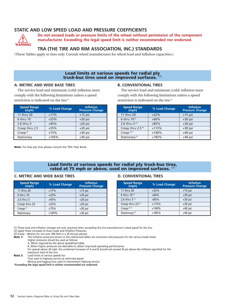
92 Section Seven: Diagonal (Bias or Cross) Ply and Tube-Type
STATIC AND LOW SPEED LOAD AND PRESSURE COEFFICIENTSDo not exceed loads or pressure limits of the wheel without permission of the componentmanufacturer. Exceeding the legal speed limit is neither recommended nor endorsed.
TRA (THE TIRE AND RIM ASSOCIATION, INC.) STANDARDS(These Tables apply to tires only. Consult wheel manufacturer for wheel load and inflation capacities.)
Load limits at various speeds for radial ply truck-bus tires used on improved surfaces. (1)
Load limits at various speeds for radial ply truck-bus tires, rated at 75 mph or above, used on improved surfaces. (1)
C. METRIC AND WIDE BASE TIRES D. CONVENTIONAL TIRES
A. METRIC AND WIDE BASE TIRESThe service load and minimum (cold) inflation must
comply with the following limitations unless a speed
restriction is indicated on the tire.*
B. CONVENTIONAL TIRESThe service load and minimum (cold) inflation must
comply with the following limitations unless a speed
restriction is indicated on the tire.*
Note: For bias ply tires please consult the TRA Year Book.
(1) These load and inflation changes are only required when exceeding the tire manufacturer’s rated speed for the tire. (2) Apply these increases to Dual Loads and Inflation Pressures.(3) Creep – Motion for not over 200 feet in a 30-minute period.Note 1: The inflation pressures shown in the referenced tables are minimum cold pressures for the various loads listed.
Higher pressures should be used as follows:A. When required by the above speed/load table.B. When higher pressures are desirable to obtain improved operating performance.For speeds above 20 mph, the combined increases of A and B should not exceed 20 psi above the inflation specified for themaximum load of the tire.
Note 2: Load limits at various speeds for:Tires used in highway service at restricted speed.Mining and logging tires used in intermittent highway service
*Exceeding the legal speed limit is neither recommended nor endorsed.
Speed Range(mph) % Load Change Inflation
Pressure Change
11 thru 20 +17% +15 psi
6 thru 10 +25% +20 psi
2.6 thru 5 +45% +20 psi
Creep thru 2.5 +55% +20 psi
Creep (2) +75% +30 psi
Stationary +105% +30 psi
Speed Range(mph) % Load Change Inflation
Pressure Change
11 thru 20 +32% +15 psi
6 thru 10 (2) +60% +30 psi
2.6 thru 5 (2) +85% +30 psi
Creep thru 2.5 (2) +115% +30 psi
Creep (2,3) +140% +40 psi
Stationary (2) +185% +40 psi
Speed Range(mph) % Load Change Inflation
Pressure Change
11 thru 20 +17% +15 psi
6 thru 10 +25% +20 psi
2.6 thru 5 +45% +20 psi
Creep thru 2.5 +55% +20 psi
Creep (2) +75% +30 psi
Stationary +105% +30 psi
Speed Range(mph) % Load Change Inflation
Pressure Change
11 thru 20 +32% +15 psi
6 thru 10 (3) +60% +30 psi
2.6 thru 5 (3) +85% +30 psi
Creep thru 2.5 (3) +115% +30 psi
Creep (2,3) +140% +40 psi
Stationary (3) +185% +40 psi
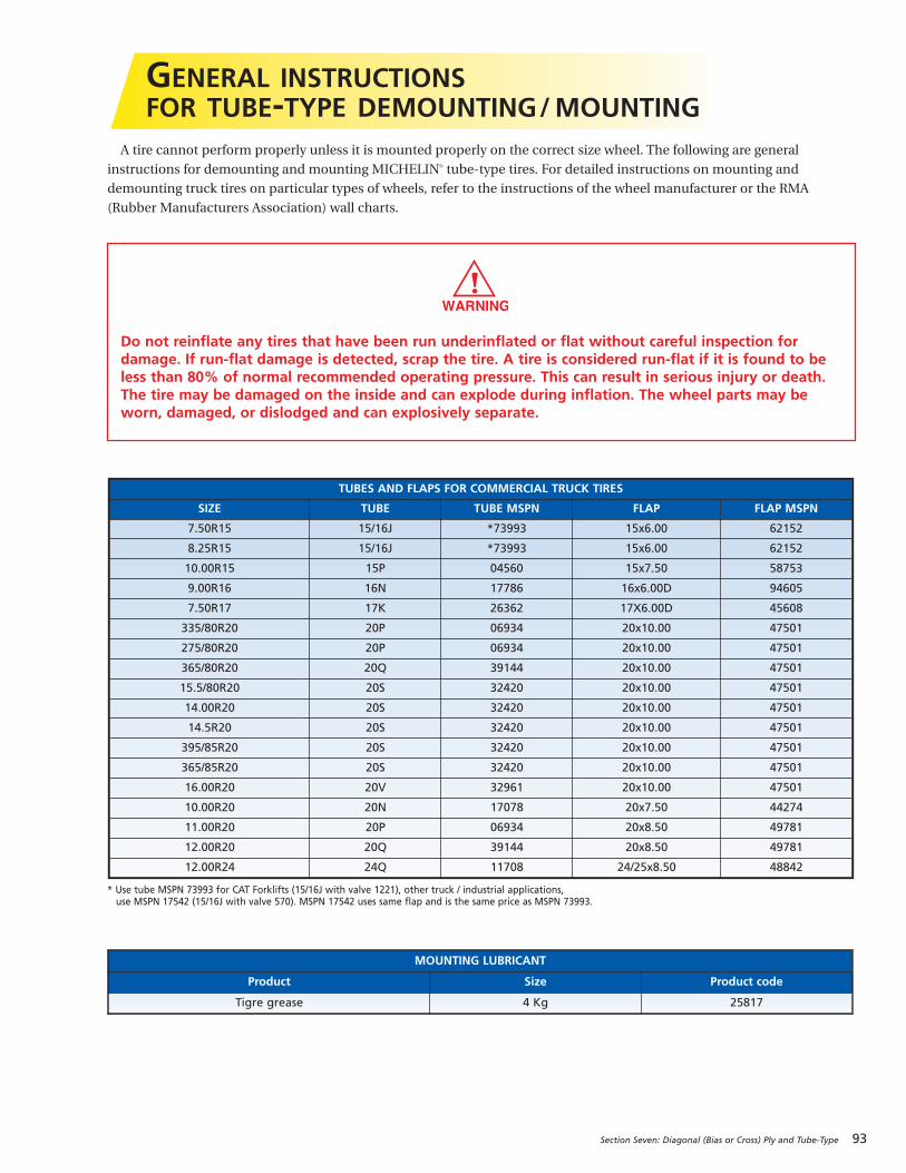
Section Seven: Diagonal (Bias or Cross) Ply and Tube-Type 93
A tire cannot perform properly unless it is mounted properly on the correct size wheel. The following are general
instructions for demounting and mounting MICHELIN® tube-type tires. For detailed instructions on mounting and
demounting truck tires on particular types of wheels, refer to the instructions of the wheel manufacturer or the RMA
(Rubber Manufacturers Association) wall charts.
GENERAL INSTRUCTIONSFOR TUBE-TYPE DEMOUNTING/MOUNTING
Do not reinflate any tires that have been run underinflated or flat without careful inspection fordamage. If run-flat damage is detected, scrap the tire. A tire is considered run-flat if it is found to beless than 80% of normal recommended operating pressure. This can result in serious injury or death.The tire may be damaged on the inside and can explode during inflation. The wheel parts may beworn, damaged, or dislodged and can explosively separate.
MOUNTING LUBRICANT
Product Size Product code
T igre grease 4 Kg 25817
TUBES AND FLAPS FOR COMMERCIAL TRUCK TIRES
SIZE TUBE TUBE MSPN FLAP FLAP MSPN
7.50R15 15/16J *73993 15x6.00 62152
8.25R15 15/16J *73993 15x6.00 62152
10.00R15 15P 04560 15x7.50 58753
9.00R16 16N 17786 16x6.00D 94605
7.50R17 17K 26362 17X6.00D 45608
335/80R20 20P 06934 20x10.00 47501
275/80R20 20P 06934 20x10.00 47501
365/80R20 20Q 39144 20x10.00 47501
15.5/80R20 20S 32420 20x10.00 47501
14.00R20 20S 32420 20x10.00 47501
14.5R20 20S 32420 20x10.00 47501
395/85R20 20S 32420 20x10.00 47501
365/85R20 20S 32420 20x10.00 47501
16.00R20 20V 32961 20x10.00 47501
10.00R20 20N 17078 20x7.50 44274
11.00R20 20P 06934 20x8.50 49781
12.00R20 20Q 39144 20x8.50 49781
12.00R24 24Q 11708 24/25x8.50 48842
* Use tube MSPN 73993 for CAT Forklifts (15/16J with valve 1221), other truck / industrial applications, use MSPN 17542 (15/16J with valve 570). MSPN 17542 uses same flap and is the same price as MSPN 73993.
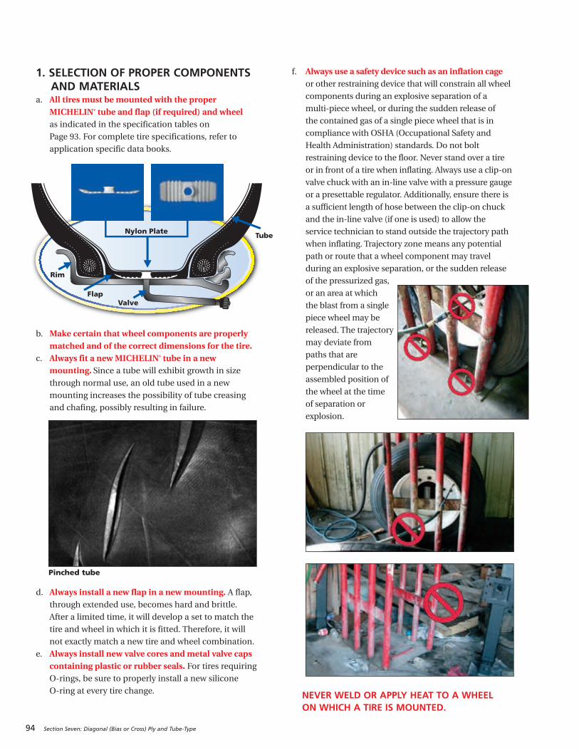
94 Section Seven: Diagonal (Bias or Cross) Ply and Tube-Type
1. SELECTION OF PROPER COMPONENTSAND MATERIALS
a. All tires must be mounted with the properMICHELIN® tube and flap (if required) and wheelas indicated in the specification tables on
Page 93. For complete tire specifications, refer to
application specific data books.
b. Make certain that wheel components are properlymatched and of the correct dimensions for the tire.
c. Always fit a new MICHELIN® tube in a newmounting. Since a tube will exhibit growth in sizethrough normal use, an old tube used in a new
mounting increases the possibility of tube creasing
and chafing, possibly resulting in failure.
d. Always install a new flap in a new mounting. A flap,through extended use, becomes hard and brittle.
After a limited time, it will develop a set to match the
tire and wheel in which it is fitted. Therefore, it will
not exactly match a new tire and wheel combination.
e. Always install new valve cores and metal valve capscontaining plastic or rubber seals. For tires requiringO-rings, be sure to properly install a new silicone
O-ring at every tire change.
f. Always use a safety device such as an inflation cageor other restraining device that will constrain all wheel
components during an explosive separation of a
multi-piece wheel, or during the sudden release of
the contained gas of a single piece wheel that is in
compliance with OSHA (Occupational Safety and
Health Administration) standards. Do not bolt
restraining device to the floor. Never stand over a tire
or in front of a tire when inflating. Always use a clip-on
valve chuck with an in-line valve with a pressure gauge
or a presettable regulator. Additionally, ensure there is
a sufficient length of hose between the clip-on chuck
and the in-line valve (if one is used) to allow the
service technician to stand outside the trajectory path
when inflating. Trajectory zone means any potential
path or route that a wheel component may travel
during an explosive separation, or the sudden release
of the pressurized gas,
or an area at which
the blast from a single
piece wheel may be
released. The trajectory
may deviate from
paths that are
perpendicular to the
assembled position of
the wheel at the time
of separation or
explosion.
TubeNylon Plate
Rim
FlapValve
Pinched tube
NEVER WELD OR APPLY HEAT TO A WHEEL ON WHICH A TIRE IS MOUNTED.
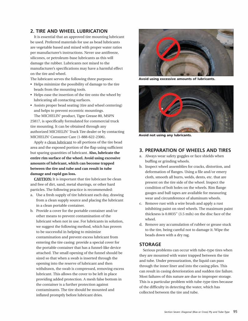
Section Seven: Diagonal (Bias or Cross) Ply and Tube-Type 95
2. TIRE AND WHEEL LUBRICATIONIt is essential that an approved tire mounting lubricant
be used. Preferred materials for use as bead lubricants
are vegetable based and mixed with proper water ratios
per manufacturer’s instructions. Never use antifreeze,
silicones, or petroleum-base lubricants as this will
damage the rubber. Lubricants not mixed to the
manufacturer’s specifications may have a harmful effect
on the tire and wheel.
The lubricant serves the following three purposes:
• Helps minimize the possibility of damage to the tire
beads from the mounting tools.
• Helps ease the insertion of the tire onto the wheel by
lubricating all contacting surfaces.
• Assists proper bead seating (tire and wheel centering)
and helps to prevent eccentric mountings.
The MICHELIN® product, Tigre Grease 80, MSPN
25817, is specifically formulated for commercial truck
tire mounting. It can be obtained through any
authorized MICHELIN® Truck Tire dealer or by contacting
MICHELIN® Consumer Care (1-888-622-2306).
Apply a clean lubricant to all portions of the tire bead
area and the exposed portion of the flap using sufficient
but sparing quantities of lubricant. Also, lubricate theentire rim surface of the wheel. Avoid using excessiveamounts of lubricant, which can become trappedbetween the tire and tube and can result in tubedamage and rapid gas loss.CAUTION: It is important that tire lubricant be clean
and free of dirt, sand, metal shavings, or other hard
particles. The following practice is recommended:
a. Use a fresh supply of tire lubricant each day, drawing
from a clean supply source and placing the lubricant
in a clean portable container.
b. Provide a cover for the portable container and/or
other means to prevent contamination of the
lubricant when not in use. For lubricants in solution,
we suggest the following method, which has proven
to be successful in helping to minimize
contamination and prevent excess lubricant from
entering the tire casing: provide a special cover for
the portable container that has a funnel-like device
attached. The small opening of the funnel should be
sized so that when a swab is inserted through the
opening into the reserve of lubricant and then
withdrawn, the swab is compressed, removing excess
lubricant. This allows the cover to be left in place
providing added protection. A mesh false bottom in
the container is a further protection against
contaminants. The tire should be mounted and
inflated promptly before lubricant dries.
3. PREPARATION OF WHEELS AND TIRESa. Always wear safety goggles or face shields when
buffing or grinding wheels.
b. Inspect wheel assemblies for cracks, distortion, and
deformation of flanges. Using a file and/or emery
cloth, smooth all burrs, welds, dents, etc. that are
present on the tire side of the wheel. Inspect the
condition of bolt holes on the wheels. Rim flange
gauges and ball tapes are available for measuring
wear and circumference of aluminum wheels.
c. Remove rust with a wire brush and apply a rust
inhibiting paint on steel wheels. The maximum paint
thickness is 0.0035" (3.5 mils) on the disc face of the
wheel.
d. Remove any accumulation of rubber or grease stuck
to the tire, being careful not to damage it. Wipe the
beads down with a dry rag.
STORAGESerious problems can occur with tube-type tires when
they are mounted with water trapped between the tire
and tube. Under pressurization, the liquid can pass
through the inner liner and into the casing plies. This
can result in casing deterioration and sudden tire failure.
Most failures of this nature are due to improper storage.
This is a particular problem with tube-type tires because
of the difficulty in detecting the water, which has
collected between the tire and tube.
Avoid using excessive amounts of lubricants.
Avoid not using any lubricants.
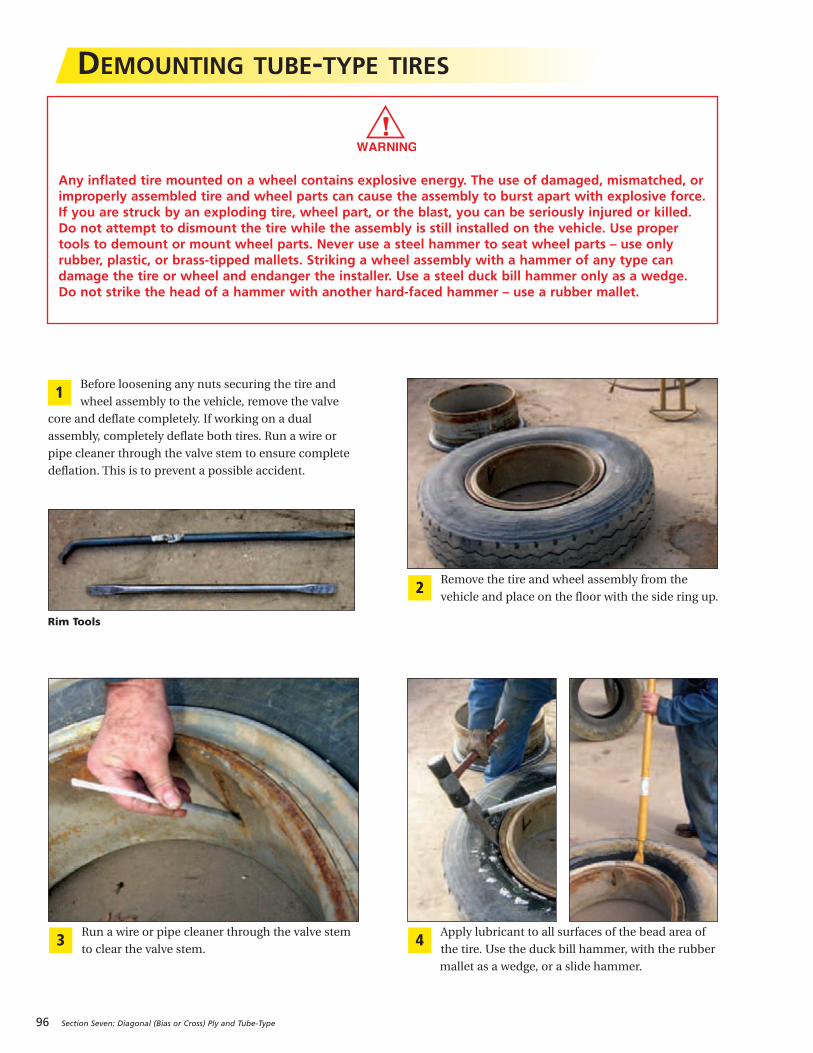
96 Section Seven: Diagonal (Bias or Cross) Ply and Tube-Type
DEMOUNTING TUBE-TYPE TIRES
Apply lubricant to all surfaces of the bead area of
the tire. Use the duck bill hammer, with the rubber
mallet as a wedge, or a slide hammer.
4Run a wire or pipe cleaner through the valve stem
to clear the valve stem. 3
Remove the tire and wheel assembly from the
vehicle and place on the floor with the side ring up.2
Before loosening any nuts securing the tire and
wheel assembly to the vehicle, remove the valve
core and deflate completely. If working on a dual
assembly, completely deflate both tires. Run a wire or
pipe cleaner through the valve stem to ensure complete
deflation. This is to prevent a possible accident.
1
Rim Tools
Any inflated tire mounted on a wheel contains explosive energy. The use of damaged, mismatched, orimproperly assembled tire and wheel parts can cause the assembly to burst apart with explosive force.If you are struck by an exploding tire, wheel part, or the blast, you can be seriously injured or killed.Do not attempt to dismount the tire while the assembly is still installed on the vehicle. Use propertools to demount or mount wheel parts. Never use a steel hammer to seat wheel parts – use onlyrubber, plastic, or brass-tipped mallets. Striking a wheel assembly with a hammer of any type candamage the tire or wheel and endanger the installer. Use a steel duck bill hammer only as a wedge.Do not strike the head of a hammer with another hard-faced hammer – use a rubber mallet.
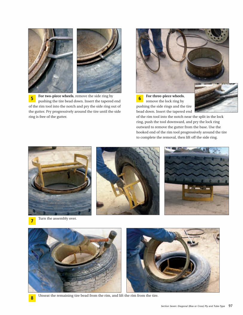
Section Seven: Diagonal (Bias or Cross) Ply and Tube-Type 97
For two-piece wheels, remove the side ring by
pushing the tire bead down. Insert the tapered end
of the rim tool into the notch and pry the side ring out of
the gutter. Pry progressively around the tire until the side
ring is free of the gutter.
5For three-piece wheels,remove the lock ring by
pushing the side rings and the tire
bead down. Insert the tapered end
of the rim tool into the notch near the split in the lock
ring, push the tool downward, and pry the lock ring
outward to remove the gutter from the base. Use the
hooked end of the rim tool progressively around the tire
to complete the removal, then lift off the side ring.
6
Turn the assembly over.7
Unseat the remaining tire bead from the rim, and lift the rim from the tire.8
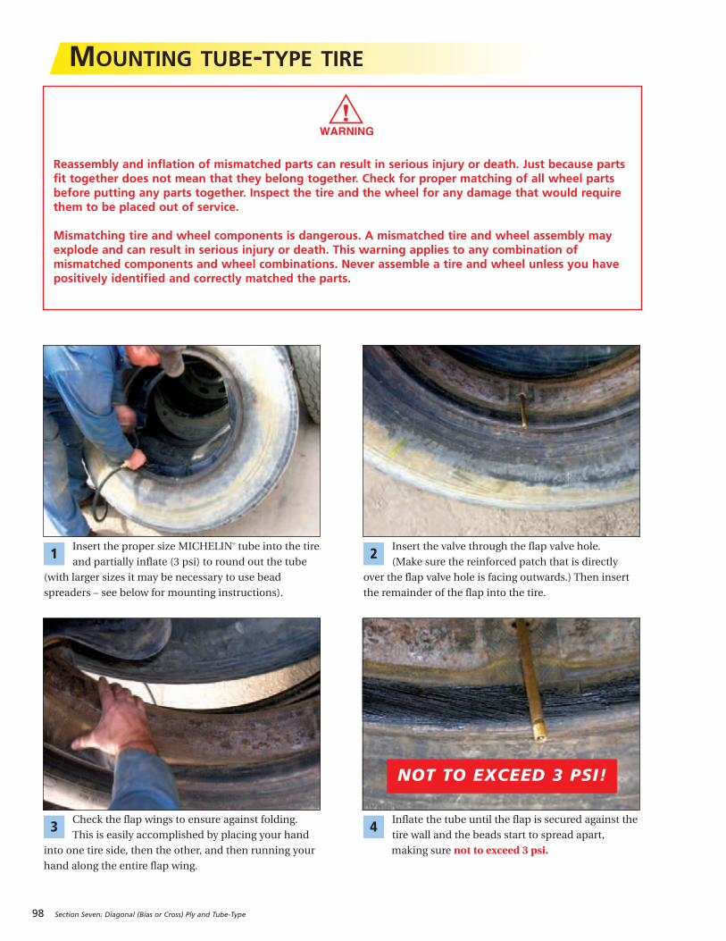
98 Section Seven: Diagonal (Bias or Cross) Ply and Tube-Type
MOUNTING TUBE-TYPE TIRE
Reassembly and inflation of mismatched parts can result in serious injury or death. Just because partsfit together does not mean that they belong together. Check for proper matching of all wheel partsbefore putting any parts together. Inspect the tire and the wheel for any damage that would requirethem to be placed out of service.
Mismatching tire and wheel components is dangerous. A mismatched tire and wheel assembly mayexplode and can result in serious injury or death. This warning applies to any combination ofmismatched components and wheel combinations. Never assemble a tire and wheel unless you havepositively identified and correctly matched the parts.
Inflate the tube until the flap is secured against the
tire wall and the beads start to spread apart,
making sure not to exceed 3 psi.
4Check the flap wings to ensure against folding.
This is easily accomplished by placing your hand
into one tire side, then the other, and then running your
hand along the entire flap wing.
3
Insert the valve through the flap valve hole.
(Make sure the reinforced patch that is directly
over the flap valve hole is facing outwards.) Then insert
the remainder of the flap into the tire.
2Insert the proper size MICHELIN® tube into the tire
and partially inflate (3 psi) to round out the tube
(with larger sizes it may be necessary to use bead
spreaders – see below for mounting instructions).
1
NOT TO EXCEED 3 PSI!
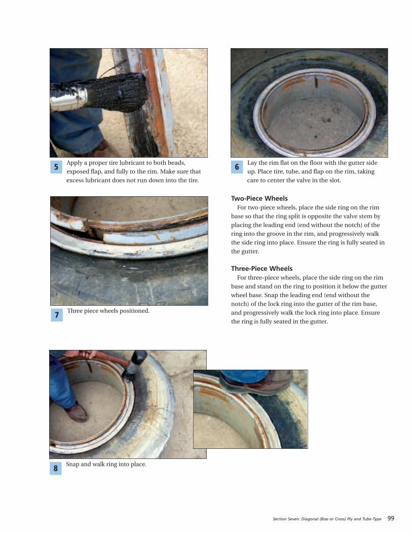
Section Seven: Diagonal (Bias or Cross) Ply and Tube-Type 99
Two-Piece WheelsFor two-piece wheels, place the side ring on the rim
base so that the ring split is opposite the valve stem by
placing the leading end (end without the notch) of the
ring into the groove in the rim, and progressively walk
the side ring into place. Ensure the ring is fully seated in
the gutter.
Three-Piece WheelsFor three-piece wheels, place the side ring on the rim
base and stand on the ring to position it below the gutter
wheel base. Snap the leading end (end without the
notch) of the lock ring into the gutter of the rim base,
and progressively walk the lock ring into place. Ensure
the ring is fully seated in the gutter.
Apply a proper tire lubricant to both beads,
exposed flap, and fully to the rim. Make sure that
excess lubricant does not run down into the tire.
5
Three piece wheels positioned.7
Lay the rim flat on the floor with the gutter side
up. Place tire, tube, and flap on the rim, taking
care to center the valve in the slot.
6
Snap and walk ring into place.8
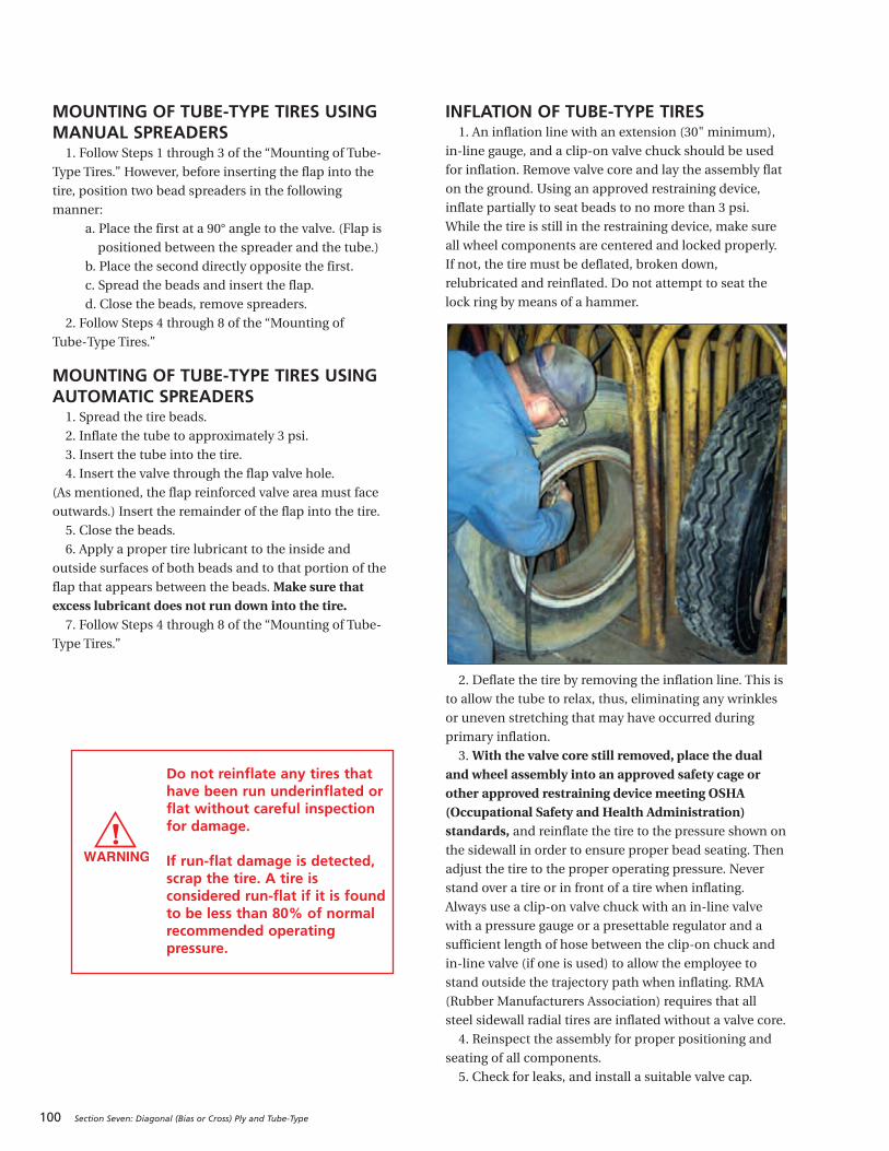
100 Section Seven: Diagonal (Bias or Cross) Ply and Tube-Type
MOUNTING OF TUBE-TYPE TIRES USINGMANUAL SPREADERS1. Follow Steps 1 through 3 of the “Mounting of Tube-
Type Tires.” However, before inserting the flap into the
tire, position two bead spreaders in the following
manner:
a. Place the first at a 90° angle to the valve. (Flap is
positioned between the spreader and the tube.)
b. Place the second directly opposite the first.
c. Spread the beads and insert the flap.
d. Close the beads, remove spreaders.
2. Follow Steps 4 through 8 of the “Mounting of
Tube-Type Tires.”
MOUNTING OF TUBE-TYPE TIRES USINGAUTOMATIC SPREADERS1. Spread the tire beads.
2. Inflate the tube to approximately 3 psi.
3. Insert the tube into the tire.
4. Insert the valve through the flap valve hole.
(As mentioned, the flap reinforced valve area must face
outwards.) Insert the remainder of the flap into the tire.
5. Close the beads.
6. Apply a proper tire lubricant to the inside and
outside surfaces of both beads and to that portion of the
flap that appears between the beads. Make sure thatexcess lubricant does not run down into the tire.7. Follow Steps 4 through 8 of the “Mounting of Tube-
Type Tires.”
INFLATION OF TUBE-TYPE TIRES 1. An inflation line with an extension (30" minimum),
in-line gauge, and a clip-on valve chuck should be used
for inflation. Remove valve core and lay the assembly flat
on the ground. Using an approved restraining device,
inflate partially to seat beads to no more than 3 psi.
While the tire is still in the restraining device, make sure
all wheel components are centered and locked properly.
If not, the tire must be deflated, broken down,
relubricated and reinflated. Do not attempt to seat the
lock ring by means of a hammer.
2. Deflate the tire by removing the inflation line. This is
to allow the tube to relax, thus, eliminating any wrinkles
or uneven stretching that may have occurred during
primary inflation.
3. With the valve core still removed, place the dualand wheel assembly into an approved safety cage orother approved restraining device meeting OSHA(Occupational Safety and Health Administration)standards, and reinflate the tire to the pressure shown onthe sidewall in order to ensure proper bead seating. Then
adjust the tire to the proper operating pressure. Never
stand over a tire or in front of a tire when inflating.
Always use a clip-on valve chuck with an in-line valve
with a pressure gauge or a presettable regulator and a
sufficient length of hose between the clip-on chuck and
in-line valve (if one is used) to allow the employee to
stand outside the trajectory path when inflating. RMA
(Rubber Manufacturers Association) requires that all
steel sidewall radial tires are inflated without a valve core.
4. Reinspect the assembly for proper positioning and
seating of all components.
5. Check for leaks, and install a suitable valve cap.
Do not reinflate any tires thathave been run underinflated orflat without careful inspectionfor damage.
If run-flat damage is detected,scrap the tire. A tire isconsidered run-flat if it is foundto be less than 80% of normalrecommended operatingpressure.
101
SECTION EIGHT
Tire Damage
RUN-FLAT . . . . . . . . . . . . . . . . . . . . . . . . . . . . 102-103
AIR INFILTRATION . . . . . . . . . . . . . . . . . . . . . 104-105
PINCH SHOCK . . . . . . . . . . . . . . . . . . . . . . . . . . . . 106
MINIMUM DUAL SPACING . . . . . . . . . . . . . . . . . . 106
IMPACT DAMAGE . . . . . . . . . . . . . . . . . . . . . . . . . 107
FATIGUE RELATED DAMAGE . . . . . . . . . . . . . . . . 108
BEAD DAMAGE. . . . . . . . . . . . . . . . . . . . . . . . . . . 109
ADDITIONAL CAUSES: REPAIRS AND RETREADING CONDITIONS . . 110-111
SCRAP INSPECTION FORM . . . . . . . . . . . . . . . . . . 112
EFFECT & CAUSEAll scrap tire failures are cause and effect related. In the majority of
the situations, it is the effect that we first see when we look at the tire
damage. However, tire condition “effects” may have many causes. Often
a pattern can be found that may point to changes needed to avoid future
scrap failures of this nature. The majority of tubeless commercial scrap
conditions are found in the following damage categories:
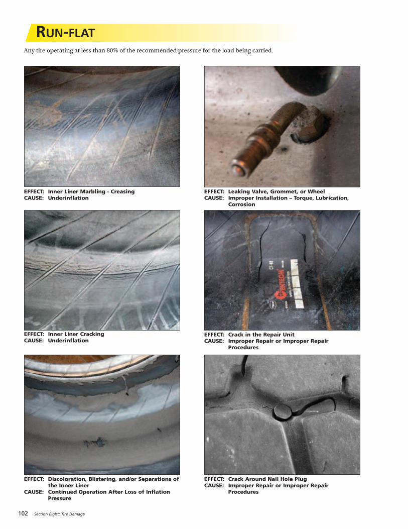
102 Section Eight: Tire Damage
RUN-FLAT
EFFECT: Inner Liner Marbling - CreasingCAUSE: Underinflation
EFFECT: Inner Liner CrackingCAUSE: Underinflation
EFFECT: Discoloration, Blistering, and/or Separations ofthe Inner Liner
CAUSE: Continued Operation After Loss of Inflation Pressure
EFFECT: Leaking Valve, Grommet, or WheelCAUSE: Improper Installation – Torque, Lubrication,
Corrosion
EFFECT: Crack Around Nail Hole Plug CAUSE: Improper Repair or Improper Repair
Procedures
EFFECT: Crack in the Repair UnitCAUSE: Improper Repair or Improper Repair
Procedures
Any tire operating at less than 80% of the recommended pressure for the load being carried.
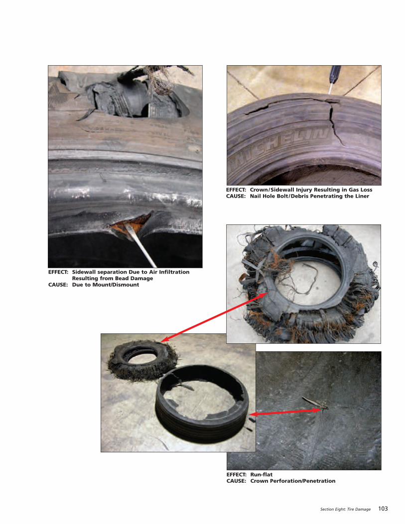
Section Eight: Tire Damage 103
EFFECT: Crown/Sidewall Injury Resulting in Gas LossCAUSE: Nail Hole Bolt /Debris Penetrating the Liner
EFFECT: Sidewall separation Due to Air InfiltrationResulting from Bead Damage
CAUSE: Due to Mount/Dismount
EFFECT: Run-flat CAUSE: Crown Perforation/Penetration
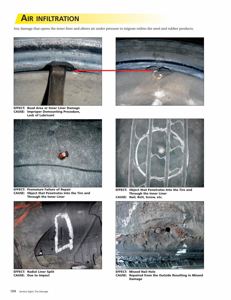
104 Section Eight: Tire Damage
AIR INFILTRATIONAny damage that opens the inner liner and allows air under pressure to migrate within the steel and rubber products.
EFFECT: Premature Failure of RepairCAUSE: Object that Penetrates Into the Tire and
Through the Inner Liner
EFFECT: Bead Area or Inner Liner DamageCAUSE: Improper Demounting Procedure,
Lack of Lubricant
EFFECT: Radial Liner Split CAUSE: Due to Impact
EFFECT: Object that Penetrates Into the Tire andThrough the Inner Liner
CAUSE: Nail, Bolt, Screw, etc.
EFFECT: Missed Nail HoleCAUSE: Repaired from the Outside Resulting in Missed
Damage

Section Eight: Tire Damage 105
EFFECT: Sidewall Separation Due to Air InfiltrationCAUSE: Improper Repair
EFFECT: Inner Liner Cut CAUSE: Shipping or Mounting Damage
EFFECT: Inner Liner Burn CAUSE: Electrical Discharge Damage
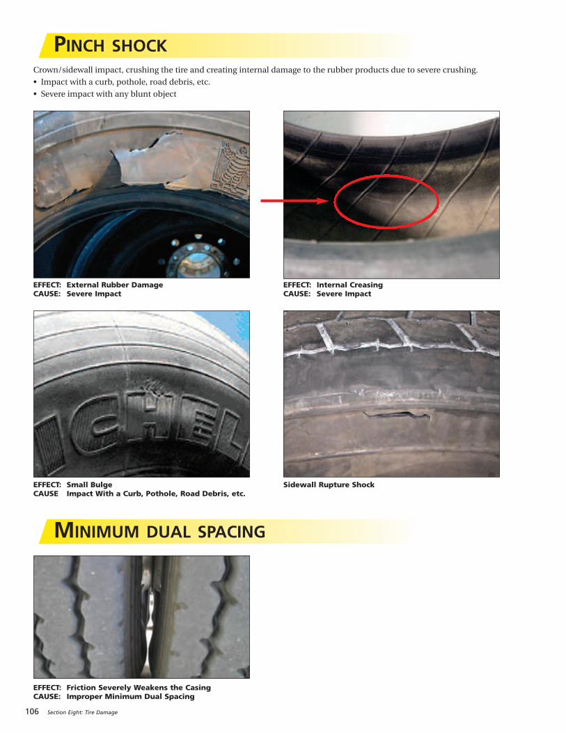
106 Section Eight: Tire Damage
PINCH SHOCKCrown/sidewall impact, crushing the tire and creating internal damage to the rubber products due to severe crushing.
• Impact with a curb, pothole, road debris, etc.
• Severe impact with any blunt object
EFFECT: External Rubber DamageCAUSE: Severe Impact
EFFECT: Small BulgeCAUSE Impact With a Curb, Pothole, Road Debris, etc.
EFFECT: Internal CreasingCAUSE: Severe Impact
Sidewall Rupture Shock
MINIMUM DUAL SPACING
EFFECT: Friction Severe ly Weakens the CasingCAUSE: Improper Minimum Dual Spacing
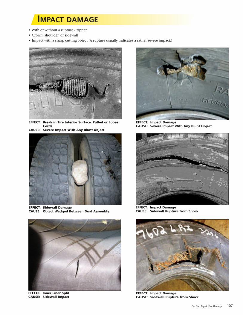
Section Eight: Tire Damage 107
IMPACT DAMAGE• With or without a rupture - zipper
• Crown, shoulder, or sidewall
• Impact with a sharp cutting object (A rupture usually indicates a rather severe impact.)
EFFECT: Impact DamageCAUSE: Sidewall Rupture from Shock
EFFECT: Impact DamageCAUSE: Sidewall Rupture from Shock
EFFECT: Inner Liner Split CAUSE: Sidewall Impact
EFFECT: Break in Tire Interior Surface, Pulled or LooseCords
CAUSE: Severe Impact With Any Blunt Object
EFFECT: Sidewall DamageCAUSE: Object Wedged Between Dual Assembly
EFFECT: Impact DamageCAUSE: Severe Impact With Any Blunt Object
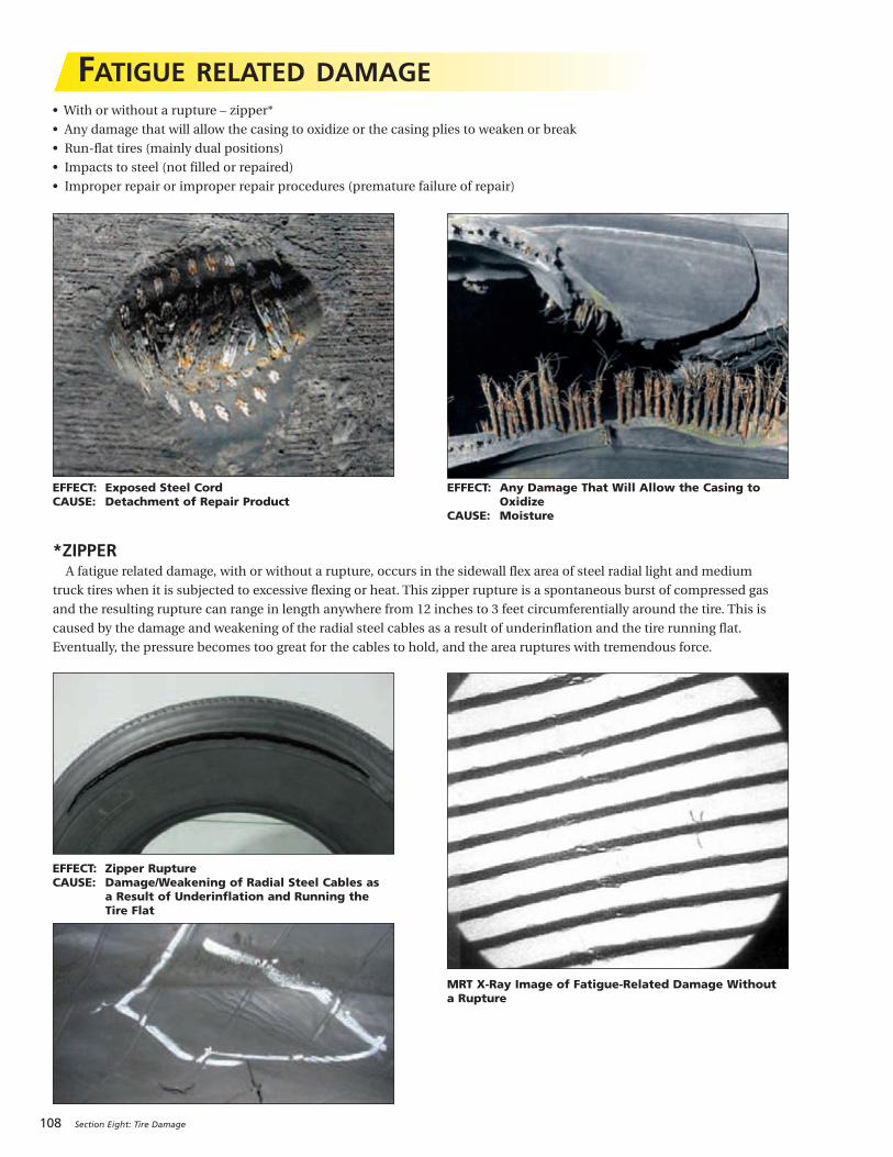
108 Section Eight: Tire Damage
FATIGUE RELATED DAMAGE• With or without a rupture – zipper*
• Any damage that will allow the casing to oxidize or the casing plies to weaken or break
• Run-flat tires (mainly dual positions)
• Impacts to steel (not filled or repaired)
• Improper repair or improper repair procedures (premature failure of repair)
EFFECT: Exposed Steel CordCAUSE: Detachment of Repair Product
EFFECT: Zipper RuptureCAUSE: Damage/Weakening of Radial Steel Cables as
a Result of Underinflation and Running the Tire Flat
MRT X-Ray Image of Fatigue-Related Damage Withouta Rupture
EFFECT: Any Damage That Will Allow the Casing toOxidize
CAUSE: Moisture
*ZIPPERA fatigue related damage, with or without a rupture, occurs in the sidewall flex area of steel radial light and medium
truck tires when it is subjected to excessive flexing or heat. This zipper rupture is a spontaneous burst of compressed gas
and the resulting rupture can range in length anywhere from 12 inches to 3 feet circumferentially around the tire. This is
caused by the damage and weakening of the radial steel cables as a result of underinflation and the tire running flat.
Eventually, the pressure becomes too great for the cables to hold, and the area ruptures with tremendous force.
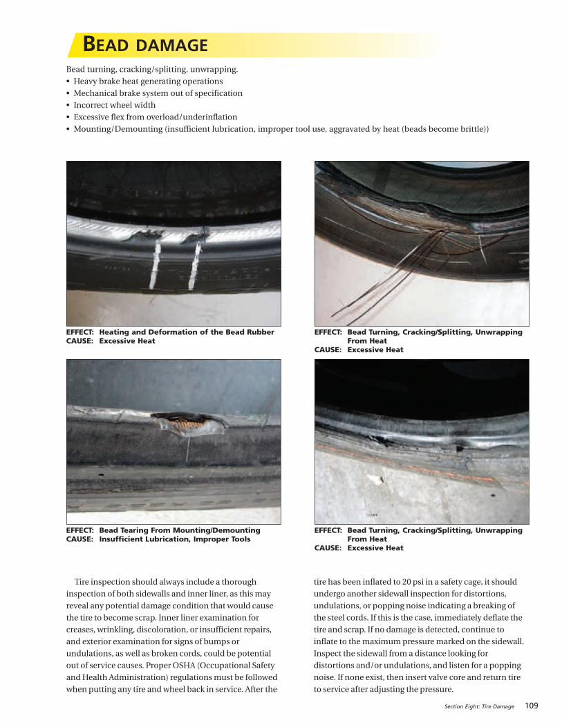
Section Eight: Tire Damage 109
BEAD DAMAGE
EFFECT: Heating and Deformation of the Bead RubberCAUSE: Excessive Heat
EFFECT: Bead Tearing From Mounting/DemountingCAUSE: Insufficient Lubrication, Improper Tools
EFFECT: Bead Turning, Cracking/Splitting, UnwrappingFrom Heat
CAUSE: Excessive Heat
EFFECT: Bead Turning, Cracking/Splitting, UnwrappingFrom Heat
CAUSE: Excessive Heat
Bead turning, cracking/splitting, unwrapping.
• Heavy brake heat generating operations
• Mechanical brake system out of specification
• Incorrect wheel width
• Excessive flex from overload/underinflation
• Mounting/Demounting (insufficient lubrication, improper tool use, aggravated by heat (beads become brittle))
Tire inspection should always include a thorough
inspection of both sidewalls and inner liner, as thismay
reveal any potential damage condition that would cause
the tire to become scrap. Inner liner examination for
creases, wrinkling, discoloration, or insufficient repairs,
and exterior examination for signs of bumps or
undulations, as well as broken cords, could be potential
out of service causes. Proper OSHA (Occupational Safety
andHealth Administration) regulationsmust be followed
when putting any tire andwheel back in service. After the
tire has been inflated to 20 psi in a safety cage, it should
undergo another sidewall inspection for distortions,
undulations, or popping noise indicating a breaking of
the steel cords. If this is the case, immediately deflate the
tire and scrap. If no damage is detected, continue to
inflate to themaximumpressuremarked on the sidewall.
Inspect the sidewall from a distance looking for
distortions and/or undulations, and listen for a popping
noise. If none exist, then insert valve core and return tire
to service after adjusting the pressure.
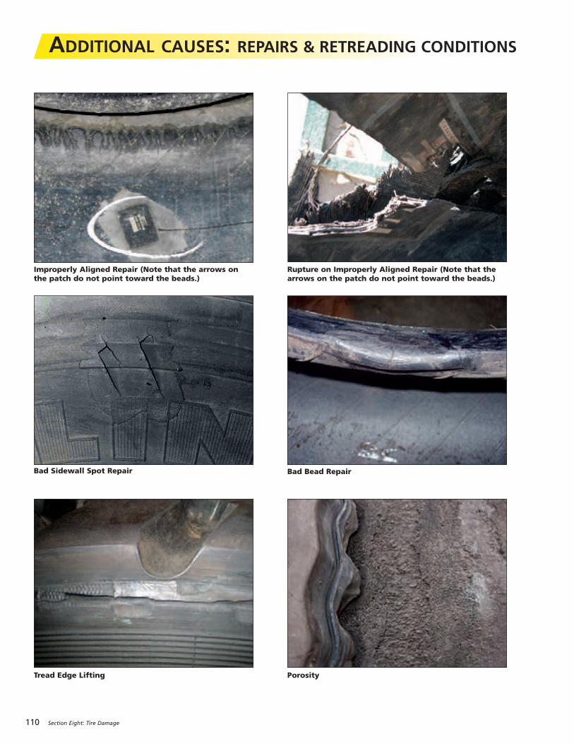
110 Section Eight: Tire Damage
ADDITIONAL CAUSES: REPAIRS & RETREADING CONDITIONS
Improperly Aligned Repair (Note that the arrows onthe patch do not point toward the beads.)
Bad Sidewall Spot Repair
Tread Edge Lifting
Rupture on Improperly Aligned Repair (Note that thearrows on the patch do not point toward the beads.)
Porosity
Bad Bead Repair
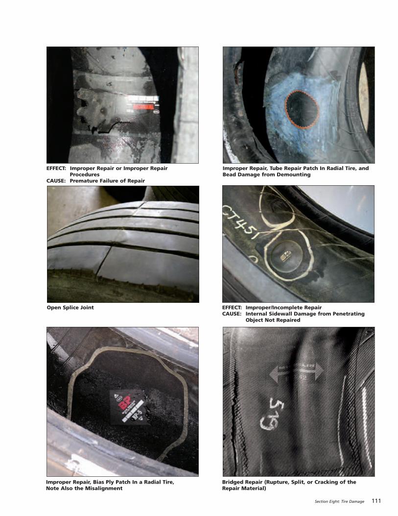
Section Eight: Tire Damage 111
Open Splice Joint
Improper Repair, Tube Repair Patch In Radial Tire, andBead Damage from Demounting
Bridged Repair (Rupture, Split, or Cracking of theRepair Material)
Improper Repair, Bias Ply Patch In a Radial Tire, Note Also the Misalignment
EFFECT: Improper/Incomplete RepairCAUSE: Internal Sidewall Damage from Penetrating
Object Not Repaired
EFFECT: Improper Repair or Improper RepairProcedures
CAUSE: Premature Failure of Repair

112 Section Eight: Tire Damage
MFR. DOT TREAD RETREAD INFO CONDITIONS
SIZE TYPE MFR. PL WK YR DEPTH # WHO WK/YR EFFECT CAUSE COMMENT
275/80R22.5 XDA-HT MX B6 29 92 07/32 2 RRL 148 RF SP
275/80R22.5 XT-1 MX B6 4 98 05/32 0 IM SI
275/80R22.5 XT-1 MX B6 1 98 08/32 0 PS CD
275/80R22.5 XDN2 MX M5 35 95 07/32 1 RRL 18 ZP IR
EXAMPLEFleet:__________________________________________________ Date:_________________
MFR. DOT TREAD RETREAD INFO CONDITIONS
SIZE TYPE MFR. PL WK YR DEPTH # WHO WK/YR EFFECT CAUSE COMMENT
275/80R22.5 XDHT MX B6 29 92 07/32 2 RRL 148 FF SW
Fleet:__________________________________________________ Date:_________________
Tire Condition Index: Effect and Cause
SCRAP INSPECTION FORM
Reference: Code Key 21, Vehicle Maintenance Reporting Standards (VMRS 2000™)

113
SECTION NINE
Appendix
GENERAL INFORMATION . . . . . . . . . . . . . . . . . . . . . . . . . . 114-117
ALIGNMENT – FIELD METHOD (ATTACC) . . . . . . . . . . . . . 118-119
RUNOUT TOLERANCES, FRONT END ALIGNMENT, AXLE ALIGNMENT . . . . . . . . . . . . . . . . . . . . . . . . . . . . 120-121
CASING MANAGEMENT . . . . . . . . . . . . . . . . . . . . . . . . . . . 122-123
COLD CLIMATE PRESSURE CORRECTION DATA . . . . . . . . . . . . 123
COST ANALYSIS . . . . . . . . . . . . . . . . . . . . . . . . . . . . . . . . . . . . . 124
FUEL SAVINGS . . . . . . . . . . . . . . . . . . . . . . . . . . . . . . . . . . . . . . 125
WHEEL TYPE . . . . . . . . . . . . . . . . . . . . . . . . . . . . . . . . . . . . 126-128
TORQUE SPECIFICATIONS. . . . . . . . . . . . . . . . . . . . . . . . . . 128-129
MOUNTING PROCEDURES FOR 16.00R20 AND 24R21. . . . . . . 130
TIRE REVOLUTIONS PER MILE CALCULATION . . . . . . . . . . . . . 131
OUT-OF-SERVICE CONDITIONS. . . . . . . . . . . . . . . . . . . . . . 132-133
RUNOUT AND VIBRATION DIAGNOSIS . . . . . . . . . . . . . . . 134-135
SERVICING MULTI-PIECE & SINGLE PIECE RIM/WHEELS (OSHA 1910.177) . . . . . . . . . . . . . . . . . . 136-138
REGROOVING . . . . . . . . . . . . . . . . . . . . . . . . . . . . . . . . . . . 139-140
TRANSIT APPLICATIONS IN URBAN CONDITIONS . . . . . . . . . . 141
THE CRITICAL 6 - FACTORS THAT COST FLEETS MONEY . . . . . 142
PUBLICATIONS, VIDEOS, AND WEBSITES . . . . . . . . . . . . . 143-144
INDEX . . . . . . . . . . . . . . . . . . . . . . . . . . . . . . . . . . . . . . . . . 145-147
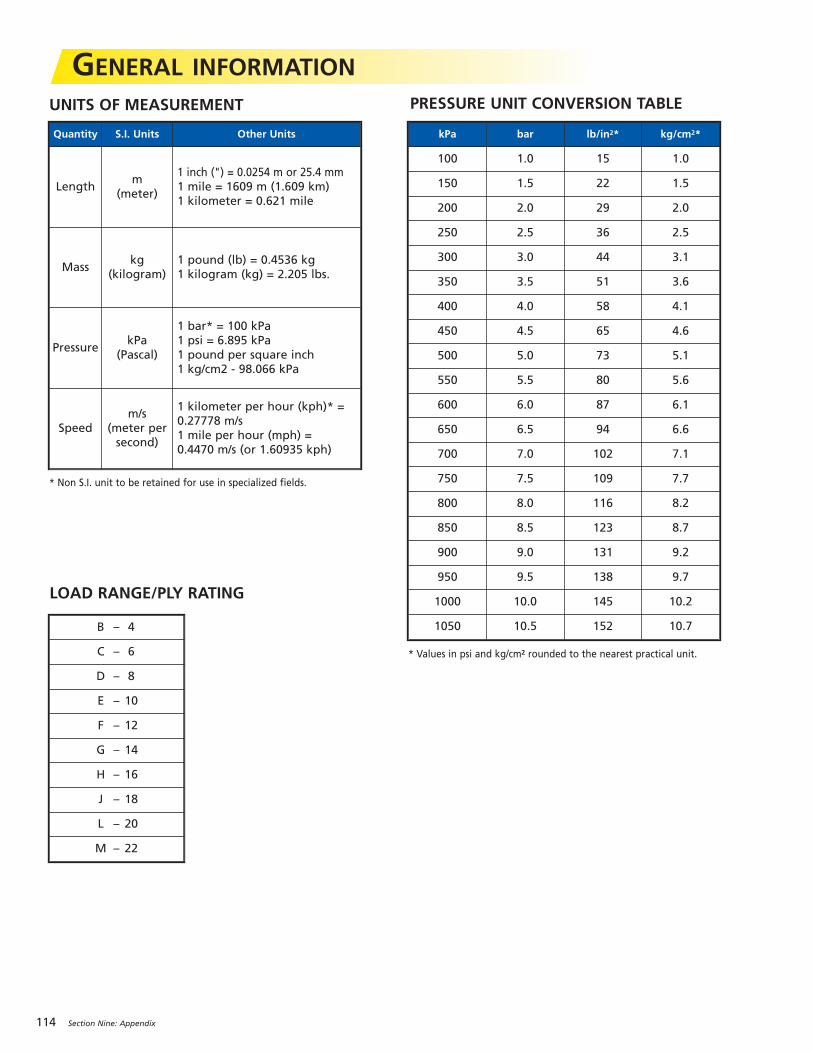
114 Section Nine: Appendix
GENERAL INFORMATIONUNITS OF MEASUREMENT
LOAD RANGE/PLY RATING
PRESSURE UNIT CONVERSION TABLE
* Non S.I. unit to be retained for use in specialized fields.
* Values in psi and kg/cm2 rounded to the nearest practical unit.
kPa bar lb/in2* kg/cm2*
100 1.0 15 1.0
150 1.5 22 1.5
200 2.0 29 2.0
250 2.5 36 2.5
300 3.0 44 3.1
350 3.5 51 3.6
400 4.0 58 4.1
450 4.5 65 4.6
500 5.0 73 5.1
550 5.5 80 5.6
600 6.0 87 6.1
650 6.5 94 6.6
700 7.0 102 7.1
750 7.5 109 7.7
800 8.0 116 8.2
850 8.5 123 8.7
900 9.0 131 9.2
950 9.5 138 9.7
1000 10.0 145 10.2
1050 10.5 152 10.7
Quantity S.I. Units Other Units
Lengthm
(meter)
1 inch (") = 0.0254 m or 25.4 mm1 mile = 1609 m (1.609 km)1 kilometer = 0.621 mile
Masskg
(kilogram)1 pound (lb) = 0.4536 kg1 kilogram (kg) = 2.205 lbs.
PressurekPa
(Pascal)
1 bar* = 100 kPa1 psi = 6.895 kPa1 pound per square inch1 kg/cm2 - 98.066 kPa
Speedm/s
(meter persecond)
1 kilometer per hour (kph)* = 0.27778 m/s1 mile per hour (mph) = 0.4470 m/s (or 1.60935 kph)
B – 4
C – 6
D – 8
E – 10
F – 12
G – 14
H – 16
J – 18
L – 20
M – 22
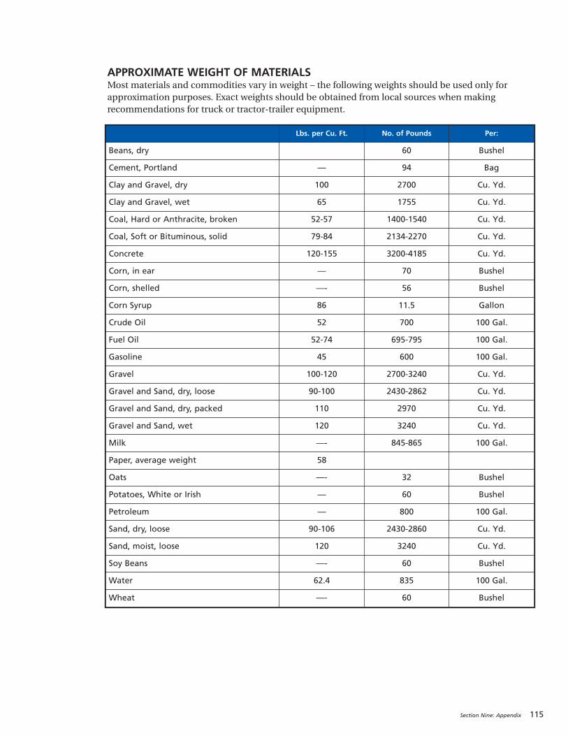
Section Nine: Appendix 115
APPROXIMATE WEIGHT OF MATERIALSMost materials and commodities vary in weight – the following weights should be used only forapproximation purposes. Exact weights should be obtained from local sources when makingrecommendations for truck or tractor-trailer equipment.
Lbs. per Cu. Ft. No. of Pounds Per:
Beans, dry 60 Bushel
Cement, Portland — 94 Bag
Clay and Gravel, dry 100 2700 Cu. Yd.
Clay and Gravel, wet 65 1755 Cu. Yd.
Coal, Hard or Anthracite, broken 52-57 1400-1540 Cu. Yd.
Coal, Soft or Bituminous, solid 79-84 2134-2270 Cu. Yd.
Concrete 120-155 3200-4185 Cu. Yd.
Corn, in ear — 70 Bushel
Corn, shelled —- 56 Bushel
Corn Syrup 86 11.5 Gallon
Crude Oil 52 700 100 Gal.
Fuel Oil 52-74 695-795 100 Gal.
Gasoline 45 600 100 Gal.
Gravel 100-120 2700-3240 Cu. Yd.
Gravel and Sand, dry, loose 90-100 2430-2862 Cu. Yd.
Gravel and Sand, dry, packed 110 2970 Cu. Yd.
Gravel and Sand, wet 120 3240 Cu. Yd.
Milk —- 845-865 100 Gal.
Paper, average weight 58
Oats —- 32 Bushel
Potatoes, White or Irish — 60 Bushel
Petroleum — 800 100 Gal.
Sand, dry, loose 90-106 2430-2860 Cu. Yd.
Sand, moist, loose 120 3240 Cu. Yd.
Soy Beans —- 60 Bushel
Water 62.4 835 100 Gal.
Wheat —- 60 Bushel

116 Section Nine: Appendix
LOAD INDEXThe ISO* LOAD INDEX is a numerical code associated with the maximum load a tire can carry at the speed indicated by its SPEED** SYMBOL under service conditions specified by the tire manufacturer. (1 kg = 2.205 lbs.)
Load Index kg lbs.
100 800 1,765
101 825 1,820
102 850 1,875
103 875 1,930
104 900 1,985
105 925 2,040
106 950 2,095
107 975 2,150
108 1,000 2,205
109 1,030 2,270
110 1,060 2,335
111 1,090 2,405
112 1,120 2470
113 1,150 2,535
114 1,180 2,600
115 1,215 2,680
116 1,250 2,755
117 1,285 2,835
118 1,320 2,910
119 1,360 3,000
120 1,400 3,085
121 1,450 3,195
122 1,500 3,305
123 1,550 3,415
124 1,600 3,525
125 1,650 3,640
126 1,700 3,750
127 1,750 3,860
128 1,800 3,970
129 1,850 4,080
130 1,900 4,190
131 1,950 4,300
132 2,000 4,410
133 2,060 4,540
Load Index kg lbs.
134 2,120 4,675
135 2,180 4,805
136 2,240 4,940
137 2,300 5,070
138 2,360 5,205
139 2,430 5,355
140 2,500 5,510
141 2,575 5,675
142 2,650 5,840
143 2,725 6,005
144 2,800 6,175
145 2,900 6,395
146 3,000 6,610
147 3,075 6,780
148 3,150 6,940
149 3,250 7,160
150 3,350 7,390
151 3,450 7,610
152 3,550 7,830
153 3,650 8,050
154 3,750 8,270
155 3,875 8,540
156 4,000 8,820
157 4,125 9,090
158 4,250 9,370
159 4,375 9,650
160 4,500 9,920
161 4,625 10,200
162 4,750 10,500
163 4,875 10,700
164 5,000 11,000
165 5,150 11,400
166 5,300 11,700
167 5,450 12,000
Load Index kg lbs.
168 5,600 12,300
169 5,800 12,800
170 6,000 13,200
171 6,150 13,600
172 6,300 13,900
173 6,500 14,300
174 6,700 14,800
175 6,900 15,200
176 7,100 15,700
177 7,300 16,100
178 7,500 16,500
179 7,750 17,100
180 8,000 17,600
181 8,250 18,195
182 8,500 18,745
183 8,750 19,295
184 9,000 19,845
185 9,250 20,400
186 9,500 21,000
187 9,750 21,500
188 10,000 22,050
189 10,300 22,720
190 10,600 23,400
191 10,900 24,040
192 11,200 24,700
193 11,500 25,360
194 11,800 26,020
195 12,150 26,800
196 12,500 27,565
197 12,850 28,355
198 13,200 29,110
199 13,600 30,000
200 14,000 30,870
201 14,500 31,980
* International Standardization Organization** Exceeding the legal speed limit is neither recommended nor endorsed.
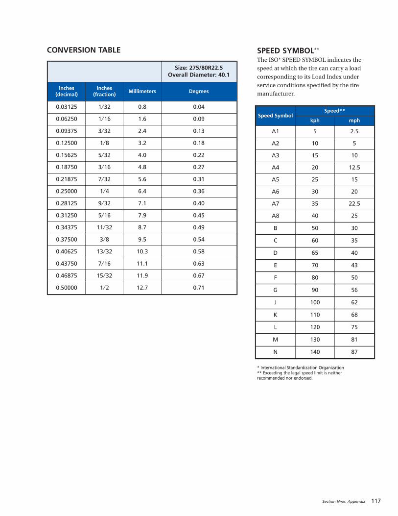
Section Nine: Appendix 117
Size: 275/80R22.5Overall Diameter: 40.1
Inches (decimal)
Inches (fraction)
Millimeters Degrees
0.03125 1 ⁄ 32 0.8 0.04
0.06250 1 ⁄ 16 1.6 0.09
0.09375 3 ⁄ 32 2.4 0.13
0.12500 1 ⁄ 8 3.2 0.18
0.15625 5 ⁄ 32 4.0 0.22
0.18750 3 ⁄ 16 4.8 0.27
0.21875 7 ⁄ 32 5.6 0.31
0.25000 1 ⁄ 4 6.4 0.36
0.28125 9 ⁄ 32 7.1 0.40
0.31250 5 ⁄ 16 7.9 0.45
0.34375 11 ⁄ 32 8.7 0.49
0.37500 3 ⁄ 8 9.5 0.54
0.40625 13 ⁄ 32 10.3 0.58
0.43750 7 ⁄ 16 11.1 0.63
0.46875 15 ⁄ 32 11.9 0.67
0.50000 1 ⁄ 2 12.7 0.71
Speed SymbolSpeed**
kph mph
A1 5 2.5
A2 10 5
A3 15 10
A4 20 12.5
A5 25 15
A6 30 20
A7 35 22.5
A8 40 25
B 50 30
C 60 35
D 65 40
E 70 43
F 80 50
G 90 56
J 100 62
K 110 68
L 120 75
M 130 81
N 140 87
SPEED SYMBOL**The ISO* SPEED SYMBOL indicates the
speed at which the tire can carry a load
corresponding to its Load Index under
service conditions specified by the tire
manufacturer.
* International Standardization Organization** Exceeding the legal speed limit is neither recommended nor endorsed.
CONVERSION TABLE

118 Section Nine: Appendix
ATTACC PLUS SYSTEM (Axle, Thrust, Toe,Ackerman, Camber, Caster Parts, Labor, User Saves)• Simple vehicle measurement system
• Quick, low cost, yet effective method
• Determine if poor alignment conditions exist
• Minimum tools required
Refer to MICHELIN® Video, MICHELIN® Truck TiresTechnical Videos DVD (MWV43100) for reference aboutATTACC Plus.
SET-UP INSTRUCTION PROCEDURESTOOLS: • Chalk Line (no chalk) • Metric Tape Measure
• 2 Cans of White Spray Paint • 1 pair of Jack Stands
• 2 Large Heavy Duty Plastic Bags • Toe-Scribe
• Vehicle Jack (10 Tons) • Flashlight
• Line Level and Wheel Chocks • 1 T-45A Tire Iron
SURFACE: Inspection site should be fairly level; use LineLevel if necessary to determine slope.
STEER/DRIVE TIRES: Note tread design, DOT, treaddepth, psi, tire conditions and mileage, and all normal
pertinent vehicle information.
VEHICLE POSITIONING1. Drive vehicle straight into inspection site, at least 3 fullvehicle lengths, to ensure it’s straight into site. Driving
into and backing out of the work area several times will
ensure the vehicle's suspension components are relaxed
to achieve proper measurements.
2. Allow vehicle to roll to a stop, shut-off the engine, andlet up on the clutch.
3. Let vehicle fully stop by transmission, no brakes.4. Engage tractor parking brakes and take out of gear;place wheel chocks on the drive tires.
MEASUREMENTSRecord all measurements.
Front of Vehicle1.Measure steering axle skew from the front of the outsideU-bolt to the zerk fitting (or bolt) on the front spring pin
perch. Tolerance is ± 3 ⁄ 16" or 5 mm side to side.
2.Measure for straight ahead steering from the innerwheel flange to edge of the leaf spring (if newer style
tapered frame) or frame on both sides of the vehicle to
ensure the steer tires are straight ahead (tolerance is
1 ⁄ 32" or 1 mm side to side). Adjust the steering wheels as
necessary to come within tolerance. Mark the steering
wheel column with a crayon for future reference.
3. Measure for steering axle offset from the frame rail tothe vertical center line on the tire on both sides.
Tolerance is ± 3 ⁄16" or 5 mm from centerline of vehicle.
4. Steering Stops: Ensure they are in place on left and
right sides, and measure length. Stops control the angle
of the turn and may be a consideration if abnormal steer
tire wear is present.
5. Check front end components and toe by jacking upfront end after placing wheel chocks on the rear tires.
Place the floor jack under the axle for support, use the
T-45A tire iron by inserting into the wheel assembly at
the 6 o’clock position and place your other hand at the
12 o’clock position. With a rocking type motion try to
move the tire assembly up with the lower bar and out
towards you with your left hand. If play is felt, it is
probably the result of loose wheel bearings or worn
kingpin bushings. If you observe the brake chamber
moving, it can be isolated to the kingpin bushing. If it
does not move, it is likely the wheel bearings.
With your hands placed at the 3 o’clock and at the
9 o’clock positions on the tire, try to move the tire in a
rapid “left turn – right turn” type of motion. Feel and
listen for any play. Play in this area would indicate either
loose or worn tie rod ends, steering arms, drag link ends,
or steering box play. Any play in this area should be
further inspected to ensure it is within the vehicle
and/or part manufacturer’s specifications.
Two additional parts that can cause tire wear need to
be checked. First, see if the brake drum has a balance
weight and second, look for wear on the spring shackle
assembly. This check is more difficult to make, and there
are various ways to inspect for this wear. Consult the part
manufacture for the proper way to inspect.
On a dry tire, with a can of spray paint, marker, or
chalk (dusting with any coating material suitable for
marking a section of tread), “highlight” a section of the
tread area around the tire. With a sharp pointed scribe,
mark a thin line in the highlighted area while rotating the
tire. (Note: At this point observe the amount of radial and
lateral runout by referencing this line to the rotating tire.
Any runout greater than 3 ⁄ 32nd inch should be further
investigated for improper tire bead seating, improper tire
and wheel runout and/or improper wheel torque
procedure during installation.)
Repeat this process on the other steer tire. Check for
steer ahead by referencing the mark on the steering
wheel column (or measure as in Paragraph 2 above), and
lower the vehicle on the folded plastic bags. Plastic
should be folded to just larger than the tire footprint so
that no part of the steer tires will make contact with the
ground. Prior to measuring, you should “joust” the
vehicle by standing on the step and shaking the unit with
your body weight. This will further relax the front
suspension, giving you a correct toe reading. Once the
steer tires are down, measure from side to side between
the scribed lines, first rear, then front, with a tape
measure or a fine lined toe gauge to determine relative
ALIGNMENT - FIELD METHOD
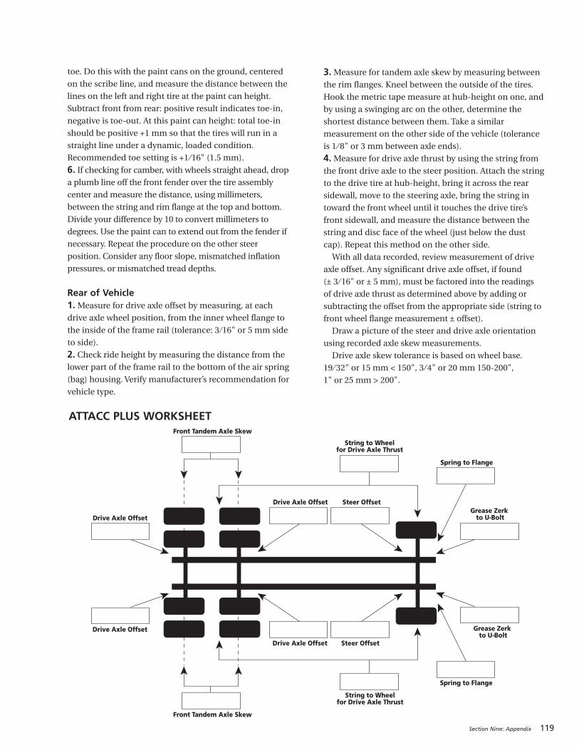
Section Nine: Appendix 119
Spring to Flange
Spring to Flange
Steer Offset
Steer Offset
String to Wheelfor Drive Axle Thrust
String to Wheelfor Drive Axle Thrust
Front Tandem Axle Skew
Front Tandem Axle Skew
Drive Axle Offset
Drive Axle Offset
Grease Zerk to U-Bolt
Grease Zerk to U-BoltDrive Axle Offset
Drive Axle Offset
ATTACC PLUS WORKSHEET
toe. Do this with the paint cans on the ground, centered
on the scribe line, and measure the distance between the
lines on the left and right tire at the paint can height.
Subtract front from rear: positive result indicates toe-in,
negative is toe-out. At this paint can height: total toe-in
should be positive +1 mm so that the tires will run in a
straight line under a dynamic, loaded condition.
Recommended toe setting is +1 ⁄16" (1.5 mm).
6. If checking for camber, with wheels straight ahead, dropa plumb line off the front fender over the tire assembly
center and measure the distance, using millimeters,
between the string and rim flange at the top and bottom.
Divide your difference by 10 to convert millimeters to
degrees. Use the paint can to extend out from the fender if
necessary. Repeat the procedure on the other steer
position. Consider any floor slope, mismatched inflation
pressures, or mismatched tread depths.
Rear of Vehicle1.Measure for drive axle offset by measuring, at eachdrive axle wheel position, from the inner wheel flange to
the inside of the frame rail (tolerance: 3 ⁄16" or 5 mm side
to side).
2. Check ride height by measuring the distance from thelower part of the frame rail to the bottom of the air spring
(bag) housing. Verify manufacturer’s recommendation for
vehicle type.
3.Measure for tandem axle skew by measuring betweenthe rim flanges. Kneel between the outside of the tires.
Hook the metric tape measure at hub-height on one, and
by using a swinging arc on the other, determine the
shortest distance between them. Take a similar
measurement on the other side of the vehicle (tolerance
is 1 ⁄ 8" or 3 mm between axle ends).
4.Measure for drive axle thrust by using the string fromthe front drive axle to the steer position. Attach the string
to the drive tire at hub-height, bring it across the rear
sidewall, move to the steering axle, bring the string in
toward the front wheel until it touches the drive tire’s
front sidewall, and measure the distance between the
string and disc face of the wheel (just below the dust
cap). Repeat this method on the other side.
With all data recorded, review measurement of drive
axle offset. Any significant drive axle offset, if found
(± 3 ⁄ 16" or ± 5 mm), must be factored into the readings
of drive axle thrust as determined above by adding or
subtracting the offset from the appropriate side (string to
front wheel flange measurement ± offset).
Draw a picture of the steer and drive axle orientation
using recorded axle skew measurements.
Drive axle skew tolerance is based on wheel base.
19 ⁄ 32" or 15 mm < 150", 3 ⁄ 4" or 20 mm 150-200",
1" or 25 mm > 200".
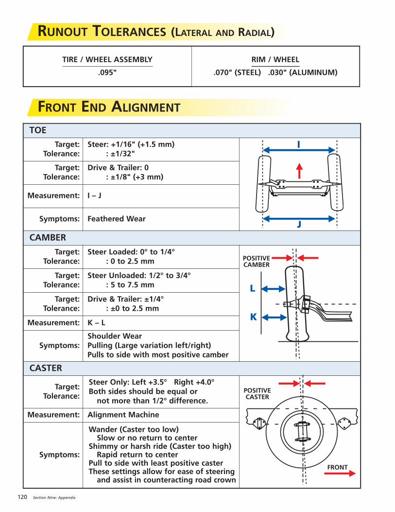
120 Section Nine: Appendix
RUNOUT TOLERANCES (LATERAL AND RADIAL)
TIRE / WHEEL ASSEMBLY
.095"
RIM / WHEEL
.070" (STEEL) .030" (ALUMINUM)
FRONT END ALIGNMENTTOE
Target:Tolerance:
Steer: +1/16" (+1.5 mm): ±1/32"
J
I
Target:Tolerance:
Drive & Trailer: 0 : ±1/8" (+3 mm)
Measurement: I – J
Symptoms: Feathered Wear
CAMBER
Target:Tolerance:
Steer Loaded: 0° to 1/4°: 0 to 2.5 mm
L
K
POSITIVECAMBER
Target:Tolerance:
Steer Unloaded: 1/2° to 3/4°: 5 to 7.5 mm
Target:Tolerance:
Drive & Trailer: ±1/4°: ±0 to 2.5 mm
Measurement: K – L
Symptoms:Shoulder WearPulling (Large variation left/right)Pulls to side with most positive camber
CASTER
Target:Tolerance:
Steer Only: Left +3.5° Right +4.0°Both sides should be equal ornot more than 1/2° difference.
POSITIVECASTER
FRONT
Measurement: Alignment Machine
Symptoms:
Wander (Caster too low)Slow or no return to center
Shimmy or harsh ride (Caster too high)Rapid return to center
Pull to side with least positive casterThese settings allow for ease of steeringand assist in counteracting road crown
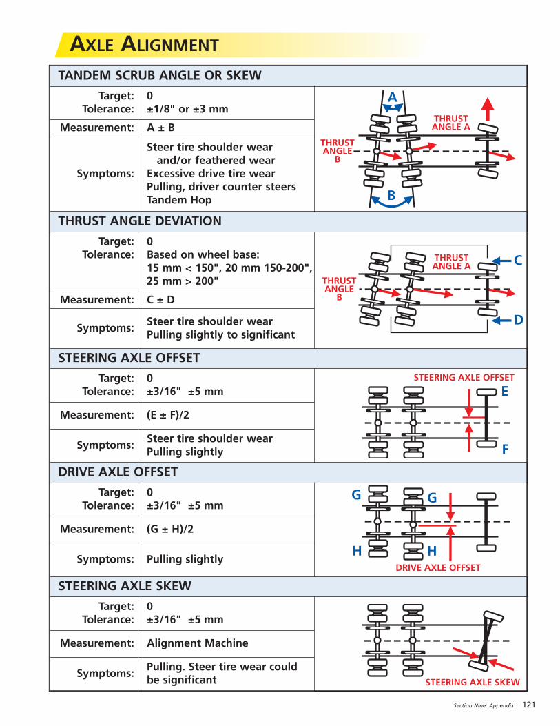
Section Nine: Appendix 121
AXLE ALIGNMENTTANDEM SCRUB ANGLE OR SKEW
Target:Tolerance:
0±1/8" or ±3 mm
THRUSTANGLE A
THRUSTANGLE
B
A
B
Measurement: A ± B
Symptoms:
Steer tire shoulder wearand/or feathered wear
Excessive drive tire wearPulling, driver counter steersTandem Hop
THRUST ANGLE DEVIATION
Target:Tolerance:
0Based on wheel base:15 mm < 150", 20 mm 150-200",25 mm > 200"
THRUSTANGLE A
THRUSTANGLE
B
C
D
Measurement: C ± D
Symptoms:Steer tire shoulder wearPulling slightly to significant
STEERING AXLE OFFSET
Target:Tolerance:
0±3/16" ±5 mm
STEERING AXLE OFFSET
E
F
Measurement: (E ± F)/2
Symptoms:Steer tire shoulder wearPulling slightly
DRIVE AXLE OFFSET
Target:Tolerance:
0±3/16" ±5 mm
DRIVE AXLE OFFSET
G G
H H
Measurement: (G ± H)/2
Symptoms: Pulling slightly
STEERING AXLE SKEW
Target:Tolerance:
0±3/16" ±5 mm
STEERING AXLE SKEW
Measurement: Alignment Machine
Symptoms:Pulling. Steer tire wear couldbe significant
122 Section Nine: Appendix
TIRE MANAGEMENTThe goal of every truck operator is to achieve the
lowest possible operating cost, taking advantage of the
performance built into each high tech MICHELIN® radial
truck tire. Tire maintenance, proper inflation pressures,
repairs, vehicle alignment, and retreading, are all keys to
help ensure maximized performance and extended
casing life.
Over the past 10 years, a number of operational
and product changes have occurred that should be
considered when establishing tire use patterns. The
single most important point of any program is “Know
Your Customer.”
TIRE CHANGES1. New Tires: Today’s wider treads and deeper treaddepths provide more original tread miles. The tire arrives
at the retreader with more time in service, more miles,
and exposure to road conditions.
2. Retread Changes: Wider treads, new tread designs,and new compounds have increased retread mileages.
VEHICLE CHANGES1. Longer Trailers: There has been a move from 40' to 48'and 53' trailers as standards in the contract and private
carriage business.
2. Wider Trailers:Widths have increased from 96" to 102".The combination of longer and wider trailers increases
the frequency of the duals being curbed.
3. Setback Front Axles: Moving the steer axle backincreases stress on steer tires and load efficiency by
allowing better load distribution. The result is higher
average axle loads.
4. Electronic Engines: Better engine control and moreefficient operation improve the ability of the vehicle to
maintain higher cruise speeds.*
OPERATIONAL CHANGES1. Speed limit: The national limit has continuallyincreased in the past decade.*
2. GVW (Gross Vehicle Weight):With the SurfaceTransportation Assistance Act of 1983, the weight limits
went from 73,280 lbs. to 80,000 lbs. With setback axles,
you can realistically load to 80,000 lbs.
3. Greater Vehicle Utilization:More loaded miles meanproductivity gains.
All of these changes lead to the casing arriving at the
retread stage with a higher level of fatigue. To utilize
these casings to their maximum, casing management
should be employed in the selection of the retread.
CASING MANAGEMENT IN THE PASTHighway fleets typically employ the casing management
pattern below:Position of
Tire First Position of First SubsequentUsed On Retread Use Retread UseSteer � Drive or Trailer � Drive or Trailer
Drive � Drive � Drive or Trailer
Trailer � Trailer � Trailer
CASING FATIGUEIn terms of casing fatigue, the severity of use is as follows:
• Drive Axle – most fatigue. New drive tires (lug type)often can accumulate twice as many miles (or more)
before retreading than new steer or trailer tires can. The
same is true for drive axle lug type retreads. The tires
also run hotter (deeper tread) and with more torque.
• Steer Axle – moderate fatigue. Steer axle tires operateat higher average loads than drive or trailer tires (20 to
40% higher). However, they wear out sooner than drive
tires and are moved to lighter axles in the retread stage.
• Trailer Axle – least fatigue. The trailer tire starts lifewith a shallow (cooler) tread and is usually retreaded
with a shallow retread. Annual miles are low. The trailer
tire casing usually sees more curb abuse, neglect, and
old age problems.
Thus, the practice of retreading new drive axle tires back
to the drive axle puts the most highly fatigued casing
back onto the most highly stressed wheel position.
CASING MANAGEMENT FOR THE FUTUREThe following guidelines are recommended in sorting
casings for their next tread life. Such a sorting would
allow the fleet and retreader to make better decisions
regarding the handling and utilization of casings
recovered from 6x4, 4x2, and trailer applications. Casings
that are judged to be more “highly fatigued” should be
retreaded in one of two ways:
1. A low rolling resistance/low heat retread rubber inrib and drive (consult your retread supplier).
2. A shallow retread (no more than 15 ⁄ 32").These retreads will reduce the operating temperature
in the crown of the tire.
Determining which tires are “highly fatigued” requires
a working knowledge of each fleet’s individual operation.
The following guidelines can be used:
1. Two or more repairs on the casing.2. Heavy sidewall abrasion.
CASING MANAGEMENT
* Exceeding the legal speed limit is neither recommended nor endorsed.
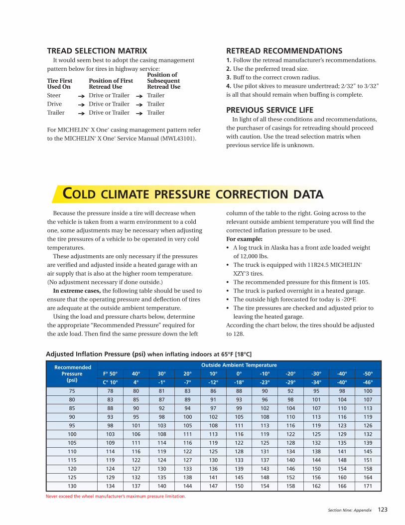
Section Nine: Appendix 123
TREAD SELECTION MATRIXIt would seem best to adopt the casing management
pattern below for tires in highway service:Position of
Tire First Position of First SubsequentUsed On Retread Use Retread UseSteer � Drive or Trailer � Trailer
Drive � Drive or Trailer � Trailer
Trailer � Drive or Trailer � Trailer
For MICHELIN® X One® casing management pattern refer
to the MICHELIN® X One® Service Manual (MWL43101).
RETREAD RECOMMENDATIONS1. Follow the retread manufacturer’s recommendations.2. Use the preferred tread size.3. Buff to the correct crown radius.4. Use pilot skives to measure undertread; 2 ⁄ 32" to 3 ⁄ 32"is all that should remain when buffing is complete.
PREVIOUS SERVICE LIFEIn light of all these conditions and recommendations,
the purchaser of casings for retreading should proceed
with caution. Use the tread selection matrix when
previous service life is unknown.
COLD CLIMATE PRESSURE CORRECTION DATABecause the pressure inside a tire will decrease when
the vehicle is taken from a warm environment to a cold
one, some adjustments may be necessary when adjusting
the tire pressures of a vehicle to be operated in very cold
temperatures.
These adjustments are only necessary if the pressures
are verified and adjusted inside a heated garage with an
air supply that is also at the higher room temperature.
(No adjustment necessary if done outside.)
In extreme cases, the following table should be used toensure that the operating pressure and deflection of tires
are adequate at the outside ambient temperature.
Using the load and pressure charts below, determine
the appropriate “Recommended Pressure” required for
the axle load. Then find the same pressure down the left
column of the table to the right. Going across to the
relevant outside ambient temperature you will find the
corrected inflation pressure to be used.
For example:• A log truck in Alaska has a front axle loaded weight
of 12,000 lbs.
• The truck is equipped with 11R24.5 MICHELIN®
XZY®3 tires.
• The recommended pressure for this fitment is 105.
• The truck is parked overnight in a heated garage.
• The outside high forecasted for today is -20ºF.
• The tire pressures are checked and adjusted prior to
leaving the heated garage.
According the chart below, the tires should be adjusted
to 128.
RecommendedPressure(psi)
Outside Ambient Temperature
F° 50° 40° 30° 20° 10° 0° -10° -20° -30° -40° -50°
C° 10° 4° -1° -7° -12° -18° -23° -29° -34° -40° -46°
75 78 80 81 83 86 88 90 92 95 98 100
80 83 85 87 89 91 93 96 98 101 104 107
85 88 90 92 94 97 99 102 104 107 110 113
90 93 95 98 100 102 105 108 110 113 116 119
95 98 101 103 105 108 111 113 116 119 123 126
100 103 106 108 111 113 116 119 122 125 129 132
105 109 111 114 116 119 122 125 128 132 135 139
110 114 116 119 122 125 128 131 134 138 141 145
115 119 122 124 127 130 133 137 140 144 148 151
120 124 127 130 133 136 139 143 146 150 154 158
125 129 132 135 138 141 145 148 152 156 160 164
130 134 137 140 144 147 150 154 158 162 166 171
Adjusted Inflation Pressure (psi) when inflating indoors at 65°F [18°C]
Never exceed the wheel manufacturer’s maximum pressure limitation.
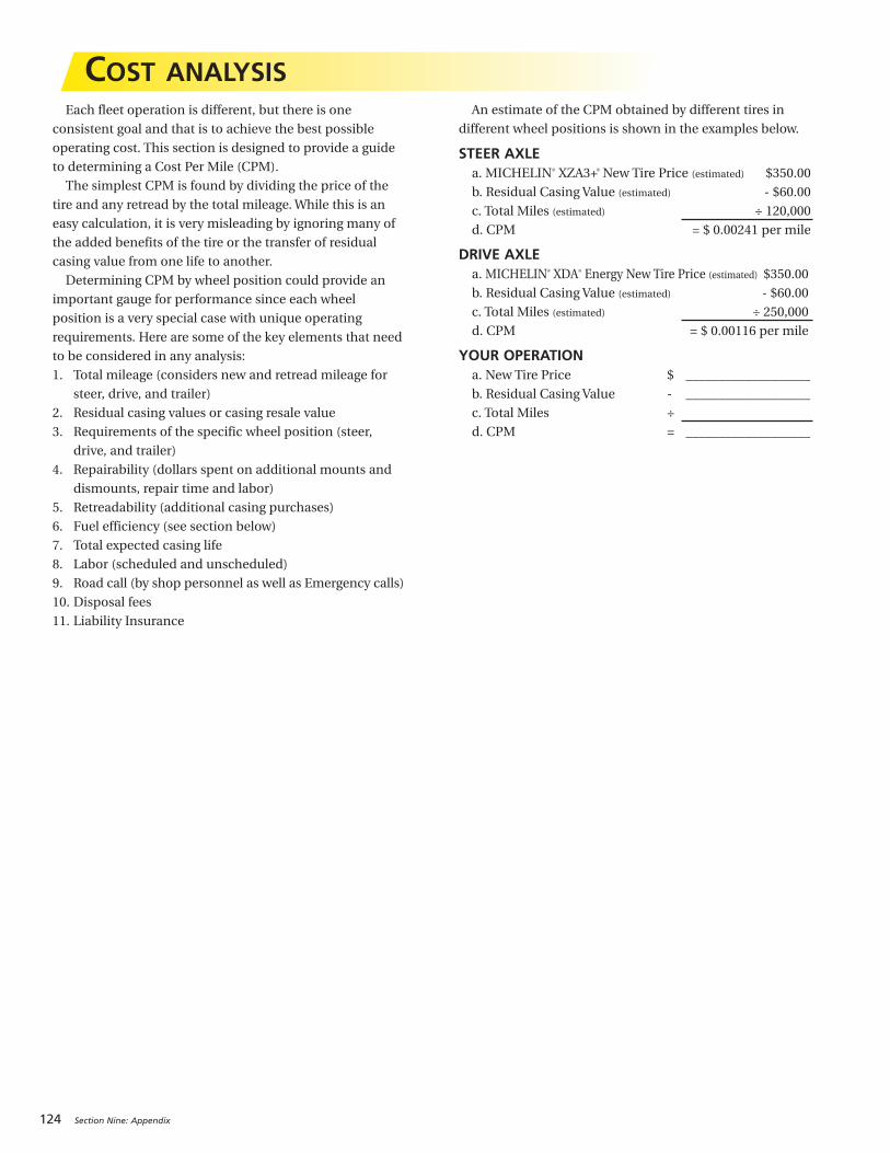
124 Section Nine: Appendix
Each fleet operation is different, but there is one
consistent goal and that is to achieve the best possible
operating cost. This section is designed to provide a guide
to determining a Cost Per Mile (CPM).
The simplest CPM is found by dividing the price of the
tire and any retread by the total mileage. While this is an
easy calculation, it is very misleading by ignoring many of
the added benefits of the tire or the transfer of residual
casing value from one life to another.
Determining CPM by wheel position could provide an
important gauge for performance since each wheel
position is a very special case with unique operating
requirements. Here are some of the key elements that need
to be considered in any analysis:
1. Total mileage (considers new and retread mileage for
steer, drive, and trailer)
2. Residual casing values or casing resale value
3. Requirements of the specific wheel position (steer,
drive, and trailer)
4. Repairability (dollars spent on additional mounts and
dismounts, repair time and labor)
5. Retreadability (additional casing purchases)
6. Fuel efficiency (see section below)
7. Total expected casing life
8. Labor (scheduled and unscheduled)
9. Road call (by shop personnel as well as Emergency calls)
10. Disposal fees
11. Liability Insurance
An estimate of the CPM obtained by different tires in
different wheel positions is shown in the examples below.
STEER AXLEa. MICHELIN® XZA3+® New Tire Price (estimated) $350.00
b. Residual Casing Value (estimated) - $60.00
c. Total Miles (estimated) ÷ 120,000
d. CPM = $ 0.00241 per mile
DRIVE AXLEa. MICHELIN® XDA® Energy New Tire Price (estimated) $350.00
b. Residual Casing Value (estimated) - $60.00
c. Total Miles (estimated) ÷ 250,000
d. CPM = $ 0.00116 per mile
YOUR OPERATIONa. New Tire Price $ ___________________
b. Residual Casing Value - ___________________
c. Total Miles ÷
d. CPM = ___________________
COST ANALYSIS
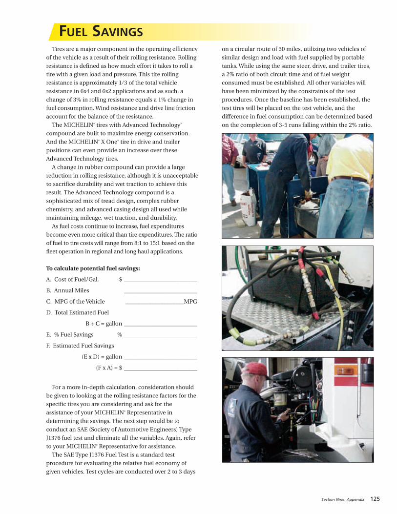
Tires are a major component in the operating efficiency
of the vehicle as a result of their rolling resistance. Rolling
resistance is defined as how much effort it takes to roll a
tire with a given load and pressure. This tire rolling
resistance is approximately 1 ⁄ 3 of the total vehicle
resistance in 6x4 and 6x2 applications and as such, a
change of 3% in rolling resistance equals a 1% change in
fuel consumption. Wind resistance and drive line friction
account for the balance of the resistance.
The MICHELIN® tires with Advanced Technology™
compound are built to maximize energy conservation.
And the MICHELIN® X One® tire in drive and trailer
positions can even provide an increase over these
Advanced Technology tires.
A change in rubber compound can provide a large
reduction in rolling resistance, although it is unacceptable
to sacrifice durability and wet traction to achieve this
result. The Advanced Technology compound is a
sophisticated mix of tread design, complex rubber
chemistry, and advanced casing design all used while
maintaining mileage, wet traction, and durability.
As fuel costs continue to increase, fuel expenditures
become even more critical than tire expenditures. The ratio
of fuel to tire costs will range from 8:1 to 15:1 based on the
fleet operation in regional and long haul applications.
To calculate potential fuel savings:
A. Cost of Fuel/Gal. $ _________________________
B. Annual Miles _________________________
C. MPG of the Vehicle ____________________MPG
D. Total Estimated Fuel
B ÷ C = gallon _________________________
E. % Fuel Savings % _________________________
F. Estimated Fuel Savings
(E x D) = gallon _________________________
(F x A) = $ _________________________
For a more in-depth calculation, consideration should
be given to looking at the rolling resistance factors for the
specific tires you are considering and ask for the
assistance of your MICHELIN® Representative in
determining the savings. The next step would be to
conduct an SAE (Society of Automotive Engineers) Type
J1376 fuel test and eliminate all the variables. Again, refer
to your MICHELIN® Representative for assistance.
The SAE Type J1376 Fuel Test is a standard test
procedure for evaluating the relative fuel economy of
given vehicles. Test cycles are conducted over 2 to 3 days
on a circular route of 30 miles, utilizing two vehicles of
similar design and load with fuel supplied by portable
tanks. While using the same steer, drive, and trailer tires,
a 2% ratio of both circuit time and of fuel weight
consumed must be established. All other variables will
have been minimized by the constraints of the test
procedures. Once the baseline has been established, the
test tires will be placed on the test vehicle, and the
difference in fuel consumption can be determined based
on the completion of 3-5 runs falling within the 2% ratio.
FUEL SAVINGS
Section Nine: Appendix 125

126 Section Nine: Appendix
WHEEL TYPE
Hub Piloted Wheel
Drum
Two-PieceFlange Nut
Stud
Hub
Stud Piloted Wheel
Drum Outer Cap Nut
Inner Cap Nut
Stud
Hub
Hub Piloted Disc WheelsHub Piloted Disc Wheels are designed to center on the hub at the center hole or bore of the wheel. The wheel center hole locates
the wheel on pilots built into the hub. Hub piloted wheels are used with two-piece flange nuts, which contact the disc face around
the bolt hole. Only one nut on each stud is used to fasten single or dual wheels to a vehicle. All stud and nut threads are right hand.
Hub piloted wheels have straight through bolt holes with no ball seat, which provides a visual way of identifying them.
Stud Piloted Disc WheelsStud Piloted Disc Wheels are designed to be centered by the nuts on the studs. The seating action of the ball seat nuts in the
ball seat bolt holes centers the wheels. Stud piloted dual wheels require inner and outer cap nuts. Fasteners with left hand
threads are used on the left side of the vehicle and those with right hand threads are used on the right side of the vehicle.
Refer to MICHELIN® X One® Truck Tire Service Manual (MWL43101) for proper fasteners and procedures for
MICHELIN® X One® tire fitments.
Before servicing any truck wheel, it is essential to know the type of mounting system you will be working on. Three basic types
of mounting systems are commonly used on commercial vehicles in North America. See TMC RP 217B, Attaching Hardware for
Disc Wheels, for more detailed information on fasteners.
Cast Spoke WheelsCast Spoke Wheels consist of a metal casting that
includes the hub with spokes, either 3, 5, or 6.
Demountable rims are attached to this axle component
with clamps. Each cast spoke wheel requires specific
clamps designed for that wheel. The cast spoke wheel
with brake drum and clamps for rear axles requires a
spacer band to hold the two rims apart and provides for
proper dual spacing. Proper torque is 210-260 lb/ft.5 Spoke
Cast Spoke Wheel With BrakeDrum and Clamps for Rear Axles
5 SpokeCast Spoke Wheel With Clamps,
Without Brake Drum for Front Axles
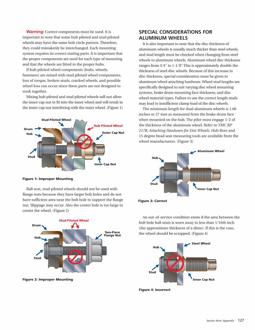
Section Nine: Appendix 127
Warning: Correct components must be used. It isimportant to note that some hub piloted and stud piloted
wheels may have the same bolt circle pattern. Therefore,
they could mistakenly be interchanged. Each mounting
system requires its correct mating parts. It is important that
the proper components are used for each type of mounting
and that the wheels are fitted to the proper hubs.
If hub piloted wheel components (hubs, wheels,
fasteners) are mixed with stud piloted wheel components,
loss of torque, broken studs, cracked wheels, and possible
wheel loss can occur since these parts are not designed to
work together.
Mixing hub piloted and stud piloted wheels will not allow
the inner cap nut to fit into the inner wheel and will result in
the inner cap nut interfering with the outer wheel. (Figure 1)
Ball seat, stud piloted wheels should not be used with
flange nuts because they have larger bolt holes and do not
have sufficient area near the bolt hole to support the flange
nut. Slippage may occur. Also the center hole is too large to
center the wheel. (Figure 2)
SPECIAL CONSIDERATIONS FOR ALUMINUM WHEELSIt is also important to note that the disc thickness of
aluminum wheels is usually much thicker than steel wheels,
and stud length must be checked when changing from steel
wheels to aluminum wheels. Aluminum wheel disc thickness
ranges from 3 ⁄4" to 1-1 ⁄ 8". This is approximately double the
thickness of steel disc wheels. Because of this increase in
disc thickness, special consideration must be given to
aluminum wheel attaching hardware. Wheel stud lengths are
specifically designed to suit varying disc wheel mounting
systems, brake drum mounting face thickness, and disc
wheel material types. Failure to use the correct length studs
may lead to insufficient clamp load of the disc wheels.
The minimum length for dual aluminum wheels is 1.06
inches or 27 mm as measured from the brake drum face
when mounted on the hub. The pilot must engage 1 ⁄ 2 of
the thickness of the aluminum wheel. Refer to TMC RP
217B, Attaching Hardware for Disc Wheels. Hub Bore and
15 degree bead seat measuring tools are available from the
wheel manufacturers. (Figure 3)
An out-of-service condition exists if the area between the
bolt hole ball seats is worn away to less than 1 ⁄16th inch
(the approximate thickness of a dime). If this is the case,
the wheel should be scrapped. (Figure 4)
Hub Piloted Wheel
Stud Piloted Wheel
DrumOuter Cap Nut
Inner Cap Nut
Stud
Hub
Drum
Two-PieceFlange Nut
Stud
Hub
Stud Piloted Wheel
Aluminum Wheel
Inner Cap Nut
Stud
Hub
Steel Wheel
Inner Cap Nut
Stud
Hub
Figure 1: Improper Mounting
Figure 2: Improper Mounting
Figure 3: Correct
Figure 4: Incorrect
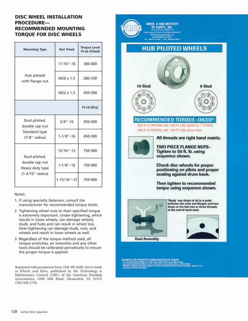
128 Section Nine: Appendix
DISC WHEEL INSTALLATIONPROCEDURE—RECOMMENDED MOUNTINGTORQUE FOR DISC WHEELS
Reprinted with permission from TMC RP 222B, User’s Guideto Wheels and Rims, published by the Technology &Maintenance Council (TMC) of the American TruckingAssociations, 2200 Mill Road, Alexandria, VA 22314 (703) 838-1776.
Mounting Type Nut TreadTorque LevelFt-Lb (Oiled)
Hub piloted
with flange nut
11 ⁄16"–16 300-400
M20 x 1.5 280-330
M22 x 1.5 450-500
Ft-Lb (Dry)
Stud piloted,
double cap nut
Standard type
(7 ⁄ 8" radius)
3 ⁄4"–16 450-500
1-1 ⁄ 8"–16 450-500
Stud piloted,
double cap nut
Heavy duty type
(1-3 ⁄16" radius)
15 ⁄16"–12 750-900
1-1 ⁄ 8"–16 750-900
1-15 ⁄16"–12 750-900
Notes:
1. If using specialty fasteners, consult themanufacturer for recommended torque levels.
2. Tightening wheel nuts to their specified torqueis extremely important. Under-tightening, whichresults in loose wheels, can damage wheels,studs, and hubs and can result in wheel loss.Over-tightening can damage studs, nuts, andwheels and result in loose wheels as well.
3. Regardless of the torque method used, alltorque wrenches, air wrenches and any othertools should be calibrated periodically to ensurethe proper torque is applied.
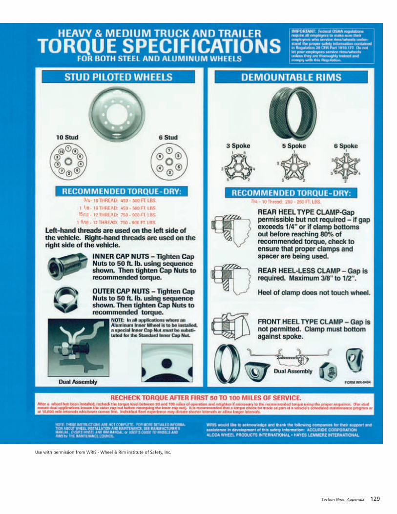
Section Nine: Appendix 129
Use with permission from WRIS - Wheel & Rim institute of Safety, Inc.
130 Section Nine: Appendix
MOUNTING PROCEDURES FOR 16.00R20AND 24R21 MICHELIN® XL™ OR XZL™ TIRESCorrect procedure for mounting multi-piece wheels for
tubeless truck tires includes proper mounting and
correct pressure.
Three-piece wheels consist of rim base, tapered bead
seat, and locking ring. Mounting tools include: large bore
valve, O-ring seal, brush or clean cloth with lubricant,
small pallet of wooden blocks, inflation hose with a
chuck or large bore valve, and miscellaneous tools.
The first step in mounting is to properly position the
wheel base by placing the wheel on the small pallet or
blocks to raise it off the floor, facilitating the lock ring
installation. Note that the wheel is placed on the support
with the fixed flange side down. Using the large bore
valve, lightly lubricate the rubber grommet on the valve
base; insert and secure with the hex nut of both sides.
Always use a large bore valve and not a standard truck
valve since the larger diameter will permit better gas
flow and better bead seating.
WHEEL LUBRICATIONWith a clean cloth or brush, lightly lubricate the rim
base completely except for the two upper grooves.
Lubrication in these grooves can cause the o-ring to be
rolled out of the groove by the tapered bead seat when
inflating the assembly. It is important to use a heavy
lubricant such as MICHELIN® Bib Grease or Murphy’s.
Heavy lubricants do not dry as quickly, thus allowing
more time to seat the beads during inflation.
LUBRICATION OF THE BEADUsing a brush or clean cloth, lubricate the inside and
outside of each tire bead area. This procedure plus the
rim lubrication will allow the tapered bead seat ring to
be installed more easily and allow the tire beads to seat
properly during inflation.
TIRE PLACEMENT ON THE WHEELPlace the tire on the wheel base. This can be done
manually or by fork lift truck for easier handling. Exercise
caution when sliding the forks below the sidewalls of the
tires since an impact by the forks can damage the casing
cords. Lifting the tire by the beads can damage or
permanently distort the beads and should be avoided.
TAPERED BEAD SEAT RINGThe bead seat ring should be lubricated on both sides
before placing it on the wheel base. This allows it to slide
between the tire and wheel base more easily and later
over the wheel base during inflation. Lubricating the
bead seating surface facilitates concentric seating of the
beads during inflation.
O-RING SEALThe most important part of tubeless mounting on
multi-piece wheels is the O-ring seal under the bead seat
ring. It is imperative that the correct O-ring be used and
properly installed. Check O-ring length and cross section
diameter for correct fit. The MICHELIN® O-ring seal
reference number is 1506 for the 24R21, which is
designated OR 6.6-21 for the 21-inch inside diameter.
The 16.00R20 uses O-ring reference number 1681,
designated OR 6.6-20 for the 20-inch or the corner ring,
reference number 1443, designated A20-TYRAN. The
corner ring has a slightly different mounting procedure –
see wheel manufacturer for proper procedures. Some
commercially available O-rings are too long. If too long,
it will push out of the groove breaking the seal and the
tire will loose gas. Do not lubricate the O-ring prior to
installation on the wheel. The lubricant tends to push the
O-ring out of the groove breaking the seal. Make sure
both the O-ring and the groove are free of debris. Place
the O-ring in the bottom groove; it should fit tightly but
not be excessively stretched.
LUBRICATION OF THE O-RINGThe outer surface of the O-ring should be lightly, but
well lubricated to allow the tapered bead seat to slide
easily over the seal during inflation. Remember an
incorrect O-ring or improper lubrication can force or
push the O-ring out of the slot upon inflation causing
gas loss. Snap the lock ring in the upper rim groove.
Check that the ring is fully seated in the groove.
INFLATIONPlace the assembly in the horizontal (preferred) or
vertical (if well lubricated) position for inflation in the
restraining device and remove the valve core. This will
allow the beads to slide more easily into position. Inflate
to 80 psi for complete tire bead seating. Install the valve
core and then adjust pressure to that recommended for
the load and condition.
Remember the keys for good mounting are:
1. Correct size, type, and compatibility of components
2. Proper lubrication and mounting procedures
3. 80 psi initial inflation pressure for bead seating,
followed by adjustment to recommended pressure.
Adherence to these simple guidelines will ensure
maximized performance and minimized downtime due
to tire mismount.
If you are having difficulty in mounting or cannot get
the assembly to inflate or hold gas, an incorrect
component or incorrect inflation is probably the cause.
MOUNTING PROCEDURES FOR 16.00R20 AND 24R21
Section Nine: Appendix 131
MEASURED TIRE REVOLUTIONS PER MILEAt Michelin, Tire Revolutions Per Mile (Tire Revs./Mile)
are officially determined using the SAE (Society of
Automotive Engineers) Recommended Practice J1025.
The test tires are placed as singles on the drive axle of the
test vehicle and loaded to the maximum dual load rating
of the tire and set to the corresponding pressure. The
vehicle is then driven over a straight 2-mile section at 45
mph while the number of revolutions are counted. (Since
speed minimally affects the results for radial tires, other
speeds are allowed.) Averaging four runs that are within
1% of each other then derives the Tire Revs./Mile
measurement.
Afterwards, the results are double-checked using
shorter distances that are more easily obtained. In
addition to these, the test tire is compared to a known
baseline tire on a road wheel. This latter method is very
accurate and very repeatable when using a similar
baseline tire with a known Tire Revs./Mile.
The SAE procedure recognizes that within the test
method itself there will be some variation. In fact, there
are other factors that cause variation on Tire Revs./Miles
among similar tires. Be aware that just because similar
tires have the same overall diameter this does not
necessarily mean that they will have the same Tire
Revs./Mile. The SAE procedure determines the Tire
Revs./Mile to within ± 1.5%.
Some factors, which cause variation among tires, are:
• Load and Pressure – A difference in Load/Pressurecould alter the Tire Revs./Mile measurement by as
much as 1.5%. If pressure is constant, going from an
empty vehicle to a fully loaded vehicle can change the
Tire Revs./Mile by 1 to 1.5%.
• Treadwear – The Tire Revs./Mile varies from a newtire to a fully worn tire. This can affect Tire Revs./Mile
by as much as 3% from the rated Tire Revs./Mile.
• Tread Geometry – The height and stiffness of theblocks and the shape of the tread pattern can affect
Tire Revs./Mile.
• Torque – The presence of driving and braking torquecan affect the Tire Revs./Mile.
• Type and Condition of Pavement – Asphalt vs.concrete, wet vs. dry can create difference in Tire
Revs./Mile.
CALCULATED TIRE REVOLUTIONS PER MILE
Michelin Equation:
Tire Revs./Mile = 20,168 / (O.D. - .8d)
O.D. = Overall Diameter
d = Correction for deflection
d = (O.D./2) - SLR
SLR = Static Loaded Radius
(Ref. Data Book)
Example: 275/80R22.5 MICHELIN® XDA® ENERGY
New TireO.D. = 40.5
SLR = 18.8
d = (40.5/2) - 18.8
d = 1.45
Tire Revs./Mile = 20,168 / (40.5 - (.8 x 1.45))
= 20,168 / (40.5 - 1.16)
= 20,168 / 39.34
Tire Revs./Mile = 512.6 (Calculated) Vs Data Book
(Measured) Tire Revs./Mile = 513
At 50% WornO.D. = 40.1
SLR = 18.6 (13 ⁄ 32nd used is
approximately a 0.2 inch
reduction of SLR)
d = (40.1 ⁄ 2) - 18.6
d = 1.45
Tire Revs./Mile = 20,168 / (40.1 - (.8 x 1.45))
Tire Revs./Mile = 518 (Calculated)
TIRE REVOLUTIONS PER MILE CALCULATION
132 Section Nine: Appendix
OUT-OF-SERVICE CONDITIONSDESCRIPTIONCode Key 21: New & Retread Tire Out-of-Service Conditions was developed for tire manufacturers as a means
of coding out-of-service conditions as determined by manufacturer/laboratory failure analysis. It is not meant to replace
related codes identified for use by technicians in Code Key 18: Technician Failure Code, or Code Key 82: Operator
Vehicle/Equipment Condition Report. Code Key 21 has two codes per condition, a two-character alpha code or an
alternative four-digit numeric code. Code Key 21 was introduced with the release of VMRS 2000™ Version 1.05.
NOTE: In release of VMRS that preceded VMRS 2000™, Code Key 21 was used redundantly to denote a vehicle
group/system. The information once contained in Code Key 21 was assigned to VMRS 2000™ Code Key 31 in 1997.
Code (Alpha) Code (Numeric) Description
Bead AreaFW 1101 Bead Damage from Rim Flange WearBO 1102 Bead Damage Due to OverloadTB 1103 Torn BeadsKB 1104 Kinked/Distorted BeadsBD 1105 Bead DeformationBB 1106 Burned BeadsCD 1107 Bead Damage from CurbingCS 1108 Reinforce/Chafter SeparationFC 1109 Lower Sidewall/Bead Area Flow Crack
Sidewall AreaSC 1201 Spread/Damaged CordSS 1202 Sidewall SeparationSI 1203 Sidewall Separation Damage InducedST 1204 Sidewall Separation Due to Tread PunctureSO 1205 Sidewall Separation Due to Bead DamageBM 1206 Branding DamageCU 1207 Cuts and SnagsOD 1208 Damage from Object Lodged Between DualsAB 1209 Sidewall Abrasion/Scuff DamageWE 1210 Weathering/Ozone CrackingRS 1211 Radial SplitSB 1212 Sidewall Bumps (Blisters)DC 1213 Diagonal CrackingHS 1214 Heavy Sidewall SpliceOZ 1215 Open Sidewall SpliceSP 1216 Sidewall PenetrationCW 1217 Crack at Edge of Retread WingCB 1218 Cracking Due to Excessive Sidewall BuffZP 1219 Circumferential Fatigue Rupture (Zipper)
Crown AreaBS 1301 Brake Skid DamageWW 1302 Wild WireDL 1303 DelaminationLB 1304 Lug Base CrackingCC 1305 Chipping/Flaking/Chunking TreadDR 1306 Stone DrillingRD 1307 Regrooving DamageDD 1308 Dynamometer Type DamageEX 1309 Excessive WearRT 1310 Rib Tearing
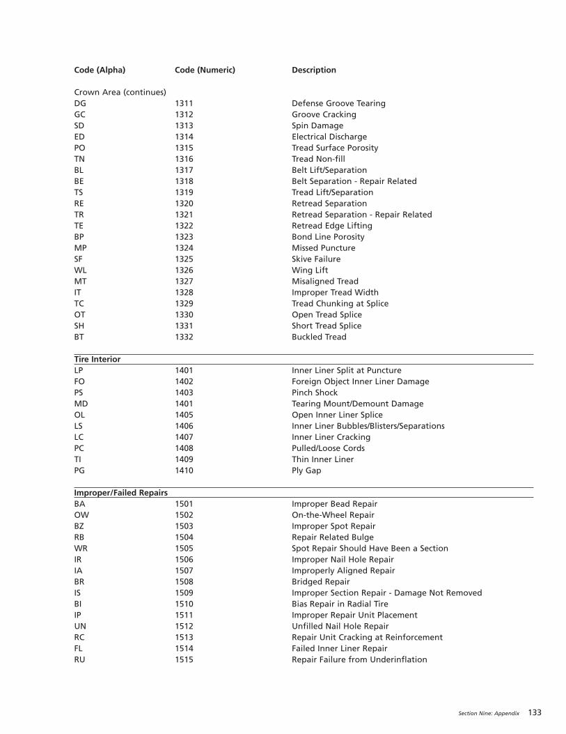
Section Nine: Appendix 133
Code (Alpha) Code (Numeric) Description
Crown Area (continues)DG 1311 Defense Groove TearingGC 1312 Groove CrackingSD 1313 Spin DamageED 1314 Electrical DischargePO 1315 Tread Surface PorosityTN 1316 Tread Non-fillBL 1317 Belt Lift/SeparationBE 1318 Belt Separation - Repair RelatedTS 1319 Tread Lift/SeparationRE 1320 Retread SeparationTR 1321 Retread Separation - Repair RelatedTE 1322 Retread Edge LiftingBP 1323 Bond Line PorosityMP 1324 Missed PunctureSF 1325 Skive FailureWL 1326 Wing LiftMT 1327 Misaligned TreadIT 1328 Improper Tread WidthTC 1329 Tread Chunking at SpliceOT 1330 Open Tread SpliceSH 1331 Short Tread SpliceBT 1332 Buckled Tread
Tire InteriorLP 1401 Inner Liner Split at PunctureFO 1402 Foreign Object Inner Liner DamagePS 1403 Pinch ShockMD 1401 Tearing Mount/Demount DamageOL 1405 Open Inner Liner SpliceLS 1406 Inner Liner Bubbles/Blisters/SeparationsLC 1407 Inner Liner CrackingPC 1408 Pulled/Loose CordsTI 1409 Thin Inner LinerPG 1410 Ply Gap
Improper/Failed RepairsBA 1501 Improper Bead RepairOW 1502 On-the-Wheel RepairBZ 1503 Improper Spot RepairRB 1504 Repair Related BulgeWR 1505 Spot Repair Should Have Been a SectionIR 1506 Improper Nail Hole RepairIA 1507 Improperly Aligned RepairBR 1508 Bridged RepairIS 1509 Improper Section Repair - Damage Not RemovedBI 1510 Bias Repair in Radial TireIP 1511 Improper Repair Unit PlacementUN 1512 Unfilled Nail Hole RepairRC 1513 Repair Unit Cracking at ReinforcementFL 1514 Failed Inner Liner RepairRU 1515 Repair Failure from Underinflation

134 Section Nine: Appendix
Rotating assembly runout can influence vehicle
vibration and contribute to irregular tire wear.
Following these procedures for verifying the
concentricity of the guide rib area as well as ensuring
that both radial and lateral runout measurements are
the lowest possible will aid in reducing any
tire/wheel/hub assembly contribution.
Tools needed:• Tire runout gauge (or dial indicator)
• Pressure gauge
• Tread depth gauge
• Feeler gauge
• Six inch metal ruler
• Tire marking crayon
• Jack and jack stands
The first step is to eliminate possible sources of the
disturbance (operation conditions, alignment posture,
driveline component balance and angles, frame and
chassis concerns, fifth wheel placement, and possible
excessive stacked tolerances). Find out as much as you
can that may be related to the issue to aid in the initial
diagnosis (maintenance file, test drive, driver interview).
Examine the assemblies for proper pressure, proper
mounting, verify balance if balanced, inspect for tire and
or wheel damage. Verify torque and proper component
assembly on tube-type or multi-piece assemblies. Proper
mounting procedure will reduce runout where it starts
during the mounting process.
Jack up the front end of the vehicle so axle is unloaded
and place jack stands for support. Inspect front end
components, including wheel bearing and kingpin play,
suspension and rear assemblies.
Use the tire runout gauge to check for both radial (top
photo) and lateral runout (bottom photo) for the rotating
assembly. Values over 0.060 inch will be a detectable
cause of vibration in steer assemblies and on recreational
vehicles. Current TMC (Technology & Maintenance
Council) assembly tolerances are 0.095 inches, radialand lateral (See Balance and Runout, Page 42).
If the value is between 0.001" and 0.060", continue
with procedures below. If the value is >0.060", remove
and deflate the tire, break it loose from the wheel,
lubricate, rotate the tire 180 degrees, reinflate, and
recheck runout.
Incorrect bead seating can occur on one or both bead
seats. This usually results in a high radial and/or lateral
reading. General cause is improper mounting procedures
or wheel is at tolerance limits. It may require taking 3
radial readings to detect: outside shoulder, center rib,
and inside shoulder.
RUNOUT AND VIBRATION DIAGNOSIS
Radial Runout
Incorrect Bead Seating
Measuring Radial Runout on Center Rib
Measuring Lateral Runout on Outside Shoulder

Section Nine: Appendix 135
Note: The bead seating surface of the tire and wheel donot match up as shown in previous illustration. This
incorrect seating is the result of mismount. The TMC
(Technology & Maintenance Council) specification is
2⁄ 32nds (0.062 inch). If both wheel and tire arelubricated and initial inflation is done with the tire flat,
then 1 ⁄ 32nd inch or less variance around the tire should
be obtainable.
Check for this mismount condition with the 6 inch
ruler, measuring in 4 locations around an unladen
assembly.
Check for hub to wheel clearance on hub piloted
assemblies with the feeler gauge. If the measured high
spot lines up with the feeler gauge gap, rotate the
assembly so the gap is at the top, loosen the lug nuts, and
allow gravity to center the wheel on the hub. Hand
tighten the top nut, tighten all nuts in the proper
sequence, recheck for runout, and retorque.
On cast spoke and
demountable rim
assemblies, loosen and
properly retighten the rim
clamp nuts to the proper
torque. Recheck for runout.
Verification of radial (top photo) and lateral (bottom
photo) wheel runout is another step to be considered.
TMC tolerances are 0.070 inch on tubeless steel discwheels and 0.030 inch on tubeless aluminum discwheels.
PROCEDURE TO CHECK THE WHEEL FORRADIAL AND LATERAL RUNOUT• Mark two studs and the wheel with a crayon.
• Remove the tire and wheel assembly from the hub.
• Mark the tire and wheel at the valve stem.
• Dismount the tire from the wheel using proper
procedures.
• Clean the wheel flange area with a wire brush. Check
the wheel for any damage.
• Identify and mark the wheel to indicate where the
radial and lateral high and low spots were found on
the tire.
• Place the wheel back on the marked hub with the
wheel matched to the marked studs. Use 3 lug nuts
and properly torque.
• Measure radial and lateral runout on the inside and
outside flange.
• See if the readings match up to the tire.
• Readings greater than 0.030" for aluminum wheels
and 0.070" on steel wheels indicate high runout.
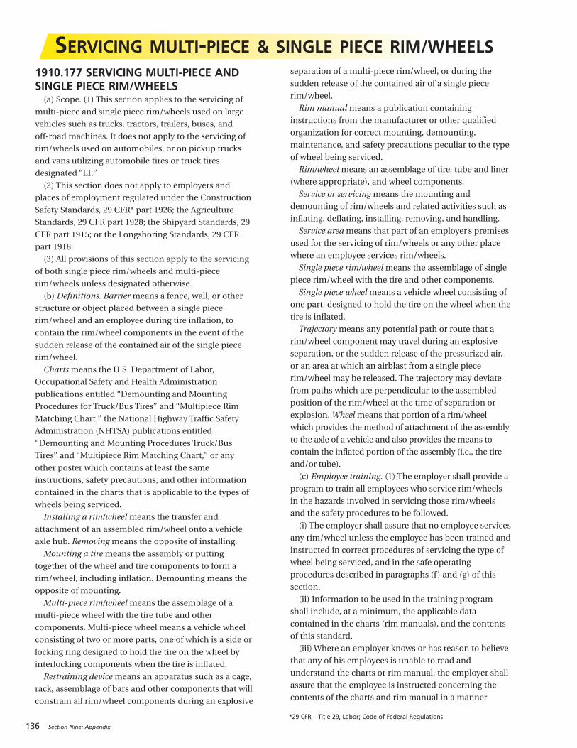
136 Section Nine: Appendix
1910.177 SERVICING MULTI-PIECE ANDSINGLE PIECE RIM/WHEELS(a) Scope. (1) This section applies to the servicing of
multi-piece and single piece rim/wheels used on large
vehicles such as trucks, tractors, trailers, buses, and
off-road machines. It does not apply to the servicing of
rim/wheels used on automobiles, or on pickup trucks
and vans utilizing automobile tires or truck tires
designated ‘‘LT.’’
(2) This section does not apply to employers and
places of employment regulated under the Construction
Safety Standards, 29 CFR* part 1926; the Agriculture
Standards, 29 CFR part 1928; the Shipyard Standards, 29
CFR part 1915; or the Longshoring Standards, 29 CFR
part 1918.
(3) All provisions of this section apply to the servicing
of both single piece rim/wheels and multi-piece
rim/wheels unless designated otherwise.
(b) Definitions. Barriermeans a fence, wall, or other
structure or object placed between a single piece
rim/wheel and an employee during tire inflation, to
contain the rim/wheel components in the event of the
sudden release of the contained air of the single piece
rim/wheel.
Chartsmeans the U.S. Department of Labor,
Occupational Safety and Health Administration
publications entitled ‘‘Demounting and Mounting
Procedures for Truck/Bus Tires’’ and ‘‘Multipiece Rim
Matching Chart,’’ the National Highway Traffic Safety
Administration (NHTSA) publications entitled
‘‘Demounting and Mounting Procedures Truck/Bus
Tires’’ and ‘‘Multipiece Rim Matching Chart,’’ or any
other poster which contains at least the same
instructions, safety precautions, and other information
contained in the charts that is applicable to the types of
wheels being serviced.
Installing a rim/wheel means the transfer and
attachment of an assembled rim/wheel onto a vehicle
axle hub. Removingmeans the opposite of installing.
Mounting a tiremeans the assembly or putting
together of the wheel and tire components to form a
rim/wheel, including inflation. Demounting means the
opposite of mounting.
Multi-piece rim/wheel means the assemblage of a
multi-piece wheel with the tire tube and other
components. Multi-piece wheel means a vehicle wheel
consisting of two or more parts, one of which is a side or
locking ring designed to hold the tire on the wheel by
interlocking components when the tire is inflated.
Restraining devicemeans an apparatus such as a cage,
rack, assemblage of bars and other components that will
constrain all rim/wheel components during an explosive
separation of a multi-piece rim/wheel, or during the
sudden release of the contained air of a single piece
rim/wheel.
Rim manualmeans a publication containing
instructions from the manufacturer or other qualified
organization for correct mounting, demounting,
maintenance, and safety precautions peculiar to the type
of wheel being serviced.
Rim/wheelmeans an assemblage of tire, tube and liner
(where appropriate), and wheel components.
Service or servicingmeans the mounting and
demounting of rim/wheels and related activities such as
inflating, deflating, installing, removing, and handling.
Service areameans that part of an employer’s premises
used for the servicing of rim/wheels or any other place
where an employee services rim/wheels.
Single piece rim/wheel means the assemblage of single
piece rim/wheel with the tire and other components.
Single piece wheelmeans a vehicle wheel consisting of
one part, designed to hold the tire on the wheel when the
tire is inflated.
Trajectorymeans any potential path or route that a
rim/wheel component may travel during an explosive
separation, or the sudden release of the pressurized air,
or an area at which an airblast from a single piece
rim/wheel may be released. The trajectory may deviate
from paths which are perpendicular to the assembled
position of the rim/wheel at the time of separation or
explosion. Wheelmeans that portion of a rim/wheel
which provides the method of attachment of the assembly
to the axle of a vehicle and also provides the means to
contain the inflated portion of the assembly (i.e., the tire
and/or tube).
(c) Employee training. (1) The employer shall provide a
program to train all employees who service rim/wheels
in the hazards involved in servicing those rim/wheels
and the safety procedures to be followed.
(i) The employer shall assure that no employee services
any rim/wheel unless the employee has been trained and
instructed in correct procedures of servicing the type of
wheel being serviced, and in the safe operating
procedures described in paragraphs (f) and (g) of this
section.
(ii) Information to be used in the training program
shall include, at a minimum, the applicable data
contained in the charts (rim manuals), and the contents
of this standard.
(iii) Where an employer knows or has reason to believe
that any of his employees is unable to read and
understand the charts or rim manual, the employer shall
assure that the employee is instructed concerning the
contents of the charts and rim manual in a manner
SERVICING MULTI-PIECE & SINGLE PIECE RIM/WHEELS
*29 CFR – Title 29, Labor; Code of Federal Regulations
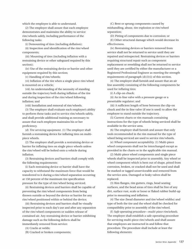
Section Nine: Appendix 137
which the employee is able to understand.
(2) The employer shall assure that each employee
demonstrates and maintains the ability to service
rim/wheels safely, including performance of the
following tasks:
(i) Demounting of tires (including deflation);
(ii) Inspection and identification of the rim/wheel
components;
(iii) Mounting of tires (including inflation with a
restraining device or other safeguard required by this
section);
(iv) Use of the restraining device or barrier and other
equipment required by this section;
(v) Handling of rim/wheels;
(vi) Inflation of the tire when a single piece rim/wheel
is mounted on a vehicle;
(vii) An understanding of the necessity of standing
outside the trajectory both during inflation of the tire
and during inspection of the rim/wheel following
inflation; and
(viii) Installation and removal of rim/wheels.
(3) The employer shall evaluate each employee’s ability
to perform these tasks and to service rim/wheels safely,
and shall provide additional training as necessary to
assure that each employee maintains his or her
proficiency.
(d) Tire servicing equipment. (1) The employer shall
furnish a restraining device for inflating tires on multi-
piece wheels.
(2) The employer shall provide a restraining device or
barrier for inflating tires on single piece wheels unless
the rim/wheel will be bolted onto a vehicle during
inflation.
(3) Restraining devices and barriers shall comply with
the following requirements:
(i) Each restraining device or barrier shall have the
capacity to withstand the maximum force that would be
transferred to it during a rim/wheel separation occurring
at 150 percent of the maximum tire specification
pressure for the type of rim/wheel being serviced.
(ii) Restraining devices and barriers shall be capable of
preventing the rim/wheel components from being
thrown outside or beyond the device or barrier for any
rim/wheel positioned within or behind the device;
(iii) Restraining devices and barriers shall be visually
inspected prior to each day’s use and after any separation
of the rim/wheel components or sudden release of
contained air. Any restraining device or barrier exhibiting
damage such as the following defects shall be
immediately removed from service:
(A) Cracks at welds;
(B) Cracked or broken components;
(C) Bent or sprung components caused by
mishandling, abuse, tire explosion or rim/wheel
separation;
(D) Pitting of components due to corrosion; or
(E) Other structural damage which would decrease its
effectiveness.
(iv) Restraining devices or barriers removed from
service shall not be returned to service until they are
repaired and reinspected. Restraining devices or barriers
requiring structural repair such as component
replacement or rewelding shall not be returned to service
until they are certified by either the manufacturer or a
Registered Professional Engineer as meeting the strength
requirements of paragraph (d)(3)(i) of this section.
(4) The employer shall furnish and assure that an air
line assembly consisting of the following components be
used for inflating tires:
(i) A clip-on chuck;
(ii) An in-line valve with a pressure gauge or a
presettable regulator; and
(iii) A sufficient length of hose between the clip-on
chuck and the in-line valve (if one is used) to allow the
employee to stand outside the trajectory.
(5) Current charts or rim manuals containing
instructions for the type of wheels being serviced shall be
available in the service area.
(6) The employer shall furnish and assure that only
tools recommended in the rim manual for the type of
wheel being serviced are used to service rim/wheels.
(e) Wheel component acceptability. (1) Multi-piece
wheel components shall not be interchanged except as
provided in the charts or in the applicable rim manual.
(2) Multi-piece wheel components and single piece
wheels shall be inspected prior to assembly. Any wheel or
wheel component which is bent out of shape, pitted from
corrosion, broken, or cracked shall not be used and shall
be marked or tagged unserviceable and removed from
the service area. Damaged or leaky valves shall be
replaced.
(3) Rim flanges, rim gutters, rings, bead seating
surfaces, and the bead areas of tires shall be free of any
dirt, surface rust, scale or loose or flaked rubber build-up
prior to mounting and inflation.
(4) The size (bead diameter and tire/wheel widths) and
type of both the tire and the wheel shall be checked for
compatibility prior to assembly of the rim/wheel.
(f) Safe operating procedure—multi-piece rim/wheels.
The employer shall establish a safe operating procedure
for servicing multi-piece rim/wheels and shall assure
that employees are instructed in and follow that
procedure. The procedure shall include at least the
following elements:
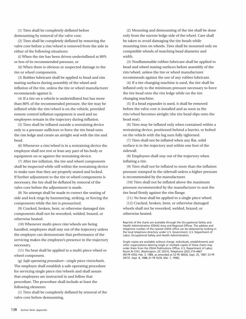
138 Section Nine: Appendix
(1) Tires shall be completely deflated before
demounting by removal of the valve core.
(2) Tires shall be completely deflated by removing the
valve core before a rim/wheel is removed from the axle in
either of the following situations:
(i) When the tire has been driven underinflated at 80%
or less of its recommended pressure, or
(ii) When there is obvious or suspected damage to the
tire or wheel components.
(3) Rubber lubricant shall be applied to bead and rim
mating surfaces during assembly of the wheel and
inflation of the tire, unless the tire or wheel manufacturer
recommends against it.
(4) If a tire on a vehicle is underinflated but has more
than 80% of the recommended pressure, the tire may be
inflated while the rim/wheel is on the vehicle, provided
remote control inflation equipment is used and no
employees remain in the trajectory during inflation.
(5) Tires shall be inflated outside a restraining device
only to a pressure sufficient to force the tire bead onto
the rim ledge and create an airtight seal with the tire and
bead.
(6) Whenever a rim/wheel is in a restraining device the
employee shall not rest or lean any part of his body or
equipment on or against the restraining device.
(7) After tire inflation, the tire and wheel components
shall be inspected while still within the restraining device
to make sure that they are properly seated and locked.
If further adjustment to the tire or wheel components is
necessary, the tire shall be deflated by removal of the
valve core before the adjustment is made.
(8) No attempt shall be made to correct the seating of
side and lock rings by hammering, striking, or forcing the
components while the tire is pressurized.
(9) Cracked, broken, bent, or otherwise damaged rim
components shall not be reworked, welded, brazed, or
otherwise heated.
(10) Whenever multi-piece rim/wheels are being
handled, employees shall stay out of the trajectory unless
the employer can demonstrate that performance of the
servicing makes the employee’s presence in the trajectory
necessary.
(11) No heat shall be applied to a multi-piece wheel or
wheel component.
(g) Safe operating procedure—single piece rim/wheels.
The employer shall establish a safe operating procedure
for servicing single piece rim/wheels and shall assure
that employees are instructed in and follow that
procedure. The procedure shall include at least the
following elements:
(1) Tires shall be completely deflated by removal of the
valve core before demounting.
(2) Mounting and demounting of the tire shall be done
only from the narrow ledge side of the wheel. Care shall
be taken to avoid damaging the tire beads while
mounting tires on wheels. Tires shall be mounted only on
compatible wheels of matching bead diameter and
width.
(3) Nonflammable rubber lubricant shall be applied to
bead and wheel mating surfaces before assembly of the
rim/wheel, unless the tire or wheel manufacturer
recommends against the use of any rubber lubricant.
(4) If a tire changing machine is used, the tire shall be
inflated only to the minimum pressure necessary to force
the tire bead onto the rim ledge while on the tire
changing machine.
(5) If a bead expander is used, it shall be removed
before the valve core is installed and as soon as the
rim/wheel becomes airtight (the tire bead slips onto the
bead seat).
(6) Tires may be inflated only when contained within a
restraining device, positioned behind a barrier, or bolted
on the vehicle with the lug nuts fully tightened.
(7) Tires shall not be inflated when any flat, solid
surface is in the trajectory and within one foot of the
sidewall.
(8) Employees shall stay out of the trajectory when
inflating a tire.
(9) Tires shall not be inflated to more than the inflation
pressure stamped in the sidewall unless a higher pressure
is recommended by the manufacturer.
(10) Tires shall not be inflated above the maximum
pressure recommended by the manufacturer to seat the
tire bead firmly against the rim flange.
(11) No heat shall be applied to a single piece wheel.
(12) Cracked, broken, bent, or otherwise damaged
wheels shall not be reworked, welded, brazed, or
otherwise heated.
Reprints of the charts are available through the Occupational Safety andHealth Administration (OSHA) Area and Regional Offices. The address andtelephone number of the nearest OSHA office can be obtained by looking inthe local telephone directory under U.S. Government, U.S. Department ofLabor, Occupational Safety and Health Administration.
Single copies are available without charge. Individuals, establishments andother organizations desiring single or multiple copies of these charts mayorder them from the OSHA Publications Office, U.S. Department of Labor,Room N–3101, Washington, DC 20210, Telephone (202) 219–4667. [49 FR 4350, Feb. 3, 1984, as amended at 52 FR 36026, Sept. 25, 1987; 53 FR34737, Sept. 8, 1988; 61 FR 9239, Mar. 7, 1996].
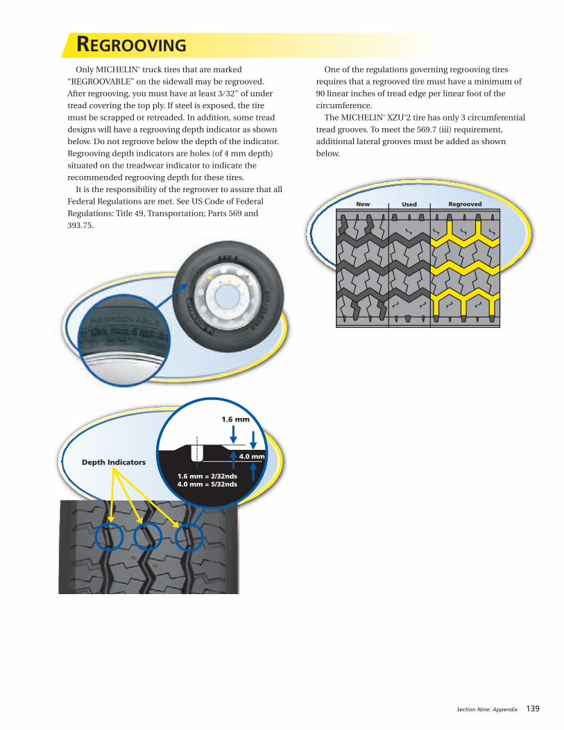
Section Nine: Appendix 139
Only MICHELIN® truck tires that are marked
“REGROOVABLE” on the sidewall may be regrooved.
After regrooving, you must have at least 3 ⁄ 32" of under
tread covering the top ply. If steel is exposed, the tire
must be scrapped or retreaded. In addition, some tread
designs will have a regrooving depth indicator as shown
below. Do not regroove below the depth of the indicator.
Regrooving depth indicators are holes (of 4 mm depth)
situated on the treadwear indicator to indicate the
recommended regrooving depth for these tires.
It is the responsibility of the regroover to assure that all
Federal Regulations are met. See US Code of Federal
Regulations: Title 49, Transportation; Parts 569 and
393.75.
One of the regulations governing regrooving tires
requires that a regrooved tire must have a minimum of
90 linear inches of tread edge per linear foot of the
circumference.
The MICHELIN® XZU®2 tire has only 3 circumferential
tread grooves. To meet the 569.7 (iii) requirement,
additional lateral grooves must be added as shown
below.
REGROOVING
New Used Regrooved
1.6 mm
4.0 mm
1.6 mm = 2/32nds4.0 mm = 5/32nds
Depth Indicators
140 Section Nine: Appendix
REGROOVING CODEU. S. CODE OF FEDERAL REGULATIONS: TITLE 49, TRANSPORTATION; PARTS 569.7 AND 393.75(EXTRACTS)For complete regulations, go to: ecfr.gpoaccess.gov
569.7 REQUIREMENTS.(a) Regrooved tires. (1) Except as permitted by
paragraph (a)(2) of this section, no person shall sell, offer
for sale, or introduce or deliver for introduction into
interstate commerce regrooved tires produced by
removing rubber from the surface of a worn tire tread to
generate a new tread pattern. Any person who regrooves
tires and leases them to owners or operators of motor
vehicles and any person who regrooves his own tires for
use on motor vehicles is considered to be a person
delivering for introduction into interstate commerce
within the meaning of this part.
(2) A regrooved tire may be sold, offered for sale, or
introduced for sale or delivered for introduction into
interstate commerce only if it conforms to each of the
following requirements:
(i) The tire being regrooved shall be a regroovable tire;
(ii) After regrooving, cord material below the grooves
shall have a protective covering of tread material at least
3 ⁄32-inch thick;
(iii) After regrooving, the new grooves generated into
the tread material and any residual original molded tread
groove which is at or below the new regrooved depth
shall have a minimum of 90 linear inches of tread edges
per linear foot of the circumference;
(iv) After regrooving, the new groove width generated
into the tread material shall be a minimum of 3/16-inch
and a maximum of 5 ⁄16-inch;
(v) After regrooving, all new grooves cut into the tread
shall provide unobstructed fluid escape passages; and
(vi) After regrooving, the tire shall not contain any of
the following defects, as determined by a visual
examination of the tire either mounted on the rim, or
dismounted, whichever is applicable:
(A) Cracking which extends to the fabric,
(B) Groove cracks or wear extending to the fabric, or
(C) Evidence of ply, tread, or sidewall separation;
(vii) If the tire is siped by cutting the tread surface
without removing rubber, the tire cord material shall not
be damaged as a result of the siping process, and no sipe
shall be deeper than the original or retread groove depth.
(b) Siped regroovable tires. No person shall sell, offer
for sale, or introduce for sale or deliver for introduction
into interstate commerce a regroovable tire that has been
siped by cutting the tread surface without removing
rubber if the tire cord material is damaged as a result of
the siping process, or if the tire is siped deeper than the
original or retread groove depth.
393.75 TIRES.(a) No motor vehicle shall be operated on any tire
that –
(1) Has body ply or belt material exposed through the
tread or sidewall,
(2) Has any tread or sidewall separation,
(3) Is flat or has an audible leak, or
(4) Has a cut to the extent that the ply or belt material
is exposed.
(b) Any tire on the front wheels of a bus, truck, or truck
tractor shall have a tread groove pattern depth of at least
4 ⁄ 32 of an inch when measured at any point on a major
tread groove. The measurements shall not be made
where tie bars, humps, or fillets are located.
(c) Except as provided in paragraph (b) of this section,
tires shall have a tread groove pattern depth of at least
2 ⁄ 32of an inch when measured in a major tread groove.
The measurement shall not be made where tie bars,
humps or fillets are located.
(d) No bus shall be operated with regrooved,recapped or retreaded tires on the front wheels.(e) A regrooved tire with a load-carrying capacity equal
to or greater than 2,232 kg (4,920 pounds) shall not be
used on the front wheels of any truck or truck tractor.
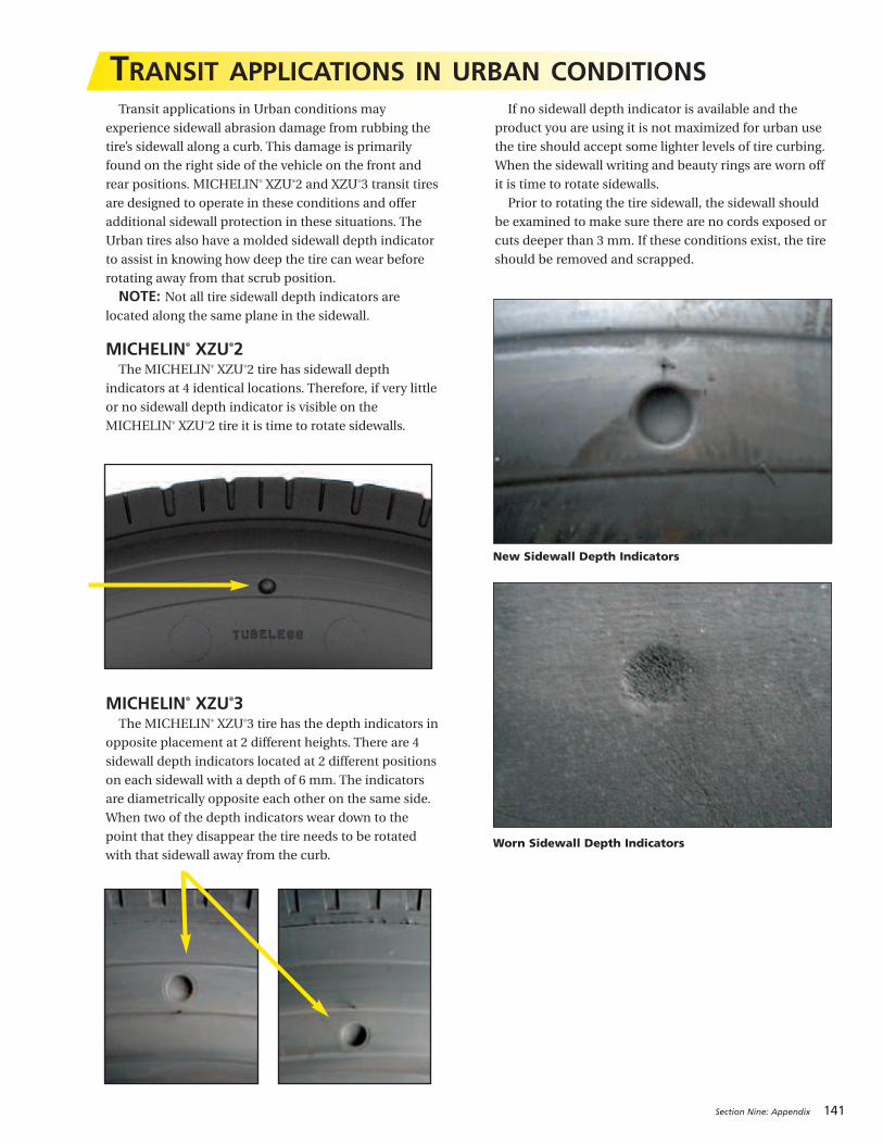
Section Nine: Appendix 141
Transit applications in Urban conditions may
experience sidewall abrasion damage from rubbing the
tire’s sidewall along a curb. This damage is primarily
found on the right side of the vehicle on the front and
rear positions. MICHELIN® XZU®2 and XZU®3 transit tires
are designed to operate in these conditions and offer
additional sidewall protection in these situations. The
Urban tires also have a molded sidewall depth indicator
to assist in knowing how deep the tire can wear before
rotating away from that scrub position.
NOTE: Not all tire sidewall depth indicators arelocated along the same plane in the sidewall.
MICHELIN® XZU®2The MICHELIN® XZU®2 tire has sidewall depth
indicators at 4 identical locations. Therefore, if very little
or no sidewall depth indicator is visible on the
MICHELIN® XZU®2 tire it is time to rotate sidewalls.
MICHELIN® XZU®3The MICHELIN® XZU®3 tire has the depth indicators in
opposite placement at 2 different heights. There are 4
sidewall depth indicators located at 2 different positions
on each sidewall with a depth of 6 mm. The indicators
are diametrically opposite each other on the same side.
When two of the depth indicators wear down to the
point that they disappear the tire needs to be rotated
with that sidewall away from the curb.
If no sidewall depth indicator is available and the
product you are using it is not maximized for urban use
the tire should accept some lighter levels of tire curbing.
When the sidewall writing and beauty rings are worn off
it is time to rotate sidewalls.
Prior to rotating the tire sidewall, the sidewall should
be examined to make sure there are no cords exposed or
cuts deeper than 3 mm. If these conditions exist, the tire
should be removed and scrapped.
TRANSIT APPLICATIONS IN URBAN CONDITIONS
New Sidewall Depth Indicators
Worn Sidewall Depth Indicators

142 Section Nine: Appendix
FACTORS THAT COST FLEETS MONEYOverall Goal: Maintain all tires at the fleet target
inflation pressure based on the manufacturers’
application data book for the particular axle load.
Well maintained fleets keep the tires within 5 psi of
this setting when monitoring inflation pressure.
1. Low Inflation PressureUnder-inflation is the biggest issue in the industry.
It is the number one cause of premature tire removal.
With the advancement in today’s radial casing, it is
virtually impossible to determine if a tire is properly
inflated without using a pressure gauge. Periodically
calibrate the gauges using a master gauge. Over time,
usage conditions can cause a pressure gauge to loose
accuracy beyond the 2 psi manufactures tolerance range.
The time and effort required to verify gauges and to
check tire pressure is time well spent.
Goal: Maintain all tires at the fleet target inflation
pressure based on the manufacturers’ application data
book for the particular axle load.
Effect: An inflation pressure mismatch of greater than
five psi will result in the two tires of a dual assembly
being significantly different in circumference resulting in
irregular wear and can also lead to eventual tire loss due
to premature casing fatigue. A difference of five psi
between steer tires will cause the vehicle to pull to the
side with the lower pressure. Additionally, under inflation
results in internal tire heat build up and potentially
premature tire failure.
2. High Inflation PressureOver inflated tires increase the likelihood of crown
cuts, impact breaks, punctures, and shock damage
resulting from the decrease of sidewall flexing and an
increase in firmness of the tread surface.
Goal: Maintain all tires at the fleet target inflation
pressure based on the manufacturers’ application data
book for the particular axle load.
Effect: Increases the probability of potential casing
damage. This change in contact patch footprint could
result in a reduction of traction and tread life.
3. Missing Valve CapsMissing valve caps are a primary source of low inflation
pressure. Valve caps are used to keep debris out of the
core and act as a secondary air seal if the valve core
happens to leak. Verify there is a good tight seal by use of
a spray type leak detector. A good “metal” cap with a
rubber seal will hold air in a tire without a valve core.
Goal: Install suitable valve caps on all wheel positions.
Consider the use of inflate-thru valve caps for easier
pressure maintenance.
Effect: The number one cause of air loss in tires can be
attributed to missing valve caps. Operating without valve
caps can result in under inflation and the conditions
mentioned above in 1 and 2.
4. Dual Mismatch Inflation PressureDual mismatched pressures can cause a permanent
irregular wear pattern to develop and within a few weeks
can potentially be a cause of early tire removal. Dual
mismatched pressure will also affect the matched tire,
causing accelerated tread wear and casing fatigue.
Goal: Maintain all tires at the fleet target inflation
pressure based on the manufacturers’ application data
book for the particular axle load. Well maintained fleets
keep the tires within 5 psi of this setting when
monitoring inflation pressure.
Effect: This irregular wear can result in early removal
or require tire rotation to minimize the effect.
5. Dual Mismatch HeightDual mismatch tread depths (tire height differences)
will cause irregular wear. Additionally, the larger tire
(the one with the greatest tread depth) will become
over-fatigued due to bearing more weight, this
accelerates premature casing failure.
Goal: Match tires in dual assembly with equal tread
depths. Well maintained fleets use +/- 4/32" of tread
depth as maximum allowable difference in overall height
between the duals.
Effect: Dual mismatch tread depths can cause a
permanent irregular wear pattern in a few weeks
resulting in early removal or a lost casing.
6. Irregular WearProper inflation pressure, correct toe settings and
proper alignment can prevent most irregular wear.
Steer, drive, and trailer axle alignment verification
and/or correction can be performed with a minimal
cost or investment in equipment.
Goal: Reduce irregular wear by proactive tire and
vehicle maintenance programs.
Effect: Once a wear pattern develops, it will continue
until the tire is rotated or removed to be retreaded or
scrapped. Diagnosis and correction ot the cause is part
of the solution in preventing future conditions. Average
occurrence of irregular wear typically results in a loss of
tread life resulting in a much higher total cost of
ownership.
“THE CRITICAL 6”

Section Nine: Appendix 143
Publications – Data Books:BFGoodrich® Commercial Truck Tires Data Book . . . . . . . . . . . . . . . . . . . . . . . . . . . . . . . . . . . . . . . . . . . . . . . . . . . . . . . . . . . . . . . . . . . . . . BWL42029MICHELIN® Agricultural Tire Data Book . . . . . . . . . . . . . . . . . . . . . . . . . . . . . . . . . . . . . . . . . . . . . . . . . . . . . . . . . . . . . . . . . . . . . . . . . . . . . . MUT41305MICHELIN® Data Book (Passenger Tire and Light Truck Tire) . . . . . . . . . . . . . . . . . . . . . . . . . . . . . . . . . . . . . . . . . . . . . . . . . . . . . . . . . . . MDL41780MICHELIN® Earthmover and Industrial Data Book . . . . . . . . . . . . . . . . . . . . . . . . . . . . . . . . . . . . . . . . . . . . . . . . . . . . . . . . . . . . . . . . . . . . MEL40017MICHELIN® Truck Tire Data Book: RV Tires, Commercial Light Truck Tires, Truck Tires and Retreads . . . . . . . . . . . . . . . . . . . . . . . MWL40731
Publications – References:Cage It Poster 24"x36" . . . . . . . . . . . . . . . . . . . . . . . . . . . . . . . . . . . . . . . . . . . . . . . . . . . . . . . . . . . . . . . . . . . . . . . . . . . . . . . . . . . . . . . . . . . . . . MWT43142Crown/Sidewall Repair Template . . . . . . . . . . . . . . . . . . . . . . . . . . . . . . . . . . . . . . . . . . . . . . . . . . . . . . . . . . . . . . . . . . . . . . . . . . . . . . . . . . . . MWT40192MICHELIN® Truck Tire Nail Hole Repair Procedures . . . . . . . . . . . . . . . . . . . . . . . . . . . . . . . . . . . . . . . . . . . . . . . . . . . . . . . . . . . . . . . . . . . MWT40163MICHELIN® Earthmover and Industrial Tire Reference Brochure . . . . . . . . . . . . . . . . . . . . . . . . . . . . . . . . . . . . . . . . . . . . . . . . . . . . . . . . MEL41736MICHELIN® RV Tires . . . . . . . . . . . . . . . . . . . . . . . . . . . . . . . . . . . . . . . . . . . . . . . . . . . . . . . . . . . . . . . . . . . . . . . . . . . . . . . . . . . . . . . . . . . . . . . MWL43146MICHELIN® X One® Truck Tire Service Manual . . . . . . . . . . . . . . . . . . . . . . . . . . . . . . . . . . . . . . . . . . . . . . . . . . . . . . . . . . . . . . . . . . . . . . . . MWL43101Nail Hole Repair Poster 24"x36" . . . . . . . . . . . . . . . . . . . . . . . . . . . . . . . . . . . . . . . . . . . . . . . . . . . . . . . . . . . . . . . . . . . . . . . . . . . . . . . . . . . . . MWT43210The Usual Suspect Poster 24"x36" . . . . . . . . . . . . . . . . . . . . . . . . . . . . . . . . . . . . . . . . . . . . . . . . . . . . . . . . . . . . . . . . . . . . . . . . . . . . . . . . . . . MWT43493The Usual Suspects Flyer . . . . . . . . . . . . . . . . . . . . . . . . . . . . . . . . . . . . . . . . . . . . . . . . . . . . . . . . . . . . . . . . . . . . . . . . . . . . . . . . . . . . . . . . . . . MWT43800Tubeless Bead Seal (TBS) Installation Guide . . . . . . . . . . . . . . . . . . . . . . . . . . . . . . . . . . . . . . . . . . . . . . . . . . . . . . . . . . . . . . . . . . . . . . . . . . MEL41298
Publications – Warranties:Agricultural Tires Limited Manufacturer’s Warranty (MICHELIN®/KLÉBER®) . . . . . . . . . . . . . . . . . . . . . . . . . . . . . . . . . . . . . . . . . . . . . . XUM41727BFGoodrich® Truck Tire Warranty . . . . . . . . . . . . . . . . . . . . . . . . . . . . . . . . . . . . . . . . . . . . . . . . . . . . . . . . . . . . . . . . . . . . . . . . . . . . . . . . . . . . BMW40844Earthmover Limited Tire Warranty . . . . . . . . . . . . . . . . . . . . . . . . . . . . . . . . . . . . . . . . . . . . . . . . . . . . . . . . . . . . . . . . . . . . . . . . . . . . . . . . . . . MEE40022Michelin Retread Technologies, Inc. National Limited Warranty . . . . . . . . . . . . . . . . . . . . . . . . . . . . . . . . . . . . . . . . . . . . . . . . . . . . . . . . MWW41268Passenger and Light Truck - MICHELIN® Complete Warranty . . . . . . . . . . . . . . . . . . . . . . . . . . . . . . . . . . . . . . . . . . . . . . . . . . . . . . . . . . MDW41156MICHELIN® Truck Tire Operator’s Manual and Limited Warranty . . . . . . . . . . . . . . . . . . . . . . . . . . . . . . . . . . . . . . . . . . . . . . . . . . . . . . . MWE40021
Technical Bulletins: www.michelintruck.com
Videos – CDs/DVDs:Fundamentals of Tire Wear Video . . . . . . . . . . . . . . . . . . . . . . . . . . . . . . . . . . . . . . . . . . . . . . . . . . . . . . . . . . . . . . . . . . . . . . . . . . . . . . . . . . . . MWV43940Nail Hole Repair Procedures Video . . . . . . . . . . . . . . . . . . . . . . . . . . . . . . . . . . . . . . . . . . . . . . . . . . . . . . . . . . . . . . . . . . . . . . . . . . . . . . . . . . . MWV43941Benefits of the MICHELIN® X One® Retread and Casing: Thermal Camera Demonstrations . . . . . . . . . . . . . . . . . . . . . . . . . . . . . . . . . MYV43856 MICHELIN® X One® Tire DVD . . . . . . . . . . . . . . . . . . . . . . . . . . . . . . . . . . . . . . . . . . . . . . . . . . . . . . . . . . . . . . . . . . . . . . . . . . . . . . . . . . . . . . . . MWV42737MICHELIN® X One® Tires Technical Videos DVD . . . . . . . . . . . . . . . . . . . . . . . . . . . . . . . . . . . . . . . . . . . . . . . . . . . . . . . . . . . . . . . . . . . . . . . MWV42085
– Real World Fuel Test – Mounting & Dismounting– MICHELIN® X One® XDA® Energy Demonstrations – Introduction to Michelin North America– Dolly Demo, “Work Smarter, Not Harder” – Rapid Air-Loss Demos: Truck, Doubles, Triples, Coach– Driver Information Concrete Mixer
MICHELIN® Truck Tires Technical Videos DVD . . . . . . . . . . . . . . . . . . . . . . . . . . . . . . . . . . . . . . . . . . . . . . . . . . . . . . . . . . . . . . . . . . . . . . . MWV43100– Introduction to Michelin – MICHELIN® XDA®5 Drive Tire– Laurens Proving Grounds – Pre-Trip Inspection– Fundamentals of Tire Wear – Proper Mounting Techniques Using T-45 Tire Irons– Scrap Tire Analysis – Rapid Air Loss, Truck – The Critical Factor– Troubleshooting Vibrations – Regenerating Tread and Matrix Siping – Antisplash Technology – Run-Flat– Axle Parallelism, Axle Thrust, Toe Ackermann, Plus (ATTACC PLUS) – Runout and Match Mounting– Commercial Road Service – Schoolbus - The Critical Factor– How a Tire is Built – Tubeless Radial Truck Tire Safety (English, Français, Español)– Infini-Coil Technology –Wheel End Maintenance
Recreational Vehicle Reference Tool CD . . . . . . . . . . . . . . . . . . . . . . . . . . . . . . . . . . . . . . . . . . . . . . . . . . . . . . . . . . . . . . . . . . . . . . . . . . . . . . MWV43111Documents: Videos:– RV Tire Guide – The Critical Factor - RV– Technical Bulletin - Service Life for RV/Motorhomes Tires –What Every RV Owner Should Know
– Mounting 2 New Car TiresTIA Training Videos DVD . . . . . . . . . . . . . . . . . . . . . . . . . . . . . . . . . . . . . . . . . . . . . . . . . . . . . . . . . . . . . . . . . . . . . . . . . . . . . . . . . . . . . . . . . . . MWV43668
– Commercial Road Service – Tubeless Radial Truck Tire Safety (English, Français, Español) –Wheel End Maintenance/Safety
To obtain copies of these Publications, CDs/DVDs and Videos, contact your MICHELIN® Sales Representative or contact PromotionalFulfillment Center at 1-800-677-3322, Option #2 (Monday through Friday, 9 a.m. to 5 p.m. Eastern Time).
Videos are available to download and/of view on www.michelintruck.com.
PUBLICATIONS, VIDEOS, AND WEBSITES
144 Section Nine: Appendix
Industry Contacts And Publications:
OSHA (Occupational Safety and Health Administration) . . . . . . . . . . . . . . . . . . . . . . . . . . . . . . . . . . . . . . . . . . . . . . . . . . . . . . . . . . . . . . . www.osha.gov– Safety Standard No. 29 Cfr, Part 1910.177
RMA (Rubber Manufacturers Association) . . . . . . . . . . . . . . . . . . . . . . . . . . . . . . . . . . . . . . . . . . . . . . . . . . . . . . . . . . . . . . . . . . . . . . . . . . . . . www.rma.org– Care And Service of Truck and Light Truck Tires – Inspection Procedures for Potential Zipper Ruptures in Steel Cord Radial Medium and Light Duty– Truck Tires (Tisb 33, Number 2)
SAE (Society of Automotive Engineers) . . . . . . . . . . . . . . . . . . . . . . . . . . . . . . . . . . . . . . . . . . . . . . . . . . . . . . . . . . . . . . . . . . . . . . . . . . . . . . . . .www.sae.org
TIA (Tire Industry Association) - Formerly ITRA and TANA . . . . . . . . . . . . . . . . . . . . . . . . . . . . . . . . . . . . . . . . . . . . . . . . . . . . . . .www.tireindustry.org– Commercial Tire Service Manual
TMC (Technology & Maintenance Council) . . . . . . . . . . . . . . . . . . . . . . . . . . . . . . . . . . . . . . . . . . . . . . . . . . . . . . . . . . . . . . . . . http://tmc.truckline.com– TMC RP 201D, Tire Flap and Rim Dimensions– TMC RP 203C, Truck Tire Regrooving– TMC RP 205B, Use of Tire Bead Lubricants– TMC RP 206B, Tire Repair Procedures– TMC RP 208C, Tire Cost Determination– TMC RP 209D, Tire and Rim Safety Procedures– TMC RP 210D, Radial Tire Construction Terminology– TMC RP 211B, Rim and Wheel Selection and Maintenance– TMC RP 212C, Industry Advisory for Retreading Truck and Bus Tires– TMC RP 213D, RMA Truck Tire and Wheel-Related Publications– TMC RP 214C, Tire/Wheel End Balance and Runout– TMC RP 215D, Sources of Tire and Wheel Information– TMC RP 216B, Radial Tire Conditions Analysis Guide– TMC RP 217B, Attaching Hardware for Disc Wheels– TMC RP 218D, DOT Tire Identification Codes– TMC RP 219B, Radial Tire Wear Conditions and Causes (A Guide to Wear Pattern Analysis)– TMC RP 220C, Tire Tread Design Selection– TMC RP 221C, Retread Plant Inspection Guidelines– TMC RP 222B, User’s Guide to Wheels and Rims– TMC RP 223C, Tire Selection Process– TMC RP 224C, Tire Retread Process– TMC RP 226B, Radial Tire Repair Identifier (Blue Triangle)– TMC RP 228A, Guidelines for Tire Radio Frequency Tags and Readers– TMC RP 229A, Computerized Tire Recordkeeping– TMC RP 230A, Tire Test Procedures for Treadwear, Serviceability and Fuel Economy– TMC RP 231A, Wheel System Maintenance Labeling Guidelines– TMC RP 232, Zipper Rupture Inspection Procedures for Light- and Medium-Duty Truck Tires– TMC RP 233A, Radial Tire Nail Hole Repair Training Guidelines– TMC RP 234, Proper Valve Hardware Selection Guidelines– TMC RP 235, Guidelines for Tire Inflation Pressure Maintenance– TMC RP 236, Outsourcing Guidelines for Tire and Wheel Maintenance– TMC RP 237, Retorquing Guidelines for Disc Wheel– TMC RP 238, Troubleshooting Disc Wheel Looseness– TMC RP 239, Commercial Vehicle Tire Inflation and/or Monitoring Systems Guidelines– TMC RP 240, Steel Wheel and Rim Refinishing Guidelines– TMC RP 241, Tubeless Disc Wheel Inspection for Undersized Bead Seats– TMC RP 242, Guidelines for Evaluating Tire and Wheel Related Products and Systems– TMC RP 243, Tire and Wheel Match Mounting Markings– TMC RP 608A, Brake Drums and Rotors– TMC RP 642A, Total Vehicle Alignment: Recommendations for Maximizing Tire and Alignment-Related Component Life– TMC RP 643, Air-Ride Suspension Maintenance Guidelines– TMC RP 645, Tie Rod End Inspection and Maintenance Procedure– TMC RP 648, Troubleshooting Ride Complaints
TRIB (Tire Retread Information Bureau) . . . . . . . . . . . . . . . . . . . . . . . . . . . . . . . . . . . . . . . . . . . . . . . . . . . . . . . . . . . . . . . . . . . . . . . . . . . .www.retread.org
TRA (The Tire and Rim Association, Inc.) . . . . . . . . . . . . . . . . . . . . . . . . . . . . . . . . . . . . . . . . . . . . . . . . . . . . . . . . . . . . . . . . . . . . . . . . . . . .www.us-tra.org
TTMA (Truck Trailer Manufacturers Association) . . . . . . . . . . . . . . . . . . . . . . . . . . . . . . . . . . . . . . . . . . . . . . . . . . . . . . . . . . . . . . . . . . .www.ttmanet.org– TTMA RP No. 17, Trailer Axle Alignment
Section Nine: Appendix 145
AAckerman Principle. . . . . . . . . . . . . . . . . . . . . . . . . . . . . . . . . . . . . . . 49Air Suspensions . . . . . . . . . . . . . . . . . . . . . . . . . . . . . . . . . . . . . . . . . . 60AIRSTOP™ Tube. . . . . . . . . . . . . . . . . . . . . . . . . . . . . . . . . . . . . . . . . . . 90 Alignment . . . . . . . . . . . . . . . . . . . . . . . . . . . . . . . . . . . . . . . . . . . . 46-52
Camber . . . . . . . . . . . . . . . . . . . . . . . . . . . . . . . . . . . . . . . . . . . . . 48Caster . . . . . . . . . . . . . . . . . . . . . . . . . . . . . . . . . . . . . . . . . . . . . . 48Recommended Alignment Targets . . . . . . . . . . . . . . . . . . . . . 49Steer Axle Geometry . . . . . . . . . . . . . . . . . . . . . . . . . . . . . . . . . 46Steer Axle Setback . . . . . . . . . . . . . . . . . . . . . . . . . . . . . . . . . . . 49Tandem Axle Parallelism. . . . . . . . . . . . . . . . . . . . . . . . . . . . . . 47Thrust Angle (Tracking) . . . . . . . . . . . . . . . . . . . . . . . . . . . . . . 47Toe . . . . . . . . . . . . . . . . . . . . . . . . . . . . . . . . . . . . . . . . . . . . . . 46-47Toe-Out-On-Turns . . . . . . . . . . . . . . . . . . . . . . . . . . . . . . . . . . . 49
Alignment Checks (Frequency) . . . . . . . . . . . . . . . . . . . . . . . . . . . . 49Alignment Equipment . . . . . . . . . . . . . . . . . . . . . . . . . . . . . . . . . . . . 50Alignment Field Method . . . . . . . . . . . . . . . . . . . . . . . . . . . . . . 50, 118Alignment Targets (TMC Guidelines) . . . . . . . . . . . . . . . . . . . . . . . 49Ambient Temperature . . . . . . . . . . . . . . . . . . . . . . . . . . . . . . . . . . 9, 36Application . . . . . . . . . . . . . . . . . . . . . . . . . . . . . . . . . . . . . . . . . . . . . 4-5
Commercial Light Truck . . . . . . . . . . . . . . . . . . . . . . . . . . . . . . . 5Long Haul. . . . . . . . . . . . . . . . . . . . . . . . . . . . . . . . . . . . . . . . . . . . 4On/Off-Road . . . . . . . . . . . . . . . . . . . . . . . . . . . . . . . . . . . . . . . . . 5Recreational Vehicle. . . . . . . . . . . . . . . . . . . . . . . . . . . . . . . . . . . 5Regional . . . . . . . . . . . . . . . . . . . . . . . . . . . . . . . . . . . . . . . . . . . . . 4Special Application Tires. . . . . . . . . . . . . . . . . . . . . . . . . . . . . . . 5Urban . . . . . . . . . . . . . . . . . . . . . . . . . . . . . . . . . . . . . . . . . . . . . . . 5
Approximate Weight of Materials . . . . . . . . . . . . . . . . . . . . . . . . . 115Aspect Ratio . . . . . . . . . . . . . . . . . . . . . . . . . . . . . . . . . . . . . . . . . . . . . . 6ATTACC Plus System (Field Alignment Method) . . . . . . . . . 118-119Automated Tire Inflation System (ATIS) . . . . . . . . . . . . . . . . . . . . . 40Axle Alignment. . . . . . . . . . . . . . . . . . . . . . . . . . . . . . . . . . . . . . . . . . 121Axle Parallelism and Tracking . . . . . . . . . . . . . . . . . . . . . . . . . . . 51-52Axle Track Width . . . . . . . . . . . . . . . . . . . . . . . . . . . . . . . . . . . . . . . . . 65
BBalance . . . . . . . . . . . . . . . . . . . . . . . . . . . . . . . . . . . . . . . . . . . . . . . . . 42Bias-Ply (Cross, Diagonal Ply). . . . . . . . . . . . . . . . . . . . . . . . . . 90-100BibAlignment System . . . . . . . . . . . . . . . . . . . . . . . . . . . . . . . . . . . . . 50Brake Heat. . . . . . . . . . . . . . . . . . . . . . . . . . . . . . . . . . . . . . . . . . . . 57-58Brake Lock. . . . . . . . . . . . . . . . . . . . . . . . . . . . . . . . . . . . . . . . . . . . 56-57Braking Systems and Issues. . . . . . . . . . . . . . . . . . . . . . . . . . . . . 56-58Branding . . . . . . . . . . . . . . . . . . . . . . . . . . . . . . . . . . . . . . . . . . . . . . . . 45Buff Radius . . . . . . . . . . . . . . . . . . . . . . . . . . . . . . . . . . . . . . . . . . . 66, 68Buff Width . . . . . . . . . . . . . . . . . . . . . . . . . . . . . . . . . . . . . . . . . . . . . . . 66Buffing Specification Chart (Retread) . . . . . . . . . . . . . . . . . . . . . . . 88
CCamber . . . . . . . . . . . . . . . . . . . . . . . . . . . . . . . . . . . . . . . . . . . . . . 48, 54Casing Management. . . . . . . . . . . . . . . . . . . . . . . . . . . . . . . . . 122-123Cast Spoke Wheel . . . . . . . . . . . . . . . . . . . . . . . . . . . . . . . . . . . . . . . 126Caster . . . . . . . . . . . . . . . . . . . . . . . . . . . . . . . . . . . . . . . . . . . . . . . . . . . 48Chains . . . . . . . . . . . . . . . . . . . . . . . . . . . . . . . . . . . . . . . . . . . . . . . 43, 69Clearances. . . . . . . . . . . . . . . . . . . . . . . . . . . . . . . . . . . . . . . . . . . . 31-32
Front Wheel Clearances . . . . . . . . . . . . . . . . . . . . . . . . . . . . . . 32Lateral Clearances . . . . . . . . . . . . . . . . . . . . . . . . . . . . . . . . . . . 31Longitudinal Clearances. . . . . . . . . . . . . . . . . . . . . . . . . . . . . . 32Vertical Clearances. . . . . . . . . . . . . . . . . . . . . . . . . . . . . . . . . . . 32
Cold Climate Pressure Correction Data . . . . . . . . . . . . . . . . . . . . 123Commercial Vehicle Safety Alliance (CVSA) . . . . . . . . . . . . . . . . . 88Comparative Sizes. . . . . . . . . . . . . . . . . . . . . . . . . . . . . . . . . . . . . . 6, 91Components and Materials . . . . . . . . . . . . . . . . . . . . . . . . . . . . 21, 94Contact Area/Footprint . . . . . . . . . . . . . . . . . . . . . . . . . . . . . . . . . . . 70Conversion Table. . . . . . . . . . . . . . . . . . . . . . . . . . . . . . . . . . . . . . . . 117Cost Analysis . . . . . . . . . . . . . . . . . . . . . . . . . . . . . . . . . . . . . . . . . . . 124Cost Per Mile (CPM) . . . . . . . . . . . . . . . . . . . . . . . . . . . . . . . . . . . . . 124Critical Six Fundamentals . . . . . . . . . . . . . . . . . . . . . . . . . . . . . . . . 142Cross (Bias) Ply. . . . . . . . . . . . . . . . . . . . . . . . . . . . . . . . . . . . . . . 89-100Cupping Wear. . . . . . . . . . . . . . . . . . . . . . . . . . . . . . . . . . . . . . . . . . . . 54
DDamages (Radial/Crown) . . . . . . . . . . . . . . . . . . . . . . . . . . . . 102-112Definitions . . . . . . . . . . . . . . . . . . . . . . . . . . . . . . . . . . . . . . . . 6, 8-9, 90Demounting . . . . . . . . . . . . . . . . . . . . . . . . . . . . . . . . . . . . . . . . . . 28-29
MICHELIN® X One® Tire. . . . . . . . . . . . . . . . . . . . . . . . . . . . . . . 66Tubeless . . . . . . . . . . . . . . . . . . . . . . . . . . . . . . . . . . . . . . . . . 28-29Tube-Type . . . . . . . . . . . . . . . . . . . . . . . . . . . . . . . . . . . . . . . 96-97
Diagonal (Bias) Ply . . . . . . . . . . . . . . . . . . . . . . . . . . . . . . . . . . . 89-100Diagonal Wear . . . . . . . . . . . . . . . . . . . . . . . . . . . . . . . . . . . . . . . . . . . 55Directional Tires. . . . . . . . . . . . . . . . . . . . . . . . . . . . . . . . . . . . . . . . . . 20Disc Wheel Installation . . . . . . . . . . . . . . . . . . . . . . . . . . . . . . . . . . 128Do Not Overload . . . . . . . . . . . . . . . . . . . . . . . . . . . . . . . . . . . . . . . . . 41DOT Sidewall Markings . . . . . . . . . . . . . . . . . . . . . . . . . . . . . . . . . . 7-8Drive at Proper Speeds. . . . . . . . . . . . . . . . . . . . . . . . . . . . . . . . . . . . 41Drive Carefully . . . . . . . . . . . . . . . . . . . . . . . . . . . . . . . . . . . . . . . . . . . 40Dual Assembly . . . . . . . . . . . . . . . . . . . . . . . . . . . . . . . . . . . . . . . . 30-33Dual Spacing/Measuring. . . . . . . . . . . . . . . . . . . . . . . . . . . . . . . . 6, 30Dynamometers . . . . . . . . . . . . . . . . . . . . . . . . . . . . . . . . . . . . . . . . . . 44
EEffect and Cause – Tire Damage . . . . . . . . . . . . . . . . . . . . . . 102-112
Air Infiltration . . . . . . . . . . . . . . . . . . . . . . . . . . . . . . . . . . 104-105Bead Damages . . . . . . . . . . . . . . . . . . . . . . . . . . . . . . . . . . . . . 109Fatigue Related Damage. . . . . . . . . . . . . . . . . . . . . . . . . . . . . 108Impact Damage . . . . . . . . . . . . . . . . . . . . . . . . . . . . . . . . . . . . 107Pinch Shock. . . . . . . . . . . . . . . . . . . . . . . . . . . . . . . . . . . . . . . . 106Repairs and Retreading Conditions . . . . . . . . . . . . . . . 110-111Run-flat . . . . . . . . . . . . . . . . . . . . . . . . . . . . . . . . . . . . . . . 102-103Scrap Inspection Form . . . . . . . . . . . . . . . . . . . . . . . . . . . . . . 112
Extending Tire Life . . . . . . . . . . . . . . . . . . . . . . . . . . . . . . . . . . . . 36-62
FFactors Affecting Tread Life/Tread Wear. . . . . . . . . . . . . . . . . . 46-52Field Alignment Checks . . . . . . . . . . . . . . . . . . . . . . . . . . . . . . . . . . . 50Fifth Wheel . . . . . . . . . . . . . . . . . . . . . . . . . . . . . . . . . . . . . . . . . . . . . . 59Flap Code . . . . . . . . . . . . . . . . . . . . . . . . . . . . . . . . . . . . . . . . . . . . 90, 93Flat Spots . . . . . . . . . . . . . . . . . . . . . . . . . . . . . . . . . . . . . . . . . . . . . 56-57Flood Damage . . . . . . . . . . . . . . . . . . . . . . . . . . . . . . . . . . . . . . . . . . . 43Footprint . . . . . . . . . . . . . . . . . . . . . . . . . . . . . . . . . . . . . . . . . . . . . . . . 70Free Radius . . . . . . . . . . . . . . . . . . . . . . . . . . . . . . . . . . . . . . . . . . . . . 6-7Free Rolling Wear. . . . . . . . . . . . . . . . . . . . . . . . . . . . . . . . . . . . . . . . . 53Fuel Efficiency/Saving/Analysis. . . . . . . . . . . . . . . . . . . . . . . . . . . 125Fuel Analysis. . . . . . . . . . . . . . . . . . . . . . . . . . . . . . . . . . . . . . . . . . . . 125
GGAWR (Gross Axle Weight Rating) . . . . . . . . . 7-8, 13, 41, 73, 75-76Gear Ratio . . . . . . . . . . . . . . . . . . . . . . . . . . . . . . . . . . . . . . . . . . . . 30, 69General Information. . . . . . . . . . . . . . . . . . . . . . . . . . . . . . . . . 114-117
Approximate Weight of Materials . . . . . . . . . . . . . . . . . . . . . 115Conversion Table (Standard - Metric - Degrees) . . . . . . . . 117Load Index . . . . . . . . . . . . . . . . . . . . . . . . . . . . . . . . . . . . . . . . . 116Load Range/Ply Rating . . . . . . . . . . . . . . . . . . . . . . . . . . . . . . 114Pressure Unit Conversion. . . . . . . . . . . . . . . . . . . . . . . . . . . . 114Speed Symbol . . . . . . . . . . . . . . . . . . . . . . . . . . . . . . . . . . . . . . 117Units of Measurement . . . . . . . . . . . . . . . . . . . . . . . . . . . . . . 114
GCW (Gross Combination Weight) . . . . . . . . . . . . . . . . . . . . . . . . . 13GCWR (Gross Combined Weight Rating) . . . . . . . . . . . . . . . . . 74-76GVW (Gross Vehicle Weight) . . . . . . . . . . . . . . . . . . . . . . . . . 12-14, 74GVWR (Gross Vehicle Weight Rating) . . . . . . . . . . . . . . . . . . . . 73, 75
HHub Piloted Disc Wheels . . . . . . . . . . . . . . . . . . . . . . . . . . . . . . . . 126
IIn-Service Alignment Recommendations . . . . . . . . . . . . . . . . . . . 49Inspections . . . . . . . . . . . . . . . . . . . . . . . . . . . . . . . . . . . 17, 38, 49, 112Installation . . . . . . . . . . . . . . . . . . . . . . . . . . . . . . . . . . . . . . . . . . . . . . 30
INDEX
146 Section Nine: Appendix
LLegal Limits. . . . . . . . . . . . . . . . . . . . . . . . . . . . . . . . . . . . . . . . . . . . . . 32Load Index . . . . . . . . . . . . . . . . . . . . . . . . . . . . . . . . . . . . . . . . . . . . . 116Load per Inch Width Law. . . . . . . . . . . . . . . . . . . . . . . . . . . . . . . . . . 41Load Range/Ply Rating. . . . . . . . . . . . . . . . . . . . . . . . . . . . . . . . . . . 114Loaded Radius . . . . . . . . . . . . . . . . . . . . . . . . . . . . . . . . . . . . . . . . . . 6-7Loads Per Axle . . . . . . . . . . . . . . . . . . . . . . . . . . . . . . . . . . . . . . . . . . . . 8Lubrication . . . . . . . . . . . . . . . . . . . . . . . . . . . . . . . . . . . . . . . . . . . 22, 95
MMaintaining the Tire . . . . . . . . . . . . . . . . . . . . . . . . . . . . . . . . . . . 36-45Maintaining the Vehicle . . . . . . . . . . . . . . . . . . . . . . . . . . . . . . . . 46-62Material Weights . . . . . . . . . . . . . . . . . . . . . . . . . . . . . . . . . . . . . . . . 115Matching Pressures. . . . . . . . . . . . . . . . . . . . . . . . . . . . . . . . . . . . . . 124Matching Tires. . . . . . . . . . . . . . . . . . . . . . . . . . . . . . . . . 30, 33-34, 124Michelin Retread Technologies (MRT). . . . . . . . . . . . . . . . 66-68, 88MICHELIN® X One® Tire . . . . . . . . . . . . . . . . . . . . . . . . . . . . . . . . 63-70Minimum Dual Spacing . . . . . . . . . . . . . . . . . . . . . . . . . . . . . . . 6, 106Mismount . . . . . . . . . . . . . . . . . . . . . . . . . . . . . . . . . . . . . . . . . . 134-135Mounting Procedures. . . . . . . . . . . . . . . . . . . . . . . . . . . . . . . 16-34, 66
MICHELIN® X One® Tire. . . . . . . . . . . . . . . . . . . . . . . . . . . . . . . 66Tubeless . . . . . . . . . . . . . . . . . . . . . . . . . . . . . . . . . . . 18-19, 23-28Tube-Type . . . . . . . . . . . . . . . . . . . . . . . . . . . . . . . . . . . . . . 98-10016.00R20 and 24R21. . . . . . . . . . . . . . . . . . . . . . . . . . . . . . . . . 13019.5" Mounting . . . . . . . . . . . . . . . . . . . . . . . . . . . . . . . . . . . 23-25
Aluminum Wheels. . . . . . . . . . . . . . . . . . . . . . . . . . . . . . . 24Steel Wheels . . . . . . . . . . . . . . . . . . . . . . . . . . . . . . . . . . . . 25
NNail Hole Repair Manual . . . . . . . . . . . . . . . . . . . . . . . . . . . . . . . 83-88Nitrogen. . . . . . . . . . . . . . . . . . . . . . . . . . . . . . . . . . . . . . . . . . . . . . . . . 37Nominal Wheel Diameter . . . . . . . . . . . . . . . . . . . . . . . . . . . . . . . . 6-7
OOSHA (Occupational Safety and Health Administration)
1910.177 . . . . . . . . . . . . . . . . . . . . . . . . . . . . . . . . . . . . . . . 136-138Offset/Outset-Dual/Front Wheels . . . . . . . . . . . . . . . . . . . . . . . . . . 31Out-of-Service Conditions . . . . . . . . . . . . . . . . . . . . . . . . . . . 132-133Overall Diameter/Width . . . . . . . . . . . . . . . . . . . . . . . . . . . . . . . . . . 32Overinflation . . . . . . . . . . . . . . . . . . . . . . . . . . . . . . . . . . . . . . . . . . . 124
PPly Rating . . . . . . . . . . . . . . . . . . . . . . . . . . . . . . . . . . . . . . . . . . . . . . 114 Preparation of Wheels and Tires . . . . . . . . . . . . . . . . . . . . . . . . 22, 95Pressure . . . . . . . . . . . . . . . . . . . . . . . . . . . . . . . 27, 36-37, 64, 100, 124Pressure Coefficients . . . . . . . . . . . . . . . . . . . . . . . . . . . . . . . . . . 10, 92Pressure Maintenance . . . . . . . . . . . . . . . . . . . . . . . . 36-37, 64, 72-73Pressure Monitoring System . . . . . . . . . . . . . . . . . . . . . . . . . . . . . . . 40Pressure Unit Conversion Table . . . . . . . . . . . . . . . . . . . . . . . . . . . 114Proper Pressure . . . . . . . . . . . . . . . . . . . . . . . . . . . . . . . . . . . . . . . . . . 37Publications . . . . . . . . . . . . . . . . . . . . . . . . . . . . . . . . . . . . . . . . . . . . 143
QQuick Checks for Suspension Faults . . . . . . . . . . . . . . . . . . . . . 60-62
Front Suspension Faults . . . . . . . . . . . . . . . . . . . . . . . . . . . . . . 61Rear Suspension Faults . . . . . . . . . . . . . . . . . . . . . . . . . . . . . . . 62Trailer System Faults . . . . . . . . . . . . . . . . . . . . . . . . . . . . . . . . . 60
Quick Reference Guide (Retreading). . . . . . . . . . . . . . . . . . . . . . . . 88
RRecreational Vehicles . . . . . . . . . . . . . . . . . . . . . . . . . . . . . . . . . . 71-82
Inflation Pressure . . . . . . . . . . . . . . . . . . . . . . . . . . . . . . . . . 72-73Common Damages . . . . . . . . . . . . . . . . . . . . . . . . . . . . . . . 79-80How to Weigh Vehicle . . . . . . . . . . . . . . . . . . . . . . . . . . . . . 74-77Maintaining MICHELIN® RV Tires . . . . . . . . . . . . . . . . . . . . . 78Replacement Tires . . . . . . . . . . . . . . . . . . . . . . . . . . . . . . . . . . . 82Vibration Diagnosis . . . . . . . . . . . . . . . . . . . . . . . . . . . . . . . . . . 81
Regrooving . . . . . . . . . . . . . . . . . . . . . . . . . . . . . . . . . . . . . . . . . 139-140Repairs. . . . . . . . . . . . . . . . . . . . . . . . . . . . . . . . . . . . . . 66-68, 83-88, 91Repair Limit . . . . . . . . . . . . . . . . . . . . . . . . . . . . . . . . . . . . . . . . . . . . . 84Retreading. . . . . . . . . . . . . . . . . . . . . . . . . . . . . . . . . . . . . . . . . 66-68, 88Rims . . . . . . . . . . . . . . . . . . . . . . . . . . . . . . . . . . . . . . . . . . . . . . . 9, 22, 23
Rim Width . . . . . . . . . . . . . . . . . . . . . . . . . . . . . . . . . . . . . . . . . . . . . . . 31Rotation . . . . . . . . . . . . . . . . . . . . . . . . . . . . . . . . . . . . . . . . . . . . . . . . . 45RPM (Engine Revolutions per Minute). . . . . . . . . . . . . . . . . . . . . . 69Runout . . . . . . . . . . . . . . . . . . . . . . . . . . . . . . . . . . 34, 42, 120, 134-135Runout Diagnosis . . . . . . . . . . . . . . . . . . . . . . . . . . . . . . . . 42, 134-135
SSafety . . 7, 9-10, 16-17, 21, 27-28, 30, 36, 44, 84, 92-93, 96, 98, 100Safety Device/Cage . . . . . . . . . . . . . . . . . . . . . . . . . . . . . 17, 21, 84, 94Scrap Inspection Form. . . . . . . . . . . . . . . . . . . . . . . . . . . . . . . . . . . 112Sealants . . . . . . . . . . . . . . . . . . . . . . . . . . . . . . . . . . . . . . . . . . . . . . . . . 38Section Height . . . . . . . . . . . . . . . . . . . . . . . . . . . . . . . . . . . . . . . . . . . . 6Siping . . . . . . . . . . . . . . . . . . . . . . . . . . . . . . . . . . . . . . . . . . . . . . . . . . . 45Spare Wheel Rack . . . . . . . . . . . . . . . . . . . . . . . . . . . . . . . . . . . . . . . . 32Speed Restrictions . . . . . . . . . . . . . . . . . . . . . . . . . . . . . . . . . . . . . . . . . 9Speed Symbol. . . . . . . . . . . . . . . . . . . . . . . . . . . . . . . . . . . . . . . . . . . 117Spinning . . . . . . . . . . . . . . . . . . . . . . . . . . . . . . . . . . . . . . . . . . . . . . . . 45Specification Data Table . . . . . . . . . . . . . . . . . . . . . . . . . . . . . . . . 7, 64Static and Low Speed Load . . . . . . . . . . . . . . . . . . . . . . . . . . . . . 10, 92Steer Axle Geometry . . . . . . . . . . . . . . . . . . . . . . . . . . . . . . . . . . . . . . 46Steer Axle Setback (Skew) . . . . . . . . . . . . . . . . . . . . . . . . . . . . . . . . . 49Storage . . . . . . . . . . . . . . . . . . . . . . . . . . . . . . . . . . . . . . . . . . . 43, 78, 95Stud Piloted Disc Wheels . . . . . . . . . . . . . . . . . . . . . . . . . . . . . . . . . 126Summary of Tire Conditions Due to Brakes . . . . . . . . . . . . . . . . . 56Suspensions . . . . . . . . . . . . . . . . . . . . . . . . . . . . . . . . . . . . . . . . . . . . . 60Suspension Fault . . . . . . . . . . . . . . . . . . . . . . . . . . . . . . . . . . . . . . 60-62
TTRA (The Tire & Rim Association, Inc.) Standards . . . . . . 9, 10, 92Tandem Axle Parallelism . . . . . . . . . . . . . . . . . . . . . . . . . . . . . . . . . . 47Tandem Axles . . . . . . . . . . . . . . . . . . . . . . . 30, 47, 49, 51-52, 119, 121Tech Identification (Blue) Triangle . . . . . . . . . . . . . . . . . . . . . . . . . 88Technical Considerations . . . . . . . . . . . . . . . . . . . . . . . . . . . . . . 30-32Thermal Equilibrium . . . . . . . . . . . . . . . . . . . . . . . . . . . . . . . . . . . . . 36Thrust Angle . . . . . . . . . . . . . . . . . . . . . . . . . . . . . . . . . . . . . . . . . . . . . 47Tire Damage – Effect & Cause . . . . . . . . . . . . . . . . . . . . . . . . 102-112
Air Infiltration . . . . . . . . . . . . . . . . . . . . . . . . . . . . . . . . . . 104-105Bead Damages . . . . . . . . . . . . . . . . . . . . . . . . . . . . . . . . . . . . . 109Fatigue Related Damage. . . . . . . . . . . . . . . . . . . . . . . . . . . . . 108Impact Damage . . . . . . . . . . . . . . . . . . . . . . . . . . . . . . . . . . . . 107Pinch Shock. . . . . . . . . . . . . . . . . . . . . . . . . . . . . . . . . . . . . . . . 106Repairs and Retreading Conditions . . . . . . . . . . . . . . . 110-111Run-flat . . . . . . . . . . . . . . . . . . . . . . . . . . . . . . . . . . . . 27, 102-103Scrap Inspection Form . . . . . . . . . . . . . . . . . . . . . . . . . . . . . . 112
Tire Deflection . . . . . . . . . . . . . . . . . . . . . . . . . . . . . . . . . . . . . . . . . . 6-7Tire Inspection. . . . . . . . . . . . . . . . . . . . . . . . . . . . . . . . . . . . . 17, 38-39Tire Mixing . . . . . . . . . . . . . . . . . . . . . . . . . . . . . . . . . . . . . . . . . . . . . . 34Tire Pressure Monitoring Sytem (TPMS) . . . . . . . . . . . . . . . . . . . . 40Tire Revolutions Per Mile (Tire Revs./Mile) . . . . . . . . 6, 30, 69, 131Tire Size Marking. . . . . . . . . . . . . . . . . . . . . . . . . . . . . . . . . . . . . . . 6, 91
MICHELIN® X One® Tire . . . . . . . . . . . . . . . . . . . . . . . . . . . . . . 65Tubeless . . . . . . . . . . . . . . . . . . . . . . . . . . . . . . . . . . . . . . . . . . . . . 6Tube-Type . . . . . . . . . . . . . . . . . . . . . . . . . . . . . . . . . . . . . . . . . . 91
Tire Wear . . . . . . . . . . . . . . . . . . . . . . . . . . . . . . . . . . . . . . . . . . . . . 53-55TMC Recommended Alignment Targets . . . . . . . . . . . . . . . . . . . . 49Toe . . . . . . . . . . . . . . . . . . . . . . . . . . . . . . . . . . . . . . . . . . . . . . . 46-47, 53Toe Wear . . . . . . . . . . . . . . . . . . . . . . . . . . . . . . . . . . . . . . . . . . . . . . . . 53
Camber Wear . . . . . . . . . . . . . . . . . . . . . . . . . . . . . . . . . . . . . . . . 54Cupping Wear . . . . . . . . . . . . . . . . . . . . . . . . . . . . . . . . . . . . . . . 54Diagonal Wear . . . . . . . . . . . . . . . . . . . . . . . . . . . . . . . . . . . . . . . 55Flat Spotting Wear . . . . . . . . . . . . . . . . . . . . . . . . . . . . . . . . . . . 55Free Rolling Wear . . . . . . . . . . . . . . . . . . . . . . . . . . . . . . . . . . . . 53
Toe-Out-On-Turns. . . . . . . . . . . . . . . . . . . . . . . . . . . . . . . . . . . . . . . . 49Torque . . . . . . . . . . . . . . . . . . . . . . . . . . . . . . . . . . . . . . . . . . 23, 128-129Torque Chart . . . . . . . . . . . . . . . . . . . . . . . . . . . . . . . . . . . . . . . 128-129Transit Application in Urban Conditions. . . . . . . . . . . . . . . . . . . 141Tread Depth Measurements . . . . . . . . . . . . . . . . . . . . . . . . . . . . . . . 40Tread Designs . . . . . . . . . . . . . . . . . . . . . . . . . . . . . . . . . . . . . . . . . 3-5, 8Tread Pattern Designations . . . . . . . . . . . . . . . . . . . . . . . . . . . . . . . 2-3Troubleshooting. . . . . . . . . . . . . . . . . . . . . . . . . . . . . . . . . . . . . . . 60-62Truck Tire Size Markings . . . . . . . . . . . . . . . . . . . . . . . . . . . . . . . . 6, 91Tube Code. . . . . . . . . . . . . . . . . . . . . . . . . . . . . . . . . . . . . . . . . . . . 90, 93
Section Nine: Appendix 147
Tubeless Tire . . . . . . . . . . . . . . . . . . . . . . . . . . . . . . . . . . . . . . . . . . 15-29Mounting . . . . . . . . . . . . . . . . . . . . . . . . . . . . . . . . . . 18-19, 23-28Demounting . . . . . . . . . . . . . . . . . . . . . . . . . . . . . . . . . . . . . 28-29Inflation . . . . . . . . . . . . . . . . . . . . . . . . . . . . . . . . . . . 27, 36-37, 64
Tube-Type Tire . . . . . . . . . . . . . . . . . . . . . . . . . . . . . . . . . . . . . . . 89-100Automatic Spreader . . . . . . . . . . . . . . . . . . . . . . . . . . . . . . . . . 100Demounting . . . . . . . . . . . . . . . . . . . . . . . . . . . . . . . . . . . . . 96-97Inflation . . . . . . . . . . . . . . . . . . . . . . . . . . . . . . . . . . . . . . . . . . . 100Manual Spreader . . . . . . . . . . . . . . . . . . . . . . . . . . . . . . . . . . . 100Mounting . . . . . . . . . . . . . . . . . . . . . . . . . . . . . . . . . . . . . . . 98-100
UUnderinflation . . . . . . . . . . . . . . . . . . . . . . . . . . . . . . . . . . . . . . . . . . . 37Undertread . . . . . . . . . . . . . . . . . . . . . . . . . . . . . . . . . . . . . . . . . . . . . . 67Units of Measurement . . . . . . . . . . . . . . . . . . . . . . . . . . . . . . . . . . . 114Urban Tire Application . . . . . . . . . . . . . . . . . . . . . . . . . . . . . . . . . . . . . 3
VValve System (Cap, Core, and Stems) . . . . . . . . . . . . . . . . . . . . 27, 30Vehicle Alignment . . . . . . . . . . . . . . . . . . . . . . . . . . . . . . . . . . . . . 46-52Vehicle Track. . . . . . . . . . . . . . . . . . . . . . . . . . . . . . . . . . . . . . . . . . . . . 65Vehicle Types – Weight Class . . . . . . . . . . . . . . . . . . . . . . . . . . . . 12-14Vibration Diagnosis . . . . . . . . . . . . . . . . . . . . . . . . . . . . . . 81, 134-135Videos . . . . . . . . . . . . . . . . . . . . . . . . . . . . . . . . . . . . . . . . . . . . . . . . . 143VMRS Code List (Vehicle Maintenance
Reporting Standards 2000). . . . . . . . . . . . . . . . . . . . . . . 132-133
WWear Bars. . . . . . . . . . . . . . . . . . . . . . . . . . . . . . . . . . . . . . . . . . . . . . . . 41Wear Patterns . . . . . . . . . . . . . . . . . . . . . . . . . . . . . . . . . . . . . . . . . 53-55
Camber Wear . . . . . . . . . . . . . . . . . . . . . . . . . . . . . . . . . . . . . . . . 54Cupping Wear . . . . . . . . . . . . . . . . . . . . . . . . . . . . . . . . . . . . . . . 54Diagonal Wear . . . . . . . . . . . . . . . . . . . . . . . . . . . . . . . . . . . . . . . 55Flat Spotting Wear . . . . . . . . . . . . . . . . . . . . . . . . . . . . . . . . . . . .55Free Rolling Wear . . . . . . . . . . . . . . . . . . . . . . . . . . . . . . . . . . . . 53Toe Wear . . . . . . . . . . . . . . . . . . . . . . . . . . . . . . . . . . . . . . . . . . . . 53
Websites. . . . . . . . . . . . . . . . . . . . . . . . . . . . . . . . . . . . . . . . . . . . . . . . 143Weight Class – Vehicle Types . . . . . . . . . . . . . . . . . . . . . . . . . . . . 12-14Weights of Materials . . . . . . . . . . . . . . . . . . . . . . . . . . . . . . . . . . . . . 115Wheel Bearing and Hub Inspection . . . . . . . . . . . . . . . . . . . . . . . . 59Wheels . . . . . . . . . . . . . . . . . . . . . . . . . 9, 22-23, 65, 126-129, 136-138Wheel Diameter . . . . . . . . . . . . . . . . . . . . . . . . . . . . . . . . . . . . . . . . . . 31
ZZipper Rupture. . . . . . . . . . . . . . . . . . . . . . . . . . . . . . . . . . . . . . .17, 108

148 Section Nine: Appendix
NOTES
MICHELIN
®TR
UCK TIR
E SERVICE M
ANUAL
MICHELIN® Truck Tire Service Manual
To learn more please contact your MICHELIN Sales Representative or visit www.michelintruck.com
To order more books, please call Promotional Fulfillment Center 1-800-677-3322, Option #2Monday through Friday, 9 a.m. to 5 p.m. Eastern Time
United StatesMichelin North America, Inc.One Parkway SouthGreenville, SC • 296151-888-622-2306
CanadaMichelin North America (Canada), Inc.2500 Daniel Johnson, Suite 500Laval, Quebec H7T 2P61-888-871-4444
MexicoIndustrias Michelin, S.A. de C.V. Av. 5 de febrero No. 2113-AFracc. Industrial Benito Juarez7 6120, Querétaro, Qro. Mexico 011 52 442 296 1600
An Equal Opportunity EmployerCopyright © 2011 Michelin North America, Inc. All rights reserved. The Michelin Man is a registered trademark owned by Michelin North America, Inc.MICHELIN® tires and tubes are subject to a continuous development program. Michelin North America, Inc. reserves the right to change product specifications
at any time without notice or obligations.
MWL40732 (05/11)
MICHELIN® Truck Tire Service Manual


