Embed Size (px)
Citation preview
3Methodology
James Welch1, Jim Davies1, Kevin Feeney2, Pieter Francois1,Jeremy Gibbons1 and Seyyed Shah1
1University of Oxford, UK2Trinity College Dublin, Ireland
3.1 Introduction
Software engineering is concerned with the development of reliable computerapplications using a systematic methodology. Data engineering involves thecollation, organisation, and maintenance of a dataset, or data product, andmay be seen as the dual of software engineering. The two processes aretypically treated as separate concerns – largely as a result of different skillsets. However, there is often a great deal of overlap: dependable softwareis reliant on consistent, semantically correct data; processing data at scalerequires high-quality tools and applications.
For most enterprises, the data they hold may well be their most valuableasset. Day-to-day operations will be dependent on data concerning customers,payments, and stock. It is vital that this data is of high quality: any loss ofintegrity or inconsistencies with operating practices or business processes,may be costly, and in many cases irreparable. Furthermore, the ongoingsuccess of the business is increasingly reliant on analysis of the data: his-torical reporting, predictive analytics, and business intelligence. These latterprocesses, along with decreasing costs for storing and managing data, drivean increase in scale: minimising human effort is vital, and new Big Data toolsand techniques are required to manage ever-larger datasets.
For some organisations, the data may be the primary artefact or theproduct in itself. From research enterprises to social networks, the value ofthe data stems from its quality, coverage, and completeness. These curateddatasets may be the product of many smaller ones, perhaps different instructure or domain, and linked to create new, richer datasets. For these
41

42 Methodology
combined datasets, the ability to version and update individual components iscritical: users of the data require up-to-date input, new features, and access tocorrections and clarifications. Tool support must be sympathetic to changesin requirements and the acquisition of new data, and must scale accordingly.
It therefore follows that Software Engineering and Data Engineering areclosely related. Mission-critical software is reliant on high-quality data, andthe construction and maintenance of large datasets is dependent on secure,reliable software. Many of the key challenges are common to both disciplines:correctness, scale, and agility; tools and techniques for improving softwarequality may also result in improved data quality and vice versa.
The increase in popularity of “Big Data” analytics means that solutionsto these challenges are required more than ever. The rise in data-intensiveapplications – those systems that deal with data that is large in scale, complex,or frequently changing1 – has brought about a requirement to abandon tradi-tional methodologies and explore new processes and techniques. A broaderrange of software applications for processing data, including visualisation,natural language processing, and machine learning, have provided new areasfor innovation, and the integration of a range of software components aroundan underpinning data corpus has become a typical system architecture.
Engineering processes for both data and software are also required to besympathetic to the so-called “Five V’s of Big Data”: velocity, volume, value,variety, and veracity. The speed at which data can be acquired – manuallythrough the efforts of large groups, or automatically through complexapplications – can impact the processes of data curation, enriching, andanalysis. The ever-increasing amount of data collected – which can includestatic “historical data” and changing contemporaneous data – can reach scaleschallenging existing software scalability. The perceived value of data cap-tured requires precision software, and rigorous data engineering processes,to ensure continuing accuracy and integrity. The ever-greater heterogeneityof data to be handled creates semantic issues, which must be resolved whenlinking and analysing data. Finally, the quality or trustworthiness creates fur-ther semantic issues – understanding the meaning, provenance, and accuracyof data is vital to realising its worth, and all phases of both software and dataengineering processes need to take this into account.
Modern approaches to software engineering consider automation foragility and correctness, formal techniques for reliability and iterativeapproaches to improve delivery time and adapt to requirements. Data
1M. Kleppmann, Designing Data-Intensive Applications: The Big Ideas behind Reliable,Scalable, and Maintainable Systems, O’Reilly Media, 2016.
3.2 Software and Data Engineering Life Cycles 43
engineering as a discipline is less mature, although certain phases of aniterative process have been identified, and dependencies between phases caninfer a natural development life cycle. However, both life cycles remain inde-pendent, and finding an integrated process, which considers both softwareand data in parallel, remains a considerable challenge.
The content in this chapter is adapted from a paper submitted (in January2018) to Elsevier’s Journal of Information Sciences.
3.2 Software and Data Engineering Life Cycles
3.2.1 Software Engineering Life Cycle
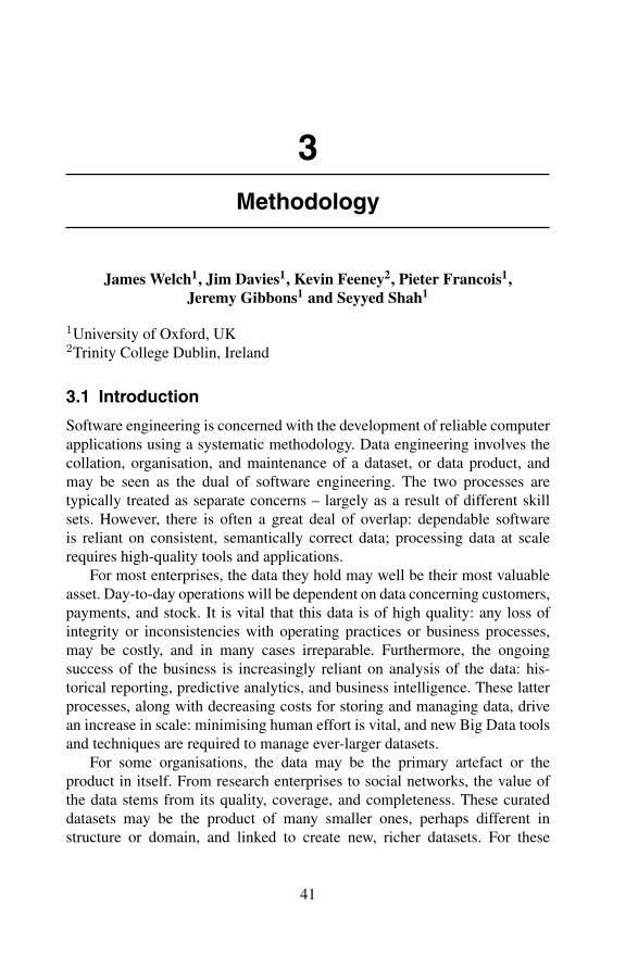
Modern software development methodologies can be seen as refinementsto the original waterfall process for hardware systems development. Firstconceived as a “stagewise” model,2 an instantiation targeting softwaredevelopment is typically summarised by the diagram in Figure 3.1.
In this most basic process, progress flows one way, through each ofthe stages, and one phase cannot begin until the previous phase has beencompleted. Each of the stages can be “signed off” by either the customer orthe developer in such a way that completion of a phase can be recognised andmade final. For example, the requirements for the system determine the scope
Figure 3.1 The waterfall process for software development.
2H. D. Benington, Production of large computer programs, IEEE Annals of the History ofComputing 5 (1983), pp. 350–361.
44 Methodology
of the specification; the completed specification document may be seen as acontract for the design work.
The first major problem with the waterfall model is that the executionof one phase of design may influence the previous stage. This is particularlyapparent in the verification stage: issues in verification will require furthereffort in design; design may be said to be unfinished until verification iscomplete. This may also hold true in the case of specification: the pro-cess of producing a clear, precise specification may uncover ambiguities orinconsistencies in the requirements provided.
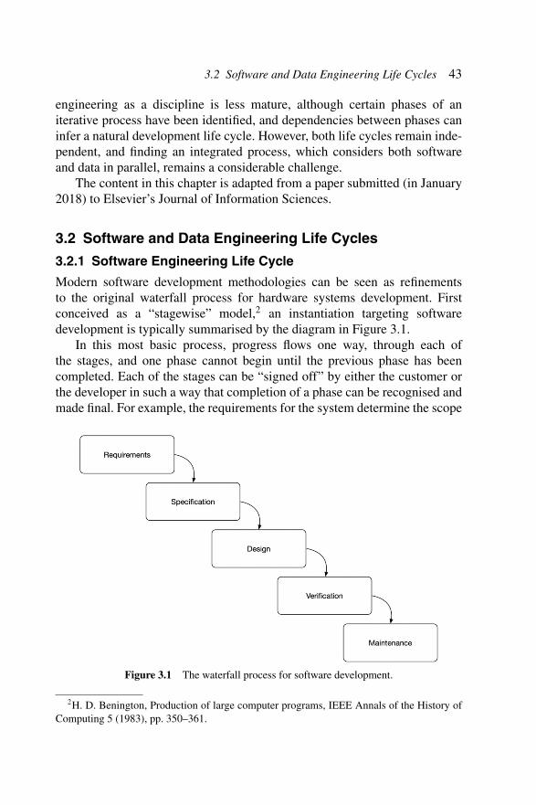
One solution to this problem is to allow feedback from one phase tomodify earlier decisions. This leads to a modified version as proposed byBoehm,3 in which backward arrows lead from one phase to the precedingone (see Figure 3.2). Although this allows for some notion of iteration indevelopment, allowing decisions made in each phase to be revisited, it suffersfrom another flaw, that is, estimating delivery time (and therefore cost) canbe very difficult. Without specific bounds on revisiting decisions, overallimplementation can take unspecified amounts of time, leading to frustrationfor both developer and customer.
Figure 3.2 A modified waterfall process.
3B. W. Boehm, Software Engineering, IEEE Transactions on Computers 25 (12),pp. 1226–1241, 1976.
3.2 Software and Data Engineering Life Cycles 45
This uncertainty can be exacerbated by another common problem insoftware development: customers often do not know, or understand, preciselywhat they want until they have had a chance to see it, or interact withit. Business rules that may seem fixed at the time of requirements andspecification may need revising in light of constraints in subsequent designor implementation stages. A good software engineering process must besympathetic to revisiting even the earliest requirements decisions after designand implementation are underway, but still be amenable to stable projectmanagement in order to allow predictable costs and timescales.
More modern approaches to these problems can take two forms. The firstof these is more technical, and directed at the actual design and implementa-tion process: by reducing the length of time taken to get from requirementsto implementation, decisions can be revisited quickly, and with less devel-opment effort. Prototyping allows the customer or user to get a feel for thesolution earlier, permitting the requirements or specification to be revisitedsooner in the overall implementation process. Automation in the implemen-tation phase can reduce the effort involved in updating implementations tomatch updated requirements.
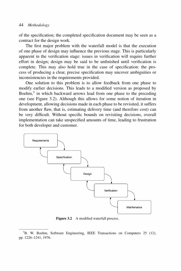
The second approach is another update to the software engineering lifecycle, allowing multiple iterations of the traditional model, typically reducingthe retrograde steps in the previous model in favour of completing an imple-mentation and starting a new requirements and specification iteration sooner.Figure 3.3 shows a typical iterative software development life cycle.
Figure 3.3 An iterative software development process.

46 Methodology
The iterative model allows a more flexible approach to contracts andtimelines: short cycles of the entire process allow prioritisation of features;early implementations can be used as prototypes and complex details canbe saved for future iterations when there may be more clarity. Cycles aretypically kept to a predefined length; at the start of each cycle, the scopeof each phase is determined, managing time and cost expectations. Althoughsystem-wide requirements will be gathered throughout the whole cycle, someanalysis will be performed at the start of each cycle in order to confirm thescope for the next cycle. Overall, time and cost estimation can be managedmore effectively4 and revised at the end of each cycle.
Another advantage to the iterative approach is that it changes the natureof the maintenance phase. Typically, during the life of the software, func-tionality will need adjusting to match evolving business requirements. Withthe standard waterfall model, the final phase of maintenance is often insuf-ficient to deal with updated requirements, and the whole process needs tobegin again; an iterative approach takes this into account, and maintenancecan be merged in as part of the overall development and re-evaluationcycle.
The “Manifesto for Agile Software Development”5 proposes 12 prin-ciples for such a development process, including to “satisfy the customerthrough early and continuous delivery of valuable software”, to “welcomechanging requirements, even late in development”, and to “deliver workingsoftware frequently, from a couple of weeks to a couple of months, witha preference to the shorter timescale”. The iterative approach is typicallyreferred to as an “agile” approach, although the principles as set out foran agile process extend beyond the software life cycle itself and provideguidance for the way in which developers work as a team and interact withtheir customers.
Managing an iterative process effectively can still be difficult: althoughindividual cycles can be fixed in duration, and development effort withinthe cycle may be reasonably estimated, it can still be difficult to managepriorities and overall development direction. A number of variations on theiterative, “agile” process have been proposed, and frameworks built around
4A. Begel, N. Nagappan, Usage and perceptions of agile software development in anindustrial context: An exploratory study, in: First International Symposium on EmpiricalSoftware Engineering and Measurement, pp. 255–264, IEEE, 2007.
5K. Beck, Manifesto for agile software development, http://agilemanifesto.org, accessed:November 2017 (2001).
3.2 Software and Data Engineering Life Cycles 47
them, for example, Scrum’,6 Kanban,7 and Extreme Programming,8 all ofwhich can help with cost estimation, reducing the time spent on verificationand enhancing code quality.
An agile approach can also be counter-productive for building certaintypes of software where solutions are complex and irreducible. Such solutionsrequire a high degree of planning and design and architectural decision-making in advance. An iterative development methodology can restrict thesolution space to one in which development time may be reasonably esti-mated, where progress may be demonstrated at the end of each iteration andwhere prioritisation stays consistent.
3.2.2 Data Engineering Life Cycle
As an emerging field of research, the processes of data engineering used inindustrial applications are still relatively immature. The LOD stack LOD29 isa collection of integrated tools supporting a life cycle for creating and man-aging Linked Data. Auer et al.10 proposed an iterative process for developinglinked open datasets. Eight core activities of Linked Data management areidentified and managed as phases in an iterative life cycle, consistent with theprinciples of Linked Data:
• storage/querying: retrieving and persisting information to be included aspart of the dataset;
• manual revision/authoring: processes for manual curation of content;• interlinking/fusing: creating and maintaining links between datasets;
6K. Schwaber, M. Beedle, Agile Software Development with Scrum, Vol. 1, Prentice Hall,2002.
7M. O. Ahmad, J. Markkula, M. Oivo, Kanban in software development: A systematicliterature review, in: Software Engineering and Advanced Applications (SEAA), 2013 39thEUROMICRO Conference on, IEEE, pp. 9–16, 2013.
8K. Beck, Embracing change with extreme programming, Computer 32 (10), pp. 70–77,1999.
9S. Auer, V. Bryl, S. Tramp, Linked Open Data–Creating Knowledge out of InterlinkedData: Results of the LOD2 Project, Vol. 8661, Springer, 2014.
10S. Auer, L. Buhmann, C. Dirschl, O. Erling, M. Hausenblas, R. Isele, J. Lehmann,M. Martin, P. N. Mendes, B. van Nuffelen, C. Stadler, S. Tramp, H. Williams, Managingthe life-cycle of linked data with the LOD2 stack, in: P. Cudre-Mauroux, J. Heflin, E. Sirin,T. Tudorache, J. Euzenat, M. Hauswirth, J. X. Parreira, J. Hendler, G. Schreiber, A. Bernstein,E. Blomqvist (Eds.), International Semantic Web Conference, pp. 1–16, Springer BerlinHeidelberg, Berlin, Heidelberg, 2012.
48 Methodology
• classification/enrichment: creating and maintaining links between dataand models of data (which themselves may be linked and part of thedataset);
• quality analysis: testing for data completeness and correctness;• evolution/repair: correcting invalid data resulting from a quality analysis
phase via either manual or automated processes;• search/browsing/exploration: making data artefacts available to domain
experts or to users beyond the original authors;• extraction: producing or publishing profiles or projections of data to be
used in other applications.
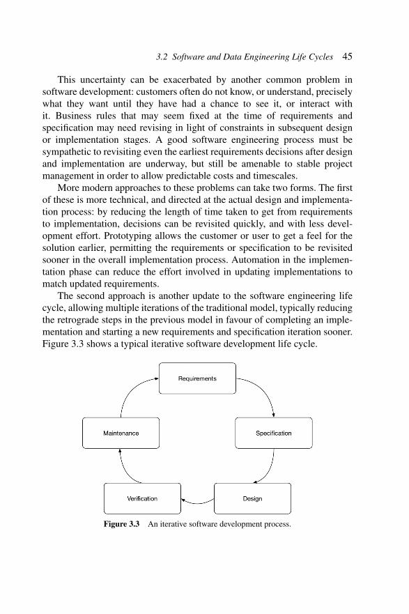
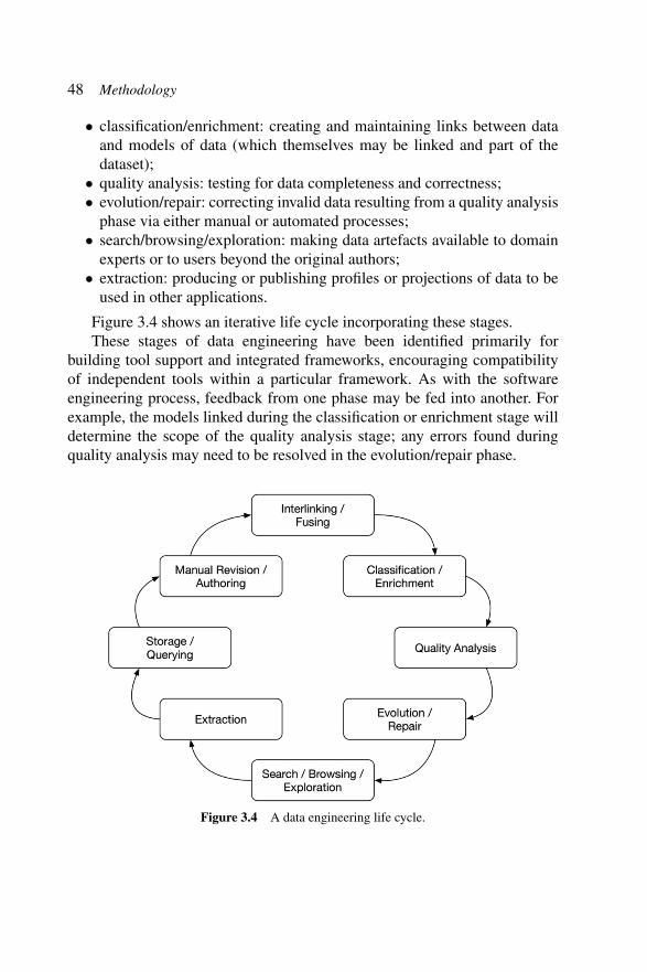
Figure 3.4 shows an iterative life cycle incorporating these stages.These stages of data engineering have been identified primarily for
building tool support and integrated frameworks, encouraging compatibilityof independent tools within a particular framework. As with the softwareengineering process, feedback from one phase may be fed into another. Forexample, the models linked during the classification or enrichment stage willdetermine the scope of the quality analysis stage; any errors found duringquality analysis may need to be resolved in the evolution/repair phase.
Figure 3.4 A data engineering life cycle.
3.3 Software Development Processes 49
3.3 Software Development Processes
In order to design a combined software and data engineering process, we willfirst consider some modern approaches to software engineering at scale andhow phases of the data engineering life cycle might be integrated or merged.As explained in Section 3.2, automation is often seen as key to improvingboth the speed of software delivery and the correctness of the deliveredproduct. In this section, we will consider three cross-cutting techniques ofsoftware engineering and discuss their advantages and disadvantages. We firstconsider model-driven approaches to software development, and the trade-offbetween automation and customisation. We then look at formal techniques,in particular formal specification, validation, and verification. Finally, wediscuss test-driven development and its role in an iterative developmentprocess.
3.3.1 Model-Driven Approaches
MDE describes a development process in which the components of thefinal software artefact are derived – either manually or automatically – frommodels that typically form part or all the specifications or requirements of thesystem. Rather than writing software that understands the data itself, softwareis written that understands the modelling language and is capable of handlingupdates to the model. Such software can be reused in different applicationswithin a similar domain, minimising the time spent on the implementationphase and capturing common repeating patterns that would otherwise have tobe repeated on each cycle of an iterative development.
MDE is a promising starting point for our combined methodology:by choosing well-suited models that fit the application domain, updatingsoftware to match evolving data can be achieved by simpler updates to amodel. With suitable tool support, this methodology may also allow ordinarybusiness users to manipulate these models and help bridge the gap betweenrequirements and specification.
As implied above, MDE approaches fall on a sliding scale between a fullyautomated generation process, and something much more manual, allowinggreater flexibility and customisation. An overview of some of the possibleapproaches and discussion of their practicality follows below.
The first MDE approach can be described as “full automation”: every-thing is modelled – including future-proofing – and machine learning is usedto learn how to change the model from the flows of data as their formatchanges over time. This approach has significant advantages in terms of
50 Methodology
maintenance cost: once the system is deployed and operational, minimalfurther intervention is required. However, although learning how to self-adapt a model is theoretically possible, it remains impractical for real-worldapplications. Another problem is the generation of training datasets for themachine-learning component: this is currently beyond the scope of most dataengineering projects.
A second approach that appears more practical is where a full modelof system behaviour is manually produced, but a fully functional softwareimplementation can be generated automatically from the model. The mod-elling language should be designed in such a way that a broad range oflikely future developments and feature requests can be handled without anycustom code needing to be written. If such tools are written with evolutionand upgrade in mind, they may be used for rapid prototyping, as part of aniterative agile process or as a technique to manage and enable software changebeyond initial deployment. If the tools for editing and managing models aregood enough, such changes may even be carried out by business users anddeployed instantly, rendering the whole process cost-free from a technicalresources point of view.
Although feasible within particular domains of application, this approachdoes not work universally: there can be no theoretical basis for automaticallyimplementing arbitrary behaviours and functionalities. However, subsets ofthe overall problem are tractable, and such modelling languages – alsoreferred to as DSLs – exist with usable tool support. The UML11 is themost significant attempt to create a complete modelling language. It doesnot have a formal semantics itself, but can be given one for a specificpurpose, and there are many tools based on subsets of the language. UMLhas been successfully deployed for building large, complex model-drivensystems. However, in practice, the development and testing of the modelstakes considerable amount of time and effort to get right. Such systems aremost appropriate for domains in which a lot of effort is spent moving datathrough highly stereotyped workflows that do not change rapidly over timeand where significant resources can be allocated to testing and managingmodel updates.
The remaining modelling approaches do not attempt to model behaviours,limiting their scope to data. The third approach is where a complete datamodel, containing a full specification of all the classes and properties that
11J. Rumbaugh, I. Jacobson, G. Booch, Unified Modelling Language Reference Manual,Pearson Higher Education, 2004.
3.3 Software Development Processes 51
are present in the data, is used to constrain or guide the manipulation of datacorresponding to that model. This approach has the advantage that constraintson data are easier to define and use than those upon behaviours. A completedata model can be used to generate a large proportion of software componentsin an information system – for example, the data storage mechanism and userinterfaces.
The disadvantages to this third approach are that although generationprocesses have been formally solved and public standards such as OWL areavailable, in practice, automated software generation from such models isstill very hard and requires tools to be built from scratch. Most importantly,the conceptual framework and the assumptions underlying the logic of OWLneed to be changed. Existing tools for model management are typicallyfocussed on knowledge engineers with specific goals and as such are notreally suited to business users.
A fourth approach is that of partial data modelling: where a subset of theinformation domain is specified – limited to ad-hoc or incomplete positive ornegative constraints on the data. Here the assumption is made that the modelis not exhaustive, that there are states of the data that are not addressed in themodel. This technique has a particular advantage in processing large datasets:where data are messy and do not necessarily conform to any model, we canidentify and filter out the most important problems caused by the lack ofstructure. A model may be incrementally built, adding rules to specificallyaddress any issues with the data as they are encountered.
A disadvantage with this approach is that the incompleteness of the modelprevents most automation techniques. Another is that the models are builtup by accumulation of ad-hoc rules and become difficult to manage overtime, invariably becoming a barrier to agility, and may become inconsis-tent. Changes to the model may result in large changes to the data – orworse, required changes to the data may go unnoticed or their calculationor derivation may be infeasible from the model.
3.3.2 Formal Techniques
The use of formal methods in the development of programs has been thetraditional practice for those systems that may be seen as safety-critical: typ-ically those systems whose failure could endanger human life. Such formaltechniques include the mathematical derivation of program code from precisespecifications, the logical proof that code exactly implements specifications inthe form of contracts, or the exhaustive verification of software to show that
52 Methodology
unwanted behaviours are precluded. Each suffers from the same problems:that formal techniques are slow and expensive, and do not scale to largecomplex software systems. A rigorous, mathematical approach will requiredevelopers with very specialised skills and experience.
However, there have been some successful applications of formal tech-niques in practical software development. Automation can solve problems ofscalability, but a completely automatic process is impossible in the generalcase. One solution is to restrict the problem domain: pattern matching canbe applied to the specification and particular refinements applied; prooflibraries and verification results can be stored for reuse. Another solution isto focus automation on part of a stepwise process; for example, automaticallygenerating method stubs or proof obligations for manual completion.
In many cases, formal techniques are associated with a more traditionalwaterfall method development. This can be because there is a need for adetailed, comprehensive specification before the mathematical process canbegin – requiring that much of the solution is explored before any program-ming starts. Hall12 described the development life cycle of the specificationitself: from Learning through Production and Simplification. These stages arenecessary within any development method, but in a formal code derivationprocess, these must typically happen before any code has been written. Thismay result in an overall speed increase, but does not incorporate the funda-mental component of an iterative process: feedback – the user’s response toan initial implementation.
However, the construction of a complete, precise specification is notwithout merit. The explication and analysis of the problem space is invaluablewhen developing code, most importantly when a team of developers requirea shared understanding. Human-readable documentation is also importantfor giving context and addressing subtleties not obvious from the plainmathematical statement. By addressing both specification and requirementsin this way, developers have a clearer sense of direction, customers can makebetter judgements on the suitability of a solution, and managers can bettermanage expectations of time and cost.
3.3.3 Test-Driven Development
A test-driven (or “test-first”) software development proceeds in an itera-tive fashion, but relies on a short development cycle, focussed on building
12A. Hall, Seven myths of formal methods, IEEE Software 7 (5), pp. 11–19, 1990.

3.4 Integration Points and Harmonisation 53
functionality to meet requirements, rather than specification. At the start ofeach iteration, acceptance tests are written to validate the implementation ofthe next round of features: the expectation is that these new tests will initiallyfail. Minimal changes to the code are made in order to get the test suitecompletely passing; once all tests pass, the feature development is complete.An optional refactoring phase can be used to tidy the code, whilst maintaininga full suite of passing tests.
As well as measuring the suitability of the latest iteration of develop-ment, tests also provide a valuable restraint on regressions: that previouslycorrect functionality is not broken by the latest updates. This can giveusers confidence in the stability of the software and reduce the burden fordevelopers.
An agile test-first approach can lead to high-quality, timely software.However, some of the caveats about agile, iterative development also apply:maintaining long-term objectives whilst focussing on short-term goals canbe difficult. Finding appropriate levels of code coverage requires experience:total coverage is often impossible; tests covering trivial or non-realistic casescan waste developer time, but too few tests may lead to a reduction in quality.
The test-driven approach to software has obvious parallels in the develop-ment of large datasets: the quality analysis phase of development can be usedto measure the correctness of the other phases – in particular those of manualrevision, interlinking, and enrichment. Tools for finding inconsistencies indata – and highlighting areas of concern – are readily available and wellunderstood by data engineers.
3.4 Integration Points and Harmonisation
Although the processes for software engineering and data engineering dis-cussed so far are complementary, it is more than likely that in the developmentof a data-intensive system, there will be dependencies between the twoprocesses. In general, an integration point corresponds to any pair of pointsin the software and data engineering life cycles where specific artefacts andprocesses should be shared. In this section we enumerate three different formsof integration point: overlaps, synchronisation points and dependencies; wediscuss the importance of each, and consider the difficulties in spotting them.We conclude the section by examining potential barriers to harmonising thetwo processes, in terms of terminologies, development roles, models, and toolsupport.
54 Methodology
3.4.1 Integration Points
The first type of integration point between the data and software engineeringprocesses is that of a natural overlap. This will be particularly prominentat the start of the project: for example, where the initial implementationof the software may run in parallel with a manual curation of the initialdataset. Similarly, in some projects, a phase of testing the software forcorrectness may coincide with a phase of quality analysis for the data: bugsin the software may be a cause of inconsistencies in the data; errors in thedata may uncover issues in the software. In general, overlapping phasessuch as these can indicate a requirement for software engineers and dataengineers to work together to ensure successful conclusions in both lifecycles.
More generally, we can consider synchronisation points: where phases inboth cycles are required to start, or finish, at the same time. This could be dueto a release of software coinciding with the linking of a new dataset. It may bedue to external pressures: the implementation of software and manual updateof data to match new business processes; the completion of a cross-cuttingsoftware and data concern before a member of staff leaves the organisation.
More generally still, it is important to consider dependencies betweenphases in cycles. Typically this can mean that a phase in one cycle must finishbefore another starts, but may simply be that one phase must reach a certainlevel of completion. One example where a software engineering phase mightdepend on a data engineering phase would be when data quality analysismust be completed before the requirements for the next iteration of softwaredevelopment can be signed off. An example where a data engineering phasemay depend on a software engineering phase might be where a particularsoftware feature must be tested and deployed before some manual datacuration may start.
Such integration points may happen regularly with every iteration – forexample the requirement to migrate data to match the deployment of newsoftware, or may happen irregularly, for example in response to changesin business processes, the implementation of new features, or updates toexternal data sources. Thus it becomes important to regularly review knownintegration points and assess the potential for new integration points in thefuture. As this requires insight into both data and software engineeringdevelopment plans, along with an understanding of overall roadmaps andbusiness direction, the integration analysis will involve many stakeholdersacross a range of disciplines or technical competencies.
3.4 Integration Points and Harmonisation 55
As with any project management activity, care should be taken to ensurethat dependencies can be appropriately managed. It is conceivable that in rarecases, cyclic dependencies appear: this may indicate that data and softwareengineering phases need more carefully defining – split up or merged – orthat requirements and design need revising. Generic tool support for suchproject management is readily available, but specialist tooling – as discussedin Section 7 – is really only available for software development processes.
The nature of each integration point needs investigation to explore thebest way of addressing it. For example, although some straightforwarddependencies may be seen to be sufficiently addressed by a simple sign-off process, the criteria for completion must be agreed beforehand. Morecomplicated dependencies, especially where an overlap in phases is con-cerned, may require more substantial collaboration between data engineersand software engineers, perhaps with intermediate checkpoints and combinedrequirements.
3.4.2 Barriers to Harmonisation
There are a number of barriers to the easy combination of software and dataengineering processes. Although both processes have foundations in com-puter science and information engineering, the two disciplines have differentterminology, and different reference or metamodels. The participants in eachwill also vary: roles may not have obvious counterparts in the other discipline,and the people carrying out each role will have different backgrounds andskills. Highlighting barriers and potential pitfalls is important so that theycan be anticipated and worked around.
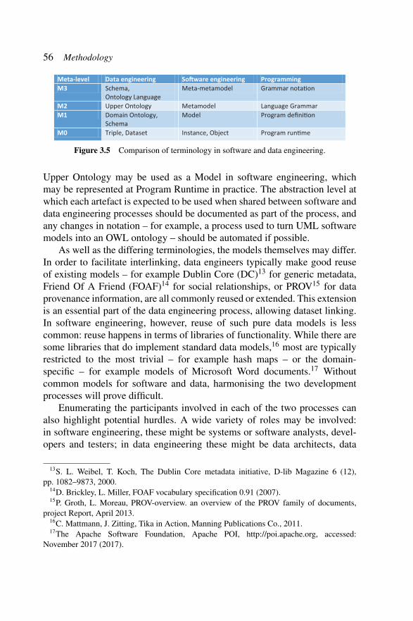
An integration point will usually indicate some shared resource betweensoftware and data engineering: typically a requirement, a model or a meta-model. It can be important to recognise this shared resource and ensurethat both data engineers and software engineers share a collective under-standing. A common barrier is that of terminology: although engineersmay typically share a common language in the domain of application, withdiffering skills and backgrounds, software and data engineers may havedifferent technical terminology. An example of this is shown in Figure 3.5 –showing a standard equivalence between terms of abstraction in differentdomains: data engineering, model-driven software engineering and moregeneral programming.
Based on the scope of the project, however, the equivalence may not beas direct as those shown. For example, in a particular project, one specific
56 Methodology
Meta-level Data engineering So�ware engineering ProgrammingM3 Schema,
Ontology LanguageMeta-metamodel Grammar nota�on
M2 Upper Ontology Metamodel Language GrammarM1 Domain Ontology,
SchemaModel Program defini�on
M0 Triple, Dataset Instance, Object Program run�me
Figure 3.5 Comparison of terminology in software and data engineering.
Upper Ontology may be used as a Model in software engineering, whichmay be represented at Program Runtime in practice. The abstraction level atwhich each artefact is expected to be used when shared between software anddata engineering processes should be documented as part of the process, andany changes in notation – for example, a process used to turn UML softwaremodels into an OWL ontology – should be automated if possible.
As well as the differing terminologies, the models themselves may differ.In order to facilitate interlinking, data engineers typically make good reuseof existing models – for example Dublin Core (DC)13 for generic metadata,Friend Of A Friend (FOAF)14 for social relationships, or PROV15 for dataprovenance information, are all commonly reused or extended. This extensionis an essential part of the data engineering process, allowing dataset linking.In software engineering, however, reuse of such pure data models is lesscommon: reuse happens in terms of libraries of functionality. While there aresome libraries that do implement standard data models,16 most are typicallyrestricted to the most trivial – for example hash maps – or the domain-specific – for example models of Microsoft Word documents.17 Withoutcommon models for software and data, harmonising the two developmentprocesses will prove difficult.
Enumerating the participants involved in each of the two processes canalso highlight potential hurdles. A wide variety of roles may be involved:in software engineering, these might be systems or software analysts, devel-opers and testers; in data engineering these might be data architects, data
13S. L. Weibel, T. Koch, The Dublin Core metadata initiative, D-lib Magazine 6 (12),pp. 1082–9873, 2000.
14D. Brickley, L. Miller, FOAF vocabulary specification 0.91 (2007).15P. Groth, L. Moreau, PROV-overview. an overview of the PROV family of documents,
project Report, April 2013.16C. Mattmann, J. Zitting, Tika in Action, Manning Publications Co., 2011.17The Apache Software Foundation, Apache POI, http://poi.apache.org, accessed:
November 2017 (2017).

3.4 Integration Points and Harmonisation 57
harvesters and data consumers. There may be roles which can, or should,be shared across the two processes: requirements engineers, system admin-istrators, technical or development managers. Users may be technical ordomain experts; they may be users of the software, the data, or both. It isimportant that interaction between roles is between both sides of the process:software developers should understand the concerns of data quality analysts,for example, and the data architects should collaborate with the softwarearchitects.
Another area where software and data engineers can be divided is on theuse of tools for managing the development process. In software development,the usual practice is to use an issue-tracking or defect-tracking tool, suchas Atlassian Jira,18 or JetBrains YouTrack.19 Such tools can help orchestratean iterative process: plugins are available to manage agile variants such asKanban or Scrum. Technical problems can be managed through this processtoo: issues can be raised directly by users, taken through a workflow fromprioritisation through development to testing by the developers, and “signedoff” as complete by management or the original users. Customisable work-flows allow this process to be adapted according to particular developmentprocesses or business culture.
Typically, such tool support for data engineering processes does not exist,in part due to the relative immaturity of formalised processes, and in part dueto the wide variety of workflows for data curation, some of which will bespecific to particular domains. In some cases, customisable tools such as Jiracan be re-purposed, and plugins developed, but data engineers – especiallythe domain experts, who may be non-technical – can often be reluctant to usesuch tools aimed at software developers. Processes can often be managed ina more ad-hoc fashion without tool support or building additional bespokesupport into data curation tools.
Having identified a number of potential barriers to integrating twodifferent engineering processes, we can consider approaches to success.Collaboration and harmonisation between two typically distinct teams in anorganisation requires a detailed understanding of the other process and those
18J. Fisher, D. Koning, A. Ludwigsen, Utilizing Atlassian JIRA for large-scale softwaredevelopment management, Tech. rep., Lawrence Livermore National Laboratory (LLNL),Livermore, CA (2013).
19JetBrains, JetBrains YouTrack, https://www.jetbrains.com/youtrack/documentation/, acce-ssed: November 2017 (2017).
58 Methodology
participating in it; of compromise in terms of terminology and modelling;a sympathy for those solving orthogonal problems within the same space;and shared sets of resources and tools for collaboration.
3.4.3 Methodology Requirements
Data-intensive systems require careful alignment between data engineeringand software engineering life cycles to ensure the quality and integrity ofthe data. Data stored in such systems typically persist longer than, and maybe more valuable than, the software itself, and so it is key that softwaredevelopment is sympathetic to the aims of “Big Data”: scalability to largevolumes of data; distributed, large-scale research across multiple disciplines;and complex algorithms and analysis. These are normally described in theliterature as the Five V’s of Big Data: velocity, volume, value, variety, andveracity.
In existing development methodologies, software and data engineeringare considered as separate concerns.20 Integrating these will introduce anumber of new challenges: software engineering aims of software quality,agility and development productivity may conflict with data engineeringaims of data quality, data usability, and researcher productivity. Furtherchallenges include federation of separate data sources, dynamic and auto-mated schema evolution, multi-source data harvesting, continuous data cura-tion and revision, data reuse and the move towards unstructured/looselystructured data.
Auer et al. identified challenges within the domain of life cycles forLinked Data.21 These include extraction, authoring, natural-language queries,automatic management of resources for linking, and Linked Data visual-isation. Typically seen as concerns for data life cycles, they all have amajor impact upon software development: the authors mentioned compo-nent integration, the management of provenance information, abstractionto hide complexity, and artefact generation from vocabularies or semanticrepresentations.
20M. Kleppmann, Designing Data-Intensive Applications: The Big Ideas behind Reliable,Scalable, and Maintainable Systems, O’Reilly Media, 2016.
21S. Auer, J. Lehmann, A.-C. N. Ngomo, A. Zaveri, Introduction to linked data and itslifecycle on the web, in: Reasoning Web. Semantic Technologies for Intelligent Data Access,pp. 1–90, Springer, 2013.
3.4 Integration Points and Harmonisation 59
Mattmann et al.22 used their experience of data-intensive software sys-tems across a range of scientific disciplines to identify seven key challengeswhich may be summarised as:
• data volume: scalability issues that apply not just to the hardware of thesystem, but may affect the tractability and usability of the data;
• data dissemination: distributed systems bring challenges of interoper-ability and can lead to complex system architectures;
• data curation: supporting workflows and tools for improving the qualityof data, in a way that allows subsequent inspection or analysis;
• use of open source: complex technologies will depend upon reliable,reusable components supporting generic functionality;
• search: making the data collected available in a usable fashion to users,including access to related metadata;
• data processing and analysis: boiling down to workflows, tasks, work-flow management systems, and resource management components;
• information modelling: the authors state that “the metadata should beconsidered as significant as the data”.
The authors split these challenges into further subcategories and pointedout many interdependencies between these problems. Zaveri et al.23 took abroader view, highlighting inadequate tool support for Linked Data qualityengineering processes. Where tool support does exist, these tools are aimedat knowledge engineers rather than domain experts or software engineers.
Anderson agreed with this issue,24 describing a more wide-ranging lackof support for developers of data-intensive systems. He also identified “thenecessity of a multidisciplinary team that provides expertise on a diverse setof skills and topics” as a non-technical issue that can be addressed by projectsdealing with large, distributed datasets. A technical equivalent to this issueis to understand notions of iteration with respect to the data modelling –he argued that domain knowledge is required in order to understand datacollection and curation. Subsequently, he also argued for technical knowledge
22C. A. Mattmann, D. J. Crichton, A. F. Hart, C. Goodale, J. S. Hughes, S. Kelly, L. Cinquini,T. H. Painter, J. Lazio, D. Waliser, et al., Architecting data-intensive software systems, in:Handbook of Data Intensive Computing, pp. 25–57, Springer, 2011.
23A. Zaveri, A. Rula, A. Maurino, R. Pietrobon, J. Lehmann, S. Auer, Quality assessmentfor linked data: A survey, Semantic Web 7 (1), pp. 63–93, 2016.
24K. M. Anderson, Embrace the challenges: Software engineering in a big data world,in: Proceedings of the First International Workshop on BIG Data Software Engineering,pp. 19–25, IEEE Press, 2015.
60 Methodology
in order to match frameworks with requirements, emphasising the need for amulti-disciplinary team.
Some solutions to these challenges have been identified – most notablyin the area of model-driven software engineering, DSLs, and generativeprogramming. These approaches, in combination with Linked Data languagesand schemas, enable self-describing data structures with rich semanticsincluded within the data itself. Aspects of program logic previously encap-sulated in software are now embedded in data models, meaning that thealignment between data and software engineering becomes even more impor-tant. But these approaches can lead to further problems: Qiu et al.25 identifiedtwo issues: firstly the interaction between domain experts and applicationdevelopers, and secondly that change to schema code may not always impactapplication code in a straightforward manner.
3.5 An ALIGNED Methodology
This section outlines the proposed methodology for combined software anddata engineering. We describe it as “lightweight”, because the techniquerequires some initial setup and maintenance, and its exact form can be heavilydetermined by the exact software and data engineering processes, by thetools available and the technical members of the team. However, in thismethodology, we propose a general framework for process management, aniterative methodology, and a number of guidelines or recommendations forsuccessful integration. We conclude the section by considering tool supportfor such a process.
3.5.1 A General Framework for Process Management
In Section 5, we outlined a number of potential barriers to harmonising thedata and software engineering processes. Our general framework is concernedwith reducing the effect of these issues, as well as providing an iterativemethodology that is suitably adaptive in response to changes in context. Theframework is split into two phases: the first, a “setup” phase, involves someanalysis of the preferred engineering processes, the shared resources andintegration points, and the impact of any tools, project roles or terminologywhere managing integration points will prove problematic. The second phase
25D. Qiu, B. Li, Z. Su, An empirical analysis of the co-evolution of schema and codein database applications, in: Proceedings of the 2013 9th Joint Meeting on Foundations ofSoftware Engineering, pp. 125–135, ACM, 2013.
3.5 An ALIGNED Methodology 61
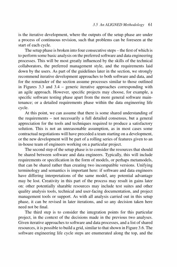
is the iterative development, where the outputs of the setup phase are undera process of continuous revision, such that problems can be foreseen at thestart of each cycle.
The setup phase is broken into four consecutive steps – the first of which isto perform some basic analysis on the preferred software and data engineeringprocesses. This will be most greatly influenced by the skills of the technicalcollaborators, the preferred management style, and the requirements laiddown by the users. As part of the guidelines later in the section, we stronglyrecommend iterative development approaches to both software and data, andfor the remainder of the section assume processes similar to those outlinedin Figures 3.3 and 3.4 – generic iterative approaches corresponding withan agile approach. However, specific projects may choose, for example, aspecific software testing phase apart from the more general software main-tenance; or a detailed requirements phase within the data engineering lifecycle.
At this point, we can assume that there is some shared understanding ofthe requirements – not necessarily a full detailed consensus, but a generalappreciation for the tools and techniques required to produce a satisfactorysolution. This is not an unreasonable assumption, as in most cases somecontractual negotiations will have preceded a team starting on a development,or the new development will be part of a rolling series of features given to anin-house team of engineers working on a particular project.
The second step of the setup phase is to consider the resources that shouldbe shared between software and data engineers. Typically, this will includerequirements or specification in the form of models, or perhaps metamodels,that can be shared rather than creating two incompatible versions. Unifyingterminology and semantics is important here: if software and data engineershave differing interpretations of the same model, any potential advantagemay be lost. Creativity in this part of the process may result in gains lateron: other potentially sharable resources may include test suites and otherquality analysis tools, technical and user-facing documentation, and projectmanagement tools or support. As with all analysis carried out in this setupphase, it can be revised in later iterations, and so any decision taken hereneed not be final.
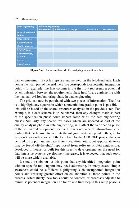
The third step is to consider the integration points for this particularproject, in the context of the decisions made in the previous two analyses.Given iterative approaches to software and data processes, and a list of sharedresources, it is possible to build a grid, similar to that shown in Figure 3.6. Thesoftware engineering life cycle steps are enumerated along the top, and the
62 Methodology
Data Engineering So�ware EngineeringRequirements Specifica�on Design Verifica�on Maintenance
Manual revision/ AuthorInter-link/fuseClassify/EnrichQuality AnalysisEvolve/RepairSearch/Browse/ Explore
Extract
Store/Query
Figure 3.6 An incomplete grid for analysing integration points.
data engineering life cycle steps are enumerated on the left-hand side. Eachbox in the main part of the grid therefore corresponds to a potential integrationpoint – for example, the first column in the first row represents a potentialsynchronisation between the requirements phase in software engineering withthe manual revision/authoring phase in data engineering.
The grid can now be populated with two pieces of information. The firstis to highlight any squares in which a potential integration point is possible –this will be based on the shared resources analysed in the previous step. Forexample, if a data schema is to be shared, then any changes made as partof the specification phase could impact some or all the data engineeringphases. Similarly, any shared test cases which are updated as part of thequality analysis phase in data engineering, will affect the verification phaseof the software development process. The second piece of information is thetooling that can be used to facilitate the integration at each point in the grid. InSection 7, we outline some of the tools built by the ALIGNED project that canbe used to support and manage these integration points, but appropriate toolsmay be found off-the-shelf, repurposed from software or data engineering,developed in-house, or built for this specific development. As the need fordata-intensive systems development increases, it is expected that such toolswill be more widely available.
It should be obvious at this point that any identified integration pointwithout specific tool support may need addressing. In many cases, simpleawareness could be sufficient: highlighting such unsupported integrationpoints and ensuring greater effort on collaboration at these points in theprocess. Alternatively, new tools could be sourced, or processes adjusted tominimise potential integration.The fourth and final step in this setup phase is

3.5 An ALIGNED Methodology 63
to consider the other barriers to harmonisation, in the context of each integra-tion point. Software and data engineers involved in the project should cometogether to consider how their terminology, standard models, developer rolesand tools can be made compatible in order to ensure maximum integration ateach feasible point.
3.5.2 An Iterative Methodology and Illustration
Once the setup phase is complete, a more traditional iterative developmentcan begin. In the setup phase, an iterative process for each of the software anddata engineering components was selected. In our methodology, these maynow continue independently in parallel, but constrained by the integrationpoints previously discussed: overlap, synchronisations, and dependencies. Toensure that these integration points may be sufficiently addressed, it is ourrecommendation that the cycles are aligned, or are coincident at a particularphase in each cycle – this will be determined by the integration points, andthe shared resources.
To illustrate, we consider a typical scenario encountered by ourALIGNED project use cases. In this scenario, the software engineering pro-cess is approximately equivalent to the iterative methodology in Figure 3.3,and the data engineering process can be seen as similar to that defined inFigure 3.4. The key shared resource is a complex data model, used as areference by the data engineers, but also forming part of the software model:data modification functionality, business rules, and additional internal datapoints are added to the external-facing data model, and used as a specificationdocument for the software engineers.
In such a process, updates to the data model can occur as part of thestorage/querying phase of the data engineering activity, where new data areadded to the existing data corpus, or as part of the specification phase of thesoftware engineering activity, where new requirements give rise to updatesin the intended functionality of the system. This forms the key integrationpoint: there is an overlap in process here, as both software and data engineersshould agree on any updates to the data model, and neither may continueuntil the updates made are complete and consistent. It is important thatsuch a key integration point is well managed: problems here could resultin wasted time and effort in curating a dataset against an incorrect model,developing software against an invalid or inconsistent schema, or managinga difficult merge operation between two parallel versions of the same datamodel. However, managed properly, having a shared data model is worth the
64 Methodology
effort: a reduction in duplication can save time and money; automation basedon this model can be shared; a common understanding can lead to a morecoherent, better designed solution.
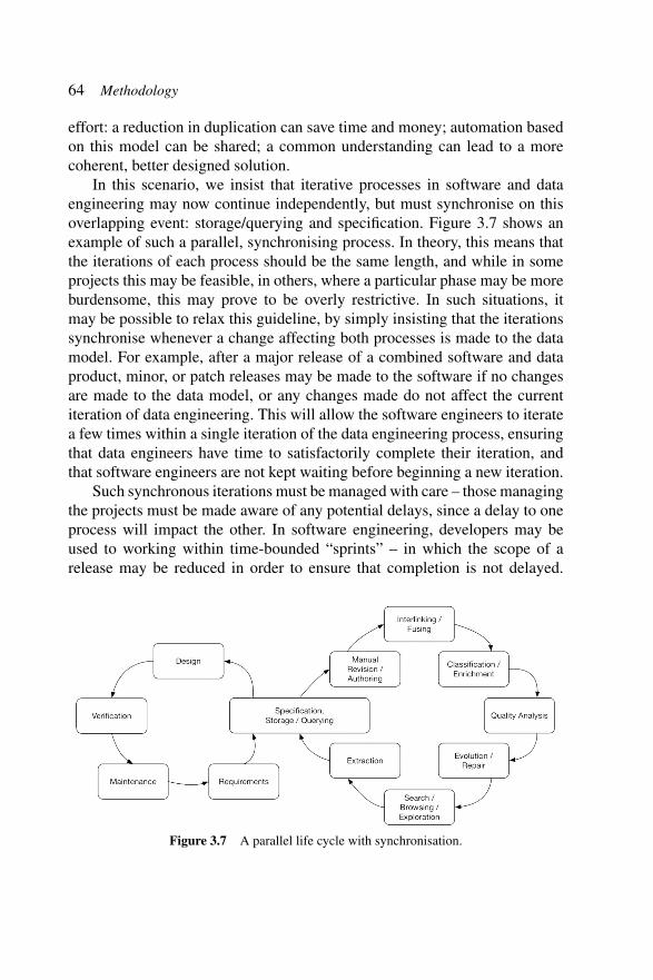
In this scenario, we insist that iterative processes in software and dataengineering may now continue independently, but must synchronise on thisoverlapping event: storage/querying and specification. Figure 3.7 shows anexample of such a parallel, synchronising process. In theory, this means thatthe iterations of each process should be the same length, and while in someprojects this may be feasible, in others, where a particular phase may be moreburdensome, this may prove to be overly restrictive. In such situations, itmay be possible to relax this guideline, by simply insisting that the iterationssynchronise whenever a change affecting both processes is made to the datamodel. For example, after a major release of a combined software and dataproduct, minor, or patch releases may be made to the software if no changesare made to the data model, or any changes made do not affect the currentiteration of data engineering. This will allow the software engineers to iteratea few times within a single iteration of the data engineering process, ensuringthat data engineers have time to satisfactorily complete their iteration, andthat software engineers are not kept waiting before beginning a new iteration.
Such synchronous iterations must be managed with care – those managingthe projects must be made aware of any potential delays, since a delay to oneprocess will impact the other. In software engineering, developers may beused to working within time-bounded “sprints” – in which the scope of arelease may be reduced in order to ensure that completion is not delayed.
Figure 3.7 A parallel life cycle with synchronisation.
3.6 Recommendations 65
In data engineering, such practices are less common, and so some trainingmay be required to ensure all technical staff understand the restrictions. Indevelopments where software and data iterations coincide, but are of differinglengths, care must be taken to ensure that any additional iterations do notimpact the shared resources. For example, in the scenario outlined above, anyadditional software iterations for a minor or patch release must not updatethe shared part of the data model, for otherwise the current data engineeringiteration may be inconsistent with the software that will next be deployed.
3.6 Recommendations
The iterative approach outlined above can provide a framework for combiningsoftware and data engineering processes, in such a way that a certain amountof autonomy can be maintained in two quite separate disciplines, but alsoin a way that can improve consistency and efficiency in the delivery of asolution made up of two closely coupled components. We now give somerecommendations, based on our experience on a number of use-case projects,for ensuring that integration points are managed efficiently, and to maximisecollaboration between software and data engineers.
Our first recommendation is that models are shared between softwareand data specifications, wherever possible. As previously discussed, thisincreases the opportunities for reuse and helps ensure that software and dataremain consistent. We further recommend that these models are formalisedin such a way that removes ambiguities, reducing the chance of inconsistentassumptions being made by software and data engineers.
Second, we recommend that development is driven by these shared mod-els, in an automated fashion wherever possible. This reduces the chance oferror in development and can ensure consistency such that developers canrely on the solutions produced in a parallel iteration.
Third, any solutions for either software or data should be rigorouslytested, where tests are also developed – automatically if possible – directlyfrom the model. Sharing or reusing test components can prove efficient, aswell as ensuring consistency between data and software.
Fourth, tool support should be used to effectively manage the iterativeprocess on both software and data sides. As discussed in Section 5, softwareengineers are used to using project management software to coordinateand administer an agile process, but such tools are not commonly used indata engineering applications. Such tools would need specialist support for
66 Methodology
managing the integration points, and a wider range of developer roles andresponsibilities.
Our final recommendation is that whenever meetings are held to discussthe iterative process – in particular the planning and feedback stages – thesemeetings should be attended by representatives of all solution stakeholders.The purpose for this is twofold: so that integration points and shared resourcescan be carefully managed; and so that the overall roadmap and architecturecan be maintained whilst engineers focus on small iterations addressing short-term goals.
These five recommendations are derived from the combined experience ofthe project use cases, but in every project, their priorities differed, accordingto the experience of the development and project management teams, the toolsavailable, and the particular iterative steps used in each development.
3.6.1 Sample Methodology
As an illustration, in this section, we look at the synchronisation pointsrequired for the ALIGNED use cases.
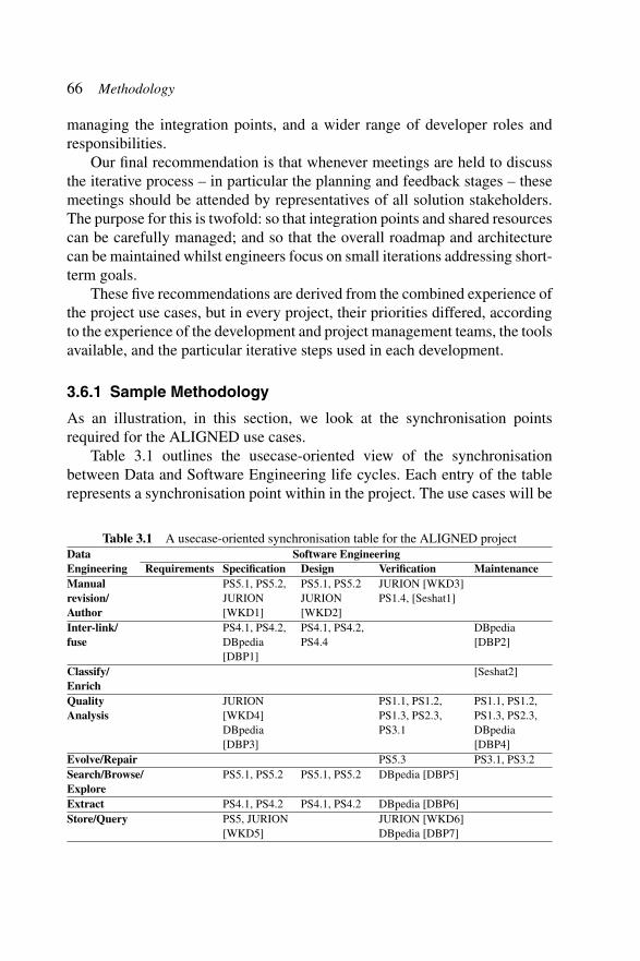
Table 3.1 outlines the usecase-oriented view of the synchronisationbetween Data and Software Engineering life cycles. Each entry of the tablerepresents a synchronisation point within in the project. The use cases will be
Table 3.1 A usecase-oriented synchronisation table for the ALIGNED projectData Software EngineeringEngineering Requirements Specification Design Verification MaintenanceManualrevision/Author
PS5.1, PS5.2,JURION[WKD1]
PS5.1, PS5.2JURION[WKD2]
JURION [WKD3]PS1.4, [Seshat1]
Inter-link/fuse
PS4.1, PS4.2,DBpedia[DBP1]
PS4.1, PS4.2,PS4.4
DBpedia[DBP2]
Classify/Enrich
[Seshat2]
QualityAnalysis
JURION[WKD4]DBpedia[DBP3]
PS1.1, PS1.2,PS1.3, PS2.3,PS3.1
PS1.1, PS1.2,PS1.3, PS2.3,DBpedia[DBP4]
Evolve/Repair PS5.3 PS3.1, PS3.2Search/Browse/Explore
PS5.1, PS5.2 PS5.1, PS5.2 DBpedia [DBP5]
Extract PS4.1, PS4.2 PS4.1, PS4.2 DBpedia [DBP6]Store/Query PS5, JURION
[WKD5]JURION [WKD6]DBpedia [DBP7]
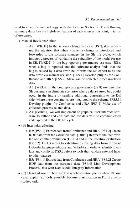
3.6 Recommendations 67
used to enact the methodology with the tools in Section 7. The followingsummary describes the high-level features of each intersection point, in termsof use cases:
• Manual Revision/Author
◦ A2: [WKD1] In the schema change use case (JS7), it is reflect-ing the situation that when a schema change is introduced andforwarded to the software manager in the SE life cycle, whichinitiates a process of validating the suitability of the model for usein SE. [WKD2] In the bug reporting governance use case (JS8),when a bug is reported and the software analyst finds that thebug is caused by a data error, he informs the DE expert to fix thedata error via manual revision. [PS5.1] Develop plugins for Con-fluence and JIRA [PS5.2] Make use of collected process-relateddata.
◦ A3: [WKD2] In the bug reporting governance (JS 8) use case, theSE designer can eliminate scenarios where a data-caused bug couldoccur in the future by sending additional constraints to the DEside, where these constraints are integrated to the schema. [PS5.1]Develop plugins for Confluence and JIRA [PS5.2] Make use ofcollected process-related data.
◦ A4: [Seshat1] We will implement of graphical user interface soft-ware to author and edit data and the data will be communicatedand captured in the DE life cycle.
• (B) Interlinking/Fusing
◦ B2: [PS4.1] Extract data from Confluence and JIRA [PS4.2] CreateRDF data from the extracted data. [DBP1] Refers to the fact over-lap and conflict evaluation (DS1.3) and in the interlink evaluation(DS3.2). DS1.3 refers to validation by fusing data from differentDBpedia language editions and Wikidata in order to identify over-laps and conflicts. DS3.2 refers to tools that validate external linksto other datasets.
◦ B3: [PS4.1] Extract data from Confluence and JIRA [PS4.2] CreateRDF data from the extracted data [PS4.4] Link DevelopmentProcess Data with Data Model Integrity Information.
• (C) Classify/Enrich: There are few synchronisation points where DE usecases exploit SE tools, possibly because classification in DE is a well-studied task.
68 Methodology
◦ A5: [Seshat2] The graphical user interface software widgets on theSE side will be continuously updated and maintained as the DEschemas evolve.
• (D) Quality Analysis
◦ D2: [DBP3] Quality analysis for mapping (DS2.1), ontology(DS2.2) and instance data (DS3.1).
◦ [WKD4] When a quality-related schema change is introduced andaccepted in the DE Life Cycle, the changes are communicatedto the SE Life Cycle, where the software is accepted. There is aprotocol for accepting quality changes.
◦ D4: [PS1.1] Constraints for Internal Actions [PS1.2] Rules forReasoning and Inferencing [PS1.3] Constraints for SpecificSchemas [PS2.3] Validate Thesaurus Against Schema.
◦ D5: [DBP4] Schemas refers to reports, generated by the automatedmapping validation tool (DS5.1) and erroneous fact report to theWikimedia community (DS5.2). [PS1.1] Constraints for InternalActions [PS1.2] Rules for Reasoning and Inferencing [PS1.3] Con-straints for Specific Schemas [PS2.3] Validate Thesaurus AgainstSchema.
• (E) Evolve/Repair
◦ E4: [PS5.3] Integrate Data Constraints Information with PPT DataMigration and Deployment Strategy.
◦ E5: [PS3.1] Formulation of Constraint Violation Repair Strategies[PS3.2] Creation of Repair User Interfaces.
• (F) Search/Browse/Explore
◦ F2: [PS5.1] Develop plugins for Confluence and JIRA [PS5.2]Make use of collected process-related data.
◦ F3: [PS5.1] Develop plugins for Confluence and JIRA [PS5.2]Make use of collected process-related data.
◦ F4: [DBP5] These integration points use the generation of DataIDas a core and auto generate tool for browsing and queryingbased on the DataID file. Browsing is achieved by auto gener-ating a download page for a DBpedia release and querying byproviding a Docker image that contains the release stored in atriple store.
3.7 Sample Synchronisation Point Activities 69
• (G) Extract
◦ G2: [PS4.1] Extract data from Confluence and JIRA [PS4.2] CreateRDF data from the extracted data.
◦ G3: [PS4.1] Extract data from Confluence and JIRA [PS4.2] CreateRDF data from the extracted data.
◦ G4: [DBP6] Extraction of two additional Wikimedia projects:Wikimedia Common (DS1.1) and Wikidata (DS1.2), implement-ing tools in the SE domain that extract the data.
• (H) Store/Query
◦ H2: [PS5.1] Develop plugins for Confluence and JIRA [PS5.2]Make use of collected process-related data [PS5.3] Integrate DataConstraints Information with PPT Data Migration and DeploymentStrategy.
◦ [WKD5] This integration point appears in the schema change(JS 7) use case. Once the schema change is in place in the DELife Cycle, new instance by the DE expert to the SE expert. Thenew data are used to execute test scenarios on how the new schemais affects the existing software, to formulate new requirements forthe design and implementation phases.
◦ H4: [DBP7] These integration points use the generation of DataIDas a core and auto generate tool for browsing and querying basedon the DataID file. Browsing is achieved by auto generating adownload page for a DBpedia release and querying by provid-ing a Docker image that contains the release stored in a triplestore.
A1–F1: The planning phase of the software engineering life cycle does notcontain any synchronisation points. Possibly because there are few toolsfor this stage (in general) artefacts produced at this stage are informal anddocumentary, and not useful to Data Engineering processes.
3.7 Sample Synchronisation Point Activities
As example, tools from the synchronisation table and details of the changesmade are included below, in the Model Catalogue tool and Semantic Booster.The aim of the following sections is to demonstrate the methodology usingthe example tools. The implication of iteration in the life cycles is alsodiscussed.
70 Methodology
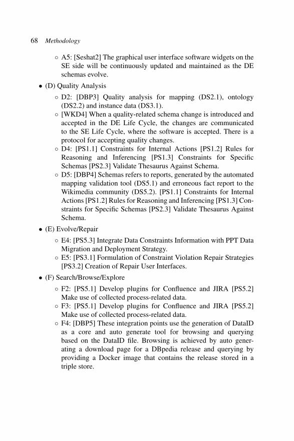
3.7.1 Model Catalogue: Analysis and Search/Browse/Explore
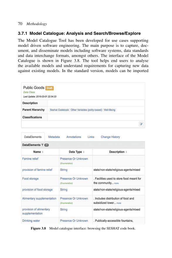
The Model Catalogue Tool has been developed for use cases supportingmodel driven software engineering. The main purpose is to capture, doc-ument, and disseminate models including software systems, data standardsand data interchange formats, amongst others. The interface of the ModelCatalogue is shown in Figure 3.8. The tool helps end users to analysethe available models and understand requirements for capturing new dataagainst existing models. In the standard version, models can be imported
Figure 3.8 Model catalogue interface: browsing the SESHAT code book.

3.7 Sample Synchronisation Point Activities 71
from formalisms such as UML and XSD. Models may be interlinked andreuse elements from related models. Some of the output formats includeBooster for software generation and Microsoft Word for documentation of themodel.
The catalogue tool has been adapted to support similar data engineeringuse cases, and thus bridge between data engineering and software engineeringdomains. The main addition has been the import and export of models instandard data engineering formats, such as RDFS and OWL. For the dataengineer, the tool can be used to explore how their data models are used inpractice in software. The models can be updated and changed without relyingon software engineers to create new versions of software. Models exportedusing the catalogue will retain interlinks between models in the two domains.This allows more streamlined integration of semantic metadata into workingsoftware.
The synchronisation point is bi-directional. The models can capture asoftware model from a data engineering model or use the model to capturedata in the data engineering domain. Multiple iterations of the softwareengineering and data engineering life cycles will typically result in newversions of the model; the changes will need to be synchronised after eachiteration. A feature to compare the changes in models in the model catalogueis planned to support this activity.
3.7.2 Model Catalogue: Design and Classify/Enrich
In model-driven development, the model catalogue tool also supports thecreation of new models for capturing emerging designs for data standards,software systems, and so on. The tool supports definition of new data classesand data elements that form the basis of data models. The tool has featuressuch as model versioning, annotation, collaborative editing and communica-tion between developers. The models can be built using existing models inthe catalogue or imported from partial models that exist in semi-structuredand human-readable formats such as spread sheets, CSV or text documents.
The model catalogue has been adapted for data engineering activity:classify data and enrich data models by linking elements with existing modelelements. Model classes can be refined and developed in the catalogue,capturing new and emerging structures in a data model, which leads to moreprecise understanding of the domain. Data engineers can use the catalogueto link between concepts in separate data engineering standards, and decidewhere links are semantically appropriate.
72 Methodology
Similar to the “Analysis and Search/Browse/Explore” synchronisationpoint, this sync point is bi-directional. Iterations of the software and dataengineering life cycles can result in new versions of the models. Themodel catalogue compare feature will support synchronisation of independentchanges in models across both life cycles.
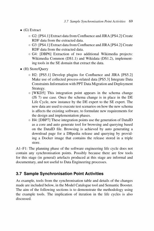
3.7.3 Semantic Booster: Implementation and Store/Query
Booster is a tool for the model-driven generation of information systems.High-level specifications are developed in Booster notation, which modelsthe system implementation. Booster performs a series of translations andrefinements on the model to generate a working system and ApplicationProgramming Interface (API) backed by a standard relational database. Auser interface to the system is provided as an example of how the APImay be used. The tool is used in the software engineering life cycle at theimplementation phase.
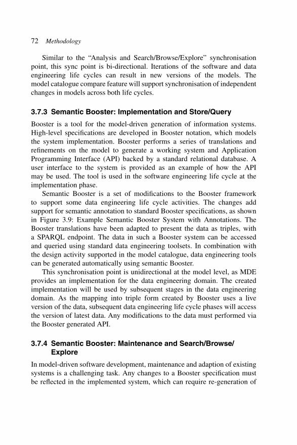
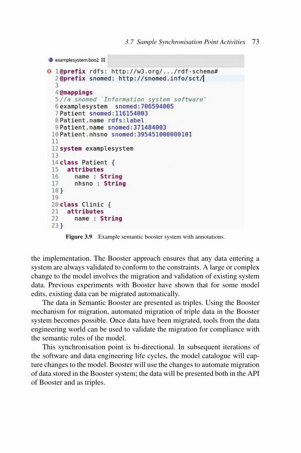
Semantic Booster is a set of modifications to the Booster frameworkto support some data engineering life cycle activities. The changes addsupport for semantic annotation to standard Booster specifications, as shownin Figure 3.9: Example Semantic Booster System with Annotations. TheBooster translations have been adapted to present the data as triples, witha SPARQL endpoint. The data in such a Booster system can be accessedand queried using standard data engineering toolsets. In combination withthe design activity supported in the model catalogue, data engineering toolscan be generated automatically using semantic Booster.
This synchronisation point is unidirectional at the model level, as MDEprovides an implementation for the data engineering domain. The createdimplementation will be used by subsequent stages in the data engineeringdomain. As the mapping into triple form created by Booster uses a liveversion of the data, subsequent data engineering life cycle phases will accessthe version of latest data. Any modifications to the data must performed viathe Booster generated API.
3.7.4 Semantic Booster: Maintenance and Search/Browse/Explore
In model-driven software development, maintenance and adaption of existingsystems is a challenging task. Any changes to a Booster specification mustbe reflected in the implemented system, which can require re-generation of
3.7 Sample Synchronisation Point Activities 73
Figure 3.9 Example semantic booster system with annotations.
the implementation. The Booster approach ensures that any data entering asystem are always validated to conform to the constraints. A large or complexchange to the model involves the migration and validation of existing systemdata. Previous experiments with Booster have shown that for some modeledits, existing data can be migrated automatically.
The data in Semantic Booster are presented as triples. Using the Boostermechanism for migration, automated migration of triple data in the Boostersystem becomes possible. Once data have been migrated, tools from the dataengineering world can be used to validate the migration for compliance withthe semantic rules of the model.
This synchronisation point is bi-directional. In subsequent iterations ofthe software and data engineering life cycles, the model catalogue will cap-ture changes to the model. Booster will use the changes to automate migrationof data stored in the Booster system; the data will be presented both in the APIof Booster and as triples.
74 Methodology
3.8 Summary
3.8.1 Related Work
That software and data engineering life cycles should be more closely inte-grated are not a new observation: Cleve et al.26 took a more concrete approachand also proposed a number of contemporary challenges in system evolution,based on higher levels of tool support; better tooling for co-evolution ofdatabases and programs; more agile coding techniques; and aligning dataorientation through Object-Relational Mappings.
A more general-purpose approach to integrating life cycles elicits a num-ber of broader challenges: software-engineering aims of software quality,agility and development productivity may conflict with data engineeringaims of data quality, usability, and user productivity. Such is the importanceof this integration work, the NESSI has identified “Collaborative ServiceEngineering based on the convergence of software and data” and “Integrationof Big Data Analytics into Business Processes” as EU research priorities.27
Further challenges relating more specifically to Big Data applications havebeen identified by Chen and Zhang:28 in particular, those relating to datacapture and storage, curation and analysis are of relevance here: hardwareas well as software limitations can impact the effectiveness of Big Datatechniques and highlighted opportunities may be missed.
Auer et al.29 identified challenges within the domain of life cycles forLinked Data. These include extraction, authoring, natural-language queries,automatic management of resources for linking, and Linked Data visu-alisation. Typically seen as concerns for data life cycles, they all havea major impact on software development: the authors mentioned compo-nent integration, the management of provenance information, abstractionto hide complexity, and artefact generation from vocabularies or semanticrepresentations.
26A. Cleve, T. Mens, J.-L. Hainaut, Data-intensive system evolution, Computer 43(8),pp. 110–112, 2010.
27NESSI, Strategic research and innovation agenda, Tech. rep., NESSI, version 2.0, April,2013.
28C. P. Chen, C.-Y. Zhang, Data-intensive applications, challenges, techniques and technolo-gies: A survey on big data, Information Sciences 275 pp. 314–347, 2014.
29S. Auer, J. Lehmann, A.-C. N. Ngomo, A. Zaveri, Introduction to linked data and itslifecycle on the web, in: Reasoning Web. Semantic Technologies for Intelligent Data Access,pp. 1–90, Springer, 2013.

3.8 Summary 75
Mattmann et al.30 used their experience of data-intensive softwaresystems across a range of scientific disciplines to identify seven keychallenges:
• data volume: scalability issues that apply not just to the hardware of thesystem, but may affect the tractability and usability of the data;
• data dissemination: distributed systems bring challenges of interoper-ability and can lead to complex system architectures;
• data curation: supporting workflows and tools for improving the qualityof data, in a way that allows subsequent inspection or analysis;
• use of open source: complex technologies will depend upon reliable,reusable components supporting generic functionality;
• search: making the data collected available in a usable fashion to users,including access to related metadata;
• data processing and analysis: boiling down to workflows, tasks, work-flow management systems, and resource management components;
• information modelling: the authors state that “the metadata should beconsidered as significant as the data”.
The authors split these challenges into further subcategories and pointedout the many interdependencies between these problems. Zaveri et al.31
took a broader view, highlighting inadequate tool support for Linked Dataquality engineering processes. Where tool support does exist, these toolsare aimed at knowledge engineers rather than domain experts or softwareengineers.
Anderson32 agreed with this issue, describing a more wide-ranging lackof support for developers of data-intensive systems. He also identified “thenecessity of a multidisciplinary team that provides expertise on a diverse setof skills and topics” as a non-technical issue that can be addressed by projectsdealing with large, distributed datasets. A technical equivalent to this issueis to understand notions of iteration with respect to the data modelling –Anderson argued that domain knowledge is required to understand datacollection and curation. Subsequently, he also argues for technical knowledge
30C. A. Mattmann, D. J. Crichton, A. F. Hart, C. Goodale, J. S. Hughes, S. Kelly, L. Cinquini,T. H. Painter, J. Lazio, D. Waliser, et al., Architecting data-intensive software systems, in:Handbook of Data Intensive Computing, pp. 25–57, Springer, 2011.
31A. Zaveri, A. Rula, A. Maurino, R. Pietrobon, J. Lehmann, S. Auer, Quality assessmentfor linked data: A survey, Semantic Web 7 (1) pp. 63–93, 2016.
32K. M. Anderson, Embrace the challenges: Software engineering in a big data world,in: Proceedings of the First International Workshop on BIG Data Software Engineering,pp. 19–25, IEEE Press, 2015.
76 Methodology
in order to match frameworks with requirements; emphasising the need for amulti-disciplinary team.
Some solutions to these challenges have been identified – most notablyin the area of model-driven software engineering, DSLs, and generativeprogramming. These approaches, in combination with Linked Data languagesand schemas, enable self-describing data structures with rich semanticsincluded within the data itself. Aspects of program logic previously encap-sulated in software are now embedded in data models, meaning that thealignment between data and software engineering becomes even more impor-tant. But these approaches can lead to further problems: Qiu et al.33 identifiedtwo issues: firstly the interaction between domain experts and applicationdevelopers, and secondly that changes to schema code may not always impactapplication code in a straightforward manner. In this document, we attemptto tackle these two issues explicitly.
3.9 Conclusions
We have described a flexible methodology for integrating software and dataengineering life cycles, identified a number of barriers to harmonisation,and made recommendations in order to better implement the combinedmethodology, and reduce the impediments. The methodology reflects theobserved practices and experiences of the ALIGNED consortium – acrossa range of application domains, development practices, and experiences, bothfor the development of new solutions and the evolution of existing ones.We outlined the application of the methodology in each of the use cases,describing the particular challenges and requirements faced by each, andhow the use of the methodology has improved development practice. We alsodescribed a number of tools built by the ALIGNED project partners that havebeen adapted to fit the integration points in the methodology, showing howthey may be repurposed, or similar tools may be adapted for application todata-intensive systems.
The use cases presented here represent a small fraction of the potentialapplication domains: further work is to apply the methodology in a widerrange of projects, with a different selection of tools, and with differentdevelopment teams. Further validation may be obtained from more qualitativeor quantitative validation: although it is rare for two system developments to
33D. Qiu, B. Li, Z. Su, An empirical analysis of the co-evolution of schema and codein database applications, in: Proceedings of the 2013 9th Joint Meeting on Foundations ofSoftware Engineering, pp. 125–135, ACM, 2013.

3.9 Conclusions 77
be directly comparable, experienced developers may be able to evaluate theeffectiveness of the methodology against previous practice.
As discussed above, the software engineering life cycle is relativelymature and is broadly similar in all developments, but the data engineeringprocesses are less well-defined, and may be more varied in further real-world applications – perhaps differing by domain or toolsets used. Furtherinvestigation is necessary to ensure that the methodology presented here isapplicable to different data engineering practices.